Nonlinear analysis and improvement of piezoelectric energy harvesting from combined loadings
15
Nonlinear Dyn DOI 10.1007/s11071-014-1355-8 ORIGINAL PAPER Piezoelectric energy harvesting from concurrent vortex-induced vibrations and base excitations H. L. Dai · A. Abdelkefi · L. Wang Received: 4 December 2013 / Accepted: 7 March 2014 © Springer Science+Business Media Dordrecht 2014 Abstract We investigate the potential of using a piezoelectric energy harvester to concurrently harness energy from base excitations and vortex-induced vibra- tions. The harvester consists of a multilayered piezo- electric cantilever beam with a circular cylinder tip mass attached to its free end which is placed in a uni- form air flow and subjected to direct harmonic exci- tations. We model the fluctuating lift coefficient by a van der Pol wake oscillator. The Euler–Lagrange prin- ciple and the Galerkin procedure are used to derive a nonlinear distributed-parameter model for a harvester under a combination of vibratory base excitations and vortex-induced vibrations. Linear and nonlinear analy- ses are performed to investigate the effects of the elec- trical load resistance, wind speed, and base acceleration on the coupled frequency, electromechanical damp- ing, and performance of the harvester. It is demon- strated that, when the wind speed is in the pre- or post- synchronization regions, its associated electromechan- ical damping is increased and hence a reduction in the H. L. Dai · L. Wang (B ) Department of Mechanics, Huazhong University of Science and Technology, Wuhan 430074, China e-mail: [email protected] H. L. Dai · L. Wang Hubei Key Laboratory for Engineering Structural Analysis and Safety Assessment, Wuhan 430074, China A. Abdelkefi Department of Engineering Science and Mechanics, MC 0219, Virginia Tech,Blacksburg, VA 24061, USA harvested power is obtained. When the wind speed is in the lock-in or synchronization region, the results show that there is a significant improvement in the level of the harvested power which can attain 150% compared to using two separate harvesters. The results also show that an increase of the base acceleration results in a reduction in the vortex-induced vibrations effects, an increase of the difference between the res- onant excitation frequency and the pull-out frequency, and a significant effects associated with the quenching phenomenon. Keywords Energy harvesting · Piezoelectric material · Vortex-induced vibrations · Combined loadings · Nonlinear analysis · Quenching phenomenon 1 Introduction Energy harvesting through conversion of wasted mechanical energy to electrical power has received sig- nificant attention over the past decade [1–5]. These energy harvesting systems have been proposed to oper- ate self-powered electronics, such as wireless and health monitoring sensors, data transmitters, medical implants, and cameras [6–9]. These harvesters are also designed to replace small batteries that have a finite life span and would require expensive or time consuming replacement. Of the different options of transduction mechanisms which include electrostatic [3], electro- magnetic [3], and piezoelectric [1, 3], the piezoelectric 123
Transcript of Nonlinear analysis and improvement of piezoelectric energy harvesting from combined loadings

Nonlinear Dyn
DOI 10.1007/s11071-014-1355-8
ORIGINAL PAPER
Piezoelectric energy harvesting from concurrent
vortex-induced vibrations and base excitations
H. L. Dai · A. Abdelkefi · L. Wang
Received: 4 December 2013 / Accepted: 7 March 2014
© Springer Science+Business Media Dordrecht 2014
Abstract We investigate the potential of using a
piezoelectric energy harvester to concurrently harness
energy from base excitations and vortex-induced vibra-
tions. The harvester consists of a multilayered piezo-
electric cantilever beam with a circular cylinder tip
mass attached to its free end which is placed in a uni-
form air flow and subjected to direct harmonic exci-
tations. We model the fluctuating lift coefficient by a
van der Pol wake oscillator. The Euler–Lagrange prin-
ciple and the Galerkin procedure are used to derive a
nonlinear distributed-parameter model for a harvester
under a combination of vibratory base excitations and
vortex-induced vibrations. Linear and nonlinear analy-
ses are performed to investigate the effects of the elec-
trical load resistance, wind speed, and base acceleration
on the coupled frequency, electromechanical damp-
ing, and performance of the harvester. It is demon-
strated that, when the wind speed is in the pre- or post-
synchronization regions, its associated electromechan-
ical damping is increased and hence a reduction in the
H. L. Dai · L. Wang (B)
Department of Mechanics, Huazhong University of Science
and Technology, Wuhan 430074, China
e-mail: [email protected]
H. L. Dai · L. Wang
Hubei Key Laboratory for Engineering Structural Analysis
and Safety Assessment, Wuhan 430074, China
A. Abdelkefi
Department of Engineering Science and Mechanics,
MC 0219, Virginia Tech, Blacksburg, VA 24061, USA
harvested power is obtained. When the wind speed is
in the lock-in or synchronization region, the results
show that there is a significant improvement in the
level of the harvested power which can attain 150 %
compared to using two separate harvesters. The results
also show that an increase of the base acceleration
results in a reduction in the vortex-induced vibrations
effects, an increase of the difference between the res-
onant excitation frequency and the pull-out frequency,
and a significant effects associated with the quenching
phenomenon.
Keywords Energy harvesting · Piezoelectric
material · Vortex-induced vibrations · Combined
loadings · Nonlinear analysis · Quenching phenomenon
1 Introduction
Energy harvesting through conversion of wasted
mechanical energy to electrical power has received sig-
nificant attention over the past decade [1–5]. These
energy harvesting systems have been proposed to oper-
ate self-powered electronics, such as wireless and
health monitoring sensors, data transmitters, medical
implants, and cameras [6–9]. These harvesters are also
designed to replace small batteries that have a finite life
span and would require expensive or time consuming
replacement. Of the different options of transduction
mechanisms which include electrostatic [3], electro-
magnetic [3], and piezoelectric [1,3], the piezoelectric
123

H. L. Dai et al.
one has received the most attention because of its ease
of application and it can effectively be placed in small
volumes. In addition, the piezoelectric option does not
require an external input voltage.
Several concepts have been introduced in order to
harvest energy from unused mechanical energy avail-
able in the environment. The most common concept
consists of a piezoelectric cantilever beam subjected
to external excitations applied at its base. When the
excitation frequency matches the natural frequency of
the harvester, resonant motions are obtained and then
the piezoelectric material strains and produces an elec-
trical charge and hence an output voltage is obtained
through an electrical load resistance. Anton and Sodano
[3] presented different strategies to enhance the per-
formance of these harvesters including the use of effi-
cient piezoelectric materials, use of distinct mode cou-
pling, and optimization of the power conditioning cir-
cuitry. For the same purpose, different techniques have
been employed, such as beam geometry [10,11], mul-
timodal systems [12,13], magnetic coupling [14–16],
and bistable configurations [17–19].
There has also been recent interest in the concept
of harvesting energy from aeroelastic or flow-induced
vibrations, such as flutter of airfoil sections [20–24],
vortex-induced vibrations (VIVs) of circular cylinders
[25–28], galloping of prismatic structures [29–33], and
wake galloping of parallel cylinders [34,35]. In this
concept, the piezoelectric energy harvester is placed in
a flow field and excited to undergo large limit-cycle
oscillation amplitudes that can be converted to usable
electrical power. Depending on the operating wind
speed, these piezoaeroelastic systems can be designed
and deployed in different locations including ventila-
tion outlets, rivers, bridges, structure’s surface, etc.
Almost all previous research studies have consid-
ered a single excitation source, either base or aeroelas-
tic. There are only three studies which investigated the
idea of energy harvesting from a combination of both
sources of excitation. Bibo and Daqaq [36,37] inves-
tigated theoretically and experimentally the response
behavior of a flutter-based piezoaeroelastic energy
harvester when subjected to a combination of vibra-
tory base excitations and aerodynamic loadings. They
demonstrated that the efficiency as well as the power
density of the harvester are significantly improved
when the wind speed is either below or above the linear
flutter speed. Furthermore, there is only one theoreti-
cal study investigating the influence of both vibratory
base and aeroelastic excitations on a galloping-based
piezoaeroelastic energy harvester [38]. Yan et al. [38]
investigated the effects of the base acceleration, wind
speed, and electrical load resistance on the performance
of the harvester and the associated nonlinear phenom-
ena that take place.
Based on the authors’ knowledge, no research study
has considered the potential of integrating both vibra-
tory base and aeroelastic excitations on a VIV-based
piezoaeroelastic energy harvester. In this work, we aim
to investigate the transduction of piezoelectric energy
harvesting under a combination of vibratory base exci-
tations and vortex-induced vibrations. To this end, a
multilayered piezoelectric cantilever beam with a cir-
cular cylinder-tip mass attached to its free end is con-
sidered. The design of the proposed harvester and the
derived distributed-parameter model are presented in
Sect. 2. In Sect. 3, the derived model is validated
with previous experimental measurements when only
vortex-induced vibrations are present. Linear and non-
linear analyses are performed in Sects. 4 and 5, respec-
tively, in order to investigate the effects of the electri-
cal load resistance, wind speed, and base acceleration
on the coupled frequency, electromechanical damping,
and performance of the harvester. Summary and con-
clusions are presented in Sect. 6.
2 Mathematical model
2.1 Model formulation
The piezoaeroelastic energy harvester under consid-
eration consists of a bimorph piezoelectric cantilever
beam with a circular cylinder attached to its free end,
as shown in Fig. 1. This harvester is placed in a uni-
form air flow with mean flow speed, U0, and subjected
to an external harmonic base motion, zb = z0cos(Ωt),
where z0 is the amplitude of the base displacement and
Ω is the base excitation frequency. In addition to the
base motion, when the shedding frequency is close to
the coupled frequency of the harvester, the harvester
can undergo steady-state limit-cycle oscillations in the
cross flow direction. The piezoelectric sheets are placed
on both sides of the cantilever beam. The two piezo-
electric sheets are bounded by two in-plane electrodes
of negligible thickness connected in series to an elec-
trical load resistance, R. The thickness of the beam is
assumed to be small compared to its length so that the
123

Piezoelectric energy harvesting from vibrations and excitations
L b
Lp
m0
U0
D y
zx
o
( )w
tx1zb
Fig. 1 Schematic of the piezoelectric energy harvester under
concurrent loadings
shear deformation and rotary inertia can be neglected.
The geometric and material properties of the system
are presented in Table 1.
To develop a reduced–order model of the considered
energy harvester, we apply the Galerkin discretization
to the Lagrangian (L = T − U ) and nonconservative
work (Wnc). To this end, we first calculate the total
potential energy U , kinetic energy T , and the noncon-
servative work. The total potential energy of the mul-
tilayered cantilever beam is given by:
U =1
2
⎡
⎢
⎣
∫
Vb
σ bx εb
x dVb+
∫
Vp
σp
x εpx dVp−
∫
Vp
E3 D3dVp
⎤
⎥
⎦,
(1)
where Vb and Vp are, respectively, the volumes of the
substrate and the piezoelectric sheets. ρb and ρp are the
densities of the substrate and piezoelectric sheets. σx
and εx are the stress and strain in the axial direction.
Using Hooke’s law and the linear constitutive relations
of piezoelectricity, the strains and stresses in the alu-
minum and piezoelectric layers are, respectively, given
by:
εbx = ε
px = εx = −z
∂2w(x, t)
∂x2, (2)
σ bx = Ebεx , (3)
σp
x = E p (εx − d31 E3) = E pεx − e31 E3, (4)
where w(x, t) denotes the relative displacement of the
beam. Eb and E p are Young’s moduli at constant elec-
tric field of the aluminum and piezoelectric layers,
d31 is the strain coefficient of the piezoelectric sheet,
e31 = E pd31 is the piezoelectric stress coefficient,
and E3 is the electric field developed in the piezoelec-
tric sheets. For series connections of the piezoelectric
sheets, the electric field is related to the voltage, V (t),
by E3 = −V (t)/2tp, where tp is the thickness of the
piezoelectric sheet [39].
In addition, D3 is the electric displacement given by
the following piezoelectric constitutive relation:
D3 = d31 E pεx + ε33 E3 = e31εx + ε33 E3, (5)
where ε33 is the permittivity component at constant
strain.
The kinetic energy of the harvester is the sum of the
kinetic energies of the beam and tip mass. Taking into
account for the moment of inertia of the cylindrical tip
mass, the kinetic energy of the system is expressed as:
T =1
2
⎡
⎢
⎣
∫
Vb
ρb
[
∂w(x, t)
∂t+
∂zb(t)
∂t
]2
dVb
+
∫
Vp
ρp
[
∂w(x, t)
∂t+
∂zb(t)
∂t
]2
dVp
]
Table 1 Dimensions and
properties of the harvester
components
Physical properties PZT elements Beam Cylinder
Length, L p, Lb, L0 (mm) 31.8 267 203
Width, wp, wb (mm) 25.4 32.5 –
Thickness, tp, tb (mm) 0.267 0.635 –
Diameter, D (mm) – – 19.8
Mass dentisy, ρp, ρb(kg/m3) 7800 2730 –
Mass, m p, mb, Mt (g) 1.68 15.8 10
Young’s modulus, E p, Eb (GPa) 66 70 –
Strain coefficient, d31
(
pm V−1)
−190 – –
Permittivity at constant strain, ε33
(
nFm−1)
13.28 – –
Capacitance, C p (nF) 20.3 – –
123
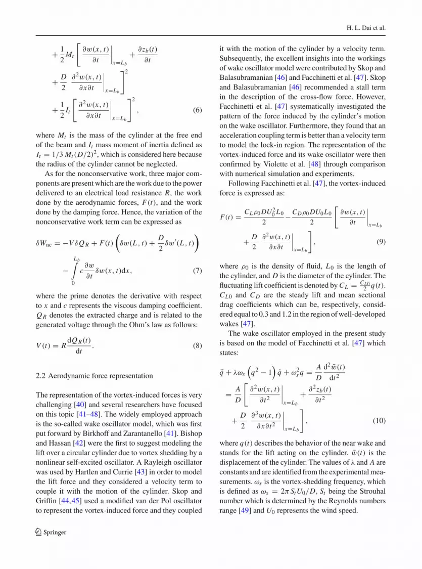
H. L. Dai et al.
+1
2Mt
[
∂w(x, t)
∂t
∣
∣
∣
∣
x=Lb
+∂zb(t)
∂t
+D
2
∂2w(x, t)
∂x∂t
∣
∣
∣
∣
x=Lb
]2
+1
2It
[
∂2w(x, t)
∂x∂t
∣
∣
∣
∣
x=Lb
]2
, (6)
where Mt is the mass of the cylinder at the free end
of the beam and It mass moment of inertia defined as
It = 1/3 Mt (D/2)2, which is considered here because
the radius of the cylinder cannot be neglected.
As for the nonconservative work, three major com-
ponents are present which are the work due to the power
delivered to an electrical load resistance R, the work
done by the aerodynamic forces, F(t), and the work
done by the damping force. Hence, the variation of the
nonconservative work term can be expressed as
δWnc = −V δQ R + F(t)
(
δw(L , t) +D
2δw′(L , t)
)
−
Lb∫
0
c∂w
∂tδw(x, t)dx, (7)
where the prime denotes the derivative with respect
to x and c represents the viscous damping coefficient.
Q R denotes the extracted charge and is related to the
generated voltage through the Ohm’s law as follows:
V (t) = RdQ R(t)
dt. (8)
2.2 Aerodynamic force representation
The representation of the vortex-induced forces is very
challenging [40] and several researchers have focused
on this topic [41–48]. The widely employed approach
is the so-called wake oscillator model, which was first
put forward by Birkhoff and Zarantanello [41]. Bishop
and Hassan [42] were the first to suggest modeling the
lift over a circular cylinder due to vortex shedding by a
nonlinear self-excited oscillator. A Rayleigh oscillator
was used by Hartlen and Currie [43] in order to model
the lift force and they considered a velocity term to
couple it with the motion of the cylinder. Skop and
Griffin [44,45] used a modified van der Pol oscillator
to represent the vortex-induced force and they coupled
it with the motion of the cylinder by a velocity term.
Subsequently, the excellent insights into the workings
of wake oscillator model were contributed by Skop and
Balasubramanian [46] and Facchinetti et al. [47]. Skop
and Balasubramanian [46] recommended a stall term
in the description of the cross-flow force. However,
Facchinetti et al. [47] systematically investigated the
pattern of the force induced by the cylinder’s motion
on the wake oscillator. Furthermore, they found that an
acceleration coupling term is better than a velocity term
to model the lock-in region. The representation of the
vortex-induced force and its wake oscillator were then
confirmed by Violette et al. [48] through comparison
with numerical simulation and experiments.
Following Facchinetti et al. [47], the vortex-induced
force is expressed as:
F(t) =CLρ0 DU 2
0 L0
2−
CDρ0 DU0 L0
2
[
∂w(x, t)
∂t
∣
∣
∣
∣
x=Lb
+D
2
∂2w(x, t)
∂x∂t
∣
∣
∣
∣
x=Lb
]
, (9)
where ρ0 is the density of fluid, L0 is the length of
the cylinder, and D is the diameter of the cylinder. The
fluctuating lift coefficient is denoted by CL = CL02
q(t).
CL0 and CD are the steady lift and mean sectional
drag coefficients which can be, respectively, consid-
ered equal to 0.3 and 1.2 in the region of well-developed
wakes [47].
The wake oscillator employed in the present study
is based on the model of Facchinetti et al. [47] which
states:
q + λωs
(
q2 − 1)
q + ω2s q =
A
D
d2w(t)
dt2
=A
D
[
∂2w(x, t)
∂t2
∣
∣
∣
∣
x=Lb
+∂2zb(t)
∂t2
+D
2
∂3w(x, t)
∂x∂t2
∣
∣
∣
∣
x=Lb
]
, (10)
where q(t) describes the behavior of the near wake and
stands for the lift acting on the cylinder. w(t) is the
displacement of the cylinder. The values of λ and A are
constants and are identified from the experimental mea-
surements. ωs is the vortex-shedding frequency, which
is defined as ωs = 2π StU0/D, St being the Strouhal
number which is determined by the Reynolds numbers
range [49] and U0 represents the wind speed.
123

Piezoelectric energy harvesting from vibrations and excitations
2.3 Reduced-order model
The Galerkin procedure is used to develop a reduced-
order model of this energy harvester. Therefore, we
express the displacement of the harvester in the fol-
lowing form:
w(x, t) =
n∑
i=1
ϕi (x)ri (t), (11)
where ri (t) are the modal coordinates of the displace-
ment and ϕi (x) are the mode shapes of a cantilever
beam with a tip mass. Taking into account for the iner-
tial force at the offset D/2 from the free end of the
beam and the rotational moment of inertia of the cylin-
der around the end of the beam, the mode shapes of this
system can be expressed as [50]:
ϕi (x) = C1 [cos (βi/Lbx) − cosh (βi/Lbx)
+ ξi (sin (βi/Lbx) − sinh (βi/Lbx))] , (12)
where
ξi =sin(βi ) − sinh(βi ) + κ1βi [cos(βi ) − cosh(βi )] − κ1κ2β
2i
[sin(βi )+sinh(βi )]
cos(βi ) + cosh(βi ) − κ1βi [sin(βi ) − sinh(βi )] − κ1κ2β2i
[cos(βi ) − cosh(βi )]. (13)
In Eq. (13), κ1 represents the mass ratio of the cylin-
der and the beam system, κ2 indicates the ratio of the
cylinder radius and beam length, and the frequency
parameters βi are the roots of the following frequency
equation
1 + cos(β) cosh(β) + κ1β [cos(β) sinh(β)
− cosh(β) sin(β)] − 2κ1κ2β2 sin(β) sinh(β)
− 4/3κ1κ22 β3 [cos(β) sinh(β) + cosh(β) sin(β)]
+ 1/3κ21 κ2
2 β4 [1 − cos(β) cosh(β)] = 0. (14)
To determine the modal amplitude constant, C1, we
apply the following orthogonality conditions:∫
Vb
ϕi (x)ρbϕ j (x)dVb +
∫
Vp
ϕi (x)ρpϕ j (x)dVp
+ ϕ′i (Lb)Jϕ′
j (Lb) + m0
[
ϕi (Lb) + D/2ϕ′i (Lb)
]
×[
ϕ j (Lb) + D/2ϕ′j (Lb)
]
= δi j
∫
Vb
z2ϕ′′i (x)Ebϕ′′
j (x)dVb
+
∫
Vp
z2ϕ′′i (x)E pϕ′′
j (x)dVp = ω2i δi j ,
(15)
where δi j is the Kronecker delta, defined as being equal
to unity for i = j and equal to zero for i = j . And ωi
is the undamped natural frequency of the i th vibration
mode.
The discretization is performed by substituting
Eq. (11) into Eqs. (1), (6), and (7). After that, we use
the Euler–Lagrange equations which are based on the
following relations:
∂
∂t
∂L
∂ ri
−∂L
∂ri
=δWnc
δri
(i = 1, 2, . . . , n), (16)
∂
∂t
∂L
∂λ−
∂L
∂λ=
δWnc
δλ= −
V
R, (17)
where λ = V .
Substituting Eq. (11) in Eq. (10) and simplifying
Eqs. (16) and (17), the reduced-order model of this
energy harvester can be expressed as:
ri +
⎧
⎨
⎩
2ςiωi +CDρ0 DU0 L0
2
[
ϕi (Lb) +D
2φ′
i (Lb)
]
×
n∑
j=1
(
ϕ j (Lb) +D
2ϕ′
j (Lb)
)
⎫
⎬
⎭
r j + ω2i ri − θi V
= f (t)(i = 1, 2, 3 . . . , n) (18)
C p V +V
R+
n∑
i=1
θi ri = 0 (19)
q + λωs(q2 − 1)q + ω2
s q
=A
D
[
n∑
i=1
([
ϕi (Lb)+D
2ϕ′
i (Lb)
]
ri
)
−a cos (t)
]
.
(20)
The external force f (t) is given by:
f (t) = αi q +
⎧
⎪
⎨
⎪
⎩
x1∫
0
m1ϕi (x)dx +
x1+L p∫
x1
m2ϕi dx
+
Lb∫
x1+L p
m1φi dx
+Mt
[
ϕi (Lb) +D
2ϕ′
i (Lb)
]
⎫
⎪
⎬
⎪
⎭
[a cos(t)] ,
(21)
123

H. L. Dai et al.
Fig. 2 Variation of the
maximum generated voltage
as a function of the wind
speed for different modes in
the Galerkin discretization
when R = 2.46 × 10⁶
0.6 0.8 1 1.2 1.4 1.6 1.8 2 2.20
5
10
15
20
251st mode
2nd mode
3rd mode
4th mode
5th mode
()
Vp
V
( )0 m sU
where a = zb2 is the base acceleration, m1 =
wbρbtb, m2 = wbρbtb + 2wpρptp, and the rest of the
coefficients are given by:
αi = CL0ρ0 DU 20 L0
[
ϕi (Lb) + D/2ϕ′i (Lb)
]
/4,
(22)
C p =ε33wp L p
2tp
, (23)
θi =e31wp
(
tp + tb)
2(ϕ′
i (x1 + L p) − ϕ′i (x1)). (24)
3 Model validation
In Sect. 2, a reduced-order model for the piezoelec-
tric energy harvester concurrently subjected to base
excitations and vortex-induced vibrations has been
developed. To determine the accuracy of the derived
distributed-parameter model, we first compare our
numerical predictions with the experimental measure-
ments of Akaydin et al. [26]. In their experiments, only
vortex-induced vibrations were present.Therefore, the
base acceleration is considered to be zero in the derived
reduced-order model. To make an accurate comparison,
we plot, in Fig. 2, the predicted numerical values of the
generated voltage as a function of the wind speed for
different number of modes in the Galerkin procedure
when the load resistance is set equal to 2.46×10⁶. We
have to mention that this plot is performed for the same
geometric and physical properties as used by Akaydin
et al. [26]. It follows from the plotted curves in Fig. 2
that one mode, two, or three modes in the Galerkin pro-
cedure are not sufficient to get convergence. Clearly,
four or five modes are required to get an excellent con-
vergence for the generated voltage and hence the har-
vested power. In the rest of this study, the numerical
predictions are performed when using five modes in
the Galerkin discretization.
A comparison between the numerical predictions
of our developed distributed-parameter model and the
experimental measurements of Akaydin et al. [26] is
performed. The plotted curves in Fig. 3a show the vari-
ation of the average harvested power as a function of
the wind speed when the load resistance is set equal to
2.46×10⁶. The average harvested power is calculated
as follows:
Pe =V 2
rms
R, (25)
where Vrms denotes the root mean square (RMS) value
of the generated voltage.
It follows from the plotted curves in Fig. 3a that there
is a very good agreement between the numerical predic-
tions of the derived model and the experimental mea-
surements of Akaydin et al. [26]. Clearly, the synchro-
nization region is well-predicted by the derived model
and particularly its starting and its peak. In fact, the
maximum value of the average power is the same and
equal to 0.1 mW when the wind speed is U0 = 1.20 m/s.
However, in the post-synchronization region, there is
an underestimation in the average harvested power
123

Piezoelectric energy harvesting from vibrations and excitations
0.5 1 1.2 1.5 2 2.3
0
0.02
0.04
0.06
0.08
0.1
0.12Simulation
ExperimentAkaydin et al.(2012)
()
mW
eP
( )0 m sU
0.5 0.8 1.1 1.4 1.7 2 2.3
0
0.05
0.1
0.15
0.2
0.25
()
mW
eP
( )0 m sU
(b)(a)
Fig. 3 a Comparison between the numerical predictions of the
derived distributed parameter model and the experimental mea-
surements of Akaydin et al. [26] and b Variation of the average
harvested power as a function of the wind speed when consider-
ing the geometric and physical parameters presented in Table 1
when considering the derived model for wind speed
values larger than 1.4 m/s. This result is probably due
to the accuracy of the wake oscillator model to the pre-
synchronization and synchronization regions.
We plot, in Fig. 3b, the variation of the average har-
vested power as a function of the wind speed when
considering the geometric and physical parameters pre-
sented in Table 1. In this plot, the electrical load resis-
tance is set equal to 106 and the base acceleration is
set equal to zero. It follows from the plotted curves in
Fig. 3(b) that the synchronization region takes place
when the wind speed is near U0 = 1.4 m/s.
4 Linear analysis: effects of the load resistance
and wind speed on the coupled frequency
and electromechanical damping
To investigate the effects of the electrical load resis-
tance and wind speed on the coupled frequency and
electromechanical damping, a linear analysis is per-
formed in which the base excitation terms as well
as the nonlinear terms in Eqs. (18) and (20) are
dropped. Because piezoaeroelastic systems are gener-
ally designed to harvest energy at low wind speeds and
hence at low shedding frequencies (ωs = 2π StU0/D),
the linear analysis is performed near the fundamen-
tal natural frequency of the harvester (ω1) and conse-
quently only one mode in the Galerkin discretization
is considered. Hence, the equations of motion can be
expressed as:
r1+
[
2ς1ω1+CDρ0 DU0 L0
2
(
ϕ1(Lb)+D
2ϕ′
1(Lb)
)2]
r1
+ ω21r1 − θ1V − α1q = 0 (26)
C p V +V
R+ θ1r1 = 0 (27)
q − λωs q + ω2s q −
A
D
(
ϕ1(Lb) +D
2ϕ′
1(Lb)
)
r1 = 0.
(28)
Then, we introduce the following state variables:
X =
⎡
⎢
⎢
⎢
⎢
⎢
⎢
⎣
X1
X2
X3
X4
X5
⎤
⎥
⎥
⎥
⎥
⎥
⎥
⎦
=
⎡
⎢
⎢
⎢
⎢
⎢
⎢
⎣
r1
r1
V
q
q
⎤
⎥
⎥
⎥
⎥
⎥
⎥
⎦
. (29)
The Eqs. (26), (27), and (28) can be rewritten as:
X = B X, (30)
123

H. L. Dai et al.
102
103
104
105
106
107
108
109
1010
22.5
23
23.5
24
24.5
25
( )R Ω
()
Fre
qu
ency
ra
d s
102
103
104
105
106
107
108
109
1010
1
2
3
4
5
( )R Ω
()
2C
ouple
d d
ampin
g r
atio
10
−
(b)(a)
Fig. 4 Variations of the a coupled frequency and b electromechanical damping as a function of the electrical load resistance when
U0 = 0 m/s
where
B =
⎡
⎢
⎢
⎢
⎢
⎢
⎢
⎢
⎢
⎢
⎢
⎣
0 1 0 0 0
−ω21 −
(
2ς1ω1 +CDρ0 DU0 L0
2ψ2
1
)
θ1 α1 0
0 − θ1C p
− 1RC p
0 0
0 0 0 0 1
− AD
ψ1ω21 − A
Dψ1
(
2ς1ω1 +CDρ0 DU0 L0
2ψ2
1
)
AD
ψ1θ1AD
ψ1α1 − ω2s λωs
⎤
⎥
⎥
⎥
⎥
⎥
⎥
⎥
⎥
⎥
⎥
⎦
(31)
and ψ1 = ϕ1(Lb) + D2ϕ′
1(Lb).
The matrix B has a set of five eigenvalues λi ,
i = 1, 2, 3, 4, 5. The first two eigenvalues are complex
conjugates and they are associated with the transverse
displacement motion of the cantilever beam. In fact,
the real part of these two eigenvalues represents the
electromechanical damping coefficient and their pos-
itive imaginary part represents the coupled frequency
of the harvester. These two eigenvalues depend on the
electrical load resistance and the wind speed when the
rest of the parameters are determined based on the given
values in Table 1. The third eigenvalue λ3 is a result of
the piezoelectric coupling and it is always real and neg-
ative. As for λ4 and λ5, they are complex conjugates
and they are associated with the response of the fluctu-
ating lift coefficient.
The plotted curves in Fig. 4a, b, respectively, depict
the variations of the coupled frequency and the electro-
mechanical damping as a function of the electrical load
resistance when the wind speed is set equal to zero.
Inspecting Fig. 4a, there is a steep increase over the
electrical load resistance values between 4×10⁵ and
107. In addition, when the load resistance is smaller
than 2 × 10⁵ or larger than 2 × 10⁷, the cou-
pled frequency is almost constant with different values.
When the load resistance is near 102; the coupled fre-
quency is equal to 22.7 rad/s. We refer to this frequency
as the short coupled frequency. On the other hand,
when the load resistance is near 108; the coupled fre-
quency of the harvester is equal to 24.85 rad/s. This
frequency is referred as the open coupled frequency.
Clearly, an increase of the electrical load resistance
results in an increase of the onset of synchronization.
Figure 4b shows that the electromechanical damping
is relatively high when the electrical load resistance
is between 4 × 10⁵ and 107. This region of load
123
Piezoelectric energy harvesting from vibrations and excitations
0 0.5 1 1.5 2
22
23
24
25
26
R=102Ω
R=106Ω
R=109Ω
0 0.5 1 1.5 20
2
4
6
8
10
12
R=102Ω
R=106Ω
R=109Ω
( )0 m sU ( )0 m sU
(b)(a)(
)F
req
uen
cy
rad
s
()
2C
ouple
d d
ampin
g r
atio
10
−
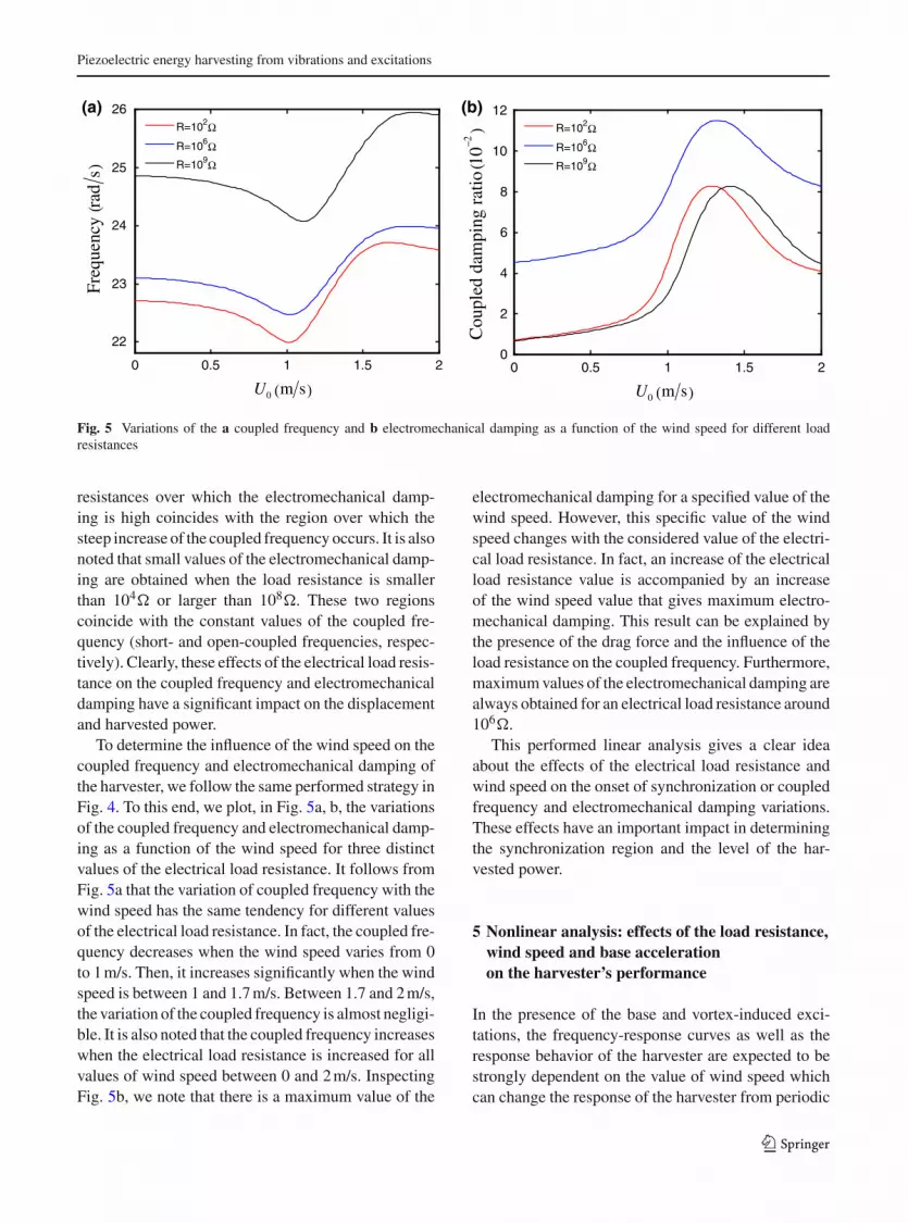
Fig. 5 Variations of the a coupled frequency and b electromechanical damping as a function of the wind speed for different load
resistances
resistances over which the electromechanical damp-
ing is high coincides with the region over which the
steep increase of the coupled frequency occurs. It is also
noted that small values of the electromechanical damp-
ing are obtained when the load resistance is smaller
than 104 or larger than 108. These two regions
coincide with the constant values of the coupled fre-
quency (short- and open-coupled frequencies, respec-
tively). Clearly, these effects of the electrical load resis-
tance on the coupled frequency and electromechanical
damping have a significant impact on the displacement
and harvested power.
To determine the influence of the wind speed on the
coupled frequency and electromechanical damping of
the harvester, we follow the same performed strategy in
Fig. 4. To this end, we plot, in Fig. 5a, b, the variations
of the coupled frequency and electromechanical damp-
ing as a function of the wind speed for three distinct
values of the electrical load resistance. It follows from
Fig. 5a that the variation of coupled frequency with the
wind speed has the same tendency for different values
of the electrical load resistance. In fact, the coupled fre-
quency decreases when the wind speed varies from 0
to 1 m/s. Then, it increases significantly when the wind
speed is between 1 and 1.7 m/s. Between 1.7 and 2 m/s,
the variation of the coupled frequency is almost negligi-
ble. It is also noted that the coupled frequency increases
when the electrical load resistance is increased for all
values of wind speed between 0 and 2 m/s. Inspecting
Fig. 5b, we note that there is a maximum value of the
electromechanical damping for a specified value of the
wind speed. However, this specific value of the wind
speed changes with the considered value of the electri-
cal load resistance. In fact, an increase of the electrical
load resistance value is accompanied by an increase
of the wind speed value that gives maximum electro-
mechanical damping. This result can be explained by
the presence of the drag force and the influence of the
load resistance on the coupled frequency. Furthermore,
maximum values of the electromechanical damping are
always obtained for an electrical load resistance around
106.
This performed linear analysis gives a clear idea
about the effects of the electrical load resistance and
wind speed on the onset of synchronization or coupled
frequency and electromechanical damping variations.
These effects have an important impact in determining
the synchronization region and the level of the har-
vested power.
5 Nonlinear analysis: effects of the load resistance,
wind speed and base acceleration
on the harvester’s performance
In the presence of the base and vortex-induced exci-
tations, the frequency-response curves as well as the
response behavior of the harvester are expected to be
strongly dependent on the value of wind speed which
can change the response of the harvester from periodic
123

H. L. Dai et al.
10 15 20 25 30 35
0
0.05
0.1
0.15
0.2
0.25
0.3U
0=0
U0=0.6m/s
U0=1.2m/s
U0=1.4m/s
U0=1.6m/s
U0=1.8m/s
( )rad sΩ
()
mW
eP
()
mW
eP(
)m
WeP(
)m
WeP
10 15 20 25 30 35
0
0.1
0.2
0.3
0.4
0.5U
0=0
U0=0.6m/s
U0=1.2m/s
U0=1.4m/s
U0=1.6m/s
U0=1.8m/s
(a)
a=0.005g
(b)
a=0.01g
10 15 20 25 30 350
0.2
0.4
0.6
0.8
1
1.2U
0=0
U0=0.6m/s
U0=1.2m/s
U0=1.4m/s
U0=1.6m/s
U0=1.8m/s
10 15 20 25 30 35
0
0.5
1
1.5
2U
0=0
U0=0.6m/s
U0=1.2m/s
U0=1.4m/s
U0=1.6m/s
U0=1.8m/s
(c)
a=0.03g
(d)
a=0.05g
( )rad sΩ
( )rad sΩ( )rad sΩ
Fig. 6 Frequency-response curves of the harvested power when the load resistance is set equal to 106 for different base accelerations
and wind speeds
to period-n or quasi-periodic. This dependence is due
to the presence of two frequencies which are the excita-
tion frequency and the shedding frequency. For a con-
stant wind speed value, the shedding frequency is fixed
through this relation ωs = 2π StU0/D. At this wind
speed, if the shedding frequency matches the coupled
frequency of the harvester, resonant transverse vibra-
tions occur and then lock-in or synchronization takes
place. Furthermore, if the excitation frequency matches
the coupled frequency of the harvester, resonant trans-
verse vibrations take place. Consequently, a significant
improvement in the level of the harvested power can
be observed if both the excitation frequency and the
shedding frequency match the coupled frequency of
the harvester. Away from the synchronization region,
there are no oscillations from the aerodynamic loading
and one expects that the harvester response is always
periodic and only contains the excitation frequency. On
the other hand, when the shedding frequency is close
to the coupled frequency, the response of the harvester
under the concurrent dynamic loads becomes complex.
This complexity depends on the values of the excitation
frequency and the coupled frequency of the harvester.
It is expected that the response of the harvester is com-
posed of a free-oscillation one due to vortex-induced
vibrations effect and a forced-oscillation one due to
base excitation. As such, the harvester mainly oscillates
with two harmonic frequencies which are the excitation
frequency and the shedding frequency. The existence
of these two frequencies is right only when these fre-
quencies are not commensurable (off-resonance). In
this case, the response of the harvester is generally
aperiodic. Away from the resonance region, the oscil-
lations due to vortex-induced vibrations are expected
to dominate. This process of unlocking between the
two frequencies is called pulling-out. When the exci-
123

Piezoelectric energy harvesting from vibrations and excitations
tation frequency is close to the coupled frequency of
the harvester (resonance region), its response changes
significantly and the oscillations due to the vortex-
induced vibrations entrained or locked onto the forced
oscillations. Therefore, a synchronization response at
the excitation frequency takes place. In addition, the
free-oscillation contribution decays with time and the
steady-state motion becomes periodic. The process
of decaying the free-oscillation contribution is called
quenching and the frequency at which the system
changes from aperiodic response to periodic one is
called pull-out frequency [51]. To demonstrate these
expectations, we investigate the effects of the electrical
load resistance, wind speed, and base acceleration on
the response of the harvester and its performance.
We plot, in Fig. 6a–d, the effects of the base acceler-
ation on the frequency-response curves of the harvester
for different wind speed values when the electrical load
resistance is set equal to 106. It follows from these
plots that the value of the resonant excitation frequency
changes when the wind speed is changed. In fact, when
the wind speed is increased from 0 to 1.2 m/s, the res-
onant excitation frequency decreases. When the wind
speed is increased from 1.2 to 1.6 m/s, the resonant
excitation frequency is increased. This result is pre-
dicted because the coupled frequency of the harvester
varies with the wind speed, as shown in Fig. 5a. Further-
more, inspecting the off-resonance regions, it is clear
that the effects of the vortex-induced vibrations are
important for wind speed values equal to 1.2, 1.4, and
1.6 m/s. This result is also expected because the syn-
chronization region takes place for wind speed values
between 1.1 and 1.7 m/s, as shown in Fig. 3b. For wind
speed values equal to 0.6 and 1.8 m/s, the tendency of
the frequency-response curves are similar to the case
of base excitation without vortex-induced vibrations
effect. This is explained due to the fact that the vortex-
induced vibrations effect is vanished in the pre- and
post-synchronization regions, as shown in Fig. 3b. In
addition, in the absence of the vortex-induced vibra-
tions effect, it is noted that more power can be har-
vested when U0 = 0 m/s compared to its counterpart
when U0 = 0.6 and 1.8 m/s. This result is due to higher
values of the electromechanical damping at U0 = 0.6
and 1.8 m/s compared to its counterpart at U0 = 0 m/s,
as shown in Fig. 5b. Consequently, in the absence of
the vortex-induced vibrations effect which corresponds
to the cases when the wind speed is not between 1.1
and 1.7 m/s, there is a reduction in the harvested power
which due to the electromechanical damping effect (see
Fig. 5b). It follows from Fig. 6c, d that for high val-
ues of the base acceleration, the maximum harvested
power when U0 = 1.6 m/s is larger than its counterpart
when U0 = 1.2 and 1.4 m/s although higher values
of the harvested power are obtained at these speeds
in the off-resonance regions. This result is also due to
the electromechanical damping effect which is much
higher at U0 = 1.2 and 1.4 m/s, as shown in Fig. 5b.
The typical time history curves of the voltage are plot-
ted in Fig. 7, which give a clear idea that the harvester
changes between aperiodic and periodic motions.
The plotted curves in Fig. 8a–d depict the frequency-
response curves of the harvested power for various
values of the electrical load resistance and four val-
ues of the wind speed. The base acceleration is set
equal to 0.01 g. It follows from these plots that the
harvested power is strongly dependent on the electri-
cal load resistance. In the case without vortex-induced
vibrations effect (U0 = 0 m/s), Fig. 8a shows that max-
imum values of the harvested power are obtained when
R = 105 and 107, respectively. Furthermore, the
value of the resonant excitation frequency depends on
the considered value of the electrical load resistance.
In fact, an increase of the electrical load resistance
is followed by an increase of the resonant excitation
frequency. This is expected because the coupled fre-
quency of the harvester has the same variations with
the electrical load resistance, as presented in Fig. 4b.
At U0 = 0.6 m/s, Fig. 8b shows that maximum val-
ues of the harvested are obtained when R = 107
and 105, respectively. This change in the optimum
electrical load resistance when varying the wind speed
from 0 to 0.6 m/s can be explained due to the fact that
increasing the electrical load resistance and the wind
speed from 0 to 0.6 m/s is accompanied by a significant
change in the electromechanical damping. Inspecting
Fig. 8a, b, it is noted that there is a reduction in the level
of harvested power when the wind speed is increased
from 0 to 0.6 m/s for all considered values of electri-
cal load resistance. This result is predicted because the
electromechanical damping increases when the wind
speed is increased from 0 to 0.6 m/s for all considered
values of electrical load resistance, as shown in Fig. 5b.
When U0 = 1.2 and 1.6 m/s, it is clear that the
vortex-induced vibrations effect takes place. In the off-
resonance regions, we note that higher levels of the har-
vested power are obtained when R = 107 and 105,
respectively. Furthermore, it is noted that the harvested
123

H. L. Dai et al.
0 10 20 30 40-30
-20
-10
0
10
20
30
t (s)
V (
V)
0 10 20 30 40-30
-20
-10
0
10
20
30
t (s)
V (
V)
(b)(a)
Fig. 7 Time history of the voltage for different excitation frequencies a = 20 rad/s, b = 23 rad/s with a = 0.01 g, U0 = 1.2 m/s
when the load resistance is set equal to 106
10 15 20 25 30 35
0
0.01
0.02
0.03
0.04
0.05
0.06R=104
Ω
R=105Ω
R=106Ω
R=107Ω
R=108Ω
10 15 20 25 30 35
0
0.01
0.02
0.03R=104
Ω
R=105Ω
R=106Ω
R=107Ω
R=108Ω
10 15 20 25 30 350
0.05
0.1
0.15
0.2
0.25
0.3
0.35R=104
Ω
R=105Ω
R=106Ω
R=107Ω
R=108Ω
10 15 20 25 30 350
0.2
0.4
0.6
0.8R=104
Ω
R=105Ω
R=106Ω
R=107Ω
R=108Ω
()
mW
eP
()
mW
eP(
)m
WeP
()
mW
eP
( )rad sΩ ( )rad sΩ
( )rad sΩ ( )rad sΩ
U0=0.6m/sU0=0
U0 U 0=1.6m/s=1.2m/s
(a) (b)
(c) (d)
Fig. 8 Frequency-response curves of the harvested power for different load resistances and wind speeds when the base acceleration is
set equal to 0.01 g
123

Piezoelectric energy harvesting from vibrations and excitations
10 15 20 25 30 350
0.2
0.4
0.6
0.8
1a=0.005g
a=0.01g
a=0.03g
a=0.05g
10 15 20 25 30 350
0.2
0.4
0.6
0.8a=0.005g
a=0.01g
a=0.03g
a=0.05g
U0=0.6m/sU0=0
10 15 20 25 30 350
0.4
0.8
1.2
1.6a=0.005g
a=0.01g
a=0.03g
a=0.05g
10 15 20 25 30 350
0.5
1
1.5
2
2.5a=0.005g
a=0.01g
a=0.03g
a=0.05g
U0 U 0=1.6m/s=1.2m/s
()
mW
eP
()
mW
eP(
)m
WeP
()
mW
eP
( )rad sΩ ( )rad sΩ
( )rad sΩ ( )rad sΩ
(a) (b)
(c) (d)
Fig. 9 Frequency-response curves of the harvested power for different base accelerations and wind speeds when the load resistance is
set equal to 106
power is higher when U0 = 1.6 m/s than its counter-
part when U0 = 1.2 m/s for all considered values of the
electrical load resistance except R = 106. Clearly,
the wide of the synchronization or lock-in region of the
vortex-induced vibrations is strongly dependent on the
electrical load resistance. When U0 = 1.2 m/s, the res-
onant excitation frequencies when R = 104, 105,
and 106 are almost the same which is due to the effects
of the wind speed on the coupled frequency, as pre-
sented in Fig. 5a. When the wind speed is increased
to 1.6 m/s, the difference between the resonant exci-
tation frequencies when R = 104, 105, and 106
becomes more important and is similar to its counter-
part when U0 = 0 m/s and 0.6 m/s.
In Fig. 9a–d, we plot the frequency-response curves
of the harvested power for different base acceleration
values and four distinct values of the wind speed when
the electrical load resistance is set equal to 106. It
follows from these plotted curves that the harvested
power increases when the base acceleration is increased
for all considered wind speed values. Inspecting these
plots, we note that the harvester is affected by the
vortex-induced vibrations for different forcing exci-
tations when U0 = 1.2 and 1.6 m/s. In the reso-
nance region, the levels of the harvested power are
more important when U0 = 0 m/s than its counterpart
when U0 = 0.6 m/s for all base acceleration values.
This result is due to higher electromechanical damp-
ing values which are obtained when the wind speed is
increased from 0 to 0.6 m/s. On the other hand, the pres-
ence of the vortex-induced vibrations (when U0 = 1.2
and 1.6 m/s) results in a significant improvement in the
level of the harvested power for all considered values
of the base acceleration. In fact, there is an enhance-
ment by 100 % and 150 % in the level of the harvested
power at U0 = 1.2 and 1.6 m/s, respectively, compared
123

H. L. Dai et al.
to their counterparts at U0 = 0 and 0.6 m/s when the
vortex-induced vibrations effect is absent. Inspecting
Fig. 9a–d, it is clear that the difference between the res-
onant excitation frequency and the pull-out frequency is
increased when the base acceleration is increased. Fur-
thermore, an increase of the base acceleration results in
significant effects associated with the quenching phe-
nomenon.
6 Conclusions
The transduction of a piezoelectric energy harvester
under the combination of vibratory base excitations and
vortex-induced vibrations has been investigated. The
harvester consists of a multilayered piezoelectric can-
tilever beam with a circular cylinder-tip mass attached
to its free end which is placed in a uniform air flow
and subjected to direct harmonic excitations. A non-
linear distributed-parameter model was derived based
on the Euler–Lagrange principle and the Galerkin dis-
cretization. The fluctuating lift coefficient was mod-
eled by a van der Pol oscillator. The results showed
that at least four modes have to be considered in the
Galerkin discretization to accurately predict the per-
formance of the harvester. The numerical predictions
based on the derived model were in a very good agree-
ment with experimental measurements when there is
no base excitations effect. A linear analysis was per-
formed to investigate the effects of the electrical load
resistance and wind speed on the coupled frequency
and electromechanical damping. The effects of the base
acceleration, wind speed, and electrical load resistance
on the performance of the harvester and the quenching
phenomenon were determined. When the wind speed is
in the pre- or post-synchronization regions, the results
showed that the presence of this wind speed results in an
increase of the electromechanical damping and hence a
reduction in the level of the harvested power. When the
wind speed is in the lock-in or synchronization region,
it was demonstrated that using a single piezoelectric
energy harvester under a combination of vibratory base
excitations and vortex-induced vibrations significantly
improves the level of the harvested power compared to
using two separate harvesters. It was also demonstrated
that increasing the base acceleration results in a reduc-
tion in the vortex-induced vibrations effect, an increase
of the difference between the resonant excitation fre-
quency and the pull-out frequency, and a significant
effects associated with the quenching phenomenon.
Acknowledgments The authors gratefully acknowledge the
support provided by the Program for New Century Excel-
lent Talents in University (NCET-11-0183) and the Funda-
mental Research Funds for the Central Universities, HUST
(2013TS034).
References
1. Sodano, H., Park, G., Inman, D.J.: A review of power har-
vesting from vibration using piezoelectric materials. Shock
Vib. Digest 36, 197–205 (2004)
2. Beeby, S.P., Tudor, M.J., White, N.M.: Energy harvesting
vibration sources for micro-systems applications. Meas. Sci.
Technol. 17, 175–195 (2006)
3. Anton, S.R., Sodano, H.A.: A review of power harvest-
ing using piezoelectric materials (2003–2006). Smart Mater.
Struct. 16, 1–21 (2007)
4. Tang, L., Padoussis, M.P., Jiang, J.: Cantilevered flexible
plates in axial flow: energy transfer and the concept of flutter
mill. J. Sound Vib. 326, 263–276 (2009)
5. Abdelkefi, A.: Global nonlinear analysis of piezoelectric
energy harvesting from ambient and aeroelastic vibrations.
PhD Dissertation, Virginia Tech (2012)
6. Roundy, S., Wright, P.K.: A piezoelectric vibration-based
generator for wireless electronics. Smart Mater. Struct. 13,
1131 (2005)
7. Inman, D., Grisso, B.: Towards autonomous sensing. Pro-
ceedings of Smart Structures and Materials Conference,
SPIE, p. 61740T (2006)
8. Karami, A., Inman, D.J.: Powering pacemakers from heart-
beat vibrations using linear and nonlinear energy harvesters.
Appl. Phys. Lett. 100, 042901 (2012)
9. Abdelkefi, A., Ghommem, M.: Piezoelectric energy harvest-
ing from morphing wing motions for micro air vehicles.
Theor. Appl. Mech. Lett. 3, 052001 (2013)
10. Goldschmidtboeing, F., Woias, P.: Characterization of dif-
ferent beam shapes for piezoelectric energy harvesting. J.
Micromech. Microeng. 18, 104013 (2008)
11. Ben Ayed, S., Abdelkefi, A., Najar, F., Hajj, M.R.: Design
and performance of variable-shaped piezoelectric energy
harvesters. J. Intell. Mater. Syst. Struct. (2013). doi:10.1177/
1045389X13489365
12. Abdelkefi, A., Najar, F., Nayfeh, A.H., Ben Ayed, S.: An
energy harvester using piezoelectric cantilever beams under-
going coupled bending–torsion vibrations. Smart Mater.
Struct. 20, 115007 (2011)
13. Abdelkefi, A., Nayfeh, A.H., Hajj, M.R., Najar, F.: Energy
harvesting from a multifrequency response of a tuned
bending–torsion system. Smart Mater. Struct. 21, 075029
(2012)
14. Karami, A., Inman, D.J.: Equivalent damping and frequency
change for linear and nonlinear hybrid vibrational energy
harvesting systems. J. Sound Vib. 330, 5583–5597 (2011)
15. Tang, L., Yang, Y.: A nonlinear piezoelectric energy har-
vester with magnetic oscillator. Apl. Phy. Let. 101, 094102
(2013)
16. Daqaq, M.F.: On intentional introduction of stiffness non-
linearities for energy harvesting under white Gaussian exci-
tations. Nonlinear Dyn. 69, 1063–1079 (2012)
123

Piezoelectric energy harvesting from vibrations and excitations
17. Harne, R.L., Wang, K.W.: A review of the recent research
on vibration energy harvesting via bistable systems. Smart
Mater. Struct. 22, 023001 (2013)
18. Mann, B.P., Sims, N.D.: Energy harvesting from the non-
linear oscillations of magnetic levitation. J. Sound Vib. 319,
515–530 (2009)
19. Erturk, A., Inman, D.J.: Broadband piezoelectric power gen-
eration on high-energy orbits of the bistable Duffing oscil-
lator with electromechanical coupling. J. Sound Vib. 330,
2339–2353 (2011)
20. Bryant, M., Garcia, E.: Energy harvesting: a key to wireless
sensor nodes. Proc. SPIE 7493, 74931W (2009)
21. Erturk, A., Vieira, W.G.R., De Marqui, C., Inman, D.J.: On
the energy harvesting potential of piezoaeroelastic systems.
Appl. Phys. Lett. 96, 184103 (2010)
22. Abdelkefi, A., Nayfeh, A.H., Hajj, M.R.: Modeling and
analysis of piezoaeroelastic energy harvester. Nonlinear
Dyn. 67, 925–939 (2012)
23. Abdelkefi, A., Nayfeh, A.H., Hajj, M.R.: Design of
piezoaeroelastic energy harvesters. Nonlinear Dyn. 68, 519–
530 (2012)
24. Abdelkefi, A., Nuhait, A.O.: Modeling and performance
analysis of cambered wing-based piezoaeroelastic energy
harvesters. Smart Mater. Struct. 22, 095029 (2013)
25. Akaydin, H.D., Elvin, N., Andreopoulos, Y.: Wake of a
cylinder: a paradigm for energy harvesting with piezoelec-
tric materials. Exp. Fluids. 49, 291–304 (2010)
26. Akaydin, H.D., Elvin, N., Andreopoulos, Y.: The perfor-
mance of a self-excited fluidic energy harvester. Smart
Mater. Struct. 21, 025007 (2012)
27. Abdelkefi, A., Hajj, M.R., Nayfeh, A.H.: Phenomena and
modeling of piezoelectric energy harvesting from freely
oscillating cylinders. Nonlinear Dyn. 70, 1377–1388 (2012)
28. Mehmood, A., Abdelkefi, A., Hajj, M.R., Nayfeh, A.H.,
Akhtar, I., Nuhait, A.O.: Piezoelectric energy harvesting
from vortex-induced vibrations of circular cylinder. J. Sound
Vib. 332, 4656–4667 (2013)
29. Sirohi, J., Mahadik, M.: Piezoelectric wind energy harvester
for low-power sensors. J. Intell. Mater. Syst. Struct. 22,
2215–2228 (2011)
30. Abdelkefi, A., Hajj, M.R., Nayfeh, A.H.: Power harvesting
from transverse galloping of square cylinder. Nonlinear Dyn.
70, 1355–1363 (2012)
31. Abdelkefi, A., Hajj, M.R., Nayfeh, A.H.: Piezoelectric
energy harvesting from transverse galloping of bluff bod-
ies. Smart Mater. Struct. 22, 015014 (2013)
32. Abdelkefi, A., Yan, Z., Hajj, M.R.: Performance analysis of
galloping-based piezoaeroelastic energy harvesters with dif-
ferent cross-section geometries. J. Intell. Mater. Syst. Struct.
(2013). doi:10.1177/1045389X13491019
33. Yang, Y.W., Zhao, L.Y., Tang, L.H.: Comparative study of
tip cross-sections for efficient galloping energy harvesting.
Appl. Phys. Lett. 102, 064105 (2013)
34. Jung, H.J., Lee, S.W.: The experimental validation of a new
energy harvesting system based on the wake galloping phe-
nomenon. Smart Mater. Struct. 20, 055022 (2011)
35. Abdelkefi, A., Scanlon, J.M., McDowell, E., Hajj, M.R.: Per-
formance enhancement of piezoelectric energy harvesters
from wake galloping. Appl. Phys. Lett. 103, 033903 (2013)
36. Bibo, A., Daqaq, M.F.: Energy harvesting under combined
aerodynamic and base excitations. J. Sound Vib. (2013).
doi:10.1016/j.jsv.2013.04.009i
37. Bibo, A., Daqaq, M.F.: Investigation of concurrent energy
harvesting from ambient vibrations and wind using a sin-
gle piezoelectric generator. Appl. Phys. Lett. 102, 243904
(2013)
38. Yan, Z., Abdelkefi, A., Hajj, M.R.: Nonlinear analysis of
piezoelectric energy harvesters from ambient and gallop-
ing vibrations. 54th AIAA/ASME/ASCE/AHS/ASC Struc-
tures, Structural Dynamics, and Materials Conference,
Boston, 8–11 April 2013.
39. Erturk, A., Inman, D.: An experimentally validated bimorph
cantilever model for piezoelectric energy harvesting from
base excitations. Smart Mater. Struct. 18, 025009–025026
(2009)
40. Benaroya, H., Gabbai, R.D.: Modelling vortex-induced
fluid–structure interaction. Phil. Trans. R. Soc. A. 366,
1231–1274 (2008)
41. Birkhoff, G., Zarantanello, E.H.: Jets Wakes and Cavities.
Academic Press, NewYork (1957)
42. Bishop, R.E.D., Hassan, Y.: The lift and drag forces on a
circular cylinder oscillating in a flowing fluid. Proc. R. Soc.
Lond. 277, 51–74 (1964)
43. Hartlen, R.T., Currie, I.G.: A lift-oscillator model for vortex-
induced vibrations. J. Eng. Mech. 69, 577–591 (1970)
44. Skop, R.A., Griffin, O.M.: A model for the vortex-excited
resonant response of bluff cylinders. J. Sound Vib. 27,
225–233 (1973)
45. Skop, R.A., Griffin, O.M.: On a theory for the vortex-excited
oscillations of flexible cylindrical structures. J. Sound Vib.
41, 263–274 (1975)
46. Skop, R.A., Balasubramanian, S.: A new twist on an old
model for vortex-excited vibrations. J. Fluids Struct. 11,
395–412 (1997)
47. Facchinetti, M.L., de Langre, E., Biolley, F.: Coupling of
structure and wake oscillators in vortex-induced vibrations.
J. Fluids Struct. 19, 123–140 (2004)
48. Violette, R., de Langre, E., Szydlowski, J.: Computation of
vortex-induced vibrations of long structures using a wake
oscillator model: comparison with DNS and experiments.
Comput. Struct. 85, 1134–1141 (2007)
49. Chen, S.S.: Flow-Induced Vibration of Circular Cylindrical
Structures. Hemisphere Publishing Corporation, Washing-
ton, DC (1987)
50. Krylov, S., Maimon, R.: Pull-in dynamics of an elastic beam
actuated by continuously distributed electrostatic force. J.
Vib. Acoust. 126, 332–342 (2004)
51. Nayfeh, A.H., Mook, D.M.: Nonlinear Oscillations. Wiley,
New York (1995). Wiley Classic Library Edition
123