Multi-Omics Studies towards Novel Modulators of Influenza A ...
Upload
independentCategory
view
0download
0
Non-Refractive Modulators for Encoding and Capturing Scene Appearance and Depth
Ashok VeeraraghavanUniversity of MarylandCollege Park, MD [email protected]
Amit Agrawal, Ramesh Raskar∗
Mitsubishi Electric Research Labs (MERL)Cambridge, MA 02139
{agrawal,raskar}@merl.com
Ankit Mohan and Jack TumblinNorthwestern UniversityEvanston, IL 60208
{mohan,jet}@cs.northwestern.edu
Abstract
We analyze the modulation of a light field via non-
refracting attenuators. In the most general case, any de-
sired modulation can be achieved with attenuators having
four degrees of freedom in ray-space. We motivate the
discussion with a universal 4D ray modulator (ray-filter)
which can attenuate the intensity of each ray independently.
We describe operation of such a fantasy ray-filter in the con-
text of altering the 4D light field incident on a 2D camera
sensor.
Ray-filters are difficult to realize in practice but we can
achieve reversible encoding for light field capture using pat-
terned attenuating mask. Two mask-based designs are an-
alyzed in this framework. The first design closely mimics
the angle-dependent ray-sorting possible with the ray filter.
The second design [17] exploits frequency-domain modula-
tion to achieve a more efficient encoding. We extend these
designs for optimal sampling of light field by matching the
modulation function to the specific shape of the band-limit
frequency transform of light field. We also show how a
hand-held version of an attenuator based light field cam-
era can be built using a medium-format digital camera and
an inexpensive mask.
1. Introduction
Light fields characterize the irradiance of each ray in free
space using a twin plane parameterization [7, 11]. By cap-
turing a light field of the scene, all the information content
about the scene appearance can be obtained. We present
a class of methods using non-refracting optical devices to
capture the information content in the light field. The key
∗Ramesh Raskar is currently with MIT Media Labs
idea is to individually attenuate each ray so that appropriate
linear combinations measured by the sensor can be used to
recover informative parts of the light field.
1.1. Contributions
Towards capture of scene information available in a light
field, we make the following contributions.
• We describe a non-refractive ray-filter which can atten-
uate the intensity of each ray independently and sup-
port a rich array of imaging functionalities.
• We show the operation of this fantasy ray-filter in the
context of altering the 4D light field inside a cam-
era. We explain how the functionality of the ray-filter
can be partially achieved using patterned attenuating
masks and analyze two previously known camera de-
signs in this framework.
• We extend the heterodyne light field camera de-
sign [17] to optimize for non-rectangular shape of the
band-limited light fields and show how ray modulators
can be designed for optimal sampling of the light field.
• We show an easy practical implementation of mask-
based light field camera using a medium-format cam-
era and inexpensive masks.
Our goal is not to invent new cameras but to analyze pre-
viously known designs using this generalized framework
and to explore potential improvements based on the new
understanding.
1.2. Related Work
Light Field Capture: Digital sensors are limited to be
two dimensional surfaces while the light field is four dimen-
sional. Therefore, it is necessary to modulate/transform it so

������
!"#$�(x,y,%,&)
'($")*+��,���
Figure 1. Conceptual design of a general ray modulator (ray-filter)
with four degrees of freedom in ray space. The ray filter is capable
of attenuating the intensity of each ray in 4D space independently.
that the information in the angular dimensions can be sam-
pled by the sensor. A straightforward way to sample angu-
lar dimensions is viewpoint sampling. This can achieved by
using a dense array of cameras, one for each viewpoint as
in [18]. Such dense camera arrays, however, are impractical
for consumer applications because of their sheer bulk.
Recently, two handheld light field cameras have been
proposed by modifying a traditional camera using refractive
elements. The first design uses an array of positive lenses
with appropriate prisms in front of a main lens [6]. The sec-
ond design (inspired by [1]) uses a microlens array in front
of the sensor surface focusing the image of the main lens
on the sensor [14]. These array of lenses or the microlens
array rebin the incoming rays to enable sampling of light
field using a 2D camera. However, all refractive modulators
suffer from inherent limitations such as spherical/chromatic
aberrations, coma and misalignment issues. Here, we ana-
lyze ’non-refractive’ modulators which only attenuate light
rays (instead of bending them) for light field capture.
Non-Refractive Light Field Modulators (NRLFM)
such as masks have been used previously in context of
coded aperture imaging, in astronomy [16] and computa-
tional photography [10, 17]. Hiura & Matsuyama [8] as
well as Farid & Simoncelli [5] describe two related meth-
ods for estimating depth from multiple images captured us-
ing coded apertures using defocus. Volume holograms [2]
have been used for four dimensional spatio-spectral imag-
ing. Zomet & Nayar [19] proposed a volume of light at-
tenuating layers that are controllable in space and time for
a lensless imaging system and showed a variety of non-
conventional imaging functionalities such as split field of
view.
The use of patterned mask to recover light field from a
single captured image was first proposed in [17]. In this
paper, we take a broader look at the light fields and their
modification based on a ray-filter. This is applicable to any
band-limited light field with two plane parameterization in-
cluding the light field inside a camera. We show that the
heterodyne design of Veeraraghavan et al. [17] is a special
case of this discussion.
In [17], the light field was assumed to be rectangularly
bandlimited for simplicity. In practice, the frequency con-
tent of images and light fields decrease with increasing fre-
quency. This fact can be utilized for optimal sampling of
light fields. For example, quincunx sampling can reduce
the sampling rate by a factor of two in digital video sys-
tems. Similarly, sampling circularly symmetric functions
on a hexagonal lattice requires 13.4% fewer samples than
rectangular sampling [9]. We show how to optimally sam-
ple incident light fields for non-rectangular shaped bandlim-
its, which leads to an increase in spatial resolution of the
recovered light field over rectangular sampling.
2. Light Field Modulation
We first describe the concept of a ray filter for generic
light field modulation.
2.1. Ray-Filter: The Universal NRLFM
An ideal ray modulator must possess four degrees of
freedom so that each individual ray can be modulated in-
dependently. A thin sheet of some special material whose
absorptiveness is precisely controllable both as a function of
the spatial location and the direction of incoming ray, may
be able to achieve such a modulation. We call this ideal
modulator the ’ray-filter’. A ray-filter can be programmed
to realize any possible non-refractive modulation and there-
fore is a ’universal non refractive modulator’. Figure 1 de-
picts a ray-filter in conjunction with a lens and a sensor
showing that it attenuates each ray of the incoming light
field independently.
However, we are unaware of any single optical element
that can act as a ray-filter. Even the stack of light attenuating
layers [19] may not be able to provide the required selectiv-
ity. Therefore, in practice, we are forced to settle for optical
elements which have lower specificity. Nevertheless, one
might be able to construct such a ray-filter in future using
refractive optics: a color LCD filter (LCD display without
backlight) with a lens array on both sides. For each lens,
all rays arriving from a specific direction gets focussed at
one point on the LCD filter, which selectively attenuates the
RGB components. The outgoing rays then pass through the
lens array on the other side which diverts them in a single
direction.
2.1.1 Ray Modulation Function
The ray-filter can be mathematically characterized by Ray
Modulation Function (RMF), r(x, y, θ, φ). Since, the ray-filter does not bend the rays of light but rather attenuates it,
the light field entering the ray-filter (l) is related to the light
field exiting the ray-filter (lr) as
lr(x, y, θ, φ) = r(x, y, θ, φ)l(x, y, θ, φ). (1)
r is constrained to be positive. Since multiplication corre-
sponds to convolution in frequency domain, the effect of the
Ray-filter
Macro Pixel Pixel
Ray-filter
Macro Pixel Pixel
Mask
Pixel
Mask
Pixel
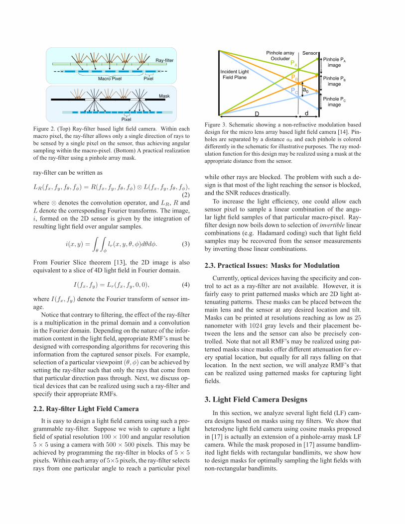
Figure 2. (Top) Ray-filter based light field camera. Within each
macro pixel, the ray-filter allows only a single direction of rays to
be sensed by a single pixel on the sensor, thus achieving angular
sampling within the macro-pixel. (Bottom) A practical realization
of the ray-filter using a pinhole array mask.
ray-filter can be written as
LR(fx, fy, fθ, fφ) = R(fx, fy, fθ, fφ)⊗ L(fx, fy, fθ, fφ),(2)
where ⊗ denotes the convolution operator, and LR, R and
L denote the corresponding Fourier transforms. The image,
i, formed on the 2D sensor is given by the integration of
resulting light field over angular samples.
i(x, y) =
∫
θ
∫
φ
lr(x, y, θ, φ)dθdφ. (3)
From Fourier Slice theorem [13], the 2D image is also
equivalent to a slice of 4D light field in Fourier domain.
I(fx, fy) = Lr(fx, fy, 0, 0), (4)
where I(fx, fy) denote the Fourier transform of sensor im-
age.
Notice that contrary to filtering, the effect of the ray-filter
is a multiplication in the primal domain and a convolution
in the Fourier domain. Depending on the nature of the infor-
mation content in the light field, appropriate RMF’s must be
designed with corresponding algorithms for recovering this
information from the captured sensor pixels. For example,
selection of a particular viewpoint (θ, φ) can be achieved bysetting the ray-filter such that only the rays that come from
that particular direction pass through. Next, we discuss op-
tical devices that can be realized using such a ray-filter and
specify their appropriate RMFs.
2.2. Ray-filter Light Field Camera
It is easy to design a light field camera using such a pro-
grammable ray-filter. Suppose we wish to capture a light
field of spatial resolution 100× 100 and angular resolution5 × 5 using a camera with 500 × 500 pixels. This may be
achieved by programming the ray-filter in blocks of 5 × 5pixels. Within each array of 5×5 pixels, the ray-filter selectsrays from one particular angle to reach a particular pixel
������PA
PB
PC
D d
Pinhole PA
image
Pinhole PB
image
Pinhole PC
image
a0
!�"�#�$%��%&$'((#)*��
+�(!*��,$-!.",$/!�#*$ #%��
Figure 3. Schematic showing a non-refractive modulation based
design for the micro lens array based light field camera [14]. Pin-
holes are separated by a distance a0 and each pinhole is colored
differently in the schematic for illustrative purposes. The ray mod-
ulation function for this design may be realized using a mask at the
appropriate distance from the sensor.
while other rays are blocked. The problem with such a de-
sign is that most of the light reaching the sensor is blocked,
and the SNR reduces drastically.
To increase the light efficiency, one could allow each
sensor pixel to sample a linear combination of the angu-
lar light field samples of that particular macro-pixel. Ray-
filter design now boils down to selection of invertible linear
combinations (e.g. Hadamard coding) such that light field
samples may be recovered from the sensor measurements
by inverting those linear combinations.
2.3. Practical Issues: Masks for Modulation
Currently, optical devices having the specificity and con-
trol to act as a ray-filter are not available. However, it is
fairly easy to print patterned masks which are 2D light at-
tenuating patterns. These masks can be placed between the
main lens and the sensor at any desired location and tilt.
Masks can be printed at resolutions reaching as low as 25nanometer with 1024 gray levels and their placement be-
tween the lens and the sensor can also be precisely con-
trolled. Note that not all RMF’s may be realized using pat-
terned masks since masks offer different attenuation for ev-
ery spatial location, but equally for all rays falling on that
location. In the next section, we will analyze RMF’s that
can be realized using patterned masks for capturing light
fields.
3. Light Field Camera Designs
In this section, we analyze several light field (LF) cam-
era designs based on masks using ray filters. We show that
heterodyne light field camera using cosine masks proposed
in [17] is actually an extension of a pinhole-array mask LF
camera. While the mask proposed in [17] assume bandlim-
ited light fields with rectangular bandlimits, we show how
to design masks for optimally sampling the light fields with
non-rectangular bandlimits.
3.1. Pinhole Array based Light Field Camera
Ng et al. [14] showed a hand-held light field camera by
placing a microlens array in front of the sensor. The key
idea was to sample the rays from a focused scene point by
diverting them to different pixels using a micro-lens array,
which otherwise would fall on a single pixel.
One can replace the microlens array with an array of pin-
holes and obtain the non-refractive analog of Ng’s camera
as shown in Figure 3. This design (first proposed by Lipp-
mann in [12]) can be realized using a ray-filter with the
RMF given by
r(x, y, θ, φ) =
{
1 if (x, y) = (ia0, ja0) (i, j) ∈ Z
0 Otherwise,
(5)
where, a0, the separation between adjacent pinholes is such
that images from adjacent pinholes do not overlap. If A is
the size of the aperture, D is the distance between the lens
and the pinholes and d is the distance between the pinholes
and the sensor, then the pinhole separation a0 is given by
a0 = AdD+d
as shown in Figure 3. The image behind each in-
dividual pinhole captures a slightly different viewpoint thus
capturing the light field.
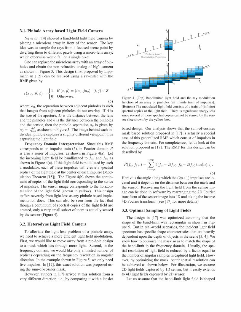
Frequency Domain Interpretation: Since this RMF
corresponds to an impulse train (5), in Fourier domain R
is also a series of impulses, as shown in Figure 4(a). Let
the incoming light field be bandlimited to fx0 and fθ0 as
shown in Figure 4(a). If this light field is modulated by such
a modulator, each of these impulses will create a spectral
replica of the light field at the center of each impulse (Mod-
ulation Theorem [15]). The Figure 4(b) shows the contin-
uum of copies of the light field corresponding to the series
of impulses. The sensor image corresponds to the horizon-
tal slice of the light field (shown in yellow). This design
suffers severely from light-loss as any pinhole based imple-
mentation does. This can also be seen from the fact that
though a continuum of spectral copies of the light field are
created, only a very small subset of them is actually sensed
by the sensor (Figure 4).
3.2. Heterodyne Light Field Camera
To alleviate the light-loss problem of a pinhole array,
we need to achieve a more efficient light field modulation.
First, we would like to move away from a pin-hole design
to a mask which lets through more light. Second, in the
frequency domain, we would like only a limited number of
replicas depending on the frequency resolution in angular
direction. In the example shown in Figure 5, we only need
five impulses. In [17], this exact solution was proposed us-
ing the sum-of-cosines mask.
However, authors in [17] arrived at this solution from a
very different direction, i.e., by comparing it with a lenslet
fθ
fx
fθ0
fx0
Pinhole Array
M odulation Function
fθ
fx
fθ0
fx0
Figure 4. (Top) Bandlimited light field and the ray modulation
function of an array of pinholes (an infinite train of impulses).
(Bottom) The modulated light field consists of a train of (infinite)
spectral copies of the light field. There is significant energy loss
since several of these spectral copies cannot be sensed by the sen-
sor slice shown by the yellow box.
based design. Our analysis shows that the sum-of-cosines
mask based solution proposed in [17] is actually a special
case of this generalized RMF which consist of impulses in
the frequency domain. For completeness, let us look at the
solution proposed in [17]. The RMF for this design can be
described by
R(fx, fθ, :) =
i=p∑
i=−p
δ(fx − 2ifx0, fθ − 2ifx0 tan(α), :).
(6)
Here α is the angle along which the (2p+1) impulses are lo-cated and it depends on the distance between the mask and
the sensor. Recovering the light field from the sensor im-
age can be done in software by rearranging the 2D Fourier
transform of the sensor image into 4D and taking the inverse
4D Fourier transform. (see [17] for more details).
3.3. Optimal Sampling of Light Fields
The design in [17] was optimized assuming that the
shape of the band-limit was rectangular as shown in Fig-
ure 5. But in real-world scenarios, the incident light field
spectrum has specific shape characteristics that are heavily
dependent upon the depth of objects in the scene [3, 4]. We
show how to optimize the mask so as to match the shape of
the band-limit in the frequency domain. Usually, the spa-
tial resolution of light field is reduced by a factor equal to
the number of angular samples in captured light field. How-
ever, by optimizing the mask, better spatial resolution can
be achieved as shown below. For illustration, we assume
2D light fields captured by 1D sensor, but it easily extends
to 4D light fields captured by 2D sensor.
Let us assume that the band-limit light field is shaped
fθ
fx
fθ0
fx0M (fx,fθ)
Mask Modulation Function
Desired
Band-limited
Light Field
α
fθR
fθ Modulated
Light Field
fx
fθ0
fx0Sensor Slice
Mask Modulation
Function
fθR
Demodulation from Sensor Slice
fθ
fxRecovered
Light Field
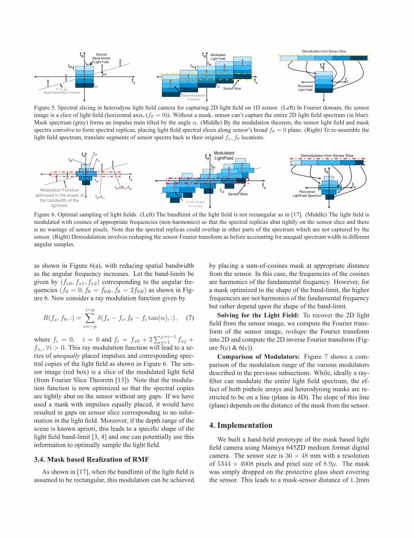
Figure 5. Spectral slicing in heterodyne light field camera for capturing 2D light field on 1D sensor. (Left) In Fourier domain, the sensor
image is a slice of light field (horizontal axis, (fθ = 0)). Without a mask, sensor can’t capture the entire 2D light field spectrum (in blue).
Mask spectrum (gray) forms an impulse train tilted by the angle α. (Middle) By the modulation theorem, the sensor light field and mask
spectra convolve to form spectral replicas, placing light field spectral slices along sensor’s broad fθ = 0 plane. (Right) To re-assemble the
light field spectrum, translate segments of sensor spectra back to their original fx, fθ locations.
fθ
fxfx0
Modulation Function optimized to the shape of
the bandwidth of the
lightfield.
fx0+fx1
fx0+2fx1+fx2
fθ0 fx1
fx2
fθModulated LightField
fx
fθ0
fx0Sensor Slice
M odulation
Function
fθ
fxRecovered
LightField Spectrum
Demodulation from Sensor Slice
Figure 6. Optimal sampling of light fields. (Left) The bandlimit of the light field is not rectangular as in [17]. (Middle) The light field is
modulated with cosines of appropriate frequencies (non-harmonics) so that the spectral replicas abut tightly on the sensor slice and there
is no wastage of sensor pixels. Note that the spectral replicas could overlap in other parts of the spectrum which are not captured by the
sensor. (Right) Demodulation involves reshaping the sensor Fourier transform as before accounting for unequal spectrum width in different
angular samples.
as shown in Figure 6(a), with reducing spatial bandwidth
as the angular frequency increases. Let the band-limits be
given by (fx0, fx1, fx2) corresponding to the angular fre-
quencies (fθ = 0, fθ = fθR, fθ = 2fθR) as shown in Fig-ure 6. Now consider a ray modulation function given by
R(fx, fθ, :) =
i=p∑
i=−p
δ(fx − fi, fθ − fi tan(α), :), (7)
where fi = 0, i = 0 and fi = fx0 + 2∑j=i−1
j=1fxj +
fxi,∀i > 0. This ray modulation function will lead to a se-
ries of unequally placed impulses and corresponding spec-
tral copies of the light field as shown in Figure 6. The sen-
sor image (red box) is a slice of the modulated light field
(from Fourier Slice Theorem [13]). Note that the modula-
tion function is now optimized so that the spectral copies
are tightly abut on the sensor without any gaps. If we have
used a mask with impulses equally placed, it would have
resulted in gaps on sensor slice corresponding to no infor-
mation in the light field. Moreover, if the depth range of the
scene is known apriori, this leads to a specific shape of the
light field band-limit [3, 4] and one can potentially use this
information to optimally sample the light field.
3.4. Mask based Realization of RMF
As shown in [17], when the bandlimit of the light field is
assumed to be rectangular, this modulation can be achieved
by placing a sum-of-cosines mask at appropriate distance
from the sensor. In this case, the frequencies of the cosines
are harmonics of the fundamental frequency. However, for
a mask optimized to the shape of the band-limit, the higher
frequencies are not harmonics of the fundamental frequency
but rather depend upon the shape of the band-limit.
Solving for the Light Field: To recover the 2D light
field from the sensor image, we compute the Fourier trans-
form of the sensor image, reshape the Fourier transform
into 2D and compute the 2D inverse Fourier transform (Fig-
ure 5(c) & 6(c)).
Comparison of Modulators: Figure 7 shows a com-
parison of the modulation range of the various modulators
described in the previous subsections. While, ideally a ray-
filter can modulate the entire light field spectrum, the ef-
fect of both pinhole arrays and heterodyning masks are re-
stricted to be on a line (plane in 4D). The slope of this line
(plane) depends on the distance of the mask from the sensor.
4. Implementation
We built a hand-held prototype of the mask based light
field camera using Mamiya 645ZD medium format digital
camera. The sensor size is 36 × 48 mm with a resolution
of 5344 × 4008 pixels and pixel size of 8.9µ. The mask
was simply dropped on the protective glass sheet covering
the sensor. This leads to a mask-sensor distance of 1.2mm
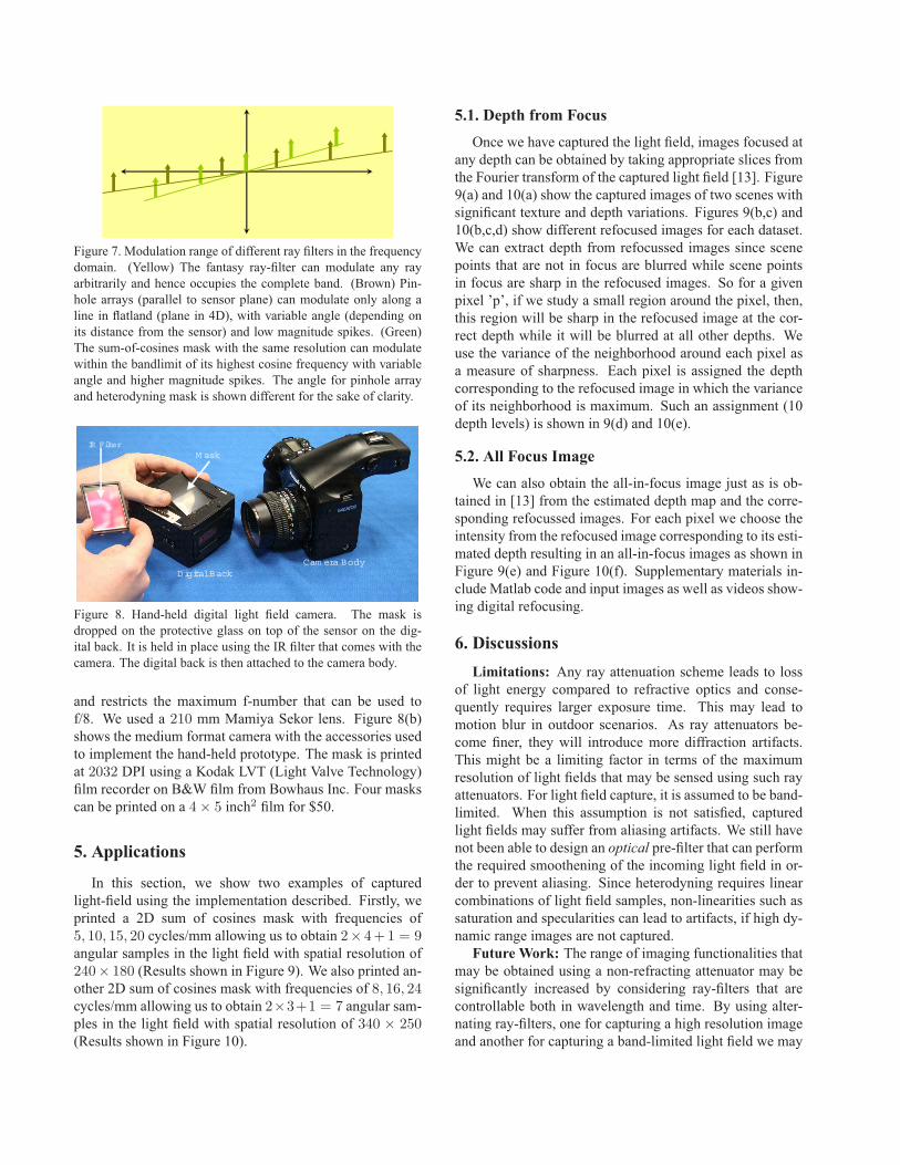
Figure 7. Modulation range of different ray filters in the frequency
domain. (Yellow) The fantasy ray-filter can modulate any ray
arbitrarily and hence occupies the complete band. (Brown) Pin-
hole arrays (parallel to sensor plane) can modulate only along a
line in flatland (plane in 4D), with variable angle (depending on
its distance from the sensor) and low magnitude spikes. (Green)
The sum-of-cosines mask with the same resolution can modulate
within the bandlimit of its highest cosine frequency with variable
angle and higher magnitude spikes. The angle for pinhole array
and heterodyning mask is shown different for the sake of clarity.
Digital Back
M ask
IR Filter
Cam era Body
Figure 8. Hand-held digital light field camera. The mask is
dropped on the protective glass on top of the sensor on the dig-
ital back. It is held in place using the IR filter that comes with the
camera. The digital back is then attached to the camera body.
and restricts the maximum f-number that can be used to
f/8. We used a 210 mm Mamiya Sekor lens. Figure 8(b)
shows the medium format camera with the accessories used
to implement the hand-held prototype. The mask is printed
at 2032 DPI using a Kodak LVT (Light Valve Technology)
film recorder on B&W film from Bowhaus Inc. Four masks
can be printed on a 4× 5 inch2 film for $50.
5. Applications
In this section, we show two examples of captured
light-field using the implementation described. Firstly, we
printed a 2D sum of cosines mask with frequencies of
5, 10, 15, 20 cycles/mm allowing us to obtain 2× 4+1 = 9angular samples in the light field with spatial resolution of
240× 180 (Results shown in Figure 9). We also printed an-
other 2D sum of cosines mask with frequencies of 8, 16, 24cycles/mm allowing us to obtain 2×3+1 = 7 angular sam-ples in the light field with spatial resolution of 340 × 250(Results shown in Figure 10).
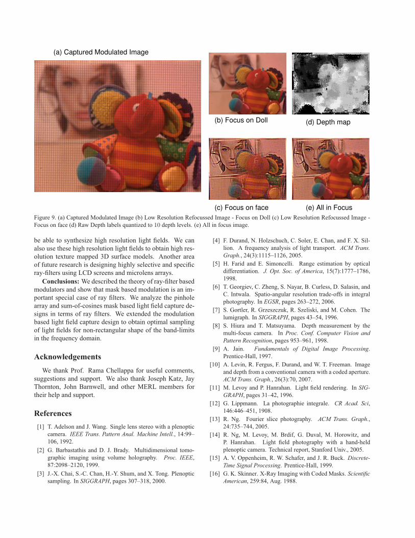
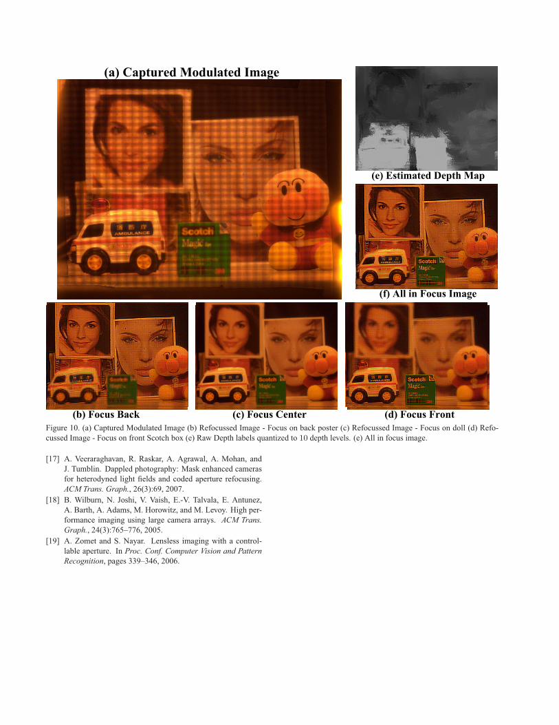
5.1. Depth from Focus
Once we have captured the light field, images focused at
any depth can be obtained by taking appropriate slices from
the Fourier transform of the captured light field [13]. Figure
9(a) and 10(a) show the captured images of two scenes with
significant texture and depth variations. Figures 9(b,c) and
10(b,c,d) show different refocused images for each dataset.
We can extract depth from refocussed images since scene
points that are not in focus are blurred while scene points
in focus are sharp in the refocused images. So for a given
pixel ’p’, if we study a small region around the pixel, then,
this region will be sharp in the refocused image at the cor-
rect depth while it will be blurred at all other depths. We
use the variance of the neighborhood around each pixel as
a measure of sharpness. Each pixel is assigned the depth
corresponding to the refocused image in which the variance
of its neighborhood is maximum. Such an assignment (10
depth levels) is shown in 9(d) and 10(e).
5.2. All Focus Image
We can also obtain the all-in-focus image just as is ob-
tained in [13] from the estimated depth map and the corre-
sponding refocussed images. For each pixel we choose the
intensity from the refocused image corresponding to its esti-
mated depth resulting in an all-in-focus images as shown in
Figure 9(e) and Figure 10(f). Supplementary materials in-
clude Matlab code and input images as well as videos show-
ing digital refocusing.
6. Discussions
Limitations: Any ray attenuation scheme leads to loss
of light energy compared to refractive optics and conse-
quently requires larger exposure time. This may lead to
motion blur in outdoor scenarios. As ray attenuators be-
come finer, they will introduce more diffraction artifacts.
This might be a limiting factor in terms of the maximum
resolution of light fields that may be sensed using such ray
attenuators. For light field capture, it is assumed to be band-
limited. When this assumption is not satisfied, captured
light fields may suffer from aliasing artifacts. We still have
not been able to design an optical pre-filter that can perform
the required smoothening of the incoming light field in or-
der to prevent aliasing. Since heterodyning requires linear
combinations of light field samples, non-linearities such as
saturation and specularities can lead to artifacts, if high dy-
namic range images are not captured.
Future Work: The range of imaging functionalities that
may be obtained using a non-refracting attenuator may be
significantly increased by considering ray-filters that are
controllable both in wavelength and time. By using alter-
nating ray-filters, one for capturing a high resolution image
and another for capturing a band-limited light field we may
(a) Captured Modulated Image
(b) Focus on Doll
(c) Focus on face
(d) Depth map
(e) All in Focus
Figure 9. (a) Captured Modulated Image (b) Low Resolution Refocussed Image - Focus on Doll (c) Low Resolution Refocussed Image -
Focus on face (d) Raw Depth labels quantized to 10 depth levels. (e) All in focus image.
be able to synthesize high resolution light fields. We can
also use these high resolution light fields to obtain high res-
olution texture mapped 3D surface models. Another area
of future research is designing highly selective and specific
ray-filters using LCD screens and microlens arrays.
Conclusions: We described the theory of ray-filter based
modulators and show that mask based modulation is an im-
portant special case of ray filters. We analyze the pinhole
array and sum-of-cosines mask based light field capture de-
signs in terms of ray filters. We extended the modulation
based light field capture design to obtain optimal sampling
of light fields for non-rectangular shape of the band-limits
in the frequency domain.
Acknowledgements
We thank Prof. Rama Chellappa for useful comments,
suggestions and support. We also thank Joseph Katz, Jay
Thornton, John Barnwell, and other MERL members for
their help and support.
References
[1] T. Adelson and J. Wang. Single lens stereo with a plenoptic
camera. IEEE Trans. Pattern Anal. Machine Intell., 14:99–
106, 1992.
[2] G. Barbastathis and D. J. Brady. Multidimensional tomo-
graphic imaging using volume holography. Proc. IEEE,
87:2098–2120, 1999.
[3] J.-X. Chai, S.-C. Chan, H.-Y. Shum, and X. Tong. Plenoptic
sampling. In SIGGRAPH, pages 307–318, 2000.
[4] F. Durand, N. Holzschuch, C. Soler, E. Chan, and F. X. Sil-
lion. A frequency analysis of light transport. ACM Trans.
Graph., 24(3):1115–1126, 2005.
[5] H. Farid and E. Simoncelli. Range estimation by optical
differentiation. J. Opt. Soc. of America, 15(7):1777–1786,
1998.
[6] T. Georgiev, C. Zheng, S. Nayar, B. Curless, D. Salasin, and
C. Intwala. Spatio-angular resolution trade-offs in integral
photography. In EGSR, pages 263–272, 2006.
[7] S. Gortler, R. Grzeszczuk, R. Szeliski, and M. Cohen. The
lumigraph. In SIGGRAPH, pages 43–54, 1996.
[8] S. Hiura and T. Matsuyama. Depth measurement by the
multi-focus camera. In Proc. Conf. Computer Vision and
Pattern Recognition, pages 953–961, 1998.
[9] A. Jain. Fundamentals of Digital Image Processing.
Prentice-Hall, 1997.
[10] A. Levin, R. Fergus, F. Durand, and W. T. Freeman. Image
and depth from a conventional camera with a coded aperture.
ACM Trans. Graph., 26(3):70, 2007.
[11] M. Levoy and P. Hanrahan. Light field rendering. In SIG-
GRAPH, pages 31–42, 1996.
[12] G. Lippmann. La photographie integrale. CR Acad. Sci,
146:446–451, 1908.
[13] R. Ng. Fourier slice photography. ACM Trans. Graph.,
24:735–744, 2005.
[14] R. Ng, M. Levoy, M. Brdif, G. Duval, M. Horowitz, and
P. Hanrahan. Light field photography with a hand-held
plenoptic camera. Technical report, Stanford Univ., 2005.
[15] A. V. Oppenheim, R. W. Schafer, and J. R. Buck. Discrete-
Time Signal Processing. Prentice-Hall, 1999.
[16] G. K. Skinner. X-Ray Imaging with Coded Masks. Scientific
American, 259:84, Aug. 1988.
(b) Focus Back (c) Focus Center (d) Focus Front
(e) Estimated Depth Map
(f) All in Focus Image
(a) Captured Modulated Image
Figure 10. (a) Captured Modulated Image (b) Refocussed Image - Focus on back poster (c) Refocussed Image - Focus on doll (d) Refo-
cussed Image - Focus on front Scotch box (e) Raw Depth labels quantized to 10 depth levels. (e) All in focus image.
[17] A. Veeraraghavan, R. Raskar, A. Agrawal, A. Mohan, and
J. Tumblin. Dappled photography: Mask enhanced cameras
for heterodyned light fields and coded aperture refocusing.
ACM Trans. Graph., 26(3):69, 2007.
[18] B. Wilburn, N. Joshi, V. Vaish, E.-V. Talvala, E. Antunez,
A. Barth, A. Adams, M. Horowitz, and M. Levoy. High per-
formance imaging using large camera arrays. ACM Trans.
Graph., 24(3):765–776, 2005.
[19] A. Zomet and S. Nayar. Lensless imaging with a control-
lable aperture. In Proc. Conf. Computer Vision and Pattern
Recognition, pages 339–346, 2006.
Copyright © 2022 FDOKUMEN