Non-Destructive Testing
29
CPCS-SPEC-NDT-003 Printed Copy Invalid as Controlled Document. SPECIFICATION FOR PIPELINE CONSTRUCTION (CANADA) Non-Destructive Testing Revision 1
-
Upload
khangminh22 -
Category
Documents
-
view
2 -
download
0
Transcript of Non-Destructive Testing

CPCS-SPEC-NDT-003
Printed Copy Invalid as Controlled Document.
SPECIFICATION FOR PIPELINE CONSTRUCTION
(CANADA)
Non-Destructive Testing
Revision 1

CPCS-SPEC-NDT-003
Printed Copy Invalid as Controlled Document. November 2011 Page 2 of 29
TABLE OF CONTENTS
1 Scope .............................................................................................................................................. 4
1.1 General ................................................................................................................................ 4
2 Acts, Regulations, Laws, Codes And Standards ........................................................................ 4
2.1 General ................................................................................................................................ 4
3 Related Specifications .................................................................................................................. 4
3.1 General ................................................................................................................................ 4
4 Definitions ...................................................................................................................................... 5
4.1 General ................................................................................................................................ 5
5 Contractor Operations .................................................................................................................. 6
5.1 General ................................................................................................................................ 6 5.2 Ndt Supervisor ..................................................................................................................... 6 5.3 Technician ........................................................................................................................... 6 5.4 Radiographer ....................................................................................................................... 7 5.5 Qualified Operator ............................................................................................................... 7
6 Inspection Units ............................................................................................................................. 8
6.1 Mainline/Poor Boy Unit ........................................................................................................ 8 6.2 Section Unit ......................................................................................................................... 8 6.3 Tie-In/Repair Unit ................................................................................................................. 8 6.4 Manual Ut Hand Scan Unit .................................................................................................. 9 6.5 Additional Units And Spare Parts ........................................................................................ 9
7 Radiographic Inspection ............................................................................................................... 9
7.1 General ................................................................................................................................ 9 7.2 X-Ray ................................................................................................................................. 10 7.3 Gamma (Iridium 192/Selenium 75) .................................................................................... 10 7.4 Pipe Diameter Range Limitations ...................................................................................... 10 7.5 Radiographic Testing Procedures ..................................................................................... 10 7.6 Film .................................................................................................................................... 11 7.7 Radiographic Quality ......................................................................................................... 12 7.8 Marking And Identification Of Radiographs ....................................................................... 13 7.9 Packaging Of Radiographs ................................................................................................ 13 7.10 Radiation Safety ................................................................................................................ 14
8 Ultrasonic Inspection .................................................................................................................. 14
8.1 Ultrasonic System .............................................................................................................. 15 8.2 Ultrasonic Testing Procedures ........................................................................................... 15 8.3 Recording System ............................................................................................................. 16 8.4 Transducers ....................................................................................................................... 17 8.5 Reference Block Standards ............................................................................................... 18 8.6 System Set-Up ................................................................................................................... 20 8.7 Calibration Scan ................................................................................................................ 21 8.8 Couplant ............................................................................................................................ 22 8.9 Surface Condition .............................................................................................................. 22

CPCS-SPEC-NDT-003
Printed Copy Invalid as Controlled Document. November 2011 Page 3 of 29
8.10 Reference Line .................................................................................................................. 22 8.11 Mandatory Re-Inspection ................................................................................................... 23 8.12 Coating Damage ................................................................................................................ 23 8.13 Evaluation Of Indications ................................................................................................... 23
9 Magnetic Particle Testing ........................................................................................................... 23
9.1 Mt Procedures ................................................................................................................... 23 9.2 Equipment And Material .................................................................................................... 24 9.3 Specific Application Parameters ........................................................................................ 24 9.4 Surface Preparation ........................................................................................................... 24 9.5 Mt Reporting Requirements ............................................................................................... 25
10 Liquid Penetrant Testing ............................................................................................................ 25
10.1 Pt Procedures .................................................................................................................... 25 10.2 Equipment And Material .................................................................................................... 26 10.3 Specific Application Parameters ........................................................................................ 26 10.4 Surface Preparation ........................................................................................................... 26 10.5 Pt Reporting Requirements ............................................................................................... 26
11 Weld Identification ....................................................................................................................... 27
12 Reporting Procedures ................................................................................................................. 28
13 Ndt Turnover Package Requirements ....................................................................................... 29
14 Standards Of Acceptability ......................................................................................................... 29
15 Additional Requirements ............................................................................................................ 29
15.1 Polishing Equipment .......................................................................................................... 29 15.2 Training .............................................................................................................................. 29
16 Non-Destructive Testing Audit ................................................................................................... 29

CPCS-SPEC-NDT-003
Printed Copy Invalid as Controlled Document. November 2011 Page 4 of 29
1 SCOPE
1.1 General
This Specification outlines the Non-Destructive Testing of pipe-to-pipe and/or pipe-to- component welds made using mechanized, semi-automatic or manual welding techniques for cross country pipelines. This Specification provides requirements for Radiographic, Ultrasonic, Magnetic Particle and Liquid Penetrant testing. This Specification does not apply to shop fabrication welding.
The Contractor shall ensure that the Non-Destructive Testing requirements set out in this Specification are complied with to the extent they are applicable in the circumstance. Except as otherwise expressly provided herein; the Contractor shall be responsible for implementing this Specification. The Contractor shall be solely responsible for ensuring that the Work is performed in strict compliance with all Environmental, Health and Safety Laws.
2 ACTS, REGULATIONS, LAWS, CODES AND STANDARDS
2.1 General
2.1.1. The latest edition of the following Acts, Codes and Standards shall form part of this Specification. It is the Contractor’s responsibility to become familiar with the latest editions of the Acts, Regulations, Laws, Codes and Standards that are necessary for the performance of the Work. These shall include but not be limited to the following:
(a) CSA Z662 – Oil and Gas Pipeline Systems;
(b) Where regulated by Federal Standards, the National Energy Board – NEB Onshore Pipeline Regulations (1999); and
(c) Alberta Pipeline Act and Regulations.
2.1.2. Where CSA Z662 is referenced hereafter it shall mean CSA Z662 – Oil and Gas Pipeline Systems, Alberta Pipeline Act and Regulations, and the National Energy Board Act as applicable. If there is a conflict between Acts, Regulations, Laws, Codes and Standards the most stringent requirement shall be met by the Contractor. The most stringent requirement shall be met by the Contractor without additional cost to Company.
2.1.3. The Contractor shall comply with the requirements of Acts, Regulations, Laws, Codes and Standards in performance of the Work.
3 RELATED SPECIFICATIONS
3.1 General
The NDT Contractor shall comply with the requirements of the following technical documents as referenced within CPCS-SPEC-NDT-003:
(a) ASME Section V Non-Destructive Examination.
(b) ASTM E-94 Standard Guide for Radiographic Testing.

CPCS-SPEC-NDT-003
Printed Copy Invalid as Controlled Document. November 2011 Page 5 of 29
(c) ASTM E-114 Standard Practice for Ultrasonic Pulse Echo Straight Beam Examination by the Contact Method.
(d) ASTM E-273-01Standard Practice for Ultrasonic Examination of the Weld Zone of Welded Pipe and Tubing.
(e) ESI Standard 98-2 Electricity Supply Industry.
(f) ASTM E-1316 Standard Terminology for Non Destructive Examinations.
(g) ASTM E-1961 2006 Mechanized Ultrasonic Examination of Girth Welds using Zonal Discrimination with Focused Search Units.
(h) BS 7706 1993 Calibration and setting up of the ultrasonic Time of Flight Diffraction (ToFD) technique for the detection, location and sizing of flaws.
(i) CAN/CGSB-48.9712-2006/ISO 9712:2005 Non-destructive Testing Qualification and Certification of Personnel.
(j) CNSC Certification of Exposure Device Operators G-229.
(k) ISO 11699-1 Non Destructive Testing Radiographic Film Classifications.
(l) ISO 19232-1 Image Quality of Radiographs Part 1 (wire type) & Part 2 (step/hole type).
(m) SE-709 Standard Guide for Magnetic Particle Examination.
4 DEFINITIONS
4.1 General
Welding terms and definitions shall be in accordance with CSA Z662, ASME E-1316-01 and the Specification as follows:
AUT – Automatic Ultrasonic Testing.
Contractor - Non-Destructive Testing (NDT) Company.
Delay Weld - Welds that are radiographed or ultrasonically inspected the following day or longer after welding.
Re-Shot/Re-Scan Weld - Welds requiring a radiographic re-shot or those requiring ultrasonic re-scanning.
Technician or Radiographer – A NDT Technician or Radiographer certified in the applicable discipline(s) to CAN/CGSB-48.9712-2006/ISO 9712:2005 Non-Destructive Testing Qualification and Certification of Personnel.
Verification Weld - Welds that are radiographed or ultrasonically inspected after an initial radiographic or ultrasonic inspection to verify weld quality.
Welding Production – All welding completed daily including all mainline, poorboy, section, field fabrication, cut-out and repair welding.

CPCS-SPEC-NDT-003
Printed Copy Invalid as Controlled Document. November 2011 Page 6 of 29
5 CONTRACTOR OPERATIONS
5.1 General
The Contractor shall have a documented Quality Program in place and a controlled copy of the Quality Program Manual shall be available to the Company at the place of Work. The Company may conduct an audit of the Contractor’s implementation of the Contractor’s Quality Program.
5.2 NDT Supervisor
The Contractor shall provide and designate 1 senior person as NDT Supervisor responsible for the direct supervision, conduct, and performance of all non-destructive Project personnel and for maintaining all equipment and supplies in reliable condition. The NDT Supervisor shall work closely with the Company’s Senior or Chief Welding Inspector in the documentation of examinations completed and shall be responsible for all Reports, interpretations and evaluations.
5.2.1. The NDT Supervisor, or a Company approved Contractor alternate, shall perform a sufficient amount of documented audits to ensure that interpretations are consistent, informative and concise. Audits shall be performed as a minimum for:
(a) 100% of all rejected welds, repair welds, cut-out replacement welds, tie-in welds and final tie-in welds.
(b) 100% of all AUT Calibrations, including 1 complete set of the AUT parameters per crew daily to ensure consistency with essential AUT variables.
(c) 10% of all mainline, poor-boy, section and field fabrication welds.
5.2.2. All audits conducted by the NDT Supervisor, or the designated Contractor alternate, shall be documented and provided to the Company, in a format approved by the Company as a minimum on a weekly basis.
5.2.3. NDT Supervisors shall be qualified to Level II or Level III in accordance with the requirements of CAN/CGSB 48.9712/ISO 9712:2005 for the non-destructive methods used for the performance of the Work.
5.2.4. If multiple non-destructive methods are used, the Supervisor shall be qualified to Level II or Level III CAN/CGSB 48.9712/ISO 9712:2005 for the non-destructive methods used for the performance of the mainline work and shall be experienced with all other methods of NDT used in the performance of the remaining Work.
5.2.5. The NDT Supervisor shall be qualified and capable of technical support for the NDT methods used for the Project. The NDT Supervisor shall be approved by the Company. The Company may require the Supervisor to demonstrate competence in operating and evaluating the results of the applicable inspection systems.
5.2.6. The NDT Supervisor shall be assisted by a Field Clerk who is proficient in the compilation of daily and weekly NDT data and the generation of related Reports.
5.3 Technician
5.3.1. Technicians shall be qualified in accordance with the requirements of CAN/CGSB 48.9712/ISO 9712:2005, as a Level II or III. The Company shall evaluate the qualifications of each Technician

CPCS-SPEC-NDT-003
Printed Copy Invalid as Controlled Document. November 2011 Page 7 of 29
and shall exclude those that, in the opinion of the Company, lack sufficient training or experience for the Work.
5.3.2. AUT Technicians shall have received a sufficient level of training on mechanized testing pertaining to the equipment and configurations to be examined. This training shall be documented by an in-house certifying Exam.
5.3.3. AUT Technicians shall qualify for pipeline weld evaluation by demonstrating their ability to detect and characterize typical weld flaw indications and determine their acceptance according to the Project criteria. The Company shall either provide qualification test pieces consisting of 1 or more pipe samples with defects, or provide a series of weld scans containing indications similar to those expected with the Welding Procedures. The Pre-Qualification Test shall be administered and witnessed by the Company and the results will be evaluated on overall quality, accuracy of defect assessment and compliance with these Specifications.
5.3.4. Manual UT Technicians must demonstrate their full understanding of the Manual Ultrasonic Procedure and acceptance criteria.
5.3.5. Prior to production welding the Contractor may be required to administer a “technical workshop” providing a clear overview of the relevant Project Procedures and acceptance criteria to all NDT Supervisors. The content shall be approved by the Company.
5.3.6. All technicians shall be approved by the Company for the performance of the Work. Only Company approved qualified Technicians are permitted to interpret Inspections. The Company shall require Technicians to demonstrate their competence in operating and evaluating the results of the Inspection System.
5.4 Radiographer
5.4.1. Radiographers shall be qualified in accordance with the requirements of CAN/CGSB 48.9712 to a minimum of Level II. The Contractor shall provide proof of qualification for all Radiographers. The Company shall evaluate the qualifications of each Radiographer and shall exclude those that, in the opinion of the Company, lack sufficient training or experience for the Work.
5.4.2. Prior to production welding, each Radiographer shall either provide a test radiograph using technique(s) previously approved by the Company to produce a qualifying radiograph, or will evaluate a series of radiographs supplied by the Company and produce a Radiographic Report with a complete weld assessment. The Pre-Qualification Test shall be administered and witnessed by the Company. The test radiograph will be evaluated on overall quality, accuracy of defect assessment and compliance with these Specifications and Standards.
5.4.3. The radiographer is encouraged to work in conjunction with the Senior Welding Inspector and Welding Foreman in consultation to improve welding quality and production.
5.4.4. Only Company approved qualified Radiographers are permitted to produce and interpret radiographs using Contractor supplied NDT interpretation facilities.
5.5 Qualified Operator
5.5.1. All personnel operating a radioisotope camera shall meet the requirements of CNSC Certification of Exposure Device Operators G-229.

CPCS-SPEC-NDT-003
Printed Copy Invalid as Controlled Document. November 2011 Page 8 of 29
6 INSPECTION UNITS
6.1 Mainline/Poor Boy Unit
6.1.1. A mainline and/or poor boy unit, for the purpose of this Specification, shall consist of a suitably equipped self-contained 4-wheel drive vehicle with a crew of qualified personnel of which 1 shall be a Company approved Technician or Radiographer suitably experienced with cross country pipeline mainline operations.
6.1.2. When radiographic testing is selected, the mainline unit shall be equipped with, but not be limited to:
(a) X-ray or Gamma Ray internal crawler(s).
(b) Experienced crawler Operator.
(c) Radiographic command source(s).
(d) Processing and drying capabilities; viewing facilities.
(e) Approved film type, calibrated densitometer and density strip traceable to a National Standard.
(f) Sufficient equipment to maintain inspection according to total daily welding production.
6.1.3. Ultrasonic testing may be selected by the Company to be the principal testing method. If ultrasonic testing is selected, the mainline unit shall be equipped with an Automated Ultrasonic Testing system as described in this Specification.
6.1.4. The poor boy ultrasonic or radiographic unit shall generally be equipped as outlined for a mainline unit with the exception that the manpower requirements may be less than that required for the mainline unit.
6.2 Section Unit
Section Units for the purpose of this Specification shall consist of a suitably equipped self-contained 4-wheel drive vehicle with a crew of 2 personnel of which 1 shall be a Company approved Technician or Radiographer. The Unit shall generally be as outlined for a mainline unit but more suitably equipped for the testing of short pipe sections.
6.3 Tie-in/Repair Unit
Tie-in/Repair Units for the purpose of these documents shall consist of a suitably equipped, self-contained 4-wheel drive vehicle with a crew of 2 personnel of which 1 shall be a Company approved Technician or Radiographer. The Unit shall generally be equipped with an AUT system and all calibration or reference blocks for ultrasonic test method(s) or with a portable x-ray or gamma exposure device for radiographic test method(s). The tie-in/repair crew shall be required to inspect tie-in welds and repair welds when requested by the Company.
6.3.1 AUT Tie-in/Repair Units shall be equipped with a suitably long umbilical to enable scans of accessibly difficult welds. The umbilical is deemed an essential variable which requires that the system shall be re-calibrated when a change in umbilical occurs.

CPCS-SPEC-NDT-003
Printed Copy Invalid as Controlled Document. November 2011 Page 9 of 29
6.4 Manual UT Hand Scan Unit
Manual UT Hand Scan Units for the purpose of these documents shall consist of a suitably equipped self contained 4-wheel drive vehicle with a crew of 1 person who shall be a Company approved Technician. The Manual Hand Scan Unit may be required to inspect tie-in welds and repair welds when required by the Company.
6.5 Additional Units and Spare Parts
Sufficient spare parts and/or equipment shall be provided and maintained by the Contractor to ensure consistent weld evaluation and continuity of construction.
7 RADIOGRAPHIC INSPECTION
This Section outlines the requirements for Radiographic Inspection (RT)
7.1 General
7.1.1. In the event that any film or report leaves control of the NDT Contractor, documentation of the transfer of this film and Report shall be recorded and signed by representatives of the Company and the Contractor and/or NDT Contractor.
7.1.2. The Contractor shall use only the latest "State of the Art" techniques in producing and interpreting the Radiographic Tests. Without restricting the generality of the foregoing, the following shall apply:
(a) Films shall be viewed in subdued background lighting using a viewer suitable for films with densities of up to 4.0 H&D.
(b) Under no circumstances shall a final interpretation be based on viewing wet film. All films shall be read in a dry condition within 12 hours of completion of weld.
(c) The Contractor shall provide suitable equipment for drying films immediately after developing and washing.
(d) Any radiograph which, in the Company’s opinion, is of substandard quality shall be retaken at no cost to the Company.
(e) The rate of interpretation shall be in accordance with good industry practice and under no circumstance shall 1 interpreter be permitted to interpret radiographic film for more than 2 consecutive hours without a 15 minute break.
7.1.3. Radiographs of repaired welds shall generally be performed by a tie-in/repair unit. Mainline units shall not normally radiograph repaired welds without Company approval.
7.1.4. The Contractor shall mark the repaired weld in a manner agreed to by the Company to indicate final acceptance of the weld repair.
7.1.5. The Contractor shall have sufficient equipment and personnel on site to maintain a production rate which ensures that any weld completed prior to 4:00 P.M. on any working day will be radiographed, interpreted and included in the Radiographic Report for that working day.

CPCS-SPEC-NDT-003
Printed Copy Invalid as Controlled Document. November 2011 Page 10 of 29
7.1.6. The Contractor shall provide at least 1 high-intensity viewer at each film interpretation location. Equipment used to view radiographs shall provide a variable light source suitable for viewing film densities up to 4.0 H&D.
7.1.7. The Contractor shall provide 1 high-intensity, variable light source viewer for use by the Company in the Field Office.
7.2 X-Ray
7.2.1 X-ray exposure devices for SWX shall have an achievable minimum rating of 160kv/3ma.
7.2.2 X-ray exposure devices for DWX shall have an achievable minimum rating of 200kv/5ma.
7.3 Gamma (Iridium 192/Selenium 75)
7.3.1 Gamma Radiography may be used with approval of the Company.
7.3.2 Sources shall have a minimum strength of 50 curies for weld diameters greater than 323.9 mm O.D.
7.4 Pipe Diameter Range Limitations
7.4.1 Less Than 88.9 mm O.D. – The radiographic technique shall be double wall gamma (DWG), ellipse or super imposed, with double wall viewing.
7.4.2 88.9mm O.D. to 323.9 mm O.D. Inclusive:
a) The radiographic technique shall be single wall gamma (SWG) for mainline, poor boy and section welds and shall be a double wall gamma (DWG) technique with single wall viewing for repair, tie-in, field fabrication, and replacement welds.
b) Double wall gamma (DWG) techniques with single wall viewing shall be permitted for all diameters 114mm and less.
7.4.3 Greater Than 323.9mm O.D. - All mainline, poor-boy and section welds shall be radiographed using a single wall x-ray (SWX) technique with a true radial beam x-ray exposure device. Tie-in welds, field fabrication welds and replacement welds shall be radiographed using a double wall x-ray (DWX) technique with single wall viewing. Weld repairs shall be radiographed with a double wall x-ray (DWX) technique with single wall viewing, or on approval of the Company, a single wall x-ray (SWX) technique will be permitted.
7.5 Radiographic Testing Procedures
Prior to commencement of any work the Contractor shall provide the Company with the Radiographic Procedures it intends to use in the performance of the Work. Procedure Specifications shall be as per CSA Z662 & ASME V Non-Destructive Examination Article 2 T-221.
7.5.1 The Contractor shall demonstrate, as follows, the effectiveness of its proposed Procedures before the Procedures will be approved for use in the performance of the Work:

CPCS-SPEC-NDT-003
Printed Copy Invalid as Controlled Document. November 2011 Page 11 of 29
(a) The details of each proposed procedural Technique shall be submitted to the Company for approval. The Record shall include the complete results of tests and radiographs qualifying the Procedure.
(b) A radiograph shall be produced under site conditions and in the Company’s presence for each proposed Procedure. Such Technique Acceptance Testing shall preferably be performed during the Pipeline Construction Contractor's Welding Procedure Qualification Tests, or similar welding, prior to the commencement of production welding.
(c) Only equipment and materials which are radiographically similar to those to be used in performing the Work shall be used for the tests.
(d) The Report of each Technique including the notation of all defects along with the test radiographic film shall be submitted to the Company for approval. The Company will notify the Contractor whether or not it approves each Procedure submitted. Any change in the approved Procedures will necessitate the resubmission of the Procedure, as changed, subject to the conditions outlined herein.
(e) Procedures approved and accepted by the Company will form part of the Contract Document.
7.5.2 In addition and prior to any RT unit’s initial production examination, a Technique of each radiographic examination shall be performed by each Radiographer and submitted to the Company with the Daily Report. The initial exposures can be applied as a Technique to prevent additional work for the specific RT unit. However, 2 films must be produced; 1 as Technique to be submitted and 1 as part of a regular full circumferential examination.
7.6 Film
7.6.1 Radiographic film shall be classified in accordance with ISO 11699-1, latest edition. As a minimum, the selection of Film System Class C4 shall apply for all welds radiographed by the X-ray method and as a minimum, the selection of Film System Class C3 shall apply for all welds radiographed by the gamma ray method.
7.6.2 The selection of film Manufacturer shall be approved by the Company prior to use.
7.6.3 Approved pre-packaged films or fluoro-metallic intensifying screens may be used at the discretion of the Company subject to prior approval.
7.6.4 If the Contractor elects to use pre-packaged film (e.g., redipack, etc.) the Contractor shall be responsible for ensuring that all garbage and excess packing material is removed daily from the Construction Right-of-Way and disposed of in accordance with the Regulations of the Authority Having Jurisdiction.
7.6.5 Film width shall cover a minimum of 15 mm on each side of the weld cap.
7.6.6 Chemicals used for processing film shall be approved by the Company and shall be used in accordance with the Manufacturer's recommendations including efficient replenishment and replacement of developer. Written Schedules of solution changes shall be posted in the dark room at all times.

CPCS-SPEC-NDT-003
Printed Copy Invalid as Controlled Document. November 2011 Page 12 of 29
7.6.7 Film shall be processed in a manner without exposure to light or radiation and must show a fog level of not more than 0.3 H&D. This shall be verified at the beginning of each new roll/box of film and shall be done daily per unit.
7.6.8 The use of “Farmers Reagent” or similar solutions for density reductions shall not be permitted.
7.6.9 Materials and processes used in film processing shall be of a quality to allow film storage without risk of deterioration for a minimum of 5 years.
7.7 Radiographic Quality
7.7.1 Each radiograph shall conform to the requirements of CSA Z662 and supplemental Specifications herein.
7.7.2 Film density shall be 2.0-3.5 H&D in the area of concern. Density in small localized areas may be as low as 1.5 H&D and up to 4.0 H&D. A calibrated densitometer and a density strip calibrated to a traceable National Standard shall be provided to each Radiographer to ensure that film densities are within the specified units.
7.7.3 The selection of wire type image quality indicator(s) (IQI’s) shall be as described in CSA Z662 and ISO 19232-1 & 2, and shall be used to measure sensitivity of the radiographic image. The placement and number of IQI(s) shall be such that sensitivity can be measured through the weld area and within the applicable limits of film coverage.
7.7.4 For single wall exposure/single-wall viewing techniques where the complete weld circumference is radiographed as a single length of film, a minimum of 3 IQI’s and 3 undercut comparator shims shall be placed 120° apart.
7.7.5 When multiple film holders are used for this technique, an image of the IQI and an image of the undercut comparator shim shall appear on each film.
7.7.6 Successive multiple films shall overlap at the adjacent ends by a minimum of 50 mm.
7.7.7 For double wall techniques with single wall viewing, an image of the IQI shall appear on each film and shall be located within 25 mm of each of the applicable limits of film coverage. The image of an undercut comparator shim shall appear on each film.
7.7.8 In addition to the requirements above, weld repair radiograph(s) require that at least 1 IQI be placed adjacent to each repair area.
7.7.9 For transition welds joining unequal nominal wall thicknesses, the essential wire for each wall thickness shall be determined by the nominal wall thickness of each material plus the maximum allowable thickness of the cap reinforcement.
7.7.10 Film placement shall be such that the bottom of the weld shall not be closer than 150 mm to either of the acceptable limits of film coverage.

CPCS-SPEC-NDT-003
Printed Copy Invalid as Controlled Document. November 2011 Page 13 of 29
7.8 Marking and Identification of Radiographs
7.8.1 The Contractor shall ensure that all radiographs will be clearly marked with the Project Title and applicable Weld Number. Survey chainage, at 200 meter intervals for mainline, poorboy or section Weld Numbers and for all tie-in Weld Numbers, shall be recorded on the Contractor Daily Weld Inspection Reports
7.8.2 All film shall be clearly and accurately identified so that the location of the weld and any weld discontinuity can be quickly and accurately located. Whenever more than 1 film is used to inspect a weld area, the identification markers shall appear on each film and each section reference marker location shall be common to 2 successive films to ensure that the entire area of concern has been examined. The markers shall be placed on the pipe on the downstream (DS) side of the weld so that the numbers on the film will read clockwise when viewed from the upstream (US) side - (DS shall be the direction of construction; US shall be opposite to the direction of construction).
7.8.3 The Contractor shall ensure that all radiographs will be clearly identified with the following:
(a) Project Title.
(b) Circumferential location markers. The Contractor shall use lead numbers to identify the circumferential location of weld defects. The maximum separation for weld location markers shall be 50 mm for diameters less than or equal to 406mm O.D. and 150 mm for diameters greater than 406 mm O.D. The zero location of such markers shall correspond to the 12 o’clock position of the weld.
(c) Approved image quality indicator(s) - IQI(s).
(d) Approved comparator shim(s).
(e) A unique weld number and Identification Code in accordance with the Numbering System designated by the Company
7.9 Packaging of Radiographs
7.9.1 At the end of each day, the Contractor shall supply to the Company, details of all radiographic testing completed that day.
7.9.2 The Contractor shall ensure that all film is thoroughly washed and dried before packaging and that all film is packaged in sequential order with a copy of the Radiographic Evaluation Form.
7.9.3 All completed radiographs shall be catalogued and stored in corrugated cardboard boxes supplied by the Contractor measuring 350 mm x 350 mm x 75 mm with dividers forming eight (8) cubicles along each side thus providing 64 cubicles per box. Each box shall be labelled sufficiently for ease of locating welds and identifying contents when stacked/stored.
7.9.4 Mainline radiographs shall be inserted into each cubicle in sequence starting from the left side of the first row toward the right and then from the right side of the second row toward the left, and so on in a serpentine manner. The bottom of each cubicle shall be clearly marked with the Film Number, (i.e. Weld Number that will occupy that space), after the radiograph has been interpreted. Boxes of mainline radiographs shall be numbered sequentially.

CPCS-SPEC-NDT-003
Printed Copy Invalid as Controlled Document. November 2011 Page 14 of 29
7.9.5 Radiographs of tie-in welds shall be handled and catalogued in the same manner as mainline radiographs and stored in separate boxes. The storage boxes shall also be sequentially numbered but will have the letter "T" behind the box number.
7.9.6 Radiographs of Fabrication assembly welds shall be handled in the same manner and stored in separate boxes.
7.9.7 Radiographs of repaired welds and verification radiographs shall be rolled with the original radiograph such that both films are stored in the same cubicle.
7.9.8 Radiographs of replaced cut-out welds shall be placed in the same cubical as the original film. If there is not enough room, then the original film may be removed and stored in a box identified as a cut-out box.
7.9.9 Clear and legible interpretation sheets shall be included inside the boxes for those films catalogued in the corresponding boxes. This means that each time a new box is started a new interpretation sheet will be started as well. These sheets are then inserted inside each box.
7.9.10 The Contractor shall supply labels for the radiographic boxes. The Contractor’s Radiographers shall fill out the labels as the films are being processed and place the labels on the completed radiographic boxes. Information required will be as follows:
(a) Project Identification.
(b) Range of Weld Numbers.
(c) Range of chainage.
(d) Dates exposed.
(e) Box number.
(f) Contractor’s name.
The boxes shall be numbered sequentially starting from number 1.
7.10 Radiation Safety
7.10.1 Radiographic practice shall comply with the relevant ionizing Radiation Acts and Codes and shall be in accordance with the requirements of CSA Z662.
7.10.2 The Contractor and all personnel operating x-ray or gamma ray equipment shall be responsible for the protection of every person working with or near radiation, and for compliance with Federal, Provincial and local laws regarding radiation safety and transportation. The Contractor shall submit to the Company a written Radiation Safety Plan.
7.10.3 Audible and visible warning devices shall be used by the Contractor's personnel for regular monitoring of radiation levels.
8 ULTRASONIC INSPECTION
This Section outlines the requirements for Ultrasonic Inspection (UT).

CPCS-SPEC-NDT-003
Printed Copy Invalid as Controlled Document. November 2011 Page 15 of 29
8.1 Ultrasonic System
8.1.1. Mainline girth welds, of the same nominal wall thickness, made by mechanized welding methods, and other welds as directed by the Company, shall be fully examined using a mechanized ultrasonic inspection system for 100% of the weld circumference, in accordance with the requirements of CSA Z662. The Inspection System shall be capable of locating and accurately establishing the through wall height and circumferential length of all defects, in a manner that permits the use of an acceptance criteria defined by the Company in accordance with the requirements of CSA Z662 Annex K.
8.1.2. AUT Systems and Technicians shall be qualified and approved by the Company prior to commencement of any work.
8.1.3. AUT inspection shall utilize pulse-echo and/or pitch catch lens focused transducers with zonal inspection and Time of Flight Diffraction (ToFD) Techniques.
8.1.4. The system shall provide an adequate number of Inspection Zones designed with sufficient beam overlap to ensure full volumetric coverage.
8.1.5. The system shall include a fully automated recording system to indicate the location of imperfections and the effectiveness of acoustic coupling. The system shall provide a linear “A” scan presentation for each channel selected.
8.1.6. The inspection channels shall allow the volume of the weld scanned to be assessed in accordance with defined inspection zones.
8.1.7. The Contractor shall provide the Company daily with either a hard copy recording of all calibrations and weld scans or alternatively electronic PDFs of the same. At the completion of each Pipeline Spread the Contractor will supply 2 copies of the original electronic data on a removable hard drive (along with viewing software) of all weld scans together with the judgement of acceptability of each weld examined and the recordings of the calibration standard scans.
8.1.8. Instrument linearity shall be determined in accordance with ASME Section V, Article 4, Mandatory Appendices - Appendix I & II. A current Calibration Certificate shall be provided to the Company indicating the instrument linearity, which shall not deviate by more than 5% from ideal. The Evaluation for linearity shall be performed every 3 months.
8.1.9. Mapping displays (B-scan) shall be used for volumetric flaw detection and characterization.
8.1.10. The testing shall be carried out using a mechanized system capable of maintaining production rates established by the Pipeline Construction Contractor. Manual Ultrasonic Testing may also be required for weld repairs or other welds as required by the Company.
8.2 Ultrasonic Testing Procedures
8.2.1. Prior to the commencement of any work, the Contractor shall provide the Company with the Procedures proposed for use in the performance of the Work. Approved Procedures shall include the applicable information stated in this Specification and information stated in paragraph T-421 of the ASME Boiler and Pressure Vessel Code Section V, Article 4 and a description of the methodology used to investigate indications. Ultrasonic Procedures using resolvable Techniques shall include a description of the sizing curves or mathematical methods used to determine the

CPCS-SPEC-NDT-003
Printed Copy Invalid as Controlled Document. November 2011 Page 16 of 29
flaw characteristics. These descriptions shall be submitted to the Company prior to any examination of production welds.
8.2.2. If Manual Ultrasonic Techniques are used for repair welds, the Manual Ultrasonic Procedures shall include the methodology used to scan repaired areas on welds as a 3 step Inspection Process.
Step 1: Acceptable removal of the defect shall be confirmed by using the same AUT probe angle(s) that detected the original defect.
Step 2: A full volumetric scan of the repaired area shall be done.
Step 3: ToFD inspection shall be performed and recorded for all weld repair area(s). ToFD image data files of weld repair areas shall be retained as permanent records.
8.2.3. Upon approval from the Company the Procedure becomes a mandatory requirement and changes are only permitted with further approval from the Company.
8.2.4. The Company shall make available to the Contractor, Project pipe, at the Contractor's request, for Procedure development and Calibration Reference Block Design. Calibration Reference Block Design shall be approved by the Company prior to use and production welding.
8.2.5. A Velocity Report, in accordance with the requirements specified in ASTM E-1961-2006, shall be completed for each pipe Manufacturer prior to production welding and submitted for approval.
8.3 Recording System
8.3.1. The Recording or Marking System shall clearly indicate the location of imperfections relative to the top 12 o’clock position of the weld with ±10.0mm accuracy (positioning shall correspond and correlate to the welding start locations). The distance from the 12 o’clock position shall be measured in a clockwise direction when viewing the pipeline in the direction of construction.
8.3.2. There shall be a Record for each transducer and confirmation of the acoustic coupling, arranged on the Chart in a logical format.
8.3.3. All data channels shall be recorded in 1.0mm or less resolution, of weld circumference.
8.3.4. Each inspection channel shall be selective for pulse echo or through transmission mode, gate position, length and gain.
8.3.5. 2 recordable signal outputs per gate shall be available: signal height and time of flight.
8.3.6. Recording for all channels shall be 0-100% of FSH (full screen height) minimum for amplitude, transit time, mapping, and ToFD records.
8.3.7. The circumferential weld distance encoder shall be coupled directly to the pipe surface.
8.3.8. Programmed scan lengths shall be sufficient to ensure all probes travel the circumferential distance required for the pipe +100mm.
8.3.9. ToFD techniques shall be included as part of the data acquisition and shall augment but not replace pulse echo techniques, unless the ToFD display represents a potential defect that may

CPCS-SPEC-NDT-003
Printed Copy Invalid as Controlled Document. November 2011 Page 17 of 29
not be fully represented by pulse echo data due to defect orientation. ToFD shall be calibrated in accordance with the requirements of BS 7706 1993.
8.3.10. ToFD data acquisition shall be considered part of the weld data information, with no loss of signal, amplitude or resolution over 100% of the circumference.
8.3.11. ToFD shall have a minimum frequency of 6 MHz for wt greater than 12.0mm, and a minimum of 10 MHz for wt less than or equal to12.0mm.
8.3.12. The lateral wave in the ToFD display shall have an amplitude response of at least 40% FSH un-rectified.
8.3.13. The transducer angle, frequency and damping characteristics of the ToFD probes shall be selected to optimize detection and to limit the depth of the lateral wave to a maximum of 4 mm.
8.3.14. The Contractor shall establish and document the wedge temperature range required to limit the refraction of the angle within the pipe material to a maximum of 2° from the original parameter. The wedge temperatures shall be documented prior to commencement and after completion of all inspection scans and calibrations.
8.3.15. Any deviation from the established temperature range shall be recorded and corrected. All welds inspected since the last acceptable verifications shall be re-inspected.
8.4 Transducers
8.4.1 Each probe must be marked with the Manufacturer’s name, probe type, exit point, beam angle, frequency, crystal size and shape. The transducer array design specific to the Project where the examination is to be carried out shall be submitted by the Contractor to the Company for approval. No transducer arrays shall be produced or used without the Company’s approval.
8.4.2 Transducers shall have been certified by the Manufacturer as meeting the performance requirements of British Electrical Supply Standard (ESI) 98-2.
8.4.3 All search units shall be contoured to match the curvature of the pipe surface.
8.4.4 The following transducer parameters shall be documented and provided to the Company prior to production welding, according to CSA Z662.
(a) Refracted Beam Angle.
(b) Nominal Frequency.
(c) Size & Shape of each crystal.
(d) Beam Size.
(e) Overall Gain.
(f) Index Point (conventional probes only).
(g) Manufacturer.
(h) Squint.
(i) Signal to Noise Ratio.
(j) Wedge Material and Velocity.

CPCS-SPEC-NDT-003
Printed Copy Invalid as Controlled Document. November 2011 Page 18 of 29
(k) Probe Manufacturer’s data sheet.
8.4.5 Beam Size
(a) Beam size at the target is defined as the point along the beam axis where the inspection is done.
(b) The -6dB vertical dimension of the beam at the target distance shall be within 25% of the applicable height for that zone.
(c) The -6dB horizontal dimension of the beam at the target distance shall not be greater than 2 times the -6dB vertical dimension of the beam.
(d) If focused elements are being used, the target shall fall within the -6dB working range of the beam.
(e) No individual -6dB beam size shall exceed 3.5mm, excluding ToFD, transverse and volumetric transducers.
8.4.6 Beam Angle
(a) For beam angles less than or equal to 45°, the measured angle shall not differ by more than 1.5° from the specified angle.
(b) For beam angles greater than 45°, the measured angle shall not differ by more than 2° from the specified angle.
8.4.7 Transducer Frequencies – Transducer frequencies shall be selected based on the beam size needed at the target and on defect type (i.e. planar or volumetric).
8.4.8 Signal to Noise
(a) For all transducers except creeping wave transducers the noise shall be at least 20dB weaker than the signal from the reference reflector at the target distance.
(b) For creeping wave transducers the noise shall be 16dB weaker than the signal from reference reflector at the target distance.
8.5 Reference Block Standards
8.5.1. Reference Block Standards shall be used to qualify the testing system for field examination and to monitor on an ongoing basis the systems performance. Reference Block Standards shall be manufactured from a section of Project specific pipe supplied by the Company. The Company will provide the Contractor with details of the Project specific weld bevel geometry. The Contractor shall then provide a Reference Block Standard Design which must be submitted to the Company for approval prior to manufacture. No design changes shall be made without prior approval from the Company. A thickness validation shall also ensure that the reference block is within normal nominal pipe wall thickness variations. Minimum and maximum wall thickness shall be reported and issued to the Company with the Manufacturer’s validation certification of the Reference Block Standards measured tolerances.
8.5.2. For Projects where mechanized GMAW is being used, reference blocks are required for each wall thickness.
8.5.3. Reference Blocks remain the property of the Company.

CPCS-SPEC-NDT-003
Printed Copy Invalid as Controlled Document. November 2011 Page 19 of 29
8.5.4. Acoustic velocity and attenuation shall be determined and documented with Reference Block Records.
8.5.5. The allowable velocity difference between materials shall not exceed +/- 100 meter/sec or a refracted beam angle change greater than 2° from the original parameter.
8.5.6. Reference Blocks must be manufactured by a well established and experienced manufacturer and must be mechanically verified as to the location and the size of all Reference Block reflectors. These Reports are to be submitted to the Company prior to production welding for approval.
8.5.7. Identification of Reference Standards shall include: a permanent hard stamp serial number, diameter, wall thickness.
8.5.8. Reference Block targets shall include the following reflectors:
(a) Primary reference targets for the hot pass and fill regions shall be 2.0mm flat bottom holes (FBH).
(b) Inspection zones for the hot pass and fill zones shall be no greater than the lesser of 3.0mm or 0.25wt for CSA Z662 Annex K applications.
(c) 1.0mm deep O.D. & I.D. notches shall be machined 10.0mm long(GMAW) & 25.0mm long (SMAW) on the bevel design fusion line(s).
(d) Root and Cap notch angles shall be identical to the orientation of the bevel used in the applicable weld process.
(e) A center line through hole or notch shall be machined to verify centerline defects and to ensure gate length is sufficient to cover as a minimum 1.0mm past weld center line.
(f) All Reference Standards shall contain a 2.0mm deep O.D. ToFD notch and a 1.0mm deep I.D. ToFD notch. ToFD notches shall be machined with a 30° nose angle to create a diffracted signal.
(g) Lateral positioning of all targets shall be such that they allow for independent signals. The beam of each transducer shall pass across its primary target without any part of the beam detecting adjacent targets during the time the primary target is in the beam.
(h) Transverse notches shall be 2.0 mm deep, measured from the pipe O.D. & I.D. surfaces and machined 10.0 mm long, and centered on the weld centerline.
(i) Primary reflectors for volumetric channels shall be 1.5-2.0mm FBH for the upper section(s) of the weld volume. The lower section (root) shall be a 2.0mm FBH. An I.D. root notch may be used for a SMAW root.
8.5.9 Location and size of reference reflectors:
(a) Each Reference Block shall be mechanically and ultrasonically inspected, these results shall be submitted prior to any production welding.
(b) Maximum allowances shall be observed for the following reflectors.
i. Hole Diameters +/- 0.2mm ii. Flatness of FBH +/- 0.1mm

CPCS-SPEC-NDT-003
Printed Copy Invalid as Controlled Document. November 2011 Page 20 of 29
iii. All Angles +/- 0.5° iv. Notch Depth +/- 10% of actual notch depth v. Notch Length +/- 10% of actual notch length vi. Center Position of Targets +/- 0.1mm vii. Hole Depth +/- 0.2mm
8.5.10. Any Reference Block whose dimensions exceed the above tolerances shall be deemed as unacceptable.
8.5.11. Accuracy of the drilled holes and machined notches contained in the Reference Blocks shall be maintained by filling with appropriate sealant. Verification that equivalent upstream (US) and downstream (DS) reflectors are within 3dB of each other shall be completed every 90 days.
8.6 System Set-up
8.6.1. Acoustic response shall be verified using a Company approved AUT technique.
8.6.2. At the maximum response location, the gain (dB) to provide 80% FSH from the reflector shall be determined and recorded.
8.6.3. Gate Settings – The length of each Detection Gate shall be set to cover a sound path which will start at a distance of not less than 5.0 mm before the weld bevel preparation for all zones with the exception of the hot pass zone which will start at a distance of not less than 3.0 mm. Gate lengths for pulse-echo channels shall end at a distance of not less than 1.0 mm past the weld zone centreline. For mapping and volumetric channels, the gate starts shall mimic the gate positions above and extend past the weld geometry. The gate length for mapping channels should be determined at the approximate 6 o’clock position during scanning of the first production welds. The gate start location of each detection channel process, in respect to the weld bevel preparation, shall be recorded in the procedure.
8.6.4. Couplant Channels
(a) Couplant verification for Phased Array (PA) systems shall be established by using both the 2T backwall echo from each probe in 0° and the Through Transmission Technique from US to DS. When Conventional Angle Wave Systems are used, each crystal used for inspection on the US side shall be coupled in the Through Transmission Mode with its counterpart on the DS side. Exceptions to this are for the ToFD and transverse probes.
(b) A re-examination of the Calibration Standard with its surface wiped dry shall produce a record showing a lack of couplant,( i.e. absence of recording signal).
(c) The gain will be set with the probe array at the 6 o’clock position on a production weld and set at 80% + 6dB. If such field conditions exist that prevent suitable coupling (pipe surface condition, high/low or weld geometry) then additional gain can be added. The recording level shall be a minimum of 40% FSH and be at least 6dB higher than the baseline noise.
8.6.5. Recording Threshold
The recording threshold of each detection channel shall be a minimum of +40% of Full Screen Height (FSH) with the exception of the volumetric indication detection channel which shall be a minimum of +20% FSH.

CPCS-SPEC-NDT-003
Printed Copy Invalid as Controlled Document. November 2011 Page 21 of 29
8.6.6. Scanning Velocity
The circumferential scanning velocity (VC) shall not exceed 80 mm/sec and shall be determined according to:
Formula: VC = >WC (PRF/3): Where: WC is the narrowest -6dB beam width at the appropriate operating distance
of all transducers in accordance with the design requirements and PRF is the pulse repetition frequency per transducer.
8.6.7. Zonal Separation
(a) Zone separation is the difference in signal amplitude between the reflector of interest and the relative response from reflectors in the adjacent zones.
(b) Focused transducers can be used to achieve an ideal separation of -6dB to -12 dB between adjacent zones. This level of separation is required in order to properly assess the maximum vertical height of a defect.
(c) Transducers may be intentionally focused using a spherical shaped lens.
8.6.8. Porosity Channels
The weld shall be divided into equal sections using separate transducers other than re-firing fusion face detection transducers.
(a) For wt greater than 12.0mm there shall be a minimum of 3 volumetric zones: 2 upper and 1 lower zone.
(b) For wt less than or equal to 12.0mm there shall be a minimum of 2 volumetric zones; 1 upper and 1 lower zone.
(c) Root Section: 60°-70° transducer with a frequency of 4-6MHz.
(d) Upper Section(s): 40°-50° transducer with a frequency of 4-5MHz.
8.7 Calibration Scan
8.7.1 A calibration scan shall be the official record for sensitivity and system set-up.
8.7.2 If adjustment is required, additional calibration(s) shall be done until the required parameters are achieved.
8.7.3 The circumferential positional accuracy of the recorded reflectors relative to each other shall be within +/- 1.0 mm.
8.7.4 Fill channels shall demonstrate at least a -6dB to -12dB over trace of adjacent fill channels.
8.7.5 Calibration Intervals
(a) Shall be at the start and end of each day/shift.
(b) After any powering off situation.
(c) Production welding: at a rate of 1 calibration every 10 welds or 1 hour whichever comes first.

CPCS-SPEC-NDT-003
Printed Copy Invalid as Controlled Document. November 2011 Page 22 of 29
(d) Tie-in/repair: before and after each scan.
(e) Every time a new set-up file is used (change of wt).
8.7.6 Re-Calibration shall be done if the following exists:
(a) Sensitivity outside the range of 64-99% FSH (+/- 2 dB) from the 80% FSH reference level.
(b) A change in the set transit distance greater than 2.0mm.
(c) Any mechanical changes to the scanner and/or probe frame.
8.7.7 The re-testing of the calibration standard with its surface wiped dry shall produce a record showing a lack of signal/couplant.
8.7.8 Calibration consistency shall be demonstrated prior to production scanning and each system shall perform 5 consecutive acceptable calibrations prior to production scanning daily.
8.7.9 All final calibration scans shall be included with the daily reporting and data files.
8.7.10 If 5 consecutive acceptable calibration scans cannot be obtained, the system shall not be used until corrections have been made.
8.8 Couplant
8.8.1. Acoustic coupling shall be achieved by contact or water column using a liquid medium suitable for the purpose.
8.8.2. An environmentally safe agent may be required to promote wetting however no residue shall remain on the pipe surface after the liquid has evaporated.
8.8.3. For winter construction methanol or similar medium shall be used. This medium shall be recovered, and filtered prior to reuse. No residue shall remain on the pipe surface after the liquid has evaporated.
8.9 Surface Condition
The scanning surface shall be free of weld spatter and other irregularities, which may interfere with the movement of the transducers or the transmission of acoustic energy into the material. The long/spiral seams shall be ground flush ID & OD for a minimum of 120 mm from the pipe ends.
8.10 Reference Line
8.10.1. Prior to welding the Contractor shall scribe a reference line on the pipe surface at a set distance with a tolerance of +/- 0.5 mm from the centre-line of the weld prep.
8.10.2. The Contractor shall take into account the circumferential shrinkage of the girth weld for the placement of the guide band. A scribe line shall be placed on both sides of the first 20 production welds to establish shrinkage dimensions.

CPCS-SPEC-NDT-003
Printed Copy Invalid as Controlled Document. November 2011 Page 23 of 29
8.11 Mandatory Re-Inspection
A re-inspection of all welds since the last valid/acceptable calibration shall be done for any of the following conditions:
8.11.1. For sensitivity outside the range 64-99% (± 2 dB) of the reference level;
8.11.2. For any gate start or length of an inspection zone outside the range greater than 2.0mm;
8.11.3. If adjustments have to be made outside tolerances to achieve an acceptable scan;
8.11.4. A coupling loss in a single channel over a circumferential distance exceeding 10mm unless such loss is compensated by data from other testing channels to maintain full volumetric examination;
8.11.5. Concurrent coupling losses in 2 adjacent testing channels;
8.11.6. A temperature variation exceeding the allowable tolerances allowed between the applicable calibration and weld scan;
8.11.7. A circumferential distance not meeting the minimum requirements;
8.11.8. Loss of ToFD signal.
8.12 Coating Damage
The Contractor shall make all efforts to minimize damage to and protect the pipe coating during NDT inspection work. Any damage recognized shall be reported to the Company.
8.13 Evaluation of Indications
Indications from weld imperfections shall be evaluated according to the defect acceptance criteria defined in CSA Z662 and/or the job specific ECA. Evaluations shall be completed immediately after examination of the weld, unless under certain circumstance it requires further evaluation by the NDE on site Supervisor
9 MAGNETIC PARTICLE TESTING
This section outlines the requirements for Magnetic Particle Testing MT.
9.1 MT Procedures
9.1.1. The NDE Contractor shall submit all proposed MT procedure(s) for review and approval prior to commencement of work.
9.1.2. The submitted procedure(s) shall detail how the requirements of this Specification the Project supplement and the governing codes and standards will be satisfied.
9.1.3. The submitted procedure(s) shall be in accordance with the requirements, specified in ASME Section V Article 7 T-721.
9.1.4. The procedure(s) shall include, as a minimum, the following attachments:

CPCS-SPEC-NDT-003
Printed Copy Invalid as Controlled Document. November 2011 Page 24 of 29
(a) Supporting MT technique(s) for the method(s) specified for the Project;
(b) A sample of all forms to be used;
(c) A list of the equipment to be used, including its condition and the date of last calibration.
9.2 Equipment and Material
9.2.1. The equipment to be used shall be an AC Yoke Magnet, Parker or equivalent.
9.2.2. The particles used in a given examination shall be from the same family or manufacturer. Particles shall be used within the temperature limitations set by the manufacturer.
9.2.3. Calibration of all test equipment used by the Contractor shall be documented and maintained in accordance with applicable ASTM and ASME Standards reference in this Specification.
9.2.4. Following examination, the component shall be sufficiently demagnetized to prevent magnetic interference with subsequent operations.
9.2.5. Measurement of residual magnetism shall be completed using a Hall-effect magnetic flux density meter or another type of calibrated instrument; however, in case of dispute, measurements made with a Hall-effect magnetic flux meter shall govern.
9.2.6. Residual magnetism shall not exceed 20 gauss (2.0 mt).
9.3 Specific Application Parameters
9.3.1. The Visible Colour Contrast Method (black on white background) shall be used on completed welds.
9.3.2. A yoke shall be used to detect discontinuities that are open to the surface.
9.3.3. Particles dry, wet and suspension vehicles shall be in accordance with SE-709.
9.3.4. Dry magnetic particles shall be used on weld root pass (prior to hot pass) or excavated repair areas under preheat condition.
9.3.5. Examination shall be performed by the continuous method only, using Alternating Current (AC), that is: the magnetizing current remains on the examination surface as the test medium is being applied and while any excess of the examination medium is being removed.
9.3.6. Each alternating current electromagnetic yoke shall have the lifting power of a least 10-lb at the maximum pole spacing to be used.
9.4 Surface Preparation
9.4.1 The surface of the part to be examined and all adjacent areas within at least 25 mm shall be essentially clean, dry and free from all contaminants such as water, oil, dirt, lint, grease, loose rust, sand or scale, thick paint, welding flux, weld splatter, loose blistering, flaking, peeling coating or any other matter that could interfere with the examination results or particle mobility.
9.4.2 Cleaning may be accomplished using wire brushing, abrasive grinding, detergents, organic solvents, de-scaling solutions, paint removers, vapour degreasing, sand or grit blasting, or ultrasonic cleaning methods.

CPCS-SPEC-NDT-003
Printed Copy Invalid as Controlled Document. November 2011 Page 25 of 29
9.4.3 Quick drying contrast paint may be used in areas where insufficient contrast between background and magnetic particles exist. The thickness of the contrast paint shall be such that the hue of the material to be tested is just visible through the coating.
9.5 MT Reporting Requirements
9.5.1 The MT report form shall contain as a minimum the following fields:
(a) Date of examination.
(b) Name of Company.
(c) Spread Identification.
(d) Contractor or Fabricator.
(e) NDE Contractor.
(f) Report number.
(g) Code name or number to which the inspection was performed.
(h) NDE Contractor’s procedure number.
(i) Identification of the area(s) examined drawing, weld or part number, material, thickness.
(j) Surface condition machined, welded, ground, cleaned and dried.
(k) Type and thickness of surface coating.
(l) Examination equipment s/n number, make, model, calibration due date.
(m) Examination method & post examination cleaning status.
(n) Interpretation and evaluation of indications noted sketch or photograph the location and size of relevant indications.
(o) Technician’s name & signature.
10 LIQUID PENETRANT TESTING
This section outlines the requirements for Liquid Penetrant Testing PT.
10.1 PT Procedures
10.1.1. The NDE Contractor shall submit all proposed PT procedure(s) for review and approval prior to commencement of work.
10.1.2. The submitted procedure(s) shall detail how the requirements of this Specification, the Project supplement and the governing codes and standards will be satisfied.
10.1.3. The submitted procedure(s) shall be in accordance with the requirements specified in ASME V Article 6 T-621.
10.1.4. The procedure(s) shall include, as a minimum, the following attachments:
(a) Supporting PT technique(s) for the method(s) specified for use on the Project;
(b) A sample of all forms to be used;

CPCS-SPEC-NDT-003
Printed Copy Invalid as Controlled Document. November 2011 Page 26 of 29
(c) A list of the equipment to be used, including its condition manufacturer’s number, serial number and the date of last calibration.
10.2 Equipment and Material
10.2.1. Penetrant materials shall meet the requirements of ASME V, Article 6 Mandatory Appendix II for content of sulphur, halogens and alkali metals regardless of the type of material being examined.
10.2.2. The penetrant, solvent and developer used in a given examination shall be from the same family or manufacturer.
10.2.3. Calibration of all test equipment used by the Contractor shall be documented and maintained in accordance with applicable ASTM and ASME Standards referenced in this Specification.
10.2.4. Following examination the component shall be sufficiently cleaned to prevent interference with subsequent operations.
10.3 Specific Application Parameters
10.3.1. The temperature of the penetrant and the surface to be inspected shall be between 5°C and 52°C as per ASME V Article 6 T-652.
10.3.2. The dwell times shall be as ASME V Article 6 T-672.
10.4 Surface Preparation
The surface of the part to be examined, and all adjacent areas within at least 25 mm shall be essentially clean, dry and free from all contaminants such as water, oil, dirt, lint, grease, loose rust, sand or scale, thick paint, welding flux, weld splatter, loose blistering, flaking, peeling coating or any other matter that could interfere with the examination results or particle mobility.
10.5 PT Reporting Requirements
10.5.1. The PT report form shall contain as a minimum the following fields:
(a) Date of examination.
(b) Name of Company.
(c) Spread Identification.
(d) Contractor or Fabricator.
(e) NDE Contractor.
(f) Report number.
(g) Code name or number to which the inspection was performed.
(h) NDE Contractor’s procedure number.
(i) Identification of the area(s) examined drawing, weld or part number, material, thickness.
(j) Surface condition.
(k) Examination equipment used.
(l) Examination method & post examination cleaning status.
CPCS-SPEC-NDT-003
Printed Copy Invalid as Controlled Document. November 2011 Page 27 of 29
(m) Interpretation and evaluation of indications noted sketch or photograph the location and size of relevant indications.
(n) Technician’s name & signature.
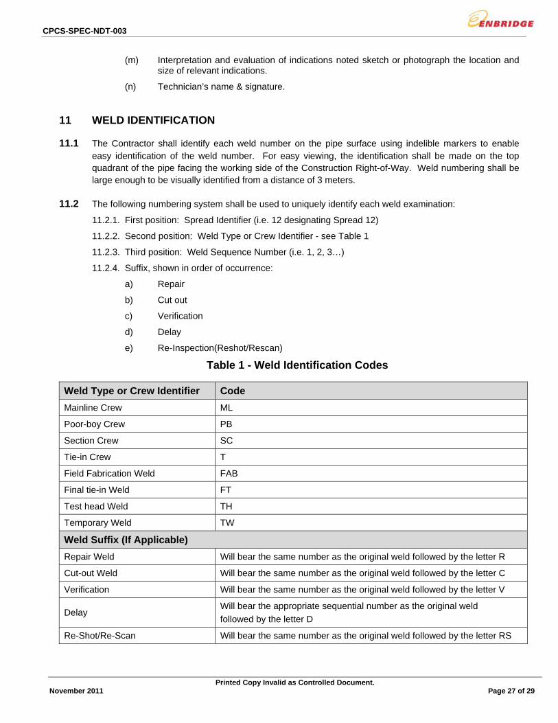
11 WELD IDENTIFICATION
11.1 The Contractor shall identify each weld number on the pipe surface using indelible markers to enable easy identification of the weld number. For easy viewing, the identification shall be made on the top quadrant of the pipe facing the working side of the Construction Right-of-Way. Weld numbering shall be large enough to be visually identified from a distance of 3 meters.
11.2 The following numbering system shall be used to uniquely identify each weld examination:
11.2.1. First position: Spread Identifier (i.e. 12 designating Spread 12)
11.2.2. Second position: Weld Type or Crew Identifier - see Table 1
11.2.3. Third position: Weld Sequence Number (i.e. 1, 2, 3…)
11.2.4. Suffix, shown in order of occurrence:
a) Repair
b) Cut out
c) Verification
d) Delay
e) Re-Inspection(Reshot/Rescan)
Table 1 - Weld Identification Codes
Weld Type or Crew Identifier Code
Mainline Crew ML
Poor-boy Crew PB
Section Crew SC
Tie-in Crew T
Field Fabrication Weld FAB
Final tie-in Weld FT
Test head Weld TH
Temporary Weld TW
Weld Suffix (If Applicable)
Repair Weld Will bear the same number as the original weld followed by the letter R
Cut-out Weld Will bear the same number as the original weld followed by the letter C
Verification Will bear the same number as the original weld followed by the letter V
Delay Will bear the appropriate sequential number as the original weld
followed by the letter D
Re-Shot/Re-Scan Will bear the same number as the original weld followed by the letter RS

CPCS-SPEC-NDT-003
Printed Copy Invalid as Controlled Document. November 2011 Page 28 of 29
11.3 In the event that a weld is repaired and then subsequently cut out, the new weld shall bear the same number as the original weld with the repair code followed by the code designating a cut out.
11.4 If the weld assessment results in a weld being completely cut out and replaced with a pup, the welds shall bear the same number as the original weld followed by a code designating the upstream(US) and the downstream(DS) weld. The US pup weld will use the original weld number with a suffix letter A. The DS pup weld will use the original weld number with a suffix letter B.
11.5 Welds that are radiographed or ultrasonically inspected after an initial radiographic or ultrasonic inspection to verify weld quality shall be designated as Verification welds and shall be identified using the suffix V. In addition, the time, shown in hour format, from the initial inspection until the subsequent inspection shall be noted on the NDT Report.
11.6 Welds that are radiographed or ultrasonically inspected the following day or longer after welding shall be designated as Delay welds and shall be identified using the suffix D. In addition, the time, shown in hour format, from the completion of the weld until the initial inspection shall be noted on the NDT report.
11.7 Welds requiring a radiographic re-shot or those requiring ultrasonic re-scanning shall be designated as Re-Shot/Re-Scanned welds and shall be identified using the suffix RS.
Example: Initial weld number: 12-ML-2345RC
Where: 12 – Represents Spread Number ML – Represents a weld completed by the mainline crew 2345 – Represents the 2345th weld made by the mainline crew on this spread R – Represents a repair examination
C – Represents a cut out If this new weld was cut out, then the replacement weld would become 12-ML-2345RC2.
If 12-ML-2345RC2 were to be cut out and replaced with a pup section length, the US replacement weld would become 12-ML-2345RC2A and the DS replacement weld would become 12-ML-2345RC2B.
12 REPORTING PROCEDURES
12.1.1 Non-Destructive Testing Reports shall be submitted daily to the Company as required by the Company. The Contractor shall ensure that chainage (200m intervals) for mainline and poor-boy and all tie-in welds are shown on the report. NDT Reports shall be signed by the Contractor and the Company prior to distribution.
12.1.2 Weld repair lists shall be provided to the Company in hard copy format each working day at a time that suits the production schedule of the spread.
12.1.3 Repair lists shall report the weld quality including outstanding weld repairs rescans/reshoots and weld cut-outs of all welds completed by the mainline welding crew by a predetermined time agreed between the Company and the NDT Supervisor.
12.1.4 All defects shall be clearly marked on the pipe in a manner agreed with the Company prior to the start of production repair welding.

CPCS-SPEC-NDT-003
Printed Copy Invalid as Controlled Document. November 2011 Page 29 of 29
12.1.5 PDF’s of daily ultrasonic Reports and recorder charts shall be uploaded daily to a central server. This process shall be approved by the Company.
12.1.6 The Contractor shall keep a current electronic weld logbook and an electronic database of all welds made for the Project in a format approved by the Company.
13 NDT TURNOVER PACKAGE REQUIREMENTS
The Contractor shall submit the following upon completion of the Project:
13.1.1. All NDE Reports in an electronic format.
13.1.2. All AUT data files (2 copies) complete with view program.
13.1.3. All Radiographic film.
The Contractor shall provide a copy of the logbook and an electronic database of all welds inspected to the Company when requested by the Company.
14 STANDARDS OF ACCEPTABILITY
Non-Destructive Testing shall be evaluated based upon the defect acceptance criteria defined in CSA Z662 and any other criteria defined by the Company.
15 ADDITIONAL REQUIREMENTS
15.1 Polishing Equipment
The Contractor shall provide 1 set of polishing and etching equipment with associated disposables capable of preparing macro-sections for visual examination of welds. Polishing capabilities shall allow for the polishing of macro-sections to a minimum 800-grit finish. The etchant shall be 5% Nital or 10% Ammonium Persulphate. Methanol drying shall also be included.
15.2 Training
When required, the Contractor shall provide training (1 day) for Company Inspectors on the techniques of Non-Destructive Testing. When required, this training shall be at a date and location determined by the Company and shall occur prior to production welding starting on the Project.
16 NON-DESTRUCTIVE TESTING AUDIT
16.1.1 All testing records are subject to an audit by the Company. The Contractor shall fully co-operate with the auditing function.
16.1.2 All items not in compliance with these Specification or Contract requirements shall be discussed with the NDT Supervisor and the Company and a plan for corrective action will be created. Repeated occurrence of non-compliance is a serious concern and may result in termination of the Contractor.