Nomograms for Assessment of Hazard Distances From a Blast ...
10
Proc. of the Eighth International Seminar on Fire & Explosion Hazards (ISFEH8), pp. xx‐xx Edited by J. Chao, V. Molkov, P. Sunderland, F. Tamanini and J. Torero Published by USTC Press ISBN: xxx‐xxx‐xx‐xxxx‐x :: doi: xx.xxxx/xxx‐xxx‐xx‐xxxx‐x_0x‐0x Nomograms for Assessment of Hazard Distances From a Blast Wave After High-Pressure Hydrogen Cylinder Rupture in a Fire Kashkarov, S.*, Li, Z., Molkov, V. Ulster University , Hydrogen Safety Engineering and Research Centre (HySAFER) Newtownabbey, BT37 0QB, Northern Ireland, UK *Corresponding author email: [email protected] ABSTRACT The paper presents nomograms as engineering tools for assessment of hazard distances from a blast wave after rupture of stand-alone or onboard hydrogen cylinder in a fire. The nomograms were built basing on the validated model, which includes the contribution of combustion of hydrogen released after a tank rupture to the blast wave strength. Two categories of the nomograms were developed. The first category is simplified and designed for the use by first responders, working on the scene of accident. These nomograms are constrained by fixed harm to people and damage to buildings. The other category of nomograms is for the use by hydrogen safety engineers. These nomograms give more flexibility to users, allowing to apply various harm/damage criteria accepted in different national and international standards. It was emphasised, that harm/damage criteria differ from one country to another. This naturally gives the different hazard distances. The need for international efforts to unify the harm/damage criteria for assessment of hazard distances from blast waves is underlined. KEYWORDS: High-pressure hydrogen storage cylinder, blast wave, harm to people, damage to buildings, criteria, hazard distance. INTRODUCTION The hazard distances from a hydrogen storage system and/or infrastructure are evaluated through the presence of various threats. There is a possible catastrophic rupture of a storage cylinder in a fire followed by a severe blast and a fast burning of hydrogen released and mixed with air forming a fireball with diameter of tens of meters. These may produce irreversible injury effects and even death to people, leaving no possibility for evacuation or rescue as well as the destructive effects to buildings as severe as their full demolition. The recently published model [1] for calculation of a blast wave decay from a high pressure hydrogen storage tank rupture in a fire has closed the knowledge gap in hydrogen safety engineering, in particular focusing on the effect from hydrogen combustion on a blast strength. It was demonstrated that the technique accounting for combustion effects is capable to reproduce the experimental data with the stand-alone as well as the under-vehicle (onboard) hydrogen tank rupture in a fire. These two typical applications have their practical industrial use. For instance, stand-alone vessels of large volumes are set up at hydrogen refuelling stations and onboard storage vessels have a variety of their motor applications, i.e. the fuel cell vehicles (FCVs) such as passenger cars, motorcycles, scooters, buses, hydrogen-powered forklifts, etc. The model [1] is applied here to develop a series of nomograms, which can be used by first responders and hydrogen safety engineers. The nomograms are classified by their application. The first category is developed for the use by first responders on an accident scene. These tools are straightforward and simple to use due to pre-selected harm criteria for people and damage criteria for buildings. It allows finding three hazard distances, i.e. “no harm”, “injury”, and “fatality” by picking of a hydrogen tank volume and a storage pressure only. Another category of the nomograms is the graphical representation of practically all features of the methodology [1].
-
Upload
khangminh22 -
Category
Documents
-
view
4 -
download
0
Transcript of Nomograms for Assessment of Hazard Distances From a Blast ...
Proc. of the Eighth International Seminar on Fire & Explosion Hazards (ISFEH8), pp. xx‐xx Edited by J. Chao, V. Molkov, P. Sunderland, F. Tamanini and J. Torero Published by USTC Press ISBN: xxx‐xxx‐xx‐xxxx‐x :: doi: xx.xxxx/xxx‐xxx‐xx‐xxxx‐x_0x‐0x
Nomograms for Assessment of Hazard Distances From a Blast Wave After High-Pressure Hydrogen Cylinder Rupture in a Fire
Kashkarov, S.*, Li, Z., Molkov, V.
Ulster University , Hydrogen Safety Engineering and Research Centre (HySAFER) Newtownabbey, BT37 0QB, Northern Ireland, UK
*Corresponding author email: [email protected]
ABSTRACT
The paper presents nomograms as engineering tools for assessment of hazard distances from a blast wave after rupture of stand-alone or onboard hydrogen cylinder in a fire. The nomograms were built basing on the validated model, which includes the contribution of combustion of hydrogen released after a tank rupture to the blast wave strength. Two categories of the nomograms were developed. The first category is simplified and designed for the use by first responders, working on the scene of accident. These nomograms are constrained by fixed harm to people and damage to buildings. The other category of nomograms is for the use by hydrogen safety engineers. These nomograms give more flexibility to users, allowing to apply various harm/damage criteria accepted in different national and international standards. It was emphasised, that harm/damage criteria differ from one country to another. This naturally gives the different hazard distances. The need for international efforts to unify the harm/damage criteria for assessment of hazard distances from blast waves is underlined. KEYWORDS: High-pressure hydrogen storage cylinder, blast wave, harm to people, damage to buildings, criteria, hazard distance.
INTRODUCTION
The hazard distances from a hydrogen storage system and/or infrastructure are evaluated through the presence of various threats. There is a possible catastrophic rupture of a storage cylinder in a fire followed by a severe blast and a fast burning of hydrogen released and mixed with air forming a fireball with diameter of tens of meters. These may produce irreversible injury effects and even death to people, leaving no possibility for evacuation or rescue as well as the destructive effects to buildings as severe as their full demolition.
The recently published model [1] for calculation of a blast wave decay from a high pressure hydrogen storage tank rupture in a fire has closed the knowledge gap in hydrogen safety engineering, in particular focusing on the effect from hydrogen combustion on a blast strength. It was demonstrated that the technique accounting for combustion effects is capable to reproduce the experimental data with the stand-alone as well as the under-vehicle (onboard) hydrogen tank rupture in a fire. These two typical applications have their practical industrial use. For instance, stand-alone vessels of large volumes are set up at hydrogen refuelling stations and onboard storage vessels have a variety of their motor applications, i.e. the fuel cell vehicles (FCVs) such as passenger cars, motorcycles, scooters, buses, hydrogen-powered forklifts, etc.
The model [1] is applied here to develop a series of nomograms, which can be used by first responders and hydrogen safety engineers. The nomograms are classified by their application. The first category is developed for the use by first responders on an accident scene. These tools are straightforward and simple to use due to pre-selected harm criteria for people and damage criteria for buildings. It allows finding three hazard distances, i.e. “no harm”, “injury”, and “fatality” by picking of a hydrogen tank volume and a storage pressure only. Another category of the nomograms is the graphical representation of practically all features of the methodology [1].
Proc. of the Eighth International Seminar on Fire and Explosion Hazards (ISFEH8)
2
It allows hydrogen safety engineers to apply any national or international harm and damage criteria for assessment of hazard distances. These nomograms can be used as hydrogen safety engineering tools to obtain values of overpressure and impulse at different distances from the tank position.
The selection of different harm criteria to humans (involving people/personnel indoors and outdoors, unprotected people and indirect effects from the blast, i.e. fragments impact) and damage criteria to buildings (different elements and types of structures) is represented for the convenience of users applying nomograms for hydrogen safety engineering or wanting to compare the effect of choice of different harm/damage thresholds.
HUMANS VULNERABILITY AND STRUCTURAL DAMAGE EFFECTS FROM BLAST
Harm effects to humans
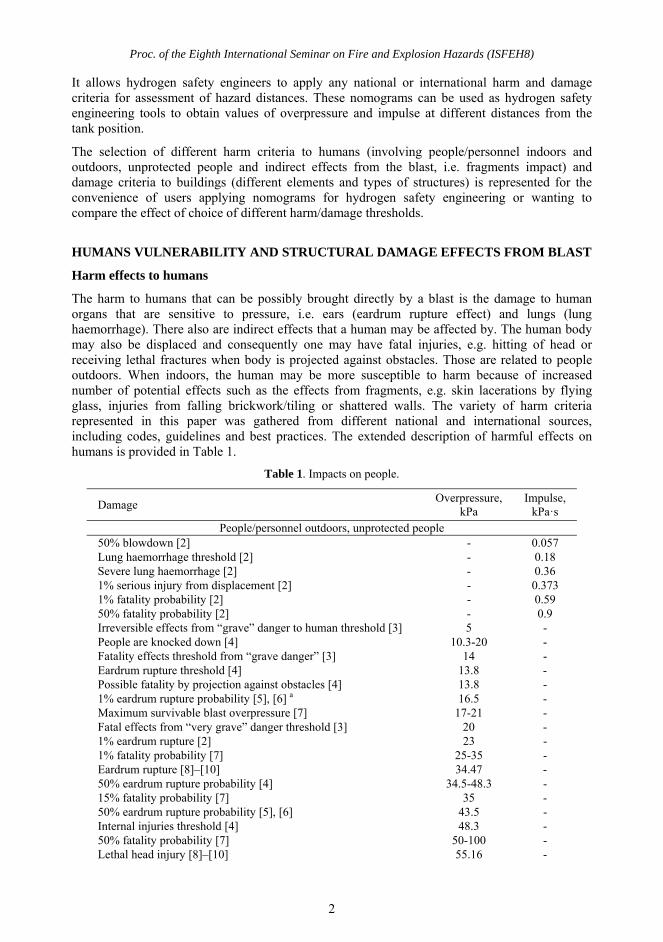
The harm to humans that can be possibly brought directly by a blast is the damage to human organs that are sensitive to pressure, i.e. ears (eardrum rupture effect) and lungs (lung haemorrhage). There also are indirect effects that a human may be affected by. The human body may also be displaced and consequently one may have fatal injuries, e.g. hitting of head or receiving lethal fractures when body is projected against obstacles. Those are related to people outdoors. When indoors, the human may be more susceptible to harm because of increased number of potential effects such as the effects from fragments, e.g. skin lacerations by flying glass, injuries from falling brickwork/tiling or shattered walls. The variety of harm criteria represented in this paper was gathered from different national and international sources, including codes, guidelines and best practices. The extended description of harmful effects on humans is provided in Table 1.
Table 1. Impacts on people.
Damage Overpressure,
kPa Impulse,
kPa·s People/personnel outdoors, unprotected people
50% blowdown [2] - 0.057 Lung haemorrhage threshold [2] - 0.18 Severe lung haemorrhage [2] - 0.36 1% serious injury from displacement [2] - 0.373 1% fatality probability [2] - 0.59 50% fatality probability [2] - 0.9 Irreversible effects from “grave” danger to human threshold [3] 5 - People are knocked down [4] 10.3-20 - Fatality effects threshold from “grave danger” [3] 14 - Eardrum rupture threshold [4] 13.8 - Possible fatality by projection against obstacles [4] 13.8 - 1% eardrum rupture probability [5], [6] a 16.5 - Maximum survivable blast overpressure [7] 17-21 - Fatal effects from “very grave” danger threshold [3] 20 - 1% eardrum rupture [2] 23 - 1% fatality probability [7] 25-35 - Eardrum rupture [8]–[10] 34.47 - 50% eardrum rupture probability [4] 34.5-48.3 - 15% fatality probability [7] 35 - 50% eardrum rupture probability [5], [6] 43.5 - Internal injuries threshold [4] 48.3 - 50% fatality probability [7] 50-100 - Lethal head injury [8]–[10] 55.16 -
Proc. of the Eighth International Seminar on Fire and Explosion Hazards (ISFEH8)
3
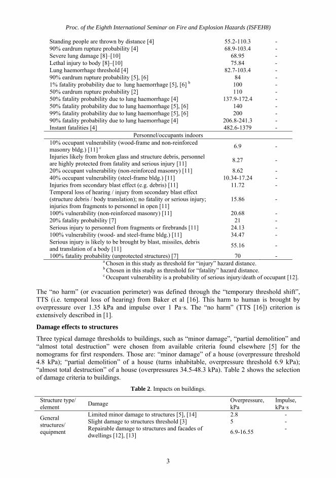
Standing people are thrown by distance [4] 55.2-110.3 - 90% eardrum rupture probability [4] 68.9-103.4 - Severe lung damage [8]–[10] 68.95 - Lethal injury to body [8]–[10] 75.84 - Lung haemorrhage threshold [4] 82.7-103.4 - 90% eardrum rupture probability [5], [6] 84 - 1% fatality probability due to lung haemorrhage [5], [6] b 100 - 50% eardrum rupture probability [2] 110 - 50% fatality probability due to lung haemorrhage [4] 137.9-172.4 - 50% fatality probability due to lung haemorrhage [5], [6] 140 - 99% fatality probability due to lung haemorrhage [5], [6] 200 - 90% fatality probability due to lung haemorrhage [4] 206.8-241.3 - Instant fatalities [4] 482.6-1379 -
Personnel/occupants indoors 10% occupant vulnerability (wood-frame and non-reinforced masonry bldg.) [11] c
6.9 -
Injuries likely from broken glass and structure debris, personnel are highly protected from fatality and serious injury [11]
8.27 -
20% occupant vulnerability (non-reinforced masonry) [11] 8.62 - 40% occupant vulnerability (steel-frame bldg.) [11] 10.34-17.24 - Injuries from secondary blast effect (e.g. debris) [11] 11.72 - Temporal loss of hearing / injury from secondary blast effect (structure debris / body translation); no fatality or serious injury; injuries from fragments to personnel in open [11]
15.86 -
100% vulnerability (non-reinforced masonry) [11] 20.68 - 20% fatality probability [7] 21 - Serious injury to personnel from fragments or firebrands [11] 24.13 - 100% vulnerability (wood- and steel-frame bldg.) [11] 34.47 - Serious injury is likely to be brought by blast, missiles, debris and translation of a body [11]
55.16 -
100% fatality probability (unprotected structures) [7] 70 - a Chosen in this study as threshold for “injury” hazard distance. b Chosen in this study as threshold for “fatality” hazard distance. c Occupant vulnerability is a probability of serious injury/death of occupant [12].
The “no harm” (or evacuation perimeter) was defined through the “temporary threshold shift”, TTS (i.e. temporal loss of hearing) from Baker et al [16]. This harm to human is brought by overpressure over 1.35 kPa and impulse over 1 Pa·s. The “no harm” (TTS [16]) criterion is extensively described in [1].
Damage effects to structures
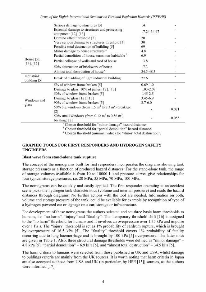
Three typical damage thresholds to buildings, such as “minor damage”, “partial demolition” and “almost total destruction” were chosen from available criteria found elsewhere [5] for the nomograms for first responders. Those are: “minor damage” of a house (overpressure threshold 4.8 kPa); “partial demolition” of a house (turns inhabitable, overpressure threshold 6.9 kPa); “almost total destruction” of a house (overpressures 34.5-48.3 kPa). Table 2 shows the selection of damage criteria to buildings.
Table 2. Impacts on buildings.
Structure type/ element
Damage Overpressure, kPa
Impulse, kPa·s
General structures/ equipment
Limited minor damage to structures [5], [14] 2.8 - Slight damage to structures threshold [3] 5 - Repairable damage to structures and facades of dwellings [12], [13]
6.9-16.55 -
Proc. of the Eighth International Seminar on Fire and Explosion Hazards (ISFEH8)
4
Serious damage to structures [3] 14 - Essential damage to structures and processing equipment [12], [13]
17.24-34.47 -
Domino effect threshold [3] 20 - Very serious damage to structures threshold [3] 30 - Possible total destruction of building [5] 69 -
House [5], [14], [15]
Minor damage to house structures a 4.8 - Partial demolition of house, turns non-habitable b 6.9 -
Partial collapse of walls and roof of house 13.8 -
50% destruction of brickwork of house 17.3 - Almost total destruction of house c 34.5-48.3 -
Industrial building [5]
Break of cladding of light industrial building 27.6 -
Windows and glass
5% of window frame broken [5] 0.69-1.0 - Damage to glass, 10% of panes [12], [13] 1.03-2.07 - 50% of window frame broken [5] 1.45-2.5 - Damage to glass [12], [13] 3.45-6.9 - 90% of window frame broken [5] 3.7-6.0 - 50% big windows (from 1.5 m2 to 2.3 m2) breakage [2]
- 0.021
50% small windows (from 0.12 m2 to 0.56 m2) breakage [2]
- 0.055 a Chosen threshold for “minor damage” hazard distance. b Chosen threshold for “partial demolition” hazard distance. c Chosen threshold (minimal value) for “almost total destruction”.
GRAPHIC TOOLS FOR FIRST RESPONDERS AND HYDROGEN SAFETY ENGINEERS
Blast wave from stand-alone tank rupture
The concept of the nomograms built for first responders incorporates the diagrams showing tank storage pressures as a function of produced hazard distances. For the stand-alone tank, the range of storage volumes available is from 10 to 10000 L and pressure curves give relationships for four typical storage pressures, i.e. 20 MPa, 35 MPa, 70 MPa, 100 MPa.
The nomograms can be quickly and easily applied. The first responder operating at an accident scene picks the hydrogen tank characteristics (volume and internal pressure) and reads the hazard distances through diagrams. No further actions with the tool are needed. Information on both, volume and storage pressure of the tank, could be available for example by recognition of type of a hydrogen powered car or signage on a car, storage or infrastructure.
For development of these nomograms the authors selected and set three basic harm thresholds to humans, i.e. “no harm”, “injury” and “fatality”. The “temporary threshold shift [16] is assigned to the “no harm” threshold for humans and it involves an overpressure over 1.35 kPa and impulse over 1 Pa·s. The “injury” threshold is set as 1% probability of eardrum rupture, which is brought by overpressure of 16.5 kPa [5]. The “fatality” threshold covers 1% probability of fatality occurring due to lung haemorrhage and is brought by 100 kPa [5] overpressure. The latter ones are given in Table 1. Also, three structural damage thresholds were defined as “minor damage” – 4.8 kPa [5], “partial demolition” – 6.9 kPa [5], and “almost total destruction” – 34.5 kPa [5].
The harm criteria to humans were selected from those published in UK and USA, whilst damage to buldings criteria are mainly from the UK sources. It is worth noting that harm criteria in Japan are also accepted as those from USA and UK (in particular, by HSE [15]) sources, as the authors were informed [17].
Proc. of the Eighth International Seminar on Fire and Explosion Hazards (ISFEH8)
5
The selected harm criteria for humans and structural damage criteria are choices of the authors exceptionally. Those are used as examples for assessment of hazard distances only. The authors do not take any responsibility for designation of specific criteria to safety engineering of hydrogen systems and infrastructure. For the reader’s remark, the overpressures and/or impulse of analogous harm effects collected from sources from different countries differ significantly. It shall further appear that the unification is desirable.
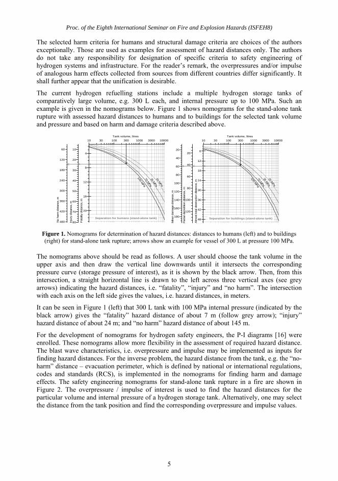
The current hydrogen refuelling stations include a multiple hydrogen storage tanks of comparatively large volume, e.g. 300 L each, and internal pressure up to 100 MPa. Such an example is given in the nomograms below. Figure 1 shows nomograms for the stand-alone tank rupture with assessed hazard distances to humans and to buildings for the selected tank volume and pressure and based on harm and damage criteria described above.
Figure 1. Nomograms for determination of hazard distances: distances to humans (left) and to buildings (right) for stand-alone tank rupture; arrows show an example for vessel of 300 L at pressure 100 MPa.
The nomograms above should be read as follows. A user should choose the tank volume in the upper axis and then draw the vertical line downwards until it intersects the corresponding pressure curve (storage pressure of interest), as it is shown by the black arrow. Then, from this intersection, a straight horizontal line is drawn to the left across three vertical axes (see grey arrows) indicating the hazard distances, i.e. “fatality”, “injury” and “no harm”. The intersection with each axis on the left side gives the values, i.e. hazard distances, in meters.
It can be seen in Figure 1 (left) that 300 L tank with 100 MPa internal pressure (indicated by the black arrow) gives the “fatality” hazard distance of about 7 m (follow grey arrow); “injury” hazard distance of about 24 m; and “no harm” hazard distance of about 145 m.
For the development of nomograms for hydrogen safety engineers, the P-I diagrams [16] were enrolled. These nomograms allow more flexibility in the assessment of required hazard distance. The blast wave characteristics, i.e. overpressure and impulse may be implemented as inputs for finding hazard distances. For the inverse problem, the hazard distance from the tank, e.g. the “no-harm” distance – evacuation perimeter, which is defined by national or international regulations, codes and standards (RCS), is implemented in the nomograms for finding harm and damage effects. The safety engineering nomograms for stand-alone tank rupture in a fire are shown in Figure 2. The overpressure / impulse of interest is used to find the hazard distances for the particular volume and internal pressure of a hydrogen storage tank. Alternatively, one may select the distance from the tank position and find the corresponding overpressure and impulse values.
10 100 1000 1000030 300 3000
Tank volume, litres
20
16
12
8
4
480
420
360
300
240
180
120
60
80
70
60
50
40
30
20
10
Inju
ry d
ista
nce
, m
Fata
lity
dis
tance
, m
100 MPa
70 MPa
35 MPa
20 MPa
No h
arm
dis
tanc
e, m
10000
Separation for humans (stand-alone tank)
10 100 1000 1000030 300 3000
Tank volume, litres
48
42
36
30
24
18
12
6
180
160
140
120
100
80
60
40
20
120
100
80
60
40
20
100 MPa
70 MPa
35 MPa
20 MPa
10000
Separation for buildings (stand-alone tank)
Par
tial d
em
olit
ion d
ista
nce
, m
Alm
ost to
tal d
est
ruct
ion d
ista
nce
, m
Min
or dam
age
dis
tanc
e, m
Proc. of the Eighth International Seminar on Fire and Explosion Hazards (ISFEH8)
6
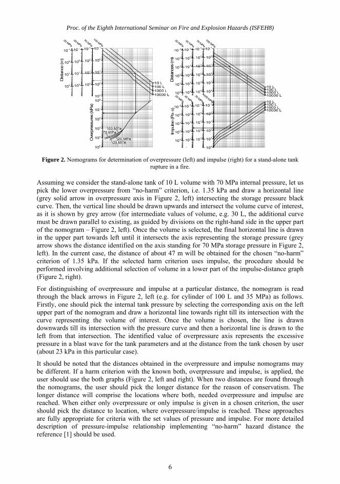
Figure 2. Nomograms for determination of overpressure (left) and impulse (right) for a stand-alone tank rupture in a fire.
Assuming we consider the stand-alone tank of 10 L volume with 70 MPa internal pressure, let us pick the lower overpressure from “no-harm” criterion, i.e. 1.35 kPa and draw a horizontal line (grey solid arrow in overpressure axis in Figure 2, left) intersecting the storage pressure black curve. Then, the vertical line should be drawn upwards and intersect the volume curve of interest, as it is shown by grey arrow (for intermediate values of volume, e.g. 30 L, the additional curve must be drawn parallel to existing, as guided by divisions on the right-hand side in the upper part of the nomogram – Figure 2, left). Once the volume is selected, the final horizontal line is drawn in the upper part towards left until it intersects the axis representing the storage pressure (grey arrow shows the distance identified on the axis standing for 70 MPa storage pressure in Figure 2, left). In the current case, the distance of about 47 m will be obtained for the chosen “no-harm” criterion of 1.35 kPa. If the selected harm criterion uses impulse, the procedure should be performed involving additional selection of volume in a lower part of the impulse-distance graph (Figure 2, right).
For distinguishing of overpressure and impulse at a particular distance, the nomogram is read through the black arrows in Figure 2, left (e.g. for cylinder of 100 L and 35 MPa) as follows. Firstly, one should pick the internal tank pressure by selecting the corresponding axis on the left upper part of the nomogram and draw a horizontal line towards right till its intersection with the curve representing the volume of interest. Once the volume is chosen, the line is drawn downwards till its intersection with the pressure curve and then a horizontal line is drawn to the left from that intersection. The identified value of overpressure axis represents the excessive pressure in a blast wave for the tank parameters and at the distance from the tank chosen by user (about 23 kPa in this particular case).
It should be noted that the distances obtained in the overpressure and impulse nomograms may be different. If a harm criterion with the known both, overpressure and impulse, is applied, the user should use the both graphs (Figure 2, left and right). When two distances are found through the nomograms, the user should pick the longer distance for the reason of conservatism. The longer distance will comprise the locations where both, needed overpressure and impulse are reached. When either only overpressure or only impulse is given in a chosen criterion, the user should pick the distance to location, where overpressure/impulse is reached. These approaches are fully appropriate for criteria with the set values of pressure and impulse. For more detailed description of pressure-impulse relationship implementing “no-harm” hazard distance the reference [1] should be used.
Proc. of the Eighth International Seminar on Fire and Explosion Hazards (ISFEH8)
7
Blast wave from under-vehicle tank rupture
The assessment of hazard distances to humans and buildings from various onboard hydrogen storage applications was performed in [1]. It was found that rupture of an under-vehicle hydrogen tank in a fire produced significantly lower overpressures in a blast wave and, as a result, much shorter hazard distances compared to the same tank ruptured as a stand-alone (due to huge amount of mechanical energy spent on translation of vehicle by 22 meters).
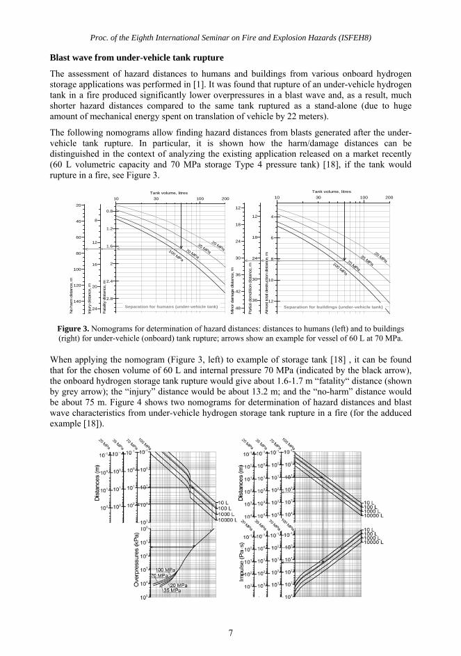
The following nomograms allow finding hazard distances from blasts generated after the under-vehicle tank rupture. In particular, it is shown how the harm/damage distances can be distinguished in the context of analyzing the existing application released on a market recently (60 L volumetric capacity and 70 MPa storage Type 4 pressure tank) [18], if the tank would rupture in a fire, see Figure 3.
Figure 3. Nomograms for determination of hazard distances: distances to humans (left) and to buildings (right) for under-vehicle (onboard) tank rupture; arrows show an example for vessel of 60 L at 70 MPa.
When applying the nomogram (Figure 3, left) to example of storage tank [18] , it can be found that for the chosen volume of 60 L and internal pressure 70 MPa (indicated by the black arrow), the onboard hydrogen storage tank rupture would give about 1.6-1.7 m “fatality“ distance (shown by grey arrow); the “injury” distance would be about 13.2 m; and the “no-harm” distance would be about 75 m. Figure 4 shows two nomograms for determination of hazard distances and blast wave characteristics from under-vehicle hydrogen storage tank rupture in a fire (for the adduced example [18]).
10 10030
Tank volume, litres
2.8
2.4
2
1.6
1.2
0.8
140
120
100
80
60
40
20
24
20
16
12
8
Inju
ry d
ista
nce, m
Fata
lity
dis
tance
, m
100 MPa
70 MPa
35 MPa
20 MPa
No h
arm
dis
tance
, m
200
Separation for humans (under-vehicle tank)
10 10030
Tank volume, litres
12
10
8
6
4
48
42
36
30
24
18
12
36
30
24
18
12
100 MPa
70 MPa
35 MPa
20 MPa
Min
or da
mage
dis
tanc
e, m
200
Alm
ost t
ota
l des
truc
tion
dist
ance
, m
Par
tial d
emol
ition
dis
tanc
e, m
Separation for buildings (under-vehicle tank)
Proc. of the Eighth International Seminar on Fire and Explosion Hazards (ISFEH8)
8
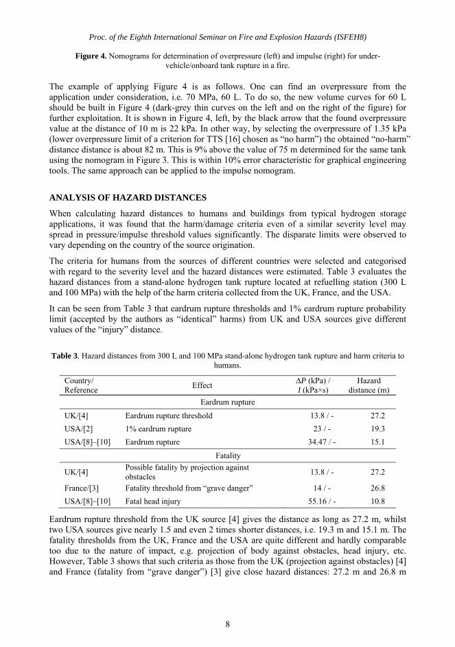
Figure 4. Nomograms for determination of overpressure (left) and impulse (right) for under-vehicle/onboard tank rupture in a fire.
The example of applying Figure 4 is as follows. One can find an overpressure from the application under consideration, i.e. 70 MPa, 60 L. To do so, the new volume curves for 60 L should be built in Figure 4 (dark-grey thin curves on the left and on the right of the figure) for further exploitation. It is shown in Figure 4, left, by the black arrow that the found overpressure value at the distance of 10 m is 22 kPa. In other way, by selecting the overpressure of 1.35 kPa (lower overpressure limit of a criterion for TTS [16] chosen as “no harm”) the obtained “no-harm” distance distance is about 82 m. This is 9% above the value of 75 m determined for the same tank using the nomogram in Figure 3. This is within 10% error characteristic for graphical engineering tools. The same approach can be applied to the impulse nomogram.
ANALYSIS OF HAZARD DISTANCES
When calculating hazard distances to humans and buildings from typical hydrogen storage applications, it was found that the harm/damage criteria even of a similar severity level may spread in pressure/impulse threshold values significantly. The disparate limits were observed to vary depending on the country of the source origination.
The criteria for humans from the sources of different countries were selected and categorised with regard to the severity level and the hazard distances were estimated. Table 3 evaluates the hazard distances from a stand-alone hydrogen tank rupture located at refuelling station (300 L and 100 MPa) with the help of the harm criteria collected from the UK, France, and the USA.
It can be seen from Table 3 that eardrum rupture thresholds and 1% eardrum rupture probability limit (accepted by the authors as “identical” harms) from UK and USA sources give different values of the “injury” distance.
Table 3. Hazard distances from 300 L and 100 MPa stand-alone hydrogen tank rupture and harm criteria to humans.
Country/ Reference
Effect ΔP (kPa) / I (kPa×s)
Hazard distance (m)
Eardrum rupture
UK/[4] Eardrum rupture threshold 13.8 / - 27.2
USA/[2] 1% eardrum rupture 23 / - 19.3
USA/[8]–[10] Eardrum rupture 34.47 / - 15.1
Fatality
UK/[4] Possible fatality by projection against obstacles
13.8 / - 27.2
France/[3] Fatality threshold from “grave danger” 14 / - 26.8
USA/[8]–[10] Fatal head injury 55.16 / - 10.8
Eardrum rupture threshold from the UK source [4] gives the distance as long as 27.2 m, whilst two USA sources give nearly 1.5 and even 2 times shorter distances, i.e. 19.3 m and 15.1 m. The fatality thresholds from the UK, France and the USA are quite different and hardly comparable too due to the nature of impact, e.g. projection of body against obstacles, head injury, etc. However, Table 3 shows that such criteria as those from the UK (projection against obstacles) [4] and France (fatality from “grave danger”) [3] give close hazard distances: 27.2 m and 26.8 m
Proc. of the Eighth International Seminar on Fire and Explosion Hazards (ISFEH8)
9
respectively (1.5% difference). The USA criterion (fatal head injury [8]–[10]) gives the distance that differs drastically, i.e. 10.8 m (more than twice shorter than European ones).
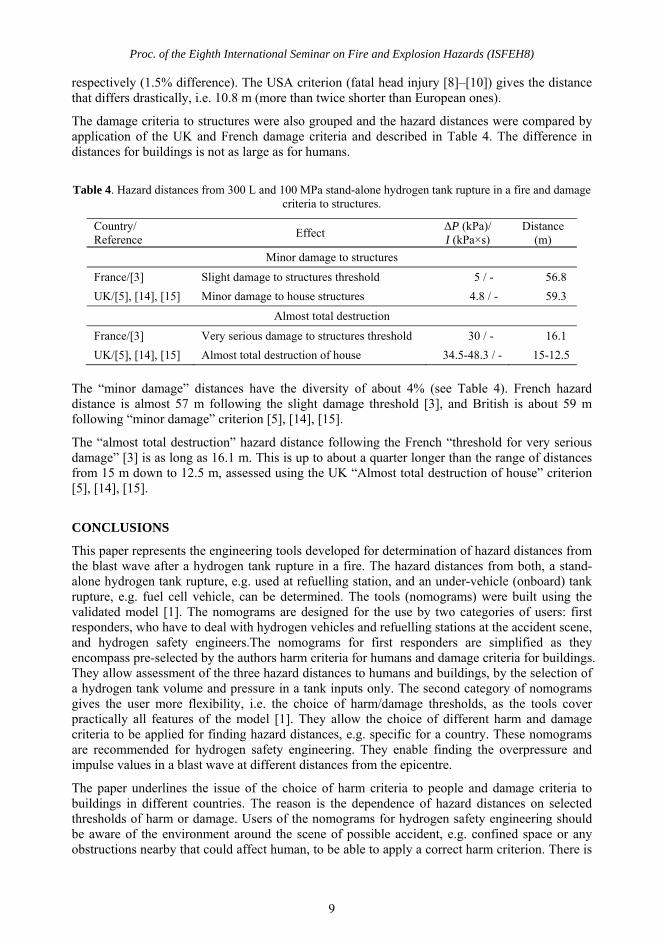
The damage criteria to structures were also grouped and the hazard distances were compared by application of the UK and French damage criteria and described in Table 4. The difference in distances for buildings is not as large as for humans.
Table 4. Hazard distances from 300 L and 100 MPa stand-alone hydrogen tank rupture in a fire and damage criteria to structures.
Country/ Reference
Effect ΔP (kPa)/ I (kPa×s)
Distance (m)
Minor damage to structures
France/[3] Slight damage to structures threshold 5 / - 56.8
UK/[5], [14], [15] Minor damage to house structures 4.8 / - 59.3
Almost total destruction
France/[3] Very serious damage to structures threshold 30 / - 16.1
UK/[5], [14], [15] Almost total destruction of house 34.5-48.3 / - 15-12.5
The “minor damage” distances have the diversity of about 4% (see Table 4). French hazard distance is almost 57 m following the slight damage threshold [3], and British is about 59 m following “minor damage” criterion [5], [14], [15].
The “almost total destruction” hazard distance following the French “threshold for very serious damage” [3] is as long as 16.1 m. This is up to about a quarter longer than the range of distances from 15 m down to 12.5 m, assessed using the UK “Almost total destruction of house” criterion [5], [14], [15].
CONCLUSIONS
This paper represents the engineering tools developed for determination of hazard distances from the blast wave after a hydrogen tank rupture in a fire. The hazard distances from both, a stand-alone hydrogen tank rupture, e.g. used at refuelling station, and an under-vehicle (onboard) tank rupture, e.g. fuel cell vehicle, can be determined. The tools (nomograms) were built using the validated model [1]. The nomograms are designed for the use by two categories of users: first responders, who have to deal with hydrogen vehicles and refuelling stations at the accident scene, and hydrogen safety engineers.The nomograms for first responders are simplified as they encompass pre-selected by the authors harm criteria for humans and damage criteria for buildings. They allow assessment of the three hazard distances to humans and buildings, by the selection of a hydrogen tank volume and pressure in a tank inputs only. The second category of nomograms gives the user more flexibility, i.e. the choice of harm/damage thresholds, as the tools cover practically all features of the model [1]. They allow the choice of different harm and damage criteria to be applied for finding hazard distances, e.g. specific for a country. These nomograms are recommended for hydrogen safety engineering. They enable finding the overpressure and impulse values in a blast wave at different distances from the epicentre.
The paper underlines the issue of the choice of harm criteria to people and damage criteria to buildings in different countries. The reason is the dependence of hazard distances on selected thresholds of harm or damage. Users of the nomograms for hydrogen safety engineering should be aware of the environment around the scene of possible accident, e.g. confined space or any obstructions nearby that could affect human, to be able to apply a correct harm criterion. There is
Proc. of the Eighth International Seminar on Fire and Explosion Hazards (ISFEH8)
10
a need for international hydrogen safety community to unify the criteria for harm to people and damage to structures.
REFERENCES
1. Molkov, V. and Kashkarov, S., “Blast wave from a high-pressure gas tank rupture in a fire: stand-alone and under-vehicle hydrogen tanks,” International Journal of Hydrogen Energy, vol. 40, no. 36, 2015, pp. 12581–12603.
2. NFPA, “NFPA® 2, Hydrogen Technologies Code,” Batterymarch Park, Quincy, MA 02169-7471, NFPA® 2, 2011.
3. Ministère de l’Interieur, “NIO Risque hydrogène,” interieur.gouv.fr, 2013. [Online]. Available: http://www.interieur.gouv.fr/Le-ministere/Securite-civile/Documentation-technique/Les-sapeurs-pompiers/Doctrines-et-techniques-professionnelles/Notes-operationnelles. [Accessed: 10-Dec-2015].
4. Jeffries, R. M., Hunt, S. J., and Gould, L., “Derivation of fatality of probability function for occupant buildings subject to blast loads,” Health & Safety Executive, 1997.
5. Mannan, S., Lees’ Loss Prevention in the Process Industries, 3rd ed., vol. 1. Elsevier Butterworth-Heinemann, 2005.
6. Fugelso, L. E., Weiner, L. M., and Schiffman, T. H., “Explosion effects computation aids,” Gen. Am. Div., Gen. Am. Transportation Co., Niles, Illinois, US, GARD Prog. 1540, 1972.
7. Health and Safety Executive, “Methods of approximation and determination of human vulnerability for offshore major accident hazard assessment.” Supporting document to SPC (SPC/Tech/OSD/30, version 3), 2010.
8. AIChE Center for Chemical Process Safety, “Guidance for Consequence Analysis of Chemical Releases,” Center for Chemical Process Safety, American Institute of Chemical Engineers, New York: American institute of Chemical Engineers, 1999.
9. CCPS, “Guidelines for Evaluating the Characteristics of Vapour Cloud Explosions, Flash Fires and BLEVEs,” New York: American institute of Chemical Engineering, 1994.
10. Federal Emergency Management Agency, “Handbook of Chemical Hazard Analysis Procedures,” Washington, D.C., 1987.
11. “Management of hazards associated with location of process plant buildings,” American Petroleum Institute, Washington D.C., API Recommended Practice 752, 1995.
12. Barry, T. F., Risk-Informed, Performance-Based Industrial Fire Protection, 1st ed. USA: Tennessee Valley Publishing, 2002.
13. Technica Ltd., “Techniques for assessing industrial hazards,” Washington, D.C., World Bank Technical Paper Number 55, 1988.
14. Clancey, V. J., “Diagnostic features of explosion damage,” presented at the Sixth Int. Mtg of Forensic Sciences, Edinburgh, UK, 1972.
15. Health and Safety Executive, “The Peterborough Explosion. A report of the investigation by the Health and Safety Executive into the explosion of a vehicle carrying explosives at Fengate Industrial Estate, Peterborough on 22 March 1989.,” 1990.
16. Baker, W. E., Cox, P. A., Westine, P. S., Kulesz, J. J., and Strehlow, R. A., Explosion hazards and evaluation. Elsevier Scientific Publishing Company, 1983.
17. Kim, W., “Private communication,” 2015. 18. Yamashita, A., Kondo, M., Goto, S., and Ogami, N., “Development of High-Pressure Hydrogen Storage
System for the Toyota ‘Mirai,’” SAE Tech. Pap., 2015.