NI 43-101 FEASIBILITY STUDY TECHNICAL REPORT INV ...
417
NI 43-101 FEASIBILITY STUDY TECHNICAL REPORT INV METALS INC. LOMA LARGA PROJECT, AZUAY PROVINCE, ECUADOR Prepared For: INV Metals Inc. Prepared By: DRA Americas Inc. Effective Date: 11 January 2019 Report: J01834-PM-REP-002
-
Upload
khangminh22 -
Category
Documents
-
view
1 -
download
0
Transcript of NI 43-101 FEASIBILITY STUDY TECHNICAL REPORT INV ...

NI 43-101 FEASIBILITY STUDY TECHNICAL REPORT INV METALS INC.
LOMA LARGA PROJECT, AZUAY PROVINCE, ECUADOR
Prepared For: INV Metals Inc.
Prepared By: DRA Americas Inc. Effective Date: 11 January 2019 Report: J01834-PM-REP-002

Document Number J01834-PM-REP-002 Rev 0
Date 11 January 2019 Page 2 of 417
Feasibility Study Report | INV Metals Inc. – Loma Larga
CONTENTS
SUMMARY ........................................................................................................................... 16
1.1 SUMMARY AND CONCLUSIONS 16
1.2 RECOMMENDATIONS 35
INTRODUCTION ................................................................................................................... 38
2.1 SOURCES OF INFORMATION 39
RELIANCE ON OTHER EXPERTS ....................................................................................... 41
PROPERTY DESCRIPTION AND LOCATION ..................................................................... 42
4.1 LAND TENURE 42
ACCESS, CLIMATE, LOCAL RESOURCES, INFRASTRUCTURE AND PHYSIOGRAPHY 47
5.1 ACCESS, TRANSPORTATION AND LOGISTICS 47
5.2 CLIMATE 49
5.3 LOCAL RESOURCES 51
5.4 INFRASTRUCTURE 51
5.5 PHYSIOGRAPHY 52
HISTORY .............................................................................................................................. 53
GEOLOGICAL SETTING AND MINERALIZATION .............................................................. 55
7.1 REGIONAL GEOLOGY 55
7.2 LOCAL AND PROPERTY GEOLOGY 57
7.3 MINERALIZATION 60
DEPOSIT TYPES .................................................................................................................. 64
EXPLORATION .................................................................................................................... 67
DRILLING ............................................................................................................................. 68
10.1 IAMGOLD DRILLING 68
10.2 INV DRILLING 68
SAMPLE PREPARATION, ANALYSES AND SECURITY .................................................... 75
11.1 PRE-2012 PROGRAMS 75
11.2 INV 2013 DRILL PROGRAM 77
11.3 RESULTS OF QA/QC PROGRAMS 78
DATA VERIFICATION ........................................................................................................ 106
12.1 MANUAL DATABASE VERIFICATION 106
12.2 INDEPENDENT ASSAYS OF DRILL CORE 107
MINERAL PROCESSING AND METALLURGICAL TESTING ........................................... 108
13.1 INTRODUCTION 108
13.2 HISTORICAL METALLURGICAL TESTWORK 108
13.3 TESTWORK FOR 2017 FEASIBILITY STUDY 109
13.4 SUPPLEMENTAL TESTWORK 141
13.5 RECOVERY ESTIMATES 142
13.6 METALLURGICAL VARIABILITY 145
13.7 DELETERIOUS ELEMENTS 145
MINERAL RESOURCE ESTIMATE .................................................................................... 146
14.1 SUMMARY 146

Document Number J01834-PM-REP-002 Rev 0
Date 11 January 2019 Page 3 of 417
Feasibility Study Report | INV Metals Inc. – Loma Larga
14.2 MINERAL RESOURCE DATABASE 147
14.3 GEOLOGICAL INTERPRETATION AND 3D SOLID 147
14.4 STATISTICAL ANALYSIS 151
14.5 CAPPING HIGH GRADE VALUES 153
14.6 COMPOSITING 155
14.7 DENSITY 157
14.8 NSR CUT-OFF VALUE 160
14.9 VARIOGRAPHY AND INTERPOLATION VALUES 161
14.10 BLOCK MODEL 164
14.11 BLOCK MODEL VALIDATION 165
14.12 CLASSIFICATION 172
14.13 SUMMARY OF MINERAL RESOURCE ESTIMATE 176
14.14 SULPHUR MODEL 177
MINERAL RESERVE ESTIMATE ....................................................................................... 187
15.1 SUMMARY 187
15.2 DILUTION 187
15.3 ORE RECOVERY 188
15.4 GOLD EQUIVALENT CALCULATIONS 188
15.5 EQUIVALENT GOLD 189
MINING ............................................................................................................................... 190
16.1 INTRODUCTION 190
16.2 MINING METHODS 192
16.3 GEOTECHNICAL CONSIDERATIONS 195
16.4 UNDERGROUND MINE DEVELOPMENT 204
16.5 PRODUCTION SCHEDULE 211
16.6 DRILLING AND BLASTING 216
16.7 MINE EQUIPMENT 218
16.8 MINE VENTILATION 223
16.9 PASTE BACKFILL 241
16.10 UNDERGROUND HYDROGEOLOGY CONSIDERATIONS 247
16.11 UNDERGROUND SERVICE FACILITIES 248
16.12 MINE SURFACE FACILITIES 257
RECOVERY METHODS ..................................................................................................... 260
17.1 INTRODUCTION 260
17.2 PROCESS FLOW SHEET 260
17.3 PLANT DESIGN 263
17.4 PRODUCTION SUMMARY 264
17.5 ENERGY, WATER AND PROCESS MATERIAL REQUIREMENTS 266
PROJECT INFRASTRUCTURE .......................................................................................... 268
18.1 SUMMARY 268
18.2 TRANSMISSION LINE AND SITE POWER DISTRIBUTION 270
18.3 ROADS 270
18.4 BUILDINGS 271
18.5 COMMUNICATIONS 272

Document Number J01834-PM-REP-002 Rev 0
Date 11 January 2019 Page 4 of 417
Feasibility Study Report | INV Metals Inc. – Loma Larga
18.6 FILTERED TAILINGS STORAGE FACILITY 272
18.7 WASTE ROCK 275
18.8 WATER AND OTHER LIQUID EFFLUENT HANDLING 275
18.9 WASTE WATER TREATMENT PLANT 276
18.10 GARBAGE, HAZARDOUS & OTHER WASTE 278
18.11 TRANSPORTATION AND LOGISTICS 281
MARKET STUDIES AND CONTRACTS ............................................................................. 282
19.1 MARKETS 282
19.2 CONTRACTS 283
ENVIRONMENTAL STUDIES, PERMITTING, AND SOCIAL OR COMMUNITY IMPACT .. 284
20.1 INTRODUCTION 284
20.2 PROJECT PERMITTING AND ENVIRONMENTAL ASSESSMENT 284
20.3 ENVIRONMENTAL STUDIES 297
20.4 SOCIAL OR COMMUNITY REQUIREMENTS 315
20.5 SOCIAL MANAGEMENT POLICIES AND PROCEDURES 321
20.6 MINE CLOSURE REQUIREMENTS 321
CAPITAL AND OPERATING COSTS ................................................................................. 326
21.1 CAPITAL COST ESTIMATE 326
21.2 OPERATING COST ESTIMATE 344
ECONOMIC ANALYSIS...................................................................................................... 362
22.1 ECONOMIC CRITERIA 362
22.2 CASH FLOW ANALYSIS AND ECONOMIC RESULTS 367
22.3 SENSITIVITY ANALYSIS 369
ADJACENT PROPERTIES ................................................................................................. 371
OTHER RELEVANT DATA AND INFORMATION .............................................................. 372
24.1 EXECUTION PLAN 372
24.2 RISK 382
24.3 POWER LINE 384
24.4 TRANSPORTATION AND LOGISTICS 384
24.5 ACCESS ROAD 384
24.6 ENVIRONMENTAL PERMITTING 384
INTERPRETATION AND CONCLUSIONS ......................................................................... 385
25.1 PROPERTY DESCRIPTION AND LOCATION 385
25.2 ACCESS, CLIMATE, LOCAL RESOURCES, INFRASTRUCTURE AND PHYSIOGRAPHY 385
25.3 GEOLOGY AND MINERAL RESOURCES 385
25.4 MINERAL RESERVE ESTIMATE AND MINING METHODS 386
25.5 MINERAL PROCESSING AND METALLURGICAL TESTING 386
25.6 RECOVERY METHODS 386
25.7 PROJECT INFRASTRUCTURE 387
25.8 ENVIRONMENTAL STUDIES, PERMITTING AND SOCIAL OR COMMUNITY IMPACT 387
25.9 CAPITAL COSTS 388
25.10 OPERATING COSTS 391
25.11 ECONOMIC ANALYSIS 392

Document Number J01834-PM-REP-002 Rev 0
Date 11 January 2019 Page 5 of 417
Feasibility Study Report | INV Metals Inc. – Loma Larga
RECOMMENDATIONS ....................................................................................................... 393
26.1 PROPERTY DESCRIPTION AND LOCATION 393
26.2 ACCESS, CLIMATE, LOCAL RESOURCES, INFRASTRUCTURE AND PHYSIOGRAPHY 393
26.3 GEOLOGY AND MINERAL RESOURCES 393
26.4 MINERAL RESERVE ESTIMATE 393
26.5 MINING METHODS 394
26.6 MINERAL PROCESSING AND METALLURGICAL TESTING 395
26.7 PROJECT INFRASTRUCTURE 396
26.8 ENVIRONMENTAL STUDIES, PERMITTING AND SOCIAL OR COMMUNITY IMPACT 396
26.9 MARKET STUDIES AND CONTRACTS 396
26.10 OTHER RELEVANT DATA AND INFORMATION 396
REFERENCES .................................................................................................................... 397
DATE AND SIGNATURE PAGE ......................................................................................... 405
CERTIFICATE OF QUALIFIED PERSONS ........................................................................ 406

Document Number J01834-PM-REP-002 Rev 0
Date 11 January 2019 Page 6 of 417
Feasibility Study Report | INV Metals Inc. – Loma Larga
LIST OF TABLES
Table 1-1: Mineral Resource Estimate Summary – October 31, 2018 22 Table 1-2: Loma Larga Mineral Reserves estimate as of October 31, 2018 24 Table 1-3: Smelter Terms 27 Table 1-4: Capital Cost Summary 29 Table 1-5: Initial Capital Estimate Summary by Discipline 30 Table 1-6: Summary of Sustaining Capital Cost 30 Table 1-7: Project Life-of-Mine Operating Costs by Major Area 31 Table 1-8: Bulk Quantity Summary 34 Table 2-1: List of QPs 40 Table 4-1: Initial IAMGOLD Mining Concessions (INV Metals Inc. – Loma Larga Project) 42 Table 4-2: Property Size for Advanced Exploration Stage 42 Table 4-3: Current Surface Rights Agreements (INV Metals Inc. – Loma Larga Project) 45 Table 5-1: Estimated Mean Monthly and Annual Site Precipitation at Loma Larga Site (NewFields, 2018) 49 Table 5-2: Mean Monthly Potential Evaporation Estimates at Loma Larga Site (NewFields, 2018) 51 Table 10-1: Metallurgical and High-Grade Zone Drill Results 69 Table 10-2: Geotechnical and Hydrogeological Drill Holes Completed in 2016 - 2017 70 Table 10-3: Selected Drill Results from the 2017 Geotechnical and Hydrogeological Drilling 70 Table 10-4: Summary of 2017 Loma Larga Drill Program 73 Table 10-5: 2017 Selected Loma Larga Drill Program Results 74 Table 11-1: QA/QC Review Summary – 2013 Drilling Program 81 Table 11-2: CRMs Used In 2013 Drilling Program 82 Table 11-3: Summary of CRM Results 83 Table 11-4: Summary of Field Duplicate Results 86 Table 11-5: Summary of Reject Duplicate Results 88 Table 11-6: Summary of Pulp Duplicate Results 90 Table 11-7: Summary of Pulp Replicate Results 91 Table 11-8: Summary of the 2016-2017 Drilling Program 93 Table 11-9: QA/QC Review Summary – 2017 Drilling Program 93 Table 11-10: CRMs Used In 2017 Drilling Program 94 Table 11-11: Summary of CRM Results 95 Table 11-12: Summary of Reject Duplicate Results 99 Table 11-13: Summary of Pulp Duplicate Results 102 Table 12-1: Drill Hole Collar Elevation Errors 107 Table 13-1 Ore Type Categories 111 Table 13-2: Head Sample Assays and Mineralogical Data 113 Table 13-3: 2017/18 Ore Hardness Testing 114 Table 13-4: Bulk Circuit Rougher and Cleaner Variability Test Results 117 Table 13-5: Overall Bulk Cleaner Results to Copper Concentrate 119 Table 13-6: LCT # 2 Recovery to Bulk Second Cleaner Concentrate 119 Table 13-7: LCT #1 Test Conditions 128 Table 13-8: LCT #1 Stream Assays 130 Table 13-9: LCT #1 Overall Recoveries 130 Table 13-10: LCT #1 Staged Recoveries 130 Table 13-11: LCT #2 Test Conditions 132 Table 13-12: LCT #2 Stream Assays 132 Table 13-13: LCT #2 Overall Recoveries 132 Table 13-14: LCT #2 Staged Recoveries 132 Table 13-15: LCT #3 Sample Head Grade 135 Table 13-16: LCT #3 Test Conditions 135 Table 13-17: LCT #3 Stream Balanced Data 136 Table 13-18: LCT #3 Overall Recoveries Balanced Data 136 Table 13-19: LCT #3 Stage Recoveries Balanced Data 136 Table 13-20: LCT #4 Sample Head Grade – 5 Year Composite 137

Document Number J01834-PM-REP-002 Rev 0
Date 11 January 2019 Page 7 of 417
Feasibility Study Report | INV Metals Inc. – Loma Larga
Table 13-21: LCT #4 Test Conditions 139 Table 13-22: LCT #4 Stream Assays – Balanced Data 139 Table 13-23: LCT #4 Overall Recoveries – Balanced Data 140 Table 13-24: LCT #4 Stage Recoveries – Balanced Data 140 Table 13-25: SFR (PP-01) vs. Average Bench Flotation Performance 141 Table 13-26: Deleterious Elements Recovery to Copper Concentrate 145 Table 13-27: Deleterious Elements Recovery to Pyrite Concentrate 145 Table 14-1: Mineral Resource Estimate Summary – October 31, 2018 146 Table 14-2: Mineral Resource Database 147 Table 14-3: Rock Codes 148 Table 14-4: Descriptive Statistics of Resource Assay Values 152 Table 14-5: Capped Grade Values of Resource Assays 153 Table 14-6: Descriptive Statistics of Resource Capped Assay Values 154 Table 14-7: Descriptive Statistics of Resource Capped Composite Values 156 Table 14-8: Descriptive Statistics of Resource Density Values 157 Table 14-9: Descriptive Statistics of Composited Density Samples 160 Table 14-10: Cut-Off Value Assumptions 160 Table 14-11: Block Estimation Parameters 162 Table 14-12: Block Model Dimensions 164 Table 14-13: Block Model Field Descriptions 164 Table 14-14: Comparison of Grade Statistics for Assays, Composites and Resource Blocks 166 Table 14-15: Mineral Resource Estimate – October 31, 2018 177 Table 14-16: Sulphur Database used for Block Grade Estimation 178 Table 14-17: Descriptive Statistics of Geochemistry Resource Assay Values 180 Table 14-18: Descriptive Statistics of Sulphur Composite Values 182 Table 14-19: Sulphur Block Estimation Parameters 183 Table 14-20: Descriptive Statistics of Sulphur Block Values 184 Table 15-1: Loma Larga Mineral Reserves estimate as of October 31, 2018 187 Table 15-2: Loma Larga NSR Cut-off Parameters 189 Table 16-1: MSO Parameters for Transverse Longhole Stope Design 193 Table 16-2: Summary of Rock Mass Classification Statistics 196 Table 16-3: Summary of Joint Set Orientations (Dip/Dip Dir’n, in degrees) 196 Table 16-4: Percentage of Each Support Category (5 m Spans) by Alteration for Permanent Openings 200 Table 16-5: Ramp Development Schedule 213 Table 16-6: Pre-Production (Ramp-up) Phase 213 Table 16-7: Ore Stockpiling During Pre-Production Phase 214 Table 16-8: Detailed Mine Schedule 215 Table 16-9: Major Mine Mobile Equipment 222 Table 16-10: Auxiliary Mobile Mine Equipment 223 Table 16-11: Design Velocities and Quantities 226 Table 16-12: Friction Factors 226 Table 16-13: Leakage 227 Table 16-14: Development Ventilation 227 Table 16-15: Diesel Equipment Utilization 227 Table 16-16: Diesel Fleet 228 Table 16-17: Surface Ambient Design Conditions 228 Table 16-18: Virgin Rock Temperatures 229 Table 16-19: Thermal Criteria 229 Table 16-20: Summary of Airborne Pollutants OEL 230 Table 16-21: Maximum Time of Exposure 230 Table 16-22: Ventilation Requirement Start of Stope Development 233 Table 16-23: Ventilation Requirement, Near North Ventilation Raise Operational 234 Table 16-24: Ventilation Requirement, Near South Ventilation Raise Operational 235 Table 16-25: Ventilation Requirement, Far North Ventilation Raise Operational 236

Document Number J01834-PM-REP-002 Rev 0
Date 11 January 2019 Page 8 of 417
Feasibility Study Report | INV Metals Inc. – Loma Larga
Table 16-26: Ventilation Requirement, Full Ventilation System Operational 237 Table 16-27: Underground Water Supply for Ramp and Pre-Production Development 248 Table 16-28: Underground Water Supply for Full Production 248 Table 16-29: Underground Electrical Equipment List and Consumption 252 Table 17-1: Summary Process Design Criteria 263 Table 17-2:Loma Larga LOM Process Plant Production Plan 265 Table 18-1: Elevation – Tailings Storage Capacity 274 Table 18-2 Annual Contact Water Volumes Requiring Treatment (Mm3/year) 276 Table 18-3 Expected Water Quality and Anticipated Discharge Limits 277 Table 19-1: Smelter Terms 283 Table 20-1: Main Permitting requirements for the Loma Larga Project 287 Table 20-2 Summary of Environmental Studies Conducted on the Loma Larga Concessions (Rio Falso, Cerro
Casco and Cristal) from 2003 to 2018 298 Table 21-1: Capital Cost Summary 326 Table 21-2: Initial Capital Estimate Summary by Discipline 327 Table 21-3: Summary of Sustaining Capital Cost 327 Table 21-4: Summary of Closure Costs 328 Table 21-5: Summary of Mine Capital Cost 328 Table 21-6: Summary of Process Plant Capital Cost Estimate 330 Table 21-7: Summary of Waste Management Capital Cost Estimate 330 Table 21-8: Summary of Plant Infrastructure Capital Cost Estimate 330 Table 21-9: Summary of Off-Site Infrastructure Capital Cost Estimate 331 Table 21-10: Summary of Project Indirect Capital Cost Estimate 331 Table 21-11: Capital Cost Estimate Basis 333 Table 21-12: Bulk Commodity Quantities for Process Plant 334 Table 21-13: Bulk Quantity Summary 334 Table 21-14: Pricing Source Breakdown 335 Table 21-15: Foreign Exchange Rates 335 Table 21-16: Project Life-of-Mine Operating Costs by Major Area 344 Table 21-17: Mining Labour Complement –Management 347 Table 21-18: Mining Labour Complement – Operations 347 Table 21-19: Mining Labour Complement – Maintenance 348 Table 21-20: Draw Point Development – Mining Labour Cost 348 Table 21-21: Stope Production – Mining Labour Cost 348 Table 21-22: Mining Equipment Cost Distribution 349 Table 21-23: Mining Equipment Cost – Component 350 Table 21-24: Draw Point Development – Mining Material Cost 351 Table 21-25: Stope Production – Mining Material Cost 351 Table 21-26: Mining Operating Cost Summary 353 Table 21-27: Process Plant Labour Complement and Cost 353 Table 21-28: Process Plant Electrical Consumption and Cost 355 Table 21-29: Process Plant Reagents and Cost 355 Table 21-30: Process Plant Grinding Media and Cost 356 Table 21-31: Crusher and Mill Liner Costs 357 Table 21-32: Process Plant Maintenance Costs 357 Table 21-33: Overall Process Plant Operating Cost 358 Table 21-34: Backfill Plant Operating Costs 358 Table 21-35: Tailings Disposal Costs 359 Table 21-36: Overall G&A Costs 359 Table 21-37: G&A Labour Complement and Cost 360 Table 21-38: G&A Costs – Corporate 360 Table 21-39: G&A Costs – Site Office Costs 361 Table 21-40: G&A Costs – Mine Support Costs 361 Table 22-1: Base Case Financial Results 362

Document Number J01834-PM-REP-002 Rev 0
Date 11 January 2019 Page 9 of 417
Feasibility Study Report | INV Metals Inc. – Loma Larga
Table 22-2: Production Rates 362 Table 22-3: Metal Prices 363 Table 22-4: Concentrate Transport 363 Table 22-5: LOM Operating Costs 363 Table 22-6: LOM Capital Expenditure 364 Table 22-7: Loma Larga Project Financial Results 367 Table 22-8: Cash Flow Statement – Base Case 368 Table 22-9: Gold Price Sensitivity 370 Table 24-1: Loma Larga Key Milestones – Project 374 Table 24-2: Loma Larga- Lead Time Long Lead Equipment 375 Table 24-3: Major Construction Contracts – Bid in Feasibility Study 379 Table 24-4: Bulk Quantity Summary 381 Table 24-5: Bulk Commodity Quantities for Process Plant 381 Table 24-6: Loma Larga – Feasibility Study Risk Register – Major Risks 383 Table 25-1: Capital Cost Summary 389 Table 25-2: Initial Capital Estimate Summary by Discipline 390 Table 25-3: Summary of Sustaining Capital Cost 390 Table 25-4: Project Life-of-Mine Operating Costs by Major Area 391

Document Number J01834-PM-REP-002 Rev 0
Date 11 January 2019 Page 10 of 417
Feasibility Study Report | INV Metals Inc. – Loma Larga
LIST OF FIGURES
Figure 1-1: Project Life-of-Mine Unit Operating Costs 31 Figure 1-2: Loma Larga Level 1 Schedule – Project 33 Figure 4-1: Loma Larga Project and Natural Protected Areas 44 Figure 5-1: Route options between Guayaquil and Girón 48 Figure 7-1: Major Terranes of Ecuador 56 Figure 7-2: Regional Geology 57 Figure 7-3: Property Geology 59 Figure 7-4: Cross Section of the Loma Larga Deposit, Looking Northeast 61 Figure 7-5: Longitudinal Section of the Loma Larga Deposit, Looking East 62 Figure 8-1: Zonation of Alteration in a High Sulphidation Deposit 65 Figure 8-2: Schematic Section of a High Sulphidation Deposit 66 Figure 10-1: Location of INV 2016-2017 Drill Holes in 3D Isometric View 71 Figure 10-2: Location of 2016-2017 Loma Larga Drill Holes in 3D Isometric View 72 Figure 11-1: Gold Control Chart for 2013 Drilling: CRM SG14 84 Figure 11-2: Gold Control Chart for 2013 drilling: CRM SI15 84 Figure 11-3: Gold Control Chart for 2013 drilling: CRM SN16 85 Figure 11-4: Gold Field Duplicate Scatterplot 87 Figure 11-5: Gold Reject Duplicate Scatterplot 89 Figure 11-6: Gold Pulp Duplicate Scatterplot 90 Figure 11-7: Gold Pulp Replicate Scatterplot 92 Figure 11-8: Gold Control Chart: CRM SG66 95 Figure 11-9: Gold Control Chart: CRM SI15 96 Figure 11-10: Gold Control Chart: CRM SJ63 96 Figure 11-11: Gold Control Chart: CRM SN16 97 Figure 11-12: Gold Control Chart: CRM SN60 97 Figure 11-13: Gold Reject Duplicate Scatterplot 100 Figure 11-14: Silver Reject Duplicate Scatterplot 100 Figure 11-15: Copper Reject Duplicate Scatterplot 101 Figure 11-16: Gold Pulp Duplicate Scatterplot 103 Figure 11-17: Silver Pulp Duplicate Scatterplot 103 Figure 11-18: Copper Pulp Duplicate Scatterplot 104 Figure 13-1:Drill Hole Locations and Ore Types 112 Figure 13-2: Bulk Cleaner Assay Reject Samples – SFR Bulk Concentrates 118 Figure 13-3: Copper Rougher Variability Results 123 Figure 13-4: Pyrite Rougher Variability Results 123 Figure 13-5: Copper Cleaner – Copper Grade vs Recovery 125 Figure 13-6: Copper Cleaner – Arsenic Grade vs Recovery 125 Figure 13-7: Copper Cleaner Gold Grade vs Recovery 126 Figure 13-8: Copper Concentrate Sulphur Grade vs Recovery 126 Figure 13-9: LCT #1 Flowsheet 129 Figure 13-10: Loma Larga 2017 Metallurgical Testing Program LCT #2 Flowsheet 131 Figure 13-11: LCT #3 Flowsheet 134 Figure 13-12: LCT #4 Flowsheet 138 Figure 13-13: Metallurgical Data and Model for Copper Recovery and Concentrate Grade 143 Figure 13-14: Gold Deportment to Copper Concentrates 144 Figure 14-1: 2018 versus 2016 Wireframe Domains in Plan View (3,600 m Level) 150 Figure 14-2: 3D View of 2018 High Grade (2.0 g/t Au) and Low Grade (0.8 g/t Au) Wireframe Domains,
Looking Northeast. 151 Figure 14-3: 3D View of 2018 High Grade (2.0 g/t Au) and Low Grade (0.8 g/t Au) Wireframe Domains,
Looking West. 151 Figure 14-4: Histogram of Resource Density Samples 158 Figure 14-5: Box Plot of Resource Density Samples by Domain 159 Figure 14-6: High Gold Grade and Classification of Selected Block in the Low Grade Lower Zone 167

Document Number J01834-PM-REP-002 Rev 0
Date 11 January 2019 Page 11 of 417
Feasibility Study Report | INV Metals Inc. – Loma Larga
Figure 14-7: Capped Gold Composites and Blocks on 3,600 m Level 168 Figure 14-8: Capped Silver Composites and Blocks on 3,600 m Level 169 Figure 14-9: Capped Copper Composites and Blocks on 3,600 m Level 170 Figure 14-10: High Grade Main Zone Trend Plots and Histograms of Capped Gold Assays versus Block
Grades 171 Figure 14-11: Low Grade Main Zone Trend Plots and Histograms of Capped Gold Assays versus Block
Grades 172 Figure 14-12: Plan View of Block Classification on the 3,600 m Level. 174 Figure 14-13: Cumulative Histogram of Distance to Nearest Sample Grouped by Class 175 Figure 14-14: 3D Isometric View of Drill Holes with Sulphur Data 179 Figure 14-15: Assay Histograms for Sulphur 181 Figure 14-16: Sulphur Composites and Blocks on 3,600 m Level 186 Figure 16-1: Loma Larga Deposit, Portal and Main Surface Infrastructure 191 Figure 16-2: Loma Larga Mine Layout 192 Figure 16-3: Primary and Secondary Transverse Longhole Stopes 194 Figure 16-4: Drift and Fill Method 195 Figure 16-5: Ground Support for 1.2 m x 1.2 m Pattern 198 Figure 16-6: Ground Support for 3 and 4-way Intersections 199 Figure 16-7: Large-Scale Structural Features 204 Figure 16-8: Portal Layout 205 Figure 16-9: Portal 3D View 206 Figure 16-10: Haulage Ramp General Arrangement with 40-ton Truck 207 Figure 16-11: Level Access General Arrangement with 40-ton Truck 208 Figure 16-12: Drawpoints and Drilling Drift General Arrangement 209 Figure 16-13: Loading Station - Plan View 210 Figure 16-14: Main Haulage Ramp and Main Haulage Drift Blast Drilling Pattern 217 Figure 16-15: Drawpoint Drift Blast Drilling Pattern 218 Figure 16-16: Main Ventilation Infrastructure 224 Figure 16-17: Extraction Profile 226 Figure 16-18: Fan Pressure Requirements Main Ramp 231 Figure 16-19: Ramp Ventilation Requirements to Meet Mine Development Schedule 232 Figure 16-20: Development of Multiple Ends as per the Mining Schedule 232 Figure 16-21: Start of Stope Development 234 Figure 16-22: Near North Ventilation Raise Operational 234 Figure 16-23: Near South Ventilation Raise Operational 235 Figure 16-24: Far North Ventilation Raise Operational 236 Figure 16-25: Full Ventilation System Operational 237 Figure 16-26: Main Fan Curve 240 Figure 16-27: Binder Estimate (28 Day Target Strength) 243 Figure 16-28: Paste Plant Site Plan (including Paste Plant and Process Plant Location) 244 Figure 16-29: Schematic Diagram of Underground Workings – Pipeline Profile (Plan View) 246 Figure 16-30: Schematic Diagram of Underground Workings – Pipeline Profile (Mine Elevation) 247 Figure 16-31: Mine Water Balance 251 Figure 16-32 : Electrical Single Line Drawing 253 Figure 16-33: Level 3,600 Power Distribution 255 Figure 16-34: Level 3,625 Power Distribution 256 Figure 16-35: Surface Facilities 259 Figure 17-1: Simplified Overall Process Flow Diagram 262 Figure 18-1: Overall Site Layout 269 Figure 18-2: FTSF Site Layout 273 Figure 18-3: Landfill Plan View and Sections and Details 279 Figure 20-1 Historical and Existing Hydro-meteorological, Air Quality and Ambient Noise Baseline and
Monitoring Locations 301

Document Number J01834-PM-REP-002 Rev 0
Date 11 January 2019 Page 12 of 417
Feasibility Study Report | INV Metals Inc. – Loma Larga
Figure 20-2: Historical and Existing Water Quality, Effluent, Fish and Macroinvertebrate Baseline and
Monitoring Locations 307 Figure 20-3: Historical and Existing Mammal, Bird, Entomological and Herpetological Baseline and Monitoring
Locations 311 Figure 20-4: Historical and Existing Vegetation and Soil Quality Baseline and Monitoring Locations 313 Figure 20-5: Areas of Social Influence of the Loma Larga Project 317 Figure 21-1: Project Life-of-Mine Unit Operating Costs 345 Figure 21-2: Mining Labour Costs by Category and Activity 346 Figure 21-3: Mining Equipment Costs (Direct and Indirect Costs) 349 Figure 21-4: Mining Material Costs 350 Figure 21-5: Mining Support Equipment Maintenance and Power Costs 352 Figure 21-6: Reagent and Grinding Media Cost Contribution 356 Figure 22-1: After-Tax Cash Flow and Cumulative Cash Flow Profiles 367 Figure 22-2: Pre-Tax NPV and IRR Sensitivity 369 Figure 22-3: After-Tax NPV and IRR Sensitivity 370 Figure 24-1: Loma Larga Level 1 Schedule – Project 373 Figure 24-2: Project Management Organization Chart 377 Figure 25-1: Project Life-of-Mine Unit Operating Costs 391

Document Number J01834-PM-REP-002 Rev 0
Date 11 January 2019 Page 13 of 417
Feasibility Study Report | INV Metals Inc. – Loma Larga
LIST OF ABBREVIATIONS
Units of measurement used in this report conform to the metric system. All Currency in this report is US Dollars (US$)
unless otherwise noted.
GENERAL
μg/m3 microgram per cubic metre
μm microns, micrometer
$ Dollar
$/m2 Dollar per square metre
$/m3 Dollar per cubic metre
$/t Dollar per metric tonne
% Percent Sign
% w/w Percent solid by weight
¢/kWh cent per Kilowatt hour
° Degree
°C degree celsius
2D Two Dimensions
3D Three Dimensions
A
AACEI Association for the Advancement of Cost Engineering
ABA acid base accounting
ADI Area of Direct Influence
Ag Silver
AI Abrasion Index
AII Area of Indirect Influence
AMSL above mean sea level
ANFO Ammonium nitrate and fuel oil
ASL Above Sea Level
Au Gold
AWG American Wire Gauge
B
BESIA Bankable Environmental and Social Impact Assessment
BSG Bulk Specify Gravity
BWI Bond Ball Mill Work Index and Bond Work Index
C
CAD$ Canadian Dollar
CAPEX Capital Expenditures
cfm cubic feet per minute
CIF Cost Insurance and Freight
CIL Carbon in Leach
CIM Canadian Institute of Mining, Metallurgy and Petroleum
CIP Carbon in Pulp or Carriage and Insurance Paid
cm Centimeter
COA Certificate of Analysis
CofA Certificate of Authorization
COP Code of Practice
COPC Constituents of potential concern
COV Coefficient of Variation
CRM Certified Reference Material
Cu Copper
CWI Crusher Work Index
D
d day
DCF Discounted cash flow
DWT Drop Weight Test
E
E East
EHS Environment Health and Safety
EIA Environmental Impact Assessment
EIS Environmental Impact Statement
EPA Environmental Protection Agency
EPCM Engineering, Procurement and Construction Management
ESIA Environmental and Social Impact Assessment
F
Fe Iron
FS Feasibility Study
ft feet
FRB FIDIC Red Book
FTSF Filtered tailings storage facility
G
g Grams
G&A General and Administration
g/t grams per tonne
GEMS Global Earth-System Monitoring Using Space
GT Geotechnical
GWH Gigawatt hour
H
H Horizontal
h Hour
HAZOP Hazard and Operability
H2 Hydrogen
HCTs Humidity cell tests
HDPE High Density Polyethylene
HF Hydrofluoric Acid
HP horse power
HQ Drill Core Size (6.4 cm diameter)
HSE Health, Safety and Environmental
I
I/O Input / Output
IFC International Finance Corporation
INVE INV Minerales Ecuador S.A.
IRR Internal Rate of Return
ITH Drill In-the-Hole Drill
IUCN International Union for Conservation of Nature
K
kg Kilogram
kg/t kilogram per metric tonne
km Kilometer
km/h kilometre per hour
kPa Kilopascal
kV Kilovolt
kW Kilowatt
kWh kilowatt-hour
kWh/t kilowatt-hour per metric tonne

Document Number J01834-PM-REP-002 Rev 0
Date 11 January 2019 Page 14 of 417
Feasibility Study Report | INV Metals Inc. – Loma Larga
L
L Litre
L/s Litres per second
Lb(s) Pound(s)
LCRS Leak collection recovery system
LCT Locked Cycle Test
LHD Load-Haul-Dump (truck)
LOM Life of Mine
LOTO Lock-out and tag-out
M
M Million
m Metre
mØ metre diameter
m/h metre per hour
m/s metre per second
m2 square metre
m3 cubic metre
m3/d cubic metre per day
m3/h cubic metre per hour
m3/s Cubic metre per second
m3/y cubic metre per year
MAE Ministry of Environment and Water in Azuay
MCC Motor Control Centre
MEL Mechanical equipment list
MIBC Methyl Isobutyl Carbinol
min Minute
min/h minute per hour
min/shift minute per Shift
mL Millilitre
mm Millimetre
MOU Memorandum of Understanding
MSO Mining stope optimizer
Mt Million metric tonnes
MTOP Ministerio de Transporte y Obras Publicas (Ministry of Transportation)
MV Medium Voltage
MVA Mega Volt-Ampere
MW Megawatts
N
N North
NAG Non-Acid Generating
NE Northeast
NI National Instrument
NNP Net neutralization potential
No. Number
NPV Net Present Value
NQ Drill Core Size (4.8 cm diameter)
NSR Net Smelter Return
NW Northwest
O
OCIP Owner-controlled insurance program
OEL Occupational exposure limits
OEM Original Equipment Manufacturers
OK Ordinary Kriging
OPEX Operating Expenditures
OSA On-stream analysis
oz ounce (troy)
P
Pa Pascal
PAG Potential Acid Generating
PAX Potassium Amyl Xanthate
PCD Process control diagram
PEA Preliminary Economic Assessment
PFD Process flow diagram
PFS Pre-Feasibility Study
PIMA Portable infrared mineral analyzer
pH Measure of acidity
PLC Programmable Logic Controllers
POF Probability of failure
POP Procurement Operating Plan
PP Preproduction
ppb part per billion
ppm part per million
Q
QA/QC Quality Assurance/Quality Control
QP Qualified Person
R
RBH Raisebore hole
RMR Rock Mass Rating
ROM Run of Mine
RWI Bond Rod Mill Work Index
S
S South
S Sulfur
SAG Semi-Autogenous Grinding
SCADA Supervisory Control and Data Acquisition
SE Southeast
s Second
SFR Staged Flotation Reactors
SGS SGS Lakefield Research Limited of Canada
SLIP Supplementary lenders information package
SMC SAG Mill Comminution
SPI SAG Power Index
SQCP Site Quality Control Plan
SUIA Unique system of environmental information
SW Southwest
T
t or tonne metric tonne
t/d metric tonne per day
t/h metric tonne per hour
t/h/m metric tonne per hour per metre
t/h/m2 metric tonne per hour per square metre
t/m metric tonne per month
t/m2 metric tonne per square metre
t/m3 metric tonne per cubic metre
ton Short ton
TOR Terms of Reference
tpa metric tonnes per annum (year)
TSF Tailings storage facility
TWA Time weighted average
U
UBR Unified basic remuneration
US$ United States Dollar

Document Number J01834-PM-REP-002 Rev 0
Date 11 January 2019 Page 15 of 417
Feasibility Study Report | INV Metals Inc. – Loma Larga
V
V Volt
VAT Value added tax
VFD Variable Frequency Drive
VRTs Virgin rock temperatures
VSD Variable speed drives
W
W Watt
W West
w/w Weight per weight
WBS Work breakdown structure
WHO World Health Organization
WMS Western Mining Services
wt wet metric tonne
WTP Water treatment plant
WWTP Waste water treatment plant
X
XRD X-Ray Diffraction
Y
y Year

Document Number J01834-PM-REP-002 Rev 0
Date 11 January 2019 Page 16 of 417
Feasibility Study Report | INV Metals Inc. – Loma Larga
SUMMARY
INV Metals Inc. (INV) is a Canadian mineral resource company headquartered in Toronto,
focused on the acquisition, exploration and development of its 100% interest in the Loma
Larga gold-copper-silver project, and its regional exploration properties, located in Ecuador.
INV is listed on the Toronto Stock Exchange under the symbol INV.
INV retained DRA Americas Inc. (DRA); Roscoe Postle Associates Inc. (RPA); Mine Design
Engineering Inc. (MDEng); Itasca Denver Inc. (Itasca); Environmental Resources
Management (ERM); NewFields; Paterson & Cooke Canada Inc. (P&C); and SGS Canada
Inc. to prepare a Feasibility Study (FS or the Study) for the Loma Larga gold-copper-silver
Project (the Project), located in Ecuador. This technical report was prepared for INV to
summarize the results of the FS. This report was prepared in compliance with the disclosure
requirements of the Canadian National Instrument 43-101 (NI 43-101) Standards of
Disclosure for Mineral Projects.
The Loma Larga Project supports conventional mining methods and proven processing
technologies. The regional infrastructure will reasonably support all phases of the project.
INV is committed to execute all phases of the Project in a socially responsible and
environmentally sustainable manner. The underground mine and related processing
infrastructure have been designed to minimize the footprint with an estimated disturbance
area of less than 80 hectares at the Project site. The process plant design, the use of paste
backfill, and a filtered tailings disposal method will recover water for re-use in processing to
minimize the use of water and reduce treated water discharge.
INV plans to break ground in early 2020, with the goal of achieving first gold concentrate
production in late 2021. It is anticipated that the Project investment will provide positive social
and economic impacts locally and nationally, including new employment, training,
procurement and business opportunities throughout the region, from construction through to
operations.
1.1 SUMMARY AND CONCLUSIONS
1.1.1 PROPERTY DESCRIPTION AND LOCATION
INV obtained 100% title to the Loma Larga property by acquiring IAMGOLD’s Ecuadorian
subsidiary in November 2012. INV maintains three mining concessions in good standing for
a total area of 7,960 hectares. In addition to the mining concessions, INV holds two areas of
surface rights that are maintained in good standing.
A strategy for land acquisition and land access for the Project’s linear components, the power
transmission line and access road, will be implemented. There are no land acquisition
requirements for the mine infrastructure given that INV already has concession rights on the
area where the mining facilities will be located.
1.1.2 ACCESS, CLIMATE, LOCAL RESOURCES, INFRASTRUCTURE AND PHYSIOGRAPHY
The current regional and national infrastructure is adequate to access the Project site through
well established network of existing major ports and roadways. The road between San

Document Number J01834-PM-REP-002 Rev 0
Date 11 January 2019 Page 17 of 417
Feasibility Study Report | INV Metals Inc. – Loma Larga
Gerardo and the Project site will be upgraded during the early stages of the project and will
be ready to support the operations phase of the project.
The analysis of the meteorological conditions of the area was based on site and regional
climate data collected by PROMAS - Universidad del Azuay. The climate data analysis was
completed by NewFields (2018) using data collected by the meteorological stations.
Daily data of wind speed, temperature, relative humidity and solar radiation was used
between August 2005 to October 2015.
The average annual temperature ranged from a high of 7.5 ºC in 2010 to a low of 5.7ºC in
2012 (represent values for full years of data available between 2005-2013). The absolute
minimum and absolute maximum daily air temperatures ranged from a low of –5.3ºC on
November 28, 2005 to a high of 24.2ºC on October 3, 2008.
Average peak 24-hour precipitation values from three of the meteorological stations were of
the same order of magnitude with an average from the three sites of approximately 36 mm
(NewFields, 2018). The annual precipitation rate used in the design for the Project was
estimated conservatively at 1.625 meters per year (a 30% increase over observed data).
Wind direction is highly variable and there is no single predominant direction (NewFields,
2018). The mean daily wind speed over the entire measurement period was 4.2 m/s, with the
maximum daily wind speed of 11.9 m/s recorded on October 31, 2011. 2012 data showed
that winds were recorded as predominantly from the east-northeast direction (31%) and from
east (19%) and northeast (16%), with the highest wind speeds from the easterly direction.
During the period of record, winds were higher than 8 m/s (28.8 km/h) 11.4% of the time and
calm (less than 0.5 m/s) 8.2% of the time.
The mean relative humidity over the entire measurement period of record at the Quimsacocha
1 meteorological station was 91.7%.
Annual evaporation is estimated (NewFields, 2018) to be approximately 844 mm.
The Project could attract resources from the local communities surrounding the Project,
including San Gerardo, Chumblin and Victoria del Portete.
There is currently minimal infrastructure on the property. The north-south access road, which
has been deemed a public road by the government, extends all the way past the future portal
entrance and up to the mine concession above the ore body.
In addition, there is a small camp at Los Pinos that can house 30 people including office space
and there is electrical power from the grid. There is also good cellular and Wi-Fi service.
Electrical power is to be provided via the local utility, CENTROSUR S.A. (CENTROSUR),
from the local network in Ecuador. The main 69 kV / 25 MVA supply will connect to the
network running between Lentag and Victoria del Portete, with the new substation located
near Girón and the transmission line up to the plant site. The incoming 69 kV will terminate
into the main substation at the plant site and will be stepped down to 22 kV from where it will
be distributed to site facilities.
A 2 MVA, 22 kV supply from San Fernando is proposed for construction power and
emergency backup power as it is fed from a different source, on different infrastructure and
overhead lines that run a different route. Diesel generators were therefore deemed not to be
necessary.

Document Number J01834-PM-REP-002 Rev 0
Date 11 January 2019 Page 18 of 417
Feasibility Study Report | INV Metals Inc. – Loma Larga
The property of Loma Larga is located within the Western Cordillera of the Andes, which is
made up of a series of narrow lands, oriented in a north-easterly direction. The Project is
located in the southern part of the Chaucha continental terrain, in the physiographic province
of the Western Cordillera. The terrain is composed of volcanic rocks from the Tertiary
continental arc deposited on marine sedimentary rocks to fluvial from the Upper Cretaceous,
which in turn were deposited on metamorphic rocks in the Paleozoic and Mesozoic bases.
The physiography at the Project consists of desert plains and rugged valleys, mainly formed
by glaciers, with an altitude ranging from 3,500 m ASL to 3,960 m ASL. Vegetation is sparse
and typical of the Andean region above tree line. Much of the property is covered by Andean
“paramo”, a type of moorland vegetation consisting mainly of coarse grasses (Calamagrostis
sp.), Pads (Plantago sp.), and upper montane forest. There are stands of small pine on
hillsides adjacent to the concessions. These were planted as part of a forestation project.
1.1.3 HISTORY
Exploration activity began in the area in the late 1970s when a United Nations survey
identified the Tasqui and Jordanita base metal stream sediment geochemical anomalies five
kilometres south of the margin of the Quimsacocha caldera.
In 1991, the property was acquired by COGEMA, which completed 2,944 m of diamond
drilling in 17 holes on vein and disseminated targets. COGEMA entered into a joint venture
with Newmont Mining Corporation (Newmont) and TVX Gold Inc. in 1993. Newmont drilled
82 holes totalling 7,581 m. With the average hole being less than 100 m deep, the drill
program failed to reach the Loma Larga deposit. IAMGOLD subsequently entered into the
option agreement with COGEMA in 1999, however, no work was carried out for several years.
IAMGOLD discovered the Loma Larga deposit in 2004 and carried out a drill program
consisting of 280 holes totalling 65,117 m. A PFS was completed in 2008.
On June 22, 2012, INV entered into a share purchase agreement with IAMGOLD and its two
subsidiaries, AGEM Ltd. and Repadre Capital (BVI) Inc., to purchase a 100% interest in
IAMGOLD Ecuador S.A. INV obtained 100% title to the property in November 2012.
Geotechnical, hydrological, and exploration drilling was performed by INV in 2016-2017. A
total of 6,978.21 metres were drilled in 32 drill holes. As a result of this drill program, an
indication of the presence of multiple feeder zones along the north-south length of the deposit
were identified.
In October of 2018, RPA updated the estimated Mineral Resources for the Loma Larga
Project using all the available drillhole data available.
In June of 2017, a Feasibility Study was started and progressed over 18 months to December
2018. This positive Feasibility Study was announced on November 29, 2018 and is the subject
of this document.
There has been no production from the Loma Larga Project to date.

Document Number J01834-PM-REP-002 Rev 0
Date 11 January 2019 Page 19 of 417
Feasibility Study Report | INV Metals Inc. – Loma Larga
1.1.4 GEOLOGY AND MINERAL RESOURCES
1.1.4.1 GEOLOGICAL SETTING AND MINERALIZATION
The Loma Larga property is located within the Ecuadorian cordillera, which consists of a
number of narrow, north to northeast trending terranes which were formed during the
separation of the Central and South American plates and accreted onto the Amazon Craton
from the Late Jurassic to Eocene. Most of the terranes extend for several hundreds of
kilometres in a north-northeast direction and are only a few tens of kilometres wide. They are
separated by deep north-northeast trending faults. These terranes were built upon during the
Tertiary and Quaternary by subduction related continental arc magmatism and reactivation of
the terrane bounding faults.
The Project lies in the southern part of the Chaucha continental terrane, in the Western
Cordilleran physiographic province. The terrane consists of Tertiary continental arc volcanic
rocks deposited upon Cretaceous marine to fluvial sedimentary rocks, which in turn were
deposited on basement Paleozoic and Mesozoic metamorphic rocks.
The Loma Larga property is located between the Gañarin fault to the northwest and the Girón
fault to the southeast. A collapsed caldera structure, four kilometres in diameter, the remnant
of an eroded stratovolcano, lies along (and probably emplaced and controlled by) the Gañarin
fault and 400 m west of the main Loma Larga mineralization. The caldera is underlain by late
felsic domes and is cut by a multi-phase diatreme. The north-south trending Rio Falso fault,
which appears to be a conjugate fault linking the Gañarin and Girón faults, is the locus for
alteration and mineralizing fluids.
The property and immediate surrounding area are mostly underlain by Upper Miocene
volcanic and volcaniclastic rocks of the Turi, Turupamba, Quimsacocha, and Tarqui
formations. These formations are flat lying to gently dipping and usually do not outcrop on
the property. The property is largely underlain by the Quimsacocha Formation which hosts
the Loma Larga deposit and consists of alternating andesitic banded lava flows with
phenocrysts of fresh plagioclase and andesite tuffs and breccias, distributed radially only
around the outside of the caldera.
The alteration is characterized by multiphase injections of hydrothermal fluids strongly
controlled by both structure and stratigraphy. It typically occurs as silica ribs mimicking fault
locations and orientations. The most significant alteration zone, host to the deposit, is
coincident with the north-trending Rio Falso fault, extending for over eight kilometres north-
south, along the eastern edge of the collapsed caldera. This long, linear zone contains
multiple large pods of silica alteration ranging up to two kilometres in east to west width. The
silica alteration is surrounded by varying widths of a halo of argillic alteration, grading from
higher to lower temperature mineral assemblages including pyrophyllite, alunite, dickite,
kaolinite, illite, and smectite.
The mineralization is also stratigraphically controlled as it occurs at lithological contacts
between Quimsacocha Formation andesitic lavas and tuffs and reaches greater thickness in
the more permeable tuffs. The mineralization is a flat lying to gently western dipping (less
than ten degrees), north-south striking, cigar shaped body, which has a strike length of
approximately 1,600 m north-south by 120 m to 400 m east-west and up to 60 m thick,
beginning approximately 120 m below surface. It also dips slightly to the north, such that the
mineralized zone is closer to surface at the south end. Resources are defined as a smaller,
higher-grade subset within this mineralization.
Document Number J01834-PM-REP-002 Rev 0
Date 11 January 2019 Page 20 of 417
Feasibility Study Report | INV Metals Inc. – Loma Larga
Mineralized zones are characterized by multiple brecciation and open-space filling events and
sulphides such as pyrite, enargite, covellite, chalcopyrite, and luzonite or, at lower
sulphidation states, tennantite and tetrahedrite. Higher grade intervals typically coincide with
increased amounts of enargite, minor barite, and intense hydraulic brecciation that contains
subrounded to rounded silicified fragments. Visible gold is rare. Gold mineralization is found,
for the most part, in one of the following mineralogical assemblages: (a) vuggy silica plus fine
grained pyrite and enargite; (b) massive pyrite, including a brilliant arsenical pyrite; or (c)
vuggy silica with grey silica banding, sulphide space-filling and banded pyrite. Very fine
grained pyrite is dominant in semi-massive to massive zones, and is interpreted to have
formed earlier than coarser fracture and vug-filling pyrite.
1.1.4.2 DEPOSIT TYPES
Loma Larga is a typical high sulphidation gold-copper-silver epithermal deposit.
1.1.4.3 EXPLORATION
INV carried out exploration activities on the property in 2017 and 2018, including the following:
• Analysis of geophysical data and potential exploration targets within the Rio Falso
concession.
• Analysis of diamond drillhole data, geological maps, and geophysical data for the
Project to develop a targeting matrix for the Loma Larga exploration program.
• Updating of the regional geology map for the Loma Larga concessions, targeting areas
with no previous geological mapping along the concession boundaries.
1.1.4.4 DRILLING
From 2002 to 2007, drilling was carried out by IAMGOLD including a total of 65,117 m in 280
holes. No drilling was carried out between 2007 and 2012, when INV acquired the Project.
INV has carried out two drilling campaigns, in 2013 and 2016-2017. INV’s drill program in
2013 comprised 12 diamond drillholes totalling 3,684.7 m, including two holes drilled for
metallurgical testwork, three holes to further define the High Grade Main Zone, and seven
holes to test step-out targets to extend the deposit. In 2016-2017, INV completed nine
geotechnical and nine hydrogeological drillholes on the Loma Larga deposit to obtain data for
modelling. Various samples of the core from these holes were used for the metallurgical and
geotechnical testwork programs as part of this Feasibility Study.
The current Mineral Resource incorporates drilling completed up to the end of August 2017.
No further drilling has been completed since that date. The resource drillhole database
consists of 365 holes, totalling 81,183 m, with 249 of the holes (58,990 m) located within the
mineralization domains.
1.1.4.5 SAMPLE PREPARATION, ANALYSIS AND SECURITY
As part of the October 2018 Mineral Resource estimate, RPA compiled and reviewed all of
the Loma Larga Project Quality Control (QC) sample results for INV’s 2013 and 2016-2017
drilling campaigns. RPA also completed a procedural and statistical review of all historical
QC data on the Project.
For the 2013 drilling campaign, all samples were collected primarily from mineralized zones
and sent to internationally recognized and independent laboratories for preparation and

Document Number J01834-PM-REP-002 Rev 0
Date 11 January 2019 Page 21 of 417
Feasibility Study Report | INV Metals Inc. – Loma Larga
testing. Prior to September 2004, samples were prepared in Quito by ALS Chemex and
analyzed by ALS Chemex laboratory in North Vancouver, Canada. From October 2004
onward (to the end of drilling by IAMGOLD in 2008), samples were prepared by Inspectorate
del Ecuador S.A. in Quito and analyzed by BSI Laboratories in Lima, Peru (BSI). Both
analytical laboratories are accredited to ISO/IEC 17025 for specific registered test and
certified to ISO 9001 standards.
In 2016-2017, samples were collected in mineralized and altered zones. Sample preparation
was carried out by Inspectorate del Ecuador S.A. (Inspectorate), part of the Bureau Veritas
Group, Llano Grande-Quito, Ecuador. Inspectorate sent the prepared samples by air freight
to their analytical laboratory in Callao-Lima, Peru. Inspectorate holds an international
certificate for ISO 9001:2008 and fulfills NTP-ISO 17025:2006.
IAMGOLD developed an industry standard QA/QC program for the Project early on in the
exploration work. From 2002 to 2008, a total of 1,015 Certified Reference Materials (CRM)
and 714 blank samples were inserted into the process stream. IAMGOLD also collected
1,046 pulp replicates, 456 pulp duplicates, and 263 triplicates (replicates) for comparative
analysis.
During the 2013 and 2016-2017 drilling campaigns, INV maintained a rigorous QA/QC
program that incorporated the regular submission of blanks, duplicates, and standards. As
part of the 2013 drilling program, 74 CRMs and 68 blank samples were inserted into the
process stream. Additionally, INV collected 24 field duplicates, 77 pulp duplicates, 77 reject
duplicates, and 167 pulp replicates. In 2016-2017, 84 CRMs and 94 blank samples were
inserted into the process stream. INV also collected 127 pulp duplicates and 127 reject
duplicates.
RPA reviewed the QA/QC results for the IAMGOLD and INV drilling campaigns and is of the
opinion that the QC samples and the QA/QC procedures implemented at Loma Larga provide
adequate confidence in the data collection and processing, and the assay data is suitable for
Mineral Resource estimation.
1.1.4.6 DATA VERIFICATION
Sampling details for the historic drilling program by IAMGOLD were verified by RPA in 2006.
In 2012, RPA verified 30 drillholes completed by IAMGOLD in 2008, which included 28
resource delineation drillholes and two drillholes for metallurgical testwork. RPA reviewed
and verified 12 drillholes completed by INV in 2013 for the purpose of a NI 43-101 Technical
Report completed by RPA for INV in 2016 (the 2016 Technical Report).
In 2018, RPA verified the assay results from 23 drillholes that were completed subsequent to
the 2016 Technical Report. Verification included checking assay certificates against the
database assay table. RPA also completed standard database validation tests of the new
drilling. In addition, RPA reviewed and verified the 248 drillholes with sulphur data, including
26 drillholes that were completed by INV during the 2017 drilling campaigns on the Project.
RPA has visited the Project twice, in 2005 and 2014. Independent samples were collected
during the 2005 visit which confirmed the presence of gold in the samples.
1.1.4.7 MINERAL PROCESSING AND METALLURGICAL TESTING
Three separate and distinct phases of metallurgical testwork have been conducted on the
Loma Larga deposit. The first two phases of testwork were conducted in 2006 and 2014 are

Document Number J01834-PM-REP-002 Rev 0
Date 11 January 2019 Page 22 of 417
Feasibility Study Report | INV Metals Inc. – Loma Larga
referred to as historical work. The first program was managed by IAMGOLD in 2006 and the
second program managed by RPA in 2014 and was used as the basis of design for the Pre-
Feasibility Study (PFS). The third program (2017 metallurgical testwork program) was
managed by INV with advisory input from DRA and Promet101. The 2017 metallurgical
program forms the basis of the 2018 Loma Larga Feasibility Study.
A significant amount of testwork was conducted to develop a robust and fit for purpose
flowsheet for the development of the Loma Larga process plant design. The merits of
sequential and bulk flotation flowsheets were examined during the program and analysed.
Sufficient testwork has been conducted to support the basis of the 2018 Feasibility Study.
The metallurgical programs concluded that a sequential flotation flowsheet for the recovery
of separate gold bearing copper and pyrite concentrates is the preferred processing route.
From the testwork, grade and recovery relationships for the copper concentrate and an
understanding of the gold-pyrite concentrate recoveries was determined.
1.1.4.8 MINERAL RESOURCE ESTIMATE
RPA estimated Mineral Resources for the Loma Larga Project using all drillhole data available
as of October 31, 2018. This Mineral Resource estimate was previously updated on June 30,
2016 and reported in the 2016 Technical Report. The current Mineral Resource estimate is
based on an underground mining scenario and is reported inclusive of Mineral Reserves.
Using a US$60/t Net Smelter Return (NSR) cut-off value, Mineral Resources as of October
31, 2018 are summarized in Table 1-1. The Mineral Resources conform to Canadian Institute
of Mining, Metallurgy, Petroleum (CIM) Definition Standards for Mineral Resources and
Mineral Reserves (CIM (2014) definitions) as incorporated by reference in NI 43-101.
Table 1-1: Mineral Resource Estimate Summary – October 31, 2018
Resource Classification
Tonnage
(Mt)
Au
(g/t)
Contained Au
(M oz)
Ag
(g/t)
Contained Ag
(M oz)
Cu
(%)
Contained Cu
(M lb)
Grade
(g/t AuEq)
Contained Gold
Equivalent
(M oz AuEq)
Measured 2.9 7.31 0.67 34.9 3.2 0.44 28.2 8.45 0.78
Indicated 17.0 3.74 2.04 26.5 14.5 0.22 81.4 4.43 2.42
Measured + Indicated
19.8 4.25 2.71 27.8 17.7 0.25 109.5 5.01 3.20
Inferred 4.7 2.22 0.33 29.7 4.5 0.14 14.5 2.84 0.43
Notes:
CIM (2014) definitions were followed for Mineral Resources.
Mineral Resources are reported at an NSR cut-off value of US$60/t.
Mineral Resources are estimated using a long-term gold price of US$1,450 per ounce, silver price of US$22.00 per ounce, and copper price of US$3.50 per pound.
The formula used to calculate gold equivalence (AuEq) is: (Au g/t x 31.31 + Ag g/t x 0.44 + Cu% x 46.19) ÷ 31.31. The formula used for calculated AuEq ounces is: AuEq Oz = (Tonnage x AuEq g/t) ÷ 31.1035
Mineral Resources are inclusive of Mineral Reserves.
Mineral Resources that are not Mineral Reserves do not have demonstrated economic viability.
Average bulk density is 2.7 t/m3.
Numbers may not add due to rounding.
Three-dimensional (3D) grade shell wireframes were constructed at 2.0 g/t Au (High Grade
Zone) and 0.8 g/t Au (Low Grade Zone). RPA used cross sections, long sections, and plan
views to interpret and validate the wireframes.
The Loma Larga High Grade Zone comprises two mineralized zones: High Grade Main Zone
and High Grade Upper Zone. The Low Grade Zone comprises two domains: Low Grade Main

Document Number J01834-PM-REP-002 Rev 0
Date 11 January 2019 Page 23 of 417
Feasibility Study Report | INV Metals Inc. – Loma Larga
Zone wireframe domain that encompasses the High Grade Main Zone, and Low Grade Lower
Zone, which lies below the Low Grade Main Zone.
Variography was performed on the 2.0 m Au, Ag, Cu, S, and density composites from the
High Grade Main Zone and Low Grade Main Zone. Block grade interpolation was carried out
using Ordinary Kriging (OK) and the gold grade shell wireframe models were used to
constrain the grade interpolations. A soft boundary was used between the Low and High
Grade Main Zones for density block interpolation.
The polymetallic sulphide mineralization at the Loma Larga deposit contains significant values
of Au, Ag, and Cu. Therefore, original assays were converted into NSR values ($ per tonne).
The NSR values account for parameters such as metal price, metallurgical recoveries,
smelter terms and refining charges, and transportation costs. For the purposes of developing
an NSR cut-off value for an underground operation, a total operating cost of US$60/t milled
was assumed, which includes mining, processing, and general and administrative (G&A)
expenses.
RPA is not aware of any environmental, permitting, legal, title, taxation, socio-economic,
marketing, political, or other relevant factors that could materially affect the Mineral Resource
estimate.
1.1.4.9 GEOLOGY AND MINERAL RESOURCES CONCLUSIONS
Specific conclusions for the geology and resource database related items of the Loma Larga
Project are summarized below.
• Loma Larga is a high sulphidation polymetallic epithermal deposit containing significant
values of gold, silver, and copper.
• The Loma Larga deposit is a stratigraphically controlled, flat lying, gently westward-
dipping, north-south striking, cigar-shaped body. It also dips slightly to the north, such
that the mineralized zone is closer to surface at the south end.
• The results of the quality control (QC) samples, together with the quality
assurance/quality control (QA/QC) procedures implemented by INV at Loma Larga,
provide adequate confidence in the data collection and processing, and the assay data
is suitable for Mineral Resource estimation.
• Understanding of the Project geology and mineralization, together with the deposit type,
is sufficiently well established to support Mineral Resource and Mineral Reserve
estimation.
1.1.5 MINERAL RESERVE ESTIMATE
The mineral reserves for Loma Larga are estimated at 13,926,000 tonnes of recoverable and
diluted ore grading 4.91 g/t Au, 29.6 g/t Ag, and 0.29% Cu using an economic cut-off of US
$60/t NSR. The mineral reserves are comprised of 21% in proven category (2,924,100 tonnes
grading 7.30 g/t Au, 34.80 g/t Ag and 0.44% Cu) and 79% in probable category (11,001,900
grading 4.28 g/t Au, 28.26 g/t Ag and 0.25% Cu). Reserves are inclusive of dilution and ore
loss.

Document Number J01834-PM-REP-002 Rev 0
Date 11 January 2019 Page 24 of 417
Feasibility Study Report | INV Metals Inc. – Loma Larga
Table 1-2: Loma Larga Mineral Reserves estimate as of October 31, 2018
Ore Category
Tonne
(M)
Au
Grade
(g/t)
Contained
Au
(M oz)
Ag
Grade
(g/t)
Contained
Ag
(M oz)
Cu
Grade
(%)
Contained
Cu
(M lb)
Au
Equivalent
(M oz)
Au Equivalent
Grade
(g/t)
Proven 2.9 7.30 0.69 34.8 3.27 0.44% 28.5 0.80 8.53
Probable 11.0 4.28 1.51 28.3 10.00 0.25% 59.5 1.80 5.09
Proven and Probable
13.9 4.91 2.20 29.6 13.27 0.29% 88.0 2.60 5.81
Notes:
CIM (2014) definitions were followed for Mineral Reserves.
Mineral Reserves include long hole and drift-and-fill stopes as well as development in ore
Mineral Reserves are reported at an NSR cut-off value of US$60/t.
Mineral Reserves are estimated using average gold price of US$1,250 per ounce, silver price of US$18.00 per ounce, and copper price of US$3.00 per pound.
Average bulk density is 2.7 t/m3.
Numbers may not add due to rounding.
1.1.6 MINING
The Loma Larga deposit, located in the Western Cordillera mountains at an elevation of 3,800
meters in Azuay Province, Ecuador, will be mined using underground methods.
1.1.6.1 MINING METHOD
The depth of the deposit (approximately 120 m) from surface and its geometry (flat and
elongated) make it ideal for conventional underground mechanized mining. Production rate
for the mine is set at 3,000 t/d of ore for the first four years and 3,400 t/d from year five. This
production rate requires a sophisticated mechanized mine with simple layouts and mining
methods.
The selected underground mining methods are longhole stoping for the majority of the deposit
with some drift-and-fill for lower portions and narrow areas of the deposit which were not
amenable to longhole mining.
1.1.6.2 MINE PLAN
The global sequence can be generalized as two active mining blocks, a north block and a
south block. Numerical stress models suggest that there are very low geomechanical risks
associated with the global sequence.
Short and long-term crown pillar stability have been evaluated. The application of backfill
essentially negates any risk of long-term instability. The ramp portal will be excavated in two
phases. The first phase will be to excavate the surface trench. The soil will be excavated to
the bed rock with an excavator. The bedrock will be benched down using a long hole surface
drill. The rock will then be trucked to the waste stock pile close to the process plant. The
goal is to create a rock face with a 5 metres pillar above the portal.
The main and internal ramps are sized at 5.0 m wide by 5.0 m high to allow for a 40-tonne
underground truck during development and up to a 40-tonne truck during production. The
main ramp from the surface will have remuck bays every 200 m, sumps and passing bays
every 400 m, and safety bays every 30 m.

Document Number J01834-PM-REP-002 Rev 0
Date 11 January 2019 Page 25 of 417
Feasibility Study Report | INV Metals Inc. – Loma Larga
1.1.6.3 VENTILATION
Six vent raises will be excavated from the 3,600 level to the surface to satisfy the ventilation
needs of the underground operation for the entire life of mine. During the first two years, the
first two raises will be driven near the bottom of the ramp. One will be the air intake and will
be equipped with manways for a second egress. The other raise will be the exhaust. The
ventilation study recommends 3.8 m diameter vent raises with smooth walls. These raises
will therefore be driven using a raisebore machine. Ventilation equipment will be installed
underground. As part of the ventilation program, small 1.5 m diameter raises will be
excavated between levels at the far ends of the ore body. These raises will be equipped with
escapeways, to allow 2nd emergency egresses from the levels.
1.1.6.4 RAMP-UP PERIOD
For the first 10 months of the mine development, the development will focus on level
accesses, excavating main infrastructure rooms, and excavating two vent raises, etc. The
pre-production (or ramp-up) phase will start with three development crews in the ore
development. The ore development will produce 43,000 tonnes of ore which will be stockpiled
at the surface. At the end of the ramp-up period, the mine will start stope production to rapidly
ramp up to full production in the next months. The process mill and backfill plant will
commence two months later and continue with the design production of 3,000 t/d.
1.1.6.5 EQUIPMENT
The underground mining equipment fleet was chosen based on the evaluation of productivity
needed to achieve the daily production rate of 3,000 t/d. The level access and the stope draw
point development will be drilled using two boom hydraulic jumbos. The development face
will be loaded using a mobile ANFO Loader. The ground support will be done using a two-
boom bolter. Stopes will be cable-bolted using a fully automated and mobile cable-bolter.
The production drilling will be accomplished using down the hole hammer drills.
Mucking of the development round will be done using 17-tonne LHDs. In the early
development phases, the waste from the development round will be mucked with the LHD to
the closest waste transfer bay (remuck bay) and from there, will be loaded into 40-tonne
haulage trucks and dumped in the waste stockpile at the surface. When the secondary stopes
are opened, the waste from the development will be dumped directly into them, and the
surface waste stockpile will be hauled back underground to be dumped into the secondary
stopes. The ore development round will be mucked with 17-tonne LHDs directly into the
underground ore sorting transfer bay. From there, it will be loaded, using a 14-tonne front
end loader, into a 40-tonne truck and hauled to the surface stockpile close to the plant. The
40-tonne truck gives the flexibility and mobility needed for this operation and reduces the size
of the main access drift and ramp. At full production, the mine will need five LHDs, five
haulage trucks and one loader working full time.
1.1.6.6 INFRASTRUCTURE
Main infrastructure for the mine includes a maintenance bay, fuel bay, explosives magazine,
mine dewatering system, ore and waste stockpiles, an office, and a dry. As part of the mine
development, other miscellaneous infrastructures will be excavated in the mine. The main
approach is to excavate crosscuts from the main haulage ramp to the size required. Other

Document Number J01834-PM-REP-002 Rev 0
Date 11 January 2019 Page 26 of 417
Feasibility Study Report | INV Metals Inc. – Loma Larga
infrastructures include: an underground shop, a parking area, a warehouse, a pump station,
ventilation raise cut-outs, two main substations, and the main refuge station.
1.1.7 RECOVERY METHODS
The Loma Larga process plant flowsheet and design are robust and allows for the treatment
of the various ore types that will be encountered over the project life of mine. It is also
considered to be conventional and fit for purpose. The design removes the requirement for
acid addition in flotation pH control, reducing both operating and capital costs. The design
considers two stages of copper cleaner flotation and one stage of pyrite cleaner flotation.
However, provision has been made in the plant design and layout for one additional copper
and one additional pyrite cleaning stage. Provision has also been made in the plant design
and layout for additional innovative flowsheet options that improve overall LOM gold recovery
The Loma Larga processing plant is designed to process 3,000 t/d of run-of-mine (ROM) ore
from a single underground mine. However, the plant will increase throughput to 3,400 t/d in
year five when plant feed gold grades reduce.
The plant will produce separate copper and pyrite concentrates for sale using conventional
sulphide flotation techniques.
Flotation (plant) tailings will be filtered and disposed of in a single tailings storage facility (TSF)
or directed to the paste backfill circuit to be used for mine backfill.
1.1.8 PROJECT INFRASTRUCTURE
The site is located close to existing infrastructure (approximately 30 km from a major centre).
Tailings production and deposition methods were evaluated, and filtered tailings was the
technology chosen. Approximately half of the tailings produced will be stored on surface in
the filtered tailings storage facility (FTSF). Geochemical characterization of filtered tailings
suggests that the material is potentially acid generating (PAG) and has the potential to leach
constituents of potential concern (COPC), including metals. The FTSF will be lined to avoid
contact of tailings material with the environment, and any water drained from the facility, along
with contact water, will be collected and treated to appropriate standards during operations
and closure.
1.1.9 MARKET STUDIES AND CONTRACTS
An extensive list of potential off-takers was approached in order to determine the relevant
markets and to identify appropriate commercial terms for purpose of the feasibility study.
Various indications were secured for both concentrates. For purpose of the gold pyrite
concentrates, Chinese copper smelters provided the most competitive terms. This market
has the added benefit of representing the lowest freight destination, providing important
financial advantages. Conversely, commercial feedback received for the gold copper
concentrates suggests both China and the West could emerge as appropriate long-term
outlets.
The terms summarized below are shown as a percentage of the payable metals on a Carriage
and Insurance Paid To (CIP) destination port basis, and include all applicable refining,
treatment and penalty charges. From a logistics perspective, the mine would need to absorb

Document Number J01834-PM-REP-002 Rev 0
Date 11 January 2019 Page 27 of 417
Feasibility Study Report | INV Metals Inc. – Loma Larga
all costs from the mine to the relevant destination port, with the buyer bearing all remaining
transportation costs from the discharge port to the receiving smelter.
Table 1-3: Smelter Terms
Item Unit Gold Pyrite Concentrate Gold Copper Concentrate
Gold % 80 88
Silver % 60 80
Copper % - 82
Payability includes the treatment and refining charges
1.1.10 ENVIRONMENTAL STUDIES, PERMITTING AND SOCIAL OR COMMUNITY IMPACT
The Loma Larga Project is currently operating within an Advanced Exploration Phase and
holds the required permits, as well as land tenure, and mining and water rights that enable
INV to perform exploratory activities in the concessions of Río Falso and Cerro Casco. For
the Cristal concession, INV is awaiting the Environmental Authority to re-issue the
environmental license for the Advanced Exploration Phase.
To progress to the exploitation phase, the main permit for the construction and operation of a
mining project is the Environmental License. An Environmental Impact Study (EIS) process
will be managed by the Provincial Directorate of the Ministry of Environment and Water (MAE)
in Azuay. The Environmental License will enable the Company to request and obtain other
necessary permits to start the construction, operation and closure of the Project.
INV is progressing with an EIS to Ecuadorian standards, and where feasible, to International
Finance Corporation (IFC) standards as well. Baseline data sets, and ongoing data collection,
are being used to support the development of an EIS for the Project. A stakeholder
engagement strategy should be implemented alongside the submission of the EIS.
Section 20 describes the applicable permits and authorizations for the three main components
of the Project: mine, power transmission line, and access road. INV will require a water
deviation authorization for the exploitation phase, as well as rights of way through third party
mining rights and private land for the project site, transmission line and access roads, which
are not yet in place. A land acquisition plan will be implemented for the Project linear
components, in a parallel process to the EIS submission. This approach should be confirmed
with regulators and statements of regulator support would mitigate potential concerns with
progressing parallel processes to the exploitation phase EIS.
There are no communities within the mining concession area, and the perception of the
Project in the Area of Direct Influence (ADI) is largely positive. This perception is based on
INV’s engagement activities and the commonly-cited Project advantages of employment and
economic resources generation. The Project’s perception in the Area of Indirect Influence
(AII) is more balanced between positive, negative and neutral. Negative perceptions are
primarily related with environmental concerns associated to impacts to water sources and
environmental pollution. These concerns have been considered in the feasibility level project
planning and will be addressed in a stakeholder engagement strategy to be implemented
alongside the EIS submission and review. Further stakeholder engagement will identify any
areas of further concern with communities in the AII about the existing design of the project
and associated infrastructure.
Document Number J01834-PM-REP-002 Rev 0
Date 11 January 2019 Page 28 of 417
Feasibility Study Report | INV Metals Inc. – Loma Larga
Based on the available information, there are currently no environmental and social
considerations that pose a material threat to the Project. There are areas of uncertainty, in
particular, related to timeliness of approvals, effluent water quality, baseline groundwater
conditions in the areas of the FTSF, and presence of special-status species that will need to
be addressed as the project development progresses. Regulator and stakeholder
engagement plans should be implemented alongside the initiation of the EIS process, to gain
regulatory clarity and support, prevent misinformation, and identify any areas of further
concern that should be addressed as the Project develops. Permitting timelines have inherent
uncertainty and a proactive approach to regulatory and stakeholder engagement
implemented alongside the development and review of the EIS is recommended.

Document Number J01834-PM-REP-002 Rev 0
Date 11 January 2019 Page 29 of 417
Feasibility Study Report | INV Metals Inc. – Loma Larga
1.1.11 CAPITAL AND OPERATING COSTS
1.1.11.1 CAPITAL COSTS
The overall capital cost estimate was compiled by DRA and summarized in the Table 1-4
below. DRA developed the mining, process plant, plant infrastructure and off-site
infrastructure capital cost estimates for the project scope described in this report. External
inputs were received as follows:
• NewFields prepared the construction quantities for the FTSF and DRA and NewFields
applied rates to complete the capital cost estimate.
• Paterson & Cooke prepared the cost estimate for the paste backfill system, where DRA
only estimated the bulk earthworks, concrete and structural steel.
• Owners G&A costs, taxes and duties, and closure costs were provided by INV.
All costs are expressed in United States Dollars (US$) and are based on Q3 2018 pricing.
The capital cost estimate is deemed to have an accuracy of +/-15% and was prepared in
accordance with the AACEI (Association for the Advancement of Cost Engineering) Class 3
estimating standard. The capital cost estimated was developed based on a typical EPCM
project implementation model. Major equipment was specified, and priced quotations
obtained from reputable Original Equipment Manufactures (OEM). Construction contract
packages were prepared, issued and priced in-country by capable construction companies.
Table 1-4: Capital Cost Summary
Area US$
Direct Cost
Mining – Underground 39,784,517
Mining Surface Infrastructure 10,064,338
Process Plant 67,879,603
Waste Management 18,475,238
Plant Infrastructure 19,802,553
Off-site Infrastructure 14,497,824
Subtotal Direct Cost 170,504,074
Indirect Cost
Contractor Indirects 26,192,721
Inventory 7,008,541
Project Services 23,774,571
Vendor Rep & Commissioning 2,404,867
Owner’s Costs 17,376,883
Freight & Logistics 5,275,777
Taxes & Duties 27,571,731
Contingency 29,360,835
Subtotal Indirect Cost 138,965,926
Total Initial Capital Cost 309,470,000
Sustaining Capital Cost 72,730,000
Closure Cost 22,000,000
Total Project Capital Cost 404,200,000
The initial Project capital cost estimate by discipline is provided in Table 1-5.

Document Number J01834-PM-REP-002 Rev 0
Date 11 January 2019 Page 30 of 417
Feasibility Study Report | INV Metals Inc. – Loma Larga
Table 1-5: Initial Capital Estimate Summary by Discipline
Description Supply
US$
Install
US$
Contingency
US$
Total
US$
Underground Mining 396,973 12,395,749 4,229,241 17,021,962
Bulk Earthworks 32,621,510 4,487,870 37,109,380
Detail Earthworks 100,000 533,949 66,347 700,296
Civils – Concrete 6,939,652 753,575 7,693,226
Structural Steelwork 2,677,189 2,290,089 436,497 5,403,774
Architectural 660,810 2,422,342 114,354 3,197,506
Mechanical 59,433,709 8,701,860 3,863,240 71,998,809
Platework 1,492,001 1,482,546 290,998 3,265,545
Painting/Protection& Insulation 589,538 635,910 122,544 1,347,992
Building Services 695,000 25,000 114,354 834,354
Piping 4,393,634 3,242,852 755,223 8,391,710
Electrical 20,892,271 4,182,267 2,008,763 27,083,301
Instrumentation & Control 2,832,404 866,821 424,529 4,123,754
Indirects 59,380,700 6,670,865 66,051,565
Owners 17,376,883 1,737,688 19,114,571
Freight & Logistics 5,275,777 527,578 5,803,355
Taxes & Duties 27,571,731 2,757,173 30,328,904
Total Initial Capital Cost 94,163,527 $ 185,945,640 29,360,840 309,470,000
The Project sustaining capital is presented in the Table 1-6.
Table 1-6: Summary of Sustaining Capital Cost
Description US$ Million
Mining Capital 50,713,808
FTSF Capital 11,288,767
Taxes & Duties 3,358,452
VAT on Initial Capital 7,368,974
Total Sustaining Capital 72,730,000

Document Number J01834-PM-REP-002 Rev 0
Date 11 January 2019 Page 31 of 417
Feasibility Study Report | INV Metals Inc. – Loma Larga
1.1.11.2 OPERATING COSTS
A summary of the overall LOM project operating costs is presented in Table 1-7 and the
summary of the unit operating costs over life-of-mine are presented in Figure 1-1. The costs
presented exclude pre-production operating cost allowances for mining, process and G&A
which were covered in the capital cost estimate. Labour rates used for the study were
provided by INV dated to 2018. Direct employment during operations will total approximately
460 people.
Table 1-7: Project Life-of-Mine Operating Costs by Major Area
Major Project Area LOM Total (US$) LOM Unit Cost (US$/t)
Mining Cost 323,389,258 23.22
Processing Cost 239,603,848 17.20
Backfill Cost 43,708,658 3.14
Tailings Disposal 31,469,759 2.26
G&A Cost 104,951,553 7.54
Total Cost 743,123,076 53.36
Figure 1-1: Project Life-of-Mine Unit Operating Costs

Document Number J01834-PM-REP-002 Rev 0
Date 11 January 2019 Page 32 of 417
Feasibility Study Report | INV Metals Inc. – Loma Larga
1.1.12 ECONOMIC ANALYSIS
Based on the assumptions presented in this Technical Report, the Project demonstrates
positive economics. The pre-tax NPV at 5% discount rate is US$621 M and pre-tax IRR is
35.1%. The pre-tax payback period is 2.2 years after the start of production.
The after-tax NPV at 5% discount rate is US$356 M and after-tax IRR is 24.7%. The after-
tax payback period is 2.6 years.
1.1.13 ADJACENT PROPERTIES
There are no adjacent properties as defined by NI 43-101.
1.1.14 OTHER RELEVANT DATA AND INFORMATION
INV head office is located in Toronto which will be the base for the engineering and
procurement phases. The project team will be established as an integrated Owner-
Engineering team to minimize project overhead costs (management, administration or
reporting). Engineering will be established with execution centres in Canada and Ecuador,
with local engineering companies contracted to reduce costs and provide design in Spanish
and to local standards. INV will oversee control for the design to ensure design integrity,
conformance to the process design and functional specification and to integrate the overall
scope into a successfully constructed, commissioned and operating facility, including on-site
and off-site plant and infrastructure; integrating vendors and external consultants.
Procurement support will be carried out in Toronto during detailed engineering to support
engineering data needs; and manage vendor’s conformance to specification.
Contracts administration will be set-up in Toronto and Ecuador to develop the major contracts
technical and commercial templates. A contracts administration team will be established in-
country to coordinate the local contracts and develop and translate contracts into Spanish.
Construction personnel will mobilize in time to support construction activities and ramp up in
accordance with the construction schedule. The construction of the mine portal will be
executed with a local contractor and will be followed by the ramp development which will be
executed by the owner. No camp will be provided at the Loma Larga Project site as it is suited
to daily commute as it is readily accessible to several nearby towns and the city of Cuenca.
The overall Project duration from detailed engineering through to start of ramp-up is estimated
at 27 months (excluding the bridging phase) as shown in Figure 1-2.. Limited activities will
occur ahead of this in the bridging phase. The overall project duration could be reduced to
24 months if the gap between finance and permits for construction availability are reduced.
The critical path for the project runs through the EIS, construction permit and process facilities
construction.
The milestones for commencement of the critical activities are as follows:
• Detailed engineering and commitment for equipment procurement: finance availability.
• Construction activities: construction permit availability.

Document Number J01834-PM-REP-002 Rev 0
Date 11 January 2019 Page 33 of 417
Feasibility Study Report | INV Metals Inc. – Loma Larga
Figure 1-2: Loma Larga Level 1 Schedule – Project
The estimated quantities for major bulk / commodity works for the Project, on which the FS
engineering design and capital and operating cost estimates are based, are shown in Table
1-8.

Document Number J01834-PM-REP-002 Rev 0
Date 11 January 2019 Page 34 of 417
Feasibility Study Report | INV Metals Inc. – Loma Larga
Table 1-8: Bulk Quantity Summary
Package Unit Quantity
Bulk Earthworks m3 2,469,450
Detail Earthworks m3 35,368
High Density Polyethylene (HDPE) liner m2 356,011
Concrete m3 11,747
Structural Steel tonne 1,051
Buildings m2 17,000
Mechanical equipment tonne 860
Mechanical equipment No. of tags 240
Platework tonne 522
Power cable m 101,885
Instrument cable m 50,308
Commissioning of the Loma Larga Project will be progressive by subsystems using EPCM
contractor standard procedures. The standard steps are typically:
• Construction completion (C1 certificates).
• Construction pre-commissioning (C2 certificate).
• Cold / wet commissioning: functional testing of equipment by the commissioning team of
a system / sub-system – (C3 cold commissioning and taking over certificate, transfer of
care, custody and control to operations).
• Hot commissioning (first feed) is carried out by operations supported by construction
and commissioning personnel. Product is introduced into the circuits progressively.
• Punch list process will be maintained through out the commissioning cycle.
• Commissioning and turnover activities present significant safety risks and all necessary
lock-out / tag-out procedures will be in place, notably where construction,
commissioning and operations may be working in common areas.
During the feasibility study, the risk management process was initiated. Project risk and
HAZOP (Hazard and Operability) review sessions were concluded. The most significant risks
identified for the execution phase identified as:
• Potential FTSF dam failure (see below).
• Potential oxidation of ore on stockpile.
• Geotechnical conditions of plant and FTSF location (drilling will be completed when
permit is received to confirm bedrock depth).
• Unknown political and social risks.
FTSF failures are an inherent risk of tailings facilities. The FTSF dam has been designed to
minimize the potential for any failures and INV is confident this risk has been mitigated to the
extent possible.
Risk management activities will continue to be addressed by INV in the execution phase with
Owner and EPCM contractor procedures and will address project, business and event risks

Document Number J01834-PM-REP-002 Rev 0
Date 11 January 2019 Page 35 of 417
Feasibility Study Report | INV Metals Inc. – Loma Larga
1.2 RECOMMENDATIONS
Specific recommendations for the Loma Larga Project are summarized below.
1.2.1 PROPERTY DESCRIPTION AND LOCATION
• Prepare and implement a land easement acquisition strategy for the linear components
of the project based on IFC guidelines.
• Further engage with the local Government of San Gerardo to gain endorsement of the
process for access road easement acquisition in order to facilitate community acceptance.
• If required, consider minor design adjustments, particularly with respect to the
transmission line, to facilitate mutually agreed land access agreements and minimize legal
easement enforcement cases.
• Obtain detailed cadastral information of affected landowners to confirm available data
from the access road and identify the properties impacted by the transmission line, in
order to perform the impact analysis and implement the land access strategy.
1.2.2 ACCESS, CLIMATE, LOCAL RESOURCES, INFRASTRUCTURE AND PHYSIOGRAPHY
• INV will engage local ports during Project execution to consider opportunities in switching
from bagged-containerized to bulk export for the pyrite concentrate; and investigate
exporting pyrite concentrate in bulk in lined containers.
1.2.3 GEOLOGY AND MINERAL RESOURCES
• Ensure that procedures for investigating, correcting, and documenting results of QA/QC
non-compliance issues such as biases or failures are followed for every drillhole program.
• Procure reference standards with grades that better reflect the range of gold grades within
the Mineral Resource (i.e., 2 g/t Au to greater than 30 g/t Au). RPA further recommends
that INV obtain an analytical standard for silver and another for copper that reflect the
average grades expected in the deposit, in order to quantify the accuracy of analyses.
• Complete an external check on the reference materials used on the Loma Larga Project.
• Resume the regular submission of check assays (pulp replicates) to a secondary
laboratory.
• Check half core duplicate analyses using core from the existing core library, to ensure
that the current practice of quarter-core analysis is accurate.
• Resurvey drillhole collars that deviated more than one metre above or below the
topographic surface.
• INV plans future drilling to potentially upgrade Mineral Resources from Inferred to
Indicated for inclusion in the mine plan and Mineral Reserves.
1.2.4 MINERAL RESERVE ESTIMATE
• Following the recommendations listed for the Mineral Resources, DRA recommends a
program of in-fill drilling be started once the ore body is reached by the ramp to better
delineate the limits of the high-grade zones and refine the limits of the ore body.

Document Number J01834-PM-REP-002 Rev 0
Date 11 January 2019 Page 36 of 417
Feasibility Study Report | INV Metals Inc. – Loma Larga
1.2.5 MINING METHODS
• Investigate options to obtain ultra-low sulphur diesel for the underground operation; with
benefits including: a more diversified choice from equipment manufacturers; improve
performance of underground equipment at a high elevation; and improved quality of
vehicle emissions reducing the exposure of workers to NOx or toxic gases.
• Investigate electric and battery operated mine fleet for the replacement underground fleet
in eight to nine years: technology improvements and potential affordability may result in it
being more competitive with the diesel option. This would result on an opportunity to
lower the ventilation cost for the remaining of the mine life.
• During the early design phase, investigate moving the level development into the ore body
to reduce waste development, and initial and sustaining capital expenses.
1.2.6 MINERAL PROCESSING AND METALLURGICAL TESTING
• Representative copper and pyrite concentrates, and flotation tailings samples will need to
be produced in sufficient quantities for filtration to be conducted by potential filtration
vendors.
• Further confirmatory testwork, through the testing of additional composite and variability
samples, can improve the process design conditions. Potential upside of additional
testwork would focus on lowering capital and / or operating costs.
• Continue to develop and optimize the metallurgical relationships for gold recovery in the
pyrite and copper concentrates.
• Investigate the applicability of new innovative technologies to improve gold recoveries.
The use of SFR cells are one such example of potential opportunities, should equipment
costs become more economical.
• Ramp up to 3,400 tpd as soon as practicable (de-bottleneck process sub-systems) and
validate further increased tonnage through de-bottlenecking.
• Evaluation of processing lower grade ore to extend the mine life.
1.2.7 PROJECT INFRASTRUCTURE
• Infrastructure buildings such as offices, kitchens and washroom facilities to be reviewed
for suitability as modularised prefabricated units or pre-engineered structures in the final
design phase.
• Completion of tailings filtration testing to verify tailings characteristics and additional
geochemical, geotechnical and hydrogeological investigation to support the FTSF design.
• Completion of geotechnical investigation and testing to confirm suitability and design for
the selected sites for the processing facilities.
1.2.8 ENVIRONMENTAL STUDIES, PERMITTING AND SOCIAL OR COMMUNITY IMPACT
• Regulatory agency engagement to support the EIS, Environmental Licence and permitting
process.
• Additional hydrogeology characterization to optimize water-treatment plant design and to
provide baseline for monitoring purposes around the FTSF.
• Additional water balance and water quality modeling to better characterize potential need
for, and duration of, post-closure water treatment.

Document Number J01834-PM-REP-002 Rev 0
Date 11 January 2019 Page 37 of 417
Feasibility Study Report | INV Metals Inc. – Loma Larga
• Continuation of baseline surface water quality monitoring.
• Targeted surveys to establish the occurrence and distribution of special status species to
determine potential critical habitat.
• Continuation of seasonal baseline data collection to support monitoring and management
plans for the exploitation phase of the Project.
• Development and implementation of local employment, procurement, and training
strategies to support local hiring and developing skills.
• Complete a material balance to demonstrate that sufficient soil will be available for
reclamation purposes.
• Formalized Social Management Plan and Stakeholder Engagement Plan.
1.2.9 MARKET STUDIES AND CONTRACTS
• INV will engage the market and assess potential to increase payabilities of concentrates
with contracts.
1.2.10 OTHER RELEVANT DATA AND INFORMATION
• The critical milestones for commencement of the critical activities is as follows:
• Detailed engineering and commitment for equipment procurement: finance
availability.
• Construction activities: construction permit availability.
• The overall project execution duration of 27 months could reasonably be reduced to 24
months if there were no restrictions between start of engineering and construction permits
– for start of construction. This can be achieved either by delaying the start of detailed
engineering until it is on critical path; or by bringing forward the construction permits.
• Commence the bridging work to de-risk the execution phase and activities on the critical
path, including testwork, fieldwork, select engineering (update design and layout
optimization based on metallurgical data results), procurement and contracts activities in
support of project critical path activities. Engage select external consultants during the
feed phase (69kV supply and access road).

Document Number J01834-PM-REP-002 Rev 0
Date 11 January 2019 Page 38 of 417
Feasibility Study Report | INV Metals Inc. – Loma Larga
INTRODUCTION
This technical report was prepared for INV to summarize the results of the FS on the Loma
Larga gold-copper-silver development project, located in Ecuador. This report was prepared
in compliance with the disclosure requirements of the Canadian National Instrument 43-101
(NI 43-101) and in accordance with the requirements of Form 43-101 F1.
INV is a Canadian mineral resource company headquartered in Toronto, focused on the
acquisition, exploration and development of its 100% interest in the Loma Larga gold-copper-
silver project, and its regional exploration properties, located in Ecuador. On November 14,
2012, INV acquired 100% of the Loma Larga Project from IAMGOLD Corporation
(IAMGOLD). INV is listed on the Toronto Stock Exchange under the symbol INV.
INV retained DRA Americas Inc. (DRA), an international engineering firm with extensive
experience both in the construction and operation of mining projects, to perform the mine
planning, mineral reserve estimation, metallurgy, processing and economic estimation and
coordinate the preparation of the Feasibility Study (FS or the Study) for the Loma Larga
Project (the Project), located in Ecuador. INV further retained the services of additional
leading consultants with expertise in various fields, including: Rosco Postle Associates Inc.
(RPA) for Mineral Resource estimation, Mine Design Engineering Inc. (MDEng) for
geotechnical design of the underground mine, Itasca Denver, Inc. (Itasca) for hydrogeology
and water quality, Environmental Resources Management (ERM) for social and
environmental, NewFields for tailings design, Paterson& Cooke Canada Inc. (P&C) for paste
backfill, and SGS Canada Inc. for metallurgical test work.
DRA, RPA, MDEng, ERM, Itasca, NewFields, P&C and INV provided input to the report and
the individuals presented in Table 2-1 are considered Qualified Persons (QPs) as defined in
NI 43-101 for this report and meet the requirement of independence as defined in NI 43-101.
The Loma Larga Project is located 30 kilometres southwest of the city of Cuenca and
approximately 15 kilometers north of the town of Girón and comprises concessions covering
an area of approximately 7,960 ha.
The Loma Larga gold-copper-silver deposit is classified as a high sulphidation epithermal
system and alteration is characterized by multiphase injections of hydrothermal fluids strongly
controlled by both structure and stratigraphy. The deposit is a flat lying to gently western
dipping (less than ten degrees), north-south striking, cigar shaped body, which has a strike
length of approximately 1,600 metres north-south by 120 metres to 400 metres east-west and
up to 60 metres thick, beginning approximately 120 metres below surface.
The FS is based on underground mining over a period of 12 years. The underground mine
will be accessed by a 1.2-kilometre-long ramp into the deposit. The ramp will serve as the
access to the mine for personnel and materials, the haulage of waste and ore, and for
ventilation. Due to the high-grade nature of the ore body and the positive geotechnical
conditions, the deposit will primarily be mined by the long-hole stoping method. Certain zones
will utilize the drift-and-fill method where appropriate. Initial daily ore production of 3,000 t/d
is planned from primary and secondary stopes for the first four years, generating
approximately 1,095,000 tonnes of ore annually. From year 5, daily average ore production
of 3,400 t/d is planned to be achieved through plant optimization, generating 1,241,000 tonnes
of ore annually. Ore will be trucked approximately 3.5 kilometres from the portal to the process
facilities. Ore will be processed using primary and secondary crushing, a ball mill, and a two-
stage sequential flotation circuit to recover gold, silver and copper into two separate saleable

Document Number J01834-PM-REP-002 Rev 0
Date 11 January 2019 Page 39 of 417
Feasibility Study Report | INV Metals Inc. – Loma Larga
concentrates which will be trucked to the port for export. No cyanide will be used in the
extraction process and it is anticipated that acid will not need to be trucked to site.
2.1 SOURCES OF INFORMATION
Discussions were held with personnel from INV:
• Candace MacGibbon, CEO
• William Shaver, COO
• Kevin Canario, CFO (to November 14, 2018)
• Sunny Lowe, CFO (current)
• Jorge Barreno, General and Country Manager
• Fernando Carrión, Social Responsibility Manager
• Franklin Vega, Geologist
• Marco Camino, Geologist and Database Manager
• Vicente Jaramillo, Manager of Environmental, Health and Safety
• Parviz Farsangi, Director
• Terry MacGibbon, Chairman
• Darren King, VP Exploration
The Qualified Persons’ responsibilities for this Technical Report are listed below: The list of
qualified persons responsible for the preparation of this technical report and the sections
under their responsibility are provided in Table 2-1.

Document Number J01834-PM-REP-002 Rev 0
Date 11 January 2019 Page 40 of 417
Feasibility Study Report | INV Metals Inc. – Loma Larga
Table 2-1: List of QPs
Name Company Position Site Visit Date Designation Report Sections 1
Esias P. Scholtz
DRA SVP Projects August 1 to 2, 2017
Pr. Eng. 5.1; 5.3; 5.4; 18; 21.1 (excluding 21.1.1; FTSF and Paste Backfill);
21.2.1; 21.2.5; 24
Daniel Gagnon DRA VP Mining, Geology and Operations
August 1 to 2, 2017
P.Eng. 6; 15; 16; 21.1.1; 21.2.2
David Frost DRA VP Process Engineering
June 27 to 28, 2017
FAusIMM 13; 17; 21.2.3
Silvia del Carpio
DRA Process Engineer and Financial Analyst
Did not visit site P.Eng., MBA 19; 22
Derek Chubb ERM Senior Partner June 28, 2017 P. Eng. 4; 5.5; 20
Houmao Liu Itasca Principal Hydrogeologist, General Manager
Did not visit site Ph.D., P.E. 10.2.2; 16.10; 16.11.5
Kathy Kalenchuk
MDEng Principal Geomechanics
Consultant
Did not visit site "Ph.D., P.Eng., P.E.
16.3
Paul Kaplan NewFields Partner, Principal
June 27 to 29, 2017
P.E. 5.2; 18.6; 18.10.1; 21.1 and 21.2 (FTSF CAPEX and OPEX)
Leslie Correia P&C Engineering Manager
Did not visit site Pr. Eng. 16.9; 21.1.1 (paste backfill CAPEX); 21.2.4
Katharine Masun
RPA Senior Geologist,
February 17 to 20, 2014
P.Geo. 7 to 12; 14; 23
Note 1: QPs are responsible for those portions of Sections 1, 2, 3, 24, 25, 26 and 27 related to the sections of the Technical Report which they authored.

Document Number J01834-PM-REP-002 Rev 0
Date 11 January 2019 Page 41 of 417
Feasibility Study Report | INV Metals Inc. – Loma Larga
RELIANCE ON OTHER EXPERTS
This Report, following National Instrument 43 101 rules and guidelines, was prepared as a
Technical Report for INV by DRA, RPA, MDEng, ERM, Itasca, NewFields and P&C at the
request of INV. The quality of information, conclusions and estimates contained herein is
consistent with the level of effort involved in DRA’s services, based on: i) information available
at the time of preparation, ii) data supplied by outside sources, and iii) the assumptions,
conditions, and qualifications set forth in this Report. This Report can be filed as a Technical
Report with Canadian Securities Regulatory Authorities pursuant to National Instrument 43-
101, Standards of Disclosure for Mineral Projects. Except for the purposes legislated under
Canadian securities laws, any other use of this Report by any third party are at that party's
sole risk.
For the purpose of this report, ERM has relied on ownership information provided by INV, as
referenced in the documents ARCOM-C-CR-RMC-2016-0220-ME (Rio Falso), ARCOM-C-
CRRMC-2016-0221-ME (Cerro Casco), ARCOM-C-CR-RMC-2016-0219-ME (Cristal) which
correspond to certificates of validity and effectiveness issued by the Agencia de Regulacion
y Control Minero (ARCOM) of Cuenca, Ecuador, on July 2016, and the update of the Mining
Titles issued in Cuenca on May 17, 2016 in the documents MM-CZM-CS-2016-0182-RM (Rio
Falso), MM-CZM-CS-2016-0183-RM (Cerro Casco), MM-CZM-CS-2016-0181-RM (Cristal),
issued by the Regional Undersecretary of Mines, Zone 6. ERM has not researched property
title or mineral rights for the Project and express no opinion as to the ownership status of the
property.
DRA has relied on INV for guidance on applicable taxes, royalties, and other government
levies or interests, applicable to revenue or income from the Loma Larga Project.
DRA has relied on INV and Ocean Partners USA, Inc. for guidance on revenue for the sale
of concentrates and associated data for the Loma Larga Project.

Document Number J01834-PM-REP-002 Rev 0
Date 11 January 2019 Page 42 of 417
Feasibility Study Report | INV Metals Inc. – Loma Larga
PROPERTY DESCRIPTION AND LOCATION
4.1 LAND TENURE
4.1.1 MINING CONCESSIONS
INV obtained 100% title to the Loma Larga property by acquiring IAMGOLD’s Ecuadorian
subsidiary in November 2012. The IAMGOLD mining concessions, each with an initial 30-
year term, are shown in Table 4-1.
Table 4-1: Initial IAMGOLD Mining Concessions (INV Metals Inc. – Loma Larga Project)
Name Code Area (ha) Registered Expiry
Cerro Casco 101580 2,572 November 23, 2001 July 1, 2030
Cristal 102195 2,250 June 5, 2003 July 12, 2032
Rio Falso 101575 3,208 November 23, 2001 July 1, 2030
To meet the requirement of Article 38 of the Mining Law and to maintain concessions in good
standing, INV has been submitting annual exploration reports for each claim, itemizing
expenditures, exploration activities and the investment plan for the following period. The
concessions have been most recently validated on September 17, 2018.
In May 2014, INV had the right under the Mining Law to submit an application to advance the
concessions from the initial exploration stage to a four-year advanced exploration stage.
INV’s minimum exploration commitment is $500,000 per year for the period from 2014 to
2018, which has been met on an annual basis over this period. The property was reduced by
70 ha to a revised total of 7,960 ha as required by the application (Table 4-2).
Table 4-2: Property Size for Advanced Exploration Stage
Mining Concession Code Current Area (ha)
Cerro Casco 101580 2,552
Rio Falso 101575 3,168
Cristal 102195 2,240
Total 7,960
The government approved the conversion of the Project’s mining concessions to the
advanced exploration stage on October 23, 2014, complying with the concession reduction
process, as noted in the registry of minutes at the Mining Registry on May 4, 2016. In October
2018, INV submitted requests to the Ministry of Energy and Non-renewable Natural
Resources to change the phase from Advanced Exploration to Economic Evaluation for the
three concessions of the Loma Larga Project, and a response has not yet been received.
The Mining Act of Ecuador stipulates that holders of mining concessions must pay an annual
“Patent Conservation Fee” for each mining hectare by March in each year. The conservation
patent fee from the date of the concession is granted up until December 31 in the year the
initial exploration period expires and is equivalent to 2.5 percent of a unified basic salary
(equivalent to US$386/month for 2018) for each mining hectare. This fee doubles to 5% of
the basic salary per hectare for the advanced exploration and economic evaluation periods.
During the operational phase of the mining licence, the fee doubles again to 10%, per hectare
per year.

Document Number J01834-PM-REP-002 Rev 0
Date 11 January 2019 Page 43 of 417
Feasibility Study Report | INV Metals Inc. – Loma Larga
INV mining concessions intersect legally recognized natural areas belonging to the National
System of Protected Areas and Protective Forests. These natural areas are:
• The National Recreation Area Quimsacocha (created on January 25, 2012, by Ministerial
Agreement No. 007 published in the Official Gazette No. 680 of April 11, 2012).
• The Protective Forest and Vegetation Sun Yanasacha.
• The Protective Forest and Vegetation El Chorro (created through Ministerial Agreement
No. 12, published in the Official Gazette No. 143 of March 4, 2010, with an update on
August 3, 2010).
• The Protective Forest of the Micro-basins of Yanuncay and Irquis rivers within the Paute
River Basin (created by Ministerial Agreement No. 292 published in the Official Gazette
Supplement No. 255 of 22 August 1985. The last change to this agreement was done on
September 3, 2015).
The Loma Larga Project layout falls within the last two areas (Figure 4-1).

Document Number J01834-PM-REP-002 Rev 0
Date 11 January 2019 Page 44 of 417
Feasibility Study Report | INV Metals Inc. – Loma Larga
Figure 4-1: Loma Larga Project and Natural Protected Areas

Document Number J01834-PM-REP-002 Rev 0
Date 11 January 2019 Page 45 of 417
Feasibility Study Report | INV Metals Inc. – Loma Larga
Mining activities are allowed within some natural protected areas, where special mining use
zones are determined. A review of the available management plans for El Chorro, Yanuncais
Irquis and Quimsacocha, indicates 12 mining concessions within the Yanuncais Irquis
Protective Forest and the El Chorro defines a specific special mining use zone. However, the
relevant authorities have not yet included specific management requirements for these
special mining zones. Current requirements are focused on protection of the biodiversity,
land reclamation, use and management of water resources, and research and strengthening
of the organizations involved in the management of the protected area. It is expected that
through the Environmental Impact Statement (EIS) review process, the Ministry of
Environment and Water will establish specific requirements for the Project, and there exists
potential for constraints to be placed on the mine that have not been considered in this FS.
4.1.2 SURFACE RIGHTS
In addition to the mining concessions, IAMGOLD Ecuador S.A. had previously purchased two
areas of surface rights, approximately 300 ha, at the Los Pinos Camp area and a 200- ha
parcel within the Forestry Reserve referred to as Chorro Tasqui. In addition, an easement
agreement was entered into with a local landowner (Table 4-3). The two land purchases as
well as the easement agreements were transferred to INV and have been maintained in good
standing.
Table 4-3: Current Surface Rights Agreements (INV Metals Inc. – Loma Larga Project)
Date Document Owner
March 17, 2006 Purchase-Sale Public Deed to Mr. Jorge Jarrin INV Minerales Ecuador S.A.
December 7, 2006 Purchase-Sale Public Deed to Mr. Leonardo Castro INV Minerales Ecuador S.A.
June 27, 2007 Easement Agreement (to carry out exploration activities in the North Concession Cerro Casco)
Mr. Juan José Mogroveio
4.1.3 LAND ACQUISITION STRATEGY
The Project´s planned mine infrastructure will be developed within the surface rights already
owned by INV. As a result, there is no need to acquire additional land to develop mine
infrastructure. That is not the case for the linear components associated with the Project,
which are the access road from San Gerardo and the transmission line. INV does not
currently possess the right-of-way for the transmission line and for sections of the access
road where modifications to the public road are required. To address the need for these
easement rights, INV has developed a land acquisition strategy and land access strategy that
incorporates relevant international standards, national legislation and corporate policies.
The land acquisition and access strategy prioritizes achieving easement access agreements
through a process that is transparent, equitable and effective. Through this process, INV will
seek to mitigate impacts caused by the project’s easement access requirements. IFC’s
Performance Standard No. 5 (PS5) on Land Acquisition and Involuntary Resettlement will be
a guiding principle for the application of the land access strategy. The proposed land access
strategy for the linear components of the Loma Larga project is structured in three phases:
preparation, collective implementation, and individual implementation.
There are two considerations in terms of land access requirements for the construction of the
proposed access road. The first consideration addresses the segments that cross the existing

Document Number J01834-PM-REP-002 Rev 0
Date 11 January 2019 Page 46 of 417
Feasibility Study Report | INV Metals Inc. – Loma Larga
road where the right of way will need to be increased, and the second concerns new road
segments that deviate from the existing road.
Land access requirements to increase the right of way of the existing road in the areas
required add up to 1.7 ha of land. This area affects approximately 27 properties. INV plans
to approach these landowners to initiate the process to acquire the relevant easement rights.
After the completion of these works, INV will transfer these easement rights back to the local
government or the Ministry of Public Works.
Land access requirements for the sections where INV proposes to build a new road total
approximately 3.1 ha. This area includes the acquisition of the easement rights for a six-
metre-wide road for the entire length of the new road. This segment crosses approximately
20 properties. INV will approach the landowners of these properties to negotiate the
easement rights. As before, INV expects to transfer the easement rights to the relevant
government authorities once construction is completed.
Preliminary engagement with stakeholders in the area revealed that people perceive the
construction of the access road as a positive development since it increases the value of their
lands. As a result, the team leading fieldwork and social engagement have not identified
major risks in the form of potential holdouts or complicated negotiations.
Approximately 21 ha of land will be required to establish the transmission line right-of-way,
assuming that construction access is within the same easement. The estimation of affected
properties and landowners is still in progress as the available cadastral information only
covers the area affected by the access road. Based on an initial review of available
information, 44 properties are affected in the seven km section where cadastral data is
available.
The estimation of landowners available on the cadastral information built by INV is based on
orthophotos and INV’s knowledge of the area. INV expects to revise this estimation once field
verification of the desktop cadastre begins.
It is worth noting that the easement rights will impose certain constraints on land use to the
landowners but will not require ceding property rights. As a result, INV expects that this
process will have minimal risks. Minor adjustments of the alignment and location of
transmission line poles could be considered in order to facilitate mutually agreed land access
agreements and minimize legal easement enforcement cases. In addition, encroachment on
forestry reserves may need to be addressed.

Document Number J01834-PM-REP-002 Rev 0
Date 11 January 2019 Page 47 of 417
Feasibility Study Report | INV Metals Inc. – Loma Larga
ACCESS, CLIMATE, LOCAL RESOURCES, INFRASTRUCTURE AND PHYSIOGRAPHY
5.1 ACCESS, TRANSPORTATION AND LOGISTICS
The Loma Larga Project is located 30 kilometres southwest of the city of Cuenca and
approximately 15 kilometers north of the town of Girón. The current regional and national
infrastructure is adequate to access the Project site through a well-established network of
existing major ports and roadways. The road between San Gerardo and the Project site will
be upgraded during the early stages of the project and will be ready to support the operations
phase of the project as described in Section 18 of this report.
5.1.1 PORTS
The Contecon Concession, Guayaquil Port has infrastructure and facilities to serve the
Project needs for importation, construction and operations phase. Manta Port is the closest
regional port which will support any oversize and roll-on/roll-off cargo.
The copper and pyrite flotation concentrates will be exported from Contecon Concession at
the Guayaquil Port in bulk bags and loaded into containers as described in Section 18.11.2.
5.1.2 ROAD TRANSPORTATION
The Ministry of Transportation (MTOP, Ministerio de Transporte y Obras Publicas) is
responsible for issuing permits for the transport of: overweight, oversize, high-volume or
hazardous cargo. A permit will be required for the import of the major equipment for the Loma
Larga Project.
There are three main routes between Guayaquil and Project Site as shown in Figure 5-1.
• Option 1 – Guayaquil, La Troncal, Cuenca, Girón (approximately 310 km)
• Option 2 – Guayaquil, Machala, Girón (approximately 300 km)
• Option 3 – Guayaquil, El Cajas National Park, Cuenca, Girón (approximately 260 km)

Document Number J01834-PM-REP-002 Rev 0
Date 11 January 2019 Page 48 of 417
Feasibility Study Report | INV Metals Inc. – Loma Larga
Figure 5-1: Route options between Guayaquil and Girón
INV will engage with the MTOP during the evaluation and selection of the best route for
overweight or oversize cargo imported for the Project; and for the export of concentrate from
site to Contecon port. The condition of the roads between Guayaquil and San Gerardo are
in good condition.
The road from San Gerardo to the Loma Larga Site is currently in a condition adequate for
the work that has been performed to date. An upgrade planned for the project to make it
suitable for a mining operation is described in Section 18.3 of this Technical Report.
A staging area will be required, the preferred alternative would be to use any of several
existing commercial options at secure storage facilities, located in the area of Guayaquil port,
which have their own lifting equipment. Where required, mining equipment can be off loaded
in San Gerardo and driven to site.
5.1.3 CUSTOMS CLEARANCE AND TRANSIT TIMES
Customs clearance processes are well established for permanent imports and differentiated
between: cases where documentation is in order and the importer is in good standing; and
cases where a customs official requests that a shipment be physically inspected. Processes
for temporary imports usually have added complexity and typically require physical inspection.
Transit from port Guayaquil to site will take approximately 12 hours for Option 1 and 12 to 14
hours from port Manta to site on a regular flatbed truck. Transit times for oversize / overweight
cargo requiring low-bed or extended / hydraulic trucks, time will be significantly longer and, in
certain cases, traveling may be restricted to daylight hours.
Option 1
Option 2
Option 3

Document Number J01834-PM-REP-002 Rev 0
Date 11 January 2019 Page 49 of 417
Feasibility Study Report | INV Metals Inc. – Loma Larga
Capital projects executed in Ecuador can apply to register to declare the entire plant as a
“functional unit” (proper term as defined by Customs is “Unidad Funcional”) and declare a
single customs tariff number. The importer would then declare the single customs tariff
number as a “functional unit”, with authorization to receive the equipment from multiple origins
in multiple shipments. It typically takes 9 to 12 months to get the duty exemption or declared
“functional unit” / single customs tariff number. This has the advantage that it significantly
simplifies and expedites import clearance procedures, and potentially reduces customs tariffs
for select equipment. The alternative would be to declare each import on its own merits. Used
equipment is more difficult to import but can be imported nonetheless, including for
construction equipment.
Regularly scheduled commercial flights are available between Quito, Cuenca, and Guayaquil.
The flight duration ranges between 30 and 45 minutes, while the drive between Cuenca and
the Project takes approximately 90 minutes. International flights are available from Quito and
Guayaquil.
5.2 CLIMATE
The analysis of the meteorological conditions of the area was based on site and regional
climate data collected by PROMAS - Universidad del Azuay. The climate data analysis was
completed by NewFields (2018) using data collected by the meteorological stations. Data
from the Quimsacocha 1 meteorological station was used to provide an indication of the
regional air temperature. The average annual temperature ranged from a high of 7.5 ºC in
2010 to a low of 5.7ºC in 2012 (represent values for full years of data available between 2005-
2013). The absolute minimum and absolute maximum daily air temperatures ranged from a
low of –5.3ºC on November 28, 2005 to a high of 24.2ºC on October 3, 2008.
Average peak 24-hour precipitation values from three of the meteorological stations were as
follows:
• Quimsacocha 1 met station: 31.3 mm
• Chanlud met station: 40.2 mm
• Labrado met station: 36.4 mm
All three sites were on the same order of magnitude with an average from the three sites of
approximately 36 mm (NewFields, 2018).
Based on an evaluation of the existing monthly and annual precipitation, there is some
uncertainty in the long-term average precipitation at the site (NewFields, 2018). Therefore, a
conservative approach (overestimation) has been used for the purposes of the FS.
Table 5-1 shows the average estimated monthly and annual site precipitation based on long-
term monthly precipitation data from Labrado with values increased by 30 percent. This 30
percent increase corresponds to the differences observed between Labrado and Zhuracay
Pozas from 2011 to 2014. As presented in the resultant mean precipitation rate is 1.625 m
per year. Actual mean annual precipitation could be less and closer to the uncorrected
Labrado value of 1.256 m per year; ongoing data collection will allow precipitation estimates
to be refined in the future.
Table 5-1: Estimated Mean Monthly and Annual Site Precipitation at Loma Larga Site (NewFields, 2018)
MONTH MEAN PRECIPITATION
(mm)
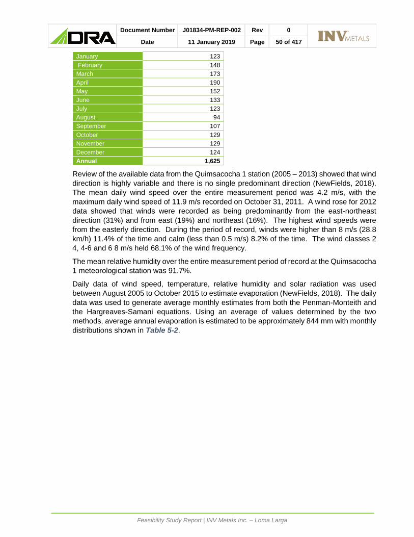
Document Number J01834-PM-REP-002 Rev 0
Date 11 January 2019 Page 50 of 417
Feasibility Study Report | INV Metals Inc. – Loma Larga
January 123
February 148
March 173
April 190
May 152
June 133
July 123
August 94
September 107
October 129
November 129
December 124
Annual 1,625
Review of the available data from the Quimsacocha 1 station (2005 – 2013) showed that wind
direction is highly variable and there is no single predominant direction (NewFields, 2018).
The mean daily wind speed over the entire measurement period was 4.2 m/s, with the
maximum daily wind speed of 11.9 m/s recorded on October 31, 2011. A wind rose for 2012
data showed that winds were recorded as being predominantly from the east-northeast
direction (31%) and from east (19%) and northeast (16%). The highest wind speeds were
from the easterly direction. During the period of record, winds were higher than 8 m/s (28.8
km/h) 11.4% of the time and calm (less than 0.5 m/s) 8.2% of the time. The wind classes 2
4, 4-6 and 6 8 m/s held 68.1% of the wind frequency.
The mean relative humidity over the entire measurement period of record at the Quimsacocha
1 meteorological station was 91.7%.
Daily data of wind speed, temperature, relative humidity and solar radiation was used
between August 2005 to October 2015 to estimate evaporation (NewFields, 2018). The daily
data was used to generate average monthly estimates from both the Penman-Monteith and
the Hargreaves-Samani equations. Using an average of values determined by the two
methods, average annual evaporation is estimated to be approximately 844 mm with monthly
distributions shown in Table 5-2.

Document Number J01834-PM-REP-002 Rev 0
Date 11 January 2019 Page 51 of 417
Feasibility Study Report | INV Metals Inc. – Loma Larga
Table 5-2: Mean Monthly Potential Evaporation Estimates at Loma Larga Site (NewFields, 2018)
MONTH AVERAGE
(mm)
January 73.7
February 70.2
March 77.8
April 64.7
May 65.3
June 56.6
July 58.0
August 60.8
September 73.4
October 83.0
November 80.1
December 80.9
Annual 844.2
5.3 LOCAL RESOURCES
The Project could attract resources from the surrounding local communities, including San
Gerardo, Chumblin and Victoria del Portete. A baseline study has been completed to
understand businesses and individuals that may be interested and/or able to support the
Project (Propraxis, 2018). The Company is incorporating this information and engaging with
the local communities as the Project advances.
5.4 INFRASTRUCTURE
There is currently a minimal amount of infrastructure on the property mainly consisting of
several man-made water ponds/reservoirs for storage and treatment of water, a nursery which
is used to grow fauna and flora for present and future rehabilitation purposes and buildings
used for storage of cores. The north-south access road, which has been deemed a public
road by the government, extends all the way past the future portal entrance and up to the
mine concession above the ore body.
In addition, there is a small camp at Los Pinos that can house 30 people including office space
and there is electrical power form the grid. There is also good cellular and Wi-Fi service.
5.4.1 TRANSMISSION LINE AND EMERGENCY POWER
Electrical power is to be provided via the local utility, CENTROSUR, from the local network in
Ecuador. This area is part of the national 230 / 138 / 69 / 22 kV network, with 69 kV and 22
kV feeds identified to supply the site. The main 69 kV / 25 MVA supply connect to the network
running between Lentag and Victoria del Portete, with the new substation located near Girón
and the transmission line up to the plant site. The incoming 69 kV will terminate into the main
substation at the plant site and will be stepped down to 22 kV from where it will be distributed
to site facilities.
A 2 MVA, 22 kV supply from San Fernando is proposed for construction power with the
permanent power supply of 69 kV being fed from the network running between Lentag and
Victoria del Portete. Lentag is fed from multiple 69 kV sources from the national grid and has
necessary protection giving assurance for the supply.

Document Number J01834-PM-REP-002 Rev 0
Date 11 January 2019 Page 52 of 417
Feasibility Study Report | INV Metals Inc. – Loma Larga
CENTROSUR have indicated that the 22-kV supply from San Fernando is fed from different
distribution networks and can therefore suitable for emergency backup power as it is fed from
a different source, on different infrastructure and overhead lines that run a different route.
Diesel generators were therefore deemed not to be necessary
The 22-kV emergency supply will terminate on a second incomer of the main substation. All
on-site distribution to the concentrator plant, mining operations, support infrastructure and
administration facilities will be from the main 22 kV substation.
The plant site electrical distribution is described in Section 18.2 of this report.
5.5 PHYSIOGRAPHY
The property of Loma Larga is located within the Western Cordillera of the Andes, which is
made up of a series of narrow lands, oriented in a north-easterly direction. The Project is
located in the southern part of the Chaucha continental terrain, in the physiographic province
of the Western Cordillera. The terrain is composed of volcanic rocks from the Tertiary
continental arc deposited on marine sedimentary rocks to fluvial from the Upper Cretaceous,
which in turn were deposited on metamorphic rocks in the Paleozoic and Mesozoic bases.
The physiography at the Project consists of desert plains and rugged valleys, mainly formed
by glaciers, with an altitude ranging from 3,500 m ASL to 3,960 m ASL. Vegetation is sparse
and typical of the Andean region above tree line. Much of the property is covered by Andean
“paramo”, a type of moorland vegetation consisting mainly of coarse grasses (Calamagrostis
sp.), Pads (Plantago sp.), and upper montane forest. There are stands of small pine on
hillsides adjacent to the concessions. These were planted as part of a forestation project.

Document Number J01834-PM-REP-002 Rev 0
Date 11 January 2019 Page 53 of 417
Feasibility Study Report | INV Metals Inc. – Loma Larga
HISTORY
Exploration activity began in the area in the late 1970s when a United Nations survey
identified the Tasqui and Jordanita base metal stream sediment geochemical anomalies five
kilometres south of the margin of the Quimsacocha caldera.
In 1991, the property was acquired by COGEMA (now Areva), which completed 2,944 m of
diamond drilling in 17 holes on vein and disseminated targets. COGEMA entered into a joint
venture with Newmont Mining Corporation (Newmont) and TVX Gold Inc. in 1993. Newmont,
as field operator, drilled 82 holes totalling 7,581 m. With the average hole being less than
100 m deep, the drill program failed to reach the levels of the Loma Larga deposit. The flat-
lying nature of the target mineralization was not recognized. The best intersection reported
was 83 g/t Au and 316 g/t Ag over two metres and the joint venture was dissolved.
COGEMA entered into an option agreement with IAMGOLD in 1999. However, no work on
the property was carried out for several years. In 2004, IAMGOLD resumed exploration
activities, drilling a total of 65,117 m across 280 drill holes, leading to the discovery of the
Loma Larga deposit in 2004 (IAMGOLD, 2009).
In April 2008, the Constituent Assembly of Ecuador passed a mandate to revise mining laws.
The Ecuadorian Ministry of Mines and Petroleum issued a 180-day suspension of all mining
and exploration activity while laws were being revised.
In October 2008, a new Ecuadorian Constitution was approved which established that non-
renewable resources, such as mineral and petroleum deposits, could only be produced in
strict compliance with the environmental principles set forth in the Constitution. Resumption
of mining activities was granted by the Ministry of Non-Renewable Natural Resources of
Ecuador on February 14, 2011.
Following a competitive bidding process in 2011, INV was selected by IAMGOLD to
exclusively negotiate a purchase agreement. On June 20, 2012, INV entered into a share
purchase agreement with IAMGOLD and its two subsidiaries, AGEM Ltd. and Repadre
Capital (BVI) Inc., to purchase a 100% interest in IAMGOLD Ecuador S.A. The transaction
closed on November 14, 2012. The subsidiary was renamed INV Minerales Ecuador S.A in
January 2014.
After the acquisition of the Project, INV initiated a 12-hole drill campaign which included seven
holes to test step-out targets to extend the deposit, three deeper holes to test for stacked
lenses at depth, and two holes drilled to obtain core samples for metallurgical testing. The
program totaled 3,684.7 metres.
Exploration activities to date at Loma Larga have been focused within the Rio Falso
concession with the objective being drilling, core collection, logging and testing of drill
samples to understand and evaluate the potential mineral resource and establish the
technical, environmental and economic conditions that must be considered in the evaluation
of a potential mine.
A Technical Report on the Loma Larga Project, Azuay Province, Ecuador, dated August 29,
2016 (2016 Technical Report) was published in 2016 that envisaged operating the mine at a
throughput of approximately 3,000 t/d. There has been no production from the Loma Larga
Project to date.
Geotechnical, hydrological, and exploration drilling was performed by INV in 2016-2017. A
total of 6,978.21 metres were drilled in 32 drill holes.

Document Number J01834-PM-REP-002 Rev 0
Date 11 January 2019 Page 54 of 417
Feasibility Study Report | INV Metals Inc. – Loma Larga
As a result of this drill program, an indication of the presence of multiple feeder zones along
the north-south length of the deposit were identified.
In 2018, Western Mining Services (WMS) completed a project assessment and target study
on Loma Larga (Western Mining Services, 2018). Following a review of the project geology,
geochemistry, and geophysics, WMS identified and prioritized nine targets within INV
concessions for future exploration programs. INV plans to follow up on these
recommendations in the next major drilling program.

Document Number J01834-PM-REP-002 Rev 0
Date 11 January 2019 Page 55 of 417
Feasibility Study Report | INV Metals Inc. – Loma Larga
GEOLOGICAL SETTING AND MINERALIZATION
7.1 REGIONAL GEOLOGY
Ecuador can be subdivided into a number of distinct physiographic provinces, which broadly
coincide with the subdivision of the crust into several terranes (Figure 7-1, Scott Wilson RPA,
2006). The Loma Larga property is located within the Ecuadorian cordillera, which consists
of a number of narrow, north to northeast trending terranes which were formed during the
separation of the Central and South American plates and accreted onto the Amazon Craton
from the Late Jurassic to Eocene (Chiaradia, 2004). Most of the terranes extend for several
hundreds of kilometres in a north-northeast direction and are only a few tens of kilometres
wide. These terranes are separated by deep north-northeast trending faults and were created
during the Tertiary and Quaternary periods by subduction related continental arc magmatism
and reactivation of the terrane bounding faults.
The Project lies in the southern part of the Chaucha continental terrane, in the Western
Cordilleran physiographic province, as shown in Figure 7-1 (Scott Wilson RPA, 2006). The
Chaucha terrane is defined by the northeast trending fault systems of Bulubulu on the
northwest side and the Girón fault system on the southeast side (Figure 7-2).
These fault zones are interpreted to have been active during the entire evolution of the
intervening basin. During each reactivation phase, fault movements influenced the location
of some intrusive and subvolcanic bodies while some acted as channels for the mineralizing
hydrothermal fluids.
The Chaucha terrane consists of Tertiary continental arc volcanic rocks deposited upon
Cretaceous marine to fluvial sedimentary rocks, which in turn were deposited on basement
Paleozoic and Mesozoic metamorphic rocks (MacDonald et al., 2010).

Document Number J01834-PM-REP-002 Rev 0
Date 11 January 2019 Page 56 of 417
Feasibility Study Report | INV Metals Inc. – Loma Larga
Figure 7-1: Major Terranes of Ecuador Source: Modified from MacDonald et al., SEG September 25, 2013 Whistler

Document Number J01834-PM-REP-002 Rev 0
Date 11 January 2019 Page 57 of 417
Feasibility Study Report | INV Metals Inc. – Loma Larga
Figure 7-2: Regional Geology Source: Modified from MacDonald et al., SEG September 2012 Peru
7.2 LOCAL AND PROPERTY GEOLOGY
The Loma Larga property is located between the Gañarin fault to the northwest and the Girón
fault to the southeast. A collapsed caldera structure, four kilometres in diameter, the remnant
of an eroded stratovolcano, lies along (and probably emplaced and controlled by) the Gañarin
fault and 400 m west of the main Loma Larga mineralization. The caldera is underlain by late
felsic domes and is cut by a multi-phase diatreme. The north-south trending Rio Falso fault,
which appears to be a conjugate fault linking the Gañarin and Girón faults, is the locus for
alteration and mineralizing fluids (Figure 7-2 and Figure 7-3).
The property and immediate surrounding area is mostly underlain by Upper Miocene volcanic
and volcaniclastic rocks, of the Turi, Turupamba, Quimsacocha, and Tarqui formations (Scott
Wilson RPA, 2006) (Figure 7-2 and Figure 7-3). These formations are flat lying to gently
dipping and usually do not outcrop on the property. The outcrops that are exposed form a
radial pattern around the caldera and gently dip away from it to the south and east.
The property is largely underlain by the Quimsacocha Formation which hosts the Loma Larga
deposit and consists of alternating andesitic banded lava flows with phenocrysts of fresh
plagioclase and andesite tuffs and breccias, distributed radially only around the outside of the

Document Number J01834-PM-REP-002 Rev 0
Date 11 January 2019 Page 58 of 417
Feasibility Study Report | INV Metals Inc. – Loma Larga
caldera. The Quimsacocha Formation overlies the Turi Formation which consists of
tuffaceous breccias, conglomerates, and sandstones with a high content of andesitic clasts
and occasional clasts of tuffaceous breccia.
The Turupamba Formation is composed of rhyolitic to dacitic tuffs with a lesser amount of
lapilli tuffs and appears to be the result of numerous minor ash falls with periods of fluvial and
lacustrine sedimentation. In the immediate surrounding area and bordering the Quimsacocha
Formation is the Saraguro Group to the north, the Tarqui Formation to the east, and the
Turupamba Formation to west.
The Saraguro Group consists of andesitic to rhyolitic pyroclastics, lava flows and
volcaniclastics as well as subordinate rocks.
The Turupamba Formation is composed of rhyolitic to dacitic tuffs with a lesser amount of
lapilli tuffs. The Turupamba Formation appears to be the result of numerous minor ash falls
with periods of fluvial and lacustrine sedimentation.
The Tarqui Formation overlies the Turi Formation. It unconformably overlies all older
formations and has a maximum thickness of 400 m. Near the Loma Larga deposit, the Tarqui
Formation mostly consists of strongly weathered quartz phyric rhyolite tuffs. In contrast,
further north the unit is mainly composed of thinly banded tuffs, tuffaceous sandstones, and
conglomerates. Plant remnants and coal are also common.
Following caldera collapse, a post-mineralization volcanic intrusive event occurred, resulting
in dacitic to rhyolitic domes and quartz-feldspar porphyritic dacite cryptodomes, emplaced
into and around the caldera in the Pliocene. Accompanying these lithologies are caldera
collapse related breccias and diatreme breccias, which locally contain mineralized clasts.
Much of the surface of the property is composed of Pliocene and Quaternary alluvial debris,
glacial moraine, and lacustrine deposits.
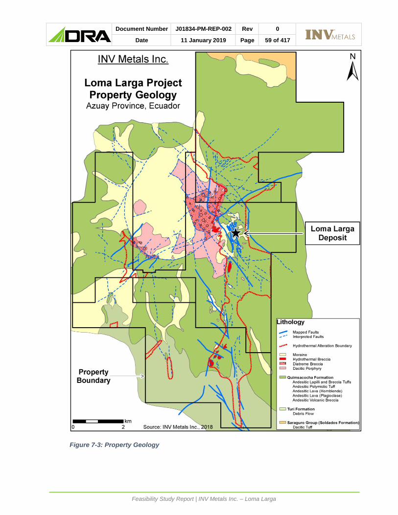
Document Number J01834-PM-REP-002 Rev 0
Date 11 January 2019 Page 59 of 417
Feasibility Study Report | INV Metals Inc. – Loma Larga
Figure 7-3: Property Geology

Document Number J01834-PM-REP-002 Rev 0
Date 11 January 2019 Page 60 of 417
Feasibility Study Report | INV Metals Inc. – Loma Larga
7.3 MINERALIZATION
At Loma Larga, like in most typical high sulphidation epithermal systems, alteration is
characterized by multiphase injections of hydrothermal fluids strongly controlled by both
structure and stratigraphy. The alteration-mineralizing event is characterized by an early
alteration phase caused by a strong inflow of volatile, acidic fluids which cooled progressively
and were neutralized by their reaction with country rock, leading to the formation of silicified
layers surrounded by alteration halos of clay minerals while the sulphides and gangue
minerals associated with the mineralization were deposited by later fluids inside the silicified
bodies (IAMGOLD, 2008).
The majority of the limited amount of outcrop exposed at Loma Larga exhibits silica alteration,
due to its resistance to weathering. In epithermal environments the silica alteration displays
evidence of hot acidic leaching. Multiple types of silica alteration occur at Loma Larga,
including vuggy, sugary, banded, fracture fill, and hydraulic-breccia (MacDonald, 2010).
Alteration can be seen to be structurally controlled as it typically occurs as silica ribs mimicking
fault locations and orientations. The most significant alteration zone, host to the deposit, is
coincident with the north-trending Rio Falso fault, extending for over eight kilometres north-
south, along the eastern edge of the collapsed caldera. This long, linear zone contains
multiple large pods of silica alteration ranging up to two kilometres in east to west width. The
location of the Rio Falso fault suggests that it was coeval with or postdates the caldera
collapse (MacDonald, 2010).
The silica alteration is surrounded by varying widths of a halo of argillic alteration, grading
from higher to lower temperature mineral assemblages including pyrophyllite, alunite, dickite,
kaolinite, illite, and smectite.
The high sulphidation epithermal gold-copper-silver mineralization in the Loma Larga deposit
is also stratigraphically controlled as it occurs at lithological contacts between Quimsacocha
Formation andesitic lavas and tuffs and reaches greater thickness in the more permeable
tuffs. The deposit is a flat lying to gently western dipping (less than ten degrees), north-south
striking, cigar shaped body, which has a strike length of approximately 1,600 m north-south
by 120 m to 400 m east-west and up to 60 m thick, beginning approximately 120 m below
surface (cross section in Figure 7-4 and long section in Figure 7-5). It also dips slightly to
the north, such that the mineralized zone is closer to surface at the south end. Resources
are defined as a smaller, higher-grade subset within this mineralization.
Mineralized zones are characterized by multiple brecciation and open-space filling events and
sulphides such as pyrite, enargite, covellite, chalcopyrite, and luzonite or, at lower
sulphidation states, tennantite and tetrahedrite. Higher grade intervals typically coincide with
increased amounts of enargite, minor barite, and intense hydraulic brecciation that contains
subrounded to rounded silicified fragments. Visible gold is rare. Gold mineralization is found,
for the most part, in one of the following mineralogical assemblages: (a) vuggy silica plus fine-
grained pyrite and enargite; (b) massive pyrite, including a brilliant arsenical pyrite; or (c)
vuggy silica with grey silica banding, sulphide space-filling and banded pyrite. Very fine-
grained pyrite is dominant in semi-massive to massive zones and is interpreted to have
formed earlier than coarser fracture and vug-filling pyrite (MacDonald, 2010).
The focus of mineralization occurs at approximately 3,610 m (± 30 m) elevation, where
structural feeder zone(s) intersected a permeable tuff horizon that was acid leached. There
is an upper barren silicic lithocap, locally indicative of steam heated alteration, which is
typically barren of mineralization, although there is an outcrop exposure of this zone that

Document Number J01834-PM-REP-002 Rev 0
Date 11 January 2019 Page 61 of 417
Feasibility Study Report | INV Metals Inc. – Loma Larga
contains minor, fine visible gold (MacDonald, 2010). Silica textures within the upper zone
range from sugary, to two-phase, massive, vuggy, and laminated, while the main body
centred at 3,610 m exhibits either massive or vuggy silica with intense brecciation in the core
and pervasive veinlet and vug infilling alunite alteration. A third lower silicified horizon
described below is primarily vuggy in nature (MacDonald, 2010).
Drilling has led to the recognition of a third, deeper zone of residual quartz, below
approximately 3,550 m elevation. This horizon is typically 20 m in thickness but is locally
thicker. Because these deeper intersections can be correlated between several drillholes and
sections, INV has interpreted the zone as a polylithic tuffaceous horizon (as opposed to a
vertical feeder); mineralization is typically ten to twenty metres thick with gold grades of 1.0
g/t to 3.0 g/t. IAMGOLD’s drilling on many sections stopped within ten to twenty metres of
passing through the main zone, leaving the third horizon and potentially deeper ones virtually
untested.
There may be multiple feeder structures along the north-south length of the deposit, possibly
associated with north-northeast trending en-echelon structures (Hedenquist, 2013). It is
interpreted that at least two vertical to sub-vertical feeder zones occur in the central to eastern
part of the deposit, in the vicinity of IAMGOLD’s discovery hole IQD-122 (9.2 g/t Au over 102
m). Above this thick, high grade zone, there is an upper lens of mineralization that is included
in the current resource as inferred based on the limited number of drillholes intersecting it.
Significant drillhole intersections in the Loma Larga upper lens include 24.0 g/t Au over 9.0 m
in drillhole IQD124 and 8.4 g/t Au over 30.7 m in drillhole IQD152501.
Figure 7-4: Cross Section of the Loma Larga Deposit, Looking Northeast

Document Number J01834-PM-REP-002 Rev 0
Date 11 January 2019 Page 62 of 417
Feasibility Study Report | INV Metals Inc. – Loma Larga
Figure 7-5: Longitudinal Section of the Loma Larga Deposit, Looking East
The presence of copper mineralized porphyry fragments within the diatreme exposed
approximately one kilometre to the northwest of the current northern margin of the deposit,
along with the zonation of decreasing copper in the deposit from north to south, suggests that
the causative intrusion that drove the hydrothermal system is located to the north, and that
fluid flow was from north to south. This is consistent with observation of chalcocite and
chalcopyrite associated with stockworks of veinlets at depth in the north (Hedenquist, 2013).
Evidence for a deeper porphyry copper-gold deposit is suggested by the following
observations:
• quartz veinlets with centre lines and margins of chalcocite to the north (IQD-109,
approximately 317 m to 343 m at 2.02 g/t Au and 0.14% Cu as chalcocite; As values of
less than 100 ppm);
• high Cu/As ratios to the north, i.e., enargite and tennantite poor despite Cu values
greater than 0.1 wt%, suggesting the presence of chalcocite and/or chalcopyrite;
• broad illite-pyrite alteration with disseminated magnetite plus pyrite ± magnetite veinlets
associated with a fragmental intrusion; and
• the diatreme to the northwest, on the eastern margin of the caldera, which contains
quartz-feldspar porphyry fragments plus potassic and phyllic-altered clasts with
anomalous copper (up to 0.1% Cu) and gold (up to 0.5 g/t Au), associated with quartz ±
magnetite ± pyrite veinlets with disseminated magnetite, chalcopyrite, chalcocite,
covellite, and molybdenite (Hedenquist, 2013).
There are multiple exploration targets. For example, INV’s 2013 drillhole LLD-367 intersected
4.9 g/t Au, 48.7 g/t Ag, and 0.51% Cu over a core length of 25.1 m, including 11.9 g/t Au, 78.7
g/t Ag, and 0.33% Cu over 6.2 m. This intersection is located approximately 165 m north of
the northern limits of the current Loma Larga Mineral Resource. Additional drilling completed

Document Number J01834-PM-REP-002 Rev 0
Date 11 January 2019 Page 63 of 417
Feasibility Study Report | INV Metals Inc. – Loma Larga
in 2016 and 2017 investigated the extent of mineralization north and west of the currently
defined resource at Loma Larga.
In 2018, Western Mining Services (WMS) completed a project assessment and target study
on Loma Larga (Western Mining Services, 2018). Following a review of the project geology,
geochemistry, and geophysics, WMS identified and prioritized nine targets within INV
concessions. The targets include eight high sulphidation style Au-Cu targets to the north,
east, west, and south of Loma Larga, and one low sulphidation style Au-Ag target to the west
of the ore body. WMS also identified the opportunity to discover a porphyry style Au-Cu
deposit at depth to the east of the Quimsacocha crater, proximate to the Loma Larga deposit.
Further to the study, WMS provided rough estimates of the size of the potential discoveries
within each target area and provided recommendations to better define targets and improve
exploration effectiveness.
The isolated gold- and coper-rich drillhole intersections between 3,550 m and 3,500 m
elevation constitute high grade mineralization that may be hosted within a structurally related
feeder zone, as at shallower depths, rather than being associated with the lower silicic
horizon. Further north, similar high-grade intervals that have been intersected at
approximately 3,600 m elevation have yet to be tested at depth for possible structural control.
In addition to the deeper high-grade zones that have yet to be tested for their potential depth
extent, there are also shallower high-grade zones that have not yet been tested. It is
anticipated that drilling scissor holes would define their potential depth extent and determine
if the high grades are hosted in structurally related feeder zones. This includes, for example,
IQD-323 with 2.7 m of approximately 77 g/t Au, 89 g/t Ag, and 7.2% Cu at approximately
3,630 m elevation, at the base of the silicic zone.
In 2017, INV completed several drillholes along the western margin of the Loma Larga
deposit. Further drilling, however, is recommended to define and constrain the margins of
the mineralization, which remains open. In addition, deeper drilling is needed to define a
horizon at approximately 3,550 m elevation.
The indications of porphyry potential at depth in the north, including veinlet stockwork with
copper sulphides, is consistent with the lithocap alteration and high sulphidation-state sulfides
of Loma Larga; the location of the intrusive centre of the porphyry and its depth remain to be
determined by further study, and eventual drill testing.
South of the southern extent of the current Loma Larga Mineral Resource there is a silver-
rich zone with drillhole IQD-265 intersecting 2.4 m of 3,180 g/t Ag, 0.2 g/t Au, and 0.1% Cu,
near the base of the silicic zone, under the main mineralized horizon. The silver-to-gold ratio
for the resources is approximately ten-to-one, or less, whereas the silver-rich intervals in IQD-
263 and 265 are two hundred-to-one, or higher. Sections to the north of the currently-defined
deposit also have high silver-to-gold ratio intersections. For example, drillhole IQD-269
intersects four metres of 896 g/t Ag and 1.3 g/t Au, and drillhole IQD-269 intersects five metres
of 566 g/t Ag and 3.8 g/t Au. The two drillholes intersect 0.3% Cu and 0.6% Cu, respectively.
Given the uncertain mineralogy responsible for the high silver-to-gold ratio and resulting high
grades, INV commissioned Inspectorate Services Peru S.A. to carry out a mineralogical study
using optical microscopy and electronic scanning. This study determined that the silver
species present include silver sulphides (argentite - acanthite), sulfosalts (AgCuAs and
CuAgAs) and sulphides (AgAs).

Document Number J01834-PM-REP-002 Rev 0
Date 11 January 2019 Page 64 of 417
Feasibility Study Report | INV Metals Inc. – Loma Larga
DEPOSIT TYPES
Epithermal deposits are defined as precious and base metal deposits that formed at depths
of less than two kilometres and at temperatures of less than 300°C in subaerial environments
within volcanic arcs at convergent plate margins and in intra-arc and back-arc as well as post-
collisional extensional settings (Robert et al., 2007). A hydrothermal system consisting of
fluids derived at depth will undergo abrupt physical and chemical changes at the shallow
depths where epithermal deposits form. These changes occur because of the change from
lithostatic to hydrodynamic pressure, which results in boiling, interaction of the fluids with
near-surface water, permeability changes, and reaction between the fluids and host rocks.
These changes affect the capacity of the hydrothermal fluid to transport metals in solution.
This decrease in the solubility of metals in the fluids results in the metals being deposited
within a restricted space as a result of focussing of the fluid flow near the surface (White and
Hedenquist, 1990).
Epithermal deposits are typically classified as either high or low sulphidation based upon the
sulphidation state of the ore minerals; as enargite and luzonite for high sulphidation and
chalcopyrite-galena-sphalerite for low sulphidation. The term high sulphidation is frequently
misused to suggest a high sulphide or high sulphur deposit, whereas in fact it refers to the
chemical state of the metals (the sulphur to metal ratio).
A schematic section showing alteration zonation through a high sulphidation gold deposit
environment is provided as Figure 8-1. High sulphidation epithermal copper-gold-silver
deposits develop in settings where volatiles (dominantly gases such as SO2, HF, and HCl)
and metal bearing fluids vent from hot magma sources at considerable depth and travel
rapidly to elevated crustal settings, without reaction with wall rocks, or mixing with
groundwater. The volatile component, which rises more rapidly than the fluids, becomes
progressively depressurized and SO2 in particular comes out of solution and in turn oxidizes
to form H2SO4, such that the rising and cooling fluid becomes increasingly acidic (to pH of 1.0
to 2.0) as it ascends to epithermal levels, where it reacts with wall rocks to produce advanced
argillic alteration. Because of the progressive cooling and neutralization of the hot acid fluid
by wall rock reaction, the advanced argillic alteration is zoned outwards from a central core
of vuggy or residual silica, from which everything but silica has been leached by the strongly
acidic waters, through alteration zones dominated by alunite, pyrophyllite, dickite, kaolin, and
then illite (Figure 8-1) (Corbett, 2005). Use of a portable infrared mineral analyzer (PIMA)
has been critical in a number of discoveries, including Loma Larga, as it allows one to vector
towards mineralization based on the zonation of the various clay alteration minerals.
The shape and intensity of alteration vary according to crustal level and permeability of the
host rocks. At Loma Larga the acidic fluids preferentially altered the more permeable
andesitic tuffs, sandwiched between more resistant and less altered andesitic lavas. The
liquid rich phase of the high sulphidation hydrothermal fluid generally follows the volatile rich
portion. Most copper-gold mineralization deposition, usually as sulphide breccia infill of
competent vuggy silica and silica-alunite altered clasts, typically is associated with pyrite-
enargite (and its low temperature polymorph luzonite) and lesser covellite (at deeper levels)
and local, generally peripheral, tennantite-tetrahedrite, as well as barite and alunite, and post-
dates the alteration.
The hot magma source for the hydrothermal system is frequently a copper-gold porphyry
(Figure 8-2). Approximately half of the major high sulphidation ore deposits around the world
have evidence for underlying porphyry mineralization, based on observations of deeply
eroded systems (e.g., Minas Conga, Peru; Halilaga, Turkey), deep drilling (e.g., Far

Document Number J01834-PM-REP-002 Rev 0
Date 11 January 2019 Page 65 of 417
Feasibility Study Report | INV Metals Inc. – Loma Larga
Southeast, Philippines), and porphyry-altered and mineralized clasts contained within
diatremes (numerous systems, including Loma Larga) (Hedenquist, 2013).
The Far Southeast porphyry deposit located under and adjacent to the Lepanto high
sulphidation deposit was discovered as a follow-up to the presence of copper-bearing
porphyry fragments within a diatreme breccia exposed at surface. A similar situation occurs
at Loma Larga, with a diatreme to the north and west of the gold deposit containing copper-
mineralized, altered porphyry fragments, suggesting that at some unknown depth a copper ±
gold porphyry may have driven the hydrothermal system responsible for forming Loma Larga.
High sulphidation deposits are the major gold producers in the Andes (e.g., Yanacocha,
Pierina, El Indio, La Coipa, Veladero), and represent some significant undeveloped resources
(e.g., Pascua-Lama and Loma Larga). Other global examples include Lepanto, Philippines;
Pueblo Viejo, Dominican Republic; Mulatos, Mexico; Paradise Peak, Nevada; and
Chelopech, Bulgaria.
Figure 8-1: Zonation of Alteration in a High Sulphidation Deposit After Arribas Jr. (1995)

Document Number J01834-PM-REP-002 Rev 0
Date 11 January 2019 Page 66 of 417
Feasibility Study Report | INV Metals Inc. – Loma Larga
Figure 8-2: Schematic Section of a High Sulphidation Deposit After Sillitoe (1999)

Document Number J01834-PM-REP-002 Rev 0
Date 11 January 2019 Page 67 of 417
Feasibility Study Report | INV Metals Inc. – Loma Larga
EXPLORATION
Exploration activities by all previous owners are discussed in Section 6 – History.
INV carried out exploration activities on the property in 2017 and 2018. These are
summarized below.
• Contracted Geoscience North Ltd. to organize and analyze geophysical data within the
Rio Falso concession. Data sets from Newmont and Val D’Or Sud America were
evaluated and a report was produced outlining potential exploration targets
(Geosciences North, 2018).
• WMS was contracted to complete a project assessment and target study on the Project.
WMS analyzed diamond drillhole data, geological maps, and geophysical data to
develop a targeting matrix for the Loma Larga exploration program. A final report was
provided in June 2018 (Western Mining Services, 2018).
• Together with Geomingold Cia. Ltda. of Ecuador, the regional geology map for the Loma
Larga concessions was updated during June of 2018. The mapping targeted areas with
no previous geological mapping along the concession boundaries and validated areas of
previous mapping.

Document Number J01834-PM-REP-002 Rev 0
Date 11 January 2019 Page 68 of 417
Feasibility Study Report | INV Metals Inc. – Loma Larga
DRILLING
10.1 IAMGOLD DRILLING
In 2002, IAMGOLD initiated diamond drilling programs based on the exploration information
accumulated by previous operators as well as their own follow-up exploration programs. The
Loma Larga deposit was discovered as a result of the 2004 drilling campaign, during which a
total of 13,930 m was drilled in 45 holes. Four of the holes were drilled in the Loma Larga
Zone, and returned encouraging results, including one sample of 214 g/t Au. From October
2005 to August 2006, IAMGOLD drilled an additional 24,542 m in 125 holes, of which
approximately half was infill drilling and the remainder was undertaken to test for a possible
extension.
IAMGOLD contracted two companies: Kluane and Paragon, to carry out drilling. All work was
done by diamond core drilling and the core diameters used were HQ (63.5 mm) and NQ (47.6
mm) for Paragon and NT (56 mm) and BT (42 mm) for Kluane. All collars were surveyed.
Most of the holes were drilled at -55° to -65° but ranged from -45° to -90°. All core obtained
from the drilling was placed in wooden boxes and transferred to the logging room at the field
camp for logging and sampling for assay. Core diameter depended on the drill type used by
each company.
From 2004 to December 2007, IAMGOLD drilled a total of 65,117 m in 280 holes (IAMGOLD,
2009).
No drilling was carried out between 2008 and 2012.
10.2 INV DRILLING
10.2.1 2013
After acquiring the Project in 2012, INV contracted Orix Geosciences Inc. (ORIX) to carry out
a detailed 3D compilation and reinterpretation of the deposit, with the goals of furthering the
understanding of the deposit and identifying drill targets. Geoscience North was engaged to
review and compile all previously collected geophysical data, which was then integrated into
the ORIX compilation. INV’s drill program in 2013 included 12 diamond drillholes totalling
3,684.7 m, including two holes drilled for metallurgical testwork, three holes to further define
the High Grade Main Zone, and seven holes to test step-out targets to extend the deposit.
Holes LLD-371 and LLD-372 were drilled to obtain material for metallurgical testwork. The
metallurgical drilling in the high-grade zone clearly demonstrates that the Loma Larga gold
deposit contains a high-grade core surrounded by a lower grade halo. For example, drillhole
LLD-371 intersected 77 m grading 13.7 g/t Au, including 20 m grading 34 g/t Au, while LLD-
372 intersected 36.5 m grading 11.8 g/t Au including 6.3 m grading 47.7 g/t Au. Holes LLD-
373 to LLD-375 were drilled to better define the margins of the high-grade zone.
The results for these holes are provided in Table 10-1.

Document Number J01834-PM-REP-002 Rev 0
Date 11 January 2019 Page 69 of 417
Feasibility Study Report | INV Metals Inc. – Loma Larga
Table 10-1: Metallurgical and High-Grade Zone Drill Results
Hole
From (m)
To (m)
Width (m)
True Width* (m)
Au (g/t)
Ag (g/t)
Cu (%)
LLD-371
105.00 182.00 77.00 77.00 13.65 40.15 0.52 including 132.00 152.00 20.00 20.00 33.95 98.84 1.23 and 158.00 163.00 5.00 5.00 12.21 24.96 0.36
LLD-372
142.50 179.00 36.50 36.50 11.80 79.57 0.93 including 170.00 176.30 6.30 6.30 47.72 217.32 3.32
LLD-373
48.50 54.86 6.36 6.36 1.66 8.54 0.12 166.50 171.00 4.50 4.50 10.36 57.30 2.90
including 167.50 168.60 1.10 1.10 38.20 214.90 11.21
LLD-374
53.40 69.00 15.60 15.60 2.73 15.69 0.77 including 56.40 60.40 4.00 4.00 4.65 30.48 1.29 and 65.00 69.00 4.00 4.00 4.46 5.59 1.00
133.50 146.00 12.50 12.50 2.81 15.58 0.24 including 133.50 137.00 3.50 3.50 5.14 34.00 0.50 and 143.80 146.00 2.20 2.20 5.01 14.44 0.43
LLD-375
124.00 162.00 38.00 37.90 3.27 55.65 0.23 including 155.00 162.00 7.00 7.00 6.83 131.21 0.19 and 128.00 131.00 3.00 3.00 6.60 48.10 0.14
*True Width is an estimation that considers both the dip of the borehole and the interpreted dip of the mineralized zone of 10° to the west.
10.2.2 2017
INV completed nine geotechnical and 14 hydrogeological drillholes on the Loma Larga
deposit to obtain data for modelling (Table 10-2). Among the 14 hydrogeological drillholes,
five of them were for dual purposes: hydrogeological and geotechnical investigation. Various
samples of the core from these holes were used for the metallurgical and geotechnical
testwork programs as part of this Feasibility Study. Geotechnical samples included strength
testing (i.e. unconfined compressive strength, triaxial, and tensile) and unconfined swelling
tests. The location of the drillholes is shown in Figure 10-1 and Figure 10-2, and Table 10-3
summarizes the drilling and assay sample results.

Document Number J01834-PM-REP-002 Rev 0
Date 11 January 2019 Page 70 of 417
Feasibility Study Report | INV Metals Inc. – Loma Larga
Table 10-2: Geotechnical and Hydrogeological Drill Holes Completed in 2016 - 2017
Drill Hole Hole Type
Easting (m) Northing (m) Elevation (m)
Azimuth (deg)
Dip (deg) Length (m)
No. of Samples
LLDGT-001 GT 697787.40 9663471.61 3803.58 180.00 -60.00 50.29 -
LLDGT-002 GT 698032.21 9663700.91 3780.99 75.00 -60.00 138.90 -
LLDGT-003 GT 698011.69 9663521.94 3781.19 360.00 -70.00 216.27 14
LLDGT-003B HG/GT 697955.93 9663488.55 3784.29 60.00 -80.00 103.70 16
LLDGT-003C HG/GT 697953.13 9663486.77 3784.72 240.00 -90.00 134.20 54
LLDGT-004 GT 698111.08 9663589.94 3776.62 90.00 -60.00 281.95 57
LLDGT-005 HG/GT 698623.30 9663566.41 3746.71 270.00 -70.00 220.70 74
LLDGT-006 HG/GT 698455.04 9663937.40 3750.00 45.00 -60.00 231.04 32
LLDGT-007 HG/GT 698598.68 9663371.64 3770.00 225.00 -70.00 213.30 88
LLDHG-008 HG 698576.00 9663764.31 3746.00 225.00 -60.00 231.30 135
LLDHG-009 HG 699149.41 9663312.20 3627.74 0.00 -90.00 22.86 -
LLDHG-009A HG 699150.52 9663314.55 3626.92 0.00 -90.00 12.50 -
LLDHG-010 HG 698853.73 9663920.87 3665.69 0.00 -90.00 15.24 -
LLDHG-010A HG 698618.96 9663914.59 3731.04 0.00 -90.00 2.20 -
LLDHG-011 HG 698581.97 9663461.11 3767.08 300.00 -74.00 208.79 120
LLDHG-012 HG 697887.88 9663356.53 3798.18 70.00 -80.00 109.73 -
LLDHG-013 HG 697885.19 9663355.09 3798.24 250.00 -75.00 156.98 -
LLDHG-014 HG 697760.66 9663095.50 3795.48 270.00 -90.00 60.85 -
*GT = geotechnical; HG= hydrogeological Total 2,410.8 590
Table 10-3: Selected Drill Results from the 2017 Geotechnical and Hydrogeological Drilling
Hole From (m) To (m) Width (m) True Width* (m) Au (g/t) Ag (g/t)
LLDGT-004 223.50 243.00 19.50 16.90 2.17 52.5
including 223.50 238.00 14.50 12.60 2.63 51.5
LLDGT-007 71.45 77.50 6.05 5.70 1.24 1.5
131.24 183.23 51.99 48.90 3.25 27.6
including 131.24 153.00 21.76 20.40 4.20 11.8
and 163.00 170.00 7.00 6.60 4.88 53.7
LLDGT-008 60.50 71.50 11.00 9.50 7.27 91.8
including 64.50 67.50 3.00 2.60 12.97 155.8
92.80 173.00 80.20 69.50 3.28 13.6
LLDGT-011 120.00 161.00 41.00 39.40 4.72 14.0
including 141.00 149.00 8.00 7.70 8.68 21.9
173.00 196.00 23.00 22.10 3.00 12.8
including 189.00 196.00 7.00 6.70 4.82 18.1
* Note: True widths determinations are estimated at 84-96% of the reported core length intervals for most of the holes, estimated sectionally based on the current alteration zone interpretation.

Document Number J01834-PM-REP-002 Rev 0
Date 11 January 2019 Page 71 of 417
Feasibility Study Report | INV Metals Inc. – Loma Larga
Figure 10-1: Location of INV 2016-2017 Drill Holes in 3D Isometric View

Document Number J01834-PM-REP-002 Rev 0
Date 11 January 2019 Page 72 of 417
Feasibility Study Report | INV Metals Inc. – Loma Larga
Figure 10-2: Location of 2016-2017 Loma Larga Drill Holes in 3D Isometric View

Document Number J01834-PM-REP-002 Rev 0
Date 11 January 2019 Page 73 of 417
Feasibility Study Report | INV Metals Inc. – Loma Larga
In 2017, INV initiated an exploration program at Loma Larga to evaluate the exploration
potential of the property and further delineate gold mineralization within silica alteration
intersected in 2017 during geotechnical and hydrogeological drilling program. The 14-hole,
4,318 m drill program commenced in April and was completed in August of 2017.
Mineralization was intersected to the west of the delineated resource at Loma Larga. Table
10-4 and Table 10-5 summarize the drillhole program and results, and the location of the
drillholes are shown in Figure 10-1 and Figure 10-2.
Highlights of the 2017 drill program include a deep hole (LLD-384) drilled to a depth of 1,160
m to follow up on historical drillholes which indicated the potential for porphyry style
mineralization outside of the mineral resource to the north of the known deposit. LLD-384
returned encouraging results including 0.2 g/t Au and 523 ppm Cu over 622.22 m (from a
depth of 538 m), including 0.29 g/t Au and 416 ppm Cu over 214.5 m (Table 10-4 ).
Table 10-4: Summary of 2017 Loma Larga Drill Program
Drill Hole Easting (m)
Northing (m)
Elevation (m)
Azimuth (deg)
Dip (deg)
Length (m) No. of Samples
LLD-376 698343 9663594 3,782 275 -75 277.4 128
LLD-377 698065 9663588 3,779 90 -60 321.6 89
LLD-378 698422 9663497 3,779 270 -75 274.3 60
LLD-379 697838 9663499 3,794 90 -70 397.8 171
LLD-380 697772 9663497 3,799 90 -80 320.0 86
LLD-381 698027 9663510 3,783 90 -68 285.0 89
LLD-382 698422 9663802 3,761 270 -75 217.9 79
LLD-383 698447 9663701 3,769 270 -70 242.3 119
LLD-384 698460 9664256 3,772 0 -90 1,160.2 607
LLD-385 698291 9663709 3,769 90 -70 266.7 148
LLD-386 698447 9663701 3,769 270 -85 205.7 69
LLD-387 698262 9663801 3,758 90 -70 225.6 61
LLD-388 698464 9663803 3,758 270 -75 187.5 52
LLD-389 698439 9663889 3,749 270 -70 185.9 75
Total 4,567.9 1,833

Document Number J01834-PM-REP-002 Rev 0
Date 11 January 2019 Page 74 of 417
Feasibility Study Report | INV Metals Inc. – Loma Larga
Table 10-5: 2017 Selected Loma Larga Drill Program Results
Hole
From
(m)
To
(m)
Length
(m)
True Width
(m)
Au
(g/t)
Ag
(g/t)
LLD-376 187.00 196.00 9.00 8.70 3.25 32.3
including 192.00 196.00 4.00 3.90 5.27 64.6
LLD-377 226.50 254.50 28.00 24.20 2.35 29.6
including 230.50 236.50 6.00 5.20 3.44 16.2
LLD-378 170.00 187.00 17.00 16.40 1.65 30.6
LLD-381
249.20 252.80 3.60 1.58 2.45 28.9
LLD-382
167.50 186.50 19.00 18.40 2.66 57.1
including 171.50 180.50 9.00 8.70 3.25 91.0
LLD-383
170.00 221.25 51.25 48.15 3.22 48.7
including 179.00 217.00 38.00 35.70 2.53 31.6 and 213.00 217.00 4.00 3.80 3.36 65.8
218.50 221.25 2.75 1.74 20.24 434.4
LLD-384 538.00 1,160.22 622.22 * 0.20 0.83
(Porphyry) including 720.50 935.00 214.50 * 0.29 0.8
LLD-385 161.00 214.00 53.00 49.80 1.59 25.5
including 162.00 177.00 15.00 14.10 1.83 11.9
and 193.00 201.00 8.00 7.50 2.69 54.6
244.00 262.00 18.00 16.90 2.28 38.8
including 250.00 252.70 2.70 1.70 8.75 211.2
LLD-386 152.00 189.35 37.35 37.20 4.89 52.2
including 162.00 189.35 27.35 27.20 5.89 67.4
and 174.00 181.00 7.00 6.97 9.39 72.0
LLD-387 137.00 197.20 60.20 56.60 0.83 26.0
including 149.00 153.00 4.00 3.80 1.44 4.5
and 186.00 197.20 11.20 10.50 1.27 64.0
and 192.00 197.20 5.20 4.90 1.65 94.5
LLD-388 126.00 161.00 35.00 33.80 2.32 20.3
including 126.00 137.00 11.00 10.60 3.36 14.0
and 133.00 137.00 4.00 3.90 5.31 24.9
LLD-389 153.00 172.00 19.00 17.9 1.81 29.7
including 165.00 172.00 7.00 6.6 2.24 32.2
*Note: True widths determinations are estimated at 84-100% of the reported core length intervals for most of the holes, estimated sectionally based on the current alteration zone interpretation. The true width of Hole LLD-384 cannot be determined at this time.

Document Number J01834-PM-REP-002 Rev 0
Date 11 January 2019 Page 75 of 417
Feasibility Study Report | INV Metals Inc. – Loma Larga
SAMPLE PREPARATION, ANALYSES AND SECURITY
As part of the September 2018 Mineral Resource estimate, RPA compiled and reviewed all
of the Loma Larga Project Quality Control (QC) sample results for INV’s 2016-2017 drilling
campaigns. RPA reviewed the QC sample results from the Loma Larga 2013 drill campaign
and also completed a procedural and statistical review of all historical QC data on the Project.
The current Mineral Resource incorporates drilling completed up to the end of August 2017.
No further drilling has been completed since this date. RPA compiled and reviewed the QC
sample results for the 2017 exploration, geotechnical, and hydrogeological drilling programs.
In RPA’s opinion, the results of the QC samples, together with the QA/QC procedures
implemented by INV at Loma Larga, provide adequate confidence in the data collection and
processing, and the assay data is suitable for Mineral Resource estimation.
11.1 PRE-2012 PROGRAMS
No information is available on the procedures utilized for the drill campaigns conducted by
Newmont (1992-1993) and COGEMA (now Areva) (1994-1996), and assay results from those
programs are not included in the current Mineral Resource.
From 2002 to 2008, sample preparation, analysis, and security on the Loma Larga Project
were conducted by IAMGOLD. This work is summarized in this section from IAMGOLD
(2009) and RPA (2012).
No drilling or sampling occurred on the Loma Larga Project between 2008 and 2012.
11.1.1 SAMPLE COLLECTION
IAMGOLD collected samples for geochemical analyses primarily in mineralized zones.
Geological criteria (feeders, hydrothermal breccias, mineralization styles, etc.) guided sample
length, to a maximum of two metres. For intervals where core loss was recorded, sample
length may be more than two metres.
After the drill core was logged, boxes tagged, and samples identified, all selected samples
were cut in half with a diamond saw. One half was sent for geochemical analysis; the other
returned to the box and later transferred to a secure warehouse at the IAMGOLD exploration
office in the city of Cuenca, Ecuador. Care was taken to prevent contamination, accidental
swapping, or loss during crating and transportation of the core. IAMGOLD personnel
transported the core from the Project to Cuenca and a shipping contractor was used to
transport the core on to Quito.
Sample collection was completed at the Project camp using the following methodology:
• Core was marked every metre from the collar down to the bottom of the hole to check
and correct driller’s metre marks.
• For each hole, a digital file was created, and all core boxes were photographed and
identified by the “FROM” and “TO” depths.
• Geotechnical logging followed by geological logging was carried out and then saved in a
dedicated database.
• The core was sampled by cutting in half using a Boart diamond saw with an eight-inch
blade.
• Samples were tagged for geochemical, metallurgical, and geotechnical tests.

Document Number J01834-PM-REP-002 Rev 0
Date 11 January 2019 Page 76 of 417
Feasibility Study Report | INV Metals Inc. – Loma Larga
• Samples were crated and shipped to the IAMGOLD Cuenca regional office where they
were numbered, and QC samples (standards and blanks) were placed into the sample
stream at predetermined frequencies.
• Four to five sample bags were grouped into rice bags that were sealed with tie-wraps
and shipped to the assay laboratory. A copy of the sample checklist held inside each
rice bag was also forwarded to the assay laboratory. A laboratory employee cross-
checked the list upon reception and faxed the list to IAMGOLD’s Quito office where it
was reviewed for inconsistencies.
• All pulps and rejects were kept at the laboratory’s yard. Only check assay pulps and
rejects were discarded.
11.1.2 DENSITY SAMPLING
To estimate rock densities at the Project, IAMGOLD took representative samples of typical
lithologies, alteration, and mineralization types. Samples were approximately three
centimetres in length, and density was determined by the Archimedes principle.
IAMGOLD’s density sampling procedure consisted of:
• Identifying a representative zone (lithology and grade) and selecting a three-centimetre
sample of core.
• Weighing the sample dry.
• Immersing the sample in melted paraffin.
• Weighing the sample and paraffin.
• Weighing the sample and paraffin in water.
IAMGOLD compiled a database of 10,793 density measurements (10,153 at Loma Larga), of
which 7,767 were used for the current Mineral Resource estimation (see Section 14 ).
In the opinion of RPA, the density measurements are suitable for use in the Resource
estimate.
11.1.3 SAMPLE PREPARATION AND ASSAY PROTOCOLS
All samples were sent to internationally recognized and independent laboratories for
preparation and testing. Prior to September 2004, samples were prepared in Quito by ALS
Chemex and analyzed by ALS Chemex laboratory in North Vancouver, Canada. IAMGOLD’s
system of check samples identified inconsistent results for ALS Chemex and from October
2004 onward (to the end of drilling by IAMGOLD by 2008); samples were prepared by
Inspectorate del Ecuador S.A. in Quito and analyzed by BSI Laboratories in Lima, Peru (BSI).
Both analytical laboratories are accredited to ISO/IEC 17025 for specific registered test and
certified to ISO 9001 standards.
The sample preparation and assay procedures are summarized below.
• Samples were dried, if necessary.
• The entire sample was crushed to 95% passing 10 mesh.
• 1,000 g was riffle-split and pulverized to 90% passing 150 mesh.
• A 250 g portion of each sample was returned to IAMGOLD.
• Each sample was analyzed for Au and Ag by fire assay and for a multi-element package
using an aqua regia digestion with an inductively coupled plasma (ICP) finish.

Document Number J01834-PM-REP-002 Rev 0
Date 11 January 2019 Page 77 of 417
Feasibility Study Report | INV Metals Inc. – Loma Larga
• Assay results were sent by the laboratory to IAMGOLD by email, followed by a hard
copy assay certificate.
• Results were imported into IAMGOLD’s database.
11.2 INV 2013 DRILL PROGRAM
11.2.1 SAMPLE COLLECTION
Collection of core samples was carried out in mineralized or altered zones. The sample length
was determined according to geological criteria (feeder zones, hydrothermal breccias,
mineralization styles and percentages, etc.) with a maximum length of two metres; samples
do not cross geological or hydrothermal alteration contacts. One metre sample lengths were
the default size within homogenous mineralized zones. At intervals where there was core
loss, the sample length may be more than two metres. Periodic sampling of barren-looking
wall rocks was done to ensure no cryptic mineralization was missed. After logging and
tagging, all selected samples were cut in half with a diamond saw. For the two metallurgical
drillholes (LLD371 and LLD372) in 2013, the core was split in half, with one half sent for
routine analysis (see Sample Preparation and Assay Protocols). The remaining half was then
quarter-split, with one quarter retained as a permanent record, and one quarter shipped to
Lakefield, Ontario, for metallurgical testwork.
Core logging was carried out at INV’s base camp, Campamento Cristal, and consisted of the
following activities:
• Core boxes, core blocks, and sample intervals were all well marked with marker blocks
nailed into place and positions marked on sides of trays.
• Aluminum tags were used to provide permanent markings on core blocks.
• Core photos were taken using a custom photo stand and tripod to provide a uniform field
of view and high-resolution photos.
• Core recovery and basic geotechnical data was collected at the same time that the
driller’s core run marker block position was checked.
• Core was labelled at one metre intervals and then logged by a project geologist, who
marked sample intervals.
The samples were double bagged in high density, clean, unused, transparent plastic bags.
Each sample was assigned a unique sample number and labelled with permanent marker. A
pre-printed paper sample ticket was placed inside each sample. Once the samples were
bagged, they were sealed. The sample bags, up to a maximum of six, were placed inside of
jute sacks, and labelled very clearly with the name of the project and the number of the
samples in each sack. The sacks were then placed in secure, sturdy fabric bags, and locked
with tamper proof seals for transport to the preparation laboratory.
In 2016 both the retained core and the samples to be dispatched for analysis were transported
by INV personnel from the Loma Larga site to Cuenca. In Cuenca, the samples taken for
analysis were trucked by Transportes Ortiz, a local trucking company, to the preparation
laboratory in Quito. In 2017 the samples taken for analysis were trucked by INV personnel
from the Loma Larga site to San Gerardo. In San Gerardo, the samples taken for analysis
were trucked by Top Logistics Solutions to the preparation laboratory in Quito. All retained
core is stored at INV’s core storage facility located on the property.
Document Number J01834-PM-REP-002 Rev 0
Date 11 January 2019 Page 78 of 417
Feasibility Study Report | INV Metals Inc. – Loma Larga
Sample preparation was carried out by Inspectorate del Ecuador S.A. (Inspectorate), part of
the Bureau Veritas Group, at their office located at Calle Garcia Moreno 886 y Calle 23 de
Abril, Llano Grande-Quito, Ecuador. Following sample preparation, Inspectorate sent the
prepared samples by air freight to their analytical laboratory at Av Elmer Faucett 444, Callao-
Lima, Peru. Inspectorate holds an international certificate for ISO 9001:2008 and fulfills NTP-
ISO 17025:2006.
11.2.2 DENSITY SAMPLING
No density sampling was carried out by INV. IAMGOLD had previously compiled an extensive
database of density values.
11.2.3 SAMPLE PREPARATION AND ASSAY PROTOCOLS
Sample preparation and analytical procedures are as follows:
• Samples are dried, if necessary.
• The entire sample is crushed to 95% passing 10 mesh.
• 1,000 g is riffle-split and pulverized to 90% passing 150 mesh.
• 200 g samples are returned to INV’s Quito office to recode in a simple random ID_INV to
ID_LAB code.
• Reference material and blanks are inserted by INV personnel.
• Samples are assayed for gold by fire assay and a multi-element package using an aqua
regia digestion with an ICP finish.
• Assay data is emailed simultaneously to INV’s Quito office as both Excel and PDF files
(the latter as the digital equivalent of an assay certificate).
In RPA’s opinion, the sample preparation, security, and analytical procedures are adequate
to support a Mineral Resource estimate.
11.3 RESULTS OF QA/QC PROGRAMS
Quality Assurance (QA) consists of evidence to demonstrate that the assay data has precision
and accuracy within generally accepted limits for the sampling and analytical method(s) used
in order to have confidence in future resource estimations. Quality Control (QC) consists of
procedures used to ensure that an adequate level of quality is maintained in the process of
sampling, preparing, and assaying the exploration drilling samples. In general, QA/QC
programs are designed to prevent or detect contamination and allow assaying (analytical)
precision (repeatability) and accuracy to be quantified. In addition, a QA/QC program can
disclose the overall sampling-assaying variability of the sampling method itself.
11.3.1 PRE-2012 PROGRAMS
No QA/QC results are available for programs prior to 2002. As noted above, data from those
drill campaigns was not used to estimate the current Mineral Resource. All results and
discussion in this section relate to IAMGOLD’s campaigns from 2002 to 2008. For additional
detail, tables, and figures, the reader is referred to the 2016 Technical Report (RPA, 2016).
IAMGOLD developed an industry standard QA/QC program for the Project early on in the
exploration work, which consisted of the regular submission of blanks, duplicates, and

Document Number J01834-PM-REP-002 Rev 0
Date 11 January 2019 Page 79 of 417
Feasibility Study Report | INV Metals Inc. – Loma Larga
standards. Furthermore, IAMGOLD defined control limits and implemented procedures to
follow up results that were at or exceeded these limits (see below). The reader is referred to
IAMGOLD (2009) for a comprehensive overview of the QA/QC program from 2002 to the
completion of the latest drill campaign at the end of 2007.
IAMGOLD inserted Certified Reference Material (CRM or analytical standard) and blank
samples, each at a rate of one in every 15 samples (6.7%). In addition, for every 20 samples,
a pulp duplicate was prepared and submitted, and ten percent of the pulp samples were split
and sent to a second laboratory (replicates). Pulp replicates were introduced in 2005.
IAMGOLD randomly selected samples every three months to be re-analyzed at ALS Chemex
(the secondary laboratory).
From 2002 to 2008, a total of 1,015 CRMs and 714 blank samples were inserted into the
process stream. IAMGOLD also collected 1,046 pulp replicates, 456 pulp duplicates, and
263 triplicates (replicates) for comparative analysis.
Once results from the analytical laboratory were uploaded, IAMGOLD personnel plotted the
control sample results to determine if the analyses for CRMs, blanks, and duplicates were
within pre-defined limits. IAMGOLD reviewed all failures in the following way:
• Notified IAMGOLD Technical Management.
• Requested a new analysis on the failed sample. In the case of a failed CRM, the five
samples analyzed prior to and after the CRM would also be re-analyzed.
• When the new analyses were received, a decision was made on how to handle the
results. This included rejection of the initial batch results, re-submittal of the samples, or
averaging the original and re-analyzed batch.
• Once final certificate was verified, results were submitted to the Project database.
In August 2005, Lynda Bloom of Analytical Solutions Ltd., Toronto, conducted a review of the
QC program. In general, Ms. Bloom concluded there was no evidence of contamination in
the analysis of the 2005 diamond drill samples. Gold assays were biased low by
approximately five percent based on reported values for CRMs and comparisons with ALS
Chemex assays. A comparison of BSI and ALS Chemex silver and copper assays
demonstrated there were biases depending on grade. Ms. Bloom recommended that
analytical procedures at both laboratories should be investigated to determine the differences.
Ms. Bloom also recommended that the IAMGOLD QC program should be augmented by
studies of the laboratory pulp duplicate assays as well as duplicate assaying of preparation
and core samples.
Scott Wilson RPA (2006) compiled and reviewed all of the Project QC sample results for the
2006 drilling program and concluded that the statistics and scatterplots of the CRMs and
duplicate samples revealed a high degree of assay precision and accuracy, and that the
results of the blank samples suggested that contamination was not an issue at the Project.
RPA notes that only the gold results were reviewed, as gold represented approximately 90%
of the unit value of the mineralization.
IAMGOLD (2009) reviewed the QA/QC results for gold only, for all of the drilling completed
on the Project, and RPA (2012) evaluated the results of IAMGOLD’s final drilling program in
2007 (i.e., all drilling that occurred after the effective date of Scott Wilson RPA, 2006) for gold,
silver, and copper.
During IAMGOLD’s drilling campaigns, control samples included 714 blanks, 1,015 CRMs,
456 pulp duplicates, and 263 pulp triplicates.

Document Number J01834-PM-REP-002 Rev 0
Date 11 January 2019 Page 80 of 417
Feasibility Study Report | INV Metals Inc. – Loma Larga
RPA reviewed the results for the CRMs, and although there are no failures, RPA notes that
there is a low bias to gold results for SG14 (15 of 18 samples returned values below the
certified value) and silver results for SN16 and SI15 (all analyses are less than the certified
mean minus one SD) and SG14 (16 of 18 are less than the certified mean minus one SD).
This suggests that the silver assay results may be low, at least for silver grades less than 20
g/t.
Of the 42 blank samples analyzed, a single sample returned a gold value (10 ppb Au) greater
than detection limit (5 ppb Au), which is still within the control limits (three times detection limit
is equivalent to 15 ppb Au). These results, along with conclusions reached by Bloom and
Scott Wilson RPA (2006), indicate that there is no evidence of gold or silver contamination at
the Project.
RPA examined scatterplots of the pulp duplicate and triplicate (replicate) assays. The results
showed excellent agreement between the primary laboratory duplicates and triplicate gold
and silver assays. Both sets of data had R-squared values of 0.98 to greater than 0.99 (a
near perfect correlation) and a coefficient of variation of 0.98.
In RPA’s opinion, the results of the QC samples, together with the QA/QC procedures used
during IAMGOLD’s ownership of the property provide adequate confidence in the data
collection and processing, and the assay data is suitable for Mineral Resource estimation.
11.3.2 2013 PROGRAM
In July 2013, INV completed a 12-hole drilling program at Loma Larga, collecting and
assaying 1,561 samples. During the drilling campaign, INV maintained a rigorous QA/QC
program that incorporated the regular submission of blanks, duplicates, and standards.
Specifically, the program included:
• Preparation duplicates (a second pulp prepared from the coarse reject) were prepared
and inserted every 20 samples according to the downhole sampling sequence.
• Assay duplicates (a second analysis of the same pulp) were prepared concurrently with
the preparation duplicates, every 20 samples according to the same downhole sequence
as the preparation duplicates.
• Field duplicates were inserted one in every 40 drill samples, with the duplicate pair
consisting of a pair of quarter core samples obtained from the original half core that would
have normally been sent for assay.
• Ten percent of all pulps were sent for check assay (pulp replicates) to a secondary
laboratory, ALS Chemex in Vancouver, British Columbia (ALS Chemex is independent
from INV).
• CRMs for gold and silver, in the form of pulps, were inserted into the sample stream at a
ratio of one in every fifteen samples, independent of the duplicates. CRMs were
commercially prepared sourced from Rocklabs in New Zealand. Gold standards included
three different grades ranging from less than 1.0 g/t Au to greater than 8.0 g/t Au.
• Blank pulp samples were inserted into the sample after each high-grade standard (SN16),
and at regular intervals throughout the sample stream. RPA notes that the analysis of a
blank pulp does not provide information on possible cross contamination during the
sample preparation process. INV initially used commercial sand as the blank, but
subsequently prepared and certified an in-house rock blank standard. Commencing with
the final drillhole of the 2013 program, INV inserted the in-house blank consisting of
uncrushed rock into the sample stream in intervals thought to be mineralized. These

Document Number J01834-PM-REP-002 Rev 0
Date 11 January 2019 Page 81 of 417
Feasibility Study Report | INV Metals Inc. – Loma Larga
blank samples provide information on possible cross contamination during the sample
preparation process. Only three in-house blanks have been analyzed, and there is
insufficient data to permit a statistical analysis.
RPA reviewed the QA/QC results of INV’s 2013 drilling campaign at Loma Larga, which
comprised 12 holes. As part of the drilling program, 74 CRMs and 68 blank samples were
inserted into the process stream. Additionally, INV collected 24 field duplicates, 77 pulp
duplicates, 77 reject duplicates, and 167 pulp replicates as listed in Table 11-1.
Table 11-1: QA/QC Review Summary – 2013 Drilling Program
Metal Blanks
Count
Field Dup.
Count
Pulp Dup.
Count
Reject Dup.
Count
CRM
Count
Check Assays
Count
Au 42 24 77 77 74 167
Ag 42 24 77 77 74 167
Cu 42 24 77 77 0 167
Results from the analytical laboratory are imported into the INV’s exploration database and
plotted to determine if the control sample results are within pre-defined limits. If the analysis
for a CRM is outside a two standard deviation range of the CRM certified gold content, INV
requests a new analysis from the laboratory, including five samples upstream and five
samples downstream of the suspected failed sample. When the new analyses are received,
INV personnel decide how the repeated analyses are managed. This includes rejection of
the original batch, averaging of the original and repeat results, or re-submittal of the entire
batch.
If duplicate mineralized sample results differ by more than 20% from the original assays,
unless the values are insignificant and outside the resource, a new analysis is requested on
the first, second, and third pulps. Once the problem is identified, a new analysis of the batch
is requested by INV, if needed.
Dr. Matthew Gray of Resource Geosciences Inc., an independent consultant to INV,
conducted a review of the drilling database of this campaign, including a statistical and
procedural QA/QC review (Gray, 2013). RPA notes that Dr. Gray only reviewed the results
for gold.
Dr. Gray compared analyses from the original laboratory certificates with INV digital database.
Approximately 20% of the samples were verified in this manner and no discrepancies were
observed. In addition, Dr. Gray conducted a statistical review of the drillhole database,
analyzing the assay results for mineralized standards, blanks, preparation and assay
duplicates, and independent laboratory check assays, and determined that the gold assays
provided by Inspectorate are reliable.
Dr. Gray concluded that field duplicates demonstrated variability indicative of primary
heterogeneity of the gold distribution (i.e., “nugget effect”), and that field duplicate data
overestimates the sampling error because field duplicates are quarter core samples.
Nonetheless, there is no significant bias between the sample sets. Gray noted a mislabeled
field bank and a significant control sample failure, which was followed up satisfactorily by INV.
Coarse reject and pulp duplicate results, once mislabeling errors were accounted for, were
acceptable. Check assays performed at a secondary laboratory were materially equivalent
for gold, silver, and copper, without significant bias.
Dr. Gray recommended that INV conduct field duplicate analyses using half core field
duplicates in order to determine if half core samples are adequately sized to provide sampling

Document Number J01834-PM-REP-002 Rev 0
Date 11 January 2019 Page 82 of 417
Feasibility Study Report | INV Metals Inc. – Loma Larga
error within acceptable limits. Furthermore, Dr. Gray suggested that metallic sieve fire assays
of representative intervals of high grade zones be conducted using the existing core library.
11.3.2.1 CERTIFIED REFERENCE MATERIAL
INV used three CRMs obtained from Rocklabs, certified for gold and silver: SG14, SI15, and
SN16. The CRMs were inserted as pulps into the sample stream after the laboratory had
completed its sample preparation, thus testing the analytical accuracy of the laboratory, but
not contamination during sample preparation. INV inserted a total of 74 CRMs for 12 drillholes
in 2013.
Table 11-2 lists the CRM name, expected mean, standard deviation, and the number of
CRMs inserted during the drilling program. No copper CRM was used during the 2013 drilling
campaign.
Table 11-2: CRMs Used In 2013 Drilling Program
Gold
CRM No Mean (g/t) St. Dev.
SG14 25 0.989 0.044
SI15 21 1.805 0.067
SN16 28 8.367 0.217
Silver
CRM No Mean (g/t) St. Dev.
SG14 25 11.12 1.03
SI15 21 19.68 1.02
SN16 28 17.64 0.96
Using INV’s criterion, four of the 74 results failed (5.4%) for gold, which is slightly higher than
the three percent that would be expected to fall outside the limits. Of these four failures, two
returned assayed values greater than ten percent above the certified mean and one failure
was greater than ten percent below the certified mean. The failures were deemed to be minor
and no re-analyses were requested by INV. The mean gold content reported by Inspectorate
for all gold control samples was within three percent of the certified mean for all three CRMs
(Table 11-3).

Document Number J01834-PM-REP-002 Rev 0
Date 11 January 2019 Page 83 of 417
Feasibility Study Report | INV Metals Inc. – Loma Larga
Table 11-3: Summary of CRM Results
Gold
CRM Number Observed Au (g/t) Expected Au (g/t) % Diff. Observed to Expected Mean Mean Std. Dev. Mean Std. Dev.
SG14 25 0.978 0.036 0.989 0.044 -1.11
SI15 21 1.748 0.063 1.805 0.067 -3.17
SN16 28 8.631 0.199 8.367 0.217 +3.15
Silver
CRM Number Observed Ag (g/t) Expected Ag (g/t) % Diff. Observed to Expected Mean Mean St. Dev. Mean St. Dev
SG14 25 11.168 0.532 11.12 1.03 +0.43
SI15 21 19.429 0.450 19.68 1.02 -1.28
SN16 28 18.182 0.805 17.64 0.96 -3.07
RPA evaluated the QA/QC results within a more conventional three standard deviation range
of the CRM certified gold content. Observed results that fell outside this range were deemed
to be failures. Using this criterion, one of 74 results failed (1.35%): a single control sample
result fell greater than three standard deviations above the mean (+16%).
RPA further notes that although observed results from CRM SG14 do not show an obvious
bias, bias is observed in both SI15 and SN16 (Figure 11-1, Figure 11-2 and Figure 11-3).
The observed results from SI15 are clearly biased low, and the observed results from SN16
are biased high. RPA recommends that INV follow up the high bias observed in SN16.
INV noted a significant control sample gold failure in Job 13-703-00313-01 and subsequent
follow-up determined a laboratory error was the cause. A sequence of 20 samples was re-
assayed (46464 to 46484), and RPA reviewed the corrected data.
RPA also evaluated the QA/QC results for silver. A description of the evaluation and
supporting graphs are available on the RPA Technical Report on the Loma Larga Project
(2016).

Document Number J01834-PM-REP-002 Rev 0
Date 11 January 2019 Page 84 of 417
Feasibility Study Report | INV Metals Inc. – Loma Larga
Figure 11-1: Gold Control Chart for 2013 Drilling: CRM SG14
Figure 11-2: Gold Control Chart for 2013 drilling: CRM SI15

Document Number J01834-PM-REP-002 Rev 0
Date 11 January 2019 Page 85 of 417
Feasibility Study Report | INV Metals Inc. – Loma Larga
Figure 11-3: Gold Control Chart for 2013 drilling: CRM SN16
11.3.2.2 BLANKS
Contamination and sample numbering errors are assessed through blank samples. A
significant level of contamination is identified when the blank samples yield values exceeding
ten times the detection limit of the analytical method. For the 2013 drilling program at the
Loma Larga Project, gold values should be below 0.05 g/t, silver below 2 g/t, and copper
below 20 ppm. A total of 68 blank samples were inserted into the sample stream by INV
during the 2013 drilling program. The results for these samples were plotted chronologically
to determine if any trends had occurred over time. All blank assay results for gold and silver
were at or below detection limit, and copper results varied between 7 ppm and 13 ppm, with
no detectable systematic pattern.
It is RPA’s opinion that these results demonstrate no evidence of contamination.
In the QA/QC report dated June 17, 2013, Dr. Gray called attention to the failure of blank
sample 46321 in Job 13-703-00278-01. A review of original data indicated an inadvertent
mislabelling of a core sample as a blank. The data used in this review by RPA is the corrected
data set.

Document Number J01834-PM-REP-002 Rev 0
Date 11 January 2019 Page 86 of 417
Feasibility Study Report | INV Metals Inc. – Loma Larga
11.3.2.3 DUPLICATES
Field Duplicates
Field duplicates assess the variability introduced by sampling the same interval. The
duplicate splits are bagged separately with separate sample numbers so as to be blind to the
sample preparation laboratory. The duplicates contain all levels of sampling and analytical
error and are used to calculate field, sample preparation, and analytical precision. To permit
the most meaningful interpretations, field duplicates should be the same size as the regular
samples sent for analysis.
A total of 24 field duplicate samples were submitted to Inspectorate during the 2013 drilling
program. INV chose to use quarter core field duplicates to maintain a complete core record.
That is, the interval selected for a field duplicate included two samples of quarter core (a
regular sample and a duplicate), whereas regular samples comprised a half core split. The
variances, however, of the smaller sample size will be greater, thus the field duplicates
overestimate the sampling error associated with the standard half core assay samples.
RPA reviewed the gold, silver, and copper field duplicate data. Summary statistics for gold
are presented in Table 11-4 and scatterplots for gold in Figure 11-4. Summary statistics,
scatterplots and description of the reviews for silver and copper are available in the RPA
Technical Report on the Loma Larga Project (2016).
The percent relative difference between mean gold content of field duplicates and originals is
less than three percent, and although observed variance is greatest at the lowest grade
ranges, there is a paucity of data (one data point) for gold grades above the Loma Larga
resource average.
Table 11-4: Summary of Field Duplicate Results
Gold (g/t) Original Duplicate
Number of Samples 24 24
Mean 1.14 1.11
Maximum Value 13.27 10.53
Minimum Value 0.01 0.01
Median 0.16 0.20
Correlation Coefficient 0.984
Percent Difference Between Means 2.4%
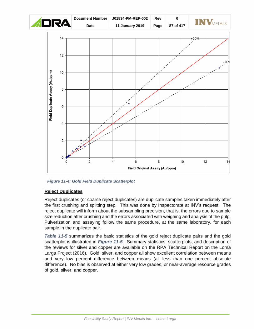
Document Number J01834-PM-REP-002 Rev 0
Date 11 January 2019 Page 87 of 417
Feasibility Study Report | INV Metals Inc. – Loma Larga
Figure 11-4: Gold Field Duplicate Scatterplot
Reject Duplicates
Reject duplicates (or coarse reject duplicates) are duplicate samples taken immediately after
the first crushing and splitting step. This was done by Inspectorate at INV’s request. The
reject duplicate will inform about the subsampling precision, that is, the errors due to sample
size reduction after crushing and the errors associated with weighing and analysis of the pulp.
Pulverization and assaying follow the same procedure, at the same laboratory, for each
sample in the duplicate pair.
Table 11-5 summarizes the basic statistics of the gold reject duplicate pairs and the gold
scatterplot is illustrated in Figure 11-5. Summary statistics, scatterplots, and description of
the reviews for silver and copper are available on the RPA Technical Report on the Loma
Larga Project (2016). Gold, silver, and copper all show excellent correlation between means
and very low percent difference between means (all less than one percent absolute
difference). No bias is observed at either very low grades, or near-average resource grades
of gold, silver, and copper.

Document Number J01834-PM-REP-002 Rev 0
Date 11 January 2019 Page 88 of 417
Feasibility Study Report | INV Metals Inc. – Loma Larga
Table 11-5: Summary of Reject Duplicate Results
Gold (g/t)
Original Duplicate
Number of Samples 77 77
Mean 19.7 19.7
Maximum Value 456.0 455.0
Minimum Value 0.2 0.2
Median 1.5 1.5
Correlation Coefficient 1.00
Percent Difference Between Means -0.6%
The duplicate data pairs taken in 2013 from Loma Larga follow the expected progression of
decreasing variance and percent difference between means from field to preparation to assay
duplicates. Although the precision is somewhat high for field duplicate pairs, it is not atypical
for an epithermal gold deposit, and also must be interpreted in consideration of the relatively
small quarter core sample size, which would overestimate the sampling error associated with
the half core assay samples.
With development at Loma Larga focused on high grade zones within the deposit, RPA
recommended that duplicate samples test intersections that are representative of the
expected average grade of the Mineral Resource.
RPA suggested that INV procure reference standards with grades that better reflect the range
of gold grades within the Mineral Resource. RPA recommended the following gold grade
ranges:
• A “low grade” standard (5 g/t to 7 g/t);
• An “average grade” standard (9 g/t to 12 g/t); and
• A “high grade” standard (greater than 30 g/t).
RPA also suggested that INV obtain a copper standard with a grade range of 6,000 ppm to
8,000 ppm (approximately the average grade of the Loma Larga Mineral Resource).

Document Number J01834-PM-REP-002 Rev 0
Date 11 January 2019 Page 89 of 417
Feasibility Study Report | INV Metals Inc. – Loma Larga
Figure 11-5: Gold Reject Duplicate Scatterplot
Pulp Duplicates
Pulp duplicates consist of second splits of final prepared pulverized samples, analyzed by the
same laboratory as the original samples under different sample numbers. The pulp duplicates
are indicators of the analytical precision, which may also be affected by the quality of
pulverization and homogenization. INV chose to analyze pulp duplicates on the same
samples that were selected for reject duplicate analysis.
Table 11-6 summarizes the basic statistics of the gold pulp duplicate pairs and the gold
scatterplot is illustrated in Figure 11-6. Summary statistics, scatterplots, and description of
the reviews for silver and copper are available on the RPA Technical Report on the Loma
Larga Project (2016). Gold, silver, and copper all show excellent correlation between means
and very low percent difference between means. No bias is observed either at very low
grades (below 1 g/t Au, 10 g/t Ag, and 1,000 ppm Cu), or near average resource grades of
gold, silver, and copper.

Document Number J01834-PM-REP-002 Rev 0
Date 11 January 2019 Page 90 of 417
Feasibility Study Report | INV Metals Inc. – Loma Larga
Table 11-6: Summary of Pulp Duplicate Results
Gold (g/t) Original Duplicate
Number of Samples 77 77
Mean 2.21 2.20
Maximum Value 56.90 56.20
Minimum Value 0.01 0.01
Median 0.14 0.13
Correlation Coefficient 1.00
Percent Difference Between Means 0.4%
Figure 11-6: Gold Pulp Duplicate Scatterplot

Document Number J01834-PM-REP-002 Rev 0
Date 11 January 2019 Page 91 of 417
Feasibility Study Report | INV Metals Inc. – Loma Larga
Pulp Replicates (Check Assays)
A total of 167 regular samples (a rate of greater than ten percent) were selected from the
2013 drilling program and duplicate splits of the pulps were sent to ALS Ltd., which served as
the secondary (check) laboratory. Sample preparation was completed at ALS’s Ecuador
facility, ALS Laboratory Group Quito, and pulps were forwarded to ALS Peru S.A. in Lima for
laboratory for analyses.
Table 11-7 summarizes the basic gold statistics of the pulp replicate pairs and the gold
scatterplot is illustrated in Figure 11-17. Summary statistics, scatterplots, and description of
the reviews for silver and copper are available on the RPA Technical Report on the Loma
Larga Project (2016). Gold, silver, and copper all show excellent correlation between means
and very low percent difference between means. No bias is observed either at very low
grades, or near average resource grades of gold, silver, and copper.
Table 11-7: Summary of Pulp Replicate Results
Gold (g/t) Primary Lab Secondary Lab
Number of Samples 167 167
Mean 1.41 1.40
Maximum Value 53.15 54.00
Minimum Value 0.01 0.01
Median 0.11 0.09
Correlation Coefficient 0.998
Percent Difference Between Means 0.7%

Document Number J01834-PM-REP-002 Rev 0
Date 11 January 2019 Page 92 of 417
Feasibility Study Report | INV Metals Inc. – Loma Larga
Figure 11-7: Gold Pulp Replicate Scatterplot
11.3.3 2016-2017 PROGRAM
In August 2017, INV completed a 23-hole drilling program at Loma Larga, collecting and
assaying 2,423 samples. During the drilling campaign, INV maintained a rigorous QA/QC
program that incorporated the regular submission of blanks, duplicates, and standards.
Specifically, the program included:
• Preparation duplicates (a second pulp prepared from the coarse reject) were prepared
and inserted every 20 samples according to the downhole sampling sequence.
• Assay duplicates (a second analysis of the same pulp) were prepared concurrently with
the preparation duplicates, every 20 samples according to the same downhole sequence
as the preparation duplicates.
• Field duplicates were inserted one in every 40 drill samples, with the duplicate pair
consisting of a pair of quarter core samples obtained from the original half core that would
have normally been sent for assay.
• CRMs for gold, in the form of pulps, were inserted into the sample stream at a ratio of one
in every fifteen samples, independent of the duplicates. CRMs were commercially
prepared sourced from Rocklabs in New Zealand. Gold standards included seven
different grades ranging from less than 1.0 g/t Au to greater than 8.0 g/t Au.

Document Number J01834-PM-REP-002 Rev 0
Date 11 January 2019 Page 93 of 417
Feasibility Study Report | INV Metals Inc. – Loma Larga
• Blank pulp samples were inserted into the sample after each high-grade standard (SN16,
SN60), and at regular intervals throughout the sample stream. RPA notes that the
analysis of a blank pulp does not provide information on possible cross contamination
during the sample preparation process. INV initially used commercial sand as the blank,
but subsequently prepared and certified an in-house rock blank standard commencing
with the final drillhole of the 2013 program. The blank consists of uncrushed rock and is
inserted into the sample stream in intervals thought to be mineralized. These blank
samples provide information on possible cross contamination during the sample
preparation process.
For the current Mineral Resource estimate, RPA reviewed the QA/QC results of INV’s 2016-
2017 drilling campaign at Loma Larga. Table 11-8 lists the drillholes, all of which were
completed after the effective date of RPA’s previous 2016 Mineral Resource estimate.
Table 11-8: Summary of the 2016-2017 Drilling Program
Hole Hole ID Hole Hole ID
1 LLD-376 13 LLD-388
2 LLD-377 14 LLD-389
3 LLD-378 15 LLDGT-003
4 LLD-379 16 LLDGT-004
5 LLD-380 17 LLDGT-005
6 LLD-381 18 LLDGT-006
7 LLD-382 19 LLDGT-007
8 LLD-383 20 LLDGT-03B
9 LLD-384 21 LLDGT-03C
10 LLD-385 22 LLDHG-008
11 LLD-386 23 LLDHG-011
12 LLD-387
During the 2016-2017 drill campaign, 84 CRMs and 94 blank samples were inserted into the
process stream. INV also collected 127 pulp duplicates, and 127 reject duplicates, as listed
in Table 11-9.
Table 11-9: QA/QC Review Summary – 2017 Drilling Program
Metal Blanks Pulp Dup. Reject Dup. CRM
Count Count Count Count
Au 94 127 127 84
Ag 94 127 127 0
Cu 94 127 127 0
Results from the analytical laboratory are imported into INV’s exploration database and
plotted to determine if the control sample results are within pre-defined limits. If the analysis
for a CRM is outside a two standard deviation range of the CRM certified gold content, INV’s
procedure is to request a new analysis from the laboratory, including five samples upstream
and five samples downstream, of the suspected failed sample. When the new analyses are
received, INV personnel decide how the repeated analyses are managed. This includes
rejection of the original batch, averaging of the original and repeat results, or re-submittal of
the entire batch. RPA notes that INV did not utilize these procedures for CRM results that
were outside of the control limits.

Document Number J01834-PM-REP-002 Rev 0
Date 11 January 2019 Page 94 of 417
Feasibility Study Report | INV Metals Inc. – Loma Larga
If duplicate mineralized sample results within the resource area differ by more than 20% from
the original assays, INV’s procedure is to request a new analysis on the first, second, and
third pulps. Once the problem is identified, a new analysis of the batch is requested by INV,
if needed.
11.3.3.1 CERTIFIED REFERENCE MATERIAL
INV used eight gold CRMs obtained from Rocklabs: HISILK2, HISILP1, SG14, SG66, SI15,
SJ63, SN16 and SN60. The CRMs were inserted as pulps into the sample stream after the
laboratory had completed its sample preparation, thus testing the analytical accuracy of the
analytical process, but not contamination during sample preparation. INV inserted a total of
84 CRMs for 23 drillholes in 2017. Three of the eight CRMs consisted of single samples and
as a result, cannot be used for statistical purposes, therefore reducing the practical number
of CRMs to 81.
Table 11-10 lists the CRM name, expected mean, standard deviation, and the number of
CRMs inserted during the drilling program. No silver or copper CRM were used during the
2017 drilling campaign.
Table 11-10: CRMs Used In 2017 Drilling Program
Gold
CRM No Mean (g/t) St. Dev.
HISILK2 1 N/A N/A
HISILP1 1 N/A N/A
SG14 1 N/A N/A
SG66 5 1.070 0.049
SI15 33 1.810 0.067
SJ63 8 2.490 0.155
SN16 27 8.367 0.217
SN60 9 8.600 0.223
INV chose to evaluate the QA/QC results within a conventional three standard deviation range
of the CRM certified gold content. Observed results that fell outside this range were deemed
to be failures. Using this criterion, 10 of 81 results failed (8.1%) for gold. As a result of the
unusually high failure rate of SG66 and SJ63 with respect to their certified mean values, INV
evaluated these CRM results using the mean of their respective assay results as opposed to
the expected values provided on the Certificate of Analysis. Using the recalculated mean and
standard deviation parameters, 2 of the 81 results failed (2.4%) for gold, which is lower than
the three percent that would be expected to fall outside the limits. The mean gold content
reported by Inspectorate for all gold control samples was within three percent of the certified
mean for CRMs SG66, SI15, SN16 and SN60 but above it for CRM SJ63 (Table 11-11 and
Figure 11-8, Figure 11-9, Figure 11-10, Figure 11-11, and Figure 11-12).

Document Number J01834-PM-REP-002 Rev 0
Date 11 January 2019 Page 95 of 417
Feasibility Study Report | INV Metals Inc. – Loma Larga
Table 11-11: Summary of CRM Results
Gold
CRM Number Observed Au (g/t) Expected Au (g/t) % Diff. Observed to Expected Mean Mean Std. Dev. Mean Std. Dev.
HISILK2 1 N/A N/A N/A N/A N/A
HISILP1 1 N/A N/A N/A N/A N/A
SG14 1 N/A N/A N/A N/A N/A
SG66 5 1.086 0.032 1.070 0.049 -1.50%
SI15 33 1.805 0.067 1.810 0.067 0.28%
SJ63 8 2.632 0.055 2.490 0.155 -5.70%
SN16 27 8.370 0.217 8.367 0.217 -0.04%
SN60 9 8.595 0.223 8.600 0.223 0.06%
RPA notes that there may be a slight overestimation bias on results from CRM SN16. The
observed results from CRM SG66 appear to be biased low. RPA recommends that INV
investigate the high and low bias observed in CRMs SN16 and SG66, respectively. RPA
recommends that INV investigate the differences between the supplied expected mean and
round-robin determined mean observed in CRMs SG66 and SJ63 by conducting an external
check.
No assay batches determined to have failed QA/QC were re-assayed.
Due to the low NSR value of silver and copper (less than 1%) no CRM evaluation for silver or
copper was performed.
Figure 11-8: Gold Control Chart: CRM SG66

Document Number J01834-PM-REP-002 Rev 0
Date 11 January 2019 Page 96 of 417
Feasibility Study Report | INV Metals Inc. – Loma Larga
Figure 11-9: Gold Control Chart: CRM SI15
Figure 11-10: Gold Control Chart: CRM SJ63
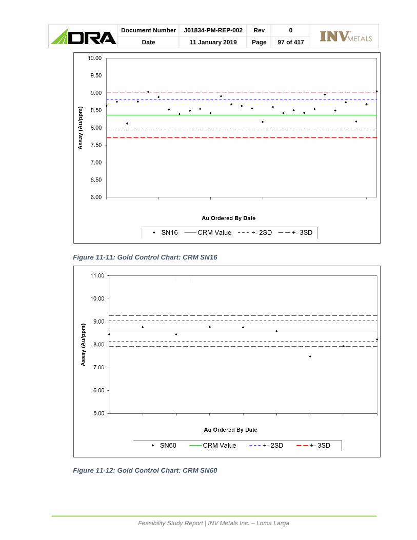
Document Number J01834-PM-REP-002 Rev 0
Date 11 January 2019 Page 97 of 417
Feasibility Study Report | INV Metals Inc. – Loma Larga
Figure 11-11: Gold Control Chart: CRM SN16
Figure 11-12: Gold Control Chart: CRM SN60

Document Number J01834-PM-REP-002 Rev 0
Date 11 January 2019 Page 98 of 417
Feasibility Study Report | INV Metals Inc. – Loma Larga
11.3.3.2 BLANKS
Contamination and sample numbering errors are assessed through blank samples. In
general, contamination is identified when the blank samples yield values exceeding ten times
the detection limit of the analytical method. For the 2016-2017 drilling program, gold values
should be below 0.05 g/t Au, silver below 2 g/t Ag, and copper below 20 ppm Cu. A total of
94 blank samples were inserted into the sample stream by INV during the 2016-2017 drilling
program. The results for these samples were plotted chronologically to determine if any
trends had occurred over time. All blank assay results for gold and silver were at or below
detection limit, and copper results varied between 2 ppm and 24 ppm, with no detectable
systematic pattern.
It is RPA’s opinion that these results demonstrate no evidence of contamination.
11.3.3.3 DUPLICATES
Field Duplicates
No field duplicates were collected during the 2016-2017 drilling program. RPA recommends
that the practice of collecting field duplicates resumes in future drilling campaigns.
Reject Duplicates
Table 11-12 summarizes the basic statistics of the reject duplicate pairs and scatterplots of
each data set are illustrated in Figure 11-13, Figure 11-14, and Figure 11-15. Gold, silver,
and copper all show excellent correlation between means and very low percent difference
between means (all less than one percent absolute difference). No bias is observed at either
very low grades, or near-average resource grades of gold, silver, and copper.
As in 2013, the duplicate data pairs taken in 2016-2017 from Loma Larga follow the expected
progression of decreasing variance and percent difference between means from preparation
to assay duplicates.
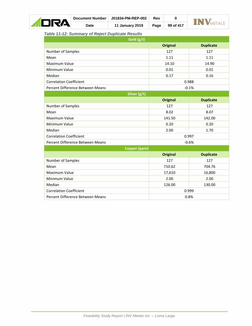
Document Number J01834-PM-REP-002 Rev 0
Date 11 January 2019 Page 99 of 417
Feasibility Study Report | INV Metals Inc. – Loma Larga
Table 11-12: Summary of Reject Duplicate Results
Gold (g/t) Original Duplicate
Number of Samples 127 127
Mean 1.11 1.11
Maximum Value 14.10 14.90
Minimum Value 0.01 0.01
Median 0.17 0.16
Correlation Coefficient 0.988
Percent Difference Between Means -0.1%
Silver (g/t) Original Duplicate
Number of Samples 127 127
Mean 8.02 8.07
Maximum Value 141.50 142.00
Minimum Value 0.20 0.20
Median 2.00 1.70
Correlation Coefficient 0.997
Percent Difference Between Means -0.6%
Copper (ppm) Original Duplicate
Number of Samples 127 127
Mean 710.62 704.76
Maximum Value 17,610 16,800
Minimum Value 2.00 2.00
Median 126.00 130.00
Correlation Coefficient 0.999
Percent Difference Between Means 0.8%

Document Number J01834-PM-REP-002 Rev 0
Date 11 January 2019 Page 100 of 417
Feasibility Study Report | INV Metals Inc. – Loma Larga
Figure 11-13: Gold Reject Duplicate Scatterplot
Figure 11-14: Silver Reject Duplicate Scatterplot

Document Number J01834-PM-REP-002 Rev 0
Date 11 January 2019 Page 101 of 417
Feasibility Study Report | INV Metals Inc. – Loma Larga
Figure 11-15: Copper Reject Duplicate Scatterplot
Pulp Duplicates
Pulp duplicates consist of second splits of final prepared pulverized samples, analyzed by the
same laboratory as the original samples under different sample numbers. The pulp duplicates
are indicators of the analytical precision, which may also be affected by the quality of
pulverization and homogenization. INV chose to analyze pulp duplicates on the same
samples that were selected for reject duplicate analysis.
Table 11-13 summarizes the basic statistics of the pulp duplicate pairs and scatterplots of
each data set are illustrated in Figure 11-16, Figure 11-17, and Figure 11-18. Gold, silver,
and copper all show excellent correlation between means and very low percent difference
between means. No bias is observed either at very low grades (below 1 g/t Au, 10 g/t Ag,
and 1,000 ppm Cu), or near average resource grades of gold, silver, and copper.

Document Number J01834-PM-REP-002 Rev 0
Date 11 January 2019 Page 102 of 417
Feasibility Study Report | INV Metals Inc. – Loma Larga
Table 11-13: Summary of Pulp Duplicate Results
Gold (g/t) Original Duplicate
Number of Samples 127 127
Mean 1.11 1.12
Maximum Value 14.10 14.20
Minimum Value 0.01 0.01
Median 0.17 0.17
Correlation Coefficient 0.989
Percent Difference Between Means -0.7%
Silver (g/t) Original Duplicate
Number of Samples 127 127
Mean 8.02 8.02
Maximum Value 141.50 140.00
Minimum Value 0.20 0.20
Median 2.00 1.70
Correlation Coefficient 0.997
Percent Difference Between Means 0.0%
Copper (ppm) Original Duplicate
Number of Samples 127 127
Mean 710.62 703.94
Maximum Value 17,610 17,380
Minimum Value 2.00 2.00
Median 126.00 129.00
Correlation Coefficient 0.999
Percent Difference Between Means 0.9%

Document Number J01834-PM-REP-002 Rev 0
Date 11 January 2019 Page 103 of 417
Feasibility Study Report | INV Metals Inc. – Loma Larga
Figure 11-16: Gold Pulp Duplicate Scatterplot
Figure 11-17: Silver Pulp Duplicate Scatterplot

Document Number J01834-PM-REP-002 Rev 0
Date 11 January 2019 Page 104 of 417
Feasibility Study Report | INV Metals Inc. – Loma Larga
Figure 11-18: Copper Pulp Duplicate Scatterplot
11.3.4 RECOMMENDATIONS AND ENHANCEMENTS TO QA/QC PROGRAM
RPA strongly recommends INV ensures that procedures for investigating, correcting, and
documenting results of QA/QC non-compliance issues such as biases or failures are followed
for all drilling programs. Non-compliance results include:
• 2013
• High bias observed in gold CRM SN16 since the expected grade of 8.37 g/t Au is very
near the average gold grade of the Loma Larga Mineral Resource.
• High bias observed in silver analyses after a brief hiatus in testing should be followed
up with the laboratory.
• 2017
• High bias observed in CRM SN16.
• Initial high bias of CRM SI15.
• Calibration issues with CRM SN60.
• Low bias in CRM SG66.
• Potential high bias in CRM SJ63.
The biases in the CRM results have been observed throughout several drilling campaigns at
Loma Larga and RPA recommends that INV completes an external check on the reference
materials used on the Loma Larga Project.
RPA recommends that INV carry out field duplicate analyses using half core duplicates. To
ensure that the results are meaningful in the context of the Loma Larga resource, RPA

Document Number J01834-PM-REP-002 Rev 0
Date 11 January 2019 Page 105 of 417
Feasibility Study Report | INV Metals Inc. – Loma Larga
recommends that INV collect duplicate field samples within mineralized core intersections.
Duplicate analyses can be achieved by using the existing core library.
Furthermore, RPA recommends that INV resume the regular submission of check assays
(pulp replicates) to a secondary laboratory.
In 2017, INV introduced eight gold analytical standards, however, only four had sufficient data
to be meaningfully analyzed. Of the four CRMs, two had grades approximately 8 g/t Au (SN16
at 8.37 g/t Au and SN60 at 8.595 g/t Au) and two CRMs were less than 3 g/t Au (SG66 at
1.156 g/t Au and SJ63 at 2.488 g/t Au). RPA recommends that INV reduce the number of
CRMs used and ensure that the grades are consistent with the ranges expected to be found
at Loma Larga (up to and greater than 30 g/t Au), as recommended in 2016. Similarly, RPA
reiterates the 2016 recommendation that INV obtain analytical standards for silver and
reintroduced a copper CRM.
RPA is of the opinion that the results of the QC samples, together with the QA/QC procedures
implemented by INV at Loma Larga, provide adequate confidence in the data collection and
processing, and the assay data is suitable for Mineral Resource estimation.

Document Number J01834-PM-REP-002 Rev 0
Date 11 January 2019 Page 106 of 417
Feasibility Study Report | INV Metals Inc. – Loma Larga
DATA VERIFICATION
Sampling details for the historic drilling program by IAMGOLD were verified by RPA in 2006.
At that time, RPA validated the drillhole database up to hole IQD354. In 2012, RPA verified
30 drillholes completed by IAMGOLD in 2008, which included 28 resource delineation
drillholes and two drillholes for metallurgical testwork. Prior to accepting the resource
database used to estimate the current Mineral Resources for the Loma Larga Project, RPA
reviewed and verified 12 drillholes completed by INV in 2013, which included drillholes
LLD364 to LLD375. The verification work included a review of the QA/QC methods and
results, checking assay certificates against the database assay table, a site visit and review
of drill core, and standard database validation tests.
In 2018, RPA verified the assay results from 23 drillholes that were completed subsequent to
the 2016 Technical Report. Verification included checking assay certificates against the
database assay table. RPA also completed standard database validation tests of the new
drilling.
RPA considers the resource database reliable and appropriate to support a Mineral Resource
estimate.
In addition, RPA reviewed and verified the 248 drillholes with sulphur data, including 26
drillholes that were completed by INV during the 2017 drilling campaigns on the Project. The
verification work consisted of a review of the QA/QC results, checking assay certificates
against the database assay tables, and standard manual validation tests.
Katharine Masun, P.Geo., RPA Senior Geologist, visited the Loma Larga property site on
February 19, 2014. During the site visit, RPA inspected the Loma Larga property, including
the location of drill collars LLD148, LLD149, and LLD370.
RPA reviewed the geological core, checked lithology, mineralization, and sampling against
drill logs of the following drillholes: IQD122, IQD183, IQ210, LLD367, and LLD372. During
the core review, no notable discrepancies were found: metre tags were placed in the correct
locations in the core boxes, samples were clearly and accurately marked, and core boxes
were clearly labelled.
12.1 MANUAL DATABASE VERIFICATION
The review of the resource database included header, survey, lithology (major and minor),
assay, and density tables. Database verification was performed using tools provided within
the Dassault Systèmes GEOVIA GEMS Version 6.6 software package (GEMS). As well, the
assay and density tables were reviewed for outliers. Any inconsistencies that were identified
were promptly corrected by INV.
A visual check of the drillhole collar elevations with respect to the topographic surface and
drillhole traces was completed. RPA noted 19 drillhole collars within the mineralized
wireframe domains that were greater than one metre above the topographic surface, and four
were greater than three metres. RPA followed up these discrepancies and found that it was
not a transcription error. RPA recommends that INV resurvey the drillhole collars listed in
Table 12-1.

Document Number J01834-PM-REP-002 Rev 0
Date 11 January 2019 Page 107 of 417
Feasibility Study Report | INV Metals Inc. – Loma Larga
Table 12-1: Drill Hole Collar Elevation Errors
Drill Hole Collar Error (m)
IQD253 6.44
IQD145001 5.37
IQD330 4.61
IQD314 4.06
IQD142501 2.95
IQD133 2.26
IQD190 2.12
IQD181 2.09
IQD165 2.02
IQD176 1.76
IQD146 1.72
IQD179 1.37
IQD142 1.32
IQD344 1.24
LLD375 1.19
IQD138 1.14
IQD175 1.14
LLD370 1.10
IQD163 1.04
RPA verified all 1,722 assay records. This included a comparison of assay results in the
resource database to 18 digital laboratory certificates of analysis (COA), which were received
directly from Inspectorate. Any inconsistencies that were identified were promptly corrected
by INV.
RPA verified 2,423 assay records to 30 digital COAs from 23 drillholes that were sampled
during INV’s 2017 drilling programs. A visual check of the drillhole GEMS collar elevations
and drillhole traces was completed. No errors or inconsistencies were found.
12.2 INDEPENDENT ASSAYS OF DRILL CORE
RPA did not collect samples from drill core for independent assay during the 2014 site visit.
In 2005, Wayne Valliant, P.Geo., Principal Geologist with RPA, collected seven samples of
quartered core for independent analyses at SGS Minerals Services, Toronto. Analyses were
by fire assay for gold and ICP for silver and copper. Although seven samples are not sufficient
for statistical comparisons, Scott Wilson RPA (2006) found the agreement to be reasonable
and confirmed the presence of gold in the samples.
RPA is of the opinion that database verification procedures for the Loma Larga Project comply
with industry standards and are adequate for the purposes of Mineral Resource estimation.

Document Number J01834-PM-REP-002 Rev 0
Date 11 January 2019 Page 108 of 417
Feasibility Study Report | INV Metals Inc. – Loma Larga
MINERAL PROCESSING AND METALLURGICAL TESTING
13.1 INTRODUCTION
Metallurgical testwork for the project location commenced in 2006. Initial testwork and
process design efforts by IAMGOLD focused on the direct production of gold dore onsite using
a combination of concentration, oxidation and cyanidation methods. In 2014, the new project
owners, INV, engaged RPA to conduct a pre-feasibility study and corroborating testwork
program. The 2014 program investigated the potential of producing saleable concentrate via
conventional bulk or sequential flotation methods. The outcome of the 2014 program was the
selection of a high level sequential flotation flowsheet for the recovery of separate gold
bearing copper and pyrite concentrates. (2016 Technical Report)
DRA reviewed the data presented in the 2014 metallurgical testwork program and agreed
with the approach of utilising a sequential flowsheet.
INV, in consultation with Promet 101 and DRA Americas, undertook a second testwork
program (the 2017 Feasibility Study Program) to further optimize the flotation flowsheet.
Optimization efforts focused on improving the operability, maintainability, capital and
operating costs associated with the flowsheet. The outcomes of the 2017 Feasibility Study
Program form the basis for the FS.
The majority of the results obtained from the 2006 Metallurgical programs are not relevant to
the current process flowsheet selected but is included with respect to the mineral properties
for the deposit and for completeness.
13.2 HISTORICAL METALLURGICAL TESTWORK
A review of the available historical metallurgical data was carried out, with a focus on obtaining
pertinent results to the current process design criteria. The findings of the review are
presented in the section below.
13.2.1 IAMGOLD METALLURGICAL TESTWORK PROGRAMS – 2006 TO 2010
Numerous metallurgical testwork programs were carried out by IAMGOLD between 2006 and
2010. In total, a set of twenty-six samples with gold grades ranging between 5 and 42 g/t and
copper grades between 0.30 to 5.40% were received at SGS Lakefield and tested.
The focus of these programs was to identify suitable conditions to maximize gold recovery via
a hydrometallurgical processing route to generate gold dore on site at Loma Larga.
The following results are relevant to the current version on the Loma Larga flowsheet:
• The ore was identified as being highly refractory in nature;
• Mineralogical testing indicated that the bulk of the gold (72%) was associated with pyrite,
followed by enargite (12%) and the remainder with siliceous gangue;
• A total of nine Bond Ball Mill Work Index tests were completed. Results ranged from 15.2
kWh/t to 18.0 kWh/t, with an average value of 16.8 kWh/t;
• Gravity preconcentration achieved less than 10% recovery of the feed gold content;
• Whole ore cyanidation achieved low gold recoveries (16 to 30% of the gold in the feed)
with high cyanide consumption levels; and

Document Number J01834-PM-REP-002 Rev 0
Date 11 January 2019 Page 109 of 417
Feasibility Study Report | INV Metals Inc. – Loma Larga
• Flotation testing achieved high gold and copper recoveries of 90 to 93% and 94 to 96%,
respectively, into a single bulk concentrate containing enargite and pyrite.
13.2.2 INV METALS METALLURGICAL TESTWORK PROGRAM – 2014
The focus of the 2014 metallurgical program was to investigate possible flotation
configurations to produce saleable concentrate(s) from the Loma Larga deposit. Both bulk
and sequential (copper, pyrite) flotation circuits were investigated using a series of open
circuit tests. The locked cycle test was subsequently completed for the sequential flotation
flowsheet. The results of the 2014 metallurgical program were used in the 2016 Technical
Report prepared by RPA.
The following tests were carried out:
• Physical characterization and mineralogy;
• Bulk rougher flotation;
• Bulk rougher cleaner flotation;
• Sequential cleaner flotation; and
• Locked cycle flotation.
The two composite (59 kg and 30.5 kg) samples were prepared from 230 kg of quartered HQ
drill core intervals by SGS Lakefield. Drill holes LLD 371 and LLD 372 contributed the sample
material for both composites. Composites head assays were found to be 12.5 g/t Au, 6.38 g/t
Au and 0.59% Cu, 0.51% Cu, respectively.
The 2014 testwork program demonstrated, at a preliminary level, the following:
• The ore can be considered moderately hard, as assessed by the bond work index;
• The ore is highly abrasive;
• Bulk flotation results in significant gold losses at the cleaner flotation stage; and
• Sequential flotation resulted in the production of saleable concentrates. However,
reagent consumption levels needed to be examined further.
The conclusions from the 2014 metallurgical testing program was that a sequential flotation
process producing separate enargite and pyrite concentrates was identified as being the
preferred process route. The sequential flotation consisted of producing a high pH pulp in a
copper rougher stage to depress pyrite (and contained gold) followed by a low pH pyrite
flotation stage via the addition of acid to the copper rougher tails stream.
13.3 TESTWORK FOR 2017 FEASIBILITY STUDY
13.3.1 INTRODUCTION
The 2017 metallurgical testwork program was designed to further optimize the flotation
flowsheets and reagent schemes in the 2014 program. Both bulk and sequential flotation
flowsheets were investigated, as each option assessed in earlier works was not considered
to be optimized (high reagent consumptions).
The 2017 metallurgical test work program consisted of:
• Physical characterization of three composites and ten variability samples;
• 91 x Rougher/Rougher Cleaner tests on 14 composites;
• 12 x Variability Rougher tests on 10 variability composites;

Document Number J01834-PM-REP-002 Rev 0
Date 11 January 2019 Page 110 of 417
Feasibility Study Report | INV Metals Inc. – Loma Larga
• 46 x Cleaner Flotation tests;
• 4 x Locked Cycle tests;
• Pilot scale Staged Flotation Reactor (SFR) tests; and
• Tails samples for downstream characterization testing.
13.3.2 SAMPLE SELECTION
The source material for the 2017/18 metallurgical program was remaining composite material
from the 2014 metallurgical program and drill core from the latest Loma Larga 2017 drill
program. In total, 14 composites were prepared over the life of the program.
It should be noted that the samples used for the metallurgical testwork were at SGS Lakefield
prior to the commencement of the feasibility study program. It is understood that all samples
are from diamond drill cores, drilled between 2014 and 2017. The impact of sample age
appears to be minimal with respect to metallurgical performance, but this has not been
checked in detail.
The samples were prepared by INV on site at Loma Larga and shipped to SGS Lakefield in
Ontario Canada.
The selection of drill core intervals for the testwork composites and variability samples was
carried out by INV. Orix Geoscience Inc. performed a comprehensive analysis of the ore
types within the deposit, see Table 13-1, and concluded that the samples chosen by INV
were representative of the overall deposit. At the time of sample selection, the production
schedule and LOM plan generated in the feasibility study was not available.
Figure 13-1 illustrates the location of each drill hole and the variability sample intervals, with
respect to the ore body.
Drill holes LLDGT-005 and LLDGT-006 were used to form the majority of the composites and
as the source of the variability samples for the project. Both LLDGT-005 and LLDGT-006 are
within the boundary of the deposit and intersect type 1 and 2 ore types. Ore types are defined
in accordance with Table 13-1.

Document Number J01834-PM-REP-002 Rev 0
Date 11 January 2019 Page 111 of 417
Feasibility Study Report | INV Metals Inc. – Loma Larga
Table 13-1 Ore Type Categories
Source: Ore type categories work performed by Orix Geoscience Inc.

Document Number J01834-PM-REP-002 Rev 0
Date 11 January 2019 Page 112 of 417
Feasibility Study Report | INV Metals Inc. – Loma Larga
Figure 13-1:Drill Hole Locations and Ore Types

Document Number J01834-PM-REP-002 Rev 0
Date 11 January 2019 Page 113 of 417
Feasibility Study Report | INV Metals Inc. – Loma Larga
13.3.3 HEAD AND MINERALOGY CHARACTERIZATION
Head assays and mineralogical analysis was carried out on subsamples on a number of
composites and variability samples (Table 13-2). Head assays for gold ranged from 1.06 to
15.4 g/t, averaging 5.6 g/t Au. Head assays for copper ranged from 0.033 to 4.12% Cu,
averaging 0.50% Cu, while sulphur assays ranged from 3.95 to 15.3% S, averaging 8.93% S.
Mineralogy was consistent for all samples examined. On average 97% of the minerals
present were either quartz or pyrite, with trace amounts of other minerals making up the
difference. Enargite was the primary copper-bearing mineral.
At a P80 of 75 µm, liberation (>80% of the cross-sectional particle area) averaged 85% for
pyrite, with little variance in this value across the samples evaluated. The liberation
characteristics for enargite were not as favourable averaging 59%, with considerably higher
variance. Non-liberated enargite was more commonly associated with pyrite than quartz,
while non-liberated pyrite was associated largely with quartz.
An analysis of the mineralogical data indicated that the primary grind size should be in the
P80 range of 50 to 75 microns. Regrinding for pyrite should be in the P80 equals 30 to 40
microns range, while copper regrinding should finer, in the P80 equals 20 to 30 microns range.
Table 13-2: Head Sample Assays and Mineralogical Data
Note: Where cells are empty, data was not measured.
13.3.4 PHYSICAL CHARACTERIZATION
Physical characterization test work was conducted on three different composite samples and
10 variability samples. The results of physical characterization tests performed on each
sample are shown in Table 13-3 below.
For the coarser particle grindability tests i.e. Drop Weight Test (DWT), Sag Mill Comminution
(SMC), and Sag Power Index (SPI), the indices indicate samples were medium to moderately
Sample Head Assays Mineral Distribution, % % Liberation*
ID Au g/t Ag g/t Cu % As % S % Pyrite Quartz Enargite Other Cu Remainder Pyrite Enargite
Master 12.5 47.0 0.59 0.22 12.8 24.2 72.1 1.19 0.07 2.4 89.5 78.4
Low Grade 6.38 34.1 0.51 0.19 8.79
Blend Comp 16.7 59.2 0.68 0.23 12.1
SFR Comp 4.83 25.9 0.21 0.088 6.36
VT-1 3.29 19.6 0.033 0.020 5.12 9.9 87.5 0.05 0.00 2.6
VT-2 3.61 13.1 0.087 0.036 4.91 9.6 88.1 0.13 0.00 2.2
VT-3 2.88 13.6 0.068 0.033 9.23 17.8 80.5 0.07 0.00 1.6
VT-4 2.66 16.8 0.20 0.074 5.91 11.4 83.5 0.26 0.00 4.9
VT-5 5.58 39.7 0.28 0.11 5.97 11.1 86.7 0.57 0.01 1.6
VT-8 14.8 112 0.71 0.27 12.9 21.6 73.2 1.57 0.02 3.7
VT-9 4.68 59.1 0.16 0.061 15.3 29.8 68.8 0.17 0.08 1.1 91.0 59.0
VT-10 6.86 79.1 4.12 1.20 7.15 8.3 79.4 5.92 2.26 4.1 83.5 35.4
VT-11 8.32 23.2 0.16 0.059 7.50 13.5 85.4 0.10 0.02 1.0 90.9 38.5
VT-12 3.96 18.3 0.30 0.11 10.2 17.1 81.4 0.33 0.03 1.2 78.5 0.0
VT-13 2.91 41.3 0.21 0.057 6.40
VT-14 3.73 107 0.50 0.11 7.76
Comp 1 5.01 23.7 0.24 0.093 6.44
Comp 2 3.18 142 0.070 0.049 12.8 21.6 73.9 0.15 0.00 4.4 90.2 59.2
Comp 3 1.74 51.4 0.39 0.18 3.95 6.9 90.5 0.82 0.00 1.8 83.1 80.5
Comp 4 1.06 475 0.054 0.037 8.84 15.1 81.2 0.12 0.00 3.6 85.3 77.3
Comp 5 2.35 148 0.15 0.054 15.4 27.6 69.0 0.19 0.00 3.2 86.9 68.3
Comp 6 1.43 146 0.31 0.11 9.09 14.8 81.7 0.62 0.00 2.9 79.1 73.7
Comp 7 1.94 260 0.053 0.022 8.84 14.2 83.3 0.08 0.00 2.4 79.3 81.0
Comp 9 15.4 104 2.17 0.67 11.5
Comp 10 4.43 26.2 0.21 0.081 8.08
* P80 ~ 75 microns. Liberation = >80% of area is the mineral of interest

Document Number J01834-PM-REP-002 Rev 0
Date 11 January 2019 Page 114 of 417
Feasibility Study Report | INV Metals Inc. – Loma Larga
hard or competent on average in comparison to the SGS database. For the mid-range particle
grindability tests (i.e. RWI), samples averaged moderately hard, while for the fine particle
grindability tests (i.e. BWI), samples were considered moderately hard on average.
Table 13-3: 2017/18 Ore Hardness Testing
Abrasion index measurements indicated extremely abrasive material, ranging from 0.75 to
1.176. The variance within each test series was relatively low in comparison to other similar
deposits. This is probably a natural feature of the Loma Larga deposit considering the
consistent predominant presence of silica gangue in the samples tested. Composite samples
tested tended to show less variance than the discrete samples tested from various locations
across the deposit which is a common observation. All composites tested can be
characterized as moderately competent, with moderately hard grindability and are highly
abrasive. These properties are most likely influenced by the predominance of silica gangue
in the material.
13.3.5 FLOTATION TESTWORK
Flotation testing was completed to evaluate the performance of the bulk and sequential
flowsheets. The flotation performed testwork was designed to provide sufficient information
for selection of the optimal processing flowsheet and design and allow for the estimation of
recoveries, concentrate grades, CAPEX and OPEX to a feasibility level design.
The objectives of the flotation testing programs were as follows:
• Evaluate flotation conditions to maximize the recovery of copper to a copper concentrate
containing gold and a gold bearing pyrite concentrate as final products;
• Identify conditions which maximize concentrate grades without significant reductions in
total copper and gold recovery;
• Identify optimal recoveries of copper and gold into the separate concentrate streams;
• Identify the optimal primary grind required for the grinding circuit design;
• Identify rougher flotation concentrate regrind requirements;
• Evaluate reagent requirements and the subsequent impact on metal recoveries; and
• Generate sufficient data to determine the preferred flotation circuit design and flowsheet
to be used in the study.
Sample Relative CWI SPI RWI AI
Name Density A x b1 A x b2 ta3 SCSE (kWh/t) (min) (kWh/t) 150M 200M (g)
Blend Comp 2.70 - 54.6 0.52 8.6 - 66.0 17.2 17.3 - 0.750
LLDHG-008 2.78 36.9 40.0 0.22 10.4 8.9 82.7 18.3 18.5 17.9 1.176
LLDHG-011 2.66 38.2 40.0 0.22 10.0 11.5 71.3 16.3 16.5 - 0.851
VT Sample #1 - - - - - - 87.4 - 16.7 - -
VT Sample #2 - - - - - - 90.3 - 19.6 - -
VT Sample #3 - - - - - - 76.3 - 18.6 - -
VT Sample #4 - - - - - - 76.1 - 14.8 - -
VT Sample #5 - - - - - - 102.1 - 18.0 - -
VT Sample #8 - - - - - - 93.6 - 17.4 - -
VT Sample #9 - - - - - - 109.4 - 12.3 - -
VT Sample #10 - - - - - - 85.0 - 15.7 - -
VT Sample #11 - - - - - - 89.1 - 17.8 - -
VT Sample #12 - - - - - - 102.8 - 17.1 - -1 A x b from DWT2 A x b from SMC3 ta from SMC test is an estimate
JK Parameters BWI (kWh/t)

Document Number J01834-PM-REP-002 Rev 0
Date 11 January 2019 Page 115 of 417
Feasibility Study Report | INV Metals Inc. – Loma Larga
All flotation testing was carried out at the SGS facilities in Lakefield, Ontario.
The sections below summarize the results of the bulk and sequential flowsheet options
investigated during the study. The outcomes of these investigations were as follows:
• The sequential flowsheet achieves higher grade copper and pyrite concentrates;
• The sequential flowsheet delivers higher overall metal recoveries to concentrate; and
• The sequential flowsheet achieved these recoveries utilizing lower reagent dosages.
13.3.5.1 BULK FLOTATION
The bulk flotation circuit considered that enargite and pyrite were to be recovered together in
a bulk concentrate, using a bulk rougher and three stage cleaning separation process;
followed by selective cleaning to produce both copper and pyrite concentrates.
Bulk rougher flotation is conducted at a pH of ~7.0, using a strong sulphide collector (PAX).
Bulk rougher concentrate is reground prior to cleaning to produce a “cleaned” bulk
concentrate.
This “cleaned” bulk concentrate is then separated into the two final concentrates in a selective
cleaning circuit. This is achieved by increasing pulp pH significantly to depress pyrite and the
use of selective copper collectors. The circuit utilizes a selective copper rougher stage
followed by three sequential stages of copper cleaning.
The concentrate of the copper cleaning circuit being the final copper concentrate and the
combined tails streams the pyrite concentrate. Both concentrates contain both gold and silver.
Two bulk circuit rougher tests and a further thirty-three combined bulk rougher-cleaner tests
were completed. The following present results of the bulk flotation testwork program.
Bulk Flowsheet Rougher Testing
Only two rougher only tests (F23 and F32) were carried out using the bulk circuit flowsheet.
The first test (F23) was carried out using the high-grade gold “Blend composite” at a primary
grind of 80% passing 60 µm, 1.3 kg/t Lime, 30 g/t PAX (collector), 15 g/t 3418A (selective
copper sulphide collector) and 25 g/t MIBC (frother). Recoveries of the major elements were
95.7% for copper, 95.1% for arsenic, 93.6% for gold and 88.8% for silver.
The second test (F32) rougher only bulk test was carried out to evaluate the staged use of
3418A versus PAX. The test conditions being a low pulp pH (7.0), 3418A (15.0 g/t), PAX
(30.0 g/t) and MIBC (20.0 g/t). Overall recoveries were 94.7% for copper, 95.1% for arsenic,
92.9% for gold and 88.5% for silver.
Bulk Flowsheet Cleaner Testing
A total of thirty-three bulk rougher cleaner tests were completed. These tests can be collated
into four different categories as follows:
• Bulk rougher flotation followed by bulk cleaning to generate a bulk concentrate, and
separation cleaning stages to generate separate copper and pyrite concentrates (Tests
F11, 13, 17 and 19). These tests were carried out on high grade gold and copper samples
(6.0-16.7 g/t Au and 0.5-0.7% Cu).
• Bulk variability sample testing followed by bulk cleaning to generate separate bulk
concentrates for each variability sample (Tests F21, F22, F24, F25, F26, F27, F28, F50,
F51, F52 and F53).

Document Number J01834-PM-REP-002 Rev 0
Date 11 January 2019 Page 116 of 417
Feasibility Study Report | INV Metals Inc. – Loma Larga
• Bulk rougher flotation followed by bulk cleaning (kinetics tests) to generate a single bulk
concentrate (F29, F30, F31 and F33).
• Bulk cleaning of LCT#2 products to generate bulk concentrate with further cleaning of this
concentrate to generate separate copper and pyrite concentrates (Tests F35, F36, F37,
F38, F39, F40, F41, F42, F43, F54, F55, F56, F66 & F67).
The tests were carried out on Composite 1 and Blend composites. The test conditions for
this phase of testing were:
• Grind target of 80% passing 66 - 78µm;
• Regrind target of 80% passing 30 - 50µm;
• Bulk rougher pulp pH target of 7.0; and
• Reagent additions of 3418A (12.5 g/t), PAX (30 g/t) and MIBC (15 g/t).
The following observations were noted:
• Only F11 resulted in a reasonable copper concentrate recovery and grade of 76.6% and
30.3% Cu respectively;
• Gold recovery to copper concentrate was on average 20%; and
• Gold losses to the bulk rougher tails and first bulk cleaner tails were on average 10.5%.
Bulk Variability Testing including Bulk Cleaner Stage
A total of eleven bulk variability tests were completed, including a bulk rougher stage and then
multiple stages of bulk concentrate cleaning.
All of the variability tests were run at the following conditions:
• Primary grind of 80% passing 60 µm. Add lime to target pulp pH 7.0;
• Bulk rougher for 20 minutes after 6 minutes conditioning time with 15 g/t 3418A, 25 g/t
MIBC, 25 g/t PAX;
• Regrind bulk concentrate for 15 minutes with 7.5 g/t 3418A and 15.0 g/t PAX;
• Bulk 1st cleaner for 10 minutes after two minutes conditioning time with up to 5 g/t 3418A,
8.0 g/t MIBC & 10 g/t PAX as required. Some tests did not use extra reagents at all; and
• Bulk 2nd cleaner for 10 minutes after one minute of conditioning time with 8 g/t MIBC.
No extra lime was added to the regrind and cleaner stages and pulp pH stabilized between
7.0 - 8.0 in cleaner stages. Total PAX addition was up to 70 g/t.
Table 13-4 presents the head grades, mass and elemental recoveries of each of the eleven
tests. Note that the concentrates generated here represent the combined final product as
this would subsequently be separated into either a copper or pyrite concentrate.

Document Number J01834-PM-REP-002 Rev 0
Date 11 January 2019 Page 117 of 417
Feasibility Study Report | INV Metals Inc. – Loma Larga
Table 13-4: Bulk Circuit Rougher and Cleaner Variability Test Results
Test Details Test # F21 F22 F24 F25 F26 F27 F28 F50 F51 F52 F53 VT#8 VT#8AR VT#1 VT#2 VT#3 VT#4 VT#5 VT#9 VT#10 VT#11 VT#12
Head Grades % Cu 0.73 0.68 0.047 0.11 0.086 0.201 0.27 0.14 4.00 0.17 0.29
% As 0.27 0.25 0.021 0.035 0.033 0.073 0.11 0.052 1.14 0.062 0.11
% S 13.0 12.9 5.13 4.73 9.15 5.85 5.64 15.4 7.28 7.51 10.0
ppm Au 15.51 15.02 3.30 3.67 2.85 2.62 5.57 4.66 7.06 8.01 3.85
Recovery to
Bulk Cleaner
Concentrate
Mass % 26.8 27.1 8.1 8.8 17.8 12.2 9.94 28.2 16.8 15.2 24.6
Cu % 95.1 92.1 73.7 70.0 87.1 93.2 92.1 91.3 95.3 89.4 91.1
As % 93.5 90.1 69.7 84.9 80.8 92.6 89.2 81.2 95.5 86.0 89.9
S% 90.0 90.9 78.1 80.5 87.0 83.8 84.8 90.3 88.0 86.2 86.5
Au % 90.4 89.8 72.3 71.5 78.7 77.2 84.6 85.4 90.9 83.9 83.2
The following was noted from the results:
• Copper head grades were highly variable from 0.05 to 4.0% Cu;
• Copper recoveries ranged from 70.0 to 95.3% despite some very low copper grades;
• Arsenic responds in a similar manner to copper as expected as the predominant copper
bearing mineral is enargite;
• Sulphur recoveries are also good but on average 5% lower than required to maximize
gold recovery;
• The sulphur grade recovery curves were not the same as gold recovery curves, implying
that the residual gold not recovered with copper is not totally associated with the pyrite;
and
• Gold head grades cover a very wide range of assays from 2.62 to 15.5 ppm Au. Gold
recovery performance was highly variable from 71.5 to 90.9%, at grades of 14 to 52 g/t
Au.
Bulk Rougher Testing and Cleaner Kinetics Evaluation
A total of four cleaner kinetics tests were carried out. Two on the blend composite, one on
assay reject samples, and one on an SFR concentrate prepared from the assay reject
samples.
The conditions used at the bulk rougher stage included a primary grind target of 80% passing
60 µm, regrind bulk concentrate to 80% passing 30 µm, and bulk cleaning using 7 and 5
stages (tests F29 and F30, respectively). Results of the test showed relatively quick kinetics,
with flotation completed within 10 minutes and 6 minutes, respectively. 70% mass pull to
concentrate was also achieved.
Assay reject material was used for bulk rougher tests F31 and F33. For bulk rougher test
F31 the following conditions were applied: regrind to 80% passing 30 µm and two stages of
bulk cleaning with an additional 1st cleaner scavenger stage used. Test F33 was carried out
on the SFR bulk concentrate and reground to 80% passing 30 µm and 2 stages of bulk
cleaning applied, with an additional 1st cleaner scavenger stage being used.
For the two tests completed, the equivalent stage recovery to the bulk cleaner circuit are
shown in Figure 13-2. The figure shows no substantial change in the cleaner stage
recoveries as a result of the differing processing methods.

Document Number J01834-PM-REP-002 Rev 0
Date 11 January 2019 Page 118 of 417
Feasibility Study Report | INV Metals Inc. – Loma Larga
Figure 13-2: Bulk Cleaner Assay Reject Samples – SFR Bulk Concentrates
Cleaning of the LCT#2 Bulk Concentrate
Bulk rougher concentrate produced from Locked Cycle Test #2 was submitted for further
cleaning. In total, fifteen tests (F35 to F43, F55 to 56, F66, and F67) were completed under
the supervision of INV.
For each test, three stages of cleaning at elevated pulp pH (12) was used with different
collectors and or depressants (Sodium Meta-Bisulphate, Cyanide, Quebracho) being
evaluated. The detailed testwork conditions are defined in the 2017/2018 SGS Lakefield
metallurgical testwork report.
The recovery results for each of the individual 15 cleaner tests were used to then calculate
the final recoveries of copper to the copper concentrate versus the original feed and results
as shown in Table 13-5 below.

Document Number J01834-PM-REP-002 Rev 0
Date 11 January 2019 Page 119 of 417
Feasibility Study Report | INV Metals Inc. – Loma Larga
Table 13-5: Overall Bulk Cleaner Results to Copper Concentrate
Second stage cleaning results are presented in Table 13-6.
Table 13-6: LCT # 2 Recovery to Bulk Second Cleaner Concentrate
The overall recovery of copper to final copper concentrate was relatively low (40-80%) and
that the concentrate grades were generally understood to be less than marketable. The
cause for the relatively low grades can be linked to the high pyrite content in all of the samples,
ranging from 60 to 80% by weight.
13.3.5.2 SEQUENTIAL FLOTATION
The sequential flotation circuit considered that enargite and pyrite are recovered sequentially
and separately via separate copper sulphides and pyrite roughing and cleaning circuits.
In the first stage of flotation, enargite and other copper sulphides are preferentially recovered
via the use of a moderately high pulp pH and a collector that is more selective to the recovery
of copper sulphides versus iron sulphides.
The copper concentrate collected may also recover associated pyrite in composites and as
such this concentrate stream is sent to a regrind circuit for further liberation before being
cleaned in three sequential stages of copper cleaner flotation.
The tails stream from the copper rougher and cleaner circuits is then combined and fed to the
pyrite rougher flotation stage, where the pulp pH is reduced and a strong collector (PAX)
introduced to activate pyrite for optimum recovery.
The recovered pyrite rougher concentrate is then reground to achieve suitable liberation and
cleaned in two sequential stages of cleaning for gangue rejection.
A total of 58 rougher, rougher-cleaner and locked cycle tests were completed as part of the
sequential flotation testing program. A breakdown of these tests are as follows:
• A total of 38 rougher only tests;

Document Number J01834-PM-REP-002 Rev 0
Date 11 January 2019 Page 120 of 417
Feasibility Study Report | INV Metals Inc. – Loma Larga
• A total of 15 rougher-cleaner tests;
• A total of 3 cleaner tests carried out on LCT tails product; and
• 2 locked cycle tests.
Rougher Flotation Tests
The rougher flotation tests provide an indication of the amount of material reporting to each
of the two rougher concentrates. Ideally, the copper recovery needs to be maximized to the
copper concentrate, and the gold recovery to the pyrite concentrate.
A total of 38 rougher flotation tests were completed as follows:
• 24 rougher kinetics tests on various composites;
• 12 rougher kinetics tests on variability composites; and
• 2 rougher kinetics tests to evaluate the impact of utilizing recycle water to reduce acid and
lime consumption.
The objectives of each test are summarized as follows:
• Tests F1 through F12 evaluated the use of high pulp pH (~11.5 – 12.0) in the copper
rougher stage followed by acid addition to achieve low pulp pH in the pyrite rougher stage;
• Tests F14 through F18 evaluated reduced copper rougher pulp pH, different collector
strategies and no acid addition to pyrite rougher feed;
• Tests F20, and F34 through F48 evaluated use of alternative reagents to improve on the
results obtained during previous test work;
• Tests F58 through F59 evaluated the impact of primary grind size on performance;
• Tests F60 and F61 evaluated the impact of regrind sizes;
• Tests F62 through F72 evaluated the impact of reagent dosage on flotation kinetics;
• Tests F73 through F82 represent rougher kinetic testing using the variability samples;
• Tests F87 and 88 represent repeat rougher testing at increased collector addition levels
to improve sulphur and gold recoveries; and
• Tests F86A and F86B represent tests including the recycle of process water to evaluate
the elimination of acid usage in the process plant.
The following observations were made regarding the copper rougher performance:
• Copper recovery ranged between 80 to 90% of copper in the feed;
• Arsenic recovery performance was similar to copper recovery;
• The average gold recovery was 32.3% (all samples) to the copper rougher concentrate.
Excluding the high sulphur recovery samples, the average gold recovery was 20%;
• Sulphur recovery averaged 22.4% (all samples). Excluding “Freezer samples from 13J
and 13G” (which gave very high sulphur and gold recoveries), the adjusted average is
10%. Freezer samples 13J and 13G were considered to have been oxidized resulting in
activation of pyrite; and
• Mass recovery of the copper rougher concentrate was on average 6.0% of fresh feed.
Excluding oxidized samples, average mass recovery was 3.0 to 3.5%.
The following observations were made regarding the pyrite rougher performance:
• Copper recovery to the rougher concentrate was on average 16.5% of copper in the feed;
• Gold recovery was on average 60.6%;
• Excluding the high recovery results to the copper concentrate average gold recovery was
68%;

Document Number J01834-PM-REP-002 Rev 0
Date 11 January 2019 Page 121 of 417
Feasibility Study Report | INV Metals Inc. – Loma Larga
• Sulphur recovery was on average 73%. Excluding the higher recovery results to the
copper concentrate, average sulphur recovery was 85%; and
• Mass recovery was on average 24.8% of new feed.
Evaluation of Kinetics in Copper and Pyrite Rougher Circuits
An evaluation of the kinetics at different primary grind sizes for both the sequential copper
and pyrite rougher circuits was completed. These tests were all completed at high copper
rougher flotation pulp pH (~11.9) levels and low pyrite rougher pulp pH (~7.0) via acid addition.
Lime consumption to achieve the desired copper rougher pulp pH was in the order of 3.5 to
4.3 kg/t. The reagent and collector additions used in the copper rougher stage included
Sodium Metabisulphate (Na2SO3 – 1 Kg/t) depressant and collectors Aerophine 407 (10 g/t)
and Aerophine 3418A (15g/t) and MIBC (20 g/t) frother.
For the pyrite rougher flotation circuit, 2.4 to 2.8 kg/t of sulphuric acid was used together with
MIBC (40 g/t) frother, and Potassium Amyl Xanthate (PAX) (70 g/t) collector.
The observations from copper kinetics tests are as follows:
• A primary grind size (P80) between 50 and 75 µm appears to be optimum for targeting
overall recovery. Note that collector addition rates can affect kinetics and overall
recovery and has not been optimised;
• Copper flotation kinetics are relatively quick and that flotation recovery for copper is
essentially completed between four and six minutes;
• Gold recovery kinetics are fast achieving 30 to 50% of recovery in the first 3 to 5
minutes;
• Pyrite recovery is similar to gold, with significant recovery within 3 to 5 minutes; and
• The non-sulphide gangue recovery profile indicates a steady recovery rate in the order
of 0.15 to 2.0% per minute of feed. This needs to be considered during design to
prevent over collection of gangue material and ensure that high copper rougher grades
are achieved.
The observations from pyrite kinetics are as follows:
• The optimum primary grind for pyrite recovery appears to be at 80% passing 54 µm;
• Pyrite recovery appears to follow a delayed response implying insufficient conditioning
time. However, kinetics is relatively fast and effectively completed in 6 to 8 minutes;
• Gold recovery profile follows that of the pyrite with some slow floating particles still being
recovered after eight minutes;
• Enargite recovery appears to be related to the recovery of non-sulphide gangue (NSG);
and
• NSG recovery is relatively constant at 0.08 to 0.12% w/w of new feed per minute.
Dilution of pyrite concentrate via excessive pulp residence times should be avoided.
Evaluation of Pulp pH on Copper and Pyrite Rougher Kinetics
Pulp pH was found to have a significant impact on the overall metal recoveries and kinetics
for both copper and pyrite. Pulp pHs between 11.0 and 1.5 were shown to be optimal for
copper flotation. Above a pH of 11.5, flotation kinetics start to reduce due to the viscosity
effects encountered through lime addition. Pyrite depression was optimal at a pulp pH greater
than 11.5.

Document Number J01834-PM-REP-002 Rev 0
Date 11 January 2019 Page 122 of 417
Feasibility Study Report | INV Metals Inc. – Loma Larga
Variability Rougher Results
A series of copper and pyrite rougher tests using the conditions defined from the kinetic testing
phase on the low-grade composites were carried out. The following conditions were applied:
• Primary grind of 80% passing 60 µm;
• Copper rougher pulp pH 11.0;
• Pyrite rougher pulp pH 9.5;
• 3418A (15 g/t) and MIBC (45 g/t) for the copper rougher circuit; and
• PAX (50 g/t) and MIBC (50 g/t) for the pyrite rougher stage.
Figure 13-3 and Figure 13-4 illustrate the results obtained during the variability testwork. It
was observed that:
• Copper recovery to copper rougher concentrate was highly variable averaging only 75%;
• Gold recovery to copper rougher concentrate was also highly variable from 8 to 23%;
• Sulphur recovery to pyrite concentrate was relatively high at an average of 70%, with
significant variability (37 to 92%);
• Gold recovery to pyrite concentrate was highly variable (19 to 82%); and
• Overall gold recovery to both rougher concentrates was on average 92.9%.

Document Number J01834-PM-REP-002 Rev 0
Date 11 January 2019 Page 123 of 417
Feasibility Study Report | INV Metals Inc. – Loma Larga
Figure 13-3: Copper Rougher Variability Results
Figure 13-4: Pyrite Rougher Variability Results

Document Number J01834-PM-REP-002 Rev 0
Date 11 January 2019 Page 124 of 417
Feasibility Study Report | INV Metals Inc. – Loma Larga
Cleaner Flotation Testing
The sequential flowsheet cleaner testing was carried out in the following groupings:
• Tests carried on high-grade gold and copper samples. Samples ranged from 6.0 to 16.7
g/t Au and 0.5% to 0.7% Cu, respectively):
• Initial testing at the start of the project using high pulp pH to depress pyrite, Na2SO3
and 407 (F3, F4, F12 and F20). These being on the high-grade gold and copper
samples (6.0 to 16.7 g/t Au and 0.5 to 0.7% Cu);
• An evaluation of primary grind on performance (F57, F58, F59, F62, F63 and F64).
These being on high grade gold and copper samples (6.0 to 16.7 g/t Au and 0.5 to
0.7% Cu); and
• Evaluation of regrind size on performance (F60 and F61). These being on high
grade gold and copper samples (6.0 to 16.7 g/t Au and 0.5 to 0.7% Cu).
• Tests carried out on the final five-year composite. The composite assayed 5.0 g/t Au
and 0.24% Cu:
• Final optimization testing (F89, F90 and F91) using test conditions identified from
Locked Cycle Test #3.
Copper Cleaner Flotation Circuit Concentrate Evaluation
The first set of sequential flotation tests were carried out on the initial high-grade copper and
composite samples from the 2014 metallurgical testwork program. These used very high pulp
pH (~12.0) followed by acid addition to achieve the desired pyrite rougher feed pulp pH.
The grind series tests utilized a low copper rougher pulp pH, with no acid in the pyrite rougher
stage. This allowed the pulp pH to naturally reduce via oxidation of pyrite.
During the final optimization tests (F86A and F86B), a lower copper rougher pulp pH, with
minor addition of acid in the pyrite cleaner stage was used. Minor additions are meant to
emulate the use of recycle of low pH process water.
Figure 13-5 to Figure 13-8 summarize the grade-recovery curves obtained for each test.

Document Number J01834-PM-REP-002 Rev 0
Date 11 January 2019 Page 125 of 417
Feasibility Study Report | INV Metals Inc. – Loma Larga
Figure 13-5: Copper Cleaner – Copper Grade vs Recovery
Figure 13-6: Copper Cleaner – Arsenic Grade vs Recovery

Document Number J01834-PM-REP-002 Rev 0
Date 11 January 2019 Page 126 of 417
Feasibility Study Report | INV Metals Inc. – Loma Larga
Figure 13-7: Copper Cleaner Gold Grade vs Recovery
Figure 13-8: Copper Concentrate Sulphur Grade vs Recovery

Document Number J01834-PM-REP-002 Rev 0
Date 11 January 2019 Page 127 of 417
Feasibility Study Report | INV Metals Inc. – Loma Larga
The best grade recovery relationships were those of the early tests with the high-grade
samples. The last tests were carried out at a much lower copper grade of only 0.24% Cu and
achieved similar results with reasonable final concentrate grades being achieved. Arsenic
performance follows that of the copper, as expected.
The best performance with respect to the rejection of gold/pyrite from the copper concentrate,
was achieved in the last few tests F89, F90 and F91 with lower gold head grades. As with
the gold, the best rejection of pyrite occurred with the last tests carried out on the 5-year mine
composite with lower head grades.
Pyrite Cleaner Flotation Performance Evaluation
The objective of the pyrite flotation stage is to recover gold associated with pyrite into a
saleable concentrate. To simulate the actual flowsheet, copper flotation rougher tails was
used as feed material to the pyrite rougher stage.
The following observations are noted with respect to the pyrite grade-recovery relationships:
• Steep grade recovery curves indicate good liberation and suitable pulp chemistry;
• The final tests indicate high recoveries and concentrate grades. Concentrate grades for
the 5-year composite achieved similar grades as those of the early tests with three times
as high head grade;
• Copper recovery is low due to good recovery in the upstream copper circuit;
• The pyrite-gold response was as expected with a very consistent relationship being
observed; and
• Optimal gold recovery ranged between 80-90% of sulphur recovery.
13.3.6 LOCKED CYCLE TESTWORK
A total of four locked cycle tests (LCT) were completed for the 2017/18 metallurgical testing
program as follows:
• LCT # 1 – Bulk flotation circuit tested using Blend Composite;
• LCT # 2 – Bulk rougher cleaner of SFR concentrates;
• LCT # 3 – Sequential flotation circuit using Low Grade Comp; and
• LCT # 4 – Sequential flotation circuit using “Five-year Composite”.
The test conditions used for each of these tests including results obtained and comments on
results achieved provided in the following sections.
13.3.6.1 LOCKED CYCLE TEST #1
Locked Cycled Test #1 evaluated the performance of the bulk flotation flowsheet. Feed
material for the test was the “Blend Composite”. The lock cycle test flowsheet is illustrated in
Figure 13-9 and test conditions outlined in Table 13-7.
The target grind sizes, pulp pH and reagent additions and actual test conditions achieved
were as follows:
• Primary grind target 80% passing 60 µm;
• Bulk concentrate regrind target 80% passing 30 µm - actual 29 µm;
• Each of the flotation stages included one minute of conditioning time (not included in
Table 13-7); and

Document Number J01834-PM-REP-002 Rev 0
Date 11 January 2019 Page 128 of 417
Feasibility Study Report | INV Metals Inc. – Loma Larga
• The bulk rougher stages included six stages of flotation, the two stages in the bulk 1st
cleaner, two stages in the bulk 2nd cleaner, and single stages thereafter.
Table 13-7: LCT #1 Test Conditions
Reagent Additions (g/t) Time pH eH
Lime 3418A MIBC Na2SO3 PAX mins mV
Primary Grind 1,250 50 6.5 0
Bulk Rougher 50 15 45 30 20 7.0 +50
Regrind 7.5 15 15 7.0 +175
Bulk 1st Cleaner 2.5 10 5 13 7.1 +175
Bulk 1st Cl-Scav 2.5 2.5 5 5 7.3 +100
Bulk 2nd Cleaner 2.5 7.5 2.5 10 7.2 +100
Cu Conditioner 1,000 500 5 12.2 -50
Cu Rougher 500 2.5 4 12.2 -50
Cu 1st Cleaner 250 2.5 50 3 12.2 -50
Cu 2nd Cleaner 250 50 2.5 12.2 -25
Total 3,300 30 70 600 57.5
Table 13-8 through Table 13-10 outline the results obtained during LCT #1.
The results of the locked cycle test showed a copper concentrate grade of 17.3%, with a mass
recovery of 2.97% and overall metal recovery of 76.5%. Gold recovery to the pyrite
concentrate was relatively poor at only 64%. The performance of this bulk circuit test
indicating insufficient rejection of pyrite with associated gold from the copper circuit to the
pyrite concentrates.

Document Number J01834-PM-REP-002 Rev 0
Date 11 January 2019 Page 129 of 417
Feasibility Study Report | INV Metals Inc. – Loma Larga
Figure 13-9: LCT #1 Flowsheet

Document Number J01834-PM-REP-002 Rev 0
Date 11 January 2019 Page 130 of 417
Feasibility Study Report | INV Metals Inc. – Loma Larga
Table 13-8: LCT #1 Stream Assays
Stage Assays % (Cu, Fe, As, S), g/t (Au, Ag)
Copper Gold Silver Arsenic Sulphur Iron
Flotation Feed 0.66 16.7 70.3 0.23 11.8 10.1
Bulk rougher tail 0.042 1.42 5.38 0.013 0.76 0.97
Bulk rougher con 1.97 48.8 207 0.68 35.0 29.3
Bulk 1st cl-scav tail 0.21 10.7 33.3 0.074 5.96 7.23
Bulk 2nd cleaner con 2.68 64.2 277 0.92 46.7 38.3
Bulk circuit combined tails 0.062 2.54 8.75 0.020 1.39 1.72
Cu rougher con 5.66 81.5 442 1.99 49.5 38.6
Cu rougher tail 0.44 52.0 146 0.11 45.5 38.8
Cu 1st cleaner tail 0.84 55.5 329 0.23 50.8 42.8
Cu 2nd cleaner con 17.3 141 857 6.23 45.9 28.0
Pyrite con 0.54 52.9 191 0.14 46.8 39.8
Source: Promet101 (2018)
Table 13-9: LCT #1 Overall Recoveries
Stage Recoveries % of Feed
Mass Copper Gold Silver Arsenic Sulphur Iron
Bulk Rougher 32.3 95.7 94.2 94.8 96.1 95.6 93.5
Bulk 1st Cleaner 25.2 94.5 90.4 92.0 94.9 93.7 90.2
Bulk 1st Cl-scav 0.60 0.60 1.12 0.78 0.58 1.18 1.35
Bulk 2nd Cleaner 23.0 92.8 88.3 90.4 93.1 91.0 86.9
Cu Rougher 10.5 89.4 51.2 66.1 91.9 44.1 40.1
Cu 1st Cleaner 5.49 83.1 34.6 42.6 86.8 22.5 18.9
Cu 2nd cleaner 2.94 76.5 24.9 35.9 80.8 11.5 8.14
Pyrite cons 20.03 16.3 63.4 54.6 12.4 79.5 78.7
Source: Promet101 (2018)
Table 13-10: LCT #1 Staged Recoveries
Stage Stage Recoveries %
Mass Copper Gold Silver Arsenic Sulphur Iron
Bulk Rougher 32.3 95.7 94.2 94.8 96.1 95.6 93.5
Bulk 1st Cleaner 71.8 96.4 92.8 94.7 96.4 94.1 91.9
Bulk 1st Cl-scav 6.06 17.0 15.8 15.0 16.1 20.1 16.9
Bulk 2nd Cleaner 91.3 98.2 97.7 98.3 98.2 97.1 96.3
Cu Rougher 41.2 90.0 52.3 68.0 92.7 43.2 41.1
Cu 1st Cleaner 52.3 92.9 67.5 64.5 94.5 51.1 47.1
Cu 2nd cleaner 53.6 92.1 71.9 84.2 93.0 50.9 43.1
Source: Promet101 (2018)

Document Number J01834-PM-REP-002 Rev 0
Date 11 January 2019 Page 131 of 417
Feasibility Study Report | INV Metals Inc. – Loma Larga
13.3.6.2 LOCKED CYCLE TEST #2
The second locked cycle test carried out was on the bulk concentrate generated as part of
pilot testing of the Staged Flotation Reactor (SFR).
Figure 13-10 outlines the flowsheet used in LCT #2. It includes the SFR rougher to generate
a bulk concentrate, concentrate regrind, two stages of cleaning and a cleaner scavenger. The
final concentrate generated would typically be re-cleaned at high pulp pH to depress pyrite
and generate the two final concentrates. As such the second cleaner concentrate generated
in this LCT represents the total recovery of copper and precious metals when using this circuit.
Figure 13-10: Loma Larga 2017 Metallurgical Testing Program LCT #2 Flowsheet
The feed material for this bulk cleaner locked cycle test was generated as part of the SFR
pilot plant program using assay reject samples.

Document Number J01834-PM-REP-002 Rev 0
Date 11 January 2019 Page 132 of 417
Feasibility Study Report | INV Metals Inc. – Loma Larga
Table 13-11 outlines the test conditions of the locked cycle test.
Table 13-11: LCT #2 Test Conditions
Unit Reagent Additions g/t Time pH eH
Lime 3418A MIBC PAX mins - mV
Bulk Con Regrind - 7.5 - 15 45 6.4 +350
Bulk 1st Cleaner 17 2.5 15 5 26 6.6 +400
Bulk 1st Cl-Scav - 2.5 2.5 5 10 6.9 +350
Bulk 2nd Cleaner - - 7.5 - 10 6.5 +200
Total 17 12.5 25 25 - - -
Table 13-12 to Table 13-14 represent the results of LCT #2.
Table 13-12: LCT #2 Stream Assays
Stage Assay % (Cu, Fe, As, S), g/t (Au, Ag)
Copper Gold Silver Sulphur Arsenic Iron
SFR Feed 0.21 4.95 27.6 6.27 0.09 5.65
SFR Rougher Con 0.71 16.0 89.0 21.1 0.27 18.0
Bulk 1st Cleaner Con 1.47 33.7 187 44.9 0.57 38.5
Bulk 1st Cl-Scav Con 0.23 14.0 57.3 14.6 0.12 15.3
Bulk 2nd Cleaner Con 1.66 36.2 203 48.5 0.63 41.3
SFR Rougher Tail 0.033 0.90 5.16 0.84 0.017 1.11
Bulk 1st Cl-Scav Tail 0.025 1.45 6.59 1.35 0.016 1.27
Combined Tail 0.032 0.99 5.41 0.93 0.017 1.14
Source: Promet101 (2018)
Table 13-13: LCT #2 Overall Recoveries
Stage Recoveries % of Feed
Mass Copper Gold Silver Sulphur Arsenic Iron
SFR Rougher Con 26.7 88.7 86.7 86.3 90.2 85.4 85.6
Bulk 1st Cleaner 12.7 87.0 86.7 86.0 91.0 84.8 86.5
Bulk 1st Cl-Scav 0.38 0.41 1.08 0.78 0.89 0.53 1.04
Bulk 2nd Cleaner 11.2 86.9 82.2 82.6 86.9 82.5 82.2
Source: Promet101 (2018)
Table 13-14: LCT #2 Staged Recoveries
Stage Stage Recoveries %
Mass Copper Gold Silver Arsenic Sulphur Iron
SFR Rougher 26.7 88.7 86.7 86.3 90.2 85.5 85.6
Bulk 1st Cleaner 44.5 97.5 93.9 95.0 95.6 96.1 95.1
Bulk 1st Cl-Scavenger 2.40 18.6 19.3 17.6 21.1 15.5 23.0
Bulk 2nd Cleaner 88.4 99.8 94.8 96.0 95.4 97.4 94.9
Source: Promet101 (2018)
The SFR gold and copper recoveries to the bulk concentrate were relatively low at 86.7 and
88.7%, respectively. Mass recovery was high at 26.7% with good sulphur recovery.
Subsequent regrind and cleaning resulted in a further recovery loss of 4.5 % and 1.8% for
gold and copper, respectively. The maximum gold recovery possible from the bulk cleaned
concentrate is 82.2%.

Document Number J01834-PM-REP-002 Rev 0
Date 11 January 2019 Page 133 of 417
Feasibility Study Report | INV Metals Inc. – Loma Larga
13.3.6.3 LOCKED CYCLE TEST #3
Locked Cycle Test #3 tested the sequential flowsheet at the conditions established during the
previous sequential flotation optimization phase of the program and approximate LOM head
grade (

Document Number J01834-PM-REP-002 Rev 0
Date 11 January 2019 Page 134 of 417
Feasibility Study Report | INV Metals Inc. – Loma Larga
Table 13-15). The flowsheet used for this locked cycle test is presented in Figure 13-11
below.
Figure 13-11: LCT #3 Flowsheet
Cu Rougher Flotation
Cu Ro. Cons.Regrind
Cu 1st Cleaner Flotation
Cu 1st Cl-Scv Flotation
Cu 2nd Cleaner Flotation
Cu 3rd Cleaner Flotation
Py Rougher Flotation
Py Ro. Cons.Regrind
Py 1st Cleaner Flotation
Py 1st Cl-Scv Flotation
Py 2nd Cleaner Flotation
Grinding
Final Tails
FEED
Final Tails
Py Concentrate
Cu Concentrate
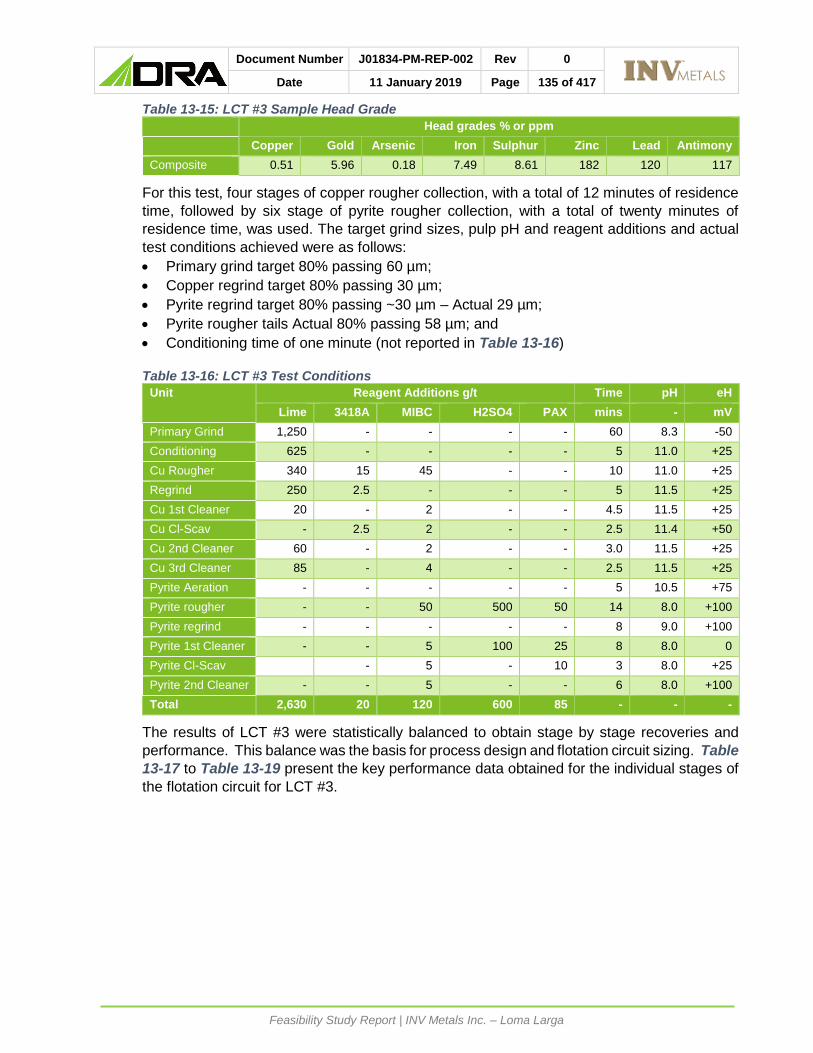
Document Number J01834-PM-REP-002 Rev 0
Date 11 January 2019 Page 135 of 417
Feasibility Study Report | INV Metals Inc. – Loma Larga
Table 13-15: LCT #3 Sample Head Grade
Head grades % or ppm
Copper Gold Arsenic Iron Sulphur Zinc Lead Antimony
Composite 0.51 5.96 0.18 7.49 8.61 182 120 117
For this test, four stages of copper rougher collection, with a total of 12 minutes of residence
time, followed by six stage of pyrite rougher collection, with a total of twenty minutes of
residence time, was used. The target grind sizes, pulp pH and reagent additions and actual
test conditions achieved were as follows:
• Primary grind target 80% passing 60 µm;
• Copper regrind target 80% passing 30 µm;
• Pyrite regrind target 80% passing ~30 µm – Actual 29 µm;
• Pyrite rougher tails Actual 80% passing 58 µm; and
• Conditioning time of one minute (not reported in Table 13-16)
Table 13-16: LCT #3 Test Conditions
Unit Reagent Additions g/t Time pH eH
Lime 3418A MIBC H2SO4 PAX mins - mV
Primary Grind 1,250 - - - - 60 8.3 -50
Conditioning 625 - - - - 5 11.0 +25
Cu Rougher 340 15 45 - - 10 11.0 +25
Regrind 250 2.5 - - - 5 11.5 +25
Cu 1st Cleaner 20 - 2 - - 4.5 11.5 +25
Cu Cl-Scav - 2.5 2 - - 2.5 11.4 +50
Cu 2nd Cleaner 60 - 2 - - 3.0 11.5 +25
Cu 3rd Cleaner 85 - 4 - - 2.5 11.5 +25
Pyrite Aeration - - - - - 5 10.5 +75
Pyrite rougher - - 50 500 50 14 8.0 +100
Pyrite regrind - - - - - 8 9.0 +100
Pyrite 1st Cleaner - - 5 100 25 8 8.0 0
Pyrite Cl-Scav - 5 - 10 3 8.0 +25
Pyrite 2nd Cleaner - - 5 - - 6 8.0 +100
Total 2,630 20 120 600 85 - - -
The results of LCT #3 were statistically balanced to obtain stage by stage recoveries and
performance. This balance was the basis for process design and flotation circuit sizing. Table
13-17 to Table 13-19 present the key performance data obtained for the individual stages of
the flotation circuit for LCT #3.

Document Number J01834-PM-REP-002 Rev 0
Date 11 January 2019 Page 136 of 417
Feasibility Study Report | INV Metals Inc. – Loma Larga
Table 13-17: LCT #3 Stream Balanced Data
Stage Assays % (Cu, Fe, As, S), g/t (Au, Ag)
Copper Gold Silver Arsenic Sulphur Iron
Flotation Feed 0.51 5.96 33.5 0.180 8.61 7.50
Copper Rougher 11.5 46.1 493 4.23 20.2 8.29
Copper 1st Cleaner 30.2 96.3 1270 10.9 36.0 14.1
Copper 2nd Cleaner 32.2 101 1348 11.7 36.0 12.9
Copper 3rd Cleaner 33.5 104 1397 12.1 35.9 12.2
Copper Cl-Scav 3.10 39.4 239 1.09 41.8 33.4
Pyrite rougher 0.18 16.4 50.1 0.039 34.2 30.4
Pyrite 1st Cleaner 0.28 22.7 61.2 0.089 42.9 36.9
Pyrite 2nd Cleaner 0.30 24.1 66.9 0.092 46.4 39.6
Pyrite Cl-Scav 0.13 11.5 17.29 0.059 17.5 14.9
Final Tails 0.02 0.98 5.38 0.005 1.07 1.39
Source: Promet101 (2018)
Table 13-18: LCT #3 Overall Recoveries Balanced Data
Stage Recoveries % of Feed
Mass Copper Gold Silver Arsenic Sulphur Iron
Copper Rougher 4.01 90.2 31.1 59.0 94.2 9.42 4.44
Copper 1st Cleaner 1.49 88.3 24.1 56.5 90.5 6.24 2.80
Copper 2nd Cleaner 1.40 88.2 23.6 56.1 90.4 5.84 2.41
Copper 3rd Cleaner 1.33 87.4 23.1 55.5 89.7 5.55 2.16
Copper Cl-Scav 0.10 0.61 0.66 0.72 0.60 0.49 0.45
Pyrite Rougher 21.5 7.48 59.0 32.1 4.60 85.2 87.1
Pyrite 1st Cleaner 17.7 9.71 67.3 32.3 8.76 88.3 87.1
Pyrite 2nd Cleaner 15.6 9.10 63.2 31.2 8.01 84.2 82.5
Pyrite Cl-Scav 0.13 0.03 0.25 0.11 0.04 0.26 0.25
Source: Promet101 (2018)
Table 13-19: LCT #3 Stage Recoveries Balanced Data
Stage Stage Recoveries %
Mass Copper Gold Silver Arsenic Sulphur Iron
Copper Rougher 4.01 90.2 31.1 59.0 94.2 9.4 4.44
Copper 1st Cleaner 34.9 96.4 73.7 93.1 94.7 58.9 50.6
Copper 2nd Cleaner 90.3 99.0 96.2 98.3 99.1 89.4 79.0
Copper 3rd Cleaner 95.0 99.2 97.8 98.9 99.2 95.0 89.6
Copper Cl-Scavenger 3.60 18.3 7.67 17.1 11.7 11.2 16.5
Pyrite Rougher 22.4 75.9 85.5 78.2 78.6 94.1 91.1
Pyrite 1st Cleaner 67.2 89.5 94.5 87.8 88.6 94.4 92.4
Pyrite 2nd Cleaner 88.3 93.7 94.0 96.5 91.4 95.4 94.7
Pyrite Cl-Scavenger 1.50 2.63 6.33 2.44 3.54 5.00 3.51
Source: Promet101 (2018)
The feed composite used for LCT #3 was relatively close in grade to that of the expected feed
gold grade of the process facilities for the first five years of operation, but almost double that
of the copper grade. A relatively high pulp pH was used to ensure low pyrite recovery in the
copper rougher stage, with a relatively low mass recovery being achieved (~4.01%) and good
copper (90.2%) and arsenic (94.2%) recoveries. Subsequent copper cleaner stages rejected
66.8% of the mass from the rougher concentrate, but only lost 2.8% of the copper. Gold and
sulphur rejected from the copper rougher concentrate being 8.0 and 3.9% respectively. The

Document Number J01834-PM-REP-002 Rev 0
Date 11 January 2019 Page 137 of 417
Feasibility Study Report | INV Metals Inc. – Loma Larga
copper concentrate grade achieved in the cleaning stages was 33.5% Cu, 12.1% As, 1,397
ppm Ag and 104 g/t Au. Gold recovery to the copper concentrate was 23.1% of total gold.
The pyrite rougher stage recovered 85.5% of the feed gold and 94.1% of the feed sulphur into
21.5% of the total feed. Subsequent cleaning of the pyrite rougher concentrate resulted in a
total of 63.2% of feed gold being recovered into the final pyrite concentrate. Note that for this
test the copper cleaner tails were sent to the pyrite first cleaner stage, not the pyrite rougher
feed.
Overall gold recovery was 86.3% at a feed grade of 5.96 g/t gold, as compared to 88.3% for
LCT #1 with a feed grade of 16.7 g/t gold and 86.9% for LCT #2 at a feed grade of 4.95 g/t
gold.
The different recoveries of copper and arsenic in the copper cleaner-scavenger stage implies
that there is some arsenic present in the form of arsenopyrite which is depressed, or non-
arsenic associated copper minerals. Arsenopyrite was noted in some of the QEMSCAN
analysis.
13.3.6.4 LOCKED CYCLE TEST #4
The objective of LCT4 was to test a more representative sample of the initial five-year average
LOM plan and confirm the influence of collector addition and residence time on the gold
recovery within the pyrite circuit.
Feed material for LCT #4 was composited from sub-samples of the “5-year composite” and
individual variability samples. The sample head grade of the final composite is presented in
Table 13-20.
Table 13-20: LCT #4 Sample Head Grade – 5 Year Composite
Head grades % or ppm
Copper Gold Arsenic Iron Sulphur Zinc Lead Antimony
Composite 0.25 5.10 0.092 5.94 6.47 177 198 101
This test utilized four stages of copper rougher collection with a total of 12 minutes of
residence time, followed by six stages of pyrite rougher collection, with a total of twenty
minutes of residence time.
The target grind sizes, pulp pH and reagent additions and actual test conditions achieved
were as follows:
• Primary grind target 80% passing 60 µm – Actual 67 µm;
• Copper regrind target 80% passing 30 µm – Actual 17 µm;
• Pyrite regrind target 80% passing 30 µm – Actual 31 µm;
• Pyrite rougher tails Actual 80% passing 55 µm;
• One minute of conditioning time (excluded from Table 13-21); and
• Moderate copper rougher pulp pH was targeted to limit lime consumption and acid use
in pyrite rougher feed.
The flowsheet used for this locked cycle test is presented in Figure 13-12 below.

Document Number J01834-PM-REP-002 Rev 0
Date 11 January 2019 Page 138 of 417
Feasibility Study Report | INV Metals Inc. – Loma Larga
Figure 13-12: LCT #4 Flowsheet

Document Number J01834-PM-REP-002 Rev 0
Date 11 January 2019 Page 139 of 417
Feasibility Study Report | INV Metals Inc. – Loma Larga
Table 13-21: LCT #4 Test Conditions
Unit Reagent additions g/t Time pH eH
Lime 3418A MIBC H2SO4 PAX mins - mV
Primary Grind 1250 - - - - 60 8.4 +25
Conditioning 870 - - - - 5.0 11.0 0
Cu Rougher 250 20 45 - - 12 11.0 +25
Regrind 250 2.5 - - - 3.0 11.3 +50
Cu 1st Cleaner 110 - 10 - - 4.5 11.5 +25
Cu Cl-Scavenger - 2.5 10 - - 2.5 11.4 +25
Cu 2nd Cleaner 85 - 10 - - 3.0 11.5 +25
Cu 3rd Cleaner 115 - 10 - - 2.5 11.5 +25
Pyrite Aeration - - - - - 5 - +50
Pyrite rougher - - 60 835 80 20 7.0 +100
Pyrite regrind - - - - - 9.0 8.7 +100
Pyrite 1st Cleaner - - 5 185 25 8 7.0 +50
Pyrite Cl-Scavenger - - 5 35 15 3 7.0 0
Pyrite 2nd Cleaner - - 5 45 - 6 7.0 +125
Total 2,930 25 160 1,100 120 - - -
The results of LCT #4 were balanced to obtain stage by stage recoveries and performance.
This balance (in conjunction with the results of LCT #3) was the basis for the project process
design and flotation circuit sizing stage recoveries. Table 13-22 to Table 13-24 present the
key performance data obtained for the individual stages of the flotation circuit for LCT #4.
Table 13-22: LCT #4 Stream Assays – Balanced Data
Stage Assays % (Cu, Fe, As, S), g/t (Au, Ag)
Copper Gold Arsenic Silver Sulphur Iron
Flotation Feed 0.25 5.15 0.093 24.1 6.38 5.98
Copper Rougher 5.59 23.1 2.07 304 18.6 18.9
Copper 1st Cleaner 15.1 43.7 5.55 932 27.8 16.9
Copper 2nd Cleaner 22.4 54.1 8.12 1,340 31.1 15.3
Copper 3rd Cleaner 27.4 61.7 10.1 1,615 32.6 13.6
Copper Cl-Scav 1.67 24.8 0.59 226 24.0 20.9
Pyrite Rougher 0.094 19.9 0.028 55.6 27.5 23.9
Pyrite 1st Cleaner 0.27 27.6 0.092 76.7 37.7 33.4
Pyrite 2nd Cleaner 0.29 29.6 0.098 82.4 40.5 35.8
Pyrite Cl-Scav 0.090 6.04 0.044 0.98 6.51 7.15
Final Tails 0.013 0.73 0.006 1.24 0.67 1.12
Source: Promet101 (2018)

Document Number J01834-PM-REP-002 Rev 0
Date 11 January 2019 Page 140 of 417
Feasibility Study Report | INV Metals Inc. – Loma Larga
Table 13-23: LCT #4 Overall Recoveries – Balanced Data
Stage Recoveries % of Feed
Mass Copper Gold Silver Arsenic Sulphur Iron
Copper Rougher 4.08 89.8 18.3 50.8 90.8 11.9 12.8
Copper 1st Cleaner 1.40 83.2 11.9 53.8 83.5 6.09 3.96
Copper 2nd Cleaner 0.93 82.0 9.77 51.6 81.2 4.53 2.38
Copper 3rd Cleaner 0.74 79.8 8.85 49.4 80.2 3.77 1.68
Copper Cl-Scav 0.45 2.96 2.16 4.3 2.86 1.69 1.57
Pyrite rougher 19.4 7.1 74.8 45.2 5.9 83.4 77.6
Pyrite 1st Cleaner 15.0 15.9 80.3 46.9 14.8 88.4 83.6
Pyrite 2nd Cleaner 13.8 15.7 79.1 46.2 14.4 87.2 82.3
Pyrite Cl-Scav 1.66 0.59 1.94 1.23 0.78 1.69 1.98
Source: Promet101 (2018)
Table 13-24: LCT #4 Stage Recoveries – Balanced Data
Stage Stage Recoveries %
Mass Copper Gold Silver Arsenic Sulphur Iron
Copper Rougher 4.08 89.8 18.3 50.8 90.8 11.9 12.8
Copper 1st Cleaner 27.0 86.5 50.6 90.4 86.1 38.4 23.7
Copper 2nd Cleaner 58.5 96.1 76.4 92.2 96.0 66.1 51.1
Copper 3rd Cleaner 79.6 97.3 90.6 95.8 98.7 83.2 70.6
Copper Cl-Scavenger 11.9 22.9 18.7 75.6 21.2 17.3 12.3
Pyrite rougher 20.2 70.1 91.4 91.8 64.2 94.6 89.0
Pyrite 1st Cleaner 58.6 88.7 91.9 96.7 83.8 93.7 90.8
Pyrite 2nd Cleaner 91.8 98.5 98.5 98.5 97.4 98.6 98.4
Pyrite Cl-Scavenger 15.7 29.1 27.6 76.4 27.2 28.5 23.5
Source: Promet101 (2018)
For this LCT, the copper rougher stage recovered 89.8% of the feed copper. For the LCT,
the copper rougher stage recovered 89.8% of the feed copper. Subsequent cleaning of the
rougher concentrate produced a cleaner concentrate, grading 27.4% Cu and 1,615 ppm
Silver. This corresponds to an overall of recovery 79.8% copper. Final mass recovery to
copper concentrate was low at only 0.74% of feed. Overall mass rejection in the copper
cleaner circuit was 81.8%.
The extended pyrite residence time and increased collector dosage resulted in excellent
sulphur (i.e. pyrite) and hence gold recovery to the pyrite rougher concentrate. Gold recovery
was 91.5%, copper recovery 88.7% and sulphur recovery 94.6% of feed to that stage. Note
that the copper cleaner tails stream with its associated gold was fed directly to the pyrite
cleaner circuit.
The final gold recovery to the pyrite concentrate being 79.1%. Overall gold recovery achieved
to the two concentrates was 88.0%.
13.3.7 STAGED FLOTATION REACTOR
The potential application of Woodgrove Technologies’ Staged Flotation Reactor (SFR) was
investigated as part of the 2017 metallurgical testwork program. Seven pilot plant scale SFR
rougher tests were conducted at SGS Lakefield. Composite and variability assay reject
material was used for all SFR testwork. The response to bench flotation of each pilot SFR

Document Number J01834-PM-REP-002 Rev 0
Date 11 January 2019 Page 141 of 417
Feasibility Study Report | INV Metals Inc. – Loma Larga
test feed sample (after reagent addition) was determined by SGS, for comparison purposes.
Table 13-25 summarizes the results obtained from the best performing metallurgical sample
(PP-01).
Table 13-25: SFR (PP-01) vs. Average Bench Flotation Performance
Element SFR Pilot Plant Bench Flotation (20 minutes)
Grade (g/t) Recovery Grade (g/t) Recovery
Au 18.9 88.5 20 91
Cu 0.89 93.3 0.84 94
Ag 106 88.0 105 92
Several findings were made during the SFR pilot plant preliminary program:
• The use of MIBC in conditioning and in the initial stages of the SFR tests increased
metallurgical performance. MIBC performance increased when used in conjunction with
X-133 frother;
• When directly compared to one another, X-133 frother outperformed W31 frother;
• Adding collector to the grind did not appear to positively affect overall metallurgical
performance;
• PAX addition was effective when added in doses 10 g/t and larger, though adding
significant amounts (30 g/t) did not result in improved metallurgical performance; and
• Little additional recovery occurs in the final eight minutes of bench flotation (from
minutes 12 to 20). Although the SFR performance is not optimized, it is anticipated that
the equivalent SFR performance for 12 minutes of bench-scale lab flotation time would
be eight stages of rougher SFRs.
13.4 SUPPLEMENTAL TESTWORK
Supplementary testwork was undertaken on tailings material produced from the Stage
Flotation Reactor testwork only. No supplementary testwork was undertaken on either the
pyrite or copper concentrates produced.
13.4.1 SETTLING
Flocculant BASF MF5250 was found to have the fastest free settling rate of the flocculant
samples tested with an estimated underflow solids concentration of 64.7% w/w.
The optimum feed solids concentration was measured to be 10% w/w using MF5250.
Dynamic thickening testwork was completed with a targeted feed concentration of 10% w/w.
Testwork investigated a range of flocculant dosages between 21 and 56 g/t and a range of
solids loading rates between 0.4 and 0.8 t/h/m².
Thickener underflow solids concentrations of 67.3% w/w, and a thickener overflow solids
concentration of 19 ppm were achieved at a solid loading rate of 0.6 t/h/m² and a flocculant
dosage of 29 g/t.

Document Number J01834-PM-REP-002 Rev 0
Date 11 January 2019 Page 142 of 417
Feasibility Study Report | INV Metals Inc. – Loma Larga
13.4.2 FILTRATION
13.4.2.1 VACUUM FILTRATION
The rougher tailings were tested at a vacuum level of 377 mm (15”) Hg, adjusted for a vacuum
pump efficiency of 85% (with one cycle time tested at 127 mm (5”) Hg to simulate blinding) at
50%, 60%, and 65% mass concentration. The cake thickness ranged from 2.8 to 18.1 mm
and cake moisture ranged from 19.1 to 22.4 % w/w.
13.4.2.2 PRESSURE FILTRATION
P&C undertook pressure filtration testwork. The testwork determined that cake moisture
levels as low as 15.5% can be achieved using pressure filtration. Filtration rates were found
to increase significantly with increasing chamber depths, reaching 324 (kg/h)/m² for a 60 mm
chamber with 30 seconds of air drying.
The conclusion from the testwork was that the tailings material is amenable to pressure
filtration.
13.4.3 RHEOLOGY
The uncemented tailings yield stress was determined over a mass concentration range from
75.4% w/w to 78.8% w/w. At 77.6% w/w, the calculated yield stress is 200 Pa.
The cemented tailings yield stress was determined over a mass concentration range from
74.5% w/w to 78.5% w/w. At 76.7% w/w (weight per weight) and 4% Guapan Type IP, the
calculated yield stress is 200 Pa.
13.5 RECOVERY ESTIMATES
Recovery estimates were derived from the sequential flotation locked cycle test completed
during the 2014 metallurgical program and LCT #3 and #4, completed during the 2017
metallurgical program.
Using the results, recovery relationships for gold and copper concentrates were developed.
13.5.1 COPPER RECOVERY
Figure 13-13 illustrates the copper recovery and concentrate grade figures obtained during
the locked cycle testwork.

Document Number J01834-PM-REP-002 Rev 0
Date 11 January 2019 Page 143 of 417
Feasibility Study Report | INV Metals Inc. – Loma Larga
Figure 13-13: Metallurgical Data and Model for Copper Recovery and Concentrate Grade
A copper concentrate recovery and concentrate grade model can be constructed from fitting
the data presented in Figure 13-13. The model is considered accurate for all copper head
grades (HCu) greater than 0.1% and less than 1.0%. Below lower limit, all copper is assumed
to report to the pyrite concentrate. Above a head grade of 1.0%, recovery is capped at 92%
and concentrate grade at 36%.
𝑅𝑒𝑐𝑜𝑣𝑒𝑟𝑦𝐶𝑢 = 9.0 ln 𝐻𝐶𝑢 + 92
𝐶𝑜𝑛𝑐𝑒𝑛𝑡𝑟𝑎𝑡𝑒𝐶𝑢 = 5.5 ln 𝐻𝐶𝑢 + 36

Document Number J01834-PM-REP-002 Rev 0
Date 11 January 2019 Page 144 of 417
Feasibility Study Report | INV Metals Inc. – Loma Larga
13.5.2 GOLD RECOVERY TO COPPER CONCENTRATE
Development of a gold recovery model to the copper concentrate is not as robust as that of
the copper model due to the significant variability in the association of gold with copper or iron
sulphide minerals. Figure 13-14 presents the gold deportment in the 2018 rougher variability
testing using the sequential flowsheet and the rougher and final cleaner stage recoveries for
the 2014 and 2018 LCTs.
Figure 13-14: Gold Deportment to Copper Concentrates
Figure 13-14 clearly shows that rougher and clear recoveries are highly variable. For the
2014 LCT the recovery at a high feed grade (12.5 Au g/t) was 17.5%
As a result of the observed variability, a fixed gold recovery to the copper final concentrate of
15% was assumed. This is considered the average of the locked cycle tests 3 and 4 from
2017 program and the median of the variability samples from the 2014 testwork program.

Document Number J01834-PM-REP-002 Rev 0
Date 11 January 2019 Page 145 of 417
Feasibility Study Report | INV Metals Inc. – Loma Larga
13.6 METALLURGICAL VARIABILITY
The metallurgical testwork completed to date is based on samples which adequately
represent the variability of the Loma Larga deposit and associated mine plan.
Mineralogical analysis of the various composites and variability samples has shown the Loma
Larga deposit to be homogenous.
13.7 DELETERIOUS ELEMENTS
Both copper and pyrite concentrates will be subject to penalty conditions, should significant
grades of zinc, lead, mercury, antimony, bismuth and arsenic be present in the concentrate.
In-situ assays of these elements within the block model are highly variable and recoveries are
difficult to predict based on the limited testwork focusing on these elements.
Table 13-26 and Table 13-27 presents the recoveries of the main deleterious elements into
the copper and pyrite concentrates, respectively. The results are based on the two LCT’s
completed in 2017 metallurgical testwork program.
Table 13-26: Deleterious Elements Recovery to Copper Concentrate
Element 2018 LCT # 3
Assay ppm/recoveries %
2028 LCT # 4
Assays ppm/Recoveries %
Recommended Recovery for
NSR Head Cons Rec Head Cons Rec
Zinc 151 3,100 28.4 177 8,815 38.5 35.0
Lead 103 760 9.97 198 3,380 0.29 5.0
Antimony 113 7,110 86.0 101 7,516 32.7 50.0
Mercury 3.49 85.5 33.6 - 79 - 30.0
Table 13-27: Deleterious Elements Recovery to Pyrite Concentrate
Element 2018 LCT # 3
Assay ppm/recoveries %
2028 LCT # 4
Assays ppm/Recoveries %
Recommended recovery for
NSR Head Cons Rec Head Cons Rec
Zinc 151 582 65.1 177 509 40.6 55.0
Lead 103 484 80.4 198 727 50.5 65.0
Antimony 113 70 9.72 101 <60 34.9 25.0
Mercury 3.49 12.1 57.0 - 15.9 - 50.0
The final assay value of bismuth in both the copper and pyrite concentrates indicated levels
less than 300 and 100 ppm, respectively.

Document Number J01834-PM-REP-002 Rev 0
Date 11 January 2019 Page 146 of 417
Feasibility Study Report | INV Metals Inc. – Loma Larga
MINERAL RESOURCE ESTIMATE
14.1 SUMMARY
RPA estimated Mineral Resources for the Loma Larga Project using all drillhole data available
as of October 31, 2018. This Mineral Resource estimate was previously updated June 30,
2016 and reported in the 2016 Technical Report (RPA, 2016). The current Mineral Resource
estimate is based on an underground mining scenario and is reported inclusive of Mineral
Reserves. Using a US$60/t Net Smelter Return (NSR) cut-off value, Mineral Resources as
of October 31, 2018 are summarized in Table 14-1.
Table 14-1: Mineral Resource Estimate Summary – October 31, 2018
Resource Classification
Tonnage
(Mt)
Au
(g/t)
Contained Au
(M oz)
Ag
(g/t)
Contained Ag
(M oz)
Cu
(%)
Contained Cu
(M lb)
Grade
(g/t AuEq)
Contained Gold
Equivalent
(M oz AuEq)
Measured 2.9 7.31 0.67 34.9 3.2 0.44 28.2 8.45 0.78
Indicated 17.0 3.74 2.04 26.5 14.5 0.22 81.4 4.43 2.42
Measured + Indicated
19.8 4.25 2.71 27.8 17.7 0.25 109.5 5.01 3.20
Inferred 4.7 2.22 0.33 29.7 4.5 0.14 14.5 2.84 0.43
Notes:
CIM (2014) definitions were followed for Mineral Resources.
Mineral Resources are reported at an NSR cut-off value of US$60/t.
Mineral Resources are estimated using a long-term gold price of US$1,450 per ounce, silver price of US$22.00 per ounce, and copper price of US$3.50 per pound.
The formula used to calculate gold equivalence (AuEq) is: (Au g/t x 31.31 + Ag g/t x 0.44 + Cu% x 46.19) ÷ 31.31. The formula used for calculated AuEq ounces is: AuEq Oz = (Tonnage x AuEq g/t) ÷ 31.1035
Mineral Resources are inclusive of Mineral Reserves.
Mineral Resources that are not Mineral Reserves do not have demonstrated economic viability.
Average bulk density is 2.7 t/m3.
Numbers may not add due to rounding.
RPA was provided with a drillhole database consisting of 365 holes, totalling 81,183 m, with
249 of the holes (58,990 m) located within the mineralization domains. INV completed two
drilling programs on the Project since the 2016 Technical Report and the current Mineral
Resource update incorporates the new drilling results.
Three-dimensional (3D) grade shell wireframes were constructed at 2.0 g/t Au (High Grade
Zone) and 0.8 g/t Au (Low Grade Zone). RPA used cross sections, long sections, and plan
views to interpret and validate the wireframes.
The Loma Larga High Grade Zone comprises two mineralized zones: High Grade Main Zone
and High Grade Upper Zone. The Low Grade Zone comprises two domains: Low Grade Main
Zone wireframe domain that encompasses the High Grade Main Zone, and Low Grade Lower
Zone, which lies below the Low Grade Main Zone.
Variography was performed on the 2.0 m Au, Ag, Cu, S, and density composites from the
High Grade Main Zone and Low Grade Main Zone. Block grade interpolation was carried out
using Ordinary Kriging (OK) and the gold grade shell wireframe models were used to
constrain the grade interpolations. A soft boundary was used between the Low and High
Grade Main Zones for density block interpolation.
The polymetallic sulphide mineralization at the Loma Larga deposit contains significant values
of Au, Ag, and Cu. Therefore, original assays were converted into NSR values ($ per tonne).

Document Number J01834-PM-REP-002 Rev 0
Date 11 January 2019 Page 147 of 417
Feasibility Study Report | INV Metals Inc. – Loma Larga
The NSR values account for parameters such as metal price, metallurgical recoveries,
smelter terms and refining charges, and transportation costs. For the purposes of developing
an NSR cut-off value for an underground operation, a total operating cost of US$60/t milled
was assumed, which includes mining, processing, and general and administrative (G&A)
expenses.
RPA is not aware of any environmental, permitting, legal, title, taxation, socio-economic,
marketing, political, or other relevant factors that could materially affect the Mineral Resource
estimate.
14.2 MINERAL RESOURCE DATABASE
RPA received new drillhole data in CSV format. Data were amalgamated and parsed as
required and imported into GEMS for modelling. Table 14-2 summarizes records directly
related to the resource estimate.
Table 14-2: Mineral Resource Database
Attribute Number
Holes 249 (199 with sulphur assays)
Surveys 806
Assays (payable metals) 23,857 (10,816 within mineralization domains)
Assays (sulphur) 13,688 (6,890 within mineralization domains)
Assay Composites (>0.5 m in length) 6,236
Sulphur Composites (>0.5 m in length) 3,993
Full zone width composites 692
Density measurements 10,153 (7,767 within mineralization domains)
Density Composites (>0.5 m in length) 4,988
Section 12, Data Verification, describes the verification steps undertaken by RPA. In
summary, all minor discrepancies identified were resolved and RPA is of the opinion that the
GEMS drillhole database is valid and suitable to estimate Mineral Resources for the Project.
14.3 GEOLOGICAL INTERPRETATION AND 3D SOLID
The wireframe model of the mineralized domains was used to constrain block model
interpretation.
Prior to creating the mineralized wireframe domains for the Loma Larga Project, RPA
validated the drillhole database by completing the following:
• Checking for location and elevation discrepancies by comparing collar coordinates with
historical data,
• Checking for inconsistencies in drillhole dip directions, and
• Checking gaps, overlaps, and out-of-sequence intervals for both assay and lithology
tables.
For the High Grade Zone, RPA reinterpreted the mineralized wireframe domains, restricting
the modelling cut-off grade to 2.0 g/t Au. The High Grade Zone 3.0 g/t Au wireframe model
from the previous resource estimate was used to assist in domaining the mineralization. The
modelling cut-off grade was reduced to align with the mine design and planning process.

Document Number J01834-PM-REP-002 Rev 0
Date 11 January 2019 Page 148 of 417
Feasibility Study Report | INV Metals Inc. – Loma Larga
For the Low Grade Zone, RPA updated the wireframe domains at a modelling cut-off grade
of 0.8 g/t Au with new drilling. The Low Grade Lower Zone was combined into a single
domain.
The Loma Larga High Grade Zone comprises two mineralized domains: Main and Upper
(Figure 14-1, Figure 14-2 and Figure 14-3). The Loma Larga Low Grade Zone also
comprises two mineralized domains: Main and Lower (Figure 14-1, Figure 14-2 and Figure
14-3). Mineralization in the High Grade Zone and Low Grade Zone has been categorized into
rock codes according to Table 14-3.
Table 14-3: Rock Codes
Mineralization GEMS Solid Name Rock Code Volume (m3)
High Grade Main Zone 130/final/2018 130 4,854,433
High Grade Upper Zone 131/final/2018 131 64,605
Low Grade Main Zone1 108/final/2018 108 13,420,552
Low Grade Lower Zone 208/final/2018 208 922,193
Note: 1inclusive of the High Grade Main Zone
A description of each modelled zone follows.
14.3.1 HIGH GRADE ZONE
• The High Grade Main Zone is a north-northwest trending, flattened, cigar-shaped zone.
It is approximately 1,150 m in length and 120 m to 290 m in width, averages 40 m to
50 m in thickness, and lies about 120 m to 125 m below the surface. The Main Zone is
intersected by 199 drillholes, i.e., 16 more than in the 2016 model (RPA, 2016).
• The High Grade Upper Zone is a north-northeast trending, tabular body approximately
125 m in length by 55 m in width, averaging 10 m in thickness. It lies 55 m to 60 m
below the surface and approximately 60 m above the Main Zone. The zone plunges
steeply to the south (approximately 60º) and the width of mineralization increases from
approximately 5 m to 20 m. The Upper Zone is intersected by six drillholes.
14.3.2 LOW GRADE ZONE
• The Low Grade Main Zone is a north-trending elongated zone that encompasses the
High Grade Main Zone and is nearly 1,600 m in length and ranges from 100 m to 400 m
in width. It averages approximately 50 m to 60 m thick and lies approximately 110 m to
120 m below the surface. It is intersected by 247 drillholes and dips at approximately
two degrees to the south.
• The Low Grade Lower Zone is a northeast trending, generally flat-lying, tabular body
approximately 200 m in length by 120 m to 340 m in width, averaging 10 m to 20 m in
thickness. It lies 10 m to 20 m below the Low Grade Main Zone and is intersected by 37
drillholes.
14.3.3 HIGH GRADE ZONE INTERPRETATION
Mineralization for the High Grade Zone Main Zone was interpreted RPA using GEOVIA
GEMS 6.8.2 (GEMS). Sectional interpretations were performed on screen via strings
snapped to drillhole intersections on northwest-southeast vertical cross sections spaced 12.5
m apart and plans spaced at a minimum of 25 m. Above the High Grade Main Zone, where

Document Number J01834-PM-REP-002 Rev 0
Date 11 January 2019 Page 149 of 417
Feasibility Study Report | INV Metals Inc. – Loma Larga
spatial continuity was evident base on drillhole spacing, the high-grade assays were
incorporated into the High Grade Upper Zone.
Strings were joined together using tie lines to honour the drillhole assay data between
sections and triangulated to build 3D wireframe solids. At model extremities, strings were
extrapolated along dip approximately 10-15 m or less, unless lithological interpretation
suggested extending mineralization further. The zones of interpreted mineralization were
generally contiguous; however, the wireframes were extended through drillholes with low
grade or narrow intersections to preserve continuity.
The re-interpretation at a 2.0 g/t Au cut-off grade resulted in a volume increase of
approximately 28% (High Grade Main Zone only), when compared to the High Grade Zone,
also modelled at a 3.0 g/t Au cut-off, from the 2016 resource estimate (4.85 Mm3 versus 3.78
Mm3).
14.3.4 LOW GRADE ZONE INTERPRETATION
Mineralization for the Low Grade Zone was interpreted using northwest-southeast sections
spaced at 25 m and plans spaced at a minimum of 25 m. Based on the visual continuity of
assay results and using the 2016 Low Grade Zone wireframe model as a guide, sections and
plans were used to make an on-screen interpretation of grade shells at a cut-off of 0.8 g/t Au.
Sectional interpretations were performed on screen via strings snapped to drillhole
intersections on the northwest-southeast oriented cross. Polylines were joined together in 3D
using tie lines. At the model extremities and along section lines, polylines were extrapolated
less than 25 m beyond the last drillhole section. Solids were further reviewed in longitudinal
sections in order to confirm continuity. RPA made minor modifications to the interpretation
along the margins of the Low Grade Main Zone and combined the two domains that
comprised the Low Grade Lower Zone in the previous resource estimate into a single
wireframe.
The incorporation of new drilling and the minor modifications to interpretation of the Low
Grade Zone wireframes has resulted in the following changes when compared to the 2016
Mineral Resource estimate:
• A volume increase of less than 1.2% in the Low Grade Main Zone inclusive of the
nested High Grade Main Zone (13.4 Mm3 vs. 13.3 Mm3).
• An increase of 4.8% in the Low Grade Lower Zone (0.92 Mm3 vs. 0.88 Mm3), when
compared to the Low Grade Zone, also modelled at a 0.8 g/t Au cut-off grade.
• Exclusive of the High Grade Main Zone, the volume of the Low Grade Main Zone has
decreased 11% (8.6 Mm3 vs. 9.5 Mm3).
Figure 14-1 illustrates the revisions to the Low Grade Zone wireframes in plan view.
All Mineral Resources estimated on the Loma Larga Project are located within the mineralized
zone wireframes.
RPA notes that there are additional drillhole intercepts outside the mineralized wireframe
domains that are greater than 2.0 g/t Au and represent exploration potential. In RPA’s
opinion, the isolated location and narrow thickness of these intercepts together with the wide
drillhole spacing, or substantial intervening material that is below the cut-off grade, precludes
the inclusion of the intercepts as Mineral Resources at this time.

Document Number J01834-PM-REP-002 Rev 0
Date 11 January 2019 Page 150 of 417
Feasibility Study Report | INV Metals Inc. – Loma Larga
Figure 14-1: 2018 versus 2016 Wireframe Domains in Plan View (3,600 m Level)

Document Number J01834-PM-REP-002 Rev 0
Date 11 January 2019 Page 151 of 417
Feasibility Study Report | INV Metals Inc. – Loma Larga
Figure 14-2: 3D View of 2018 High Grade (2.0 g/t Au) and Low Grade (0.8 g/t Au) Wireframe Domains, Looking Northeast.
Figure 14-3: 3D View of 2018 High Grade (2.0 g/t Au) and Low Grade (0.8 g/t Au) Wireframe Domains, Looking West.
14.4 STATISTICAL ANALYSIS
Assay values located inside the wireframes, or resource assays, were tagged with
mineralized zone domain identifiers (rock codes) and exported for statistical analysis. RPA
compiled and reviewed the basic statistics for Au, Ag, and Cu assays, which are summarized
in Table 14-4.

Document Number J01834-PM-REP-002 Rev 0
Date 11 January 2019 Page 152 of 417
Feasibility Study Report | INV Metals Inc. – Loma Larga
Table 14-4: Descriptive Statistics of Resource Assay Values Length (m) Au (g/t) Ag (g/t) Cu (ppm)
High Grade Main Zone
No. of Cases 5,255 5,255 5,255 5,255
Minimum 0.07 0.00 0.50 1
Maximum 4.43 768.67 2,295.6 204,000
Median 1.00 3.46 16.60 1,169
Length Weighted Mean - 6.40 33.21 3,762
Standard Deviation 0.33 18.24 65.78 10,242
Coefficient of Variation 0.31 2.85 1.98 2.72
High Grade Upper Zone
No. of Cases 67 67 67 67
Minimum 0.52 0.21 0.10 53
Maximum 2.00 105.50 250.1 67,000
Median 1.10 3.28 13.49 2,604
Length Weighted Mean - 9.51 26.13 6,078
Standard Deviation 0.45 18.15 38.93 9,966
Coefficient of Variation 0.37 1.91 1.49 1.64
High Grade Zone Total
No. of Cases 5,322 5,322 5,322 5,322
Minimum 0.07 0.00 0.10 1
Maximum 4.43 768.67 2,295.6 204,000
Median 1.00 3.46 16.50 1,180
Length Weighted Mean - 6.45 33.10 3,796
Standard Deviation 0.33 18.24 65.47 10,240
Coefficient of Variation 0.31 2.83 1.98 2.70
Low Grade Main Zone1
No. of Cases 4,839 4,839 4,839 4,839
Minimum 0.18 0.01 0.00 1
Maximum 5.00 101.80 1,743.0 216,000
Median 1.00 1.25 6.70 338
Length Weighted Mean - 1.67 16.16 920
Standard Deviation 0.39 2.88 49.11 3,505
Coefficient of Variation 0.33 1.72 3.04 3.81
Low Grade Lower Zone1
No. of Cases 655 655 655 655
Minimum 0.24 0.02 0.20 8
Maximum 3.00 59.33 721.0 126,800
Median 1.00 1.62 10.20 990
Length Weighted Mean - 2.19 15.89 1,969
Standard Deviation 0.32 2.88 37.44 6,977
Coefficient of Variation 0.30 1.31 2.36 3.54
Low Grade Zone Total1
No. of Cases 5,494 5,494 5,494 5,494
Minimum 0.18 0.01 0.00 1
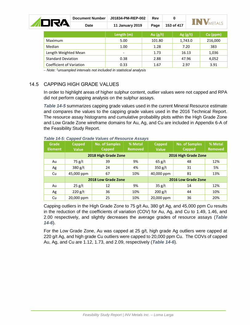
Document Number J01834-PM-REP-002 Rev 0
Date 11 January 2019 Page 153 of 417
Feasibility Study Report | INV Metals Inc. – Loma Larga
Length (m) Au (g/t) Ag (g/t) Cu (ppm)
Maximum 5.00 101.80 1,743.0 216,000
Median 1.00 1.28 7.20 383
Length Weighted Mean - 1.73 16.13 1,036
Standard Deviation 0.38 2.88 47.96 4,052
Coefficient of Variation 0.33 1.67 2.97 3.91
Note: 1unsampled intervals not included in statistical analysis
14.5 CAPPING HIGH GRADE VALUES
In order to highlight areas of higher sulphur content, outlier values were not capped and RPA
did not perform capping analysis on the sulphur assays.
Table 14-5 summarizes capping grade values used in the current Mineral Resource estimate
and compares the values to the capping grade values used in the 2016 Technical Report.
The resource assay histograms and cumulative probability plots within the High Grade Zone
and Low Grade Zone wireframe domains for Au, Ag, and Cu are included in Appendix 6-A of
the Feasibility Study Report.
Table 14-5: Capped Grade Values of Resource Assays
Grade Element
Capped
Value
No. of Samples Capped
% Metal Removed
Capped
Value
No. of Samples Capped
% Metal Removed
2018 High Grade Zone 2016 High Grade Zone
Au 75 g/t 39 9% 65 g/t 48 12%
Ag 380 g/t 24 4% 350 g/t 31 5%
Cu 45,000 ppm 67 10% 40,000 ppm 81 13% 2018 Low Grade Zone 2016 Low Grade Zone
Au 25 g/t 12 9% 35 g/t 14 12%
Ag 220 g/t 36 10% 200 g/t 44 10%
Cu 20,000 ppm 25 10% 20,000 ppm 36 20%
Capping outliers in the High Grade Zone to 75 g/t Au, 380 g/t Ag, and 45,000 ppm Cu results
in the reduction of the coefficients of variation (COV) for Au, Ag, and Cu to 1.49, 1.46, and
2.00 respectively, and slightly decreases the average grades of resource assays (Table
14-6).
For the Low Grade Zone, Au was capped at 25 g/t, high grade Ag outliers were capped at
220 g/t Ag, and high grade Cu outliers were capped to 20,000 ppm Cu. The COVs of capped
Au, Ag, and Cu are 1.12, 1.73, and 2.09, respectively (Table 14-6).

Document Number J01834-PM-REP-002 Rev 0
Date 11 January 2019 Page 154 of 417
Feasibility Study Report | INV Metals Inc. – Loma Larga
Table 14-6: Descriptive Statistics of Resource Capped Assay Values Length (m) Au (g/t) Ag (g/t) Cu (ppm)
High Grade Main Zone
No. of Cases 5,255 5,255 5,255 5,255
Minimum 0.07 0.00 0.50 1
Maximum 4.43 75.00 380.0 45,000
Median 1.00 3.46 16.60 1,169
Length Weighted Mean - 5.79 31.92 3,368
Standard Deviation 0.33 8.53 46.46 6,767
Coefficient of Variation 0.31 1.47 1.46 2.01
High Grade Upper Zone
No. of Cases 67 67 67 67
Minimum 0.52 0.21 0.10 53
Maximum 2.00 75.00 250.1 45,000
Median 1.10 3.28 13.49 2,604
Length Weighted Mean - 8.99 26.13 5,871
Standard Deviation 0.45 15.70 38.93 8,849
Coefficient of Variation 0.37 1.75 1.49 1.51
High Grade Zone Total
No. of Cases 5,322 5,322 5,322 5,322
Minimum 0.07 0.00 0.10 1
Maximum 4.43 75.00 380.0 45,000
Median 1.00 3.46 16.50 1,180
Length Weighted Mean - 5.84 31.84 3,404
Standard Deviation 0.33 8.68 46.36 6,807
Coefficient of Variation 0.31 1.49 1.46 2.00
Low Grade Main Zone1
No. of Cases 4,839 4,839 4,839 4,839
Minimum 0.18 0.01 0.00 1
Maximum 5.00 25.00 220.0 22,000
Median 1.00 1.25 6.70 338
Length Weighted Mean - 1.62 14.51 848
Standard Deviation 0.39 1.83 25.56 1,832
Coefficient of Variation 0.33 1.13 1.76 2.16
Low Grade Lower Zone1
No. of Cases 655 655 655 655
Minimum 0.24 0.02 0.20 8
Maximum 3.00 25.00 220.0 22,000
Median 1.00 1.62 10.20 990
Length Weighted Mean - 2.15 14.66 1,629
Standard Deviation 0.32 2.23 20.87 2,654
Coefficient of Variation 0.30 1.04 1.42 1.63
Low Grade Zone Total1
No. of Cases 5,494 5,494 5,494 5,494
Minimum 0.18 0.01 0.00 1

Document Number J01834-PM-REP-002 Rev 0
Date 11 January 2019 Page 155 of 417
Feasibility Study Report | INV Metals Inc. – Loma Larga
Length (m) Au (g/t) Ag (g/t) Cu (ppm)
Maximum 5.00 25.00 220.0 22,000
Median 1.00 1.28 7.20 383
Length Weighted Mean - 1.68 14.52 934
Standard Deviation 0.38 1.88 25.08 1,956
Coefficient of Variation 0.33 1.12 1.73 2.09
Note: 1unsampled intervals not included in statistical analysis
14.6 COMPOSITING
Assay sample lengths range from 0.07 m to 5.00 m within the wireframe domains. Slightly
less than half the samples (47%) were taken at 1.0 m lengths. The median assay length is
1.0 m and mean assay length is 1.11 m. Approximately 0.7% have lengths greater than 2.0
m. Given these distributions and considering the width of mineralization, RPA determined
that a composite length of 2.0 m was appropriate.
A set of wireframe intersection intervals were identified for each drillhole within the
mineralized wireframe domains and resource assays were composited starting at the first
composite control interval from the collar and resetting at each new wireframe boundary.
Within the Low Grade Zone wireframe models, unsampled intervals were treated as null.
Within the High Grade Zone wireframe models, all unsampled intervals were metallurgical
samples and treated as unsampled. A total of 151 Au, Ag, and Cu composites measuring
less than 0.5 m were removed from the database prior to statistical analysis, variography, and
resource estimation. The elimination of the small composites did not affect the overall
integrity of the composited database.
Table 14-7 summarizes statistics of the capped and uncapped composite resource assay
values. When Au, Ag, and Cu values are compared to uncapped resource assays, the
average grades have decreased slightly, while the COV values have been greatly reduced.

Document Number J01834-PM-REP-002 Rev 0
Date 11 January 2019 Page 156 of 417
Feasibility Study Report | INV Metals Inc. – Loma Larga
Table 14-7: Descriptive Statistics of Resource Capped Composite Values
Uncapped Capped
Au (g/t) Ag (g/t) Cu (ppm) Au (g/t) Ag (g/t) Cu (ppm)
High Grade Main Zone
No. of Cases 2,846 2,846 2,846 2,846 2,846 2,846
Minimum 0.24 0.70 1 0.24 0.70 1
Maximum 341.68 1,483.8 143,469 75.00 373.6 45,000
Median 3.70 18.57 1,331 3.69 18.56 1,331
Arithmetic Mean 6.38 33.38 3,744 5.78 32.07 3,352
Standard Deviation 14.18 55.82 8,581 7.44 41.23 5,871
Coefficient of Variation 2.22 1.67 2.29 1.29 1.29 1.75
High Grade Upper Zone
No. of Cases 43 43 43 43 43 43
Minimum 0.27 1.20 65 0.27 1.20 65
Maximum 60.29 130.4 33,732 43.51 130.4 25,262
Median 3.86 15.00 3,183 3.86 15.00 3,183
Arithmetic Mean 9.38 26.06 6,154 8.89 26.06 5,956
Standard Deviation 12.12 26.91 7,563 10.38 26.91 6,910
Coefficient of Variation 1.29 1.03 1.23 1.17 1.03 1.16
High Grade Zone Total
No. of Cases 2,889 2,889 2,889 2,889 2,889 2,889
Minimum 0.24 0.70 1 0.24 0.70 1
Maximum 341.68 1,483.8 143,469 75.00 373.6 45,000
Median 3.71 18.50 1,346 3.71 18.49 1,345
Arithmetic Mean 6.42 33.27 3,780 5.83 31.98 3,391
Standard Deviation 14.16 55.50 8,570 7.50 41.06 5,895
Coefficient of Variation 2.20 1.67 2.27 1.29 1.28 1.74
Low Grade Main Zone
No. of Cases 2,968 2,968 2,968 2,968 2,968 2,968
Minimum 0.00 0.00 0 0.00 0.00 0
Maximum 71.04 1,385.4 78,334 24.46 220.0 22,000
Median 1.31 7.11 373 1.31 7.10 372
Arithmetic Mean 1.64 16.00 896 1.59 14.38 826
Standard Deviation 2.29 44.68 2,551 1.51 23.50 1,482
Coefficient of Variation 1.39 2.79 2.85 0.95 1.63 1.79
Low Grade Lower Zone
No. of Cases 368 368 368 368 368 368
Minimum 0.00 0.00 0 0.00 0.00 0
Maximum 24.00 434.9 75,711 15.77 207.1 20,917
Median 1.66 10.85 1,037 1.64 10.85 1,027
Arithmetic Mean 2.14 15.69 1,942 2.10 14.41 1,600
Standard Deviation 2.13 32.14 5,849 1.82 19.20 2,354
Coefficient of Variation 0.99 2.05 3.01 0.87 1.33 1.47
Low Grade Zone Total
No. of Cases 3,336 3,336 3,336 3,336 3,336 3,336
Minimum 0.00 0.00 0 0.00 0.00 0
Maximum 71.04 1,385.4 78,334 24.46 220.0 22,000
Median 1.34 7.61 419 1.34 7.60 419
Arithmetic Mean 1.70 15.97 1,011 1.65 14.38 912
Standard Deviation 2.27 43.47 3,109 1.55 23.06 1,619
Coefficient of Variation 1.34 2.72 3.07 0.94 1.60 1.78

Document Number J01834-PM-REP-002 Rev 0
Date 11 January 2019 Page 157 of 417
Feasibility Study Report | INV Metals Inc. – Loma Larga
14.7 DENSITY
IAMGOLD began a systematic density measurement program at the Project in 2005
(IAMGOLD, 2009). To estimate densities, representative samples of typical lithology,
alteration, and mineralization styles were collected. Selected core was sealed in wax before
estimating the density using the water immersion method.
The Loma Larga density database included 10,793 density measurements covering a diverse
range of lithology, mineralization, and alteration types. Approximately 72% (7,767) of the
measurements were located within the mineralized wireframe domains. RPA reviewed the
descriptive statistics for density samples taken within the mineralization wireframes (Table
14-8). Although the density data shows an approximately normal distribution, there is a long
tail to the right of the mean (positively skewed). RPA reviewed the descriptive statistics (Table
14-8), histograms Figure 14-4) box plots (Figure 14-5) for density samples taken within the
mineralization wireframes the data, and determined that there were no high density outliers
that should be removed from the data set. RPA further tested whether density weighting
should be applied to grade interpolation and concluded that there was no strong correlation
between grade and density.
Table 14-8: Descriptive Statistics of Resource Density Values
Domain Rock Code
No. of Cases
Min
(g/cm3)
Max
(g/cm3)
Median
(g/cm3)
Arithmetic Mean
Std.
Dev.
COV
High Grade Zone
130 3,995 1.85 4.75 2.66 2.76 0.34 0.12
131 27 2.51 3.01 2.69 2.72 0.15 0.05
All High Grade Zone 4,022 1.85 4.75 2.66 2.76 0.34 0.12
Low Grade Zone
108 3,298 1.77 4.29 2.59 2.62 0.23 0.09
208 447 2.02 4.44 2.61 2.68 0.29 0.11
All Low Grade Zone 3,745 1.77 4.44 2.60 2.62 0.24 0.09
All Composites 7,767 1.77 4.75 2.62 2.70 0.30 0.11

Document Number J01834-PM-REP-002 Rev 0
Date 11 January 2019 Page 158 of 417
Feasibility Study Report | INV Metals Inc. – Loma Larga
Figure 14-4: Histogram of Resource Density Samples

Document Number J01834-PM-REP-002 Rev 0
Date 11 January 2019 Page 159 of 417
Feasibility Study Report | INV Metals Inc. – Loma Larga
Figure 14-5: Box Plot of Resource Density Samples by Domain
The average density of the High Grade Main and Upper Zones is 2.76 g/cm3 and 2.72 g/cm3,
respectively. The Low Grade Main and Lower Zones have average density values of 2.62
g/cm3 and 2.68 g/cm3, respectively, and these values are consistent with those calculated by
RPA in 2012 and 2016.
As with the resource assays, density samples were composited to 2.0 m, starting at the first
mineralized wireframe boundary from the collar and resetting at each new wireframe
boundary. Composites less than 0.5 m were removed from the database for Mineral
Resource estimation and unsampled intervals were treated as unsampled.
Table 14-9 summarizes the descriptive statistics of the composited resource density samples.

Document Number J01834-PM-REP-002 Rev 0
Date 11 January 2019 Page 160 of 417
Feasibility Study Report | INV Metals Inc. – Loma Larga
Table 14-9: Descriptive Statistics of Composited Density Samples
Domain Rock Code
No. of Cases
Min
(g/cm3)
Max
(g/cm3)
Median
(g/cm3)
Arithmetic Mean
Std.
Dev.
COV
High Grade Zone
130 2,201 2.09 4.46 2.68 2.74 0.25 0.09
131 21 2.38 2.90 2.65 2.67 0.12 0.05
All High Grade Zone 2,222 2.09 4.46 2.68 2.74 0.25 0.09
Low Grade Zone
108 2,474 1.85 3.61 2.57 2.58 0.18 0.07
208 292 2.20 3.90 2.59 2.65 0.23 0.09
All Low Grade Zone 2,766 1.85 3.90 2.57 2.59 0.19 0.07
All Composites 4,988 1.850 4.460 2.62 2.657 0.23 0.09
14.8 NSR CUT-OFF VALUE
The shallow depth of the mineralized zone at Loma Larga makes it amenable to either open
pit or underground mining methods. The large stripping ratio that would be required for an
open pit, and the resulting large tonnage of potentially acid-generating waste rock, however,
has led to the selection of underground mining as the most appropriate method with the
smallest environmental footprint for the Project. Thus, a potential underground production
scenario serves as the basis for estimating the cut-off grade for Mineral Resources.
NSR factors were developed by RPA for the purposes of Mineral Resource reporting. NSR
is the estimated value per tonne of mineralized material after allowance for metallurgical
recovery and consideration of smelter terms, which may include payables, treatment charges,
refining charges, price participation, penalties, smelter losses, transportation, and sales
charges. These assumptions, summarized in Table 14-10, are based on the current
processing scenario and results from metallurgical testwork.
Table 14-10: Cut-Off Value Assumptions
Unit 2018
Metal Recovery
Pyrite Concentrate Au 75%
Ag 45%
Cu 17%
As 14%
Copper Concentrate Au 15%
Ag 50%
Cu 79%
As 83%
Operating Costs
Mining Underground $/t 31.00
Processing (1.05 M tpa) $/t 20.00
G&A $/t 7.56
Total (Rounded) $/t 60
NSR Royalty 5%

Document Number J01834-PM-REP-002 Rev 0
Date 11 January 2019 Page 161 of 417
Feasibility Study Report | INV Metals Inc. – Loma Larga
The net revenue from each metal is used to calculate an NSR factor, representing revenue
(US$) per metal grade unit (per g/t Au, for example). RPA multiplied block grades by the
following factors to calculate NSR: $31.31 per g/t Au, $0.44 per g/t Ag, and $46.19 per % Cu,
for each block in the model.
Although various inputs to the NSR calculation have changed from those used in the 2016
Mineral Resource estimate, the net effect on the NSR factors is not significant.
The NSR value (in units of US$ per tonne) for each block in the block model, was compared
directly to unit operating costs required to mine that block. For the purposes of developing
an NSR cut-off value for an underground mining operation, a total operating cost of US$60/t
milled was assumed, which includes mining, processing, and G&A expenses. The NSR cut-
off value remains unchanged from the 2016 Technical Report.
All classified resource blocks located within the mineralized wireframe domains with NSR
values greater than US$60/t were included in the Mineral Resource estimate. RPA reviewed
the blocks above the cut-off to found continuity to be reasonable.
In RPA’s opinion, an NSR of US$60/t (rounded) is suitable for an underground mining
scenario.
14.9 VARIOGRAPHY AND INTERPOLATION VALUES
RPA re-evaluated variography for Au, Ag, Cu, and density and also prepared variograms
using composites located within the main mineralized domains. The nugget effect was
established with the downhole linear semi-variogram and was well developed in all cases.
The longest semi-variogram ranges were consistently oriented parallel to and across strike in
the horizontal plane. Variogram models for gold, silver, copper, and density are included in
Appendix 6-A of the Feasibility Study Report.
For both the High Grade and Low Grade Zones, grades for Au, Ag, and Cu were interpolated
using Ordinary Kriging (OK) and density values were also interpolated using OK. Variography
was used to determine the search ellipsoid orientation and dimensions. Parameters derived
for the High Grade Main Zone were applied to the High Grade Upper Zone and the parameters
derived for the Low Grade Main Zone were applied the Low Grade Lower Zone. Interpolation
and search parameters used by RPA are summarized in Table 14-11.

Document Number J01834-PM-REP-002 Rev 0
Date 11 January 2019 Page 162 of 417
Feasibility Study Report | INV Metals Inc. – Loma Larga
Table 14-11: Block Estimation Parameters
Parameter1
Au Ag Cu Density
Method OK OK OK OK
Boundary Type Hard Hard Hard Soft
High Grade Zone Sample Restrictions
Min. No. Comps. 4 4 4 3
Max. No. Comps. 12 12 12 15
Max. Comps. Per Drill Hole 3 3 3 3
High Grade Zone Search Ellipse
Range X (m) 200 180 190 300
Range Y (m) 140 150 140 240
Range Z (m) 40 60 65 55
High Grade Zone Search Anisotropy1
Z +0° +165° +165° -160°
Y +0° +15° +10° +15°
Z +75° -90° -90° +90°
Variogram Model High Grade Zone
Nugget (C0) 0.06 0.09 0.05 0.11
Relative Nugget (C0) 6% 9% 5% 11%
Structure High Grade Zone
C1 0.61 0.11 0.28 0.32
Range X (m) 43 29 20 12
Range Y (m) 17 18 26 20
Range Z (m) 2 6 8 3
C2 0.34 0.81 0.68 0.58
Range X (m) 98 89 93 41
Range Y (m) 71 73 70 71
Range Z (m) 20 27 33 22
Total Sill 1.00 1.00 1.00 1.00
Low Grade Zone Sample Restrictions
Min. No. Comps. 4 4 4 3
Max. No. Comps. 12 12 12 15
Max. Comps. Per Drill Hole 3 3 3 3
Low Grade Zone Search Ellipse
Range X (m) 240 390 390 300
Range Y (m) 150 270 190 240
Range Z (m) 60 45 60 55
Low Grade Zone Search Anisotropy1
Z -165° +0° +45° -160°
Y +10° +0° +10° +15°
Z +75° +75° +45° +90°
Variogram Model Low Grade Zone
Nugget (C0) 0.23 0.16 0.28 0.11
Relative Nugget (C0) 23% 16% 28% 11%
Structure Low Grade Zone C1 0.73 0.29 0.33 0.32
Range X (m) 53 26 57 12
Range Y (m) 43 65 56 20
Range Z (m) 12 17 6 3
C2 0.04 0.56 0.39 0.58
Range X (m) 118 268 258 41
Range Y (m) 76 180 125 71
Range Z (m) 29 29 41 22
Total Sill 1.00 1.00 1.00 1.00
Note: 1 Rotation around each axis (positive is counter-clockwise)

Document Number J01834-PM-REP-002 Rev 0
Date 11 January 2019 Page 163 of 417
Feasibility Study Report | INV Metals Inc. – Loma Larga
Block grade interpolation was carried out in a single pass using OK. Interpolation was
restricted by the mineralized wireframe models for Au, Ag, and Cu, which were used as hard
boundaries to prevent the use of composites outside of the zones. A minimum of four 2.0 m
composites and a maximum of 12 composites were used to interpolate grades within each
block for Au, Ag, and Cu, with a maximum of three composites per drillhole.
A soft boundary was used to interpolate density in the High and Low Grade Main Zones. A
soft boundary allowed composites from one zone to be used for density interpolation of the
other zone. A minimum of three 2.0 m composites and a maximum of 15 composites were
used to interpolate density within each block with a maximum of three composites per
drillhole. The wireframe model was used to restrict the density interpolation of the Low Grade
Lower Zone, using the same composite sample restriction as the main zones. The average
value of domain density composites was coded directly into the block model for the High
Grade Upper Zone.

Document Number J01834-PM-REP-002 Rev 0
Date 11 January 2019 Page 164 of 417
Feasibility Study Report | INV Metals Inc. – Loma Larga
14.10 BLOCK MODEL
A model of 2,992,500 blocks was built in GEMS. Blocks are 5 m by 10 m by 5 m with 270
columns, 235 rows, and 90 levels. The model is oriented N15ºW and fully encloses the
modelled resource wireframes. The extents and dimensions of the block model are
summarized in Table 14-12.
Table 14-12: Block Model Dimensions
Description Easting (X) Northing (Y) Elevation (Z)
Minimum (m) 698,366.43 9,662,637.824 3,400
Maximum (m) 699,316.43 9,664,387.824 3,850
Extents (m) 950 1,750 450
Column Row Level
Block size (m) 5 10 5
Number of blocks 190 175 90
RPA built a block model with separate GEMS folders for the High Grade Zone and Low Grade
Zone, with attributes that included rock type, density, Au, Ag, Cu, S grades, and NSR value
(Table 14-13). The blocks were assigned a volumetric percent to adequately account for the
proportion of the blocks located within the wireframe domains.
Table 14-13: Block Model Field Descriptions
Block Model Description
Rock Type Air=0, Waste=99, High Grade Main Zone = 130, High Grade Upper Zone = 131, Low Grade Main Zone = 108, Low Grade Lower Zone = 208/308
Density High Grade and Low Grade Main Zones interpolated density composite samples
High Grade Upper Zone = 2.67 g/cm3
Percent Percent of block ascribed to the assigned rock type
AU_KR Interpolated Au capped grades using OK
AG_KR Interpolated Ag capped grades using OK
CU_KR Interpolated Cu capped grades using OK
S1 Interpolated S grades using OK
NSR_KR NSR factor calculated from OK metal grades: 30.90*Au(g/t)+0.49*Ag(g/t)+38.02*Cu(%)
CLASS Classification of block (1 = Measured, 2 = Indicated, 3 = Inferred)
Min-Dist Distance from the block centroid to the nearest sample used in block estimate
No-DHs Number of drillholes used in block estimate
No-Samp Number of sample points used in block estimate
Note: 1 See Section 14.14- Sulphur Model
The density factor applied to the High Grade Main Zone and Low Grade Main and Lower
Zones was interpolated into each block using OK and applied to convert block volume to
tonnage. A tonnage factor of 2.67 g/cm3 for the High Grade Upper Zone was coded directly
into each block based on the rock type model.

Document Number J01834-PM-REP-002 Rev 0
Date 11 January 2019 Page 165 of 417
Feasibility Study Report | INV Metals Inc. – Loma Larga
14.11 BLOCK MODEL VALIDATION
RPA carried out a number of block model validation procedures including:
• Visual comparisons of block gold, silver, and copper grades versus composite grades.
• Statistical comparisons.
• Comparison of the volumes of the wireframe models to the block model volume results.
• Trend plots of block and composite gold, silver, and copper grades by elevation and
northings/eastings.
• Comparison of block and composite grades in blocks containing composites.
Block model grades were visually examined and compared with composite grades in vertical
cross sections and on elevation level plans. RPA found grade continuity to be reasonable
and confirmed that the block grades were reasonably consistent with local drillhole assay and
composite grades and that there was no significant bias.
Grade statistics for assays, composites, and resource blocks were examined and compared
for the High Grade Main and Upper Zones and Low Grade Main and Lower Zones (Table
14-14). In the Low Grade Lower Zone, average block grades are slightly higher than average
composite grades. This is attributed to a larger influence of higher grade drillholes in some
parts of these zones due to their relative location and spacing locally, and accordingly the
blocks are assigned an Inferred classification (Figure 14-6). Otherwise, the comparisons of
average grades of capped assays, composites, and blocks are reasonable.
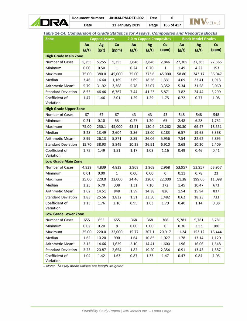
Document Number J01834-PM-REP-002 Rev 0
Date 11 January 2019 Page 166 of 417
Feasibility Study Report | INV Metals Inc. – Loma Larga
Table 14-14: Comparison of Grade Statistics for Assays, Composites and Resource Blocks
Zone Capped Assays 2.0 m Capped Composites Block Model Grades
Au
(g/t)
Ag
(g/t)
Cu
(ppm)
Au
(g/t)
Ag
(g/t)
Cu (ppm)
Au
(g/t)
Ag
(g/t)
Cu (ppm)
High Grade Main Zone
Number of Cases 5,255 5,255 5,255 2,846 2,846 2,846 27,365 27,365 27,365
Minimum 0.00 0.50 1 0.24 0.70 1 1.49 4.22 153
Maximum 75.00 380.0 45,000 75.00 373.6 45,000 58.80 243.17 36,047
Median 3.46 16.60 1,169 3.69 18.56 1,331 4.09 23.41 1,913
Arithmetic Mean1 5.79 31.92 3,368 5.78 32.07 3,352 5.34 31.58 3,060
Standard Deviation 8.53 46.46 6,767 7.44 41.23 5,871 3.82 24.44 3,299
Coefficient of Variation
1.47 1.46 2.01 1.29 1.29 1.75 0.72 0.77 1.08
High Grade Upper Zone
Number of Cases 67 67 67 43 43 43 548 548 548
Minimum 0.21 0.10 53 0.27 1.20 65 2.48 6.28 1,751
Maximum 75.00 250.1 45,000 43.51 130.4 25,262 20.30 66.47 18,331
Median 3.28 13.49 2,604 3.86 15.00 3,183 6.57 19.65 5,358
Arithmetic Mean1 8.99 26.13 5,871 8.89 26.06 5,956 7.54 22.62 5,895
Standard Deviation 15.70 38.93 8,849 10.38 26.91 6,910 3.68 10.30 2,409
Coefficient of Variation
1.75 1.49 1.51 1.17 1.03 1.16 0.49 0.46 0.41
Low Grade Main Zone
Number of Cases 4,839 4,839 4,839 2,968 2,968 2,968 53,957 53,957 53,957
Minimum 0.01 0.00 1 0.00 0.00 0 0.11 0.78 23
Maximum 25.00 220.0 22,000 24.46 220.0 22,000 11.38 199.66 11,098
Median 1.25 6.70 338 1.31 7.10 372 1.45 10.47 673
Arithmetic Mean1 1.62 14.51 848 1.59 14.38 826 1.54 15.94 837
Standard Deviation 1.83 25.56 1,832 1.51 23.50 1,482 0.62 18.23 733
Coefficient of Variation
1.13 1.76 2.16 0.95 1.63 1.79 0.40 1.14 0.88
Low Grade Lower Zone
Number of Cases 655 655 655 368 368 368 5,781 5,781 5,781
Minimum 0.02 0.20 8 0.00 0.00 0 0.30 2.53 186
Maximum 25.00 220.0 22,000 15.77 207.1 20,917 11.24 153.12 16,444
Median 1.62 10.20 990 1.64 10.85 1,027 1.78 13.14 1,120
Arithmetic Mean1 2.15 14.66 1,629 2.10 14.41 1,600 1.96 16.06 1,548
Standard Deviation 2.23 20.87 2,654 1.82 19.20 2,354 0.91 13.43 1,587
Coefficient of Variation
1.04 1.42 1.63 0.87 1.33 1.47 0.47 0.84 1.03
Note: 1Assay mean values are length weighted

Document Number J01834-PM-REP-002 Rev 0
Date 11 January 2019 Page 167 of 417
Feasibility Study Report | INV Metals Inc. – Loma Larga
Figure 14-6: High Gold Grade and Classification of Selected Block in the Low Grade Lower Zone
Examples of the composite and block grades of Au, Ag, and Cu in plan and sections are
provided in Figure 14-7, Figure 14-8, and Figure 14-9 respectively.
To check for conditional bias, trend plots were created which compared the Au, Ag, and Cu
block model grade estimates of the High Grade Zone and Low Grade Zone to capped
composite sample average grades. Figure 14-10 and Figure 14-11 illustrate the gold trend
plots for the High Grade Main Zone and Low Grade Main Zone, respectively. In RPA’s
opinion, there is no significant bias between the resource block grades and the composited
capped assay samples.
RPA compared the volume of the wireframe models to the block model volume results. The
estimated total volume of the wireframe models is 14,407,350 m3 and the block model volume
is 14,395,927 m3. The volume difference is -0.08%, which RPA considers to be an acceptable
result.

Document Number J01834-PM-REP-002 Rev 0
Date 11 January 2019 Page 168 of 417
Feasibility Study Report | INV Metals Inc. – Loma Larga
Figure 14-7: Capped Gold Composites and Blocks on 3,600 m Level

Document Number J01834-PM-REP-002 Rev 0
Date 11 January 2019 Page 169 of 417
Feasibility Study Report | INV Metals Inc. – Loma Larga
Figure 14-8: Capped Silver Composites and Blocks on 3,600 m Level

Document Number J01834-PM-REP-002 Rev 0
Date 11 January 2019 Page 170 of 417
Feasibility Study Report | INV Metals Inc. – Loma Larga
Figure 14-9: Capped Copper Composites and Blocks on 3,600 m Level

Document Number J01834-PM-REP-002 Rev 0
Date 11 January 2019 Page 171 of 417
Feasibility Study Report | INV Metals Inc. – Loma Larga
Figure 14-10: High Grade Main Zone Trend Plots and Histograms of Capped Gold Assays versus Block Grades

Document Number J01834-PM-REP-002 Rev 0
Date 11 January 2019 Page 172 of 417
Feasibility Study Report | INV Metals Inc. – Loma Larga
Figure 14-11: Low Grade Main Zone Trend Plots and Histograms of Capped Gold Assays versus Block Grades
14.12 CLASSIFICATION
Definitions for resource categories used in this report are consistent with those defined by
Canadian Institute of Mining, Metallurgy, Petroleum (CIM) Definition Standards for Mineral
Resources and Mineral Reserves (CIM (2014) definitions) as incorporated by reference in
NI 43-101. In the CIM classification, a Mineral Resource is defined as “a concentration or
occurrence of natural, solid, inorganic or fossilized organic material in or on the Earth’s crust
in such form and quantity and of such grade or quality that it has reasonable prospects for
economic extraction”. Mineral Resources are classified into Measured, Indicated, and
Inferred categories, according to the confidence level in the estimated blocks.

Document Number J01834-PM-REP-002 Rev 0
Date 11 January 2019 Page 173 of 417
Feasibility Study Report | INV Metals Inc. – Loma Larga
RPA classified the Mineral Resources on the Loma Larga Project as Measured, Indicated,
and Inferred. All blocks within the High Grade Main Zone were classified as Measured or
Indicated Mineral Resources, and all blocks in the High Grade Upper Zone were classified as
Inferred Mineral Resources. Blocks within the Low Grade Main Zone and Low Grade Lower
Zone were classified as Indicated and Inferred. RPA manually classified the blocks within
these zones based on drillhole spacing and grade continuity above the NSR cut-off of
US$60/t. The general guidelines for drillhole spacing are as follows:
• Measured: 25 m x 25 m.
• Indicated: 50 m x 50 m.
• Inferred: > 100 m x 100 m.
Figure 14-12 illustrates block classification on the 3,600 m level, and the distance to the
nearest sample is shown for Measured, Indicated, and Inferred blocks as a histogram in
Figure 14-13. Drillhole spacing for Measured blocks averages 20 m, and ranges from less
than ten metres to 40 m. Nearly 75% of blocks classified as Measured have a drillhole
spacing less than 25 m.

Document Number J01834-PM-REP-002 Rev 0
Date 11 January 2019 Page 174 of 417
Feasibility Study Report | INV Metals Inc. – Loma Larga
Figure 14-12: Plan View of Block Classification on the 3,600 m Level.

Document Number J01834-PM-REP-002 Rev 0
Date 11 January 2019 Page 175 of 417
Feasibility Study Report | INV Metals Inc. – Loma Larga
Figure 14-13: Cumulative Histogram of Distance to Nearest Sample Grouped by Class
Most of the blocks classified as Indicated Mineral Resources in the Low Grade Main Zone
have good continuity, but RPA cautions that there are a few isolated drillhole intercepts with
grades above the cut-off that are classified as Indicated.

Document Number J01834-PM-REP-002 Rev 0
Date 11 January 2019 Page 176 of 417
Feasibility Study Report | INV Metals Inc. – Loma Larga
14.13 SUMMARY OF MINERAL RESOURCE ESTIMATE
RPA estimated Mineral Resources for the Loma Larga Project using drillhole data available
as of October 31, 2018.
In RPA’s opinion, an NSR cut-off value of US$60/t is appropriate for reporting current Mineral
Resources for the Project. The Mineral Resources, effective October 31, 2018, are
summarized in Table 14-15.

Document Number J01834-PM-REP-002 Rev 0
Date 11 January 2019 Page 177 of 417
Feasibility Study Report | INV Metals Inc. – Loma Larga
Table 14-15: Mineral Resource Estimate – October 31, 2018
Resource Classification
Zone Tonnage Grade Contained Gold
Grade Contained Silver
Grade Contained Copper
Grade Contained
Gold
Equivalent
(Mt) (g/t Au) (M oz Au) (g/t Ag) (M oz Ag) (% Cu) (M lb Cu) (g/t AuEq)
(M oz AuEq)
Measured High Grade Main Zone
2.9 7.31 0.67 34.9 3.2 0.44 28.2 8.45 0.78
Indicated High Grade Main Zone
10.3 4.85 1.60 30.7 10.1 0.28 62.3 5.68 1.88
Low Grade Main Zone
6.0 2.01 0.39 21.1 4.0 0.12 15.7 2.49 0.48
Low Grade Lower Zone
0.7 2.21 0.05 12.8 0.3 0.21 3.4 2.70 0.06
Total 17.0 3.74 2.04 26.5 14.5 0.22 81.4 4.43 2.42
Measured + Indicated
High Grade Main Zone
13.1 5.4 2.28 31.6 13.4 0.31 90.5 6.29 2.66
Low Grade Main Zone
6.0 2.0 0.39 21.1 4.0 0.12 15.7 2.49 0.48
Low Grade Lower Zone
0.7 2.21 0.05 12.8 0.3 0.21 3.4 2.70 0.06
Total 19.8 4.25 2.71 27.8 17.7 0.25 109.5 5.01 3.20
Inferred High Grade Upper Zone
0.2 7.10 0.04 21.7 0.1 0.56 2.1 8.24 0.05
Low Grade Main Zone
3.6 1.96 0.23 32.7 3.8 0.12 9.4 2.60 0.30
Low Grade Lower Zone
0.9 2.31 0.07 18.7 0.5 0.15 2.9 2.79 0.08
Total 4.7 2.22 0.33 29.7 4.5 0.14 14.5 2.84 0.43
Notes:
CIM (2014) definitions were followed for Mineral Resources.
Mineral Resources are reported at an NSR cut-off value of US$60/t.
Mineral Resources are estimated using a long-term gold price of US$1,450 per ounce, silver price of US$22.00 per ounce, and copper price of US$3.50 per pound.
The formula used to calculate gold equivalence (AuEq) is: (Au g/t x 31.31 + Ag g/t x 0.44 + Cu% x 46.19) ÷ 31.31. The formula used for calculated AuEq ounces is: AuEq Oz = (Tonnage x AuEq g/t) ÷ 31.1035
Mineral Resources are inclusive of Mineral Reserves.
Mineral Resources that are not Mineral Reserves do not have demonstrated economic viability.
Average bulk density is 2.7 t/m3.
Numbers may not add due to rounding.
14.14 SULPHUR MODEL
14.14.1 SULPHUR DATABASE
Using data available as of October 31, 2018, RPA generated a block model for sulphur grades
to support metallurgical testwork (RPA, 2018). INV provided sulphur assay data for drilling
completed in 2017 in addition to sulphur assay data from drillholes completed prior to 2016
by IAMGOLD. Files were received in Excel format, amalgamated and parsed as required,
and imported into GEMS. Table 14-16 summarizes data used for the sulphur block grade
estimates.

Document Number J01834-PM-REP-002 Rev 0
Date 11 January 2019 Page 178 of 417
Feasibility Study Report | INV Metals Inc. – Loma Larga
RPA notes that not all drillhole assay samples were analyzed for sulphur (see Table 14-2),
and there are no samples south of 9,663,100 metres North. As a result, a small area of the
southern portion of the Low Grade Main Zone (located in Inferred Mineral Resources outside
the current mine plan) does not have sulphur grade estimates and RPA did not assign default
values to the blocks.
Table 14-16: Sulphur Database used for Block Grade Estimation
Attribute Count
Holes 199
Total Length Drilled 36,059 m
Assays 6,890
Composites (>0.5 m) 3,993
The sulphur block model estimate is based on assays from 199 drillholes that totalled
36,059 m in length. Drilling was completed by IAMGOLD and INV between 2005 and 2017.
Figure 14-14 illustrates the location of drillholes with sulphur data within the Loma Larga
deposit.

Document Number J01834-PM-REP-002 Rev 0
Date 11 January 2019 Page 179 of 417
Feasibility Study Report | INV Metals Inc. – Loma Larga
Figure 14-14: 3D Isometric View of Drill Holes with Sulphur Data

Document Number J01834-PM-REP-002 Rev 0
Date 11 January 2019 Page 180 of 417
Feasibility Study Report | INV Metals Inc. – Loma Larga
14.14.2 STATISTICAL ANALYSIS
Sulphur assays located inside the Loma Larga mineralization wireframe domains were tagged
within the GEMS project drillhole database rock codes. RPA exported the sulphur assays for
statistical analysis and for later comparison with composite grades and block model grades.
Sulphur assay grades less than the detection limit were replaced with zero values, and
sulphur assay grades above the analytical method detection limit were replaced by the upper
detection limit (Figure 14-15). Intervals without sulphur assays were treated as unsampled.
For statistical analysis, the sulphur assays have been subdivided into High Grade Zone (Main
Zone and Upper Zone) and Low Grade Zone (Main Zone and Lower Zone). The basic
statistics are summarized in Table 14-17, and the histograms are illustrated in Figure 14-15.
The histogram shows distinct peaks where assays results were above the analytical upper
detection limit and not reanalyzed. RPA is unaware of the risk that may be associated with
the uncertainty of high sulphur assays.
Table 14-17: Descriptive Statistics of Geochemistry Resource Assay Values
High Grade Zone S %
Count 3,458
Minimum 0.18
Maximum 16.00
Median 5.58
Arithmetic Mean 6.47
Standard Deviation 3.74
Coefficient of Variation 0.58
Low Grade Zone S %
Count 3,432
Minimum 0.03
Maximum 21.18
Median 3.70
Arithmetic Mean 4.38
Standard Deviation 3.05
Coefficient of Variation 0.70

Document Number J01834-PM-REP-002 Rev 0
Date 11 January 2019 Page 181 of 417
Feasibility Study Report | INV Metals Inc. – Loma Larga
Figure 14-15: Assay Histograms for Sulphur
14.14.3 CAPPING OF HIGH VALUES
In order to highlight areas of higher sulphur content, outlier values were not capped and RPA
did not perform capping analysis on the sulphur assays. However, many analyses were
effectively capped by exceeding the upper detection limit of the analytical method with no
subsequent reanalysis.
14.14.4 COMPOSITING
Sulphur assay sample lengths range from 0.15 m to 4.20 m within the wireframe domains.
Greater than 99% of the resource assays have lengths less than 2.0 m. RPA used composite
lengths of 2.0 m.
A set of drillhole-wireframe intersection intervals were identified for each drillhole within the
mineralized wireframe domains and sulphur assays were composited starting at the first
composite control interval from the collar and resetting at each new wireframe boundary.
Unsampled intervals were treated as unsampled and not used in the composite calculation.
Composites measuring less than 0.5 m were removed from the database prior to statistical
analysis and block model grade interpolation. The elimination of the small composites did
not affect the overall integrity of the composited database.
Table 14-18 summarizes statistics of the uncapped sulphur composite assay values.

Document Number J01834-PM-REP-002 Rev 0
Date 11 January 2019 Page 182 of 417
Feasibility Study Report | INV Metals Inc. – Loma Larga
Table 14-18: Descriptive Statistics of Sulphur Composite Values
High Grade Zone S %
Count 1,908
Minimum 0.76
Maximum 16.00
Median 5.89
Arithmetic Mean 6.50
Standard Deviation 3.37
Coefficient of Variation 0.52
Low Grade Zone S %
Count 2,085
Minimum 0.03
Maximum 18.06
Median 3.87
Arithmetic Mean 4.41
Standard Deviation 2.79
Coefficient of Variation 0.63
14.14.5 VARIOGRAPHY AND INTERPOLATION VALUES
RPA reviewed the variography for sulphur and also prepared variograms using composites
located within the main mineralized domains. The nugget effect was established with the
downhole linear semi-variogram and the longest semi-variogram range was oriented parallel
to and across strike in the horizontal plane.
Interpolation and search parameters used for sulphur are summarized in Table 14-19.

Document Number J01834-PM-REP-002 Rev 0
Date 11 January 2019 Page 183 of 417
Feasibility Study Report | INV Metals Inc. – Loma Larga
Table 14-19: Sulphur Block Estimation Parameters
Parameter Method OK
Boundary Type Hard
High Grade Zone Sample Restrictions Min. No. Comps. 3
Max. No. Comps. 15
Max. Comps. Per Drill Hole 3
High Grade Zone Search Ellipse Range X (m) 160
Range Y (m) 130
Range Z (m) 130
High Grade Zone Search Anisotropy1 Z 0°
Y 0°
Z +75°
Variogram Model High Grade Zone Nugget (C0) 0.05
Relative Nugget (C0) 5%
Structure High Grade Zone C1 0.65
Range X (m) 24
Range Y (m) 8
Range Z (m) 6
C2 0.30
Range X (m) 79
Range Y (m) 63
Range Z (m) 67
Total Sill 1.00
Low Grade Zone Sample Restrictions Min. No. Comps. 3
Max. No. Comps. 15
Max. Comps. Per Drill Hole 3
Low Grade Zone Search Ellipse Range X (m) 300
Range Y (m) 215
Range Z (m) 165
Low Grade Zone Search Anisotropy1 Z 0°
Y 0°
Z -40°
Variogram Model Low Grade Zone Nugget (C0) 0.05
Relative Nugget (C0) 5%
Structure Low Grade Zone C1 0.52
Range X (m) 72
Range Y (m) 102
Range Z (m) 13
C2 0.43
Range X (m) 203
Range Y (m) 144
Range Z (m) 111
Total Sill 1.00
Note:1 Rotation around each axis (positive is counter-clockwise)

Document Number J01834-PM-REP-002 Rev 0
Date 11 January 2019 Page 184 of 417
Feasibility Study Report | INV Metals Inc. – Loma Larga
Block grade interpolation was carried out in a single pass using OK. Interpolation was
restricted by the mineralized wireframe models, which were used as hard boundaries to
prevent the use of composites outside of the zones. A minimum of three 2.0 m composites
and a maximum of 15 composites were used to interpolate grades within each block for
sulphur, with a maximum of three samples per drillhole.
14.14.6 BLOCK MODEL
A sulphur block model was added to the Loma Larga GEMS project. Table 14-20 summarizes
the statistics of the uncapped sulphur block grades.
Table 14-20: Descriptive Statistics of Sulphur Block Values
High Grade Zone S %
Count 27,913
Minimum 1.89
Maximum 14.00
Median 6.54
Arithmetic Mean 6.71
Standard Deviation 1.72
Coefficient of Variation 0.26
% of Interpolated blocks 100%
Low Grade Zone1 S %
Count 58,784
Minimum 0.50
Maximum 14.43
Median 4.38
Arithmetic Mean 4.71
Standard Deviation 1.91
Coefficient of Variation 0.41
% of Interpolated blocks 98.4%
Note:1 Includes only blocks with interpolated grades
14.14.7 BLOCK MODEL VALIDATION
RPA carried out a number of block model validation procedures including:
• Visual comparisons of block sulphur grades versus composite grades.
• Statistical comparisons of assays, composites, and blocks on plan and vertical section.
• Trend plots of block and composite sulphur grades by elevation and northings/eastings.
Block model sulphur grades were visually examined and compared with composite grades in
cross section and on elevation plans. RPA found grade continuity to be reasonable and
confirmed that the block grades were reasonably consistent with local drillhole assay and
composite grades and that there was no significant bias. RPA notes that the mean block
grades were slightly higher than mean composite grades. This result is expected since
capping was not performed, and higher sulphur assays had a larger influence on block
grades, especially in areas where drillhole spacing was wide.
Figure 14-16 shows sulphur composite and block grades in plan view.

Document Number J01834-PM-REP-002 Rev 0
Date 11 January 2019 Page 185 of 417
Feasibility Study Report | INV Metals Inc. – Loma Larga
In RPA’s opinion, the sulphur block grade estimates are suitable to support metallurgical
testwork for the Feasibility Study but cautions that local block sulphur grades are not as well
supported as the payable metal block grades in the Mineral Resource estimate. This includes
areas of the block model without date and incomplete or lacking information on the analytical
methods used for sulphur assaying.

Document Number J01834-PM-REP-002 Rev 0
Date 11 January 2019 Page 186 of 417
Feasibility Study Report | INV Metals Inc. – Loma Larga
Figure 14-16: Sulphur Composites and Blocks on 3,600 m Level

Document Number J01834-PM-REP-002 Rev 0
Date 11 January 2019 Page 187 of 417
Feasibility Study Report | INV Metals Inc. – Loma Larga
MINERAL RESERVE ESTIMATE
15.1 SUMMARY
DRA has designed an underground mine to produce 3,000 t/d of gold-copper and silver ore
from the Loma Larga deposit for 12 years. The mine will be accessed by a decline and mined
using conventional mechanized transverse long-hole and drift-and-fill mining methods. Ore
will be trucked to the concentrator via a 3 km surface road.
The mineral reserves for Loma Larga are estimated at 13,926,500 tonnes of recoverable and
diluted ore grading 4.91 g/t Au, 29.6 g/t Ag, and 0.29% Cu using an economic cut-off of US
$60/t NSR. The mineral reserves are comprised of 21% in proven category (2,924,600 tonnes
grading 7.30 g/t Au, 34.80 g/t Ag and 0.44% Cu) and 79% in probable category (11,001,900
grading 4.28 g/t Au, 28.26 g/t Ag and 0.25% Cu). Reserves are inclusive of dilution and ore
loss.
The mineral reserves are based on the mining schedule presented in Section 16 . The
mineral reserves are the stope and development tonnage (including material above the cut-
off and internal low-grade dilution) to which dilution and recovery factors explained below are
added.
Details of the mineral reserves are given in Table 15-1 below.
Table 15-1: Loma Larga Mineral Reserves estimate as of October 31, 2018
Ore Category
Tonne
(M)
Au
Grade
(g/t)
Contained
Au
(M oz)
Ag
Grade
(g/t)
Contained
Ag
(M oz)
Cu
Grade
(%)
Contained
Cu
(M lb)
Au
Equivalent
(M oz)
Au Equivalent
Grade
(g/t)
Proven 2.9 7.30 0.69 34.8 3.27 0.44% 28.5 0.8019 8.53
Probable 11.0 4.28 1.51 28.3 10.00 0.25% 59.5 1.80 5.09
Proven and Probable
13.9 4.91 2.20 29.6 13.27 0.29% 88.0 2.60 5.81
Notes:
CIM (2014) definitions were followed for Mineral Reserves.
Mineral Reserves include long hole and drift-and-fill stopes as well as development in ore
Mineral Reserves are reported at an NSR cut-off value of US$60/t.
Mineral Reserves are estimated using average gold price of US$1,250 per ounce, silver price of US$18.00 per ounce, and copper price of US$3.00 per pound.
Average bulk density is 2.7 t/m3.
Numbers may not add due to rounding.
Headings -see above.
15.2 DILUTION
Dilution is the material (ore, waste, or backfill) that breaks off from stope and drift walls, backs
and walls and which is inherent to underground mining. The dilution was calculated as per
the formula and parameters below.
Dilution = (Stope volume + dilution shell) / (Stope volume)
• For primary stopes:
• Hanging wall and footwall dilution: 0.5m.
• Unsupported stope back dilution: 0.4m.
• Supported stope back dilution: 0m.
• Bottom level floor dilution: 0.25m.

Document Number J01834-PM-REP-002 Rev 0
Date 11 January 2019 Page 188 of 417
Feasibility Study Report | INV Metals Inc. – Loma Larga
• Ore/Waste contact limit dilution (North and South): 0.20m.
• Internal dilution from secondary stopes: 0m.
• Dilution from adjacent backfilled primary stope: 0.25m.
• For secondary stopes:
• Hanging wall and footwall dilution: 0.5m.
• Unsupported stope back dilution: 0.4m.
• Supported stope back dilution: 0m.
• Bottom level floor dilution: 0.25m.
• Ore/Waste contact limit dilution (North and South): 0.20m.
• Internal dilution from primary backfilled stopes: 0.25m (each side).
• Dilution from adjacent backfilled secondary stope: 0.25m.
DRA calculated the number of primary and secondary stopes affected by these dilution factors
and estimated an overall stope dilution at 6.31%, with 2.81% coming from low grade and
waste, and 3.5% coming from backfill.
Low grade and waste dilution grades were estimated by querying the block model with an
envelope of 0.5m thickness around the stope solids which reported average grades of 1.82
g/t Au, 12.76 g/t Ag and 0.096% Cu. These grades were applied to the external dilution.
Backfill dilution was given a grade of 0.
15.3 ORE RECOVERY
DRA assessed the stope recovery factor based on the geometry of the deposit and the stopes
and the mining methods. The following factors were estimated:
• For 25m long hole stopes, ore loss in the stope is estimated at leaving an equivalent
thickness of ore of 0.50m or 2% resulting in ore recovery of 98%.
• For drift-and-fill stopes and ore development, ore loss is estimated at 0% (100% ore
recovery).
Since long hole stopes count for approximately 80% of all ore tonnage, overall ore recovery
is estimated at 98.4%: 100%-(80% at 2%) - (20% at 0%). Overall ore loss is therefore
estimated at 1.6%.
15.4 GOLD EQUIVALENT CALCULATIONS
The mineral reserves economic cut-off grade for Loma Larga was estimated at $60/t NSR.
An NSR value was estimated for each block of the block model allowing for metallurgical
recovery and consideration of smelter terms, including payables, treatment charges, refining
charges, price participation, penalties, smelter losses, transportation, and sales charges. The
value of $60/t selected as the cut-off is the total cost per tonne of ore including mining,
processing, G&A, sustaining and closure costs. Any block that has a minimum NSR value of
$60/t is considered ore. Cut-offs we taken at stope and development levels.
Details of the NSR parameters used to calculate the value for each block is presented in
Table 15-2 below.

Document Number J01834-PM-REP-002 Rev 0
Date 11 January 2019 Page 189 of 417
Feasibility Study Report | INV Metals Inc. – Loma Larga
Table 15-2: Loma Larga NSR Cut-off Parameters
Parameter Unit Value
Au Price USD /Oz 1,250
Ag Price USD / Oz 18
Cu Price USD / lb 3
Au recovery in copper concentrate % 15.0
Ag recovery in copper concentrate % 49.3
Cu recovery in copper concentrate % 81.5
Au recovery in pyrite concentrate % 75.2
Ag recovery in pyrite concentrate % 45.7
Cu recovery in pyrite concentrate % 14.5
Au payable in copper concentrate % 88
Ag payable in copper concentrate % 80
Cu payable in copper concentrate % 82
Au payable in pyrite concentrate % 80
Ag payable in pyrite concentrate % 60
Cu payable in pyrite concentrate % 0
Mining & backfill cost $/t ore 31.00
Process & tailings costs $/t ore 19.50
G & A costs $/t ore 7.50
Sustaining costs $/t ore 4.70
Closure costs $/t ore 1.60
Refinery & transport cost $/t conc. 98.00
15.5 EQUIVALENT GOLD
The equivalent gold (AuEq) values in ounces (oz) and g/t (gpt) in the reserves estimate were
calculated as follows, based on the parameters in Table 15-1:
𝐴𝑢𝐸𝑞 (𝑜𝑧) = 𝐴𝑢(𝑜𝑧) + (𝐴𝑔 (𝑜𝑧) 𝑥 $ 18/𝑜𝑧
$ 1,250/𝑜𝑧) + (𝐶𝑢 (𝑡) 𝑥 32,150.7
𝑜𝑧
𝑡𝑥
$3.0 𝑙𝑏
14.5833𝑙𝑏
𝑜𝑧) 𝑥
1
$1,250/𝑜𝑧
𝐴𝑢𝐸𝑞 ( 𝑔𝑝𝑡) = 𝐴𝑢𝐸𝑞 (𝑜𝑧) 𝑥 32.1034
𝑡𝑜𝑡𝑎𝑙 𝑜𝑟𝑒 𝑡𝑜𝑛𝑛𝑎𝑔𝑒

Document Number J01834-PM-REP-002 Rev 0
Date 11 January 2019 Page 190 of 417
Feasibility Study Report | INV Metals Inc. – Loma Larga
MINING
16.1 INTRODUCTION
The Loma Larga ore body is approximately 1.6 km long, 150 to 400 m wide and 60 to 80 m
thick. The bottom of the orebody is relatively flat and lies 175 m below surface at 3,600 m.
The mine has been designed to have the smallest environmental impact possible in terms of
the area of disturbance. The mine will be operated as an underground operation which will
have a very small surface impact compared to an open pit mining operation.
Access to the mine will be via a surface portal and ramp to the orebody. This portal will be
approximately 1.2 km southwest of the center of the orebody. The ore from the mine will be
moved via a road from the mine to the process plant facilities which will be approximately
3 km south of the mine as shown in Figure 16-1.

Document Number J01834-PM-REP-002 Rev 0
Date 11 January 2019 Page 191 of 417
Feasibility Study Report | INV Metals Inc. – Loma Larga
Figure 16-1: Loma Larga Deposit, Portal and Main Surface Infrastructure

Document Number J01834-PM-REP-002 Rev 0
Date 11 January 2019 Page 192 of 417
Feasibility Study Report | INV Metals Inc. – Loma Larga
16.2 MINING METHODS
The mine has been designed to produce 3,000 to 3,500 t/d from an underground operation
using conventional highly mechanized mining equipment routinely used in similar operations
around the world.
The orebody configuration will allow for a straightforward and simple mine layout. The mine
will have a relatively small amount of lateral development due to the elongated and flat
configuration of the ore. There are only three main mining levels and almost no ramp
development other than the initial access ramp and the accesses to the three levels.
The principal mining method will be transverse longhole stoping followed by paste backfilling.
Drift-and-fill will also be used where the ore is narrower than a full stope or where the stopes
are relatively short in height. The method is very similar to the cut-and-fill mining method.
The selected mining methods are relatively simple, permit standard operating routines and
are highly flexible. This, combined with good ground conditions, in a high percentage of the
orebody (as per MDEng) should lead to a safe and highly productive operation.
Figure 16-2: Loma Larga Mine Layout

Document Number J01834-PM-REP-002 Rev 0
Date 11 January 2019 Page 193 of 417
Feasibility Study Report | INV Metals Inc. – Loma Larga
16.2.1 STOPE DESIGN
Stopes were designed using a two-pass method. The first pass design was done using Mining
Stope Optimizer (MSO) module in Datamine software to automatically design longhole stopes
based on several parameters (minimum and maximum stope dimensions, minimum cut-off,
dilution and recovery). The MSO parameters used for Loma Larga are presented in Table
16-1 below. The second pass was implemented to manually adjust (in Datamine) the
automatic Longhole stope shapes designed by MSO to reduce dilution and remove low grade
stopes. Drift-and-fill stopes not identified by MSO were also added.
Table 16-1: MSO Parameters for Transverse Longhole Stope Design
MSO Parameter Unit Longhole
Value Variance
Block Density t/m3 2.75
Slice Interval m 0.5
Default Dip degrees 90
Default Strike degrees 0
Section Spacing m 20 18 to 20
Level Spacing m 25 15 to 40
Maximum Waste Fraction % 5 0 to 100
Minimum Width of Shape m 5
Maximum Length (Span) of Shape m 100
Minimum Waste Pillar Width m ~0
Minimum Dip Angle of Shape degrees 85
Maximum Dip Angle of Shape degrees 95
Maximum Strike Angle of Shape degrees 45
Maximum Angle Change degrees 20
Maximum Side Length Ratio 1.5
16.2.2 TRANSVERSE LONGHOLE MINING
The majority of the mine will be developed for transverse longhole stoping, with stopes aligned
perpendicularly to the strike of the orebody. The stopes will be mined in a primary-secondary
sequence, with primary stopes measuring 20 m wide x 25 m high x 20 m deep and secondary
stopes measuring 20 m wide x 25 m high x 20 m deep. Mining will start at the footwall (east)
and retreat to the hanging wall (west).
Stope access and development will be performed by two-boom jumbos to open the upper
drilling drifts and lower drawpoints.
Production drilling will be done by longhole drills, capable of drilling up to 115 mm diameter
holes up to 40 m long. Twin parallel drilling drifts in the primary stopes will permit vertical
parallel holes along the primary stope walls to help provide smoother blasted walls for tight
backfill placement and reduce backfill dilution in adjacent secondary stopes. Secondary
stopes will have single centrally located drilling drifts as shown in Figure 16-3. Both primary
and secondary stopes will use a small raise boring machine to drill the cut.

Document Number J01834-PM-REP-002 Rev 0
Date 11 January 2019 Page 194 of 417
Feasibility Study Report | INV Metals Inc. – Loma Larga
Mucking of the ore will be done using 17-tonne (10m³) Load-Haul-Dump (LHD) machines
equipped with remote control for mucking in the stopes. Broken ore will be brought to three
central truck loading and blending stations, including one near the main ramp by the LHDs,
before haulage to the surface ore stockpile near the process plant by 40-tonne underground
mining trucks.
The truck loading will be carried out by a Caterpillar 988 or equivalent loader which will
minimize the truck loading time. The elimination of the truck-LHD interface will make both
operations very efficient and reduce the number of machines involved in each operation.
Figure 16-3: Primary and Secondary Transverse Longhole Stopes

Document Number J01834-PM-REP-002 Rev 0
Date 11 January 2019 Page 195 of 417
Feasibility Study Report | INV Metals Inc. – Loma Larga
16.2.3 DRIFT-AND-FILL MINING METHOD
In areas of the deposit where the thickness of the ore is less than 10 m, the drift-and-fill mining
will be accomplished using lateral development equipment.
For the drift-and-fill operation, the backfill will be pumped in place using a pipe installed in the
drift to be backfilled. The backfill will start from the far end of the drift and the backfill pipe will
be removed as the backfill is placed. When the backfill operation is completed the upper drift
excavation will start. A total of 13,400 m of drift-and-fill will occur at Loma Larga. Figure 16-
4 illustrates the drift and fill mining method.
Figure 16-4: Drift and Fill Method
16.3 GEOTECHNICAL CONSIDERATIONS
Geotechnical considerations for the underground development and production were
performed by MDEng. The summary of their findings is found below.
16.3.1 GROUND CONDITIONS
The Loma Larga geotechnical site characterization has incorporated geological and
geotechnical drill core logs and laboratory strength testing. Detailed review and analyses of
all available data has led to the following conclusions:
• Rock quality is closely associated with alteration type:
• Silicified ground is on average very strong (UCS = 150 to 250 MPa), and of good
rock mass quality.
• Advanced Argillic ground is on average strong (UCS = 50 to 80 MPa), and of fair to
good rock mass quality.
• Propylitic ground is on average medium strong (UCS = 30 to 50 MPa, and of fair
rock mass quality.

Document Number J01834-PM-REP-002 Rev 0
Date 11 January 2019 Page 196 of 417
Feasibility Study Report | INV Metals Inc. – Loma Larga
• The mean rock mass classification rankings for each alteration type is presented in
Table 16-2.
• Spatial variances in joint set orientations have been identified, resulting in four spatial
domains: Dacite, North Volcanics, South Volcanics and West Volcanics. Since all of the
domains have less than three well-defined joint sets, wedge-type instability is not a
major design consideration. The orientations are summarized in Table 16-3.
• The three volcanic domains have a common steeply dipping joint set which strikes
north-south (correlating to regional strike-slip faulting). The North and South Volcanics
domains have additional steeply dipping sets (NE-SW striking in the north and SSE-
NNW striking in the south). These both correlate to fault trends in each of the respective
domains. In addition to these sets, the volcanics all have random jointing.
• The dacite features a steeply south dipping joint set, an inclined set dipping to the
southeast plus random jointing.
• There is high uncertainty in the in-situ stress field due to limited regional data. This
study has evaluated two stress tensors:
• Extensional: σ1=σv, σ2=0.7σv (horizontal trending E-W), σ3=0.5σv (horizontal
trending N-S.
• Compressional: σ3=σv, σ2=1.5σv (horizontal trending N-S), σ1=2σv (horizontal
trending E-W).
• Analyses indicate that the in-situ stress field does not play a significant role in mine
stability thus the risk associated with this uncertainty is small.
Table 16-2: Summary of Rock Mass Classification Statistics
Alteration Q' 50 RMR8950
Fresh 13.2 67
Silica 20.5 71
Kaolinite 7.7 62
Illite 6.2 60
Pyrophyllite 9.7 64
Dickite 9.6 64
Smectite 8.4 63
Smectite+Chlorite 4.4 57
Smectite+Illite 3.1 54
Table 16-3: Summary of Joint Set Orientations (Dip/Dip Dir’n, in degrees)
Structural Domain J1 J2 J3 J4
Dacite --
74/179 53/132
Volcanics North 86/263 87/033 -- --
Volcanics South 81/077 -- 78/156 --
Volcanics West 86/258 -- 87/297 --

Document Number J01834-PM-REP-002 Rev 0
Date 11 January 2019 Page 197 of 417
Feasibility Study Report | INV Metals Inc. – Loma Larga
16.3.2 LONGHOLE MINING
The base case mining method intended for Loma Larga is primarily transverse open stope.
16.3.2.1 STOPE SIZING AND TRANSVERSE PRIMARY-SECONDARY STOPE
The majority of stopes (approx. 69% of stope backs) are located entirely within the silica
domain and are generally expected to perform well. Cable bolting of stope backs in silica is
expected to be rarely required and only minor overbreak is anticipated in stope sidewalls.
Stopes which expose advanced argillic (approx. 23% of stope backs) or propylitic materials
(approx. 8% of stope backs) will perform much more poorly than stopes in silica. It is
empirically predicted that roughly a third of stope backs in advanced argillic ground and 80%
of stopes in propylitic ground will require cable bolting. Overall (all domains combined), it is
expected that cable bolting will be required in 19% of the proposed stope backs.
In the worst ground conditions (7% of all proposed stopes) cable bolts may not be effective
at stabilizing the backs of stopes in the advanced argillic or propylitic domains. Stope
sidewalls in advanced argillic and propylitic material are also expected to commonly see
severe failures (>2 m of overbreak).
Very poor stope performance is expected when advanced argillic and propylitic ground is
exposed in stope backs and/or side walls. The exposure of these domains will occur in some
areas of the ore body periphery. Smaller stopes in these design domains will significantly
reduce this risk; constraints on stope sizes are provided in MDEng report #17018-104.
Another geotechnical risk associated with the weaker alteration domains is that failure may
occur in the secondary stope pillar foundations where lower strength argillic and/or propylitic
material is encountered. This is particularly problematic where the advanced argillic zone is
thin and propylitic material is more likely to be exposed. Strategies for mitigating pillar
foundation failure are provided within the MDEng report.
Complete backfilling of all stopes will be important in all areas.
Overall, it is concluded that primary-secondary sequencing presents low geotechnical risk to
Loma Larga operations as secondary stope pillars are predicted to perform well. Long
transverse stoping panels (multiple stopes per cross cut) provide operational flexibility to
optimize stope design by adjusting individual stope panel lengths according to local ground
conditions. Adjustments for optimization can also be made for panel length in primary vs.
secondary stopes depending on backfill strengths. (Note: longer panel lengths in secondary
stopes may increase the amount of cable bolting required within the silica domain).
16.3.3 DEVELOPMENT HEADINGS
Three categories for primary ground support have been defined for the Loma Larga Project
according to rock mass quality.
• Category 1: Typical Ground Conditions (Q >= 1)
• 19 mm or #6 Grade 60 (or better) fully grouted rebar, 2.1 m bolt length installed on a
3-2-3 pattern for each sheet of screen (maximum 1.2 x 1.2 m bolt spacing).
• #6 AWG screen (sheet size will be 1.5 m x 2.7 m), installed with 3 squares of overlap
(bolt through the center square).
• Screens and bolts across the back and down the walls to within 1.2 m of the floor
• MDEng does not recommend the use of push plates to pin overlapping screens

Document Number J01834-PM-REP-002 Rev 0
Date 11 January 2019 Page 198 of 417
Feasibility Study Report | INV Metals Inc. – Loma Larga
• Category 2: (0.2 <= Q < 1) and all Clay Rich rock units with Q > 1
• 19 mm or #6 Grade 60 (or better) fully grouted rebar, 2.1 m bolt length installed on a
3-2-3 pattern for each sheet of screen (maximum 1.2 x 1.2 m bolt spacing).
• #6 AWG screen (sheet size will be 1.5 m x 2.7 m), installed with 3 squares of overlap
(bolt through the center square).
• 75 mm of shotcrete should be installed.
• Shotcrete should cover the walls down to the floor. To avoid a loss of shotcrete in
the lower portion of the walls, it is recommended that screen and bolts be brought
down as low as reasonably possible to the floor (realistically this is likely near 0.5 m).
• Category 3: (Q < 0.2)
• 19 mm or #6 Grade 60 (or better) fully grouted rebar, 2.1 m bolt length installed on a
3-2-3 pattern for each sheet of screen (maximum 1.2 x 1.2 m bolt spacing).
• #6 AWG screen (sheet size will be 1.5 m x 2.7 m), installed with 3 squares of overlap
(bolt through the center square).
• 100 mm of shotcrete should be installed.
• Shotcrete should cover the walls down to the floor. To avoid loss of shotcrete in the
lower portion of the walls it is recommended that screens and bolts be brought down
as low as reasonably possible to the floor (realistically this is likely near 0.5 m).
A schematic of the 1.2 m x1.2 m, 3-2-3 bolting pattern with a 3 square overlap can be found in Figure 16-5 below. Figure 16-5: Ground Support for 1.2 m x 1.2 m Pattern

Document Number J01834-PM-REP-002 Rev 0
Date 11 January 2019 Page 199 of 417
Feasibility Study Report | INV Metals Inc. – Loma Larga
16.3.3.1 LARGER SPANS – SECONDARY SUPPORT
In addition to the primary support detailed above, for larger back spans such as a 3-way or 4-
way intersection, secondary support will be necessary in the back. This includes a 4.0 m
long, single strand bulbed cable bolts installed on a 2.0 m x 2.0 m pattern which will provide
sufficient support for a 3-way intersection spanning 7.0 m, and for 4-way intersections
spanning up to 10.0 m. Each individual cable bolt should have a minimum capacity of 25
tonnes. It is recommended that 4-way intersections be avoided to minimize ground control
issues. It is also recommended that all very large spans be structurally mapped to verify
ground support requirements on a case-by-case basis.
A design of the 3-way and 4-way intersections can be found in Figure 16-6 below.
Figure 16-6: Ground Support for 3 and 4-way Intersections
16.3.3.2 DISTRIBUTION OF SUPPORT CATEGORIES THROUGH MINE WORKINGS
A preliminary estimation on the expected ground support requirements has been made for
costing purposes. The three primary support categories have been defined on the basis of
rock mass quality (in terms of a Q-value range) and type of alteration of rock. By determining
the cumulative distribution of rock mass quality for a given rock type, a probabilistic
assessment of the Category 1, 2, and 3 primary support requirements can be made. Table
16-4 presents the estimated percentages of development requiring primary support Category
1, 2, and 3, grouped by each of the major alteration types.

Document Number J01834-PM-REP-002 Rev 0
Date 11 January 2019 Page 200 of 417
Feasibility Study Report | INV Metals Inc. – Loma Larga
Table 16-4: Percentage of Each Support Category (5 m Spans) by Alteration for Permanent Openings
Alteration Type % of development by support category
Category 1 Category 2 Category 3
Unaltered (andesite) and dacite 96 4 -
Silicified 97 3 -
Non-swelling clay (Kaolinite, Dickite) - 100 0
Swelling clay (smectite)* - 78 22
* The smectite altered rocks have proven to be susceptible to swelling. The design of ground support for swelling ground conditions will require special consideration further discussed below in the Section on Special Design Considerations.

Document Number J01834-PM-REP-002 Rev 0
Date 11 January 2019 Page 201 of 417
Feasibility Study Report | INV Metals Inc. – Loma Larga
Special Considerations for Swelling Clays
Swelling clays are located in the propylitic domain and are expected to be most severe near
the boundary of advanced argillic alteration, as alteration intensity generally reduces with
distance from the siliceous core. The thickness of the swelling clay zone is expected to
correspond with the thickness of the adjacent advanced argillic alteration zone. Swelling
clays will rarely affect stopes and will primarily influence mine access excavations (ramps and
drifts) and ventilation raises.
Excavations in strongly altered smectite zones may incur very high swelling pressures which
are likely to exceed the capacity of the conventional support (Categories 1, 2 and 3). It is
expected that over-excavation, short rounds, and two cycles (minimum) of ground support
will be required to stabilize excavations in highly altered smectite zones. In severe squeezing
conditions floor support may be required. There is exceptionally high uncertainty regarding
how swelling clays will behave in underground excavations; instrumentation will be heavily
relied on to monitor ground behaviour in swelling clays.
The optimal bolt type and support design for poorer ground conditions will require some trial
and optimization as severe ground squeezing can be very difficult to control without proper
mitigation measures. The potential for squeezing ground to require ongoing support
rehabilitation is significant and could lead to production delays if critical infrastructures (i.e.
ramps, ventilation shafts) are affected. Development in this type of ground should be avoided
whenever practical.
Infrastructure Siting
None of the Loma Larga permanent infrastructure (ramp and raise development) is expected
to be influenced by mine-induced rock mass damage
Additional general guidelines for infrastructure siting are as follows:
• Cross structures (faults, contacts, shears) at angles as near to perpendicular as
reasonably possible.
• Avoid “stacking” intersections from level to level.
• Minimize spans by avoiding 4-way intersections.
• Based on numerical stress modelling results, there are no stress-related limitations on
cross-cut length. A reasonable minimum is three times the haulage drive width (~15 m)
to minimize interaction between the haulage drive and stopes. This dimension is more
likely to be constrained by operational factors.
• Delay developing secondary cross-cuts until they are needed to minimize required
rehabilitation
16.3.4 DRIFT-AND-FILL MINING
Drift and fill stopes can be supported according to the same support classes defined for
infrastructure development. Where the span or height of the drift and fill stopes exceeds the
typical 5 m span of the development, additional support will be required. This should be
analyzed once location and expected ground conditions for drift and fill mining have been
identified.

Document Number J01834-PM-REP-002 Rev 0
Date 11 January 2019 Page 202 of 417
Feasibility Study Report | INV Metals Inc. – Loma Larga
16.3.5 RAISE SUPPORT
Development plans provided to MDEng include 6 raises to surface. Some of the currently
proposed raise locations pass through long (>10m) zones of poor quality ground, though it is
understood that the locations of raises have not yet been finalized. Where weak ground
conditions are intercepted raise development will be difficult. Special consideration will have
to be given to the presence of clay rich units which will be susceptible to deterioration over
time (slaking), at which time shotcrete will be required. Some clays may also be susceptible
to swelling which will make raise development exceptionally difficult and present significant
risk to long-term raise stability. Swelling clays and long zones of weak ground also pose a
risk to raise boring equipment and could result in loss of the raise and/or boring equipment.
Pilot holes are strongly recommended to verify local ground conditions prior to raise
construction.
The stability of individual raises should be analysed at the design stage, following drilling of
geotechnical pilot/probe holes at the proposed locations. If ground conditions at the currently
proposed locations are deemed unsatisfactory for vertical development, the following
guidelines are given for finding more suitable locations:
• Wide, heavily clay-altered zones and long stretches of ground (>10 m) with low RMR
should be avoided
• Where bad ground is present near surface, it could be stabilized using conventional shaft
sinking techniques prior to raise-boring the remainder of the excavation.
• Areas, where the advanced argillic halo is thinnest, provide the least geotechnical risk.
• Areas between stacked silica zones pose the greatest likelihood of wide clay-altered
zones and should be avoided.
• Faults identified in the structural model should be avoided, particularly those located in
clay-altered zones.
• Once a new ventilation raise location has been selected a new geotechnical hole will have
to be drilled to confirm the new location as suitable.
16.3.6 GENERAL COMMENTS
16.3.6.1 MINING METHOD AND GLOBAL SEQUENCE
The global sequence can be generalized as two active mining blocks, a north block and a
south block. Numerical stress models suggest that there are very low geomechanical risks
associated with the global sequence. However, it will be very important to follow the mine
plan sequencing and to ensure that backfill is placed judiciously to ensure stopes are
completely filled, especially in areas with poor ground conditions and in all stopes next to the
crown pillar.
16.3.6.2 CROWN PILLAR
Short and long-term crown pillar stability has been evaluated. The application of backfill
essentially negates any risk of long-term instability. A 20% probability of failure (POF) has
been estimated for short term crown pillar stability. 20% POF is an acceptable standard for
service life in the order of one year. If multiple panels are left open simultaneously the POF
will increase. A well-managed backfill program is of critical importance for maintaining global
mine stability. Backfill should be filled to stope backs as tightly as is practicable to minimize
instability. Risk of short-term failure is mitigated by:

Document Number J01834-PM-REP-002 Rev 0
Date 11 January 2019 Page 203 of 417
Feasibility Study Report | INV Metals Inc. – Loma Larga
• Ground support installed in stope backs.
• Rapid cycle time to minimize the necessary stand up time for critical crown pillar areas.
• Continuous monitoring. In most circumstances visual monitoring of stope performance
and/or cavity surveys will be sufficient. If critical stopes are identified during stoping
operations (i.e. very poor local ground conditions encountered during development)
conventional geotechnical instrumentation can also be implemented (i.e. slough meters
or borehole extensometers installed in stope backs).
From a geotechnical perspective, the most significant crown pillar risk is deemed to be
unanticipated fluid flow along the fault structures. Some rock mass yield will occur within the
crown pillar over the LOM. It is not known how rock mass yield in the crown pillar may
influence groundwater flow from the Paramo horizon to the deep bedrock water system. The
risks associated with a high permeability fault zone is increased water inflow (requires a more
extensive dewatering program) and degradation of the fault within the crown pillar. In severe
conditions fluid flow along the fault zone can result in wash out of fault material which can
cause piping failure (and hence accelerated inflows and crown pillar destabilization).
16.3.6.3 FAULTING
Regionally, the Loma Larga deposit is located between the Girón and Bulubulu faults. In the
fall of 2016, Orix Geosciences Inc. (Orix) consolidated and validated a project-scale fault
model based on previous structural interpretations developed by project geologists and a
review of all available surface mapping and drillhole data including core photos. The
interpreted structures are based on zones of poor quality ground encountered in exploration
holes and surface mapping. Orix validated structures within, and in close proximity to the
mineralization. They provided a three-dimensional structural model as shown below in Figure
16-7. Structures beyond this footprint have not been validated and are not included in the
Orix model. It should therefore be noted that the area beyond the mineralized zone is not
devoid of faults, only that they have not been delineated.
The geotechnical characteristics of these faults are highly variable. Ground conditions
ranging from minor increases in fracture frequency, to highly fractured zones to clay-gouge
seams may be encountered. Faulting in the silica body is more likely to be characterized as
fractured with little or no clay while faulting outside of the silica body is more likely to contain
clay/gouge seams.
Stope design should consider these faults as proper placement of these faults within. Stope
boundaries will mitigate their impact and ensure the extension of these faults are fully
supported.
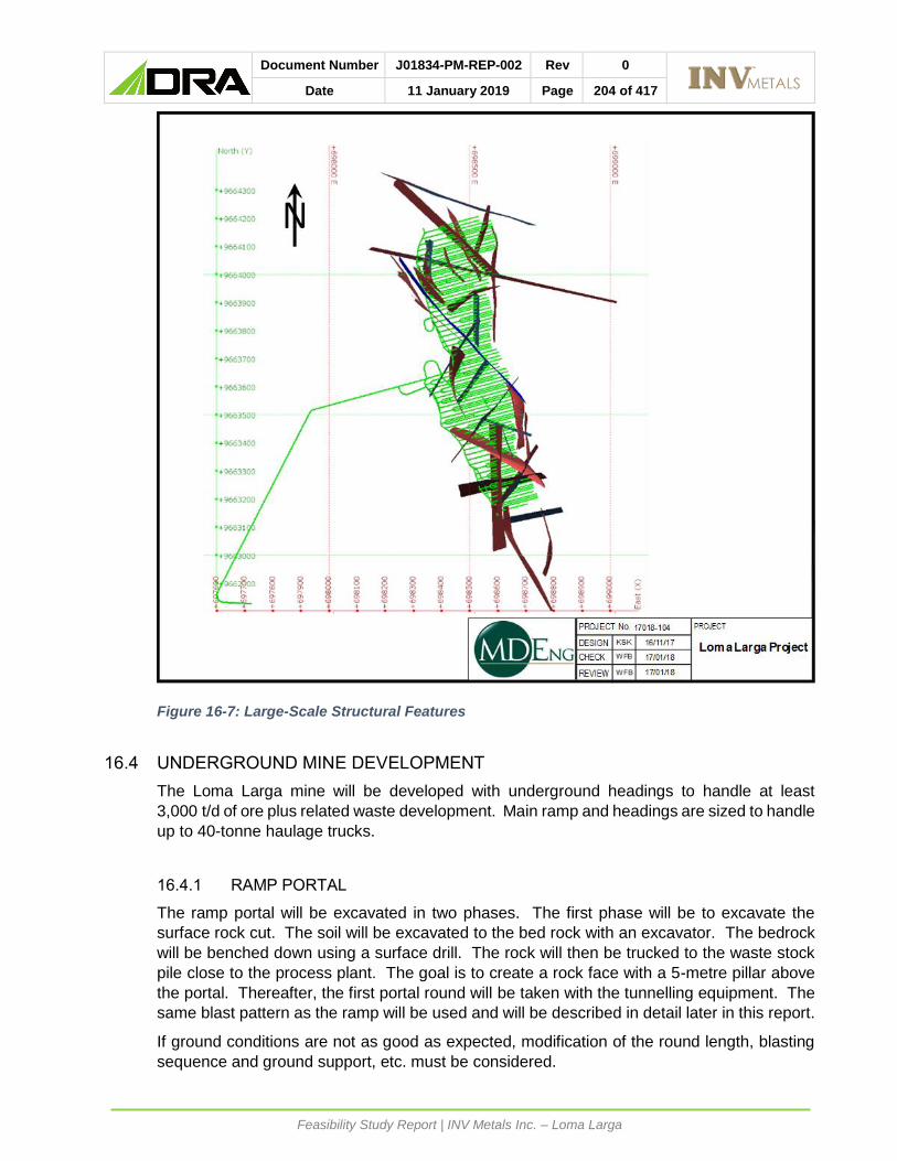
Document Number J01834-PM-REP-002 Rev 0
Date 11 January 2019 Page 204 of 417
Feasibility Study Report | INV Metals Inc. – Loma Larga
Figure 16-7: Large-Scale Structural Features
16.4 UNDERGROUND MINE DEVELOPMENT
The Loma Larga mine will be developed with underground headings to handle at least
3,000 t/d of ore plus related waste development. Main ramp and headings are sized to handle
up to 40-tonne haulage trucks.
16.4.1 RAMP PORTAL
The ramp portal will be excavated in two phases. The first phase will be to excavate the
surface rock cut. The soil will be excavated to the bed rock with an excavator. The bedrock
will be benched down using a surface drill. The rock will then be trucked to the waste stock
pile close to the process plant. The goal is to create a rock face with a 5-metre pillar above
the portal. Thereafter, the first portal round will be taken with the tunnelling equipment. The
same blast pattern as the ramp will be used and will be described in detail later in this report.
If ground conditions are not as good as expected, modification of the round length, blasting
sequence and ground support, etc. must be considered.

Document Number J01834-PM-REP-002 Rev 0
Date 11 January 2019 Page 205 of 417
Feasibility Study Report | INV Metals Inc. – Loma Larga
The portal will be driven at + 3% slope for 10 metres to avoid any runoff water going inside
the mine. The portal area is presented in Figure 16-8.
Figure 16-8: Portal Layout

Document Number J01834-PM-REP-002 Rev 0
Date 11 January 2019 Page 206 of 417
Feasibility Study Report | INV Metals Inc. – Loma Larga
Figure 16-9: Portal 3D View
16.4.2 RAMPS
The main and internal ramps are sized 5 m high by 5 m wide to allow for 40-tonne
underground trucks during development and up to 60-tonne trucks during production, and
1.5 m rigid ventilation ducts as shown in Figure 16-10. Ramps have a maximum slope of
15%, which is typical for underground mines.
The main ramp from the surface will have remuck bays every 200 m, sumps every 400 m and
safety bays every 30 m. Equipment passing bays are also excavated at every 400 m of the
ramp. The main ramp will be approximately 1,200 m long and will include approximately
1,820 equivalent meters of development within an additional 1,150 m of ramp development
to be completed to access other levels. The 2.1 m resin ground support and screening will
be installed using a fully mechanized bolter. If needed, fibre shotcrete will be applied on top
of the screen using a wet shotcrete mix. Mucking of the heading will be completed by 17-
tonne load-haul-dump (LDH) equipment to the remuck bay to be thereafter loaded in 40-tonne
trucks and hauled to the surface.
The general arrangement of the ramp is shown in Figure 16-10.

Document Number J01834-PM-REP-002 Rev 0
Date 11 January 2019 Page 207 of 417
Feasibility Study Report | INV Metals Inc. – Loma Larga
Figure 16-10: Haulage Ramp General Arrangement with 40-ton Truck
16.4.3 MAIN HAULAGE DRIFTS
The main haulage drifts have been designed at 5 m wide by 5 m high to fit a 40-tonne truck
and a 17-tonne LHD using a smaller ventilation duct. They will connect the drawpoints to the
ramp access located near the center of the level. During production, the main activity in the
haulage drifts will be by LHDs carrying the ore from the stope to the loading station.
Furthermore, this access will be equipped with services to carry compressed air, water,
power, communication and blasting and ground cables, and ventilation conduit to the working
areas.

Document Number J01834-PM-REP-002 Rev 0
Date 11 January 2019 Page 208 of 417
Feasibility Study Report | INV Metals Inc. – Loma Larga
All haulage drifts will be driven at a 3% slope to drain the ground water and process water
towards the main ramp where the water management system will be located.
The level access has been designed and located in the best ground possible to optimize
ground support requirements. No excavations are presently planned on the east side of the
orebody due to ground condition consideration. The primary ground support remains the
same as the ramp and is installed sharing the same bolters. The access will be mucked with
17-tonne LHDs to the remuck bay to be later loaded in 40-tonne trucks and hauled to the
surface or to secondary stopes as backfill. Alternatively, the waste can go directly to the truck
loading station for haulage to the waste stockpile. Parts of the access drift is in ore. This
muck will be hauled to the truck loading station and be hauled to the ore stockpile area at the
plant (high grade or low grade).
The general arrangement of the main haulage drifts is shown in Figure 16-11.
Figure 16-11: Level Access General Arrangement with 40-ton Truck

Document Number J01834-PM-REP-002 Rev 0
Date 11 January 2019 Page 209 of 417
Feasibility Study Report | INV Metals Inc. – Loma Larga
16.4.4 DRAWPOINTS AND DRILLING DRIFTS
The drawpoints and drilling drifts are designed at 4.5 m wide by 4.5 m high to fit 17-tonne
LHDs used for the ore mucking. Temporary ventilation flexible ducting will be installed to
ventilate the excavation and ore mucking operations. Temporary services will be installed for
longer drawpoints. The drilling drifts will become drawpoints as the stope drilling moves to
an upper level.
Including the drilling drift, 37.5 km of drawpoints are planned to be excavated throughout the
life of the mine in ore or marginal waste and will be mucked to the truck loading station and
to surface proper stockpiles. The ore will be trucked to the surface sorting stockpiles and the
marginal ore will be trucked to a surface stockpile near the process plant to be processed at
the end of mine life or perhaps as part of the future plant expansion.
The general arrangement of the drawpoints and drilling drifts is shown in Figure 16-12.
Figure 16-12: Drawpoints and Drilling Drift General Arrangement

Document Number J01834-PM-REP-002 Rev 0
Date 11 January 2019 Page 210 of 417
Feasibility Study Report | INV Metals Inc. – Loma Larga
16.4.5 TRUCK LOADING STATION
Ore and waste will be moved with LHDs to an underground truck loading station on the 3,600
level. This loading station is a group of temporary storage bays created from opening
crosscuts between drawpoints to store ore and waste for easy loading and access of the
underground haul trucks without disturbance from LHDs. During the operation, the ore will
be stored by grade (high grade, medium grade, low grade and waste) in the different storage
bays then loaded into the haul trucks by a dedicated surface loader (Cat 988 type) for
transport to the surface stockpiles near the plant. Blending of the ore will be carried out as
the ore is being hauled to the plant or on surface at the plant from the high, medium and low-
grade stockpiles.
The excavation of the station will use the same methodology as all the other lateral
development. Shotcrete will be applied to the back and walls of this excavation that will
remain a high traffic area for the full life of the mine. Figure 16-13 shows a plan view of the
loading station.
Figure 16-13: Loading Station - Plan View

Document Number J01834-PM-REP-002 Rev 0
Date 11 January 2019 Page 211 of 417
Feasibility Study Report | INV Metals Inc. – Loma Larga
16.4.6 ORE AND WASTE PASSES
Ore and waste passes will be limited to excavating short ore and waste passes in low grade
ore close to the loading station from the levels above to eliminate ore and waste transport in
the ramp. This will allow for limited interference between the LHDs and the haul trucks, while
also minimizing the travel time of the LHDs. The ore and waste passes will be excavated
using a longhole drop raise method with a production drill.
16.4.7 VENT RAISES AND ESCAPEWAYS
Six vent raises will be excavated from level 3,600 to the surface throughout the LOM to satisfy
the ventilation needs of the underground operation. During the first two years, the first two
raises will be driven near the bottom of the ramp. One 3.8 m diameter raise will be the air
intake and equipped with a manway for a second safety egress (in addition to the main ramp).
The other raise will be the air exhaust. The ventilation study recommends 3.8 m diameter
vent raises with smooth walls for the other raises. These raises will therefore be driven using
a raisebore machine and the ventilation raises have been placed to optimize ground condition
and avoid swelling clay. Geotechnical diamond drill core holes will be drilled prior to drilling
these holes to ensure they will be in the best ground possible. At the surface, a concrete collar
and slab will be poured, and a cover installed to prevent unauthorised access to the mine.
Ventilation equipment will be installed underground. For each raise breakthrough on surface,
an access road will be built for construction and maintenance.
As part of the ventilation program, small raises will be bored between levels at the far end.
Off the main haulage drift, these raises will be equipped with escapeways, to allow second
emergency egresses from the levels. Raises will also be bored for ventilation and safety
egress for the sublevels below level 3,600.
A total of approximately 1,100 metres of raises will be excavated at Loma Larga for the
ventilation system with a raisebore drill.
16.4.8 MISCELLANEOUS UNDERGROUND INFRASTRUCTURE
As part of the mine development, other miscellaneous infrastructure will be excavated in the
mine. The main approach is to excavate crosscuts from the main haulage ramp to the size
required. Other infrastructure includes: an underground shop; a parking area; a warehouse;
a pump station; ventilation raise cut-outs; two main substations; and the main refuge station.
16.5 PRODUCTION SCHEDULE
The production schedule for Loma Larga was prepared using EPS scheduling module from
Datamine software based on the 3D stope design and underground development and block
model provided by RPA. The software used the productivities and scheduling assumptions
listed below as well as the dilution and ore loss described in Section 6 of this Feasibility Study
Report.

Document Number J01834-PM-REP-002 Rev 0
Date 11 January 2019 Page 212 of 417
Feasibility Study Report | INV Metals Inc. – Loma Larga
16.5.1 PRODUCTIVITIES
The following is a description of the mine scheduling parameters used in the Loma Larga
production schedule.
For all working areas of the mine, the productivities take into consideration the Ecuadorian
regulation for underground mines, which states that underground miners are limited to six
hours of active work underground per eight-hour shift.
• Development heading:
• The main ramp development will be done as a single heading. The single heading
productivity on a 5 m wide x 5 m high is estimated at an average of 140 m per month
for 1.3 rounds per day at 3.6 m broken per round.
• For the remainder of the lateral development, the advancing development will be
done as multiple headings. The estimate productivity for the average size
excavation is 250 m per month representing 2.3 rounds per day per crew.
• Stope production:
• The stope productivity is 91,250 tonnes per month, driven by the process plant
capacity. Approximately 11,250 tonnes of ore will come from development and
80,000 tonnes will come from stopes.
• A slot drilling rate was included of four days per slot.
• The stope drilling and blasting rate is 38 days per blast of 24,000 tonnes.
• Stope mucking rate is six days per blast of 24,000 tonnes.
• Backfilling rate and curing time:
• Three days for building of barricade and six days for filling of the stope.
• 28 days for curing of backfill.
16.5.2 SCHEDULE ASSUMPTIONS
The mine mill complex is designed to produce and process 1,241,000 tonnes of ore per year
at a rate of 3,545 t/d, seven days per week, 350 days per year. During the first four years,
the high-grade zones will be prioritized, and the mine will produce and process 91,250 tonnes
of ore per month at a rate of 3,000 t/d. Starting in year five, when most of the high-grade zone
have been mined, the productivity will be increased to 103,417 tonnes per month at a rate of
3,400 t/d. At the beginning, in the pre-production phase, the ore from the level development
will be stockpiled at the surface for processing in the initial ramp-up period. The mine is
scheduled to ramp up production before the mill is completed construction.
16.5.3 RAMP DEVELOPMENT AND PRODUCTION RAMP-UP PERIOD
The ramp-up period assumes that the main ramp has already been excavated as well as
500 m of level development on level 3,600, and three stopes will be available.
The ramp development schedule is given in the Table 16-5 below.

Document Number J01834-PM-REP-002 Rev 0
Date 11 January 2019 Page 213 of 417
Feasibility Study Report | INV Metals Inc. – Loma Larga
Table 16-5: Ramp Development Schedule
Ramp Development Advance Rate
Cumulative Advance
Notes
Month 1 70 m 60 m Portal and ramp up period
Month 2 120 m 190 m 1 Heading start
Month 3 145 m 335 m
Month 4 145 m 480 m
Month 5 145 m 625 m
Month 6 145 m 770 m
Month 7 145 m 915 m
Month 8 145 m 1060 m
Month 9 145 m 1205 m Main ramp bottom
Month 10 145 m 1350 m Multiple heading level development start
The first nine months of the development will focus on the ramp development. At the ramp
bottom, the following month will focus on ramp access to the 3,625 level and 3,600 level,
excavating at the same time the main infrastructure rooms. The development crew will then
focus on ore development to open stopes in the central zone at the 3,600 level. Prior to the
first stope blast, the excavation of the two first vent raises will take place. The permanent
pumping system, the first main fan and the electrical installations will all be installed as well.
The pre-production (or ramp-up) phase will start then with three development crews in the ore
development. The ore development will produce 52,100 tonnes of ore which will be stockpiled
at the surface. Table 16-6 and Table 16-7 below outline the production ramp-up and
stockpiling of ore on surface during the same period.
Table 16-6: Pre-Production (Ramp-up) Phase
Month Stope Ore (t) Development Ore (t) Total (t)
Month 11 0 3,900 3,900
Month 12 6,000 (1 Stope) 17,300 23,300
Month 13 7,900 (2 Stopes) 21,400 29,300
Month 14 (Mill Start) 24,700 (2 Stopes) 9,400 34,100
Month 15 40,100 (3 Stopes) 12,900 53,000
Month 16 76,300 (4 Stopes) 13,900 90,200
Month 17 47,600 (4 Stopes) 11,000 58,600
Month 18 79,000 (6 Stopes) 10,000 89,000
Month 19 72,000 (6 Stopes) 21,300 93,200

Document Number J01834-PM-REP-002 Rev 0
Date 11 January 2019 Page 214 of 417
Feasibility Study Report | INV Metals Inc. – Loma Larga
Table 16-7: Ore Stockpiling During Pre-Production Phase
Month Mine (t) Mill (t) Ore Stockpile (t)
Month 11-13 56,500 0 56,500
Month 14 (Mill Start) 34,100 -53,500 37,100
Month 15 53,000 -73,000 17,100
Month 16 90,200 -77,500 29,800
Month 17 58,600 -86,700 1,700
Month 18 89,000 -90,400 200
Month 19 93,200 -91,250 2,200
As described in Table 16-6 at the end of the ramp-up period, the mine will start stope
production to rapidly ramp up to full production in the next month. The process mill and backfill
plan will commence one months later and continue with the design production of 3,000 t/d.
16.5.4 MINE PRODUCTION SCHEDULE (MINE PLAN)
The total proven reserve is estimated to be 13,976,476 tonnes of ore which represents
2,199,965 ounces of gold that will be produced over 12 years as per the schedule below,
using the scheduling parameters discussed previously. The mine plan presented in Table
16-8 below does not show the blending taking place at the process plant stockpiles and does
not represent the actual ore going through the plant. The process plant schedule is discussed
in Section 17of this Technical Report.

Document Number J01834-PM-REP-002 Rev 0
Date 11 January 2019 Page 215 of 417
Feasibility Study Report | INV Metals Inc. – Loma Larga
Table 16-8: Detailed Mine Schedule

Document Number J01834-PM-REP-002 Rev 0
Date 11 January 2019 Page 216 of 417
Feasibility Study Report | INV Metals Inc. – Loma Larga
16.6 DRILLING AND BLASTING
Details for drilling and blasting for the different development headings and production is
presented in this section of the report.
16.6.1 DEVELOPMENT HEADINGS
All development headings will be drilled with a two-boom hydraulic jumbo. All blast holes will
be charged with an ammonium nitrate and fuel oil (ANFO) loader (usually ANFO and emulsion
for wet areas).
16.6.1.1 RAMPS
The ramp will be excavated using drill and blast methodology. A two-boom jumbo will drill
the 5 m wide by 5 m high ramps. The arch height will be 1.3 m which represents 26% of the
tunnel width, and the arch radius will be 3.06 m. The round depth will be 3.6 m deep, the
blast holes will be 45 mm diameters and four cut holes will be rimmed to a 101 mm diameter.
A total of 25 perimeter holes will be drilled at a spacing of 60 cm and charged with light control
explosives to minimize overbreak and wall damage. A total of 42 production holes, with four
reamed to 100 mm, including the 13 holes cut, will be charged with ANFO and the seven
lifters will be charged using stick emulsion. In normal ground conditions the jumbo will be
drilling 3.8 metre rounds and breaking 3.6 meters. Shorter rounds may be drilled in difficult
ground conditions.
The blast pattern for the ramp excavation is shown in Figure 16-14.

Document Number J01834-PM-REP-002 Rev 0
Date 11 January 2019 Page 217 of 417
Feasibility Study Report | INV Metals Inc. – Loma Larga
Figure 16-14: Main Haulage Ramp and Main Haulage Drift Blast Drilling Pattern
The same drill jumbo and the same blast methodology as the ramp will be used for the other
lateral development heading. The blast pattern for the main haulage drift will be similar to the
main ramp and the ore access drifts (drawpoints) drilling pattern in presented in Figure 16-15
below.

Document Number J01834-PM-REP-002 Rev 0
Date 11 January 2019 Page 218 of 417
Feasibility Study Report | INV Metals Inc. – Loma Larga
Figure 16-15: Drawpoint Drift Blast Drilling Pattern
16.6.2 TRANSVERSE LONGHOLE STOPES
Production drilling is done using a longhole hydraulic drill. For the primary stope, the
perimeter holes are drilled parallel and the center is fanned. The secondary stopes are drilled
on a fanned pattern. For all stopes, the blast hole diameter is 115 mm by 25 m long and is
loaded with ANFO. The average spacing and burden is 1.83 m and average steaming is
13 m. A 76 cm diameter open cut is drilled using a small raisebore machine. Overall powder
factor is 0.56 kg/tonnes.
16.7 MINE EQUIPMENT
The underground mining equipment fleet was chosen based on the evaluation of productivity
needed to achieve the daily production rate of 3,000 t/d (3,400 t/d in year five), 350 days per
year. Including a variability factor of 85%.

Document Number J01834-PM-REP-002 Rev 0
Date 11 January 2019 Page 219 of 417
Feasibility Study Report | INV Metals Inc. – Loma Larga
The underground equipment fleet has been chosen based on productivity, safety, reliability,
anticipated to be achievable in Ecuador. The study assumed that INV will purchase the
underground mining equipment fleet.
The development of the ramp and pre-production phases will be accomplished by the owner.
Prior to the ramp portal, a fleet of equipment will be purchased to complete the 1,200 m of
the main ramp access. After the nine months of the main ramp development, it is anticipated
that INV will have purchased and received a full underground equipment fleet and will
increase to three lateral development crew and start the stope development and production.
16.7.1 EQUIPMENT OPERATING PARAMETERS
The equipment selection for the Loma Larga Project was based on a productivity goal of 3,000
t/d. For each major mobile equipment, the productivity was calculated in relation to the
working area. The average operating parameters are as follows:
• 17-Tonne LHD
• Hauling distance: 500 m maximum.
• Average LHD loading and dumping time: 90 sec per bucket.
• Haulage speed: 11 km/hr maximum.
• Mechanical Availability: 85%.
• Trips per hour: 12.9.
• Load factor: 14.5 t.
• Overall Productivity: Tonnes / LHD / shift: 180 t.
• Overall Productivity: Tonnes / LDH / day: 540 t.
• Overall Productivity: Operating LHD required: 7 (6 considering mechanical
availability).
• Effective hours / shift: 6 hrs.
• 40-Tonne Truck
• Hauling distance: 5,160 m.
• Average speed: 11 km/hr.
• Loading and dumping time: 3 minutes 45 seconds.
• Haulage time roundtrip: 57 mins (from truck loading station to surface stockpile near
concentrator).
• Availability: 85%.
• Load factor: 100%.
• Overall Productivity: Tonnes / truck / shift: 180 t.
• Overall Productivity: Tonnes / truck / day: 540 t.
• Overall Productivity: Operating trucks required: 7 (6 considering mechanical
availability).
• 2 Boom Jumbo
• Availability: 80% (multiple heading).
• Overall productivity: 57 drilled m per hour (29 m per boom hour).
• Bolter
• Availability: 80% (multiple heading).
• Overall Productivity: 14 m of bolt per hr + 10 m2 screen per hour.
• Longhole Production Drill
Document Number J01834-PM-REP-002 Rev 0
Date 11 January 2019 Page 220 of 417
Feasibility Study Report | INV Metals Inc. – Loma Larga
• Availability: 80%.
• Overall Productivity: 5.5 drilled m per hour.
• ANFO Loader
• Availability: 80%.
• Overall Productivity: 744 kg loaded per hour.
16.7.2 DEVELOPMENT MINING EQUIPMENT
The level access and the stope drawpoints development will be drilled using two boom
hydraulic jumbos. The two-boom jumbo has been selected based on the size of the different
headings at Loma Larga. For the ramp and lateral development, the jumbo will drill a 3.8 m
round and break 3.6 m with an average of 70 blast holes of 45 mm diameter with four ream
holes in the cut of 100 mm diameter.
The development face will be loaded using a mobile ANFO Loader. This loader will also be
used to load the production stopes and has been selected for its productivity and mobility as
it will need to travel from the explosive magazine to all underground headings and stopes.
When the mine reaches the full production of 3,000 t/d, one ANFO loader with an average of
10 hours per day to load 2,500 kg of ANFO per day will be required. A second separate
loader will also be required.
16.7.3 GROUND SUPPORT EQUIPMENT
The ground support will be done using a two-boom bolting Jumbo. The first boom will be
equipped with a screen holder and the second boom equipped with a drill and carousel to
install 2.4 metre resins grouted rebars. The bolter will also be equipped with a resin cartridge
injector. To complete the ground support at the peak of the mine development phase, two
bolters will be needed, both working 15 hours per day to install 120 square m of screen and
120 rebars for the 4 rounds per day.
Stopes will be cable-bolted using a fully automated and mobile cable-bolter. The cable-bolts
will be drilled, installed and grouted with that same unit. Only one cable bolter will be used
when required and will install a maximum of 400 m of cables installed per day. The cables
will be 6 to 12 m long depending on the ground support requirement.
16.7.4 MUCKING EQUIPMENT
Mucking of the development round will be done using 17-tonne LHDs. In the early
development phases, the waste from the development round will be mucked with the LHD to
the closest waste transfer bay (remuck bay) and from there, will be loaded into 40-tonne
haulage trucks and dumped in the waste stockpile at the surface. When the secondary stopes
will be operational, the waste from the development will be dumped directly into them, also
the surface waste stockpile will be hauled back underground to be dumped into the secondary
stopes. The ore development round will be mucked with 17-tonne LHDs directly into the
underground truck loading station then loaded, using a 14-tonne front end loader, into 40-
tonne truck and haul to the surface stockpile close to the plant. The truck loading station has
been inserted into the process for two reasons. First, to make the LHD equipment more
productive as these pieces of equipment will not be loading the trucks. Second, the truck
loading stations will make the trucks more effective as they will always have a full load and at

Document Number J01834-PM-REP-002 Rev 0
Date 11 January 2019 Page 221 of 417
Feasibility Study Report | INV Metals Inc. – Loma Larga
no time will they be waiting to be loaded as the loader will be fully dedicated to this work. The
loader will also load the trucks faster than an LHD.
The 40-tonne trucks give the flexibility and mobility needed for this operation and reduces the
size of the main access drift and ramp. At full production, the mine will need seven LHDs,
seven haulage trucks and one loader working full time.
16.7.5 PRODUCTION DRILLING
The production drilling will be accomplished using hydraulic Top Hammer Drills. The
production drills will be mobile and equipped with an air compressor for drill lubrication and
with a carousel to handle 1.5 m drilling rods. Hydraulic Drills will be required to offset for the
loss of power at high altitudes. The blast hole diameter will be 115 mm diameter and a
760 mm diameter boring head will be used to drill the cut hole. The plan is to ramp up the
production to three drills working full time and drilling on average 90 metres per day, per unit.
16.7.6 SHOTCRETE INSTALLATION
The shotcrete operation will be assumed to be a wet shotcrete sprayer. The wet shotcrete
gives the opportunities to pre-mix additives and fibers to the concrete batch. The shotcrete
mix will be carried underground using a concrete low profile mobile mixer. One shotcrete
sprayer will be on site and ready to work when needed. One mobile concrete mixer will be
on site to support the shotcrete operation and some underground concrete pouring in the
early construction phases. The concrete will be prepared in the concrete plant located on
surface.
16.7.7 SERVICE VEHICLES
The service installations will be assumed by two scissor decks and will also be used to assist
the mine development and production activities.
The major mobile underground equipment purchased in the first four years is shown in Table
16-9.

Document Number J01834-PM-REP-002 Rev 0
Date 11 January 2019 Page 222 of 417
Feasibility Study Report | INV Metals Inc. – Loma Larga
Table 16-9: Major Mine Mobile Equipment
DESCRIPTION P-P Year 1 Year 2 Year 3 Year 4 Total
Mobile ANFO Loader 1 - - - - 1
Cable Bolter 1 - - - - 1
Hydraulic Production Drill
4 - - - 1 5
Raise Drill 1 - 1 - 1 2
Jumbo Drill 2 Boom 2 - - - - 2
LHD 17 Tonnes 3 - 4 - - 7
Mine Truck 40t 2 - 5 - - 7
Roof Bolter 2 - - - - 2
Scissor Lift 1 - - - - 1
Shotcrete Sprayer - - 1 - - 1
Shotcrete Mixer - - 1 - - 1
Loader Cat 988 - - 1 - - 1
16.7.8 AUXILIARY MOBILE EQUIPMENT
The following auxiliary underground mobile equipment has been planned to support the
underground operation:
• Underground boom truck: For transporting consumables, small and stationary equipment,
and spare parts.
• Underground grader: For maintaining the underground ramp and the main haulage roads
as well as the surface road to the concentrator.
• Fuel and lube truck: To service the underground equipment fleet as needed.
• Underground forklift with man-basket: Will be used to pull electrical cables and help install
underground services.
• Telehandler: Will be used to help the operations at the portal and at the lay-down areas,
to unload containers and to move surface inventory.
• Underground 4x4 pickup trucks: To transport personnel underground to access the
underground mine by the ramp. The summary of auxiliary underground equipment is
shown in Table 16-10.

Document Number J01834-PM-REP-002 Rev 0
Date 11 January 2019 Page 223 of 417
Feasibility Study Report | INV Metals Inc. – Loma Larga
Table 16-10: Auxiliary Mobile Mine Equipment
Description Number Required
Telehandler 1
Grader 1
Forklift 1
UG Boom truck 1
Fuel/Lube truck 1
4x4 UG Pick-up - Project Manager (8 passengers) 1
4x4 UG Pick-up - Personnel Carrier (8 passenger) 3
4x4 UG Pick-up - Shift Boss (Crew Cab) 1
4x4 UG Pick-up - Surveyor (Scissor) 1
4x4 UG Pick-up - Ambulance 1
16.8 MINE VENTILATION
The objective of the ventilation system is to provide the best and safest possible working
conditions for the people working at Loma Larga, as well as providing very good working
conditions for the equipment that will be used in the mine.
A one pass exhaust system where the major ventilation power is on the exhaust side of the
system will be used.
The system will have a Near North Ventilation Raise and a Near South Ventilation Raise
which will be installed in the early part of the mine life (as early as possible).
The system will also have a Far North Ventilation Raise and a Far South Ventilation Raise
which will only be installed when the development gets to the end of the ore.
If more ore is found, these raises can be located closer to the end of the ore. Note also, if
more ore is found to the west of the present ore, another raise could be installed for this zone.
In this regard, the system is very flexible.
16.8.1 PLAN OVERVIEW
The plan below in Figure 16-16 depicts the main ventilation infrastructure for the Loma Larga
Project in January 2027.

Document Number J01834-PM-REP-002 Rev 0
Date 11 January 2019 Page 224 of 417
Feasibility Study Report | INV Metals Inc. – Loma Larga
Figure 16-16: Main Ventilation Infrastructure
16.8.1.1 AIR DISTRIBUTION
The mine will be accessed from one decline adit. Steady state operations will require six,
raisebore shafts, one intake, four returns and a dedicated escape way which will also be used
as an intake, but at a lower velocity. The main decline adit further augments the intake air
requirement. The volumetric flow in the decline will be modulated by using an air jet fan
should the velocity in the decline increase to unacceptable levels. The trucking and dedicated
loading bay will be in through ventilation, allowing for unimpeded 24 hours operation.
An overall allowance of 10% has been made for leakages.
16.8.1.2 MAIN FANS
Five axial flow fans will operate over a series of duties between 50 and 150 m3/s. The peak
steady state operation of these fans will be a combined quantity of 500 m3/s. These fans will
be equipped with Variable Frequency Drives (VFD) in order to match volume requirement
with extraction strategy, and to ensure fan efficacy.
Emanating from the Vuma model, the maximum fan design duty is 150 m3/s @ 1 040 Pa with
density of 0.78 kg/m3.
16.8.1.3 PRODUCTION OF DRIFT VENTILATION
The production drifts should be developed using a 55-kW dual speed axial flow, high
efficiency silenced fans on 1,016 mm anti-static force ducting with the following two duties.
• Duty 1-22m3/s @ 1 800 Pa. (@ 0.063m3/s per kW the LHD would require 17 m3/s).
• Duty 2-12m3/s @ 500 Pa. (@ 0.063m3/s per kW the other utilities would require 8 to 10
m3/s)
Each developing drift will be equipped with the above mentioned dual speed fan. The fan will
speed up to full duty of 22 m3/s while either mucking or blasting takes place and will revert to
the reduced volume of 12 m3/s for all other activities. This has a major positive impact on the

Document Number J01834-PM-REP-002 Rev 0
Date 11 January 2019 Page 225 of 417
Feasibility Study Report | INV Metals Inc. – Loma Larga
electrical infrastructure and overall operating cost. This dual speed arrangement drastically
reduces power requirements for this facet of mining.
16.8.2 DESIGN CRITERIA
This section outlines the key design parameters used in the ventilation assessment study.
16.8.2.1 GENERAL MINE LAYOUT AND CONSTRAINTS
The mine will be accessed from one adit. Steady state operations will require six, raisebore
shafts, one intake, four returns and a dedicated escape way.
The project has the following features and design assumptions:
• Mining will be on an eight-hour cycle.
• Blasting of production ‘hang-ups’ or development will be synchronised at the end of a
shift on a fixed-time system.
• All workshops are ventilated directly to return.
Dimensions for Underground Excavation
Main decline haulage (adit) 5 m x 5 m
Main haulage drifts 5 m x 5 m
Main intake raisebore airway 3.8 m
Main return raisebore airways 3.8 m
Dedicated escape raisebore 1.8 m
16.8.2.2 PRODUCTION PROFILE
The total production rate will be approximately 3,000 t/d of ore, increasing to 3,400 t/d in year
five.
Although the tonnage profile remains constant, the ventilation requirement varies due to the
initial ramp-up sequence, and extraction profile. Figure 16-17 depicts the tonnage over the
LOM operation.

Document Number J01834-PM-REP-002 Rev 0
Date 11 January 2019 Page 226 of 417
Feasibility Study Report | INV Metals Inc. – Loma Larga
Figure 16-17: Extraction Profile
16.8.2.3 DESIGN AIR VELOCITIES AND QUANTITIES
When determining velocity, pressure loss and critical speed, economics and other practical
issues were taken into account, design velocities are listed in Table 16-11.
Table 16-11: Design Velocities and Quantities
Description Ideal Design Range
Max. upcast shafts (unequipped) 24m/s
Max. downcast shafts (unequipped) 24m/s
Max. intake airways (personnel) 8m/s
Max. return airways (personnel and tramming] 8m/s
Max. dedicated escape way 12m/s
Min. drift airways 0.20m3/s/m2
Min. workshops 0.3m/s
16.8.2.4 FRICTION FACTORS
Design friction factors used for modelling are listed in Table 16-12.
Table 16-12: Friction Factors
Blasted airways (intake/return) 0.0158Ns2/m4
Corten ventilation ducting (shaft sink) 0.0025Ns2/m4
Steel ventilation ducting 0.0021Ns2/m4
Ventilation flexible duct 0.003Ns2/m4
Raise bore holes (unequipped) 0.004Ns2/m4
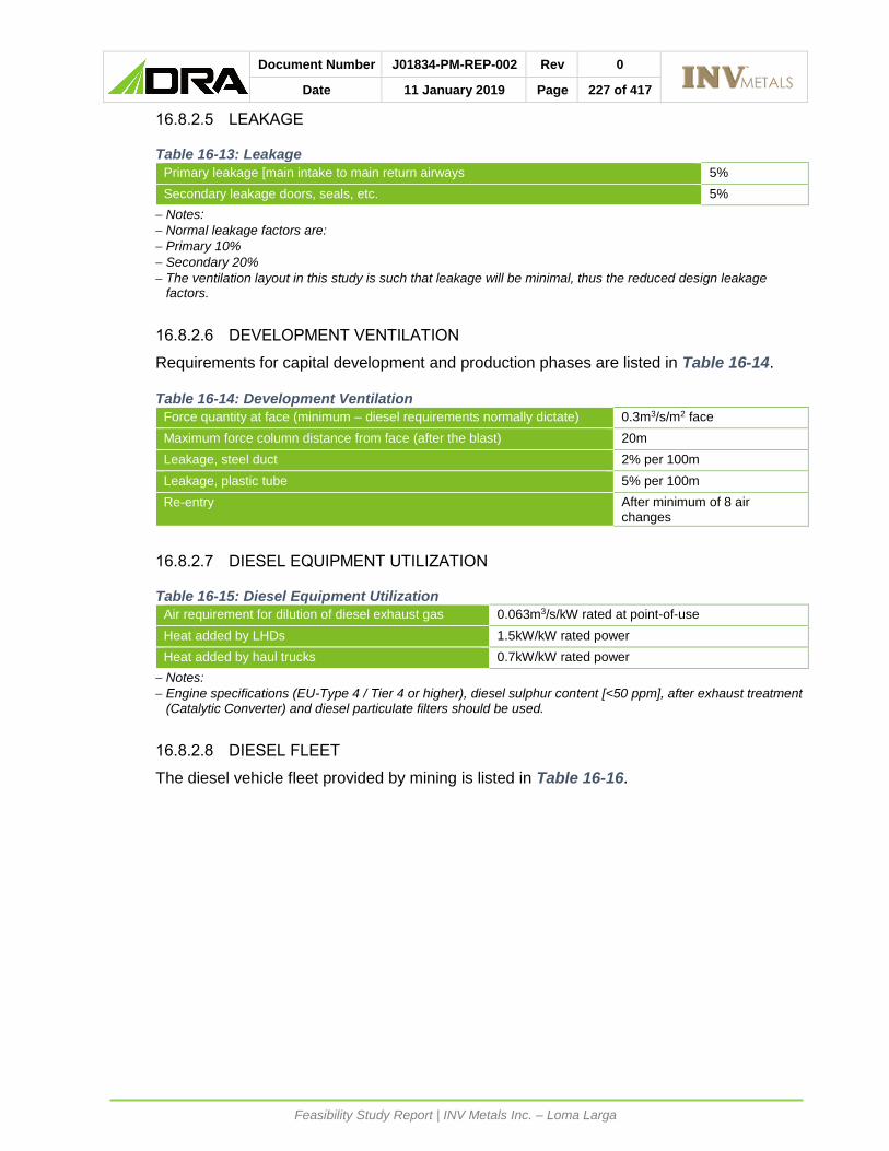
Document Number J01834-PM-REP-002 Rev 0
Date 11 January 2019 Page 227 of 417
Feasibility Study Report | INV Metals Inc. – Loma Larga
16.8.2.5 LEAKAGE
Table 16-13: Leakage
Primary leakage [main intake to main return airways 5%
Secondary leakage doors, seals, etc. 5%
Notes:
Normal leakage factors are:
Primary 10%
Secondary 20%
The ventilation layout in this study is such that leakage will be minimal, thus the reduced design leakage factors.
16.8.2.6 DEVELOPMENT VENTILATION
Requirements for capital development and production phases are listed in Table 16-14.
Table 16-14: Development Ventilation
Force quantity at face (minimum – diesel requirements normally dictate) 0.3m3/s/m2 face
Maximum force column distance from face (after the blast) 20m
Leakage, steel duct 2% per 100m
Leakage, plastic tube 5% per 100m
Re-entry After minimum of 8 air changes
16.8.2.7 DIESEL EQUIPMENT UTILIZATION
Table 16-15: Diesel Equipment Utilization
Air requirement for dilution of diesel exhaust gas 0.063m3/s/kW rated at point-of-use
Heat added by LHDs 1.5kW/kW rated power
Heat added by haul trucks 0.7kW/kW rated power
Notes:
Engine specifications (EU-Type 4 / Tier 4 or higher), diesel sulphur content [<50 ppm], after exhaust treatment (Catalytic Converter) and diesel particulate filters should be used.
16.8.2.8 DIESEL FLEET
The diesel vehicle fleet provided by mining is listed in Table 16-16.

Document Number J01834-PM-REP-002 Rev 0
Date 11 January 2019 Page 228 of 417
Feasibility Study Report | INV Metals Inc. – Loma Larga
Table 16-16: Diesel Fleet
Machine Type Quantity Rated kW
% Utilization Total kW
Air Required
[@ 0.063 m3/s per kW]
Production
Mobile Anfo loader
A64 EXC3000
1 129 50%
100%
65
129
4m3/s
8m3/s
Cable Bolter DS421 1 119 50%
100%
60
119
4m3/s
8m3/s
Hydraulic Production Drill 2 93 50%
100%
93
186
6m3/s
12m3/s
Jumbo Drill DD321 2 134 50%
100%
134
268
9m3/s
18m3/s
LHD 17 tonnes 6 275 100% 1650 104m3/s
Roof bolter DS411 2 119 50%
100%
119
238
8m3/s
16m3/s
Scissor Lift A64 SL 2 129 100% 258 4m3/s
Shotcrete sprayer A64 SST
1 150 100% 150 10m3/s
Shotcrete mixer
HD R60
1 164
(Cummins Motor)
100% 164 10m3/s
Tramming
Loader Cat 988 2 280 100% 560 35m3/s
Mine truck 40t TH540
7 405 60%
100%
1701
2835
107m3/s
179m 3/s
Volume required based on percentage utilization (excluding leakage and commitments) 303m3/s
Volume required based on total kW @ 0.063 m3/s per kW (excluding leakage and commitments) 413m3/s
Total volume required including leakage 10% and commitments 50 m3/s (Workshop) 503m3/s
16.8.2.9 SURFACE AMBIENT DESIGN CONDITIONS
Table 16-17: Surface Ambient Design Conditions
Design temperature 4.0°C to 17°C
Average minimum temperature 8°C
Average temperature 11.0°C
Barometric pressure 65.0kPa
Surface density 0.800kg/m³
16.8.2.10 GEOTHERMAL PROPERTIES
Reference Virgin Rock Temperatures (VRTs) are given in the Table 16-18 below.

Document Number J01834-PM-REP-002 Rev 0
Date 11 January 2019 Page 229 of 417
Feasibility Study Report | INV Metals Inc. – Loma Larga
Table 16-18: Virgin Rock Temperatures
Level VRT [°C]
3,600 m (Estimated) 4°C
16.8.2.11 THERMAL CRITERIA
Table 16-19: Thermal Criteria
Minimum temperature 2°C
16.8.2.12 FIRE PREVENTION AND DETECTION
Compliance with best practice, and any legal requirements.
16.8.2.13 WORKSHOPS / TYRE BAYS / BULK LIQUID AND OIL STORES
Workshops, bulk fuel and oil storage tanks are ventilated directly to return. An automatic
foam / sprinkler system should be installed in these areas.
16.8.2.14 VEHICLES AND MACHINERY
All vehicles and machines will be equipped with an automated approved on-board fire
suppression system.
16.8.2.15 FLAMMABLE GAS
A Code of Practice (COP) is required in compliance with best practice, and any legal
requirements.
16.8.2.16 AIRBORNE POLLUTANTS
All exposures to airborne pollutants are to be within the following Occupational Exposure
Limits (OELs) as specified. (See Table 16-20).

Document Number J01834-PM-REP-002 Rev 0
Date 11 January 2019 Page 230 of 417
Feasibility Study Report | INV Metals Inc. – Loma Larga
Table 16-20: Summary of Airborne Pollutants OEL
Silica dust, crystalline 0.1mg/m3 Time Weighted Average (TWA)
Fibres 2 f/mL Time Weighted Average (TWA)
PNOC Inhalable 10mg/m3 and respirable 3mg/m3
Carbon Monoxide (CO) 30ppm (TWA) and 100ppm (OEL-Stel)
Carbon Dioxide (CO2) 5000ppm (TWA) and 30,000ppm (OEL-Stel)
Nitric oxide (NO) 25ppm (TW)] and 35ppm (OEL-Stel)
Nitrogen dioxide (NO2) 3ppm (TWA) and 5ppm (OEL-Stel)
Sulphur dioxide (SO2) 2ppm (TWA) and 5ppm (OEL-Stel)
Diesel Particulate Matter – Total carbon 160µg/m3
Diesel Particulate Matter – Elemental carbon 123µg/m3
Flammable gas < 1.0%
Radiation < 20mSv/annum (personal exposure)
16.8.2.17 COLD STRESS MANAGEMENT
Table 16-21: Maximum Time of Exposure
Temperature Range Exposure Time
0ºC to -18ºC No restriction
-19ºC to -34ºC Fifty minutes per hour
-35ºC to -57ºC Two periods of 30 minutes each, after a 4-hour interval
Below -57ºC Fifty minutes during any period of 8 hours
16.8.2.18 ERGONOMICS
Albeit that most vehicles will be operating remotely, several concerns must be highlighted in
terms of ergonomic hazards with regards to work station design interface, these include:
• Body positions and movement.
• Handling loads.
It is recommended that an ergonomic survey be conducted as part of the ongoing risk
assessment process. In addition, manufacturers of machinery to demonstrate their duty of
care by furnishing reports on their machinery in this regard.
16.8.3 DECLINE RAMP VENTILATION
16.8.3.1 BACKGROUND
The initial ramp ventilation calculations catered for the ventilation requirements up to the
downcast shaft position, with a nominal 500 m of extra haulage development.
To this end revised calculations are included to cater for the increased diesel vehicle ratings
as well as leakages for this initial scenario.
However, mine schedule indicates that a considerable amount of development on multiple
fronts are being planned, prior to the availability of the raisebore hole (RBH) to surface. This
RBH will initially be used as an upcast to facilitate through ventilation and cater for the
development program.
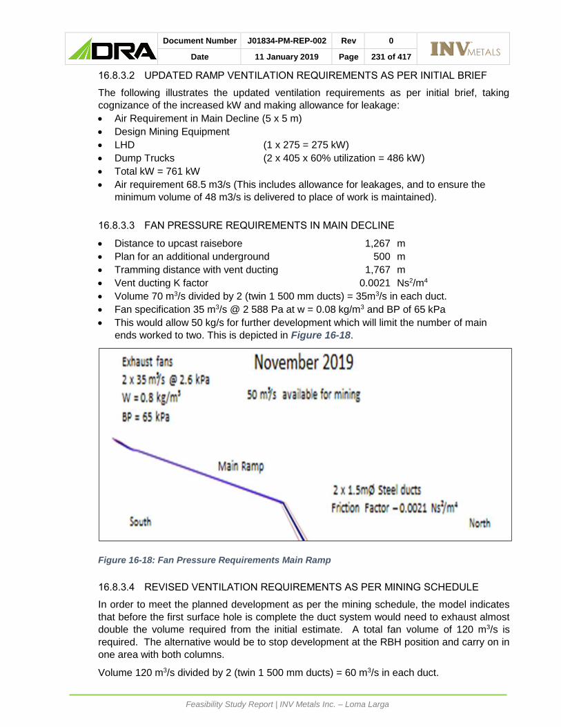
Document Number J01834-PM-REP-002 Rev 0
Date 11 January 2019 Page 231 of 417
Feasibility Study Report | INV Metals Inc. – Loma Larga
16.8.3.2 UPDATED RAMP VENTILATION REQUIREMENTS AS PER INITIAL BRIEF
The following illustrates the updated ventilation requirements as per initial brief, taking
cognizance of the increased kW and making allowance for leakage:
• Air Requirement in Main Decline (5 x 5 m)
• Design Mining Equipment
• LHD (1 x 275 = 275 kW)
• Dump Trucks (2 x 405 x 60% utilization = 486 kW)
• Total kW = 761 kW
• Air requirement 68.5 m3/s (This includes allowance for leakages, and to ensure the
minimum volume of 48 m3/s is delivered to place of work is maintained).
16.8.3.3 FAN PRESSURE REQUIREMENTS IN MAIN DECLINE
• Distance to upcast raisebore 1,267 m
• Plan for an additional underground 500 m
• Tramming distance with vent ducting 1,767 m
• Vent ducting K factor 0.0021 Ns2/m4
• Volume 70 m3/s divided by 2 (twin 1 500 mm ducts) = 35m3/s in each duct.
• Fan specification 35 m3/s @ 2 588 Pa at w = 0.08 kg/m3 and BP of 65 kPa
• This would allow 50 kg/s for further development which will limit the number of main
ends worked to two. This is depicted in Figure 16-18.
Figure 16-18: Fan Pressure Requirements Main Ramp
16.8.3.4 REVISED VENTILATION REQUIREMENTS AS PER MINING SCHEDULE
In order to meet the planned development as per the mining schedule, the model indicates
that before the first surface hole is complete the duct system would need to exhaust almost
double the volume required from the initial estimate. A total fan volume of 120 m3/s is
required. The alternative would be to stop development at the RBH position and carry on in
one area with both columns.
Volume 120 m3/s divided by 2 (twin 1 500 mm ducts) = 60 m3/s in each duct.

Document Number J01834-PM-REP-002 Rev 0
Date 11 January 2019 Page 232 of 417
Feasibility Study Report | INV Metals Inc. – Loma Larga
Fan specification 60 m3/s @ 5 400 Pa at w = 0.8 kg/m3 and BP of 65 kPa.
This would allow 90 kg/s for further development and will satisfy the development schedule
requirements. Figure 16-19 and Figure 16-20 depict the main ventilation requirements for
this scenario.
Figure 16-19: Ramp Ventilation Requirements to Meet Mine Development Schedule
Figure 16-20: Development of Multiple Ends as per the Mining Schedule
16.8.4 PRIMARY VENTILATION
16.8.4.1 OVERVIEW
The mine will be accessed from one decline adit. Steady state operations will require six,
raisebore shafts, one intake, four returns and a dedicated escape way which will also be used

Document Number J01834-PM-REP-002 Rev 0
Date 11 January 2019 Page 233 of 417
Feasibility Study Report | INV Metals Inc. – Loma Larga
as an intake, but at a lower velocity. The main decline adit further augments the intake air
requirement. The volumetric flow in the decline will be modulated by using an air jet fan
should the velocity in the decline increase to unacceptable levels. The trucking and dedicated
loading bay will be in through ventilation, allowing for unimpeded 24-hour operation. The
workshop and lubrication stores will ventilate directly to return enabling all contaminants in
these areas to report directly to return.
During steady state, air will be extracted from the mine via underground main fan installations
situated at the connections to the various upcast shafts. Fans will be moved as per the
ventilation dictates stemming from the mine extraction strategy.
During the LOM, and depending on the mining sequence, the volumetric flow varies from 190
to 500 m3/s. The main fans have been specifically selected in order to cater for this varied
requirement.
These fans will be equipped with Variable Speed Drives (VSD) in order to match volume
requirement with ramp up, varied volumetric requirements to meet the extraction plan, and to
ensure fan efficiency. A set of critical spares has also been recommended.
The layout is designed, that leakage which can normally consume 30% of installed volume is
reduced to 10%.
16.8.4.2 VENTILATION REQUIREMENTS
Airflow requirements allow for the adequate ventilation of production and drift development,
the central loading station, the underground offices and workshop.
The main air quantities, excluding leakages required during the LOM and captured at
significant ventilation infrastructure stages, are depicted below.
Table 16-22: Ventilation Requirement Start of Stope Development
Main Ventilation Infrastructure
Number of Main Fans in
Operation
Quantity Per Fan
Volume Circulated
Central ventilation raise (Temporary Exhaust) 2 95m3/s 190m3/s
Escape way raise (Regulated Intake)
20m3/s 20m3/s
Main ramp (Intake) 170m3/s
Total Required
190m3/s

Document Number J01834-PM-REP-002 Rev 0
Date 11 January 2019 Page 234 of 417
Feasibility Study Report | INV Metals Inc. – Loma Larga
Figure 16-21: Start of Stope Development Note: The escape way raise will be regulated to a nominal 20 m3/s for the LOM. Furthermore, as an additional
safety precaution a diesel standby fan installed at the top of the escape way shaft, with a simple ducting arrangement and airlock could be started in an emergency (total power failure scenario) with a recommended duty for the fan of 20 m3/s @ 500 Pa.
Table 16-23: Ventilation Requirement, Near North Ventilation Raise Operational
Main Ventilation Infrastructure Number of Main Fans in Operation
Quantity Per Fan
Volume Circulated
Escape way raise (Regulated Intake) 2 80m3/s 160m3/s
Near north ventilation raise (Exhaust) 2 125m3/s 250m3/s
Main ramp (Intake) 160m3/s
Central ventilation raise (Temporary Exhaust) 250m3/s
Total Required
340m3/s
Figure 16-22: Near North Ventilation Raise Operational
Escape Way RaiseIntake• 1.8 mØ• 20 m³/s • 8.0 m/s
Main RampIntake• 170 m³/s• 6.2 m/s
Central Ventilation RaiseTemporary Exhaust• 3.8 mØ• 190m ³/s @ 850 Pa• 0.77 kg/m³• 16.8 m/s• Fans installed in bottom
access
Start of Stope Development
South North

Document Number J01834-PM-REP-002 Rev 0
Date 11 January 2019 Page 235 of 417
Feasibility Study Report | INV Metals Inc. – Loma Larga
Note: The central upper mining block needs to be accessed from the South side in order to return the air from this section to the Near North Ventilation Raise. It is recommended that this is affected by a drilling a small ventilation raise down to the North Upper haulage and connected to the Near North Ventilation Raise with steel ducting. This will ensure that the contaminants from this section do not affect the rest of the mine as it will be a separate ventilation district.
Table 16-24: Ventilation Requirement, Near South Ventilation Raise Operational
Main Ventilation Infrastructure
Number of Main Fans in Operation
Quantity Per Fan
Volume Circulated
Near south ventilation raise (Exhaust) 2 100m3/s 200m3/s
Near north ventilation raise (Exhaust) 2 140m3/s 280m3/s
Main ramp (Intake) 180m3/s
Central ventilation raise (Intake) 280m3/s
Escape way raise (Regulated Intake) 20m3/s
Total Required
480m3/s
Figure 16-23: Near South Ventilation Raise Operational

Document Number J01834-PM-REP-002 Rev 0
Date 11 January 2019 Page 236 of 417
Feasibility Study Report | INV Metals Inc. – Loma Larga
Table 16-25: Ventilation Requirement, Far North Ventilation Raise Operational
Main Ventilation Infrastructure
Number of Main Fans in
Operation
Quantity Per Fan
Volume Circulated
Near south ventilation raise (Exhaust) 2 100m3/s 200m3/s
Near north ventilation raise (Exhaust) 1 60m3/s 60m3/s
Far north ventilation raise (Exhaust) 2 118m3/s 235m3/s
Main ramp (Intake) 180m3/s
Central ventilation raise (Intake) 295m3/s
Escape way raise (Regulated Intake) 20m3/s
Total Required
495m3/s
Figure 16-24: Far North Ventilation Raise Operational
South North
Escape way RaiseIntake1.8 mØ20 m³/s 8.0 m/s
Main RampIntake• 180 m³/s• 6.5 m/s
Central Ventilation RaiseIntake• 3.8 mØ• 295 m³/s• 26.0 m/s
Near North Ventilation RaiseReturn• 3.8 mØ• 60 m³/s @ 350 Pa• 0.72 kg/m³• 11.2 m/s
Near South Ventilation RaiseReturn• 3.8 mØ• 200 m³/s @ 360 Pa• 0.71 kg/m³• 17.4 m/s
Workshop 50 m³/s
Far North Ventilation RaiseReturn• 3.8 mØ• 235 m³/s @ 560 Pa• 0.71 kg/m³• 20.8 m/s
Far North Ventilation Raise Operational

Document Number J01834-PM-REP-002 Rev 0
Date 11 January 2019 Page 237 of 417
Feasibility Study Report | INV Metals Inc. – Loma Larga
Table 16-26: Ventilation Requirement, Full Ventilation System Operational
Main Ventilation Infrastructure Number of Main Fans in
Operation
Quantity Per Fan
Volume Circulated
Far south ventilation raise (Exhaust) 1 100m3/s 100m3/s
Near south ventilation raise (Exhaust) 1 50m3/s 50m3/s
Far north ventilation raise (Exhaust) 2 150m3/s 300m3/s
Near north ventilation raise (Exhaust) 1 50m3/s 50m3/s
Main ramp (Intake) 180m3/s
Central ventilation raise (Intake) 300m3/s
Escape way raise (Regulated Intake) 20m3/s
Total Required
500m3/s
Figure 16-25: Full Ventilation System Operational
16.8.5 SECONDARY VENTILATION
16.8.5.1 PRODUCTION DRIFT DEVELOPMENT VENTILATION
The production drifts should be developed using a 55-kW dual speed axial flow, high
efficiency silenced fan on 1 016 mm anti-static force ducting with the following two duties.
• Duty 1.22 m3/s @ 1 800 Pa. (@ 0.063 m3/s per kW the LHD would require 17 m3/s)
• Duty 2.12m3/s @ 500 Pa. (@ 0.063 m3/s per kW the other utilities would require 8 to
10 m3/s)
Each developing drift will be equipped with the above mentioned dual speed fan. The fan will
speed up to full duty of 22 m3/s while either mucking or blasting takes place and will revert to
the reduced volume of 12m3/s for all other activities. This has a major positive impact on the
electrical infrastructure and overall operating cost. This dual speed arrangement drastically
reduces power requirements for this facet of mining.
South North
Escape way RaiseIntake• 1.8 mØ• 20 m³/s • 8.0 m/s
Main Ramp Intake• 180 m³/s • 6.5 m/s
Central Ventilation RaiseIntake• 3.8 mØ• 300 m³/s• 26.5 m/s
Near North Ventilation RaiseReturn• 3.8 mØ• 50m³/s @ 990 Pa• 0.79 kg/m³• 4.4 m/s• Underground fan
Near South Ventilation RaiseReturn• 3.8 mØ• 50 m³/s @ 445 Pa• 0.8 kg/m³• 4.4 m/s• Underground fan
Workshop50 m³/s
Far North Ventilation RaiseReturn• 3.8 mØ• 300 m³/s @ 1040 Pa• 0.78 kg/m³• 26.9m/s
Full Ventilation System Operational
Far South Ventilation RaiseReturn• 3.8 mØ• 100 m³/s @ 530 Pa• 0.78 kg/m³• 9.1 m/s

Document Number J01834-PM-REP-002 Rev 0
Date 11 January 2019 Page 238 of 417
Feasibility Study Report | INV Metals Inc. – Loma Larga
16.8.5.2 HAULAGE TUNNEL DEVELOPMENT VENTILATION
The haulage tunnels should be developed using 90 kW axial flow high efficiency silenced fans
on 1 200 mm anti-static flexible force ducting, with a duty of 37 m3/s @ 2.0 kPa. This will allow
for adequate volumes in terms of drift development offtake and negate recirculation.

Document Number J01834-PM-REP-002 Rev 0
Date 11 January 2019 Page 239 of 417
Feasibility Study Report | INV Metals Inc. – Loma Larga
16.8.6 MAIN FAN SPECIFICATION
16.8.6.1 FAN DUTY
Emanating from the Vuma model, the maximum fan design duty is 150 m3/s @ 1040 Pa with
density of 0.78 kg/m3.
16.8.6.2 FAN TYPE
It is recommended that these fans be of the Axial Flow type. Centrifugal fans are generally
quieter than axial fans operating at the same speed and duty, primarily due to reduced blade
tip clearance. However, if silencing is required, axial fans are inherently easier to silence due
to their architecture. In terms of reliability, modern axial flow fans have been shown to provide
good reliability, and their component nature, hub and blades, provides simple maintenance
and replacement methods, should excess wear be noticed. If an impeller on a centrifugal fan
is damaged or worn, a major replacement exercise is to be expected.
Further motivation for the selection of axial flow fans are:
• Identical fans can be selected for all sites, with differences in duty handled by small
adjustments to blade angles.
• Axial flow fans are generally less expensive. The relatively short lifespan of the Loma
Larga project does not justify the extra cost of centrifugal fans, which are typically
designed to last for 25 to 40 years.
16.8.6.3 VOLUME FLEXIBILITY
The available multiple return raise-bores and the planned Variable Frequency Drives (VFDs)
gives full ventilation flexibility over the LOM extraction.
Blade angles can be adjusted to compensate for variations in the build-up, and steady state
requirements
These fans will operate over a wide range of duties during its life, due to the initial build-up
and ore extraction plan which is not split evenly between the North and South mining blocks.
The maximum volume will be 500 m3/s
With the wide range of operation, it would be prudent to specify a higher motor kW rating,
which at a negligible cost will provide a much higher volume capability if an increase is
tonnage/mining is possible in the future.
16.8.6.4 FAN SPECIFICATION
The fan should be able to operate over the following continuum:
• Maxima Main Fan Design Duty (Fan Operating Point)
• Volume 150 m3/s
• Pressure 1 200 Pa
• Density 0.8k g/m3
• Atmospheric Pressure 65 kPa
• Minima Main Fan Design Duty (Fan Operating Point)
• Volume 50 m3/s
• Pressure 350 Pa

Document Number J01834-PM-REP-002 Rev 0
Date 11 January 2019 Page 240 of 417
Feasibility Study Report | INV Metals Inc. – Loma Larga
• Density 0.8 kg/m3
• Atmospheric Pressure 65 kPa
16.8.6.5 NUMBER OF FANS REQUIRED
Five complete Axial Flow units.
16.8.6.6 FAN CURVE
The following fan curve as depicted in Figure 16-26 is included as an example of the fan
duties required. The budget quotation is appended for benchmarking purposes.
Figure 16-26: Main Fan Curve

Document Number J01834-PM-REP-002 Rev 0
Date 11 January 2019 Page 241 of 417
Feasibility Study Report | INV Metals Inc. – Loma Larga
16.8.6.7 FAN TYPE AND ANCILLIARY EQUIPMENT
Axial Flow
Low voltage motors and Variable Frequency Drives (VFDs)will:
• Allow start-up from generator power supply with low inrush current.
• Provide flexibility during ‘mine establishment and production ‘ramp-up.
• Provide the necessary flexibility to meet the varied production volume requirements,
between the north and south mining areas, as per the Mine extraction schedule.
• In the event of a fan failure, other motors can be “speeded up” to compensate.
Manually adjustable impellors which with the VFDs, will allow the fans to operate at optimal
efficiency during mine establishment and full production phases. This will specifically allow
for good efficiencies at low duties.
Allowance for the following critical spares should be made:
• One complete rotating assembly.
• One spare motor.
It is further recommended that it would be beneficial to procure fans that are driven by motors
that are external to the fan drift via a cardan shaft. The benefits of this arrangement are:
• Improved cooling of the motor as in a mechanised mine, the amount of diesel soot flowing
through the fan drift can impair the cooling capabilities of the fan motor.
• Improved access to the electric motor for maintenance.
16.9 PASTE BACKFILL
Patterson & Cooke (P&C) has completed a feasibility level study of the backfill system for the
Loma Larga Project. A mine plan has been completed by DRA which relies on backfill as a
primary ground support medium. The majority of voids underground are to be filled using
cemented pastefill.
P&C’s scope of work included supporting test work and the design of the paste plant and
reticulation, capable of supplying cemented pastefill to the underground stopes.
This section has been prepared by P&C to document the work undertaken, provide an
overview of the process design and equipment selected, and to present the engineering for
both the paste plant and underground distribution system.
Reference is made to P&C’s Feasibility Study Report (32-0252-2210-GE-REP-0001) which
presents the complete backfill feasibility level engineering design and is included in Appendix
8D of the Feasibility Study Report.
The base case for the feasibility study considered pumping thickened tails from the process
plant to the paste plant area near the mine. An alternate option was reviewed and selected
for the feasibility study utilising the tailings filtration facility in the process plant area which is
sized to filter the full tailings throughput. The filter cake that is produced in the process plant
area is then trucked to either the filtered tailings storage facility or the paste plant as required.
16.9.1 PASTE FILL STRENGTH REQUIREMENTS
Cemented paste backfill requires a minimum strength to ensure wall stability in vertical
exposures. MDEng recommended (MDEng Feasibility Level Geotechnical Design Report

Document Number J01834-PM-REP-002 Rev 0
Date 11 January 2019 Page 242 of 417
Feasibility Study Report | INV Metals Inc. – Loma Larga
#17018-104) the paste strength requirements will vary from ~190 to 340 kPa depending on
the panel length in secondary transverse stopes.
Current mine plans are for bottom-up advance and so strength requirements for mining under
paste have not been evaluated at this time.
Tight filling of backfill is important for long term stability of stope backs and particularly for the
crown pillar. Stopes should be backfilled as soon as reasonably practicable and should be
tight filled to minimize potential for instability.
16.9.2 PASTE FILL DEMANDS
On average, the paste plant will be required to fill ~990 m³ per day for the 3,000 t/d milling
rate. This represents approximately 90% of the stope volume which is normally excavated
on a daily basis. The remaining 10% will remain empty or will be filled with waste rock. The
paste plant system capacity volumetric rate is calculated at 100 to 120 m³:
The same system capacity is assumed over the LOM.
16.9.3 PASTE TEST WORK SUMMARY AND RECIPES
P&C conducted pastefill test work on both rougher and a combined tailing comprising 2:1
rougher to cleaner ratio (Loma Larga Paste Backfill Feasibility Study Report 32-0252-00-TW-
REP-0001). The following summarizes the main outcomes of the test work which influenced
the design process:
• Rougher tailings Particle Size Distribution (PSD): Fine with 46% passing 20 μm. Cleaner
tailings PSD: Very fine with 72% passing 20 μm.
• Rougher tailings comprise mostly of quartz (~98%) with ~1% of rutile and ~1% of pyrite.
Cleaner tailings consist of the silicate minerals Quartz (96%) and oxide mineral Rutile
(titanium oxide, 1%). Quartz and Rutile are inert and will not participate in any
cementitious reactions in the backfill and provide a good filler material for the backfill.
Pyrite can be a concern for long-term strengths due to sulfate attack; however, the
content is sufficiently low that it will not have a significant effect.
• The binder estimate required is presented in Figure 16-27. This estimate is based on
achieving 300 kPa after 28 days and distributing paste at a mass concentration of
77%m.

Document Number J01834-PM-REP-002 Rev 0
Date 11 January 2019 Page 243 of 417
Feasibility Study Report | INV Metals Inc. – Loma Larga
Figure 16-27: Binder Estimate (28 Day Target Strength)
16.9.4 PASTE PLANT SITE OVERVIEW
The paste plant is located above the orebody centroid and directly north of the process plant
(Figure 16-28). A mine road approximately 4 km in length will connect the paste plant with
the process plant. Filtered tailings will be trucked along this road and return water pipelines
will be routed in an adjacent pipe corridor. Return water will include the excess water and
slurry from the backfill plant, from the mining process, as well as water that flows into the mine
from the surrounding rock mass.

Document Number J01834-PM-REP-002 Rev 0
Date 11 January 2019 Page 244 of 417
Feasibility Study Report | INV Metals Inc. – Loma Larga
Figure 16-28: Paste Plant Site Plan (including Paste Plant and Process Plant Location)

Document Number J01834-PM-REP-002 Rev 0
Date 11 January 2019 Page 245 of 417
Feasibility Study Report | INV Metals Inc. – Loma Larga
16.9.5 PASTE PLANT DESIGN
The process design on surface is strongly influenced by the requirements of the underground
(both mining and reticulation) and the material properties of the tailings. It is expected that
the properties of the filtered tailings will remain fairly constant and the use of a continuous
mixing process is therefore included in the design. Minor changes to the tailings material
properties, binder content, water content etc. will be controlled by specific sampling and
monitoring measures included in the design to ensure a consistent backfill is produced.
All tailings leaving the process plant are dewatered to ~85%m solids. When pastefill is
scheduled for underground, approximately 50 to 100% of the dewatered tailings is trucked
4 km to the paste plant. The balance of filtered tailings will be trucked to the FTSF. Excess
paste and/or process water will be pumped back from the paste plant to the process plant
using a second pipeline.
Tailings will be received at the paste backfill plant via dump hopper and filter cake feeder filter
cake feeder. From the feeder, filter cake will be measured onto a filter cake conveyor and be
fed into a continuous twin-shaft mixer fitted.
Dry binder is screw fed from two storage silos (one duty / one standby) and discharged into
the mixer. A binder content of ~3% will be added depending on the underground distribution
point and recipe requirements.
Final slump control water is dosed into the mixer by the Programmable Logic Controller (PLC)
based on the power draw that the mixer motors are experiencing. A power draw that is too
high indicates the pastefill is too stiff, so water is added to bring the power draw back in line
with the recipe’s expectations.
The mixer has an inner volume of 7.8 m³ and a mixing capacity of 149 m³/h (peak) with 150
second retention time. The mixing action is performed by mixing arms and paddles which are
hydrodynamically designed to reduce wear and promote optimum mixing. The mixer includes
a high impact washing system.
The pastefill from the mixer overflows into a paste hopper and is gravity fed into the suction
side of one of the two piston positive displacement pumps. The piston pumps (one duty and
one standby) pump paste on a continuous basis down the paste boreholes for deposition
underground at the nominal design flow rate of 124 m³/h.
16.9.6 PASTE PLANT LAYOUT
The design of the site, building and foundations is governed by the process and equipment
requirements, in conjunction with specific design criteria provided by DRA, as well as the
Ecuadorian National Codes. The paste plant consists of a single multilevel building and a
service area. Contained within this area will be the major and supporting pieces of equipment
required to produce pastefill.
The lab building, e-rooms and control room are modularized modified high cube containers.
The rooms have been strategically located around the paste plant to optimize operating and
maintenance activities required.
The Loma Larga Project site is located within an environmentally sensitive zone. All design
considerations have been taken to ensure the paste plant area is a zero-discharge site.

Document Number J01834-PM-REP-002 Rev 0
Date 11 January 2019 Page 246 of 417
Feasibility Study Report | INV Metals Inc. – Loma Larga
Only a single service road is required around the front of the paste plant building. Any
equipment outside the paste plant building will be accessed with the 200-tonne plant mobile
crane.
The cement silos will be fed from the front of the building with a truck pulling up in front of the
plant and blowing the cement into the silos.
16.9.7 PASTE BACKFILL UNDERGROUND DISTRIBUTION SYSTEM
The Loma Larga underground pastefill distribution system includes two surface to
underground cased boreholes to supply paste to the underground workings. The surface
boreholes were designed to breakthrough on 3,625 level with a dip between 65° and 70°. The
second borehole will be constructed as backup which is considered good practice.
Once underground, the pastefill travels through a network of pipelines to reach the locations
where the paste is needed. An eight-inch pipe size has been specified for the underground
distribution system.
Paste backfill deposition will occur from the 3,625 and 3,600 levels. No top access will be
available to the stopes that sill out on the 3,625 level and will be mined using blind uphole
blast techniques. As a result, paste will be deposited into the tops of these upper stopes
using inclined deposition and breather boreholes.
Pressure instrumentation and cameras will be provided throughout the mine for monitoring
the pour. Emergency blast-off spools and manual drain valves will be installed at critical
locations. Manual valves near the discharge to the stopes will be used to divert water during
a flush.
The pipeline profile is shown as a plan view and mine elevation view in Figure 16-29 and
Figure 16-30, respectively.
Figure 16-29: Schematic Diagram of Underground Workings – Pipeline Profile (Plan View)

Document Number J01834-PM-REP-002 Rev 0
Date 11 January 2019 Page 247 of 417
Feasibility Study Report | INV Metals Inc. – Loma Larga
Figure 16-30: Schematic Diagram of Underground Workings – Pipeline Profile (Mine Elevation)
16.10 UNDERGROUND HYDROGEOLOGY CONSIDERATIONS
Itasca have done extensive work at the Loma Larga project to determine the quantity and
quality of the water that will be expected underground during the ramp development and
during operations. The summary of their findings is presented below.
During the ramp development phase, the water supply will be pumped out of the settling pond
near the portal. The main water consumption (estimated by DRA) during that phase will be
the jumbo drill (30 L/min) and the Bolter (15 L/min) for a maximum consumption of 45 L/min.
The average daily water consumption will be 10,800 litres. Also, for the first 300 m of the
ramp, the ground will not generate enough water and it is assuming that some fresh water
will be required for 50% of the mine needs. As the ramp advances, sumps will be used to
collect ground water and waste water. The water collected will be pumped to the settling
pond near the portal to be used for development purposes. The same principle will be applied
during the pre-production development as a second development crew will be added.
The summary of the underground water supply for the ramp and pre-production development
(estimated by DRA) is shown in Table 16-27.

Document Number J01834-PM-REP-002 Rev 0
Date 11 January 2019 Page 248 of 417
Feasibility Study Report | INV Metals Inc. – Loma Larga
Table 16-27: Underground Water Supply for Ramp and Pre-Production Development
Ramp Development
Equipment Number Consumption Peak Consumption Consumption per day
(ea) (l/min) (l/hours) (litre)
Jumbo 2 boom 1 30 1,800 7,200
Bolter 1 15 900 3,600
Total Water Equipment Consumption per day 1,800 10,800
% recirculated for the first 300 metres
50%
Water needed for the treatment plant for the first 300 m 5,400
Pre-Production development
Equipment Number of Consumption Peak Consumption Consumption per day
Equipment (l/min) (l/hours) (litre)
Jumbo 2 boom 2 60 3,600 14,400
Bolter 2 30 1,800 7,200
Total Water Equipment Consumption per day 3,600 25,600
% recirculated
100%
Water needed from the treatment plant
-
In the mining production phase, the required water supply will come from the main dewatering
system. The solids will be separated, from the water collected underground, and recirculated
to the development and production drills. In addition to the jumbos and bolters from the mine
development, DRA estimates that four production drills will each consume water at a rate of
5 L/min and one cable bolter will consume water at a rate of 15 L/min. The average daily
water consumption will be 45,000 litres and will be all supplied from the underground
dewatering system. Throughout the full mine life, the underground water supply will come
entirely from the water collected underground.
The summary of the underground water supply at full production (estimated by DRA) is shown
in Table 16-28.
Table 16-28: Underground Water Supply for Full Production
Production phase (14 years)
Equipment Number of Consumption Peak Consumption Consumption per day
Equipment (l/min) (l/hours) (litre)
Jumbo 2 boom 2 60 3,600 14,400
Production Drill 4 20 1,200 21,600
Cable Bolter 1 15 900 1,800
Bolter 2 30 1,800 7,200
Total Water Consumption per day 7,200 45,000
% recirculated
100%
Water needed from the treatment plant
-
16.11 UNDERGROUND SERVICE FACILITIES
16.11.1 MAINTENANCE
Most of the repair services on mobile underground equipment will be done on the surface.
The maintenance shop will be built near the plant and office facilities. The underground

Document Number J01834-PM-REP-002 Rev 0
Date 11 January 2019 Page 249 of 417
Feasibility Study Report | INV Metals Inc. – Loma Larga
mobile equipment will be on a maintenance schedule to minimize equipment breakdowns
during work. Only emergency repairs will be done underground on mobile equipment. A
small underground shop bay will carry minimal parts inventory to quickly respond to
equipment breakdowns. Also, the fuel and lube truck will be able to fill up the hydraulic
systems underground when needed.
The underground shop will carry spare pumps, pump motors, auxiliary ventilators and motors,
in case of a breakdown. The pump and fans will be replaced underground and serviced in the
surface shop. The pumps will also be on a maintenance schedule and brought to the surface
shop on a regular basis. The same principle will apply for the ventilation fans. Spare fans
will be kept in inventory for all motor fans.
16.11.2 FUEL BAY
The underground haulage truck will refuel at the surface fuel tank. An underground fuel and
lube truck will bring the fuel from the surface tank to refuel the underground mobile equipment.
Also, the underground fuel and lube truck will be responsible to refuel dedicated to work
equipment such as jumbos and production drills at the work place.
16.11.3 EXPLOSIVE MAGAZINES
The explosive storage magazines will be located on surface one kilometre from any
infrastructure. One storage magazine will be for the detonators and the other for ammonia
nitrate/fuel (ANFO), the detonating cord and the sticks of packaged emulsion and perimeter
explosives. The magazines will be purchased from the explosive supplier. The mobile ANFO
loader will directly take the explosives from the magazines. The blasting crew will be
responsible for marking the explosives used in the inventory log books located in each
magazine. The site superintendent will be responsible to arrange regular powder magazine
inventory as required by regulations.
16.11.4 REFUGE STATIONS AND SANITARY FACILITIES
Portable self-contained refuge stations will be purchased and installed to follow the lateral
development. The portable refuge will primarily be installed near a fresh air intake and
connected to the compressed air system coming from the surface. A main refuge station will
be installed close at the bottom of the main fresh air raise intake. This facility will be equipped
with eye and hand washing system and potable water will be available. The facility will also
be used as a lunch room and meeting room.
Portable toilets will also be advancing with the lateral development.
16.11.5 MINE DEWATERING
As mentioned in the previous section, the underground water supply will not represent
additional water consumption from the main water treatment plant. The dewatering system,
throughout all phases of the operation, has been designed to supply clear water to the
underground operations and to handle the water inflow.
A simulation of the groundwater inflow for the mine life has been conducted by Itasca. The
study indicates that during the ramp excavation the water inflow will be 7.5 L/sec. As the

Document Number J01834-PM-REP-002 Rev 0
Date 11 January 2019 Page 250 of 417
Feasibility Study Report | INV Metals Inc. – Loma Larga
Project reaches full production, a peak water inflow of 13.8 L/sec is anticipated due to the
presence of the two main ventilation raises and several open stopes, as well as a significant
amount of level development.
During the ramp development phase, a sump will be excavated every 400 m to collect ground
water running down the ramp. Also, a face pump will collect drilling water to convey it to the
nearest sump. These sumps will settle the biggest solid particles and the waste water will get
pumped from one sump to the other all the way to the surface settling pound using a series
of 13 HP submersible pumps through a schedule 80, 102 mm diameter discharge line. The
water in the settling pound will be treated and part of the water will be sent back to the
underground operation.
At the ramp bottom, the main sump will be excavated, and the main dewatering system
installed. The main dewatering system is designed to separate the solids from the water.
This system will give clear water and a 30% solid slurry. The resulting clear water will be
used for the underground drilling operation, the excess will be pumped directly to the surface
plant using a 125 HP centrifugal pump through a schedule 10, 102 mm discharge line installed
in the ramp. The slurry will be pumped to surface using a mixer and slurry pumps. This slurry
will be pumped thought another schedule 80, 102 mm diameter installed in the ramp.
The water balance for the mine is represented in Figure 16-31.

Document Number J01834-PM-REP-002 Rev 0
Date 11 January 2019 Page 251 of 417
Feasibility Study Report | INV Metals Inc. – Loma Larga
Figure 16-31: Mine Water Balance
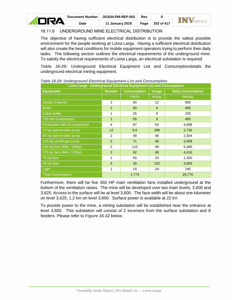
Document Number J01834-PM-REP-002 Rev 0
Date 11 January 2019 Page 252 of 417
Feasibility Study Report | INV Metals Inc. – Loma Larga
16.11.6 UNDERGROUND MINE ELECTRICAL DISTRIBUTION
The objective of having sufficient electrical distribution is to provide the safest possible
environment for the people working at Loma Larga. Having a sufficient electrical distribution
will also create the best conditions for mobile equipment operators trying to perform their daily
tasks. The following section outlines the electrical requirements of the underground mine.
To satisfy the electrical requirements of Loma Larga, an electrical substation is required.
Table 16-29: Underground Electrical Equipment List and Consumptiondetails the
underground electrical mining equipment.
Table 16-29: Underground Electrical Equipment List and Consumption
Loma Larga - Underground Electrical Equipment List and Consumption
Equipment Number Consumption Usage Daily Consumption
KW/hr hr/day kW/day
Jumbo 2 booms 2 50 12 600
Bolter 2 50 9 450
Cable bolter 1 25 9 225
700 cfm Compressor 1 55 9 495
Production drill cw compressor 4 87 54 4,698
13 hp submersible pump 12 9.5 288 2,736
40 hp submersible pump 2 48 48 2,304
125 hp centrifugal pump 2 71 48 3,408
150 hp fans (84in, 150hp) 2 110 48 5,280
125 hp fans (84in. 125hp) 2 92 48 4,416
75 hp fans 1 55 24 1,320
40 hp fans 5 30 120 3,600
Light 1 10 24 240
Total Consumption
1,774
29,770
Furthermore, there will be five 350 HP main ventilation fans installed underground at the
bottom of the ventilation raises. The mine will be developed over two main levels, 3,600 and
3,625. Access to the surface will be at level 3,600. The face width will be about one kilometer
on level 3,625, 1.2 km on level 3,600. Surface power is available at 22 kV.
To provide power to the mine, a mining substation will be established near the entrance at
level 3,600. This substation will consist of 2 incomers from the surface substation and 8
feeders. Please refer to Figure 16-32 below.

Document Number J01834-PM-REP-002 Rev 0
Date 11 January 2019 Page 253 of 417
Feasibility Study Report | INV Metals Inc. – Loma Larga
Figure 16-32 : Electrical Single Line Drawing

Document Number J01834-PM-REP-002 Rev 0
Date 11 January 2019 Page 254 of 417
Feasibility Study Report | INV Metals Inc. – Loma Larga
The 460-volt unitary substations will provide power to the mining equipment. The unitary
substations will be equipped with feeder circuit breakers for connection of the mining motor
control panels. This configuration will be repeated with two feeders and four unitary
substations on level 3,600 and two feeders and three unitary substations on level 3,625.
Please refer to Figure 16-33 and Figure 16-34 below.

Document Number J01834-PM-REP-002 Rev 0
Date 11 January 2019 Page 255 of 417
Feasibility Study Report | INV Metals Inc. – Loma Larga
Figure 16-33: Level 3,600 Power Distribution

Document Number J01834-PM-REP-002 Rev 0
Date 11 January 2019 Page 256 of 417
Feasibility Study Report | INV Metals Inc. – Loma Larga
Figure 16-34: Level 3,625 Power Distribution

Document Number J01834-PM-REP-002 Rev 0
Date 11 January 2019 Page 257 of 417
Feasibility Study Report | INV Metals Inc. – Loma Larga
For the ventilation vans there will be a ring supply, feeding two ring main units. Fed from the
ring, there will be two 22 kV main units, 4,160-volt units and 1.6 MVA transformers. The
4,160-volt units will feed the 400 HP starters for the ventilation vans.
16.11.7 UNDERGROUND COMMUNICATION
Based on the reliability, ease of use and ease of maintenance and repair, a leaky feeder
system is recommended for the underground communication system.
A leaky feeder system can be used to transmit data, video and voice communication from
underground to the mine surface. It can also be used to remotely operate fans, pumps and
the blasting system. It can do wireless or wired PLC / SCADA interface with equipment like
fans and pumps. It can connect to cameras and can be used for people and machine tracking
and voice communication.
The leaky feeder equipment has been designed to allow for underground communication
within range of the leaky feeder cable positioning.
The leaky feeder system will consist of a base repeater station comprising of a base station
cabinet with the functionality of enabling full radio communications and coverage for providing
voice channels to surface and underground. Batteries will allow for backup power under
power outages as well. Further stations will be installed in levels 3,600, 3,625 and 3,575.
16.12 MINE SURFACE FACILITIES
16.12.1 PRE-PRODUCTION FACILITIES
During the ramp development and pre-production until the main haul road is constructed, a
temporary installation will be constructed at the portal of the mine ramp. That area will include
a temporary shop, a small waste stockpile, a small ore stockpile, temporary compressors and
generators. The temporary shop and surface plant will be used by the underground contractor
completing the main ramp and pre-production development. The portal waste stockpile will
be loaded into highway trucks and hauled to the main waste stockpile near the FTSF. Also,
near the portal the mine settling pond will collect the water coming out of the ramp. This water
will be treated to remove solids and directed to a temporary water treatment facility (WTF)
prior to discharge.
16.12.2 STOCKPILES
The main waste stockpile will be located at the tailings site. The design for the waste stockpile
has a capacity of 60,000 cubic metres.
A 100,000-tonne ore stockpile is planned close to the process plant to allow for the stockpiling
of different ore grades (high, low and marginal).
16.12.3 WAREHOUSE
Also close to the process plant, the main laydown area and warehouse will carry the inventory
required for the mining operation. The main maintenance will also be close to the warehouse
and laydown area.
Document Number J01834-PM-REP-002 Rev 0
Date 11 January 2019 Page 258 of 417
Feasibility Study Report | INV Metals Inc. – Loma Larga
16.12.4 MINE OFFICE, DRY AND MAINTENANCE FACILITIES
The mine office will be in the office complex near the maintenance facility and will include the
man dry. That building will include office places for the management, administration and
technical support. This is also where the main blasting switch will be and where the
underground workers will tag in and out of the mine. The main office will have rooms for
safety talks and conferences. The mine and process facilities are combined, and a detailed
description is included in Section 18 .
Figure 16-35 represents the general layout of the surface facilities.

Document Number J01834-PM-REP-002 Rev 0
Date 11 January 2019 Page 259 of 417
Feasibility Study Report | INV Metals Inc. – Loma Larga
Figure 16-35: Surface Facilities
Document Number J01834-PM-REP-002 Rev 0
Date 11 January 2019 Page 260 of 417
Feasibility Study Report | INV Metals Inc. – Loma Larga
RECOVERY METHODS
17.1 INTRODUCTION
The process plant design is derived from data and design criteria provided by INV, DRA
Americas, Promet101, vendor data, testwork and regulatory/ permitting requirements. These
data and criteria provide the basis for the calculation and design criteria derived from the
mass balance.
The crushing and grinding circuit design is based upon the design throughput requirements
and ore competency and hardness. The ball mill sizing is based on achieving the primary
grind size required to obtain optimal flotation performance and based on the outcomes of the
metallurgical testwork. Sizing calculations have been completed using, first principle, power-
based modelling methods.
The design of the flotation circuit is based upon the testwork results. The results of the locked
cycle testwork provided the basis for recovery and grade calculations, and residence times.
Concentrate and tailings products are dewatered using conventional plate and frame pressure
filtration. The filtration circuit design is based on pressure filtration testwork on tailings and
common design practices for concentrate.
For other equipment items the peak production rates were used for sizing. For equipment
which is influenced by the volumetric flow, the sizing requirement is based off the requirement
for 120% of the instantaneous flow.
There are four types of water defined for the process: low pH process water, high pH process
water, raw water, and gland seal water. Low and high pH process water are recovered from
the grinding product and copper tailings thickener, respectively. Raw water is sourced from
the local environment and gland seal is produced by filtration from the raw water tank.
Electrical power is provided by the local utility via overland power line. No diesel generators
will be used for emergency power generation. Emergency power will be provided by the 22
KV line discussed earlier.
17.2 PROCESS FLOW SHEET
The process plant is designed to produce saleable separate copper and pyrite concentrates.
Testwork examined both bulk and sequential sulphide flotation circuit flowsheets; with
sequential flotation being shown as the optimal flowsheet. The sequential flowsheet was
shown to reduce capital and operating costs whilst producing high value concentrates.
ROM ore from the underground mine is crushed on surface in a two-stage crushing (primary
jaw crusher, secondary cone crusher) closed circuit to provide feed material suitable for
milling in a single-stage ball mill. A 3,000-tonne live capacity stockpile provides an operating
buffer between the crushing and milling circuits.
Material is withdrawn via tunnel reclaim from the stockpile and fed to the ball mill. The ball
mill operates in closed circuit with a bank of hydro-cyclones. Milk of lime and low pH process
water are added to the ball mill feed chute with the crushed ore to maintain a target mill pulp
pH. Hydro-cyclone underflow material is returned to the grinding circuit. Hydro-cyclone
overflow pulp reports to a grinding product thickener. Thickened underflow is conditioned
with lime to raise the pH prior to copper rougher flotation in conventional tank cells.

Document Number J01834-PM-REP-002 Rev 0
Date 11 January 2019 Page 261 of 417
Feasibility Study Report | INV Metals Inc. – Loma Larga
Copper flotation feed is first conditioned with milk of lime and high pH process water in the
copper rougher flotation conditioning tank. The conditioned slurry flows by gravity to the
copper rougher feed box and into the first of four rougher flotation tank cells. Copper rougher
tails are sent to the copper tails thickener. Copper rougher concentrate is reground in a
vertically stirred media mill before copper cleaner flotation using two sequential stages of
cleaning.
The first stage of copper cleaning consists of four conventional forced air flotation cells. Tails
from the first cleaner cells flow to the copper first cleaner scavenger feed box and then to four
conventional forced air flotation cells. Tails from the cleaner scavenger cells are directed to
the copper tails thickener. Concentrate from the first cleaners is pumped to the second
cleaners, whilst concentrate from the first cleaner scavengers is returned to the first cleaner
feed box.
The second cleaner bank consists of three conventional forced air flotation cells. The second
cleaner concentrate reports to final concentrate dewatering, and the second cleaner tails
report to the first cleaner feed box.
Provision for the future addition of a bank of third cleaner cells and associated equipment has
been allowed for in the process plant layout.
Final copper concentrate is thickened and filtered prior to being bagged for shipment on site.
The underflow from the copper tails thickener is pumped to the pyrite rougher flotation
conditioning tank, where low pH process water is added. The conditioning tank overflows to
the pyrite rougher feed box and discharges into the first of six pyrite rougher flotation tank
cells.
Pyrite rougher concentrate is reground in a vertically stirred media mill before further cleaning
in a single stage of flotation. The pyrite cleaning flotation circuit consists of six conventional
forced air flotation cells. Tails from the pyrite rougher and first cleaner cells flow to the tailings
thickener.
Concentrate from the first cleaners is final pyrite concentrate and reports to the pyrite
concentrate thickener and pressure filters.
Provision in the future has been made for the installation of a bank of second cleaner cells
and associated equipment.
Pyrite concentrate is dewatered and stored, in bulk, in the concentrate storage area prior to
being shipped in containers.
Pyrite flotation tails are thickened in the tailings thickener. Thickener underflow is directed to
the tailings filtration area for final dewatering. Filtered tails are hauled to either the FTSF for
deposition or to the paste backfill plant at the mine as required.
Water recovered from the grinding circuit thickener, copper thickener and pressure filters are
considered the source of high pH process water. Low pH water is recovered from the tailings
thickener and pyrite pressure filters.
Figure 17-1 illustrates the process plant flowsheet for the Loma Larga project.

Document Number J01834-PM-REP-002 Rev 0
Date 11 January 2019 Page 262 of 417
Feasibility Study Report | INV Metals Inc. – Loma Larga
Figure 17-1: Simplified Overall Process Flow Diagram
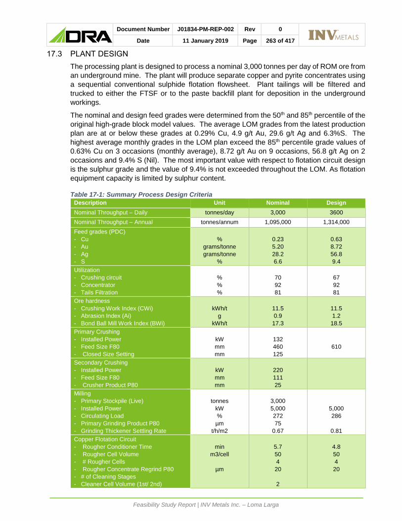
Document Number J01834-PM-REP-002 Rev 0
Date 11 January 2019 Page 263 of 417
Feasibility Study Report | INV Metals Inc. – Loma Larga
17.3 PLANT DESIGN
The processing plant is designed to process a nominal 3,000 tonnes per day of ROM ore from
an underground mine. The plant will produce separate copper and pyrite concentrates using
a sequential conventional sulphide flotation flowsheet. Plant tailings will be filtered and
trucked to either the FTSF or to the paste backfill plant for deposition in the underground
workings.
The nominal and design feed grades were determined from the 50th and 85th percentile of the
original high-grade block model values. The average LOM grades from the latest production
plan are at or below these grades at 0.29% Cu, 4.9 g/t Au, 29.6 g/t Ag and 6.3%S. The
highest average monthly grades in the LOM plan exceed the 85th percentile grade values of
0.63% Cu on 3 occasions (monthly average), 8.72 g/t Au on 9 occasions, 56.8 g/t Ag on 2
occasions and 9.4% S (Nil). The most important value with respect to flotation circuit design
is the sulphur grade and the value of 9.4% is not exceeded throughout the LOM. As flotation
equipment capacity is limited by sulphur content.
Table 17-1: Summary Process Design Criteria
Description Unit Nominal Design
Nominal Throughput – Daily tonnes/day 3,000 3600
Nominal Throughput – Annual tonnes/annum 1,095,000 1,314,000
Feed grades (PDC)
- Cu
- Au
- Ag
- S
%
grams/tonne
grams/tonne
%
0.23
5.20
28.2
6.6
0.63
8.72
56.8
9.4
Utilization
- Crushing circuit
- Concentrator
- Tails Filtration
%
%
%
70
92
81
67
92
81
Ore hardness
- Crushing Work Index (CWi)
- Abrasion Index (Ai)
- Bond Ball Mill Work Index (BWi)
kWh/t
g
kWh/t
11.5
0.9
17.3
11.5
1.2
18.5
Primary Crushing
- Installed Power
- Feed Size F80
- Closed Size Setting
kW
mm
mm
132
460
125
610
Secondary Crushing
- Installed Power
- Feed Size F80
- Crusher Product P80
kW
mm
mm
220
111
25
Milling
- Primary Stockpile (Live)
- Installed Power
- Circulating Load
- Primary Grinding Product P80
- Grinding Thickener Settling Rate
tonnes
kW
%
µm
t/h/m2
3,000
5,000
272
75
0.67
5,000
286
0.81
Copper Flotation Circuit
- Rougher Conditioner Time
- Rougher Cell Volume
- # Rougher Cells
- Rougher Concentrate Regrind P80
- # of Cleaning Stages
- Cleaner Cell Volume (1st/ 2nd)
min
m3/cell
µm
5.7
50
4
20
2
4.8
50
4
20

Document Number J01834-PM-REP-002 Rev 0
Date 11 January 2019 Page 264 of 417
Feasibility Study Report | INV Metals Inc. – Loma Larga
Description Unit Nominal Design
- # of Cells per Stage (1st/ 2nd)
- Cleaner-Scavenger Cell Volume
- # of Cells per Stage (Cl-Scav)
- Copper Tails Thickener Settling Rate
m3
m3
t/h/m2
4 / 2
4 / 3
2
2
0.67
0.80
Pyrite Flotation Circuit
- Rougher Conditioner Time
- Rougher Cell Volume
- # Rougher Cells
- Rougher Concentrate Regrind P80
- # of Cleaning Stages
- Cleaner Cell Volume (1st)
- # of Cells per Stage (1st)
- Cleaner-Scavenger Cell Volume
- # of Cells per Stage (Cl-Scav)
min
m3/cell
µm
m3
m3
5.5
50
6
30
1
10
6
2
10
4.8
30
17.4 PRODUCTION SUMMARY
An integrated mine and process plant concentrator plan was developed with the following
considerations:
• The process plant nominal throughput rate is 3,000 t/d. This rate will increase to
3,400 t/d in year five, after the commencement of mining;
• A high-grade stockpile is created during the mining development and ramp up period
such that once the process plant commences operations there will be no periods where
plant operations cease due to insufficient ore supply from the mine;
• The process plant has a throughput ramp up period of six months and a metal recovery
ramp up period of nine months;
Table 17-2 outlines the anticipated production results over the LOM. The basis for the
development of the concentrate recoveries and grades were the locked cycle tests carried
out during the 2017 metallurgical program, in consideration of the final flow sheet. Life of
mine gold recovery is estimated at 90% with 15% of the gold recovery to the copper
concentrate and 75% reporting to the pyrite concentrate.

Document Number J01834-PM-REP-002 Rev 0
Date 11 January 2019 Page 265 of 417
Feasibility Study Report | INV Metals Inc. – Loma Larga
Table 17-2:Loma Larga LOM Process Plant Production Plan
Ye
ar
Fe
ed
C
op
pe
r C
on
ce
ntr
ate
P
yri
te C
on
cen
tra
te
T
ailin
gs
To
nn
es
Au
g
/t
Ag
g
/t
To
nn
es
Au
g
/t
Ag
g
/t
Cu
R
ec
%
Au
R
ec
%
To
nn
es
Au
g
/t
Ag
g
/t
Au
R
ec %
T
on
ne
s
Au
g
/t
Ag
g
/t
1
- -
- -
- -
- -
- -
-
- -
-
2
669,7
75
7.4
9
27.5
7,1
60
105.0
7
1284.0
84.0
15.0
92,0
14
40.9
0
89.9
75.0
570,6
01
0.8
8
1.6
3
1,0
95,0
00
7.6
1
35.9
12,6
00
99.1
8
1559.0
85.0
15.0
154,4
67
40.5
0
114.5
75.0
927,9
33
0.8
9
2.1
4
1,0
95,0
00
7.9
9
45.0
16,9
95
77.2
3
1451.0
87.0
15.0
151,6
16
43.3
0
146.4
75.0
926,3
89
0.9
4
2.7
5
1,2
41,0
00
6.7
6
40.2
14,3
02
88.0
3
1746.0
85.0
15.0
165,0
91
38.1
0
136.1
75.0
1,0
61,6
07
0.7
9
2.4
6
1,2
41,0
00
4.3
2
28.3
9,5
94
83.8
2
1829.0
81.0
15.0
154,6
83
26.0
0
102.1
75.0
1,0
76,7
23
0.5
0
1.6
7
1,2
41,0
00
3.9
4
27.7
8,1
74
89.6
6
2103.0
79.0
15.0
154,5
87
23.7
0
100.1
75.0
1,0
78,2
39
0.4
6
1.6
8
1,2
41,0
00
3.9
6
26.0
4,7
15
130.5
3
2816.0
68.0
15.0
188,9
13
20.2
0
92.1
75.0
1,0
47,3
72
0.4
6
1.5
9
1,2
41,0
00
3.7
3
28.3
7,1
80
96.7
2
2444.0
78.0
15.0
169,4
45
20.5
0
93.2
75.0
1,0
64,3
75
0.4
3
1.6
10
1,2
41,0
00
4.0
4
30.6
8,3
03
90.5
3
2284.0
80.0
15.0
168,2
30
22.3
0
101.5
75.0
1,0
64,4
67
0.4
8
1.8
11
1,2
41,0
00
3.6
0
21.9
6,1
49
109.1
0
2212.0
76.0
15.0
154,5
67
21.7
0
79.2
75.0
1,0
80,2
84
0.4
1
1.3
12
1,2
41,0
00
3.8
1
23.5
7,8
33
90.6
3
1862.0
79.0
15.0
151,1
57
23.5
0
86.8
75.0
1,0
82,0
10
0.4
3
1.4
13
1,1
38,7
01
3.4
5
21.7
6,4
91
90.7
8
1899.0
78.0
15.0
141,0
07
20.9
0
78.7
75.0
991,2
03
0.4
0
1.2
Yrs
1-
3
1,7
64,7
75
7.5
6
32.7
19,7
60
101.3
1
1459.4
84.6
4
15.0
246,4
81
40.6
5
105.3
75.0
1,4
98,5
34
0.8
9
1.9
Yrs
1-
5
4,1
00,7
75
7.4
3
38.3
51,0
57
89.5
8
1536.9
85.5
3
15.0
563,1
88
40.6
2
125.4
75.0
3,4
86,5
30
0.8
7
2.2
LO
M
13,9
26,4
76
4.9
1
29.6
109,4
96
92.6
3
1858.6
81.5
3
15.0
1,8
45,7
77
27.8
8
102.2
75.0
11,9
71,2
03
0.5
7
1.7

Document Number J01834-PM-REP-002 Rev 0
Date 11 January 2019 Page 266 of 417
Feasibility Study Report | INV Metals Inc. – Loma Larga
17.5 ENERGY, WATER AND PROCESS MATERIAL REQUIREMENTS
17.5.1 REAGENTS AND CONSUMABLES
The following reagents are used throughout the process plant:
• Methyl Isobutyl Carbinol (MIBC) – frother;
• Aerophine 3418A – copper mineral collector;
• Potassium Amyl Xanthate (PAX) –pyrite mineral collector;
• Hydrated Lime – alkalinity control;
• BASF MF250 Flocculant – for increased settling rates in thickeners; and
• Antiscalant – prevention of pipe scale.
Reagent mixing will be completed in a designated area within the plant. The design of this
area includes features such as bunding, with dedicated sump pumps. The layout and general
arrangement of the reagent area account for the need to prevent contact of incompatible
reagent types. Separate onsite long-term reagent supply storage is provided a safe distance
away from the process plant.
Reagents are made up or diluted with fresh water (where necessary); milk of lime and solid
flocculant are made up using clean fresh or raw water. PAX collector is diluted with fresh
water. Copper collector 3418A and MIBC are delivered in 1,000 L bulk containers and added
to the flotation circuit neat.
Grinding media is supplied in 200 L steel drums (steel balls for the primary grinding mill) or
500 kg supersacs whilst the ceramic grinding media for the regrind mills will be delivered in
500 kg supersacs. Replacement filter clothes are also provided for the concentrate and
tailings pressure filtration systems. Based on the available geometallurgical information, no
acid addition is anticipated to maintain steady state operating conditions. It is recommended
that a minimum supply of acid is retained on site for plant start-ups and abnormal conditions
that may be encountered during operations.
17.5.2 AIR
Dedicated, independent, low pressure air blowers and distribution systems will supply the
process air required for each flotation circuit. In each circuit, one blower will be operational,
the other will be on standby.
Compressed air for plant distribution will be provided by the centralized plant compressor
plant. Air receivers will be positioned throughout the process plant to buffer and control
fluctuations within the system.
Instrument air for the process plant will be provided by drying an off-take stream from the
centralized compressed air plant. Air receivers will be positioned throughout the plant to
buffer and control fluctuations within the system.
Compressed air for the truck shop and primary crusher area will be provided by independent
systems due to their distance away from the main plant.
17.5.3 WATER
The use of external make-up water has been minimized as part of the process plant design.
Process water is recovered within the circuit using thickeners and filtration unit operations. In

Document Number J01834-PM-REP-002 Rev 0
Date 11 January 2019 Page 267 of 417
Feasibility Study Report | INV Metals Inc. – Loma Larga
the low pH case, water will be recovered from the grinding circuit and the tailings thickener.
In the high pH case, water will be recovered from the copper tailings thickener.
Independent low and high pH process water tanks and distribution systems have been
incorporated into the design. The utilization of independent systems will reduce reagent
consumption and reduce interaction effects.
Raw (fresh) water will be withdrawn from local collection ponds or supplied from the water
treatment plant. A combined raw and fire water tank will hold sufficient quantities of water to
meet the instantaneous process demands of the plant. The raw water suction nozzle will be
placed mid-way up the tank wall to ensure a reserve volume is always available for fire
suppression.
Gland seal water will be withdrawn from the raw water tank, filtered and stored in a tank prior
to distribution.

Document Number J01834-PM-REP-002 Rev 0
Date 11 January 2019 Page 268 of 417
Feasibility Study Report | INV Metals Inc. – Loma Larga
PROJECT INFRASTRUCTURE
18.1 SUMMARY
Loma Larga consists of both on-site and off-site infrastructure.
• The on-site infrastructure includes:
• Site roads;
• Water supply and distribution;
• Fuel storage and distribution;
• Warehouse;
• Truck shop and maintenance facility;
• Assay and metallurgical laboratory;
• Plant offices and control room;
• Administrative offices;
• Mining offices and change house facilities;
• Telephone and internet communications systems;
• Filtered tailings storage facility (FTSF);
• Waste water treatment plant (WTP); and
• Site power distribution.
• The off-site infrastructure includes:
• Transmission line;
• Site access road;
• Off site parking facilities.
The overall site layout is shown in Figure 18-1.

Document Number J01834-PM-REP-002 Rev 0
Date 11 January 2019 Page 269 of 417
Feasibility Study Report | INV Metals Inc. – Loma Larga
Figure 18-1: Overall Site Layout

Document Number J01834-PM-REP-002 Rev 0
Date 11 January 2019 Page 270 of 417
Feasibility Study Report | INV Metals Inc. – Loma Larga
18.2 TRANSMISSION LINE AND SITE POWER DISTRIBUTION
Electrical power is to be provided via the local utility, CENTROSUR, from the local network in
Ecuador. This area is part of the national 230 / 138 / 69 / 22 kV network, with 69 kV and
22 kV feeds identified to supply the site. The main 69 kV / 25 MVA supply connect to the
network running between Lentag and Victoria del Portete, with the new substation located
near Girón and the transmission line up to the plant site. The incoming 69 kV will terminate
into the main substation at the plant site and will be stepped down to 22 kV from where it will
be distributed to site facilities. Lentag is fed from multiple 69 kV sources from the national
grid and has necessary protection, assuring the reliability of the supply
A 2 MVA, 22 kV supply from San Fernando is proposed for construction power.
CENTROSUR have indicated that the 22-kV supply from San Fernando is fed from different
distribution networks and is therefore suitable for emergency backup power as it is fed from
a different source, on different infrastructure and overhead lines that run a different route.
Diesel generators were therefore deemed not necessary
The 22-kV emergency supply will terminate on a second incomer of the main substation. All
on-site distribution to the concentrator plant, mining operations, support infrastructure and
administration facilities will be from the main 22 kV substation.
The surface 22 kV substation will be metalclad switchgear of modular construction fed from
the 69 / 22 kV transformer and distribute power to the mine, backfill plant and process plant
as well as the related infrastructure buildings and utilities.
22 kV / 440 V and 22 kV / 4 160 V stepdown transformers will feed the 440 V and 4,160 V
MCCs. The MCCs will be located close to the equipment to reduce cable lengths and will be
housed in E-House type structures throughout the plant.
22 kV / 207 V stepdown transformers will provide the lighting and small power supply and
also feed the infrastructure buildings.
18.3 ROADS
The main access road from San Gerardo to the mine site will be upgraded in two phases
during the execution of the Project with completion of phase two scheduled prior to the
commencement of operation of the process plant.
Phase one will consist of the enhancement and ongoing maintenance, during the construction
phase, of the existing road only. The existing road surface will be improved to a minimum
road width of 3.6 m, a turning radius of 9.4 m and the cross-fall slopes will be maintained to
ensure drainage into the existing side drains. This road currently has an average gradient of
approximately 12-16% and isolated areas where the maximum gradient reaches 20%. No
major realignment is planned ahead of the start of the main road construction.
Phase two will be the upgrade of the existing enhanced road. The FS level design for the site
access road was completed using the functional classification C3 for an agricultural/forestry
class of roadway according to the Ecuadorian standard for roads, NEVI-12, published by the
ministry of transport and public works “Ministerio de Transporte y Obras Publicas” (MTOP).
This classification allows for a maximum of 500 vehicles per day which is above the calculated
expected daily vehicle traffic volumes for the construction phase and LOM operation.
The road is 11.6 km long and has a width of 4 m with an additional 1 m wide shoulder on
either side. Design speed is a maximum of 30 km/h and maximum slope of 14%. A new

Document Number J01834-PM-REP-002 Rev 0
Date 11 January 2019 Page 271 of 417
Feasibility Study Report | INV Metals Inc. – Loma Larga
section of road will be constructed from the existing road between San Gerardo and Chumblin
up to the local existing quarry area primarily to: bypass the centre of San Gerardo, and to
avoid a section of road that was identified to be prone to rock falls and slope instabilities on
the existing road. From the local quarry up to the FTSF the existing road will be modified to
meet the design parameters.
Various site roads will be required to access other areas of the site and these are as follows:
• A 3 km long and 12 m wide haul road will be constructed between the process plant
stockpile, ROM tip and the portal to the underground mine. This road will have a gravel-
wearing coarse with safety berms on both sides of the roadway, and will accommodate
mine trucks that will be delivering ore from the mine to the primary crusher stockpile area
and other vehicles between the two locations.
• A 1.1 km long class C3 road between the portal and the location of the paste backfill plant
• A pipe corridor with berms on either side will be constructed adjacent to the above two
mentioned roads to accommodate various pipes between the process plant, mine portal
and paste backfill plant.
• Internal plant roads will be designed to access the crusher, milling, flotation and
concentrate filtration areas.
• A 12 m wide road and adjacent pipe corridor will be designed to join the maintenance
workshop area to the new haul road.
• Additional roads will be added to access the explosives storage areas, ventilation fans,
FTSF and WTP.
To minimize the number of vehicles travelling between San Gerardo and the Project site,
parking facilities for personnel private vehicles will be provided in San Gerardo. Bus
transportation will be provided to and from facilities and the Project site. A drop-off point has
been allowed at the main entrance to the process facility, near the main gate house, and this
includes a small parking area for visitor’s light vehicles.
18.4 BUILDINGS
Infrastructure buildings have been designed as brickwork structures combined with steel and
cladding where required.
A lube storage area, fuel storage tanks and a fuel dispensing area are provided adjacent to
the truck shop to store and dispense fuel for surface vehicles and the underground mining
fleet.
A warehouse structure of 500 m2 will provide for plant and mining stores. A separate office
area of approximately 90 m² is included and positioned against one of the sides of the
warehouse.
An 800 m2 steel structured building is provided for the combined surface and mining truck
shop and process plant maintenance facility. A separate area of approximately 345 m² for
offices, stores and facilities are positioned along the sides of the building.
An assay and metallurgical laboratory of 450 m² will include office space, the assay and
metallurgical laboratories, storage for samples and other associated facilities.
Plant offices and a control room measuring 165 m² will be located close to the concentrator
facility and away from the administrative offices.

Document Number J01834-PM-REP-002 Rev 0
Date 11 January 2019 Page 272 of 417
Feasibility Study Report | INV Metals Inc. – Loma Larga
An administrative office building measuring 470 m² will include a combination of single and
open plan office spaces, boardrooms, store and filing rooms and washrooms.
Mining offices, training facility, change house, laundry, first aid area, kitchen and dining area
will be combined into one building, measuring 1,970 m², and have been sized to
accommodate the surface and underground crews. The mining offices will include a
combination of single and open plan office spaces and washrooms.
18.5 COMMUNICATIONS
The communication network on site will be a modular ethernet network for ease of future
upgrade and functionality, with connection to internet and telecommunications providers
dictated by their network speeds. The architecture will be a single physical layer network,
segmented into several virtual networks to enable segregation and isolation of different types
of network traffic.
The network backbone is a multicore fiber backbone consisting of a combination of single
mode and multimode fiber cables. The use of a fiber network will ensure that communications
will not be affected by interference from any electrical or magnetic sources along the various
cabling runs. Fiber networks is also the most efficient transmission mechanism with the least
performance loss over long distances.
A Multicore Fiber cable network will provide redundancy in the form of a multi route
configuration and the flexibility to create a mesh network design. A mesh network is a local
network topology in which the infrastructure nodes (i.e. bridges, switches and other
infrastructure devices) connect directly, dynamically and non-hierarchically to as many other
nodes as possible and cooperate with one another to efficiently route data from/to clients.
18.6 FILTERED TAILINGS STORAGE FACILITY
The process plant production is currently planned for 3,000 t/d with a conventional ball mill
and flotation circuit. Following metallurgical processing, the tailings will be thickened and 1)
filtered and stored on surface at the FTSF or 2) routed to the paste plant for placement as
cemented backfill in the underground mine.
The planned FTSF is located adjacent to and on the Pacific side of the continental divide.
The FTSF is located on Rio Cristal, which is part of the Rio Zhurucay basin. The location is
within the project surface rights and there is a significantly smaller population within the
downstream catchments in comparison to other locations. The location is approximately
500 m to the south of the proposed mill and process facility in a small drainage basin, as
illustrated in Figure 18-2.

Document Number J01834-PM-REP-002 Rev 0
Date 11 January 2019 Page 273 of 417
Feasibility Study Report | INV Metals Inc. – Loma Larga
Figure 18-2: FTSF Site Layout

Document Number J01834-PM-REP-002 Rev 0
Date 11 January 2019 Page 274 of 417
Feasibility Study Report | INV Metals Inc. – Loma Larga
Approximately half of the tailings produced will be stored on surface in the FTSF and it is
estimated that approximately 5.5 million dry tonnes (Mt) will be placed in the FTSF over the
life-of-mine currently projected as approximately 12 years.
The FTSF design consists of four phases to limit the footprint of disturbed area as the mine
develops and to facilitate effective management of Project capital resources. The phases
(1A, 1B, 2 and 3) have been designed to store 1.0, 1.5, 4 and 6 Mt (dry) of filtered tailings,
respectively. The storage capacity provides for an extra 0.5 Mt of tailings to provide for some
upside in the resource.
The elevation – capacity characteristics of the proposed FTSF are presented in Table 18-1.
Table 18-1: Elevation – Tailings Storage Capacity
Phase Capacity
(M tonnes)
Main Embankment Elevation
(m amsl)
1 (A + B) 1.5 3,663.5
2 4 3,668.0
3 6 3,672.0
Geochemical characterization of filtered tailings suggests that the material is potentially acid
generating (PAG) and has the potential to leach constituents of potential concern (COPC),
including metals. FTSF design components that address contact water during operations and
closure include the following:
• Surface water diversion channels to minimize the amount of contact water;
• Embankment design to achieve acceptable factors of safety for static and pseudostatic
scenarios;
• Basin and embankment liner systems to provide containment;
• Internal storage for contact stormwater;
• An internal underdrain system to collect consolidation flow and drainage from the tailings;
• A double-lined external underdrain collection pond with leachate collection recovery
system to manage contact water prior to treatment;
• A FTSF cover system installed at the start of closure to limit infiltration and promote run
off; and
• An emergency spillway, constructed during Phase 3 of development, to convey
stormwater from the facility during closure.
The design also includes a groundwater collection system below the FTSF lining system to
intercept, collect and convey non-contact groundwater downstream of the facility. The FTSF
design was supported by climate analyses, water balance calculations, a seismic hazard
assessment and slope stability calculations.
The FTSF closure strategy includes managing stormwater runoff, providing a 2.0 mm HDPE
geomembrane cover system overlain by approximately 1 m of growth media material and
revegetated to limit infiltration. Post-closure maintenance will be provided. During placement
and in anticipation of the closure strategy, the tailings will be deposited to slope to the
southeast corner of the facility where the Phase 3 emergency spillway will be constructed.

Document Number J01834-PM-REP-002 Rev 0
Date 11 January 2019 Page 275 of 417
Feasibility Study Report | INV Metals Inc. – Loma Larga
18.7 WASTE ROCK
Waste rock geochemistry assessments consisted of identifying loading rates from the major
lithological and alteration categories for the rock expected to be removed as waste (e.g., non-
ore-bearing) material from the underground mine and ramp developments. Additionally,
these materials will be exposed as wall rock in the underground workings and have the
potential to generate acidity and release metals once exposed to oxygen.
Testing programs were carried out as follows:
• Phase 1: Included static geochemical testing, such as acid-base accounting (ABA) and
static leaching tests.
• Phase 2: Included kinetic geochemical testing, including humidity cell tests (HCTs),
specific surface area measurements using gas adsorption and sieve analysis
techniques, mineralogical determinations (X-ray diffraction [XRD]), and whole rock
digestion methods.
The results of the Phase 1 and Phase 2 testing indicate that all of the altered andesite rock
types present at the site are PAG and have the potential to leach a variety of constituents at
concentrations that may exceed applicable water quality standards. Although some samples
of the propylitic altered andesite were net acid neutralizing, half of the propylitic samples were
net acid generating, and the average net neutralization potential (NNP) for the propylitic
samples was net acid generating. The dacite rock type is essentially inert and is classified
as non-PAG, but the dacite testing did indicate the potential to leach some metals at
concentrations that exceed applicable water quality standards.
Consequently, it was assumed in the Study that all waste rock and temporary ore storage
facilities will be lined with a HDPE geomembrane to prevent migration of seepage into the
native materials and groundwater regime. A collection pond has been allowed and water will
be pumped to the main contact water pond for treatment.
18.8 WATER AND OTHER LIQUID EFFLUENT HANDLING
Natural runoff will be diverted around the mine infrastructure to the extent possible. Contact
water including water that must be withdrawn from the underground mine to maintain a safe
working environment, will be collected and used for mineral processing.
The site drainage system will consist of a combination of terraces, cut-off berms, roads,
drainage trenches and culverts throughout the plant site. The surface drainage system will
consist of a combination of cut-off berms, drainage trenches, culverts and elevated roads
throughout the mine property. Both systems will be designed to keep clean water from mixing
with contact water wherever possible.
A static site-wide water balance model was developed using the GoldSim™ simulation
platform, for a maximum build-out snapshot near the end of mine life. The objectives of the
water balance model are to quantify annual treatment volume requirements and predict
quality of site contact water. The maximum build-out snapshot was selected to provide
conservative estimates of contact water volumes and quality characteristics. Contact water
includes water withdrawn from the mine, water discharged from the process facility, and
surface water that comes into contact with plant areas and stockpiled material, including ore,
waste rock, and tailings. Based on geochemical analysis completed to date, contact water
will require treatment and will be directed to the waste water treatment plant (WWTP), located
between the FTSF and the process facility.

Document Number J01834-PM-REP-002 Rev 0
Date 11 January 2019 Page 276 of 417
Feasibility Study Report | INV Metals Inc. – Loma Larga
Predicted annual volumes of water reporting to Project site ponds and the WWTP are
summarized in Table 18-2 for an average precipitation year and for one-in-ten year wet and
dry conditions.
Table 18-2 Annual Contact Water Volumes Requiring Treatment (Mm3/year)
Surface Water Facility Average Conditions 1 in 10 Year Dry 1 in 10 Year Wet
Contact Water Pond 0.313 0.270 0.352
FTSF Stormwater Pond 0.291 0.169 0.399
FTSF Underdrain Collection Pond
0.072 0.068 0.076
Total to WWTP 0.676 0.507 0.827
The site-wide water balance model was also used to predict contact water quality influent to
the water treatment plant to identify target constituents for treatment.
A buried sewer pipe reticulation network collects sewage and gray water from the various
buildings, across the process plant facility, into a combined main system which flows to the
lowest point in the plant area and discharges to a sewage treatment plant. This system will
treat the incoming water to the required criteria for treated water discharge into the natural
environment. Solids will be collected and transported off site to the appropriate waste
management facility.
18.9 WASTE WATER TREATMENT PLANT
Excess contact water, not used in mineral processing, will be treated and discharged to meet
drinking water standards in the immediate receiving environment. The point of discharge
from the treatment plant has been sited outside of the watershed that supplies the City of
Cuenca, which will ensure there are no impacts to water quality upstream of the city. Water
management, including water treatment, will continue during the closure phase until discharge
from the site meets established discharge criteria without treatment
The Loma Larga site is expected to operate in a positive water balance over the duration of
the project. All water falling within the catchment area of the site and excess water released
from the process will require treatment to ensure compliance with the governing discharge
standards. Table 18-3, extracted from BQE (2018a), outlines the anticipated metal
concentration and assumed discharge limits, based on complying with the most conservative
of Ecuadorian aquatic life, drinking water and irrigation use standards, or existing downstream
conditions in the receiving environment where existing downstream average concentrations
exceed Ecuadorian standards.

Document Number J01834-PM-REP-002 Rev 0
Date 11 January 2019 Page 277 of 417
Feasibility Study Report | INV Metals Inc. – Loma Larga
Table 18-3 Expected Water Quality and Anticipated Discharge Limits
Constituent
(mg/L)
Phase 1 (Itasca)
Upper Case
Phase 2 (ERM)
1:10 Year, Wet Discharge Target
Al 7.1 14.89 0.95
Cd 0.0006 0.264 0.0011
Co 0.013 1.084 0.011
Cr 0.046 2.376 0.035
Cu 0.027 6.223 0.0052
Fe 36 140 1.0
Pb 0.019 2.679 0.0069
Mn 1.2 7.864 0.11
Mo 0.09 0.012 0.011
Ni 0.006 1.088 0.027
Zn 0.3 10.22 0.03
Se 0.012 0.007 0.001
SO4 210 382 250
The potential contaminants of concern in waste water are mostly from metals leaching from
mineralized surfaces of waste rock and tailings and nitrogen species (nitrate/ammonia)
leaching from explosive residue left on blasted rock.
During Phase 1 (ramp development) both metals and nitrogen species are expected to be
relevant contaminants of potential concern, while during Phase 2 (operations) the load of
nitrogen species is expected to decrease, and metals will be the only relevant contaminants
of potential concern.
All water requiring treatment will be collected in the contact water collection pond, located
southeast of process plant area. The proposed water treatment plant will consist of:
• Oxidation and neutralization circuit for metals removal.
• Sulphide precipitation.
• Clarification to remove the majority of solids from treated water.
• Multi Media Filtration (MMF) to remove any residual participates.
The applicable receiving environment regulations will be confirmed during permitting. For the
purposes of this study, the water treatment plant will meet Ecuadorian drinking water
standards. Should the more-stringent Ecuadorian aquatic life standards apply, a
modification(s) to the water treatment plant may be required. This has been identified as a
risk in the Feasibility Study Risk Register (Source: DRA Americas Inc. 2018; Loma Larga
Feasibility Study Risk Register).
Natural runoff will be diverted around the mine infrastructure to the extent possible. Contact
water, including water from mine dewatering will be collected and used for mineral processing.
This will minimize the amount of water use from surrounding groundwater and surface water
systems. Water recycling within the process plant is expected to be greater than 90%.
Excess contact water, not used in mineral processing, will be treated and discharged to meet
applicable standards in the receiving environment in the Quebrada Cristal-Alumbre
watershed. The treated discharge will avoid the watershed that feeds the City of Cuenca.
Water management, including water treatment, will continue during the closure phase until
discharge from the site meets established discharge criteria without treatment.

Document Number J01834-PM-REP-002 Rev 0
Date 11 January 2019 Page 278 of 417
Feasibility Study Report | INV Metals Inc. – Loma Larga
The complete water treatment plant will be modular in design, consisting of pre-fabricated
and standard shipping containers. Final installation of larger mechanical pieces will be
completed on site.
All reagent make-up and distribution will be included within the water treatment plant. The
following reagents are required for successful operation:
• Flocculant.
• Sodium hydrosulphide (NaHS).
• Organosulphide (TMT).
• Lime (calcium hydroxide).
• Calcium hypochlorite (Ca(OCl)2).
18.10 GARBAGE, HAZARDOUS & OTHER WASTE
18.10.1 GARBAGE DISPOSAL AND LANDFILL
Domestic waste generated during mine construction and operation will be disposed of and
managed at the mine landfill. The waste will be non-hazardous and comprised of construction
debris, food wastes, glass, office waste, cardboard, paper and plastics. The waste will be
generated from a variety of sources including the construction areas, warehouse, workshop,
plant, offices and cafeteria.
The volume of waste generated during mine construction and operation is based on the
assumption that a total of 520 mine personnel will be commuting to the mine on a daily basis.
The daily per person mass of waste generated is estimated to be 1.5 kg/day according to a
World Bank (2012) 2015 projection for Ecuador. This estimate was doubled to account for
other wastes generated by construction and mine activities. The mass assumptions equate
to a total of approximately 570 tonnes/year and approximately 8,500 tonnes for the 2 years
of construction and 13 years of mine operation. It is assumed that the waste will be placed
and compacted to a density of 0.6 tonnes/m3 (World Bank, 2012). The annual compacted
volume of waste is estimated at approximately 950 m3/yr, for a total of approximately 14,000
m3 for the period of mine construction and operation.
The landfill will be located adjacent to the rock quarry and between the mine and process
plant, as illustrated in Figure 18-3. According to the PFS (RPA, 2016), wind direction at the
Quimsacocha weather station is predominately from the west. The facility will not be upwind
of mine and plant facilities.

Document Number J01834-PM-REP-002 Rev 0
Date 11 January 2019 Page 279 of 417
Feasibility Study Report | INV Metals Inc. – Loma Larga
Figure 18-3: Landfill Plan View and Sections and Details

Document Number J01834-PM-REP-002 Rev 0
Date 11 January 2019 Page 280 of 417
Feasibility Study Report | INV Metals Inc. – Loma Larga
The landfill will include an access road, stormwater diversion channel, disposal area, leachate
drainage and collection system and leachate management pond. An access road will provide
light vehicle access to the perimeter of the landfill and leachate management pond to facilitate
waste disposal and maintenance. Diversion channels will be constructed and maintained
upstream of the landfill to minimize run-on and leachate generation.
The landfill disposal area will be constructed in phases to manage the area of disturbance
and minimize the potential for erosion and sediment transport. Growth media will be removed
from areas underlying each phase of landfill development and stockpiled for future
reclamation. The disposal area will consist of compacted, low permeability soil layer to limit
the migration of leachate into the subsurface (Figure 18-3). Leachate and runoff will flow via
gravity to a double-lined leachate collection pond and be routed to the process facility or the
WTP via a small-diameter pipeline, as necessary and based on routine sampling and
laboratory analytical results. Leachate and runoff that meets relevant water quality standards
will be discharged to the environment. It is estimated that discharge from the leachate
collection pond, based on average monthly precipitation inputs, will range from approximately
600 m3/month in August to 1,600 m3/month in April.
The waste will be placed in layers to form a domed landfill. On a daily basis, the waste will
be covered by a 150-mm layer of soil to prevent animals from scavenging, improve access
and reduce wind dispersion. Gas monitoring is not specified because there are no adjacent
structures and therefore no risk of gas migration (World Bank, 1999). The access road and
seepage management collection ponds will be constructed in Phase I.
At closure the landfill surface will be covered with 1 m of compacted clay overlain by
approximately 1 m of growth media material and will be revegetated. Once the cover system
is in place and infiltration of surface water is eliminated, the post-closure leachate flows will
decrease over time. Leachate flow will continue to be collected and treated until flow has
ceased or water quality supports discharge. The leachate collection pond will then be
reclaimed by folding the liner system in on itself and covering the area with backfill to provide
positive drainage. The pond area will then be covered with growth media and reseeded.
18.10.2 HAZARDOUS MATERIAL
The hazardous materials can be broken down into two distinct areas:
• Concentrates; and
• Reagents.
The hazards for the copper concentrate are associated with the high content of contained
arsenic which is in the order of 10% by weight.
Precautions will need to be taken including wearing dust masks when working within the
confines of the copper concentrate filtering building. A fume extraction system will also be
installed. Whenever possible, filtered product should be bagged and placed into a sea
container ready for shipping. The product also poses an explosive risk due to the high level
of sulphur present at 33% by weight. The building must be kept ventilated at all times to
prevent the buildup of gas. The pyrite product at 42% sulphur by weight poses a similar risk
and is maintained in a well-ventilated building with fume extraction.
On the chemical front, the main chemical of concern is potassium amyl xanthate (PAX) which
is toxic and poses a risk to health if ingested or absorbed. The product can also leak easily
from mild steel fittings due to its corrosive nature and the materials of construction for the

Document Number J01834-PM-REP-002 Rev 0
Date 11 January 2019 Page 281 of 417
Feasibility Study Report | INV Metals Inc. – Loma Larga
mixing, storage and dosing of the pump need to be well considered. Hydrate lime poses a
burn risk once it has been mixed with water and stored prior to dosing. The lines for dosing
should be well marked and be HDPE to prevent any direct contact with plant personnel.
Methyl isobutyl carbinol (MIBC) and Aerophine 3418A chemicals are also toxic when
ingested. They are delivered in bulk containers and dosed directly to the flotation circuit. It
is important that the lines for dosing a chemical resistant are well marked to prevent contact
with the skin of employees. Flocculant is a slip hazard once it is mixed with water and any
spillages of mixed flocculant need to be cleaned quickly once they occur. Dosing lines to the
thickeners should be well marked.
18.10.3 OTHER WASTE
Medical waste from the clinic and first aid facilities will be collected and transported off site to
the appropriate waste management facility.
18.11 TRANSPORTATION AND LOGISTICS
The Loma Larga Project is located 30 kilometres southwest of the city of Cuenca and 15
kilometers north of the town of Girón. The current regional and national infrastructure is
adequate to access the Project site through a well-established network of existing major ports
and roadways. The road between San Gerardo and the Project site will be upgraded during
the early stages of the project and will be ready to support the operations phase of the project.
Regional infrastructure (ports and roads) is described in Section 5.1 of this Technical Report.
18.11.1 PERSONNEL TRANSPORTATION
On-site vehicles will be provided to transport employees from the bus unloading area adjacent
to the change house to their place of work. Pickups will be provided to transport supervisors
and maintenance personnel around the site. No private vehicles will be allowed on site.
It is planned that employees will primarily live in the Girón, San Gerardo, Chumblin and
surrounding areas. No camp is planned for the Loma Larga site. INV may contract an independent
service provider for the transportation services during construction and operations phases for INV
personnel. Construction contractors will be responsible to transport their personnel to site.
18.11.2 CONCENTRATE STORAGE, HANDLING AND TRANSPORT
The copper concentrate will be directly loaded into bags and into standard twenty-foot
shipping containers prior to trucking to the port for export over the life of the operations, as
the low volume does not support bulk export. The copper concentrate loadout building
includes special controls for dust due to the presence of arsenic in the concentrate.
The pyrite concentrate filtration and storage area is located inside an enclosed building at the
Project site. The pyrite concentrate will be loaded by front-end loader into dump trucks for
transport to the bagging facility located near Guayaquil. Handling equipment will be provided on-
site for handling the bags and containers. The pyrite concentrate will be loaded into bags and
loaded into standard twenty-foot shipping containers near Guayaquil initially due to the lack of
existing concentrate bulk loadout facilities at the regional ports. When facilities are operational at
a regional port, INV will consider switching to bulk export for the pyrite concentrate.

Document Number J01834-PM-REP-002 Rev 0
Date 11 January 2019 Page 282 of 417
Feasibility Study Report | INV Metals Inc. – Loma Larga
MARKET STUDIES AND CONTRACTS
19.1 MARKETS
INV’ Loma Larga Mine will produce two different concentrates, specifically a pyrite
concentrate (also referred to as gold-pyrite), and a high-grade gold-copper concentrate. The
gold-pyrite concentrate will represent the majority of the annual concentrate production (90%),
and it is expected to contain 28 g/t of gold, and 102 g/t of silver, with no significant deleterious
elements. The gold-copper concentrate is expected to grade 93 g/t of gold, 30% copper, and
1,860 g/t of silver. Other than containing roughly 8.5% arsenic, there are expected to be no
other significant deleterious elements in the gold-copper concentrate.
INV’s pyrite concentrate can be considered clean from an impurity perspective and relatively
low in gold content. The market for these types of materials is generally gold smelters and
refineries, copper smelters, especially where sulphur fuel may be required and, to a lesser
extent, blending facilities where trading companies would mix such clean material with other
complex gold and copper concentrates.
Traditionally Western smelters look for pyrite concentrates with a higher gold content (i.e.
minimum 3 ounces per tonne or 93 g/t), and as a result it is the Chinese market that consumes
the lion’s share of the lower grade pyrite concentrates exported globally. These concentrates
are mainly processed by gold smelters located in Shangdong and Henan provinces.
However, Chinese copper smelters have become more interested in pyrite concentrates, as
their precious metal refining capacity has increased significantly. In addition, Chinese copper
smelters use clean pyrite concentrates to balance and regulate their average feed intake.
The potential market for Loma Larga gold copper concentrate is more focused, due to the
expected arsenic level. This would include several Western custom copper smelters, who
would be well positioned to treat such arsenic levels. Further, given the high gold content of
Loma Larga's gold-copper concentrate, it could be imported to China as a gold concentrate
without arsenic restrictions. Accordingly, China represents an additional potential outlet,
which depending on prevailing market conditions, could be quite competitive.
Blending facilities could also represent a potential market for Loma Larga's gold-cooper
concentrate. Blending operations have proliferated in recent years as a solution to both the
increasing level of impurities, especially arsenic, and the introduction of regulatory restrictions
of harmful elements in destination markets. Traditionally, the largest blending facilities have
been located in South America, as the majority of complex concentrates are found there.
More recently, blending operations have emerged closer to destination markets such as
Taiwan and Korea.
An extensive list of potential off-takers was approached to determine the relevant markets as
outlined above, and also to identify commercial terms for the feasibility study. Various
indications were secured for both concentrates. For purpose of the gold-pyrite concentrate,
Chinese copper smelters provided the most competitive terms. This market has the added
benefit of representing the lowest freight destination. Commercial feedback received for the
gold-copper concentrates suggests both China and the West would offer potential long-term
sales agreements.
The terms summarized below are shown as a percentage of the payable metals on a Carriage
and Insurance Paid To (CIP) destination port basis, and include all applicable refining,
treatment and penalty charges. From a logistics perspective, the mine would need to absorb

Document Number J01834-PM-REP-002 Rev 0
Date 11 January 2019 Page 283 of 417
Feasibility Study Report | INV Metals Inc. – Loma Larga
all costs from the mine to the relevant destination port, with the buyer bearing all remaining
transportation costs from the discharge port to the receiving smelter.
Table 19-1: Smelter Terms
Item Unit Gold Pyrite Concentrate
Gold Copper Concentrate
Gold % 80 88
Silver % 60 80
Copper % - 82
Payability includes the treatment and refining charges
19.2 CONTRACTS
No contracts have been established to date by INV. However, based on feedback secured
by INV, it is expected that the full production of both concentrates will be sold.

Document Number J01834-PM-REP-002 Rev 0
Date 11 January 2019 Page 284 of 417
Feasibility Study Report | INV Metals Inc. – Loma Larga
ENVIRONMENTAL STUDIES, PERMITTING, AND SOCIAL OR COMMUNITY IMPACT
20.1 INTRODUCTION
This section presents available and relevant information on environmental, permitting and
social or community issues related to the Project. A summary of Project environmental
baseline studies and discussion of pertinent environmental issues which are material to the
development of the Project are provided. Potential social and community related plans and
ongoing consultation and engagement efforts with local communities are discussed.
Data and information gathered in all areas (i.e., environmental baselines, regulatory
compliance, stakeholder feedback and practicable closure options) have been used to inform
and optimize Project design to date. Ongoing data collection will be used by INV to continue
to refine the Project design and mitigate environmental and social impacts through its various
phases of development.
20.2 PROJECT PERMITTING AND ENVIRONMENTAL ASSESSMENT
Ecuador has specific legislation for mining activities as well as for environmental impact
prevention and mitigation. In Ecuador, the mine exploitation phase includes a set of mining
operations and works for the preparation and development of a mineral deposit, its extraction,
and transport of the minerals for processing. The environmental license for new projects is
granted through an Ex ante1 - Environmental Impact Study (EIS) review process.
The timelines for the Loma Larga project permitting are outlined in Section 24. Based on
existing information and understanding of current Ecuadorian regulations, an allowance of 7
months has been included in the project schedule to obtain an Environmental License after
submission of the complete document to the government regulator. After approval of the
Environmental License, an additional 7 months has been built into the schedule to obtain
construction permits. The permitting schedule is based on reasonable expectations with
government review timelines, however there is inherent uncertainty in these timelines. The
political spectrum in Ecuador is also changing with the increasing presence of opposition to
development and mining in particular. INV continues monitoring these developments and
working with stakeholders to reduce risks for the project.
20.2.1 PERMITTING REQUIREMENTS
The main government institutions that regulate and provide approval to a mining project are:
The Ministry of Energy and Non-Renewable Natural Resources, including the Mining Control
and Regulatory Agency (ARCOM), and Electricity Control and Regulatory Agency
(ARCONEL); and the Ministry of Environment and Water (MAE). As of November 2018, the
former National Secretariat of Water (SENAGUA) merged with the former Ministry of
Environment and the new MAE applies the same administrative procedures as both
institutions had previously established. Each of these institutions have representation in
1 “Ex ante – Environmental Impact Study” is the full name of an EIS applicable for new activities
obtaining environmental permits.

Document Number J01834-PM-REP-002 Rev 0
Date 11 January 2019 Page 285 of 417
Feasibility Study Report | INV Metals Inc. – Loma Larga
every Province for administrative and permitting processes. In the case of the Loma Larga
Project, the agencies of the Province of Azuay will manage the permitting process.
The Mining Law and its regulations were issued in 2009, including the first mining guidelines
for generating responsible mining activities in the country. The largest number of regulations
related to mining activities were issued in 2014. Since then, the regulations have continued
to change, or new regulations have been generated. Thus, some important legislation and
regulations related to mining activities, especially specific mining guidelines from the Agency
of Mining Regulation and Control, ARCOM, are relatively new.
The previous Ministry of Mines, currently the Ministry of Energy and Non-Renewable Natural
Resources grants mining title for each project phase, administrative authorization for phase
changes, and negotiates and administers mining exploitation contracts. INV has submitted a
report called “Previous Report for the Change of Advanced Exploration Phase to the Stage
of Economic Evaluation of the Mineral Deposit” to ARCOM to change from the Advanced
Exploration phase to the Economic Evaluation phase. To change from Economic Evaluation
to the Exploitation phase the Company will be required to submit a report called “Report on
Activities and Investments Prior to Subscription of the Exploitation Contract”.
The Mining Exploitation Contract between the Company and the Government of Ecuador
(normally, through the Ministry of Energy and Non-Renewable Natural Resources), will allow
the Company to initiate the project exploitation phase. This contract will establish the terms,
conditions and schedule for the construction, assembly, extraction, transport and
commercialization of minerals. Additionally, the contract will define the Company obligations
on environmental management, bonds, community engagement, royalties and closure
activities including environmental liabilities payments for LOM. The contract will only be
signed by the Government upon submission of the aforementioned mandatory reports and
once the Environmental License for the Exploitation Project is granted.
The Environmental Organic Code (COA) regulates all the economic activities including
mining. The Environmental Mining Rule (Reglamento Ambiental de Actividades Mineras,
RAAM) regulates specifically the mining sector, which establishes the environmental
requirements for each of the phases of the mining activities. The COA and the main Ministerial
Agreements No. 061, No. 097A, No. 109, No. 1040, and the RAAM establish the permits,
administrative processes, environmental standards and social participation that are
applicable to the projects.
The main permit granted by the MAE for the construction and operation of a mining project is
the Environmental License. For the exploitation phase of the Loma Larga Project the
environmental impact study (EIS) process will be managed by the Provincial Directorate of
the Ministry of Environment and Water in Azuay. The MAE is responsible for the review and
approval of the environmental impact study and issuance of the environmental license, after
payment of administrative taxes, and the issuance of the Environmental Management Plan
Compliance Bond (póliza de fiel cumplimiento del Plan de Manejo Ambiental).
In order to apply for the Environmental License, the following permits or documentation are
required to be submitted with the EIS Terms of Reference for approval, and then subsequently
alongside the submission of the Draft Environmental Impact Study:
• Original and validated Mining Concession Title, including rights payments;
• Water intake permit and water diversion permit;

Document Number J01834-PM-REP-002 Rev 0
Date 11 January 2019 Page 286 of 417
Feasibility Study Report | INV Metals Inc. – Loma Larga
• Technical feasibility certificate of the project granted by the Ministry of Energy and Non-
Renewable Natural Resources, with the certification of environmental feasibility assessed
within the report of feasibility of the mining right;
• Creation of user in the Unique System of Environmental Information (SUIA);
• Certificate of Intersection in SUIA by uploading the name of the project and the geographic
coordinates in the Reference System in SUIA (WGS84-Zone 17 South). The system will
perform a verification of coordinates with respect to the mining cadastre and the
coordinate system requested by SUIA;
• Rights of way for Project infrastructure (transmission line and access road).
The Environmental License will enable the Company to request and obtain other necessary
permits to start the construction, operation and closure of the Project.
Through analysis and review of the main mining and environmental legislation, technical and
environmental regulations and general authorizations, a list of the primary permits and
authorizations required for the Exploitation Phase of the Project is summarized below in Table
20-1. The Ministry of Environment and Water is still developing or updating regulations, so
the list of permits and authorizations currently identified for this Project may change with time,
and new requirements or additional permits may need to be considered.
Table 20-1 includes a brief description of the applicable permits and authorizations required
for the three main components of the Project: mine, power transmission line for the mine, and
access road (note that this table does not include the needs for the land access rights
necessary to develop the area – see Section 4 for further details on land tenure). The permits
for the 22-kV power line proposed for construction use are not considered in this permit list.

Document Number J01834-PM-REP-002 Rev 0
Date 11 January 2019 Page 287 of 417
Feasibility Study Report | INV Metals Inc. – Loma Larga
Table 20-1: Main Permitting requirements for the Loma Larga Project

Document Number J01834-PM-REP-002 Rev 0
Date 11 January 2019 Page 288 of 417
Feasibility Study Report | INV Metals Inc. – Loma Larga

Document Number J01834-PM-REP-002 Rev 0
Date 11 January 2019 Page 289 of 417
Feasibility Study Report | INV Metals Inc. – Loma Larga

Document Number J01834-PM-REP-002 Rev 0
Date 11 January 2019 Page 290 of 417
Feasibility Study Report | INV Metals Inc. – Loma Larga

Document Number J01834-PM-REP-002 Rev 0
Date 11 January 2019 Page 291 of 417
Feasibility Study Report | INV Metals Inc. – Loma Larga

Document Number J01834-PM-REP-002 Rev 0
Date 11 January 2019 Page 292 of 417
Feasibility Study Report | INV Metals Inc. – Loma Larga

Document Number J01834-PM-REP-002 Rev 0
Date 11 January 2019 Page 293 of 417
Feasibility Study Report | INV Metals Inc. – Loma Larga
20.2.2 EXISTING PERMITS
INV currently holds various permits in accordance with national legislation. INV has submitted
its application for the Economic Evaluation phase and holds the required permits for the
Advanced Exploration phase, as well as land tenure, and mining and water rights that enable
them to perform exploratory activities in the concessions of Río Falso and Cerro Casco. For
the Cristal concession INV is awaiting the Ministry of Environment and Water to re-issue the
environmental license for the Advanced Exploration Phase.
The permits and authorizations held by INV, are listed below:
• 100% land title of the Loma Larga property in order to develop the mining Project;
• Mining Titles for Metallic Mining, in the concessions Cerro Casco (Code 101580), Río
Falso (Code 101577), and Cristal (Code 102195), most recently validated on September
17, 2018;
• Environmental license No. 054 for the advanced exploration of the mining areas Cerro
Casco and Río Falso, granted on October 11, 2002. INV has maintained its environmental
permit through periodic audits and evidence of compliance with the environmental
management plan of the approved environmental license No. 054;
• Authorization for the right to use and consume water, granted on July 5, 2010. This
authorization is for rainwater up to 1 L/s to be collected in the Cristal-Aguarongos sector
of the San Gerardo Parish, Girón Canton for forest nursery irrigation and for advanced
exploration use;
• Authorization for the right to use and consume water. This authorization is for withdrawal
of up to 8 L/s taken from the Quebrada Cristal-Alumbre located in the San Gerardo Parish
of the Girón Canton, Province of Azuay for mining industrial activities use. The
authorization was renewed on October 11th, 2016;
• Certification of the National Institute of Cultural Heritage that endorses an authorization
granted by this institute on August 30, 2007 to IAMGOLD in the area of concessions
Cristal - code 102195, Cerro Casco - code 101580, Río Falso - code 101575. The
Certification established that the mine area has no known archaeological structures or
sites but does have a potential for archeological findings and approves the development
of the mining concession under specific considerations that include active presence of an
archaeologist during development in case unknown sites are encountered.
20.2.3 SUPPORT FOR ENVIRONMENTAL APPROVALS
Under the Ecuadorian Mining Law and the Environmental Management Law, issuance of an
Environmental License, is a key authorization required prior to approval of the full suite of
permits and authorizations needed to advance the project into the exploitation phase.
Prior to the initiation of mining exploitation activities, the proponent of a mining project, must
prepare and develop an environmental impact study (EIS) to prevent, mitigate, control and
repair environmental and social impacts arising from their activities. An EIS describes the
potential environmental impacts that may occur due to a proposed project in a particular area
and associated management and/or mitigation measures that will be implemented. The EIS
process is managed by the Ministry of Environment and Water (MAE). The general steps of
the EIS process are summarized below:
• Prior to submission of an EIS, the proponent obtains an “Intersection certificate with the
National System of Protected Areas, Protective Forests and Forest Patrimony of the
State”;

Document Number J01834-PM-REP-002 Rev 0
Date 11 January 2019 Page 294 of 417
Feasibility Study Report | INV Metals Inc. – Loma Larga
• Proponent submits a proposed Terms of Reference (TOR) for the EIS to the MAE for
review and approval;
• Proponent requests Biological Research Permit for baseline development (to be
requested and granted after TORs are approved);
• Proponent completes a draft EIS and submits to the MAE a request to begin the social
participation process, including public disclosure;
• Social participation process, including a public disclosure hearing and other social
participation mechanisms, is undertaken following a process approved by the MAE and
facilitated by an Environmental Facilitator assigned by the MAE;
• Proponent addresses the results of the social participation process and public hearing in
a Final EIS submitted to the MAE;
• MAE reviews the EIS and may request additional information or clarifications from the
proponent;
• MAE issues an official statement approving the EIS;
• Payment of fees and issuance of environmental compliance bond are completed;
• Issuance of an Environmental License following payment of applicable fees and issuance
of environmental compliance bond. The license will be an Ex-ante Environmental
License.
In accordance with common administrative practice by the MAE, it is preferable that water
use and water deviation authorizations be in place prior to submission of the exploitation
phase EIS. INV has existing water use permits associated with the advanced exploration
activities but will require water deviation authorization for the exploitation phase. An
exploitation phase EIS can be prepared within the timeframe required to obtain water
deviation authorization. In order to advance the overall time frame to complete the
exploitation phase EIS process, it is recommended that the relevant agency of water, formerly
SENAGUA now MAE, be engaged to gain statements of support regarding water diversion.
Statements of support from MAE and ARCOM would mitigate potential concerns in relation
to progressing the exploitation phase EIS in parallel with the water deviation authorization
and rights-of-way processes. While this is an opportunity to advance the overall permitting
and EIS timelines, there remains a risk that MAE will enforce the requirement of having the
water deviation authorization and rights-of-way in place before review of the EIS and/or
issuance of Environmental License for the exploitation phase.
The EIS must describe all project activities, project resources, previous exploration phases,
areas of influence, and alternatives that were evaluated with respect to the proposed
activities. The environmental baseline for all physical and social components, evaluation of
potential impacts, and environmental management plan, are also required to be collected.
While a robust set of environmental and social baseline data exists for the Project, additional
baseline data collection is required to address some data gaps specific to the exploitation
phase project description, including the power transmission line corridor and area of new
access road construction. Baseline data collection will need to continue while the exploitation
phase EIS is advanced. Some allowance for outstanding data gaps can be accommodated
in the EIS with the use of regionally available information and incorporation of conservative
assumptions.
In addition to the laws and regulations indicated in the Table 20-1 that require specific permits,
authorization, or concession, other applicable regulations to the exploitation phase of the
project are listed below.

Document Number J01834-PM-REP-002 Rev 0
Date 11 January 2019 Page 295 of 417
Feasibility Study Report | INV Metals Inc. – Loma Larga
The Ministerial Agreement 097A establishes applicable environmental standards to all
economic activities, including mining. The following Book VI annexes of the Unified Text of
Secondary Legislation of the Ministry of the Environment apply to the Project.
• Annex 1. Environmental Quality Standard and Discharge of Water Resource Effluents.
• Annex 2. Standard of Environmental Quality of the Soil Resource and Remediation
Criteria for Contaminated Soils.
• Annex 3. Standard of Air Emissions from Stationary Sources.
• Annex 4. Ambient Air Quality Standard or Emission Level
• Annex 5. Maximum Noise Emission Levels and Measurement Methodology for Fixed
Sources and Mobile Sources and Maximum Vibration Emission Levels and Measurement
Methodology.
According to the National Constitution and the Mining Law, mining activities are forbidden in
protected areas.
Upon declaration of National Interest of Mining Activities by the Government, in 2010 it was
declared that mining activities will be allowed within some natural protected areas for which
a special zone was declared and instructed the authorities include these special zones in the
Protective Forest Management Plans.
INV mining concessions intersect legally recognized natural areas belonging to the National
System of Protected Areas and Protective Forests. These natural areas are:
• The National Recreation Area Quimsacocha - created on January 25, 2012, by Ministerial
Agreement No. 007 published in the Official Gazette No. 680 of April 11, 2012);
• The Protective Forest and Vegetation Sun Yanasacha;
• The Protective Forest and Vegetation El Chorro (created through Ministerial Agreement
No. 12, published in the Official Gazette No. 143 of March 4, 2010, with an update on
August 3, 2010); and
• The Protective Forest of the Micro-basins of Yanuncay and Irquis rivers within the Paute
River Basin (created by Ministerial Agreement No. 292 published in the Official Gazette
Supplement No. 255 of 22 August 1985. The last change to this agreement was on
September 3, 2015).
The Loma Larga Project layout falls within the last two areas.
A review of the available management plans for El Chorro, Yanuncais Irquis and
Quimsacocha, indicates that the relevant authorities have not yet included specific
management requirements for the exclusion zone. Current requirements are focused on
protection of the biodiversity, land reclamation, use and management of water resources,
research and strengthening of the organizations involved in the management of the protected
area. It is expected that through the EIS review process MAE will establish specific
requirements for the Project, and there exists potential for constraints to be placed on the
mine that have not been considered in this FS. As part of the EIS, a forest inventory and
economical ecosystem valuation is in progress for the project area. As a result, there may be
a value identified which the Company will need to pay.
The environmental approval processes include public consultation, and should follow the
guidance below:
• Ministerial Agreement No. 109 – Reform of the Book VI of TULSMA stablished in the
Ministerial Agreement No. 061.
• Executive Decree 1040 – Regulation of Application of the Social Participation
Mechanisms established in the Law of Environmental Management.

Document Number J01834-PM-REP-002 Rev 0
Date 11 January 2019 Page 296 of 417
Feasibility Study Report | INV Metals Inc. – Loma Larga
• Guide for the Elaboration of the Social Component of Terms of Reference and
Environmental Studies of Hydrocarbons, Mining and Other Sectors.
• Ministry of the Environment, Subsecretariat Of Environmental Quality - National Direction
Of Prevention Of Pollution- Environmental Standardized Guide For The Execution Of
Processes Of Social Participation Of Environmental Studies Of Category II, III and IV.
• Technical Guide for the Definition of Influence Areas - March 2015.
• Manual for Category IV Environmental License.
• General Guide for the Development of Standard Terms of Reference for the Preparation
of Environmental Impact Studies applicable to the Phases of Exploitation, Benefit,
Smelting and Refining - Mining Projects Category IV.
20.2.4 COMPLIANCE WITH INTERNATIONAL LENDING PRACTICE
INV has committed to the establishment of environmental and social practices for the Loma
Larga Project that comply with the legal requirements established by the government of
Ecuador. Where possible and practicable, INV may align its efforts with the applicable
International Finance Corporation (IFC) Performance Standards (IFC 2012a) and
environmental, health and safety guidelines (IFC 2007a).
Based on the baseline studies and stakeholder engagement to date, the following IFC
Performance Standards would be applicable to the Project:
• Performance Standard 1: Assessment and Management of Environmental and Social
Risks and Impacts;
• Performance Standard 2: Labor and Working Conditions;
• Performance Standard 3: Resource Efficiency and Pollution Prevention;
• Performance Standard 4: Community Health, Safety, and Security;
• Performance Standard 5: Land Acquisition and Involuntary Resettlement;
• Performance Standard 6: Biodiversity Conservation and Sustainable Management of
Living Natural Resources; and
• Performance Standard 8: Cultural Heritage.
Current information available shows that Performance Standard 7: Indigenous Peoples would
not be triggered, as there are no currently-identified Indigenous People in the Project Area of
Influence.
The following World Bank Group/IFC Environmental, Health and Safety (EHS) Guidelines
may also be applied to the Project:
• General EHS Guidelines (IFC 2007a);
• EHS Guidelines for Mining (IFC 2007b);
• EHS Guidelines for Electric Power Transmission and Distribution (IFC 2007c).
The approach INV will use to demonstrate alignment to international lenders standards, if
required, will be to prepare supplementary documentation following submission of an
Environmental Impact Study pursuant to Ecuadorian requirements. This could take the form
of a “Supplementary Lenders Information Package” (SLIP) or a second Environmental and
Social Impact Assessment developed specifically for potential lenders to the Project. These
are often referred to as a “bankable ESIA” or “BESIA”. In either case, the document would
be prepared to address all relevant aspects of the applicable IFC Performance Standards and
EHS Guidelines including impact predictions, mitigation measure including application of the
mitigation hierarchy, and management plans.

Document Number J01834-PM-REP-002 Rev 0
Date 11 January 2019 Page 297 of 417
Feasibility Study Report | INV Metals Inc. – Loma Larga
As public consultations/stakeholder engagement, land acquisition, baseline data collection
and impact predictions for the Ecuadorean EIS have been purposely aligned, where possible,
with requirements of the applicable IFC Performance Standards, the BESIA will endeavor to
maximize use of existing information, which will facilitate the process. If additional
environmental or social baseline data is necessary to align with IFC, the work may need to
be carried out prior to preparation of the SLIP/BESIA. Considering that baseline data
gathering will continue occurring after submission of an EIS to the MAE, the SLIP/ESIA could
include an expanded baseline characterisation of the Project area and also an expanded
impact assessment.
The main aspects that may require additional preparation to comply with IFC expectations
are the definition and implementation of an Environmental and Social Management System,
including all relevant policies for the Project and Management Plans for the different Project
phases.
20.3 ENVIRONMENTAL STUDIES
Environmental studies associated with the development of the Loma Larga Project have been
ongoing since 2004. Key environmental studies have included:
• Baseline data collection from 2005 to 2008, to support authorization for earlier and on-
going Advanced Exploration activities;
• Environmental monitoring as part of regular environmental audits required by the
Environmental License No. 054 for Advanced Exploration of the Mining Areas Cerro
Casco and Río Falso (2004-2017);
• Additional data to support feasibility level planning and authorization for development of
the underground mine and ancillary components in Concessions Río Falso, Cerro Casco
and Cristal (2017-ongoing).

Document Number J01834-PM-REP-002 Rev 0
Date 11 January 2019 Page 298 of 417
Feasibility Study Report | INV Metals Inc. – Loma Larga
Table 20-2 Summary of Environmental Studies Conducted on the Loma Larga Concessions (Rio Falso, Cerro Casco and Cristal) from 2003 to 2018
Environmental Discipline
Source Timeframe Data Collection Ongoing or Planned
Climate PROMAS – University of Cuenca
University of Cuenca*
2005–2017
2010-2017
Yes
Air Quality AFH Services
Gruntec Environmental Services
INV Metals, Inc.: Environmental Audits
2013 & 2016
2016-2018
2003-2016
Yes
Noise Gruntec Environmental Services
INV Metals, Inc.: Environmental Audits
2013-2018
2003-2016
Yes
Soil INV Metals, Inc.: Environmental Audits
Gruntec Environmental Services
2003-2016
2008, 2009, 2011-2018
Yes
Hydrology PROMAS – University of Cuenca
INV Metals, Inc.
2006-2017
2006-2017
Yes
Hydrogeology Itasca
Gruntec Environmental Services
INV Metals, INC.: Groundwater sampling
2016-2018
2017-2018
2017 – 2018
Yes
Surface Water Quality
PROMAS – University of Cuenca
Gruntec Environmental Services
2009-2011
2008-2018
Yes
Terrestrial Biology
University of Azuay 2008-2018 Yes
Aquatic Resources and Sediment
University of Azuay
Gruntec Environmental Services
2008-2018 Yes
* Department of Water Resources and Environmental Sciences (Departamento de Recursos Hídricos y Ciencias Ambientales (iDHRICA))
The following sections provide a summary of the baseline information collected to date, to
support subsequent phases of project development, including completion of an EIS to meet
Ecuadorian standards. Sampling locations associated with baseline data collection and
project-related monitoring conducted to date are shown on Figure 20-1; Figure 20-2; Figure
20-3 and Figure 20-4.
20.3.1 CLIMATE
Understanding local climate is important for project planning, design, and to support
environmental impact studies. Climate data, such as precipitation and evaporation, has been
incorporated in the site water balance and subsequent water quality predictive modelling.
The main source of local meteorological information for the Project has been collected from
the Quimsacocha 1 station (IAM-001-M) and IFSII-Calluancay station (IFS-II-004-M) (Figure
20-1). The Quimsacocha 1 station is located in the Chorrotasqui surface rights area within
the Río Irquis watershed and has been operating since 2005 with continuous data available
to 2012 and discontinuous data from 2013 - 2015 in the Project area. The IFSII-Calluancay
station is also located in the Río Falso concession area but is further to the west, outside the
surface rights area and in the Río Bermejos watershed. The station was installed in 2012
and data is available until 2017. The stations have been administered by PROMAS -
Universidad del Cuenca (PROMAS), and now are managed by INV.
The location around the Project area is mountainous with great topographic relief. Therefore,
due to elevation changes and topographic features, there can be substantial spatial variability
in climate conditions. Additional regional and local climate data exists and has been taken

Document Number J01834-PM-REP-002 Rev 0
Date 11 January 2019 Page 299 of 417
Feasibility Study Report | INV Metals Inc. – Loma Larga
into consideration in the planning and design phases of the Project as outlined in this FS
(NewFields 2018).
Average annual temperatures have been observed to range from 5.2ºC (in 2012) to 7.5ºC (in
2010) at the two stations. The coolest months are typically July and August and the warmest
typically is February at Quimsachoca 1 and November at IFSII-Calluancay.
The absolute minimum and absolute maximum daily air temperatures recorded in the Project
area have ranged from a low of –5.3ºC on November 28, 2005 to a high of 24.2ºC on October
3, 2008 recorded by the Quimsachoca station, and of –3.0ºC on November 21, 2016 to a high
of 16.1ºC on March 25, 2013 at the IFSII-Calluancay station.
Average annual wind speeds recorded in at the Quimsachoca 1 station have ranged between
3.7 m/s to 4.5 m/s. The predominant wind direction recorded for the Quimsacocha 1 station
is from the east-northeast direction. At the IFSII-Calluancay station the mean daily wind
speed over the entire measurement period was 6.9 m/s with the maximum daily wind speed
being 16.8 m/s on June 27, 2015. Winds at IFSII-Calluancay are predominantly from the
east-northeast with highest wind speeds from the easterly direction.
The area is typically humid with average relative humidity measured at both Quimsachoca 1
and IFSII-Calluancay to be greater than 90%.
As climate conditions can vary substantially from year to year and can display longer-term
trends, site-specific climate monitoring will continue in order to support on-going project
planning and design, as well as operational air quality and water management.
20.3.2 AIR QUALITY
The Project area has no current industrial activities and no urban areas. The only
anthropogenic sources of air emissions are dirt roads, where the emission source includes
vehicle, road and fugitive emissions.
To characterize the baseline air quality in the vicinity of the Project area a number of air quality
monitoring events have been undertaken since 2016. Monitoring was conducted by AFH
Services in June 2016 and Gruntec thereafter, through the use of a mobile air quality
monitoring station. Results of the measurement events completed (i.e., January 2016-
December 2017) indicate that in general, the ambient concentrations of the measured
contaminants are very low with all measurements below the permissible limits established by
the Ecuadorian government (Unified Text of Secondary Legislation of the Ministry of the
Environment (TULSMA) - Ministerial Agreement 097a, Annex 3: Standard of Air Emissions
from Stationary Sources and Annex 4: Ambient Air Quality Standard or Emission Level). Four
24-hour air quality monitoring events were conducted in October 2018 to supplement previous
measurement campaigns. The 2018 measurements took place in Chumblin, San Gerardo,
Campamento Los Pinos and the deposit site. The results were consistent with previous
measurement periods with most parameters measuring below the instrumental detection
limits.
20.3.3 NOISE
In 2009, Center for Environmental Studies (CEA) of the University of Cuenca performed 24-
hour noise monitoring events each month over a four-month period at monitoring points in the
towns of San Gerardo, Chumblin and Victoria del Portete, the Campamento Pinos (within Los

Document Number J01834-PM-REP-002 Rev 0
Date 11 January 2019 Page 300 of 417
Feasibility Study Report | INV Metals Inc. – Loma Larga
Pinos Surface Rights area), and in the planned underground mine area within the Río Falso
concession. Additional monitoring has been conducted biannually since December 2015 at
Campamento Pinos and the planned underground mine area and results are compared to
Ecuadorian standards (Table 1 – Industrial Zone, Annex 5, Ministerial Agreement 097a,
Ministerial Agreement 061, Book VI of TULSMA) (Figure 20-1).
All the baseline information collected to date indicates that background noise levels in the
Project area are low, below Ecuadorian standards. Monitoring at site stations P1 and P2 will
continue on a quarterly basis in order to obtain robust dataset for evaluating impacts of the
Project and inform management and monitoring plans.
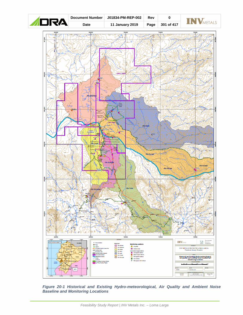
Document Number J01834-PM-REP-002 Rev 0
Date 11 January 2019 Page 301 of 417
Feasibility Study Report | INV Metals Inc. – Loma Larga
Figure 20-1 Historical and Existing Hydro-meteorological, Air Quality and Ambient Noise Baseline and Monitoring Locations

Document Number J01834-PM-REP-002 Rev 0
Date 11 January 2019 Page 302 of 417
Feasibility Study Report | INV Metals Inc. – Loma Larga
20.3.4 SOIL
From 2008 to 2011, PROMAS carried out annual soil studies describing the physical,
hydrophysical and chemical characteristics, as well as the morphological conditions within the
project area, with a primary focus on the underground mine area Additional soil quality
monitoring has been conducted by Gruntec within the project area including the Los Pinos
surface rights area (Figure 20-3).
The predominant soils are the Andosols and Histosols formed from the accumulation of
volcanic ash and organic matter, with a very low apparent density (less than 0.5 g cm-3) and
a high capacity of water retention (PROMAS 2011). Results of the soil quality monitoring
within the project area indicate that most of the parameters evaluated are well below the
maximum limit established in the TULSMA (Tables 2 - Industrial Use, Annex 2, Ministerial
Agreement 097a, Ministerial Agreement 061, Book VI of TULSMA). There are some
parameters that exceed the regulatory limits, but these are naturally occurring. The locations
sampled focused primarily on the planned underground mine area, which would suggest that
concentrations are due to a natural characteristic of the Páramo soils of the areas evaluated
and that additional soil monitoring in the project area may result in similar observations.
The sampling completed to date has been localized to the planned underground mine area and
does not capture the areas of surface disturbance that will result from the full scale mine.
Additional baseline soil sampling will be conducted within the footprint of the mine including
FTSF and the plant area (i.e., Los Pinos surface rights area), transmission line corridor, and
new sections of the access road. Data gained from the additional sampling program will
support further understanding of soil management needs, longer-term reclamation and
closure planning, and environmental impact study.
20.3.5 HYDROLOGY
The Project straddles the continental divide. The three northern watersheds, Río Berjemos,
Río Irquis (Quinuahuaycu), and Río Portete, drain to the Atlantic Ocean. The three southern
watersheds, Río Falso, Río Cristal, and Rio Alumbre (Quebrada Cristal- Alumbre) are both
sub-watersheds of the Río Zhurucay; (Figure 20-2) that flow to the Pacific Ocean.
In December 2006, a hydrometeorological monitoring network was installed by PROMAS. In
2009, PROMAS performed a survey specifically developing the baseline hydrology in the
high-altitude wetlands (Páramos) of Quimsacocha and its area of influence. The stations
were installed at the Bermejos, Calluancay (in the Río Portete watershed), Quinuahuaycu,
Zhurucay, Jordanita (in the Río Alumbre watershed), and the San Gerardo Irrigation Canal.
Streams in the area are primarily driven by rainfall runoff events, with peak flow periods
typically during the wet period of May to July. Low flows occur during the months of November
to January. The Jordanita station (Quebrada Cristal-Alumbre) and Quinuahuaycu station (Rio
Irquiz) were selected for analysis as they have the longest periods of records when compared
to the other monitoring stations (2007-2013, and 2006-2014 respectively). Average annual
runoff is to 633 mm in the Jordanita tributary of the Quebrada Cristal-Alumbre and 743 mm in
the Rio Irquiz.
Baseflow reduction in the Río Irquis is expected through the construction and operations
phases as the underground mine is dewatered which will redirect groundwater towards the
underground mine rather than naturally discharging into the stream. The water collected in
the underground mine will be transferred via pipe to the process plant for use as make-up
Document Number J01834-PM-REP-002 Rev 0
Date 11 January 2019 Page 303 of 417
Feasibility Study Report | INV Metals Inc. – Loma Larga
water. Excess water (not used for mining purposes), will be treated and discharged to the
Jordanita tributary of the Quebrada Cristal-Alumbre. Baseflow reduction in the Río Irquis is
expected to be approximately 0.38 L/s, compared to current estimated baseflows between 0
and 5 L/s and monitored stream flows in the downstream receiving environment in the range
of 5 to 100 L/s in the Upper Río Irquiz.
Water collected within diversions around the ore processing plant site, ore stockpile,
temporary waste rock stockpile and FTSF, along with dewatering inputs from the mine, will
be directed to the planned water treatment facility before discharge to the receiving
environment (the Quebrada Cristal-Alumbre). The average annual background flows in the
Quebrada Cristal-Alumbre are 54 L/s (measured at the Jordanita Station). The Project site
infrastructure and diversions will reduce natural flows by approximately 9 L/s on average, and
approximately 21 L/s of treated water will be discharged, meaning that during mine
operations, average annual flows in the Quebrada Cristal-Alumbre may increase to 66 L/s.
The flow changes represent an expected average flow increase of 6.6% at the mouth of this
watercourse. The expected average flow increase further downstream in Rio Zhurucay (near
Chumblin) is less than 3%.
The existing data sets provide a reasonable spatial and temporal coverage of the Project
area, however additional data analysis will be completed using the available field collected
data to increase the confidence of the flow data for use in on-going project planning and
environmental impact study.
20.3.6 HYDROGEOLOGY
Hydrogeologic field investigation around the ore zone and access ramp (i.e., Río Falso
concession) was conducted in 2016 and 2017. This field investigation focused on hydraulic
testing of boreholes (drilled across the ore zone) and installation of 11 piezometers (Itasca
2017a).
Subsequent to this field investigation, additional water-level data for the Project was collected
(Itasca 2017b) and used to generate a conceptual water balance and water management
plan (Itasca 2017c). In Q1 of 2018 analytical and numerical simulations of groundwater
inflows provided an assessment of the inflows to the proposed mine during its various stages
of development. Maximum model-predicted rate of groundwater inflow into the mine, 13.8
L/sec, would occur during mine year 3. The analyses also generated predictions of the
chemical composition of the discharge waters from the planned ramp to the underground
mine (Itasca 2018a; Itasca 2018b; Itasca 2018c).
Data from the field investigations completed to date, indicate that the Project is within a
complex geologic setting, which translates into a complex hydrogeologic system (Itasca
2017a). The complexity of the system can result in highly-variable groundwater flow gradients
(Itasca 2017a). The system features in the area of the mine include bedrock groundwater
underlying a cap of saturated Páramo vegetation, and shallow, perched groundwater. The
underground mine is in bedrock and dewatering will affect the groundwater system and, to a
limited extent, the streams around. Reductions in the groundwater table are unlikely, as the
mine will influence primarily the groundwater within localized bedrock formations. The
shallow Paramo groundwater would be affected by the mine dewatering to a much lesser
extent as it is perched over bedrock.

Document Number J01834-PM-REP-002 Rev 0
Date 11 January 2019 Page 304 of 417
Feasibility Study Report | INV Metals Inc. – Loma Larga
20.3.7 WATER USE
There are no known human groundwater users within the model-simulated cone of
depression that could be affected by dewatering of the underground mine.
The social baseline study (Propaxis 2018) indicates that within the direct area of influence of
the Project 48% of households are connected to a community irrigation system. Community
irrigation systems allow these water users to manage available water resources, which are
critical for agricultural and livestock production. Schedules and regulations of the irrigation
systems are enforced and respected by all members. These systems report low levels of
technical and administrative capacity, which has a direct impact on the continuity and quality
of maintenance work, which has the potential to impact the distribution of water (Propraxis
2018). The remaining households that are not connected to community irrigation systems,
mainly rely on rainfall for agricultural and livestock production.
Currently, INV holds an administrative authorization for the right to use and consume water,
which was granted on July 5, 2010. This authorization provides INV the right to use rainwater
to be collected in the Cristal-Aguarongos sector of the San Gerardo Parish, Canton Girón in
eight reservoirs/storage ponds up to 0.03 million cubic metres per year (Mm3/yr) (flow of 1
liter/second (L/s)). The reservoirs/ponds capacity is approximately 15,000 m3 and the
authorization particularly indicates that the water will be used for forest nurseries irrigation
and advanced exploration activities. The existing permitted flow is 0.6 L/s for nurseries
(granted for a 10-year renewable concession) and 0.4 L/s for industrial use for the duration of
advanced exploration works.
INV also holds another administrative authorization for the right to use and consume water,
granted with renewal possibility for 10 years. This is a Production Water Use Authorization
for mining activities with an 8 L/s flow taken from the Quebrada Cristal-Alumbre located in the
San Gerardo Parish of the Girón Canton, Province of Azuay. This Authorization ensures a
water use up to 0.25 Mm3/yr (8 L/s) for mining industrial activities from Cristal Creek.
20.3.8 WATER QUALITY
20.3.8.1 SURFACE WATER
Surface water quality monitoring has occurred between 2003 and 2017 at a total of 30 water
quality stations (PROMAS, INV and IAMGOLD) (Figure 20-2). While the spatial extent of
monitoring is adequate, covering potential receiving environments, farfield sites, and
upstream watersheds, the scope of monitoring (parameters monitored, monitoring frequency,
and monitoring duration) has varied from year-to-year.
INV has been conducting quarterly monitoring in the Quinuahuaycu Alto, Quinuahuaycu,
Calluancay, Kalluancay and Río Falso streams. The results are compared with Ecuadorian
regulatory standards and submitted as an annual report to the Ecuadorian Ministry of
Environment. In addition, two discharge points in the location of the Pino and Base camp,
are monitored quarterly.
Comparison of available water quality data to Ecuador’s criteria for aquatic life and IFC’s
guidelines for monitoring mining effluents indicates several exceedances in the levels of
aluminum, copper, lead, cadmium, mercury, selenium, manganese, iron and zinc. In
additional, baseline pH levels have been measured to be as low as 3.2, below the minimum
pH per Ecuador’s aquatic life criteria of 6.5, indicating existing naturally occurring acidic

Document Number J01834-PM-REP-002 Rev 0
Date 11 January 2019 Page 305 of 417
Feasibility Study Report | INV Metals Inc. – Loma Larga
drainage from local mineral deposits. Results of site wide water balance modelling (see
Sections 18.8 and 18.9) indicate that constituents of potential concern in mine-related waters
directed to treatment are generally consistent with those identified above in baseline
monitoring that are naturally occurring. Parameters that are expected to be main targets for
treatment, based on preliminary results from the site wide water balance modelling and
proposed regulatory criteria, are aluminum, cadmium, cobalt, chromium, copper, iron, lead,
manganese, molybdenum, nickel and zinc.
Within the Zhurucay Bajo watershed, exceedances were found for copper, iron, lead and zinc
at all three sites within the watershed. Aluminum, cadmium, manganese, mercury and
selenium were only higher for one or two of the sites. Metals concentration exceedances,
like those observed in other watersheds, are attributable to natural processes.
Within the Cristal Concession, surface water quality monitoring will continue on a quarterly
basis for Río Alumbre, the main receiving environment for the Project. At minimum,
monitoring will capture wet season, dry season and shoulder seasons (quarterly). A far-field
monitoring station will be established on Río Alumbre at the concession boundary,
downstream of WQ-011 and upstream of WQ-003 and data will be collected on a quarterly
basis prior to the start of effluent discharge from the FTSF. Within the Río Falso Concession,
monitoring will continue at existing sites on Quinuahuaycu which will capture wet season, dry
season and shoulder seasons (quarterly).
Although existing conditions in the near-stream receiving environment indicate low quality
aquatic habitat, regulatory uncertainty exists with respect to whether Ecuadorian aquatic and
wildlife criteria will be applicable to Project effluent discharge permitting. Currently the water
treatment systems will be designed to limit potential for additional exceedances of Ecuador’s
water use criteria for drinking water and irrigation in the receiving environment and effects on
receptors and existing water uses. If the aquatic and wildlife criteria are applicable, additional
costs associated with implementing specialized water treatment technologies may be
incurred to meet more stringent standards for some constituents.
20.3.8.2 GROUND WATER
No previous deep groundwater chemistry data existed for the Project (Itasca 2017a),
therefore a 2016-2017 field investigation program commenced with the installation of
additional monitoring points for collection of water-quality samples of the deep-bedrock
groundwater system.
The main Project elements that have a potential to affect groundwater system (and indirectly
surface waters) are the underground mine and tailings storage facility.
Predictions of the chemical composition of the discharge waters indicate that the Ecuadorian
Freshwater Aquatic Life and Wildlife Standards (Freshwater Standards) would be exceeded
for some solutes including aluminum, copper, nitrate, lead, arsenic, chromium, iron, mercury,
manganese, and zinc. Itasca has indicated that this geochemical characterization can be
used to preliminarily characterize groundwater quality characteristics during full mine
development.
As such, water from the underground will be transferred to the FTSF; excess water will be
treated prior to discharge to the environment.
Additional groundwater characteristics will continue to be monitored as recommended by
Itasca (2018c) to optimize the water-treatment plant design. The existing network for the

Document Number J01834-PM-REP-002 Rev 0
Date 11 January 2019 Page 306 of 417
Feasibility Study Report | INV Metals Inc. – Loma Larga
mine area will be augmented by installing a few shallow wells for monitoring water quality of
the Páramo system, some of them located up-gradient of the Proyecto/Chorotasqui and
Upper Irquis streams (receiving environment for post-closure mine-contact groundwater).
Surface seeps near the bottom of the (Proyecto/Chorotasqui) stream’s valleys (within the
mine site) have been sampled in late 2018 and the analytical results will also provide some
information on current baseline and naturally occurring groundwater quality conditions.
Additional modelling for the Project closure phase is required to support the environmental
impact study as well as refinement of closure and reclamation planning. Such analysis will
include estimation of the dissolved chemical concentrations in the post-mine contact
groundwater (geochemical modeling) and a simple (as a minimum) fate and transport analysis
(with consideration of preferential pathways, such as the ramp).
The Project includes a fully lined FTSF that provides the primary mechanism of control for
impacts to groundwater and surface water from seepage, which reduces risk of impacts to
the receiving environment. Characterizing the baseline groundwater around the FTSF
conditions prior to development of the FTSF will allow for monitoring of potential groundwater
contamination from the FTSF during the operation and post-closure phases of the project.
Without additional characterization, any naturally elevated concentrations of groundwater
chemicals likely could not be distinguished from the Project related impacts.
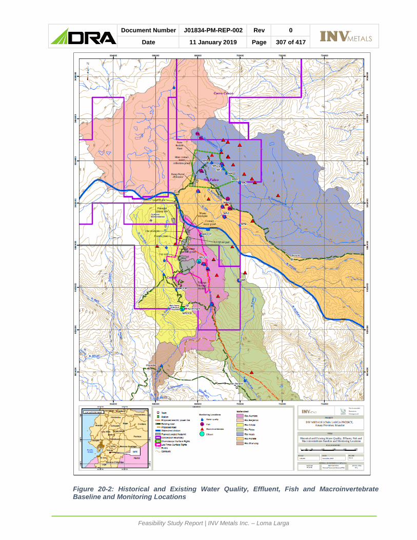
Document Number J01834-PM-REP-002 Rev 0
Date 11 January 2019 Page 307 of 417
Feasibility Study Report | INV Metals Inc. – Loma Larga
Figure 20-2: Historical and Existing Water Quality, Effluent, Fish and Macroinvertebrate Baseline and Monitoring Locations

Document Number J01834-PM-REP-002 Rev 0
Date 11 January 2019 Page 308 of 417
Feasibility Study Report | INV Metals Inc. – Loma Larga
20.3.9 TERRESTRIAL ENVIRONMENT
20.3.9.1 TERRESTRIAL FAUNA
The predominant ecosystem type within the Project area is Páramo grasslands which also
includes wetlands (Mosquera et al. 2015). This ecosystem occurs above treeline and below
the snowline in the Andes (Carrascal et al. 2011, Madrinan et al. 2013).
Terrestrial fauna groups for which baseline data has been collected include mammals,
amphibians and reptiles, birds, and insects. Baseline data on these groups have been
collected to determine the species occurrence within the Project area and to identify any
special status species and their habitat that could interact with the Project (Figure 20-4).
Threatened and endemic species that are considered Endangered or Critically Endangered
as identified on the International Union for Conservation of Nature (IUCN) red list or have
small ranges (i.e. endemic to Ecuador) require more in-depth consideration for mitigation to
meet International Finance Corporation (IFC) Performance Standard 6 expectations of avoid,
minimize, restore and offset.
Habitat that is of significant importance to IUCN red list Critically Endangered or Endangered,
and range-restricted species is considered Critical Habitat under IFC PS6 (IFC 2012a; IFC,
2018). Mitigation for impacts to critical habitat includes following the mitigation hierarchy of
avoid, minimize, restore and offset (IFC 2018). The portal location was chosen to avoid a
nearby stream and its associated riparian area, thereby incorporating the principle of
‘mitigation by design’ in the Project.
20.3.9.2 AMPHIBIANS AND REPTILES
Surveys for amphibians and reptiles have been conducted by Azuay University biologists for
10 years between 2007 and 2018 (no sampling in 2011 and 2014), at 36 locations. Based
on survey programs conducted to-date, ten species have been detected in the Project area,
three reptiles and seven amphibian species, from two orders and six families. The most
commonly observed species was the frog species Pristimantis riveti. Four of the amphibian
species are considered Endangered or Critically Endangered by IUCN and one reptile species
is considered Vulnerable. Critical habitat (as defined under the recently-released IFC
threshold, IFC 2018; Frenkel et al., 2018), for one amphibian species may also exist on site.
For the three amphibian species that reproduce in streams and wetlands, avoiding these
habitats whenever possible during the Project design assists with reducing other potential
mitigation requirements.
For Project impacts on special-status species that cannot be avoided, or sufficiently
minimized, a biodiversity offset may be required for the Critically Endangered, Endangered
and range-restricted frog species. The need for an offset and the specifics of a biodiversity
management plan will be defined once the EIS of the Project is complete. It is expected that
through the EIS review process, the Ministry of Environment and Water will establish specific
requirements for the Project.
Biannual data collection associated with the 13 transects associated with the Project footprint
will continue to be monitored, as surveying at some of these locations has been limited to
2017 and repeat sampling will give a more robust data set. Additional baseline data collection
will be carried out for habitats not previously sampled along new segments of the access road
and along the transmission line during both the wet and dry seasons (biannual; January and
August) to inform the evaluation of impacts for the construction and use of these Project

Document Number J01834-PM-REP-002 Rev 0
Date 11 January 2019 Page 309 of 417
Feasibility Study Report | INV Metals Inc. – Loma Larga
features. It is possible that during additional surveys for other project components e.g. access
road and transmission line, that additional IUCN red list species may be detected. The
probability of this occurring is highest in habitats that have not been extensively surveyed
previously such as high montane evergreen forest through which the new road route will pass.
However, it is anticipated that important habitat for these species can be avoided through
minor adjustments of the road route and location of transmission line poles.
20.3.9.3 BIRDS
Avian surveys have been conducted by Azuay University biologists from 2007 to 2018 at 51
sampling locations. The information in the Azuay University database indicates that a total of
95 species have been detected corresponding with nine orders and 26 families. The families
with the most number of species detected were hummingbirds, Trochilidae, with 16 species
and Tyrannidae with 14 species. Four species that have been detected are of conservation
concern, the hummingbird, Metallura baroni, is considered Endangered by the IUCN and is
endemic to Ecuador, and the shrike, Agriornis andicola, is considered Vulnerable. Both
species are federally Endangered (Granizo et al. 2002). The songbird, Xenodacnis parina, is
considered federally Endangered (IUCN Least Concern) and the vulture, Vultur gryphus, is
Critically Endangered federally (IUCN Near Threatened; Granizo et al. 2002). Based on
information in the database it is unknown if habitat that these species use for nesting is
present within the Project area. However, if there is a Project interaction with potential nesting
habitat, impacts to these species can be minimized by avoiding vegetation clearing and
ground disturbance activities during the nesting period. If this is not possible then pre-clearing
surveys can be conducted to identify any active nests and avoid them using no disturbance
buffers until the young have left the nest.
Biannual data collection associated with the 11 transects associated with the Project footprint
will continue, as surveying at some of these locations has been limited to 2017 and repeat
sampling would give a more robust data set. Additional baseline data collection for new
habitats not previously sampled along the new segments of the access road and along the
transmission line during both the wet and dry seasons will be carried out. This will provide
data for the evaluation of impacts and identification of mitigation for the construction and use
of these Project features.
20.3.9.4 MAMMALS
Mammal surveys have been conducted by Azuay University biologists from 2009 to 2018 at
24 locations. More recent data collection in December 2017 (Universidad del Azuay, 2017)
and February 2018 (Universidad del Azuay, 2017) has occurred within the Los Pinos Surface
Rights area within the Cristal concession.
Based on survey programs conducted to-date, a total of 28 species have been detected from
nine orders and 15 families. The most commonly observed species was Sylvilagus
brasiliensis, the tapeti or forest rabbit. One species detected is considered Vulnerable by the
IUCN (IUCN 2018), Mazama rufina, the little red brocket deer, was observed during field
surveys in 2009 and 2010. Vulnerable species are important to consider for mitigation and
monitoring programs in the event that their status changes to Endangered. Two species
endemic to Ecuador were observed: Cryptotis montivaga (Ecuadorean small-eared shrew)
and Phyllotis haggard (Haggard's Leaf-eared Mouse), both of which are considered Least
Concern by IUCN.

Document Number J01834-PM-REP-002 Rev 0
Date 11 January 2019 Page 310 of 417
Feasibility Study Report | INV Metals Inc. – Loma Larga
Biannual data collection associated with the 12 transects associated with the Project footprint
will continue, as surveying at some of these locations has only occurred in 2017 and repeat
sampling will give a more robust data set to inform management plans. Data collection for
habitats not previously sampled along new segments of the access road and along the
transmission line during both the wet and dry seasons to inform the evaluation of impacts and
identification of mitigation measures for the construction and use of these Project features will
be carried out over one year.
20.3.9.5 INSECTS
Entomological surveys have been conducted by Azuay University biologists in 2012, 2013,
2016 and 2018 at 35 locations. The information in the database indicates that 39 orders have
been detected and 150 families. The families with the most number of morphospecies
observed were family of small flies and fungus gnats, Mycetophilidae (10), and leafhoopers,
Cicadellidae (9). The maximum number of morphospecies per family were determined from
a single survey rather than multiple surveys when species overlap may have been possible.
Biannual data collection associated with the nine locations associated with the Project
footprint will be continued in order to provide a robust baseline set for impact predictions,
mitigation and monitoring plans.

Document Number J01834-PM-REP-002 Rev 0
Date 11 January 2019 Page 311 of 417
Feasibility Study Report | INV Metals Inc. – Loma Larga
Figure 20-3: Historical and Existing Mammal, Bird, Entomological and Herpetological Baseline and Monitoring Locations
Document Number J01834-PM-REP-002 Rev 0
Date 11 January 2019 Page 312 of 417
Feasibility Study Report | INV Metals Inc. – Loma Larga
20.3.9.6 TERRESTRIAL FLORA
Vegetation surveys have been conducted by Azuay University biologists from 2007 to 2018
at 45 locations. Based on survey programs conducted to-date 47 orders, 91 families, and
410 species have been observed in the Project area; potentially more were observed as not
all species were identified beyond the genus level. The most commonly observed family was
the Aster family, Asteraceae, with at least 66 species detected. Six of the observed species
are listed as Endangered by IUCN, 20 as Vulnerable, 6 as Near Threatened (IUCN 2018),
one as extinct in the wild, and 10 are Endemic to Ecuador that are rare, or little is known about
them. Two of the endemic plant species are Polylepis reticulata and P. lanuginosa which are
also considered Vulnerable by IUCN (IUCN 2018).
Four of the Endangered plant species have been observed in the Chorro Tasqui surface rights
area and three in the Los Pinos surface rights area. The Project as described in this FS will
directly impact three Endangered species, Gentianella hirculus, Lysipomia vitreola and
Loricaria azuayensis, which have been detected within the FTSF area. Critical habitat under
IFC thresholds (IFC, 2018), may exist for L. azuayensis.
Mitigation measures for the species in the FTSF area could include creating no disturbance
buffers around the plants during Project construction (for occurrences near but not within the
project footprint), translocating plants or propagating them in the existing nursery. For Project
impacts on special-status species that cannot be avoided or sufficiently minimized, a
biodiversity offset may be required for Endangered and range-restricted plant species. The
need for an offset and the specifics of a biodiversity management plan will be defined once
the EIS of the Project is complete. It is expected that through the EIS review process, the
Ministry of Environment and Water will establish specific requirements for the Project.
A species that is considered to be extinct in the wild by IUCN, Brugmansia sanguinea, was
observed during August 2018 field studies. This species is sometimes cultivated by
communities. It is known locally as floripondio, grown in people’s gardens and used for certain
rituals. The observation of the plant was in a small patch of forest surrounded by pasture and
cattle. It is thought to be a cultivated plant.
Polylepis forests are important biologically as they occur at the highest treeline elevations
globally (i.e, up to ~5000 m) and provide habitat for unique biodiversity such as endemic plant
and animal species (Gradstein and Leon-Yanez 2017, Toivonen et al. 2011). Many Polylepis
forests exist as fragmented or remnant habitat patches due to a long history of human land
use in the Andes (Castillo et al. 2017, Toivonen et al. 2011). To date these species have only
been observed between the Río Falso and Cristal concessions outside of the Comuna
Sombrederas community.
Biannual data collection associated with the Project footprint will be continued to provide a
robust baseline set for impact predictions, mitigation and monitoring plans.
Additional data collection will be carried out for habitats not previously sampled along new
segments of the access road and along the transmission line during both the wet and dry
seasons to inform the evaluation of impacts and identification of mitigation for the construction
and use of these Project features.

Document Number J01834-PM-REP-002 Rev 0
Date 11 January 2019 Page 313 of 417
Feasibility Study Report | INV Metals Inc. – Loma Larga
Figure 20-4: Historical and Existing Vegetation and Soil Quality Baseline and Monitoring Locations

Document Number J01834-PM-REP-002 Rev 0
Date 11 January 2019 Page 314 of 417
Feasibility Study Report | INV Metals Inc. – Loma Larga
20.3.10 AQUATIC BIOLOGY
Aquatic faunal groups for which baseline data has been collected include fish and
macroinvertebrates.
Aquatic biology surveys have occurred in the following rivers in the Loma Larga concessions:
• Quebrada Quinauhuayca in the Cerro Casco concession;
• Quebrada Quinauhuayca, Quebrada Chorotasqui, Quebrada Rumihuayco, and Río
Portete in the Río Falso concession;
• Río Falso, and Quebrada Cristal-Alumbre in the Cristal concession.
20.3.10.1 FISH AND FISH HABITAT
Fish surveys have been conducted by Azuay University biologists in in 2013, 2015, 2016 and
2018 from 13 locations. Two species were detected from the Salmonid family, Salmonidae,
rainbow trout (Oncorhynchus mykiss) and brown trout (Salmo trutta), both of which are
introduced species in Ecuador. Rainbow trout have been detected in Río Falso, Quebrada
Quinuahuayca, and Quebrada Kalluancay (Anexos Ambiental Cuarto Trimestre 2015).
Brown trout have been detected in Quebrada Kalluancay. Of the rivers and streams where
fish have been detected, only the Quebrada Quinuahuayca within the Río Falso concession
is potentially impacted by the Project. No other fish species have been detected during the
baseline surveys conducted to-date and no IUCN Redlisted Vulnerable, Endangered or
Critically Endangered fish species have ranges that overlap the Project area.
Biannual data collection at 11 locations associated with the Project footprint will be conducted
to obtain robust dataset for evaluating impacts of the Project and identifying appropriate
mitigation and to inform management and monitoring plans. One year of biannual data
collection will be carried out during the wet and dry seasons in Quebrada Cristal-Alumbre
near the new segment of the access road and at stream crossings along the transmission line
alignment. This will provide data for the evaluation of impacts and identification of potential
mitigation for the construction and use of this Project feature.
20.3.10.2 MACROINVERTEBRATES
Macroinvertebrate data has been collected and analyzed by biologists with the Azuay
University during eight years between 2008 and 2018 (no data collected in 2009, 2010 and
2012) at 37 locations.
Based on surveys conducted to-date, 21 orders, 63 families, and 77 genera have been
identified in the Project area. Non-biting midges (Chironomidae) had the most number of
genera detected (9) and crane flies, Tipulidae (6) genera were detected. Recent analyses of
the data from February 2018 (Universidad de Azuay, 2018) indicated that there were three
sampling locations along the Quebrada Cristal-Alumbre where water quality was degraded
using the Andean Biotic Index (Acosta et al. 2009) which uses the presence of
Ephemeroptera, Plecoptera and Tricoptera as indicators of good quality water. Two of these
sites also had baseline (naturally occurring) water quality exceedances.
Biannual data collection at 11 locations associated with the Project footprint will be conducted
to obtain robust dataset for evaluating impacts of the Project and identifying appropriate
mitigation and to inform management and monitoring plans. One year of data collection will
be carried out during the wet and dry seasons in Quebrada Cristal-Alumbre near the new
segment of the access road and at stream crossings along the transmission line alignment.

Document Number J01834-PM-REP-002 Rev 0
Date 11 January 2019 Page 315 of 417
Feasibility Study Report | INV Metals Inc. – Loma Larga
20.4 SOCIAL OR COMMUNITY REQUIREMENTS
20.4.1 SOCIO-ECONOMIC CONTEXT
The Loma Larga Project is located in the province of Azuay, in the western mountain range
of the Andes. The concession area of the Project is located in the cantons of Cuenca, Girón
and San Fernando. The Project is one of five mining projects in the country declared as
“National Strategic Projects” by the Ecuadorian Government (Ministry of Mines, 2016 and
2018).
The socio-economic context and social baseline data presented, corresponds to the areas of
influence of the Project. The area of social influence of the Project refers to the area that is
likely to be affected by the activities of the Project and its facilities. Although there are no
communities within the mining concession area, the area of social influence considers the
communities closest to the Project that are most likely expected to be impacted.
The delimitation of the area of social influence considers three levels: area of direct influence
(ADI), area of indirect influence (AII) and area of regional influence (ARI). The Ministry of
Environment provides guidelines to define the first two (Guide for the elaboration of the social
component of terms of reference and environmental studies of hydrocarbons, mining and
other sectors, 2015).
Taking into account the role that the city of Cuenca plays in the socio-economic context of
the Province of Azuay, INV included it as part of the regional layer of its area of influence. INV
expects that the city will provide a variety of inputs, services and materials that can’t be found
in the ADI and AII, and that are required for the construction and the production phases of the
Project.
The population in the ADI and AII is mainly rural. The results of the social baseline show that
the number of people living below the poverty line in the ADI and AII is above the national
average. Approximately 75% of households qualify as poor in the ADI, while in the AII the
number is closer to 50%. The ADI and AII are rural areas where most of the people work in
agriculture and cattle raising (49% of population in ADI and 28% in AII). These activities do
not formally employ people and do not provide access to recognized social security or
employment benefits. Rural family income is not likely to cover expenses and families often
need to access informal credit to cover basic needs (52% of families in ADI, and 41% in AII
are in debt). These numbers contrast the average poverty, income and employment rates of
the Province of Azuay, which are driven by the urban population of Cuenca, Ecuador’s third
largest city and one of the most important industrial hubs of the country.
The female population in the ADI and AII is proportionally greater than male population (54%
women, 46% men). This indicator responds to the high migration rates reported in the past
in the studied area. The annual growth rate of the population from 2001 to 2010 was only
0.3% due to the high migration rate from people looking for employment opportunities outside
the areas of influence. Most households in the area identify themselves as mestizo (person
of mixed race, Spaniard and American Indian), Spanish speakers, and Catholics. This
characterization is in-line with the cultural and traditional practices of the studied communities
(Propraxis 2018).
Literacy levels show that 93% of adult residents in the area of influence are literate; however,
there are low rates of formal education, only 22% of adults have finished high school. Lack
of resources is the most common limitation reported for not studying. Economic activities are

Document Number J01834-PM-REP-002 Rev 0
Date 11 January 2019 Page 316 of 417
Feasibility Study Report | INV Metals Inc. – Loma Larga
concentrated in cattle growing and farming. The unemployment rate of economically active
population reaches 13.4%. Employment in the area does not offer stability or social security
benefits, most of the people are either self-employed or work per day. Around 82% of the
population do not have social security (Propraxis 2018).
Housing indicators show that most residents have access to electricity on their homes (99%).
Access to potable water reaches 71% of households, some households obtain water through
a connection to the local water distribution network or use of a well. In terms of sanitation,
42% of houses in San Gerardo, Chumblin and Victoria del Portete have toilet and sewerage
connected to the public network, while 43 % have a toilet connected to a septic tank system.
Public service of garbage collection covers 76% of households. Household overcrowding
indicator shows that 3% of households have more than 3 people per room, 2 people per room
is the area’s average. Internet penetration in homes remains low with 49% of households
reporting not having any kind of internet access (Propraxis 2018).

Document Number J01834-PM-REP-002 Rev 0
Date 11 January 2019 Page 317 of 417
Feasibility Study Report | INV Metals Inc. – Loma Larga
Figure 20-5: Areas of Social Influence of the Loma Larga Project

Document Number J01834-PM-REP-002 Rev 0
Date 11 January 2019 Page 318 of 417
Feasibility Study Report | INV Metals Inc. – Loma Larga
20.4.2 SUMMARY OF SOCIO-ECONOMIC BASELINE INFORMATION
Under the direction of ERM, Propraxis S.A. (Propraxis), an Ecuadorean consulting firm,
conducted a detailed socio-economic baseline study for the direct and indirect areas of
influence of the Loma Larga Project (Propraxis, 2018). The socio-economic baseline study
included quantitative and qualitative information collected through a socio-economic survey,
focus groups, community mappings, and interviews.
The socio-economic baseline information collected and analyzed as part of the study was
organized using the methodology of the sustainable livelihoods framework, which considers
that societal units have five capitals: human, economic, natural, physical, and social capital.
The structure of the data collection tool included the following sections:
• General information: demographics, migration, head of household characteristics;
• Human capital: education, training, health, food security;
• Economic capital: productive activities, employment, income and expenses;
• Social capital: Participation and social cohesion, governance, gender equality, Project’s
perception;
• Natural capital: land use, ecological services; and
• Physical capital: house characteristics, household services, transport, public and
communal infrastructure.
Migration is a phenomenon that affects a large part of ADI. Approximately 30% of households
report that at least a member of their family has permanently emigrated. Annual population
growth in both areas is very low (0.3%) due to the high emigration rate of people looking for
employment opportunities. In this sense, the Loma Larga Project represents an opportunity
that may provide local employment alternatives that could decrease emigration and promote
the return of people who left the area.
Low levels of formal education and low skilled labor in the area of influence increases the
difficulty to directly hire local people for mining projects. Training programs will be required
in advance of mining activity to facilitate the availability of local labor for the Project and reduce
the reliance on skilled labor to immigrate to the area. INV is aware of this need of training
programs, which is something that will be integrated into the social management plans to be
developed as part of the ESIA.
Income remuneration is low in agriculture and livestock, which are the main economic
activities in the area of influence; hence there are high levels of poverty, as measured by the
wealth index, 84% of HH in the ADI are considered poor. Employment in the area does not
often offer stability or social security benefits, and the long working hours per week in
precarious conditions report little economic return. As reported by the households, there is a
lack of technology to support the production processes of the families (Propraxis 2018).
As reflected in the survey results, most of the families in the ADI know about the Project and
have received information from INV through the Company’s engagement activities. In
addition, more than 44% of families in the ADI, have a positive perception of the project,
mostly in the parishes of Chumblin and San Gerardo. In the AII 31% of surveyed households
do not know about the Project.
The expectation of employment opportunities and economic resources generation are the
most common advantages cited that generate a positive perception of the Project. Potential
risks of water and environmental pollution are the main concerns related to Project
development from families of the ADI and AII (Propraxis 2018). INV will need to include
specific strategies in its Social Management Plans and Stakeholder Engagement and

Document Number J01834-PM-REP-002 Rev 0
Date 11 January 2019 Page 319 of 417
Feasibility Study Report | INV Metals Inc. – Loma Larga
Communications Plans that consider the interests of local stakeholders. These plans will
need to be formalized as the Company advances the Project and seeks regulatory approval.
Population growth in the ADI if the Project was to induce immigration to the area could also
become a challenge given that the rural parishes have limited capacity in terms of local
infrastructure to accommodate newcomers. An influx management plan for immigration flows
needs to be developed by INV in order to mitigate the potential impact of migration to the ADI.
A strategy for achieving easement access agreements for the Project’s linear components,
the power transmission line and access road, will be designed and implemented to comply
with national regulations. This strategy may need to take into consideration the particularities
of land tenure in the area to account for legitimate ownership rights, even when a property
title does not exist. According to the baseline information, around 41% of households in the
ADI, and 25% of households in the AII do not have a property title over the land they own
(Propraxis 2018).
20.4.3 CONSULTATION ACTIVITIES
This section summarizes consultation work conducted by INV and IAMGOLD to support
exploration activities, early stage Project development, and social baseline data collection
activities. The main focus of consultation efforts to date has been to inform local communities
about the state of the Project and social projects undertaken in local communities.
INV has a communication and dissemination system that considers several mechanisms of
communication to inform the public about the Loma Larga Project and associated community
development projects. These mechanisms include:
• Public assemblies;
• Guided visits to the concession area;
• Information centers in ADI parishes San Gerardo and Chumblin;
• Mining tent with participation in the area of influence, Azuay province, and national forums
of mining dialogue;
• Door to door information campaigns;
• Radio campaigns;
• Newspaper publications;
• Printed material to hand over to people visiting the information centers;
• Community development project planning sessions;
• Training sessions for community members.
INV’s consultation efforts look to comply with national regulations requirements, by
disseminating environmental management plans, environmental auditing and environmental
impact studies (when available). Furthermore, INV’s efforts go beyond regulatory
requirements, aiming to reach families and individuals of the area of influence in an effective
manner providing key, factual information specific to the Project, engaging them to interact
with the Project, discuss doubts and issues, and get involved in community development
programs.
INV’s Community Relations staff have conducted numerous consultation activities from 2008
to 2018 (INV, 2018). During that period, the team has held a total of 328 events in the
Parishes of Chumblin and San Gerardo. Over 7,380 local and regional residents, authorities,
and institutional representatives have visited either the mine site or the information centers

Document Number J01834-PM-REP-002 Rev 0
Date 11 January 2019 Page 320 of 417
Feasibility Study Report | INV Metals Inc. – Loma Larga
and have received information regarding exploration and future activities (INV, 2018). Around
11,900 people received information at INV’s Mining Tent that has been participating in several
fairs, congresses and events to present INV’s technical work, and environmental and social
responsibility practices (INV 2018). Additionally, since 2010, INV has been implementing a
program called “Mining Door to Door” in the direct and indirect area of influence looking to
address residents’ concerns of potential environmental impacts of the Project.
Consultation activities are documented using sign-in sheets, guest registers, photographs,
videos, audios, reports and other written registers (INV, 2018).
An engagement and communication strategy for the EIS will be designed and implemented
in order to comply with Ecuadorian regulations. The existing mechanisms of communication
will be key elements during the consultation and dissemination activities related to the
Project’s EIS given that these are communication channels already established with the
residents of the area of influence and other relevant stakeholders. The proposed
mechanisms include:
• Establishing of public information spaces;
• Holding disclosure assemblies;
• Conducting disclosure workshops;
• Organizing group meetings with leaders and authorities;
• Performing door to door information campaigns;
• Information disclosure in public media; and
• Publishing relevant information in Project’s web page.
The focus of the engagement and communication strategy will be to validate EIS findings in
a participatory manner and with inputs to finalize the EIS and inform detailed engineering.
The strategy will aim to identify any further areas of concern with the communities about the
existing design of the project and associated infrastructure. Information regarding the
perceived environmental impacts of the Project, particularly to water sources, will be an area
of focus for these efforts.
20.4.4 CORPORATE SOCIAL RESPONSIBILITY AND COMMUNITY DEVELOPMENT PROJECTS
INV has conducted numerous corporate social responsibility initiatives focused within the
areas of influence. The areas of work carried out with the communities are based on aspects
considered of importance by the local population(s). These include:
• Enhancement of traditional production activities;
• Projects to stimulate agricultural and livestock production;
• Land management;
• Local human talent;
• Local employment;
• Productive entrepreneurship;
• Gender equality; and
• Education and environmental protection.
INV maintains cooperation agreements with the local Governments at the parish level to align
the community programs and projects with the land use and development plans of each
parish. The agreements establish that the programs and projects to be financed and
implemented have to be framed within the local development plans. Each local Government,

Document Number J01834-PM-REP-002 Rev 0
Date 11 January 2019 Page 321 of 417
Feasibility Study Report | INV Metals Inc. – Loma Larga
as the main authority, permanently coordinates with community members, representatives,
organized groups, and public institutions, to jointly perform project management and
implementation. The actions implemented are publicly evaluated and endorsed every six
months in the parish assemblies. All programs and projects, with the allocated budget are
known and approved by the parish assemblies, the local organizations and local authorities.
Monitoring and accountability are public through the communication and disclosure system.
The cooperation agreements between INV and the local Governments, facilitates the idea
that mining can become a factor of local development that does not compete with the State
or create parallel development plans, and that the objective is to strengthen and optimize
public and private resources.
INV has generated strategic agreements of mutual collaboration for monitoring of its technical
and scientific processes with the academic sector. INV currently works with two key
universities: The University of Cuenca and the University of Azuay. These academic entities
participate in specific studies related to water quality and quantity, water basins, soil structure,
and monitoring systems of biological indicators, among others.
20.5 SOCIAL MANAGEMENT POLICIES AND PROCEDURES
INV has developed a set of policies and procedures to prevent and minimize social risks. The
Community Complaints Procedure functions as an early warning system to allow INV’s
Community Relations Team to quickly deal with any community concerns before it becomes
a major issue. The Code of Business Conduct and Ethics outlines the behavior that INV
expects from its employees. The Disclosure, Foreign Corrupt Practices, and Whistleblower
Policies outline corporate commitments to applicable laws and regulations.
20.6 MINE CLOSURE REQUIREMENTS
The Ecuadorian Mining Law (art. 27), and the Environmental Regulation of Mining Activities,
consider the closure of a mine as a regulated phase of the mining activities. The closure
phase consists of the termination of the mining activities and the consequent dismantling of
facilities used in either exploitation, beneficiation, foundry, refining, or commercialization.
Two years prior to the planned completion of the Project, INV must submit the Mining
Operations Closure Plan to the National Environmental Authority, for approval. The Mining
Operations Closure Plan should include plans for the recovery of the area, and a plan to verify
environmental compliance, to identify social impacts and to establish compensation
measures (if needed). The preliminary Closure Plan must be included in the EIS of the Mine
Project, and planning of the final closure and abandonment must be incorporated in the
Environmental Management Plans as part of the Mine EIS.
The Mining Exploitation Contract will also have specific closure considerations including the
payment of all environmental liabilities corresponding to a period equivalent to that of the
mining concession. An insurance policy or bank guarantee, unconditional, irrevocable and of
immediate collection in favor of the Ministry of the Environment will be required during closure.
The insurance policy must remain in force and be updated until full closure of operations in
the area and for one year after the end of the period of validity of the concessions.
Mine Closure and Reclamation for the Project also seeks to be consistent with the
International Finance Corporation (IFC) EHS Mining Guidelines 1.1 and 1.4 Mine Closure and
Post-Closure (IFC 2007b).

Document Number J01834-PM-REP-002 Rev 0
Date 11 January 2019 Page 322 of 417
Feasibility Study Report | INV Metals Inc. – Loma Larga
An adequate period of monitoring will be implemented to demonstrate compliance with
proposed criteria and conditions that ensure the mine site is safe, stable and has reached the
planned closure objectives. Such conditions must be demonstrated for a period of five years
after the cessation of mining and closure of the mine or until the time that the Ministry of the
Environment foresees according to the nature of the mine project. A progress and
effectiveness report of the environmental measures implemented for the closure of the mine
must be submitted to the Environmental Authority on a biannual basis for its approval.
Once the obligations of the closing and monitoring activities have been fulfilled after the
operations have been completed, INV will present a closing environmental audit, which will
verify compliance with closure activities and will allow the extinction of the environmental
license. All environmental records will be present in an environmental closure report. The
communication of the results of the Environmental Audit will be defined in the respective
Terms of Reference of the Audit and will be subject to the approval of the Environmental
Authority. In the event that closure of the Project cannot be fulfilled for all of the aspects of
the Project, such as water quality compliance with the criteria selected, INV will present a
closure plan that include long term management of that particular aspect until compliance can
be achieved.
The Closure Environmental Audit approval will determine the rehabilitation of the mining area
and the requirement for any financial guarantee.
If the Project ceases operations due to expiration or extinction of the mining rights, the
Environmental Authority will carry out an inspection in order to determine the current situation
of the area, considering the following conditions:
• For operations that have an approved Environmental Management Plan, the company
must apply the closure and abandonment plan specified therein.
• In the event that the National Environmental Authority determines that an area has not
been intervened at all, a Closure Plan will not be applied, and only the report issued by
the Environmental Authority and the ARCOM inactivity certificate will be the enabling
documents.
The Conceptual Mine Closure and Reclamation Plan is applicable for the life of the mine
(LOM) extending over all Project areas within the Los Pinos and Chorrotasqi Surface rights,
including the mine access road and power / waterline corridors connecting these two surface
rights. The closure of the offsite mine access road from San Gerardo to the mine site from
the south is not included in the closure plan or cost estimate at this time as the future of
ownership of these project support components will need confirmation. If ownership of this
infrastructure remains with INV at closure, the cost of closure will increase.
A final detailed Plan will be prepared and approved near the end of the Operational phase,
prior to closure.
The specific objectives of the mine closure and reclamation activities are to:
• Leave a site with physical, chemical and biological stable landforms, including meeting
site specific discharge surface water and groundwater quality standards of Ecuador for
the protection of drinking water.
• Consult with local stakeholders on the desired end land use and function of the site
post-closure that is compliant with regulations and sustains socio-economic benefits.
• Salvage, stockpile and protect soil from disturbed areas, which will be used to restore
and revegetate the site. Reclamation may start as soon as any area is defined as not
required by the Project or areas that require erosion management.

Document Number J01834-PM-REP-002 Rev 0
Date 11 January 2019 Page 323 of 417
Feasibility Study Report | INV Metals Inc. – Loma Larga
• Implement the mine closure and reclamation program as cost effectively as possible
with commercially available skills, equipment and materials, taking into consideration
prevailing local factors such as climate, seasonality, geography, demography,
infrastructure, security, governance, capacity and operational reliability.
• Include contingencies for temporary suspension of activities and permanent early
closure.
The successful reclamation program will depend on the identification and retention of soil
resources for future growth medium on disturbed sites, as well as the continued
implementation of successful native plant re-establishment that has been developed on the
site at the existing plant nursery. To date, no full material balance study exists and it is an
assumption that sufficient soil exists to meet the reclamation and closure objectives stated in
this FS. A full material balance is recommended to validate whether there is enough soils to
progressively cap the landfill.
For the underground mine, all stoping areas will be backfilled to best standard practices in
Normal Mining Operations in North America. All areas of development where there could be
long term potential for ground failures resulting in a failure to surface will be backfilled,
although none are anticipated.
The backfill plant area buildings, utilities and all equipment will be removed from the backfill
plant area, and will be trucked from site, sold or scrapped. The foundation will be left in place
with all anchor bolts cut off at the top of the concrete. Concrete foundations may be broken
and left in place, covered by overburden and 300 mm soil to provide for successful
revegetation growth media. Site drainage will be re-established to natural patterns.
The paste backfill plant site pond will be decommissioned. Remaining water will be pumped
to the FTSF. Accumulated sediment will be sampled and removed to the FTSF if determined
to be of potential environmental concern. The drained sediment pond liners will be removed
and placed into the ramp or removed from site. The final decommissioned ponds will be filled
with suitable material from the berms and if necessary, covering with 300 mm soil prior to
revegetation.
In the portal area, buildings and electrical equipment will be removed, including the powerline
from the main substation. Surface areas will be de-compacted and ripped, covered with 300
mm soil and revegetated.
The portal area water and sediment ponds will be decommissioned and reclaimed in the same
manner as the paste backfill plant pond.
The ramp will be closed to access. A steel fence will be installed 6 m inside the portal with
stainless steel 100mm x 100mm welded wire fabric to limit entry. The complete portal area
will be backfilled with clean material to an angle of repose of 30 degrees to return the area to
the original topography as much as possible and covered with 300 mm soils and seeded with
native grasses.
Ventilation raise areas and site access are to be decommissioned and reclaimed. All
ventilation and escape raise equipment will be removed from the top of the raises and the fan
foundations will be left in place. A platform will be hung from the surface to allow the
installation of an engineered concrete bulkhead at the top of the raise complete with proper
reinforcing. All protruding construction material will be removed, and the bulkhead will be
covered with overburden as appropriate to create positive drainage, and 300 mm of topsoil
material so that the area can be revegetated. The site access roads to the ventilation raises

Document Number J01834-PM-REP-002 Rev 0
Date 11 January 2019 Page 324 of 417
Feasibility Study Report | INV Metals Inc. – Loma Larga
will be decommissioned, landscaped and scarified, covered with soil and revegetated with
grasses and plants. Ditches will be filled, culverts removed, and natural drainage patterns
restored.
At the end of the LOM, any material left on the storage pad of the run of mine ore storage
area will be processed or moved to the FTSF for sub-aerial deposition and will be part of the
FTSF closure. The stockpile base seepage collection liner may be removed, and the site will
be de-compacted, ripped and regraded to restrict issues with angles of repose over 30
degrees, and covered with overburden, as required, to complete landscaping as well as 300
mm of topsoil material as a growth medium for revegetation.
The electrical substation and specific powerlines will be left in place as power is required to
run the water treatment plant until it is no longer required. INV will hold discussions with
CENTROSUR prior to closure to determine the ownership structure of the transmissions line
in the future. For the purposes of this study, INV have assumed that the powerlines will remain
with INV post-closure.
The 3 km long on-site powerline connecting the plant site to the mine site will be
decommissioned, conductors removed from site, sold or scrapped, and the power poles
removed.
The feed and return pipelines connecting the plant site with the mine site will be drained to
the FTSF, dismantled and removed from site, and along with steel supports, sold or scrapped.
Cement foundations for the supports will be buried and capped with growth medium and
revegetated.
The potential waste rock stockpile of non-PAG rock at the various locations on site will be re-
contoured to stable configuration and topped with 0.5 m of overburden and up to 300 mm of
growth medium prior to revegetation.
The FTSF area will require ongoing operating and maintenance considerations. The
Operation, Maintenance and Surveillance Manual for the FTSF will specify the inspection,
monitoring and reporting requirements of the facility until permanent closure is achieved.
Post-closure water treatment not yet been modeled and for the purposes of this FS only, has
been assumed for a period of ten years. Modeling of post-closure water treatment needs is
recommended to determine the timeline of water treatment after closure. An operable
emergency spillway will be maintained until permanent closure of the facility. The spillway
area will be incorporated into the final closure plan. The spillway may still be in effect for
major storm events, and in this case, will divert water around the dam structure in a similar
way to the operating plan. Annual maintenance and post-storm maintenance may be required
in addition to regular monitoring, which could be done remotely (e.g. SCADA system).
The FTSF is estimated to have approximately 6 Mt of tailings at closure. The FTSF may also
have some waste material from mining operation, and if so, this material will be placed
underground as fill.
The FTSF underdrain collection pond will be maintained, monitored and inspected as required
to meet closure criteria until closed.
After reclamation is complete, the tailings will drain over a period of time. During the time the
FTSF is draining to the FTSF underdrain collection pond, the water treatment plant will be
operated on a regular basis to treat effluent to meet receiving environment water quality
standards. The FTSF will be permanently closed once surface and seepage water from the
facility is demonstrated to meet discharge criteria without further management/treatment.

Document Number J01834-PM-REP-002 Rev 0
Date 11 January 2019 Page 325 of 417
Feasibility Study Report | INV Metals Inc. – Loma Larga
The tailings facility will be covered with a geomembrane liner, and then covered by
overburden and soil to form a growth medium for grasses and shrubs. Trees and deep-
rooting shrubs will be discouraged from establishing to prevent liner damage by root systems
at depth.
The water treatment plant will be operated throughout the post-closure mining phase until
such time as stable water discharge from the FTSF, and other surface water discharges can
demonstrate an approved period of time where effluent can be safely discharged to the
surface receiving environment without further treatment.
Decommissioning of the water treatment plant will involve disconnecting electrical
infrastructure, removal of all chemicals and equipment from buildings and on site, dismantling
buildings, covering broken up cement foundations with overburden and soil, and revegetation.
The FTSF underdrain collection ponds, when no longer required, will be reclaimed by folding
the liner system in on itself and covering the area with backfill to provide positive drainage.
The area will then be covered with growth media and reseeded. Post closure will require
maintenance of the closure cap until a vegetated surface can be established. The closure
surface will be monitored, inspected and repaired, if needed, to address water and wind
erosion. In addition to the closure cap, the perimeter road, stormwater diversion channels
and underdrain collection pond areas will also be monitored, inspected and repaired, if
needed.
During closure activities, monitoring will be undertaken to confirm that no incremental
environmental impacts are incurred as a result of closure activities, with special attention to
incidental spills of hydrocarbon fluids and chemicals during their containerization and
shipment. Regular inspections will be undertaken to confirm sites are left clean and
reclamation actions are undertaken as prescribed. INV will monitor chain of custody
performance offsite to confirm proper disposal.
The existing plant nursery will be maintained and operated for additional plant and seed stock
into the post-closure period as some revegetation and reforestation is anticipated. The
nursery will eventually be shut-down, and the site reclaimed.

Document Number J01834-PM-REP-002 Rev 0
Date 11 January 2019 Page 326 of 417
Feasibility Study Report | INV Metals Inc. – Loma Larga
CAPITAL AND OPERATING COSTS
21.1 CAPITAL COST ESTIMATE
The overall capital cost estimate was compiled by DRA and summarized in the Table 21-1
below. DRA developed the mining, process plant, plant infrastructure and off-site
infrastructure capital cost estimates for the Project scope described in this report. External
inputs received are given in Section 21.1.4.9.
All costs are expressed in United States Dollars (US$) and are based on Q3 2018 pricing.
The capital cost estimate is deemed to have an accuracy of ±15% and was prepared in
accordance with the AACEI (Association for the Advancement of Cost Engineering) Class 3
estimating standard.
The capital cost estimated was developed based on a typical EPCM project execution model.
Major equipment was specified, and priced quotations obtained from reputable Original
Equipment Manufacturers (OEM). Construction contract packages were prepared, issued
and priced in-country by capable construction companies.
Table 21-1: Capital Cost Summary
Area US$
Direct Cost
Mining – Underground 39,784,517
Mining Surface Infrastructure 10,064,338
Process Plant 67,879,603
Waste Management 18,475,238
Plant Infrastructure 19,802,553
Off-site Infrastructure 14,497,824
Subtotal Direct Cost 170,504,074
Indirect Cost
Contractor Indirects 26,192,721
Inventory 7,008,541
Project Services 23,774,571
Vendor Rep & Commissioning 2,404,867
Owner’s Costs 17,376,883
Freight & Logistics 5,275,777
Taxes & Duties 27,571,731
Contingency 29,360,835
Subtotal Indirect Cost 138,965,926
Total Initial Capital Cost 309,470,000
Sustaining Capital Cost 72,730,000
Closure Cost 22,000,000
Total Project Capital Cost 404,200,000
The initial Project capital cost estimate by discipline is provided in Table 21-2.

Document Number J01834-PM-REP-002 Rev 0
Date 11 January 2019 Page 327 of 417
Feasibility Study Report | INV Metals Inc. – Loma Larga
Table 21-2: Initial Capital Estimate Summary by Discipline
Description Supply
US$
Install
US$
Contingency
US$
Total
US$
Underground Mining 396,973 12,395,749 4,229,241 17,021,962
Bulk Earthworks 32,621,510 4,487,870 37,109,380
Detail Earthworks 100,000 533,949 66,347 700,296
Civils – Concrete 6,939,652 753,575 7,693,226
Structural Steelwork 2,677,189 2,290,089 436,497 5,403,774
Architectural 660,810 2,422,342 114,354 3,197,506
Mechanical 59,433,709 8,701,860 3,863,240 71,998,809
Platework 1,492,001 1,482,546 290,998 3,265,545
Painting/Protection& Insulation 589,538 635,910 122,544 1,347,992
Building Services 695,000 25,000 114,354 834,354
Piping 4,393,634 3,242,852 755,223 8,391,710
Electrical 20,892,271 4,182,267 2,008,763 27,083,301
Instrumentation & Control 2,832,404 866,821 424,529 4,123,754
Indirects 59,380,700 6,670,865 66,051,565
Owners 17,376,883 1,737,688 19,114,571
Freight & Logistics 5,275,777 527,578 5,803,355
Taxes & Duties 27,571,731 2,757,173 30,328,904
Total Initial Capital Cost 94,163,527 185,945,640 29,360,840 309,470,000
The Project sustaining capital is presented in Table 21-3.
Table 21-3: Summary of Sustaining Capital Cost
Description US$
Mining Capital 50,713,808
FTSF Capital 11,288,767
Taxes & Duties 3,358,452
VAT on Initial Capital 7,368,974
Total Sustaining Capital 72,730,000
The summary of closure costs is presented in Table 21-4 below.

Document Number J01834-PM-REP-002 Rev 0
Date 11 January 2019 Page 328 of 417
Feasibility Study Report | INV Metals Inc. – Loma Larga
Table 21-4: Summary of Closure Costs
Description Amount US$
Mining - Underground 1,532,827
Mining - Surface Infrastructure 900,201
Process Plant 5,878,872
Waste Management 6,840,993
Plant Infrastructure 1,206,130
Off-Site Infrastructure 935,000
Total Direct cost 17,294,024
Total Indirect cost 2,594,104
Contingency 2,111,873
Total Closure Cost 22,000,000
21.1.1 MINE CAPITAL COST
The mine capital estimate includes the facilities described in this report and can be
summarised as follows:
• Mining underground: mobile equipment, mine development, mine infrastructure,
underground services and stationary equipment.
• Mining surface infrastructure: ventilation, backfill plant, fuel storage and distribution,
surface ore and waste storage.
The underground mine capital cost is summarized in Table 21-5.
Table 21-5: Summary of Mine Capital Cost
Description Initial Capital
US$
Sustaining Capital
US$
Total
US$
Mobile Equipment 17,196,012 22,743,553 39,939,566
Mine Development 14,818,547 12,047,724 26,866,271
Mine Infrastructure 199,390 200,000 399,390
Underground Services 7,570,568 10,685,745 18,256,313
Mine Surface Infrastructure 10,064,338 74,500 10,138,838
Total Mining 49,848,856 45,751,522 95,600,378
Initial capital requirements were estimated to be US$49.8M and include capitalized
preproduction cost of US$6.1M. The capital cost estimate is based on INV completing the
ramp and pre-production underground development. INV will purchase the required
equipment directly. The initial portal trench will be prepared by a contractor. The capital
estimate further allows for mine infrastructure including temporary laydown, warehousing,
batch plant, fuelling system, electrical substations, electrical switchgear, explosive magazine,
detonator magazine, dewatering pump systems, safety gear and main refuge station, surface
settling pond and piping systems as described in this report. In addition, mine support
equipment was estimated to include the main and auxiliary fans, submersible and main mine
dewater pump systems.

Document Number J01834-PM-REP-002 Rev 0
Date 11 January 2019 Page 329 of 417
Feasibility Study Report | INV Metals Inc. – Loma Larga
21.1.2 PLANT AND INFRASTRUCTURE CAPITAL COST
The process plant and infrastructure capital estimate are based on the facilities described in
this report and can be summarized as follows:
• Process plant: ore receiving, crushing and pre-concentration, grinding, cleaner flotation,
tailings handling, concentrate handling, concentrate plant services and utilities and
reagents.
• Waste management: FTSF, waste rock, surface water management and effluent water
treatment.
• Plant infrastructure: site development and roads, power generation and distribution and
buildings.
• Off-site Infrastructure: port facilities, site access road and offsite parking facilities in San
Gerardo.
The plant and infrastructure capital cost estimate is summarized in Table 21-6.

Document Number J01834-PM-REP-002 Rev 0
Date 11 January 2019 Page 330 of 417
Feasibility Study Report | INV Metals Inc. – Loma Larga
Table 21-6: Summary of Process Plant Capital Cost Estimate
Description Initial Capital US$
Sustaining Capital US$
Total US$
Ore Receiving, Crushing & Pre-Concentration 8,840,729 8,840,729
Milling 13,824,833 13,824,833
Copper Flotation 7,035,844 7,035,844
Pyrite Flotation 5,562,878 5,562,878
Tailings Handling 6,373,884 6,373,884
Concentrate Handling 6,035,775 6,035,775
Process Plant Services and Utilities 2,912,736 2,912,736
Reagents 2,356,028 2,356,028
Plant Mobile Equipment 4,792,224 4,792,224
Electrical Rooms 5,606,410 5,606,410
Grounding 1,000,525 1,000,525
Control and Communication Systems 3,280,305 3,280,305
Control Room 257,433 257,433
Total Process Plant 67,879,603 67,879,603
A summary of the waste management capital cost estimate is set out in Table 21-7.
Table 21-7: Summary of Waste Management Capital Cost Estimate
Description Initial Capital US$
Sustaining Capital US$
Total US$
Tailings Storage Facility 12,804,396 6,922,042 19,726,438
Surface Water Management 1,264,022 1,264,022
Effluent Water Treatment 4,406,820 4,406,820
Total Waste Management 18,475,238 6,922,042 25,397,280
A summary of the plant infrastructure capital cost estimate is shown in Table 21-8.
Table 21-8: Summary of Plant Infrastructure Capital Cost Estimate
Description Initial Capital US$
Total US$
Site Development and Roads 7,549,661 7,549,661
Power Generation and Distribution 4,841,801 4,841,801
Admin Facilities & Stores 3,715,503 3,715,503
Maintenance Facilities 3,695,588 3,695,588
Total Plant Infrastructure 19,802,553 19,802,553

Document Number J01834-PM-REP-002 Rev 0
Date 11 January 2019 Page 331 of 417
Feasibility Study Report | INV Metals Inc. – Loma Larga
A summary of the off-site infrastructure capital cost estimate is set out in Table 21-9.
Table 21-9: Summary of Off-Site Infrastructure Capital Cost Estimate
Description Initial Capital US$
Total US$
Roads 9,680,386 9,680,386
Power Supply 2,903,982 2,903,982
Port Facilities 1,527,328 1,527,328
Cuenca Facilities 198,064 198,064
San Gerardo Facilities 188,064 188,064
Total Off-Site Infrastructure 14,497,824 14,497,824
A summary of the Project indirect capital cost estimate is set out in Table 21-10.
Table 21-10: Summary of Project Indirect Capital Cost Estimate
Description Initial Capital
US$
Sustaining Capital US$
Total
US$
Contractor Indirect
Construction Temporary Facilities 15,912,123 1,799,731 17,711,854
Construction Equipment / Site Support 10,280,598 10,280,598
Inventory
Spares 917,136 917,136
Initial Fill 2,738,631 2,738,631
Inventory Setup 3,352,773 3,352,773
Project Services
EP - Engineering & Procurement 17,642,441 346,102 17,988,544
CM - Construction Management 5,246,923 276,882 5,523,805
Quality Control 507,162 507,162
Other Consultants 378,044 415,323 793,367
Vendor Representative & Commissioning
Vendor Representative 1,327,972 1,327,972
Start-up & Commissioning 1,076,895 1,076,895
Owner's Cost 17,376,883 17,376,883
Freight & Logistics
Ocean Freight-Port of Origin to Port of Destination
3,438,373 3,438,373
Land Transport-Port of Destination to Mine site 1,837,404 1,837,404
Taxes & Duties
Taxes 5,394,684 3,053,138 8,447,822
VAT 22,177,046 6,661,392 28,838,438
Contingency 29,360,835 7,503,868 36,864,703
Total Project Indirect 138,965,924 20,056,436 159,022,360
21.1.3 BASIS OF ESTIMATE
This section describes the basis and methodology used to compile the capital cost estimate,
covering initial and sustaining capital requirements, including direct, indirect and contingency.
The capital cost estimate provides a substantiated assessment of capital requirements for the

Document Number J01834-PM-REP-002 Rev 0
Date 11 January 2019 Page 332 of 417
Feasibility Study Report | INV Metals Inc. – Loma Larga
defined scope to provide a basis to allow project economic evaluation and provide a budget
for project implementation.
21.1.3.1 CAPITAL ESTIMATE BASIS
The basis for the capital cost estimate is summarized in the Table 21-11 below.

Document Number J01834-PM-REP-002 Rev 0
Date 11 January 2019 Page 333 of 417
Feasibility Study Report | INV Metals Inc. – Loma Larga
Table 21-11: Capital Cost Estimate Basis
Description Basis
Mine
Mining Method Detailed
Mine Plan, Layout and Infrastructure Detailed
Mine Production Schedule Detailed
Fleet Sizing and Sequence Detailed
Mine Man Plan Detailed
Waste Rock Dumps Detailed
Ventilation Detailed
Backfill Detailed
Mine Surface Infrastructure Detailed
Process
Process Design Criteria Finalized
Process Flow Diagrams Finalized
Mechanical Equipment List Finalized
Mass and Water Balance Finalized
Piping and Instrumentation Diagrams Preliminary
Control Philosophy Preliminary
Engineering
Engineering Design Criteria Detailed
Site Location Finalized
Geotechnical Assumed
Plot and Block Plan Finalized
Plant General Arrangement Drawings Finalized for FS
Architectural Drawings Preliminary
Electrical Load List Detailed
Electrical Drawings (SLDs, MCCs) Detailed
Electrical Design Finalized for FS
Instrumentation Design Finalized for FS
Infrastructure
Tailings Storage Facility Detailed
Access Road Detailed
Closure Cost
Closure Cost Preliminary
21.1.3.2 QUANTITY DEVELOPMENT
Bulk commodity quantities were derived through preliminary engineering related to the
specific layouts prepared for the Project, estimated or factored from similar project designs
with the necessary adjustment. These quantities are summarized in Table 21-12 and
expressed as a percentage based on value.

Document Number J01834-PM-REP-002 Rev 0
Date 11 January 2019 Page 334 of 417
Feasibility Study Report | INV Metals Inc. – Loma Larga
Table 21-12: Bulk Commodity Quantities for Process Plant
Description Quantity Unit Preliminary Engineering
%
Estimated
%
Factored
%
Bulk Earthworks 409,648 m3 100% 0 0
Detail Earthworks 22,061 m3 100% 0 0
Concrete 8,142 m3 100% 0 0
Structural Steel 724 t 100% 0 0
Architectural Building 8,277 m2 100% 0 0
Platework 416 t 100% 0 0
Electrical 101,885 m 62% 0 38%
Instrumentation 50,308 m 62% 0 38%
Piping 0 - 0 0 100%
Bulk quantities are summarized in Table 21-13 below.
Table 21-13: Bulk Quantity Summary
Package Unit Quantity
Bulk Earthworks m3 2,469,450
Detail Earthworks m3 35,368
High Density Polyethylene (HDPE) liner m2 356,011
Concrete m3 11,747
Structural Steel tonne 1,051
Buildings m2 17,000
Mechanical equipment tonne 860
Mechanical equipment No. of tags 240
Platework tonne 522
Power cable m 101,885
Instrument cable m 50,308
21.1.3.3 PRICING BASIS
Estimate pricing was determined from a combination of budget quotations, historical data,
benchmarked industry factors and allowances. Table 21-14 summarize the source of pricing
used by major commodity expressed as a percentage by value of the project direct cost.

Document Number J01834-PM-REP-002 Rev 0
Date 11 January 2019 Page 335 of 417
Feasibility Study Report | INV Metals Inc. – Loma Larga
Table 21-14: Pricing Source Breakdown
Description Budget Quotation
%
Database
%
Estimated
%
Factored / Allowance
%
Bulk Earthworks 100 0 0 0
Detail Earthworks 100 0 0 0
Concrete 99 1 0 0
Structural Steel 100 0 0 0
Architectural Building 45 30 0 25
Platework 99 1 0 0
Mechanical Equipment 90 8 2 0
Electrical 20 20 10 50
Instrumentation 20 20 10 50
Piping-Plant 0 0 0 100
Overland Pipeline 100 0 0 0
21.1.4 ESTIMATE CRITERIA
21.1.4.1 BASE DATE
The base date for the capital cost estimate is September 2018.
21.1.4.2 BASE CURRENCY
The estimate is presented in United States Dollars (US$). Prices obtained in other currencies
have been converted to US$ using the applicable exchange rates. Equipment and services
quoted in other currencies were converted using exchange rates specified in Table 21-15.
These exchange rates have been used and fixed in the estimate data sheet and all costs
quoted in these currencies have been linked to these exchange rates to enable them to be
changed at a later stage, if required.
Table 21-15: Foreign Exchange Rates
Currency Rate Currency Code Value of Initial Capital
(shown in US$)
%
United States Dollar 1 USD 300,797,800 97
Canadian Dollar 1.292 CAD 5,720,100 2
Euro 0.847 EURO 2,952,100 1
Total 309,470,000 100
21.1.4.3 ACCURACY
The capital cost estimate is deemed to have an accuracy of ±15% and was prepared in
accordance with the AACE (Association for the Advancement of Cost Engineering) Class 3
estimating standard.
21.1.4.4 ESCALATION
Escalation after the estimate Base Date has not been allowed for in the Capital Cost Estimate.

Document Number J01834-PM-REP-002 Rev 0
Date 11 January 2019 Page 336 of 417
Feasibility Study Report | INV Metals Inc. – Loma Larga
21.1.4.5 ESTIMATING SYSTEM AND FORMAT
The estimate was prepared in the DRA estimating system in MS Excel format.
21.1.4.6 ESTIMATE REPORT REQUIREMENTS
The capital cost estimate is presented as a fully detailed estimate, together with various
summary sheets. The summary sheets have been compiled with the following area splits so
that the total costs for each area can be immediately identified:
• Mining;
• Mining Infrastructure;
• Processing Plant;
• Processing Plant Infrastructure;
• Project Indirect Costs;
• Capital by Area; and
• Capital by Discipline.
21.1.4.7 COST CATEGORIES
The cost category for the allocation of costs to the engineering disciplines, as well as the
defined Project support functions are as follows:
• 08 Underground mining;
• 10 Bulk Earthworks;
• 13 Detail Earthworks;
• 20 Concrete;
• 30 Structural Steel;
• 40 Architectural;
• 50 Equipment;
• 55 Platework;
• 58 Building Services;
• 59 Plant Mobile Equipment;
• 60 Piping;
• 70 Electrical;
• 80 Instrumentation/Automation; and
• 90 Project Indirects.
These codes represent the different tabs within the estimate where the discipline costs are
captured. Each separate section of the project is designated with a Work Breakdown
Structure (WBS) code for that area.
21.1.4.8 ITEM LEVEL
Each line item of the estimate is in accordance with the WBS numbering system and ties up
with the equipment item number as shown on the Mechanical Equipment List and the
applicable PFD.

Document Number J01834-PM-REP-002 Rev 0
Date 11 January 2019 Page 337 of 417
Feasibility Study Report | INV Metals Inc. – Loma Larga
21.1.4.9 ESTIMATING RESPONSIBILITY
DRA prepared the estimate for the mine and concentrator plant, the associated equipment
and infrastructure. NewFields were responsible for the FTSF and Paterson & Cooke for the
backfill plant system. G&A costs, taxes and duties, and closure costs were provided by INV.
21.1.5 ESTIMATE METHODOLOGY
The general approach followed to estimating the project capital was to define Project areas
in accordance with the WBS and quantify or measure each cost element from engineering
drawings, PFDs, mechanical equipment list, motor lists, cable schedules, and instrument lists.
Budget quotations from vendors were obtained for the all major items of mechanical and
electrical equipment whereas minor items of mechanical or electrical equipment, in general,
were either single sourced, or taken from the DRA database.
The estimate for the mine and plant have been developed assuming a continuous
engineering, procurement and construction effort with no interruption of the implementation
programme after funding approval has been obtained.
The estimate is based on an EPCM Project execution strategy whereby the Project execution
will be managed by an EPCM Contractor who would work in conjunction with the Owner’s
Team that would provide overall direction and oversight. The EPCM Contractor would place
contracts for and on behalf of the Owner. Contracts for major construction work packages
would be tendered to multiple regional pre-selected Construction Contractors, covering the
general disciplines of Earthworks, Civil Works (Concrete), Structural Steel, Platework, Piping,
Mechanical Installation, Electrical and Instrumentation Installation. Mechanical and Electrical
equipment will be supplied by OEMs and free-issued to the appointed erection contractors for
installation or erected by the OEM.
The total Project cost and duration has been estimated on a single shift basis and therefore
no secondary shifts, or overtime work has been allowed for in the estimate.
The productivity rates for the project have been provided by local subcontractors.
DRA utilized the internationally recognized FIDIC (Fédération Internationale Des Ingénieurs-
Conseils) suite of contract terms and conditions for all measurable construction work
packages and DRA’s standard terms and conditions for equipment supply packages.
21.1.5.1 MINING
The mining estimate considered a cycle time for each task calculated based on the equipment
selected. The mine will operate on three shifts of eight hours with six hours of working time
per shift. The total amount of hours required to complete the work have been estimated for
each piece of equipment. Based on the total amount on hours calculated, the number of each
piece of equipment required have been estimated. The labour work force required to
complete the work was then estimated based on the equipment fleet. Support crew and
equipment were evaluate based on the direct equipment fleet and staff required to complete
the work. DRA issued enquiries for all equipment and mine fleet to prominent suppliers and
received up to three quotations for major equipment whilst minor equipment was generally
single sourced. Quotations for major equipment were technically and commercially
adjudicated to determine selection and inclusion in the estimate.

Document Number J01834-PM-REP-002 Rev 0
Date 11 January 2019 Page 338 of 417
Feasibility Study Report | INV Metals Inc. – Loma Larga
21.1.5.2 EARTHWORKS
Earthworks were quantified by DRA from the block plan, general arrangement drawings, plant
terrace model and access road design. A bill of quantities was produced by DRA, quantifying
all earthworks items in accordance with a detailed preamble describing each item to allow for
clear and consistent pricing.
Earthworks rates were obtained in the market from regional contractors during a formal
tendering process. Earthworks rates were selected following adjudication of tenders and
clarifications with the contractors. These rates were populated in the estimate to determine
the capital cost.
The earthworks contractor’s indirect costs were priced and applied as a percentage in the
estimate.
21.1.5.3 CIVIL WORKS
Concrete quantities were quantified by DRA from the block plan and general arrangement
drawings developed specifically for this project. A bill of quantities was produced to quantify
all civil works items in accordance with a detailed preamble describing each item to allow for
clear and consistent pricing.
Concrete rates were obtained in the market from regional contractors during a formal
tendering process. Concrete rates were selected following adjudication of tenders and
clarifications with the contractors. These rates were populated in the estimate to determine
the capital cost.
The civil works contractor’s indirect costs were priced and applied as a percentage in the
estimate.
21.1.5.4 BUILDING WORKS
The building works were quantified from preliminary layout drawings and a schedule of square
meterage was produced by DRA. Buildings will mostly be brickwork structures with pre-
engineered structures for workshops and stores.
Building rates were obtained from local vendors and contractors, benchmarked against DRA
internal database information and used to populate the estimate.
The building works contractor’s indirect costs were estimated and applied as a percentage in
the estimate.
21.1.5.5 STRUCTURAL STEELWORK SUPPLY AND ERECTION
Steelwork quantities for plant structures were estimated by DRA from general arrangement
and layout drawings specifically prepared for this project referencing similar concepts from
DRA’s database. The quantity take-off covered all of the steelwork as well as ancillary
equipment, i.e. sheeting, grating, handrailing, kickflats, stairtreads, etc. These quantities were
inserted directly into the estimate.
Structural steel fabrication and erection rates were obtained in the market from regional
Contractors during a formal tendering process, as part of the Structural, Mechanical and
Platework (SMP) package. The steel supply and erection rates were selected following
adjudication of tenders and clarifications with the contractors. These rates were populated in
the estimate to determine the capital cost.

Document Number J01834-PM-REP-002 Rev 0
Date 11 January 2019 Page 339 of 417
Feasibility Study Report | INV Metals Inc. – Loma Larga
Unit rates were priced per tonne of steel, with separate rates being provided for shop
fabrications, delivery to site and erection on site. Rates for steel fabrication, delivery and
erection are categorised as either, light, medium or heavy steelwork. Rates for erection on
site are for all heights and regardless of position in the structure.
The SMP contractor’s indirect costs were priced and applied as a percentage in the estimate.
21.1.5.6 PLATEWORK AND LINING
All platework and liner quantities were estimated and quantified by DRA from general
arrangement and layout drawings. The material take-offs were inserted directly into the
estimate.
Rates for platework and lining were selected from the SMP package used for structural steel.
These rates were populated in the estimate to determine the capital cost.
The platework (SMP) contractor’s indirect costs were priced and applied as a percentage in
the estimate.
21.1.5.7 CORROSION PROTECTION
All steelwork and platework will be painted. The rates for painting to the specified specification
were quoted by the fabrication contractor and these have been included in the estimate as
part of the fabrication rate. A rate for site touch-up painting has been allowed for in the
estimate for both steelwork and platework to repair damage from both transportation and
installation.
Indirect costs related to corrosion protection are included in the SMP contractor’s allowance.
21.1.5.8 MECHANICAL EQUIPMENT
DRA issued enquiries, complete with full specifications, to prominent suppliers of mechanical
equipment and received up to three quotations for major equipment whilst minor equipment
was generally single sourced. Quotations for major equipment were technically and
commercially adjudicated to determine selection and inclusion in the estimate.
The erection cost for the mechanical equipment was based on rates received from the OEM
or erection contractor. Erection costs for minor and ancillary items were taken from previous
quotations or the DRA’s database.
The SMP contractor’s indirect costs were priced and applied as a percentage in the estimate.
21.1.5.9 CONVEYORS
From the conveyor belt-line drawings and preliminary engineering designs, quotations were
received to provide a complete conveyor package. The conveyor design, supply and
construction package cost were included in the estimate.
21.1.5.10 PIPING
The cost for process plant piping was factored as a percentage of the mechanical equipment
cost based on DRA’s historical data and experience. In this case, the factor is 16% (12%
supply and 4% erect). Overland piping was quantified with material take-offs and priced using
rates from suppliers and fabricators of piping systems.

Document Number J01834-PM-REP-002 Rev 0
Date 11 January 2019 Page 340 of 417
Feasibility Study Report | INV Metals Inc. – Loma Larga
The piping contractor’s indirect cost were estimated and applied as a percentage in the
estimate.
21.1.5.11 ELECTRICAL AND INSTRUMENTATION
E&I Equipment
The electrical and instrumentation equipment was priced using a combination of quotations,
suppliers pricing, DRA database and recent project information. Budget quotations were
obtained for major equipment (like the MV switchgear, transformers and Motor Control
Centres (MCCs)) from reputable electrical and instrumentation suppliers represented in
Ecuador.
In-country quotations were obtained for the HV power distribution to site by the local power
utility.
E&I Installations Contract
The installation cost was built up using estimated quantities and priced by in-country
installation contractors. Where additional information and rates were required for items or
equipment not covered by the quotations, this was obtained from DRA’s electrical and
instrumentation database prices.
The instrumentation quantities were based on a set of Process Control Diagrams (PCDs) and
the Mechanical Equipment List combined with the instrumentation and control components
typical to concentrator plants similar to this project. Instrument pricing was obtained from
reputable international manufacturers.
A basic control network design was estimated and priced based on equipment manufactured
by Siemens.
The electrical & instrumentation contractor’s indirect costs were priced and applied as a
percentage in the estimate.
21.1.5.12 TRANSPORT AND LOGISTICS
Transport costs for mechanical equipment for shipping and freight forwarding based on the
location and transport details received from the equipment vendors was estimated by Ballore
Logistics – Toronto, Canada and Intercilsa Logistics – Quito, Ecuador. Transport costs for
steelwork and platework were quoted by the fabricator / erector. Other transport costs were
based on a tonnage or “per load” basis.
21.1.5.13 CONTRACTOR INDIRECT COSTS
Contractor indirect costs include all contractors’ overheads such as contractual requirements
(safety, sureties, insurance, etc.), the site establishment and the removal thereof, as well as
company and head office overheads. They also cover supervision, travel to and from the site,
contractor supplied temporary facilities, offices and laydown areas, tools and contractors’
equipment.
Indirect costs have been converted to a percentage of the value of the works to be executed
and are shown separately against each discipline estimate value.

Document Number J01834-PM-REP-002 Rev 0
Date 11 January 2019 Page 341 of 417
Feasibility Study Report | INV Metals Inc. – Loma Larga
21.1.5.14 FIRST FILL AND CONSUMABLES
The extent of the first fill and consumables has been determined by DRA. Enquiries were
issued to suppliers and quotations were received. From the information received, this section
of the estimate was populated with the quoted rates.
21.1.5.15 SPARE PARTS
Commissioning and operating spares for the mechanical equipment were estimated by a
combination of priced spares and a percentage of mechanical equipment supply prices. The
percentages used are 1% for the mechanical commissioning spares and 4.5% for the
mechanical operating spares.
Strategic spares were identified and individually priced by the relevant vendors and included
in an itemised strategic spares schedule in the estimate.
For the electrical and instrumentation spares, a percentage has been taken of electrical and
instrumentation equipment supply prices. The percentages used are 5% for all electrical and
instrumentation spares. Piping and valve spares were taken as 2% of the piping and valve
supply price.
21.1.5.16 PROJECT SERVICES
The following costs have been allowed for in for project services:
• EPCM-Engineering Procurement Construction Management:
• These costs cover the project management, detailed engineering, procurement and
construction management costs directly associated with the implementation of the
project.
• Project management and EPCM costs relating to mining, processing and associated
infrastructure were developed from first principles considering the team organisational
structure, in-country detail design and project schedule. The EPCM cost was
benchmarked to similar projects and is considered appropriate for the type, nature,
size and location of the project. The EPCM cost includes reimbursable travel and other
sundry costs.
• Quality control.
• Geotechnical services.
• Fire protection consultant.
• FTSF site surveying services.
21.1.5.17 ASSUMPTIONS
The following assumptions have been made in the preparation of this estimate:
• Quotes from vendors for equipment and materials are valid for budget purposes only.
• Suitable backfill material will be available locally. Soil conditions will be adequate for
foundation bearing pressures.
• Engineering and construction activities will be carried out in a continuous program with
full funding available including contingency.
• Labour productivities are established with input from experienced local contractors and
checked against DRA’s in-house database of current projects.
• Bulk materials such as cement, rebar, structural steel and plate, cable, cable tray, and
piping are all readily available in the scheduled timeframe.

Document Number J01834-PM-REP-002 Rev 0
Date 11 January 2019 Page 342 of 417
Feasibility Study Report | INV Metals Inc. – Loma Larga
21.1.5.18 EXCLUSIONS
The following are not included in the capital cost estimate:
• Escalation.
• Cost of schedule delays such as those caused by:
• Scope changes.
• Events that would be considered Force Majeure.
• Environmental permitting activities.
• Cost of financing.
• Acquisition costs.
• Sunk costs.
• Additional studies prior to EPCM.
• All royalties, commissions, lease payments, rentals and other payments to landowners,
title holders, mineral rights holders, surface right holders, and / or any other third parties
not mentioned in this documentation.
• Forward cover for any foreign content, (it is assumed that this would be accommodated
by the client if necessary).
• All operating costs.
• Any work outside the defined battery limits.
• Any provision for project risks outside of those related to design and estimating
confidence levels.
• Fuel storage, other than the provision of any fuel bunkers in our scope of work
• Interest on capital loans.
• Any costs to be expended following completion of the feasibility study and prior to Board
approval for project implementation.
• Mineral rights and the purchase or use of land.
• The costs of any trade off studies.
• Post-closure operating costs.
• Scope outside of the battery limits as defined by the block plan, PFD’s, equipment list
and scope specifically defined in the Technical Report.
• Any management reserves required by the owner outside of contingency, including
project risk reserve.
21.1.6 ESCALATION
Escalation costs past the base date have not been allowed for in the estimate.
21.1.7 CONTINGENCY
Estimating Accuracy and Design Development Allowance
The Project capital estimate was developed as described in this section, supported by
preliminary engineering which vary in level of development in specific discipline areas. The
estimate is considered comprehensive and adequate for a FS. Contingency was assessed
per discipline considering the level of engineering development, level and confidence of
market pricing for supply and erection costs received.

Document Number J01834-PM-REP-002 Rev 0
Date 11 January 2019 Page 343 of 417
Feasibility Study Report | INV Metals Inc. – Loma Larga
A schedule and project duration have been considered in the development of this estimate
detailing the design development assessment and contingency value assigned to each
discipline.
Contingency has then been assessed as a percentage for the individual cost components,
from which and overall estimating design development allowance has been derived.
The design development allowance, reflected as contingency, is assessed as a measure of
the confidence in the design and estimating processes /outputs. The confidence in each
design and engineering discipline has been assessed against the following scale with the
following scale with the associated contingency allowance.
• HH (High High Confidence) 5%
• H (High Confidence) 7.5%
• HM (High Medium Confidence) 10%
• M (Medium Confidence) 12.5%
• ML (Medium Low Confidence) 15%
• L (Low Confidence) 20%
It should be noted that the design development allowance / estimating contingency is
applicable only to potential quantity and rate inaccuracies within the estimate.
For this estimate a total contingency of 10.6% has been provided.
21.1.8 CASH FLOW FORECASTING
A cash flow forecast was prepared as input to the financial model.

Document Number J01834-PM-REP-002 Rev 0
Date 11 January 2019 Page 344 of 417
Feasibility Study Report | INV Metals Inc. – Loma Larga
21.2 OPERATING COST ESTIMATE
This chapter describes the basis of estimate and approach taken in the FS operating cost
estimation.
The operating cost estimate is presented in United States Dollars (US$) and uses prices
obtained in H1 2018. The estimate is deemed to have an accuracy of ±15%. DRA developed
these operating costs in conjunction with INV, with specific inputs provided by external
consultants for backfill and tailings disposal costs which were determined by P&C and
NewFields.
All labour, materials and consumables deemed to be required for the operation have been
included in this estimate. The process inputs were generated by DRA, based on data
obtained from metallurgical test work results from SGS and others, using quotations from
reputable suppliers for plant consumables, as well as current design and DRA database
information.
For economic modelling, the operating cost has been broken into the following major areas:
• Mine operations;
• Process plant;
• Backfill plant and tailings disposal;
• G&A.
Operating costs, when reported as a LOM average annual value, are stated as a weighted
average cost basis in accordance with the LOM production plan.
The following are examples of cost items specifically excluded from the operating cost
estimate:
• VAT (included in the financial model, Section 16 of this report), import duties and / or
any other statutory taxation, levies by national and / or local institutions.
• Project financing and interest charges.
21.2.1 OPERATING COST SUMMARY
A summary of the overall LOM operating costs, by major project areas is presented in Table
21-16. The costs presented exclude pre-production operating. All pre-production costs are
covered in the capital cost estimate presented in Section 21.1 of this Technical Report.
Table 21-16: Project Life-of-Mine Operating Costs by Major Area
Major Project Area LOM Total (US$)
LOM Unit Cost (US$/t)
Mining Cost 323,389,258 23.22
Processing Cost 239,603,848 17.20
Backfill Cost 43,708,658 3.14
Tailings Disposal 31,469,759 2.26
G&A Cost 104,951,553 7.54
Total Cost 743,123,076 53.36
A summary of the unit operating costs, by major project area, and for the total Project over
LOM is presented in Figure 21-1.

Document Number J01834-PM-REP-002 Rev 0
Date 11 January 2019 Page 345 of 417
Feasibility Study Report | INV Metals Inc. – Loma Larga
Figure 21-1: Project Life-of-Mine Unit Operating Costs
21.2.2 MINING COSTS
21.2.2.1 LABOUR COSTS
Labour costs reflect the labour complement for mine management, operations and
maintenance. The labour costs for mine management are shown in Table 21-17. Table
21-18 and Table 21-19 respectively were developed jointly by DRA and INV, with the labour
rates used for the study provided by INV.
The annualized overall, LOM, labour costs for mining are summarized in Figure 21-2.

Document Number J01834-PM-REP-002 Rev 0
Date 11 January 2019 Page 346 of 417
Feasibility Study Report | INV Metals Inc. – Loma Larga
Figure 21-2: Mining Labour Costs by Category and Activity

Document Number J01834-PM-REP-002 Rev 0
Date 11 January 2019 Page 347 of 417
Feasibility Study Report | INV Metals Inc. – Loma Larga
The labour costs exclude any cost for administration, camp and security. These costs are
accounted for under the G&A costs for the project. The average steady state (Year 2 -12)
labour complement for management, operations and maintenance is 34, 126 and 43
respectively.
Table 21-17: Mining Labour Complement –Management
Table 21-18: Mining Labour Complement – Operations
Year 1 Year 2 Year 3 Year 4 Year 5 Year 6 Year 7 Year 8 Year 9 Year 10 Year 11 Year 12
1. MANAGEMENT
Mine Manager 1 1 1 1 1 1 1 1 1 1 1 1
Underground Superintendant (expatriate) 2 2 2 2 2 2 2 2 2 2 2 2
Mine Captain (expatriate) 2 2 2 2 2 2 2 2 2 2 2 2
Mechanical General Foreman (expatriate) 2 2 2 2 2 2 2 2 2 2 2 2
Shift Boss (expatriate) 4 4 4 4 4 4 4 4 4 4 4 4
Operations Trainer (Expat) 2 2 2 2 2 2 2 2 2 2 2 2
Clerk 1 1 1 1 1 1 1 1 1 1 1 1
Maintenance Superintendent 1 1 1 1 1 1 1 1 1 1 1 1
Maintenance Foreman 3 3 3 3 3 3 3 3 3 3 3 3
Mechanical Engineer 1 1 1 1 1 1 1 1 1 1 1 1
Electrical Engineer 1 1 1 1 1 1 1 1 1 1 1 1
Chief Mining Engineer 1 1 1 1 1 1 1 1 1 1 1 1
Mining Engineer Production 2 2 2 2 2 2 2 2 2 2 2 2
Mining Engineer Development 3 3 3 3 3 3 3 3 3 3 3 3
Mining Engineer Ventilation 1 1 1 1 1 1 1 1 1 1 1 1
Mine Technician Survey 3 3 3 3 3 3 3 3 3 3 3 3
Senior Geologist 1 1 1 1 1 1 1 1 1 1 1 1
Mine Geologist 3 3 3 3 3 3 3 3 3 3 3 3
Surveyor Expat 4 4 0 0 0 0 0 0 0 0 0 0
Description
Year 1 Year 2 Year 3 Year 4 Year 5 Year 6 Year 7 Year 8 Year 9 Year 10 Year 11 Year 12
2. OPERATIONS
In The Hole (ITH) drilling operator (local) 15 20 20 20 24 24 24 24 24 24 24 14
In The Hole (ITH) drilling operator (expatriate) 2 0 0 0 0 0 0 0 0 0 0 0
Blasting miner (local) 2 3 3 3 3 3 3 3 3 3 3 3
Blasting miner (expatriate) 1 0 0 0 0 0 0 0 0 0 0 0
LHD Operator (local) 10 24 24 24 24 24 24 24 24 24 24 17
Truck operator (local) 7 24 24 24 24 25 24 24 24 24 24 17
Loader Operator (local) 0 3 3 3 3 3 3 3 3 3 3 3
Ground Support miner (local) 1 3 3 3 3 3 3 3 3 3 3 3
Ground Support miner (Expactriate) 2 0 0 0 0 0 0 0 0 0 0 0
Cable Bolter Operator (Local) 0 1 3 3 3 3 3 3 3 3 3 3
Cable Bolter (expatriate) 3 2 0 0 0 0 0 0 0 0 0 0
Jumbo Operator (local) 5 7 7 7 3 3 3 3 3 3 3 3
Jumbo Operator (expatriate) 2 0 0 0 0 0 0 0 0 0 0 0
Shotcrete Operator (local) 0 3 3 3 3 3 3 3 3 3 3 3
UG Labourer (local) 12 12 12 12 12 12 12 12 12 12 12 12
Services
Pump Operators (local) 3 3 3 3 3 3 3 3 3 3 3 3
Machine doctor drill (local) 1 1 1 1 1 1 1 1 1 1 1 1
Bit Sharpening & Tool Deck mechanic (local) 1 1 1 1 1 1 1 1 1 1 1 1
Grader operator (local) 4 4 4 4 4 4 4 4 4 4 4 4
U/G Labor (local) 4 4 4 4 4 4 4 4 4 4 4 4
U/G Backfill Operator (local) 8 8 8 8 8 8 8 8 8 8 8 8
Maintenance (surface) (local) 3 3 3 3 3 3 3 3 3 3 3 3
Description

Document Number J01834-PM-REP-002 Rev 0
Date 11 January 2019 Page 348 of 417
Feasibility Study Report | INV Metals Inc. – Loma Larga
Table 21-19: Mining Labour Complement – Maintenance
The following tables show the development and stope production labour cost distribution for
the mining operation at production.
Table 21-20: Draw Point Development – Mining Labour Cost
Description Quantity (Linear Metre) Rate (US$) Total Amount (US$)
Direct Labour 36,130 173.66 6,274,400
Indirect and Maintenance Labour 36,130 437.00 15,788,700
Table 21-21: Stope Production – Mining Labour Cost
Description Quantity (Ore Tonne) Rate (US$) Total Amount (US$)
Direct Labour 13,870,000 1.15 15,891,400
Indirect and Maintenance Labour 13,870,000 2.98 41,280,400
Note that there are 13,870,002 tonnes of ore mined during production and this number excludes the 56,474 tonnes mined during the pre-production phase. The combined total is 13 926 476 tonnes.
21.2.2.2 OPERATING EQUIPMENT
The mining costs make allowance for all operating equipment required for draw points and
stope production. Equipment allowance includes both direct and indirect costs. A summary
of the LOM equipment operating costs is provided in Figure 21-3.
The direct operating equipment cost for draw points includes scissor lift, jumbo drill, mobile
ANFO loader, load-haul-dump (LHD) truck (10 yrd³), 40 t mine truck, shotcrete sprayer and
roof bolter. Indirect costs include operating allowances for fuel, electrical, parts, filters/lube
and tire replacement.
Direct costs for stope production equipment, include costs for similar equipment and are
inclusive of an ITH drill. Allowance is also made for LHDs and 40 t mine dump trucks for
backfill placement. Indirect costs include operating allowances for fuel, electrical, equipment
parts, filters/lube and tyre replacement.
Year 1 Year 2 Year 3 Year 4 Year 5 Year 6 Year 7 Year 8 Year 9 Year 10 Year 11 Year 12
3. MAINTENANCE
Maintenance Superintendent 1 1 1 1 1 1 1 1 1 1 1 1
Maintenance Foreman 5 5 5 5 5 5 5 5 5 5 5 5
Mechanic 12 12 12 12 12 12 12 12 12 12 12 12
Mechanic's helper 4 4 4 4 4 4 4 4 4 4 4 4
Welder 4 4 4 4 4 4 4 4 4 4 4 4
Electrician 8 8 8 8 8 8 8 8 8 8 8 8
Instrumentation 1 1 1 1 1 1 1 1 1 1 1 1
Tradesmen (surface and u/g) (local) 4 4 4 4 4 4 4 4 4 4 4 4
Clerk/Warehouse 4 4 4 4 4 4 4 4 4 4 4 4
Description

Document Number J01834-PM-REP-002 Rev 0
Date 11 January 2019 Page 349 of 417
Feasibility Study Report | INV Metals Inc. – Loma Larga
Figure 21-3: Mining Equipment Costs (Direct and Indirect Costs)
The direct and indirect equipment operating cost is provided in Table 21-22. The operating
cost for the production equipment is built from: fuel consumption, power consumption, repair
parts, filters and lubes and tire. Table 21-23 shows the breakdown of those costs.
Table 21-22: Mining Equipment Cost Distribution
Description Unit Quantity Rate (US$) Total Amount (US$)
Draw Point Lateral Development
Direct Equipment Operating Metre 36,130 410.79 14,842,011
Indirect Equipment Operating Metre 36,130 100.13 3,617,576
Subtotal 18,459,587
Production Stope
Direct Equipment Operating Tonne 13,870,000 6.66 92,355,336
Indirect Equipment Operating Tonne 13,870,000 1.73 23,963,072
Subtotal 116,318,408
TOTAL 134,777,995

Document Number J01834-PM-REP-002 Rev 0
Date 11 January 2019 Page 350 of 417
Feasibility Study Report | INV Metals Inc. – Loma Larga
Table 21-23: Mining Equipment Cost – Component
Description Unit Quantity Rate (US$) Total Amount (US$)
Fuel liter 51,047,103 0.48 24,629,998
Power Consumption KW/h 23,390,985 0.11 2,573,008
Parts Eq. Hours 86,217,151
Filter/lubes Eq. Hours 5,168,641
Tire Eq. Hours 16,189,197
TOTAL 134,777,995
21.2.2.3 MINING MATERIALS
Mining materials required for both draw points and stope production, include general items
such as explosive production holes, lifters, caps, ground support meters, shotcrete and cable
bolts. LOM material costs for both draw-points and stope production are shown in Figure
21-4.
Figure 21-4: Mining Material Costs
The permanent material and the consumables have been calculated based on the volumes
of rock excavated, the ground condition, the services required to support the operation and
the manhours needed to complete the work. The permanent material and the consumables
for the mining operation are listed in Table 21-24 and Table 21-25.

Document Number J01834-PM-REP-002 Rev 0
Date 11 January 2019 Page 351 of 417
Feasibility Study Report | INV Metals Inc. – Loma Larga
Table 21-24: Draw Point Development – Mining Material Cost
Description Unit Quantity Rate (US$) Amount (US$)
Explosives & Accessories kg charged 2,236,064 3.35 7,480,108
Ground Support metre 36,130 229.56 8,293,842
Consumables metre 36,130 91.45 3,303,942
TOTAL 36,130 528.03 19,077,892
Table 21-25: Stope Production – Mining Material Cost
Description Unit Quantity Rate (US$) Amount (US$)
Explosive & accessories kg charged 8,241,103 1.41 11,647,634
Ground Support Tonne 12,909,120 0.05 658,634
Consumables Tonne 12,909,120 1.18 15,281,678
TOTAL 12,909,120 2.14 27,587,947
21.2.2.4 MINING SUPPORT EQUIPMENT MAINTENANCE
Allowance for mining support equipment maintenance is provided as well as support
equipment power costs. The maintenance estimates vary over LOM, with an average steady
state annual allowance of US$2.58 million. Power costs average US$1.78 million per annum
during steady state, with an increase to US$4.8 million in year nine due to an increase
demand on ventilation.
The mining support equipment maintenance includes maintenance on the following
equipment:
• Fans (Main and Auxiliary);
• Pumps;
• Others.
LOM material costs for both support equipment maintenance as well as support equipment
power costs are shown in Figure 21-5.

Document Number J01834-PM-REP-002 Rev 0
Date 11 January 2019 Page 352 of 417
Feasibility Study Report | INV Metals Inc. – Loma Larga
Figure 21-5: Mining Support Equipment Maintenance and Power Costs

Document Number J01834-PM-REP-002 Rev 0
Date 11 January 2019 Page 353 of 417
Feasibility Study Report | INV Metals Inc. – Loma Larga
21.2.2.5 MINING COST SUMMARY
An overall summary of the mine operating costs (excluding the pre-production period) is
provided in Table 21-26.
Table 21-26: Mining Operating Cost Summary
Description LOM Total LOM Annual Average
Unit Cost
US$ US$ US$/t
DRAW POINTS 59,600,578 4,966,715 4.28
Direct Labour 6,274,380 522,865 0.45
Indirect and Maintenance Labour 15,788,719 1,315,727 1.13
Direct Equipment Operating 14,842,011 1,236,834 1.07
Indirect Equipment Operating 3,617,576 301,465 0.26
Material 19,077,892 1,589,824 1.37
STOPE PRODUCTION 201,078,180 16,756,515 14.44
Direct Labour 15,891,412 1,324,284 1.14
Indirect and Maintenance Labour 41,280,414 3,440,034 2.96
Direct Equipment Operating 92,355,336 7,696,278 6.63
Indirect Equipment Operating 23,963,072 1,996,923 1.72
Material 27,587,947 2 298 996 1.98
SUPPORT PLANT MAINTENANCE 31,014,289 2,584,524 2.23
Electrical permanent equipment 31,014,289 2,584,524 2.23
POWER COMSUMPTION 31,696,210 2,641,351 2.28
Electrical permanent equipment 31,696,210 2,641,351 2.28
TOTAL 323,389,258 26,949,105 23.22
21.2.3 PROCESS OPERATING COSTS
21.2.3.1 LABOUR COSTS
Process plant labour costs reflect the labour complement as provided in Table 21-27. The
labour rates used for the study have been supplied directly from INV. The structure and
number of team members have been collectively determined by DRA and INV.
The processing plant labour costs exclude any cost for administration and security. These
costs are accounted for under the G&A costs for the project. Laboratory labour costs are
included in the overall plant labour.
Operating personnel complements are based on four rotational shift teams. Allowances have
been made for leave and absenteeism within the process and engineering teams. The total
staff complement of 83 people has been allowed for to cover the plant management,
operations and engineering maintenance functions.
Table 21-27 provides a summary of the overall labour costs for the process plant, for the
initial year one to two period (additional expatriate process trainer and metallurgical support),
and subsequent costs for the remainder of LOM, year three onwards.
Table 21-27: Process Plant Labour Complement and Cost

Document Number J01834-PM-REP-002 Rev 0
Date 11 January 2019 Page 354 of 417
Feasibility Study Report | INV Metals Inc. – Loma Larga

Document Number J01834-PM-REP-002 Rev 0
Date 11 January 2019 Page 355 of 417
Feasibility Study Report | INV Metals Inc. – Loma Larga
21.2.3.2 PROCESS PLANT POWER COSTS
The electrical load requirements for the process plant were prepared in the overall process
plant load list. The total absorbed electrical power estimate for the process plant, during
steady state operation, is estimated at 9.2 MW. The estimated average running load has
been calculated using expected power draw as determined for individual items, and after
applying utilization and electrical correction factors.
Based on the operating schedules for the various areas, this equates to approximately
94 GWh/year.
The electrical tariff supply cost for the project is US$0.11/kWh and has been determined after
consultation with local authorities. The supply tariff is a time weighted average annual rate
and includes all administrative and other costs.
The power costs for process and raw water supply pumps, camp or office buildings and
change house have not been included in the plant power cost.
Table 21-28: Process Plant Electrical Consumption and Cost
Description Quantity Units
Installed Grinding Power 22.4 kWh/t
Plant Load (full Production, excluding Mill) 5,682 kW
Total Power Consumption 80,172,349 kWh/annum
Power Cost 0.11 US$/kWh
LOM Average Annual Power Costs 8,818,958 US$
21.2.3.3 PROCESS PLANT REAGENTS
Numerous reagents are consumed in the plant, all of which are detailed in Process Design
Criteria (PDC). The consumption rates for the various reagents are based primarily on results
obtained from laboratory scale test work. In the absence of metallurgical test work, reagent
consumption estimates are based upon either vendor recommendations or determined from
first principles, as detailed in the PDC.
The supply prices for all the reagents are based on quotations obtained from reputable
suppliers. The costs include a quoted overland transportation allowance of US$0.15/tonne/km
from Guayaquil to site and include all clearance charges and taxes that may be incurred.
Table 21-29: Process Plant Reagents and Cost
Description
Supply Cost
US$/kg
Freight Allowance
US$/kg
Unit Consumption
g/t
Annual Consumption
kg
Annual Cost
US$
Unit Cost
US$/t milled
Hydrated Lime (Plant) 0.17 0.035 2,200 2,600,849 534,865 0.45
Hydrated Lime (WTP) 0.17 0.035 328,500 67,556 0.06
Flocculant 3.19 Incl. 35.0 41,377 131,993 0.11
Collector (3418-A) 12.50 0.250 25.0 29,555 376,828 0.32
Collector (PAX) 2.39 2.00 120 141,864 622,821 0.53
Depressant (MIBC) 2.43 Incl. 160 189,153 459,641 0.39
Total - Reagents 2,193,703 1.86

Document Number J01834-PM-REP-002 Rev 0
Date 11 January 2019 Page 356 of 417
Feasibility Study Report | INV Metals Inc. – Loma Larga
Grinding media consumption is based on results obtained from test work, namely abrasion
indices, and established models. Consumption rates have been verified by vendors. Supply
prices for grinding media, are based on quotations obtained from reputable suppliers.
Table 21-30: Process Plant Grinding Media and Cost
Description Unit Cost
US$/kg
Freight Allowance
US$/kg
Unit Consumption
kg/t
Annual Consumption
tonnes
Annual Cost
US$
Unit Cost
US$/t milled
Primary Ball Mill 1.10 0.035 2.80 3,310.2 3,743,307 3.17
Copper Regrind Mill 3.10 Incl. 0.185 11.1 34,496 0.03
Pyrite Regrind Mill 3.10 Incl. 0.130 27.2 84,194 0.07
Total - Grinding Media 3,348.5 3,861,998 3.27
All reagents and consumables that are consumed in the laboratory, as well as all minor
reagents, have not been included as the contribution and are regarded as insignificant.
Figure 21-6 provides a summary of the cost contribution for all reagents and grinding media.
The chart clearly illustrates that primary ball mill grinding media is the highest cost contributor,
followed by PAX and MIBC usage.
Figure 21-6: Reagent and Grinding Media Cost Contribution
21.2.3.4 ENGINEERING MAINTENANCE
The annual engineering and plant maintenance costs are described in several categories,
including crusher maintenance, mill relining, conveyor and screen maintenance, mechanical
maintenance, platework, piping replacements, electrical and instrumentation and general
engineering costs.
The maintenance cost estimate for the front-end section of the plant is based on the abrasion
indices obtained from test work. Wear rates for liner replacement frequencies were estimated
based on vendor supplied data. Quoted prices for liner sets have been obtained from the
respective crusher OEM.

Document Number J01834-PM-REP-002 Rev 0
Date 11 January 2019 Page 357 of 417
Feasibility Study Report | INV Metals Inc. – Loma Larga
The mill liner life for the mills was calculated using the abrasion index test results, mill
dimensions and anticipated grinding media load. The monthly mill liner consumption rate is
based on an annual liner change frequency.
Unit costs (for full sets) were provided by various mill suppliers in their tenders submitted for
the project. Table 21-31 outlines the anticipated annual liner costs for all mills and crushers.
Table 21-31: Crusher and Mill Liner Costs
Description Annual Cost
US$
Unit Cost
US$/t milled
Primary jaw crusher 94,021 0.08
Secondary cone crusher 186,849 0.16
Primary ball mill 989,617 0.84
Copper regrind mill 72,268 0.06
Pyrite regrind mill 127,122 0.11
Total - Liners 1,468,876 1.24
Unit costs for (full sets of) filter clothes for each pressure filter application were also obtained
from the respective bids submitted for the project. A total LOM average unit cost of
$0.03/tonne was determined.
The general maintenance cost has been calculated based on estimates derived from the
mechanical, platework and piping capital estimates for the project. The cost estimate is based
on a mechanical replacement estimate of 5% per annum (20-year effective life) for all
mechanical, piping and platework items. A breakdown of the total maintenance estimate is
shown in the Table 21-32.
Table 21-32: Process Plant Maintenance Costs
Description Annual Cost
US$ Unit Cost
US$/t milled
Crushing 160,977 0.13
Milling 309,824 0.26
Copper Flotation 138,902 0.12
Pyrite Flotation 146,812 0.12
Tailings Thickener 120,580 0.10
Concentrate Handling 82,984 0.07
Utility Services 15,924 0.01
Reagents 46,079 0.04
Total - Maintenance 1,022,082 0.86
21.2.3.5 MISCELLANEOUS COSTS
Provision for a fully equipped assay and metallurgical laboratory has been made. Labour
costs for laboratory operation are covered under the process plant labour costs, whilst an
additional allowance of US$150,000 per annum is provided for consumables. An allowance
for external assaying is provided under miscellaneous costs.
Minor operating costs (US$200,000 per annum) for the continued maintenance and operation
of the water treatment plant and sewage treatment plant have been provided under
miscellaneous costs.
21.2.3.6 PROCESS PLANT SUMMARY
An overall summary of the process plant operating costs is provided below in Table 21-33.

Document Number J01834-PM-REP-002 Rev 0
Date 11 January 2019 Page 358 of 417
Feasibility Study Report | INV Metals Inc. – Loma Larga
Table 21-33: Overall Process Plant Operating Cost
Description LOM Total
US$ m
LOM Annual Average
US$ m
Unit Cost
US$/t
Labour Cost 30.51 2.50 2.19
Power 103.89 8.82 7.46
Reagents 25.91 2.20 1.86
Grinding Media 45.50 3.86 3.27
Liner and Other Consumable Costs 17.69 1.50 1.27
Maintenance 11.92 1.02 0.86
Miscellaneous Costs 4.20 0.35 0.29
Total 239.60 20.25 17.20
21.2.4 BACKFILL AND TAILINGS MANAGEMENT
The annual operating cost estimate for the backfill plant has been estimated by P&C. The
estimate makes allowance for electrical power, consumables (binder and flocculant) and
backfill plant maintenance cost and a general allowance for minor cost items. The total
absorbed power for the backfill plant is estimated at 3.29 MW.
The cost of labour for the backfill plant is based on 13 team members, inclusive of operational
and maintenance staff. Table 21-34 provides a summary of the costs for the backfill plant.
Table 21-34: Backfill Plant Operating Costs
Description LOM Annual Average
US$
Unit Cost
US$/t
Backfill Labour 160,878 0.15
Backfill Power 290,548 0.27
Binder 2,374,264 2.17
Maintenance Spares 511,000 0.47
Other 100,000 0.09
Total - Backfill 3,436,690 3.14
Placement costs for backfill are included under the mining operating costs, reported under the direct stope production costs.
The annual operating cost estimate for tailings disposal has been provided by DRA,
NewFields and P&C. The estimates include all equipment and personnel costs for tailings
placement. The equipment includes a loader, haul truck, and support equipment. Personnel
costs cover operators, labourers and maintenance.

Document Number J01834-PM-REP-002 Rev 0
Date 11 January 2019 Page 359 of 417
Feasibility Study Report | INV Metals Inc. – Loma Larga
Table 21-35: Tailings Disposal Costs
Description LOM Annual Average
US$
Unit Cost
US$/t
Labour 144,091 0.12
Tailings to Backfill 282,622 1.89
Tailings to FTSF 2,195,767 0.24
Total - Tailings Disposal 2,622,480 2.26
Tailings dam inspection and management costs are included under the G&A costs.
21.2.5 GENERAL AND ADMINISTRATION COSTS (G&A)
Project-wide G&A costs include the following categories and allowances:
• Corporate and overhead labour;
• Corporate costs;
• Site costs; and
• Mine support costs.
The overall G&A annual costs are summarized in Table 21-36.
Table 21-36: Overall G&A Costs
Description Annual Cost
US$
Labour Costs 4,516,655
Corporate Costs 562,908
Site Costs 3,196,400
Support Costs 470,000
Total - G&A 8,745,963

Document Number J01834-PM-REP-002 Rev 0
Date 11 January 2019 Page 360 of 417
Feasibility Study Report | INV Metals Inc. – Loma Larga
21.2.5.1 CORPORATE AND OVERHEAD LABOUR
Project-wide G&A labour costs cover all management, support and overhead labour for the
mine. Corporate and in country personnel costs are included in the G&A allowance. No
allowance is made for corporate staff members in Toronto or Quito.
The G&A labour complement and annual salary costs are summarized in Table 21-37.
Table 21-37: G&A Labour Complement and Cost
Description Number Annual Salary (incl. benefits)
US$
Cuenca
Social Responsibility Manager 1 47,250
Secretarial, Support and Communications 3 48,507
San Gerardo, Chumblin or Girón
Social Coordinators 4 23,757
Site Office
Management 3 585,503
Financial and Accounts 3 156,393
Human Resources 4 84,612
Engineering and Technical Services 8 638,688
Clinic, Safety and Environment 16 350,947
Training 3 148,500
Information Technology 1 49,500
Stores 10 259,878
Security 9 226,370
Cleaning and Catering 47 787,500
Surface Infrastructure Operators 61 1,109,250
Total Salaried 173 4,516,655
21.2.5.2 CORPORATE COSTS
Corporate cost allowances include costs associated with insurances, legal services,
accounting services and systems, property leases, corporate overhead costs, leases and
local taxes.
A summary of the corporate allowances is provided in Table 21-38.
Table 21-38: G&A Costs – Corporate
Description Annual Cost
USS
Insurances 10,000
Legal Services 120,000
Accounting Services 30,000
Property Leases 37,908
Land Lease - Parking and Bagging Loadout Facilities 120,000
Corporate Overheads (others) 45,000
Leases 150,000
Local taxes 50,000
Sub-Total - G&A: Corporate 562,908

Document Number J01834-PM-REP-002 Rev 0
Date 11 January 2019 Page 361 of 417
Feasibility Study Report | INV Metals Inc. – Loma Larga
21.2.5.3 SITE OFFICE COSTS
Site office costs provide allowance for the following items:
• Transport;
• Fire protection;
• Site security;
• Information technology, software and communications;
• Health, safety and environment;
• Training and human resources; and
• Miscellaneous office costs.
A summary of the site office costs is provided in Table 21-39.
Table 21-39: G&A Costs – Site Office Costs
Description Annual Cost
US$
Employee Transport: Bus Services 200,000
Fire Protection Services 50,000
Security: Concentrate Shipping 12,000
Waste Management and Disposal 20,000
Software Fees 50,000
Computer & Office Supplies 50,000
IT and Communications 60,000
Clinic Costs, Medical and First Aid 30,000
Safety Equipment (PPE) 20,000
Employee Relations, Community Relations 400,000
Recruitment and Training Costs 50,000
Site Security Costs 14,400
Environmental Monitoring/Reporting 500,000
Access and internal road maintenance 100,000
Surface Mobile Equipment 1,300,000
Catering Costs 240,000
Miscellaneous: Supplies 100,000
Sub-Total - G&A: Site Costs 3,196,400
21.2.5.4 G&A SUPPORT COSTS
Mine support costs include all costs associated with employee travel, maintenance of light
vehicles and external assaying allowances. A summary of these allowances is provided in
Table 21-40.
Table 21-40: G&A Costs – Mine Support Costs
Description Annual Cost
US$
International Travel 60,000
Local Travel 60,000
Travel Costs - Miscellaneous 50,000
Laboratory Costs: External Assays 200,000
Light vehicle maintenance 100,000
Sub-Total - G&A: Support Costs 470,000

Document Number J01834-PM-REP-002 Rev 0
Date 11 January 2019 Page 362 of 417
Feasibility Study Report | INV Metals Inc. – Loma Larga
ECONOMIC ANALYSIS
The project has been evaluated using a discounted cash flow analysis (DCF). Cash inflows
were estimated based on annual revenue projections. Cash outflows consist of operating
costs, capital expenditures, royalties and taxes. In addition, the economic assessment
assumed the project was financed entirely through equity.
Cash flows were assumed to occur at the mid-point of each year.
The Net Present Value (NPV) of the project was calculated by discounting back cash flow
projections throughout the LOM to the Project valuation date using three different discount
rates, 5%, 7.5% and 10%. The base case used a discount rate of 5%. The internal rate of
return (IRR) and the payback period were also calculated.
Table 22-1 summarizes the economic/financial results of the Project for the base case. All
figures are in US$ currency.
Table 22-1: Base Case Financial Results
Financial Results Unit Pre-tax After-tax
NPV @ 5% Million US$ 621 356
IRR % 35.1 24.7
Payback Period Year 2.2 2.6
22.1 ECONOMIC CRITERIA
The Project’s cash inflows were estimated based on annual revenue projections. Cash
outflows consisted of operating costs, capital expenditures, royalties and taxes.
22.1.1 REVENUE
Revenue was estimated based on the production of two concentrates, a gold pyrite and a
gold copper concentrate. Annual production of each of these concentrates as well as their
metal content was calculated based on the mine plan and process production plan described
in Sections 16 and 13, respectively. Table 22-2 below summarizes the LOM and annual
averages production rates used.
Table 22-2: Production Rates
Item Unit Gold Pyrite Concentrate
Gold Copper Concentrate
Total tonnes concentrate produced Tonnes 1,845,778 109,497
Average LOM concentrate produced 1 Tonnes 161,276 9,585
Gold grade g/t 27.9 92.6
Silver grade g/t 102.2 1,858.6
Copper grade % 0.31 29.7
1Annual LOM averages are calculated based on full production years from Year 2 to 11

Document Number J01834-PM-REP-002 Rev 0
Date 11 January 2019 Page 363 of 417
Feasibility Study Report | INV Metals Inc. – Loma Larga
The following metal prices provided by INV were used to estimate revenue.
Table 22-3: Metal Prices
Item Unit Value (Base Case)
Copper price US$/lb 3
Gold price US$/troy ounce 1,250
Silver price US$/troy ounce 18
22.1.1.1 CONCENTRATE TRANSPORTATION COSTS
The transport costs for concentrate included packaging, transportation by road from site to
port and shipping costs from Ecuador to China.
Gold pyrite concentrate will be transported in bulk from site to a facility near the port in
Guayaquil. It will then be bagged into one tonne super sacks and loaded into 20 feet
containers for shipping to China.
Gold copper concentrate will be bagged on-site into one tonne super sacks and loaded into
20 feet containers to be transported by road to the port of Guayaquil. From there, it will be
loaded into boats for shipping to China.
The total transport costs for each concentrate are summarized in Table 22-4 below.
Table 22-4: Concentrate Transport
Item Unit Gold Pyrite Concentrate
Gold Copper Concentrate
Total transport costs US$ 177,782,605 13,956,135
Average LOM transport costs US$ 15,531,345 1,221,033
1Annual LOM averages are calculated based on full production years from Year 2 to 11
22.1.2 PRODUCTION COSTS
The operating costs included were: mining, process, paste backfill, tailings management and
general and administrative costs. The table below summarizes these costs and is compiled
from information detailed in Section 21 .
Table 22-5: LOM Operating Costs
Item US$/tonne milled Total (M US$)
Mining 23.22 323
Processing 17.20 240
Paste backfill 3.14 44
Tailings management 2.26 31
General & administration 7.54 105
Total operating costs 53.36 743
22.1.3 CAPITAL INVESTMENT
Capital expenditures for Loma Larga are detailed in Section 21 . These include initial pre-
production capital, sustaining capital and closure costs.

Document Number J01834-PM-REP-002 Rev 0
Date 11 January 2019 Page 364 of 417
Feasibility Study Report | INV Metals Inc. – Loma Larga
Table 22-6: LOM Capital Expenditure
Item Initial Pre-production Capital ($M)
Sustaining Capital ($M)
Closure costs ($M)
Total Directs + Indirects 279.1 62.3 22.0
Non-refundable taxes 5.9 3.1 -
VAT 24.5 7.3 -
Total 309.5 72.7 22.0
22.1.4 WORKING CAPITAL
Working capital cash outflows and inflows were also included in the financial model. These
were calculated based on the assumptions that accounts receivables will be received within
30 days and accounts payable will be paid within 45 days.
22.1.5 MINERAL ROYALTIES
22.1.5.1 GOVERNMENT ROYALTIES
INV will be subject to a royalty of 5% on the net sales revenue of precious metals and related
by-products sales and is payable to the Government of Ecuador. INV has agreed to pay
US$15 M of the royalty in advance (Advanced Royalty).
Payments of the Advanced Royalty will be subject to the following schedule and milestones:
• US$5 M on the execution of the Exploitation Contract;
• US$5 M on the first anniversary of the execution of the Exploitation Contract; and
• US$5 M on the second anniversary of the execution of the Exploitation Contract.
The Advanced Royalty is deductible against future royalties payable in the amount that is
lesser of:
• 50% of the royalties payable in a six-month period, or
• 20% of the total Advanced Royalty paid annually.
Based on the mine plan the second method will apply and the Advanced Royalty will be
recovered over five years.
22.1.5.2 COGEMA AGREEMENT
The Loma Larga project is subject to a Net Profit Interest (NPI) payment payable to AREVA
(formerly COGEMA), under an agreement signed on March 5, 1999 between IAMGOLD and
AREVA. As per this agreement, INV will make a payment of two US Dollars (US$2.00) per
ounce of gold contained in proven and probable reserves plus the indicated and measured
resources defined in the Feasibility Study. This payment will be made in three equal annual
installments commencing on the date that a formal production decision is made.
Following commencement of production, AREVA will be entitled to a 5% NPI in any mining
operation undertaken. The NPI is defined as the excess of gross cash income after all the
capital investment and preproduction expenditures including working capital, interest, taxes
(with the exception of income taxes), royalties and depreciation, have been recovered from
the sale of minerals.
Document Number J01834-PM-REP-002 Rev 0
Date 11 January 2019 Page 365 of 417
Feasibility Study Report | INV Metals Inc. – Loma Larga
22.1.6 TAXATION REGIME
Corporate tax liabilities were calculated under the Ecuadorian tax regime based on public
information and information provided by INV. The following taxes are applicable:
• Income tax;
• Profit sharing with state and workers;
• Sovereign adjustment;
• Value-added tax; and
• Import duties.
22.1.6.1 INCOME TAX
As per the tax update of January 1, 2018, a standard corporate tax rate of 25% was applied
on income taxes. Companies domiciled in Ecuador are subject to tax on their worldwide
income. The income tax is paid annually in April of the following calendar year. The income
tax basis is determined by the total taxable income less allowable deductions according to
the tax law. All deductions and rates are based on currently enacted legislation, and are
subject to change in the future, or until the Company has an investment protection agreement
subscribed with the Ecuadorian Government with tax stability benefits.
22.1.6.2 PROFIT SHARING
A profit sharing tax rate of 15% is applicable to the taxable income of the Loma Larga Project.
Based on Loma Larga’s scale of mining, the worker’s portion will be 3% and the State’s portion
12%. This tax is deductible for income tax purposes.
22.1.6.3 SOVEREIGN ADJUSTMENT
Under the “Sovereign Adjustment” tax, the Ecuadorian constitution requires that the
government receives at least 50% of benefits from non-renewable resource projects.
Sovereign Adjustment is only payable when the present value of cumulative company benefits
exceeds the present value of cumulative government benefits.
The benefits will be calculated annually as the net present value of the cumulative free cash
flows of Loma Larga since the concession was granted. The benefits to the Government of
Ecuador will be calculated as the net present value of the cumulative sum of corporate income
tax, royalties, state profit sharing taxes, non-recoverable VAT and previous Sovereign
Adjustment payments, if any, over the same period. Based on the base case metal prices
used in the financial model presented in this report, the Project will not trigger the Sovereign
Adjustment payment.
22.1.6.4 VALUE ADDED TAX (VAT)
VAT is levied at the rates of either 12% or 0% on the transfer of goods, import of goods, and
the rendering of services, as well as on services rendered within the country or imported.
Royalties and intangible property, imported or locally paid, are also levied with a 12% VAT.
VAT was applied to both capital investment and operating costs items.
In Ecuador, exportation of goods and services are levied with 0% VAT, as well as, other goods
and services specifically included in the tax law. Mining concessionaires are entitled to the
refund of VAT paid since January 1, 2018, once exportation of concentrate commences,

Document Number J01834-PM-REP-002 Rev 0
Date 11 January 2019 Page 366 of 417
Feasibility Study Report | INV Metals Inc. – Loma Larga
which will be a maximum of 12% of the value of exports in the period. Any amounts not
refunded will be available for carry forward for a period of five years.
22.1.6.5 OTHER TAXES
• Environmental conservation: The concessionaire has to pay an annual fee per mining
hectare each March, as follows:
• During the initial exploration phase, an amount equivalent to 2.5% of a unified basic
remuneration (UBR) (the UBR is US$386 for 2018).
• During the period of advanced exploration and economic evaluation an amount
equivalent to 5% of the UBR.
• During the operations phase, an amount equivalent to 10% of the UBR.
• Payments for the import of raw materials, supplies and capital goods contained on a list
issued by the Tax Policy Committee generally pay duty on importation at a rate of 0% to
5%.
• Fodinfa: This is an additional contribution on the import of goods for the Development
Fund for Children. The taxable basis is the cost, insurance and freight (CIF) of the
importation, and the rate is 0.5%.
22.1.7 HISTORICAL COSTS
An amount of US$75 million of historical costs is considered in the financial model. These
historical costs provide a shield against taxes and profit-sharing expenses.

Document Number J01834-PM-REP-002 Rev 0
Date 11 January 2019 Page 367 of 417
Feasibility Study Report | INV Metals Inc. – Loma Larga
22.2 CASH FLOW ANALYSIS AND ECONOMIC RESULTS
Figure 22-1 shows the after-tax cash flow and cumulative cash flow profiles of the Project for
base case conditions. The after-tax payback period has been estimated at 2.6 years.
Figure 22-1: After-Tax Cash Flow and Cumulative Cash Flow Profiles
Table 22-7 summarizes the financial results. NPV is calculated at three different discount
rates, 5%, 7.5% and 10%. The base case uses a discount rate of 5% and has been
highlighted in the table below.
Table 22-7: Loma Larga Project Financial Results
Financial Results Unit Pre-tax After-tax
NPV @ 5% US$ M 621 356
NPV @ 7.5% US$ M 503 277
NPV @ 10% US$ M 408 212
IRR % 35.1 24.7
Payback period Year 2.2 2.6
After-tax NPV is US$356 M at a discount rate of 5%. The after-tax IRR is 24.7% and the
after-tax payback on initial investment is 2.6 years.
Table 22-8 shows the annual cash flow projections for the Loma Larga project.
(800)
(600)
(400)
(200)
-
200
400
600
800
(250)
(200)
(150)
(100)
(50)
-
50
100
150
200
250
0 1 2 3 4 5 6 7 8 9 10 11 12 13 14 15
Cu
mu
lati
ve a
fter
-ta
x C
ash
Flo
w (
M U
SD)
Aft
er t
ax
Ca
sh F
low
(M
USD
)
After-tax cash flow Total taxes - Mine Cumulative cash flow

Document Number J01834-PM-REP-002 Rev 0
Date 11 January 2019 Page 368 of 417
Feasibility Study Report | INV Metals Inc. – Loma Larga
Table 22-8: Cash Flow Statement – Base Case
NPV
00
00
00
00
00
00
00
00
NPV
- Su
mm
ary
DRA
(in '0
00 U
SD)
-2-1
12
34
56
78
910
1112
1314
01
23
45
67
89
1011
1213
1415
Item
FY20
20FY
2021
FY20
22FY
2023
FY20
24FY
2025
FY20
26FY
2027
FY20
28FY
2029
FY20
30FY
2031
FY20
32FY
2033
FY20
34FY
2035
TOTA
L
Net s
ales
reve
nue
-
-
160,
806
27
2,29
7
29
9,06
3
27
9,21
9
168,
244
15
0,23
7
13
7,57
0
137,
541
15
3,21
0
13
0,36
8
14
3,14
7
11
5,30
9
-
-
2,
147,
011
Roya
lties
-
-
(5,0
40)
(1
1,21
5)
(1
3,03
3)
(1
2,42
5)
(7
,183
)
(6,5
29)
(6
,092
)
(6,2
48)
(7
,157
)
(6,1
16)
(6
,835
)
(4,4
77)
-
-
(9
2,35
1)
Gros
s In
com
e-
-
15
5,76
6
261,
082
286,
030
266,
794
16
1,06
0
143,
709
131,
478
13
1,29
3
146,
053
124,
252
136,
312
110,
832
-
-
2,05
4,66
0
Ope
ratin
g co
sts
-
-
(52,
082)
(61,
471)
(60,
526)
(63,
304)
(63,
094)
(63,
452)
(62,
899)
(62,
931)
(66,
427)
(64,
685)
(64,
479)
(57,
773)
-
-
(743
,123
)
EBIT
DA-
-
10
3,68
4
199,
611
225,
504
203,
490
97
,966
80,2
56
68,5
79
68
,362
79,6
26
59,5
67
71,8
33
53,0
58
-
-
1,31
1,53
7
64%
73%
75%
73%
58%
53%
50%
50%
52%
46%
50%
46%
#DIV
/0!
#DIV
/0!
Oth
er c
osts
-
-
14,8
29
13
,106
90
1
574
490
721
365
288
165
274
147
-
-
-
31,8
61
Sub-
tota
l-
-
11
8,51
3
212,
717
226,
405
204,
065
98
,457
80,9
77
68,9
44
68
,650
79,7
91
59,8
42
71,9
81
53,0
58
-
-
1,34
3,39
9
Min
e Pr
e-pr
oduc
tion
Capi
tal E
xpen
ditu
re
Min
e de
velo
pmen
t - P
re-s
trip
ping
(3,6
00)
(1
1,21
9)
-
-
-
-
-
-
-
-
-
-
-
-
-
-
(14,
819)
Min
e eq
uipm
ent
-
(2
4,96
6)
-
-
-
-
-
-
-
-
-
-
-
-
-
-
(24,
966)
Min
e si
te in
fras
truc
ture
(7,7
03)
(2
,362
)
-
-
-
-
-
-
-
-
-
-
-
-
-
-
(1
0,06
4)
Proc
ess
plan
t(4
4,62
4)
(2
3,25
5)
-
-
-
-
-
-
-
-
-
-
-
-
-
-
(67,
880)
Taili
ngs
& w
ater
man
agem
ent
-
(1
8,47
5)
-
-
-
-
-
-
-
-
-
-
-
-
-
-
(18,
475)
Plan
t inf
rast
ruct
ure
(7,1
63)
(1
2,64
0)
-
-
-
-
-
-
-
-
-
-
-
-
-
-
(19,
803)
Off-
site
infr
astr
uctu
re(1
3,86
1)
(6
37)
-
-
-
-
-
-
-
-
-
-
-
-
-
-
(1
4,49
8)
Indi
rect
cos
ts(9
0,84
5)
(1
8,76
0)
-
-
-
-
-
-
-
-
-
-
-
-
-
-
(109
,605
)
Cont
inge
ncy
(17,
588)
(11,
773)
-
-
-
-
-
-
-
-
-
-
-
-
-
-
(2
9,36
1)
Roya
lty b
uy-o
ut o
ptio
n-
-
-
-
-
-
-
-
-
-
-
-
-
-
-
-
-
Tota
l cap
ital e
xpen
ditu
re(1
85,3
84)
(1
24,0
86)
-
-
-
-
-
-
-
-
-
-
-
-
-
-
(309
,470
)
Debt
fina
ncem
ent
-
-
-
-
-
-
-
-
-
-
-
-
-
-
-
-
Equi
ty p
ortio
n of
cap
ital e
xpen
ditu
re(1
85,3
84)
(1
24,0
86)
-
-
-
-
-
-
-
-
-
-
-
-
-
-
(309
,470
)
Resi
dual
-
-
-
-
-
-
-
-
-
-
-
-
-
-
-
-
-
Chan
ge o
f Wor
king
Cap
ital
-
-
(6,8
90)
(8
,117
)
(2,3
49)
2,
001
9,
222
1,
545
98
6
6
(869
)
1,
686
(1
,091
)
1,48
2
2,38
7
-
0
Sust
aini
ng C
apita
l Exp
endi
ture
Min
e de
velo
pmen
t - O
pen
pit
-
-
-
-
-
-
-
-
-
-
-
-
-
-
-
-
-
Min
e de
velo
pmen
t - U
ndeg
roun
d-
-
-
-
(2,2
23)
(1
,270
)
-
(3
,541
)
(943
)
(5
15)
-
-
-
-
-
-
(8,4
90)
Unde
rgro
und
equi
pmen
t & in
fras
truc
ture
-
-
(6,9
58)
(1
8,23
5)
(3
,520
)
(2,0
10)
(2
,645
)
(845
)
(1
,121
)
(619
)
(2
04)
(1,0
32)
(7
4)
-
-
-
(37,
262)
Min
e eq
uipm
ent
-
-
-
-
-
-
-
-
-
-
-
-
-
-
-
-
-
Taili
ngs
& s
urfa
ce w
ater
man
agem
ent
-
-
-
(7
01)
(1,0
54)
(1
,054
)
(1,0
54)
(1
,054
)
(691
)
(1
,038
)
(1,0
38)
(1
,038
)
(1,0
38)
-
-
-
(9
,760
)
Non-
refu
ndab
le ta
xes
-
-
(383
)
(1
,041
)
(374
)
(2
38)
(203
)
(2
99)
(151
)
(1
19)
(68)
(1
14)
(61)
-
-
-
(3
,053
)
VAT
-
-
(835
)
(2
,272
)
(816
)
(5
20)
(444
)
(6
53)
(330
)
(2
61)
(149
)
(2
48)
(133
)
-
-
-
(6
,661
)
Cont
inge
ncy
-
-
(941
)
(2
,560
)
(919
)
(5
86)
(500
)
(7
35)
(372
)
(2
94)
(168
)
(2
80)
(150
)
-
-
-
(7
,504
)
Inve
stm
ent f
or s
usta
inin
g ca
pita
l ass
ets
-
-
(9,1
16)
(2
4,80
9)
(8
,905
)
(5,6
77)
(4
,846
)
(7,1
26)
(3
,608
)
(2,8
45)
(1
,628
)
(2,7
12)
(1
,458
)
-
-
-
(72,
730)
Min
e re
habi
litat
ion
trus
t fun
d pa
ymen
ts-
-
-
-
-
-
-
-
-
-
-
-
-
-
-
-
-
Min
e cl
osur
e co
sts
-
-
-
-
-
-
-
-
-
-
-
-
-
(2
2,00
0)
-
-
(2
2,00
0)
Debt
pay
men
t-
-
-
-
-
-
-
-
-
-
-
-
-
-
-
-
-
Pre-
tax
cash
flow
(185
,384
)
(124
,086
)
102,
506
17
9,79
0
21
5,15
2
20
0,38
8
102,
833
75
,397
66
,322
65,8
11
77
,294
58
,815
69
,432
32
,540
2,
387
-
93
9,19
9
Cum
ulat
ive
cash
flow
(180
,916
)
(305
,002
)
(202
,496
)
(22,
706)
192,
446
392,
834
49
5,66
7
571,
064
637,
386
70
3,19
7
780,
491
839,
306
908,
739
941,
279
943,
666
943,
666
Frac
tions
cal
cula
tions
n/m
n/m
n/m
n/m
0.11
0.96
3.82
6.57
8.61
9.69
9.10
13.2
7
12.0
9
27.9
3
394.
27
Mid
-yea
r adj
ustm
ent
11
11
11
11
11
11
11
11
Disc
ount
fact
or5.
00%
0.97
6
0.92
9
0.88
5
0.84
3
0.80
3
0.76
5
0.72
8
0.69
4
0.66
1
0.62
9
0.59
9
0.57
1
0.54
3
0.51
8
0.49
3
0.46
9
Disc
ount
ed c
ash
flow
(180
,916
)
(115
,329
)
90,7
35
15
1,56
6
17
2,74
0
15
3,22
6
74,8
86
52
,292
43
,808
41,4
00
46
,308
33
,559
37
,731
16
,841
1,
177
-
Adva
nced
Roy
alty
(5,0
00)
(5
,000
)
(5,0
00)
-
-
-
-
-
-
-
-
-
-
-
-
-
(1
5,00
0)
Inco
me
tax
25.0
0%-
-
(4
,163
)
(18,
862)
(24,
959)
(25,
459)
(14,
477)
(15,
855)
(13,
231)
(13,
139)
(15,
323)
(11,
036)
(13,
379)
(5,0
35)
-
-
(1
74,9
19)
Stat
e &
Em
ploy
men
t Tax
-
-
(3,9
18)
(1
7,75
2)
(2
1,39
1)
(1
7,97
1)
(1
0,21
9)
(1
1,19
2)
(9
,340
)
(9,2
75)
(1
0,81
6)
(7
,790
)
(9,4
44)
(3
,554
)
-
-
(132
,662
)
COGE
MA
(1,4
67)
(1
,467
)
(1,4
67)
-
(9
,343
)
(8,7
53)
(4
,355
)
(2,8
92)
(2
,515
)
(2,4
86)
(2
,940
)
(2,1
56)
(2
,548
)
(2,1
81)
(1
19)
-
(44,
688)
Sove
reig
n Ad
just
men
t-
-
-
-
-
-
-
-
-
-
-
-
-
-
-
-
-
Afte
r-ta
x ca
sh fl
ow(1
91,8
50)
(1
30,5
53)
87
,958
143,
176
159,
459
148,
205
73
,781
45,4
58
41,2
36
40
,911
48,2
15
37,8
33
44,0
61
21,7
71
2,26
8
-
571,
930
Cum
ulat
ive
cash
flow
(187
,227
)
(317
,780
)
(229
,822
)
(86,
645)
72,8
14
221,
019
29
4,80
0
340,
258
381,
494
42
2,40
5
470,
620
508,
453
552,
514
574,
285
576,
553
576,
553
Frac
tions
cal
cula
tions
n/m
n/m
n/m
n/m
0.54
0.49
3.00
6.49
8.25
9.32
8.76
12.4
4
11.5
4
25.3
8
253.
21
Disc
ount
ed c
ash
flow
(187
,227
)
(121
,340
)
77,8
58
12
0,70
1
12
8,02
6
11
3,32
4
53,7
30
31
,528
27
,237
25,7
36
28
,887
21
,587
23
,944
11
,267
1,
118
-

Document Number J01834-PM-REP-002 Rev 0
Date 11 January 2019 Page 369 of 417
Feasibility Study Report | INV Metals Inc. – Loma Larga
22.3 SENSITIVITY ANALYSIS
A sensitivity analysis was carried out to assess the impact of changes in total pre-production
capital expenditure (Capex), operating costs (Opex) and metal prices (Price) on the project’s
NPV at 5% (i.e. base case) and IRR. Each variable was examined one-at-a-time. An interval
of ± 30% with increments of 10% was applied to the Capex, Opex and Price variables.
The pre-tax sensitivity analysis is shown in Figure 22-2. Price has the highest impact on the
Project’s performance as observed by the steep change in the Project’s NPV and IRR as
Price changes. If the price of all metals (gold, silver and copper) was to drop by 30%, to 875
$/oz, 12.6 $/oz, and 2.1 $/lb respectively, the Pre-tax NPV at 5% would drop to US$148 M
and IRR to 15%. Conversely, if metal prices were to increase by 30%, to 1,625 $/oz Au, 23.4
$/oz Ag and 3.9 $/lb Cu, Pre-tax NPV at 5% would increase to US$1,094 M and IRR to 50%.
Figure 22-2: Pre-Tax NPV and IRR Sensitivity
A similar trend, although less steep, is observed on the after-tax results (see Figure 21-3). If
all metals price decrease by 30%, after-tax NPV at 5% discount rate decreases to US$60 M
and IRR drops to 9.3%. An increase in metal prices of 30% results in an increase in after-tax
NPV at 5% to US$633 M and after-tax IRR of 35%.
0
200
400
600
800
1,000
1,200
-30% -20% -10% 0% 10% 20% 30%
P-T
NP
V @
5%
(in
M U
SD
)
Relative Variation (%)
Pre-Tax NPV Sensitivity
Price CAPEX OPEX
0%
10%
20%
30%
40%
50%
60%
-30% -20% -10% 0% 10% 20% 30%
P-T
IR
R (
%)
Relative Variation (%)
Pre-Tax IRR Sensitivity
Price CAPEX OPEX

Document Number J01834-PM-REP-002 Rev 0
Date 11 January 2019 Page 370 of 417
Feasibility Study Report | INV Metals Inc. – Loma Larga
Figure 22-3: After-Tax NPV and IRR Sensitivity
Given that 86% of the Project’s revenue is generated through the sale of gold, the impact of
gold price alone was also evaluated. Table 22-9 summarizes the results obtained.
Table 22-9: Gold Price Sensitivity
Financial Results
US$1,150/oz
Base Case
US$1,250/oz
US$1,350/oz
Pre-Tax
NPV @ 5% $513 M $621 M $729 M
IRR 31.2% 35.1% 38.7%
Payback period (years) 2.3 2.2 2.0
After-Tax
NPV @ 5% $291 M $356 M $422 M
IRR 21.8% 24.7% 27.4%
Payback period (years) 2.8 2.6 2.4
0
100
200
300
400
500
600
700
-30% -20% -10% 0% 10% 20% 30%
A-T
NP
V @
5%
(in
M U
SD
)
Relative Variation (%)
After-Tax NPV Sensitivity
Price CAPEX OPEX
0%
5%
10%
15%
20%
25%
30%
35%
40%
-30% -20% -10% 0% 10% 20% 30%
A-T
IR
R (
%)
Relative Variation (%)
After-Tax IRR Sensitivity
Price CAPEX OPEX

Document Number J01834-PM-REP-002 Rev 0
Date 11 January 2019 Page 371 of 417
Feasibility Study Report | INV Metals Inc. – Loma Larga
ADJACENT PROPERTIES
There are no adjacent properties as defined by NI 43-101.

Document Number J01834-PM-REP-002 Rev 0
Date 11 January 2019 Page 372 of 417
Feasibility Study Report | INV Metals Inc. – Loma Larga
OTHER RELEVANT DATA AND INFORMATION
24.1 EXECUTION PLAN
24.1.1 INTRODUCTION
INV head office is located in Toronto which will be the base for the engineering and
procurement phases. The engineering team will be established with the main execution
centres of Canada, with support centres established in Ecuador.
Procurement support will be carried out in Toronto during detailed engineering to support
engineering data needs; and manage vendor’s conformance to specification.
Construction personnel will commence mobilizing to support early construction activities
(earthworks, access road and mine portal), and ramped up in accordance with the
construction schedule. The construction of the mine portal will be executed with a local
contractor and will be followed by the ramp development which will be executed by the owner.
No camp will be provided at the Loma Larga Project site as it is suited to daily commute as it
is readily accessible to several nearby towns and the city of Cuenca.
24.1.2 PROJECT SCHEDULE AND KEY MILESTONES
The overall project duration from detailed engineering through to start of ramp-up is estimated
at 27 months (excluding the bridging phase) as shown in Figure 24-1. Limited activities will
occur ahead of this in the bridging phase.
The critical path for the project runs through the EIS, construction permits and process
facilities construction.
The milestones for commencement of the critical activities are as follows:
• Detailed engineering and commitment for equipment procurement: finance availability.
• Construction activities: construction permit availability,
The summary of the Project milestones is presented in Table 24-1.
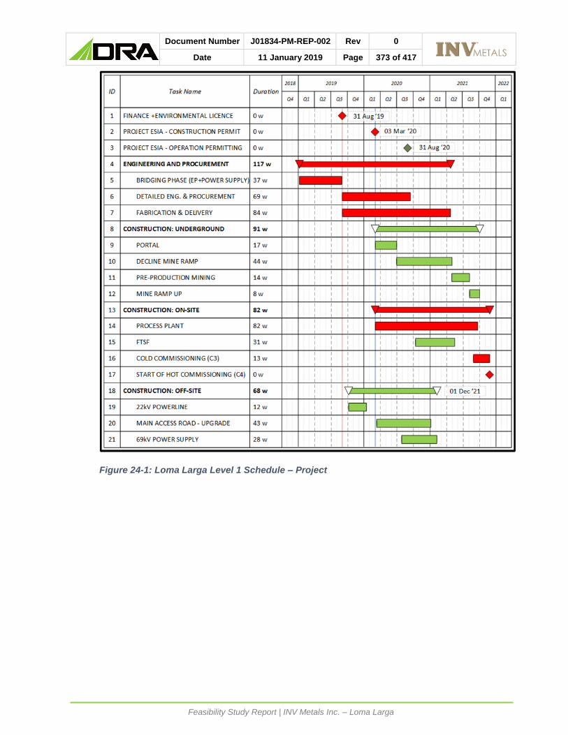
Document Number J01834-PM-REP-002 Rev 0
Date 11 January 2019 Page 373 of 417
Feasibility Study Report | INV Metals Inc. – Loma Larga
Figure 24-1: Loma Larga Level 1 Schedule – Project

Document Number J01834-PM-REP-002 Rev 0
Date 11 January 2019 Page 374 of 417
Feasibility Study Report | INV Metals Inc. – Loma Larga
Table 24-1: Loma Larga Key Milestones – Project
Activity ID Activity Forecast
MS0000GEN170 Commence Bridging Metallurgical Testwork and Site Fieldwork 07 Jan '19
MS0000ENV110 Project ESIA – EIS Submitted to MAE 28 Jan '19
MS0000GEN450 Commence Bridging Phase Engineering & Procurement 01 May '19
MS0000ENV120 Project ESIA – Approval – Environmental License 20 Aug '19
MS0000GEN210 Financing in Place 31 Aug '19
MS0000GEN220 Start Detailed Engineering - Process Plant 01 Sep '19
MS0000GEN370 Major Equipment Packages Awarded (Front End, Mills, Flotation, Thickeners, Filter Presses, 69kV S/G, Power TX, WTP)
01 Dec '19
MS0000GEN530 22kV 2.5MVA Off-Site Transmission Line Complete 31 Jan '20
MS0000GEN540 Start Mobilizing Contractor: Earthworks and Access Road Construction 01 Apr '20
MS0000ENV130 Project ESIA – Construction Permitting Complete 03 Mar '20
MS0000GEN460 Start Mobilizing Contractor for Mine Portal Construction 01 Mar '20
MS0000GEN480 Start Earthworks and Main Access Road Construction 01 Apr '20
MS0000GEN410 22kV 2.5MVA Power Available 31 May '20
MS0000GEN300 Substantial Engineering Completion (95%) 30 Jun '20
MS0000GEN470 Start Concrete Construction 01 Jul '20
MS0000GEN550 69kV – Approvals from CENTROSUR to commence construction 31 Jul '20
MS0000GEN400 Start FTSF Construction 01 Nov '20
MS0000GEN430 Main Access Road Complete 31 Jan '21
MS0000GEN420 Energizing 69kV Power Supply Switchyard 31 Mar '21
MS4110TSF100 FTSF Completed to 2 Year Level (Ready for Tailings Deposition) 31 May '21
MS0000GEN390 Achieve Construction Completion (C1/C2) - Process Plant 30 Sep '21
MS0000GEN260 Achieve Cold Commissioning (C3) Completion - Process Plant 30 Nov '21
MS0000GEN280 Commence Hot Commissioning (C4) - Process Plant 01 Dec '21
The lead time for long lead equipment critical or near critical is shown in Table 24-2 with the
duration from award to delivered at site. The equipment lead times were based on budgetary
quotes obtained during the feasibility study and include for shipping to site.

Document Number J01834-PM-REP-002 Rev 0
Date 11 January 2019 Page 375 of 417
Feasibility Study Report | INV Metals Inc. – Loma Larga
Table 24-2: Loma Larga- Lead Time Long Lead Equipment
Activity ID Weeks
Mining Equipment (Ramp) 28
Ball Mill 54
MV Equipment 50
Thickeners 45
Water Treatment Plant 44
Flotation Equipment 44
Regrind Mills 38
Front End Equipment 34
Filter Press 28
24.1.3 BRIDGING PHASE
The bridging work will focus on testwork, fieldwork and front-end engineering to de-risk the
execution phase and activities on the critical path, and initiate procurement activities for most
critical activities.
• Testwork to support process design refinement (gaps, vendor testwork and value
engineering), will be concluded prior to detailed engineering to minimize rework or delays
in detailed engineering.
• Fieldwork: predominantly geotechnical in the FTSF and process plant areas; geochemical
and hydrogeological studies ongoing for the FTSF scope; ongoing geochemical testwork
of waste and ore from the underground mine; and suitability of rock to be excavated and
used for construction rock fill for the process plant and FTSF areas.
• Select engineering will be conducted ahead of the detailed engineering phase as follows:
• Update design based on metallurgical data results: Process Design Criteria, Process
Flow Diagrams, mechanical and electrical equipment lists, electrical single line
diagram).
• Prepare datasheets and technical specifications for all long lead and critical process
equipment.
• Layout optimization.
• Further Water Balance work - recycling for pH control and clean feed / buildup.
• Prepare site samples and conduct testwork for water treatment.
• Review recirculation loop required for pressure filtration circuits (notable tailings).
• During the early phase external consultants will be engaged for the following:
• Commence detailed engineering for the 69kV supply including review of quality of grid
power supply for main and emergency power. The approvals and permitting process
through CENTROSUR will follow during detailed engineering.
• Prepare the design criteria and start the approvals process for the access road.
• This phase will also include interfacing with land owners.
• Procurement and contracts activities will commence during the bridging phase for critical
equipment and construction contracts:
• Issue critical equipment bids.
• Prepare the construction bid for mine portal construction.
• Prepare the construction bid for the earthworks (process plant and tailings facility).
• Engage local engineering companies for in-country detailed engineering.

Document Number J01834-PM-REP-002 Rev 0
Date 11 January 2019 Page 376 of 417
Feasibility Study Report | INV Metals Inc. – Loma Larga
• Engage local market for prefabricated administration facilities and mining offices.
• Initiate the process to registering or declaring the entire plant as a “functional unit” as
described in Section 11.3.1 and the Technical Report.
24.1.4 PROJECT MANAGEMENT
The Project will be established as an integrated Owner-engineering team to minimize project
administration and management roles required to oversee and direct the engineering,
procurement, and construction. The organization chart is presented in Figure 24-2.
Key Project roles include:
• Owner’s Project Manager will provide guidance to the team, will support the EPCM Project
Manager and report back to INV management.
• EPCM Project Manager will provide direction to the team, is responsible for all project
phases and accountable for activities, including detailed engineering, procurement,
logistics, construction, commissioning, and project controls.
• Project Engineer: oversee, coordinate and integrate consultant and engineering, design
and drawing activities.
• Contracts administration will be established in Toronto and transition to site for the
oversight of the fabrication and construction. The site-based team will establish and
mange the contracts in Spanish. Expediting and quality control will report into contracts
administration.
• Procurement will be based in Toronto during engineering phase and transition to site
during delivery and installation.
• Project controls will develop, maintain and control: planning (forecasting, scheduling and
Earned Value reporting), estimating, cost control, QA/QC and document control. Project
controls will compile all project and cost reporting and change control.
• The Construction Manager will be responsible for construction safety, progress, and
quality. The construction management team will coordinate and manage all site activities
to ensure construction progresses on schedule and within budget.
• A core team of process, mechanical, electrical and control engineers will provide the
commissioning management. They will be supported by construction and will be
responsible for the handover of process and infrastructure systems to the owner.
Construction contractors will be responsible to achieve mechanical completion and pre-
commissioning. On successful completion of commissioning, the transfer of care,
custody, and control of completed systems will be formalized to the operations team.
• The Construction Manager will retain control until formal handover of each system is
completed (progressive handover).
• Owners operations team will be integrated into the construction and commissioning
phases for smooth transition. Operations electrical, instrumentation and software
technicians will be required to support the respective construction activities. Key
resources from the integrated EPCM team will be transition over to the Owner’s team
where skill set is appropriate (e.g.: HSEC, field engineering, finance, IT, administration).

Document Number J01834-PM-REP-002 Rev 0
Date 11 January 2019 Page 377 of 417
Feasibility Study Report | INV Metals Inc. – Loma Larga
Figure 24-2: Project Management Organization Chart

Document Number J01834-PM-REP-002 Rev 0
Date 11 January 2019 Page 378 of 417
Feasibility Study Report | INV Metals Inc. – Loma Larga
24.1.5 ENGINEERING
The engineering team will be established with the main execution centres of Canada and
Ecuador. The core engineering will be carried out in Canada which will be responsible to
coordinate the detailing activities carried out in Ecuador, plant layout and scope definition for
on-site and off-site plant and infrastructure; managing and integrating the scope between
EPCM, vendors and external consultants, 3D model and coordination of certified vendor data
in order to maintain effective quality and control of the work and minimize execution phase
costs.
During execution the following detailed engineering scope will be awarded to consultants:
• FTSF associated water diversion and collection structures.
• 69kV overhead powerline from Girón to mine site including permitting and construction.
• Site access road including permitting and construction.
• Paste backfill plant including equipment supply.
• Water treatment plant including equipment supply.
• Local engineering companies will be contracted for part of the design and detailing to local
standards and produce all deliverables in Spanish.
• Construction contracts will include shop drawing detailing be provided by the respective
local contractors for their scope.
INV will retain overall control and responsibility for the design to ensure design integrity and
conformance to the process design and functional specification and to integrate the overall
scope into a successfully constructed, commissioned and operating facility.
Pre-assembly and modularization will be developed during detailed engineering.
24.1.6 PROCUREMENT
During the FS, the major equipment was tendered on budget pricing basis.
The Procurement Operating Plan (POP) will identify all equipment, construction and services
contracts required for the execution of the Project.
The procurement team will be established in Toronto to manage all equipment procurement
with close interface to the engineering team and will transfer to Ecuador. During project setup
the preferred suppliers list and the minimum level vendor quality surveillance / inspection
recommended for each package will be prepared and issued to the Owner for approval.
Procurement activities will be executed to EPCM and Owner policies and procedures, will be
auditable, and will comply with ethical, anti-bribery and anti-corruption practices, and will
follow competitive bidding process. Preference for vendors with local presence, local or
regional support will form part of the bid evaluation and adjudication criteria.
The Project Engineer will focus on coordinating the larger engineering scope contracts (FTSF,
access roads, overhead powerline, paste backfill plant and water treatment plant).
24.1.7 CONTRACTS ADMINISTRATION
Contracts administration will be set-up in Toronto to develop the major contracts. A contracts
administration team will be established in-country to coordinate the local contracts and
develop and translate contracts into Spanish.
During the FS the contract basis was developed as follows:

Document Number J01834-PM-REP-002 Rev 0
Date 11 January 2019 Page 379 of 417
Feasibility Study Report | INV Metals Inc. – Loma Larga
• A bespoke short form contract was developed (not used during the FS) and is intended to
be used for small construction contracts and contracts for services on-site (includes
minimum HSEC criteria for provision of construction activities on site).
• FIDIC Red Book (FRB) was developed based on DRA experience and customized based
on INV input and INV in-country legal opinion. This contract was issued with the requests
for tender during the FS to contractors as the contract basis for pricing. FIDIC contract
terms are internationally recognised standard construction contracts developed by the
International Federation of Consulting Engineers. The FIDIC Red book contract form is
for reimbursable contracts where the engineering is provided by the Owner. It is titled
“Conditions of Contract for Construction for Building and Engineering Works Designed by
the Employer”.
The major construction contracts identified during the FS are shown in Table 24-3.
Construction procedures will deal with contractor pre-qualification, criteria for local content,
and local labour; health and safety culture and performance. The Owner will leverage the
skills developed with the EPCM team for key administrative, management and technical
(engineering) personnel.
Table 24-3: Major Construction Contracts – Bid in Feasibility Study
Package Description
A-100 Advanced Exploration Ramp
C-100 Bulk Earthworks and Plant Roads Construction Contract
Filtered Tailings Storage Facility
C-101 Buildings
C-102 Water Treatment Plant
C-103 Steel, Platework Supply-Install, Mechanical Install
C-104 EC&I Installation (Electrical, C&I)
C-106 Off-site Electrical
C-112 Civil Construction Contract
C-113 Pre-Production Mine Development
C-202 Logistics
24.1.8 CONSTRUCTION EXECUTION STRATEGY – PORTAL AND RAMP
The construction of the mine portal will be executed with a local contractor and will be followed
by the ramp development which will be executed by the Owner.
24.1.9 INSURANCE
The project execution phase will consider an overall project specific “Owner Controlled
Insurance Program” (OCIP) to cover the most significant insurable risks for purchased
equipment and construction contracts and will include cover for: public and general liability,
builders’ risk, marine cargo, excess liability, and professional liability. The construction
contractors will cover insurance up to a limit specified in the contract.
24.1.10 CONSTRUCTION EXECUTION PLAN
The key schedule considerations for the construction phase include:

Document Number J01834-PM-REP-002 Rev 0
Date 11 January 2019 Page 380 of 417
Feasibility Study Report | INV Metals Inc. – Loma Larga
• The critical path for construction goes through the earthworks, and the contract award will
target contractor mobilization occurring in parallel with finalizing the construction permit
such that construction can commencing soon after permits are in place.
• Construction activities for major third-party packages (FTSF, paste plant and water
treatment plant) will be scheduled with similar construction activities occurring at the same
time as the process plant facilities.
• Off-site infrastructure is scheduled to coincide with project objectives, i.e. access road:
construction to commence after construction permits are in place; 22kV off site
transmission line is scheduled to commence on finance being available and ahead of
permits being in place as the line will be installed on existing infrastructure; and the 69kV
off-site transmission construction to commence on permits being in place and approvals
from CENTROSUR, and ready for process plant commissioning of the heavy equipment
(notably the mill).
The main objectives of the construction execution plan for the Loma Larga Project include:
• Goal of zero harm (personnel, facilities and the environment).
• Proactive safety management and broad participation to identify and eliminate hazards.
• Meet or exceed regulatory and permit requirements.
• Deliver a high-quality facility that meets or exceeds the defined project goals.
• Maintain morale and provide a respectful, positive and cooperative work environment for
all personnel and companies involved.
• Identify and remove barriers that affect progress; project reporting to encourage barrier
identification and escalation for timely attention.
• Encourage an atmosphere of positive social impact and local participation for the
immediate and surrounding communities.
• Report on the successes during construction and commissioning of the Project.
The contractor’s scope will include supply, fabrication and installation of all bulk items. The
EPCM site materials management team will coordinate with logistics for owner purchased
equipment, formal receipt on delivery and formal handover to the respective sub-contractor.
The laydown areas for equipment (EPCM team’s and/or sub-contractors’ control) and sub-
contractors’ bulk materials will be prepared on the site terrace intended for the truck
maintenance and fueling facilities.
A comprehensive Health, Safety and Environment (HSE) management plan will be developed
prior to mobilization. The HSE management plan will address overall policies, procedures,
and standards for the Project, including standard operating practices and emergency
response plans. Contractor involvement and pre-mobilization risk assessments; ongoing
supervision, incident identification, investigation and reporting.
The HSE management plan specifically address safety procedures required for the attaining
zero energy state for construction and commissioning phases with necessary procedures for
lock-out and tag-out (LOTO) including training and work permits required prior to release of
the work.
Construction quality will be managed through the implementation of a Site Quality Control
Plan (SQCP), which will detail the site quality management systems to be used for all
construction activities, documentation, reporting, deficiency identification and remediation,
non-conformance. SQCP is the responsibility of the field engineering team, and will act to
verify that quality control is being performed by the contractor, subcontractor, laboratory, and
third-party inspection services.

Document Number J01834-PM-REP-002 Rev 0
Date 11 January 2019 Page 381 of 417
Feasibility Study Report | INV Metals Inc. – Loma Larga
Construction team will establish the punch list system which is used during construction and
commissioning phases, to ensure quality of the works, identification of deficiencies and
prioritizing safety and process critical items and as record for ongoing contractor warranty
items to be addressed.
24.1.11 CONSTRUCTION QUANTITIES
The estimated quantities for the major bulk / commodity works for the Project based on the
FS engineering design and capital estimate are shown in Table 24-4.
Table 24-4: Bulk Quantity Summary
Package Unit Quantity
Bulk Earthworks m3 2,469,450
Detail Earthworks m3 35,368
High Density Polyethylene (HDPE) liner m2 356,011
Concrete m3 11,747
Structural Steel tonne 1,051
Buildings m2 17,000
Mechanical equipment tonne 860
Mechanical equipment No. of tags 240
Platework tonne 522
Power cable m 101,885
Instrument cable m 50,308
The bulk commodity quantities for the process plant are set out in Table 24-5 below.
Table 24-5: Bulk Commodity Quantities for Process Plant
Description Quantity Unit Preliminary Engineering %
Estimated % Factored %
Bulk Earthworks 409,648 m3 100 0 0
Detail Earthworks 22,061 m3 100 0 0
Concrete 8,142 m3 100 0 0
Structural Steel 724 tonne 100 0 0
Architectural Buildings 8,277 m2 100 0 0
Platework 416 tonne 100 0 0
Electrical 101,885 m 62 0 38
Instrumentation 50,308 m 62 0 38
Piping 0 0 0 0 100
24.1.12 COMMISSIONING PLAN
The Loma Larga Project will be commissioned progressively by subsystems using EPCM
contractor standard procedures. The standard steps are typically:
• Construction activities carried out by the construction contractor include construction
completion (C1 certificates) and pre-commissioning (C2 certificate) checks completed
proving the equipment operates correctly, ready for cold commissioning.

Document Number J01834-PM-REP-002 Rev 0
Date 11 January 2019 Page 382 of 417
Feasibility Study Report | INV Metals Inc. – Loma Larga
• Cold / wet commissioning involves the functional testing of equipment by the EPCM
commissioning team; equipment is considered live and all necessary controls are in place
for LOTO. Safe practices from construction procedures for safe access and controlled of
activities and safe work permits will be strictly enforced. On completion the cold
commissioning sub-area acceptance certificate (C3 certificate) and the taking over
certificate are issued which results in the transfer of care, custody and control to the
operations team for the respective sub-system.
• Hot commissioning (first feed) is carried out by of operations supported by construction
and commissioning personnel as needed on a sub-system.
• Punch list process will be maintained through out the commissioning cycle.
• Commissioning and turnover activities present significant safety risks and all necessary
LOTO procedures will be in place, notably where construction, commissioning and
operations may be working in common areas (centralized switchyard for example).
24.2 RISK
During the Feasibility study, the risk management process was initiated. Project risk and
HAZOP (Hazard and Operability) review sessions were concluded.
The most significant risks identified for the execution phase are shown in Table 24-6 (ranked
high, no risks were ranked in extreme category). The findings of the risk review and HAZOP
were addressed in the FS and Project Execution Plan.

Document Number J01834-PM-REP-002 Rev 0
Date 11 January 2019 Page 383 of 417
Feasibility Study Report | INV Metals Inc. – Loma Larga
Table 24-6: Loma Larga – Feasibility Study Risk Register – Major Risks
Risk Impact Mitigation Level
FTSF dam failure • Personal injury or death
• Contamination of environment
• Remediation cost
• Loss of social and / or regulation license
possible
• Embankment design is technically very conservative (assumes no strength in tailings)
• Filtered tailings has less water runout than conventional design
• Conservative operating strategy
• Robust closure plan
• Robust dam monitoring program and emergency response plan
• Ability to improve design with operational experience
• More work required in detailed engineering phase
10
Oxidation of ore on stockpiles
• Reduced recovery or increased OPEX or both
• Production schedule / mine plan to minimize time on stockpile
• Plan to develop stopes and drill production holes and blast as ore required
• Issue more important in enargite
• Will do testwork to understand timing and
magnitude of issue
• More work in bridging phase
9
Geotech drilling not complete due to permit issues
• Could impact CAPEX
• Critical to FTSF design
• Critical to plant foundation design
• May need more clean
rock for site works
• More PAG to deal with
• Drilling required as soon as permit available
• Local quarry available with 400,000 M3 capacity (NAG)
• More PAG can go underground
• Work will be completed during bridging or
detailed engineering
8
Political climate • Schedule risk
• Cost risk
• Could slow or stop project
• Continue very good social programs and community engagement
• Continue continuous engagement at all levels of
Government
• Continue monitoring all mining issues in-country and keep pulse of community and political leaders
8
Lack of hydrogeological information at FTSF
Incomplete groundwater data collection due to
permit issue
• Delay in permits / regulatory approvals could impact CAPEX
and OPEX
• If acidic conditions found could need larger water
treatment facility
• Drilling and studies to be completed as permits available
• Diversion of more water may be helpful
• Mitigation could include removal of PAG rock or
covering with concrete or clay cover
• To be completed in bridging phase
7
Spanish translation for the local procurement
packages
• Delay bids
• Make some contractors non-responsive
• Lead to high pricing due
to risk understanding
• All documents to be translated in bridging phase
• Procurement group to be bilingual
• Will use FIDIC contract which is already translated
• Construction group will build report with contractors during detailed engineering phase
7
Lack or poor engineering and execution if industry is busy
• Poor quality affecting schedule, CAPEX and OPEX
• Plan is to build a bridging team which will carry on to detailed engineering and construction
• Plan for expat / Ecuadorian integrated team with functional design in Canada and detailed engineering in Ecuador
• Work packages need to be sized to attract local
participation.
7

Document Number J01834-PM-REP-002 Rev 0
Date 11 January 2019 Page 384 of 417
Feasibility Study Report | INV Metals Inc. – Loma Larga
Risk management activities will continue and address Project, business and event risks
through progressive phases of the project (detailed engineering, construction, commissioning
and operations) in accordance with Owner and EPCM contractor’s procedures.
24.3 POWER LINE
The construction of a new 69 kV substation near Girón to tie-in to the existing network and
new 69 kV overhead powerline up to the mine site is described in Section 18.2 of this
Technical Report.
24.4 TRANSPORTATION AND LOGISTICS
Access to the Loma Larga Project site is adequately supported through a well-established
network of existing major ports and roadways up to San Gerardo. Various regional ports offer
bulk, roll-on, roll-off and containerized facilities. The regional infrastructure and logistics are
detailed in Section 18.11 of this Technical Report.
24.5 ACCESS ROAD
The upgrade of the road between San Gerardo and the Project site will occur in two phases
as described in Section 18.3 of this report. Phase One will consist of the enhancement and
ongoing maintenance of the existing road only (during the construction phase). Phase Two
will be the upgrade of the existing enhanced road to an agricultural/forestry class of roadway
(C3 classification).
24.6 ENVIRONMENTAL PERMITTING
The EIS started during the FS and will continue post completion of the FS.

Document Number J01834-PM-REP-002 Rev 0
Date 11 January 2019 Page 385 of 417
Feasibility Study Report | INV Metals Inc. – Loma Larga
INTERPRETATION AND CONCLUSIONS
The Loma Larga Project supports conventional mining methods and proven processing
technologies. The regional infrastructure will reasonably support all phases of the project.
INV is committed to execute all phases of the Project in a socially responsible and
environmentally sustainable manner. The underground mine and related processing
infrastructure have been designed to minimize the footprint with an estimated disturbance
area of less than 80 hectares at the Project site. The process plant design, the use of paste
backfill, and a filtered tailings disposal method will recover water for re-use in processing to
minimize the use of surface water and reduce treated water discharge.
INV plans to break ground in early 2020, with the goal of achieving first gold concentrate
production in late 2021. Project investment will provide positive social and economic impacts
locally and nationally, including new employment, training, procurement and business
opportunities throughout the region, from construction through to operations.
25.1 PROPERTY DESCRIPTION AND LOCATION
INV plans to develop and implement a well-managed land access process based on
international standards in order to facilitate reaching mutually consensual agreements with
landowners affected by the linear components of the Loma Larga project. INV expects that
doing so will mitigate the risks associated with imposing legal compulsory easements on
affected parties which could complicate the relationship with stakeholders and extend the time
to access the land.
Landowners around the access road perceive its improvement and modifications as a positive
development since it increases the value of their properties and facilitates their transportation.
INV does not estimate any major risk with the land access process for the Access Road.
INV also expects that the easement acquisition of the Transmission Line will be less sensitive
since property rights remain with the landowner with certain restrictions to the use of the land.
25.2 ACCESS, CLIMATE, LOCAL RESOURCES, INFRASTRUCTURE AND PHYSIOGRAPHY
To develop the project, the existing road will be enhanced and upgraded; and a new
transmission line will be required.
The Contecon Concession, Guayaquil Port has infrastructure and facilities to serve all other
project needs, with Manta Port supporting oversize and roll-on/roll-off cargo. The copper and
pyrite flotation concentrates will be exported from Contecon Concession at the Guayaquil Port
in bulk bags and loaded into containers.
Electrical power is to be provided via the local utility, CENTROSUR, from the local network in
Ecuador to the existing 69 kV grid near Girón. 22 kV supply from San Fernando will be
provided for construction power and emergency backup power.
25.3 GEOLOGY AND MINERAL RESOURCES
Specific conclusions for the geology and resource database related items of the Loma Larga
Project are summarized below.

Document Number J01834-PM-REP-002 Rev 0
Date 11 January 2019 Page 386 of 417
Feasibility Study Report | INV Metals Inc. – Loma Larga
• Loma Larga is a high sulphidation polymetallic epithermal deposit containing significant
values of gold, silver, and copper.
• The Loma Larga deposit is a stratigraphically controlled, flat lying, gently westward-
dipping, north-south striking, cigar-shaped body. It also dips slightly to the north, such
that the mineralized zone is closer to surface at the south end.
• The results of the quality control (QC) samples, together with the quality assurance/quality
control (QA/QC) procedures implemented by INV at Loma Larga, provide adequate
confidence in the data collection and processing, and the assay data is suitable for Mineral
Resource estimation.
• Understanding of the Project geology and mineralization, together with the deposit type,
is sufficiently well established to support Mineral Resource and Mineral Reserve
estimation.
25.4 MINERAL RESERVE ESTIMATE AND MINING METHODS
DRA has designed an underground mine with a 12-year LOM. In the early years, the mine
will produce 3,000 t/d of gold-copper and silver ore from the Loma Larga deposit, and reach
3,400 tpd in year five. The mine will be accessed by a decline and mined using conventional
mechanized transverse long-hole and drift-and-fill mining methods. Ore will be trucked to the
concentrator via a 3 km surface road.
The estimated proven and probable mineral reserves are 13.9 Mt grading 4.91 g/t Au, 29.64
g/t Ag and 0.29% Cu mining both the Main High Grade and Low Grade zones.
The Mineral reserves include dilution and ore loss and are estimated at an NSR cut-off of
US$60 NSR at stope and development levels.
Definitions for reserves categories used in this report are consistent with those defined by
Canadian Institute of Mining, Metallurgy and Petroleum (CIM) Definition Standards for Mineral
Resources and Mineral Reserves (CIM (2014) definitions) and incorporated by reference in
NI 43-101.
25.5 MINERAL PROCESSING AND METALLURGICAL TESTING
A significant amount of testwork was conducted to develop a robust and fit for purpose
flowsheet for the development of the Loma Larga process plant design. The merits of
sequential and bulk flotation flowsheets were examined during the program and analysed.
Sufficient testwork has been conducted to support the basis of the 2018 FS.
25.6 RECOVERY METHODS
The Loma Larga process plant flowsheet and design are robust and allow for the treatment
of the various ore types that will be encountered over the project LOM. It is also considered
to be conventional and fit for purpose. The design removes the requirement for acid addition
in flotation pH control, reducing both operating and capital costs. The design considers two
stages of copper cleaner flotation and one stage of pyrite cleaner flotation. However,
provision has been made in the plant design and layout for one additional copper and one
additional pyrite cleaning stage. Provision has also been made in the plant design and layout
for additional innovative flowsheet options that improve overall LOM gold recovery

Document Number J01834-PM-REP-002 Rev 0
Date 11 January 2019 Page 387 of 417
Feasibility Study Report | INV Metals Inc. – Loma Larga
25.7 PROJECT INFRASTRUCTURE
To develop the project, the existing road will be enhanced and upgraded; and a new
transmission line will be required.
Tailings production and deposition methods were evaluated, and filtered tailings was the
technology chosen.
25.8 ENVIRONMENTAL STUDIES, PERMITTING AND SOCIAL OR COMMUNITY IMPACT
The Loma Larga Project has submitted its application to move to the Economic Evaluation
phase and is currently operating within the Advanced Exploration Phase and holds the
required permits, as well as land tenure, and mining and water rights that enable INV to
perform exploratory activities in the concessions of Río Falso and Cerro Casco.
To progress to the exploitation phase, the main permit for the construction and operation of a
mining project is the Environmental License. An Environmental Impact Study (EIS) process
will be managed by the Provincial Directorate of the Ministry of Environment and Water (MAE)
in Azuay. The Environmental License will enable the Company to request and obtain other
necessary permits to start the construction, operation and closure of the Project.
INV is progressing with an EIS to Ecuadorian standards, and where feasible, to International
Finance Corporation (IFC) standards as well. Baseline data sets, and ongoing data collection,
are being used to support the development of an EIS for the Project. A stakeholder
engagement strategy should be implemented alongside the submission of the EIS.
The environmental baseline data collected to date provides a good understanding of existing
conditions, and additional baseline data collection will be obtained to strengthen datasets for
impact assessment as part of the exploitation phase EIS, potential international lender
requirements, as well to refine specific mitigation measures and provide the basis of Project
monitoring and management plans.
The applicable permits and authorizations are required for the three main components of the
Project: mine, power transmission line, and access road. INV will require a water deviation
authorization for the exploitation phase, as well as rights of way through third party mining
rights and private land for the project site, transmission line and access roads, which are not
yet in place. A land acquisition plan will be implemented for the Project linear components,
in a parallel process to the EIS submission. This approach should be confirmed with
regulators and statements of regulator support would mitigate potential concerns will
progressing parallel processes to the exploitation phase EIS.
As some of the mining and environmental legislations are relatively new, there are some
unknowns with respect to regulatory expectations for appropriate receiving water quality
criteria, and the management plans associated with protective forests. A regulatory
engagement plan is recommended to support the EIS and permitting for the exploitation
phase of the mine.
There are no communities within the mining concession area, and the perception of the
Project in the Area of Direct Influence is largely positive. This perception is based on INV’s
engagement activities and the commonly-cited Project advantages of employment and
economic resources generation. The Project’s perception in the Area of Indirect Influence is
more balanced between positive, negative and neutral. Negative perceptions are primarily
related with environmental concerns associated to impacts to water sources and

Document Number J01834-PM-REP-002 Rev 0
Date 11 January 2019 Page 388 of 417
Feasibility Study Report | INV Metals Inc. – Loma Larga
environmental pollution. These concerns have been considered in the feasibility level project
planning and will be addressed in a stakeholder engagement strategy to be implemented
alongside the EIS submission and review. Further stakeholder engagement will identify any
areas of further concern with communities in the AII about the existing design of the project
and associated infrastructure.
Disclosure of information and engagement efforts are ongoing, including a public
information campaign to increase understanding of mining activities as they relate to the
Project. In addition to these activities, INV has designed and executed small-scale
community development projects, in partnership with local communities. These community
development projects have been designed in a participatory manner to ensure they meet the
needs of local communities.
Based on the available information, there are currently no environmental and social
considerations that pose a material threat to the Project. There are areas of uncertainty, in
particular, the timeliness of approvals related to effluent water quality, baseline groundwater
conditions in the areas of the FTSF and presence of special-status species that will need to
be addressed as the project development progresses. Regulator and stakeholder
engagement plans should be implemented alongside the initiation of the EIS process, to gain
regulatory clarity and support, prevent misinformation, and identify any areas of further
concern that should be addressed as the Project develops. Permitting timelines have inherent
uncertainty and a proactive approach to regulatory and stakeholder engagement
implemented alongside the development and review of the EIS is recommended.
25.9 CAPITAL COSTS
The overall capital cost estimate was compiled by DRA and summarized in the Table 21-1
below. DRA developed the mining, process plant, plant Infrastructure and off-site
infrastructure capital cost estimates for the project scope described in this report. External
inputs were received as follows:
• NewFields prepared the construction quantities for the FTSF and DRA applied rates to
complete the capital cost estimate.
• P&C prepared the cost estimate for the past backfill system, where DRA only estimated
the bulk earthworks, concrete and structural steel.
• Owners G&A costs, taxes and duties, and closure costs were provided by INV.
All costs are expressed in United States Dollars (US$) and are based on Q3 2018 pricing.
The capital cost estimate is deemed to have an accuracy of +/-15% and was prepared in
accordance with the AACEI (Association for the Advancement of Cost Engineering) Class 3
estimating standard.
The capital cost estimated was developed based on a typical EPCM project implementation
model. Major equipment was specified, and priced quotations obtained from reputable
Original Equipment Manufactures (OEM). Construction contract packages were prepared,
issued and priced in-country by capable construction companies.

Document Number J01834-PM-REP-002 Rev 0
Date 11 January 2019 Page 389 of 417
Feasibility Study Report | INV Metals Inc. – Loma Larga
Table 25-1: Capital Cost Summary
Area US$
Direct Cost
Mining – Underground 39,784,517
Mining Surface Infrastructure 10,064,338
Process Plant 67,879,603
Waste Management 18,475,238
Plant Infrastructure 19,802,553
Off-site Infrastructure 14,497,824
Subtotal Direct Cost 170,504,074
Indirect Cost
Contractor Indirects 26,192,721
Inventory 7,008,541
Project Services 23,774,571
Vendor Rep & Commissioning 2,404,867
Owner’s Costs 17,376,883
Freight & Logistics 5,275,777
Taxes & Duties 27,571,731
Contingency 29,360,835
Subtotal Indirect Cost 138,965,926
Total Initial Capital Cost 309,470,000
Sustaining Capital Cost 72,730,000
Closure Cost 22,000,000
Total Project Capital Cost 404,200,000
The initial Project capital cost estimate by discipline is provided in Table 25-2.

Document Number J01834-PM-REP-002 Rev 0
Date 11 January 2019 Page 390 of 417
Feasibility Study Report | INV Metals Inc. – Loma Larga
Table 25-2: Initial Capital Estimate Summary by Discipline
Description Supply
US$
Install
US$
Contingency
US$
Total
US$
Underground Mining 396,973 12,395,749 4,229,241 17,021,962
Bulk Earthworks 32,621,510 4,487,870 37,109,380
Detail Earthworks 100,000 533,949 66,347 700,296
Civils – Concrete 6,939,652 753,575 7,693,226
Structural Steelwork 2,677,189 2,290,089 436,497 5,403,774
Architectural 660,810 2,422,342 114,354 3,197,506
Mechanical 59,433,709 8,701,860 3,863,240 71,998,809
Platework 1,492,001 1,482,546 290,998 3,265,545
Painting/Protection& Insulation 589,538 635,910 122,544 1,347,992
Building Services 695,000 25,000 114,354 834,354
Piping 4,393,634 3,242,852 755,223 8,391,710
Electrical 20,892,271 4,182,267 2,008,763 27,083,301
Instrumentation & Control 2,832,404 866,821 424,529 4,123,754
Indirects 59,380,700 6,670,865 66,051,565
Owners 17,376,883 1,737,688 19,114,571
Freight & Logistics 5,275,777 527,578 5,803,355
Taxes & Duties 27,571,731 2,757,173 30,328,904
Total Initial Capital Cost 94,163,527 185,945,640 29,360,840 309,470,000
The Project sustaining capital is presented in the Table 25-3.
Table 25-3: Summary of Sustaining Capital Cost
Description US$
Mining Capital 50,713,808
FTSF Capital 11,288,767
Taxes & Duties 3,358,452
VAT on Initial CAPEX 7,368,974
Total Sustaining Capital 72,730,000

Document Number J01834-PM-REP-002 Rev 0
Date 11 January 2019 Page 391 of 417
Feasibility Study Report | INV Metals Inc. – Loma Larga
25.10 OPERATING COSTS
A summary of the overall LOM project operating costs is presented in Table 25-4 and the
summary of the unit operating costs over LOM are presented in Figure 25-1. The costs
presented exclude pre-production operating cost allowances for mining, process and G&A
which were covered in the capital cost estimate. Labour rates used for the study were
provided by INV dated to 2018. Direct employment during operations will total approximately
460 people.
Table 25-4: Project Life-of-Mine Operating Costs by Major Area
Major Project Area LOM Total (US$)
LOM Unit Cost (US$/t)
Mining Cost 323,389,258 23.22
Processing Cost 239,603,848 17.20
Backfill Cost 43,708,658 3.14
Tailings Disposal 31,469,759 2.26
G&A Cost 104,951,553 7.54
Total Cost 743,123,076 53.36
Figure 25-1: Project Life-of-Mine Unit Operating Costs

Document Number J01834-PM-REP-002 Rev 0
Date 11 January 2019 Page 392 of 417
Feasibility Study Report | INV Metals Inc. – Loma Larga
25.11 ECONOMIC ANALYSIS
Based on the assumptions presented in this Report, the Project demonstrates positive
economics. The pre-tax NPV at 5% discount rate is US$621 M and pre-tax IRR is 35.1%.
The pre-tax payback period is 2.2 years after the start of production.
The after-tax NPV at 5% discount rate is US$356 M and after-tax IRR is 24.7%. The after-
tax payback period is 2.6 years.

Document Number J01834-PM-REP-002 Rev 0
Date 11 January 2019 Page 393 of 417
Feasibility Study Report | INV Metals Inc. – Loma Larga
RECOMMENDATIONS
Specific recommendations for the Loma Larga Project are summarized below for each area.
26.1 PROPERTY DESCRIPTION AND LOCATION
• Prepare and implement an easement acquisition strategy for the linear components of the
Project based on IFC guidelines.
• Further engage with the local government of San Gerardo to gain endorsement of the
process for access road land easement acquisition in order to facilitate community
acceptance.
• If required, consider minor design adjustments, particularly with respect to the
transmission line, to facilitate mutually agreed land access agreements and minimize legal
easement enforcement cases.
• Obtain detailed cadastral information of affected landowners to confirm available data
from the access road and identify the properties impacted by the power transmission line,
in order to perform the impact analysis and implement the land access strategy.
26.2 ACCESS, CLIMATE, LOCAL RESOURCES, INFRASTRUCTURE AND PHYSIOGRAPHY
• INV will engage local ports during Project execution to consider opportunities in switching
from bagged-containerized to bulk export for the pyrite concentrate; and investigate
exporting pyrite concentrate in bulk in lined containers.
26.3 GEOLOGY AND MINERAL RESOURCES
• Ensure that procedures for investigating, correcting, and documenting results of QA/QC
non-compliance issues such as biases or failures are followed for every drillhole program.
• Procure reference standards with grades that better reflect the range of gold grades within
the Mineral Resource (i.e., 2 g/t Au to greater than 30 g/t Au). RPA further recommends
that INV obtain an analytical standard for silver and another for copper that reflect the
average grades expected in the deposit, in order to quantify the accuracy of analyses.
• Complete an external check on the reference materials used on the Loma Larga Project.
• Resume the regular submission of check assays (pulp replicates) to a secondary
laboratory.
• Check half core duplicate analyses using core from the existing core library, to ensure
that the current practice of quarter-core analysis is accurate.
• Resurvey drillhole collars that deviated more than one metre above or below the
topographic surface.
• INV plans future drilling to potentially upgrade Mineral Resources from Inferred to
Indicated for inclusion in the mine plan and Mineral Reserves;
26.4 MINERAL RESERVE ESTIMATE
• Following the recommendations listed for the Mineral Resources, DRA recommends a
program of in-fill drilling be started once the ore body is reached by the ramp to better
delineate the limits of the high-grade zones and refine the limits of the ore body.

Document Number J01834-PM-REP-002 Rev 0
Date 11 January 2019 Page 394 of 417
Feasibility Study Report | INV Metals Inc. – Loma Larga
26.5 MINING METHODS
• Investigate options to obtain ultra-low sulphur diesel for the underground operation; with
benefits including: a more diversified choice from equipment manufacturers; improve
performance of underground equipment at a high elevation; and improved quality of
vehicle emissions reducing the exposure of workers to NOx or toxic gases.
• Investigate electric and battery operated mine fleet for the replacement underground fleet
in eight to nine years: technology improvements and potential affordability may result in it
being more competitive with the diesel option. This would result on an opportunity to
lower the ventilation cost for the remaining of the mine life.
• During the early design phase, investigate moving the level development into the ore body
to reduce waste development, initial and sustaining capitals expenses.
26.5.1 GEOTECHNICAL RECOMMENDATIONS
26.5.1.1 SITE CHARACTERIZATION
• Routine geotechnical mapping during construction, development and operation at Loma
Larga should be carried out.
• Data regarding ground reactions should be collected during operation as a check on the
geomechanical design assumptions. This may include:
• Damage mapping;
• Pull test data;
• Overbreak/underbreak during development and mining;
• Falls of ground; and
• Instrumentation.
• Fault projections should be updated and maintained as new drilling or underground
mapping data becomes available over the project life. Faults should be mapped when
intercepted underground to better refine their geomechanical characteristics and
behaviour.
• Updates to the geological model must be clearly communicated to engineering teams over
the project life to achieve strategic and optimized design.
26.5.1.2 STOPE DESIGN
• During early stoping, design verification should be conducted by back analysis (using the
empirical Matthews/Potvin Stability Graph Method) of observed (by CMS survey) stope
performance. This will aid in identifying opportunity for:
• Increasing stope size (where stopes have historically performed well); or
• Reducing unplanned dilution by adjusting stope dimensions (where stopes have
historically suffered from an unacceptable degree of overbreak).
• One design aspect that will require further detailed engineering will be the dimensioning
of silica pillars to maintain stability where stope backs and/or floors would otherwise
expose low quality ground (particularly intensely altered advanced argillic and propylitic
materials).

Document Number J01834-PM-REP-002 Rev 0
Date 11 January 2019 Page 395 of 417
Feasibility Study Report | INV Metals Inc. – Loma Larga
26.5.1.3 GROUND SUPPORT
Additional structural data should be acquired by routine geotechnical mapping during early
production. More detailed kinematic stability analyses are warranted once data is available
to improve confidence in joint set orientations. Joint persistence data will be very valuable for
scaling wedges for support optimization.
26.5.1.4 SWELLING CLAY
There is significant uncertainty in the ground reaction that may occur when swelling clays are
encountered. It is strongly recommended that instrumentation be utilized to closely monitor
deformations (rate and magnitude) where development is required in the susceptible units.
Ground support can then be engineered specifically for the local conditions and behaviour.
26.5.1.5 INFRASTRUCTURE SITING:
• There are a few fault structures in proximity to the planned truck load outs (additional
faults may also occur which have not been defined in the structural model). It is
understood that the ultimate location of the truck loading station is flexible. From a
geotechnical perspective, zones with minimal faulting (or where ground quality is not
significantly reduced by the presence of faults), in siliceous rock with sufficient siliceous
pillars separating the truck loading station from advanced argillic and propylitic horizons
are appropriate for these larger excavations.
• Routine geotechnical mapping of the truck load-out area is strongly recommended during
construction to ensure that ground support standards are adequate for in-situ conditions.
26.5.1.6 VERTICAL DEVELOPMENT:
• Pilot holes are strongly recommended prior to raise construction and individual raise
stability analyses should be done at the detailed design stage prior to construction.
• Relocation of raises should be considered if zones of extensive poor ground and/or
swelling clays are encountered to mitigate risk.
26.6 MINERAL PROCESSING AND METALLURGICAL TESTING
• Representative copper and pyrite concentrates, and flotation tailings samples should be
produced in sufficient quantities for filtration to be conducted by potential filtration vendors.
• Further confirmatory testwork, through the testing of additional composite and variability
samples, can improve the process design conditions. Potential upside of additional
testwork would focus on lowering capital and / or operating costs.
• Continue to develop and optimize the metallurgical relationships for gold recovery in the
pyrite and copper concentrates.
• Investigate the applicability of new innovative technologies to improve gold recoveries.
The use of SFR cells are one such example of potential opportunities, should equipment
costs become more economical.
• Ramp up to 3,400 tpd as soon as practicable (de-bottleneck process sub-systems) and
validate further increased tonnage through de-bottlenecking.
• Evaluation of processing lower grade ore to extend the mine life.

Document Number J01834-PM-REP-002 Rev 0
Date 11 January 2019 Page 396 of 417
Feasibility Study Report | INV Metals Inc. – Loma Larga
26.7 PROJECT INFRASTRUCTURE
• Infrastructure buildings such as offices, kitchens and washroom facilities to be reviewed
for suitability as modularised prefabricated units or pre-engineered structures in the final
design phase.
• Completion of tailings filtration testing to verify tailings characteristics and additional
geochemical, geotechnical and hydrogeological investigation to support the FTSF design.
• Completion of geotechnical investigation and testing to confirm suitability and design for
the selected sites for the processing facilities.
26.8 ENVIRONMENTAL STUDIES, PERMITTING AND SOCIAL OR COMMUNITY IMPACT
• Regulatory agency engagement to support the EIS, Environmental Licence and permitting
process.
• Additional hydrogeology characterization to optimize water-treatment plant design and to
provide baseline for monitoring purposes around the FTSF.
• Additional water balance and water quality modeling to better characterize potential need
for, and duration of, post-closure water treatment.
• Continuation of baseline surface water quality monitoring.
• Targeted surveys to establish the occurrence and distribution of special status species to
determine potential critical habitat.
• Continuation of seasonal baseline data collection to support monitoring and management
plans for the exploitation phase of the Project.
• Development and implementation of local employment, procurement, and training
strategies to support local hiring and developing skills.
• Complete a material balance to demonstrate that sufficient soil will be available for
reclamation purposes.
• Formalized Social Management Plan and Stakeholder Engagement Plan.
26.9 MARKET STUDIES AND CONTRACTS
• INV will engage the market and assess potential to increase payabilities of concentrates
with contracts.
26.10 OTHER RELEVANT DATA AND INFORMATION
The critical milestones for commencement of the critical activities are as follows:
• Detailed engineering and commitment for equipment procurement: finance availability.
• Construction activities: construction permit availability.
The overall project execution duration of 27 months could reasonably be reduced to 24
months if there were no restrictions between start of engineering and construction permits –
for start of construction. This can be achieved either by delaying the start of detailed
engineering until it is on critical path; or by bringing forward the construction permits.
Commence the bridging work to de-risk the execution phase and activities on the critical path,
including testwork, fieldwork, select engineering (update design and layout optimization
based on metallurgical data results), procurement and contracts activities in support of Project
critical path activities.

Document Number J01834-PM-REP-002 Rev 0
Date 11 January 2019 Page 397 of 417
Feasibility Study Report | INV Metals Inc. – Loma Larga
REFERENCES
Agency of Mining Regulation and Control – ARCOM, 2010: Integral Mining Manual.
Comprehensive Manual of Legal, Technical and Economic Procedures, 2010.
Agency of Mining Regulation and Control – ARCOM, 2014: Regulation of health and safety
at work 16, 2014.
Agency of Mining Regulation and Control – ARCOM, 2015: Instructions for the Constitution
of Right-of-way. Published by Resolution No. 045 DIR-ARCOM-2015 on December
29, 2015.
Agency of Mining Regulation and Control – ARCOM, 2016: Technical Guideline 006.
Technical guidelines of the ARCOM. Published in the Official Gazette, supplement
789 of July 15, 2016.
Arribas, A. 1995: Magmas, Fluids, and Ore Deposits. Nepean, Ont.: Mineralogical Association
of Canada.
Arribas, A. Jr. 1995: Characteristics of High-Sulphidation Epithermal Deposits, and Their
Relation to Magmatic Fluid. In Magmas, Fluids, and Ore Deposits, Ed.: J.FM.
Thompson, Mineralogical Association of Canada Short Course Vol. 23 (1995).
Astudillo, P. X., Barros, S., Siddons, D. C. and E. Zarate., 2017: Influence of Habitat
Modification by Livestock on Paramo Bird Abundance in Southern Andes of Ecuador.
Studies on Neotropical Fauna and Environment, 2017.
https://doi.org/10.1080/01650521.2017.1382122.
Barbour, M., Gerristen, J., Snyder, B. & Stribling, J., 1999: Rapid Bioassessment protocols
for use in streams and wadeable rivers: periphyton, benthic macroinvertebrates and
fish. Second Edition. EPA 841-B-99-002. Environmental Protection Agency; Office of
Water; Washington,
DChttps://www3.epa.gov/region1/npdes/merrimackstation/pdfs/ar/AR-1164.pdf
BQE 2018a: Treatment of Mine Impacted Water at Loma Larga. Engineering Design Report,
October 26, 2018.
BQE 2018b: Selenium Removal from Mine Impacted Water at Loma Larga as Project
Contingency, Addendum to Water Treatment Plant (WTP) Engineering Design,
November 7, 2018.
Canadian Dam Association 2014: Application of Dam Safety Guidelines to Mining Dams,
Technical Bulletin.
Carrascal, D. R., del Pilar Arroyave, M., Lagoueyte, M. E. G, and P. A. Z. Jaramillo, 2011:
Increased Climatic Stress on High-Andean Ecosystems in the Cordillera Central of
Columbia. In book: Climate change and biodiversity in the Tropical Andes. Edition: 1.
MacArthur Foundation, Inter-American Institute of Global Change Research (IAI) and
Scientific Committee on Problems of the Environment (SCOPE) Editors: Herzog SK,
Martínez R, Jørgensen PM, Tiessen H
Castillo, D.D, Quevedo, L. A, Gavilanes, A. V., Carrasco, J.C., Ricaurte, C. B. and S. A. Borz.,
2017: Diversity, Composition, and Structure of Andean High Forest in Ecuador, South
America. Bulletin of the Transilvania University of Brasov 10 (59) No. 2
Chiaradia, M., et al. 2004: Metal Sources in Mineral Deposits and Crustal Rocks of Ecuador,
A Lead Isotope Synthesis. In Economic Geology, v. 99, pp 1085-1106.

Document Number J01834-PM-REP-002 Rev 0
Date 11 January 2019 Page 398 of 417
Feasibility Study Report | INV Metals Inc. – Loma Larga
Chouinard, A., Williams-Jones, A.E., Leonardson, R.W., Hodgson, C.J., Silva, P., Tellez, C.,
Rojas, F. 2005: Geology and Genesis of the Multistage High-Sulfidation Epithermal
Pascua Au-Ag-Cu Deposit, Chile and Argentina. Economic Geology, 100(3), 463-490.
CIM 2014: CIM Definition Standards for Mineral Resources and Mineral Reserves, prepared
by the CIM Standing Committee on Reserve Definitions, adopted by CIM Council on
May 10, 2014.
Corbett, G. 2005: Epithermal Au-Ag Deposit Types – Implication for Exploration. In
Proceedings of Proexplo Conference Peru, 2005.
Directory of the Electricity Regulation and Control Agency - ARCONEL, 2017: Regulation for
the Distribution and commercialization of electrical energy - Regulation No. ARCONEL
005/17 of December 7, 2017. Published on December 7, 2017.
DRA Americas Inc. 2018; Loma Larga Feasibility Study Risk Register, J01834-PM-REG-001
Rev I, Nov 21, 2018.
DRA Americas Inc. 2019; Feasibility Study on the Loma Larga Project, Azuay Province,
Ecuador. Prepared on behalf of INV Metals Inc, January 2019.
ERM 2018: Proyecto Minero Loma Larga: Water Modelling Report. Prepared for INV
Minerales Ecuador S.A. by ERM Consultants Canada Ltd.: Vancouver, British
Columbia.
ERM, 2017: Review and Identification of Data Gaps of Baseline Studies for the Loma Larga
Project. Prepared on behalf of INV Metals, Inc.
Ex Ministry of Non-renewable Natural Resources, 2009: General regulation of the mining law.
Executive Decree 119. Published in the Official Register Supplement 67 of November
16, 2009. Last modification: January 04, 2017.
Ex Ministry of Non-renewable Natural Resources, 2009: Mining Law. Law 45 published in the
Official Gazette, Supplement 517 of January 29, 2009. Last modification: April 29,
2016.
Executive function of the Presidency of the Republic, 2010: Organic Code of Territorial
Organization. Law 0 published in the Official Register Supplement 303 of October 19,
2010. Last modification: January 24, 2017.
Farley, K. A. and E. F. Kelly., 2004: Effects of Afforestation of a Paramo Grassland on Soil
Nutrient Status. Forest Ecology and Management 195 (3):281-290.
Frenkel, C., Guayasamín, J. M., Yánez-Muñoz, M. H., Varela-Jaramillo, A., Ron, S. R. 2014:
Pristimantis cryophilius Anfibios del Ecuador:
https://bioweb.bio/faunaweb/amphibiaweb/FichaEspecie/Pristimantis%20cryophilius
(accessed October 3, 2018).
Gareca Leon, Edgar E., Fernadez, M., and Stanton S. 2010: Dendrochronological
investigation of the high Andean tree species Polylepis besseri and implications for
management and conservation. Biodiversity and Conservation. 19. 1839-1851.
Geosciences North Ltd. (2018) Internal Memo: Summary of Work on INV Loma Larga –
Geophysics to date. Prepared for INV Metals Limited.
Golder 2009: Assessment of Critical Hydrogeological Issues, Quimsacocha Project, Ecuador.
Prepared for IAMGold Corporation, June.

Document Number J01834-PM-REP-002 Rev 0
Date 11 January 2019 Page 399 of 417
Feasibility Study Report | INV Metals Inc. – Loma Larga
Gradstein, S. R., and S. Leon-Yanez., 2017: Liverworts (Marchantiophyta) of Polylepis pauta
forests from Ecuador with description of Leptoscyphus leoniae sp. nov. and
Plagiochila pautaphila sp. nov. Nova Hewigia published online July 2017. DOI:
10.1127/nova_hedwigia/2017/0432.
Granizo, T., Pacheco, C., Ribadeneira, M. B., Guerrero, M. y Suárez, L., 2002: Libro Rojo de
las Aves del Ecuador. SIMBIO, Conservación Internacional, EcoCiencia, Ministerio
del Ambiente, UICN. Quito, Ecuador.
Gray, M. D. 2013: QA/QC Review, Drillhole Database Inclusive of LLD-364 through 375,
Loma Larga Project, Ecuador (2013). Prepared for INV Metals Limited by Resource
Geosciences Incorporated.
Hedenquist, J.W. 2013: Update on the Loma Larga Au-Cu-Ag project, Ecuador, Report for
INV, April 2013.
Hydrocarbons Regulation and Control Agency, 2014: Instruction for Purchasing Fuels in the
Industrial Segment. Resolution of the Hydrocarbons Regulation and Control Agency.
Official registration 387 of December 02, 2014.
IAMGOLD 2008: Press Release: IAMGOLD releases Quimsacocha Pre-feasibility Study,
Positive Results Demonstrate a Solid Project for IAMGOLD, July 29, 2008, Toronto.
IAMGOLD 2008: Unpublished Pre-feasibility study, July 2008.
IAMGOLD 2009: Quimsacocha Gold Project, Azuay Province, Ecuador, a technical report
prepared by IAMGOLD Technical Services, February 16, 2009.
IAMGOLD, 2011: Auditoria Ambiental de Cumplimiento. Concesiones Mineras: Cerro Casco
y Rio Falso. Año 2011. IAMGOLD Ecuador S.A.
IFC, 2007a: International Finance Corporation Environmental, Health, and Safety General
Guidelines. World Bank Group.
IFC, 2007b: International Finance Corporation Environmental, Health, and Safety Guidelines
for Mining. World Bank Group.
IFC, 2007c: International Finance Corporation Environmental, Health, and Safety Guidelines
for Electric Power Transmission and Distribution. World Bank Group.
IFC, 2012a: International Finance Corporation Performance Standards on Environmental and
Social Sustainability. World Bank Group.
IFC, 2012b: International Finance Corporation Performance Standard 6. Biodiversity
Conservation and Sustainable Management of Living Natural Resources. World
Bank Group.
https://www.ifc.org/wps/wcm/connect/bff0a28049a790d6b835faa8c6a8312a/PS6_En
glish_2012.pdf?MOD=AJPERES. Accessed June 2018.
IFC, 2012c: International Finance Corporation Guidance Note 6. Biodiversity Conservation
and Sustainable Management of Living Natural Resources. World Bank Group.
https://www.ifc.org/wps/wcm/connect/a359a380498007e9a1b7f3336b93d75f/Update
d_GN6-2012.pdf?MOD=AJPERES. Accessed June 2018.
https://www.ifc.org/wps/wcm/connect/115482804a0255db96fbffd1a5d13d27/PS_English_20
12_Full-Document.pdf?MOD=AJPERES. Accessed November 2018.
Document Number J01834-PM-REP-002 Rev 0
Date 11 January 2019 Page 400 of 417
Feasibility Study Report | INV Metals Inc. – Loma Larga
https://www.ifc.org/wps/wcm/connect/1f4dc28048855af4879cd76a6515bb18/Final%2B-
%2BMining.pdf?MOD=AJPERES&id=1323153264157. Accessed November 2018.
https://www.ifc.org/wps/wcm/connect/554e8d80488658e4b76af76a6515bb18/Final%2B-
%2BGeneral%2BEHS%2BGuidelines.pdf?MOD=AJPERES. Accessed November
2018.
https://www.ifc.org/wps/wcm/connect/66b56e00488657eeb36af36a6515bb18/Final%2B-
%2BElectric%2BTransmission%2Band%2BDistribution.pdf?MOD=AJPERES&id=13
23162154847
Iniguez, V., 2017: Multi-scale monitoring and modelling for the analysis of the hydrologic
response of southern Ecuadorian Andean Páramos.
Loma Larga 2016/2017: Ore Characterization for Metallurgical Testing – April 12, 2017.
MacDonald, P.J., Bissig, T., Hart, C.J.R., Barreno, J., Viera, F., Mantilla, G., and Rogers, J.
2012: Hydrothermal evolution of the Rio Falso Fault, Quimsacocha High Sulfidation
Au-Ag-Cu District, Azuay Province, Ecuador. Presented to SEG conference, Lima,
Peru, September 2012.
MacDonald, P.J., Bissig, T., Hart, C.J.R., Rogers, J., Barreno, J. E., and Bell, R. C. 2013:
Magmatic evolution during flattened subduction and high-sulfidation epithermal ore
deposition: Quimsacocha volcanic center, Azuay Province, Ecuador. Presented to
SEG conference, Whistler, B.C. September 25, 2013.
MacDonald, P.J., Hart, C., Bissig, T. 2010: Field Report on the Geology of the Quimsacocha
Property, Azuay Province, Ecuador, Report for PhD at Mineral Deposit Research Unit,
University of British Columbia.
Madrinan, S., Cortes, A. J., and J. E. Richardson, 2013: Paramo is the World’s Fastest
Evolving and Coolest Biodiversity Hotspot. Front Genet 4:192
https://www.ncbi.nlm.nih.gov/pmc/articles/PMC3793228/. Accessed June 2018.
Minga, D., Ansaloni R., Verdugo, A. And C.U. Ulloa. 2016: Flora del Paramo del Cajas,
Ecuador. Universidad del Azuay. Imprenta Don Bosco. Cuenca.
Ministry of Environment, Government of Ecuador, 2004: Environmental management law.
Coding 19 published in the Official Gazette Supplement 418 of September 10, 2004.
Last modification: May 22, 2016.
Ministry of Environment, Government of Ecuador, 2008: Ministerial Agreement No. 26 of the
issues the procedures for registering hazardous waste generators, managing
hazardous waste prior to environmental licensing, and for transporting hazardous
materials. Published in Official Gazette No. 334 of May 12, 2008.
Ministry of Environment, Government of Ecuador, 2014: Environmental Regulation of Mining
Activities. Ministerial Agreement 37 published in the Official Gazette Supplement 213
of March 27, 2014. Last modification: July 12, 2016.
Ministry of Environment, Government of Ecuador, 2015: Ministerial Agreement of the Ministry
of Environment 083b, Posted on June 8, 2015.
Ministry of Environment, Government of Ecuador, 2017: Environmental Code. Official
Register: Supplement 983 on April 12, 2017.

Document Number J01834-PM-REP-002 Rev 0
Date 11 January 2019 Page 401 of 417
Feasibility Study Report | INV Metals Inc. – Loma Larga
Ministry of Mines, Government of Ecuador, 2015: Ministerial Agreement No.18 of the Ministry
of Mines- Instructions for authorizations for processing plants, smelting and tailings,
published in the Official Gazette 554 of July 29, 2015.
Ministry of Mines, Government of Ecuador, 2018: Strategic Mining Projects. PDAC 2018
Presentation. Accessed on June 28, 2018. https://www.mineria.gob.ec/wp-
content/uploads/2018/03/Strategic-Mining-Projects-2018.pdf.
Ministry of National Defense, Government of Ecuador, 1997: Regulation of the Law on arms,
ammunition, explosives and accessories. Executive Decree 169 published in the
Official Gazette 32 of March 27, 1997. Last modification: June 15, 2015.
Ministry of National Defense, Government of Ecuador, 2016: Ministerial Agreement 270 of
the Ministry of Defense. Posted on September 6, 2016.
Ministry of Public Health, Government of Ecuador, 2014: Ministerial Agreement No. 5212 that
issues the typology to standardize health establishments by levels of care and support
services of the national health system. Published by the Ministry of Public Health on
December 24, 2014.
Ministry of Public Health, Government of Ecuador, 2014: Substitute regulation for granting
permits of functioning to the establishments subject to sanitary control and
surveillance (Ministerial Agreement No. 00004712). Published on February 11, 2014.
Ministry of Public Health, Government of Ecuador, 2016: Ministerial Agreement No. 79 Issues
the sanitary regulations for the issuance of the operating permit of public and private
health facilities of the national health system, home health care services,
establishments providing indirect support services and prepaid health and medicine
companies. Published in Official Gazette No. 834 of September 6, 2016.
Ministry of Transport and Public Works, Government of Ecuador, 2013: General specifications
for construction of roads and bridges. Prepared by the Ministry of Transport and Public
Works. Volume No.3 in Quito, 2013.
Ministry of Urban Development and Housing, Government of Ecuador, 2015: Ecuadorian
Standard for Fire Construction- Code NEC-HS-CI. Published in October 2015.
Mosquera, G. M., Lazo, P. X, Celleri, R., Wilcox, B. P. and P. Crespo, 2015: Runoff from
Tropical Alpine Grasslands Increases with Areal Extent of Wetlands. Catena 125: 120-
128.
National Assembly, Government of Ecuador, 2014: Comprehensive Organic Criminal Code.
Published in the Official Register Supplement 180 of February 10, 2014.
National Congress Committee on legislation and codification, Government of Ecuador, 2005:
Civil Code. Codification 10 published in the Official Register Supplement 46 of June
24, 2005. Last modification: May 22, 2016.
National Constitution, Government of Ecuador, 2008. Published in Legislative Decree 0
through Official Register 449 of October 20, 2008. Last modified: July 13, 2011.
National Police, Ecudaor, 2008: Organic Law of Land Transport, Traffic and Road Safety.
Law published in the Official Gazette, Supplement 398 of August 07, 2008. Last
modification: December 31, 2014.
NewFields 2018: Seismic Hazard Assessment Report Loma Larga Project, Azuay Province,
Ecuador, March 30,2018.

Document Number J01834-PM-REP-002 Rev 0
Date 11 January 2019 Page 402 of 417
Feasibility Study Report | INV Metals Inc. – Loma Larga
NewFields 2018a: Technical Memorandum Rougher Tailings – Geotechnical Laboratory
Testing Summary, Loma Larga Project, 2 February.
NewFields 2018d: Technical Memorandum Site Visit Trip Report, Loma Larga Project, Azuay
Province, Ecuador, 14 May.
NewFields 2018e: Technical Memorandum Interim Results for the Geochemical
Characterization of Floatation Tailings, Loma Larga Project, Azuay Province,
Ecuador, 17 May.
NewFields 2018f: Technical Memorandum Static Test Results for Prospective Quarry Sites,
Loma Larga Project, Azuay Province, Ecuador. 15 June.
NewFields 2018g: Technical Memorandum Additional Climate Analysis, Loma Larga Project,
Azuay Province, Ecuador, 27 September.
NewFields 2018h: Technical Memorandum Water Balance – Filtered Tailings Storage
Facility, Loma Larga Feasibility Study & NI 43-101 Report, Azuay Province, Ecuador,
27 September.
NewFields 2018i: Filtered Tailings Storage Facility, Loma Larga Project Feasibility Study. 19
November.
NewFields. 2018: Technical Memorandum: Climate Analysis Loma Larga Project Azuay
Province, Ecuador. April 30, Prepared on behalf of INV Metals, Inc.
Orix Presentations on sample selection for PFS testwork program:
Met Sampling Program Update – December 19, 2016 Loma Larga Met test: DDH
Samples INV Metals – S Ramnath – August 19, 2013.
Paterson & Cooke Project #INL-32-0252, INV Metals Loma Larga Paste Backfill Feasibility
Study.
Paterson & Cooke Feasibility Study Report (32-0252-2210-GE-REP-0001).
Paterson & Cooke: Loma Larga Paste Backfill Feasibility Study – Test Work Report,
Document No. 32-0252-00-TW-REP-0010-C, Revision C, June 6, 2018.
Presidency of the Republic, Ecuador, 2007: General regulations of the Cultural Heritage Law,
2007. Published in the Decree 2733 on February 27, 2007. Last modification: April 12,
2007.
Presidency of the Republic, Ecuador, 2012: Regulation on Land Transport, Traffic and Road
Safety Law. Published by Executive Decree 1196 in the Official Gazette Supplement
731 of June 25, 2012.
Presidency of the Republic, Ecuador, 2015: Published by Executive Decree 650 in the Official
Register Supplement 483 of April 20, 2015. Regulation to the Law of Water Resources
and Use of Water.
PROMAS (Universidad de Cuenca), 2009 (March): Estudio de hidrologia - informe segundo
año. Universidad de Cuenca.
PROMAS (Universidad de Cuenca), 2011a: Informe de Edafologia. Línea Base en Hidrología
para los páramos de Quimsacocha y su área de Influencia. Universidad de Cuenca.
PROMAS (Universidad de Cuenca), 2011b: Linea Base En Hidrológia, Cuarto Año.
Universidad de Cuenca.

Document Number J01834-PM-REP-002 Rev 0
Date 11 January 2019 Page 403 of 417
Feasibility Study Report | INV Metals Inc. – Loma Larga
Promet 101, 2018, Loma Larga - Feasibility Study Metallurgical Report Rev C1, November
29, 2018.
Propaxis, 2018: Social Baseline Report for Loma Larga Project.
Propaxis, 2018: Línea Base Social Proyecto Loma Larga. Prepared on behalf of INV Metals
Inc.
Propraxis, 2018: Línea Base Social Proyecto Loma Larga. Prepared on behalf of INV Metals
Inc.
PUCE. 2018: Libro Rojo de las Plantas Endemicas del Ecuador.
https://bioweb.bio/floraweb/librorojo/home. Accessed October 2018.
Robert, F., et al. 2007: Models and Exploration Methods for Major Gold Deposit Types. In
Proceedings of Exploration 07: Fifth Decennial International Conference on Mineral
Exploration, Ed: B. Milkereit, 2007, pp 691-711.
RPA 2012: Technical Report on the Quimsacocha Project, Azuay Province, Ecuador.
Technical report prepared by Valliant, W., Masun, K., and Postle, J. for INV Metals
Inc.
RPA 2016: Technical Report on the Loma Larga Project, Azuay Province, Ecuador. NI 43-
101 Technical Report prepared by Cox J.J., Altman K.A., Masun, K., Robertson, L.,
and Diaz, C.A. for INV Metals Inc. August 29, 2016.
RPA 2018: Memorandum on the Loma Larga Geochemistry Block Model prepared by K.
Masun for INV Metals Limited.
RPA, 2016: Pre-feasibility Study on the Loma Larga Project, Azuay Province, Ecuador.
Prepared on behalf of INV Metals, Inc.
Scott Wilson RPA (2006) Technical Report on the Quimsacocha Project, Azuay Province,
Ecuador. Technical report prepared by Valliant, W., Roscoe, W.E., and Ross, D. for
IAMGOLD Corporation.
SGS Lakefield Research Limited – 2018: An Investigation into the Recovery of Gold and
Copper from Samples from Loma Larga, Project 14269-002 - Final Report – October
25, 2018.
SGS Lakefield Research Limited, 2006: An Investigation into the Recovery of Gold and
Copper from Quimsacocha Project Samples, Project 11035-001 – Report 1, May 10,
2006.
Sillitoe, R.H., 1999: Styles of High-Sulphidation Gold, Silver and Copper Mineralisation in
Porphyry and Epithermal Environments. In Proceedings Pacrim Congress 1999, Bali
Indonesia October 10-13, 1999.
SRK (2006). Quimsacocha Gold Project, Azuay Province, Ecuador, Preliminary Assessment
Report. Prepared for IAMGold Corporation, May.
Supreme Council of Government, Ecuador, 1980: Law on arms, ammunition, explosives and
accessories Published in Supreme Decree 3757 through Official Register 311 of
November 7, 1980. Last modification: March 9, 2009.
Supreme Council of Government: Regulation of Radiological Safety. Published in the
Supreme Decree 3640 of the Official Registry 891 of August 8, 1979.

Document Number J01834-PM-REP-002 Rev 0
Date 11 January 2019 Page 404 of 417
Feasibility Study Report | INV Metals Inc. – Loma Larga
Tirara, D., 2017: Guia de campo de los mamiferos del Ecuador. Ediciones Murielago Blanco.
Publicacion especial sobre los mamiferos del Ecuador 11. Quito. 600 pp.
Toivonen, J. M., Kessler, M., Ruokolainen, K., and D. Hertel., 2011: Accessibility Predits
Structural Variation of Andean Polylepis forests. Biodiversity Conservation 20:1789-
1802.
Ulloa, C.U., Molina, S.A., Jorgensen, P.M., and D. Minga. 2018. Cajas National Park Field
Guide of 100 Wild Plants of the Paramo.
http://www.missouribotanicalgarden.org/Portals/0/staff/PDFs/ulloa/GuiaPlantas.pdf.
Accessed October 2018.
UNEP-WCMC, 2016: The State of Biodiversity in Latin America and the Caribbean: A mid-
term review of progress towards the Aichi Biodiversity Targets. United Nations
Environmental Programme-World Conservation Monitoring Centre, Cambridge, UK.
Universidad de Azuay, 2017 (Diciembre): Informe Final del Monitoreo Biotico del Proyecto
Minero Loma Larga. Coordinacion Dr. Pedro Astudillo Webster, Blgo. Santiogo Barros
Q., Blgo. Boris Landazuri P. Escuela de Biologia, Ecologia y Gestion. Cuenca,
Ecuador.
Universidad de Azuay, 2018 (Febrero): Informe Final del Monitoreo Biotico del Proyecto
Minero Loma Larga. Coordinacion Dr. Pedro Astudillo Webster, Blgo. Santiogo Barros
Q., Blgo. Boris Landazuri P. Escuela de Biologia, Ecologia y Gestion. Cuenca,
Ecuador.
Western Mining Services (2018) Loma Larga Project Assessment and Targeting Study.
Confidential report prepared by Bussey, S. and Margeson, B. for INV Metals Inc.
White, N.C., & Hedenquist, J.W. (1995). Epithermal Gold Deposits: Styles, Characteristics
and Exploration. SEG Newsletter, 23, 1,9-13.
White, N.C., and Hedenquist, J.W. (1990) Epithermal Environments and Styles of
Mineralization: Variations and Their Causes, and Guidelines for Exploration, II. In:
J.W. Hedenquist, N.C. White and G. Siddeley (Editors), Epithermal Gold
Mineralization of the Circum-Pacific: Geology, Geochemistry, Origin and Exploration,
J. Geochem Exploration, 36: pp 445-474.
World Bank (1999). Solid Waste landfills in Middle- and Lower- Income Countries, A Technical
Guide to Planning, Design, and Operation, World Bank Technical Paper No. 426.
World Bank (2012). What a Waste, A Global Review of Solid Waste Management, Urban
Development Series Knowledge Papers, No. 15. March.

Document Number J01834-PM-REP-002 Rev 0
Date 11 January 2019 Page 405 of 417
Feasibility Study Report | INV Metals Inc. – Loma Larga
DATE AND SIGNATURE PAGE
This report titled “NI 43-101 Feasibility Study Technical Report” on the Loma Larga Project,
Azuay Province, Ecuador and dated January 11, 2019 was prepared and signed by the
following authors:
(Signed & Sealed) “Phildi Scholtz”
Dated at Toronto, ON
January 11, 2019
Esias P. Scholtz, Pr. Eng.
SVP Projects (DRA)
(Signed & Sealed) “Daniel Gagnon”
Dated at Montreal, QC
January 11, 2019
Daniel Gagnon, P. Eng
SVP Mining Geology and Operations (DRA)
(Signed & Sealed) “David Frost”
Dated at Toronto, ON
January 11, 2019
David Frost, FAusIMM, B. Met Eng.
VP Process Engineering (DRA)
(Signed & Sealed) “Silvia del Carpio”
Dated at Montreal, QC
January 11, 2019
Silvia del Carpio, P. Eng., MBA
Process Engineer and Financial Analyst (DRA)
(Signed & Sealed) “Katharine Masun”
Dated at Toronto, QC
January 11, 2019
Katharine Masun, P. Geo
Senior Geologist (RPA)
(Signed & Sealed) “Kathy Kalenchuk”
Dated at Toronto, QC
January 11, 2019
Kathy Kalenchuk, P. Eng.
Principal Geomechanics Consultant (MDEng)
(Signed & Sealed) “Houmao Liu”
Dated at Denver, CO
January 11, 2019
Houmao Liu, Ph. D, P.E.
General Manager, Principal Hydrogeologist (ITASCA)
(Signed & Sealed) “Paul Kaplan”
Dated at Sparks, NV
January 11, 2019
Paul Kaplan, P.E.
Partner, Principal (NewFields)
(Signed & Sealed) “Derek Chubb”
Dated at Toronto, ON
January 11, 2019
Derek Chubb, P. Eng.
Senior Partner (ERM)
(Signed & Sealed) “Leslie Correia”
Dated at Sudbury, ON
January 11, 2019
Leslie Correia, Pr. Eng.
Engineering Manager (Paterson & Cooke)

Document Number J01834-PM-REP-002 Rev 0
Date 11 January 2019 Page 406 of 417
Feasibility Study Report | INV Metals Inc. – Loma Larga
CERTIFICATE OF QUALIFIED PERSONS
Document Number J01834-PM-REP-002 Rev 0
Date 11 January 2019 Page 407 of 417
Feasibility Study Report | INV Metals Inc. – Loma Larga

Document Number J01834-PM-REP-002 Rev 0
Date 11 January 2019 Page 408 of 417
Feasibility Study Report | INV Metals Inc. – Loma Larga

Document Number J01834-PM-REP-002 Rev 0
Date 11 January 2019 Page 409 of 417
Feasibility Study Report | INV Metals Inc. – Loma Larga

Document Number J01834-PM-REP-002 Rev 0
Date 11 January 2019 Page 410 of 417
Feasibility Study Report | INV Metals Inc. – Loma Larga

Document Number J01834-PM-REP-002 Rev 0
Date 11 January 2019 Page 411 of 417
Feasibility Study Report | INV Metals Inc. – Loma Larga
Document Number J01834-PM-REP-002 Rev 0
Date 11 January 2019 Page 412 of 417
Feasibility Study Report | INV Metals Inc. – Loma Larga

Document Number J01834-PM-REP-002 Rev 0
Date 11 January 2019 Page 413 of 417
Feasibility Study Report | INV Metals Inc. – Loma Larga

Document Number J01834-PM-REP-002 Rev 0
Date 11 January 2019 Page 414 of 417
Feasibility Study Report | INV Metals Inc. – Loma Larga

Document Number J01834-PM-REP-002 Rev 0
Date 11 January 2019 Page 415 of 417
Feasibility Study Report | INV Metals Inc. – Loma Larga

Document Number J01834-PM-REP-002 Rev 0
Date 11 January 2019 Page 416 of 417
Feasibility Study Report | INV Metals Inc. – Loma Larga

Document Number J01834-PM-REP-002 Rev 0
Date 11 January 2019 Page 417 of 417
Feasibility Study Report | INV Metals Inc. – Loma Larga