
New Hybrid Fe-based MOF/polymer Composites for the ...
40
HAL Id: hal-03334725 https://hal.archives-ouvertes.fr/hal-03334725 Submitted on 4 Sep 2021 HAL is a multi-disciplinary open access archive for the deposit and dissemination of sci- entific research documents, whether they are pub- lished or not. The documents may come from teaching and research institutions in France or abroad, or from public or private research centers. L’archive ouverte pluridisciplinaire HAL, est destinée au dépôt et à la diffusion de documents scientifiques de niveau recherche, publiés ou non, émanant des établissements d’enseignement et de recherche français ou étrangers, des laboratoires publics ou privés. New Hybrid Fe-based MOF/polymer Composites for the photodegradation of organic dyes Chaima Brahmi, Mahmoud Benltifa, Cyril Vaulot, Laure Michelin, Frédéric Dumur, Effrosyni Gkaniatsou, Clémence Sicard, Aissam Airoudj, Fabrice Morlet-savary, Latifa Bousselmi, et al. To cite this version: Chaima Brahmi, Mahmoud Benltifa, Cyril Vaulot, Laure Michelin, Frédéric Dumur, et al.. New Hy- brid Fe-based MOF/polymer Composites for the photodegradation of organic dyes. ChemistrySelect, Wiley, 2021, 6 (31), pp.8120-8132. 10.1002/slct.202102194. hal-03334725
-
Upload
khangminh22 -
Category
Documents
-
view
1 -
download
0
Transcript of New Hybrid Fe-based MOF/polymer Composites for the ...

HAL Id: hal-03334725https://hal.archives-ouvertes.fr/hal-03334725
Submitted on 4 Sep 2021
HAL is a multi-disciplinary open accessarchive for the deposit and dissemination of sci-entific research documents, whether they are pub-lished or not. The documents may come fromteaching and research institutions in France orabroad, or from public or private research centers.
L’archive ouverte pluridisciplinaire HAL, estdestinée au dépôt et à la diffusion de documentsscientifiques de niveau recherche, publiés ou non,émanant des établissements d’enseignement et derecherche français ou étrangers, des laboratoirespublics ou privés.
New Hybrid Fe-based MOF/polymer Composites for thephotodegradation of organic dyes
Chaima Brahmi, Mahmoud Benltifa, Cyril Vaulot, Laure Michelin, FrédéricDumur, Effrosyni Gkaniatsou, Clémence Sicard, Aissam Airoudj, Fabrice
Morlet-savary, Latifa Bousselmi, et al.
To cite this version:Chaima Brahmi, Mahmoud Benltifa, Cyril Vaulot, Laure Michelin, Frédéric Dumur, et al.. New Hy-brid Fe-based MOF/polymer Composites for the photodegradation of organic dyes. ChemistrySelect,Wiley, 2021, 6 (31), pp.8120-8132. �10.1002/slct.202102194�. �hal-03334725�

1
New Hybrid Fe-based MOF/polymer Composites for the photodegradation of
organic dyes
Chaima Brahmia,b,c,d, Mahmoud Benltifa*c, Cyril Vaulota,b, Laure Michelina,b, Frédéric Dumur e,
Effrosyni Gkaniatsou f, Clémence Sicard f, Aissam Airoudja,b, Fabrice Morlet-Savarya,b, Latifa
Bousselmic, Jacques Lalevée* a,b
a University of Haute-Alsace, CNRS, IS2M UMR 7361, F-68100 Mulhouse, France
b University de Strasbourg, France
c Laboratory of Wastewaters and Environment, Center for Water Research and Technologies
CERTE, BP 273, Soliman 8020, Tunisia
d University of Carthage, National Institute of Applied Sciences and Technology, Tunis 1080,
Tunisia e Aix Marseille Univ, CNRS, ICR, UMR7273, F-13397 Marseille (France) f Institut Lavoisier Versailles, UMR CNRS 8180, Université de Versailles-St-Quentin-en-Yvelines, 45
Avenue des États-Unis, 78035 Versailles cedex, France
*Corresponding author: [email protected] and [email protected]
Abstract
Metals Organic Frameworks (MOFs) are promising crystalline, embrittled materials
generally produced in powdering form with varied remarkably functionalities. In contrary,
polymer are flexible and processable materials. Therefore, obtaining shaped solids gathering
polymer malleability and MOFs properties such as their photocatalytic activities, have
attracked many reasearchers attention. This work, report the successful fruitful incorporation
of two different Fe-based MOFs into a polymer matrix via a facile and cheap
photopolymerization process upon mild visible light irradiation at 405 nm. The as-prepared
photocomposites displayed excellent stability and photocalytic performance for several Acid
Black degradation cycles. Hence, approximatively, 95% of this model dye was decomposed by
the two MIL-100(Fe)/polymer and MIL-88A(Fe)/polymer composites under juste 30 min of UV
lamp irradiation. Incorporation of the MOFs into the polymer was confirmed by several
techniques including Scanning Electron Microscopy (SEM), Energy-dispersive X- ray analysis
2
(EDX), Transmission Electron Microscopy (TEM), X- Ray Diffraction analysis (DRX), Fourier-
Transform Infrared Spectroscopy (FTIR). Furthermore, these photocatalysts exhibited a high
thermal stability, excellent rigidity and low band gap energy characterized by
Thermogravimetric Analysis (TGA) Atomic Force Microscopy (AFM), Dynamic Mechanical
Analysis (DMA) and UV-Visible diffuse reflectance spectroscopy, respectively.
1. Introduction
Metal Organic Frameworks are a class of porous and crystalline materials that have
captivated attention of many researchers during the last few decades. These hybrid
inorganic/organic solids are constituted by metal or metal clusters connected in a three
dimensional structure by polyfunctional organic molecules1,2. Thanks to the countless
possible combinations between metal ions and ligands, numerous MOFs can be designed and
developed with specific properties depending on the desired applications2. Indeed, the
different flexible chemical and physical properties of MOFs including their huge surface area,
high controllable internal volume and chemical stability, have allowed their applications in
several fields such as separation processes3, biomedicine4, gas storage5, photoluminescence6
and catalysis7.
Thanks to their semiconductor’s properties, MOFs have been recently used for
removing different organic pollutants such as dyes8, pesticides9, pharmaceuticals9,10, personal
care products9 and heavy metals11 from water effluents. In fact, the photocatalytic behavior
of these materials emerges from the coordination between the metal and the oxygen of the
ligand forming metal-oxide cluster which could exhibit photocatalytic performance12. Previous
studies on MOF-5 (Zn4O(BDC)6) have demonstrated the semiconductor behvior of this MOF
which is one of the first used MOFs as photocatalysts1,13. In fact, the organic linkers, excited
under irradiation, activate the MOFs metal clusters considered as inorganic semiconductors
via linker-to-metal cluster charge transfer (LCCT)13. Previous studies on the photoluminiscence
of MOF-5 have also cofirmed the possibility of this matrial to act like photocatalyst1. Since
then, several MOFs based chrominium, titanium, aluminium and zirconium were applied in
the photocatalytic field14,15.

3
Thanks to the large earth abundance and the low-cost of the iron, Fe-based MOFS
became one of the most interesting and attrative MOFs among those reported in the literature
and used as photocatalysts14,16. Moreover, owing to the presence of the Fe-O cluster, the iron
based MOFs exhibit high absorption in visible region which make them more promising and
advantageous for phototcatalytic applications14–16. Examples of their high photocatalytic
performances were reported previously by Li et al. who compared the adsorption and
degradation of acid orange 7 via the generation of higly reactive radicals from activated
persulfate by four different MIL Fe-based MOFs17. Liang et al. have also applied the MIL-53(Fe)
as photocatalyst for the simultaneous reduction of Cr(IV) and oxidation of organic dyes,
methyl orange and rhodmine B under visible light18.
The different interesting propreties of MOFs including their large surface area, their
semiconductor behavior, their low-cost and ease of synthesis have make them very attractive
for several applications fields19. However, these catalysts are generally synthesized in powder
dispersed form with poor chemical stability and processability which limit their catalytic
applications where shaped catalysts are generally more desired. Indeed, thanks to their
enhanced mechanical properties and their resistance to high applied wastewater flow,
immobilized photocatalysts can be recycble and reuse through facile processes, avoiding then
supplementary expensive and time-consuming regeneration steps20–23. Therefore,
immobilizing MOFs into suitable matrix was an interesting solution to overcome these
catalysts disadvantages20. In this context, Chang et al. have developed a structured SiO2/MIL-
100(Fe) membrane characterized by an important catalytic efficiency for the degradation of
Rhodamine B under visible irradiation20. Thanks to polymers exceptional properties including
chemical and thermal stability as well as their flexibility and good mechanical properties,
associating them with MOFs inside or outside their pores, was also a considerable solution to
enhance the workability and the processability of these materials21,24. Indeed, Zhang et al.
have modified the surface of different MOFs by their association with PDMS layer, deposited
via a thermal process, ameliorating then the MOFs stability towards water degradation25. The
same group have also reported the hybridization of UiO-66-NH2 MOF functionalized by
methacrylate anhydride polymerizable functional groups, with butyl methacrlyate under UV
light irradiation, obtaining then an elastic membrane with enhanced separation proprties26.

4
In this study, we report the successful synthesis of a new Fe-based MOF/polymer
composites, by a facile, green and rapid post photopolymerization process, realized at
ambient temperature and withtout the release of volatil organic compounds27. The obtained
shaped hybrid materials gathered the good processability, maellability and robustenss of the
polymer as well as the remarkable photocatlytic activities of the MOFs towards the
degradation of organic pollutants when exposed to irradiation sources. This strategy
facilitated then their applications in the photocatalytic filed where high pollutant flow rate are
generally applied at the photocatalysts, and especially their recovering and regeneration
avoiding then the time-consuming steps of filtration or centrifugation usually carried out at
the end of the photocatalytic process.
The stability, surface structure, porosity, optical and mechanical properties of the
developped MOF/polymer photocomposites were fully characterized by several analytical
techniques such as Thermogravimetric Analysis (TGA), Transmission Electron Microscopy
(TEM), Scanning Electron Microscopy (SEM), Energy-dispersive X-ray analyses (EDX), X- Ray
Diffraction analysis (DRX), Fourier-Transform Infrared Spectroscopy (FTIR), BET specific
surface area, Dynamic Mechanical Analysis (DMA), Atomic Force Microscopy (AFM) and UV-
Visible diffuse reflectance spectroscopy. Furthermore, the newly developped materials exhibit
high photocatalytic efficiency for the removal of Acid Black from water under UV lamp
irradiation and without the addition of oxidatives chemicals, even after several photocatalytic
cycles. Acid Black was targeted as model dye to test the photocatalytic ability of the Fe-based
MOF/polymer composites, because of its hamrful impacts in the environment, its cariogenic
effects and its massive presence in the texitle industries sewages28,29. Degradation routes,
were also studied based on different scavenging experiments under air and under N2. Such
applications of MOFs were fewly reported in the litteratue, however these catalysts were
generally used as powdred samples, not as immobilized or shaped ones30.
2. Experimental section
2.1. MOFs synthesis
2.2. Other chemicals compounds

5
Trimethylolpropane triacrylate (TMPTA from Allnex) was chosen as monomer for composites
develeopement. Bis(4-tert-butylphenyl) iodonium hexafluorophosphate (Iod or Speedcure
938), phenyl bis(2,4,6-trimethylbenzoyl) phosphine oxide (BAPO or Speedcure BPO), used
together as a photoinitiator system, were obtained from Lambson Ltd (UK). EDTA
(Ethylenediaminetetraacetic acid), 2,2,6,6-tetramethyl-1-piperidinyloxy (TEMPO) and Acid
Black dye were obtained from Sigma Aldrich. 4-Methoxyphenol (MEHQ) and titanium dioxide
(predominantly rutile and anatase) were purchased from Alfa Aesar. Structures of the
chemicals used in this paper are represented in Figure 1.
Figure 1. Structures of the chemicals used in this work.
2.3. Photopolymerization experiments
In this study, MIL-100(Fe) and MIL-88A(Fe) MOFs were immobilized in a triacrylate monomer
(TMPTA) via a free radical polymerization process, under air and using BAPO and the iodonium
salt as a photoinitiator and co-initiator, respectively. The obtained light sensitive resins were
placed in a mold to define the final form of the composites (thickness = 1.3 mm), and irradiated
by a Light Emitting Diode LED@405 nm (I0 = 100mW/cm2). Photopolymerization conversion
Acid Black
Iodonium salt (IOD)
MIL-100(Fe) MIL-88A(Fe)
TMPTA BAPO
EDTA
MEHQ
TEMPO

6
rates were evaluated by monitoring the gradual change of the TMPTA double bond located
at 4730 cm-1 for thick samples via a real-time Fourier transform infrared spectroscopy.
2.4. Photocatalytic activity
Photocatalytic efficiency of MIL-100(Fe)/polymer and MIL-88A(Fe)/polymer composites were
investigated by Acid Black photodegradation upon an Omnicure Dynamic lamp, series 1000
lumen (I0 = 250mW/cm2, =320-520nm). The intital concentration and volume of the Acid
black were equal to 15mg/L (24.25 µmol/L) and 4ml, respectively, since the photodegradation
experiments were carried out directly in the analysis cuvette where the photocomposites
pellet were added ih the aqueous solution. pH of the solution was equivalent to 5.9.
The evolution of the model dye concentration was investigated by monitoring its aborbance
at 618 nm over time, performed by a JASCO V730 spectrophotometer. The degradation dye
rate at different irradiation times was calculated by the following formula (eq.1):
Dye conversion = (1 −𝐴𝑏𝑠 𝑡
𝐴𝑏𝑠 𝑡=0) ×100 (eq.1)
Where 𝐴𝑏𝑠 𝑡 = 0 and 𝐴𝑏𝑠 𝑡 are the measured Acid Balck absorbances before and after a given
time (t) of irradiation.
2.5. Composites stability
2.5.1. Stability in water
Swelling tests were realized by immersing composites and polymer in water for 24h. The
swelling ratio were evaluated using the following formula (eq.2):
Swelling = (Ws
Wd− 1) × 100 (eq.2)
Where Wd is the initial weight of the material and Ws is the weight of swollen material.
Also, the dry extracts of the different developed materials were calculated after the swelling
experiments by drying them in an oven at 50° C for 1h. The dry extract was estimated using
the following formula (eq.3):
Dry extract = Wsd
Wd × 100 (eq.3)
Where Wsd = Weight of dried materials after swelling.

7
2.5.2. Thermal stability
The Thermogravimetric Analysis (TGA) experiments were carried out by a TGA Mettler Toledo
TGA/DSC3+, at temperatures between 30°C to 800 °C, at heating frequency of 10 K/min under
a dry airflow of 100 mL/min.
2.6. Composites characterization
2.6.1. Morphological characterization
Morphological characterization was carried out by a JSM-7900F Scanning Electron Microscopy
(SEM) from JEOL, possessing an annular detector from DEBEN for transmission images.
2.6.2. Chemical analysis
A QUANTAX double detector from Bruker, was used to realize Energy-dispersive X-ray
analyses.
2.6.3. Composites structural characterization
X-ray diffraction experiments were carried out using a Panalytical X'Pert PRO diffractometer
equipped with a Cu X-ray tube (CuKa = 0.1542 nm) operating at 45 kV and 40 mA, and a PIXCel
detector.
Fourier transform infrared absorption patterns were obtained in the range of 650–4000 cm-1,
by a thermo scientific is-50 FTIR spectrometer, using a diamond golden gate ATR accessory
(GRASEBY) from SPECAC.
2.6.4. Composites surface topography and rigidity
Atomic Force Microscopy (AFM) technique was applied for the determination of the
roughness and the elastic modulus of the different MOF/polymer composites and the
polymer. A Bruker Multimode IV, with a Nanoscope V controller and an E “vertical” scanner
(Bruker), and a Peak Force Quantitative Nanomechanical Mapping (PF-QNM, Bruker) method
were used for AFM experiments. The concrete experimental spring constant and resonance
frequency, equal respectively to 158 N/m and 522,48 KHz were determined thanks to the
Sader method. The calibrated Tip radius was equivalent to 75 nm. More details on these
characterization technique were reported in our previous works31.

8
2.6.5. Textural properties and porosity
Porosities of the different developed materials were evaluated from nitrogen
adsorption/desorption at 77.35 K via a micromeritics ASAP 2420 instrument. Standard
Brunauer, Emmett, and Teller (BET) method were used to calculate the BET specific surface
area and average pore diameter (Gurlich law).
The samples were degassed at 25°C for 60 hours on degassing port and weighted. Then, the
samples were degassed once again at 25°C for 4 hours on the analysis port to extract the
trapped nitrogen. Analyses were realized with a reactor of the free volume to optimize the
measurement and the free volumes were determined after analysis to avoid the pollution of
the samples.
2.6.6. Mechanical properties in bulk
Bulk mechanical properties of the synthesized composites were evaluated by a DMA Mettler
Toledo DMA861e.
2.6.7. Optical properties
Reflectance measumrements of the polymer as well as the MOF/polymer composites were
carried out by UV-visible spectrophotometer (JASCO V-750) equipped with an integrating
sphere.
3. Results and discussion
3.1. Synthesis of MOF/polymer composites by photopolymerization
The different Fe-based MOF/polymer composites were synthesized by
photopolymerization technique which is the most suitable approach for immobilizing MOFs
into polymers. In fact, in contrary to the classical thermal polymerization, no heat was
necessary for initiating the polymerization reaction thus avoiding an eventual thermal
degradation of MOFs during the synthesis process. The obtained photopolymerization
conversion rates for the free radical polymerization (FRP) of TMPTA are reported in Figure 2.
9
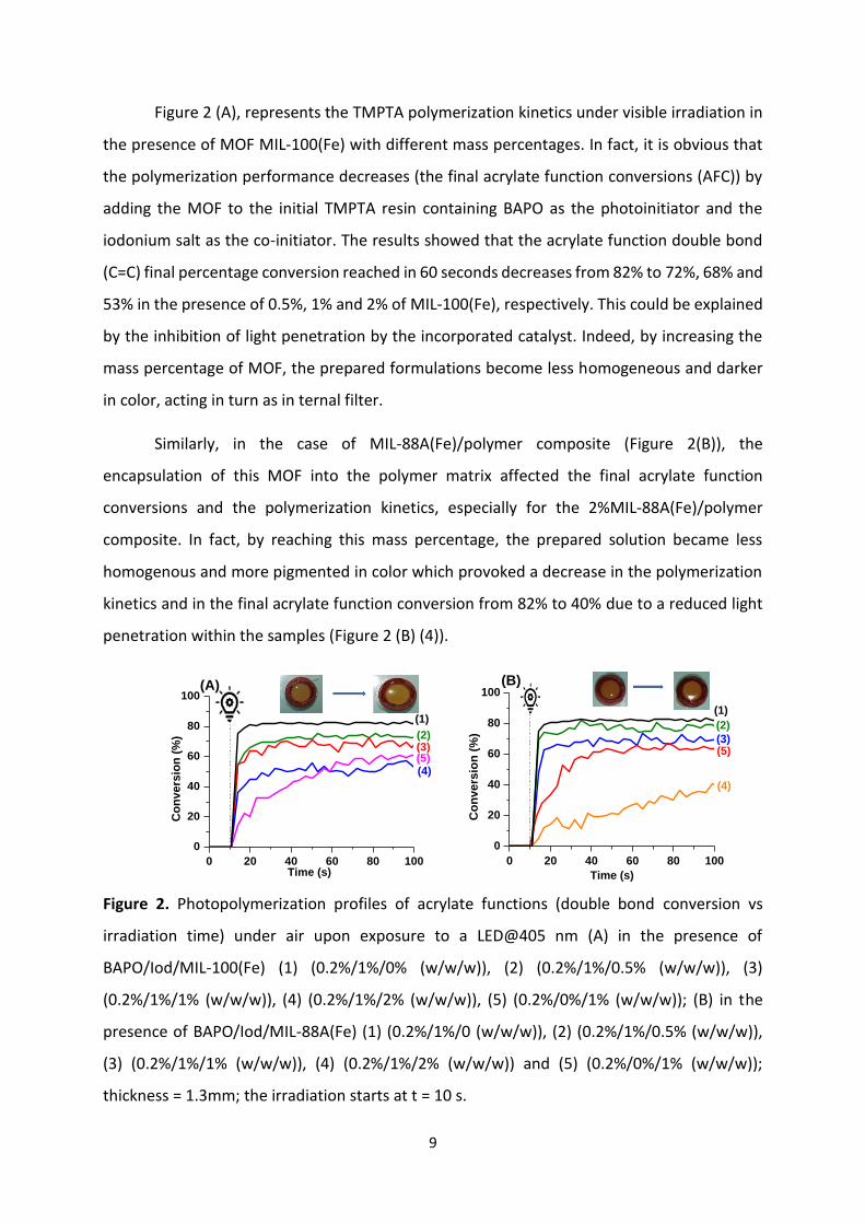
Figure 2 (A), represents the TMPTA polymerization kinetics under visible irradiation in
the presence of MOF MIL-100(Fe) with different mass percentages. In fact, it is obvious that
the polymerization performance decreases (the final acrylate function conversions (AFC)) by
adding the MOF to the initial TMPTA resin containing BAPO as the photoinitiator and the
iodonium salt as the co-initiator. The results showed that the acrylate function double bond
(C=C) final percentage conversion reached in 60 seconds decreases from 82% to 72%, 68% and
53% in the presence of 0.5%, 1% and 2% of MIL-100(Fe), respectively. This could be explained
by the inhibition of light penetration by the incorporated catalyst. Indeed, by increasing the
mass percentage of MOF, the prepared formulations become less homogeneous and darker
in color, acting in turn as in ternal filter.
Similarly, in the case of MIL-88A(Fe)/polymer composite (Figure 2(B)), the
encapsulation of this MOF into the polymer matrix affected the final acrylate function
conversions and the polymerization kinetics, especially for the 2%MIL-88A(Fe)/polymer
composite. In fact, by reaching this mass percentage, the prepared solution became less
homogenous and more pigmented in color which provoked a decrease in the polymerization
kinetics and in the final acrylate function conversion from 82% to 40% due to a reduced light
penetration within the samples (Figure 2 (B) (4)).
0 20 40 60 80 100
0
20
40
60
80
100
(2)
(4)(5)(3)
Co
nvers
ion
(%
)
Time (s)
(1)
(A)
0 20 40 60 80 100
0
20
40
60
80
100
(4)
(5)(3)
(2)
Co
nvers
ion
(%
)
Time (s)
(1)
(B)
Figure 2. Photopolymerization profiles of acrylate functions (double bond conversion vs
irradiation time) under air upon exposure to a LED@405 nm (A) in the presence of
BAPO/Iod/MIL-100(Fe) (1) (0.2%/1%/0% (w/w/w)), (2) (0.2%/1%/0.5% (w/w/w)), (3)
(0.2%/1%/1% (w/w/w)), (4) (0.2%/1%/2% (w/w/w)), (5) (0.2%/0%/1% (w/w/w)); (B) in the
presence of BAPO/Iod/MIL-88A(Fe) (1) (0.2%/1%/0 (w/w/w)), (2) (0.2%/1%/0.5% (w/w/w)),
(3) (0.2%/1%/1% (w/w/w)), (4) (0.2%/1%/2% (w/w/w)) and (5) (0.2%/0%/1% (w/w/w));
thickness = 1.3mm; the irradiation starts at t = 10 s.

10
Figure 2 ((A, B), curves (3 and 5)) show that the addition of the Iodonium salt as the co-
initiator for MIL-100(Fe)/polymer and MIL-88A(Fe)/polymer composites synthesis accelerated
the polymerization kinetics and increased the final monomer conversions. In fact, in the
absence of this chemical, the acrylate function double bond (C=C) final conversion rate
reached within 100 seconds was decreased from 67% to 61% and from 68% to 63% in the case
of the 1%MIL-100(Fe)/polymer and MIL-88A(Fe)/polymer composites.
Addition of the iodonium salt in the formulations was carried out in order to be able
to compare under the same conditions, the current results with those obtained in our previous
works on POMs/polymer composites where the presence of this co-initiator had significantly
improved the photopolymerization rates as well as the materials photocatalytic efficiency32.
3.2. MOF/Polymer composite stability
The stability in solutions and at high temperatures of the polymer as well as the synthesized
phtotocomposites were investigated in order to improve their photocatalytic applications in
the industrial field.
3.2.1. Stability in water
Heterogenous photocatalysis treatements are usually carried out in water, avoinding then the
use of supplementary chemicals. Photocatalysts should be therefore, stable in this solvent.
Consequently, swelling and dry extract ratios of the synthesized photocomposites were
calculated to evaluate their stabilities and the monomer loss probability after polymerization.
Table 1. Acrylates Final Conversion (AFC %), Swelling (%) (in water) and dry extract (%) of
different synthesized MOF/polymer composites.
AFC (%) Swelling (%) Dry extract (%)
Polymer 82 10 ± 0.02 100 ± 2
0.5% MIL-100(Fe)/polymer 79 0 ± 0.02 100 ± 2
1% MIL-100(Fe)/polymer 79 0 ± 0.02 100 ± 2
2% MIL-100(Fe)/polymer 80 0 ± 0.02 100 ± 2
0.5% MIL-88A(Fe)/polymer 80 0 ± 0.02 100 ± 2
1% MIL-88A(Fe)/polymer 77 0 ± 0.02 100 ± 2
2% MIL-88A(Fe)/polymer 71 0 ± 0.02 100 ± 2

11
The very low calculated swelling percentages as well as the large dry extract
percentages, reported in Table 1 suggest respectively a highly crosslinked acrylate network
despite the MOFs presence into the polymer and a low probability of monomer loss after the
polymerization process. This is was line with the obtained high final Acrylates Final Conversion
(AFC) proving then the excellent stability of the developed MOF/polymer composites in water.
3.2.2. Thermal stability
Thermal stability of the developed MOF/polymer composites was studied by TGA analysis.
DTG curves for the crystallite MOF, the MOF/polymer composites as well as the polymer are
shown in Figure 3. The different degradation temperatures are gathered in Table 2.
100 200 300 400 500 600-0,06
-0,03
0,00
-0,01
0,00
-0,02
-0,01
0,00
100 200 300 400 500 600
MIL-100(Fe)/polymer
1/°
C
°C
(1)
(3)
MIL-100(Fe) Powder
(2)
(A)
Polymer
100 200 300 400 500 600
-0,03
-0,02
-0,01
0,00
-0,02
-0,01
0,00
-0,02
-0,01
0,00
100 200 300 400 500 600
(1)
(2)
MIL-88A(Fe)/polymer
°C
(3)
MIL-88A(Fe) Powder
1/°
C
Polymer
(B)
Figure 3. DTG curves of (A) (1) Polymer; (2) MIL-100(Fe) powder and (3) 2% MIL-
100(Fe)/polymer composite. (B) (1) Polymer; (2) MIL-88A(Fe) powder and (3)1% MIL-
88A(Fe) /polymer composite.
The decomposition temperature of the polymer was slightly decreased by adding the
MIL-100(Fe) and the MIL-88A(Fe) MOFs to the initial resin (476 °C for the polymer vs. 446 °C
and 444°C for the composites). However, the developed photocatalysts still have high and
stable degradation temperatures for the different synthesized materials which promotes their
application in the photocatalytic industrial field.

12
Table 2. Decomposition temperatures of the polymers, the crystals MOFs and the MOF (2%
and 1%)/polymer composites.
Material Polymer MOF Powder MOF/polymer composites
MIL-100(Fe) MIL-88A(Fe) 2% MIL-100(Fe) 1% MIL-88A(Fe)
Decomposition
temperature(°C)
476 321 378 446 444
3.3. MOF/polymer composites characterization
A full characterization of the as-prepared Fe-based MOF/polymer composites
including: morphological, structural, mechanical and optical characterizations, ensures a
further understanding of the properties as well as the behavior of these materials as
photocatalysts which guarantee a better application performances for intended use in
industry.
3.3.1. Morphological and chemical characterization
Taking into account, that heterogenous photocatalysis is a phenomenon occurring at
the photocatalyst surface, the developed MOF/polymer composites morphologies were
characterized by Scanning Electron Microscopy (SEM) and Transmission Electron Microscopy
(TEM). SEM images of the polymer used as a matrix for MOFs incorporation show a
homogenous surface for the polymer film (See Figure 4 (a)).
(a)
20 µm

13
Figure 4. SEM images of (a) polymer without MOF; (b) MIL-100(Fe) powder; (d, f) 2% MIL-
100(Fe)/polymer composite at different scales; (c) MIL-88A(Fe) powder; (e, g) 1% MIL-88A(Fe)
/polymer composite at different scales. TEM images of (h) 2% MIL-100(Fe)/polymer
composite; (i) 1% MIL-88A(Fe) /polymer composite.
10 µm 100 µm
(b) (c)
100 µm 100 µm
(d) (e)
50 µm 50 µm
(f) (g)
)
50 µm
(h) (i)
)

14
It can be clearly seen from the SEM images (Figure 4(b–c)) that the two MOFs displayed
different microcrystals. MIL-100(Fe) was principally constituted of irregular flaky-like crystals33
however, MIL-88A(Fe) presents spindle-like shape crystals34. Figure 4 (d, e, f, g) represent the
heterogenous surfaces of the MIL-100(Fe)/polymer composite and the MIL-88A(Fe)/polymer
composite constituted by a randomly dispersed spherical MOFs aggregates of different sizes
varying between 10 nm and 6 µm. Also, Figure 4 (h, i) show TEM images of the MIL-
100(Fe)/polymer and MIL-88A(Fe)/polymer composites indicating the presence of these
catalysts at the polymer surface.
Moreover, Energy Dispersive X-ray (EDX) analysis was carried out in order to further
understand MOFs dispersion at the surfaces of the synthesized composites and to confirm
the immobilization of these catalysts into the polymer (See Figure 5).
(a)
Fe
(b)
Fe
(d) (c)

15
Figure 5. SEM-EDX analysis of (a, b, e) 2% MIL-100(Fe)/polymer composite; (c, d, f) 1% MIL-
88A(Fe)/polymer composite.
MEB-EDX mapping results (Figure 5(a, b, c and d)) showed an heterogenous MIL-
100(Fe) and MIL-88A(Fe) distribution into the polymer which is in agreement with the
obtained SEM images (Figure 4). Furthermore, EDX spectrums (shown in Figure 5(e, f)) confirm
also the presence in the composite of iron ions belonging to MOFs, iodonium and phosphorus
emerging from the BPO and the iodonium salt used as photoinitiator system during the
photopolymerization process, as well as carbon and oxygen coming from TMPTA monomer
and the photocatalyst.
In conclusion, TEM, SEM and EDX experiments demonstrate that MOFs are clearly well
incorporated into the polymer matrix by photopolymerization which is a mild process.
3.3.2. Structural characterization
In order to confirm the MOFs immobilization into the polymer matrix, the different
prepared composites were structurally characterized by FTIR spectroscopy and by X-Ray
Diffraction.
3.3.2.1. Fourier-transform infrared spectroscopy
In order to further verify the stability of the MOFs structure after their immobilization into the
polymer, Fourier-transform infrared (FTIR) spectra of MOFs, composites and polymer were
acquired in the 600–4500 cm−1 region and the different spectra. Results are shown in Figure
6, Table 3.
(f) (e)

16
Figure 6. (A) FTIR spectra of (a) the 2% MIL-100((Fe)/polymer composite, (b) the crystalline
MIL-100(Fe), (c) the polymer and (B) Zoom-in of 1381 cm-1 peak, (C) Zoom-in of 710 cm-1 and
759 cm-1 peaks.
Table 3. FTIR characterization of the MOF MIL-100(Fe).
MIL-100(Fe), MIL-100(Fe)/polymer composite functional groups were studied by FTIR
spectroscopy in the range of 4500cm-1 to 600 cm-1 (Figure 6, Table 3). The IR spectrum of MIL-
100(Fe) shows clear absorption at 3390, 1630, 1453, 1381, 759 and 710 cm−1.The weak
curvature at 3369 cm-1 is assigned to -OH. The peak at 1630 is attributed to v(C=O) of
carboxylate group, whereas bands at 1453 and 1381 reflect the symmetric and asymmetric
-OH stretching vibration
C=O stretching vibration
C-O symmetric stretching vibration
C-O asymmetric stretching vibration
C-H stretching/Vibration of the benzene ring
Wavenumber (cm-1)
3390 1630 1453 1381 759/710
4000 3500 3000 2500 2000 1500 10000,6
0,8
1,0
1,2
1,4
1,6
1,8
2,0759cm-1(b) MIL-100(Fe)/polymer composite
(b) MIL-100(Fe)
3390cm-1
3390cm-1
1453cm-1 759cm-11630cm
-1
1630cm-1
1381cm-1
1381cm-1
710cm-1
Tra
nsm
itta
nce
(%
)
Wavenumber (cm-1)
710cm-1
(c) Polymer
(A)
(B) (C)

17
vibrational bands characteristic of the O-C-O group respectively. Also, peaks at 759 and 710
cm−1 corresponds to C–H bending vibrations of benzene ring. These identified functional
groups of the MIL-100(Fe) are matching with those reported in the literature35,36. The FTIR
spectrum obtained after incorporating this photocatalyst into the polymer matrix shows five
absorptions bands at 3390, 1630, 1381 and 710 and 759 cm-1 among the six peaks present in
the FTIR spectra of MIL-100(Fe). The non-identification of the last one located at 1453 cm-1
could be explained by the low mass percentage of MOF in the polymer matrix which is about
2% or by their superimposition with the polymer intense peaks.
In the case of the MIL-88A(Fe)/polymer composite, the chracteristics peaks of the MOF
couldn’t be distinguished from those of the polymer because of its low mass percentage (1%)
in the polymer. Increasing the catalyst mass percentage in the TMPTA matrix wass impossible
due to the decreasing of polymerization rate (See Figure 2 (B)).
3.3.2.2. X-Ray Diffraction (XRD)
XRD analyses were carried out in order to deeply analyze the molecular structure of
composites and to get further insight on the structural variations of the catalyst after its
incorporation n into the polymer matrix (See Figure 7).
5 10 15 20 25 30 35 40 45 50 550
2000
4000
6000
8000
1800
3600
5400
72002000
4000
6000
8000
10000
5 10 15 20 25 30 35 40 45 50 55
(c) Polymer
2 Theta
(A)
(b) MIL-100(Fe)/polymer
Inte
ns
ity
(%
)
(a) MIL-100(Fe)
5 10 15 20 25 30 35 40 45 50
0
1900
3800
5700
0
14
28
42
0
86
172
258
5 10 15 20 25 30 35 40 45 50
(C) Polymer
2 Theta
(b) MIL-88A(Fe)/polymer
Inte
nsit
y (
%)
(B)
(a) MIL-88A(Fe) Powder

18
Figure 7. XRD analysis of (A) (a) MIL-100(Fe), (b) 2%MIL-100(Fe)/polymer composite, (c)
Polymer and (B) (a) MIL-88A(Fe), (b) 1% MIL-88A(Fe)/polymer composite, (c) Polymer.
The XRD diffraction pattern of the crystallite MIL-100(Fe) (as shown in Figure 7 (A(a))
exhibits different intensive peaks at: 5.26°, 6.06°, 6.32°, 6.85°, 7.11°, 10.38°, 11.03°, 12,57°,
14.22°, 20.14°, 24.11°. These sharp and intense patterns, in line with those previously reported
in the literature, indicate a highly crystalline nature of MIL-100(Fe)35,37,38.
Furthermore, the crystallographic structure of MIL-88A(Fe) was examined by XRD. As
seen in Figure 7 (B(a)), the XRD pattern of this MOF shows intense peaks at 2 Theta values of
10.5° and 11.9° already reported in the literature12,39.
Due to the low mass percentages of these MOFs in the polymer (2% and 1% w/w), their
characteristics XRD peaks were hardly identified in the XRD patterns of their corresponding
composites because of the decrease of their intensities (Figure 7 (A, B (2)). In fact, only the
most intense peaks of the MIL-100(Fe) and the MIL-88A(Fe) located at 2 Theta 10.38°, 11.03°
and of the MIL-88A(Fe) situated at 11.9° are also identified, respectively in the XRD patterns
in the MIL-100(Fe)/polymer and MIL-88A(Fe)/polymer composites indicating perhaps no
crystallinity changes during the photopolymerization process.
3.3.3. Surface properties and porosity
3.3.3.1. BET analysis
To further understand the composites catalysis behavior, it was interesting to estimate
their BET surfaces area, the adsorption average pore width and the total area in pores of the
different synthesized MOF/polymer composites. Results are gathered in Table 4.
Table 4. BET surface area and adsorption average pore width of the different MOF/polymer
based TMPTA composites and of the neat polymer.
BET surface area (m².g-1)
Adsorption average pore width (nm)
Total area in pores (m².g-1)
TMPTA polymer 9.3 ± 0.4 4.3 6.3
0.5% MIL-100(Fe)/polymer 8.8 ± 0.5 4.5 2.3

19
1% MIL-100(Fe)/polymer 3.4 ± 0.3 7.6 0.8
2% MIL-100(Fe)/polymer 5.5 ± 0.1 4.2 1.9
0.5% MIL-88A(Fe)/polymer 8.3 ± 1.4 2.4 1.6
1% MIL-88A(Fe)/polymer 4.23 ± 0.5 7.3 0.9
The pore size distribution of the neat polymer exhibiting a BET surface area of 9.3 m2.g-
1 was already reported in our previous work31. This value was decreased by the incorporation
of the photocatalysts into the polymer, which could be explained by a probable confinement
with the polymer channel31. Indeed, the Fe-based MOFs/polymer composites displayed low
BET surface areaand total area in pores ranging from 3.4 m².g-1 to 8.8 m².g-1 and from 0.8 m².g-
1 to 6.3 m².g-1, respectively. The target Fe-MOFs applied as photocatalysts, are immobilized
in the polymer whitout degassing and at ambient temperature. In this experimental
conditions, the MOFs are in non active and non-porous forms which justify the obtained low
BET surface area of the Fe-based MOFs/polymer composites. Improving BET surface area of
the developed materials is an objective which will be studied soon in our group.
3.3.3.2. Surface topography by AFM
Roughness and topography of MIL-100(Fe)/polymer composite, MIL-88A(Fe)/polymer
composite and the TMPTA neat polymer were characterized by Atomic Force Microscopy
(AFM) with the Peak-Force QNM imaging (Figure 8).
(a) (b)

20
Figure 8. AFM topography images of (a, b) the 1% MIL-100(Fe)/polymer composite and (c, d)
the 1% MIL-88A(Fe)/polymer composite.
The neat polymer exhibits a rough surface with a roughness average value (Ra)of 5 nm,
already evaluated in our previous works31. This surface property was increased to 272 nm and
189 nm by the encapsulation of MIL-100(Fe) and MIL-88A(Fe), respectively into the TMPTA
polymer (See Figure 8). The observed difference of roughness between the polymer and
MOF/polymer composites is undoubtedly due to the presence of these MOFs at the polymer
surface (see EDX data (Figure 5)). Indeed, as shown in Figure 8 (a) which corresponds to a 2D
image recorded over an area of 5 µm × 5 µm of the MIL-100(Fe)/polymer composite and in
agreement with the SEM images shown in Figure 4, MIL-100(Fe) in the form of cylindric
aggregates, is randomly dispersed at the polymer surface. Figure 8 (c) shows also the presence
of MIL-88A(Fe) aggregates at the composite surface.
For a facile collect and reuse during the photocatalytic process, photocatalysts should
be characterized by a good mechanical’s properties. Therefore, effect of the encapsulation of
MOFs into the TMPTA neat polymer, on the mechanical properties was investigated.
3.3.4. Mechanical properties
Mechanical properties of the synthesized composites were studied by AFM (Peak-
Force QNM imaging mode). Figure 9 shows the recorded topography of the elastic modulus
on the surface of the MIL-100(Fe)/polymer and MIL-88A(Fe)/polymer composites.
(c) (d)

21
Figure 9. 2D elastic modulus maps (a, b) 1% MIL-100(Fe)/polymer composite and (c, d) 1%
MIL-88A(Fe)/polymer composite recorded at different scales.
The elastic modulus distribution of the neat polymer with a mean value of 1.4 GPa was
reported in our previous work31. This material stiffness was affected by the incorporation of
the MOFs based iron. Indeed, MIL-100(Fe)/polymer and MIL-88A(Fe)/polymer composites
exhibit mean elastic modulus values of 1.5 GPa and 2.4 GPa, respectively. This change of
polymers rigidity is attributed to the MOFs crystals presence at the polymer network surface
(See Figure 8 and 9).
Additionally, to the mechanical surface property characterized by AFM, bulk
mechanical properties of the composites were evaluated by Dynamic Mechanical Analysis
(DMA) experiments. The obtained values of dynamic storage modulus G’ and dynamic loss
modulus G’’ at 25°C are presented in Table 5.
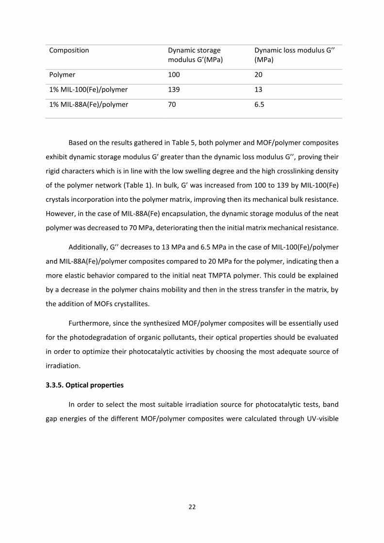
Table 5. Dynamic storage modulus (G’), dynamic loss modulus (G’’) at 25°C and Elastic
Modulus of TMPTA based polymer, 1% MIL-100(Fe)/polymer and 1% MIL-88A(Fe)/polymer
composites.
(a) (b)
(c) (d)
22
Composition Dynamic storage modulus G’(MPa)
Dynamic loss modulus G’’ (MPa)
Polymer 100 20
1% MIL-100(Fe)/polymer 139 13
1% MIL-88A(Fe)/polymer 70 6.5
Based on the results gathered in Table 5, both polymer and MOF/polymer composites
exhibit dynamic storage modulus G’ greater than the dynamic loss modulus G’’, proving their
rigid characters which is in line with the low swelling degree and the high crosslinking density
of the polymer network (Table 1). In bulk, G’ was increased from 100 to 139 by MIL-100(Fe)
crystals incorporation into the polymer matrix, improving then its mechanical bulk resistance.
However, in the case of MIL-88A(Fe) encapsulation, the dynamic storage modulus of the neat
polymer was decreased to 70 MPa, deteriorating then the initial matrix mechanical resistance.
Additionally, G’’ decreases to 13 MPa and 6.5 MPa in the case of MIL-100(Fe)/polymer
and MIL-88A(Fe)/polymer composites compared to 20 MPa for the polymer, indicating then a
more elastic behavior compared to the initial neat TMPTA polymer. This could be explained
by a decrease in the polymer chains mobility and then in the stress transfer in the matrix, by
the addition of MOFs crystallites.
Furthermore, since the synthesized MOF/polymer composites will be essentially used
for the photodegradation of organic pollutants, their optical properties should be evaluated
in order to optimize their photocatalytic activities by choosing the most adequate source of
irradiation.
3.3.5. Optical properties
In order to select the most suitable irradiation source for photocatalytic tests, band
gap energies of the different MOF/polymer composites were calculated through UV-visible

23
diffuse reflectance spectra and the results are shown in Figure 10 and in Table 6.
300 400 500 600 700 800
10
15
20
25
30
35
(4)
(3)(2)
Re
fle
cta
nc
e (%
)
(nm)
(1)(A)
300 400 500 600 700 800
10
15
20
25(3)
(2)
Refl
ecta
nce (
%)
(nm)
(1)
(B)
Figure 10. UV-Visible diffuse reflectance spectra of (A) (1) 1% TiO2/polymer composite, (2)
0.5%, (3) 1%, (4) 2% MIL-100(Fe)/polymer composites and (B) (1) the polymer, (2) 0.5% and
(3) 1% MIL-88A(Fe)/polymer composites.
Table 6. Bandgap energy values and absorption wavelengths of different synthesized
composites with polymer derived from TMPTA.
Band Gap energy (eV) (max) (nm)
Neat polymer - -
1% TiO2/polymer 3.1 396
0.5% MIL-100(Fe)/polymer 2.6 468
1% MIL-100(Fe)/polymer 2.5 488
2% MIL-100(Fe)/polymer 2.4 503
0.5% MIL-88A(Fe)/polymer 2.4 498
1% MIL-88A(Fe)/polymer 2.3 532
Table 6 shows gap energies and absorption wavelengths of the different synthesized
Fe-based MOF/polymer composites, which were compared to those of the titanium
dioxide/polymer composite. The MIL-100(Fe)/polymer and MIL-88A(Fe)/polymer composites
exhibit a band gap energy between 2.3 and 2.6 eV, weaker than that of the TiO2/polymer
composite (3.1 eV). Consequently, the developed photocatalysts are expected to be more
performant under visible light than the usually used one in photocatalysis, the TiO2.

24
Furthermore, increasing MOFs mass percentages, causes a slight decrease of
MOF/polymer composites energy bandgaps and an increase of their reflectance percentages
and therefore probably an improvement in their photocatalytic performances. Effectiveness
of these different synthesized materials for Acid Black photodegradation will be compared
below.
4. Photocatalytic activity of the Fe-based MOF/polymer composites
Photocatalytic activities of the different synthesized Fe-based MOF/polymer
composites were tested by monitoring the Acid Black absorbance recorded by UV-visible
spectrometry at different irradiation times under UV lamp irradiation. Results are shown in
Figure 11 (A, B). Adsorption performances of the photocomposites were evaluated by kepting
in the dark during 1 hour the Acid Black acqueous solutions with the photocatalysts. Almost,
no dye absorbance decreasing was noticed. This was in agreement with the low BET surface
area of the MOF/polymer composites (See Table 4).
300 400 500 600 700
0,0
0,4
0,8
1,2
Ab
so
rba
nc
e
Wavelength (nm)
0 min
15 min
30 min
45 min
60 min
Irradiation time
(A)
300 400 500 600 700
0,0
0,4
0,8
1,2
Ab
so
rba
nc
e
Wavelength (nm)
0 min
15 min
30 min
45 min
60 min
Irradiation time
(B)
0 20 40 60
0
20
40
60
80
100
(4)
(7)
(6)
(1)
(5)
(2)
Co
nvers
ion
(%
)
Time (min)
(3)
(C)
0 10 20 30 40 50 60
0
20
40
60
80
100
(6)
(5)(4)
(3) (1)
Co
nvers
ion
(%
)
Time (min)
(2)
(D)
Figure 11. UV-visible absorption spectra of Acid Black water solutions during the
photocatalytic degradation process under UV lamp irradiation in the presence of (A) 2% MIL-

25
100(Fe)/polymer composite and (B) 1% MIL-88A(Fe)/polymer composite. [AB]0 = 15 ppm, pH
= 7. Degradation plot of Acid Black (15 ppm) under UV lamp irradiation (C) in the presence of
(1) 0.5%, (2) 1%, (3) 2% MIL-100(Fe)/polymer composites, (4) 1% MIL-100(Fe)/polymer
composite without iodonium salt, (5) 1%TiO2/polymer composite, (6) neat polymer, (7)
photolysis plot of Acid black without composites and (D) in the presence of (1) 0.5%, (2) 1%
MIL-88A(Fe)/polymer composites, (3) 1% MIL-88A(Fe)/polymer without iodonium salt, (4) 1%
TiO2/polymer composite, (5) neat polymer and (6) photolysis plot of Acid black without
composites.
Obviously, the two characteristics absorbance peaks of the Acid Black located at 618
nm and 310 nm, corresponding respectively, to the azo group and to the naphtalene
transition, decreased gradually during the photocatalytic process in the presence of the MIL-
100(Fe)/polymer and the MIL-88A(Fe)/polymer composites (See Figure 11 (A, B)),. This
absorbance bands abatement reflects the dye decolorization as well as the degradation of the
aromatic part40,41. The degradation mechansim of the Acid Black, the possible formation of
by-products and the monitoring of the dye solution color changement during the
photocatalytic treatment, were discussed in ou previous works (Article MOF 1).
Kinetics of the Acid Blak photodegradation reaction by the two Fe-based MOF/polymer
composites as well as their comparaison with the TiO2/polymer composite and the neat
polymer were quantitavely studied by matching the experimental data to the apparent first-
order equation given by the following expression42 :
-Ln(C/C0) = kapp t (1)
Where C0 and C designate respectively the Acid Black initial concentration and at time
t, kapp is the first-order rate constant (min-1) and allows the evaluation of the photocatalytic
of the catalyst. Results are shown in Table S1.
Acid Black concentration is only decreased by 26 % (kapp=0.005 min-1) and 35%
(kapp=0.007 min-1), under 60 min of UV lamp irradiation in the absence of the composites or
the polymer and in the presence of the neat polymer, respectively (Figure 11 (C (curves 6, 7)),
(D (curves 5, 6))). However 95.2% of this dye is degraded in just 30 min of irradiation in the
presence of the Fe-based MOF/polymer composites proving then the remarkable
photocatalytic efficiency of the develloped photocomposites which are also more performant
26
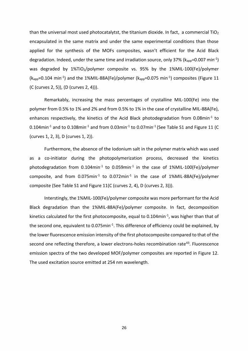
than the universal most used photocatalytst, the titanium dioxide. In fact, a commercial TiO2
encapsulated in the same matrix and under the same experimental conditions than those
applied for the synthesis of the MOFs composites, wasn’t efficient for the Acid Black
degradation. Indeed, under the same time and irradiation source, only 37% (kapp=0.007 min-1)
was degraded by 1%TiO2/polymer composite vs. 95% by the 1%MIL-100(Fe)/polymer
(kapp=0.104 min-1) and the 1%MIL-88A(Fe)/polymer (kapp=0.075 min-1) composites (Figure 11
(C (curves 2, 5)), (D (curves 2, 4))).
Remarkably, increasing the mass percentages of crystalline MIL-100(Fe) into the
polymer from 0.5% to 1% and 2% and from 0.5% to 1% in the case of crystalline MIL-88A(Fe),
enhances respectively, the kinetics of the Acid Black photodegradation from 0.08min-1 to
0.104min-1 and to 0.108min-1 and from 0.03min-1 to 0.07min-1 (See Table S1 and Figure 11 (C
(curves 1, 2, 3), D (curves 1, 2)).
Furthermore, the absence of the Iodonium salt in the polymer matrix which was used
as a co-initiator during the photopolymerization process, decreased the kinetics
photodegradation from 0.104min-1 to 0.059min-1 in the case of 1%MIL-100(Fe)/polymer
composite, and from 0.075min-1 to 0.072min-1 in the case of 1%MIL-88A(Fe)/polymer
composite (See Table S1 and Figure 11(C (curves 2, 4), D (curves 2, 3))).
Interstingly, the 1%MIL-100(Fe)/polymer composite was more performant for the Acid
Black degradation than the 1%MIL-88A(Fe)/polymer composite. In fact, decomposition
kinetics calculated for the first photocomposite, equal to 0.104min-1, was higher than that of
the second one, equivalent to 0.075min-1. This difference of efficiency could be explained, by
the lower fluorescence emission intensity of the first photocomposite compared to that of the
second one reflecting therefore, a lower electrons-holes recombination rate43. Fluorescence
emission spectra of the two developed MOF/polymer composites are reported in Figure 12.
The used excitation source emitted at 254 nm wavelength.

27
300 400 500 600 700
0
50
100
150
200
Rela
tive in
ten
sit
y
Wavelength (nm)
(1) MIL-100(Fe)/polymer composite
(2) MIL-88A(Fe)/polymer composite
(1)
(2)
Figure 12. Fluorescence emission spectra of the two different MOF/polymer composites : (1)
1%Mil-100(Fe)/polymer composite, (2) 1%MIL-88A(Fe)/polymer composite.
5. Proposed photocatalytic degradation mechanism
In order to understand the enhanced degradation mechanism of the Acid Black by the
newly developed Fe-based MOF/polymer composites, photolysis under different
atmospheres (Air and N2) and radical-trapping experiments were carried out. In this study,
EDTA44,45, isopropanol46, MEHQ47 and TEMPO48 were applied as scavengers of h+, Hydroxyl
radicals (•OH), oxygen active species (RO• and ROO• ) and carbon centered radicals,
respectively. The trappers concentrations were equal to 1Mm and their impacts on the Acid
Black photodegradation were identified by monitoring this dye concentration under UV lamp
irradiation (See Figure 13).
1 2 3 4 5 6 7
0
20
40
60
80
100
11%
96%
60.1%
28.7%
15.9%
28.8%
(7)
(6)
(5)
(4)(3)
(2)
Co
nv
ers
ion
(%
)
(1)
70%
(A)
1 2 3 4 5 6 7
0
20
40
60
80
100
(7)
(6)
(5)(4)(3)
(2)
11%
75.8%
29.5%23.3%
35%
Co
nv
ers
ion
(%
)
49.7%
12.5%(1)
(B)
Figure 13. Effects of different scavengers on the degradation of Acid Black under UV lamp
irradiation at t=15min, in the presence of (A) 2% MIL-100(Fe)/polymer composite and (B) 1%
MIL-88A(Fe)/polymer composite: (1) Without scavengers, under air, (2) Without scavengers,

28
under N2. Under air, with the addition of (3) TEMPOL, (4) MEHQ, (5) Isopropyl alcohol and (6)
EDTA. (7) Without composite, without scavengers.
Figure 13 (batons 1 and 2) proves the important role played by the dissolved oxygen in
the enhancement of Acid Black degradation in the presence of the Fe-based MOF/polymer
composites. In fact, under N2 and under 15 min of UV lamp irradiation, the Acid Black
conversion rate was decreased from 70% and 48.7% to 28.8% and 12.6% respectively, in the
presence of 2%MIL-100(Fe)/polymer and 1%MIL-88A(Fe)/polymer composites demonstrating
the significant function of •O2-, formed by the reaction between the excited e- and the O2
dissolved in the solution, during the photocatalytic process. This was in agreement with the
high Acid Black removal rates obtained after adding the EDTA into the aqueous solution.
Indeed, conversion percentages were increased from 70% to 96% and from 49.7% to 75.8% in
the presence of 2%MIL-100(Fe)/polymer and 1%MIL-88A(Fe)/polymer composites,
respectively. The enhancement of the photodegradation process in the presence of this holes
scavenger, could be explained by the inhibition of recombination between the excited
electons under UV lamp irradiation and the holes through surface and direct recombinations.
Therefore, more •O2− are formed since more migrated electons are present at the composites
surface and could react with the dissoved oxygen present in the aqueous solution. Hence, •O2−
are the most important radical species involved in the photodegradation route of the different
Fe-based MOFs/polymer composites.
Furthermore, the addition of MEHQ and isopropyl alcohol declined the dye
degradation from 70% and 49.7% to 28.7%, 60.1%, and to 23.3%, 29.5% after 15 min of UV
lamp irradiation in the presence of MIL-100(Fe)/polymer and MIL-88A(Fe)/polymer
composites, respectively (Figure 13 (A and B (batons 1, 4 and 5). The obtained results show
the oxygenated active species and the hydroxyl radicals are also implicated in the Acid Black
degradation mechanism.
Besides, in the presence of TEMPO, in the Acid Black aqueous solution, the dye
degradation was reduced from 70% and 49.7% to 16.9% and 35%, respectively, in the
presence of the 2%MIL-100(Fe)/polymer and 1%MIL-88A(Fe)/polymer composites, showing
29
that carbonated radicals participates also in the Acid Black removal route (See Figure 13
(batons 1 and 3).
Based on the trapping experiments above, the degradation mechanism of the Acid
Black by the two different Fe-MOF/polymer composites could be explained by the excitation
of electrons from the valence band (VB) to the conduction band (CB) and the formation of
holes in the VB. This phenomenon occurrs when the composites photocatalysts absorb
equivalent or higher energy than their band gap energies. The photogenerated electons
migrate to the catalyst surface and reduce the dissolved oxygen in the aqueous solution (O2)
to superoxide radicals (•O2−) which are transformed in their turn to hydroxyl radicals (•OH).
Simutaneously, holes oxidize water molecules into hydroxyl radicals (•OH). Such,
decomposition mechanisms, were already reported in the literature by Wang et al. who have
applied Fe-MOFs for the adsorption and photodegradation of tetracycline by Fe-based
MOFs14. C. Das et al. have also demonstrated the same decomposition route, when
photodegrading the methyl orange dye by an UTSA-38 MOF49.
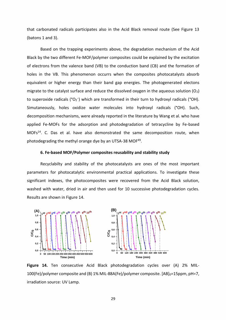
6. Fe-based MOF/Polymer composites reusability and stability study
Recyclabilty and stability of the photocatalysts are ones of the most important
parameters for photocatalytic environmental practical applications. To investigate these
significant indexes, the photocomposites were recovered from the Acid Black solution,
washed with water, dried in air and then used for 10 successive photodegradation cycles.
Results are shown in Figure 14.
0 50 100 150 200 250 300 350 400 450 500 550 600
0,0
0,2
0,4
0,6
0,8
1,09th 10th
8th7th6th5th4th3rd2nd
C/C
0
Time (min)
1st(A)
0 60 120 180 240 300 360 420 480 540 6000,0
0,2
0,4
0,6
0,8
1,010th9th8th7th6th5th4th3rd2nd
C/C
0
Time (min)
1st(B)
Figure 14. Ten consecutive Acid Black photodegradation cycles over (A) 2% MIL-
100(Fe)/polymer composite and (B) 1% MIL-88A(Fe)/polymer composite. [AB]0=15ppm, pH=7,
irradiation source: UV Lamp.

30
Figure 14 shows that the photocatalytic performance of the MIL-100(Fe)/polymer
composite starts to decrease from the 7th cycles and from the 5th cycle, in the case of the MIL-
88A(Fe)/polymer composite. Indeed, the first photocatalyst still more performant than the
neat polymer even after the seventh catalytic cycle and until the tenth process showing its
high catalytic stability by a facile and low-cost recovery and regeneration process. However,
the second one lose totally its photocatalytic efficiency starting from the ninth cycle.
Therefore, these experiments prove the advantages of the immobilization of the MOFs into
the polymer consisting in the enhancement of their mechanical properties in order to facilitate
their recovery and regeneration. Hence, usually time-consuming and expensive regeneration
methods could be avoided.
Photostability of the different developped composites were also investigated by
comparing SEM characterizations images before and after the photocatalytic process (See
Figure 15).
Figure 15 (a, b) shows, that the MIL-100(Fe)/polymer composite surface wasn’t altered
by the irradiation. Approximatively, the same MIL-100(Fe) MOFs density still present at the
surface of the polymer after the photodegradation process. However, in the case of the MIL-
88A(Fe)/polymer composite less MOFs remain at the surface which could explain the decrease
of the photocatalytic activity of this composite starting from the 5th degradation cycle. The
better stability of the MIL-100(Fe)/polymer composite during the regeneration and reuse, in
comparaison to that of the MIL-88A(Fe)/polymer composite could be probably due to its
higher dynamic storage modulus (G’) reflecting a better bulk rigidity (See Table 5).

31
Figure 15. SEM-EDX images of 2% MIL-100(Fe)/polymer composite (a) before and (b) after one
photodegradation cycle. SEM-EDX images of 1% MIL-88A(Fe)/polymer composite (c) before
and (d) after one photodegradation cycle.
(a) (b)
(c)
50 µm
(d)
50 µm

32
Conclusion
In this study, two Fe-based MOFs/polymer composites with higher photocatalytic
properties have been successfully fabricated by a simple, low-cost, rapid and green
photopolymerization process under mild visible Light Emitting Diode LED@405 nm irradiation.
The developed photocatalysts exhibited exceptional photocatalytic performances, compared
to the universal and most used one, the titanium dioxide which was applied in the same
experimental conditions than the MOFs/polymer composites. Approximatively, 95% of the
Acid Black dye, chosen as poulltant model to evaluate the photocatalytix activities of these
photocomposites was removed from water under only 30 minutes of UV lamp irradiation.
Moreover, in order to get futher insight the Acid Black degradation mechanism in the
presence of the synthesized MOF/polymer composites, several experiments were realized
under different atmospheres and in the presence of three scavangers used separately.
Dissolved oxygen seemed to be the key species for Acid Black degradation. Superoxide,
hydroxyl, oxygenated and carobonated radicals were also involved in the dye decomposition.
Characterization of the new proposed materials were fully investigated by various
methods including XRD, AFM, DMA, SEM, TEM, EDX, FTIR which have verified the fruitful MOFs
immobilization into the polymer matrix. The shaped materials displayed enhanced rigidity and
high thermal stability, allowing their recovering from the aqueous solution and their reuse by
a simple, inexpensive and rapid method. Therefore, the two composites remain
photocatlytically actifs under UV lamp irradiation after several degradation process.
In conclusion, associating MOFs with polymers simplified and facilitated their
tecnological environemental applications, by obtaining composites gathering at the same
time, the processability of the polymer and the interesting photocatalytic activity of the MOFs.
This method of synthesis have proved its effectiveness in this work, and could then be used to
immobilize a large number of other photocatlysts. Further studies will be carried out in order
to improve the polymer stability and to develop composites with larger active surface area.

33
Table of contents Graphic (TOC)

34
References
(1) Alvaro, M.; Carbonell, E.; Ferrer, B.; Llabrés i Xamena, F. X.; Garcia, H. Semiconductor
Behavior of a Metal-Organic Framework (MOF). Chem. Eur. J. 2007, 13 (18), 5106–5112.
https://doi.org/10.1002/chem.200601003.
(2) Nasalevich, M. A.; Hendon, C. H.; Santaclara, J. G.; Svane, K.; van der Linden, B.; Veber,
S. L.; Fedin, M. V.; Houtepen, A. J.; van der Veen, M. A.; Kapteijn, F.; Walsh, A.; Gascon,
J. Electronic Origins of Photocatalytic Activity in D0 Metal Organic Frameworks. Sci Rep
2016, 6 (1), 23676. https://doi.org/10.1038/srep23676.
(3) Carboni, M.; Abney, C. W.; Liu, S.; Lin, W. Highly Porous and Stable Metal–Organic
Frameworks for Uranium Extraction. Chem. Sci. 2013, 4 (6), 2396.
https://doi.org/10.1039/c3sc50230a.
(4) Tamames-Tabar, C.; García-Márquez, A.; Blanco-Prieto, M. J.; Serre, C.; Horcajada, P.
MOFs in Pharmaceutical Technology. In Bio- and Bioinspired Nanomaterials; Ruiz-
Molina, D., Novio, F., Roscini, C., Eds.; Wiley-VCH Verlag GmbH & Co. KGaA: Weinheim,
Germany, 2014; pp 83–112. https://doi.org/10.1002/9783527675821.ch04.
(5) Li, H.; Wang, K.; Sun, Y.; Lollar, C. T.; Li, J.; Zhou, H.-C. Recent Advances in Gas Storage
and Separation Using Metal–Organic Frameworks. Materials Today 2018, 21 (2), 108–
121. https://doi.org/10.1016/j.mattod.2017.07.006.
(6) Dong, J.; Zhao, D.; Lu, Y.; Sun, W.-Y. Photoluminescent Metal–Organic Frameworks and
Their Application for Sensing Biomolecules. J. Mater. Chem. A 2019, 7 (40), 22744–
22767. https://doi.org/10.1039/C9TA07022B.
(7) Dhakshinamoorthy, A.; Li, Z.; Garcia, H. Catalysis and Photocatalysis by Metal Organic
Frameworks. Chem. Soc. Rev. 2018, 47 (22), 8134–8172.
https://doi.org/10.1039/C8CS00256H.
(8) Wang, C.-C.; Li, J.-R.; Lv, X.-L.; Zhang, Y.-Q.; Guo, G. Photocatalytic Organic Pollutants
Degradation in Metal–Organic Frameworks. Energy Environ. Sci. 2014, 7 (9), 2831–2867.
https://doi.org/10.1039/C4EE01299B.
(9) Bedia, J.; Muelas-Ramos, V.; Peñas-Garzón, M.; Gómez-Avilés, A.; Rodríguez, J. J.;
Belver, C. A Review on the Synthesis and Characterization of Metal Organic Frameworks
for Photocatalytic Water Purification. Catalysts 2019, 9 (1), 52.
https://doi.org/10.3390/catal9010052.

35
(10) Gómez-Avilés, A.; Peñas-Garzón, M.; Bedia, J.; Dionysiou, D. D.; Rodríguez, J. J.; Belver,
C. Mixed Ti-Zr Metal-Organic-Frameworks for the Photodegradation of Acetaminophen
under Solar Irradiation. Applied Catalysis B: Environmental 2019, 253, 253–262.
https://doi.org/10.1016/j.apcatb.2019.04.040.
(11) Wang, C.-C.; Du, X.-D.; Li, J.; Guo, X.-X.; Wang, P.; Zhang, J. Photocatalytic Cr(VI)
Reduction in Metal-Organic Frameworks: A Mini-Review. Applied Catalysis B:
Environmental 2016, 193, 198–216. https://doi.org/10.1016/j.apcatb.2016.04.030.
(12) Andrew Lin, K.-Y.; Chang, H.-A.; Hsu, C.-J. Iron-Based Metal Organic Framework, MIL-
88A, as a Heterogeneous Persulfate Catalyst for Decolorization of Rhodamine B in
Water. RSC Adv. 2015, 5 (41), 32520–32530. https://doi.org/10.1039/C5RA01447F.
(13) Llabrés i Xamena, F. X.; Corma, A.; Garcia, H. Applications for Metal−Organic
Frameworks (MOFs) as Quantum Dot Semiconductors. J. Phys. Chem. C 2007, 111 (1),
80–85. https://doi.org/10.1021/jp063600e.
(14) Wang, D.; Jia, F.; Wang, H.; Chen, F.; Fang, Y.; Dong, W.; Zeng, G.; Li, X.; Yang, Q.; Yuan,
X. Simultaneously Efficient Adsorption and Photocatalytic Degradation of Tetracycline
by Fe-Based MOFs. Journal of Colloid and Interface Science 2018, 519, 273–284.
https://doi.org/10.1016/j.jcis.2018.02.067.
(15) Wang, D.; Albero, J.; García, H.; Li, Z. Visible-Light-Induced Tandem Reaction of o -
Aminothiophenols and Alcohols to Benzothiazoles over Fe-Based MOFs: Influence of
the Structure Elucidated by Transient Absorption Spectroscopy. Journal of Catalysis
2017, 349, 156–162. https://doi.org/10.1016/j.jcat.2017.01.014.
(16) Wang, D.; Wang, M.; Li, Z. Fe-Based Metal–Organic Frameworks for Highly Selective
Photocatalytic Benzene Hydroxylation to Phenol. ACS Catal. 2015, 5 (11), 6852–6857.
https://doi.org/10.1021/acscatal.5b01949.
(17) Li, X.; Guo, W.; Liu, Z.; Wang, R.; Liu, H. Fe-Based MOFs for Efficient Adsorption and
Degradation of Acid Orange 7 in Aqueous Solution via Persulfate Activation. Applied
Surface Science 2016, 369, 130–136. https://doi.org/10.1016/j.apsusc.2016.02.037.
(18) Liang, R.; Jing, F.; Shen, L.; Qin, N.; Wu, L. MIL-53(Fe) as a Highly Efficient Bifunctional
Photocatalyst for the Simultaneous Reduction of Cr(VI) and Oxidation of Dyes. Journal
of Hazardous Materials 2015, 287, 364–372.
https://doi.org/10.1016/j.jhazmat.2015.01.048.
36
(19) Ahmed, I.; Jhung, S. H. Composites of Metal–Organic Frameworks: Preparation and
Application in Adsorption. Materials Today 2014, 17 (3), 136–146.
https://doi.org/10.1016/j.mattod.2014.03.002.
(20) Chang, M.-J.; Cui, W.-N.; Chai, X.-J.; Liu, J.; Wang, K.; Qiu, L. Fabrication of Flexible MIL-
100(Fe) Supported SiO2 Nanofibrous Membrane for Visible Light Photocatalysis. J
Mater Sci: Mater Electron 2019, 30 (2), 1009–1016. https://doi.org/10.1007/s10854-
018-0370-9.
(21) Kalaj, M.; Bentz, K. C.; Ayala, S.; Palomba, J. M.; Barcus, K. S.; Katayama, Y.; Cohen, S. M.
MOF-Polymer Hybrid Materials: From Simple Composites to Tailored Architectures.
Chem. Rev. 2020, 120 (16), 8267–8302. https://doi.org/10.1021/acs.chemrev.9b00575.
(22) Chen, L.; Xu, Q. Metal-Organic Framework Composites for Catalysis. Matter 2019, 1 (1),
57–89. https://doi.org/10.1016/j.matt.2019.05.018.
(23) Hou, L.; Wang, L.; Zhang, N.; Xie, Z.; Dong, D. Polymer Brushes on Metal–Organic
Frameworks by UV-Induced Photopolymerization. Polym. Chem. 2016, 7 (37), 5828–
5834. https://doi.org/10.1039/C6PY01008C.
(24) Kitao, T.; Zhang, Y.; Kitagawa, S.; Wang, B.; Uemura, T. Hybridization of MOFs and
Polymers. Chem. Soc. Rev. 2017, 46 (11), 3108–3133.
https://doi.org/10.1039/C7CS00041C.
(25) Zhang, W.; Hu, Y.; Ge, J.; Jiang, H.-L.; Yu, S.-H. A Facile and General Coating Approach to
Moisture/Water-Resistant Metal–Organic Frameworks with Intact Porosity. J. Am.
Chem. Soc. 2014, 136 (49), 16978–16981. https://doi.org/10.1021/ja509960n.
(26) Zhang, Y.; Feng, X.; Li, H.; Chen, Y.; Zhao, J.; Wang, S.; Wang, L.; Wang, B. Photoinduced
Postsynthetic Polymerization of a Metal-Organic Framework toward a Flexible Stand-
Alone Membrane. Angew. Chem. 2015, 127 (14), 4333–4337.
https://doi.org/10.1002/ange.201500207.
(27) Tehfe, M.; Louradour, F.; Lalevée, J.; Fouassier, J.-P. Photopolymerization Reactions: On
the Way to a Green and Sustainable Chemistry. Applied Sciences 2013, 3 (2), 490–514.
https://doi.org/10.3390/app3020490.
(28) Saroyan, H.; Kyzas, G.; Deliyanni, E. Effective Dye Degradation by Graphene Oxide
Supported Manganese Oxide. Processes 2019, 7, 40.
https://doi.org/10.3390/pr7010040.

37
(29) Rauf, M. A.; Meetani, M. A.; Hisaindee, S. An Overview on the Photocatalytic
Degradation of Azo Dyes in the Presence of TiO2 Doped with Selective Transition
Metals. Desalination 2011, 276 (1), 13–27.
https://doi.org/10.1016/j.desal.2011.03.071.
(30) Kalaj, M.; Denny, M. S.; Bentz, K. C.; Palomba, J. M.; Cohen, S. M. Nylon–MOF
Composites through Postsynthetic Polymerization. Angew. Chem. Int. Ed. 2019, 58 (8),
2336–2340. https://doi.org/10.1002/anie.201812655.
(31) Ghali, M.; Brahmi, C.; Benltifa, M.; Vaulot, C.; Airoudj, A.; Fioux, P.; Dumur, F.; Simonnet‐
Jégat, C.; Morlet‐Savary, F.; Jellali, S.; Bousselmi, L.; Lalevée, J. Characterization of
Polyoxometalate/Polymer Photo‐composites: A Toolbox for the Photodegradation of
Organic Pollutants. Journal of Polymer Science 2020, pol.20200568.
https://doi.org/10.1002/pol.20200568.
(32) Ghali, M.; Brahmi, C.; Benltifa, M.; Dumur, F.; Duval, S.; Simonnet‐Jégat, C.; Morlet‐
Savary, F.; Jellali, S.; Bousselmi, L.; Lalevée, J. New Hybrid Polyoxometalate/Polymer
Composites for Photodegradation of Eosin Dye. Journal of Polymer Science Part A:
Polymer Chemistry 2019, 57 (14), 1538–1549. https://doi.org/10.1002/pola.29416.
(33) Han, L.; Qi, H.; Zhang, D.; Ye, G.; Zhou, W.; Hou, C.; Xu, W.; Sun, Y. A Facile and Green
Synthesis of MIL-100(Fe) with High-Yield and Its Catalytic Performance. New J. Chem.
2017, 41 (22), 13504–13509. https://doi.org/10.1039/C7NJ02975F.
(34) Fu, H.; Song, X.-X.; Wu, L.; Zhao, C.; Wang, P.; Wang, C.-C. Room-Temperature
Preparation of MIL-88A as a Heterogeneous Photo-Fenton Catalyst for Degradation of
Rhodamine B and Bisphenol a under Visible Light. Materials Research Bulletin 2020,
125, 110806. https://doi.org/10.1016/j.materresbull.2020.110806.
(35) Lv, H.; Zhao, H.; Cao, T.; Qian, L.; Wang, Y.; Zhao, G. Efficient Degradation of High
Concentration Azo-Dye Wastewater by Heterogeneous Fenton Process with Iron-Based
Metal-Organic Framework. Journal of Molecular Catalysis A: Chemical 2015, 400, 81–
89. https://doi.org/10.1016/j.molcata.2015.02.007.
(36) Farsani, M.; Yadollahi, B. Synthesis, Characterization and Catalytic Performance of a Fe
Polyoxometalate/Silica Composite in the Oxidation of Alcohols with Hydrogen Peroxide.
Journal of Molecular Catalysis A: Chemical 2014, 392.
https://doi.org/10.1016/j.molcata.2014.05.001.
38
(37) Chaturvedi, G.; Kaur, A.; Umar, A.; Khan, M. A.; Algarni, H.; Kansal, S. K. Removal of
Fluoroquinolone Drug, Levofloxacin, from Aqueous Phase over Iron Based MOFs, MIL-
100(Fe). Journal of Solid State Chemistry 2020, 281, 121029.
https://doi.org/10.1016/j.jssc.2019.121029.
(38) Hindocha, S.; Poulston, S. Study of the Scale-up, Formulation, Ageing and Ammonia
Adsorption Capacity of MIL-100(Fe), Cu-BTC and CPO-27(Ni) for Use in Respiratory
Protection Filters. Faraday Discuss. 2017, 201, 113–125.
https://doi.org/10.1039/C7FD00090A.
(39) Ren, G.; Zhao, K.; Zhao, L. A Fenton-like Method Using ZnO Doped MIL-88A for
Degradation of Methylene Blue Dyes. RSC Adv. 2020, 10 (66), 39973–39980.
https://doi.org/10.1039/D0RA08076D.
(40) Bechiri, O.; Abbessi, M. Catalytic Oxidation of Naphtol Blue Black in Water: Effect of
Operating Parameters and the Type of Catalyst. Journal of Water and Environmental
Nanotechnology 2017, 2 (1), 9–16. https://doi.org/10.7508/jwent.2017.01.002.
(41) Onder, S.; Celebi, M.; Altikatoglu, M.; Hatipoglu, A.; Kuzu, H. Decolorization of Naphthol
Blue Black Using the Horseradish Peroxidase. Appl Biochem Biotechnol 2011, 163 (3),
433–443. https://doi.org/10.1007/s12010-010-9051-8.
(42) Zhang, H.; Liu, D.; Ren, S.; Zhang, H. Kinetic Studies of Direct Blue Photodegradation
over Flower-like TiO2. Res Chem Intermed 2017, 43 (3), 1529–1542.
https://doi.org/10.1007/s11164-016-2713-6.
(43) Cai, T.; Yue, M.; Wang, X.; Deng, Q.; Peng, Z.; Zhou, W. Preparation, Characterization,
and Photocatalytic Performance of NdPW12O40/TiO2 Composite Catalyst. Chinese
Journal of Catalysis 2007, 28 (1), 10–16. https://doi.org/10.1016/S1872-
2067(07)60007-2.
(44) Senasu, T.; Nanan, S. Photocatalytic Performance of CdS Nanomaterials for
Photodegradation of Organic Azo Dyes under Artificial Visible Light and Natural Solar
Light Irradiation. J Mater Sci: Mater Electron 2017, 28 (23), 17421–17441.
https://doi.org/10.1007/s10854-017-7676-x.
(45) Pedrosa, M.; Da Silva, E. S.; Pastrana-Martínez, L. M.; Drazic, G.; Falaras, P.; Faria, J. L.;
Figueiredo, J. L.; Silva, A. M. T. Hummers’ and Brodie’s Graphene Oxides as
Photocatalysts for Phenol Degradation. Journal of Colloid and Interface Science 2020,
567, 243–255. https://doi.org/10.1016/j.jcis.2020.01.093.

39
(46) Tang, L.; Jia, C.; Xue, Y.; Li, L.; Wang, A.; Xu, G.; Liu, N.; Wu, M. Fabrication of
Compressible and Recyclable Macroscopic G-C3N4/GO Aerogel Hybrids for Visible-Light
Harvesting: A Promising Strategy for Water Remediation. Applied Catalysis B:
Environmental 2017, 219, 241–248. https://doi.org/10.1016/j.apcatb.2017.07.053.
(47) Cutié, S. S.; Henton, D. E.; Powell, C.; Reim, R. E.; Smith, P. B.; Staples, T. L. The Effects
of MEHQ on the Polymerization of Acrylic Acid in the Preparation of Superabsorbent
Gels. Journal of Applied Polymer Science 1997, 64 (3), 577–589.
https://doi.org/10.1002/(SICI)1097-4628(19970418)64:3<577::AID-APP14>3.0.CO;2-V.
(48) Liang, J.; Liu, F.; Li, M.; Liu, W.; Tong, M. Facile Synthesis of Magnetic Fe3O4@BiOI@AgI
for Water Decontamination with Visible Light Irradiation: Different Mechanisms for
Different Organic Pollutants Degradation and Bacterial Disinfection. Water Research
2018, 137, 120–129. https://doi.org/10.1016/j.watres.2018.03.027.
(49) Das, M. C.; Xu, H.; Wang, Z.; Srinivas, G.; Zhou, W.; Yue, Y.-F.; Nesterov, V. N.; Qian, G.;
Chen, B. A Zn4O-Containing Doubly Interpenetrated Porous Metal–Organic Framework
for Photocatalytic Decomposition of Methyl Orange. Chem. Commun. 2011, 47 (42),
11715. https://doi.org/10.1039/c1cc12802g.