Synthesis and characterizations of Ni 0.8 Zn 0.2 Fe 2 O 4-MWCNTs composites for their application in...
9
Synthesis and characterizations of Ni 0.8 Zn 0.2 Fe 2 O 4 -MWCNTs composites for their application in sea bed logging Majid Niaz Akhtar a, * , Noorhana Yahya b , Krzysztof Koziol c , Nadeem Nasir a a Electrical and Electronic Engineering Department, Universiti Teknologi PETRONAS, Bandar Seri Iskandar, 31750, Tronoh Perak, Malaysia b Fundamental and Applied Sciences Department, Universiti Teknologi PETRONAS, Bandar Seri Iskandar, 31750, Tronoh Perak, Malaysia c Department of Materials Science and Metallurgy, University of Cambridge, Pembroke Street, CB2 3 QZ, United Kingdom Received 16 March 2011; received in revised form 18 May 2011; accepted 19 May 2011 Available online 27 May 2011 Abstract Sea bed logging is new technique for the detection of hydrocarbon reservoir. Magnitude of EM waves is important for the detection of deep target hydrocarbon reservoir below 4000 m from the sea floor. A new aluminium based EM transmitter is developed and NiZn (Ni 0.8 Zn 0.2 Fe 2 O 4 ) ferrite with and with out multiwall carbon nano tubes (MWCNTs) polymer composites as magnetic feeders are used in a scaled tank. Nickel zinc ferrite plays an important role in many applications due to its best magnetic properties. Nanocrystalline NiZn (Ni 0.8 Zn 0.2 Fe 2 O 4 ) ferrite and novel Ni 0.8 Zn 0.2 Fe 2 O 4 -MWCNTs composites were prepared by sol–gel route. The samples were sintered at 750–950 8C and were characterized by XRD, FESEM, HRTEM and Raman spectroscopy. Single phase of Ni 0.8 Zn 0.2 Fe 2 O 4 having [3 1 1] major peak was obtained by sol–gel method at 750 8C and 950 8C. FESEM micrographs show that grain size increases with the increase of sintering temperature and ranges from 24 to 60 nm. FESEM and HRTEM results showed coating of Ni 0.8 Zn 0.2 Fe 2 O 4 on MWCNTs and show better morphology at the sintering temperature of 750 8C. The magnetic properties measured from impedance vector network analyzer showed that sample (Ni 0.8 Zn 0.2 Fe 2 O 4 -MWCNTs) sintered at 750 8C have higher initial permeability (20.043), Q-factor (50.047), and low loss factor (0.0001) as compared Ni 0.8 Zn 0.2 Fe 2 O 4 -MWCNTs sintered at 950 8C. Due to better magnetic properties, Sample (Ni 0.8 Zn 0.2 Fe 2 O 4 -MWCNTs sintered at 750 8C) composites were used as magnetic feeders for the EM transmitter. It was found that magnitude of EM waves from EM transmitter increased up to 243% by using Ni 0.8 Zn 0.2 Fe 2 O 4 -MWCNTs polymer composites. # 2011 Elsevier Ltd and Techna Group S.r.l. All rights reserved. Keywords: Nano structured materials; Multiwall carbon nano tubes; XRD; FESEM; HRTEM; Magnitude vs. offset (MVO) 1. Introduction Sea bed logging or marine controlled source electromagnetic method (MCSEM) has been used for the detection of hydrocarbon reservoirs below the seabed. Horizontal electric dipole (HED) or horizontal magnetic dipole (HMD) is used to transmit EM wave signal into the sea bed through sea water. HED or HMD transmitters have been used to transmit electromagnetic (EM) waves in all directions in marine environment. Direct waves, reflected waves, and guided waves are received by EM receivers on the seafloor. It has been found that the guided waves received by the receivers from high resistive target layer has very low magnetic field [1,2]. A strong EM signal is required from the HED or HMD for detection of deep target hydrocarbon reservoir. Ferrimagnetic materials (ferrites) are magnetic ceramics which have potential applications in many devices such as antennas, permanent magnets, memory storage devices, microwave devices and telecommunication equipments. Spinel ferrites have attraction due to their potential electrical and magnetic proper- ties. Ni ferrite is an inverse spinel magnetic material where as Zn ferrite is a normal spinel ferrite. Nickel zinc (NiZn) ferrite is a mixed spinel ferrite in which A-sites (tetrahedral site) are occupied by Zn +2 and Fe +3 ions where as B-sites (octahedral sites) are occupied by Ni +2 and Fe +3 ions [3]. NiZn ferrite has outstanding applications among the different types of ferrite materials due to super exchange interactions of metal ions between A and B sites. NiZn ferrite has high resistivity, high permeability, low loss, better chemical stability and high Curie temperature [4,5]. Carbon nano tubes (CNTs) have potential applications for their unique electrical, optical, thermal, and www.elsevier.com/locate/ceramint Available online at www.sciencedirect.com Ceramics International 37 (2011) 3237–3245 * Corresponding author. Tel.: +60 195137275. E-mail address: [email protected] (M.N. Akhtar). 0272-8842/$36.00 # 2011 Elsevier Ltd and Techna Group S.r.l. All rights reserved. doi:10.1016/j.ceramint.2011.05.113
-
Upload
independent -
Category
Documents
-
view
0 -
download
0
Transcript of Synthesis and characterizations of Ni 0.8 Zn 0.2 Fe 2 O 4-MWCNTs composites for their application in...

Synthesis and characterizations of Ni0.8Zn0.2Fe2O4-MWCNTs
composites for their application in sea bed logging
Majid Niaz Akhtar a,*, Noorhana Yahya b, Krzysztof Koziol c, Nadeem Nasir a
a Electrical and Electronic Engineering Department, Universiti Teknologi PETRONAS, Bandar Seri Iskandar, 31750, Tronoh Perak, Malaysiab Fundamental and Applied Sciences Department, Universiti Teknologi PETRONAS, Bandar Seri Iskandar, 31750, Tronoh Perak, Malaysia
c Department of Materials Science and Metallurgy, University of Cambridge, Pembroke Street, CB2 3 QZ, United Kingdom
Received 16 March 2011; received in revised form 18 May 2011; accepted 19 May 2011
Available online 27 May 2011
Abstract
Sea bed logging is new technique for the detection of hydrocarbon reservoir. Magnitude of EM waves is important for the detection of deep
target hydrocarbon reservoir below 4000 m from the sea floor. A new aluminium based EM transmitter is developed and NiZn (Ni0.8Zn0.2Fe2O4)
ferrite with and with out multiwall carbon nano tubes (MWCNTs) polymer composites as magnetic feeders are used in a scaled tank. Nickel zinc
ferrite plays an important role in many applications due to its best magnetic properties. Nanocrystalline NiZn (Ni0.8Zn0.2Fe2O4) ferrite and novel
Ni0.8Zn0.2Fe2O4-MWCNTs composites were prepared by sol–gel route. The samples were sintered at 750–950 8C and were characterized by XRD,
FESEM, HRTEM and Raman spectroscopy. Single phase of Ni0.8Zn0.2Fe2O4 having [3 1 1] major peak was obtained by sol–gel method at 750 8Cand 950 8C. FESEM micrographs show that grain size increases with the increase of sintering temperature and ranges from 24 to 60 nm. FESEM
and HRTEM results showed coating of Ni0.8Zn0.2Fe2O4 on MWCNTs and show better morphology at the sintering temperature of 750 8C. The
magnetic properties measured from impedance vector network analyzer showed that sample (Ni0.8Zn0.2Fe2O4-MWCNTs) sintered at 750 8C have
higher initial permeability (20.043), Q-factor (50.047), and low loss factor (0.0001) as compared Ni0.8Zn0.2Fe2O4-MWCNTs sintered at 950 8C.
Due to better magnetic properties, Sample (Ni0.8Zn0.2Fe2O4-MWCNTs sintered at 750 8C) composites were used as magnetic feeders for the EM
transmitter. It was found that magnitude of EM waves from EM transmitter increased up to 243% by using Ni0.8Zn0.2Fe2O4-MWCNTs polymer
composites.
# 2011 Elsevier Ltd and Techna Group S.r.l. All rights reserved.
Keywords: Nano structured materials; Multiwall carbon nano tubes; XRD; FESEM; HRTEM; Magnitude vs. offset (MVO)
www.elsevier.com/locate/ceramint
Available online at www.sciencedirect.com
Ceramics International 37 (2011) 3237–3245
1. Introduction
Sea bed logging or marine controlled source electromagnetic
method (MCSEM) has been used for the detection of
hydrocarbon reservoirs below the seabed. Horizontal electric
dipole (HED) or horizontal magnetic dipole (HMD) is used to
transmit EM wave signal into the sea bed through sea water. HED
or HMD transmitters have been used to transmit electromagnetic
(EM) waves in all directions in marine environment. Direct
waves, reflected waves, and guided waves are received by EM
receivers on the seafloor. It has been found that the guided waves
received by the receivers from high resistive target layer has very
low magnetic field [1,2]. A strong EM signal is required from the
* Corresponding author. Tel.: +60 195137275.
E-mail address: [email protected] (M.N. Akhtar).
0272-8842/$36.00 # 2011 Elsevier Ltd and Techna Group S.r.l. All rights reserve
doi:10.1016/j.ceramint.2011.05.113
HED or HMD for detection of deep target hydrocarbon reservoir.
Ferrimagnetic materials (ferrites) are magnetic ceramics which
have potential applications in many devices such as antennas,
permanent magnets, memory storage devices, microwave
devices and telecommunication equipments. Spinel ferrites have
attraction due to their potential electrical and magnetic proper-
ties. Ni ferrite is an inverse spinel magnetic material where as Zn
ferrite is a normal spinel ferrite. Nickel zinc (NiZn) ferrite is a
mixed spinel ferrite in which A-sites (tetrahedral site) are
occupied by Zn+2 and Fe+3 ions where as B-sites (octahedral
sites) are occupied by Ni+2 and Fe+3 ions [3]. NiZn ferrite has
outstanding applications among the different types of ferrite
materials due to super exchange interactions of metal ions
between A and B sites. NiZn ferrite has high resistivity, high
permeability, low loss, better chemical stability and high Curie
temperature [4,5]. Carbon nano tubes (CNTs) have potential
applications for their unique electrical, optical, thermal, and
d.
M.N. Akhtar et al. / Ceramics International 37 (2011) 3237–32453238
mechanical properties in different fields [6]. CNTs can play
important role in the fabrication of many electronic and magnetic
data storage devices due to their versatile properties [7]. Non-
conventional methods such as chemical co-precipitation [8],
hydrothermal precipitation [9], auto combustion method [10],
glass crystallization method [11], mechanical alloying [12], sol–
gel synthesis [13] and self combustion [14] have been used to
synthesize the magnetic nanoparticles. Coating and encapsula-
tion of nano magnetic materials on and inside CNTs have been
investigated [15,16]. Magnetic nano particles encapsulated and
coating in and on the CNTs have important applications such as
magnetic data storage, electromagnetic applications, fabrica-
tions of nano electronic devices and nano inductors etc. [17,18].
Nanoparticles of Ni0.5Zn0.5Fe2O4 with CNTs attributed better
magnetic properties and have potential for versatile electro-
magnetic properties [7]. Iron oxide nanoparticles were coated on
the carbon nano tubes by using polymer wrapping [19].
Magnetite were coated on the MWCNTs were also investigated.
The increase in the electrical conductivity of the composites was
found as compared to other samples with out MWCNTs [20].
Composites of NiFe2O4 with CNTs prepared by hydrothermal
method have been studied. It was found that electrical
conductivity of composites increased by five times than the
NiFe2O4. However, magnetic properties of the composites were
not studied by the researchers [21]. Magnetic composites of
NiZn-CNTs for different concentration have been investigated
but Ni0.8Zn0.2Fe2O4 with MWCNTs (multiwall carbon nano
tube) was not studied yet. Ferrite and ferroelectric phase were
achieved by sintering ferromagnetic materials at higher sintering
temperature. However, mismatch between two phases can causes
cracks and wraps in the final products. These types of problems
can be reduced by using polymer based composites [22].
Polymer based composites with high initial permeability and
large Q factor have much attentions due to their versatile
properties such as compatibility, flexibility and ability to be
easily fabricated into different shapes [23].
Ferrites can be used as a magnetic feeder to improve the
strength of the EM waves. The magnetic feeders are used to
excite the TM wave field components such as Hf, Ez, and Er.
When the magnetic feeders are used on the wire antenna
(conductor), the magnetic flux energy will transfer from
magnetic feeders to the current flowing along the antenna
conductor. Higher Q value gives higher efficiency of the power
which is delivered to the antenna current. It was also found that
hysteresis losses and eddy current losses increases as the
frequency increases [24]. Nickel zinc ferrite is best ferrite
material which has good performance overall a wide range of
frequencies (low as well as high) [25,26].
In the present work, development of new EM transmitter
with Ni0.8Zn0.2Fe2O4, Ni0.8Zn0.2Fe2O4-MWCNTs based mag-
netic feeders has been discussed. Ni0.8Zn0.2Fe2O4 nanoparticles
with and with out multiwall carbon nano tubes (MWCNTs) are
prepared by sol–gel method. All powdered samples are
characterized by X-ray diffraction analysis, Raman spectro-
scopy, Field emission scanning electron microscopy (FESEM)
and high resolution transmission electron microscopy
(HRTEM). Polymer composites for all samples are fabricated
by using polyvinylidene flouride (PVDF) polymer. Polymer
composite samples are used as magnetic feeders with EM
transmitter in a built scale tank with a scale factor of 2000 for
improved magnitude of EM waves.
2. Materials and methods
2.1. Materials
The raw materials, nickel nitrate [(Ni (NO3)2�6H2O)], zinc
nitrate [(Zn (NO3)2�6H2O)], iron nitrate [(Fe (NO3)3�9H2O)],
and nitric acid (HNO3) (purity 99.99%) were used to prepare
nanoparticles of Ni0.8Zn0.2Fe2O4. Multiwall carbon nano
tubes (MWCNTs) with diameter of 20–80 nm were used to
prepare Ni0.8Zn0.2Fe2O4-MWCNTs composite. Nanoparticles
of Ni0.8Zn0.2Fe2O4 and Ni0.8Zn0.2Fe2O4-MWCNTs composites
were added in polyvinylidene flouride [(C2H2F2) n] (PVDF)
and propylene carbonate (C4H6O3) to fabricate polymer
composites.
2.2. Preparation of samples
Nickel nitrate [(Ni (NO3)2�6H2O)], zinc nitrate [(Zn
(NO3)2�6H2O)], iron nitrate [(Fe (NO3)3�9H2O)] with stoichio-
metric ratios were dissolved in nitric acid (HNO3) to get
nanoparticles of Ni0.8Zn0.2Fe2O4. The aqueous solution was
stirred for 7 days at 250 rpm. MWCNTs were washed out by
using distilled water and nitric acid respectively. After washing
MWCNTs, filtration was done and dried in oven at 80 8C to
remove impurities. Synthesis of Ni0.8Zn0.2Fe2O4-MWCNTs
was done by adding treated MWCNTs slowly in aqueous
solution of Ni0.8Zn0.2Fe2O4. Both aqueous solutions were kept
on stirring for 7 days and then allowed to make gel below 80 8C.
The samples in gel form were dried in an oven at 110 8C for
24 h. The dried powders were grounded for 6 h and then
sintered at 750 8C and 950 8C for 6 h. The sintered ferrite
powders were mixed in polyvinylidene flouride (PVDF) and
polypropylene carbonate to make thick toroidal shape polymer
composites.
2.3. Characterizations of samples
Crystalline structure of Ni0.8Zn0.2Fe2O4 and Ni0.8Zn0.2-
Fe2O4-MWCNTs was examined by X-ray diffractometer with
CuKa radiation 1.5406 A (Bruker D8 advance). The shape,
morphology and grain size of the particles were measured by
field emission scanning electron microscopy FESEM (SUPRA
55VP ZEISS). Raman spectra were taken from Raman
spectroscopy for Ni0.8Zn0.2Fe2O4 with and without MWCNTs
by using 514.5 nm line of argon ion laser. High resolution TEM
(ZEISS LIBRA 200FE) was used to see the morphology of the
Ni0.8Zn0.2Fe2O4 with and without MWCNTs at sintering
temperature of 750 8C. Magnetic properties such as initial
permeability, Q-factor and relative loss factor of polymer base
PVDF, Ni0.8Zn0.2Fe2O4 with and without MWCNTs compo-
sites in toroidal form were measured by Agilent impedance
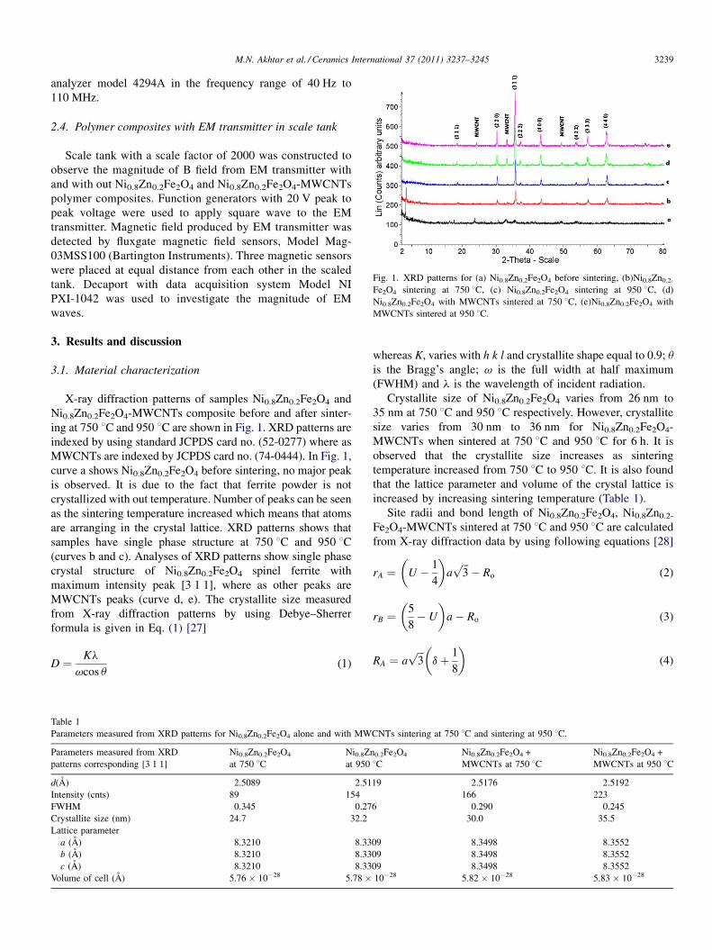
Fig. 1. XRD patterns for (a) Ni0.8Zn0.2Fe2O4 before sintering, (b)Ni0.8Zn0.2-
Fe2O4 sintering at 750 8C, (c) Ni0.8Zn0.2Fe2O4 sintering at 950 8C, (d)
Ni0.8Zn0.2Fe2O4 with MWCNTs sintered at 750 8C, (e)Ni0.8Zn0.2Fe2O4 with
MWCNTs sintered at 950 8C.
M.N. Akhtar et al. / Ceramics International 37 (2011) 3237–3245 3239
analyzer model 4294A in the frequency range of 40 Hz to
110 MHz.
2.4. Polymer composites with EM transmitter in scale tank
Scale tank with a scale factor of 2000 was constructed to
observe the magnitude of B field from EM transmitter with
and with out Ni0.8Zn0.2Fe2O4 and Ni0.8Zn0.2Fe2O4-MWCNTs
polymer composites. Function generators with 20 V peak to
peak voltage were used to apply square wave to the EM
transmitter. Magnetic field produced by EM transmitter was
detected by fluxgate magnetic field sensors, Model Mag-
03MSS100 (Bartington Instruments). Three magnetic sensors
were placed at equal distance from each other in the scaled
tank. Decaport with data acquisition system Model NI
PXI-1042 was used to investigate the magnitude of EM
waves.
3. Results and discussion
3.1. Material characterization
X-ray diffraction patterns of samples Ni0.8Zn0.2Fe2O4 and
Ni0.8Zn0.2Fe2O4-MWCNTs composite before and after sinter-
ing at 750 8C and 950 8C are shown in Fig. 1. XRD patterns are
indexed by using standard JCPDS card no. (52-0277) where as
MWCNTs are indexed by JCPDS card no. (74-0444). In Fig. 1,
curve a shows Ni0.8Zn0.2Fe2O4 before sintering, no major peak
is observed. It is due to the fact that ferrite powder is not
crystallized with out temperature. Number of peaks can be seen
as the sintering temperature increased which means that atoms
are arranging in the crystal lattice. XRD patterns shows that
samples have single phase structure at 750 8C and 950 8C(curves b and c). Analyses of XRD patterns show single phase
crystal structure of Ni0.8Zn0.2Fe2O4 spinel ferrite with
maximum intensity peak [3 1 1], where as other peaks are
MWCNTs peaks (curve d, e). The crystallite size measured
from X-ray diffraction patterns by using Debye–Sherrer
formula is given in Eq. (1) [27]
D ¼ Kl
vcos u(1)
Table 1
Parameters measured from XRD patterns for Ni0.8Zn0.2Fe2O4 alone and with MW
Parameters measured from XRD
patterns corresponding [3 1 1]
Ni0.8Zn0.2Fe2O4
at 750 8CNi0.8Zn
at 950
d(A) 2.5089 2.51
Intensity (cnts) 89 154
FWHM 0.345 0.27
Crystallite size (nm) 24.7 32.2
Lattice parameter
a (A) 8.3210 8.33
b (A) 8.3210 8.33
c (A) 8.3210 8.33
Volume of cell (A) 5.76 � 10�28 5.78 �
whereas K, varies with h k l and crystallite shape equal to 0.9; u
is the Bragg’s angle; v is the full width at half maximum
(FWHM) and l is the wavelength of incident radiation.
Crystallite size of Ni0.8Zn0.2Fe2O4 varies from 26 nm to
35 nm at 750 8C and 950 8C respectively. However, crystallite
size varies from 30 nm to 36 nm for Ni0.8Zn0.2Fe2O4-
MWCNTs when sintered at 750 8C and 950 8C for 6 h. It is
observed that the crystallite size increases as sintering
temperature increased from 750 8C to 950 8C. It is also found
that the lattice parameter and volume of the crystal lattice is
increased by increasing sintering temperature (Table 1).
Site radii and bond length of Ni0.8Zn0.2Fe2O4, Ni0.8Zn0.2-
Fe2O4-MWCNTs sintered at 750 8C and 950 8C are calculated
from X-ray diffraction data by using following equations [28]
rA ¼ U � 1
4
� �affiffiffi3p� Ro (2)
rB ¼5
8� U
� �a � Ro (3)
RA ¼ affiffiffi3p
d þ 1
8
� �(4)
CNTs sintering at 750 8C and sintering at 950 8C.
0.2Fe2O4
8CNi0.8Zn0.2Fe2O4 +
MWCNTs at 750 8CNi0.8Zn0.2Fe2O4 +
MWCNTs at 950 8C
19 2.5176 2.5192
166 223
6 0.290 0.245
30.0 35.5
09 8.3498 8.3552
09 8.3498 8.3552
09 8.3498 8.3552
10�28 5.82 � 10�28 5.83 � 10�28

Table 2
Site radii and bond length calculated from XRD patterns for Ni0.8Zn0.2Fe2O4 with and without MWCNTs sintering at 750 8C and at 950 8C.
Site radii and bond length calculation of Ni0.8Zn0.2Fe2O4 Site radii Bond length
rA rB RA RB
Ni0.8Zn0.2Fe2O4 sintering at 750 8C 0.5379 0.6803 1.8879 2.0314
Ni0.8Zn0.2Fe2O4 sintering at 950 8C 0.5402 0.6827 1.8902 2.0339
Ni0.8Zn0.2Fe2O4 + MWCNTs sintering at 750 8C 0.5445 0.6873 1.8945 2.0385
457 0.6886 1.8957 2.0398
Table 3
M.N. Akhtar et al. / Ceramics International 37 (2011) 3237–32453240
RB ¼ a1
16� d
2þ 3d2
� �1=2
(5)
where d = U � Uideal, d is the deviation for oxygen parameter
and Ro, radius of oxygen ion = 1.35 A, U is the oxygen posi-
tional parameter for Ni ferrite (0.381 A) and Uideal is 0.375 A.
Table 2 shows calculated values of rA, rB and RA, RB for
Ni0.8Zn0.2Fe2O4 and Ni0.8Zn0.2Fe2O4-MWCNTs composite
sintered at 750 8C and 950 8C. The site radii and bond length
values of Ni0.8Zn0.2Fe2O4 and Ni0.8Zn0.2Fe2O4-MWCNTs
composite increases by increasing temperature from 750 8Cto 950 8C as given in Table 2. As Zn+2 ions would like to go on
the tetrahedral site where as Ni+2 ions prefer to go octahedral
site. Since rA has lower values than rB which is due to more Ni+2
ions on the B-site and also larger ionic radius than Fe+2 ions
located on the A-site. It is found that site radii and bond length
results are in good agreement reported earlier [29,30].
Raman spectra of Ni0.8Zn0.2Fe2O4 and Ni0.8Zn0.2Fe2O4 with
MWCNTs before and after sintering at 750 8C and 950 8C were
taken from Raman spectroscopy system. Fig. 2 shows no
Raman peaks before sintering where as Raman peaks increases
at sintering temperature of 750 8C at 950 8C. Table 3 shows
intensity counts and Raman shift for Ni0.8Zn0.2Fe2O4 and
Ni0.8Zn0.2Fe2O4 with MWCNTs before and after sintering at
750 8C and 950 8C. The disorder occurs between Fe+2 and Zn+2
cations in the tetrahedral and octahedral (A and B) sites
respectively. It was found that first order Raman shift occurs
due to the distribution of Fe+2 and Zn+2 cations in the spinel
lattice. The vibrations of different frequencies can be found by
distributing Fe+2 and Zn+2 cations at the same atomic crystal
site (A or B site) [31]. The existence of spinel phase confirmed
Ni0.8Zn0.2Fe2O4 + MWCNTs sintering at 950 8C 0.5
0
10
20
30
40
50
60
70
80
90
2000150010005000
Raman shift (cm-1)
Inte
nsity
(a.u
) NiZN BS
NiZn at 750 C
NiZn at 950 C
NiZn with CNTsat 750 C
NiZn with CNTsat 950 C
Fig. 2. Raman spectra for Ni0.8Zn0.2Fe2O4 (NiZn), and Ni0.8Zn0.2Fe2O4 with
MWCNTs before and after sintering at 750 8C and 950 8C temperatures.
from Raman shifts which occurs in between 337 cm�1 and
711 cm�1 [32]. Raman peaks occurs over the region of 660–
720 cm�1 represents the mode of tetrahedra in the ferrites
where as 460–660 cm�1 region corresponds to the mode of
octahedra as shown in Table 3 [33].
Fig. 3a shows FESEM micrograph of multiwall carbon nano
tubes (MWCNT’s). Representative FESEM images of
Ni0.8Zn0.2Fe2O4 at 750 8C and 950 8C and Ni0.8Zn0.2Fe2O4-
MWCNTs at temperature of 550 8C, 750 8C and 950 8C are
presented in Fig. 3b–f. It can be seen from the morphology of
Ni0.8Zn0.2Fe2O4 sample sintered at 750 8C that nanoparticles
are spherical in shape (Fig. 3b). Surface morphology of
Ni0.8Zn0.2Fe2O4 nanoparticles with MWCNTs are elliptical in
shape and consists of well crystallized grains with relatively
homogenous grain distribution are shown in Fig. 3e and f. Grain
size depends on the factors such as sintering temperature,
porosity and grain boundary [34]. It was observed that values of
grain size increases in all samples as temperature increases
from 750 8C to 950 8C. The grain size varies between 20 nm
and 60 nm which is in accord with the crystallite size calculated
from XRD graphs. It is observed that at temperature of 550 8C,
Ni0.8Zn0.2Fe2O4 nanoparticles are not in single crystals form
and are agglomerated with MWCNTs. At the temperature of
750 8C, Ni0.8Zn0.2Fe2O4 nanoparticles are well crystallized. It
is found that multiwall carbon nano tubes are coated on the
Ni0.8Zn0.2Fe2O4 nanoparticles (Fig. 3e). It is also investigated
that sintering at the higher temperature in air (>750 8C) may
bursts MWCNTs, which changed the properties of carbon nano
Raman shift and intensity (counts) of Ni0.8Zn0.2Fe2O4 before sintering,
Ni0.8Zn0.2Fe2O4, and Ni0.8Zn0.2Fe2O4 with MWCNTs at different temperatures.
Raman spectra results Raman shift Intensity
(counts)
Ni0.8Zn0.2Fe2O4 before sintering 1054.792 13.823
Ni0.8Zn0.2Fe2O4 sintering at 750 8C 517.153
711.048
30.523
30.339
Ni0.8Zn0.2Fe2O4 sintering at 950 8C 496.391
590.562
675.611
38.341
36.008
43.970
Ni0.8Zn0.2Fe2O4 + MWCNTs sintering at 750 8C 691.811
496.397
352.621
215.421
61.592
58.671
54.818
53.706
Ni0.8Zn0.2Fe2O4 + MWCNTs sintering at 950 8C 220.995
337.939
482.222
699.404
71.645
69.791
75.675
75.669

Fig. 3. FESEM graphs for (a) multiwall carbon nano tubes, (b) Ni0.8Zn0.2Fe2O4 sintering at 750 8C, (c) Ni0.8Zn0.2Fe2O4 sintering at 950 8C, (d) Ni0.8Zn0.2Fe2O4 with
MWCNTs sintering at 550 8C, (e) Ni0.8Zn0.2Fe2O4 with MWCNTs sintering at 750 8C, (f) Ni0.8Zn0.2Fe2O4 with MWCNTs sintering at 950 8C.
M.N. Akhtar et al. / Ceramics International 37 (2011) 3237–3245 3241
tubes. FESEM graphs show Ni0.8Zn0.2Fe2O4 nano particles
with MWCNTs at 750 8C shows less porosity, and better
morphology than Ni0.8Zn0.2Fe2O4 nanoparticles without
MWCNTs as shown in Fig. 3e.
Fig. 4 shows the EDX spectrum of Ni0.8Zn0.2Fe2O4 ferrite
powder. EDX results show that oxygen, iron, nickel and zinc
elements are with atomic percentages of 62.92%, 24.19%
Fig. 4. EDX spectrum of Ni0.8Zn0.2Fe2O4 ferrite powder.
10.69% and 2.21%, respectively as given in Table 4. No
impurity is observed due to high purity of the starting materials
for the preparation of the Ni0.8Zn0.2Fe2O4 nanoparticles. Fig. 5
shows the EDX spectrum of Ni0.8Zn0.2Fe2O4 with MWCNTs
composite powder. Table 5 shows atomic and weight
percentage of Ni0.8Zn0.2Fe2O4-MWCNTs composite according
to the stoichiometric ratios, which shows the purity of sample.
Fig. 6a shows high resolution transmission electron
microscope (HRTEM) image of Ni0.8Zn0.2Fe2O4 prepared at
750 8C by sol–gel method. Fig. 6b shows TEM image of
Ni0.8Zn0.2Fe2O4-MWCNTs composites at the sintering tem-
Table 4
EDX results of Ni0.8Zn0.2Fe2O4 ferrite powder.
Element Weight% Atomic%
O K 32.17 62.92
Fe K 43.16 24.19
Ni K 20.05 10.69
Zn K 4.62 2.21
Total 100.00

Table 5
EDX results of Ni0.8Zn0.2Fe2O4 with MWCNTs ferrite powder.
Element Weight% Atomic%
C K 13.53 27.96
O K 30.88 47.90
Fe K 37.41 16.62
Ni K 14.29 6.04
Zn K 3.89 1.48
Total 100.00
0
5
10
15
20
25
120100806040200
Frequency (MHz)
Initi
al P
erm
eabi
lity
PVDF
NiZn at 750 C
NiZn at 950 C
NiZn-MWCNTs at 950 C
NiZn-MWCNTs at 750 C
Fig. 7. Initial permeability of PVDF, Ni0.8Zn0.2Fe2O4 sintering at 750 8C and
950 8C, Ni0.8Zn0.2Fe2O4 with MWCNTs at 750 8C and 950 8C.Fig. 5. EDX spectrum of Ni0.8Zn0.2Fe2O4 with MWCNTs ferrite powder.
M.N. Akhtar et al. / Ceramics International 37 (2011) 3237–32453242
perature of 750 8C. Ni0.8Zn0.2Fe2O4 shows that the nanopar-
ticles sizes are in the range 20 nm to 30 nm. From Fig. 6a, it is
attributed that Ni0.8Zn0.2Fe2O4 nanoparticles are well crystal-
lized and are hexagon in shape. Composite (Ni0.8Zn0.2Fe2O4-
MWCNTs) consisted with Ni0.8Zn0.2Fe2O4 nanoparticles with
graphitized sheets as shown in Fig. 6b. Ni0.8Zn0.2Fe2O4
nanoparticles are coated on outer surface of the MWCNTs
are also investigated during the HRTEM study as shown in
Fig. 6b. It was found that Ni0.8Zn0.2Fe2O4-MWCNTs sintered
at 950 8C result the deformation of MWCNTs which changes
the properties of MWCNTs.
Magnetic properties such as initial permeability, Q-factor
and relative loss factor (RLF) for polymer composites of PVDF,
Ni0.8Zn0.2Fe2O4 sintered at 750 8C and 950 8C, Ni0.8Zn0.2-
Fe2O4-MWCNTs at 750 8C and 950 8C were taken from series
inductance (LS) and Q values by using LCR vector network
analyser (Figs. 7–9). Initial permeability is an important
Fig. 6. HRTEM graphs for (a) Ni0.8Zn0.2Fe2O4 sintering at 750
property to study the qualities of the magnetic materials. Initial
permeability in ferrites depends on the grain size, bulk density,
porosity, morphology, spin rotational contributions and single
phase structure [35,36]. Initial permeability mi was calculated
by using formula given below
mi ¼2pLS
N2motlnðDo=DiÞ(6)
where LS is the series inductance, mo is the magnetic perme-
ability, Do is the outer diameter of the toroid, Di is the inner
diameter of the toroid, N is no. of turns and t is the thickness of
the toroid. Initial permeability increases in all samples as the
grain size increases. Initial permeability of Ni0.8Zn0.2Fe2O4-
MWCNTs composite at 750 8C has greater value (20.043) than
PVDF and Ni0.8Zn0.2Fe2O4 at frequency of 100 MHz as given
in Table 6. Q-factor was also found maximum (50.062) for
Ni0.8Zn0.2Fe2O4 with MWCNTs at frequency of 25 MHz as
shown in the Table 6. Ni0.8Zn0.2Fe2O4-MWCNTs composite at
750 8C has high values of initial permeability and Q factor and
low loss factor due to single phase structure of Ni0.8Zn0.2Fe2O4
and better characteristics of multiwall carbon nano tubes
(MWCNTs). It was also found that Ni0.8Zn0.2Fe2O4-MWCNTs
composite at 950 8C shows less values of initial permeability
and Q factor than Ni0.8Zn0.2Fe2O4-MWCNTs composite at
750 8C. This is due to the fact that MWCNTs has changed
its properties at higher temperature (>750 8C). The relative loss
factor decreases up to 100 kHz and after this it remains smooth.
8C (b) Ni0.8Zn0.2Fe2O4 with MWCNTs sintering at 750 8C.

0
10
20
30
40
50
60
120100806040200
Frequency (MHz)
Q-F
acto
r PVDF
NiZn at 750 C
NiZn at 950 C
NiZn-MWCNTs at 950 C
NiZn-MWCNTs at 750 C
Fig. 8. Q-factor Initial permeability of PVDF, Ni0.8Zn0.2Fe2O4 sintering at
750 8C and 950 8C, Ni0.8Zn0.2Fe2O4 with MWCNTs at 750 8C and 950 8C.
0.0
0.2
0.4
0.6
0.8
1.0
1.2
6005004003002001000
Frequency (kHz)
Rel
ativ
e Lo
ss F
acto
r
PVDF
NiZn at 750 C
NiZn at 950 C
NiZn-MWCNTs at 950 C
NiZn-MWCNTs at 750C
Fig. 9. Relative loss factor of PVDF, Ni0.8Zn0.2Fe2O4 sintering at 750 8C and
950 8C, Ni0.8Zn0.2Fe2O4 with MWCNTs at 750 8C and 950 8C.
0.00E+00
5.00E-08
1.00E-07
1.50E-07
2.00E-07
2.50E-07
3.00E-07
3.50E-07
200150100500
Source receiver offset (cm)
B (T
esla
)
Al wire 1mm diameter astransmitter
Al wire 1mm diameter astransmitter
Al wire 1mm diameter astransmitter
Fig. 10. MVO results for EM transmitter with out polymer composite.
M.N. Akhtar et al. / Ceramics International 37 (2011) 3237–3245 3243
The frequency at which loss factor has minimum value and
decreases by increasing frequency is called threshold frequen-
cy. The low loss factor value indicates high purity of samples
obtained by non-conventional method [37]. Relative loss factor
is ratio of the tand to initial permeability and was calculated by
using equation given below
RLF ¼ 1
miQ(7)
Relative loss factor of Ni0.8Zn0.2Fe2O4-MWCNTs at 750 8Cshows minimum value (0.0001) as compared to all other
samples due to better characteristics of MWCNTs at 750 8C.
Initial permeability increases by increasing frequency whereas
loss factor decreases at higher frequency are shown in Figs. 7
and 9. Fig. 9 shows PVDF polymer and Ni0.8Zn0.2Fe2O4 at
750 8C shows higher loss factor than all the other samples.
Composite Ni0.8Zn0.2Fe2O4-MWCNTs at 750 8C has better
magnetic characteristics due to single phase Ni0.8Zn0.2Fe2O4
crystals without deformation of MWCNTs. Low loss factor and
high initial permeability resulted that Ni0.8Zn0.2Fe2O4-
MWCNTs sintered at low temperature could be used for
electromagnetic applications, heterogeneous catalysis and as
well as in electronic industry.
Table 7
Comparison of MVO results for EM transmitter with and with out Ni0.8Zn0.2Fe2O
EM transmitter with out
polymer composites
EM transmitter wit
polymer composite
B-Field 3.0 � 10�7 9.59 � 10�7
Table 6
Initial permeability, Q-factor and relative loss factor for PVDF, Ni0.8Zn0.2Fe2O4 at75
Samples Initial permeability at
PVDF 8.7141
Ni0.8Zn0.2Fe2O4 at 750 8C with PVDF 13.219
Ni0.8Zn0.2Fe2O4 at 950 8C with PVDF 18.013
Ni0.8Zn0.2Fe2O4-MWCNTs at 950 8C with PVDF 18.963
Ni0.8Zn0.2Fe2O4-MWCNTs at 750 8C with PVDF 20.043
3.2. Magnitude vs. offset (MVO) results from as prepared
polymer composites samples
Comparison of EM transmitter was done by using
aluminium wire transmitter with Ni0.8Zn0.2Fe2O4-PVDF, and
Ni0.8Zn0.2Fe2O4-MWCNTs-PVDF magnetic feeders in a
designed scale tank (Figs. 10–12). Magnitude verses offset
of EM transmitter with Ni0.8Zn0.2Fe2O4-PVDF, Ni0.8Zn0.2-
Fe2O4-MWCNTs-PVDF magnetic feeders were done in tab
4, Ni0.8Zn0.2Fe2O4-MWCNTs polymer composites.
h Ni0.8Zn0.2Fe2O4
s
EM transmitter with Ni0.8Zn0.2Fe2O4 with
MWCNTs polymer composites
1.03 � 10�6
0 8C and 950 8C Ni0.8Zn0.2Fe2O4-MWCNTs composites at 750 8C and 950 8C.
100 MHz Q-factor at 25 MHz Relative loss factor at
100 kHz 6 MHz
33.858 0.0491 0.0049
39.317 0.0231 0.0045
41.984 0.0082 0.0032
42.442 0.0016 0.0021
50.062 0.0011 0.0001

0.00E+00
2.00E-07
4.00E-07
6.00E-07
8.00E-07
1.00E-06
1.20E-06
200150100500
Source receiver offset (cm)
B (T
esla
) Al wire 1mm diameter withNiZn-PVDF toroids
Al wire 1mm diameter withNiZn-PVDF toroids
Al wire 1mm diameter withNiZn-PVDF toroids
Fig. 11. MVO results for EM transmitter with Ni0.8Zn0.2Fe2O4 polymer
composites.
0.00E+00
2.00E-07
4.00E-07
6.00E-07
8.00E-07
1.00E-06
200150100500
Source receiver offset (m)
Mag
netic
fiel
d (T
)
Al wire 1mm diameter withNiZn-PVDF-MWCNTs toroids
Al wire 1mm diameter withNiZn-PVDF-MWCNTs toroids
Al wire 1mm diameter withNiZn-PVDF-MWCNTs toroids
Fig. 12. MVO results for EM transmitter with Ni0.8Zn0.2Fe2O4–MWCNTs
polymer composites.
M.N. Akhtar et al. / Ceramics International 37 (2011) 3237–32453244
water to replicate the marine environment. It was found that EM
transmitter with Ni0.8Zn0.2Fe2O4-MWCNTs as magnetic
feeders resulted (1.03 � 10�6) than without magnetic feeders
(3.0 � 10�7) as given in Table 7. It was investigated that
magnetic field strength has been increased with new EM
transmitter based (Ni0.8Zn0.2Fe2O4-MWCNTs) magnetic fee-
ders up to 243%.
4. Conclusions
Single phase nano crystals of Ni0.8Zn0.2Fe2O4 and Ni0.8Zn0.2-
Fe2O4-MWCNTs composites with [3 1 1] major peak were
successfully synthesised at sintering temperature of 750 8C and
950 8C by sol–gel method. Average particle sizes are in the range
of 24–60 nm confirmed from XRD, FESEM and HRTEM. Better
morphology of Ni0.8Zn0.2Fe2O4-MWCNTs composite at the
sintering temperature of 750 8C was observed by FESEM and
HRTEM. Ni0.8Zn0.2Fe2O4-MWCNTs at 750 8C have high initial
permeability (20.043), high Q-factor (51.178) as compared to
PVDF and Ni0.8Zn0.2Fe2O4 samples. Sample (Ni0.8Zn0.2Fe2O4-
MWCNTs sintered at 750 8C) composites were used as magnetic
feeders for EM transmitter due to better magnetic properties. It
was investigated that the magnitude of EM waves from EM
transmitter increased up to 243% by using Ni0.8Zn0.2Fe2O4-
MWCNTs polymer composites. This new EM transmitter may
open new horizon for oil and gas industry for deep target
hydrocarbon exploration.
References
[1] S. Ellingsrud, T. Eidesmo, S. Jphansen, M.C. Sinha, L.M. MacGregor, S.
Constable, Remote sensing of hydrocarbon layers by seabed logging
(SBL) results from a cruise offshore Angola, The Leading Edge 21
(2002) 972–982.
[2] M.N. Akhtar, N. Yahya, H. Daud, A. Shafie, H.M. Zaid, M. Kashif, N.
Nasir, Development of EM wave guide amplifier potentially used for
seabed logging, J. Appl. Sci. 11 (2011) 1361–1365.
[3] M.A.T.G. Reynolds III, Ferrites magnetic ceramics, in: R.C. ed. Buchanan
(Ed.), Ceramics Materials for Electronics, Marcel Dekker, Inc., NY, 1988.
[4] Q. Song, Z.J. Zhang, Shape control and associated magnetic properties of
spinel cobalt ferrite nanocrystals, J. Am. Chem. Soc. 126 (2004) 6164–
6168.
[5] A. Goldman, Modern Ferrite Technology, Van Nostrand Reinhold, New
York, 1990.
[6] H. Dai, J.H. Hafner, A.G. Rinzler, D.T. Colbert, R.E. Smalley, Nanotubes
as nanoprobes in scanning probe microscopy, Nature 384 (1996) 147–150.
[7] H. Cao, M. Zhu, Y. Li, J. Liu, Z. Ni, Z. Qin, A highly coercive carbon
nanotube coated with Ni0.5Zn0.5Fe2O4 nanocrystals synthesized by chem-
ical precipitation hydrothermal process, J. Solid State Chem. 180 (2007)
3218–3223.
[8] F.X. Liu, T.Z. Li, H.G. Zhang, Synthesis and magnetic properties of
SnFe2O4 nanoparticles, Mater. Lett. 59 (2005) 194–196.
[9] A. Dias, R.L. Moreira, N.D.S. Mohallem, Sintering studies of hydrother-
mal NiZn ferrites, J. Phys. Chem. Solids 58 (1997) 543–547.
[10] S. Deka, P.A. Joy, Characterization of nanosized NiZn ferrite powders
synthesized by an autocombustion method, Mater. Chem. Phys. 100
(2006) 98–101.
[11] S. Woltz, R. Hiergeist, P. Gornert, C. Russel, Magnetite nanoparticles
prepared by the glass crystallization method and their physical properties,
J. Magn. Magn. Mater. 298 (2006) 7–13.
[12] J. Ding, H. Yang, W.F. Miao, P.G. Mccormick, R. Street, High coercivity
Ba hexaferrite prepared by mechanical alloying, J. Alloys Compd. 221
(1995) 70–73.
[13] N. Yahya, M.N. Akhtar, A.F. Masuri, M. Kashif, Synthesis and character-
isations of ZnO-CNTs filled PVA composite as EM detector, J. Appl. Sci.
11 (2011) 1303–1308.
[14] M.N. Akhtar, N. Yahya, P.B. Hussain, Structural and magnetic character-
izations of nano structured Ni0.8Zn0.2Fe2O4 prepared by self combustion
method, Int. J. Basic Appl. Sci. (IJBAS) 9 (2009) 151–154.
[15] G. Vasilios, T. Vasilios, G. Dimitrios, P. Dimitrios, Attachment of mag-
netic nanoparticles on carbon nanotubes and their soluble derivatives,
Chem. Mater. 17 (2005) 1613–1617.
[16] S.R. Bakshi, V. Singh, K. Balani, D.G. McCartney, Carbon nanotube
reinforced aluminum composite coating via cold spraying, Surf. Coat.
Technol. 202 (2008) 5162–5169.
[17] Q. Zhang, Meifang Zhu, Qinghong Zhang, Yaogang Li, Hongzhi
Wang, The formation of magnetite nanoparticles on the sidewalls of
multi-walled carbon nanotubes, Comp. Sci. Technol. 69 (2009) 633–
638.
[18] C.P. Collier, T. Vossmeyer, J.R. Heath, Nano crystal super lattices, Rev.
Phys. Chem. 49 (1998) 371–404.
[19] M.A. Correa-Daurte, M. Grzelczak, V. Salgueinno-Maceira, M. Giersig,
L.M. Liz-Marzan, M. Farle, Alignment of carbon nanotubes under low
magnetic fields through attachment of magnetic nanoparticles, J. Phys.
Chem. B 109 (2005) 19060–19063.
[20] L.Q. Jiang, L. Gao, Carbon nanotubes–magnetite nanocomposites from
solvothermal processes: formation, characterization, and enhanced elec-
trical properties, Chem. Mater. 14 (2003) 2848–2853.
[21] Y.Q. Liu, L. Gao, A study of the electrical properties of carbon nanotube-
NiFe2O4 composites: effect of the surface treatment of the carbon
nanotubes, Carbon 43 (2005) 47–52.
[22] Y. Sheng, Z. Yue, M. Li, C.W. Nan, Magnetic and dielectric properties of a
double-percolating Ni0.3Zn0.7Fe1.95O4–Ni–polymer composite, J. Electro-
ceram. 21 (2008) 385–389.
[23] R. Lebourgeoisa, S. Berenguerb, C. Ramiarinjaonab, T. Waeckerle,
Analysis of the initial complex permeability versus frequency of soft

M.N. Akhtar et al. / Ceramics International 37 (2011) 3237–3245 3245
nanocrystalline ribbons and derived composites, J. Magn. Magn. Mater.
254 (2003) 191–194.
[24] F.N. Kong, H. Westerdahl, F. Antonsen, Excitation of a long wire antenna
– antennas from 200 MHz to 1 Hz, in: Tenth International Conference on
Ground Penetrating Radar, 21–24 June, Delft, The Netherlands, 2004.
[25] Kenneth, E.M. Kaiser, Compatibility Handbook, Taylor & Francis, Inc.,
2004.
[26] N. Yahya, M.N. Akhtar, N. Nasir, A. Shafie, M.S. Jabeli, K. Koziol, CNT
fibres/aluminium-NiZnFe2O4 based EM transmitter for improved mag-
nitude vs. offset (MVO) in a scaled marine environment, J. Nanosci.
Nanotechnol. (2011).
[27] K.J. Standly, Oxide Magnetic Materials, Oxford University Press, Lon-
don, 1962.
[28] H.P. Klung, L.E. Alexander, X-ray Diffraction Procedure for Polycrystal-
line Procedure for Polycrystalline and Amorphous Materials, Wiley, New
York, 1974.
[29] S.A. Mazen, H.A. Dawoud, Structure and magnetic properties of Li–Cu
ferrite, Phys. Status Solidi A 172 (1999) 275–289.
[30] T.J. Shinde, A.B. Gadkari, P.N. Vasambekar, Saturation magnetization and
structural analysis of Ni0.6Zn0.4NdyFe2 � yO4 by XRD, IR and SEM
techniques, J. Mater. Sci.: Mater. Electron. 21 (2010) 120–124.
[31] Z. Wang, D. Schiferl, Y. Zhao, H.S.C.O. Neill, High pressure Raman
spectroscopy of spinel-type ferrite ZnFe2O4, J. Phys. Chem. Solids 64
(2003) 2517–2523.
[32] H. Kojitani, K. Nishimusa, A. Kubo, M. Sakashita, K. Aoti, M. Akagi,
Raman spectroscopy and heat capacity measurement of calcium ferrite
type MgAl2O4 and CaAl2O4, Phys. Chem. Miner. 30 (2003) 409–
415.
[33] J. Kreisel, G. Lucazeau, H. Vincent, Raman spectra and vibrational
analysis of BaFe12O19 hexagonal Ferrite, J. Solid State Chem. 137
(1998) 127–137.
[34] T.T. Ahmed, I.Z. Rahman, M.A. Rahman, Study on the properties of the
copper substituted NiZn ferrites, J. Mater. Proc. Technol. 153–154 (2004)
797–803.
[35] E.C. Snelling, Soft Ferrites, 2nd ed., Butterworths, London, 1998.
[36] J.J. Shrotri, S.D. Kulkarni, C.E. Deshpande, A. Mitra, S.R. Sainkar, P.S.
Anil Kumar, S.K. Date, Effect of Cu substitution on the magnetic and
electrical properties of Ni–Zn ferrite synthesised by soft chemical method,
Mater. Chem. Phys. 59 (1999) 1–5.
[37] R.V. Mangalaraja, S. Ananthakumar, P. Manohar, F.D. Gnanam, Initial
permeability studies of Ni–Zn ferrites prepared by flash combustion
technique, Mater. Sci. Eng. A 355 (2003) 320–324.