Comparative study of predictive FE methods for mechanical properties of nuclear composites
7
Comparative study of predictive FE methods for mechanical properties of nuclear composites Joshim Ali a, * , Johar K. Farooqi b , Derek Buckthorpe a , Allister Cheyne a , Paul Mummery b a AMEC, Booths Park, Chelford Road, Knutsford, Cheshire WA16 8QZ, UK b School of Materials, University of Manchester, Grosvenor Street, Manchester M1 7HS, UK article info Article history: Received 14 June 2008 Accepted 18 September 2008 abstract Carbon fiber reinforced carbon (C/C) composites are candidate materials for plasma facing components in experimental fusion reactors such as: the ITER; the JT-60 – a Tokamak fusion test facility (JAEA); and for control rods in the next generation fission reactors. Therefore, determining their thermo-mechanical properties under irradiation is essential for safe design-cum-operation of future reactors. Development of reliable models which can predict such materials’ behavior is of massive advantage against the conven- tional experimental verification which is hugely expensive and time-consuming. Three-dimensional finite element (FE) methods are used here for predicting Young’s modulus of two woven C/C composites where tensile tests are performed for validation. Stress distribution results indicate that a novel image- based route for FE meshes compared to a unit cell approach gives stronger agreement with experimental data. The image-based approach captures true porosity as fine microstructural details are converted from X-ray tomographic data. In comparison, the unit cell model represents idealizations of composite archi- tecture that ignores porosities. Ó 2008 Elsevier B.V. All rights reserved. 1. Introduction In the literature, numerous models have been reported that de- scribe the behavior of composites [1–4]. These models are mainly based on meshes that have been manually or digitally created, e.g., the unit cell approach. These necessarily assume that the material can be represented reliably by an infinitely, repeating ideal structure. This is unlikely to be absolutely true for materials such as woven composites that have complex architectures with difficult and complicated fabrication processes. The main advantages of finite element (FE) approaches com- pared to other numerical analysis methods are that: it is applicable to any field problem; it has no limitations on geometry, shape, boundary conditions or loading; many different parts and compo- nents can be combined; the material properties are not just re- stricted to isotropy; and it can closely represent the actual material with the potential to easily improve the approximation by upgrading the mesh, e.g., enhancing features through increase of number of elements. Points to be cautious about are: (1) it is complicated, (2) time-consuming and (3) initially unreliable as it is possible to carry out complete FE analyses with little background knowledge of the method [5,6]. The aim of the current study is to show the potential of reliable FE models for advanced reinforced composite structures. This is done by comparing two different approaches for modeling woven composites. The first is a unique method that uses an image-based route in acquiring FE meshes [7]. This is achieved by combining X- ray microtomography (XMT) [8,9], which gives a high resolution image of the microstructure in 3D, with FE software codes [10,11]. Here the ‘real’ structure is converted directly into a 3D FE mesh. The development of this novel image-based approach has been presented elsewhere [7,12]. Somewhat similar ap- proaches have also been adopted in literature for modeling polyurethane foams [13], cellular structures [14], graphite [15], alumina coatings [16], trabecular bone [17], dental structures [18] and metal matrix composites [19]. The second method used here is a 3D unit cell model of the structure [1,2], based on ideal- izations of the composite architecture through a plane-symmetric volumetric representative region. This model assumes that the material can be represented reliably by an infinitely repeating ideal structure modeled with a unit cell. In this paper, the Young’s moduli of two 2D woven C/C compos- ites are predicted through FE analyses employed on both of these model types. The predictions are compared with experimental data for validation. 2. Composite material Two-dimensional woven C/C composites in two heat-treated conditions were studied. These were graphitised and un-graphi- tised samples manufactured by Toyo Tanso, Japan (CX-270 grade). 0022-3115/$ - see front matter Ó 2008 Elsevier B.V. All rights reserved. doi:10.1016/j.jnucmat.2008.09.020 * Corresponding author. Tel.: +44 1565 684 838; fax: +44 1565 684 870. E-mail address: [email protected] (J. Ali). Journal of Nuclear Materials 383 (2009) 247–253 Contents lists available at ScienceDirect Journal of Nuclear Materials journal homepage: www.elsevier.com/locate/jnucmat
-
Upload
independent -
Category
Documents
-
view
0 -
download
0
Transcript of Comparative study of predictive FE methods for mechanical properties of nuclear composites
Journal of Nuclear Materials 383 (2009) 247–253
Contents lists available at ScienceDirect
Journal of Nuclear Materials
journal homepage: www.elsevier .com/locate / jnucmat
Comparative study of predictive FE methods for mechanical propertiesof nuclear composites
Joshim Ali a,*, Johar K. Farooqi b, Derek Buckthorpe a, Allister Cheyne a, Paul Mummery b
a AMEC, Booths Park, Chelford Road, Knutsford, Cheshire WA16 8QZ, UKb School of Materials, University of Manchester, Grosvenor Street, Manchester M1 7HS, UK
a r t i c l e i n f o
Article history:Received 14 June 2008Accepted 18 September 2008
0022-3115/$ - see front matter � 2008 Elsevier B.V. Adoi:10.1016/j.jnucmat.2008.09.020
* Corresponding author. Tel.: +44 1565 684 838; faE-mail address: [email protected] (J. Ali).
a b s t r a c t
Carbon fiber reinforced carbon (C/C) composites are candidate materials for plasma facing components inexperimental fusion reactors such as: the ITER; the JT-60 – a Tokamak fusion test facility (JAEA); and forcontrol rods in the next generation fission reactors. Therefore, determining their thermo-mechanicalproperties under irradiation is essential for safe design-cum-operation of future reactors. Developmentof reliable models which can predict such materials’ behavior is of massive advantage against the conven-tional experimental verification which is hugely expensive and time-consuming. Three-dimensionalfinite element (FE) methods are used here for predicting Young’s modulus of two woven C/C compositeswhere tensile tests are performed for validation. Stress distribution results indicate that a novel image-based route for FE meshes compared to a unit cell approach gives stronger agreement with experimentaldata. The image-based approach captures true porosity as fine microstructural details are converted fromX-ray tomographic data. In comparison, the unit cell model represents idealizations of composite archi-tecture that ignores porosities.
� 2008 Elsevier B.V. All rights reserved.
1. Introduction
In the literature, numerous models have been reported that de-scribe the behavior of composites [1–4]. These models are mainlybased on meshes that have been manually or digitally created,e.g., the unit cell approach. These necessarily assume that thematerial can be represented reliably by an infinitely, repeatingideal structure. This is unlikely to be absolutely true for materialssuch as woven composites that have complex architectures withdifficult and complicated fabrication processes.
The main advantages of finite element (FE) approaches com-pared to other numerical analysis methods are that: it is applicableto any field problem; it has no limitations on geometry, shape,boundary conditions or loading; many different parts and compo-nents can be combined; the material properties are not just re-stricted to isotropy; and it can closely represent the actualmaterial with the potential to easily improve the approximationby upgrading the mesh, e.g., enhancing features through increaseof number of elements. Points to be cautious about are: (1) it iscomplicated, (2) time-consuming and (3) initially unreliable as itis possible to carry out complete FE analyses with little backgroundknowledge of the method [5,6].
The aim of the current study is to show the potential of reliableFE models for advanced reinforced composite structures. This is
ll rights reserved.
x: +44 1565 684 870.
done by comparing two different approaches for modeling wovencomposites. The first is a unique method that uses an image-basedroute in acquiring FE meshes [7]. This is achieved by combining X-ray microtomography (XMT) [8,9], which gives a high resolutionimage of the microstructure in 3D, with FE software codes[10,11]. Here the ‘real’ structure is converted directly into a 3DFE mesh. The development of this novel image-based approachhas been presented elsewhere [7,12]. Somewhat similar ap-proaches have also been adopted in literature for modelingpolyurethane foams [13], cellular structures [14], graphite [15],alumina coatings [16], trabecular bone [17], dental structures[18] and metal matrix composites [19]. The second method usedhere is a 3D unit cell model of the structure [1,2], based on ideal-izations of the composite architecture through a plane-symmetricvolumetric representative region. This model assumes that thematerial can be represented reliably by an infinitely repeating idealstructure modeled with a unit cell.
In this paper, the Young’s moduli of two 2D woven C/C compos-ites are predicted through FE analyses employed on both of thesemodel types. The predictions are compared with experimental datafor validation.
2. Composite material
Two-dimensional woven C/C composites in two heat-treatedconditions were studied. These were graphitised and un-graphi-tised samples manufactured by Toyo Tanso, Japan (CX-270 grade).
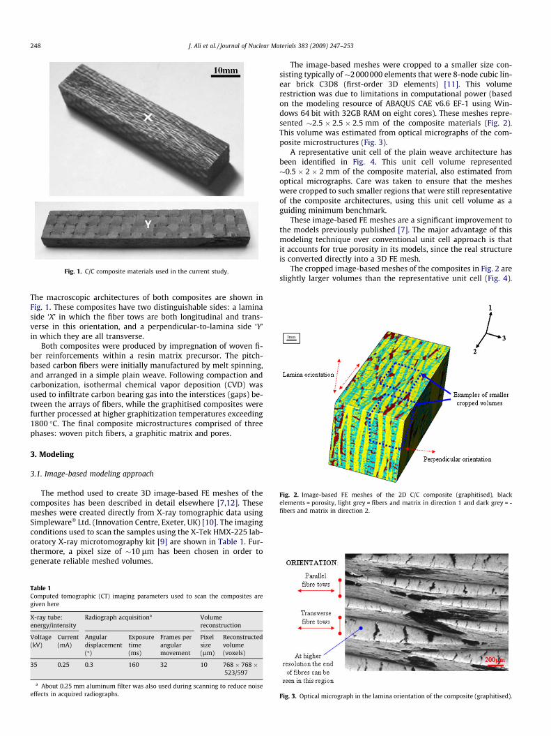
Fig. 1. C/C composite materials used in the current study.
Fig. 2. Image-based FE meshes of the 2D C/C composite (graphitised), blackelements = porosity, light grey = fibers and matrix in direction 1 and dark grey = -fibers and matrix in direction 2.
248 J. Ali et al. / Journal of Nuclear Materials 383 (2009) 247–253
The macroscopic architectures of both composites are shown inFig. 1. These composites have two distinguishable sides: a laminaside ‘X’ in which the fiber tows are both longitudinal and trans-verse in this orientation, and a perpendicular-to-lamina side ‘Y’in which they are all transverse.
Both composites were produced by impregnation of woven fi-ber reinforcements within a resin matrix precursor. The pitch-based carbon fibers were initially manufactured by melt spinning,and arranged in a simple plain weave. Following compaction andcarbonization, isothermal chemical vapor deposition (CVD) wasused to infiltrate carbon bearing gas into the interstices (gaps) be-tween the arrays of fibers, while the graphitised composites werefurther processed at higher graphitization temperatures exceeding1800 �C. The final composite microstructures comprised of threephases: woven pitch fibers, a graphitic matrix and pores.
3. Modeling
3.1. Image-based modeling approach
The method used to create 3D image-based FE meshes of thecomposites has been described in detail elsewhere [7,12]. Thesemeshes were created directly from X-ray tomographic data usingSimpleware� Ltd. (Innovation Centre, Exeter, UK) [10]. The imagingconditions used to scan the samples using the X-Tek HMX-225 lab-oratory X-ray microtomography kit [9] are shown in Table 1. Fur-thermore, a pixel size of �10 lm has been chosen in order togenerate reliable meshed volumes.
Table 1Computed tomographic (CT) imaging parameters used to scan the composites aregiven here
X-ray tube:energy/intensity
Radiograph acquisitiona Volumereconstruction
Voltage(kV)
Current(mA)
Angulardisplacement(�)
Exposuretime(ms)
Frames perangularmovement
Pixelsize(lm)
Reconstructedvolume(voxels)
35 0.25 0.3 160 32 10 768 � 768 �523/597
a About 0.25 mm aluminum filter was also used during scanning to reduce noiseeffects in acquired radiographs.
The image-based meshes were cropped to a smaller size con-sisting typically of�2000000 elements that were 8-node cubic lin-ear brick C3D8 (first-order 3D elements) [11]. This volumerestriction was due to limitations in computational power (basedon the modeling resource of ABAQUS CAE v6.6 EF-1 using Win-dows 64 bit with 32GB RAM on eight cores). These meshes repre-sented �2.5 � 2.5 � 2.5 mm of the composite materials (Fig. 2).This volume was estimated from optical micrographs of the com-posite microstructures (Fig. 3).
A representative unit cell of the plain weave architecture hasbeen identified in Fig. 4. This unit cell volume represented�0.5 � 2 � 2 mm of the composite material, also estimated fromoptical micrographs. Care was taken to ensure that the mesheswere cropped to such smaller regions that were still representativeof the composite architectures, using this unit cell volume as aguiding minimum benchmark.
These image-based FE meshes are a significant improvement tothe models previously published [7]. The major advantage of thismodeling technique over conventional unit cell approach is thatit accounts for true porosity in its models, since the real structureis converted directly into a 3D FE mesh.
The cropped image-based meshes of the composites in Fig. 2 areslightly larger volumes than the representative unit cell (Fig. 4).
Fig. 3. Optical micrograph in the lamina orientation of the composite (graphitised).

Fig. 4. Representative unit cell volume of the plain weave architecture(benchmark).
Table 2Indentation properties of the (a) graphitised and (b) un-graphitised composites [7]
Region indented Number of indents Mean modulus (GPa) to 1 d.p.
(a)Transverse fibers 11 7.1 (±1.6)End-of-fibers 3 24.9 (±1.9)Matrix 3 11.4 (±2.7)
(b)Transverse fibers 10 5.5 (±1.6)End-of-fibers 3 22.8 (±1.9)Matrix 3 7.5 (±2.7)
J. Ali et al. / Journal of Nuclear Materials 383 (2009) 247–253 249
However, in these image-based meshes there were anomalous ele-ments which caused discontinuities in the architecture. This wasdue to noise in the initially acquired tomographic data, whichcould not be removed despite the use of various filters and changesin imaging parameters.
3.2. 3D unit cell model
The unit cell FE model used for comparison was structured withdimensions from a series of observations and details through scan-ning electron micrographs [1,2]. It is based on plain weave fabricarchitecture of a representative volumetric cell, comprising of186754 C3D4 (4-node linear tetrahedron) elements of ABAQUSsoftware and represents �0.5 � 2 � 2 mm of the composite vol-ume. The shapes of elements were tetragonal as this gave best-fitand geometric conformity during meshing. This model was origi-nally designed for thermal analyses and contained a jagged edgestructure which did not affect thermal behavior [1]. However, forthe current study the same FE model has been modified to a curvi-linear shaped structure (Fig. 5), i.e., to avoid possible stress concen-tration effects at its edges under tension.
Fig. 5. Jagged edge unit cell modified to a cu
4. Experiments
4.1. Scanning electron microscopy
The Jeol JSM-6300 scanning electron microscope (SEM) wasused to image the microstructures of the composites in secondaryelectron mode. Hence characterizing their complex woven archi-tectures at a much higher resolution compared to the tomographicdata. The composites were positioned in the venting chamber ofthe SEM and held in place by a press, while high vacuum was built,the accelerating voltage was set to 10 kV with the chamber closedand finally the electron beam activated. The composite surfaceswere scanned and micrographs obtained.
4.2. Nanoindentation (input data)
The mechanical properties of the fiber and matrix constituentswithin the composites were determined by nanoindentation (Table2) as it has been explained earlier in detail [7]. An MTS XP nanoind-enter with a Berkovich diamond indenter was used to obtain trans-verse properties of the fibers, while a Hysitron Triboscope indentersystem (Hysitron Inc., Minneapolis, USA) [20] with a diamond cu-bic corner tip, containing a corresponding atomic force microscope(AFM) was used to obtain longitudinal properties of the fibers andmatrix properties. This was because the end-of-fiber regions thatwere indented for longitudinal properties were very small, i.e.,�5 lm in diameter. The MTS XP nanoindenter was used at a loadrange of 0–60 lN, while the Hysitron Triboscope indenter was con-ducted at a peak force of 5000 lN.
The Poisson’s ratio used was 0.2 [21] and this has been retainedfor subsequent modeling. Since nanoindentation determines thenear-surface mechanical properties of materials [22], it is impor-tant to evaluate the reliability of these data (Table 2) with regardsto bulk properties reported in literature. These property data ap-peared suspicious for the fibers, particularly in the longitudinaldirection, which were considerably lower than the values reportedin the literature [23,24]. An assumption for this is that duringindentation the longitudinal fibers may have separated under com-
rved structure for mechanical analysis.
0
50
100
150
200
250
0 0.05 0.1 0.15 0.2 0.25 0.3
Strain (%)
Str
ess
(MP
a)
250
Experimental Line of best fit
Experimental
a
b
250 J. Ali et al. / Journal of Nuclear Materials 383 (2009) 247–253
pression, therefore, the stiffness could not be accurately measured.Furthermore, nanoindentation has been reported to only give the‘reduced’ elastic modulus [25]. Thus, the mechanical propertiesused as input for the finite element calculations were 380 and12 GPa [21,24], respectively, for the longitudinal and transversedirections of the fibers, while the data for the matrix were deemedacceptable.
4.3. Tensile tests
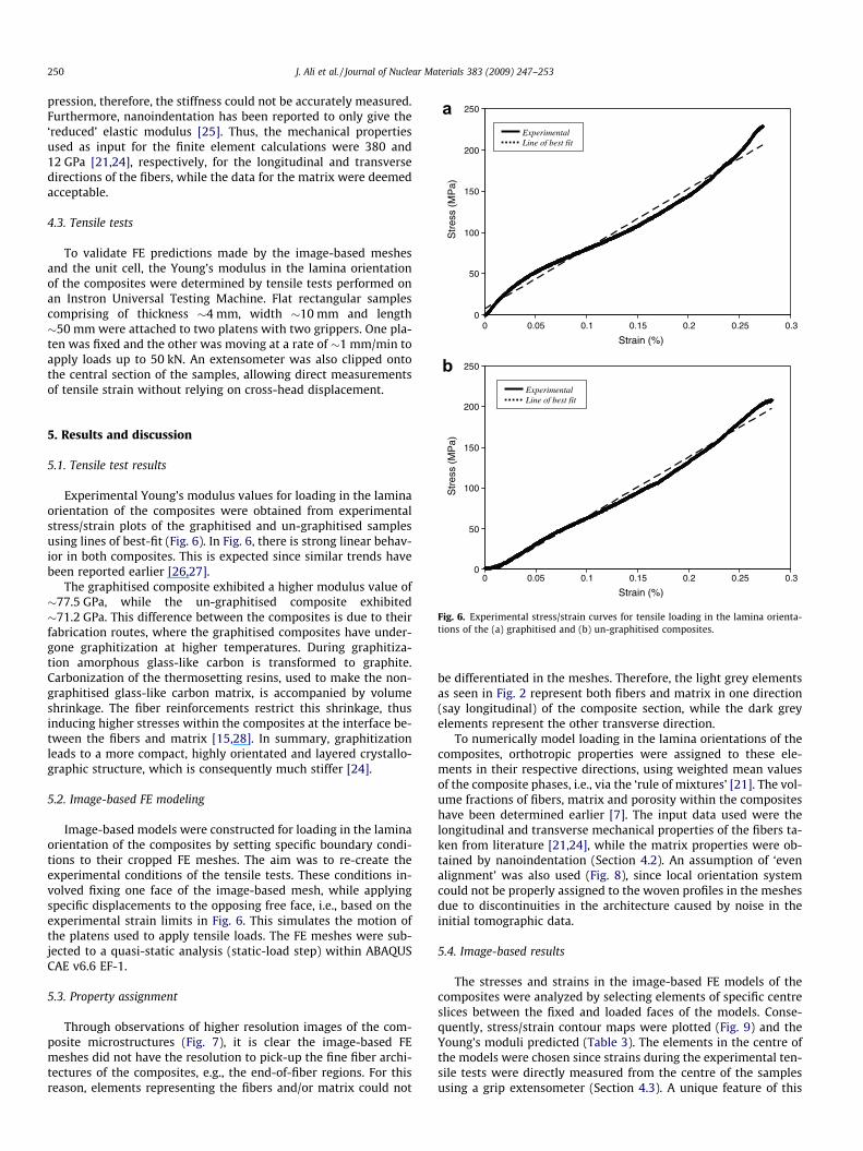
To validate FE predictions made by the image-based meshesand the unit cell, the Young’s modulus in the lamina orientationof the composites were determined by tensile tests performed onan Instron Universal Testing Machine. Flat rectangular samplescomprising of thickness �4 mm, width �10 mm and length�50 mm were attached to two platens with two grippers. One pla-ten was fixed and the other was moving at a rate of �1 mm/min toapply loads up to 50 kN. An extensometer was also clipped ontothe central section of the samples, allowing direct measurementsof tensile strain without relying on cross-head displacement.
0 0.05 0.1 0.15 0.2 0.25 0.30
50
100
150
200
Strain (%)
Str
ess
(MP
a)
Line of best fit
Fig. 6. Experimental stress/strain curves for tensile loading in the lamina orienta-tions of the (a) graphitised and (b) un-graphitised composites.
5. Results and discussion
5.1. Tensile test results
Experimental Young’s modulus values for loading in the laminaorientation of the composites were obtained from experimentalstress/strain plots of the graphitised and un-graphitised samplesusing lines of best-fit (Fig. 6). In Fig. 6, there is strong linear behav-ior in both composites. This is expected since similar trends havebeen reported earlier [26,27].
The graphitised composite exhibited a higher modulus value of�77.5 GPa, while the un-graphitised composite exhibited�71.2 GPa. This difference between the composites is due to theirfabrication routes, where the graphitised composites have under-gone graphitization at higher temperatures. During graphitiza-tion amorphous glass-like carbon is transformed to graphite.Carbonization of the thermosetting resins, used to make the non-graphitised glass-like carbon matrix, is accompanied by volumeshrinkage. The fiber reinforcements restrict this shrinkage, thusinducing higher stresses within the composites at the interface be-tween the fibers and matrix [15,28]. In summary, graphitizationleads to a more compact, highly orientated and layered crystallo-graphic structure, which is consequently much stiffer [24].
5.2. Image-based FE modeling
Image-based models were constructed for loading in the laminaorientation of the composites by setting specific boundary condi-tions to their cropped FE meshes. The aim was to re-create theexperimental conditions of the tensile tests. These conditions in-volved fixing one face of the image-based mesh, while applyingspecific displacements to the opposing free face, i.e., based on theexperimental strain limits in Fig. 6. This simulates the motion ofthe platens used to apply tensile loads. The FE meshes were sub-jected to a quasi-static analysis (static-load step) within ABAQUSCAE v6.6 EF-1.
5.3. Property assignment
Through observations of higher resolution images of the com-posite microstructures (Fig. 7), it is clear the image-based FEmeshes did not have the resolution to pick-up the fine fiber archi-tectures of the composites, e.g., the end-of-fiber regions. For thisreason, elements representing the fibers and/or matrix could not
be differentiated in the meshes. Therefore, the light grey elementsas seen in Fig. 2 represent both fibers and matrix in one direction(say longitudinal) of the composite section, while the dark greyelements represent the other transverse direction.
To numerically model loading in the lamina orientations of thecomposites, orthotropic properties were assigned to these ele-ments in their respective directions, using weighted mean valuesof the composite phases, i.e., via the ‘rule of mixtures’ [21]. The vol-ume fractions of fibers, matrix and porosity within the compositeshave been determined earlier [7]. The input data used were thelongitudinal and transverse mechanical properties of the fibers ta-ken from literature [21,24], while the matrix properties were ob-tained by nanoindentation (Section 4.2). An assumption of ‘evenalignment’ was also used (Fig. 8), since local orientation systemcould not be properly assigned to the woven profiles in the meshesdue to discontinuities in the architecture caused by noise in theinitial tomographic data.
5.4. Image-based results
The stresses and strains in the image-based FE models of thecomposites were analyzed by selecting elements of specific centreslices between the fixed and loaded faces of the models. Conse-quently, stress/strain contour maps were plotted (Fig. 9) and theYoung’s moduli predicted (Table 3). The elements in the centre ofthe models were chosen since strains during the experimental ten-sile tests were directly measured from the centre of the samplesusing a grip extensometer (Section 4.3). A unique feature of this

100µm
Transverse
Shrinkage crack Fibers
End of Fibers
Matrix
10µm
Fig. 7. SEM images of the composite microstructure, showing the end-of-fibers athigher resolution.
1
1
1
2 2
2
3 3
3
3
21
1
2
3 12
3 a
b
Fig. 8. Forms of property assignment (a) local coordinate systems accounting forundulating woven profiles (b) one global coordinate system assuming uniform or‘even’ alignment.
Fig. 9. (a) Stress/strain contour maps for loading in the lamina orientations of theimage-based FE models (graphitised) and (b) porosity effects within the 3Dstructure.
Table 3Experimental results compared to image-based and unit cell FE predictions forYoung’s modulus, E, in the lamina orientations of the composites
Modulus results (GPa) Graphitised composite Un-graphitised composite
Experimental 77.5 71.2Image-based FE model 74.2 (�4.3%) 72.0 (+1.1%)Unit cell FE model 85.0 (+9.7%) 70.0 (�1.7%)
Percentage errors are shown in parenthesis.
J. Ali et al. / Journal of Nuclear Materials 383 (2009) 247–253 251
image-based approach compared to prior unit cell methods [1–3]is that due to the presence of porosities in the model the character-ization of stress effects around the different types of porositiescould be characterized [2], even those within the 3D structure,which has always been difficult to do in the past.
The plotted stress/strain contour maps showed regions in thesamples where higher localized stresses had accumulated due tothe presence of pores. Examples of this have been highlighted in
Fig. 9(b). The results for loading in the lamina orientation of thecomposites indicated that the image-based models showed strongagreement with experimental data, particularly for the un-graphi-tised sample (Table 3). The improved agreement for the un-graph-itised material could be due to the volume sampled in the analysis.The strong agreement of the experimental with the numericallymodeled values demonstrates the validity of these numerical mod-els in this orientation.
5.5. Unit cell FE modeling
The unit cell model adopted for comparison was based on thesame FE analysis used for the image-based models, while the finerarchitectures of the composites were considered, and orthotropic
252 J. Ali et al. / Journal of Nuclear Materials 383 (2009) 247–253
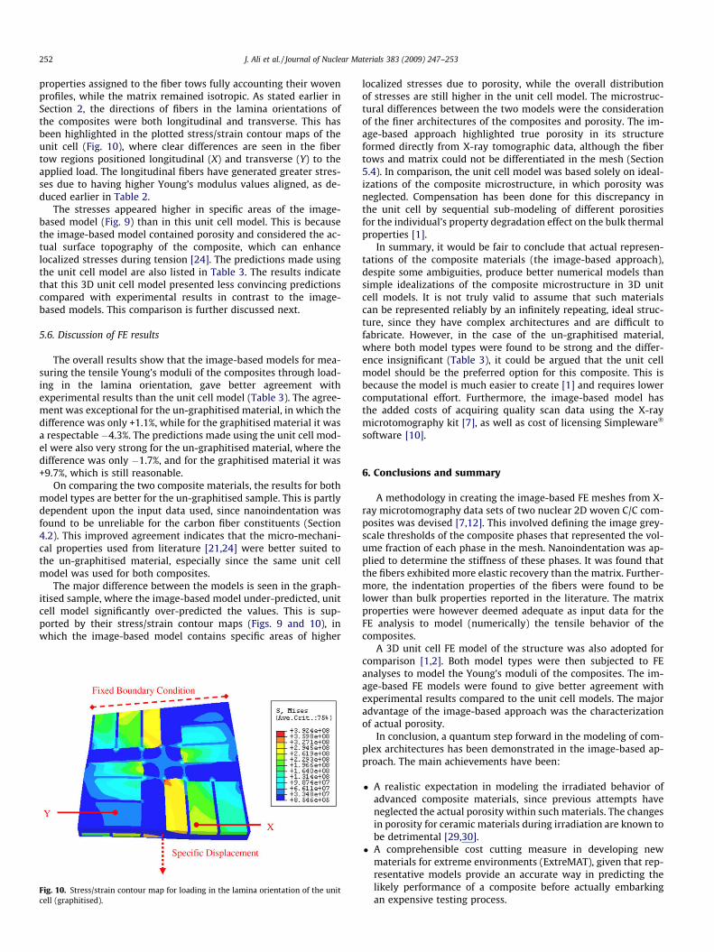
properties assigned to the fiber tows fully accounting their wovenprofiles, while the matrix remained isotropic. As stated earlier inSection 2, the directions of fibers in the lamina orientations ofthe composites were both longitudinal and transverse. This hasbeen highlighted in the plotted stress/strain contour maps of theunit cell (Fig. 10), where clear differences are seen in the fibertow regions positioned longitudinal (X) and transverse (Y) to theapplied load. The longitudinal fibers have generated greater stres-ses due to having higher Young’s modulus values aligned, as de-duced earlier in Table 2.
The stresses appeared higher in specific areas of the image-based model (Fig. 9) than in this unit cell model. This is becausethe image-based model contained porosity and considered the ac-tual surface topography of the composite, which can enhancelocalized stresses during tension [24]. The predictions made usingthe unit cell model are also listed in Table 3. The results indicatethat this 3D unit cell model presented less convincing predictionscompared with experimental results in contrast to the image-based models. This comparison is further discussed next.
5.6. Discussion of FE results
The overall results show that the image-based models for mea-suring the tensile Young’s moduli of the composites through load-ing in the lamina orientation, gave better agreement withexperimental results than the unit cell model (Table 3). The agree-ment was exceptional for the un-graphitised material, in which thedifference was only +1.1%, while for the graphitised material it wasa respectable �4.3%. The predictions made using the unit cell mod-el were also very strong for the un-graphitised material, where thedifference was only �1.7%, and for the graphitised material it was+9.7%, which is still reasonable.
On comparing the two composite materials, the results for bothmodel types are better for the un-graphitised sample. This is partlydependent upon the input data used, since nanoindentation wasfound to be unreliable for the carbon fiber constituents (Section4.2). This improved agreement indicates that the micro-mechani-cal properties used from literature [21,24] were better suited tothe un-graphitised material, especially since the same unit cellmodel was used for both composites.
The major difference between the models is seen in the graph-itised sample, where the image-based model under-predicted, unitcell model significantly over-predicted the values. This is sup-ported by their stress/strain contour maps (Figs. 9 and 10), inwhich the image-based model contains specific areas of higher
Fig. 10. Stress/strain contour map for loading in the lamina orientation of the unitcell (graphitised).
localized stresses due to porosity, while the overall distributionof stresses are still higher in the unit cell model. The microstruc-tural differences between the two models were the considerationof the finer architectures of the composites and porosity. The im-age-based approach highlighted true porosity in its structureformed directly from X-ray tomographic data, although the fibertows and matrix could not be differentiated in the mesh (Section5.4). In comparison, the unit cell model was based solely on ideal-izations of the composite microstructure, in which porosity wasneglected. Compensation has been done for this discrepancy inthe unit cell by sequential sub-modeling of different porositiesfor the individual’s property degradation effect on the bulk thermalproperties [1].
In summary, it would be fair to conclude that actual represen-tations of the composite materials (the image-based approach),despite some ambiguities, produce better numerical models thansimple idealizations of the composite microstructure in 3D unitcell models. It is not truly valid to assume that such materialscan be represented reliably by an infinitely repeating, ideal struc-ture, since they have complex architectures and are difficult tofabricate. However, in the case of the un-graphitised material,where both model types were found to be strong and the differ-ence insignificant (Table 3), it could be argued that the unit cellmodel should be the preferred option for this composite. This isbecause the model is much easier to create [1] and requires lowercomputational effort. Furthermore, the image-based model hasthe added costs of acquiring quality scan data using the X-raymicrotomography kit [7], as well as cost of licensing Simpleware�
software [10].
6. Conclusions and summary
A methodology in creating the image-based FE meshes from X-ray microtomography data sets of two nuclear 2D woven C/C com-posites was devised [7,12]. This involved defining the image grey-scale thresholds of the composite phases that represented the vol-ume fraction of each phase in the mesh. Nanoindentation was ap-plied to determine the stiffness of these phases. It was found thatthe fibers exhibited more elastic recovery than the matrix. Further-more, the indentation properties of the fibers were found to belower than bulk properties reported in the literature. The matrixproperties were however deemed adequate as input data for theFE analysis to model (numerically) the tensile behavior of thecomposites.
A 3D unit cell FE model of the structure was also adopted forcomparison [1,2]. Both model types were then subjected to FEanalyses to model the Young’s moduli of the composites. The im-age-based FE models were found to give better agreement withexperimental results compared to the unit cell models. The majoradvantage of the image-based approach was the characterizationof actual porosity.
In conclusion, a quantum step forward in the modeling of com-plex architectures has been demonstrated in the image-based ap-proach. The main achievements have been:
� A realistic expectation in modeling the irradiated behavior ofadvanced composite materials, since previous attempts haveneglected the actual porosity within such materials. The changesin porosity for ceramic materials during irradiation are known tobe detrimental [29,30].
� A comprehensible cost cutting measure in developing newmaterials for extreme environments (ExtreMAT), given that rep-resentative models provide an accurate way in predicting thelikely performance of a composite before actually embarkingan expensive testing process.
J. Ali et al. / Journal of Nuclear Materials 383 (2009) 247–253 253
References
[1] J.K. Farooqi, M.A. Sheikh, Compos. Mater. Sci. 37 (2006) 361.[2] P. Del Puglia, M.A. Sheikh, D.R. Hayhurst, Composites Part A 35 (2004) 223.[3] E.J. Barbero, T.M. Damiani, J. Trovillion, Int. J. Solids Struct. 42 (2005) 2489.[4] D. Scida, Z. Aboura, M.L. Benzegagh, E.A. Bocherens, Compos. Sci. Technol. 59
(1999) 505.[5] K.M. Entwistle, Basic Principles of the Finite Element Method, IOM
Communications Ltd., London, 1999.[6] M. Alenius, Finite Element Modelling of Composite Bridge Stability, MSc
Thesis, Royal Institute of Technology, Department of Mechanics, Stockholm,2003.
[7] J. Ali, C. Berre, P.M. Mummery, Energy Mater. 1 (2006) 179.[8] T.J. Marrow, J.Y. Buffiere, P.J. Withers, G. Johnson, D. Engelberg, Int. J. Fatigue 26
(2004) 717.[9] L. Babout, P.M. Mummery, T.J. Marrow, A. Tzelepi, P.J. Withers, Carbon 43
(2005) 765.[10] Simpleware� Ltd., Innovation Centre, Rennes Drive, Exeter, EX4 4RN, UK.[11] ABAQUS CAE v6.6 EF-1 (2007), ABAQUS/CAE, ABAQUS Inc., Rhode Island, USA.[12] J. Ali, P.M. Mummery, in: Proceedings, Seventh IEA International Workshop on
SiC/SiC Composites for Fusion and Advanced Fission Applications, September2006, Petten, Holland, NRG.
[13] S. Youssef, E. Maire, R. Gaertner, Acta Mater. 53 (2005) 719.[14] P. Babin, G. Della Valle, R. Dendievel, N. Lassoued, L. Salvo, J. Mater. Sci. 40
(2005) 5867.
[15] C. Berre, S.L. Fok, B.J. Marsden, L. Babout, A. Hodgkins, T.J. Marrow, P.M.Mummery, J. Nucl. Mater. 352 (2006) 1.
[16] O. Amsellem, K. Madi, F. Borit, D. Jeulin, V. Guipont, M. Jeandin, E. Boller, F.Pauchet, J. Mater. Sci. 43 (2008) 4091.
[17] D. Ulrich, B. Van Rietbergen, A. Laib, P. Ruegsegger, J. Biomech. 32 (1999)821.
[18] P. Magne, Dent. Mater. 23 (2007) 539.[19] J.D. Wolodko, Z. Xia, F. Ellyin, Mater. Sci. Technol. 16 (2000) 837.[20] Hysitron Inc., 10025 Valley View Road, Minneapolis, MN 55344, USA.[21] D. Hull, T.W. Clyne, An Introduction to Composite Materials, second ed.,
Cambridge University Press, 1993.[22] D.T. Marx, L. Riester, Carbon 37 (1999) 1679.[23] C.R. Thomas, Essentials of Carbon–Carbon Composites, Royal Society of
Chemistry, Cambridge, 1993.[24] K.K. Chawla, Ceramic Matrix Composites, Chapman & Hall, 1993.[25] M. Zhao, C. Jiang, S. Li, S.X. Mao, Mater. Sci. Eng. A 409 (2005) 223.[26] B.N. Cox, G. Flanagan, Handbook of Analytical Methods for Textile Composites,
Contractor Report, National Aeronautics and Space Administration (NASA),USA, 1997.
[27] P.B. Pollock, Carbon 28 (1990) 717.[28] F.A. Quli, P.A. Thrower, L.R. Radovic, Carbon 36 (1998) 1623.[29] K. Hamada, S. Sato, A. Kohyama, J. Nucl. Mater. 212–215 (p-2) (1994)
1228.[30] S. Blazewicz, J. Piekarczyk, J. Chlopek, J. Blocki, J. Michalowski, M. Stodulski, P.
Zychowski, Carbon 40 (2002) 721.