Neural network analysis for erosion wear of nickel-aluminide coatings on steel by plasma spraying
10
Neural Network Analysis for Erosion Wear of Nickel- Aluminide Coatings on Steel by Plasma Spraying S C Mishra 1 , M Chaithanya 1 , Alok Satapathy 1 , P V Ananthapadmanabhan 2 , K P Sreekumar 2 1 National Institute of Technology, Rourkela 2 Laser & Plasma Technology Division, B.A.R.C., Mumbai 1 corresponding author: [email protected] ABSTRACT In the present investigation plasma spray inter metallic coating of Nickel-aluminide was deposited on mild steel substrates. The response of plasma sprayed nickel-aluminide coatings to the impingement of such solid particles has been presented in this work. Nickel pre-mixed with alumina powder is deposited on mild steel substances by atmospheric plasma spraying at various operating power level. The coatings are subjected to erosion wear test. An erosion test setup developed in our laboratory is used to simulate real time erosive situations. Dry silica sand of average particle size 400 micron is used as the erodent. The erosion rate is calculated on the basis of ‘coating mass losses. The erosion studies are made and different velocities and impingement angles. A computational technique (ANN analysis) is used to predict the rate of erosion wear under various operational conditions. This technique involves database training to predict property parameter evolutions in process having large number of interdependent variables. This paper presents the database construction, implementation protocol and also the set of predicted results related to the erosion wear rate of nickel-aluminide coating. It is shown that the erosion wear is strongly influenced by the angle of impact. The test is conducted at room temperature i.e.27 o C and 60% RH. Ni 3 Al coatings deposited at different power levels (10, 12, 16, 20, 24 kW) are found to exhibit different wear rate under similar test conditions. INTRODUCTION Inter metallic compounds find extensive use in high temperature structural applications [1-4]. In particular, these alloys have potential demand in aerospace industry and other high performance applications [3, 4]. In thermal spray applications, nickel aluminides and their derivative alloys are used as bond coat materials, where their function is to minimize the thermo-mechanical stresses at the substrate-coating interface and also to promote coating adhesion [5]. The coefficient of thermal expansion of these alloys is intermediate between those of ceramics and metals and therefore can take care of interface stresses. Moreover, the reaction leading to the formation of the alloy is highly exothermic leading to better coating adhesion. The nickel-aluminide (Ni 3 Al) has drawn enormous attention because of its technological and scientific interest. In addition to wear related application, it is mostly used as bond coat for ceramic materials [ 6 ]. Nickel based coatings are used in applications 23rd National Symposium on Plasma Science & Technology (PLASMA-2008) IOP Publishing Journal of Physics: Conference Series 208 (2010) 012112 doi:10.1088/1742-6596/208/1/012112 c 2010 IOP Publishing Ltd 1
-
Upload
independent -
Category
Documents
-
view
3 -
download
0
Transcript of Neural network analysis for erosion wear of nickel-aluminide coatings on steel by plasma spraying

Neural Network Analysis for Erosion Wear of Nickel-
Aluminide Coatings on Steel by Plasma Spraying
S C Mishra
1, M Chaithanya
1, Alok Satapathy
1,
P V Ananthapadmanabhan2, K P Sreekumar
2
1National Institute of Technology, Rourkela
2Laser & Plasma Technology Division, B.A.R.C., Mumbai
1corresponding author: [email protected]
ABSTRACT
In the present investigation plasma spray inter metallic coating of Nickel-aluminide was
deposited on mild steel substrates. The response of plasma sprayed nickel-aluminide coatings to
the impingement of such solid particles has been presented in this work. Nickel pre-mixed with
alumina powder is deposited on mild steel substances by atmospheric plasma spraying at
various operating power level. The coatings are subjected to erosion wear test. An erosion test
setup developed in our laboratory is used to simulate real time erosive situations. Dry silica sand
of average particle size 400 micron is used as the erodent. The erosion rate is calculated on the
basis of ‘coating mass losses. The erosion studies are made and different velocities and
impingement angles. A computational technique (ANN analysis) is used to predict the rate of
erosion wear under various operational conditions. This technique involves database training to
predict property parameter evolutions in process having large number of interdependent
variables. This paper presents the database construction, implementation protocol and also the
set of predicted results related to the erosion wear rate of nickel-aluminide coating. It is shown
that the erosion wear is strongly influenced by the angle of impact. The test is conducted at
room temperature i.e.27oC and 60% RH. Ni3Al coatings deposited at different power levels (10,
12, 16, 20, 24 kW) are found to exhibit different wear rate under similar test conditions.
INTRODUCTION
Inter metallic compounds find extensive use in high temperature structural applications [1-4]. In
particular, these alloys have potential demand in aerospace industry and other high performance applications [3, 4]. In thermal spray applications, nickel aluminides and their derivative alloys are
used as bond coat materials, where their function is to minimize the thermo-mechanical stresses at the
substrate-coating interface and also to promote coating adhesion [5]. The coefficient of thermal
expansion of these alloys is intermediate between those of ceramics and metals and therefore can take
care of interface stresses. Moreover, the reaction leading to the formation of the alloy is highly
exothermic leading to better coating adhesion. The nickel-aluminide (Ni3Al) has drawn enormous
attention because of its technological and scientific interest. In addition to wear related application, it
is mostly used as bond coat for ceramic materials [ 6 ]. Nickel based coatings are used in applications
23rd National Symposium on Plasma Science & Technology (PLASMA-2008) IOP PublishingJournal of Physics: Conference Series 208 (2010) 012112 doi:10.1088/1742-6596/208/1/012112
c© 2010 IOP Publishing Ltd 1

when wear resistance combined with oxidation or hot corrosion resistance is required [ 7 ]. It is the
most important strengthening constituent, generally referred to as γ-phase of commercial Ni- base
super-alloys used extensively as high temperature structural materials for jet engines and aerospace
applications. It is responsible for the high strength and creep resistance of the super-alloys at elevated
temperatures. Ni3Al containing about 25% Al has the ability to form protective aluminum-oxide scales, resulting in excellent oxidation resistance.
In the present investigation, attempts are made to deposit nickel-aluminide on steel substrates (mild
steel) with varying the particle size. Erosion wear tests were carried out on the coatings to ensure its
applicability. Solid particle erosion is a process where particles strike against a surface and cause
material loss. During flight, a particle carries momentum and kinetic energy, which is dissipated
during impact due to its interaction with a target surface. Erosion is a non-linear process with respect
to its variables: either materials or operating conditions. To obtain the best functional output coatings
exhibiting selected in-service properties and the right combinations of operating parameters are to be
known. These combinations normally differ by their influence on the erosion wear rate or coating
mass loss. In order to achieve certain values of erosion wear rate accurately and repeatedly, the
influence parameters of the process have to be controlled accordingly. Since the number of such
parameters in erosion wear is too large and the parameter-property correlations are not always known,
statistical methods can be employed for precise identification of significant control parameters for
optimization. Neural computation can be used as a tool to process very large data related to a spraying
process and to predict any desired coating characteristic the simulation can be extended to a parameter
space larger than the domain of experimentation.
EXPERIMENTAL DETAILS
Coating Deposition:
Nickel and aluminum powders were taken in a ratio of 3:1 by weight and were mixed thoroughly in a
planetary ball mill to get homogeneous mixture. This mixture was sprayed on mild steel substrates of
dimensions 50×20×3 mm. Spraying is done is using a 40 kW APS (atmospheric plasma spray) system
in the thermal plasma laboratory at NIT Rourkela. This is a typical plasma spray system operating in
the non-transferred mode. The major components of this set up include the plasma torch, power
supply, power feeder, plasma gas supply, control console, cooling water and spray booth. Prior to
spraying, the substrates were grit blasted by compressed air at the pressure of 3kgf/cm2. A current
regulated dc power supply was used. A four stage closed loop centrifugal pump at a pressure of 10
kgf/cm2 supplied cooling water for the system. The primary plasma gas (argon) and the secondary gas
(nitrogen) were taken from normal cylinders at an outlet pressure of 4kgf/cm2. The plasma torch
input power was varied from 10 to 24 kW by controlling the gas flow rate, plasma arc current and the arc voltage. The powder feed rate was kept constant at about 50 gm/min by a turntable type
volumetric powder feeder. Weighing method is accepted widely to calculate the deposition efficiency.
Weighing of samples is done using a precision electronic balance with + 0.1 mg accuracy. Operating
parameters used during the spraying are given in table-1.
23rd National Symposium on Plasma Science & Technology (PLASMA-2008) IOP PublishingJournal of Physics: Conference Series 208 (2010) 012112 doi:10.1088/1742-6596/208/1/012112
2

Table 1 Operating parameters used during the plasma spraying process
Parameter Range
Torch input power
Current
Voltage
Plasma gas (Ar) flow rate
Secondary gas (N2) flow rate
Powder feed rate
Carrier gas (Ar) flow rate
Torch to base distance
10-24 kW
250-480 Amp
40-50 Volt
20 lpm
2 lpm
50 gm/min
12 lpm
100 mm
Erosion Test
Solid Particle Erosion (SPE) is a wear process where particles strike against surfaces and promote
material loss. During flight a particle carries momentum and kinetic energy, which can be dissipated
during impact, due to its interaction with a target surface. Different models have been proposed that allow estimations of the stresses that a moving particle will impose on a target [ 8 ]. It has been
experimentally observed by many investigators that during the impact the target can be locally
scratched, extruded, melted and/or cracked in different ways [9, 10, and 11]. The imposed surface
damage will vary with the target material, erodent particle, impact angle, erosion time, particle
velocity, temperature and atmosphere [9, 12].
Plasma sprayed coatings are used today as erosion or abrasion resistant coatings in a wide variety of
applications [13]. Extensive research shows that the deposition parameters like energy input in the
plasma and powder properties affect the porosity, splat size, phase composition, hardness etc. of
plasma sprayed coatings [ 14-18 ].
Solid particle erosion is usually simulated in laboratory by one of two methods. The ‘sand blast’
method, where particles are carried in an air flow and impacted onto a stationary target and the
‘whirling arm’ method , where the target is spun through a chamber of falling particles. In the present
investigation, an erosion apparatus (self-made) of the ‘sand blast’ type is used. It is capable of
creating highly reproducible erosive situations over a wide range of particle sizes, velocities, particles
fluxes and incidence angles, in order to generate quantitative data on materials and to study the
mechanisms of damage. The test is conducted as per ASTM G76 standards.
The jet erosion test rig used in this work employs a 300 mm long nozzle of 3 mm bore and 300 mm
long. This nozzle size permits a wider range of particle types to be used in the course of testing,
allowing better simulations of real erosion conditions. The mass flow rate is measured by
conventional method. Particles are fed from a simple hopper under gravity into the groove. Velocity
of impact is measured using double disc method [19].Some of the features of this test set up are:
23rd National Symposium on Plasma Science & Technology (PLASMA-2008) IOP PublishingJournal of Physics: Conference Series 208 (2010) 012112 doi:10.1088/1742-6596/208/1/012112
3

• Vertical traverse for the nozzle: provides variable nozzle to target standoff distance, which
influences the size of the eroded area.
• Different nozzles may be accommodated: provides ability to change the particle plume
dimensions and the velocity range.
• Large test chamber with sample mount that can be angled to the flow direction: by tilting the
sample stage, the angle of impact of the particles can be changed in the range of 00 – 900 and
this will influence the erosion process.
In this work, room temperature solid particle erosion test on mild steel substrate coated with nickel-
aluminide feed materials(at 20 kW) is carried out under five different impact angles 15o, 30°, 45
o, 60°
and 90°. The nozzle is kept at 100mm stand-off distance from the target. 400µm average size dry
silica sand particles are used as erodent with three different impact velocities 31.2m/s, 44.2m/s and
58.5m/s and pressure 4-7kgf/cm2. 7cm
2 area of each coating sample is exposed to the compressed air
jet carrying erodent. Amount of wear is determined on ‘mass loss’ basis. It is done by measuring the
mass of the samples at the beginning of the test and at regular intervals in the test duration. A
precision electronic balance with + 0.1 mg accuracy is used for weighing. Erosion rate, defined as the
coating mass loss per unit erodent mass (mg/g) is calculated.
ARTIFICIAL NEURAL NETWORK (ANN) ANALYSIS
Erosion wear rate not only depends on the mass flow, impact angle and velocity of the erodent, also
depends on the spraying parameters. Only the spraying process is dependent on around 150 factors,
hence we cannot account all the factors during the experiment. To account all the factors, Prediction
of erosion wear rate properties by some numerical technique is one of the most important
requirements. Artificial neural networks have the ability to tackle the problem of complex
relationships among variables that cannot be accomplished by more traditional methods. Simple linear
regression is not an answer for process like these that have nonlinear properties. Another advantage of
using neural network model is that it can predict an output with accuracy even if the variable
interactions are not completely understood. Artificial neural networks (ANN), which is a technique
that involves, database training to predict property-parameter evolutions. This section presents the database construction, implementation protocol and a set of predicted results related to the erosion
wear rate. The details of this methodology are described by Rajasekaran and Pai [20].
NEURAL NETWORK MODEL: Development and Implementation
An ANN is a computational system that simulates the microstructure (neurons) of biological nervous
system. The most basic components of ANN are modeled after the structure of brain. Inspired by
these biological neurons, ANN is composed of simple elements operating in parallel. It is the simple
clustering of the primitive artificial neurons. This clustering occurs by creating layers, which are then
connected to one another. The multilayered neural network has been utilized in the most of the
research works for material science. A software package NEURALNET for neural computing
developed by Rao and Rao [21] using back propagation algorithm is used as the prediction of erosion
wear rate at different impact angles and velocities.
The database is built considering experiments at the limit ranges of each parameter. Experimental
result sets are used to train the ANN in order to understand the input-output correlations. The database
is then divided into three categories, namely: a validation category, which is required to define the
ANN architecture and adjust the number of neurons for each layer. a training category, which is
23rd National Symposium on Plasma Science & Technology (PLASMA-2008) IOP PublishingJournal of Physics: Conference Series 208 (2010) 012112 doi:10.1088/1742-6596/208/1/012112
4

Table 2 Input parameters selected for training
Input Parameters for Training Values
Error tolerance 0.0001
Learning parameter(ß) 0.1
Momentum parameter(α) 0.002
Noise factor (NF) 0.0001
Maximum cycles for simulations 2000,000
Slope parameter (£) 0.6
Number of hidden layer neuron 6
Number of input layer neuron (I) 2
Number of output layer neuron (O) 1
exclusively used to adjust the network weights and a test category , which corresponds to the set that
validates the results of the training protocol. The input variables are normalized so as to lie in the same range group of 0-1. To train the neural network used for this work, about 45 data sets on
selected substrates are taken. It is ensured that these extensive data sets represent all possible input
variations within the experimental domain. So a network that is trained with this data is expected to be
capable of simulating the plasma spray process. Different ANN structures (I-H-O) with varying
number of neurons in the hidden layer are tested at constant cycles, learning rate, error tolerance,
momentum parameter and noise factor and slope parameter. Based on least error criterion, one
structure, shown in table 2, is selected for training of the input-output data. The network optimization process (training and testing) is conducted for 2000,000 cycles for which stabilization of the error is
obtained. Neuron numbers in the hidden layer is varied and in the optimized structure of the network,
this number is 6. The number of cycles selected during training is high enough so that the ANN
models could be rigorously trained. Fig.1 presents the optimized three layer network.
23rd National Symposium on Plasma Science & Technology (PLASMA-2008) IOP PublishingJournal of Physics: Conference Series 208 (2010) 012112 doi:10.1088/1742-6596/208/1/012112
5

Fig 1. The three layer neural network
Hidden layer ( H )
Output layer ( O ) Input layer ( I )
Fig.2 Comparison plot for predicted and experimental values of Erosion rate
[Impact velocity =31.2m/s]
4.50E-05
4.70E-05
4.90E-05
5.10E-05
5.30E-05
5.50E-05
5.70E-05
5.90E-05
6.10E-05
0 15 30 45 60 75 90 105
Impact Angle (degree)
Ero
sio
n rate
(g/g
)
Experimental
ANN predicted
ANN PREDICTION OF EROSION WEAR RATE
The prediction neural network was tested with nine data sets from the original process data. Each data
set contained inputs such as impact velocity, impact angle and an output value i.e. erosion wear rate
23rd National Symposium on Plasma Science & Technology (PLASMA-2008) IOP PublishingJournal of Physics: Conference Series 208 (2010) 012112 doi:10.1088/1742-6596/208/1/012112
6

was returned by the network. As further evidence of the effectiveness of the model, an arbitrary set of
inputs is used in the prediction network. Results were compared to experimental sets that may or may
not be considered in the training or in the test procedures. Fig. 2 presents the comparison of predicted
output values for erosion wear rate with those obtained experimentally at three different impact
velocities 31.2m/s, 44.2m/s and 58.5m/s.
Fig.3 Comparison plot for predicted and experimental values of Erosion rate
[Impact velocity =44.2m/s]
4.90E-05
5.10E-05
5.30E-05
5.50E-05
5.70E-05
5.90E-05
6.10E-05
0 15 30 45 60 75 90 105
Impact Angle (degree)
Ero
sio
n rate
(g/g
)
Experimental
ANN predicted
Fig.4 Comparison plot for predicted and experimental values of Erosion rate
[Impact velocity =58.5m/s]
5.10E-05
5.30E-05
5.50E-05
5.70E-05
5.90E-05
6.10E-05
6.30E-05
6.50E-05
6.70E-05
6.90E-05
7.10E-05
0 15 30 45 60 75 90 105Impact Angle (degree)
Ero
sio
n rate
(g/g
)
Experimental
ANN predicted
23rd National Symposium on Plasma Science & Technology (PLASMA-2008) IOP PublishingJournal of Physics: Conference Series 208 (2010) 012112 doi:10.1088/1742-6596/208/1/012112
7
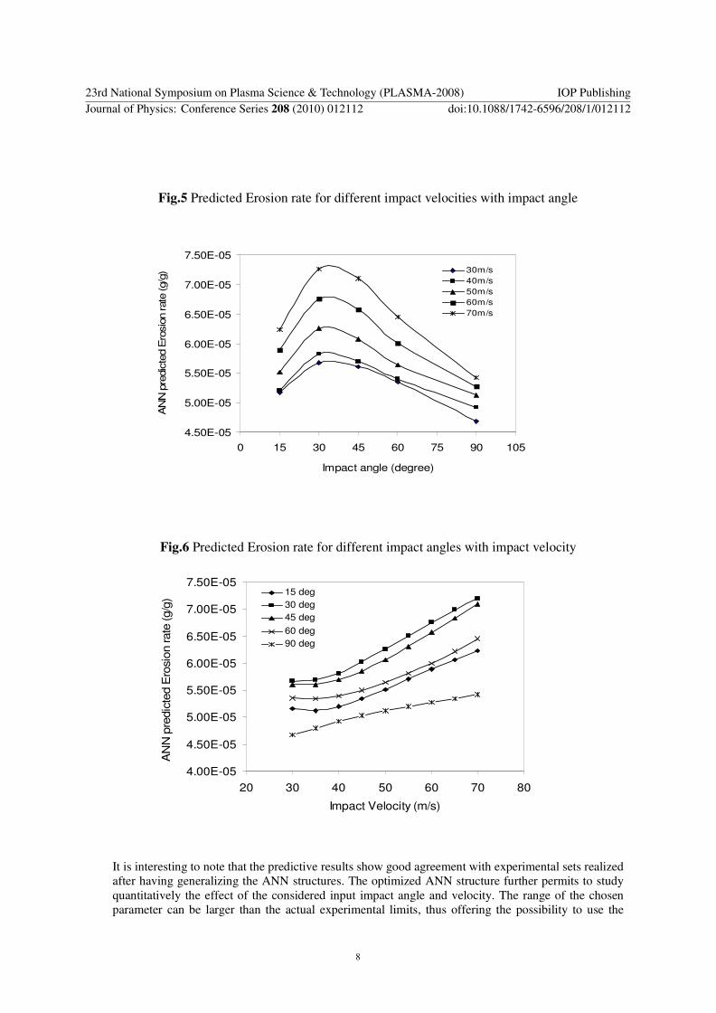
Fig.5 Predicted Erosion rate for different impact velocities with impact angle
4.50E-05
5.00E-05
5.50E-05
6.00E-05
6.50E-05
7.00E-05
7.50E-05
0 15 30 45 60 75 90 105
Impact angle (degree)
AN
N p
redic
ted E
rosio
n rate
(g/g
) 30m/s
40m/s
50m/s
60m/s
70m/s
Fig.6 Predicted Erosion rate for different impact angles with impact velocity
4.00E-05
4.50E-05
5.00E-05
5.50E-05
6.00E-05
6.50E-05
7.00E-05
7.50E-05
20 30 40 50 60 70 80
Impact Velocity (m/s)
AN
N p
redic
ted E
rosio
n rate
(g/g
)
15 deg
30 deg
45 deg
60 deg
90 deg
It is interesting to note that the predictive results show good agreement with experimental sets realized
after having generalizing the ANN structures. The optimized ANN structure further permits to study
quantitatively the effect of the considered input impact angle and velocity. The range of the chosen
parameter can be larger than the actual experimental limits, thus offering the possibility to use the
23rd National Symposium on Plasma Science & Technology (PLASMA-2008) IOP PublishingJournal of Physics: Conference Series 208 (2010) 012112 doi:10.1088/1742-6596/208/1/012112
8

generalization property of ANN in a large parameter space. In the present investigation, this
possibility was explored by selecting the impact velocity in a range from 30 m/s to 70m/s, and a set of
prediction for erosion wear rate is evolved. Fig.5 illustrates the predicted evolution of erosion wear
rate of nickel aluminide coatings on mild steel substrate with impact angle at different velocities and
fig.6 illustrates the predicted evolution of erosion wear rate with impact velocity at different impact angles.
As seen in fig. 5, the erosion wear rate for the different impact velocities shows a similar effect
like first it is increases linearly from 15o to 30
o, again it decreases. For the nickel-aluminide
coating, the erosion wear rate at a 30o impact angle was higher than at a 90
o impact angle.
And in fig.6, the erosion rate presents a sigmoid-type evolution with the impact velocity. As the
impact velocity increases, a remarkable increase of the erosion rate, the maximum mass loss moves at
30o impact angle with the increase of the impact speed. Erosion rate is increasing linearly from 15o to
30o and it decreases linearly to 90o with the increase of the impact speed. There fore the coating
basically displays its erosion behavior as a ductile material.
CONCLUSIONS
For nickel-aluminide coatings, the erosion rate at 30o impact angle was higher than at 90
o impact
angle, thus suggesting the ductile behavior of the coating. In order to achieve certain values of erosion
wear rate accurately and repeatedly, the influence parameters of the process have to be controlled
accordingly. Neural computation can be gainfully employed as a tool for this purpose. The simulation
can be extended to a parameter space larger than the domain of experimentation.
REFERENCES
[1] Liu C T and White C L, in High Temp. Ordered Intermetallic Alloys, ed. by
Koch C C, Liu C T and Stoloff N S, Mat. Res. Soc., 39, 365 (1985)
[2] Cahn R W, Load-Bearing Ordered Intermetallic Compounds- A Historical View,
MRS Bulletin, 5, 18 (1991)
[3] Chen J Z, Herman H and Safai S, Evaluation of NiAl and NiAl-B Deposited by
Vacuum Plasma Spray, J. Thermal Spray Technology, 2, 357 (1993)
[4] Liu C and Sikka V K, Nickel Aluminides for Structural Uses, J. of Metals, 38,
13 (1986)
[5] Robert B Hiemann, Plasma-Spray Coating-Principles and Applications, VCH
Publishers Inc., New York, NY, USA, (1996)
[6] Lee N Y, Stinton D P, Brandt C C, Erdogan F, Lee Y D and Mutasim Z 1996, J. Am. Cer. Soc., v 79(12), P, 3003.
[7] Rosso M, Bennani A, PM World Congress Thermal Spraying/ Spray Forming,
1998, p.524
[8] Angle, P. A. Impact Wear of Materials, (Elsevier; New York, 1976).
[9] Tilly G P, “Erosion Caused by Impact of Solid Particles”, in Herman H (ed),
Treatise on Materials Science and Technology, vol. 13:D. Scott(ed), Wear.
23rd National Symposium on Plasma Science & Technology (PLASMA-2008) IOP PublishingJournal of Physics: Conference Series 208 (2010) 012112 doi:10.1088/1742-6596/208/1/012112
9

(Academic Press: New York, 1979) p. 287 – 320.
[10] Erosion by Liquid and Solid Impact. (Cavendish Laboratory, University of
Cambridge: Cambridge, England, 1979).
[11] Erosion by Liquid and Solid Impact. (Cavendish Laboratory, University of
Cambridge: Cambridge, England, 1987).
[12] Evans, A G “Impact Damage Mechanism – Solid Projectile”, in Herman H (ed.),
Treatise on Materials Science and Technology, Vol. 16: Preece C M (ed.),
Materials Erosion, (Academic Press: New York, 1979), p. 1 – 67.
[13] The erosion and abrasion characteristics of alumina coatings plasma sprayed under
different spraying conditions Westergard R, Erickson L C, Axen N,
Hawthorne H M and Hogmark S, Tribology International, Volume #1, Issue%,
May 1998, Pages 271 – 279
[14] Tucker, R C Jr., On the relationship between the microstructure and the wear
characterstics of selected thermal spray coatings. Proceeding of ITSC, Kobe,
Japan, 1995, pp. 477 – 482.
[15] Hawthorne H M, Erickson L C, Ross D, Tai H and Troczynski T, The
. microstructurral dependence of wear and indentation behaviour of some plasma
sprayed alumina coatings. Wear 203 – 204 (1997), pp. 709 – 714
[16] Erickson L C, Troczynski T, Ross D, Tai H and Hawthorne H M, Processing
– dependent microstructure and wear – related surface properties of plasma
sprayed alumina coatings, presented to World Tribology Congress, Londan, U.
K., September 1997.
[17] Erickson L C, Troczynski T, Hawthorne H M, Tai H and Ross D, Alumina
coatings by plasma spraying of monosize sapphire powders, published in the proceedings of ITSC’98, Nice, France .
[18] Ohmori A, Li C J and Arata Y, Influence of Plasma spray conditions on the
structure of Al2O3 coatings. Trans. Of JWRI 19 2 (1990), pp. 99 – 110.
[19] Venkataraman B – Evaluation of Tribological Coatings – Proc. of DAE-BRNS.
Workshop on Plasma Surface Engineering, BARC, Mumbai, September 2004,
pp. 217 – 235
[20] Rajasekaran S , Vijayalakshmi G A, Pai --Neural Networks, Fuzzy Logic And
Genetic Algorithms—Synthesis and Applications -Prentice Hall of India Pvt.
Ltd. , New Delhi (2003)
[21] Rao V and Rao H, ‘C++ Neural Networks and Fuzzy Systems’ BPB Publication
2000.
23rd National Symposium on Plasma Science & Technology (PLASMA-2008) IOP PublishingJournal of Physics: Conference Series 208 (2010) 012112 doi:10.1088/1742-6596/208/1/012112
10