Correlation of microstructure and wear resistance of molybdenum blend coatings fabricated by...
12
Materials Science and Engineering A366 (2004) 152–163 Correlation of microstructure and wear resistance of molybdenum blend coatings fabricated by atmospheric plasma spraying Byoungchul Hwang a , Sunghak Lee a,∗ , Jeehoon Ahn b a Center for Advanced Aerospace Materials, Pohang University of Science and Technology, Pohang 790-784, South Korea b Materials & Processes Research Center, Research Institute of Industrial Science and Technology, Pohang 790-600, South Korea Received 6 June 2003; received in revised form 5 September 2003 Abstract The correlation of microstructure and wear resistance of various molybdenum blend coatings applicable to automotive parts was investigated in this study. Five types of spray powders, one of which was pure molybdenum powder and the others were blends of brass, bronze, and aluminum alloy powders with molybdenum powder, were deposited on a low-carbon steel substrate by atmospheric plasma spraying (APS). Microstructural analysis of the coatings showed that they consisted of a curved lamellar structure formed by elongated splats, with hard phases that formed during spraying being homogeneously distributed in the molybdenum matrix. The wear test results revealed that the blend coatings showed better wear resistance than the pure molybdenum coating because they contained a number of hard phases. In particular, the molybdenum coating blended with bronze and aluminum alloy powders and the counterpart material showed an excellent wear resistance due to the presence of hard phases, such as CuAl 2 and Cu 9 Al 4 . In order to improve overall wear properties for the coating and the counterpart material, appropriate spray powders should be blended with molybdenum powders to form hard phases in the coatings. © 2003 Elsevier B.V. All rights reserved. Keywords: Atmospheric plasma spraying; Molybdenum blend coating; Pin-on-disc wear test; Wear resistance; Hardness 1. Introduction In plasma spraying method, a coated layer is formed on a substrate surface by spraying melted powders onto a substrate at a high speed, using a high-temperature plasma heat source. The plasma spraying method is the most eco- nomical and effective method applied to automotive parts, such as cylinder bores, synchronizer rings, crankshafts, and piston rings, in order to reduce their surface degradation [1–3]. For the coating materials for synchronizer rings or piston rings, molybdenum and molybdenum alloy powders which have an excellent resistance to heat and wear have been studied, and the coating technology has been commercial- ized in the USA and European countries for the luxury cars. Despite its high-temperature hardness and corrosion resis- tance, Mo does pose problems of high price, embrittlement caused by high hardness, and poor deformability. In or- ∗ Corresponding author. Tel.: +82-54-279-2140; fax: +82-54-279-2399. E-mail address: [email protected] (S. Lee). der to overcome these shortcomings studies have been un- dertaken towards enhancing overall wear properties of Mo coatings by blending or alloying powders such as NiCrBSi, MoO 2 /MoO, Mo 2 C, and MoSi 2 with Mo powders [4–7]. Though most of the coatings fabricated by this way show excellent hardness and wear resistance, they can cause se- rious wear on the counterpart material, thereby leading to limitations when applied to automotive parts, such as cylin- der bores, synchronizer rings, and piston rings which require excellent wear properties of both the coating and the coun- terpart material. In order as to improve overall wear resis- tance of both the coating and the counterpart material, it is imperative to develop blend coatings which can minimize the wear on the counterpart even at the cost of a slight hard- ness reduction in the coating [8]. In the case of Mo coat- ings fabricated by flame spraying, the coated layer is ex- tremely hard but brittle and fragile because Mo powders are partially oxidized to form MoO 2 during the spraying pro- cess [4]. When processed by high-velocity oxy-fuel (HVOF) spraying method, limitations ensue in the process of melting and effectively depositing Mo powders which have a high melting point, because of the lower flame temperature and 0921-5093/$ – see front matter © 2003 Elsevier B.V. All rights reserved. doi:10.1016/j.msea.2003.09.062
-
Upload
independent -
Category
Documents
-
view
3 -
download
0
Transcript of Correlation of microstructure and wear resistance of molybdenum blend coatings fabricated by...

Materials Science and Engineering A366 (2004) 152–163
Correlation of microstructure and wear resistance of molybdenum blendcoatings fabricated by atmospheric plasma spraying
Byoungchul Hwanga, Sunghak Leea,∗, Jeehoon Ahnb
a Center for Advanced Aerospace Materials, Pohang University of Science and Technology, Pohang 790-784, South Koreab Materials& Processes Research Center, Research Institute of Industrial Science and Technology, Pohang 790-600, South Korea
Received 6 June 2003; received in revised form 5 September 2003
Abstract
The correlation of microstructure and wear resistance of various molybdenum blend coatings applicable to automotive parts was investigatedin this study. Five types of spray powders, one of which was pure molybdenum powder and the others were blends of brass, bronze, andaluminum alloy powders with molybdenum powder, were deposited on a low-carbon steel substrate by atmospheric plasma spraying (APS).Microstructural analysis of the coatings showed that they consisted of a curved lamellar structure formed by elongated splats, with hardphases that formed during spraying being homogeneously distributed in the molybdenum matrix. The wear test results revealed that the blendcoatings showed better wear resistance than the pure molybdenum coating because they contained a number of hard phases. In particular, themolybdenum coating blended with bronze and aluminum alloy powders and the counterpart material showed an excellent wear resistance dueto the presence of hard phases, such as CuAl2 and Cu9Al4. In order to improve overall wear properties for the coating and the counterpartmaterial, appropriate spray powders should be blended with molybdenum powders to form hard phases in the coatings.© 2003 Elsevier B.V. All rights reserved.
Keywords:Atmospheric plasma spraying; Molybdenum blend coating; Pin-on-disc wear test; Wear resistance; Hardness
1. Introduction
In plasma spraying method, a coated layer is formedon a substrate surface by spraying melted powders onto asubstrate at a high speed, using a high-temperature plasmaheat source. The plasma spraying method is the most eco-nomical and effective method applied to automotive parts,such as cylinder bores, synchronizer rings, crankshafts, andpiston rings, in order to reduce their surface degradation[1–3].
For the coating materials for synchronizer rings or pistonrings, molybdenum and molybdenum alloy powders whichhave an excellent resistance to heat and wear have beenstudied, and the coating technology has been commercial-ized in the USA and European countries for the luxury cars.Despite its high-temperature hardness and corrosion resis-tance, Mo does pose problems of high price, embrittlementcaused by high hardness, and poor deformability. In or-
∗ Corresponding author. Tel.:+82-54-279-2140;fax: +82-54-279-2399.
E-mail address:[email protected] (S. Lee).
der to overcome these shortcomings studies have been un-dertaken towards enhancing overall wear properties of Mocoatings by blending or alloying powders such as NiCrBSi,MoO2/MoO, Mo2C, and MoSi2 with Mo powders[4–7].Though most of the coatings fabricated by this way showexcellent hardness and wear resistance, they can cause se-rious wear on the counterpart material, thereby leading tolimitations when applied to automotive parts, such as cylin-der bores, synchronizer rings, and piston rings which requireexcellent wear properties of both the coating and the coun-terpart material. In order as to improve overall wear resis-tance of both the coating and the counterpart material, it isimperative to develop blend coatings which can minimizethe wear on the counterpart even at the cost of a slight hard-ness reduction in the coating[8]. In the case of Mo coat-ings fabricated by flame spraying, the coated layer is ex-tremely hard but brittle and fragile because Mo powders arepartially oxidized to form MoO2 during the spraying pro-cess[4]. When processed by high-velocity oxy-fuel (HVOF)spraying method, limitations ensue in the process of meltingand effectively depositing Mo powders which have a highmelting point, because of the lower flame temperature and
0921-5093/$ – see front matter © 2003 Elsevier B.V. All rights reserved.doi:10.1016/j.msea.2003.09.062

B. Hwang et al. / Materials Science and Engineering A366 (2004) 152–163 153
the corresponding shorter dwell time of the process itself[7].
In the present study, a pure Mo coating and Mo blend coat-ings in which Cu alloy and Al alloy powders were blendedwith Mo powders were deposited by atmospheric plasmaspraying (APS), and the effects of coating microstructure onwear properties of the coating and the counterpart materialwere investigated as a function of wear load. For this pur-pose, five different coatings were processed by varying thepowders blended with Mo powders and establishing optimalprocess parameters, and their microstructure, hardness andwear properties were evaluated. The investigation were fo-cused on wear mechanisms of Mo and Mo blend coatings,and elucidation of the correlation between microstructure,and hardness, wear rate, friction coefficient of coating andcounterpart material.
2. Experimental
2.1. Spray powders
Four spray powders were used for the Mo blend coat-ings: pure Mo, Al–Si alloy (Al–12% Si), brass, and bronzepowders. Their chemical composition, particle size, shapeas fabrication methods, companies, and brand names areprovided in Table 1. Mo and Al–Si powders have com-mercial brand names of Sulzer Metco Co., ‘Metco 63NS’and ‘Metco 52C-NS’, respectively, while brass and bronzepowders have brand names of United States Bronze PowderCo. and Fukuda Metal Foil & Powder Co., ‘B-130’ and‘Bro-Atw-200’, respectively. Particle sizes of brass, bronze,and Al–Si powders are confined in the range from 45 to90�m, in order to obtain high-density coatings by increas-ing flowability of powders inside the plasma jet stream.These spray powders are observed using a scanning elec-tron microscope (SEM), as shown inFig. 1(a)–(d). Spraypowders were processed in various ways, such as gas at-omization, water atomization, and sintering and crushing.Their particle shape, size, distribution, and microstructuredepend on fabrication technique[5]. Mo powders show anirregular morphology because they are processed by sinter-ing and crushing (Fig. 1(a)). Brass and bronze processedby water atomization have an irregular shape (Fig. 1(b) and(c)), while Al–Si powders processed by gas atomization arefine and spheroidal (Fig. 1(d)).
Table 1Compositions and characteristics of powders used for atmospheric plasma spray coating
Powder Mo Brass Bronze Al–12Si
Composition Mo 99% Cu–30% Zn Cu–10% Sn Al–12% SiParticle size (�m) 45–75 45–90 45–90 45–90Particle shape Irregular Irregular Irregular SpheroidalManufacturing method Sintered and crushed Water atomized Water atomized Gas atomizedManufacture company
and brand nameSulzer Metco Co.“Metco 63NS”
United States BronzePowder Co. “B-130”
Fukuda Metal Foil &Powder Co. “Bro-Atw-200”
Sulzer Metco Co.“Metco 52C-NS”
Table 2Atmospheric plasma spraying conditions used
Arc flow rate (l/min) 80Arc pressure (MPa) 0.690Auxiliary gas flow rate (l/min) 10Auxiliary gas pressure (MPa) 0.345Spray rate (kg/h) 3.81Arc voltage (V) 66Arc current (A) 500Spray distance (mm) 98
2.2. Processing of coatings
One kind of Mo coating was processed with pure Mo pow-ders, and four kinds of Mo blend coatings, by mixing Mopowders with brass, bronze, and Al–Si powders using a tur-bulent shake mixer at a revolving speed of 42 rpm for 30 min.For convenience, the Mo coating sprayed with pure Mopowders is hereinafter referred to as ‘A’, the blend coatingssprayed with pure Mo powders mixed with 30 wt.% brass,bronze, and Al–Si powders as ‘B’, ‘C’, and ‘D’, respectively,and the blend coating sprayed with pure Mo powders mixedwith 15 wt.% bronze and 15 wt.% Al–Si powders as ‘E’. Aplain carbon steel: Fe–0.45C–0.3Si–0.75Mo–0.03P–0.035S(wt.%) used as a substrate, was cut into 30 mm× 30 mm×5 mm in size for a wear testing. The specimen surface waspolished and blasted with Al2O3 grits (0.6–1.4 mm in di-ameter) to improve the adhesive bond strength between thecoating and substrate, and was ultrasonically cleansed withacetone and alcohol.
Plasma spraying was conducted with a Sulzer Metco 9MBspray system, and argon combined with hydrogen was usedas fuel gas. To prevent overheating in specimens duringspraying, the specimen holder was cooled with compressedair, and the traverse speed of the spraying gun was main-tained constant. Detailed plasma spraying conditions arelisted inTable 2.
2.3. Microstructural analysis and hardness test
Average surface roughness of the coatings was measuredusing a roughness gauge (Model; Surfest 402, MitutoyoCorp., Kawasaki, Japan). The coatings were sectioned per-pendicular to the coated surface, polished, and observed byan optical microscope and an SEM. Phases present in thecoatings and their chemical compositions were analyzed by
154 B. Hwang et al. / Materials Science and Engineering A366 (2004) 152–163
Fig. 1. SEM micrographs of (a) Mo, (b) brass, (c) bronze, and (d) Al–12Si powders.
X-ray diffraction and energy dispersive spectroscopy (EDS)analyses. Hardness was measured by a Vickers hardnesstester under a 300 g load, and microhardness of the ma-trix and phases was measured under a 10 g load by an ultramicro-Vickers hardness tester.
2.4. Wear test
The wear test was conducted on the coatings, using apin-on-disc type wear tester (Model; EFM-III-EN/F, Ori-entec Co., Japan) in accordance with ASTM G99-95a[9].An SCM420 steel: Fe–0.2C–0.2Si–0.7Mn–1.0Cr–0.2Mo(wt.%) was used for the pin (counterpart material) of 5 mmin diameter. It was subjected to a carburnizing treatment toraise the surface hardness over 700 VHN, so that it matchesthe hardness level of a commercial cone ring used as acounterpart component of a synchronizer ring. The coatingwas ground using a grinder to make the surface roughnessconstant at about 0.1�m according to the ASTM G99-95acondition, and then was used as the disc specimen. Thecoated disc specimen was worn in contact with the upperpin as the rotating axis was rotated, while being pressedfrom the upper body of the wear tester. The test was per-formed under loads of 5, 10, and 20 kgf at 100◦C for 30 minusing an SAE 80W90 gear oil, a manual transmission lubri-cant. Wear track radius, rotation speed, and wear distancewere 12 mm, 200 rpm, and 450 m, respectively. Volumeloss of the disc and pin was measured from the standard
method in accordance with ASTM G99-95a[9], and thenwas converted to wear rate (mm3/m). The worn surface andcross-section of the disc and pin were observed using anSEM after the wear test.
3. Results
3.1. Microstructure
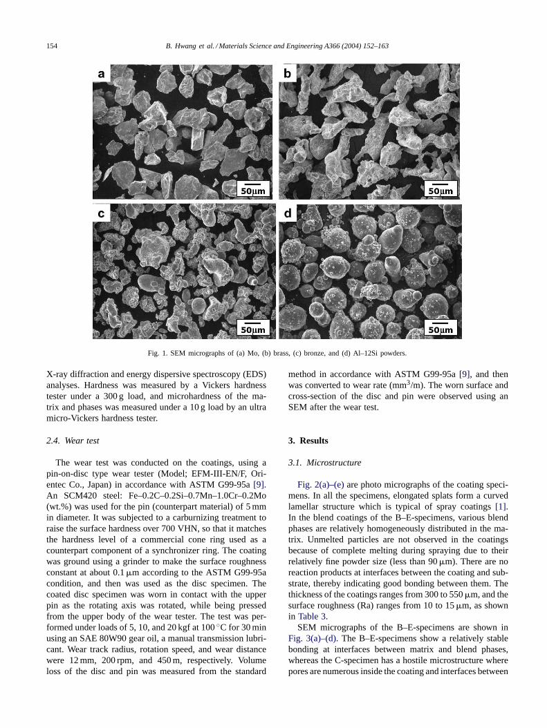
Fig. 2(a)–(e)are photo micrographs of the coating speci-mens. In all the specimens, elongated splats form a curvedlamellar structure which is typical of spray coatings[1].In the blend coatings of the B–E-specimens, various blendphases are relatively homogeneously distributed in the ma-trix. Unmelted particles are not observed in the coatingsbecause of complete melting during spraying due to theirrelatively fine powder size (less than 90�m). There are noreaction products at interfaces between the coating and sub-strate, thereby indicating good bonding between them. Thethickness of the coatings ranges from 300 to 550�m, and thesurface roughness (Ra) ranges from 10 to 15�m, as shownin Table 3.
SEM micrographs of the B–E-specimens are shown inFig. 3(a)–(d). The B–E-specimens show a relatively stablebonding at interfaces between matrix and blend phases,whereas the C-specimen has a hostile microstructure wherepores are numerous inside the coating and interfaces between
B. Hwang et al. / Materials Science and Engineering A366 (2004) 152–163 155
Fig. 2. Optical micrographs of (a) A-, (b) B-, (c) C-, (d) D-, and (e) E-specimens (not etched).
splats are unstable. The B–D-specimens consist of two re-gions (Fig. 3(a)–(c)), while the E-specimen consists of fourregions (Fig. 3(d)). When these regions were analyzed byEDS, Mo was detected in the matrix of the B–D-specimens(white region), while Cu and Zn, Cu and Sn, and Al and Siwere detected in the gray regions of the B–D-specimens,respectively. EDS mapping analysis was done on theE-specimen, and the results are provided inFig. 4(a)–(d).
In the E-specimen, four regions of different darkness areobserved (Fig. 4(a)). Mo is detected in the white matrixregion, Cu in the light gray region, and Al in the dark grayregion, respectively. At interfaces between light gray anddark gray regions, Cu and Al are simultaneously detected(Fig. 4(b)–(d)).
X-ray diffraction analysis results of the coatings are pre-sented inFig. 5. In the A-specimen, only Mo is detected,

156 B. Hwang et al. / Materials Science and Engineering A366 (2004) 152–163
Table 3Properties of the molybdenum blend coatings
Specimen Thickness (�m) Roughness, Ra (�m) Vickers hardness (VHN)
Matrixa Blend phasea Overall bulkb
A 297 11.5 467± 36 – 342± 35B 278 10.5 451± 56 122± 35 227± 56C 326 12.2 453± 37 205± 14 259± 28
D 468 11.7 469± 22 143± 29 248± 43215 ± 65 (Cu–Sn)
E 542 13.3 481± 69 132± 43 (Al–Si) 282± 29693 ± 110 (Cu–Al)
a Vickers microhardness values measured under a load of 10 g.b Vickers microhardness values measured under a load of 300 g.
while (Cu, Zn),�-(Cu–Sn), Al–Si are additionally detectedbesides Mo in the B–D-specimens, respectively. In theE-specimen, not only all the phases detected in the C- andD-specimens are present, but new phases like CuAl2 andCu9Al4 are also observed. In all the coatings oxides are notdetected. This is because the powders used in this study donot react with oxygen in the air during spraying.
Fig. 3. SEM micrographs of (a) B-, (b) C-, (c) D-, and (d) E-specimens (not etched).
3.2. Hardness
Table 3 provides overall bulk hardness and hardnessof blend phases formed inside the coatings. Overall bulkhardness is the highest in the A-specimen fabricated withMo powders alone, and decreases in the order of the E-,C-, D, and B-specimens, depending on the type of blend

B. Hwang et al. / Materials Science and Engineering A366 (2004) 152–163 157
Fig. 4. (a) SEM image of the E-specimen and (b)–(d) EDS mappings of Mo, Al, and Cu, respectively.
phases contained in the coatings. In all the specimens, thematrix hardness ranges from 450 to 480 VHN, and thethat of the brass, bronze, and Al–Si regions formed in thecoatings of the B–D-specimens, from 122 to 205, and 143VHN, respectively. The hardness of blend phases formedin the E-specimen is 215, 132, and 600–800, dependingon the regions ofFig. 4(a). The overall bulk hardness ofthe A-specimen is lower than that of the matrix, presum-ably because of the presence of pores in the overall coatedstructure, and the difference between the correspondingindentation loads. The B–E-specimens show lower overallbulk hardness values than the A-specimen, because of thelow hardness of blend phases. Thus, the hardness of thecoatings is affected by that of the matrix and blend phases,their volume fraction, and porosity.
3.3. Wear rate and friction coefficient
Fig. 6(a)–(c)are the results of the pin-on-disc wear testsin which the wear load applied to the coating was varied.The Mo blend coatings (B–E-specimens), show a wear rateof the coating (disc) of less than 1/2–1/10 of the A-specimen
(the pure Mo coating) and a wear rate of the counterpartmaterial (pin) of less than 1/2–1/5 (Fig. 6(a) and (b)). In allthe coatings, the wear rate of both the disc and the pin risewith increasing wear load, whereas the friction coefficientin general decreases (Fig. 6(c)). Though the wear rate ofthe disc is about the same under a load of 5 kgf, it furthervaries when the wear load increases. Under a 20 kgf load,the wear rate decreases in the order of the A-, C-, D-, B-,and E-specimens. The wear rate of the pin shows an almostsimilar tendency to that of the disc.
Fig. 7presents variations in friction coefficient as a func-tion of sliding distance when the wear test was conductedunder a load of 20 kgf. In the A- and C-specimens, thefriction coefficient slowly increases in the beginning andthen abruptly drops beyond 150 m. The friction coefficientof the E-specimen is gradually reduced from the begin-ning and then stabilized after 100 m, while that of the B-and D-specimens stays at about the same level through-out. The average friction coefficient of the D-specimen isrelatively higher than those of other specimens whose av-erage friction coefficients are less than 0.10 after beingstabilized.

158 B. Hwang et al. / Materials Science and Engineering A366 (2004) 152–163
Fig. 5. X-ray diffraction patterns of the coatings.
3.4. Observation of worn surface and worn cross-section
Fig. 8(a)–(e)are SEM micrographs of the worn surface ofthe coatings tested under a load of 20 kgf. The worn surfaceof all the specimens shows a typical abrasive wear mode inwhich grooves are formed in the wear direction, and somemicrocracks are found. In the D-specimen, the grooves aredeep, whereas they are shallow and almost unnoticeable inthe B- and E-specimens. On the worn surfaces of the A- andC-specimens, regions where parts of the coating have fallenoff because of delamination are clearly visible together withgrooves (Fig. 8(a) and (c)).
After the wear test, the worn surface of the coatingswas sectioned vertically to the surface, and the worncross-section was observed using an SEM. Results are pre-sented inFig. 9(a)–(e). In the A-specimen, areas formedwhen splats near the worn surface were either fracturedor delaminated are observed, as indicated by arrows inFig. 9(a). In the C-specimen, areas where splats near theworn surface are separated and have fallen off are observed,as in the A-specimen (Fig. 9(c)). The worn surface of the B-,D-, and E-specimens is relatively smooth, and microcracksare rarely found beneath the worn surface.
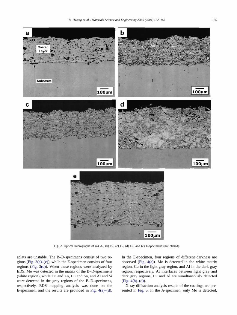
Fig. 10(a)–(e)are SEM micrographs of the worn surfaceof the pin after the wear test. In all the pins, scratches areobserved. The worn areas of the pin against the A- andC-specimens are slightly larger than those against other spec-imens, and the scratches are more visible (Fig. 10(a) and
5 10 15 200.00
0.05
0.10
0.15
0.20
0.25
A B C D E
(a)
(b)
(c)
Load ( kgf )
Wea
r R
ate
of D
isc
(1x1
0-6
mm
3 /m
)W
ear
Rat
e of
Pin
(1x
10-5
mm
3 /m
)
Load ( kgf )
Load ( kgf )
Fric
tion
Coe
ffici
ent
5 10 15 20
0
10
20
30
40
50
60
A B C D E
5 10 15 200
1
2
3
4
5
A B C D E
Fig. 6. Variation of (a) wear rate of disc, (b) wear rate of pin, and (c)friction coefficient as a function of wear load.
(c)). The worn area of the pin against the E-specimen is al-most circular, while those against the B- and D-specimensshow non-circular shapes.
4. Discussion
Four kinds of Mo blend coatings prepared in the presentstudy exhibit under all wear load conditions better wear

B. Hwang et al. / Materials Science and Engineering A366 (2004) 152–163 159
0 100 200 300 400 5000.00
0.05
0.10
0.15
0.20
0.25
0.30
A B C D E
Sliding Distance (m)
Fic
tion
Coe
ffici
ent
Fig. 7. Variation of friction coefficient as a function of sliding distanceunder a load of 20 kgf.
properties than the pure Mo coating which is harder. This isbecause wear in Mo and Mo blend coatings takes place dif-ferently, depending on factors, such as microstructure andwear load. In general, hardness is the most critical factor af-fecting wear properties. However, the ductility and the pres-ence of pores and cracks within the coatings, and the mor-phology, and distribution of blend phases, as well as externalfactors including load, speed, distance, counterpart material,dry- and wet-mixing conditions, and temperature do playcritical roles in the wear process[10–13]. Consequently, toanalyze the wear properties of Mo and Mo blend coatings,wear tests were under various wear loads. The microstruc-tures of the worn surface and the cross-section of the coat-ings and the counterpart materials were observed and ana-lyzed to elucidate the wear mechanism, and their effects onthe wear rate were discussed.
As shown inFig. 6(a), the wear rate of all the coatings in-creases with increasing wear load, although there are minorvariations depending on specimens. Wear rate of the pureMo coating and the Mo blend coatings does not show anydifference under a low wear load (5 kgf), but shows greatervariations under a higher load. Under a high load (10 and20 kgf), wear rate of the A-specimen is higher than those ofthe blend coatings, and it increases significantly as wear loadincreases from 10 to 20 kgf. Observation of the worn surfaceand the cross-section of the A-specimen after the wear test(Fig. 8(a) and 9(a)) reveals that the Mo coating which com-posed of Mo splats only is brittle presumably due to the highhardness of splats. Consequently, interfaces between splatscan be easily separated or splats themselves are fractured insome areas. Such phenomena of fracture and delaminationvary with wear load, and considerably affect the wear rateof the coating.
Since fracture and delamination become more severewhen the wear load increases from 10 to 20 kgf, the wear rate
increases, thereby causing transition of wear mechanisms.Liu and Hua[11] reported that hard phases were crackedand fractured in Mo coatings fabricated by flame sprayingwhen the wear load increased, and that three steps of weartogether with a transition of the dominant wear mechanismfrom mild wear to severe were observed. Likewise, in thecase of other coatings fabricated by plasma spraying, it iswell known that the wear mechanism changes with changesin wear load[12,13]. In the C-specimen where bronze isblended with Mo, splats near the worn surface are readilyfallen off along the interfaces when tested under high loads,due to the poor microstructure of the coating itself, and thenwear transition takes place, as in the A-specimen; thus, theC-specimen shows much higher wear rate than other Moblend coatings (B-, D-, and E-specimens).
Friction coefficient as a function of sliding distance inthe A- and C-specimens, whose wear rate varies with wearload to a great extent (Fig. 7), gradually increases in thebeginning, then abruptly drops between sliding distance of100 and 200 m, and becomes stable after 200 m. This is be-cause the friction coefficient rises in these two specimensdue to increasing contact stress when the coating is delami-nated at the initial wear stage, also and because wear debrisformed in this process remain between the coating and thecounterpart material and reduce direct friction, thus reduc-ing the friction coefficient. Comparing the worn areas of thepin against the A- and C-specimens with those against otherspecimens, the worn area is larger, and scratches are morevisible (Fig. 10(a) and (c)). This might result from the ef-fect of wear debris fallen off from the coating, which workas abrasive particles against the counterpart material. Thehigher wear rate of the pin against the A-specimen than thatagainst the C-specimen is associated with the acceleratedwear rate of the pin by harder wear debris formed in theA-specimen when hard Mo splats are fractured and coatingis lamination follows.
In the B- and D-specimens, where brass and Al–Si alloypowders were blended with Mo powders, respectively, wearrate is slower than in the C-specimen, and friction coeffi-cient is hardly varied with sliding distance. This is becausesplats near the worn surface are not easily removed due tothe interface soundness condition between matrix and blendphases during the wear test, even under high wear loads.
In the E-specimen in which a mixture of bronze andAl–Si powders was blended with Mo powders, new phaseswhich were not present in Mo blend coatings where bronzeand Al–Si powders were each blended are found. In theEDS maps ofFig. 4(a)–(d), blended zones where both Aland Cu are detected are observed, and are confirmed to beCuAl2 and Cu9Al4, by XRD diffraction analysis (Fig. 5).These phases seem to have been formed when bronze andAl–Si powders were coalesced during melting and spray-ing by high-temperature plasma, were solutionized into anAl–Cu alloy, were deposited on the substrate, and under-went the aging process of supersaturated solid solution→G.P. zones→ θ′′ → θ′ → θ phases while maintained at a

160 B. Hwang et al. / Materials Science and Engineering A366 (2004) 152–163
Fig. 8. SEM micrographs of the worn surface of (a) A-, (b) B-, (c) C-, (d) D-, and (e) E-specimens after the wear test under a load of 20 kgf.
constant temperature after quenching[14–16]. Al–Cu alloy,whose major hardening phases are metastableθ′(CuAl2), isa typical age-harden alloy[16–20]. Sn contained in bronzepowders is segregated at interfaces between matrix andphases, hence lowers the interfacial energy, and promotesthe nucleation ofθ′ phases[21].
Intermetallic compounds formed in Al–Cu alloys, suchas CuAl2, Cu9Al4, and CuAl are extremely hard[16],
and some martensitic structure may be form during rapidquenching, which also raises hardness[22]. Consequently,the E-specimen shows a higher overall bulk hardness thanother Mo blend coating specimens because of the forma-tion of very hard phases in the hardened matrix (Table 3).According to the SEM micrograph of the E-specimen(Fig. 3(d)), splats are comparatively smaller than in otherMo blend coatings, since CuAl2 and Cu9Al4 phases together

B. Hwang et al. / Materials Science and Engineering A366 (2004) 152–163 161
Fig. 9. SEM micrographs of the cross-section of (a) A-, (b) B-, (c) C-, (d) D-, and (e) E-specimens after the wear test under a load of 20 kgf.
with various compounds are relatively homogeneously dis-persed inside the coating. This is also considered to havecontributed to the improvement of overall bulk hardness.These hard phases increase the wear resistance, as well asthe overall bulk hardness of the coating (Fig. 6(a)). Sincethey are hardly fractured or delaminated during the wearprocess and do not act as abrasive debris against the coun-
terpart material, the wear rate of the pin is slower thanin other Mo blend coatings. Therefore, the overall wearproperties of the E-specimen are excellent judging from thewear rate of the coating and the counterpart material.
In order to process Mo blend coatings with excellent wearproperties, it is most desirable to increase their hardness andwear resistance by blending or alloying powders with Mo
162 B. Hwang et al. / Materials Science and Engineering A366 (2004) 152–163
Fig. 10. SEM micrographs of the worn surface of the pin against (a) A-, (b) B-, (c) C-, (d) D-, and (e) E-specimens after the wear test under a load of 20 kgf.
powders so that fine, hard phases would be form inside thecoating, with a simultaneous reduction wear of the counter-part material.
In the present study, factors affecting coating microstruc-ture and wear rate of coating and counterpart material as afunction of wear load are discussed, and possibilities of thesecoatings to be practically applied to the coatings for synchro-
nizer rings or piston rings are presented. For further propertyimprovement of these coatings in the future, it is necessaryto understand the wear mechanisms occurring in variouswear environments, to develop Mo blend coatings using newblend powders, to establish optimal spraying techniques andconditions, and to develop evaluation methods of propertiessuch as fracture toughness and cohesive bonding strength.
B. Hwang et al. / Materials Science and Engineering A366 (2004) 152–163 163
5. Conclusions
(1) Mo blend coatings exhibited a lower hardness and asignificantly lower wear rate in both the coating andcounterpart material than pure Mo coatings.
(2) In all cases the wear rate of coatings and counterpart ma-terial increased with increasing load, whereas the fric-tion coefficient decreased.
(3) In Mo blend coatings with bronze and Al–Si powderscoating hardness and wear resistance were higher thanin other blend coatings, and counterpart wear rate waslower.
Acknowledgements
The work was supported by the Ministry of Commerce,Industry, and Energy (MOCIE) of Korea. The authors wouldlike to thank Mr. Ju Wan Kim of University of Ulsan fortheir help of the plasma spraying experiments.
References
[1] L. Pawlowsky, The Science and Engineering of Thermal Spray Coat-ings, Wiley, New York, 1995.
[2] S. Sampath, H. Herman, J. Therm. Spray Technol. 5 (1996)445.
[3] S. Choo, S. Lee, S.J. Kwon, Metall. Mater. Trans. 30A (1999)1211.
[4] A. Crowson, E.S. Chen, J.A. Shields, P.R. Subramanian, Molybde-num and Molybdenum Alloys, TMS, 1998, p. 415.
[5] K. Euh, J. Lee, S. Lee, Metall. Mater. Trans. 32A (2001)2499.
[6] J.M. Tura, A. Traveria, M.D. de Castellar, J. Pujadas, J. Blouet, R.Gras, H.G. Magham, P. Belair, T. Hanau, A. Romero, Wear 189(1995) 70.
[7] S.F. Wayne, S. Sampath, V. Anand, Tribol. T. 37 (1994) 636.[8] B. Hwang, S. Lee, J. Ahn, Mater. Sci. Eng. A335 (2002) 268.[9] ASTM Standard G99-95a, ASTM, 1995.
[10] ASM Handbook, vol. 18.[11] Z. Liu, M. Hua, Tribol. Intern. 32 (1999) 499.[12] B. Hwang, J. Ahn, S. Lee, Metall. Trans. 33A (2002) 2933.[13] M. Gui, S.B. Kang, Metall. Trans. 32A (2001) 2383.[14] D.A. Porter, K.E. Easterling, Phase Transformation in Metals and
Alloys, Chapman & Hall, London, 1992 (Chapter 5).[15] Y. Joo, Metals Mater. Int. 4 (1998) 1033.[16] D. Moreno, J. Garrett, J.D. Embury, Intermetallics 7 (1999) 1001.[17] D. Lee, J. Moon, Metals Mater. Int. 8 (2002) 327.[18] Z. Shi, A. Bloyce, Y. Sun, T. Bell, Wear 198 (1996) 300.[19] S. Tomida, K. Nakata, S. Saji, T. Kubo, Surf. Coat. Technol. 142
(2001) 585.[20] S. Alam, S. Sasaki, H. Shimura, Wear 248 (2001) 75.[21] J.D. Boyd, R.B. Nicholson, Acta Metall. 19 (1971) 1101.[22] P.R. Swann, H. Warlimont, Acta Metall. 11 (1963) 511.