TRICEPS MOTOR NERVE BRANCHES AS A DONOR OR RECEIVER IN NERVE TRANSFERS
Upload
khangminh22Category
view
0download
0
NERVE MUSCLE PHYSIOLOGY
Dr. Atanu sahaS d i l f B S (H) Ph i l d S Study material for B.Sc (H) Physiology 2nd Sem


NERVE + MUSCLE+PHYSIOLOGY
Nerve:The filamentous bands of nervous tissue that connect parts of the nervous system with the other organs, conduct nerve impulses and are made up of axons and conduct nerve impulses, and are made up of axons and dendrites together with protective and supportive structures.

NERVE + MUSCLE+PHYSIOLOGY
Neuron:

MUSCLEUSC Muscle is a soft tissue Muscle cells contain protein filaments of actin and myosin Types of Muscle
a. Skeletal Muscle;b Smooth Muscle; andb. Smooth Muscle; andc. Cardiac Muscle.

SKELETAL MUSCLE STRUCTURES USC S UC U

STIMULATION AND CONTRACTION OF SKELETAL MUSCLESKELETAL MUSCLE Excitability‐ ability to receive and respond to stimulus; Contractility‐ ability to shorten when adequate stimulus is received; Extensibility‐ ability of muscle to be stretched; and Elasticity‐ ability to recoil and resume resting length after stretching.
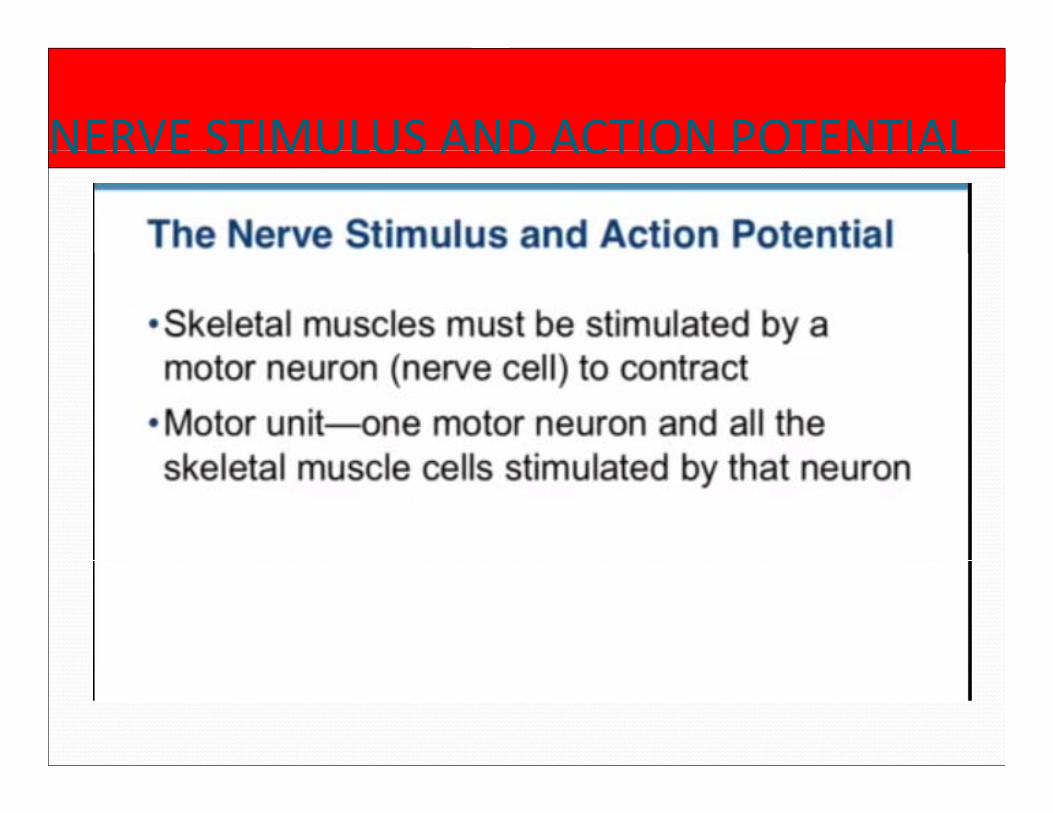
NERVE STIMULUS AND ACTION POTENTIALNERVE STIMULUS AND ACTION POTENTIAL

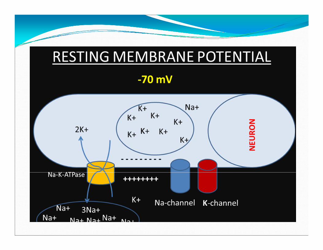
RESTING MEMBRANE POTENTIALRESTING MEMBRANE POTENTIAL• Resting Membrane Potential
(RMP) is the voltage (charge) difference across the cell membrane when the cell is at rest.
• RMP is a product of theRMP is a product of the distribution of charged particles (ions).
• There are positively charged i ll d i ( Nions called cations (e.g., Na+, K+, Mg2+, Ca2+) and negatively charged ions called anions (e.g., Cl- andcalled anions (e.g., Cl and proteins that act as anions).


ACTION POTENTIALACTION POTENTIALStep 1: Resting membrane potential.Step 2: Some of the voltage gated Na channels open and Na Step 2: Some of the voltage‐gated Na‐channels open and Na
enters the cell (threshold potential).Step 3: Opening of more voltage‐gated Na‐channels and
further depolarization (rapid upstroke).Step 4: Reaches to peak level.Step 5: Direction of electrical gradient for Na is reversed + p 5 g
Na‐channels rapidly enter a closed state “inactivated state” + voltage – gated K‐channels open (start of repolarization)repolarization).
Step 6: Slow return of K‐channels to the closed state (after‐hyperpolarization).
Step 7: Return to the resting membrane potential.

ACTION POTENTIAL• Decreasing the external Na concentration has little effect on RMP, but reduces the size of action potential.H k l i b i bl• Hyperkalemia: neuron becomes more excitable.
• Hypokalemia: neuron becomes hyperpolarized.H l i i h i bili f h • Hypocalsemia: increases the excitability of the nerve.
• Hypercalsemia: decreases the excitability.

ACTION POTENTIAL Once threshold intensity is reached, a full action potential is produced.p p
The action potential fails to occur if the stimulus is sub threshold in magnitude.
Further increases in the intensity of the stimulus produce no other changes in the action potential. S h i i l i ll i h So, the action potential is all or none in character.

ALL OR NONE LAW The all‐or‐none law is a principle that states, that the strength of a response of a nerve cell or muscle fiber is not dependent upon the strength of the stimulus If a not dependent upon the strength of the stimulus. If a stimulus is above a certain threshold, a nerve or muscle fiber will fire. Essentially, there will either be a y,full response or there will be no response at all.

ACTION POTENTIALACTION POTENTIAL Absolute refractoryyperiod: From the timethe threshold potentialis reached untilis reached untilrepolarization is aboutone‐third complete.
Relative refractoryperiod: From the end ofabsolute refractoryabsolute refractoryperiod to the start ofafter–depolarization.

FLOW OF ACTION POTENTIALFLOW OF ACTION POTENTIAL

FLOW OF ACTION POTENTIALFLOW OF ACTION POTENTIAL
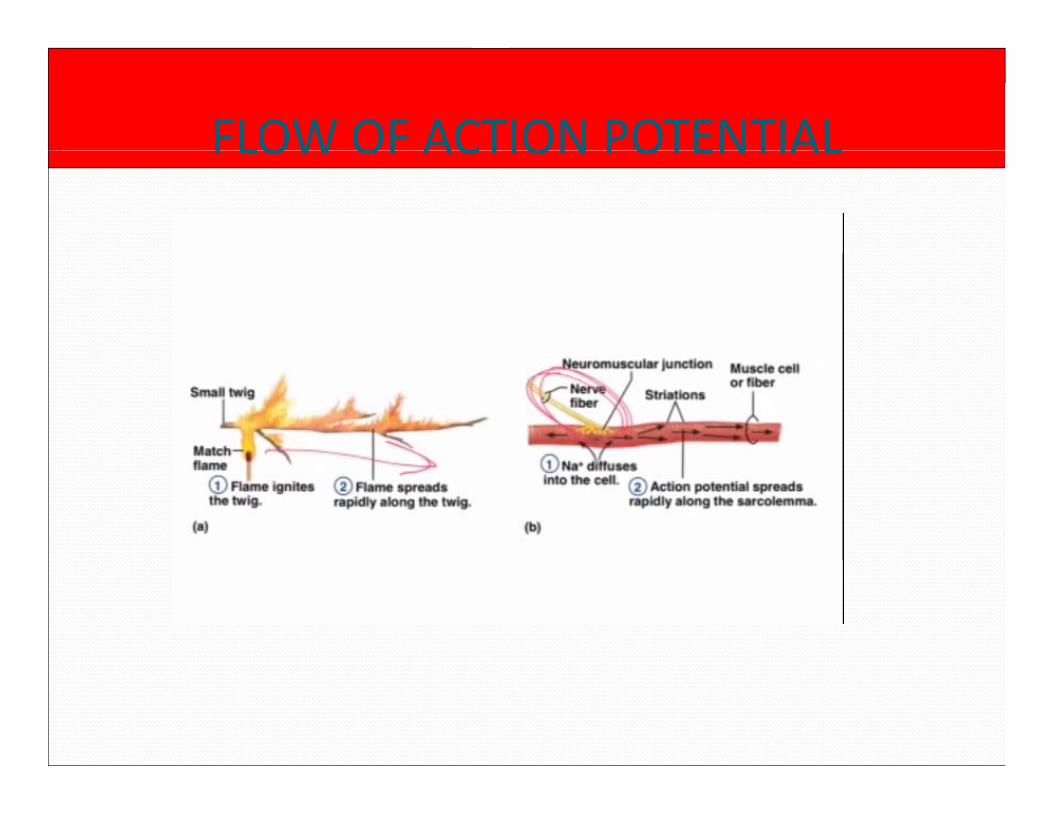
FLOW OF ACTION POTENTIALFLOW OF ACTION POTENTIAL

FLOW OF ACTION POTENTIALFLOW OF ACTION POTENTIAL

CONDUCTION of the ACTION POTENTIALCONDUCTION of the ACTION POTENTIAL Unmyelinated axon:
Positive charges from the Positive charges from the membrane ahead and behind the action potential flow into the area of negativity.g y
By drawing off (+) charges, this flow decreases the polarity of the membrane p yahead of the action potential.
This initiates a local response.p
When the threshold level is reached, a propagated response occurs that in turn pelectronically depolarizes the membrane in front of it.


CONDUCTION of the ACTION POTENTIAL Myelinated axon:ye ated a o :
Myelin is an effective insulator.
Depolarization travels Depolarization travels from one node of Ranvier to the next.
This jumping of This jumping of depolarization from node to node is called “saltatory conduction”saltatory conduction
Faster than unmyelinated axons.

ORTHODROMIC & ANTIDROMIC CONDUCTION
Orthodromic: From synaptic junctions or
Antidromic: The opposite direction synaptic junctions or
receptors along axons to their termination.
opposite direction (towards the soma).

NERVE FIBER TYPES & FUNCTIONFIBER TYPE FUNCTION FIBER CONDUCTIO MYELINATIO
DIAMETER (µm)
N VELOCITY (m/s)
N
Aα Proprioception,somatic motor
12‐20 70‐120 Myelinatedsomatic motor
Aβ Touch, pressure 5‐12 30‐70 Myelinated
Aγ Motor to muscle 3‐6 15‐30 MyelinatedAγspindles
3 6 15 30 Myelinated
Aδ Pain, temperature 2‐5 12‐30 Myelinated
B Preganglionic, autonomic
˂3 3‐15 Myelinated
C, Dorsal root Pain, temperature 0,4‐1,2 0,5‐2 UnmyelinatedC, Dorsal root 0,4 1,2 0,5 2 Unmyelinated
D,Sympathetic
Postganglionicsympathetic
0,3‐1,3 0,7‐2,3

STRENGTH DURATION CURVE It shows the interdependence between stimulus strength and the time required in activating the muscles muscles.
It indicates the strength of impulses of various durations required to produce muscle contraction by durations required to produce muscle contraction by joining the points that graphically represent the threshold value along the ordinate for various durations.

ADVANTAGES & DISADVANTAGES This is a simple, reliable and shows a proportion of denervation.√
In large muscles it can not shows the full pictures but only a proportion of muscle fibers can be stimulated Xonly a proportion of muscle fibers can be stimulated.X
It can not show the site of lesion.X

Optimum timing of SDCOptimum timing of SDC:
SDC test can be done 10 – 14 days after the lesion has occurred. Th d i f f h i l di l The degeneration of nerve from the proximal to distal is called Wallerian degeneration.
When the motor end plate is no longer functioning it When the motor end plate is no longer functioning, it is done weekly under the same condition until there is recovery and decision has been reached on the yeventual final state of the muscle.
SDC is used to identify denervation, partial i i d iinnervation, and compression.

Methods of SDC: Take a neuromuscular stimulator (TENS, DL‐2‐ stimulator) having rectangular duration i.e. 0.3, 0.1, 1, 3 10 30 100 300 ms and constant current 3, 10, 30, 100, 300 ms and constant current.
Put the passive electrode over the midline of the body or near the origin of the muscle or near the origin of the muscle.
Put the active electrode over the fleshy belly of the muscle.

Alternately both the electrodes are placed on both ends of the muscle. Fi l h i l d i d l k First apply current having longest duration and look for minimum perceptible contraction, gradually shorten the impulse duration and note the shorten the impulse duration and note the corresponding increase in current strength.
The electrode placement should not be changed p gthrough out the test.
Plot a SD graph from the results of the test.

STRENGTH DURATION CURVE 1901‐Weiss Purpose‐measurement of excitability of tissues;
a. nerve i.e action potential; andb. muscle i.e contraction.


Innervated Muscle When all the nerve fibers supplying the muscles are intact, the strength duration curve has a shape characteristic of normally innervated muscles as characteristic of normally innervated muscles as shown in the figure.
The same strength of stimulus is required to produce a The same strength of stimulus is required to produce a response with all the impulses of longer duration, while those of shorter duration require an increase in strengths of the stimulus each time the duration is reduced.


lDenervated muscles: When all the nerve fibers supplying a muscle have degenerated, the strength duration produced is characteristic of complete denervation as shown in the characteristic of complete denervation as shown in the figure.
For all impulses with duration of 100 ms or less the For all impulses with duration of 100 ms or less the strength of the stimulus must be increased each time the duration is reduced and no response is obtained to impulses of very short duration. The curve rises steeply and is shifted to the right than that of normally innervated muscleinnervated muscle.


Partial denervated muscles: The kink produce show the partial denervation

Factors affecting Rehobase &Factors affecting Rehobase & ChronaxieChronaxie1. Ion channels Na+ & K+
mainmain2. Activity of sodium potassium ATP ase;
If decreases intracellular Na increasesIf decreases intracellular Na increases
Transmembrane Na gradient decreasesTransmembrane Na gradient decreases
sensitivity decreases

3.Temperature.4.Demyelination there will be right ward shift of curve.

STIMULATION FOR WOUND HEALINGSTIMULATION FOR WOUND HEALING
The use of an electrical current to transfer energy to a wound
W fWave form:Monophasic twin peaked High Voltage Pulsed Current ( HVPC)HVPC)

The pulse width varies with a range from 20‐200 microseconds.Th HVPC d i l ll f l i f l i The HVPC devices also allow for selection of polarity and variation in pulse rates both of which seem to be important in wound healingimportant in wound healing.
It is a very safe current because it's very short pulse duration prevents significant changes in both tissue p g gpH and temperature.
Therefore, the most tested and safe type of stimulation i h d dis the one recommended.

Bioelectric System The body has its own bioelectric system. This system influences wound healing by attracting
h ll f i h i ll b the cells of repair, changing cell membrane permeability ,enhancing cellular secretion through cell membranes and orientating cell structuresmembranes and orientating cell structures.
A current termed the "current of injury" is generated between the skin and inner tissues when there is a break in the skin.
The current will continue until the skin defect is i drepaired.

Healing of the injured tissue is arrested or will be incomplete if these currents no longer flow while the wound is openwound is open.
A moist wound environment is required for the bioelectric system to functionbioelectric system to function.

Rationale for applying electricalRationale for applying electrical stimulation It mimics the natural current of injury and will jump start or accelerate the wound healing process.

Clinical Wound Healing Studies Early studies using direct current stimulation reported long treatment times of 20‐40 hours per weeks.Wh f d & h di i h Whereas after advance & recent research studies with HVPC report a mean healing time of 9.5 weeks with 45‐60 minute treatment 5‐7x/wk45 60 minute treatment 5 7x/wk.

l l l ff h b l l hElectrical stimulation affects the biological phases of wound healing in the following ways: Inflammation phase
1. Initiates the wound repair process by its effect on the current of injury.
2. Increases blood flow.3. Promotes phagocytosis.4. Enhances tissue oxygenation.5. Reduces edema perhaps from reduced
microvascular leakage.6 A d i l fib bl d 6. Attracts and stimulates fibroblasts and
epithelial cells.

7. Stimulates DNA synthesis.8. Controls infection ( Note: HVPC proven
bacteriocidal at higher intensities than use in clinic and may not be tolerated by patient).
9. Solubilizes blood products including necrotic tissue.

Proliferation phase Stimulates fibroblasts and epithelial cells. Stimulates DNA and protein synthesis. Increases ATP generation. Improves membrane transport. Produces better collagen matrix organization, Stimulates wound contraction.

Epithelialization phase Stimulates epidermal cell reproduction and migration Produces a smoother, thinner scar

INDICATIONS FOR THEINDICATIONS FOR THE THERAPYTHERAPY Pressure Ulcers Stage I through IV Diabetic ulcers due to pressure, insensitivity and dysvascularity
Venous Ulcers T ti W d Traumatic Wounds Surgical Wounds Ischemic Ulcers Ischemic Ulcers Vasculitic Ulcers Donor Sites Wound Flaps Burn wounds

Protocol for treatment Wound Healing Phase Diagnosis: Inflammation phase
Expected outcomes:Wound progresses to the Proliferation phase
Change in Wound Healing Phase Diagnosis: Proliferation phase
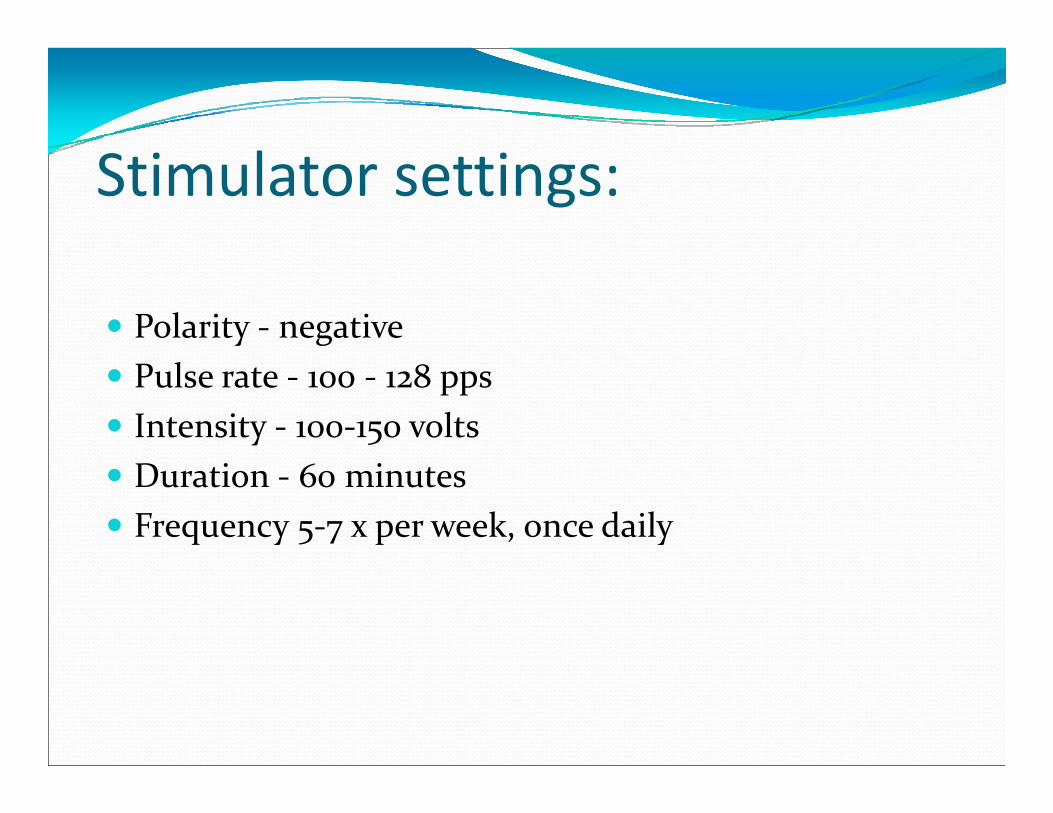
lStimulator settings:
Polarity ‐ negative Pulse rate ‐ 100 ‐ 128 pps Intensity ‐ 100‐150 volts Duration ‐ 60 minutes Frequency 5‐7 x per week, once daily
Expected Outcomes: Wound progresses to Contraction and Epithelizationphase.

Epithelialization phase Stimulator settings:Polarity ‐ alternate every three days ie 3 days negative
followed by 3 days positivePulse rate ‐ 64 PPSIntensity ‐ 100‐150 voltsDuration ‐ 60 minutesFrequency 5‐7 x per week, once daily

Expected Outcomes: Wound progresses to Remodeling phase

Setting Up the Patient Have supplies ready before undressing the wound. Position patient for ease of access by staff and comfort
f b hof both. Remove the dressing and place in an infectious waste bagbag.
Cleanse wound thoroughly to remove slough, exudate and any petrolatum productsand any petrolatum products
Sharp debride necrotic tissue, if required, before HVPC treatment

Open gauze pads and fluff, then soak in normal saline solution, squeeze out excess liquid. An alternative is to use an amorphous hydrogel impregnated gauze use an amorphous hydrogel impregnated gauze. Hydrogel sheets can also be used to conduct current under the electrodes
Fill the wound cavity with gauze including any undermined/tunneled spaces. Pack gently.
Place an electrode over the gauze packing cover with dry gauze pad and hold in place with bandage tape.C lli li h f il Connect an alligator clip to the foil.
Connect to stimulator lead

Dispersive electrodeDispersive electrode placement:placement: Usually placed proximal to the wound Place over soft tissues, avoid bony prominences Place a washcloth, wetted with water and wrung out, under the dispersive electrode
Place against skin and hold in good contact at all edges with a nylon elasticized strap.
If placed on the back the weight of the body plus the If placed on the back, the weight of the body plus the strap can be used to achieve good contact at the edges

Dispersive pad should be larger than the sum of the areas of the active electrodes and wound packing.Th h i b h i d The greater the separation between the active and dispersive electrode the deeper the current path. Use for deep and undermined woundsfor deep and undermined wounds
Dispersive and active electrodes can be close together but should not touch. Current flow will be shallow> Use for shallow, partial thickness wounds

PRECAUTIONS Check for skin irritation or tingling under the electrodes.P i i h i h l l l i Patients with severe peripheral vascular occlusive disease (PVD), may experience some increased pain, usually described as throbbing in the leg after usually described as throbbing, in the leg after electrical stimulation.

CONTRAINDICATIONS Pl t f l t d t ti l t th h t Placement of electrodes tangential to the heart Presence of a cardiac pacemaker Placement of electrodes along regions of the phrenic Placement of electrodes along regions of the phrenic nerve
Presence of malignancyPresence of malignancy Placement of electrodes over the carotid sinus Placement of electrodes over the laryngeal Placement of electrodes over the laryngeal musculature
Placement of electrodes over topical substances containing metal ions
Placement of electrodes over osteomyelitis

Copyright © 2022 FDOKUMEN