NEMA & General Purpose Controls - Amazon S3
160
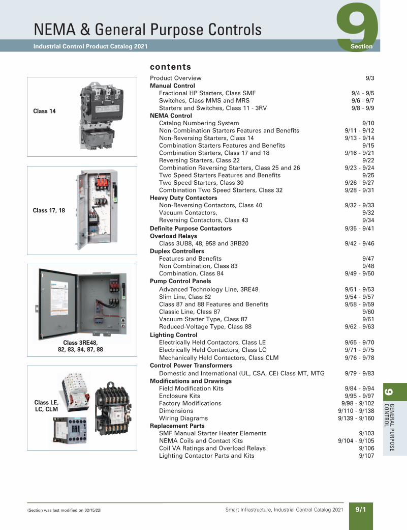
9 GENERAL PURPOSE CONTROL 9/1 Smart Infrastructure, Industrial Control Catalog 2021 9 NEMA & General Purpose Controls Industrial Control Product Catalog 2021 Section contents Product Overview 9/3 Manual Control Fractional HP Starters, Class SMF 9/4 - 9/5 Switches, Class MMS and MRS 9/6 - 9/7 Starters and Switches, Class 11 - 3RV 9/8 - 9/9 NEMA Control Catalog Numbering System 9/10 Non-Combination Starters Features and Benefits 9/11 - 9/12 Non-Reversing Starters, Class 14 9/13 - 9/14 Combination Starters Features and Benefits 9/15 Combination Starters, Class 17 and 18 9/16 - 9/21 Reversing Starters, Class 22 9/22 Combination Reversing Starters, Class 25 and 26 9/23 - 9/24 Two Speed Starters Features and Benefits 9/25 Two Speed Starters, Class 30 9/26 - 9/27 Combination Two Speed Starters, Class 32 9/28 - 9/31 Heavy Duty Contactors Non-Reversing Contactors, Class 40 9/32 - 9/33 Vacuum Contactors, 9/32 Reversing Contactors, Class 43 9/34 Definite Purpose Contactors 9/35 - 9/41 Overload Relays Class 3UB8, 48, 958 and 3RB20 9/42 - 9/46 Duplex Controllers Features and Benefits 9/47 Non Combination, Class 83 9/48 Combination, Class 84 9/49 - 9/50 Pump Control Panels Advanced Technology Line, 3RE48 9/51 - 9/53 Slim Line, Class 82 9/54 - 9/57 Class 87 and 88 Features and Benefits 9/58 - 9/59 Classic Line, Class 87 9/60 Vacuum Starter Type, Class 87 9/61 Reduced-Voltage Type, Class 88 9/62 - 9/63 Lighting Control Electrically Held Contactors, Class LE 9/65 - 9/70 Electrically Held Contactors, Class LC 9/71 - 9/75 Mechanically Held Contactors, Class CLM 9/76 - 9/78 Control Power Transformers Domestic and International (UL, CSA, CE) Class MT, MTG 9/79 - 9/83 Modifications and Drawings Field Modification Kits 9/84 - 9/94 Enclosure Kits 9/95 - 9/97 Factory Modifications 9/98 - 9/102 Dimensions 9/110 - 9/138 Wiring Diagrams 9/139 - 9/160 Replacement Parts SMF Manual Starter Heater Elements 9/103 NEMA Coils and Contact Kits 9/104 - 9/105 Coil VA Ratings and Overload Relays 9/106 Lighting Contactor Parts and Kits 9/107 Class 14 Class 17, 18 Class 3RE48, 82, 83, 84, 87, 88 Class LE, LC, CLM (Section was last modified on 02/15/22)
-
Upload
khangminh22 -
Category
Documents
-
view
2 -
download
0
Transcript of NEMA & General Purpose Controls - Amazon S3
9G
enera
l PurPo
se Co
ntro
l
9/1Smart Infrastructure, Industrial Control Catalog 2021
9neMa & General Purpose Controls Industrial Control Product Catalog 2021 Section
contentsProduct Overview 9/3Manual Control Fractional HP Starters, Class SMF 9/4 - 9/5 Switches, Class MMS and MRS 9/6 - 9/7 Starters and Switches, Class 11 - 3RV 9/8 - 9/9NEMA Control Catalog Numbering System 9/10 Non-Combination Starters Features and Benefits 9/11 - 9/12 Non-Reversing Starters, Class 14 9/13 - 9/14 Combination Starters Features and Benefits 9/15 Combination Starters, Class 17 and 18 9/16 - 9/21 Reversing Starters, Class 22 9/22 Combination Reversing Starters, Class 25 and 26 9/23 - 9/24 Two Speed Starters Features and Benefits 9/25 Two Speed Starters, Class 30 9/26 - 9/27 Combination Two Speed Starters, Class 32 9/28 - 9/31Heavy Duty Contactors Non-Reversing Contactors, Class 40 9/32 - 9/33 Vacuum Contactors, 9/32 Reversing Contactors, Class 43 9/34Definite Purpose Contactors 9/35 - 9/41Overload Relays Class 3UB8, 48, 958 and 3RB20 9/42 - 9/46Duplex Controllers Features and Benefits 9/47 Non Combination, Class 83 9/48 Combination, Class 84 9/49 - 9/50Pump Control Panels Advanced Technology Line, 3RE48 9/51 - 9/53 Slim Line, Class 82 9/54 - 9/57 Class 87 and 88 Features and Benefits 9/58 - 9/59 Classic Line, Class 87 9/60 Vacuum Starter Type, Class 87 9/61 Reduced-Voltage Type, Class 88 9/62 - 9/63Lighting Control Electrically Held Contactors, Class LE 9/65 - 9/70 Electrically Held Contactors, Class LC 9/71 - 9/75 Mechanically Held Contactors, Class CLM 9/76 - 9/78Control Power Transformers Domestic and International (UL, CSA, CE) Class MT, MTG 9/79 - 9/83Modifications and Drawings Field Modification Kits 9/84 - 9/94 Enclosure Kits 9/95 - 9/97 Factory Modifications 9/98 - 9/102 Dimensions 9/110 - 9/138 Wiring Diagrams 9/139 - 9/160Replacement Parts SMF Manual Starter Heater Elements 9/103 NEMA Coils and Contact Kits 9/104 - 9/105 Coil VA Ratings and Overload Relays 9/106 Lighting Contactor Parts and Kits 9/107
New naming conventionic21-sect-09-general-purpose
Class 14
Class 17, 18
Class 3RE48, 82, 83, 84, 87, 88
Class LE, LC, CLM
(Section was last modified on 02/15/22)
9G
ener
al
PurP
ose
Co
ntr
ol
9/2 Smart Infrastructure, Industrial Control Catalog 2021
Control Products
NEMA & General Purpose ControlsControls Express
updated in SPEEDFAXRevised on 03/31/20
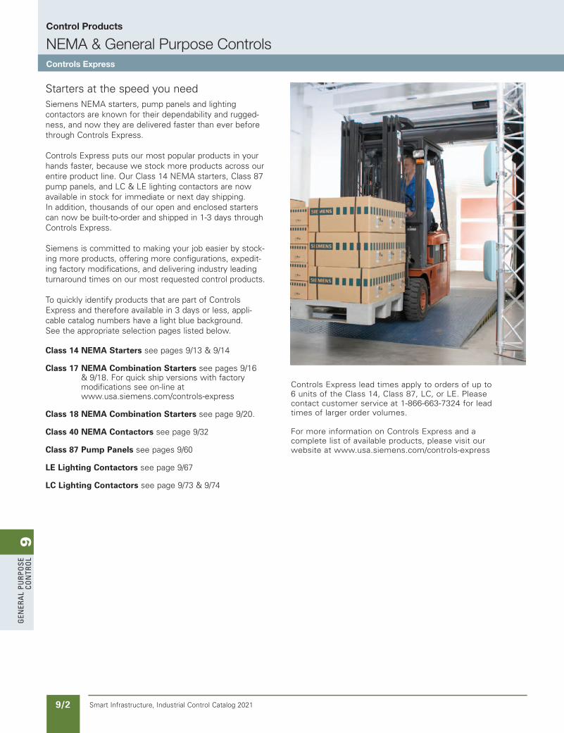
Starters at the speed you needSiemens NEMA starters, pump panels and lighting contactors are known for their dependability and rugged-ness, and now they are delivered faster than ever before through Controls Express.
Controls Express puts our most popular products in your hands faster, because we stock more products across our entire product line. Our Class 14 NEMA starters, Class 87 pump panels, and LC & LE lighting contactors are now available in stock for immediate or next day shipping. In addition, thousands of our open and enclosed starters can now be built-to-order and shipped in 1-3 days through Controls Express.
Siemens is committed to making your job easier by stock-ing more products, offering more configurations, expedit-ing factory modifications, and delivering industry leading turnaround times on our most requested control products.
To quickly identify products that are part of Controls Express and therefore available in 3 days or less, appli-cable catalog numbers have a light blue background. See the appropriate selection pages listed below.
Class 14 NEMA Starters see pages 9/13 & 9/14
Class 17 NEMA Combination Starters see pages 9/16 & 9/18. For quick ship versions with factory modifications see on-line at www.usa.siemens.com/controls-express
Class 18 NEMA Combination Starters see page 9/20.
Class 40 NEMA Contactors see page 9/32
Class 87 Pump Panels see pages 9/60
LE Lighting Contactors see page 9/67
LC Lighting Contactors see page 9/73 & 9/74
Controls Express lead times apply to orders of up to 6 units of the Class 14, Class 87, LC, or LE. Please contact customer service at 1-866-663-7324 for lead times of larger order volumes.
For more information on Controls Express and a complete list of available products, please visit our website at www.usa.siemens.com/controls-express
SS copied this page from SF to IC on 05/24/20
9G
enera
l PurPo
se Co
ntro
l
9/3Smart Infrastructure, Industrial Control Catalog 2021
Control Products
NEMA & General Purpose ControlsProduct Overview
NEED to UPDATE in SPEEDFAX
Revised on 12/31/21
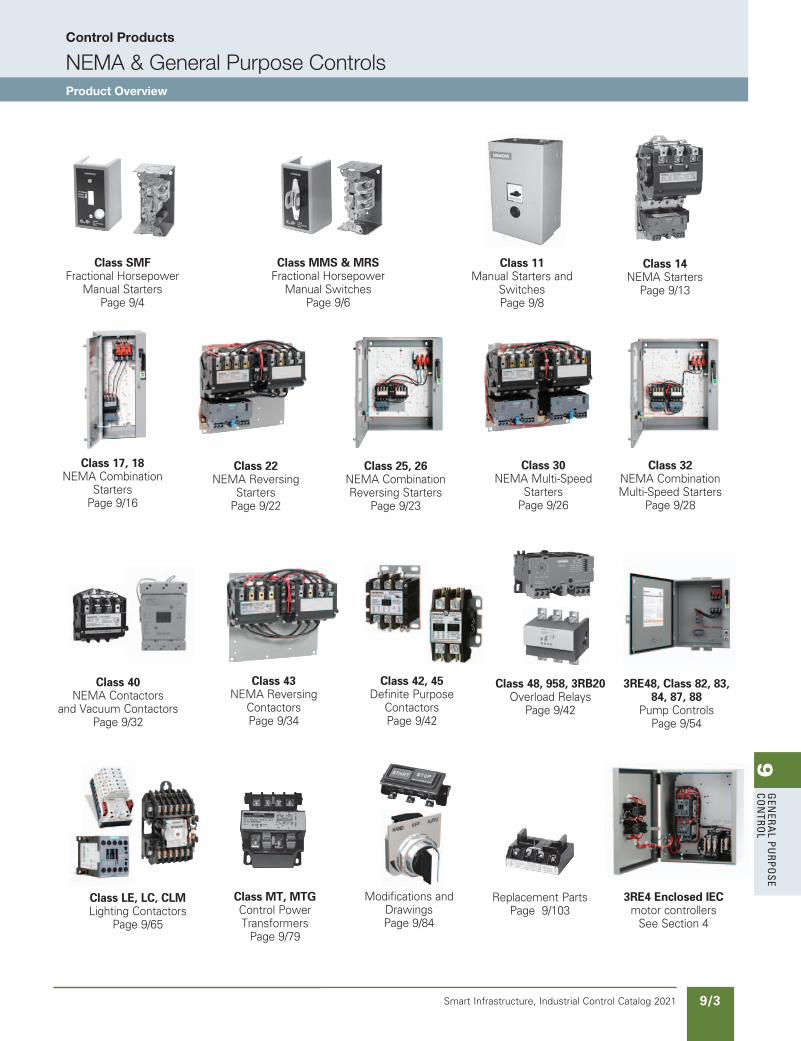
Class 48, 958, 3RB20 Overload Relays
Page 9/42
Class 43NEMA Reversing
Contactors Page 9/34
Class SMFFractional Horsepower
Manual Starters Page 9/4
Class MMS & MRSFractional Horsepower
Manual Switches Page 9/6
Class 11Manual Starters and
Switches Page 9/8
Class 14NEMA Starters
Page 9/13
Class 17, 18 NEMA Combination
Starters Page 9/16
Class 22NEMA Reversing
Starters Page 9/22
Class 25, 26NEMA Combination Reversing Starters
Page 9/23
Class 30NEMA Multi-Speed
Starters Page 9/26
Class 32NEMA Combination Multi-Speed Starters
Page 9/28
Replacement PartsPage 9/103
3RE4 Enclosed IEC motor controllers
See Section 4
Class 40NEMA Contactors
and Vacuum Contactors Page 9/32
Modifications andDrawingsPage 9/84
3RE48, Class 82, 83, 84, 87, 88
Pump ControlsPage 9/54
Class LE, LC, CLMLighting Contactors
Page 9/65
Class MT, MTGControl Power Transformers
Page 9/79
Class 42, 45Definite Purpose
ContactorsPage 9/42
SS copied this page from SF to IC on 05/24/20
9G
ener
al
PurP
ose
Co
ntr
ol
9/4 Smart Infrastructure, Industrial Control Catalog 2021
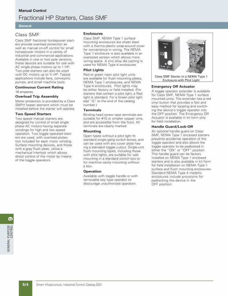
Class SMFClass SMF fractional horsepower start-ers provide overload protection as well as manual on-off control for small horsepower motors in a variety of industrial and commercial applications. Available in one or two pole versions, these devices are suitable for use with AC single phase motors up to 1 HP. Two pole starters can also be used with DC motors up to 3⁄4 HP. Typical applications include fans, conveyors, pumps, and small machine tools.
Continuous Current Rating16 amperes.Overload Trip AssemblyMotor protection is provided by a Class SMFH heater element which must be installed before the starter will operate.
Two Speed StartersTwo speed manual starters are designed for control of small single phase AC motors having separate windings for high and low speed operation. Two toggle operated start-ers are used, with overload protec-tion included for each motor winding. Surface mounting devices, and those with a gray flush plate, utilize a mechanical interlock which allows direct control of the motor by means of the toggle operators.
EnclosuresClass SMF, NEMA Type 1 surface mounting enclosures are sheet steel with a thermo-plastic wrap-around cover for convenience in wiring. The NEMA Type 1 enclosure is also available in an oversized version which allows more wiring space. A zinc alloy die casting is used for NEMA Type 4 enclosures.
Pilot LightsRed or green neon pilot light units are available for flush mounting plates, NEMA Type 1 enclosures, and NEMA Type 4 enclosures. Pilot lights may be either factory or field installed. (For starters that contain a pilot light, a Red light is standard. For a Green pilot light add ”G” to the end of the catalog number.)
TerminalsBinding head screw type terminals are suitable for #10 or smaller copper wire, and are accessible from the front. All terminals are clearly marked.
MountingOpen types without a pilot light fit standard single gang switch boxes, and can be used with any cover plate hav-ing a standard toggle cutout. Single-unit flush mounting types, including those with pilot lights, are suitable for wall mounting in a standard switch box or for machine cavity mounting without a box.
OperationAvailable with toggle handle or with removable key type operator to discourage unauthorized operation.
Emergency Off ActuatorA toggle operator extender is available for Class SMF, NEMA Type 1 surface mounted units. The extender has a red vinyl button that provides a fast and easy method for locating and switch-ing the device‘s toggle operator into the OFF position. The Emergency Off Actuator is available in kit form only for field installation.
Handle Guard/Lock-OffAn optional handle guard on Class SMF, NEMA Type 1 enclosed starters prevents accidental operation of the toggle operator and also allows the toggle operator to be padlocked in either the “ON” or “OFF” position. This handle guard can be factory installed on NEMA Type 1 enclosed starters and is also available in kit form for field installation on NEMA Type 1 surface and flush mounting enclosures. Standard NEMA Type 4 metallic enclosures include provisions for padlocking the device in the OFF position.
Class SMF Starter in a NEMA Type 1 Enclosure with Pilot Light
Manual Control
Fractional HP Starters, Class SMFGeneral
9G
enera
l PurPo
se Co
ntro
l
9/5Smart Infrastructure, Industrial Control Catalog 2021
Manual Control
Fractional HP Starters with Melting Alloy Overload, Class SMFSelection
Product Category: NEMA
a One heater element required.b Furnished with (1) 3⁄4" NPT Outlet in bottom (revers-
ible for top feed).
c Two heater elements required.d Order Open Type starter plus separate handle guard kit.
e For starters that contain a pilot light, a Red light is standard. For a Green pilot light add ”G” to the end of the catalog number.
One Starter in Duplex Enclosure—Class SMF, Single Phasea
GeneralPurposeFlushMounting
OpenStarterwithFlushPlate-(NoEnclosureProvided)
GrayFlushPlate StainlessSteelFlush NEMAType1General ForWallorCavity PlateforWallorCavity PurposeEnclosure Replacement Typeof Number Mounting Mounting SurfaceMounting Starters Operator ofPoles StarterFeaturese CatalogNumber ListPrice$ CatalogNumber ListPrice$ CatalogNumber ListPrice$ CatalogNumber ListPrice$
Toggle 2 Standard — — — — SMFFG02 — — RedPilotLight — — — — — — — — Key 2 RedPilotLight — — — — SMFFG04P — —
Two Starters In Duplex Enclosure—Class SMF, Single Phasec
Toggle 2PerStarter Standard SMFFF222 — — SMFFG222 — — RedPilotLightonEachStarter SMFFF222P — — — — — — Key 2PerStarter RedPilotLightonEachStarter SMFFF44P SMFFS44P SMFFG44P — —
Starter And “Auto-Off-Hand” SPDT Selector Switch (AC Only)—Class SMF, Single Phasea
1 Standard — — — — — — — — Toggle RedPilotLight SMFFF71P SMFFS71P SMFFG71P — — 2 Standard — — — — SMFFG72 — — RedPilotLight SMFFF72P SMFFS72P — — — — Key 2 RedPilotLight SMFFF74P SMFFS74P SMFFG74P — —
Two Speed Starters (AC Only)—Class SMF, Single Phasec
MechanicalInterlock SMFFF11 — — — — SMFF01T 1 MechanicalInterlockand(2)RedPilotLights SMFFF11P — — — — — — MechanicalInterlock,HIGH-OFF-LOW Toggle SelectorSwitchand(2)RedPilotLights — — — — — — — —
MechanicalInterlock SMFFF22 — — SMFFG22 — — 2 MechanicalInterlockand(2)RedPilotLights SMFFF22P — — SMFFG22P SMFF02PT MechanicalInterlock,HIGH-OFF-LOW SelectorSwitchand(2)RedPilotLights — — SMFFS202P — — SMFF02PT
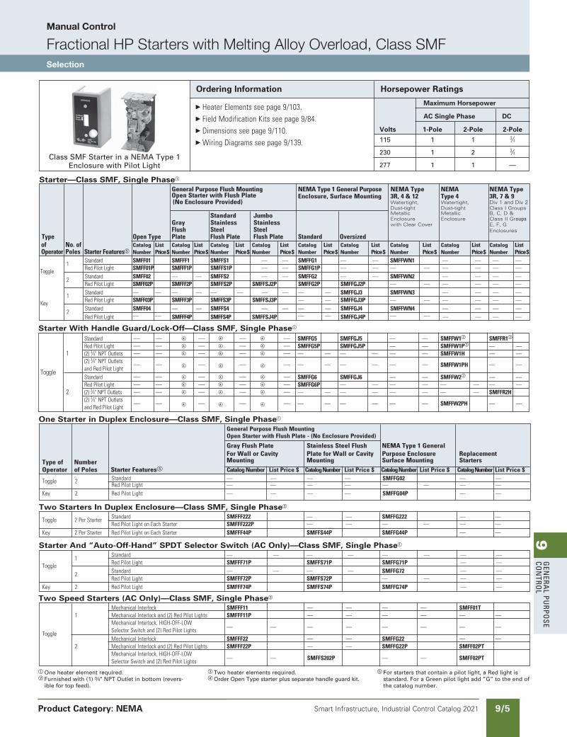
Starter—Class SMF, Single Phasea
GeneralPurposeFlushMounting NEMAType1GeneralPurpose NEMAType NEMA NEMAType OpenStarterwithFlushPlate Enclosure,SurfaceMounting 3R,4&12 Type4 3R,7&9 (NoEnclosureProvided) Watertight, Watertight, Div 1 and Div 2 Dust-tight Dust-tight Class I Groups
Standard Jumbo Metallic Metallic B, C, D &
Gray Stainless Stainless Enclosure Enclosure Class II Groups
Flush Steel Steel with Clear Cover E, F, G
Type OpenType Plate FlushPlate FlushPlate Standard Oversized Enclosures
of No.of Catalog List Catalog List Catalog List Catalog List Catalog List Catalog List Catalog List Catalog List Catalog ListOperator Poles StarterFeaturese Number Price$ Number Price$ Number Price$ Number Price$ Number Price$ Number Price$ Number Price$ Number Price$ Number Price$ 1 Standard SMFF01 SMFFF1 SMFFS1 — — SMFFG1 — — SMFFWN1 — — — —
Toggle RedPilotLight SMFF01P SMFFF1P SMFFS1P — — SMFFG1P — — — — — — — — 2 Standard SMFF02 — — SMFFS2 — — SMFFG2 — — SMFFWN2 — — — — RedPilotLight SMFF02P SMFFF2P SMFFS2P SMFFSJ2P SMFFG2P SMFFGJ2P — — — — — — 1 Standard — — — — — — — — — — SMFFGJ3 SMFFWN3 — — — —
Key RedPilotLight SMFF03P SMFFF3P SMFFS3P SMFFSJ3P — — SMFFGJ3P — — — — — — 2 Standard SMFF04 — — SMFFS4 — — — — SMFFGJ4 SMFFWN4 — — — — RedPilotLight — — SMFFF4P SMFFS4P SMFFSJ4P — — SMFFGJ4P — — — — — —
Starter With Handle Guard/Lock-Off—Class SMF, Single Phasea
Standard — — d — d — d — SMFFG5 SMFFGJ5 — — SMFFW1b SMFFR1b RedPilotLight — — d — d — d — SMFFG5P SMFFGJ5P — — SMFFW1Pb — — 1 (2)3⁄4"NPTOutlets — — d — d — d — — — — — — — SMFFW1H — — (2)3⁄4"NPTOutletsToggle andRedPilotLight — — d — d — d — — — — — — — SMFFW1PH — —
Standard — — d — d — d — SMFFG6 SMFFGJ6 — — SMFFW2b — — RedPilotLight — — d — d — d — SMFFG6P — — — — — — — — 2 (2)3⁄4"NPTOutlets — — d — d — d — — — — — — — — — SMFFR2H (2)3⁄4"NPTOutlets andRedPilotLight — — d — d — d — — — — — — — SMFFW2PH — —
Ordering Information Horsepower Ratings
Class SMF Starter in a NEMA Type 1 Enclosure with Pilot Light
Maximum Horsepower
AC Single Phase DC
Volts 1-Pole 2-Pole 2-Pole
115 1 1 3⁄4
230 1 2 3⁄4
277 1 1 —
HeaterElementsseepage9/103.FieldModificationKitsseepage9/84.Dimensionsseepage9/110.WiringDiagramsseepage9/139.
NEED TO UPDATE IN SPEEDFAX
Revised on 12/31/21
9G
ener
al
PurP
ose
Co
ntr
ol
9/6 Smart Infrastructure, Industrial Control Catalog 2021
Class MMS, MRSClass MMS and MRS motor starting switches provide manual “ON-OFF” control of single or three phase AC motors where overload protection is not required or is provided separately. Compact construction and a 600 volt rating make these switches suitable for a wide range of industrial and commercial uses. Typical applications include small machine tools, pumps, fans, conveyors and many other types of electrical machinery. They can also be used on non-motor loads such as resistance heating applications.
Continuous Current RatingMMS & MRS: 30 amperes at 250 volts max, 26.4 amperes at 277 volts, 20 amperes at 600 volts max, 30 amperes resistive at 600 volts max.
Two Speed—Class MRSTwo speed manual switches may be used with separate winding three phase or single phase AC motors where overload protection is not required or is provided separately. Two switches are employed to give “ON-OFF” control in each speed.
Reversing—Class MRSReversing manual switches provide a compact means of starting, stopping and reversing AC motors where overload protection is not required or is provided separately. They are suitable for use with three phase squirrel cage motors and for single phase motors which can be reversed by reconnecting motor leads. Two switches are used, one to connect the motor forward rotation and one for reverse.
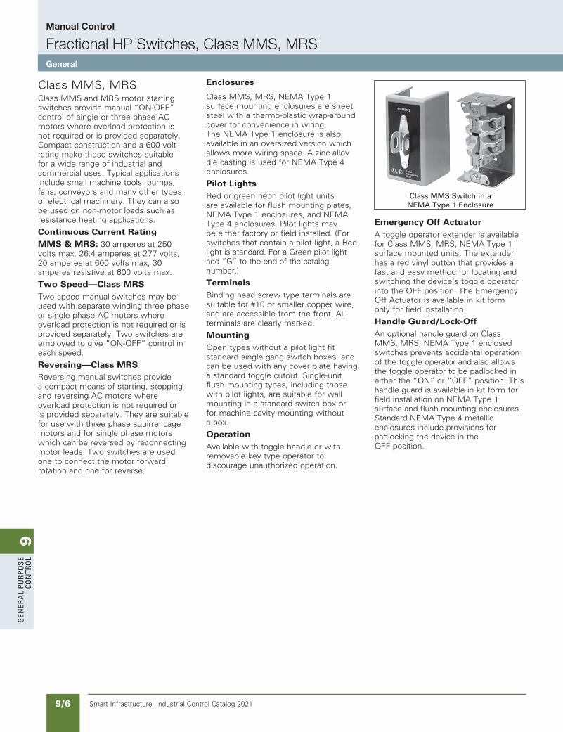
Enclosures
Class MMS, MRS, NEMA Type 1 surface mounting enclosures are sheet steel with a thermo-plastic wrap-around cover for convenience in wiring. The NEMA Type 1 enclosure is also available in an oversized version which allows more wiring space. A zinc alloy die casting is used for NEMA Type 4 enclosures.
Pilot LightsRed or green neon pilot light units are available for flush mounting plates, NEMA Type 1 enclosures, and NEMA Type 4 enclosures. Pilot lights may be either factory or field installed. (For switches that contain a pilot light, a Red light is standard. For a Green pilot light add ”G” to the end of the catalog number.)
TerminalsBinding head screw type terminals are suitable for #10 or smaller copper wire, and are accessible from the front. All terminals are clearly marked.
MountingOpen types without a pilot light fit standard single gang switch boxes, and can be used with any cover plate having a standard toggle cutout. Single-unit flush mounting types, including those with pilot lights, are suitable for wall mounting in a standard switch box or for machine cavity mounting without a box.
OperationAvailable with toggle handle or with removable key type operator to discourage unauthorized operation.
Emergency Off ActuatorA toggle operator extender is available for Class MMS, MRS, NEMA Type 1 surface mounted units. The extender has a red vinyl button that provides a fast and easy method for locating and switching the device‘s toggle operator into the OFF position. The Emergency Off Actuator is available in kit form only for field installation.
Handle Guard/Lock-OffAn optional handle guard on Class MMS, MRS, NEMA Type 1 enclosed switches prevents accidental operation of the toggle operator and also allows the toggle operator to be padlocked in either the “ON” or “OFF” position. This handle guard is available in kit form for field installation on NEMA Type 1 surface and flush mounting enclosures. Standard NEMA Type 4 metallic enclosures include provisions for padlocking the device in the OFF position.
Class MMS Switch in aNEMA Type 1 Enclosure
Manual Control
Fractional HP Switches, Class MMS, MRSGeneral
9G
enera
l PurPo
se Co
ntro
l
9/7Smart Infrastructure, Industrial Control Catalog 2021 Product Category: NEMA
Manual Control
Switchesa, Class MMS, MRSSelection
a Manual switches do not include overloads.b Furnished with (1) 3/4" NPT outlet in bottom (reversible
for top feed). In order to obtain a 3⁄4" NPT outlet in top and bottom, add suffix letter “H” to type number with List Price adder.
c Do not use as replacement interiors for NEMA Type 4 metallic enclosures. For replacement unit, order Type MMSK01 or MMSK02 and separate pilot light kit.
d For switches that contain a pilot light, a Red light is standard. For a Green pilot light add ”G” to the end of the catalog number.
Ordering Information
HeaterElementsnotRequired.
FieldModificationKitssee page9/84.
Dimensionsseepage9/110.
WiringDiagramsseepage9/139.
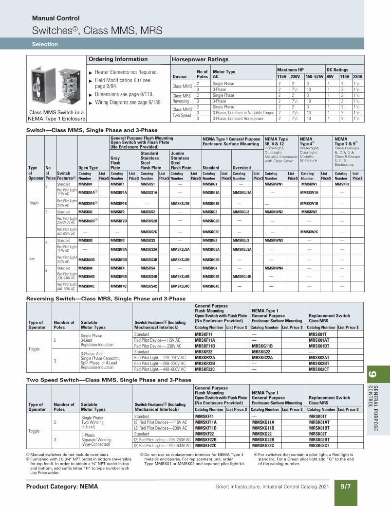
Horsepower Ratings
Noof MotorType MaximumHP DCRatings
Device Poles AC 115V 230V 450–575V 90V 115V 230V
ClassMMS 2 SinglePhase 2 2 3 1 2 11/2
3 3-Phase 2 71/2 10 1 2 11/2
ClassMRS 2 SinglePhase 2 2 3 1 2 11/2
Reversing 3 3-Phase 2 71/2 10 1 2 11/2
ClassMMS 2 SinglePhase 2 2 3 1 2 11/2
TwoSpeed 3 3-Phase,ConstantorVariableTorque 2 71/2 10 1 2 11/2
3 3-Phase,ConstantHorsepower 2 71/2 10 1 2 11/2
Class MMS Switch in a NEMA Type 1 Enclosure
Reversing Switch—Class MRS, Single Phase and 3-Phase GeneralPurpose FlushMounting NEMAType1 OpenSwitchwithFlushPlate GeneralPurpose ReplacementSwitch
Typeof Numberof Suitable SwitchFeaturesd(Including (NoEnclosureProvided) EnclosureSurfaceMounting ClassMRS Operator Poles MotorTypes MechanicalInterlock) CatalogNumber ListPrice$ CatalogNumber ListPrice$ CatalogNumber ListPrice$
SinglePhase Standard MRSKF11 — MRSK01T 2 3-Lead RedPilotDevice—115VAC MRSKF11A — MRSK01AT Repulsion-Induction RedPilotDevice—230VAC MRSKF11B MRSKG11B MRSK01BT Toggle
3-Phase;Also Standard MRSKF22 MRSKG22 — SinglePhaseCapacitor, RedPilotLight—110–120VAC MRSKF22A MRSKG22A MRSK02AT 3 SplitPhase,or4-Lead RedPilotLight—208–220VAC MRSKF22B — MRSK02BT Repulsion-Induction RedPilotLight—440–600VAC MRSKF22C — MRSK02CT
Two Speed Switch—Class MMS, Single Phase and 3-Phase GeneralPurpose FlushMounting NEMAType1 OpenSwitchwithFlushPlate GeneralPurpose ReplacementSwitch
Typeof Numberof Suitable SwitchFeaturesd(Including (NoEnclosureProvided) EnclosureSurfaceMounting ClassMRS Operator Poles MotorTypes MechanicalInterlock) CatalogNumber ListPrice$ CatalogNumber ListPrice$ CatalogNumber ListPrice$
SinglePhase Standard MMSKF11 — MRSK01T 2 TwoWinding (2)RedPilotDevices—115VAC MMSKF11A MMSKG11A MRSK01AT (3-Lead) (2)RedPilotDevices—230VAC MMSKF11B MMSKG11B MRSK01BT Toggle
3-Phase Standard MMSKF22 MMSKG22 MRSK02T 3 SeparateWinding (2)RedPilotLights—208–240VAC MMSKF22B MMSKG22B MRSK02BT (Wye-Connected) (2)RedPilotLights—440–600VAC MMSKF22C MMSKG22C MRSK02CT
Switch—Class MMS, Single Phase and 3-Phase
GeneralPurposeFlushMounting NEMAType1GeneralPurpose NEMAType NEMA NEMA OpenSwitchwithFlushPlate EnclosureSurfaceMounting 3R,4&12 Type4
b
Type7&9b
(NoEnclosureProvided) Watertight, Watertight, Class I Groups
Standard Jumbo Dust-tight Dust-tight B, C & D &
Gray Stainless Stainless Metallic Enclosurer Metallic Class II Groups
Flush Steel Steel with Clear Cover Enclosure E, F, G
Type No OpenType Plate FlushPlate FlushPlate Standard Oversized Enclosures
of of Switch Catalog List Catalog List Catalog List Catalog List Catalog List Catalog List Catalog List Catalog List Catalog List Operator PolesFeaturesd Number Price$ Number Price$ Number Price$ Number Price$ Number Price$ Number Price$ Number Price$ Number Price$ Number Price$ 2 Standard MMSK01 MMSKF1 MMSKS1 — MMSKG1 — MMSKWN1 MMSKW1 MMSKR1 RedPilotLight 115VAC MMSK01Ac MMSKF1A MMSKS1A — MMSKG1A MMSKGJ1A — MMSKW1A —
Toggle RedPilotLight 230VAC
MMSK01Bc MMSKF1B — MMSKSJ1B MMSKG1B — — MMSKW1B —
3 Standard MMSK02 MMSKF2 MMSKS2 — MMSKG2 MMSKGJ2 MMSKWN2 MMSKW2 —
RedPilotLight 208-240VAC MMSK02Bc MMSKF2B MMSKS2B — MMSKG2B — — — —
RedPilotLight 440-600VAC
— — MMSKS2C — MMSKG2C — — MMSKW2C —
2 Standard MMSK03 MMSKF3 MMSKS3 — MMSKG3 MMSKGJ3 MMSKWN3 — —
RedPilotLight 115VAC — MMSKF3A MMSKS3A MMSKSJ3A MMSKG3A MMSKGJ3A — — —
Key RedPilotLight 230VAC
MMSK03B MMSKF3B MMSKS3B MMSKSJ3B MMSKG3B — — — —
3 Standard MMSK04 MMSKF4 MMSKS4 — MMSKG4 — MMSKWN4 — — RedPilotLight 208–240VAC MMSK04B MMSKF4B MMSKS4B MMSKSJ4B MMSKG4B MMSKGJ4B — — —
RedPilotLight 440–600VAC
MMSK04C MMSKF4C MMSKS4C MMSKSJ4C MMSKG4C — — — —
SS copied this page from SF to IC on 05/24/20
NEED TO UPDATE IN SPEEDFAX
Revised on 12/31/21
9G
ener
al
PurP
ose
Co
ntr
ol
9/8 Smart Infrastructure, Industrial Control Catalog 2021
Manual Control
Starters and Switches, Class 11 - 3RVGeneral
Class 11 - 3RVClass 11 across the line manual starters and switches provide control for machinery where remote start stop control is not required.
Class 11 - 3RV manual starters are used for single and poly-phase motors up to 20HP @ 575V. Starters have bime-tallic heater elements to provide class 10 overcurrent protection. Each starter has a fourth bimetallic strip that reacts only to the ambient temperature inside the control panel. This ambient compensation helps prevent the starter from nuisance tripping when the panel temperature is higher than the ambient temperature of the motor.
A built-in differential trip bar causes the starter to trip faster on a phase loss condition to help reduce motor damage.
Magnetic trip elements in each starter take the device off line when it senses current of 13 times the maximum FLA dial setting.
Class 11 - 3RV switches provide control for inherently protected motors. Typical applications include metal and woodworking machinery, grinders, power saws, conveyors, fans, pumps, blowers, textile and packaging machinery, and paper cutters.
Each switch is provided with magnetic trip elements which take the device off line when it senses current of 13 times the maximum switch rating.
Class 11 - 3RV manual starters can be used as Type E self-protected manual combination starters (up to 22 amps) per UL508 or as components in Group Installation per NEC 430.53. When using the Class 11 - 3RV as a manual combination starter upstream protection is not required.
Class 11 - 3RV controllers are available with low voltage protection which will automatically open the power poles when the voltage drops or the power is interrupted.
Controllers with the LVP option provide the OSHA requirements for protecting personnel from potential injury caused by the automatic start-up of machinery following a voltage drop or power interruption when low voltage protection is specified.
Class 11 - 3RV is available as Open style, or in NEMA 1.
Standard Features include:b ON/OFF rotary handle with lockout
and visible trip indication
b Adjustment dial for setting to motor FLA (Starters only)
b Low Voltage Protection (LVP) Option
b Short Circuit trip at 13 times the maximum setting of the FLA dial or rated current
b Ambient compensated up to 140°F
b Phase loss sensitivity
b Test trip function
b LVP Option Meets OSHA Requirements
b UL Listed
b CSA Certified
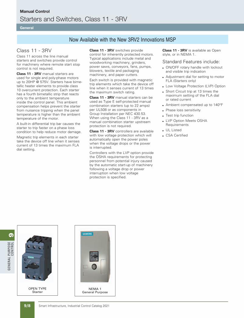
OPEN TYPE Starter
NEMA 1 General Purpose
Now Available with the New 3RV2 Innovations MSP
updated in SPEEDFAXRevised on 03/31/20
SS copied this page from SF to IC on 05/24/20
9G
enera
l PurPo
se Co
ntro
l
9/9Smart Infrastructure, Industrial Control Catalog 2021
Manual Control
Starters and Switches, Class 11 - 3RVSelection
Product Category: NEMA
updated in SPEEDFAXRevised on 03/31/20
a Instantaneous Magnetic Trip will occur at 13 times the maximum FLA dial setting or rated switch current.
b Product Category: IEC
c Shaded Ratings apply for Manual Motor Controllers Only! These Ratings do not apply as UL Listed Manual Combination Starters.
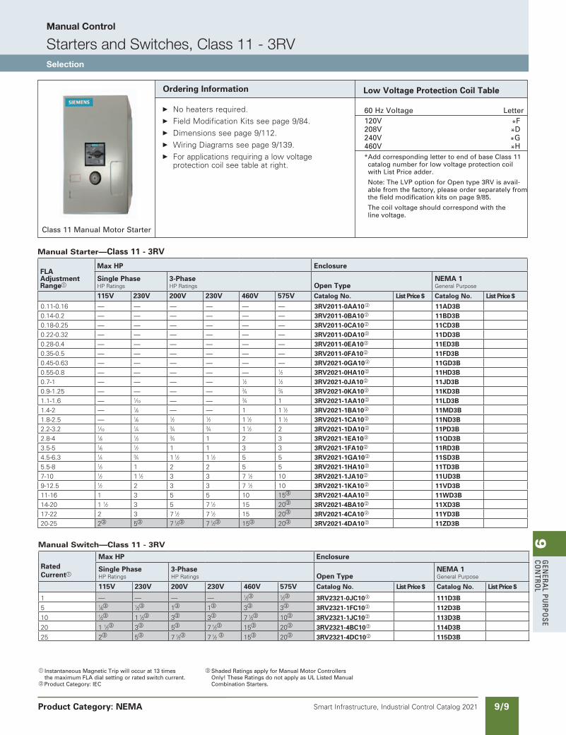
Ordering Information
No heaters required. Field Modification Kits see page 9/84. Dimensions see page 9/112. Wiring Diagrams see page 9/139. For applications requiring a low voltage
protection coil see table at right.
Class 11 Manual Motor Starter
Low Voltage Protection Coil Table
60 Hz Voltage Letter 120V *F 208V *D 240V *G 460V *H * Add corresponding letter to end of base Class 11
catalog number for low voltage protection coil with List Price adder.
Note: The LVP option for Open type 3RV is avail-able from the factory, please order separately from the field modification kits on page 9/85.
The coil voltage should correspond with the line voltage.
Manual Switch—Class 11 - 3RV
RatedCurrenta
Max HP Enclosure
Single PhaseHP Ratings
3-PhaseHP Ratings Open Type
NEMA 1General Purpose
115V 230V 200V 230V 460V 575V Catalog No. List Price $. Catalog No. List Price $
1 — — — — 1⁄2c 1⁄2c 3RV2321-0JC10b 111D3B 5 1⁄6c 1⁄2c 1c 1c 3c 3c 3RV2321-1FC10b 112D3B 10 1⁄2c 1 1⁄2c 3c 3c 7 1⁄2c 10c 3RV2321-1JC10b 113D3B 20 1 1⁄2c 3c 5c 7 1⁄2c 15c 20c 3RV2321-4BC10b 114D3B 25 2c 5c 7 1⁄2c 7 1⁄2 c 15c 20c 3RV2321-4DC10b 115D3B
Manual Starter—Class 11 - 3RV
FLA Adjustment Rangea
Max HP Enclosure
Single PhaseHP Ratings
3-PhaseHP Ratings Open Type
NEMA 1General Purpose
115V 230V 200V 230V 460V 575V Catalog No. List Price $. Catalog No. List Price $
0.11-0.16 — — — — — — 3RV2011-0AA10b 11AD3B 0.14-0.2 — — — — — — 3RV2011-0BA10b 11BD3B 0.18-0.25 — — — — — — 3RV2011-0CA10b 11CD3B 0.22-0.32 — — — — — — 3RV2011-0DA10b 11DD3B 0.28-0.4 — — — — — — 3RV2011-0EA10b 11ED3B 0.35-0.5 — — — — — — 3RV2011-0FA10b 11FD3B 0.45-0.63 — — — — — — 3RV2021-0GA10b 11GD3B 0.55-0.8 — — — — — 1⁄2 3RV2021-0HA10b 11HD3B 0.7-1 — — — — 1⁄2 1⁄2 3RV2021-0JA10b 11JD3B 0.9-1.25 — — — — 3⁄4 3⁄4 3RV2021-0KA10b 11KD3B 1.1-1.6 — 1⁄10 — — 3⁄4 1 3RV2021-1AA10b 11LD3B 1.4-2 — 1⁄8 — — 1 1 1⁄2 3RV2021-1BA10b 11MD3B 1.8-2.5 — 1⁄6 1⁄2 1⁄2 1 1⁄2 1 1⁄2 3RV2021-1CA10b 11ND3B 2.2-3.2 1⁄10
1⁄4 3⁄4 3⁄4 1 1⁄2 2 3RV2021-1DA10b 11PD3B 2.8-4 1⁄8 1⁄3 3⁄4 1 2 3 3RV2021-1EA10b 11QD3B 3.5-5 1⁄6 1⁄2 1 1 3 3 3RV2021-1FA10b 11RD3B 4.5-6.3 1⁄4 3⁄4 1 1⁄2 1 1⁄2 5 5 3RV2021-1GA10b 11SD3B 5.5-8 1⁄3 1 2 2 5 5 3RV2021-1HA10b 11TD3B 7-10 1⁄2 1 1⁄2 3 3 7 1⁄2 10 3RV2021-1JA10b 11UD3B 9-12.5 1⁄2 2 3 3 7 1⁄2 10 3RV2021-1KA10b 11VD3B 11-16 1 3 5 5 10 15c 3RV2021-4AA10b 11WD3B 14-20 1 1⁄2 3 5 7 1⁄2 15 20c 3RV2021-4BA10b 11XD3B 17-22 2 3 7 1⁄2 7 1⁄2 15 20c 3RV2021-4CA10b 11YD3B 20-25 2c 5c 7 1⁄2c 7 1⁄2c 15c 20c 3RV2021-4DA10b 11ZD3B
SS copied this page from SF to IC on 05/24/20
9G
ener
al
PurP
ose
Co
ntr
ol
9/10 Smart Infrastructure, Industrial Control Catalog 2021
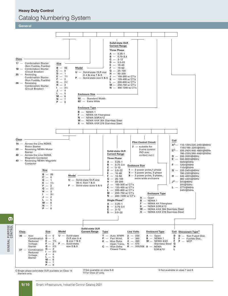
Heavy Duty Control
Catalog Numbering SystemGeneral
updated in SPEEDFAXRevised on 03/31/20
a Single phase solid-state OLR available on Class 14 Starters only.
Class
14 — Across the Line NEMA Motor Starter22 — Reversing NEMA Motor
Starter40 — Across the Line NEMA Magnetic Contactor43 — Reversing NEMA Magnetic Contactor
Size
B — 00C — 0D — 1E — 13⁄4F — 2G — 21⁄2H — 3I — 31⁄2J — 4L — 5M — 6N — 7P — 8
Model
U — Solid-state OLR size 00–4, Size 7 & 8
P — Solid-state sizes 5 & 6
Enclosure Size
1 — 2 power poles,1-phase 3 — 3 power poles, 3-phase 8 — 3 power poles, 3-phase,
extra wide enclosure
Pilot Control Circuit
2 — suitable for 3-wire control (NO aux. contact incl.)
Enclosure Type
A — OpenB — NEMA 1F — NEMA 4X Fiberglass0 — NEMA 3/3R/4/12W — NEMA 4/4X 304 Stainless Steel X — NEMA 4/4X 316 Stainless Steel
Coil
Ab— 110–120V/220–240V@60Hz 110V/190–220V@50HzCb— 220–240V/440–480V@60Hz 190–220V/380–440V@50HzD — 200–208V@60HzE — 550–600V@60Hz 550V@50HzF — 120V@60Hz 110V@50HzG — 220–240V@60Hz 190–220V@50HzH — 440–480V@60Hz 380–440V@50HzJd — 24V@60Hz
24V@50HzL — 277V@60Hz 240V@50Hz
Class
17 — Combination Starter (Non Fusible, Fusible)18 — Combination Starter (Circuit Breaker)25 — Reversing Combination Starter (Non Fusible, Fusible)26 — Reversing Combination Starter (Circuit Breaker)
Size
B — 00C — 0D — 1E — 13⁄4F — 2G — 21⁄2H — 3I — 31⁄2J — 4L — 5M — 6N — 7P — 8
Model
U — Solid-state OLR size 0–4 & size 7 & 8
P — Solid-state size 5 & 6
Enclosure Size
92 — Standard Width82 — Extra Wide
Enclosure Type
B — NEMA 1F — NEMA 4X FiberglassN — NEMA 3/3R/4/12W — NEMA 4/4X 304 Stainless SteelX — NEMA 4/4X 316 Stainless Steel
Solid-state OLR Current Range
Three Phase
A — 0.25–1 B — 0.75–3.4 C — 3–12D — 5.5–22E — 10–40F — 13–52G — 25–100H — 50–200J — 100–300 w/ CT’sK — 133–400 w/ CT’sL — 200–600 w/ CT’sM — 250–750 w/ CT’sN — 400–1200 w/ CT’s
Solid-state OLR Current Range
Three Phase
A — 0.25–1 B — 0.75–3.4 C — 3–12D — 5.5–22E — 10–40F — 13–52G — 25–100H — 50–200J — 100–300 w/ CT’sK — 133–400 w/ CT’sL — 200–600 w/ CT’sM — 250–750 w/ CT’sN — 400–1200 w/ CT’s
Single Phasea
A — 0.25–1 B — 0.75–3.4 C — 3–12 D — 5.5–22
Disconnect Typec
D — Non Fused Disc.F — Fusible Disc.P — MCP
Size
C — 0D — 1E — 13⁄4F — 2G — 21⁄2H — 3I — 31⁄2J — 4L — 5M — 6N — 7P — 8
Model
U — Solid-state OLR size 0–4 & size 7 & 8P — Solid-state size 5 & 6
Solid-state OLR Current Range Type
T — Auto XFMRP — Part Wind.0 — Wye Delta Open Trans.C — Wye Delta Closed Trans.
Line Volts
2 — 2303 — 3804 — 4605 — 5756 — 200/208
CoilEnclosure Type
A — Open DB — NEMA 1 EW — NEMA 4/4X F Stainless Steel G0 — NEMA H 3/3R/4/12 L
Class
36 — Non Combination Reduced Voltage Starter
37 — Combination Reduced Voltage Starter
b Not available on sizes 5–8.c For Class 37 only.
d Not available on sizes 7 and 8.
SS copied this page from SF to IC on 05/24/20
9G
enera
l PurPo
se Co
ntro
l
9/11Smart Infrastructure, Industrial Control Catalog 2021
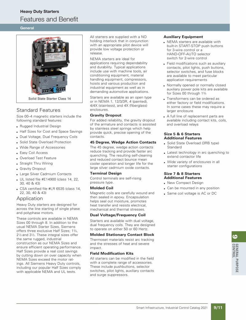
Heavy Duty Starters
Features and BenefitGeneral
updated in SPEEDFAXRevised on 03/31/20
Standard FeaturesSize 00–4 magnetic starters include the following standard features:
b Rugged Industrial Design
b Half Sizes for Cost and Space Savings
b Dual Voltage, Dual Frequency Coils
b Solid State Overload Protection
b Wide Range of Accessories
b Easy Coil Access
b Overload Test Feature
b Straight Thru Wiring
b Gravity Dropout
b Large Silver Cadmium Contacts
b UL listed file #E14900 (class 14, 22, 30, 40 & 43)
b CSA certified file #LR 6535 (class 14, 22, 30, 40 & 43)
ApplicationHeavy Duty starters are designed for across the line starting of single phase and polyphase motors.
These controls are available in NEMA Sizes 00 through 8. In addition to the usual NEMA Starter Sizes, Siemens offers three exclusive Half Sizes; 13⁄4, 21⁄2 and 31⁄2. These integral sizes offer the same rugged, industrial construction as our NEMA Sizes and ensure efficient operating performance. Half Sizes provide a real cost savings by cutting down on over capacity when NEMA Sizes exceed the motor rat-ings. All Siemens Heavy Duty controls, including our popular Half Sizes comply with applicable NEMA and UL tests.
All starters are supplied with a NO holding interlock that in conjunction with an appropriate pilot device will provide low voltage protection or release.
NEMA starters are ideal for applications requiring dependability and durability. Typical applications include use with machine tools, air conditioning equipment, material handling equipment, compressors, hoists and various production and industrial equipment as well as in demanding automotive applications.
Starters are available as an open type or in NEMA 1, 12/3/3R, 4 (painted), 4/4X (stainless), and 4X (fiberglass) enclosures.
Gravity DropoutFor added reliability, the gravity dropout of the armature and contacts is assisted by stainless steel springs which help provide quick, precise opening of the contacts.
45 Degree, Wedge Action ContactsThe 45 degree, wedge action contacts reduce tracking and provide faster arc quenching. The resulting self-cleaning and reduced contact bounce mean cooler operation and longer life for the large silver cadmium oxide contacts.
Terminal DesignControl terminals are self-rising pressure type.
Molded CoilMagnetic coils are carefully wound and then sealed in epoxy. Encapsulation helps seal out moisture, promotes heat transfer and resists electrical, mechanical and thermal stresses.
Dual Voltage/Frequency Coil
Starters are available with dual voltage, dual frequency coils. They are designed to operate on either 50 or 60 Hertz.
Molded Stationary Contact BlockThermoset materials resist arc tracking and the stresses of heat and severe impact.
Field Modification KitsAll starters can be modified in the field with a complete range of accessories. These include pushbuttons, selector switches, pilot lights, auxiliary contacts and surge suppressors.
Auxiliary Equipment
b NEMA starters are available with built-in START-STOP push buttons for 3-wire control or a HAND-OFF-AUTO selector switch for 2-wire control
b Field modifications such as auxiliary contacts, pilot lights, push buttons, selector switches, and fuse blocks are available to meet particular application requirements
b Normally opened or normally closedauxiliary power pole kits are available for Sizes 00 through 13⁄4
b Transformers can be ordered as either factory or field modifications. In some cases these may require a larger enclosure
b A full line of replacement parts areavailable including contact kits, coils, and overload relays
Size 5 & 6 Starters Additional Features
b Solid State Overload (3RB type) Standard
b Latest technology in arc quenching to extend contactor life
b Wide variety of enclosures in all starter configurations
Size 7 & 8 Starters Additional Features
b New Compact Design
b Can be mounted in any position
b Same coil voltage is AC or DC
Solid State Starter Class 14
SS copied this page from SF to IC on 05/24/20
9G
ener
al
PurP
ose
Co
ntr
ol
9/12 Smart Infrastructure, Industrial Control Catalog 2021
Heavy Duty Starters
Features and BenefitsSelection
Product Category: NEMA
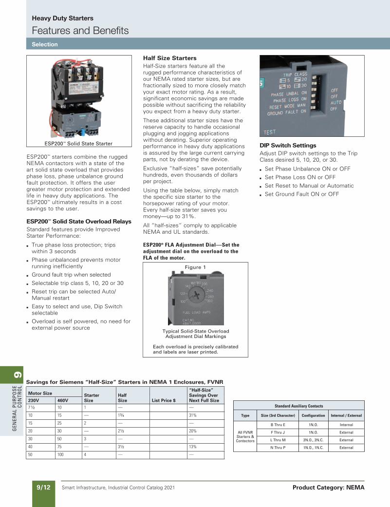
ESP200™ starters combine the rugged NEMA contactors with a state of the art solid state overload that provides phase loss, phase unbalance ground fault protection. It offers the user greater motor protection and extended life in heavy duty applications. The ESP200™ ultimately results in a cost savings to the user.
ESP200™ Solid State Overload RelaysStandard features provide Improved Starter Performance:
b True phase loss protection; tripswithin 3 seconds
b Phase unbalanced prevents motor running inefficiently
b Ground fault trip when selected
b Selectable trip class 5, 10, 20 or 30
b Reset trip can be selected Auto/Manual restart
b Easy to select and use, Dip Switch selectable
b Overload is self powered, no need for external power source
Half Size StartersHalf-Size starters feature all the rugged performance characteristics of our NEMA rated starter sizes, but are fractionally sized to more closely match your exact motor rating. As a result, significant economic savings are made possible without sacrificing the reliability you expect from a heavy duty starter.
These additional starter sizes have the reserve capacity to handle occasional plugging and jogging applications without derating. Superior operating performance in heavy duty applications is assured by the large current carrying parts, not by derating the device.
Exclusive “half-sizes” save potentially hundreds, even thousands of dollars per project.
Using the table below, simply match the specific size starter to the horsepower rating of your motor. Every half-size starter saves you money—up to 31%.
All “half-sizes” comply to applicable NEMA and UL standards.
ESP200®FLAAdjustmentDial—SettheadjustmentdialontheoverloadtotheFLAofthemotor.
DIP Switch SettingsAdjust DIP switch settings to the Trip Class desired 5, 10, 20, or 30.
b Set Phase Unbalance ON or OFF
b Set Phase Loss ON or OFF
b Set Reset to Manual or Automatic
b Set Ground Fault ON or OFF
Typical Solid-State Overload Adjustment Dial Markings
Each overload is precisely calibrated and labels are laser printed.
Figure 1
ESP200™ Solid State Starter
StandardAuxiliaryContacts
Type Size(3rdCharacter) Configuration Internal/External
B thru e 1n.o. Internal
all FVnr F thru J 1n.o. external
starters &
l thru M 2n.o., 2n.C. external
Contactors
n thru P 1n.o., 1n.C. external
Savings for Siemens “Half-Size” Starters in NEMA 1 Enclosures, FVNR
Motor Size StarterSize
HalfSize List Price $
“Half-Size”Savings OverNext Full Size230V 460V
71⁄2 10 1 — —
10 15 — 13⁄4 31%
15 25 2 — —
20 30 — 21⁄2 20%
30 50 3 — —
40 75 — 31⁄2 13%
50 100 4 — —
SS copied this page from SF to IC on 05/24/20
9G
enera
l PurPo
se Co
ntro
l
9/13Smart Infrastructure, Industrial Control Catalog 2021
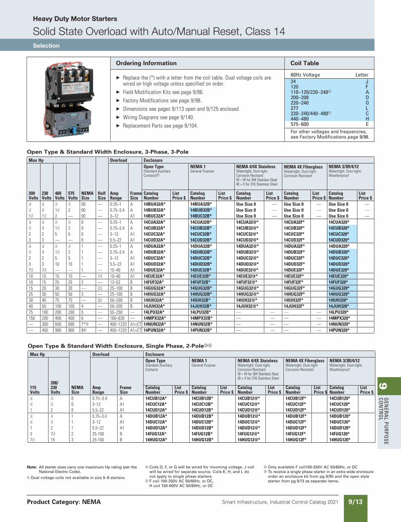
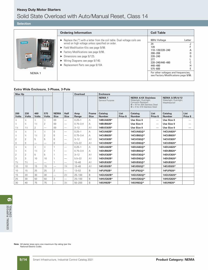
Heavy Duty Motor Starters
Solid State Overload with Auto/Manual Reset, Class 14Selection
Product Category: NEMA
Note: All starter sizes carry one maximum Hp rating (per the National Electric Code).
a Dual voltage coils not available in size 5–8 starters.
b Coils D, F, or G will be wired for incoming voltage. J coil will be wired for separate source. Coils E, H, and L do not apply to single phase starters.
c F coil 100-250V AC 50/60Hz, or DC, H coil 150-500V AC 50/60Hz, or DC
d Only available F coil100-250V AC 50/60Hz, or DCe To receive a single phase starter in an extra wide enclosure
order an enclosure kit from pg 9/95 and the open style starter from pg 9/13 as separate items.
Coil Table
60Hz Voltage letter 24 J 120 F 110–120/220–240a a 200–208 D 220–240 G 277 l 220–240/440–480a C 440–480 H 575–600 e For other voltages and frequencies,
see Factory Modifications page 9/98.
Ordering Information
Replacethe(*)withaletterfromthecoiltable.Dualvoltagecoilsarewiredonhighvoltageunlessspecifiedonorder.
FieldModificationKitsseepage9/86. FactoryModificationsseepage9/98. Dimensionsseepages9/113openand9/125enclosed. WiringDiagramsseepage9/140. ReplacementPartsseepage9/104.
Open Type & Standard Width Enclosure, Single Phase, 2-Polebe
MaxHp
NEMASize
Overload Enclosure
115Volts
208/230Volts
AmpRange
FrameSize
OpenTypeStandardAuxiliaryContacts
NEMA1GeneralPurpose
NEMA4/4XStainlessWatertight,Dust-tight,CorrosionResistant@=Wfor304StainlessSteel@=Xfor316StainlessSteel
NEMA4XFiberglassWatertight,Dust-tightCorrosionResistant
NEMA3/3R/4/12Watertight,Dust-tight,Weatherproof
CatalogNumber
ListPrice$
CatalogNumber
ListPrice$
CatalogNumber
ListPrice$
CatalogNumber
ListPrice$
CatalogNumber
ListPrice$
1⁄8 1⁄4 0 0.75–3.4 A 14CUB12A* 14CUB12B* 14CUB12@* 14CUB12F* 14CUB120* 1⁄4 1⁄2 0 3–12 A1 14CUC12A* 14CUC12B* 14CUC12@* 14CUC12F* 14CUC120* 1 2 0 5.5–22 A1 14CUD12A* 14CUD12B* 14CUD12@* 14CUD12F* 14CUD120* 1⁄8 1⁄4 1 0.75–3.4 A 14DUB12A* 14DUB12B* 14DUB12@* 14DUB12F* 14DUB120* 1⁄4 1⁄2 1 3–12 A1 14DUC12A* 14DUC12B* 14DUC12@* 14DUC12F* 14DUC120* 1 2 1 5.5–22 A1 14DUD12A* 14DUD12B* 14DUD12@* 14DUD12F* 14DUD120* 3 71⁄2 2 25-100 B 14FUG12A* 14FUG12B* 14FUG12@* 14FUG12F* 14FUG120*71⁄2 15 3 25-100 B 14HUG12A* 14HUG12B* 14HUG12@* 14HUG12F* 14HUG120*
Open Type & Standard Width Enclosure, 3-Phase, 3-PoleMaxHp
NEMASize
HalfSize
Overload Enclosure
200Volts
230Volts
460Volts
575Volts
AmpRange
FrameSize
OpenTypeStandardAuxiliaryContactsg
NEMA1GeneralPurpose
NEMA4/4XStainlessWatertight,Dust-tight,CorrosionResistant@=Wfor304StainlessSteel@=Xfor316StainlessSteel
NEMA4XFiberglassWatertight,Dust-tightCorrosionResistant
NEMA3/3R/4/12Watertight,Dust-tight,Weatherproof
CatalogNumber
ListPrice$
CatalogNumber
ListPrice$
CatalogNumber
ListPrice$
CatalogNumber
ListPrice$
CatalogNumber
ListPrice$
1⁄6 1⁄6 1⁄3 1⁄2 00 — 0.25–1 A 14BUA32A* 14BUA32B* UseSize0 — UseSize0 — UseSize0 —1⁄2 3⁄4 11⁄2 2 00 — 0.75–3.4 A 14BUB32A* 14BUB32B* UseSize0 — UseSize0 — UseSize0 —11⁄2 11⁄2 2 — 00 — 3–12 A1 14BUC32A* 14BUC32B* UseSize0 — UseSize0 — UseSize0 —1⁄6 1⁄6 1⁄3 1⁄2 0 — 0.25–1 A 14CUA32A* 14CUA32B* 14CUA32@* 14CUA32F* 14CUA320* 1⁄2 3⁄4 11⁄2 2 0 — 0.75–3.4 A 14CUB32A* 14CUB32B* 14CUB32@* 14CUB32F* 14CUB320* 2 2 5 5 0 — 3–12 A1 14CUC32A* 14CUC32B* 14CUC32@* 14CUC32F* 14CUC320* 3 3 — — 0 — 5.5–22 A1 14CUD32A* 14CUD32B* 14CUD32@* 14CUD32F* 14CUD320* 1⁄6 1⁄6 1⁄3 1⁄2 1 — 0.25–1 A 14DUA32A* 14DUA32B* 14DUA32@* 14DUA32F* 14DUA320* 1⁄2 3⁄4 11⁄2 2 1 — 0.75–3.4 A 14DUB32A* 14DUB32B* 14DUB32@* 14DUB32F* 14DUB320* 2 2 5 5 1 — 3–12 A1 14DUC32A* 14DUC32B* 14DUC32@* 14DUC32F* 14DUC320* 3 3 10 10 1 — 5.5–22 A1 14DUD32A* 14DUD32B* 14DUD32@* 14DUD32F* 14DUD320* 71⁄2 71⁄2 — — 1 — 10–40 A1 14DUE32A* 14DUE32B* 14DUE32@* 14DUE32F* 14DUE320* 10 10 15 15 — 13⁄4 10–40 A1 14EUE32A* 14EUE32B* 14EUE32@* 14EUE32F* 14EUE320* 10 15 25 25 2 — 13–52 B 14FUF32A* 14FUF32B* 14FUF32@* 14FUF32F* 14FUF320* 15 20 30 30 — 21⁄2 25–100 B 14GUG32A* 14GUG32B* 14GUG32@* 14GUG32F* 14GUG320* 25 30 50 50 3 — 25–100 B 14HUG32A* 14HUG32B* 14HUG32@* 14HUG32F* 14HUG320* 30 40 75 75 — 31⁄2 50–200 B 14IUH32A* 14IUH32B* 14IUH32@* 14IUH32F* 14IUH320* 40 50 100 100 4 — 50–200 B 14JUH32A* 14JUH32B* 14JUH32@* 14JUH32F* 14JUH320* 75 100 200 200 5 — 55–250 — 14LPU32A* 14LPU32B* — — — — 14LPU320* 150 200 400 400 6 — 160–630 — 14MPX32A* 14MPX32B* — — — — 14MPX320* — 300 600 600 7*c — 400–1220 A1+CT 14NUN32A* 14NUN32B* — — — — 14NUN320* — 450 900 900 8d — 400–1220 A1+CT 14PUN32A* 14PUN32B* — — — — 14PUN320*
SS copied this page from SF to IC on 05/24/20
updated in SPEEDFAXRevised on 03/31/20
9G
ener
al
PurP
ose
Co
ntr
ol
9/14 Smart Infrastructure, Industrial Control Catalog 2021 Product Category: NEMA
Ordering Information
Replacethe(*)withaletterfromthecoiltable.Dualvoltagecoilsarewiredonhighvoltageunlessspecifiedonorder.
FieldModificationKitsseepage9/98. FactoryModificationsseepage9/98. Dimensionsseepage9/125. WiringDiagramsseepage9/140. ReplacementPartsseepage9/104.
Coil Table
60Hz Voltage letter 24 J 120 F 110–120/220–240 a 200–208 D 220–240 G 277 l 220–240/440–480 C 440–480 H 575–600 e For other voltages and frequencies,
see Factory Modifications page 9/98.NEMA 1
Note: All starter sizes carry one maximum Hp rating (per the National Electric Code).
Extra Wide Enclosure, 3-Phase, 3-PoleMax Hp
NEMA Size
Half Size
Overload Enclosure
200 Volts
230 Volts
460 Volts
575 Volts
Amp Range
Frame Size
NEMA 1 General Purpose
NEMA 4/4X Stainless Watertight, Dust-tight,Corrosion Resistant@ = W for 304 Stainless Steel@ = X for 316 Stainless Steel
NEMA 3/3R/4/12Watertight, Dust-tight, Weatherproof
Catalog Number
List Price $
Catalog Number
List Price $
Catalog Number
List Price $
1⁄6 1⁄6 1⁄3 1⁄2 00 — 0.25–1 A 14BUA82B* Use Size 0 — Use Size 0 —1⁄2 3⁄4 11⁄2 2 00 — 0.75–3.4 A 14BUB82B* Use Size 0 — Use Size 0 —
11⁄2 11⁄2 2 — 00 — 3–12 A1 14BUC82B* Use Size 0 — Use Size 0 —1⁄6 1⁄6 1⁄3 1⁄2 0 — 0.25–1 A 14CUA82B* 14CUA82@* 14CUA820* 1⁄2 3⁄4 11⁄2 2 0 — 0.75–3.4 A 14CUB82B* 14CUB82@* 14CUB820*
2 2 5 5 0 — 3–12 A1 14CUC82B* 14CUC82@* 14CUC820*
3 3 — — 0 — 5.5–22 A1 14CUD82B* 14CUD82@* 14CUD820* 1⁄6 1⁄6 1⁄3 1⁄2 1 — 0.25–1 A 14DUA82B* 14DUA82@* 14DUA820* 1⁄2 3⁄4 11⁄2 2 1 — 0.75–3.4 A 14DUB82B* 14DUB82@* 14DUB820*
2 2 5 5 1 — 3–12 A1 14DUC82B* 14DUC82@* 14DUC820*
3 3 10 10 1 — 5.5–22 A1 14DUD82B* 14DUD82@* 14DUD820*
71⁄2 71⁄2 — — 1 — 10–40 A1 14DUE82B* 14DUE82@* 14DUE820*
10 10 15 15 — 13⁄4 10–40 A1 14EUE82B* 14EUE82@* 14EUE820*
10 15 25 25 2 — 13–52 B 14FUF82B* 14FUF82@* 14FUF820*
15 20 30 30 — 21⁄2 25–100 B 14GUG82B* 14GUG82@* 14GUG820*
25 30 50 50 3 — 25–100 B 14HUG82B* 14HUG82@* 14HUG820*
30 40 75 75 — 31⁄2 50–200 B 14IUH82B* 14IUH82@* 14IUH820*
updated in SPEEDFAXRevised on 03/31/20
updated in SPEEDFAXRevised on 03/31/20
SS copied this page from SF to IC on 05/24/20
Heavy Duty Motor Starters
Solid State Overload with Auto/Manual Reset, Class 14Selection
9G
enera
l PurPo
se Co
ntro
l
9/15Smart Infrastructure, Industrial Control Catalog 2021
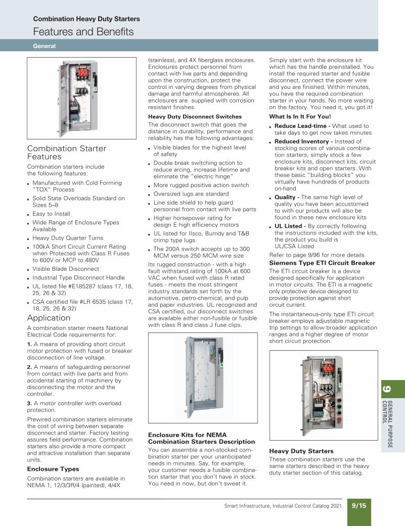
Combination Heavy Duty Starters
Features and BenefitsGeneral
Combination Starter FeaturesCombination starters include the following features:
b Manufactured with Cold Forming “TOX” Process
b Solid State Overloads Standard on Sizes 5–8
b Easy to Install
b Wide Range of Enclosure Types Available
b Heavy Duty Quarter Turns
b 100kA Short Circuit Current Rating when Protected with Class R Fuses to 600V or MCP to 480V
b Visible Blade Disconnect
b Industrial Type Disconnect Handle
b UL listed file #E185287 (class 17, 18, 25, 26 & 32)
b CSA certified file #LR 6535 (class 17, 18, 25, 26 & 32)
ApplicationA combination starter meets National Electrical Code requirements for:
1. A means of providing short circuit motor protection with fused or breaker disconnection of line voltage.
2. A means of safeguarding personnel from contact with live parts and from accidental starting of machinery by disconnecting the motor and the controller.
3. A motor controller with overload protection.
Prewired combination starters eliminate the cost of wiring between separate disconnect and starter. Factory testing assures field performance. Combination starters also provide a more compact and attractive installation than separate units.
Enclosure Types
Combination starters are available in NEMA 1, 12/3/3R/4 (painted), 4/4X
(stainless), and 4X fiberglass enclosures. Enclosures protect personnel from contact with live parts and depending upon the construction, protect the control in varying degrees from physical damage and harmful atmospheres. All enclosures are supplied with corrosion resistant finishes.
Heavy Duty Disconnect SwitchesThe disconnect switch that goes the distance in durability, performance and reliability has the following advantages:
b Visible blades for the highest level of safety
b Double break switching action to reduce arcing, increase lifetime and eliminate the “electric hinge”
b More rugged positive action switch
b Oversized lugs are standard
b Line side shield to help guard personnel from contact with live parts
b Higher horsepower rating for design E high efficiency motors
b UL listed for IIsco, Burndy and T&B crimp type lugs
b The 200A switch accepts up to 300 MCM versus 250 MCM wire size
Its rugged construction - with a high fault withstand rating of 100kA at 600 VAC when fused with class R rated fuses - meets the most stringent industry standards set forth by the automotive, petro-chemical, and pulp and paper industries. UL recognized and CSA certified, our disconnect switches are available either non-fusible or fusible with class R and class J fuse clips.
Enclosure Kits for NEMA Combination Starters DescriptionYou can assemble a non-stocked com-bination starter per your unanticipated needs in minutes. Say, for example, your customer needs a fusible combina-tion starter that you don’t have in stock. You need in now, but don’t sweat it.
Simply start with the enclosure kit which has the handle preinstalled. You install the required starter and fusible disconnect, connect the power wire and you are finished. Within minutes, you have the required combination starter in your hands. No more waiting on the factory. You need it, you got it!
What Is In It For You!
b Reduce Lead-time - What used to take days to get now takes minutes
b Reduced Inventory - Instead of stocking scores of various combina-tion starters, simply stock a few enclosure kits, disconnect kits, circuit breaker kits and open starters. With these basic “building blocks” you virtually have hundreds of products on-hand
b Quality - The same high level of quality you have been accustomed to with our products will also be found in these new enclosure kits
b UL Listed - By correctly following the instructions included with the kits, the product you build is UL/CSA Listed
Refer to page 9/96 for more details.Siemens Type ETI Circuit BreakerThe ETI circuit breaker is a device designed specifically for application in motor circuits. The ETI is a magnetic only protective device designed to provide protection against short circuit current.
The instantaneous-only type ETI circuit breaker employs adjustable magnetic trip settings to allow broader application ranges and a higher degree of motor short circuit protection.
Heavy Duty StartersThese combination starters use the same starters described in the heavy duty starter section of this catalog.
updated in SPEEDFAXRevised on 03/31/20
SS copied this page from SF to IC on 05/24/20
9G
ener
al
PurP
ose
Co
ntr
ol
9/16 Smart Infrastructure, Industrial Control Catalog 2021
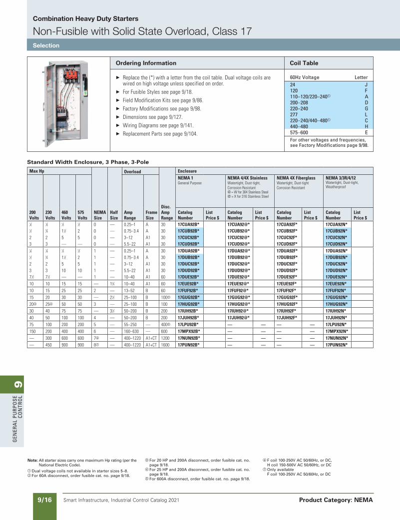
Combination Heavy Duty Starters
Non-Fusible with Solid State Overload, Class 17Selection
Product Category: NEMA
Ordering Information
Replacethe(*)withaletterfromthecoiltable.Dualvoltagecoilsarewiredonhighvoltageunlessspecifiedonorder.
ForFusibleStylesseepage9/18. FieldModificationKitsseepage9/86. FactoryModificationsseepage9/98. Dimensionsseepage9/127. WiringDiagramsseepage9/141. ReplacementPartsseepage9/104.
Coil Table
60Hz Voltage letter 24 J 120 F 110–120/220–240a a 200–208 D 220–240 G 277 l 220–240/440–480a C 440–480 H 575–600 e For other voltages and frequencies,
see Factory Modifications page 9/98.
Standard Width Enclosure, 3 Phase, 3-Pole
MaxHp
NEMASize
HalfSize
Overload
Disc.AmpRange
Enclosure
200Volts
230Volts
460Volts
575Volts
AmpRange
FrameSize
NEMA1GeneralPurpose
NEMA4/4XStainlessWatertight,Dust-tight,CorrosionResistant@=Wfor304StainlessSteel@=Xfor316StainlessSteel
NEMA4XFiberglassWatertight,Dust-tightCorrosionResistant
NEMA3/3R/4/12Watertight,Dust-tight,Weatherproof
CatalogNumber
ListPrice$
CatalogNumber
ListPrice$
CatalogNumber
ListPrice$
CatalogNumber
ListPrice$
1⁄6 1⁄6 1⁄3 1⁄2 0 — 0.25–1 A 30 17CUA92B* 17CUA92@* 17CUA92F* 17CUA92N* 1⁄2 3⁄4 11⁄2 2 0 — 0.75–3.4 A 30 17CUB92B* 17CUB92@* 17CUB92F* 17CUB92N* 2 2 5 5 0 — 3–12 A1 30 17CUC92B* 17CUC92@* 17CUC92F* 17CUC92N* 3 3 — — 0 — 5.5–22 A1 30 17CUD92B* 17CUD92@* 17CUD92F* 17CUD92N* 1⁄6 1⁄6 1⁄3 1⁄2 1 — 0.25–1 A 30 17DUA92B* 17DUA92@* 17DUA92F* 17DUA92N* 1⁄2 3⁄4 11⁄2 2 1 — 0.75–3.4 A 30 17DUB92B* 17DUB92@* 17DUB92F* 17DUB92N* 2 2 5 5 1 — 3–12 A1 30 17DUC92B* 17DUC92@* 17DUC92F* 17DUC92N* 3 3 10 10 1 — 5.5–22 A1 30 17DUD92B* 17DUD92@* 17DUD92F* 17DUD92N* 71⁄2 71⁄2 — — 1 — 10–40 A1 60 17DUE92B* 17DUE92@* 17DUE92F* 17DUE92N* 10 10 15 15 — 13⁄4 10–40 A1 60 17EUE92B* 17EUE92@* 17EUE92F* 17EUE92N* 10 15 25 25 2 — 13–52 B 60 17FUF92B* 17FUF92@* 17FUF92F* 17FUF92N* 15 20 30 30 — 21⁄2 25–100 B 100b 17GUG92B* 17GUG92@* 17GUG92F* 17GUG92N* 20c 25d 50 50 3 — 25–100 B 100 17HUG92B* 17HUG92@* 17HUG92F* 17HUG92N* 30 40 75 75 — 31⁄2 50–200 B 200 17IUH92B* 17IUH92@* 17IUH92F* 17IUH92N* 40 50 100 100 4 — 50–200 B 200 17JUH92B* 17JUH92@* 17JUH92F* 17JUH92N* 75 100 200 200 5 — 55–250 — 400e 17LPU92B* — — — — 17LPU92N* 150 200 400 400 6 — 160–630 — 600 17MPX92B* — — — — 17MPX92N* — 300 600 600 7 — 400–1220 A1+CT 1200 17NUN92B* — — — — 17NUN92N* — 450 900 900 8g — 400–1220 A1+CT 1600 17PUN92B* — — — — 17PUN92N*
Note: All starter sizes carry one maximum Hp rating (per the National Electric Code).
a Dual voltage coils not available in starter sizes 5–8.b For 60A disconnect, order fusible cat. no. page 9/18.
c For 20 HP and 200A disconnect, order fusible cat. no. page 9/18.
d For 25 HP and 200A disconnect, order fusible cat. no. page 9/18.
e For 600A disconnect, order fusible cat. no. page 9/18.
F coil 100-250V AC 50/60Hz, or DC, H coil 150-500V AC 50/60Hz, or DC
g Only availableF coil 100-250V AC 50/60Hz, or DC
updated in SPEEDFAXRevised on 03/31/20
SS copied this page from SF to IC on 05/24/20
9G
enera
l PurPo
se Co
ntro
l
9/17Smart Infrastructure, Industrial Control Catalog 2021
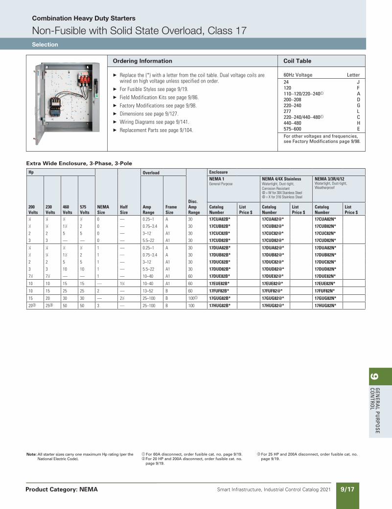
Combination Heavy Duty Starters
Non-Fusible with Solid State Overload, Class 17Selection
Product Category: NEMA
SS copied this page from SF to IC on 05/24/20
Note: All starter sizes carry one maximum Hp rating (per the National Electric Code).
a For 60A disconnect, order fusible cat. no. page 9/19.b For 20 HP and 200A disconnect, order fusible cat. no.
page 9/19.
c For 25 HP and 200A disconnect, order fusible cat. no. page 9/19.
Ordering Information
Replacethe(*)withaletterfromthecoiltable.Dualvoltagecoilsarewiredonhighvoltageunlessspecifiedonorder.
ForFusibleStylesseepage9/19. FieldModificationKitsseepage9/86. FactoryModificationsseepage9/98. Dimensionsseepage9/127. WiringDiagramsseepage9/141. ReplacementPartsseepage9/104.
Coil Table
60Hz Voltage letter 24 J 120 F 110–120/220–240a a 200–208 D 220–240 G 277 l 220–240/440–480a C 440–480 H 575–600 e For other voltages and frequencies,
see Factory Modifications page 9/98.
Extra Wide Enclosure, 3-Phase, 3-Pole
Hp
NEMASize
HalfSize
Overload
Disc.AmpRange
Enclosure
200Volts
230Volts
460Volts
575Volts
AmpRange
FrameSize
NEMA1GeneralPurpose
NEMA4/4XStainlessWatertight,Dust-tight,CorrosionResistant@=Wfor304StainlessSteel@=Xfor316StainlessSteel
NEMA3/3R/4/12Watertight,Dust-tight,Weatherproof
CatalogNumber
ListPrice$
CatalogNumber
ListPrice$
CatalogNumber
ListPrice$
1⁄6 1⁄6 1⁄3 1⁄2 0 — 0.25–1 A 30 17CUA82B* 17CUA82@* 17CUA82N* 1⁄2 3⁄4 11⁄2 2 0 — 0.75–3.4 A 30 17CUB82B* 17CUB82@* 17CUB82N*
2 2 5 5 0 — 3–12 A1 30 17CUC82B* 17CUC82@* 17CUC82N*
3 3 — — 0 — 5.5–22 A1 30 17CUD82B* 17CUD82@* 17CUD82N* 1⁄6 1⁄6 1⁄3 1⁄2 1 — 0.25–1 A 30 17DUA82B* 17DUA82@* 17DUA82N* 1⁄2 3⁄4 11⁄2 2 1 — 0.75–3.4 A 30 17DUB82B* 17DUB82@* 17DUB82N*
2 2 5 5 1 — 3–12 A1 30 17DUC82B* 17DUC82@* 17DUC82N*
3 3 10 10 1 — 5.5–22 A1 30 17DUD82B* 17DUD82@* 17DUD82N*
71⁄2 71⁄2 — — 1 — 10–40 A1 60 17DUE82B* 17DUE82@* 17DUE82N*
10 10 15 15 — 13⁄4 10–40 A1 60 17EUE82B* 17EUE82@* 17EUE82N*
10 15 25 25 2 — 13–52 B 60 17FUF82B* 17FUF82@* 17FUF82N*
15 20 30 30 — 21⁄2 25–100 B 100a 17GUG82B* 17GUG82@* 17GUG82N*
20b 25c 50 50 3 — 25–100 B 100 17HUG82B* 17HUG82@* 17HUG82N*
updated in SPEEDFAXRevised on 03/31/20
9G
ener
al
PurP
ose
Co
ntr
ol
9/18 Smart Infrastructure, Industrial Control Catalog 2021
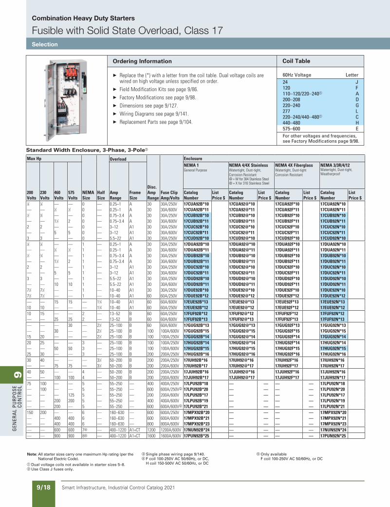
Combination Heavy Duty Starters
Fusible with Solid State Overload, Class 17Selection
updated in SPEEDFAXRevised on 03/31/20
SS copied this page from SF to IC on 05/24/20
Note: All starter sizes carry one maximum Hp rating (per the National Electric Code).
a Dual voltage coils not available in starter sizes 5–8.b Use Class J fuses only.
c Single phase wiring page 9/140.d F coil 100-250V AC 50/60Hz, or DC,
H coil 150-500V AC 50/60Hz, or DC
e Only availableF coil 100-250V AC 50/60Hz, or DC
Ordering Information
Replacethe(*)withaletterfromthecoiltable.Dualvoltagecoilsarewiredonhighvoltageunlessspecifiedonorder.
FieldModificationKitsseepage9/86. FactoryModificationsseepage9/98. Dimensionsseepage9/127. WiringDiagramsseepage9/141. ReplacementPartsseepage9/104.
Coil Table
60Hz Voltage letter 24 J 120 F 110–120/220–240a a 200–208 D 220–240 G 277 l 220–240/440–480a C 440–480 H 575–600 e For other voltages and frequencies,
see Factory Modifications page 9/98.
Standard Width Enclosure, 3-Phase, 3-Polec
MaxHp
NEMASize
HalfSize
Overload
Disc.AmpRange
FuseClipAmp/Volts
Enclosure
200Volts
230Volts
460Volts
575Volts
AmpRange
FrameSize
NEMA1GeneralPurpose
NEMA4/4XStainlessWatertight,Dust-tight,CorrosionResistant@=Wfor304StainlessSteel@=Xfor316StainlessSteel
NEMA4XFiberglassWatertight,Dust-tightCorrosionResistant
NEMA3/3R/4/12Watertight,Dust-tight,Weatherproof
CatalogNumber
ListPrice$
CatalogNumber
ListPrice$
CatalogNumber
ListPrice$
CatalogNumber
ListPrice$
1⁄6 1⁄6 — — 0 — 0.25–1 A 30 30A/250V 17CUA92B*10 17CUA92@*10 17CUA92F*10 17CUA92N*10 — — 1⁄3 1⁄2 0 — 0.25–1 A 30 30A/600V 17CUA92B*11 17CUA92@*11 17CUA92F*11 17CUA92N*11 1⁄2 3⁄4 — — 0 — 0.75–3.4 A 30 30A/250V 17CUB92B*10 17CUB92@*10 17CUB92F*10 17CUB92N*10 — — 11⁄2 2 0 — 0.75–3.4 A 30 30A/600V 17CUB92B*11 17CUB92@*11 17CUB92F*11 17CUB92N*11 2 2 — — 0 — 3–12 A1 30 30A/250V 17CUC92B*10 17CUC92@*10 17CUC92F*10 17CUC92N*10 — — 5 5 0 — 3–12 A1 30 30A/600V 17CUC92B*11 17CUC92@*11 17CUC92F*11 17CUC92N*11 3 3 — — 0 — 5.5–22 A1 30 30A/250V 17CUD92B*10 17CUD92@*10 17CUD92F*10 17CUD92N*10 1⁄6 1⁄6 — — 1 — 0.25–1 A 30 30A/250V 17DUA92B*10 17DUA92@*10 17DUA92F*10 17DUA92N*10 — — 1⁄3 1⁄2 1 — 0.25–1 A 30 30A/600V 17DUA92B*11 17DUA92@*11 17DUA92F*11 17DUA92N*11 1⁄2 3⁄4 — — 1 — 0.75–3.4 A 30 30A/250V 17DUB92B*10 17DUB92@*10 17DUB92F*10 17DUB92N*10 — — 11⁄2 2 1 — 0.75–3.4 A 30 30A/600V 17DUB92B*11 17DUB92@*11 17DUB92F*11 17DUB92N*11 2 2 — — 1 — 3–12 A1 30 30A/250V 17DUC92B*10 17DUC92@*10 17DUC92F*10 17DUC92N*10 — — 5 5 1 — 3–12 A1 30 30A/600V 17DUC92B*11 17DUC92@*11 17DUC92F*11 17DUC92N*11 3 3 — — 1 — 5.5–22 A1 30 30A/250V 17DUD92B*10 17DUD92@*10 17DUD92F*10 17DUD92N*10 — — 10 10 1 — 5.5–22 A1 30 30A/600V 17DUD92B*11 17DUD92@*11 17DUD92F*11 17DUD92N*11 71⁄2 71⁄2 — — 1 — 10–40 A1 30 30A/250V 17DUE92B*10 17DUE92@*10 17DUE92F*10 17DUE92N*10 71⁄2 71⁄2 — — 1 — 10–40 A1 60 60A/250V 17DUE92B*12 17DUE92@*12 17DUE92F*12 17DUE92N*12 — — 15 15 — 13⁄4 10–40 A1 60 60A/600V 17EUE92B*13 17EUE92@*13 17EUE92F*13 17EUE92N*13 10 10 — — — 13⁄4 10–40 A1 60 60A/250V 17EUE92B*12 17EUE92@*12 17EUE92F*12 17EUE92N*12 10 15 — — 2 — 13–52 B 60 60A/250V 17FUF92B*12 17FUF92@*12 17FUF92F*12 17FUF92N*12 — — 25 25 2 — 13–52 B 60 60A/600V 17FUF92B*13 17FUF92@*13 17FUF92F*13 17FUF92N*13 — — — 30 — 21⁄2 25–100 B 60 60A/600V 17GUG92B*13 17GUG92@*13 17GUG92F*13 17GUG92N*13 — — 30 — — 21⁄2 25–100 B 100 100A/600V 17GUG92B*15 17GUG92@*15 17GUG92F*15 17GUG92N*15 15 20 — — — 21⁄2 25–100 B 100 100A/250V 17GUG92B*14 17GUG92@*14 17GUG92F*14 17GUG92N*14 20 25 — — 3 — 25–100 B 100 100A/250V 17HUG92B*14 17HUG92@*14 17HUG92F*14 17HUG92N*14 — — 50 50 3 — 25–100 B 100 100A/600V 17HUG92B*15 17HUG92@*15 17HUG92F*15 17HUG92N*15 25 30 — — 3 — 25–100 B 200 200A/250V 17HUG92B*16 17HUG92@*16 17HUG92F*16 17HUG92N*16 30 40 — — — 31⁄2 50–200 B 200 200A/250V 17IUH92B*16 17IUH92@*16 17IUH92F*16 17IUH92N*16 — — 75 75 — 31⁄2 50–200 B 200 200A/600V 17IUH92B*17 17IUH92@*17 17IUH92F*17 17IUH92N*17 40 50 — — 4 — 50–200 B 200 200A/250V 17JUH92B*16 17JUH92@*16 17JUH92F*16 17JUH92N*16 — — 100 100 4 — 50–200 B 200 200A/600V 17JUH92B*17 17JUH92@*17 17JUH92F*17 17JUH92N*17 75 100 — — 5 — 55–250 — 400 400A/250V 17LPU92B*18 — — — — 17LPU92N*18 — 100 — — 5 — 55–250 — 600 600A/250Vb 17LPU92B*20 — — — — 17LPU92N*20 — — — 125 5 — 55–250 — 200 200A/600V 17LPU92B*17 — — — — 17LPU92N*17 — — 200 200 5 — 55–250 — 400 400A/600V 17LPU92B*19 — — — — 17LPU92N*19 — — 200 — 5 — 55–250 — 600 600A/600Vb 17LPU92B*21 — — — — 17LPU92N*21 150 200 — — 6 — 160–630 — 600 600A/250V 17MPX92B*20 — — — — 17MPX92N*20 — — 400 400 6 — 160–630 — 600 600A/600V 17MPX92B*21 — — — — 17MPX92N*21 — — 400 400 6 — 160–630 — 800 800A/600V 17MPX92B*23 — — — — 17MPX92N*23 — — 600 600 7d — 400–1220 A1+CT 1200 1200A/600V 17NUN92B*24 — — — — 17NUN92N*24 — — 900 900 8e — 400–1220 A1+CT 1600 1600A/600V 17PUN92B*25 — — — — 17PUN92N*25
9G
enera
l PurPo
se Co
ntro
l
9/19Smart Infrastructure, Industrial Control Catalog 2021
Combination Heavy Duty Starters
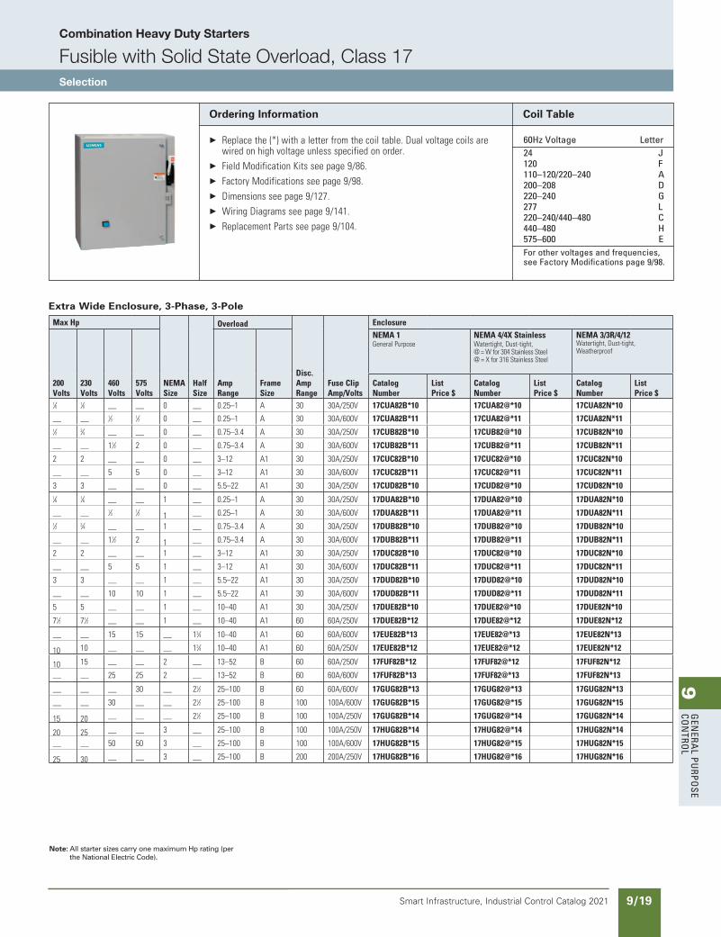
Fusible with Solid State Overload, Class 17Selection
updated in SPEEDFAXRevised on 03/31/20
SS copied this page from SF to IC on 05/24/20
Note: All starter sizes carry one maximum Hp rating (per the National Electric Code).
Ordering Information
Replacethe(*)withaletterfromthecoiltable.Dualvoltagecoilsarewiredonhighvoltageunlessspecifiedonorder.
FieldModificationKitsseepage9/86. FactoryModificationsseepage9/98. Dimensionsseepage9/127. WiringDiagramsseepage9/141. ReplacementPartsseepage9/104.
Coil Table
60Hz Voltage letter 24 J 120 F 110–120/220–240 a 200–208 D 220–240 G 277 l 220–240/440–480 C 440–480 H 575–600 e For other voltages and frequencies,
see Factory Modifications page 9/98.
Extra Wide Enclosure, 3-Phase, 3-Pole
MaxHp
NEMASize
HalfSize
Overload
Disc.AmpRange
FuseClipAmp/Volts
Enclosure
200Volts
230Volts
460Volts
575Volts
AmpRange
FrameSize
NEMA1GeneralPurpose
NEMA4/4XStainlessWatertight,Dust-tight,@=Wfor304StainlessSteel@=Xfor316StainlessSteel
NEMA3/3R/4/12Watertight,Dust-tight,Weatherproof
CatalogNumber
ListPrice$
CatalogNumber
ListPrice$
CatalogNumber
ListPrice$
1⁄6 1⁄6 — — 0 — 0.25–1 A 30 30A/250V 17CUA82B*10 17CUA82@*10 17CUA82N*10
— —1⁄3 1⁄2 0 — 0.25–1 A 30 30A/600V 17CUA82B*11 17CUA82@*11 17CUA82N*11
1⁄2 3⁄4 — — 0 — 0.75–3.4 A 30 30A/250V 17CUB82B*10 17CUB82@*10 17CUB82N*10
— — 11⁄2 2 0 — 0.75–3.4 A 30 30A/600V 17CUB82B*11 17CUB82@*11 17CUB82N*11
2 2 — — 0 — 3–12 A1 30 30A/250V 17CUC82B*10 17CUC82@*10 17CUC82N*10
— — 5 5 0 — 3–12 A1 30 30A/600V 17CUC82B*11 17CUC82@*11 17CUC82N*11
3 3 — — 0 — 5.5–22 A1 30 30A/250V 17CUD82B*10 17CUD82@*10 17CUD82N*10 1⁄6 1⁄6 — — 1 — 0.25–1 A 30 30A/250V 17DUA82B*10 17DUA82@*10 17DUA82N*10
— —1⁄3 1⁄2 1 — 0.25–1 A 30 30A/600V 17DUA82B*11 17DUA82@*11 17DUA82N*11
1⁄2 3⁄4 — — 1 — 0.75–3.4 A 30 30A/250V 17DUB82B*10 17DUB82@*10 17DUB82N*10
— — 11⁄2 2 1 — 0.75–3.4 A 30 30A/600V 17DUB82B*11 17DUB82@*11 17DUB82N*11
2 2 — — 1 — 3–12 A1 30 30A/250V 17DUC82B*10 17DUC82@*10 17DUC82N*10
— — 5 5 1 — 3–12 A1 30 30A/600V 17DUC82B*11 17DUC82@*11 17DUC82N*11
3 3 — — 1 — 5.5–22 A1 30 30A/250V 17DUD82B*10 17DUD82@*10 17DUD82N*10
— — 10 10 1 — 5.5–22 A1 30 30A/600V 17DUD82B*11 17DUD82@*11 17DUD82N*11
5 5 — — 1 — 10–40 A1 30 30A/250V 17DUE82B*10 17DUE82@*10 17DUE82N*10
71⁄2 71⁄2 — — 1 — 10–40 A1 60 60A/250V 17DUE82B*12 17DUE82@*12 17DUE82N*12
— — 15 15 — 13⁄4 10–40 A1 60 60A/600V 17EUE82B*13 17EUE82@*13 17EUE82N*13
10 10 — — — 13⁄4 10–40 A1 60 60A/250V 17EUE82B*12 17EUE82@*12 17EUE82N*12
10 15 — — 2 — 13–52 B 60 60A/250V 17FUF82B*12 17FUF82@*12 17FUF82N*12
— — 25 25 2 — 13–52 B 60 60A/600V 17FUF82B*13 17FUF82@*13 17FUF82N*13
— — — 30 — 21⁄2 25–100 B 60 60A/600V 17GUG82B*13 17GUG82@*13 17GUG82N*13
— — 30 — — 21⁄2 25–100 B 100 100A/600V 17GUG82B*15 17GUG82@*15 17GUG82N*15
15 20 — — — 21⁄2 25–100 B 100 100A/250V 17GUG82B*14 17GUG82@*14 17GUG82N*14
20 25 — — 3 — 25–100 B 100 100A/250V 17HUG82B*14 17HUG82@*14 17HUG82N*14
— — 50 50 3 — 25–100 B 100 100A/600V 17HUG82B*15 17HUG82@*15 17HUG82N*15
25 30 — — 3 — 25–100 B 200 200A/250V 17HUG82B*16 17HUG82@*16 17HUG82N*16
9G
ener
al
PurP
ose
Co
ntr
ol
9/20 Smart Infrastructure, Industrial Control Catalog 2021
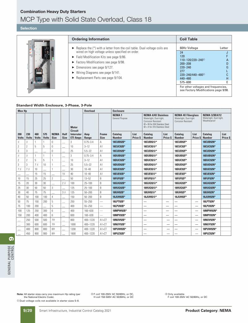
Combination Heavy Duty Starters
MCP Type with Solid State Overload, Class 18Selection
Product Category: NEMA
updated in SPEEDFAXRevised on 03/31/20
SS copied this page from SF to IC on 05/24/20
Note: All starter sizes carry one maximum Hp rating (per the National Electric Code).
a Dual voltage coils not available in starter sizes 5–8.
b F coil 100-250V AC 50/60Hz, or DC, H coil 150-500V AC 50/60Hz, or DC
c Only availableF coil 100-250V AC 50/60Hz, or DC
Ordering Information
Replacethe(*)withaletterfromthecoiltable.Dualvoltagecoilsarewiredonhighvoltageunlessspecifiedonorder.
FieldModificationKitsseepage9/86. FactoryModificationsseepage9/98. Dimensionsseepage9/127. WiringDiagramsseepage9/141. ReplacementPartsseepage9/104.
Coil Table
60Hz Voltage letter 24 J 120 F 110–120/220–240a a 200–208 D 220–240 G 277 l 220–240/440–480a C 440–480 H 575–600 e For other voltages and frequencies,
see Factory Modifications page 9/98.
Standard Width Enclosure, 3-Phase, 3-Pole
MaxHp
NEMASize
HalfSize
MotorCircuitInterruterETIAmps
Overload Enclosure
200Volts
230Volts
460Volts
575Volts
AmpRange
FrameSize
NEMA1GeneralPurpose
NEMA4/4XStainlessWatertight,Dust-tight,CorrosionResistant@=Wfor304StainlessSteel@=Xfor316StainlessSteel
NEMA4XFiberglassWatertight,Dust-tightCorrosionResistant
NEMA3/3R/4/12Watertight,Dust-tight,Weatherproof
CatalogNumber
ListPrice$
CatalogNumber
ListPrice$
CatalogNumber
ListPrice$
CatalogNumber
ListPrice$
1⁄2 1⁄2 1 1 0 — 3 0.75–3.4 A 18CUB92B* 18CUB92@* 18CUB92F* 18CUB92N*
2 2 5 5 0 — 10 3–12 A1 18CUC92B* 18CUC92@* 18CUC92F* 18CUC92N*
3 3 — — 0 — 25 5.5–22 A1 18CUD92B* 18CUD92@* 18CUD92F* 18CUD92N* 1⁄2 1⁄2 1 1 1 — 3 0.75–3.4 A 18DUB92B* 18DUB92@* 18DUB92F* 18DUB92N*
2 2 5 5 1 — 10 3–12 A1 18DUC92B* 18DUC92@* 18DUC92F* 18DUC92N*
3 3 71⁄2 10 1 — 25 5.5–22 A1 18DUD92B* 18DUD92@* 18DUD92F* 18DUD92N*
71⁄2 71⁄2 10 — 1 — 30 10–40 A1 18DUE92B* 18DUE92@* 18DUE92F* 18DUE92N*
— — 15 15 — 13⁄4 40 10–40 A1 18EUE92B* 18EUE92@* 18EUE92F* 18EUE92N*
10 15 25 25 2 — 50 13–52 B 18FUF92B* 18FUF92@* 18FUF92F* 18FUF92N*
15 20 30 30 — 21⁄2 100 25–100 B 18GUG92B* 18GUG92@* 18GUG92F* 18GUG92N*
25 30 50 50 3 — 125 25–100 B 18HUG92B* 18HUG92@* 18HUG92F* 18HUG92N*
30 40 75 75 — 31⁄2 125 50–200 B 18IUH92B* 18IUH92@* 18IUH92F* 18IUH92N*
40 50 100 100 4 — 150 50–200 B 18JUH92B* 18JUH92@* 18JUH92F* 18JUH92N*
50 75 150 200 5 — 250 55–250 — 18LPT92B* — — — — 18LPT92N*
75 100 200 — 5 — 400 55–250 — 18LPU92B* — — — — 18LPU92N*
100 125 250 300 6 — 400 160–630 — 18MPW92B* — — — — 18MPW92N*
150 200 400 400 6 — 600 160–630 — 18MPX92B* — — — — 18MPX92N*
— 250 500 500 7b — 800 400–1220 A1+CT 18NUV92B* — — — — 18NUV92N*
— 300 600 600 7b — 1000 400–1220 A1+CT 18NUY92B* — — — — 18NUY92N*
— 400 800 800 8c — 1200 400–1220 A1+CT 18PUW92B* — — — — 18PUW92N*
— 450 900 900 8c — 1600 400–1220 A1+CT 18PUZ92B* — — — — 18PUZ92N*
9G
enera
l PurPo
se Co
ntro
l
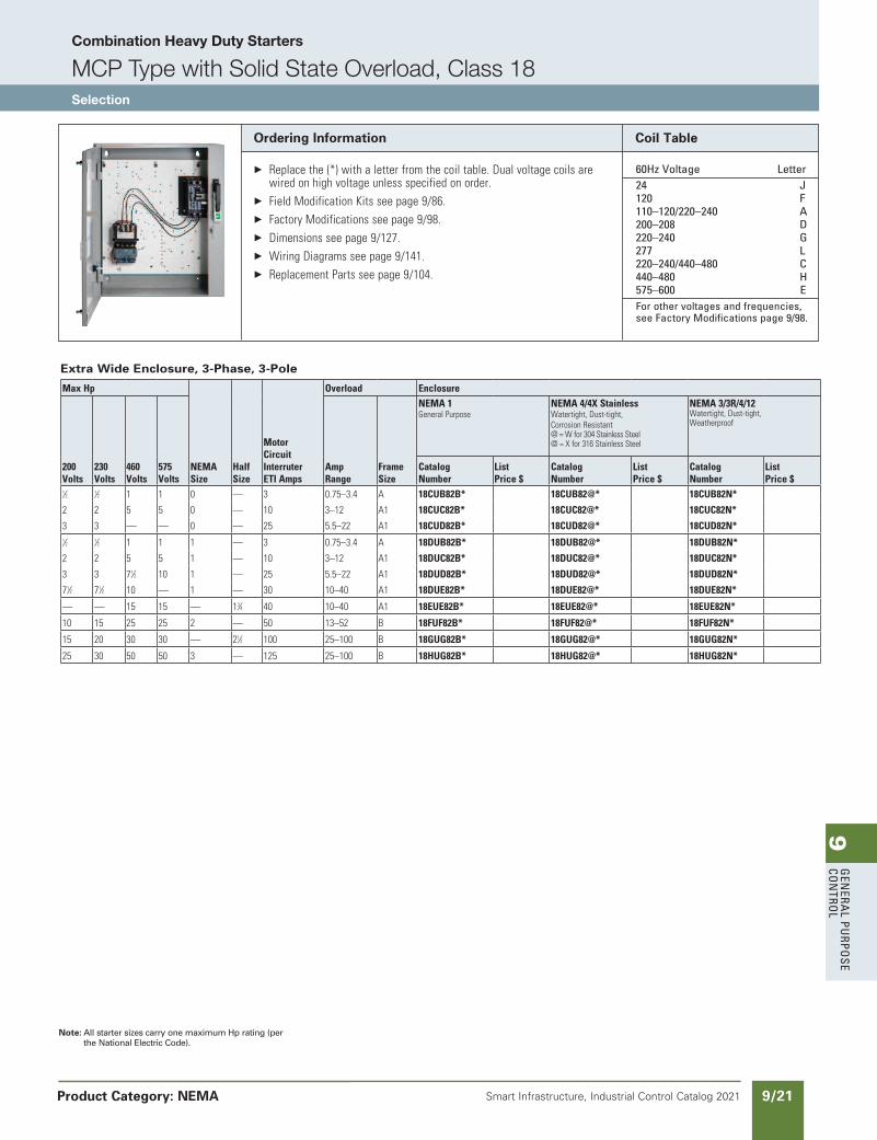
9/21Smart Infrastructure, Industrial Control Catalog 2021 Product Category: NEMA
Note: All starter sizes carry one maximum Hp rating (per the National Electric Code).
Ordering Information
Replacethe(*)withaletterfromthecoiltable.Dualvoltagecoilsarewiredonhighvoltageunlessspecifiedonorder.
FieldModificationKitsseepage9/86. FactoryModificationsseepage9/98. Dimensionsseepage9/127. WiringDiagramsseepage9/141. ReplacementPartsseepage9/104.
Coil Table
60Hz Voltage letter 24 J 120 F 110–120/220–240 a 200–208 D 220–240 G 277 l 220–240/440–480 C 440–480 H 575–600 e For other voltages and frequencies,
see Factory Modifications page 9/98.
Extra Wide Enclosure, 3-Phase, 3-Pole
MaxHp
NEMASize
HalfSize
MotorCircuitInterruterETIAmps
Overload Enclosure
200Volts
230Volts
460Volts
575Volts
AmpRange
FrameSize
NEMA1GeneralPurpose
NEMA4/4XStainlessWatertight,Dust-tight,CorrosionResistant@=Wfor304StainlessSteel@=Xfor316StainlessSteel
NEMA3/3R/4/12Watertight,Dust-tight,Weatherproof
CatalogNumber
ListPrice$
CatalogNumber
ListPrice$
CatalogNumber
ListPrice$
1⁄2 1⁄2 1 1 0 — 3 0.75–3.4 A 18CUB82B* 18CUB82@* 18CUB82N*
2 2 5 5 0 — 10 3–12 A1 18CUC82B* 18CUC82@* 18CUC82N*
3 3 — — 0 — 25 5.5–22 A1 18CUD82B* 18CUD82@* 18CUD82N* 1⁄2 1⁄2 1 1 1 — 3 0.75–3.4 A 18DUB82B* 18DUB82@* 18DUB82N*
2 2 5 5 1 — 10 3–12 A1 18DUC82B* 18DUC82@* 18DUC82N*
3 3 71⁄2 10 1 — 25 5.5–22 A1 18DUD82B* 18DUD82@* 18DUD82N*
71⁄2 71⁄2 10 — 1 — 30 10–40 A1 18DUE82B* 18DUE82@* 18DUE82N*
— — 15 15 — 13⁄4 40 10–40 A1 18EUE82B* 18EUE82@* 18EUE82N*
10 15 25 25 2 — 50 13–52 B 18FUF82B* 18FUF82@* 18FUF82N*
15 20 30 30 — 21⁄2 100 25–100 B 18GUG82B* 18GUG82@* 18GUG82N*
25 30 50 50 3 — 125 25–100 B 18HUG82B* 18HUG82@* 18HUG82N*
updated in SPEEDFAXRevised on 03/31/20
SS copied this page from SF to IC on 05/24/20
Combination Heavy Duty Starters
MCP Type with Solid State Overload, Class 18Selection
9G
ener
al
PurP
ose
Co
ntr
ol
9/22 Smart Infrastructure, Industrial Control Catalog 2021
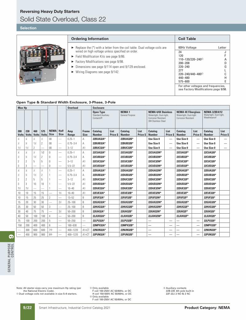
Reversing Heavy Duty Starters
Solid State Overload, Class 22Selection
Product Category: NEMA
Note: All starter sizes carry one maximum Hp rating (per the National Electric Code).
a Dual voltage coils not available in size 5–8 starters.
b Only available F coil 100-250V AC 50/60Hz, or DC H coil 150-500V AC 50/60Hz, or DC
c Only availableF coil 100-250V AC 50/60Hz, or DC
d Auxiliary contacts22B-22E 4th pole built-in 22F-22J 2 NO & 2 NC
Open Type & Standard Width Enclosure, 3-Phase, 3-Pole
MaxHp
NEMASize
HalfSize
Overload Enclosure
200Volts
230Volts
460Volts
575Volts
AmpRange
FrameSize
OpenTypeStandardAuxiliaryContactsd
NEMA1GeneralPurpose
NEMA4/4XStainlessWatertight,Dust-tight,CorrosionResistant304StainlessSteel
NEMA4XFiberglassWatertight,Dust-tightCorrosionResistant
NEMA3/3R/4/12Watertight,Dust-tight,Weatherproof
CatalogNumber
ListPrice$
CatalogNumber
ListPrice$
CatalogNumber
ListPrice$
CatalogNumber
ListPrice$
CatalogNumber
ListPrice$
1⁄6 1⁄6 1⁄3 1⁄2 00 — 0.25–1 A 22BUA32A* 22BUA32B* UseSize0 — UseSize0 — UseSize0 —1⁄2 3⁄4 11⁄2 2 00 — 0.75–3.4 A 22BUB32A* 22BUB32B* UseSize0 — UseSize0 — UseSize0 —
11⁄2 11⁄2 2 — 00 — 3–12 A1 22BUC32A* 22BUC32B* UseSize0 — UseSize0 — UseSize0 —1⁄6 1⁄6 1⁄3 1⁄2 0 — 0.25–1 A 22CUA32A* 22CUA32B* 22CUA32W* 22CUA32F* 22CUA320* 1⁄2 3⁄4 11⁄2 2 0 — 0.75–3.4 A 22CUB32A* 22CUB32B* 22CUB32W* 22CUB32F* 22CUB320*
2 2 5 5 0 — 3–12 A1 22CUC32A* 22CUC32B* 22CUC32W* 22CUC32F* 22CUC320*
3 3 — — 0 — 5.5–22 A1 22CUD32A* 22CUD32B* 22CUD32W* 22CUD32F* 22CUD320* 1⁄6 1⁄6 1⁄3 1⁄2 1 — 0.25–1 A 22DUA32A* 22DUA32B* 22DUA32W* 22DUA32F* 22DUA320* 1⁄2 3⁄4 11⁄2 2 1 — 0.75–3.4 A 22DUB32A* 22DUB32B* 22DUB32W* 22DUB32F* 22DUB320*
2 2 5 5 1 — 3–12 A1 22DUC32A* 22DUC32B* 22DUC32W* 22DUC32F* 22DUC320*
3 3 10 10 1 — 5.5–22 A1 22DUD32A* 22DUD32B* 22DUD32W* 22DUD32F* 22DUD320*
71⁄2 71⁄2 — — 1 — 10–40 A1 22DUE32A* 22DUE32B* 22DUE32W* 22DUE32F* 22DUE320*
10 10 15 15 — 13⁄4 10–40 A1 22EUE32A* 22EUE32B* 22EUE32W* 22EUE32F* 22EUE320*
10 15 25 25 2 — 13–52 B 22FUF32A* 22FUF32B* 22FUF32W* 22FUF32F* 22FUF320*
15 20 30 30 — 21⁄2 25–100 B 22GUG32A* 22GUG32B* 22GUG32W* 22GUG32F* 22GUG320*
25 30 50 50 3 — 25–100 B 22HUG32A* 22HUG32B* 22HUG32W* 22HUG32F* 22HUG320*
30 40 75 75 — 31⁄2 50–200 B 22IUH32A* 22IUH32B* 22IUH32W* 22IUH32F* 22IUH320*
40 50 100 100 4 — 50–200 B 22JUH32A* 22JUH32B* 22JUH32W* 22JUH32F* 22JUH320*
75 100 200 200 5 — 55–250 — 22LPU32A* 22LPU32B* — — — — 22LPU320*
150 200 400 400 6 — 160–630 — 22MPX32A* 22MPX32B* — — — — 22MPX320*
— 300 600 600 7b — 400–1220 A1+CT 22NUN32A* 22NUN32B* — — — — 22NUN320*
— 450 900 900 8c — 400–1220 A1+CT 22PUN32A* 22PUN32B* — — — — 22PUN320*
Ordering Information
Replacethe(*)withaletterfromthecoiltable.Dualvoltagecoilsarewiredonhighvoltageunlessspecifiedonorder.
FieldModificationKitsseepage9/86. FactoryModificationsseepage9/98. Dimensionsseepage9/114openand9/129enclosed. WiringDiagramsseepage9/142.
Coil Table
60Hz Voltage letter 24 J 120 F 110–120/220–240a a 200–208 D 220–240 G 277 l 220–240/440–480a C 440–480 H 575–600 e For other voltages and frequencies,
see Factory Modifications page 9/98.
updated in SPEEDFAXRevised on 03/31/20
SS copied this page from SF to IC on 05/24/20
9G
enera
l PurPo
se Co
ntro
l
9/23Smart Infrastructure, Industrial Control Catalog 2021
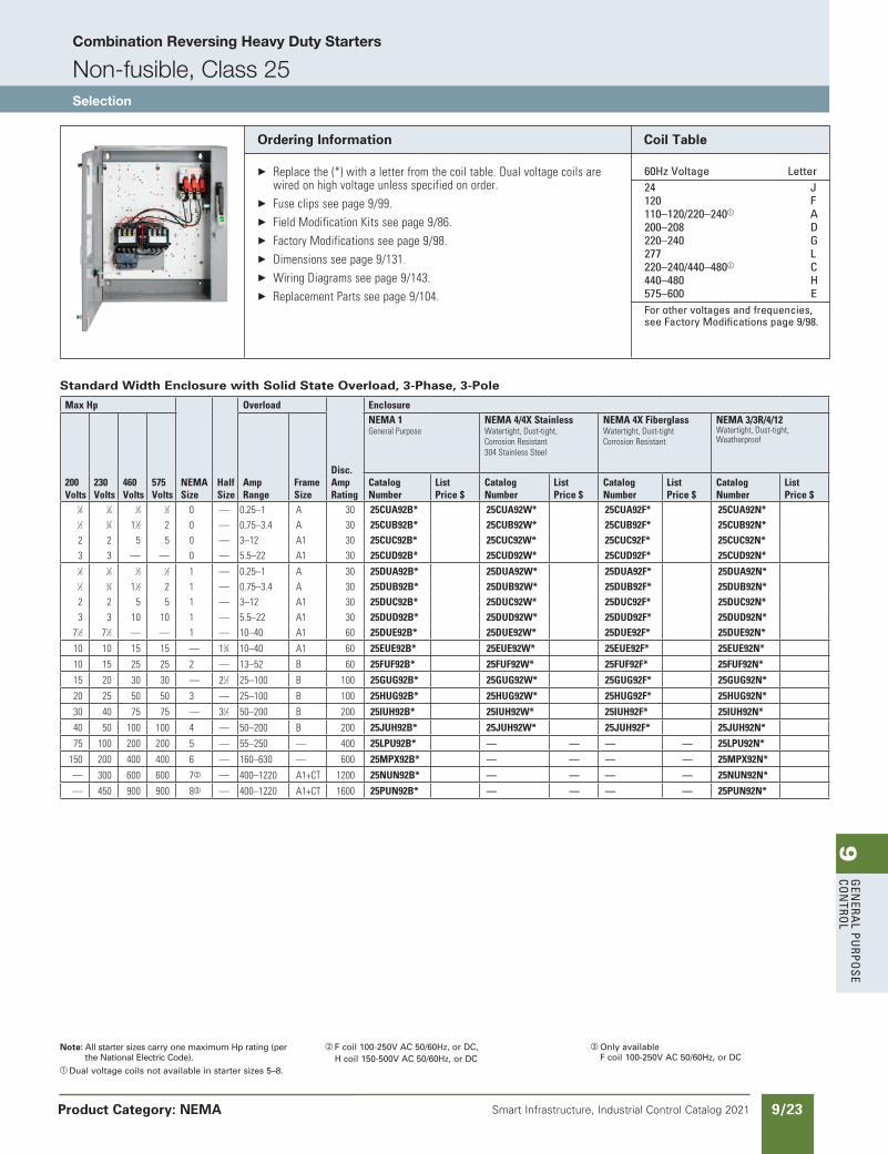
Combination Reversing Heavy Duty Starters
Non-fusible, Class 25Selection
Product Category: NEMA
updated in SPEEDFAXRevised on 03/31/20
SS copied this page from SF to IC on 05/24/20
Note: All starter sizes carry one maximum Hp rating (per the National Electric Code).
a Dual voltage coils not available in starter sizes 5–8.
b F coil 100-250V AC 50/60Hz, or DC, H coil 150-500V AC 50/60Hz, or DC
c Only availableF coil 100-250V AC 50/60Hz, or DC
Ordering Information
Replacethe(*)withaletterfromthecoiltable.Dualvoltagecoilsarewiredonhighvoltageunlessspecifiedonorder.
Fuseclipsseepage9/99. FieldModificationKitsseepage9/86. FactoryModificationsseepage9/98. Dimensionsseepage9/131. WiringDiagramsseepage9/143. ReplacementPartsseepage9/104.
Coil Table
60Hz Voltage letter 24 J 120 F 110–120/220–240a a 200–208 D 220–240 G 277 l 220–240/440–480a C 440–480 H 575–600 e For other voltages and frequencies,
see Factory Modifications page 9/98.
Standard Width Enclosure with Solid State Overload, 3-Phase, 3-Pole
MaxHp
NEMASize
HalfSize
Overload
Disc.AmpRating
Enclosure
200Volts
230Volts
460Volts
575Volts
AmpRange
FrameSize
NEMA1GeneralPurpose
NEMA4/4XStainlessWatertight,Dust-tight,CorrosionResistant304StainlessSteel
NEMA4XFiberglassWatertight,Dust-tightCorrosionResistant
NEMA3/3R/4/12Watertight,Dust-tight,Weatherproof
CatalogNumber
ListPrice$
CatalogNumber
ListPrice$
CatalogNumber
ListPrice$
CatalogNumber
ListPrice$
1⁄6 1⁄6 1⁄3 1⁄2 0 — 0.25–1 A 30 25CUA92B* 25CUA92W* 25CUA92F* 25CUA92N* 1⁄2 3⁄4 11⁄2 2 0 — 0.75–3.4 A 30 25CUB92B* 25CUB92W* 25CUB92F* 25CUB92N* 2 2 5 5 0 — 3–12 A1 30 25CUC92B* 25CUC92W* 25CUC92F* 25CUC92N* 3 3 — — 0 — 5.5–22 A1 30 25CUD92B* 25CUD92W* 25CUD92F* 25CUD92N* 1⁄6 1⁄6 1⁄3 1⁄2 1 — 0.25–1 A 30 25DUA92B* 25DUA92W* 25DUA92F* 25DUA92N* 1⁄2 3⁄4 11⁄2 2 1 — 0.75–3.4 A 30 25DUB92B* 25DUB92W* 25DUB92F* 25DUB92N* 2 2 5 5 1 — 3–12 A1 30 25DUC92B* 25DUC92W* 25DUC92F* 25DUC92N* 3 3 10 10 1 — 5.5–22 A1 30 25DUD92B* 25DUD92W* 25DUD92F* 25DUD92N*
71⁄2 71⁄2 — — 1 — 10–40 A1 60 25DUE92B* 25DUE92W* 25DUE92F* 25DUE92N*
10 10 15 15 — 13⁄4 10–40 A1 60 25EUE92B* 25EUE92W* 25EUE92F* 25EUE92N*
10 15 25 25 2 — 13–52 B 60 25FUF92B* 25FUF92W* 25FUF92F* 25FUF92N*
15 20 30 30 — 21⁄2 25–100 B 100 25GUG92B* 25GUG92W* 25GUG92F* 25GUG92N*
20 25 50 50 3 — 25–100 B 100 25HUG92B* 25HUG92W* 25HUG92F* 25HUG92N*
30 40 75 75 — 31⁄2 50–200 B 200 25IUH92B* 25IUH92W* 25IUH92F* 25IUH92N*
40 50 100 100 4 — 50–200 B 200 25JUH92B* 25JUH92W* 25JUH92F* 25JUH92N*
75 100 200 200 5 — 55–250 — 400 25LPU92B* — — — — 25LPU92N*
150 200 400 400 6 — 160–630 — 600 25MPX92B* — — — — 25MPX92N*
— 300 600 600 7b — 400–1220 A1+CT 1200 25NUN92B* — — — — 25NUN92N*
— 450 900 900 8c — 400–1220 A1+CT 1600 25PUN92B* — — — — 25PUN92N*
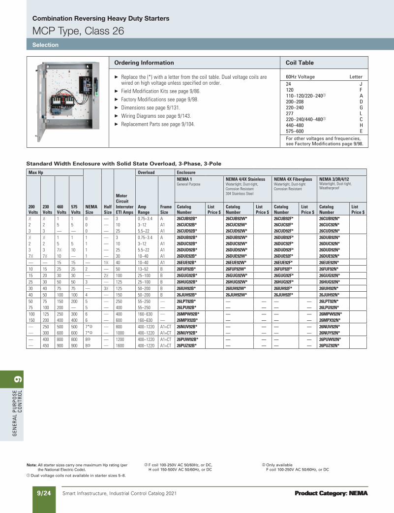
9G
ener
al
PurP
ose
Co
ntr
ol
9/24 Smart Infrastructure, Industrial Control Catalog 2021
Combination Reversing Heavy Duty Starters
MCP Type, Class 26Selection
Product Category: NEMAProduct Category: NEMA
Note: All starter sizes carry one maximum Hp rating (per the National Electric Code).
a Dual voltage coils not available in starter sizes 5–8.
b F coil 100-250V AC 50/60Hz, or DC, H coil 150-500V AC 50/60Hz, or DC
c Only availableF coil 100-250V AC 50/60Hz, or DC
Ordering Information
Replacethe(*)withaletterfromthecoiltable.Dualvoltagecoilsarewiredonhighvoltageunlessspecifiedonorder.
FieldModificationKitsseepage9/86. FactoryModificationsseepage9/98. Dimensionsseepage9/131. WiringDiagramsseepage9/143. ReplacementPartsseepage9/104.
Coil Table
60Hz Voltage letter 24 J 120 F 110–120/220–240a a 200–208 D 220–240 G 277 l 220–240/440–480a C 440–480 H 575–600 e For other voltages and frequencies,
see Factory Modifications page 9/98.
Standard Width Enclosure with Solid State Overload, 3-Phase, 3-Pole
MaxHp
NEMASize
HalfSize
MotorCircuitInterruterETIAmps
Overload Enclosure
200Volts
230Volts
460Volts
575Volts
AmpRange
FrameSize
NEMA1GeneralPurpose
NEMA4/4XStainlessWatertight,Dust-tight,CorrosionResistant304StainlessSteel
NEMA4XFiberglassWatertight,Dust-tightCorrosionResistant
NEMA3/3R/4/12Watertight,Dust-tight,Weatherproof
CatalogNumber
ListPrice$
CatalogNumber
ListPrice$
CatalogNumber
ListPrice$
CatalogNumber
ListPrice$
1⁄2 1⁄2 1 1 0 — 3 0.75–3.4 A 26CUB92B* 26CUB92W* 26CUB92F* 26CUB92N* 2 2 5 5 0 — 10 3–12 A1 26CUC92B* 26CUC92W* 26CUC92F* 26CUC92N* 3 3 — — 0 — 25 5.5–22 A1 26CUD92B* 26CUD92W* 26CUD92F* 26CUD92N* 1⁄2 1⁄2 1 1 1 — 3 0.75–3.4 A 26DUB92B* 26DUB92W* 26DUB92F* 26DUB92N* 2 2 5 5 1 — 10 3–12 A1 26DUC92B* 26DUC92W* 26DUC92F* 26DUC92N* 3 3 71⁄2 10 1 — 25 5.5–22 A1 26DUD92B* 26DUD92W* 26DUD92F* 26DUD92N* 71⁄2 71⁄2 10 — 1 — 30 10–40 A1 26DUE92B* 26DUE92W* 26DUE92F* 26DUE92N* — — 15 15 — 13⁄4 40 10–40 A1 26EUE92B* 26EUE92W* 26EUE92F* 26EUE92N* 10 15 25 25 2 — 50 13–52 B 26FUF92B* 26FUF92W* 26FUF92F* 26FUF92N* 15 20 30 30 — 21⁄2 100 25–100 B 26GUG92B* 26GUG92W* 26GUG92F* 26GUG92N* 25 30 50 50 3 — 125 25–100 B 26HUG92B* 26HUG92W* 26HUG92F* 26HUG92N* 30 40 75 75 — 31⁄2 125 50–200 B 26IUH92B* 26IUH92W* 26IUH92F* 26IUH92N* 40 50 100 100 4 — 150 50–200 B 26JUH92B* 26JUH92W* 26JUH92F* 26JUH92N* 50 75 150 200 5 — 250 55–250 — 26LPT92B* — — — — 26LPT92N* 75 100 200 — 5 — 400 55–250 — 26LPU92B* — — — — 26LPU92N* 100 125 250 300 6 — 400 160–630 — 26MPW92B* — — — — 26MPW92N* 150 200 400 400 6 — 600 160–630 — 26MPX92B* — — — — 26MPX92N* — 250 500 500 7*b — 800 400–1220 A1+CT 26NUV92B* — — — — 26NUV92N* — 300 600 600 7*b — 1000 400–1220 A1+CT 26NUY92B* — — — — 26NUY92N* — 400 800 800 8c — 1200 400–1220 A1+CT 26PUW92B* — — — — 26PUW92N* — 450 900 900 8c — 1600 400–1220 A1+CT 26PUZ92B* — — — — 26PUZ92N*
updated in SPEEDFAXRevised on 03/31/20
SS copied this page from SF to IC on 05/24/20
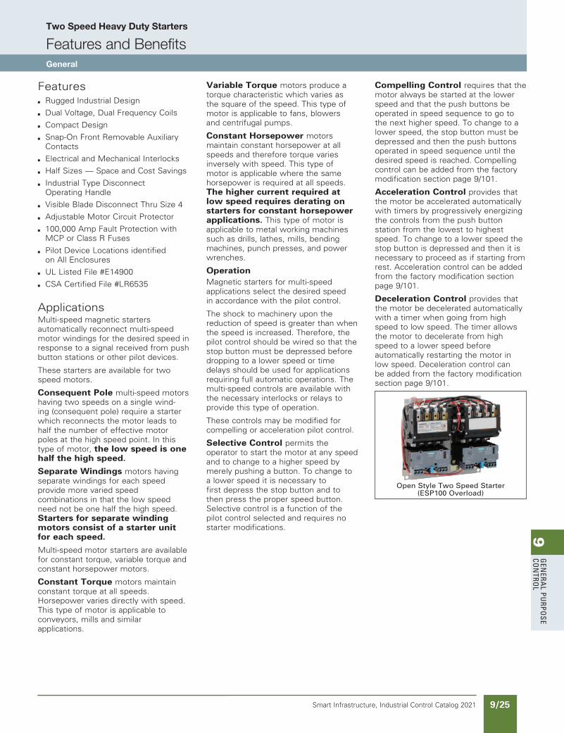
9G
enera
l PurPo
se Co
ntro
l
9/25Smart Infrastructure, Industrial Control Catalog 2021
Two Speed Heavy Duty Starters
Features and BenefitsGeneral
Featuresb Rugged Industrial Design
b Dual Voltage, Dual Frequency Coils
b Compact Design
b Snap-On Front Removable Auxiliary Contacts
b Electrical and Mechanical Interlocks
b Half Sizes — Space and Cost Savings
b Industrial Type Disconnect Operating Handle
b Visible Blade Disconnect Thru Size 4
b Adjustable Motor Circuit Protector
b 100,000 Amp Fault Protection with MCP or Class R Fuses
b Pilot Device Locations identified on All Enclosures
b UL Listed File #E14900
b CSA Certified File #LR6535
ApplicationsMulti-speed magnetic starters automatically reconnect multi-speed motor windings for the desired speed in response to a signal received from push button stations or other pilot devices.
These starters are available for two speed motors.
Consequent Pole multi-speed motors having two speeds on a single wind-ing (consequent pole) require a starter which reconnects the motor leads to half the number of effective motor poles at the high speed point. In this type of motor, the low speed is one half the high speed.
Separate Windings motors having separate windings for each speed provide more varied speed combinations in that the low speed need not be one half the high speed. Starters for separate winding motors consist of a starter unit for each speed.
Multi-speed motor starters are available for constant torque, variable torque and constant horsepower motors.
Constant Torque motors maintain constant torque at all speeds. Horsepower varies directly with speed. This type of motor is applicable to conveyors, mills and similar applications.
Variable Torque motors produce a torque characteristic which varies as the square of the speed. This type of motor is applicable to fans, blowers and centrifugal pumps.
Constant Horsepower motors maintain constant horsepower at all speeds and therefore torque varies inversely with speed. This type of motor is applicable where the same horsepower is required at all speeds. The higher current required at low speed requires derating on starters for constant horsepower applications. This type of motor is applicable to metal working machines such as drills, lathes, mills, bending machines, punch presses, and power wrenches.
OperationMagnetic starters for multi-speed applications select the desired speed in accordance with the pilot control.
The shock to machinery upon the reduction of speed is greater than when the speed is increased. Therefore, the pilot control should be wired so that the stop button must be depressed before dropping to a lower speed or time delays should be used for applications requiring full automatic operations. The multi-speed controls are available with the necessary interlocks or relays to provide this type of operation.
These controls may be modified for compelling or acceleration pilot control.
Selective Control permits the operator to start the motor at any speed and to change to a higher speed by merely pushing a button. To change to a lower speed it is necessary to first depress the stop button and to then press the proper speed button. Selective control is a function of the pilot control selected and requires no starter modifications.
Compelling Control requires that the motor always be started at the lower speed and that the push buttons be operated in speed sequence to go to the next higher speed. To change to a lower speed, the stop button must be depressed and then the push buttons operated in speed sequence until the desired speed is reached. Compelling control can be added from the factory modification section page 9/101.
Acceleration Control provides that the motor be accelerated auto matically with timers by progressively energizing the controls from the push button station from the lowest to highest speed. To change to a lower speed the stop button is depressed and then it is necessary to proceed as if starting from rest. Acceleration control can be added from the factory modification section page 9/101.
Deceleration Control provides that the motor be decelerated auto matically with a timer when going from high speed to low speed. The timer allows the motor to decelerate from high speed to a lower speed before automatically restarting the motor in low speed. Deceleration control can be added from the factory modification section page 9/101.
Open Style Two Speed Starter (ESP100 Overload)
updated in SPEEDFAXRevised on 03/31/20
SS copied this page from SF to IC on 05/24/20
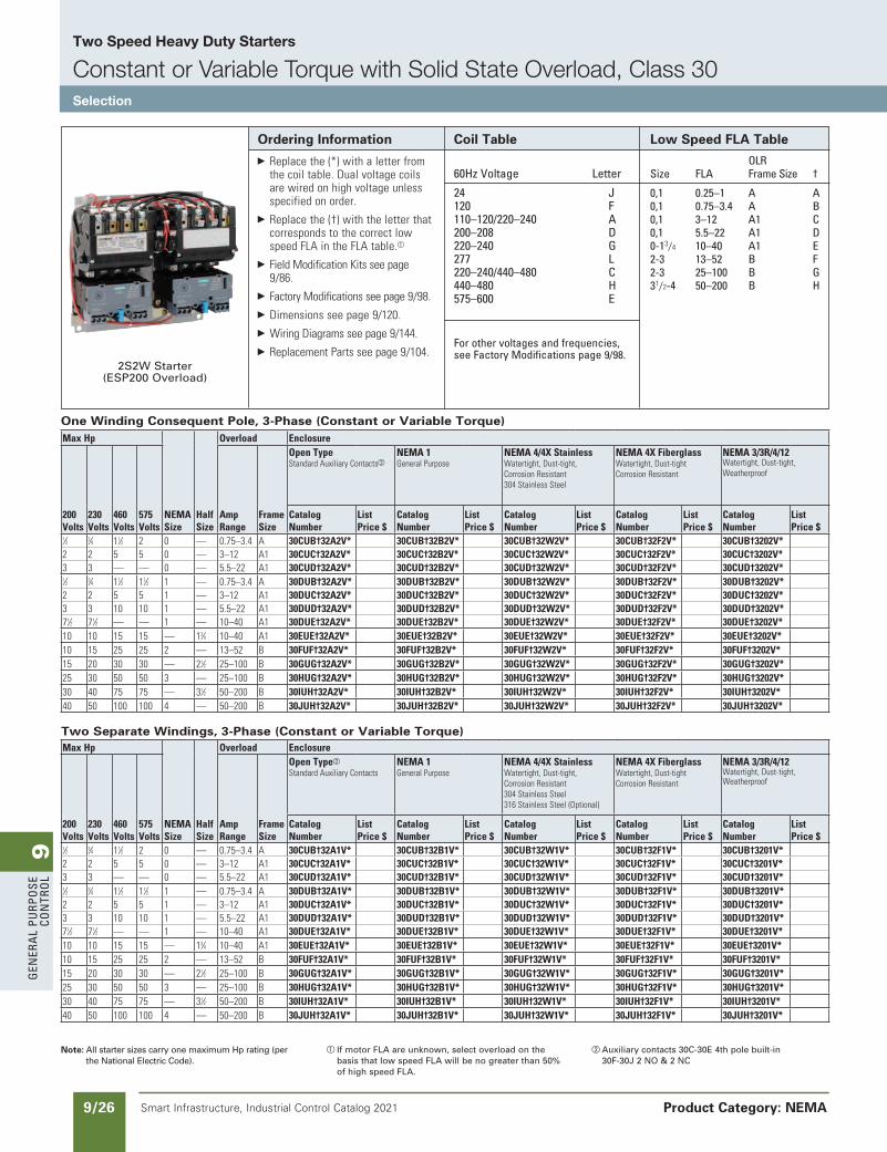
9G
ener
al
PurP
ose
Co
ntr
ol
9/26 Smart Infrastructure, Industrial Control Catalog 2021
Two Speed Heavy Duty Starters
Constant or Variable Torque with Solid State Overload, Class 30Selection
Product Category: NEMA
Note: All starter sizes carry one maximum Hp rating (per the National Electric Code).
a If motor FLA are unknown, select overload on the basis that low speed FLA will be no greater than 50% of high speed FLA.
b Auxiliary contacts 30C-30E 4th pole built-in30F-30J 2 NO & 2 NC
Ordering Information Replacethe(*)withaletterfrom
thecoiltable.Dualvoltagecoilsarewiredonhighvoltageunlessspecifiedonorder.
Replacethe(†)withtheletterthatcorrespondstothecorrectlowspeedFLAintheFLAtable.a
FieldModificationKitsseepage9/86.
FactoryModificationsseepage9/98. Dimensionsseepage9/120. WiringDiagramsseepage9/144. ReplacementPartsseepage9/104.
Coil Table
60Hz Voltage letter
24 J120 F110–120/220–240 a200–208 D220–240 G277 l220–240/440–480 C440–480 H575–600 e
For other voltages and frequencies, see Factory Modifications page 9/98.
Low Speed FLA Table
olr size Fla Frame size †
0,1 0.25–1 a a0,1 0.75–3.4 a B0,1 3–12 a1 C0,1 5.5–22 a1 D0-13/4 10–40 a1 e2-3 13–52 B F2-3 25–100 B G31/2-4 50–200 B H
2S2W Starter(ESP200 Overload)
One Winding Consequent Pole, 3-Phase (Constant or Variable Torque)
Two Separate Windings, 3-Phase (Constant or Variable Torque)MaxHp
NEMASize
HalfSize
Overload Enclosure
200Volts
230Volts
460Volts
575Volts
AmpRange
FrameSize
OpenTypeb
StandardAuxiliaryContactsNEMA1GeneralPurpose
NEMA4/4XStainlessWatertight,Dust-tight,CorrosionResistant304StainlessSteel316StainlessSteel(Optional)
NEMA4XFiberglassWatertight,Dust-tightCorrosionResistant
NEMA3/3R/4/12Watertight,Dust-tight,Weatherproof
CatalogNumber
ListPrice$
CatalogNumber
ListPrice$
CatalogNumber
ListPrice$
CatalogNumber
ListPrice$
CatalogNumber
ListPrice$
1⁄2 3⁄4 11⁄2 2 0 — 0.75–3.4 A 30CUB†32A1V* 30CUB†32B1V* 30CUB†32W1V* 30CUB†32F1V* 30CUB†3201V* 2 2 5 5 0 — 3–12 A1 30CUC†32A1V* 30CUC†32B1V* 30CUC†32W1V* 30CUC†32F1V* 30CUC†3201V* 3 3 — — 0 — 5.5–22 A1 30CUD†32A1V* 30CUD†32B1V* 30CUD†32W1V* 30CUD†32F1V* 30CUD†3201V* 1⁄2 3⁄4 11⁄2 11⁄2 1 — 0.75–3.4 A 30DUB†32A1V* 30DUB†32B1V* 30DUB†32W1V* 30DUB†32F1V* 30DUB†3201V* 2 2 5 5 1 — 3–12 A1 30DUC†32A1V* 30DUC†32B1V* 30DUC†32W1V* 30DUC†32F1V* 30DUC†3201V* 3 3 10 10 1 — 5.5–22 A1 30DUD†32A1V* 30DUD†32B1V* 30DUD†32W1V* 30DUD†32F1V* 30DUD†3201V* 71⁄2 71⁄2 — — 1 — 10–40 A1 30DUE†32A1V* 30DUE†32B1V* 30DUE†32W1V* 30DUE†32F1V* 30DUE†3201V* 10 10 15 15 — 13⁄4 10–40 A1 30EUE†32A1V* 30EUE†32B1V* 30EUE†32W1V* 30EUE†32F1V* 30EUE†3201V* 10 15 25 25 2 — 13–52 B 30FUF†32A1V* 30FUF†32B1V* 30FUF†32W1V* 30FUF†32F1V* 30FUF†3201V* 15 20 30 30 — 21⁄2 25–100 B 30GUG†32A1V* 30GUG†32B1V* 30GUG†32W1V* 30GUG†32F1V* 30GUG†3201V* 25 30 50 50 3 — 25–100 B 30HUG†32A1V* 30HUG†32B1V* 30HUG†32W1V* 30HUG†32F1V* 30HUG†3201V* 30 40 75 75 — 31⁄2 50–200 B 30IUH†32A1V* 30IUH†32B1V* 30IUH†32W1V* 30IUH†32F1V* 30IUH†3201V* 40 50 100 100 4 — 50–200 B 30JUH†32A1V* 30JUH†32B1V* 30JUH†32W1V* 30JUH†32F1V* 30JUH†3201V*
MaxHp
NEMASize
HalfSize
Overload Enclosure
200Volts
230Volts
460Volts
575Volts
AmpRange
FrameSize
OpenTypeStandardAuxiliaryContactsb
NEMA1GeneralPurpose
NEMA4/4XStainlessWatertight,Dust-tight,CorrosionResistant304StainlessSteel
NEMA4XFiberglassWatertight,Dust-tightCorrosionResistant
NEMA3/3R/4/12Watertight,Dust-tight,Weatherproof
CatalogNumber
ListPrice$
CatalogNumber
ListPrice$
CatalogNumber
ListPrice$
CatalogNumber
ListPrice$
CatalogNumber
ListPrice$
1⁄2 3⁄4 11⁄2 2 0 — 0.75–3.4 A 30CUB†32A2V* 30CUB†32B2V* 30CUB†32W2V* 30CUB†32F2V* 30CUB†3202V* 2 2 5 5 0 — 3–12 A1 30CUC†32A2V* 30CUC†32B2V* 30CUC†32W2V* 30CUC†32F2V* 30CUC†3202V* 3 3 — — 0 — 5.5–22 A1 30CUD†32A2V* 30CUD†32B2V* 30CUD†32W2V* 30CUD†32F2V* 30CUD†3202V* 1⁄2 3⁄4 11⁄2 11⁄2 1 — 0.75–3.4 A 30DUB†32A2V* 30DUB†32B2V* 30DUB†32W2V* 30DUB†32F2V* 30DUB†3202V* 2 2 5 5 1 — 3–12 A1 30DUC†32A2V* 30DUC†32B2V* 30DUC†32W2V* 30DUC†32F2V* 30DUC†3202V* 3 3 10 10 1 — 5.5–22 A1 30DUD†32A2V* 30DUD†32B2V* 30DUD†32W2V* 30DUD†32F2V* 30DUD†3202V* 71⁄2 71⁄2 — — 1 — 10–40 A1 30DUE†32A2V* 30DUE†32B2V* 30DUE†32W2V* 30DUE†32F2V* 30DUE†3202V* 10 10 15 15 — 13⁄4 10–40 A1 30EUE†32A2V* 30EUE†32B2V* 30EUE†32W2V* 30EUE†32F2V* 30EUE†3202V* 10 15 25 25 2 — 13–52 B 30FUF†32A2V* 30FUF†32B2V* 30FUF†32W2V* 30FUF†32F2V* 30FUF†3202V* 15 20 30 30 — 21⁄2 25–100 B 30GUG†32A2V* 30GUG†32B2V* 30GUG†32W2V* 30GUG†32F2V* 30GUG†3202V* 25 30 50 50 3 — 25–100 B 30HUG†32A2V* 30HUG†32B2V* 30HUG†32W2V* 30HUG†32F2V* 30HUG†3202V* 30 40 75 75 — 31⁄2 50–200 B 30IUH†32A2V* 30IUH†32B2V* 30IUH†32W2V* 30IUH†32F2V* 30IUH†3202V* 40 50 100 100 4 — 50–200 B 30JUH†32A2V* 30JUH†32B2V* 30JUH†32W2V* 30JUH†32F2V* 30JUH†3202V*
updated in SPEEDFAXRevised on 03/31/20
SS copied this page from SF to IC on 05/24/20
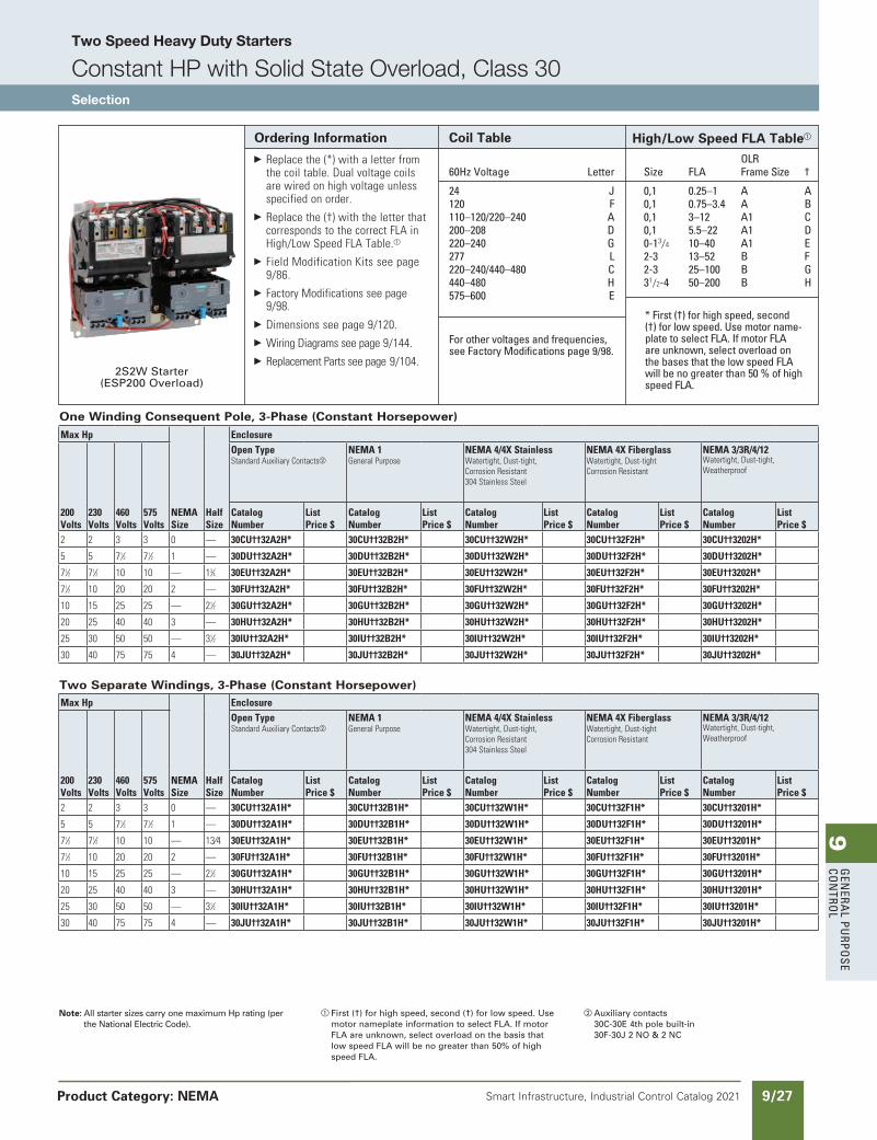
9G
enera
l PurPo
se Co
ntro
l
9/27Smart Infrastructure, Industrial Control Catalog 2021 Product Category: NEMA
Note: All starter sizes carry one maximum Hp rating (per the National Electric Code).
a First (†) for high speed, second (†) for low speed. Use motor nameplate information to select FLA. If motor FLA are unknown, select overload on the basis that low speed FLA will be no greater than 50% of high speed FLA.
b Auxiliary contacts30C-30E 4th pole built-in 30F-30J 2 NO & 2 NC
Ordering Information Replacethe(*)withaletterfrom
thecoiltable.Dualvoltagecoilsarewiredonhighvoltageunlessspecifiedonorder.
Replacethe(†)withtheletterthatcorrespondstothecorrectFLAinHigh/LowSpeedFLATable.a
FieldModificationKitsseepage9/86.
FactoryModificationsseepage9/98.
Dimensionsseepage9/120. WiringDiagramsseepage9/144. ReplacementPartsseepage9/104.
Coil Table
60Hz Voltage letter
24 J120 F110–120/220–240 a200–208 D220–240 G277 l220–240/440–480 C440–480 H575–600 e
For other voltages and frequencies, see Factory Modifications page 9/98.
olrsize Fla Frame size †
0,1 0.25–1 a a0,1 0.75–3.4 a B0,1 3–12 a1 C0,1 5.5–22 a1 D0-13/4 10–40 a1 e2-3 13–52 B F2-3 25–100 B G31/2-4 50–200 B H
2S2W Starter(ESP200 Overload)
High/Low Speed FLA Tablea
* First (†) for high speed, second (†) for low speed. use motor name-plate to select Fla. If motor Fla are unknown, select overload on the bases that the low speed Fla will be no greater than 50 % of high speed Fla.
One Winding Consequent Pole, 3-Phase (Constant Horsepower)
Two Separate Windings, 3-Phase (Constant Horsepower)MaxHp
NEMASize
HalfSize
Enclosure
200Volts
230Volts
460Volts
575Volts
OpenTypeStandardAuxiliaryContactsb
NEMA1GeneralPurpose
NEMA4/4XStainlessWatertight,Dust-tight,CorrosionResistant304StainlessSteel
NEMA4XFiberglassWatertight,Dust-tightCorrosionResistant
NEMA3/3R/4/12Watertight,Dust-tight,Weatherproof
CatalogNumber
ListPrice$
CatalogNumber
ListPrice$
CatalogNumber
ListPrice$
CatalogNumber
ListPrice$
CatalogNumber
ListPrice$
2 2 3 3 0 — 30CU††32A1H* 30CU††32B1H* 30CU††32W1H* 30CU††32F1H* 30CU††3201H*
5 5 71⁄2 71⁄2 1 — 30DU††32A1H* 30DU††32B1H* 30DU††32W1H* 30DU††32F1H* 30DU††3201H*
71⁄2 71⁄2 10 10 — 13⁄4 30EU††32A1H* 30EU††32B1H* 30EU††32W1H* 30EU††32F1H* 30EU††3201H*
71⁄2 10 20 20 2 — 30FU††32A1H* 30FU††32B1H* 30FU††32W1H* 30FU††32F1H* 30FU††3201H*
10 15 25 25 — 21⁄2 30GU††32A1H* 30GU††32B1H* 30GU††32W1H* 30GU††32F1H* 30GU††3201H*
20 25 40 40 3 — 30HU††32A1H* 30HU††32B1H* 30HU††32W1H* 30HU††32F1H* 30HU††3201H*
25 30 50 50 — 31⁄2 30IU††32A1H* 30IU††32B1H* 30IU††32W1H* 30IU††32F1H* 30IU††3201H*
30 40 75 75 4 — 30JU††32A1H* 30JU††32B1H* 30JU††32W1H* 30JU††32F1H* 30JU††3201H*
MaxHp
NEMASize
HalfSize
Enclosure
200Volts
230Volts
460Volts
575Volts
OpenTypeStandardAuxiliaryContactsb
NEMA1GeneralPurpose
NEMA4/4XStainlessWatertight,Dust-tight,CorrosionResistant304StainlessSteel
NEMA4XFiberglassWatertight,Dust-tightCorrosionResistant
NEMA3/3R/4/12Watertight,Dust-tight,Weatherproof
CatalogNumber
ListPrice$
CatalogNumber
ListPrice$
CatalogNumber
ListPrice$
CatalogNumber
ListPrice$
CatalogNumber
ListPrice$
2 2 3 3 0 — 30CU††32A2H* 30CU††32B2H* 30CU††32W2H* 30CU††32F2H* 30CU††3202H*
5 5 71⁄2 71⁄2 1 — 30DU††32A2H* 30DU††32B2H* 30DU††32W2H* 30DU††32F2H* 30DU††3202H*
71⁄2 71⁄2 10 10 — 13⁄4 30EU††32A2H* 30EU††32B2H* 30EU††32W2H* 30EU††32F2H* 30EU††3202H*
71⁄2 10 20 20 2 — 30FU††32A2H* 30FU††32B2H* 30FU††32W2H* 30FU††32F2H* 30FU††3202H*
10 15 25 25 — 21⁄2 30GU††32A2H* 30GU††32B2H* 30GU††32W2H* 30GU††32F2H* 30GU††3202H*
20 25 40 40 3 — 30HU††32A2H* 30HU††32B2H* 30HU††32W2H* 30HU††32F2H* 30HU††3202H*
25 30 50 50 — 31⁄2 30IU††32A2H* 30IU††32B2H* 30IU††32W2H* 30IU††32F2H* 30IU††3202H*
30 40 75 75 4 — 30JU††32A2H* 30JU††32B2H* 30JU††32W2H* 30JU††32F2H* 30JU††3202H*
updated in SPEEDFAXRevised on 03/31/20
SS copied this page from SF to IC on 05/24/20
Two Speed Heavy Duty Starters
Constant HP with Solid State Overload, Class 30Selection

9G
ener
al
PurP
ose
Co
ntr
ol
9/28 Smart Infrastructure, Industrial Control Catalog 2021
Combination Two Speed Heavy Duty Starters
Non-Fusible, Constant or Variable Torque with Solid State Overload, Class 32Selection
Product Category: NEMA
Note: All starter sizes carry one maximum Hp rating (per the National Electric Code).
a Dual voltage coils not available in modified starters.
b If motor FLA are unknown, select overload on the basis that low speed FLA will be no greater than 50% of high speed FLA.
Ordering Information Replacethe(*)withaletterfrom
thecoiltable.Dualvoltagecoilsarewiredonhighvoltageunlessspecifiedonorder.
Replacethe(†)withtheletterthatcorrespondstothecorrectlowspeedFLAintheFLAtable.b
Fuseclipsseepage9/99. FieldModificationKitsseepage
9/86. FactoryModificationsseepage
9/98. Dimensionsseepage9/133. WiringDiagramsseepage9/144. ReplacementPartsseepage9/104.
Coil Table 60Hz Voltage letter
24 J120 F110–120/220–240a a200–208 D220–240 G277 l220–240/440–480a C440–480 H575–600 e
For other voltages and frequencies, see Factory Modifications page 9/98.
Low Speed FLA Table olrsize Fla Frame size †
0,1 0.25–1 a a0,1 0.75–3.4 a B0,1 3–12 a1 C0,1 5.5–22 a1 D0-13/4 10–40 a1 e2-3 13–52 B F2-3 25–100 B G31/2-4 50–200 B H
One Winding Consequent Pole, 3-Phase (Constant or Variable Torque)
MaxHp
NEMASize
HalfSize
Overload
Disc.AmpRange
Enclosure
200Volts
230Volts
460Volts
575Volts
AmpRange
FrameSize
NEMA1GeneralPurpose
NEMA4/4XStainlessWatertight,Dust-tight,CorrosionResistant304StainlessSteel
NEMA4XFiberglassWatertight,Dust-tightCorrosionResistant
NEMA3/3R/4/12Watertight,Dust-tight,Weatherproof
CatalogNumber
ListPrice$
CatalogNumber
ListPrice$
CatalogNumber
ListPrice$
CatalogNumber
ListPrice$
1⁄2 3⁄4 11⁄2 2 0 — 0.75–3.4 A 30 32CUB†92B2V2* 32CUB†92W2V2* 32CUB†92F2V2* 32CUB†92N2V2* 2 2 5 5 0 — 3–12 A1 30 32CUC†92B2V2* 32CUC†92W2V2* 32CUC†92F2V2* 32CUC†92N2V2* 3 3 — — 0 — 5.5–22 A1 30 32CUD†92B2V2* 32CUD†92W2V2* 32CUD†92F2V2* 32CUD†92N2V2* 1⁄2 3⁄4 11⁄2 11⁄2 1 — 0.75–3.4 A 30 32DUB†92B2V2* 32DUB†92W2V2* 32DUB†92F2V2* 32DUB†92N2V2* 2 2 5 5 1 — 3–12 A1 30 32DUC†92B2V2* 32DUC†92W2V2* 32DUC†92F2V2* 32DUC†92N2V2* 3 3 10 10 1 — 5.5–22 A1 30 32DUD†92B2V2* 32DUD†92W2V2* 32DUD†92F2V2* 32DUD†92N2V2* 71⁄2 71⁄2 — — 1 — 10–40 A1 60 32DUE†92B2V2* 32DUE†92W2V2* 32DUE†92F2V2* 32DUE†92N2V2* 10 10 15 15 — 13⁄4 10–40 A1 60 32EUE†92B2V2* 32EUE†92W2V2* 32EUE†92F2V2* 32EUE†92N2V2* 10 15 25 25 2 — 13–52 B 60 32FUF†92B2V2* 32FUF†92W2V2* 32FUF†92F2V2* 32FUF†92N2V2* 15 20 30 30 — 21⁄2 25–100 B 100 32GUG†92B2V2* 32GUG†92W2V2* 32GUG†92F2V2* 32GUG†92N2V2* 20 25 50 50 3 — 25–100 B 100 32HUG†92B2V2* 32HUG†92W2V2* 32HUG†92F2V2* 32HUG†92N2V2* 30 40 75 75 — 31⁄2 50–200 B 200 32IUH†92B2V2* 32IUH†92W2V2* 32IUH†92F2V2* 32IUH†92N2V2* 40 50 100 100 4 — 50–200 B 200 32JUH†92B2V2* 32JUH†92W2V2* 32JUH†92F2V2* 32JUH†92N2V2*
Two Separate Windings, 3-Phase (Constant or Variable Torque)MaxHp
NEMASize
HalfSize
Overload
Disc.AmpRange
Enclosure
200Volts
230Volts
460Volts
575Volts
AmpRange
FrameSize
NEMA1GeneralPurpose
NEMA4/4XStainlessWatertight,Dust-tight,CorrosionResistant304StainlessSteel
NEMA4XFiberglassWatertight,Dust-tightCorrosionResistant
NEMA3/3R/4/12Watertight,Dust-tight,Weatherproof
CatalogNumber
ListPrice$
CatalogNumber
ListPrice$
CatalogNumber
ListPrice$
CatalogNumber
ListPrice$
1⁄2 3⁄4 11⁄2 2 0 — 0.75–3.4 A 30 32CUB†92B1V2* 32CUB†92W1V2* 32CUB†92F1V2* 32CUB†92N1V2* 2 2 5 5 0 — 3–12 A1 30 32CUC†92B1V2* 32CUC†92W1V2* 32CUC†92F1V2* 32CUC†92N1V2* 3 3 — — 0 — 5.5–22 A1 30 32CUD†92B1V2* 32CUD†92W1V2* 32CUD†92F1V2* 32CUD†92N1V2* 1⁄2 3⁄4 11⁄2 11⁄2 1 — 0.75–3.4 A 30 32DUB†92B1V2* 32DUB†92W1V2* 32DUB†92F1V2* 32DUB†92N1V2* 2 2 5 5 1 — 3–12 A1 30 32DUC†92B1V2* 32DUC†92W1V2* 32DUC†92F1V2* 32DUC†92N1V2* 3 3 10 10 1 — 5.5–22 A1 30 32DUD†92B1V2* 32DUD†92W1V2* 32DUD†92F1V2* 32DUD†92N1V2* 71⁄2 71⁄2 — — 1 — 10–40 A1 60 32DUE†92B1V2* 32DUE†92W1V2* 32DUE†92F1V2* 32DUE†92N1V2* 10 10 15 15 — 13⁄4 10–40 A1 60 32EUE†92B1V2* 32EUE†92W1V2* 32EUE†92F1V2* 32EUE†92N1V2* 10 15 25 25 2 — 13–52 B 60 32FUF†92B1V2* 32FUF†92W1V2* 32FUF†92F1V2* 32FUF†92N1V2* 15 20 30 30 — 21⁄2 25–100 B 100 32GUG†92B1V2* 32GUG†92W1V2* 32GUG†92F1V2* 32GUG†92N1V2* 20 25 50 50 3 — 25–100 B 100 32HUG†92B1V2* 32HUG†92W1V2* 32HUG†92F1V2* 32HUG†92N1V2* 30 40 75 75 — 31⁄2 50–200 B 200 32IUH†92B1V2* 32IUH†92W1V2* 32IUH†92F1V2* 32IUH†92N1V2* 40 50 100 100 4 — 50–200 B 200 32JUH†92B1V2* 32JUH†92W1V2* 32JUH†92F1V2* 32JUH†92N1V2*
updated in SPEEDFAXRevised on 03/31/20
SS copied this page from SF to IC on 05/24/20
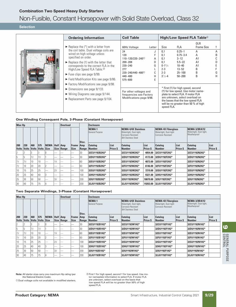
9G
enera
l PurPo
se Co
ntro
l
9/29Smart Infrastructure, Industrial Control Catalog 2021
Combination Two Speed Heavy Duty Starters
Non-Fusible, Constant Horsepower with Solid State Overload, Class 32Selection
Product Category: NEMA
Note: All starter sizes carry one maximum Hp rating (per the National Electric Code).
a Dual voltage coils not available in modified starters.
b First † for high speed, second † for low speed. Use mo-tor nameplate information to select FLA. If motor FLA are unknown, select overload on the basis that low speed FLA will be no greater than 50% of high speed FLA.
Ordering Information
Replacethe(*)withaletterfromthecoiltable.Dualvoltagecoilsarewiredonhighvoltageunlessspecifiedonorder.
Replacethe(†)withtheletterthatcorrespondstothecorrectFLAintheHigh/LowSpeedFLATable.b
Fuseclipsseepage9/99. FieldModificationKitsseepage9/86. FactoryModificationsseepage9/98. Dimensionsseepage9/133. WiringDiagramsseepage9/144. ReplacementPartsseepage9/104.
Coil Table
60Hz Voltage letter
24 J 120 F 110–120/220–240a a 200–208 D 220–240 G 277 l 220–240/440–480a C 440–480 H 575–600 e
For other voltages and frequencies see Factory Modifications page 9/98.
High/Low Speed FLA Tableb
olr size Fla Frame size † 0,1 0.25–1 a a 0,1 0.75–3.4 a B 0,1 3–12 a1 C 0,1 5.5–22 a1 D 0-13/4 10–40 a1 e 2-3 13–52 B F 2-3 25–100 B G 31/2-4 50–200 B H
* First (†) for high speed, second (†) for low speed. use motor name-plate to select Fla. If motor Fla are unknown, select overload on the bases that the low speed Fla will be no greater than 50 % of high speed Fla.
One Winding Consequent Pole, 3-Phase (Constant Horsepower)
Two Separate Windings, 3-Phase (Constant Horsepower)
MaxHp
NEMASize
HalfSize
Overload
Disc.AmpRange
Enclosure
200Volts
230Volts
460Volts
575Volts
AmpRange
FrameSize
NEMA1GeneralPurpose
NEMA4/4XStainlessWatertight,Dust-tight,CorrosionResistant304StainlessSteel
NEMA4XFiberglassWatertight,Dust-tightCorrosionResistant
NEMA3/3R/4/12Watertight,Dust-tight,Weatherproof
CatalogNumber
ListPrice$
CatalogNumber
ListPrice$
CatalogNumber
ListPrice$
CatalogNumber
ListPrice$
2 2 3 3 0 — — — 30 32CU††92B2H2* 32CU††92W2H2* 4054.00 32CU††92F2H2* 32CU††92N2H2*
5 5 71⁄2 71⁄2 1 — — — 30 32DU††92B2H2* 32DU††92W2H2* 4173.00 32DU††92F2H2* 32DU††92N2H2*
71⁄2 71⁄2 10 10 — 13⁄4 — — 60 32EU††92B2H2* 32EU††92W2H2* 4873.00 32EU††92F2H2* 32EU††92N2H2*
71⁄2 10 20 20 2 — — — 60 32FU††92B2H2* 32FU††92W2H2* 6146.00 32FU††92F2H2* 32FU††92N2H2*
10 15 25 25 — 21⁄2 — — 100 32GU††92B2H2* 32GU††92W2H2* 7219.00 32GU††92F2H2* 32GU††92N2H2*
20 25 40 40 3 — — — 100 32HU††92B2H2* 32HU††92W2H2* 9321.00 32HU††92F2H2* 32HU††92N2H2*
25 30 50 50 — 31⁄2 — — 200 32IU††92B2H2* 32IU††92W2H2* 18079.00 32IU††92F2H2* 32IU††92N2H2*
30 40 75 75 4 — — — 200 32JU††92B2H2* 32JU††92W2H2* 19263.00 32JU††92F2H2* 32JU††92N2H2*
MaxHp
NEMASize
HalfSize
Overload
Disc.AmpRange
Enclosure
200Volts
230Volts
460Volts
575Volts
AmpRange
FrameSize
NEMA1GeneralPurpose
NEMA4/4XStainlessWatertight,Dust-tight,CorrosionResistant304StainlessSteel
NEMA4XFiberglassWatertight,Dust-tightCorrosionResistant
NEMA3/3R/4/12Watertight,Dust-tight,Weatherproof
CatalogNumber
ListPrice$
CatalogNumber
ListPrice$
CatalogNumber
ListPrice$
CatalogNumber
ListPrice$
2 2 3 3 0 — — — 30 32CU††92B1H2* 32CU††92W1H2* 32CU††92F1H2* 32CU††92N1H2*
5 5 71⁄2 71⁄2 1 — — — 30 32DU††92B1H2* 32DU††92W1H2* 32DU††92F1H2* 32DU††92N1H2*
71⁄2 71⁄2 10 10 — 13⁄4 — — 60 32EU††92B1H2* 32EU††92W1H2* 32EU††92F1H2* 32EU††92N1H2*
71⁄2 10 20 20 2 — — — 60 32FU††92B1H2* 32FU††92W1H2* 32FU††92F1H2* 32FU††92N1H2*
10 15 25 25 — 21⁄2 — — 100 32GU††92B1H2* 32GU††92W1H2* 32GU††92F1H2* 32GU††92N1H2*
20 25 40 40 3 — — — 100 32HU††92B1H2* 32HU††92W1H2* 32HU††92F1H2* 32HU††92N1H2*
25 30 50 50 — 31⁄2 — — 200 32IU††92B1H2* 32IU††92W1H2* 32IU††92F1H2* 32IU††92N1H2*
30 40 75 75 4 — — — 200 32JU††92B1H2* 32JU††92W1H2* 32JU††92F1H2* 32JU††92N1H2*
updated in SPEEDFAXRevised on 03/31/20
SS copied this page from SF to IC on 05/24/20
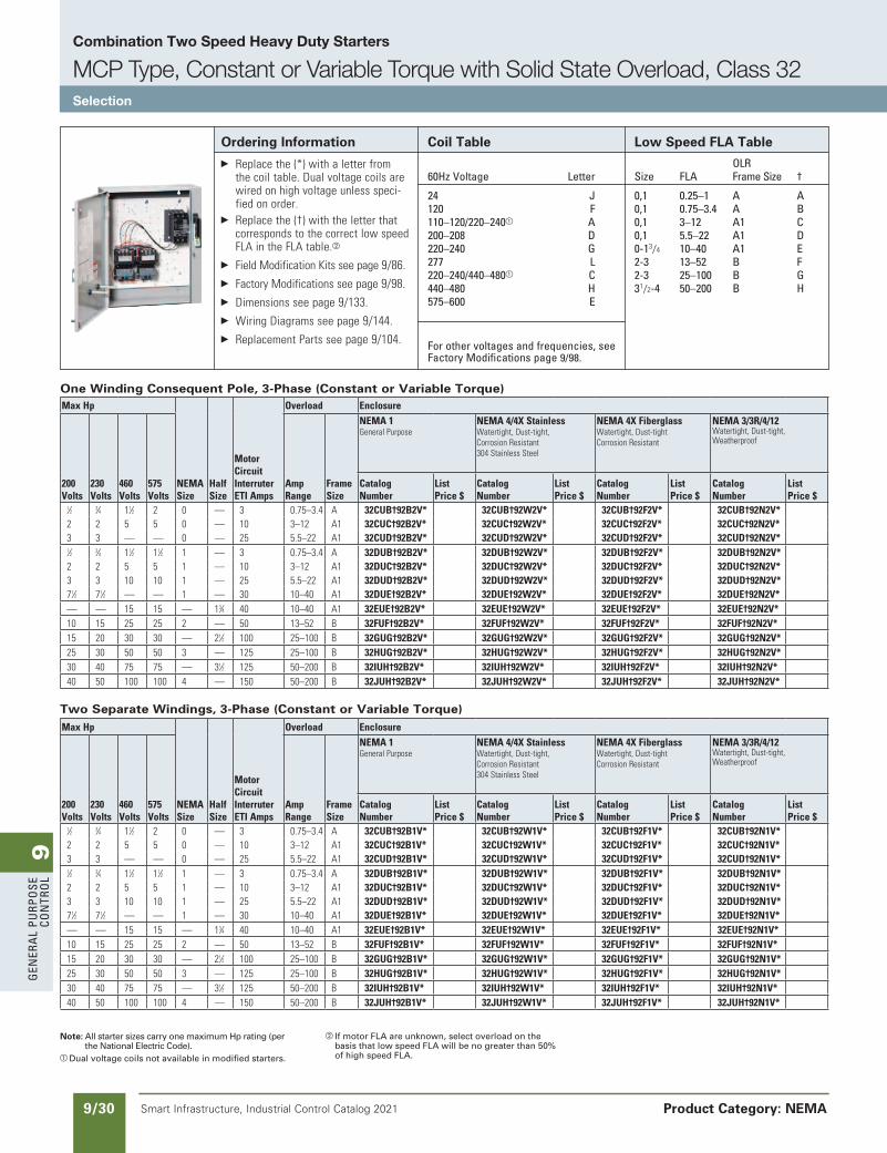
9G
ener
al
PurP
ose
Co
ntr
ol
9/30 Smart Infrastructure, Industrial Control Catalog 2021
Combination Two Speed Heavy Duty Starters
MCP Type, Constant or Variable Torque with Solid State Overload, Class 32Selection
Product Category: NEMA
Note: All starter sizes carry one maximum Hp rating (per the National Electric Code).
a Dual voltage coils not available in modified starters.
b If motor FLA are unknown, select overload on the basis that low speed FLA will be no greater than 50% of high speed FLA.
Ordering Information Replacethe(*)withaletterfrom
thecoiltable.Dualvoltagecoilsarewiredonhighvoltageunlessspeci-fiedonorder.
Replacethe(†)withtheletterthatcorrespondstothecorrectlowspeedFLAintheFLAtable.b
FieldModificationKitsseepage9/86. FactoryModificationsseepage9/98. Dimensionsseepage9/133. WiringDiagramsseepage9/144. ReplacementPartsseepage9/104.
Coil Table
60Hz Voltage letter
24 J120 F110–120/220–240a a200–208 D220–240 G277 l220–240/440–480a C440–480 H575–600 e
For other voltages and frequencies, see Factory Modifications page 9/98.
Low Speed FLA Table
olrsize Fla Frame size †
0,1 0.25–1 a a0,1 0.75–3.4 a B0,1 3–12 a1 C0,1 5.5–22 a1 D0-13/4 10–40 a1 e2-3 13–52 B F2-3 25–100 B G31/2-4 50–200 B H
One Winding Consequent Pole, 3-Phase (Constant or Variable Torque)
Two Separate Windings, 3-Phase (Constant or Variable Torque)MaxHp
NEMASize
HalfSize
MotorCircuitInterruterETIAmps
Overload Enclosure
200Volts
230Volts
460Volts
575Volts
AmpRange
FrameSize
NEMA1GeneralPurpose
NEMA4/4XStainlessWatertight,Dust-tight,CorrosionResistant304StainlessSteel
NEMA4XFiberglassWatertight,Dust-tightCorrosionResistant
NEMA3/3R/4/12Watertight,Dust-tight,Weatherproof
CatalogNumber
ListPrice$
CatalogNumber
ListPrice$
CatalogNumber
ListPrice$
CatalogNumber
ListPrice$
1⁄2 3⁄4 11⁄2 2 0 — 3 0.75–3.4 A 32CUB†92B1V* 32CUB†92W1V* 32CUB†92F1V* 32CUB†92N1V* 2 2 5 5 0 — 10 3–12 A1 32CUC†92B1V* 32CUC†92W1V* 32CUC†92F1V* 32CUC†92N1V* 3 3 — — 0 — 25 5.5–22 A1 32CUD†92B1V* 32CUD†92W1V* 32CUD†92F1V* 32CUD†92N1V* 1⁄2 3⁄4 11⁄2 11⁄2 1 — 3 0.75–3.4 A 32DUB†92B1V* 32DUB†92W1V* 32DUB†92F1V* 32DUB†92N1V* 2 2 5 5 1 — 10 3–12 A1 32DUC†92B1V* 32DUC†92W1V* 32DUC†92F1V* 32DUC†92N1V* 3 3 10 10 1 — 25 5.5–22 A1 32DUD†92B1V* 32DUD†92W1V* 32DUD†92F1V* 32DUD†92N1V* 71⁄2 71⁄2 — — 1 — 30 10–40 A1 32DUE†92B1V* 32DUE†92W1V* 32DUE†92F1V* 32DUE†92N1V* — — 15 15 — 13⁄4 40 10–40 A1 32EUE†92B1V* 32EUE†92W1V* 32EUE†92F1V* 32EUE†92N1V* 10 15 25 25 2 — 50 13–52 B 32FUF†92B1V* 32FUF†92W1V* 32FUF†92F1V* 32FUF†92N1V* 15 20 30 30 — 21⁄2 100 25–100 B 32GUG†92B1V* 32GUG†92W1V* 32GUG†92F1V* 32GUG†92N1V* 25 30 50 50 3 — 125 25–100 B 32HUG†92B1V* 32HUG†92W1V* 32HUG†92F1V* 32HUG†92N1V* 30 40 75 75 — 31⁄2 125 50–200 B 32IUH†92B1V* 32IUH†92W1V* 32IUH†92F1V* 32IUH†92N1V* 40 50 100 100 4 — 150 50–200 B 32JUH†92B1V* 32JUH†92W1V* 32JUH†92F1V* 32JUH†92N1V*
MaxHp
NEMASize
HalfSize
MotorCircuitInterruterETIAmps
Overload Enclosure
200Volts
230Volts
460Volts
575Volts
AmpRange
FrameSize
NEMA1GeneralPurpose
NEMA4/4XStainlessWatertight,Dust-tight,CorrosionResistant304StainlessSteel
NEMA4XFiberglassWatertight,Dust-tightCorrosionResistant
NEMA3/3R/4/12Watertight,Dust-tight,Weatherproof
CatalogNumber
ListPrice$
CatalogNumber
ListPrice$
CatalogNumber
ListPrice$
CatalogNumber
ListPrice$
1⁄2 3⁄4 11⁄2 2 0 — 3 0.75–3.4 A 32CUB†92B2V* 32CUB†92W2V* 32CUB†92F2V* 32CUB†92N2V* 2 2 5 5 0 — 10 3–12 A1 32CUC†92B2V* 32CUC†92W2V* 32CUC†92F2V* 32CUC†92N2V* 3 3 — — 0 — 25 5.5–22 A1 32CUD†92B2V* 32CUD†92W2V* 32CUD†92F2V* 32CUD†92N2V* 1⁄2 3⁄4 11⁄2 11⁄2 1 — 3 0.75–3.4 A 32DUB†92B2V* 32DUB†92W2V* 32DUB†92F2V* 32DUB†92N2V* 2 2 5 5 1 — 10 3–12 A1 32DUC†92B2V* 32DUC†92W2V* 32DUC†92F2V* 32DUC†92N2V* 3 3 10 10 1 — 25 5.5–22 A1 32DUD†92B2V* 32DUD†92W2V* 32DUD†92F2V* 32DUD†92N2V* 71⁄2 71⁄2 — — 1 — 30 10–40 A1 32DUE†92B2V* 32DUE†92W2V* 32DUE†92F2V* 32DUE†92N2V* — — 15 15 — 13⁄4 40 10–40 A1 32EUE†92B2V* 32EUE†92W2V* 32EUE†92F2V* 32EUE†92N2V* 10 15 25 25 2 — 50 13–52 B 32FUF†92B2V* 32FUF†92W2V* 32FUF†92F2V* 32FUF†92N2V* 15 20 30 30 — 21⁄2 100 25–100 B 32GUG†92B2V* 32GUG†92W2V* 32GUG†92F2V* 32GUG†92N2V* 25 30 50 50 3 — 125 25–100 B 32HUG†92B2V* 32HUG†92W2V* 32HUG†92F2V* 32HUG†92N2V* 30 40 75 75 — 31⁄2 125 50–200 B 32IUH†92B2V* 32IUH†92W2V* 32IUH†92F2V* 32IUH†92N2V* 40 50 100 100 4 — 150 50–200 B 32JUH†92B2V* 32JUH†92W2V* 32JUH†92F2V* 32JUH†92N2V*
updated in SPEEDFAXRevised on 03/31/20
SS copied this page from SF to IC on 05/24/20
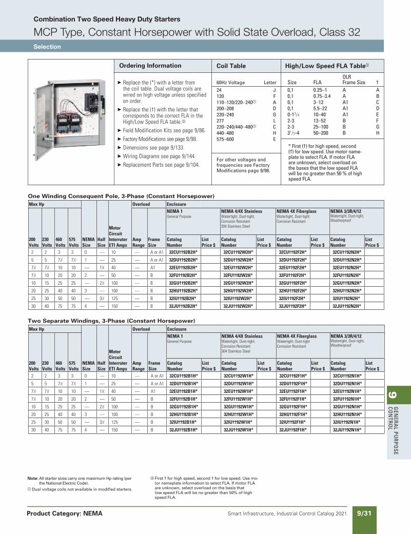
9G
enera
l PurPo
se Co
ntro
l
9/31Smart Infrastructure, Industrial Control Catalog 2021 Product Category: NEMA
Note: All starter sizes carry one maximum Hp rating (per the National Electric Code).
a Dual voltage coils not available in modified starters.
b First † for high speed, second † for low speed. Use mo-tor nameplate information to select FLA. If motor FLA are unknown, select overload on the basis that low speed FLA will be no greater than 50% of high speed FLA.
Ordering Information
Replacethe(*)withaletterfromthecoiltable.Dualvoltagecoilsarewiredonhighvoltageunlessspecifiedonorder.
Replacethe(†)withtheletterthatcorrespondstothecorrectFLAintheHigh/LowSpeedFLAtable.b
FieldModificationKitsseepage9/86. FactoryModificationsseepage9/98. Dimensionsseepage9/133. WiringDiagramsseepage9/144. ReplacementPartsseepage9/104.
Coil Table
60Hz Voltage letter
24 J 120 F 110–120/220–240a a 200–208 D 220–240 G 277 l 220–240/440–480a C 440–480 H 575–600 e
For other voltages and frequencies see Factory Modifications page 9/98.
High/Low Speed FLA Tableb
olr size Fla Frame size † 0,1 0.25–1 a a 0,1 0.75–3.4 a B 0,1 3–12 a1 C 0,1 5.5–22 a1 D 0-13/4 10–40 a1 e 2-3 13–52 B F 2-3 25–100 B G 31/2-4 50–200 B H
* First (†) for high speed, second (†) for low speed. use motor name-plate to select Fla. If motor Fla are unknown, select overload on the bases that the low speed Fla will be no greater than 50 % of high speed Fla.
One Winding Consequent Pole, 3-Phase (Constant Horsepower)
Two Separate Windings, 3-Phase (Constant Horsepower)MaxHp
NEMASize
HalfSize
MotorCircuitInterruterETIAmps
Overload Enclosure
200Volts
230Volts
460Volts
575Volts
AmpRange
FrameSize
NEMA1GeneralPurpose
NEMA4/4XStainlessWatertight,Dust-tight,CorrosionResistant304StainlessSteel
NEMA4XFiberglassWatertight,Dust-tightCorrosionResistant
NEMA3/3R/4/12Watertight,Dust-tight,Weatherproof
CatalogNumber
ListPrice$
CatalogNumber
ListPrice$
CatalogNumber
ListPrice$
CatalogNumber
ListPrice$
2 2 3 3 0 — 10 — AorA1 32CU††92B1H* 32CU††92W1H* 32CU††92F1H* 32CU††92N1H*
5 5 71⁄2 71⁄2 1 — 25 — AorA1 32DU††92B1H* 32DU††92W1H* 32DU††92F1H* 32DU††92N1H*
71⁄2 71⁄2 10 10 — 13⁄4 40 — A1 32EU††92B1H* 32EU††92W1H* 32EU††92F1H* 32EU††92N1H*
71⁄2 10 20 20 2 — 50 — B 32FU††92B1H* 32FU††92W1H* 32FU††92F1H* 32FU††92N1H*
10 15 25 25 — 21⁄2 100 — B 32GU††92B1H* 32GU††92W1H* 32GU††92F1H* 32GU††92N1H*
20 25 40 40 3 — 100 — B 32HU††92B1H* 32HU††92W1H* 32HU††92F1H* 32HU††92N1H*
25 30 50 50 — 31⁄2 125 — B 32IU††92B1H* 32IU††92W1H* 32IU††92F1H* 32IU††92N1H*
30 40 75 75 4 — 150 — B 32JU††92B1H* 32JU††92W1H* 32JU††92F1H* 32JU††92N1H*
MaxHp
NEMASize
HalfSize
MotorCircuitInterruterETIAmps
Overload Enclosure
200Volts
230Volts
460Volts
575Volts
AmpRange
FrameSize
NEMA1GeneralPurpose
NEMA4/4XStainlessWatertight,Dust-tight,CorrosionResistant304StainlessSteel
NEMA4XFiberglassWatertight,Dust-tightCorrosionResistant
NEMA3/3R/4/12Watertight,Dust-tight,Weatherproof
CatalogNumber
ListPrice$
CatalogNumber
ListPrice$
CatalogNumber
ListPrice$
CatalogNumber
ListPrice$
2 2 3 3 0 — 10 — AorA1 32CU††92B2H* 32CU††92W2H* 32CU††92F2H* 32CU††92N2H*
5 5 71⁄2 71⁄2 1 — 25 — AorA1 32DU††92B2H* 32DU††92W2H* 32DU††92F2H* 32DU††92N2H*
71⁄2 71⁄2 10 10 — 13⁄4 40 — A1 32EU††92B2H* 32EU††92W2H* 32EU††92F2H* 32EU††92N2H*
71⁄2 10 20 20 2 — 50 — B 32FU††92B2H* 32FU††92W2H* 32FU††92F2H* 32FU††92N2H*
10 15 25 25 — 21⁄2 100 — B 32GU††92B2H* 32GU††92W2H* 32GU††92F2H* 32GU††92N2H*
20 25 40 40 3 — 100 — B 32HU††92B2H* 32HU††92W2H* 32HU††92F2H* 32HU††92N2H*
25 30 50 50 — 31⁄2 125 — B 32IU††92B2H* 32IU††92W2H* 32IU††92F2H* 32IU††92N2H*
30 40 75 75 4 — 150 — B 32JU††92B2H* 32JU††92W2H* 32JU††92F2H* 32JU††92N2H*
updated in SPEEDFAXRevised on 03/31/20
SS copied this page from SF to IC on 05/24/20
Combination Two Speed Heavy Duty Starters
MCP Type, Constant Horsepower with Solid State Overload, Class 32Selection
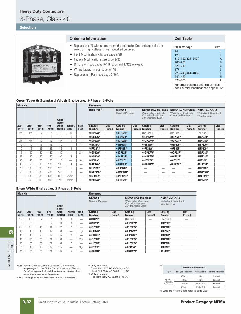
9G
ener
al
PurP
ose
Co
ntr
ol
9/32 Smart Infrastructure, Industrial Control Catalog 2021
Heavy Duty Contactors
3-Phase, Class 40Selection
Product Category: NEMA
Note: Hp’s shown above are based on the overload amp range for the FLA’s (per the National Electric Code) of typical industrial motors. All starter sizes carry one maximum Hp rating.
a Dual voltage coils not available in size 5-8 starters.
b Only available F coil 100-250V AC 50/60Hz, or DC H coil 150-500V AC 50/60Hz, or DC
c Only availableF coil100-250V AC 50/60Hz, or DC
d
e Lugs are not included, refer to page 9/90.
Ordering Information
Replacethe(*)withaletterfromthecoiltable.Dualvoltagecoilsarewiredonhighvoltageunlessspecifiedonorder.
FieldModificationKitsseepage9/86. FactoryModificationsseepage9/98. Dimensionsseepages9/115openand9/125enclosed. WiringDiagramsseepage9/146. ReplacementPartsseepage9/104.
Coil Table
60Hz Voltage letter 24 J 120 F 110–120/220–240a a 200–208 D 220–240 G 277 l 220–240/440–480a C 440–480 H 575–600 e For other voltages and frequencies,
see Factory Modifications page 9/112.
StandardAuxiliaryContacts
Type Size(3rdCharacter) Configuration Internal/External
B thru e 1n.o. Internal
all FVnr F thru J 1n.o. external
starters &
l thru M 2n.o., 2n.C. external
Contactors
n thru P 1n.o., 1n.C. external
Open Type & Standard Width Enclosure, 3-Phase, 3-PoleMaxHp
Cont-actorAmpRating
NEMASize
HalfSize
Enclosure
200Volts
230Volts
460Volts
575Volts
OpenTyped NEMA1General Purpose
NEMA4/4XStainlessWatertight, Dust-tightCorrosion Resistant304 Stainless Steel
NEMA4XFiberglassWatertight, Dust-tightCorrosion Resistant
NEMA3/3R/4/12Watertight, Dust-tight, Weatherproof
CatalogNumber
ListPrice$
CatalogNumber
ListPrice$
CatalogNumber
ListPrice$
CatalogNumber
ListPrice$
CatalogNumber
ListPrice$
11⁄2 11⁄2 2 2 9 00 — 40BP32A* 40BP32B* UseSize0 — UseSize0 — UseSize0 —3 3 5 5 18 0 — 40CP32A* 40CP32B* 40CP32W* 40CP32F* 40CP320*
71⁄2 71⁄2 10 10 27 1 — 40DP32A* 40DP32B* 40DP32W* 40DP32F* 40DP320* 10 10 15 15 40 — 13⁄4 40EP32A* 40EP32B* 40EP32W* 40EP32F* 40EP320* 10 15 25 25 45 2 — 40FP32A* 40FP32B* 40FP32W* 40FP32F* 40FP320* 15 20 30 30 60 — 21⁄2 40GP32A* 40GP32B* 40GP32W* 40GP32F* 40GP320* 25 30 50 50 90 3 — 40HP32A* 40HP32B* 40HP32W* 40HP32F* 40HP320* 30 40 75 75 115 — 31⁄2 40IP32A* 40IP32B* 40IP32W* 40IP32F* 40IP320* 40 50 100 100 135 4 — 40JG32A* 40JG32B* 40JG32W* 40JG32F* 40JG320* 75 100 200 200 270 5 — 40LP32A* 40LP32B* — — — — 40LP320*
150 200 400 400 540 6 — 40MP32A* 40MP32B* — — — — 40MP320* — 300 600 600 810 7be — 40NH32A* 40NH32B* — — — — 40NH320* — 450 900 900 1215 8ce — 40PH32A* 40PH32B* — — — — 40PH320*
Extra Wide Enclosure, 3-Phase, 3-PoleMaxHp
Cont-actorAmpRating
NEMASize
HalfSize
Enclosure
200Volts
230Volts
460Volts
575Volts
NEMA1d
General PurposeNEMA4/4XStainlessWatertight, Dust-tightCorrosion Resistant304 Stainless Steel
NEMA3/3R/4/12Watertight, Dust-tight, Weatherproof
CatalogNumber
ListPrice$
CatalogNumber
ListPrice$
CatalogNumber
ListPrice$
11⁄2 11⁄2 2 2 9 00 — 40BP82B* UseSize0 — UseSize0 —3 3 5 5 18 0 — 40CP82B* 40CP82W* 40CP820*
71⁄2 71⁄2 10 10 27 1 — 40DP82B* 40DP82W* 40DP820* 10 10 15 15 40 — 13/4 40EP82B* 40EP82W* 40EP820* 10 15 25 25 45 2 — 40FP82B* 40FP82W* 40FP820* 15 20 30 30 60 — 21/2 40GP82B* 40GP82W* 40GP820* 25 30 50 50 90 3 — 40HP82B* 40HP82W* 40HP820* 30 40 75 75 115 — 31/2 40IP82B* 40IP82W* 40IP820* 40 50 100 100 135 4 — 40JG82B* 40JG82W* 40JG820*
updated in SPEEDFAXRevised on 03/31/20
SS copied this page from SF to IC on 05/24/20
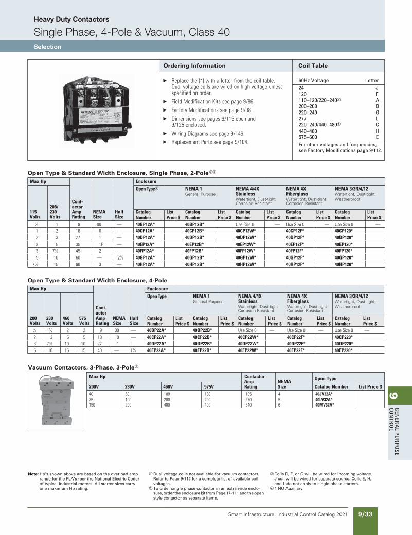
9G
enera
l PurPo
se Co
ntro
l
9/33Smart Infrastructure, Industrial Control Catalog 2021
Heavy Duty Contactors
Single Phase, 4-Pole & Vacuum, Class 40Selection
Ordering Information
Replacethe(*)withaletterfromthecoiltable.Dualvoltagecoilsarewiredonhighvoltageunlessspecifiedonorder.
FieldModificationKitsseepage9/86. FactoryModificationsseepage9/98. Dimensionsseepages9/115openand
9/125enclosed. WiringDiagramsseepage9/146. ReplacementPartsseepage9/104.
Note: Hp’s shown above are based on the overload amp range for the FLA’s (per the National Electric Code) of typical industrial motors. All starter sizes carry one maximum Hp rating.
a Dual voltage coils not available for vacuum contactors.Refer to Page 9/112 for a complete list of available coil voltages.
b To order single phase contactor in an extra wide enclo-sure, order the enclosure kit from Page 17-111 and the open style contactor as separate items.
c Coils D, F, or G will be wired for incoming voltage.J coil will be wired for separate source. Coils E, H, and L do not apply to single phase starters.
d 1 NO Auxiliary.
Coil Table
60Hz Voltage letter 24 J 120 F 110–120/220–240a a 200–208 D 220–240 G 277 l 220–240/440–480a C 440–480 H 575–600 e For other voltages and frequencies,
see Factory Modifications page 9/112.
Vacuum Contactors, 3-Phase, 3-Polea
MaxHp Contactor OpenType Amp NEMA 200V 230V 460V 575V Rating Size CatalogNumber ListPrice$
40 50 100 100 135 4 40JV32A* 75 100 200 200 270 5 40LV32A* 150 200 400 400 540 6 40MV32A*
Open Type & Standard Width Enclosure, Single Phase, 2-Polebc
MaxHp
Cont-actorAmpRating
NEMASize
HalfSize
Enclosure
115Volts
208/230Volts
OpenTyped NEMA1General Purpose
NEMA4/4XStainlessWatertight, Dust-tightCorrosion Resistant
NEMA4XFiberglassWatertight, Dust-tightCorrosion Resistant
NEMA3/3R/4/12Watertight, Dust-tight, Weatherproof
CatalogNumber
ListPrice$
CatalogNumber
ListPrice$
CatalogNumber
ListPrice$
CatalogNumber
ListPrice$
CatalogNumber
ListPrice$
1⁄3 1 9 00 — 40BP12A* 40BP12B* UseSize0 — UseSize0 — UseSize0 —1 2 18 0 — 40CP12A* 40CP12B* 40CP12W* 40CP12F* 40CP120* 2 3 27 1 — 40DP12A* 40DP12B* 40DP12W* 40DP12F* 40DP120* 3 5 35 1P — 40EP12A* 40EP12B* 40EP12W* 40EP12F* 40EP120* 3 71⁄2 45 2 — 40FP12A* 40FP12B* 40FP12W* 40FP12F* 40FP120* 5 10 60 — 21⁄2 40GP12A* 40GP12B* 40GP12W* 40GP12F* 40GP120*
71⁄2 15 90 3 — 40HP12A* 40HP12B* 40HP12W* 40HP12F* 40HP120*
Open Type & Standard Width Enclosure, 4-PoleMaxHp
Cont-actorAmpRating
NEMASize
HalfSize
Enclosure
200Volts
230Volts
460Volts
575Volts
OpenType NEMA1General Purpose
NEMA4/4XStainlessWatertight, Dust-tightCorrosion Resistant
NEMA4XFiberglassWatertight, Dust-tightCorrosion Resistant
NEMA3/3R/4/12Watertight, Dust-tight, Weatherproof
CatalogNumber
ListPrice$
CatalogNumber
ListPrice$
CatalogNumber
ListPrice$
CatalogNumber
ListPrice$
CatalogNumber
ListPrice$
1⁄3 11⁄2 2 2 9 00 — 40BP22A* 40BP22B* UseSize0 — UseSize0 — UseSize0 —2 3 5 5 18 0 — 40CP22A* 40CP22B* 40CP22W* 40CP22F* 40CP220* 3 71⁄2 10 10 27 1 — 40DP22A* 40DP22B* 40DP22W* 40DP22F* 40DP220* 5 10 15 15 40 — 13⁄4 40EP22A* 40EP22B* 40EP22W* 40EP22F* 40EP220*
updated in SPEEDFAXRevised on 03/31/20
SS copied this page from SF to IC on 05/24/20
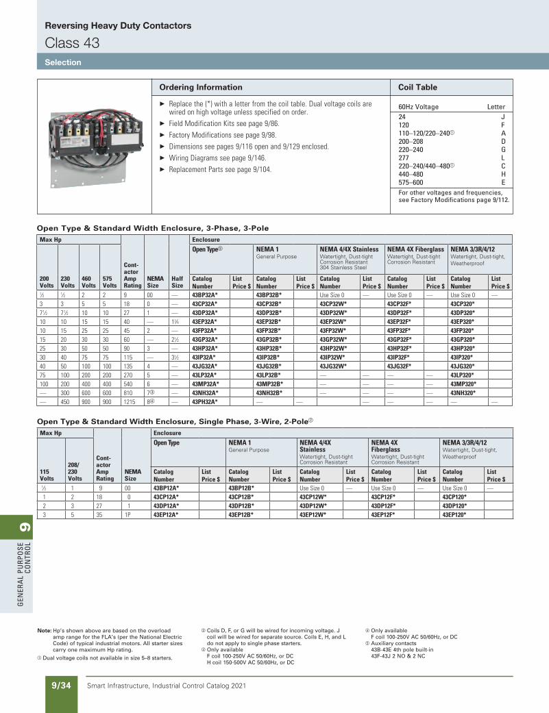
9G
ener
al
PurP
ose
Co
ntr
ol
9/34 Smart Infrastructure, Industrial Control Catalog 2021
Reversing Heavy Duty Contactors
Class 43Selection
Note: Hp’s shown above are based on the overload amp range for the FLA’s (per the National Electric Code) of typical industrial motors. All starter sizes carry one maximum Hp rating.
a Dual voltage coils not available in size 5–8 starters.
b Coils D, F, or G will be wired for incoming voltage. J coil will be wired for separate source. Coils E, H, and L do not apply to single phase starters.
c Only available F coil 100-250V AC 50/60Hz, or DC H coil 150-500V AC 50/60Hz, or DC
d Only availableF coil 100-250V AC 50/60Hz, or DC
e Auxiliary contacts43B-43E 4th pole built-in 43F-43J 2 NO & 2 NC
Ordering Information
Replacethe(*)withaletterfromthecoiltable.Dualvoltagecoilsarewiredonhighvoltageunlessspecifiedonorder.
FieldModificationKitsseepage9/86. FactoryModificationsseepage9/98. Dimensionsseepages9/116openand9/129enclosed. WiringDiagramsseepage9/146. ReplacementPartsseepage9/104.
Coil Table
60Hz Voltage letter 24 J 120 F 110–120/220–240a a 200–208 D 220–240 G 277 l 220–240/440–480a C 440–480 H 575–600 e For other voltages and frequencies,
see Factory Modifications page 9/112.
Open Type & Standard Width Enclosure, 3-Phase, 3-PoleMaxHp
Cont-actorAmpRating
NEMASize
HalfSize
Enclosure
200Volts
230Volts
460Volts
575Volts
OpenTypee NEMA1General Purpose
NEMA4/4XStainlessWatertight, Dust-tightCorrosion Resistant304 Stainless Steel
NEMA4XFiberglassWatertight, Dust-tightCorrosion Resistant
NEMA3/3R/4/12Watertight, Dust-tight, Weatherproof
CatalogNumber
ListPrice$
CatalogNumber
ListPrice$
CatalogNumber
ListPrice$
CatalogNumber
ListPrice$
CatalogNumber
ListPrice$
1⁄2 1⁄2 2 2 9 00 — 43BP32A* 43BP32B* UseSize0 — UseSize0 — UseSize0 —3 3 5 5 18 0 — 43CP32A* 43CP32B* 43CP32W* 43CP32F* 43CP320* 71⁄2 71⁄2 10 10 27 1 — 43DP32A* 43DP32B* 43DP32W* 43DP32F* 43DP320* 10 10 15 15 40 — 13⁄4 43EP32A* 43EP32B* 43EP32W* 43EP32F* 43EP320* 10 15 25 25 45 2 — 43FP32A* 43FP32B* 43FP32W* 43FP32F* 43FP320* 15 20 30 30 60 — 21⁄2 43GP32A* 43GP32B* 43GP32W* 43GP32F* 43GP320* 25 30 50 50 90 3 — 43HP32A* 43HP32B* 43HP32W* 43HP32F* 43HP320* 30 40 75 75 115 — 31⁄2 43IP32A* 43IP32B* 43IP32W* 43IP32F* 43IP320* 40 50 100 100 135 4 — 43JG32A* 43JG32B* 43JG32W* 43JG32F* 43JG320* 75 100 200 200 270 5 — 43LP32A* 43LP32B* — — — — 43LP320* 100 200 400 400 540 6 — 43MP32A* 43MP32B* — — — — 43MP320* — 300 600 600 810 7c — 43NH32A* 43NH32B* — — — — 43NH320* — 450 900 900 1215 8d — 43PH32A* — — — — — — —
Open Type & Standard Width Enclosure, Single Phase, 3-Wire, 2-Poleb
MaxHp
Cont-actorAmpRating
NEMASize
Enclosure
115Volts
208/230Volts
OpenType NEMA1General Purpose
NEMA4/4XStainlessWatertight, Dust-tightCorrosion Resistant
NEMA4XFiberglassWatertight, Dust-tightCorrosion Resistant
NEMA3/3R/4/12Watertight, Dust-tight, Weatherproof
CatalogNumber
ListPrice$
CatalogNumber
ListPrice$
CatalogNumber
ListPrice$
CatalogNumber
ListPrice$
CatalogNumber
ListPrice$
1⁄3 1 9 00 43BP12A* 43BP12B* UseSize0 — UseSize0 — UseSize0 —1 2 18 0 43CP12A* 43CP12B* 43CP12W* 43CP12F* 43CP120* 2 3 27 1 43DP12A* 43DP12B* 43DP12W* 43DP12F* 43DP120* 3 5 35 1P 43EP12A* 43EP12B* 43EP12W* 43EP12F* 43EP120*
updated in SPEEDFAXRevised on 03/31/20
SS copied this page from SF to IC on 05/24/20
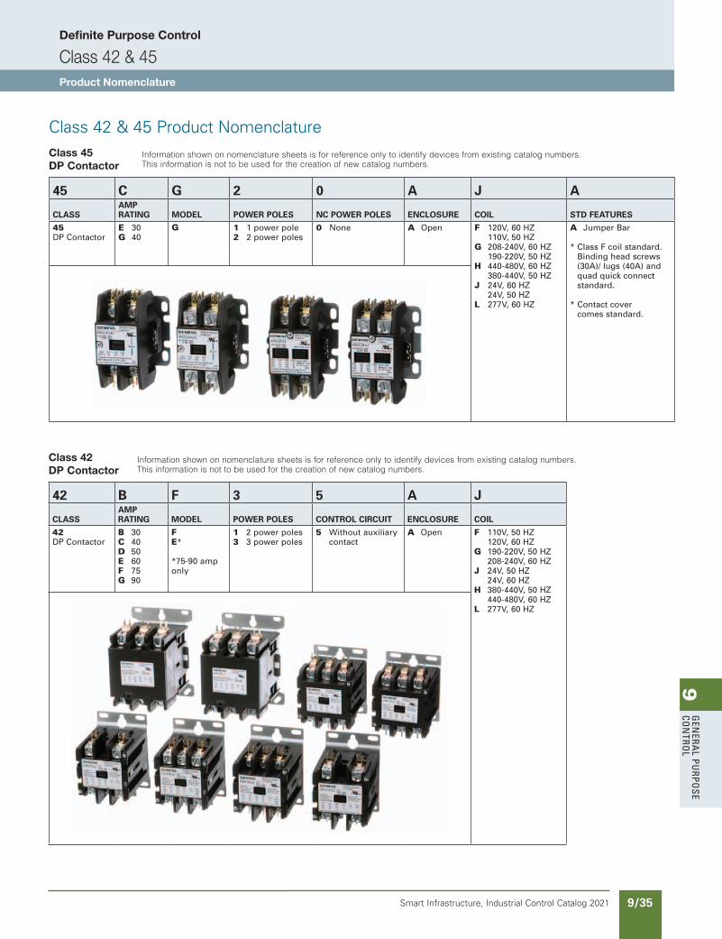
9G
enera
l PurPo
se Co
ntro
l
9/35Smart Infrastructure, Industrial Control Catalog 2021
Class 42 & 45 Product NomenclatureClass 45DP Contactor
45 C G 2 0 A J A
CLASSAMP RATING MODEL POWER POLES NC POWER POLES ENCLOSURE COIL STD FEATURES
45 DP Contactor
E 30G 40
G 1 1 power pole2 2 power poles
0 None A Open F 120V, 60 HZ 110V, 50 HZ G 208-240V, 60 HZ 190-220V, 50 HZ H 440-480V, 60 HZ 380-440V, 50 HZ J 24V, 60 HZ 24V, 50 HZ L 277V, 60 HZ
A Jumper Bar
* Class F coil standard. Binding head screws (30A)/ lugs (40A) and quad quick connect standard.
* Contact cover comes standard.
Class 42 DP Contactor
42 B F 3 5 A J
CLASSAMP RATING MODEL POWER POLES CONTROL CIRCUIT ENCLOSURE COIL
42 DP Contactor
B 30C 40D 50E 60F 75G 90
FE* *75-90 amp only
1 2 power poles3 3 power poles
5 Without auxiliary contact
A Open F 110V, 50 HZ 120V, 60 HZ G 190-220V, 50 HZ 208-240V, 60 HZ J 24V, 50 HZ 24V, 60 HZ H 380-440V, 50 HZ 440-480V, 60 HZ L 277V, 60 HZ
Information shown on nomenclature sheets is for reference only to identify devices from existing catalog numbers. This information is not to be used for the creation of new catalog numbers.
Information shown on nomenclature sheets is for reference only to identify devices from existing catalog numbers. This information is not to be used for the creation of new catalog numbers.
Definite Purpose Control
Class 42 & 45Product Nomenclature
Old Definite Purpose Section added back Revised on 10/31/19
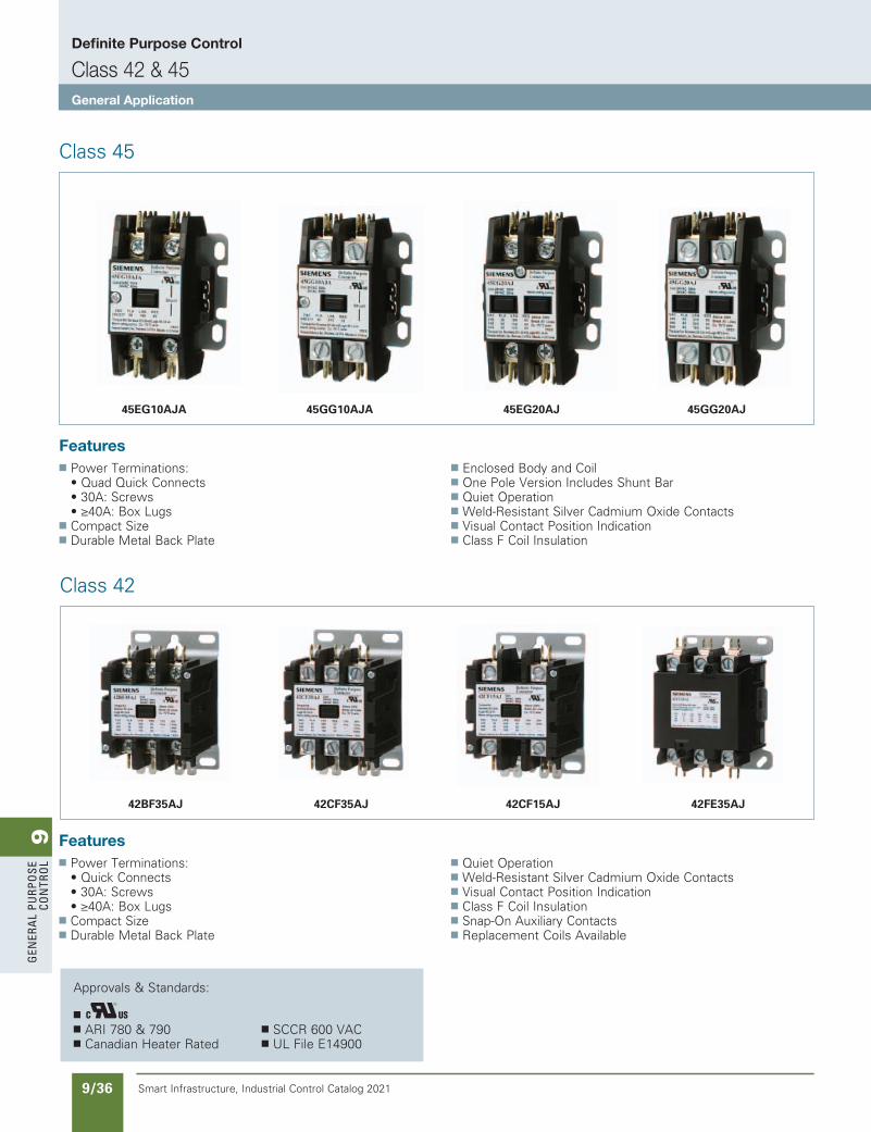
9G
ener
al
PurP
ose
Co
ntr
ol
9/36 Smart Infrastructure, Industrial Control Catalog 2021
Class 45
n Power Terminations: • Quad Quick Connects • 30A: Screws • ≥40A: Box Lugsn Compact Sizen Durable Metal Back Plate
n Enclosed Body and Coiln One Pole Version Includes Shunt Bar n Quiet Operationn Weld-Resistant Silver Cadmium Oxide Contactsn Visual Contact Position Indicationn Class F Coil Insulation
Features
Definite Purpose Control
Class 42 & 45General Application
45GG10AJA45EG10AJA 45EG20AJ 45GG20AJ
Class 42
n Power Terminations: • Quick Connects • 30A: Screws • ≥40A: Box Lugsn Compact Sizen Durable Metal Back Plate
n Quiet Operationn Weld-Resistant Silver Cadmium Oxide Contactsn Visual Contact Position Indicationn Class F Coil Insulationn Snap-On Auxiliary Contactsn Replacement Coils Available
Features
42CF35AJ42BF35AJ 42CF15AJ 42FE35AJ
Approvals & Standards:
n n ARI 780 & 790 n SCCR 600 VACn Canadian Heater Rated n UL File E14900
Old Definite Purpose Section added back Revised on 10/31/19
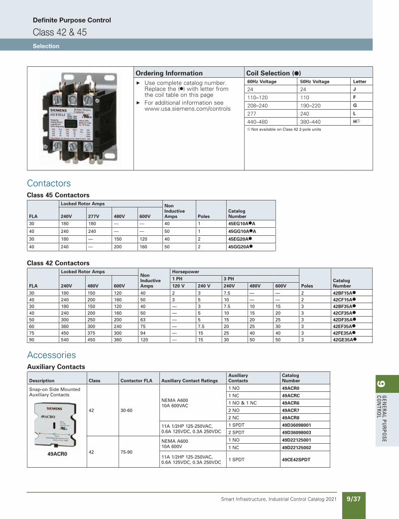
9G
enera
l PurPo
se Co
ntro
l
9/37Smart Infrastructure, Industrial Control Catalog 2021
Definite Purpose Control
Class 42 & 45Selection
Ordering Information Coil Selection (●) Use complete catalog number.
Replace the (●) with letter from the coil table on this page
For additional information see www.usa.siemens.com/controls
60Hz Voltage 50Hz Voltage Letter
24 24 J
110–120 110 F
208–240 190–220 G
277 240 L
440–480 380–440 Ha
a Not available on Class 42 2-pole units
ContactorsClass 45 Contactors
FLA
Locked Rotor Amps Non Inductive Amps Poles
Catalog Number240V 277V 480V 600V
30 180 180 — — 40 1 45EG10A●A
40 240 240 — — 50 1 45GG10A●A
30 180 — 150 120 40 2 45EG20A●
40 240 — 200 160 50 2 45GG20A●
Class 42 Contactors
FLA
Locked Rotor AmpsNon Inductive Amps
Horsepower
PolesCatalog Number240V 480V 600V
1 PH 3 PH
120 V 240 V 240V 480V 600V
30 180 150 120 40 2 3 7.5 — — 2 42BF15A●
40 240 200 160 50 3 5 10 — — 2 42CF15A●
30 180 150 120 40 — 3 7.5 10 15 3 42BF35A●
40 240 200 160 50 — 5 10 15 20 3 42CF35A●
50 300 250 200 63 — 5 15 20 25 3 42DF35A●
60 360 300 240 75 — 7.5 20 25 30 3 42EF35A●
75 450 375 300 94 — 15 25 40 40 3 42FE35A●
90 540 450 360 120 — 15 30 50 50 3 42GE35A●
AccessoriesAuxiliary Contacts
Description Class Contactor FLA Auxiliary Contact RatingsAuxiliary Contacts
Catalog Number
Snap-on Side Mounted Auxiliary Contacts
49ACR0
42 30-60
NEMA A60010A 600VAC
1 NO 49ACR0
1 NC 49ACRC
1 NO & 1 NC 49ACR6
2 NO 49ACR7
2 NC 49ACR8
11A 1/2HP 125-250VAC, 0.6A 125VDC, 0.3A 250VDC
1 SPDT 49D36098001
2 SPDT 49D36098003
42 75-90
NEMA A60010A 600V
1 NO 49D22125001
1 NC 49D22125002
11A 1/2HP 125-250VAC,0.6A 125VDC, 0.3A 250VDC 1 SPDT 49CE42SPDT
Old Definite Purpose Section added back Revised on 10/31/19
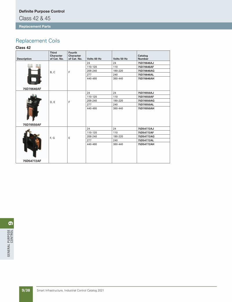
9G
ener
al
PurP
ose
Co
ntr
ol
9/38 Smart Infrastructure, Industrial Control Catalog 2021
Replacement CoilsClass 42
Description
Third Character of Cat. No.
Fourth Character of Cat. No. Volts 60 Hz Volts 50 Hz
Catalog Number
75D70646AF
B, C F
24 24 75D70646AJ110-120 110 75D70646AF208-240 190-220 75D70646AG277 240 75D70646AL440-480 380-440 75D70646AH
75D70550AF
D, E F
24 24 75D70550AJ110-120 110 75D70550AF208-240 190-220 75D70550AG277 240 75D70550AL440-480 380-440 75D70550AH
75D54772AF
F, G E
24 24 75D54772AJ110-120 110 75D54772AF208-240 190-220 75D54772AG277 240 75D54772AL440-480 380-440 75D54772AH
Definite Purpose Control
Class 42 & 45Replacement Parts
Old Definite Purpose Section added back Revised on 10/31/19
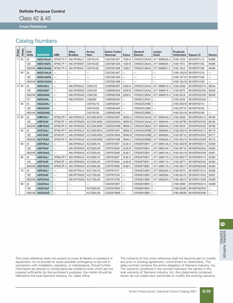
9G
enera
l PurPo
se Co
ntro
l
9/39Smart Infrastructure, Industrial Control Catalog 2021
Definite Purpose Control
Class 42 & 45Cross Reference
This cross reference does not purport to cover all details or variations in equipment, nor to provide for every possible contingency to be met in connection with installation, operation, or maintenance. Should further information be desired or should particular problems arise which are not covered sufficiently for the purchaser’s purposes, the matter should be referred to the local Siemens Industry, Inc. sales office.
The contents of this cross reference shall not become part or modify any prior or existing agreement, commitment or relationship. The sales contract contains the entire obligation of Siemens Industry, Inc. The warranty contained in the contract between the parties is the sole warranty of Siemens Industry, Inc. Any statements contained herein do not create new warranties or modify the existing warranty.
Catalog Numbers
Po
les
Am
ps
Coil Volts SIEMENS ABB
Allen Bradley
Arrow Hart
Eaton Cutler Hammer Fasco
General Electric
Joslyn Clark
Products Unlimited Square D Steveco
1 30 24 45EG10AJA DP30C1P-F 400-DP30NJ1 C301NU10 C25CNB130T 1S30-A CR453CC3HAA A77-306653A-3 3100-15Q2 8910DP31V14 94388
120 45EG10AFA DP30C1P-1 400-DP30ND1 C301NU20 C25CNB130A 1S30-B CR453CC3AAA A77-306653A-1 3100-15T2 8910DP31V02 94389
208/240 45EG10AGA DP30C1P-2 400-DP30NA1 C301NU30 C25CNB130B 1S30-C CR453CC3BAA A77-3066531-2 3100-15U2 8910DP31V09 94390
40 24 45GG10AJA — — — C25CNB140T — — — 3100-15Q19 8910DP41V14 —
120 45GG10AFA — — — C25CNB140A — — — 3100-15T19 8910DP41V02 —
208/240 45GG10AGA — — — C25CNB140B — — — 3100-15U19 8910DP41V09 —
2 30 24 45EG20AJ — 400-DP30NJ2 C302U10 C25BNB230T 2S30-A CR453CC2HAA A77-306657A-3 3100-20Q6 8910DPA32V14 90244
120 45EG20AF — 400-DP30ND2 C302U20 C25BNB230A 2S30-B CR453CC2AAA A77-306657A-1 3100-20T6 8910DPA32V02 90245
208/240 45EG20AG — 400-DP30NA2 C302U30 C25BNB230B 2S30-C CR453CC2BAA A77-306657A-2 3100-20U6 8910DPA32V09 90246
277 45EG20AL — 400-DP30NF2 C302050 C25BNB230H — CR453CC2FAA — 3100-20V6 8910DPA32V04 —
40 24 45GG20AJ — — CA01NU10 C25BNB240T — CR453CE2HBB — 3100-20Q18 8910DP42V14 —
120 45GG20AF — — CA01NU20 C25BNB240A — CR453CE2ABB — 3100-20T18 8910DP42V02 —
208/240 45GG20AG — — CA01NU30 C25BNB240B — CR453CE2BBB — 3100-20U18 8910DP42V09 —
3 30 24 42BF35AJ DP30C3P-F 400-DP30NJ3 ACC330UM10 C25DND330T 3M30-A CR453AC3HAA A77-309044A-3 3100-30Q9 8910DPA33V14 90163
120 42BF35AF DP30C3P-1 400-DP30ND3 ACC330UM20 C25DND330A 3M30-B CR453AC3AAA A77-309044A-1 3100-30T99 8910DPA33V02 90164
208/240 42BF35AG DP30C3P-2 400-DP30NA3 ACC330UM30 C25DND330B 3M30-C CR453AC3BAA A77-309044A-2 3100-30U9 8910DPA33V03 90165
40 24 42CF35AJ DP40C4P-F 400-DP40NJ3 ACC430UM10 C25DNF340T 3M40-A CR453AD3HBB A77-309046A-3 3100-30Q10 8910DPA43V14 90170
120 42CF35AF DP40C4P-1 400-DP40ND3 ACC430UM20 C25DNF340A 3M40-B CR453AD3ABB A77-309046A-1 3100-30T10 8910DPA43V02 90171
208/240 42CF35AG DP40C4P-2 400-DP40NA3 ACC430UM30 C25DNF340B 3M40-C CR453AD3BBB A77-309046A-2 3100-30U10 8910DPA43V09 90172
50 24 42DF35AJ — 400-DP50NJ3 ACC530U10 C25FNF350T 3L50-A CR353FE3BH1 A77-288514A-3 3100-30Q16 8910DPA53V14 92459
120 42DF35AF — 400-DP50ND3 ACC530U20 C25FNF350A 3L50-B CR353FE3BA1 A77-288514A-1 3100-30T16 8910DPA53V02 92460
208/240 42DF35AG — 400-DP50NA3 ACC530U30 C25FNF350B 3L50-C CR353FE3BB1 A77-288514A-2 3100-30U16 8910DPA53V09 92461
60 24 42EF35AJ DP60C3P-F 400-DP60NJ3 ACC630U10 C25FNF360T 3L60-A CR353FF3BH1 A77-288517A-3 3100-30Q17 8910DPA63V14 92462
120 42EF35AF DP60C3P-1 400-DP60ND3 ACC630U20 C25FNF360A 3L60-B CR353FF3BA1 A77-288517A-1 3100-30T17 8910DPA63V02 92463
208/240 42EF35AG DP60C3P-2 400-DP60NA3 ACC630U30 C25FNF360B 3L60-C CR353FF3BB1 A77-288517A-2 3100-30U17 8910DPA63V09 92464
75 24 42FE35AJ — 400-DP75NJ3 ACC730U10 C25FNF375T — CR353EG3BH1 A77-288520A-3 3186-30I75 8910DPA73V14 92465
120 42FE35AF — 400-DP75ND3 ACC730U20 C25FNF375A — CR353EG3BA1 A77-288520A-1 3186-30J75 8910DPA73V02 92467
208/240 42FE35AG — 400-DP75NA3 ACC730U30 C25FNF375B — CR353EG3BB1 A77-288520A-2 3186-30K75 8910DPA73V09 92468
90 24 42GE35AJ — — — C25GNF390T — CR353EH3BH1 — 3186-30I90 8910DPA93V14 92469
120 42GE35AF — — ACC930U20 C25GNF390A — CR353EH3BA1 — 3186-30J90 8910DPA93V02 —
208/240 42GE35AG — — ACC930U30 C25GNF390B — CR353EH3BB1 — 3186-30K90 8910DPA93V09 —
Old Definite Purpose Section added back Revised on 10/31/19
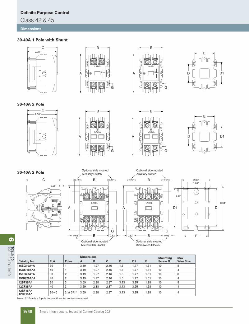
9G
ener
al
PurP
ose
Co
ntr
ol
9/40 Smart Infrastructure, Industrial Control Catalog 2021
30-40A 1 Pole with Shunt
30-40A 2 Pole
30-40A 2 Pole
Definite Purpose Control
Class 42 & 45Dimensions
Catalog No. FLA Poles
Dimensions Mounting Screw G
Max Wire SizeA B C D D1 E
45EG10A*A 30 1 3.19 1.97 2.46 1.5 1.77 1.61 10 845GG10A*A 40 1 3.19 1.97 2.46 1.5 1.77 1.61 10 445EG20A*A 30 2 3.19 1.97 2.46 1.5 1.77 1.61 10 845GG20A*A 40 2 3.19 1.97 2.46 1.5 1.77 1.61 10 442BF35A* 30 3 3.69 2.38 2.87 3.13 3.25 1.98 10 842CF35A* 40 3 3.69 2.38 2.87 3.13 3.25 1.98 10 442BF15A*42CF15A* 30-40 2(at 3P)* 3.69 2.38 2.87 3.13 3.25 1.98 10 4
Note - 2* Pole is a 3 pole body with center contacts removed.
B0.08"
A
0.42" 0.42"
0.62" B B
A
B
D1
0.30"
0.62"
0.42" 0.42"
0.62"0.62" E
D3.64"
2.38"
0.06"
C
0.42" 0.42"B
B0.62" 0.62"
A
G
G G
G G
GG
A A
AA
B B
B B
E
E
D D1
D1D
C
C
D13.19"
3.64"0.30"
0.31"
1.50"
2.87"2.24"
E
A
3.96"
4.53"B
C E
D1 D
3.50"
2.87"
2.48"
Optional side moutedAuxiliary Switch
Optional side moutedMicroswitch Blocks
C
G
D
2.38"
2.38"
Optional side moutedMicroswitch Blocks
Optional side moutedAuxiliary Switch
Optional side moutedAuxiliary Switch
Optional side moutedMicroswitch Blocks
Optional side moutedMicroswitch Blocks
Optional side moutedAuxiliary Switch
1.50"
5.00"
LABEL
Shunt Shunt
LABEL
LABEL LABEL
LABEL LABEL
LABEL
LABEL
Old Definite Purpose Section added back Revised on 10/31/19
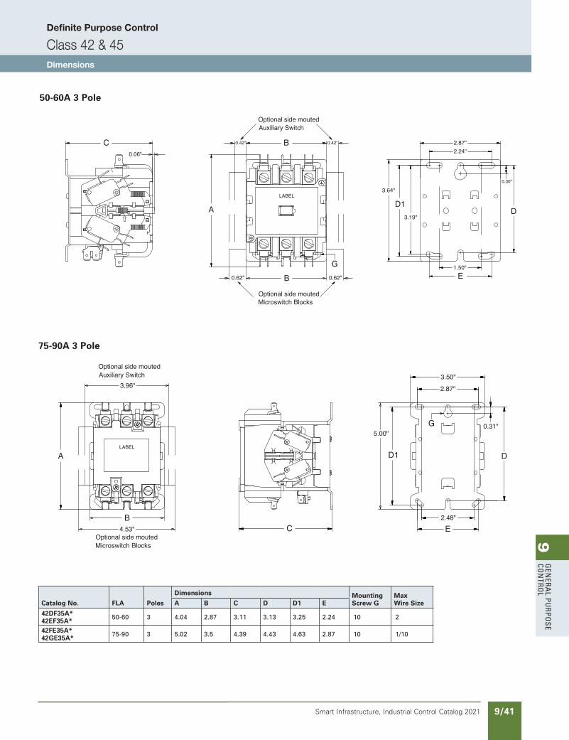
9G
enera
l PurPo
se Co
ntro
l
9/41Smart Infrastructure, Industrial Control Catalog 2021
B0.08"
A
0.42" 0.42"
0.62" B B
A
B
D1
0.30"
0.62"
0.42" 0.42"
0.62"0.62" E
D3.64"
2.38"
0.06"
C
0.42" 0.42"B
B0.62" 0.62"
A
G
G G
G G
GG
A A
AA
B B
B B
E
E
D D1
D1D
C
C
D13.19"
3.64"0.30"
0.31"
1.50"
2.87"2.24"
E
A
3.96"
4.53"B
C E
D1 D
3.50"
2.87"
2.48"
Optional side moutedAuxiliary Switch
Optional side moutedMicroswitch Blocks
C
G
D
2.38"
2.38"
Optional side moutedMicroswitch Blocks
Optional side moutedAuxiliary Switch
Optional side moutedAuxiliary Switch
Optional side moutedMicroswitch Blocks
Optional side moutedMicroswitch Blocks
Optional side moutedAuxiliary Switch
1.50"
5.00"
LABEL
Shunt Shunt
LABEL
LABEL LABEL
LABEL LABEL
LABEL
LABEL
Catalog No. FLA Poles
Dimensions Mounting Screw G
Max Wire SizeA B C D D1 E
42DF35A*42EF35A* 50-60 3 4.04 2.87 3.11 3.13 3.25 2.24 10 2
42FE35A*42GE35A* 75-90 3 5.02 3.5 4.39 4.43 4.63 2.87 10 1/10
50-60A 3 Pole
75-90A 3 Pole
Definite Purpose Control
Class 42 & 45Dimensions
B0.08"
A
0.42" 0.42"
0.62" B B
A
B
D1
0.30"
0.62"
0.42" 0.42"
0.62"0.62" E
D3.64"
2.38"
0.06"
C
0.42" 0.42"B
B0.62" 0.62"
A
G
G G
G G
GG
A A
AA
B B
B B
E
E
D D1
D1D
C
C
D13.19"
3.64"0.30"
0.31"
1.50"
2.87"2.24"
E
A
3.96"
4.53"B
C E
D1 D
3.50"
2.87"
2.48"
Optional side moutedAuxiliary Switch
Optional side moutedMicroswitch Blocks
C
G
D
2.38"
2.38"
Optional side moutedMicroswitch Blocks
Optional side moutedAuxiliary Switch
Optional side moutedAuxiliary Switch
Optional side moutedMicroswitch Blocks
Optional side moutedMicroswitch Blocks
Optional side moutedAuxiliary Switch
1.50"
5.00"
LABEL
Shunt Shunt
LABEL
LABEL LABEL
LABEL LABEL
LABEL
LABEL
Old Definite Purpose Section added back Revised on 10/31/19
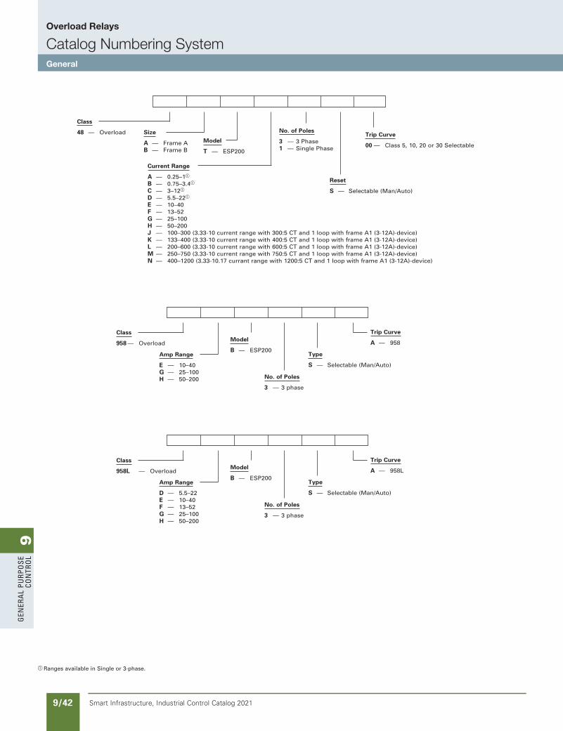
9G
ener
al
PurP
ose
Co
ntr
ol
9/42 Smart Infrastructure, Industrial Control Catalog 2021
Overload Relays
Catalog Numbering SystemGeneral
Class
48 — Overload Size
A — Frame AB — Frame B
Model
T — ESP200
No. of Poles
3 — 3 Phase1 — Single Phase
Reset
S — Selectable (Man/Auto)
Trip Curve
00 — Class 5, 10, 20 or 30 Selectable
Current Range
A — 0.25–1a B — 0.75–3.4a C — 3–12a
D — 5.5–22a
E — 10–40F — 13–52G — 25–100H — 50–200J — 100–300 (3.33-10 current range with 300:5 CT and 1 loop with frame A1 (3-12A)-device)K — 133–400 (3.33-10 current range with 400:5 CT and 1 loop with frame A1 (3-12A)-device)L — 200–600 (3.33-10 current range with 600:5 CT and 1 loop with frame A1 (3-12A)-device)M — 250–750 (3.33-10 current range with 750:5 CT and 1 loop with frame A1 (3-12A)-device)N — 400–1200 (3.33-10.17 currant range with 1200:5 CT and 1 loop with frame A1 (3-12A)-device)
Class
958 — Overload
Amp Range
E — 10–40G — 25–100H — 50–200
Model
B — ESP200
No. of Poles
3 — 3 phase
Type
S — Selectable (Man/Auto)
Trip Curve
A — 958
Class
958L — Overload
Amp Range
D — 5.5–22E — 10–40F — 13–52G — 25–100H — 50–200
Model
B — ESP200
No. of Poles
3 — 3 phase
Type
S — Selectable (Man/Auto)
Trip Curve
A — 958L
a Ranges available in Single or 3-phase.
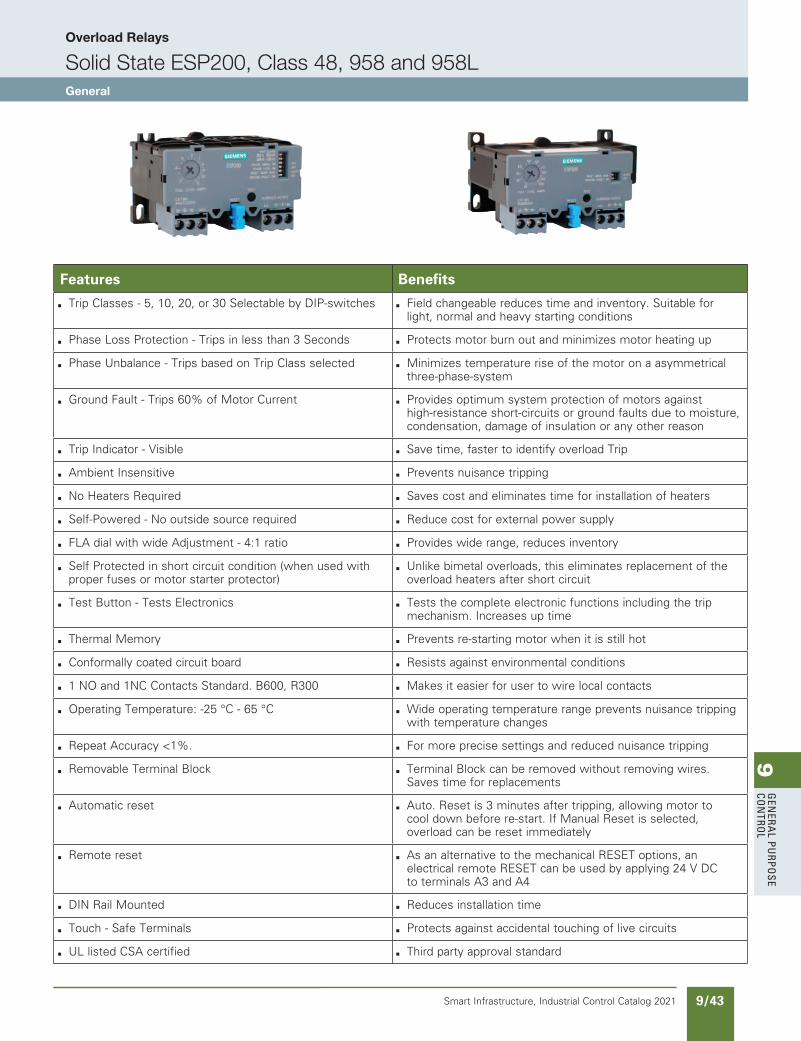
9G
enera
l PurPo
se Co
ntro
l
9/43Smart Infrastructure, Industrial Control Catalog 2021
Overload Relays
Solid State ESP200, Class 48, 958 and 958LGeneral
Features Benefits
b Trip Classes - 5, 10, 20, or 30 Selectable by DIP-switches b Field changeable reduces time and inventory. Suitable for light, normal and heavy starting conditions
b Phase Loss Protection - Trips in less than 3 Seconds b Protects motor burn out and minimizes motor heating up
b Phase Unbalance - Trips based on Trip Class selected b Minimizes temperature rise of the motor on a asymmetrical three-phase-system
b Ground Fault - Trips 60% of Motor Current b Provides optimum system protection of motors against high-resistance short-circuits or ground faults due to moisture, condensation, damage of insulation or any other reason
b Trip Indicator - Visible b Save time, faster to identify overload Trip
b Ambient Insensitive b Prevents nuisance tripping
b No Heaters Required b Saves cost and eliminates time for installation of heaters
b Self-Powered - No outside source required b Reduce cost for external power supply
b FLA dial with wide Adjustment - 4:1 ratio b Provides wide range, reduces inventory
b Self Protected in short circuit condition (when used with proper fuses or motor starter protector)
b Unlike bimetal overloads, this eliminates replacement of the overload heaters after short circuit
b Test Button - Tests Electronics b Tests the complete electronic functions including the trip mechanism. Increases up time
b Thermal Memory b Prevents re-starting motor when it is still hot
b Conformally coated circuit board b Resists against environmental conditions
b 1 NO and 1NC Contacts Standard. B600, R300 b Makes it easier for user to wire local contacts
b Operating Temperature: -25 °C - 65 °C b Wide operating temperature range prevents nuisance tripping with temperature changes
b Repeat Accuracy <1%. b For more precise settings and reduced nuisance tripping
b Removable Terminal Block b Terminal Block can be removed without removing wires. Saves time for replacements
b Automatic reset b Auto. Reset is 3 minutes after tripping, allowing motor to cool down before re-start. If Manual Reset is selected, overload can be reset immediately
b Remote reset b As an alternative to the mechanical RESET options, an electrical remote RESET can be used by applying 24 V DC to terminals A3 and A4
b DIN Rail Mounted b Reduces installation time
b Touch - Safe Terminals b Protects against accidental touching of live circuits
b UL listed CSA certified b Third party approval standard
SS copied this page from SF to IC on 05/24/20
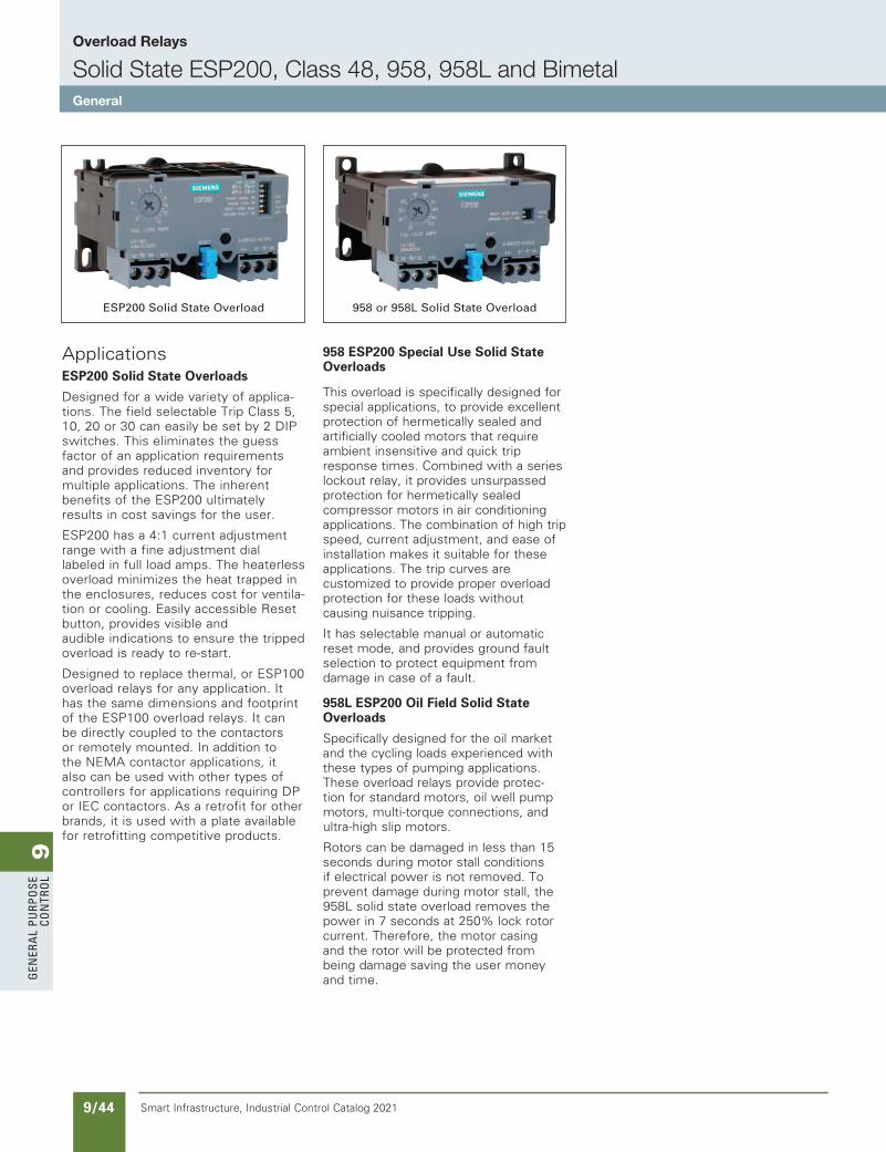
9G
ener
al
PurP
ose
Co
ntr
ol
9/44 Smart Infrastructure, Industrial Control Catalog 2021
Overload Relays
Solid State ESP200, Class 48, 958, 958L and BimetalGeneral
ApplicationsESP200 Solid State Overloads
Designed for a wide variety of applica-tions. The field selectable Trip Class 5, 10, 20 or 30 can easily be set by 2 DIP switches. This eliminates the guess factor of an application requirements and provides reduced inventory for multiple applications. The inherent benefits of the ESP200 ultimately results in cost savings for the user.
ESP200 has a 4:1 current adjustment range with a fine adjustment dial labeled in full load amps. The heaterless overload minimizes the heat trapped in the enclosures, reduces cost for ventila-tion or cooling. Easily accessible Reset button, provides visible and audible indications to ensure the tripped overload is ready to re-start.
Designed to replace thermal, or ESP100 overload relays for any application. It has the same dimensions and footprint of the ESP100 overload relays. It can be directly coupled to the contactors or remotely mounted. In addition to the NEMA contactor applications, it also can be used with other types of controllers for applications requiring DP or IEC contactors. As a retrofit for other brands, it is used with a plate available for retrofitting competitive products.
958 ESP200 Special Use Solid State Overloads
This overload is specifically designed for special applications, to provide excellent protection of hermetically sealed and artificially cooled motors that require ambient insensitive and quick trip response times. Combined with a series lockout relay, it provides unsurpassed protection for hermetically sealed compressor motors in air conditioning applications. The combination of high trip speed, current adjustment, and ease of installation makes it suitable for these applications. The trip curves are customized to provide proper overload protection for these loads without causing nuisance tripping.
It has selectable manual or automatic reset mode, and provides ground fault selection to protect equipment from damage in case of a fault.
958L ESP200 Oil Field Solid State Overloads
Specifically designed for the oil market and the cycling loads experienced with these types of pumping applications. These overload relays provide protec-tion for standard motors, oil well pump motors, multi-torque connections, and ultra-high slip motors.
Rotors can be damaged in less than 15 seconds during motor stall conditions if electrical power is not removed. To prevent damage during motor stall, the 958L solid state overload removes the power in 7 seconds at 250% lock rotor current. Therefore, the motor casing and the rotor will be protected from being damage saving the user money and time.
ESP200 Solid State Overload 958 or 958L Solid State Overload
updated in SPEEDFAXRevised on 03/31/20
SS copied this page from SF to IC on 05/24/20
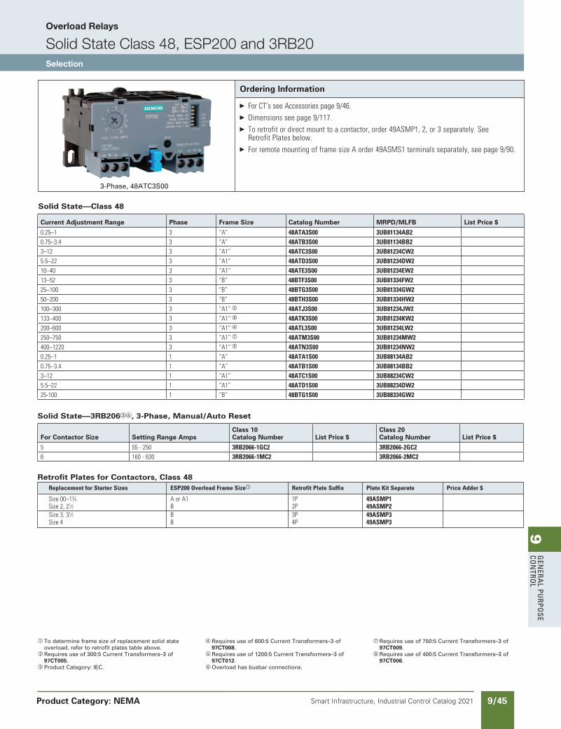
9G
enera
l PurPo
se Co
ntro
l
9/45Smart Infrastructure, Industrial Control Catalog 2021
Overload Relays
Solid State Class 48, ESP200 and 3RB20Selection
Product Category: NEMA
a To determine frame size of replacement solid state overload, refer to retrofit plates table above.
b Requires use of 300:5 Current Transformers–3 of 97CT005.
c Product Category: IEC.
d Requires use of 600:5 Current Transformers–3 of 97CT008.
e Requires use of 1200:5 Current Transformers–3 of 97CT012.
Overload has busbar connections.
g Requires use of 750:5 Current Transformers–3 of 97CT009.
h Requires use of 400:5 Current Transformers–3 of 97CT006.
Ordering Information
ForCT’sseeAccessoriespage9/46. Dimensionsseepage9/117. Toretrofitordirectmounttoacontactor,order49ASMP1,2,or3separately.See
RetrofitPlatesbelow. ForremotemountingofframesizeAorder49ASMS1terminalsseparately,seepage9/90.
3-Phase, 48ATC3S00
Solid State—Class 48
Solid State—3RB206c, 3-Phase, Manual/Auto Reset
ReplacementforStarterSizes ESP200OverloadFrameSizea RetrofitPlateSuffix PlateKitSeparate PriceAdder$
Size00–13⁄4 AorA1 1P 49ASMP1 Size2,21⁄2 B 2P 49ASMP2 Size3,31⁄2 B 3P 49ASMP3 Size4 B 4P 49ASMP3
Retrofit Plates for Contactors, Class 48
Current Adjustment Range Phase Frame Size Catalog Number MRPD/MLFB List Price $
0.25–1 3 “A” 48ATA3S00 3UB81134AB2 0.75–3.4 3 “A” 48ATB3S00 3UB81134BB2 3–12 3 “A1” 48ATC3S00 3UB81234CW2 5.5–22 3 “A1” 48ATD3S00 3UB81234DW2 10–40 3 “A1” 48ATE3S00 3UB81234EW2 13–52 3 “B” 48BTF3S00 3UB81334FW2 25–100 3 “B” 48BTG3S00 3UB81334GW2 50–200 3 “B” 48BTH3S00 3UB81334HW2 100–300 3 “A1”b 48ATJ3S00 3UB81234JW2 133–400 3 “A1”h 48ATK3S00 3UB81234KW2 200–600 3 “A1”d 48ATL3S00 3UB81234LW2 250–750 3 “A1”g 48ATM3S00 3UB81234MW2 400–1220 3 “A1”e 48ATN3S00 3UB81234NW2 0.25–1 1 “A” 48ATA1S00 3UB88134AB2 0.75–3.4 1 “A” 48ATB1S00 3UB88134BB2 3–12 1 “A1” 48ATC1S00 3UB88234CW2 5.5–22 1 “A1” 48ATD1S00 3UB88234DW2 25-100 1 “B” 48BTG1S00 3UB88334GW2
For Contactor Size Setting Range AmpsClass 10 Catalog Number List Price $
Class 20 Catalog Number List Price $
5 55-250 3RB2066-1GC2 3RB2066-2GC26 160-630 3RB2066-1MC2 3RB2066-2MC2
updated in SPEEDFAXRevised on 03/31/20
SS copied this page from SF to IC on 05/24/20
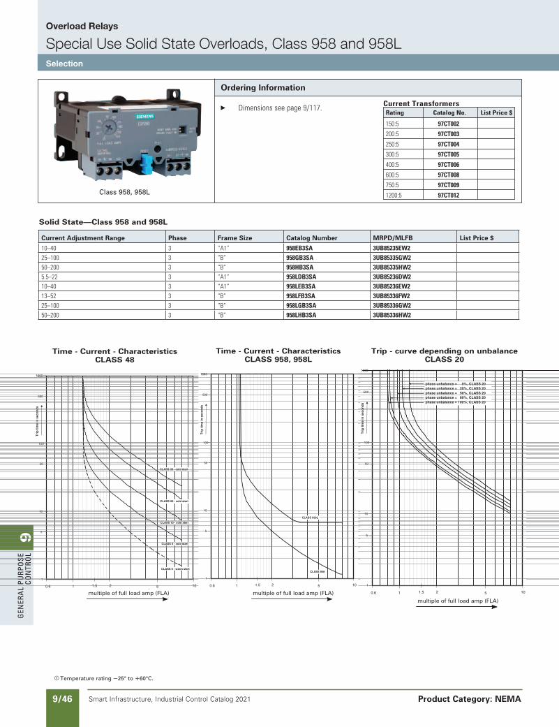
9G
ener
al
PurP
ose
Co
ntr
ol
9/46 Smart Infrastructure, Industrial Control Catalog 2021
Overload Relays
Special Use Solid State Overloads, Class 958 and 958LSelection
Product Category: NEMA
a Temperature rating S25° to R60°C.
Ordering Information
Dimensionsseepage9/117. CurrentTransformers
Time - Current - CharacteristicsCLASS 48
1 2 0.6 10 5 1.5
1
5
10
50
500
1000
multiple of full load amp (FLA)
Tri
p t
ime
in s
eco
nd
s
100
CLASS 5 - cold start
CLASS 5 - warm start
CLASS 10 - cold start
CLASS 20 - cold start
CLASS 30 - cold start
Trip - curve depending on unbalance - CLASS 20
1 2 0.6 10 5 1.5
1
5
10
50
500
1000
multiple of full load amp (FLA)
Tri
p t
ime
in s
eco
nd
s
100
phase unbalance = 0%, CLASS 20phase unbalance = 20%, CLASS 20phase unbalance = 50%, CLASS 20phase unbalance = 80%, CLASS 20phase unbalance = 100%, CLASS 20
Time - Current - CharacteristicsCLASS 958, 958L
1 2 0.6 10 5 1.5
1
5
10
50
500
1000
multiple of full load amp (FLA)
Tri
p t
ime
in s
eco
nd
s
100
CLASS 958L
CLASS 958
Solid State—Class 958 and 958L
Class 958, 958L
Time - Current - Characteristics CLASS 958, 958L
Trip - curve depending on unbalance CLASS 20
Time - Current - Characteristics CLASS 48
multiple of full load amp (FLA) multiple of full load amp (FLA)multiple of full load amp (FLA)
Rating CatalogNo. ListPrice$
150:5 97CT002
200:5 97CT003
250:5 97CT004
300:5 97CT005
400:5 97CT006
600:5 97CT008
750:5 97CT009
1200:5 97CT012
Current Adjustment Range Phase Frame Size Catalog Number MRPD/MLFB List Price $
10–40 3 “A1” 958EB3SA 3UB85235EW2 25–100 3 “B” 958GB3SA 3UB85335GW2 50–200 3 “B” 958HB3SA 3UB85335HW2 5.5–22 3 “A1” 958LDB3SA 3UB85236DW2 10–40 3 “A1” 958LEB3SA 3UB85236EW2 13–52 3 “B” 958LFB3SA 3UB85336FW2 25–100 3 “B” 958LGB3SA 3UB85336GW2 50–200 3 “B” 958LHB3SA 3UB85336HW2
SS copied this page from SF to IC on 05/24/20
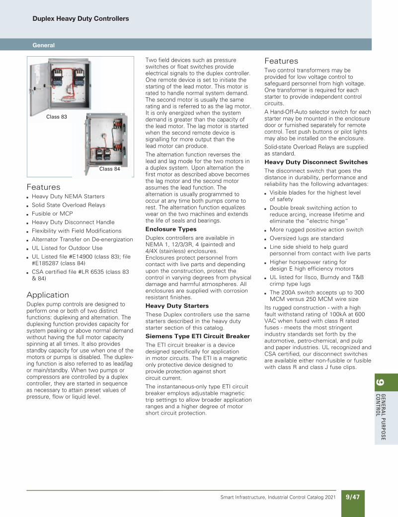
9G
enera
l PurPo
se Co
ntro
l
9/47Smart Infrastructure, Industrial Control Catalog 2021
Duplex Heavy Duty Controllers
General
Featuresb Heavy Duty NEMA Starters
b Solid State Overload Relays
b Fusible or MCP
b Heavy Duty Disconnect Handle
b Flexibility with Field Modifications
b Alternator Transfer on De-energization
b UL Listed for Outdoor Use
b UL Listed file #E14900 (class 83); file #E185287 (class 84)
b CSA certified file #LR 6535 (class 83 & 84)
ApplicationDuplex pump controls are designed to perform one or both of two distinct functions: duplexing and alternation. The duplexing function provides capacity for system peaking or above normal demand without having the full motor capacity spinning at all times. It also provides standby capacity for use when one of the motors or pumps is disabled. The duplex-ing function is also referred to as lead/lag or main/standby. When two pumps or compressors are controlled by a duplex controller, they are started in sequence as necessary to attain preset values of pressure, flow or liquid level.
Two field devices such as pressure switches or float switches provide electrical signals to the duplex controller. One remote device is set to initiate the starting of the lead motor. This motor is rated to handle normal system demand. The second motor is usually the same rating and is referred to as the lag motor. It is only energized when the system demand is greater than the capacity of the lead motor. The lag motor is started when the second remote device is signalling for more output than the lead motor can produce.
The alternation function reverses the lead and lag mode for the two motors in a duplex system. Upon alternation the first motor as described above becomes the lag motor and the second motor assumes the lead function. The alternation is usually programmed to occur at any time both pumps come to rest. The alternation function equalizes wear on the two machines and extends the life of seals and bearings.
Enclosure TypesDuplex controllers are available in NEMA 1, 12/3/3R, 4 (painted) and 4/4X (stainless) enclosures. Enclosures protect personnel from contact with live parts and depending upon the construction, protect the control in varying degrees from physical damage and harmful atmospheres. All enclosures are supplied with corrosion resistant finishes.
Heavy Duty StartersThese Duplex controllers use the same starters described in the heavy duty starter section of this catalog.
Siemens Type ETI Circuit BreakerThe ETI circuit breaker is a device designed specifically for application in motor circuits. The ETI is a magnetic only protective device designed to provide protection against short circuit current.
The instantaneous-only type ETI circuit breaker employs adjustable magnetic trip settings to allow broader application ranges and a higher degree of motor short circuit protection.
FeaturesTwo control transformers may be provided for low voltage control to safeguard personnel from high voltage. One transformer is required for each starter to provide independent control circuits.
A Hand-Off-Auto selector switch for each starter may be mounted in the enclosure door or furnished separately for remote control. Test push buttons or pilot lights may also be installed on the enclosure.
Solid-state Overload Relays are supplied as standard.
Heavy Duty Disconnect SwitchesThe disconnect switch that goes the distance in durability, performance and reliability has the following advantages:
b Visible blades for the highest level of safety
b Double break switching action to reduce arcing, increase lifetime and eliminate the “electric hinge”
b More rugged positive action switch
b Oversized lugs are standard
b Line side shield to help guard personnel from contact with live parts
b Higher horsepower rating for design E high efficiency motors
b UL listed for IIsco, Burndy and T&B crimp type lugs
b The 200A switch accepts up to 300 MCM versus 250 MCM wire size
Its rugged construction - with a high fault withstand rating of 100kA at 600 VAC when fused with class R rated fuses - meets the most stringent industry standards set forth by the automotive, petro-chemical, and pulp and paper industries. UL recognized and CSA certified, our disconnect switches are available either non-fusible or fusible with class R and class J fuse clips.
Class 83
Class 84
updated in SPEEDFAXRevised on 03/31/20
SS copied this page from SF to IC on 05/24/20
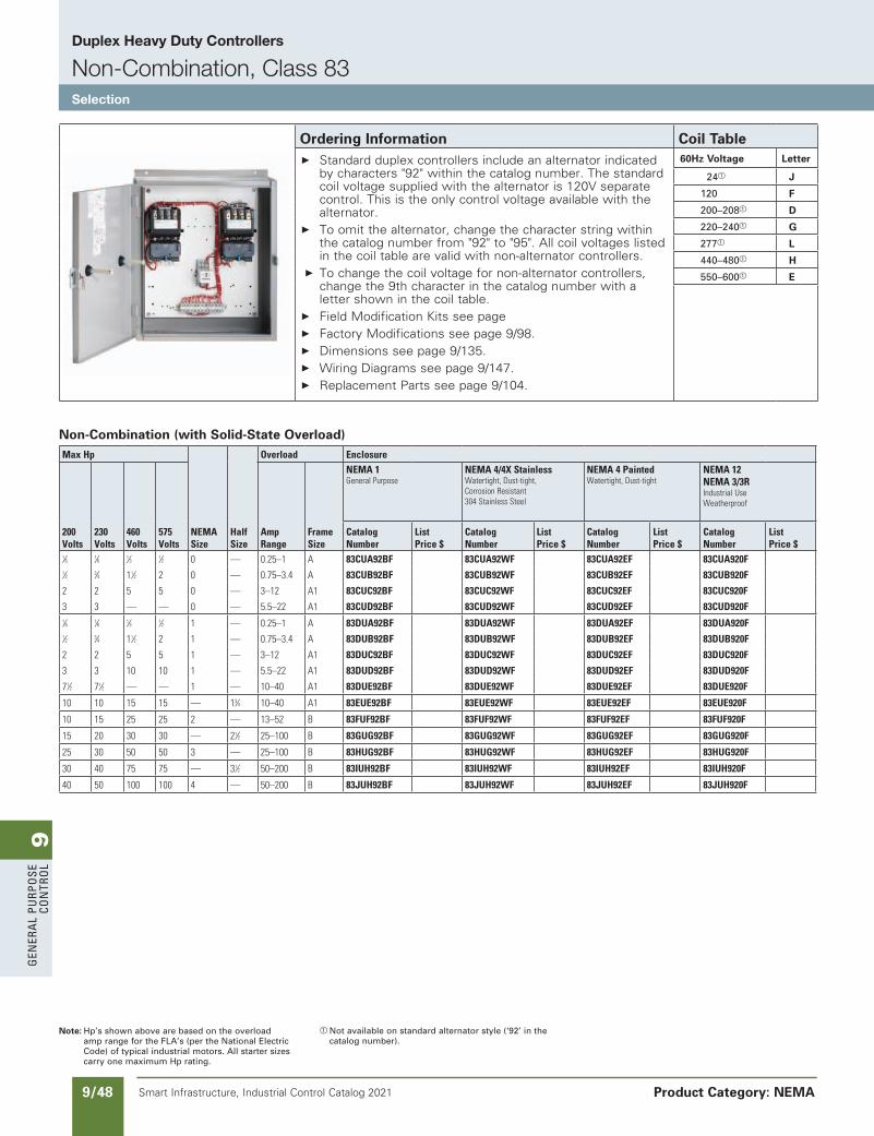
9G
ener
al
PurP
ose
Co
ntr
ol
9/48 Smart Infrastructure, Industrial Control Catalog 2021
Duplex Heavy Duty Controllers
Non-Combination, Class 83Selection
Product Category: NEMA
Note: Hp’s shown above are based on the overload amp range for the FLA’s (per the National Electric Code) of typical industrial motors. All starter sizes carry one maximum Hp rating.
a Not available on standard alternator style (‘92’ in the catalog number).
Non-Combination (with Solid-State Overload)MaxHp
NEMASize
HalfSize
Overload Enclosure
200Volts
230Volts
460Volts
575Volts
AmpRange
FrameSize
NEMA1GeneralPurpose
NEMA4/4XStainlessWatertight,Dust-tight,CorrosionResistant304StainlessSteel
NEMA4PaintedWatertight,Dust-tight
NEMA12NEMA3/3RIndustrialUseWeatherproof
CatalogNumber
ListPrice$
CatalogNumber
ListPrice$
CatalogNumber
ListPrice$
CatalogNumber
ListPrice$
1⁄6 1⁄6 1⁄3 1⁄2 0 — 0.25–1 A 83CUA92BF 83CUA92WF 83CUA92EF 83CUA920F 1⁄2 3⁄4 11⁄2 2 0 — 0.75–3.4 A 83CUB92BF 83CUB92WF 83CUB92EF 83CUB920F
2 2 5 5 0 — 3–12 A1 83CUC92BF 83CUC92WF 83CUC92EF 83CUC920F
3 3 — — 0 — 5.5–22 A1 83CUD92BF 83CUD92WF 83CUD92EF 83CUD920F 1⁄6 1⁄6 1⁄3 1⁄2 1 — 0.25–1 A 83DUA92BF 83DUA92WF 83DUA92EF 83DUA920F 1⁄2 3⁄4 11⁄2 2 1 — 0.75–3.4 A 83DUB92BF 83DUB92WF 83DUB92EF 83DUB920F
2 2 5 5 1 — 3–12 A1 83DUC92BF 83DUC92WF 83DUC92EF 83DUC920F
3 3 10 10 1 — 5.5–22 A1 83DUD92BF 83DUD92WF 83DUD92EF 83DUD920F
71⁄2 71⁄2 — — 1 — 10–40 A1 83DUE92BF 83DUE92WF 83DUE92EF 83DUE920F
10 10 15 15 — 13⁄4 10–40 A1 83EUE92BF 83EUE92WF 83EUE92EF 83EUE920F
10 15 25 25 2 — 13–52 B 83FUF92BF 83FUF92WF 83FUF92EF 83FUF920F
15 20 30 30 — 21⁄2 25–100 B 83GUG92BF 83GUG92WF 83GUG92EF 83GUG920F
25 30 50 50 3 — 25–100 B 83HUG92BF 83HUG92WF 83HUG92EF 83HUG920F
30 40 75 75 — 31⁄2 50–200 B 83IUH92BF 83IUH92WF 83IUH92EF 83IUH920F
40 50 100 100 4 — 50–200 B 83JUH92BF 83JUH92WF 83JUH92EF 83JUH920F
Ordering Information Coil Table Standard duplex controllers include an alternator indicated
by characters "92" within the catalog number. The standard coil voltage supplied with the alternator is 120V separate control. This is the only control voltage available with the alternator.
To omit the alternator, change the character string within the catalog number from "92" to "95". All coil voltages listed in the coil table are valid with non-alternator controllers.
To change the coil voltage for non-alternator controllers, change the 9th character in the catalog number with a letter shown in the coil table.
Field Modification Kits see page Factory Modifications see page 9/98. Dimensions see page 9/135. Wiring Diagrams see page 9/147. Replacement Parts see page 9/104.
60Hz Voltage Letter
24a J
120 F
200–208a D
220–240a G
277a L
440–480a H
550–600a E
updated in SPEEDFAXRevised on 03/31/20
SS copied this page from SF to IC on 05/24/20
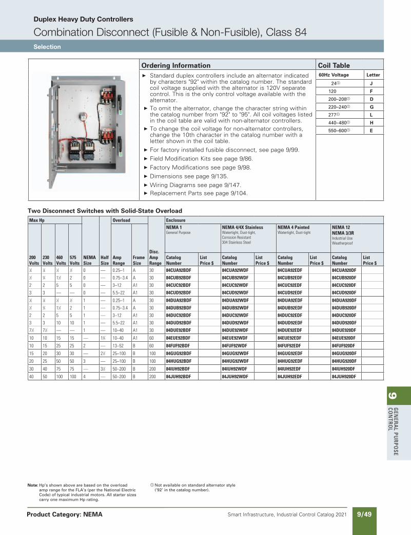
9G
enera
l PurPo
se Co
ntro
l
9/49Smart Infrastructure, Industrial Control Catalog 2021
Duplex Heavy Duty Controllers
Combination Disconnect (Fusible & Non-Fusible), Class 84Selection
Product Category: NEMA
Note: Hp’s shown above are based on the overload amp range for the FLA’s (per the National Electric Code) of typical industrial motors. All starter sizes carry one maximum Hp rating.
a Not available on standard alternator style (‘92’ in the catalog number).
Two Disconnect Switches with Solid-State OverloadMaxHp
NEMASize
HalfSize
Overload
Disc.AmpRange
Enclosure
200Volts
230Volts
460Volts
575Volts
AmpRange
FrameSize
NEMA1GeneralPurpose
NEMA4/4XStainlessWatertight,Dust-tight,CorrosionResistant304StainlessSteel
NEMA4PaintedWatertight,Dust-tight
NEMA12NEMA3/3RIndustrialUseWeatherproof
CatalogNumber
ListPrice$
CatalogNumber
ListPrice$
CatalogNumber
ListPrice$
CatalogNumber
ListPrice$
1⁄6 1⁄6 1⁄3 1⁄2 0 — 0.25–1 A 30 84CUA92BDF 84CUA92WDF 84CUA92EDF 84CUA920DF 1⁄2 3⁄4 11⁄2 2 0 — 0.75–3.4 A 30 84CUB92BDF 84CUB92WDF 84CUB92EDF 84CUB920DF
2 2 5 5 0 — 3–12 A1 30 84CUC92BDF 84CUC92WDF 84CUC92EDF 84CUC920DF
3 3 — — 0 — 5.5–22 A1 30 84CUD92BDF 84CUD92WDF 84CUD92EDF 84CUD920DF 1⁄6 1⁄6 1⁄3 1⁄2 1 — 0.25–1 A 30 84DUA92BDF 84DUA92WDF 84DUA92EDF 84DUA920DF 1⁄2 3⁄4 11⁄2 2 1 — 0.75–3.4 A 30 84DUB92BDF 84DUB92WDF 84DUB92EDF 84DUB920DF
2 2 5 5 1 — 3–12 A1 30 84DUC92BDF 84DUC92WDF 84DUC92EDF 84DUC920DF
3 3 10 10 1 — 5.5–22 A1 30 84DUD92BDF 84DUD92WDF 84DUD92EDF 84DUD920DF
71⁄2 71⁄2 — — 1 — 10–40 A1 30 84DUE92BDF 84DUE92WDF 84DUE92EDF 84DUE920DF
10 10 15 15 — 13⁄4 10–40 A1 60 84EUE92BDF 84EUE92WDF 84EUE92EDF 84EUE920DF
10 15 25 25 2 — 13–52 B 60 84FUF92BDF 84FUF92WDF 84FUF92EDF 84FUF920DF
15 20 30 30 — 21⁄2 25–100 B 100 84GUG92BDF 84GUG92WDF 84GUG92EDF 84GUG920DF
20 25 50 50 3 — 25–100 B 100 84HUG92BDF 84HUG92WDF 84HUG92EDF 84HUG920DF
30 40 75 75 — 31⁄2 50–200 B 200 84IUH92BDF 84IUH92WDF 84IUH92EDF 84IUH920DF
40 50 100 100 4 — 50–200 B 200 84JUH92BDF 84JUH92WDF 84JUH92EDF 84JUH920DF
Ordering Information Coil Table Standard duplex controllers include an alternator indicated
by characters "92" within the catalog number. The standard coil voltage supplied with the alternator is 120V separate control. This is the only control voltage available with the alternator.
To omit the alternator, change the character string within the catalog number from "92" to "95". All coil voltages listed in the coil table are valid with non-alternator controllers.
To change the coil voltage for non-alternator controllers, change the 10th character in the catalog number with a letter shown in the coil table.
For factory installed fusible disconnect, see page 9/99.
Field Modification Kits see page 9/86.
Factory Modifications see page 9/98.
Dimensions see page 9/135.
Wiring Diagrams see page 9/147. Replacement Parts see page 9/104.
60Hz Voltage Letter
24a J
120 F
200–208a D
220–240a G
277a L
440–480a H
550–600a E
updated in SPEEDFAXRevised on 03/31/20
SS copied this page from SF to IC on 05/24/20
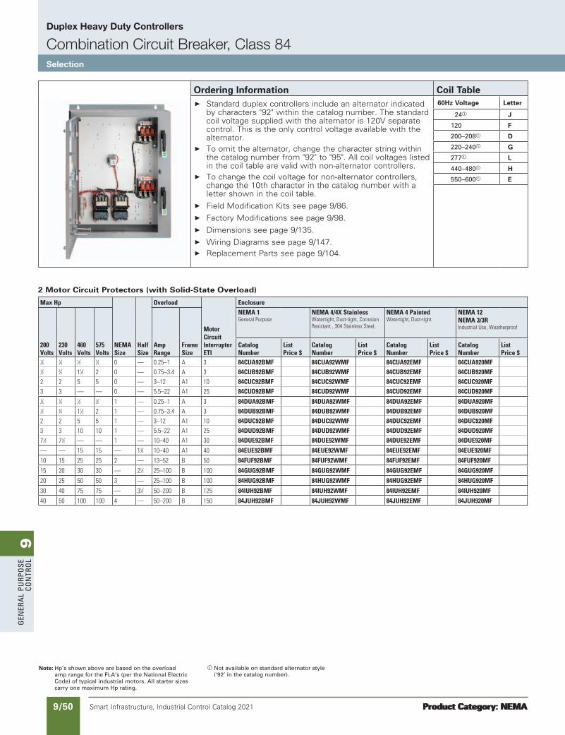
9G
ener
al
PurP
ose
Co
ntr
ol
9/50 Smart Infrastructure, Industrial Control Catalog 2021
Duplex Heavy Duty Controllers
Combination Circuit Breaker, Class 84Selection
Product Category: NEMAProduct Category: NEMA
Note: Hp’s shown above are based on the overload amp range for the FLA’s (per the National Electric Code) of typical industrial motors. All starter sizes carry one maximum Hp rating.
a Not available on standard alternator style (‘92’ in the catalog number).
2 Motor Circuit Protectors (with Solid-State Overload)
MaxHp
NEMASize
HalfSize
Overload
MotorCircuitInterrupterETI
Enclosure
200Volts
230Volts
460Volts
575Volts
AmpRange
FrameSize
NEMA1GeneralPurpose
NEMA4/4XStainlessWatertight,Dust-tight,CorrosionResistant,304StainlessSteel,
NEMA4PaintedWatertight,Dust-tight
NEMA12NEMA3/3RIndustrialUse,Weatherproof
CatalogNumber
ListPrice$
CatalogNumber
ListPrice$
CatalogNumber
ListPrice$
CatalogNumber
ListPrice$
1⁄6 1⁄6 1⁄3 1⁄2 0 — 0.25–1 A 3 84CUA92BMF 84CUA92WMF 84CUA92EMF 84CUA920MF 1⁄2 3⁄4 11⁄2 2 0 — 0.75–3.4 A 3 84CUB92BMF 84CUB92WMF 84CUB92EMF 84CUB920MF 2 2 5 5 0 — 3–12 A1 10 84CUC92BMF 84CUC92WMF 84CUC92EMF 84CUC920MF 3 3 — — 0 — 5.5–22 A1 25 84CUD92BMF 84CUD92WMF 84CUD92EMF 84CUD920MF 1⁄6 1⁄6 1⁄3 1⁄2 1 — 0.25–1 A 3 84DUA92BMF 84DUA92WMF 84DUA92EMF 84DUA920MF 1⁄2 3⁄4 11⁄2 2 1 — 0.75–3.4 A 3 84DUB92BMF 84DUB92WMF 84DUB92EMF 84DUB920MF 2 2 5 5 1 — 3–12 A1 10 84DUC92BMF 84DUC92WMF 84DUC92EMF 84DUC920MF 3 3 10 10 1 — 5.5–22 A1 25 84DUD92BMF 84DUD92WMF 84DUD92EMF 84DUD920MF 71⁄2 71⁄2 — — 1 — 10–40 A1 30 84DUE92BMF 84DUE92WMF 84DUE92EMF 84DUE920MF
— — 15 15 — 13⁄4 10–40 A1 40 84EUE92BMF 84EUE92WMF 84EUE92EMF 84EUE920MF
10 15 25 25 2 — 13–52 B 50 84FUF92BMF 84FUF92WMF 84FUF92EMF 84FUF920MF
15 20 30 30 — 21⁄2 25–100 B 100 84GUG92BMF 84GUG92WMF 84GUG92EMF 84GUG920MF
20 25 50 50 3 — 25–100 B 100 84HUG92BMF 84HUG92WMF 84HUG92EMF 84HUG920MF
30 40 75 75 — 31⁄2 50–200 B 125 84IUH92BMF 84IUH92WMF 84IUH92EMF 84IUH920MF
40 50 100 100 4 — 50–200 B 150 84JUH92BMF 84JUH92WMF 84JUH92EMF 84JUH920MF
Ordering Information Coil Table Standard duplex controllers include an alternator indicated
by characters "92" within the catalog number. The standard coil voltage supplied with the alternator is 120V separate control. This is the only control voltage available with the alternator.
To omit the alternator, change the character string within the catalog number from "92" to "95". All coil voltages listed in the coil table are valid with non-alternator controllers.
To change the coil voltage for non-alternator controllers, change the 10th character in the catalog number with a letter shown in the coil table.
Field Modification Kits see page 9/86. Factory Modifications see page 9/98. Dimensions see page 9/135. Wiring Diagrams see page 9/147. Replacement Parts see page 9/104.
60Hz Voltage Letter
24a J
120 F
200–208a D
220–240a G
277a L
440–480a H
550–600a E
updated in SPEEDFAXRevised on 03/31/20
SS copied this page from SF to IC on 05/24/20
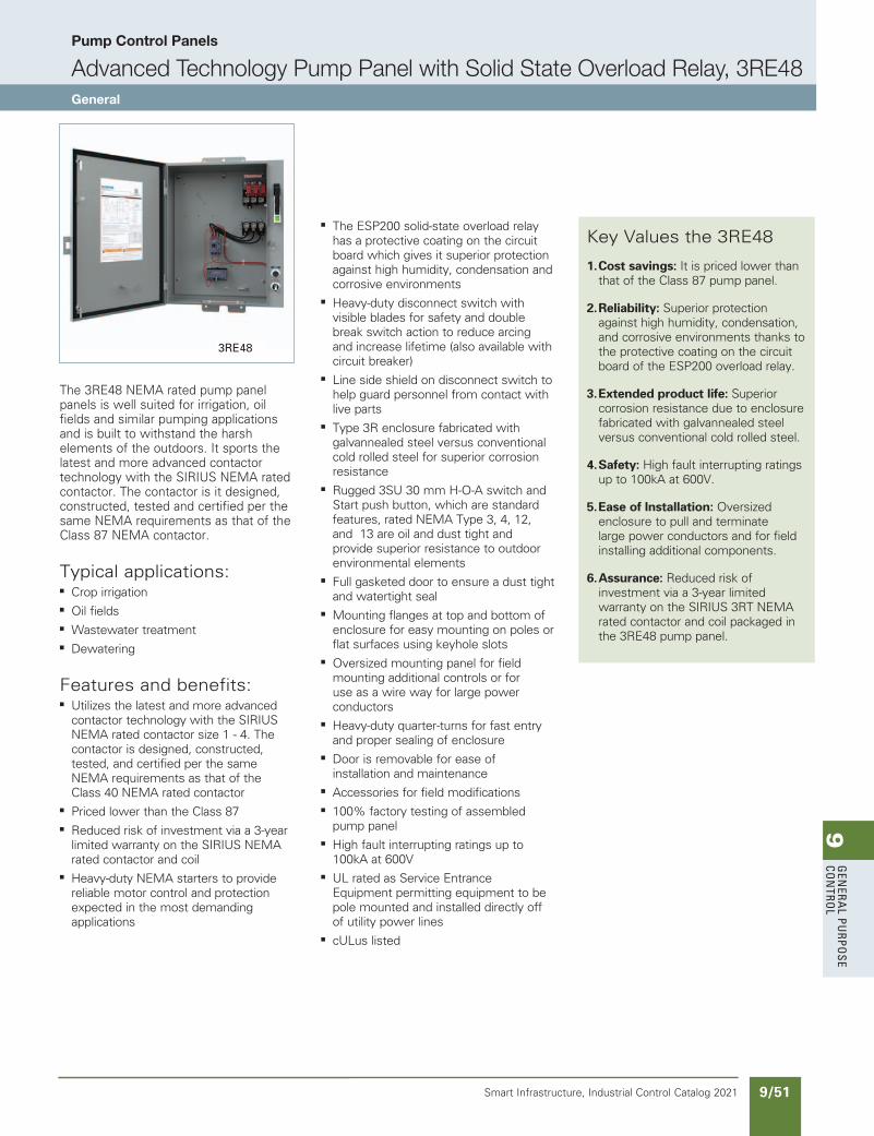
9G
enera
l PurPo
se Co
ntro
l
9/51Smart Infrastructure, Industrial Control Catalog 2021
Pump Control Panels
Advanced Technology Pump Panel with Solid State Overload Relay, 3RE48General
3RE48
NEED to UPDATE in SPEEDFAX
Revised on 12/31/21
The 3RE48 NEMA rated pump panel panels is well suited for irrigation, oil fields and similar pumping applications and is built to withstand the harsh elements of the outdoors. It sports the latest and more advanced contactor technology with the SIRIUS NEMA rated contactor. The contactor is it designed, constructed, tested and certified per the same NEMA requirements as that of the Class 87 NEMA contactor.
Typical applications:b Crop irrigation
b Oil fields
b Wastewater treatment
b Dewatering
Features and benefits:b Utilizes the latest and more advanced
contactor technology with the SIRIUS NEMA rated contactor size 1 - 4. The contactor is designed, constructed, tested, and certified per the same NEMA requirements as that of the Class 40 NEMA rated contactor
b Priced lower than the Class 87
b Reduced risk of investment via a 3-year limited warranty on the SIRIUS NEMA rated contactor and coil
b Heavy-duty NEMA starters to provide reliable motor control and protection expected in the most demanding applications
b The ESP200 solid-state overload relay has a protective coating on the circuit board which gives it superior protection against high humidity, condensation and corrosive environments
b Heavy-duty disconnect switch with visible blades for safety and double break switch action to reduce arcing and increase lifetime (also available with circuit breaker)
b Line side shield on disconnect switch to help guard personnel from contact with live parts
b Type 3R enclosure fabricated with galvannealed steel versus conventional cold rolled steel for superior corrosion resistance
b Rugged 3SU 30 mm H-O-A switch and Start push button, which are standard features, rated NEMA Type 3, 4, 12, and 13 are oil and dust tight and provide superior resistance to outdoor environmental elements
b Full gasketed door to ensure a dust tight and watertight seal
b Mounting flanges at top and bottom of enclosure for easy mounting on poles or flat surfaces using keyhole slots
b Oversized mounting panel for field mounting additional controls or for use as a wire way for large power conductors
b Heavy-duty quarter-turns for fast entry and proper sealing of enclosure
b Door is removable for ease of installation and maintenance
b Accessories for field modifications
b 100% factory testing of assembled pump panel
b High fault interrupting ratings up to 100kA at 600V
b UL rated as Service Entrance Equipment permitting equipment to be pole mounted and installed directly off of utility power lines
b cULus listed
Key Values the 3RE48
1. Cost savings: It is priced lower than that of the Class 87 pump panel.
2. Reliability: Superior protection against high humidity, condensation, and corrosive environments thanks to the protective coating on the circuit board of the ESP200 overload relay.
3. Extended product life: Superior corrosion resistance due to enclosure fabricated with galvannealed steel versus conventional cold rolled steel.
4. Safety: High fault interrupting ratings up to 100kA at 600V.
5. Ease of Installation: Oversized enclosure to pull and terminate large power conductors and for field installing additional components.
6. Assurance: Reduced risk of investment via a 3-year limited warranty on the SIRIUS 3RT NEMA rated contactor and coil packaged in the 3RE48 pump panel.
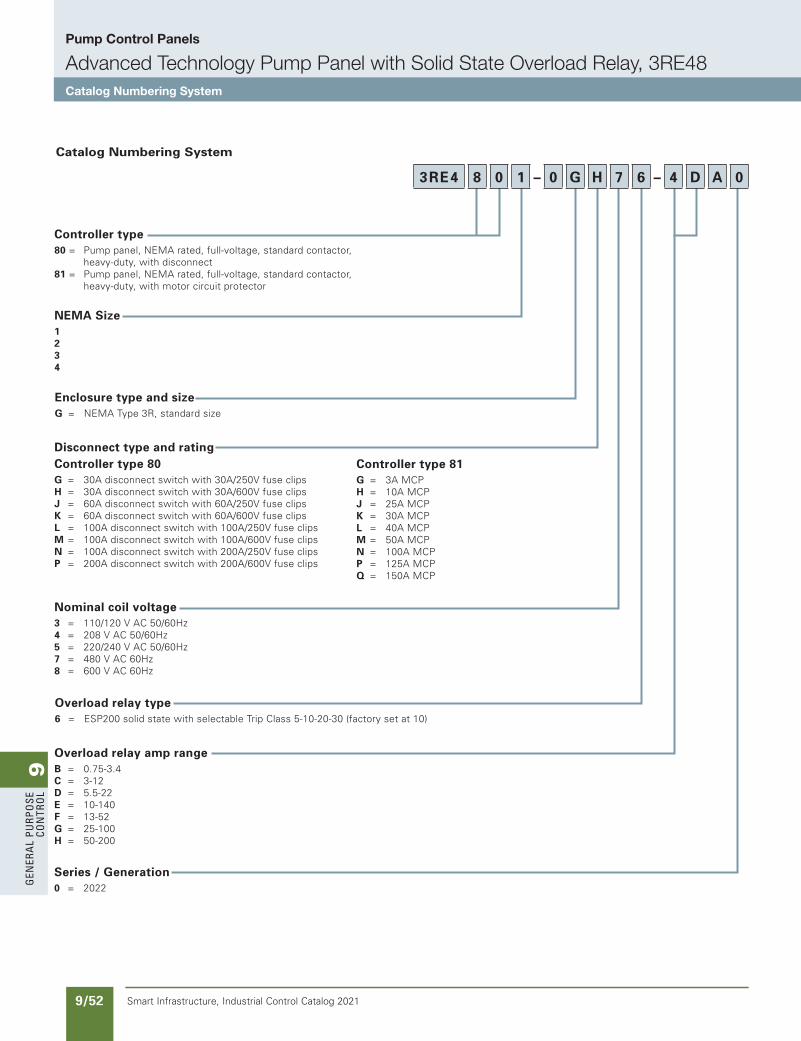
9G
ener
al
PurP
ose
Co
ntr
ol
9/52 Smart Infrastructure, Industrial Control Catalog 2021
Pump Control Panels
Advanced Technology Pump Panel with Solid State Overload Relay, 3RE48Catalog Numbering System
Controller type80 = Pump panel, NEMA rated, full-voltage, standard contactor, heavy-duty, with disconnect81 = Pump panel, NEMA rated, full-voltage, standard contactor, heavy-duty, with motor circuit protector
Disconnect type and ratingController type 80G = 30A disconnect switch with 30A/250V fuse clipsH = 30A disconnect switch with 30A/600V fuse clipsJ = 60A disconnect switch with 60A/250V fuse clipsK = 60A disconnect switch with 60A/600V fuse clipsL = 100A disconnect switch with 100A/250V fuse clipsM = 100A disconnect switch with 100A/600V fuse clipsN = 100A disconnect switch with 200A/250V fuse clipsP = 200A disconnect switch with 200A/600V fuse clips
Nominal coil voltage3 = 110/120 V AC 50/60Hz4 = 208 V AC 50/60Hz5 = 220/240 V AC 50/60Hz7 = 480 V AC 60Hz8 = 600 V AC 60Hz
Overload relay amp rangeB = 0.75-3.4C = 3-12D = 5.5-22E = 10-140F = 13-52G = 25-100H = 50-200
Controller type 81G = 3A MCPH = 10A MCPJ = 25A MCPK = 30A MCPL = 40A MCPM = 50A MCPN = 100A MCPP = 125A MCPQ = 150A MCP
NEMA Size1234
Catalog Numbering System
NEED to UPDATE in SPEEDFAX
Revised on 12/31/21
Enclosure type and sizeG = NEMA Type 3R, standard size
Overload relay type6 = ESP200 solid state with selectable Trip Class 5-10-20-30 (factory set at 10)
Series / Generation0 = 2022
3RE4 8 0 1 – 0 G H 7 6 – 4 D A 0
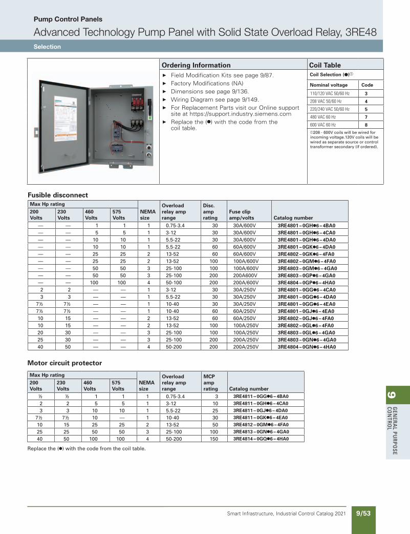
9G
enera
l PurPo
se Co
ntro
l
9/53Smart Infrastructure, Industrial Control Catalog 2021
Pump Control Panels
Advanced Technology Pump Panel with Solid State Overload Relay, 3RE48Selection
Ordering Information Coil Table Field Modification Kits see page 9/87. Factory Modifications (NA) Dimensions see page 9/136. Wiring Diagram see page 9/149. For Replacement Parts visit our Online support
site at https://support.industry.siemens.com Replace the (●) with the code from the
coil table.
Coil Selection (●)a
Nominal voltage Code
110/120VAC50/60Hz 3
208VAC50/60Hz 4
220/240VAC50/60Hz 5
480VAC60Hz 7
600VAC60Hz 8a208 - 600V coils will be wired for incoming voltage.120V coils will be wired as separate source or control transformer secondary (if ordered).
NEED to UPDATE in SPEEDFAX
Revised on 12/31/21
Fusible disconnectMax Hp rating
NEMA size
Overloadrelay amprange
Disc.amprating
Fuse clipamp/volts Catalog number
200 Volts
230 Volts
460 Volts
575 Volts
— — 1 1 1 0.75-3.4 30 30A/600V 3RE4801 – 0GH●6 – 4BA0— — 5 5 1 3-12 30 30A/600V 3RE4801 – 0GH●6 – 4CA0— — 10 10 1 5.5-22 30 30A/600V 3RE4801 – 0GH●6 – 4DA0— — 10 10 1 5.5-22 60 60A/600V 3RE4801 – 0GK●6 – 4DA0— — 25 25 2 13-52 60 60A/600V 3RE4802 – 0GK●6 – 4FA0— — 25 25 2 13-52 100 100A/600V 3RE4802 – 0GM●6 – 4FA0— — 50 50 3 25-100 100 100A/600V 3RE4803 – 0GM●6 – 4GA0— — 50 50 3 25-100 200 200A600V 3RE4803 – 0GP●6 – 4GA0— — 100 100 4 50-100 200 200A/600V 3RE4804 – 0GP●6 – 4HA02 2 — — 1 3-12 30 30A/250V 3RE4801 – 0GG●6 – 4CA03 3 — — 1 5.5-22 30 30A/250V 3RE4801 – 0GG●6 – 4DA0
7½ 7½ — — 1 10-40 30 30A/250V 3RE4801 – 0GG●6 – 4EA07½ 7½ — — 1 10-40 60 60A/250V 3RE4801 – 0GJ●6 – 4EA010 15 — — 2 13-52 60 60A/250V 3RE4802 – 0GJ●6 – 4FA010 15 — — 2 13-52 100 100A/250V 3RE4802 – 0GL●6 – 4FA020 30 — — 3 25-100 100 100A/250V 3RE4803 – 0GL●6 – 4GA025 30 — — 3 25-100 200 200A/250V 3RE4803 – 0GN●6 – 4GA040 50 — — 4 50-200 200 200A/250V 3RE4804 – 0GN●6 – 4HA0
Motor circuit protector
Max Hp ratingNEMA size
Overloadrelay amprange
MCPamprating Catalog number
200 Volts
230 Volts
460 Volts
575 Volts
½ ½ 1 1 1 0.75-3.4 3 3RE4811 – 0GG●6 – 4BA0
2 2 5 5 1 3-12 10 3RE4811 – 0GH●6 – 4CA0
3 3 10 10 1 5.5-22 25 3RE4811 – 0GJ●6 – 4DA0
7½ 7½ 10 — 1 10-40 30 3RE4811 – 0GK●6 – 4EA0
10 15 25 25 2 13-52 50 3RE4812 – 0GM●6 – 4FA0
25 25 50 50 3 25-100 100 3RE4813 – 0GN●6 – 4GA0
40 50 100 100 4 50-200 150 3RE4814 – 0GQ●6 – 4HA0
Replace the (●) with the code from the coil table.

9G
ener
al
PurP
ose
Co
ntr
ol
9/54 Smart Infrastructure, Industrial Control Catalog 2021
FeaturesThe Class 82 Slim Line NEMA Pump was designed specifically for the agricultural market. It is well suited for irrigation and similar pumping applications and is built to withstand the harsh elements of the outdoors
Typical applications include:• Crop irrigation
• Sprinklers, misters and soakers
• Watering for livestock and other dairy applications
• Ground dewatering for excavation and construction sites
Why you should use the Class 82 Pump Panel• Simplicity and its compact lightweight design makes
this an attractive solution to your budgeting challenges.
• The contactor is NEMA rated to provide reliable motor control and protection expected in the most demanding applications.
• The ESP200 solid-state overload relay has a protective coating on the circuit board which gives it superior pro-tection against high humidity, condensation and corro-sive environments.
• Its size and weight is about half that of the Class 87 which increases the ease of installation.
Starter Size
D = 1F = 2
OLR Current Range
B = 0.75-3.4AC = 3-12AD = 5.5-22AE = 10-40AF = 13-52A
Cover Control
6 = HOA selector switch with Start push button
Catalog Numbering System
82 A D C 6 F B H
Disconnect Type
F = Fusible disconnect
Disconnect & Fuse Clip Rating
A = 30A/250VB = 30A/600VC = 60A/250VD = 60A/600V Coil Voltage
F = 110VAC 50HZ / 120VAC 60HZG = 220VAC 50HZ / 240VAC 60HZH = 480VAC 60HZ
Series
A = Standard size enclosureB = Extra large enclosure (starter size 1 only)
Pump Control Panels
Slim Line NEMA Pump Controller for the Agricultural industry, Class 82General
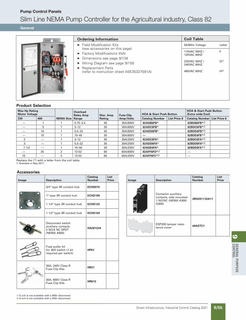
9G
enera
l PurPo
se Co
ntro
l
9/55Smart Infrastructure, Industrial Control Catalog 2021
Pump Control Panels
Slim Line NEMA Pump Controller for the Agricultural industry, Class 82General
Ordering Information Field Modification Kits
(see accessories on this page) Factory Modifications (NA) Dimensions see page 9/134 Wiring Diagram see page 9/150 Replacement Parts
(refer to instruction sheet A5E35327591A)
Coil Table
50/60Hz Voltage Letter
110VAC 50HZ / F 120VAC 60HZ
220VAC 50HZ / Ga
240VAC 60HZ 480VAC 60HZ Hb
Accessories
Image DescriptionCatalog Number
List Price
3/4" type 3R conduit hub ECHS075
1" type 3R conduit hub ECHS100
1 1/4" type 3R conduit hub ECHS125
1 1/2" type 3R conduit hub ECHS150
Disconnect switch auxiliary contacts 2 NO/2 NC DPDT (NEMA A600)
HA261234
Fuse puller kit for 30A switch (1 kit required per switch)
HP61
30A, 240V Class R Fuse Clip Kits HR21
30A, 600V Class R Fuse Clip Kits HR612
Image DescriptionCatalog Number
List Price
Contactor auxiliary contacts, side mounted 1 NO/NC (NEMA A300/Q300)
3RH29111DA11
ESP200 tamper resis-tance cover 49ASTC1
Product SelectionMax Hp RatingMotor Voltage
NEMA Size
Overload Relay Amp Range
Disc. Amp Rating
Fuse Clip Amp/Volts
HOA & Start Push ButtonHOA & Start Push Button (Extra wide Encl)
230 460 Catalog Number List Price $ Catalog Number List Price $
— 1 1 0.75–3.4 30 30A/600V 82ADB6FB* 82BDB6FB*c
— 5 1 3–12 30 30A/600V 82ADC6FB* 82BDC6FB*c
— 10 1 5.5–22 30 30A/600V 82ADD6FB* 82BDD6FB*c
— 10 1 10–40 30 30A/600V — 82BDE6FB*c
2 — 1 3–12 30 30A/250V 82ADC6FA* 82BDC6FA*c
3 — 1 5.5–22 30 30A/250V 82ADD6FA* 82BDD6FA*c
7 1/2 — 1 10–40 30 30A/250V 82ADE6FA* 82BDE6FA*c
— 25 2 13-52 60 60A/600V 82AFF6FD*c —15 — 2 13-52 60 60A/250V 82AFF6FC*c —
Replace the (*) with a letter from the coil table.c Available in May 2017.
a G coil is not available with a 600v disconnectb H coil is not available with a 250v disconnect
updated in SPEEDFAXRevised on 04/20/17
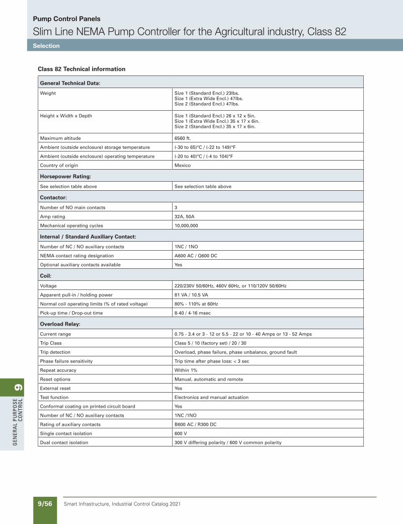
9G
ener
al
PurP
ose
Co
ntr
ol
9/56 Smart Infrastructure, Industrial Control Catalog 2021
Pump Control Panels
Slim Line NEMA Pump Controller for the Agricultural industry, Class 82Selection
Class 82 Technical information
General Technical Data:
Weight Size 1 (Standard Encl.) 23lbs.Size 1 (Extra Wide Encl.) 47lbs.Size 2 (Standard Encl.) 47lbs.
Height x Width x Depth Size 1 (Standard Encl.) 26 x 12 x 5in.Size 1 (Extra Wide Encl.) 35 x 17 x 6in.Size 2 (Standard Encl.) 35 x 17 x 6in.
Maximum altitude 6560 ft.
Ambient (outside enclosure) storage temperature (-30 to 65)°C / (-22 to 149)°F
Ambient (outside enclosure) operating temperature (-20 to 40)°C / (-4 to 104)°F
Country of origin Mexico
Horsepower Rating:
See selection table above See selection table above
Contactor:
Number of NO main contacts 3
Amp rating 32A, 50A
Mechanical operating cycles 10,000,000
Internal / Standard Auxiliary Contact:
Number of NC / NO auxiliary contacts 1NC / 1NO
NEMA contact rating designation A600 AC / Q600 DC
Optional auxiliary contacts available Yes
Coil:
Voltage 220/230V 50/60Hz, 460V 60Hz, or 110/120V 50/60Hz
Apparent pull-in / holding power 81 VA / 10.5 VA
Normal coil operating limits (% of rated voltage) 80% - 110% at 60Hz
Pick-up time / Drop-out time 8-40 / 4-16 msec
Overload Relay:
Current range 0.75 - 3.4 or 3 - 12 or 5.5 - 22 or 10 - 40 Amps or 13 - 52 Amps
Trip Class Class 5 / 10 (factory set) / 20 / 30
Trip detection Overload, phase failure, phase unbalance, ground fault
Phase failure sensitivity Trip time after phase loss: < 3 sec
Repeat accuracy Within 1%
Reset options Manual, automatic and remote
External reset Yes
Test function Electronics and manual actuation
Conformal coating on printed circuit board Yes
Number of NC / NO auxiliary contacts 1NC /1NO
Rating of auxiliary contacts B600 AC / R300 DC
Single contact isolation 600 V
Dual contact isolation 300 V differing polarity / 600 V common polarity
SS copied this page from SF to IC on 05/24/20
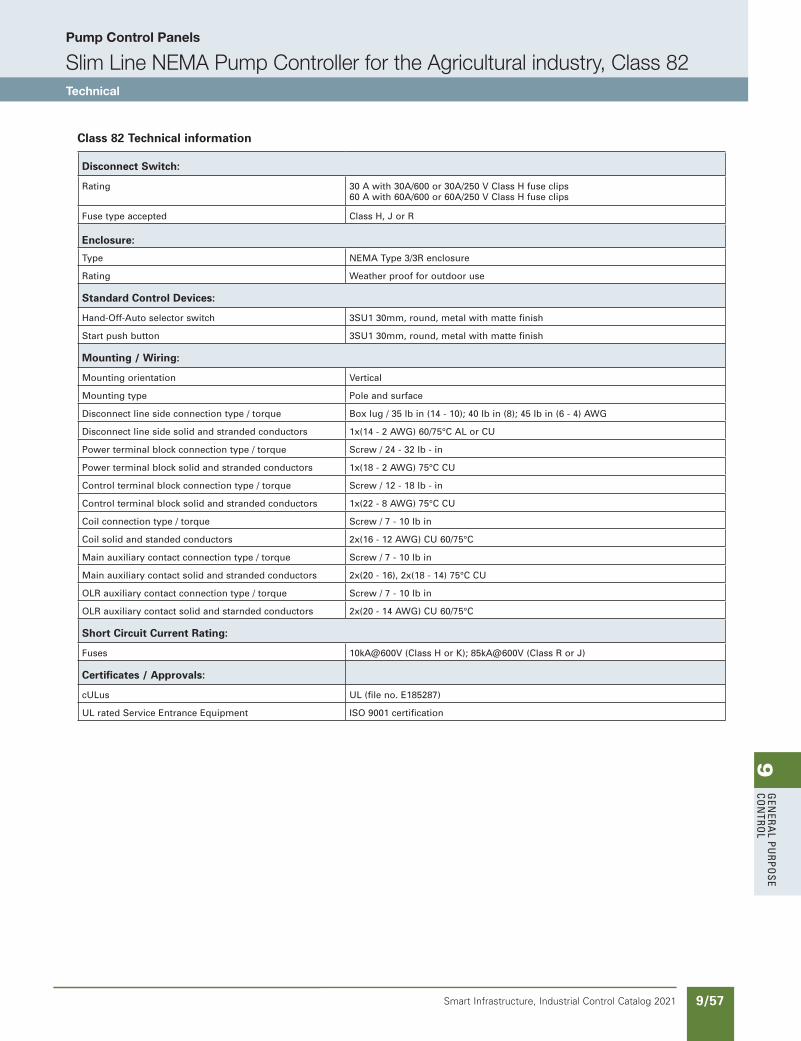
9G
enera
l PurPo
se Co
ntro
l
9/57Smart Infrastructure, Industrial Control Catalog 2021
Pump Control Panels
Slim Line NEMA Pump Controller for the Agricultural industry, Class 82Technical
Class 82 Technical information
Disconnect Switch:
Rating 30 A with 30A/600 or 30A/250 V Class H fuse clips60 A with 60A/600 or 60A/250 V Class H fuse clips
Fuse type accepted Class H, J or R
Enclosure:
Type NEMA Type 3/3R enclosure
Rating Weather proof for outdoor use
Standard Control Devices:
Hand-Off-Auto selector switch 3SU1 30mm, round, metal with matte finish
Start push button 3SU1 30mm, round, metal with matte finish
Mounting / Wiring:
Mounting orientation Vertical
Mounting type Pole and surface
Disconnect line side connection type / torque Box lug / 35 lb in (14 - 10); 40 lb in (8); 45 lb in (6 - 4) AWG
Disconnect line side solid and stranded conductors 1x(14 - 2 AWG) 60/75°C AL or CU
Power terminal block connection type / torque Screw / 24 - 32 lb - in
Power terminal block solid and stranded conductors 1x(18 - 2 AWG) 75°C CU
Control terminal block connection type / torque Screw / 12 - 18 lb - in
Control terminal block solid and stranded conductors 1x(22 - 8 AWG) 75°C CU
Coil connection type / torque Screw / 7 - 10 lb in
Coil solid and standed conductors 2x(16 - 12 AWG) CU 60/75°C
Main auxiliary contact connection type / torque Screw / 7 - 10 lb in
Main auxiliary contact solid and stranded conductors 2x(20 - 16), 2x(18 - 14) 75°C CU
OLR auxiliary contact connection type / torque Screw / 7 - 10 lb in
OLR auxiliary contact solid and starnded conductors 2x(20 - 14 AWG) CU 60/75°C
Short Circuit Current Rating:
Fuses 10kA@600V (Class H or K); 85kA@600V (Class R or J)
Certificates / Approvals:
cULus UL (file no. E185287)
UL rated Service Entrance Equipment ISO 9001 certification
updated in SPEEDFAXRevised on 03/17/17
SS copied this page from SF to IC on 05/24/20
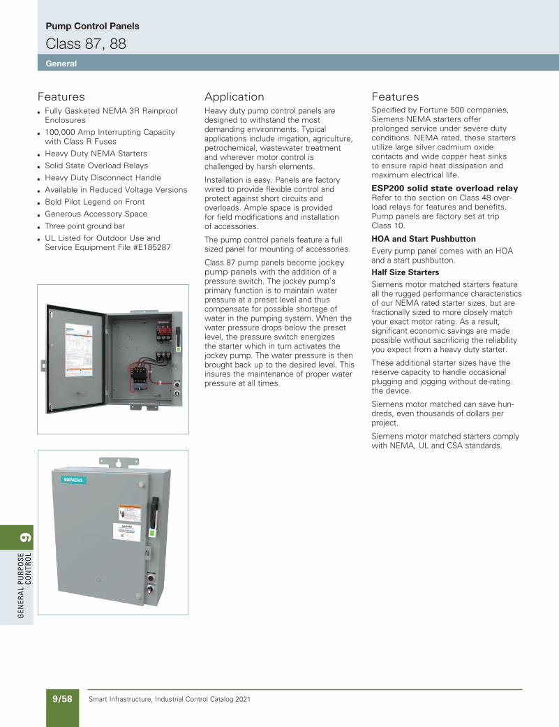
9G
ener
al
PurP
ose
Co
ntr
ol
9/58 Smart Infrastructure, Industrial Control Catalog 2021
Pump Control Panels
Class 87, 88General
ApplicationHeavy duty pump control panels are designed to withstand the most demanding environments. Typical applications include irrigation, agriculture, petrochemical, wastewater treatment and wherever motor control is challenged by harsh elements.
Installation is easy. Panels are factory wired to provide flexible control and protect against short circuits and overloads. Ample space is provided for field modifications and installation of accessories.
The pump control panels feature a full sized panel for mounting of accessories.
Class 87 pump panels become jockey pump panels with the addition of a pressure switch. The jockey pump’s primary function is to maintain water pressure at a preset level and thus compensate for possible shortage of water in the pumping system. When the water pressure drops below the preset level, the pressure switch energizes the starter which in turn activates the jockey pump. The water pressure is then brought back up to the desired level. This insures the maintenance of proper water pressure at all times.
FeaturesSpecified by Fortune 500 companies, Siemens NEMA starters offer prolonged service under severe duty conditions. NEMA rated, these starters utilize large silver cadmium oxide contacts and wide copper heat sinks to ensure rapid heat dissipation and maximum electrical life.
ESP200 solid state overload relay Refer to the section on Class 48 over-load relays for features and benefits. Pump panels are factory set at trip Class 10.
HOA and Start PushbuttonEvery pump panel comes with an HOA and a start pushbutton.
Half Size StartersSiemens motor matched starters feature all the rugged performance characteristics of our NEMA rated starter sizes, but are fractionally sized to more closely match your exact motor rating. As a result, significant economic savings are made possible without sacrificing the reliability you expect from a heavy duty starter.
These additional starter sizes have the reserve capacity to handle occasional plugging and jogging without de-rating the device.
Siemens motor matched can save hun-dreds, even thousands of dollars per project.
Siemens motor matched starters comply with NEMA, UL and CSA standards.
Featuresb Fully Gasketed NEMA 3R Rainproof
Enclosures
b 100,000 Amp Interrupting Capacity with Class R Fuses
b Heavy Duty NEMA Starters
b Solid State Overload Relays
b Heavy Duty Disconnect Handle
b Available in Reduced Voltage Versions
b Bold Pilot Legend on Front
b Generous Accessory Space
b Three point ground bar
b UL Listed for Outdoor Use and Service Equipment File #E185287
SS copied this page from SF to IC on 05/24/20
NEED to UPDATE in SPEEDFAX
Revised on 12/31/21
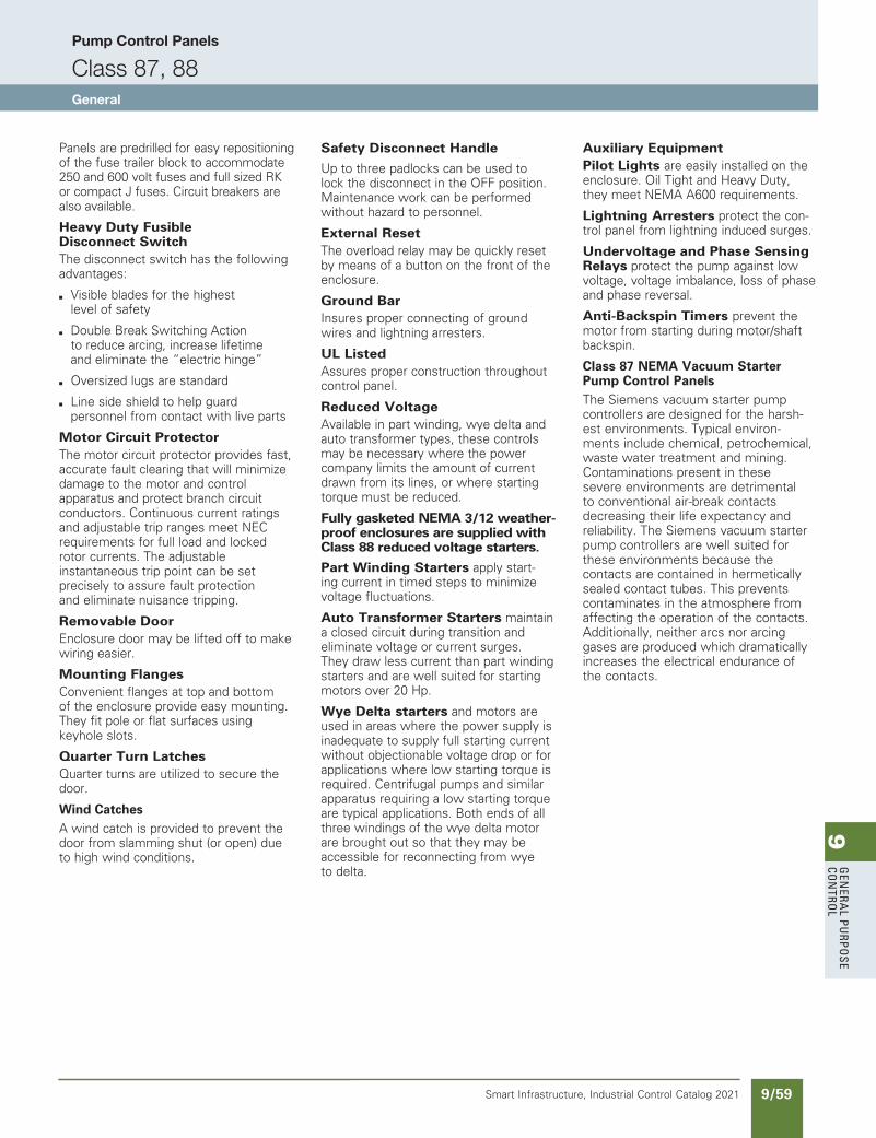
9G
enera
l PurPo
se Co
ntro
l
9/59Smart Infrastructure, Industrial Control Catalog 2021
Pump Control Panels
Class 87, 88General
Panels are predrilled for easy repositioning of the fuse trailer block to accommodate 250 and 600 volt fuses and full sized RK or compact J fuses. Circuit breakers are also available.
Heavy Duty Fusible Disconnect SwitchThe disconnect switch has the following advantages:
b Visible blades for the highest level of safety
b Double Break Switching Action to reduce arcing, increase lifetime and eliminate the “electric hinge”
b Oversized lugs are standard
b Line side shield to help guard personnel from contact with live parts
Motor Circuit ProtectorThe motor circuit protector provides fast, accurate fault clearing that will minimize damage to the motor and control apparatus and protect branch circuit conductors. Continuous current ratings and adjustable trip ranges meet NEC requirements for full load and locked rotor currents. The adjustable instantaneous trip point can be set precisely to assure fault protection and eliminate nuisance tripping.
Removable DoorEnclosure door may be lifted off to make wiring easier.
Mounting FlangesConvenient flanges at top and bottom of the enclosure provide easy mounting. They fit pole or flat surfaces using keyhole slots.
Quarter Turn LatchesQuarter turns are utilized to secure the door.
Wind CatchesA wind catch is provided to prevent the door from slamming shut (or open) due to high wind conditions.
Safety Disconnect Handle
Up to three padlocks can be used to lock the disconnect in the OFF position. Maintenance work can be performed without hazard to personnel.
External ResetThe overload relay may be quickly reset by means of a button on the front of the enclosure.
Ground BarInsures proper connecting of ground wires and lightning arresters.
UL ListedAssures proper construction throughout control panel.
Reduced VoltageAvailable in part winding, wye delta and auto transformer types, these controls may be necessary where the power company limits the amount of current drawn from its lines, or where starting torque must be reduced.
Fully gasketed NEMA 3/12 weather-proof enclosures are supplied with Class 88 reduced voltage starters.
Part Winding Starters apply start-ing current in timed steps to minimize voltage fluctuations.
Auto Transformer Starters maintain a closed circuit during transition and eliminate voltage or current surges. They draw less current than part winding starters and are well suited for starting motors over 20 Hp.
Wye Delta starters and motors are used in areas where the power supply is inadequate to supply full starting current without objectionable voltage drop or for applications where low starting torque is required. Centrifugal pumps and similar apparatus requiring a low starting torque are typical applications. Both ends of all three windings of the wye delta motor are brought out so that they may be accessible for reconnecting from wye to delta.
Auxiliary EquipmentPilot Lights are easily installed on the enclosure. Oil Tight and Heavy Duty, they meet NEMA A600 requirements.
Lightning Arresters protect the con-trol panel from lightning induced surges.
Undervoltage and Phase Sensing Relays protect the pump against low voltage, voltage imbalance, loss of phase and phase reversal.
Anti-Backspin Timers prevent the motor from starting during motor/shaft backspin.
Class 87 NEMA Vacuum Starter Pump Control PanelsThe Siemens vacuum starter pump controllers are designed for the harsh-est environments. Typical environ-ments include chemical, petrochemical, waste water treatment and mining. Contaminations present in these severe environments are detrimental to conventional air-break contacts decreasing their life expectancy and reliability. The Siemens vacuum starter pump controllers are well suited for these environments because the contacts are contained in hermetically sealed contact tubes. This prevents contaminates in the atmosphere from affecting the operation of the contacts. Additionally, neither arcs nor arcing gases are produced which dramatically increases the electrical endurance of the contacts.
NEED to UPDATE in SPEEDFAX
Revised on 12/31/21
SS copied this page from SF to IC on 05/24/20
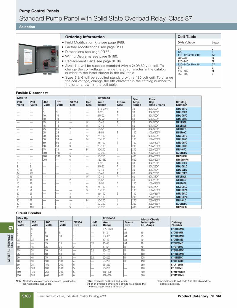
9G
ener
al
PurP
ose
Co
ntr
ol
9/60 Smart Infrastructure, Industrial Control Catalog 2021
Pump Control Panels
Standard Pump Panel with Solid State Overload Relay, Class 87Selection
Product Category: NEMA
Note: All starter sizes carry one maximum Hp rating (per the National Electric Code).
a Not available on Size 5 and larger.b For an overload amp range of 0.25-1A, change the
5th character from a ‘B’ to an ‘A’.
c A version with coil code A is also stocked via Controls Express.
Ordering Information Field Modification Kits see page 9/86. Factory Modifications see page 9/98. Dimensions see page 9/136. Wiring Diagrams see page 9/150. Replacement Parts see page 9/104. Sizes 1-4 will be supplied standard with a 240/480 volt coil. To
change the coil voltage, change the 8th character in the catalog number to the letter shown in the coil table.
Sizes 5 & 6 will be supplied standard with a 480 volt coil. To change the coil voltage, change the 8th character in the catalog number to the letter shown in the coil table.
Coil Table
60Hz Voltage Letter
24 J 120 F 110–120/220–240 Aa
200–208 D 220–240 G 220–240/440–480 Ca
277 L 440–480 H 550–600 E
Fusible Disconnect
Max Hp
NEMA Size
Half Size
Overload Disc. Amp Range
Fuse Clip Amp / Volts
Catalog Number
200 Volts
230 Volts
460 Volts
575 Volts
Amp Range
Frame Size
— — 1 1 1 — 0.75–3.4b A 30 30A/600V 87DUB6FC— — 5 5 1 — 3–12 A1 30 30A/600V 87DUC6FC— — 10 10 1 — 5.5–22 A1 30 30A/600V 87DUD6FC— — 10 10 1 — 5.5–22 A1 60 60A/600V 87DUD60C— — 15 15 — 13⁄4 10–40 A1 30 30A/600V 87EUE6FC— — 15 15 — 13⁄4 10–40 A1 60 60A/600V 87EUE60C— — 25 25 2 — 13–52 B 60 60A/600V 87FUF6FC— — 25 25 2 — 13–52 B 100 100A/600V 87FUF60C— — 30 30 — 21⁄2 25–100 B 60 60A/600V 87GUG6FC— — 30 30 — 21⁄2 25–100 B 100 100A/600V 87GUG60C— — 50 50 3 — 25–100 B 100 100A/600V 87HUG6FC— — 50 50 3 — 25–100 B 200 200A/600V 87HUG60C— — 75 75 — 31⁄2 50–200 B 200 200A/600V 87IUH6FC— — 100 100 4 — 50–200 B 200 200A/600V 87JUH6FC— — 200 200 5 — 55–250 — 400 400A/600V 87LPU6FH— — 250 — 6 — 160–630 — 600 600A/600V 87MSW6FH2 2 — — 1 — 3–12 A1 30 30A/250V 87DUC6LC3 3 — — 1 — 5.5–22 A1 30 30A/250V 87DUD6LC71⁄2 71⁄2 — — 1 — 10–40 A1 30 30A/250V 87DUE6LC71⁄2 71⁄2 — — 1 — 10–40 A1 60 60A/250V 87DUE6PC10 10 — — — 13⁄4 10–40 A1 60 60A/250V 87EUE6LC10 15 — — 2 — 13–52 B 60 60A/250V 87FUF6LC10 15 — — 2 — 13–52 B 100 100A/250V 87FUF6PC15 20 — — — 21⁄2 25–100 B 60 60A/250V 87GUG6LC15 20 — — — 21⁄2 25–100 B 100 100A/250V 87GUG6PC20 30 — — 3 — 25–100 B 100 100A/250V 87HUG6LC25 30 — — 3 — 25–100 B 200 200A/250V 87HUG6PC30 40 — — — 31⁄2 50–200 B 200 200A/250V 87IUH6LC40 50 — — 4 — 50–200 B 200 200A/250V 87JUH6LC75 100 — — 5 — 55–250 — 400 400A/250V 87LPU6LG
Circuit Breaker
Max Hp
NEMA Size
Half Size
Overload Motor Circuit Interrupter ETI Amps
Catalog Number
200 Volts
230 Volts
460 Volts
575 Volts
Amp Range
Frame Size
1⁄2 1⁄2 1 1 1 — 0.75–3.4b A 3 87DUB6MC2 2 5 5 1 — 3–12 A1 10 87DUC6MC3 3 10 10 1 — 5.5–22 A1 25 87DUD6MC71⁄2 71⁄2 10 — 1 — 10–40 A1 30 87DUE6MC— — 15 15 — 13⁄4 10–40 A1 40 87EUE6MC10 15 25 25 2 — 13–52 B 50 87FUF6MC15 20 30 30 — 21⁄2 25–100 B 100 87GUG6MC25 30 50 50 3 — 25–100 B 100 87HUG6MC30 40 75 75 — 31⁄2 50–200 B 125 87IUH6MC40 50 100 100 4 — 50–200 B 150 87JUH6MC50 75 150 200 5 — 55–250 — 250 87LPT6MH75 100 200 200 5 — 55–250 — 400 87LPU6MH100 125 250 300 6 — 160–630 — 400 87MSW6MH150 200 400 400 6 — 160–630 — 600 87MSX6MH
SS copied this page from SF to IC on 05/24/20
NEED to UPDATE in SPEEDFAX
Revised on 12/31/21
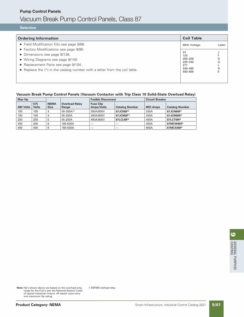
9G
enera
l PurPo
se Co
ntro
l
9/61Smart Infrastructure, Industrial Control Catalog 2021
Pump Control Panels
Vacuum Break Pump Control Panels, Class 87Selection
Product Category: NEMA
Ordering Information Field Modification Kits see page 9/86. Factory Modifications see page 9/98. Dimensions see page 9/136. Wiring Diagrams see page 9/150. Replacement Parts see page 9/104. Replace the (*) in the catalog number with a letter from the coil table.
Coil Table
60Hz Voltage Letter
24 J 120 F 200–208 D 220–240 G 277 L 440–480 H 550–600 E
Note: Hp’s shown above are based on the overload amp range for the FLA’s (per the National Electric Code) of typical industrial motors. All starter sizes carry one maximum Hp rating.
a ESP200 overload relay.
Vacuum Break Pump Control Panels (Vacuum Contactor with Trip Class 10 Solid-State Overload Relay)Max Hp
NEMA Size
Overload Relay Range
Fusible Disconnect Circuit Breaker
480 Volts575 Volts
Fuse Clip Amps/Volts Catalog Number MCI Amps Catalog Number
100 100 4 50-200Aa 200A/600V 87JCN6F* 250A 87JCN6M*100 100 4 55-250A 200A/600V 87JCM6F* 250A 87JCM6M*200 200 5 55-250A 400A/600V 87LCU6F* 400A 87LCT6M*250 300 6 160-630A — — 400A 87MCW6M*400 400 6 160-630A — — 600A 87MCX6M*
NEED to UPDATE in SPEEDFAX
Revised on 12/31/21
SS copied this page from SF to IC on 05/24/20
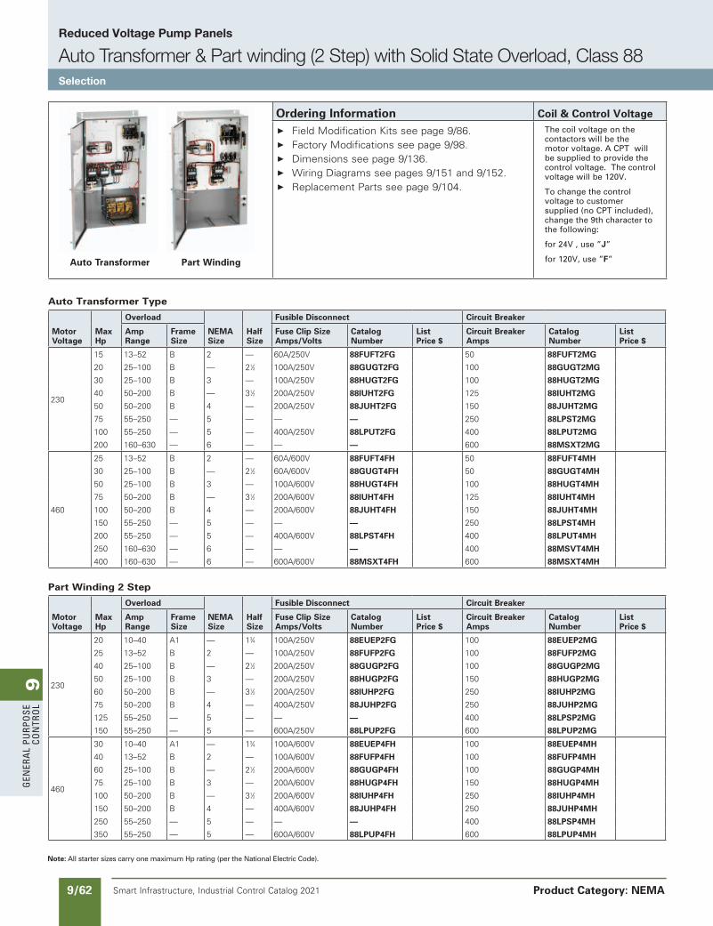
9G
ener
al
PurP
ose
Co
ntr
ol
9/62 Smart Infrastructure, Industrial Control Catalog 2021
Reduced Voltage Pump Panels
Auto Transformer & Part winding (2 Step) with Solid State Overload, Class 88Selection
Product Category: NEMA
Note: All starter sizes carry one maximum Hp rating (per the National Electric Code).
Auto Transformer Type
Motor Voltage
Max Hp
Overload
NEMA Size
Half Size
Fusible Disconnect Circuit Breaker
Amp Range
Frame Size
Fuse Clip Size Amps/Volts
Catalog Number
List Price $
Circuit Breaker Amps
Catalog Number
List Price $
230
15 13–52 B 2 — 60A/250V 88FUFT2FG 50 88FUFT2MG
20 25–100 B — 21⁄2 100A/250V 88GUGT2FG 100 88GUGT2MG
30 25–100 B 3 — 100A/250V 88HUGT2FG 100 88HUGT2MG
40 50–200 B — 31⁄2 200A/250V 88IUHT2FG 125 88IUHT2MG
50 50–200 B 4 — 200A/250V 88JUHT2FG 150 88JUHT2MG
75 55–250 — 5 — — — 250 88LPST2MG
100 55–250 — 5 — 400A/250V 88LPUT2FG 400 88LPUT2MG
200 160–630 — 6 — — — 600 88MSXT2MG
460
25 13–52 B 2 — 60A/600V 88FUFT4FH 50 88FUFT4MH
30 25–100 B — 21⁄2 60A/600V 88GUGT4FH 50 88GUGT4MH
50 25–100 B 3 — 100A/600V 88HUGT4FH 100 88HUGT4MH
75 50–200 B — 31⁄2 200A/600V 88IUHT4FH 125 88IUHT4MH
100 50–200 B 4 — 200A/600V 88JUHT4FH 150 88JUHT4MH
150 55–250 — 5 — — — 250 88LPST4MH
200 55–250 — 5 — 400A/600V 88LPST4FH 400 88LPUT4MH
250 160–630 — 6 — — — 400 88MSVT4MH
400 160–630 — 6 — 600A/600V 88MSXT4FH 600 88MSXT4MH
Part Winding 2 Step
Motor Voltage
Max Hp
Overload
NEMA Size
Half Size
Fusible Disconnect Circuit Breaker
Amp Range
Frame Size
Fuse Clip Size Amps/Volts
Catalog Number
List Price $
Circuit Breaker Amps
Catalog Number
List Price $
230
20 10–40 A1 — 13⁄4 100A/250V 88EUEP2FG 100 88EUEP2MG
25 13–52 B 2 — 100A/250V 88FUFP2FG 100 88FUFP2MG
40 25–100 B — 21⁄2 200A/250V 88GUGP2FG 100 88GUGP2MG
50 25–100 B 3 — 200A/250V 88HUGP2FG 150 88HUGP2MG
60 50–200 B — 31⁄2 200A/250V 88IUHP2FG 250 88IUHP2MG
75 50–200 B 4 — 400A/250V 88JUHP2FG 250 88JUHP2MG
125 55–250 — 5 — — — 400 88LPSP2MG
150 55–250 — 5 — 600A/250V 88LPUP2FG 600 88LPUP2MG
460
30 10–40 A1 — 13⁄4 100A/600V 88EUEP4FH 100 88EUEP4MH
40 13–52 B 2 — 100A/600V 88FUFP4FH 100 88FUFP4MH
60 25–100 B — 21⁄2 200A/600V 88GUGP4FH 100 88GUGP4MH
75 25–100 B 3 — 200A/600V 88HUGP4FH 150 88HUGP4MH
100 50–200 B — 31⁄2 200A/600V 88IUHP4FH 250 88IUHP4MH
150 50–200 B 4 — 400A/600V 88JUHP4FH 250 88JUHP4MH
250 55–250 — 5 — — — 400 88LPSP4MH
350 55–250 — 5 — 600A/600V 88LPUP4FH 600 88LPUP4MH
Auto Transformer Part Winding
Ordering Information Coil & Control Voltage Field Modification Kits see page 9/86. Factory Modifications see page 9/98. Dimensions see page 9/136. Wiring Diagrams see pages 9/151 and 9/152. Replacement Parts see page 9/104.
The coil voltage on the contactors will be the motor voltage. A CPT will be supplied to provide the control voltage. The control voltage will be 120V.
To change the control voltage to customer supplied (no CPT included), change the 9th character to the following:
for 24V , use ”J”
for 120V, use ”F”
SS copied this page from SF to IC on 05/24/20
updated in SPEEDFAXRevised on 03/31/20
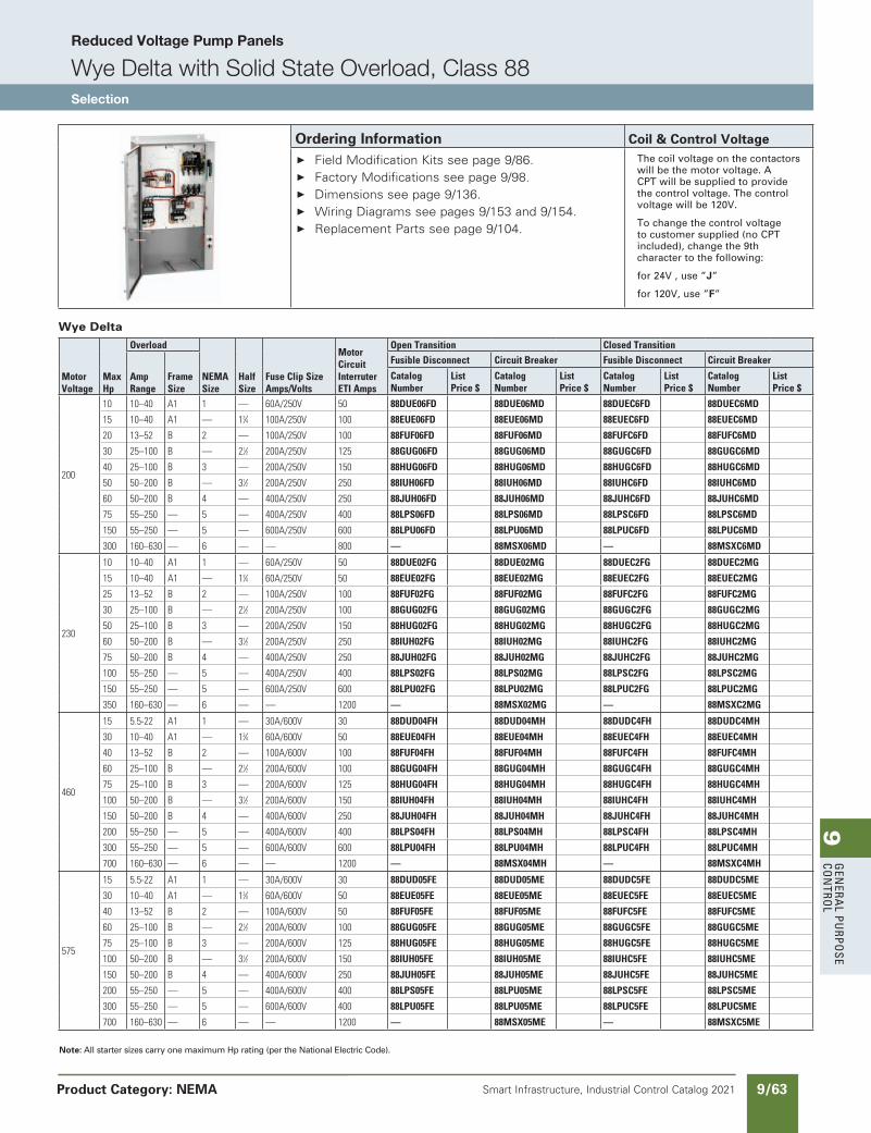
9G
enera
l PurPo
se Co
ntro
l
9/63Smart Infrastructure, Industrial Control Catalog 2021
Reduced Voltage Pump Panels
Wye Delta with Solid State Overload, Class 88Selection
Product Category: NEMA
Note: All starter sizes carry one maximum Hp rating (per the National Electric Code).
Wye Delta
MotorVoltage
MaxHp
Overload
NEMASize
HalfSize
FuseClipSizeAmps/Volts
MotorCircuitInterruterETIAmps
OpenTransition ClosedTransition
AmpRange
FrameSize
FusibleDisconnect CircuitBreaker FusibleDisconnect CircuitBreaker
CatalogNumber
ListPrice$
CatalogNumber
ListPrice$
CatalogNumber
ListPrice$
CatalogNumber
ListPrice$
200
10 10–40 A1 1 — 60A/250V 50 88DUE06FD 88DUE06MD 88DUEC6FD 88DUEC6MD
15 10–40 A1 — 13⁄4 100A/250V 100 88EUE06FD 88EUE06MD 88EUEC6FD 88EUEC6MD
20 13–52 B 2 — 100A/250V 100 88FUF06FD 88FUF06MD 88FUFC6FD 88FUFC6MD
30 25–100 B — 21⁄2 200A/250V 125 88GUG06FD 88GUG06MD 88GUGC6FD 88GUGC6MD
40 25–100 B 3 — 200A/250V 150 88HUG06FD 88HUG06MD 88HUGC6FD 88HUGC6MD
50 50–200 B — 31⁄2 200A/250V 250 88IUH06FD 88IUH06MD 88IUHC6FD 88IUHC6MD
60 50–200 B 4 — 400A/250V 250 88JUH06FD 88JUH06MD 88JUHC6FD 88JUHC6MD
75 55–250 — 5 — 400A/250V 400 88LPS06FD 88LPS06MD 88LPSC6FD 88LPSC6MD
150 55–250 — 5 — 600A/250V 600 88LPU06FD 88LPU06MD 88LPUC6FD 88LPUC6MD
300 160–630 — 6 — — 800 — 88MSX06MD — 88MSXC6MD
230
10 10–40 A1 1 — 60A/250V 50 88DUE02FG 88DUE02MG 88DUEC2FG 88DUEC2MG
15 10–40 A1 — 13⁄4 60A/250V 50 88EUE02FG 88EUE02MG 88EUEC2FG 88EUEC2MG
25 13–52 B 2 — 100A/250V 100 88FUF02FG 88FUF02MG 88FUFC2FG 88FUFC2MG
30 25–100 B — 21⁄2 200A/250V 100 88GUG02FG 88GUG02MG 88GUGC2FG 88GUGC2MG
50 25–100 B 3 — 200A/250V 150 88HUG02FG 88HUG02MG 88HUGC2FG 88HUGC2MG
60 50–200 B — 31⁄2 200A/250V 250 88IUH02FG 88IUH02MG 88IUHC2FG 88IUHC2MG
75 50–200 B 4 — 400A/250V 250 88JUH02FG 88JUH02MG 88JUHC2FG 88JUHC2MG
100 55–250 — 5 — 400A/250V 400 88LPS02FG 88LPS02MG 88LPSC2FG 88LPSC2MG
150 55–250 — 5 — 600A/250V 600 88LPU02FG 88LPU02MG 88LPUC2FG 88LPUC2MG
350 160–630 — 6 — — 1200 — 88MSX02MG — 88MSXC2MG
460
15 5.5-22 A1 1 — 30A/600V 30 88DUD04FH 88DUD04MH 88DUDC4FH 88DUDC4MH
30 10–40 A1 — 13⁄4 60A/600V 50 88EUE04FH 88EUE04MH 88EUEC4FH 88EUEC4MH
40 13–52 B 2 — 100A/600V 100 88FUF04FH 88FUF04MH 88FUFC4FH 88FUFC4MH
60 25–100 B — 21⁄2 200A/600V 100 88GUG04FH 88GUG04MH 88GUGC4FH 88GUGC4MH
75 25–100 B 3 — 200A/600V 125 88HUG04FH 88HUG04MH 88HUGC4FH 88HUGC4MH
100 50–200 B — 31⁄2 200A/600V 150 88IUH04FH 88IUH04MH 88IUHC4FH 88IUHC4MH
150 50–200 B 4 — 400A/600V 250 88JUH04FH 88JUH04MH 88JUHC4FH 88JUHC4MH
200 55–250 — 5 — 400A/600V 400 88LPS04FH 88LPS04MH 88LPSC4FH 88LPSC4MH
300 55–250 — 5 — 600A/600V 600 88LPU04FH 88LPU04MH 88LPUC4FH 88LPUC4MH
700 160–630 — 6 — — 1200 — 88MSX04MH — 88MSXC4MH
575
15 5.5-22 A1 1 — 30A/600V 30 88DUD05FE 88DUD05ME 88DUDC5FE 88DUDC5ME
30 10–40 A1 — 13⁄4 60A/600V 50 88EUE05FE 88EUE05ME 88EUEC5FE 88EUEC5ME
40 13–52 B 2 — 100A/600V 50 88FUF05FE 88FUF05ME 88FUFC5FE 88FUFC5ME
60 25–100 B — 21⁄2 200A/600V 100 88GUG05FE 88GUG05ME 88GUGC5FE 88GUGC5ME
75 25–100 B 3 — 200A/600V 125 88HUG05FE 88HUG05ME 88HUGC5FE 88HUGC5ME
100 50–200 B — 31⁄2 200A/600V 150 88IUH05FE 88IUH05ME 88IUHC5FE 88IUHC5ME
150 50–200 B 4 — 400A/600V 250 88JUH05FE 88JUH05ME 88JUHC5FE 88JUHC5ME
200 55–250 — 5 — 400A/600V 400 88LPS05FE 88LPU05ME 88LPSC5FE 88LPSC5ME
300 55–250 — 5 — 600A/600V 400 88LPU05FE 88LPU05ME 88LPUC5FE 88LPUC5ME
700 160–630 — 6 — — 1200 — 88MSX05ME — 88MSXC5ME
Ordering Information Coil & Control Voltage Field Modification Kits see page 9/86. Factory Modifications see page 9/98. Dimensions see page 9/136. Wiring Diagrams see pages 9/153 and 9/154. Replacement Parts see page 9/104.
The coil voltage on the contactors will be the motor voltage. A CPT will be supplied to provide the control voltage. The control voltage will be 120V.
To change the control voltage to customer supplied (no CPT included), change the 9th character to the following:
for 24V , use ”J”
for 120V, use ”F”
updated in SPEEDFAXRevised on 03/31/20
SS copied this page from SF to IC on 05/24/20
9G
ener
al
PurP
ose
Co
ntr
ol
9/64 Smart Infrastructure, Industrial Control Catalog 2021
Pump Controls Panels
Notes
updated in SPEEDFAXRevised on 08/31/18
SS copied this page from SF to IC on 05/24/20
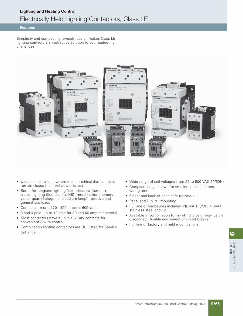
9G
enera
l PurPo
se Co
ntro
l
9/65Smart Infrastructure, Industrial Control Catalog 2021
Lighting and Heating Control
Electrically Held Lighting Contactors, Class LEFeatures
Simplicity and compact lightweight design makes Class LE lighting contactors an attractive solution to your budgeting challenges.
• Used in applications where it is not critical that contacts remain closed if control power is lost• Rated for tungsten lighting (incandescent filament), ballast lighting (fluorescent, HID, metal halide, mercury vapor, quartz halogen and sodium-lamp), resistive and general use loads• Contacts are rated 20 - 400 amps at 600 volts• 3 and 4 pole (up to 12 pole for 30 and 60 amp contactors)• Most contactors have built-in auxiliary contacts for convenient 3-wire control• Combination lighting contactors are UL Listed for Service Entrance
• Wide range of coil voltages from 24 to 600 VAC 50/60Hz• Compact design allows for smaller panels and more wiring room• Finger and back-of-hand safe terminals• Panel and DIN rail mounting• Full line of enclosures including NEMA 1, 3/3R, 4, 4/4X stainless steel and 12• Available in combination form with choice of non-fusible disconnect, fusible disconnect or circuit breaker• Full line of factory and field modifications
updated in SPEEDFAXRevised on 05/31/19
SS copied this page from SF to IC on 05/24/20
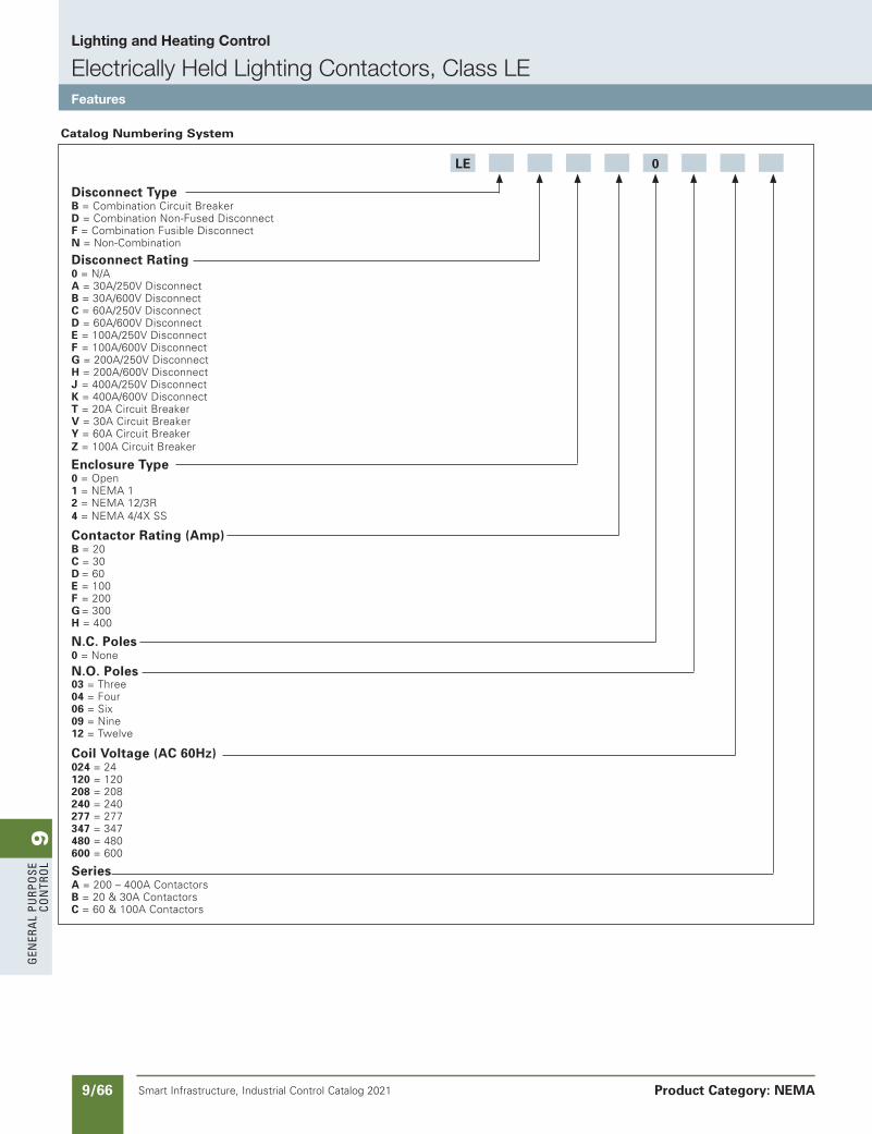
9G
ener
al
PurP
ose
Co
ntr
ol
9/66 Smart Infrastructure, Industrial Control Catalog 2021
Lighting and Heating Control
Electrically Held Lighting Contactors, Class LEFeatures
Product Category: NEMA
Disconnect TypeB = Combination Circuit BreakerD = Combination Non-Fused DisconnectF = Combination Fusible DisconnectN = Non-Combination
Disconnect Rating0 = N/AA = 30A/250V DisconnectB = 30A/600V DisconnectC = 60A/250V DisconnectD = 60A/600V DisconnectE = 100A/250V DisconnectF = 100A/600V DisconnectG = 200A/250V DisconnectH = 200A/600V DisconnectJ = 400A/250V DisconnectK = 400A/600V DisconnectT = 20A Circuit BreakerV = 30A Circuit BreakerY = 60A Circuit BreakerZ = 100A Circuit Breaker
Enclosure Type0 = Open1 = NEMA 12 = NEMA 12/3R4 = NEMA 4/4X SS
Contactor Rating (Amp)B = 20C = 30D = 60E = 100F = 200G = 300H = 400
N.C. Poles0 = None
N.O. Poles03 = Three04 = Four06 = Six09 = Nine12 = Twelve
Coil Voltage (AC 60Hz)024 = 24120 = 120208 = 208240 = 240277 = 277347 = 347480 = 480600 = 600
SeriesA = 200 – 400A ContactorsB = 20 & 30A ContactorsC = 60 & 100A Contactors
LE 0
Catalog Numbering System
SS copied this page from SF to IC on 05/24/20
updated in SPEEDFAXRevised on 03/31/20
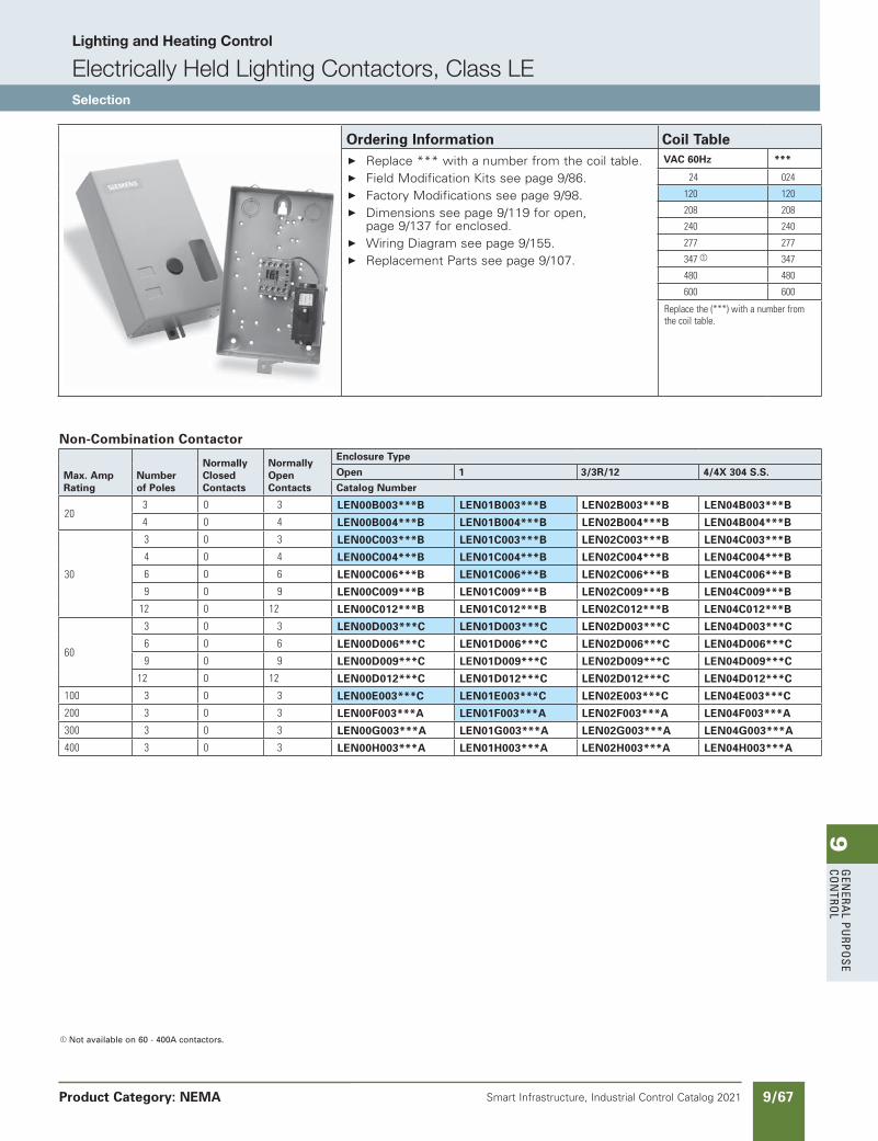
9G
enera
l PurPo
se Co
ntro
l
9/67Smart Infrastructure, Industrial Control Catalog 2021
Lighting and Heating Control
Electrically Held Lighting Contactors, Class LESelection
Product Category: NEMA
a Not available on 60 - 400A contactors.
Max. Amp Rating
Number of Poles
Normally Closed Contacts
Normally Open Contacts
Enclosure Type
Open 1 3/3R/12 4/4X 304 S.S.
Catalog Number
203 0 3 LEN00B003***B LEN01B003***B LEN02B003***B LEN04B003***B
4 0 4 LEN00B004***B LEN01B004***B LEN02B004***B LEN04B004***B
30
3 0 3 LEN00C003***B LEN01C003***B LEN02C003***B LEN04C003***B
4 0 4 LEN00C004***B LEN01C004***B LEN02C004***B LEN04C004***B
6 0 6 LEN00C006***B LEN01C006***B LEN02C006***B LEN04C006***B
9 0 9 LEN00C009***B LEN01C009***B LEN02C009***B LEN04C009***B
12 0 12 LEN00C012***B LEN01C012***B LEN02C012***B LEN04C012***B
60
3 0 3 LEN00D003***C LEN01D003***C LEN02D003***C LEN04D003***C
6 0 6 LEN00D006***C LEN01D006***C LEN02D006***C LEN04D006***C
9 0 9 LEN00D009***C LEN01D009***C LEN02D009***C LEN04D009***C
12 0 12 LEN00D012***C LEN01D012***C LEN02D012***C LEN04D012***C
100 3 0 3 LEN00E003***C LEN01E003***C LEN02E003***C LEN04E003***C
200 3 0 3 LEN00F003***A LEN01F003***A LEN02F003***A LEN04F003***A
300 3 0 3 LEN00G003***A LEN01G003***A LEN02G003***A LEN04G003***A
400 3 0 3 LEN00H003***A LEN01H003***A LEN02H003***A LEN04H003***A
Non-Combination Contactor
Ordering Information Coil Table Replace *** with a number from the coil table. Field Modification Kits see page 9/86. Factory Modifications see page 9/98. Dimensions see page 9/119 for open,
page 9/137 for enclosed. Wiring Diagram see page 9/155. Replacement Parts see page 9/107.
VAC 60Hz ***
24 024
120 120
208 208
240 240
277 277
347a 347
480 480
600 600
Replacethe(***)withanumberfromthecoiltable.
updated in SPEEDFAXRevised on 03/31/20
SS copied this page from SF to IC on 05/24/20
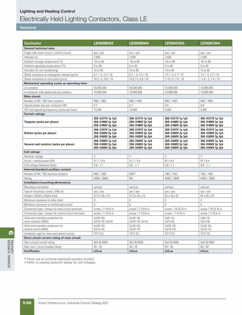
9G
ener
al
PurP
ose
Co
ntr
ol
9/68 Smart Infrastructure, Industrial Control Catalog 2021
Lighting and Heating Control
Electrically Held Lighting Contactors, Class LETechnical
Contactor LEN00B003 LEN00B004 LEN00C003 LEN00C004 LEN00D003 LEN00E003 LEN00F003 LEN00G003 LEN00H003General technical data:
Finger-safe(maincircuit/controlcircuit) yes/yes yes/yes yes/yes yes/yes no/yes no/yes no/yes no/yes no/yesAltitude(m) 2,000 2,000 2,000 2,000 2,000 2,000 2,000 2,000 2,000Ambientstoragetemperature(°C) -55to80 -55to80 -55to80 -55to80 -55to80 -55to80 -55to80 -55to80 -55to80Ambientoperatingtemperature(°C) 0to40 0to40 0to40 0to40 0to40 0to40 0to40 0to40 0to40Humidity(%non-condensing) 10to95 10to95 10to95 10to95 10to95 10to95 10to95 10to95 10to95Shockresistanceatrectangularimpulse(g/ms) 6.7/5,4.2/10 6.7/5,4.2/10 7.5/5,4.7/10 7.5/5,4.7/10 11.8/5,7.4/10 6.7/5,4/10 8.5/5,4.2/10 8.5/5,4.2/10 8.5/5,4.2/10Shockresistanceatsinepulse(g/ms) 10.5/5,6.6/10 10.5/5,6.6/10 11.8/5,7.4/10 11.8/5,7.4/10 18.5/5,10/10 10.6/5,6.3/10 13.4/5,6.5/10 13.4/5,6.5/10 13.4/5,6.5/10Mechanical operating cycles as operating time: Mechanical operating cycles as operating time:
ofcontactor 30,000,000 30,000,000 10,000,000 10,000,000 10,000,000 10,000,000 10,000,000 10,000,000 10,000,000ofcontactorwithadditionalauxcontacts 10,000,000 10,000,000 10,000,000 10,000,000 10,000,000 10,000,000 10,000,000 10,000,000 10,000,000Main circuit: Main circuit:
NumberofNC/NOmaincontacts 0NC/3NO 0NC/4NO 0NC/3NO 0NC/4NO 0NC/3NO 0NC/3NO 0NC/3NO 0NC/3NO 0NC/3NOTypicalpowerlossperconductor(W) 0.7 0.7 0.9 0.9 3.8 5.3 13 18 35Off-loadoperatingfrequency(cyclesperhour) 10,000 10,000 5,000 5,000 5,000 5,000 2,000 2,000 2,000Current ratings: Current ratings:
Tungsten(polesperphase)20A@277V1p1ph20A@480V2p1ph20A@480V3p3ph
20A@277V1p1ph20A@480V2p1ph20A@480V3p3ph
30A@277V1p1ph30A@480V2p1ph30A@480V3p3ph
30A@277V1p1ph30A@480V2p1ph30A@480V3p3ph
60A@277V1p1ph60A@480V2p1ph60A@480V3p3ph
100A@277V1p1ph100A@480V2p1ph100A@480V3p3ph
200A@277V1p1ph200A@480V2p1ph200A@480V3p3ph
300A@277V1p1ph300A@480V2p1ph300A@480V3p3ph
400A@277V1p1ph400A@480V2p1ph400A@480V3p3ph
Ballast(polesperphase)20A@347V1p1ph20A@600V2p1ph20A@600V3p3ph
20A@347V1p1ph20A@600V2p1ph20A@600V3p3ph
30A@347V1p1ph30A@600V2p1ph30A@660V3p3ph
30A@347V1p1ph30A@600V2p1ph30A@600V3p3ph
60A@347V1p1ph60A@600V2p1ph60A@600V3p3ph
100A@347V1p1ph100A@600V2p1ph100A@600V3p3ph
200A@600V1p1ph200A@600V2p1ph200A@600V3p3ph
300A@600V1p1ph300A@600V2p1ph300A@600V3p3ph
400A@600V1p1ph400A@600V2p1ph400A@600V3p3ph
Generalandresistive(polesperphase)20A@600V1p1ph20A@600V2p1ph20A@600V3p3ph
20A@600V1p1ph20A@600V2p1ph20A@600V3p3ph
30A@600V1p1ph30A@600V2p1ph30A@600V3p3ph
30A@600V1p1ph30A@600V2p1ph30A@600V3p3ph
60A@347V1p1ph60A@600V2p1ph60A@600V3p3ph
100A@347V1p1ph100A@600V2p1ph100A@600V3p3ph
200A@600V1p1ph200A@600V2p1ph200A@600V3p3ph
300A@600V1p1ph300A@600V2p1ph300A@600V3p3ph
400A@600V1p1ph400A@600V2p1ph400A@600V3p3ph
Coil ratings: Coil ratings:
Nominalvoltage 2) 2) 2) 2) 2) 2) 2) 2) 2)
Inrush/sealedpower(VA) 31.7/4.8 31.7/4.8 87/9.4 87/9.4 188/16.5 326/22 300/5.8 590/6.7 830/9.2Coilvoltagetolerancefactor 0.8-1.1 0.8-1.1 0.8-1.1 0.8-1.1 0.8-1.1 0.8-1.1 0.8-1.1 0.8-1.1 0.8-1.1Internal/standard auxiliary contact: Internal/standard auxiliary contact:
NumberofNC/NOauxiliarycontacts 0NC/1NO NAa 1NC/1NO 1NC/1NO 1 N C / 1 N O 1 N C / 1 N O 2NC/2NO 2NC/2NO 2NC/2NORating A600/Q600 NA A600/Q600 A600/Q600 A600/P600 A600/P600 A300/Q300 A300/Q300 A300/Q300Installation/mounting/dimensions: Installation/mounting/dimensions:
Mountingorientation vertical vertical vertical vertical vertical vertical vertical vertical verticalTypeofmounting:screw/DINrail yes/yes yes/yes yes/yes yes/yes yes/yes yes/yes yes/no yes/no yes/noHeightxWidthxDepth(mm) 57.5x45x73 57.5x45x73 85x45x97 85x60x97 113x55x130 140x70x152 172x120x180 210x145x202 214x160x225Minimumclearancetosides(mm) 0 0 0 0 6 6 10 10 10Minimumclearancetoearthedparts(mm) 6 6 6 6 6 6 10 10 10Connectiontype/torqueformaincircuitterminals screw/7-10lbin screw/7-10lbin screw/18-22lbin screw/18-22lbin screw/26-39lbin screw/26-39lbin screw/90-110lbin screw/180-195lbin screw/180-195lbinConnectiontype/torqueforcontrolcircuitterminals screw/7-10lbin screw/7-10lbin screw/7-10lbin screw/7-10lbin screw/7-10lbin screw/7-10lbin screw/7-10lbin screw/7-10lbin screw/7-10lbin
Solidandstrandedconductorsformaincontacts(AWG)
2x(20-16),2x(18-14),2x(12)
2x(20-16),2x(18-14),2x(12)
2x(6-12),2x(14-8)
2x(6-12),2x(14-8)
2x(18...2),1x(18...1)
2x(18...2),1x(18...1)
2x(6-3/0) 2x(2/0-500MCM) 2x(2/0-500MCM)
Solidandstrandedconductorsforcontrolcircuit(AWG)
2x(20-16),2x(18-14)
2x(20-16),2x(18-14)
2x(20-16),2x(18-14)
2x(20-16),2x(18-14)
2x(20...16),2x(18...14)
2x(18...2),1x(18...1)
2x(18-14) 2x(18-14) 2x(18-14)
Conductortypeformainandcontrolcircuits 75°CCU 75°CCU 75°CCU 75°CCU 75°CCU 75°CCU 75°CCU 75°CCU 75°CCUShort circuit current rating of main circuit: Short circuit current rating of main circuit:
Shortcircuitcurrentrating 5kA@600V 5kA@600V 5kA@600V 5kA@600V 5kA@600V 10kA@600V 10kA@600V 18kA@600V 18kA@600V
Maxfuse/circuitbreaker(Amp) 30/25 30/25 60/40 60/40 100/80 200/125 400/250 600/400 800/500Certificates: cULus cULus cULus cULus cULus cULus cULus cULus cULus
a Must use an external (optional) auxiliary contact.2) Refer to catalog selection tables for coil voltages.
SS copied this page from SF to IC on 05/24/20
updated in SPEEDFAXRevised on 03/31/20
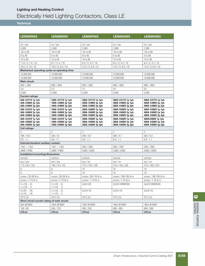
9G
enera
l PurPo
se Co
ntro
l
9/69Smart Infrastructure, Industrial Control Catalog 2021
Lighting and Heating Control
Electrically Held Lighting Contactors, Class LETechnical
updated in SPEEDFAXRevised on 03/31/20
SS copied this page from SF to IC on 05/24/20
Contactor LEN00B003 LEN00B004 LEN00C003 LEN00C004 LEN00D003 LEN00E003 LEN00F003 LEN00G003 LEN00H003General technical data:
Finger-safe(maincircuit/controlcircuit) yes/yes yes/yes yes/yes yes/yes no/yes no/yes no/yes no/yes no/yesAltitude(m) 2,000 2,000 2,000 2,000 2,000 2,000 2,000 2,000 2,000Ambientstoragetemperature(°C) -55to80 -55to80 -55to80 -55to80 -55to80 -55to80 -55to80 -55to80 -55to80Ambientoperatingtemperature(°C) 0to40 0to40 0to40 0to40 0to40 0to40 0to40 0to40 0to40Humidity(%non-condensing) 10to95 10to95 10to95 10to95 10to95 10to95 10to95 10to95 10to95Shockresistanceatrectangularimpulse(g/ms) 6.7/5,4.2/10 6.7/5,4.2/10 7.5/5,4.7/10 7.5/5,4.7/10 11.8/5,7.4/10 6.7/5,4/10 8.5/5,4.2/10 8.5/5,4.2/10 8.5/5,4.2/10Shockresistanceatsinepulse(g/ms) 10.5/5,6.6/10 10.5/5,6.6/10 11.8/5,7.4/10 11.8/5,7.4/10 18.5/5,10/10 10.6/5,6.3/10 13.4/5,6.5/10 13.4/5,6.5/10 13.4/5,6.5/10Mechanical operating cycles as operating time: Mechanical operating cycles as operating time:
ofcontactor 30,000,000 30,000,000 10,000,000 10,000,000 10,000,000 10,000,000 10,000,000 10,000,000 10,000,000ofcontactorwithadditionalauxcontacts 10,000,000 10,000,000 10,000,000 10,000,000 10,000,000 10,000,000 10,000,000 10,000,000 10,000,000Main circuit: Main circuit:
NumberofNC/NOmaincontacts 0NC/3NO 0NC/4NO 0NC/3NO 0NC/4NO 0NC/3NO 0NC/3NO 0NC/3NO 0NC/3NO 0NC/3NOTypicalpowerlossperconductor(W) 0.7 0.7 0.9 0.9 3.8 5.3 13 18 35Off-loadoperatingfrequency(cyclesperhour) 10,000 10,000 5,000 5,000 5,000 5,000 2,000 2,000 2,000Current ratings: Current ratings:
Tungsten(polesperphase)20A@277V1p1ph20A@480V2p1ph20A@480V3p3ph
20A@277V1p1ph20A@480V2p1ph20A@480V3p3ph
30A@277V1p1ph30A@480V2p1ph30A@480V3p3ph
30A@277V1p1ph30A@480V2p1ph30A@480V3p3ph
60A@277V1p1ph60A@480V2p1ph60A@480V3p3ph
100A@277V1p1ph100A@480V2p1ph100A@480V3p3ph
200A@277V1p1ph200A@480V2p1ph200A@480V3p3ph
300A@277V1p1ph300A@480V2p1ph300A@480V3p3ph
400A@277V1p1ph400A@480V2p1ph400A@480V3p3ph
Ballast(polesperphase)20A@347V1p1ph20A@600V2p1ph20A@600V3p3ph
20A@347V1p1ph20A@600V2p1ph20A@600V3p3ph
30A@347V1p1ph30A@600V2p1ph30A@660V3p3ph
30A@347V1p1ph30A@600V2p1ph30A@600V3p3ph
60A@347V1p1ph60A@600V2p1ph60A@600V3p3ph
100A@347V1p1ph100A@600V2p1ph100A@600V3p3ph
200A@600V1p1ph200A@600V2p1ph200A@600V3p3ph
300A@600V1p1ph300A@600V2p1ph300A@600V3p3ph
400A@600V1p1ph400A@600V2p1ph400A@600V3p3ph
Generalandresistive(polesperphase)20A@600V1p1ph20A@600V2p1ph20A@600V3p3ph
20A@600V1p1ph20A@600V2p1ph20A@600V3p3ph
30A@600V1p1ph30A@600V2p1ph30A@600V3p3ph
30A@600V1p1ph30A@600V2p1ph30A@600V3p3ph
60A@347V1p1ph60A@600V2p1ph60A@600V3p3ph
100A@347V1p1ph100A@600V2p1ph100A@600V3p3ph
200A@600V1p1ph200A@600V2p1ph200A@600V3p3ph
300A@600V1p1ph300A@600V2p1ph300A@600V3p3ph
400A@600V1p1ph400A@600V2p1ph400A@600V3p3ph
Coil ratings: Coil ratings:
Nominalvoltage 2) 2) 2) 2) 2) 2) 2) 2) 2)
Inrush/sealedpower(VA) 31.7/4.8 31.7/4.8 87/9.4 87/9.4 188/16.5 326/22 300/5.8 590/6.7 830/9.2Coilvoltagetolerancefactor 0.8-1.1 0.8-1.1 0.8-1.1 0.8-1.1 0.8-1.1 0.8-1.1 0.8-1.1 0.8-1.1 0.8-1.1Internal/standard auxiliary contact: Internal/standard auxiliary contact:
NumberofNC/NOauxiliarycontacts 0NC/1NO NAa 1NC/1NO 1NC/1NO 1 N C / 1 N O 1 N C / 1 N O 2NC/2NO 2NC/2NO 2NC/2NORating A600/Q600 NA A600/Q600 A600/Q600 A600/P600 A600/P600 A300/Q300 A300/Q300 A300/Q300Installation/mounting/dimensions: Installation/mounting/dimensions:
Mountingorientation vertical vertical vertical vertical vertical vertical vertical vertical verticalTypeofmounting:screw/DINrail yes/yes yes/yes yes/yes yes/yes yes/yes yes/yes yes/no yes/no yes/noHeightxWidthxDepth(mm) 57.5x45x73 57.5x45x73 85x45x97 85x60x97 113x55x130 140x70x152 172x120x180 210x145x202 214x160x225Minimumclearancetosides(mm) 0 0 0 0 6 6 10 10 10Minimumclearancetoearthedparts(mm) 6 6 6 6 6 6 10 10 10Connectiontype/torqueformaincircuitterminals screw/7-10lbin screw/7-10lbin screw/18-22lbin screw/18-22lbin screw/26-39lbin screw/26-39lbin screw/90-110lbin screw/180-195lbin screw/180-195lbinConnectiontype/torqueforcontrolcircuitterminals screw/7-10lbin screw/7-10lbin screw/7-10lbin screw/7-10lbin screw/7-10lbin screw/7-10lbin screw/7-10lbin screw/7-10lbin screw/7-10lbin
Solidandstrandedconductorsformaincontacts(AWG)
2x(20-16),2x(18-14),2x(12)
2x(20-16),2x(18-14),2x(12)
2x(6-12),2x(14-8)
2x(6-12),2x(14-8)
2x(18...2),1x(18...1)
2x(18...2),1x(18...1)
2x(6-3/0) 2x(2/0-500MCM) 2x(2/0-500MCM)
Solidandstrandedconductorsforcontrolcircuit(AWG)
2x(20-16),2x(18-14)
2x(20-16),2x(18-14)
2x(20-16),2x(18-14)
2x(20-16),2x(18-14)
2x(20...16),2x(18...14)
2x(18...2),1x(18...1)
2x(18-14) 2x(18-14) 2x(18-14)
Conductortypeformainandcontrolcircuits 75°CCU 75°CCU 75°CCU 75°CCU 75°CCU 75°CCU 75°CCU 75°CCU 75°CCUShort circuit current rating of main circuit: Short circuit current rating of main circuit:
Shortcircuitcurrentrating 5kA@600V 5kA@600V 5kA@600V 5kA@600V 5kA@600V 10kA@600V 10kA@600V 18kA@600V 18kA@600V
Maxfuse/circuitbreaker(Amp) 30/25 30/25 60/40 60/40 100/80 200/125 400/250 600/400 800/500Certificates: cULus cULus cULus cULus cULus cULus cULus cULus cULus
a Must use an external (optional) auxiliary contact.2) Refer to catalog selection tables for coil voltages.
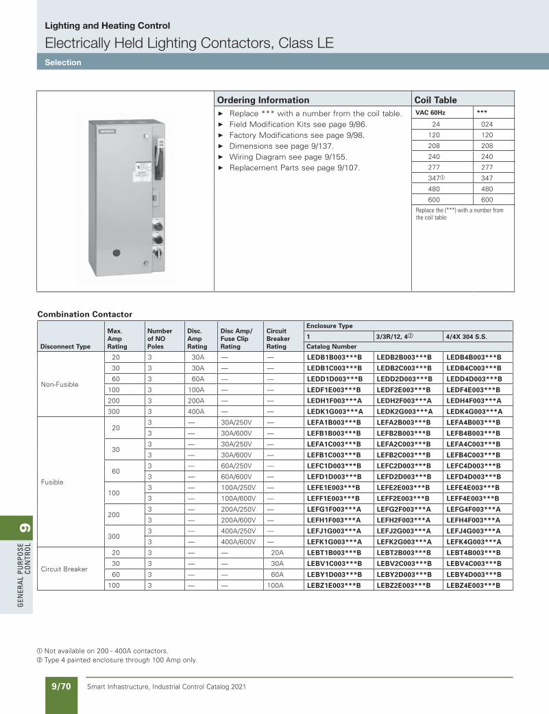
9G
ener
al
PurP
ose
Co
ntr
ol
9/70 Smart Infrastructure, Industrial Control Catalog 2021
Lighting and Heating Control
Electrically Held Lighting Contactors, Class LESelection
Combination Contactor
Disconnect Type
Max. Amp Rating
Number of NO Poles
Disc. Amp Rating
Disc Amp/ Fuse Clip Rating
Circuit Breaker Rating
Enclosure Type
1 3/3R/12, 4b 4/4X 304 S.S.
Catalog Number
Non-Fusible
20 3 30A — — LEDB1B003***B LEDB2B003***B LEDB4B003***B
30 3 30A — — LEDB1C003***B LEDB2C003***B LEDB4C003***B
60 3 60A — — LEDD1D003***B LEDD2D003***B LEDD4D003***B
100 3 100A — — LEDF1E003***B LEDF2E003***B LEDF4E003***B
200 3 200A — — LEDH1F003***A LEDH2F003***A LEDH4F003***A
300 3 400A — — LEDK1G003***A LEDK2G003***A LEDK4G003***A
Fusible
203 — 30A/250V — LEFA1B003***B LEFA2B003***B LEFA4B003***B
3 — 30A/600V — LEFB1B003***B LEFB2B003***B LEFB4B003***B
303 — 30A/250V — LEFA1C003***B LEFA2C003***B LEFA4C003***B
3 — 30A/600V — LEFB1C003***B LEFB2C003***B LEFB4C003***B
603 — 60A/250V — LEFC1D003***B LEFC2D003***B LEFC4D003***B
3 — 60A/600V — LEFD1D003***B LEFD2D003***B LEFD4D003***B
1003 — 100A/250V — LEFE1E003***B LEFE2E003***B LEFE4E003***B
3 — 100A/600V — LEFF1E003***B LEFF2E003***B LEFF4E003***B
2003 — 200A/250V — LEFG1F003***A LEFG2F003***A LEFG4F003***A
3 — 200A/600V — LEFH1F003***A LEFH2F003***A LEFH4F003***A
3003 — 400A/250V — LEFJ1G003***A LEFJ2G003***A LEFJ4G003***A
3 — 400A/600V — LEFK1G003***A LEFK2G003***A LEFK4G003***A
Circuit Breaker
20 3 — — 20A LEBT1B003***B LEBT2B003***B LEBT4B003***B
30 3 — — 30A LEBV1C003***B LEBV2C003***B LEBV4C003***B
60 3 — — 60A LEBY1D003***B LEBY2D003***B LEBY4D003***B
100 3 — — 100A LEBZ1E003***B LEBZ2E003***B LEBZ4E003***B
a Not available on 200 - 400A contactors. b Type 4 painted enclosure through 100 Amp only.
Ordering Information Coil Table Replace *** with a number from the coil table. Field Modification Kits see page 9/86. Factory Modifications see page 9/98. Dimensions see page 9/137. Wiring Diagram see page 9/155. Replacement Parts see page 9/107.
VAC 60Hz ***
24 024
120 120
208 208
240 240
277 277
347a 347
480 480
600 600
Replacethe(***)withanumberfromthecoiltable.
SS copied this page from SF to IC on 05/24/20
updated in SPEEDFAXRevised on 08/31/18
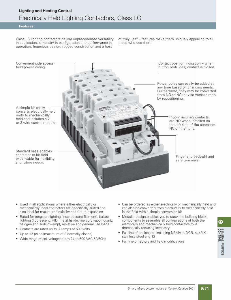
9G
enera
l PurPo
se Co
ntro
l
9/71Smart Infrastructure, Industrial Control Catalog 2021
Lighting and Heating Control
Electrically Held Lighting Contactors, Class LCFeatures
Class LC lighting contactors deliver unprecedented versatility in application, simplicity in configuration and performance in operation. Ingenious design, rugged construction and a host
of truly useful features make them uniquely appealing to all those who use them.
• Used in all applications where either electrically or mechanically held contactors are specifically suited and also ideal for maximum flexibility and future expansion• Rated for tungsten lighting (incandescent filament), ballast lighting (fluorescent, HID, metal halide, mercury vapor, quartz halogen and sodium-lamp), resistive and general use loads• Contacts are rated up to 30 amps at 600 volts• Up to 12 poles (maximum of 8 normally closed)• Wide range of coil voltages from 24 to 600 VAC 50/60Hz
• Can be ordered as either electrically or mechanically held and can also be converted from electrically to mechanically held in the field with a simple conversion kit• Modular design enables you to stock the building block components to assemble all configurations of both the electrically and mechanically held contactors thus dramatically reducing inventory• Full line of enclosures including NEMA 1, 3/3R, 4, 4/4X stainless steel and 12• Full line of factory and field modifications
Contact position indication – when button protrudes, contact is closed .
Convenient side access field power wiring.
Power poles can easily be added at any time based on changing needs. Furthermore, they may be converted from NO to NC (or vice versa) simply by repositioning.
A simple kit easily converts electrically held units to mechanically held and includes a 2- or 3-wire control module.
Plug-in auxiliary contacts are NO when installed on the left side of the contactor,NC on the right.
Finger and back-of-hand safe terminals.
Standard base enables contactor to be field expandable for flexibility and future needs.
SS copied this page from SF to IC on 05/24/20
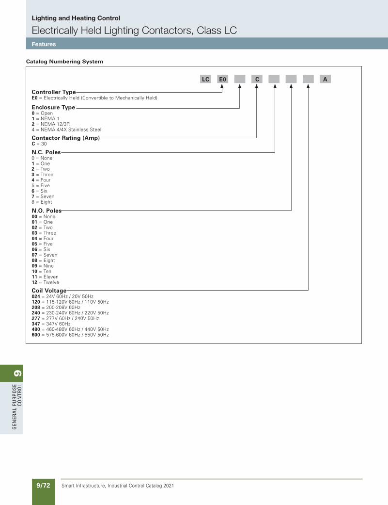
9G
ener
al
PurP
ose
Co
ntr
ol
9/72 Smart Infrastructure, Industrial Control Catalog 2021
Lighting and Heating Control
Electrically Held Lighting Contactors, Class LCFeatures
Controller TypeE0 = Electrically Held (Convertible to Mechanically Held)
Enclosure Type0 = Open1 = NEMA 12 = NEMA 12/3R4 = NEMA 4/4X Stainless Steel
Contactor Rating (Amp)C = 30
N.C. Poles0 = None1 = One2 = Two3 = Three4 = Four5 = Five6 = Six7 = Seven8 = Eight
N.O. Poles00 = None01 = One02 = Two03 = Three04 = Four05 = Five06 = Six07 = Seven08 = Eight09 = Nine10 = Ten11 = Eleven12 = Twelve
Coil Voltage 024 = 24V 60Hz / 20V 50Hz120 = 115-120V 60Hz / 110V 50Hz208 = 200-208V 60Hz240 = 230-240V 60Hz / 220V 50Hz277 = 277V 60Hz / 240V 50Hz347 = 347V 60Hz480 = 460-480V 60Hz / 440V 50Hz600 = 575-600V 60Hz / 550V 50Hz
LC E0 C A
Catalog Numbering System
SS copied this page from SF to IC on 05/24/20
updated in SPEEDFAXRevised on 04/30/21
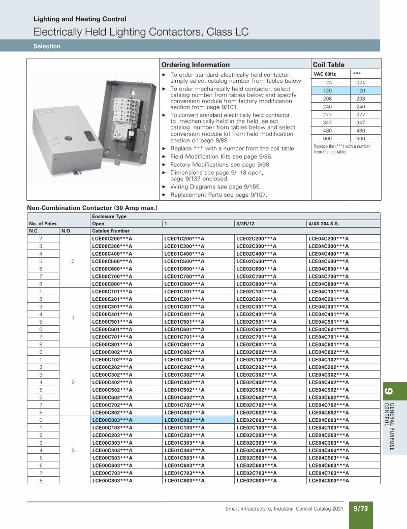
9G
enera
l PurPo
se Co
ntro
l
9/73Smart Infrastructure, Industrial Control Catalog 2021
Lighting and Heating Control
Electrically Held Lighting Contactors, Class LCSelection
Non-Combination Contactor (30 Amp max.)
No. of Poles
Enclosure Type
Open 1 3/3R/12 4/4X 304 S.S.
N.C. N.O. Catalog Number
2
0
LCE00C200***A LCE01C200***A LCE02C200***A LCE04C200***A3 LCE00C300***A LCE01C300***A LCE02C300***A LCE04C300***A4 LCE00C400***A LCE01C400***A LCE02C400***A LCE04C400***A5 LCE00C500***A LCE01C500***A LCE02C500***A LCE04C500***A6 LCE00C600***A LCE01C600***A LCE02C600***A LCE04C600***A7 LCE00C700***A LCE01C700***A LCE02C700***A LCE04C700***A8 LCE00C800***A LCE01C800***A LCE02C800***A LCE04C800***A1
1
LCE00C101***A LCE01C101***A LCE02C101***A LCE04C101***A2 LCE00C201***A LCE01C201***A LCE02C201***A LCE04C201***A3 LCE00C301***A LCE01C301***A LCE02C301***A LCE04C301***A4 LCE00C401***A LCE01C401***A LCE02C401***A LCE04C401***A5 LCE00C501***A LCE01C501***A LCE02C501***A LCE04C501***A6 LCE00C601***A LCE01C601***A LCE02C601***A LCE04C601***A7 LCE00C701***A LCE01C701***A LCE02C701***A LCE04C701***A8 LCE00C801***A LCE01C801***A LCE02C801***A LCE04C801***A0
2
LCE00C002***A LCE01C002***A LCE02C002***A LCE04C002***A1 LCE00C102***A LCE01C102***A LCE02C102***A LCE04C102***A2 LCE00C202***A LCE01C202***A LCE02C202***A LCE04C202***A3 LCE00C302***A LCE01C302***A LCE02C302***A LCE04C302***A4 LCE00C402***A LCE01C402***A LCE02C402***A LCE04C402***A5 LCE00C502***A LCE01C502***A LCE02C502***A LCE04C502***A6 LCE00C602***A LCE01C602***A LCE02C602***A LCE04C602***A7 LCE00C702***A LCE01C702***A LCE02C702***A LCE04C702***A8 LCE00C802***A LCE01C802***A LCE02C802***A LCE04C802***A0
3
LCE00C003***A LCE01C003***A LCE02C003***A LCE04C003***A1 LCE00C103***A LCE01C103***A LCE02C103***A LCE04C103***A2 LCE00C203***A LCE01C203***A LCE02C203***A LCE04C203***A3 LCE00C303***A LCE01C303***A LCE02C303***A LCE04C303***A4 LCE00C403***A LCE01C403***A LCE02C403***A LCE04C403***A5 LCE00C503***A LCE01C503***A LCE02C503***A LCE04C503***A6 LCE00C603***A LCE01C603***A LCE02C603***A LCE04C603***A7 LCE00C703***A LCE01C703***A LCE02C703***A LCE04C703***A8 LCE00C803***A LCE01C803***A LCE02C803***A LCE04C803***A
Ordering Information Coil Table To order standard electrically held contactor,
simply select catalog number from tables below. To order mechanically held contactor, select
catalog number from tables below and specify conversion module from factory modification section from page 9/101.
To convert standard electrically held contactor to mechanically held in the field, select catalog number from tables below and select conversion module kit from field modification section on page 9/88.
Replace *** with a number from the coil table. Field Modification Kits see page 9/86. Factory Modifications see page 9/98. Dimensions see page 9/118 open,
page 9/137 enclosed. Wiring Diagrams see page 9/155. Replacement Parts see page 9/107.
VAC 60Hz ***
24 024
120 120
208 208
240 240
277 277
347 347
480 480
600 600
Replacethe(***)withanumberfromthecoiltable.
updated in SPEEDFAXRevised on 08/31/18
SS copied this page from SF to IC on 05/24/20
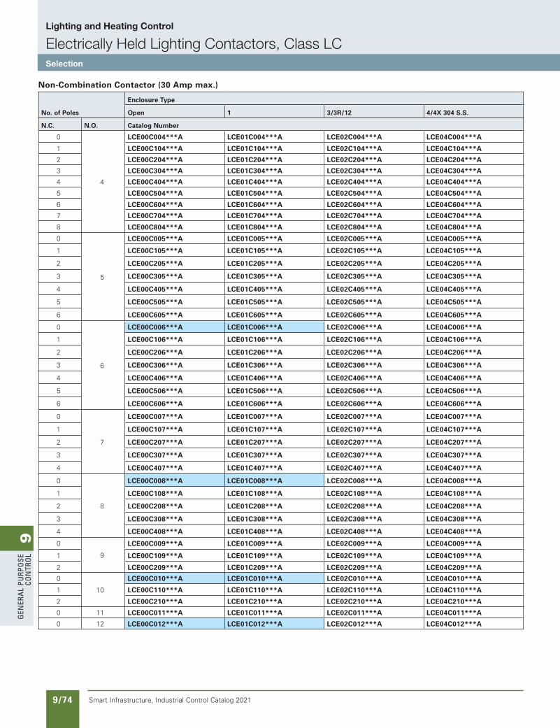
9G
ener
al
PurP
ose
Co
ntr
ol
9/74 Smart Infrastructure, Industrial Control Catalog 2021
Lighting and Heating Control
Electrically Held Lighting Contactors, Class LCSelection
No. of Poles
Enclosure Type
Open 1 3/3R/12 4/4X 304 S.S.
N.C. N.O. Catalog Number
0
4
LCE00C004***A LCE01C004***A LCE02C004***A LCE04C004***A
1 LCE00C104***A LCE01C104***A LCE02C104***A LCE04C104***A
2 LCE00C204***A LCE01C204***A LCE02C204***A LCE04C204***A
3 LCE00C304***A LCE01C304***A LCE02C304***A LCE04C304***A
4 LCE00C404***A LCE01C404***A LCE02C404***A LCE04C404***A
5 LCE00C504***A LCE01C504***A LCE02C504***A LCE04C504***A
6 LCE00C604***A LCE01C604***A LCE02C604***A LCE04C604***A
7 LCE00C704***A LCE01C704***A LCE02C704***A LCE04C704***A
8 LCE00C804***A LCE01C804***A LCE02C804***A LCE04C804***A
0
5
LCE00C005***A LCE01C005***A LCE02C005***A LCE04C005***A
1 LCE00C105***A LCE01C105***A LCE02C105***A LCE04C105***A
2 LCE00C205***A LCE01C205***A LCE02C205***A LCE04C205***A
3 LCE00C305***A LCE01C305***A LCE02C305***A LCE04C305***A
4 LCE00C405***A LCE01C405***A LCE02C405***A LCE04C405***A
5 LCE00C505***A LCE01C505***A LCE02C505***A LCE04C505***A
6 LCE00C605***A LCE01C605***A LCE02C605***A LCE04C605***A
0
6
LCE00C006***A LCE01C006***A LCE02C006***A LCE04C006***A
1 LCE00C106***A LCE01C106***A LCE02C106***A LCE04C106***A
2 LCE00C206***A LCE01C206***A LCE02C206***A LCE04C206***A
3 LCE00C306***A LCE01C306***A LCE02C306***A LCE04C306***A
4 LCE00C406***A LCE01C406***A LCE02C406***A LCE04C406***A
5 LCE00C506***A LCE01C506***A LCE02C506***A LCE04C506***A
6 LCE00C606***A LCE01C606***A LCE02C606***A LCE04C606***A
0
7
LCE00C007***A LCE01C007***A LCE02C007***A LCE04C007***A
1 LCE00C107***A LCE01C107***A LCE02C107***A LCE04C107***A
2 LCE00C207***A LCE01C207***A LCE02C207***A LCE04C207***A
3 LCE00C307***A LCE01C307***A LCE02C307***A LCE04C307***A
4 LCE00C407***A LCE01C407***A LCE02C407***A LCE04C407***A
0
8
LCE00C008***A LCE01C008***A LCE02C008***A LCE04C008***A
1 LCE00C108***A LCE01C108***A LCE02C108***A LCE04C108***A
2 LCE00C208***A LCE01C208***A LCE02C208***A LCE04C208***A
3 LCE00C308***A LCE01C308***A LCE02C308***A LCE04C308***A
4 LCE00C408***A LCE01C408***A LCE02C408***A LCE04C408***A
0
9
LCE00C009***A LCE01C009***A LCE02C009***A LCE04C009***A
1 LCE00C109***A LCE01C109***A LCE02C109***A LCE04C109***A
2 LCE00C209***A LCE01C209***A LCE02C209***A LCE04C209***A
0
10
LCE00C010***A LCE01C010***A LCE02C010***A LCE04C010***A
1 LCE00C110***A LCE01C110***A LCE02C110***A LCE04C110***A
2 LCE00C210***A LCE01C210***A LCE02C210***A LCE04C210***A
0 11 LCE00C011***A LCE01C011***A LCE02C011***A LCE04C011***A
0 12 LCE00C012***A LCE01C012***A LCE02C012***A LCE04C012***A
Non-Combination Contactor (30 Amp max.)
SS copied this page from SF to IC on 05/24/20
updated in SPEEDFAXRevised on 08/31/18
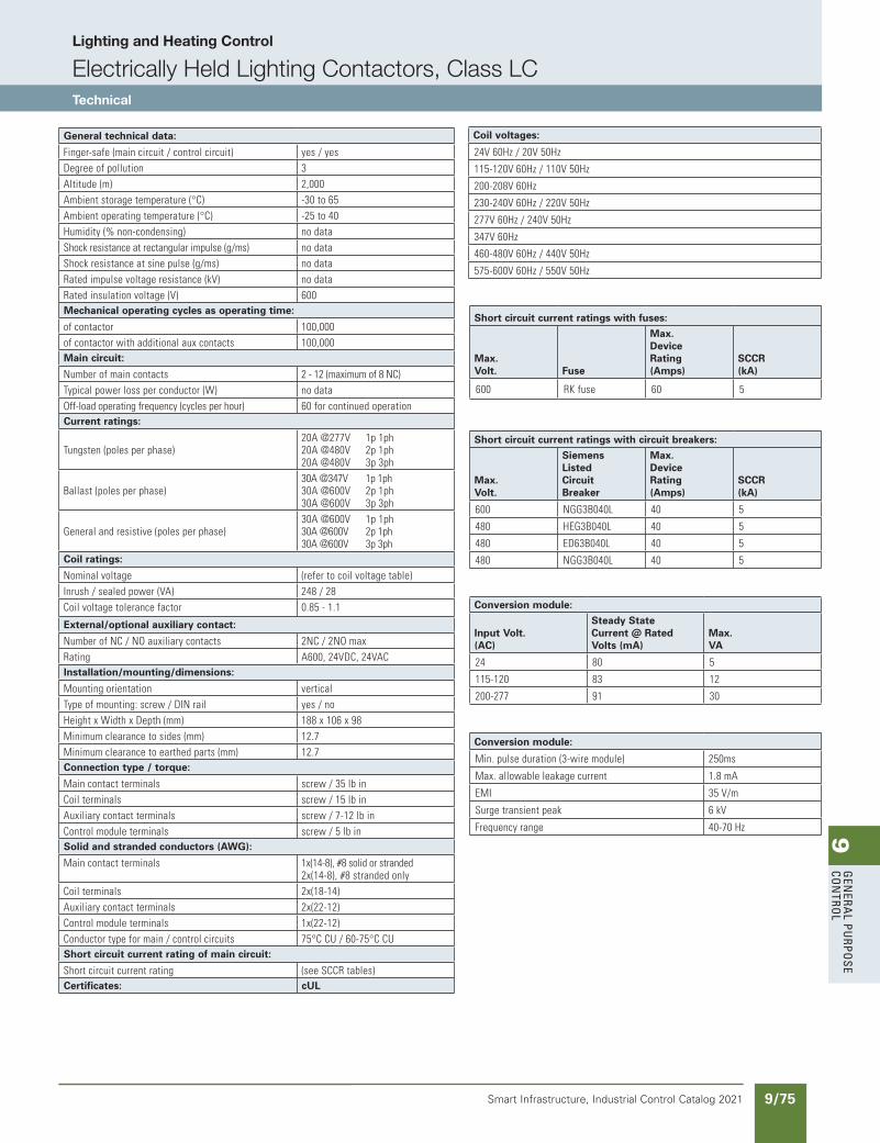
9G
enera
l PurPo
se Co
ntro
l
9/75Smart Infrastructure, Industrial Control Catalog 2021
Lighting and Heating Control
Electrically Held Lighting Contactors, Class LCTechnical
General technical data:
Finger-safe(maincircuit/controlcircuit) yes/yesDegreeofpollution 3Altitude(m) 2,000Ambientstoragetemperature(°C) -30to65Ambientoperatingtemperature(°C) -25to40Humidity(%non-condensing) nodataShockresistanceatrectangularimpulse(g/ms) nodataShockresistanceatsinepulse(g/ms) nodataRatedimpulsevoltageresistance(kV) nodataRatedinsulationvoltage(V) 600Mechanical operating cycles as operating time:
ofcontactor 100,000ofcontactorwithadditionalauxcontacts 100,000Main circuit:
Numberofmaincontacts 2-12(maximumof8NC)Typicalpowerlossperconductor(W) nodataOff-loadoperatingfrequency(cyclesperhour) 60forcontinuedoperationCurrent ratings:
Tungsten(polesperphase)20A@277V 1p1ph20A@480V 2p1ph20A@480V 3p3ph
Ballast(polesperphase)30A@347V 1p1ph30A@600V 2p1ph30A@600V 3p3ph
Generalandresistive(polesperphase)30A@600V 1p1ph30A@600V 2p1ph30A@600V 3p3ph
Coil ratings:
Nominalvoltage (refertocoilvoltagetable)Inrush/sealedpower(VA) 248/28Coilvoltagetolerancefactor 0.85-1.1
External/optional auxiliary contact:
NumberofNC/NOauxiliarycontacts 2NC/2NOmaxRating A600,24VDC,24VACInstallation/mounting/dimensions:
Mountingorientation verticalTypeofmounting:screw/DINrail yes/noHeightxWidthxDepth(mm) 188x106x98Minimumclearancetosides(mm) 12.7Minimumclearancetoearthedparts(mm) 12.7Connection type / torque:
Maincontactterminals screw/35lbinCoilterminals screw/15lbinAuxiliarycontactterminals screw/7-12lbinControlmoduleterminals screw/5lbinSolid and stranded conductors (AWG):
Maincontactterminals 1x(14-8),#8solidorstranded2x(14-8),#8strandedonly
Coilterminals 2x(18-14)Auxiliarycontactterminals 2x(22-12)Controlmoduleterminals 1x(22-12)Conductortypeformain/controlcircuits 75°CCU/60-75°CCUShort circuit current rating of main circuit:
Shortcircuitcurrentrating (seeSCCRtables)Certificates: cUL
Coil voltages:
24V60Hz/20V50Hz
115-120V60Hz/110V50Hz
200-208V60Hz
230-240V60Hz/220V50Hz
277V60Hz/240V50Hz
347V60Hz
460-480V60Hz/440V50Hz
575-600V60Hz/550V50Hz
Short circuit current ratings with fuses:
Max.Volt. Fuse
Max.DeviceRating(Amps)
SCCR(kA)
600 RKfuse 60 5
Short circuit current ratings with circuit breakers:
Max.Volt.
SiemensListed CircuitBreaker
Max.DeviceRating(Amps)
SCCR(kA)
600 NGG3B040L 40 5
480 HEG3B040L 40 5
480 ED63B040L 40 5
480 NGG3B040L 40 5
Conversion module:
Input Volt.(AC)
Steady State Current @ Rated Volts (mA)
Max.VA
24 80 5
115-120 83 12
200-277 91 30
Conversion module:
Min.pulseduration(3-wiremodule) 250ms
Max.allowableleakagecurrent 1.8mA
EMI 35V/m
Surgetransientpeak 6kV
Frequencyrange 40-70Hz
SS copied this page from SF to IC on 05/24/20
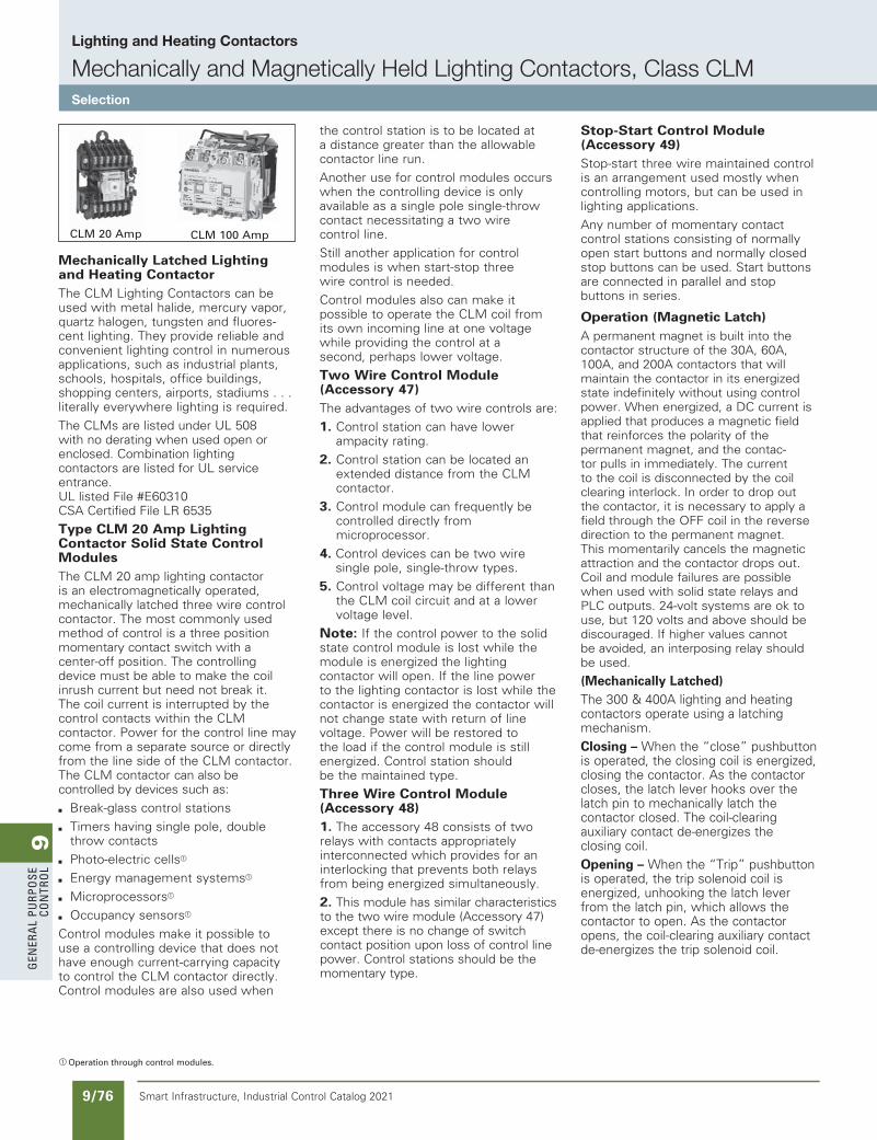
9G
ener
al
PurP
ose
Co
ntr
ol
9/76 Smart Infrastructure, Industrial Control Catalog 2021
Mechanically Latched Lighting and Heating ContactorThe CLM Lighting Contactors can be used with metal halide, mercury vapor, quartz halogen, tungsten and fluores-cent lighting. They provide reliable and convenient lighting control in numerous applications, such as industrial plants, schools, hospitals, office buildings, shopping centers, airports, stadiums . . . literally everywhere lighting is required.
The CLMs are listed under UL 508 with no derating when used open or enclosed. Combination lighting contactors are listed for UL service entrance. UL listed File #E60310 CSA Certified File LR 6535
Type CLM 20 Amp Lighting Contactor Solid State Control ModulesThe CLM 20 amp lighting contactor is an electromagnetically operated, mechanically latched three wire control contactor. The most commonly used method of control is a three position momentary contact switch with a center-off position. The controlling device must be able to make the coil inrush current but need not break it. The coil current is interrupted by the control contacts within the CLM contactor. Power for the control line may come from a separate source or directly from the line side of the CLM contactor. The CLM contactor can also be controlled by devices such as:
b Break-glass control stations
b Timers having single pole, double throw contacts
b Photo-electric cellsa
b Energy management systemsa
b Microprocessorsa
b Occupancy sensorsa
Control modules make it possible to use a controlling device that does not have enough current-carrying capacity to control the CLM contactor directly. Control modules are also used when
the control station is to be located at a distance greater than the allowable contactor line run.
Another use for control modules occurs when the controlling device is only available as a single pole single-throw contact necessitating a two wire control line.
Still another application for control modules is when start-stop three wire control is needed.
Control modules also can make it possible to operate the CLM coil from its own incoming line at one voltage while providing the control at a second, perhaps lower voltage.
Two Wire Control Module (Accessory 47)The advantages of two wire controls are:
1. Control station can have lower ampacity rating.
2. Control station can be located an extended distance from the CLM contactor.
3. Control module can frequently be controlled directly from microprocessor.
4. Control devices can be two wiresingle pole, single-throw types.
5. Control voltage may be different than the CLM coil circuit and at a lower voltage level.
Note: If the control power to the solid state control module is lost while the module is energized the lighting contactor will open. If the line power to the lighting contactor is lost while the contactor is energized the contactor will not change state with return of line voltage. Power will be restored to the load if the control module is still energized. Control station should be the maintained type.
Three Wire Control Module (Accessory 48)1. The accessory 48 consists of two relays with contacts appropriately interconnected which provides for an interlocking that prevents both relays from being energized simultaneously.
2. This module has similar characteristics to the two wire module (Accessory 47) except there is no change of switch contact position upon loss of control line power. Control stations should be the momentary type.
Stop-Start Control Module (Accessory 49)Stop-start three wire maintained control is an arrangement used mostly when controlling motors, but can be used in lighting applications.
Any number of momentary contact control stations consisting of normally open start buttons and normally closed stop buttons can be used. Start buttons are connected in parallel and stop buttons in series.
Operation (Magnetic Latch)A permanent magnet is built into the contactor structure of the 30A, 60A, 100A, and 200A contactors that will maintain the contactor in its energized state indefinitely without using control power. When energized, a DC current is applied that produces a magnetic field that reinforces the polarity of the permanent magnet, and the contac-tor pulls in immediately. The current to the coil is disconnected by the coil clearing interlock. In order to drop out the contactor, it is necessary to apply a field through the OFF coil in the reverse direction to the permanent magnet. This momentarily cancels the magnetic attraction and the contactor drops out. Coil and module failures are possible when used with solid state relays and PLC outputs. 24-volt systems are ok to use, but 120 volts and above should be discouraged. If higher values cannot be avoided, an interposing relay should be used.
(Mechanically Latched)The 300 & 400A lighting and heating contactors operate using a latching mechanism. Closing – When the “close” pushbutton is operated, the closing coil is energized, closing the contactor. As the contactor closes, the latch lever hooks over the latch pin to mechanically latch the contactor closed. The coil-clearing auxiliary contact de-energizes the closing coil.Opening – When the “Trip” pushbutton is operated, the trip solenoid coil is energized, unhooking the latch lever from the latch pin, which allows the contactor to open. As the contactor opens, the coil-clearing auxiliary contact de-energizes the trip solenoid coil.
a Operation through control modules.
CLM 20 Amp CLM 100 Amp
Lighting and Heating Contactors
Mechanically and Magnetically Held Lighting Contactors, Class CLMSelection
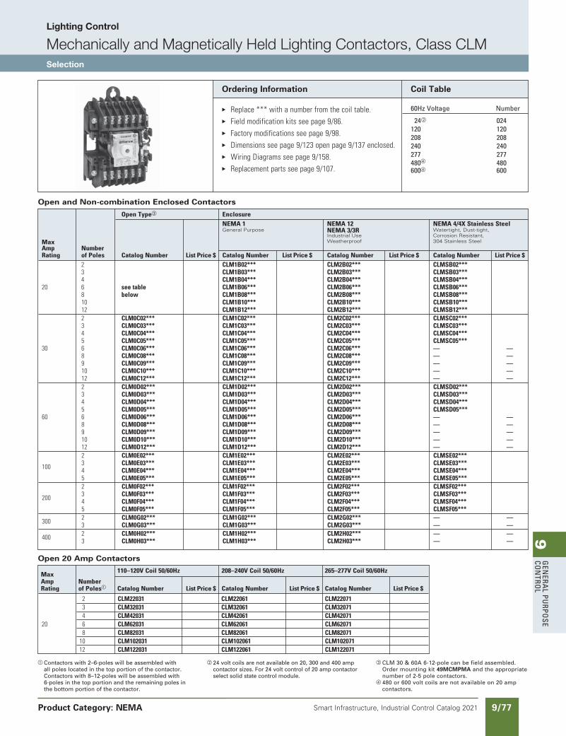
9G
enera
l PurPo
se Co
ntro
l
9/77Smart Infrastructure, Industrial Control Catalog 2021
Lighting Control
Mechanically and Magnetically Held Lighting Contactors, Class CLMSelection
Product Category: NEMA
a Contactors with 2–6-poles will be assembled with all poles located in the top portion of the contactor. Contactors with 8–12-poles will be assembled with 6-poles in the top portion and the remaining poles in the bottom portion of the contactor.
b 24 volt coils are not available on 20, 300 and 400 amp contactor sizes. For 24 volt control of 20 amp contactor select solid state control module.
c CLM 30 & 60A 6-12-pole can be field assembled. Order mounting kit 49MCMPMA and the appropriate number of 2-5 pole contactors.
d 480 or 600 volt coils are not available on 20 amp contactors.
Coil Table
60Hz Voltage number
24b 024 120 120 208 208 240 240 277 277 480d 480 600d 600
Ordering Information
E Replace***withanumberfromthecoiltable. E Fieldmodificationkitsseepage9/86. E Factorymodificationsseepage9/98. E Dimensionsseepage9/123openpage9/137enclosed.
E WiringDiagramsseepage9/158.
E Replacementpartsseepage9/107.
Max 110–120VCoil50/60Hz 208–240VCoil50/60Hz 265–277VCoil50/60Hz
Amp Number Rating ofPolesa CatalogNumber ListPrice$ CatalogNumber ListPrice$ CatalogNumber ListPrice$
2 CLM22031 CLM22061 CLM22071 3 CLM32031 CLM32061 CLM32071 4 CLM42031 CLM42061 CLM42071 20 6 CLM62031 CLM62061 CLM62071 8 CLM82031 CLM82061 CLM82071 10 CLM102031 CLM102061 CLM102071 12 CLM122031 CLM122061 CLM122071
Open 20 Amp Contactors
OpenTypec Enclosure NEMA1 NEMA12 NEMA4/4XStainlessSteel General Purpose NEMA3/3R Watertight, Dust-tight,
Max Industrial Use
Corrosion Resistant,
Amp
Number Weatherproof 304 Stainless Steel
Rating ofPoles CatalogNumber ListPrice$ CatalogNumber ListPrice$ CatalogNumber ListPrice$ CatalogNumber ListPrice$ 2 CLM1B02*** CLM2B02*** CLMSB02*** 3 CLM1B03*** CLM2B03*** CLMSB03*** 4 CLM1B04*** CLM2B04*** CLMSB04*** 20 6 seetable CLM1B06*** CLM2B06*** CLMSB06*** 8 below CLM1B08*** CLM2B08*** CLMSB08*** 10 CLM1B10*** CLM2B10*** CLMSB10*** 12 CLM1B12*** CLM2B12*** CLMSB12*** 2 CLM0C02*** CLM1C02*** CLM2C02*** CLMSC02*** 3 CLM0C03*** CLM1C03*** CLM2C03*** CLMSC03*** 4 CLM0C04*** CLM1C04*** CLM2C04*** CLMSC04*** 5 CLM0C05*** CLM1C05*** CLM2C05*** CLMSC05*** 30 6 CLM0C06*** CLM1C06*** CLM2C06*** — — 8 CLM0C08*** CLM1C08*** CLM2C08*** — — 9 CLM0C09*** CLM1C09*** CLM2C09*** — — 10 CLM0C10*** CLM1C10*** CLM2C10*** — — 12 CLM0C12*** CLM1C12*** CLM2C12*** — — 2 CLM0D02*** CLM1D02*** CLM2D02*** CLMSD02*** 3 CLM0D03*** CLM1D03*** CLM2D03*** CLMSD03*** 4 CLM0D04*** CLM1D04*** CLM2D04*** CLMSD04*** 5 CLM0D05*** CLM1D05*** CLM2D05*** CLMSD05*** 60 6 CLM0D06*** CLM1D06*** CLM2D06*** — — 8 CLM0D08*** CLM1D08*** CLM2D08*** — — 9 CLM0D09*** CLM1D09*** CLM2D09*** — — 10 CLM0D10*** CLM1D10*** CLM2D10*** — — 12 CLM0D12*** CLM1D12*** CLM2D12*** — — 2 CLM0E02*** CLM1E02*** CLM2E02*** CLMSE02*** 100 3 CLM0E03*** CLM1E03*** CLM2E03*** CLMSE03*** 4 CLM0E04*** CLM1E04*** CLM2E04*** CLMSE04*** 5 CLM0E05*** CLM1E05*** CLM2E05*** CLMSE05*** 2 CLM0F02*** CLM1F02*** CLM2F02*** CLMSF02*** 200 3 CLM0F03*** CLM1F03*** CLM2F03*** CLMSF03*** 4 CLM0F04*** CLM1F04*** CLM2F04*** CLMSF04*** 5 CLM0F05*** CLM1F05*** CLM2F05*** CLMSF05*** 300 2 CLM0G02*** CLM1G02*** CLM2G02*** — — 3 CLM0G03*** CLM1G03*** CLM2G03*** — — 400 2 CLM0H02*** CLM1H02*** CLM2H02*** — — 3 CLM0H03*** CLM1H03*** CLM2H03*** — —
Open and Non-combination Enclosed Contactors
updated in SPEEDFAXRevised on 08/31/19
SS copied this page from SF to IC on 05/24/20
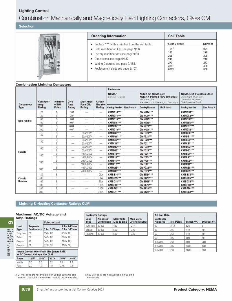
9G
ener
al
PurP
ose
Co
ntr
ol
9/78 Smart Infrastructure, Industrial Control Catalog 2021
Lighting Control
Combination Mechanically and Magnetically Held Lighting Contactors, Class CMSelection
Product Category: NEMA
Lighting & Heating Contactor Ratings CLM
a 24 volt coils are not available on 20 and 300 amp con-tactors. Use solid state control module on 20 amp size.
b 600 volt coils are not available on 20 amp contactors.
Coil Table
60Hz Voltage number
24a 024 120 120 208 208 240 240 277 277 480 480 600b 600
Ordering Information
E Replace***withanumberfromthecoiltable. E Fieldmodificationkitsseepage9/86. E Factorymodificationsseepage9/98. E Dimensionsseepage9/137.
E WiringDiagramsseepage9/158.
E Replacementpartsseepage9/107.
PolestoLoadLoad Amperes 2for1-PhaseType Continuous 1for1-Phase 3for3-Phase
Tungsten 20 250VAC 250VAC
Ballast 20 347VAC 600VAC
General 30 347VAC 600VAC
General 20 125VDC 250VDC
Maximum AC/DC Voltage and Amp Ratings
InrushCurrentOverFuseSize(ampsRMS)atACControlVoltage20ACLM
Amps 120V 240V 277V 347V 480VInrush 5.0 2.5 2.2 1.8 1.3Fuse 2.0 1.0 1.0 0.75 0.5
ContactorRatingsLoad Amperes MaxVolts MaxVoltsType Continuous LinetoLine LinetoNeutral
Tungsten 30-400 480 277
Ballast 30-400 600 346
Heating 30-400 600 346
ACCoilDataContactor Amperes No.Poles InrushVA DropoutVA
20 2-12 625 6
30 2-5 410 40
60 2-3 410 40
60 4-5 600 40
100/200 2-3 900 200
100/200 4-5 1300 130
300/400 2-3 1600 550
Combination Lighting Contactors
20 3 30A — — CMNB14*** CMNB24*** CMNBS4*** 30 3 30A — — CMNC14*** CMNC24*** CMNCS4*** Non-Fusible 60 3 60A — — CMND15*** CMND25*** CMNDS5*** 100 3 100A — — CMNE16*** CMNE26*** CMNES6*** 200 3 200A — — CMNF17*** CMNF27*** CMNFS7*** 300 3 400A — — CMNG18*** CMNG28*** CMNGS8*** 20 3 — 30A/250V — CMFB10*** CMFB20*** CMFBS0*** 3 — 30A/600V — CMFB11*** CMFB21*** CMFBS1*** 30 3 — 30A/250V — CMFC10*** CMFC20*** CMFCS0*** 3 — 30A/600V — CMFC11*** CMFC21*** CMFCS1*** 60 3 — 60A/250V — CMFD12*** CMFD22*** CMFDS2*** Fusible 3 — 60A/600V — CMFD13*** CMFD23*** CMFDS3*** 100 3 — 100A/250V — CMFE14*** CMFE24*** CMFES4*** 3 — 100A/600V — CMFE15*** CMFE25*** CMFES5*** 200 3 — 200A/250V — CMFF16*** CMFF26*** CMFFS6*** 3 — 200A/600V — CMFF17*** CMFF27*** CMFFS7*** 300 3 — 400A/250V — CMFG18*** CMFG28*** CMFGS8*** 3 — 400A/600V — CMFG19*** CMFG29*** CMFGS9*** 20 3 — — 20A CMBB14*** CMBB24*** CMBBS4*** Circuit 30 3 — — 30A CMBC15*** CMBC25*** CMBCS5*** Breaker 60 3 — — 60A CMBD18*** CMBD28*** CMBDS8*** 100 3 — — 100A CMBE18*** CMBE28*** CMBES8*** 200 3 — — 200A CMBF10*** CMBF20*** CMBFS0*** 300 3 — — 300A CMBG11*** CMBG21*** CMBGS1***
Enclosure
NEMA1 NEMA12,NEMA3/3R NEMA4/4XStainlessSteel General Purpose
NEMA4Painted(thru100amps)
Watertight, Dust-tight, Industrial Use
Corrosion Resistant,
Contactor
Number
Disc
DiscAmp/
Circuit
Weatherproof, Watertight, Dust-tight
304 Stainless Steel Disconnect Amp ofNO Amp FuseClip Breaker Type Rating Poles Rating Rating Rating CatalogNumber ListPrice$ CatalogNumber ListPrice$ CatalogNumber ListPrice$
SS copied this page from SF to IC on 05/24/20
updated in SPEEDFAXRevised on 08/31/18
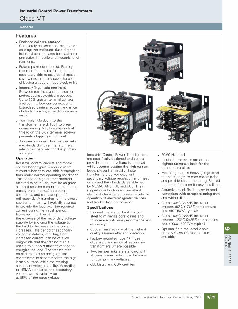
9G
enera
l PurPo
se Co
ntro
l
9/79Smart Infrastructure, Industrial Control Catalog 2021
Industrial Control Power Transformers
Class MTGeneral
Featuresb Enclosed coils (50-5000VA);
Completely encloses the transformer coils against moisture, dust, dirt and industrial contaminants for maximum protection in hostile and industrial envi-ronments.
b Fuse clips (most models). Factory mounted for integral fusing on the secondary side to save panel space, save wiring time and save the cost of buying an add-on fuse block or kit
b Integrally finger safe terminals. Between terminals and transformer, protect against electrical creepage. Up to 30% greater terminal contact area permits low-loss connections. Extra-deep barriers reduce the chance of shorts from frayed leads or careless wiring
b Terminals. Molded into the transformer, are difficult to break during wiring. A full quarter-inch of thread on the 8-32 terminal screws prevents stripping and pullout
b Jumpers supplied. Two jumper links are standard with all transformers which can be wired for dual primary voltages
OperationIndustrial control circuits and motor control loads typically require more current when they are initially energized than under normal operating conditions. This period of high current demand, referred to as inrush, may be as great as ten times the current required under steady state (normal) operating conditions, and can last up to 40 milliseconds. A transformer in a circuit subject to inrush will typically attempt to provide the load with the required current during the inrush period. However, it will be at the expense of the secondary voltage stability by allowing the voltage to the load to decrease as the current increases. This period of secondary voltage instability, resulting from increased current, can be of such magnitude that the transformer is unable to supply sufficient voltage to energize the load. The transformer must therefore be designed and constructed to accommodate the high inrush current, while maintaining secondary voltage stability. According to NEMA standards, the secondary voltage would typically be at 85% of the rated voltage.
Industrial Control Power Transformers are specifically designed and built to provide adequate voltage to the load while accommodating the high current levels present at inrush. These transformers deliver excellent secondary voltage regulation and meet or exceed the standards established by NEMA, ANSI, UL and cUL. Their rugged construction and excellent electrical characteristics ensure reliable operation of electromagnetic devices and trouble-free performance.
Specifications
b Laminations are built with silicon steel to minimize core losses and to increase optimum performance and efficiency
b Copper magnet wire of the highest quality assures efficient operation
b Factory mounted type “K” fuse clips are standard on all secondary transformers where possible
b Two jumper links are standard withall transformers which can be wired for dual primary voltages
b cUL Listed and CSA certified
b 50/60 Hz rated
b Insulation materials are of the highest rating available for the temperature class
b Mounting plate is heavy gauge steel to add strength to core construction and provide stable mounting. Slotted mounting feet permit easy installation
b Attractive black finish; easy-to-read nameplate with complete rating data and wiring diagram
b Class 130°C (226°F) insulation system. 80°C (176°F) temperature rise. (50-750VA typical)
b Class 180°C (356°F) insulationsystem. 120°C (248°F) temperature rise. (1000–5000VA typical)
b Optional field mounted 2-pole primary Class CC fuse block is available
updated in SPEEDFAXRevised on 03/31/30
SS copied this page from SF to IC on 05/24/20
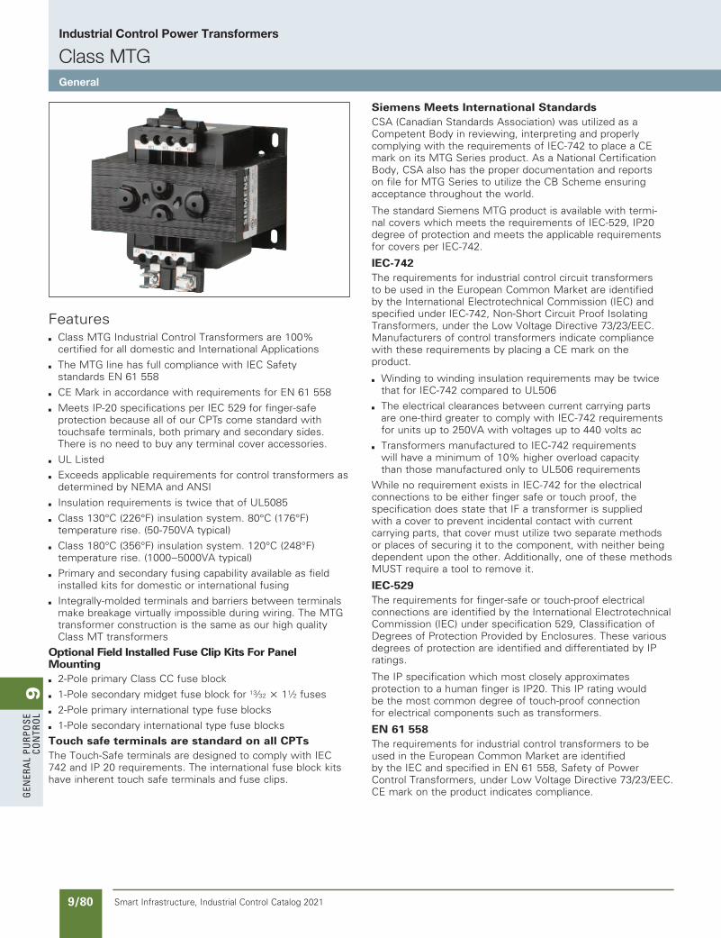
9G
ener
al
PurP
ose
Co
ntr
ol
9/80 Smart Infrastructure, Industrial Control Catalog 2021
Industrial Control Power Transformers
Class MTGGeneral
Featuresb Class MTG Industrial Control Transformers are 100%
certified for all domestic and International Applications
b The MTG line has full compliance with IEC Safety standards EN 61 558
b CE Mark in accordance with requirements for EN 61 558
b Meets IP-20 specifications per IEC 529 for finger-safe protection because all of our CPTs come standard with touchsafe terminals, both primary and secondary sides. There is no need to buy any terminal cover accessories.
b UL Listed
b Exceeds applicable requirements for control transformers as determined by NEMA and ANSI
b Insulation requirements is twice that of UL5085
b Class 130°C (226°F) insulation system. 80°C (176°F) temperature rise. (50-750VA typical)
b Class 180°C (356°F) insulation system. 120°C (248°F)temperature rise. (1000–5000VA typical)
b Primary and secondary fusing capability available as field installed kits for domestic or international fusing
b Integrally-molded terminals and barriers between terminals make breakage virtually impossible during wiring. The MTG transformer construction is the same as our high quality Class MT transformers
Optional Field Installed Fuse Clip Kits For Panel Mounting
b 2-Pole primary Class CC fuse block
b 1-Pole secondary midget fuse block for 13⁄32 u 11⁄2 fuses
b 2-Pole primary international type fuse blocks
b 1-Pole secondary international type fuse blocks
Touch safe terminals are standard on all CPTsThe Touch-Safe terminals are designed to comply with IEC 742 and IP 20 requirements. The international fuse block kits have inherent touch safe terminals and fuse clips.
Siemens Meets International StandardsCSA (Canadian Standards Association) was utilized as a Competent Body in reviewing, interpreting and properly complying with the requirements of IEC-742 to place a CE mark on its MTG Series product. As a National Certification Body, CSA also has the proper documentation and reports on file for MTG Series to utilize the CB Scheme ensuring acceptance throughout the world.
The standard Siemens MTG product is available with termi-nal covers which meets the requirements of IEC-529, IP20 degree of protection and meets the applicable requirements for covers per IEC-742.
IEC-742The requirements for industrial control circuit transformers to be used in the European Common Market are identified by the International Electrotechnical Commission (IEC) and specified under IEC-742, Non-Short Circuit Proof Isolating Transformers, under the Low Voltage Directive 73/23/EEC. Manufacturers of control transformers indicate compliance with these requirements by placing a CE mark on the product.
b Winding to winding insulation requirements may be twice that for IEC-742 compared to UL506
b The electrical clearances between current carrying parts are one-third greater to comply with IEC-742 requirements for units up to 250VA with voltages up to 440 volts ac
b Transformers manufactured to IEC-742 requirements will have a minimum of 10% higher overload capacity than those manufactured only to UL506 requirements
While no requirement exists in IEC-742 for the electrical connections to be either finger safe or touch proof, the specification does state that IF a transformer is supplied with a cover to prevent incidental contact with current carrying parts, that cover must utilize two separate methods or places of securing it to the component, with neither being dependent upon the other. Additionally, one of these methods MUST require a tool to remove it.
IEC-529The requirements for finger-safe or touch-proof electrical connections are identified by the International Electrotechnical Commission (IEC) under specification 529, Classification of Degrees of Protection Provided by Enclosures. These various degrees of protection are identified and differentiated by IP ratings.
The IP specification which most closely approximates protection to a human finger is IP20. This IP rating would be the most common degree of touch-proof connection for electrical components such as transformers.
EN 61 558The requirements for industrial control transformers to be used in the European Common Market are identified by the IEC and specified in EN 61 558, Safety of Power Control Transformers, under Low Voltage Directive 73/23/EEC. CE mark on the product indicates compliance.
SS copied this page from SF to IC on 05/24/20
updated in SPEEDFAXRevised on 04/30/21
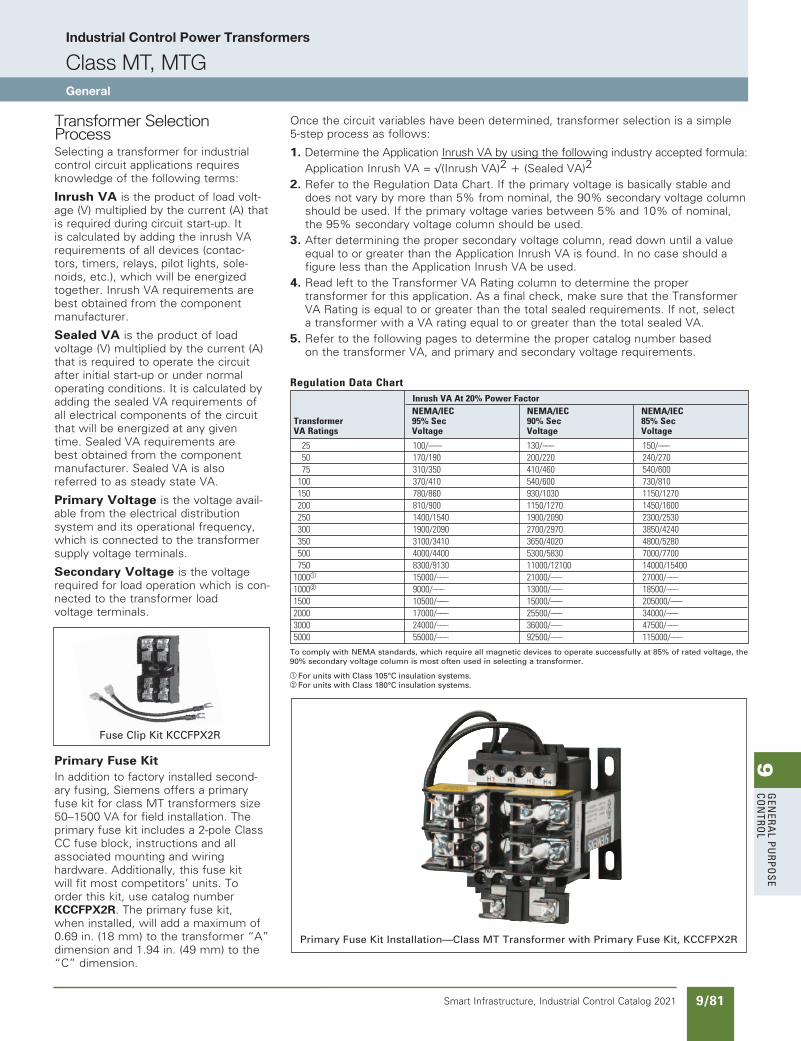
9G
enera
l PurPo
se Co
ntro
l
9/81Smart Infrastructure, Industrial Control Catalog 2021
Industrial Control Power Transformers
Class MT, MTGGeneral
Transformer Selection ProcessSelecting a transformer for industrial control circuit applications requires knowledge of the following terms:
Inrush VA is the product of load volt-age (V) multiplied by the current (A) that is required during circuit start-up. It is calculated by adding the inrush VA requirements of all devices (contac-tors, timers, relays, pilot lights, sole-noids, etc.), which will be energized together. Inrush VA requirements are best obtained from the component manufacturer.
Sealed VA is the product of load voltage (V) multiplied by the current (A) that is required to operate the circuit after initial start-up or under normal operating conditions. It is calculated by adding the sealed VA requirements of all electrical components of the circuit that will be energized at any given time. Sealed VA requirements are best obtained from the component manufacturer. Sealed VA is also referred to as steady state VA.
Primary Voltage is the voltage avail-able from the electrical distribution system and its operational frequency, which is connected to the transformer supply voltage terminals.
Secondary Voltage is the voltage required for load operation which is con-nected to the transformer load voltage terminals.
Primary Fuse KitIn addition to factory installed second-ary fusing, Siemens offers a primary fuse kit for class MT transformers size 50–1500 VA for field installation. The primary fuse kit includes a 2-pole Class CC fuse block, instructions and all associated mounting and wiring hardware. Additionally, this fuse kit will fit most competitors’ units. To order this kit, use catalog number KCCFPX2R. The primary fuse kit, when installed, will add a maximum of 0.69 in. (18 mm) to the transformer “A” dimension and 1.94 in. (49 mm) to the “C” dimension.
Primary Fuse Kit Installation—Class MT Transformer with Primary Fuse Kit, KCCFPX2R
Fuse Clip Kit KCCFPX2R
Once the circuit variables have been determined, transformer selection is a simple 5-step process as follows:
1. Determine the Application Inrush VA by using the following industry accepted formula: Application Inrush VA = √(Inrush VA)2 r (Sealed VA)2
2. Refer to the Regulation Data Chart. If the primary voltage is basically stable and does not vary by more than 5% from nominal, the 90% secondary voltage column should be used. If the primary voltage varies between 5% and 10% of nominal, the 95% secondary voltage column should be used.
3. After determining the proper secondary voltage column, read down until a value equal to or greater than the Application Inrush VA is found. In no case should a figure less than the Application Inrush VA be used.
4. Read left to the Transformer VA Rating column to determine the proper transformer for this application. As a final check, make sure that the Transformer VA Rating is equal to or greater than the total sealed requirements. If not, select a transformer with a VA rating equal to or greater than the total sealed VA.
5. Refer to the following pages to determine the proper catalog number based on the transformer VA, and primary and secondary voltage requirements.
RegulationDataChart
——————————–
To comply with NEMA standards, which require all magnetic devices to operate successfully at 85% of rated voltage, the 90% secondary voltage column is most often used in selecting a transformer.
a For units with Class 105°C insulation systems.b For units with Class 180°C insulation systems.
InrushVAAt20%PowerFactor NEMA/IEC NEMA/IEC NEMA/IECTransformer 95%Sec 90%Sec 85%SecVARatings Voltage Voltage Voltage
25 100/––– 130/––– 150/––– 50 170/190 200/220 240/270 75 310/350 410/460 540/600 100 370/410 540/600 730/810 150 780/860 930/1030 1150/1270 200 810/900 1150/1270 1450/1600 250 1400/1540 1900/2090 2300/2530 300 1900/2090 2700/2970 3850/4240 350 3100/3410 3650/4020 4800/5280 500 4000/4400 5300/5830 7000/7700 750 8300/9130 11000/12100 14000/154001000a 15000/––– 21000/––– 27000/–––1000b 9000/––– 13000/––– 18500/–––1500 10500/––– 15000/––– 205000/–––2000 17000/––– 25500/––– 34000/–––3000 24000/––– 36000/––– 47500/–––5000 55000/––– 92500/––– 115000/–––
SS copied this page from SF to IC on 05/24/20
updated in SPEEDFAXRevised on 04/30/21
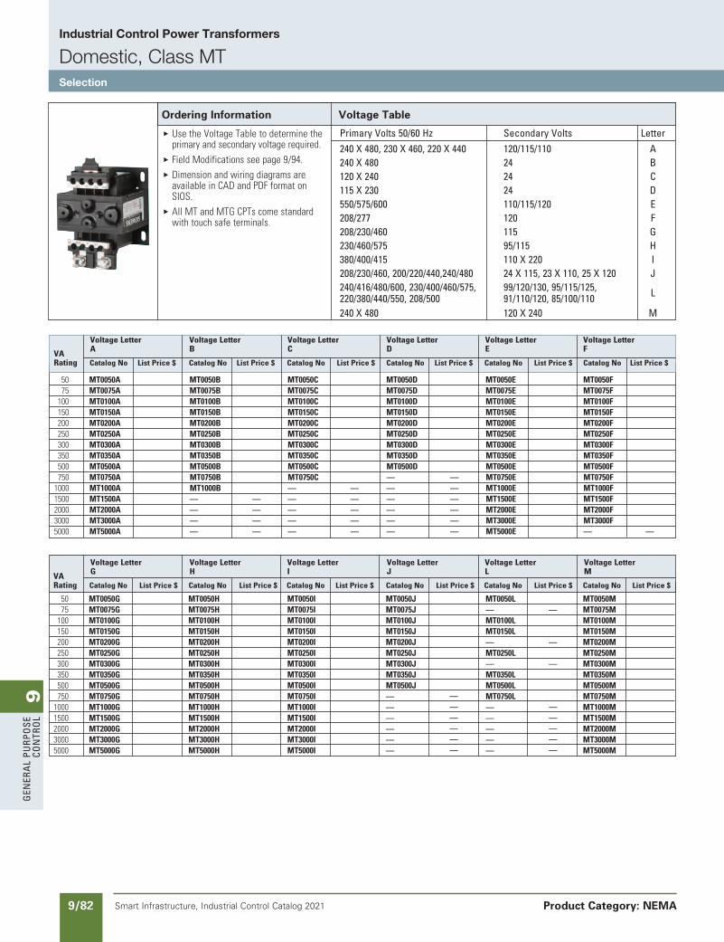
9G
ener
al
PurP
ose
Co
ntr
ol
9/82 Smart Infrastructure, Industrial Control Catalog 2021 Product Category: NEMA
Industrial Control Power Transformers
Domestic, Class MTSelection
SS copied this page from SF to IC on 05/24/20
Primary Volts 50/60 Hz secondary Volts letter 240 X 480, 230 X 460, 220 X 440 120/115/110 a 240 X 480 24 B 120 X 240 24 C 115 X 230 24 D 550/575/600 110/115/120 e 208/277 120 F 208/230/460 115 G 230/460/575 95/115 H 380/400/415 110 X 220 I 208/230/460, 200/220/440,240/480 24 X 115, 23 X 110, 25 X 120 J 240/416/480/600, 230/400/460/575, 99/120/130, 95/115/125, 220/380/440/550, 208/500 91/110/120, 85/100/110
l
240 X 480 120 X 240 M
Ordering Information Voltage Table
E UsetheVoltageTabletodeterminetheprimaryandsecondaryvoltagerequired.
E FieldModificationsseepage9/94.E Dimensionandwiringdiagramsare
availableinCADandPDFformatonSIOS.
E AllMTandMTGCPTscomestandardwithtouchsafeterminals.
50 MT0050A MT0050B MT0050C MT0050D MT0050E MT0050F 75 MT0075A MT0075B MT0075C MT0075D MT0075E MT0075F 100 MT0100A MT0100B MT0100C MT0100D MT0100E MT0100F 150 MT0150A MT0150B MT0150C MT0150D MT0150E MT0150F 200 MT0200A MT0200B MT0200C MT0200D MT0200E MT0200F 250 MT0250A MT0250B MT0250C MT0250D MT0250E MT0250F 300 MT0300A MT0300B MT0300C MT0300D MT0300E MT0300F 350 MT0350A MT0350B MT0350C MT0350D MT0350E MT0350F 500 MT0500A MT0500B MT0500C MT0500D MT0500E MT0500F 750 MT0750A MT0750B MT0750C — — MT0750E MT0750F 1000 MT1000A MT1000B — — — — MT1000E MT1000F 1500 MT1500A — — — — — — MT1500E MT1500F 2000 MT2000A — — — — — — MT2000E MT2000F 3000 MT3000A — — — — — — MT3000E MT3000F 5000 MT5000A — — — — — — MT5000E — —
VoltageLetter VoltageLetter VoltageLetter VoltageLetter VoltageLetter VoltageLetter VA A B C D E F
Rating CatalogNo ListPrice$ CatalogNo ListPrice$ CatalogNo ListPrice$ CatalogNo ListPrice$ CatalogNo ListPrice$ CatalogNo ListPrice$
50 MT0050G MT0050H MT0050I MT0050J MT0050L MT0050M 75 MT0075G MT0075H MT0075I MT0075J — — MT0075M 100 MT0100G MT0100H MT0100I MT0100J MT0100L MT0100M 150 MT0150G MT0150H MT0150I MT0150J MT0150L MT0150M 200 MT0200G MT0200H MT0200I MT0200J — — MT0200M 250 MT0250G MT0250H MT0250I MT0250J MT0250L MT0250M 300 MT0300G MT0300H MT0300I MT0300J — — MT0300M 350 MT0350G MT0350H MT0350I MT0350J MT0350L MT0350M 500 MT0500G MT0500H MT0500I MT0500J MT0500L MT0500M 750 MT0750G MT0750H MT0750I — — MT0750L MT0750M 1000 MT1000G MT1000H MT1000I — — — — MT1000M 1500 MT1500G MT1500H MT1500I — — — — MT1500M 2000 MT2000G MT2000H MT2000I — — — — MT2000M 3000 MT3000G MT3000H MT3000I — — — — MT3000M 5000 MT5000G MT5000H MT5000I — — — — MT5000M
VoltageLetter VoltageLetter VoltageLetter VoltageLetter VoltageLetter VoltageLetter VA G H I J L M
Rating CatalogNo ListPrice$ CatalogNo ListPrice$ CatalogNo ListPrice$ CatalogNo ListPrice$ CatalogNo ListPrice$ CatalogNo ListPrice$
updated in SPEEDFAXRevised on 04/30/21
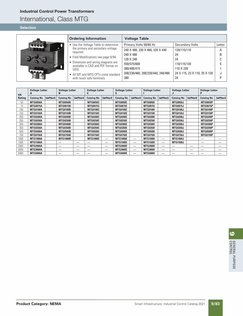
9G
enera
l PurPo
se Co
ntro
l
9/83Smart Infrastructure, Industrial Control Catalog 2021
Industrial Control Power Transformers
International, Class MTGSelection
Product Category: NEMA
updated in SPEEDFAXRevised on 04/30/21
SS copied this page from SF to IC on 05/24/20
50 MTG0050A MTG0050B MTG0050C MTG0050E MTG0050I MTG0050J MTG0050P 75 MTG0075A MTG0075B MTG0075C MTG0075E MTG0075I MTG0075J MTG0075P 100 MTG0100A MTG0100B MTG0100C MTG0100E MTG0100I MTG0100J MTG0100P 150 MTG0150A MTG0150B MTG0150C MTG0150E MTG0150I MTG0150J MTG0150P 200 MTG0200A MTG0200B MTG0200C MTG0200E MTG0200I MTG0200J MTG0200P 250 MTG0250A MTG0250B MTG0250C MTG0250E MTG0250I MTG0250J MTG0250P 300 MTG0300A MTG0300B MTG0300C MTG0300E MTG0300I MTG0300J MTG0300P 350 MTG0350A MTG0350B MTG0350C MTG0350E MTG0350I MTG0350J MTG0350P 500 MTG0500A MTG0500B MTG0500C MTG0500E MTG0500I MTG0500J MTG0500P 750 MTG0750A MTG0750B MTG0750C MTG0750E MTG0750I MTG0750J MTG0750P 1000 MTG1000A MTG1000B MTG1000C — MTG1000E — MTG1000I — MTG1000J — — 1500 MTG1500A — — — — MTG1500E — MTG1500I — MTG1500J — — 2000 MTG2000A — — — — MTG2000E — MTG2000I — — — — — 3000 MTG3000A — — — — MTG3000E — MTG3000I — — — — — 5000 MTG5000A — — — — MTG5000E — MTG5000I — — — — —
VoltageLetter VoltageLetter VoltageLetter VoltageLetter VoltageLetter VoltageLetter VoltageLetter VA A B C E I J P
Rating CatalogNo ListPrice$ CatalogNo ListPrice$ CatalogNo ListPrice$ CatalogNo ListPrice$ CatalogNo ListPrice$ CatalogNo ListPrice$ CatalogNo ListPrice$
Primary Volts 50/60 Hz secondary Volts letter 240 X 480, 230 X 460, 220 X 440 120/115/110 a 240 X 480 24 B 120 X 240 24 C 550/575/600 110/115/120 e 380/400/415 110 X 220 I 208/230/460, 200/220/440, 240/480 24 X 115, 23 X 110, 25 X 120 J 380 24 P
Ordering Information Voltage Table
E UsetheVoltageTabletodeterminetheprimaryandsecondaryvoltagerequired.
E FieldModificationsseepage9/94.E Dimensionandwiringdiagramsare
availableinCADandPDFformatonSIOS.
E AllMTandMTGCPTscomestandardwithtouchsafeterminals.
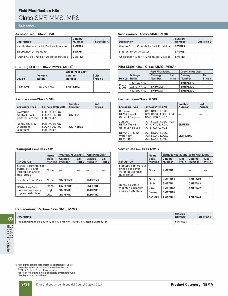
9G
ener
al
PurP
ose
Co
ntr
ol
9/84 Smart Infrastructure, Industrial Control Catalog 2021
Field Modification Kits
Class SMF, MMS, MRSSelection
Product Category: NEMA
a Pilot lights can be field installed on standard NEMA 1 general purpose surface mount enclosures, and NEMA 3R, 4 and 12 enclosures only. For flush mounting units a complete switch unit with pilot light must be ordered.
SS copied this page from SF to IC on 05/24/20
Pilot Light Kits—Class MMS, MRSa
DeviceVoltageRating
Green Pilot Light
Catalog Number
List Price $
Class SMF 115–277V AC SMFPL10G
Enclosures—Class SMF
Enclosure Type For Use With SMFCatalog Number
List Price $
Oversized NEMA Type 1 General Purpose
FO1, FO1P, FO2, FO2P, FO3, FO3P, FO4, FO4P
SMFFE1
NEMA 3R, 4, 12 Watertight Dust-tight
FO1, FO1P, FO2, FO2P, FO3, FO3P, FO4, FO4P
SMF40BC2
Enclosures—Class MMS
Enclosure Type For Use With SMFCatalog Number
List Price $
Oversized NEMA Type 1 General Purpose
KO1, KO2B, KO2C, KO3, KO3A, KO3B, KO4, KO4B, KO4C, KO2
— —
Jumbo NEMA Type 1 General Purpose
KO1, KO2B, KO2C, KO3,KO3A, KO3B, KO4, KO4B, KO4C, KO2
SMFKE2
NEMA 3R, 4, 12 Watertight Dust-tight
KO1, KO2B, KO2C, KO3, KO3A, KO3B, KO4, KO4B, KO4C
SMF40BC2
Pilot Light Kits—Class MMS, MRSa
DeviceVoltageRating
Red Pilot Light Green Pilot Light
Catalog Number
List Price $
Catalog Number
List Price $
Class MMS
110–120V AC — SMFPL11G208–277V AC SMFPL12 SMFPL12G440–600V AC SMFPL13 SMFPL13G
Accessories—Class SMF
DescriptionCatalog Number List Price $
Handle Guard Kit with Padlock Provision SMFFL1
Emergency Off Actuator SMFPB1
Additional Key for Key Operated Devices SMFFK1
Replacement Parts—Class SMF, MMS
DescriptionCatalog Number List Price $
Replacement Toggle Kits:Type FW and KW (NEMA 4 Metallic Enclosure) SMFHW1
Accessories—Class MMS, MRS
DescriptionCatalog Number List Price $
Handle Guard Kit with Padlock Provision SMFFL1
Emergency Off Actuator SMFPB1
Additional Key for Key Operated Devices SMFFK1
Nameplates—Class SMF
For Use On
Name-plateMarking
Without Pilot Light With Pilot Light
Catalog Number
ListPrice $
Catalog Number
ListPrice $
Standard commercial switch box cover including stainless steel plates
None — — — —
Stainless Steel Plate None SMFFSN3 SMFFSN4
NEMA 1 surface mounted enclosureor gray flush plate
None SMFFN30 SMFFN40
High SMFFN31 SMFFN41
Low SMFFN32 SMFFN42
Nameplates—Class MMS
For Use On
Name-plateMarking
Without Pilot Light With Pilot Light
Catalog Number
ListPrice $
Catalog Number
ListPrice $
Standard commercial switch box cover including stainless steel plates
None SMFFN1 — —
NEMA 1 surface mounted enclosureor gray flush plate
None SMFFN10 SMFFN20
High SMFFN11 SMFFN21
Low SMFFN12 SMFFN22
Forward SMFFN13 — —
Reverse SMFFN14 SMFFN24
NEED TO UPDATE IN SPEEDFAX
Revised on 12/31/21
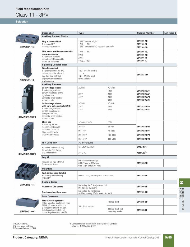
9G
enera
l PurPo
se Co
ntro
l
9/85Smart Infrastructure, Industrial Control Catalog 2021
Field Modification Kits
Class 11 - 3RVSelection
Product Category: NEMA
a 100% on time.b 5 sec. max. on time.c Product Category: PILO.
d Compatible for use in dusty atmospheres. Contacts rated for 1-300mA @ 3-60V.
Description Type Catalog Number List Price $
Auxiliary Contact Blocks
Plugincontactblock1blockper3RVmountableatthefront
1SPDTcontact,NO/NC1NOr1NC1SPDTcontactNO/NCelectroniccontactd
3RV2901-1D3RV2901-1E
3RV2901-1D 3RV2901-1G
Sidemountauxiliarycontactwithscrewconnection1sidemountauxiliarycontactper3RVmountableontheleft-handside
1NOr1NC 3RV2901-1A2NO 3RV2901-1B2NC 3RV2901-1C
2NOr2NC 3RV2901-1J
Signaling Contact BlockSignalingcontact1signalingcontactper3RVmountableontheleft-handside.Canalsobefittedtogetherwithsidemountauxiliarycontact.
1NO+1NCforanytrip+1NO+1NCforshortcircuittriponly.
3RV2921-1M
3RV2901-1A
Auxiliary ReleasesUndervoltagerelease1undervoltagereleaseper3RVmountableontheright-handside.Cannotbefittedtogetherwithshunttrip.
AC50Hz AC60Hz— 120V 3RV2902-1AF0230V 208V 3RV2902-1AM1415V 240V 3RV2902-1AP0
480V 3RV2902-1AV1
Undervoltagereleasewithearlymakecontacts(2NO)1undervoltagereleaseper3RVmountableattheright-handside.Cannotbefittedtogetherwithshunttrip.
AC50Hz AC60Hz230V 240V 3RV2922-1CP0415V 480V 3RV2922-1CV1
3RV2922-1CP0
3RV2902-1DP0
Shunttrip1shunttripper3RVmountableattheright-handside.Cannotbefittedtogetherwithundervoltagerelease.
AC50Hz/60Hza DCb
20–24V 20–70V 3RV2902-1DB0
90–110V 70–190V 3RV2902-1DF0
200–240V 190–330V 3RV2902-1DP0
350–415V 330–500V 3RV2902-1DV0
PilotLights(LED) AC 50Hz/60Hz
ForNEMA1enclosureonly.KitincludesRed,Green,andAmberlenses
24to240VAC/DC 49SDLBUc
277VAC 49SDLBLc
Lug Kit
RequiredforTypeEManualCombinationStarter
For3RVwithamprange:0.11-22Aupto480VMax.0.11-12.5Aupto575VMax
3RV2928-1H
Mounting
Push-inMountingHoleKitForscrewpanelmountingofthe3RV
Fourmountingholesrequiredforeach3RV. 3RV2928-0B
Sealing device3RV2928-1H
AdjustmentDialcovers ForsealingtheFLAadjustmentdial(Kitincludes10covers) 3RV2908-0P
Frontmountauxiliarycover Forsealingthefrontmountauxiliaryopening.(Kitincludes10covers) 3RV2901-0H
3RV2901-0H
Door Operators
Thru-the-dooroperatorsRotaryoperatingmechanism,ratedNEMA12,lockablewithupto3padlocksintheOFFposition.Includesextensionshiftandconnectingelementforthe3RV.
WithBlackHandle
130mmdepth 3RV2926-0B
330mmdepthwithsupportingbracket 3RV2926-0K
SS copied this page from SF to IC on 05/24/20
updated in SPEEDFAXRevised on 12/31/20
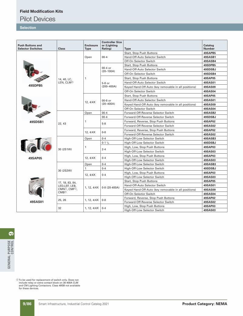
9G
ener
al
PurP
ose
Co
ntr
ol
9/86 Smart Infrastructure, Industrial Control Catalog 2021
Field Modification Kits
Pilot DevicesSelection
Product Category: NEMA
SS copied this page from SF to IC on 05/24/20
a To be used for replacement of switch only. Does not include relay or extra contact block on 30-400A CLM and CM Lighting Contactors. Class 49SB not available for these devices.
SS copied this page from SF to IC on 05/24/20
NEED to UPDATE in SPEEDFAX
Revised on 12/31/21
Push Buttons andSelector Switches Class
EnclosureType
Controller Size or (Lighting Rating) Type
CatalogNumber
49SDPB5
49SDSB1
49SAP05
49SAS01
14, 40, LC, LEN, CLMa
Open 00-4Start, Stop Push Buttons 49SAPB5Hand-Off-Auto Selector Switch 49SASB1Off-On Selector Switch 49SASB4
1
00-4 or (20–100A)
Start, Stop Push Buttons 49SDPB5Hand-Off-Auto Selector Switch 49SDSBJ
Off-On Selector Switch 49SDSB4
5-8 or (200–400A)
Start, Stop Push Buttons 49SAP05
Hand-Off-Auto Selector Switch 49SAS01
Keyed Hand-Off-Auto (key removable in all positions) 49SAS09
Off-On Selector Switch 49SAS04
12, 4/4X 00-8 or (20–400A)
Start, Stop Push Buttons 49SAP05
Hand-Off-Auto Selector Switch 49SAS01
Keyed Hand-Off-Auto (key removable in all positions) 49SAS09Off-On Selector Switch 49SAS04
22, 43
Open 00-4 Forward-Off-Reverse Selector Switch 49SASB2
1
00-4 Forward-Off-Reverse Selector Switch 49SDSBJ
5-8Forward, Reverse, Stop Push Buttons 49SAP02
Forward-Off-Reverse Selector Switch 49SAS02
12, 4/4X 0-8Forward, Reverse, Stop Push Buttons 49SAP02Forward-Off-Reverse Selector Switch 49SAS02
30 (2S1W)
Open 0-4 High-Off-Low Selector Switch 49SASB3
1
0-1 3⁄4 High-Off-Low Selector Switch 49SDSBJ
2-4High, Low, Stop Push Buttons 49SAP03
High-Off-Low Selector Switch 49SAS03
12, 4/4X 0-4High, Low, Stop Push Buttons 49SAP03High-Off-Low Selector Switch 49SAS03
30 (2S2W)
Open 0-4 High-Off-Low Selector Switch 49SASB31 0-4 High-Off-Low Selector Switch 49SDSBJ
12, 4/4X 0-4High, Low, Stop Push Buttons 49SAP03High-Off-Low Selector Switch 49SAS03
17, 18, 83, 84, LED,LEF, LEB, CMNa, CMFa, CMBa
1, 12, 4/4X 0-8 (20-400A)
Start, Stop Push Buttons 49SAP05Hand-Off-Auto Selector Switch 49SAS01
Keyed Hand-Off-Auto (key removable in all positions) 49SAS09Off-On Selector Switch 49SAS04
25, 26 1, 12, 4/4X 0-8Forward, Reverse, Stop Push Buttons 49SAP02Forward-Off-Reverse Selector Switch 49SAS02
32 1, 12, 4/4X 0-4High, Low, Stop Push Buttons 49SAP03High-Off-Low Selector Switch 49SAS03
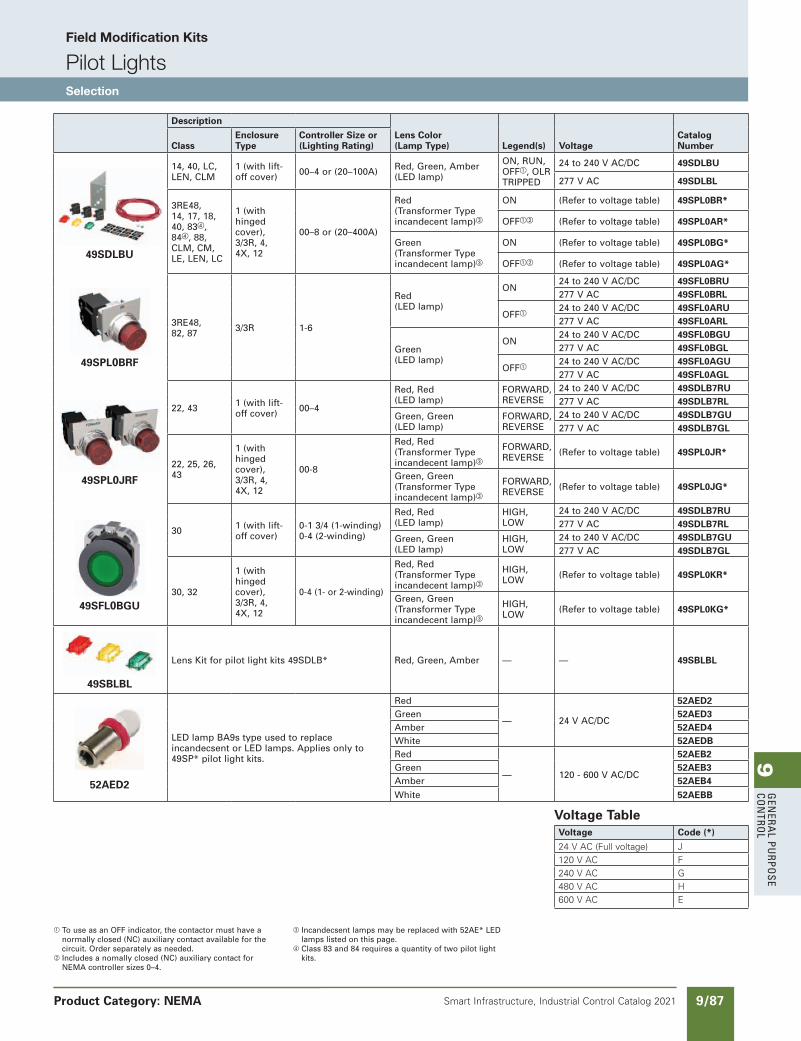
9G
enera
l PurPo
se Co
ntro
l
9/87Smart Infrastructure, Industrial Control Catalog 2021 Product Category: NEMA
SS copied this page from SF to IC on 05/24/20
a To use as an OFF indicator, the contactor must have a normally closed (NC) auxiliary contact available for the circuit. Order separately as needed.
b Includes a nomally closed (NC) auxiliary contact for NEMA controller sizes 0–4.
c Incandecsent lamps may be replaced with 52AE* LED lamps listed on this page.
d Class 83 and 84 requires a quantity of two pilot light kits.
Description
Lens Color (Lamp Type) Legend(s) Voltage
Catalog NumberClass
Enclosure Type
Controller Size or (Lighting Rating)
49SDLBU
14, 40, LC, LEN, CLM
1 (with lift-off cover) 00–4 or (20–100A) Red, Green, Amber
(LED lamp)
ON, RUN, OFFa, OLR TRIPPED
24 to 240 V AC/DC 49SDLBU
277 V AC 49SDLBL
3RE48, 14, 17, 18, 40, 83d, 84d, 88, CLM, CM, LE, LEN, LC
1 (with hinged cover), 3/3R, 4, 4X, 12
00–8 or (20–400A)
Red (Transformer Type incandecent lamp)c
ON (Refer to voltage table) 49SPL0BR*
OFFab (Refer to voltage table) 49SPL0AR*
Green (Transformer Type incandecent lamp)c
ON (Refer to voltage table) 49SPL0BG*
OFFab (Refer to voltage table) 49SPL0AG*
49SPL0BRF
3RE48, 82, 87 3/3R 1-6
Red (LED lamp)
ON24 to 240 V AC/DC 49SFL0BRU277 V AC 49SFL0BRL
OFFa24 to 240 V AC/DC 49SFL0ARU277 V AC 49SFL0ARL
Green (LED lamp)
ON24 to 240 V AC/DC 49SFL0BGU277 V AC 49SFL0BGL
OFFa24 to 240 V AC/DC 49SFL0AGU277 V AC 49SFL0AGL
49SPL0JRF
22, 43 1 (with lift-off cover) 00–4
Red, Red (LED lamp)
FORWARD, REVERSE
24 to 240 V AC/DC 49SDLB7RU277 V AC 49SDLB7RL
Green, Green (LED lamp)
FORWARD, REVERSE
24 to 240 V AC/DC 49SDLB7GU277 V AC 49SDLB7GL
22, 25, 26, 43
1 (with hinged cover), 3/3R, 4, 4X, 12
00-8
Red, Red (Transformer Type incandecent lamp)c
FORWARD, REVERSE (Refer to voltage table) 49SPL0JR*
Green, Green (Transformer Type incandecent lamp)c
FORWARD, REVERSE (Refer to voltage table) 49SPL0JG*
49SFL0BGU
30 1 (with lift-off cover)
0-1 3/4 (1-winding) 0-4 (2-winding)
Red, Red (LED lamp)
HIGH, LOW
24 to 240 V AC/DC 49SDLB7RU277 V AC 49SDLB7RL
Green, Green (LED lamp)
HIGH, LOW
24 to 240 V AC/DC 49SDLB7GU277 V AC 49SDLB7GL
30, 32
1 (with hinged cover), 3/3R, 4, 4X, 12
0-4 (1- or 2-winding)
Red, Red (Transformer Type incandecent lamp)c
HIGH, LOW (Refer to voltage table) 49SPL0KR*
Green, Green (Transformer Type incandecent lamp)c
HIGH, LOW (Refer to voltage table) 49SPL0KG*
49SBLBL
Lens Kit for pilot light kits 49SDLB* Red, Green, Amber — — 49SBLBL
52AED2
LED lamp BA9s type used to replace incandecsent or LED lamps. Applies only to 49SP* pilot light kits.
Red
— 24 V AC/DC
52AED2Green 52AED3Amber 52AED4White 52AEDBRed
— 120 - 600 V AC/DC
52AEB2Green 52AEB3Amber 52AEB4White 52AEBB
Voltage TableVoltage Code (*)
24 V AC (Full voltage) J120 V AC F240 V AC G480 V AC H600 V AC E
NEED to UPDATE in SPEEDFAX
Revised on 12/31/21
SS copied this page from SF to IC on 05/24/20
Field Modification Kits
Pilot LightsSelection
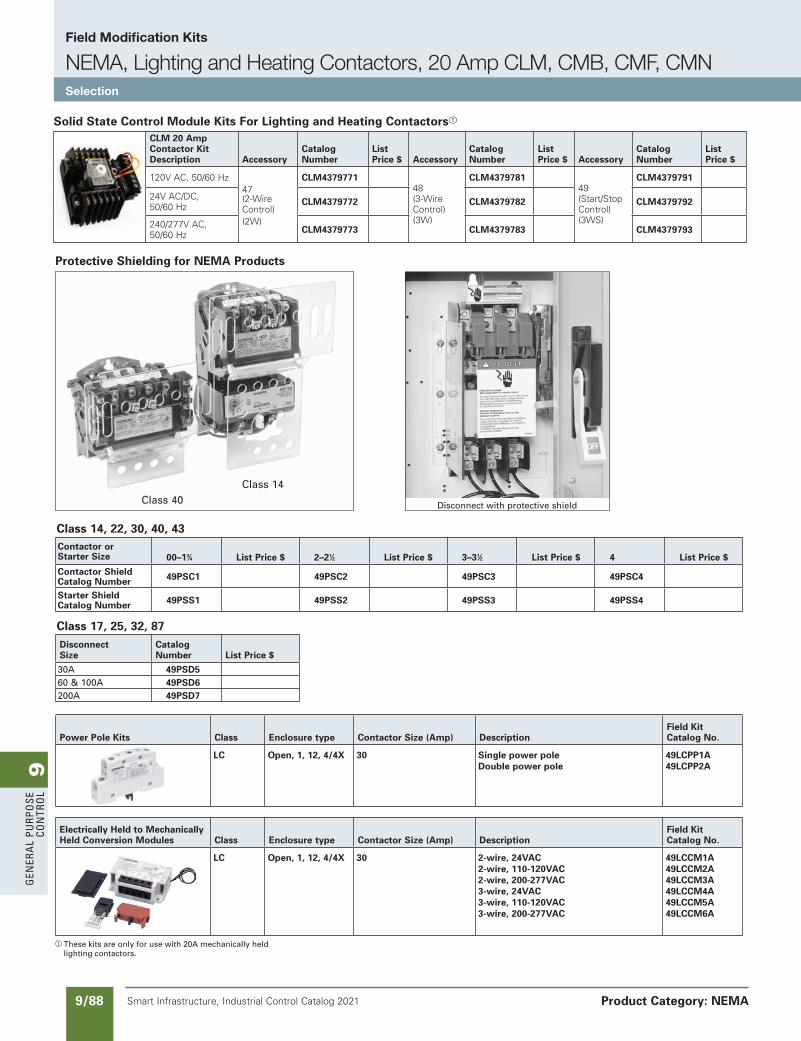
9G
ener
al
PurP
ose
Co
ntr
ol
9/88 Smart Infrastructure, Industrial Control Catalog 2021
Field Modification Kits
NEMA, Lighting and Heating Contactors, 20 Amp CLM, CMB, CMF, CMNSelection
Product Category: NEMA
a These kits are only for use with 20A mechanically held lighting contactors.
Class 14, 22, 30, 40, 43
Class 17, 25, 32, 87
Protective Shielding for NEMA Products
Class 40Class 14
Disconnect with protective shield
Power Pole Kits Class Enclosure type Contactor Size (Amp) DescriptionField Kit Catalog No.
LC Open, 1, 12, 4/4X 30 Single power poleDouble power pole
49LCPP1A49LCPP2A
Electrically Held to Mechanically Held Conversion Modules Class Enclosure type Contactor Size (Amp) Description
Field Kit Catalog No.
LC Open, 1, 12, 4/4X 30 2-wire, 24VAC2-wire, 110-120VAC2-wire, 200-277VAC3-wire, 24VAC3-wire, 110-120VAC3-wire, 200-277VAC
49LCCM1A49LCCM2A49LCCM3A49LCCM4A49LCCM5A49LCCM6A
Contactor or Starter Size 00–13⁄4 List Price $ 2–21⁄2 List Price $ 3–31⁄2 List Price $ 4 List Price $
Contactor Shield Catalog Number 49PSC1 49PSC2 49PSC3 49PSC4
Starter Shield Catalog Number 49PSS1 49PSS2 49PSS3 49PSS4
Disconnect Size
Catalog Number List Price $
30A 49PSD5 60 & 100A 49PSD6 200A 49PSD7
Solid State Control Module Kits For Lighting and Heating Contactorsa
CLM 20 AmpContactor KitDescription Accessory
CatalogNumber
ListPrice $ Accessory
CatalogNumber
ListPrice $ Accessory
CatalogNumber
ListPrice $
120V AC, 50/60 Hz47 (2-Wire Control) (2W)
CLM4379771 48 (3-Wire Control) (3W)
CLM4379781 49 (Start/Stop Control) (3WS)
CLM4379791
24V AC/DC,50/60 Hz CLM4379772 CLM4379782 CLM4379792
240/277V AC,50/60 Hz CLM4379773 CLM4379783 CLM4379793
SS copied this page from SF to IC on 05/24/20
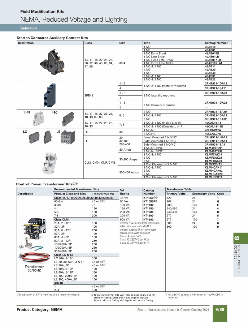
9G
enera
l PurPo
se Co
ntro
l
9/89Smart Infrastructure, Industrial Control Catalog 2021
Field Modification Kits
NEMA, Reduced Voltage and LightingSelection
Product Category: NEMA
NEED to UPDATE in SPEEDFAX
Revised on 12/31/21
SS copied this page from SF to IC on 05/24/20
a Installation of CPTs may require a larger enclosure.
Starter/Contactor Auxiliary Contact KitsDescription Class Size Type Catalog Number
14, 17, 18, 22, 25, 26, 30, 32, 40, 43, 83, 84, 87, 88
00-4
1 NO 49AB101 NC 49AB011 NC Early Break 49AB01EB1 NC Late Break 49AB01LB1 NC Extra Late Break 49AB01XLB1 NO Extra Late Make 49AB10XLM1 NO & 1 NC 49AB112 NO 49AB204 NO 49AB403 NO & 1 NC 49AB312 NO & 2 NC 49AB22
3RE48
1 - 31 NO & 1 NC laterally mounted
3RH2921-1DA11
4 3RH1921-1JA11
1 - 32 NO laterally mounted
3RH2921-1DA20
4 —
1 - 32 NC laterally mounted
3RH2921-1DA02
4 —
3RH 49C 14, 17, 18, 22, 25, 26, 40, 43, 87, 88 5, 6
2 NO 3RH1921-1EA201 NO & 1 NC 3RH1921-1DA112 NC 3RH1921-1EA02
14, 17, 18, 22, 25, 26, 40, 43 7, 8
1 NO & 1 NC (Inside L or R) 49CAL18-111 NO & 1 NC (Outside L or R) 49CAL18-11B
LC LE LC 301 NO/NC 49LCAC1PA2 NO/NC 49LCAC2PA
LE2030-100200-400
Front Mounted 1 NO/NC 3RH2911-1HA11Side Mounted 1 NO/NC 3RH2911-1DA11Side Mounted 1 NO/NC 3RH1921-1EA11
CLM, CMN, CMF, CMB
20 Amps 1 NO/NC SPDT CLM40972912 NO/NC SPDT CLM4097292
30-200 Amps
1 NO & 1 NC CLMFCAK112 NC CLMFCAK022 NO CLMFCAK201 Coil Clearing NO & NC CLMFCCK11
300-400 Amps
1 NO & 1 NC CLMHCAK112 NC CLMHCAK022 NO CLMHCAK201 Coil Clearing NO & NC CLMHCCK11
Control Power Transformer Kitsac
Description
Recommended Transformer Size VARating
Catalog Number
Transformer Table
Product Class and Size Transformer VA Primary Volts Secondary Volts Code
Transformer50/60HZ
Class 14,17,18,22,25,26,30,32,40,43,83,84,87 45 VA KT*050bc 120 24 100–2½ 45 or 50c 50 VA KT*050Pc 208 24 G3–3½ 75 100 VA KT*100 208 120 H4 150 150 VA KT*150 240/480 24 45-6 150 200 VA KT*200 240/480 120 87-8 300 300 VA KT*300 277 24 5Class CLM 500 VA KT*500 277 120 720A, 2 - 12P 150 Replace*withcodefromTransformer
table.KitsusedwithNEMA1generalpurposelift-offcovertyperequireextrawideenclosure.Class14Sizes0-21⁄2Class30(2S2W)Sizes0-21⁄2Class30(2S1W)Sizes0-13⁄4
600 24 630A, 3P 100 600 120 930A, 6 - 12P 20060A, 3P 10060A, 4 - 6P 15060A, 8 - 12P 250100/200A, 3P 200100/200A, 5P 250300/400A, 3P 250Class LC & LELC 30A, 2-12P 100LE 20, 30, 60A, 3 & 4P 45 or 50c
LE 30A, 6P 45 or 50c
LE 30A, 9-12P 100LE 60A, 6-12P 150LE 100, 200A, 3P 100LE 300, 400A, 3P 1503RE481 45 or 50c
2–4 100
b 45VA transformer kits will include secondary but not primary fusing. Sizes 50VA and higher include 2-pole primary fusing and 1-pole secondary fusing.
c For 24VAC control a minimum of 100VA CPT is required.
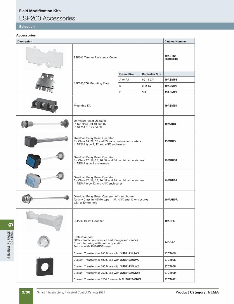
9G
ener
al
PurP
ose
Co
ntr
ol
9/90 Smart Infrastructure, Industrial Control Catalog 2021
Field Modification Kits
ESP200 AccessoriesSelection
Product Category: NEMA
Accessories
Description Catalog Number
ESP200 Tamper Resistance Cover 49ASTC1 3UB89848
ESP100/200 Mounting Plate
Frame Size Controller Size
A or A1 00 - 1 3/4 49ASMP1
B 2 -2 1/2 49ASMP2
B 3-4 49ASMP3
Mounting Kit 49ASMS1
Universal Reset Operator 8" for class 3RE48 and 87 in NEMA 1, 12 and 3R
49MARB
Overload Relay Reset Operatorfor Class 14, 22, 30 and 83 non-combination startersin NEMA type 1, 12 and 4/4X enclosures
49MBRS
Overload Relay Reset Operatorfor Class 17, 18, 25, 26, 32 and 84 combination starters in NEMA type 1 enclosures
49MBRS1
Overload Relay Reset Operatorfor Class 17, 18, 25, 26, 32 and 84 combination starters in NEMA type 12 and 4/4X enclosures
49MBRS2
Overload Relay Reset Operator with red buttonfor any Class in NEMA type 1, 3R, 4/4X and 12 enclosureswith a 30mm hole
49MARSR
ESP200 Reset Extender 49ASRE
Protective BootOffers protection from ice and foreign substances from interfering with button operation. For use with 49MARSR reset.
52AABA
Current Transformer 300:5 use with 3UB81234JW2 97CT005
Current Transformer 400:5 use with 3UB81234KW2 97CT006
Current Transformer 600:5 use with 3UB81234LW2 97CT008
Current Transformer 750:5 use with 3UB81234MW2 97CT009
Current Transformer 1200:5 use with 3UB81234NW2 97CT012
SS copied this page from SF to IC on 05/24/20
NEED to UPDATE in SPEEDFAX
Revised on 12/31/21
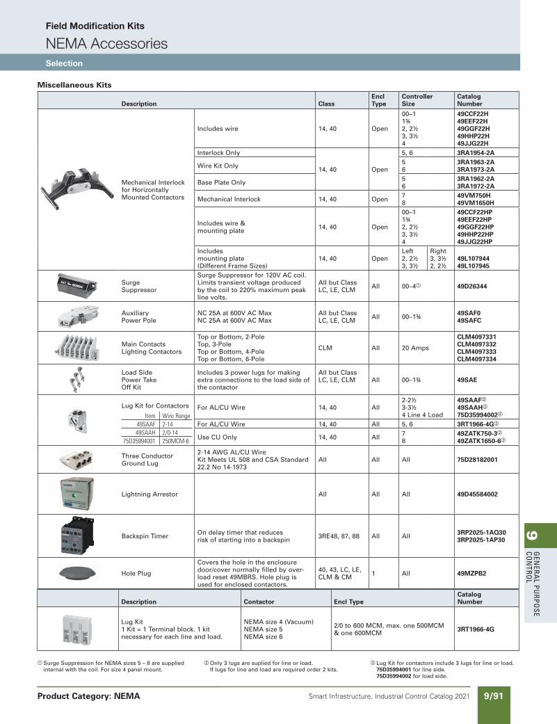
9G
enera
l PurPo
se Co
ntro
l
9/91Smart Infrastructure, Industrial Control Catalog 2021
Field Modification Kits
NEMA AccessoriesSelection
Product Category: NEMA
SS copied this page from SF to IC on 05/24/20
NEED to UPDATE in SPEEDFAX
Revised on 12/31/21
a Surge Suppression for NEMA sizes 5 – 8 are supplied internal with the coil. For size 4 panel mount.
b Only 3 lugs are suplied for line or load.If lugs for line and load are required order 2 kits.
c Lug Kit for contactors include 3 lugs for line or load.75D35994001 for line side.75D35994002 for load side.
Miscellaneous Kits
Description ClassEncl Type
ControllerSize
CatalogNumber
Mechanical Interlockfor HorizontallyMounted Contactors
Includes wire 14, 40 Open
00–11¾2, 2½3, 3½4
49CCF22H49EEF22H49GGF22H49HHP22H49JJG22H
Interlock Only
14, 40 Open
5, 6 3RA1954-2A
Wire Kit Only 56
3RA1963-2A3RA1973-2A
Base Plate Only 56
3RA1962-2A3RA1972-2A
Mechanical Interlock 14, 40 Open 78
49VM750H49VM1650H
Includes wire &mounting plate 14, 40 Open
00–11¾2, 2½3, 3½4
49CCF22HP49EEF22HP49GGF22HP49HHP22HP49JJG22HP
Includesmounting plate(Different Frame Sizes)
14, 40 OpenLeft2, 2½3, 3½
Right3, 3½2, 2½
49L10794449L107945
SurgeSuppressor
Surge Suppressor for 120V AC coil. Limits transient voltage produced by the coil to 220% maximum peak line volts.
All but Class LC, LE, CLM All 00–4a 49D26344
AuxiliaryPower Pole
NC 25A at 600V AC MaxNC 25A at 600V AC Max
All but Class LC, LE, CLM All 00–1¾ 49SAF0
49SAFC
Main ContactsLighting Contactors
Top or Bottom, 2-PoleTop, 3-PoleTop or Bottom, 4-PoleTop or Bottom, 6-Pole
CLM All 20 Amps
CLM4097331CLM4097332CLM4097333CLM4097334
Load SidePower Take Off Kit
Includes 3 power lugs for making extra connections to the load side of the contactor
All but Class LC, LE, CLM All 00–1¾ 49SAE
Lug Kit for Contactors
Item WireRange49SAAF 2-1449SAAH 2/0-14
75D35994001 250MCM-6
For AL/CU Wire 14, 40 All2-2½3-3½4 Line 4 Load
49SAAFc
49SAAHc
75D35994002c
For AL/CU Wire 14, 40 All 5, 6 3RT1966-4Gb
Use CU Only 14, 40 All 78
49ZATK750-3b
49ZATK1650-6b
Three Conductor Ground Lug
2-14 AWG AL/CU WireKit Meets UL 508 and CSA Standard 22.2 No 14-1973
All All All 75D28182001
Lightning Arrestor All All All 49D45584002
Backspin Timer On delay timer that reducesrisk of starting into a backspin 3RE48, 87, 88 All All 3RP2025-1AQ30
3RP2025-1AP30
Hole Plug
Covers the hole in the enclosure door/cover normally filled by over-load reset 49MBRS. Hole plug is used for enclosed contactors.
40, 43, LC, LE,CLM & CM 1 All 49MZPB2
Description Contactor Encl TypeCatalogNumber
Lug Kit1 Kit = 1 Terminal block. 1 kitnecessary for each line and load.
NEMA size 4 (Vacuum)NEMA size 5NEMA size 6
2/0 to 600 MCM, max. one 500MCM& one 600MCM 3RT1966-4G
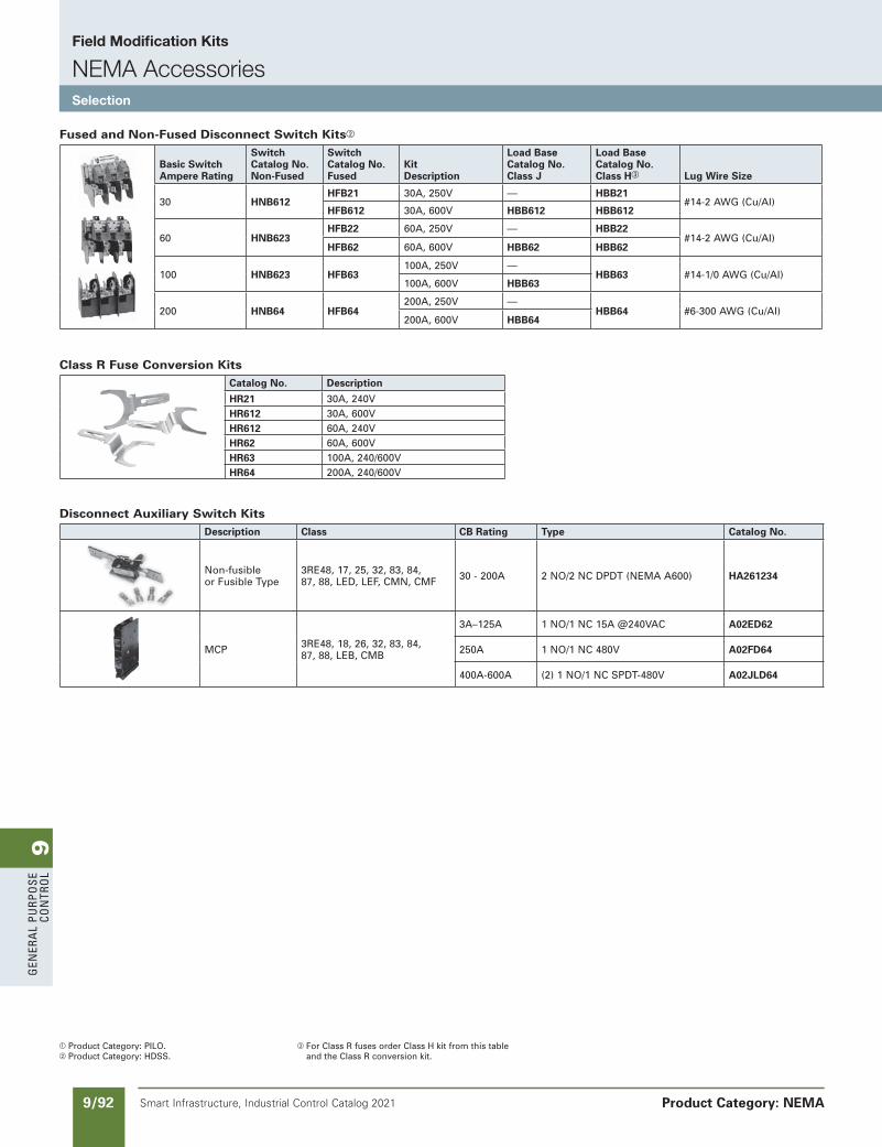
9G
ener
al
PurP
ose
Co
ntr
ol
9/92 Smart Infrastructure, Industrial Control Catalog 2021
Field Modification Kits
NEMA AccessoriesSelection
Product Category: NEMA
a Product Category: PILO.b Product Category: HDSS.
c For Class R fuses order Class H kit from this table and the Class R conversion kit.
SS copied this page from SF to IC on 05/24/20
NEED to UPDATE in SPEEDFAX
Revised on 12/31/21
Fused and Non-Fused Disconnect Switch Kitsb
Basic SwitchAmpere Rating
SwitchCatalog No.Non-Fused
SwitchCatalog No.Fused
KitDescription
Load BaseCatalog No.Class J
Load BaseCatalog No.Class Hc Lug Wire Size
30 HNB612HFB21 30A, 250V — HBB21
#14-2 AWG (Cu/AI)HFB612 30A, 600V HBB612 HBB612
60 HNB623HFB22 60A, 250V — HBB22
#14-2 AWG (Cu/AI)HFB62 60A, 600V HBB62 HBB62
100 HNB623 HFB63100A, 250V —
HBB63 #14-1/0 AWG (Cu/AI)100A, 600V HBB63
200 HNB64 HFB64200A, 250V —
HBB64 #6-300 AWG (Cu/AI)200A, 600V HBB64
Class R Fuse Conversion KitsCatalog No. Description
HR21 30A, 240VHR612 30A, 600VHR612 60A, 240VHR62 60A, 600VHR63 100A, 240/600VHR64 200A, 240/600V
Disconnect Auxiliary Switch KitsDescription Class CB Rating Type Catalog No.
Non-fusibleor Fusible Type
3RE48, 17, 25, 32, 83, 84,87, 88, LED, LEF, CMN, CMF 30 - 200A 2 NO/2 NC DPDT (NEMA A600) HA261234
MCP 3RE48, 18, 26, 32, 83, 84, 87, 88, LEB, CMB
3A–125A 1 NO/1 NC 15A @240VAC A02ED62
250A 1 NO/1 NC 480V A02FD64
400A-600A (2) 1 NO/1 NC SPDT-480V A02JLD64

9G
enera
l PurPo
se Co
ntro
l
9/93Smart Infrastructure, Industrial Control Catalog 2021
Field Modification Kits
NEMA, Overload RelaysSelection
Product Category: NEMA
NEMA Plate Manufacturer Size PartNumber ListPrice$
A-B 0,1 49D57090 A-B 2 49D57161 Sq.D 0,1 49D57091
Competitive Retrofit Overload Plates
Illustration Description ForOverloadType CatalogNumber ListPrice$ Resetmechanisms
Reset plunger Mountsdirectlytooverloadrelay.Requires 3RB206 3RU1900-1A separateresetoperatorinenclosuredoor.Kit includesresetplunger,holderandfunnel.
Cablelength 3RU1900-1B Flexible cable reset mechanism 15.75in(400mm) Requiresa6.5mmholeinthe 3RB206 enclosurewithamaximum Cablelength enclosurethicknessof8mm. 23.62in(600mm) 3RU1900-1C
Covers
Tamperresistantcoverforcurrentsettingandmanual/automaticresetbutton. 3RB206 3RB2984-0
Sirius 3RB20
Resetplungerwithresetbutton
Flexiblereset
21-27V 96-127V 200-277VClass Size ModelType CatalogNumber ListPrice$ CatalogNumber ListPrice$ CatalogNumber ListPrice$ 5 P – – 3RT1965-5PF31 3RT1965-5PP31
All V – – 3RT1966-5PF31 3RT1966-5PP31 6 P – – 3RT1975-5PF31 3RT1975-5PP31 V – – 3RT1976-5PF31 3RT1976-5PP31
Electronic Coil System with Remaining Lifetime Indication and 24VDC PLC Output
SS copied this page from SF to IC on 05/24/20
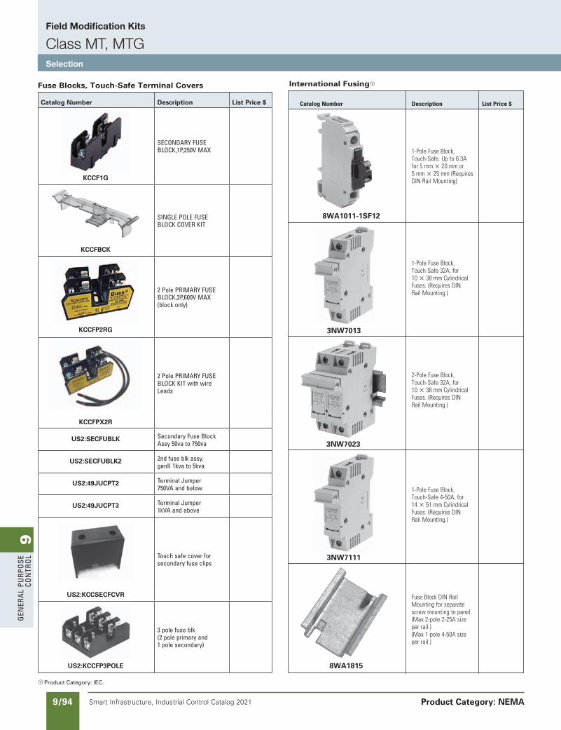
9G
ener
al
PurP
ose
Co
ntr
ol
9/94 Smart Infrastructure, Industrial Control Catalog 2021 Product Category: NEMA
International Fusinga
CatalogNumber Description ListPrice$
1-PoleFuseBlock, Touch-Safe.Upto6.3A for5mmu20mmor 5mmu25mm(Requires DINRailMounting)
1-PoleFuseBlock, Touch-Safe32A,for 10u38mmCylindrical Fuses.(RequiresDIN RailMounting.)
2-PoleFuseBlock, Touch-Safe32A,for 10u38mmCylindrical Fuses.(RequiresDIN RailMounting.)
1-PoleFuseBlock, Touch-Safe4-50A,for 14u51mmCylindrical Fuses.(RequiresDIN RailMounting.)
FuseBlockDINRail Mountingforseparate screwmountingtopanel. (Max2-pole2-25Asize perrail.) (Max1-pole4-50Asize perrail.)
8WA1011-1SF12
3NW7013
3NW7023
3NW7111
8WA1815
a Product Category: IEC.
Fuse Blocks, Touch-Safe Terminal Covers
Catalog Number Description List Price $
KCCF1G
seConDarY Fuse BloCK,1P,250V MaX
KCCFBCK
sInGle Pole Fuse BloCK CoVer KIt
KCCFP2RG
2 Pole PrIMarY Fuse BloCK,2P,600V MaX (block only)
2 Pole PrIMarY Fuse BloCK KIt with wire leads
KCCFPX2R
US2:SECFUBLK secondary Fuse Block assy 50va to 750va
US2:SECFUBLK2 2nd fuse blk assy. genII 1kva to 5kva
US2:49JUCPT2 terminal Jumper 750Va and below
US2:49JUCPT3 terminal Jumper 1kVa and above
touch safe cover for secondary fuse clips
US2:KCCSECFCVR
US2:KCCFP3POLE
3 pole fuse blk (2 pole primary and 1 pole secondary)
SS copied this page from SF to IC on 05/24/20
updated in SPEEDFAXRevised on 04/30/21
Field Modification Kits
Class MT, MTGSelection
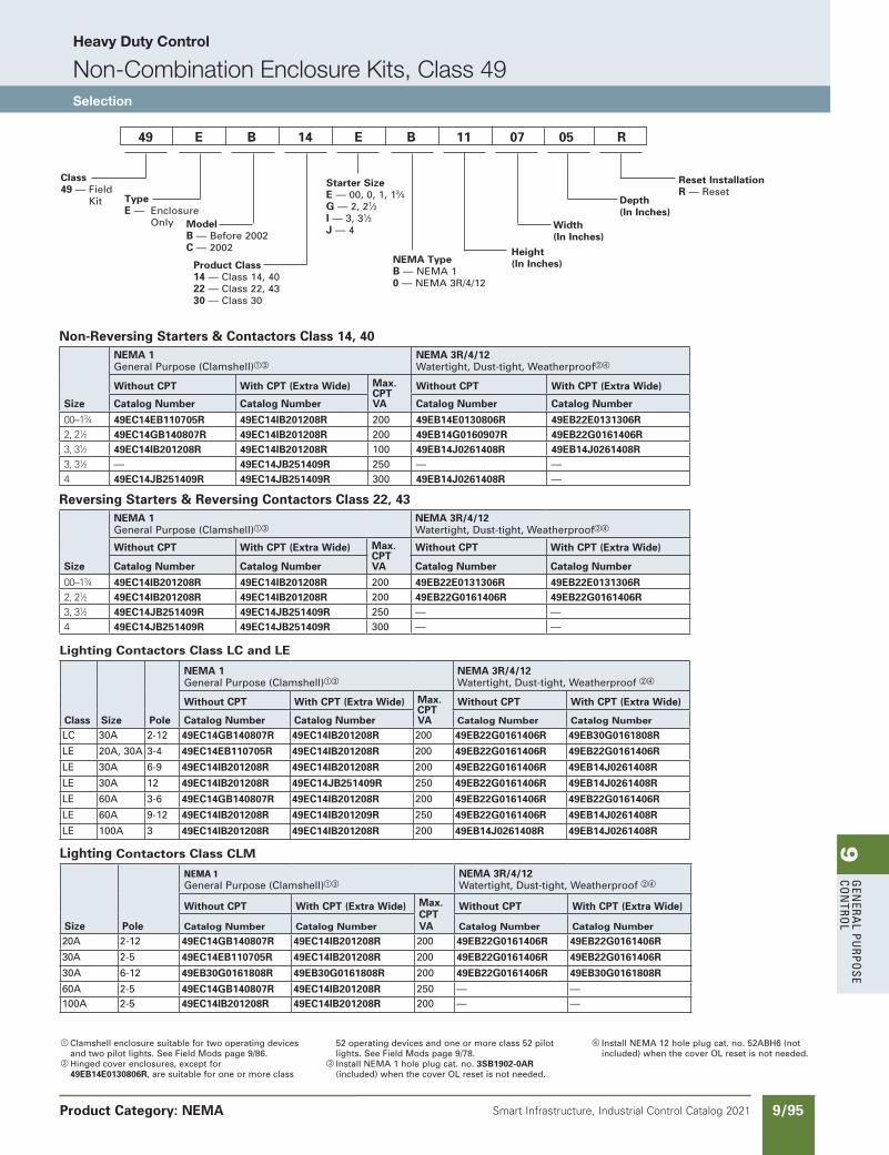
9G
enera
l PurPo
se Co
ntro
l
9/95Smart Infrastructure, Industrial Control Catalog 2021
Heavy Duty Control
Non-Combination Enclosure Kits, Class 49Selection
Product Category: NEMA
updated in SPEEDFAXRevised on 02/28/21
SS copied this page from SF to IC on 05/24/20
49 E B 14 E B 11 07 05 R
Class49 — Field
Kit TypeE — Enclosure
Only ModelB — Before 2002C — 2002
Product Class14 — Class 14, 4022 — Class 22, 4330 — Class 30
Starter SizeE — 00, 0, 1, 13⁄4G — 2, 21⁄2I — 3, 31⁄2J — 4
NEMA TypeB — NEMA 10 — NEMA 3R/4/12
Height (In Inches)
Width (In Inches)
Depth (In Inches)
Reset InstallationR — Reset
Non-Reversing Starters & Contactors Class 14, 40
Size
NEMA 1General Purpose (Clamshell)ac
NEMA 3R/4/12Watertight, Dust-tight, Weatherproofbd
Without CPT With CPT (Extra Wide) Max.CPTVA
Without CPT With CPT (Extra Wide)
Catalog Number Catalog Number Catalog Number Catalog Number
00–13⁄4 49EC14EB110705R 49EC14IB201208R 200 49EB14E0130806R 49EB22E0131306R2, 21⁄2 49EC14GB140807R 49EC14IB201208R 200 49EB14G0160907R 49EB22G0161406R 3, 31⁄2 49EC14IB201208R 49EC14IB201208R 100 49EB14J0261408R 49EB14J0261408R3, 31⁄2 — 49EC14JB251409R 250 — —4 49EC14JB251409R 49EC14JB251409R 300 49EB14J0261408R —
Reversing Starters & Reversing Contactors Class 22, 43
Size
NEMA 1General Purpose (Clamshell)ac
NEMA 3R/4/12Watertight, Dust-tight, Weatherproofbd
Without CPT With CPT (Extra Wide) Max.CPTVA
Without CPT With CPT (Extra Wide)
Catalog Number Catalog Number Catalog Number Catalog Number
00–13⁄4 49EC14IB201208R 49EC14IB201208R 200 49EB22E0131306R 49EB22E0131306R2, 21⁄2 49EC14IB201208R 49EC14IB201208R 200 49EB22G0161406R 49EB22G0161406R3, 31⁄2 49EC14JB251409R 49EC14JB251409R 250 — —4 49EC14JB251409R 49EC14JB251409R 300 — —
Lighting Contactors Class LC and LE
Class Size Pole
NEMA 1General Purpose (Clamshell)ac
NEMA 3R/4/12Watertight, Dust-tight, Weatherproof bd
Without CPT With CPT (Extra Wide) Max.CPTVA
Without CPT With CPT (Extra Wide)
Catalog Number Catalog Number Catalog Number Catalog Number
LC 30A 2-12 49EC14GB140807R 49EC14IB201208R 200 49EB22G0161406R 49EB30G0161808R
LE 20A, 30A 3-4 49EC14EB110705R 49EC14IB201208R 200 49EB22G0161406R 49EB22G0161406R
LE 30A 6-9 49EC14IB201208R 49EC14IB201208R 200 49EB22G0161406R 49EB14J0261408R
LE 30A 12 49EC14IB201208R 49EC14JB251409R 250 49EB22G0161406R 49EB14J0261408R
LE 60A 3-6 49EC14GB140807R 49EC14IB201208R 200 49EB22G0161406R 49EB22G0161406R
LE 60A 9-12 49EC14IB201208R 49EC14IB201209R 250 49EB22G0161406R 49EB14J0261408R
LE 100A 3 49EC14IB201208R 49EC14IB201208R 200 49EB14J0261408R 49EB14J0261408R
Lighting Contactors Class CLM
Size Pole
NEMA1General Purpose (Clamshell)ac
NEMA 3R/4/12Watertight, Dust-tight, Weatherproof bd
Without CPT With CPT (Extra Wide) Max.CPT VA
Without CPT With CPT (Extra Wide)
Catalog Number Catalog Number Catalog Number Catalog Number
20A 2-12 49EC14GB140807R 49EC14IB201208R 200 49EB22G0161406R 49EB22G0161406R
30A 2-5 49EC14EB110705R 49EC14IB201208R 200 49EB22G0161406R 49EB22G0161406R
30A 6-12 49EB30G0161808R 49EB30G0161808R 200 49EB22G0161406R 49EB30G0161808R
60A 2-5 49EC14GB140807R 49EC14IB201208R 250 — —100A 2-5 49EC14IB201208R 49EC14IB201208R 200 — —
a Clamshell enclosure suitable for two operating devices and two pilot lights. See Field Mods page 9/86.
b Hinged cover enclosures, except for 49EB14E0130806R, are suitable for one or more class
52 operating devices and one or more class 52 pilot lights. See Field Mods page 9/78.
c Install NEMA 1 hole plug cat. no. 3SB1902-0AR (included) when the cover OL reset is not needed.
d Install NEMA 12 hole plug cat. no. 52ABH6 (not included) when the cover OL reset is not needed.
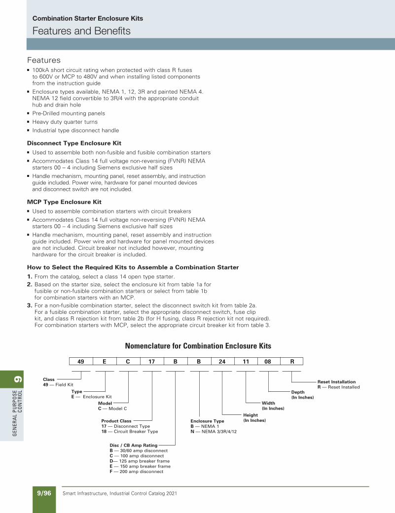
9G
ener
al
PurP
ose
Co
ntr
ol
9/96 Smart Infrastructure, Industrial Control Catalog 2021
NEED to UPDATE in SPEEDFAX
Revised on 12/31/21
SS copied this page from SF to IC on 05/24/20
Class49 — Field Kit
TypeE — Enclosure Kit
ModelC — Model C
Product Class17 — Disconnect Type18 — Circuit Breaker Type
Disc / CB Amp RatingB — 30/60 amp disconnectC — 100 amp disconnectD— 125 amp breaker frameE — 150 amp breaker frameF — 200 amp disconnect
Enclosure TypeB — NEMA 1N — NEMA 3/3R/4/12
49 E C 17 B B 24 11 08 R
Height (In Inches)
Width (In Inches)
Depth (In Inches)
Reset InstallationR — Reset Installed
NomenclatureforCombinationEnclosureKits
Featuresb 100kA short circuit rating when protected with class R fuses
to 600V or MCP to 480V and when installing listed components from the instruction guide
b Enclosure types available, NEMA 1, 12, 3R and painted NEMA 4.NEMA 12 field convertible to 3R/4 with the appropriate conduit hub and drain hole
b Pre-Drilled mounting panels
b Heavy duty quarter turns
b Industrial type disconnect handle
Disconnect Type Enclosure Kit
b Used to assemble both non-fusible and fusible combination starters
b Accommodates Class 14 full voltage non-reversing (FVNR) NEMA starters 00 – 4 including Siemens exclusive half sizes
b Handle mechanism, mounting panel, reset assembly, and instruction guide included. Power wire, hardware for panel mounted devices and disconnect switch are not included.
MCP Type Enclosure Kit
b Used to assemble combination starters with circuit breakers
b Accommodates Class 14 full voltage non-reversing (FVNR) NEMAstarters 00 – 4 including Siemens exclusive half sizes
b Handle mechanism, mounting panel, reset assembly and instruction guide included. Power wire and hardware for panel mounted devices are not included. Circuit breaker not included however, mounting hardware for the circuit breaker is included.
How to Select the Required Kits to Assemble a Combination Starter
1. From the catalog, select a class 14 open type starter.2. Based on the starter size, select the enclosure kit from table 1a for
fusible or non-fusible combination starters or select from table 1b for combination starters with an MCP.
3. For a non-fusible combination starter, select the disconnect switch kit from table 2a.For a fusible combination starter, select the appropriate disconnect switch, fuse clip kit, and class R rejection kit from table 2b (for H fusing, class R rejection kit not required). For combination starters with MCP, select the appropriate circuit breaker kit from table 3.
Combination Starter Enclosure Kits
Features and Benefits
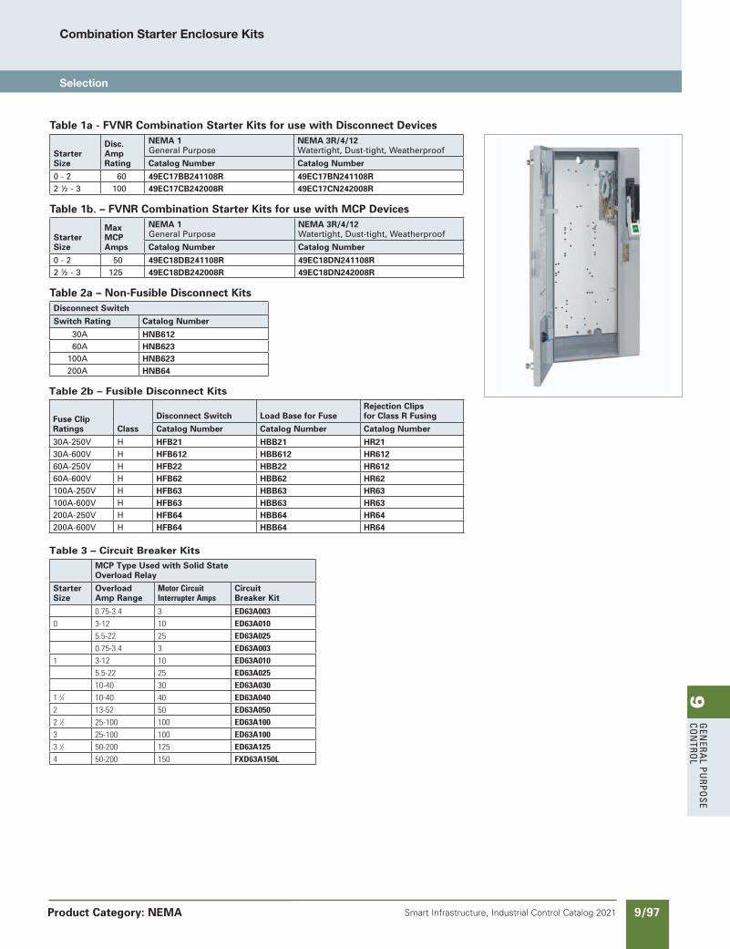
9G
enera
l PurPo
se Co
ntro
l
9/97Smart Infrastructure, Industrial Control Catalog 2021 Product Category: NEMA
SS copied this page from SF to IC on 05/24/20
updated in SPEEDFAXRevised on 10/15/20
Table 3 – Circuit Breaker Kits
MCP Type Used with Solid State Overload Relay
Starter Size
OverloadAmp Range
MotorCircuitInterrupterAmps
CircuitBreaker Kit
0.75-3.4 3 ED63A003
0 3-12 10 ED63A010
5.5-22 25 ED63A025
0.75-3.4 3 ED63A003
1 3-12 10 ED63A010
5.5-22 25 ED63A025
10-40 30 ED63A030
13⁄4 10-40 40 ED63A040
2 13-52 50 ED63A050
21⁄2 25-100 100 ED63A100
3 25-100 100 ED63A100
31⁄2 50-200 125 ED63A125
4 50-200 150 FXD63A150L
Table 2b – Fusible Disconnect Kits
Fuse Clip Ratings Class
Disconnect Switch Load Base for FuseRejection Clips for Class R Fusing
Catalog Number Catalog Number Catalog Number
30A-250V H HFB21 HBB21 HR2130A-600V H HFB612 HBB612 HR61260A-250V H HFB22 HBB22 HR61260A-600V H HFB62 HBB62 HR62100A-250V H HFB63 HBB63 HR63100A-600V H HFB63 HBB63 HR63200A-250V H HFB64 HBB64 HR64200A-600V H HFB64 HBB64 HR64
Table 1a - FVNR Combination Starter Kits for use with Disconnect Devices
Starter Size
Disc. AmpRating
NEMA 1General Purpose
NEMA 3R/4/12Watertight, Dust-tight, Weatherproof
Catalog Number Catalog Number
0 - 2 60 49EC17BB241108R 49EC17BN241108R2 ½ - 3 100 49EC17CB242008R 49EC17CN242008R
Table 1b. – FVNR Combination Starter Kits for use with MCP Devices
Starter Size
MaxMCPAmps
NEMA 1General Purpose
NEMA 3R/4/12Watertight, Dust-tight, Weatherproof
Catalog Number Catalog Number
0 - 2 50 49EC18DB241108R 49EC18DN241108R2 ½ - 3 125 49EC18DB242008R 49EC18DN242008R
Table 2a – Non-Fusible Disconnect Kits Disconnect Switch
Switch Rating Catalog Number
30A HNB61260A HNB623
100A HNB623200A HNB64
Combination Starter Enclosure Kits
Selection
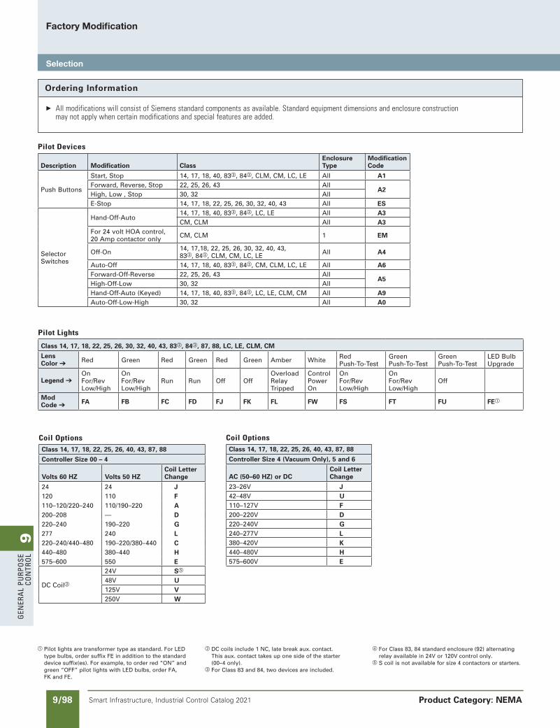
9G
ener
al
PurP
ose
Co
ntr
ol
9/98 Smart Infrastructure, Industrial Control Catalog 2021
Factory Modification
Selection
Product Category: NEMA
a Pilot lights are transformer type as standard. For LED type bulbs, order suffix FE in addition to the standard device suffix(es). For example, to order red “ON” and green “OFF” pilot lights with LED bulbs, order FA, FK and FE.
Ordering Information
AllmodificationswillconsistofSiemensstandardcomponentsasavailable.Standardequipmentdimensionsandenclosureconstructionmaynotapplywhencertainmodificationsandspecialfeaturesareadded.
b DC coils include 1 NC, late break aux. contact. This aux. contact takes up one side of the starter (00–4 only).
c For Class 83 and 84, two devices are included.
d For Class 83, 84 standard enclosure (92) alternating relay available in 24V or 120V control only.
e S coil is not available for size 4 contactors or starters.
SS copied this page from SF to IC on 05/24/20
NEED to UPDATE in SPEEDFAX
Revised on 12/31/21
PilotDevices
Description Modification ClassEnclosure Type
Modification Code
Push Buttons
Start, Stop 14, 17, 18, 40, 83c, 84c, CLM, CM, LC, LE All A1Forward, Reverse, Stop 22, 25, 26, 43 All
A2 High, Low , Stop 30, 32 AllE-Stop 14, 17, 18, 22, 25, 26, 30, 32, 40, 43 All ES
Selector Switches
Hand-Off-Auto14, 17, 18, 40, 83c, 84c, LC, LE All A3 CM, CLM All A3
For 24 volt HOA control, 20 Amp contactor only CM, CLM 1 EM
Off-On 14, 17,18, 22, 25, 26, 30, 32, 40, 43,83c, 84c, CLM, CM, LC, LE All A4
Auto-Off 14, 17, 18, 40, 83c, 84c, CM, CLM, LC, LE All A6Forward-Off-Reverse 22, 25, 26, 43 All
A5 High-Off-Low 30, 32 AllHand-Off-Auto (Keyed) 14, 17, 18, 40, 83c, 84c, LC, LE, CLM, CM All A9Auto-Off-Low-High 30, 32 All A0
PilotLights
Class 14, 17, 18, 22, 25, 26, 30, 32, 40, 43, 83c, 84c, 87, 88, LC, LE, CLM, CM
Lens Color ➔ Red Green Red Green Red Green Amber White Red
Push-To-TestGreen Push-To-Test
GreenPush-To-Test
LED BulbUpgrade
Legend ➔OnFor/RevLow/High
OnFor/RevLow/High
Run Run Off OffOverloadRelayTripped
ControlPowerOn
OnFor/RevLow/High
OnFor/RevLow/High
Off
Mod Code ➔ FA FB FC FD FJ FK FL FW FS FT FU FEa
CoilOptionsClass 14, 17, 18, 22, 25, 26, 40, 43, 87, 88
Controller Size 00 – 4
Volts 60 HZ Volts 50 HZCoil LetterChange
24 24 J120 110 F110–120/220–240 110/190–220 A200–208 — D220–240 190–220 G277 240 L220–240/440–480 190–220/380–440 C440–480 380–440 H575–600 550 E
DC Coilb
24V Se
48V U125V V250V W
CoilOptionsClass 14, 17, 18, 22, 25, 26, 40, 43, 87, 88
Controller Size 4 (Vacuum Only), 5 and 6
AC (50–60 HZ) or DCCoil Letter Change
23–26V J42–48V U110–127V F200–220V D220–240V G240–277V L380–420V K440–480V H575–600V E

9G
enera
l PurPo
se Co
ntro
l
9/99Smart Infrastructure, Industrial Control Catalog 2021
Factory Modifications
Selection
Product Category: NEMA
Note: Factory will furnish the same voltage coils as transformer secondary voltage (except with class 36,37).
a The standard control transformer supplied for starter sizes 0 through 21⁄2 will be rated 45VA and have the appropriate secondary fuse. Primary fuses will not be supplied as standard. For primary fuse option select appropriate suffix from table.
c Class 83 and 84 duplex controllers requires two CPTs.d Class 84 Duplex Controllers require two fusible
disconnects.
Ordering Information
Replace(*)withletterfromTransformerTable.
Transformer Table Primary secondary Volts Volts letter 120 24 B 208 24 s 208 120 t 240 24 J 240 120 F 277 24 n 277 120 P 380 110 u 415 100 W 480 240 r 480/240 24 D 480/240 120 a 600 24 e 600 120 C
Fuse ClipAmps Volts ModificationCode 30 250 10 30 600 11 60 250 12 60 600 13 100 250 14 100 600 15 200 250 16 200 600 17 400 250 18 400 600 19 600 250 20 600 600 21 800 600 23 1200 600 24 1600 600 25
Factory Assembled Fuse Clips—Class 25, 32, 84d
Control Power Transformers
DescriptionModificationCode
ProductClassc
Standard Capacitya
with 1-Secondary Fuse B*
All
Standard Capacity with 2-Primary and 1-Secondary Fuse D*
100VA Extra Capacity with 2-Primary and 1-Secondary Fuse C*
150VA Extra Capacity with 2-Primary and 1-Secondary Fuse C*1
updated in SPEEDFAXRevised on 03/31/20
SS copied this page from SF to IC on 05/24/20
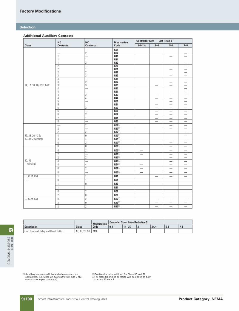
9G
ener
al
PurP
ose
Co
ntr
ol
9/100 Smart Infrastructure, Industrial Control Catalog 2021
Factory Modifications
Selection
Product Category: NEMA
a Auxiliary contacts will be added evenly across contactors. (i.e. Class 22, G02 suffix will add 2 NC contacts (one per contactor).
b Double the price addition for Class 30 and 32.c For class 83 and 84 contacts will be added to both
starters. Price x 2.
ModificationCode
ControllerSize-PriceDeduction$
Description Class 0,1 13⁄4-21⁄2 3 31⁄2,4 5,6 7,8OmitOverloadRelayandResetButton 17,18,25,26 EX1
Additional Auxiliary Contacts
NO NC Modication ControllerSize—ListPrice$
Class Contacts Contacts Code 00–13⁄4 2–4 5–6 7–8
— 1 G01 — — — 2 G02 — 1 — G10 — — 1 1 G11 1 2 G12 — — 2 — G20 — 2 1 G21 — — 2 2 G22 — 2 3 G23 — — 3 1 G31 — 3 2 G32 — —14,17,18,40,83c,84c 3 3 G33 — — — 4 — G40 — 4 1 G41 — — 4 2 G42 — — — 4 4 G44 — — — 5 — G50 — — 5 1 G51 — — — 5 3 G53 — — — 6 — G60 — — — 6 2 G62 — — — 7 1 G71 — — — 8 — G80 — — — — 2 G02a — — 2 — G20a — — 2 2 G22a — 22,25,26,43& 4 0 G40a — 30,32(2-winding) 4 4 G44a — — 6 2 G62a — — 8 0 G80a — —
0 2 G02a — — — 2 — G20a — — — 2 2 G22a — — 30,32 4 — G40a — — (1-winding) 4 4 G44a — — — 6 2 G62a — — — 8 — G80a — — — LE,CLM,CM 1 1 G11 — — — LC 0 1 G01 1 0 G10 1 1 G11 0 2 G02 2 0 G20 LE,CLM,CM 0 2 G02a — — — 2 0 G20a — — — 2 2 G22a — — —
SS copied this page from SF to IC on 05/24/20
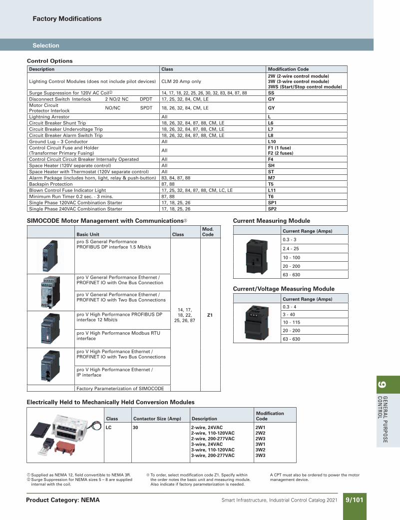
9G
enera
l PurPo
se Co
ntro
l
9/101Smart Infrastructure, Industrial Control Catalog 2021
Factory Modifications
Selection
Product Category: NEMA
NEED to UPDATE in SPEEDFAX
Revised on 12/31/21
SS copied this page from SF to IC on 05/24/20
SIMOCODE Motor Management with Communicationsc
Basic Unit ClassMod. Code
pro S General Performance PROFIBUS DP interface 1.5 Mbit/s
14, 17, 18, 22,
25, 26, 87Z1
pro V General Performance Ethernet / PROFINET IO with One Bus Connection
pro V General Performance Ethernet / PROFINET IO with Two Bus Connections
pro V High Performance PROFIBUS DP interface 12 Mbit/s
pro V High Performance Modbus RTU interface
pro V High Performance Ethernet / PROFINET IO with Two Bus Connections
pro V High Performance Ethernet / IP interface
Factory Parameterization of SIMOCODE
a Supplied as NEMA 12, field convertible to NEMA 3R.b Surge Suppression for NEMA sizes 5 – 8 are supplied
internal with the coil.
c To order, select modification code Z1. Specify within the order notes the basic unit and measuring module. Also indicate if factory parameterization is needed.
A CPT must also be ordered to power the motor management device.
Electrically Held to Mechanically Held Conversion Modules
Class Contactor Size (Amp) DescriptionModification Code
LC 30 2-wire, 24VAC2-wire, 110-120VAC2-wire, 200-277VAC3-wire, 24VAC3-wire, 110-120VAC3-wire, 200-277VAC
2W12W22W33W13W23W3
Control OptionsDescription Class Modification Code
Lighting Control Modules (does not include pilot devices) CLM 20 Amp only2W (2-wire control module)3W (3-wire control module)3WS (Start/Stop control module)
Surge Suppression for 120V AC Coilb 14, 17, 18, 22, 25, 26, 30, 32, 83, 84, 87, 88 SSDisconnect Switch Interlock 2 NO/2 NC DPDT 17, 25, 32, 84, CM, LE GYMotor Circuit NO/NC SPDTProtector Interlock 18, 26, 32, 84, CM, LE GY
Lightning Arrestor All LCircuit Breaker Shunt Trip 18, 26, 32, 84, 87, 88, CM, LE L6 Circuit Breaker Undervoltage Trip 18, 26, 32, 84, 87, 88, CM, LE L7Circuit Breaker Alarm Switch Trip 18, 26, 32, 84, 87, 88, CM, LE L8 Ground Lug – 3 Conductor All L10Control Circuit Fuse and Holder(Transformer Primary Fusing) All F1 (1 fuse)
F2 (2 fuses)Control Circuit Circuit Breaker Internally Operated All F4Space Heater (120V separate control) All SHSpace Heater with Thermostat (120V separate control) All STAlarm Package (includes horn, light, relay & push-button) 83, 84, 87, 88 M7Backspin Protection 87, 88 T5Blown Control Fuse Indicator Light 17, 25, 32, 84, 87, 88, CM, LC, LE L11Minimum Run Timer 0.2 sec. - 3 mins. 87, 88 T6Single Phase 120VAC Combination Starter 17, 18, 25, 26 SP1Single Phase 240VAC Combination Starter 17, 18, 25, 26 SP2
Current Measuring Module
Current Range (Amps)
0.3 - 3
2.4 - 25
10 - 100
20 - 200
63 - 630
Current/Voltage Measuring Module
Current Range (Amps)
0.3 - 4
3 - 40
10 - 115
20 - 200
63 - 630
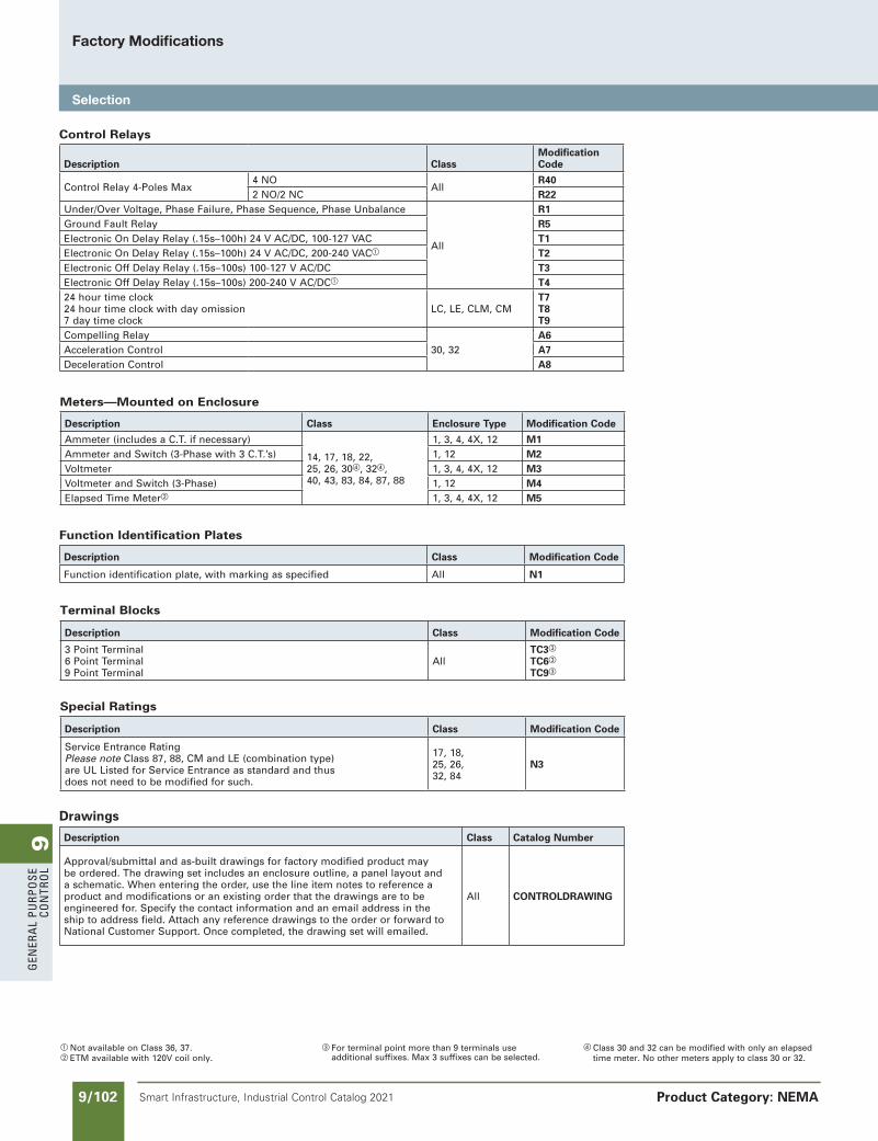
9G
ener
al
PurP
ose
Co
ntr
ol
9/102 Smart Infrastructure, Industrial Control Catalog 2021
Factory Modifications
Selection
Product Category: NEMA
a Not available on Class 36, 37.b ETM available with 120V coil only.
c For terminal point more than 9 terminals use additional suffixes. Max 3 suffixes can be selected.
d Class 30 and 32 can be modified with only an elapsed time meter. No other meters apply to class 30 or 32.
Drawings
Description Class Catalog Number
Approval/submittal and as-built drawings for factory modified product may be ordered. The drawing set includes an enclosure outline, a panel layout and a schematic. When entering the order, use the line item notes to reference a product and modifications or an existing order that the drawings are to be engineered for. Specify the contact information and an email address in the ship to address field. Attach any reference drawings to the order or forward to National Customer Support. Once completed, the drawing set will emailed.
All CONTROLDRAWING
Control Relays
Description ClassModificationCode
Control Relay 4-Poles Max4 NO
AllR40
2 NO/2 NC R22Under/Over Voltage, Phase Failure, Phase Sequence, Phase Unbalance
All
R1Ground Fault Relay R5Electronic On Delay Relay (.15s–100h) 24 V AC/DC, 100-127 VAC T1Electronic On Delay Relay (.15s–100h) 24 V AC/DC, 200-240 VACa T2Electronic Off Delay Relay (.15s–100s) 100-127 V AC/DC T3Electronic Off Delay Relay (.15s–100s) 200-240 V AC/DCa T424 hour time clock24 hour time clock with day omission7 day time clock
LC, LE, CLM, CMT7T8T9
Compelling Relay30, 32
A6Acceleration Control A7Deceleration Control A8
Meters—Mounted on Enclosure
Description Class Enclosure Type Modification Code
Ammeter (includes a C.T. if necessary)
14, 17, 18, 22,25, 26, 30d, 32d, 40, 43, 83, 84, 87, 88
1, 3, 4, 4X, 12 M1Ammeter and Switch (3-Phase with 3 C.T.’s) 1, 12 M2Voltmeter 1, 3, 4, 4X, 12 M3Voltmeter and Switch (3-Phase) 1, 12 M4Elapsed Time Meterb 1, 3, 4, 4X, 12 M5
Function Identification Plates
Description Class Modification Code
Function identification plate, with marking as specified All N1
Terminal Blocks
Description Class Modification Code
3 Point Terminal6 Point Terminal9 Point Terminal
AllTC3c
TC6c
TC9c
Special Ratings
Description Class Modification Code
Service Entrance RatingPlease note Class 87, 88, CM and LE (combination type) are UL Listed for Service Entrance as standard and thus does not need to be modified for such.
17, 18, 25, 26, 32, 84
N3
SS copied this page from SF to IC on 05/24/20
NEED to UPDATE in SPEEDFAX
Revised on 12/31/21
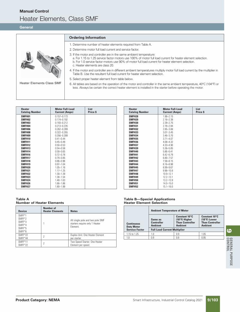
9G
enera
l PurPo
se Co
ntro
l
9/103Smart Infrastructure, Industrial Control Catalog 2021 Product Category: NEMA
Heater Elements Class SMF
Table B—Special Applications Heater Element Selection
AmbientTemperatureofMotor
Constant10°C Constant10°C Sameas (18°F)Higher (18°F)Lower Continuous Controller ThanController ThanController DutyMotor Ambient Ambient Ambient
ServiceFactor FullLoadCurrentMultiplier
1.15to1.25 1.0 0.9 1.05 1.0 0.9 0.8 0.95
Table A Number of Heater Elements
Numberof Device HeaterElements Notes
SMFF*1 SMFF*2 AllsinglepoleandtwopoleSMF SMFF*3 1 startersrequireonly1Heater SMFF*4 Element. SMFF*5 SMFF*6 SMFF*22 2 DuplexUnit.OneHeaterElement SMFF*44 perstarter. SMFF*11 2 TwoSpeedStarter.OneHeater SMFF*22 Elementperspeed.
Ordering Information
1. Determine number of heater elements required from Table A.
2. Determine motor full load current and service factor.
3. If the motor and controller are in the same ambient temperature: a. For 1.15 to 1.25 service factor motors use 100% of motor full load current for heater element selection. b. For 1.0 service factor motors use 90% of motor full load current for heater element selection. c. Heater elements are class 20.
4. If the motor and controller are in different ambient temperatures multiply motor full load current by the multiplier in Table B. Use the resultant full load current for heater element selection.
5. Select proper heater element from table below.
6. All tables are based on the operation of the motor and controller in the same ambient temperature, 40°C (104°F) or less. Always be certain the correct heater element is installed in the starter before operating the motor.
Heater MotorFull-Load List CatalogNumber Current(Amps) Price$
SMFH01 0.157–0.173 SMFH02 0.174–0.192 SMFH03 0.193–0.212 SMFH04 0.213–0.235 SMFH06 0.262–0.289 SMFH08 0.322–0.355 SMFH09 0.356–0.399 SMFH10 0.41–0.44 SMFH11 0.45–0.49 SMFH12 0.50–0.53 SMFH13 0.54–0.58 SMFH14 0.59–0.65 SMFH16 0.72–0.78 SMFH17 0.79–0.85 SMFH18 0.86–0.96 SMFH19 0.97–1.04 SMFH20 1.05–1.16 SMFH21 1.17–1.25 SMFH22 1.30–1.39 SMFH23 1.38–1.54 SMFH24 1.48–1.63 SMFH26 1.66–1.86 SMFH27 1.80–1.99
Heater MotorFull-Load List CatalogNumber Current(Amps) Price$
SMFH28 1.96–2.15 SMFH29 2.16–2.38 SMFH30 2.39–2.75 SMFH31 2.76–2.84 SMFH32 2.85–3.06 SMFH33 3.07–3.45 SMFH34 3.46–3.70 SMFH35 3.71–4.07 SMFH36 4.08–4.32 SMFH37 4.33–4.90 SMFH39 5.36–5.85 SMFH40 5.86–6.41 SMFH41 6.42–6.79 SMFH42 6.80–7.57 SMFH43 7.58–8.15 SMFH44 8.16–8.98 SMFH45 8.99–9.67 SMFH47 9.96–10.8 SMFH48 10.9–12.1 SMFH49 12.2–13.1 SMFH50 13.2–13.9 SMFH51 14.0–15.0 SMFH52 15.1–16.0
SS copied this page from SF to IC on 05/24/20
Manual Control
Heater Elements, Class SMFGeneral
NEED TO UPDATE IN SPEEDFAX
Revised on 12/31/21
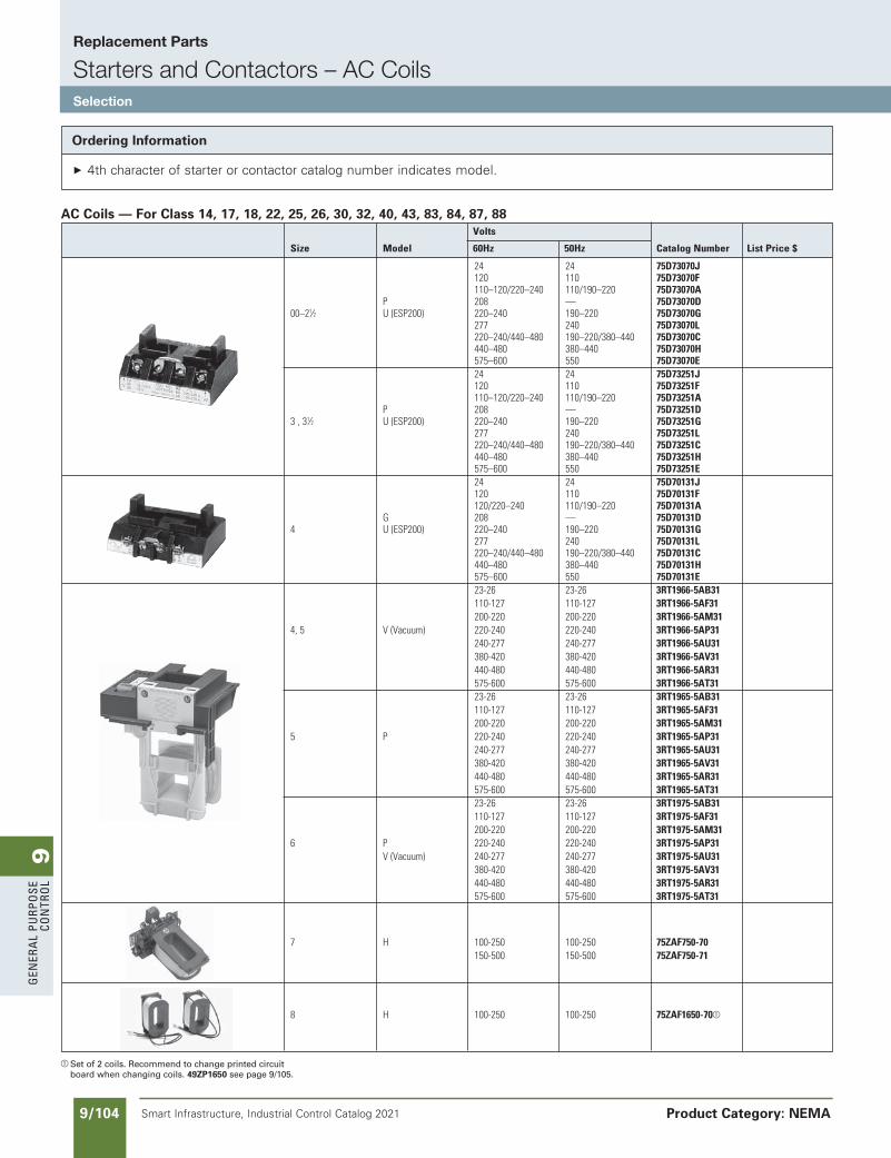
9G
ener
al
PurP
ose
Co
ntr
ol
9/104 Smart Infrastructure, Industrial Control Catalog 2021
Replacement Parts
Starters and Contactors – AC CoilsSelection
Product Category: NEMA
Ordering Information
4th character of starter or contactor catalog number indicates model.
AC Coils — For Class 14, 17, 18, 22, 25, 26, 30, 32, 40, 43, 83, 84, 87, 88
a Set of 2 coils. Recommend to change printed circuit board when changing coils. 49ZP1650 see page 9/105.
Volts
Size Model 60Hz 50Hz CatalogNumber ListPrice$
24 24 75D73070J 120 110 75D73070F 110–120/220–240 110/190–220 75D73070A P 208 — 75D73070D 00–21⁄2 U(ESP200) 220–240 190–220 75D73070G 277 240 75D73070L 220–240/440–480 190–220/380–440 75D73070C 440–480 380–440 75D73070H 575–600 550 75D73070E 24 24 75D73251J 120 110 75D73251F 110–120/220–240 110/190–220 75D73251A P 208 — 75D73251D 3,31⁄2 U(ESP200) 220–240 190–220 75D73251G 277 240 75D73251L 220–240/440–480 190–220/380–440 75D73251C 440–480 380–440 75D73251H 575–600 550 75D73251E 24 24 75D70131J 120 110 75D70131F 120/220–240 110/190–220 75D70131A G 208 — 75D70131D 4 U(ESP200) 220–240 190–220 75D70131G 277 240 75D70131L 220–240/440–480 190–220/380–440 75D70131C 440–480 380–440 75D70131H 575–600 550 75D70131E 23-26 23-26 3RT1966-5AB31 110-127 110-127 3RT1966-5AF31 200-220 200-220 3RT1966-5AM31 4,5 V(Vacuum) 220-240 220-240 3RT1966-5AP31 240-277 240-277 3RT1966-5AU31 380-420 380-420 3RT1966-5AV31 440-480 440-480 3RT1966-5AR31 575-600 575-600 3RT1966-5AT31 23-26 23-26 3RT1965-5AB31 110-127 110-127 3RT1965-5AF31 200-220 200-220 3RT1965-5AM31 5 P 220-240 220-240 3RT1965-5AP31 240-277 240-277 3RT1965-5AU31 380-420 380-420 3RT1965-5AV31 440-480 440-480 3RT1965-5AR31 575-600 575-600 3RT1965-5AT31 23-26 23-26 3RT1975-5AB31 110-127 110-127 3RT1975-5AF31 200-220 200-220 3RT1975-5AM31 6 P 220-240 220-240 3RT1975-5AP31 V(Vacuum) 240-277 240-277 3RT1975-5AU31 380-420 380-420 3RT1975-5AV31 440-480 440-480 3RT1975-5AR31 575-600 575-600 3RT1975-5AT31
7 H 100-250 100-250 75ZAF750-70 150-500 150-500 75ZAF750-71
8 H 100-250 100-250 75ZAF1650-70a
SS copied this page from SF to IC on 05/24/20
NEED to UPDATE in SPEEDFAX
Revised on 12/31/21
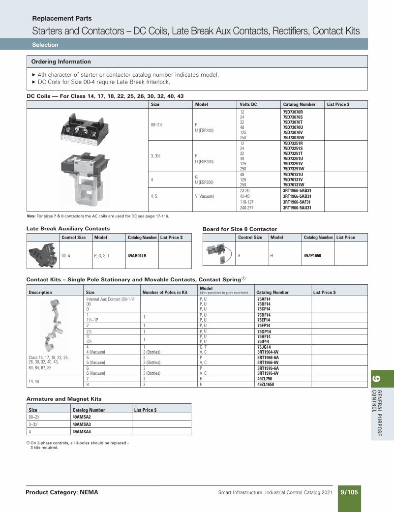
9G
enera
l PurPo
se Co
ntro
l
9/105Smart Infrastructure, Industrial Control Catalog 2021
Replacement Parts
Starters and Contactors – DC Coils, Late Break Aux Contacts, Rectifiers, Contact KitsSelection
Product Category: NEMA
Armature and Magnet Kits
Ordering Information
4th character of starter or contactor catalog number indicates model. DC Coils for Size 00-4 require Late Break Interlock.
DC Coils — For Class 14, 17, 18, 22, 25, 26, 30, 32, 40, 43
a On 3-phase controls, all 3-poles should be replaced - 3 kits required.
Late Break Auxiliary Contacts
Note: For sizes 7 & 8 contactors the AC coils are used for DC see page 17-116.
Contact Kits – Single Pole Stationary and Movable Contacts, Contact Springa
Board for Size 8 Contactor
Size Model VoltsDC CatalogNumber ListPrice$
12 75D73070R 24 75D73070S 32 75D73070T 00–21⁄2 P 48 75D73070U U(ESP200) 125 75D73070V 250 75D73070W 12 75D73251R 24 75D73251S 32 75D73251T 3,31⁄2 P 48 75D73251U U(ESP200) 125 75D73251V 250 75D73251W G 48 75D70131U 4 U(ESP200) 125 75D70131V 250 75D70131W 23-26 3RT1966-5AB31 4,5 V(Vacuum) 42-48 3RT1966-5AD31 110-127 3RT1966-5AF31 240-277 3RT1966-5AU31
ControlSize Model CatalogNumber ListPrice$
00–4 P,G,S,T 49AB01LB
Model Description Size NumberofPolesinKit (4th positionin part number) CatalogNumber ListPrice$
InternalAuxContact(00-1-3⁄4) P,U 75AF14 00 P,U 75BF14 0 P,U 75CF14 1 1 P,U 75DF14 13⁄4–1P P,U 75EF14 2 1 P,U 75FP14 21⁄2 1 P,U 75GP14 3 P,U 75HF14 31⁄2 1 P,U 75IF14 4 1 G,T 75JG14 4(Vacuum) 3(Bottles) V,C 3RT1964-6V Class14,17,18,22,25, 5 3 P 3RT1966-6A 26,30,32,40,43, 5(Vacuum) 3(Bottles) V,C 3RT1966-6V 83,84,87,88 6 3 P 3RT1976-6A 6(Vacuum) 3(Bottles) V,C 3RT1976-6V 14,40 7 3 H 49ZL750 8 3 H 49ZL1650
ControlSize Model CatalogNumber ListPrice
8 H 49ZP1650
Size CatalogNumber ListPrice$00–21⁄2 49AMSA2
3–31⁄2 49AMSA3
4 49AMSA4
SS copied this page from SF to IC on 05/24/20
NEED TO UPDATE IN SPEEDFAX
Revised on 12/31/21
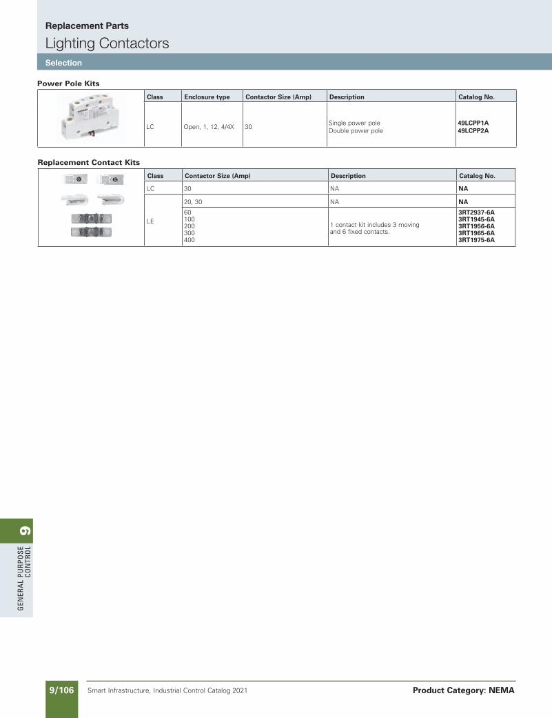
9G
ener
al
PurP
ose
Co
ntr
ol
9/106 Smart Infrastructure, Industrial Control Catalog 2021
Replacement Parts
Lighting ContactorsSelection
Product Category: NEMA
Power Pole Kits
Class Enclosure type Contactor Size (Amp) Description Catalog No.
LC Open, 1, 12, 4/4X 30Single power poleDouble power pole
49LCPP1A49LCPP2A
Replacement Contact Kits
Class Contactor Size (Amp) Description Catalog No.
LC 30 NA NA
LE
20, 30 NA NA
60100200300400
1 contact kit includes 3 moving and 6 fixed contacts.
3RT2937-6A3RT1945-6A3RT1956-6A3RT1965-6A3RT1975-6A
SS copied this page from SF to IC on 05/24/20
NEED TO UPDATE IN SPEEDFAX
Revised on 12/31/21
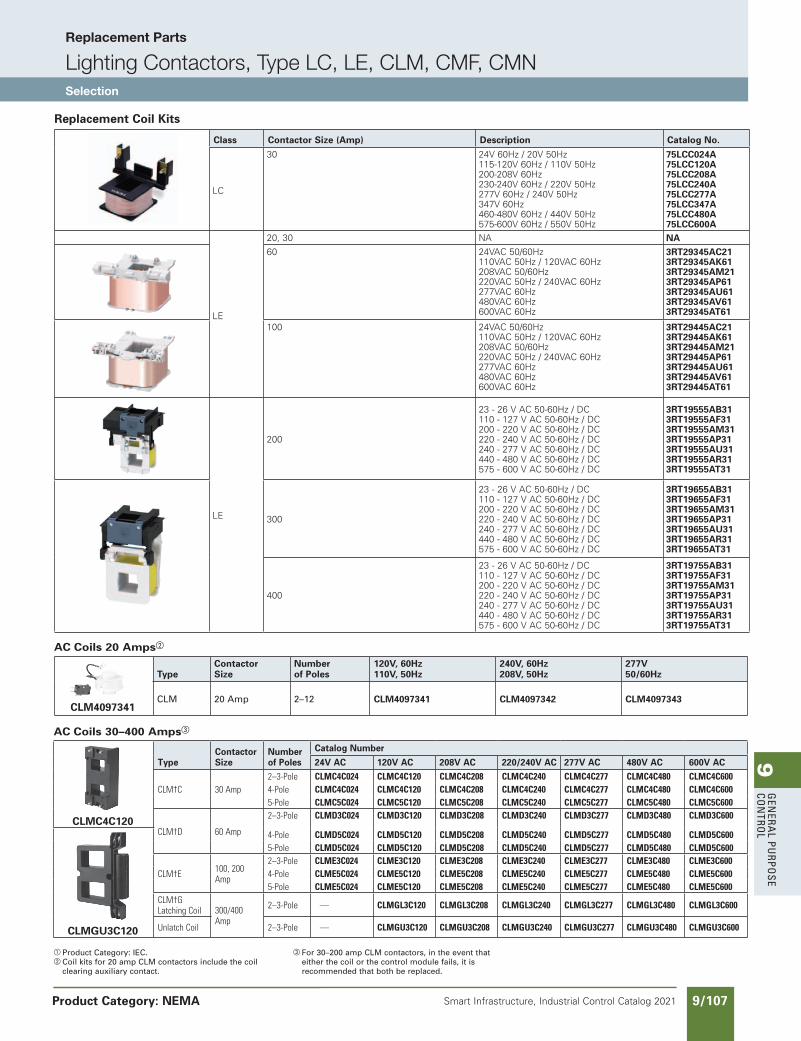
9G
enera
l PurPo
se Co
ntro
l
9/107Smart Infrastructure, Industrial Control Catalog 2021
Replacement Parts
Lighting Contactors, Type LC, LE, CLM, CMF, CMNSelection
Product Category: NEMA
a Product Category: IEC.b Coil kits for 20 amp CLM contactors include the coil
clearing auxiliary contact.
c For 30–200 amp CLM contactors, in the event that either the coil or the control module fails, it is recommended that both be replaced.
Replacement Coil Kits
Class Contactor Size (Amp) Description Catalog No.
LC
30 24V 60Hz / 20V 50Hz115-120V 60Hz / 110V 50Hz200-208V 60Hz230-240V 60Hz / 220V 50Hz277V 60Hz / 240V 50Hz347V 60Hz460-480V 60Hz / 440V 50Hz575-600V 60Hz / 550V 50Hz
75LCC024A75LCC120A75LCC208A75LCC240A75LCC277A75LCC347A75LCC480A75LCC600A
LE
20, 30 NA NA60 24VAC 50/60Hz
110VAC 50Hz / 120VAC 60Hz208VAC 50/60Hz220VAC 50Hz / 240VAC 60Hz277VAC 60Hz480VAC 60Hz600VAC 60Hz
3RT29345AC213RT29345AK613RT29345AM213RT29345AP613RT29345AU613RT29345AV613RT29345AT61
100 24VAC 50/60Hz 110VAC 50Hz / 120VAC 60Hz208VAC 50/60Hz220VAC 50Hz / 240VAC 60Hz277VAC 60Hz480VAC 60Hz600VAC 60Hz
3RT29445AC213RT29445AK613RT29445AM213RT29445AP613RT29445AU613RT29445AV613RT29445AT61
LE
200
23 - 26 V AC 50-60Hz / DC110 - 127 V AC 50-60Hz / DC200 - 220 V AC 50-60Hz / DC220 - 240 V AC 50-60Hz / DC240 - 277 V AC 50-60Hz / DC440 - 480 V AC 50-60Hz / DC575 - 600 V AC 50-60Hz / DC
3RT19555AB313RT19555AF313RT19555AM313RT19555AP313RT19555AU313RT19555AR313RT19555AT31
300
23 - 26 V AC 50-60Hz / DC110 - 127 V AC 50-60Hz / DC200 - 220 V AC 50-60Hz / DC220 - 240 V AC 50-60Hz / DC240 - 277 V AC 50-60Hz / DC440 - 480 V AC 50-60Hz / DC575 - 600 V AC 50-60Hz / DC
3RT19655AB313RT19655AF313RT19655AM313RT19655AP313RT19655AU313RT19655AR313RT19655AT31
400
23 - 26 V AC 50-60Hz / DC110 - 127 V AC 50-60Hz / DC200 - 220 V AC 50-60Hz / DC220 - 240 V AC 50-60Hz / DC240 - 277 V AC 50-60Hz / DC440 - 480 V AC 50-60Hz / DC575 - 600 V AC 50-60Hz / DC
3RT19755AB313RT19755AF313RT19755AM313RT19755AP313RT19755AU313RT19755AR313RT19755AT31
AC Coils 30–400 Ampsc
CLMC4C120
TypeContactorSize
Numberof Poles
Catalog Number
24V AC 120V AC 208V AC 220/240V AC 277V AC 480V AC 600V AC
CLM†C 30Amp2–3-Pole CLMC4C024 CLMC4C120 CLMC4C208 CLMC4C240 CLMC4C277 CLMC4C480 CLMC4C6004-Pole CLMC4C024 CLMC4C120 CLMC4C208 CLMC4C240 CLMC4C277 CLMC4C480 CLMC4C6005-Pole CLMC5C024 CLMC5C120 CLMC5C208 CLMC5C240 CLMC5C277 CLMC5C480 CLMC5C600
CLM†D 60Amp
2–3-Pole CLMD3C024 CLMD3C120 CLMD3C208 CLMD3C240 CLMD3C277 CLMD3C480 CLMD3C600
CLMGU3C120
4-Pole CLMD5C024 CLMD5C120 CLMD5C208 CLMD5C240 CLMD5C277 CLMD5C480 CLMD5C6005-Pole CLMD5C024 CLMD5C120 CLMD5C208 CLMD5C240 CLMD5C277 CLMD5C480 CLMD5C600
CLM†E 100,200Amp
2–3-Pole CLME3C024 CLME3C120 CLME3C208 CLME3C240 CLME3C277 CLME3C480 CLME3C6004-Pole CLME5C024 CLME5C120 CLME5C208 CLME5C240 CLME5C277 CLME5C480 CLME5C6005-Pole CLME5C024 CLME5C120 CLME5C208 CLME5C240 CLME5C277 CLME5C480 CLME5C600
CLM†GLatchingCoil 300/400
Amp
2–3-Pole — CLMGL3C120 CLMGL3C208 CLMGL3C240 CLMGL3C277 CLMGL3C480 CLMGL3C600
UnlatchCoil 2–3-Pole — CLMGU3C120 CLMGU3C208 CLMGU3C240 CLMGU3C277 CLMGU3C480 CLMGU3C600
AC Coils 20 Ampsb
CLM4097341
TypeContactorSize
Numberof Poles
120V, 60Hz110V, 50Hz
240V, 60Hz208V, 50Hz
277V50/60Hz
CLM 20 Amp 2–12 CLM4097341 CLM4097342 CLM4097343
updated in SPEEDFAXRevised on 12/31/19
SS copied this page from SF to IC on 05/24/20
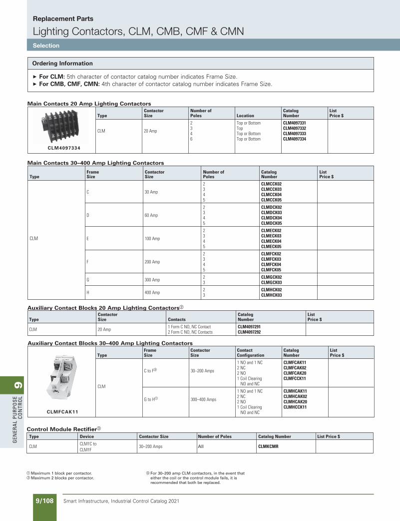
9G
ener
al
PurP
ose
Co
ntr
ol
9/108 Smart Infrastructure, Industrial Control Catalog 2021
Replacement Parts
Lighting Contactors, CLM, CMB, CMF & CMNSelection
SS copied this page from SF to IC on 05/24/20
updated in SPEEDFAXRevised on 12/31/19
Control Module Rectifierc
Type Device ContactorSize NumberofPoles CatalogNumber ListPrice$
CLM CLM†Cto 30–200Amps All CLMKCMR CLM†F
Frame Contactor Contact Catalog List Type Size Size Configuration Number Price$
1NOand1NC CLMFCAK11
CtoFb 30–200Amps 2NC CLMFCAK02
2NO CLMFCAK20 1CoilClearing CLMFCCK11 CLM NOandNC
1NOand1NC CLMHCAK11
GtoHa 300–400Amps 2NC CLMHCAK02
2NO CLMHCAK20 1CoilClearing CLMHCCK11 NOandNC
Contactor Catalog ListType Size Contacts Number Price$
CLM 20Amp 1FormCNO,NCContact CLM4097291 2FormCNO,NCContacts CLM4097292
Frame Contactor Numberof Catalog List Type Size Size Poles Number Price$ 2 CLMCCK02 C 30Amp 3 CLMCCK03 4 CLMCCK04 5 CLMCCK05
2 CLMDCK02 D 60Amp 3 CLMDCK03 4 CLMDCK04 5 CLMDCK05
2 CLMECK02 CLM E 100Amp 3 CLMECK03 4 CLMECK04 5 CLMECK05
2 CLMFCK02 F 200Amp 3 CLMFCK03 4 CLMFCK04 5 CLMFCK05
G 300Amp 2 CLMGCK02 3 CLMGCK03
H 400Amp 2 CLMHCK02 3 CLMHCK03
Contactor Numberof Catalog List Type Size Poles Location Number Price$
2 ToporBottom CLM4097331 CLM 20Amp 3 Top CLM4097332 4 ToporBottom CLM4097333 6 ToporBottom CLM4097334
CLM4097334
Main Contacts 20 Amp Lighting Contactors
Auxiliary Contact Blocks 20 Amp Lighting Contactorsb
a Maximum 1 block per contactor.b Maximum 2 blocks per contactor.
c For 30–200 amp CLM contactors, in the event that either the coil or the control module fails, it is recommended that both be replaced.
Main Contacts 30–400 Amp Lighting Contactors
CLMFCAK11
Auxiliary Contact Blocks 30–400 Amp Lighting Contactors
Ordering Information
For CLM: 5th character of contactor catalog number indicates Frame Size. For CMB, CMF, CMN: 4th character of contactor catalog number indicates Frame Size.
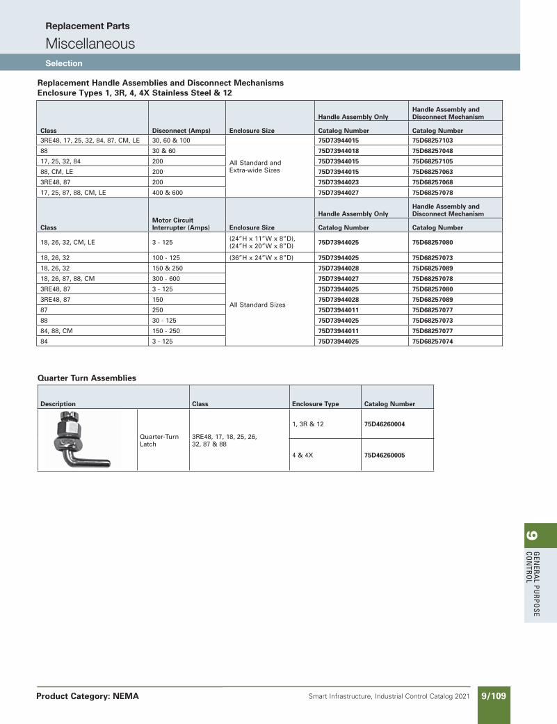
9G
enera
l PurPo
se Co
ntro
l
9/109Smart Infrastructure, Industrial Control Catalog 2021
Replacement Parts
MiscellaneousSelection
Product Category: NEMA
SS copied this page from SF to IC on 05/24/20
Replacement Handle Assemblies and Disconnect Mechanisms Enclosure Types 1, 3R, 4, 4X Stainless Steel & 12
Class Disconnect (Amps) Enclosure Size
Handle Assembly OnlyHandle Assembly and Disconnect Mechanism
Catalog Number Catalog Number3RE48, 17, 25, 32, 84, 87, CM, LE 30, 60 & 100
All Standard and Extra-wide Sizes
75D73944015 75D68257103
88 30 & 60 75D73944018 75D68257048
17, 25, 32, 84 200 75D73944015 75D68257105
88, CM, LE 200 75D73944015 75D68257063
3RE48, 87 200 75D73944023 75D68257068
17, 25, 87, 88, CM, LE 400 & 600 75D73944027 75D68257078
ClassMotor Circuit Interrupter (Amps) Enclosure Size
Handle Assembly OnlyHandle Assembly and Disconnect Mechanism
Catalog Number Catalog Number
18, 26, 32, CM, LE 3 - 125 (24”H x 11”W x 8”D), (24”H x 20”W x 8”D) 75D73944025 75D68257080
18, 26, 32 100 - 125 (36”H x 24”W x 8”D) 75D73944025 75D68257073
18, 26, 32 150 & 250
All Standard Sizes
75D73944028 75D68257089
18, 26, 87, 88, CM 300 - 600 75D73944027 75D68257078
3RE48, 87 3 - 125 75D73944025 75D68257080
3RE48, 87 150 75D73944028 75D68257089
87 250 75D73944011 75D68257077
88 30 - 125 75D73944025 75D68257073
84, 88, CM 150 - 250 75D73944011 75D68257077
84 3 - 125 75D73944025 75D68257074
Quarter Turn Assemblies
Description Class Enclosure Type Catalog Number
Quarter-Turn Latch
3RE48, 17, 18, 25, 26, 32, 87 & 88
1, 3R & 12 75D46260004
4 & 4X 75D46260005
NEED TO UPDATE IN SPEEDFAX
Revised on 12/31/21
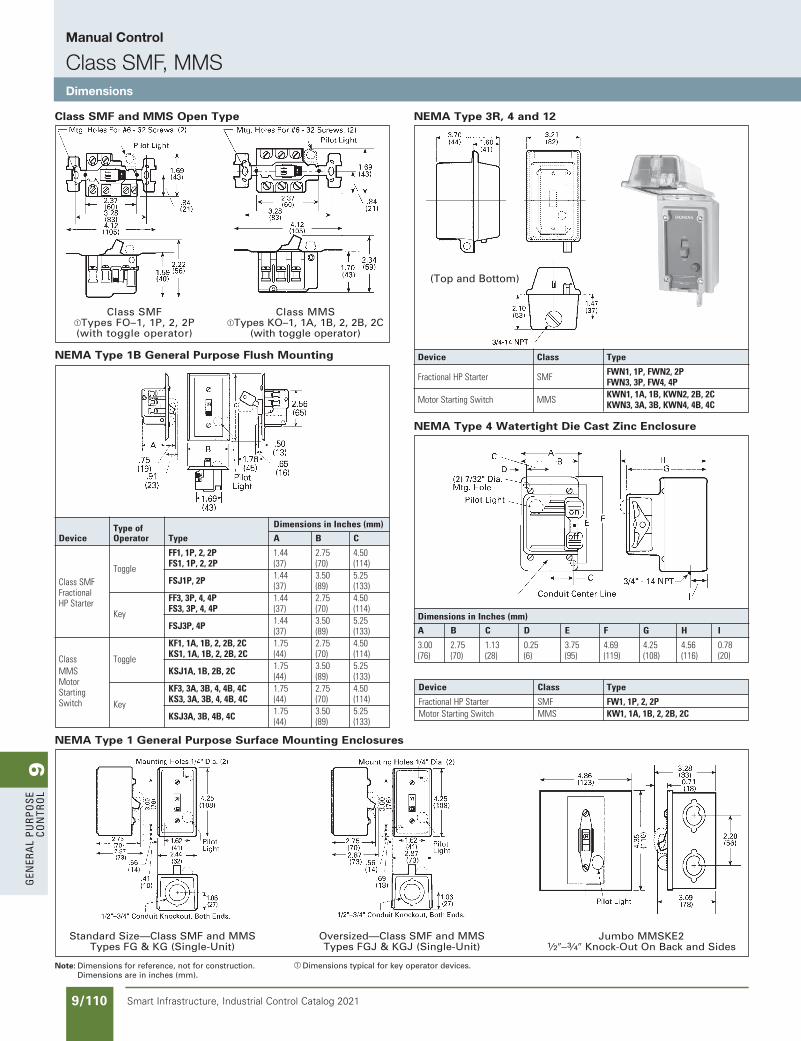
9G
ener
al
PurP
ose
Co
ntr
ol
9/110 Smart Infrastructure, Industrial Control Catalog 2021
Manual Control
Class SMF, MMSDimensions
Note: Dimensions for reference, not for construction.Dimensions are in inches (mm).
a Dimensions typical for key operator devices.
Class SMF and MMS Open Type
Class SMFaTypes FO–1, 1P, 2, 2P(with toggle operator)
Class MMSaTypes KO–1, 1A, 1B, 2, 2B, 2C
(with toggle operator)
(Top and Bottom)
Device Class Type
FractionalHPStarter SMF FWN1,1P,FWN2,2P FWN3,3P,FW4,4P MotorStartingSwitch MMS KWN1,1A,1B,KWN2,2B,2C KWN3,3A,3B,KWN4,4B,4C
NEMA Type 4 Watertight Die Cast Zinc Enclosure
DimensionsinInches(mm)
A B C D E F G H I
3.00 2.75 1.13 0.25 3.75 4.69 4.25 4.56 0.78 (76) (70) (28) (6) (95) (119) (108) (116) (20)
Device Class Type
FractionalHPStarter SMF FW1,1P,2,2P MotorStartingSwitch MMS KW1,1A,1B,2,2B,2C
Typeof DimensionsinInches(mm)
Device Operator Type A B C
FF1,1P,2,2P 1.44 2.75 4.50 Toggle FS1,1P,2,2P (37) (70) (114) FSJ1P,2P 1.44 3.50 5.25 ClassSMF (37) (89) (133) Fractional FF3,3P,4,4P 1.44 2.75 4.50 HPStarter Key FS3,3P,4,4P (37) (70) (114) FSJ3P,4P 1.44 3.50 5.25 (37) (89) (133) KF1,1A,1B,2,2B,2C 1.75 2.75 4.50 Toggle KS1,1A,1B,2,2B,2C (44) (70) (114)Class
KSJ1A,1B,2B,2C 1.75 3.50 5.25 MMS (44) (89) (133)Motor
KF3,3A,3B,4,4B,4C 1.75 2.75 4.50Starting
Key KS3,3A,3B,4,4B,4C (44) (70) (114)Switch
KSJ3A,3B,4B,4C 1.75 3.50 5.25 (44) (89) (133)
NEMA Type 1 General Purpose Surface Mounting Enclosures
Standard Size—Class SMF and MMS Types FG & KG (Single-Unit)
Oversized—Class SMF and MMS Types FGJ & KGJ (Single-Unit)
Jumbo MMSKE21⁄20–3⁄40 Knock-Out On Back and Sides
NEMA Type 1B General Purpose Flush Mounting
NEMA Type 3R, 4 and 12
SS copied this page from SF to IC on 05/24/20
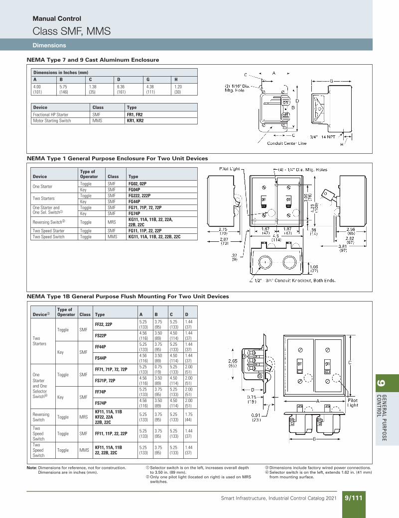
9G
enera
l PurPo
se Co
ntro
l
9/111Smart Infrastructure, Industrial Control Catalog 2021
Manual Control
Class SMF, MMSDimensions
Note: Dimensions for reference, not for construction.Dimensions are in inches (mm).
a Selector switch is on the left, increases overall depth to 3.50 in. (89 mm).
b Only one pilot light (located on right) is used on MRS switches.
c Dimensions include factory wired power connections.d Selector switch is on the left, extends 1.62 in. (41 mm)
from mounting surface.
Typeof Devicec Operator Class Type A B C D
FF22,22P 5.25 3.75 5.25 1.44 Toggle SMF (133) (95) (133) (37) FS22P 4.56 3.50 4.50 1.44 Two (116) (89) (114) (37) Starters FF44P 5.25 3.75 5.25 1.44 Key SMF (133) (95) (133) (37) FS44P 4.56 3.50 4.50 1.44 (116) (89) (114) (37) FF71,71P,72,72P 5.25 0.75 5.25 2.00 One Toggle SMF (133) (19) (133) (51) Starter FS71P,72P 4.56 3.50 4.50 2.00 andOne (116) (89) (114) (51) Selector FF74P 5.25 3.75 5.25 2.00 Switchd Key SMF (133) (95) (133) (51) FS74P 4.56 3.50 4.50 2.00 (116) (89) (114) (51) Reversing KF11,11A,11B 5.25 3.75 5.25 1.75 Switch Toggle MRS KF22,22A (133) (95) (133) (44) 22B,22C Two 5.25 3.75 5.25 1.44 Speed Toggle SMF FF11,11P,22,22P (133) (95) (133) (37) Switch Two KF11,11A,11B 5.25 3.75 5.25 1.44 Speed Toggle MMS 22,22B,22C (133) (95) (133) (37) Switch
Typeof Device Operator Class Type
OneStarter Toggle SMF FG02,02P Key SMF FG04P TwoStarters Toggle SMF FG222,222P Key SMF FG44P OneStarterand Toggle SMF FG71,71P,72,72P OneSel.Switcha Key SMF FG74P ReversingSwitchb Toggle MRS KG11,11A,11B,22,22A, 22B,22C TwoSpeedStarter Toggle SMF FG11,11P,22,22P TwoSpeedSwitch Toggle MMS KG11,11A,11B,22,22B,22C
NEMA Type 1 General Purpose Enclosure For Two Unit Devices
NEMA Type 1B General Purpose Flush Mounting For Two Unit Devices
NEMA Type 7 and 9 Cast Aluminum Enclosure
DimensionsinInches(mm)
A B C D G H
4.00 5.75 1.38 6.36 4.38 1.20 (101) (146) (35) (161) (111) (30)
Device Class Type
FractionalHPStarter SMF FR1,FR2 MotorStartingSwitch MMS KR1,KR2
SS copied this page from SF to IC on 05/24/20
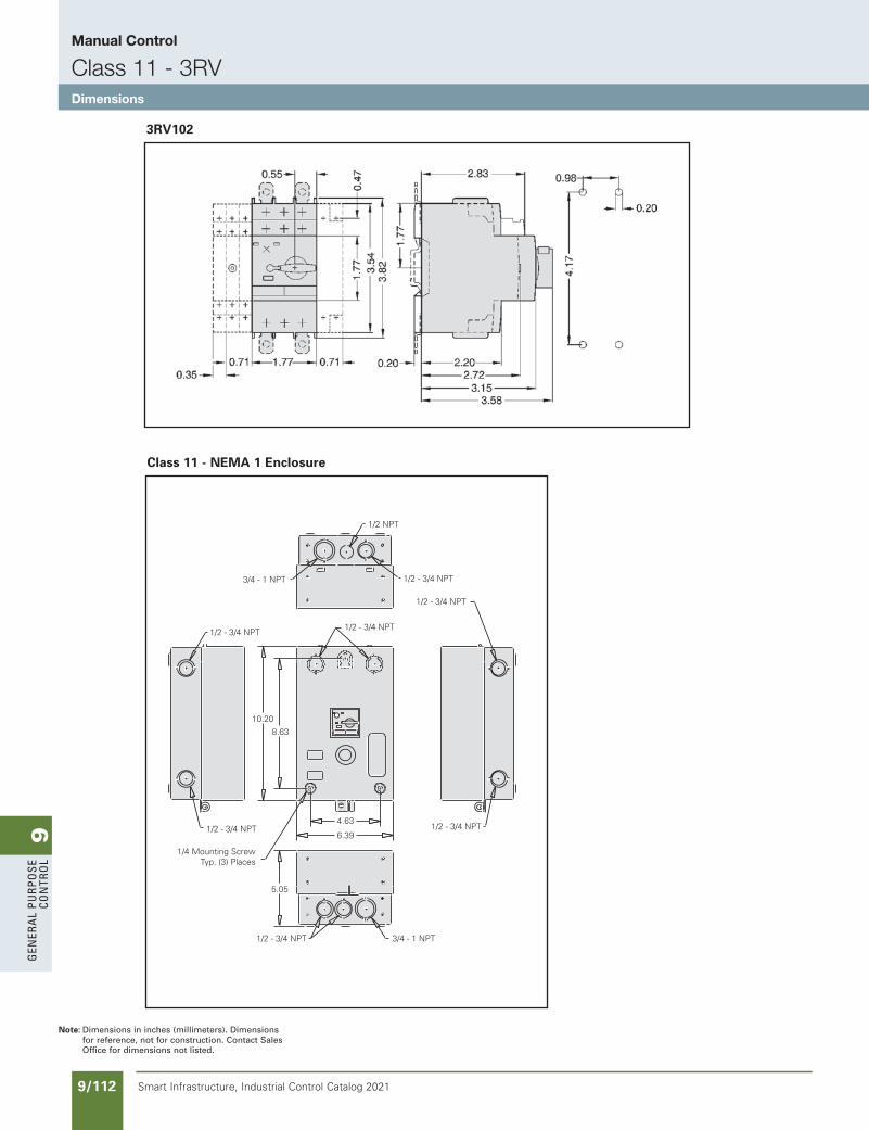
9G
ener
al
PurP
ose
Co
ntr
ol
9/112 Smart Infrastructure, Industrial Control Catalog 2021
Note: Dimensions in inches (millimeters). Dimensions for reference, not for construction. Contact Sales Office for dimensions not listed.
3RV102
1/2 NPT
1/2 - 3/4 NPT
1/2 - 3/4 NPT
1/2 - 3/4 NPT1/2 - 3/4 NPT
3/4 - 1 NPT
1/2 - 3/4 NPT
10.20
8.63
1/2 - 3/4 NPT4.63
6.39
1/2 - 3/4 NPT
5.05
1/4 Mounting ScrewTyp. (3) Places
3/4 - 1 NPT
Class 11 - NEMA 1 Enclosure
SS copied this page from SF to IC on 05/24/20
updated in SPEEDFAXRevised on 03/31/20
Manual Control
Class 11 - 3RVDimensions
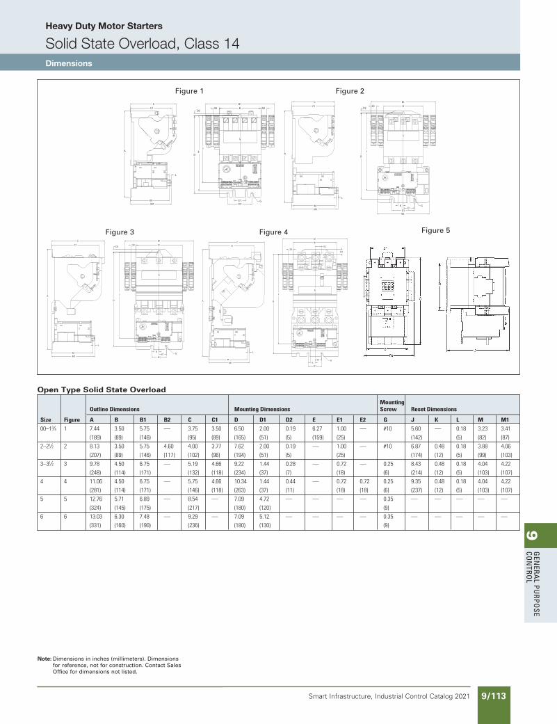
9G
enera
l PurPo
se Co
ntro
l
9/113Smart Infrastructure, Industrial Control Catalog 2021
Heavy Duty Motor Starters
Solid State Overload, Class 14Dimensions
C1
C
CL
A
MM1
L
E2.50
D2
B
B1
J
D
E1K
D1
G
Figure 4Figure 4 Figure 5
Open Type Solid State Overload
Mounting
OutlineDimensions MountingDimensions Screw ResetDimensions
Size Figure A B B1 B2 C C1 D D1 D2 E E1 E2 G J K L M M1
00–13⁄4 1 7.44 3.50 5.75 — 3.75 3.50 6.50 2.00 0.19 6.27 1.00 — #10 5.60 — 0.18 3.23 3.41
(189) (89) (146) (95) (89) (165) (51) (5) (159) (25) (142) (5) (82) (87)
2–21⁄2 2 8.13 3.50 5.75 4.60 4.00 3.77 7.62 2.00 0.19 — 1.00 — #10 6.87 0.48 0.18 3.88 4.06
(207) (89) (146) (117) (102) (96) (194) (51) (5) (25) (174) (12) (5) (99) (103)
3–31⁄2 3 9.78 4.50 6.75 — 5.19 4.66 9.22 1.44 0.28 — 0.72 — 0.25 8.43 0.48 0.18 4.04 4.22
(248) (114) (171) (132) (118) (234) (37) (7) (18) (6) (214) (12) (5) (103) (107)
4 4 11.06 4.50 6.75 — 5.75 4.66 10.34 1.44 0.44 — 0.72 0.72 0.25 9.35 0.48 0.18 4.04 4.22
(281) (114) (171) (146) (118) (263) (37) (11) (18) (18) (6) (237) (12) (5) (103) (107)
5 5 12.76 5.71 6.89 — 8.54 — 7.09 4.72 — — — — 0.35 — — — — —
(324) (145) (175) (217) (180) (120) (9)
6 6 13.03 6.30 7.48 — 9.29 — 7.09 5.12 — — — — 0.35 — — — — —
(331) (160) (190) (236) (180) (130) (9)
CL
A
B
B1C
C1
J
D
KE1
D1
D2
GMM1
L
.50
Figure 3Figure 3
CL
C
C1
A
MM1
L
J
D
.50 B
B1
KE1
D1B2
G
D2
Figure 2Figure 2
Note: Dimensions in inches (millimeters). Dimensions for reference, not for construction. Contact Sales Office for dimensions not listed.
CL
L
MM1
JE
D
E1D1
G
B.50 .50B1
D2
A
C1C
Figure 1Figure 1
SS copied this page from SF to IC on 05/24/20
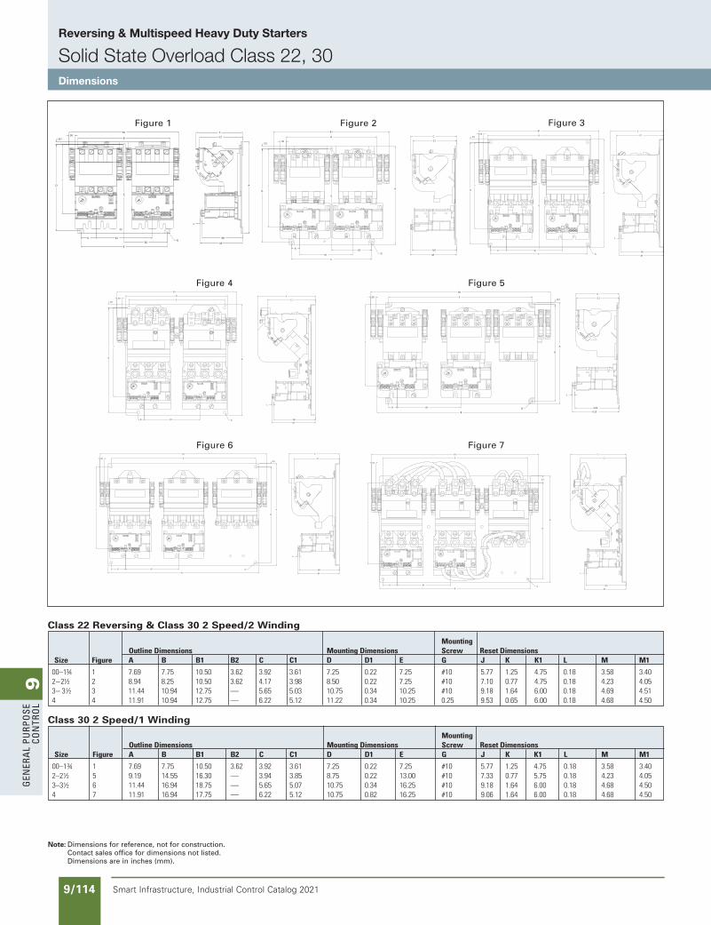
9G
ener
al
PurP
ose
Co
ntr
ol
9/114 Smart Infrastructure, Industrial Control Catalog 2021
Reversing & Multispeed Heavy Duty Starters
Solid State Overload Class 22, 30Dimensions
Note: Dimensions for reference, not for construction.Contact sales office for dimensions not listed. Dimensions are in inches (mm).
Mounting OutlineDimensions MountingDimensions Screw ResetDimensionsSize Figure A B B1 B2 C C1 D D1 E G J K K1 L M M1
00–1¾ 1 7.69 7.75 10.50 3.62 3.92 3.61 7.25 0.22 7.25 #10 5.77 1.25 4.75 0.18 3.58 3.402–2½ 2 8.94 8.25 10.50 3.62 4.17 3.98 8.50 0.22 7.25 #10 7.10 0.77 4.75 0.18 4.23 4.053–3½ 3 11.44 10.94 12.75 — 5.65 5.03 10.75 0.34 10.25 #10 9.18 1.64 6.00 0.18 4.69 4.514 4 11.91 10.94 12.75 — 6.22 5.12 11.22 0.34 10.25 0.25 9.53 0.65 6.00 0.18 4.68 4.50
Class 22 Reversing & Class 30 2 Speed/2 Winding
Class 30 2 Speed/1 Winding
Mounting OutlineDimensions MountingDimensions Screw ResetDimensionsSize Figure A B B1 B2 C C1 D D1 E G J K K1 L M M1
00–1¾ 1 7.69 7.75 10.50 3.62 3.92 3.61 7.25 0.22 7.25 #10 5.77 1.25 4.75 0.18 3.58 3.402–2½ 5 9.19 14.55 16.30 — 3.94 3.85 8.75 0.22 13.00 #10 7.33 0.77 5.75 0.18 4.23 4.053–3½ 6 11.44 16.94 18.75 — 5.65 5.07 10.75 0.34 16.25 #10 9.18 1.64 6.00 0.18 4.68 4.504 7 11.91 16.94 17.75 — 6.22 5.12 10.75 0.82 16.25 #10 9.06 1.64 6.00 0.18 4.68 4.50
A
CL
Figure 1
B
B1
B2
C
C1
J
D
K K1
E
M1
M
L
D1
G
.50
Figure 1C
C1
CL
Figure 2
.50
B
B1
J
D
KB2
K1
E
G
A
M1
M
D1
Figure 2
Figure 4
E
B
B1
J
D
K K1
A
G M1M
L
C1
C
D1
.50
Figure 4E
Figure 5
B1
.50
D
A
D1
K K1
B
J
G
C1
C
4.054.23
L
Figure 5
E
B1
.50
J
K K1
B
D
A
D1
G
C1
C
M1
M
L
Figure 6Figure 6
L3
E
B1
.50
J
K K1
B
D
A
D1
C1
C
M1
M
L
G
Figure 7Figure 7
Figure 3B
CL
Figure 3
M1
M
L
C1
C.50
B1
J
D
D1
K K1
E G
A
SS copied this page from SF to IC on 05/24/20
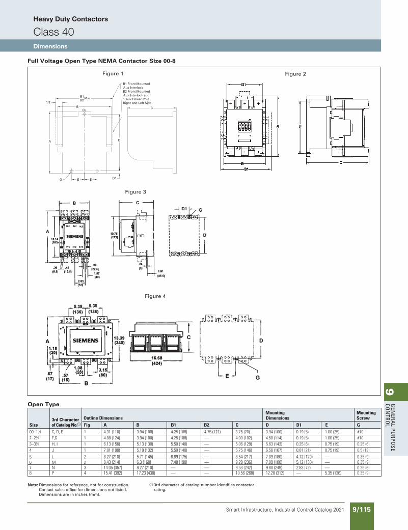
9G
enera
l PurPo
se Co
ntro
l
9/115Smart Infrastructure, Industrial Control Catalog 2021
Heavy Duty Contactors
Class 40Dimensions
Full Voltage Open Type NEMA Contactor Size 00-8
Mounting Mounting 3rdCharacter OutlineDimensions Dimensions Screw
Size ofCatalogNo.a Fig A B B1 B2 C D D1 E G00–13⁄4 C,D,E 1 4.31(110) 3.94(100) 4.25(108) 4.75(121) 3.75(70) 3.94(100) 0.19(5) 1.00(25) #102–21⁄2 F,G 1 4.88(124) 3.94(100) 4.25(108) — 4.00(102) 4.50(114) 0.19(5) 1.00(25) #103–31⁄2 H,I 1 6.13(156) 5.13(130) 5.50(140) — 5.06(129) 5.63(143) 0.25(6) 0.75(19) 0.25(6)4 J 1 7.81(198) 5.19(132) 5.50(140) — 5.75(146) 6.56(167) 0.81(21) 0.75(19) 0.5(13)5 L 2 8.27(210) 5.71(145) 6.89(175) — 8.54(217) 7.09(180) 4.72(120) — 0.35(9)6 M 2 8.43(214) 6.3(160) 7.48(190) — 9.29(236) 7.09(180) 5.12(130) — 0.35(9)7 N 3 14.05(357) 8.27(210) — — 9.53(242) 9.80(249) 2.83(72) — 0.25(6)8 P 4 15.41(392) 17.23(438) — — 10.56(268) 12.28(312) — 5.35(136) 0.35(9)
Open Type
Note: Dimensions for reference, not for construction.Contact sales office for dimensions not listed. Dimensions are in inches (mm).
a 3rd character of catalog number identifies contactor rating.
Figure 1
Figure 3
Figure 4
Figure 2
SS copied this page from SF to IC on 05/24/20
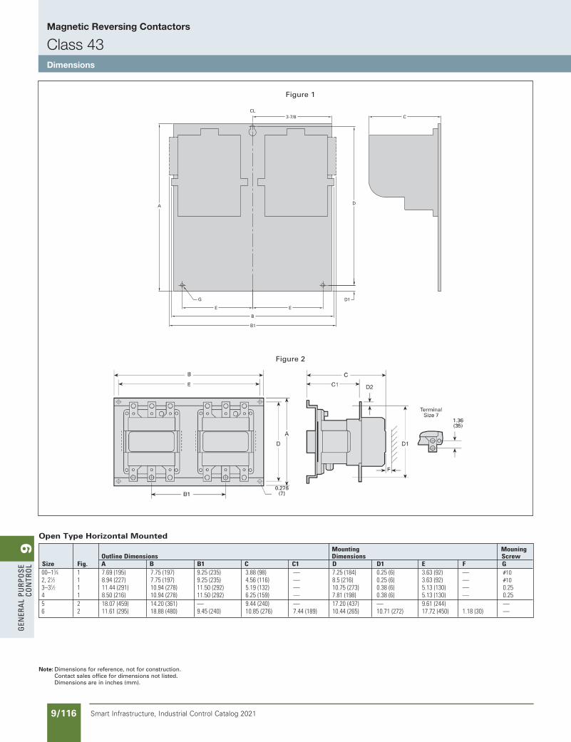
9G
ener
al
PurP
ose
Co
ntr
ol
9/116 Smart Infrastructure, Industrial Control Catalog 2021
Magnetic Reversing Contactors
Class 43Dimensions
Figure 2
Note: Dimensions for reference, not for construction.Contact sales office for dimensions not listed. Dimensions are in inches (mm).
Open Type Horizontal Mounted
Mounting Mouning OutlineDimensions Dimensions Screw Size Fig. A B B1 C C1 D D1 E F G 00–13⁄4 1 7.69(195) 7.75(197) 9.25(235) 3.88(98) — 7.25(184) 0.25(6) 3.63(92) — #10 2,21⁄2 1 8.94(227) 7.75(197) 9.25(235) 4.56(116) — 8.5(216) 0.25(6) 3.63(92) — #10 3–31⁄2 1 11.44(291) 10.94(278) 11.50(292) 5.19(132) — 10.75(273) 0.38(6) 5.13(130) — 0.25 4 1 8.50(216) 10.94(278) 11.50(292) 6.25(159) — 7.81(198) 0.38(6) 5.13(130) — 0.25 5 2 18.07(459) 14.20(361) — 9.44(240) — 17.20(437) — 9.61(244) — 6 2 11.61(295) 18.88(480) 9.45(240) 10.85(276) 7.44(189) 10.44(265) 10.71(272) 17.72(450) 1.18(30) —
Figure 1
SS copied this page from SF to IC on 05/24/20
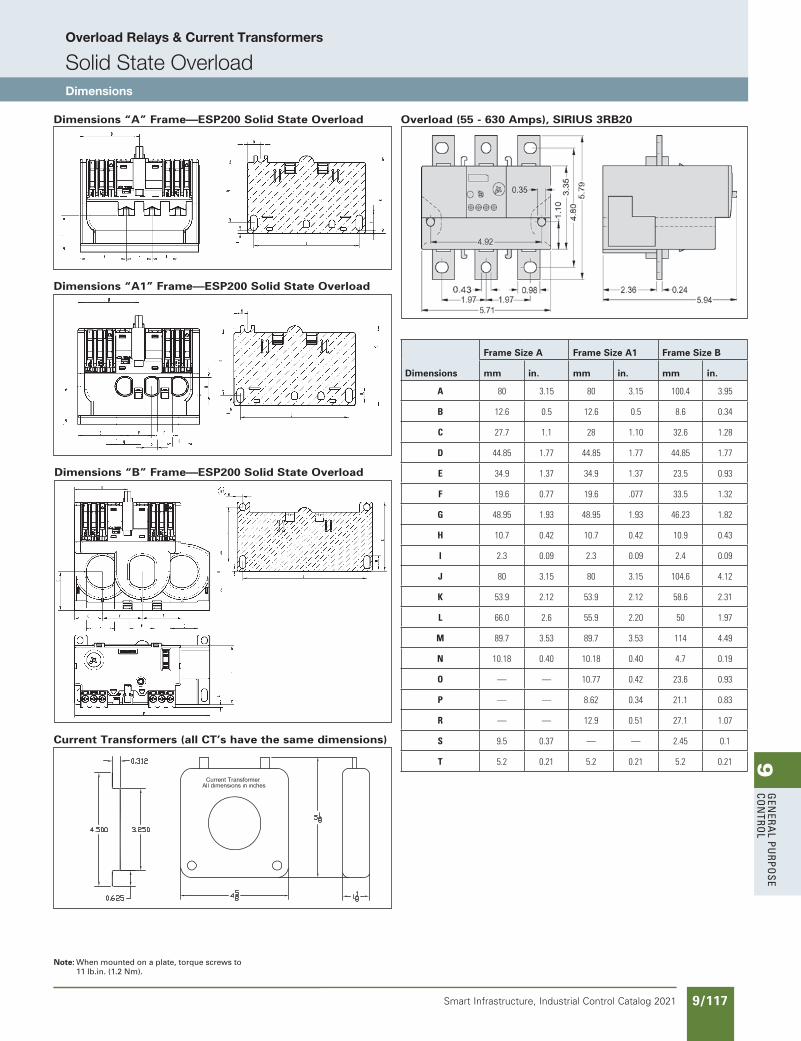
9G
enera
l PurPo
se Co
ntro
l
9/117Smart Infrastructure, Industrial Control Catalog 2021
Overload Relays & Current Transformers
Solid State OverloadDimensions
Dimensions “A1” Frame—ESP200 Solid State Overload
Note: When mounted on a plate, torque screws to 11 lb.in. (1.2 Nm).
Overload (55 - 630 Amps), SIRIUS 3RB20
Dimensions
Frame Size A Frame Size A1 Frame Size B
mm in. mm in. mm in.
A 80 3.15 80 3.15 100.4 3.95
B 12.6 0.5 12.6 0.5 8.6 0.34
C 27.7 1.1 28 1.10 32.6 1.28
D 44.85 1.77 44.85 1.77 44.85 1.77
E 34.9 1.37 34.9 1.37 23.5 0.93
F 19.6 0.77 19.6 .077 33.5 1.32
G 48.95 1.93 48.95 1.93 46.23 1.82
H 10.7 0.42 10.7 0.42 10.9 0.43
I 2.3 0.09 2.3 0.09 2.4 0.09
J 80 3.15 80 3.15 104.6 4.12
K 53.9 2.12 53.9 2.12 58.6 2.31
L 66.0 2.6 55.9 2.20 50 1.97
M 89.7 3.53 89.7 3.53 114 4.49
N 10.18 0.40 10.18 0.40 4.7 0.19
O — — 10.77 0.42 23.6 0.93
P — — 8.62 0.34 21.1 0.83
R — — 12.9 0.51 27.1 1.07
S 9.5 0.37 — — 2.45 0.1
T 5.2 0.21 5.2 0.21 5.2 0.21
Dimensions “A” Frame—ESP200 Solid State Overload
Dimensions “B” Frame—ESP200 Solid State Overload
Current Transformers (all CT’s have the same dimensions)
SS copied this page from SF to IC on 05/24/20
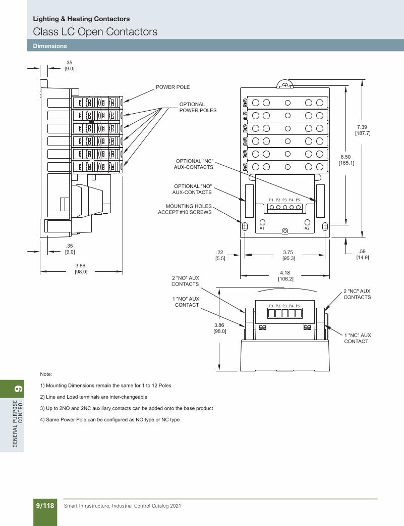
9G
ener
al
PurP
ose
Co
ntr
ol
9/118 Smart Infrastructure, Industrial Control Catalog 2021
Lighting & Heating Contactors
Class LC Open ContactorsDimensions
SS copied this page from SF to IC on 05/24/20
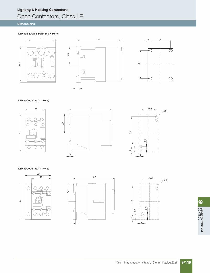
9G
enera
l PurPo
se Co
ntro
l
9/119Smart Infrastructure, Industrial Control Catalog 2021
Lighting & Heating Contactors
Open Contactors, Class LEDimensions
73
29.8
5
45
57.5
LEN00B (20A 3 Pole and 4 Pole)
LEN00C003 (30A 3 Pole)
LEN00C004 (30A 4 Pole)
5
97
43
45
85
35.1
752.
5
4.8
7.5
5
5
5
97
43
4560
87
35.1
752.
5
4.8
7.5
5
5
50
5 53
SS copied this page from SF to IC on 05/24/20
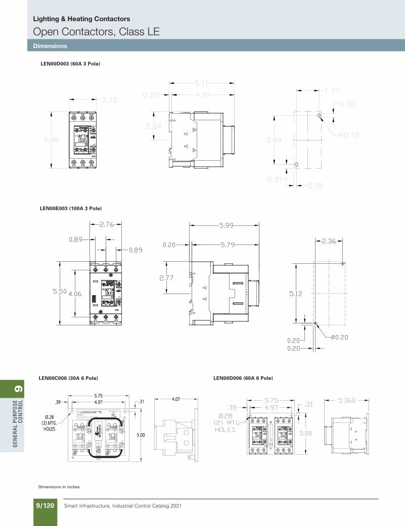
9G
ener
al
PurP
ose
Co
ntr
ol
9/120 Smart Infrastructure, Industrial Control Catalog 2021
Lighting & Heating Contactors
Open Contactors, Class LEDimensions
LEN00D003 (60A 3 Pole)
LEN00E003 (100A 3 Pole)
LEN00C006 (30A 6 Pole) LEN00D006 (60A 6 Pole)
Dimensions in inches.
SS copied this page from SF to IC on 05/24/20
updated in SPEEDFAXRevised on 03/31/20
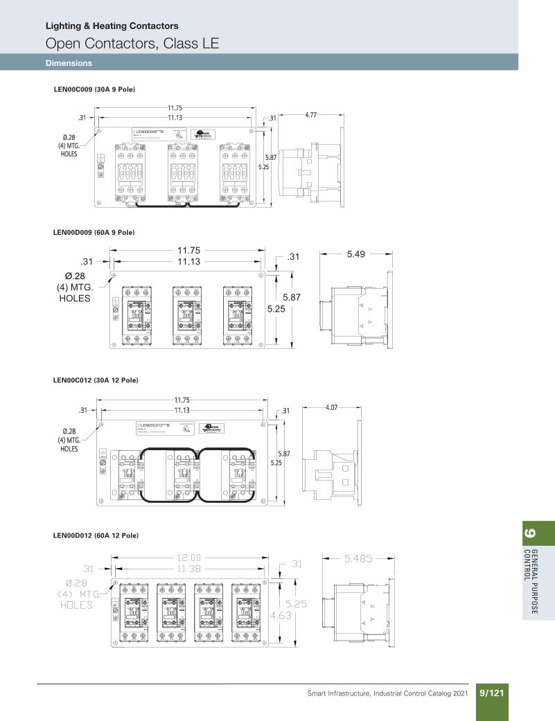
9G
enera
l PurPo
se Co
ntro
l
9/121Smart Infrastructure, Industrial Control Catalog 2021
Lighting & Heating Contactors
Open Contactors, Class LEDimensions
LEN00C009 (30A 9 Pole)
LEN00D009 (60A 9 Pole)
LEN00C012 (30A 12 Pole)
LEN00D012 (60A 12 Pole)
GROUND
.31 11.1311.75
Ø.28(4) MTG.HOLES
.31
5.255.87
1/ L1 3/ L2 5/ L3
6/ T34/ T22/ T1
3RT20
A1
A2
21NC
22NC
13NO
14NO
11
3. 4. 5. 6.
1/ L1 3/ L2 5/ L3
6/ T34/ T22/ T1
3RT20
A1
A2
21NC
22NC
13NO
14NO
11
3. 4. 5. 6.
1/ L1 3/ L2 5/ L3
6/ T34/ T22/ T1
3RT20
A1
A2
21NC
22NC
13NO
14NO
11
3. 4. 5. 6.
5.49
updated in SPEEDFAXRevised on 03/31/20
SS copied this page from SF to IC on 05/24/20
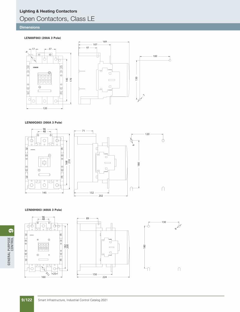
9G
ener
al
PurP
ose
Co
ntr
ol
9/122 Smart Infrastructure, Industrial Control Catalog 2021
Lighting & Heating Contactors
Open Contactors, Class LEDimensions
LEN00F003 (200A 3 Pole)
LEN00G003 (300A 3 Pole)
LEN00H003 (400A 3 Pole)9
SIEMENS
17 37
170
140
120
10761
169
130
7
100
180
120
9
71
132202
168
210
4896
145
SIEMENS
130
180
9
89
150224
4896
182
200
25
511
160
SIEMENS
SS copied this page from SF to IC on 05/24/20
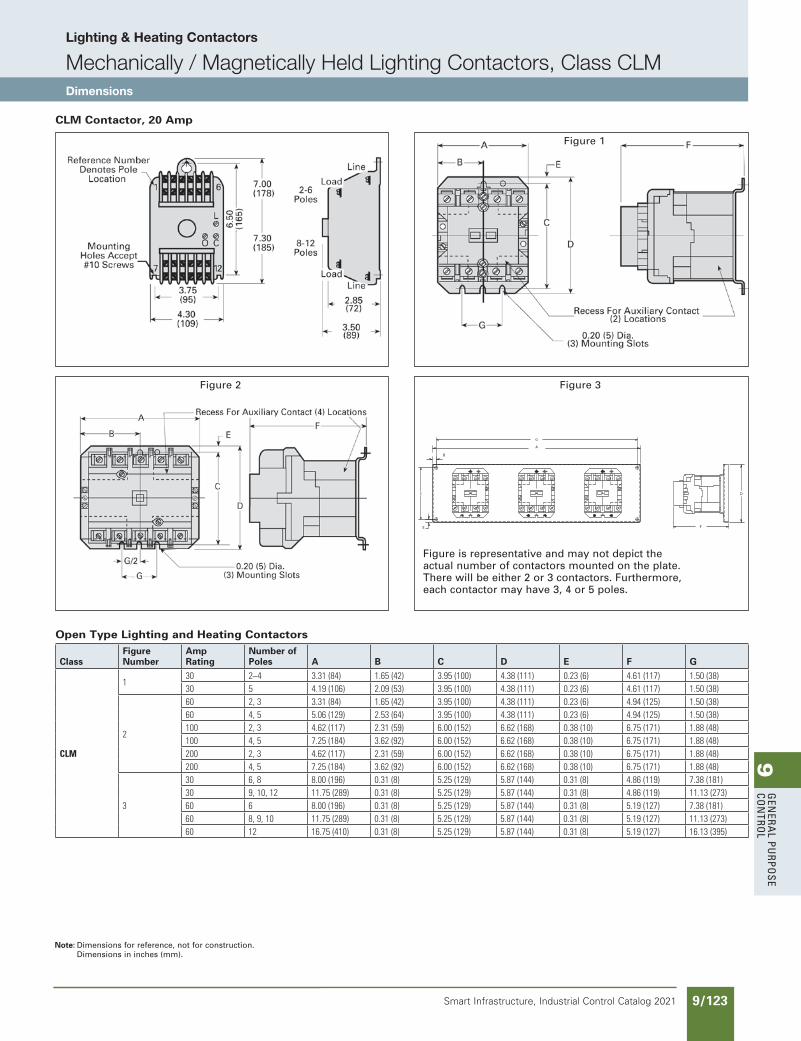
9G
enera
l PurPo
se Co
ntro
l
9/123Smart Infrastructure, Industrial Control Catalog 2021
Lighting & Heating Contactors
Mechanically / Magnetically Held Lighting Contactors, Class CLMDimensions
CLM Contactor, 20 Amp
Note: Dimensions for reference, not for construction.Dimensions in inches (mm).
Figure 1
Figure 2
A
B
D
E F
C
G
Figure 3
Open Type Lighting and Heating Contactors
ClassFigureNumber
AmpRating
Number ofPoles A B C D E F G
CLM
130 2–4 3.31(84) 1.65(42) 3.95(100) 4.38(111) 0.23(6) 4.61(117) 1.50(38)30 5 4.19(106) 2.09(53) 3.95(100) 4.38(111) 0.23(6) 4.61(117) 1.50(38)
2
60 2,3 3.31(84) 1.65(42) 3.95(100) 4.38(111) 0.23(6) 4.94(125) 1.50(38)60 4,5 5.06(129) 2.53(64) 3.95(100) 4.38(111) 0.23(6) 4.94(125) 1.50(38)100 2,3 4.62(117) 2.31(59) 6.00(152) 6.62(168) 0.38(10) 6.75(171) 1.88(48)100 4,5 7.25(184) 3.62(92) 6.00(152) 6.62(168) 0.38(10) 6.75(171) 1.88(48)200 2,3 4.62(117) 2.31(59) 6.00(152) 6.62(168) 0.38(10) 6.75(171) 1.88(48)200 4,5 7.25(184) 3.62(92) 6.00(152) 6.62(168) 0.38(10) 6.75(171) 1.88(48)
3
30 6,8 8.00(196) 0.31(8) 5.25(129) 5.87(144) 0.31(8) 4.86(119) 7.38(181)30 9,10,12 11.75(289) 0.31(8) 5.25(129) 5.87(144) 0.31(8) 4.86(119) 11.13(273)60 6 8.00(196) 0.31(8) 5.25(129) 5.87(144) 0.31(8) 5.19(127) 7.38(181)60 8,9,10 11.75(289) 0.31(8) 5.25(129) 5.87(144) 0.31(8) 5.19(127) 11.13(273)60 12 16.75(410) 0.31(8) 5.25(129) 5.87(144) 0.31(8) 5.19(127) 16.13(395)
Figure is representative and may not depict the actual number of contactors mounted on the plate. There will be either 2 or 3 contactors. Furthermore, each contactor may have 3, 4 or 5 poles.
SS copied this page from SF to IC on 05/24/20
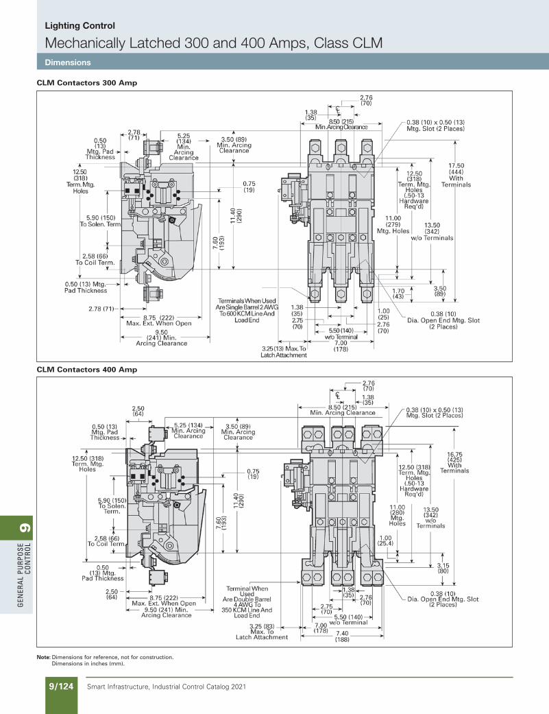
9G
ener
al
PurP
ose
Co
ntr
ol
9/124 Smart Infrastructure, Industrial Control Catalog 2021
Lighting Control
Mechanically Latched 300 and 400 Amps, Class CLMDimensions
CLM Contactors 300 Amp
CLM Contactors 400 Amp
Note: Dimensions for reference, not for construction.Dimensions in inches (mm).
SS copied this page from SF to IC on 05/24/20
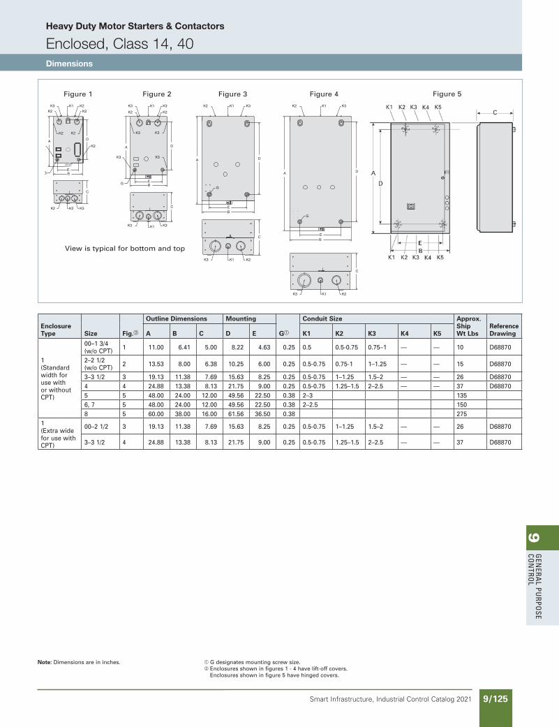
9G
enera
l PurPo
se Co
ntro
l
9/125Smart Infrastructure, Industrial Control Catalog 2021
Heavy Duty Motor Starters & Contactors
Enclosed, Class 14, 40Dimensions
Figure 1 Figure 2 Figure 3 Figure 4 Figure 5
View is typical for bottom and top
Note: Dimensions are in inches. a G designates mounting screw size.b Enclosures shown in figures 1 - 4 have lift-off covers.
Enclosures shown in figure 5 have hinged covers.
Enclosure Type Size Fig.b
Outline Dimensions Mounting
Ga
Conduit Size Approx. Ship Wt Lbs
Reference DrawingA B C D E K1 K2 K3 K4 K5
1 (Standard width for use with or without CPT)
00–1 3/4 (w/o CPT) 1 11.00 6.41 5.00 8.22 4.63 0.25 0.5 0.5-0.75 0.75–1 — — 10 D68870
2–2 1/2 (w/o CPT) 2 13.53 8.00 6.38 10.25 6.00 0.25 0.5-0.75 0.75-1 1–1.25 — — 15 D68870
3–3 1/2 3 19.13 11.38 7.69 15.63 8.25 0.25 0.5-0.75 1–1.25 1.5–2 — — 26 D688704 4 24.88 13.38 8.13 21.75 9.00 0.25 0.5-0.75 1.25–1.5 2–2.5 — — 37 D688705 5 48.00 24.00 12.00 49.56 22.50 0.38 2–3 1356, 7 5 48.00 24.00 12.00 49.56 22.50 0.38 2–2.5 1508 5 60.00 38.00 16.00 61.56 36.50 0.38 275
1 (Extra wide for use with CPT)
00–2 1/2 3 19.13 11.38 7.69 15.63 8.25 0.25 0.5-0.75 1–1.25 1.5–2 — — 26 D68870
3–3 1/2 4 24.88 13.38 8.13 21.75 9.00 0.25 0.5-0.75 1.25–1.5 2–2.5 — — 37 D68870
updated in SPEEDFAXRevised on 10/31/19
SS copied this page from SF to IC on 05/24/20

9G
ener
al
PurP
ose
Co
ntr
ol
9/126 Smart Infrastructure, Industrial Control Catalog 2021
Heavy Duty Motor Starters & Contactors
Enclosed, Class 14, 40Dimensions
Figure 2Figure 1
G
Figure 3
G
Typical viewtop and bottom
Enclosure Type Size Fig.
Outline Dimensions Mounting Conduit Size Approx. Ship Wt Lbs
Reference DrawingA B C D E Ga K1 K2 K3
4/4X Fiberglass (Standard width for use with or without CPT)
0-1 3/4 1 13.00 7.75 5.44 12.25 5.00 0.375 — — — 12 D41547
2-2 1/2 1 16.00 8.13 6.06 15.25 5.00 0.375 — — — 18 D41547
3-4 1 26.00 13.13 7.56 25.25 10.00 0.375 — — — 49 D41552
3/3R/4/12 (Standard width for use without CPT)
0-1 3/4 2 13.00 7.75 5.44 12.25 5.00 0.25 — — — 12 D41547
2-2 1/2 2 16.00 8.13 6.06 15.25 5.00 0.25 — — — 18 D41547
3-4 2 26.00 13.13 7.56 25.25 10.00 0.25 — — — 49 D41552
3/3R/4/12 (Extra wide for use with CPT)
0–1 3/4 2 13.00 12.63 5.38 12.25 10.00 0.25 — — — 30 D17150
2–2 1/2 2 16.00 13.25 6.13 15.25 11.00 0.25 — — — 33 D17150
3–3 1/2 2 24.00 20.00 8.00 25.56 18.50 0.375 — — — 49 D41552
4 2 30.00 24.00 10.00 31.56 22.50 0.375 — — — 64 D17150
5 3 48.00 24.00 12.00 49.56 22.50 0.375 — — — D65608007
6, 7 3 48.00 24.00 12.00 49.56 22.50 0.375 — — — D65608009
8 3 60.00 38.00 16.00 61.56 36.50 0.375 — — — 275 D65632006
4/4X Stainless Steel (Standard width for use without CPT)
0-1 3/4 2 13.00 7.75 5.44 12.25 5.00 0.25 — — — 18 D41546
2-2 1/2 2 16.00 8.13 6.06 15.25 5.00 0.25 — — — 36 D41546
3-4 2 26.00 13.13 7.56 25.25 10.00 0.25 — — — 67 D41551
4/4X Stainless Steel (Extra wide for use with CPT)
0–1 3/4 2 13.00 12.63 5.38 12.25 10.00 0.25 — — — 30 D41917
2–2 1/2 2 16.00 13.25 6.13 15.25 11.00 0.25 — — — 33 D42935
3–3 1/2 2 24.00 20.00 8.00 25.56 18.50 0.375 — — — 64 D41551
4 2 30.00 24.00 10.00 31.56 22.50 0.375 — — — 67 D43292
5 (Painted) 3 48.00 24.00 12.00 49.56 22.50 0.375 — — — D65608007
6, 7 (Painted) 3 48.00 24.00 12.00 49.56 22.50 0.375 — — — D65608009
8 3 60.00 38.00 16.00 61.56 26.50 0.375 — — — 275 D65632006
Note: Dimensions are in inches. a G designates mounting screw size.
SS copied this page from SF to IC on 05/24/20
updated in SPEEDFAXRevised on 03/31/20
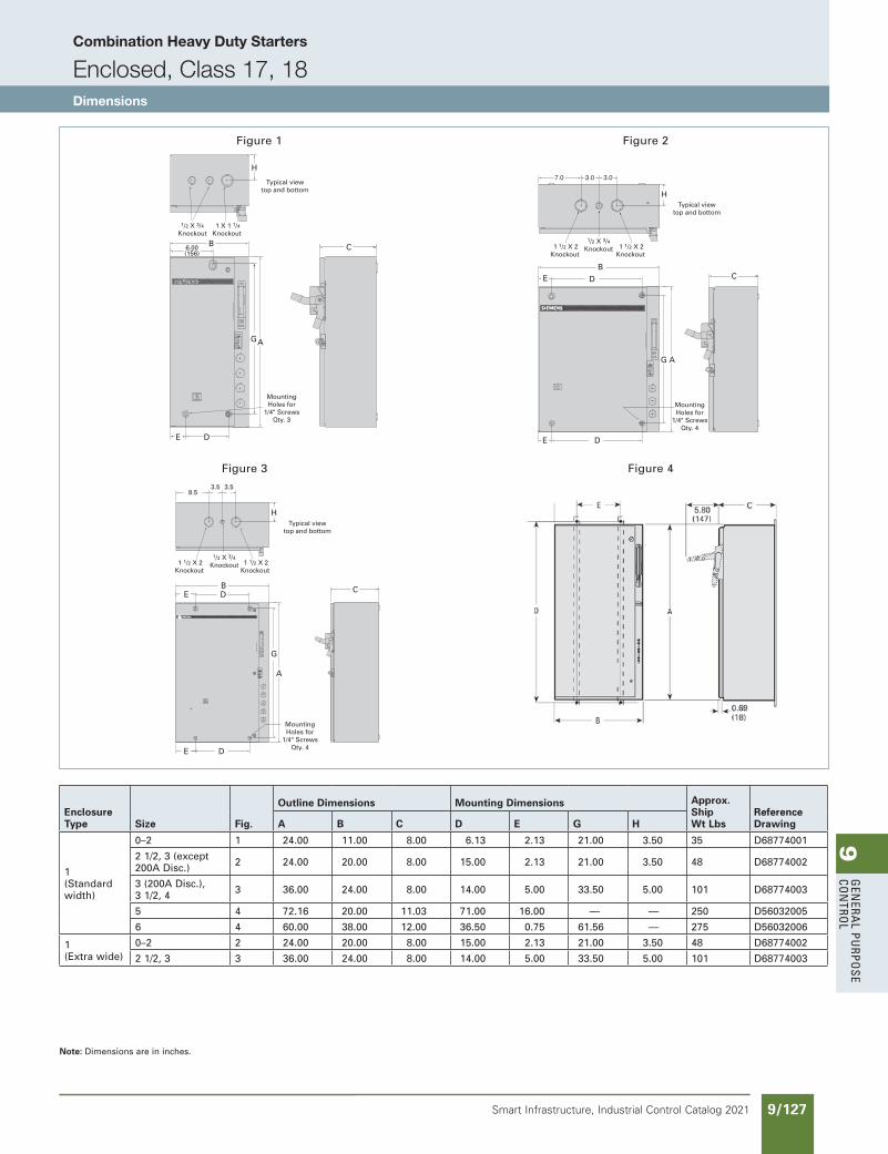
9G
enera
l PurPo
se Co
ntro
l
9/127Smart Infrastructure, Industrial Control Catalog 2021
Combination Heavy Duty Starters
Enclosed, Class 17, 18Dimensions
Figure 1 Figure 2
Figure 3 Figure 4
B6.00(156)
H
C
AG
E D
MountingHoles for
1/4" ScrewsQty. 3
1 X 1 1/4Knockout
Typical viewtop and bottom
1/2 X 3/4 Knockout
AG
H
CB
DE
E D
MountingHoles for
1/4" ScrewsQty. 4
1 1/2 X 2Knockout
1 1/2 X 2Knockout
1/2 X 3/4 Knockout
7.0 3.0 3.0
Typical viewtop and bottom
C
H
A
MountingHoles for
1/4" ScrewsQty. 4
1 1/2 X 2Knockout
3.53.58.5
1 1/2 X 2Knockout
1/2 X 3/4 Knockout
G
DE
B DE
Typical viewtop and bottom
Note: Dimensions are in inches.
Enclosure Type Size Fig.
Outline Dimensions Mounting Dimensions Approx. Ship Wt Lbs
Reference DrawingA B C D E G H
1 (Standard width)
0–2 1 24.00 11.00 8.00 6.13 2.13 21.00 3.50 35 D68774001
2 1/2, 3 (except 200A Disc.) 2 24.00 20.00 8.00 15.00 2.13 21.00 3.50 48 D68774002
3 (200A Disc.), 3 1/2, 4 3 36.00 24.00 8.00 14.00 5.00 33.50 5.00 101 D68774003
5 4 72.16 20.00 11.03 71.00 16.00 — — 250 D56032005
6 4 60.00 38.00 12.00 36.50 0.75 61.56 — 275 D56032006
1 (Extra wide)
0–2 2 24.00 20.00 8.00 15.00 2.13 21.00 3.50 48 D68774002
2 1/2, 3 3 36.00 24.00 8.00 14.00 5.00 33.50 5.00 101 D68774003
updated in SPEEDFAXRevised on 10/31/19
SS copied this page from SF to IC on 05/24/20
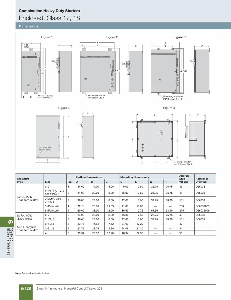
9G
ener
al
PurP
ose
Co
ntr
ol
9/128 Smart Infrastructure, Industrial Control Catalog 2021
Combination Heavy Duty Starters
Enclosed, Class 17, 18Dimensions
Figure 3
CD
AGH
E
B
Mounting Holes for1/4" Screws Qty. 4
Figure 2Figure 1
5.50(140)
E D
BC
AG
H
Mounting Holes for1/4" Screws Qty. 3
C
AGH
BE D
Mounting Holes for1/4" Screws Qty. 4
Mounting Holefor 1/4" screw
C
D A
EB
Figure 4
Mounting Holes forNo. 10 Screws Qty. 4
Figure 5
Enclosure Type Size Fig.
Outline Dimensions Mounting Dimensions Approx. Ship Wt Lbs
Reference DrawingA B C D E G H
3/3R/4/4X/12 (Standard width)
0–2 1 24.00 11.00 8.00 6.00 2.50 25.75 26.75 35 D56033
2 1/2, 3 (except 200A Disc.) 2 24.00 20.00 8.00 15.00 2.50 25.75 26.75 48 D56033
3 (200A Disc.), 3 1/2, 4 3 36.00 24.00 8.00 12.00 6.00 37.75 38.75 101 D56033
5 (Painted) 4 72.16 20.00 11.03 71.00 16.00 — — 250 D56032005
6 (Painted) 4 60.00 38.00 12.00 36.50 0.75 61.56 63.10 275 D56032006
3/3R/4/4X/12 (Extra wide)
0–2 2 24.00 20.00 8.00 15.00 2.50 25.75 26.75 48 D56033
2 1/2, 3 3 36.00 24.00 8.00 12.00 6.00 37.75 38.75 101 D56033
4/4X Fiberglass (Standard width)
0–1 3/4 5 23.75 14.62 7.12 24.09 12.20 — — 42
2–3 1/2 5 23.75 23.75 8.50 24.06 21.30 — — 44
4 5 39.37 29.52 12.20 40.94 27.95 — — 55
Note: Dimensions are in inches.
SS copied this page from SF to IC on 05/24/20
updated in SPEEDFAXRevised on 10/31/19
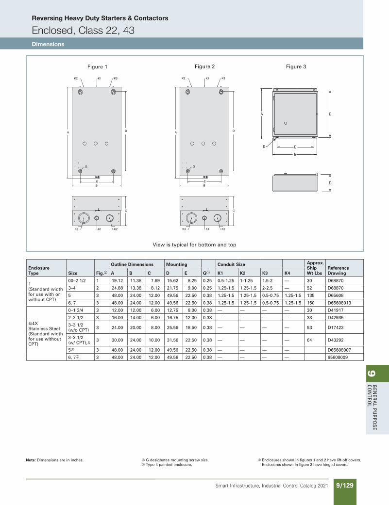
9G
enera
l PurPo
se Co
ntro
l
9/129Smart Infrastructure, Industrial Control Catalog 2021
SS copied this page from SF to IC on 05/24/20
updated in SPEEDFAXRevised on 03/31/20
Reversing Heavy Duty Starters & Contactors
Enclosed, Class 22, 43Dimensions
Figure 3Figure 2
View is typical for bottom and top
Figure 1
Enclosure Type Size Fig.c
Outline Dimensions Mounting
Ga
Conduit Size Approx. Ship Wt Lbs
Reference DrawingA B C D E K1 K2 K3 K4
1 (Standard width for use with or without CPT)
00–2 1/2 1 19.12 11.38 7.69 15.62 8.25 0.25 0.5-1.25 1-1.25 1.5-2 — 30 D68870
3–4 2 24.88 13.38 8.12 21.75 9.00 0.25 1.25-1.5 1.25-1.5 2-2.5 — 52 D68870
5 3 48.00 24.00 12.00 49.56 22.50 0.38 1.25-1.5 1.25-1.5 0.5-0.75 1.25-1.5 135 D65608
6, 7 3 48.00 24.00 12.00 49.56 22.50 0.38 1.25-1.5 1.25-1.5 0.5-0.75 1.25-1.5 150 D65608013
4/4X Stainless Steel (Standard width for use without CPT)
0–1 3/4 3 12.00 12.00 6.00 12.75 8.00 0.38 — — — — 30 D41917
2–2 1/2 3 16.00 14.00 6.00 16.75 12.00 0.38 — — — — 33 D42935
3–3 1/2 (w/o CPT) 3 24.00 20.00 8.00 25.56 18.50 0.38 — — — — 53 D17423
3–3 1/2 (w/ CPT),4 3 30.00 24.00 10.00 31.56 22.50 0.38 — — — — 64 D43292
5b 3 48.00 24.00 12.00 49.56 22.50 0.38 — — — — D65608007
6, 7b 3 48.00 24.00 12.00 49.56 22.50 0.38 — — — — 65608009
Note: Dimensions are in inches. a G designates mounting screw size.b Type 4 painted enclosure.
c Enclosures shown in figures 1 and 2 have lift-off covers. Enclosures shown in figure 3 have hinged covers.

9G
ener
al
PurP
ose
Co
ntr
ol
9/130 Smart Infrastructure, Industrial Control Catalog 2021
Reversing Heavy Duty Starters & Contactors
Enclosed, Class 22, 43Dimensions
K3K2K1
Figure 5 Figure 6
A
ABC
B C B A
20.00
11.62
0
0.50
7.25
10.0
0
12.7
5
16.5
0
15.25
2.71
.38 HOLE DIA.FOR PADLOCK
COMB. K.O.’s FOR 1.00, 1.25, 1.50, 2.00, OR 2.50 CONDUITCOMB. K.O.’s FOR 1.00, 1.25, OR 1.50 CONDUITCOMB. K.O.’s FOR 0.50 OR 0.75 CONDUIT
29.88DOOROPEN
90ϒ
4-POINT MOUNTINGFOR .31 SCREWS
2.38
5.00 10.00
1.20
45.75
48.00
12.50 .188
.69
Figure 7
View is typical for bottom and top
Note: Dimensions are in inches. a G designates mounting screw size.
Enclosure Type Size
Outline Dimensions Mounting
Ga
Conduit Size Approx. Ship Wt Lbs
Reference DrawingFig. A B C D E K1 K2 K3
3/3R/4/12 (Standard width for use with or without CPT)
0–1 3/4 5 13.00 12.63 5.63 12.25 10.00 0.25 — — — 30 D17150
2–2 1/2 5 16.00 13.25 6.13 15.25 11.00 0.25 — — — 33 D17150
3–3 1/2 (w/o CPT) 5 24.00 20.00 8.00 25.56 18.50 0.380 — — — 53 D17150
3–4 (w/ CPT) 5 30.00 24.00 10.00 31.56 22.50 0.380 — — — 64 D17150
5 7 48.00 24.00 12.00 49.56 22.50 0.375 — — — D65608007
6 7 48.00 24.00 12.00 49.56 22.50 0.375 — — —
4/4X Fiberglass (Standard width for use with or without CPT)
0–2 1/2 6 24.00 20.00 8.00 25.56 18.50 0.380 — — — 35
3–4 6 30.00 24.00 10.00 31.56 22.50 0.380 — — — 38
SS copied this page from SF to IC on 05/24/20
updated in SPEEDFAXRevised on 03/31/20
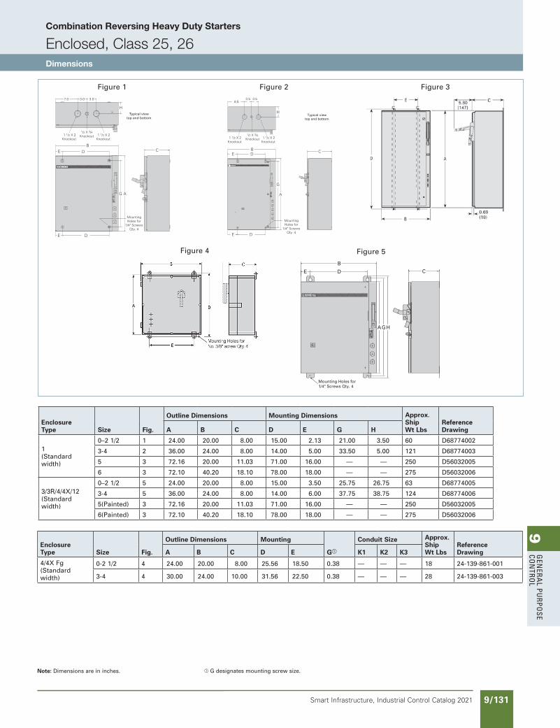
9G
enera
l PurPo
se Co
ntro
l
9/131Smart Infrastructure, Industrial Control Catalog 2021
Combination Reversing Heavy Duty Starters
Enclosed, Class 25, 26Dimensions
AG
H
CB
DE
E D
MountingHoles for
1/4" ScrewsQty. 4
1 1/2 X 2Knockout
1 1/2 X 2Knockout
1/2 X 3/4 Knockout
7.0 3.0 3.0
Typical viewtop and bottom
C
H
A
MountingHoles for
1/4" ScrewsQty. 4
1 1/2 X 2Knockout
3.53.58.5
1 1/2 X 2Knockout
1/2 X 3/4 Knockout
G
DE
B DE
Figure 1 Figure 2 Figure 3
Figure 4
CD
AGH
E
B
Mounting Holes for1/4" Screws Qty. 4
Figure 5
Typical viewtop and bottom
Enclosure Type Size Fig.
Outline Dimensions Mounting Dimensions Approx. Ship Wt Lbs
Reference DrawingA B C D E G H
1 (Standard width)
0–2 1/2 1 24.00 20.00 8.00 15.00 2.13 21.00 3.50 60 D68774002
3-4 2 36.00 24.00 8.00 14.00 5.00 33.50 5.00 121 D68774003
5 3 72.16 20.00 11.03 71.00 16.00 — — 250 D56032005
6 3 72.10 40.20 18.10 78.00 18.00 — — 275 D56032006
3/3R/4/4X/12 (Standard width)
0–2 1/2 5 24.00 20.00 8.00 15.00 3.50 25.75 26.75 63 D68774005
3-4 5 36.00 24.00 8.00 14.00 6.00 37.75 38.75 124 D68774006
5(Painted) 3 72.16 20.00 11.03 71.00 16.00 — — 250 D56032005
6(Painted) 3 72.10 40.20 18.10 78.00 18.00 — — 275 D56032006
Enclosure Type Size Fig.
Outline Dimensions Mounting
Ga
Conduit Size Approx. Ship Wt Lbs
Reference DrawingA B C D E K1 K2 K3
4/4X Fg (Standard width)
0-2 1/2 4 24.00 20.00 8.00 25.56 18.50 0.38 — — — 18 24-139-861-001
3-4 4 30.00 24.00 10.00 31.56 22.50 0.38 — — — 28 24-139-861-003
Note: Dimensions are in inches. a G designates mounting screw size.
SS copied this page from SF to IC on 05/24/20
updated in SPEEDFAXRevised on 03/31/20
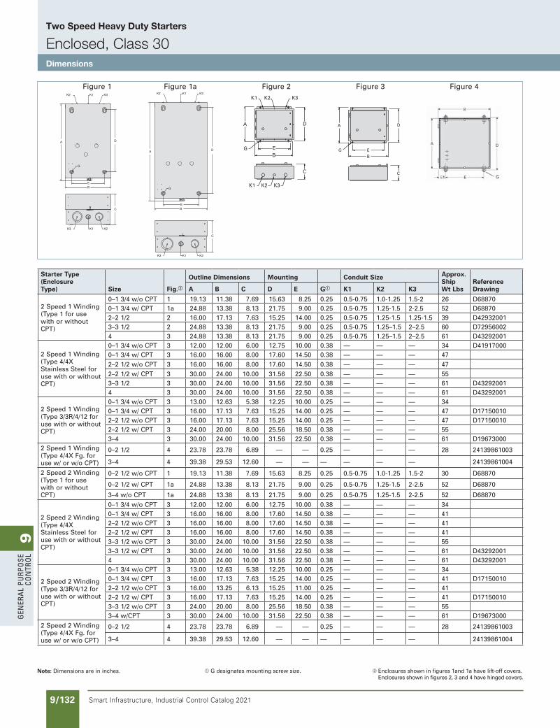
9G
ener
al
PurP
ose
Co
ntr
ol
9/132 Smart Infrastructure, Industrial Control Catalog 2021
Two Speed Heavy Duty Starters
Enclosed, Class 30Dimensions
K1 K2 K3
K1 K2 K3
D
EB
G
C
A
Figure 2
DA
G EB
C
Figure 3 Figure 4 Figure 1 Figure 1a
Note: Dimensions are in inches. a G designates mounting screw size. b Enclosures shown in figures 1and 1a have lift-off covers. Enclosures shown in figures 2, 3 and 4 have hinged covers.
Starter Type(Enclosure Type) Size Fig.b
Outline Dimensions Mounting Conduit Size Approx. Ship Wt Lbs
Reference DrawingA B C D E Ga K1 K2 K3
2 Speed 1 Winding (Type 1 for use with or without CPT)
0–1 3/4 w/o CPT 1 19.13 11.38 7.69 15.63 8.25 0.25 0.5-0.75 1.0-1.25 1.5-2 26 D688700–1 3/4 w/ CPT 1a 24.88 13.38 8.13 21.75 9.00 0.25 0.5-0.75 1.25-1.5 2-2.5 52 D688702–2 1/2 2 16.00 17.13 7.63 15.25 14.00 0.25 0.5-0.75 1.25-1.5 1.25-1.5 39 D429320013–3 1/2 2 24.88 13.38 8.13 21.75 9.00 0.25 0.5-0.75 1.25–1.5 2–2.5 60 D729560024 3 24.88 13.38 8.13 21.75 9.00 0.25 0.5-0.75 1.25–1.5 2–2.5 61 D43292001
2 Speed 1 Winding (Type 4/4X Stainless Steel for use with or without CPT)
0–1 3/4 w/o CPT 3 12.00 12.00 6.00 12.75 10.00 0.38 — — — 34 D419170000–1 3/4 w/ CPT 3 16.00 16.00 8.00 17.60 14.50 0.38 — — — 472–2 1/2 w/o CPT 3 16.00 16.00 8.00 17.60 14.50 0.38 — — — 472–2 1/2 w/ CPT 3 30.00 24.00 10.00 31.56 22.50 0.38 — — — 553–3 1/2 3 30.00 24.00 10.00 31.56 22.50 0.38 — — — 61 D432920014 3 30.00 24.00 10.00 31.56 22.50 0.38 — — — 61 D43292001
2 Speed 1 Winding (Type 3/3R/4/12 for use with or without CPT)
0–1 3/4 w/o CPT 3 13.00 12.63 5.38 12.25 10.00 0.25 — — — 340–1 3/4 w/ CPT 3 16.00 17.13 7.63 15.25 14.00 0.25 — — — 47 D171500102–2 1/2 w/o CPT 3 16.00 17.13 7.63 15.25 14.00 0.25 — — — 47 D171500102–2 1/2 w/ CPT 3 24.00 20.00 8.00 25.56 18.50 0.38 — — — 553–4 3 30.00 24.00 10.00 31.56 22.50 0.38 — — — 61 D19673000
2 Speed 1 Winding (Type 4/4X Fg. for use w/ or w/o CPT)
0–2 1/2 4 23.78 23.78 6.89 — — 0.25 — — — 28 24139861003
3–4 4 39.38 29.53 12.60 — — — — — — 24139861004
2 Speed 2 Winding (Type 1 for use with or without CPT)
0–2 1/2 w/o CPT 1 19.13 11.38 7.69 15.63 8.25 0.25 0.5-0.75 1.0-1.25 1.5-2 30 D68870
0–2 1/2 w/ CPT 1a 24.88 13.38 8.13 21.75 9.00 0.25 0.5-0.75 1.25-1.5 2-2.5 52 D68870
3–4 w/o CPT 1a 24.88 13.38 8.13 21.75 9.00 0.25 0.5-0.75 1.25-1.5 2-2.5 52 D68870
2 Speed 2 Winding (Type 4/4X Stainless Steel for use with or without CPT)
0–1 3/4 w/o CPT 3 12.00 12.00 6.00 12.75 10.00 0.38 — — — 340–1 3/4 w/ CPT 3 16.00 16.00 8.00 17.60 14.50 0.38 — — — 412–2 1/2 w/o CPT 3 16.00 16.00 8.00 17.60 14.50 0.38 — — — 412–2 1/2 w/ CPT 3 16.00 16.00 8.00 17.60 14.50 0.38 — — — 413–3 1/2 w/o CPT 3 30.00 24.00 10.00 31.56 22.50 0.38 — — — 553–3 1/2 w/ CPT 3 30.00 24.00 10.00 31.56 22.50 0.38 — — — 61 D432920014 3 30.00 24.00 10.00 31.56 22.50 0.38 — — — 61 D43292001
2 Speed 2 Winding (Type 3/3R/4/12 for use with or without CPT)
0–1 3/4 w/o CPT 3 13.00 12.63 5.38 12.25 10.00 0.25 — — — 340–1 3/4 w/ CPT 3 16.00 17.13 7.63 15.25 14.00 0.25 — — — 41 D171500102–2 1/2 w/o CPT 3 16.00 13.25 6.13 15.25 11.00 0.25 — — — 412–2 1/2 w/ CPT 3 16.00 17.13 7.63 15.25 14.00 0.25 — — — 41 D171500103–3 1/2 w/o CPT 3 24.00 20.00 8.00 25.56 18.50 0.38 — — — 553–4 w/CPT 3 30.00 24.00 10.00 31.56 22.50 0.38 — — — 61 D19673000
2 Speed 2 Winding (Type 4/4X Fg. for use w/ or w/o CPT)
0–2 1/2 4 23.78 23.78 6.89 — — 0.25 — — — 28 24139861003
3–4 4 39.38 29.53 12.60 — — — — — — 24139861004
SS copied this page from SF to IC on 05/24/20
updated in SPEEDFAXRevised on 03/31/20
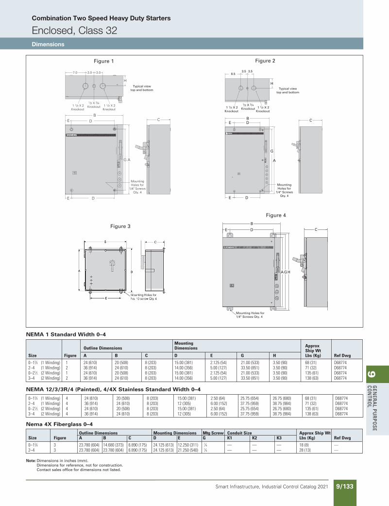
9G
enera
l PurPo
se Co
ntro
l
9/133Smart Infrastructure, Industrial Control Catalog 2021
Combination Two Speed Heavy Duty Starters
Enclosed, Class 32Dimensions
OutlineDimensions MountingDimensions MtgScrew ConduitSize ApproxShipWt Size Figure A B C D E G K1 K2 K3 Lbs(Kg) RefDwg
0–13⁄4 3 23.780(604) 14.680(373) 6.890(175) 24.125(613) 12.250(311) 1⁄4 — — — 18(8) —2–4 3 23.780(604) 23.780(604) 6.890(175) 24.125(613) 21.250(540) 1⁄4 — — — 28(13) —
NEMA 1 Standard Width 0–4
NEMA 12/3/3R/4 (Painted), 4/4X Stainless Standard Width 0–4
0–13⁄4 (1Winding) 4 24(610) 20(508) 8(203) 15.00(381) 2.50(64) 25.75(654) 26.75(680) 68(31) D687742–4 (1Winding) 4 36(914) 24(610) 8(203) 12(305) 6.00(152) 37.75(959) 38.75(984) 71(32) D687740–21⁄2, (2Winding) 4 24(610) 20(508) 8(203) 15.00(381) 2.50(64) 25.75(654) 26.75(680) 135(61) D687743–4 (2Winding) 4 36(914) 24(610) 8(203) 12(305) 6.00(152) 37.75(959) 38.75(984) 138(63) D68774
Note: Dimensions in inches (mm).Dimensions for reference, not for construction. Contact sales office for dimensions not listed.
AG
H
CB
DE
E D
MountingHoles for
1/4" ScrewsQty. 4
1 1/2 X 2Knockout
1 1/2 X 2Knockout
1/2 X 3/4 Knockout
7.0 3.0 3.0
Typical viewtop and bottom
CD
AGH
E
B
Mounting Holes for1/4" Screws Qty. 4
Figure 4
Figure 1 Figure 2
Figure 3
C
H
A
MountingHoles for
1/4" ScrewsQty. 4
1 1/2 X 2Knockout
3.53.58.5
1 1/2 X 2Knockout
1/2 X 3/4 Knockout
G
DE
B DE
Typical viewtop and bottom
Mounting Approx OutlineDimensions Dimensions ShipWt Size Figure A B C D E G H Lbs(Kg) RefDwg
0–13⁄4 (1Winding) 1 24(610) 20(508) 8(203) 15.00(381) 2.125(54) 21.00(533) 3.50(90) 68(31) D687742–4 (1Winding) 2 36(914) 24(610) 8(203) 14.00(356) 5.00(127) 33.50(851) 3.50(90) 71(32) D687740–21⁄2, (2Winding) 1 24(610) 20(508) 8(203) 15.00(381) 2.125(54) 21.00(533) 3.50(90) 135(61) D687743–4 (2Winding) 2 36(914) 24(610) 8(203) 14.00(356) 5.00(127) 33.50(851) 3.50(90) 138(63) D68774
Nema 4X Fiberglass 0–4
SS copied this page from SF to IC on 05/24/20
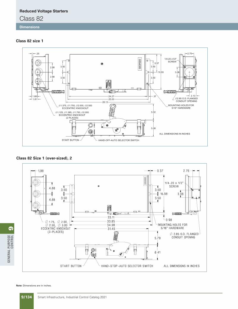
9G
ener
al
PurP
ose
Co
ntr
ol
9/134 Smart Infrastructure, Industrial Control Catalog 2021
Reduced Voltage Starters
Class 82Dimensions
Class 82 Size 1 (over-sized), 2
ALL DIMENSIONS IN INCHES
10.93
5.573.50
3.50
5.08
5.02
26.1325.00
3.50
3.50
MOUNTING HOLES FOR5/16" HARDWARE
∅1.125, ∅1.385, ∅1.750, ∅2.000ECCENTRIC KNOCKOUT
(2 PLACES)
∅1.375, ∅1.700, ∅2.000, ∅2.500ECCENTRIC KNOCKOUT
1.681.81 ∅2.85 O.D. FLANGED
CONDUIT OPENING
2.13
2.75
1/4-20 x1/2"SCREW
3.06
24.27 .37
2.88
2.88
HAND-OFF-AUTO SELECTOR SWITCHSTART BUTTON
.25
Class 82 size 1
Note: Dimensions are in inches.
SS copied this page from SF to IC on 05/24/20
NEED TO UPDATE IN SPEEDFAX
Revised on 12/31/21
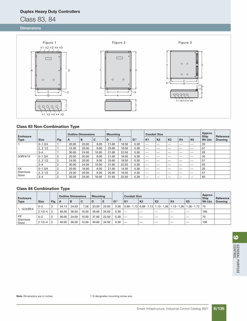
9G
enera
l PurPo
se Co
ntro
l
9/135Smart Infrastructure, Industrial Control Catalog 2021
Duplex Heavy Duty Controllers
Class 83, 84Dimensions
Figure 2 Figure 3Figure 1
A
Class 83 Non-Combination Type
Enclosure Type Size Fig.
Outline Dimensions Mounting
Ga
Conduit Size Approx. Ship Wt Lbs
Reference DrawingA B C D E K1 K2 K3 K4 K5
1 0–1 3/4 1 20.00 20.00 6.00 21.60 18.50 0.38 — — — — — 202, 2 1/2 1 24.00 20.00 8.00 25.60 18.50 0.38 — — — — — 573–4 1 30.00 24.00 10.00 31.60 22.50 0.38 — — — — — 93
3/3R/4/12 0–1 3/4 2 20.00 20.00 6.00 21.60 18.50 0.38 — — — — — 202, 2 1/2 2 24.00 20.00 8.00 25.60 18.50 0.38 — — — — — 573–4 2 30.00 24.00 10.00 31.60 22.50 0.38 — — — — — 93
4X Stainless Steel
0–1 3/4 2 20.00 16.00 6.00 21.60 14.50 0.38 — — — — — 202, 2 1/2 2 24.00 20.00 8.00 25.60 18.50 0.38 — — — — — 573–4 2 30.00 24.00 10.00 31.60 22.50 0.38 — — — — — 93
Class 84 Combination Type
Enclosure Type Size Fig.
Outline Dimensions Mounting
Ga
Conduit Size Approx. Ship Wt Lbs
Reference DrawingA B C D E K1 K2 K3 K4 K5
1, 12/3/3R/40–2 3 34.13 24.63 7.56 33.00 20.00 0.38 0.88 – 1.13 0.88 – 1.13 1.13 – 1.36 1.13 – 1.36 1.36 – 1.72 70
2 1/2–4 3 48.00 36.00 10.00 49.60 34.50 0.38 — — — — — 106
4X Stainless Steel
0–2 3 36.00 24.00 10.00 37.60 22.50 0.38 — — — — — 70
2 1/2–4 3 48.00 36.00 12.00 49.60 34.50 0.38 — — — — — 106
Note: Dimensions are in inches. a G designates mounting screw size.
SS copied this page from SF to IC on 05/24/20
updated in SPEEDFAXRevised on 03/31/20
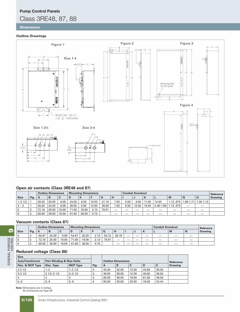
9G
ener
al
PurP
ose
Co
ntr
ol
9/136 Smart Infrastructure, Industrial Control Catalog 2021
Mounting Holefor 1/4" screw
C
D A
EB
F
BE CF
A D G
5.000
Figure 3Figure 2
FE G
D
J
A
B HC
K
L
(4) .687 Dia Holes
Handle(Optional)
Figure 4
FE G
D
J
A
B HC
K
L
(4) .687 Dia Holes
Handle(Optional)
Figure 1
Outline Drawings
Open air contacts (Class 3RE48 and 87)
Size Fig.
Outline Dimensions Mounting Dimensions Conduit Knockout Reference DrawingA B C D E F G H I J K L M N O
1–2 1/2 1 28.50 20.00 8.06 24.00 6.50 10.00 27.10 7.00 5.50 8.50 11.50 14.50 1.12-.875 1.96-1.71 1.35-1.123 – 4 1 40.20 24.00 8.06 36.00 6.50 12.00 38.80 7.00 8.50 12.00 15.50 2.46-1.96 1.12-.875 — —5 2 72.16 20.00 10.00 71.00 16.00 2.13 70.91 — — — — — — — —6 2 60.00 38.00 16.00 61.60 36.50 0.75 — — — — — — — —
Vacuum contacts (Class 87)
Size Fig.
Outline Dimensions Mounting Dimensions Conduit Knockout Reference DrawingA B C D E F G H I J K L M N
4 2 55.97 24.38 9.69 54.81 20.25 2.13 54.72 26.19 — — — — — —5 2 72.16 20.00 10.00 71.00 16.00 2.13 70.91 — — — — — — —6 2 60.00 38.00 16.00 61.60 36.50 0.75 — — — — — — —
Reduced voltage (Class 88)Size
Fig.
Outline Dimensions Reference Drawing
AutoTransformer Part Winding & Wye Delta
Disc. & MCP Type Disc. Type MCP Type A B C D E
2-2 1/2 1–2 1–2 1/2 3 42.00 32.00 12.00 43.60 30.503-3 1/2 2 1/2–3 1/2 3–3 1/2 3 48.00 38.00 12.00 49.60 36.504 4 4 3 60.00 38.00 16.00 61.60 36.505, 6 5, 6 5, 6 4 90.00 30.00 20.00 16.00 24.44
Note: Dimensions are in inches. All enclosures are Type 3R
SS copied this page from SF to IC on 05/24/20
NEED TO UPDATE IN SPEEDFAX
Revised on 12/31/21
Size 1-4
Size 1-2½ Size 3-4
Pump Control Panels
Class 3RE48, 87, 88Dimensions
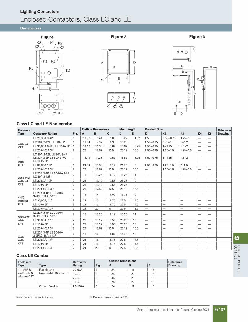
9G
enera
l PurPo
se Co
ntro
l
9/137Smart Infrastructure, Industrial Control Catalog 2021
Lighting Contactors
Enclosed Contactors, Class LC and LEDimensions
Class LC and LE Non-comboEnclosureType Contactor Rating Fig.
Outline Dimensions Mountinga Conduit Size Reference DrawingA B C D E K1 K2 K3 K4 K5
1 without CPT
LE 20/30A 3-4P 1 10.97 6.41 5.03 8.22 4.62 0.5 0.50 – 0.75 0.75 – 1 — —LC 30A 2-12P, LE 60A 3P 1 13.53 7.97 6.38 10.25 6 0.50 – 0.75 0.75 – 1 1 – 1.25 — —LE 30/60A 6-12P, LE 100A 3P 1 19.12 11.38 7.69 15.62 8.25 0.50 – 0.75 1 – 1.25 1.5 – 2 — —LE 200-400A 3P 2 26 17.62 12.5 25.19 15.5 0.50 – 0.75 1.25 – 1.5 1.25 – 1.5 — —
1 with CPT
LC 30A 2-12P, LE 20A 3-4P, LE 30A 3-9P, LE 60A 3-9P, LE 100A 3P
1 19.12 11.38 7.69 15.62 8.25 0.50 – 0.75 1 – 1.25 1.5 – 2 — —
LE 30/60A 12P 1 24.88 13.38 8.12 21.75 9 0.50 – 0.75 1.25 – 1.5 2 – 2.5 — —LE 200-400A 3P 2 26 17.62 12.5 25.19 15.5 — 1.25 – 1.5 1.25 – 1.5 — —
3/3R/4/12 without CPT
LE 20A 3-4P, LE 30/60A 3-9P, LC 30A 2-12P 2 16 13.25 6.12 15.25 11 — — — — —
LE 30/60A 12P 2 26 13.12 7.56 25.25 10 — — — — —LE 100A 3P 2 26 13.12 7.56 25.25 10 — — — — —LE 200-400A 3P 2 26 17.62 12.5 25.19 15.5 — — — — —
4/4X without CPT
LE 20A 3-4P, LE 30/60A 3-9P,LC 30A 2-12P 2 16 14 6.02 16.75 12 — — — — —
LE 30/60A, 12P 2 24 16 8.76 22.5 14.5 — — — — —LE 100A 3P 2 24 16 8.76 22.5 14.5 — — — — —LE 200-400A,3P 2 24 20 10 22.5 18.5 — — — — —
3/3R/4/12with CPT
LE 20A 3-4P, LE 30/60A 3-9P,LC 30A 2-12P 2 16 13.25 6.12 15.25 11 — — — — —
LE 30/60A, 12P 2 26 13.12 7.56 25.25 10 — — — — —LE 100A 3P 2 26 13.12 7.56 25.25 10 — — — — —LE 200-400A,3P 2 26 17.62 12.5 25.19 15.5 — — — — —
4/4X with CPT
LE 20A 3-4P, LE 30/60A 3-9P,LC 30A 2-12P 2 16 14 6.02 16.75 12 — — — — —
LE 30/60A, 12P 2 24 16 8.76 22.5 14.5 — — — — —LE 100A 3P 2 24 16 8.76 22.5 14.5 — — — — —LE 200-400A,3P 2 24 20 10 22.5 18.5 — — — — —
Figure 1 Figure 2 Figure 3
Class LE ComboEnclosure Type Type
ContactorRating Fig.
Outline Dimensions Reference DrawingA B C
1, 12/3R & 4/4X with & without CPT
Fusible and Non-fusible Disconnect
20–60A 3 24 11 8100A 3 24 20 8200A 3 46 20 10300A 3 76 22 13
Circuit Breaker 20–100A 3 24 11 8
Note: Dimensions are in inches. a Mounting screw G size is 0.25".
SS copied this page from SF to IC on 05/24/20
updated in SPEEDFAXRevised on 03/31/20
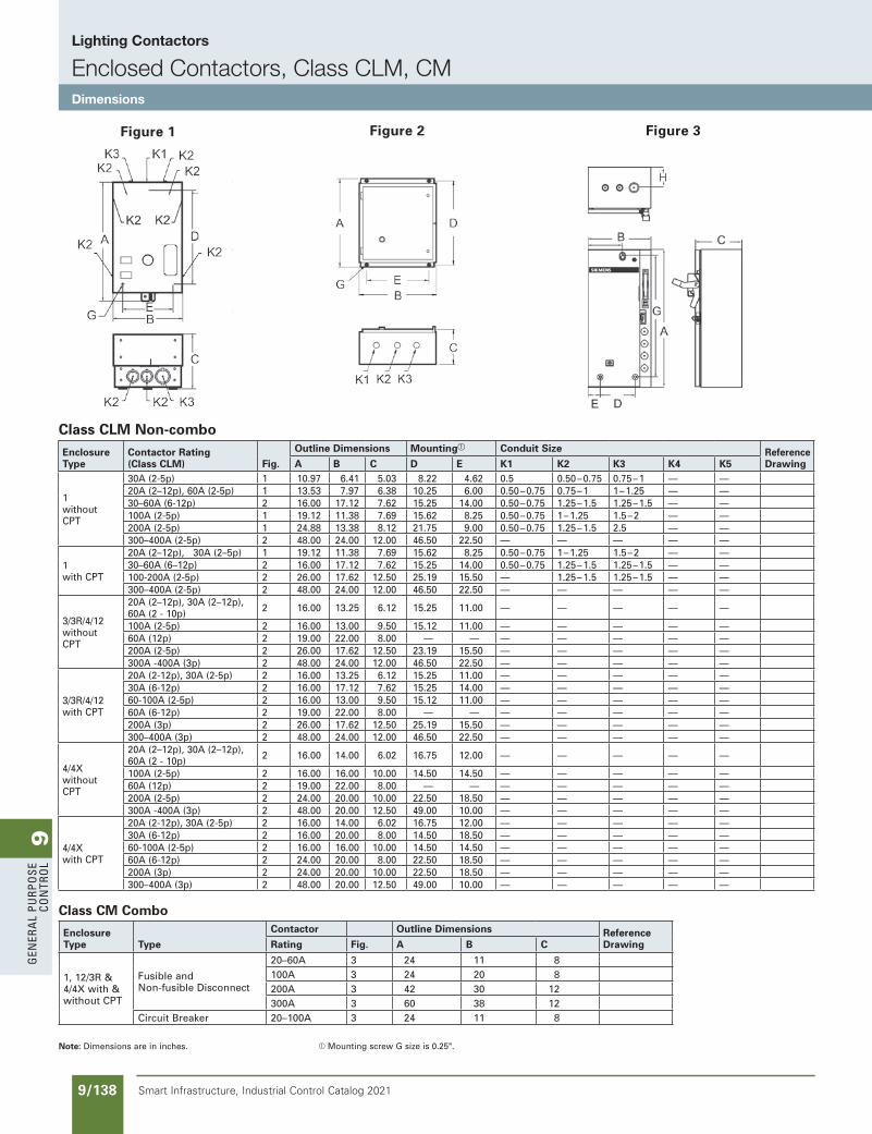
9G
ener
al
PurP
ose
Co
ntr
ol
9/138 Smart Infrastructure, Industrial Control Catalog 2021
Lighting Contactors
Enclosed Contactors, Class CLM, CMDimensions
Figure 1 Figure 2 Figure 3
Class CLM Non-comboEnclosureType
Contactor Rating(Class CLM) Fig.
Outline Dimensions Mountinga Conduit Size Reference DrawingA B C D E K1 K2 K3 K4 K5
1 without CPT
30A (2-5p) 1 10.97 6.41 5.03 8.22 4.62 0.5 0.50 – 0.75 0.75 – 1 — —20A (2–12p), 60A (2-5p) 1 13.53 7.97 6.38 10.25 6.00 0.50 – 0.75 0.75 – 1 1 – 1.25 — —30–60A (6-12p) 2 16.00 17.12 7.62 15.25 14.00 0.50 – 0.75 1.25 – 1.5 1.25 – 1.5 — —100A (2-5p) 1 19.12 11.38 7.69 15.62 8.25 0.50 – 0.75 1 – 1.25 1.5 – 2 — —200A (2-5p) 1 24.88 13.38 8.12 21.75 9.00 0.50 – 0.75 1.25 – 1.5 2.5 — —300–400A (2-5p) 2 48.00 24.00 12.00 46.50 22.50 — — — — —
1 with CPT
20A (2–12p), 30A (2–5p) 1 19.12 11.38 7.69 15.62 8.25 0.50 – 0.75 1 – 1.25 1.5 – 2 — —30–60A (6–12p) 2 16.00 17.12 7.62 15.25 14.00 0.50 – 0.75 1.25 – 1.5 1.25 – 1.5 — —100-200A (2-5p) 2 26.00 17.62 12.50 25.19 15.50 — 1.25 – 1.5 1.25 – 1.5 — —300–400A (2-5p) 2 48.00 24.00 12.00 46.50 22.50 — — — — —
3/3R/4/12 without CPT
20A (2–12p), 30A (2–12p), 60A (2 - 10p) 2 16.00 13.25 6.12 15.25 11.00 — — — — —
100A (2-5p) 2 16.00 13.00 9.50 15.12 11.00 — — — — —60A (12p) 2 19.00 22.00 8.00 — — — — — — —200A (2-5p) 2 26.00 17.62 12.50 23.19 15.50 — — — — —300A -400A (3p) 2 48.00 24.00 12.00 46.50 22.50 — — — — —
3/3R/4/12 with CPT
20A (2-12p), 30A (2-5p) 2 16.00 13.25 6.12 15.25 11.00 — — — — —30A (6-12p) 2 16.00 17.12 7.62 15.25 14.00 — — — — —60-100A (2-5p) 2 16.00 13.00 9.50 15.12 11.00 — — — — —60A (6-12p) 2 19.00 22.00 8.00 — — — — — — —200A (3p) 2 26.00 17.62 12.50 25.19 15.50 — — — — —300–400A (3p) 2 48.00 24.00 12.00 46.50 22.50 — — — — —
4/4X without CPT
20A (2–12p), 30A (2–12p), 60A (2 - 10p) 2 16.00 14.00 6.02 16.75 12.00 — — — — —
100A (2-5p) 2 16.00 16.00 10.00 14.50 14.50 — — — — —60A (12p) 2 19.00 22.00 8.00 — — — — — — —200A (2-5p) 2 24.00 20.00 10.00 22.50 18.50 — — — — —300A -400A (3p) 2 48.00 20.00 12.50 49.00 10.00 — — — — —
4/4X with CPT
20A (2-12p), 30A (2-5p) 2 16.00 14.00 6.02 16.75 12.00 — — — — —30A (6-12p) 2 16.00 20.00 8.00 14.50 18.50 — — — — —60-100A (2-5p) 2 16.00 16.00 10.00 14.50 14.50 — — — — —60A (6-12p) 2 24.00 20.00 8.00 22.50 18.50 — — — — —200A (3p) 2 24.00 20.00 10.00 22.50 18.50 — — — — —300–400A (3p) 2 48.00 20.00 12.50 49.00 10.00 — — — — —
Class CM Combo
Enclosure Type Type
Contactor Outline Dimensions Reference DrawingRating Fig. A B C
1, 12/3R & 4/4X with & without CPT
Fusible and Non-fusible Disconnect
20–60A 3 24 11 8100A 3 24 20 8200A 3 42 30 12300A 3 60 38 12
Circuit Breaker 20–100A 3 24 11 8
Note: Dimensions are in inches. a Mounting screw G size is 0.25".
SS copied this page from SF to IC on 05/24/20
Updated in SPEEDFAXRevised on 06/30/21
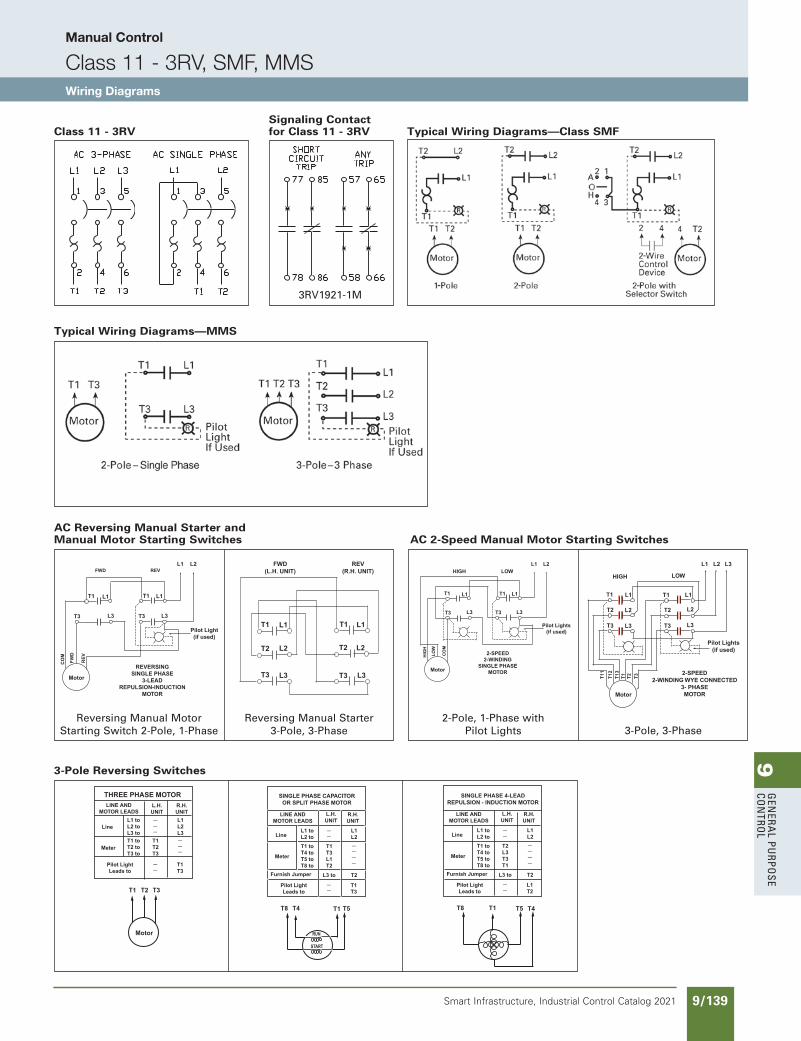
9G
enera
l PurPo
se Co
ntro
l
9/139Smart Infrastructure, Industrial Control Catalog 2021
Manual Control
Class 11 - 3RV, SMF, MMSWiring Diagrams
Class 11 - 3RV
Signaling Contact for Class 11 - 3RV
3RV1921-1M
Typical Wiring Diagrams—Class SMF
Typical Wiring Diagrams—MMS
AC Reversing Manual Starter and Manual Motor Starting Switches
AC 2-Speed Manual Motor Starting Switches
Reversing Manual Motor Starting Switch 2-Pole, 1-Phase
Reversing Manual Starter 3-Pole, 3-Phase
3-Pole Reversing Switches
2-Pole, 1-Phase with Pilot Lights 3-Pole, 3-Phase
L1 L2
T1 T1L1 L1
L3L3T3 T3
CO
M
FW
D
RE
V
Motor
Pilot Light(if used)
REVERSINGSINGLE PHASE
3-LEADREPULSION-INDUCTION
MOTOR
FWD REVHIGH LOW
L1 L2 L3
T1 T1L1 L1
L3L3T3 T3
L2L2T2 T2T
11
T12
T13
T3
T2
Motor
Pilot Lights(if used)
2-SPEED2-WINDING WYE CONNECTED
3- PHASEMOTOR
T1
HIGH LOWL1 L2
T1 T1L1 L1
L3L3T3 T3
HIG
H
LO
W
CO
M
Motor
Pilot Lights(if used)
2-SPEED2-WINDING
SINGLE PHASEMOTOR
T1 T1L1
T2 L2
T3 L3
L1
L3
T2
FWD(L.H. UNIT)
REV(R.H. UNIT)
T3
L2
SINGLE PHASE 4-LEADREPULSION - INDUCTION MOTOR
LINE ANDMOTOR LEADS
Line
Furnish Jumper
Meter
Pilot LightLeads to
L.H.UNIT
R.H.UNIT
L1 toL2 to
L3 to T2
L1L2
T1 toT4 toT5 toT8 to
T2L3T3T1
L1T2
__
____
__
T4T8 T1 T5
SINGLE PHASE CAPACITOROR SPLIT PHASE MOTOR
LINE ANDMOTOR LEADS
Line
Furnish Jumper
Meter
Pilot LightLeads to
L.H.UNIT
R.H.UNIT
L1 toL2 to
L3 to T2
L1L2
T1 toT4 toT5 toT8 to
T1T3L1T2
T1T3
__
____
__
T5T8 T4
START
RUN
T1
THREE PHASE MOTORLINE AND
MOTOR LEADS
Line
Meter
Pilot LightLeads to
L.H.UNIT
R.H.UNIT
L1 toL2 toL3 to
L1L2L3
T1 toT2 toT3 to
T1T2T3
T1T3
___
___
__
T3T2
Motor
T1
SS copied this page from SF to IC on 05/24/20
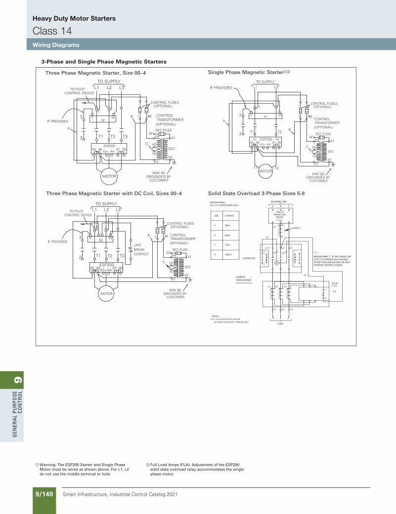
9G
ener
al
PurP
ose
Co
ntr
ol
9/140 Smart Infrastructure, Industrial Control Catalog 2021
Heavy Duty Motor Starters
Class 14Wiring Diagrams
3-Phase and Single Phase Magnetic Starters
a Warning: The ESP200 Starter and Single Phase Motor must be wired as shown above. For L1, L2 do not use the middle terminal or hole.
b Full Load Amps (FLA): Adjustment of the ESP200 solid state overload relay accommodates the single phase motor.
Solid State Overload 3-Phase Sizes 5-8
(WHEN USED, SEE TABLE)
TRANSFORMERCURRENT
O.L.
RELAY(IF USED)
" "C
" "
T3T2
3
2M
A1 A2
L1/1 L2 L3
CIRCUITPROTECTIVE
DEVICE(IF USED)
A B C
INCOMING LINE
T1
LOAD
A
CONTACTOR""
SEPARATE CONTROL SOURCE.OTHER THAN LINE VOLTAGE OR ON ACOIL IS TO OPERATE ON A VOLTAGEREMOVE WIRE C IF THE CONTACTOR
B ""
POWER WIRING:USE 75°C COPPER WIRE ONLY.
95
96
X1 X1X1
X1
NOTE A
NOTES:A: 2CT IS LOCATED ON THE LINE SIDE
OF CONTACTOR ON SIZE 7 STARTERS ONLY.
2CT
1CT 2CT 3CT
750:5
600:5
300:5
CT RATIOSIZE
7
6
5
1200:58
Three Phase Magnetic Starter with DC Coil, Sizes 00–4
M
2
MOTOR
T2T1 T3
WIRING DIAGRAM
CONTROL DEVICE
3
TO PILOT
WV
1
L1 L2 L3TO SUPPLY
IF PROVIDED
ESP2009695 A4-97 98A3+
LATEBREAKCONTACT
NEMA 00 - 4
GROUNDED BYCUSTOMER
MAY BE
(OPTIONAL)
SEC FUSE
CONTROL FUSES
1
C
XF
H1
H4
H3
H2
X2
SEC
X1
CONTROL TRANSFORMER(OPTIONAL)
B 96
THREE PHASE MAGNETIC STARTER WITH D.C. COIL
Three Phase Magnetic Starter, Size 00–4WIRING DIAGRAM
M
2
MOTOR
T2T1 T3
CONTROL DEVICE
3
TO PILOT
WV
1
L1 L2 L3TO SUPPLY
IF PROVIDED
ESP2009695
A4-97 98
A3+
GROUNDED BYCUSTOMER
MAY BE
(OPTIONAL)
SEC FUSE
CONTROL FUSES
1
C
XF
H1
H4
H3
H2
B
X2
SEC
X1
NEMA 00 - 4
CONTROL TRANSFORMER(OPTIONAL)
96
A
3 PHASE MAGNETIC STARTER SIZE 00 - 4
Single Phase Magnetic StarterabWIRING DIAGRAM
T1 T2
L2L1TO SUPPLY
WV
T1 T2
MOTOR
M
1
3
2
IF PROVIDED
ESP2009695
A4-97 98
A3+
GROUNDED BYCUSTOMER
MAY BE
(OPTIONAL)
SEC FUSE
CONTROL FUSES
1
C
XF
H1
H4
H3
H2
B
X2
SEC
X1
NEMA 00 - 4
CONTROL TRANSFORMER(OPTIONAL)
96A
SINGLE PHASE MAGNETIC STARTER SIZE 00 - 4
A1 A3
SS copied this page from SF to IC on 05/24/20
updated in SPEEDFAXRevised on 03/31/20
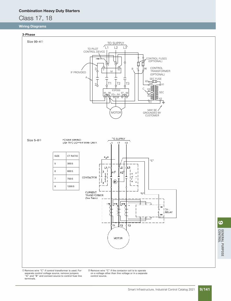
9G
enera
l PurPo
se Co
ntro
l
9/141Smart Infrastructure, Industrial Control Catalog 2021
Combination Heavy Duty Starters
Class 17, 18Wiring Diagrams
Size 5–8b
3-Phase WIRING DIAGRAM
M
2
MOTOR
T2T1 T3
CONTROL DEVICE
3
TO PILOT
WV
1
L1 L2 L3TO SUPPLY
IF PROVIDED
ESP2009695
A4-97 98
A3+
GROUNDED BYCUSTOMER
MAY BE
(OPTIONAL)
SEC FUSE
CONTROL FUSES
1
C
XF
H1
H4
H3
H2
B
X2
SEC
X1
NEMA 00 - 4
CONTROL TRANSFORMER(OPTIONAL)
96
A
3 PHASE MAGNETIC STARTER SIZE 00 - 4
Size 00–4a
a Remove wire “C” if control transformer is used. For separate control voltage source, remove jumpers “A” and “B” and connect source to control fuse line terminals.
b Remove wire “C” if the contactor coil is to operate on a voltage other than line voltage or in a separate control source.
SIZE CT RATIO
5 300:5
6 600:5
7 750:5
8 1200:5
“C”
SS copied this page from SF to IC on 05/24/20
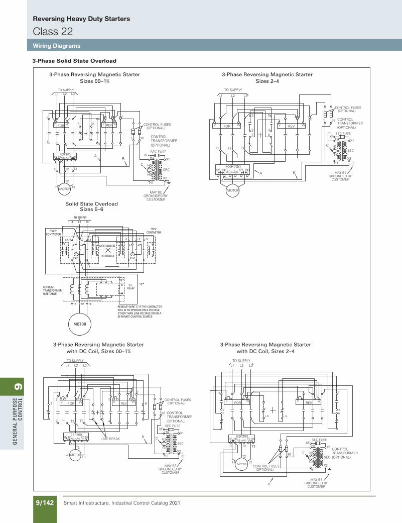
9G
ener
al
PurP
ose
Co
ntr
ol
9/142 Smart Infrastructure, Industrial Control Catalog 2021
Reversing Heavy Duty Starters
Class 22Wiring Diagrams
3-Phase Solid State Overload
Solid State OverloadSizes 5–6
TO SUPPLY
REMOVE WIRE "C" IF THE CONTACTORCOIL IS TO OPERATE ON A VOLTAGEOTHER THAN LINE VOLTAGE OR ON A SEPARATE CONTROL SOURCE.
CURRENTTRANSFORMER(SEE TABLE)
"FWD"CONTRACTOR
MECHANICAL
INTERLOCK
"REV"CONTACTOR
O.L.RELAY
"FWD"CONTACTOR
L1 L2 L3
MOTOR
3-Phase Reversing Magnetic StarterSizes 00–13⁄4
MOTOR
V VW WFOR REV
L1 L2 L3
5
4
3
2
T2 T3T1
TO SUPPLY
1
67
ESP2009695 A4-97 98A3+
NEMA 00 - 1 34WIRING DIAGRAM
GROUNDED BYCUSTOMER
MAY BE
(OPTIONAL)
SEC FUSE
CONTROL FUSES
1
C
XF
H1
H4
H3
H2
X2
SEC
X1
CONTROL TRANSFORMER(OPTIONAL)
B
96
A
T2
T1 T3
3 PHASE REVERSINGMAGNETIC STARTER
3-Phase Reversing Magnetic StarterSizes 2–4
TO SUPPLY
MOTOR
V FOR W
3
2
L1 L2 L3
WREVV
4
51
A
WIRING DIAGRAM
T1 T2 T3
67
ESP2009695 A4-97 98A3+
NEMA 2 - 4
GROUNDED BYCUSTOMER
MAY BE
(OPTIONAL)
SEC FUSE
CONTROL FUSES
1
C
XF
H1
H4
H3
H2
X2
SEC
X1
CONTROL TRANSFORMER(OPTIONAL)
B
96
3 PHASE REVERSINGMAGNETIC STARTER
3-Phase Reversing Magnetic Starter with DC Coil, Sizes 00–13⁄4WIRING DIAGRAM
LATE BREAK
T1
2 T1
T2
MOTOR T3
T2 T3 4
TO SUPPLY
L1
37 V FOR W
L2 L3
5W
REVV 6
ESP2009695 A4-97 98A3+
NEMA 00 - 1 34
GROUNDED BYCUSTOMER
MAY BE
(OPTIONAL)
SEC FUSE
CONTROL FUSES
96
C
XF
H1
H4
H3
H2
X2
SEC
X1
1
1
B
CONTROL TRANSFORMER(OPTIONAL)
3 PHASE REVERSINGMAGNETIC STARTER W/DC COIL
3-Phase Reversing Magnetic Starter with DC Coil, Sizes 2–4
TO SUPPLY
T1 T3
L3L1
WV
MOTOR
FOR
L2
T2
T1 T2 T3
WIRING DIAGRAM
REV
L.B.
5
7L.B.
V W
2
3
64
ESP2009695 A4-97 98A3+
NEMA 2 - 4
GROUNDED BYCUSTOMER
MAY BE
(OPTIONAL)
SEC FUSE
CONTROL FUSES
1
C
XF
H1
H4
H3
H2
X2
SEC
X1
96
CONTROL TRANSFORMER(OPTIONAL)
B
3 PHASE REVERSINGMAGNETIC STARTER W/DC COIL
SS copied this page from SF to IC on 05/24/20
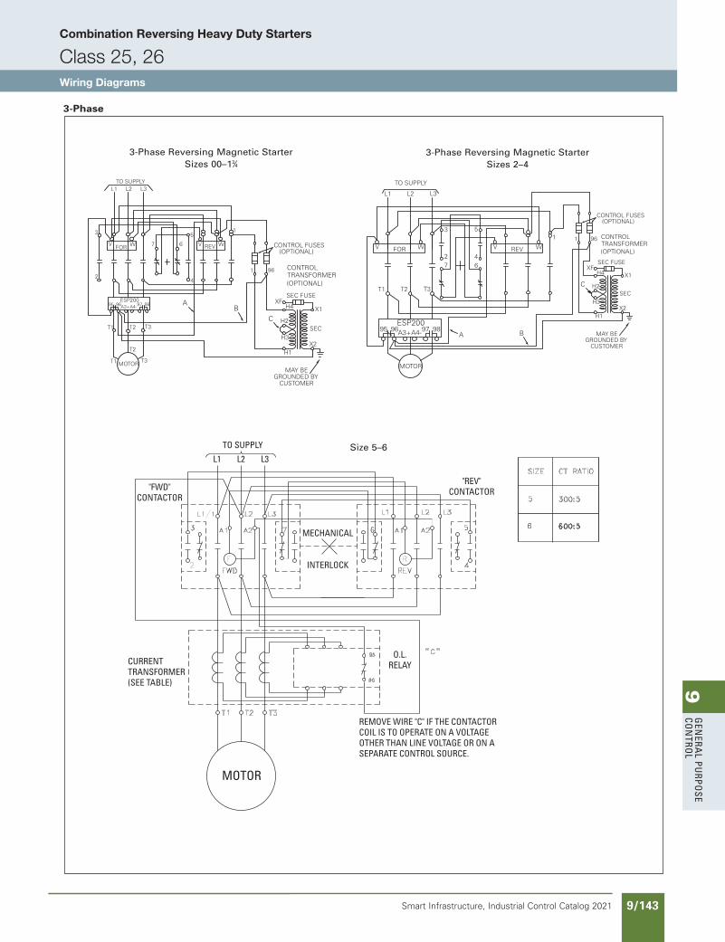
9G
enera
l PurPo
se Co
ntro
l
9/143Smart Infrastructure, Industrial Control Catalog 2021
Combination Reversing Heavy Duty Starters
Class 25, 26Wiring Diagrams
TO SUPPLY
REMOVE WIRE "C" IF THE CONTACTORCOIL IS TO OPERATE ON A VOLTAGEOTHER THAN LINE VOLTAGE OR ON A SEPARATE CONTROL SOURCE.
CURRENTTRANSFORMER(SEE TABLE)
"FWD"CONTRACTOR
MECHANICAL
INTERLOCK
"REV"CONTACTOR
O.L.RELAY
"FWD"CONTACTOR
L1 L2 L3
MOTOR
3-Phase
Size 5–6
3-Phase Reversing Magnetic StarterSizes 00–13⁄4
MOTOR
V VW WFOR REV
L1 L2 L3
5
4
3
2
T2 T3T1
TO SUPPLY
1
67
ESP2009695 A4-97 98A3+
NEMA 00 - 1 34WIRING DIAGRAM
GROUNDED BYCUSTOMER
MAY BE
(OPTIONAL)
SEC FUSE
CONTROL FUSES
1
C
XF
H1
H4
H3
H2
X2
SEC
X1
CONTROL TRANSFORMER(OPTIONAL)
B
96
A
T2
T1 T3
3 PHASE REVERSINGMAGNETIC STARTER
3-Phase Reversing Magnetic StarterSizes 2–4
TO SUPPLY
MOTOR
V FOR W
3
2
L1 L2 L3
WREVV
4
51
A
WIRING DIAGRAM
T1 T2 T3
67
ESP2009695 A4-97 98A3+
NEMA 2 - 4
GROUNDED BYCUSTOMER
MAY BE
(OPTIONAL)
SEC FUSE
CONTROL FUSES
1
C
XF
H1
H4
H3
H2
X2
SEC
X1
CONTROL TRANSFORMER(OPTIONAL)
B
96
3 PHASE REVERSINGMAGNETIC STARTER
SS copied this page from SF to IC on 05/24/20
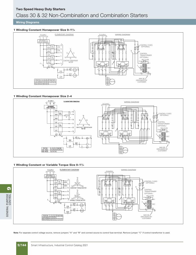
9G
ener
al
PurP
ose
Co
ntr
ol
9/144 Smart Infrastructure, Industrial Control Catalog 2021
Two Speed Heavy Duty Starters
Class 30 & 32 Non-Combination and Combination StartersWiring Diagrams
1 Winding Constant Horsepower Size 2–4
WIRING DIAGRAM
T6
T4T5
MOTOR
T2T3
T1
L3L2L1
T3T1 T2
WLOWV
4
A
5
WHIGHV
31
2
LV W
T6 T5T4
TO SUPPLY
6 7
6
NEMA 2 - 4
ESP2009695
A4-97 98
A3+
ESP2009695
A4-97 98
A3+
GROUNDED BYCUSTOMER
MAY BE
CONTROL TRANSFORMER(OPTIONAL)
(OPTIONAL)
SEC FUSE
CONTROL FUSES
1
C
XF
H1
H4
H3
H2
X2
SEC
X1
96B
2 SPEED 3 PHASE 1 WINDINGCONSTANT HORSEPOWER
X1
A
(OPTIONAL)
B
961C
WIRING DIAGRAM
8V LOW W37
2
OVERLOAD RELAY
H2
H4SEC FUSE
X2H1
H3
T3 XFT2T1
M
95 96(OPTIONAL)
CONTROL TRANSFORMER
SEC
CONTROL FUSES
L2 L3L1
CIRCUIT BREAKERDISCONNECT or
TO SUPPLY
WV HIGH
OVERLOAD RELAY
56
4
T5T6 T48
95 96
T6T2T1
T6T2
T1
T4
T5
T3
T5VARIABLE TORQUE MOTOR
CONSTANT TORQUE MOTOR
T3
T4
L3
HIGH
HIGH
OLLOW
LOW
LOW
OL
ALL OL'S
HIGH
HIGH
HIGH
HIGH
LOW
T4
T5
T6
T3
T2
T1
ELEMENTARY DIAGRAM
LOW
HIGH
6
7
HIGH
LOW
3
5
2
4
9596
T2T1T5T3L3
T4T2L2
T3
TOGETHER
HIGH
LOW
L2L1
A
T6T1L1
HIGH SPEEDLOW SPEED
POSITION
CIRCUIT BREAKERDISCONNECT or
TO SUPPLY
T1
T6
T3
T5T4
T2
WIRING DIAGRAM
T4 T5T6 T1 T2 T3
T1T2T3T4T5T6
MOTOR
V W LOWVHIGH W
5
4
3
2
8 1
TO SUPPLYL1 L2 L3
6 7
NEMA 00 - 1 34
GROUNDED BYCUSTOMER
MAY BE
CONTROL TRANSFORMER(OPTIONAL)
(OPTIONAL)
SEC FUSE
CONTROL FUSES
1
C
XF
H1
H4
H3
H2
X2
SEC
X1
96B
ESP2009695
A4-97 98
A3+
ESP2009695
A4-97 98
A3+
A
2 SPEED 3 PHASE 1 WINDINGCONSTANT OR VARIABLE TORQUE
1 Winding Constant or Variable Torque Size 0–13/4
1 Winding Constant Horsepower Size 0–13/4
5
4
TOGETHER
LOWOL
HIGHOL
ALL OL'S
POSITIONLOW SPEEDHIGH SPEED
L3T3T5
L2T2T4T6
T1L1
T4 T5
96
CIRCUIT BREAKER
ALOW
LOW
LOW
HIGH
HIGH
HIGH
DISCONNECT or
TO SUPPLY
L1 L2 L3
MOTORCONSTANT HORSEPOWER
T6
95
4
LOW
2
HIGH
5
3
7 HIGH
6 LOW
T2
T3
T1
LOW
LOWT5
T4
T6
T3
T5T2
T4
LOW
HIGH8
T1
T6
6
ELEMENTARY DIAGRAM
CIRCUIT BREAKER
T2T1
95
T1
T6
T3
T5T4
T2
T3
96OVERLOAD RELAY
V LOW W
95
M
T6 T4 T5
96OVERLOAD RELAY
37
2
V8
HIGH W
C
TO SUPPLY
DISCONNECT or
L1 L2 L3
WIRING DIAGRAM
CONTROL TRANSFORMER
H1
H3
XF
H2
H4
SEC FUSE
X2
SEC
X1
(OPTIONAL)
(OPTIONAL)CONTROL FUSES1 96
AB
WIRING DIAGRAM
T2 T3T1 T6 T4 T5
T1T2T3T4 MOTOR
V WLOW V HIGH W
5
4
3
2
8 1
A
L1 L2 L3
67
TO SUPPLY NEMA 00 - 1 34
GROUNDED BYCUSTOMER
MAY BE
CONTROL TRANSFORMER(OPTIONAL)
(OPTIONAL)
SEC FUSE
CONTROL FUSES
1
C
XF
H1
H4
H3
H2
X2
SEC
X1
96B
T5T6
ESP2009695
A4-97 98
A3+
ESP2009695
A4-97 98
A3+
2 SPEED 3 PHASE 1 WINDINGCONSTANT HORSEPOWER
Note: For separate control voltage source, remove jumpers “A” and “B” and connect source to control fuse terminal. Remove jumper “C” if control transformer is used.
SS copied this page from SF to IC on 05/24/20
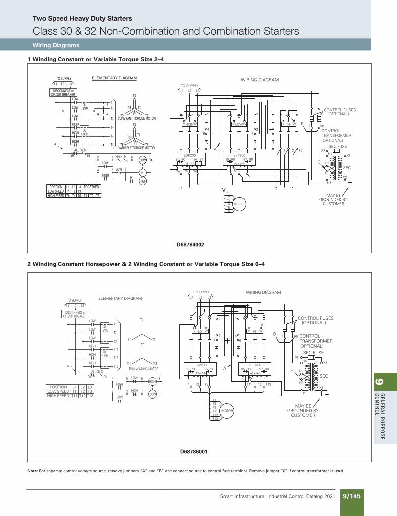
9G
enera
l PurPo
se Co
ntro
l
9/145Smart Infrastructure, Industrial Control Catalog 2021
Two Speed Heavy Duty Starters
Class 30 & 32 Non-Combination and Combination StartersWiring Diagrams
2 Winding Constant Horsepower & 2 Winding Constant or Variable Torque Size 0–4
WIRING DIAGRAM
L3L2L1
T6
T4T5
MOTOR
T2T3
T1
T5T6 T4
WHIGHV
4
A
5
WLOWV
31
2
HV W
T1 T3T2
TO SUPPLY
6 7
GROUNDED BYCUSTOMER
MAY BE
CONTROL TRANSFORMER(OPTIONAL)
(OPTIONAL)
SEC FUSE
CONTROL FUSES
1
C
XF
H1
H4
H3
H2
X2
SEC
X1
96B
ESP2009695
A4-97 98
A3+
ESP2009695
A4-97 98
A3+
2 SPEED 3 PHASE 1 WINDINGCONSTANT OR VARIABLE TORQUE
NEMA 2 - 4
X2H1
H3MT3
T12T11
T13
A
CONTROL FUSES(OPTIONAL)
B
96C 1
WIRING DIAGRAM
W
T13
V
T11
HIGH
T12
85
47
H4SEC FUSE
SEC
XF
H2
95 96OVERLOAD RELAY
(OPTIONAL)CONTROL TRANSFORMER
X1
L3L2L1TO SUPPLY
6
3
2
W
T2
V
T1
LOW
CIRCUIT BREAKER
T3
DISCONNECT or
T13
T3
T2T1
95 96
8
LOW
HIGH
OVERLOAD RELAY
T2
T12
T2
T1
T11
T3
T12
T11
T1
L3
OLLOW
OLHIGH
LOW
LOW
LOW
HIGH
HIGH
HIGH
ELEMENTARY DIAGRAM
6
7
LOW
HIGH
5
3
HIGH
LOW
9596
L2T2 T3
L3
T12 T13
ALL OL'S
2
4
T13TWO WINDING MOTOR
L1
L1LOW SPEEDHIGH SPEED
POSITION
A
T1T11
CIRCUIT BREAKERDISCONNECT or
TO SUPPLYL2
T2 T3T1 T11 T12 T13
T1T2T3T11T12T13
MOTOR
V WLO V HI W
3
2
5 1
A
TO SUPPLY
L1 L2 L3WIRING DIAGRAM
47
8
6
NEMA 2 - 4
GROUNDED BYCUSTOMER
MAY BE
CONTROL TRANSFORMER(OPTIONAL)
(OPTIONAL)
SEC FUSE
CONTROL FUSES
1
C
XF
H1
H4
H3
H2
X2
SEC
X1
96B
ESP2009695
A4-97 98
A3+
ESP2009695
A4-97 98
A3+
2 SPEED 3 PHASE 2 WINDINGSEPARATE WINDING
1 Winding Constant or Variable Torque Size 2–4
D68784002
D68786001
Note: For separate control voltage source, remove jumpers “A” and “B” and connect source to control fuse terminal. Remove jumper “C” if control transformer is used.
SS copied this page from SF to IC on 05/24/20
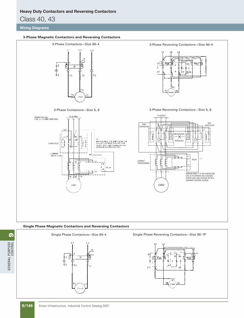
9G
ener
al
PurP
ose
Co
ntr
ol
9/146 Smart Infrastructure, Industrial Control Catalog 2021
Heavy Duty Contactors and Reversing Contactors
Class 40, 43Wiring Diagrams
3-Phase Contactors—Size 00–4
Single Phase Reversing Contactors—Size 00–1P
3-Phase Reversing Contactors—Size 00–4
TO SUPPLY
REMOVE WIRE "C" IF THE CONTACTORCOIL IS TO OPERATE ON A VOLTAGEOTHER THAN LINE VOLTAGE OR ON A SEPARATE CONTROL SOURCE.
CURRENTTRANSFORMER
"FWD"CONTRACTOR
MECHANICAL
INTERLOCK
"REV"CONTACTOR
RELAY
"FWD"
CONTACTOR
L1 L2 L3
LOAD
3-Phase Reversing Contactors—Size 5, 6
3-Phase Magnetic Contactors and Reversing Contactors
Single Phase Magnetic Contactors and Reversing Contactors
Single Phase Contactors—Size 00–4
3-Phase Contactors—Size 5, 6
SS copied this page from SF to IC on 05/24/20
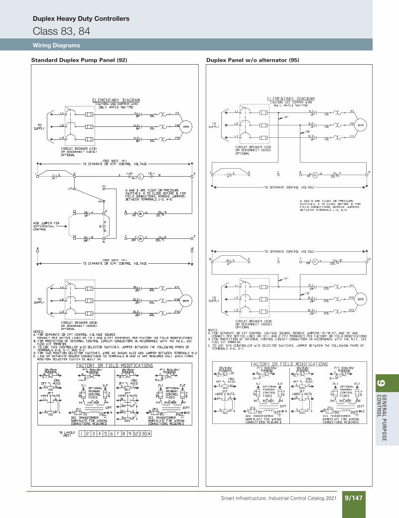
9G
enera
l PurPo
se Co
ntro
l
9/147Smart Infrastructure, Industrial Control Catalog 2021
Duplex Heavy Duty Controllers
Class 83, 84Wiring Diagrams
Standard Duplex Pump Panel (92) Duplex Panel w/o alternator (95)
SS copied this page from SF to IC on 05/24/20
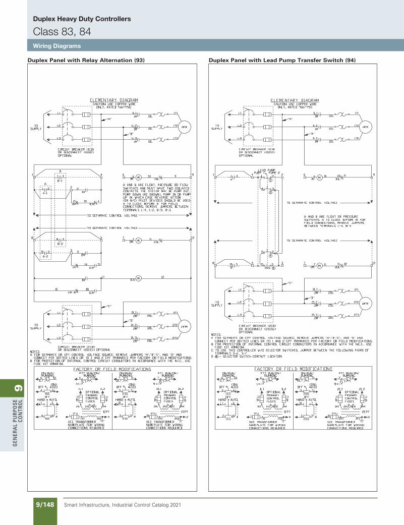
9G
ener
al
PurP
ose
Co
ntr
ol
9/148 Smart Infrastructure, Industrial Control Catalog 2021
Duplex Heavy Duty Controllers
Class 83, 84Wiring Diagrams
Duplex Panel with Relay Alternation (93) Duplex Panel with Lead Pump Transfer Switch (94)
SS copied this page from SF to IC on 05/24/20
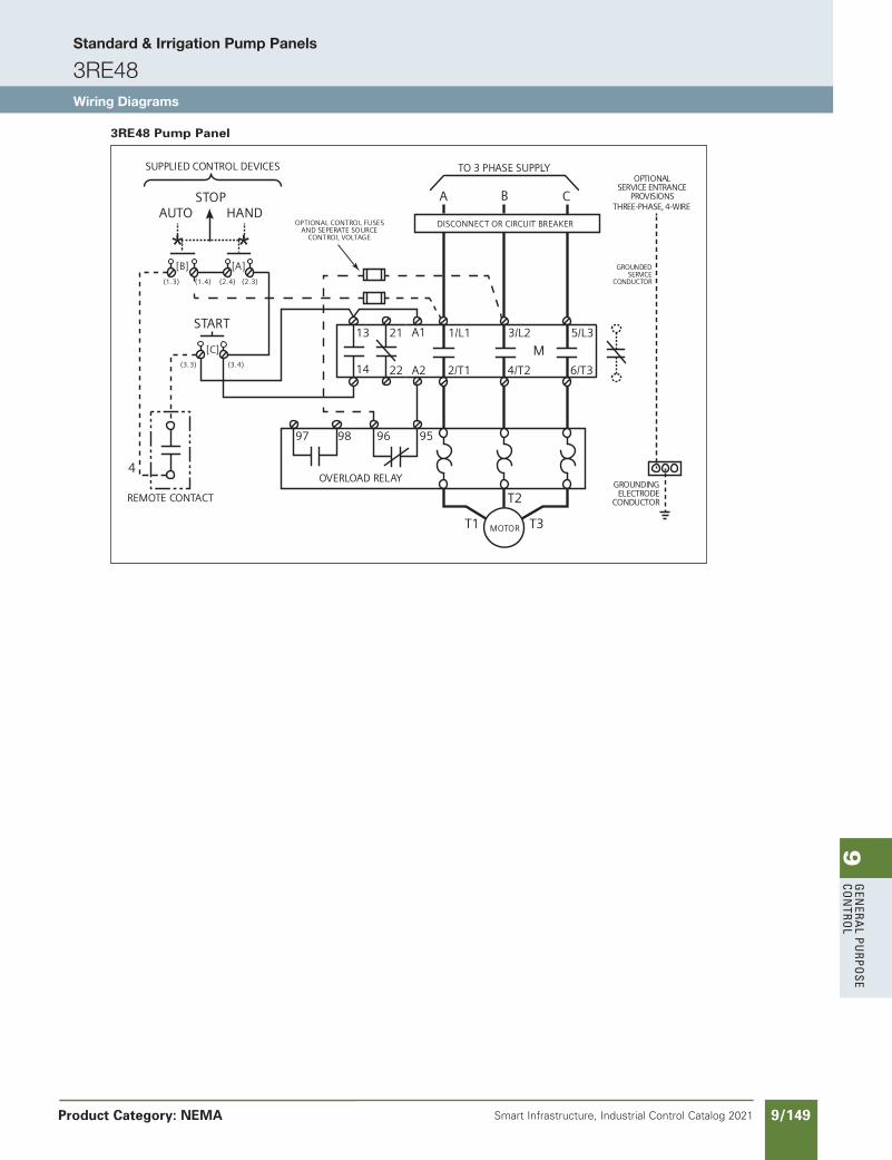
9G
enera
l PurPo
se Co
ntro
l
9/149Smart Infrastructure, Industrial Control Catalog 2021 Product Category: NEMA
START
STOPAUTO HAND
4
1/L1
[B] [A]
[C]
(1.3)
(3.3) (3.4)
(2.4) (2.3)(1.4)
**
A1
A2
A B
TO 3 PHASE SUPPLY
13 3/L2 5/L3
2/T1 4/T2 6/T314
C
REMOTE CONTACT
SUPPLIED CONTROL DEVICES
DISCONNECT OR CIRCUIT BREAKER
M
98
OVERLOAD RELAY
T1
T2
T3MOTOR
96 9597
21
22
OPTIONAL CONTROL FUSESAND SEPERATE SOURCE
CONTROL VOLTAGE
GROUNDEDSERVICE
CONDUCTOR
GROUNDINGELECTRODE
CONDUCTOR
OPTIONALSERVICE ENTRANCE
PROVISIONSTHREE-PHASE, 4-WIRE
3RE48 Pump Panel
NEED TO UPDATE IN SPEEDFAX
Revised on 12/31/21NEW PAGE
Standard & Irrigation Pump Panels
3RE48Wiring Diagrams
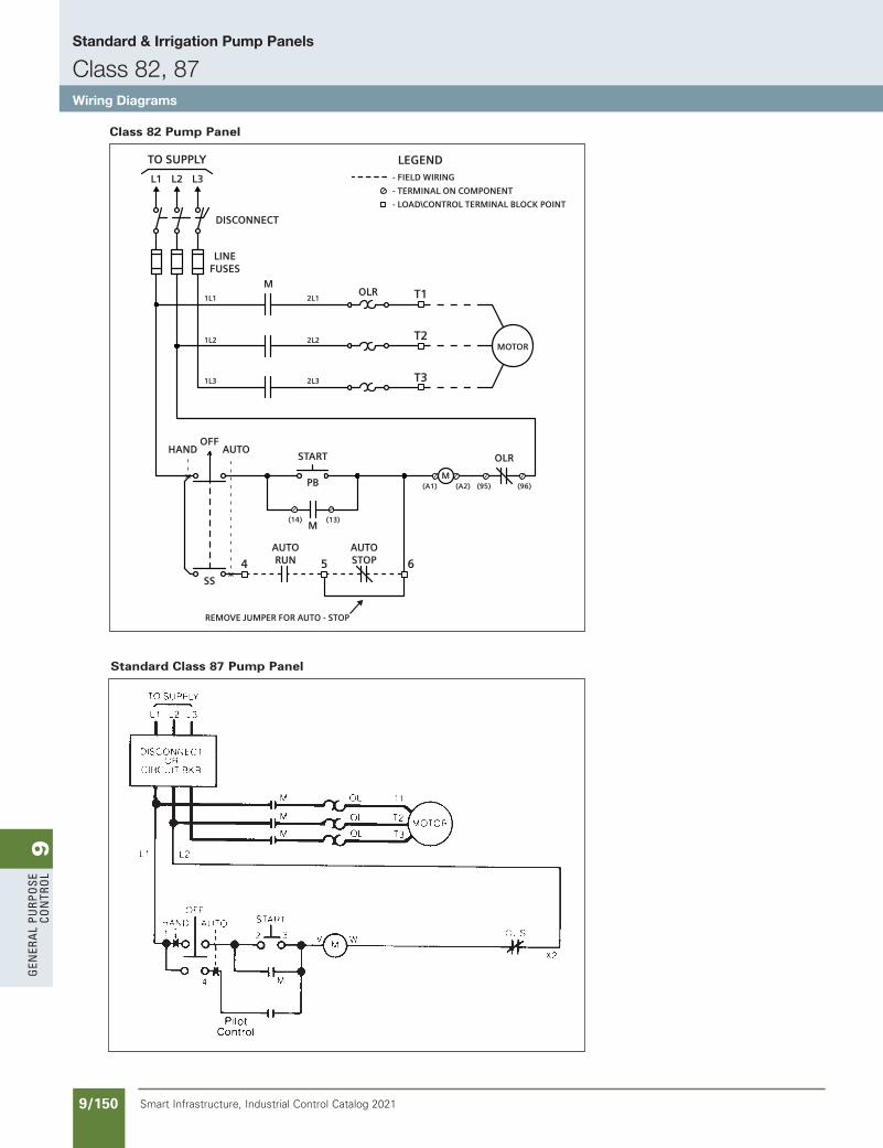
9G
ener
al
PurP
ose
Co
ntr
ol
9/150 Smart Infrastructure, Industrial Control Catalog 2021
Standard & Irrigation Pump Panels
Class 82, 87Wiring Diagrams
Standard Class 87 Pump Panel
T1OLRM
LINEFUSES
DISCONNECT
MOTOR
L1
1L1
1L2
1L3
2L1
2L2
2L3
L2
TO SUPPLY LEGEND
L3
T2
T3
- FIELD WIRING
- TERMINAL ON COMPONENT
- LOAD\CONTROL TERMINAL BLOCK POINT
M(13)(14)
REMOVE JUMPER FOR AUTO - STOP
4 5 6
OLR
M
OFFSTART
AUTORUN
AUTOSTOP
HAND
SS
PB
AUTO
(A2) )69()1A( (95)
Class 82 Pump Panel
SS copied this page from SF to IC on 05/24/20
updated in SPEEDFAXRevised on 01/17/17
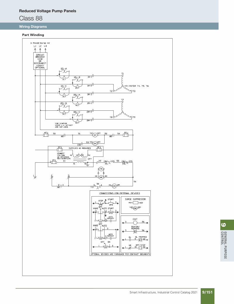
9G
enera
l PurPo
se Co
ntro
l
9/151Smart Infrastructure, Industrial Control Catalog 2021
Reduced Voltage Pump Panels
Class 88Wiring Diagrams
Part Winding
EMT
SS copied this page from SF to IC on 05/24/20
NEED TO UPDATE IN SPEEDFAX
Revised on 12/31/21
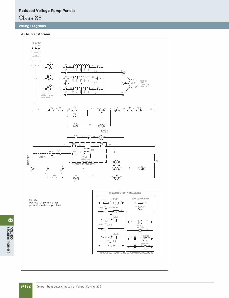
9G
ener
al
PurP
ose
Co
ntr
ol
9/152 Smart Infrastructure, Industrial Control Catalog 2021
Reduced Voltage Pump Panels
Class 88Wiring Diagrams
Auto Transformer
OL
2CT
OL
1CT
OL
3CT
CR2
ETM
1LT
4LT
OL
5LT
MR
OL(95) (96)
4FU
MR
1FU
2FU
1S
H1 H4
CPT
X1
TR
3FU
73MR 1S 74
77
OR
DISCONNECT
R
* INTLKMECH
5FU
1S
2S
2S
R MR71 75 76 72
7978
1 3
X2
MR
1
4
L1 L2
2
CIRCUIT BREAKER
2L3
2L2
2L1
0%50%
65%
80%
100%
R
R
R
2S
2S
1L3
1L2
3L3
3L2
L2L1 L3 2S1L1 3L1
T1
1S
1S
T3
T2 MOTOR*
1S
100%
80%
65%
50%
0%
100%
80%
65%
50%
0%
TR
TAS 12
2 3
X2
3
L1 L2
OPTIONAL
(A1) (A2)
(A1) (A2)
(A1) (A2)
(A1) (A2)
CR1
CR1
CR1
NOTC
6 (A2)(A1)
TO SUPPLY
L1LMB
SEKSESSAW
LMB
SEKSESSAW
LMB
SEKSESSAW
L2 L3
SURGE SUPPRESSOR
CONNECTIONS FOR OPTIONAL DEVICES
OPTIONAL DEVICES ARE FURNISHED PER CONTRACT DOCUMENTS
*
*
*
*
*
STOPSTART
HANDOFF
AUTO
AUTOOFF
HAND
OFF ON
1 2 3
1PB 2PB
1 2 3
5
START
2PB
1SS
AUTOCONTACT
1
1
15
AUTOCONTACT
1SS
3
1 31SS
(A1) (A2)
(A1) (A2)
3 4
3 4
1 X2
RUN/ON/
OL TRIPPED9
RUNNING
JUM
PE
R
NOTE ECONNECTVOLTAGEAS SPECIFIEDPER NAMEPLATE
FOR MOTORHP SEECONTROLLERNAMEPLATE
1OFF/STOP
10 X2
FOR STARTERSIZES 1-4, 1CT-3CTARE NOT USED.
SUPPLIED AS REQUIRED
LMB
SEKSESSAW
LMB
SEKSESSAW
Note E:Remove jumper if thermal protection switch is provided.
SS copied this page from SF to IC on 05/24/20
NEED TO UPDATE IN SPEEDFAX
Revised on 12/31/21
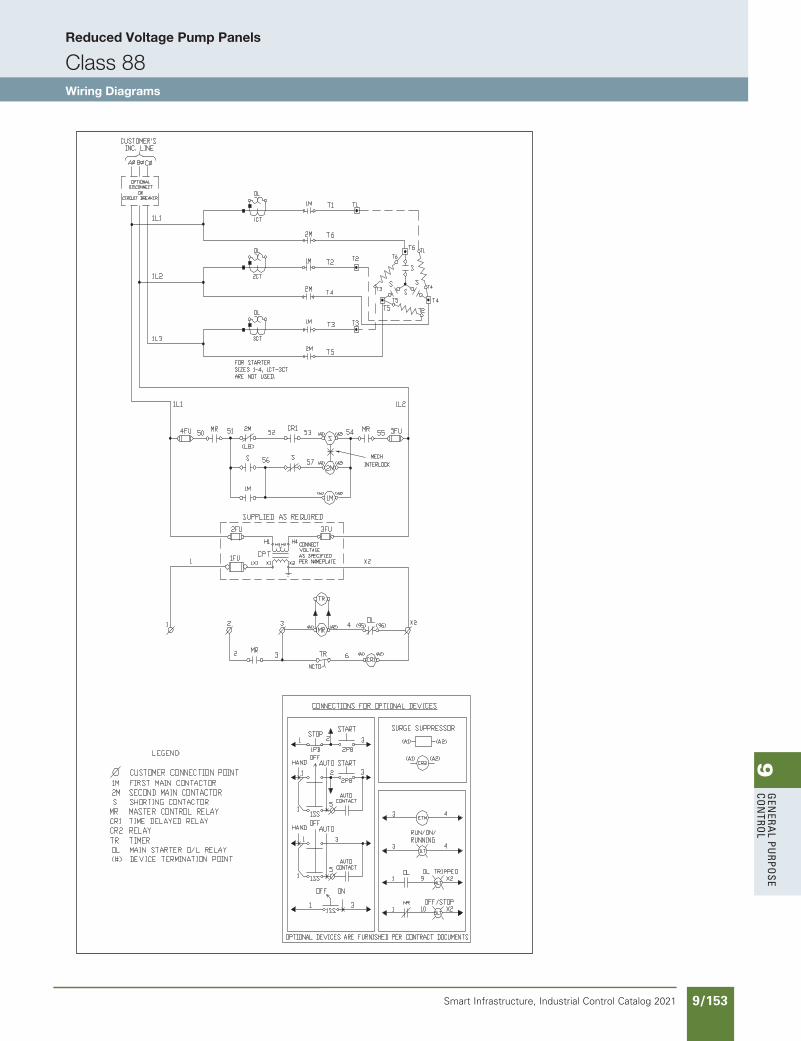
9G
enera
l PurPo
se Co
ntro
l
9/153Smart Infrastructure, Industrial Control Catalog 2021
Reduced Voltage Pump Panels
Class 88Wiring Diagrams
SS copied this page from SF to IC on 05/24/20
NEED TO UPDATE IN SPEEDFAX
Revised on 12/31/21
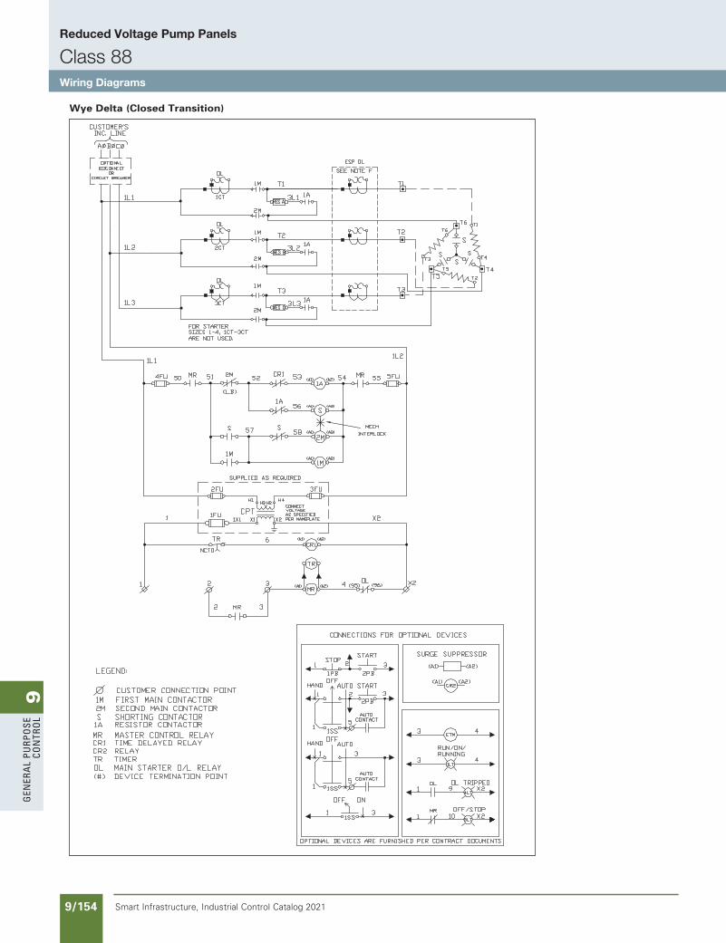
9G
ener
al
PurP
ose
Co
ntr
ol
9/154 Smart Infrastructure, Industrial Control Catalog 2021
Reduced Voltage Pump Panels
Class 88Wiring Diagrams
Wye Delta (Closed Transition)
SS copied this page from SF to IC on 05/24/20
NEED TO UPDATE IN SPEEDFAX
Revised on 12/31/21
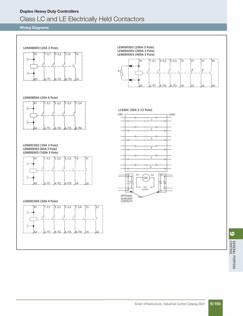
9G
enera
l PurPo
se Co
ntro
l
9/155Smart Infrastructure, Industrial Control Catalog 2021
Duplex Heavy Duty Controllers
Class LC and LE Electrically Held ContactorsWiring Diagrams
LEN00B003 (20A 3 Pole)
LEN00B004 (20A 4 Pole)
LEN00F003 (200A 3 Pole)LEN00G003 (300A 3 Pole)LEN00H003 (400A 3 Pole)/L1 /L2 L3
/T1 /T2 /T3
A1 1 3 5 13
A2 2 4 6 14
/L1 /L2 /L3
/T1 /T2 /T3
/L4
/T4
1 3 5
2 4 6
A1 7
A2 8
/L1 /L2 /L3
/T1 /T2 /T3
1 3 5
2 4 6
A1 13 21 31 43
A2 14 22 32 44
U
LEN00C003 (30A 3 Pole)LEN00D003 (60A 3 Pole)LEN00E003 (100A 3 Pole)
/L1 /L2 /L3
/T1 /T2 /T3
1 3 5
2 4 6
12311A
A2 14 22
LEN00C004 (30A 4 Pole)
/L1 /L2 /L3
/T1 /T2 /T3
/L4
/T4
1 3 5
2 4 6
A1 13 21
A2 14 22
7
8
LCE00C (30A 2-12 Pole)
COIL
COIL VOLTAGE
CONTACTSAUXILIARYOPTIONAL
A1
6
A2
LINE
3
4
5
1
2
LOAD
SS copied this page from SF to IC on 05/24/20
updated in SPEEDFAXRevised on 03/31/20
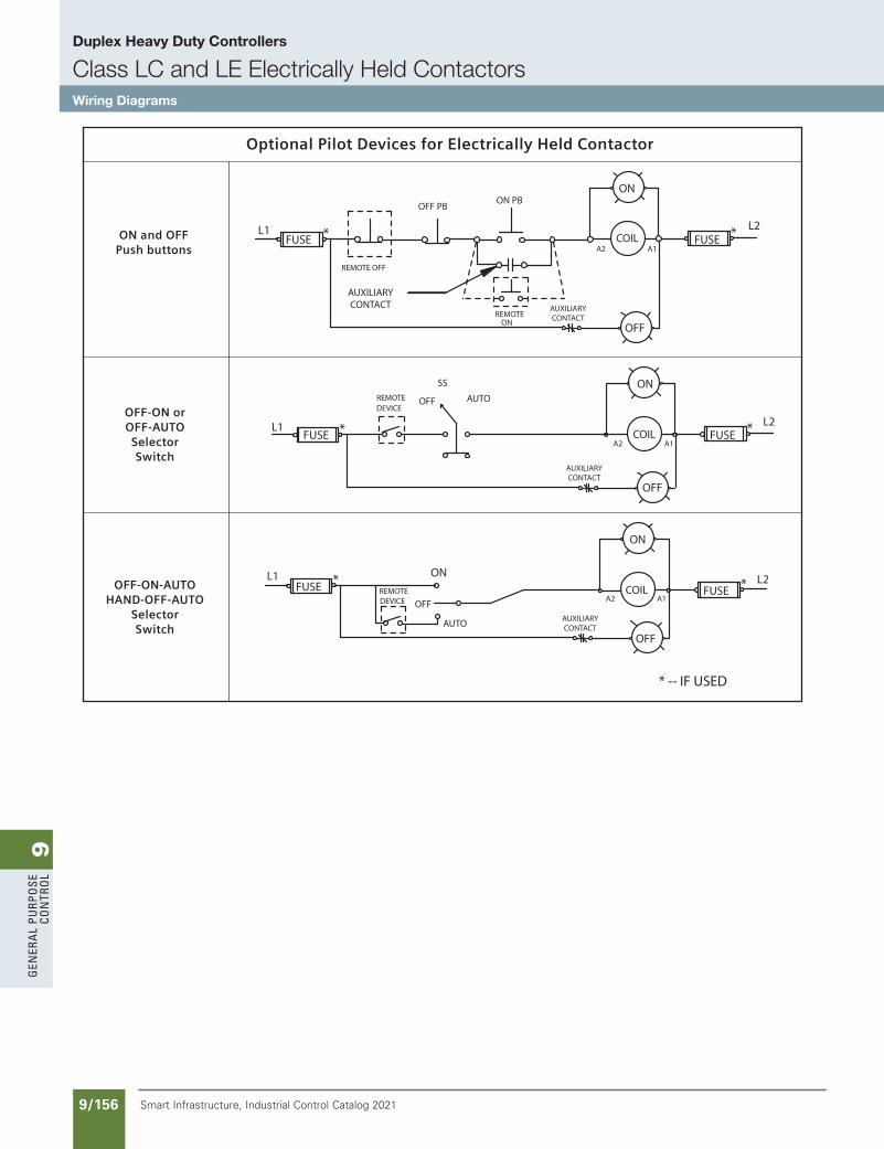
9G
ener
al
PurP
ose
Co
ntr
ol
9/156 Smart Infrastructure, Industrial Control Catalog 2021
Duplex Heavy Duty Controllers
Class LC and LE Electrically Held ContactorsWiring Diagrams
ON PB
ONREMOTE
AUTO
REMOTE*FUSE
L1
OFF
ON
DEVICE
DEVICEREMOTE
*L1FUSE
AUTOOFF
SS
CONTACTAUXILIARY
REMOTE OFF
FUSEL1 *
OFF PB
* -- IF USED
CONTACT
OFF
ON
COILA2
AUXILIARY
*A1
FUSEL2
*A2
AUXILIARYCONTACT
FUSECOIL
ON
A1
OFF
OFF
A2
AUXILIARYCONTACT
A1
L2
L2COIL
ON
*FUSE
Optional Pilot Devices for Electrically Held Contactor
ON and OFFPush buttons
OFF-ON orOFF-AUTOSelectorSwitch
OFF-ON-AUTOHAND-OFF-AUTO
SelectorSwitch
SS copied this page from SF to IC on 05/24/20
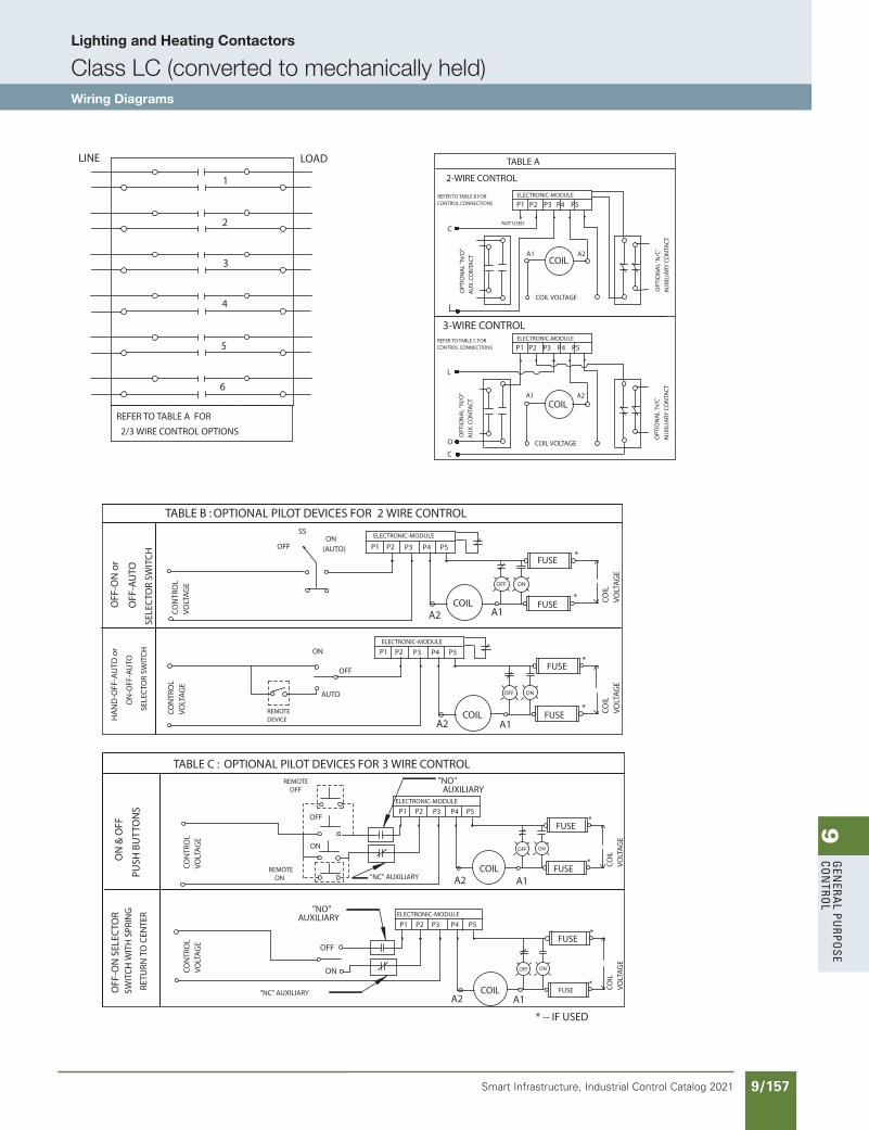
9G
enera
l PurPo
se Co
ntro
l
9/157Smart Infrastructure, Industrial Control Catalog 2021
Lighting and Heating Contactors
Class LC (converted to mechanically held)Wiring Diagrams
TABLE C : OPTIONAL PILOT DEVICES FOR 3 WIRE CONTROL
TABLE B : OPTIONAL PILOT DEVICES FOR 2 WIRE CONTROL
P1 P2 P3 P4 P5
TABLE A
2/3 WIRE CONTROL OPTIONS
3-WIRE CONTROL
2-WIRE CONTROL
P1 P2 P3 P4 P5
C
L
C
REFER TO TABLE A FOR
LINE
6
5
4
3
2
1
LOAD
P1 P2 P3 P4 P5
ELECTRONIC-MODULE
*
*
*
FUSE
ELECTRONIC-MODULE
*
*
*
*
*P1 P2 P3 P4 P5
P1 P2 P3 P4 P5
OFF ON
P1 P2 P3 P4 P5
OFF ON
OFF ON
REFER TO TABLE B FORCONTROL CONNECTIONS
ELECTRONIC-MODULE
COIL
COIL VOLTAGE
A1 A2
NOT USED
OPT
ION
AL
"N/O
"
AU
X. C
ON
TAC
T
OPT
ION
AL
'N/C
'
AU
XIL
IARY
CO
NTA
CT
ELECTRONIC-MODULEREFER TO TABLE C FORCONTROL CONNECTIONS
COILA1 A2
COIL VOLTAGE
OPT
ION
AL
"N/O
"
AU
X. C
ON
TAC
T
OPT
ION
AL
'N/C
'
AU
XIL
IARY
CO
NTA
CT
O
HA
ND
-OFF
-AU
TO o
r
ON
-OFF
-AU
TO
SELE
CTO
R SW
ITC
H
OFF
-ON
or
OFF
-AU
TO
SELE
CTO
R SW
ITC
H
CO
NTR
OL
VO
LTA
GE
CO
NTR
OL
VO
LTA
GE
CO
ILV
OLT
AG
EC
OIL
VO
LTA
GE
ELECTRONIC-MODULE
ELECTRONIC-MODULE
COIL
COIL
COIL
REMOTEDEVICE
ON
OFF
AUTO
A1A2
ONOFF
SS
(AUTO)
FUSE
FUSE
FUSE
FUSE
FUSE
FUSE
FUSE
A2 A1
CO
NTR
OL
VO
LTA
GE
REMOTEON
REMOTEOFF
A2 A1
CO
ILV
OLT
AG
E
ON
& O
FF
PUSH
BU
TTO
NS
OFF
ON
"NO"AUXILIARY
"NC" AUXILIARY
CO
NTR
OL
VO
LTA
GE
"NO"AUXILIARY
OFF
ON
"NC" AUXILIARYA2 A1
CO
ILV
OLT
AG
E
COIL
* -- IF USED
OFF ON
OFF
-ON
SEL
ECTO
RSW
ITC
H W
ITH
SPR
ING
RETU
RN T
O C
ENTE
R
SS copied this page from SF to IC on 05/24/20
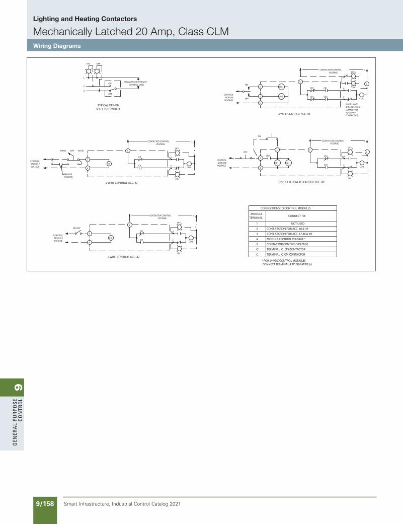
9G
ener
al
PurP
ose
Co
ntr
ol
9/158 Smart Infrastructure, Industrial Control Catalog 2021
Lighting and Heating Contactors
Mechanically Latched 20 Amp, Class CLMWiring Diagrams
2 WIRE CONTROL ACC. 47 ON-OFF (FORM 3) CONTROL ACC. 49
CR2
CR1
3 WIRE CONTROL ACC. 48
2 WIRE CONTROL ACC. 47
SELECTOR SWITCHTYPICAL OFF-ON
OFF
ON
MODULEVOLTAGE
CONTROL
CR2
OFF
4
2
CR1 CR2
3 5
CONTROL
VOLTAGEMODULE
ON
OFF
ON
4
3
2
CR2
CR1
5
ON-OFF
MODULEVOLTAGE
CONTROL3
4
CR
CONTROLREMOTE
OFF
CONTROL
VOLTAGEMODULE
HAND
3
4
CR
AUTO
0
C
ON
L
OFF
L
ON
VOLTAGECONTACTOR CONTROL
CR1
CR1
C
0
OFF
COIL
L
L
VOLTAGE
CONTACT KIT.AUXILIARYCLM4097291REQUIRE (1) EA.PILOT LIGHTS
CR2
CR1
C
0 ON
COIL
L
VOLTAGE
CONTACTOR CONTROLOFF
5
CR
CR
L
ON
C
0
OFF
COIL
L
CONTACTOR CONTROLVOLTAGE
CONTACTOR CONTROL
CR
5
CR
ON
CCOIL
0
OFF
L
L
COMMON OR SEPARATECONTROL LINES
CONNECT TERMINAL 4 TO NEGATIVE (-)
CONT. STATION FOR ACC. 47,48 & 49
CONT. STATION FOR ACC. 48 & 49
* FOR 24 VDC CONTROL MODULES
TERMINAL O ON CONTACTOR
TERMINAL C ON CONTACTOR
CONTACTOR CONTROL VOLTAGE
C
O
5
" "
" "
MODULE CONTROL VOLTAGE *
CONNECTIONS TO CONTROL MODULES
MODULETERMINAL
3
4
2
1
CONNECT TO:
NOT USED
SS copied this page from SF to IC on 05/24/20
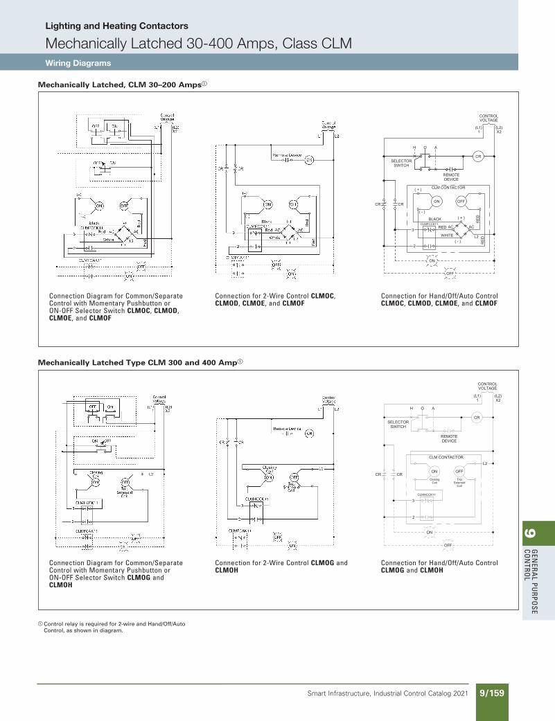
9G
enera
l PurPo
se Co
ntro
l
9/159Smart Infrastructure, Industrial Control Catalog 2021
Lighting and Heating Contactors
Mechanically Latched 30-400 Amps, Class CLMWiring Diagrams
Control relay is required for 2-wire and Hand/Off/Auto Control, as shown in diagram.
Mechanically Latched Type CLM 300 and 400 Amp
Mechanically Latched, CLM 30–200 Amps
Connection Diagram for Common/Separate Control with Momentary Pushbutton or ON-OFF Selector Switch CLMOC, CLMOD, CLMOE, and CLMOF
Connection for 2-Wire Control CLMOC, CLMOD, CLMOE, and CLMOF
Connection for Hand/Off/Auto Control CLMOC, CLMOD, CLMOE, and CLMOF
Connection Diagram for Common/Separate Control with Momentary Pushbutton or ON-OFF Selector Switch CLMOG and CLMOH
Connection for 2-Wire Control CLMOG and CLMOH
Connection for Hand/Off/Auto Control CLMOG and CLMOH
VOLTAGECONTROL
ON OFF
( + )
( - )
BLACK ( + )
( - )
ACAC
L2
RED
WHITE
CLMFCCK11
3
2
RED
ON
OFF
RED
CR
REMOTE
CR CR
(L1)1
(L2)X2
H AO
DEVICE
SELECTORSWITCH
CLM CONTACTOR
VOLTAGECONTROL
ON OFF
CLMHCCK11
3
2
ON
OFF
CR
REMOTE
CR CR
(L1)1
(L2)X2
H AO
DEVICE
SELECTORSWITCH
CLM CONTACTOR
CoilClosing
SolenoidTrip
Coil
L2
SS copied this page from SF to IC on 05/24/20
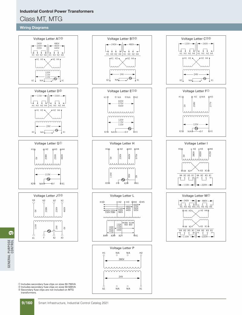
9G
ener
al
PurP
ose
Co
ntr
ol
9/160 Smart Infrastructure, Industrial Control Catalog 2021
Industrial Control Power Transformers
Class MT, MTGWiring Diagrams
a Includes secondary fuse clips on sizes 50-750VAb Includes secondary fuse clips on sizes 50-500VAc Secondary fuse clips are not included on MTG
transformers.
Voltage Letter Aac
Voltage Letter Db
Voltage Letter Ga
Voltage Letter Jbc
Voltage Letter Bbc
Voltage Letter Eac
Voltage Letter H
Voltage Letter L
Voltage Letter P
Voltage Letter Cbc
Voltage Letter Fa
Voltage Letter I
Voltage Letter Ma
240V230V220V
120V115V110V
480V460V440V
H1 H3
H1 H3
X2 X1FN/A
H2 H4
H2 H4
H1 H3 H2 H4
600V575V550V
120V115V110V
240V
24V
480V
H1 H3
H1 H3
X2 X1FN/A
H2 H4
H2 H4
H1 H3 H2 H4
120V 240V
24V
H1 H3
H1 H3
X2 X1FN/A
X2 X1FN/A
N/A N/A H2H1
H2 H4
H2 H4
H1 H3 H2 H4
115V 230V
24V
H1 H3
H1 H3
X2 X1FN/A
H2 H4
H2 H4
H1 H3 H2 H4
0V
20
8V
27
7V
120V
X2 X1FN/A
H2 N/A H3H1
0V
20
8V
46
0V
115V
X2 X1FN/A
H2 H3 H4H1
23
0V
0V 38
0V
41
5V
H2 H3 H4H1
40
0V
0V
11
5V
95
V
0V
11
5V
24
V
0V
23
0V
57
5V
X3 X1X2F
H2
H2
H3
H3
H4
H4
H1
H1
X2FX1 X3
46
0V
0V
20
8V
46
0V
23
0V
X4 X2 X3 X1
X4 X2 X3 X1
H4 H3 H2 H4
110V 220V
X4 X2
X4
H1 H2 H3 H4 H5
X3 X2 X1
H1 H3 H2 H4 H1 H3 H2 H4
X3 X1 X4 X2 X3 X1
240V 480V
110V 220V
X4 X2 X3 X1 X4 X2 X3 X1
130V125V120V110V
120V115V110V100V
600V575V550V500V
480V460V440V
216V200V380V
99V 91V95V 85V
240V 220V230V 208V
24V
380V
X2 N/A N/A X1
H1 N/A N/A H2
240V230V220V
120V115V110V
480V460V440V
H1 H3
H1 H3
X2 X1FN/A
H2 H4
H2 H4
H1 H3 H2 H4
600V575V550V
120V115V110V
240V
24V
480V
H1 H3
H1 H3
X2 X1FN/A
H2 H4
H2 H4
H1 H3 H2 H4
120V 240V
24V
H1 H3
H1 H3
X2 X1FN/A
X2 X1FN/A
N/A N/A H2H1
H2 H4
H2 H4
H1 H3 H2 H4
115V 230V
24V
H1 H3
H1 H3
X2 X1FN/A
H2 H4
H2 H4
H1 H3 H2 H4
0V
20
8V
27
7V
120V
X2 X1FN/A
H2 N/A H3H1
0V
20
8V
46
0V
115V
X2 X1FN/A
H2 H3 H4H1
23
0V
0V 38
0V
41
5V
H2 H3 H4H1
40
0V
0V
11
5V
95
V
0V
11
5V
24
V
0V
23
0V
57
5V
X3 X1X2F
H2
H2
H3
H3
H4
H4
H1
H1
X2FX1 X3
46
0V
0V
20
8V
46
0V
23
0V
X4 X2 X3 X1
X4 X2 X3 X1
H4 H3 H2 H4
110V 220V
X4 X2
X4
H1 H2 H3 H4 H5
X3 X2 X1
H1 H3 H2 H4 H1 H3 H2 H4
X3 X1 X4 X2 X3 X1
240V 480V
110V 220V
X4 X2 X3 X1 X4 X2 X3 X1
130V125V120V110V
120V115V110V100V
600V575V550V500V
480V460V440V
216V200V380V
99V 91V95V 85V
240V 220V230V 208V
SS copied this page from SF to IC on 05/24/20