FUH1010 IP65 NEMA 4X Precision Volume
266
Ultrasonic flowmeters SITRANS FUH1010 IP65 NEMA 4X & IP66 NEMA 7 Precision Volume 7ME360x-3, x=0,3 Operating Instructions - January 2013 SITRANS F Answers for industry.
-
Upload
khangminh22 -
Category
Documents
-
view
0 -
download
0
Transcript of FUH1010 IP65 NEMA 4X Precision Volume

Ultrasonic flowmetersSITRANS FUH1010 IP65 NEMA 4X & IP66 NEMA 7 Precision Volume 7ME360x-3, x=0,3
Operating Instructions - January 2013
SITRANS FAnswers for industry.


___________________
FUH1010 IP65 NEMA 4X
___________________
___________________
___________________
___________________
___________________
___________________
___________________
___________________
___________________
___________________
___________________
___________________
1Introduction
2Safety notes
3Description
SITRANS F
4Installing/mounting
Ultrasonic Flowmeters
5FUH1010 IP65 NEMA 4X and IP66 NEMA 7 Precision Volume
Connecting
6 Commissioning Operating Instructions
7Functions
Alarm, error and system messages
8
Service and maintenance 9
10Troubleshooting
11Technical Data
AAppendix A
BAppendix B
01/2013 A5E32122003-AA

Siemens AG Industry Sector Postfach 48 48 90026 NÜRNBERG GERMANY
Order number: A5E32122003 Ⓟ 06/2013 Technical data subject to change
Copyright © Siemens AG 2013. All rights reserved
Legal information Warning notice system
This manual contains notices you have to observe in order to ensure your personal safety, as well as to prevent damage to property. The notices referring to your personal safety are highlighted in the manual by a safety alert symbol, notices referring only to property damage have no safety alert symbol. These notices shown below are graded according to the degree of danger.
DANGER indicates that death or severe personal injury will result if proper precautions are not taken.
WARNING indicates that death or severe personal injury may result if proper precautions are not taken.
CAUTION indicates that minor personal injury can result if proper precautions are not taken.
NOTICE indicates that property damage can result if proper precautions are not taken.
If more than one degree of danger is present, the warning notice representing the highest degree of danger will be used. A notice warning of injury to persons with a safety alert symbol may also include a warning relating to property damage.
Qualified Personnel The product/system described in this documentation may be operated only by personnel qualified for the specific task in accordance with the relevant documentation, in particular its warning notices and safety instructions. Qualified personnel are those who, based on their training and experience, are capable of identifying risks and avoiding potential hazards when working with these products/systems.
Proper use of Siemens products Note the following:
WARNING Siemens products may only be used for the applications described in the catalog and in the relevant technical documentation. If products and components from other manufacturers are used, these must be recommended or approved by Siemens. Proper transport, storage, installation, assembly, commissioning, operation and maintenance are required to ensure that the products operate safely and without any problems. The permissible ambient conditions must be complied with. The information in the relevant documentation must be observed.
Trademarks All names identified by ® are registered trademarks of Siemens AG. The remaining trademarks in this publication may be trademarks whose use by third parties for their own purposes could violate the rights of the owner.
Disclaimer of Liability We have reviewed the contents of this publication to ensure consistency with the hardware and software described. Since variance cannot be precluded entirely, we cannot guarantee full consistency. However, the information in this publication is reviewed regularly and any necessary corrections are included in subsequent editions.

Table of contents
1 Introduction................................................................................................................................................ 9
1.1 Items supplied................................................................................................................................9
1.2 History ............................................................................................................................................9
1.3 Further Information ......................................................................................................................10
2 Safety notes............................................................................................................................................. 11
2.1 Warning Symbols.........................................................................................................................11
2.2 Laws and directives .....................................................................................................................12
2.3 Lithium batteries...........................................................................................................................13
2.4 Installation in hazardous area......................................................................................................13
2.5 Safety Notes.................................................................................................................................16
2.6 Certificates ...................................................................................................................................20
3 Description............................................................................................................................................... 21
3.1 FUH1010 features........................................................................................................................21
3.2 NEMA 4X & NEMA 7 Transmitters ..............................................................................................21
3.3 Applications..................................................................................................................................23
3.4 Theory of Operation .....................................................................................................................24
4 Installing/mounting................................................................................................................................... 31
4.1 Installation safety precautions......................................................................................................31
4.2 Determining a location .................................................................................................................31
4.3 Application Guidelines .................................................................................................................32
4.4 Mounting the Transmitter .............................................................................................................32
5 Connecting .............................................................................................................................................. 35
5.1 Safety notes for connecting .........................................................................................................35
5.2 Transmitter Wiring........................................................................................................................37 5.2.1 Connecting Power........................................................................................................................37 5.2.2 Wiring Temperature Sensor to Transmitter .................................................................................39
5.3 Sensor Wiring...............................................................................................................................43 5.3.1 Wiring the Sensors.......................................................................................................................43
5.4 Navigating the Menu ....................................................................................................................45
5.5 Programming the Transmitter ......................................................................................................46
5.6 Sensor Installation .......................................................................................................................50 5.6.1 Preliminary Installation Procedures .............................................................................................50 5.6.2 Sensor Identification and Selection .............................................................................................52
FUH1010 IP65 NEMA 4X Precision Volume Operating Instructions, 01/2013, A5E32122003-AA 3

Table of contents
FUH1010 IP65 NEMA 4X Precision Volume 4 Operating Instructions, 01/2013, A5E32122003-AA
5.6.3 Reflect Mount .............................................................................................................................. 56 5.6.4 Direct Mount................................................................................................................................ 58 5.6.5 1012T Mounting Tracks .............................................................................................................. 63
5.7 Mounting Temperature Sensors ................................................................................................. 71
6 Commissioning ........................................................................................................................................ 73
6.1 General requirements ................................................................................................................. 73
6.2 Commissioning............................................................................................................................ 73
6.3 Empty Pipe Set ........................................................................................................................... 75
6.4 Installation Menus ....................................................................................................................... 78
7 Functions ................................................................................................................................................. 83
7.1 Setting Liquid Parameters........................................................................................................... 83
7.2 Selecting Flow Units.................................................................................................................... 89
7.3 Span Data ................................................................................................................................... 94
7.4 Analog Out Setup........................................................................................................................ 99
7.5 Analog Input Setup.................................................................................................................... 101
7.6 Expanded I/O Option................................................................................................................. 104
7.7 Logger Control .......................................................................................................................... 108
7.8 Setting Thermal Coefficient and Modulus of Elasticity.............................................................. 111
7.9 Operation Adjust Menu Settings ............................................................................................... 113
7.10 Setting Relays ........................................................................................................................... 115
7.11 Memory Control......................................................................................................................... 118
7.12 Analog Output Trim ................................................................................................................... 119
7.13 Resistive Temperature Device (RTD) Calibration..................................................................... 122
7.14 SONILOCATOR Operation ....................................................................................................... 125
8 Alarm, error and system messages ....................................................................................................... 129
8.1 Alarm Codes ............................................................................................................................. 129
8.2 Alarms ....................................................................................................................................... 130
9 Service and maintenance ...................................................................................................................... 133
9.1 Maintenance.............................................................................................................................. 133
9.2 Technical support...................................................................................................................... 133
9.3 Transportation and storage....................................................................................................... 134
9.4 Repair........................................................................................................................................ 135 9.4.1 Unit repair.................................................................................................................................. 135
9.5 Return and disposal .................................................................................................................. 136 9.5.1 Return procedures (incl lithium batteries) ................................................................................. 136 9.5.2 Battery disposal......................................................................................................................... 137 9.5.3 Disposal..................................................................................................................................... 138

Table of contents
FUH1010 IP65 NEMA 4X Precision Volume Operating Instructions, 01/2013, A5E32122003-AA 5
10 Troubleshooting..................................................................................................................................... 139
10.1 Troubleshooting .........................................................................................................................139
10.2 F4 Reset Procedure...................................................................................................................141
10.3 Test Facilities Graph Screen......................................................................................................142
10.4 Site Setup Data..........................................................................................................................152
10.5 Force Transmit ...........................................................................................................................157
11 Technical Data....................................................................................................................................... 161
A Appendix A ............................................................................................................................................ 163
A.1 Ordering .....................................................................................................................................163
A.2 I/O Connections and Wiring .......................................................................................................163
A.3 RS-232 Connection....................................................................................................................177
A.4 Flowrate Calibration and Calibration Tables..............................................................................186
B Appendix B ............................................................................................................................................ 191
B.1 Installation/Outline Drawings .....................................................................................................191
Glossary ................................................................................................................................................ 193
Index...................................................................................................................................................... 199
Tables
Table 5- 1 Keypad Function Chart ................................................................................................................46 Table 5- 2 Temperature Sensors ..................................................................................................................71 Table 7- 1 Common Liquid Classes ..............................................................................................................86 Table 7- 2 Liquid Table Data.........................................................................................................................86 Table 7- 3 Totalizer Modes ...........................................................................................................................90 Table 7- 4 Totalizer Controls (the "n" in <Fn> = channel number)* ..............................................................93 Table 7- 5 Input/Output Wiring (TB2) - 7ME39400AL03 Expanded I/O Module...........................................96 Table 7- 6 Open Collector User Resistor Recommendations .......................................................................97 Table 7- 7 Analog Outputs ............................................................................................................................99 Table 7- 8 Analog Out Setup Data Categories .............................................................................................99 Table 7- 9 I/O Data Control Menu ...............................................................................................................101 Table 7- 10 Typical 2-Channel Flow Meter Expanded I/O Option Connections ...........................................106 Table 7- 11 Logger Control Menu Option List ...............................................................................................108 Table 7- 12 Relay Option List........................................................................................................................116 Table 7- 13 Memory Control Menu ...............................................................................................................118 Table 7- 14 Analog Out Trim Menu Structure ...............................................................................................119 Table 7- 15 RTD Calibrate Menu Structure...................................................................................................122

Table of contents
FUH1010 IP65 NEMA 4X Precision Volume 6 Operating Instructions, 01/2013, A5E32122003-AA
Table 10- 1 Troubleshooting Tips..................................................................................................................139 Table 10- 2 Description of Graph Screen Text Display Parameters .............................................................150 Table 10- 3 Hot Key Summary ......................................................................................................................151 Table 10- 4 Site Setup Menu Items...............................................................................................................152 Table A- 1 Connection Diagrams and Part Numbers ..................................................................................163 Table A- 2 Input/Output Wiring (TB2) - 7ME39400AL00 and 7ME39400AL01 I/O Module ........................165 Table A- 3 Input/Output Wiring (TB3) - 7ME39400AL00 and 7ME39400AL01 I/O Module ........................166 Table A- 4 Connection Diagrams and Part Numbers ..................................................................................167 Table A- 5 Input/Output Wiring (TB2) - 7ME39400AL03 and 7ME39400AL04 Expanded I/O Module.......169 Table A- 6 Input/Output Wiring (TB3) - 7ME39400AL03 and 7ME39400AL04 Expanded I/O Module.......170 Table A- 7 Input/Output Wiring (TB4) - 7ME39400AL03 and 7ME39400AL04 Expanded I/O Module.......171 Table A- 8 Connection Diagrams and Part Numbers ..................................................................................172 Table A- 9 Input/Output Wiring (TB2) - 7ME39400AL04 Expanded I/O Module.........................................174 Table A- 10 Open Collector User Resistor Recommendations .....................................................................175 Table A- 11 Input/Output Wiring (TB3) - 7ME39400AL04 Expanded I/O Module.........................................175 Table A- 12 Input/Output Wiring (TB4) - 7ME39400AL04 Expanded I/O Module.........................................176
Figures
Figure 3-1 Typical Transmitter Label.............................................................................................................22 Figure 3-2 NEMA 4X Transmitter Case.........................................................................................................22 Figure 3-3 NEMA 7 Transmitter Enclosure with graphic display and keypad. ..............................................23 Figure 4-1 Pipe Mounting and Mounting Locations for Transmitter ..............................................................33 Figure 5-1 Input Power (J10) Wiring..............................................................................................................38 Figure 5-2 Analog Input Module Access........................................................................................................40 Figure 5-3 Single Channel Temperature Sensor Inputs................................................................................41 Figure 5-4 Sensor Cable Connections ..........................................................................................................44 Figure 5-5 Software Version (xx.xx.xx)..........................................................................................................45 Figure 5-6 Keypad .........................................................................................................................................45 Figure 5-7 Pipe Surface Preparation.............................................................................................................51 Figure 5-8 Universal Sensor Label ................................................................................................................53 Figure 5-9 Hi Precision Sensor Label............................................................................................................54 Figure 5-10 Sensor Installation........................................................................................................................57 Figure 5-11 Sensor ..........................................................................................................................................58 Figure 5-12 Mylar Spacing Guide....................................................................................................................59

Table of contents
FUH1010 IP65 NEMA 4X Precision Volume Operating Instructions, 01/2013, A5E32122003-AA 7
Figure 5-13 Wrap Strap Under Pipe and Attach to Adjusting Screw...............................................................60 Figure 5-14 Wrapping the Mylar Spacing Guide around the pipe (End View) ................................................61 Figure 5-15 Finding the Halfway Distance ......................................................................................................62 Figure 5-16 Aligning the Sensors for Direct Mode operation (End View) .......................................................62 Figure 5-17 Reflect Mount with Model 1012TN Mounting Track (Side View) .................................................65 Figure 5-18 Direct Mount 180° opposed with Mounting Tracks ......................................................................67 Figure 5-19 Track Rail Alignment....................................................................................................................69 Figure 5-20 REF and Number Index Pin Locations ........................................................................................70 Figure 5-21 Clamp-on Temperature Sensor ...................................................................................................71 Figure 5-22 Insert Temperature Sensor ..........................................................................................................72 Figure 6-1 EmptyPipeSet_Actual-MTY_Fill ...................................................................................................76 Figure 6-2 Typical Installation Menu Screen.................................................................................................82 Figure 7-1 PGEN Wiring Diagram.................................................................................................................96 Figure 10-1 Test Facilities Graph Screen......................................................................................................143 Figure 10-2 Setting Digital Damping Factor ..................................................................................................146 Figure 10-3 Setting the MinDamp Factor ......................................................................................................147 Figure 10-4 Envelope Threshold Adjustment ................................................................................................149 Figure A-1 7ME39400AL00 and 7ME39400AL01 I/O Module.....................................................................164 Figure A-2 7ME39400AL03 and 7ME39400AL04 Expanded I/O Module ...................................................168 Figure A-3 7ME39400AL04 Expanded I/O Module .....................................................................................173 Figure A-4 1015CPC-N Serial Interface Cable............................................................................................178

Table of contents
FUH1010 IP65 NEMA 4X Precision Volume 8 Operating Instructions, 01/2013, A5E32122003-AA

Introduction 1
These instructions contain all information required to commission and use the device. It is your responsibility to read the instructions carefully prior to installation and commissioning. In order to use the device correctly, first review its principle of operation.
The instructions are aimed at persons mechanically installing the device, connecting it electronically, configuring the parameters and commissioning it, as well as service and maintenance engineers.
1.1 Items supplied ● SITRANS F Transmitter
● SITRANS F literature CD
● For additional items refer to your packing slip.
Inspection 1. Check for mechanical damage due to possible improper handling during shipment. All
claims for damage are to be made promptly to the shipper.
2. Make sure the scope of delivery, and the information on the type plate corresponds to the ordering information.
1.2 History The following table shows the most important changes in the documentation compared to each previous edition.
Edition Remarks 01/2013 First Edition of the Operating Instructions for the SITRANS FUH1010 IP65 NEMA 4X and
IP66 NEMA 7 Precision Volume flow meter.
FUH1010 IP65 NEMA 4X Precision Volume Operating Instructions, 01/2013, A5E32122003-AA 9

Introduction 1.3 Further Information
FUH1010 IP65 NEMA 4X Precision Volume 10 Operating Instructions, 01/2013, A5E32122003-AA
1.3 Further Information
Product information on the Internet The Operating Instructions are available on the CD-ROM shipped with the device, and on the Internet on the Siemens homepage, where further information on the range of SITRANS F flowmeters may also be found:
Product information on the internet (http://www.siemens.com/flow)
Worldwide contact person If you need more information or have particular problems not covered sufficiently by these Operating Instructions, get in touch with your contact person. You can find contact information for your local contact person on the Internet:
Local contact person (http://www.automation.siemens.com/partner)
The contents of this manual shall not become part of or modify any prior or existing agreement, commitment or legal relationship. The sales contract contains all obligations on the part of Siemens as well as the complete and solely applicable warranty conditions. Any statements regarding device versions described in the manual do not create new warranties or modify the existing warranty.
The content reflects the technical status at the time of publishing. Siemens reserves the right to make technical changes in the course of further development.

Safety notes 2
This device left the factory in good working condition. In order to maintain this status and to ensure safe operation of the device, observe these instructions and all the specifications relevant to safety.
Observe the information and symbols on the device. Do not remove any information or symbols from the device. Always keep the information and symbols in a completely legible state.
2.1 Warning Symbols Symbol Explanation
Consult operating instructions
Hot surface
Dangerous electrical voltage
Corrosive materials
Toxic materials
Isolate the device from power using a circuit-breaker
Protect the device from impact otherwise loss of degree of protection
Protective insulation; device in protection class II
FUH1010 IP65 NEMA 4X Precision Volume Operating Instructions, 01/2013, A5E32122003-AA 11

Safety notes 2.2 Laws and directives
FUH1010 IP65 NEMA 4X Precision Volume 12 Operating Instructions, 01/2013, A5E32122003-AA
2.2 Laws and directives
General requirements Installation of the equipment must comply with national regulations. For example, the National Electrical Codes.
Instrument safety standards The device has been tested at the factory, based on the safety requirements. In order to maintain this condition over the expected life of the device the requirements described in these Operating Instructions must be observed.
NOTICE Material compatibility
Siemens can provide assistance with the selection of sensor parts. However, the full responsibility for the selection rests with the customer and Siemens can take no responsibility for any failure due to material incompatibility.
CE marked equipment The CE-mark symbolizes the compliance of the device with the following Directives:
● EMC-Directive 2004/108/EC
● Low voltage Directive 2006/95/EC
● Pressure equipment Directive (PED) 97/23/EC
● ATEX Directive 94/9/EC
Safety notes 2.3 Lithium batteries
FUH1010 IP65 NEMA 4X Precision Volume Operating Instructions, 01/2013, A5E32122003-AA 13
2.3 Lithium batteries Lithium batteries are primary power sources with high energy content designed to represent the highest possible degree of safety.
WARNING Potential hazard
Lithium batteries may present a potential hazard if they are abused electrically or mechanically. Observe the following precautions when handling and using lithium batteries:
– Do not short-circuit, recharge or connect with false polarity. – Do not expose to temperature beyond the specified temperature range or incinerate
the battery. – Do not crush, puncture or open cells or disassemble battery packs. – Do not weld or solder to the battery’s body. – Do not expose contents to water.
2.4 Installation in hazardous area
WARNING Explosion Hazard
Equipment used in hazardous areas must be Ex-approved and marked accordingly.
It is required that the special conditions for safe use provided in the manual and in the Ex certificate are followed!
Hazardous area approvals The device is approved for use in hazardous area and has the following approval:
● FM and CSA certified
- Class I, Division 1, Groups ABCD
- Class II, Division 1, Groups EFG
● ATEX

Safety notes 2.4 Installation in hazardous area
FUH1010 IP65 NEMA 4X Precision Volume 14 Operating Instructions, 01/2013, A5E32122003-AA
WARNING
Explosion Hazard
Devices without the correct hazardous area approval create dangerous environments.
Make sure the hazardous area approval is suitable for the environment in which the device will be installed.
Intrinsically safe data
WARNING Explosion Hazard
User must install unit with Siemens drawings. With intrinsically safe circuits, use only certified meters appropriate for the transmitter.
If a non-conforming supply unit is used, the "fail-safe" type of protection will no longer be effective and the approval certification will be invalid.
Hazardous area safety requirements It is required that:
● Electrical connections are in accordance with EN60079-14 (Installing Electrical Systems in Explosion Hazardous Areas).
● The protective cover over the power supply is properly installed. For intrinsically safe circuits the connection area can be opened.
● Appropriate cable connectors are used for the output circuits:
– Intrinsically safe: blue
– Non-intrinsically safe: black
● Sensor and transmitter are connected to the potential equalization. For intrinsically safe output circuits potential equalization must be maintained along the entire connection path.
● When protective earth (PE) is connected, no potential difference between the protective earth (PE) and the potential equalization (PA) can exist, even during a fault condition.

Safety notes 2.4 Installation in hazardous area
FUH1010 IP65 NEMA 4X Precision Volume Operating Instructions, 01/2013, A5E32122003-AA 15
WARNING
Explosion Hazard
"Flameproof enclosure" type of protection
Only open devices with type of protection "Flameproof enclosure" (e.g. FUT1010 NEMA 7) in hazardous areas when the power to the device is turned off, otherwise there is a risk of explosion.
WARNING
Explosion Hazard
Laying Cables
Cable for use in zone 1 and 2 must satisfy the requirements for having a proof voltage < AC 500 V applied between the conductor/ground, conductor/shield and shield/ground.
Connect the devices that are operated in hazardous areas as per the stipulations applicable in the country of operation, e.g. for Ex "d" and "nA", permanent cables must be laid.
WARNING
Explosion Hazard
Devices with the common approval "Intrinsically safe" and "Flameproof"
The following is applicable for devices with the common approval "Intrinsically safe" and "Flameproof" (Ex ia + Ex d): Before commissioning, make sure that the type of protection that is not suitable is permanently defaced on the nameplate to avoid improper use.
If a non-conforming infeed is used, the "fail-safe" type of protection will no longer be effective.

Safety notes 2.5 Safety Notes
FUH1010 IP65 NEMA 4X Precision Volume 16 Operating Instructions, 01/2013, A5E32122003-AA
2.5 Safety Notes
Safety Information for Hazardous Areas
DANGER
Explosion Hazard
Will Cause Death, Serious Injury or Property Damage.
Restrict use and repair to qualified personnel.
DANGER Explosion Hazard
Death or severe personal injury and/or equipment and property damage will result if proper Hazardous (Classified) Locations installation precautions are not taken.
Restrict use and repair to qualified personnel.
DANGER Explosion Hazard
The use of unauthorized parts in the repair of the equipment, tampering by unqualified personnel, or operation with the cover open in a Hazardous (Classified) Location will result in dangerous conditions which will cause death, serious injury, and/or equipment and property damage.
Restrict use and repair to qualified personnel.
Follow all safety instructions contained or referenced herein.
DANGER Explosion Hazard
Death or severe personal injury and/or equipment and property damage will result due to improper installation or use of this equipment when located in a Hazardous (Classified) Location. Install as directed. Disconnect power source before servicing. Keep cover closed when equipment is operating.

Safety notes 2.5 Safety Notes
FUH1010 IP65 NEMA 4X Precision Volume Operating Instructions, 01/2013, A5E32122003-AA 17
WARNING Qualified personnel
This flowmeter system may only be set up and used in conjunction with this document and the instructions on the electronic media provided. Installation, maintenance and operation of the flowmeter system may only be performed by qualified personnel. Within the context of this Document, qualified persons are defined as persons who have the skills and knowledge related to the construction and operation of the electrical equipment and installations and have received safety training to recognize and avoid the potentially explosive hazards involved. Qualified personnel posses the following qualifications 1. Is trained and authorized to energize, de-energize, clear, ground and tag circuits and
equipment in accordance with established safety practices. 2. Is trained in the proper care and use of protective equipment such as rubber gloves,
hard hat, safety glasses or face shields, flash clothing, etc., in accordance with established safety practices.
3. Is trained in rendering first aid.
Note
This document does not purport to cover all details or variations in equipment, or to provide for every possible contingency to be met in connection with installation, operation or maintenance. Should further information be desired or should particular problems arise, which are not covered sufficiently for the purchaser's purposes, the matter should be referred to the local Siemens sales office (www.automation.siemens.com/partner). The contents of this Document shall not become part of or modify any prior or existing agreement, commitment or relationship. The sales contract contains the entire obligation of Siemens. The warranty contained in the contact between the parties is the sole warranty of Siemens. Any statements contained herein do not create new warranties or modify the existing warranty.
Safety Information for Hazardous Areas
Note Ratings under this heading apply to specific model families.
Check Your Model Number: FUH1010, 7ME3600-0, 7ME3600-3 only.
FM-CSA installation
Read, understand and follow all safety instructions on the electronic media provided. This equipment is rated for use in hazardous (classified) locations as stated below and must be installed according to the 1010-304 installation drawing provided on the media. Failure to install the equipment in the prescribed manner will result in unsafe operation. Follow all local jurisdictional safety codes when operating this equipment. When properly installed the equipment meets the following FM – CSA ratings.

Safety notes 2.5 Safety Notes
FUH1010 IP65 NEMA 4X Precision Volume 18 Operating Instructions, 01/2013, A5E32122003-AA
Transmitter
● Intrinsically safe connections Class I and II, Division 1, Groups A, B, C, D, E, F and G;
● Nonincendive for Class I, Division 2, Groups A, B, C and D;
● Suitable for Class II, Division 2, Groups E, F and G outdoor (Type 4X), Class III (CSA only)
● Temperature code T5 at an ambient of 40°C
Sensors
● Intrinsically safe Class I and II, Division 1, Groups A, B, C, D, E, F and G;
● Nonincendive for Class I, Division 2, Groups A, B, C and D;
● Suitable for Class II, Division 2, Groups E, F and G outdoor (Type 4X), Class III (CSA only)
● Temperature code T6 at an ambient of 40°C
ATEX installation
Read, understand and follow all safety instruction on the electronic media provided. This equipment complies with Directive 94/9/EC and is rated for use in potentially explosive atmospheres. The equipment markings are shown and explained below. Equipment must be installed according to the 1010-389 installation drawing provided on the media. Failure to install the equipment in the prescribed manner will result in unsafe operation. Follow all regional safety laws when operating this equipment. When properly installed the equipment meets the following ATEX ratings as stated in EC-Type Examination Certificate KEMA03ATEX1134
Transmitter Markings and Explanations
● II (1) G [Ex ia] IIC – Transmitter located in the non-hazardous area with intrinsically safe circuits of category Ex ia, which can be connected to Category 1 Sensors
● II 3 (1) G Ex nC [ia] IIC T5 Tamb = 0 to +50°C – Category 3 Transmitter located in Ex
● ght and against liquid,
xplanations
Zone 2 potentially explosive atmosphere area with intrinsically safe circuits of categoryia, which can be connected to Category 1 Sensors in Zone 0
IP65 – Ingress protection against solid bodies, rating of dust-tirating of water jets
Sensor Markings and E
● II I G Ex ia IIC T5 Ga Tamb = +60°C – Category 1 Sensors located in Zone 0 r use in potentially explosive atmosphere with intrinsically safe circuits of category Ex ia fo
potentially explosive atmosphere containing gases

Safety notes 2.5 Safety Notes
FUH1010 IP65 NEMA 4X Precision Volume Operating Instructions, 01/2013, A5E32122003-AA 19
Safety Information for Hazardous Areas
Note Ratings under this heading apply to specific model families.
Check Your Model Number: FUH1010, 7ME3603-0, 7ME3603-3
FM-CSA installation
Read, understand and follow all safety instruction on the electronic media provided. This equipment is rated for use in hazardous (classified) locations as stated below and must be installed according to the 1010-443 installation drawing provided on the media. Failure to install the equipment in the prescribed manner will result in unsafe operation. Follow all local jurisdictional safety codes when operating this equipment. When properly installed the equipment meets the following FM – CSA ratings:
Transmitter
● Explosionproof for Class I, Division1, Groups B, C, D;
● Dust-ignitionproof for Class II, Division 1, Groups E, F and G
● Intrinsically safe connections for Class I and II, Division 1, Groups A, B, C, D, E, F and G;
● Nonincendive for Class I, Division 2, Groups A, B, C and D;
● Suitable for Class II, Division 2, Groups E, F and G outdoor (Type 4X), Class III (CSA only)
Sensors
● Intrinsically safe Class I and II, Division 1, Groups A, B, C, D, E, F and G;
● Nonincendive for Class I, Division 2, Groups A, B, C and D;
● Suitable for Class II, Division 2, Groups E, F and G outdoor (Type 4X), Class III (CSA only)
● Temperature code T6 at an ambient of 40°C
ATEX installation
Read, understand and follow all safety instruction on the electronic media provided. This equipment is rated for use in explosive atmospheres as stated below and must be installed according to the 1010-464 installation drawing provided on the media. Failure to install the equipment in the prescribed manner will result in unsafe operation. Follow all regional safety laws when operating this equipment. When properly installed the equipment meets the following ATEX ratings as stated in EC-Type Examination Certificate KEMA03ATEX1134

Safety notes 2.6 Certificates
FUH1010 IP65 NEMA 4X Precision Volume 20 Operating Instructions, 01/2013, A5E32122003-AA
Transmitter Markings and Explanations
● II (1) G [Ex ia] IIC– Transmitter located in the non-hazardous area with intrinsically safe circuits of category Ex ia, which can be connected to Category 1 Sensors for use in potentially explosive atmosphere containing gases
● II 3 (1) G Ex nC [ia] IIC T5 Tamb = 0 to +50°C – Category 3 Transmitter located in Zo ,
●
ne 2 potentially explosive atmosphere with intrinsically safe circuits of category Ex iawhich can be connected to Category 1 Sensors in Zone 0 potentially explosive atmosphere containing gases
II 2 (1) G Ex d [ia II C Ga] IIB+H2 T5 Gb Tamb = 0 to +50°C) – Category 2 Tlocated in Zone 1 potentially ex
ransmitter plosive atmosphere with intrinsically safe circuits of
category Ex ia, which can be connected to Category 1 Sensors for use in potentially explosive atmosphere containing gases
● IP66 – Ingress protection against solid bodies, rating of dust-tight and against liquid, rating of heavy seas
Sensor Markings and Explanations
● II I G Ex ia IIC T5 Ga Tamb = +60°C – Category 1 Sensors located in Zone 0 potentially explosive atmosphere with intrinsically safe circuits of category Ex ia for use in
containing gases
2.6
potentially explosive atmosphere
Certificates Certificates are posted on the Internet and on the documentation CD-ROM shipped with the device.
See also tes on the Internet (http://www.siemens.com/processinstrumentation/certificatesCertifica )
3Description
3.1 FUH1010 features
Description The Siemens SITRANS FUH1010 IP65 NEMA 4X and IP66 NEMA 7 precision volume flow meters achieve highly accurate flow measurement owing to the WideBeam ultrasonic transit-time technology. The sensors are mounted on the outside of the pipe, preventing contact with the medium. This means no cavities or clogging by high paraffin liquids found in many hydrocarbon applications.
The sensors offer superior performance in terms of mass flow accuracy, density accuracy, and turn-down ratio. The sensor construction makes installation and commissioning of even the largest sizes very straight forward and easy.
Note
This operating Instructions manual applies to the following FUH1010 IP65 (NEMA 4X) operating systems: Version 3.02.00 and later and version 5.03.00 and later.
3.2 NEMA 4X & NEMA 7 Transmitters
SITRANS FUH1010 Transmitters The SITRANS FUH1010 NEMA 4 and NEMA 7 series transmitters are available in Single and Dual Path versions. The transmitters include a graphic display providing flow rate, diagnostics data and keypad interface to access on-screen software setup menus. Safety agency approved SITRANS FUH1010 series transmitters have hazardous area certification as indicated in the label examples below.
FUH1010 IP65 NEMA 4X Precision Volume Operating Instructions, 01/2013, A5E32122003-AA 21

Description 3.2 NEMA 4X & NEMA 7 Transmitters
FUH1010 IP65 NEMA 4X Precision Volume 22 Operating Instructions, 01/2013, A5E32122003-AA
SITRANS FUH1010 NEMA Transmitter Labels The transmitter label is located on the right side panel of the unit. The illustration shows a typical label but labels vary depending upon model and installation location.
Figure 3-1 Typical Transmitter Label
SITRANS FUH1010 Model Numbers The SITRANS FUH1010 NEMA 4X model numbers:
● Single Path - 7ME3600-0
● Dual Path - 7ME3600-3
Figure 3-2 NEMA 4X Transmitter Case
Note
The NEMA 4X Multi-Path transmitter case is slightly larger.

Description 3.3 Applications
FUH1010 IP65 NEMA 4X Precision Volume Operating Instructions, 01/2013, A5E32122003-AA 23
The SITRANS FUH1010 NEMA 7 model numbers:
● Single Path - 7ME3603-0
● Dual Path - 7ME3603-3 (Wall Mount with display window)
WARNING
Electrical Shock Hazard
Access to the Graphic display and keypad setup must be done with cover opened exposing high voltage connections.
Consult local codes for permit needed to setup FUH1010 NEMA 7 units using the graphic display and local keypad to avoid injury.
① Standard Transmitter Enclosure Figure 3-3 NEMA 7 Transmitter Enclosure with graphic display and keypad.
3.3 Applications
Measurement of Liquids SITRANS F flow meters are designed for measurement of a variety of liquids. The transmitters are multi-parameter devices offering accurate measurement of volume flow, viscosity, and temperature.
Typical Applications The typical applications of the flowmeter are:
● Fuel Flow Measurement
● Hydraulic Oil Leak Detection
● Measurement of Additives
● Oil: Furnace control, CNG-dispensers, test separators
● Crude Oil

Description 3.4 Theory of Operation
FUH1010 IP65 NEMA 4X Precision Volume 24 Operating Instructions, 01/2013, A5E32122003-AA
● Finished Hydrocarbon Products
● Fuel Oil
● Bunker Fuel
Typical Industries Serviced ● HVAC (Hotels, Airports, Government)
● Power Generation (Nuclear, Fossil, and Hydro)
● Chemical Processing
● Food and Pharmaceutical
● Aircraft Avionics and Ground Support
● Water and Wastewater
● Aerospace
● Automobile Manufacturing
● Hydrocarbon Industries
3.4 Theory of Operation The liquid flow meter relies on the MultiPulse transit-time. Two WideBeam ultrasonic sensors per measuring path, alternating as transmitter and receiver, are used to interrogate the liquid flowing within the metering section. The resulting time of arrival for each direction of transmit (upstream and downstream) is then measured using a highly accurate and stable digital signal processing method.
Using this detection scheme, the flow meter is capable of resolving the relative transit-time difference (dT) to within ±100 psec. Considering typical liquid flow transit-time differences ranging from 1x10⁴ to 1x10⁶ psec, the flow meter is capable of providing an exceptional turn-down ratio. The flow meter also incorporates a correlation technique which enables the system to detect very high flow velocities with the same high degree of resolution. The ultrasonic sensors are designed with sufficient beam divergence characteristics to insure that the receive sensor will always have sufficient signal to maintain operation under conditions of high beam blowing, a condition that occurs under very high flow velocities where the path of the ultrasonic beam is actually blown past the receivable area of the sensor.
With accurate signal arrival time available, the flow meter can compute the raw flow velocity from the measured upstream and downstream transit times.

Description 3.4 Theory of Operation
FUH1010 IP65 NEMA 4X Precision Volume Operating Instructions, 01/2013, A5E32122003-AA 25
① Velocity of Sound ② Flow Vector ③ Pipe ID ④ WideBeam Sensors
∅= sin1 (VOS / Vphase) Where: VOS = Velocity of sound in liquid
Vphase = Phase velocity of sensor TL = 2 * ID / (VOS * cos ∅) ID = Pipe inside diameter
TL = Transit time in liquid VF = Vphase * DT / (2 * TL) DT = Measured Transit-Time difference
VF = Flow Velocity
Flow Profile Compensation The flow equation shown above is only valid for "plug" flow, where the flow velocity is uniform across the entire cross-section of the pipe. Frictional forces between the fluid and the pipe wall cause the flow velocity to be nearly zero at the pipe wall and peaked toward the center of the pipe (as shown in the diagram below).
The acoustic beam traverses the center of the pipe and therefore must account for the influence that flow profile has on the line integration through a round pipe. The shape of this flow profile (for fully developed flow) is defined by the Reynolds number.

Description 3.4 Theory of Operation
FUH1010 IP65 NEMA 4X Precision Volume 26 Operating Instructions, 01/2013, A5E32122003-AA
① Fluid velocity near the axis of the flow stream tends to be greater.
The Reynolds number is then computed as follows:
where:
viscosity = cS = cP/density Pipe ID = inches VF = inches/sec
cS = kinematic viscosity cP = absolute viscosity
The flow meter then uses this computation of Reynolds number to compensate the raw flow velocity for conditions of laminar or turbulent flow profile as defined by an internal Reynolds compensation table. The flow meter then converts the compensated flow velocity to volumetric flow rate.
Rate = VF * Comp(Rn) * Pipe area

Description 3.4 Theory of Operation
FUH1010 IP65 NEMA 4X Precision Volume Operating Instructions, 01/2013, A5E32122003-AA 27
Viscosity Compensation Wide Beam technology is designed to utilize the resonant frequency of the pipe wall. It does so by broadcasting signals with various frequencies with the aim of finding the frequency that best matches the pipe wall. When found, the signal is transmitted into the flowing media with the wall of the pipe acting as a waveguide. This method allows for a low transmit voltage of approximately +/- 15 volts and produces a focused, coherent signal that covers a large axial area. This Wide Beam measurement method proves valuable especially when measuring liquid hydrocarbon and is also and applicable for a expansive range of pipeline, refinery and terminal purposes such as line balance, interface detection, transmix metering, and liquid loading and unloading. Wide Beam flow meters match the resonance frequency of the pipe by sending out numerous signals with varying frequencies so there is a greater chance that the signal will be able to penetrate a highly viscous fluid. This decreases the likelihood of an attenuated signal and improves the reliability of the flow readings. Since viscosity contributes to flow measurement difficulties by changing from liquid to liquid, it is easily affected by temperature and pressure; it impacts the ideal signal required to penetrate a liquid, and it results in various flow profiles. To compensate for this, the resonant frequency of the pipe wall is used and the ultrasonic signal is transmitted into the flowing media with the wall of the pipe acting as a waveguide. This produces a very strong and coherent signal that works in numerous upstream, midstream and downstream applications. The Wide Beam technology generates a strong and coherent signal that enables measurement over an extensive range of viscosities, Vs and temperatures. By using viscosity compensation and Reynolds number tables assure reliable flow readings.
Flow Meter Types The meter automatically conditions Installation Menu choices to suit the selected meter type. The following paragraphs introduce the available flow meter types that include:
● Single-Path
● 2-Path

Description 3.4 Theory of Operation
FUH1010 IP65 NEMA 4X Precision Volume 28 Operating Instructions, 01/2013, A5E32122003-AA
2-Path 2-Path flow meters use two measurement channels to achieve a single output via a "virtual" third channel. The resultant data is the average of the two channels. Only clamp-on or in-line transit-time operation is allowed. Benefits include highest available precision and enhanced immunity to distorted flow profile conditions.
① ③ Sensor Path 1 Average= (Path 1 + Path 2) / 2 ② Sensor Path 2 ④ Pipe (front view)
WideBeam Transmission As shown in the figure above, an ultrasonic sensor induces an axial sonic beam within the wall of the pipe. These vibrations spread along the pipe wall and then enter the liquid in the form of a WideBeam wave front traveling at an angle to the main pipe axis. The WideBeam "rains" over the receiving sensor. The wide coverage of the receiver is necessary because the angle of the sonic beam is related to the liquid’s sonic propagation velocity by Snell’s Law.
According to this formula, it can be stated that as the liquid sonic propagation velocity changes so will the angle between the sonic beam and the flow stream.
Therefore, a significant liquid sonic velocity shift could deflect a "narrow" beam transmission away from the receiving sensor entirely. The upstream vs. downstream transit-time difference will also be affected by the changing (or refracting) beam angle. This makes it necessary for flow meter systems to continuously compute this angle, since it is subject to varying degrees of refraction. The flow meter derives the angle by knowing the fixed position of the sensors, the dimensions of the pipe and the measured transit-time.
Description 3.4 Theory of Operation
FUH1010 IP65 NEMA 4X Precision Volume Operating Instructions, 01/2013, A5E32122003-AA 29
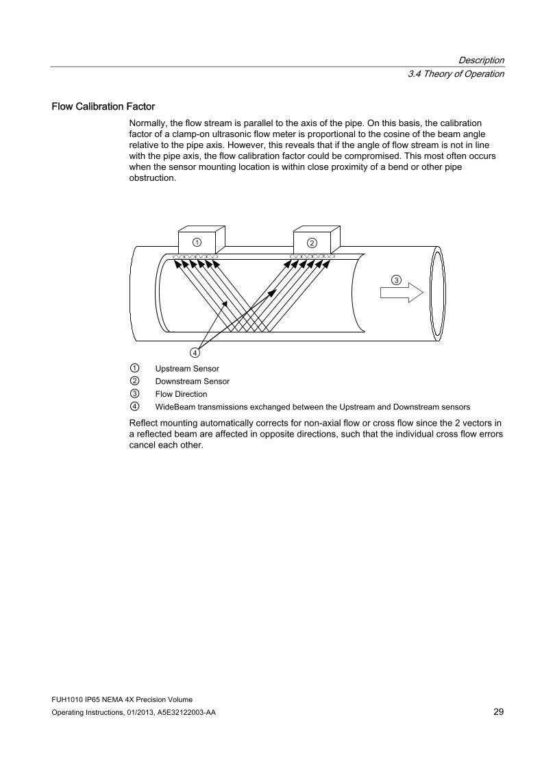
Flow Calibration Factor Normally, the flow stream is parallel to the axis of the pipe. On this basis, the calibration factor of a clamp-on ultrasonic flow meter is proportional to the cosine of the beam angle relative to the pipe axis. However, this reveals that if the angle of flow stream is not in line with the pipe axis, the flow calibration factor could be compromised. This most often occurs when the sensor mounting location is within close proximity of a bend or other pipe obstruction.
① Upstream Sensor ② Downstream Sensor ③ Flow Direction ④ WideBeam transmissions exchanged between the Upstream and Downstream sensors
Reflect mounting automatically corrects for non-axial flow or cross flow since the 2 vectors in a reflected beam are affected in opposite directions, such that the individual cross flow errors cancel each other.

Description 3.4 Theory of Operation
FUH1010 IP65 NEMA 4X Precision Volume 30 Operating Instructions, 01/2013, A5E32122003-AA

4Installing/mounting
4.1 Installation safety precautions
WARNING High pressure hazard
In applications with working pressures/media that can be dangerous to people, surroundings, equipment or others in case of pipe fracture, we recommend that special precautions such as special placement, shielding or installation of a pressure guard or a safety valve are taken when the flowmeter is mounted.
4.2 Determining a location
WARNING Electrical Shock Hazard
May cause death or serious personal injury.
Disconnect power before working on this product.
Upstream / Downstream ● Avoid long drop lines downstream from the sensor to prevent the meter pipe from
draining.
● Avoid installing the sensor upstream of a free discharge in a drop line where possible.
Sensor Location in piping system The optimum location in the system depends on the application
● For liquid applications the presence of excessive gas or air bubbles in the fluid may result in erroneous measurements. Therefore, it is preferred not to install the sensor at the highest point in the system, where gas / air bubbles will be trapped. For liquids it is advantageous to install the sensor in low pipeline sections, at the bottom of a U-section in the pipeline.
FUH1010 IP65 NEMA 4X Precision Volume Operating Instructions, 01/2013, A5E32122003-AA 31

Installing/mounting 4.3 Application Guidelines
FUH1010 IP65 NEMA 4X Precision Volume 32 Operating Instructions, 01/2013, A5E32122003-AA
4.3 Application Guidelines
Basic Requirements ● Determine pipe material and dimensions.
● Avoid vertical pipes flowing in a downward direction.
● Avoid installation of sensors on the top and bottom of horizontal pipes, if possible.
● Pipe surface should be smooth and, if necessary, free of paint.
● Avoid pressure reduction components upstream, if possible.
● Avoid mounting on or near weld seams.
● Pipe must be full to achieve proper operation.
4.4 Mounting the Transmitter
WARNING Hazardous Voltage
May cause death or serious personal injury.
Disconnect power before working on this product.
Wall Mounting The transmitter can be mounted on any wall surface including wood, metal or concrete. Use the appropriate bolts and screws as needed for your mounting application and adhere to local codes. (See figure below for mounting bracket locations.)
Pipe Mounting For installation on 2-inch (6 cm) mounting pipe use Pipe Mount Kit CQO:1012NMB-1 (optional - see catalog). See figure below.
Note
Pipe mounting kit CQO:1012NMB-1 is not available for IP66 NEMA 7 enclosures.

Installing/mounting 4.4 Mounting the Transmitter
FUH1010 IP65 NEMA 4X Precision Volume Operating Instructions, 01/2013, A5E32122003-AA 33
① 2-in (6cm) pipe ④ Cable Entry Ports ② Transmitter ⑤ Mounting Flange (also use for wall mounting) ③ Mounting Plate ⑥ U-Bolt Assembly for standard 2-in (6 cm) mounting pipe
Figure 4-1 Pipe Mounting and Mounting Locations for Transmitter
Note
Use conduit fittings or cable glands on all cables.
NOTICE Weather Seal Malfunctions
Incorrect installation of weather seals may result in failure to meet to IP65 standards and damage to the equipment.
Install weather tight seals at all unused holes using proper cable conduit and close additional holes to IP65 standards.

Installing/mounting 4.4 Mounting the Transmitter
FUH1010 IP65 NEMA 4X Precision Volume 34 Operating Instructions, 01/2013, A5E32122003-AA

5Connecting
5.1 Safety notes for connecting
Use in hazardous locations
DANGER Explosion Hazard
Death or severe personal injury and/or equipment and property damage will result if proper Hazardous (Classified) Locations installation precautions are not taken.
Restrict use and repair to qualified personnel. Only qualified personnel may carry out work on the electrical connections.
Before opening the terminal box check that:
● No explosion hazard exists
● Local safety codes and policy requirements have been followed
● All connection leads are potential free
FUH1010 IP65 NEMA 4X Precision Volume Operating Instructions, 01/2013, A5E32122003-AA 35

Connecting 5.1 Safety notes for connecting
FUH1010 IP65 NEMA 4X Precision Volume 36 Operating Instructions, 01/2013, A5E32122003-AA
DANGER
Explosion Hazard
"Flameproof enclosure" type of protection
Only open devices with type of protection "Flameproof enclosure" (e.g. FUT1010 NEMA 7) in hazardous areas when the power to the device is turned off, otherwise there is a risk of explosion.
DANGER
Explosion Hazard
Hazardous areas
Observe the type examination certificates or the test certifications applicable in your country if you use transmitters as category 1/2 equipment, otherwise there is a risk of explosion.
DANGER
Explosion Hazard
Intrinsically safe circuits
If a non-conforming supply unit is used, the "fail-safe" type of protection will no longer be effective and the approval certification will be invalid, otherwise there is a risk of explosion.
With intrinsically safe circuits, use only certified meters appropriate for the transmitter.
DANGER
Explosion Hazard
Laying Cables
Cable for use in zone 1 and 2 must satisfy the requirements for having a proof voltage < AC 500 V applied between the conductor/ground, conductor/shield and shield/ground, otherwise there is a risk of explosion.
Connect the devices that are operated in hazardous areas as per the stipulations applicable in the country of operation, e.g. for Ex "d" and "nA", permanent cables must be laid.
DANGER
Explosion Hazard
Devices with the common approval "Intrinsically safe" and "Flameproof"
The following is applicable for devices with the common approval "Intrinsically safe" and "Flameproof" (Ex ia + Ex d): Before commissioning, make sure that the type of protection that is not suitable is permanently defaced on the nameplate to avoid improper use, otherwise there is a risk of explosion.
If a non-conforming infeed is used, the "fail-safe" type of protection will no longer be effective.
Connecting 5.2 Transmitter Wiring
FUH1010 IP65 NEMA 4X Precision Volume Operating Instructions, 01/2013, A5E32122003-AA 37
WARNING
Electrical Voltage Hazard
Incorrect device connections may result in death or severe personal injury and/or equipment and property damage.
Only commission the device after the device has been properly connected and, if required, closed.
5.2 Transmitter Wiring
5.2.1 Connecting Power
DANGER Electrical Shock Hazard
Contact with exposed wiring will lead to fire, electric shock or serious injury
Turn off main power before installing AC connections to the transmitter. .
Note
If the transmitter is not already mounted and cabling has not been run, proceed to Mounting the Transmitter (Page 32) before connecting power.
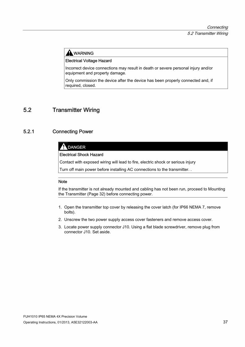
1. Open the transmitter top cover by releasing the cover latch (for IP66 NEMA 7, remove bolts).
2. Unscrew the two power supply access cover fasteners and remove access cover.
3. Locate power supply connector J10. Using a flat blade screwdriver, remove plug from connector J10. Set aside.

Connecting 5.2 Transmitter Wiring
FUH1010 IP65 NEMA 4X Precision Volume 38 Operating Instructions, 01/2013, A5E32122003-AA
① ⑥ Power Supply Wire Entry ② Power Supply Access Cover ⑦ Strip length 8mm (0.31 in) ③ Fuse F1 ⑧ Wire Clamp Screws ④ Input Power Conn. J10 ⑨ Ferrite power cord ⑤ Connector mounting screws
Figure 5-1 Input Power (J10) Wiring
4. Pull the desired length of input power wires through a cable gland and into transmitter case.
5. Wire input power connector for AC or DC power depending on power supply provided.
Note
Dress cables and make sure cable length is not excessive as to impede proper replacement of access cover.
6. Insert wires into wire entry holes and secure by tightening wire clamp screws (see figure above).
Note
Power Supply connector wires should be stripped AWG 12 - 18 stranded wire or solid conductors.

Connecting 5.2 Transmitter Wiring
FUH1010 IP65 NEMA 4X Precision Volume Operating Instructions, 01/2013, A5E32122003-AA 39
7. Plug input power plug into connector J10 and secure using two captive connector mounting screws.
8. Replace access cover. Make sure Keypad Enable switch is in the "Enable" position (see below).
① Keypad Enable Switch
5.2.2 Wiring Temperature Sensor to Transmitter
Wiring Temperature Sensor to the Analog Input ModuleSensor
DANGER Hazard Voltage
Contact with exposed wiring will lead to fire, electric shock, or serious personal injury.
Set transmitter and instrumentation power to OFF when inserting or removing the Analog Input Module, or when making connections to TB1, TB2, TB3 and TB4.
1. Disconnect power to the transmitter.
2. Open the transmitter top cover by releasing the cover latch.

Connecting 5.2 Transmitter Wiring
FUH1010 IP65 NEMA 4X Precision Volume 40 Operating Instructions, 01/2013, A5E32122003-AA
3. Loosen the captive thumbscrew securing the Access Cover and remove Access Cover.
4. Using a flat-blade screwdriver, remove four captive screws securing the I/O board. Remove board and set it aside.
① ④ Access Cover Screw Latch ② Transmitter ⑤ Access to Analog Input Module ③ Fuse
Figure 5-2 Analog Input Module Access

Connecting 5.2 Transmitter Wiring
FUH1010 IP65 NEMA 4X Precision Volume Operating Instructions, 01/2013, A5E32122003-AA 41
① Black ⑥ Short Terminals 1 and 4 (For FUE1010 -
TB2 is used for another Temperature sensor.)
② Orange ⑦ Ground Terminals 2 and 3 to Terminal 5 ③ Brown ⑧ To Sensor ④ Red ⑨ 7ME39600CR (992EC) Series Cable ⑤ Blue Figure 5-3 Single Channel Temperature Sensor Inputs

Connecting 5.2 Transmitter Wiring
FUH1010 IP65 NEMA 4X Precision Volume 42 Operating Instructions, 01/2013, A5E32122003-AA
Wiring Temperature Sensor Board 1. Using a flat-blade screwdriver, loosen Terminal Block TB1 and TB2 screws.
2. Wire the RTD liquid 992EC temperature cable as shown in the table below:
992EC Series Cable Terminal TB1 Wire #1 (Black) To TB1--1 Wire #2 (Orange) To TB1--2 Wire #3 (Brown) To TB1--3 Wire #4 (Red) To TB1--4 Wire #5 GND/SHLD (Blue) *To TB1--5
Note
*For cathodically protected pipes, DO NOT attach Blue #5 wire at RTD end of cable.
3. For single channel use, wire TB2 as shown in figure above.
4. For dual channel use, connect Channel 2 temperature sensor to TB2.
5. Replace I/O Board and secure with four captive screws paying careful attention to pin alignment.
6. Replace Access Cover and finger tighten captive thumbscrew.
Note
TB3 and TB4 are also active analog inputs. See wiring table below.
Pin TB3 Function TB4 Function Use Description Behavior Load Wiring 1 AUX. 1 IN AUX. 3 IN Iin1 Input 2 AUX. 1 COM AUX. 3 COM Iin1 Common3 AUX. 2 IN AUX. 4 IN Iin2 Input 4 AUX. 2 COM AUX. 4 COM Iin2 Common
Analog current input referenced to meter ground.
4 to 20mA 200Ω 1000 ft. Max w/o factory approval

Connecting 5.3 Sensor Wiring
FUH1010 IP65 NEMA 4X Precision Volume Operating Instructions, 01/2013, A5E32122003-AA 43
Note
If analog input is used for temperature, this will take priority over clamp-on RTD measurement.
NOTICE
Power Supply Damage
Improper power connections will damage power supply.
Ensure that all AC or DC power supply connections are properly connected to the appropriate power source (100-250 VAC @ 50/60 Hz or 9-36 VDC).
WARNING
Electrical Shock Hazard
Certain parts inside the device carry dangerous high voltage and may result in electric shock, or serious personal injury.
The transmitter must be grounded and the top cover closed before applying power to the device.
7. Connect power cables to the appropriate power source (90-240 VAC @ 50-60 Hz or 9-36 VDC). Close cover.
5.3 Sensor Wiring
5.3.1 Wiring the Sensors
Connecting Sensors to the Transmitter 1. Open the transmitter top cover. Using a flat blade screwdriver, remove the Cable Strain
Relief bracket (see figure below).
2. Observing the upstream and downstream orientation, attach the UP (upstream) and DN (downstream) cables to the sensors and make snug. Attach the other ends to the UP and DN terminals of the transmitter (see figure below).
3. Replace the Cable Strain Relief bracket. Close top cover.

Connecting 5.3 Sensor Wiring
FUH1010 IP65 NEMA 4X Precision Volume 44 Operating Instructions, 01/2013, A5E32122003-AA
① ⑤ Transmitter Input Module To CH-2 UP ② Transducer Cables Connected to
Transmitter ⑥ To CH-1 DN
③ Cable Strain Relief Bracket ⑦ To CH-1 UP ④ To CH-2 DN ⑧ Channel 2 ⑨ Channel 1 Figure 5-4 Sensor Cable Connections
4. Apply power.
5. Within 10 seconds of power-up the transmitter main display will become active and a typical Siemens graphic will appear. The screen also identifies the software version of the unit as shown below.

Connecting 5.4 Navigating the Menu
FUH1010 IP65 NEMA 4X Precision Volume Operating Instructions, 01/2013, A5E32122003-AA 45
Figure 5-5 Software Version (xx.xx.xx)
6. Press the <MENU> key and the Main Menu will appear. (Language selection is not on Version 3 op systems.)
5.4 Navigating the Menu
Installation Menu Navigation
+-= +
*
F1 F3F2 F4
MENU CLR ENTER
DATALOG
ALTCTRL
HELP
1 2 30
7 8 94 5 6
Figure 5-6 Keypad

Connecting 5.5 Programming the Transmitter
FUH1010 IP65 NEMA 4X Precision Volume 46 Operating Instructions, 01/2013, A5E32122003-AA
Table 5- 1 Keypad Function Chart
Keys Description MENU Press to activate the Installation Menu. ENTER Store numeric data, select from option lists, etc. Left / Right Arrows Menu navigation keys move cursor. Use <Left Arrow> key to return to previous menus. Up / Down Arrows Same as <Left> and <Right> arrows. Scrolls option lists and graphic display screen. CLR Erases data or selects list options. Numbers 0 - 9 Use to type numeric data. Decimal Point Use for decimal points in numeric data. Math Operators 4-function math operations in numeric entry cells. "F" Keys 1, 2, and 3 Used to start/stop/reset Totalizer. F4 Caution: used during power up for system reset. CTRL and ALT Used as shift keys for alternative key functions. DATALOG Triggers immediate Datalogger report. Plus and Minus [+ / -] Changes the sign of numeric data.
5.5 Programming the Transmitter
Select Language and Units
Note
Before creating a site select a language and then English or Metric units from the Meter Facilities menu.
Selecting a Meter Type (Required Entry) 1. Press the <MENU> key and select [Meter type].
2. If English is not the preferred language, scroll to [Language] to change.
3. Scroll to [Meter Type], press the <Right Arrow> and scroll to [Dual Path Flow].
4. Press <ENTER> to select. Press <Right Arrow> to select a different meter function, if available and desired the press <ENTER>.

Connecting 5.5 Programming the Transmitter
FUH1010 IP65 NEMA 4X Precision Volume Operating Instructions, 01/2013, A5E32122003-AA 47
Create a Site (Required Entry) 1. At the [Channel Setup] menu press the <Right Arrow>.
Note
Before proceeding make sure that English or Metric units have been selected.
2. Press <Down Arrow> to select the [Create/Name Site] menu and enter a Site name.
3. Press <ENTER> to create Site name (e.g., ABC).
① Insert desired name (8 characters max.)
Note
To select letters: Press <Right Arrow> to cursor and then press <Up/Down Arrows> to select letters. Press <ENTER> when done.
4. Press <Left Arrow> and return to the [Channel Setup] menu.
Note
After site configuration procedures that follow are complete the newly created site must be saved again to retain the new site data. Refer to the Save/Rename Site procedure below.

Connecting 5.5 Programming the Transmitter
FUH1010 IP65 NEMA 4X Precision Volume 48 Operating Instructions, 01/2013, A5E32122003-AA
Select Pipe Class Pipe Class is a pre-loaded set of default pipe sizes for various ASA and metric pipes. If the intended pipe is standard the user may select this function to pre-load necessary pipe data, otherwise enter data manually using [Pipe O.D.], [Pipe Material] and [Wall Thickness].
1. Press the <Right Arrow> to select Pipe Class. Press <Right Arrow> again and scroll to desired Pipe Class.
2. Press <ENTER> to select.
3. Pre-programmed Pipe Size and relevant pipe parameters will appear in menu cells. Press
<Right Arrow> and scroll to desired pipe size. Press <ENTER>. Enter dimensions manually if pre-programmed dimensions do not match application.
Note
The DN sizes listed in the [Select Pipe Size] menu option list are referenced to DIN Table 2448. After selecting pipe size, check pipe OD and wall thickness for correct dimensions.
4. Press the <Left Arrow> and return to the main menu.
Select a Liquid Class 1. Press the <Down Arrow> and scroll to [Application Data].
2. Press the <Right Arrow> to select [Liquid Class].
3. Press the <Right Arrow> again and scroll to desired liquid.

Connecting 5.5 Programming the Transmitter
FUH1010 IP65 NEMA 4X Precision Volume Operating Instructions, 01/2013, A5E32122003-AA 49
4. Press <ENTER> to save selection.
① Select from list.
5. Press the <Left Arrow> and return to the main menu.
Save/Rename Site Procedure 1. To save all programmed data to site, return to [Channel Setup] menu.
2. Press <Right Arrow> and scroll to [Save/Rename Site].
① The saved site name now appears in the menu screen.
3. Press <Right Arrow> and then <ENTER> to save all programmed data to site.
4. To return to the top menu, continue to press the <Left Arrow> key.
See also Sensor Installation (Page 50)

Connecting 5.6 Sensor Installation
FUH1010 IP65 NEMA 4X Precision Volume 50 Operating Instructions, 01/2013, A5E32122003-AA
5.6 Sensor Installation
5.6.1 Preliminary Installation Procedures
Reflect and Direct Sensor Mounting Reflect and Direct mounting modes are supported for clamp-on sensors. The transmitter recommends a mounting mode after analyzing your pipe and liquid data entries.
1. After receiving the spacing index from the Installation Menu, prepare the pipe surface area where the sensors will be mounted. Use the supplied abrasive material to prepare a clean contact surface for the sensors.
2. Make a note of the Number Index displayed in the [Install Sensor] menu. Check to ensure that you have a matched set of sensors. They both should have the same S/N number but marked with either an "A" or "B" (e.g. 100A and 100B).
Mounting Supplies The following items will be needed to mount the sensors in addition to what is supplied:
● Flat blade screwdriver
● Tape, chalk and a ruler or measuring tape (For Direct mounting)
Mounting Strap Kits The available Mounting Strap kits are listed below. Each kit comes with bands. Sizes cover designated pipe diameter ranges and a spacing guide for Direct Mount.
Mounting Strap Kits Pipe Diameter SAE Band Sizes (Qty.)
7ME396000SM00 50.8mm (2-inch) to 177.8mm (7-inch) #88 (2) #128 (2) 7ME396000SM10 50.8mm (2-inch) to 330.2mm (13-inch) #88 (2) #152 (2) 7ME396000SM20 330.2mm (13-inch) to 609.6mm (24-
inch) #188 (2) #280 (2)
7ME396000SM30 609.6mm (24-inch) to 1219.2mm (48-inch)
#152 (4) #312 (4)
Note
Optional lager bands sizes are available for larger pipe diameters.

Connecting 5.6 Sensor Installation
FUH1010 IP65 NEMA 4X Precision Volume Operating Instructions, 01/2013, A5E32122003-AA 51
Selecting a location for the sensors 1. The pipe at the mounting location must remain full, even at zero flow to maintain
operation.
2. For the purposes of this device any location of straight pipe long enough to physically mount the sensors is adequate. Unlike ultrasonic flow meters, this interface detector does not require lengths of straight run to perform as specified.
3. Avoid, if possible, installing the sensors downstream from a throttling valve, a mixing tank, the discharge of a positive displacement pump or any other equipment that could possibly aerate the liquid causing signal aberrations. The best location will be as free as possible from flow disturbances, vibration, sources of heat, noise, or radiated energy.
4. Do not mount the sensors on a surface aberration (pipe seam, etc.)
5. Do not mount sensors from different ultrasonic meters on the same pipe within reasonable distance. Also, do not run the sensor cables in common bundles with cables from other instrumentation. Sensor cables originating from a common transmitter can be in a single conduit.
6. Always mount sensors on a dry pipe surface. Optional submersible units can be purchased for installation in wet environments and must be installed in accordance with factory instructions.
7. Avoid mounting sensors on the top or bottom of a horizontal pipe. The best placement on a horizontal pipe is either the three o’clock or nine o’clock position. Mounting on a vertical pipe is recommended only if flow is in the upward direction. When mounting on a vertical pipe flowing in a downward direction make sure there is sufficient back pressure in the system to maintain a full pipe.
Preparing the Pipe Decide on your mounting mode (Direct or Reflect). Choose Direct Mode if your pipe is plastic.
① Pipe ② Cleaned Areas
Figure 5-7 Pipe Surface Preparation

Connecting 5.6 Sensor Installation
FUH1010 IP65 NEMA 4X Precision Volume 52 Operating Instructions, 01/2013, A5E32122003-AA
Direct mount provides a shorter sonic beam path. This usually improves signal with sonically attenuative liquids or pipe materials. Direct mount is recommended for plastic pipes. Compared to Direct mounting, Reflect mount requires almost double the amount of mounting length. Therefore, direct mount may be the only option if the availability of mounting space is limited.
Reflect mount is recommended whenever possible because it is the simplest way to mount the sensors.
Ltn Menu Cell The Ltn menu cell is a view only menu cell that shows the distance in inches or millimeters between the front faces of the sensors along the axis of the pipe. If you are mounting the sensors without a track or spacer bar, you have to space them according to this value. Note that Ltn may be a negative number for direct mount on very small pipes where the sensor spacing overlaps.
5.6.2 Sensor Identification and Selection
Sensor identification The sensor part number located on the front face provides a detailed identification. For example, the Part Number: 1011HNS-D1T1-S2 means:
① ⑤ Model Size ② Hi Precision ⑥ Temperature ③ NEMA w/F-Conn ⑦ Agency Approved ④ Pipe Material
Note
Check to make sure that the sensors are a matched set with the same serial numbers and marked with an "A" and "B" (e.g., 19256A and 19256B).
Note
Sensor Model names for Version 3 op systems are as follows: 1011H Hi Precision, 1011 Universal and 991 Universal

Connecting 5.6 Sensor Installation
FUH1010 IP65 NEMA 4X Precision Volume Operating Instructions, 01/2013, A5E32122003-AA 53
Typical Sensor Labels
① Universal Sensor model number ② Sensor size
Figure 5-8 Sample Universal Sensor Label

Connecting 5.6 Sensor Installation
FUH1010 IP65 NEMA 4X Precision Volume 54 Operating Instructions, 01/2013, A5E32122003-AA
① Hi Precision sensor model number ② Sensor size
Figure 5-9 Sample Hi Precision Sensor Label
Sensor Selection The following is a typical sensor selection procedure.
Note
The transmitter must be powered up before you can select a sensor model. Refer to Transmitter Wiring (Page 37).
1. Press <Left Arrow> to return to main menu. At [Meter Type], press the <Right Arrow> and then <ENTER>.
2. The [Channel Setup] menu will appear.
3. Press the <Down Arrow> to select [install Sensor].
4. Press the <Right Arrow> to [Sensor Model]. Press <Right Arrow> and scroll to select the sensor model number on the sensor label.

Connecting 5.6 Sensor Installation
FUH1010 IP65 NEMA 4X Precision Volume Operating Instructions, 01/2013, A5E32122003-AA 55
5. The drop down menu lists the following sensor selections:
– 1011 Universal
– 1011HP-T1 - Usable -40 to 120°C, recommended for Ø Temperature <40°C; Standard.
– 1011HP-T2 - Usable -40 to 120°C, recommended for Ø Temperature >40°C - <80°C; Named as high temperature.
– 1011HP-T3 - Usable -40 to 120°C, recommended for Ø Temperature >80°C <120°C; special request.
– 991 Universal
Note
The meter will automatically recommend a sensor depending on the application data that has been entered.
6. For this example, select the sensor model that appears on the sensor label then press <ENTER>.
① Select based on type ② Select based on size ③ After sensor is mounted select "Install."
7. To select Sensor Size, press <Right Arrow>. Scroll to select the sensor size that matches the size indicated on the sensor label. Press <ENTER>.
8. At [Sensor Mount Mode], press the <Right Arrow>. Scroll to select [Reflect] or [Direct] mount and then press <ENTER>.
9. IMPORTANT: Record Spacing Method and Number Index. This data will be used to mount the sensors.
10. Sensors can now be mounted. Refer to Sensor Installation mounting procedures and select the mounting mode desired.
11. After sensors are mounted scroll to [Install Complete] and select [Install].

Connecting 5.6 Sensor Installation
FUH1010 IP65 NEMA 4X Precision Volume 56 Operating Instructions, 01/2013, A5E32122003-AA
5.6.3 Reflect Mount
Mounting Frame Installation 1. On a flat surface, attach the Spacer Bar to a Mounting Frame so that the Reference Hole
on the Spacer Bar fits over the metal post on the platform of the frame. Tighten the clamping screw.
2. Slide the second Mounting Frame onto the other end of the Spacer Bar and align the Number Index Hole with the metal post on the platform. Then tighten the clamping screw. Ensure that the angled sides of both frames face away from each other.
3. Wrap a Mounting Strap around the pipe. Make sure to position it so there is easy access to the Mounting Strap Adjusting Screw.
4. At the mounting location, place the Mounting Frame/Spacer Bar Assembly on the pipe so that it rests on the top of the pipe.
5. Engage the end of the Mounting Strap with the Mounting Strap Adjusting Screw.
6. Slide strap under the spring clip of one of the Mounting Frames.
7. Tighten the Mounting Strap Screw enough to take up all of the slack, but not enough to prevent rotation of the assembly. Attach the second mounting strap.
8. Rotate the assembly on the pipe to the final conditioned location, ensuring that it is straight along the pipe axis. (Refer to the sensor orientation diagram)
9. Tighten the mounting straps to seat the assembly firmly on the pipe. Do not over tighten.

Connecting 5.6 Sensor Installation
FUH1010 IP65 NEMA 4X Precision Volume Operating Instructions, 01/2013, A5E32122003-AA 57
① ⑥ Front View Pipe ② Spring Clip (Not present on some
models) ⑦ Mounting Strap Note: Optional 2nd
Mounting Strap shown. Larger pipes over 76cm (30 inches) may need an additional support.
③ Sensor Clamping Screw ⑧ Spacer Bar Platform and Clamping Screw
④ Spacer Bar ⑨ Spacer Bar Reference Hole ⑤ 7ME39600M Mounting Frame ⑩ Orientation for Single Beam Sensor at 9
o'clock position ⑪ Orientation for Dual Path Sensor at 10 &
2 o'clock positions Figure 5-10 Sensor Installation

Connecting 5.6 Sensor Installation
FUH1010 IP65 NEMA 4X Precision Volume 58 Operating Instructions, 01/2013, A5E32122003-AA
Installing the Sensor 1. Take either sensor and apply a continuous lengthwise 3mm (1/8-inch) bead of coupling
compound across the center of the sensor emitting surface.
① ④ Coupling Compound Sensor ② Emitting Surface ⑤ Angled Edge ③ Front Face ⑥ F-Connector Figure 5-11 Sensor
2. Slide sensor into a mounting frame back end first aligning the angled edge of the sensor with the angled edge of the mounting frame. Keep sensor from making contact with the pipe until it butts up against the mounting frame stop. Push sensor down to mate with pipe.
3. Tighten the sensor clamping screws to hold the sensor firmly in place. Repeat procedure for the other sensor.
4. If installing a temperature sensor proceed to Mounting Temperature Sensor (Page 71). If not, proceed to Sensor Wiring (Page 43).
5.6.4 Direct Mount
Sensor Installation using Mounting Frames, Spacer Bar and Spacing Guides The combination of mounting frames, spacer bar and spacing guides is the recommended way to mount Direct Mode sensors. The mounting frame establishes the axial alignment of the sensors and allows you to remove and replace either sensor while preserving their exact mounting location.
For Direct Mode mounting, a spacer bar is used to establish the distance between sensors and a spacing guide to locate the sensors at the nine o’clock and three o’clock positions. Should the distance between sensors be beyond the span of a spacer bar, a measuring tape can be used. The Mylar spacing guide comes in various lengths and widths to accommodate most pipe sizes.

Connecting 5.6 Sensor Installation
FUH1010 IP65 NEMA 4X Precision Volume Operating Instructions, 01/2013, A5E32122003-AA 59
Spacing Guide Sizes
Metric English 5.08cm x 66.04cm 2" x 26" 5.08cm x 114.3cm 2" x 45" 10.16cm x 393.7cm 4" x 155" 15.2cm x 497.8cm 6" x 196"
Figure 5-12 Mylar Spacing Guide
1. After receiving the spacing index from the Installation Menu, prepare the pipe surface area where the sensors will be mounted.
2. Degrease the surface and remove any grit, corrosion, rust, loose paint, etc.
3. Make a note of the Number Index displayed in the [Install] menu. Check to ensure that you have a matched set of sensors. They both should have the same S/N number but marked with either an "A" or "B" (e.g., 100A and 100B).
4. Temporarily position one of the frames on the pipe where you will be mounting it. Ensure that this is a smooth area without any raised areas (seams, etc.) With a pencil or chalk, mark a generous area of 13 mm (1/2") all around the frame. Remove the assembly.
5. Prepare the area you marked by de-greasing surface, if needed, and removing any grit, corrosion, rust, loose paint or surface irregularities with the abrasive material provided
6. Put a mounting strap around the pipe and engage an end into adjusting screw (screw should be pointing up). Position frame in the middle of area you have cleaned and centered on the pipe with its angled end facing away from where the other frame will sit.

Connecting 5.6 Sensor Installation
FUH1010 IP65 NEMA 4X Precision Volume 60 Operating Instructions, 01/2013, A5E32122003-AA
① ③ Sensor Clamping Screw Mounting Strap ② Spring Clip ④ Mounting Strap Adjusting Screw Figure 5-13 Wrap Strap Under Pipe and Attach to Adjusting Screw
7. Slide the mounting strap over it (and under the clip if there is one) and tighten with a screwdriver. While tightening, check to ensure that the center of the tapered roller is centered on the pipe.
8. Attach the second frame to the spacer bar with an index spacer screw into the index hole specified in Step 1. The angle on the frame should be facing away from the direction that the length of the bar is going.
9. Now attach the free end of the spacer bar by inserting an index spacer screw through the REF hole on the spacer bar and then into the hole on the mounted frame. Tighten. Sight to ensure that this frame is lined up in center of pipe and while holding alignment, place a dot (with pencil or chalk) in the center of the tapered roller at the bottom of the frame (see A below). While holding, also mark along the front edge of the frame with pencil or fine chalk line (see B below).

Connecting 5.6 Sensor Installation
FUH1010 IP65 NEMA 4X Precision Volume Operating Instructions, 01/2013, A5E32122003-AA 61
① ⑤ Sensor 1 Sensor Edge Line ② Pipe ⑥ Spacer Bar ③ Dot ⑦ Dot ④ Sensor 2 ⑧ Line ⑨ Mylar Spacing Guide
10. Disassemble the spacer bar and the unmounted frame. Use the bar as a straight edge and, with one edge against the mounted frames tapered roller center and the other crossing the dot you drew, draw a line crossing the dot (see "B" above). Set the bar aside.
① Trim material from inner edge if necessary ② Mylar Spacing Guide ③ 8cm (3-inch) Overlapping Edge Figure 5-14 Wrapping the Mylar Spacing Guide around the pipe (End View)

Connecting 5.6 Sensor Installation
FUH1010 IP65 NEMA 4X Precision Volume 62 Operating Instructions, 01/2013, A5E32122003-AA
11. Wrap the Mylar spacing guide around the pipe so that the left edge is against the sensor edge mark (see "C" above). Arrange so that one end overlaps the other by at least three inches. Trim to fit if necessary, but be sure not to trim at the overlapping end in order to keep it square.
12. Realign left edge of the guide with the sensor edge mark. Line up both vertical edges of the guide and ensuring that it is snug around the pipe, mark along the overlapping edge.
13. Remove Mylar spacing guide and lay it out on a flat surface. Either measure the exact distance half-way between the overlap edge and the mark at the overlap, or fold the guide from the overlap edge to overlap mark and draw a line at the fold or halfway point.
① ③ Overlap Edge Spacing Guide ② Mark (or fold) exactly at half-way point ④ Circumference Figure 5-15 Finding the Halfway Distance
14. Reinstall the spacing guide; its left edge abutting the sensors edge mark on the pipe and the overlapping edge in line with the dot (now a line) on the pipe (see "C). Tape it in this position on the pipe. Take the second frame and place it against the edge of the guide with its tapered roller centered on the center mark on the guide.
15. Temporarily position the frame (in the 3 o’clock position opposite the mounted frame - see below) where it will be mounted. Ensure that this is a smooth area without any raised spots (seams, etc.). Mark a generous area of 13 mm (1/2-inch) all around the mounting frames with a pencil or chalk. Remove the frame and the Mylar guide.
① 9 o'clock Sensor ② 3 o'clock Sensor Figure 5-16 Aligning the Sensors for Direct Mode operation (End View)

Connecting 5.6 Sensor Installation
FUH1010 IP65 NEMA 4X Precision Volume Operating Instructions, 01/2013, A5E32122003-AA 63
16. Prepare the area you marked by de-greasing the surface, if needed, and removing any grit, corrosion, rust, loose paint or surface irregularities with the abrasive pipe conditioning material provided. Clean the pipe of any debris and abrasive particles.
17. Replace the Mylar guide back in the same position it was in and retape it to the pipe
18. Put a mounting strap around the pipe and engage an end into adjusting screw (screw should be pointing up).
19. Position frame in the middle of area you have cleaned and centered on the pipe with its angled end facing away from where the other frame will sit and aligned with the edge and center marks on the guide. Slide the mounting strap over it (and under the clip if there is one) and tighten with a screwdriver. While tightening, check to ensure that the center of the tapered roller is centered on the pipe.
20. Take either sensor and apply a continuous lengthwise 3 mm (1/8-inch) bead of coupling compound across the center of the sensor emitting surface.
21. Tighten the sensor clamping screws to hold the sensor firmly in place. Repeat procedure for the other sensor.
22. Slide sensor into a mounting frame back end first aligning the angled edge of the sensor with the angled edge of the mounting frame. Keep sensor from making contact with the pipe until it butts up against the mounting frame stop. Push sensor down to mate with pipe.
23. Open the transmitter top cover. Using a flat blade screwdriver, remove the Cable Strain Relief bracket.
24. Observing the upstream and downstream orientation, attach the UP (upstream) and DN (downstream) cables to the sensors and make snug. Attach the other ends to the UP and DN terminals of the transmitter.
25. Replace the Cable Strain Relief bracket. Close top cover.
26. Proceed to Commissioning (Page 73).
5.6.5 1012T Mounting Tracks
Using 1012T Sensor Mounting Tracks The 1012TN and 1012TNH Mounting Tracks provide a rigid mounting platform for Series 1011 Universal or high precision sensors. The mounting tracks service pipe sizes up to a maximum of 140 mm (5.00") outer diameter. The 1012T mounting tracks support both Direct and Reflect mounting modes. The transmitter recommends the appropriate sensors, mounting track and mounting mode, based on the pipe data entries.

Connecting 5.6 Sensor Installation
FUH1010 IP65 NEMA 4X Precision Volume 64 Operating Instructions, 01/2013, A5E32122003-AA
Installing a 1012T Mounting Track in Reflect Mode The sensor installation procedures show how the automatic selection of sensors, mounting mode and spacing method are established. Examine the figure below, which illustrates a typical [Install Sensor] menu screen. Note the automatic assignment of mounting track part number, plus the designation of the number index.
① Sensor type, size and mounting mode selection. ② Automatic selection of mounting track part number and number index.
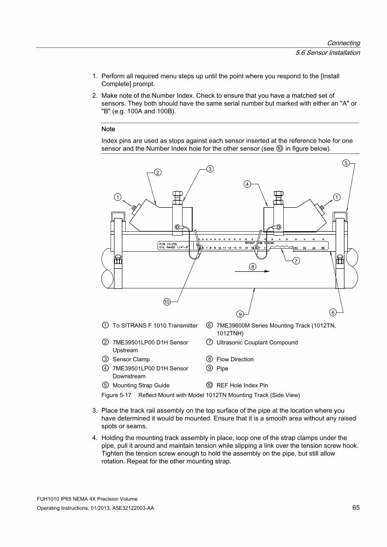
Connecting 5.6 Sensor Installation
FUH1010 IP65 NEMA 4X Precision Volume Operating Instructions, 01/2013, A5E32122003-AA 65
1. Perform all required menu steps up until the point where you respond to the [Install Complete] prompt.
2. Make note of the Number Index. Check to ensure that you have a matched set of sensors. They both should have the same serial number but marked with either an "A" or "B" (e.g. 100A and 100B).
Note
Index pins are used as stops against each sensor inserted at the reference hole for one sensor and the Number Index hole for the other sensor (see ⑩ in figure below).
① To SITRANS F 1010 Transmitter ⑥ 7ME39600M Series Mounting Track (1012TN,
1012TNH) ② 7ME39501LP00 D1H Sensor
Upstream ⑦ Ultrasonic Couplant Compound
③ Sensor Clamp ⑧ Flow Direction ④ 7ME39501LP00 D1H Sensor
Downstream ⑨ Pipe
⑤ Mounting Strap Guide ⑩ REF Hole Index Pin Figure 5-17 Reflect Mount with Model 1012TN Mounting Track (Side View)
3. Place the track rail assembly on the top surface of the pipe at the location where you have determined it would be mounted. Ensure that it is a smooth area without any raised spots or seams.
4. Holding the mounting track assembly in place, loop one of the strap clamps under the pipe, pull it around and maintain tension while slipping a link over the tension screw hook. Tighten the tension screw enough to hold the assembly on the pipe, but still allow rotation. Repeat for the other mounting strap.

Connecting 5.6 Sensor Installation
FUH1010 IP65 NEMA 4X Precision Volume 66 Operating Instructions, 01/2013, A5E32122003-AA
5. Rotate the track rail assembly to the intended mounting position on the pipe, then tighten both tension screws just enough to prevent rotation. Do not over tighten.
6. Prepare the sensor location by degreasing the surface, if needed, and removing any grit, corrosion, rust, loose paint or surface irregularities with the abrasive pipe conditioning material provided. Clean the pipe of all debris and abrasive particles.
7. Insert one index pin into the reference hole and one in the Number Index hole previously mentioned.
8. Apply a thin band of supplied couplant compound to the sensor’s emitting surface.
9. One at a time, place the sensors between the track rails, slightly behind the pin and under the clamping screw assembly. Slide it forward until it butts up firmly against the reference pin.
10. Once each sensor is in place secure it with the sensor clamping screw. Do not over tighten.
11. Repeat the procedure for the Number Index sensor making sure to insert an index pin into the correct Number Index hole
12. Observing the upstream and downstream orientation, attach the UP (upstream) and DN (downstream) cables to the sensors and make snug. Attach the other ends to the UP and DN terminals of the transmitter.
Installing a 1012T Mounting Track in Direct Mode The Sensor Installation procedures show how the automatic selection of sensors, mounting mode and spacing method are established. Examine the figure below, which illustrates a typical [Install Sensor] menu screen. Note the automatic assignment of model numbers for the sensor and mounting track, plus the designation of the number index.
① Automatic selection of mounting track part number , mount mode and number index
The combination of two Model 7ME39600M (1012TN) Mounting Tracks and a spacer guide is the recommended way to mount sensors in the Direct Mode. This method ensures that sensors will align exactly 180° from each other and remain spaced the proper distance apart.
The Direct Mount configuration uses a set of two track rail assemblies; one for each sensor, installed 180° apart on the pipe. The set includes:

Connecting 5.6 Sensor Installation
FUH1010 IP65 NEMA 4X Precision Volume Operating Instructions, 01/2013, A5E32122003-AA 67
● Direct Mode Track Assembly - This track rail has number index holes for inserting an index pin to position the other sensor.
Note
Index pins are used as stops against each sensor at the reference hole for one sensor, and the Number Index hole for the other sensor (see ⑨ in figure below).
① ⑥To SITRANS F Transmitter 7ME39501LP00 D1H Sensor Downstream ② Sensor Clamp ⑦ Flow Direction ③ 7ME39501LP00 D1H Sensor
Upstream ⑧ 7ME39600M Series Mounting Track (1012TN,
1012TNH) ④ 7ME39600M Series Mounting
Track (1012TN, 1012TNH) ⑨ REF Hole Index Pin
⑤ Mounting Strap Guide ⑩ Ultrasonic Couplant Compound ⑪ Pipe
Figure 5-18 Direct Mount 180° opposed with Mounting Tracks

Connecting 5.6 Sensor Installation
FUH1010 IP65 NEMA 4X Precision Volume 68 Operating Instructions, 01/2013, A5E32122003-AA
1. Perform all required menu programming steps up until the point where you respond to the [Install Complete] prompt.
2. Make a note of the reported Number Index displayed in the [Install Sensor] menu. Check to ensure that you have a matched set of sensors. They both should have the same serial number but marked with either an "A" or "B" (e.g. 100A and 100B).
Note
Some sensors require a right-angle adapter. This adapter should be installed before placing the sensors in the tracks.
3. Prepare pipe for the track mounts by degreasing the surface, if needed, and removing any grit, corrosion, rust, loose paint or surface irregularities with the abrasive pipe conditioning material provided.
4. Wrap the mounting strap around the pipe and through the strap guide of both tracks.
5. Finger-tighten the chain Tension Screw to secure the strap and tracks to the pipe.
Note
For easier installation, it may be helpful to use a tie, tape or bungee cord to hold the two tracks in place while mounting.
Positioning Track Assemblies 1. Wrap the supplied Mylar guide around the pipe and alongside the track assemblies noting
the point of overlap with a marker.
2. Remove the guide; fold in half at the point of overlap creating a crease in the Mylar at the halfway point. This crease will act as a location point where the track will sit centered 180 degrees on the opposite side of the pipe.
3. Re-install the Mylar guide ensuring alignment of the overlap point with the center of one track.
4. Loosen the mounting straps enough to allow you to rotate the track assembly until the center of one track aligns with the center line on the Spacer Guide and the center of the other track aligns at the point where the Spacer Guide ends meet. Use the edge of the Mylar guide to ensure the tracks are parallel. The tracks should now be 180° apart. Tighten both straps (or chains, if provided).

Connecting 5.6 Sensor Installation
FUH1010 IP65 NEMA 4X Precision Volume Operating Instructions, 01/2013, A5E32122003-AA 69
① Align tracks with Spacer Guide edge ② Mylar Spacer Guide ③ Halfway distance of Spacer Guide Figure 5-19 Track Rail Alignment

Connecting 5.6 Sensor Installation
FUH1010 IP65 NEMA 4X Precision Volume 70 Operating Instructions, 01/2013, A5E32122003-AA
Sensor Installation 1. Insert an index pin into the REF hole of the track marked "Reflect Mode Spacing."
2. Take one sensor and apply a 3mm (1/8-inch) continuous bead of couplant compound along the center of the contact surface of the sensor. Insert it between the track rails and to the left of the index pin with the cable connector pointing away from the pin. Move the sensor until the pin stops it. Hold sensor in place. Move sensor clamping screw over the sensor and tighten.
① Sensor Clamping Screw ② REF hole ③ Number Index hole
Figure 5-20 REF and Number Index Pin Locations
3. Insert the other index pin into the correct Number Index hole on the other track marked "Direct Mode Spacing."
4. Apply a 3mm (1/8-inch) continuous bead of couplant compound along the center of the contact surface of the second sensor.
Note
Remember to install the sensors with the cable connectors facing away from each other.
5. Insert the second sensor into the track rail with its cable connector pointing away from the pin. Move the sensor until it’s stopped by the pin. Move sensor clamping screw over the sensor and tighten.
6. Once the sensors are in place, secure with its clamping screws. Do not over tighten.

Connecting 5.7 Mounting Temperature Sensors
FUH1010 IP65 NEMA 4X Precision Volume Operating Instructions, 01/2013, A5E32122003-AA 71
7. Observing the upstream and downstream orientation, attach the UP (upstream) and DN (downstream) cables to the sensors and make snug. Attach the other ends to the UP and DN terminals of the transmitter.
8. Proceed to Commissioning (Page 73).
5.7 Mounting Temperature Sensors Temperature is used to normalize the liquids sonic velocity in order to properly determine interfaces and for density determination. Temperature sensors are available in clamp-on style or in insert (Thermowell) style. Refer to the table below. Both styles incorporate 1000 ohm platinum RTD’s for high precision.
Table 5- 2 Temperature Sensors
Description Part Number Standard clamp-on RTD 7ME39501TA00 Submersible clamp-on RTD 7ME39501TB00 Insertion style RTD (size 1): 140mm (5.5 in) 7ME39501TJ00 Insertion style RTD (size 2): 216mm (8.5 in) 7ME39501TJ01 Insertion style RTD (size 3): 292mm (11.5 in) 7ME39501TJ02 Insertion style RTD (size 4): 368mm (14.5 in) 7ME39501TJ03
① 7ME39600CR (992EC) Series Cable ④ Pipe ② Clamp-on Temperature Sensor ⑤ Mounting Assembly ③ Thermal Couplant
Figure 5-21 Clamp-on Temperature Sensor

Connecting 5.7 Mounting Temperature Sensors
FUH1010 IP65 NEMA 4X Precision Volume 72 Operating Instructions, 01/2013, A5E32122003-AA
Clamp-on style sensors are mounted on the surface of the monitored pipe using series mounting assemblies. Apply a generous quantity of thermal couplant (provided) to the tip of the sensor and attach it securely to the cleaned pipe surface with the proper mounting assembly. Temperature measurement anomalies resulting from variations in the ambient conditions can be minimized by insulating the pipe and sensor after installation.
① Temperature Sensor Connector Head
Assembly ⑤ Thermal Couplant
② 7ME39600CR (992EC) Series Cable ⑥ Spring Loaded Sensing Element ③ Threaded Pipe Fitting ⑦ Pipe Wall ④ Thermowell
Figure 5-22 Insert Temperature Sensor
Insert sensors are designed to be used in pipes equipped with Thermowells. Sensors are spring-loaded, 1/4" diameter with 1/2" NPT integral connection heads, available in several lengths to accommodate a range of pipe sizes.
Proceed to Commissioning (Page 73).
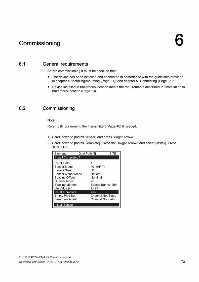
6Commissioning
6.1 General requirements Before commissioning it must be checked that:
● The device has been installed and connected in accordance with the guidelines provided in chapter 4 "Installing/mounting (Page 31)" and chapter 5 "Connecting (Page 35)"
● Device installed in hazardous location meets the requirements described in "Installation in hazardous location (Page 13)"
6.2 Commissioning
Note
Refer to [Programming the Transmitter] (Page 46) if needed.
1. Scroll down to [Install Sensor] and press <Right Arrow>.
2. Scroll down to [Install Complete]. Press the <Right Arrow> and select [Install]. Press <ENTER>.
FUH1010 IP65 NEMA 4X Precision Volume Operating Instructions, 01/2013, A5E32122003-AA 73

Commissioning 6.2 Commissioning
FUH1010 IP65 NEMA 4X Precision Volume 74 Operating Instructions, 01/2013, A5E32122003-AA
3. The meter will go through the drives.
4. Observe the Measured Vs window and verify a correct sound velocity measurement (if
known).
5. Press the <Down Arrow> to accept sound velocity value.
6. Press the <Right Arrow> and then <ENTER> to save the site data.
7. Press the <MENU> key.
8. The unit is now ready to display data.
14.35
354.6597 14.27
100.0
0.031.74

Commissioning 6.3 Empty Pipe Set
FUH1010 IP65 NEMA 4X Precision Volume Operating Instructions, 01/2013, A5E32122003-AA 75
See also Refer to I/O Connections and Wiring (Page 163) for input/output wiring and Span Data (Page 94) for data spanning procedures.
6.3 Empty Pipe Set The flow meter performs the MTYmatic routine automatically during its Initial Make-up to establish a standard setting for the Empty Pipe alarm. This process is normally sufficient for setting this parameter. The [Empty Pipe Set] option list allows you to re-invoke MTYmatic, use an Actual MTY routine (if application conditions allow you to empty and refill the pipe) or use the Set Empty routine to set the empty pipe threshold by direct numeric entry.
Actual MTY Command If application conditions allow you to empty and refill the pipe, then you may choose to perform the Actual Empty procedure; however, it is not required to do so.
Note IMPORTANT
NEVER perform the Actual MTY procedure if the pipe can not be emptied.
To use the Actual MTY command: 1. From [Channel Setup] scroll down to [Install Sensor].
2. Press the <Right Arrow> to access the [Empty Pipe Set] option list.
3. Press the <Down Arrow> to [Actual MTY] then press <ENTER>.
– Empty Pipe Press [ENT] appears on the menu prompt line.

Commissioning 6.3 Empty Pipe Set
FUH1010 IP65 NEMA 4X Precision Volume 76 Operating Instructions, 01/2013, A5E32122003-AA
4. Empty the pipe completely, then press <ENTER>.
– Fill Pipe Press [ENT] appears on the menu prompt line.
Figure 6-1 Empty Pipe Set
5. Refill the pipe completely, then press <ENTER>.
Using the MTYmatic command You can repeat MTYmatic (performed during the Initial Makeup) to correct an inaccurate Actual MTY setting if conditions do not allow you to repeat the Actual Empty procedure.
Note IMPORTANT
Only use the MTYmatic procedure when the pipe is full.

Commissioning 6.3 Empty Pipe Set
FUH1010 IP65 NEMA 4X Precision Volume Operating Instructions, 01/2013, A5E32122003-AA 77
To start MTYmatic: 1. From [Channel Setup] scroll down to [Install Sensor].
2. Press the <Right Arrow> to access the [Empty Pipe Set] option list.
3. Move the cursor next to [MTYmatic] press the <Right Arrow>.
4. To invoke MTYmatic press <ENTER>.
Using the Set Empty command Use [Set Empty] to enter a number that represents the signal strength level consistent with an empty pipe. [Set Empty] uses non-linear scaling. There is no direct correlation between the number you enter and any standard amplitude unit. If you set the number too low, the meter may not detect a true empty pipe. If you set it too high, it could trigger the empty pipe alarm, suspending flow measurement, even though the liquid is flowing.
To enter an Empty Pipe Alarm Threshold: 1. From [Channel Setup] scroll down to [Install Sensor].
2. Press the <Right Arrow> to access the [Empty Pipe Set] option list.
3. Press <Up Arrow> to move the cursor to [Set Empty].

Commissioning 6.4 Installation Menus
FUH1010 IP65 NEMA 4X Precision Volume 78 Operating Instructions, 01/2013, A5E32122003-AA
4. Press <ENTER>. The current empty threshold number appears in a pop-up window.
5. Use the numeric keys to type a new Set Empty number.
6. To store the Set Empty number press <ENTER>
6.4 Installation Menus
FUH1010 Precision Volume Installation Menu Chart Use <Left>, <Right>, <Up> and<Down> arrow buttons to navigate the menu between levels and sub menus.
For example: To navigate to [Sensor Size]:
1. Press <MENU> to return to Level A.
2. Press <Right Arrow> to Level B (Dual Path Flow) then press <ENTER>.
3. Scroll using <Down Arrow> to [Install Sensor].
4. Press <Right Arrow> to Level D.
5. Scroll using <Down Arrow> to [Sensor Size].
6. Press <ENTER> select size from list.
Note
Menu items in bold are required entries to establish operation.
Level A Level B Level C Level D (see
manual) Level E Level F
Meter Type Dual Path Flow
Chan/Path Setup Recall Site Setup Enter From List
Channel Enable Enter From List Create/Name Site Enter From List Site Security On/Off Delete Site Enter/Clear Site Name Save/Rename
Site Enter From List
Pipe Data Pick Pipe Class Enter From List Select Pipe Size Enter From List Pipe OD (in) Numeric Entry Pipe Material Enter From List Wall Thickness Numeric Entry Liner Material Enter From List Liner Thickness Numeric Entry ThermExpCoef
1/F Numeric Entry
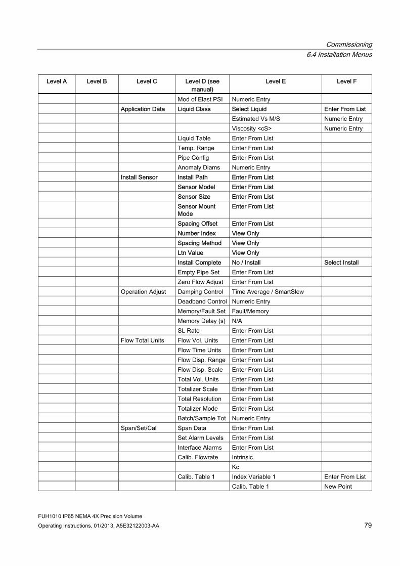
Commissioning 6.4 Installation Menus
FUH1010 IP65 NEMA 4X Precision Volume Operating Instructions, 01/2013, A5E32122003-AA 79
Level A Level B Level C Level D (see manual)
Level E Level F
Mod of Elast PSI Numeric Entry Application Data Liquid Class Select Liquid Enter From List Estimated Vs M/S Numeric Entry Viscosity <cS> Numeric Entry Liquid Table Enter From List Temp. Range Enter From List Pipe Config Enter From List Anomaly Diams Numeric Entry Install Sensor Install Path Enter From List Sensor Model Enter From List Sensor Size Enter From List Sensor Mount
Mode Enter From List
Spacing Offset Enter From List Number Index View Only Spacing Method View Only Ltn Value View Only Install Complete No / Install Select Install Empty Pipe Set Enter From List Zero Flow Adjust Enter From List Operation Adjust Damping Control Time Average / SmartSlew Deadband Control Numeric Entry Memory/Fault Set Fault/Memory Memory Delay (s) N/A SL Rate Enter From List Flow Total Units Flow Vol. Units Enter From List Flow Time Units Enter From List Flow Disp. Range Enter From List Flow Disp. Scale Enter From List Total Vol. Units Enter From List Totalizer Scale Enter From List Total Resolution Enter From List Totalizer Mode Enter From List Batch/Sample Tot Numeric Entry Span/Set/Cal Span Data Enter From List Set Alarm Levels Enter From List Interface Alarms Enter From List Calib. Flowrate Intrinsic Kc Calib. Table 1 Index Variable 1 Enter From List Calib. Table 1 New Point

Commissioning 6.4 Installation Menus
FUH1010 IP65 NEMA 4X Precision Volume 80 Operating Instructions, 01/2013, A5E32122003-AA
Level A Level B Level C Level D (see manual)
Level E Level F
Table Active 1 No/Yes- Clear Table 1 No/Yes Calib. Table 2 Same as Table 1 Calib. Table 3 Same as Table 1 Display Setup Select Data Enter From List Data Display Enter From List Time Base Enter From List StripChart Clear No/Yes Logger Setup Logger Mode Enter From List Logger Data Enter From List Logger Interval Enter From List Logger Events Enter From List Display Logger Enter From List I/O Data Control Analog Out Setup Enter From List Relay Setup Relay 1,2,3,4 Analog Inp Setup Enter From List Diagnostic Data Path Select 1,2, 1 & 2 Path Enable No/Yes Flow Data Enter From List Application Info Enter From List Liquid Data Enter From List Site Setup Data Enter From List Test Facilities Enter From List Print Site Setup No/Yes Site Created: View Only Meter Facilities
Preferred Units
English
Metric Table Setups Pipe Table Create/Edit Pipe Enter From List Delete Pipe Enter From List Sensor Type Enter From List Logger
Control Display Logger Off/Line Wrap
No Line Wrap
Output Logger Yes/No Circular Memory Yes/No Est LogTime Left View Only Clear Logger Yes/No Memory
Control Log Memory Left Yes/No
Memory Map Yes/No Defragment Yes/No

Commissioning 6.4 Installation Menus
FUH1010 IP65 NEMA 4X Precision Volume Operating Instructions, 01/2013, A5E32122003-AA 81
Level A Level B Level C Level D (see manual)
Level E Level F
Analog Out Trim
Trim Io1 Operate / Trim @ 4mA
Trim Io2 Operate / Trim @ 4mA
Trim Vo1 Operate / Trim @ 2V
Trim Vo2 Operate / Trim @ 2V
Trim Pgen1 Operate / Trim @ 1Khz
Trim Pgen2 Operate / Trim @ 1Khz
RTD Calibrate RTD1 Factory / User Cal RTD2 Factory / User Cal Clock Set Date (MM.DD.YY) Edit Date Time (HH.MM) Edit Time RS-232 Setup Baud Rate Enter From List Parity Enter From List Data Bits 7/8 Line Feed Yes/No Network ID Numeric Entry RTS Key Time Enter From List Backlight Enter From List System Info Version View Only Reset Data/Time View Only mm.dd.yy.hh.mm.ss Op System P/N View Only Checksum View only Code View Only System Time View Only mm.dd.yy.hh.mm.ss Language Enter From
List

Commissioning 6.4 Installation Menus
FUH1010 IP65 NEMA 4X Precision Volume 82 Operating Instructions, 01/2013, A5E32122003-AA
① Menu Cell Data (left-hand column) ⑤ Current Selected Measurement Channel ② Highlighted Menu Cell ⑥ Site Name Identified ③ Menu Prompt Line (Reverse Video) ⑦ Highlighted Data ④ Current Selected Meter Type ⑧ Menu Cell Data (right-hand column)
Figure 6-2 Typical Installation Menu Screen

Functions 77.1 Setting Liquid Parameters
Introduction The flow meter measures and reports the flowing liquid’s sonic velocity (Vs) and its temperature (T). These components create the liquid’s "Vs/T" signature. This signature is a fundamental component of the LiquIdent routine that identifies positively any liquid monitored by the flow meter. Since a temperature change will affect the sonic velocity of the liquid, a method to balance the measured sonic velocity to a fixed reference temperature (15.6ºC/60ºF) is provided. The LiquIdent Slope Factor must be configured to represent the linear change in the liquid’s sonic velocity per degree Fahrenheit. The LiquIdent routine uses this slope factor to maintain an accurate liquid identification as the liquid temperature varies.
Note
The LiquIdent Slope Factor for all liquids within a liquid class should be essentially identical, even though their individual sonic velocities may be very different.
This menu cell allows the LiquIdent Slope Factor to be edited for optimal operation. The LiquIdent Slope Factor default is 2.300.
Calculating the LiquIdent Slope Factor 1. Establish the maximum (Tmax) and minimum (Tmin) operating temperatures for all liquids
within the Liquid Class. For each liquid, note the measured sonic velocity (located in the Diagnostic Data menu in [Liquid Data]) at Tmax and the sonic velocity at Tmin (in-meters-per-second).
2. Use the following formula to calculate the LiquIdent Slope Factors with the Liquid Class:
Note
If the Celsius scale is used for Tmax and Tmin, multiply the result by 0.56 to obtain the liquid’s LiquIdent Slope Factor.
3. Calculate the average of all the LiquIdent Slope Factors with the Liquid Class.
FUH1010 IP65 NEMA 4X Precision Volume Operating Instructions, 01/2013, A5E32122003-AA 83
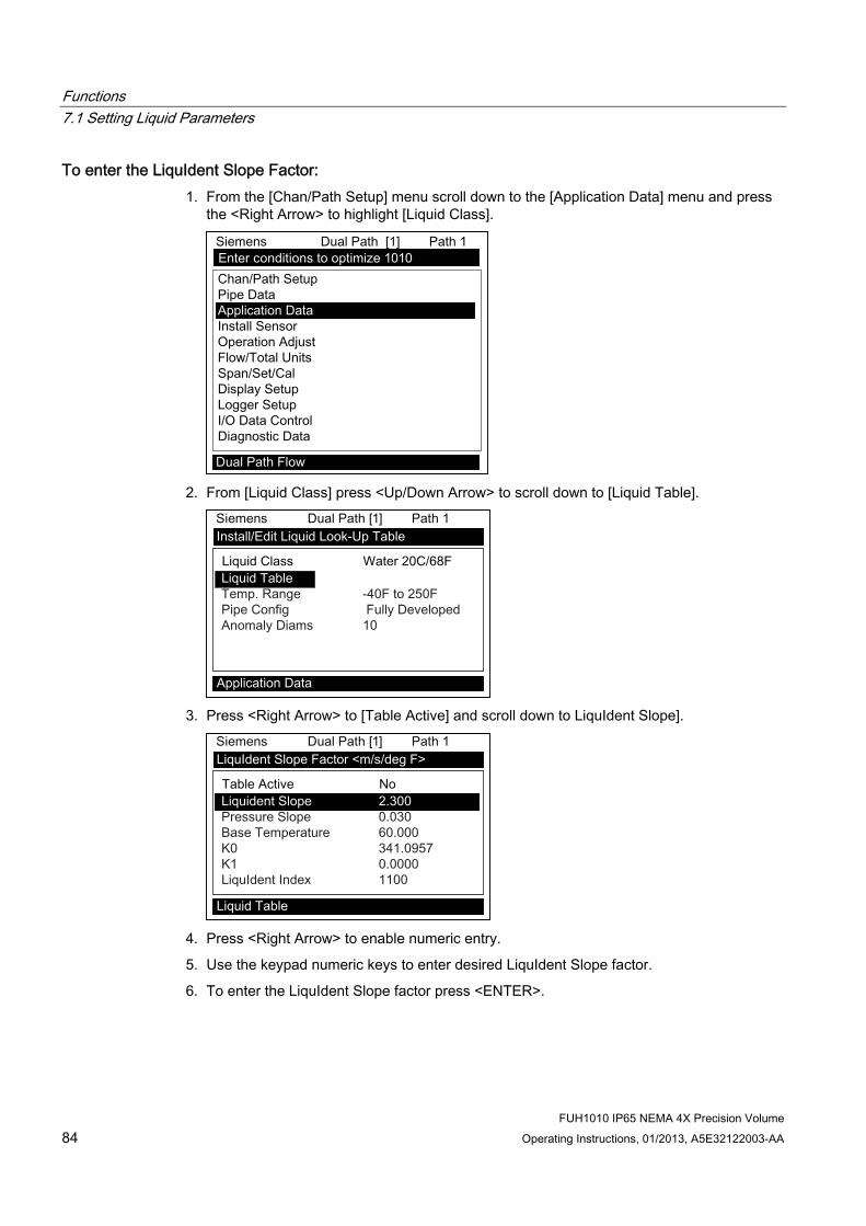
Functions 7.1 Setting Liquid Parameters
FUH1010 IP65 NEMA 4X Precision Volume 84 Operating Instructions, 01/2013, A5E32122003-AA
To enter the LiquIdent Slope Factor: 1. From the [Chan/Path Setup] menu scroll down to the [Application Data] menu and press
the <Right Arrow> to highlight [Liquid Class].
2. From [Liquid Class] press <Up/Down Arrow> to scroll down to [Liquid Table].
3. Press <Right Arrow> to [Table Active] and scroll down to LiquIdent Slope].
4. Press <Right Arrow> to enable numeric entry.
5. Use the keypad numeric keys to enter desired LiquIdent Slope factor.
6. To enter the LiquIdent Slope factor press <ENTER>.

Functions 7.1 Setting Liquid Parameters
FUH1010 IP65 NEMA 4X Precision Volume Operating Instructions, 01/2013, A5E32122003-AA 85
Setting the Pressure Slope The flow meter measures and reports the flowing liquid’s sonic velocity (Vs) and its related pressure (P). Since a pressure change will affect the sonic velocity of the liquid, a method to balance the measured sonic velocity to a fixed reference temperature (15.6ºC/60ºF) default) is provided. The Pressure Slope Factor default is 0.030 (m/s per PSI). This pressure slope factor helps maintain an accurate liquid identification as the LiquIdent factor and liquid temperature vary.
The flow meter has the ability to accept a 4-20 mA input for pressure. If used, the flow meter will process pressure data based on the analog input. This is recommended for pipelines that have wide pressure variances.
To calculate a liquid's Pressure Slope Factor: 1. Establish the maximum (Pmax) and minimum (Pmin) pressures for all liquids within the
Liquid Class. For each liquid, note the measured sonic velocity at Pmax and the sonic velocity at Pmin (in-meters-per-second).
2. Use the following formula to calculate the Pressure Slope Factors with the Liquid Class:
3. Calculate the average of all the Pressure Slope Factors within the Liquid Class.
To enter the Pressure Slope Factor 1. From the [Liquid Table] menu cell, press <Up/Down> Arrow> to scroll down to [Pressure
Slope].
2. Press <Right Arrow> to enable numeric entry.
3. Use the keypad numeric keys to enter the desired Pressure Slope Factor.
4. To enter the Pressure Slope Factor press <ENTER>.
5. This moves the highlight down to [Base Temperature].
Setting the Base Reference Temperature The flow meter uses a reference Base Temperature of 15.6ºC (60ºF) for the LiquIdent calculation and Standard Volume compensation. Any temperature can be entered and used as the reference Base Temperature (e.g., 20ºC/68ºF).
To enter the Base temperature: 1. From the [Liquid Table] menu cell, press <Up/Down Arrow> to scroll down to [Base
Temperature].
2. Press <Right> to enable numeric entry.
3. Use the keypad numeric keys to enter the desired Base Temperature.
4. To enter the Base Temperature press <ENTER>.

Functions 7.1 Setting Liquid Parameters
FUH1010 IP65 NEMA 4X Precision Volume 86 Operating Instructions, 01/2013, A5E32122003-AA
Note
Altering the Base Temperature will result in all "Base" outputs and settable items to be referenced to the selected temperature.
Entering K0 and K1 parameters (API thermal expansion coefficients): The K0 and K1 parameters represent the thermal expansion coefficients for the Liquid Class. The meter requires these parameters to apply the proper volume correction. These coefficients can be found in the ASTM designation: D1250 or the API standard: 2540. The default K0 and K1 values are 341.0957 and 0.0, respectively. These correspond to Crude Oils. If these values suit the application, these menu cells can be bypassed by pressing the <Down Arrow> twice. The following tables list K0 and K1 values of some common classes of liquids.
Table 7- 1 Common Liquid Classes
Liquid K0 K1 Crude Oils 341.0957 0.0 Gasoline and Naphthenes 182.4571 0.2438 Jet Fuels and Kerosenes 330.3010 0.0 Diesels, Heating Oils and Fuel Oil
144.0427 0.1896
Table 7- 2 Liquid Table Data
LiquIdent Viscosity Compressibility Liquid Name K0 K1 1100 0.15 0.00001 MTBE (Additive
for Oxygen) 192.4571 0.2438
1180 0.6 0.00001 LFP (Lead Free Premium)
192.4571 0.2438
1200 0.6 0.00001 LR (Leaded Regular)
192.4571 0.2438
1330 1.0 0.00001 KEROSENE 330.301 0.0 1350 1.16 0.00001 AVJET (AV Jet
Fuel) 330.301 0.0
1380 1.95 0.00001 HSD (High Sulfur Diesel)
103.872 0.2701
1410 2.75 0.00001 LSD (Low Sulfur Diesel)
103.872 0.2701
1420 3.2 0.00001 GASSOIL (Sour Light Cycle Gas Oil)
103.872 0.2701
1490 119.00 0.00001 FO (Fuel Oil) 103.872 0.2701 1579 1049.00 0.00001 HFO (Heavy
Fuel Oil) 103.872 0.2701

Functions 7.1 Setting Liquid Parameters
FUH1010 IP65 NEMA 4X Precision Volume Operating Instructions, 01/2013, A5E32122003-AA 87
Entering the K0 and K1 thermal expansion coefficients: 1. From the [Application Data] menu press <Right Arrow> to highlight [Liquid Class] menu.
2. Scroll down to [Liquid Table] menu cell and press <Right Arrow>.
3. Press <Up/Down Arrow> to scroll down to [K0].
4. Press <Right Arrow> to enable numeric entry.
5. Use the keypad numeric keys to enter the desired K0 factor.
6. To enter the K0 factor press <ENTER>.
7. This moves the highlight down to [K1].
8. Repeat the procedure for [K1].
Setting the LiquIdent Index A Liquid Class must have an associated LiquIdent Index Scale. The flow meter uses this scale to compensate its outputs for variations in liquid type, specific gravity, and viscosity. The LiquIdent Index Scale enables positive liquid identification.
A LiquIdent Index is the sonic velocity for the liquid at the Base Temperature, generally 15ºC (60ºF). When a LiquIdent Index is entered for a particular liquid within the Liquid Class, the liquid’s specific gravity and its viscosity must also be entered at the LiquIdent Index.
To create a LiquIdent Index Scale for the Liquid Class, a minimum of two LiquIdent Indices are required to be entered. If desired, up to thirty-two LiquIdent indices can be entered. However, the computer only needs two to establish a linear relationship between LiquIdent and the physical properties of the liquids.
The scale can be fine-tuned by manually adjusting the factors at up to thirty-two separate points.
To enter the LiquIdent Index: 1. From the [Application Data] press <Right Arrow> to highlight [Liquid Class] menu.
2. Scroll down to [Liquid Table] menu and press <Right Arrow>.
3. Press <Up/Down Arrow> to scroll down to [LiquIdent Index].
4. Press <Right Arrow> twice to enable numeric entry Index Value.
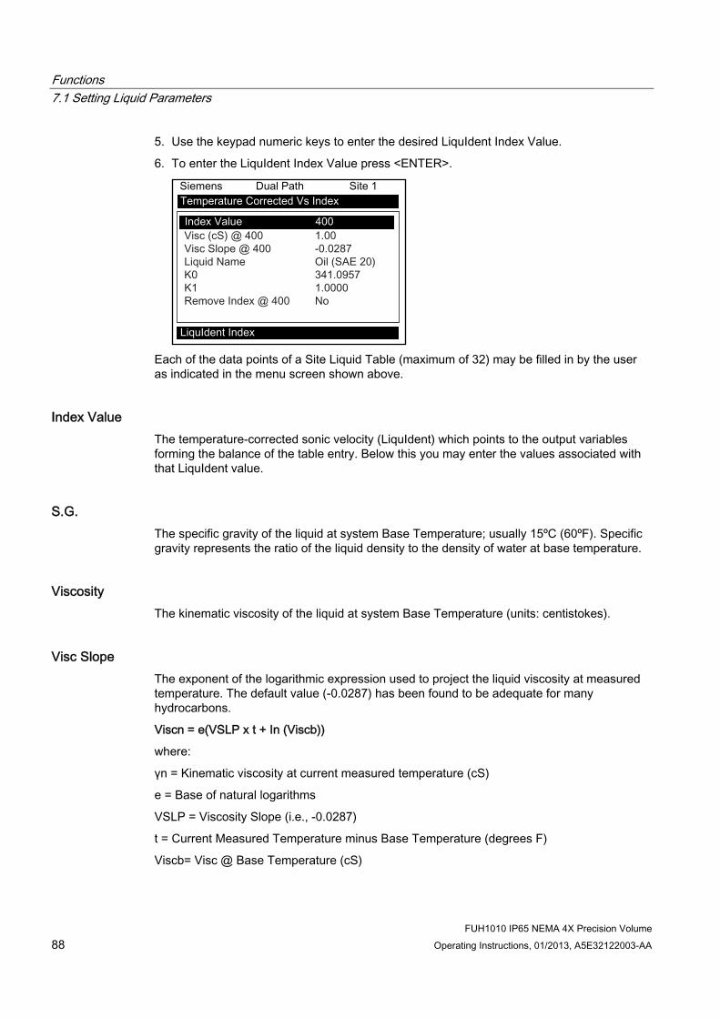
Functions 7.1 Setting Liquid Parameters
FUH1010 IP65 NEMA 4X Precision Volume 88 Operating Instructions, 01/2013, A5E32122003-AA
5. Use the keypad numeric keys to enter the desired LiquIdent Index Value.
6. To enter the LiquIdent Index Value press <ENTER>.
Each of the data points of a Site Liquid Table (maximum of 32) may be filled in by the user as indicated in the menu screen shown above.
Index Value The temperature-corrected sonic velocity (LiquIdent) which points to the output variables forming the balance of the table entry. Below this you may enter the values associated with that LiquIdent value.
S.G. The specific gravity of the liquid at system Base Temperature; usually 15ºC (60ºF). Specific gravity represents the ratio of the liquid density to the density of water at base temperature.
Viscosity The kinematic viscosity of the liquid at system Base Temperature (units: centistokes).
Visc Slope The exponent of the logarithmic expression used to project the liquid viscosity at measured temperature. The default value (-0.0287) has been found to be adequate for many hydrocarbons.
Viscn = e(VSLP x t + In (Viscb))
where:
γn = Kinematic viscosity at current measured temperature (cS)
e = Base of natural logarithms
VSLP = Viscosity Slope (i.e., -0.0287)
t = Current Measured Temperature minus Base Temperature (degrees F)
Viscb= Visc @ Base Temperature (cS)

Functions 7.2 Selecting Flow Units
FUH1010 IP65 NEMA 4X Precision Volume Operating Instructions, 01/2013, A5E32122003-AA 89
Liquid Name You may install a name here if you wish to identify the liquid in the meter's datalogger report. To prevent flicker of two names when the LiquIdent is at transition points, you may wish to create ranges of LiquIdent and additional entries in between with no name installed.
K0 and K1 These variables, also found in the global table area as defaults for each table point, are used by the ASTM D1250 or API 2540 routine to project liquid S.G. at the measured temperature (refer to Entering K0 and K1 Parameters above). If you are measuring only one class of liquids, for example oils, accept the default for each data point. For a pipeline carrying many different hydrocarbon classes, you may be able to create a table that will automatically move from one set of factors to another, based on LiquIdent. Just as with liquid names, you should create ranges of LiquIdents where the appropriate K0/K1 variables are installed for their corresponding liquids.
7.2 Selecting Flow Units
Selecting Flow Units The [Flow/Total Units] menu is available after selecting a meter type and measurement channel. Use the [Flow/Total Units] menu to select volumetric flow units and an associated time base for the flow rate and total outputs. After making your selections, a view-only menu cell shows the resultant scaling. Another menu cell lets you adjust the output resolution by selecting a display range.
Selecting Flow Volume Units The [Flow Vol. Units] option list allows you to select the rate units the flow meter uses to report volumetric or mass flow. If you select mass units, the flow meter uses the specific gravity parameter to convert volumetric flow to mass flow. The default in English Units for liquid is [Gallons].
To select a Volumetric or Mass unit: 1. Press the <MENU> key and [Meter Type] will be highlighted.
2. Press the <Right Arrow> to [Dual Path Flow] and then press <ENTER>.
3. The [Dual Path Flow] menu with appear with [Chan/Path Setup] menu item highlighted.

Functions 7.2 Selecting Flow Units
FUH1010 IP65 NEMA 4X Precision Volume 90 Operating Instructions, 01/2013, A5E32122003-AA
4. Scroll down to the [Flow/Total Units] menu and press the <Right Arrow> to select the [Flow Vol. Units] menu.
5. Press the <Right Arrow> to select the option list and use the <Up/Down Arrows> to select
the desired units.
6. Press <ENTER> to store selection.
Totalizer Modes The Totalizer function operates in any of the modes listed below:
Table 7- 3 Totalizer Modes
Mode Flow Direction Notes POSFLOW positive flow Accumulates flow in positive
direction only NEGFLOW negative flow Accumulates flow in reverse
direction only NETFLOW positive or negative flow Adds to positive total; subtracts
from reverse total

Functions 7.2 Selecting Flow Units
FUH1010 IP65 NEMA 4X Precision Volume Operating Instructions, 01/2013, A5E32122003-AA 91
Note
NETFLOW (default) is best for applications where there may be zero flow for long periods. It minimizes false Totalizer register increments due to data scatter. Press the <Down Arrow> to accept the default setting.
Selecting Totalizer modes 1. Press the <MENU> key and [Meter Type] will be highlighted.
2. Press the <Right Arrow> to [Dual Path Flow] and then press <ENTER>.
3. The [Dual Path Flow] menu with appear with [Chan/Path Setup] menu item highlighted.
4. Scroll down to the [Totalizer Mode] menu and press the <Right Arrow> to select the Totalizer Mode option list.
5. Press the <Up/Down Arrows> to select the desired mode.
6. Press <ENTER> to store selection.
Totalizer Mode Controls From the RS-232 serial port all of the Totalizer commands listed below can be executed using PC keyboard function keys via VT100 terminal key emulation.
Note
Si-Ware or HyperTerminal should be in the Data Display mode when invoking the function keys referenced in the table below. Use the key sequence <Ctrl L> to display the Data Display mode.

Functions 7.2 Selecting Flow Units
FUH1010 IP65 NEMA 4X Precision Volume 92 Operating Instructions, 01/2013, A5E32122003-AA
Communications Setup Connect the flow meter to your PC. Refer to Appendix A for programming and communicating, if needed.
1. Access Si-Ware or, if using a PC, access HyperTerminal from the PC [Programs] menu, then select [HyperTerminal].
2. In [Connection Description] dialog box, enter a connection name (e.g. FUP1010). Click [OK].
3. In [Phone Number] dialog box, select [Direct to COM 1 (or COM 2)]. Click [OK] to select.
4. In [Properties] dialog box, enter RS-232 parameters. Click [OK].
5. At terminal screen, click [File]. Select [Properties].
6. Select [Settings] tab. At [Emulation] box, select [VT-100].
7. Select [ASCII Setup]. In [ASCII Sending] uncheck boxes. In [ASCII Receiving] check [Append line feeds to incoming line ends.]. Click [OK].
8. At the Terminal screen, press <ENTER> and the Data Display mode appears.
9. If not, to enter the Data Display mode type MENU and then press <Ctrl L>.

Functions 7.2 Selecting Flow Units
FUH1010 IP65 NEMA 4X Precision Volume Operating Instructions, 01/2013, A5E32122003-AA 93
Table 7- 4 Totalizer Controls (the "n" in <Fn> = channel number)*
Key PC # Command Description F1 F2 F3 F4
CLRTOT (also clears overflow)
Resetting the Totalizer registers clears all total data accumulated during operation. Note: In Dual Path mode, the Totalizer operates only on the virtual system channel (Ch 3). Therefore in this case, the CLRTOT trigger would be <F3> <1> Commands that can be invoked from Si-Ware or HyperTerminal: Terminal Command: CLRTOT 1.
F1 F2 F3 F4
NOTOT (Totalizer Freeze)
Invoking the NOTOT command disables the Totalizer. Totalization will not resume until you repeat the <Fn> <2> key sequence. When you activate NOTOT, an N precedes the TOTAL symbol (i.e. [NTOTAL]) on the LCD Screen. Commands that can be invoked from Si-Ware or HyperTerminal: Terminal Command: NOTOT 1 = Stop Totalizer Terminal Command: NOTOT 1 = Start Totalizer
F1 F2 F3 F4
LAPTOT (Totalizer snapshot)
The LAPTOT command freezes the Totalizer screen display. However, the flow meter will continue to update its internal registers. The flow meter will show the current total when you repeat the <F1>< 3> key sequence. When you activate LAPTOT, an L precedes the TOTAL symbol (i.e., [LTOTAL]) on the HyperTerminal screen.
F1 F2 F3 F4
CLEAR (Batch/Tot register)
Clears the Batch/Sample Totalizer register. The flow meter maintains a separate Totalizer register for Batching or Sampling applications but cannot be accessed directly. It is used for relay control only. If you assign the system relay to this function, a momentary (200 ms) relay pulse occurs whenever the BATCHTOT register accumulates a specified liquid quantity. In the [Batch/Sample Tot] menu cell the required total flow volume is entered to activate the relay,. This numeric entry must reflect the selected flow total units. The [Totalizer Scale] menu cell shows the applicable flow total units. The sign of the Batch/Sample Total determines positive or negative accumulation.
F1 F2 F3 F4
CLEAR (Makeup Latch)
Clears the Makeup Latch. Refer to the Span Data menu [Set Alarm Levels] and then the [Makeup Latch] On / Off option.
*Use the <F1> key as the "Lead-in command" for 4-Path Totalizer operations.

Functions 7.3 Span Data
FUH1010 IP65 NEMA 4X Precision Volume 94 Operating Instructions, 01/2013, A5E32122003-AA
7.3 Span Data The [Span Data] menu allows you to set 0% and 100% output limits for volumetric flow (Vfo), absolute flow (Vfab) and sonic velocity (Vs). Each menu cell shows appropriate rate units and time base. If you change flow rate units after spanning the system, the computer automatically updates the output data setup to reflect the change. Span limits apply to both the analog outputs and the on-screen strip chart. The flow outputs operate as follows:
Vfo Spanned Volumetric
The minimum and maximum flow rate entries establish the Vfo span. The Max Flow menu cell sets 100% of span. The Min Flow menu cell sets 0% of span. Use signed numbers for bi-directional spanning. Note that negative (reverse) flow is always lower than positive flow, whatever its absolute magnitude. For example, for a flow measurement range of -30 GPM to +10 GPM, the 4mA span will be -30 GPM, and the 20mA span will be +10 GPM.
Vfab Spanned Absolute Volumetric Flow Rate
Vfab is the absolute magnitude of the volumetric flow rate (Vfo). There are no menu cells provided to span this output. Vfab shares the Vfo span entries. The Vfab minimum span is always zero. The maximum span for Vfab is the largest absolute value of either the min. or the max. flow rate (Vfo) entries. For example, a span between +10 GPM and -30 GPM, spans the Vfab output from 0 GPM to 30 GPM.
Vs Spanned liquid sonic Velocity
Vs is the sonic velocity in meters-per-second (m/s) of the flowing liquid. The min. and max. Vs entries establish the Vs span. Max Vs (m/s) defines 100% of span. The Min Vs (m/s) defines 0% of span.
Maximum span values represent: Minimum span values represent:
100% of span Current output of 20mA Voltage output of 10 VDC Pulse output of 5000 Hz
0% of span Current output of 4mA Voltage output of 0 VDC Pulse output of 0 Hz
To change the default Span Data settings: 1. At [Meter Type], press <Right Arrow> to [Dual Path Flow] and press <ENTER>.
2. At [Chan/Path Setup] press <Right Arrow> to <Clamp-on> and press <ENTER>.
3. At [Clamp-on] menu scroll down to [Span/Set/Cal] and press <Right Arrow>.

Functions 7.3 Span Data
FUH1010 IP65 NEMA 4X Precision Volume Operating Instructions, 01/2013, A5E32122003-AA 95
4. Highlight [Span Data] and press the <Right Arrow>.
5. Highlight [Max Flow] and press <Right Arrow> to. Input 100% flow rate numeric data for
20mA. Press <ENTER> to store data.
6. Scroll down to [Min Flow].Press <Right Arrow> to input 0% flow rate numeric data for 4mA. Press <ENTER> to store data.
① Input numeric flow data here.
PGEN Function The [PGEN P/Unit Volume] menu cell entry controls a digital output pulse function and is available in all units with 7ME3600-x and 7ME3603-x part numbers. It allows the assigning of PGEN digital signal pulses per unit of volume. For example, 1000 output pulses per unit of liquid.
Note
The unit of volume is determined by the Volume Units initially selected from the [Total Volume Units] menu cell option list.

Functions 7.3 Span Data
FUH1010 IP65 NEMA 4X Precision Volume 96 Operating Instructions, 01/2013, A5E32122003-AA
Table 7- 5 Input/Output Wiring (TB2) - 7ME39400AL03 Expanded I/O Module
Pin# Signal Definition Description Function Dual/Quad Path Only
12 PG4 POS [+] Total TTL POS [+] Total TTL 11 PG3 POS [+] Total OC POS [+] Total OC 10 PG2 NEG [-] Total TTL) NEG [-] Total TTL
PG1 NEG [-] Total OC
0-5000 Hz frequency output , assignable
9 NEG [-] Total OC Use reference ground for returns (TB2-2 and TB2-4)
+5V
+5V
PG1
PG3
PG4
1
32
1
32
PG2
DPGEN_1-Ø1
DPGEN_1-Ø2
DPGEN_2-Ø2
DPGEN_2-Ø1 2
3
4
5
TTL/CMOS
2
3
4
5
TTL/CMOS
Figure 7-1 PGEN Wiring Diagram
Note
TB2-9 and TB2-11 are Open Collector Outputs that require external pull-up resistors for operation. See table for External Supply Voltage and suggested resistor value and ratings. Maximum current into the transistor is 100mA. Maximum Voltage is +36 VDC.
NOTICE Transistor Damage
Negative voltages with respect to ground will permanently damage transistors.
Use caution when applying power to circuit boards.

Functions 7.3 Span Data
FUH1010 IP65 NEMA 4X Precision Volume Operating Instructions, 01/2013, A5E32122003-AA 97
Table 7- 6 Open Collector User Resistor Recommendations
User Supply Voltage (VDC)
External Resistor Expected Recommended Resistor Wattage (Watts) (Ohms) Current Draw (mA)
5 270 18.5 1/2 9 510 17.6 1/2
12 680 17.6 1/2 18 1000 18 3/4 24 1500 16 1 28 1800 15.5 1 1/4 36 2400 15 1 1/4
To change the default PGEN settings: 1. From the [Span Data] menu press <Right Arrow>.
2. Highlight the [PGEN P/Unit Volume] menu cell and press <Right Arrow> to activate the numeric entry.
① Input PGEN pulse factor here.
3. Use the numeric keys to enter the desired number of PGEN pulses per unit volume.
Note
Ensure that the number entered will provide sufficient resolution while remaining within the 20 Hz to 5000 Hz pulse frequency range. Note that the PGEN output will stop sending pulses at flow rates corresponding to frequencies less than 20 Hz. In this case the PGEN value must then be increased.
4. To store data press <ENTER>.

Functions 7.3 Span Data
FUH1010 IP65 NEMA 4X Precision Volume 98 Operating Instructions, 01/2013, A5E32122003-AA
Adjusting the PGEN Output The default setting for the Digital PGEN output provides a 5000 Hz frequency at an assumed maximum velocity of 100 ft/sec. In certain cases it may be necessary to change this default PGEN value. For example:
● If the PGEN signal cable is very long, then the added cable capacitance may prevent reliable RTU pulse detection at or near 5000 Hz. In this case it may be necessary to decrease the PGEN (Pulses / Unit Volume) setting using the equation below.
Pulses / Unit Volume = MaxFreq / MaxFlow
Where:
MaxFreq = Maximum desired frequency (Hz)
MaxFlow = Maximum flow rate (Unit Volume / second)
For very low operating flow rates, the pulse frequency may approach the 20 Hz limit of the PGEN output. In this case it may be necessary to increase the PGEN (Pulses / Unit Volume) setting.
Pulses / Unit Volume = MinFreq / MinFlow
Where:
MinFreq = Minimum desired frequency (Hz). Must be greater than 20 Hz!
MinFlow = Minimum operating flow rate (Unit Volume / second)
Note
If STD VOL is selected then the "unit volume" for PGEN will represent Standard Volume, not actual volume.
Forcing the PGEN Output Frequency To test the operation of the flow meter with a Remote Transmitting Unit (RTU), or other pulse counting device, it may be necessary to force the PGEN output frequency, especially when the pipeline is not flowing during flow meter commissioning. This can be accomplished by setting the AnCal diagnostic value to a flow rate corresponding to the desired frequency output. (Refer to the appropriate paragraph in your manual for operation of the AnCal function.)
The example below demonstrates how to calculate the AnCal flow rate based on the desired pulse output frequency and the entered PGEN (Pulses / Unit volume) setting:
For PGEN setting = 53 Pulses /CU FT and a desired frequency = 1000 Hz
1. Temporarily change flow rate units to CU FT / SEC (Use same volume units as Totalizer.)
2. Set AnCal = 1000 / 53 = 18.868 CU FT / SEC
3. 1000 Hz frequency should now be observed on the PGEN output.

Functions 7.4 Analog Out Setup
FUH1010 IP65 NEMA 4X Precision Volume Operating Instructions, 01/2013, A5E32122003-AA 99
7.4 Analog Out Setup The flow meter provides current, voltage and pulse-rate analog outputs. The [Analog Out Setup] menu allows you to assign data functions for these signals. The transmitter terminal strip contains the analog output terminals.
Table 7- 7 Analog Outputs
Io (Isolated Current) 4 to 20mA varies in proportion to an assigned data function.
Vo (DC Voltage) 0 to 10 VDC varies in proportion to an assigned data function.
Pgen (TTL Logic) 0 to 5000 Hz varies in proportion to an assigned data function.
Table 7- 8 Analog Out Setup Data Categories
S LiquIdent m/s System sonic velocity compensated for temperature.
S Viscosity System liquid viscosity. S T1 Current liquid temperature. S Vfo System spanned volumetric flow (unsigned). S Vfab System spanned and signed absolute flow. S Vs System sonic velocity. S Valc System signal amplitude. S Vaer System aeration number. Iin1, Iin2, Iin3, Iin4 Represents a re-transmit of the analog input
signals (e.g., Pressure and Temp inputs can be transmitted on the 4/20mA output).
Note
For Multi-Path flow meters: "1" = Path 1, "2" = Path 2, "3" = Path 3, "4" = Path 4 and "S" represents the system or average channel. These characters appear to the left of the option list parameter.
Io Output Functions
Note
4-20mA outputs also provide a fault indication by dropping to 2mA if assigned to flow rate and under fault conditions.

Functions 7.4 Analog Out Setup
FUH1010 IP65 NEMA 4X Precision Volume 100 Operating Instructions, 01/2013, A5E32122003-AA
Assigning a function to the current output: 1. From the [Chan/Path Setup] menu scroll to [I/O Data Control].
2. Press <Right Arrow] to highlight the [Analog Out Setup] menu.
3. Press <Right Arrow> twice to access the [Io] option list.
4. Move the cursor to the desired data function by pressing <Up/Down Arrow>.
5. To store selection press <ENTER>.
Vo Output Functions The Vo analog output is a 0-10 VDC signal that varies linearly in relation to a selected function.

Functions 7.5 Analog Input Setup
FUH1010 IP65 NEMA 4X Precision Volume Operating Instructions, 01/2013, A5E32122003-AA 101
Assigning a function to the voltage output: 1. From the [Analog Out Setup] menu, press <Right Arrow> to access the [Vo1] option list.
2. Move the cursor to the desired data function by pressing <Up/Down Arrow>.
3. To store selection press <ENTER>.
Note
Refer to drawing 1010N-7-7 for Analog output connections.
7.5 Analog Input Setup The optional Analog Input Setup function assigns an active analog input to a measurement channel/path. The flow meter provides four DC current input ports for single channel and Dual Path units. The DC current input ranges from a zero level of 4mA to a full scale of 20mA. The [Analog Inp Setup] menu cell allows you to enable this port and then span it to any desired scaling.
For example, when using the analog input viscosity function the numeric variables might be spanned as follows: 4mA=1 (water) and 20mA=100 (more viscous liquid). This spanning configuration allows the flow meter to use this constant numerical change to improve calibration in real time.
The various flow meter models allow you to associate the analog input to active system variables such as viscosity and others (see table below).
Note
Refer to the Installation Drawings or I/O Module markings for the locations of these inputs and wiring procedures.
Table 7- 9 I/O Data Control Menu
Input Off Aux cS cP PSIA BARA T1 Deg F T1Deg C T2 Deg F T2 Deg C
Iin1
4 mA 20 mA
Numeric entry Numeric entry
I/O Data Control Analog Inp Setup
Iin2 / Iin3 / Iin4 See In1 option list

Functions 7.5 Analog Input Setup
FUH1010 IP65 NEMA 4X Precision Volume 102 Operating Instructions, 01/2013, A5E32122003-AA
The flow meter recognizes the first analog input variable that is assigned to any given parameter and ignores any subsequent input with the same assignment. For example, if Iin1 and Iin2 are both assigned to represent pressure (PSIA), the flow meter will only use the pressure input from Iin1.
Setting the Analog Current Input The DC current input port must be enabled first. From the [Analog Inp Setup] menu proceed as follows:

Functions 7.5 Analog Input Setup
FUH1010 IP65 NEMA 4X Precision Volume Operating Instructions, 01/2013, A5E32122003-AA 103
1. Access the [Iin1] option list by pressing the <Right Arrow> twice.
2. Move the cursor down to [Aux] by pressing the <Down Arrow> and then press <ENTER>.
This enables the port to receive an input current. The cursor moves to [4 mA].
3. To enable numeric entry, press the <Right Arrow>. Type a numeric value corresponding
to a 4mA input signal.
4. To store the data press <ENTER>. This moves the cursor to [20 mA].
5. To enable numeric entry, press the <Right Arrow>. Type the numeric value corresponding to a 20mA input signal.
6. To store the data, press <ENTER>.

Functions 7.6 Expanded I/O Option
FUH1010 IP65 NEMA 4X Precision Volume 104 Operating Instructions, 01/2013, A5E32122003-AA
7.6 Expanded I/O Option
Note
For SITRANS F 1010 systems equipped with 1010N-7 Expanded I/O Module only.
The 1010N-2 I/O Module and 1010N-7 Expanded I/O Module both provide current (Io1, Io2), voltage (Vo1 and Vo2) and pulse rate (Pgen 1 and Pgen 2) analog outputs. The Expanded I/O Module Option allows users to drive as many as four additional 4-20mA loop-powered instrumentation outputs. The following information is intended to be used with the I/O Data Control, Span Data and Analog Output Trim Menu information in the manual.
The SITRANS F 1010 flow meter provides an Analog Output Setup menu that allows the user to assign data functions for these output signals (refer to Analog Output Setup in the appropriate manual). In addition, refer to Installation Drawings 1010N-2-7 and 1010N-7-7 in the manual for additional connection information and terminal block numerical designators.
Note
All flow meters in the SITRANS F 1010 product family can accept the Expanded I/O Module except 4-Channel flow meters and compact units.
Note
Use the I/O Data Control menu to assign data functions to the analog outputs.

Functions 7.6 Expanded I/O Option
FUH1010 IP65 NEMA 4X Precision Volume Operating Instructions, 01/2013, A5E32122003-AA 105
Expanded I/O Module Option The Expanded I/O Module Option provides expanded Io analog outputs. It is implemented through the use of a 1010N-7 Expanded I/O Module occupying the same position as the 1010N-2 I/O Module. This option allows users to drive up to four additional 4-20mA loop-powered instrumentation outputs.
Note
The flow meter menu does not indicate that these supplementary outputs are present and available. The outputs, in addition to being loop-powered, are isolated from one another as well as the flow meter.
Expanded I/O Module Option Identification To verify that your flow meter has the Expanded I/O Module Option installed check the following:
The designation C should be part of the flow meter MLFB part number.
For example: 7ME36003C...
1010N-2 I/O Module The conventional 1010N-2 I/O module provides the following:
● Two self-powered, isolated 4-20mA current loops (signals Io1 and Io2) that are assignable and spannable by the user to many flow meter variables such as flow, sonic velocity, signal strength, etc. These self-powered outputs also provide an industry-standard fault indication by dropping to 2mA if assigned to flow rate and under fault conditions. Note that these outputs, though isolated from the system, are NOT isolated from each other.
● Two 0-10 VDC outputs (signals Vo1 and Vo2) that are also assignable and spannable by the user as above. These are also self-powered, but are not isolated from the system.
● Two 0-5000 Hz Pgen signals (Pgen1 and Pgen2) also assignable and spannable by the user. These are TTL level pulses.
The 1010N/DN class of flow meters has a total of six analog outputs as indicated above. In addition (refer to Installation Drawings 1010N-2-7 and 1010N-7-7):
● Alarms/Status/Totalizer pulses are generally presented as relay closures as either Mercury Wetted Form 1A or Dry Reed Form C relays.
● Analog inputs, when provided, are in the form of 4-20mA non-isolated inputs.
● The meter also has four non-isolated Totalizer command lines providing Totalizer Clear and Totalizer Hold (NoTot) functionality.

Functions 7.6 Expanded I/O Option
FUH1010 IP65 NEMA 4X Precision Volume 106 Operating Instructions, 01/2013, A5E32122003-AA
1010N-7 Expanded I/O Module Option The Expanded I/O Module Option provides all of the above plus the following outputs:
● The four signals that drive the pulse generator outputs (Pgen1 and Pgen2) and voltage outputs (Vo1 and Vo2) of the flow meter create four current outputs: Aux Io1, Aux Io2, Aux Io3 and Aux Io4 (see diagram).
● By spanning and assigning a system variable to 0-10 volt (Vo1 and Vo2) or 0-5000 Hz pulse output (Pgen1 and Pgen2) the module simultaneously outputs these signals to the Expanded I/O Module Option Aux outputs. For a 2-Channel flow meter the programming assignments are as follows:
Table 7- 10 Typical 2-Channel Flow Meter Expanded I/O Option Connections
Channel Signal AUX Io Meter Menu Display CH1 Pgen1
Vo1 Io1 Io3
Vo1 Pgen1
CH2 Pgen2 Vo2
Io2 Io4
Vo1 Pgen1
Note
The four Aux Io outputs are externally powered.

Functions 7.6 Expanded I/O Option
FUH1010 IP65 NEMA 4X Precision Volume Operating Instructions, 01/2013, A5E32122003-AA 107
Expanded I/O Module Option Programming The diagram below illustrates the Expanded I/O Module Option programming for a Single Channel flow meter with a 1010N-7 Expanded I/O Module.
① Flow meter Internal Connections ② Output Terminal Strip
Note
The 1010N-7 Expanded I/O Module auxiliary output signals (Aux Io1 - Aux Io4) generated from Pgen1, Pgen2, Vo1 and Vo2 are "mirrored" output currents. For example, if Vo1 is a 5 VDC signal then Aux Io3 will be 12mA.
Note
The method used to create auxiliary current loops makes it impractical to generate the 2mA fault current produced by the primary 4-20mA outputs of the flow meter.

Functions 7.7 Logger Control
FUH1010 IP65 NEMA 4X Precision Volume 108 Operating Instructions, 01/2013, A5E32122003-AA
7.7 Logger Control
Logger Control Menu The Logger Control menu in the [Meter Facilities] menu provides the Logger controls for the flow meter measurement channels and paths. It allows the user to select data items/alarm events, a logging interval and a destination for Logger reports. While the Logger Setup menu is measurement channel/path specific, this Logger Control menu provides global control functions. This means that the settings made here apply to all measurement channels/paths, meter types, operating modes, etc. This is possible because the flow meter stores logged data in a single file.
The [Est LogTime Left] menu view-only menu cell shows an estimate of the hours and minutes of logging time remaining. For convenience sake, the Display Logger command is essentially a duplicate of the menu cell in Logger Setup. It sends Logger data to the graphic screen with or without line wrapping. The Output Logger command sends data to an external device via the RS-232 serial port. The Clear Logger command erases the entire Logger file.
1. From the Meter Facilities menu access the [Logger Control] menu by pressing the <Right Arrow>.
2. Scroll down to [Logger Control]. Press the <Right Arrow> to access the [Logger Control] menu option list.
Table 7- 11 Logger Control Menu Option List
Display Logger Off Line Wrap No Line Wrap
Logger Control
Output Logger No Yes
Circular Memory (Available for Multi-Path units only)
No Yes
Est LogTime Left --:-- Clear Logger No
Yes

Functions 7.7 Logger Control
FUH1010 IP65 NEMA 4X Precision Volume Operating Instructions, 01/2013, A5E32122003-AA 109
Display Logger This menu cell allows you to send the Logger contents to the display screen. This command is effective only after a successful install. You can set the report to scroll on the screen with or without line-wrap. Selecting line wrap, forces a line feed after approximately 40 characters. In addition, you have to enable datalogging and then select items in the Logger Setup menu. Note that this command transmits the data from both channels/paths.
To send Logger contents to the display screen: 1. Press <Right Arrow> to access the [Display Logger] option list.
2. Scroll cursor to either [Line Wrap] or [No Line Wrap] by pressing <Up/Down Arrow>.
3. To view Logger contents press <ENTER>.
4. To return to [Logger Control] press <MENU>.
Output Logger This menu cell allows you to send the Logger contents to an external device (usually a computer or printer) via the flow meter’s RS-232 Serial I/O port. This command is effective only after a successful install. In addition, you have to enable datalogging and select data items in the [Logger Setup] menu.
The flow meter interfaces with most serial printers or personal computers for Logger printouts. You must use the proper cabling between the flow meter and the external device. In addition, you must configure the RS-232 Setup correctly. You should turn off the Logger function before you transmit an extensive printout. This will avoid contaminating the printout with new Logger data. Logger reports are sequential ASCII text files.
To send Logger contents to the RS-232 Serial Port: 1. Check the flow meter-to-external device connections and your RS-232 Setup parameters
(see RS-232 Setup menu).
2. To access the [Output Logger] option list press <Right Arrow>.
3. Scroll the cursor to [Yes] by pressing <Up/Down Arrow>.
Functions 7.7 Logger Control
FUH1010 IP65 NEMA 4X Precision Volume 110 Operating Instructions, 01/2013, A5E32122003-AA
4. To transmit Logger contents to external device via the serial port press <ENTER>.
5. To stop printout press <Left Arrow>.
Circular Memory In its default mode, the Logger collects data until its memory becomes full. At that time the flow meter suspends datalogging and cannot resume until the Logger memory is cleared (see Clear Logger command). Circular Memory allows the Logger to "‘write over" its oldest records when memory reaches full capacity. If you enable [Circular Memory], you are assured of always collecting the most recent data. But also remember that you will lose the oldest Logger reports and that further invoking of [Circular Memory] deletes the current contents of the Logger.
To setup and enable Circular Memory: 1. The Logger Mode menu must have the [Memory] menu cell selected.
2. Logger items must be selected (e.g., Site ID, Date, Time, etc.).
3. All active channels/paths in the Channel Setup menu must be disabled. To disable active channels, select the [Channel Enable] menu cell and then [No].
4. In the Logger Control menu, select [Circular Memory].
5. Press <Right Arrow> to access the [Circular Memory] option list.
6. Move the cursor to [Yes] by pressing <Up/Down Arrow>.
7. To store selection press <ENTER>.
8. Lastly, re-enable the channels/paths that you disabled earlier to begin logging.
Est LogTime Left Est LogTime Left is a "view-only" menu cell that shows an estimate of the amount of Logger time remaining in hours and minutes. This menu cell becomes active after you enable datalogging. Selecting [Circular Memory] and/or event-based datalogging (see Logger Setup), blanks the [Est LogTime Left] field and is based on the log interval and data selections made in the Logger Setup.
Clear Logger If you use the Logger in its default mode, eventually you will use all the memory available for Logger storage. When this occurs, you will not be able to log more data until you free up the memory. The [Clear Logger] command erases ALL stored Logger data. Therefore, you should evaluate the currently stored data, and print any valuable information before using this command.
Note
Saved Sites also consume Logger RAM.

Functions 7.8 Setting Thermal Coefficient and Modulus of Elasticity
FUH1010 IP65 NEMA 4X Precision Volume Operating Instructions, 01/2013, A5E32122003-AA 111
Clearing Logger Memory 1. To access the [Clear Logger] option list press <Right Arrow>.
2. Move the cursor to [Yes] by pressing <Up/Down Arrow>.
3. To clear the memory press <ENTER>.
7.8 Setting Thermal Coefficient and Modulus of Elasticity
Introduction This operating system includes routines that will compensate the measured raw flow rate for dynamic changes in the pipe dimensions, caused by variations in line temperature and pressure supplied to the flow meter. To account for variations in pipe material, two data entry items (Thermal Expansion Coefficient and Modulus of Elasticity) are provided in the Pipe Data menu screen (see sample menu screen below).
The equation used to automatically compute the change in pipe inside diameter is:
α
Where: d0 = inside diameter of pipe at STP d1 = inside diameter of pipe after temperature and pressure change w = pipe wall thickness T0 and P0 = Standard temperature and pressure T1 and P1 = Operating temperature and pressure α = Coefficient of Thermal Expansion of Pipe material E = Modulus of Elasticity of pipe material
① Use this menu cell to change the Modulus Of Elasticity of the pipe wall. ② Use this menu cell to edit the Thermal Expansion Coefficient of the pipe wall.

Functions 7.8 Setting Thermal Coefficient and Modulus of Elasticity
FUH1010 IP65 NEMA 4X Precision Volume 112 Operating Instructions, 01/2013, A5E32122003-AA
The default value for each of these new parameters is 0.0. A value of zero effectively disables the pressure and temperature pipe volume compensation routine. When entering a value for the thermal expansion coefficient and modulus of elasticity, keep in mind that the numeric entry already includes an exponent multiplier. For the Thermal Expansion Coefficient the multiplier is 10-6 and for the Modulus of Elasticity the multiplier is 106.
Typical values for each parameter are shown below:
Pipe Material Thermal Expansion Modulus of Elasticity
Mild Carbon Steel 6.20 x 10⁻⁶ F-1 (11.16 x 10⁻⁶ C-1)
30 x 106 psi 2.07 x 10⁶ bar
304 Stainless 9.60 x 10⁻⁶ F-1 (17.28 x 10⁻⁶ C-1)
28 x 106 psi 1.93 x 10⁶ bar
316 Stainless 8.83 x 10⁻⁶ F-1 (15.89 x 10⁻⁶ C-1)
28 x 106 psi 1.93 x 10⁶ bar
Note
Do not enter exponents of above values.
[ThermExp Coef 1/F] Use this menu cell to set the Thermal Expansion Coefficient.
Entering the Thermal Expansion Coefficient value: 1. In the [Pipe Data] menu, scroll down to highlight [ThermExp Coef 1/F].
2. To enable numeric entry press <Right Arrow>.
3. Use the number keys to type the Thermal Coefficient value.
4. To register the data press <ENTER>.
Mod of Elast PSI Use this menu cell to set the Modular Elasticity in PSI.
Entering the Modulus of Elasticity value: 1. In the [Pipe Data] menu, scroll down to highlight [Mod of Elast PSI].
2. To enable numeric entry press <Right Arrow>.
3. Use the number keys to type the Modular Elasticity PSI value.
4. To register the data press <ENTER>.

Functions 7.9 Operation Adjust Menu Settings
FUH1010 IP65 NEMA 4X Precision Volume Operating Instructions, 01/2013, A5E32122003-AA 113
7.9 Operation Adjust Menu Settings
Introduction The [Operation Adjust] menu becomes available after picking a meter type and measurement channel. It is recommended that you use it after the sensors are installed and operating to "fine-tune" the meter’s output characteristics.
Each application presents different data display and output requirements due to unique pipe and liquid conditions. Use the [Operation Adjust] menu to match flow meter operation to the site. You can set damping controls for the primary flow rate output. You can define a Deadband, (usually a very low flow rate), below which the flow output will be forced to zero. You can also select the flow meter response to a continuous Fault condition.
Damping Control The flow meter provides two different data output filter types, Time Average and SmartSlew. Time Average (recommended) integrates the instantaneous flow rate over a selectable time period. Use the Time Average function when stability in flow reading is essential. A value entered (in seconds) sets the time it takes the flow meter to respond to a rate change. The default is 10 seconds. Enter any amount of time up to 60 seconds maximum.
SmartSlew performs data scatter damping during steady flow periods while maintaining the ability to respond to changing flow rates. SmartSlew values range from [1 to 9]. Pick a higher number to slow flow meter response to a rate change.
Setting the Time Average (default): 1. From the [Dual Path Flow] menu scroll to the [Operation Adjust] menu and press <Right
Arrow>.
2. At the [Damping Control] menu press the <Right Arrow> and move the cursor down to [Time Average].
3. To enable Time Average entry press <Right Arrow>.
4. Use the numeric keys to type the new Time Average setting.
5. To register the new value press <ENTER>.

Functions 7.9 Operation Adjust Menu Settings
FUH1010 IP65 NEMA 4X Precision Volume 114 Operating Instructions, 01/2013, A5E32122003-AA
Setting SmartSlew: 1. From the [Dual Path Flow] menu scroll to the [Operation Adjust] menu and press <Right
Arrow>.
2. At the [Damping Control] menu press the <Right Arrow> and move the cursor down to [SmartSlew].
3. To access SmartSlew option list press <Right Arrow>.
4. Scroll the numeric list to the desired choice by pressing <Up/Down Arrow>.
5. To register the new value press <ENTER>.
Deadband Control Use the Deadband Control to instruct the flow meter to report zero flow if the flow rate falls below a specified level (usually a very low rate). It will prevent the possibility of data scatter (a natural result of digital computation) from causing false Totalizer accumulation during long non-flowing periods. Inspect the actual data scatter during zero flow conditions to find the proper Deadband setting for your application.
To edit Deadband default setting (0.000): 1. From the [Dual Path Flow] menu scroll to the [Operation Adjust] menu and press <Right
Arrow>.
2. Scroll to the [Deadband Control] menu
3. Press <Right Arrow>to enable numeric entry.
4. Use the numeric keys to type in the desired rate (using selected flow rate units).
5. To register the new value press <ENTER>.
Memory/Fault Set Certain situations will interrupt data production (e.g., an empty pipe or excessive aeration). Use Memory/Fault Set to select the flow meter response to such an interruption. The Fault setting (default) will zero the flow rate output and declare an alarm on a flow display screen, Datalogger report and an assigned relay output.
For some applications, occasional temporary Fault conditions may be a normal part of the process and would not require an alarm response. The flow meter offers a Memory operating mode to support such an application. Memory Mode suspends the flow meter Fault response by preventing the flow outputs from dropping to zero for the interval specified in the Memory Delay menu cell. During the Memory duration, the flow meter will maintain the last valid flow reading measured before the onset of the fault condition. The default Memory Delay is 60 seconds. You may select any duration from 3 to 604,800 seconds (one week).
Selecting Memory Mode 1. From the [Dual Path Flow] menu scroll to the [Operation Adjust] menu and press <Right
Arrow>.
2. Scroll to the [Memory/Fault Set] and press <Right Arrow> to access option list.

Functions 7.10 Setting Relays
FUH1010 IP65 NEMA 4X Precision Volume Operating Instructions, 01/2013, A5E32122003-AA 115
3. Move the cursor down to [Memory] by pressing <Up/Down Arrow>.
4. To make selection press <ENTER>.
5. This moves the highlight to [Memory Delay <s>].
Memory Delay (s) Selecting [Memory Delay <s>] activates the suppressed [Memory Delay] menu cell. It allows you to specify the number of seconds that the flow meter maintains its last valid flow reading. When the memory delay expires, it triggers the fault alarm response described previously.
Setting Memory Delay 1. To enable numeric entry press <Right Arrow>.
2. Use the number keys to type the delay in seconds.
3. To register the new value press <ENTER>.
Setting Sonilocator SL Rate SONILOCATOR Operation (Page 125)
7.10 Setting Relays
Relay Functions Use the [Relay Setup] menu to assign a function to channel relays. The flow meter supports two types of relay outputs, Alarm Relay and Pulse Relay. Alarm Relay outputs operate in "fail-safe" mode. The relay(s) are energized under normal conditions - an alarm condition causes the relay(s) to de-energize until the alarm clears. The Pulse Relay output supports Totalizer and batch relay functions, with an output pulse width of approximately 200 ms; maximum activation rate is 2.5 pulses per sec. If Totalizer pulses exceed this rate, excess pulses are stored in an overflow register. This allows the relay to "catch up" when flow decreases enough.
Note
Using the <F1> key (Totalizer clear command) also clears all channel Totalizers plus the overflow register described in the last paragraph.
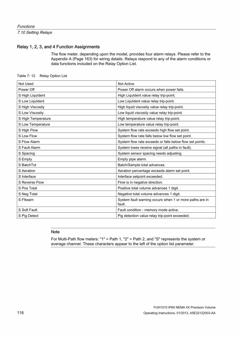
Functions 7.10 Setting Relays
FUH1010 IP65 NEMA 4X Precision Volume 116 Operating Instructions, 01/2013, A5E32122003-AA
Relay 1, 2, 3, and 4 Function Assignments The flow meter, depending upon the model, provides four alarm relays. Please refer to the Appendix A (Page 163) for wiring details. Relays respond to any of the alarm conditions or data functions included on the Relay Option List.
Table 7- 12 Relay Option List
Not Used Not Active Power Off Power Off alarm occurs when power fails. S High LiquIdent High LiquIdent value relay trip-point. S Low LiquIdent Low LiquIdent value relay trip-point. S High Viscosity High liquid viscosity value relay trip-point. S Low Viscosity Low liquid viscosity value relay trip-point. S High Temperature High temperature value relay trip-point. S Low Temperature Low temperature value relay trip-point. S High Flow System flow rate exceeds high flow set point. S Low Flow System flow rate falls below low flow set point. S Flow Alarm System flow rate exceeds or falls below flow set points. S Fault Alarm System loses receive signal (all paths in fault). S Spacing System sensor spacing needs adjusting. S Empty Empty pipe alarm. S BatchTot Batch/Sample total advances. S Aeration Aeration percentage exceeds alarm set point. S Interface Interface setpoint exceeded. S Reverse Flow Flow is in negative direction. S Pos Total Positive total volume advances 1 digit. S Neg Total Negative total volume advances 1 digit. S Fltwarn System fault warning occurs when 1 or more paths are in
fault. S Soft Fault Fault condition - memory mode active. S Pig Detect Pig detection value relay trip-point exceeded.
Note
For Multi-Path flow meters: "1" = Path 1, "2" = Path 2, and "S" represents the system or average channel. These characters appear to the left of the option list parameter.

Functions 7.10 Setting Relays
FUH1010 IP65 NEMA 4X Precision Volume Operating Instructions, 01/2013, A5E32122003-AA 117
Assigning functions to Relay 1: 1. From the [Dual Path Flow] menu scroll down and highlight [I/O Data Control].
2. Press <Right Arrow> and scroll down to [Relay Setup].
3. To access the [Relay Setup] option list press <Right Arrow>.
4. Move the cursor to the desired Relay assignment by pressing <Up/Down Arrow>.
5. To store selection press <ENTER>. Repeat procedure for all other relays.

Functions 7.11 Memory Control
FUH1010 IP65 NEMA 4X Precision Volume 118 Operating Instructions, 01/2013, A5E32122003-AA
7.11 Memory Control
Introduction Memory Control is a reference menu that shows the amount of bytes of data memory left. The data memory capacity depends on the number and complexity of the site setups stored in memory and the size of the current Datalogger file.
The [Memory Control] menu is located in the [Meter Facilities] menu.
Table 7- 13 Memory Control Menu
Log Memory Left→ XXXXXXX Memory Map→ No
Yes Defragment→ No
Yes
Log Memory Left This view only menu cell shows the minimum remaining number of characters available for Datalogger and site storage. When the Datalogger is enabled for circular mode, the meter allocates all memory left except for two conventional empty sites required for Datalogger use.
To view the amount of data memory bytes available press <Right Arrow>.
Memory Map Selecting [YES] for this item enables a snapshot display of current memory usage. In this display, the asterisk indicates a used memory block, a space indicates a free block, while a dash character indicates unused filler.
Defragment Selecting [YES] for this item consolidates memory data blocks into contiguous storage; collapsing the filler regions. You may be able to use an additional block for site or Datalogger storage as a result. Use this command if you seem to be out of memory even though the [Log Memory Left] item indicates free capacity.

Functions 7.12 Analog Output Trim
FUH1010 IP65 NEMA 4X Precision Volume Operating Instructions, 01/2013, A5E32122003-AA 119
7.12 Analog Output Trim
Introduction Analog Out Trim function allows you to fine-tune the flow meter’s analog voltage and current outputs using an ammeter connected to the output under test. In addition, you can use a frequency counter to fine-tune the flow meter’s pulse rate output.
Note
The current, voltage, and Pgen trimming will be limited by the 12-bit resolution of the flow meter’s D/A Convertor (DAC).
1. From the [Meter Facilities] menu, scroll to the [Analog Out Trim] menu.
2. Press the <Right Arrow> to access the option list.
Table 7- 14 Analog Out Trim Menu Structure
Io1/Io2 Operate Trim@4mA Indicated mA=x.xx
Analog Out Trim
Vo1/Vo2 Operate Trim@2V Indicated V=x.xx

Functions 7.12 Analog Output Trim
FUH1010 IP65 NEMA 4X Precision Volume 120 Operating Instructions, 01/2013, A5E32122003-AA
Current Output Trim (Io1 & Io2)
Note
Can be trimmed to within .005mA of nominal.
To calculate a current output: 1. Set up an ammeter to read Amps, then connect it to the supply and return terminals of
the current output under test.
2. Move the highlight to the port to be tested by pressing the <Up/Down Arrow>. Press the <Right Arrow> and then press the <Down Arrow> to move the cursor to [Trim @ 4mA].
3. Press <ENTER>. This triggers a 4.00mA pop-up window. The ammeter should now be
reading 4.00mA.
4. If the ammeter reading does not match, use the numeric keys to type in the current reading.
5. Press <ENTER> to register setting. This adjusts the flow meter’s DAC (digital-to-analog converter) so that a 4mA output corresponds with 4mA on the ammeter.
6. Re-check the ammeter to make sure that it is now reading 4mA.

Functions 7.12 Analog Output Trim
FUH1010 IP65 NEMA 4X Precision Volume Operating Instructions, 01/2013, A5E32122003-AA 121
Voltage Output Trim (Vo1 & Vo2)
Note
Can be trimmed to within .0025 V of nominal.
To calculate a voltage output: 1. Set up a multimeter to read volts, then connect it to the supply and return terminals of the
voltage output under test.
2. Move the highlight to the port to be tested by pressing the <Up/Down Arrow>. Then press the<Right Arrow> and then press <Down Arrow> to move the cursor to [Trim @ 2V].
3. Press <ENTER>. This triggers a 2.00 Volts pop-up window. The multimeter should now
be reading 2.00 Volts.
4. If the multimeter reading does not match, use the numeric keys to type in the voltage reading.
5. Press <ENTER> to register setting. This adjusts the flow meter’s DAC (digital-to-analog converter) so that a 2.00 Volts output corresponds with 2.00 Volts on the multimeter.
6. Re-check the multimeter to make sure that it is now reading 2.00 Volts.

Functions 7.13 Resistive Temperature Device (RTD) Calibration
FUH1010 IP65 NEMA 4X Precision Volume 122 Operating Instructions, 01/2013, A5E32122003-AA
7.13 Resistive Temperature Device (RTD) Calibration The [RTD Calibrate] menu appears on all SITRANS 1010 models. Use this menu to calibrate Temperature Sensors to an external standard. It is important to note that Siemens RTD temperature sensors are factory-calibrated for high accuracy. We recommend that before deciding to perform the calibration, check the current RTD reading in the [Diagnostics Data] menu. You may find that you do not need to calibrate the sensor. In any case, make sure that the temperature reading stabilizes before proceeding further. The [RTD Calibrate] menu allows you to perform an external calibration, which can be accomplished either by data entry of the current RTD temperature or by a 0°C (32°F) Ice-Bath procedure. You can switch between the intrinsic and external calibration modes at any time.
Note
If you perform an external temperature calibration, you should mark and record the location of each connector and sensor-cable. Once you have re-calibrated the temperature sensors, changing the sensor/connector orientation established during the procedure may void the calibration.
1. From the [Meter Facilities] menu scroll to the [RTD Calibrate] menu.
2. To access the [RTD Calibrate] menu press <Right Arrow>.
Table 7- 15 RTD Calibrate Menu Structure
RTD 1→ Factory User Cal
RTD Calibrate
RTD 2→ Factory User Cal
RTD Calibration by Entry Data The [RTD Calibrate] menu allows you to adjust the intrinsic RTD reading to match an external reference thermometer by directly entering its reading. Only perform this procedure while the RTD under test is installed and currently measuring temperature.

Functions 7.13 Resistive Temperature Device (RTD) Calibration
FUH1010 IP65 NEMA 4X Precision Volume Operating Instructions, 01/2013, A5E32122003-AA 123
To enter the current RTD temperature: 1. From the [RTD Calibrate] menu press <Right Arrow> to access the RTD option list.
2. Press <Right Arrow> to highlight the RTD you want to calibrate (RTD 1 or RTD 2).
3. Move the highlight to [Factory] or [User Cal] then press <ENTER>.
4. This triggers the pop-up window:
5. To enable numeric entry <Right Arrow>, then type in the reading of the reference
thermometer (e.g., 72.0).
6. To recalibrate the RTD sensor <ENTER>. To verify the calibrated reading, go to the Dual Path Flow menu [Diagnostic Data/Liquid Data] menu to check the current RTD output. Make sure that it coincides with the reading of the reference thermometer. Repeat for the other RTD, if necessary.
Note
Factory Calibration provides an additional prompt after a new temperature is entered: [Are you Sure? No Yes]. It is recommended that you use [User Cal] to avoid alteration of preset factory calibration.

Functions 7.13 Resistive Temperature Device (RTD) Calibration
FUH1010 IP65 NEMA 4X Precision Volume 124 Operating Instructions, 01/2013, A5E32122003-AA
Ice Bath RTD Calibration Use deionized water and ice mixture at 0°C (32°F) equilibrium for an ice bath. Ensure temperature with a reference thermometer. Siemens can not assume responsibility for the incorrect design, construction or operation of an Ice Bath.
NOTICE Sensor Damage
If RTD sensor makes direct contact with ice during an ice bath calibration procedure the sensor may be damaged and the calibration results will be incorrect.
Do not allow an RTD sensor to make direct contact with ice during an ice bath calibration procedure.
To perform a 0°C (32°F) calibration: 1. Immerse RTD sensor in deionized water and ice mixture. Stir the mixture constantly.
2. In the [RTD Calibrate] menu move the highlight by pressing the <Up/Down Arrow> to the RTD you want to calibrate (RTD 1 or RTD 2).
3. To access the RTD option list press <the Right Arrow>. Move the highlight to [User Cal] then press <ENTER>. This triggers the pop-up window.
4. After the RTD sensor reaches equilibrium at 0°C (32°F), press <ENTER> to recalibrate the RTD sensor.
5. To verify the calibrated reading, go to Dual Path Flow [Diagnostic Data/Liquid Data] menu to check the current RTD output. Make sure that it coincides with the reading of the reference thermometer. Repeat for the other RTD, if necessary.

Functions 7.14 SONILOCATOR Operation
FUH1010 IP65 NEMA 4X Precision Volume Operating Instructions, 01/2013, A5E32122003-AA 125
7.14 SONILOCATOR Operation
Introduction
Note
The Sonilocator function can only be invoked while flow meter is used as part of a Siemens Leak Detection System.
In the event of a pipeline leak, a sudden drop in pressure occurs radiating a pressure wave both upstream and downstream from that point at the speed of sound in the liquid. This drop in pressure decreases the density of the liquid, which results in a sudden drop in the current value of the liquid’s sonic propagation velocity (Vs). Vs is measured at each of the upstream and downstream Site Stations (metering points) an average of ten times per second. The decrease in Vs is detected and time stamped with the arrival of the pressure wave’s leading edge. Since both Site Stations have synchronized time clocks, the relative arrival times of the pressure waves at each Site Station is easily determined. The accuracy of the location function is dependent on the resolution of time stamping and the sonic propagation velocity of 1500 meters per second. The leak will be located within +/- 150 meters, providing that:
1. The pressure wave table is able to travel the entire pipeline segment.
2. The magnitude of the pressure transient must be greater that the pressure fluctuations during normal pipeline operation.
Setting [Sonilocate]
Note
The Sonilocator function is only operational with a Siemens Master Station and SITRANS F 1010 flow meter.
1. At the [Meter Type] menu, press the <Right Arrow> key and then <ENTER> to select the desired Path (e.g., Dual Path Flow).
2. In the [Dual Path Flow] menu, press the <Down Arrow> key. Scroll to the [Operation Adjust] menu cell. Press the <Right Arrow> to select it.
3. Press the <Down Arrow> key and scroll to the [SL Rate] menu cell.

Functions 7.14 SONILOCATOR Operation
FUH1010 IP65 NEMA 4X Precision Volume 126 Operating Instructions, 01/2013, A5E32122003-AA
4. Press the <Right Arrow> key and then the <Up/Down> key to scroll to the desired Slew Rate resolution. Press the <ENTER> key to select it.
5. Verify [SL Rate] resolution is selected (> symbol will appear to the left of menu item). SL Rate choices include: 20 ms, 50 ms, 100 ms, 250 ms (20 ms highest resolution; 250 ms lowest resolution).
6. Continually press the <Left Arrow> key to return to main menu.
Note
IMPORTANT: The Sonilocator function will not operate unless the [Sonilocate] menu item is selected in the [Logger Setup] menu.
Selecting [Sonilocate] 1. At the [Meter Type] Menu, press the <Right Arrow> key and then the <ENTER> key to
select the desired path (e.g., Dual Path Flow).
2. In the [Dual Path Flow] Menu, press the <Down Arrow> key and scroll to the [Logger Setup] menu cell. Press the <Right Arrow> to select it.
3. Press the <Up/Down Arrow> key and scroll to the [Logger Data] menu cell.
4. Press the <Right Arrow> key to highlight [Logger Data] option list items.

Functions 7.14 SONILOCATOR Operation
FUH1010 IP65 NEMA 4X Precision Volume Operating Instructions, 01/2013, A5E32122003-AA 127
5. Press the <Up/Down Arrow> key and scroll to the [Sonilocate] menu item. Press the <ENTER> key to select it. (A + sign will appear to the left of the menu item.) If desired, press <CLR> key to deselect menu item.
6. Continually press the <Left Arrow> key to return to the main menu.

Functions 7.14 SONILOCATOR Operation
FUH1010 IP65 NEMA 4X Precision Volume 128 Operating Instructions, 01/2013, A5E32122003-AA

Alarm, error and system messages 88.1 Alarm Codes
Alarm Codes and Descriptions The following alarm codes appear on the main display of the transmitter.
Letter Codes Alarm Code Description
SPACE Spacing Sensor spacing may need adjustment EMPTY Empty Pipe is empty HI/LO Rate Flow above High setting or below Low setting FAULT Fault Three continuous seconds without new data update AER Aeration Current aeration percentage exceeds the alarm set point MEMRY Memory Last valid reading for a selected interval during Fault condition MAKUP Makeup In-Process Makeup occurred
The following alarm codes appear in the Datalogger status messages: I Interface Liquid Vs exceeds interface alarm set point P Pig Pig passage detected (optional) Z ZeroMatic ZeroMatic signal occurred
The displays shown below indicate where the Alarm Codes appear on the screen. Press <UP> or <DOWN> Arrows to change screen views.
14.35
354.6597 14.27
100.0
0.031.74
① Alarm Codes
FUH1010 IP65 NEMA 4X Precision Volume Operating Instructions, 01/2013, A5E32122003-AA 129

Alarm, error and system messages 8.2 Alarms
FUH1010 IP65 NEMA 4X Precision Volume 130 Operating Instructions, 01/2013, A5E32122003-AA
9/26 12:45
68.10112.3830.0
-30.0
① Alarm Codes
8.2 Alarms
Set Alarm Levels Menu The [Set Alarm Levels] menu allows you to select system alarm functions. Alarms appear locally on the LCD digital display. In addition, you can use the Relay Setup menu to assign those functions to the system’s relays. You may select from high or low energy or flow rate, liquid interface (Vs) and liquid aeration alarm functions. Entry of all alarm set points is accomplished using the selected rate units. You can enable or disable a Makeup Alarm Latch to keep the makeup alarm active until you reset it manually by an <Fn>6 simultaneous key press.
Interface Alarms Menu The [Interface Alarms] menu cell is selected to monitor the sonic velocity (Vs). It is a constant rate of change alarm function that monitors the LiquIdent setting. The alarms appear locally on the LCD digital display.
ROC Alm Set m/s (Rate of Change) Use the [Roc Alm Set m/s] menu item to set the desired numerical alarm relay set point in meters per second (m/s). For example, if the alarm relay set point value is set to 50 m/s, when the Vs varies by 50 m/s from the current LiquIdent setting for the assigned time interval (e.g., 10 seconds), the alarm relay will trip.
Interval Secs Select the [Interval] menu item to set the time interval in seconds. This time interval value affects how long the variation in [Rate Value m/s] will last before the alarm relay is tripped.

Alarm, error and system messages 8.2 Alarms
FUH1010 IP65 NEMA 4X Precision Volume Operating Instructions, 01/2013, A5E32122003-AA 131
Relay Hold Time The [Relay Hold Time] menu item allows the setting of the time in seconds that the alarm relay will stay closed.
High LiquIdent Use the [High LiquIdent] menu item to set the numerical high limit span of the LiquIdent function.
Low LiquIdent Use the [Low LiquIdent] menu item to set the numerical low limit of the LiquIdent function.

Alarm, error and system messages 8.2 Alarms
FUH1010 IP65 NEMA 4X Precision Volume 132 Operating Instructions, 01/2013, A5E32122003-AA

9Service and maintenance
9.1 Maintenance The device is maintenance-free. However, a periodic inspection according to pertinent directives and regulations must be carried out.
An inspection can include check of:
● Ambient conditions
● Seal integrity of the process connections, cable entries, and cover screws
● Reliability of power supply, lightning protection, and grounds
NOTICE
Repair and service must be carried out by Siemens authorized personnel only.
Note
Siemens defines flow sensors as non-repairable products.
9.2 Technical support If you have any technical questions about the device described in these Operating Instructions and do not find the right answers, you can contact Customer Support:
● Via the Internet using the Support Request: Support request (http://www.siemens.com/automation/support-request)
● Via Phone:
– Europe: +49 (0)911 895 7222
– America: +1 423 262 5710 / 1800 333-7421
– Asia-Pacific: +86 10 6475 7575
Further information about our technical support is available on the Internet at Technical support (http://support.automation.siemens.com/WW/view/en/16604318)
Service & Support on the Internet In addition to our documentation, we offer a comprehensive knowledge base online on the Internet at:
Service and support (http://www.siemens.com/automation/service&support)
FUH1010 IP65 NEMA 4X Precision Volume Operating Instructions, 01/2013, A5E32122003-AA 133

Service and maintenance 9.3 Transportation and storage
FUH1010 IP65 NEMA 4X Precision Volume 134 Operating Instructions, 01/2013, A5E32122003-AA
There you will find:
● The latest product information, FAQs, downloads, tips and tricks.
● Our newsletter, providing you with the latest information about your products.
● Our bulletin board, where users and specialists share their knowledge worldwide.
● You can find your local contact partner for Industry Automation and Drives Technologies in our partner database.
● Information about field service, repairs, spare parts and lots more under "Services."
Additional Support Please contact your local Siemens representative and offices if you have additional questions about the device.
Find your local contact partner at: http://www.automation.siemens.com/partner
See also Local contact person (http://www.automation.siemens.com/partner)
9.3 Transportation and storage To guarantee sufficient protection during transport and storage, observe the following:
● Keep the original packaging for subsequent transportation.
● Devices/replacement parts should be returned in their original packaging.
● If the original packaging is no longer available, ensure that all shipments are properly packaged to provide sufficient protection during transport. Siemens cannot assume liability for any costs associated with transportation damages.
CAUTION
Insufficient protection during storage
The packaging only provides limited protection against moisture and infiltration. Provide additional packaging as necessary.
Special conditions for storage and transportation of the device are listed in "Technical data".
See also Technical Data (Page 161)

Service and maintenance 9.4 Repair
FUH1010 IP65 NEMA 4X Precision Volume Operating Instructions, 01/2013, A5E32122003-AA 135
9.4 Repair
9.4.1 Unit repair
NOTICE Repair and service must be carried out by Siemens authorized personnel only.
Note
Siemens defines flow sensors as non-repairable products.
WARNING Impermissible repair of explosion protected devices
Danger of explosion in areas subject to explosion hazard. Repair must be carried out by Siemens authorized personnel only.
WARNING Impermissible accessories and spare parts
Danger of explosion in areas subject to explosion hazard. Only use original accessories or original spare parts. Observe all relevant installation and safety instructions described in the instructions for
the device or enclosed with the accessory or spare part.
Service and maintenance 9.5 Return and disposal
FUH1010 IP65 NEMA 4X Precision Volume 136 Operating Instructions, 01/2013, A5E32122003-AA
9.5 Return and disposal
WARNING Incorrect disassembly
The following dangers may result through incorrect disassembly:
- Injury through electric shock
- Danger through emerging media when connected to the process
- Danger of explosion in hazardous area
In order to disassemble correctly, observe the following: Before starting work, make sure that you have switched off all physical variables such
as pressure, temperature, electricity etc. or that they have a harmless value. If the device contains dangerous media, it must be emptied prior to disassembly. Make
sure that no environmentally hazardous media are released. Secure the remaining connections so that no damage can result if the process is started
unintentionally.
9.5.1 Return procedures (incl lithium batteries) Enclose the delivery note, the cover note for return delivery together with the declaration of decontamination form on the outside of the package in a well-fastened clear document pouch.

Service and maintenance 9.5 Return and disposal
FUH1010 IP65 NEMA 4X Precision Volume Operating Instructions, 01/2013, A5E32122003-AA 137
Required forms ● Delivery Note
● Cover Note for Return Delivery with the following information
Return delivery form (http://support.automation.siemens.com/WW/view/en/16604370)
– product (ordering number)
– number of devices or spare parts returned
– reason for the return
● Declaration of Decontamination
Decontamination declaration (http://pia.khe.siemens.com/efiles/feldg/files/Service/declaration_of_decontamination_en.pdf)
With this declaration you certify that the returned products/spare parts have been carefully cleaned and are free from any residues. If the device has been operated together with toxic, caustic, flammable or water-damaging products, clean the device before return by rinsing or neutralizing. Ensure that all cavities are free from dangerous substances. Then, double-check the device to ensure the cleaning is completed.
We will not service a device or spare part unless the declaration of decontamination confirms proper decontamination of the device or spare part. Shipments without a declaration of decontamination will be cleaned professionally at your expense before further proceeding.
You can find the forms on the Internet and on the CD delivered with the device.
Note Return of products with Lithium batteries
Lithium batteries are certified as dangerous goods according to the Regulation of Dangerous Goods, UN 3090 and UN 3091. Special transport documentation is required to observe these regulations.
Therefore it is recommended to remove lithium batteries prior to shipment
If the battery is important for the examination of the product and it cannot be removed, the product has to be returned according to the Regulation of Dangerous goods.
9.5.2 Battery disposal In accordance with EU directive 2006/66/EC, batteries are not to be disposed of using municipal waste disposal services.
Waste industrial batteries are accepted back by Siemens or by the local Siemens representative. Please talk to your local Siemens contact (http://www.siemens.com/automation/service&support) or follow the return procedures (Page 136) of Siemens Flow Instruments.

Service and maintenance 9.5 Return and disposal
FUH1010 IP65 NEMA 4X Precision Volume 138 Operating Instructions, 01/2013, A5E32122003-AA
9.5.3 Disposal
Devices identified by this symbol may not be disposed of in the municipal waste disposal services under observance of the Directive 2002/96/EC on waste electronic and electrical equipment (WEEE). They can be returned to the supplier within the EC or to a locally approved disposal service. Observe the specific regulations valid in your country.

Troubleshooting 1010.1 Troubleshooting
The following is list of troubleshooting tips and messages that you may encounter. They include explanations and, in some cases, a recommended action. If a problem seems unsolvable, contact your local Siemens Ultrasonic Flow Representative for expert help at www.automation.siemens.com/partner (http://www.automation.siemens.com/partner).
Table 10- 1 Troubleshooting Tips
Error or Message Probable Cause Solution Memory Full! Response to an attempt to save site data,
when data memory is full. Delete an obsolete site or clear Datalogger memory to make room for the new data.
Memory Corrupted! Memory read error occurred while accessing the active site data.
Refer to F4 reset procedure in the Operation Instructions manual.
Chan Not Setup Response to an attempt to invoke an operation that requires a channel to be enabled.
Enable the channel [Channel Setup - Channel Enable - Yes]. Note that a channel cannot be enabled until an "Install" operation is completed.
Clr Active Memory? Response to pressing the F4 key. Use the F4 function to restore operation if a severe event (e.g., a violent power surge) disrupts system operation.
Clr Saved Data? [Clr Saved Data?] only appears after pressing the <Down Arrow> to [Clr Active Memory?].
Answering Yes to [Clr Saved Data?] will erase ALL saved data. To invoke in RS-232 serial mode, type @@@ and then press <ENTER> key.
<EOT> Response to a request to output Datalogger data to the printer or the Graphics screen when no Datalogger data exists or at the end of a transmitted file.
Set up the Datalogger.
No Sites - Press <ENTER>
Response while trying to recall/delete a site setup when no sites are stored.
Create a site.
Security Response upon changing previously entered data when security switch is in [Disable] position or security code has been entered.
Change switch position to [Enable]. Enter previously set security code.
RTC Error Component level problem. Meter requires service. Request RMA.
- - -F- - - Fault Alarm Loss of signal strength (ALC) Change of Rx signal location (Beam
Blowing)
Recouple sensors with fresh couplant. Install sensors in Direct mount mode. Note: If problem persists call Tech support.
Re-space Index The measured liquid sonic velocity (Vs) is more than +/- 25% of the average Vs range.
Assure proper pipe dimensions and/or Liquid data entries are correct.
Properly enter correct Sensor Size into the meter [Install Sensor] menu.
Confirm sensor spacing is correct by checking [Install Sensor] menu spacing parameters.
FUH1010 IP65 NEMA 4X Precision Volume Operating Instructions, 01/2013, A5E32122003-AA 139
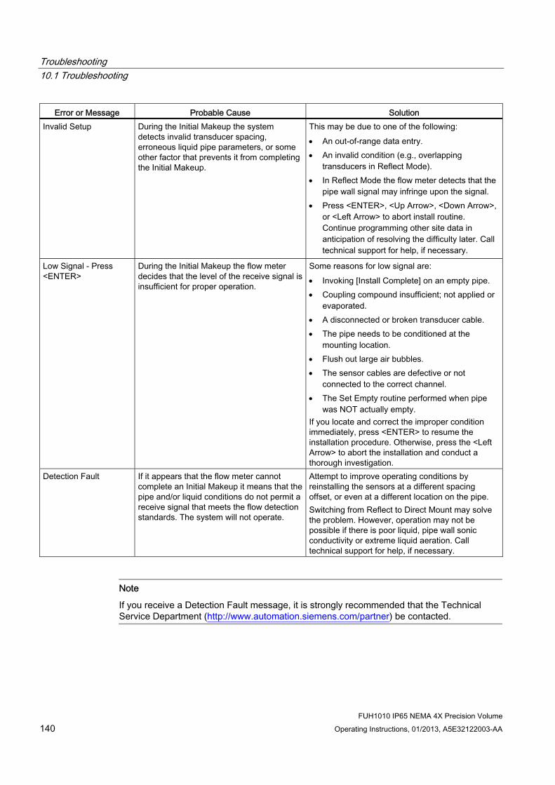
Troubleshooting 10.1 Troubleshooting
FUH1010 IP65 NEMA 4X Precision Volume 140 Operating Instructions, 01/2013, A5E32122003-AA
Error or Message Probable Cause Solution Invalid Setup During the Initial Makeup the system
detects invalid transducer spacing, erroneous liquid pipe parameters, or some other factor that prevents it from completing the Initial Makeup.
This may be due to one of the following: An out-of-range data entry. An invalid condition (e.g., overlapping
transducers in Reflect Mode). In Reflect Mode the flow meter detects that the
pipe wall signal may infringe upon the signal. Press <ENTER>, <Up Arrow>, <Down Arrow>,
or <Left Arrow> to abort install routine. Continue programming other site data in anticipation of resolving the difficulty later. Call technical support for help, if necessary.
Low Signal - Press <ENTER>
During the Initial Makeup the flow meter decides that the level of the receive signal is insufficient for proper operation.
Some reasons for low signal are: Invoking [Install Complete] on an empty pipe. Coupling compound insufficient; not applied or
evaporated. A disconnected or broken transducer cable. The pipe needs to be conditioned at the
mounting location. Flush out large air bubbles. The sensor cables are defective or not
connected to the correct channel. The Set Empty routine performed when pipe
was NOT actually empty. If you locate and correct the improper condition immediately, press <ENTER> to resume the installation procedure. Otherwise, press the <Left Arrow> to abort the installation and conduct a thorough investigation.
Detection Fault If it appears that the flow meter cannot complete an Initial Makeup it means that the pipe and/or liquid conditions do not permit a receive signal that meets the flow detection standards. The system will not operate.
Attempt to improve operating conditions by reinstalling the sensors at a different spacing offset, or even at a different location on the pipe. Switching from Reflect to Direct Mount may solve the problem. However, operation may not be possible if there is poor liquid, pipe wall sonic conductivity or extreme liquid aeration. Call technical support for help, if necessary.
Note
If you receive a Detection Fault message, it is strongly recommended that the Technical Service Department (http://www.automation.siemens.com/partner) be contacted.

Troubleshooting 10.2 F4 Reset Procedure
FUH1010 IP65 NEMA 4X Precision Volume Operating Instructions, 01/2013, A5E32122003-AA 141
10.2 F4 Reset Procedure You may encounter an operating problem that blocks access to the Diagnostics Menu, or the flow meter may operate erratically after exposure to a power transient or some other traumatic event. These cases may require use of the F4-reset sequence to restore operation.
The F4-Reset sequence operates on two levels:
● Clear Active Memory
The first F4-Reset deletes all the data currently in Active Memory, but leaves Datalogger data and all stored Site Setups intact. This is the most desirable method since all you have to do to restore operation is reload a saved Site Setup.
● Clear All Saved Memory
If the first sequence fails then you have to resort to the second level of the F4 sequence, which allows you to clear ALL Saved Memory. Be aware that this erases all saved Site Setups (including flow calibrated sites), Datalogger Data and user-defined pipe and sensor tables. This will require you to completely re-install the system and repeat all desired default settings, custom pipe tables, etc. The table below shows the sequence of the [F4] routine:
[Power On/Off + F4]⇒ [Clr Active Memory?]⇒
⇑ ⇓ [Clr Saved Data?]⇒
⇒No ⇒Yes ⇒No ⇒Yes
Clearing only Active Memory 1. Turn off power (if it is currently on). Press <F4> and keep it pressed while you turn on
power. The prompt: [Clr Active Memory? No] appears at the top of the screen.
2. Press <Right Arrow> to access F4 Reset option list. Press <Down Arrow> to switch the option list to [Clr Active Memory? Yes]. Press <ENTER> to clear all Active Site Data (but not saved Site Setups).
3. To restore operation, press <MENU> to access the installation menu. Create a new site setup or recall a stored site setup.
4. Re-select any Meter Facilities menu items (e.g. RS-232 setup parameters).
Clearing All Saved Data 1. Turn off power (if it is currently on).
2. Press <F4> and keep it pressed while you turn on power. The prompt: [Clr Active Memory? No] appears at the top of the screen. Press the <Down Arrow>. Note that the prompt switches to [Clr Saved Data? No].

Troubleshooting 10.3 Test Facilities Graph Screen
FUH1010 IP65 NEMA 4X Precision Volume 142 Operating Instructions, 01/2013, A5E32122003-AA
3. To access the F4 Reset option list press the <Right Arrow>. Press the <Down Arrow> to switch the option list to [Clr Saved Data? Yes].
NOTICE
Loss of RAM Data
Before proceeding further it is essential to understand that this function eliminates ALL data stored in RAM. This means that all saved site setups including the site data of a flow-calibrated site will be erased! In addition, the entire Datalogger file plus any custom factory or user-created pipe or sensor tables will be eliminated.
The impact of this is such that we strongly recommend that you consult Technical Services before continuing with this procedure. Be aware that you will have to create a new Site Setup, re-enter all site specific parameters including pipe or sensor tables, plus all desired Meter Facilities menu entries.
4. To clear all Saved Memory press <ENTER>.
5. Create a Site Setup before attempting to access other menu items.
6. To restore operation, press <MENU> to access the installation menu. Create a new site setup and complete the installation procedure.
7. Re-select desired Meter Facilities menu items (e.g. RS-232 setup parameters).
10.3 Test Facilities Graph Screen When operating in the transit time mode the Test Facilities Graph Screen is an exceptional diagnostic tool for troubleshooting problem applications or simply determining Receive signal quality. The primary function of this screen is to display the digitized receive signal waveform with the similar appearance and function of a digital oscilloscope. This screen also allows the user to override some of the flow meter default settings by permitting adjustment to the measured transit time, the digital averaging and the zero crossover used in the measurement of the up/down transit time difference. The figure shown below is a representation of the diagnostic graph.
Note
The Test Facilities Graph Screen requires significant CPU overhead. The flow meter should not be left in this mode during normal operation where the Datalogger is the primary output or during calibration work.

Troubleshooting 10.3 Test Facilities Graph Screen
FUH1010 IP65 NEMA 4X Precision Volume Operating Instructions, 01/2013, A5E32122003-AA 143
Figure 10-1 Test Facilities Graph Screen
Entering the Diagnostic Graph Screen Before you can view the Diagnostic Graph Screen the flow channel must first be properly installed and operating in a non-empty condition. If a previously installed channel is in a "Fault" condition, but not reporting "Empty", you can still access the Graph Screen to aid in troubleshooting the cause of the failure to measure flow.
To view the Graph Screen first enter the [Test Facilities] menu, which is a submenu of the main [Diagnostic Data] menu.
1. Pressing the <Up/Down Arrows>, scroll to the [Graph] menu item.
2. Press the <Right Arrow> to enter the [Graph] menu and scroll to highlight the [Yes] item in the option list.
3. Now press the <ENTER> key to access the Graph Screen.
4. To exit the Graph Screen and return to the main menu, press the <MENU> key once.
Diagnostic Text Display The text to the upper left-hand corner of the screen represents diagnostic items which can be individually turned on or off to reduce unnecessary clutter on the screen. This text display can be modified by pressing the <ENTER> key and scrolling up or down through the various parameters that appear in the Graph Display menu. Pressing the <ENTER> key will select the highlighted parameter (a "+" sign appears next to selected items) and pressing <CLR> will deselect the item. Pressing the <Left Arrow> will return you to the graph screen with the selected parameters appearing at the top left corner of the screen. (The sample graph above is shown with all diagnostics items selected).

Troubleshooting 10.3 Test Facilities Graph Screen
FUH1010 IP65 NEMA 4X Precision Volume 144 Operating Instructions, 01/2013, A5E32122003-AA
Time Base Control The digitized receive signal can be moved either to the left or right on the screen by pressing the <Left> or <Right> keypad arrows. The direction of the arrow actually represents the direction in which the Receive "window" will move, thereby causing the receive signal to shift in the opposite direction on the screen (e.g., Pressing the <Left Arrow> moves the signal to the right).
The digitized receive signal can be expanded or contracted in the time domain by pressing the <+> or <-> keys on the keypad. This allows you to see the entire contents of the receive window, or zoom in to see greater detail. Pressing the <CLR> key once will automatically center the receive signal on the screen. When expanding the Receive signal small vertical "tick" marks will eventually appear. These marks represent the time at which the receive signal is digitally sampled.
Correlated Plot During conditions of flow, the actual transit time delta (difference) can be observed in the displayed receive signal waveform when the [Correlated Plot] menu parameter is not selected. To observe this time difference simply depress the <+> key (to see greater signal detail) until the individual up and down receive signals are clearly discernible. To verify that the flow meter signal processing algorithms are properly correlating the up and down stream receive signals, select the [Correlated Plot] option from the display menu list.
Return to the graph screen and observe the relative position of the up and down waveforms. In a properly correlated receive signal the two images should be nearly superimposed on top of each other, even during high flow conditions. In the unlikely situation where the two images appear to be offset by one or more receive cycles then the flow readings should be considered questionable.
Command Modes Although the flow meter signal processing algorithms are capable of accommodating a very wide range of signal conditions, it may be desirable to override these default settings under extremely difficult operating conditions. The following functions are available for this purpose.
Digital Damping Control: (Hot Key 1 and 2) The meter permits user modification of the digital averaging used by the signal processing routines. In general, the default damping values selected by the flow meter will provide optimal performance over a wide range of transit time applications. However, in extreme cases of unstable flow, pulsating flow, low signal levels or high electronic noise it may be necessary to override these default settings to permit uninterrupted and reliable flow measurement.
Test Facilities Graph Screen The Graph Screen includes the capability to access a set of command codes, which enable a user to override a number of default meter settings. The most important parameter is the digital damping control, which can be accessed by pressing number <1> or <2> on the keypad while in the Signal Graph Screen mode.

Troubleshooting 10.3 Test Facilities Graph Screen
FUH1010 IP65 NEMA 4X Precision Volume Operating Instructions, 01/2013, A5E32122003-AA 145
[MinDamp #] Command Pressing the <1> key will cause [MinDamp #] to appear on the command line at the lower left-hand corner of the screen. The number listed to the right of the command code represents the exponent in the meter exponential averaging routine, where the larger the number the greater the digital averaging. Pressing the <+> key will increase the damping value. Likewise, pressing the <-> key will decrease the damping value.
To exit this mode, press the <0> key on the keypad.
[MaxDamp #] Command Pressing the <2> key will bring up the [MaxDamp #] command. The function of this parameter is similar to the [MinDamp #] command described above; however, the two parameters interact in the following manner. The MinDamp value must not exceed the MaxDamp value; therefore increasing the MinDamp value above the previous MaxDamp value will set both parameters to the same value. In most cases, it is preferred that both damping parameters be set to the same value, however, in cases where rapid response to changes in liquid sound velocity for flow rate is required, the two values may be set differently. In this situation the meter will use the MaxDamp value when conditions are stable, but then switch to a faster damping value (limited by MinDamp) when a significant change in sound velocity or flow rate is perceived.
To exit this mode, press the <0> key on the keypad.
To access the Digital Damping Control using the Test Facilities Graph Screen, proceed as follows:
Note
To use the Test Facilities Graph Screen you must have a working site.

Troubleshooting 10.3 Test Facilities Graph Screen
FUH1010 IP65 NEMA 4X Precision Volume 146 Operating Instructions, 01/2013, A5E32122003-AA
To activate the Test Facilities Graph Screen: 1. In the main menu, scroll to the [Diagnostic Data] menu and select [Test Facilities].
2. Scroll down to [Graph], press the <Right Arrow> and highlight [Yes]. Press <ENTER> to select.
3. The Test Facilities Graphic Screen will appear on the meter display as shown below.
① Damping Factors ④ Min Damping Factor (Hot Key 1) ② ⑤ Digitized Receive Signal TN Marker ③ Crossover Marker ⑥ High Baseline Noise Figure 10-2 Setting Digital Damping Factor
Setting the Digital Damping Factor to a value HIGHER than the default value of 4 may be necessary in cases where the signal-to-noise ratio (SN) is found to be unacceptably low (<15:1), but only if the noise is determined to be asynchronous (i.e., not associated with the transmit or flow meter timing circuitry) as shown in the signal example above, where the baseline noise has a higher frequency than the true liquid signal.
The following application conditions may require a higher Digital Damping Factor:
● Close proximity to pressure control valves which may generate in-band acoustic noise
● High un-dissolved gas solids content in liquid.
● High electronic noise from variable frequency drives or other external equipment.

Troubleshooting 10.3 Test Facilities Graph Screen
FUH1010 IP65 NEMA 4X Precision Volume Operating Instructions, 01/2013, A5E32122003-AA 147
To INCREASE the Digital Damping: 1. Press the <1> key while viewing the Test Facilities Graph Screen as shown above. The
damping control [MinDamp #] will appear on the command line at the lower left-hand corner of the screen.
Note
The number listed to the right of the command code on the screen represents the exponent in the exponential averaging routine (digital damping), where the larger the number represents the greater the digital averaging. Setting this exponent higher than 7 is generally not recommended.
2. Pressing the <+> key will increase the MinDamp Factor by one unit for each key press. To exit this mode, press the <0> key on the keypad.
① Increased Damping Factor Figure 10-3 Setting the MinDamp Factor
The above example shows that increasing the Digital Damping reduces asynchronous noise.
Setting the Digital Damping factor to a value LOWER than the default value of 4 may be justified in cases where pulsating flow is present (such as from a reciprocating pump) or for the purpose of diagnosing transient signal behavior. A pulsating flow condition that generates more than +/- 45 degrees of phase jitter will generally cause signal correlation problems when any digital averaging is used. In this case it may be necessary to completely eliminate the digital averaging by reducing the Digital Damping Factor to 0.
To DECREASE the Digital Damping: 1. Press the <2> key while viewing the Test Facilities Graph Screen. The damping control
[MaxDamp #] will appear on the command line at the lower left-hand corner of the screen.
2. Pressing the <-> key will decrease the MaxDamp Factor by one unit for each key press. To exit this mode, press the <0> key on the keypad.

Troubleshooting 10.3 Test Facilities Graph Screen
FUH1010 IP65 NEMA 4X Precision Volume 148 Operating Instructions, 01/2013, A5E32122003-AA
Transit Time Adjustment: (Hot Key 3) Observe the short vertical marker at the beginning of the receive signal in the Graph Screen above. This line represents the position in time (Tn) where the flow meter perceives the arrival of the ultrasonic signal. There are actually two Tn markers, one for the upstream arrival time and one for the downstream arrival time. For proper liquid sound velocity measurement these Tn markers should be positioned near the beginning edge of the receive waveform envelope (as shown), however, in cases of poor signal conditions it is possible for this measurement to be off by several receive waveform cycles.
1. To adjust the Tn mark position press the <3> key on the keypad to bring up the [TnSet #] command.
2. Pressing the <+> or <-> keys will cause the Tn marker to move later or earlier, respectively. As you adjust the Tn marker, both Tn and Vs (liquid sound velocity) will change accordingly.
3. To exit this mode, press the <0> key on the keypad.
Zero Crossover Adjustment: (Hot Key 4) Observe the small "X" mark located on the zero crossing line near the middle of the receive signal in the Graph Screen above. This "X" indicates the central crossover which the flow meter is using to measure the transit-time delta. This crossover will generally be close to the peak of the Receive signal with at least one well formed (non-aberrated) receive cycle on each side of the crossover.
1. If it appears that the placement of this crossover is unsatisfactory then it can be adjusted by pressing the <4> key on the keypad, which will invoke the [ZCO Set #] command. The crossover point can then be moved in either direction on the waveform using the plus <+> or minus <-> keys. The change from the default value (in receive cycles) will appear in the number to the right of the command.
2. To exit this mode, press the <0> key.

Troubleshooting 10.3 Test Facilities Graph Screen
FUH1010 IP65 NEMA 4X Precision Volume Operating Instructions, 01/2013, A5E32122003-AA 149
Envelope Threshold Adjustment: (Hot Key 5 & 6) Pressing the <=> key causes the graph to toggle between the default signal waveform screen and the signal envelope screen (see example below). This envelope screen can aid in the diagnosis of Tn errors caused by unusual receive waveform distortion. Signal distortion is sometimes caused by poor sensor selection or poor pipe wall conditions, which may result in an incorrectly measured fluid sound velocity. To improve the automatic measurement of Tn, the envelope threshold limit can be adjusted to exclude portions of the envelope, which may be causing the Tn detection problem.
① ④ Envelope Signal Crossover Marker ② ⑤ HiSet Envelope Threshold TN Marker ③ LoSet Envelope Threshold ⑥ Zero Baseline
Figure 10-4 Envelope Threshold Adjustment
1. If it appears that the default placement of the Tn marker is incorrect or unstable, it can be adjusted by pressing the <5> key on the keypad to invoke the [Hi Set #] command or by pressing the <6> key to invoke the [Low Set #] command (while viewing the envelope screen). A horizontal line representing the envelope threshold level will appear along with a number indicating the percentage level. The High and Low thresholds can then be moved either up or down on the envelope using the <+> or <-> keys. While viewing the Tn marker position, adjust the thresholds so that they are well above the baseline "noise" level but below the first major peak.
2. To exit this mode, press the <0> key.
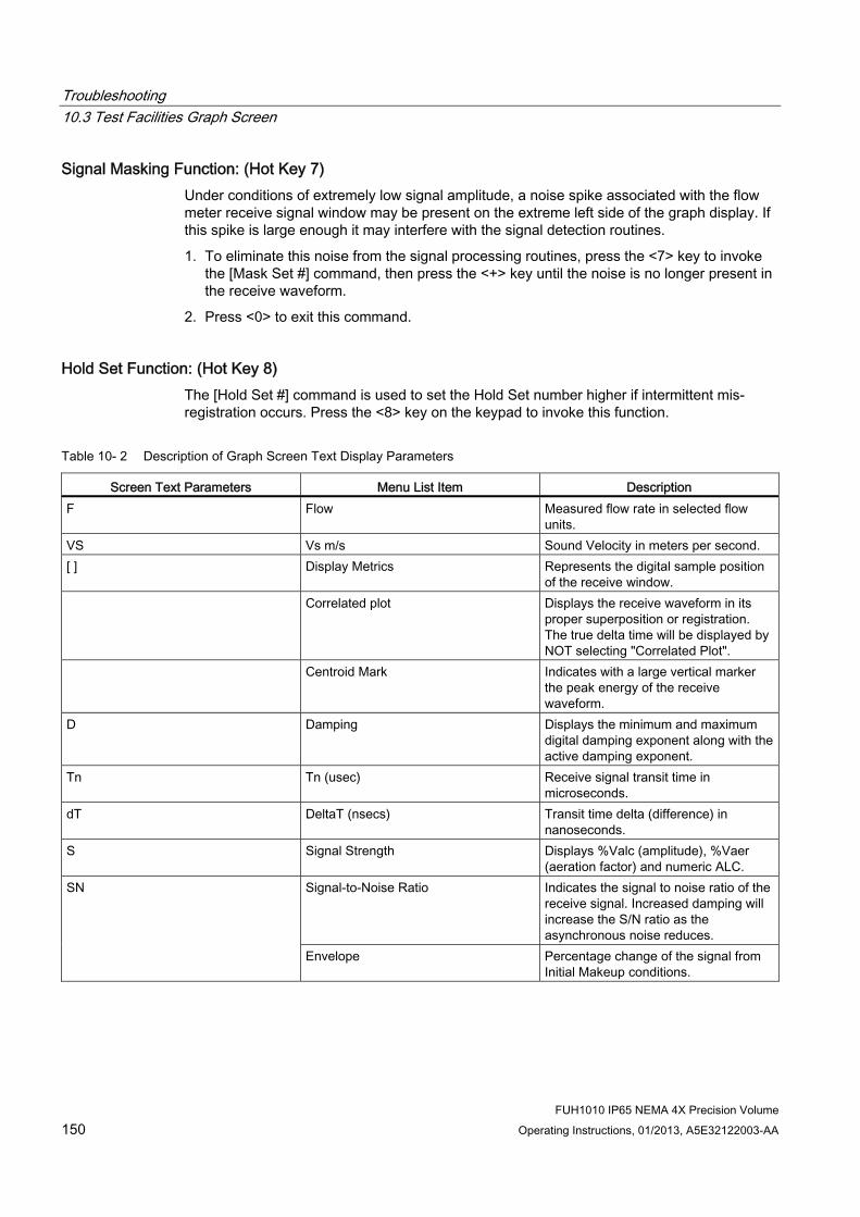
Troubleshooting 10.3 Test Facilities Graph Screen
FUH1010 IP65 NEMA 4X Precision Volume 150 Operating Instructions, 01/2013, A5E32122003-AA
Signal Masking Function: (Hot Key 7) Under conditions of extremely low signal amplitude, a noise spike associated with the flow meter receive signal window may be present on the extreme left side of the graph display. If this spike is large enough it may interfere with the signal detection routines.
1. To eliminate this noise from the signal processing routines, press the <7> key to invoke the [Mask Set #] command, then press the <+> key until the noise is no longer present in the receive waveform.
2. Press <0> to exit this command.
Hold Set Function: (Hot Key 8) The [Hold Set #] command is used to set the Hold Set number higher if intermittent mis-registration occurs. Press the <8> key on the keypad to invoke this function.
Table 10- 2 Description of Graph Screen Text Display Parameters
Screen Text Parameters Menu List Item Description F Flow Measured flow rate in selected flow
units. VS Vs m/s Sound Velocity in meters per second. [ ] Display Metrics Represents the digital sample position
of the receive window. Correlated plot Displays the receive waveform in its
proper superposition or registration. The true delta time will be displayed by NOT selecting "Correlated Plot".
Centroid Mark Indicates with a large vertical marker the peak energy of the receive waveform.
D Damping Displays the minimum and maximum digital damping exponent along with the active damping exponent.
Tn Tn (usec) Receive signal transit time in microseconds.
dT DeltaT (nsecs) Transit time delta (difference) in nanoseconds.
S Signal Strength Displays %Valc (amplitude), %Vaer (aeration factor) and numeric ALC.
Signal-to-Noise Ratio Indicates the signal to noise ratio of the receive signal. Increased damping will increase the S/N ratio as the asynchronous noise reduces.
SN
Envelope Percentage change of the signal from Initial Makeup conditions.

Troubleshooting 10.3 Test Facilities Graph Screen
FUH1010 IP65 NEMA 4X Precision Volume Operating Instructions, 01/2013, A5E32122003-AA 151
Table 10- 3 Hot Key Summary
Key Command Line Description <+> Expands (magnifies) waveform to view
more detail. <-> Contracts waveform to view more of
the waveform. <Left Arrow> Shifts receive window to the left
(waveform to the right). <Right Arrow> Shifts receive window to the right
(waveform to the left). <CLR> Brings waveform to the center of the
screen. <ENTER> Calls up Text Display menu items.
<Left Arrow> to return to graph. <MENU> Exits the Graph Screen and returns to
the main menu. <1> MinDamp Minimum damping exponent control (+
or - to increase or decrease). <2> MaxDamp Maximum damping exponent control (+
or - to increase or decrease). <3> TnSet Transit time adjustment (use + or - to
move Tn marker). <4> ZCOSet Zero Crossover adjustment (use + or -
to move crossover marker). <5> HiSet Signal envelope threshold level (use +
or - to move threshold). <6> LoSet Signal envelope threshold level (use +
or - to move threshold). <7> MaskSet Leading edge masking functions (use +
or - to alter number of samples masked).
<8> Hold Set Set this number higher if intermittent mis-registration occurs.
<0> Exits the command line. <=> Toggle graph between receive
waveform and envelope waveform. <F1> and <.> Dumps the digitized waveform data
over the RS-232 port. You must first leave the Graph Screen mode before invoking this command.

Troubleshooting 10.4 Site Setup Data
FUH1010 IP65 NEMA 4X Precision Volume 152 Operating Instructions, 01/2013, A5E32122003-AA
10.4 Site Setup Data This menu provides data pertaining to sensor characteristics and operation. Some menu items are for technical support interpretation only.
Table 10- 4 Site Setup Menu Items
fx Drive Current Transmit drive code selected during Initial Makeup. The drive code controls the sonic transmit signal.
N (burst length) Transmit burst duration selected during Initial Makeup. To change N count press <Right Arrow>. At equal sign enter numeric value (1 to 9 only).
Ltn (mm/in) Spacing distance between the sensors. It will be in inches or millimeters, depending on default units.
Vf max The flow velocity (in selected units) corresponding to one whole cycle offset between upstream and downstream receive signals.
Vs max M/S Maximum Vs for current sensor spacing. Vs min M/S Minimum Vs for current sensor spacing. Empty Value of Empty Alarm Setting. The meter will
declare an empty status if signal strength drops below this value.
Samples/Cycle Digital sampling rate. Max Damping Maximum signal damping. Use to average digital
data when an unstable condition occurs. Min Damping Minimum signal damping. Use to average digital
data when an unstable condition occurs. HF Flow registration correction parameter.

Troubleshooting 10.4 Site Setup Data
FUH1010 IP65 NEMA 4X Precision Volume Operating Instructions, 01/2013, A5E32122003-AA 153
[HF] Menu Item The flow meter includes a Diagnostics Menu item that permits the entry of a flow registration correction parameter labelled [HF]. This "HF" parameter is the input for a proprietary algorithm that automatically compensates for signal beam blowing, thereby extending the upper flow limit of the flow meter. The HF parameter should only be adjusted in cases where the user suspects that extreme flow velocity or a large delta-time may be causing signal correlation problems.
Using the [HF] Menu Cell Two methods for adjusting this parameter are provided via the [HF] menu cell, located within the [Diagnostics] / [Site Setup] submenu. The "Manual" method provides direct entry of this parameter and is primarily intended for the advanced user, whereas the "Automatic" method allows the flow meter to automatically measure the required correction and install the parameter.
Guidelines for use ● This menu is only accessible for the sensor channels, not the virtual (average flow)
channel of the flow meter (i.e., Diagnostics Path 1 or Path 2, but not Path 1 & 2).
● The flow meter will inhibit the "Automatic" installation of the [HF] parameter if the flow rate is insufficient (too low) to accurately measure the required correction. If the maximum flow rate for the application is relatively low then this correction is not be required.
● If the flow rate is very high and the flow meter is reporting erroneous or unstable flow, then the flow meter may already be having trouble resolving the upstream and downstream signals. In this event, it may be necessary to first lower the flow rate to a moderate level before performing the "Automatic" HF adjustment. Once this is done the flow meter should be able to properly measure the highest flow rates without problems.
● The limits of the "HF" parameter are +/- 0.7 and any attempt to manually install a larger value will cause the flow meter to abort the installation of the parameter.
Note
Pressing the <Left Arrow> at any stage prior to accepting the measured value will abort the installation and return to the previous setting.
Accessing the [HF] Function 1. At the [Meter Type] Menu, press the <Right Arrow> and then <ENTER> to select the
desired Path (e.g., Dual Path Flow).
2. In the [Dual Path Flow] Menu, press the <Down Arrow> and scroll to the [Diagnostic Data] menu cell. Press the <Right Arrow> to select it.
3. In the [Diagnostic Data] Menu, highlight [Path Select] and select the desired sensor path. Press <ENTER> to select path.
4. Press the <Down Arrow> and scroll to the [Site Setup Data] menu cell. Press the <Right Arrow> to select it.

Troubleshooting 10.4 Site Setup Data
FUH1010 IP65 NEMA 4X Precision Volume 154 Operating Instructions, 01/2013, A5E32122003-AA
Manual Adjustment Procedure 1. In the [Site Setup Data] Menu, press the <Down Arrow> and scroll to the [HF] menu cell.
Press the <Right Arrow> and a pop-up [Manual] prompt will appear as shown below.
Note
Press the <Up/Down Arrow> to select [Automatic], if desired.
2. Use the numerical keys to input the desired correction value. Press <ENTER> to input value.
3. The new correction value will appear next to the [HF] menu cell as shown below.

Troubleshooting 10.4 Site Setup Data
FUH1010 IP65 NEMA 4X Precision Volume Operating Instructions, 01/2013, A5E32122003-AA 155
Automatic Adjustment Procedure 1. In the [Site Setup Data] Menu, press the <Down Arrow> and scroll to the [HF] menu cell.
Press the <Right Arrow> and a pop-up [Manual] prompt will appear.
2. Press the <Up or Down Arrow> to select [Automatic] then press <ENTER>.
3. The current measured correction value is displayed (see below).
4. Press <ENTER> again to install this correction value which will now appear next to the [HF] menu cell.

Troubleshooting 10.4 Site Setup Data
FUH1010 IP65 NEMA 4X Precision Volume 156 Operating Instructions, 01/2013, A5E32122003-AA
Note
The value shown in the [Automatic] pop-up prompt can not be changed and is for user information only.
5. If you decide not to use the [Automatic] selection, press any key other than <ENTER> to
abort the operation.

Troubleshooting 10.5 Force Transmit
FUH1010 IP65 NEMA 4X Precision Volume Operating Instructions, 01/2013, A5E32122003-AA 157
10.5 Force Transmit
NOTICE Incorrect Diagnostic Procedures
The Force Transmit and Force Frequency diagnostic procedures are preconfigured at the factory and should only be implemented by approved Siemens personnel otherwise damage to the equipment may occur.
Restrict use and repair to qualified personnel.
This diagnostic software routine allows the user to "force" a transmitting condition that can be used to search for an amplitude level (ALC) when Detection Fault or Low Signal alarms are present. The routine forces the flow meter to generate constant transmit bursts while reporting current receive signal strength for the user. To initiate the Force Transmit function, refer to the Short Burst detection mode example shown below.

Troubleshooting 10.5 Force Transmit
FUH1010 IP65 NEMA 4X Precision Volume 158 Operating Instructions, 01/2013, A5E32122003-AA
Setting a Force Transmit condition 1. After [Install] command is invoked and while the flow meter is going through the drive
selections press the <ALT> and <MENU> keys simultaneously.
Note
The <ALT> and <MENU> keys must be pressed before the flow meter scans through all the drives, or the Force Transmit function must be initiated again.
2. A typical menu screen will appear as shown below and indicate the current ALC (e.g., 50). This ALC number indicates the current receive signal strength and can be used for further diagnostic purposes.
3. To exit Force Transmit, press the <Left Arrow> and a Detection Fault prompt will appear (see above).
4. Press the <Left Arrow> again and the meter will return to the [Install Sensor] menu and highlight the [Empty Pipe Set] menu cell.

Troubleshooting 10.5 Force Transmit
FUH1010 IP65 NEMA 4X Precision Volume Operating Instructions, 01/2013, A5E32122003-AA 159
Setting a Forced Frequency 1. To force a frequency, repeat steps 1 and 2 above, but press <Right Arrow>. The following
typical display line will appear: Drive =0
2. Using numeric keys enter the frequency and press <ENTER>.
3. To complete the Install process after mounting the transducers press <ENTER>.
4. If the Force Transmit diagnostic procedure is not used, the normal [Install Complete] function occurs.

Troubleshooting 10.5 Force Transmit
FUH1010 IP65 NEMA 4X Precision Volume 160 Operating Instructions, 01/2013, A5E32122003-AA

11Technical Data
Transmitter ● Operating Temperature Range: -18°C to 60°C (0°F to 140°F)
● Storage Temperature Range: -20°C to 93°C (-4°F to 200°F)
Degree of Protection ● Wall mount enclosure: IP65 (NEMA 4X)
● Wall mount explosionproof: IP66 (NEMA 7)
Input ● Flow Range: ± 12 m/s (± 40 ft/s), bidirectional
● Flow sensitivity: 0.0003 m/s (0.001 ft/s), flow rate independent
Accuracy ● Calibratable accuracy: ± 0.15% to 0.3% of flow, depending on version
● Batch repeatability: ± 0.05% of flow, maximum
● Zero Drift: 0.0003 m/s (0.001 ft/s), with ZeroMatic path active
● Data refresh rate; 5 Hz (80 Hz output for flow rate available on special order)
Power Supply ● IP65 (NEMA 4X) and IP66 (NEMA 7) Wall Mount - 90 to 240 VAC @50 or 60 Hz 30 VA /
9 to 36 VDC, 12 Watts
Sensor ● Type: Nonintrusive, externally mounted
● Temperature Range: -40°C to +120°C (-40°F to +250°F)
Dimensions ● 23.6 cm (9.31 in) x 28.7 cm (11.31 in)
● Net weight: 4.1 kg (9.0 lbs.) max
FUH1010 IP65 NEMA 4X Precision Volume Operating Instructions, 01/2013, A5E32122003-AA 161

Technical Data
FUH1010 IP65 NEMA 4X Precision Volume 162 Operating Instructions, 01/2013, A5E32122003-AA
Liquid Temperature ● Standard: -40°C to +120°C (-40°F to +250°F)
● Optional: -40°C to +230°C (-40°F to +450°F)
Liquid Type ● Water
● Multiple Crude Oils
● Light Crude only
● Heavy Crude only
● Multiple Finished Products
● Gasolines Only
● Kerosene
● Jet Fuel
● Diesel
● Multiple Fuel Oils
● Heavy Fuel Oils
● Liquefied Gases
● Other (Define Liquid name and Vs)
Unit Repair and Excluded Liability All changes and repairs must be done by qualified personnel, applicable safety regulations must be followed. Please note the following:
● The user is responsible for all changes and repairs made to the device.
● All new components must be provided by Siemens Industry, Inc.
● Restrict repair to faulty components only.
● Do not re-use faulty components.

AAppendix A
A.1 Ordering In order to ensure that the ordering data you are using is not outdated, the latest ordering data is always available on the Internet: Catalog process instrumentation (http://www.siemens.com/processinstrumentation/catalogs)
A.2 I/O Connections and Wiring Terminal Block Wiring - 7ME39400AL00 and 7ME39400AL01 I/O Module
(Refer to manual drawing 1010N-2-7 sheet 2 of 2)
These connection diagrams apply to the part numbers listed below.
Table A- 1 Connection Diagrams and Part Numbers
1010N-2-7 (Sheet 2 of 2) Drawing FUH1010 7ME3600-0, 7ME3600-3
FUH1010 IP65 NEMA 4X Precision Volume Operating Instructions, 01/2013, A5E32122003-AA 163

Appendix A A.2 I/O Connections and Wiring
FUH1010 IP65 NEMA 4X Precision Volume 164 Operating Instructions, 01/2013, A5E32122003-AA
Figure A-1 7ME39400AL00 and 7ME39400AL01 I/O Module

Appendix A A.2 I/O Connections and Wiring
FUH1010 IP65 NEMA 4X Precision Volume Operating Instructions, 01/2013, A5E32122003-AA 165
Table A- 2 Input/Output Wiring (TB2) - 7ME39400AL00 and 7ME39400AL01 I/O Module
Pin# Signal Description Definition Function 1 Vo1+ 0-10 Volt Analog Output 2 Vo1- Ref. Ground 3 Vo2+ 0-10 Volt Analog Output 4 Vo2- Ref. Ground 5 CGND Chassis GND 6 Io1+ 4-20mA Output 1 7 Io1- Isolated Return 8 Io2+ 4-20mA Output 2 9 Io2- Isolated Return
10 CGND
Meter process variables are assigned to individual outputs under menu control.
System outputs assignable and scalable to flow related parameters. CGND is for cable shield terminations.
4-20mA outputs also provide a fault indication by dropping to 2mA if assigned to flow rate and under fault conditions.
Chassis GND 11 PG1 Frequency Output 1 NEG [-] Total OC 12 PG2 GND NEG [-] Total TTL
0 to 5000 Hz Frequency output; assignable.
13 PG3 Frequency Output 2 POS [+] Total OC 14 PG4 GND POS [+] Total TTL
+
-
+
-
+
-
+
-
}}
1
2
3
4
5
6
7
8
9
10
11
12
13
14
TB2
① 0 to 10 VDC, Load 10k ohm (min) ② 4-20mA Load 1k ohm (max) ③ TB2-11 - NEG [-] Total OC (GND TB2-2 or TB2-4)
TB2-12 - NEG [-] Total TTL (GND TB2-2 or TB2-4) TB2-13 - POS [+] Total OC (GND TB2-2 or TB2-4) TB2-14 - POS [+] Total TTL (GND TB2-2 or TB2-4)
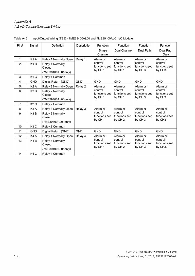
Appendix A A.2 I/O Connections and Wiring
FUH1010 IP65 NEMA 4X Precision Volume 166 Operating Instructions, 01/2013, A5E32122003-AA
Table A- 3 Input/Output Wiring (TB3) - 7ME39400AL00 and 7ME39400AL01 I/O Module
Pin# Signal Definition Description Function Single
Channel
Function Dual Channel
Function Dual Path
Function Dual Path
Only 1 K1 A Relay 1 Normally Open 2 K1 B Relay 1 Normally
Closed (7ME39400AL01only)
3 K1 C Relay 1 Common
Relay 1 Alarm or control functions set by CH 1
Alarm or control functions set by CH 1
Alarm or control functions set by CH 3
Alarm or control functions set by CH3
4 GND Digital Return [GND] GND GND GND GND GND 5 K2 A Relay 2 Normally Open 6 K2 B Relay 2 Normally
Closed (7ME39400AL01only)
7 K2 C Relay 2 Common
Relay 2 Alarm or control functions set by CH 1
Alarm or control functions set by CH 1
Alarm or control functions set by CH 3
Alarm or control functions set by CH3
8 K3 A Relay 3 Normally Open 9 K3 B Relay 3 Normally
Closed (7ME39400AL01only)
10 K3 C Relay 3 Common
Relay 3 Alarm or control functions set by CH 1
Alarm or control functions set by CH 2
Alarm or control functions set by CH 3
Alarm or control functions set by CH3
11 GND Digital Return [GND] GND GND GND GND GND 12 K4 A Relay 4 Normally Open 13 K4 B Relay 4 Normally
Closed (7ME39400AL01only)
14 K4 C Relay 4 Common
Relay 4 Alarm or control functions set by CH 1
Alarm or control functions set by CH 2
Alarm or control functions set by CH 3
Alarm or control functions set by CH3.

Appendix A A.2 I/O Connections and Wiring
FUH1010 IP65 NEMA 4X Precision Volume Operating Instructions, 01/2013, A5E32122003-AA 167
1
2
3
4
5
6
7
8
9
10
11
12
13
14
K1-A
GND
GND
*K1-B
K1-C
K2-A
*K2-B
K2-C
K3-A
*K3-B
K3-C
K4-A
*K4-B
K4-C
TB3
Note
Relays shown in Power OFF position, which is the same as the alarm assertion position.
*7ME39400AL00 Mercury Relay only available with Normally Open.
Terminal Block Wiring - 7ME39400AL03 and 7ME39400AL04 Expanded I/O Module (Refer to manual drawing 1010N-7-7 sheet 2 of 2)
These connection diagrams apply to the part numbers listed below.
Table A- 4 Connection Diagrams and Part Numbers
1010N-7-7 (Sheet 2 of 2) Drawing FUH1010 7ME3600-0, 7ME3600-3

Appendix A A.2 I/O Connections and Wiring
FUH1010 IP65 NEMA 4X Precision Volume 168 Operating Instructions, 01/2013, A5E32122003-AA
Figure A-2 7ME39400AL03 and 7ME39400AL04 Expanded I/O Module

Appendix A A.2 I/O Connections and Wiring
FUH1010 IP65 NEMA 4X Precision Volume Operating Instructions, 01/2013, A5E32122003-AA 169
Table A- 5 Input/Output Wiring (TB2) - 7ME39400AL03 and 7ME39400AL04 Expanded I/O Module
Pin# Signal Definition Description Function Dual/Quad Path Only
14 Chassis Ground Chassis Ground Cable Shield Terminations 13 Chassis Ground Chassis Ground Cable Shield Terminations 12 PG4 POS [+] Total TTL POS [+] Total TTL 11 PG3 POS [+] Total OC POS [+] Total OC 10 PG2 NEG [-] Total TTL NEG [-] Total TTL 9 PG1 NEG [-] Total OC
0-5000 Hz frequency output , assignable
NEG [-] Total OC 8 Io2 (-) Isolated Return 7 Io2 (+) 4-20mA Output 2 6 Io1 (-) Isolated Return 5 Io1 (+) 4-20mA Output 1 4 Vo2- Ref. Ground 3 Vo2+ 0 to 10 Volt Output 2 Vo1- Ref. Ground 1 Vo1+ 0 to 10 Volt Output
Flow meter process variables assigned to individual outputs under menu control.
System outputs assignable & scalable to flow related parameters.
4-20mA outputs also provide a fault indication by dropping to 2mA if assigned to flow rate and under fault conditions.
OC = Open Collector
① TB2-11 - POS [+] Total OC ④ 4-20mA Load 1k ohm (max)
TB2-12 - POS [+] Total TTL ② TB2-9 - NEG [-] Total OC ⑤ 0 to 10 V Load 10k ohm (min)
TB2-10 - NEG [-] Total TTL ③ 4-20mA Load 1k ohm (max) ⑥ 0 to 10 V Load 10k ohm (min)
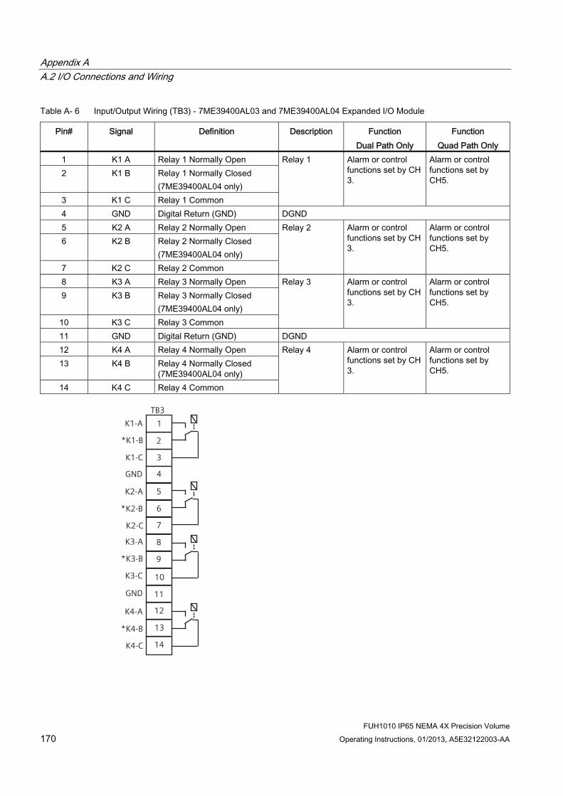
Appendix A A.2 I/O Connections and Wiring
FUH1010 IP65 NEMA 4X Precision Volume 170 Operating Instructions, 01/2013, A5E32122003-AA
Table A- 6 Input/Output Wiring (TB3) - 7ME39400AL03 and 7ME39400AL04 Expanded I/O Module
Pin# Signal Definition Description Function Dual Path Only
Function Quad Path Only
1 K1 A Relay 1 Normally Open 2 K1 B Relay 1 Normally Closed
(7ME39400AL04 only) 3 K1 C Relay 1 Common
Relay 1 Alarm or control functions set by CH 3.
Alarm or control functions set by CH5.
4 GND Digital Return (GND) DGND 5 K2 A Relay 2 Normally Open 6 K2 B Relay 2 Normally Closed
(7ME39400AL04 only) 7 K2 C Relay 2 Common
Relay 2 Alarm or control functions set by CH 3.
Alarm or control functions set by CH5.
8 K3 A Relay 3 Normally Open 9 K3 B Relay 3 Normally Closed
(7ME39400AL04 only)
Relay 3 Alarm or control functions set by CH 3.
10 K3 C Relay 3 Common
Alarm or control functions set by CH5.
11 GND Digital Return (GND) DGND 12 K4 A Relay 4 Normally Open 13 K4 B Relay 4 Normally Closed
(7ME39400AL04 only) 14 K4 C Relay 4 Common
Relay 4 Alarm or control functions set by CH 3.
Alarm or control functions set by CH5.
1
2
3
4
5
6
7
8
9
10
11
12
13
14
K1-A
GND
GND
*K1-B
K1-C
K2-A
*K2-B
K2-C
K3-A
*K3-B
K3-C
K4-A
*K4-B
K4-C
TB3

Appendix A A.2 I/O Connections and Wiring
FUH1010 IP65 NEMA 4X Precision Volume Operating Instructions, 01/2013, A5E32122003-AA 171
Note
Relays shown in Power OFF position, which is the same as the alarm assertion position.
*7ME39400AL03 Mercury Relay only available with Normally Open.
Table A- 7 Input/Output Wiring (TB4) - 7ME39400AL03 and 7ME39400AL04 Expanded I/O Module
Pin # Signal Definition Description Single CH Function
Dual CH Function
Dual Path Function
Dual Path Only
Function
Quad Path Only Function
1 AUX I01+
Isolated Loop Supply Io1
Io1 External Power
+30gV max. supply voltage allowed
2 AUX I01-
Io1 4-20 mA Output
Io1 Signal Same output assignment as TB2-9
3 AUX I02+
Isolated Loop Supply Io2
Io2 External Power
+30V max. supply voltage allowed
4 AUX I02-
Io2 4-20 mA Output
Io2 Signal Same output assignment as TB2-11
Not Used
5 AUX I03+
Isolated Loop Supply Io3
Io3 External Power
6 AUX I03-
Io3 4-20 mA Output
Io3 Signal
+30 V max. Same as TB2-1
7 AUX I04+
Isolated Loop Supply Io4
Io4 External Power
8 AUX I04-
Io4 4-20 mA Output
Io4 Signal
System outputs assignable and scalable to flow related parameters. 4-20mA outputs also provide a fault indication by dropping to 2mA if assigned to flow rate and under fault conditions.
+30 V max. Same as TB2-3
Note
Auxiliary 4-20mA loops are assigned and spanned under menu control of Vo and PGEN outputs.

Appendix A A.2 I/O Connections and Wiring
FUH1010 IP65 NEMA 4X Precision Volume 172 Operating Instructions, 01/2013, A5E32122003-AA
-
+
-
RL
+
-
RL
I
I
VC
VC
+
RL
+
-
RL
I
I
VC
VC
AUX Io1
AUX Io2
AUX Io3
AUX Io4
Vc: 24 VDC typical (+15 VDC to 30 VDC max) Loop Supply
RL: 1000 ohms max, = Loop wire resistance plus user's input load resistance
I: 4-20mA
Terminal Block Wiring - 7ME39400AL04 Expanded I/O Module (Refer to manual drawing 1010N-7-7 sheet 2 of 2)
These connection diagrams apply to the part numbers listed below.
Table A- 8 Connection Diagrams and Part Numbers
1010N-7-7 (Sheet 2 of 2) Drawing FUH1010 7ME3600-0, 7ME3600-3

Appendix A A.2 I/O Connections and Wiring
FUH1010 IP65 NEMA 4X Precision Volume Operating Instructions, 01/2013, A5E32122003-AA 173
Figure A-3 7ME39400AL04 Expanded I/O Module

Appendix A A.2 I/O Connections and Wiring
FUH1010 IP65 NEMA 4X Precision Volume 174 Operating Instructions, 01/2013, A5E32122003-AA
Table A- 9 Input/Output Wiring (TB2) - 7ME39400AL04 Expanded I/O Module
Pin# Signal Definition Description Function Dual/Quad Path Only
14 Chassis Ground Chassis Ground Cable Shield Terminations 13 Chassis Ground Chassis Ground Cable Shield Terminations 12 PG4 POS [+] Total TTL POS [+] Total TTL 11 PG3 POS [+] Total OC POS [+] Total OC 10 PG2 NEG [-] Total TTL NEG [-] Total TTL 9 PG1 NEG [-] Total OC
0-5000 Hz frequency output , assignable
NEG [-] Total OC 8 Io2 (-) Isolated Return 7 Io2 (+) 4-20 mA Output 2 6 Io1 (-) Isolated Return 5 Io1 (+) 4-20 mA Output 1 4 Vo2- Ref. Ground 3 Vo2+ 0 to 10 Volt Output 2 Vo1- Ref. Ground 1 Vo1+ 0 to 10 Volt Output
Flow meter process variables assigned to individual outputs under menu control.
System outputs assignable & scalable to flow related parameters.
4-20mA outputs also provide a fault indication by dropping to 2mA if assigned to flow rate and under fault conditions.
OC = Open Collector
+5V
+5V
PG1
PG3
PG4
1
32
1
32
PG2
DPGEN_1-Ø1
DPGEN_1-Ø2
DPGEN_2-Ø2
DPGEN_2-Ø1 2
3
4
5
TTL/CMOS
2
3
4
5
TTL/CMOS

Appendix A A.2 I/O Connections and Wiring
FUH1010 IP65 NEMA 4X Precision Volume Operating Instructions, 01/2013, A5E32122003-AA 175
Table A- 10 Open Collector User Resistor Recommendations
User Supply Voltage (V DC)
External Resistor (Ohms)
Expected Current Draw (mA)
Recommended Resistor Wattage (Watts)
5 270 18.5 1/2 9 510 17.6 1/2
12 680 17.6 1/2 18 1000 18 3/4 24 1500 16 1 28 1800 15.5 1 1/4 36 2400 15 1 1/4
Note
TB2-9 and TB2-11 are Open Collector Outputs that require external pull-up resistors for operation. See table for External Supply Voltage and suggested resistor value and ratings. Maximum current into the transistor is 100 mA. Maximum Voltage is +36 VDC.
NOTICE Transistor Damage
Negative voltages with respect to ground will permanently damage transistors.
Use caution when applying power to circuit boards.
Table A- 11 Input/Output Wiring (TB3) - 7ME39400AL04 Expanded I/O Module
Pin# Signal Definition Description Function Dual Path Only
Function Quad Path Only
1 K1 A Relay 1 Normally Open 2 K1 B Relay 1 Normally Closed 3 K1 C Relay 1 Common
Relay 1 Alarm or control functions set by CH 3.
Alarm or control functions set by CH5.
4 GND Digital Return (GND) DGND 5 K2 A Relay 2 Normally Open 6 K2 B Relay 2 Normally Closed 7 K2 C Relay 2 Common
Relay 2 Alarm or control functions set by CH 3.
Alarm or control functions set by CH5.
8 K3 A Relay 3 Normally Open 9 K3 B Relay 3 Normally Closed 10 K3 C Relay 3 Common
Relay 3 Alarm or control functions set by CH 3.
Alarm or control functions set by CH5.
11 GND Digital Return (GND) DGND 12 K4 A Relay 4 Normally Open 13 K4 B Relay 4 Normally Closed 14 K4 C Relay 4 Common
Relay 4 Alarm or control functions set by CH 3.
Alarm or control functions set by CH5.

Appendix A A.2 I/O Connections and Wiring
FUH1010 IP65 NEMA 4X Precision Volume 176 Operating Instructions, 01/2013, A5E32122003-AA
Note
Relays shown in Power OFF position, which is the same as the alarm assertion position.
Table A- 12 Input/Output Wiring (TB4) - 7ME39400AL04 Expanded I/O Module
Pin# Signal Function Description 1 No Connection 2 No Connection 3 No Connection 4 No Connection 5 AUX 103+ Isolated Loop Supply Connect +30V max. Loop Supply here 6 AUX 103- Loop-Powered 4-20mA PGEN 1 Data Presented as 4-20mA 7 AUX 104+ Isolated Loop Supply Connect +30V max. Loop Supply here 8 AUX 104- Loop-Powered 4-20mA PGEN 2 Data Presented as 4-20mA
Note
Auxiliary 4-20 mA loops are assigned and spanned under menu control of Vo and PGEN outputs.

Appendix A A.3 RS-232 Connection
FUH1010 IP65 NEMA 4X Precision Volume Operating Instructions, 01/2013, A5E32122003-AA 177
+
-
RL
+
-
RL
I
I
VC
VC
1
2
3
4
5
6
7
8
NC
NC
TB4
AUX Io3
AUX Io4
NC
NC
Vc: 24 VDC typical (+15 VDC to +30 VDC max) Loop Power
RL: 1000 ohms (max), Loop wire resistance plus user's input load resistance
I: 4-20mA
A.3 RS-232 Connection The optionally serial interface cable includes 9-pin and 25-pin connectors to accommodate both types of IBM-compatible serial ports. A PC communication program such as Siemens Si-Ware (download program at: http://s13.me/ns/cv) or HyperTerminal (Windows 95/98/NT/2000/XP) serves as the data entry interface. These programs reproduce the menu screens that would appear on the system’s graphic screen. Once the serial interface is established you can choose to program a graphic display system using a PC and a communications program.
Note
Many newer laptop PCs are not equipped with serial ports and only have USB ports. These PCs will require a USB RS-232 adaptor that can be purchased commercially.
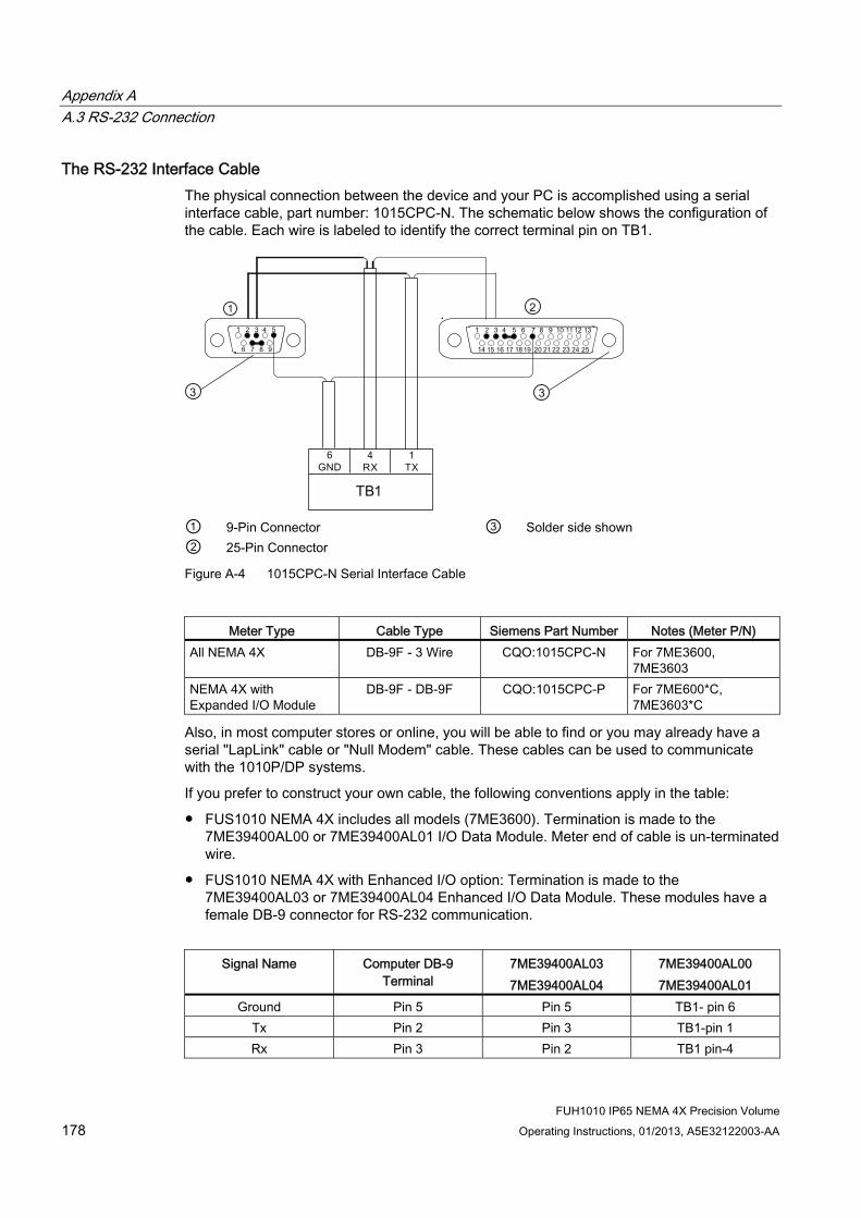
Appendix A A.3 RS-232 Connection
FUH1010 IP65 NEMA 4X Precision Volume 178 Operating Instructions, 01/2013, A5E32122003-AA
The RS-232 Interface Cable The physical connection between the device and your PC is accomplished using a serial interface cable, part number: 1015CPC-N. The schematic below shows the configuration of the cable. Each wire is labeled to identify the correct terminal pin on TB1.
① ③ 9-Pin Connector Solder side shown ② 25-Pin Connector
Figure A-4 1015CPC-N Serial Interface Cable
Meter Type Cable Type Siemens Part Number Notes (Meter P/N)
All NEMA 4X DB-9F - 3 Wire CQO:1015CPC-N For 7ME3600, 7ME3603
NEMA 4X with Expanded I/O Module
DB-9F - DB-9F CQO:1015CPC-P For 7ME600*C, 7ME3603*C
Also, in most computer stores or online, you will be able to find or you may already have a serial "LapLink" cable or "Null Modem" cable. These cables can be used to communicate with the 1010P/DP systems.
If you prefer to construct your own cable, the following conventions apply in the table:
● FUS1010 NEMA 4X includes all models (7ME3600). Termination is made to the 7ME39400AL00 or 7ME39400AL01 I/O Data Module. Meter end of cable is un-terminated wire.
● FUS1010 NEMA 4X with Enhanced I/O option: Termination is made to the 7ME39400AL03 or 7ME39400AL04 Enhanced I/O Data Module. These modules have a female DB-9 connector for RS-232 communication.
Signal Name Computer DB-9
Terminal 7ME39400AL03 7ME39400AL04
7ME39400AL00 7ME39400AL01
Ground Pin 5 Pin 5 TB1- pin 6 Tx Pin 2 Pin 3 TB1-pin 1 Rx Pin 3 Pin 2 TB1 pin-4

Appendix A A.3 RS-232 Connection
FUH1010 IP65 NEMA 4X Precision Volume Operating Instructions, 01/2013, A5E32122003-AA 179
Communicating with SITRANS F 1010 Systems via the RS-232 Interface The following sections assume that you are familiar with the basics of using Windows 95/98/NT/2000/XP based communications program. Most computers provide at least one serial port using either a 9-pin or 25-pin D-type connector. The port designation can be either COM 1 or COM 2. Usually, when a computer includes two serial ports, COM 1 will be the 9-pin connector and COM 2 will be the 25-pin connector. However, port designations can vary from manufacturer to manufacturer, so you will have to positively identify the COM port you wish to use for the meter interface. Connect the cable between the meter and your PC using the 25-pin, 9-pin or USB to RS-232 adapter connector, depending upon the port’s architecture.
How to use the Windows HyperTerminal Program
Note Si-Ware
If you want to use the Si-Ware program instead of HyperTerminal, download the program at [http://s13.me/ns/cv] and follow the setup instructions.
Windows provides a communication program called HyperTerminal, which is ideal for interfacing your computer with the meter. The following typical example explains how to set up HyperTerminal.
Note
Depending upon the Windows applications being used this setup procedure may vary.
1. Invoke HyperTerminal.
2. Set Com port to port that is designated for use (COM 1).
3. Confirm port settings match the RS-232 setting in the meter.
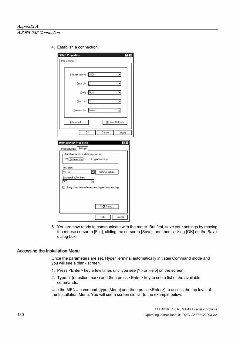
Appendix A A.3 RS-232 Connection
FUH1010 IP65 NEMA 4X Precision Volume 180 Operating Instructions, 01/2013, A5E32122003-AA
4. Establish a connection.
5. You are now ready to communicate with the meter. But first, save your settings by moving
the mouse cursor to [File], sliding the cursor to [Save], and then clicking [OK] on the Save dialog box.
Accessing the Installation Menu Once the parameters are set, HyperTerminal automatically initiates Command mode and you will see a blank screen.
1. Press <Enter> key a few times until you see [? For Help] on the screen.
2. Type: ? (question mark) and then press <Enter> key to see a list of the available commands.
Use the MENU command (type [Menu] and then press <Enter>) to access the top level of the Installation Menu. You will see a screen similar to the example below.

Appendix A A.3 RS-232 Connection
FUH1010 IP65 NEMA 4X Precision Volume Operating Instructions, 01/2013, A5E32122003-AA 181
Note
To facilitate connecting through modems, the [Menu] command times out after three minutes of inactivity. To maintain a longer connection type: Menu 1000 and press <Enter>. The optional number is the amount in minutes that the connection will be maintained. Typing [Menu 1000] essentially keeps the interface active for a prolonged period of time.

Appendix A A.3 RS-232 Connection
FUH1010 IP65 NEMA 4X Precision Volume 182 Operating Instructions, 01/2013, A5E32122003-AA
Data Display Mode After you complete the installation, you can toggle between Installation Menu mode to Data Display mode. This is the same as using the <MENU> key on the keypad (see Operating Instructions manual). The PC keyboard equivalent key to the keypad <MENU> key is <CTRL> + <L>. Note that the RS-232 interface does not support graphics. Therefore, when you use HyperTerminal to view the data display screens, you will see the same data in alphanumeric form only (as shown below). You can still use the <Up Arrow> and <Down Arrow> to switch between available display screens.
① Current active site setup name. The [1]
indicates that the measurement channel is active.
③ The flow Total display.
② The current measured liquid sonic velocity. ④ The current flow reading and flow units.

Appendix A A.3 RS-232 Connection
FUH1010 IP65 NEMA 4X Precision Volume Operating Instructions, 01/2013, A5E32122003-AA 183
Navigating through the Installation Menu After accessing the Installation Menu, you can begin to setup your meter according to the instructions in this manual. The chart below shows the PC keyboard equivalents to the keypad keys while you are in the menu.
SITRANS F 1010 Keypad PC Keyboard Description
<Up Arrow> <Up Arrow> Move up 1 menu cell (or Flow Display screen)
<Down Arrow> <Down Arrow> Move down 1 menu cell (or Flow Display screen)
<Right Arrow> <Right Arrow> Move right 1 menu cell (or Flow Display screen)
<Left Arrow> <Left Arrow> Move left 1 menu cell (or Flow Display screen)
<MENU> ^L (Ctrl L) Toggle between Menu and Flow Display <DATALOG> ^D (Ctrl D) Generate Datalogger report <CLR> <Backspace> or <DEL> Deselect list selection <ALT+Up Arrow> ^U (Ctrl U) Logger Display Page Advance <+/-> (chg sign) | (bar, shift + backslash) Change numeric sign. Can also type (-)
key <Enter> <Carriage Return> Enter Key Digits Digits Numerals zero through 9 / / Divide by X * (upper case 8) Multiply by + + Plus - - Minus = = Equals . . Decimal Point
Terminal Mode Menu Commands In addition, the following commands (followed by the <ENTER> key) can be used to control the meter while in Terminal Mode.
Note
The "n" refers to the meter Channel number. For a 2-Channel Arithmetic site (Ch1 + Ch2 or Ch1 – Ch2) the virtual Channel is number 3.
Logger Invokes the download of all data stored in the Datalogger. Note that the Datalogger data is not erased from the meter memory when it is downloaded. It is recommended to capture this information into a file with a "csv" extension, which can be easily imported into MS Excel.

Appendix A A.3 RS-232 Connection
FUH1010 IP65 NEMA 4X Precision Volume 184 Operating Instructions, 01/2013, A5E32122003-AA
SITE Invokes a full site download for a single channel or multi-path meter.
SITE "n" Invokes a site download for channel "n", where "n" = the Channel # (1, 2, 3, 4, etc.).
DP "n" Commands the meter to download the digitized receive signal data for Channel or Path "n".
CLRTOT Clears the Totalizer for a single channel or multi-path meter.
CLRTOT "n" Clears the Totalizer for Channel "n" of a multi-channel meter.
Lf on Turns on the Line Feed at the end of any text string sent by the meter.
Lf off Turns off the Line Feed at the end of any text string sent by the meter.
? Provides a list of available Terminal Mode meter commands.
Transferring information from the meter to a PC With HyperTerminal active:
1. Point to [Transfers], and click.
2. Select [Capture Text].
3. Select desired drive path or directory, enter a file name, and click the Start button.
4. Use the following conventions for data file names:
– For site data or Wave shape data: filename.txt
– For Datalogger data: filename.csv
5. On PC type the proper command for the data desired (Logger, Site, or DP) and then press [Enter] key.
6. The data should begin streaming on the HyperTerminal screen.
Appendix A A.3 RS-232 Connection
FUH1010 IP65 NEMA 4X Precision Volume Operating Instructions, 01/2013, A5E32122003-AA 185
7. Wait for EOT (End Of Transmission) to be displayed.
8. Close the file by pointing to Transfer, drag to Capture Text and click Stop button.
Closing the Terminal or HyperTerminal Program You may now close the Terminal program. The file(s) you have downloaded are now saved in the location you selected. You may now import the file you have saved into the appropriate program (i.e. MS Word for site data, or MS Excel for Datalogger or wave shape data for graphing or analysis).
The Datalogger contains data that has its fields separated by commas. By using the file extension ".csv" (comma separated values) suggested earlier, the data will import directly into MS Excel without any further modification. For the wave shape data, the fields are separated by spaces, therefore, it is best to save those files as .txt and then use the MS Excel Import Wizard to select "Space Delimiters" for importation of the data.
Site data is downloaded in plain text and can be imported directly into MS Word.
Reset Procedure using RS-232 port SITRANS F 1010 systems allow you to perform a system reset via the RS-232 interface. The following instructions require the meter to be connected serially to a PC.
Note
Custom RS-232 settings for baud rate, parity and data bits may not be preserved. Therefore, be prepared to set your communications program back to the default (9600, Odd, 7) settings.
To Clear Active Memory using the RS-232 Interface 1. Turn off power (if it is currently on). Turn power on. As soon as you apply power,
immediately type the @ character three times. The prompt: [Clr Active Memory? No] appears at the top of the screen.
2. Press the <Right Arrow> and then the <Down Arrow> to switch the option list to: [Clr Active Memory? Yes] Press <ENTER> to clear all Active Site Data (but not saved site setups).
3. To restore operation, press <MENU> to access the Installation Menu. Create a new site setup or recall a stored site setup. Re-select any Meter Facilities items (e.g., RS-232 setup parameters).

Appendix A A.4 Flowrate Calibration and Calibration Tables
FUH1010 IP65 NEMA 4X Precision Volume 186 Operating Instructions, 01/2013, A5E32122003-AA
To Clear All Saved Data using the RS-232 Interface
NOTICE Loss of RAM Data
Before proceeding further it is essential to understand that this function eliminates ALL data stored in RAM. This means that all saved site setups including the site data of a flow-calibrated site will be erased! In addition, the entire Datalogger file plus any custom factory or user-created pipe or sensor tables will be eliminated.
The impact of this is such that we strongly recommend that you consult Technical Services before continuing with this procedure. Be aware that you will have to create a new Site Setup, re-enter all site specific parameters including pipe or sensor tables, plus all desired Meter Facilities menu entries.
1. Turn off power (if it is currently on).
2. Turn the power on. As soon as you apply power, type the @ character three times.
– The prompt: [Clr Active Memory?] appears at the top of the screen. Press the <Down Arrow>.
Note
Note that the prompt switches to [Clr Saved Data? No].
3. Press the <Right Arrow> and then the <Down Arrow> to switch the option list to: [Clr Saved Data? Yes].
4. Press <ENTER> to clear all Saved Site Data, Datalogger Data, user created Pipe Data and Sensor Data.
5. To restore operation, press <MENU> to access the Installation Menu. Create a new site setup or recall a stored site setup. Reselect any Meter Facilities items (e.g., RS-232 setup parameters).
A.4 Flowrate Calibration and Calibration Tables
Flowrate Calibration Methods SITRANS F 1010 equipment provides three ways to condition the calibration performance of its flowrate output: Intrinsic (factory set), Kc, and Calibration Tables 1 through 3. Access to these calibration options is found in the [Calibrate Flowrate] menu cell and the three [Calib. Table] menu cells of the [Span/Set/Cal] menu.
Intrinsic When selected, the flow meter uses no slope adjustment at all. Output data is still zeroed and corrected for Reynolds number, but no slope adjustment is imposed on the flow meter’s flow register.

Appendix A A.4 Flowrate Calibration and Calibration Tables
FUH1010 IP65 NEMA 4X Precision Volume Operating Instructions, 01/2013, A5E32122003-AA 187
Some applications may require an output adjustment to match an official external reference. The [Calibrate Flowrate] menu allows you to select a calibration mode. The right-hand column shows the active calibration mode. You can select Intrinsic (factory) and Kc (Slope Correction) Calibration. Selecting either of the external calibration modes will not eliminate the Intrinsic (factory) calibration. You can use this menu cell to switch between Intrinsic and Kc at any time.
Kc Calibration For most applications, the measured flow range produces a linear meter response. Therefore, the Kc (slope correction) calibration is the preferred method since it only requires a single correction factor for all the flow rates encountered.
Note
Changing the calibration can cause profound changes in flow meter operating characteristics. Use only the most respected flow standard to obtain a correction factor. The percentage entered must provide an accurate and consistent shift across the entire flow range anticipated for the application.
Kc Factor To obtain the Kc factor, compare flow total data taken simultaneously from the flow meter and a reference meter whose accuracy meets the required standard. Allow both meters to accumulate flow total data long enough to average out any differences due to flow fluctuation between the two meter locations. Compare outputs of the two totalizers to determine percentage increase (+) or decrease (-) that is necessary to produce the best average correlation between the flow meter and the reference standard.
Selecting the Kc Factor When the [Kc] menu cell is selected, the flow meter imposes this percentage slope adjustment of its rate output. Output data is zeroed and corrected for the Reynolds number (flow profile compensated), however, a percent change in the rate output is imposed based on the data entered in this cell. The number entered by the user is evaluated into a slope correction factor by dividing it by 100 and algebraically adding it to 1. The resulting factor is used as a multiplier on the rate register of the instrument. Thus an entry of -3% will multiply the rate register by 0.97, for example.
To calculate Kc:

Appendix A A.4 Flowrate Calibration and Calibration Tables
FUH1010 IP65 NEMA 4X Precision Volume 188 Operating Instructions, 01/2013, A5E32122003-AA
To enter the Kc Factor 1. To enable numeric entry press <Right Arrow>.
2. Use the numeric keys to type the required Kc (as calculated above). Note that the Kc value can be negative or positive. Enter the - or + sign first, then type in the calibrated value.
3. To store the data press <ENTER>. Note that Kc now appears in the right-hand column of the [Calibrate Flow Rate] menu cell with its new value. Also note that this Kc value can be viewed on the site printout.
Calibration Tables 1 through 3 SITRANS F 1010 instruments offer a unique methodology by which a particular flow response of an instrument may be linearized or optimized by tabulating the results of a series of calibration exercises or collected batch data points. Basically, the flow meter allows the user to select any of a wide variety of system variables (flow rate, pressure, viscosity, etc.) as a pointer into a table of calibration factors (up to 32). As the system variable is updated, the value of the table’s output factors (or positive and negative flow) is re-evaluated and used as a modifier for the current rate register. Note that the flow register is still zeroed and Reynolds number compensated normally and these slope corrections are in addition to these fundamentals.
Note
Kc is still active when this method is being used.
To install a Calibration table: 1. The user selects a system variable that appears to correlate strongly with calibration
shifts observed.
2. A table of values is formed comprised of the values that this index could assume over the range of system operation. Remember, the tables created do not extrapolate beyond their end points, they "clip."
3. A calibration factor, a number usually close to 1.00, is entered as a positive and a negative flow rate correction factor (termed PosFlow Corr and NegFlow Corr) for each of the desired index points.

Appendix A A.4 Flowrate Calibration and Calibration Tables
FUH1010 IP65 NEMA 4X Precision Volume Operating Instructions, 01/2013, A5E32122003-AA 189
The table may contain up to 32 pairs of these slope correction factors. Note that the Kc factor, unlike these slope correction factors, is entered as a signed percent change in rate, while these factors are simply rate multipliers. As points are entered, the point editor will provide list access to the already entered points plus access to the [New Point] menu cell, used to add a new point. The table may be created in its entirety and then activated by selecting [Yes] in the [Table Active] menu cell. The entire table may be cleared by selecting [Yes] in the [Clear Table] menu cell.
Note
Careless use of the calibration tables can have a detrimental impact on the measurement performance of the flow meter.
Note
Take precautions before enabling these calibration tables. Although it is unlikely that all three tables would ever be employed in a real installation, three tables are offered for maximum user flexibility. Since the tables can be disabled without being destroyed, 2 or 3 optimization strategies may be tested by this means in order to determine which approach is most effective.

Appendix A A.4 Flowrate Calibration and Calibration Tables
FUH1010 IP65 NEMA 4X Precision Volume 190 Operating Instructions, 01/2013, A5E32122003-AA

BAppendix B
B.1 Installation/Outline Drawings The following are the installation and outline drawings for the SITRANS FUH1010 IP65 NEMA 4X and IP66 NEMA 7 Precision Volume Flow Meter.
1010NS2-7 Rev D - Installation Drawing, 1010 Series Flow Computer, Agency Approved
1010N-7-7 Rev 08 - Installation Wiring, Expanded I/O Module
1010N-2-7 Rev 05 - Installation Wiring, I/O Module
1010N-5S2-7 Rev D - Installation Drawing, Analog Input Module
1010N-5DS2-7 Rev 06 - Installation Drawing, Analog Input Module
1010-304 Rev 14 - Connection Diagram for Hazardous Area Use, Agency Approved, 1010NS2/1010MNS2 Series Flow Computer
1010WX-S2-7 Rev A - Installation Drawing, 1010 Series Single/Dual Channel Flow Computer, Agency Approved
1010-443 Rev 05 - Connection Diagram for Hazardous Area Use, Agency Approved, 1010WX-S2 Series Flow Computer
1010NS9-7 Rev A - Installation Drawing, 1010 Series Flow Computer, Agency Approved
1010MNS9-7 Rev A - Installation Drawing, 1010 Series Multi-Channel Flow Computer, Agency Approved
1010-389 Rev 05 - Connection Diagram, Agency Approved for Hazardous Area Use, 1010NS9/1010MNS9 Series Flow Computer
1010-391 Rev C - Connection Diagram, Agency Approved for Zone 2 Connections, 1010NS9 Flow Computer System
1011NS2-7 Rev D - Installation Guide, Connection Diagram Selection, Agency Approved, 1011N Series Transducers
1011NS9-7 Rev C1 - Installation Guide, Connection Diagram Selection, Agency Approved, 1011N Series Transducers
1011NFPS-7 Rev B - Installation Drawing, 1011NPFS Series dedicated Plastic Body Transducer
1011HNS2-7 Rev D - Installation Guide, Connection Diagram Selection, Agency Approved, 1011HN Series Transducers
1011HNS9-7 Rev C1 - Installation Guide, Connection Diagram Selection, Agency Approved, 1011HN Series Transducers
1011HNFS-7 Rev 02 - Installation, 1011HNFS Series Dedicated Plastic Body Transducer
FUH1010 IP65 NEMA 4X Precision Volume Operating Instructions, 01/2013, A5E32122003-AA 191

Appendix B B.1 Installation/Outline Drawings
FUH1010 IP65 NEMA 4X Precision Volume 192 Operating Instructions, 01/2013, A5E32122003-AA
1012F-DB-7 Rev B - Installation Drawing, Dual Path Transducer Set w/Mounting Frames
1012MS-8 Rev F - Installation/Outline, Adjustable Mounting Strap
1012TN-7 Rev A - Installation Drawing, 1010 Series Transducers and Mounting Tracks
1012TNH-7 Rev A - Installation Drawing, 1010 Series Transducer and Mounting Tracks
991TS2-7 Rev 03- Installation Drawing, Temp. Sensor, Dedicated NEMA 4, Pipe O.D. 1 1/4" - 48" (32-1220mm)
991TDS2-7 Rev 03 - Installation Drawing, 991TD Temperature Sensor, Submersible, Agency Approved
990TDMVH-7B Rev F - Installation Drawing, 990 Series Transducer, Direct Mode, Very High Temp.
990TRMVH-7B Rev F - Installation Drawing, 990 Series Transducer, Reflect Mode, Very High Temp.


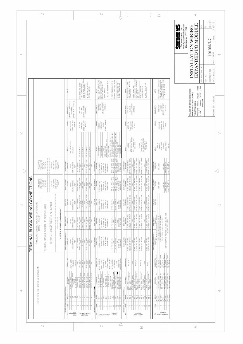


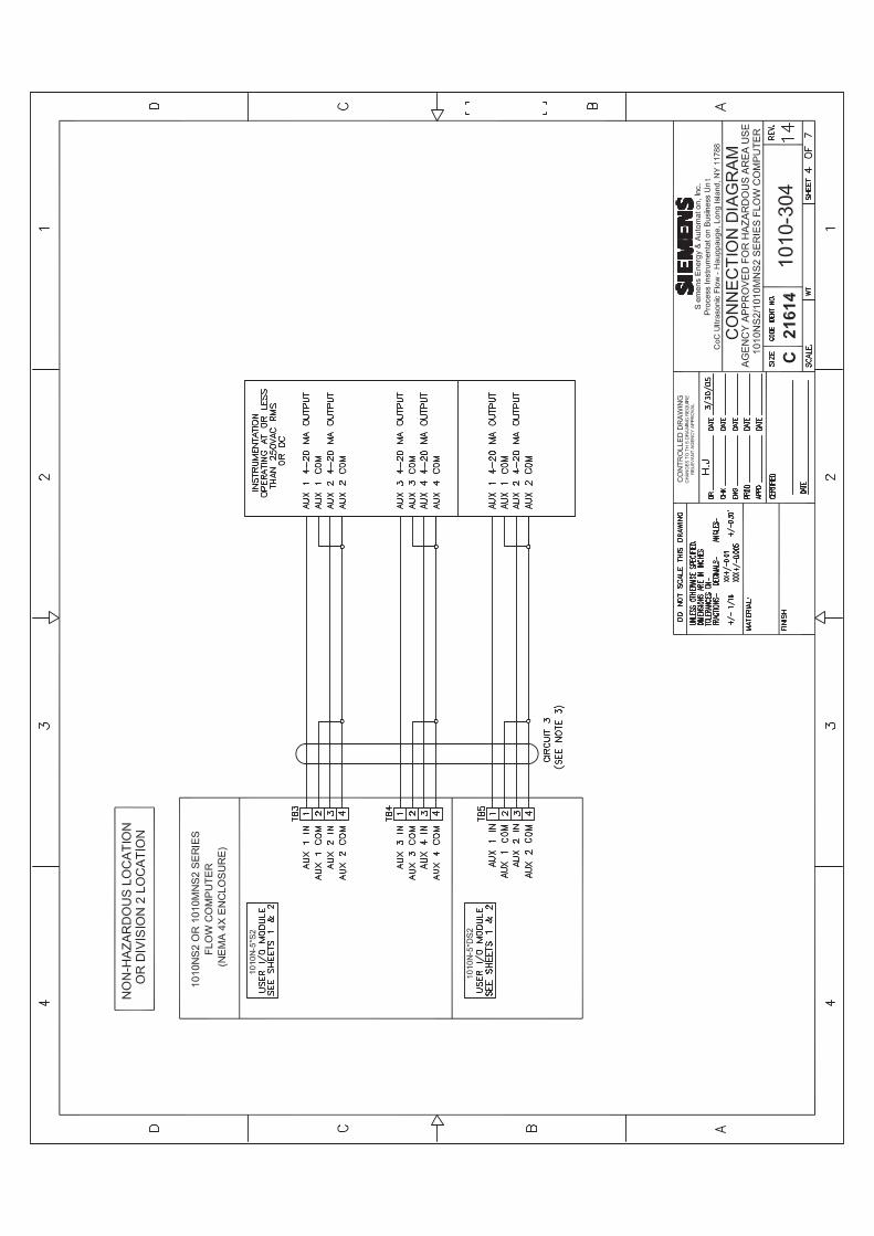


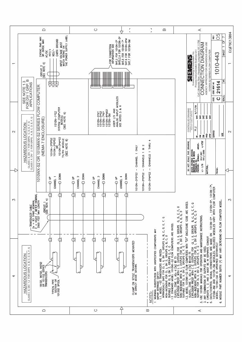


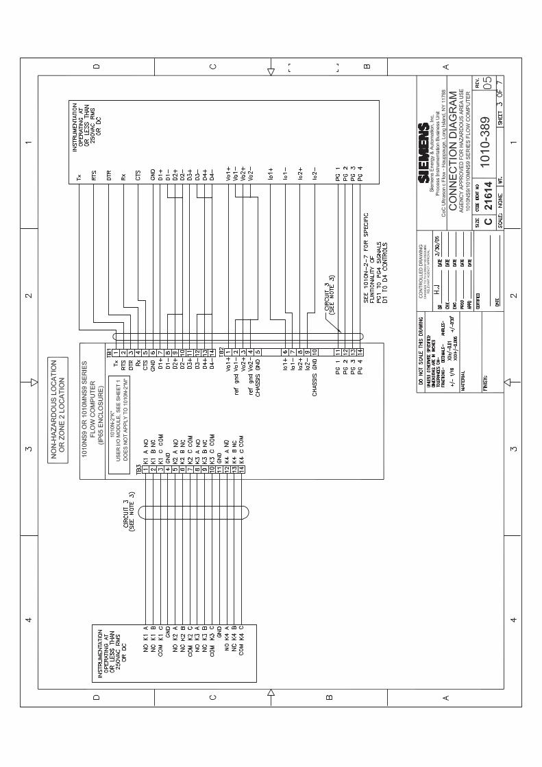


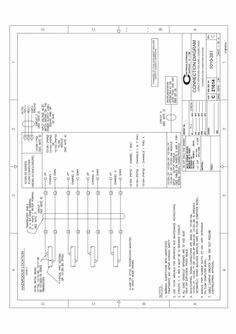


2161
4C
1011
NFP
S-7

1011
NFP
S-7
C21
614

1011
NFP
S-7
C21
614

2161
4C
1011
NFP
S-7


21
61
4C
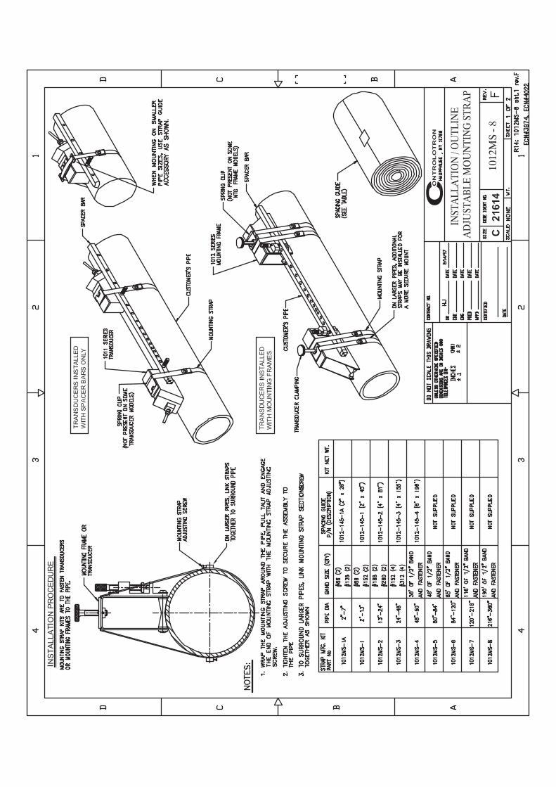


1012
TN-7
INST
ALL
ATI
ON
DRA
WIN
G10
10 S
ERIE
S TR
AN
SDU
CER
SA
ND
MO
UN
TIN
G T
RAC
KS
21
61
4C

1012
TN-7
INST
ALL
ATI
ON
DRA
WIN
G10
10 S
ERIE
S TR
AN
SDU
CER
SA
ND
MO
UN
TIN
G T
RAC
KS
21
61
4C

1012
TNH
-7
INST
ALL
ATI
ON
DRA
WIN
G10
10 S
ERIE
S TR
AN
SDU
CERS
AN
D M
OU
NTI
NG
TRA
CKS
2161
4C

1012
TNH
-7
INST
ALL
ATI
ON
DRA
WIN
G10
10 S
ERIE
S TR
AN
SDU
CERS
AN
D M
OU
NTI
NG
TRA
CKS
2161
4C


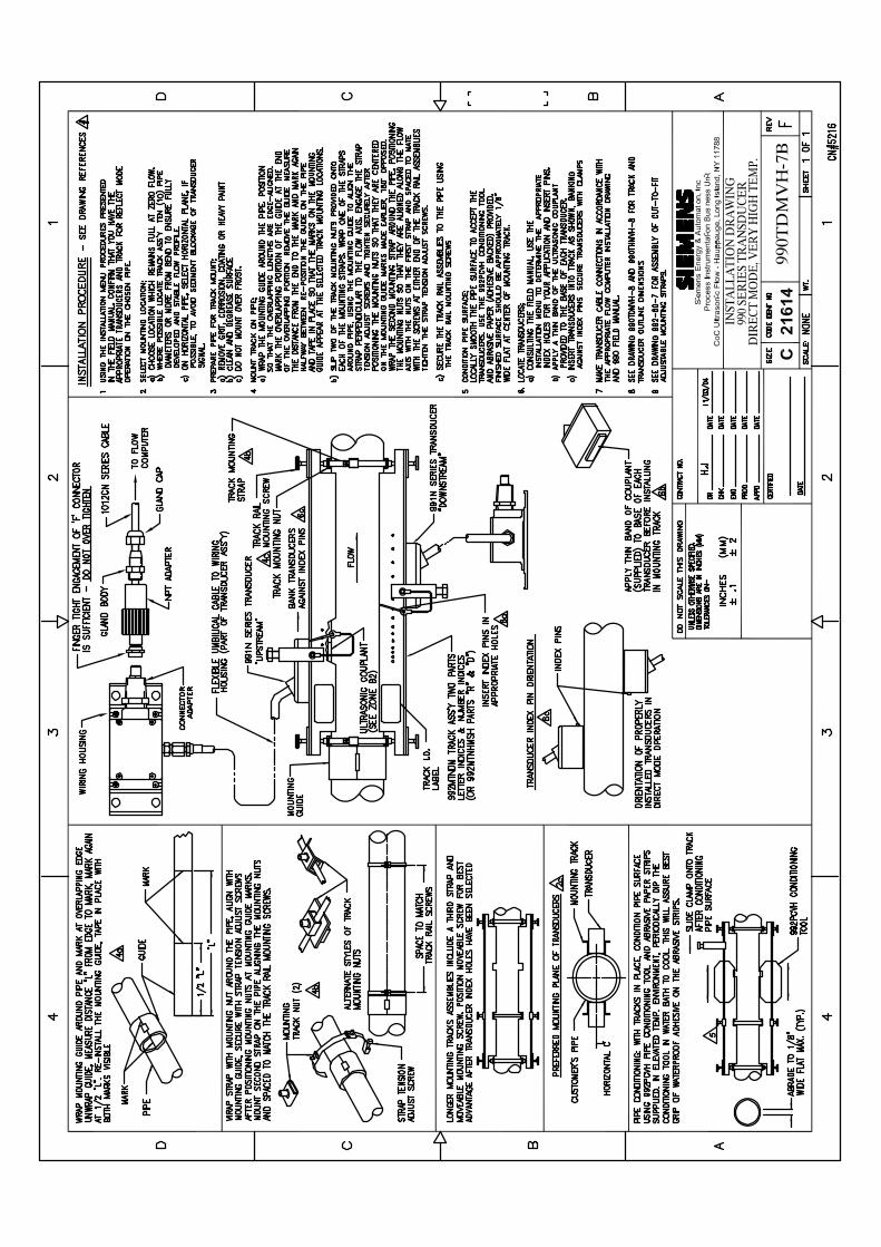
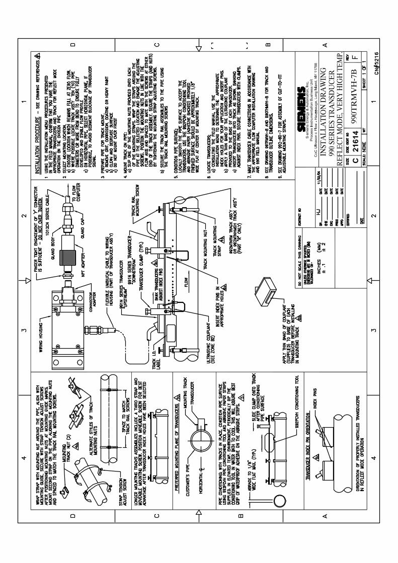


CL
AS
S 5
0N
om
inal
Dia
met
er
3 4 6 8 10 12 14 16 18 20 24 30 36 42 48 54
N/A
N
/AN
/A
N/A
0.25
6.4
00.
27 8
.51
0.29
10.
520.
31 1
2.58
0.33
14.
640.
34 1
6.72
0.35
18.
800.
36 2
0.88
0.38
25.
040.
39 3
1.22
0.43
37.
440.
47 4
3.56
0.51
49.
780.
57 5
6.42
Wal
l I.
D.
DU
CT
ILE
IR
ON
PIP
E
Act
ual
O.D
.
3.96
4.80
6.90
9.05
11.1
013
.20
15.3
017
.40
19.5
021
.60
25.8
032
.00
38.3
044
.50
50.8
057
.56
CL
AS
S 5
1
0.25
3.
460.
26
4.28
0.28
6.
340.
30
8.45
0.32
10.
460.
34 1
2.52
0.36
14.
580.
37 1
6.66
0.38
18.
740.
39 2
0.82
0.41
24.
980.
43 3
1.14
0.48
37.
340.
53 4
3.44
0.58
49.
640.
65 5
6.26
Wal
l I.
D.
CL
AS
S 5
2
0.28
3.
400.
29
4.22
0.31
6.
280.
33
8.39
0.35
10.
400.
37 1
2.46
0.39
14.
520.
40 1
6.60
0.41
18.
680.
42 2
0.76
0.44
24.
920.
47 3
1.06
0.53
37.
240.
59 4
3.32
0.65
49.
500.
73 5
6.10
Wal
l I.
D.
CL
AS
S 5
3
0.31
3.
340.
32
4.16
0.34
6.
220.
36
8.33
0.38
10.
340.
40 1
2.40
0.42
14.
460.
43 1
6.54
0.44
18.
620.
45 2
0.70
0.47
24.
860.
51 3
0.99
0.58
37.
140.
65 4
3.20
0.72
49.
360.
81 5
5.94
Wal
l I.
D.
CL
AS
S 5
4
0.34
3.
280.
35
4.10
0.37
6.
160.
39
8.27
0.41
10.
280.
43 1
2.34
0.45
14.
400.
46 1
6.48
0.47
18.
560.
48 2
0.64
0.50
24.
800.
55 3
0.90
0.63
37.
040.
71 4
3.08
0.79
49.
220.
89 5
5.78
Wal
l I.
D.
CL
AS
S 5
5
0.37
3.
220.
38
4.04
0.40
6.
100.
42
8.21
0.44
10.
220.
46 1
2.28
0.48
14.
340.
49 1
6.42
0.50
18.
500.
51 2
0.58
0.53
24.
740.
59 3
0.82
0.68
36.
940.
77 4
2.96
0.86
49.
080.
97 5
5.62
Wal
l I.
D.
0.40
3.
160.
41
3.98
0.43
6.
040.
45
8.15
0.47
10.
160.
49 1
2.22
0.51
14.
280.
52 1
6.36
0.53
18.
440.
54 2
0.52
0.56
24.
680.
63 3
0.74
0.73
36.
840.
83 4
2.84
0.93
48.
941.
05 5
5.46
Wal
l I.
D.
CL
AS
S 5
6
0.12
50.
250
0.12
50.
250
0.12
50.
250
0.12
50.
250
0.12
50.
250
0.12
50.
250
0.18
750.
375
0.18
750.
375
0.18
750.
375
0.18
750.
375
0.18
750.
375
0.25
00.
500
0.25
00.
500
0.25
00.
500
0.25
00.
500
0.25
00.
500
Sin
gle
D
ou
ble
Lin
er (
Cem
ent)
Sie
men
s In
dust
ry, I
nc.
Indu
stry
Aut
omat
ion
Div
isio
nC
oC U
ltras
onic
Flo
wH
aupp
auge
, New
Yor
k 11
788
US
AW
eb:
ww
w.u
sa.s
iem
ens.
com
CL
AS
S A
Pip
eS
ize
3 4 6 8 10 12 14 16 18 20 24 30 36 42 48 54 60 72 84
3.80
0.
39 3
.02
4.80
0.
42 3
.96
6.90
0.
44 6
.02
9.05
0.
46 8
.13
11.1
0 0.
50 1
0.10
13.2
0 0.
54 1
2.12
15.3
0 0.
57 1
4.16
17.4
0 0.
60 1
6.20
19.5
0 0.
64 1
8.22
21.6
0 0.
67 2
0.26
25.8
0 0.
76 2
4.28
31.7
4 0.
88 2
9.98
37.9
6 0.
99 3
5.98
44.2
0 1.
10 4
2.00
50.5
0 1.
26 4
7.98
56.6
6 1.
35 5
3.96
62.8
0 1.
39 6
0.02
75.3
4 1.
62 7
2.10
87.5
4 1.
72 8
4.10
O.D
Wal
l I.
D.
CL
AS
S B
3.96
0.
42 3
.12
5.00
0.
45 4
.10
7.10
0.
48 6
.14
9.05
0.
51 8
.03
11.1
0 0.
57 9
.96
13.2
0 0.
62 1
1.96
15.3
0 0.
66 1
3.96
17.4
0 0.
70 1
6.00
19.5
0 0.
75 1
8.00
21.6
0 0.
80 2
0.00
25.8
0 0.
89 2
4.02
32.0
0 1.
03 2
9.94
38.3
0 1.
15 3
6.00
44.5
0 1.
28 4
1.94
50.8
0 1.
42 4
7.96
57.1
0 1.
55 5
4.00
64.4
0 1.
67 6
0.06
76.0
0 1.
95 7
2.10
88.5
4 2.
22 8
4.10
O.D
Wal
l I.
D.
CL
AS
S C
3.96
0.
45 3
.06
5.00
0.
48 4
.04
7.10
0.
51 6
.08
9.30
0.
56 8
.18
11.4
0 0.
62 1
0.16
13.5
0 0.
68 1
2.14
15.6
5 0.
74 1
4.17
17.8
0 0.
80 1
6.20
19.9
2 0.
87 1
8.18
22.0
6 0.
92 2
0.22
26.3
2 1.
04 2
4.22
32.4
0 1.
20 3
0.00
38.7
0 1.
36 3
9.98
45.1
0 1.
54 4
2.02
51.4
0 1.
71 4
7.98
57.8
0 1.
90 5
4.00
64.2
0 2.
00 6
0.20
76.8
8 2.
39 7
2.10
O.D
Wal
l I.
D.
CL
AS
S D
3.96
0.
48 3
.00
5.00
0.
52 3
.96
7.10
0.
55 6
.00
9.30
0.
60 8
.10
11.4
0 0.
68 1
0.04
13.5
0 0.
75 1
2.00
15.6
5 0.
82 1
4.01
17.8
0 0.
89 1
6.02
19.9
2 0.
96 1
8.00
22.0
6 1.
03 2
0.00
26.3
2 1.
16 2
4.00
32.7
4 1.
37 3
0.00
39.1
6 1.
58 3
6.00
45.5
8 1.
78 4
2.02
51.9
8 1.
96 4
8.06
58.4
0 2.
23 5
3.94
64.8
2 2.
38 6
0.06
O.D
Wal
l I.
D.
CL
AS
S E
7.22
0.
58 6
.06
9.42
0.
66 8
.10
11.6
0 0.
74 1
0.12
13.7
8 0.
82 1
2.14
15.9
8 0.
90 1
4.18
18.1
6 0.
98 1
6.20
20.3
4 1.
07 1
8.20
22.5
4 1.
15 2
0.24
26.9
0 1.
31 2
4.28
33.1
0 1.
55 3
0.00
39.6
0 1.
80 3
6.00
O.D
Wal
l I.
D.
CL
AS
S F
7.22
0.
61 6
.00
9.42
0.
71 8
.00
11.6
0 0.
80 1
0.00
13.7
8 0.
89 1
2.00
15.9
8 0.
99 1
4.00
18.1
6 1.
08 1
6.00
20.3
4 1.
17 1
8.00
22.5
4 1.
27 2
0.00
26.9
0 1.
45 2
4.00
33.4
6 1.
73 3
0.00
40.0
4 2.
02 3
6.00
O.D
Wal
l I.
D.
CL
AS
S G
7.38
0.
65 6
.08
9.60
0.
75 8
.10
11.8
4 0.
86 1
0.12
14.0
8 0.
97 1
2.14
16.3
2 1.
07 1
4.18
18.5
4 1.
18 1
6.18
20.7
8 1.
28 1
8.22
23.0
2 1.
39 2
0.24
27.7
6 1.
75 2
4.26
O.D
Wal
l I.
D.
CL
AS
S H
7.38
0.
69 6
.00
9.60
0.
80 8
.00
11.8
4 0.
92 1
0.00
14.0
8 1.
04 1
2.00
16.3
2 1.
16 1
4.00
18.5
4 1.
27 1
6.00
20.7
8 1.
39 1
8.00
23.0
2 1.
51 2
0.00
27.7
6 1.
88 2
4.00
O.D
Wal
l I.
D.
CA
ST
IRO
N P
IPE
- A
WW
A S
TAN
DA
RD

PIP
E W
EIG
HT
FO
RM
UL
A F
OR
ST
EE
L P
IPE
(lb
s p
er f
oo
t)
10.6
8 (D
-t) t,
whe
re D
=Out
side
Dia
met
er a
nd t=
Wal
l Thi
ckne
ss
Thes
e m
ater
ials
are
gen
eral
ly a
vaila
ble
in S
ched
ules
40
and
80 o
nly.
| W
all T
hick
ness
of S
ched
ule
5S &
10S
doe
s no
t per
mit
thre
adin
g in
acco
rdan
ce w
ith th
e A
mer
ican
Sta
ndar
d fo
r Pip
e Th
read
s (A
SA
No.
B2.
1)
Wal
l thi
ckne
ss id
entic
al w
ith th
ickn
ess
of “S
tand
ard
Wei
ght”
pipe
.
^ W
all T
hick
ness
iden
tical
with
thic
knes
s of
“Ext
ra-H
eavy
” pip
e.* T
hese
do
not c
onfo
rm to
Am
eric
an S
tand
ard
B36
. 10.
24.0
0023
.563
0.21
823
.500
0.25
0
Sch
ed.
0.84
01.
050
0.71
00.
920
0.06
50.
065
0.67
40.
884
0.08
30.
083
0.62
20.
824
0.10
90.
113
0.54
60.
742
^.1
47^
.154
1/2
3/4
STA
INL
ES
S S
TE
EL
, H
AS
TE
LL
OY
“C
” &
TIT
AN
IUM
PIP
ES
ize
O.D
.I.D
.W
all
I.D.
Wal
l
5S|
10
S|
40
S
80
S
I.D.
Wal
lI.D
.W
all
1.31
51.
660
1.18
51.
530
0.06
50.
065
1.09
71.
442
0.10
90.
109
1.04
91.
380
0.13
30.
140
0.95
71.
278
^.1
79^
.191
11
1/4
1.90
02.
375
1.77
02.
245
0.06
50.
065
1.68
22.
157
0.10
90.
109
1.61
02.
067
0.14
50.
154
1.50
01.
939
^.2
00^
.218
1 1/
22
2.87
53.
500
2.70
93.
334
0.08
30.
083
2.63
53.
260
0.12
00.
120
2.46
93.
068
0.20
30.
216
2.32
32.
900
^.2
76^
.300
2 1/
23
4.00
04.
500
3.83
44.
334
0.08
30.
083
3.76
04.
260
0.12
00.
120
3.54
84.
026
0.22
60.
237
3.36
43.
826
^.3
18^
.337
3 1/
24
5.56
36.
625
5.34
56.
407
0.10
90.
109
5.29
56.
357
0.13
40.
134
5.04
76.
065
0.25
80.
280
4.81
35.
761
^.3
75^
.432
56
8.62
510
.750
8.40
710
.482
0.10
90.
134
8.32
910
.420
0.14
80.
165
7.98
110
.020
0.32
20.
365
7.62
59.
750
^.5
00^
.500
81
0
12.7
5014
.000
12.4
3813
.688
0.15
60.
156
12.3
9013
.624
0.18
00.
188
12.0
00*
.375
11.7
50*
.500
12
14
16.0
0018
.000
15.6
7017
.670
0.16
50.
165
15.6
2417
.624
0.18
80.
188
16
18
20.0
0022
.000
19.6
3421
.624
0.18
80.
188
19.5
6421
.564
0.21
80.
218
20
22
24
7.00
1 8
.750
10.5
0011
.500
13.1
2414
.876
16.5
0018
.250
19.8
76
3.62
44.
563
5.50
17.
189
9.06
410
.750
11.8
1413
.564
15.2
5017
.000
18.7
5020
.376
7.43
9 9
.314
11.0
6412
.126
13.9
3815
.688
17.4
3819
.250
20.9
38
7.81
3 9
.750
11.6
2612
.814
14.6
8816
.500
18.3
7620
.250
22.0
64
O.D
.I.D
.W
all
Pip
e1/
2
CA
RB
ON
ST
EE
L a
nd
PV
C P
IPE
Siz
e
I.D I.D.
Wal
l
11
1/2
2 1/
24
6
Stan
d-ar
dI.D
.Ex
traSt
rong
(XS
)
^.1
47^
.154
^.1
79^
.191
^.2
00^
.218
^.2
76^
.300
^.3
18^
.337
^.3
75^
.432
^.5
000.
593
0.68
70.
750
0.84
30.
937
1.03
11.
125
1.21
8
Dou
ble
Extra
Stro
ng(X
XS
)Sc
hed.
10
Wal
l
Wal
l
I.D.
Wal
lSc
hed.
20I.D
.W
all
Sche
d.30
I.D.
Wal
lSc
hed.
40I.D
.W
all
Sche
d.60
I.D.
Wal
lSc
hed.
80I.D
.W
all
Sche
d.10
0I.D
.W
all
Sche
d.12
0I.D
.W
all
Sche
d.14
0I.D
.W
all
Sche
d.16
0
3/4
0.84
01.
050
1.31
51.
660
1.90
02.
375
2.87
53.
500
4.00
04.
500
5.56
36.
625
8.62
510
.750
12.7
5014
.000
16.0
0018
.000
20.0
0022
.000
24.0
0026
.000
28.0
0030
.000
32.0
0034
.000
36.0
0042
.000
0.10
90.
113
0.13
30.
140
0.14
50.
154
0.20
30.
216
0.22
60.
237
0.25
80.
280
0.32
20.
365
0.40
60.
438
^.5
000.
562
0.59
30.
687
0.25
00.
250
0.25
00.
312
0.31
20.
312
0.37
50.
375
0.37
5^
.500
^.5
00^
.500
^.5
00^
.500
^.5
00^
.500
1 1/
42
33
1/2
58
1012
1416
1824
2826
3032
3436
4220
22
0.62
20.
824
1.04
91.
380
1.61
02.
067
2.46
93.
068
3.54
84.
026
5.04
76.
065
7.98
110
.020
12.0
0013
.250
15.2
5017
.250
19.2
5021
.250
23.2
5025
.250
27.2
5029
.250
31.2
5033
.250
35.2
5041
.250
0.10
90.
113
0.13
30.
140
0.14
50.
154
0.20
30.
216
0.22
60.
237
0.25
80.
280
0.32
2 0
.365
0.3
75 0
.375
0.3
75 0
.375
0.3
75 0
.375
0.3
75 0
.375
0.3
75 0
.375
0.37
50.
375
0.37
5* .
375
0.54
60.
742
0.95
71.
278
1.50
01.
939
2.32
32.
900
3.36
43.
826
4.81
35.
761
7.62
5 9
.750
11.7
5013
.000
15.0
0017
.000
19.0
0021
.000
23.0
0025
.000
27.0
0029
.000
31.0
0033
.000
35.0
0041
.000
0.14
70.
154
0.17
90.
191
0.20
00.
218
0.27
60.
300
0.31
80.
337
0.37
50.
432
0.50
0 0
.500
0.5
00 0
.500
0.5
00 0
.500
0.5
00 0
.500
0.5
00 0
.500
0.5
00 0
.500
0.50
00.
500
0.50
0* .
500
0.25
20.
434
0.59
90.
896
1.10
01.
503
1.77
12.
300
2.72
83.
152
4.06
34.
897
6.87
5 8
.750
10.7
50
0.29
40.
308
0.35
80.
382
0.40
00.
436
0.55
20.
600
0.63
60.
674
0.75
00.
864
0.87
5 1
.000
1.0
00
13.5
0015
.500
17.5
0019
.500
21.5
0023
.500
25.3
7627
.376
29.3
7631
.376
33.3
7635
.376
0.2
50 0
.250
0.2
50 0
.250
0.2
50 0
.250
0.3
12 0
.312
0.3
12 0
.312
0.3
12 0
.312
8.12
510
.250
12.2
5013
.376
15.3
7617
.376
19.2
5021
.250
23.2
5025
.000
27.0
0029
.000
31.0
0033
.000
35.0
0041
.000
8.07
110
.136
12.0
9013
.250
15.2
5017
.124
19.0
0021
.000
22.8
7626
.750
28.7
5030
.750
32.7
5034
.750
40.7
500.
277
0.30
70.
330
0.37
50.
375
0.43
8^
.500
^.5
000.
562
0.62
50.
625
0.62
50.
625
0.62
5* .
625
0.62
20.
824
1.04
91.
380
1.61
02.
067
2.46
93.
068
3.54
84.
026
5.04
76.
065
7.98
110
.020
11.9
3813
.124
15.0
0016
.876
18.1
8422
.626
0.40
6 ^
.500
0.5
62 0
.593
0.6
56 0
.750
0.8
12 0
.875
0.9
680.
546
0.74
20.
957
1.27
81.
500
1.93
92.
323
2.90
03.
364
3.82
64.
813
5.76
17.
625
9.5
6411
.376
12.5
0014
.314
16.1
2617
.938
19.7
5021
.564
0.59
3 0
.718
0.8
43 0
.937
1.0
31 1
.156
1.2
81 1
.375
1.5
31
0.43
80.
500
0.56
20.
718
0.84
3 1
.000
1.0
93 1
.218
1.3
75 1
.500
1.6
25 1
.812
0.81
2 1
.000
1.1
25 1
.250
1.4
38 1
.562
1.7
50 1
.875
2.0
620.
466
0.61
40.
815
1.16
01.
338
1.68
92.
125
2.62
43.
438
4.31
35.
189
6.81
3 8
.500
10.1
2611
.188
12.8
1414
.438
16.0
6417
.750
19.3
140.
187
0.21
80.
250
0.25
00.
281
0.34
30.
375
0.43
80.
531
0.62
50.
718
0.90
6 1
.125
1.3
12 1
.406
1.5
93 1
.781
1.9
68 2
.125
2.3
43
Siz
e1
02
02
42
4
O.D
.10
.750
20.0
0024
.000
24.0
00I.D
.10
.192
19.3
7523
.375
22.1
26W
all
0.27
90.
312
0.31
20.
937
The
abov
e si
zes
are
prod
uced
by
pipe
mills
but
dim
ensi
ons
do n
ot c
onfo
rm to
any
reg
ular
sta
n-da
rd o
r sch
edul
e.
NO
N-S
TAN
DA
RD
CA
RB
ON
Sie
men
s In
dust
ry In
c.In
dust
ry A
utom
atio
n D
ivis
ion
Coc
Ultr
ason
ic F
low
Hau
ppau
ge, N
ew Y
ork
1178
8 U
SA
Web
: ww
w.u
sa.s
iem
ens.
com

Glossary
Active Memory Section of RAM allocated for active site parameters (all current values). The flow meter receives site-specific operating instructions from Active Memory.
Alphanumeric Field An 8-character data entry field that allows you to specify a Site Name or a Security code.
Arrow Keys Use the <Up, Down, Left and Right> Arrows to navigate through the Installation Menu in their respective directions. The <Up or Down> Arrows allow you also to scroll through option list items.
Asterisk Refers to the marker used in the Installation Menu to indicate a current option list selection. When you access an option list, you can move the asterisk with the <Up or Down> Arrows to a new selection, then press <ENTER> to select the item.
CLR (Clear) Key Use the <CLR> key to erase a numeric value or clear a selection from a multiple select option list.
Cursor This refers to the highlighted text and the arrow cursor that you move via the arrow direction when navigating through menus or menu cells.
Data Entry Refers to data entered into a menu cell (either numeric or option list selection).
Datalogger Memory Memory segment that stores data items logged during operation. You can view the Datalogger contents either on-screen or transmit it to an external device via the RS-232 serial port. The amount of Datalogger memory depends on how many sites reside in Site Storage memory.
FUH1010 IP65 NEMA 4X Precision Volume Operating Instructions, 01/2013, A5E32122003-AA 193
Glossary
FUH1010 IP65 NEMA 4X Precision Volume 194 Operating Instructions, 01/2013, A5E32122003-AA
ENTER Key Use the <ENTER> key to store a current numeric value or option list item.
Flow Meter Refers to the flow meter itself (the transmitter and sensors combined).
Graphic Screen Refers to the integral LCD display screen.
Initial Makeup An internal process performed during installation, where the flow meter acquires its receive signal and enhances other parameters for optimal operation at a site.
In-process Makeup An internal process where the flow meter recovers its Initial Makeup parameters after a fault condition interrupts operation.
Installation Menu The flow meter’s overall menu structure. It allows you to define all aspects of operation for the flow meter.
Interface m/s Refers to an alarm function that declares the passage of a liquid or gas interface by a comparison analysis of the relative sonic velocities of the two liquids or two gases.
LAPTOT Refers to a system function that freezes the Totalizer display, while the Totalizer continues to update its registers.
Local Display Refers to the transmitter integral display screen.
Menu Sub-sections of the Installation Menu that allow you to define specific operational functions (e.g., RS-232 Setup).

Glossary
FUH1010 IP65 NEMA 4X Precision Volume Operating Instructions, 01/2013, A5E32122003-AA 195
Menu Cell A location within a menu where you can define either a single numeric value or option list selection that supports the Sub-Menu’s function. Certain view-only menu cells show reference data appropriate to the current application.
NEGFLOW Totalizer mode for negative flow total only.
NETFLOW Totalizer mode that combines positive and negative flow totals.
NOTOT System function that disables the internal Totalizer.
Number Index Computed sensor spacing index based on the estimated sonic velocity measurement. This Index can not be overridden by installer.
Numeric Data Refers to a value entered into a menu cell. An example would be the pipe outer diameter.
Numeric Entry Refers to a number you type into menu cell that stores numeric data.
Numeric Keys Use the Numeric keys to type a numeric value where appropriate.
Op Sys ROM The Read-Only-Memory that stores the basic operating instructions and permanent defaults of the flow meter's operating system.
Option List Lists of options presented at menu cells that allow you to select either a single item or multiple items (depending on the function that the menu cell controls).
Parameters Refers to value (either numeric or list selection) stored in a menu cell.

Glossary
FUH1010 IP65 NEMA 4X Precision Volume 196 Operating Instructions, 01/2013, A5E32122003-AA
POSFLOW Totalizer mode for positive flow total only.
Register Refers to a memory location used by the flow meter to store data such as the flow total, etc.
RTD Resistive Temperature Device. Temperature sensors used with energy flow of mass flow systems.
Sensor Refers to entire spool piece, in some instances. Also flow sensors that the flow meter uses to measure the flow rate. Also called transducers and abbreviated as Xdcr.
Site Name A user-entered name that the flow meter associates with a stored Site Setup. You retrieve a particular Site by selecting its name from a site name list.
Site Setup A collection of parameters used by the flow meter to service a specific site (or location). The flow meter allows you to store several independent Site Setups.
Site Storage Memory Section of RAM allocated for permanent data storage. This memory segment stores inactive site setups (including a backup of active site). The flow meter’s Site Setup storage capacity depends on the dynamic memory allocation as dictated by each application. In addition, the flow meter uses Site Storage Memory to store configurable operating parameters such as pipe, liquid or gas tables.
Si-Ware Siemens software program that interfaces with Siemens flow meters to assess flow meter installation conditions and to collect data for comparison with prior baseline data.
Spacing Index Refers to the Number Index used by the flow meter to determine the space between the upstream and downstream sensors on clamp-on systems.

Glossary
FUH1010 IP65 NEMA 4X Precision Volume Operating Instructions, 01/2013, A5E32122003-AA 197
Spacing Offset Fixed sensor offset assigned by the flow meter. This can be overridden by the installer.
TOTCNT A Totalizer pulse count function used for Batching or Sampling.
Transducer Also known as sensor.
Vaer The flow meter’s aeration percent output.
Vps The sonic propagation velocity of a pipe.
Vs The sonic velocity of a liquid or gas.

Glossary
FUH1010 IP65 NEMA 4X Precision Volume 198 Operating Instructions, 01/2013, A5E32122003-AA

Index
1
1012T Mounting Tracks Direct Mode, 66 Reflect Mode, 64
A
Alarms Letter Codes and Desciptions, 129 Setting, 130
Analog Input Setup, 101 Setting Current Output, 102
Analog Out Setup, 99 Io Output, 99 Vo Output, 100
Analog Out Trim, 119 Setting Current Output Trim, 120 Setting Voltage Output Trim, 121
Application Guidelines Basic Set Up Requirements, 32
C
CE marked equipment, 12 CE-mark, 12 Commissioning, 73 Connecting Power, 37 Contact person, 10 Customer Support Hotline, 133
D
Datalogger Circular Memory, 110 Clear Logger data, 110 Control menu, 108 Display screen setup, 109 Est LogTime Left, 110 RS-232 output, 109
Decontamination, 136 Device inspection, 9 Digital Damping Control:(Hot Key 1 and 2), 144
E
Empty Pipe Set Actual MTY Command, 75 Alarms, 75 MTYmatic Command, 76 Set Empty Command, 77
Expanded I/O Module, 104 Identification, 105 Programming, 107
F
F4 Reset, 141 Clearing Active Memory, 141 Clearing All Saved Memory, 141
Flow Meter Types, 27 2-Path, 28
Flow Profile Compensation, 25 Flow Rate
Calibration Methods, 186 Calibration Tables, installation, 188 Intrinsic Calibration (factory), 186 Kc Calibration (Slope Correction), 187
H
Hazardous area safety requirements, 14 Hotline, 133
I I/O Module, 105 Installation
Safety instructions, 31 Installation Menu
Navigation and keypad functions, 45 Installation Menu Chart, 78 Installation/Outline Drawings, 191 Internet
Contact person, 134 Flow documentation, 10 Support, 133
FUH1010 IP65 NEMA 4X Precision Volume Operating Instructions, 01/2013, A5E32122003-AA 199

Index
FUH1010 IP65 NEMA 4X Precision Volume 200 Operating Instructions, 01/2013, A5E32122003-AA
K
K0 and K1 API thermal expansion coefficients, 86
L
Language Selecting, 46
Liquid Class Selecting, 48
LiquIdent Base reference temperature, 85 Pressure Slope, 85 Setting LiquIdent Index, 87 Slope Factor, 83
Lithium batteries Return, 137 Safety, 13
Logger Control, 108
M
Maintenance, 133 Memory Control Menu, 118
Defragment, 118 Log Memory Left, 118 Memory Map, 118
Modulus of Elasticity, 112
O
Operation Adjust Menu, 113 Damping Controls, Time Average and SmartSlew, 113 Deadband Control, 114 Memory Delay, 115 Memory/Fault Set, 114
P
Pipe Class Selecting, 48
Pipe Mounting, 32 Pressure
Safety instructions, 31
R
Reflect Mount, 56
Relays, 115 Repair, 135 Resistive Temperature Device (RTD)
Calibration, 122 Ice Bath RTD Calibration, 124
Return procedures, 136 RS-232 Serial Port, 177
Interface Cable, 178 System Reset, 185 Terminal Mode Commands, 183
RS-232 Setup, 92
S
Safety Sensor installation, 31
Safety Information Hazardous Areas, 16
Selecting Flow Units, 89 Sensors
1012T Mounting Tracks, 63 Connecting to transmitter, 43 Forced Transmit and Forced Frequency, 157 Identification, 52 Installation, Direct Mount, 58 Ltn Menu Cell, 52 Mounting Strap Kits, 50 Mounting Supplies, 50 Reflect and Direct Mounting, 50 Selecting, 54 Typical Labels, 53
Service, 135 Site Setup Data Menu, 152
HF Diagnostic Menu Item, 153 Sites
Create a Site, 47 Save/Rename Site procedure, 49
SITRANS FUH1010 Transmitters, 21 SL Rate, 115 SmartSlew, 113 Sonilocator, 125 Span Data
PGEN function, 95 Setting 0% to 100% output limits for Vfo, 94
Support, 133 Symbols, 11
T
Temperature Sensors Clamp-on and insert, installation, 71

Index
FUH1010 IP65 NEMA 4X Precision Volume Operating Instructions, 01/2013, A5E32122003-AA 201
Test Facilities Command Modes, 144 Graphic Screens, 142 Hot Key Summary, 151
Theory of Operation, 24 Thermal Expansion Coefficient, 112 Time Average, 113 Totalizer Mode Controls, 91 Totalizer Modes, 90 Troubleshooting, 139 Typical Flowmeter Applications, 23 Typical Industries Serviced, 24
W
Wall Mounting, 32 Warning symbols, 11 WideBeam Transmission, 28 Wiring
Expanded I/O Module, 167 I/O Module, 163 Temperature Sensor to Analog Input Module, 39

Index
FUH1010 IP65 NEMA 4X Precision Volume 202 Operating Instructions, 01/2013, A5E32122003-AA


Get more information
www.siemens.com/flow
www.siemens.com/processautomation
Subject to change without prior noticeOrder No.: A5E32122003-AAPrinted in the USA© Siemens AG 01.2013
Siemens Industry, Inc.Industry Automation DivisionCoC Ultrasonic FlowHauppauge, NY 11788USA