
HP StorageWorks Fabric OS 5.x Fabric Watch administrator ...

HP 24-Port 4x Fabric Copper Switch Command Line Reference Guide
March 2005 (Second Edition)
Part Number 377708-002

© Copyright 2005 Hewlett-Packard Development Company, L.P.
Confidential computer software. Valid license from HP required for possession, use or copying. Consistent with FAR 12.211 and 12.212, Commercial Computer Software, Computer Software Documentation, and Technical Data for Commercial Items are licensed to the U.S. Government under vendor’s standard commercial license.
The information contained herein is subject to change without notice. The only warranties for HP products and services are set forth in the express warranty statements accompanying such products and services. Nothing herein should be construed as constituting an additional warranty. HP shall not be liable for technical or editorial errors or omissions contained herein.
Microsoft®, MS Windows®, Windows®, and Windows NT® are U.S. registered marks of Microsoft Corporation.
Printed in the U.S.A.
HP 24-Port 4x Fabric Copper Switch Command Line Reference Guide
March 2005 (Second Edition) Part Number 377708-002

i
Preface.......................................................... viiIntended Audience .................................................................................................................................... viiTypographical Conventions ...................................................................................................................... viiContact Information ................................................................................................................................. viii
1: Using the CLI ............................................. 1Initial Setup..................................................................................................................................................1Starting A CLI Session ................................................................................................................................2
Log In.............................................................................................................................................. 3Entering CLI Modes ....................................................................................................................................3
User Execute Mode......................................................................................................................... 3Privileged Execute Mode................................................................................................................ 4Global Configuration Mode............................................................................................................ 4
Exiting CLI Modes ......................................................................................................................................5Quick Help ...................................................................................................................................................5
Command Abbreviation.................................................................................................................. 6Command-Line Editing ...............................................................................................................................7Exiting the CLI Session ...............................................................................................................................8Specifying Cards and Ports..........................................................................................................................8
Slot#/Port# Pairs ............................................................................................................................. 8Ranges............................................................................................................................................. 8Lists................................................................................................................................................. 9The “all” Keyword.......................................................................................................................... 9
Using the Documentation ............................................................................................................................9Synopsis .......................................................................................................................................... 9Syntax ............................................................................................................................................. 9Platform Availability .................................................................................................................... 10Command Modes .......................................................................................................................... 10Privilege Level .............................................................................................................................. 10Usage Guidelines .......................................................................................................................... 10Examples....................................................................................................................................... 10Defaults ......................................................................................................................................... 10Related Commands ....................................................................................................................... 10
2: Administrative Commands ....................... 11action..........................................................................................................................................................13addr-option.................................................................................................................................................15authentication.............................................................................................................................................16auto-negotiate.............................................................................................................................................17boot-config.................................................................................................................................................19broadcast ....................................................................................................................................................20card.............................................................................................................................................................21clock set .....................................................................................................................................................22

ii
configure terminal......................................................................................................................................24copy............................................................................................................................................................26delete ..........................................................................................................................................................29dir ...............................................................................................................................................................31disable ........................................................................................................................................................34enable .........................................................................................................................................................35exec ............................................................................................................................................................36exit .............................................................................................................................................................37ftp-server enable.........................................................................................................................................38gateway ......................................................................................................................................................39help.............................................................................................................................................................40history ........................................................................................................................................................41hostname ....................................................................................................................................................42install..........................................................................................................................................................43interface......................................................................................................................................................45ip http .........................................................................................................................................................47link-trap......................................................................................................................................................49location.......................................................................................................................................................50logging .......................................................................................................................................................51login ...........................................................................................................................................................52logout .........................................................................................................................................................53more ...........................................................................................................................................................54name...........................................................................................................................................................56ntp ..............................................................................................................................................................57ping ............................................................................................................................................................58radius-server...............................................................................................................................................59reload .........................................................................................................................................................61save-log ......................................................................................................................................................63shutdown....................................................................................................................................................64snmp-server................................................................................................................................................67speed ..........................................................................................................................................................70telnet...........................................................................................................................................................72terminal ......................................................................................................................................................73trace............................................................................................................................................................75type.............................................................................................................................................................77username ....................................................................................................................................................79who.............................................................................................................................................................83write ...........................................................................................................................................................84
3: Fibre Channel Commands ....................... 85fc srp initiator.............................................................................................................................................86fc srp initiator-wwpn..................................................................................................................................89fc srp it .......................................................................................................................................................91fc srp itl ......................................................................................................................................................93fc srp lu ......................................................................................................................................................96fc srp target ................................................................................................................................................98fc srp-global gateway-portmask-policy restricted .....................................................................................99

iii
fc srp-global itl .........................................................................................................................................100fc srp-global lun-policy restricted............................................................................................................103
4: InfiniBand Commands............................ 105ib sm db-sync ...........................................................................................................................................106ib sm.........................................................................................................................................................108ib-agent ....................................................................................................................................................111
5: IP Commands ........................................ 113arp ethernet...............................................................................................................................................114bridge-group.............................................................................................................................................115distribution-type.......................................................................................................................................117half-duplex ...............................................................................................................................................119ip ..............................................................................................................................................................120redundancy-group ....................................................................................................................................123trunk-group ..............................................................................................................................................124
6: Show Commands................................... 125show arp ethernet .....................................................................................................................................127show authentication .................................................................................................................................128show backplane........................................................................................................................................129show boot-config .....................................................................................................................................131show bridge-group ...................................................................................................................................133show card .................................................................................................................................................135show card-inventory.................................................................................................................................140show clock ...............................................................................................................................................142show diagnostic card................................................................................................................................143show diagnostic fan .................................................................................................................................145show diagnostic interface ethernet...........................................................................................................147show diagnostic interface fc.....................................................................................................................149show diagnostic interface ib.....................................................................................................................151show diagnostic power-supply.................................................................................................................153show config..............................................................................................................................................155show fan ...................................................................................................................................................156show fc srp initiator .................................................................................................................................158show fc srp initiator-wwpn-view .............................................................................................................161show fc srp it ............................................................................................................................................163show fc srp itl...........................................................................................................................................165show fc srp itl-statistics............................................................................................................................168show fc srp lu ...........................................................................................................................................170show fc srp statistics ................................................................................................................................173show fc srp target .....................................................................................................................................175show fc srp-global....................................................................................................................................177

iv
show host .................................................................................................................................................180show ib dm ioc .........................................................................................................................................181show ib dm iou.........................................................................................................................................184show ib sm configuration.........................................................................................................................185show ib sm db-sync..................................................................................................................................188show ib sm multicast................................................................................................................................190show ib sm neighbor ................................................................................................................................192show ib sm node ......................................................................................................................................194show ib sm partition.................................................................................................................................197show ib sm port........................................................................................................................................199show ib sm service ...................................................................................................................................206show ib sm switch....................................................................................................................................209show ib sm switch-elem-route .................................................................................................................212show ib sm switch-route ..........................................................................................................................214show ib-agent channel-adapter ................................................................................................................216show ib-agent summary ...........................................................................................................................218show ib-agent switch ...............................................................................................................................220show interface ethernet ............................................................................................................................231show interface fc ......................................................................................................................................239show interface gateway............................................................................................................................245show interface ib ......................................................................................................................................250show interface mgmt-ethernet..................................................................................................................259show interface mgmt-ib ...........................................................................................................................261show interface mgmt-serial......................................................................................................................262show ip .....................................................................................................................................................263show ip http..............................................................................................................................................265show ip http server secure........................................................................................................................266show location ...........................................................................................................................................267show logging............................................................................................................................................268show ntp ...................................................................................................................................................270show power-supply ..................................................................................................................................271show redundancy-group...........................................................................................................................273show running-status .................................................................................................................................275show sensor..............................................................................................................................................277show snmp ...............................................................................................................................................279show system-services...............................................................................................................................281show terminal...........................................................................................................................................283show trace ................................................................................................................................................284show trunk................................................................................................................................................285show user .................................................................................................................................................286show version ............................................................................................................................................288
7: Diagnostic Commands........................... 289Running Diagnostic Tests ........................................................................................................................289diagnostic .................................................................................................................................................291data-pattern ..............................................................................................................................................293data-size ...................................................................................................................................................294

v
iterations...................................................................................................................................................295source-wwpn............................................................................................................................................296start...........................................................................................................................................................297stop...........................................................................................................................................................298target-wwpn .............................................................................................................................................299test ............................................................................................................................................................300validate.....................................................................................................................................................302

vi

vii
Preface
This document is a guide to the Command Line Interface, or CLI. This document explains how to use the CLI and provides a categorized, alphabetical listing all available CLI commands.
Intended AudienceThe intended audience is administrators who install, configure, and manage the equipment. This document assumes that administrators have prior Ethernet, Fibre Channel (FC), and network administration experience.
Typographical ConventionsThe following typographic conventions are used in this manual to provide visual clues as to the purpose or application of specific text.• Bold text indicates a command or keyword, or text that appears in your display.• Italics indicate variables that you replace with an actual value. • Square brackets ([,]) indicate an optional argument that you choose to include or exclude when you
enter a command.• Pipe character (|) indicates an “or” choice. For example, “a | b” indicates “a or b.”• Ellipses (…) indicate truncated text. You will see these in long examples depicting terminal output
that is too long to be shown in its entirety.
NOTE: Indicates an important point or aspect that you need to consider before continuing.

viii
Contact InformationTable 2-1: Customer Contact Information
For the name of your nearest authorized HP reseller:
In the United States, call 1-800-345-1518.In Canada, call 1-800-263-5868.Outside the United States and Canada, refer towww.hp.com
For HP technical support: In the United States and Canada, call 1-800-HP-INVENT (1-800-474-6836). This service is available 24 hours a day, 7 days a week. For continuous quality improvement, calls may be recorded or monitored.Outside the United States and Canada, refer towww.hp.com
1
1
Using the CLIThis chapter provides a general overview of the HP 24-Port 4x Fabric Copper Switch CLI. It describes how to start a CLI session, how to enter commands, and how to view online help. Details about individual commands appear later in this document. The following sections appear in this chapter:• “Initial Setup” on page 1• “Starting A CLI Session” on page 2• “Entering CLI Modes” on page 3• “Exiting CLI Modes” on page 5• “Quick Help” on page 5• “Command-Line Editing” on page 7• “Exiting the CLI Session” on page 8• “Specifying Cards and Ports” on page 8• “Using the Documentation” on page 9
Initial SetupThe first time that you access your switch, you must connect a management station, such as a PC or Linux terminal, to the Serial Console port on your switch. Once you establish this connection, you can configure the management ports on your switch so you can perform configuration tasks with a telnet session, Element Manager (EM), or Chassis Manager (CM).To configure a switch through the Serial Console port:1. Connect a PC or terminal to the Serial Console port. For more detailed instructions, refer to the
hardware guide for your switch.
2. Open a terminal emulation program (such as HyperTerminal for Windows®) and configure session parameters as follows:

2
• Baud: 9600 b/s• Data Bits: 8• Parity: None• Stop Bits: 1• Flow control: None
3. Attach both power plugs to the switch chassis to power up the switch. The CLI login prompt appears on the management station terminal. The HP 24-Port 4x Fabric Copper Switch User Guide describes this process in more detail.
Starting A CLI SessionThe CLI login prompt automatically appears in a terminal window when you connect the serial port of a computer to the Serial Console port. It also appears when you launch a telnet session to an Ethernet Management port. The user account that you use to log in determines your level of access. By default, you can log in as super, admin, or guest. Table 1-1 lists and describes user login privileges.
NOTE: The CLI is case-sensitive.
In addition to the default user accounts described above, there are administrative roles that may be assigned to individual user accounts. Roles allow granular levels of privileges. For example, you can create separate FC, Ethernet, or InfiniBand™ (IB) administrators, who only need access to specific subsystems. The switch combines multiple roles with read and read-write access for flexible control.
NOTE: If a user does not have access to particular functionality, that functionality will not appear in the CLI, on-line help, or any GUI management windows.
The unrestricted (super) administrator assigns these roles. Table 1-2 lists and describes these access levels.
Table 1-1: Privilege Levels
User Log-in Privilegessuper The super user has unrestricted privileges. Use this account for initial configuration.
This user may view and modify a configuration, as well as administer user accounts and access privileges. This user configures the console and management ports for initial switch setup. This login uses super as the default password.
admin The admin user has general read-write privileges. This user may view and modify the current configuration. However, the admin user can change only its own user information, such as the admin password. This login uses admin as the default password.
guest The guest user has read-only privileges. This user may only view the current configuration. The guest user cannot make any changes during the CLI session. When you first bring up your switch, you must enable this login (refer to the username command on page 81). This login uses guest as the default password.
Table 1-2: Access Levels
Role Descriptionib-ro IB read-only access.

3
To configure accounts, refer to the username command on page 81.
Log InAt the CLI prompt, enter the appropriate user name and password to log in as the super user.
Example
You are now logged in as an administrator and can view and configure the CLI configuration.
NOTE: switches support up to three concurrent CLI sessions.
Entering CLI ModesThe CLI uses the following three command modes:• User Exec mode• Privileged Exec mode• Global Configuration mode
NOTE: Global Configuration mode includes a number of submodes.
The commands that you can Exec depend upon the current command mode and your user login. You may enter a question mark (?) at the CLI prompt to list the commands available to the current user identity in the current mode.
User Exec ModeAll CLI sessions begin in User Exec mode. This mode provides commands for viewing some of the configuration and some user information. Guest users may only work in User Exec mode. From User Exec mode, authorized users can access Privileged Execute mode.
Privileged Execute ModeWhen you enter the enable command in User Exec mode, you enter Privileged Execute mode. From Privileged Exec mode, you can view the entire switch configuration and all user information. From this
ib-rw IB read-write access.
ip-ethernet-ro Ethernet read-only access.
ip-ethernet-rw Ethernet read-write access.
fc-ro FC read-only access.
fc-rw FC read-write access.
unrestricted-rw Read-write access to all network configuration commands.
Table 1-2: Access Levels (Continued)
Role Description
Login: superPassword: xxxxxTopspin-360>

4
mode, you can perform certain high-level administrative tasks, such as saving the current configuration and setting the system clock. You can also access Global Configuration mode. You must enter Privileged Exec mode before you can enter configuration modes. Only administrative and unrestricted users may enter Privileged Exec mode.
Example
Mode changes are reflected in changes to the CLI prompt. When you transition from User Exec mode to Privileged Exec mode, the prompt changes from Topspin-360> to Topspin-360#.
Global Configuration ModeYou enter Global Configuration mode from Privileged Exec mode. Global Configuration (config) mode configures system-level attributes, such as SNMP, SNMP agents, and networks. To enter config mode, enter the configure terminal command in Privileged Exec mode.
Example
When you transition from Privileged Exec to Global Configuration mode, the prompt changes from Topspin-360# to Topspin-360(config)#.
Configuration SubmodesTo configure particular elements of the switch, you must enter a configuration submode specific to that element. All Ethernet, FC, and IB configuration occurs in submodes. In submodes, you can assign IP addresses to interface gateway ports, set connection speeds, set connection types, etc.To enter the Ethernet Interface Configuration (config-if-ether) submode from Global Configuration mode, enter the interface command, specify the interface type, and specify the port(s) to configure.
Example
The commands that you enter in a configuration submode apply to the specified cards and ports. The Ethernet Management port, however, does not require you to specify a port number because there is only one active Ethernet Management port during a switch session.
Example
# telnet topspin-360Login: superPassword: xxxxTopspin-360> enableTopspin-360#
Topspin-360# configure terminalTopspin-360(config)#
Topspin-360(config)# interface ethernet 4/1-4/4Topspin-360(config-if-ether-4/1-4/4)#
Topspin-360(config)# interface mgmt-ethernetTopspin-360(config-if-mgmt-ethernet)#

5
Exiting CLI ModesMost commands are mode-dependent. For example, you can only configure clock settings in Global Configuration mode. To configure the switch, you will have to enter and exit CLI modes. The exit command returns you to the previous mode.
Example
NOTE: If you enter the exit command in User Exec mode or Privileged Exec mode, your telnet session ends.
You may also enter the exit command with the all keyword to return to User Exec mode in one step.
Example
To return to User Exec mode from Privileged Exec mode, enter the disable command.
Example
Quick HelpYou can enter the question mark (?) at the CLI prompt to display one of three types of user information.1. Enter a question mark (?) at the CLI prompt at any time to display the commands that you can
execute. Only the commands appropriate to the current mode and user login appear.
Example
Topspin-90(config-if-fc-5/1)# exitTopspin-90(config)# exitTopspin-90#
Topspin-90(config-if-fc-5/1)# exit allTopspin-90>
Topspin-90# disableTopspin-90>
Topspin-360> ?Exec Commands: broadcast - Write message to all users logged in enable - Turn on privileged commands exit - Exit current mode help - Show command help history - Show command history login - Login as a different user logout - Logout of this system ping - Send echo messages show - Show running system information terminal - Set terminal line parameters who - Display users currently logged in write - Write text to another user
6
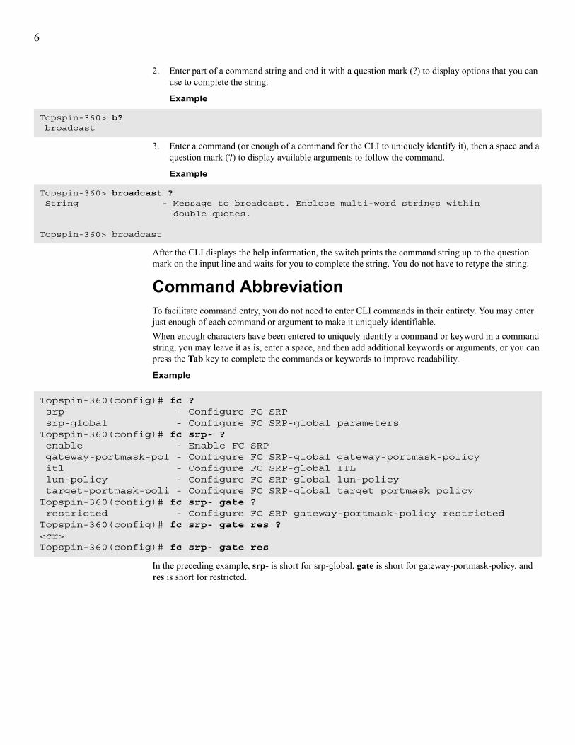
2. Enter part of a command string and end it with a question mark (?) to display options that you can use to complete the string.
Example
3. Enter a command (or enough of a command for the CLI to uniquely identify it), then a space and a question mark (?) to display available arguments to follow the command.
Example
After the CLI displays the help information, the switch prints the command string up to the question mark on the input line and waits for you to complete the string. You do not have to retype the string.
Command AbbreviationTo facilitate command entry, you do not need to enter CLI commands in their entirety. You may enter just enough of each command or argument to make it uniquely identifiable.When enough characters have been entered to uniquely identify a command or keyword in a command string, you may leave it as is, enter a space, and then add additional keywords or arguments, or you can press the Tab key to complete the commands or keywords to improve readability.
Example
In the preceding example, srp- is short for srp-global, gate is short for gateway-portmask-policy, and res is short for restricted.
Topspin-360> b? broadcast
Topspin-360> broadcast ? String - Message to broadcast. Enclose multi-word strings within
double-quotes.
Topspin-360> broadcast
Topspin-360(config)# fc ? srp - Configure FC SRP srp-global - Configure FC SRP-global parametersTopspin-360(config)# fc srp- ? enable - Enable FC SRP gateway-portmask-pol - Configure FC SRP-global gateway-portmask-policy itl - Configure FC SRP-global ITL lun-policy - Configure FC SRP-global lun-policy target-portmask-poli - Configure FC SRP-global target portmask policyTopspin-360(config)# fc srp- gate ? restricted - Configure FC SRP gateway-portmask-policy restrictedTopspin-360(config)# fc srp- gate res ?<cr>Topspin-360(config)# fc srp- gate res

7
Command-Line EditingCommand-line editing lets you modify a command line command that you have just entered or a command line that you entered previously in the CLI session. The CLI supports a variety of ways to move about and edit the currently displayed command line. Table 1-3 lists and describes these options.
Table 1-3: Key Stroke Shortcuts
Key Strokes DescriptionCtrl-a Moves the cursor to the beginning of the line.
Ctrl-b Moves the cursor left (back) one character.
Ctrl-d Deletes the current character.
Ctrl-e Moves the cursor to the end of the line.
Ctrl-f Moves the cursor to the right (forward) one character.
Ctrl-k Deletes text from cursor to the end of the line.
Ctrl-l Refreshes the input line.
Ctrl-n Displays the next command in the history queue.
Ctrl-p Displays the previous command in the history queue.
Ctrl-q Returns to User Exec mode.
NOTE: If a command is currently entered on the command line, execute the command before returning to User Exec mode.
Ctrl-t Transposes the current and previous characters.
Ctrl-u Deletes all text to the left of the cursor.
Ctrl-w Deletes the text of a word up to cursor.
Ctrl-z Returns you to Privileged Exec mode.
Esc-b Moves the cursor left (back) one word.
Esc-c Converts characters, from the cursor to the end of the word, to upper case.
Esc-d Deletes characters from the cursor through remainder of the word.
Esc-f Moves the cursor right (forward) one word.
Esc-l Converts characters, from the cursor to the end of the word, to lower case.
down-arrow Displays the next command in the history queue.
up-arrow Displays the previous command in the history queue.
left-arrow Moves the cursor left (back) one character.
right-arrow Moves the cursor right (forward) one character.

8
Exiting the CLI SessionTo exit the CLI session, return to User Exec mode or Privileged Exec mode, and enter the logout command or the exit command. The CLI session ends.
Example
NOTE: If you use Telnet or SSH to run a remote CLI session, the connection closes when you log out. Conversely, when you terminate a telnet or SSH session, you log out of the switch.
Specifying Cards and PortsTo configure one or more ports on one or more cards, you must specify those ports that you want to configure when you enter the appropriate configuration submode.Many CLI commands allow you to enter:• A slot#/port# pair.• A range of pairs.• A list of pairs.• The all keyword.
Slot#/Port# PairsA slot#/port# pair (sometimes referred to as the card#/port# pair) is a slash-separated (/) pair of numbers. The first number indicates the slot in which the interface card resides, and the second number represents a port on that card. Refer to your hardware documentation to identify slot numbers and port numbers.
NOTE: Hardware platforms with no removable cards, such as the Topspin 120, the slot number defaults to 1.
RangesA range is a dash-separated (-) set of two slot#/port# pairs. A range may span multiple cards of the same interface type. Card and port numbers in a range must both appear in ascending order. That is, specify the lower card and port number in the first slot#/port# pair and the higher card and port number in the second slot#/port# pair.
NOTE: Do not insert spaces between elements in the range.
The range 3/2-4/3 indicates all the ports starting with card 3, port 2, up to and including card 4, port 3. (This example assumes that cards 3 and 4 are of the same interface type.)
Topspin-90(config-if-fc-5/1)# exit allTopspin-90> logoutLogin:

9
ListsA list is a comma-separated (,) series of slot#/port# pairs and/or ranges. Sequencing of pairs in the list is not important. You may specify pairs in any order you wish, however, the data returned is displayed in numerical sequence with the lowest slot#/port# pair first. Do not insert spaces between elements in the list. You can include ranges in lists.
Example3/1,3/3,4/3—indicates ports 1 and 3 on interface card 3 and port 3 on interface card 4. This assumes that cards 3 and 4 are of the same interface type.
Example3/1,4/1-4/4,5/1—assumes that cards 3, 4, and 5 are of the same interface type.
The “all” KeywordThe all keyword indicates all the ports of all the cards of a specific type of interface. That is, all Ethernet, FC, or IB interface cards. The subsequent prompt will appear as though you entered the ports as a list.
Using the DocumentationThe command descriptions in this guide provide quick access to the information about each command. This guide divides each command description into subsections so you can go directly to the desired information.
SynopsisThe Synopsis subsection provides a brief, high-level description of the command.
SyntaxThe Syntax subsection provides the command syntax. The following conventions apply:• Text in bold font represents text that you enter exactly as it appears.• Text in italicized font represents variables that you replace with actual values when you enter it at
the command line.• Square brackets ([,]) enclose optional syntax. Do not enter square brackets in the CLI.• Braces ({,}) enclose required syntax choices. Do not enter braces in the CLI.• The pipe character (|) delineates between selections in syntax. That is, if command X requires
argument Y or argument Z, but not both at the same time, the syntax will appear as follows:X {Y | Z}
A table that describes all syntax argument follows the syntax line(s).
NOTE: Input strings such as device names and descriptions must be contiguous without any intervening spaces or blanks. In the event you wish to enter a multi-word string, enclose the string within double-quotes (“,”), otherwise the CLI parses each word as a separate argument, which results in a syntax violation.
Platform AvailabilityThe platform subsection indicates the platform or platforms on which you may execute the command.

10
Command ModesThe Command Modes subsection indicates the command mode or submode that you must enter in order to execute the command.
Privilege LevelThe Privilege Level subsection indicates the user permissions that are required to execute the command. For example, there are commands that only an unrestricted read-write user (for example, super) can execute that a user with general read-write permissions (for example, admin) cannot.
Usage GuidelinesThe Usage Guidelines subsection supplies additional information and details to help you use the command to its full potential.
ExamplesThe examples subsection shows actual command entry and CLI output.
Example
DefaultsThe Defaults subsection lists command default behavior or values.
Related CommandsThe Related Commands subsection provides hypertext links to related CLI commands.
Topspin-360# show interface gateway 5=============================Gateway Information================================ gateway : 5 name : 5/0 type : fc-gateway desc : 5/0 (320) last-change : none mtu : 0 admin-status : up oper-status : upTopspin-360#

11
2
Administrative CommandsThis chapter documents the following commands:• action command on page 13• addr-option command on page 15• authentication command on page 16• auto-negotiate command on page 18• boot-config command on page 20• broadcast command on page 22• card command on page 23• clock set command on page 24• configure terminal command on page 26• copy command on page 28• delete command on page 31• dir command on page 33• disable command on page 36• enable command on page 37• exec command on page 38• exit command on page 39• ftp-server enable command on page 40• gateway command on page 41• help command on page 42• history command on page 43• hostname command on page 44• install command on page 45

12
• interface command on page 47• ip http command on page 49• link-trap command on page 51• location command on page 52• logging command on page 53• login command on page 54• logout command on page 55• more command on page 56• name command on page 58• ntp command on page 59• ping command on page 60• radius-server command on page 61• reload command on page 63• save-log command on page 65• shutdown command on page 66• snmp-server command on page 69• speed command on page 72• telnet command on page 74• terminal command on page 75• trace command on page 77• type command on page 79• username command on page 81• who command on page 85• write command on page 86
13
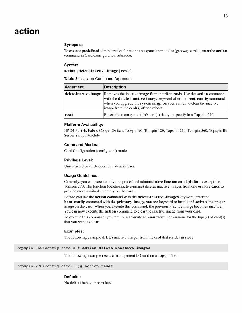
actionSynopsis:To execute predefined administrative functions on expansion modules (gateway cards), enter the action command in Card Configuration submode.
Syntax:action {delete-inactive-image | reset}
Platform Availability:HP 24-Port 4x Fabric Copper Switch, Topspin 90, Topspin 120, Topspin 270, Topspin 360, Topspin IB Server Switch Module
Command Modes:Card Configuration (config-card) mode.
Privilege Level:Unrestricted or card-specific read-write user.
Usage Guidelines:Currently, you can execute only one predefined administrative function on all platforms except the Topspin 270. The function (delete-inactive-image) deletes inactive images from one or more cards to provide more available memory on the card.Before you use the action command with the delete-inactive-images keyword, enter the boot-config command with the primary-image-source keyword to install and activate the proper image on the card. When you execute this command, the previously-active image becomes inactive. You can now execute the action command to clear the inactive image from your card.To execute this command, you require read-write administrative permissions for the type(s) of card(s) that you want to clear.
Examples:The following example deletes inactive images from the card that resides in slot 2.
The following example resets a management I/O card on a Topspin 270.
Defaults:No default behavior or values.
Table 2-1: action Command Arguments
Argument Descriptiondelete-inactive-image Removes the inactive image from interface cards. Use the action command
with the delete-inactive-image keyword after the boot-config command when you upgrade the system image on your switch to clear the inactive image from the card(s) after a reboot.
reset Resets the management I/O card(s) that you specify in a Topspin 270.
Topspin-360(config-card-2)# action delete-inactive-images
Topspin-270(config-card-15)# action reset

14
Related Commands:“boot-config” on page 20“copy” on page 28“install” on page 45“show card” on page 137“shutdown” on page 66

15
addr-optionSynopsis:To configure the Ethernet Management port to do the following:• use a static IP address,• obtain an IP address from a DHCP server,• automatically obtain an IP address from a hardware-designated controller, enter the addr-option command in Ethernet Management Configuration submode.
Syntax:addr-option {auto | dhcp | static}
Platform Availability:HP 24-Port 4x Fabric Copper Switch, Topspin 90, Topspin 120, Topspin 270, Topspin 360, Topspin IB Server Switch Module
Command Modes:Ethernet Management Configuration (config-mgmt-ethernet) mode.
Privilege Level:Ethernet read-write user.
Usage Guidelines:If you use the static keyword, configure the IP address of the Ethernet Management port with the ip command on page 122.
Examples:The following example configures the Ethernet Management port to obtain an IP address from a DHCP server.
Defaults:No default behavior or values.
Related Commands:“ip” on page 122
Table 2-2: addr-option Command Arguments
Argument Descriptionauto Applies an IP address from an outside controller to the Ethernet Management port.
dhcp Uses DHCP to configure the address for the Ethernet Management port.
static Changes the address of the Ethernet management port from the DCHP address to the static address that you configure with the ip command.
Topspin-270(config-if-mgmt-ethernet)# addr-option dhcp

16
authenticationSynopsis:To do the following:• configure your switch to use RADIUS server authentication in addition to local authentication
(always active)• configure the order in which your switch authenticates enter the authentication command in Global Configuration mode.
Syntax:authentication login [default {local [radius] | radius local}]
Platform Availability:HP 24-Port 4x Fabric Copper Switch, Topspin 90, Topspin 120, Topspin 270, Topspin 360, Topspin IB Server Switch Module
Command Modes:Global Configuration (config) mode.
Privilege Level:Unrestricted read-write user.
Usage Guidelines:If you enter the local keyword before the radius keyword, your switch authenticates logins locally first, then on the RADIUS server if local authentication fails. If you enter the radius keyword before the local keyword, your switch authenticates logins with the RADIUS server first, then on the local CLI user database.
Examples:The following example configures the switch to authenticate to the RADIUS server, then to the local database if server authentication fails.
Defaults:CLI logins authenticate locally by default.
Table 2-3: authentication Command Arguments
Argument Descriptionlogin Enables local login authentication.
NOTE: When you enter authentication login, the command behaves as though you had entered authentication login default local.
default Configures where and in what order your switch authenticates logins.
local Authenticates the login with the local CLI user database.
radius Authenticates the login with the RADIUS server.
Topspin-360(config)# authentication login default radius local

17
Related Commands:“configure terminal” on page 26“radius-server” on page 61“show authentication” on page 130

18
auto-negotiateSynopsis:To configure your switch to do the following:• dynamically determine the connection speed of direct-attached FC devices• dynamically determine the connection speed of direct-attached Ethernet devices• dynamically determine the connection speed of direct-attached IB devicesenter the auto-negotiate command in the appropriate Interface Configuration submode. To disable auto-negotiation, use the no form of this command.
Syntax:auto-negotiateno auto-negotiate
Platform Availability:HP 24-Port 4x Fabric Copper Switch, Topspin 90, Topspin 120, Topspin 270, Topspin 360, Topspin IB Server Switch Module
Command Modes:Fibre Channel Interface Configuration (config-if-fc) submode, Ethernet Interface Configuration (config-if-ether) submode, InfiniBand Interface Configuration (config-if-ib) submode.
Privilege Level:FC read-write user (for FC ports), Ethernet read-write user (for Ethernet ports), IB read-write user (for IB ports).
Usage Guidelines:Fibre Channel:Before you configure your FC port to auto-negotiate speed, perform the following steps to verify that the attached FC device supports auto-negotiation:1. Enter the show interface fc command in User Exec mode or Privileged Exec mode.2. Verify that the auto-negotiate-supported field of the command output displays yes. If the field
displays no, you must manually configure the connection speed of the port.
NOTE: If you disable auto-negotiation in the CLI but leave it active on the attached FC devices, the port manager for the FC interface on your device does not negotiate speed and mode with the FC devices. The FC devices may choose a different duplex setting than the port manager and produce unexpected results.
Ethernet:Before you enable auto-negotiation, verify that the Ethernet host supports auto-negotiation:1. Enter the show interface ethernet command in User Exec mode or Privileged Exec mode.2. Verify that the auto-negotiate-supported field displays yes. If the field displays no, you must
manually configure the connection speed of the port.

19
InfiniBand:Before you enable auto-negotiation, verify that the IB host supports auto-negotiation:1. Enter the show interface ib command in User Exec mode or Privileged Exec mode.2. Verify that the auto-negotiate-supported field displays yes. If the field displays no, you must
manually configure the connection speed of the port.
Examples:The following example disables auto-negotiation on ports 1 through 2 on FC card 5. The result of this command appears in the auto-negotiate field of the show interface fc command.
The following example disables auto-negotiation on ports 1 through 4 on Ethernet card 4. The result of this command appears in the auto-negotiate-supported field of the show interface ethernet command.
The following example enables auto-negotiation on port 1 on a Topspin 120. The result of this command appears in the auto-negotiate-supported field of the show interface ib command.
Defaults:FC and Ethernet ports auto-negotiate connection speeds by default.
Related Commands:“link-trap” on page 51“name” on page 58“show fc srp initiator” on page 160“show interface ethernet” on page 233“show interface fc” on page 241“show interface ib” on page 252“shutdown” on page 66“speed” on page 72
Topspin-360(config-if-fc-5/1-5/2)# no auto-negotiate
Topspin-90(config-if-ether-4/1-4/4)# no auto-negotiate
Topspin-120(config-if-ib-1/1)# auto-negotiate

20
boot-configSynopsis:To specify the system image to run when your switch boots, enter the boot-config command in Global Configuration mode.
Syntax:boot-config primary-image-source dir
Platform Availability:HP 24-Port 4x Fabric Copper Switch, Topspin 90, Topspin 120, Topspin 270, Topspin 360, Topspin IB Server Switch Module
Command Modes:Global Configuration (config) mode.
Privilege Level:Unrestricted read-write user.
Usage Guidelines:Specify an image directory as a boot image. Do not specify image files that end in “.img” since these are compressed archives that must be installed first.
NOTE: Use the dir command with the image keyword to view a list of images on your device.
Examples:The following example configures the switch controller to use the TopspinOS-1.1.0/build460 directory when the switch boots. Without this directory, the system cannot boot successfully.
Defaults:No default behavior or values.
Related Commands:“dir” on page 33“install” on page 45“interface” on page 47“radius-server” on page 61“reload” on page 63“show boot-config” on page 133“show card” on page 137
Table 2-4: boot-config Command Arguments
Argument Descriptionprimary-image-source Specifies that you want to configure the boot image.
dir Directory that contains the boot image.
Topspin-360(config)# boot-config primary-image-source TopspinOS-1.1.0/build460

21
“show card-inventory” on page 142

22
broadcastSynopsis:To send text messages to all other CLI users, enter the broadcast command in User Exec mode or Privileged Exec mode.
Syntax:broadcast “message”
Platform Availability:HP 24-Port 4x Fabric Copper Switch, Topspin 90, Topspin 120, Topspin 270, Topspin 360, Topspin IB Server Switch Module
Command Modes:User Exec mode, Privileged Exec mode.
Privilege Level:Unrestricted read-write user.
Usage Guidelines:Multi-word messages must begin and end with quotation marks (“ ”). Single-word messages do not require quotation marks.You can broadcast a message to warn other CLI users about events that may impact their sessions, such as a network outage or major configuration change. A broadcast message appears on every active CLI session on the switch, including the user who sends the message.
Examples:The following example prints FC card 5 going down in 10 minutes to the terminal screens of all users on the switch.
Defaults:No default behavior or values.
Related Commands:“reload” on page 63“who” on page 85“write” on page 86
Table 2-5: broadcast Command Arguments
Argument Descriptionmessage Message to broadcast. This message may consist of one or more words and may
include any alphanumeric character or symbol (except for quotation marks).
Topspin-90# broadcast "FC card 5 going down in 10 minutes."

23
cardSynopsis:To enter Card Configuration submode, enter the card command in Global Configuration mode.
Syntax:card {card-selection | all}
Platform Availability:HP 24-Port 4x Fabric Copper Switch, Topspin 90, Topspin 120, Topspin 270, Topspin 360, Topspin IB Server Switch Module
Command Modes:Global Configuration (config) mode.
Privilege Level:Card-specific read-write user
Usage GuidelinesEnter Card Configuration submode to enable, disable, configure, and reinitialize cards in your switch.
Examples:The following example enters Card Configuration submode for all cards on the switch. Any commands that execute in this mode apply to all of the cards in the chassis.
Defaults:No default behavior or values.
Related Commands:“clock set” on page 24“delete” on page 31“install” on page 45“interface” on page 47“show card” on page 137“show card-inventory” on page 142“shutdown” on page 66
Table 2-6: card Command Arguments
Argument Descriptioncard-selection Card, list of cards, or range of cards to configure.
all Configures all cards in the chassis.
Topspin-360(config)# card allTopspin-360(config-card-1,6,11,15-16)#

24
clock setSynopsis:To manually configure the time and date of the on-board switch clock, enter the clock set command in Privileged Exec mode.
Syntax:clock set hh:mm:ss dd mm yyHP 24-Port 4x Fabric
Platform Availability:HP 24-Port 4x Fabric Copper Switch, Topspin 90, Topspin 120, Topspin 270, Topspin 360, Topspin IB Server Switch Module
Command Modes:Privileged Exec mode.
Privilege Level:Unrestricted and general read-write user.
Usage Guidelines:Your switch uses one of the following means to maintain system time:• an on-board system clock• an external NTP server (recommended)When you first power on your switch, factory-default system clock settings run. To ensure accurate synchronization, we recommend that you use an external NTP server, as it will synchronize log dates with other management systems. To configure NTP servers, refer to the ntp command on page 59.
Examples:The following example sets the clock time to 7:22 PM and 10 seconds on the 25th of May, 2015.
Defaults:No default behavior or values.
Related Commands:“card” on page 23“ntp” on page 59“radius-server” on page 61
Table 2-7: clock Command Arguments
Argument Descriptionhh Hour to assign.
mm Minute to assign.
ss Second to assign.
dd Day to assign.
mm Month to assign.
yy Year to assign.
Topspin-90# clock set 19:22:10 25 05 15

25
“show clock” on page 144

26
configure terminalSynopsis:To enter Global Configuration mode, enter the configure terminal command in Privileged Exec mode.
Syntax:configure terminal
Platform Availability:HP 24-Port 4x Fabric Copper Switch, Topspin 90, Topspin 120, Topspin 270, Topspin 360, Topspin IB Server Switch Module
Command Modes:Privileged Exec mode.
Privilege Level:Unrestricted and general read-write user.
Usage Guidelines:Use the configure terminal command to enter Global Configuration mode. From this mode, you can configure gateway and switch cards, subnet management, IP addressing, and various aspects of your switch.
Examples:The following example enters Global Configuration mode.
Defaults:No default behavior or values.
Related Commands:“arp ethernet” on page 116“authentication” on page 16“boot-config” on page 20“bridge-group” on page 117“card” on page 23“diagnostic” on page 297“exit” on page 39“fc srp initiator” on page 88“fc srp initiator-wwpn” on page 91“fc srp it” on page 93“fc srp itl” on page 95“fc srp lu” on page 98“fc srp target” on page 100“fc srp-global gateway-portmask-policy restricted” on page 101“fc srp-global itl” on page 102“fc srp-global lun-policy restricted” on page 105
Topspin-360# configure terminalTopspin-360(config)#

27
“ftp-server enable” on page 40“help” on page 42“history” on page 43“hostname” on page 44“ib sm” on page 110“ib-agent” on page 113“interface” on page 47“ip” on page 122“location” on page 52“logging” on page 53“ntp” on page 59“radius-server” on page 61“redundancy-group” on page 125“snmp-server” on page 69“telnet” on page 74“trace” on page 77“trunk-group” on page 126“username” on page 81

28
copySynopsis:To copy files:• to your switch from a remote location,• from your switch to a remote location,• from one directory on your switch to another,enter the copy command in Privileged Exec mode.
Syntax:copy ftp://user-id:password@host[/path]/file-name [slot-number:]file-system[:file-name]
Downloads a file from a FTP server.copy tftp://remote-system[/path]/file-name [slot-number:]file-system[:file-name]
Downloads a file from a remote TFTP server.copy {[slot-number:]file-system:file-name | startup-config | running-config} ftp://user-id:password@host[/path]/[file-name]
Uploads a file to a FTP server.copy running-config startup-config
Saves the running configuration as the startup configuration.copy [slot-number:]file-system:file-name running-config
Executes a configuration file without a system reboot.
Platform Availability:HP 24-Port 4x Fabric Copper Switch, Topspin 90, Topspin 120, Topspin 270, Topspin 360, Topspin IB Server Switch Module
Command Modes:Privileged Exec mode.
Table 2-8: copy Command Arguments
Argument Descriptionftp Identifies a remote system that runs file transfer protocol (FTP).
tftp Identifies a remote system that runs trivial file transfer protocol (TFTP).
remote-system IP address (or DNS name, if appropriate) of the remote host.
running-config Refers to the active configuration running on your switch.
startup-config Refers to the configuration that your switch runs when it boots.
user-id User ID that you use to log in to the FTP server.
password Password that you use to log in to the FTP server.
host FTP server domain name or IP address.
path Directory path on the host from which or to which you want to copy a file.
slot-number Slot of the controller card (1 on the Topspin 90 and Topspin 120, 1 or 14 on the Topspin 360).
file-name Name of the file that you want to copy.
file-system File system on your switch.

29
Privilege Level:Unrestricted read-write user.
Usage Guidelines:• Use the copy command to:
• save a running configuration as a boot-up configuration• download image files to install • upload configurations that you want to propagate to other switches.
NOTE: Configuration files that you upload from your switch to a remote host contain plain text that you can read with any word processor. Log files also appear in plain text.
• The copy command copies image, configuration, and log data locally as well as onto and off of the system chassis. The copy command can also execute the contents of a configuration file.
• You may download image and configuration files from an FTP server to the system chassis. You may also upload log and configuration files from the system chassis to an FTP server.
• Download image files to your switch to upgrade system firmware. Download configuration files to quickly replicate a desired configuration. Upload configuration and log files to maintain backups and to troubleshoot your switch.
• Image files require additional processing. Your switch can run an image only after you install the image file. For more information on how to install an image, refer to “install” on page 45.
• After you download a configuration file to your switch, you can use the boot-config command to configure your switch to load that configuration when you reboot the switch.
• The copy command recognizes Ctrl-c as a command to terminate a file transfer. Use Ctrl-c to cancel a transfer if the network hangs.
NOTE: You can only download image and configuration files. Log files cannot be downloaded. You can only upload configuration and log files. System image data cannot be uploaded.
Examples:The following example downloads an image file from a remote host to the switch.
The following example saves the running configuration as the startup configuration so the current configuration executes when the switch reboots.
Topspin-360# copy ftp://bob:[email protected]/Topspin-360-TopspinOS-1.1.1-build497.img image:Topspin-360-1.1.1-build497.img
TopspinOS-1.1.2-build497.imgoperation completed successfully
Topspin-360# copy running-config startup-configoperation completed successfully
Topspin-360

30
The following example copies the startup configuration image from the controller card in slot 1 on a Topspin 360 to the controller card in slot 14.
Defaults:No default behavior or values.
Related Commands:“action” on page 13“boot-config” on page 20“delete” on page 31“dir” on page 33“exec” on page 38“ftp-server enable” on page 40“history” on page 43“install” on page 45“show boot-config” on page 133“show config” on page 157
Topspin-360# copy 1:config:startup-config 14:config:save.cfg** operation completed successfully

31
deleteSynopsis:To remove image, configuration, or log files from your switch, enter the delete command in Privileged Exec mode.
Syntax:delete [slot-number:]file-system:file
Platform Availability:HP 24-Port 4x Fabric Copper Switch, Topspin 90, Topspin 120, Topspin 270, Topspin 360, Topspin IB Server Switch Module
Command Modes:Privileged Exec mode.
Privilege Level:Unrestricted read-write user.
Usage Guidelines:You cannot delete an active image. To deactivate an active system image in order to delete it, install a new image (“install” on page 45) and configure your switch to boot that image (“boot-config” on page 20), then delete the old image.
Examples:The following example deletes the delete-me.cfg file from the controller card in slot 1 of a Topspin 360.
Table 2-9: delete Command Arguments
Argument Descriptionfile-system switch file system. Your switch displays this internal directory by name only. The
file systems are config, images, and syslog. The specified file system must be appropriate to the type of file that you want to delete. For example, if you attempt to delete a configuration file from the syslog file system, an error occurs because the name of the file does not match the file system. A colon (:) always follows the file-system specification.
NOTE: The startup configuration maps to config:startup-config. Therefore, you do not need to specify the file system at the CLI.
slot-number Slot of the controller card (1 on the Topspin 90 and Topspin 120, 1 or 14 on the Topspin 360).
file Name of the configuration, image, or log file that you want to delete.
Topspin-360# delete 1:config:delete-me.cfgDelete file 1:delete-me.cfg? [yes(default) | no] yes******

32
The following example deletes an image file from the controller card in slot 14 of a Topspin 360.
Defaults:No default behavior or values.
Related Commands:“boot-config” on page 20“copy” on page 28“dir” on page 33“install” on page 45
Topspin-360# delete 14:image:Topspin360-TopspinOS-2.0.0-build488.imgDelete file 14:Topspin360-TopspinOS-2.0.0-build488.img? [yes(default) | no] yes******
33
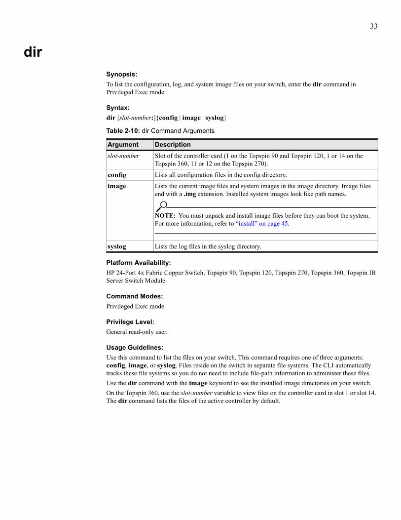
dirSynopsis:To list the configuration, log, and system image files on your switch, enter the dir command in Privileged Exec mode.
Syntax:dir [slot-number:]{config | image | syslog}
Platform Availability:HP 24-Port 4x Fabric Copper Switch, Topspin 90, Topspin 120, Topspin 270, Topspin 360, Topspin IB Server Switch Module
Command Modes:Privileged Exec mode.
Privilege Level:General read-only user.
Usage Guidelines:Use this command to list the files on your switch. This command requires one of three arguments: config, image, or syslog. Files reside on the switch in separate file systems. The CLI automatically tracks these file systems so you do not need to include file-path information to administer these files.Use the dir command with the image keyword to see the installed image directories on your switch.On the Topspin 360, use the slot-number variable to view files on the controller card in slot 1 or slot 14. The dir command lists the files of the active controller by default.
Table 2-10: dir Command Arguments
Argument Descriptionslot-number Slot of the controller card (1 on the Topspin 90 and Topspin 120, 1 or 14 on the
Topspin 360, 11 or 12 on the Topspin 270).
config Lists all configuration files in the config directory.
image Lists the current image files and system images in the image directory. Image files end with a .img extension. Installed system images look like path names.
NOTE: You must unpack and install image files before they can boot the system. For more information, refer to “install” on page 45.
syslog Lists the log files in the syslog directory.

34
Examples:The following example displays the configuration files on the switch:
The following example displays installed system images and image files on the switch:
The following example displays the log files in the syslog directory on the switch.
Topspin-360# dir config============================================================================ Existing Configurations on System============================================================================slot date-created size file-name----------------------------------------------------------------------------1 Thu Oct 24 11:21:06 2002 58 check.cfg1 Thu Dec 5 14:50:09 2002 39216 check2.cfg1 Wed Dec 11 09:09:54 2002 1712 config_bc.cfg1 Thu Dec 5 11:18:21 2002 1712 running_config.cfg1 Wed Dec 4 07:10:23 2002 4407 running_config.cfg.backup1 Thu Dec 5 12:04:53 2002 1712 running_config2.cfg1 Thu Oct 24 11:19:53 2002 58 test.cfgTopspin-90#
Topspin-360# dir image=============================================================== Existing Boot-Images on System===============================================================slot date-created size file-name----------------------------------------------------------------------------1 Thu Jun 1 11:16:50 2003 23691613 TopspinOS-1.1.3-build548.img1 Wed Jul 11 00:56:52 2002 1024 TopspinOS-1.1.3/build5411 Thu Jul 1 00:10:40 2003 1024 TopspinOS-1.1.3/build548Topspin-360#
Topspin-360# dir syslog============================================================================ Existing Syslog-files on System============================================================================slot date-created size file-name----------------------------------------------------------------------------1 Thu Jun 12 12:13:06 2002 19636 ts_log1 Wed Jun 11 13:28:54 2002 4978 ts_log.1.gz1 Tue Jun 10 04:02:02 2002 30 ts_log.2.gz1 Mon Jun 9 04:02:02 2002 30 ts_log.3.gz1 Sun Jul 8 04:02:02 2002 30 ts_log.4.gz1 Sat Jul 7 04:02:02 2002 30 ts_log.5.gz1 Fri Jul 6 17:20:35 2002 16264 ts_log.6.gz1 Thu Jul 5 15:14:57 2002 245 ts_log.7.gzTopspin-360#

35
The following example displays the files in the image directory on the controller in slot 14 of a Topspin 360.
Defaults:No default behavior or values.
Related Commands:“boot-config” on page 20“copy” on page 28“delete” on page 31“install” on page 45“more” on page 56
Topspin-360# dir 14:image
================================================================================ Existing Boot-Images on System================================================================================slot date-created size file-name--------------------------------------------------------------------------------14 Thu Mar 18 14:59:06 2004 0 TopspinOS-2.0.0/build488
36
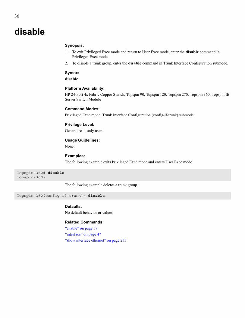
disableSynopsis:1. To exit Privileged Exec mode and return to User Exec mode, enter the disable command in
Privileged Exec mode.2. To disable a trunk group, enter the disable command in Trunk Interface Configuration submode.
Syntax:disable
Platform Availability:HP 24-Port 4x Fabric Copper Switch, Topspin 90, Topspin 120, Topspin 270, Topspin 360, Topspin IB Server Switch Module
Command Modes:Privileged Exec mode, Trunk Interface Configuration (config-if-trunk) submode.
Privilege Level:General read-only user.
Usage Guidelines:None.
Examples:The following example exits Privileged Exec mode and enters User Exec mode.
The following example deletes a trunk group.
Defaults:No default behavior or values.
Related Commands:“enable” on page 37“interface” on page 47“show interface ethernet” on page 233
Topspin-360# disableTopspin-360>
Topspin-360(config-if-trunk)# disable

37
enableSynopsis:1. To enter Privileged Exec mode from User Exec mode, enter the enable command in User Exec
mode.2. To enable a trunk group, enter the enable command in Trunk Interface Configuration submode.
Syntax:enable
Platform Availability:HP 24-Port 4x Fabric Copper Switch, Topspin 90, Topspin 120, Topspin 270, Topspin 360, Topspin IB Server Switch Module
Command Modes:User Exec mode, Trunk Interface Configuration (config-if-trunk) mode.
Privilege Level:General read-only user.
Usage Guidelines:Enter the enable command in User Exec mode to make administrative configuration changes to your switch. Enter the enable command in Trunk Interface Configuration submode to activate a trunk group.
Examples:The following example enters Privileged Exec mode from User Exec mode.
The following example enables a new trunk group.
Defaults:No default behavior or values.
Related Commands:“configure terminal” on page 26“disable” on page 36“exit” on page 39“interface” on page 47
Topspin-90> enableTopspin-90#
Topspin-90(config-if-trunk)# enable

38
execSynopsis:To execute a file in the config file system on your switch, enter the exec command in Privileged Exec mode.
Syntax:exec file-name
Platform Availability:HP 24-Port 4x Fabric Copper Switch, Topspin 90, Topspin 120, Topspin 270, Topspin 360, Topspin IB Server Switch Module
Command Modes:Privileged Exec mode.
Privilege Level:Unrestricted read-write user.
Usage Guidelines:You can create command files on a management workstation and copy them to config file system on the switch using copy command. Then you can execute these files with exec command. Use the save-log command to save the latest commands that you have executed in the CLI to a file, then copy the file to the management station and use it as an example. See the save-log and copy commands for further details.
NOTE: You can only run files from the config directory of your file system.
Examples:The following example executes the test.cfg file in the config file system on the switch.
Defaults:No default behavior or values.
Related Commands:“configure terminal” on page 26“copy” on page 28
Table 2-11: exec Command Arguments
Keyword Descriptionfile-name Name of the file that you want to execute.
Topspin-90# exec test.cfg
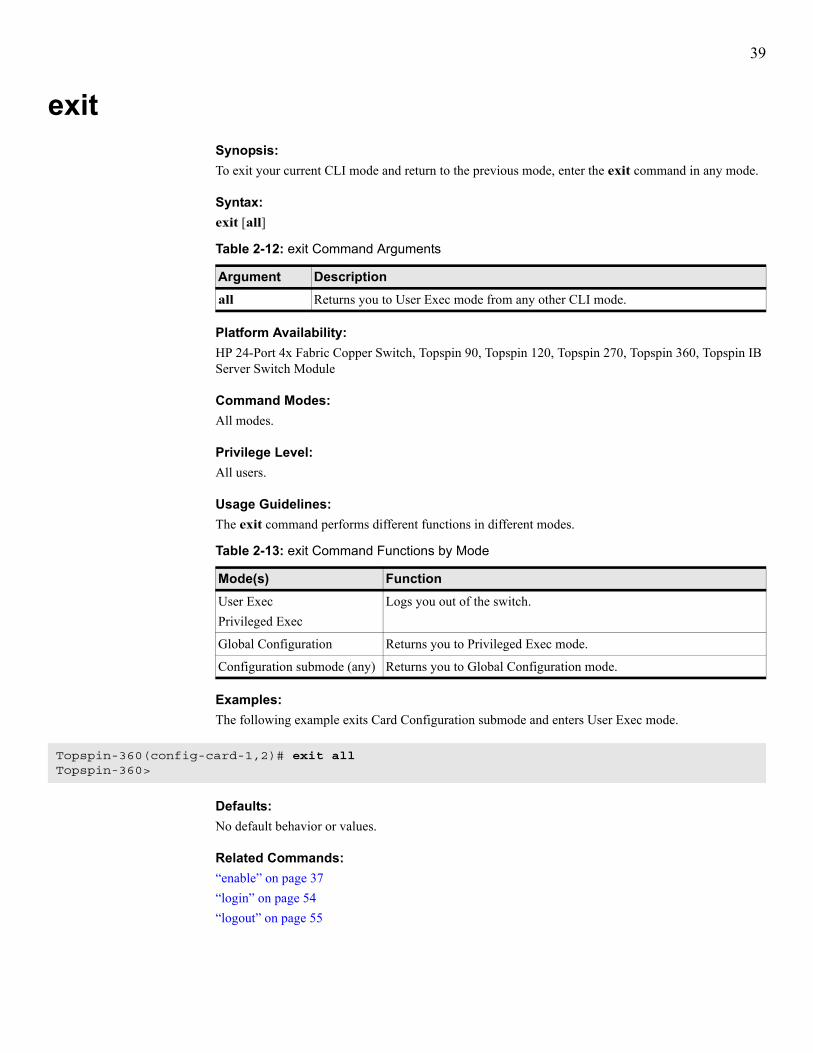
39
exitSynopsis:To exit your current CLI mode and return to the previous mode, enter the exit command in any mode.
Syntax:exit [all]
Platform Availability:HP 24-Port 4x Fabric Copper Switch, Topspin 90, Topspin 120, Topspin 270, Topspin 360, Topspin IB Server Switch Module
Command Modes:All modes.
Privilege Level:All users.
Usage Guidelines:The exit command performs different functions in different modes.
Examples:The following example exits Card Configuration submode and enters User Exec mode.
Defaults:No default behavior or values.
Related Commands:“enable” on page 37“login” on page 54“logout” on page 55
Table 2-12: exit Command Arguments
Argument Descriptionall Returns you to User Exec mode from any other CLI mode.
Table 2-13: exit Command Functions by Mode
Mode(s) FunctionUser ExecPrivileged Exec
Logs you out of the switch.
Global Configuration Returns you to Privileged Exec mode.
Configuration submode (any) Returns you to Global Configuration mode.
Topspin-360(config-card-1,2)# exit allTopspin-360>

40
ftp-server enableSynopsis:To enable the FTP server on your switch, enter the ftp-server enable command in Global Configuration mode. To disable this feature, use the no form of this command.
Syntax:ftp-server enableno ftp-server enable
Platform Availability:HP 24-Port 4x Fabric Copper Switch, Topspin 90, Topspin 120, Topspin 270, Topspin 360, Topspin IB Server Switch Module
Command Modes:Global Configuration (config) mode.
Privilege Level:All users.
Usage Guidelines:The FTP server feature provides read-only access to the file systems on the switch, and complements the copy command. Use a FTP client on a management workstation to connect to the server via FTP protocol. You can download log files, configuration files, or image files.
Examples:The following example disables FTP services on the switch.
Defaults:No default behavior or values.
Related Commands:“show system-services” on page 286“copy” on page 28“telnet” on page 74
Topspin-360(config)# no ftp-server enable

41
gatewaySynopsis:To assign a default IP gateway to:• the Ethernet Management port,• the virtual in-band IB port,enter the gateway command in the appropriate Interface Configuration mode. To disassociate a port from a gateway, use the no form of this command.
Syntax:gateway gatewayno gateway
Platform Availability:HP 24-Port 4x Fabric Copper Switch, Topspin 90, Topspin 120, Topspin 270, Topspin 360, Topspin IB Server Switch Module
Command Modes:Ethernet Management Interface Configuration (config-if-mgmt-ethernet) submode, InfiniBand Management Interface Configuration (config-if-mgmt-ib) submode.
Privilege Level:Unrestricted read-write user.
Usage Guidelines:The gateway that you assign connects the port to the IB backplane on your switch. You must configure the gateway through the Serial Console port. Enter the IP address of the gateway when you configure the management interfaces.
Examples:The following example assigns a default IP gateway to the Ethernet Management interface.
The following example assigns a default IP gateway to the IB Management interface.
Defaults:The gateway address defaults to 0.0.0.0.
Related Commands:“interface” on page 47“show interface mgmt-ethernet” on page 262“show interface mgmt-ib” on page 264“snmp-server” on page 69
Table 2-14: gateway Command Arguments
Argument Descriptiongateway IP address of the gateway to assign to the port.
Topspin-360(config-if-mgmt-ethernet)# gateway 10.3.0.94
Topspin-360(config-if-mgmt-ib)# gateway 10.3.0.2

42
helpSynopsis:To view the help options that the CLI provides, enter the help command in any mode.
Syntax:help
Platform Availability:HP 24-Port 4x Fabric Copper Switch, Topspin 90, Topspin 120, Topspin 270, Topspin 360, Topspin IB Server Switch Module
Command Modes:All modes.
Privilege Level:All users.
Usage Guidelines:This command may be executed in any mode. It provides the methods for you to display the various types of available help. The help command provides the same instructions regardless of mode.
Examples:The following example displays help options.
Defaults:No default behavior or values.
Related Commands:None.
Topspin-360(config-if-ib-16/1-16/12)# helpHelp may be requested at any point in a command by enteringa question mark '?'. If nothing matches, the help list willbe empty and you must backup until entering a '?' shows theavailable options.Two styles of help are provided:1. Full help is available when you are ready to enter a command argument (e.g. 'show ?') and describes each possible argument.2. Partial help is provided when an abbreviated argument is entered and you want to know what arguments match the input (e.g. 'show pr?'.)Topspin-90360(config-if-ib-16/1-16/12)#

43
historySynopsis:To display a list of the commands that you executed during your CLI session, enter the history command in any mode.
Syntax:history
Platform Availability:HP 24-Port 4x Fabric Copper Switch, Topspin 90, Topspin 120, Topspin 270, Topspin 360, Topspin IB Server Switch Module
Command Modes:All modes.
Privilege Level:All users.
Usage Guidelines:The format of the history output and a configuration file are similar. You can cut and paste the contents of the history output to a text file and, with minor editing, use it as a configuration file.This global command may be executed in any mode. To display just one screen of history data at a time, configure the terminal display length.
Examples:The following example displays the recent command history.
Defaults:The history command stores the last 40 commands that you entered.
Related Commands:“copy” on page 28“telnet” on page 74“show config” on page 157“show system-services” on page 286
Topspin-90(config)# history 1 history2 enable3 config4 arp5 boot-conf6 boot-config7 diagn8 interface ib all9 exit10 interface ethernet all11 ip12 history
Topspin-90(config)#

44
hostnameSynopsis:To assign a hostname to your switch, enter the hostname command in Global Configuration mode.
Syntax:hostname name
Platform Availability:HP 24-Port 4x Fabric Copper Switch, Topspin 90, Topspin 120, Topspin 270, Topspin 360, Topspin IB Server Switch Module
Command Modes:Global Configuration (config) mode.
Privilege Level:Unrestricted read-write user.
Usage Guidelines:When you enter the hostname command, you apply the new name to the following three areas:• switch version information• CLI prompt• switch network nameAfter you configure the host name, the name that you assigned appears in the show version command output. When you change modes, the new host name will appear in the CLI prompt.
Examples:Note the change in the CLI prompt that occurs in the last line of example output.
Defaults:No default behavior or values.
Related Commands:“ip” on page 122“ping” on page 60“show version” on page 293
Table 2-15: hostname Command Arguments
Argument Descriptionname Name to assign to the system.
Topspin-360(config)# hostname samplenameTopspin-360(config)# exitsamplename#

45
installSynopsis:To install an image file on your switch, enter the install command in Privileged Exec mode.
Syntax:install [slot-number:]image:file
Image files must reside in the image file system and the file name must have the .img extension.
Platform Availability:HP 24-Port 4x Fabric Copper Switch, Topspin 90, Topspin 120, Topspin 270, Topspin 360, Topspin IB Server Switch Module
Command Modes:Privileged Exec mode.
Privilege Level:Unrestricted read-write user.
Usage Guidelines:To run a new system image:1. Download an image file to your switch (refer to“copy” on page 28).2. Bring up all cards in your chassis.3. Install the image file with the install command.4. Configure your switch to run the new system image when it boots (refer to“boot-config” on
page 20).5. (Optional) Execute the action command with the delete-inactive-images keyword for each card
in your chassis to remove old images.The install command performs everything necessary to install a new system image to flash memory. It automatically installs all necessary firmware and component images. The command updates all cards with an administrative status of up.To update additional cards, re-enter the install and boot-config commands after you add the cards.
NOTE: When you upgrade your switch, your configuration file persists.
Table 2-16: install Command Arguments
Argument Descriptionslot-number Slot of the controller card (1 on the Topspin 90, Topspin 120, and Topspin IB Server
Switch Module; 1 or 14 on the Topspin 360; 11 or 12 on the Topspin 270).
image Specifies that the file resides in the image file-system.
file The name of the image file to install.
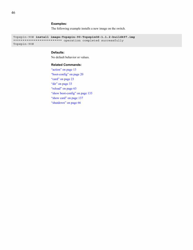
46
Examples:The following example installs a new image on the switch.
Defaults:No default behavior or values.
Related Commands:“action” on page 13“boot-config” on page 20“card” on page 23“dir” on page 33“reload” on page 63“show boot-config” on page 133“show card” on page 137“shutdown” on page 66
Topspin-90# install image:Topspin-90-TopspinOS-1.1.2-build497.img************************** operation completed successfullyTopspin-90#

47
interfaceSynopsis:To enter an Interface Configuration submode, enter the interface command in Global Configuration mode.Syntax:interface ethernet {port-selection | all} (excludes Topspin 120)interface fc {port-selection | all} (excludes Topspin 120)interface gateway port-selectioninterface ib {port-selection | all}interface mgmt-ethernet interface mgmt-ibinterface trunk trunk-id
Platform Availability:HP 24-Port 4x Fabric Copper Switch, Topspin 90, Topspin 120, Topspin 270, Topspin 360, Topspin IB Server Switch Module
Command Modes:Global Configuration (config) mode.
Privilege Level:Unrestricted read-write user.
Usage Guidelines:Enter an Interface Configuration submode to configure the attributes of a port, a list of ports, or a range of ports. For instance, enter Ethernet Management Interface Configuration submode to enter the ip and
Table 2-17: interface Command Arguments
Argument Descriptionethernet Enters Ethernet Interface Configuration submode to configure Ethernet interface
cards. For more information, refer to “IP Commands” on page 115.
fc Enters Fibre Channel Interface Configuration submode to configure FC interface cards. For more information, refer to “Fibre Channel Commands” on page 87.
gateway Enters Gateway Interface Configuration submode to configure the internal IB gateway ports on Ethernet and FC interface cards.
ib Enters InfiniBand Interface Configuration submode to configure IB interface cards. For more information, refer to “InfiniBand Commands” on page 107.
mgmt-ethernet Enters Ethernet Management Interface Configuration submode to configure the port and gateway of the out-of-band Ethernet port. You can use this port to administer your switch.
mgmt-ib Enters InfiniBand Management Interface Configuration submode to configure the in-band management port on your switch. You can use this port to administer the switch.
trunk Enters Trunk Configuration submode to create Ethernet trunk groups.
all Configures all ports of the appropriate type.
port-selection Slot#/port# pair, list of slot#/port# pairs, or range of slot#/port# pairs to configure.
trunk-id ID number (integer) of the trunk group.

48
gateway commands so you can access your switch over Ethernet. Enter Fibre Channel Interface Configuration submode to bring up FC ports that you plan to connect to a SAN.
Example:The following example enters InfiniBand Management Interface Configuration submode.
The following example enters Fibre Channel Interface Configuration submode to configure FC port 1 on the card in slot 9.
Defaults:No default behavior or values.
Related Commands:“boot-config” on page 20“card” on page 23“fc srp initiator” on page 88“fc srp itl” on page 95“fc srp-global gateway-portmask-policy restricted” on page 101“fc srp-global lun-policy restricted” on page 105“fc srp target” on page 100“ib-agent” on page 113“name” on page 58“show interface fc” on page 241“speed” on page 72“trunk-group” on page 126
Topspin-360(config)# interface mgmt-ibTopspin-360(config int-mgmt-ib-1)#
Topspin-360(config)# interface fc 9/1Topspin-360(config-if-fc-9/1)#
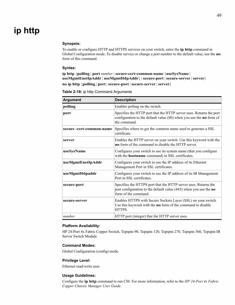
49
ip httpSynopsis:To enable or configure HTTP and HTTPS services on your switch, enter the ip http command in Global Configuration mode. To disable service or change a port number to the default value, use the no form of this command.
Syntax:ip http {polling | port number | secure-cert-common-name {useSysName | useMgmtEnetIpAddr | useMgmtIbIpAddr} | secure-port | secure-server | server}no ip http {polling | port | secure-port | secure-server | server}
Platform Availability:HP 24-Port 4x Fabric Copper Switch, Topspin 90, Topspin 120, Topspin 270, Topspin 360, Topspin IB Server Switch Module
Command Modes:Global Configuration (config) mode.
Privilege Level:Ethernet read-write user.
Usage Guidelines:Configure the ip http command to run CM. For more information, refer to the HP 24-Port 4x Fabric Copper Chassis Manager User Guide.
Table 2-18: ip http Command Arguments
Argument Descriptionpolling Enables polling on the switch.
port Specifies the HTTP port that the HTTP server uses. Returns the port configuration to the default value (80) when you use the no form of the command.
secure -cert-common-name Specifies where to get the common name used to generate a SSL certificate.
server Enables the HTTP server on your switch. Use this keyword with the no form of the command to disable the HTTP server.
useSysName Configures your switch to use its system name (that you configure with the hostname command) in SSL certificates.
useMgmtEnetIpAddr Configures your switch to use the IP address of its Ethernet Management Port in SSL certificates.
useMgmtIbIpaddr Configures your switch to use the IP address of its IB Management Port in SSL certificates.
secure-port Specifies the HTTPS port that the HTTP server uses. Returns the port configuration to the default value (443) when you use the no form of the command.
secure-server Enables HTTPS with Secure Sockets Layer (SSL) on your switch. Use this keyword with the no form of the command to disable HTTPS.
number HTTP port (integer) that the HTTP server uses.

50
Examples:The following example enables the HTTP server on the switch:
Defaults:• The HTTP port value defaults to 80. HTTP services on your switch run by default.• The HTTPS port value defaults to 443. HTTPS services on your switch run by default.
Related Commands:“show ip http” on page 268“show ip http server secure” on page 270
Topspin-360(config)# ip http server

51
link-trapSynopsis:To configure internal and external ports to generate link-up and link-down SNMP traps when the operating status (oper-status) of the ports changes, enter the link-trap command in the appropriate Interface Configuration mode. To disable this function, use the no form of this command.
Syntax:link-trapno link-trap
Platform Availability:HP 24-Port 4x Fabric Copper Switch, Topspin 90, Topspin 120, Topspin 270, Topspin 360, Topspin IB Server Switch Module
Command Modes:All Interface Configuration submodes.
Privilege Level:FC read-write user, Ethernet read-write user.
Usage Guidelines:Ports generate link-up traps when the oper-status of the port changes to up and link-down traps when the oper-status of the port changes to down. Trap receivers (that you define with the snmp-server command) receive the traps. You can then perform link validation and checking with the receivers, or configure SNMP alerts.
Examples:The following example enables link-trap generation for FC interface ports 1and 2, on card 5.
The following example enables link-trap generation for IB interface ports 1 through 5 on card 15. The resulting traps are sent to trap receivers, as defined by the snmp-server command.
The following example enables link-trap generation for Ethernet interface port 1 on card 4. The resulting traps are sent to trap receivers, as defined by the snmp-server command.
Defaults:By default, ports do not generate link traps.
Related Commands:“auto-negotiate” on page 18“shutdown” on page 66“show snmp” on page 284“snmp-server” on page 69
Topspin-90(config-if-fc-5/1-5/2)# link-trap
Topspin-360(config-if-ib-15/1-15/5)# link-trap
Topspin-90(config-if-ether-4/1)# link-trap

52
locationSynopsis:To assign a text-based location identifier to your switch, enter the location command in Global Configuration mode. To reset the location to an empty string, use the no form of this command.
Syntax:location “string”no location
Platform Availability:HP 24-Port 4x Fabric Copper Switch, Topspin 90, Topspin 120, Topspin 270, Topspin 360, Topspin IB Server Switch Module
Command Modes:Global Configuration (config) mode.
Privilege Level:Unrestricted read-write user.
Usage Guidelines:Use the location command to assign a readable identifier to your switch. Use the location string to identify support providers, the switch owner, the switch itself, or the physical location of the switch. Display the location with the show location command.
NOTE: The location command configures the same parameter that the snmp-server command configures with the location and location-string arguments.
Examples: The following example assigns a location to the switch.
Defaults:No default behavior or values.
Related Commands:“snmp-server” on page 69“show location” on page 272“show version” on page 293
Table 2-19: location Command Arguments
Argument Descriptionstring refers to an ASCII text string. Enclose multi-word strings within double-quotes (“,”).
Topspin-90(config)# location "515 Ellis Street, Mountain View, CA 94043"

53
loggingSynopsis:To identify a remote server as a server that accepts log messages from your switch, enter the logging command in Global Configuration mode.
Syntax:logging ip-address
Platform Availability:HP 24-Port 4x Fabric Copper Switch, Topspin 90, Topspin 120, Topspin 270, Topspin 360, Topspin IB Server Switch Module
Command Modes:Global Configuration (config) mode.
Privilege Level:All users.
Usage Guidelines:Warnings, errors, notifications, and alerts occur once the switch boots successfully. The logging command sends these occurrences to the remote server that you specify.
Examples:The following example configures the switch to send log messages to the host with an IP address of 10.3.0.60.
Defaults:No default behavior or values.
Related Commands:“show logging” on page 273“terminal” on page 75“snmp-server” on page 69“show snmp” on page 284
Table 2-20: logging Command Arguments
Argument Descriptionip-address IP address of the remote syslog server.
Topspin-360(config)# logging 10.3.0.60

54
loginSynopsis:To change user identity during a CLI session, enter the login command in User Exec mode or Privileged Exec mode.
Syntax:login userid
Platform Availability:HP 24-Port 4x Fabric Copper Switch, Topspin 90, Topspin 120, Topspin 270, Topspin 360, Topspin IB Server Switch Module
Command Modes:User Exec mode, Privileged Exec mode.
Privilege Level:All users.
Usage Guidelines:The login command allows you to assume the identity of another user without having to exit the CLI. The CLI prompts you for your password.
NOTE: To change back to a previous login, do not use the logout command. Instead, use the login command again.
Examples:In the following example, the user moves from the current login to the super login.
Defaults:No default behavior or values.
Related Commands:“exit” on page 39“logout” on page 55“username” on page 81“show user” on page 291
Table 2-21: login Command Arguments
Argument Descriptionuserid User ID that you want to use to log in.
Topspin-360> login superPassword: xxxxxTopspin-360>

55
logoutSynopsis:To log out of the current CLI session, enter the logout command in User Exec mode or Privileged Exec mode.
Syntax:logout
Platform Availability:HP 24-Port 4x Fabric Copper Switch, Topspin 90, Topspin 120, Topspin 270, Topspin 360, Topspin IB Server Switch Module
Command Modes:User Exec mode, Privileged Exec mode.
Privilege Level:All users.
Usage Guidelines:The logout command ends the current CLI session. If logged in through the Serial Console port, the CLI login prompt appears. If logged in through a Telnet connection, the Telnet session ends and you are returned to your operating system.
Examples:The following example logs the user out of the CLI.
Defaults:No default behavior or values.
Related Commands:“exit” on page 39“login” on page 54
Topspin-90# logoutTopspin-90#Connection to host lost.

56
moreSynopsis:To view the contents of a text file on your terminal screen, enter the more command in Privileged Exec mode.
Syntax:more [slot-number:]file-system:file-name
Platform Availability:HP 24-Port 4x Fabric Copper Switch, Topspin 90, Topspin 120, Topspin 270, Topspin 360, Topspin IB Server Switch Module
Command Modes:Privileged Exec mode.
Privilege Level:General read-write user.
Usage Guidelines:The more command displays text data resident on the chassis in increments determined by the terminal length command. The specified file system must be appropriate for the file. See also the dir command to list the names of files in the respective file-systems.Press any key (except the q key) to display the next screen of text lines. The file-system variable represents the file system that contains the file. The file system may be config or syslog. You cannot display image file data or compressed system log files. Only the currently active log file, ts_log, may be viewed.
Table 2-22: more Command Arguments
Argument Descriptionslot-number Slot of the controller card (1 on the Topspin 90 and Topspin 120, 1 or 14 on the
Topspin 360).
file-system File system on your switch in which the text file resides.
NOTE: For the startup configuration file, you do not need to include the file system in the command syntax.
file-name Name of the file to display.

57
Examples:The following example displays the contents of the startup configuration file.
NOTE: The lines beginning with an exclamation point (!) are comments ignored when the configuration file executes.
The following example displays the contents of the hwif_log file.
Defaults:No default behavior or values
Related Commands:“dir” on page 33“telnet” on page 74“terminal” on page 75
Topspin-90# more config:startup-config! TopspinOS-1.1.1/build560! Fri Mar 15 18:06:10 1935enableconfig terminal!boot-config primary-image-source TopspinOS-1.1.1/build560!interface mgmt-ethernet ip address 10.3.106.25 255.255.0.0 gateway 10.3.0.1 no shutdown!Topspin-90#
Topspin-360# more 14:syslog:hwif_logMon Mar 1 00:32:10 2004: card_startup.x : card is starting upMon Mar 1 00:32:26 2004: POST: Tavor: Firmware rev 200000000 matches tavor_fw.A1.200000000.bin: PASSEDMon Mar 1 03:58:49 2004: card_startup.x : card is starting upMon Mar 1 03:59:05 2004: POST: Tavor: Firmware rev 200000000 matches tavor_fw.A1.200000000.bin: PASSEDMon Mar 1 04:01:37 2004: card_startup.x : card is starting upMon Mar 1 04:01:53 2004: POST: Tavor: Firmware rev 200000000 matches tavor_fw.A1.200000000.bin: PASSEDMon Mar 1 04:04:27 2004: card_startup.x : card is starting upMon Mar 1 04:04:43 2004: POST: Tavor: Firmware rev 200000000 matches tavor_fw.A1.200000000.bin: PASSEDMon Mar 1 04:07:10 2004: card_startup.x : card is starting upMon Mar 1 04:07:26 2004: POST: Tavor: Firmware rev 200000000 matches tavor_fw.A1.200000000.bin: PASSEDMon Mar 1 19:27:10 2004: card_startup.x : card is starting upMon Mar 1 19:27:26 2004: POST: Tavor: Firmware rev 200000000 matches tavor_fw.A1.200000000.bin: PASSEDMon Mar 1 19:30:39 2004: card_startup.x : card is starting upMon Mar 1 19:30:55 2004: POST: Tavor: Firmware rev 200000000 matches tavor_fw.A1.200000000.bin: PASSEDMon Mar 1 19:55:33 2004: card_startup.x : card is starting upMon Mar 1 19:55:50 2004: POST: Tavor: Firmware rev 200000000 matches tavor_fw.A

58
nameSynopsis:To assign a user-defined name to an interface port, enter the name command in the appropriate Interface Configuration submode.
Syntax:name “string”
Platform Availability:HP 24-Port 4x Fabric Copper Switch, Topspin 90, Topspin 120, Topspin 270, Topspin 360, Topspin IB Server Switch Module
Command Modes:Interface Configuration (config-if-fc, config-if-ib, config-if-ether) submodes.
Privilege Level:FC read-write user, IB read-write user, Ethernet read-write user.
Usage Guidelines:The name can be used to simplify port identification and indicate port use. Assign the same name to multiple ports to identify the ports as a group with a uniform function. The name that you assign appears in the name field of the appropriate show interface command.
Examples:The example below assigns the name “storage bank 3” to all the ports on FC interface card 5, ports 1-2.
This example assigns the name “InfiniBand Group 1-6” to the first 6 ports of IB card 15.
Defaults:By default, the name of a port appears as a slot#/port# pair.
Related Commands:“auto-negotiate” on page 18“interface” on page 47“show fc srp initiator” on page 160“show ib sm configuration” on page 188“show interface ethernet” on page 233“show interface fc” on page 241“show interface ib” on page 252
Table 2-23: name Command Arguments
Argument Descriptionstring Alphanumeric ASCII text string (up to 20 characters, including spaces) to assign to
one or more ports.
Topspin-360(config-if-fc-5/1-5/4)# name "storage bank 3"
Topspin-90(config-if-ib-15/1-15/6)# name "InfiniBand Group 1-6"

59
ntpSynopsis:To synchronize the clock on your switch to primary, secondary, and tertiary NTP servers, enter the ntp command in Global Configuration mode. To reset an NTP configuration to the default value, use the no form of this command.
Syntax:ntp {server-one | server-two | server-three} ip-addressno ntp {server-one | server-two | server-three}
Platform Availability:HP 24-Port 4x Fabric Copper Switch, Topspin 90, Topspin 120, Topspin 270, Topspin 360, Topspin IB Server Switch Module
Command Modes:Global Configuration (config) mode.
Privilege Level:Unrestricted read-write user.
Usage Guidelines:Use the ntp command to configure your switch to take time information from up to three servers so that your switch can identify a problem when one server sends faulty data packets. We strongly recommend that you configure all three servers for maximum precision.
Examples:The following example assigns primary, secondary, and tertiary NTP servers to the switch.
Defaults:No default behavior or values.
Related Commands:“clock set” on page 24“show clock” on page 144“show ntp” on page 275“snmp-server” on page 69
Topspin-360(config)# ntp server-one 10.0.3.110Topspin-360(config)# ntp server-two 10.0.3.111Topspin-360(config)# ntp server-three 10.0.3.112

60
pingSynopsis:To verify that your switch can reach a given host, enter the ping command from User Exec mode or Privileged Exec mode.
Syntax:ping host
Platform Availability:HP 24-Port 4x Fabric Copper Switch, Topspin 90, Topspin 120, Topspin 270, Topspin 360, Topspin IB Server Switch Module
Command Modes:User Exec mode, Privileged Exec mode.
Privilege Level:General read-only user.
Usage Guidelines:Use the ping command to verify connectivity between your switch and a host or port. The reply packet tells you if the host received the ping and the amount of time it took to return the packet.
NOTE: You must configure a DNS server on your network to use hostnames as an argument in the ping command.
Examples:The following example verifies that the switch can contact the device with an IP address of 10.3.102.24.
Defaults:No default behavior or values.
Related Commands:“hostname” on page 44“ip” on page 122
Table 2-24: ping Command Arguments
Argument Descriptionhost IP address or hostname of the host, port, or expansion module that you want to reach.
Topspin-90# ping 10.3.102.24Sending 5 ICMP Echoes to 10.3.102.24, 56 data bytes!!!!!Success rate is 100 percent (5/5)round-trip min/avg/max = 0.000000/0.000000/0.000000 msTopspin-90#

61
radius-serverSynopsis:To configure the RADIUS server that your switch uses to authenticate CLI user logins, enter the radius-server command in Global Configuration mode. To remove a RADIUS server from the configuration, use the no form of this command.
Syntax:radius-server host ip-address [auth-port udp-port] [timeout seconds] [retransmit retries] [key encryption-key]no radius-server host ip-address
Platform Availability:HP 24-Port 4x Fabric Copper Switch, Topspin 90, Topspin 120, Topspin 270, Topspin 360, Topspin IB Server Switch Module
Command Modes:Global Configuration (config) mode.
Privilege Level:Unrestricted read-write access.
Usage Guidelines:Configure a RADIUS server to authenticate CLI user logins. Enter the authentication command to enable authentication and to configure your switch to authenticate with the RADIUS server.
Examples:The following example assigns the RADIUS server that the switch can use to validate logins.
Table 2-25: radius-server Command Arguments
Argument Descriptionhost Specifies the IP address of the RADIUS server.
ip-address IP address of the RADIUS server.
auth-port Specifies the user datagram protocol (UDP) authentication port of the RADIUS server.
udp-port UDP authentication port of the RADIUS server.
timeout Specifies the amount of time that your switch waits for a reply from the server before the login request times out.
seconds Amount of time, in seconds, that your switch waits for a reply from the server before the login request times out.
retransmit Specifies the number of times that your switch tries to authenticate after a timeout.
retries Number of times that your switch tries to authenticate after a timeout.
key Specifies the authentication key that the client and radius server use.
encryption-key Authentication key that the client and radius server use.
Topspin-90(config)# radius-server host 10.5.0.100

62
Defaults:The RADIUS server IP address defaults to 0.0.0.0, which assigns no server, and the switch authenticates locally by default.The udp-port variable defaults to 1812.
Related Commands:“authentication” on page 16“boot-config” on page 20“clock set” on page 24“snmp-server” on page 69

63
reloadSynopsis:To reboot your switch, enter the reload command in Privileged Exec mode.
Syntax:reload [no-failover]
Platform Availability:HP 24-Port 4x Fabric Copper Switch, Topspin 90, Topspin 120, Topspin 270, Topspin 360, Topspin IB Server Switch Module
Command Modes:Privileged Exec mode.
Privilege Level:General read-write user.
Usage Guidelines:At stages of chassis and interface setup, you need to reinitialize chassis firmware or restore interface card configurations. Use the reload command because it allows the chassis to close files and prepare for shutdown. The reload command brings down the entire switch and restarts all of the cards in the switch.The switch prompts you to verify the reload. If you have not already saved configuration changes, and the switch detects the changes, it prompts you to save. To store the new configuration as the startup configuration, enter yes at the prompt. To store the configuration elsewhere under a different file name, enter the new file name and press the Enter key.The system reinitializes itself and then loads the active system image and the startup configuration file. Wait a few minutes and attempt to log onto the chassis.
NOTE: If your switch includes a second controller card, the CLI will prompt you to save changes to the backup controller as well as to the primary controller.
Examples:The following example reloads the switch.
Table 2-26: reload Command Arguments
Argument Descriptionno-failover (Topspin 360 only) Forces a Topspin 360 to run from the same controller card when it
reboots. By default, Topspin 360 switches swap active controller cards when they reboot.
Topspin-90# reloadSystem configuration has been modified. Save?[yes(default)/no/*.cfg] yesProceed with reload? [confirm]Topspin-90#Connection to host lost.#

64
Defaults:No default behavior or values.
Related Commands:“boot-config” on page 20“broadcast” on page 22“install” on page 45“who” on page 85“show boot-config” on page 133

65
save-logSynopsis:To save a log file of the last 40 commands that you entered, enter the save-log command in Privileged Exec mode.
Syntax:save-log [filename]
Platform Availability:HP 24-Port 4x Fabric Copper Switch, Topspin 90, Topspin 120, Topspin 270, Topspin 360, Topspin IB Server Switch Module
Command Modes:Privileged Exec mode.
Privilege Level:General read-write user.
Usage Guidelines:Your switch stores save-log files to the syslog directory. To execute the commands in the save-log file, copy the file to a host, edit it appropriately, and copy it to the config file system on a switch and run the exec command.
Examples:The following example saves the last 40 commands as a file called mylog.log.
Defaults:If you do not provide a name for the log file, your switch assigns a name with the following format:
savelog.mmddhhmmsswhere mmddhhmmss represents the system UTC time.
Related Commands:“exec” on page 38“history” on page 43
Table 2-27: save-log Command Arguments
Argument Descriptionfilename Name of the file you create to store your command history.
Topspin-360# save-log mylog.log

66
shutdownSynopsis:To disable the following:• a specific interface card or port• the Ethernet Management port• the IB Management portenter the shutdown command in the appropriate Configuration submode. To enable any of these elements, use the no form of this command.
Syntax:shutdownno shutdown
Platform Availability:HP 24-Port 4x Fabric Copper Switch, Topspin 90, Topspin 120, Topspin 270, Topspin 360, Topspin IB Server Switch Module
Command Modes:Card Configuration (config-card) submode, Ethernet Management Interface Configuration (config-int-mgmt-ethernet) submode, InfiniBand Management Interface Configuration (config-int-mgmt-ib) submode, Ethernet Interface Configuration (config-if-ether) submode, InfiniBand Interface Configuration (config-if-ib) submode, Fibre Channel Interface Configuration (config-if-fc) submode.
Privilege Level:Unrestricted or card-specific read-write user.
Usage Guidelines:Enabling/Disabling a cardBefore you use the action command on a card, you must enable (bring up) the card. To enable or disable a card:1. In User Exec mode, enter the enable command to enter Privileged Exec mode.2. Enter the configure terminal command to enter Global Configuration mode.3. Enter the card command and specify the card or cards that you want to enable. 4. Enter the shutdown command or the no shutdown command to disable or enable the cards that
you specified in Step 3.When you use the shutdown command to disable a card, the card stops processing packets and powers down.
NOTE: You cannot update or delete the active system image on a card when you disable the card. Before you update the active system image on your switch, enable all cards that you want to update.
Enabling/Disabling an interface portTo enable or disable a port:1. In User Exec mode, enter the enable command to enter Privileged Exec mode.2. Enter the configure terminal command to enter Global Configuration mode.

67
3. Enter the interface command and appropriate keyword (ethernet, fc, or ib), then specify the port or ports that you want to enable.
4. Enter the shutdown command or the no shutdown command to disable or enable the cards that you specified in Step 3.
Enabling/Disabling the Ethernet Management PortTo enable or disable the Ethernet Management port:1. In User Exec mode, enter the enable command to enter Privileged Exec mode.2. Enter the configure terminal command to enter Global Configuration mode.3. Enter the interface mgmt-ethernet command to enter Ethernet Management Interface
Configuration submode. 4. Enter the shutdown command or the no shutdown command to disable or enable the port.You must enable the Ethernet Management port before you can configure it. Use the no shutdown command to bring up the Ethernet Management port before you assign IP and gateway addresses to the port. When you disable the Ethernet Management port, the current configuration of the port remains intact. If you experience problems configuring the Ethernet Management port, first check that the admin-status field in the show interface mgmt-ethernet command output displays up. Enabling/Disabling the Infiniband Management portTo enable or disable the IB Management port:1. In User Exec mode, enter the enable command to enter Privileged Exec mode.2. Enter the configure terminal command to enter Global Configuration mode.3. Enter the interface mgmt-ib command to enter InfiniBand Management Interface Configuration
submode. 4. Enter the shutdown command or the no shutdown command to disable or enable the port.The IB Management port provides Telnet, SSH, and Element Manager (EM) access to IB hosts that run IPoIB and connect to any of the IB ports on your switch. With the IB management port, you can run management applications over IPoIB.
NOTE: You must configure the IP address and gateway of the IB Management port through the Serial Console terminal. Use the ip and gateway commands.
Examples:The following example enables interface card 12.
The following example enables the interface Management Ethernet port.
The following example enables the interface Management IB port.
The following example sets the admin-status field for ports 1 through 6 on IB card 15 to up.
Topspin-360(config-card-12)# no shutdown
Topspin-90# Topspin-90(config-if-mgmt-ethernet)# no shutdown
Topspin-90360(config-if-mgmt-ib)# no shutdown
Topspin-360(config-if-ib-15/1-15/6)# no shutdown

68
Defaults:No default behavior or values.
Related Commands:“action” on page 13“auto-negotiate” on page 18“card” on page 23“gateway” on page 41“interface” on page 47“ip” on page 122“link-trap” on page 51“show card” on page 137“show fc srp initiator” on page 160“show interface mgmt-serial” on page 265“type” on page 79

69
snmp-serverSynopsis:To store contact and location information and to configure the SNMP notification host and SNMPv3 user, enter the snmp-server command in Global Configuration mode. To replace these values with empty strings, enter the no form of this command.
Syntax:snmp-server {contact “contact-string” | engineID local engine-string | host dest [community-string] [recv-event-traps] | location “location-string”}snmp-server user username {disable | enable | privilege privileges | v3 [encrypted] auth {md5 | sha} password [priv des56 privacy]}no snmp-server {contact | host ip-address [recv-event-traps] | location | user username v3}
Table 2-28: snmp-server Command Arguments
Argument Descriptioncontact Stores the contact information for your switch. This contact information appears in
the show version command output.
host Configures your switch to communicate with the host that receives SNMP traps from your switch.
engineID Configures a SNMPv3 engine ID.
local Configures the engine ID of the local agent.
engine-string Engine ID, as a 15-octet string.
location Stores location information about your switch. This contact information appears in the show version command output.
contact-string ASCII text string of contact information.
dest IP address or DNS name of an SNMP server.
community-string SNMP community string that authenticates your switch to the SNMP server.
recv-event-traps Configures the switch to send SNMP traps to the receiver. If you configure this keyword, the remote host receives SNMP events as well as traps.
location-string ASCII text string of location information.
user Specifies the user ID that you want to configure.
username User ID that you want to configure.
disable Disables the SNMP user.
enable Enables the SNMP user.
privilege Assigns privileges to the user.

70
Platform Availability:HP 24-Port 4x Fabric Copper Switch, Topspin 90, Topspin 120, Topspin 270, Topspin 360, Topspin IB Server Switch Module
Command Modes:Global Configuration (config) mode.
Privilege Level:Unrestricted read-write user.
Usage Guidelines:• The snmp-server contact string appears when you view system version or SNMP information.• The snmp-server host string appears in the show snmp command output.• The host keyword configures the IP address of the host that you want to receive traps.
NOTE: SNMPv3 configurations are not portable across switches. You must configure SNMPv3 individually on each chassis. If you migrate a configuration file from one chassis to another, the SNMPv3 section does not appear.
privileges Privileges to apply to the user. The privileges may be any combination of the following:• ib-ro• ib-rw• ip-ethernet-ro• ip-ethernet-rw• fc-ro• fc-rw• unrestricted-rwand you must enter whatever privileges you include in the order that they appear above.
v3 Configures a user with the SNMPv3 security model.
encrypted Specifies passwords as digests
auth Configures authentication parameters for the user.
md5 Specifies md5 authentication.
sha Specifies sha authentication.
password Authentication password to assign to the user.
priv Configures privacy for the user and assigns a privacy password.
des56 Configures the privacy type
privacy Privacy password.
Table 2-28: snmp-server Command Arguments (Continued)
Argument Description

71
Examples:The following example stores contact information on your switch and assigns an SNMP server to your switch.
The following example inputs user “dog” with the SNMPv3 security model, assigns md5 authentication a password of “cat,” and des56 privacy with a password of “fish” in the configuration.
Related Commands:“gateway” on page 41“radius-server” on page 61“ntp” on page 59“location” on page 52“logging” on page 53
Topspin-90(config)# snmp-server contact "[email protected]"Topspin-90(config)# snmp-server host 10.3.106.99 secret
Topspin-270(config)# snmp-server user dog v3 auth md5 cat priv des56 fish

72
speedSynopsis:To configure the connection speed between FC interface ports on your switch and FC devices, enter the speed command in Fibre Channel Interface Configuration submode.To assign an Ethernet connection speed to a port or ports, enter the speed command in Ethernet Interface Configuration submode.
Syntax:speed speed
Platform Availability:HP 24-Port 4x Fabric Copper Switch, Topspin 90, Topspin 120, Topspin 270, Topspin 360, Topspin IB Server Switch Module
Command Modes:Fibre Channel Interface Configuration (config-if-fc) mode, Ethernet Interface Configuration (config-if-ether) submode, InfiniBand Interface Configuration (config-if-ib) submode (select switches).
Privilege Level:Unrestricted read-write user, FC read-write user, Ethernet read-write user, IB read-write user.
Usage Guidelines:Fibre Channel:The speed of a connection does not necessarily match the speed that you configure. If your connection cannot physically connect at the speed that you specify, the connection runs at a slower speed that your switch automatically detects. As soon as a physical change makes your speed setting possible, the connection will run at the speed that you specified.
NOTE: You cannot manually configure connection speed you enable auto-negotiation. Enter the no auto-negotiate command before you manually configure connection speed.
Ethernet:The speed command sets the administrative speed (the speed that you want) only. Self-detection determines the actual speed, which depends on the capabilities of the connection. You must disable the auto-negotiation feature to manually configure speed.InfiniBand:The speed command sets the administrative speed only. Self-detection determines the actual speed, which depends on the capabilities of the connection. You must disable the auto-negotiation feature to manually configure speed.
Table 2-29: speed Command Arguments
Argument Descriptionspeed Integer value that configures the speed (in Mbps) of the connection between your
switch and a FC device or Ethernet device. For FC, enter 1000 for 1 Gbps or 2000 for 2 Gbps.

73
Examples:The following example sets the preferred speed to 1,000 Mbps (1 Gbps). The results of this command may be viewed in the admin-speed field for FC interfaces using the show interface fc command.
The following example sets the ethernet interface (slot 4, port 1) to a speed of 100 Mbps.
The following example sets all IB interfaces on a Topspin 120 to a speed of 4x.
Defaults:By default, FC connections run at 2000 Mbps (2 Gbps).
Related Commands:“auto-negotiate” on page 18“half-duplex” on page 121“interface” on page 47“show fc srp initiator” on page 160“show interface ethernet” on page 233
Topspin-360(config-if-fc-5/4)# speed 1000
Topspin-360(config-if-ether-4/1)# speed 100
Topspin-120(config-if-ib-1/1-1/24)# speed 4x

74
telnetSynopsis:To enable or disable telnet services on your switch, enter the telnet command in Privileged Exec mode.
Syntax:telnet {enable | disable}
Platform Availability:HP 24-Port 4x Fabric Copper Switch, Topspin 90, Topspin 120, Topspin 270, Topspin 360, Topspin IB Server Switch Module
Command Modes:Global Configuration (config) mode.
Privilege Level:Unrestricted read-write access.
Usage Guidelines:Disable the telnet feature to restrict access to your switch to SSH only.
Examples:The following example enables telnet access to the switch.
Defaults:By default, telnet services run on your switch.
Related Commands:“ftp-server enable” on page 40“history” on page 43“more” on page 56“show interface mgmt-ib” on page 264“show system-services” on page 286
Topspin-360(config)# telnet enable

75
terminalSynopsis:To configure • the maximum number of lines that appear on the terminal screen when you enter commands that
display multiple lines of output, • the duration of idle time that triggers your switch to automatically log you out and end your CLI
sessionenter the terminal length command in User Exec mode or Privileged Exec mode. To restore these settings to default values, use the no form of this command.
Syntax:terminal {length number-of-lines | time-out minutes}terminal no {length | time-out}
Platform Availability:HP 24-Port 4x Fabric Copper Switch, Topspin 90, Topspin 120, Topspin 270, Topspin 360, Topspin IB Server Switch Module
Command Modes:User Exec mode, Privileged Exec mode.
Privilege Level:General read-only user.
Usage Guidelines:• length
A number-of-lines value of 0 turns off paging and displays data on the screen without stopping until completed. We recommend that you set the terminal page length to 0 when you use the show logging command with the end argument. Otherwise, you will have to keep pressing the space bar to continue each time the maximum display length prints. The no form of this command resets the terminal length to the default. The number of lines specified only applies to the current CLI session. Other users are unaffected by changes to the display length.
NOTE: If you set the page length to 0 to disable paging, do not change the terminal window size. Changing window size restores the terminal length to that of the window and re-enables paging.
Table 2-30: terminal Command Arguments
Argument Descriptionlength Specifies the number of lines that appear on the screen when you run commands
such as the more command an on-line help (?).
number-of-lines Number (integer) of lines that appear on the screen when you run commands such as the more command. Enter 0 to disable paging and display all output at once.
time-out Specifies the amount of idle time that your switch allows before it logs a user out of the CLI.
minutes Number of minutes (integer ranging from 1 to 100000) of idle time that prompts your switch to end your CLI session and log you out.

76
• time-outChanges to this parameter apply immediately to all users and continue to apply to users who log in after you configure the timeout value. Enter 0 to disable timeouts.
NOTE: System timeouts apply if you use Telnet or SSH to connect to your switch.
Examples:The following example configures the CLI to display 66 lines of display output at a time.
The following example configures the CLI to time out after 60 minutes.
Defaults:By default: • the CLI displays 24 lines per screen.• your switch logs you out after 15 minutes of inactivity.
Related Commands:“logging” on page 53“more” on page 56“show logging” on page 273“show system-services” on page 286
Topspin-90# terminal length 66
Topspin-90# terminal time-out 60

77
traceSynopsis:To track internal switch program modules that specific interface cards call, enter the trace command in Global Configuration mode.
NOTE: Use this command only under the direction of support personnel for program debug purposes.
Syntax:trace app app module mod level {no-display | very-terse | terse | verbose | very-verbose | scream} flowmask val [card slot]
Platform Availability:HP 24-Port 4x Fabric Copper Switch, Topspin 90, Topspin 120, Topspin 270, Topspin 360, Topspin IB Server Switch Module
Command Modes:Global Configuration (config) mode.
Privilege Level:General read-write user.
Usage Guidelines:Use this command to debug your system.
Table 2-31: trace Command Arguments
Argument Descriptionapp Identifies an internal application to trace.
module Identifies a program module to trace within the specified application.
level Specifies the verbosity level of the trace command output.
flowmask Masks modules that you do not want to display.
card Identifies the card to trace.
no-display Disables tracing when you also set the val variable to 0x00.
very-terse Contact technical support for details.
terse Contact technical support for details.
verbose Contact technical support for details.
very-verbose Contact technical support for details.
scream Contact technical support for details.
application Integer that indicates the internal application to trace.
mod Program module within the application.
val Decimal or hexadecimal value of modules to mask. A value of 0xFFFFFFFF masks all modules. A value of 0x00 displays all modules.
slot Slot number of the card to trace.

78
The number of applications and modules may change between releases. The numbers assigned to applications and modules may also change. Check application and module number assignments using CLI help (?) before you execute this command, as shown in the following example.
Examples:The following example displays the applications that you can trace (output abridged).
The following example enables tracing for application 4, module 36.
Defaults:No default behavior or values.
Related Commands:“help” on page 42“show trace” on page 289
Topspin-360(config)# trace app ?app <1-25>app numbers:APP_ID_CLI = 1APP_ID_OSPF = 2APP_ID_RIP = 3……APP_ID_IP_AGENT = 22APP_ID_FIB_AGENT = 23APP_ID_KERNEL = 24APP_ID_CARD_AGENT = 25APP_ID_SM = 26
Topspin-360(config)# trace app 4 module 36 level very-verbose flowmask 0x12 card 2

79
typeSynopsis:To assign an administrative card-type to a slot into which you want to install a card, enter the type command in Card Configuration submode.
Syntax:type card-type
Platform Availability:HP 24-Port 4x Fabric Copper Switch, Topspin 90, Topspin 120, Topspin 270, Topspin 360, Topspin IB Server Switch Module
Command Modes:Configuration Card (config-card) mode.
Privilege Level:Unrestricted or card-specific read-write user.
Usage Guidelines:Use the type command to reserve slots for particular card types. For example, if you want a slot to run only FC gateway cards, configure the type of the slot to “fc2port2G” so that only that card type will function in the slot. Any other card that you place in the slot will not function. Table 2-33 lists and describes available card types.
Table 2-32: type Command Arguments
Argument Descriptioncard-type Type of card in the slot. See Table 2-33 for available card types.
Table 2-33: Available Card Types
Type Descriptioncontroller Configures the slot for a Topspin 360 controller card.
controllerIb12port4x Configures the slot for a Topspin 90 controller card with 12 4x IB ports.
controllerIb24port4x Configures the slot for an HP 24-Port 4x Fabric Copper Switch controller card with 24 4x IB ports.
en4port1G Configures the slot for a 4-port, 1Gbps Ethernet gateway.
en6port1G Configures the slot for a 6-port, 1Gbps Ethernet gateway.
fabric12x Configures a slot in a Topspin 270 for a fabric controller module (FCM).
fc2port2G Configures the slot for a 2-port, 2Gbps FC gateway.
ib12port4x Configures the slot for a 12-port, 4X IB switch card.
ib12port4xTX Configures a slot in a Topspin 270 for a line interface module (LIM) with twelve 4x IB ports.
mgmtIO Configures the slot for a Topspin 270 management I/O card.

80
Examples:The following example assigns a card-type to the expansion module slot on a Topspin 90.
The following example assigns a card-type to expansion modules 2 through 4 on a Topspin 360.
Defaults:No default behavior or values.
Related Commands:“shutdown” on page 66“show card” on page 137
Topspin-90(config-card-2)# type en4port1G
Topspin-360(config-card-2-4)# type en4port1G

81
usernameSynopsis:To reconfigure or create and configure user accounts, enter the username command in Global Configuration mode. To delete a user account, use the no form of this command.
Syntax:username user password passwd
Creates a new user account.username user {[disable | enable] | [community-string string | no-community-string] | privilege priv[priv priv...]}
Reconfigures an existing user account.no username user
Deletes an existing user account.
Platform Availability:HP 24-Port 4x Fabric Copper Switch, Topspin 90, Topspin 120, Topspin 270, Topspin 360, Topspin IB Server Switch Module
Table 2-34: username Command Arguments
Argument Descriptionpassword Configures the password for the user account.
disable Disables the user account.
enable Enables the user account.
community-string Assigns a SNMP community string to the user account.
no-community-string Clears the SNMP community string of the user.
privilege Assigns access privileges to the user.
NOTE: When you assign privileges, new privileges completely overwrite your previous privilege settings. If you omit an access privilege, the user account will lose this privilege even if you previously assigned it to the account.
user Account login name (up to 20 alphanumeric characters).
passwd Account password (5 to 34 alphanumeric characters).
string SNMP community string.
priv Access privilege. The priv variable may be any of the following:• ib-ro, for IB read-only access• ib-rw, for IB read-write access• ip-ethernet-ro, for Ethernet read-only access• ip-ethernet-rw, for Ethernet read-write access• fc-ro, for FC read-only access• fc-rw, for FC read-write access• unrestricted-rw, for universal read-write access

82
Command Modes:Global Configuration (config) mode.
Privilege Level:Unrestricted read-write user or general read-write user (change own password only).
Usage Guidelines:The username command:• Creates and remove user accounts. The default CLI user accounts are guest, admin, and super.• Changes user password. A user with read-write access may change their own password.• Assigns access levels based upon functional areas, such as FC, Ethernet, and IB administrative
areas. Access levels may be unrestricted or read-only or read-write for the various administrative areas. Unrestricted indicates super user.
• Enables or disables the account. • Associates user accounts with SNMP community strings. This community string serves as the
password for EM access. You must create the user account with the password keyword before you can configure the account. By default, the switch provides the unrestricted user login super (that uses a default password of super). This login uses secret as its default SNMP community string. SNMP community strings provide the user credentials necessary to access Management Information Base (MIB) object.Each user login uses one unique community string and one password. A login must use a community string to launch an EM session. To restrict a deny a user access to SNMP, do not provide the login with a community string.
NOTE: SNMP community strings are sent across the network in UDP packets with no encryption.
By default, new user accounts have read-only access. You may grant write privileges to a user for functional areas, such as IB, Ethernet, and FC. Privileges are order-dependent. You must enter multiple access privileges in the following order:1. ib-ro2. ib-rw3. ip-ethernet-ro4. ip-ethernet-rw5. fc-ro6. fc-rw7. unrestricted-rwWhen changing the privileges of an existing user, specify all the privileges allowed to the user (including re-entering existing privileges), because the privilege argument removes all existing privileges and replaces them with them with the new ones.

83
For security purposes, since multiple users exist on the system, we recommend that you change the default passwords after initial configuration. The default user accounts are listed in the following table.
Examples:The following example creates a user with IB and FC administrative privileges, as well as an SNMP community-string.
The following example disables a user account but does not delete it.
The following example deletes a user account.
Defaults:Guest user accounts are disabled by default. All other user accounts are enabled.
Table 2-35: Default User Accounts
User Name Password Privilegesuper By default, the password is
super. The default community string is secret.
The super user has unrestricted privileges. Use this account to manage any part of the switch. This user may view and modify a configuration, as well as administer user accounts and access privileges. This user configures the console and management ports for initial chassis setup.
admin By default, the password is admin. The default community string is “private”.
The admin user has general read-write privileges. This user may view and modify the current configuration. However, the admin user can change only its own user information, such as the admin password.
guest The default password is guest. The default community string is public.
The guest user has read-only privileges. This user may only view the current configuration. The guest user cannot make any changes during the CLI session.
Topspin-90(config)# username ib-fc_admin password ibFcAdminTopspin-90(config)# username ib-fc_admin community-string ibFc-commStrTopspin-90(config)# username ib-fc_admin privilege ib-rw ip-ethernet-ro fc-rwTopspin-90(config)# username ib-fc_admin enableTopspin-90(config)# exitTopspin-90# show user ib-fc_admin=============================================================== User Information=============================================================== username : ib-fc_admin password : $1$JwcI/25k$3aCHn3BAQcTF3V2PGv1m7. snmp-community : ibFc-commStr permission-level : ib-rw, ip-ethernet-ro, fc-rw admin-status : enabled num-logins : 0 num-unsuccessful-logins : 0 last-login : last-unsuccessful-login :Topspin-90#
Topspin-360(config)# username ib-fc_admin disable
Topspin-90(config)# username ib-fc_admin no

84
Related Commands:“show user” on page 291

85
whoSynopsis:To display the following:• the users currently connected to your switch,• the host system from which each connected user logged in, enter the who command in User Exec mode or Privileged Exec mode.
Syntax:who
Platform Availability:HP 24-Port 4x Fabric Copper Switch, Topspin 90, Topspin 120, Topspin 270, Topspin 360, Topspin IB Server Switch Module
Command Modes:User Exec mode, Privileged Exec mode.
Privilege Level:General read-only user.
Usage Guidelines:Use this command before you reboot the switch so you can broadcast a message about impending reboots if other users have sessions open to the switch.
Examples:The following example displays the users on the switch.
Defaults:No default behavior or values.
Related Commands:“broadcast” on page 22“reload” on page 63“write” on page 86
Topspin-360# whosuper Consolesuper 10.10.253.47admin 10.10.196.8Topspin-360#
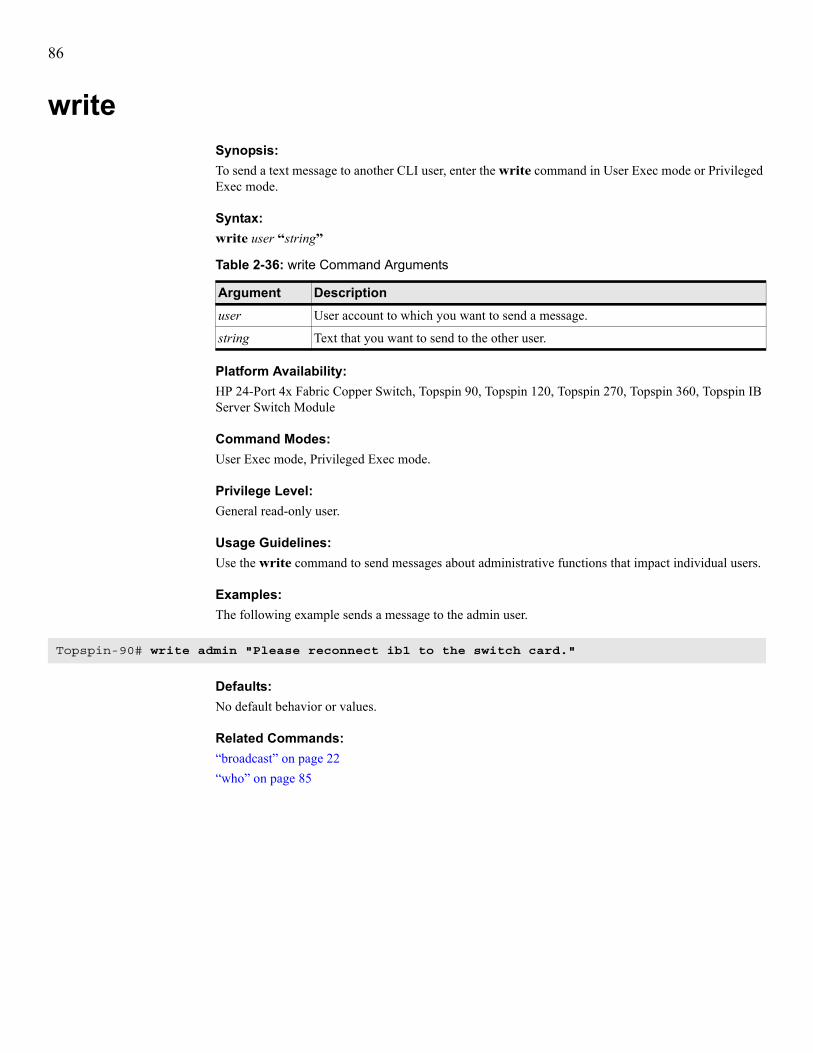
86
writeSynopsis:To send a text message to another CLI user, enter the write command in User Exec mode or Privileged Exec mode.
Syntax:write user “string”
Platform Availability:HP 24-Port 4x Fabric Copper Switch, Topspin 90, Topspin 120, Topspin 270, Topspin 360, Topspin IB Server Switch Module
Command Modes:User Exec mode, Privileged Exec mode.
Privilege Level:General read-only user.
Usage Guidelines:Use the write command to send messages about administrative functions that impact individual users.
Examples:The following example sends a message to the admin user.
Defaults:No default behavior or values.
Related Commands:“broadcast” on page 22“who” on page 85
Table 2-36: write Command Arguments
Argument Descriptionuser User account to which you want to send a message.
string Text that you want to send to the other user.
Topspin-90# write admin "Please reconnect ib1 to the switch card."

87
3
Fibre Channel CommandsThis chapter documents the following commands:• fc srp initiator command on page 88• fc srp initiator-wwpn command on page 91• fc srp it command on page 93• fc srp itl command on page 95• fc srp lu command on page 98• fc srp target command on page 100• fc srp-global gateway-portmask-policy restricted command on page 101• fc srp-global itl command on page 102• fc srp-global lun-policy restricted command on page 105
NOTE: If you enter an FC command and receive an error message that reads, “Operation temporarily failed - try again,” give your FC gateway time to finish initializing, then retry the command.

88
fc srp initiatorSynopsis:To configure an initiator— normally a SAN-attached host but in IB terms a SRP host combined with a switch—to communicate with an FC SAN across an FC gateway on your switch, enter the fc srp initiator command in Global Configuration mode. To deny SAN access to the SRP host, to delete an initiator from the running configuration, or to reconfigure the description of the initiator to an empty string, use the no form of this command.
Syntax:fc srp initiator guid extension {auto-bind | bootup target target-wwpn lu logical-unit | description “descr” | discover-itl | pkey pkey-value | wwnn wwnn-value}no fc srp initiator guid extension [description]
Table 3-1: fc srp initiator Command Arguments
Argument Descriptionguid Global unique identifier (GUID) of the SRP host.
NOTE: The GUID of your SRP host appears printed on the HCA in your server, and you can use host driver utilities to view the GUID. For more information, refer to the HP Dual-Port 4x Fabric Adapter User Guide.
extension GUID extension of the SRP host.
auto-bind 1. Creates the initiator entry in the configuration file and binds the host to a worldwide node name (WWNN) that your switch generates internally to uniquely identify the host.
2. Creates virtual ports for this initiator on every possible physical FC gateway port on your switch. FC devices use these virtual ports to communicate with the initiator.
bootup Configures the SRP host to boot from an FC logical unit (LU).
target Specifies the WWPN of the port of the FC storage device that stores the image that you want the initiator to boot.
target-wwpn WWPN of the port of the FC storage device that stores the image that you want the initiator to boot.
lu Specifies the logical unit (LU) that stores the image that you want the initiator to boot.
logical-unit Logical ID of the LU that stores the image that you want the initiator to boot.
description Assigns an alphanumeric ASCII description string to the initiator.
descr Alphanumeric ASCII description string to assign to the initiator.
discover-itl Discovers initiator-target-LUN (ITL) combinations and adds them to your configuration file. Targets refer to SAN storage devices, and LUNs refer to the logical units within SAN storage devices.
pkey Assigns a partition key (P_key) to the initiator.
NOTE: Your switch does not currently support partition keys for SRP.

89
Platform Availability:Topspin 90, Topspin 360
Command Modes:Global Configuration (config) mode.
Privilege Level:Unrestricted read-write user, FC read-write user
Usage Guidelines:Configure initiators so SRP hosts can communicate with SANs.
NOTE: When you configure new initiators, those initiators inherit the global policies that exist at that time. When you change global policies, the new global policies do not apply to existing initiators.
Before you can customize an initiator, you must create an initiator entry with the auto-bind keyword or the wwnn keyword. Once you identify a host as an initiator, you can customize the initiator with the remaining keywords.Command Keyword Usage Guidelines:• auto-bind—You must create initiators and assign, or bind, a WWNN (an identifier that
FC devices recognize) to each initiator so that FC devices can communicate with initiators. When you use the auto-bind keyword to create an initiator and generate a WWNN for an initiator, your switch creates a virtual port (NL_Port) that represents the initiator on every physical port on the FC gateway. Your switch assigns an internally-generated WWPN to each virtual port. Each physical port on the FC gateway supports 32 virtual ports to form a virtual FC arbitrated loop.
NOTE: We strongly recommend that you use the auto-bind keyword to assign WWNNs to initiators as you configure the initiators. If you perform a manual configuration, you may create duplicate WWNNs that create traffic conflicts.
• description—Enter a description to help identify an initiator without reading its GUID and extension.
• discover-itl—Discover ITLs to add all available ITL groups to the running configuration. • pkey—Refer to the HP 24-Port 4x Fabric Copper Switch User Guide to learn more about
partitions.• wwnn—When you enter a question mark (?) after the wwnn keyword, the CLI provides a
recommended WWNN value.
pkey-value 16-bit partition key to assign to the initiator. Assign multiple partition keys by appending a colon, then the next key (aa:aa:bb:bb:cc:cc:dd:dd).
wwnn Creates the initiator entry in the configuration file and assigns a manually-entered WWNN to the initiator.
wwnn-value WWNN to assign to the initiator.
Table 3-1: fc srp initiator Command Arguments (Continued)
Argument Description

90
Examples:The following example adds an initiator to the running configuration and automatically configures the WWNN of the initiator and the WWPNs of the virtual ports that point to the initiator from the physical FC gateway ports.
The following example assigns the description InfiniBand Host to an existing initiator. The name now appears in the show fc srp initiator command output.
The following example discovers all potential ITL combinations that your switch can support and adds them to the running configuration. To view the results of this command, enter the show fc srp itl command.
Defaults:By default, global policies apply to initiators, but P_keys do not. Configure global policies with fc srp-global commands.
Related Commands:“fc srp-global lun-policy restricted” on page 105“interface” on page 47“show fc srp initiator” on page 160
Topspin-90(config)# fc srp initiator 00:00:2C:90:01:1b:b7:50 00:00:00:00:00:00:00:00 auto-bind
Topspin-90(config)# fc srp initiator 00:00:2C:90:01:1b:b7:50 00:00:00:00:00:00:00:00 description "InfiniBand Host"
Topspin-90(config)# fc srp initiator 00:00:2C:90:01:1b:b7:50 00:00:00:00:00:00:00:00 discover-itl

91
fc srp initiator-wwpnSynopsis:To manually create, on a physical FC gateway port, a virtual port that points to an initiator, enter the fc srp initiator-wwpn command in Global Configuration mode.
Syntax:fc srp initiator-wwpn guid extension slot#/port# wwpn
Platform Availability:Topspin 90, Topspin 360
Command Modes:Global Configuration (config) mode.
Privilege Level:Unrestricted read-write user or FC read-write user.
Usage Guidelines:Configure WWPNs for initiators so that FC devices can recognize them and communicate with them. With virtual ports (NL_ports), physical FC ports can point to multiple initiators, and multiple ports can point to the same initiator. For example, if you have Initiators X and Y and Physical FC Ports A and B, you can create the following virtual ports:• virtual port AX on port A that points to initiator X• virtual port AY on port A that points to initiator Y• virtual port BX on port B that points to initiator X• virtual port BY on port B that points to initiator YAs you can see, in this way, multiple virtual ports can point to one initiator and individual physical ports can support multiple initiators.When you enter a question mark (?) after the port# variable, the CLI provides a suggested WWPN value.
NOTE: Use the recommended WWPN unless you have a compelling reason to do otherwise. We strongly recommend that you use the fc srp initiator command with the auto-bind keyword to create initiator entries and assign WWPNs to initiators.
Table 3-2: fc srp initiator-wwpn Command Arguments
Argument Descriptionguid Global unique identifier (GUID) of the SRP host (initiator) that you want to connect
to an FC SAN.
extension GUID extension of the SRP host that you want to connect to an FC SAN.
slot# Slot of the FC gateway expansion module that you want to use.
port# FC gateway port that you want to use to connect your initiator to the SAN.
wwpn WWPN to assign to the new virtual port.

92
Examples:The following example uses the online help (?) to find the recommended WWPN value, then configures a virtual port on port 1 on the FC gateway expansion module in slot 7.
Defaults:No default behavior or values.
Related Commands:“fc srp initiator” on page 88“interface” on page 47“show fc srp initiator” on page 160
Topspin-360(config)# fc srp initiator-wwpn 00:00:2c:90:01:1b:b7:50 00:00:00:00:00:00:00:00 7/1 ?<wwpn> - wwpnSuggested wwpn = 20:03:00:05:ad:70:00:02Topspin-360(config)# fc srp initiator-wwpn 00:00:2c:90:01:1b:b7:50 00:00:00:00:00:00:00:00 7/1 20:03:00:05:ad:70:00:02Topspin-360(config)#

93
fc srp itSynopsis:To configure an initiator-target (IT) pair—a fully-configured link between an initiator and a target storage device port—with your switch, enter the fc srp it command in Global Configuration mode. To delete or reconfigure an IT pair entry from the configuration file, use the no form of this command.
Syntax:fc srp it guid extension wwpn {description “descr” | discover-itl | gateway-portmask-policy {default | restricted port-selection}}no fc srp it guid extension wwpn [gateway-portmask-policy restricted port-selection]
Syntax:
Platform Availability:Topspin 90, Topspin 360
Command Modes:Global Configuration (config) mode.
Privilege Level:Unrestricted read-write user or FC read-write user.
Table 3-3: fc srp it Command Arguments
Argument Descriptionguid GUID of the initiator.
extension GUID extension of the initiator.
wwpn WWPN of the target port of the FC storage device.
description Assigns a description to the initiator-target pair.
descr Alphanumeric description to assign to the initiator target.
discover-itl Discovers ITL groups for the specified target and adds them to the configuration file.
gateway-portmask-policy Designates the physical FC gateway ports that the initiator can use to access the storage port. When you add FC gateway ports to the policy, the initiator cannot use those ports to access the storage. When you use the no keyword to remove FC gateway ports from the policy, the initiator can access the storage through those ports.
default Assigns the global gateway portmask policy to the IT. To view your default policy, enter the show fc srp-global command (in User Exec mode or Privileged Exec mode) and view the default-gateway-portmask-policy field.
restricted Denies the initiator access to the ports that you specify with the port-selection variable. Use the no form of the command to add ports to the policy to grant the initiator access.
port-selection Port, list of ports, or range of ports to which you grant or deny the initiator access.

94
Usage Guidelines:The fc srp it command sets policies that control the extent to which the initiator accesses FC gateway ports. Use the no form of this command with the gateway-portmask-policy keyword to grant an initiator access to the ports you specify.
NOTE: HP strongly recommends that you let your switch populate the running configuration with IT pairs; do not manually enter IT pairs.
Examples:The following example assigns a description of entry to an existing IT:
Defaults:By default, this policy denies initiators access to all targets.
Related Commands:“fc srp-global gateway-portmask-policy restricted” on page 101“show fc srp it” on page 165“show interface fc” on page 241
Topspin-360(config)# fc srp it 00:00:2c:90:01:1b:b7:40 00:00:00:00:00:00:00:00 21:00:00:04:cf:75:6b:3b description "entry"
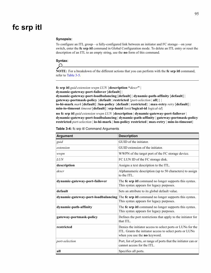
95
fc srp itlSynopsis:To configure an ITL group—a fully-configured link between an initiator and FC storage—on your switch, enter the fc srp itl command in Global Configuration mode. To delete an ITL entry or reset the description of an ITL to an empty string, use the no form of this command.
Syntax:
NOTE: For a breakdown of the different actions that you can perform with the fc srp itl command, refer to Table 3-5.
fc srp itl guid extension wwpn LUN {description “descr” | dynamic-gateway-port-failover [default] | dynamic-gateway-port-loadbalancing [default] | dynamic-path-affinity [default] | gateway-portmask-policy {default | restricted {port-selection | all}} | io-hi-mark mark [default] | lun-policy {default | restricted} | max-retry retry [default] | min-io-timeout timeout [default] | srp-lunid lunid logical-id logical-id}no fc srp itl guid extension wwpn LUN {description | dynamic-gateway-port-failover | dynamic-gateway-port-loadbalancing | dynamic-path-affinity | gateway-portmask-policy restricted port-selection | io-hi-mark | lun-policy restricted | max-retry | min-io-timeout}
Table 3-4: fc srp itl Command Arguments
Argument Descriptionguid GUID of the initiator.
extension GUID extension of the initiator.
wwpn WWPN of the target port of the FC storage device.
LUN FC LUN ID of the FC storage disk.
description Assigns a text description to the ITL.
descr Alphanumeric description (up to 50 characters) to assign to the ITL.
dynamic-gateway-port-failover The fc srp itl command no longer supports this syntax. This syntax appears for legacy purposes.
default Sets an attribute to its global default value.
dynamic-gateway-port-loadbalancing The fc srp itl command no longer supports this syntax. This syntax appears for legacy purposes.
dynamic-path-affinity The fc srp itl command no longer supports this syntax. This syntax appears for legacy purposes.
gateway-portmask-policy Defines the port restrictions that apply to the initiator for that ITL.
restricted Denies the initiator access to select ports or LUNs for the ITL. Grants the initiator access to select ports or LUNs when you use the no keyword.
port-selection Port, list of ports, or range of ports that the initiator can or cannot access for the ITL.
all Specifies all ports.

96
Platform Availability:Topspin 90, Topspin 360
Command Modes:Global Configuration (config) mode.
Privilege Level:Unrestricted read-write user or FC read-write user.
Usage Guidelines:The fc srp itl command configures new ITLs and sets policies to control access that the SCSI RDMA Protocol (SRP) initiator has to the FC storage devices on a per-lun basis. An ITL identifies a fully-configured link between an initiator and storage.HP recommends that you create ITLs with the discover-itl keyword in the CLI or the Discover LUNs button in EM.:
lun-policy Permits the initiator to access the LUN or denies the initiator access to the LUN.
io-hi-mark The fc srp itl command no longer supports this syntax. This syntax appears for legacy purposes.
mark The fc srp itl command no longer supports this syntax. This syntax appears for legacy purposes.
max-retry The fc srp itl command no longer supports this syntax. This syntax appears for legacy purposes.
retry The fc srp itl command no longer supports this syntax. This syntax appears for legacy purposes.
min-io-timeout The fc srp itl command no longer supports this syntax. This syntax appears for legacy purposes.
timeout The fc srp itl command no longer supports this syntax. This syntax appears for legacy purposes.
srp-lunid Specifies a LUN ID called the SRP LUN ID to which you map an existing FC LUN ID. Essentially, this keyword creates an alias LUN ID.
lunid SRP LUN ID that maps to an existing FC LUN ID. This value appears in the srp-lunid field of the show fc srp itl command output.
logical-id Specifies the FC LUN ID to map to the SRP LUN ID.
logical-id Complete Logical ID (entered without colons, as per the second example below of the LU that maps to the user-created SRP LUN ID. This value appears in the fc-lunid field of the show fc srp itl command output.
Table 3-5: fc srp itl Command Usage Examples
Example Resultfc srp itl guid extension wwpn LUN srp-lunid lunid logical-id logical-id
Creates an SRP LUN ID alias for an existing FC LUN ID.
no fc srp itl guid extension wwpn LUN Deletes an ITL entry from the ITL table.
Table 3-4: fc srp itl Command Arguments (Continued)
Argument Description

97
Examples:This example denies the initiator access to port 1 of FC interface card 6 for this ITL.
The following example creates a SRP LUN and maps a LU to it.
Defaults:Default values and behaviors appear in Table 3-4 on page 95 and Table 3-5 on page 96.
Related Commands:“interface” on page 47“fc srp lu” on page 98“fc srp target” on page 100“show fc srp initiator” on page 160
fc srp itl guid extension wwpn LUN description “descr”
Assigns a text description to the ITL.
no fc srp itl guid extension wwpn LUN description
Resets the description of the ITL to an empty string.
fc srp itl guid extension wwpn LUN gateway-portmask-policy restricted port-selection
Denies the ITL access to the ports that you specify with the port-selection variable.
fc srp itl guid extension wwpn LUN gateway-portmask-policy default
Applies global default port access to the ITL. You configure the default access with the fc srp-global gateway-portmask-policy restricted command.
no fc srp itl guid extension wwpn LUN gateway-portmask-policy restricted port-selection
Grants the ITL access to the ports that you specify with the port-selection variable.
fc srp itl guid extension wwpn LUN lun-policy restricted
Denies the initiator access to the storage.
no fc srp itl guid extension wwpn LUN lun-policy restricted
Grants the initiator access to the storage.
fc srp itl guid extension wwpn LUN lun-policy default
Resets the LUN-policy to the global default. Set the default with the fc srp-global lun-policy restricted command.
Table 3-5: fc srp itl Command Usage Examples (Continued)
Example Result
Topspin-360(config)# fc srp itl 00:00:2c:90:01:1b:b7:40 00:00:00:00:00:00:00:00 21:00:00:04:cf:75:6b:3b 00:00:00:00:00:00:00:00 gateway-portmask-policy restricted 6/1
Topspin-360(config)# fc srp itl 00:02:c9:01:07:fc:64:a0 00:00:00:00:00:00:00:00 21:00:00:04:cf:fb:8c:87 00:00:00:00:00:00:00:00 srp-lunid 01:01:01:01:01:01:01:01 logical-id 0103000820000004cffb8c8700000000000000000000000000000000000000000000000000000000000000000000000000000000000000000000000000000000

98
fc srp luSynopsis:To configure a logical unit, enter the fc srp lu command in Global Configuration mode. To delete a logical unit or to set a LU attribute to the factory default value, use the no form of this command.
Syntax:fc srp lu logical-id {description “descr” | device-category {random target wwpn | sequential target wwpn} | dynamic-gateway-port-failover [default] | dynamic-gateway-port-loadbalancing [default] | dynamic-path-affinity [default] | io-hi-mark mark [default] | max-retry retry [default] | min-io-timeout timeout [default] | target wwpn}no fc srp lu logical-id {dynamic-gateway-port-failover | dynamic-gateway-port-loadbalancing | dynamic-path-affinity | target}
Table 3-6: fc srp itl Command Arguments
Argument Descriptionlogical-id LU identifier in 64-byte, hexadecimal format without
colons (refer to the following example).
description Assigns a textual description to the LU.
descr Alphanumeric description to assign to the LU.
device-category Configures the device category of the LU: random (disk) or sequential (tape).
random Identifies a LU for a random device.
sequential Identifies a LU for a sequential device
dynamic-gateway-port-failover Enables dynamic gateway port failover so that if one gateway port fails, the other port on the gateway maintains the traffic to the LU.
default Sets an attribute to its global default value.
dynamic-gateway-port-loadbalancing Enables gateway port load balancing across multiple ports for this LU to optimize performance and utilize all available bandwidth.
dynamic-path-affinity Enables dynamic path affinity for this LU, which locks a storage connection to a path for the duration of data transfer to provide faster, more efficient data delivery.
io-hi-mark Configures the maximum amount of I/O that the LU can send to the initiator.
mark Maximum amount of I/O (integer value from 1 - 256) that the initiator can send to the storage device (LU). This value defaults to 5.
max-retry Maximum number of times that the initiator unsuccessfully sends data to a LU before the initiator identifies the LU as inaccessible.
retry Integer value from 1 - 100. The retry variable defaults to 5.
min-io-timeout Configures the maximum amount of time during which the storage device can accept I/O.

99
Platform Availability:Topspin 90, Topspin 360
Command Modes:Global Configuration (config) mode.
Privilege Level:Unrestricted read-write user or FC read-write user.
Usage Guidelines:Use the fc srp lu command to configure LU attributes.We recommend that you do not manually create LUs. We recommend that you let your gateway card(s) detect LUs. The gateway card automatically creates LU entries when it discovers LUs.
Examples:The following example assigns a name to more easily identify the LU.
Defaults:Refer to Table 3-6 on page 98 for default behavior and values.
Related Commands:“fc srp itl” on page 95“interface” on page 47“show fc srp initiator” on page 160“show interface fc” on page 241
timeout Maximum amount of time during which a storage device can accept I/O. Integer value from 1 - 1800. This value defaults to 10.
target Specifies a target to add to the LU target list.
wwpn WWPN of the target port to add to the LU target list.
Table 3-6: fc srp itl Command Arguments (Continued)
Argument Description
Topspin-360(config)# fc srp lu 0103000820000004cf86a01f00000000000000000000000000000000000000000000000000000000000000000000000000000000000000000000000000000000 description "my-LUN"

100
fc srp targetSynopsis:To configure targets, enter the fc srp target command in Global Configuration mode. To delete a target from the running configuration, use the no form of this command.
Syntax:fc srp target wwpn {description “desc” | ioc-guid guid}no fc srp target wwpn [description | service-name]
Platform Availability:Topspin 90, Topspin 360
Command Modes:Global Configuration (config) mode.
Privilege Level:Unrestricted read-write user or FC read-write user.
Usage Guidelines:Use the fc srp target command to configure target attributes.We recommend that you do not manually create targets. We recommend that you let your gateway card(s) detect targets. The gateway card automatically creates FC-SRP target entries when it discovers targets.
Examples:The following example assigns a name to more easily identify the target.
Defaults:The service name serves as the default target name.
Related Commands:“fc srp itl” on page 95“interface” on page 47“show interface fc” on page 241“show fc srp initiator” on page 160
Table 3-7: fc srp target Command Arguments
Argument Descriptionwwpn WWPN of the target port.
description Applies a text description to the target port.
desc Description to apply to the target port.
ioc-guid Manually assigns an I/O Controller (IOC) to the target.
guid GUID of the IOC to assign to the target.
service-name Configures the service name of the target to an empty string.
Topspin-90(config)# fc srp target 21:00:00:04:cf:75:6b:3b description jumbalya

101
fc srp-global gateway-portmask-policy restrictedSynopsis:To deny new initiators port access to FC gateway ports, enter the fc srp-global gateway-portmask-policy restricted command in Global Configuration mode. To grant port access to new initiators, enter the no form of this command.
Syntax:fc srp-global gateway-portmask-policy restricted no fc srp-global gateway-portmask-policy restricted
Platform Availability:Topspin 90, Topspin 360
Command Modes:Global Configuration (config) mode.
Privilege Level:Unrestricted read-write user or FC read-write user.
Usage Guidelines:Apply the default policy to new ITs and ITLs to restrict access so new SRP initiators do not use the FC gateway or see the FC fabric. If you do not restrict access, new SRP initiators can communicate through the FC gateway ports. You can modify access policies on an individual basis with the fc srp itl command.
NOTE: Policies only apply to ITs and ITLs that you create after you configure the policies.
Examples:The following example denies port access to all new ITLs.
Defaults:By default, ports deny access to initiators.
Related Commands:“interface” on page 47“show fc srp initiator” on page 160“show interface fc” on page 241
Topspin-360(config)# fc srp-global gateway-portmask-policy restricted

102
fc srp-global itlSynopsis:To configure the default attributes that your switch assigns to all new ITLs, enter the fc srp-global itl command in Global Configuration mode. To configure any attribute to an empty string or disable an attribute, use the no form of this command.
Syntax:fc srp-global itl [sequential] {dynamic-gateway-port-failover | dynamic-gateway-port-loadbalancing | dynamic-path-affinity | io-hi-mark mark | max-retry retry | min-io-timeout timeout}no fc srp-global itl [sequential] {dynamic-gateway-port-failover | dynamic-gateway-port-loadbalancing | dynamic-path-affinity | io-hi-mark | max-retry | min-io-timeout}
Platform Availability:Topspin 90, Topspin 360
Command Modes:Global Configuration (config) mode.
Privilege Level:Unrestricted read-write user or FC read-write user.
Table 3-8: fc srp-global itl Command Arguments
Argument Descriptionsequential Configures SRP global defaults for ITLs of sequential
devices.
dynamic-gateway-port-failover The fc srp-global itl command no longer supports this syntax. This syntax appears for legacy purposes.
dynamic-gateway-port-loadbalancing The fc srp-global itl command no longer supports this syntax. This syntax appears for legacy purposes.
dynamic-path-affinity The fc srp-global itl command no longer supports this syntax. This syntax appears for legacy purposes.
io-hi-mark Assigns the maximum number of I/O requests that the initiator can send to the storage device.
mark Maximum number of requests that the initiator can send to the storage device.
max-retry Assigns the maximum number of consecutive, failed attempts to pass traffic to a LUN that the initiator makes before it identifies the LUN as inaccessible.
retry Number of retries before an initiator recognizes a LUN as inaccessible.
min-io-timeout Configures the maximum amount of time during which the storage device can accept I/O.
timeout Maximum amount of time during which a storage device can accept I/O.

103
Usage Guidelines:Table 3-9 provides usage guidelines for this command.
Table 3-9: Usage Guidelines for fc srp-global itl Command Arguments
Policy Descriptiondynamic-gateway-port-failover Allows the controller to select an alternate gateway
interface port if the primary path fails. Enter the fc srp-global itl command with this keyword to enable this feature. Otherwise, include the no keyword at the beginning of the command string to disable this feature. If you enable this policy, you implicitly disable port load balancing and dynamic path affinity.
dynamic-gateway-port-loadbalancing Allows data to be sent between the initiator and FC target using all available ports on the gateway interface. Port selection relies upon comparative IO traffic. The controller attempts to distribute traffic equally between the ports. Enter the fc srp-global itl command with this keyword to enable this feature. Otherwise, include the no keyword at the beginning of the command string to disable this feature. If you enable this policy, you implicitly disable port failover and dynamic path affinity.
dynamic-path-affinity Allows the system to maintain a preference for a specific path. If the number of outstanding I/Os becomes excessive, or the path fails, the gateway uses an alternate path. When enabled, the gateway uses the current path until the path condition changes. Note that frequent switching degrades performance. Enter the fc srp-global itl command with this keyword to enable this feature. Otherwise, include the no keyword at the beginning of the command string to disable this feature. If you enable this policy, you implicitly disable port failover and port loadbalancing.
io-hi-mark mark Sets the maximum number of requests that can be sent per logical unit. The value, an integer, must fall between 1 and 256. The hi mark defaults to 16. Enter the fc srp-global itl command with this keyword and the desired io-hi-mark value to set this feature.
max-retry retry Number of times the same I/O may be sent to a logical unit. Increase the value if heavy traffic runs, or increase the min-io-timeout value. The value, an integer, must fall between 1 and 100. The retry value defaults to 5. Enter the fc srp-global itl command with this keyword and the desired max-retry value to set this feature.
min-io-timeout timeout Maximum amount of time allowed for I/O traffic to be accepted by a logical unit. Increase this value (or increase the max-retry value) if you use a known slow connection. The value, an integer, must fall between 1 and 1800. The timeout defaults to 10 seconds.
sequential Configures ITL defaults globally for sequential devices.

104
Examples:The following example sets the I/O high mark of the ITL to 32.
Defaults:By default, the fc srp-global itl command configures ITLs for random (non-sequential) targets. For additional default values, see Table 3-9 on page 103.
Related Commands:“show interface fc” on page 241“show fc srp-global” on page 179
Topspin-90(config)fc srp itl 00:05:ad:00:00:01:29:c5 00:00:00:00:00:00:00:00 21:00:00:04:cf:f6:c2:ab 00:00:00:00:00:00:00:00 io-hi-mark 32

105
fc srp-global lun-policy restrictedSynopsis:To enable LUN masking on all new ITs and ITLs, enter the fc srp-global lun-policy restricted command in Global Configuration mode. To disable default LUN masking, use the no form of this command.
Syntaxfc srp-global lun-policy restrictedno fc srp-global lun-policy restricted
Platform Availability:Topspin 90, Topspin 360
Command Modes:Global Configuration (config) mode.
Privilege Level:Unrestricted read-write user or FC read-write user.
Usage Guidelines:Enable global LUN masking to deny LUN access to new initiators so that they cannot communicate with SAN nodes until you grant them access on an individual basis. Disable LUN masking to grant new ITLs immediate access to all LUNs.
NOTE: An initiator requires both port and LUN access before it can successfully access a LUN. To grant port access, use the fc srp-global gateway-portmask-policy restricted, fc srp it and fc srp itl commands.
NOTE: Policies only apply to ITs and ITLs that you create after you configure the policies.
Examples:The following example denies all new initiators access to all LUNs.
Defaults:Topspin restricts the LUN policy by default.
Related Commands:“fc srp it” on page 93“fc srp itl” on page 95“fc srp-global gateway-portmask-policy restricted” on page 101“show fc srp-global” on page 179
Topspin-360(config)# fc srp-global lun-policy restricted

106
107
4
InfiniBand CommandsThis chapter documents the following commands:• ib sm db-sync command on page 108• ib sm command on page 110• ib-agent command on page 113

108
ib sm db-syncSynopsis:To synchronize the databases of the master SM and one or more standby (slave) SMs, enter the ib sm db-sync command in Global Configuration mode. To disable database synchronization features, use the no form of this command.
NOTE: With database sync enabled on all chassis, only the chassis running the master SM will accept partition configuration form the user.
Syntax:ib sm db-sync subnet-prefix prefix {enable | max-backup-sms max | session-timeout timeout | poll-interval interval | cold-sync-timeout cs-timeout | cold-sync-limit cs-limit | cold-sync-period cs-period | new-session-delay delay | resync-interval resync}no ib sm db-sync subnet-prefix prefix {enable | max-backup-sms | session-timeout | poll-interval | cold-sync-timeout | cold-sync-limit | cold-sync-period | new-session-delay | resync-interval}
Table 4-1: ib sm db-sync Command Arguments
Argument Descriptionenable Enables database synchronization on your IB fabric.
max-backup-sms Specifies the maximum number of backup SMs that will synchronize with the master SM.
max Maximum number of backup SMs that will synchronize with the master SM. This value defaults to 1.
session-timeout Specifies the interval, in seconds, during which a synchronization session status MAD packet must arrive at the master SM to maintain synchronization.
timeout Timeout interval, in seconds. This value defaults to 10 seconds.
poll-interval Interval at which the master SM polls an active slave SM to verify synchronization.
interval Poll interval, in seconds. This value defaults to 3 seconds.
cold-sync-timeout Allots a maximum amount of time in which to perform a cold sync. During the cold sync, the master SM copies all out-of-sync tables to the standby.
cs-timeout Cold sync interval, in seconds. This value defaults to 10 seconds.
cold-sync-limit Specifies the maximum number of cold syncs that may take place during the cold sync period. This value defaults to 2.
cs-limit Maximum number of cold syncs per cold sync period (integer).
cold-sync-period Specifies the length of the interval during which cold syncs may occur.
cs-period Duration, in seconds, of the cold sync period. This value defaults to 900 seconds.
new-session-delay Specifies the amount of time that the master SM waits before it attempts to initiate a synchronization session with a new SM.
delay Delay length, in seconds. This value defaults to 120 seconds.
resync-interval Specifies the interval at which the master SM sends a resynchronization request to all active sync sessions.

109
Platform Availability:HP 24-Port 4x Fabric Copper Switch, Topspin 90, Topspin 120, Topspin 270, Topspin 360, Topspin IB Server Switch Module
Command Modes:Global Configuration (config) mode.
Privilege Level:IB read-write access
Usage Guidelines:Synchronize the database of the master SM with one or more standby SMs to retain all database information in the event of a failover.
NOTE: If you make configuraiton changes to the master SM and then save the configuration, verify that the master and backup have synchronized, then save the configuration on the backup as well.
Examples:The following example enables database synchronization on the IB fabric.
Defaults:Databases synchronize by default. Use the disable keyword to prevent synchronizing SM databases. For attribute-specific defaults, refer to Table 4-1.
Related Commands:“show ib sm db-sync” on page 191
resync Resynchronization interval, in seconds. This value defaults to 3600 seconds.
Table 4-1: ib sm db-sync Command Arguments (Continued)
Argument Description
Topspin-360(config)# ib sm db-sync subnet-prefix fe:80:00:00:00:00:00:00 enable

110
ib smSynopsis:To administer the SM on your switch, and to create and populate partitions, enter the ib sm command in Global Configuration mode. To undo configurations and partitions, use the no form of this command.
Syntax:ib sm subnet-prefix prefix [p_key pkey | priority sm-priority [sm-key key] | response-timeout timeout | sm-key key | sweep-interval interval | lid-mask-control LMC | master-poll-intval mp-interval | master-poll-retries retries | max-active-sms SMs]no ib sm subnet-prefix guid [p_key pkey [partition-member member-guid member-port] | priority | response-timeout | sweep-interval]
Table 4-2: ib sm Command Arguments
Argument Descriptionsubnet-prefix Specifies the subnet prefix of the SM.
prefix Subnet prefix of the SM. You may enter any prefix, but HP recommends that you enter fe:80:00:00:00:00:00:00 to indicate a locally administered subnet.
p_key Creates a partition and optionally assigns members to the partition.
NOTE: With database sync enabled on all chassis, only the chassis running the master SM will accept partition configuration from the user.
pkey Partition identifier, in ##:## format.
priority Assigns a priority level to the SM. Because multiple SMs can run on the system and other SMs may run in your IB network, the priority attribute identifies the master SM.
sm-priority Integer value that represents the SM priority level. The higher the integer, the higher the priority.
sm-key Assigns a subnet management key to a new SM.
NOTE: We recommend that you do not create additional SMs. An SM resides on your switch from the moment you boot.
key 64-bit subnet management key.
response-timeout Specifies the maximum amount of time that the SM waits for a response after it sends a packet to a port. If the SM does not receive a response in time, the SM identifies the port as unresponsive.
timeout Maximum amount of time, in milliseconds, that the SM waits for a response after it sends a packet to a port. The timeout variable defaults to 2000 milliseconds.
sweep-interval Specifies how frequently the SM queries the IB fabric for network changes.
interval Frequency, in seconds, at which the SM queries the IB fabric for network changes.

111
Platform Availability:HP 24-Port 4x Fabric Copper Switch, Topspin 90, Topspin 120, Topspin 270, Topspin 360, Topspin IB Server Switch Module
Command Modes:Global Configuration (config) mode.
Privilege Level:General read-write user.
Usage Guidelines:The subnet manager:• Discovers the subnet topology and dynamically updates it at a specified sweep interval that you
specify with the interval variable.• Assigns the local identifiers (LIDs), global identifier (GID) subnet prefix, and partition keys for
each HCA port.• Assigns the LIDs, GID subnet prefix, and forwarding databases for each switch on the subnet.• Maintains the end-node and service databases of the subnet, providing a GUID to LID/GID
resolution service as well as a services directory.One SM administers the IB fabric. All IB hosts run on this one subnet. The SM loads upon bootup.Each node in the fabric has a subnet management agent (SMA) to shuttle communication requests between the node and the SM. Communication between the SM and the SMA uses the common management datagram (MAD) message structure.Regarding Partitions: Partitions are created, and then ports are added to those partitions to enforce isolation.
Examples:The following example defines an SM, or redefines the existing SM, with the specified priority, sm-key, response-timeout, and sweep-interval configurations.
lid-mask-control Assigns the number of path bits present in the base LID to each channel adapter port. Increasing the LMC value increases the number of LIDs assigned to each port to increase the number of potential paths to reach each port. This value defaults to 0.
LMC Number of path bits.
master-poll-intval Specifies the interval at which the slave SM polls the master to see if it still runs.
mp-interval Poll interval, in seconds. This value defaults to 3 seconds.
master-poll-retries Specifies the number of unanswered polls that cause the slave to identify the master as dead.
retries Number of unanswered polls (integer). This value defaults to 2.
max-active-sms Specifies the maximum number of standby SMs that the master supports. This value defaults to 0, which indicates unlimited SMs.
SMs Number of standby SMs that the master supports (integer).
Table 4-2: ib sm Command Arguments (Continued)
Argument Description
Topspin-360(config)# ib sm subnet-prefix fe:80:00:00:00:00:00:00 priority 10 sm-key 00:00:00:00:00:00:00:00 response-timeout 2000 sweep-interval 10

112
The following example removes a specified SM.
The following example resets the response-timeout value for the specified SM back to its default value.
The following example creates a partition and adds a member.
Defaults:
NOTE: You may enter this command without arguments to add an SM with default values.
Related Commands:“ib-agent” on page 113“show ib sm configuration” on page 188
Topspin-360(config)# no ib sm subnet-prefix fe:80:00:00:00:00:00:00
Topspin-360(config)# no ib sm subnet-prefix fe:80:00:00:00:00:00:00 response-timeout
Topspin-360(config)# ib sm subnet-prefix fe:80:00:00:00:00:00:00 p_key 00:02 partition-member 00:00:2c:90:01:1a:c8:00 3 full-member
Table 4-3: ib sm subnet-prefix Command Defaults
Variable Defaultsm-key 00:00:00:00:00:00:00:00
priority 10
sweep-interval 10 seconds
response-timeout 400 microseconds

113
ib-agentSynopsis:To configure SMA node strings, enter the ib-agent command in Global Configuration mode.
Syntax:ib-agent {channel-adapter HCA-port-guid | switch switch-guid} node-string “string”
Platform Availability:HP 24-Port 4x Fabric Copper Switch, Topspin 90, Topspin 120, Topspin 270, Topspin 360, Topspin IB Server Switch Module
Command Modes:Global Configuration (config) mode.
Privilege Level:Unrestricted and IB read-write users.
Usage Guidelines:A node string identifies an object.An SMA serves as the intermediary between an SM and the network entities that it manages, such as the internal IB switches and host channel adapters. The SMA maps the operations between managed conceptual objects and the physical resources inside the switch chassis and routes event notifications from locally managed objects to remote entities. Each node in the fabric has an SMA to shuttle communication requests between the node and the SM. Communication between the SM and the subnet management agent uses the MAD message structure. This structure entails the passing of SMPs. The subnet management agent receives and transmits SMPs to and from the SM. The subnet management packets never extend beyond their respective local IB subnet. Internally, the IB switch consists of multiple switch chips. Each switch chip runs its own subnet management agent and can be viewed by the SM as a unique entity. Change the node-string for a channel-adapter or switch to make it easier to identify.
Examples:The following example changes the node string of a channel adapter.
Table 4-4: ib-agent Command Arguments
Argument Descriptionchannel-adapter Specifies the HCA that you want to identify with a node string.
HCA-port-guid GUID of the HCA that you want to identify with a node string.
switch Specifies the switch that you want to identify with a node string.
switch-guid GUID of the switch that you want to identify with a node string.
node-string Specifies the node string description.
string Node string description.
Topspin-90(config)# ib-agent channel-adapter 00:05:ad:00:00:00:13:f7 node-string "primary HCA"

114
The following example changes the node string of a switch.
Defaults:No default behavior or values.
Related Commands:“ib sm” on page 110“interface” on page 47“show ib sm configuration” on page 188“show ib-agent summary” on page 221
Topspin-90(config)# ib-agent switch 00:05:ad:00:00:00:13:da node-string "Switch 0, LID 2"

115
5
IP CommandsThis chapter documents the following commands:• arp ethernet command on page 116• bridge-group command on page 117• distribution-type command on page 119• half-duplex command on page 121• ip command on page 122• redundancy-group command on page 125• trunk-group command on page 126
NOTE: The 6-port Ethernet gateway does not support half-duplex transmission or 10 Mbps speed.

116
arp ethernetSynopsis:To statically map an IP address to the physical machine address of an Ethernet host on the local network, enter the arp ethernet command in Global Configuration mode. To clear a static IP address, use the no form of this command.
Syntax:arp ethernet ip-address mac-address slot#/port#no arp ethernet ip-address mac-address
Platform Availability:Topspin 90, Topspin 360
Command Modes:Global Configuration (config) mode.
Privilege Level:Ethernet read-write user.
Usage Guidelines:The switch supports dynamic ARP so that any IP host that connects to an Ethernet gateway port may see or detect all the other connected IP and IPoIB hosts.An ARP table contains the available ARP records in the gateway. An ARP record may be dynamically learned or statically created. In most cases, you can rely upon dynamic ARP addressing. Dynamic ARP records may be deleted from the table after a period of time, or updated, if a host address-change occurs.
Examples:
Defaults:No default behavior or values.
Related Commands:“show arp ethernet” on page 129
Table 5-1: arp ethernet Command Arguments
Argument Descriptionip-address IP address of the host.
mac-address MAC address of the host.
slot# Slot on the switch that holds the Ethernet gateway that connects to the host.
port# Ethernet gateway port that connects to the host.
Topspin-360(config)# arp ethernet 10.2.0.50 00:30:48:23:A9:0A 4/1

117
bridge-groupSynopsis:To create and configure bridge groups, enter the bridge-group command in Global Configuration mode or Ethernet Interface Configuration submode. To remove bridge groups or attributes of bridge groups, use the no form of this command.
Syntax:bridge-group bridgegroupID {broadcast-forwarding | eth-next-hop ip-address | ib-next-hop ip-address | name “name-string”| subnet-prefix prefix length | loop-protection one | multicast | fail-over-priority priority | redundancy-group group}no bridge-group bridgegroupID [broadcast-forwarding | eth-next-hop | ib-next-hop | loop-protection one | multicast | redundancy-group group]
Platform Availability:Topspin 90, Topspin 360
Command Modes:Global Configuration (config) mode, Ethernet Interface Configuration (config-if-ether) submode, Gateway Interface Configuration (config-if-gw) mode.
Privilege Level:Ethernet read-write user.
Table 5-2: bridge-group Command Arguments
Argument DescriptionbridgegroupID Bridge group to create or reconfigure.
broadcast-forwarding Enables broadcast forwarding for the bridge group.
eth-next-hop Identifies the next-hop IP address connected to the ethernet gateway.
ip-address Next-hop IP address
ib-next-hop Identifies the next-hop IP address connected to the IB switch.
loop-protection Specifies the type of loop protection for the bridge group.
one Specifies type one loop protection (ARP packet painting enabled).
multicast Enables IP-V4 multicast forwarding for the bridge group.
name Assigns an ASCII text string identifier to the bridge group.
name-string ASCII text string identifier for the bridge group.
subnet-prefix Assigns a subnet to the bridge group.
prefix Subnet to assign to the bridge group.
length Length, in bits, of the subnet mask to assign to the bridge group.
fail-over-priority Specifies the failover priority of the bridge group.
priority Integer value (1 - 255), where the lower the integer the higher the priority.
redundancy-group Assigns the bridge group to a redundancy group.
group Redundancy group to which you want the bridge group to belong.

118
Usage Guidelines:Create bridge groups to associate specific Ethernet gateway ports with Ethernet switch ports. Bridge groups are used to associate the IB fabric with an Ethernet subnet.
Examples:The following example creates a bridge group and uses auto-detect to discover all available subnets.
The following example assigns a subnet prefix to a bridge group.
The following example disables multicast forwarding for a bridge group.
The following example assigns bridge group 62 to the Ethernet interface slot 6, port 2.
The following example assigns bridge group 62 to the internal gateway interface slot 6, ports 1 and 2.
The following example assigns a bridge group to a redundancy group and configures the failover priority of the bridge group.
Defaults:No default behavior or values.
Related Commands:“configure terminal” on page 26“interface” on page 47“redundancy-group” on page 125“show bridge-group” on page 135
Topspin-360(config)# bridge-group 61
Topspin-360> Topspin-360(config)# bridge-group 61 subnet-prefix 61.0.0.0 16
Topspin-360(config)# no bridge-group 61 multicast
Topspin-360(config-if-ether-6/2)# bridge-group 62
Topspin-360(config-if-gw-6)# bridge-group 62
Topspin-360(config)# bridge-group 11 redundancy-group 11 fail-over-priority 10

119
distribution-typeSynopsis:To configure the type of load distribution that your Ethernet gateway uses to communicate with a Link Aggregation-aware switch, enter the distribution-type command in Trunk Interface Configuration submode.
Syntax:distribution-type {dist-ip | dst-mac | src-dst-ip | src-dst-mac | src-ip | src-mac | round-robin}
Platform Availability:Topspin 90, Topspin 360
Command Modes:Trunk Interface Configuration (config-if-trunk) submode.
Privilege Level:Ethernet read-write user.
Usage Guidelines:You must configure a distribution type to bridge to a load aggregation-aware Ethernet switch. Contact your administrator to discover if a switch is load aggregation-aware.
Examples:The following example configures src-mac distribution for the trunk interface.
Table 5-3: distribution-type Command Arguments
Argument Descriptiondst-ip Bases the load distribution on the destination IP address of the incoming packet.
Packets to the same destination travel on the same port, but packets to different destinations travel on different ports in the channel.
dst-mac Bases the load distribution on the destination host MAC address of the incoming packet. Packets to the same destination travel on the same port, but packets to different destinations travel on different ports in the channel.
src-dst-ip Bases load distribution on the IP address of the source logic gate (XOR) destination.
src-dst-mac Bases load distribution on the MAC address of the source logic gate (XOR) destination.
src-ip Bases the load distribution on the source IP address. Packets from the same source travel on the same port, but packets from different sources travel on different ports in the channel.
src-mac Bases load distribution on the source MAC address of the incoming packet. Packets from different hosts use different ports in the channel, but packets from the same host use the same port in the channel.
round-robin Bases the load distribution on a circular pattern to create an evenly distributed load.
Topspin-90# interface trunk 1Topspin-90(config-if-trunk)# distribution-type src-mac

120
Defaults:The distribution-type defaults to src-mac.
Related Commands:“show trunk” on page 290“interface” on page 47

121
half-duplexSynopsis:To configure an Ethernet connection in half-duplex mode, enter the half-duplex command in Ethernet Interface Configuration submode. To undo this configuration, use the no form of this command.
Syntax:half-duplexno half-duplex
Platform Availability:Topspin 90, Topspin 360
Command Modes:Ethernet Interface Configuration (config-if-ether) submode.
Privilege Level:Ethernet read-write user.
Usage Guidelines:If you disable auto-negotiation, set speed and duplex mode with the half-duplex command and speed command.You cannot manually configure half-duplex mode while auto-negotiation runs on your switch or while the connection speed exceeds 1000 Mbps.
NOTE: The 6-port Ethernet gateway does not support half-duplex transmission or 10 Mbps speed.
Examples:The example below configures half-duplex mode for ports 1 - 4 on slot 4.
Defaults:Your switch runs in full-duplex mode by default.
Related Commands:“auto-negotiate” on page 18“show interface ethernet” on page 233“speed” on page 72
Topspin-360(config-if-ether-4/1-4/4)# half-duplex

122
ipSynopsis:• To assign an IP address and subnet mask to an Ethernet port, enter the ip command in Ethernet
Interface Configuration submode. To clear this configuration, use the no form of this command.• To assign an IP address to the Ethernet Management Interface port, enter the ip command in
Ethernet Management Interface submode. To clear this configuration, use the no form of this command.
• To assign an IP address to the IB Management Interface port, enter the ip command in InfiniBand Management Interface submode. To clear this configuration, use the no form of this command.
• To configure IP networking attributes on your switch, enter the ip command in Global Configuration mode. To clear this configuration, use the no form of this command.
Syntax:To configure Ethernet ports:
NOTE: This layer 3 command is available for 4-port Ethernet gateways but not 6-port gateways.
ip address ip-address subnet-maskno ip address ip-address subnet-maskTo configure the Ethernet Management port:ip address ip-address subnet-maskno ipTo configure the IB Management port:ip address ip-address subnet-maskno ipTo configure your switch:ip {domain-name “name-string” | name-server-one server | name-server-two server | route dest-address dest-subnet-mask next-hop}no ip {domain-name | name-server-one | name-server-two | route dest-address subnet-mask next-hop}
Table 5-4: ip Command Arguments
Argument Descriptionaddress Assigns a primary IP address to a port.
ip-address IP address to assign.
subnet-mask Subnet mask to assign.
domain-name Assigns a DNS name to your switch.
name-string Domain name to assign.
name-server-one Specifies a primary domain name server (DNS).
name-server-two Specifies a secondary DNS.
server Domain name server for your switch to use.
route Defines static routes to remote hosts or networks to forward IP packets.
dest-address IP address of the host or network that you want to reach.

123
Platform Availability:Topspin 90, Topspin 360
Command Modes:Ethernet Interface Configuration (config-if-ether) submode, Ethernet Management Interface Configuration (config-if-mgmt-ethernet) submode, InfiniBand Management Interface (config-if-mgmt-ib) submode, Global Configuration (config) mode.
Privilege Level:Ethernet read-write user.
Usage Guidelines:• You can only assign an IP address to one port at a time.• Assign a DNS name and servers to support network name resolution.• The maximum transmission unit dictates payload size. TCP uses the MTU to determine the
maximum payload allowed for every transmission. Too great a value can overwhelm routers and result in data retransmission. Too small a value results in degraded performance because there are more headers and acknowledgements required to transmit the same amount of data.
• Configure ip routes to hosts that reside one or more hops away from your switch.
Examples:The following example assigns the IP address 10.3.0.24 and the subnet mask 255.255.255.0 to ethernet card 4, port 1.
The following example assigns the domain name shasta to the switch.
The following example configures your switch to use a primary DNS.
The following example configures your switch to use a secondary DNS.
The following example configures a static route on which to forward IP packets.
Defaults:No default behavior or values.
dest-subnet-mask Netmask used to resolve host and network addressing. The netmask may be an IP network address, a host route (for example, 255.255.255.255), or the default route (for example, 0.0.0.0).
next hop IP address of the next hop (out of your switch) on the way to the destination.
Table 5-4: ip Command Arguments (Continued)
Argument Description
Topspin-360(config-if-ether-4/1)# ip address 10.3.0.24 255.255.255.0
Topspin-90(config)# ip domain-name “shasta”
Topspin-90(config)# ip name-server-one 10.3.103.22
Topspin-360(config)# ip name-server-two 10.3.103.23
Topspin-90(config)# ip route 192.168.3.0 255.255.255.0 10.10.1.0

124
Related Commands:“hostname” on page 44“ip” on page 122“interface” on page 47“ping” on page 60

125
redundancy-groupSynopsis:To create or configure a redundancy group, enter the redundancy-group command in Global Configuration mode. To disable an attribute of a redundancy group or to delete a redundancy group, use the no form of this command.
Syntax:redundancy-group rg-number [load-balancing | name name | recover-failover-order]no redundancy-group rg-number [load-balancing | name | recover-failover-order]]
Platform Availability:Topspin 90, Topspin 360
Command Modes:Global Configuration (config) mode.
Privilege Level:Ethernet read-write user.
Usage Guidelines:Create and configure redundancy groups with this command.
Examples:The following example creates a redundancy group.
Defaults:By default, load balancing does not run on redundancy groups.
Related Commands:“show redundancy-group” on page 278“bridge-group” on page 117
Table 5-5: redundancy-group Command Arguments
Argument Descriptionrg-number Number of the redundancy group.
load-balancing Enables load balancing among all members of the group.
name Configures a name for the redundancy group
name Name to assign to the redundancy group.
recover-failover-order Sets failover priorities to the configured order (refer to the bridge-group command on page 117).
Topspin-360(config)# redundancy-group 11
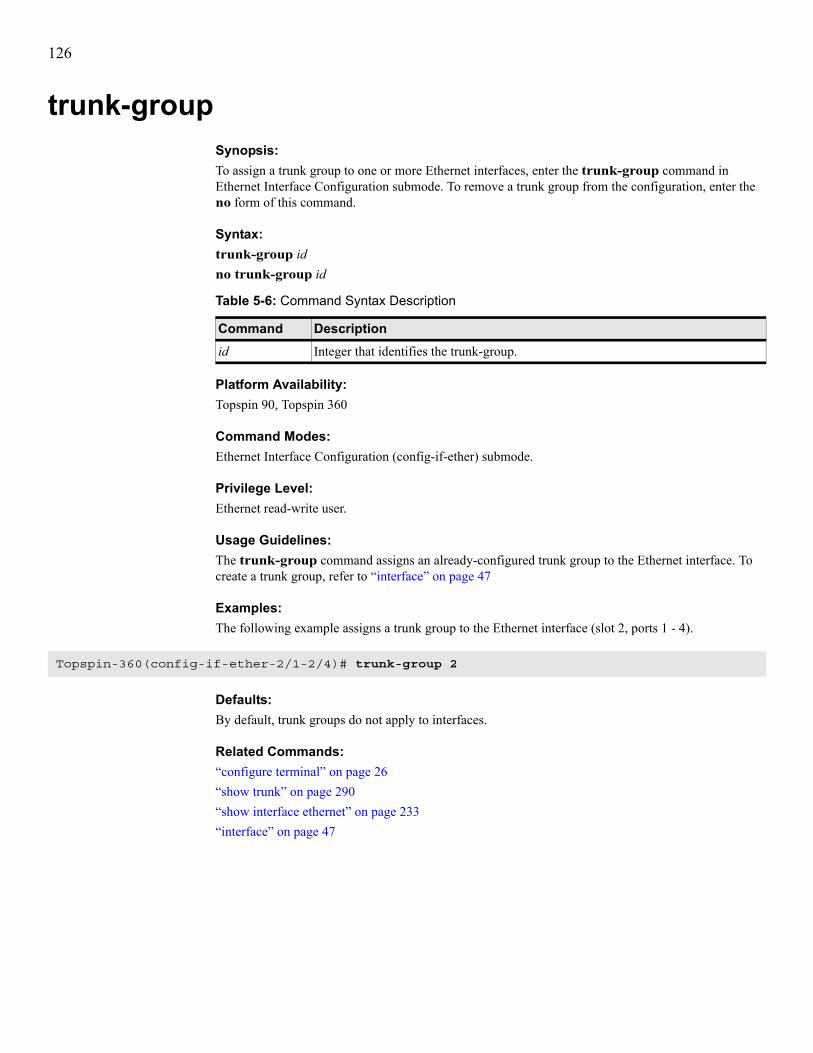
126
trunk-groupSynopsis:To assign a trunk group to one or more Ethernet interfaces, enter the trunk-group command in Ethernet Interface Configuration submode. To remove a trunk group from the configuration, enter the no form of this command.
Syntax:trunk-group idno trunk-group id
Platform Availability:Topspin 90, Topspin 360
Command Modes:Ethernet Interface Configuration (config-if-ether) submode.
Privilege Level:Ethernet read-write user.
Usage Guidelines:The trunk-group command assigns an already-configured trunk group to the Ethernet interface. To create a trunk group, refer to “interface” on page 47
Examples:The following example assigns a trunk group to the Ethernet interface (slot 2, ports 1 - 4).
Defaults:By default, trunk groups do not apply to interfaces.
Related Commands:“configure terminal” on page 26“show trunk” on page 290“show interface ethernet” on page 233“interface” on page 47
Table 5-6: Command Syntax Description
Command Descriptionid Integer that identifies the trunk-group.
Topspin-360(config-if-ether-2/1-2/4)# trunk-group 2

127
6
Show CommandsThis chapter documents the following commands:• show arp ethernet command on page 129• show authentication command on page 130• show backplane command on page 131• show boot-config command on page 133• show bridge-group command on page 135• show card command on page 137• show card-inventory command on page 142• show clock command on page 144• show config command on page 157• show diagnostic card command on page 145• show diagnostic fan command on page 147• show diagnostic interface ethernet command on page 149• show diagnostic interface fc command on page 151• show diagnostic interface ib command on page 153• show diagnostic power-supply command on page 155• show fan command on page 158• show fc srp initiator command on page 160• show fc srp initiator-wwpn-view command on page 163• show fc srp it command on page 165• show fc srp itl command on page 167• show fc srp itl-statistics command on page 170• show fc srp lu command on page 172

128
• show fc srp statistics command on page 175• show fc srp target command on page 177• show fc srp-global command on page 179• show host command on page 182• show ib dm ioc command on page 183• show ib dm iou command on page 186• show ib sm configuration command on page 188• show ib sm db-sync command on page 191• show ib sm multicast command on page 193• show ib sm neighbor command on page 195• show ib sm node command on page 197• show ib sm partition command on page 200• show ib sm port command on page 202• show ib sm service command on page 209• show ib sm switch command on page 212• show ib sm switch-elem-route command on page 215• show ib sm switch-route command on page 217• show ib-agent channel-adapter command on page 219• show ib-agent summary command on page 221• show ib-agent switch command on page 223• show interface ethernet command on page 233• show interface fc command on page 241• show interface gateway command on page 247• show interface ib command on page 252• show interface mgmt-ethernet command on page 262• show interface mgmt-ib command on page 264• show interface mgmt-serial command on page 265• show ip command on page 266• show ip http command on page 268• show location command on page 272• show logging command on page 273• show ntp command on page 275• show power-supply command on page 276• show running-status command on page 280• show sensor command on page 282• show snmp command on page 284• show system-services command on page 286• show terminal command on page 288• show trace command on page 289• show trunk command on page 290• show user command on page 291• show version command on page 293

129
show arp ethernetSynopsis:To display entries in the Ethernet ARP routing table, enter the show arp ethernet command in User Exec mode or Privileged Exec mode.
Syntax:show arp ethernet
Platform Availability:Topspin 90, Topspin 360
Command Modes:User Exec mode, Privileged Exec mode.
Privilege Level:Ethernet read-only user.
Usage Guidelines:Your switch dynamically creates ARP connections on an as-needed basis and removes ARP entries from ARP routing tables when connections drop.Table 6-1 describes the fields in the show arp ethernet command output.
Examples:The following example displays the entries in the Ethernet ARP routing table of the switch.
Defaults:No default behavior or values.
Related Commands:“arp ethernet” on page 116
Table 6-1: show arp ethernet Command Fields
Field Descriptionport Port (in slot#/port# format) on your switch to which the host connects.
physical-address
MAC address of the host.
net-address IP address of the host.
type Type of route between the host and your switch, either static or dynamic.
Topspin-360# show arp ethernet=============================================================== ARP Information===============================================================port physical-address net-address type----------------------------------------------------------------------------4/1 00:05:ad:00:10:41 20.45.0.1 static
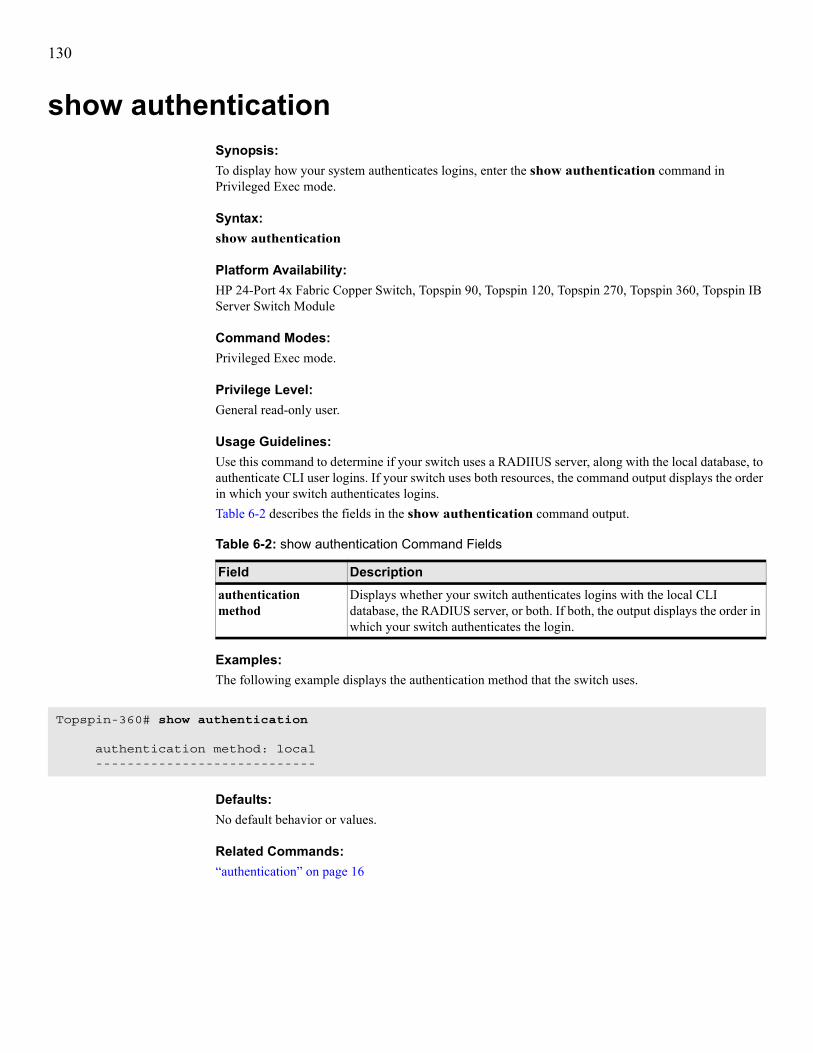
130
show authenticationSynopsis:To display how your system authenticates logins, enter the show authentication command in Privileged Exec mode.
Syntax:show authentication
Platform Availability:HP 24-Port 4x Fabric Copper Switch, Topspin 90, Topspin 120, Topspin 270, Topspin 360, Topspin IB Server Switch Module
Command Modes:Privileged Exec mode.
Privilege Level:General read-only user.
Usage Guidelines:Use this command to determine if your switch uses a RADIIUS server, along with the local database, to authenticate CLI user logins. If your switch uses both resources, the command output displays the order in which your switch authenticates logins.Table 6-2 describes the fields in the show authentication command output.
Examples:The following example displays the authentication method that the switch uses.
Defaults:No default behavior or values.
Related Commands:“authentication” on page 16
Table 6-2: show authentication Command Fields
Field Descriptionauthentication method
Displays whether your switch authenticates logins with the local CLI database, the RADIUS server, or both. If both, the output displays the order in which your switch authenticates the login.
Topspin-360# show authentication
authentication method: local ----------------------------

131
show backplaneSynopsis:To display a breakdown of Serial Electrically Erasable and Programmable Read-Only Memory (SEEPROM) details of your switch, enter the show backplane command in User Exec mode or Privileged Exec mode.
Syntax:show backplane
Platform Availability:HP 24-Port 4x Fabric Copper Switch, Topspin 90, Topspin 120, Topspin 270, Topspin 360
Command Modes:User Exec mode, Privileged Exec mode.
Privilege Level:General read-only user.
Usage Guidelines:The output of the show backplane command assists product support personnel.Table 6-3 describes the fields in the show backplane command output.
Table 6-3: show backplane Command Fields
Field Descriptionbase-mac-addr 24-bit base MAC address of this chassis.
chassis-id Factory-assigned, 64-bit chassis-identification number.
chassis-guid Factory-assigned GUID of the chassis.
product serial-number
Factory-assigned product serial number.
pca serial-number PCA serial number.
pca number PCA assembly number.
fru number FRU number for the actual switch (Topspin 90) or chassis (Topspin 360).

132
Examples:The following example displays the SEEPROM details of the switch backplane.
Defaults:No default behavior or values.
Related Commands:None.
Topspin-270> show backplane
================================================================================ Backplane Seeprom================================================================================base-mac-addr chassis-id chassis-guid --------------------------------------------------------------------------------0:5:ad:0:0:0 0x5ad000000197d 0x5ad000000197d
================================================================================ Backplane Seeprom================================================================================product pca pca fru serial-number serial-number number number --------------------------------------------------------------------------------0 PY-0405-00044 TOPSPIN-270 248

133
show boot-configSynopsis:To display the active system image that runs when your switch boots, enter the show boot-config command in User Exec mode or Privileged Exec mode.
Syntax:show boot-config
Platform Availability:HP 24-Port 4x Fabric Copper Switch, Topspin 90, Topspin 120, Topspin 270, Topspin 360
Command Modes:User Exec mode, Privileged Exec mode.
Privilege Level:General read-only user.
Usage Guidelines:The show boot-config command displays the image that initializes chassis firmware and configures the interfaces.This command lists the files that were used to bring up the system, the files to use the next time the system reboots, and the backup files to use in the event that the primary boot files are not available. Table 6-4 describes the fields in the show boot-config command output.
Examples:The following example displays the image that the switch boots.
Defaults:No default behavior or values
Table 6-4: show boot-config Command Fields
Field Descriptionslot-id Slot identifier of the controller card in use.
sw-version Version of the software image that initialized chassis components.
last-image-source Directory name of the active system image used to initialize chassis components.
primary-image-source Name and directory location of the active system image to use to initialize chassis components the next time the system boots.
Topspin-360# show boot-config============================================================================
System Boot Configuration============================================================================ slot-id : 1 sw-version : TopspinOS-1.1.3/build255 last-image-source : TopspinOS-1.1.3/build255 primary-image-source : TopspinOS-1.1.3/build255

134
Related Commands:“boot-config” on page 20“install” on page 45“reload” on page 63“show version” on page 293

135
show bridge-groupSynopsis:To display the attributes of bridge groups, enter the show bridge-group command in User Exec mode or Privileged Exec mode.
Syntax:show bridge-group [bridge-groupID#]
Platform Availability:Topspin 90, Topspin 360
Command Modes:User Exec mode, Privileged Exec mode.
Privilege Level:General read-only user.
Usage Guidelines:Table 6-6 describes the fields in the show bridge-group command output.
Table 6-5: Syntax Description
Syntax Descriptionbridge-groupID# Integer value that represents a bridge group. Use the bridge-group ID number to
view the attributes of one specific bridge group.
Table 6-6: show bridge-group Command Fields
Field Descriptionbridge-group-id Displays the integer-value identifier of the bridge group that the
administrator assigned with the bridge-group command.
bridge-group-name Displays the ASCII text string identifier that the administrator assigned with the bridge-group command.
subnet-prefix Displays the subnet prefix that the administrator assigned to the bridge group. If no output appears in this field, the administrator has not assigned a subnet prefix to this bridge group.
subnet-prefix-len Displays the length (in bits) of the subnet prefix that the administrator assigned to the bridge group.
eth-bridge-port Displays the trunk that the bridge group uses to connect to the Ethernet switch.
ib-bridge-port Displays the internal gateway slot#/port# of the bridge group.
eth-next-hop-addr Displays the Ethernet next hop address that the administrator configured with the bridge-group command.
ib-next-hop-addr Displays the IB next hop address that the administrator configured with the bridge-group command.
broadcast-forwarding Displays True if you enable broadcast-forwarding. Displays False if you disable broadcast forwarding.
loop-protection Displays one if you enable ARP Packet Painting. Displays ? if you disable ARP Packet Painting. .

136
Examples:The following example (output abridged) shows all bridge groups on the switch.
Defaults:Without an argument, the show bridge-group command shows all bridge groups.
Related Commands:“bridge-group” on page 117
multicast Displays true if the bridge group belongs to a multicast group. Displays false if the bridge group does not belong to a multicast group.
redundancy-group Displays the redundancy group to which the bridge group belongs.
admin-failover-priority Displays the administratively-configured failover priority of the bridge group.
oper-failover-priority Displays the dynamically-discovered failover priority of the bridge group:• 1 identifies the primary group.• 0 indicates that this group went down (another one took over).• 2, 3, 4 represents the current fail-over assignments. 2 means this group
will be the next one to take over, 3 takes over next, etc.• -1 indicates that catastrophic failure occurred during the fail-over
process. Contact Technical Support.
Table 6-6: show bridge-group Command Fields (Continued)
Field Description
Topspin-360# show bridge-group
================================================================================ Bridge Groups================================================================================ bridge-group-id : 11 bridge-group-name : subnet-prefix : 0.0.0.0 subnet-prefix-len : 0 eth-bridge-port : 3/1 (not tagged) ib-bridge-port : 3/2(gw) (pkey: ff:ff) eth-next-hop-addr : 0.0.0.0 ib-next-hop-addr : 0.0.0.0 broadcast-forwarding : false loop-protection-method : one multicast : false redundancy-group : 11 admin-failover-priority : 10 oper-failover-priority : 10

137
show cardSynopsis:To display the configuration, status, and Serial Electrically Erasable and Programmable Read Only Memory (SEEPROM) details of interface cards, enter the show card command in User Exec mode or Privileged Exec mode.
Syntax:show card {card-selection | all}
Platform Availability:HP 24-Port 4x Fabric Copper Switch, Topspin 90, Topspin 120, Topspin 270, Topspin 360, Topspin IB Server Switch Module
Command Modes:User Exec mode, Privileged Exec mode.
Privilege Level:General read-only user.
Usage Guidelines:• Use the show card 5 syntax format to display the details of one card.• Use the show card 5,9,14 syntax format to display the details of a list of cards.• Use the show card 5-9 syntax format to display the details of a range of cards.• Use the show card 5, 7-9, 14 syntax format to display the details of a list with ranges of cards.Table 6-8 describes the fields in the show card command output.
Table 6-7: show card Command Arguments
Argument Commandcard-selection Card, list of cards, or range of cards to view.
all Displays the details of all interface cards in your switch.
Table 6-8: show card Command Fields
Field Descriptionslot Displays the number of the slot that the card occupies.

138
admin type Displays the type of the interface card that the administrator specified with the type command. The first two letters of the entry indicate the general type of the card:• en for Ethernet• ib for IB• fc for FCThe number of ports on the card follow the two-letter type identifier. The remaining number and letter identify the speed of the ports on the card. The admin type fc2port2G indicates a FC card with two ports that run at a maximum speed of 2 Gbps.
NOTE: The controller and controllerIb12port4x cards serve as an exception to these rules.
The admin type identifier controller indicates the type of independent controller card found on both sides of the switch chassis. The admin type identifier controllerIb12port4x indicates a controller card that piggy-backs onto a 12-port IB switch card where each port connection can support speeds up to 4X.
oper type Displays the type of the card as detected by the controller. If any conflict occurs between admin type and oper type, the switch assumes that the type specified by oper type is correct and allows you to configure the card based upon this assumption. If a type mismatch occurs, verify that you are selecting the correct type for the card in the chassis.
admin status Displays the administrative status (that you configure with the shutdown and no shutdown commands) of the port.
oper status Displays the operational status as detected by the controller. This represents the absolute status of the interface card based upon self detection. The value of this read-only field appears as one of the following:• unknown, which generally indicates that an error occurred when the card
booted• up, which indicates that the card successfully runs• down, which indicates that a user disabled the card with the shutdown
command• failure, which indicates that the card failed to boot correctlyThe up indicator means that your card runs successfully. You can only configure cards with an operational status of up.
Table 6-8: show card Command Fields (Continued)
Field Description

139
oper code Displays the general condition of the interface card. The general condition may appear as any of the following:• unknown• normal• wrongBootImage• bootFailed• tooHot• checkingBootImage• rebooting• booting• standby• recoveryImageA condition of unknown indicates an unsupported interface card. To address this condition, replace the card with a supported card.The oper code of a card must appear as normal for the oper status of the card to appear as up.A wrongBootImage condition indicates that the active system image on the interface card does not match the active system image on the controller. All cards must run the same active system image as the controller card to function.A bootFailed condition indicates that the active system image on the card was incompletely or incorrectly loaded. If the other interface cards come up successfully, reset the individual card. Otherwise, reboot your entire switch.When your card overheats, the tooHot condition appears in the show card command output. Enter the show fan command to check to see if your fans have failed.The booting condition indicates that the card has not finished loading necessary image data for internal configuration.
boot stage Boot Stage could be any of the following:• recovery• ipl • ppcboot • fpga • pic • ib • rootfs • kernel • exe • done
Table 6-8: show card Command Fields (Continued)
Field Description

140
boot status Boot Status may appear as any of the following:• upgrading• success• failed• badVersion• badCrc• memoryError• outOfSpace• programmingError• hardwareError • fileNotFound • inProgress
boot image Displays the active system image that the card runs when it boots.
product serial-number Displays the factory-assigned product serial number of the card.
pca serial-number Displays the (PCA serial number of the card.
pca number Displays the PCA assembly number of the card.
fru number Displays the FRU number of the card.
Table 6-8: show card Command Fields (Continued)
Field Description

141
Examples:The following example displays the configuration and status information for cards 5, 9, 14, and 16.
Defaults:The show card command displays all cards by default.
Related Commands:“action” on page 13“boot-config” on page 20“card” on page 23“install” on page 45“shutdown” on page 66“type” on page 79
Topspin-360# show card 5,9,14,16============================================================================ Card Information============================================================================ admin oper admin oper operslot type type status status code----------------------------------------------------------------------------5 en4port1G en4port1G up up normal9 fc2port2G fc2port2G up up normal14 controller controller up up normal16 ib12port4x ib12port4x up up normal
============================================================================ Card Boot Information============================================================================ boot boot bootslot stage status image----------------------------------------------------------------------------5 done success TopspinOS-1.1.2/build0849 done success TopspinOS-1.1.2/build08414 done success TopspinOS-1.1.2/build08416 done success TopspinOS-1.1.2/build084
============================================================================ Card Seeprom============================================================================ product pca pca fruslot serial-number serial-number number number----------------------------------------------------------------------------5 00024 1234 95-00007-01 12349 1234 1234 95-00008-01 123414 00002 00002 95-00005-01 123416 1234 1234 95-00006-01 1234Topspin-360#

142
show card-inventorySynopsis:To display the system resources and image data of interface cards, enter the show card-inventory command in User Exec mode or Privileged Exec mode.
NOTE: The show card-inventory command only displays cards with an oper-status of up.
Syntax:show card-inventory [card-selection | all]
Platform Availability:HP 24-Port 4x Fabric Copper Switch, Topspin 90, Topspin 120, Topspin 270, Topspin 360, Topspin IB Server Switch Module
Command Modes:User Exec mode, Privileged Exec mode.
Privilege Level:General read-only user.
Usage Guidelines:Each Topspin interface card is a system in itself. The following comprise system resources:• available and used memory• available and used flash memory• active system image on the interface card• CPU name and versionThe active system image should match the active image that runs on the controller card. Occasions may occur when you update the system image on the controller but not on an interface card, such as when you swap interface cards between chassis or update the system image on the controller when an interface card goes down. Disk space may be an issue if you try to update the system image on the controller but cannot propagate this data to the interface card because the interface card has no free space.The CPU description may be requested by HP support-personnel in the event you are experiencing difficulties with a controller or interface card.Table 6-10 describes the fields in the show card-inventory command output.
Table 6-9: show card-inventory Command Arguments
Argument Descriptioncard-selection Card, list of cards, or range of cards to view.
all Displays resources and data of all cards in the chassis.
Table 6-10: show card-inventory Command Fields
field descriptionslot-id Slot number of the controller card, gateway module, or IB switch.
used-memory Total amount of local RAM being used by the card.

143
Examples:The following example displays the configuration and status information for the cards on the switch.
Defaults:The show card-inventory defaults to show card-inventory all.
Related Commands:“boot-config” on page 20“card” on page 23
free-memory Total amount of available local RAM.
used-disk-space Total amount of local flash memory space being used by the card.
free-disk-space Total amount of available local flash memory space.
last-image-source Last image that the card booted.
primary-image-source
Active system image to use when the system reboots. This value should be the same for all cards in the system.
image If only one instance of the image field appears, it indicates the system image used to initialize the card firmware. If there are two instances of the image field, the second instance indicates a second system image present on the card.
cpu-descr CPU type, model, and firmware version.
fpga-firmware-rev Current FPGA firmware version that the card runs.
ib-firmware-rev Version of IB firmware on the card.
Table 6-10: show card-inventory Command Fields (Continued)
field description
Topspin-360# show card-inventory
================================================================================
Card Resource/Inventory Information================================================================================
slot-id : 1 used-memory : 73936 (kbytes) free-memory : 53368 (kbytes) used-disk-space : 44833 (kbytes) free-disk-space : 57546 (kbytes) last-image-source : TopspinOS-2.0.0/build543 primary-image-source : TopspinOS-2.0.0/build543 image : TopspinOS-2.0.0/build543 cpu-descr : PPC 440GP Rev. C - Rev 4.129 (pvr 4012 0481) fpga-firmware-rev : 6 ib-firmware-rev : 200000000

144
show clockSynopsis:To display the current system time, enter the show clock command in User Exec mode or Privileged Exec mode.
Syntax:show clock
Platform Availability:HP 24-Port 4x Fabric Copper Switch, Topspin 90, Topspin 120, Topspin 270, Topspin 360, Topspin IB Server Switch Module
Command Modes:User Exec mode, Privileged Exec mode.
Privilege Level:Unrestricted read-write user.
Usage Guidelines:If you have not set the clock, system time begins at 00:00:00, January 1, 1970.
Examples:The following example displays the clock settings of the switch.
Defaults:No default behavior or values.
Related Commands:“clock set” on page 24
Topspin-360# show clockMon Mar 17 02:26:32 2003 (UTC)Topspin-360#

145
show diagnostic cardSynopsis:To display completed or ongoing diagnostic tests for cards, enter the show diagnostic card command in User Exec mode or Privileged Exec mode.
Syntax:show diagnostic card {all | card-selection}
Platform Availability:HP 24-Port 4x Fabric Copper Switch, Topspin 90, Topspin 120, Topspin 270, Topspin 360, Topspin IB Server Switch Module
Command Modes:User Exec mode, Privileged Exec mode.
Privilege Level:Unrestricted read-write user.
Usage Guidelines:Table 6-12 lists and describes the fields in the show diagnostic card command.
Table 6-11: show diagnostic card Command Arguments
Argument Descriptionall Specifies all cards on the switch.
card-selection Card or cards whose tests you want to view.
Table 6-12: show diagnostic card Command Fields
Field Descriptiontest Test that ran or runs on the card.
slot-id Slot of the card.
iterations Number of iterations that the test completed.
action Last action that an administrator applied to the test.
result Result of the last action that an administrator applied to the test.
percentage-completed Percentage of the test that has executed.
result-string Diagnostic test results.

146
Examples:The following example displays the completed and ongoing diagnostic tests on card 3.
Defaults:No default behavior or values.
Related Commands:“diagnostic” on page 297“test” on page 306
Topspin-360# show diag card 3
================================================================================ Diagnostic Tests For Cards================================================================================ test : led slot-id : 3 iterations : 1 action : start result : invalidValue percentage-completed : 0 result-string :

147
show diagnostic fanSynopsis:To display completed or ongoing diagnostic tests for fans, enter the show diagnostic fan command in User Exec mode or Privileged Exec mode.
Syntax:show diagnostic fan {all | fan-selection}
Platform Availability:HP 24-Port 4x Fabric Copper Switch, Topspin 120, Topspin 270
Command Modes:User Exec mode, Privileged Exec mode.
Privilege Level:Unrestricted read-write user.
Usage Guidelines:Table 6-14 lists and describes the fields in the show diagnostic fan command.
Table 6-13: show diagnostic card Command Arguments
Argument Descriptionall Specifies all fans on the switch.
fan-selection Fan or fans whose tests you want to view.
Table 6-14: show diagnostic card Command Fields
Field Descriptiontest Test that ran or runs on the card.
slot-id Slot of the card.
iterations Number of iterations that the test completed.
action Last action that an administrator applied to the test.
result Result of the last action that an administrator applied to the test.
percentage-completed Percentage of the test that has executed.
result-string Diagnostic test results.

148
Examples:The following example displays the completed and ongoing diagnostic tests on card 3.
Defaults:No default behavior or values.
Related Commands:“diagnostic” on page 297“test” on page 306
Topspin-360# show diag card 3
================================================================================ Diagnostic Tests For Cards================================================================================ test : led slot-id : 3 iterations : 1 action : start result : invalidValue percentage-completed : 0 result-string :

149
show diagnostic interface ethernetSynopsis:To display completed or ongoing diagnostic tests for Ethernet gateway ports, enter the show diagnostic interface ethernet command in User Exec mode or Privileged Exec mode.
Syntax:show diagnostic interface ethernet {port | all}
Platform Availability:Topspin 90, Topspin 360
Command Modes:User Exec mode, Privileged Exec mode.
Privilege Level:Ethernet read-only user.
Usage Guidelines:Table 6-16 lists and describes the fields in the show diagnostic interface ethernet command.
Table 6-15: show diagnostic card Command Arguments
Argument Descriptionport Ethernet port, in slot#/port# notation.
all Specifies all Ethernet ports on the switch.
Table 6-16: show diagnostic interface ethernet Command Fields
Field Descriptiontest Test that ran or runs on the card.
port Ethernet port number, in slot#/port# format.
validation Displays enabled or disabled to indicate validation status.
data-size Size of the test data.
data-pattern Pattern of the test data.
iterations Number of iterations of the test.
action Last action that an administrator performed on the test.
result Result of the last action that an administrator performed on the test.
percentage-completed Percentage of the test that has executed.
result-string Result of the diagnostic test.

150
Examples:The following example displays the completed and ongoing diagnostic tests on port 1 of Ethernet gateway 9.
Defaults:No default behavior or values.
Related Commands:“diagnostic” on page 297“test” on page 306
Topspin-360# show diagnostic interface ethernet 9/1
================================================================================ Diagnostic Tests For Ethernet Interfaces================================================================================ test : led port : 9/1 validation : enabled data-size : 0 data-pattern : 00:00:00:00 iterations : 0 action : stop result : none percentage-completed : 0 result-string : Unknown Test Unknown status, Current report : Passed=0, Failed=0, Total=0

151
show diagnostic interface fcSynopsis:To display completed or ongoing diagnostic tests for FC gateway ports, enter the show diagnostic interface fc command in User Exec mode or Privileged Exec mode.
Syntax:show diagnostic interface fc {port | all}
Platform Availability:Topspin 90, Topspin 360
Command Modes:User Exec mode, Privileged Exec mode.
Privilege Level:FC read-only user.
Usage Guidelines:Table 6-18 lists and describes the fields in the show diagnostic interface fc command.
Table 6-17: show diagnostic card Command Arguments
Argument Descriptionport Ethernet port, in slot#/port# notation.
all Specifies all Ethernet ports on the switch.
Table 6-18: show diagnostic card Command Fields
Field Descriptiontest Test that ran or runs on the card.
port FC port number, in slot#/port# format.
validation Displays enabled or disabled to indicate validation status.
data-size Size of the test data.
data-pattern Pattern of the test data.
iterations Number of iterations of the test.
source-id Source WWPN for the test.
target-id Target WWPN for the test.
action Last action that an administrator performed on the test.
result Result of the last action that an administrator performed on the test.
percentage-completed Percentage of the test that has executed.
result-string Result of the diagnostic test.
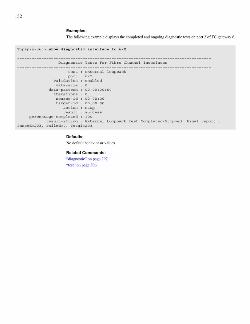
152
Examples:The following example displays the completed and ongoing diagnostic tests on port 2 of FC gateway 6.
Defaults:No default behavior or values.
Related Commands:“diagnostic” on page 297“test” on page 306
Topspin-360> show diagnostic interface fc 6/2
================================================================================ Diagnostic Tests For Fibre Channel Interfaces================================================================================ test : external-loopback port : 6/2 validation : enabled data-size : 0 data-pattern : 00:00:00:00 iterations : 0 source-id : 00:00:00 target-id : 00:00:00 action : stop result : success percentage-completed : 100 result-string : External Loopback Test Completed/Stopped, Final report : Passed=203, Failed=0, Total=203

153
show diagnostic interface ibSynopsis:To display completed or ongoing diagnostic tests for IB switch ports, enter the show diagnostic interface ib command in User Exec mode or Privileged Exec mode.
Syntax:show diagnostic interface ib {port | all}
Platform Availability:HP 24-Port 4x Fabric Copper Switch, Topspin 90, Topspin 120, Topspin 270, Topspin 360, Topspin IB Server Switch Module
Command Modes:User Exec mode, Privileged Exec mode.
Privilege Level:IB read-only user.
Usage Guidelines:Table 6-20 lists and describes the fields in the show diagnostic interface ib command.
Table 6-19: show diagnostic card Command Arguments
Argument Descriptionport Ethernet port, in slot#/port# notation.
all Specifies all Ethernet ports on the switch.
Table 6-20: show diagnostic card Command Fields
Field Descriptiontest Test that ran or runs on the card.
port IB port number, in slot#/port# format.
validation Displays enabled or disabled to indicate validation status.
data-size Size of the test data.
data-pattern Pattern of the test data.
iterations Number of iterations of the test.
source-id Source LID for the test.
target-id Target LID for the test.
action Last action that an administrator performed on the test.
result Result of the last action that an administrator performed on the test.
percentage-completed Percentage of the test that has executed.
result-string Result of the diagnostic test.

154
Examples:The following example displays the completed and ongoing diagnostic tests on port 1 of IB switch card 16.
Defaults:No default behavior or values.
Related Commands:“diagnostic” on page 297“test” on page 306
Topspin-360> show diagnostic interface ib 16/1
================================================================================ Diagnostic Tests For IB Interfaces================================================================================ test : external-loopback port : 16/1 validation : enabled data-size : 0 data-pattern : 00:00:00:00 iterations : 0 source-id : 00:00:00 target-id : 00:00:00 action : stop result : none percentage-completed : 0 result-string : External Loopback Test Unknown status, Current report : Passed=0, Failed=0, Total=0
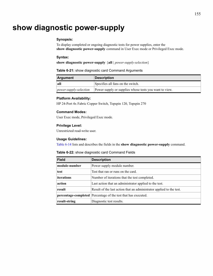
155
show diagnostic power-supplySynopsis:To display completed or ongoing diagnostic tests for power supplies, enter the show diagnostic power-supply command in User Exec mode or Privileged Exec mode.
Syntax:show diagnostic power-supply {all | power-supply-selection}
Platform Availability:HP 24-Port 4x Fabric Copper Switch, Topspin 120, Topspin 270
Command Modes:User Exec mode, Privileged Exec mode.
Privilege Level:Unrestricted read-write user.
Usage Guidelines:Table 6-14 lists and describes the fields in the show diagnostic power-supply command.
Table 6-21: show diagnostic card Command Arguments
Argument Descriptionall Specifies all fans on the switch.
power-supply-selection Power supply or supplies whose tests you want to view.
Table 6-22: show diagnostic card Command Fields
Field Descriptionmodule-number Power supply module number.
test Test that ran or runs on the card.
iterations Number of iterations that the test completed.
action Last action that an administrator applied to the test.
result Result of the last action that an administrator applied to the test.
percentage-completed Percentage of the test that has executed.
result-string Diagnostic test results.

156
Examples:The following example displays the completed and ongoing diagnostic tests on all power supplies.
Defaults:No default behavior or values.
Related Commands:None.
Topspin-270> show diagnostic power-supply all
================================================================================ Diagnostic Tests For Power Supplies================================================================================ module-number : 1 test : none iterations : 1 action : stop result : none percentage-completed : 0 result-string :

157
show configSynopsis:To display the running configuration, enter the show config command in User Exec mode or Privileged Exec mode.
Syntax:show config
Platform Availability:HP 24-Port 4x Fabric Copper Switch, Topspin 90, Topspin 120, Topspin 270, Topspin 360, Topspin IB Server Switch Module
Command Modes:User Exec mode, Privileged Exec mode.
Privilege Level:Unrestricted read-write user.
Usage Guidelines:The show config command displays the current configuration as a series of commands in the format that you use when you execute commands in a CLI session. This command queries all active service components to collect their current configuration data and translates the data into a CLI command format.This record of the configuration may be saved, edited, and reused to replicate a configuration.
Examples:The following example displays the running configuration on the switch:
Defaults:No default behavior or values.
Related Commands:“copy” on page 28“history” on page 43
Topspin-90# show configenableconfig terminalcard 2type en4port1Gno shutdownib sm subnet-prefix fe:80:00:00:00:00:00:00 priority 0interface gateway 2ip address 192.168.2.1 255.255.255.0interface ethernet 2/1ip address 192.168.1.1 255.255.255.0interface ethernet 2/2ip address 192.168.3.1 255.255.255.0arp ib 192.168.2.2 gid fe:80:00:00:00:00:00:00:00:02:c9:00:00:13:68:c3 qpn 2 2/0arp ib 192.168.2.3 gid fe:80:00:00:00:00:00:00:00:02:c9:00:00:16:af:d3 qpn 2 2/0Topspin-90#

158
show fanSynopsis:To display the status of the fans in your switch, enter the show fan command in User Exec mode or Privileged Exec mode.
Syntax:show fan
Platform Availability:HP 24-Port 4x Fabric Copper Switch, Topspin 90, Topspin 120, Topspin 270, Topspin 360
Command Modes:User Exec mode, Privileged Exec mode.
Privilege Level:General read-only user.
Usage Guidelines:For the health of your switch, you want both fans to function while your switch runs. If the operational status of a fan appears as down, contact customer support for a fan module replacement.Table 6-23 describes the fields in the show fan command output.
Table 6-23: show fan Command Fields
field descriptionfan Fan number. Fan 1 resides on the left-side as you are facing the front of the
chassis. Fan 2 resides on the right-side of the chassis.
oper status Operational status of the fan. The value appears as unknown, up, down, or failure. An up value indicates the fan functions correctly.
speed (%) Speed of the fan as a percentage of the maximum speed of the fan.
product serial number
Factory-assigned product serial-number.
pca serial-number PCA serial-number.
pca number PCA assembly-number.
fru number FRU number.

159
Examples:The following example displays the fan settings on the switch.
Defaults:No default behavior or values.
Related Commands:“show power-supply” on page 276“show sensor” on page 282
Topspin-270> show fan
================================================================================ Fan Information================================================================================fan oper-status speed(%) --------------------------------------------------------------------------------1 up 76 2 up 77 3 up 74 4 up 77
================================================================================ Fan Seeprom================================================================================ product pca pca fru fan serial-number serial-number number number --------------------------------------------------------------------------------1 - - - - 2 - - - - 3 - - - - 4 - - - -

160
show fc srp initiatorSynopsis:To display the attributes of initiators that you have configured on your switch, enter the show fc srp initiator command in User Exec mode or Privileged Exec mode.
Syntax:show fc srp initiator [guid extension]
Platform Availability:Topspin 90, Topspin 360
Command Modes:User Exec mode, Privileged Exec mode.
Privilege Level:FC read-only user.
Usage Guidelines:This command displays active and inactive initiators.Enter this command without any arguments to display the initiator information for all configured SRP initiators. If you specify a GUID, you must also specify the extension.
NOTE: Initiators do not need to connect to the switch to appear in the show output. As long as you configured them, they appear in the command output.
Table 6-24: show fc srp initiator Command Syntax Description
Syntax Descriptionguid GUID of the initiator to view.
extension GUID extension of the initiator to view.
Table 6-25: show fc srp initiator Command Fields
Field Descriptionguid GUID of the initiator.
extension GUID extension of the initiator.
description User-assigned ASCII description of the initiator.
wwnn Worldwide node name (WWNN) of the initiator.
credit Indicates the amount of traffic that the initiator can accept.
active-ports IB ports on your switch through which the initiator passes traffic.
pkeys Partition key(s) of the initiator.
action Last action that the initiator took.
result Result of the action that appears in the action field. Any result other than Operation completed successfully occur due to interface errors.
wwpns World-wide port names (WWPNs) of the virtual ports (NL_ports) that point to the initiator.
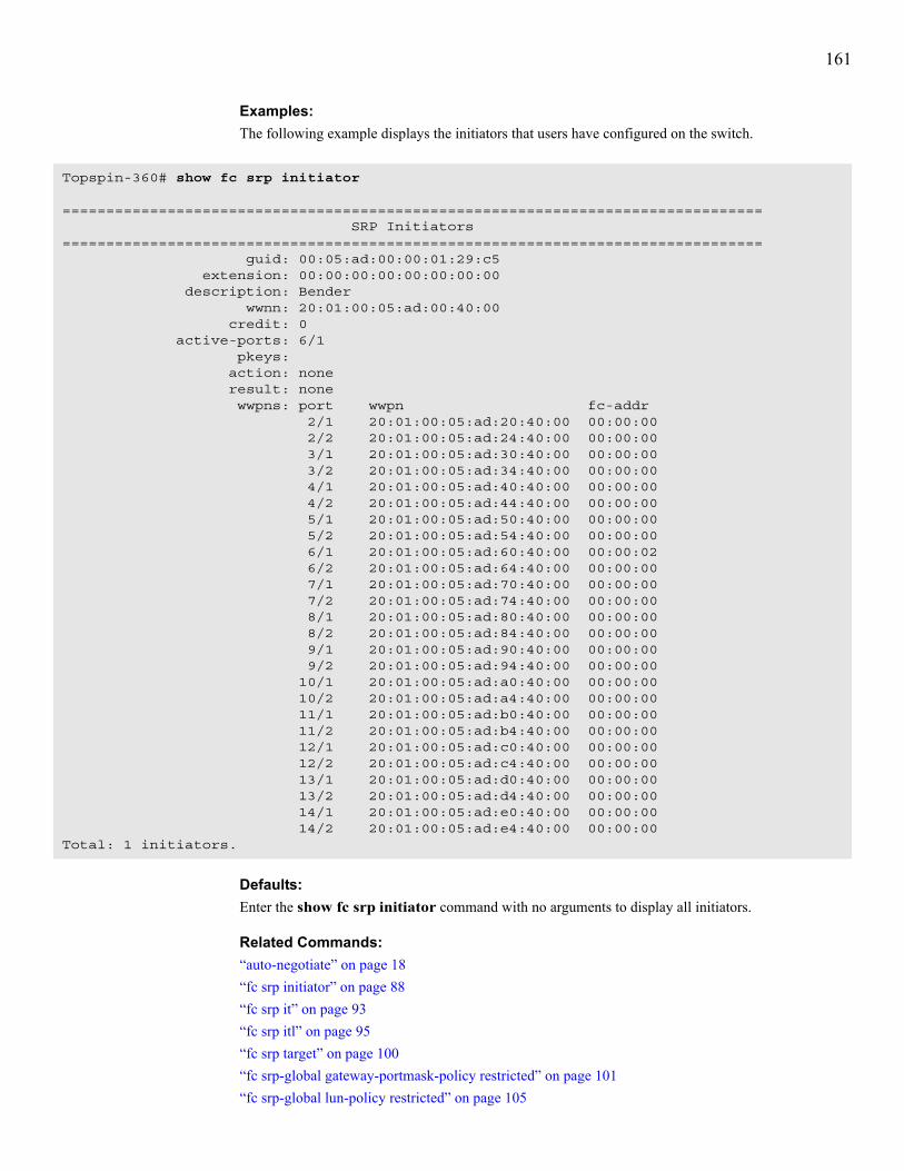
161
Examples:The following example displays the initiators that users have configured on the switch.
Defaults:Enter the show fc srp initiator command with no arguments to display all initiators.
Related Commands:“auto-negotiate” on page 18“fc srp initiator” on page 88“fc srp it” on page 93“fc srp itl” on page 95“fc srp target” on page 100“fc srp-global gateway-portmask-policy restricted” on page 101“fc srp-global lun-policy restricted” on page 105
Topspin-360# show fc srp initiator
================================================================================ SRP Initiators================================================================================ guid: 00:05:ad:00:00:01:29:c5 extension: 00:00:00:00:00:00:00:00 description: Bender wwnn: 20:01:00:05:ad:00:40:00 credit: 0 active-ports: 6/1 pkeys: action: none result: none wwpns: port wwpn fc-addr 2/1 20:01:00:05:ad:20:40:00 00:00:00 2/2 20:01:00:05:ad:24:40:00 00:00:00 3/1 20:01:00:05:ad:30:40:00 00:00:00 3/2 20:01:00:05:ad:34:40:00 00:00:00 4/1 20:01:00:05:ad:40:40:00 00:00:00 4/2 20:01:00:05:ad:44:40:00 00:00:00 5/1 20:01:00:05:ad:50:40:00 00:00:00 5/2 20:01:00:05:ad:54:40:00 00:00:00 6/1 20:01:00:05:ad:60:40:00 00:00:02 6/2 20:01:00:05:ad:64:40:00 00:00:00 7/1 20:01:00:05:ad:70:40:00 00:00:00 7/2 20:01:00:05:ad:74:40:00 00:00:00 8/1 20:01:00:05:ad:80:40:00 00:00:00 8/2 20:01:00:05:ad:84:40:00 00:00:00 9/1 20:01:00:05:ad:90:40:00 00:00:00 9/2 20:01:00:05:ad:94:40:00 00:00:00 10/1 20:01:00:05:ad:a0:40:00 00:00:00 10/2 20:01:00:05:ad:a4:40:00 00:00:00 11/1 20:01:00:05:ad:b0:40:00 00:00:00 11/2 20:01:00:05:ad:b4:40:00 00:00:00 12/1 20:01:00:05:ad:c0:40:00 00:00:00 12/2 20:01:00:05:ad:c4:40:00 00:00:00 13/1 20:01:00:05:ad:d0:40:00 00:00:00 13/2 20:01:00:05:ad:d4:40:00 00:00:00 14/1 20:01:00:05:ad:e0:40:00 00:00:00 14/2 20:01:00:05:ad:e4:40:00 00:00:00Total: 1 initiators.

162
“speed” on page 72

163
show fc srp initiator-wwpn-viewSynopsis:To display SRP targets that an initiator can access through one of its virtual ports, enter the show fc srp initiator-wwpn-view command in User Exec mode or Privileged Exec mode.
Syntax:show fc srp initiator-wwpn-view wwpn target
Platform Availability:Topspin 90, Topspin 360
Command Modes:User Exec mode, Privileged Exec mode.
Privilege Level:FC read-only user.
Usage Guidelines:Use this command to verify that your initiator connects to all of the targets that you configured for it.Table 6-27 lists and describes the fields in the show fc srp initiator-wwpn-view command output.
Table 6-26: Syntax Description
Syntax Descriptionwwpn WWPN of the virtual port of the initiator.
target Displays the targets that your initiator can access through the virtual port.
Table 6-27: show fc srp initiator-wwpn-view Command Fields
Field Descriptionwwpn WWPN of the target port that the initiator can access through the virtual port.
wwnn WWNN of the target.
description Description of the target.
ioc-guid GUID of the I/O controller of the target.
service-name Service name of the target.
protocol-ids Protocols that the target supports.
fc-address FC address of the target.
mtu MTU, in bytes, of the target.
connection-type Displays nl-port to indicate a virtual FC port.
physical-access Physical FC port (in slot#/port# format) of the virtual port.

164
Examples:The following example displays the targets that the initiator can access through the specified virtual port.
Defaults:No default behavior or values.
Related Commands:“fc srp initiator” on page 88“fc srp-global lun-policy restricted” on page 105“show fc srp initiator” on page 160
Topspin-360> show fc srp initiator-wwpn-view 20:03:00:05:ad:21:5a:5c target
================================================================================ SRP Targets Accessible to Initiator Via Port WWN 20:03:00:05:ad:51:5a:5c================================================================================ wwpn: 20:01:00:60:45:17:36:1c wwnn: 20:09:00:60:45:17:36:1c description: SRP.T10:200100604517361C ioc-guid: 00:05:ad:00:00:01:38:80 service-name: SRP.T10:200100604517361C protocol-ids: 04:00:00:00:00:00:00:00:00:00 fc-address: 61:1b:13 mtu: 0 connection-type: nl-port physical-access: 5/1-5/2,7/1

165
show fc srp itSynopsis:To display initiator-target pairs that you have configured or that your switch has discovered, enter the show fc srp it command in User Exec mode or Privileged Exec mode.
Syntax:show fc srp it [guid extension target-wwpn]
Platform Availability:Topspin 90, Topspin 360
Command Modes:User Exec mode, Privileged Exec mode.
Privilege Level:Unrestricted read-write user.
Usage Guidelines:Use this command to verify you successfully created IT pairs on your switch.
Table 6-28: show fc srp it Syntax Description
Syntax Descriptionguid GUID of the initiator in the IT pair.
extension GUID extension of the initiator in the IT pair.
target-wwpn WWPN of the target FC storage port in the IT pair.
Table 6-29: show fc srp it Command Output Fields
Field Descriptionguid GUID of the initiator in the IT pair.
extension GUID extension of the initiator in the IT pair.
target-wwpn WWPN of the target storage.
description User-assigned description of the IT pair.
non-restricted-ports Ports on your switch that grant the initiator of the IT pair access to storage.
active-ports Ports on your switch through which the initiator of the IT pair passes traffic.
physical-access Physical port(s) on your switch to which the initiator of the IT pair connects.
action Last action that the initiator of the IT pair took.
result Result of the action that appears in the action field. Any result other than Operation completed successfully occurs due to interface errors.
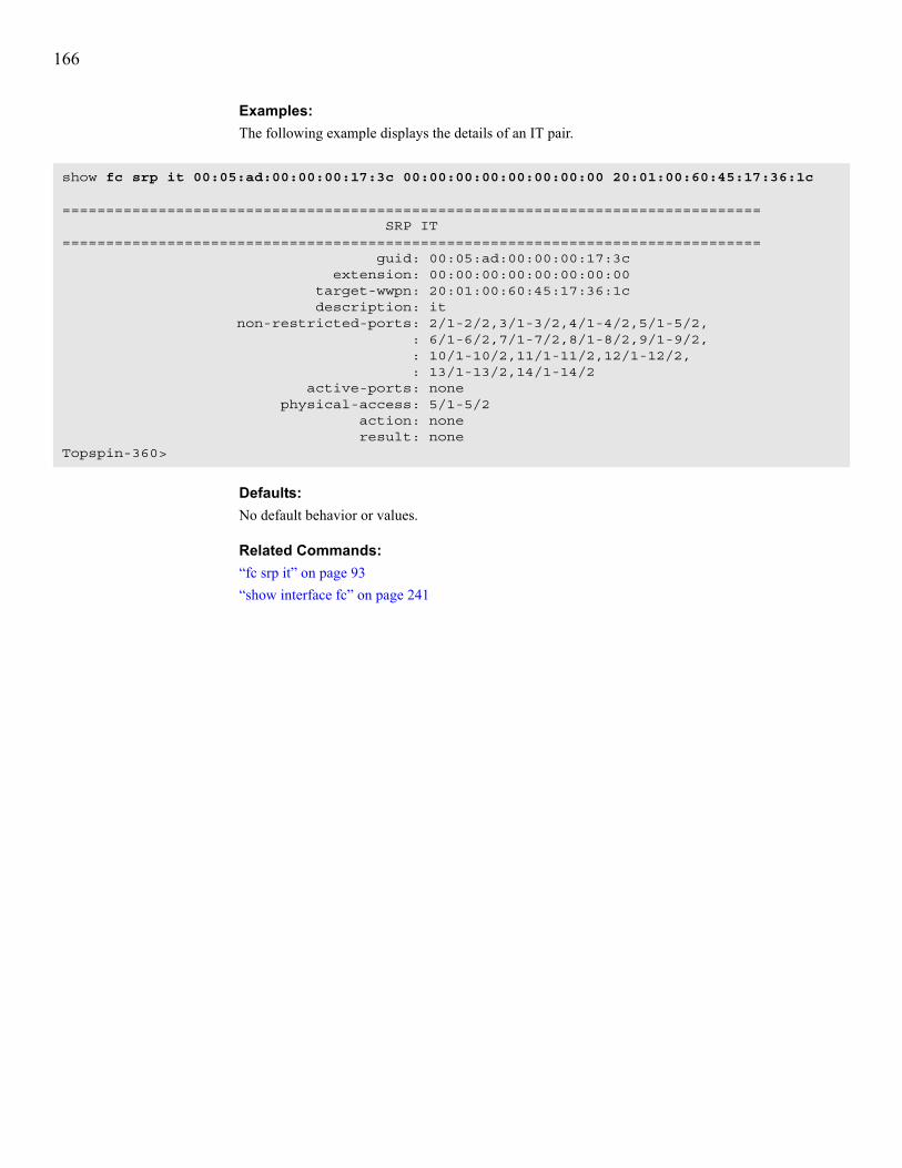
166
Examples:The following example displays the details of an IT pair.
Defaults:No default behavior or values.
Related Commands:“fc srp it” on page 93“show interface fc” on page 241
show fc srp it 00:05:ad:00:00:00:17:3c 00:00:00:00:00:00:00:00 20:01:00:60:45:17:36:1c
================================================================================ SRP IT================================================================================ guid: 00:05:ad:00:00:00:17:3c extension: 00:00:00:00:00:00:00:00 target-wwpn: 20:01:00:60:45:17:36:1c description: it non-restricted-ports: 2/1-2/2,3/1-3/2,4/1-4/2,5/1-5/2, : 6/1-6/2,7/1-7/2,8/1-8/2,9/1-9/2, : 10/1-10/2,11/1-11/2,12/1-12/2, : 13/1-13/2,14/1-14/2 active-ports: none physical-access: 5/1-5/2 action: none result: noneTopspin-360>

167
show fc srp itlSynopsis:To display all ITLs that run through your switch, enter the show fc srp itl command in User Exec mode or Privileged Exec mode.
Syntax:show fc srp itl [guid extension wwpn LUN]
Platform Availability:Topspin 90, Topspin 360
Command Modes:User Exec mode, Privileged Exec mode.
Privilege Level:Unrestricted read-write user.
Usage Guidelines:Enter this command without arguments to display the ITL information for all connected FC devices. This command displays active and inactive ITLs.Table 6-31 describes the fields in the show fc srp itl command output.
Table 6-30: show fc srp itl Command Arguments
Argument Descriptionguid Global unique identifier (GUID) of the initiator.
extension GUID extension of the initiator.
wwpn World-wide port name (WWPN) of the target port on the FC storage device.
LUN Logical unit number (LUN) of the FC storage device.
Table 6-31: show fc srp itl Command Fields
Field Descriptionguid GUID of the initiator.
extension GUID extension of the initiator.
target-wwpn WWPN of the target port on the FC storage device.
fc-lunid FC LUN ID of the storage disk/tape/stripe.
description User-configured description.
srp-lunid Internal SRP LUN ID. This value serves as a SRP-side alias for a FC LUN ID. By default, the srp-lunid value matches the LUN variable.
logical-id (raw 64 bytes) Numeric disk LU.
logical-id (formatted display) Alphanumeric disk LU.
use-default-mask No longer applicable.
gateway-port-mask-policy Displays a list of unrestricted ports though which the ITL traffic can pass.

168
lun-policy Displays restricted when you activate the LUN masking policy and non-restricted when you deactivate the policy.
hi-mark The maximum number of outstanding requests from the initiator to the storage that the ITL can maintain.
max-retry Configures the maximum number of retries that the initiator can send to the storage device.
min-io-timeout Maximum amount of time, in seconds, that elapses before a SRP request times out.
dynamic-path-affinity Displays true when you enable the feature, otherwise displays false.
dynamic-gateway-port-loadbalancing
Displays true when you enable the feature, otherwise displays false.
dynamic-storage-port-loadbalancing Displays true when you enable the feature, otherwise displays false. If this feature does not apply to the storage, no output appears.
dynamic-gateway-port-failover Displays true when you enable the feature, otherwise displays false.
dynamic-storage-port-failover Displays true when you enable the feature, otherwise displays false. If this feature does not apply to the storage, no output appears.
active-slots Slots on which ITL traffic actively runs.
Table 6-31: show fc srp itl Command Fields (Continued)
Field Description

169
Examples:The following example displays the ITLs in the configuration file on the switch.
Defaults:Enter the show fc srp itl command without any arguments to display all ITLs on your switch.
Related Commands:“fc srp itl” on page 95“interface” on page 47“show fc srp it” on page 165“show interface fc” on page 241
Topspin-360# show fc srp itl
================================================================================ SRP ITL================================================================================ guid: 00:05:ad:00:00:01:29:c5 extension: 00:00:00:00:00:00:00:00 target-wwpn: 21:00:00:04:cf:f6:c2:ab fc-lunid: 00:00:00:00:00:00:00:00 srp-lunid: 00:00:00:00:00:00:00:00 logical-id (raw 64 bytes): 01:03:00:08:20:00:00:04:cf:f6:c2:ab:00:00:00:00 : 00:00:00:00:00:00:00:00:00:00:00:00:00:00:00:00 : 00:00:00:00:00:00:00:00:00:00:00:00:00:00:00:00 : 00:00:00:00:00:00:00:00:00:00:00:00:00:00:00:00 logical-id (formatted display): 2000000000000000 description: itl device-category: random lun-policy: non restricted non-restricted-ports: none active-ports: 6/1 physical-access: 6/1 hi-mark: 16 max-retry: 5 min-io-timeout: 10 dynamic-path-affinity: false dynamic-gateway-port-loadbalancing: true dynamic-storage-port-loadbalancing: dynamic-gateway-port-failover: false dynamic-storage-port-failover: active-slots: 6
Total: 1 itls.

170
show fc srp itl-statisticsSynopsis:To display ITL I/O statistics, enter the show fc srp itl-statistics command in User Exec mode or Privileged Exec mode.
Syntax:show fc srp itl-statistics [guid extension wwpn LUN]
Platform Availability:Topspin 90, Topspin 360
Command Modes:User Exec mode, Privileged Exec mode.
Privilege Level:FC read-only user.
Usage Guidelines:Enter this command without any arguments to display the SRP/FC statistics for every ITL.Table 6-33 lists and describes the output of the show fc srp itl-statistics command.
Table 6-32: show fc srp itl Command Arguments
Argument Descriptionguid GUID of the initiator.
extension GUID extension of the initiator.
wwpn WWPN of the target port on the FC storage device.
LUN LUN of the FC storage device.
Table 6-33: show fc srp itl-statistics Command Fields
Field Descriptionguid GUID of the initiator.
extension GUID extension of the initiator.
target-wwpn WWPN of the target.
srp-lunid LUN ID of the LUN in the ITL.
slot-id Slot on the switch in which the FC gateway resides.
srp-cmds-outstanding Cumulative number of outstanding SRP commands.
srp-errors Cumulative number of SRP errors.
srp-initiated-ios Total number of SRP I/O requests.
srp-bytes-read Cumulative number of SRP bytes read by one or all FC gateways.
srp-bytes-written Cumulative number of SRP bytes written by one or all FC gateways.
fcp-cmds-outstanding Cumulative number of outstanding FC commands.
fcp-cmds-completed Cumulative number of commands that one or all FC gateways executed.
fcp-errors Cumulative number of FC errors on one or all gateways.
fcp-initiated-ios Total number of FC I/O requests.

171
Examples:The following example displays ITL traffic statistics for the ITLs in the configuration file on the switch.
Defaults:No default behavior or values.
Related Commands:“fc srp itl” on page 95“show fc srp statistics” on page 175
fcp-bytes-read Cumulative number of FC bytes read by one or all FC gateways.
fcp-bytes-written Cumulative number of FC bytes written by one or all FC gateways.
Table 6-33: show fc srp itl-statistics Command Fields (Continued)
Field Description
Topspin-360# show fc srp itl-statistics=========================================================================== SRP ITL statistics=========================================================================== guid: 00:02:c9:00:01:1d:aa:00 extension: 00:00:00:00:00:00:00:00 target-wwpn: 20:01:00:60:45:17:36:1c srp-lunid: 00:00:00:00:00:00:00:00 slot-id: 5 srp-cmds-outstanding: 0 srp-errors: 0 srp-initiated-ios: 0 srp-bytes-read: 0 srp-bytes-written: 0 fcp-cmds-outstanding: 0 fcp-cmds-completed: 0 fcp-errors: 0 fcp-initiated-ios: 0 fcp-bytes-read: 0 fcp-bytes-written: 0

172
show fc srp luSynopsis:To display attributes of logical units, enter the show fc srp lu command in User Exec mode or Privileged Exec mode.
Syntax:show fc srp lu [logical-id]
Platform Availability:Topspin 90, Topspin 360
Command Modes:User Exec mode, Privileged Exec mode.
Privilege Level:FC read-only user.
Usage Guidelines:Table 6-35 describes the fields in the show fc srp lu command output.
Table 6-34: show fc srp lu Command Arguments
Argument Descriptionlogical-id LU identifier, in 64-byte, hexadecimal format OMITTING ALL COLONS.
Table 6-35: show fc srp lu Command Fields
Field Descriptionlogical-id (formatted display) ID of the LUN.
description User-defined LU description.
device-category Displays random or sequential to identify the type of LUN.
targets Displays the WWPN of the target in which the LUN resides.
hi-mark The maximum number of outstanding requests from the initiator to the storage that the ITL can maintain.
max-retry Displays the number of failed communication attempts that must occur before the LUN identifies the initiator as inaccessible.
min-io-timeout Maximum amount of time that elapses before an SRP request times out.
dynamic-path-affinity Displays true if you enable the feature and false if you disable the feature.
dynamic-gateway-port-loadbalancing
Displays true if you enable the feature and false if you disable the feature.
dynamic-storage-port-loadbalancing Displays true if you enable the feature and false if you disable the feature.
vendor-id Vendor-assigned ID of the LUN.
product-id Vendor-assigned product ID of the LUN.
product-revision Manufacturer-assigned product revision number.

173
Examples:The following example displays the LUs (storage disks) that connect to the switch.
physical-access FC gateway Ports on your switch that connect to the LU.
Table 6-35: show fc srp lu Command Fields (Continued)
Field Description
Topspin-360# show fc srp lu
================================================================================ SRP LUs================================================================================ logical-id (raw 64 bytes): 01:03:00:08:20:00:00:04:cf:f6:c2:ab:00:00:00:00 : 00:00:00:00:00:00:00:00:00:00:00:00:00:00:00:00 : 00:00:00:00:00:00:00:00:00:00:00:00:00:00:00:00 : 00:00:00:00:00:00:00:00:00:00:00:00:00:00:00:00 logical-id (formatted display): 2000000000000000 description: lu-SEAGATE -ST336753FC -0005 device-category: random targets: 21:00:00:04:cf:f6:c2:ab hi-mark: 16 max-retry: 5 min-io-timeout: 10 dynamic-path-affinity: false dynamic-gateway-port-loadbalancing: true dynamic-gateway-port-failover: false vendor-id: SEAGATE product-id: ST336753FC product-revision: 0005 physical-access: 6/1Total: 1 lus.

174
The following example displays details about one LU.
Defaults:No default behavior or values.
Related Commands:“fc srp lu” on page 98“interface” on page 47“show fc srp initiator” on page 160“show fc srp itl” on page 167“show interface fc” on page 241
Topspin-360# show fc srp lu 0103000820000004cf86a01f00000000000000000000000000000000000000000000000000000000000000000000000000000000000000000000000000000000
================================================================================ SRP LUs================================================================================ logical-id (raw 64 bytes): 01:03:00:08:20:00:00:04:cf:86:a0:1f:00:00:00:00 : 00:00:00:00:00:00:00:00:00:00:00:00:00:00:00:00 : 00:00:00:00:00:00:00:00:00:00:00:00:00:00:00:00 : 00:00:00:00:00:00:00:00:00:00:00:00:00:00:00:00 logical-id (formatted display): 2000000000000000 description: lu-SEAGATE -ST336753FC -0005 device-category: random targets: 21:00:00:04:cf:86:a0:1f hi-mark: 16 max-retry: 5 min-io-timeout: 10 dynamic-path-affinity: false dynamic-gateway-port-loadbalancing: true dynamic-gateway-port-failover: false vendor-id: SEAGATE product-id: ST336753FC product-revision: 0005 physical-access: 5/1-5/2,7/2Topspin-360#

175
show fc srp statisticsSynopsis:To display aggregate SRP I/O statistics for all ITLs on your switch, enter the show fc srp statistics command in User Exec mode or Privileged Exec mode.
Syntax:show fc srp statistics
Platform Availability:Topspin 90, Topspin 360
Command Modes:User Exec mode, Privileged Exec mode.
Privilege Level:FC read-only user.
Usage Guidelines:Use the show fc srp statistics command to determine load and error count.The statistical information consists of the following:• SRP and FC commands initiated, outstanding, and completed.• SRP and FC bytes read and written.• SRP and FC errors reported.Table 6-36 describes the fields in the show fc srp statistics command output.
Table 6-36: show fc srp statistics Command Fields
Field Descriptionlink-events Total number of link events (for example, link up, link down) processed by
the FC interface gateway(s).
srp-cmds-outstanding Total number of SRP commands outstanding on the FC interface gateway(s).
srp-cmds-completed Total number of SRP commands completed on the FC interface gateway(s).
srp-errors Total number of SRP errors encountered on the FC interface gateway((s).
srp-initiated-ios Total number of I/O transactions requested by the SRP initiator.
srp-bytes-read Total number of I/O bytes read by the SRP initiator that connects to this chassis.
srp-bytes-written Total number of I/O bytes written by the SRP initiator.
srp-connections Total number of connections used by the SRP initiator.
fcp-cmds-outstanding Total number of FCP commands outstanding on the FC interface gateway(s).
fcp-cmds-completed Total number of FCP commands completed on the FC interface gateway(s).
fcp-errors Total number of FCP errors encountered on the FC interface gateway(s).
fcp-initiated-ios Total number of I/O responses by the FC device to SRP initiator requests.
fcp-bytes-read Total number of I/O bytes read by the target device.
fcp-bytes-written Total number of I/O bytes written by the target device.
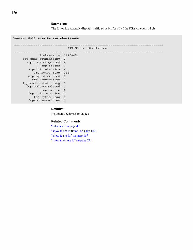
176
Examples:The following example displays traffic statistics for all of the ITLs on your switch.
Defaults:No default behavior or values.
Related Commands:“interface” on page 47“show fc srp initiator” on page 160“show fc srp itl” on page 167“show interface fc” on page 241
Topspin-360# show fc srp statistics
================================================================================ SRP Global Statistics================================================================================ link-events: 1410805 srp-cmds-outstanding: 0 srp-cmds-completed: 4 srp-errors: 0 srp-initiated-ios: 4 srp-bytes-read: 288 srp-bytes-written: 0 srp-connections: 2 fcp-cmds-outstanding: 0 fcp-cmds-completed: 2 fcp-errors: 0 fcp-initiated-ios: 2 fcp-bytes-read: 0 fcp-bytes-written: 0

177
show fc srp targetSynopsis:To display the properties of targets (that you manually configured or your switch discovered), enter the show fc srp target command in User Exec mode or Privileged Exec mode.
Syntax:show fc srp target [wwpn]
Platform Availability:Topspin 90, Topspin 360
Command Modes:User Exec mode, Privileged Exec mode.
Privilege Level:FC read-only user.
Usage Guidelines:Enter this command without any arguments to display all the target devices known to the Topspin switch.Table 6-38 describes the fields in the show fc srp target command output.
Table 6-37: show fc srp target Command Arguments
Argument Descriptionwwpn WWPN of the target port.
Table 6-38: show fc srp target Command Fields
Field Descriptionwwpn FC interface port name of the SRP target.
wwnn WWNN of the target.
description Text label used to identify the service in the EM GUI or CLI output. If you do not apply a description, the switch defaults to the service name.
ioc-guid IB I/O controller (IOC) through which the initiator accesses the target. On the Topspin 360 and Topspin 90 platforms, the IOC identifies a FC gateway slot.
service-name Name of the service to associate with the target.
protocol-ids Protocols that the target supports.
fc-address 3-byte FC Protocol address of the target.
mtu Maximum transmission unit, in bytes, of the target.
connection-type Displays down if the connection cannot pass traffic. Displays nl-port when the target communicates with the virtual port on the FC gateway.
physical -access FC port that physically connects to the target.

178
Examples:The following example displays the targets that connect to the switch.
Defaults:No default behavior or values.
Related Commands:“fc srp target” on page 100“interface” on page 47“show fc srp initiator” on page 160
Topspin-360# show fc srp target============================================================================ SRP Targets============================================================================ wwpn: 20:01:00:60:45:17:36:1c wwnn: 20:09:00:60:45:17:36:1c description: SRP.T10:200100604517361C ioc-guid: 00:05:ad:00:00:01:38:80 service-name: SRP.T10:200100604517361C protocol-ids: 04:00:00:00:00:00:00:00:00:00 fc-address: 61:1b:13 mtu: 0 connection-type: nl-port physical-access: 5/1-5/2

179
show fc srp-globalSynopsis:To display the permissions that automatically apply to all new ITs and ITLs, enter the show fc srp-global command in User Exec mode or Privileged Exec mode.
Syntax:show fc srp-global
Platform Availability:Topspin 90, Topspin 360
Command Modes:User Exec mode, Privileged Exec mode.
Privilege Level:FC read-only user.
Usage Guidelines:This command displays the policies that apply, by default, to all newly created ITLs. Configure defaults with the fc srp-global commands in “Fibre Channel Commands” on page 87.Table 6-39 describes the fields in the show fc srp-global command output.
Table 6-39: show fc srp-global command Fields
Field Descriptiondefault-gateway-port-mask-policy Boolean value that indicates if ports allow new
SRP initiators to communicate through the FC interface card(s). The value appears as restricted or non-restricted. Ports deny access by default.
default-lun-policy Boolean value that indicates if new SRP initiators have immediate access to target LUNs. The value appears as restricted or non-restricted. ITLs restrict LUN access by default.
default-itl-hi-mark The maximum number of requests that can be sent per logical unit. This value, an integer, falls between 1 and 256. This value defaults to 16.
default-itl-max-retry Number of times an initiator may send the same I/O to a logical unit. Increase the value (with the fc srp-global command) if you expect heavy traffic, or increase the default-itl-min-io-timeout value. The value, an integer, falls between 1 and 100. The value defaults to 5.
default-itl-min-io-timeout Maximum amount of time for a logical unit to accept I/O traffic. Increase this value if you use a known slow connection or increase the default-itl-max-retry value. The value, an integer, falls between 1 and 1800. The value defaults to 10 seconds.

180
default-itl-dynamic-path-affinity Boolean value that indicates if the system maintains a preference for a specific path. If the number of outstanding I/O requests becomes excessive, or the path fails, the ITL uses an alternative path.
default-itl-dynamic-gateway-port-load-balancing
Boolean value that indicates if data may be sent between the initiator and FC target using both ports on the gateway interface. Port selection occurs based upon comparative I/O traffic. The controller attempts to distribute traffic equally between the ports. This feature runs by default.
default-itl-dynamic-gateway-port-failover Boolean value that indicates if the controller may select an alternate gateway interface port if the primary path fails. This feature does not run by default.
default-seq-itl-hi-mark Shows the default I/O high mark for a sequential device. Specify this value with the fc srp-global itl command.
default-seq-itl-max-retry Shows the default of the maximum number of retries for a sequential device. Specify this value with the fc srp-global itl command.
default-seq-itl-min-io-timeout Shows the default of the maximum number of retries for a sequential device. Specify this value with the fc srp-global itl command.
default-seq-itl-dynamic-path-affinity Shows the default of the dynamic path affinity setting for a sequential device. Specify this value with the fc srp-global itl command.
default-seq-itl-dynamic-load-balancing Shows the default of the dynamic path affinity setting for a sequential device. Specify this value with the fc srp-global itl command.
default-seq-itl-dynamic-gateway-port-failover Boolean value that indicates if the controller may select an alternate storage port if the primary path fails. This feature does not run by default.
Table 6-39: show fc srp-global command Fields (Continued)
Field Description
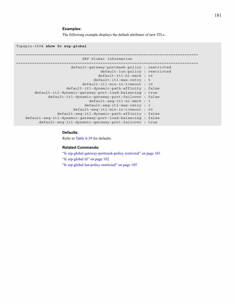
181
Examples:The following example displays the default attributes of new ITLs:
Defaults:Refer to Table 6-39 for defaults.
Related Commands:“fc srp-global gateway-portmask-policy restricted” on page 101“fc srp-global itl” on page 102“fc srp-global lun-policy restricted” on page 105
Topspin-360# show fc srp-global
================================================================================ SRP Global Information================================================================================ default-gateway-portmask-policy : restricted default-lun-policy : restricted default-itl-hi-mark : 16 default-itl-max-retry : 5 default-itl-min-io-timeout : 10 default-itl-dynamic-path-affinity : false default-itl-dynamic-gateway-port-load-balancing : true default-itl-dynamic-gateway-port-failover : false default-seq-itl-hi-mark : 1 default-seq-itl-max-retry : 1 default-seq-itl-min-io-timeout : 60 default-seq-itl-dynamic-path-affinity : false default-seq-itl-dynamic-gateway-port-load-balancing : false default-seq-itl-dynamic-gateway-port-failover : true

182
show hostSynopsis:To display the DNS name servers and domain name that your switch uses, enter the show host command in User Exec mode or Privileged Exec mode.
Syntax:show host
Platform Availability:HP 24-Port 4x Fabric Copper Switch, Topspin 90, Topspin 120, Topspin 270, Topspin 360, Topspin IB Server Switch Module
Command Modes:User Exec mode, Privileged Exec mode.
Privilege Level:FC read-only user.
Usage Guidelines:Use this command to display the network domain of the chassis and the DNS servers that your switch uses to resolve network names to IP addresses.Table 6-40 lists and describes the fields in the show host command output.
Examples:The following example displays the IP addresses of the DNS servers that the switch uses to resolve host names.
Defaults:No default behavior or values.
Related Commands:“hostname” on page 44“ip” on page 122
Table 6-40: show host Command Fields
Field Descriptionname-server-one IP address of the primary name server.
name-server-two IP address of the backup name server.
domain-name Host name of the switch.
Topspin-360# show host============================================================================
Host Information============================================================================ name-server-one : 10.3.106.20 name-server-two : 0.0.0.0 domain-name : shastaTopspin-360#

183
show ib dm iocSynopsis:To display the Device Manager input/output controller (IOC) configuration, enter the show ib dm ioc command in User Exec mode or Privileged Exec mode.
Syntax:show ib dm ioc [ioc-guid | all] [services]
Platform Availability:Topspin 90, Topspin 360
Command Modes:User Exec mode, Privileged Exec mode.
Privilege Level:General read-only user.
Usage Guidelines:Table 6-42 describes the fields in the show ib dm ioc command output.
Table 6-41: show ib dm ioc Command Arguments
Argument Descriptionioc-guid GUID of the controller that you want to view.
all Displays all controllers on the IB fabric.
services Displays the services that run on the IOC(s).
Table 6-42: show ib dm ioc Command Fields
Field Descriptionguid GUID of the controller.
description User-assigned description.
vendor-id Organization Unique Identifier (OUI) of the vendor.
ioc-device-id Vendor-assigned device identifier.
device-version Vendor-assigned device version.
subsystem-vendor-id Vendor-assigned subsystem vendor identifier
subsystem-id Vendor-assigned subsystem identifier.
io-class I/O class that the IOC supports.
io-subclass Subclass of the I/O class protocol of the IOC.
protocol Standard protocol definition that the IOC supports.
protocol-version Protocol version that the IOC supports.
send-msg-q-depth Maximum number of messages that the send message queue supports.
rdma-read-q-depth Maximum depth of the per-channel RDMA Read Queue.
send-msg-size Maximum size, in bytes, of send messages.
rdma-transfer-size Maximum size, in bytes, of outbound RDMA transfers that the IOC initiates.

184
Table 6-43 describes the fields in the services keyword output.
Examples:The following example displays the configuration of all IOCs on the fabric.
controller-op-cap Integer value (from 8 cumulative bits) between 1 and 255 that represents the operation type(s) that the IOC supports.• bit 0: ST—Send Messages To IOCs• bit 1: SF—Send Messages From IOCs• bit 2: RT—RDMA Read Requests To IOCs• bit 3: RF—RDMA Read Requests From IOCs• bit 4: WT—RDMA Write Requests To IOCs• bit 5: WF—RDMA Write Requests From IOCs• bit 6: AT—Atomic Operations To IOCs• bit 7: AF—Atomic Operations From IOCs
service-entries Number of services that the IOC provides.
Table 6-43: services Keyword Display Output
Field Descriptionioc-guid GUID of the node that provides the service.
service-name ASCII identifier of the service.
service-id Numeric identifier that nodes use to call the service.
Table 6-42: show ib dm ioc Command Fields (Continued)
Field Description
Topspin-360> show ib dm ioc
================================================================================ IB Device Manager I/O Controller================================================================================ guid: 00:05:ad:00:00:00:14:fe description: vendor-id: 0x5ad ioc-device-id: 0x5ad device-version: 1 subsystem-vendor-id: 0x5ad subsystem-id: 0x5ad io-class: 256 io-subclass: 24734 protocol: 264 protocol-version: 1 send-msg-q-depth: 65535 rdma-read-q-depth: 65535 send-msg-size: -1 rdma-transfer-size: -1 controller-op-cap: 255 service-entries: 14

185
The following example displays all of the services on all of the IOCs in the fabric (output abridged).
Defaults:No default behavior or values.
Related Commands:“show ib dm iou” on page 186
Topspin-360> show ib dm ioc services
================================================================================ IB Device Manager Services================================================================================ ioc-guid: 00:05:ad:00:00:00:14:fe service-name: SRP.T10:2200000C5002CA21 service-id: 00:00:00:00:00:00:00:66
ioc-guid: 00:05:ad:00:00:00:14:fe service-name: SRP.T10:2200000C50056281 service-id: 00:00:00:00:00:00:00:66

186
show ib dm iouSynopsis:To display the Device Manager input/output unit (IOU) configuration, enter the show ib dm iou command in User Exec mode or Privileged Exec mode.
Syntax:show ib dm iou
Platform Availability:HP 24-Port 4x Fabric Copper Switch, Topspin 90, Topspin 120, Topspin 270, Topspin 360
Command Modes:User Exec mode, Privileged Exec mode.
Privilege Level:General read-only user.
Usage Guidelines:Table 6-44 describes the fields in the show ib dm command output.
Examples:The following example displays the DM I/O details for the switch.
Table 6-44: show ib dm Command Output Fields
Field Descriptionchange-id Cumulative number of changes to the controller list since the device last
booted.
max-controllers Maximum number of controllers that your device can support.
diag-device-id Displays 1 if diagnostics can provide IOC details, otherwise displays 0.
option-rom Indicates the presence or absence of Option ROM.
controllers Lists virtual slots on your switch that run IOC controllers.
NOTE: All references to “slot” in this field refer to virtual slots, not physical slots on the switch.
Topspin-360> show ib dm iou
================================================================================ IB Device Manager I/O Unit================================================================================ change-id: 2352 max-controllers: 1 diag-device-id: 0 option-rom: absent controllers: slot-1 IOC present

187
Defaults:No default behavior or values.
Related Commands:“show ib dm ioc” on page 183

188
show ib sm configurationSynopsis:To display information about the SMs on your IB fabric, enter the show ib sm configuration command in User Exec mode or Privileged Exec mode.
Syntax:show ib sm configuration {subnet-prefix prefix | all} [summary]
Platform Availability:HP 24-Port 4x Fabric Copper Switch, Topspin 90, Topspin 120, Topspin 270, Topspin 360, Topspin IB Server Switch Module
Command Modes:User Exec mode, Privileged Exec mode.
Privilege Level:IB read-only user.
Usage Guidelines:Table 6-46 describes the fields in the show ib sm configuration command output.
Table 6-45: show ib sm configuration Command Syntax Description
Syntax Descriptionsubnet-prefix Specifies the subnet prefix of the SM that you want to view.
prefix Subnet prefix of the SM that you want to view.
all Displays the attributes of all the SMs that are currently configured and running on the IB fabric.
summary Displays an abridged form of the command output. The abridged information includes the subnet prefix, GUID, priority, and SM key of the SMs.
Table 6-46: show ib sm configuration Command Fields
Field Descriptionsubnet-prefix 64-bit value used that identifies the IB subnet. This is a unique subnet identifier
and joins with the GUID to form the GID of the port. All GIDs within a subnet have the same subnet prefix.
guid GUID of this SM.
priority User-assigned priority for this SM. You must enter an integer between 0 and 15. The value defaults to 10.
NOTE: When the chassis boots, the SM priority defaults to 10. When you add the SM manually, the priority defaults to 0.
sm-key 64-bit subnet management key assigned to the SM.The sm-key defaults to 00:00:00:00:00:00:00:00. The SM key serves as the prefix of all GIDs and “brands” nodes as members of this subnet.

189
Examples:The following example shows the detailed configuration of an SM.
admin-status Administrative status of the SM. The value appears as enable or disable. Disabling an SM places it in an inactive state but leaves it intact in the configuration. The switch enables SMs by default.
oper-status Operational status of the SM. Self-detection determines this status. The value appears as notActive, discovering, standby, or master. If notActive appears, the SM has not been enabled or has been disabled. The discovering output appears when the SM sweeps the fabric. If standby appears, the SM servers as a a slave SM. If only one SM runs on the fabric, it serves as the master.
act-count Activity counter that increments each time the SM issues an SMP or performs other management activities.
status Status of the SM. It appears as active or inactive. If active, it is actively managing subnets. If inactive, it is not managing subnets.
master-poll-interval Interval at which the slave SM polls the master to see if the master is still alive.
master-poll-retries Number of unanswered polls that cause the slave to identify the master as dead.
max-active-sms Maximum number of standby SMs that the master supports.
LID-mask-control Number of path bits present in the base LID to each channel adapter port. Increasing the LMC value increases the number of LIDs assigned to each port to increase the number of potential paths to reach each port.
Table 6-46: show ib sm configuration Command Fields (Continued)
Field Description
Topspin-360# show ib sm configuration subnet-prefix fe:80:00:00:00:00:00:00
================================================================================ Subnet Manager Information================================================================================ subnet-prefix : fe:80:00:00:00:00:00:00 guid : 00:05:ad:00:00:01:1e:82 priority : 10 sm-key : 00:00:00:00:00:00:00:00 admin-status : enable oper-status : standby act-count : 38692 status : active sweep-interval : 10 response-timeout : 400 master-poll-interval : 3 master-poll-retries : 2 max-active-sms : 0 LID-mask-control : 0

190
The following example shows the summary configuration of an SM.
Defaults:No default behavior or values.
Related Commands:“ib sm” on page 110“ib-agent” on page 113“show ib-agent switch” on page 223“interface” on page 47“name” on page 58
Topspin-360# show ib sm configuration subnet-prefix fe:80:00:00:00:00:00:00 summary
================================================================================ Subnet Manager Configuration Summary================================================================================subnet-prefix guid priority sm-key --------------------------------------------------------------------------------fe:80:00:00:00:00:00:00 00:05:ad:00:00:01:1e:82 10 00:00:00:00:00:00:00:00

191
show ib sm db-syncSynopsis:To display SM synchronization information, enter the show ib sm db-sync command in User Exec mode or Privileged Exec mode.
Syntax:show ib sm db-sync subnet-prefix {prefix | all}
Platform Availability:HP 24-Port 4x Fabric Copper Switch, Topspin 90, Topspin 120, Topspin 270, Topspin 360, Topspin IB Server Switch Module
Command Modes:User Exec mode, Privileged Exec mode.
Privilege Level:IB read-only user.
Usage Guidelines:Use this command to determine• If the database of the master SM synchronizes with one or more standby databases.• The frequency with which the databases synchronize.
Table 6-47: show ib sm db-sync Command Arguments
Argument Descriptionsubnet-prefix Specifies the subnet prefix of the SM whose sync status you want to view.
prefix Prefix of the SM whose sync status you want to view.
all Displays sync data for all SMs on the fabric.
Table 6-48: show ib sm db-sync Command Fields
Field Descriptionsubnet-prefix Subnet prefix of the subnet whose synchronization information you want to
view.
enable Displays true if an administrator has enabled synchronization, otherwise displays false.
max-backup-sms The maximum number of backup SMs that the master SM supports.
session-timeout The interval, in seconds, during which a synchronization session status MAD packet must arrive at the master SM to maintain synchronization.
poll-interval Interval at which the master SM polls an active slave SM to verify synchronization.
cold-sync-timeout Maximum amount of time in which SMs can perform a cold sync. During the cold sync, the master SM copies all out-of-sync tables to the standby.
cold-sync-limit Maximum number of cold syncs that may take place during the cold sync period.
cold-sync-period Length of the interval during which cold syncs may occur.

192
Examples:The following example displays SM synchronization information.
Defaults:No default behavior or values.
Related Commands:“ib sm db-sync” on page 108
new-session-delay Amount of time that the master SM waits before it attempts to initiate a synchronization session with a new SM.
resync-interval Specifies the interval at which the master SM sends a re-synchronization request to all active sync sessions.
state Specifies whether or not the Subnet Manager is in sync with the backup.
Table 6-48: show ib sm db-sync Command Fields
Field Description
Topspin-270# show ib sm db-sync subnet-prefix fe:80:00:00:00:00:00:00
================================================================================
Subnet Manager Database Synchronization Information================================================================================
subnet-prefix : fe:80:00:00:00:00:00:00 enable : false max-backup-sms : 1 session-timeout : 10 poll-interval : 3 cold-sync-timeout : 10 cold-sync-limit : 2 cold-sync-period : 900 new-session-delay : 120 resync-interval : 3600 state : not in-sync

193
show ib sm multicastSynopsis:To display attributes of the multicast groups on your switch, enter the show ib sm multicast command in User Exec or Privileged Exec mode.
Syntax:show ib sm multicast {subnet-prefix prefix [mgid multicast-group-GID] [summary] | summary}
Platform Availability:HP 24-Port 4x Fabric Copper Switch, Topspin 90, Topspin 120, Topspin 270, Topspin 360, Topspin IB Server Switch Module
Command Modes:User Exec mode, Privileged Exec mode.
Privilege Level:IB read-only user.
Usage Guidelines:Troubleshoot with this command when a host does not receive a broadcast packet. Use this command to verify that the multicast group includes the host. The SM dynamically configures all multicast groups.Table 6-50 describes the fields in the show ib sm configuration command output.
Table 6-49: show ib sm multicast Command Arguments
Argument Descriptionsubnet-prefix Specifies the subnet prefix of the SM that you want to view.
prefix Subnet prefix of the SM that you want to view.
mgid Specifies the GID of the multicast group.
multicast-group-GID GID of the multicast group.
summary Displays an abridged form of the data. The abridged information includes the subnet prefix, GUID, priority, and SM key of the SMs.
Table 6-50: show ib sm multicast Command Fields
Field Descriptionsubnet-prefix Subnet prefix of the SM.
MGID Multicast group identifier.
port-GID GID of a port that belongs to the multicast group.
member-join-state
Type of membership that the member has in the multicast group. Members qualify as full members, non-members, or send-only members.
proxy-join-status This field displays false except for trusted requests. For details, refer to InfiniBand Architecture®, Vol. 1, Release 1.1.
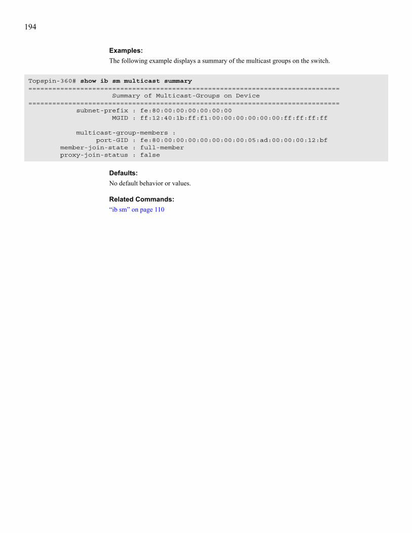
194
Examples:The following example displays a summary of the multicast groups on the switch.
Defaults:No default behavior or values.
Related Commands:“ib sm” on page 110
Topspin-360# show ib sm multicast summary============================================================================== Summary of Multicast-Groups on Device============================================================================== subnet-prefix : fe:80:00:00:00:00:00:00 MGID : ff:12:40:1b:ff:f1:00:00:00:00:00:00:ff:ff:ff:ff
multicast-group-members : port-GID : fe:80:00:00:00:00:00:00:00:05:ad:00:00:00:12:bf member-join-state : full-member proxy-join-status : false
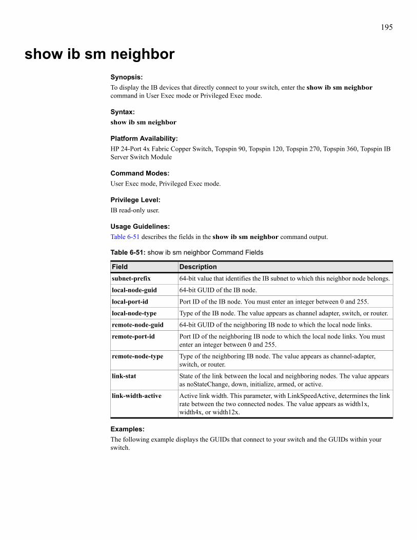
195
show ib sm neighborSynopsis:To display the IB devices that directly connect to your switch, enter the show ib sm neighbor command in User Exec mode or Privileged Exec mode.
Syntax:show ib sm neighbor
Platform Availability:HP 24-Port 4x Fabric Copper Switch, Topspin 90, Topspin 120, Topspin 270, Topspin 360, Topspin IB Server Switch Module
Command Modes:User Exec mode, Privileged Exec mode.
Privilege Level:IB read-only user.
Usage Guidelines:Table 6-51 describes the fields in the show ib sm neighbor command output.
Examples:The following example displays the GUIDs that connect to your switch and the GUIDs within your switch.
Table 6-51: show ib sm neighbor Command Fields
Field Descriptionsubnet-prefix 64-bit value that identifies the IB subnet to which this neighbor node belongs.
local-node-guid 64-bit GUID of the IB node.
local-port-id Port ID of the IB node. You must enter an integer between 0 and 255.
local-node-type Type of the IB node. The value appears as channel adapter, switch, or router.
remote-node-guid 64-bit GUID of the neighboring IB node to which the local node links.
remote-port-id Port ID of the neighboring IB node to which the local node links. You must enter an integer between 0 and 255.
remote-node-type Type of the neighboring IB node. The value appears as channel-adapter, switch, or router.
link-stat State of the link between the local and neighboring nodes. The value appears as noStateChange, down, initialize, armed, or active.
link-width-active Active link width. This parameter, with LinkSpeedActive, determines the link rate between the two connected nodes. The value appears as width1x, width4x, or width12x.

196
NOTE: Truncated output appears here.
Defaults:No default behavior or values.
Related Commands:“ib sm” on page 110
Topspin-360# show ib sm neighbor============================================================================ Subnet Management Neighbors============================================================================ subnet-prefix : fe:80:00:00:00:00:00:00 local-node-guid : 00:05:ad:00:00:00:11:97 local-port-id : 2 local-node-type : channel-adapter remote-node-guid : 00:05:ad:00:00:00:13:da remote-port-id : 1 remote-node-type : switch link-state : active link-width-active : width4x
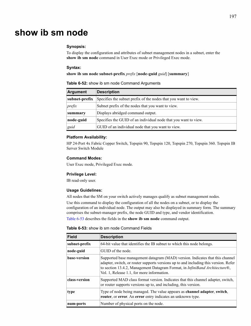
197
show ib sm nodeSynopsis:To display the configuration and attributes of subnet management nodes in a subnet, enter the show ib sm node command in User Exec mode or Privileged Exec mode.
Syntax:show ib sm node subnet-prefix prefix [node-guid guid] [summary]
Platform Availability:HP 24-Port 4x Fabric Copper Switch, Topspin 90, Topspin 120, Topspin 270, Topspin 360. Topspin IB Server Switch Module
Command Modes:User Exec mode, Privileged Exec mode.
Privilege Level:IB read-only user.
Usage Guidelines:All nodes that the SM on your switch actively manages qualify as subnet management nodes.Use this command to display the configuration of all the nodes on a subnet, or to display the configuration of an individual node. The output may also be displayed in summary form. The summary comprises the subnet-manager prefix, the node GUID and type, and vendor identification.Table 6-53 describes the fields in the show ib sm node command output.
Table 6-52: show ib sm node Command Arguments
Argument Descriptionsubnet-prefix Specifies the subnet prefix of the nodes that you want to view.
prefix Subnet prefix of the nodes that you want to view.
summary Displays abridged command output.
node-guid Specifies the GUID of an individual node that you want to view.
guid GUID of an individual node that you want to view.
Table 6-53: show ib sm node Command Fields
Field Descriptionsubnet-prefix 64-bit value that identifies the IB subnet to which this node belongs.
node-guid GUID of the node.
base-version Supported base management datagram (MAD) version. Indicates that this channel adapter, switch, or router supports versions up to and including this version. Refer to section 13.4.2, Management Datagram Format, in InfiniBand Architecture®, Vol. 1, Release 1.1, for more information.
class-version Supported MAD class format version. Indicates that this channel adapter, switch, or router supports versions up to, and including, this version.
type Type of node being managed. The value appears as channel adapter, switch, router, or error. An error entry indicates an unknown type.
num-ports Number of physical ports on the node.

198
port-guid GUID of the port that connects the node to the switch. A port within a node can return the node GUID as its PortGUID if the port serves as an integral part of the node and you cannot replace the port in the field (not swappable).
partition-cap Capacity of entries in the partition table for channel adapter, router, and the switch management port. The value appears the same for all ports on the node. This defaults to at least 1 for all nodes including switches. You cannot configure this value.
device-id Manufacturer-assigned device identification.
revision Manufacturer-assigned device revision.
local-portnum The link port number from which this SMP arrived. The value appears the same for all ports on the node.
vendor-id Device vendor ID. The value appears the same for all ports on the node.
system-image-guid
GUID of an associated supervisory node. No supervisory node exists if the command output displays 00:00:00:00:00:00:00:00.
Table 6-53: show ib sm node Command Fields (Continued)
Field Description

199
Examples:The following example (output abridged) displays the configuration of all the nodes on all the subnets on the IB fabric.
The following example displays a node configuration in summary form.
Defaults:No default behavior or values.
Related Commands:“ib sm” on page 110
Topspin-360# show ib sm node subnet-prefix fe:80:00:00:00:00:00:00
================================================================================ Subnet Management Nodes================================================================================ subnet-prefix : fe:80:00:00:00:00:00:00 node-guid : 00:00:2c:90:01:1b:ba:80 description : swfc5 HCA-1 (Topspin HCA) base-version : 1 class-version : 1 type : channel adapter num-ports : 2 port-guid : 00:00:2c:90:01:1b:ba:81 partition-cap : 64 device-id : 0 revision : 0 local-portnum : 1 vendor-id : 00:2c:90 system-image-guid : 00:00:00:00:00:00:00:00
subnet-prefix : fe:80:00:00:00:00:00:00 node-guid : 00:05:ad:00:00:00:13:da description : Topspin Switch - U1 base-version : 1 class-version : 1 type : switch num-ports : 8 port-guid : 00:05:ad:00:00:00:13:da partition-cap : 32 device-id : 0 revision : 0 local-portnum : 6 vendor-id : 00:05:ad system-image-guid : 00:00:00:00:00:00:00:00
Topspin-90# show ib sm node subnet-prefix fe:80:00:00:00:00:00:00 node-guid 00:05:ad:00:00:00:13:80 summary============================================================================ Subnet Manager Node Summary============================================================================subnet-prefix node-guid node-type vendor-id----------------------------------------------------------------------------fe:80:00:00:00:00:00:00 00:05:ad:00:00:00:13:80 channel adapter 00:05:adTopspin-90#

200
show ib sm partitionSynopsis:To display the partitions that the SM on your switch manages, enter the show ib sm partition command in User Exec mode or Privileged Exec mode.
Syntax:show ib sm partition
Platform Availability:HP 24-Port 4x Fabric Copper Switch, Topspin 90, Topspin 120, Topspin 270, Topspin 360, Topspin IB Server Switch Module
Command Modes:User Exec mode, Privileged Exec mode.
Privilege Level:IB read-only user.
Usage Guidelines:In the output, 7f:ff refers to the default partition, which cannot be altered. Members of partitions are identified by their Node GUID and port number. A single partition can have members that have full membership, as well as members that have limited membership.Refer to the HP 24-Port 4x Fabric Copper Switch User Guide for more detailed partition information.Table 6-54 lists and describes the fields in the show ib sm partition command output.
Table 6-54: show ib sm partition Command Fields
Field Descriptionsubnet-prefix Subnet prefix of the subnet whose partitions you want to view.
p_key Partition key of the partition whose members the display prints below.
node-guid GUID of the node in the partition.
port-number Port on the node that belongs to the partition.
member-type Type of membership that an administrator assigned to the node, either full or limited.

201
Examples:The following example displays the configuration of all nodes on all subnets on the IB fabric.
Defaults:No default behavior or values.
Related Commands:“ib sm” on page 110
Topspin-360# show ib sm partition=============================================================================== Partitions Managed By The Subnet Managers=============================================================================== subnet-prefix : fe:80:00:00:00:00:00:00 p_key : 7f:ff
partition-members : node-guid : 00:05:ad:00:00:00:02:40 port-number : 0 member-type : full-member
node-guid : 00:05:ad:00:00:00:02:42 port-number : 0 member-type : full-member
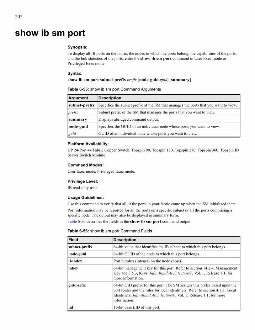
202
show ib sm portSynopsis:To display all IB ports on the fabric, the nodes to which the ports belong, the capabilities of the ports, and the link statistics of the ports, enter the show ib sm port command in User Exec mode or Privileged Exec mode.
Syntax:show ib sm port subnet-prefix prefix [node-guid guid] [summary]
Platform Availability:HP 24-Port 4x Fabric Copper Switch, Topspin 90, Topspin 120, Topspin 270, Topspin 360, Topspin IB Server Switch Module
Command Modes:User Exec mode, Privileged Exec mode.
Privilege Level:IB read-only user.
Usage Guidelines:Use this command to verify that all of the ports in your fabric came up when the SM initialized them.Port information may be reported for all the ports on a specific subnet or all the ports comprising a specific node. The output may also be displayed in summary form.Table 6-56 describes the fields in the show ib sm port command output.
Table 6-55: show ib sm port Command Arguments
Argument Descriptionsubnet-prefix Specifies the subnet prefix of the SM that manages the ports that you want to view.
prefix Subnet prefix of the SM that manages the ports that you want to view.
summary Displays abridged command output.
node-guid Specifies the GUID of an individual node whose ports you want to view.
guid GUID of an individual node whose ports you want to view.
Table 6-56: show ib sm port Command Fields
Field Descriptionsubnet-prefix 64-bit value that identifies the IB subnet to which this port belongs.
node-guid 64-bit GUID of the node to which this port belongs.
if-index Port number (integer) on the node (host).
mkey 64-bit management key for this port. Refer to section 14.2.4, Management Key and 3.5.3, Keys, InfiniBand Architecture®, Vol. 1, Release 1.1, for more information.
gid-prefix 64-bit GID prefix for this port. The SM assigns this prefix based upon the port router and the rules for local identifiers. Refer to section 4.1.3, Local Identifiers, InfiniBand Architecture®, Vol. 1, Release 1.1, for more information.
lid 16-bit base LID of this port.

203
master-sm-lid 16-bit base LID of the master SM managing this port.
cap-mask The capability mask identifies the functions that the host supports. 32-bit bitmask that specifies the supported capabilities of the port. A bit value of 1 (one) indicates a supported capability. The bits are:• 0, 11-15, 18, 21-31 (Reserved and always 0)• 1 IsSM• 2 IsNoticeSupported• 3 IsTrapSupported• 4 IsResetSupported• 5 IsAutomaticMigrationSupported• 6 IsSLMappingSupported • 7 IsMKeyNVRAM (supports M_Key in NVRAM)• 8 IsPKeyNVRAM (supports P_Key in NVRAM)• 9 Is LED Info Supported• 10 IsSMdisabled• 16 IsConnectionManagementSupported• 17 IsSNMPTunnelingSupported • 19 IsDeviceManagementSupported • 20 IsVendorClassSupportedValues are expressed in hexadecimal.
diag-code 16-bit diagnostic code. Refer to section 14.2.5.6.1 Interpretation of Diagcode, InfiniBand Architecture®, Vol. 1, Release 1.1, for more information. This field does not currently apply to your switch.
mkey-lease-period Initial value of the lease-period timer in seconds. The lease period is the length of time that the M_Key protection bits are to remain non-zero after a SubnSet (PortInfo) fails an M_Key check. After the lease period expires, clearing the M_Key protection bits allows any SM to read (and then set) the M_Key. Set this field to 0 to indicate that the lease period never expires. Refer to section 14.2.4, Management Key, InfiniBand Architecture®, Vol. 1, Release 1.1, for more information.
link-width-enabled Enabled link width (bandwidth). The value (an integer) indicates the enabled link-width sets for this port. The value may be:• 0 (no state change)• 1 (1x)• 2 (4x)• 3 (1x or 4x)• 8 (12x)• 9 (1x or 12x)• 10 (4x or 12x)• 11 (1x, 4x or 12x)• 255 (set this parameter to the link-width-supported value)
link-width-supported Supported link width. The value appears as 1 (1x), 3 (1x or 4x), or 11 (1x, 4x, or 12x).
Table 6-56: show ib sm port Command Fields (Continued)
Field Description

204
link-width-active Active link width. Used in conjunction with LinkSpeedActive to determine the link rate between two nodes. The value appears as 1 (1x), 2 (4x), or 8 (12x).
link-speed-supported Supported link speed. The value appears as 1 (2.5 Gbps).
state A higher form of addressing than PhyState, state determines that the nodes can actually communicate and indicates the state transition that has occurred. A transition identifies a port change from down to initialize, initialize to down, armed to down, or active to down as a result of link state machine logic. Changes to the port state resulting from SubnSet have no affect on this parameter value. The value appears as noStateChange, down, initialize, armed, or active.
phy-state Indicates the physical state of the port. This determines that electricity flows between nodes and they can perform a handshake. The value appears as noStateChange, sleeping, polling, disabled, portConfigurationTraining, linkup, or linkErrorRecovery. The state, upon power-up, defaults to polling.
link-down-def-state Default LinkDown state to return to. The value appears as noStateChange, sleeping, or polling. Refer to section 5.5.2, Status Outputs (MAD GET), InfiniBand Architecture®, Vol. 1, Release 1.1, for more information.
mkey-prot-bits Management key protection bits for the port. The bits are 0, 1, 2, and 3. Refer to section 14.2.4.1, Levels of Protection, InfiniBand Architecture®, Vol. 1, Release 1.1, for more information.
lmc Local-identifier mask control (LMC) for multipath support. A LMC resides on each channel adapter and router port on the subnet. It provides multiple virtual ports within a single physical port. The value of the LMC specifies the number of path bits in the LID. A value of 0 (zero) indicates one LID can apply to this port. Refer to sections 3.5.10, Addressing, and 4.1.3, Local Identifiers, InfiniBand Architecture®, Vol. 1, Release 1.1, for more information.
link-speed-active Speed of an active link. The value appears as 1 (2.5 Gbps).
link-speed-enabled Maximum speed that the link can handle. The value appears as 0 (No state change), 1 (2.5 Gbps), or 3 (value derived from link-speed-supported).
neighbor-mtu Active maximum transmission unit enabled on this port for transmit. Check the mtu-cap value at both ends of every link and use the lesser speed. The value appears as mtu256, mtu512, mtu1024, mtu2048, or mtu4096.
master-sm-SL Administrative service level required for this port to send a non-SMP message to the SM.
VL-cap Maximum range of data virtual lanes supported by this port. The value appears as vl0, vl0ToVl1, vl0ToVl3, vl0ToVl7, or vl0ToVl14. See also oper-VL. Each port can support up to fifteen virtual lanes (VLs 0 - 15). The VL-cap field displays the range of those lanes (e.g. lanes 0 - 7) that the port currently supports.
VL-high-limit Maximum high-priority limit on the number of bytes allowed for transmitting high-priority packets when both ends of a link operate with multiple data virtual-lanes. Used with the virtual-lane arbitration table. The maximum high-limit matches the vl-arb-high-cap on the other side of the link and then negotiating downward.
Table 6-56: show ib sm port Command Fields (Continued)
Field Description

205
VL-arb-high-cap Highest arbitration value allowed by the arbiter in determining the next packet in a set of packets to send across the link. Used with the virtual-lane arbitration table and specified as a VL/Weight pair. Refer to section 14.2.5.9, VL Arbitration Table, InfiniBand Architecture®, Vol. 1, Release 1.1, for more information.
VL-arb-low-cap Lowest arbitration value allowed by the arbiter in determining the next packet in a set of packets to send across the link. Used with the virtual-lane arbitration table and specified as a VL/Weight pair. Refer to section 14.2.5.9, VL Arbitration Table, InfiniBand Architecture®, Vol. 1, Release 1.1, for more information.
mtu-cap Used in conjunction with neighbor-mtu to determine the maximum transmission size supported on this port. The lesser of mtu-cap and neighbor-mtu determines the actual MTU used. The value appears as 256, 512, 1024, 2048, or 4096
VL-stall-count Number of sequentially dropped packets at which the port enters a VLStalled state. The virtual lane exits the VLStalled state (8 * HLL) units after entering it. Refer to section 18.2.5.4, Transmitter Queuing, InfiniBand Architecture®, Vol. 1, Release 1.1, for a description of HLL.
HOQ-life Maximum duration allowed to packets at the head of a virtual-lane queue. Used with VL-stall-count to determine the outgoing packets to discard.
oper-VL Administrative limit for the number of virtual lanes allowed to the link. Do not set this above the VL-cap value. The value appears as vl0, vl0-Vl1, vl0-Vl3, vl0-Vl7, or vl0-Vl14.
in-part-enforce Boolean value that indicates whether or not to support optional partition enforcement for the packets received by this port. No default value applies.
out-part-enforce Boolean value that indicates whether or not to support optional partition enforcement for the packets transmitted by this port. No default value applies.
in-filter-raw-pkt-enforce
Boolean value that indicates whether or not to support optional raw packet enforcement for the raw packets received by this port. No default value applies.
out-filter-raw-pkt-enforce
Boolean value that indicates whether or not to support optional raw packet enforcement for the raw packets transmitted by this port. No default value applies.
mkey-violation Number of SMPs that have been received on this port with invalid M_Keys since initial power up or the last reset. Refer to section 14.2.4, Management Key, InfiniBand Architecture®, Vol. 1, Release 1.1, for more information.
pkey-violation Number of SMPs that have been received on this port with invalid P_Keys since initial power up or the last reset. Refer to section 9.2.7, partition key (P_KEY), InfiniBand Architecture®, Vol. 1, Release 1.1, for more information.
qkey-violation Number of SMPs that have been received on this port with invalid Q_Keys since initial power up or the last reset. Refer to section 10.2.4, Q Keys, InfiniBand Architecture®, Vol. 1, Release 1.1, for more information.
guid-cap Number of GUID entries allowed for this port in the port table. Any entries that exceed this value are ignored on write and read back as zero. Refer to section 14.2.5.5, GUIDCap, InfiniBand Architecture®, Vol. 1, Release 1.1, for more information.
Table 6-56: show ib sm port Command Fields (Continued)
Field Description

206
subnet-timeout Maximum propagation delay allowed for this port to reach any other port in the subnet. This value also affects the maximum rate at with traps can be sent from this port. Switch configuration affects delay. Requestors may use this parameter to determine the interval to wait for a response to a request. Duration matches (4.096 ms * 2^SubnetTimeout).
resp-time Maximum time allowed between the port reception of an SMP and the transmission of the associated response. Refer to section 13.4.6.2, Timers and Timeouts, InfiniBand Architecture®, Vol. 1, Release 1.1, for more information.
local-phy-error Threshold at which ICRC, VCRC, FCCRC, and all physical errors result in an entry into the BAD PACKET or BAD PACKET DISCARD states of the local packet receiver. Refer to section 7.12.2, Error Recovery Procedures, InfiniBand Architecture®, Vol. 1, Release 1.1, for more information.
local-overrun-error Threshold at which the count of buffer overruns, across consecutive flow-control update periods, result in an overrun error. A possible cause of such errors is when an earlier packet has physical errors and the buffers are not immediately reclaimed.
Table 6-56: show ib sm port Command Fields (Continued)
Field Description

207
Examples:The following example displays the details of the ports that the specified SM manages.
Topspin-90> show ib sm port subnet-prefix fe:80:00:00:00:00:00:00
================================================================================ Subnet Management Ports================================================================================ subnet-prefix : fe:80:00:00:00:00:00:00 node-guid : 00:02:c9:01:07:e4:41:d0 if-index : 1 mkey : 00:00:00:00:00:00:00:00 gid-prefix : fe:80:00:00:00:00:00:00 lid : 2 master-sm-lid : 1 cap-mask : 00:10:02:48 diag-code : 10:26 mkey-lease-period : 15 link-width-enabled : 3 link-width-supported : 3 link-width-active : 2 link-speed-supported : 1 state : active phy-state : no state change link-down-def-state : polling mkey-prot-bits : 0 lmc : 0 link-speed-active : 1 link-speed-enabled : 1 neighbor-mtu : 2048 master-sm-SL : 0 VL-cap : vl0-vl7 VL-high-limit : 0 VL-arb-high-cap : 8 VL-arb-low-cap : 8 mtu-cap : 2048 VL-stall-count : 16 HOQ-life : 7 oper-VL : vl0-vl7 in-part-enforce : false out-part-enforce : false in-filter-raw-pkt-enf : false out-filter-raw-pkt-enf : false mkey-violation : 0 pkey-violation : 0 qkey-violation : 0 guid-cap : 32 subnet-timeout : 8 resp-time : 8 local-phy-error : 0 local-overrun-error : 0

208
The following example displays a summary of the ports that the specified SM manages.
Defaults:No default behavior or values.
Related Commands:“ib sm” on page 110“show ib sm configuration” on page 188“show ib sm multicast” on page 193“show ib sm neighbor” on page 195“show ib sm partition” on page 200“show ib sm port” on page 202
Topspin-90> show ib sm port subnet-prefix fe:80:00:00:00:00:00:00 summary
================================================================================ Subnet Manager Port Summary================================================================================subnet-prefix node-guid if-index lid state --------------------------------------------------------------------------------fe:80:00:00:00:00:00:00 00:02:c9:01:07:e4:41:d0 1 2 activefe:80:00:00:00:00:00:00 00:02:c9:01:07:e4:41:d0 2 3 activefe:80:00:00:00:00:00:00 00:02:c9:01:07:e4:57:b0 1 6 activefe:80:00:00:00:00:00:00 00:05:ad:00:00:01:1c:60 0 1 activefe:80:00:00:00:00:00:00 00:05:ad:00:00:01:1c:60 1 0 activefe:80:00:00:00:00:00:00 00:05:ad:00:00:01:1c:60 2 0 activefe:80:00:00:00:00:00:00 00:05:ad:00:00:01:1c:60 3 0 activefe:80:00:00:00:00:00:00 00:05:ad:00:00:01:1c:60 4 0 activefe:80:00:00:00:00:00:00 00:05:ad:00:00:01:1c:60 5 0 activefe:80:00:00:00:00:00:00 00:05:ad:00:00:01:1c:60 6 0 down fe:80:00:00:00:00:00:00 00:05:ad:00:00:01:1c:60 7 0 activefe:80:00:00:00:00:00:00 00:05:ad:00:00:01:1c:60 8 0 activefe:80:00:00:00:00:00:00 00:05:ad:00:00:01:1c:62 0 4 activefe:80:00:00:00:00:00:00 00:05:ad:00:00:01:1c:62 1 0 activefe:80:00:00:00:00:00:00 00:05:ad:00:00:01:1c:62 2 0 activefe:80:00:00:00:00:00:00 00:05:ad:00:00:01:1c:62 3 0 activefe:80:00:00:00:00:00:00 00:05:ad:00:00:01:1c:62 4 0 activefe:80:00:00:00:00:00:00 00:05:ad:00:00:01:1c:62 5 0 down fe:80:00:00:00:00:00:00 00:05:ad:00:00:01:1c:62 6 0 down fe:80:00:00:00:00:00:00 00:05:ad:00:00:01:1c:62 7 0 activefe:80:00:00:00:00:00:00 00:05:ad:00:00:01:1c:62 8 0 down fe:80:00:00:00:00:00:00 00:05:ad:00:00:01:1c:64 0 5 activefe:80:00:00:00:00:00:00 00:05:ad:00:00:01:1c:64 1 0 activefe:80:00:00:00:00:00:00 00:05:ad:00:00:01:1c:64 2 0 activefe:80:00:00:00:00:00:00 00:05:ad:00:00:01:1c:64 3 0 activefe:80:00:00:00:00:00:00 00:05:ad:00:00:01:1c:64 4 0 activefe:80:00:00:00:00:00:00 00:05:ad:00:00:01:1c:64 5 0 down fe:80:00:00:00:00:00:00 00:05:ad:00:00:01:1c:64 6 0 down fe:80:00:00:00:00:00:00 00:05:ad:00:00:01:1c:64 7 0 down fe:80:00:00:00:00:00:00 00:05:ad:00:00:01:1c:64 8 0 down fe:80:00:00:00:00:00:00 00:05:ad:00:00:01:29:8f 1 7 activeTopspin-90>

209
show ib sm serviceSynopsis:To display services on your subnet, enter the show ib sm service command in User Exec mode or Privileged Exec mode.
Syntax:show ib sm service [subnet-prefix {prefix | all} [p_key pkey | service-gid GID | service-id ID]] [summary]
Platform Availability:HP 24-Port 4x Fabric Copper Switch, Topspin 90, Topspin 120, Topspin 270, Topspin 360, Topspin IB Server Switch Module
Command Modes:User Exec mode, Privileged Exec mode.
Privilege Level:IB read-only user.
Usage Guidelines:Services represent actions or functions that a node can perform across the network at the request of another node. Nodes register their services with the SM so other nodes can discover and use these services. The GID of a service matches the GID of the host that provides the service.Switch information may be reported for all the switches on a specific subnet or for a specific switch. The output may also be displayed in summary form. Table 6-58 lists and describes the fields in the show ib sm service command output.
Table 6-57: show ib sm service Command Arguments
Argument Descriptionsubnet-prefix Specifies the subnet prefix of the SMs that you want to display.
prefix Subnet prefix of the SMs that you want to display.
all Specifies all subnet prefixes on your IB network.
p_key Specifies a partition whose nodes run services that you want to view.
pkey Partition that contains nodes that run services that you want to view.
service-gid Specifies the GID of the service (the GID of the node that provides the service).
GID GID of the service (node).
service-id Specifies the ID of the service to display.
ID ID of the service to display.
summary Displays a summarized version of the command output.
Table 6-58: show ib sm service Command Fields
Field Descriptionsubnet-prefix Subnet prefix of the service.
service-id Service ID of the service.
GID GID of the service.

210
Examples:The following example displays the services on the switch.
p_key Partition key of the service.
service-name Name of the service.
service-data Header of the data types: 8, 16,. 32, and 64.
Table 6-58: show ib sm service Command Fields (Continued)
Field Description
Topspin-120# show ib sm service subnet-prefix fe:80:00:00:00:00:00:00
================================================================================ Summary of Services on Device================================================================================ subnet-prefix : fe:80:00:00:00:00:00:00 service-id : 10:00:0c:e1:00:41:54:53 GID : fe:80:00:00:00:00:00:00:00:02:c9:02:00:00:24:41 p_key : ff:ff lease : indefinite service-key : 00:00:00:00:00:00:00:00:00:00:00:00:00:00:00:00 service-name : DAPL Address Translation Service service-data : data-8 : 00:00:00:00:00:00:00:00:00:00:00:00:c0:a8:01:02 data-16 : 0000:0000:0000:0000:0000:0000:0000:0000 data-32 : 00000000:00000000:00000000:00000000 data-64 : 0000000000000000:0000000000000000
subnet-prefix : fe:80:00:00:00:00:00:00 service-id : 10:00:0c:e1:00:41:54:53 GID : fe:80:00:00:00:00:00:00:00:02:c9:02:00:00:24:7d p_key : ff:ff lease : indefinite service-key : 00:00:00:00:00:00:00:00:00:00:00:00:00:00:00:00 service-name : DAPL Address Translation Service service-data : data-8 : 00:00:00:00:00:00:00:00:00:00:00:00:c0:a8:01:01 data-16 : 0000:0000:0000:0000:0000:0000:0000:0000 data-32 : 00000000:00000000:00000000:00000000 data-64 : 0000000000000000:0000000000000000
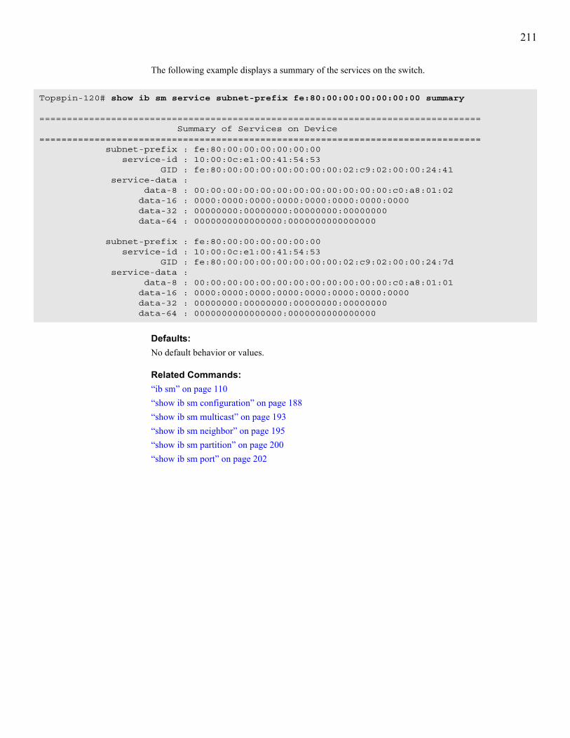
211
The following example displays a summary of the services on the switch.
Defaults:No default behavior or values.
Related Commands:“ib sm” on page 110“show ib sm configuration” on page 188“show ib sm multicast” on page 193“show ib sm neighbor” on page 195“show ib sm partition” on page 200“show ib sm port” on page 202
Topspin-120# show ib sm service subnet-prefix fe:80:00:00:00:00:00:00 summary
================================================================================ Summary of Services on Device================================================================================ subnet-prefix : fe:80:00:00:00:00:00:00 service-id : 10:00:0c:e1:00:41:54:53 GID : fe:80:00:00:00:00:00:00:00:02:c9:02:00:00:24:41 service-data : data-8 : 00:00:00:00:00:00:00:00:00:00:00:00:c0:a8:01:02 data-16 : 0000:0000:0000:0000:0000:0000:0000:0000 data-32 : 00000000:00000000:00000000:00000000 data-64 : 0000000000000000:0000000000000000
subnet-prefix : fe:80:00:00:00:00:00:00 service-id : 10:00:0c:e1:00:41:54:53 GID : fe:80:00:00:00:00:00:00:00:02:c9:02:00:00:24:7d service-data : data-8 : 00:00:00:00:00:00:00:00:00:00:00:00:c0:a8:01:01 data-16 : 0000:0000:0000:0000:0000:0000:0000:0000 data-32 : 00000000:00000000:00000000:00000000 data-64 : 0000000000000000:0000000000000000

212
show ib sm switchSynopsis:To display the attributes of all IB switches in your fabric (for debug purposes), enter the show ib sm switch command in User Exec mode or Privileged Exec mode.
Syntax:show ib sm switch {subnet-prefix prefix | all} [node-guid guid][summary]
Platform Availability:HP 24-Port 4x Fabric Copper Switch, Topspin 90, Topspin 120, Topspin 270, Topspin 360, Topspin IB Server Switch Module
Command Modes:User Exec mode, Privileged Exec mode.
Privilege Level:IB read-only user.
Usage Guidelines:Switch information may be reported for all the switches on a specific subnet or all the switches comprising a specific node. The output may also be displayed in summary form.Table 6-60 lists and describes the fields in the show ib sm switch command output.
Table 6-59: show ib sm switch Command Arguments
Argument Descriptionsubnet-prefix Specifies the subnet prefix of the SMs that you want to view.
prefix Subnet prefix of the SMs that you want to view.
all Displays the attributes of all SMs that run on your IB fabric.
node-guid Specifies the GUID of the switch that you want to view.
guid GUID of the switch that you want to view.
summary Displays a summarized version of the command output.
Table 6-60: show ib sm switch Command Fields
Field Descriptionsubnet-prefix 64-bit value that identifies the IB subnet to which this node belongs.
node-guid 64-bit GUID of the node.
linear-fdb-cap Maximum number of entries allowed in the linear unicast forwarding table. 0 (zero) indicates the absence of a linear forwarding database.
random-fdb-cap Maximum number of entries allowed in the random unicast forwarding table. 0 (zero) indicates an absence of a random forwarding database.
mcast-fdb-cap Maximum number of entries allowed in the multicast forwarding table.
linear-fdb-top Specifies the top of the linear forwarding table. Packets received with unicast LIDs greater than this value are discarded by the switch. This parameter applies only to switches that implement linear forwarding tables. Switches that implement random forwarding tables ignore this parameter.

213
default-port Specifies the default port to forward all the unicast packets from other ports whose destination location ID (DLID) does not exist in the random forwarding table.
default-pri-mcast-port
Specifies the default port to forward all the multicast packets from other ports whose DLID does not exist in the multicast forwarding table.
def-non-pri-mcast-port
Specifies the port to forward all the multicast packets from default-pri-mcast-port whose DLID does not exist in the multicast forwarding table.
life-time-value Specifies the duration a packet can live in the switch. Time units are in milliseconds. Refer to section 18.2.5.4, Transmitter Queueing, InfiniBand Architecture®, Vol. 1, Release 1.1, for more information.
port-state-change Indicates a change in port state. The value changes from NotInTransition to PortInTransition anytime the State parameter of a port changes from down to initialize, initialize to down, armed to down, or active to down, as a result of link state machine logic.
lid-per-port Number of LID/LMC combinations that may be assigned to a given external port for switches that support the random forwarding table. This value is always 0. 0 indicates one LID per port.
partition-enf-cap Number of entries in this partition enforcement table per physical port. 0 (zero) indicates that the switch does not support partition enforcement.
in-enf-cap Indicates if the switch can enforce partitions on received packets. The value appears as true or false.
out-enf-cap Indicates if the switch can enforce partitions on transmitted packets. The value appears as true or false.
in-filter-raw-pkt-cap Indicates if the switch can enforce raw packets on received packets. The value appears as true or false.
out-filter-raw-pkt-cap Indicates if the switch enforces raw packets on transmitted packets. The value appears as true or false.
Table 6-60: show ib sm switch Command Fields (Continued)
Field Description

214
Examples:The following example displays attributes of the IB switch with a GUID of 00:05:ad:00:00:00:13:81.
The following example displays the switches of a subnet in summary form.
Defaults:No default behavior or values.
Related Commands:“ib sm” on page 110“show ib sm configuration” on page 188“show ib sm multicast” on page 193“show ib sm neighbor” on page 195“show ib sm partition” on page 200“show ib sm port” on page 202
Topspin-90# show ib sm switch subnet-prefix fe:80:00:00:00:00:00:00 node-guid 00:05:ad:00:00:00:13:81=============================================================== Subnet Management Switches=============================================================== subnet-prefix : fe:80:00:00:00:00:00:00 node-guid : 00:05:ad:00:00:00:13:81 linear-fdb-cap : 49152 random-fdb-cap : 0 mcast-fdb-cap : 1024 linear-fdb-top : 1024 default-port : 255 def-pri-mcast-port : 255 def-non-pri-mcast-port : 255 life-time-value : 11 port-state-change : port in transition lid-per-port : 0 partition-enf-cap : 64 in-enf-cap : false out-enf-cap : false in-filter-raw-pkt-cap : true out-filter-raw-pkt-cap : trueTopspin-90#
Topspin-90# show ib sm switch subnet-prefix fe:80:00:00:00:00:00:00 summary============================================================================ Subnet Manager Switch Summary==============================================================subnet-prefix node-guid----------------------------------------------------------------------------fe:80:00:00:00:00:00:00 00:05:ad:00:00:00:13:7ffe:80:00:00:00:00:00:00 00:05:ad:00:00:00:13:81fe:80:00:00:00:00:00:00 00:05:ad:00:00:00:13:83fe:80:00:00:00:00:00:00 00:05:ad:00:00:00:13:85fe:80:00:00:00:00:00:00 00:05:ad:00:00:00:13:87fe:80:00:00:00:00:00:00 00:05:ad:00:00:00:13:89Topspin-90#

215
show ib sm switch-elem-routeSynopsis:To display the SM route switch element table, enter the show ib sm switch-elem-route command in User Exec mode or Privileged Exec mode.
Syntax:show ib sm switch-elem-route subnet-prefix {prefix [src-lid srclid dst-lid dstlid] | all} [summary]
Platform Availability:HP 24-Port 4x Fabric Copper Switch, Topspin 90, Topspin 120, Topspin 270, Topspin 360, Topspin IB Server Switch Module
Command Modes:User Exec mode, Privileged Exec mode
Privilege Level:IB read-only user.
Usage Guidelines:This command displays the internal ports through which traffic enters and exits the switch as it travels from the source LID to the destination LID.Table 6-62 lists and describes the field of this command output.
Table 6-61: show ib sm switch-route Command Arguments
Argument Descriptionsubnet-prefix Specifies the subnet prefix of the route.
prefix Subnet prefix of the route.
src-lid Specifies the source LID of the route.
srclid Source LID of the route.
dst-lid Specifies the destination LID of the route.
dstlid Destination LID of the route.
all Specifies all routes in the subnet.
summary Displays fewer output fields.
Table 6-62: show ib sm switch-elem-route Command Output Fields
Field Descriptionchassis-GUID Chassis that runs the route.
input-port Input port of the route.
output-port Output port of the route.
subnet-prefix Subnet prefix of the route.
src-lid Source LID of the route.
dst-lid Destination LID of the route.
last-change Time of the last change to the route.

216
Examples:The following example displays the SM route switch element table for one source and destination.
The following example displays a summary of the SM route switch element table for one source and destination.
Defaults:No default behavior or values.
Related Commands:“ib sm” on page 110
Topspin-360# show ib sm switch-elem-route subnet-prefix fe:80:00:00:00:00:00:00 src-lid 858 dst-lid 857
================================================================================ SM Route Switch Element Table by Subnet w/ Src and Dest LID================================================================================ subnet-prefix : fe:80:00:00:00:00:00:00 src-lid : 858 dst-lid : 857 chassis-GUID : 00:05:ad:00:00:00:03:00 input-port : 0/7 output-port : 0/8
last-change : Sun Jul 13 20:32:00 1930
Topspin-360# show ib sm switch-elem-route subnet-prefix fe:80:00:00:00:00:00:00 src-lid 889 dst-lid 9 summary
================================================================================ Summary of SM Route Switch Element Table by Subnet w/ Src and Dest LID================================================================================ subnet-prefix : fe:80:00:00:00:00:00:00 src-lid : 1 dst-lid : 1 last-change : Tue Jan 27 22:51:56 2004

217
show ib sm switch-routeSynopsis:The complete path that traffic takes through the IB fabric from the source LID to the destination LID, enter the show ib sm switch-route command in User Exec mode or Privileged Exec mode.
Syntax:show ib sm switch-route subnet-prefix {prefix [src-lid srclid dst-lid dstlid] | all} [summary]
Platform Availability:HP 24-Port 4x Fabric Copper Switch, Topspin 90, Topspin 120, Topspin 270, Topspin 360, Topspin IB Server Switch Module
Command Modes:User Exec mode, Privileged Exec mode
Privilege Level:IB read-only user.
Usage Guidelines:This command displays the ports within switches through which traffic travels from a source LID to a destination LID.Table 6-64 lists and describes the fields in the command output.
Table 6-63: show ib sm switch-route Command Arguments
Argument Descriptionsubnet-prefix Specifies the subnet prefix of the route.
prefix Subnet prefix of the route.
src-lid Specifies the source LID of the route.
srclid Source LID of the route.
dst-lid Specifies the destination LID of the route.
dstlid Destination LID of the route.
all Specifies all routes in the subnet.
summary Displays fewer output fields.
Table 6-64: show ib sm switch-route Command Output Fields
Field Descriptionnode-GUID Node that runs the route.
input-port Input port of the route.
output-port Output port of the route.
subnet-prefix Subnet prefix of the route.
src-lid Source LID of the route.
dst-lid Destination LID of the route.
last-change Last change to the route.

218
Examples:The following example displays the switch route for one source/destination LID pair.
Defaults:No default behavior or values.
Related Commands:“ib sm” on page 110
Topspin-360# show ib sm switch-route subnet-prefix fe:80:00:00:00:00:00:00 src-lid 858 dst-lid 857
================================================================================ SM Route Switch Table by Subnet with Source LID and Dest LID================================================================================ subnet-prefix : fe:80:00:00:00:00:00:00 src-lid : 858 dst-lid : 857 node-GUID : 00:05:ad:00:00:00:03:00 input-port : 7 output-port : 8
last-change : Sun Jul 13 20:36:39 1930

219
show ib-agent channel-adapterSynopsis:To view the attributes of IB agents for channel adapters on your switch, enter the show ib-agent channel-adapter command in Privileged Exec mode or User Exec mode.
Syntax:show ib-agent channel-adapter {node-guid guid | all} node-info
Platform Availability:HP 24-Port 4x Fabric Copper Switch, Topspin 90, Topspin 120, Topspin 270, Topspin 360, Topspin IB Server Switch Module
Command Modes:User Exec mode, Privileged Exec mode.
Privilege Level:IB read-only user.
Usage Guidelines:Each switch channel adapter runs its own subnet-management agent. Table 6-66 lists and describes the fields in the show ib-agent channel-adapter command output.
Table 6-65: show ib-agent channel-adapter Command Arguments
Argument Descriptionnode-guid Specifies the GUID of a specific gateway or controller on your switch.
guid GUID of a specific gateway or controller on your switch.
all Displays the attributes of all channel adapters on your switch.
node-info Displays IB information for the channel adapter.
Table 6-66: show ib-agent channel-adapter Command Fields
Field Descriptionguid GUID of the channel adapter as an 8-byte string.
type Type of device this SMA supports. The field always displays adapter.
lid LID of the channel adapter port.
base-version Supported base management datagram version supported.
class-version Supported subnet management class.
port-guid GUID of the node port.
partition-cap Number of entries in the partition table for channel adapter, router, and switch management ports. This displays, at a minimum, 1 for all nodes including switches.
device-id Device ID information, as assigned by the device manufacturer.
revision Device revision, as assigned by the device manufacturer.
local-port-num Number of the link port that received this request, otherwise the field displays 0.
vendor-id Device vendor, per the IEEE standard.
trap-buffer Special purpose string buffer for IB trap data.

220
Examples:The following example displays the attributes of the IB host with a GUID of 00:05:ad:00:00:00:13:17.
Defaults:No default behavior or values.
Related Commands:“ib-agent” on page 113
num-ports Number of physical ports on this node.
string Node description string. Unicode characters are 16 bits.
Table 6-66: show ib-agent channel-adapter Command Fields (Continued)
Field Description
Topspin-360# show ib-agent channel-adapter 00:05:ad:00:00:00:13:17 node-info============================================================================ SMA Node Information============================================================================ guid : 00:05:ad:00:00:00:13:17 type : adapter lid : 14 base-version : 1 class-version : 1 port-guid : 00:05:ad:00:00:00:13:18 partition-cap : 64 device-id : 5a:44 revision : 00:00:00:a0 local-port-num : 1 vendor-id : 00:05:ad trap-buffer : num-ports : 2 string : slot 7: /dev/ts_ua0
guid : 00:05:ad:00:00:00:13:17 type : adapter lid : 0 base-version : 1 class-version : 1 port-guid : 00:05:ad:00:00:00:13:18 partition-cap : 64 device-id : 5a:44 revision : 00:00:00:a0 local-port-num : 1 vendor-id : 00:05:ad trap-buffer : num-ports : 2 string : slot 7: /dev/ts_ua0

221
show ib-agent summarySynopsis:To view the attributes of all IB agents on your switch, enter the show ib-agent summary command in Privileged Exec mode or User Exec mode.
Syntax:show ib-agent summary
Platform Availability:HP 24-Port 4x Fabric Copper Switch, Topspin 90, Topspin 120, Topspin 270, Topspin 360, Topspin IB Server Switch Module
Command Modes:User Exec mode, Privileged Exec mode.
Privilege Level:IB read-only user.
Usage Guidelines:Subnet-management agent information may be displayed in a summary form. This summary helps you assign IP addresses to Ethernet interface gateways because the summary supplies much of the important information you need to configure gateways, such as GUID and LID values.Table 6-66 lists and describes the fields in the show ib-agent summary command output.
Table 6-67: show ib-agent summary Command Fields
Field Descriptionslot Chassis slot to which the HCA or switch connects.
type Type of node being managed. The value appears as adapter, switch, router, or error. The error value indicates an unknown type.
state Logical state of the port. The value appears as down or active.
port SMA-node port number.
guid GUID of the SMA node.
string Node description string. The string identifies the chassis slot and OS device used by the agent.
lid LID, in decimal format, of this port.

222
Examples:The following example displays a summary of all the SMA nodes.
Defaults:No default behavior or values.
Related Commands:“ib sm” on page 110“ib-agent” on page 113“show ib sm configuration” on page 188“show ib sm multicast” on page 193“show ib sm neighbor” on page 195“show ib sm partition” on page 200“show ib sm port” on page 202
Topspin-90# show ib-agent summary============================================================================ SMA Node Information Summary============================================================================slot type state port guid string lid----------------------------------------------------------------------------7 adapter active 1 00:05:ad:00:00:00:13:17 slot 7: /dev/ts_ua0 147 adapter down 2 00:05:ad:00:00:00:13:17 slot 7: /dev/ts_ua0 016 switch active 0 00:05:ad:00:00:00:13:7f slot 16: /dev/ts_ua0 216 switch active 0 00:05:ad:00:00:00:13:81 slot 16: /dev/ts_ua1 416 switch active 0 00:05:ad:00:00:00:13:83 slot 16: /dev/ts_ua2 616 switch active 0 00:05:ad:00:00:00:13:85 slot 16: /dev/ts_ua3 816 switch active 0 00:05:ad:00:00:00:13:87 slot 16: /dev/ts_ua4 1016 switch active 0 00:05:ad:00:00:00:13:89 slot 16: /dev/ts_ua5 121 adapter down 1 00:05:ad:00:00:00:13:f3 slot 1: /dev/ts_ua0 01 adapter active 2 00:05:ad:00:00:00:13:f3 slot 1: /dev/ts_ua0 14 adapter active 1 00:05:ad:00:00:00:14:14 slot 4: /dev/ts_ua0 154 adapter down 2 00:05:ad:00:00:00:14:14 slot 4: /dev/ts_ua0 0Topspin-90#

223
show ib-agent switchSynopsis:To view the attributes of IB agents for switches on your switch, enter the show ib-agent switch command in Privileged Exec mode or User Exec mode.
Syntax:show ib-agent switch {guid | all} {linear-frd-info lid {lids | all} | mcast-info lid {lids | all} | node-info | pkey-info | port-info | sl-vl-map | switch-info}
Platform Availability:HP 24-Port 4x Fabric Copper Switch, Topspin 90, Topspin 120, Topspin 270, Topspin 360, Topspin IB Server Switch Module
Command Modes:User Exec mode, Privileged Exec mode.
Privilege Level:IB read-only user.
Usage Guidelines:Table 6-69 lists and describes the fields in the linear-frd-info keyword output.
Table 6-68: show ib-agent switch Command Arguments
Argument Descriptionguid GUID of the switch that you want to view.
all • When the all keyword follows the show b-agent switch command, it displays statistics for all switches in the IB fabric.
• When the all keyword follows the lid keyword, it displays the attributes of all applicable ports.
linear-frd-info Displays the linear forwarding tables of specified switches.
lid Specifies the LID(s) of the port(s) that you want to view.
lids LID, list of LIDs, or range of LIDs that you want to view.
mcast-info Displays the multicast forwarding tables of specified switches.
node-info Displays attributes of nodes that connect to the switch.
pkey-info Displays the partition key table index.
port-info Displays the port attributes of switches.
sl-vl-map Displays service level (SL) to virtual lane (VL) mapping table for nodes on the IB fabric.
switch-info Displays IB information for switches, but not channel adapters.
Table 6-69: linear-frd-info Keyword Output Fields
Field Descriptionswitch-guid GUID of the switch.
lid LID of the port.
0 - 7 Represents ports 0 - 7 on an IB switch card.

224
Table 6-70 lists and describes the fields in the mcast-info keyword output.
Table 6-71 lists and describes the fields in the node-info keyword output.
Table 6-70: mcast-info Keyword Output Fields
Field Descriptionnode-guid GUID of the switch whose LIDs immediately follow.
lid LIDs of the ports on the switch.
Table 6-71: node-info Keyword Output Fields
Field Descriptionguid GUID of the node.
type Type of SMA node. This value always appears as switch.
lid LID of the port that connects to the node.
base-version Base management datagram version that the switch supports.
class-version Subnet management class that the switch supports.
port-guid GUID of the port that connects to the node.
partition-cap Number of partitions that the node supports.
device-id Manufacturer-assigned device ID.
revision Manufacturer-assigned device revision.
local-port-num Number of the link port that received this show request.
vendor-id Device vendor ID, as per the IEEE standard.
trap-buffer Number of traps that the node supports.
num-ports Number of physical ports on the SMA node.
string SMA node description string.

225
Table 6-72 lists and describes the fields in the port-info keyword output.
Table 6-72: port-info Keyword Output Fields
Field Descriptionnode-guid 64-bit GUID of the SMA node to which this port belongs.
port Number of the port on the SMA node.
mkey 64-bit management key for the port. For more information, refer to sections 14.2.4, Management Key, and 3.5.3, Keys, in InfiniBand Architecture®, Vol. 1, Release 1.1.
gid-prefix 64-bit GID prefix for this port. The SM assigns this prefix. For more information, refer to section 4.1.3, Local Identifiers, in InfiniBand Architecture®, Vol. 1, Release 1.1.
lid 16-bit base LID of the port.
master-SML-id 16-bit base LID of the master SM that manages this port.
capability-mask 32-bit bitmask that specifies the supported capabilities of the port. A bit value of 1 (one) indicates a supported capability. The bits are:• 0, 11-15, 18, 21-31 (Reserved and always 0)• 1 IsSM• 2 IsNoticeSupported• 3 IsTrapSupported• 4 IsResetSupported• 5 IsAutomaticMigrationSupported• 6 IsSLMappingSupported• 7 IsMKeyNVRAM (supports M_Key in NVRAM)• 8 IsPKeyNVRAM (supports P_Key in NVRAM)• 9 IsLEDInfoSupported• 10 IsSMdisabled• 16 IsConnectionManagementSupported• 17 IsSNMPTunnelingSupported• 19 IsDeviceManagementSupported• 20 IsVendorClassSupportedValues are expressed in hexadecimal.
diag-code 16-bit diagnostic code. For more information, refer to section 14.2.5.6.1, Interpretation of Diagcode in InfiniBand Architecture®, Vol. 1, Release 1.1.
mkey-lease-period Initial value of the lease-period timer, in seconds. The lease period indicates the length of time that the M_Key protection bits remain non-zero after a SubnSet (Portinfo) fails an M_Key check. After the lease period expires, clearing the M_Key protection bits allows any SM to read (and then set) the M_Key. Set this field to 0 to indicate that the lease period never expires. For more information, refer to section 14.2.4, “Management Key” in InfiniBand Architecture®, Vol. 1, Release 1.1.
local-port-num Number of the link port that received this SNMP request.

226
link-width-enabled Integer value that indicates the enabled link-width sets for this port. The value may be any of the following:• 0 (no state change)• 1 (1x)• 2 (4x)• 3 (1x or 4x)• 8 (12x)• 9 (1x or 12x)• 10 (4x or 12x)• 11 (1x, 4x, or 12x)• 255 (sets this parameter to the LinkWidthSupported value)
link-width-supported Supported link width. Value may be any of the following:• 1x• 1x or 4x• 1x, 4x, or 12x
link-width active Active width of the link. Value may be 1x, 4x, or 12x.
link-speed-supported Supported link speed. This value always appears as 2.5 Gbps.
state A form of addressing, higher than port-phys, that determines if the nodes can actually communicate, and indicates the state transition that has occurred. A transition indicates a port state change from down to initialize, initialize to down, armed to down, or active to down as a result of link stat machine logic. Changes to the port state that result from SubnSet have no effect on this parameter value. The value appears as noStateChange, down, initialize, armed, or active.
port-phys Indicates the actual state of the port. Determines that electricity flows between nodes so they can hand-shake. The value appears as noStateChange, sleeping, polling, disabled, portConfigurationTrainig, linkup, or linkErrorRecovery.
link-down-def LinkDown state to return to. The value appears as noStateChange, sleeping, or polling. For more information, refer to section 5.5.2, “Status Outputs” in InfiniBand Architecture®, Vol. 1, Release 1.1.
mkey-protect-bits Management key protection bits for the port. The bits are 0, 1, 2, and 3. For more information, refer to section 14.2.4.1, “Levels of Protection” of InfiniBand Architecture®, Vol. 1, Release 1.1.
lmc Local-identifier mask control (LMC) for multipath support. An LMC resides on each channel adapter and router port on the subnet. It provides multiple virtual ports within a single physical port. The value of the LMC specifies the number of path bits in the LID. A value of 0 allows one LID on the port. For more information, refer to sections 3.5.10, “Addressing” and 4.1.3, “Local Identifiers” in InfiniBand Architecture®, Vol. 1, Release 1.1.
ls-active Speed of an active link. The field displays 2.5 Gbps.
ls-active-enabled Maximum speed that the link can handle. The value can be 0 (no state change), 1 (2.5 Gbps), or 3 (value derived from LinkSpeedSupported).
Table 6-72: port-info Keyword Output Fields (Continued)
Field Description

227
neighbor-MTU Active maximum transmission unit (MTU) enabled on this port for transmission. Check the MTUCap value at both ends of every link use the lesser speed. The value appears as 256, 512, 1024, 2048, or 4096.
master-SMSL Administrative service level required for this port to send a non-SMP message to the SM.
VL-cap Maximum range of data virtual lanes (VLs) supported by this port.
VL-high-limit Maximum high-priority limit on the number of bytes allowed for transmitting high-priority packets when both ends of a link operate with multiple data virtual lanes. Used with the virtual-lane arbitration table. The maximum high-limit is determined by checking the v1-arbitration-high-cap on the other side of the link and then negotiating downward.
VL-arbitration-high-cap
Highest arbitration value allowed by the arbiter in determining the next packet in a set of packets to transmit across the link. Used with the virtual-lane arbitration table and specified as a VL/Weight pair. For more information, refer to section 14.2.5.9, “VL Arbitration Table” of InfiniBand Architecture®, Vol. 1, Release 1.1.
VL-arbitration-low-cap Lowest arbitration value allowed by the arbiter in determining the next packet in a set of packets to transmit across the link. Used with the virtual-lane arbitration table and specified as a VL/Weight pair. For more information, refer to section 14.2.5.9, “VL Arbitration Table” of InfiniBand Architecture®, Vol. 1, Release 1.1.
MTU-cap Determines, with neighbor-mtu, the maximum transmission size supported on this port. The lesser of MTUCap and NeighborMTU determines the actual MTU used. The value appears as 256, 512, 1024, 2048, or 4096.
VL-stall-count Number of sequentially dropped packets at which the port enters a VLStalled state. For more information, refer to section 18.2.5.4, “Transmitter Queuing” in InfiniBand Architecture®, Vol. 1, Release 1.1.
HOQ-life Maximum duration allowed to packets at the head of a virtual-lane queue. Used with VLStallCount to determine the outgoing packets to discard.
op-VLs Administrative limit for the number of virtual lanes allowed to the link. Do not set this above the VLCap value.
pkey-enf-in Boolean value that indicated whether or not to support optional partition enforcement for the packets received by this port.
pkey-enf-out Boolean value that indicates whether or not to support optional partition enforcement for the packets transmitted by this port.
filter-raw-pkt-in Boolean value that indicates whether or not to support optional raw packet enforcement for the raw packets received by this port.
filter-raw-pkt-out Boolean value that indicates whether or not to support optional raw packet enforcement for the raw packets transmitted by this port.
mkey-violations Number of SMPs that have been received on this port with invalid M_Keys since initial powerup or last reset. For more information refer to section 14.2.4, “Management Key” in InfiniBand Architecture®, Vol. 1, Release 1.1.
Table 6-72: port-info Keyword Output Fields (Continued)
Field Description

228
Examples:The following example displays the linear forwarding details of the IB switch.
pkey-violations Number of SMPs that have been received on this port with invalid P_Keys since initial power-up or the last reset. For more information, refer to section 9.2.7, “Partition Key” in InfiniBand Architecture®, Vol. 1, Release 1.1.
qkey-violations Number of SMPs that have been received on this port with invalid Q_Keys since initial power up or the last reset. For more information, refer to section 10.2.4, “Q Keys” in InfiniBand Architecture®, Vol. 1, Release 1.1.
guid-cap Number of GUID entries allowed for this port in the port table. For more information, refer to section 14.2.5.5, “GUIDCap” in InfiniBand Architecture®, Vol. 1, Release 1.1.
subnet-timeout Maximum propagation delay allowed for this port to reach any other port in the subnet. This value also affects the maximum rate at which traps can be sent from this port.
resp-time-value Maximum time allowed between the port reception of a subnet management packet and the transmission of the associated response. For more information, refer to section 13.4.6.2, “Timers and Timeouts” in InfiniBand Architecture®, Vol. 1, Release 1.1.
local-phys-err Threshold at which ICRC, VCRC, FCCRC, and all physical errors result in an entry into the BAD PACKET or BAD PACKET DISCARD states of the local packet receiver. For more information, refer to section 7.12.2, “Error Recovery Procedures” in InfiniBand Architecture®, Vol. 1, Release 1.1.
overrun-err Threshold at which the count of buffer overruns across consecutive flow-control update periods results in an overrun error.
Table 6-72: port-info Keyword Output Fields (Continued)
Field Description
Topspin-360# show ib-agent switch 00:05:ad:00:00:00:13:7f linear-frd-info lid 2====================================================================== Linear Forwarding Information======================================================================switch-guid : 00:05:ad:00:00:00:13:7flid 0 1 2 3 4 5 6 7--- ----- ----- ----- ----- ----- ----- ----- -----0 0Topspin-360#
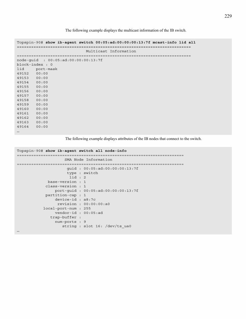
229
The following example displays the multicast information of the IB switch.
The following example displays attributes of the IB nodes that connect to the switch.
Topspin-90# show ib-agent switch 00:05:ad:00:00:00:13:7f mcast-info lid all========================================================================= Multicast Information=========================================================================node-guid : 00:05:ad:00:00:00:13:7fblock-index : 0lid port-mask49152 00:0049153 00:0049154 00:0049155 00:0049156 00:0049157 00:0049158 00:0049159 00:0049160 00:0049161 00:0049162 00:0049163 00:0049164 00:00…
Topspin-90# show ib-agent switch all node-info====================================================================== SMA Node Information====================================================================== guid : 00:05:ad:00:00:00:13:7f type : switch lid : 2 base-version : 1 class-version : 1 port-guid : 00:05:ad:00:00:00:13:7f partition-cap : 1 device-id : a8:7c revision : 00:00:00:a0 local-port-num : 255 vendor-id : 00:05:ad trap-buffer : num-ports : 9 string : slot 16: /dev/ts_ua0…

230
The following example displays the port attributes of the switch.
Topspin-360# show ib-agent switch 00:05:ad:00:00:00:13:7f port-info====================================================================== Port Information====================================================================== node-guid : 00:05:ad:00:00:00:13:7f port : 0 mkey : 00:00:00:00:00:00:00:00 gid-prefix : 00:00:00:00:00:00:00:00 lid : 2 master-SML-id : 1 capability-mask : 00:00:02:08 diag-code : 00:00 mkey-lease-period : 00:00 local-port-num : 255 link-width-enabled : 1x, 4x link-width-supported : 1x, 4x link-width-active : 1x link-speed-supported : 2.5 Gbps state : active port-phys : nop link-down-def : polling mkey-protect-bits : 0 LMC : 0 ls-active : 2.5 Gbps ls-active-enabled : 2.5 Gbps neighbor-MTU : 256 master-SMSL : 0 VL-cap : VL0 - VL7 VL-high-limit : 0 VL-arbitration-high-cap : 8 VL-arbitration-low-cap : 8 MTU-cap : 1024 VL-stall-count : 0 HOQ-life : 7 op-VLs : VL0 - VL7 pkey-enf-in : 0 pkey-enf-out : 0 filter-raw-pkt-in : 0 filter-raw-pkt-out : 0 mkey-violations : 0 pkey-violations : 0 qkey-violations : 0 guid-cap : 1 subnet-timeout : 31 resp-time-value : 8 local-phys-err : 4 overrun-err : 0

231
The following example displays the service level to virtual lane mapping table on the switch.
The following example displays SMA switch information.
Defaults:No default behavior or values.
Related Commands:“ib sm” on page 110“show ib sm configuration” on page 188“show ib sm neighbor” on page 195
Topspin-90# show ib-agent switch 00:05:ad:00:00:00:13:7f sl-vl-map====================================================================== SLVL-Map Table====================================================================== node-guid : 00:05:ad:00:00:00:13:7f in-ib-port : 0 out-ib-port : 0 sl0toVl : 0 sl1toVl : 0 sl2toVl : 0 sl3toVl : 0 sl4toVl : 0 sl5toVl : 0 sl6toVl : 0 sl7toVl : 0 sl8toVl : 0 sl9toVl : 0 sl10toVl : 0 sl11toVl : 0 sl12toVl : 0 sl13toVl : 0 sl14toVl : 0 sl15toVl : 0…
Topspin-360# show ib-agent switch all switch-info
============================================================================ SMA Switch Information============================================================================ guid : 00:05:ad:00:00:00:02:40 lft-cap : 49152 rft-cap : 0 mft-cap : 1024 lft-top : 1024 default-port : 255 def-mcast-pri-port : 255 def-mcast-NP-port : 255 life-time-value : 11 port-state-change : 0 lids-per-port : 0 partition-enf-cap : 64 inbound-enf-cap : 1 outbound-enf-cap : 1 filter-raw-pkt-in-cap : 1 filter-raw-pkt-out-cap : 1

232
“show ib sm partition” on page 200“show ib sm port” on page 202

233
show interface ethernetSynopsis:To display the attributes of Ethernet ports, enter the show interface ethernet command in User Exec mode or Privileged Exec mode.
Syntax:show interface ethernet {port-selection | all} [ip {ip-address | all} ip-info | ip-backup {backup-address | all} | statistics]
Platform Availability:Topspin 90, Topspin 360
Command Modes:User Exec mode, Privileged Exec mode.
Privilege Level:Ethernet read-only user.
Usage Guidelines:Use this command to help diagnose Ethernet connectivity problems.Table 6-74 lists and describes the fields in the show interface ethernet command output.
Table 6-73: show interface ethernet Command Arguments
Argument Descriptionport-selection Port, list of port, or range of ports that you want to view.
all • Displays the attributes of all the Ethernet ports on your switch when you enter it after the show interface ethernet command.
• Displays details on all IP addresses when you enter it after the ip keyword.• Displays details on all backup IP addresses when you enter it after the
ip-backup keyword.
ip Displays IP address table of the port(s) that you specify.
ip-address IP address whose details you want to view.
ip-info Displays statistical data of the transmissions that occur on IP addresses.
ip-backup Displays statistical data of the transmissions that occur on the backup IP addresses.
backup-address Backup IP address whose details you want to view.
statistics Displays Ethernet interface statistics for diagnostic purposes.
Table 6-74: show interface ethernet Command Fields
Field Descriptionport Port number, in slot#/port# format.
name Administratively configured port name.
type Type of port.
desc Name that you assign with the name command.
last-change Time of the most recent configuration change that a user made to the port.
mac-address MAC address of the port.

234
Table 6-75 lists and describes the fields in the ip keyword output.
Table 6-76 lists and describes the fields in the ip-info keyword output.
mtu MTU of the port, in bytes.
auto-negotiate-supported
Displays yes if the port supports auto negotiation.
auto-negotiate Displays enabled if you have configured auto negotiation to run on the port.
admin-status Administrative status of the port.
oper-status Operational status of the port.
admin-speed Administrative speed that you configured on the port.
oper-speed Operational (actual) speed at which the port runs. Actual speed differs from admin speed if the port on the other end of the connection cannot support the speed that you configured.
admin-duplex Administrative duplex type (half or full) that you configured to run on the port.
oper-duplex Operational (actual) duplex type at which the port runs. Actual duplex type differs from admin duplex type if the port on the other end of the connection cannot support the type that you specified.
link-trap Displays enabled if you configured the port to send link traps with the link-trap command.
action Action (such as flushing the ARP table) that you had the interface perform.
result Status of the action that you had the interface perform.
Table 6-75: ip Keyword Output Fields
Field Descriptionport Port number, in card#port# format. A port# of 0 represents the gateway port of the
interface card.
address IP address that you assigned to the port.
mask Subnet mask that you assigned to the port.
bcast-addr format
IP broadcast address format that the port uses.
reasm max-size Size of the largest IP datagram which this port can receive and reassemble from incoming fragmented IP datagrams.
type Displays primary or backup to indicate that the interface card acts as the primary or backup interface for the IP address that appears in the address field.
status Displays active or inactive to indicate that the card actively services IP packets addressed to the IP address in the address field or does not service packets to the specified address.
Table 6-76: ip-info Keyword Output Fields
Field Descriptionport Port number, in slot#/port# format.
default-ttl Default time-to-live value, in seconds.
Table 6-74: show interface ethernet Command Fields (Continued)
Field Description

235
Table 6-77 lists and describes the fields in the ip-backup keyword output.
in-receives Cumulative number of input datagrams (including errors) that interfaces received for the IP address that you specified with the ip keyword.
in-hdr-errors Cumulative number of datagrams that interfaces discarded. Reasons to discard a datagram include the following:• bad checksums• version number mismatches• format errors• exceeded time-to-live values• IP option processing errors
in-addr-errors Cumulative number of input datagrams that ports discarded because the IP address in the destination field of the header of the datagram was not a valid address to be received by the port.
forw-datagrams Cumulative number of datagrams that arrived at the port en-route to a final destination. For non-IP-gateway ports, this value includes only packets that the port Source-Routed successfully.
in-unknown-protos
Cumulative number of datagrams that the port successfully received but discarded due to an unknown or unsupported protocol.
in-discards Cumulative number of datagrams that the port discarded for a reason other than a problem with the datagram (for example, lack of buffer space).
in-delivers Cumulative number of input datagrams that the port successfully delivered to IP user-protocols, including Internet Control-Message Protocol (ICMP).
out-requests Cumulative number of IP datagrams that local IP user-protocols (including ICMP) supplied to IP in-requests. This counter does not include any datagrams counted as forw-datagrams.
out-discards Cumulative number of output IP datagrams that the port discarded for a reason other than a problem with the datagram (for example, lack of buffer space).
out-no-routes Cumulative number of IP datagrams that the port discarded because a route could not be found to transmit them to their destination. This counter includes any packets counted in forw-datagrams that still qualify. This counter also includes any datagrams that a switch cannot route because all of the gateways on the switch are down.
frag-OKs Cumulative number of IP datagrams that the port has successfully fragmented.
frag-fails Cumulative number of IP datagrams that the port discarded because the port could not fragment them. (For example, this occurs when the Don’t Fragment flag of the datagram is set.)
frag-creates Cumulative number of IP datagram fragments that the port has generated.
Table 6-77: ip-backup Keyword Output Fields
Field Descriptionif-index Port number.
backup-addr Backup address of the port.
priority Priority of the backup address that you applied with the ip command.
Table 6-76: ip-info Keyword Output Fields (Continued)
Field Description

236
Table 6-77 lists and describes the fields in the statistics keyword output.
Table 6-78: statistics Keyword Output Fields
Field Descriptionport Port identifier, in slot#/port# format.
name Administrative port name that you configured with the name command. The parenthetical identifier represents the SNMP identifier.
in-octets Cumulative number of octets that arrived at the port, including framing characters.
in-ucast-pkts Cumulative number of incoming packets destined for a single port.
in-multicast-pkts Cumulative number of incoming packets destined for the ports of a multicast group.
in-broadcast-pkts Cumulative number of incoming packets destined for all ports on the fabric.
in-discards Cumulative number of inbound packets that the port discarded for a reason other than a packet error (for example, lack of buffer space).
in-errors Number of inbound packets with errors that the port discarded.
in-unknown-protos For packet-oriented interfaces, the number of packets received via the interface which were discarded because of an unknown or unsupported protocol. For character-oriented or fixed-length interfaces that support protocol multiplexing, the number of transmission units received via the interface which were discarded because of an unknown or unsupported protocol. For any interface that does not support protocol multiplexing, this counter is always 0.
out-octets Total number of octets transmitted out of the interface, including framing characters.
out-ucast-pkts Total number of packets that higher-level protocols requested be transmitted, and which were not addressed to a multicast or broadcast address at this sub-layer, including those that were discarded or not sent.
out-multicast-pkts Total number of packets that higher-level protocols requested be transmitted, and which were addressed to a multicast address at this sub-layer, including those that were discarded or not sent. For a MAC layer protocol, this includes both Group and Functional addresses.
out-broadcast-pkts Total number of packets that higher-level protocols requested to be transmitted, and which were addressed to a broadcast address at this sub-layer, including those that were discarded or not sent.
out-discards Number of outbound packets which were chosen to be discarded even though no errors had been detected to prevent their being transmitted. One possible reason for discarding such a packet could be to free-up buffer space.
our-errors For packet-oriented interfaces, the number of outbound packets that could not be transmitted because of errors. For character-oriented or fixed-length interfaces, the number of outbound transmission units that could not be transmitted because of errors.

237
alignment-errors A count of frames received on a particular interface that are not an integral number of octets in length and do not pass the FCS check. The count represented by an instance of this object is incremented when the alignmentError status is returned by the MAC service to the LLC (or other MAC user). Received frames for which multiple error conditions obtain are counted exclusively according to the error status presented to the LLC. This counter does not increment for 8-bit wide group encoding schemes.
fcs-errors A count of frames received on a particular interface that are an integral number of octets in length but do not pass the FCS check. This count does not include frames received with frame-too-long or frame-too-short error. The count represented by an instance of this object is incremented when the frameCheckError status is returned by the MAC service to the LLC (or other MAC user). Received frames for which multiple error conditions obtain are counted exclusively according to the error status presented to the LLC. Coding errors detected by the physical layer for speeds above 10 Mbps will cause the frame to fail the FCS check.
single-collision-frames A count of successfully transmitted frames on a particular interface for which transmission is inhibited by exactly one collision. A frame that is counted by an instance of this object is also counted by the corresponding instance of the out-ucast-pkts, out-multicast-pkts, or out-broadcast-pkts, and is not counted by the corresponding instance of the multiple-collision-frames object. This counter does not increment when the interface is operating in full-duplex mode.
multiple-collision-frames A count of successfully transmitted frames on a particular interface for which transmission is inhibited by more than one collision. A frame that is counted by an instance of this object is also counted by the corresponding instance of the out-ucast-pkts, out-multicast-pkts, or out-broadcast-pkts, and is not counted by the corresponding instance of the single-collision-frames object. This counter does not increment when the interface is operating in full-duplex mode.
sqe-test-errors A count of times that the SQE TEST ERROR message is generated by the PLS sublayer for a particular interface. The SQE TEST ERROR is set in accordance with the rules for verification of the SQE detection mechanism in the PLS Carrier Sense Function, as described in IEEE Std. 802.3, 1998 Edition, section 7.2.4.6. This counter does not increment on interfaces operating at speeds greater than 10 Mbps, or on interfaces operating in full-duplex mode.
deferred-transmissions A count of frames for which the first transmission attempt on a particular interface is delayed because the medium is busy. The count represented by an instance of this object does not include frames involved in collisions. This counter does not increment when the interface is operating in full-duplex mode.
late-collisions The number of times that a collision is detected on a particular interface later than one Ethernet slot-time unit into the transmission of a packet. A late collision included in a count represented by an instance of this object is also considered as a generic collision for purposes of other collision-related statistics. This counter does not increment when the interface is operating in full-duplex mode.
Table 6-78: statistics Keyword Output Fields (Continued)
Field Description

238
Examples:The following example shows the general information about a specific IP address on an Ethernet interface port.
excessive-collisions A count of frames for which transmission on a particular interface fails due to excessive collisions. This counter does not increment when the interface is operating in full-duplex mode.
internal-mac-transmit-errors
A count of frames for which transmission on a particular interface fails due to an internal MAC sublayer transmit error. A frame is only counted by an instance of this object if it is not counted by the corresponding instance of the late-collisions object, the excessive-collisions object, or the carrier-sense-errors object. The precise meaning of the count represented by an instance of this object is implementation-specific. In particular, an instance of this object may represent a count of transmission errors on a particular interface that is not otherwise counted.
carrier-sense-errors Number of times that the carrier sense condition was lost or never asserted when attempting to transmit a frame on a particular interface. The count represented by an instance of this object is incremented at most once per transmission attempt, even if the carrier sense condition fluctuates during a transmission attempt. This counter does not increment when the interface is operating in full-duplex mode.
frame-too-longs A count of frames received on a particular interface that exceed the maximum permitted frame size. The count represented by an instance of this object is incremented when the frame-too-longs status is returned by the MAC service to the LLC (or other MAC user). Received frames for which multiple error conditions obtain are counted exclusively according to the error status presented to the LLC.
internal-mac-receive-errors A count of frames for which reception on a particular interface fails due to an internal MAC sublayer receive error. A frame is only counted by an instance of this object if it is not counted by the corresponding instance of the frame-too-longs, alignment-errors, or fcs-errors object. The precise meaning of the count represented by an instance of this object is implementation-specific. In particular, an instance of this object may represent a count of receive errors on a particular interface that is not otherwise counted.
Table 6-78: statistics Keyword Output Fields (Continued)
Field Description
Topspin-90# show inter ether 4/1 ip 10.3.22.4====================================================================== IP Address Table======================================================================port address mask bcast-addr reasm type status format max-size----------------------------------------------------------------------4/1 10.3.22.4 255.255.255.0 1 0 primary activeTopspin-90#

239
The following example displays statistical data regarding the IP transactions of all the IP addresses on an interface port. Statistical data is comprised of transmission errors, requests, discards, packet fragments, etc.
The following example displays traffic statistics for port 4/1.
Topspin-90# show inter ether 4/1 ip all ip-info====================================================================== IP Information====================================================================== port : 4/1 default-ttl : 0 in-receives : 0 in-hdr-errors : 0 in-addr-errors : 0 forw-datagrams : 0 in-unknown-protos : 0 in-discards : 0 in-delivers : 0 out-requests : 0 out-discards : 0 out-no-routes : 0 frag-OKs : 0 frag-fails : 0 frag-creates : 0Topspin-90#
Topspin-360# show interface ethernet 4/1 statistics====================================================================== Ethernet Interface Statistics====================================================================== port : 4/1 name : 4/1 (257) in-octets : 0 in-ucast-pkts : 0 in-multicast-pkts : 0 in-broadcast-pkts : 0 in-discards : 0 in-errors : 0 in-unknown-protos : 0 out-octets : 0 out-ucast-pkts : 0 out-multicast-pkts : 0 out-broadcast-pkts : 0 out-discards : 0 out-errors : 0
alignment-errors : 0 fcs-errors : 0 single-collision-frames : 0 multiple-collision-frames : 0 sqe-test-errors : 0 deferred-transmissions : 0 late-collisions : 0 excessive-collisions : 0 internal-mac-transmit-errors : 0 carrier-sense-errors : 0 frame-too-longs : 0 internal-mac-receive-errors : 0Topspin-360#

240
Defaults:No default behavior or values.
Related Commands:“half-duplex” on page 121“ip” on page 122“trunk-group” on page 126

241
show interface fcSynopsis:To display the attributes of FC ports, enter the show interface fc command in User Exec mode or Privileged Exec mode.
Syntax:show interface fc {port-selection | all} [statistics | targets | virtual-ports]
Platform Availability:Topspin 90, Topspin 360
Command Modes:User Exec mode, Privileged Exec mode.
Privilege Level:FC read-only user.
Usage Guidelines:The administrative (admin) status, speed, and connection-type reflect the values you had assigned. The operational (oper) status, speed, and connection-type reflect the values derived from the physical hardware and its connections. This allows you to verify your configuration settings against the actual hardware. The admin/oper pairs do not have to match for you to use the card. However, if there is a mismatch, the oper value is used.Table 6-80 lists and describes the fields in the show interface fc command output.
Table 6-79: show interface fc Command Arguments
Argument Descriptionport-selection Port, list of ports, or range of ports to display.
all Displays all FC ports on your switch.
statistics Displays traffic statistics for the port(s) that you specify.
targets Displays the targets that the ports(s) that you specify can access.
virtual-ports Displays the virtual ports that the FC gateway mapped to the port(s) that you specify.
Table 6-80: show interface fc Command Fields
Field Descriptionport FC gateway port number, in slot#/port# format.
name Administrative port name that you configure with the name command.
type Identifies the type of the port. All type identifiers begin with fc for FC ports.
desc Text description of the interface port. The default is the port identifier in slot#/port# format. The parenthetical number to the right of the description is the SNMP identifier. The SNMP identifier is useful if you are running your own SNMP software.
last-change Time of the most recent configuration change that a user made to the port.
fc-address FC Protocol address of the port.

242
Table 6-81 lists and describes the fields in the statistics keyword output.
wwnn WWNN of the port. The WWNN defaults to 00:00:00:00:00:00:00:00.
wwpn WWNN of the port. The WWPN defaults to 00:00:00:00:00:00:00:00.
mtu MTU of the port. The MTU value defaults to 2080 bytes.
auto-negotiate-supported Displays yes if the port supports auto-negotiation or no if the port does not support auto-negotiation.
auto-negotiate Indicates if the FC port on the interface card is configured to automatically negotiate connection parameters when it connects with a FC device. If auto negotiation is enabled, the connection speed and mode (duplex, half-duplex) are determined at the time of connection. If the device does not support auto negotiation, this field still displays a value, but the value does not apply. The value is enabled or disabled. The default is disabled. This field is set by the auto-negotiate command.
admin-status Indicates if you have enabled the port for configuration and use. The value of this field may be up or down. The default is down. The field is set by the shutdown command.
oper-status Indicates if the port is physically ready for configuration and use. The value of this field may be up or down. If this field is down but the admin-status is up, check that the FC interface card is securely seated in the slot and a cable is attached between the port and the target FC device.
admin-speed Indicates the speed administratively assigned to the FC port. The value of this field may be 2 Gbps or 1 Gbps. Speed defaults to 2 Gbps. You can configure this setting with the speed command.
oper-speed Indicates the maximum speed of the FC port, based upon the attached FC cable and polling the connected FC device.
admin-connection-type Indicates the type of connection administratively assigned to the interface port. The value may be forceNLPort, forceBPort, or none. The default is forceNLPort. This field is set by the type command.
oper-connection-type Indicates the type of connection dynamically discovered for the interface port.
link-trap Indicates if connection link errors are to be captured and sent to trap recipients. The value may be either enabled or disabled. This field is set by the link-trap command.
Table 6-81: statistics Keyword Output Fields
Field Descriptionport FC gateway port number, in slot#/port# format.
name Administratively assigned or default name of the port. The default name is the port name in slot#/port# format. Configure this field with the name command. The number in parentheses to the right of the name is the SNMP identifier. The SNMP identifier is useful if you are running your own SNMP software.
in-octets Cumulative number of octets received on the interface, including framing characters.
Table 6-80: show interface fc Command Fields (Continued)
Field Description

243
in-ucast-pkts Cumulative number of packets, delivered by this sub-layer to a higher layer, which were not addressed to a multicast or broadcast address at this sub-layer.
in-multicast-pkts Cumulative number of packets, delivered by this sub-layer to a higher layer, that were addressed to a multicast address at this sub-layer. For a MAC layer protocol, this includes both Group and Functional addresses.
in-broadcast-pkts Cumulative number of packets, delivered by this sub-layer to a higher layer, that were addressed to a broadcast address at this sub-layer.
in-discards Cumulative number of inbound packets that were discarded even though no errors had been detected to prevent their being delivered to a higher-layer protocol. One possible reason for discarding such a packet can be to free-up buffer space.
in-errors For packet-oriented interfaces, the cumulative number of inbound packets that contained errors that prevented them from being delivered to a higher-layer protocol. For character-oriented or fixed-length interfaces, the number of inbound transmission units that contained errors preventing them from being delivered to a higher-layer protocol.
in-unknown-protos For packet-oriented interfaces, the cumulative number of packets received via the interface which were discarded because of an unknown or unsupported protocol. For character-oriented or fixed-length interfaces that support protocol multiplexing, the number of transmission units received via the interface which were discarded because of an unknown or unsupported protocol. For any interface that does not support protocol multiplexing, this counter is always 0.
out-octets Cumulative number of octets transmitted out of the interface, including framing characters.
out-ucast-pkts Cumulative number of packets that higher-level protocols requested be transmitted, and which were not addressed to a multicast or broadcast address at this sub-layer, including those that were discarded or not sent.
out-multicast-pkts Cumulative number of packets that higher-level protocols requested be transmitted, and which were addressed to a multicast address at this sub-layer, including those that were discarded or not sent. For a MAC layer protocol, this includes both Group and Functional addresses.
out-broadcast-pkts Cumulative number of packets that higher-level protocols requested to be transmitted, and which were addressed to a broadcast address at this sub-layer, including those that were discarded or not sent.
out-discards Cumulative number of outbound packets which were chosen to be discarded even though no errors had been detected to prevent their being transmitted. One possible reason for discarding such a packet could be to free-up buffer space.
out-errors For packet-oriented interfaces, the cumulative number of outbound packets that could not be transmitted because of errors. For character-oriented or fixed-length interfaces, the number of outbound transmission units that could not be transmitted because of errors.
link-events Cumulative number of link events processed by the FC interface port.
fcp-cmds-outstanding Cumulative number of FCP commands outstanding on the FC interface port.
Table 6-81: statistics Keyword Output Fields (Continued)
Field Description

244
Table 6-82 lists and describes the fields in the targets keyword output.
Table 6-83 lists and describes the fields in the virtual-ports keyword output.
fcp-cmds-completed Cumulative number of FCP commands completed on the FC interface port.
fcp-errors Cumulative number of FCP errors encountered on the FC interface port.
fc-initiator-IO Cumulative number of transactions between the FC initiator and this port.
Table 6-82: targets Keyword Output Fields
Field Descriptionwwpn WWPN of the target.
wwnn WWNN of the target.
description Dynamically-assigned or administratively-assigned description of the target. Enter the fc srp target command with the description keyword to configure this field.
ioc-guid IOC GUID of the FC gateway that accesses the target.
service-name Name of the service that the target runs.
protocol-ids Lists the protocols that the target supports.
fc-address FC protocol address of the target.
mtu MTU of the target, in bytes.
connection-type For this release, all targets connect to NL_Ports.
physical-access Port, in slot#/port# format, on your switch to which the target connects.
Table 6-83: virtual-ports Keyword Output Fields
Field Descriptionguid GUID of the physical initiator.
extension GUID extension of the physical initiator.
initiator-description Administratively-assigned description of the initiator.
wwnn WWNN of the initiator.
port Physical port on your switch to which the virtual port maps.
wwpn WWPN of the virtual port.
fc-address FC protocol address of the virtual port.
Table 6-81: statistics Keyword Output Fields (Continued)
Field Description

245
Examples:The following example shows the output of the show interface fc command without the statistics keyword.
The following example displays all FC targets that the FC interfaces see.
Topspin-360# show interface fc 5/1====================================================================== Fibre Channel Interface Info====================================================================== port : 5/1 name : 5/1 type : fc2GFX desc : 5/1 (321) last-change : none fc-address : 00:00:00 wwnn : 00:00:00:00:00:00:00:00 wwpn : 00:00:00:00:00:00:00:00 mtu : 2080 auto-negotiate-supported : yes auto-negotiate : enabled admin-status : up oper-status : down admin-speed : 2gbps oper-speed : unknown oper-duplex : unknown admin-connection-type : force-NL oper-connection-type : down link-trap : enabled
Topspin-360# show interface fc all targets=============================================================================== Fc Targets=============================================================================== wwpn: 50:06:01:60:10:20:4e:31 wwnn: 50:06:01:60:90:20:4e:31 description: SRP.T10:5006016010204E31 ioc-guid: 00:05:ad:00:00:01:38:80 service-name: SRP.T10:5006016010204E31 protocol-ids: 04:00:00:00:00:00:00:00:00:00 fc-address: 61:07:13 mtu: 0 connection-type: nl-port physical-access: 9/2
wwpn: 50:06:01:68:10:20:4e:31 wwnn: 50:06:01:60:90:20:4e:31 description: SRP.T10:5006016810204E31 ioc-guid: 00:05:ad:00:00:01:38:80 service-name: SRP.T10:5006016810204E31 protocol-ids: 04:00:00:00:00:00:00:00:00:00<output truncated>

246
The following example displays all virtual ports on the interface.
Defaults:No default behavior or values.
Related Commands:“fc srp-global gateway-portmask-policy restricted” on page 101“fc srp-global itl” on page 102“fc srp it” on page 93“fc srp target” on page 100“interface” on page 47“show fc srp initiator” on page 160“show interface fc” on page 241“type” on page 79
Topspin-360# show interface fc all virtual-ports=============================================================================== Fc Virtual Ports=============================================================================== guid: 00:05:ad:00:00:12:34:56 extension: 00:00:00:00:00:00:00:00 initiator-description: kauai wwnn: 20:01:00:05:ad:01:5a:5c port: 9/1 wwpn: 20:01:00:05:ad:91:5a:5c fc-address: 61:0a:02
guid: 00:05:ad:00:00:12:34:56 extension: 00:00:00:00:00:00:00:00 initiator-description: kauai wwnn: 20:01:00:05:ad:01:5a:5c port: 9/2 wwpn: 20:01:00:05:ad:95:5a:5c fc-address: 61:05:02

247
show interface gatewaySynopsis:To display attributes of the internal IB gateway ports of FC and Ethernet expansion modules, enter the show interface gateway command in User Exec mode or Privileged Exec mode.
Syntax:show interface gateway slot-selection [fc srp initiator-target guid extension | {ip | ip-backup} {ip-address | all} | sma {node-info | port-info [details]}| statistics]
Platform Availability:Topspin 360, Topspin 90
Command Modes:User Exec mode, Privileged Exec mode.
Privilege Level:FC read-only user.
Usage GuidelinesUse this command to troubleshoot connectivity issues. Verify that the show output matches the configuration file.Table 6-85 lists and describes the fields in the show interface gateway command output.
Table 6-84: show interface gateway Command Arguments
Argument Descriptionslot-selection Internal gateway port that you want to view.
fc srp initiator-target Displays FC targets that an initiator can access.
guid GUID of the initiator.
extension GUID extension of the initiator.
ip Displays attributes of IP addresses on the card.
ip-backup Displays attributes of backup IP addresses on the card.
ip-address Individual IP address whose attributes you want to view.
all Displays attributes of all addresses.
sma Displays SMA information.
node-info Displays SMA node information
port-info Displays SMA port information.
details Displays detailed SMA port information.
statistics Displays gateway statistics of the card.
Table 6-85: show interface gateway Command Fields
Field Descriptiongateway Number of the slot in which the gateway resides.
name Administrative name that you configure with the name command.
type Type of interface card, either Ethernet or FC.

248
Table 6-86 lists and describes the fields that appear when you use the fc srp initiator-target argument with the show interface gateway command.
Table 6-87 lists and describes the fields that appear when you use the ip keyword with the show interface gateway command.
desc Description of the port, in slot#/port# format. The port identifier appears as zero (0) to indicate an internal port. The number in parentheses serves as the SNMP identifier.
last-change Time of the most recent configuration change that a user made to the port.
mtu Maximum transmission unit (MTU) of the internal gateway port.
admin-status Administrative status of the gateway that you configure with the shutdown command.
oper-status Actual status of the gateway.
Table 6-86: fc srp initiator-target Keyword Output Fields
Field Descriptionwwpn World-wide port name (WWPN) of the target that the initiator can access.
wwnn Wold-wide node name (WWNN) of the target that the initiator can access.
description Description of the target.
ioc-guid GUID of the IOC assigned to the target.
service-name Service that the target runs.
protocol-ids Lists the protocols that the target supports.
fc-address FC protocol address of the target.
mtu Maximum transmission unit (MTU) of the target.
connection-type Type of connection between the storage and the IB host. The field will always display nl-port, because all storage-to-IB host connections occur over a virtual port, or NL_Port.
physical-access Port or ports through which the target connects to the initiator.
Table 6-87: ip Keyword Output Fields
Field Descriptionport Port number, in card#/port# format. A port# of 0 represents the gateway port of the
interface card.
address IP address that you assigned to the port.
mask Subnet mask that you assigned to the port.
bcast-addr format
IP broadcast address format that the port uses.
reasm max-size Size of the largest IP datagram which this port can receive and reassemble from incoming fragmented IP datagrams.
type Displays primary or backup to indicate that the interface card acts as the primary or backup interface for the IP address that appears in the address field.
Table 6-85: show interface gateway Command Fields (Continued)
Field Description

249
Table 6-88 lists and describes the fields that appear when you use the ip-backup keyword with the show interface gateway command.
Table 6-89 lists and describes the fields that appear when you use the statistics keyword with the show interface gateway command.
NOTE: This keyword applies only to FC cards.
status Displays active or inactive to indicate that the card actively services IP packets addressed to the IP address in the address field or does not service packets to the specified address.
Table 6-88: ip-backup Keyword Output Fields
Field Descriptionif-index Numeric identifier, or “interface index,” of the port, in slot#/port# format.
backup-addr Lists backup IP addresses of the gateway.
priority Displays the priority of each backup address.
Table 6-89: statistics Keyword Output Fields
Field Descriptionslot-id Chassis slot that contains the gateway that you want to display.
link-events Cumulative number of link events that the gateway has processed.
srp-cmds-outstanding Cumulative number of unresolved SRP commands on the gateway.
srp-cmds-completed Cumulative number of SRP commands that the gateway executed.
srp-errors Cumulative number of SRP errors that the gateway encountered.
srp-initiated-ios Cumulative number of I/O transactions that initiators requested of FC devices through the gateway.
srp-bytes-read Cumulative number of I/O bytes that the gateway has read.
srp-bytes-written Cumulative number of I/O bytes that the gateway has written.
srp-connections Cumulative number of I/O connections that the gateway has used.
fcp-cmds-outstanding Cumulative number of unresolved FCP commands on the gateway.
fcp-cmds-completed Cumulative number of FCP commands that the gateway executed.
fcp-errors Cumulative number of FCP errors that the gateway encountered.
fcp-initiated-ios Cumulative number of I/O replies that FC devices sent through the gateway in response to SRP requests from initiators.
fcp-bytes-read Cumulative number of FC Protocol bytes that the card has read since it came up.
fcp-bytes-written Cumulative number of FC Protocol bytes that the card has written since it came up.
Table 6-87: ip Keyword Output Fields (Continued)
Field Description

250
Examples:The following example displays the attributes of the IP address of the gateway port.:
The following example uses the show interface gateway command to display general gateway properties. The information fields displayed depend upon the interface type. The example below displays the properties of a FC gateway port. To see the properties of an Ethernet port, refer to the description of “show interface ethernet” on page 233.
The following example displays traffic statistics for the internal gateway port.
Defaults:No default behavior or values.
Topspin-360# show interface gateway 5 ip all====================================================================== IP Address Table======================================================================port address mask bcast-addr reasm type status format max-size----------------------------------------------------------------------------4/0 10.3.22.0 255.255.255.0 1 0 primary activeTopspin-360#
Topspin-90# show interface gateway 4==============================================================================================================================
Gateway Information=============================================================== gateway : 4 name : 4/0 type : fc-gateway desc : 4/0 (320) last-change : none mtu : 0 admin-status : up oper-status : upTopspin-90#
Topspin-360# show inter gateway 2 stat=============================================================== Gateway Statistics=============================================================== slot-id: 2 link-events: 0 srp-cmds-outstanding: 0 srp-cmds-completed: 0 srp-errors: 0 srp-initiated-ios: 0 srp-bytes-read: 0 srp-bytes-written: 0 srp-connections: 0 fcp-cmds-outstanding: 0 fcp-cmds-completed: 0 fcp-errors: 0 fcp-initiated-ios: 0 fcp-bytes-read: 0 fcp-bytes-written: 0Topspin-360#

251
Related Commands:“fc srp initiator” on page 88“fc srp it” on page 93“interface” on page 47“show ip” on page 266

252
show interface ibSynopsis:To display attributes of IB ports, enter the show interface ib command in User Exec mode or Privileged Exec mode.
Syntax:show interface ib port-selection [sma {node-info | port-info [detail]} | statistics]
Platform Availability:HP 24-Port 4x Fabric Copper Switch, Topspin 90, Topspin 120, Topspin 270, Topspin 360, Topspin IB Server Switch Module
Command Modes:User Exec mode, Privileged Exec mode.
Privilege Level:IB read-only user.
Usage Guidelines:Without the optional sma or statistics keywords, the show interface ib command displays general information about the IB interface port, such as its administrative status, its operational speed and status, and duplex mode.Table 6-91 lists and describes the fields in the show interface ib command output.
Table 6-90: show interface ib Command Arguments
Argument Descriptionport-selection Port, list of ports, or range of ports that you want to view.
sma Displays SMA information.
node-info Displays node-based SMA information.
port-info Displays port-based SMA information
detail Displays detailed, port-based SMA information.
statistics Displays IB interface traffic statistics.
Table 6-91: show interface ib Command Fields
Field Descriptionport Identifies the IB interface card and port, in
slot#/port# format.
name User assigned name. If no name is assigned, the port name is displayed instead. This field is set by the name command.
type Identifies the type of the IB card. Supported cards are ib1xTX, ib1xFX, ib4xTX, and ib4xFX. This field is set by the type command.
desc Description of the port, in slot#/port# format. The number in parentheses serves as the SNMP identifier.

253
The administrative (admin) status, speed, and connection-type reflect the values you had assigned. The operational (oper) status, speed, and connection-type reflect the values derived from the physical hardware and its connections. This allows you to verify your configuration settings against the actual hardware. The admin/oper pairs do not have to match for you to use the card. However, if there is a mismatch, the oper value is used.Table 6-92 lists and describes the fields that appear when you use the sma node-info argument with the show interface ib command.
last-change Time at which the IB port configuration was last changed.
mtu MTU for the IB port. Used to configure the MTU size of IP network traffic.
auto-negotiate supported (select switches) Displays yes if the port supports auto negotiation or no if the port does not support auto negotiation.
auto-negotiate (select switches) Indicates if the IB port on the interface card is configured to automatically negotiate connection parameters when it connects with an IB device. If auto-negotiation is enabled, the connection speed is determined at the time of connection. If the device does not support auto negotiation, this field still displays a value, but the value does not apply. The value is enabled or disabled. The default is disabled. This field is set by the auto-negotiate command.
admin-status Indicates if you have enabled the port for configuration and use. The value of this field may be up or down. The default is down. The field is set by the shutdown command.
oper-status Indicates if the port is physically ready for configuration and use. The value of this field may be up or down. If this field is down but the admin-status is up, check that the IB interface card is securely seated in the slot and a cable is attached between the port and the target IB host.
admin-speed (select switches) Indicates the speed administratively assigned to the IB port. You can configure this setting with the speed command.
oper-speed (select switches) Indicates the maximum speed of the IB port, based upon the attached IB cable and polling the connected IB device.
link-trap Indicates if connection link errors are to be captured and sent to trap recipients. The value may be either enabled or disabled. This field is set by the link-trap command.
Table 6-92: sma node-info Keyword Output Fields
Field Descriptionguid GUID of the host.
type Type of SMA node. This value always appears as switch.
Table 6-91: show interface ib Command Fields (Continued)
Field Description

254
Table 6-93 lists and describes the fields that appear when you use the sma port-info argument with the show interface ib command.
lid Base LID of the port.
base-version Base management datagram version that the switch supports.
class-version Subnet management class that the switch supports.
port-guid GUID of the port(s) that you specified with the port-selection variable.
partition-cap Maximum number of partitions that the port supports.
device-id Manufacturer-assigned device ID.
revision Manufacturer-assigned device revision.
local-port-num Number of the link port that received this show request.
vendor-id Device vendor ID, as per the IEEE standard.
trap-buffer Special purpose string buffer for InfiniBand Trap Data.
num-ports Number of physical ports on the SMA node.
string SMA node description string.
Table 6-93: sma port-info Keyword Output Fields
Field Descriptionnode-guid GUID of the IB host that connects to the port.
port Host port that connects to your switch.
mkey 64-bit management key for this port. Refer to section 14.2.4, Management Key and 3.5.3, Keys, InfiniBand Architecture®, Vol. 1, Release 1.1, for more information.
gid-prefix 64-bit GID prefix for this port. This prefix is assigned by the SM, based upon the port router and the rules for local identifiers. See section 4.1.3, Local Identifiers, InfiniBand Architecture®, Vol. 1, Release 1.1, for more information.
lid 16-bit base-LID of this port.
Table 6-92: sma node-info Keyword Output Fields (Continued)
Field Description

255
Table 6-94 lists and describes the fields that appear when you use the sma port-info details argument with the show interface ib command.
capability-mask
32-bit bitmask that specifies the supported capabilities of the port. A bit value of 1 (one) indicates a supported capability. The bits are: • 0, 11-15, 18, 21-31 (Reserved and always 0) • 1 IsSM • 2 IsNoticeSupported • 3 IsTrapSupported • 4 IsResetSupported • 5 IsAutomaticMigrationSupported • 6 IsSLMappingSupported • 7 IsMKeyNVRAM (supports M_Key in NVRAM) • 8 IsPKeyNVRAM (supports P_Key in NVRAM) • 9 Is LED Info Supported • 10 IsSMdisabled • 16 IsConnectionManagementSupported • 17 IsSNMPTunnelingSupported• 19 IsDeviceManagementSupported • 20 IsVendorClassSupportedValues are expressed in hexadecimal.
state A higher form of addressing than PhyState, state determines that the nodes can actually communicate and indicates the state transition that has occurred. A transition is a port change from down to initialize, initialize to down, armed to down, or active to down as a result of link state machine logic. Changes to the port state resulting from SubnSet have no affect on this parameter value. The value is noStateChange, down, initialize, armed, or active.
Table 6-94: sma port-info details Keyword Output Fields
Field Descriptionnode-guid GUID of the IB host that connects to the port.
port Host port that connects to your switch.
mkey 64-bit management key for this port. Refer to section 14.2.4, Management Key and 3.5.3, Keys, InfiniBand Architecture®, Vol. 1, Release 1.1, for more information.
gid-prefix 64-bit GID prefix for this port. This prefix is assigned by the SM, based upon the port router and the rules for local identifiers. Refer to section 4.1.3, Local Identifiers, InfiniBand Architecture®, Vol. 1, Release 1.1, for more information.
lid 16-bit base-LID of this port.
master-sm-lid 16-bit base LID of the master SM managing this port.
Table 6-93: sma port-info Keyword Output Fields
Field Description

256
capability-mask 32-bit bitmask that specifies the supported capabilities of the port. A bit value of 1 (one) indicates a supported capability. The bits are: • 0, 11-15, 18, 21-31 (Reserved and always 0)• 1 IsSM • 2 IsNoticeSupported • 3 IsTrapSupported• 4 IsResetSupported• 5 IsAutomaticMigrationSupported • 6 IsSLMappingSupported • 7 IsMKeyNVRAM (supports M_Key in NVRAM) • 8 IsPKeyNVRAM (supports P_Key in NVRAM) • 9 Is LED Info Supported • 10 IsSMdisabled • 16 IsConnectionManagementSupported• 17 IsSNMPTunnelingSupported • 19 IsDeviceManagementSupported • 20 IsVendorClassSupportedValues are expressed in hexadecimal.
diag-code 16-bit diagnostic code. For more information, refer to section 14.2.5.6.1, “Interpretation of Diagcode” in InfiniBand Architecture®, Vol. 1, Release 1.1.
mkey-lease-period Initial value of the lease-period timer in seconds. The lease period is the length of time that the M_Key protection bits are to remain non-zero after a SubnSet (PortInfo) fails an M_Key check. After the lease period expires, clearing the M_Key protection bits allows any SM to read (and then set) the M_Key. Set this field to 0 to indicate that the lease period is never to expire. Refer to section 14.2.4, “Management Key” in InfiniBand Architecture®, Vol. 1, Release 1.1.
local-port-num Number of the link port which received this request, otherwise the value is 0.
link-width-enabled Enabled link width (speed). The value is an integer that indicates the enabled link-width sets for this port. The value may be:• 0 (no state change)• 1 (1x)• 2 (4x)• 3 (1x or 4x)• 8 (12x)• 9 (1x or 12x)• 10 (4x or 12x)• 11 (1x, 4x or 12x)• 255 (set this parameter to the link-width-supported value)
link-width-supported Supported link width. The value is 1 (1x), 3 (1x or 4x), or 11 (1x, 4x, or 12x).
Table 6-94: sma port-info details Keyword Output Fields (Continued)
Field Description

257
link-width-active Active link width. This parameter is used with LinkSpeedActive to determine the link rate between the two connected nodes. The value is width1x, width4x, or width12x.
link-speed-supported Speed that the link between the host and your device supports.
state A higher form of addressing than PhyState, state determines that the nodes can actually communicate and indicates the state transition that has occurred. A transition is a port change from down to initialize, initialize to down, armed to down, or active to down as a result of link state machine logic. Changes to the port state resulting from SubnSet have no affect on this parameter value. The value is noStateChange, down, initialize, armed, or active.
port-phys Indicates the actual state of the port. Determines that electricity flows between nodes so they can hand-shake. The value is noStateChange, sleeping, polling, disabled, portConfigurationTrainig, linkup, or linkErrorRecovery.
link-down-def Default LinkDown state to return to. The value is noStateChange, sleeping, or polling. See section 5.5.2, Status Outputs (MAD GET), InfiniBand Architecture®, Vol. 1, Release 1.1, for more information.
mkey-protect-bits Management key protection bits for the port. The bits are 0, 1, 2, and 3. See section 14.2.4.1, Levels of Protection, InfiniBand Architecture®, Vol. 1, Release 1.1, for more information.
lmc Local-identifier mask control (LMC) for multipath support. A LMC is assigned to each channel adapter and router port on the subnet. It provides multiple virtual ports within a single physical port. The value of the LMC specifies the number of path bits in the LID. A value of 0 (zero) indicates one LID is allowed on this port. See sections 3.5.10, Addressing, and 4.1.3, Local Identifiers, InfiniBand Architecture®, Vol. 1, Release 1.1, for more information.
ls-active Speed of an active link. The value is 1 (2.5 Gbps).
ls-active-enabled Maximum speed the link is capable of handling. The value is 0 (No state change), 1 (2.5 Gbps), or 3 (value derived from link-speed-supported).
neighbor-mtu Active maximum transmission unit enabled on this port for transmit. Check the mtu-cap value at both ends of every link and use the lesser speed. The value is mtu256, mtu512, mtu1024, mtu2048, or mtu4096.
master-sm-sl Administrative service level required for this port to send a non-SMP message to the SM.
vl-cap Maximum range of data virtual lanes supported by this port. The value is vl0, vl0ToVl1, vl0ToVl3, vl0ToVl7, or vl0ToVl14. See also oper-VL.
vl-high-limit Maximum high-priority limit on the number of bytes allowed for transmitting high-priority packets when both ends of a link operate with multiple data virtual-lanes. Used with the virtual-lane arbitration table. The maximum high-limit is determined by checking the vl-arb-high-cap on the other side of the link and then negotiating downward.
vl-arbitration-high-cap Highest arbitration value allowed by the arbiter in determining the next packet in a set of packets to send across the link. Used with the virtual-lane arbitration table and specified as a VL/Weight pair. Refer to section 14.2.5.9, VL Arbitration Table, InfiniBand Architecture®, Vol. 1, Release 1.1, for more information.
Table 6-94: sma port-info details Keyword Output Fields (Continued)
Field Description

258
vl-arbitration-low-cap Lowest arbitration value allowed by the arbiter in determining the next packet in a set of packets to send across the link. Used with the virtual-lane arbitration table and specified as a VL/Weight pair. Refer to section 14.2.5.9, VL Arbitration Table, InfiniBand Architecture®, Vol. 1, Release 1.1, for more information.
mtu-cap Used in conjunction with neighbor-mtu to determine the maximum transmission size supported on this port. The lesser of mtu-cap and neighbor-mtu determines the actual MTU used. The value is 256, 512, 1024, 2048, or 4096
vl-stall-count Number of sequentially dropped packets at which the port enters a VLStalled state. The virtual lane exits the VLStalled state (8 * HLL) units after entering it. Refer to section 18.2.5.4, Transmitter Queuing, InfiniBand Architecture®, Vol. 1, Release 1.1, for a description of HLL.
hoq-life Maximum duration allowed to packets at the head of a virtual-lane queue. Used with VL-stall-count to determine the outgoing packets to discard.
op-vls Administrative limit for the number of virtual lanes allowed to the link. Do not set this above the VL-cap value. The value is vl0, vl0-Vl1, vl0-Vl3, vl0-Vl7, or vl0-Vl14.
pkey-enf-in Boolean value that indicated whether or not to support optional partition enforcement for the packets received by this port.
pkey-enf-out Boolean value that indicates whether or not to support optional partition enforcement for the packets transmitted by this port.
filter-raw-pkt-in Boolean value that indicates whether or not so support optional raw packet enforcement for the raw packets received by this port.
filter-raw-pkt-out Boolean value that indicates whether or not so support optional raw packet enforcement for the raw packets transmitted by this port.
mkey-violations Number of SMPs that have been received on this port with invalid M_Keys since initial power-up or last reset. For more information, refer to section 14.2.4, “Management Key” in InfiniBand Architecture®, Vol. 1, Release 1.1.
pkey-violations Number of SMPs that have been received on this port with invalid P_Keys since initial power-up or the last reset. For more information, refer to section 9.2.7, “Partition Key” in InfiniBand Architecture®, Vol. 1, Release 1.1.
qkey-violations Number of SMPs that have been received on this port with invalid Q_Keys since initial power up or the last reset. For more information, refer to section 10.2.4, “Q Keys” in InfiniBand Architecture®, Vol. 1, Release 1.1.
guid-cap Number of GUID entries allowed for this port in the port table. For more information, refer to section 14.2.5.5, “GUIDCap” in InfiniBand Architecture®, Vol. 1, Release 1.1.
subnet-timeout Maximum propagation delay allowed for this port to reach any other port in the subnet. This value also affects the maximum rate at which traps can be sent from this port.
resp-timeout Maximum time allowed between the port reception of an SMP and the transmission of the associated response. For more information, refer to section 13.4.6.2, “Timers and Timeouts” in InfiniBand Architecture®, Vol. 1, Release 1.1.
Table 6-94: sma port-info details Keyword Output Fields (Continued)
Field Description

259
Table 6-95 lists and describes the fields that appear when you use the statistics keyword with the show interface ib command.
local-phys-err Threshold at which ICRC, VCRC, FCCRC, and all physical errors result in an entry into the BAD PACKET or BAD PACKET DISCARD states of the local packet receiver. For more information, refer to section 7.12.2, “Error Recovery Procedures” in InfiniBand Architecture®, Vol. 1, Release 1.1.
overrun-err Threshold at which the count of buffer overruns across consecutive flow-control update periods results in an overrun error.
Table 6-95: statistics Keyword Output Fields
Field Descriptionport Port identifier, in slot#/port# format.
name Administrative port name that you configured with the name command.
in-octets Cumulative number of octets that arrived at the port, including framing characters.
in-ucast-pkts Cumulative number of incoming packets destined for a single port.
in-multicast-pkts Cumulative number of incoming packets destined for the ports of a multicast group.
in-broadcast-pkts Cumulative number of incoming packets destined for all ports on the fabric.
in-discards Cumulative number of inbound packets that the port discarded for a reason other than a packet error (for example, lack of buffer space).
in-errors Number of inbound packets with errors that the port discarded.
in-unknown-protos For packet-oriented interfaces, the number of packets received via the interface which were discarded because of an unknown or unsupported protocol. For character-oriented or fixed-length interfaces that support protocol multiplexing, the number of transmission units received via the interface which were discarded because of an unknown or unsupported protocol. For any interface that does not support protocol multiplexing, this counter is always 0.
out-octets Total number of octets transmitted out of the interface, including framing characters.
out-ucast-pkts Total number of packets that higher-level protocols requested be transmitted, and which were not addressed to a multicast or broadcast address at this sub-layer, including those that were discarded or not sent.
out-multicast-pkts Total number of packets that higher-level protocols requested be transmitted, and which were addressed to a multicast address at this sub-layer, including those that were discarded or not sent.
out-broadcast-pkts Total number of packets that higher-level protocols requested to be transmitted, and which were addressed to a broadcast address at this sub-layer, including those that were discarded or not sent.
out-discards Number of outbound packets which were chosen to be discarded even though no errors had been detected to prevent their being transmitted. One possible reason for discarding such a packet could be to free-up buffer space.
Table 6-94: sma port-info details Keyword Output Fields (Continued)
Field Description

260
Examples:The following example shows the output of the show interface ib command without the sma or statistics keywords.
The following example shows the output of the show interface ib command with the statistics keyword.
out-errors For packet-oriented interfaces, the number of outbound packets that could not be transmitted because of errors. For character-oriented or fixed-length interfaces, the number of outbound transmission units that could not be transmitted because of errors.
Table 6-95: statistics Keyword Output Fields (Continued)
Field Description
Topspin-270# show interface ib 4/7
================================================================================ InfiniBand Interface Information================================================================================ port : 4/7 name : 4/7 type : ib4xFX desc : 4/7 (263) last-change : none mtu : 0 auto-negotiate-supported : yes auto-negotiate : enabled admin-status : up oper-status : down admin-speed : 10gbps oper-speed : unknown link-trap : enabled
Topspin-270# show interface ib 4/7 statistics
InfiniBand Interface Statistics================================================================================
port : 4/7 name : 4/7 in-octets : 0 in-ucast-pkts : 0 in-multicast-pkts : 0 in-broadcast-pkts : 0 in-discards : 0 in-errors : 0 in-unknown-protos : 0 out-octets : 0 out-ucast-pkts : 0 out-multicast-pkts : 0 out-broadcast-pkts : 0 out-discards : 0 out-errors : 0

261
Defaults:No default behavior or values.
Related Commands:“interface” on page 47“ib-agent” on page 113“name” on page 58

262
show interface mgmt-ethernetSynopsis:To show the configuration of the Ethernet Management port on the controller card of your switch, enter the show interface mgmt-ethernet command in User Exec mode or Privileged Exec mode.
Syntax:show interface mgmt-ethernet
Platform Availability:HP 24-Port 4x Fabric Copper Switch, Topspin 90, Topspin 120, Topspin 270, Topspin 360, Topspin IB Server Switch Module
Command Modes:User Exec mode, Privileged Exec mode.
Privilege Level:General read-only user.
Usage Guidelines:The Ethernet Management port is an Out-of-Band Management (OBM) port that provides network access to the switch chassis in order to run remote CLI and Element Manager sessions. The port must be configured before it can be used. This command displays the administrative status of the interface port, its assigned IP address and subnet mask, plus the IP address of the gateway port used to connect to the Ethernet Management port. If the Ethernet host is directly connected to the Ethernet Management port, without having to go through Ethernet switches, the default gateway-addr value is 0.0.0.0.On the Topspin 360, you may only access the Ethernet Management port on the currently active controller card. The CLI always defaults to port 2 on the active controller card.Table 6-96 lists and describes the fields that appear in the show interface mgmt-ethernet command output.
Table 6-96: show interface mgmt-ethernet Command Output Fields
Field Descriptionport Ethernet management port number, in slot#/port# format.
mac-address MAC address of the Ethernet management port.
auto-negotiate Displays enabled if the port automatically negotiates link speed.
admin-status Displays up if you enabled the port and down if you disabled the port.
ip-addr IP address of the port.
mask Subnet mask of the port.
gateway-addr Gateway configured for the port.
addr-option Address option of the port (refer to addr-option command on page 15).

263
Examples:The following example displays the configuration of the Ethernet Management port on the active controller.
Defaults:The gateway address value defaults to 0.0.0.0.
Related Commands:“gateway” on page 41“interface” on page 47
Topspin-270# show interface mgmt-ethernet
================================================================================
Mgmt-Ethernet Information================================================================================
port : 15/1 mac-address : 00:05:ad:00:19:16 auto-negotiate : enabled admin-status : up ip-addr : 10.3.108.43 mask : 255.255.0.0 gateway-addr : 10.3.0.1 addr-option : static

264
show interface mgmt-ibSynopsis:To display the status and address information for the virtual IB Management port, enter the show interface mgmt-ib command in User Exec mode or Privileged Exec mode.
Syntax:show interface mgmt-ib
Platform Availability:HP 24-Port 4x Fabric Copper Switch, Topspin 90, Topspin 120, Topspin 270, Topspin 360, Topspin IB Server Switch Module
Command Modes:User Exec mode, Privileged Exec mode.
Privilege Level:General read-only user.
Usage Guidelines:Use this command to verify that you have configured your IB Management port successfully. Compare this output to the configuration file and check for discrepancies. You must configure the IB Management port successfully to run telnet, SSH, and EM.
Examples:The following example displays the status and address information of the IB Management port.
Defaults:No default behavior or values.
Related Commands:“gateway” on page 41“interface” on page 47“telnet” on page 74
Topspin-90# show interface mgmt-ib=============================================================== Mgmt-InfiniBand Information=============================================================== descr : Inband Management Port admin-status : up ip-addr : 192.168.2.200 mask : 255.255.255.0 gateway-addr : 0.0.0.0Topspin-90#

265
show interface mgmt-serialSynopsis:To display the configuration of the Serial Console port on the controller card of your switch, enter the show interface mgmt-serial command in User Exec mode or Privileged Exec mode.
Syntax:show interface mgmt-serial
Platform Availability:HP 24-Port 4x Fabric Copper Switch, Topspin 90, Topspin 120, Topspin 270, Topspin 360, Topspin IB Server Switch Module
Command Modes:User Exec mode, Privileged Exec mode.
Privilege Level:General read-only user.
Usage Guidelines:This command displays the default configuration. This configuration cannot be changed.The Serial Console port is the initial connection point with the switch chassis and is used to configure the Ethernet Management and Infiniband Management ports. This port must be configured and a management station attached before any interaction with the switch chassis is possible. For the Topspin 360, you may only access the Serial Console port on the currently active controller card.
Examples:
Defaults:No default behavior or values.
Related Commands:“show interface mgmt-ethernet” on page 262“show interface mgmt-ib” on page 264“shutdown” on page 66
Topspin-90# show interface mgmt-serial=============================================================== Mgmt-Serial Information=============================================================== baud-rate : 9600 data-bits : 8 stop-bits : 1 parity : offTopspin-90#
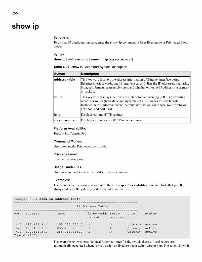
266
show ipSynopsis:To display IP configuration data, enter the show ip command in User Exec mode or Privileged Exec mode.
Syntax:show ip [address-table | route | http [server secure]]
Platform Availability:Topspin 90, Topspin 360
Command Modes:User Exec mode, Privileged Exec mode.
Privilege Level:Ethernet read-only user.
Usage Guidelines:Use this command to view the results of the ip command.
Examples:The example below shows the output of the show ip address-table command. Note that port 0 always indicates the gateway port of the interface card.
The example below shows the local Ethernet routes for the switch chassis. Local routes are automatically generated whenever you assign an IP address to a switch card or port. The codes shown in
Table 6-97: show ip Command Syntax Description
Syntax Descriptionaddress-table This keyword displays the address information of Ethernet interface ports,
Ethernet interface cards, and IB interface cards. It lists the IP addresses, netmasks, broadcast formats, reassembly sizes, and whether or not the IP address is a primary or backup.
route This keyword displays the Classless Inter-Domain Routing (CIDR) forwarding records or routes (both static and dynamic) of all IP routes to switch ports. Included in this information are the route destination, route type, route protocol, next hop, and port used.
http Displays current HTTP settings.
server secure Displays current secure HTTP server settings.
Topspin-360# show ip address-table=============================================================== IP Address Table===============================================================port address mask bcast-addr reasm type status format max-size---------------------------------------------------------------------------- 4/0 192.168.2.1 255.255.255.0 1 0 primary active 4/1 192.168.1.1 255.255.255.0 1 0 primary active 4/2 192.168.3.1 255.255.255.0 1 0 primary activeTopspin-360#

267
the proto column are explained in the output header. A next-hop value of 0.0.0.0 always indicates a local route.
Defaults:No default behavior or values.
Related Commands:“interface” on page 47“ip” on page 122
Topspin-90# show ip route============================================================================ IP Routes============================================================================Protocol Codes: OT - other L - local NM - netmgmt IC - icmp E - egp G - ggp H - hello R - rip IS - ISIS ES - ES_IS, CI - ciscoIgrp BS - bbnSpfIgp O - OSPF B - BGP ID - IDPR
dest mask next-hop port type proto metric----------------------------------------------------------------------------10.10.0.3 255.255.255.0 192.168.1.0 4/1 remote NM 0192.168.1.0 255.255.255.0 0.0.0.0 4/1 local L 0192.168.2.0 255.255.255.0 0.0.0.0 4/0 local L 0192.168.3.0 255.255.255.0 0.0.0.0 4/2 local L 0Topspin-90#

268
show ip httpSynopsis:To view the configuration of the HTTP server on your switch, enter the show ip http command in User Exec mode or Privileged Exec mode.
Syntax:show ip http
Platform Availability:HP 24-Port 4x Fabric Copper Switch, Topspin 90, Topspin 120, Topspin 270, Topspin 360, Topspin IB Server Switch Module
Command Modes:User Exec mode, Privileged Exec mode.
Privilege Level:Ethernet read-only user.
Usage Guidelines:Use this command to determine if your HTTP server actively runs on your switch, and to determine the HTTP port number that it uses.Table 6-98 lists and describes the fields in the command output.
Examples:The following example displays the configuration of the HTTP server on the switch.
Defaults:No default behavior or values.
Table 6-98: show ip http Command Output Fields
Field Descriptionserver Displays enabled if you have activated the server with the ip http server
command. Displays disabled if you have deactivated the server with the no ip http server command.
port Displays the HTTP port number that the HTTP server uses.
polling Displays enabled or disabled to indicate polling status.
Topspin-270# show ip http
================================================================================
IP HTTP Info================================================================================
server : enabled port : 80 polling : enabled

269
Related Commands:“ip http” on page 49

270
show ip http server secureSynopsis:To view the HTTP configuration on your switch, enter the show ip http secure server command in User Exec mode or Privileged Exec mode.
Syntax:show ip http secure server
Platform Availability:HP 24-Port 4x Fabric Copper Switch, Topspin 90, Topspin 120, Topspin 270, Topspin 360, Topspin IB Server Switch Module
Command Modes:User Exec mode, Privileged Exec mode.
Privilege Level:Ethernet read-only user.
Usage Guidelines:Use this command to determine if HTTP actively runs on your switch, and to determine the HTTP port number that it uses.Table 6-99 lists and describes the fields in the command output.
Examples:The following example displays the HTTP configuration on the switch.
Defaults:No default behavior or values.
Table 6-99: show ip http Command Output Fields
Field Descriptionsecure-server Displays enabled if you have activated the server with the ip http
server command. Displays disabled if you have deactivated the server with the no ip http server command.
secure-port Displays the HTTP port number that the HTTP server uses.
secure-cert-common-name
Certificate name of the secure server.
Topspin-270# show ip http server secure
================================================================================
IP HTTP Secure Info================================================================================
secure-server : enabled secure-port : 443 secure-cert-common-name : useMgmtEnetIpAddr

271
Related Commands:“ip http” on page 49

272
show locationSynopsis:To display the location data on your switch, enter the show location command in User Exec mode or Privileged Exec mode.
Syntax:show location
Platform Availability:HP 24-Port 4x Fabric Copper Switch, Topspin 90, Topspin 120, Topspin 270, Topspin 360, Topspin IB Server Switch Module
Command Modes:User Exec mode, Privileged Exec mode.
Privilege Level:General read-only user.
Usage Guidelines:The show location command displays some contact information to the user, however, it may be configured to display any desired text string.
Examples:The following example displays the location information that you configured with the location command.
Defaults:No default behavior or values.
Related Commands:“location” on page 52“snmp-server” on page 69“show version” on page 293
Topspin-90# show location515 Ellis Street, Mountain View, CA 94043Topspin-90#

273
show loggingSynopsis:To display the active system log file, enter the show logging command in User Exec mode or Privileged Exec mode.
Syntax:show logging [end]
Platform Availability:HP 24-Port 4x Fabric Copper Switch, Topspin 90, Topspin 120, Topspin 270, Topspin 360, Topspin IB Server Switch Module
Command Modes:User Exec mode, Privileged Exec mode.
Privilege Level:General read-only user.
Usage Guidelines:• Use this command to view any of the following:
• warnings• errors• notifications• alerts
• You may want to set the number of lines displayed per screen using the terminal length command. You can also use the more command on ts_log instead of the show logging command.
• The show logging end command is the equivalent of using the UNIX tail -f command. The CLI continues to display log entries as they occur until you enter Ctrl-c. No other CLI commands may be entered until Ctrl-c is used to stop the log display.
• It is recommended you set the terminal page length to 0 when using the end argument. Otherwise, you will have to keep pressing the space bar to continue each time the maximum display length is reached. Once you set the page length, do not change the terminal window size. Changing window size restores the terminal length to that of the window and restarts paging.
• The system log file on the chassis controller is /var/log/topspin.
Table 6-100: show logging Syntax Description
Syntax Descriptionend Displays approximately the last 10 entries in the system log and then continues to display
log entries as they occur.

274
Examples:The following example displays the last 10 log entries.
Defaults:No default behavior or values.
Related Commands:“copy” on page 28“logging” on page 53“show config” on page 157“telnet” on page 74“terminal” on page 75
Topspin-90# show logging endJan 3 11:09:58 igr-cc ib_sm.x[597]: [INFO]: Successfully add pgid fe800000000000000005ad0000001199 to mgid ff18a01b00000000000005ad00000002Jan 3 17:02:56 igr-cc port_mgr.x[535]: [INFO]: port down - port=16/7, type=ib4xFXJan 3 17:02:58 igr-cc port_mgr.x[535]: [INFO]: port up - port=16/7, type=ib4xFXJan 3 18:21:46 igr-cc port_mgr.x[535]: [INFO]: port down - port=16/2, type=ib4xFXJan 3 18:21:48 igr-cc port_mgr.x[535]: [INFO]: port up - port=16/2, type=ib4xFXJan 3 19:35:55 igr-cc chassis_mgr.x[523]: [CONF]: [super]: config snmp trap-receiver 10.10.253.47Jan 3 19:35:55 igr-cc chassis_mgr.x[523]: [CONF]: [super]: config snmp trap-receiver 10.10.253.47 version v2cJan 3 19:35:55 igr-cc chassis_mgr.x[523]: [CONF]: [super]: config snmp trap-receiver 10.10.253.47 community publicJan 3 19:35:55 igr-cc chassis_mgr.x[523]: [CONF]: [super]: config snmp trap-receiver 10.10.253.47 community public

275
show ntpSynopsis:To display the following:• the current date and time of your switch• the Network Time Protocol (NTP) servers that your switch uses to set the system clockenter the show ntp command in User Exec mode or Privileged Exec mode.
Syntax:show ntp
Platform Availability:HP 24-Port 4x Fabric Copper Switch, Topspin 90, Topspin 120, Topspin 270, Topspin 360, Topspin IB Server Switch Module
Command Modes:User Exec mode, Privileged Exec mode.
Privilege Level:General read-only user.
Usage Guidelines:Use the clock set command to set the time and date. Use the ntp command to set the NTP servers that are to maintain the system clock.
Examples:The following example displays the current date and time, as well as NTP server details.
Defaults:No default behavior or values.
Related Commands:“ntp” on page 59“clock set” on page 24
Topspin-360> show ntp=============================================================== NTP Information=============================================================== Date : 04/16/03 Time : 16:02:43 Server One : 10.3.120.55 Server Two : 10.3.120.56 Server Three : 10.3.120.57Topspin-360>

276
show power-supplySynopsis:To display the status of the power supplies on your switch, enter the show power-supply command in User Exec mode or Privileged Exec mode.
Syntax:show power-supply
Platform Availability:HP 24-Port 4x Fabric Copper Switch, Topspin 90, Topspin 120, Topspin 270, Topspin 360, Topspin IB Server Switch Module
Command Modes:User Exec mode, Privileged Exec mode.
Privilege Level:General read-only user.
Usage Guidelines:Use this command to monitor the power supply. This command primarily serves to help management tools continuously monitor power supply status. Errors in the ts_log file may prompt you to check power supply status.
Table 6-101: show power-supply Command Fields
Field Descriptiontype Indicates AC power.
oper-status Displays up or down to indicate the status of the power supply.
utilization Displays percentage of power utilization when multiple power supplies provide power. Displays n/a when one power supply runs.
voltage Voltage of the power supply.
product serial-number
Factory-assigned product serial number.
pca serial-number PCA serial number.
pca number PCA assembly number.
fru number FRU number for the actual switch (select chassis) or chassis (select chassis).

277
Examples:The following example displays power supply details.
Defaults:No default behavior or values.
Related Commands:“show backplane” on page 131“show fan” on page 158“show sensor” on page 282
Topspin-270> show power-supply
================================================================================ Power-supply Information================================================================================ps type oper-status utilization voltage --------------------------------------------------------------------------------1 AC up n/a 48 2 AC down n/a 48
================================================================================ Power-supply Seeprom================================================================================ product pca pca fru ps serial-number serial-number number number --------------------------------------------------------------------------------1 - - - - 2

278
show redundancy-groupSynopsis:To display redundancy group information, enter the show redundancy-group command in User Exec mode or Privileged Exec mode.
Syntax:show redundancy-group [rlb-id]
Platform Availability:Topspin 90, Topspin 360
Command Modes:User Exec mode, Privileged Exec mode.
Privilege Level:Ethernet read-only user.
Usage Guidelines:Use this command to view redundancy groups and attributes of redundancy groups. Table 6-103 lists and describes the fields in the command output.
Examples:The following example displays the redundancy groups on the chassis.
Defaults:This command displays all redundancy groups by default.
Table 6-102: show redundancy-group Command Arguments
Argument Descriptionrlb-id Number of the redundancy group that you want to view.
Table 6-103: show redundancy-group Command Fields
Field Descriptionrlb-id Redundancy group ID.
name Redundancy group name.
fail-over-order Failover order of the group.
load-balancing Displays enabled if load balancing runs, otherwise displays disabled.
num-members Number of members in the redundancy group.
Topspin-360# show redundancy-group
================================================================================ Redundancy Groups================================================================================ rlb-id : 11 name : fail-over-order : auto load-balancing : disabled num-members : 2

279
Related Commands:“redundancy-group” on page 125

280
show running-statusSynopsis:To execute a thorough range of show commands for a particular technology, enter the show running-status command in User Exec mode or Privileged Exec mode.
Syntax:show running-status {all | ethernet | fc | ib} [to-file]
Platform Availability:HP 24-Port 4x Fabric Copper Switch, Topspin 90, Topspin 120, Topspin 270, Topspin 360, Topspin IB Server Switch Module
Command Modes:User Exec mode, Privileged Exec mode.
Privilege Level:General read-only user.
Usage Guidelines:This command can generate a large amount of data. Data is displayed per terminal length command settings. When executed, this command first prompts you to verify your desire to generate the data. Enter y to continue or n to cancel.The default output file is syslog:igr_interface_runningstatus, where interface may be ether, fc, ib, or all. If the file already exists, it will be overwritten. This text file may be uploaded to another system using the copy command or viewed using the more command.
Table 6-104: show running-status Command Arguments
Argument Descriptionall Runs show commands for Ethernet, FC, and IB technologies.
ethernet Runs show commands for Ethernet only.
fc Runs show commands for FC only.
ib Runs show command for IB only.
to-file Saves the output of the show commands to a file in the syslog directory on your switch and displays the name of the file.

281
Examples:The following example runs all Ethernet show commands.
Defaults:No default behavior or values.Related Commands:See most of the other “show” commands. “show interface ethernet” on page 233“show interface fc” on page 241
Topspin-90> show running-status ethernetAre you sure you want to continue? [yes/no] yGathering system-wide information, please wait.....Topspin-90> show arp ethernet=============================================================== ARP Information===============================================================port physical-address net-address type---------------------------------------------------------------Topspin-90> show arp ib
=============================================================== ARP Information===============================================================port physical-address net-address type----------------------------------------------------------------------------
Topspin-90> show backplane=============================================================== Backplane Seeprom===============================================================base-mac-addr chassis-id---------------------------------------------------------------1a:0:a:3a:0:a 0x600000000……
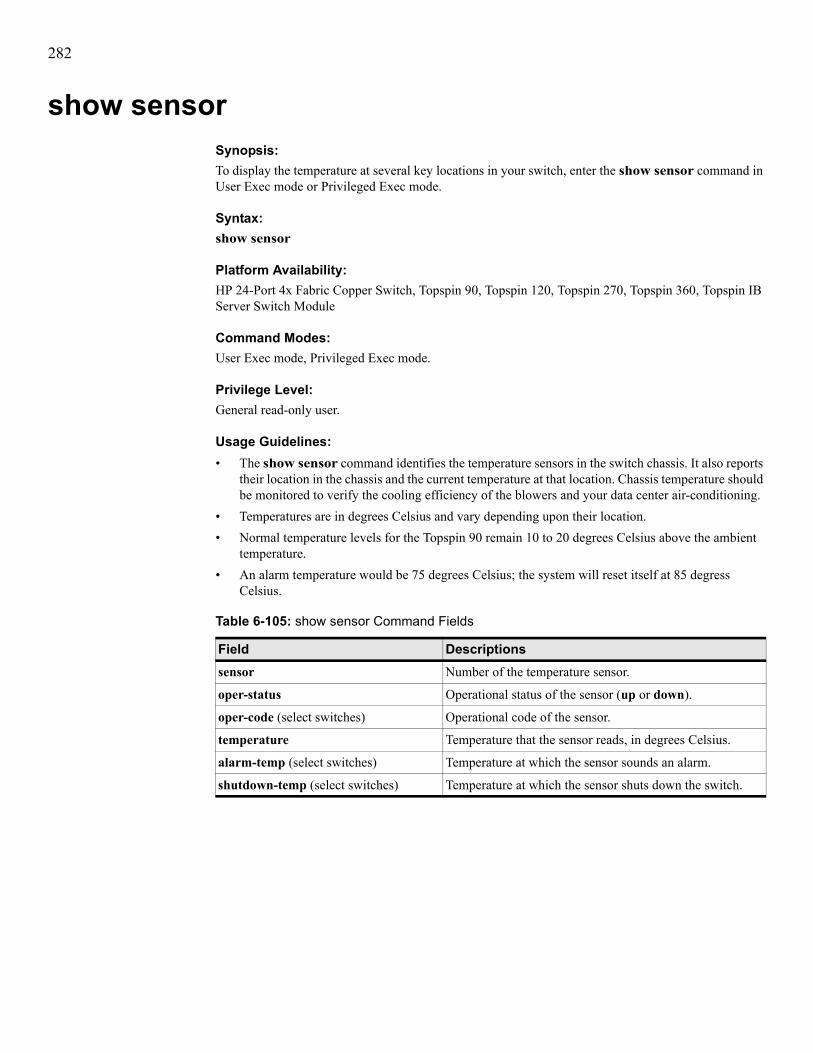
282
show sensorSynopsis:To display the temperature at several key locations in your switch, enter the show sensor command in User Exec mode or Privileged Exec mode.
Syntax:show sensor
Platform Availability:HP 24-Port 4x Fabric Copper Switch, Topspin 90, Topspin 120, Topspin 270, Topspin 360, Topspin IB Server Switch Module
Command Modes:User Exec mode, Privileged Exec mode.
Privilege Level:General read-only user.
Usage Guidelines:• The show sensor command identifies the temperature sensors in the switch chassis. It also reports
their location in the chassis and the current temperature at that location. Chassis temperature should be monitored to verify the cooling efficiency of the blowers and your data center air-conditioning.
• Temperatures are in degrees Celsius and vary depending upon their location.• Normal temperature levels for the Topspin 90 remain 10 to 20 degrees Celsius above the ambient
temperature. • An alarm temperature would be 75 degrees Celsius; the system will reset itself at 85 degress
Celsius.
Table 6-105: show sensor Command Fields
Field Descriptionssensor Number of the temperature sensor.
oper-status Operational status of the sensor (up or down).
oper-code (select switches) Operational code of the sensor.
temperature Temperature that the sensor reads, in degrees Celsius.
alarm-temp (select switches) Temperature at which the sensor sounds an alarm.
shutdown-temp (select switches) Temperature at which the sensor shuts down the switch.

283
Examples:The following example displays the temperature sensor information on the switch.
Defaults:No default behavior or values.
Related Commands:“show fan” on page 158“show power-supply” on page 276
Topspin-270# show sensor
================================================================================
Sensor Information================================================================================
sensor oper-status oper-code temperature(c) alarm-temp(c) shutdown-temp(c)--------------------------------------------------------------------------------
10/1 up normal 35 75 8511/1 up normal 31 75 8512/1 up normal 29 75 8513/1 up normal 31 75 8515/1 up normal 38 70 8016/1 up normal 37 70 80

284
show snmpSynopsis:To display the SNMP receivers for link traps on your switch, enter the show snmp command in User Exec mode or Privileged Exec mode.
Syntax:show snmp[user {all | user-name}]
Platform Availability:HP 24-Port 4x Fabric Copper Switch, Topspin 90, Topspin 120, Topspin 270, Topspin 360, Topspin IB Server Switch Module
Command Modes:User Exec mode, Privileged Exec mode.
Privilege Level:Unrestricted read-write user.
Usage Guidelines:Use this command to verify the SNMP servers that you configure with the snmp-server command.
Examples:The following example displays the SNMP trap receivers configured on the switch.
Table 6-106: show snmp Command Arguments
Argument Descriptionuser Displays SNMP information for all users or for one particular user if you specify that
user with the user-name variable.
user-name User whose SNMP information you want to display.
Topspin-270# show snmp
================================================================================ SNMP Information================================================================================ contact : [email protected] location : 515 Ellis Street, Mountain View, CA 94043
================================================================================ Trap Receivers================================================================================ipaddr version community recv-events ----------------------------------------------------------------------

285
The following example displays the SNMP trap receivers for all users.
Defaults:No default behavior or values.Related Commands:“link-trap” on page 51“location” on page 52“logging” on page 53“snmp-server” on page 69
Topspin-270# show snmp user
================================================================================ SNMPv3 User Information================================================================================ engine-id : 80:00:18:3b:05:05:00:30:30:30:30:30:31:39:37:64
username : admin auth-type : sha auth-password : C568FC22657A9EF602C0B81EEC159554B89DD75A priv-type : des56 priv-password : C568FC22657A9EF602C0B81EEC159554 permission-level : ib-rw, ip-ethernet-rw, fc-rw enable : disabled
username : guest auth-type : none priv-type : none permission-level : ib-ro, ip-ethernet-ro, fc-ro enable : disabled
username : super auth-type : md5 auth-password : C447A2DCD5FE2AD2167DF19401881AE0 priv-type : des56 priv-password : C447A2DCD5FE2AD2167DF19401881AE0 permission-level : unrestricted-rw enable : disabled

286
show system-servicesSynopsis:To display system services such as FTP and telnet, enter the show system-services command in User Exec mode or Privileged Exec mode.
Syntax:show system-services
Platform Availability:HP 24-Port 4x Fabric Copper Switch, Topspin 90, Topspin 120, Topspin 270, Topspin 360
Command Modes:User Exec mode, Privileged Exec mode.
Privilege Level:Unrestricted read-write user.
Usage Guidelines:Use this command to discover what system services (e.g. telnet, ftp, and syslog) run on your switch. You can configure any or all of these services to manage your switch.
Examples:The following example displays the system services that run on the switch.
Defaults:No default behavior or values.Related Commands:“ftp-server enable” on page 40“history” on page 43“radius-server” on page 61“snmp-server” on page 69
Topspin-360# show system-services================================================================================ System Services================================================================================ ftp service : disabled telnet service : enabled syslog server : 0.0.0.0================================================================================ NTP Information================================================================================ date : 09/30/03 time : 09:57:19 server-one : 0.0.0.0 server-two : 0.0.0.0 server-three : 0.0.0.0================================================================================ Host Information================================================================================ name-server-one : 0.0.0.0 name-server-two : 0.0.0.0 domain-name :

287
“ntp” on page 59“hostname” on page 44“ip” on page 122“telnet” on page 74“terminal” on page 75

288
show terminalSynopsis:To display terminal parameters, enter the show terminal command in User Exec mode or Privileged Exec mode.
Syntax:show terminal
Platform Availability:HP 24-Port 4x Fabric Copper Switch, Topspin 90, Topspin 120, Topspin 270, Topspin 360, Topspin IB Server Switch Module
Command Modes:User Exec mode, Privileged Exec mode.
Privilege Level:General read-only user.
Usage Guidelines:Use this command to view information about your CLI session. The command provides useful information such as timeout parameters, output-screen length, and history-buffer size.
Examples:
Defaults:No default behavior or values.
Related Commands:“telnet” on page 74“terminal” on page 75
Topspin-90# show terminalConsole is enabledConnection host address is 10.10.253.128Length: 25 lines, Width: 80 columnsTimeouts: enabled, Value: 15 minutesSession limit is set to 3History is enabled, history size is 30Maximum command length is 512 charactersMaximum login attempts is 5

289
show traceSynopsis:To display the system program modules that your switch calls, enter the show trace command in User Exec mode or Privileged Exec mode.
Syntax:show trace app application-number [module module-number] [card card-number]
Platform Availability:HP 24-Port 4x Fabric Copper Switch, Topspin 90, Topspin 120, Topspin 270, Topspin 360, Topspin IB Server Switch Module
Command Modes:User Exec mode, Privileged Exec mode.
Privilege Level:General read-only user.
Usage Guidelines:This command is intended primarily for program debug under the direction of Support personnel. Recommend hiding this command from customers.
Examples:The following example traces application 9, module 1, card 2.
Defaults:No default behavior or values.
Related Commands:“show logging” on page 273“trace” on page 77
Table 6-107: show trace Command Arguments
Argument Descriptionapp Specifies the application to trace.
application-number Number of the application to trace. Use the online help (?) to view a list of applications and application numbers.
module Specifies the module to trace.
module-number Number of the module to trace. Use the online help (?) to view a list of modules and module numbers.
card Specifies the card to trace.
card-number Number of the card to trace. Use the online help (?) to view a list of cards and card numbers.
Topspin-360> show trace app 9 mod 1 card 2 AMF 1 0x0 0x0

290
show trunkSynopsis:To display the current configuration of trunk groups, enter the show trunk command in User Exec mode or Privileged Exec mode.
Syntax:show trunk [trunk id]
Platform Availability:Topspin 90, Topspin 360
Command Modes:User Exec mode, Privileged Exec mode.
Privilege Level:Unrestricted read-write user.
Usage Guidelines:Use this command to view the trunk groups that you have configured on your switch. You can verify trunk-group related changes that you have made to the configuration file with the show trunk command.
Examples:The following example displays the trunk groups on the switch.
Defaults:No default behavior or values.
Related Commands:“distribution-type” on page 119“interface” on page 47“trunk-group” on page 126
Topspin-90# show trunk
================================================================================ Trunks Groups ================================================================================ trunk-group-id : 1 trunk-group-name : distribution-type : src-dst-mac port-members : enable : false mtu : 0 mac-addr : 00:00:00:00:00:00 ifindex : 45057
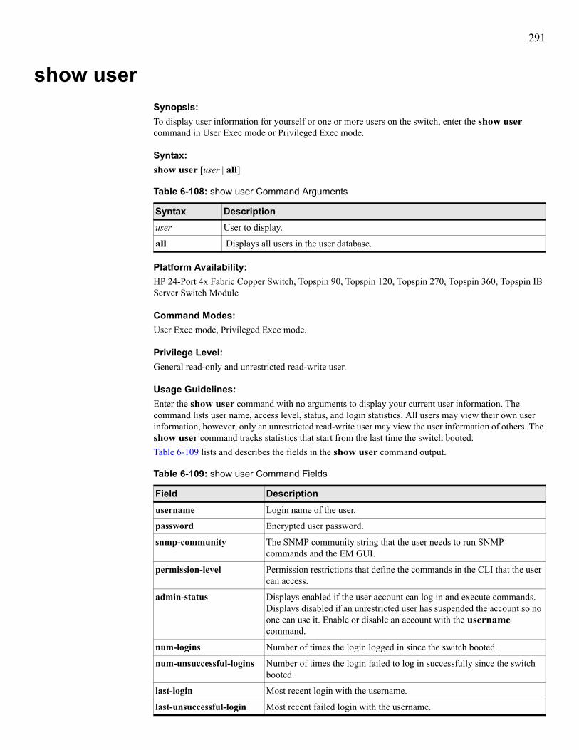
291
show userSynopsis:To display user information for yourself or one or more users on the switch, enter the show user command in User Exec mode or Privileged Exec mode.
Syntax:show user [user | all]
Platform Availability:HP 24-Port 4x Fabric Copper Switch, Topspin 90, Topspin 120, Topspin 270, Topspin 360, Topspin IB Server Switch Module
Command Modes:User Exec mode, Privileged Exec mode.
Privilege Level:General read-only and unrestricted read-write user.
Usage Guidelines:Enter the show user command with no arguments to display your current user information. The command lists user name, access level, status, and login statistics. All users may view their own user information, however, only an unrestricted read-write user may view the user information of others. The show user command tracks statistics that start from the last time the switch booted.Table 6-109 lists and describes the fields in the show user command output.
Table 6-108: show user Command Arguments
Syntax Descriptionuser User to display.
all Displays all users in the user database.
Table 6-109: show user Command Fields
Field Descriptionusername Login name of the user.
password Encrypted user password.
snmp-community The SNMP community string that the user needs to run SNMP commands and the EM GUI.
permission-level Permission restrictions that define the commands in the CLI that the user can access.
admin-status Displays enabled if the user account can log in and execute commands. Displays disabled if an unrestricted user has suspended the account so no one can use it. Enable or disable an account with the username command.
num-logins Number of times the login logged in since the switch booted.
num-unsuccessful-logins Number of times the login failed to log in successfully since the switch booted.
last-login Most recent login with the username.
last-unsuccessful-login Most recent failed login with the username.

292
Examples:The following example displays the admin user.
The following example shows the login information of the current user.
Defaults:The show user command without arguments displays the account information for the user who executes the command.
Related Commands:“username” on page 81
Topspin-360> show user admin=============================================================== User Information=============================================================== username : admin password : $1$IJ5..U6.$lSxb8uqVuUG7kOmiRsxHt1 snmp-community : private permission-level : ib-rw, ip-ethernet-rw, fc-rw admin-status : enabled num-logins : 1 num-unsuccessful-logins : 0 last-login : Thu Apr 10 22:06:48 2003 last-unsuccessful-login :Topspin-360>
Topspin-90> show user=============================================================== User Information=============================================================== username : super password : $1$IJ5..U6.$ES3pIhx/ccUaCKgM65vp6. snmp-community : secret permission-level : unrestricted-rw admin-status : enabled num-logins : 4 num-unsuccessful-logins : 0 last-login : Thu Apr 10 22:06:59 2003 last-unsuccessful-login :Topspin-90>
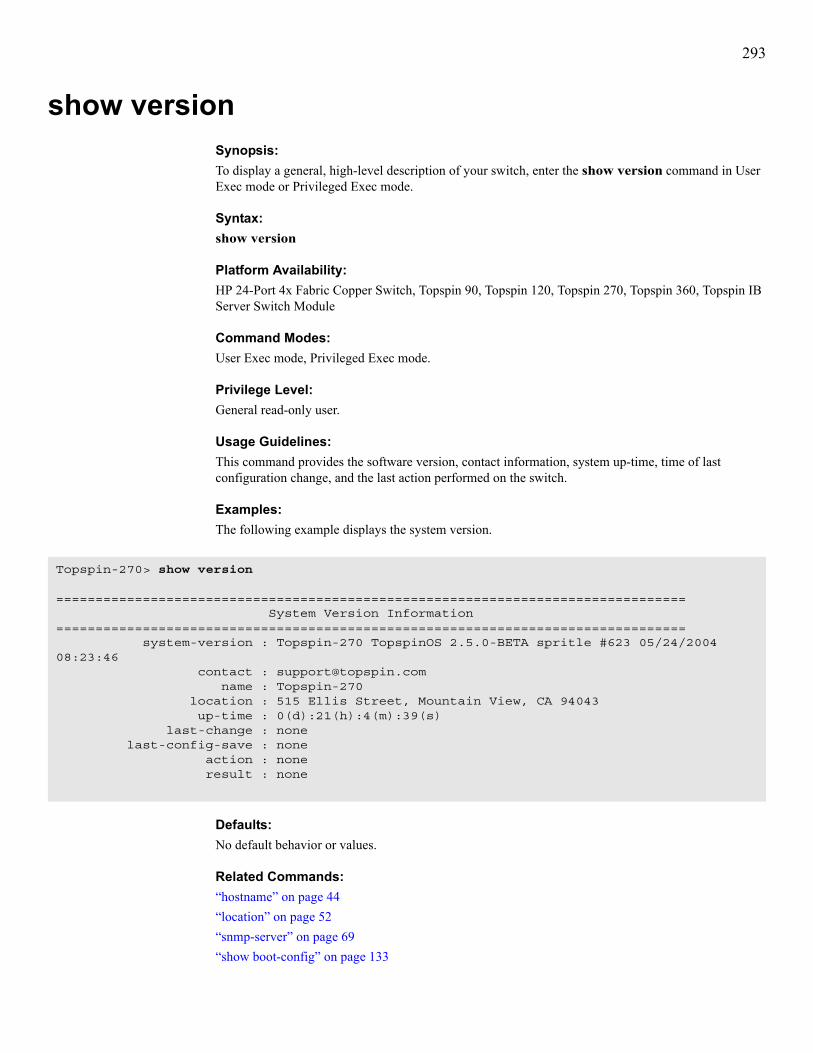
293
show versionSynopsis:To display a general, high-level description of your switch, enter the show version command in User Exec mode or Privileged Exec mode.
Syntax:show version
Platform Availability:HP 24-Port 4x Fabric Copper Switch, Topspin 90, Topspin 120, Topspin 270, Topspin 360, Topspin IB Server Switch Module
Command Modes:User Exec mode, Privileged Exec mode.
Privilege Level:General read-only user.
Usage Guidelines:This command provides the software version, contact information, system up-time, time of last configuration change, and the last action performed on the switch.
Examples:The following example displays the system version.
Defaults:No default behavior or values.
Related Commands:“hostname” on page 44“location” on page 52“snmp-server” on page 69“show boot-config” on page 133
Topspin-270> show version
================================================================================ System Version Information================================================================================ system-version : Topspin-270 TopspinOS 2.5.0-BETA spritle #623 05/24/2004 08:23:46 contact : [email protected] name : Topspin-270 location : 515 Ellis Street, Mountain View, CA 94043 up-time : 0(d):21(h):4(m):39(s) last-change : none last-config-save : none action : none result : none

294

295
7
Diagnostic CommandsDiagnostic commands configure diagnostics on both cards and interfaces. These commands are described in the following order:• diagnostic command on page 297• data-pattern command on page 299• data-size command on page 300• iterations command on page 301• source-wwpn command on page 302• start command on page 303• stop command on page 304• target-wwpn command on page 305• test command on page 306• validate command on page 308
Running Diagnostic TestsTo perform a diagnostic test, you must perform the following high-level steps:1. Enter the appropriate configuration submode for the port or card that you want to test.2. Configure the properties of the test:
• data-pattern• data-size• iterations• source-wwpn (FC only)• target-wwpn (FC only)

296
3. Configure the type of test:• internal-loopback• external-loopback• echo• self-test
NOTE: Available test types vary by card type and interface type.
4. Start and stop tests as needed.

297
diagnosticSynopsis:To enter Diagnostic Configuration submode, enter the diagnostic command in Global Configuration mode.
Syntax:diagnostic {card {card-selection | all} | chassis | interface {fc | ib | ethernet} {interface-selection | all} | fan {fan-number | all} | power-supply {supply | all} | rack-locator {locator | all}}
NOTE: Not all syntax applies to all hardware platforms
Platform Availability:HP 24-Port 4x Fabric Copper Switch, Topspin 90, Topspin 120, Topspin 270, Topspin 360, Topspin IB Server Switch Module
NOTE: The Topspin 90 and Topspin 360 can only run card and interface tests.
Command Modes:Global Configuration (config) mode.
Privilege Level:Read-write user for the appropriate technology.
Usage Guidelines:Enter Diagnostic submode to run test on cards and interfaces. For more information, refer to “test” on page 306.For the Topspin 120, the following caveats apply:
Table 7-1: diagnostic Command Arguments
Argument Descriptioncard Enters Card Diagnostic Configuration submode.
card-selection Card, list of cards, or range of cards to diagnose.
chassis Configures chassis-specific diagnostic tests.
fan Configures fan-specific diagnostic tests.
interface Enters Interface Diagnostic Configuration submode.
fc Specifies FC interfaces.
ib Specifies IB interfaces.
ethernet Specifies Ethernet interfaces.
interface-selection Interface, list of interfaces, or range of interfaces to diagnose.
all Specifies all interfaces of the technology type that you specified or all cards.
power-supply Configures power supply-specific diagnostic tests.
rack-locator Configures rack locator-specific diagnostic tests.

298
• The rack-locator keyword supports only 12x, not 4x.• All fan diagnostics occur in the power supply diagnostic tests, because the fans and power compose
one FRU.
Examples:The following example enters Diagnostic Configuration submode for Ethernet port 2/1.
Defaults:No default behavior or values.
Related Commands“show card” on page 137“start” on page 303“stop” on page 304“test” on page 306
Topspin-90(config)# diagnostic interface ethernet 2/1Topspin-90(config-diag-if-ether-2/1)#

299
data-patternSynopsis:To specify a data pattern when you run a diagnostic test on interfaces, enter the data-pattern command in Interface Diagnostic Configuration submode. To clear the data pattern, use the no form of this command.
Syntax:data-pattern patternno data-pattern pattern
Platform Availability:HP 24-Port 4x Fabric Copper Switch, Topspin 90, Topspin 120, Topspin 270, Topspin 360, Topspin IB Server Switch Module
Command Modes:Interface Diagnostic Configuration (config-diag-if) mode.
Usage Guidelines:Specify a data pattern to create easily-recognizable traffic output for your test.
Examples:The following example configures the data pattern that runs during a diagnostic test.
Defaults:No default behavior or values.
Related Commands:“test” on page 306“diagnostic” on page 297“start” on page 303“stop” on page 304“show interface ethernet” on page 233“show interface fc” on page 241“show interface ib” on page 252
Table 7-2: data pattern Command Arguments
Argument Descriptionpattern Pattern of the artificial traffic to create for testing purposes. The repetitive data lets
you identify the test traffic.
Topspin-360(config-diag-if-fc-4/1)# data pattern 11:22:33:44

300
data-sizeSynopsis:To configure the payload size of an interface, enter the data-size command in Interface Diagnostic Configuration submode. To clear the data size, use the no form of this command.
Syntax:data-size sizeno data-size size
Platform Availability:HP 24-Port 4x Fabric Copper Switch, Topspin 90, Topspin 120, Topspin 270, Topspin 360, Topspin IB Server Switch Module
Command Modes:Interface Diagnostic Configuration (config-diag-if) mode.
Usage Guidelines:Configure the data size property of your test to customize the size of packets, frames, or IB packets that your switch uses for your test.
Examples:The following example configures the payload size for a diagnostic test.
Defaults:Data size defaults to 4 octets.
Related Commands:“diagnostic” on page 297“show interface ethernet” on page 233“show interface fc” on page 241“show interface gateway” on page 247“start” on page 303“stop” on page 304“test” on page 306
Table 7-3: data-size Command Arguments
Argument Descriptionsize Integer value that represents the payload size, in octets.
Topspin-360(config-diag-if-fc-4/1)# data size 8

301
iterationsSynopsis:To specify the number of times to run a diagnostic test on an interface, enter the iterations command in Interface Diagnostic Configuration submode.
Syntax:iterations repetitions
Platform Availability:HP 24-Port 4x Fabric Copper Switch, Topspin 90, Topspin 120, Topspin 270, Topspin 360, Topspin IB Server Switch Module
Command Modes:Interface Diagnostic Configuration submode.
Usage Guidelines:If you did not specify a specific amount of times for a test to run, use the stop command.
Examples:The following example configures diagnostic tests to run four times, then end.
Defaults:The iterations value defaults to 0, which causes the test to run until you stop it.
Related Commands:“diagnostic” on page 297“show interface ethernet” on page 233“show interface fc” on page 241“show interface gateway” on page 247“start” on page 303“stop” on page 304“test” on page 306
Table 7-4: iteration Command Arguments
Argument Descriptionrepetitions Integer value for the number of times that you want a test to run.
Topspin-360(config-diag-if-fc-4/1)# iteration 4

302
source-wwpnSynopsis:To configure an optional WWPN identifier for a FC interface Echo test, enter the source-wwpn command in Fibre Channel Interface Diagnostic Configuration submode.
Syntax:source-wwpn wwpnno source-wwpn wwpn
Platform Availability:Topspin 90, Topspin 360
Command Modes:Configuration Diag Interface Fibre Channel (config-diag-if-fc) submode.
Usage Guidelines:This specification applies only to FC tests.
Examples:
Defaults:No default behavior or values.
Related Commands:“diagnostic” on page 297“show interface ethernet” on page 233“show interface fc” on page 241“show interface gateway” on page 247“start” on page 303“stop” on page 304“test” on page 306
Table 7-5: source-wwpn Command Arguments
Argument Descriptionwwpn Optional 24-bit source identifier to use with the FC interface Echo test.
Topspin-360(config-diag-if-fc-4/1)# source-wwpn 20:01:00:05:ad:00:40:00

303
startSynopsis:To begin a diagnostic test, enter the start command in the appropriate Interface Diagnostic Configuration submode.
Syntax:start
Platform Availability:HP 24-Port 4x Fabric Copper Switch, Topspin 90, Topspin 120, Topspin 270, Topspin 360, Topspin IB Server Switch Module
Command Modes:Fibre Channel Interface Diagnostic Configuration (config-diag-if-fc) submode, Ethernet Interface Diagnostic Configuration (config-diag-if-en) submode, or Card Interface Diagnostic Configuration (config-diag-if-card) submode.
Privilege Level:Read-write user.
Usage Guidelines:Configure the iterations command to automatically end a test. Otherwise, enter the stop command to manually end a test.
Examples:The following example starts a LED diag test on a FC interface.
The following example starts a self-test diagnostic test on a card.
Defaults:No default behavior or values.
Related Commands:“diagnostic” on page 297“show interface ethernet” on page 233“show interface fc” on page 241“show interface gateway” on page 247“stop” on page 304“test” on page 306
Topspin-360(config-diag-if-fc-4/1)# test ledTopspin-360(config-diag-if-fc-4/1)# start
Topspin-90(config-diag-card-6)# test self-testTopspin-360(config-diag-card-6)# start

304
stopSynopsis:To end a diagnostic test, enter the stop command in the appropriate Interface Diagnostic Configuration submode.
Syntax:stop
Platform Availability:HP 24-Port 4x Fabric Copper Switch, Topspin 90, Topspin 120, Topspin 270, Topspin 360, Topspin IB Server Switch Module
Command Modes:Fibre Channel Interface Diagnostic Configuration (config-diag-if-fc) submode, Ethernet Interface Diagnostic Configuration (config-diag-if-en) submode, or Card Interface Diagnostic Configuration (config-diag-if-card) submode.
Privilege Level:FC read-write user.
Usage Guidelines:Use the stop command to end a test for which you did not specify a particular number of iterations.
Examples:The following example stops the test on FC port 4/1.
Defaults:The default is no link-trap.
Related Commands:“diagnostic” on page 297“show interface ethernet” on page 233“show interface fc” on page 241“show interface gateway” on page 247“start” on page 303“test” on page 306
Topspin-360(config-diag-if-fc-4/1)# stop

305
target-wwpnSynopsis:To configure an optional WWPN identifier for a FC interface Echo test, enter the target-wwpn command in Fibre Channel Interface Diagnostic Configuration submode.
Syntax:source-wwpn wwpnno source-wwpn wwpn
Platform Availability:Topspin 90, Topspin 360
Command Modes:Configuration Diag Interface Fibre Channel (config-diag-if-fc) submode.
Usage Guidelines:This property applies only to FC tests.
Examples:The following example configures a WWPN identifier for an Echo test on port 4/1.
Defaults:No default behavior or values.
Related Commands:“diagnostic” on page 297“show interface ethernet” on page 233“show interface fc” on page 241“show interface gateway” on page 247“start” on page 303“stop” on page 304“test” on page 306
Table 7-6: source-wwpn Command Arguments
Argument Descriptionwwpn Optional 24-bit source identifier to use with the FC interface Echo test.
Topspin-360(config-diag-if-fc-4/1)# target-wwpn 20:01:00:05:ad:00:40:00
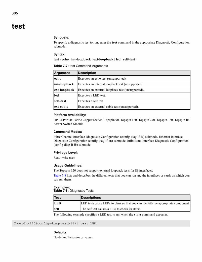
306
testSynopsis:To specify a diagnostic test to run, enter the test command in the appropriate Diagnostic Configuration submode.
Syntax:test {echo | int-loopback | ext-loopback | led | self-test}
Platform Availability:HP 24-Port 4x Fabric Copper Switch, Topspin 90, Topspin 120, Topspin 270, Topspin 360, Topspin IB Server Switch Module
Command Modes:Fibre Channel Interface Diagnostic Configuration (config-diag-if-fc) submode, Ethernet Interface Diagnostic Configuration (config-diag-if-en) submode, InfiniBand Interface Diagnostic Configuration (config-diag-if-ib) submode.
Privilege Level:Read-write user.
Usage Guidelines:The Topspin 120 does not support external loopback tests for IB interfaces.Table 7-8 lists and describes the different tests that you can run and the interfaces or cards on which you can run them.
Examples:
The following example specifies a LED test to run when the start command executes.
Defaults:No default behavior or values.
Table 7-7: test Command Arguments
Argument Descriptionecho Executes an echo test (unsupported).
int-loopback Executes an internal loopback test (unsupported).
ext-loopback Executes an external loopback test (unsupported).
led Executes a LED test.
self-test Executes a self test.
ext-cable Executes an external cable test (unsupported).
Table 7-8: Diagnostic Tests
Test DescriptionsLED LED tests cause LEDs to blink so that you can identify the appropriate component.
self The self test causes a FRU to check its status.
Topspin-270(config-diag-card-11)# test LED

307
Related Commands:“diagnostic” on page 297“show interface ethernet” on page 233“show interface fc” on page 241“show interface gateway” on page 247“start” on page 303“stop” on page 304

308
validateSynopsis:To validate diagnostic tests, enter the validate command in the appropriate Diagnostic Configuration submode.
Syntax:validate no validateUse the no keyword to disable validation
Platform Availability: HP 24-Port 4x Fabric Copper Switch, Topspin 90, Topspin 120, Topspin 270, Topspin 360, Topspin IB Server Switch Module
Command Modes:Diagnostic Configuration (config-diag) submode.
Usage Guidelines:Setting validation may slow the results of the test.
Examples:The following example validates diagnostic tests on port 6/2.
Defaults:Your switch validates tests by default.
Related Commands:“diagnostic” on page 297“show interface ethernet” on page 233“show interface fc” on page 241“show interface gateway” on page 247“start” on page 303“stop” on page 304
Topspin-360(config-diag-if-en-6/2)# validate

Aaction command 13addr-option command 15arp ethernet command 114authentication command 16auto-negotiate command 17
Bboot-config command 19bridge-group command 115broadcast command 20
Ccard command 21clock set command 22command
show version 288commands
action 13addr-option 15arp ethernet 114authentication 16auto-negotiate 17boot-config 19bridge-group 115broadcast 20card 21clock set 22configure terminal 24copy 26data pattern 293data size 294delete 29diagnostic 291dir 31disable 34distribution-type 117enable 35exec 36exit 37fc srp initiator 86fc srp initiator-wwpn 89fc srp it 91fc srp itl 93fc srp lu 96fc srp target 98fc srp-global gateway-portmask-policy restricted
99fc srp-global itl 100
fc srp-global lun-policy restricted 103ftp-server enable 38gateway 39half-duplex 119help 40history 41hostname 42ib sm 108ib sm db-sync 106ib-agent 111install 43interface 45ip (internal gateway ports, ethernet ports) 120ip http 47iterations 295link-trap 49location 50logging 51login 52logout 53more 54name 56ntp 57ping 58radius-server 59redundancy-group 123reload 61save-log 63show arp ethernet 127show authentication 128show backplane 129show boot-config 131show bridge-group 133show card 135show card-inventory 140show clock 142show config 155show diagnostic card 143show diagnostic fan 145show diagnostic interface ethernet 147show diagnostic interface fc 149show diagnostic interface ib 151show diagnostic power-supply 153show fan 156show fc srp initiator 158show fc srp initiator-wwpn-view 161show fc srp it 163show fc srp itl 165show fc srp itl-statistics 168show fc srp lu 170show fc srp statistics 173

show fc srp target 175show fc srp-global 177show host 180show ib dm ioc 181show ib dm iou 184show ib sm configuration 185show ib sm db-sync 188show ib sm multicast 190show ib sm neighbor 192show ib sm node 194show ib sm partition 197show ib sm port 199show ib sm service 206show ib sm switch 209show ib sm switch-element-route 212show ib sm switch-route 214show ib-agent channel-adapter 216show ib-agent summary 218show ib-agent switch 220show interface ethernet 231show interface fc 239show interface gateway 245show interface ib 250show interface mgmt-ethernet 259show interface mgmt-ib 261show interface mgmt-serial 262show ip 263show ip http 265show ip http server secure 266show location 267show logging 268show ntp 270show power-supply 271show redundancy-group 273show running-status 275show sensor 277show snmp 279show system-services 281show terminal 283show trace 284show trunk 285show user 286shutdown 64snmp-server 67source-wwpn 296speed (Fibre Channel) 70start 297stop 298target-wwpn 299telnet 72terminal 73
trace 75trunk-group 124type 77username 79validate 302who 83write 84
configure terminal command 24copy command 26
Ddata pattern command 293data size command 294delete command 29diagnostic command 291dir command 31disable command 34distribution-type command 117
Eenable command 35exec command 36exit command 37
Ffc srp initiator command 86fc srp initiator-wwpn command 89fc srp it command 91fc srp itl 94fc srp itl command 93fc srp lu command 96fc srp target command 98fc srp-global gateway-portmask-policy restricted com-mand 99fc srp-global itl command 100fc srp-global lun-policy restricted command 103ftp-server enable command 38
Ggateway command 39
Hhalf-duplex command 119help command 40history command 41hostname command 42

Iib sm command 108ib sm db-sync command 106ib-agent command 111install command 43interface command 45ip command, internal gateway ports and ethernet ports120ip http command 47iterations command 295
Llink-trap command 49location command 50logging command 51login command 52logout command 53
Mmore command 54
Nname 56name command 56ntp command 57
Ppartition
show sm 197partitions, creating and changing 108ping command 58
Rradius-server command 59redundancy-group command 123reload command 61
Ssave-log command 63show arp ethernet command 127show authentication command 128show backplane command 129show boot-config command 131show bridge-group command 133show card command 135
show card-inventory command 140show clock command 142show config 155show config command 155show diagnostic card command 143show diagnostic fan command 145show diagnostic interface ethernet command 147show diagnostic interface fc command 149show diagnostic interface ib command 151show diagnostic power-supply command 153show fan command 156show fc srp initiator command 158show fc srp initiator-wwpn-view command 161show fc srp it command 163show fc srp itl command 165show fc srp itl-statistics command 168show fc srp lu command 170show fc srp statistics command 173show fc srp target command 175show fc srp-global command 177show host command 180show ib dm ioc command 181show ib dm iou command 184show ib sm configuration command 185show ib sm db-sync command 188show ib sm multicast command 190show ib sm neighbor command 192show ib sm node command 194show ib sm partition command 197show ib sm port command 199show ib sm service command 206show ib sm switch command 209show ib sm switch-element-route command 212show ib sm switch-route command 214show ib-agent channel-adapter command 216show ib-agent summary command 218show ib-agent switch command 220show interface ethernet command 231show interface fc command 239show interface gateway command 245show interface ib command 250show interface mgmt-ethernet command 259show interface mgmt-ib command 261show interface mgmt-serial command 262show ip command 263show ip http command 265show ip http server secure command 266show location command 267show logging command 268show ntp command 270show power-supply command 271

show redundancy-group command 273show running-status command 275show sensor command 277show snmp command 279show system-services command 281show terminal command 283show trace command 284show trunk command 285show user command 286show version command 288shutdown command 64SM GUID, viewing 185snmp-server command 67source-wwpn command 296speed command, Fibre Channel 70start command 297stop command 298subnet manager GUID, viewing 185
Ttarget-wwpn command 299telnet command 72terminal command 73trace command 75trunk-group command 124type command 77
Uusername command 79
Vvalidate command 302
Wwho command 83write command 84
Copyright © 2022 FDOKUMEN