
HC25 AT Command Specification
290
s HC25 Siemens Cellular Engine Version: 01.200 DocId: HC25_ATC_V01.200 AT Command Set
-
Upload
khangminh22 -
Category
Documents
-
view
3 -
download
0
Transcript of HC25 AT Command Specification

s
HC25Siemens Cellular Engine Version: 01.200DocId: HC25_ATC_V01.200
AT
Com
man
d S
et

HC25 AT Command Set
HC25_ATC_V01.200 Page 2 of 290 7/25/07Confidential / Released
s
General NotesProduct is deemed accepted by recipient and is provided without interface to recipient’s products. The documen-tation and/or product are provided for testing, evaluation, integration and information purposes. The documen-tation and/or product are provided on an “as is” basis only and may contain deficiencies or inadequacies. Thedocumentation and/or product are provided without warranty of any kind, express or implied. To the maximumextent permitted by applicable law, Siemens further disclaims all warranties, including without limitation any im-plied warranties of merchantability, completeness, fitness for a particular purpose and non-infringement of third-party rights. The entire risk arising out of the use or performance of the product and documentation remains withrecipient. This product is not intended for use in life support appliances, devices or systems where a malfunctionof the product can reasonably be expected to result in personal injury. Applications incorporating the describedproduct must be designed to be in accordance with the technical specifications provided in these guidelines. Fail-ure to comply with any of the required procedures can result in malfunctions or serious discrepancies in results.Furthermore, all safety instructions regarding the use of mobile technical systems, including GSM products,which also apply to cellular phones must be followed. Siemens or its suppliers shall, regardless of any legal the-ory upon which the claim is based, not be liable for any consequential, incidental, direct, indirect, punitive or otherdamages whatsoever (including, without limitation, damages for loss of business profits, business interruption,loss of business information or data, or other pecuniary loss) arising out the use of or inability to use the docu-mentation and/or product, even if Siemens has been advised of the possibility of such damages. The foregoinglimitations of liability shall not apply in case of mandatory liability, e.g. under the German Product Liability Act, incase of intent, gross negligence, injury of life, body or health, or breach of a condition which goes to the root ofthe contract. However, claims for damages arising from a breach of a condition, which goes to the root of thecontract, shall be limited to the foreseeable damage, which is intrinsic to the contract, unless caused by intent orgross negligence or based on liability for injury of life, body or health. The above provision does not imply achange on the burden of proof to the detriment of the recipient. Subject to change without notice at any time. Theinterpretation of this general note shall be governed and construed according to German law without referenceto any other substantive law.
CopyrightTransmittal, reproduction, dissemination and/or editing of this document as well as utilization of its contents andcommunication thereof to others without express authorization are prohibited. Offenders will be held liable forpayment of damages. All rights created by patent grant or registration of a utility model or design patent are re-served.
Copyright © Siemens AG 2007
Document Name: HC25 AT Command Set Version: 01.200
Date: July 25, 2007
DocId: HC25_ATC_V01.200
Status Confidential / Released

HC25 AT Command Set Contents s
HC25_ATC_V01.200 Page 3 of 290 7/25/07Confidential / Released
1. Introduction............................................................................................................................................ 101.1 Scope of the document ................................................................................................................. 101.2 Related documents ....................................................................................................................... 111.3 Document Conventions ................................................................................................................. 12
1.3.1 Quick Reference Table .................................................................................................. 121.3.2 Superscript Notation for Parameters And Values .......................................................... 12
1.4 HC25 AT Command Interpreter .................................................................................................... 141.5 AT Command Syntax .................................................................................................................... 15
1.5.1 Using Parameters .......................................................................................................... 151.6 Supported character sets .............................................................................................................. 16
1.6.1 GSM alphabet tables and UCS2 character values ........................................................ 181.6.2 UCS2 and GSM data coding and conversion for SMS text mode and Remote SAT..... 201.6.2.1 Implementing output of SIM data to Terminal (direction TA to TE) ................................ 201.6.2.2 Implementing input of Terminal data to SIM (direction TE to TA)................................... 21
1.7 Communication between Customer Application and HC25 .......................................................... 221.8 Unsolicited Result Code Presentation........................................................................................... 23
1.8.1 Common URCs.............................................................................................................. 241.9 Errors and Messages .................................................................................................................... 25
2. Configuration Commands..................................................................................................................... 262.1 AT&F Set all current parameters to manufacturer defaults ......................................................... 262.2 AT&V Display current configuration ............................................................................................ 272.3 ATQ Set result code presentation mode ..................................................................................... 282.4 ATV Set result code format mode ............................................................................................... 29
2.4.1 Verbose and numeric result codes ................................................................................ 292.5 ATX Set CONNECT result code format ...................................................................................... 302.6 ATZ Reset all current parameters to the default configuration.................................................... 312.7 AT+CFUN Set phone functionality .............................................................................................. 322.8 AT+CMEE Mobile Equipment Error Message Format ................................................................ 33
2.8.1 CME/CMS Error Code Overview ................................................................................... 342.9 AT+CSCS Select TE character set ............................................................................................. 372.10 AT+GCAP Request complete TA capabilities list........................................................................ 382.11 AT^SCFG Extended Configuration Settings ............................................................................... 392.12 AT^SMSO Switch off mobile station............................................................................................ 442.13 AT^SUSB USB Configuration ..................................................................................................... 45
3. Status Control Commands ................................................................................................................... 503.1 AT^SIND Extended Indicator Control .......................................................................................... 503.2 AT+CEER Extended Error Report............................................................................................... 55
3.2.1 List of status codes for the extended error report .......................................................... 553.3 AT+CPAS Mobile equipment activity status................................................................................ 613.4 AT+WS46 Select wireless network ............................................................................................. 62
4. Serial Interface Control Commands..................................................................................................... 634.1 AT^SQPORT Query Port Type ................................................................................................... 634.2 AT&C Set Data Carrier Detect (DCD) Line mode ....................................................................... 64
Contents
HC25 AT Command Set Contents s
HC25_ATC_V01.200 Page 4 of 290 7/25/07Confidential / Released
4.3 AT&D Set circuit Data Terminal Ready (DTR) function mode..................................................... 654.4 AT&S Set circuit Data Set Ready (DSR) function mode ............................................................. 664.5 ATE Enable command echo........................................................................................................ 67
5. Security Commands.............................................................................................................................. 685.1 AT+CLCK Facility lock ................................................................................................................ 685.2 AT+CPIN PIN Authentication ...................................................................................................... 72
5.2.1 What to do if PIN or password authentication fails? ...................................................... 745.3 AT+CPWD Change Password .................................................................................................... 755.4 AT^SCSL Customer SIM Lock .................................................................................................... 77
6. Identification Commands...................................................................................................................... 796.1 ATI Display product identification information ............................................................................. 796.2 AT+CGMI Request manufacturer identification........................................................................... 806.3 AT+GMI Request manufacturer identification ............................................................................. 806.4 AT+CGMM Request model identification .................................................................................... 816.5 AT+GMM Request model identification....................................................................................... 816.6 AT+CGMR Request revision identification of software status..................................................... 826.7 AT+GMR Request revision identification of software status ....................................................... 826.8 AT+CGSN Request International Mobile Equipment Identity (IMEI) ........................................... 836.9 AT+GSN Request International Mobile Equipment Identity (IMEI) ............................................. 836.10 AT+CIMI Request International Mobile Subscriber Identity (IMSI).............................................. 84
7. Call related Commands......................................................................................................................... 857.1 ATA Answer a call ....................................................................................................................... 857.2 ATD Mobile originated call to specified number .......................................................................... 867.3 ATD><mem><n> Mobile originated call using specific memory and index number ................... 887.4 ATD><n> Mobile originated call from active memory using index number ................................. 907.5 ATD><str> Mobile originated call from active memory using corresponding field ...................... 917.6 ATH Disconnect existing data connection................................................................................... 927.7 AT+CHUP Hang up call .............................................................................................................. 937.8 ATS0 Set number of rings before automatically answering a call ............................................... 947.9 ATS6 Set pause before blind dialing ........................................................................................... 957.10 ATS7 Set number of seconds to wait for connection completion ................................................ 967.11 ATS8 Set number of seconds to wait for comma dialing modifier............................................... 977.12 ATS10 Set disconnect delay after indicating the absence of data carrier ................................... 987.13 ATO Switch from command mode to data mode ........................................................................ 997.14 +++ Switch from data mode to command mode ....................................................................... 1007.15 AT+CLCC List of current calls ................................................................................................... 1017.16 AT+CR Service reporting control .............................................................................................. 1037.17 AT+CRC Set Cellular Result Codes for incoming call indication .............................................. 1047.18 AT+CBST Select bearer service type ....................................................................................... 106
7.18.1 Parameter configurations supported by AT+CBST...................................................... 1077.19 AT+CRLP Select radio link protocol parameters for originated non-transparent data calls ...... 1087.20 ATP Select pulse dialing ........................................................................................................... 1107.21 ATT Select tone dialing ............................................................................................................. 1107.22 AT+ES Synchronous Data Mode Configuration........................................................................ 1117.23 AT+ESA Synchronous access mode configuration................................................................... 1127.24 AT+CSTA Select type of address ............................................................................................. 114

HC25 AT Command Set Contents s
HC25_ATC_V01.200 Page 5 of 290 7/25/07Confidential / Released
8. Network Service Commands .............................................................................................................. 1158.1 AT+COPN Read operator names ............................................................................................. 1158.2 AT+COPS Operator Selection .................................................................................................. 1168.3 AT^SOPS Extended Operator Selection................................................................................... 1198.4 AT+CREG Network Registration............................................................................................... 121
8.4.1 Typical Registration Times .......................................................................................... 1238.5 AT+CSQ Signal quality ............................................................................................................. 1248.6 AT^SMONI Monitor idle mode................................................................................................... 125
8.6.1 AT^SMONI responses ................................................................................................. 1258.7 AT^SMONP Monitor neighbour cells......................................................................................... 127
8.7.1 AT^SMONP responses................................................................................................ 1278.8 AT^SNWS Network Selection ................................................................................................... 129
9. Supplementary Service Commands .................................................................................................. 1319.1 AT+CACM Accumulated call meter (ACM) reset or query ........................................................ 1319.2 AT+CAMM Accumulated call meter maximum (ACMmax) set or query.................................... 1329.3 AT+CAOC Advice of Charge information.................................................................................. 1339.4 AT+CCUG Closed User Group ................................................................................................. 1359.5 AT+CCFC Call forwarding number and conditions control ....................................................... 1379.6 AT+CCWA Call Waiting ............................................................................................................ 1419.7 AT+CHLD Call Hold and Multiparty........................................................................................... 1449.8 AT+CLIP Calling Line Identification Presentation ..................................................................... 1479.9 AT+CLIR Calling Line Identification Restriction ........................................................................ 1499.10 AT+COLP Connected Line Identification Presentation ............................................................. 1509.11 AT+CPUC Price per unit and currency table............................................................................. 1529.12 AT+CSSN Supplementary service notifications ........................................................................ 1539.13 AT+CUSD Unstructured supplementary service data............................................................... 155
10. GPRS Commands................................................................................................................................ 15710.1 AT+CGATT PS attach or detach............................................................................................... 15710.2 AT+CGACT PDP context activate or deactivate ....................................................................... 15810.3 AT+CGDATA Enter data state .................................................................................................. 160
10.3.1 Automatic deactivation of PDP context during dial-up PPP......................................... 16110.4 AT+CGDCONT Define PDP Context ........................................................................................ 16210.5 AT+CGPADDR Show PDP address ......................................................................................... 16410.6 AT+CGQMIN Quality of Service Profile (Minimum acceptable) ................................................ 16510.7 AT+CGEQMIN 3G Quality of Service Profile (Minimum acceptable) ........................................ 16810.8 AT+CGREG GPRS Network Registration Status...................................................................... 17210.9 AT+CGQREQ Quality of Service Profile (Requested) .............................................................. 17410.10 AT+CGEQREQ 3G Quality of Service Profile (Requested) ...................................................... 17710.11 AT+CGSMS Select service for MO SMS messages................................................................. 18110.12 AT+CGTFT Traffic Flow Template ............................................................................................ 18210.13 ATD*99# Request GPRS service.............................................................................................. 18510.14 AT^SGAUTH Set type of authentication for PDP-IP connections ............................................. 186
11. FAX Commands................................................................................................................................... 18811.1 AT+FCLASS Set the Service Class of a facsimile DCE............................................................ 18811.2 AT+FAR Adaptive Rate Control ................................................................................................ 18911.3 AT+FDD Double Escape Character Replacement.................................................................... 19011.4 AT+FCL Carrier Loss Timeout .................................................................................................. 191

HC25 AT Command Set Contents s
HC25_ATC_V01.200 Page 6 of 290 7/25/07Confidential / Released
11.5 AT+FIT DTE Inactivity Timeout ................................................................................................. 19211.6 AT+FTS Transmit silence.......................................................................................................... 19311.7 AT+FRS Receive Silence.......................................................................................................... 19411.8 AT+FTM Transmit message...................................................................................................... 19511.9 AT+FRM Receive message ...................................................................................................... 19611.10 AT+FTH Transmit Data Using HDLC Framing.......................................................................... 19711.11 AT+FRH Receive Data Using HDLC Framing .......................................................................... 198
12. Short Message Service (SMS) Commands........................................................................................ 19912.1 SMS parameters ......................................................................................................................... 19912.2 AT+CMGC Send an SMS command......................................................................................... 20312.3 AT+CMGD Delete short message............................................................................................. 20412.4 AT+CMGF Select SMS message format .................................................................................. 20512.5 AT+CMGL List SMS messages from preferred store................................................................ 20612.6 AT+CMGR Read SMS messages............................................................................................. 20812.7 AT+CMGS Send Short Message .............................................................................................. 21012.8 AT+CMGW Write Short Messages to Memory ......................................................................... 21112.9 AT+CMMS More Messages to Send......................................................................................... 21212.10 AT+CMSS Send short messages from storage ........................................................................ 21312.11 AT+CNMA New Message Acknowledgement to ME/TE, only phase 2+ .................................. 21412.12 AT+CNMI New short Message Indication ................................................................................. 21512.13 AT+CPMS Preferred SMS message storage............................................................................ 21812.14 AT+CSCA SMS Service Center Address.................................................................................. 22012.15 AT+CSCB Select Cell Broadcast Message Indication .............................................................. 22112.16 AT+CSMP Set SMS text Mode Parameters.............................................................................. 22312.17 AT+CSMS Select Message Service.......................................................................................... 22512.18 AT^SMGL List Short Messages from preferred store without setting status to REC READ ..... 227
13. SIM related Commands....................................................................................................................... 22813.1 AT+CRSM Restricted SIM Access............................................................................................ 22813.2 AT+CSIM Generic SIM Access ................................................................................................. 23013.3 AT^SCKS Query SIM and Chip Card Holder Status ................................................................. 232
14. SIM Application Toolkit (SAT) Commands........................................................................................ 23414.1 AT^SSTA SAT Interface Activation ........................................................................................... 23414.2 ^SSTN SAT Notification ............................................................................................................ 23614.3 AT^SSTGI SAT Get Information ............................................................................................... 23714.4 AT^SSTR SAT Response ......................................................................................................... 238
15. Phonebook Commands....................................................................................................................... 23915.1 AT+CNUM Read own numbers................................................................................................. 23915.2 AT+CPBF Find phonebook entries ........................................................................................... 24015.3 AT+CPBR Read from phonebook ............................................................................................. 24315.4 AT+CPBS Select phonebook memory storage ......................................................................... 24615.5 AT+CPBW Write into phonebook.............................................................................................. 248
16. Audio Commands................................................................................................................................ 25116.1 ATL Set monitor speaker loudness ........................................................................................... 25116.2 ATM Set monitor speaker mode................................................................................................ 25116.3 AT+CMUT Mute control ............................................................................................................ 25216.4 AT+VTS DTMF and tone generation......................................................................................... 253

HC25 AT Command Set Contents s
HC25_ATC_V01.200 Page 7 of 290 7/25/07Confidential / Released
16.5 AT^SNFI Set microphone path parameters .............................................................................. 25416.6 AT^SNFO Set audio output parameter (loudspeaker path) ...................................................... 25616.7 AT^SNFS Select audio hardware set ........................................................................................ 25816.8 AT^SNFTTY Signal TTY/CTM audio mode capability............................................................... 26016.9 AT^SRTC Ring tone configuration ............................................................................................ 262
17. Hardware Related Commands............................................................................................................ 26417.1 AT^SLED LED Feature ............................................................................................................. 26417.2 AT^SBV Battery/Supply Voltage ............................................................................................... 26617.3 AT^SCTM Set critical operating temperature presentation mode or query temperature........... 267
18. Miscellaneous Commands.................................................................................................................. 26918.1 ATS3 Set command line termination character......................................................................... 26918.2 ATS4 Set response formatting character .................................................................................. 27018.3 ATS5 Write command line editing character ............................................................................. 27118.4 AT^SFDL Enter Firmware Download Mode .............................................................................. 272
19. Appendix .............................................................................................................................................. 27319.1 Restricted access to SIM data after SIM PIN authentication....................................................... 27319.2 Star-Hash (*#) Network Commands............................................................................................ 27419.3 Available AT Commands and Dependency on SIM PIN ............................................................. 27719.4 Factory Default Settings Restorable with AT&F.......................................................................... 28219.5 Summary of Unsolicited Result Codes (URC)............................................................................. 28419.6 AT Commands Supported Only on the Modem Interface ........................................................... 28619.7 Alphabetical List of AT Commands ............................................................................................. 287

HC25 AT Command Set List of Tables s
HC25_ATC_V01.200 Page 8 of 290 7/25/07Confidential / Released
Table 1.1: Symbols used to mark the type of parameters ........................................................................... 12Table 1.2: Symbols used to indicate the correlations with other commands ............................................... 12Table 1.3: Symbols Used to Mark Different Types of Default Values of Parameters ................................. 13Table 1.4: Types of AT commands and responses .................................................................................... 15Table 1.5: Examples for character definitions depending on alphabet ........................................................ 17Table 2.1: General "CME ERROR" Codes (GSM 07.07) .......................................................................... 34Table 2.2: GPRS related "CME ERROR" Codes (GSM 07.07) ................................................................. 35Table 2.3: SIEMENS specific "CME ERROR" Codes ................................................................................ 35Table 2.4: SMS related "CMS ERROR" Codes (GSM 07.05) ................................................................... 35Table 7.1: Parameter configurations supported by AT+CBST.................................................................... 107Table 19.1: Star-Hash (*#) Command Overview ........................................................................................ 274Table 19.2: Abbreviations of Codes and Parameters used in Table 19.1 .................................................. 275Table 19.3: Star-Hash Command Response Parameters .......................................................................... 275Table 19.4: Star-Hash Commands for Supplementary Services ................................................................ 276Table 19.5: Available AT Commands and Dependency on SIM PIN........................................................... 277Table 19.6: Factory Default Settings Restorable with AT&F ....................................................................... 282Table 19.7: Summary of Unsolicited Result Codes (URC) .......................................................................... 284Table 19.8: AT Commands Supported Only on the Modem Interface......................................................... 286Table 19.9: Alphabetical List of AT Commands........................................................................................... 287
List of Tables

HC25 AT Command Set List of Figures s
HC25_ATC_V01.200 Page 9 of 290 7/25/07Confidential / Released
Figure 1.1: Main character table of GSM 03.38 alphabet ............................................................................. 18Figure 1.2: Extension character table of GSM 03.38 alphabet ..................................................................... 19
List of Figures

HC25 AT Command Set 1. Introduction s
HC25_ATC_V01.200 Page 10 of 290 7/25/07Confidential / Released
1. Introduction
1.1 Scope of the document
This document presents the AT Command Set for the Siemens Cellular Engine HC25 Release 01.200.
Before using the Cellular Engine or upgrading to a new firmware version please read the latest product informa-tion provided in the Release Notes [1].
More information is available at the Siemens Website: http://www.siemens.com/wm.
HC25 AT Command Set 1.2 Related documents s
HC25_ATC_V01.200 Page 11 of 290 7/25/07Confidential / Released
1.2 Related documents
[1] HC25 Release Notes, Version 01.200[2] HC25 Hardware Interface Description, Version 01.200[3] User's Guide: Getting Started with HC25 [4] Remote-SAT User's Guide[5] Application Note 16: Updating HC25 Firmware[6] Application Note 22: Using TTY / CTM equipment with HC25[7] Application Note 39: USB Interface Description for HC25 [8] ISO/IEC10646: "Universal Multiple-Octet Coded Character Set (UCS)"; UCS2, 16 bit coding [9] ITU-T Recommendation V.24: List of definitions for interchange circuits between data terminal equipment
(DTE) and data circuit-terminating equipment (DCE) [10] ITU-T Recommendation V.250: Serial asynchronous automatic dialling and control [11] 3GPP TS 100 918/EN 300 918 (GSM 02.04): General on supplementary services [12] 3GPP TS 100 907 (GSM 02.30): Man-Machine Interface (MMI) of the Mobile Station (MS) [13] 3GPP TS 23.038 (GSM 03.38): Alphabets and language specific information [14] 3GPP TS 27.005 (GSM 07.05): Use of Data Terminal Equipment - Data Circuit terminating Equipment (DTE
- DCE) interface for Short Message Service (SMS) and Cell Broadcast Service (CBS) [15] 3GPP TS 27.007 (GSM 07.07): AT command set for User Equipment (UE) [16] 3GPP TS 27.060 (GSM 07.60): Mobile Station (MS) supporting Packet Switched Services [17] 3GPP TS 51.011 (GSM 11.11): Specification of the Subscriber Identity Module - Mobile Equipment (SIM -
ME) interface [18] ETSI 102 221: Smart cards; UICC-Terminal interface; Physical and logical characteristics [19] 3GPP TS 31.102: 3rd Generation Partnership Project; Technical Specification Group Network and Termi-
nals; Characteristics of the USIM application [20] 3GPP TS 11.14 (GSM 11.14): Specification of the SIM Application Toolkit for the Subscriber Identity Module
- Mobile Equipment (SIM - ME) interface [21] 3GPP TS 22.101 (GSM 22.101): Service principles [22] Common PCN Handset Specification (CPHS) v4.2 [23] USB Class Definitions for Communication Devices, Version 1.1 January 19, 1999

HC25 AT Command Set 1.3 Document Conventions s
HC25_ATC_V01.200 Page 12 of 290 7/25/07Confidential / Released
1.3 Document Conventions
Throughout the document, the GSM engines are referred to as ME (Mobile Equipment), MS (Mobile Station), TA(Terminal Adapter), DCE (Data Communication Equipment) or facsimile DCE (FAX modem, FAX board). To control your GSM engine you can simply send AT Commands via its serial interface. The controlling deviceat the other end of the serial line is referred to as TE (Terminal Equipment), DTE (Data Terminal Equipment) orplainly 'the application' (probably running on an embedded system). All abbreviations and acronyms used throughout this document are based on the GSM specifications. For defi-nitions please refer to TR 100 350 V7.0.0 (1999-08), (GSM 01.04, version 7.0.0 release 1998).
1.3.1 Quick Reference Table
Each AT command description includes a table similar to the example shown below. The table is intended as aquick reference to indicate the following functions:
Example:
1.3.2 Superscript Notation for Parameters And ValuesTable 1.1: Symbols used to mark the type of parameters
Table 1.2: Symbols used to indicate the correlations with other commands
PIN: Is the AT command PIN protected? + Yes - No ± Usage is dependent on conditions specified for the command, or not all command
types are PIN protected (for example write command PIN protected, read command not).
Note: The table provided in Section 19.3, Available AT Commands and Dependency on SIM PIN uses the same symbols.
USB0-MDM: Is the AT command supported on the Modem interface? + Yes - NoUSB0-APP: Is the AT command supported on the Application interface? + Yes - NoLast: If commands are concatenated, this AT command must be the last one. + Yes - No Note: See also Section 1.5, AT Command Syntax for details on concatenated AT com-
mands.
PIN USB0-MDM USB0-APP Last
- + + -
Parameter type Meaning<param>(num) Parameter value must be numeric type<param>(str) Parameter value must be string type enclosed in quotation marks.
Parameter option Meaning<param>(+CSCS) Parameter value has to be (is) coded according to current setting of <chset> (see
AT+CSCS for details)

HC25 AT Command Set 1.3 Document Conventions s
HC25_ATC_V01.200 Page 13 of 290 7/25/07Confidential / Released
Table 1.3: Symbols Used to Mark Different Types of Default Values of Parameters
Value option Meaning[x] Default value: if the parameter is omitted, the value 'x' will be assumedx(&F) Factory default value, will be restored to 'x' with AT&Fx(P) Powerup default value of a parameter which is not stored at power downx(D) Delivery default value of a parameter which cannot be restored automatically

HC25 AT Command Set 1.4 HC25 AT Command Interpreter s
HC25_ATC_V01.200 Page 14 of 290 7/25/07Confidential / Released
1.4 HC25 AT Command Interpreter
After successful installation of the HC25 driver package, the physical USB interface of the module is representedin the operating system by two virtual interfaces, each assigned to a virtual COM port of its own: • Modem interface:
This interface is referred to as "Modem" if queried with AT^SQPORT. In the quick reference tables it is namedUSB0-MDM. In Windows XP, it will show up as "Siemens HSDPA USB Modem" in the Windows Device Man-ager, under Modems. The COM port number automatically assigned by Windows during the installation canbe gathered from the Modems property page.The modem interface is intended particularly for data transmission (HSDPA, GPRS, CSD or FAX) establishedover a dial-up connection. Using AT commands on this interface is not recommended, except for data callrelated commands like ATD or ATO.URCs relevant for data calls (RING, NO CARRIER) are issued on the modem interface, all other URCs nor-mally only on the application interface.
• Application interface: This port is referred to as "Application" if queried with AT^SQPORT. In the quick reference tables it is namedUSB0-APP. In Windows XP, it will show up as "Siemens HSDPA USB Com Port" in the Windows Device Man-ager, under Ports (COM&LPT), along with the COM port number automatically assigned by Windows. The application interface is designed especially for controlling the HC25, i.e. for entering AT commands,receiving URCs, or sending and receiving short messages. It cannot be used as data interface for HSDPA,GPRS, CSD or FAX. Please note that URCs are normally indicated only on this interface, no matter which of the two interfaceswas used to send the AT commands for activating their presentation. This URC management scheme is the default configuration recommended for a typical HC25 application. Forfurther detail on URCs please refer to Section 1.8, Unsolicited Result Code Presentation.
If you need to operate the HC25 from both interfaces at a time, bear in mind that both are handled by the sameAT command interpreter. As a result, AT commands entered on both interfaces are not executed in parallel butsequentially, one after the other. So, an AT command issued on one interface will be buffered on this interfaceto be executed after the other interface has completed processing earlier AT command(s). The buffered com-mand string is not echoed, but will be indicated when executed.
When a dial-up connection is established over the modem interface, the application interface can be used simul-taneously for any control functions. This eliminates the need for the user to enter AT commands, such as +++and ATO, to switch back and forth between command and online mode when working on one interface only. Yet,it should be noted that the dial-up connection disables the echo on both interfaces, due to the initialization stringstypically set by modems. The echo can be re-activated by executing ATE1.

HC25 AT Command Set 1.5 AT Command Syntax s
HC25_ATC_V01.200 Page 15 of 290 7/25/07Confidential / Released
1.5 AT Command Syntax
The "AT" or "at" prefix must be set at the beginning of each command line. To terminate a command line enter<CR>. Commands are usually followed by a response that includes "<CR><LF><response><CR><LF>". Through-out this document, only the responses are presented, <CR><LF> are omitted intentionally.
Table 1.4: Types of AT commands and responses
1.5.1 Using Parameters
• Optional parameters are enclosed in square brackets. If optional parameters are omitted, the current settingsare used until you change them.
• Optional parameters or subparameters can be omitted unless they are followed by other parameters. If youwant to omit a parameter in the middle of a string it must be replaced by a comma. See also example 1.
• A parameter value enclosed in square brackets represents the value that will be used if an optional parameteris omitted. See also example 2.
• When the parameter is a character string, e.g. <text> or <number>, the string must be enclosed in quotationmarks, e.g. "Charlie Brown" or "+49030xxxx". Symbols in quotation marks will be recognized as strings.
• All spaces will be ignored when using strings without quotaton marks.• It is possible to omit the leading zeros of strings which represent numbers.• If an optional parameter of a V.250 command is omitted, its value is assumed to be 0.Example 1: Omitting parameters in the middle of a string
AT command type Syntax FunctionTest command AT+CXXX=? The mobile equipment returns the list of parameters and value
ranges set with the corresponding Write command or by internal processes.
Read command AT+CXXX? This command returns the currently set value of the parameter or parameters.
Write command AT+CXXX=<...> This command sets user-definable parameter values.Exec(ution) command AT+CXXX The execution command reads non-variable parameters deter-
mined by internal processes in the GSM engine.
AT+CCUG? Query current setting+CCUG: 1,10,1OKAT+CCUG=,9 Set only the middle parameterOKAT+CCUG? Query new setting+CCUG: 1,9,1OK

HC25 AT Command Set 1.6 Supported character sets s
HC25_ATC_V01.200 Page 16 of 290 7/25/07Confidential / Released
1.6 Supported character sets
The ME supports two character sets: GSM 03.38 (7 bit, also referred to as GSM alphabet or SMS alphabet) andUCS2 (16 bit, refer to ISO/IEC 10646). See AT+CSCS for information about selecting the character set. Charactertables can be found below.
Explanation of terms • International Reference Alphabet (IRA)
IRA means that one byte is displayed as two characters in hexadecimal format. For example, the byte 0x36(decimal 54) is displayed as "36" (two characters). IRA is used here for input 8-bit or 16-bit data via terminaldevices using text mode. This means only characters 'A'..F','a'..'f' and '0'..'9' are valid.
• Escape sequencesThe escape sequence used within a text coded in the GSM default alphabet (0x1B) must be correctly inter-preted by the TE, both for character input and output. To the module, an escape sequence appears like anyother byte received or sent.
• Terminal Adapter (TA)TA is an equivalent to Mobile Equipment (ME) which stands for the GSM module described here. It uses GSMdefault alphabet as its character set.
• Terminal Equipment (TE)TE is the device connected to the TA via serial interface. In most cases TE is an ANSI/ASCII terminal thatdoes not fully support the GSM default alphabet, for example MS Hyperterminal.
• TE Character SetThe character set currently used by Terminal Equipment is selected with AT+CSCS.
• Data Coding Scheme (dcs)DCS is part of a short message and is saved on the SIM. When writing a short message to the SIM in textmode, the dcs stored with AT+CSMP is used and determines the coded character set.
The behavior when encountering characters that are not valid characters of the supported alphabets is unde-fined. Due to the constraints described below it is recommended to prefer the USC2 alphabet in any external applica-tion. If the GSM alphabet is selected all characters sent over the serial line (between TE and TA) are in the range from0 to 127 (7 Bit range). CAUTION: ASCII alphabet (TE) is not GSM alphabet (TA/ME) !
Several problems resulting from the use of GSM alphabet with ASCII terminal equipment: • "@" character with GSM alphabet value 0 is not printable by an ASCII terminal program (e.g. Microsoft©
Hyperterminal®).• "@" character with GSM alphabet value 0 will terminate any C string! This is because the 0 is defined as C
string end tag. Therefore, the GSM Null character may cause problems on application level when using a 'C'-function as "strlen()". This can be avoided if it is represented by an escape sequence as shown in the tablebelow. By the way, this may be the reason why even network providers often replace "@"with "@=*" in their SIMapplication.
• Other characters of the GSM alphabet are misinterpreted by an ASCII terminal program. For example, GSM"ö" (as in "Börse") is assumed to be "|" in ASCII, thus resulting in "B|rse". This is because both alphabets meandifferent characters with values hex. 7C or 00 and so on.
• In addition, decimal 17 and 19 which are used as XON/XOFF control characters when software flow controlis activated, are interpreted as normal characters in the GSM alphabet.
When you write characters differently coded in ASCII and GSM (e.g. Ä, Ö, Ü), you need to enter escapesequences. Such a character is translated into the corresponding GSM character value and, when output later,the GSM character value can be presented. Any ASCII terminal then will show wrong responses.

HC25 AT Command Set 1.6 Supported character sets s
HC25_ATC_V01.200 Page 17 of 290 7/25/07Confidential / Released
Table 1.5: Examples for character definitions depending on alphabet
CAUTION: Often, the editors of terminal programs do not recognize escape sequences. In this case, an escapesequence will be handled as normal characters. The most common workaround to this problem is to write a scriptwhich includes a decimal code instead of an escape sequence. This way you can write, for example, short mes-sages which may contain differently coded characters.
GSM 03.38character
GSM characterhex. value
CorrespondingASCII character
ASCIIEsc sequence
Hex Escsequence
Ö 5C \ \5C 5C 35 43" 22 " \22 5C 32 32@ 00 NULL \00 5C 30 30

HC25 AT Command Set 1.6 Supported character sets s
HC25_ATC_V01.200 Page 18 of 290 7/25/07Confidential / Released
1.6.1 GSM alphabet tables and UCS2 character values
This section provides tables for the GSM 03.38 alphabet supported by the ME. Below any GSM character findthe corresponding two byte character value of the UCS2 alphabet. (For related mapping definition see: http://www.unicode.org/Public/MAPPINGS/ETSI/GSM0338.TXT)
1) This code is an escape to the following extension of the 7 bit default alphabet table.2) This code is not a printable character and therefore not defined for the UCS2 alphabet. It shall be treated as the accom-
panying control character.3) As the standard GSM alphabet does not provide a backspace functionality the HC25 is designed to use the GSM char-
acter 08 (hex 0x08) as backspace. This allows the user to easily erase the last character when using an ASCII terminal.On the other hand, this solution requires entering the escape sequence \08 for writing the "ò" character in GSM alphabet.
Figure 1.1: Main character table of GSM 03.38 alphabet

HC25 AT Command Set 1.6 Supported character sets s
HC25_ATC_V01.200 Page 19 of 290 7/25/07Confidential / Released
1) This code value is reserved for the extension to another extension table. On receipt of this code, a receiving entity shalldisplay a space until another extension table is defined.
2) This code represents the EURO currency symbol. The code value is the one used for the character 'e'. Therefore a receiv-ing entity which is incapable of displaying the EURO currency symbol will display the character 'e' instead.
3) This code is defined as a Page Break character and may be used for example in compressed CBS messages. Any mobilewhich does not understand the 7 bit default alphabet table extension mechanism will treat this character as Line Feed.
Figure 1.2: Extension character table of GSM 03.38 alphabet

HC25 AT Command Set 1.6 Supported character sets s
HC25_ATC_V01.200 Page 20 of 290 7/25/07Confidential / Released
In the event that an MS receives a code where a symbol is not represented in Figure 1.2, Extension charactertable of GSM 03.38 alphabet the MS shall display the character shown in the main default 7 bit alphabet table(see Figure 1.1, Main character table of GSM 03.38 alphabet).
1.6.2 UCS2 and GSM data coding and conversion for SMS text mode and Remote SAT
This section provides basic information on how to handle input and output character conversion for SMS textmode and Remote SAT if internal (TA) and external (TE) character representation differ, i.e. if the Data CodingScheme and the TE character use different coding.
1.6.2.1 Implementing output of SIM data to Terminal (direction TA to TE)
Note: The ratio of SIM bytes to output bytes is given in parentheses.
Case 1Every GSM character is sent to the TE as it is (8-bit value with highest bit set to zero).Example: 47'H, 53'H, 4D'H → 47'H, 53'H, 4D'H, displayed as "GSM"
Case 2Every data byte is sent to the TE as 2 IRA characters each representing a halfbyte.Example: B8'H (184 decimal) → 42'H, 38'H, displayed as "B8"
Case 3Every 16-bit UCS2 value is sent to the TE as 4 IRA characters.Example: C4xA7'H (50343 decimal) → 43'H, 34'H, 41'H, 37'H, displayed as "C4A7"Problem: An odd number of bytes leads to an error because there are always two bytes needed for each USC2character
Case 4Every GSM character is sent to the TE as 4 IRA characters to show UCS2 in text mode.Example: 41'H ("A") → 30'H, 30'H, 34'H, 31'H, displayed as "0041"
Case 5Every data byte is sent to the TE as IRA representation of UCS2 (similar to case 4).Example: B2'H → 30'H, 30'H, 42'H, 32'H, displayed as "00B2"
Case 6Every 16-bit value is sent to the TE as IRA representation of it. It is assumed that number of bytes is even.Example: C3x46'H → 43'H, 33'H, 34'H, 36'H, displayed as "C346"
Used character set DCS = 7 bitGSM
DCS = 8 bitData
DCS = 16 bitUCS2
GSM Case 1GSM (1:1)
Case 28 bit to IRA (1:2)
Case 3UCS2 to IRA (2:4)
UCS2 Case 4GSM to IRA (1:4)
Case 58 bit to IRA (1:4)
Case 6UCS2 to IRA (2:4)

HC25 AT Command Set 1.6 Supported character sets s
HC25_ATC_V01.200 Page 21 of 290 7/25/07Confidential / Released
1.6.2.2 Implementing input of Terminal data to SIM (direction TE to TA)
Note: The ratio between the number of input characters and bytes stored on the SIM is given in parentheses.
Case 1Every character is sent from TE to TA as GSM character (or ASCII with standard terminal emulation, e.g. Hyper-terminal).Character value must be in range from 0 to 127 because of 7-bit GSM alphabet.To reach maximum SMS text length of 160 characters in 140 bytes space characters will be compressed on SIM.This must be set using the parameter <dcs> of AT+CSMP (add 64).Example: "ABCDEFGH" typed is sent and stored uncompressed as → 4142434445464748'H (stored com-pressed as 41E19058341E91'H)
Case 2Every data byte is sent as 2 IRA characters.Maximum text length is 280 IRA characters which will be converted into 140 bytes SMS binary user dataExample: "C8" typed is sent as 43'H, 38'H → stored as C8'H
Case 3Every 16-bit value is sent as 4 IRA characters.Maximum text length is 280 IRA characters which will be converted into 70 UCS2 characters (16-bit each)Number of IRA characters must be a multiple of four because always 4 half bytes are needed for a 16-bit valueExample: "D2C8" typed is sent as 44'H, 32'H, 43'H, 38'H → stored as D2C8'H
Case 4Every GSM character is sent as 4 IRA characters representing one UCS2 character.Example: To store text "ABC" using UCS2 character set you have to type "004100420043".This is sent as 30'H,30'H,34'H,31'H, 30'H,30'H,34'H,32'H, 30'H,30'H,34'H,33'H → detected as IRA representa-tion of 3 UCS2 characters, converted to GSM character set and stored as 41'H, 42'H, 43'H.Maximum input is 640 IRA characters repesenting 160 UCS2 characters when compression is active. These areconverted to 160 GSM 7-bit characters.Without compression only 140 GSM characters can be stored which are put in as 560 IRA characters.Values of UCS2 characters must be smaller than 80'H (128 decimal) to be valid GSM characters.Number of IRA characters must be a multiple of four. Problems:• "41" → Error, there are four IRA characters (two bytes) needed• "0000" → Error, not an UCS2 character• "4142" → Error, value of UCS2 character > 7F'H• "008B" → Error, value of UCS2 character > 7F'H This affects the maximum input length of a string)
Case 5Every UCS2 character is sent as 4 IRA characters and is converted into two 8-bit values. This means that thefirst two characters have to be '00'.Example: UCS2 character 009F'H typed as "009F" is sent as 30'H,30'H,39'H,46'H → converted into 8-bit value9F'H.Maximum number of UCS2 characters is 140 which are represented by 560 IRA characters. Number of IRA char-acters must be a multiple of four.
Case 6Every UCS2 character is sent as 4 IRA characters each and is converted into a 16-bit value again.Example: UCS2 character 9F3A'H typed as "9F3A" is sent as 39'H,46'H,33'H,41'H → converted into 9F3A'H.Maximum number of UCS2 characters is 70 which are represented by 280 IRA characters. Number of IRA char-acters must be a multiple of four.Invalid UCS2 values must be prevented.
Used character set DCS = 7 bitGSM
DCS = 8 bitData
DCS = 16 bitUCS2
GSM Case 1GSM (1:1)
Case 2IRA to 8 bit (2:1)
Case 3IRA to 16 bit (4:2)
UCS2 Case 4UCS2 to GSM (4:1)
Case 5UCS2 to 8 bit (4:1)
Case 6UCS2 to 16 bit (4:2)

HC25 AT Command Set 1.7 Communication between Customer Application and HC25 s
HC25_ATC_V01.200 Page 22 of 290 7/25/07Confidential / Released
1.7 Communication between Customer Application and HC25
Leaving hardware flow control unconsidered the Customer Application (TE) is coupled with the HC25 (ME) viaa receive and a transmit line. Since both lines are driven by independent devices collisions may (and will) happen. For example, if the TEissues an AT command the HC25 starts sending a URC. This will probably cause the TE to misinterpret of theURC being part of the AT command's response.
To avoid this conflict the following measures must be taken: • If an AT command is finished (with "OK" or "ERROR") the TE shall always wait at least 100 milliseconds
before sending the next one. This gives the HC25 the opportunity to transmit pending URCs and get necessary service. Note that some AT commands may require more delay after "OK" or "ERROR" response, refer to the followingcommand specifications for details.
• The TE shall communicate with the HC25 using activated echo (ATE1), i.e. the HC25 echoes charactersreceived from the TE. Hence, when the TE receives the echo of the first character "A" of the AT command just sent by itself it hascontrol both over the receive and the transmit paths.

HC25 AT Command Set 1.8 Unsolicited Result Code Presentation s
HC25_ATC_V01.200 Page 23 of 290 7/25/07Confidential / Released
1.8 Unsolicited Result Code Presentation
URC stands for Unsolicited Result Code and is a report message issued by the ME without being requested bythe TE, i.e. a URC is issued automatically when a certain event occurs. Hence, a URC is not issued as part ofthe response related to an executed AT command.
Typical events leading to URCs are incoming calls ("RING"), waiting calls, received short messages, changes intemperature, network registration etc. For most of these messages, the ME needs to be configured whether ornot to send a URC. Descriptions of these URCs are provided with the associated AT command. Only the URCsrelated to automatic undervoltage and overvoltage shutdown are not user definable. These URCs are describedin Section 1.8.1, Common URCs. A summary of all URCs can be found in Section 19.5, Summary of Unso-licited Result Codes (URC).
As specified in Section 1.4, HC25 AT Command Interpreter the modem interface is dedicated for data transmis-sion (HSDPA, GPRS, CSD). The application interface is designed primarily for control functions. This implies thatthe majority of URCs are normally issued on the application interface, no matter which of the AT interfaces wasused to send the AT command for activating their presentation. Only URCs relevant for data calls (RING, NOCARRIER) are issued on the modem interface to ensure compatability with existing modem applications.
If the interface is blocked by a running AT command, the URCs are buffered internally and issued when the inter-face becomes idle again. There is no inband signaling if a URC is buffered.
Enabled by default when the ME is powered up, the above URC management scheme is the recommendedapproach for a typical HC25 application. Yet, as an alternative to this approach, the configuration commandAT^SCFG provides the option to determine the interface used for issuing the URCs. Refer to the <udi> param-eter for details. IMPORTANT: When using the modem interface for URC output, keep in mind that if the interfaceis blocked by an active data connection you are required to suspend the connection at regular intervals to checkfor pending URCs because inband signaling is not supported.

HC25 AT Command Set 1.8 Unsolicited Result Code Presentation s
HC25_ATC_V01.200 Page 24 of 290 7/25/07Confidential / Released
1.8.1 Common URCs
This section contains all URCs not associated to a certain AT command. They cannot be defined by the user andappear automatically when the voltage conditions described below occur. Please refer to [2] for specificationsregarding the minimum and maximum operating voltage limits. The automatic shutdown procedure is usuallyequivalent to the Power-down initiated with the AT^SMSO command, except when the voltage threshold isexceeded very quickly.
URC 1
^SBC: Undervoltage
The URC indicates that the ME is close to the undervoltage threshold. If the undervoltage persists the MEkeeps sending the URC up to three times within 60 seconds before switching off automatically. When the und-ervoltage threshold is exceeded before the 60-second period expires the ME will switch off instantly.
URC 2
^SBC: Overvoltage Warning
Module close to overvoltage.
URC 3
^SBC: Overvoltage Shutdown
Overvoltage threshold exceeded. Module switches off within 5 seconds after sending the URC.

HC25 AT Command Set 1.9 Errors and Messages s
HC25_ATC_V01.200 Page 25 of 290 7/25/07Confidential / Released
1.9 Errors and Messages
The command result codes "+CME ERROR: <err>" and "+CMS ERROR: <err>" indicate errors related to mobileequipment or network functionality.
The format of <err> can be either numeric or verbose and is selectable via AT+CMEE.
A result error code terminates the execution of the command and prevents the execution of all remaining com-mands that may follow on the same command line.
Using the wrong command syntax may result in errors: For example, using the execute command syntaxalthough the command has no execute format, causes "ERROR" to be returned. Likewise, using the write com-mand syntax although the command has no write format causes "+CME ERROR: <err>" to be returned.
See also: • Section 2.8.1, CME/CMS Error Code Overview• Section 2.4.1, Verbose and numeric result codes• Section 3.2, AT+CEER

HC25 AT Command Set 2. Configuration Commands s
HC25_ATC_V01.200 Page 26 of 290 7/25/07Confidential / Released
2. Configuration Commands
The AT Commands described in this chapter allow the external application to determine the HC25's behaviourunder various conditions.
2.1 AT&F Set all current parameters to manufacturer defaults
AT&F sets all current parameters to the manufacturer defined profile.
Syntax
Parameter Description
[0] Set all TA parameters to manufacturer defaults
Notes• List of parameters reset to manufacturer default can be found in Section 19.4, Factory Default Set-
tings Restorable with AT&F.• Every ongoing or incoming call will be terminated.
Exec Command
AT&F[<value>]Response(s)
OK
Reference(s) PIN USB0-MDM USB0-APP Last
V.250 + + + -
<value>(num)

HC25 AT Command Set 2.2 AT&V s
HC25_ATC_V01.200 Page 27 of 290 7/25/07Confidential / Released
2.2 AT&V Display current configuration
AT&V returns the status of all AT command parameters applicable to the current operating mode, including thesingle-letter AT command parameters not otherwise readable.
SyntaxExec Command
AT&VResponse(s)
... Status of all AT command parameters applicable to the current operating mode ...OK
PIN USB0-MDM USB0-APP Last
+ + + -

HC25 AT Command Set 2.3 ATQ s
HC25_ATC_V01.200 Page 28 of 290 7/25/07Confidential / Released
2.3 ATQ Set result code presentation mode
This parameter setting determines whether or not the TA transmits any result code to the TE. Information texttransmitted in response is not affected by this setting.
Syntax
Parameter Description
[0](&F) DCE transmits result code1 Result codes are suppressed and not transmitted
Exec Command
ATQ[<n>]Response(s)
If <n>=0:OKIf <n>=1:(none)
Reference(s) PIN USB0-MDM USB0-APP Last
V.250 + + + -
<n>(num)

HC25 AT Command Set 2.4 ATV s
HC25_ATC_V01.200 Page 29 of 290 7/25/07Confidential / Released
2.4 ATV Set result code format mode
This command determines the contents of header and trailer transmitted with AT command result codes andinformation responses. Possible responses are described in Section 2.4.1, Verbose and numeric result codes.
Syntax
Parameter Description
[0] Information response: <text><CR><LF>Short result code format: <numeric code><CR>
1(&F) Information response: <CR><LF><text><CR><LF>Long result code format: <CR><LF><verbose code><CR>
2.4.1 Verbose and numeric result codes
Exec Command
ATV[<value>]Response(s)
OKERROR
Reference(s) PIN USB0-MDM USB0-APP Last
V.250 - + + -
<value>(num)
Verbose format Numeric format MeaningOK 0 Command executed, no errors CONNECT 1 Link establishedRING 2 Ring detectedNO CARRIER 3 Link not established or disconnectedERROR 4 Invalid command or command line too longNO DIALTONE 6 No dial tone, dialling impossible, wrong modeBUSY 7 Remote station busyCONNECT 2400/RLP 47 Link with 2400 bps and Radio Link ProtocolCONNECT 4800/RLP 48 Link with 4800 bps and Radio Link ProtocolCONNECT 9600/RLP 49 Link with 9600 bps and Radio Link ProtocolCONNECT 14400/RLP 50 Link with 14400 bps and Radio Link ProtocolALERTING Alerting at called phoneDIALING Mobile phone is dialing

HC25 AT Command Set 2.5 ATX s
HC25_ATC_V01.200 Page 30 of 290 7/25/07Confidential / Released
2.5 ATX Set CONNECT result code format
ATX determines whether or not the TA transmits particular result codes to the TE. It also controls whether or notthe TA verifies the presence of a dial tone when it begins dialing, and whether or not engaged tone (busy signal)detection is enabled.
Syntax
Parameter Description
[0](&F) CONNECT result code only returned. Dial tone and busy detection are dis-abled.
1 CONNECT <text> result code returned. Dial tone and busy detection are dis-abled.
2 CONNECT <text> result code returned. Dial tone detection is enabled, busydetection is disabled.
3 CONNECT <text> result code returned. Dial tone detection is disabled, busydetection is enabled.
4 CONNECT <text> result code returned. Dial tone and busy detection areboth enabled.
Exec Command
ATX[<value>]Response(s)
OKERROR
Reference(s) PIN USB0-MDM USB0-APP Last
V.250 + + + -
<value>(num)

HC25 AT Command Set 2.6 ATZ s
HC25_ATC_V01.200 Page 31 of 290 7/25/07Confidential / Released
2.6 ATZ Reset all current parameters to the default configuration
ATZ resets all current parameters to the default configuration. It does not change DCE baud rate or PDP contextprofiles.
Syntax
Parameter Description
[0] Reset to user profile
Exec Command
ATZ[<value>]Response(s)
OK
Reference(s) PIN USB0-MDM USB0-APP Last
V.250 + + + -
<value>(num)

HC25 AT Command Set 2.7 AT+CFUN s
HC25_ATC_V01.200 Page 32 of 290 7/25/07Confidential / Released
2.7 AT+CFUN Set phone functionality
The AT+CFUN command serves to control the functionality level of the ME. It can be used to reset the ME andto choose between different modes.
Syntax
Parameter Description
0 Minimum functionality. TX and RX RF off. The ME logs off from the network.The SIM remains accessible for network independent functions.
1(P) Normal functionality 4 Minimum functionality. TX and RX RF off. The ME logs off from the network.
The SIM remains accessible for network independent functions. 5 Do not use. 6 Do not use. 7 Do not use.
Due to the command syntax, you need to enter parameter <fun>, followed by <rst>, where <fun> needs tobe set to 1. [0] Do not reset the MT before setting it to <fun> power level. 1 ME resets and restarts. After this, PIN 1 authentication is necessary
(AT+CPIN).
Test Command
AT+CFUN=?Response(s)
+CFUN: (list of supported <fun>s) , (list of supported <rst>s)OKERROR+CME ERROR
Read Command
AT+CFUN?Response(s)
+CFUN: <fun>OKERROR+CME ERROR
Write Command
AT+CFUN=<fun>[, <rst>]Response(s)
OKERROR+CME ERROR
Reference(s) PIN USB0-MDM USB0-APP Last
3GPP TS 27.007 - + + -
<fun>(num)
<rst>(num)

HC25 AT Command Set 2.8 AT+CMEE s
HC25_ATC_V01.200 Page 33 of 290 7/25/07Confidential / Released
2.8 AT+CMEE Mobile Equipment Error Message Format
AT+CMEE controls the format of the error result codes that indicates errors related to HC25 functionality. Formatcan be selected between plain "ERROR" output, error numbers or verbose "+CME ERROR: <err>" and "+CMSERROR: <err>" messages. Possible error result codes are listed in Table 2.1, General "CME ERROR" Codes (GSM 07.07)Table 2.2, GPRSrelated "CME ERROR" Codes (GSM 07.07) and Table 2.4, SMS related "CMS ERROR" Codes (GSM 07.05).
Syntax
Parameter Description
0(&F) Disable result code, i.e. only "ERROR" will be displayed. 1 Enable error result code with numeric values. 2(P) Enable error result code with verbose (string) values.
Note• The exec command performs a write command with factory default parameter setting.
Test Command
AT+CMEE=?Response(s)
+CMEE: (list of supported<errMode>s)OK
Read Command
AT+CMEE?Response(s)
+CMEE: <errMode>OK
Exec Command
AT+CMEEResponse(s)
OK ERROR +CME ERROR: <err>
Write Command
AT+CMEE=<errMode>Response(s)
OK ERROR +CME ERROR: <err>
Reference(s) PIN USB0-MDM USB0-APP Last
3GPP 27.007 - + + -
<errMode>(num)

HC25 AT Command Set 2.8 AT+CMEE s
HC25_ATC_V01.200 Page 34 of 290 7/25/07Confidential / Released
2.8.1 CME/CMS Error Code OverviewTable 2.1: General "CME ERROR" Codes (GSM 07.07)
<err> Code Text (if AT+CMEE=2) 0 phone failure 1 no connection to phone 2 phone-adapter link reserved 3 Operation not allowed 4 Operation not supported 5 PH-SIM PIN required 6 PH-FSIM PIN required 7 PH-FSIM PUK required 10 SIM not inserted 11 SIM PIN required 12 SIM PUK required 13 SIM failure 14 SIM busy 15 SIM wrong 16 Incorrect password 17 SIM PIN2 required 18 SIM PUK2 required 20 Memory full 21 invalid index 22 not found 23 Memory failure 24 text string too long 25 invalid characters in text string 26 dial string too long 27 invalid characters in dial string 30 no network service 31 Network timeout 32 Network not allowed emergency calls only 40 Network personalization PIN required 41 Network personalization PUK required 42 Network subset personalization PIN required 43 Network subset personalization PUK required 44 service provider personalization PIN required 45 service provider personalization PUK required 46 Corporate personalization PIN required 47 Corporate personalization PUK required 100 unknown

HC25 AT Command Set 2.8 AT+CMEE s
HC25_ATC_V01.200 Page 35 of 290 7/25/07Confidential / Released
Table 2.2: GPRS related "CME ERROR" Codes (GSM 07.07)
Table 2.3: SIEMENS specific "CME ERROR" Codes
Table 2.4: SMS related "CMS ERROR" Codes (GSM 07.05)
<err> Code Text (if AT+CMEE=2) 103 Illegal MS 106 Illegal ME 107 GPRS services not allowed 111 PLMN not allowed 112 Location area not allowed 113 Roaming not allowed in this location area 148 unspecified GPRS error 149 PDP authentication failure 150 invalid mobile class 273 minimum TFT per PDP address error 274 duplicate TFT eval prec index 275 invalid TFT param combination
<err> Code Text (if AT+CMEE=2) 257 network rejected supserv request 258 retry operation 259 invalid deflected to number 260 deflected to number 261 unknown subscriber 262 service not available 263 unknown class 264 unknown network message 300 Resource limitation 301 Subscription violation 302 TeleService not provisioned 303 Error BearerService not provisioned 304 System failure 305 Data missing 306 Unknown alphabet 307 Unexpected data value 308 Unrecognized component 309 Mistyped component 310 Badly structured component 311 Mistyped parameter 312 Initiating release
<err> Code Text (if AT+CMEE=2) 0 None 300 ME failure
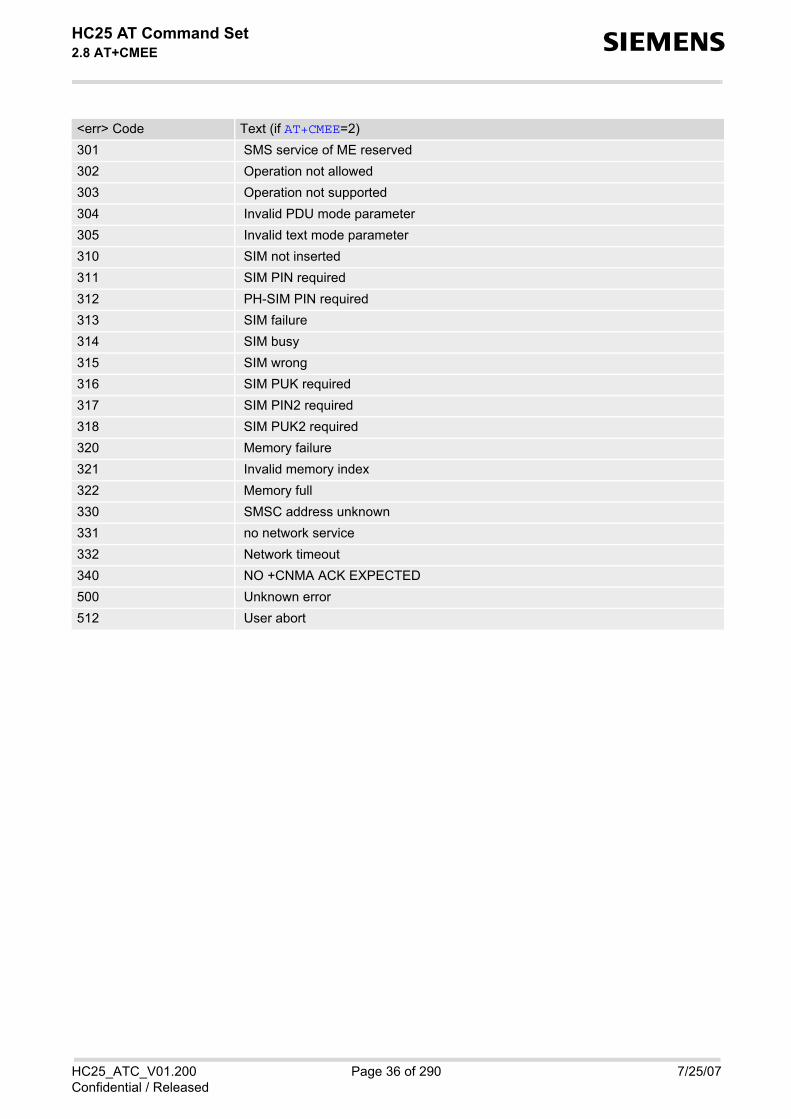
HC25 AT Command Set 2.8 AT+CMEE s
HC25_ATC_V01.200 Page 36 of 290 7/25/07Confidential / Released
301 SMS service of ME reserved 302 Operation not allowed 303 Operation not supported 304 Invalid PDU mode parameter 305 Invalid text mode parameter 310 SIM not inserted 311 SIM PIN required 312 PH-SIM PIN required 313 SIM failure 314 SIM busy 315 SIM wrong 316 SIM PUK required 317 SIM PIN2 required 318 SIM PUK2 required 320 Memory failure 321 Invalid memory index 322 Memory full 330 SMSC address unknown 331 no network service 332 Network timeout 340 NO +CNMA ACK EXPECTED 500 Unknown error 512 User abort
<err> Code Text (if AT+CMEE=2)

HC25 AT Command Set 2.9 AT+CSCS s
HC25_ATC_V01.200 Page 37 of 290 7/25/07Confidential / Released
2.9 AT+CSCS Select TE character set
The AT+CSCS write command informs the TA which character set <chset> is used by the TE. This enables theTA to convert character strings correctly between TE and ME character sets. See also Section 1.6, Supportedcharacter sets.Note that when the TA-TE interface is set to 8-bit operation and the used TE alphabet is 7-bit, the highest bit willbe set to zero.
Syntax
Parameter Description
“GSM“ GSM default alphabet (GSM 03.38 subclause 6.2.1);Note: This setting may cause software flow control problems since the codesused to stop and resume data flow (XOFF = decimal 19, XON = decimal 17)are interpreted as normal characters.
“UCS2“ 16-bit universal multiple-octet coded character set (ISO/IEC10646 [32]); UCS2character strings are converted to hexadecimal numbers from 0000 to FFFF;e.g. "004100620063" equals three 16-bit characters with decimal values 65, 98and 99.
“IRA“(&F)(P) International reference alphabet (ITU T T.50)
Test Command
AT+CSCS=?Response(s)
+CSCS: (list of supported<chset>s)OK
Read Command
AT+CSCS?Response(s)
+CSCS: <chset>OK
Write Command
AT+CSCS=[<chset>]Response(s)
OK
Reference(s) PIN USB0-MDM USB0-APP Last
3GPP 27.007 + + + -
<chset>(str)

HC25 AT Command Set 2.10 AT+GCAP s
HC25_ATC_V01.200 Page 38 of 290 7/25/07Confidential / Released
2.10 AT+GCAP Request complete TA capabilities list
AT+GCAP returns a list of additional capabilities.
Syntax
Parameter Description
e.g.: +CGSM
Note• +CGSM: The response text shows which GSM commands of the ETSI standard are supported.
Test Command
AT+GCAP=?Response(s)
OK
Exec Command
AT+GCAPResponse(s)
+GCAP: <name>OK
Reference(s) PIN USB0-MDM USB0-APP Last
V.250 + + + -
<name>(str)

HC25 AT Command Set 2.11 AT^SCFG s
HC25_ATC_V01.200 Page 39 of 290 7/25/07Confidential / Released
2.11 AT^SCFG Extended Configuration Settings
AT^SCFG can be used to query and configure various settings of the HC25. The AT^SCFG read command returns a list of all supported parameters and their current values. The AT^SCFG write command queries a configuration parameter (if no value is entered) or sets its value(s).
The following error messages may be returned by the AT^SCFG write commands: • "+CME ERROR: operation temporary not allowed"
Change of parameter value(s) temporarily not allowed. • "+CME ERROR: invalid index"
Invalid parameter name or value(s). • "+CME ERROR: invalid characters in text string"
Character set conversion of parameter value(s) failed. • "+CME ERROR: memory failure"
Could not allocate necessary memory or storing a parameter failed. • "+CME ERROR: operation not allowed"
Change of parameter value(s) not allowed • "+CME ERROR: unknown"
Other error
SyntaxTest Command
AT^SCFG=?Response(s)
^SCFG: "GPRS/Auth", (list of supported <gauth>s)^SCFG: "GPRS/AutoAttach", (list of supported <gaa>s)^SCFG: "MEopMode/RM", (list of supported <rm>s)^SCFG: "MEShutdown/OnIgnition", (list of supported <msi>s)^SCFG: "URC/DstIfc", (list of supported <udi>s)OK
Read Command
AT^SCFG?Response(s)
^SCFG: "GPRS/Auth", <gauth>^SCFG: "GPRS/AutoAttach", <gaa>^SCFG: "MEopMode/RM", <rm>^SCFG: "MEShutdown/OnIgnition", <msi>^SCFG: "URC/DstIfc", <udi>OK
Write Command
Configure PPP authenticationAT^SCFG="GPRS/Auth"[, <gauth>]Response(s)
^SCFG: "GPRS/Auth", <gauth>OKERROR+CME ERROR

HC25 AT Command Set 2.11 AT^SCFG s
HC25_ATC_V01.200 Page 40 of 290 7/25/07Confidential / Released
Write Command
Automatic GPRS attachAT^SCFG="GPRS/AutoAttach"[, <gaa>]Response(s)
^SCFG: "GPRS/AutoAttach", <gaa>OKERROR+CME ERROR
Write Command
Query/Configure Registration Mode:AT^SCFG="MEopMode/RM"[, <rm>]Response(s)
^SCFG: "MEopMode/RM", <rm>OKERROR+CME ERROR
Write Command
Enable/disable shutdown by ignition lineAT^SCFG="MEShutdown/OnIgnition"[, <msi>]Response(s)
^SCFG: "MEShutdown/OnIgnition", <msi>OKERROR+CME ERROR
Write Command
Enable/disable radio bandsAT^SCFG="Radio/Band"[, <rba>]Response(s)
^SCFG: "Radio/Band", <rba>OKERROR+CME ERROR
Write Command
Specify frequency band groupAT^SCFG="Radio/Band/Group"[, <rbg>]Response(s)
^SCFG: "Radio/Band/Group", <rbg>OKERROR+CME ERROR
Write Command
Configure URC destination interface:AT^SCFG="URC/DstIfc"[, <udi>]Response(s)
^SCFG: "URC/DstIfc", <udi>OKERROR+CME ERROR

HC25 AT Command Set 2.11 AT^SCFG s
HC25_ATC_V01.200 Page 41 of 290 7/25/07Confidential / Released
Parameter Description
PPP authentication mechanismThis parameter can be used to configure which authentication algorithm the AT+CGDATA or ATD*99# com-mands will apply, during the PPP startup phase, for PDP contexts not yet activated.Parameter is global for all interfaces, volatile and will not be reset by AT&F. For contexts activated with AT+CGACT please use the AT command AT^SGAUTH to configure the authenticationmethod. “0“ CHAP only“1“ PAP only“2“(P) Try CHAP first, then PAP
GPRS with AutoAttachThis parameter can be used to control whether or not the ME will perform a GPRS attach immediately afterpower-up and registering to the network. If the setting is changed to "enabled" and the ME is not attached yet,it will not initiate an attach immediately but after the next restart and registration to the network.Parameter is global for all interfaces, non volatile and will not be reset by AT&F. “disabled“(D) GPRS auto attach is disabled“enabled“ GPRS auto attach is enabled
Registration ModeThis parameter can be used to influence the time the ME takes to register to the network. Any change to thisparameter will take effect after reboot. Parameter is global for all interfaces, non-volatile and will not be reset by AT&F. “0“(D) Normal
When trying to register to a network the ME sleeps longer than in "Fast mode"before restarting a network scan.
“1“ Fast"Fast mode" reduces the time the ME sleeps before restarting a network scanwhen trying to register.Advantage: If the ME is out of network service it may take less time to find anetwork.Disadvantage: Higher current consumption while the ME is out of network ser-vice.
MEShutdown/OnIgnition: Enable/disable shutdown by IGT lineThe parameter specifies two different switching modes of the ignition line IGT: The line may either be used onlyto switch on the ME, or to switch it on and off. Parameter <msi> is global for all interfaces, non-volatile and will not be reset by AT&F. “on“ Ignition line (IGT) can be used to switch on and off the ME. “off“(D) Ignition line (IGT) can be used to switch on the ME.
PIN USB0-MDM USB0-APP Last
- + + -
<gauth>(str)
<gaa>(str)
<rm>(str)
<msi>(str)

HC25 AT Command Set 2.11 AT^SCFG s
HC25_ATC_V01.200 Page 42 of 290 7/25/07Confidential / Released
Radio/Band: Enable/disable frequency band(s)The parameter can be used to select or deselect one or several frequency band(s) the ME is allowed to registerto. The value of <rba> may be one of the single bands listed below or an appropriate band combination. Tospecify a band combination calculate the sum of the values of all desired bands.
Any change to this parameter will take effect after reboot. So, <rba> is a parameter that may be used to readout the current band combination any time, but is primarily intended for reinitializing the ME after next restart. Parameter is global for all interfaces, non-volatile and will not be reset by AT&F. 1 GSM 9002 GSM 18004 GSM 8508 GSM 190016 WCDMA 2100 (BC1)32 WCDMA 1900 (BC2)64 WCDMA 850 (BC5)
Radio/Band/Group: Specify frequency band groupThe "Radio/Band/Group" feature enables the HC25 to start searching a network inside a band combinationspecified by <rba>. The purpose of this feature is improving the band search if the ME is expected to operatein different band groups. If the ME is not required to move around in different band groups the default settingsof <rba> and <rbg> can be left unchanged.
Writing <rbg> modifies the allowed bands (see <rba>) immediately and causes the ME to restart a networksearch based on the new <rba> setting:Writing <rbg> value 0 will restrict the allowed bands to the EU band group (<rba>= 19).Writing <rbg> value 1 will restrict the allowed bands to the US band group (<rba>= 108).Writing <rbg> value 2 will re-enable all supported bands (<rba>= 127).Changing the allowed bands with <rbg> takes effect without reboot and is non-volatile.
Execution of the write command AT^SCFG="Radio/Band/Group,<rbg> causes the ME to deregister from andre-register to the network. Therefore, it is useful to have the URC "+CREG" enabled. The status of the SIM PINauthentication remains unchanged, eliminating the need to enter the SIM PIN again after the change. To querythe allowed bands set with <rbg> use the read command AT^SCFG="Radio/Band, which displays <rba>. 0 All frequency bands typically supported in European countries:
GSM 1800, GSM 900, WCDMA 2100Value 0 is equivalent to <rba>= 19.
1 All frequency bands typically supported in North American countries:GSM 850, WCDMA 850, GSM 1900, WCDMA 1900Value 1 is equivalent to <rba>= 108.
2 This option can be used to re-enable all supported bands immediately withoutreboot if the allowed bands have been restricted, e.g. after setting <rbg> "0"or "1" or after selecting a specific provider with AT^SNWS.Value 2 is equivalent to <rba>= 127.
Example: A typical use case of "Radio/Band/Group" may be improving a change from EU to US bands. Thesame scenario will work in the opposite direction (US to EU).• Precondition: All bands enabled (<rba>= 127), ME is registered in an EU band. • Enter AT^SCFG="Radio/Band/Group",1. ME deregisters, changes to US band group, searches US bands
only and registers in US band group. • Enter AT^SCFG="Radio/Band/Group",2. ME deregisters, enables all bands, and re-registers quickly to US
without searching the EU bands. Allowed bands are not restricted (<rba>= 127).
<rba>(num)
<rbg>(num)

HC25 AT Command Set 2.11 AT^SCFG s
HC25_ATC_V01.200 Page 43 of 290 7/25/07Confidential / Released
URC destination interfaceThis parameter can be used to configure the interface which will be used to output URCs. Note that the recom-mended approach for a typical HC25 application is using the default configuration. If you consider changing theconfiguration please carefully read Section 1.4, HC25 AT Command Interpreter and Section 1.8, UnsolicitedResult Code Presentation. Parameter is global for all interfaces, volatile and will not be reset by AT&F. If the modem interface is used, keep in mind, that if the interface is blocked by an active data connection, thenthis connection should be periodically suspended to check for pending URCs! “usb0-mdm“ Use modem interface to output URCs“usb0-app“(P) Use application interface to output URCs
<udi>(str)

HC25 AT Command Set 2.12 AT^SMSO s
HC25_ATC_V01.200 Page 44 of 290 7/25/07Confidential / Released
2.12 AT^SMSO Switch off mobile station
AT^SMSO initiates the power-off procedure.
Syntax
Note• Do not send any other AT command after AT^SMSO.
Test Command
AT^SMSO=?Response(s)
OK
Exec Command
AT^SMSOResponse(s)
OKERROR+CME ERROR
Reference(s) PIN USB0-MDM USB0-APP Last
SIEMENS - + + +

HC25 AT Command Set 2.13 AT^SUSB s
HC25_ATC_V01.200 Page 45 of 290 7/25/07Confidential / Released
2.13 AT^SUSB USB Configuration
AT^SUSB can be used to query and configure various settings of the USB interface. The AT^SUSB read command returns a list of all supported parameters and their current values. The AT^SUSB write commands query a configuration parameter (if no value is entered) or set the value(s).
Specifications of the USB interface are provided in [2]. Advice on how integrate the HC25 into different operatingsystems can be found in [7].
SyntaxRead Command
AT^SUSB?Response(s)
^SUSB: "Startup", <start>^SUSB: "MaxPower", <maxpow>^SUSB: "PowerSource", <powsrc>^SUSB: "MdmNet/TO", <mnto>^SUSB: "MS/CRC", <mscrc>^SUSB: "MS/OnEject", <msoe>^SUSB: "MS/WProt", <mswprot>OKERROR+CME ERROR
Write Command
Startup configuration:AT^SUSB="Startup"[, <start>]Response(s)
^SUSB: "Startup", <start>OKERROR+CME ERROR
Write Command
Maximum power:AT^SUSB="MaxPower"[, <maxpow>]Response(s)
^SUSB: "MaxPower", <maxpow>OKERROR+CME ERROR
Write Command
Power source:AT^SUSB="PowerSource"[, <powsrc>]Response(s)
^SUSB: "PowerSource", <powsrc>OKERROR+CME ERROR

HC25 AT Command Set 2.13 AT^SUSB s
HC25_ATC_V01.200 Page 46 of 290 7/25/07Confidential / Released
Write Command
Modem Class request timeout period:AT^SUSB="MdmNet/TO"[, <mnto>]Response(s)
^SUSB: "MdmNet/TO", <mnto>OKERROR+CME ERROR
Write Command
Query Mass Storage CRC:AT^SUSB="MS/CRC"Response(s)
^SUSB: "MS/CRC", <mscrc>OKERROR+CME ERROR
Write Command
Query usable Mass Storage size:AT^SUSB="MS/FSize"Response(s)
^SUSB: "MS/FSize", <msfs>OKERROR+CME ERROR
Write Command
Configure the mode after Mass Storage eject:AT^SUSB="MS/OnEject"[, <msoe>]Response(s)
^SUSB: "MS/OnEject", <msoe>OKERROR+CME ERROR
Write Command
Mass Storage write protection:AT^SUSB="MS/WProt"[, <mswprot>]Response(s)
^SUSB: "MS/WProt", <mswprot>OKERROR+CME ERROR
PIN USB0-MDM USB0-APP Last
- + + -

HC25 AT Command Set 2.13 AT^SUSB s
HC25_ATC_V01.200 Page 47 of 290 7/25/07Confidential / Released
Parameter Description
USB startup configurationThis parameter can be used to control the USB startup enumeration. Any change takes effect the next time theME is re-enumerated. Parameter is global for all interfaces, non-volatile and will not be reset by AT&F. “MS“ On power-up the HC25 enumerates as USB mass storage device.
The Product ID for the mass storage device is 0x0041.The mass storage can be used with standard drivers typically integrated inmost operating systems.
When you are finished using the mass storage you can easily switch over tocomposite device operation. To do so, use the Eject option. Under WindowsXP, for example, open the Windows Explorer, right-click the "Removable Disk"drive and select "Eject". This deactivates the mass storage and, at the sametime, activates the USB composite communication device without any need torestart the ME. Parameter <msoe> determines the type of USB compositecommunication device to activate when the mass storage is ejected. The option "Safely Remove the Hardware" commonly used for USB devicesunder Windows terminates the mass storage function without activating thecomposite device function.
“MdmNet“(D) On power-up the HC25 enumerates as USB composite communication devicewith the following virtual ports: modem port, application port (VCOM) and wire-less network adapter (NET).The Product ID for this enumeration is 0x0040.The "MdmNet" enumeration mode is intended for PC based Windows operat-ing systems and is fully supported by the HC25 USB driver package suppliedby Siemens for Windows XP and Windows Vista.
“Mdm“ On power-up the HC25 enumerates as USB composite communication devicesupporting modem port and application port (VCOM), but no wireless networkadapter (NET). The Product ID for this enumeration is 0x0047. The "Mdm" enumeration mode is not supported by the HC25 USB driver pack-age supplied by Siemens for Windows XP and Windows Vista. Before selecting "Mdm" carefully read the information provided in [7]. See alsonotes below.
Maximum powerMaximum power consumption of the USB device from the USB bus. This parameter is reported to a USB hostas part of the USB enumeration. Only even values are supported. Odd values are truncated. Any change of this parameter becomes active with the next device enumeration. Parameter is global for all interfaces, non-volatile and will not be reset by AT&F. 0...10(D)...500 Device maximum power consumption in mA
Power sourceThis parameter can be used to specify the power source. Any change of this parameter becomes active with thenext device enumeration. Parameter is global for all interfaces, non-volatile and will not be reset by AT&F. “BUS“ Device enumerates as bus powered device.“SELF“(D) Device enumerates as self powered device.
<start>(str)
<maxpow>(str)
<powsrc>(str)

HC25 AT Command Set 2.13 AT^SUSB s
HC25_ATC_V01.200 Page 48 of 290 7/25/07Confidential / Released
Modem and Modem/Net Class Request timeoutThis parameter specifies the time the HC25 waits for a Communication Device Class request from the host. Anychange takes effect the next time the ME is restarted. Parameter is global for all interfaces, non-volatile and will not be reset by AT&F. “0“ No timeout supervision 100...10000(D)...65535 Timeout in ms
If no Communication Device Class request is received within the specified timethe ME enumerates as mass storage device. This is typically the case if you have not yet installed the supplied HC25 USBdrivers on Windows XP or Windows Vista, or if you select an enumerationmode not supported by the operating system and then reboot the ME on thesame system (e.g. "Mdm" on a Windows system or "MdmNet" on a non-Win-dows system). See notes below.
Mass storage sizeThis parameter reports the usable USB mass storage size. 0...2147483647 Usable mass storage size in bytes.
Mass storage CRC valueThis parameter reports the USB mass storage CRC value. 00000000...FFFFFFFF ASCII hex CRC value up to 8 digits long; if CRC recalculation is not finished
yet, then a ASCII question mark is appended.
Mode on mass storage ejectThis parameter determines the type of USB composite communication device to activate when the mass storageis ejected. Parameter is global for all interfaces, non-volatile and will not be reset by AT&F. “MdmNet“(D) After ejecting the mass storage the HC25 enumerates as USB composite com-
munication device with modem port, application port (VCOM) and wireless net-work adapter (NET).
“Mdm“ After ejecting themass storage the HC25 enumerates as USB composite com-munication device with modem port and application port (VCOM).The "Mdm" enumeration mode is not supported by the HC25 USB driver pack-age supplied by Siemens for Windows XP and Windows Vista. Before selecting "Mdm" carefully read the information provided in [7]. See alsonotes below.
Mass storage write protectionThis parameter can be used to enable or disable the USB mass storage write protection. communication device(modem). Any change of this parameter becomes active immediately. Parameter is global for all interfaces, non-volatile and will not be reset by AT&F. “Enabled“ Mass storage is write protected“Disabled“(D) Mass storage is not write protected
<mnto>(str)
<msfs>(str)
<mscrc>(str)
<msoe>(str)
<mswprot>(str)

HC25 AT Command Set 2.13 AT^SUSB s
HC25_ATC_V01.200 Page 49 of 290 7/25/07Confidential / Released
Note• When changing the USB enumeration parameters take care to choose the right configuration depending on
the type of USB drivers used. Keep in mind that "Mdm" makes the ME inaccessible with the Windows XP andWindows Vista USB drivers supplied by Siemens. If alternate usage with different USB drivers is necessary during application development, take care not tochange all three enumeration parameters <start>, <msoe> and <mnto> for only one specific driver setup.In particular, we strongly recommend to configure <start> and <msoe> for different USB enumerationmodes. This gives you the flexibility to easily revert to the enumeration mode needed when you connect theME to a USB host based on another driver setup. For example, if <start> equals "Mdm" select "MdmNet"for <msoe> or vice versa. Also, do not set <mnto>= "0" because the timeout enables the ME to enumerate as mass storage if the driv-ers required by the currently selected enumeration mode are not found. Depending on whether drivers areinstalled you can then decide how to proceed: installing the USB drivers if required, or, if the drivers arealready installed, ejecting the mass storage to revert to the composite device enumeration needed. Of course, if you do not wish to operate the ME with different drivers the "MdmNet" and "Mdm" enumerationmodes should not be different for <start> and <msoe>.
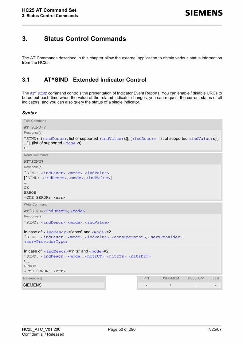
HC25 AT Command Set 3. Status Control Commands s
HC25_ATC_V01.200 Page 50 of 290 7/25/07Confidential / Released
3. Status Control Commands
The AT Commands described in this chapter allow the external application to obtain various status informationfrom the HC25.
3.1 AT^SIND Extended Indicator Control
The AT^SIND command controls the presentation of Indicator Event Reports. You can enable / disable URCs tobe output each time when the value of the related indicator changes, you can request the current status of allindicators, and you can also query the status of a single indicator.
SyntaxTest Command
AT^SIND=?Response(s)
^SIND: (<indDescr>, list of supported <indValue>s)[, (<indDescr>, list of supported <indValue>s)[, ...]], (list of supported <mode>s)OK
Read Command
AT^SIND?Response(s)
^SIND: <indDescr>, <mode>, <indValue>[^SIND: <indDescr>, <mode>, <indValue>]...OKERROR+CME ERROR: <err>
Write Command
AT^SIND=<indDescr>, <mode>Response(s)
^SIND: <indDescr>, <mode>, <indValue>
In case of: <indDescr>="eons" and <mode>=2^SIND: <indDescr>, <mode>, <indValue>, <eonsOperator>, <servProvider>, <servProviderType>
In case of: <indDescr>="nitz" and <mode>=2^SIND: <indDescr>, <mode>, <nitzUT>, <nitzTZ>, <nitzDST>OKERROR+CME ERROR: <err>
Reference(s) PIN USB0-MDM USB0-APP Last
SIEMENS - + + -

HC25 AT Command Set 3.1 AT^SIND s
HC25_ATC_V01.200 Page 51 of 290 7/25/07Confidential / Released
Unsolicited Result Codes
URC 1
Format of the standard indicator:+CIEV: <indDescr>, <indValue>
Value of an indicator has changed.
URC 2
Format of the "eons" indicator: +CIEV: <indDescr>, <indValue>, <eonsOperator>, <servProvider>, <servProviderType>
One URC is issued for each new LAI (Location Area Information) broadcast by the network.
URC 3
Format of the "nitz" indicator: +CIEV: <indDescr>, <nitzUT>, <nitzTZ>, <nitzDST>
Parameter Description
String values and their <indValue> ranges.“signal“ Channel bit error rate of the signal received:
The parameter is always set to value 99. See also AT+CSQ. “service“ Service availability:
“sounder“ Sounder activity:Reports every event that causes the ME to generate a tone.
“message“ Unread short message at memory location <mem1>. Refer to AT+CPMS.
“call“ Call in progress:
“roam“ Roaming indicator:
“smsfull“ Capacity of storage for received short messages:
<indDescr>(str)
0 Not registered to any network.1 Registered to home network or, if "roam"=1 then registered to another
network.
0 Tone generator not active.1 Tone generator active.
Value 1 means for example:Incoming call - ME is ringing. Note that in this case the URC "+CIEV: sounder" will be output only if ringing tones are enabled with AT^SRTC.Waiting call - ME generates waiting call tone (if call waiting is enabled).Outgoing call - ME generates Call Progress tone.Outgoing call - ME generates BUSY tone.Playback of ringing tones when tested with AT^SRTC.
0 No unread message(s) available.1 Unread message(s) available.
0 No call.1 At least one MO or MT call is in state "active" (connection established)
or "held".
0 Registered to home network or not registered.1 Registered to other network.
0 The short message memory location <mem3> is still free or has just become free again. Refer to AT+CPMS.
1 All memory locations of <mem3> are used up.

HC25 AT Command Set 3.1 AT^SIND s
HC25_ATC_V01.200 Page 52 of 290 7/25/07Confidential / Released
“rssi“ Received signal (field) strength:
Received signal (field) strength can also be obtained with AT+CSQ. However,the signal strength is scaled to value range 0..31 by this command.
“audio“ Activity of the built-in audio unit:
“eons“ Enhanced Operator Name String (EONS) Indication:The Enhanced Operator Name String indicator feature allows the HC25 to out-put various operator names for different PLMN identities via URC. It also allowsthe output of a different operator name based on a subset of the registered net-work by using a range of Location Area Codes (LACs) or a single LAC.The presentation of the "eons" indicator is determined by network activity. Forexample, the indicator appears every time a location update occurs or a NITZinformation is sent, no matter whether or not the status of the EONS informa-tion has changed. This means that the same EONS information may bereported several times.The EONS tables are stored in the SIM card and will be read at power-up. Following are the SIM Elementary Files that are affected by the introduction ofEONS feature in the SIM card:EFSST (SIM Service Table) - describes which features are active. EFOPL (Operator PLMN List) - contains the PLMN identification and location IDtogether with the index of the corresponding PNN record EFPNN (PLMN Network Name) - contains the full and short form version of thenetwork name for the registered PLMN If the Operator Name Source is CPHS Operator Name String long and shortform, refer to <indValue>, the following two SIM Elementary Files will beused: EFONString (Operator Name String) - contains the name of the PLMN operatorwho issued the SIM. EFOPShort (Operator Name Short form) - contains a short form of the name ofthe PLMN operator who issued the SIM.
“nitz“ Network Identity and Time Zone indication:This indicator shows the time relevant information elements of an MM Informa-tion (MMI) or GMM Information (GMMI) message received from the network(see GSM 24.008, ch. 9.2.15a and 9.4.19). The network usually sends a NITZindicator when the mobile attaches to the network, when it enters a locationarea with different time zone or when a daylight change occurs.A NITZ indicator may consist of the following parameters: Universal Time (UT),local Time Zone (TZ), Daylight Saving Time (DST). All information elements ofMMI/GMMI are optional and therefore, the presentation of the parameters<nitzUT>, <nitzTZ>, <nitzDST> varies with the network. For example, thenetwork may send all three parameters UT, TZ, DST, or only UT and TZ or onlyTZ.
UT is indicated in usual date/time format and represents the current world time(GMT) at the moment when sent.TZ is given as a positive (east) or negative (west) offset from UT in units of 15minutes.DST shows the number of hours added to the local TZ because of daylight sav-ing time (summertime) adjustment. Usually DST is 1 hour but it can be also 2hours in certain locations.
Example for time and time zone with DST:+CIEV: nitz,"04/07/23,13:39:20",-28,1
0 Signal strength ≤ -112 dBm1 - 4 Signal strength in 15 dB steps5 Signal strength ≥ -51 dBm99 Signal strength not known or not detectable
0 Audio unit not active.1 Audio unit is active, for example:
MO voice call: Indicator is output with value 1 when dialing starts.MT voice call: Indicator is output with value 1 when call is answered.
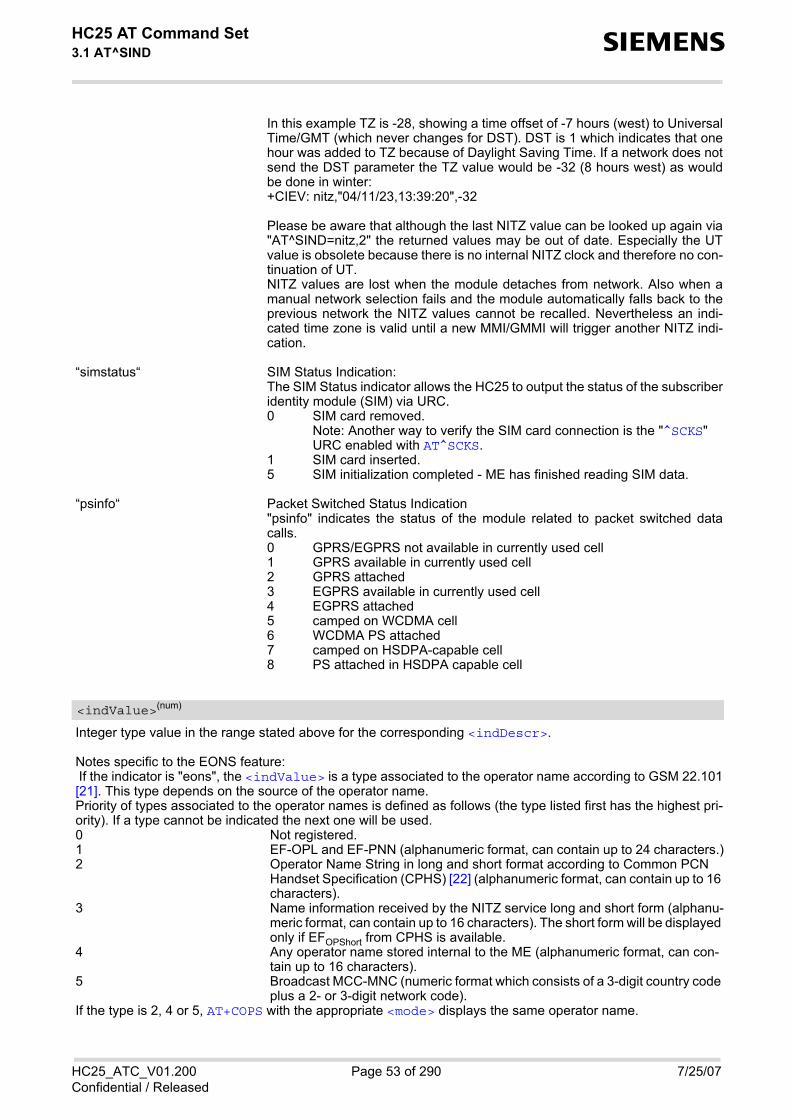
HC25 AT Command Set 3.1 AT^SIND s
HC25_ATC_V01.200 Page 53 of 290 7/25/07Confidential / Released
In this example TZ is -28, showing a time offset of -7 hours (west) to UniversalTime/GMT (which never changes for DST). DST is 1 which indicates that onehour was added to TZ because of Daylight Saving Time. If a network does notsend the DST parameter the TZ value would be -32 (8 hours west) as wouldbe done in winter:+CIEV: nitz,"04/11/23,13:39:20",-32
Please be aware that although the last NITZ value can be looked up again via"AT^SIND=nitz,2" the returned values may be out of date. Especially the UTvalue is obsolete because there is no internal NITZ clock and therefore no con-tinuation of UT.NITZ values are lost when the module detaches from network. Also when amanual network selection fails and the module automatically falls back to theprevious network the NITZ values cannot be recalled. Nevertheless an indi-cated time zone is valid until a new MMI/GMMI will trigger another NITZ indi-cation.
“simstatus“ SIM Status Indication:The SIM Status indicator allows the HC25 to output the status of the subscriberidentity module (SIM) via URC.
“psinfo“ Packet Switched Status Indication"psinfo" indicates the status of the module related to packet switched datacalls.
Integer type value in the range stated above for the corresponding <indDescr>.
Notes specific to the EONS feature: If the indicator is "eons", the <indValue> is a type associated to the operator name according to GSM 22.101[21]. This type depends on the source of the operator name. Priority of types associated to the operator names is defined as follows (the type listed first has the highest pri-ority). If a type cannot be indicated the next one will be used.
If the type is 2, 4 or 5, AT+COPS with the appropriate <mode> displays the same operator name.
0 SIM card removed.Note: Another way to verify the SIM card connection is the "^SCKS" URC enabled with AT^SCKS.
1 SIM card inserted.5 SIM initialization completed - ME has finished reading SIM data.
0 GPRS/EGPRS not available in currently used cell 1 GPRS available in currently used cell 2 GPRS attached 3 EGPRS available in currently used cell 4 EGPRS attached 5 camped on WCDMA cell 6 WCDMA PS attached 7 camped on HSDPA-capable cell 8 PS attached in HSDPA capable cell
<indValue>(num)
0 Not registered.1 EF-OPL and EF-PNN (alphanumeric format, can contain up to 24 characters.)2 Operator Name String in long and short format according to Common PCN
Handset Specification (CPHS) [22] (alphanumeric format, can contain up to 16 characters).
3 Name information received by the NITZ service long and short form (alphanu-meric format, can contain up to 16 characters). The short form will be displayed only if EFOPShort from CPHS is available.
4 Any operator name stored internal to the ME (alphanumeric format, can con-tain up to 16 characters).
5 Broadcast MCC-MNC (numeric format which consists of a 3-digit country code plus a 2- or 3-digit network code).

HC25 AT Command Set 3.1 AT^SIND s
HC25_ATC_V01.200 Page 54 of 290 7/25/07Confidential / Released
0(&F)(P) Disables the presentation of a specific URC.1 Enables the presentation of a specific URC.
The URC will be buffered in the TA when the TA-TE link is reserved (e.g. inonline data mode), and flushed to the TE when the TA-TE link is free again.Otherwise, the URC will be forwarded directly to the TE.
2 Requests the presentation mode of the URC status and the current value of asingle indicator type.
Operator in format which depends on the type associated to the operator name. Refer to <indValue>.
Service Provider Name according to the status settings (SIM Service No. 17) in the SIM Service Table (SST) ofthe SIM. Service Provider Name (SPN) will be read from EFSPN. Service Provider Display Information (SPDI) will be readfrom EFSPDI list.
Service Provider Type according to Registered Public Land Mobile Network (RPLMN) and Home Public LandMobile Network (HPLMN).0 No Service Provider Information available. 1 Service Provider Name will be displayed. RPLMN is the HPLMN. 2 Service Provider Display Information will be displayed. One list entry is equal
to the RPLMN.
Universal Time delivered as part of the "nitz" Indicator. Refer to <indDescr>.
Time Zone delivered as part of the "nitz" Indicator. Refer to <indDescr>.
Adjustment for Daylight Saving Time as part of the "nitz" Indicator. Refer to <indDescr>.
<mode>(num)
<eonsOperator>(str)(+CSCS)
<servProvider>(str)(+CSCS)
<servProviderType>(num)
<nitzUT>(str)(+CSCS)
<nitzTZ>(num)
<nitzDST>(num)

HC25 AT Command Set 3.2 AT+CEER s
HC25_ATC_V01.200 Page 55 of 290 7/25/07Confidential / Released
3.2 AT+CEER Extended Error Report
AT+CEER returns an extended error report regarding the reason of the last • call release• failure to set up a call (both mobile originated or terminated)• failure to modify a call by using Supplementary Services • failed attempt to activate, register, query, deactivate or deregister a Supplementary Service • unsuccessful GPRS attach or unsuccessful PDP context activation • GPRS detach or PDP context deactivation ≠≠The release cause report <report> is a single line containing the cause information given by GSM networkin textual format.
Syntax
Parameter Description
release cause reportReason for the last call failure to setup or release (listed in Section 3.2.1, List of status codes for the extendederror report).Both CS and PS domain call types are reported. Cause data is captured from Call Manager events and cachedlocally to later use by this command.
3.2.1 List of status codes for the extended error report
Test Command
AT+CEER=?Response(s)
OKERROR+CME ERROR
Exec Command
AT+CEERResponse(s)
+CEER: <report>OKERROR+CME ERROR
Reference(s) PIN USB0-MDM USB0-APP Last
GSM 07.07 + + + -
<report>(str)
CS internal cause lookupNo cause information available (default)Phone is offlineNo service availableNetwork release, no reason givenReceived incoming call

HC25 AT Command Set 3.2 AT+CEER s
HC25_ATC_V01.200 Page 56 of 290 7/25/07Confidential / Released
Client ended callUIM not presentAccess attempt already in progressAccess failure, unknown sourceConcur service not supported by networkNo response received from networkGPS call ended for user callSMS call ended for user callData call ended for emergency callRejected during redirect or handoffLower-layer ended callCall origination request failedClient rejected incoming callClient rejected setup indicationNetwork ended callNo funds availableNo service availableFull service not availableMaximum packet calls exceededVideo connection lostVideo protocol closed after setupVideo protocol setup failureInternal error
CS network cause lookupUnassigned/unalloacted numberNo route to destinationChannel unacceptableOperator determined barringNormal call clearingUser busyNo user respondingUser alerting, no answerCall rejectedNumber changedNon selected user clearingDestination out of orderInvalid/incomplete numberFacility rejectedResponse to Status EnquiryNormal, unspecifiedNo circuit/channel available
CS internal cause lookup

HC25 AT Command Set 3.2 AT+CEER s
HC25_ATC_V01.200 Page 57 of 290 7/25/07Confidential / Released
Network out of orderTemporary failureSwitching equipment congestionAccess information discardedRequested circuit/channel not availableResources unavailable, unspecifiedQuality of service unavailableRequested facility not subscribedIncoming calls barred within the CUGBearer capability not authorizedBearer capability not availableService/option not availableBearer service not implementedACM >= ACMmaxRequested facility not implementedOnly RDI bearer is availableService/option not implementedInvalid transaction identifier valueUser not member of CUGIncompatible destinationInvalid transit network selectionSemantically incorrect messageInvalid mandatory informationMessage non-existent/not implementedMessage type not compatible with stateIE non-existent/not implementedConditional IE errorMessage not compatible with stateRecovery on timer expiryProtocol error, unspecifiedInterworking, unspecified
CS network reject lookupIMSI unknown in HLRIllegal MSIMSI unknown in VLRIMEI not acceptedIllegal MEGPRS services not allowedGPRS and non GPRS services not allowedMS identity cannot be derivedImplicitly detached
CS network cause lookup
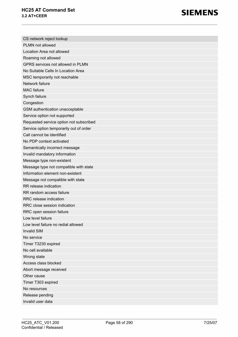
HC25 AT Command Set 3.2 AT+CEER s
HC25_ATC_V01.200 Page 58 of 290 7/25/07Confidential / Released
PLMN not allowedLocation Area not allowedRoaming not allowedGPRS services not allowed in PLMNNo Suitable Cells In Location AreaMSC temporarily not reachableNetwork failureMAC failureSynch failureCongestionGSM authentication unacceptableService option not supportedRequested service option not subscribedService option temporarily out of orderCall cannot be identifiedNo PDP context activatedSemantically incorrect messageInvalid mandatory informationMessage type non-existentMessage type not compatible with stateInformation element non-existentMessage not compatible with stateRR release indicationRR random access failureRRC release indicationRRC close session indicationRRC open session failureLow level failureLow level failure no redial allowedInvalid SIMNo serviceTimer T3230 expiredNo cell availableWrong stateAccess class blockedAbort message receivedOther causeTimer T303 expiredNo resourcesRelease pendingInvalid user data
CS network reject lookup

HC25 AT Command Set 3.2 AT+CEER s
HC25_ATC_V01.200 Page 59 of 290 7/25/07Confidential / Released
PS internal cause lookupInvalid connection identifierInvalid NSAPIInvalid Primary NSAPIPDP establish timeoutInvalid fieldSNDCP failureRAB setup failureNo GPRS contextPDP activate timeoutPDP modify timeoutPDP inactive max timeoutPDP lowerlayer errorPDP duplicateAccess technology changePDP unknown reason
CS PS network cause lookupLLC or SNDCP failureInsufficient resourcesMissing or unknown APNUnknown PDP address or PDP typeUser Aauthentication failedActivation rejected by GGSNActivation rejected, unspecifiedService option not supportedRequested service option not subscribedService option temporarily out of orderNSAPI already used (not sent)Regular deactivationQoS not acceptedNetwork failureReactivation requiredFeature not supportedSemantic error in the TFT operationSyntactical error in the TFT operationUnknown PDP contextPDP context without TFT already activatedSemantic errors in packet filterSyntactical errors in packet filterInvalid transaction identifierSemantically incorrect messageInvalid mandatory information

HC25 AT Command Set 3.2 AT+CEER s
HC25_ATC_V01.200 Page 60 of 290 7/25/07Confidential / Released
Message non-existent/not implementedMessage type not compatible with stateIE non-existent/not implementedConditional IE errorMessage not compatible with stateProtocol error, unspecified
CS PS network cause lookup

HC25 AT Command Set 3.3 AT+CPAS s
HC25_ATC_V01.200 Page 61 of 290 7/25/07Confidential / Released
3.3 AT+CPAS Mobile equipment activity status
The AT+CPAS execute command indicates the activity status of the ME.
Syntax
Parameter Description
0 Ready3 Incoming call (ringing)4 Call in progress
Test Command
AT+CPAS=?Response(s)
+CPAS: (list of supported<pas>s)OK
Exec Command
AT+CPASResponse(s)
+CPAS: <pas>OK
Reference(s) PIN USB0-MDM USB0-APP Last
GSM 07.07 - + + -
<pas>(num)

HC25 AT Command Set 3.4 AT+WS46 s
HC25_ATC_V01.200 Page 62 of 290 7/25/07Confidential / Released
3.4 AT+WS46 Select wireless network
The AT+WS46 command is intended for reading the current status of the network selection. The write commandhas no effect. To select the network please use the AT+COPS command.
Syntax
Parameter Description
12 GSM Digital Cellular Systems (GERAN only)22 UTRAN only25 3GPP Systems (both GERAN and UTRAN)
Test Command
AT+WS46=?Response(s)
+WS46: (list of supported<n>s)OK
Read Command
AT+WS46?Response(s)
<n>OK
Write Command
AT+WS46=[<n>]Response(s)
OKERROR+CME ERROR
Reference(s) PIN USB0-MDM USB0-APP Last
GSM 07.07 - + + -
<n>(num)

HC25 AT Command Set 4. Serial Interface Control Commands s
HC25_ATC_V01.200 Page 63 of 290 7/25/07Confidential / Released
4. Serial Interface Control Commands
The AT Commands described in this chapter allow the external application to determine various settings relatedto the HC25's serial interface.
4.1 AT^SQPORT Query Port Type
AT^SQPORT enables the host application to query the type of virtual COM port it is connected to. Further detailson the different types of virtual HC25 interfaces can be found in Section 1.4, HC25 AT Command Interpreter.
Syntax
Parameter Description
“Modem“ The virtual COM port is defined for use as a modem, mainly intended for dial-up connections. Using AT commands is not recommended except for the dial-ing command ATD.
“Application“ The virtual COM port is defined as application interface. It is recommended thatthis interface be used for controlling the HC25, e.g. for entering AT commands,receiving URCs, or sending and receiving short messages. URCs are indicatedonly on this interface, no matter which of the two interfaces was used to sendthe AT commands for activating their presentation. For further detail on URCsplease refer to Section 1.8, Unsolicited Result Code Presentation.
Test Command
AT^SQPORT=?Response(s)
OK
Read Command
AT^SQPORT?Response(s)
<type>OK
Exec Command
AT^SQPORTResponse(s)
<type>OK
Reference(s) PIN USB0-MDM USB0-APP Last
Siemens - + + -
<type>(str)

HC25 AT Command Set 4.2 AT&C s
HC25_ATC_V01.200 Page 64 of 290 7/25/07Confidential / Released
4.2 AT&C Set Data Carrier Detect (DCD) Line mode
The AT&C command determines how the state of the DCD line (circuit 109) of the virtual modem COM portreflects the HC25's internal activity.
Syntax
Parameter Description
[0] DCD line shall always be on. 1 DCD line shall be on only when data carrier signal is present. 2(&F) Setting winks (briefly transitions off, then back on) the DCD line when data calls
end.
Exec Command
AT&C[<value>]Response(s)
OK
Reference(s) PIN USB0-MDM USB0-APP Last
V.250 + + + -
<value>(num)

HC25 AT Command Set 4.3 AT&D s
HC25_ATC_V01.200 Page 65 of 290 7/25/07Confidential / Released
4.3 AT&D Set circuit Data Terminal Ready (DTR) function mode
The AT&D determines how the TA responds when circuit 108/2 (DTR) is changed from ON to OFF during datamode.
Syntax
Parameter Description
[0] TA ignores status of DTR.1 ON->OFF on DTR: Change to command mode while retaining the connected
call.2(&F) ON->OFF on DTR: Disconnect data call, change to command mode. During
state DTR = OFF auto-answer is off.
Exec Command
AT&D[<value>]Response(s)
OK
Reference(s) PIN USB0-MDM USB0-APP Last
V.250 + + + -
<value>(num)

HC25 AT Command Set 4.4 AT&S s
HC25_ATC_V01.200 Page 66 of 290 7/25/07Confidential / Released
4.4 AT&S Set circuit Data Set Ready (DSR) function mode
The AT&S command determines how the TA sets circuit 107 (DSR) depending on the communication state ofthe TA interfacing TE.
Syntax
Parameter Description
[0](&F) DSR line is always ON1 TA in command mode: DSR is OFF.
TA in data mode: DSR is ON.
Exec Command
AT&S[<value>]Response(s)
OK
Reference(s) PIN USB0-MDM USB0-APP Last
V.250 - + + -
<value>(num)

HC25 AT Command Set 4.5 ATE s
HC25_ATC_V01.200 Page 67 of 290 7/25/07Confidential / Released
4.5 ATE Enable command echo
The ATE command determines whether or not the TA echoes characters received from TE during commandstate.
Syntax
Parameter Description
0 Echo mode off[1](&F) Echo mode on
Exec Command
ATE[<value>]Response(s)
OK
Reference(s) PIN USB0-MDM USB0-APP Last
V.250 - + + -
<value>(num)

HC25 AT Command Set 5. Security Commands s
HC25_ATC_V01.200 Page 68 of 290 7/25/07Confidential / Released
5. Security Commands
The AT Commands described in this chapter allow the external application to determine various security relatedsettings.
5.1 AT+CLCK Facility lock
AT+CLCK can be used to lock, unlock or interrogate a network or ME <facility>. The command can beaborted when network facilities are being set or interrogated.
Syntax
Parameter Description
Phone security locks set by client or factoryPrimarily intended for the client to take safety precautions, "SC"can be configured individually.Parameter <class> is not applicable to security locks.See examples below for further details. “SC“ SIM (lock SIM cards). SIM requests password upon ME power-up and when
this lock command is issued.<password>: SIM PIN1.
“FD“ SIM fixed dialling memory: If the mobile is locked to "FD", only the phone num-bers stored to the "FD" memory can be dialled. (Capacity of FD phonebookdepending on the SIM card).<password>: SIM PIN 2.If a lock on the SIM fixed dialing memory is active, the following applies:
Test Command
AT+CLCK=?Response(s)
+CLCK:list of supported <facility>s OK
Write Command
AT+CLCK=<facility>, <mode>[, <password>][, <class>]Response(s)
if <mode> is not equal 2 and command successful: OKif <mode>= 2 and command successful: +CLCK: <status>[, <class>][+CLCK: <status>[, <class>]][+CLCK: ...]OKIf error is related to ME functionality +CME ERROR
Reference(s) PIN USB0-MDM USB0-APP Last
GSM 07.07, GSM 02.04, GSM 02.88, GSM 03.88, GSM 04.88
+ + + -
<facility>(str)

HC25 AT Command Set 5.1 AT+CLCK s
HC25_ATC_V01.200 Page 69 of 290 7/25/07Confidential / Released
• Outgoing voice, data or fax calls can be made only to numbers stored in''FD'' phonebook. Result code depends on the type of the call:for voice calls, indication is ''+CME Error 257: Call barred''.for data and fax calls, indication is ''NO CARRIER''.
• Access to defined Supplementary Services such as Call barring, Call wait-ing, Call forwarding, Call hold and Multiparty is possible only if the exact cor-responding public MMI *# code for the desired service is stored in the fixeddialing number phone book, and used with ATD.AT commands for supplementary service control are barred while "FD" lockis active.Indication is ''+CME Error 257: Call barred''.
• Access to Unstructured Supplementary Services (''USSD'') is possible onlyif the exact desired USSD string is stored in the fixed dialling number phonebook, and used with ATD.AT commands for USSD are barred while "FD" lock is active.Indication is ''+CME Error 257: Call barred''.
• SMS can be sent only to phone numbers which are stored in the ''fixed dial-ling numbers'' phonebook ''FD''.Indication is ''+CMS Error 302: operation not allowed''.
• GPRS commands can be used only if the ''fixed dialling numbers'' phone-book ''FD'' contains an entry with phone number ''*99#''. This single entryenables all GPRS commands, including AT commands and modem com-patibility commands like ''ATD*99***1#'' or ''ATD*98***1#''.Indication is ''+CME Error 257: Call barred''.
Supplementary Service Call Barring:Supplementary Service "Call Barring" allows to specify conditions under which calls will be disallowed by thenetwork.The availability of the Supplementary Services varies with the network. To benefit from call barring the client willneed to subscribe them, though a limited number of call barring types may be included in the basic tariff pack-age. When you attempt to set a <facility> or <class> which is not provisioned, not yet subscribed to, or not sup-ported by the module, the setting will not take effect regardless of the response returned. The responses in thesecases vary with the network (for example "OK", "+CME ERROR: Operation not allowed", "+CME ERROR: Oper-ation not supported" etc.). To make sure check the extended error response with AT+CEER and the lock statuswith <mode>=2. <password>: Network password supplied from the provider or operator. Usually there is one password whichapplies to all call barring options. For details contact your provider. “AO“ BAOC (Bar All Outgoing Calls) “OI“ BOIC (Bar Outgoing International Calls) “OX“ BOIC-exHC (Bar Outgoing International Calls except to Home Country) “AI“ BAIC (Bar All Incoming Calls) “IR“ BIC-Roam (Bar Incoming Calls when Roaming outside the home country) “AB“ All Barring services (applicable only for <mode>=0) “AG“ All outGoing barring services (applicable only for <mode>=0) “AC“ All inComing barring services (applicable only for <mode>=0)
0 unlock 1 lock 2 query status
<mode>(num)

HC25 AT Command Set 5.1 AT+CLCK s
HC25_ATC_V01.200 Page 70 of 290 7/25/07Confidential / Released
0 lock is inactive1 lock is active
Password string used to lock and to unlock a <facility>. Length and authority for passwords depend on the<facility> in question and are therefore listed in the section on parameter <facility>. Passwords can bemodified with AT+CPWD.
Integer or sum of integers each representing a class of information, i.e. a bearer service, telecommunication ser-vice or bearer service group as defined in "GSM 02.04". 1 voice2 class 2 ("data") comprises all those individual data classes between 16 and
128, that are supported both by the network and the MS. This means, a settingmade for class 2 applies to all individual data classes (if supported). In addition,you can assign a different setting to a specific class. For example, you can acti-vate Call Forwarding for all data classes, but deactivate it for data class 64,"dedicated packet access".
4 fax8 SMS16 data circuit sync32 data circuit async64 dedicated packet access128 dedicated PAD access1...[7]...255 combination of some of the above classes.
For example, the default setting 7 represents the sum of the integers 1, 2 and4 (voice, data and fax).The value 255 covers all classes. If parameter "class" is omitted, the default value 7 is used.
Notes• The AT+CLCK command offers the full range of <class> parameters according to the GSM specifications.
However, when you attempt to use a service option which is not provisioned or not yet subscribed to, the set-ting will not take effect regardless of the response returned.The responses in these cases vary with the network (for example "OK", "Operation not allowed", "Operationnot supported" etc.). To make sure check the extended error response with AT+CEER and the lock status with<mode>=2.
• The command has been implemented with the full set of <class> parameters according to GSM 07.07. Foractual applicability of a desired Call barring service to a specific service or service group (a specific <class>value) please consult table A.1 of GSM 02.04.
• If an outgoing Fax or Data Call is rejected due to an active ''call barring'' supplementary service, the call willbe terminated with result code NO CARRIER.Under the same conditions, an outgoing Voice call will be terminated with result code NO DIALTONE.
• If an invalid <password> is entered several times in succession, a delay incremented after each failedattempt will increase the time to wait before the input of the <password> is accepted. To avoid blocking theserial interface the running AT+CLCK command is aborted after a short timeout and returns CME ERROR 100("unknown"). If then the AT+CLCK command is issued once again execution is denied with CME ERROR 256("Operation temporary not allowed"). For details regarding the delay see Section 5.2.1, What to do if PIN orpassword authentication fails?.
<status>(num)
<password>(str)
<class>(num)

HC25 AT Command Set 5.1 AT+CLCK s
HC25_ATC_V01.200 Page 71 of 290 7/25/07Confidential / Released
• If the user tries to set a lock although it is already active or, the other way round, tries to unlock an inactivelock, the response will be OK, but the <password> will not be checked or verified.
• As stated above <class> 2 is intended only to send the data classes 16/32/64/128 to the network. However,the responses returned when the subscriber sets or queries the lock refer only to the status of the data classesreceived from the network. This means that the responses will display only those data classes between 16and 128 which are supported by the network and currently activated. There will be no output for class 2, norfor classes which are not supported or not set.
• The parameter <class> will not be sent to the network if <mode>=2. Therefore it may happen that theresponse of the query command contains information about classes which were not requested, or it showsonly the inactive status of the class 1 or 255. This means that the status is valid for all classes.
• For PN (Network Personalisation) value of <facility> parameter refer to AT^SCSL command.
Example
Lock SIM card (<facility>= "SC")
To query the status of the SIM card lock:
AT+CLCK="SC",1,"9999" The "SC" parameter enables or disables the SIM PIN authentication(PIN 1) when you power up the GSM engine
OK SIM card locked. As a result, SIM PIN 1 must be entered to enable MEto register to the GSM network.
AT+CLCK="SC",0,"9999" Unlocks SIM card. OK When powered up, ME registers to the GSM network without requesting
SIM PIN1. Note: Depending on the services offered by the provider, this feature isnot supported by all SIM card types. If so, the command returns ERRORwhen you attempt to unlock the card.
AT+CLCK="SC",2 Query the status of SIM card lock. +CLCK: 1 SIM card is locked. SIM PIN1 must be entered to enable ME to register
to the GSM network. OK

HC25 AT Command Set 5.2 AT+CPIN s
HC25_ATC_V01.200 Page 72 of 290 7/25/07Confidential / Released
5.2 AT+CPIN PIN Authentication
AT+CPIN controls network authentication of the HC25.
The read command returns an alphanumeric string indicating whether or not network authentication is required.
The write command allows the HC25 to store the entered password. This may be for example the SIM PIN1 toregister to the GSM network, or the SIM PUK1 to replace a disabled SIM PIN1 with a new one, or the PH-SIMPIN if the client has taken precautions for preventing damage in the event of loss or theft etc.
If no PIN1 request is pending (for example if PIN1 authentication has been done and the same PIN1 is enteredagain) HC25 responds "+CME ERROR: operation not allowed"; no further action is required.
Each time a password is entered with AT+CPIN the module starts reading data from the SIM. The duration ofreading varies with the SIM card. This may cause a delay of several seconds before all commands which needaccess to SIM data are effective. See Section 19.1, Restricted access to SIM data after SIM PIN authenticationfor further detail.
Syntax
Parameter Description
Password (string type), usually SIM PIN1.If the requested password was a PUK, such as SIM PUK1 or PH-FSIM PUK or another password, then <pin>must be followed by <new pin>.
If the requested code was a PUK: specify a new password or restore the former disabled password. See Section5.2.1, What to do if PIN or password authentication fails? for more information about when you may need toenter the PUK.
Test Command
AT+CPIN=?Response(s)
OK
Read Command
AT+CPIN?Response(s)
+CPIN: <code>OK ERROR +CME ERROR: <err>
Write Command
AT+CPIN=<pin>[, <new pin>]Response(s)
OK ERROR +CME ERROR: <err>
Reference(s) PIN USB0-MDM USB0-APP Last
GSM 07.07 - + + -
<pin>(str)
<new pin>(text)

HC25 AT Command Set 5.2 AT+CPIN s
HC25_ATC_V01.200 Page 73 of 290 7/25/07Confidential / Released
SIM PIN authentication READY PIN has already been entered. No further entry needed.SIM PIN ME is waiting for SIM PIN1.SIM PUK ME is waiting for SIM PUK1 if PIN1 was disabled after three failed attempts to
enter PIN1.SIM PIN2 ME is waiting for PIN2. SIM PUK2 ME is waiting for PUK2 to unblock a disabled PIN2. Phone security locks set by client or factoryPH-SIM PIN ME is waiting for phone-to-SIM card password if "PS" lock is active and the cli-
ent inserts other SIM card than the one used for the lock. ("PS" lock is alsoreferred to as phone or antitheft lock).
PH-FSIM PIN ME is waiting for phone-to-very-first-SIM card. Necessary when "PF" lock wasset. When powered up the first time, ME locks itself to the first SIM card put intothe card holder. As a result, operation of the mobile is restricted to this one SIMcard (unless the PH-FSIM PUK is used as described below).
PH-FSIM PUK ME is waiting for phone-to-very-first-SIM card unblocking password to begiven. Necessary when "PF" lock is active and other than first SIM card isinserted.
PH-NET PIN ME is waiting for network personalisation passwordPH-NET PUK ME is waiting for network personalisation unblocking passwordPH-NETSUB PIN ME is waiting for network subset personalisation passwordPH-NETSUB PUK ME is waiting for network subset unblocking passwordPH-SP PIN ME is waiting for service provider personalisation passwordPH-SP PUK ME is waiting for service provider personalisation unblocking passwordPH-CORP PIN ME is waiting for corporate personalisation passwordPH-CORP PUK ME is waiting for corprorate personalisation un-blocking password
Notes• Successful PIN authentication only confirms that the entered PIN was recognized and correct. The output of
the result code OK does not necessarily imply that the mobile is registered to the desired network.Typical example: PIN was entered and accepted with OK, but the ME fails to register to the network. This maybe due to missing network coverage, denied network access with currently used SIM card, no valid roamingagreement between home network and currently available operators etc.HC25 offers various options to verify the present status of network registration: For example, the AT+COPScommand indicates the currently used network. With AT+CREG you can also check the current status and acti-vate an unsolicited result code which appears whenever the status of the network registration changes (e.g.when the ME is powered up, or when the network cell changes).
• <pin> and <new pin> can also be entered in quotation marks (e.g. "1234").• See AT+CPWD for information on passwords.• See AT+CLCK for information on lock types.• See AT+CPBS for information on write access to the FD phonebook with PIN2• PIN2 can be entered only after at least first usage of protected functionality
<code>(text)

HC25 AT Command Set 5.2 AT+CPIN s
HC25_ATC_V01.200 Page 74 of 290 7/25/07Confidential / Released
5.2.1 What to do if PIN or password authentication fails?
PIN1 / PUK1:After three failures to enter PIN 1, the SIM card is blocked (except for emergency calls). +CME ERROR: 12 willprompt the client to unblock the SIM card by entering the associated PUK (= PIN Unblocking Key / PersonalUnblocking Key). After ten failed attempts to enter the PUK, the SIM card will be invalidated and no longer oper-able In such a case, the card needs to be replaced. PIN1 consists of 4 to 8 digits, PUK1 is an 8-digit code only.To unblock a disabled PIN1 you have two options: • You can enter AT+CPIN=PUK1,new PIN1.• You can use the ATD command followed by the GSM code **05*PUK*newPIN*newPIN#;.
PIN2 / PUK2: PIN2 prevents unauthorized access to the features listed in AT+CPIN. The handling of PIN2 varies with the pro-vider. PIN2 may either be a specific code supplied along with an associated PUK2, or a default code such as0000. In either case, the client is advised to replace it with an individual code. Incorrect input of PUK2 will per-manently block the additional features subject to PIN2 authentification, but usually has no effect on PIN1. PIN2consists of 4 digits, PUK2 is an 8-digit code only.To unblock a disabled PIN2 you have two options: • You can enter AT+CPIN=PUK2,new PIN2.• You can use the ATD command followed by the GSM code **052*PUK2*newPIN2*newPIN2#;.
SIM locks: These are factory set locks, such as "PF", "PN", "PU", "PP", "PC". An 8-digit unlocking code is required to operatethe mobile with a different SIM card, or to lift the lock. The code can only be obtained from the provider.If incorrectly input, the password is governed by a specific timing algorithm: (n-1)*256 seconds (see table below).
Call barring: Supported modes are "AO", "OI", "OX", "AI", "IR", "AB", "AG", "AC". If the call barring password is entered incor-rectly three times, the client will need to contact the service provider to obtain a new one.
Related sections: "+CME ERROR: <err>" values are specified at Section 2.8.1, CME/CMS Error Code Overview. For furtherinstructions and examples see AT+CLCK and AT+CPWD. For a complete list of Star-Hash codes please refer Section 19.2, Star-Hash (*#) Network Commands.
Number of failed attempts Time to wait before next input is allowed1st failed attempt No time to wait2nd failed attempt 4 seconds3rd failed attempt 3 * 256 seconds4th failed attempt 4 * 256 seconds5th failed attempt 5 * 256 seconds6th failed attempt and so forth 6 * 256 seconds and so forth

HC25 AT Command Set 5.3 AT+CPWD s
HC25_ATC_V01.200 Page 75 of 290 7/25/07Confidential / Released
5.3 AT+CPWD Change Password
AT+CPWD allows to define a new password for a password protected <facility> lock function. Each passwordis a string of digits, the length of which varies with the associated <facility>. The test command returns a listof pairs which represent the available facilities and the maximum length of the associated password. See ATcommands AT+CLCK for more information on the various lock features.
To delete a password use the following syntax: at+cpwd=<facility>,<old password>
Syntax
Parameter Description
Phone security locks set by client or factory:Primarily intended for the client to take safety precautions, passwords "SC" (SIM PIN) and "P2" (SIM PIN2) areusually predefined, but can be configured individually. “SC“ SIM PIN. SIM requests password upon ME power-up and when this lock com-
mand is issued.If incorrectly entered three times, the SIM PUK is required to perform authen-tication. Input of the SIM PUK password is possible only with AT commandAT+CPIN or ATD. For further details please refer to Section 5.2.1, What to doif PIN or password authentication fails?.<password length>: 4 to 8 digits.
“P2“ SIM PIN 2, e.g. required for authentication with facility lock "FD" (cf. AT+CLCK).If incorrectly entered three times, the SIM PUK 2 is required to perform authen-tication. Input of the SIM PUK 2 password is possible only with AT commandAT+CPIN or ATD. For further detail please refer to Section 5.2.1, What to do ifPIN or password authentication fails?.<password length>: 4 to 8 digits.
Test Command
AT+CPWD=?Response(s)
+CPWD:list of supported (<facility>, <password length>) OK
Write Command
AT+CPWD=<facility>, <old password>[, <new password>]Response(s)
New password has been registered for the facility lock function. OKIf parameter <old password> was not correct:+CME ERROR 16 (+CME ERROR: incorrect password)If the password for the selected <facility> has been invalidated due to too many failed attempts:+CME ERROR ...If the network provider or network operator doesn't supply the Network Password:+CME ERROR: 258 (+CME ERROR: retry operation)If error is related to ME functionality: +CME ERROR
Reference(s) PIN USB0-MDM USB0-APP Last
GSM 07.07 + + + -
<facility>(str)

HC25 AT Command Set 5.3 AT+CPWD s
HC25_ATC_V01.200 Page 76 of 290 7/25/07Confidential / Released
Supplementary Service Call Barring:The call barring supplementary service allows to specify conditions under which calls will be disallowed by thenetwork.The availability of the supplementary services varies with the network. To benefit from call barring the client willneed to subscribe them, though a limited number of call barring types may be included in the basic tariff pack-age. <password length>: ThenNetwork password needs to be supplied from the network provider or networkoperator. Usually there is one 4 digit password which applies to all call barring options. For details contact yourprovider. “AO“ BAOC (Bar All Outgoing Calls) “OI“ BOIC (Bar Outgoing International Calls) “OX“ BOIC-exHC (Bar Outgoing International Calls except to Home Country) “AI“ BAIC (Bar All Incoming Calls) “IR“ BIC-Roam (Bar Incoming Calls when Roaming outside the home country) “AB“ All Barring services “AG“ All outGoing barring services“AC“ All inComing barring services
4...8 Length of password. The range of permitted length for a password depends onthe associated <facility>. It is available from the test command response,or in the description of parameter <facility>. If the entered password islonger then the maximum password length it will be stripped to the maximumlength and the remaining digits will be ignored.
Password specified for the facility. Parameter <old password> can be ignored if no old password was allocated to the facility. Take into account that a password may have already been set by factory, or that the service is subject to a pass-word issued by the provider. See notes above or contact provider.
New password. Mandatory, if <old password> was an unblocking key (PUK).
Note• As stated above there is usually a one 4-digit password for all call barring facilities. To change the password
please use only the "AB" <facility> (All Barring services).
ExamplesEXAMPLE 1
To change PIN2
EXAMPLE 2
To set the password used to enable or disable Call Barring:
<password length>(num)
<old password>(str)
<new password>(str)
AT+CPWD="P2","0000","8888" (where "0000" = old PIN2 and "8888" = new PIN2) OK PIN2 password has been changed to "8888"
AT+CPWD="AB","0000","3333" Requests the network to change the password forthe call barring supplementary service.
OK Even though issued for "AB" only the request appliesto all other call barring services, too.

HC25 AT Command Set 5.4 AT^SCSL s
HC25_ATC_V01.200 Page 77 of 290 7/25/07Confidential / Released
5.4 AT^SCSL Customer SIM Lock
AT^SCSL is a Siemens defined command especially designed to manage the Customer SIM Lock feature. Thisfeature allows application manufacturers to lock a mobile to specific operators by activating a Network Person-alization ("PN"). If the lock is enabled the mobile will accept only SIM cards from the given operators.The lock is activated by specifying the mobile country codes and mobile networks codes on command line.The Customer SIM Lock feature is protected by depersonalization key.
Syntax
Parameter Description
“PN“ Network Personalisation (= Customer SIM Lock)
0 Delete programmed SIM lock data and disable the personalization.Required parameters: <facility>="PN", <action>=0, <password>.Removing the Customer SIM Lock deletes all <data>, i.e. the entire list ofoperators .To make the change take effect the ME must be restarted.
1 Program given Customer SIM lock data and activate lock.Required parameters: <facility>="PN", <action>=1, <password>,<data>.To make the change take effect the ME must be restarted.
2 Request Customer SIM Lock status.Required parameters: <facility>="PN", <action>=2.
3 Set Customer SIM Lock into prepared state (Autolock), the SIM lock data willbe read from the first inserted SIM card. Required parameters: <facil-ity>="PN", <action>=3, <password>. Setting the lock into prepared state will remove all <data>, i.e. the entire list ofoperators.To make the change take effect the ME must be restarted.
4 Request the depersonalization key, allowed if Customer SIM Lock has notalready been programmed. Otherwise returns error.Required parameters: <facility>="PN", <action>=4.
Test Command
AT^SCSL=?Response(s)
OK
Write Command
AT^SCSL=<facility>, <action>[, <password>, <data>]Response(s)
OKERRORCME ERROR
Reference(s) PIN USB0-MDM USB0-APP Last
Siemens - + + -
<facility>(str)
<action>(num)

HC25 AT Command Set 5.4 AT^SCSL s
HC25_ATC_V01.200 Page 78 of 290 7/25/07Confidential / Released
Depersonalization key associated with the device. The password is not needed for <action>=2 and<action>=4.
Data of the allowed network operators.Each operator code consists of the "Mobile Country Code" MCC and the "Mobile Network Code" MNC, both sep-arated by a dot, e.g. MCC1.MNC1. If more than one operator is entered on the same line, then a colon must beset between each operator code, e.g. MCC1.MNC1:MCC2.MNC2:MCC3.MNC3. For example, for the threeoperators T-Mobile D, Vodafone D2 and E-Plus you would enter the following data: 262.01:262.02:262.03Note that each time the AT^SCSL write command is executed using the parameter <action>=1 the existingoperator codes will not be overwritten, but all new data will be added to the list. This applies no matter whetherthe same operator code is already listed, i.e. entering the same operator again causes double entries.
Notes• Usage of the Customer SIM lock features may be restricted by existing facility locks. • Reprogramming active SIM lock is possible, but overwrites previous settings.
Example
To check <password>, configure and remove the Customer SIM Lock:
<password>(str)
<data>(str)
AT^SCSL="PN",4 Check the <password> - possible if Customer SIMLock not programmed yet.
^SCSL: 12345678OKAT^SCSL="PN",2 Request status^SCSL: "" SIM Lock disabledOKAT^SCSL="PN",1,"12345678","MCC1.MNC1:MCC2.MNC2"
Program Customer SIM Lock
OKAT^SCSL="PN",2 Request status^SCSL: "MCC1.MNC1:MCC2.MNC2" SIM Lock disabledOKAT^SCSL="PN",0,"12345678" Remove Customer SIM LockOK

HC25 AT Command Set 6. Identification Commands s
HC25_ATC_V01.200 Page 79 of 290 7/25/07Confidential / Released
6. Identification Commands
The AT Commands described in this chapter allow the external application to obtain various identification infor-mation related to the HC25 and linked entities.
6.1 ATI Display product identification information
The ATI execute command delivers a product information text.The 'Revision' information consists of the following parts: Version xx and variant yy of software release.
SyntaxExec Command
ATIResponse(s)
SIEMENSHC25REVISION xx.yyOK
Exec Command
ATIResponse(s)
OK
Reference(s) PIN USB0-MDM USB0-APP Last
V.250 - + + -

HC25 AT Command Set 6.2 AT+CGMI s
HC25_ATC_V01.200 Page 80 of 290 7/25/07Confidential / Released
6.2 AT+CGMI Request manufacturer identification
AT+CGMI returns a manufacturer identification text. See also: AT+GMI.
Syntax
6.3 AT+GMI Request manufacturer identification
AT+GMI returns a manufacturer identification text. See also: AT+CGMI.
Syntax
Test Command
AT+CGMI=?Response(s)
OK
Exec Command
AT+CGMIResponse(s)
SIEMENS AGOK
Reference(s) PIN USB0-MDM USB0-APP Last
GSM 07.07 - + + -
Test Command
AT+GMI=?Response(s)
OK
Exec Command
AT+GMIResponse(s)
SIEMENS AGOK
Reference(s) PIN USB0-MDM USB0-APP Last
V.250 - + + -

HC25 AT Command Set 6.4 AT+CGMM s
HC25_ATC_V01.200 Page 81 of 290 7/25/07Confidential / Released
6.4 AT+CGMM Request model identification
AT+CGMM returns a product model identification text. Command is identical with AT+GMM.
Syntax
6.5 AT+GMM Request model identification
AT+GMM returns a product model identification text. Command is identical with AT+CGMM.
Syntax
Test Command
AT+CGMM=?Response(s)
OK
Exec Command
AT+CGMMResponse(s)
HC25OK
Reference(s) PIN USB0-MDM USB0-APP Last
GSM 07.07 - + + -
Test Command
AT+GMM=?Response(s)
OK
Exec Command
AT+GMMResponse(s)
HC25OK
Reference(s) PIN USB0-MDM USB0-APP Last
V.250 - + + -

HC25 AT Command Set 6.6 AT+CGMR s
HC25_ATC_V01.200 Page 82 of 290 7/25/07Confidential / Released
6.6 AT+CGMR Request revision identification of software status
AT+CGMR delivers a product firmware version identification. Command is identical with AT+GMR.
Syntax
Parameter Description
Version xx and variant yyy of software release.
6.7 AT+GMR Request revision identification of software status
AT+GMR delivers a product firmware version identification. Command is identical with AT+CGMR.
Syntax
Parameter Description
Version xx and variant yyy of software release.
Test Command
AT+CGMR=?Response(s)
OK
Exec Command
AT+CGMRResponse(s)
REVISION <xx.yyy>OK
Reference(s) PIN USB0-MDM USB0-APP Last
GSM 07.07 - + + -
<xx.yyy>(str)
Test Command
AT+GMR=?Response(s)
OK
Exec Command
AT+GMRResponse(s)
REVISION <xx.yyy>OK
Reference(s) PIN USB0-MDM USB0-APP Last
V.250 - + + -
<xx.yyy>(text)

HC25 AT Command Set 6.8 AT+CGSN s
HC25_ATC_V01.200 Page 83 of 290 7/25/07Confidential / Released
6.8 AT+CGSN Request International Mobile Equipment Identity (IMEI)
AT+CGSN delivers the International Mobile Equipment Identity (IMEI). Command is identical with: AT+GSN.
Syntax
Parameter Description
International Mobile Equipment Identity (IMEI) used to identify a GSM mobile equipment to the GSM network
6.9 AT+GSN Request International Mobile Equipment Identity (IMEI)
AT+GSN delivers the International Mobile Equipment Identity (IMEI). Command is identical with AT+CGSN
Syntax
Parameter Description
International Mobile Equipment Identity (IMEI) used to identify a GSM mobile equipment to the GSM network.
Test Command
AT+CGSN=?Response(s)
OK
Exec Command
AT+CGSNResponse(s)
<sn>OK
Reference(s) PIN USB0-MDM USB0-APP Last
GSM 07.07 - + + -
<sn>(str)
Test Command
AT+GSN=?Response(s)
OK
Exec Command
AT+GSNResponse(s)
<sn>OK
Reference(s) PIN USB0-MDM USB0-APP Last
V.250 - + + -
<sn>(str)

HC25 AT Command Set 6.10 AT+CIMI s
HC25_ATC_V01.200 Page 84 of 290 7/25/07Confidential / Released
6.10 AT+CIMI Request International Mobile Subscriber Identity (IMSI)
AT+CIMI delivers the International Mobile Subscriber Identity (IMSI). The IMSI permits the TE to identify the indi-vidual SIM attached to the ME.
Syntax
Parameter Description
International Mobile Subscriber Identity (string without quotes).
Test Command
AT+CIMI=?Response(s)
OK
Exec Command
AT+CIMIResponse(s)
<imsi>OKERROR+CME ERROR: <err>
Reference(s) PIN USB0-MDM USB0-APP Last
GSM 07.07 + + + -
<imsi>(str)

HC25 AT Command Set 7. Call related Commands s
HC25_ATC_V01.200 Page 85 of 290 7/25/07Confidential / Released
7. Call related Commands
The AT Commands described in this chapter are related to Mobile Originated (MOC, i.e. outgoing) Calls andMobile Terminated (MTC, i.e. incoming) Calls.
7.1 ATA Answer a call
Syntax
Command DescriptionTA causes remote station to go off-hook (e.g. answer call).
Parameter Description
Connection statusOutput only if ATX parameter setting with value greater 0. Connection speed values: “9600““14400““28800““57600““64000“
Notes• The command may be aborted generally by receiving a character during execution. It can't be aborted in
some connection setup states, such as handshaking. • See also ATX for <text>. • If an incoming call is no longer available (already disconnected/hanged up)a "NO CARRIER" result code will
be given.
Exec Command
ATAResponse(s)
In case of data call, if successfully connected (TA switches to data mode):CONNECT <text>In case of voice call, if successfully connected:OKWhen TA returns to command mode after call release:OKIf no connection:NO CARRIER
Reference(s) PIN USB0-MDM USB0-APP Last
V.250 + + + -
<text>(str)

HC25 AT Command Set 7.2 ATD s
HC25_ATC_V01.200 Page 86 of 290 7/25/07Confidential / Released
7.2 ATD Mobile originated call to specified number
Syntax
Command DescriptionThis command can be used to set up outgoing voice, data or fax calls. It also serves to control SupplementaryServices. The termination character ";" is mandatory to set up voice calls or to send *# codes for SupplementaryServices. It must not be used for data and fax calls.
Additional notes on the responses returned after dialing with ATD: • For data connections, call setup always terminates when the call has been established (indicated by the result
code "CONNECT <text>), or when it fails (indicated by "NO CARRIER" or "BUSY") at the modem port. • For voice calls the ME responds once the call setup is completed either successfully or unsuccessfully with
("OK").
Parameter Description
String of dialing digits and optional V.250 modifiers: 0-9,*, #, +, A, B, CThe following V.250 modifiers are ignored: ,(comma), T, P, !, W ,@
String of GSM modifiers:I Activates CLIR (disables presentation of own phone number to called party)i Deactivates CLIR (enables presentation of own phone number to called party)G Activate Closed User Group explicit invocation for this call only.g Deactivate Closed User Group explicit invocation for this call only.
Exec Command
ATD<n>[<mgsm>][;]Response(s)
If busy (parameter setting ATX3 or ATX4):BUSYIf a connection cannot be set up:NO CARRIERNO ANSWEROKIf successfully connected and non-voice call (TA switches to online data mode) at the modem port:CONNECT <text>When TA returns to command mode after call release:OKIf voice call (successfully or not):OK
Reference(s) PIN USB0-MDM USB0-APP Last
V.250 ± + + -
<n>(text)
<mgsm>(str)

HC25 AT Command Set 7.2 ATD s
HC25_ATC_V01.200 Page 87 of 290 7/25/07Confidential / Released
Notes• The command may be aborted generally when receiving a character during execution. It cannot be aborted
in some connection setup states, such as handshaking. • See also ATX for <text>.• Emergency calls: HC25 supports (standardized GSM emergency number, usable with or without SIM).
If a SIM with ECC-file is inserted, additional call numbers stored in the ECC-file cause an emergency callsetup.If SIM without ECC-file is inserted, call numbers 000, 08, 110, 112, 911 and 999 cause an emergency callsetup.If no SIM is inserted, call numbers 000, 08, 110, 112, 118,119, 911 and 999 cause an emergency call setup.

HC25 AT Command Set 7.3 ATD><mem><n> s
HC25_ATC_V01.200 Page 88 of 290 7/25/07Confidential / Released
7.3 ATD><mem><n> Mobile originated call using specific memory and index number
Syntax
Command DescriptionTA attempts to set up an outgoing call to the specified number.
Parameter Description
Phonebook storage:For detailed description of storages see AT+CPBS. FD Fixed dialing phonebookSM SIM phonebookON MSISDN listME Mobile Equipment PhonebookLD Last number dialed phonebookMC Missed (unanswered received) calls listRC Received calls listEN Emergency numbersDC Dialled calls list
Integer type memory location in the range of locations available in the selected memory, i.e. the index numberreturned by AT+CPBR.
Notes• This command may be aborted generally by receiving a character during execution. Abortion is not possible
during some states of connection setup such as handshaking. • See ATX for setting result code and call monitoring parameters.
Exec Command
ATD><mem><n>;Response(s)
ERROR+CME ERROR: <err>If no dialtone (parameter ATX2 or ATX4):NO DIALTONEIf busy (parameter setting ATX3 or ATX4):BUSYIf connection cannot be set up:NO CARRIERWhen TA returns to command mode after call release:OKIf voice call setup successful or not:OK
Reference(s) PIN USB0-MDM USB0-APP Last
V.250 + + + -
<mem>(text)
<n>(num)

HC25 AT Command Set 7.3 ATD><mem><n> s
HC25_ATC_V01.200 Page 89 of 290 7/25/07Confidential / Released
ExamplesEXAMPLE 1
To query the location number of the phonebook entry:
TA returns the entries available in the active phonebook.
EXAMPLE 2
To dial a number from the SIM phonebook, for example the number stored to location 15:
EXAMPLE 3
To dial a phone number stored in the last dial memory on the SIM card:
AT+CPBR=1,xx
ATD>"SM15";OK
ATD>"LD9";OK

HC25 AT Command Set 7.4 ATD><n> s
HC25_ATC_V01.200 Page 90 of 290 7/25/07Confidential / Released
7.4 ATD><n> Mobile originated call from active memory using index number
Syntax
Command DescriptionTA attempts to set up an outgoing call to the stored number.
Parameter Description
Integer type memory location in the range of locations available in the selected memory, i.e. the index numberreturned by AT+CPBR.
Note• This command may be aborted generally by receiving a character during execution. Abortion is not possible
during some states of connection setup such as handshaking.
Exec Command
ATD><n>;Response(s)
ERROR+CME ERROR: <err>If no dialtone (parameter ATX2 or ATX4):NO DIALTONEIf busy (parameter setting ATX3 or ATX4):BUSYIf connection cannot be set up:NO CARRIERWhen TA returns to command mode after call release:OKIf successfully connected:OKIf csv call successfully or not:OK
Reference(s) PIN USB0-MDM USB0-APP Last
V.250 + + + -
<n>(str)

HC25 AT Command Set 7.5 ATD><str> s
HC25_ATC_V01.200 Page 91 of 290 7/25/07Confidential / Released
7.5 ATD><str> Mobile originated call from active memory using cor-responding field
Syntax
Command DescriptionThis command searches the active phonebook for a given string <str> and dials the assigned phone number.
Parameter Description
String type value ("x"), which should equal an alphanumeric field in at least one phonebook entry in the searchedmemories; used character set should be the one selected with AT+CSCS. <str> can contain escape sequencesas described in chapter "Supported character sets".If AT+CSCS is set to "UCS2", with respect to the coding of UCS2-characters only phonebook entries that containan alphanumeric string with a size less than the half of the parameter <tlength> from AT+CPBW can be dialed.
Note• This command may be aborted generally by receiving a character during execution. Abortion is not possible
during some states of connection setup such as handshaking.
Exec Command
ATD><str>;Response(s)
ERROR+CME ERROR: <err>If no dialtone (parameter ATX2 or ATX4):NO DIALTONEIf busy (parameter setting ATX3 or ATX4):BUSYIf connection cannot be set up:NO CARRIERWhen TA returns to command mode after call release:OKIf successfully connected:OKIf csv call successfully or not:OK
Reference(s) PIN USB0-MDM USB0-APP Last
V.250 + + + -
<str>(str)(+CSCS)

HC25 AT Command Set 7.6 ATH s
HC25_ATC_V01.200 Page 92 of 290 7/25/07Confidential / Released
7.6 ATH Disconnect existing data connection
Syntax
Command DescriptionDisconnect existing data (csd) call from command line by local TE and terminate call.
Parameter Description
[0] disconnect from line and terminate call
Exec Command
ATH[<n>]Response(s)
OK
Reference(s) PIN USB0-MDM USB0-APP Last
V.250 + + + -
<n>(num)

HC25 AT Command Set 7.7 AT+CHUP s
HC25_ATC_V01.200 Page 93 of 290 7/25/07Confidential / Released
7.7 AT+CHUP Hang up call
Syntax
Command DescriptionCancels all active and held calls.
Note• AT+CHUP supports only voice calls. Data or Fax connections can be disconnected with ATH only.
Test Command
AT+CHUP=?Response(s)
OKERROR+CME ERROR
Exec Command
AT+CHUPResponse(s)
OKERROR+CME ERROR
Reference(s) PIN USB0-MDM USB0-APP Last
GSM 07.07 - + + -

HC25 AT Command Set 7.8 ATS0 s
HC25_ATC_V01.200 Page 94 of 290 7/25/07Confidential / Released
7.8 ATS0 Set number of rings before automatically answering a call
Syntax
Parameter Description
000(&F) Automatic answer mode is disabled.001-255 Enable automatic answering after specified number of rings.
Notes• This command works for MT data and fax calls.• If <n> is set to higher values, the calling party may hang up before the call is automatically answered.• The correlation between ATS7 and ATS0 is important.
Example: Call setup may fail if ATS7=30 and ATS0=20.
Read Command
ATS0?Response(s)
<n>OKERROR
Write Command
ATS0=<n>Response(s)
OKERROR
Reference(s) PIN USB0-MDM USB0-APP Last
V.250 + + + -
<n>(num)
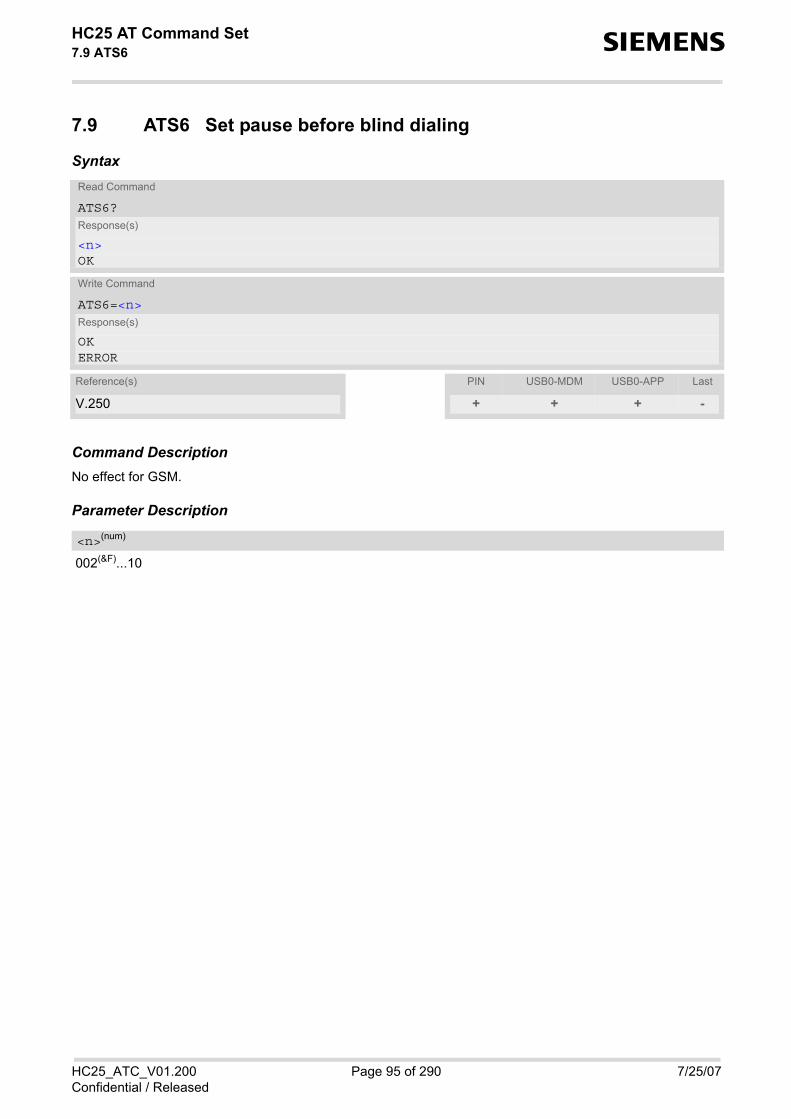
HC25 AT Command Set 7.9 ATS6 s
HC25_ATC_V01.200 Page 95 of 290 7/25/07Confidential / Released
7.9 ATS6 Set pause before blind dialing
Syntax
Command DescriptionNo effect for GSM.
Parameter Description
002(&F)...10
Read Command
ATS6?Response(s)
<n>OK
Write Command
ATS6=<n>Response(s)
OKERROR
Reference(s) PIN USB0-MDM USB0-APP Last
V.250 + + + -
<n>(num)

HC25 AT Command Set 7.10 ATS7 s
HC25_ATC_V01.200 Page 96 of 290 7/25/07Confidential / Released
7.10 ATS7 Set number of seconds to wait for connection completion
ATS7 specifies the number of seconds the TA will wait for the completion of the call setup when answering ororiginating a data call. Also referred to as "no answer timeout". To put it plainly, this is the time to wait for thecarrier signal. If no carrier signal is received within the specified time, the TA hangs up.
Syntax
Parameter Description
Number of seconds to wait for connection completion001...50(&F)...255
Notes• Command ATS7 is only applicable to data calls. • The correlation between ATS7 and ATS0 is important. If the called party has specified a high value for
ATS0=<n> call setup may fail. Example: Call setup may fail if ATS7=30 and ATS0=20.
Read Command
ATS7?Response(s)
<n>OK
Write Command
ATS7=<n>Response(s)
OKERROR
Reference(s) PIN USB0-MDM USB0-APP Last
V.250 + + + -
<n>(num)

HC25 AT Command Set 7.11 ATS8 s
HC25_ATC_V01.200 Page 97 of 290 7/25/07Confidential / Released
7.11 ATS8 Set number of seconds to wait for comma dialing modifier
This command specifies the amount of time, in seconds, that the DCE shall pause, during signalling of calladdressing information to the network (dialling), when a "," (comma) dial modifier is encountered in a dial string.
Syntax
Command DescriptionNo effect for GSM.
Parameter Description
0 DCE does not pause when "," encountered in dial string1...2(&F)...255 Number of seconds to pause
Read Command
ATS8?Response(s)
<n>OK
Write Command
ATS8=<n>Response(s)
OKERROR
Reference(s) PIN USB0-MDM USB0-APP Last
V.250 + + + -
<n>(num)

HC25 AT Command Set 7.12 ATS10 s
HC25_ATC_V01.200 Page 98 of 290 7/25/07Confidential / Released
7.12 ATS10 Set disconnect delay after indicating the absence of data carrier
Syntax
Command DescriptionThis parameter setting determines the amount of time, that the TA remains connected in absence of a data car-rier. If the data carrier is detected before disconnect, the TA remainsconnected.
Parameter Description
number of tenths of seconds of delay001...14(&F)...255
Read Command
ATS10?Response(s)
<n>OK
Write Command
ATS10=<n>Response(s)
OKERROR
Reference(s) PIN USB0-MDM USB0-APP Last
V.250 + + + -
<n>(num)

HC25 AT Command Set 7.13 ATO s
HC25_ATC_V01.200 Page 99 of 290 7/25/07Confidential / Released
7.13 ATO Switch from command mode to data mode
Syntax
Command DescriptionATO is the corresponding command to the +++ escape sequence: When you have established a CSD call andTA is in command mode, ATO causes the TA to resume the data connection and takes you back to data modemode.
Parameter Description
[0] Switch from command mode to data mode
Exec Command
ATO[<n>]Response(s)
If connection is not successfully resumed:NO CARRIERorTA returns to data mode from command modeCONNECT <text>Note: <text> output only if ATX parameter setting with value > 0.
Reference(s) PIN USB0-MDM USB0-APP Last
V.250 + + - -
<n>(num)

HC25 AT Command Set 7.14 +++ s
HC25_ATC_V01.200 Page 100 of 290 7/25/07Confidential / Released
7.14 +++ Switch from data mode to command mode
Syntax
Command DescriptionThis command is only available during a CSD call connection. The +++ character sequence causes the TA tocancel the data flow over the AT interface and switch to command mode. This allows you to enter AT commandswhile maintaining the data connection to the remote device . To prevent the +++ escape sequence from being misinterpreted as data, it must be preceded and followed by apause of at least 1000 ms. The +++ characters must be entered in quick succession, all within 1000 ms.
Notes• To return from command mode to data online mode: Enter ATO. • The DTR function mode 1 provides the same functionality as "+++" (see AT&D).
Exec Command
+++Response(s)
OK
Reference(s) PIN USB0-MDM USB0-APP Last
V.250 - + - -

HC25 AT Command Set 7.15 AT+CLCC s
HC25_ATC_V01.200 Page 101 of 290 7/25/07Confidential / Released
7.15 AT+CLCC List of current calls
The execute command lists all current calls. If the command is successful, but no calls are available, no infor-mation response is sent to TE.
Syntax
Parameter Description
Call identification number as described in GSM02.30 subclause 4.5.5.1; this number can be used in AT+CHLDcommand operations
0 Mobile originated call (MOC)1 Mobile terminated call (MTC)
State of the call0 Active1 Held2 Dialing (MOC)3 Alerting (MOC)4 Incoming (MTC)5 Waiting (MTC)
Bearer/teleservice0 Voice1 Data2 Fax
Test Command
AT+CLCC=?Response(s)
OK
Exec Command
AT+CLCCResponse(s)
[+CLCC: <idx>, <dir>, <stat>, <mode>, <mpty>[, <number>, <type>[, <alpha>]]][+CLCC: <idx>, <dir>, <stat>, <mode>, <mpty>[, <number>, <type>[, <alpha>]]][+CLCC: ...]OKERROR+CME ERROR
Reference(s) PIN USB0-MDM USB0-APP Last
GSM 07.07 + + + -
<idx>(num)
<dir>(num)
<stat>(num)
<mode>(num)

HC25 AT Command Set 7.15 AT+CLCC s
HC25_ATC_V01.200 Page 102 of 290 7/25/07Confidential / Released
0 Call is not one of multiparty (conference) call parties 1 Call is one of multiparty (conference) call parties
Phone number in format specified by <type>
Type of address octect128 Restricted <number> includes unknown type and format.145 Dialing string <number> includes international access code character '+'129 Otherwise
Alphanumeric representation of <number> corresponding to the entry found in phonebook. The maximum displayed length of <alpha> is 14 characters.
Note• For alphanumeric representation the number stored in phonebook must be identical to number transported
via network then the corresponding name will be recognized.
<mpty>(num)
<number>(str)
<type>(num)
<alpha>(str)(+CSCS)

HC25 AT Command Set 7.16 AT+CR s
HC25_ATC_V01.200 Page 103 of 290 7/25/07Confidential / Released
7.16 AT+CR Service reporting control
AT+CR configures the TA whether or not to transmit an intermediate result code +CR: <serv> to the TE when acall is being set up. Setting the value of <mode> to 1 may lead to connection failure, if the application (e.g. WinFax) waits for defaultresult code/URC.
Syntax
Intermediate Result CodeIf enabled, an intermediate result code is transmitted during connect negotiation when the TA has determinedthe speed and quality of service to be used, before any error control or data compression reports are transmitted,and before any final result code (e.g. CONNECT) appears. +CR: <serv>
Parameter Description
0(&F) Disable1 Enable
“REL ASYNC“ Asynchronous non-transparent“GPRS“ GPRS“SYNC“ Fax connection
Test Command
AT+CR=?Response(s)
+CR: (list of supported<mode>s)OKERROR
Read Command
AT+CR?Response(s)
+CR: <mode>OKERROR
Write Command
AT+CR=<mode>Response(s)
OKERROR
Reference(s) PIN USB0-MDM USB0-APP Last
GSM 07.07 + + + -
<mode>(num)
<serv>(str)

HC25 AT Command Set 7.17 AT+CRC s
HC25_ATC_V01.200 Page 104 of 290 7/25/07Confidential / Released
7.17 AT+CRC Set Cellular Result Codes for incoming call indication
The AT+CRC command controls whether or not to use the extended format of incoming call indication.<mode>=1 may lead to connection failure, if the application (e.g. WinFax) waits for the default URC.
Syntax
Unsolicited Result Codes
URC 1
RING
Indicates incoming call to the TE if <mode>=0.
URC 2
+CRING: <type>
Indicates incoming call to the TE if <mode>=1.
Parameter Description
[0](&F) Disable extended format1 Enable extended format
Test Command
AT+CRC=?Response(s)
+CRC: (list of supported<mode>s)OKERROR
Read Command
AT+CRC?Response(s)
+CRC: <mode>OKERROR
Exec Command
AT+CRCResponse(s)
OKERROR
Write Command
AT+CRC=[<mode>]Response(s)
OKERROR
Reference(s) PIN USB0-MDM USB0-APP Last
GSM 07.07 + + + -
<mode>(num)

HC25 AT Command Set 7.17 AT+CRC s
HC25_ATC_V01.200 Page 105 of 290 7/25/07Confidential / Released
“REL ASYNC“ Asynchronous non-transparent“FAX“ Facsimile“VOICE“ Voice
<type>(str)

HC25 AT Command Set 7.18 AT+CBST s
HC25_ATC_V01.200 Page 106 of 290 7/25/07Confidential / Released
7.18 AT+CBST Select bearer service type
The AT+CBST write command selects the bearer service <name>, the data rate <speed> and the connectionelement <ce> to be used when data calls are originated. The settings also apply to mobile terminated data calls.See GSM 02.02[1].
Syntax
Parameter Description
[0](&F) Autobauding7 9600 bps (V.32)12 9600 bps (V.34)14 14400 bps (V.34)16 28800 bps (V.34)17 33600 bps (V.34)39 9600 bps (V.120)43 14400 bps (V.120)48 28800 bps (V.120)51 56000 bps (V.120)71 9600 bps (V.110)75 14400 bps (V.110)80 28800 bps (V.110 or X.31 flag stuffing)81 38400 bps (V.110 or X.31 flag stuffing)83 56000 bps (V.110 or X.31 flag stuffing; this setting can be used in conjunction
with asynchronous non-transparent UDI or RDI service in order to get FTM)84 64000 bps (X.31 flag stuffing; this setting can be used in conjunction with asyn-
chronous non-transparent UDI service in order to get FTM)
Test Command
AT+CBST=?Response(s)
+CBST: (list of supported<speed>s), (list of supported<name>s), (list of supported<ce>s)OK
Read Command
AT+CBST?Response(s)
+CBST: <speed>, <name>, <ce>OK
Write Command
AT+CBST=<speed>[, <name>[, <ce>]]Response(s)
OKERROR
Reference(s) PIN USB0-MDM USB0-APP Last
GSM 07.07 + + + -
<speed>(num)

HC25 AT Command Set 7.18 AT+CBST s
HC25_ATC_V01.200 Page 107 of 290 7/25/07Confidential / Released
116 64000 bps (bit transparent)134 64000 bps (multimedia)
0(&F) Asynchronous modem1 Synchronous modem4 Asynchronous (RDI)
0 Transparent1(&F) Non-transparent
7.18.1 Parameter configurations supported by AT+CBSTTable 7.1: Parameter configurations supported by AT+CBST
<name>(num)
<ce>(num)
<speed> GSM WCDMA SYNC. ASYNC. TRANSP. NON-TRANSP.
0 + + + +7 + + + +12 + + + +14 + + + + +16 + + +17 + + +39 + + +43 + + + +48 + + +51 + + +71 + + +75 + + + +80 + + + +81 + + + +83 + + + +84 + + +116 + + +134 + + +

HC25 AT Command Set 7.19 AT+CRLP s
HC25_ATC_V01.200 Page 108 of 290 7/25/07Confidential / Released
7.19 AT+CRLP Select radio link protocol parameters for originated non-transparent data calls
The AT+CRLP write command sets radio link protocol (RLP) parameters used when non-transparent data callsare originated. The read command returns the current settings for the supported RLP version 0 till 2.
Syntax
Parameter Description
Interworking window size (IWF to MS)0...61(&F)
0...240(&F)...488 for <ver>=2
Mobile window size (MS to IWF)0...61(&F)
0...240(&F)...488 for <ver>=2
Acknowledgement timer (T1 in 10 ms units)38...48(&F)...25542...52(&F)...255 for <ver>=2
Test Command
AT+CRLP=?Response(s)
+CRLP: (list of supported<iws>s), (list of supported<mws>s), (list of supported<T1>s), (list of supported<N2>s), (list of supported<ver>s)OK
Read Command
AT+CRLP?Response(s)
+CRLP: <iws>, <mws>, <T1>, <N2>, <ver>+CRLP: <iws>, <mws>, <T1>, <N2>, <ver>+CRLP: <iws>, <mws>, <T1>, <N2>, <ver>OK
Write Command
AT+CRLP=[<iws>[, <mws>[, <T1>[, <N2>[, <ver>]]]]]Response(s)
OKERROR+CME ERROR: <err>
Reference(s) PIN USB0-MDM USB0-APP Last
GSM 07.07 + + + -
<iws>(num)
<mws>(num)
<T1>(num)

HC25 AT Command Set 7.19 AT+CRLP s
HC25_ATC_V01.200 Page 109 of 290 7/25/07Confidential / Released
Re-transmission attempts N21...6(&F)...255
RLP version number 0...2
<N2>(num)
<ver>(num)
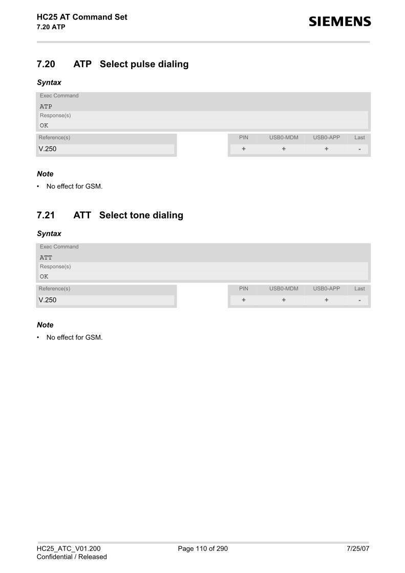
HC25 AT Command Set 7.20 ATP s
HC25_ATC_V01.200 Page 110 of 290 7/25/07Confidential / Released
7.20 ATP Select pulse dialing
Syntax
Note• No effect for GSM.
7.21 ATT Select tone dialing
Syntax
Note• No effect for GSM.
Exec Command
ATPResponse(s)
OK
Reference(s) PIN USB0-MDM USB0-APP Last
V.250 + + + -
Exec Command
ATTResponse(s)
OK
Reference(s) PIN USB0-MDM USB0-APP Last
V.250 + + + -

HC25 AT Command Set 7.22 AT+ES s
HC25_ATC_V01.200 Page 111 of 290 7/25/07Confidential / Released
7.22 AT+ES Synchronous Data Mode Configuration
This command enables the Synchronous Data Mode
Syntax
Parameter Description
Requested mode6(D) Initiate Synchronous Access mode when connection is completed, and Data
Suite is entered
Fallback mode answerer8(D) Initiate Synchronous Mode when connection is completed, and Data Suite is
entered
Test Command
AT+ES=?Response(s)
+ES: list of supported <orig_rqst>values, , list of supported <ans_fbk>valuesOK ERROR +CME ERROR: <err>
Read Command
AT+ES?Response(s)
+ES:[<orig_rqst>], [, <ans_fbk>]OK ERROR +CME ERROR: <err>
Write Command
AT+ES=[<orig_rqst>], [, <ans_fbk>]Response(s)
OK ERROR +CME ERROR: <err>
Reference(s) PIN USB0-MDM USB0-APP Last
ITU-T V.80ter ± + + -
<orig_rqst>(num)
<ans_fbk>(num)

HC25 AT Command Set 7.23 AT+ESA s
HC25_ATC_V01.200 Page 112 of 290 7/25/07Confidential / Released
7.23 AT+ESA Synchronous access mode configuration
This command configures the Synchronous access Mode
Syntax
Parameter Description
transmitted_bit_sequencespecifies the bit sequence transmitted by the DCE when a transmit data buffer underrun condition occurs, whileoperating in Transparent sub-Mode. 0 In Transparent sub-Mode, DCE transmits 8-bit SYN sequence on idle. DCE
receiver does not hunt for synchronization sequence
CRC checking0 CRC generation and checking disabled
nrzi encoding0 NRZI encoding and decoding disabled
Test Command
AT+ESA=?Response(s)
+ESA: (list of supported <trans_idle>values), , , , (list of supported <crc_type>values), (list of supported <nrzi_en>values), (list of supported <syn1>values), OK ERROR +CME ERROR: <err>
Read Command
AT+ESA?Response(s)
+ESA:<trans_idle>, , , , <crc_type>, <nrzi_en>, <syn1>, OK ERROR +CME ERROR: <err>
Write Command
AT+ESA=[<trans_idle>][,][,][,][,][<crc_type>][<nrzi_en>][<syn1>]Response(s)
OK ERROR +CME ERROR: <err>
Reference(s) PIN USB0-MDM USB0-APP Last
ITU-T V.80ter + + + -
<trans_idle>(num)
<crc_type>(num)
<nrzi_en>(num)

HC25 AT Command Set 7.23 AT+ESA s
HC25_ATC_V01.200 Page 113 of 290 7/25/07Confidential / Released
When <trans_idle>=0, specifies the 8-bit transmit idle sequence to be used by the DCE. When<trans_idle>=1, specifies the 8-bit synchronization sequence to be used by the DCE. When<trans_idle>=2, specifies first 8 bits of 16-bit synchronization sequence to be used by the DCE 0 - 255
<syn1>(num)

HC25 AT Command Set 7.24 AT+CSTA s
HC25_ATC_V01.200 Page 114 of 290 7/25/07Confidential / Released
7.24 AT+CSTA Select type of address
Set command selects the type of number for further dialling commands ATD according to GSM/UMTS specifica-tions. Test command returns values supported a compound value.
Syntax
Parameter Description
145 when dialling string includes international access code character "+"129 otherwise
Test Command
AT+CSTA=?Response(s)
+CSTA: (list of supported<type>s)OK
Read Command
AT+CSTA?Response(s)
+CSTA: <type>OK
Write Command
AT+CSTA=<type>Response(s)
OKERROR
Reference(s) PIN USB0-MDM USB0-APP Last
GSM 07.07 + + + -
<type>(num)

HC25 AT Command Set 8. Network Service Commands s
HC25_ATC_V01.200 Page 115 of 290 7/25/07Confidential / Released
8. Network Service Commands
The AT Commands described in this chapter are related to various network services. More commands relatedto this area can be found in Chapter 9., Supplementary Service Commands.
8.1 AT+COPN Read operator names
The AT+COPN command returns the list of operator names from the ME. Each operator code <numericn> thathas an alphanumeric equivalent <alphan> in the ME memory is returned.
Syntax
Parameter Description
Operator in numeric format; GSM location area identification number.
Operator in long alphanumeric format; can contain up to 16 characters.
Test Command
AT+COPN=?Response(s)
OKERROR+CME ERROR
Exec Command
AT+COPNResponse(s)
+COPN: <numericn>, <alphan>+COPN: ...OKERROR+CME ERROR
Reference(s) PIN USB0-MDM USB0-APP Last
GSM 07.07 + + + -
<numericn>(str)
<alphan>(str)

HC25 AT Command Set 8.2 AT+COPS s
HC25_ATC_V01.200 Page 116 of 290 7/25/07Confidential / Released
8.2 AT+COPS Operator Selection
AT+COPS queries the present status of the HC25's network registration and allows to determine whether auto-matic or manual network selection shall be used. Additional service is available with AT^SOPS. Another com-mand that can be used for operator selection is AT^SNWS. The major advantage of AT^SNWS is the ability to scanall frequency bands supported by HC25 and to allow the subscriber to manually select a provider from all bands.See AT^SNWS for detail.
Three operator selection modes are available with AT+COPS: • Automatic
HC25 searches for the home operator automatically. If successful the HC25 registers to the home network.If the home network is not found, HC25 goes on searching. If a permitted operator is found, HC25 registersto this operator. If no operator is found the HC25 remains unregistered.
• Manual Desired operator can be determined using the AT+COPS write command. If the operator is found, HC25 reg-isters to it immediately. If the selected operator is forbidden, the HC25 remains unregistered.
• Manual/automatic The ME first tries to find the operator determined via AT+COPS write command. If the ME fails to register tothis operator, then it starts to select another (permitted) operator automatically.
The AT+COPS test command lists sets of five parameters, each representing an operator present in the network. A set consists of • an integer indicating the availability of the operator, • long alphanumeric format of the operator's name, • short alphanumeric format of the operator's name, • numeric format representation of the operator and • an integer indicating the acccess technology of the operator. Any of the parameters may be unavailable and will then be an empty field (,,). The list of operators comes in thefollowing order: Home network, networks referenced in SIM and other networks. The operator list is followed by a list of the supported <mode>s and <format>s. These lists are delimited fromthe operator list by two commas.The test command returns a list of operators with the same <AcT> used by the last AT+COPS write command. Ifthe <mode> is set to automatic the test command will return a list of operators of the supported <AcT>s. If the test command is used during an ongoing GPRS transfer, traffic will be interrupted for up to one minute.
The AT+COPS read command returns the current <mode> and the currently selected operator. If no operator isselected, <format> and <oper> are omitted.
The AT+COPS write command forces an attempt to select and register to a network operator (see note below). Ifthe selected operator is not available, no other operator will be selected (except <mode>=4). The selected oper-ator name <format> will apply to further read commands, too.
The AT+COPS exec command returns OK and has no effect on the current <mode>.
SyntaxTest Command
AT+COPS=?Response(s)
+COPS: [list of present operators (<opStatus>, long alphanumeric <oper>s, short alphanumeric <oper>s, numeric <oper>s , <AcT>], , (list of supported <mode>s), (list of supported <format>s)OK ERROR +CME ERROR: <err>

HC25 AT Command Set 8.2 AT+COPS s
HC25_ATC_V01.200 Page 117 of 290 7/25/07Confidential / Released
Parameter Description
Status0 Unknown1 Operator available2 Current operator 3 Operator forbidden
OperatorIf test command: Operator name in long alphanumeric format, short alphanumeric format and numeric format.If read command: Operator name as per <format>.If write command: Operator name in numeric format.
0(P) Automatic mode; <oper> field is ignored. 1 Manual operator selection
Write command requires <oper> in numeric format, i.e. <format> shall be 2. Read command returns the current <mode> and the currently selected<oper>. If no operator is selected, <format> and <oper> are omitted.
2 Manually deregister from network and remain unregistered until <mode>=0 or1 or 4 is selected.
3 Set only <format> (for AT+COPS read command). 4 Automatic / manual selection; if manual selection fails, automatic mode
(<mode>=0) is entered (<oper> field will be present).
Read Command
AT+COPS?Response(s)
+COPS:<mode>[, <format>[, <oper>][, <AcT>]]OK ERROR +CME ERROR: <err>
Exec Command
AT+COPSResponse(s)
OK
Write Command
AT+COPS=<mode>[, <format>[, <oper>][, <AcT>]]Response(s)
OK ERROR +CME ERROR: <err>
Reference(s) PIN USB0-MDM USB0-APP Last
GSM 07.07 + + + -
<opStatus>(num)
<oper>(str)
<mode>(num)

HC25 AT Command Set 8.2 AT+COPS s
HC25_ATC_V01.200 Page 118 of 290 7/25/07Confidential / Released
Access technology selected0 GSM 2(D) UTRAN
0(&F) Long alphanumeric format of <oper>. Can be up to 16 characters long. 1 Short alphanumeric format of <oper>. Can be up to 8 characters long. 2 Numeric format of <oper>. This is the GSM Location Area Identification (LAI)
number, which consists of the 3-digit Mobile Country Code (MCC) plus the 2-or 3-digit Mobile Network Code (MNC).
Notes• It is not recommended to use the AT+COPS command before passing the CHV (card holder verification) / SIM
PIN1 verification. This is because after PIN1 verification the module will automatically try to register to thenetwork as though AT+COPS were 0, regardless of the settings done before with or without SIM, such asAT+COPS=2 which remains unchanged. Also, the test command should only be used after PIN1 authentica-tion.
• The module will automatically try to register to the network with the same <AcT> used by the last AT+COPSwrite command. If the <mode> is set to automatic the module will try to register to network operators with sup-ported <AcT>s.
<AcT>(num)
<format>(num)

HC25 AT Command Set 8.3 AT^SOPS s
HC25_ATC_V01.200 Page 119 of 290 7/25/07Confidential / Released
8.3 AT^SOPS Extended Operator Selection
AT^SOPS queries the present status of the HC25's network registration. Since basic operator selection servicesare available with AT+COPS this command uses the methods of the Enhanced Operator Name String (EONS)specification while handling operator name strings. Additional EONS related information is available withAT^SIND.
AT^SOPS test command lists sets of five parameters, each representing an operator present in the network. A set consists of
1. an integer indicating the availability of the operator, 2. specification of the source of the operator name <eonsOperator>, 3. operator name according to EONS Table, 4. Service Provider Name from the SIM Service Table and 5. numeric format representation of the operator.
Any of the parameters may be unavailable and will then be an empty field (,,). The list of operators comes in the following order: Home network, networks referenced in SIM and other net-works. After the operator list the HC25 returns lists of supported <mode>s and <format>s. These lists are delimitedfrom the operator list by two commas. If the test command is used while an ongoing GPRS transfer, traffic will be interrupted for up to one minute.
Command settings are effective over all serial interfaces of the HC25.
Syntax
Parameter Description
Status0 unknown1 operator available2 current operator3 operator forbidden
Specification of the source of the operator name <eonsOperator>. Details of EONS-supplied operator nametypes are available at AT^SIND.
Test Command
AT^SOPS=?Response(s)
^SOPS:[list of present operator( <opStatus>, <eonsType>, <eonsOperator>, <servProvider>, <servProviderType>, <opName>, <acT>)s ], , (list of supported <mode>)s, (list of supported <format>)sOK ERROR +CME ERROR: <err>
Reference(s) PIN USB0-MDM USB0-APP Last
SIEMENS + + + -
<opStatus>(num)
<eonsType>(num)

HC25 AT Command Set 8.3 AT^SOPS s
HC25_ATC_V01.200 Page 120 of 290 7/25/07Confidential / Released
Operator name; format depends on the source of the operator name, specified by <eonsType>.
Service Provider Name according to setting of Service No. 17 in the SIM Service Table (EFSST).Service Provider Name (SPN) will be read from EFSPN. Service Provider Display Information (SPDI) will be readfrom EFSPDI list.
Service Provider Type according to Registered Public Land Mobile Network (RPLMN) and Home Public LandMobile Network (HPLMN). 0 No Service Provider Information available. 1 Service Provider Name will be displayed. RPLMN is the HPLMN. 2 Service Provider Display Information will be displayed. One list entry is equal
to the RPLMN.
OperatorOperator name in numerical presentation contains the GSM Location Area Identification (LAI) number, whichconsists of the 3-digit Mobile Country Code (MCC) plus the 2- or 3-digit Mobile Network Code (MNC). Parameter is stored non-volatile to the SIM.
Parameter is not applicable.
Access technology selected0 GSM 2(D) UTRAN
Parameter is not applicable.
Note• The AT^SOPS Test command is only accepted by the module after a valid pin has been entered.
<eonsOperator>
<servProvider>(str)
<servProviderType>(num)
<opName>
<mode>(num)
<acT>(num)
<format>(num)

HC25 AT Command Set 8.4 AT+CREG s
HC25_ATC_V01.200 Page 121 of 290 7/25/07Confidential / Released
8.4 AT+CREG Network Registration
The AT+CREG command serves to verify the network registration status of the ME. For this purpose two types ofURCs are available. The AT+CREG read command returns the URC presentation mode <n> and an integer <stat> that shows theregistration status of the ME. The AT+CREG exec command sets the URC presentation mode <n> to the factorydefault value.
Syntax
Unsolicited Result Codes
URC 1
If <n>=1 and there is a change in the ME network registration status: +CREG: <stat>
URC 2
If <n>=2 and there is a change in the ME network registration status or a change of the network cell: +CREG: <stat>[, <lac>, <ci>]
Test Command
AT+CREG=?Response(s)
+CREG: (list of supported<n>s)OK
Read Command
AT+CREG?Response(s)
+CREG: <n>, <stat>[, <lac>, <ci>]OKERROR+CME ERROR: <err>
Exec Command
AT+CREGResponse(s)
OKERROR+CME ERROR: <err>
Write Command
AT+CREG=[<n>]Response(s)
OKERROR+CME ERROR: <err>
Reference(s) PIN USB0-MDM USB0-APP Last
GSM 07.07 - + + -

HC25 AT Command Set 8.4 AT+CREG s
HC25_ATC_V01.200 Page 122 of 290 7/25/07Confidential / Released
Parameter Description
[0](&F) Disable +CREG URC1 Enable URC +CREG:<stat> to report status of network registration 2 Enable URC +CREG:<stat>[,<lac>,<ci>] to report status of network regis-
tration including location information. Optional parameters <lac> and <ci>will not be displayed during calls or if these values have not changed since lastAT+CREG read command or since last indication by +CREG URC.
0 Not registered, ME is currently not searching for new operatorThere is a technical problem. User intervention is required. Yet, emergencycalls can be made if any network is available. Probable causes: • no SIM card available• no PIN entered• no valid Home PLMN entry found on the SIM
1 Registered to home network2 Not registered, but ME is currently searching for a new operator
The ME searches for an available network. Failure to log in until after more thana minute may be due to one of the following reasons: • No network available or insufficient Rx level.• The ME has no access rights to the networks available.• Networks from the SIM list of allowed networks are around, but login fails
due to one of the following reasons: - #11 ... PLMN not allowed- #12 ... Location area not allowed- #13 ... Roaming not allowed in this location areaAfter this, the search will be resumed (if automatic network search isenabled).
• The Home PLMN or an allowed PLMN is available, but login is rejected bythe cell (reasons: Access Class or LAC).
If at least one network is available, emergency calls can be made. 3 Registration denied
• Authentication or registration fails after Location Update Reject due to oneof the following reasons: - #2 ... IMSI unknown at HLR- #3 ... Illegal MS- #6 ... Illegal MEEither the SIM or the MS or the ME are unable to log into any network. Userintervention is required. Emergency calls can be made, if any network isavailable.
4 Unknown (not used) 5 Registered, roaming
The ME is registered at a foreign network (national or international network)
Two byte location area code in hexadecimal format (e.g. "00C3" equals 193 in decimal).
<n>(num)
<stat>(num)
<lac>(str)

HC25 AT Command Set 8.4 AT+CREG s
HC25_ATC_V01.200 Page 123 of 290 7/25/07Confidential / Released
Two byte cell ID in hexadecimal format.
Example
8.4.1 Typical Registration Times
Typical registration times are • below 1 minute at first time registration (using SIM card the first time)• below 10 seconds after restart and prior switch-off with AT^SMSO within same band/frequency• below 1 minute after restart when switching to different band/frequencyThe above values are measured under Siemens WM laboratory conditions and cannot be guaranteed for life net-works.
But please note that the timing in life networks is dependent on a great variety of factors. The factors listed belowmay increase the duration of the registering procedure up to several minutes. • Pollution of bands• Presence of frequencies stored in the Acquisition Database of the phone• Last active RAT• Signal strength of the cell that the ME can camp on• Interference from other systems or self-interference
<ci>(str)
AT+CREG=1 Activates URC mode.OKAT+COPS=0 Forces ME to automatically search network operator.OK+CREG: 2 URC reports that ME is currently searching.+CREG: 1 URC reports that operator has been found.

HC25 AT Command Set 8.5 AT+CSQ s
HC25_ATC_V01.200 Page 124 of 290 7/25/07Confidential / Released
8.5 AT+CSQ Signal quality
The AT+CSQ execute command indicates the quality of the received signal strength.
Syntax
Parameter Description
0 -113 dBm or less1 -111 dBm2..30 -109... -53 dBm31 -51 dBm or greater99 not known or not detectable
99 The indication of the channel bit error rate is not supported. The value is always99.
Note• After using network related commands such as AT+CCWA, AT+CCFC, users are advised to wait 3s before
entering AT+CSQ. This is recommended to be sure that any network access required for the preceding com-mand has finished.
Test Command
AT+CSQ=?Response(s)
+CSQ: (list of supported<rssi>s), (list of supported<ber>s)OK
Exec Command
AT+CSQResponse(s)
+CSQ: <rssi>,<ber>OK
Reference(s) PIN USB0-MDM USB0-APP Last
GSM 07.07 + + + -
<rssi>(num)
<ber>(num)

HC25 AT Command Set 8.6 AT^SMONI s
HC25_ATC_V01.200 Page 125 of 290 7/25/07Confidential / Released
8.6 AT^SMONI Monitor idle mode
The AT^SMONI command supplies information of the serving cell. To retrieve the information use the executecommand.
Syntax
Notes• The parameters LAC and cell are presented as hexadecimal digits, the remaining parameters are composed
of decimal digits. • Please note that the output will be changed in future releases. The order of the parameters will not be
changed. Unsupported parameters are signed as "-" .
8.6.1 AT^SMONI responses
ME is not connected:a) ME is camping on a 2G cell:
b) ME is camping on a 3G cell:
Columns for Serving Cell (2G parameters):
Test Command
AT^SMONI=?Response(s)
OK
Exec Command
AT^SMONIResponse(s)
See: Section 8.6.1, AT^SMONI responsesOK
Reference(s) PIN USB0-MDM USB0-APP Last
SIEMENS - + + -
^SMONI: ACT,ARFCN,BCCH,MCC,MNC,LAC,cell,C1Example:^SMONI: 2G,71,-61,262,02,0143,83BA,33
^SMONI: ACT,UARFCN,PSC,EC/n0,RSCP,MCC,MNC,LAC,cell,C1Example:^SMONI: 3G,10564,296,7,-79,262,02,0143,3B2F,-92,-78
Column DescriptionACT Access technology of the serving cell (2G/3G)ARFCN ARFCN (Absolute Radio Frequency Channel Number) of the BCCH carrierBCCH Receiving level of the BCCH carrier in dBmMCC Mobile Country Code (first part of the PLMN code)MNC Mobile Network Code (second part of the PLMN code)LAC Location Area Code, see note

HC25 AT Command Set 8.6 AT^SMONI s
HC25_ATC_V01.200 Page 126 of 290 7/25/07Confidential / Released
Columns for Serving Cell (3G parameters):
cell Cell IDC1 Coefficient for base station selection
Column DescriptionUARFCN UARFCN (UTRAN Absolute Radio Frequency Channel Number) of the BCCH car-
rierPSC Primary Synchronisation CodeEC/n0 Carrier to noise ratio in dBRSCP Received Signal Code Power in dBmMCC Mobile Country Code (first part of the PLMN code)MNC Mobile Network Code (second part of the PLMN code)LAC Location Area Code, see notecell Cell IDSQual Quality value for base station selection in dB (see 3GPP 25.304)SRxLev RX level value for base station selection in dB (see 3GPP 25.304)
Column Description

HC25 AT Command Set 8.7 AT^SMONP s
HC25_ATC_V01.200 Page 127 of 290 7/25/07Confidential / Released
8.7 AT^SMONP Monitor neighbour cells
The AT^SMONP supplies information of neighbour cells. To retrieve the information use the execute command.
Syntax
Notes• Due to the fact that not all necessary information of the neighbour cells can be decoded during a connection,
there are several constraints to be considered: - Only neighbour cells that have already been visible in IDLE mode will be further updated, as long as they
are still included in the list.- Though new neighbour cells can be added to the list (e.g. due to handover), their C1 and C2 parameters
cannot be displayed until the connection is released. In this case "-" is presented for C1 and C2.• The neighbour cells have the same PLMN as the serving cell.In case of searcing for a network the serving
cell can change and the ME shows different sets of neighbour cells depending on the PLMN of the servingcell.
• In case of a 2G serving cell the ME shows 2G and 3G neighbour cells. If 3G is available then no neighboring2G cells are shown.
• Please note that the output will be changed in future releases. Unsupported parameters are signed as "-" .
8.7.1 AT^SMONP responses
Response of AT^SMONP:
Test Command
AT^SMONP=?Response(s)
OK
Exec Command
AT^SMONPResponse(s)
See: Section 8.7.1, AT^SMONP responsesOK
Reference(s) PIN USB0-MDM USB0-APP Last
SIEMENS - + + -
2G:ARFCN1,BCCH1ARFCN2,BCCH2...ARFCNn,BCCHn3G:UARFCN1,PSC1,EC/n01,RSCP1UARFCN2,PSC2,EC/n02,RSCP2...UARFCNn,PSCn,EC/n0n,RSCPn
Example:
2G:

HC25 AT Command Set 8.7 AT^SMONP s
HC25_ATC_V01.200 Page 128 of 290 7/25/07Confidential / Released
Columns for 2G paramaters:
Columns for 3G paramaters:
8,-11012,-11051,-11055,-11059,-11067,-11075,-110737,-110744,-110746,-1103G:10564,296,6,-6810564,96,35,-83
Column DescriptionARFCN Absolute Radio Frequency Channel Number of the BCCH carrierBCCH Receiving level of the BCCH carrier in dBm
Column DescriptionUARFCN UTRAN Absolute Radio Frequency Channel Number of the BCCH carrierPSC Primary Synchronisation CodeEC/n0 Carrier to noise ratio in dBRSCP Received Signal Code Power in dBm

HC25 AT Command Set 8.8 AT^SNWS s
HC25_ATC_V01.200 Page 129 of 290 7/25/07Confidential / Released
8.8 AT^SNWS Network Selection
The AT^SNWS command is smilar to AT+COPS. The major advantage of AT^SNWS is the ability to scan all fre-quency bands supported by HC25, while AT+COPS is always determined by the band most recently used andtherefore starts searching either across the GSM 850, WCDMA 850, PCS 1900, WCDMA 1900 bands or acrossthe DCS 1800, EGSM 900, WCDMA 2100 bands. So AT^SNWS allows the subscriber to manually select a spe-cific provider from all these bands.
This means the AT^SNWS write command forces an attempt to select and register to the given operator. If theselected operator is not found, the ME reverts to the band previously used and tries to register again.
The AT^SNWS test command enforces a multiple band selection in order to find all available networks. This pro-cedure will take a few seconds depending on the amount of available networks. During this time the serving cellwill be lost because of band changing. After the scan the ME reverts to the previously used network. The testcommand returns a list of all operators currently available. The response consists of several sets of five param-eters, where each set is representing a visible operator. Each set contains the following information: • an integer indicating the availability of the operator, • long alphanumeric format of the operator's name, • short alphanumeric format of the operator's name, • numeric format representation of the operator and • an integer indicating the acccess technology of the operator. Any of the parameters may be unavailable and will then be an empty field (,,). The list of operators comes in thefollowing order: Home network, networks referenced in SIM and other networks. The operator list is followed bya list of the supported <mode>s and <format>s. These lists are delimited from the operator list by two commas.
Syntax
Parameter Description
Status0 Unknown1 Operator available2 Current operator 3 Operator forbidden
Test Command
AT^SNWS=?Response(s)
^SNWS: [list of present operators (<opStatus>, long alphanumeric <oper>s, short alphanumeric <oper>s, numeric <oper>s , <AcT>], , (supported <mode>), (supported <format>)OK ERROR +CME ERROR: <err>
Write Command
AT^SNWS=<mode>, <format>, <oper>[, <AcT>]Response(s)
OK ERROR +CME ERROR: <err>
PIN USB0-MDM USB0-APP Last
+ + + -
<opStatus>(num)

HC25 AT Command Set 8.8 AT^SNWS s
HC25_ATC_V01.200 Page 130 of 290 7/25/07Confidential / Released
OperatorIf test command: Operator name in long alphanumeric format, short alphanumeric format and numeric format.If write command: Operator name in numeric format.
1 Manual operator selection Write command requires <oper> in numeric format, i.e. <format> shall be 2.
Access technology selected0 GSM 2(D) UTRAN If the parameter is omitted in the AT^SNWS write command, the ME will register to the given operator using the<AcT> determined with the last AT+COPS or AT^SNWS write command. This means that the found <AcT> iseither the one explicitly specified by the user, or if <mode> of AT+COPS is set to automatic, it is automaticallyassigned. Likeweise, the AT^SNWS test command will show the operators either with the <AcT> explicitlyselected or automatically assigned.
2 Numeric format of <oper>. This is the GSM Location Area Identification (LAI)number, which consists of the 3-digit Mobile Country Code (MCC) plus the 2-or 3-digit Mobile Network Code (MNC).
Notes• It is not recommended to use the AT^SNWS command before passing the CHV (card holder verification) / SIM
PIN1 verification. Also, the test command should only be used after PIN1 authentication. • It is not recommended to use the AT^SNWS command when an active connection is established.
<oper>(str)
<mode>(num)
<AcT>(num)
<format>(num)

HC25 AT Command Set 9. Supplementary Service Commands s
HC25_ATC_V01.200 Page 131 of 290 7/25/07Confidential / Released
9. Supplementary Service Commands
The AT Commands described in this chapter are related to the Supplementary Services offered by the GSM net-work.
9.1 AT+CACM Accumulated call meter (ACM) reset or query
Syntax
Command DescriptionThe read command returns the current ACM value. The write command resets the Advice of Charge related to the accumulated call meter (ACM) value in SIM fileEF(ACM). ACM contains the total number of home units for both the current and preceding calls.
Parameter Description
Three bytes of the current ACM value in hexadecimal format (e.g. "00001E" indicates decimal value 30) 000000- FFFFFF.
SIM PIN2
Test Command
AT+CACM=?Response(s)
OK
Read Command
AT+CACM?Response(s)
+CACM: <acm>OKERROR+CME ERROR: <err>
Write Command
AT+CACM=[<passwd>]Response(s)
OKERROR+CME ERROR: <err>
Reference(s) PIN USB0-MDM USB0-APP Last
GSM 07.07 + + + -
<acm>(str)
<passwd>(str)
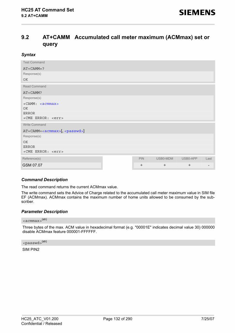
HC25 AT Command Set 9.2 AT+CAMM s
HC25_ATC_V01.200 Page 132 of 290 7/25/07Confidential / Released
9.2 AT+CAMM Accumulated call meter maximum (ACMmax) set or query
Syntax
Command DescriptionThe read command returns the current ACMmax value. The write command sets the Advice of Charge related to the accumulated call meter maximum value in SIM fileEF (ACMmax). ACMmax contains the maximum number of home units allowed to be consumed by the sub-scriber.
Parameter Description
Three bytes of the max. ACM value in hexadecimal format (e.g. "00001E" indicates decimal value 30) 000000disable ACMmax feature 000001-FFFFFF.
SIM PIN2
Test Command
AT+CAMM=?Response(s)
OK
Read Command
AT+CAMM?Response(s)
+CAMM: <acmmax>OKERROR+CME ERROR: <err>
Write Command
AT+CAMM=<acmmax>[, <passwd>]Response(s)
OKERROR+CME ERROR: <err>
Reference(s) PIN USB0-MDM USB0-APP Last
GSM 07.07 + + + -
<acmmax>(str)
<passwd>(str)

HC25 AT Command Set 9.3 AT+CAOC s
HC25_ATC_V01.200 Page 133 of 290 7/25/07Confidential / Released
9.3 AT+CAOC Advice of Charge information
Syntax
Unsolicited Result Code+CCCM: <ccm>
When activated, an unsolicited result code is sent when the CCM value changes, but not more often than every10 seconds.
Command DescriptionThe write command sets the Advice of Charge supplementary service function mode.
Parameter Description
0 query CCM value1 deactivate the unsolicited reporting of <ccm> value2 activate the unsolicited reporting of <ccm> value
Test Command
AT+CAOC=?Response(s)
+CAOC: (list of supported<mode>s)OK
Read Command
AT+CAOC?Response(s)
+CAOC: <mode>OK
Exec Command
AT+CAOCResponse(s)
ERROR+CME ERROR: <err>OK
Write Command
AT+CAOC=[<mode>]Response(s)
ERROR+CME ERROR: <err>If <mode>=0, TA returns the current <ccm> value.+CAOC: <ccm> OK
Reference(s) PIN USB0-MDM USB0-APP Last
GSM 07.07 + + + -
<mode>(num)

HC25 AT Command Set 9.3 AT+CAOC s
HC25_ATC_V01.200 Page 134 of 290 7/25/07Confidential / Released
Three bytes of the current CCM value in hexadecimal format (e.g. "00001E" indicates decimal value 30); bytesare similarly coded as ACMmax value in the SIM 000000-FFFFFF.
<ccm>(str)

HC25 AT Command Set 9.4 AT+CCUG s
HC25_ATC_V01.200 Page 135 of 290 7/25/07Confidential / Released
9.4 AT+CCUG Closed User Group
Syntax
Command DescriptionThe Test command returns the supported parameters. The Read command returns if the Explicit CUG invocation is activated (in parameter <n>), which CUG <index>is chosen, and if Preferential Group or Outgoing Access is suppressed (in parameter <info>). The write command serves to activate or deactivate the explicit CUG invocation, to set the desired index, and tospecify if Preferential Group or Outgoing Access shall be suppressed.
Parameter Description
explicit CUG invocation options0(D) Deactivate explicit CUG invocation 1 Activate explicit CUG invocation
0-9 explicit selection of CUG index10(D) No index (preferred CUG taken from subscriber data)
state of the call0(D) no information1 suppress outgoing access
Test Command
AT+CCUG=?Response(s)
OK
Read Command
AT+CCUG?Response(s)
+CCUG:<n>, <index>, <info>OKERROR+CME ERROR
Write Command
AT+CCUG=[[<n>][, <index>][, <info>]]Response(s)
OKERROR+CME ERROR
Reference(s) PIN USB0-MDM USB0-APP Last
GSM 07.07, GSM 02.85, GSM 03.85, GSM 04.85
+ + + -
<n>(num)
<index>(num)
<info>(num)

HC25 AT Command Set 9.4 AT+CCUG s
HC25_ATC_V01.200 Page 136 of 290 7/25/07Confidential / Released
2 suppress preferential CUG3 Suppress preferential CUG and Outgoing Access.
Notes• The active settings for omitted parameters are retained without changes. • Explicit CUG invocation means that at each call setup, CUG information is added to the called number. • Upon delivery, settings are predefined with
<n>=0, <index>=10, <info>=0. These delivery defaults cannot be recalled automatically.
• When starting a call with ATD, Parameter 'G' or 'g' of command ATD will have no effect if the option selectedfor this single call is identical to the option already selected with AT+CCUG.
• Current settings are saved in the ME automatically. • ATZ or AT&F do not influence the current settings. • some combinations of parameters may lead to rejection of CUG calls by the network. For more information,
please consult GSM 04.85
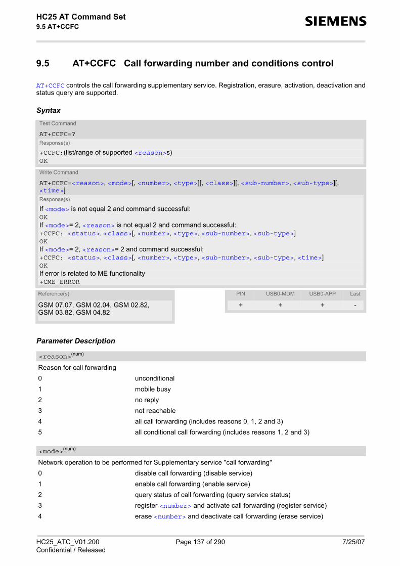
HC25 AT Command Set 9.5 AT+CCFC s
HC25_ATC_V01.200 Page 137 of 290 7/25/07Confidential / Released
9.5 AT+CCFC Call forwarding number and conditions control
AT+CCFC controls the call forwarding supplementary service. Registration, erasure, activation, deactivation andstatus query are supported.
Syntax
Parameter Description
Reason for call forwarding 0 unconditional1 mobile busy2 no reply3 not reachable4 all call forwarding (includes reasons 0, 1, 2 and 3)5 all conditional call forwarding (includes reasons 1, 2 and 3)
Network operation to be performed for Supplementary service "call forwarding"0 disable call forwarding (disable service)1 enable call forwarding (enable service)2 query status of call forwarding (query service status)3 register <number> and activate call forwarding (register service)4 erase <number> and deactivate call forwarding (erase service)
Test Command
AT+CCFC=?Response(s)
+CCFC:(list/range of supported <reason>s) OK
Write Command
AT+CCFC=<reason>, <mode>[, <number>, <type>][, <class>][, <sub-number>, <sub-type>][, <time>]Response(s)
If <mode> is not equal 2 and command successful: OKIf <mode>= 2, <reason> is not equal 2 and command successful: +CCFC: <status>, <class>[, <number>, <type>, <sub-number>, <sub-type>]OKIf <mode>= 2, <reason>= 2 and command successful: +CCFC: <status>, <class>[, <number>, <type>, <sub-number>, <sub-type>, <time>]OKIf error is related to ME functionality +CME ERROR
Reference(s) PIN USB0-MDM USB0-APP Last
GSM 07.07, GSM 02.04, GSM 02.82, GSM 03.82, GSM 04.82
+ + + -
<reason>(num)
<mode>(num)

HC25 AT Command Set 9.5 AT+CCFC s
HC25_ATC_V01.200 Page 138 of 290 7/25/07Confidential / Released
String type phone number of forwarding address in format specified by <type>. If you select <mode>= 3, thephone <number> will be registered in the network. This allows you to disable / enable CF to the same destinationwithout the need to enter the phone number once again. Depending on the services offered by the provider theregistration may be mandatory before CF can be used. The number remains registered in the network until youregister another number or erase it using <mode> = 4.
Type of address octect145 dialing string <number> includes international access code character '+'129 otherwise
Integer or sum of integers each representing a class of information, i.e. a bearer service, telecommunication ser-vice or bearer service group as defined in "GSM 02.04" 1 voice2 data
<class> 2 (data) comprises all those <class> values between 16 and 128, thatare supported both by the network and the MS. This means, a setting made for<class> 2 applies to all remaining data classes (if supported). In addition, youcan assign a different setting to a specific class. For example, you can activatecall forwarding for all data classes, but deactivate it for a specific data class.
4 fax8 SMS16 data circuit sync32 data circuit async64 dedicated packet access128 dedicated PAD access1...[7]...255 combination of some of the above classes. For example, the default setting 7
represents the sum of the integers 1, 2 and 4 (CF for voice, data and fax). Thevalue 255 covers all classes. If the <class> parameter is omitted, the defaultvalue 7 is used.
String type phone number of sub address in format specified by <type>.
Type of sub-address octect145 international access code character '+'129 otherwise
5...[20]...30 Time to wait before call is forwarded, rounded to a multiple of 5 sec. (only for<reason>=no reply)
0 Call forwarding not active1 Call forwarding active
<number>(str)
<type>(num)
<class>(num)
<sub-number>(str)
<sub-type>(num)
<time>(num)
<status>(num)
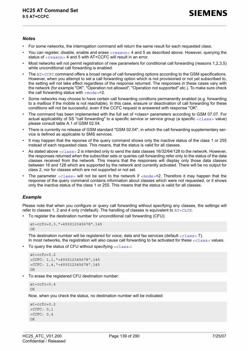
HC25 AT Command Set 9.5 AT+CCFC s
HC25_ATC_V01.200 Page 139 of 290 7/25/07Confidential / Released
Notes• For some networks, the interrogation command will return the same result for each requested class. • You can register, disable, enable and erase <reason> 4 and 5 as described above. However, querying the
status of <reason> 4 and 5 with AT+CCFC will result in an error. • Most networks will not permit registration of new parameters for conditional call forwarding (reasons 1,2,3,5)
while unconditional call forwarding is enabled. • The AT+CCFC command offers a broad range of call forwarding options according to the GSM specifications.
However, when you attempt to set a call forwarding option which is not provisioned or not yet subscribed to,the setting will not take effect regardless of the response returned. The responses in these cases vary withthe network (for example "OK", "Operation not allowed", "Operation not supported" etc.). To make sure checkthe call forwarding status with <mode>=2.
• Some networks may choose to have certain call forwarding condtions permanently enabled (e.g. forwardingto a mailbox if the mobile is not reachable). In this case, erasure or deactivation of call forwarding for theseconditions will not be successful, even if the CCFC request is answered with response "OK".
• The command has been implemented with the full set of <class> parameters according to GSM 07.07. Foractual applicability of SS "call forwarding" to a specific service or service group (a specific <class> value)please consult table A.1 of GSM 02.04.
• There is currently no release of GSM standard "GSM 02.04", in which the call forwarding supplementary ser-vice is defined as applicable to SMS services.
• It may happen that the reponse of the query command shows only the inactive status of the class 1 or 255instead of each requested class. This means, that the status is valid for all classes.
• As stated above <class> 2 is intended only to send the data classes 16/32/64/128 to the network. However,the responses returned when the subscriber sets or queries call forwarding refer only to the status of the dataclasses received from the network. This means that the responses will display only those data classesbetween 16 and 128 which are supported by the network and currently activated. There will be no output forclass 2, nor for classes which are not supported or not set.
• The parameter <class> will not be sent to the network if <mode>=2. Therefore it may happen that theresponse of the query command contains information about classes which were not requested, or it showsonly the inactive status of the class 1 or 255. This means that the status is valid for all classes.
Example
Please note that when you configure or query call forwarding without specifying any classes, the settings willrefer to classes 1, 2 and 4 only (=default). The handling of classes is equivalent to AT+CLCK. • To register the destination number for unconditional call forwarding (CFU):
The destination number will be registered for voice, data and fax services (default <class> 7).In most networks, the registration will also cause call forwarding to be activated for these <class> values.
• To query the status of CFU without specifying <class>:
• To erase the registered CFU destination number:
Now, when you check the status, no destination number will be indicated:
at+ccfc=0,3,"+493012345678",145 OK
at+ccfc=0,2 +CCFC: 1,1,"+493012345678",145 +CCFC: 1,4,"+493012345678",145 OK
at+ccfc=0,4 OK
at+ccfc=0,2 +CCFC: 0,1 +CCFC: 0,4 OK

HC25 AT Command Set 9.5 AT+CCFC s
HC25_ATC_V01.200 Page 140 of 290 7/25/07Confidential / Released
• To query the status of CFU for all classes:
• <reason> 4 or 5 cannot be used to query the status of all call forwarding reasons (see also notes above):
at+ccfc=0,2,,,255 +CCFC: 0,255 OK
at+ccfc=4,2 error at+ccfc=5,2 error

HC25 AT Command Set 9.6 AT+CCWA s
HC25_ATC_V01.200 Page 141 of 290 7/25/07Confidential / Released
9.6 AT+CCWA Call Waiting
The AT+CCWA write command controls the call waiting supplementary service according to GSM 02.83. Activa-tion, deactivation and status query are supported. The read command returns the current value of <n>.
Syntax
Unsolicited Result CodeIndication of a call that is currently waiting and can be accepted.+CCWA: <calling number>, <type of number>[, <class>], [, <CLI validity>]
If <n>=1 and the call waiting supplementary service is enabled in the network, URC "+CCWA" indicates a waitingcall to the TE. It appears while the waiting call is still ringing.
Parameter Description
Switch URCs "+CCWA" for call waiting on/off0 Disable display of URCs "+CCWA"1 Enable display of URCs "+CCWA"
Test Command
AT+CCWA=?Response(s)
+CCWA:(list of supported <n>s) OK
Read Command
AT+CCWA?Response(s)
+CCWA:<n> OK
Write Command
AT+CCWA=[[<n>][, <mode>][, <class>]]Response(s)
If <mode> is not equal 2 and command successful: OKIf <mode>= 2 and command successful: +CCWA: <status>, <class>[+CCWA: <status>, <class>][+CCWA: ...]OKIf error is related to ME functionality +CME ERROR
Reference(s) PIN USB0-MDM USB0-APP Last
GSM 07.07, GSM 02.04, GSM 02.83, GSM 03.83, GSM 04.83
+ + + -
<n>(num)

HC25 AT Command Set 9.6 AT+CCWA s
HC25_ATC_V01.200 Page 142 of 290 7/25/07Confidential / Released
Network operation to be performed for Supplementary service call waiting0 Disable call waiting (disable service)1 Enable call waiting (enable service)2 Query status of call waiting (query service status)
Integer or sum of integers each representing a class of information, i.e. a bearer service, telecommunication ser-vice or bearer service group as defined in "GSM 02.04".In the write command, parameter <class> specifies the class of the active call during which an incoming callof any class is to be regarded as a waiting call.In URC "+CCWA: <calling number>, <type of number>[, <class>], [, <CLI validity>]", parameter<class> specifies the class of the waiting call. 1 Voice2 Data
<class> 2 (data) comprises all those <class> values between 16 and 128, thatare supported both by the network and the MS. This means, a setting made for<class> 2 applies to all remaining data classes (if supported). In addition, youcan assign a different setting to a specific class. For example, you can activatecall waiting for all data classes, but deactivate it for a specific data class.
4 Fax[7] Voice, data and fax (1+2+4)8 SMS16 Data circuit sync32 Data circuit async64 Dedicated packet access128 Dedicated PAD access1...[7]...255 Combination of some of the above classes. For example, the default setting 7
represents the sum of the integers 1, 2 and 4 (CF for voice, data and fax). Thevalue 255 covers all classes. If parameter "class"is omitted, the default value 7is used.
0 Call waiting service is not active1 Call waiting service is active
Phone number of waiting caller in the format specified by parameter <type of number>.
Type of address octet in integer format (refer to GSM 04.08, subclause 10.5.4.7) 145 <calling number> includes international access code character '+'128 number restricted129 Otherwise
0 CLI valid
<mode>(num)
<class>(num)
<status>(num)
<calling number>(str)
<type of number>(num)
<CLI validity>(num)

HC25 AT Command Set 9.6 AT+CCWA s
HC25_ATC_V01.200 Page 143 of 290 7/25/07Confidential / Released
1 CLI has been withheld 2 CLI is not available
Notes• With the AT+CHLD command, it is possible to establish a multiparty call or to set the active voice call on hold
and then accept a waiting voice call (not possible with fax and data call). See also AT+CHLD • Users should be aware that if call waiting is activated (<mode>=1), the presentation of URCs needs to be
enabled, too (<n>=1). Otherwise, on the one hand, a waiting caller would be kept waiting due to lack of BUSY signals, while, on theother hand, the waiting call would not be indicated to the called party.
• The AT+CCWA command offers a broad range of options according to the GSM specifications. However,when you attempt to enable call waiting for a <class> for which the service is not provisioned or not sup-ported , the setting will not take effect regardless of the response returned. The responses in these cases varywith the network (for example "OK", "Operation not allowed", "Operation not supported" etc.). To make surecheck the current call waiting settings with <mode>=2.
• The AT+CCWA command has been implemented with the full set of <class> parameters according toGSM 07.07. For actual applicability of SS call waiting to a specific service or service group (a specific<class> value) please consult table A.1 of GSM 02.04
• Despite the specifications stated in GSM 02.04 call waiting is not handled uniformly among all networks: GSM 02.04, Annex A, provides the following specification: "The applicability of call waiting refers to the telecommunication service of the active call and not of the waitingcall. The incoming, waiting, call may be of any kind." Nevertheless, networks do differ on the actual imple-mentation of the service. For example, the activation of call waiting for <class> 4, "fax", causes some net-works to send a call waiting indication if a call "of any kind" comes in during an active fax call, but others may(with the same settings active) indicate a waiting fax call during any kind of active call. Thus, the only reliableway to receive or prevent a call waiting indication under any circumstances and in any network, is to activateor deactivate call waiting for all tele- and bearer services (<class> 255).
• As stated above <class> 2 is intended only to send the data classes 16/32/64/128 to the network. However,the responses returned when the subscriber sets or queries call waiting refer only to the status of the dataclasses received from the network. This means that the responses will display only those data classesbetween 16 and 128 which are supported by the network and currently activated. There will be no output forclass 2, nor for classes which are not supported or not set.
• The parameter <class> will not be sent to the network if <mode>= 2. Therefore it may happen that theresponse of the query command contains information about classes which were not requested or it showsonly the inactive status of the class 1 or 255. This means, that the status is valid for all classes.

HC25 AT Command Set 9.7 AT+CHLD s
HC25_ATC_V01.200 Page 144 of 290 7/25/07Confidential / Released
9.7 AT+CHLD Call Hold and Multiparty
Syntax
Command DescriptionTA controls the Supplementary Services Call Hold and Multiparty. Calls can be put on hold, recovered, released,and added to a conversation.Like for all Supplementary Services, the availability and detailed functionality of Call Hold and Multiparty servicesdepends on the configuration of the GSM network. The HC25 can only request the service, but the networkdecides whether and how the request will be answered.
Parameter Description
0 Release all held calls or set User Determined User Busy (UDUB) for a waitingcall: • If a call is waiting, release the waiting call. The calling party will receive a
"BUSY" indication (Supplementary Service User Determined User Busy"UDUB")
• Otherwise, terminate all held calls (if any). 1 Terminate all active calls (if any) and accept "the other call" as the active call:
• If a call is waiting, the waiting call will be accepted. • Otherwise, if a held call is present, the held call becomes active.
1X Terminate a specific call X (X= 1-7). The call may be active, held or waiting.The remote party of the terminated call will receive a "NO CARRIER" indica-tion. Parameter X is the call number <idx> of the targeted call in the list of cur-rent calls available with AT command AT+CLCC.
2 Place all active calls on hold (if any) and accept "the other call" as the activecall: • If a call is waiting, the waiting call will be accepted. • Otherwise, if a held call is present, the held call becomes active.
2X Place all active calls except call X (X= 1-7) on hold. Parameter X is the callnumber <idx> of the targeted call in the list of current calls available with ATcommand AT+CLCC.
Test Command
AT+CHLD=?Response(s)
+CHLD: (list of supported <n>s)OK
Write Command
AT+CHLD=[<n>]Response(s)
OKERROR+CME ERROR: <err>
Reference(s) PIN USB0-MDM USB0-APP Last
GSM 07.07 + + + -
<n>(num)

HC25 AT Command Set 9.7 AT+CHLD s
HC25_ATC_V01.200 Page 145 of 290 7/25/07Confidential / Released
3 Add a held call to the active calls in order to set up a conference (multiparty)call.
4 Connects the two calls of a multiparty call and disconnects the subscriber fromboth calls (ECT).
Notes• The AT+CHLD command offers a broad range of options according to the GSM specifications. However, if you
attempt to invoke an option which is not provisioned by the network, or not subscribed to, invocation of thisoption will fail. The responses in these cases may vary with the network (for example "Operation not allowed","Operation not supported" etc.).
• The handling of the supplementary service Call hold and Multiparty varies with the types of calls. This isbecause only voice calls can be put on hold, while data or fax calls cannot. The following procedures apply:With AT+CHLD=2 the user can simultaneously place a voice call on hold and accept another waiting voice,data or fax call. If the waiting call is a data or fax call, it is also possible to put the voice call on hold. The userneeds to wait for the RING signal and manually answer the data / fax call with ATA. To switch back from theactive data or fax call to the held voice call the active call must be terminated with AT+CHLD=1. If all activeand held calls are voice calls it is possible to switch back and forth with AT+CHLD=2.
• In conflict situations, e.g. when a waiting call comes while there are already held calls, the above proceduresapply to the waiting call only. For example, <n>=0 rejects the waiting call, but does not affect the held calls.
• See also the AT+CCWA command for details on how to display waiting calls.
Example
^SYSSTARTat+cpin="9999"OK
+CREG: 2
+CREG: 1,"0145","0016" The mobile is now registered.at+ccwa=1,1,1 You activate the indication of waiting calls during
voice calls.OKatd"1234567"; You make a voice call.OK+CCWA: "+491791292364",145,32,,0 You receive a URC indicating a waiting data call.at+chld=2 You put the voice call on hold.OKRING You now receive the RING of the data call.
RING
RINGATA You accept the data call.OKCONNECT 9600/RLP The data connection is set up.hello+++ With ''+++'' you go in command mode.OKat+clcc You interrogate the status of all established calls.+CLCC: 1,0,1,0,0,"03038639268",129+CLCC: 2,1,0,1,0,"+491791292364",145OKat+chld=1 The active data call is terminated and the held voice
call becomes active.OK

HC25 AT Command Set 9.7 AT+CHLD s
HC25_ATC_V01.200 Page 146 of 290 7/25/07Confidential / Released
at+clcc+CLCC: 1,0,0,0,0,"03038639268",129OK

HC25 AT Command Set 9.8 AT+CLIP s
HC25_ATC_V01.200 Page 147 of 290 7/25/07Confidential / Released
9.8 AT+CLIP Calling Line Identification Presentation
This command refers to the GSM supplementary service CLIP (Calling Line Identification Presentation) thatenables a called subscriber to get the calling line identity (CLI) of the calling party when receiving a mobile ter-minated call. The AT+CLIP write command enables or disables the presentation of the CLI at the TE. It has no effect on theexecution of the supplementary service CLIP in the network. The AT+CLIP read command gives the status of <n>, and also triggers an interrogation of the provision statusof the CLIP service according to GSM 02.81 (given in <m>).
Syntax
Unsolicited Result Code+CLIP: <number>, <type>, , [, <alpha>][, <CLI validity>]
When CLIP is enabled at the TE (and is permitted by the calling subscriber), this URC is delivered after every"RING" or "+CRING" URC when a mobile terminated voice call occurs. For data calls the URC is delivered onlyonce.
Parameter Description
[0](&F) Suppress unsolicited result codes1 Display unsolicited result codes
0 CLIP not provisioned1 CLIP provisioned2 Unknown
Test Command
AT+CLIP=?Response(s)
+CLIP: (list of supported<n>s)OK
Read Command
AT+CLIP?Response(s)
+CLIP: <n>, <m>OKERROR+CME ERROR: <err>
Write Command
AT+CLIP=<n>Response(s)
OKERROR+CME ERROR: <err>
Reference(s) PIN USB0-MDM USB0-APP Last
GSM 07.07, GSM 02.81 + + + -
<n>(num)
<m>(num)

HC25 AT Command Set 9.8 AT+CLIP s
HC25_ATC_V01.200 Page 148 of 290 7/25/07Confidential / Released
String type phone number of calling address in format specified by <type>.
Type of address octet in integer format; 145 when dialing string includes international access code character"+", otherwise 129.TA shall return the recommended value 128 for <type> (TON/NPI unknown in accordance with GSM 04.08subclause 10.5.4.7).
String type alphanumeric representation of <number> corresponding to the entry found in phonebook; usedcharacter set is the one selected with AT+CSCS.
0 CLI valid1 CLI has been withheld by the originator.2 CLI is not available due to interworking problems or limitations of originating
network. <number> shall be an empty string ("") and <type> value will not besignificant.
When CLI is not available ( <CLI validity>=2), <number> shall be an plus string ("+") and <type> valuewill be "145". Nevertheless, TA shall return the recommended value 128 for <type> (TON/NPI unknown inaccordance with GSM 04.08 subclause 10.5.4.7). When CLI has been withheld by the originator, (<CLI validity>=1) and the CLIP is provisioned with the"override category" option (refer GSM 02.81 and GSM 03.81), <number> and <type> is provided. Otherwise,TA shall return the same setting for <number> and <type> as if the CLI was not available.
<number>(str)
<type>(num)
<alpha>(str)
<CLI validity>(num)

HC25 AT Command Set 9.9 AT+CLIR s
HC25_ATC_V01.200 Page 149 of 290 7/25/07Confidential / Released
9.9 AT+CLIR Calling Line Identification Restriction
The AT+CLIR command refers to the GSM supplementary service CLIR (Calling Line Identification Restriction).
Syntax
Parameter Description
Parameter shows the settings for outgoing calls:[0](P) Presentation indicator is used according to the subscription of the CLIR service1 CLIR invocation2 CLIR suppression
Parameter shows the subscriber CLIR service status in the network:0 CLIR not provisioned1 CLIR provisioned in permanent mode2 Unknown (e.g. no network, etc.)3 CLIR temporary mode presentation restricted4 CLIR temporary mode presentation allowed
Note• The settings made with AT+CLIR=1 or AT+CLIR=2 are used for all outgoing calls until the ME is switched off
or AT+CLIR=0 is used.
Test Command
AT+CLIR=?Response(s)
+CLIR: (list of supported <n>s)OK
Read Command
AT+CLIR?Response(s)
+CLIR<n>, <m>OKERROR+CME ERROR: <err>
Write Command
AT+CLIR=[<n>]Response(s)
+CLIR: <n>, <m>OKERROR+CME ERROR: <err>
Reference(s) PIN USB0-MDM USB0-APP Last
GSM 07.07 + + + -
<n>(num)
<m>(num)

HC25 AT Command Set 9.10 AT+COLP s
HC25_ATC_V01.200 Page 150 of 290 7/25/07Confidential / Released
9.10 AT+COLP Connected Line Identification Presentation
This command refers to the GSM supplementary service COLP (Connected Line Identification Presentation) thatenables a calling subscriber to get the connected line identity (COL) of the called party after setting up a mobileoriginated voice call. The command enables or disables the presentation of the COL at the TE. It has no effecton the execution of the supplementary service COLR in the network.
Syntax
Unsolicited Result CodeCall response format: +COLP: <number>, <type>[, <sub-number>][, <sub-type>][, <alpha>]
Parameter Description
0 Disable - suppress unsolicited result codes 1 Enable - display unsolicited result codes
0 COLP not provisioned (no presentation)1 COLP provisioned2 Unknown
String type phone number of connected address in format specified by <type>
Test Command
AT+COLP=?Response(s)
+COLP:(list of supported <n>s)OK
Read Command
AT+COLP?Response(s)
+COLP: <n>, <m>OKERROR+CME ERROR: <err>
Write Command
AT+COLP=[<n>]Response(s)
OKERROR+CME ERROR: <err>
Reference(s) PIN USB0-MDM USB0-APP Last
GSM 07.07 + + + -
<n>(num)
<m>(num)
<number>(str)

HC25 AT Command Set 9.10 AT+COLP s
HC25_ATC_V01.200 Page 151 of 290 7/25/07Confidential / Released
Type of address octet in integer format; 145 when dialling string includes international access code character"+", otherwise 129.
String type phone number of sub address in format specified by <sub-type>.
Type of sub-address octect145 international access code character '+'129 otherwise
String type alphanumeric representation of <number> corresponding to the entry found in phonebook; usedcharacter set is the one selected with AT+CSCS.
<type>(num)
<sub-number>(str)
<sub-type>(num)
<alpha>(str)

HC25 AT Command Set 9.11 AT+CPUC s
HC25_ATC_V01.200 Page 152 of 290 7/25/07Confidential / Released
9.11 AT+CPUC Price per unit and currency table
Syntax
Command DescriptionRead command returns the current parameters of PUC. Write command sets the parameters of Advice of Charge related price per unit and currency table. SIM PIN2 isusually required to set the parameters.
Parameter Description
Three-character currency code (e.g. "GBP", "EUR"). If the currency name is longer than three characters, allcharacters will be cut off after the third position. Before they are written to the SIM Card, these characters areconverted to the standard GSM alphabet.
Price per unit; dot is used as a decimal separator (e.g. "2.66"). The length is limited to 20 characters. If the stringlength is exceeded, the command is terminated with an error. This string may only contain digits and a dot. Lead-ing zeros are removed from the string. The minimum and maximum value are determined by the structure of theSIM-PUCT file. The maximum price per unit value is 999 999 999.00. When successfully entered, this value isrounded to maximum accuracy.Note: Due to storage in mantisse (range 0-4095) and exponent (-7 to 7) it is possible that rounding errors occur.
SIM PIN2. String parameter which can contain any combination of characters. The maximum string length islimited to 8 characters. If this value is exceeded, the command terminates with an error message. If the PIN2 isincorrect, a CME error (+CME ERROR: incorrect password) is output.
Test Command
AT+CPUC=?Response(s)
OK
Read Command
AT+CPUC?Response(s)
+CPUC: <currency>, <ppu>OKERROR+CME ERROR: <err>
Write Command
AT+CPUC=<currency>, <ppu>[, <passwd>]Response(s)
OKERROR+CME ERROR: <err>
Reference(s) PIN USB0-MDM USB0-APP Last
GSM 07.07 + + + -
<currency>(str)(+CSCS)
<ppu>(str)
<passwd>(str)
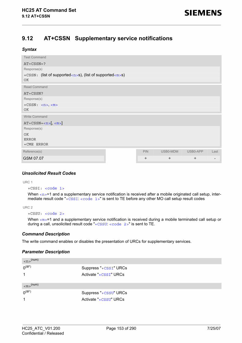
HC25 AT Command Set 9.12 AT+CSSN s
HC25_ATC_V01.200 Page 153 of 290 7/25/07Confidential / Released
9.12 AT+CSSN Supplementary service notifications
Syntax
Unsolicited Result Codes
URC 1
+CSSI: <code 1>
When <n>=1 and a supplementary service notification is received after a mobile originated call setup, inter-mediate result code "+CSSI: <code 1>" is sent to TE before any other MO call setup result codes
URC 2
+CSSU: <code 2>
When <m>=1 and a supplementary service notification is received during a mobile terminated call setup orduring a call, unsolicited result code "+CSSU: <code 2>" is sent to TE.
Command DescriptionThe write command enables or disables the presentation of URCs for supplementary services.
Parameter Description
0(&F) Suppress "+CSSI" URCs 1 Activate "+CSSI" URCs
0(&F) Suppress "+CSSU" URCs 1 Activate "+CSSU" URCs
Test Command
AT+CSSN=?Response(s)
+CSSN: (list of supported<n>s), (list of supported<m>s)OK
Read Command
AT+CSSN?Response(s)
+CSSN: <n>, <m>OK
Write Command
AT+CSSN=<n>[, <m>]Response(s)
OKERROR+CME ERROR
Reference(s) PIN USB0-MDM USB0-APP Last
GSM 07.07 + + + -
<n>(num)
<m>(num)

HC25 AT Command Set 9.12 AT+CSSN s
HC25_ATC_V01.200 Page 154 of 290 7/25/07Confidential / Released
0 unconditional call forwarding is active 1 some of the conditional call forwardings are active 2 call has been forwarded 3 Waiting call is pending 5 Outgoing call are barreded
0 The incoming call is a forwarded call. 2 call has been put on hold (during a voice call). 3 call has been retrieved (during a voice call). 5 Held call was terminated by other party 10 additional incoming call forwarded
Note• URCs will be displayed only if the call concerned is a voice call, but some URCs will be displayed as well as
for data calls (like "+CSSU"=0).
<code 1>(num)
<code 2>(num)

HC25 AT Command Set 9.13 AT+CUSD s
HC25_ATC_V01.200 Page 155 of 290 7/25/07Confidential / Released
9.13 AT+CUSD Unstructured supplementary service data
AT+CUSD allows control of the Unstructured Supplementary Service Data (USSD) according to GSM 02.90. Bothnetwork and mobile initiated operations are supported. The interaction of this command with other commandsbased on other GSM supplementary services is described in the GSM standard.
Parameter <n> is used to disable/enable the presentation of an unsolicited result code (USSD response fromthe network, or network initiated operation) "+CUSD: <m>[<str_urc>[<dcs>]]" to the TE.
When parameter <str_write> is given, a mobile initiated USSD string or a response USSD string to a networkinitiated operation is sent to the network. The response USSD string from the network is returned in a subsequentunsolicited result code "+CUSD"
Syntax
Unsolicited Result Code+CUSD: <m>[<str_urc>[<dcs>]]
URC "+CUSD" indicates an USSD response from the network, or network initiated operation
Parameter Description
0(&F) Disable the result code presentation in the TA 1 Enable the result code presentation in the TA 2 Cancel session (not applicable to read command response)
String type USSD-string (when <str_write> parameter is not given, network is not interrogated). For the write command, only <dcs>= 15 is supported.
Test Command
AT+CUSD=?Response(s)
+CUSD: (list of supported<n>s)OK
Read Command
AT+CUSD?Response(s)
+CUSD: <n>OK
Write Command
AT+CUSD=<n>[, <str_write>[, <dcs>]]Response(s)
OK+CME ERROR
Reference(s) PIN USB0-MDM USB0-APP Last
GSM 07.07, GSM 02.90, GSM 03.90, GSM 04.90
+ + + -
<n>(num)
<str_write>(str)(+CSCS)

HC25 AT Command Set 9.13 AT+CUSD s
HC25_ATC_V01.200 Page 156 of 290 7/25/07Confidential / Released
String type USSD-string . If <dcs> indicates that GSM 03.38 default alphabet is used TA converts GSM alphabet into current TE characterset according to rules of GSM 07.05 Annex A. Otherwise in case of invalid or omitted <dcs> conversion of<str_urc> is not possible.
GSM 03.38 Cell Broadcast Data Coding Scheme in integer format (default 15). In case of an invalid or omitted<dcs> from the network side (MT) <dcs> will not be given out.
0 No further user action required (network initiated USSD-Notify, or no furtherinformation needed after mobile initiated operation)
1 Further user action required (network initiated USSD-Request, or further infor-mation needed after mobile initiated operation). If <m>=1, then user input has to be done with an additional AT+CUSD=1 com-mand <ESC>.
2 USSD terminated by network. 3 other local client has responded, this means the interface was not idle and an
busy was send to the network already 5 network time out
Notes• When a USSD string is sent via ATD, a "AT+CUSD=1" is executed implicitly. • It is recommended to finalize or escape a pending USSD user interaction before further actions are done to
prevent blocking situations. • If a network initiated operation is left unanswered, several error codes may be output. The first error code is
given when the AT command is timed out. Other network indications may follow, depending on the network.
<str_urc>(str)(+CSCS)
<dcs>(num)
<m>(num)

HC25 AT Command Set 10. GPRS Commands s
HC25_ATC_V01.200 Page 157 of 290 7/25/07Confidential / Released
10. GPRS Commands
This chapter describes AT commands that a TE (Terminal Equipment, e.g. an application running on a controllingPC) may use to control the HC25 acting as GPRS Mobile Termination (MT).
10.1 AT+CGATT PS attach or detach
The execution command is used to attach the MT to, or detach the MT from, the Packet Domain service. Afterthe command has completed, the MT remains in V.25ter command state. If the MT is already in the requestedstate, the command is ignored and the OK response is returned. If the requested state cannot be achieved, anERROR or +CME ERROR response is returned. Any active PDP contexts will be automatically deactivated when the attachment state changes to detached. The read command returns the current Packet Domain service state. The test command is used for requesting information on the supported Packet Domain service states.
Syntax
Parameter Description
Indicates the state of PS attachment.0(P) detached[1] attached
Test Command
AT+CGATT=?Response(s)
+CGATT: (list of supported <state>s)OK
Read Command
AT+CGATT?Response(s)
+CGATT: <state>OK
Write Command
AT+CGATT=[<state>]Response(s)
OKERROR+CME ERROR
Reference(s) PIN USB0-MDM USB0-APP Last
3GPP 27.007 + + + -
<state>(num)
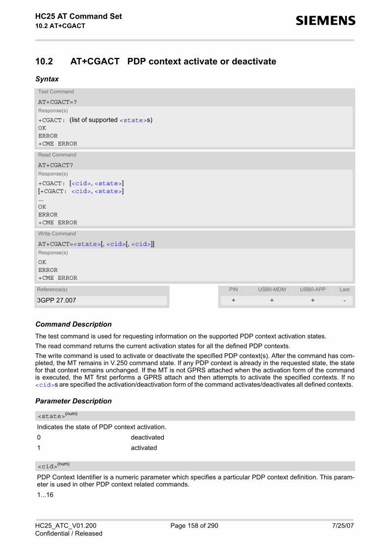
HC25 AT Command Set 10.2 AT+CGACT s
HC25_ATC_V01.200 Page 158 of 290 7/25/07Confidential / Released
10.2 AT+CGACT PDP context activate or deactivate
Syntax
Command DescriptionThe test command is used for requesting information on the supported PDP context activation states. The read command returns the current activation states for all the defined PDP contexts. The write command is used to activate or deactivate the specified PDP context(s). After the command has com-pleted, the MT remains in V.250 command state. If any PDP context is already in the requested state, the statefor that context remains unchanged. If the MT is not GPRS attached when the activation form of the commandis executed, the MT first performs a GPRS attach and then attempts to activate the specified contexts. If no<cid>s are specified the activation/deactivation form of the command activates/deactivates all defined contexts.
Parameter Description
Indicates the state of PDP context activation.0 deactivated1 activated
PDP Context Identifier is a numeric parameter which specifies a particular PDP context definition. This param-eter is used in other PDP context related commands. 1...16
Test Command
AT+CGACT=?Response(s)
+CGACT: (list of supported <state>s)OKERROR+CME ERROR
Read Command
AT+CGACT?Response(s)
+CGACT: [<cid>, <state>][+CGACT: <cid>, <state>]...OKERROR+CME ERROR
Write Command
AT+CGACT=<state>[, <cid>[, <cid>]]Response(s)
OKERROR+CME ERROR
Reference(s) PIN USB0-MDM USB0-APP Last
3GPP 27.007 + + + -
<state>(num)
<cid>(num)

HC25 AT Command Set 10.2 AT+CGACT s
HC25_ATC_V01.200 Page 159 of 290 7/25/07Confidential / Released
Note• A maximum of 1 contexts can be activated at the same time, no matter on which interface. Trying to activate
more than 1 contexts will cause "+CME ERROR: no network service". Note that, depending on the provider,the number of activated contexts may be further restricted. Remember that contexts may be activated implicitly by using the ATD*99# GPRS compatibility commandwithout specifying a <cid>.

HC25 AT Command Set 10.3 AT+CGDATA s
HC25_ATC_V01.200 Page 160 of 290 7/25/07Confidential / Released
10.3 AT+CGDATA Enter data state
Syntax
Command DescriptionThe test command is used for requesting information on the supported layer 2 protocols to be used between theTE and MT. The write command causes the MT to perform all actions which are necessary to establish communicationbetween the TE and the network using one or more GPRS PDP types. This may include performing a GPRSattach and one or more PDP context activations. Commands following the AT+CGDATA command in the AT com-mand line will not be processed by the MT. If the write command is successful, the MT issues the intermediate result code CONNECT and enters V.250online data state. The application that initiates the PPP mode must be designed to start all LCP configure requests in accordancewith TS 27.060 par 9.1. Otherwise the MT remains, after the CONNECT, infinitely in a waiting state. After data transfer is complete, and the layer 2 protocol termination procedure has completed successfully, thecommand state is reentered and the MT returns the final result code OK. If the <L2P> parameter value is unacceptable to the MT, the MT returns ERROR or +CME ERROR. In the event of erroneous termination or a failure to start up, the command state is reentered and the MT returnsNO CARRIER, or if enabled +CME ERROR.
Parameter Description
Layer 2 protocol to be used between the TE and MT. [“PPP“] Layer 2 protocol PPP
Parameter specifies a particular PDP context definition and is also used in other PDP context-related com-mands. If parameter is not specified, then the first defined primary context is used. 1...16
Test Command
AT+CGDATA=?Response(s)
+CGDATA: (list of supported <L2P>s)OK
Write Command
AT+CGDATA=[<L2P>[, <cid>]]Response(s)
CONNECTNO CARRIERERROR+CME ERROR
Reference(s) PIN USB0-MDM USB0-APP Last
3GPP 27.007 + + - +
<L2P>(str)
<cid>(num)

HC25 AT Command Set 10.3 AT+CGDATA s
HC25_ATC_V01.200 Page 161 of 290 7/25/07Confidential / Released
10.3.1 Automatic deactivation of PDP context during dial-up PPP
When using the AT+CGDATA write command or ATD*99# the MT issues the intermediate result code CON-NECT and enters V.250ter online data state. In V.250 online data state, first some LCP protocol exchangebetween MT and TE is performed to set up the PPP link. After successfully establishing the PPP link, the MTperforms the PDP context activation procedure if the context is not already activated. As a result, the MT is in a"PDP context activated" state within the PLMN, the PPP link is established on the mobile side and the mobile isready for IP data transfer. If the TE wants to close the LCP link the MT may perform an LCP termination request procedure on PPP level.After this LCP termination procedure the MT deactivates the PDP context automatically and the MT returns toV.250 command mode and issues the final result code NO CARRIER. If DTR is configured to disconnect data connections (AT&D2), then the application should not toggle DTR duringthe implicit PDP context deactivation and before "NO CARRIER" is received.

HC25 AT Command Set 10.4 AT+CGDCONT s
HC25_ATC_V01.200 Page 162 of 290 7/25/07Confidential / Released
10.4 AT+CGDCONT Define PDP Context
Syntax
Command DescriptionThe test command returns supported values as a compound value. The read command returns the current settings for each defined PDP context. The write command specifies the parameters for a PDP context identified by the context identifier <cid>. Thenumber of contexts that may be in a defined state at the same time is given by the range returned by the testcommand. A special form of the write command (AT+CGDCONT=<cid>) causes the values for context <cid> tobecome undefined.
Parameter Description
PDP Context IdentifierParameter specifies a particular PDP context definition. This parameter is used in other PDP context-relatedcommands. 1...16
Packet Data Protocol typeSpecifies the type of the packet data protocol.“IP“ Internet Protocol (IETF STD 5)
Test Command
AT+CGDCONT=?Response(s)
+CGDCONT: (range of supported<cid>s), <PDP_type>, , , (list of supported <d_comp>s), (list of supported <h_comp>s)OKERROR+CME ERROR
Read Command
AT+CGDCONT?Response(s)
+CGDCONT: [<cid>, <PDP_type>, <APN>, <PDP_addr>, <d_comp>, <h_comp>][+CGDCONT: <cid>, <PDP_type>, <APN>, <PDP_addr>, <d_comp>, <h_comp>][+CGDCONT: ...]OKERROR+CME ERROR
Write Command
AT+CGDCONT=<cid>[, <PDP_type>[, <APN>[, <PDP_addr>[, <d_comp>[, <h_comp>]]]]]Response(s)
OKERROR+CME ERROR
Reference(s) PIN USB0-MDM USB0-APP Last
3GPP 27.007 + + + -
<cid>(num)
<PDP_type>(str)

HC25 AT Command Set 10.4 AT+CGDCONT s
HC25_ATC_V01.200 Page 163 of 290 7/25/07Confidential / Released
Access Point NameThe logical name that is used to select the GGSN or the external packet data network. If the value is null oromitted, then the subscription value will be requested.
Packet Data Protocol addressIdentifies the MT in the address space applicable to PDP (e.g. IP V4 address for PDP type IP). If the value isnull or omitted, then a value may be provided by the TE during the PDP startup procedure or, failing that, adynamic address will be requested. The read command will continue to return the null string even if an addresshas been allocated during the PDP startup procedure. The allocated address may be read using AT+CGPADDR.
Data CompressionControls the PDP data compression (applicable for Subnetwork Dependent Convergence Protocol (SNDCP)only) 3GPP TS 44.065 [0] off
Header CompressionControls the PDP header compression 3GPP TS 44.065, 3GPP TS 25.323[0] off1 on
Note• All context definitions will be stored non volatile.
<APN>(str)
<PDP_addr>(str)
<d_comp>(num)
<h_comp>(num)
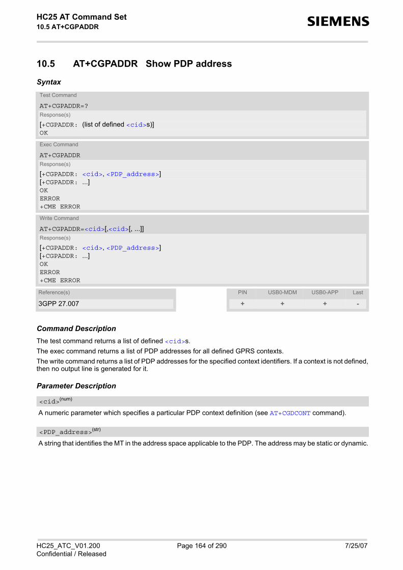
HC25 AT Command Set 10.5 AT+CGPADDR s
HC25_ATC_V01.200 Page 164 of 290 7/25/07Confidential / Released
10.5 AT+CGPADDR Show PDP address
Syntax
Command DescriptionThe test command returns a list of defined <cid>s. The exec command returns a list of PDP addresses for all defined GPRS contexts. The write command returns a list of PDP addresses for the specified context identifiers. If a context is not defined,then no output line is generated for it.
Parameter Description
A numeric parameter which specifies a particular PDP context definition (see AT+CGDCONT command).
A string that identifies the MT in the address space applicable to the PDP. The address may be static or dynamic.
Test Command
AT+CGPADDR=?Response(s)
[+CGPADDR: (list of defined <cid>s)]OK
Exec Command
AT+CGPADDRResponse(s)
[+CGPADDR: <cid>, <PDP_address>][+CGPADDR: ...]OKERROR+CME ERROR
Write Command
AT+CGPADDR=<cid>[,<cid>[, ...]]Response(s)
[+CGPADDR: <cid>, <PDP_address>][+CGPADDR: ...]OKERROR+CME ERROR
Reference(s) PIN USB0-MDM USB0-APP Last
3GPP 27.007 + + + -
<cid>(num)
<PDP_address>(str)

HC25 AT Command Set 10.6 AT+CGQMIN s
HC25_ATC_V01.200 Page 165 of 290 7/25/07Confidential / Released
10.6 AT+CGQMIN Quality of Service Profile (Minimum acceptable)
Syntax
Command DescriptionThe test command returns values supported as a compound value. If the MT supports several PDP types, theparameter value ranges for each PDP type are returned on a separate line. The read command returns the current settings for each context for which a QOS was explicitly specified. This command allows the TE to specify a minimum acceptable profile which is checked by the MT against thenegotiated profile returned in the Activate PDP Context Accept message.The set command specifies a profile for the context identified by the context identification parameter, <cid>.A special form of the set command, AT+CGQMIN= <cid> causes the minimum acceptable profile for contextnumber <cid> to become undefined. In this case no check is made against the negotiated profile.
Parameter Description
Parameter specifies a particular PDP context definition. The parameter is also used in other PDP context-relatedcommands. 1...16
Precedence class[0] network subscribed value
Test Command
AT+CGQMIN=?Response(s)
+CGQMIN: <PDP_type>, (list of supported <precedence>s), (list of supported <delay>s), (list of supported <reliability>s), (list of supported <peak>s), (list of supported <mean>s)OKERROR+CME ERROR
Read Command
AT+CGQMIN?Response(s)
+CGQMIN: [<cid>, <precedence>, <delay>, <reliability>, <peak>, <mean>][+CGQMIN: <cid>, <precedence>, <delay>, <reliability>, <peak>, <mean>][+CGQMIN: ...]OKERROR+CME ERROR
Write Command
AT+CGQMIN=<cid>[, <precedence>[, <delay>[, <reliability>[, <peak>[, <mean>]]]]]Response(s)
OKERROR+CME ERROR
Reference(s) PIN USB0-MDM USB0-APP Last
3GPP 27.007 + + + -
<cid>(num)
<precedence>(num)

HC25 AT Command Set 10.6 AT+CGQMIN s
HC25_ATC_V01.200 Page 166 of 290 7/25/07Confidential / Released
1 High PriorityService commitments shall be maintained ahead of precedence classes 2 and3
2 Normal priorityService commitments shall be maintained ahead of precedence class 3
3 Low priorityService commitments shall be maintained
Delay classThe delay parameter defines the end-to-end transfer delay incurred in the transmission of SDUs through theGPRS network(s).[0] network subscribed value1..4 SDU size: 128 octets:
SDU size: 1024 octets:
Reliability class[0] network subscribed value1 Non real-time traffic, error-sensitive application that cannot cope with data loss2 Non real-time traffic, error-sensitive application that can cope with infrequent
data loss3 Non real-time traffic, error-sensitive application that can cope with data loss,
GMM/SM, and SMS4 Real-time traffic, error-sensitive application that can cope with data loss5 Real-time traffic, error non-sensitive application that can cope with data loss
Peak throughput class (in octets per second).[0] network subscribed value1 Up to 1 000 (8 kbit/s).2 Up to 2 000 (16 kbit/s).3 Up to 4 000 (32 kbit/s).4 Up to 8 000 (64 kbit/s).
<delay>(num)
Delay Class Mean Transfer Delay 95 percentile1 (Predictive) <0.5 <1.52 (Predictive) <5 <253 (Predictive) <50 <2504 (Best Effort) Unspecified
Delay Class Mean Transfer Delay 95 percentile1 (Predictive) <0.5 <1.52 (Predictive) <5 <253 (Predictive) <50 <2504 (Best Effort) Unspecified
<reliability>(num)
<peak>(num)

HC25 AT Command Set 10.6 AT+CGQMIN s
HC25_ATC_V01.200 Page 167 of 290 7/25/07Confidential / Released
5 Up to 16 000 (128 kbit/s).6 Up to 32 000 (256 kbit/s).7 Up to 64 000 (512 kbit/s).8 Up to 128 000 (1024 kbit/s).9 Up to 256 000 (2048 kbit/s).
Mean throughput class(in octets per hour).[0] network subscribed value1 100 (~0.22 bit/s)2 200 (~0.44 bit/s)3 500 (~1.11 bit/s)4 1 000 (~2.2 bit/s)5 2 000 (~4.4 bit/s)6 5 000 (~11.1 bit/s)7 10 000 (~22 bit/s)8 20 000 (~44 bit/s)9 50 000 (~111 bit/s)10 100 000 (~0.22 kbit/s)11 200 000(~0.44 kbit/s)12 500 000(~1.11 kbit/s)13 1 000 000 (~2.2 kbit/s)14 2 000 000 (~4.4 kbit/s)15 5 000 000 (~11.1 kbit/s)16 10 000 000 (~22 kbit/s)17 20 000 000 (~44 kbit/s)18 50 000 000 (~111 kbit/s)31 best effort
Packet Data Protocol Type“IP“ Internet Protocol (IETF STD 5)
Notes• Definitions of parameters can be found in 3GPP 23.107.• All QOS settings will be stored non volatile.
<mean>(num)
<PDP_type>(str)

HC25 AT Command Set 10.7 AT+CGEQMIN s
HC25_ATC_V01.200 Page 168 of 290 7/25/07Confidential / Released
10.7 AT+CGEQMIN 3G Quality of Service Profile (Minimum accept-able)
Syntax
Command DescriptionThe test command returns values supported as a compound value. The read command returns the current settings for each defined context for which a QOS was explicitly specified. The write command allows the TE to specify a Quality of Service Profile for the context identified by the contextidentification parameter <cid> which is checked by the MT against the negotiated profile returned in the Acti-vate/Modify PDP Context Accept message. A special form of the write command, AT+CGEQMIN=<cid> causes the requested profile for context number<cid> to become undefined.
Test Command
AT+CGEQMIN=?Response(s)
+CGEQMIN: <PDP_type>, (list of supported <Traffic class>s), (list of supported <Maximum bitrate UL>s), (list of supported <Maximum bitrate DL>s), (list of supported <Guaranteed bitrate UL>s), (list of supported <Guaranteed bitrate DL>s), (list of supported <Delivery order>s), (list of supported <Maximum SDU size>s), (list of supported <SDU error ratio>s), (list of supported <Residual bit error ratio>s), (list of supported <Delivery of erroneous SDUs>s), (list of supported <Transfer delay>s), (list of supported <Traffic handling priority>s)OK
Read Command
AT+CGEQMIN?Response(s)
+CGEQMIN: [<cid>, <Traffic class>, <Maximum bitrate UL>, <Maximum bitrate DL>, <Guaranteed bitrate UL>, <Guaranteed bitrate DL>, <Delivery order>, <Maximum SDU size>, <SDU error ratio>, <Residual bit error ratio>, <Delivery of erroneous SDUs>, <Transfer delay>, <Traffic handling priority>][+CGEQMIN: <cid>, <Traffic class>, <Maximum bitrate UL>, <Maximum bitrate DL>, <Guaranteed bitrate UL>, <Guaranteed bitrate DL>, <Delivery order>, <Maximum SDU size>, <SDU error ratio>, <Residual bit error ratio>, <Delivery of erroneous SDUs>, <Transfer delay>, <Traffic handling priority>][+CGEQMIN: ...]
Write Command
AT+CGEQMIN=<cid>[, <Traffic class>[, <Maximum bitrate UL>[, <Maximum bitrate DL>[, <Guaranteed bitrate UL>[, <Guaranteed bitrate DL>[, <Delivery order>[, <Maximum SDU size>[, <SDU error ratio>[, <Residual bit error ratio>[, <Delivery of erroneous SDUs>[, <Transfer delay>[, <Traffic handling priority>]]]]]]]]]]]]Response(s)
OKERROR+CME ERROR
Reference(s) PIN USB0-MDM USB0-APP Last
3GPP TS 27.007 + + + -

HC25 AT Command Set 10.7 AT+CGEQMIN s
HC25_ATC_V01.200 Page 169 of 290 7/25/07Confidential / Released
Parameter Description
Parameter specifies a particular PDP context definition. The parameter is also used in other PDP context-relatedcommands. 1...16
0 conversational1 streaming2 interactive3 background[4] subscribed value
This parameter indicates the maximum number of kbits/s delivered to UMTS (up-link traffic) at a SAP. As anexample a bitrate of 32kbit/s would be specified as 32 (e.g. AT+CGEQMIN=...,32,...). [0] subscribed value1...512
This parameter indicates the maximum number of kbits/s delivered by UMTS (down-link traffic) at a SAP. As anexample a bitrate of 32kbit/s would be specified as 32 (e.g. AT+CGEQMIN=...,32,...). [0] subscribed value1...16000
This parameter indicates the guaranteed number of kbits/s delivered to UMTS (up-link traffic) at a SAP (providedthat there is data to deliver). As an example a bitrate of 32kbit/s would be specified as 32 (e.g.AT+CGEQMIN=...,32,...). [0] subscribed value1...512
This parameter indicates the guaranteed number of kbits/s delivered by UMTS (down-link traffic) at a SAP (pro-vided that there is data to deliver). As an example a bitrate of 32kbit/s would be specified as 32 (e.g.AT+CGEQMIN=...,32,...). [0] subscribed value1...16000
This parameter indicates whether the UMTS bearer shall provide in-sequence SDU delivery or not. 0 no1 yes[2] subscribed value
<cid>(num)
<Traffic class>(num)
<Maximum bitrate UL>(num)
<Maximum bitrate DL>(num)
<Guaranteed bitrate UL>(num)
<Guaranteed bitrate DL>(num)
<Delivery order>(num)

HC25 AT Command Set 10.7 AT+CGEQMIN s
HC25_ATC_V01.200 Page 170 of 290 7/25/07Confidential / Released
This parameter indicates the maximum allowed SDU size in octets.[0] subscribed value10...1520 (value needs to be divisible by 10 without remainder)
This parameter indicates the target value for the fraction of SDUs lost or detected as erroneous. SDU error ratiois defined only for conforming traffic. The value is specified as "mEe". As an example a target SDU error ratioof 5*10-3 would be specified as "5E3" (e.g. AT+CGEQMIN=...,"5E3",...). [“0E0“] subscribed value“1E2““7E3““1E3““1E4““1E5““1E6““1E1“
This parameter indicates the target value for the undetected bit error ratio in the delivered SDUs. If no errordetection is requested, Residual bit error ratio indicates the bit error ratio in the delivered SDUs. The value isspecified as "mEe". As an example a target residual bit error ratio of 5*10-3 would be specified as "5E3" (e.g.AT+CGEQMIN=...,"5E3",...). [“0E0“] subscribed value“5E2““1E2““5E3““4E3““1E3““1E4““1E5““1E6““6E8“
This parameter indicates whether SDUs detected as erroneous shall be delivered or not.0 no1 yes2 no detect[3] subscribed value
This parameter indicates the targeted time between request to transfer an SDU at one SAP to its delivery at theother SAP, in milliseconds. [0] subscribed value
<Maximum SDU size>(num)
<SDU error ratio>(str)
<Residual bit error ratio>(str)
<Delivery of erroneous SDUs>(num)
<Transfer delay>(num)

HC25 AT Command Set 10.7 AT+CGEQMIN s
HC25_ATC_V01.200 Page 171 of 290 7/25/07Confidential / Released
10...150 (value needs to be divisible by 10 without remainder)200...950 (value needs to be divisible by 50 without remainder)1000...4000 (value needs to be divisible by 100 without remainder)
This parameter specifies the relative importance for handling of all SDUs belonging to the UMTS bearer com-pared to the SDUs of the other bearers. [0] subscribed123
Packet Data Protocol Type“IP“ Internet Protocol (IETF STD 5)
Notes• Definitions of parameters can be found in 3GPP 23.107.• All QOS settings will be stored non volatile.
<Traffic handling priority>(num)
<PDP_type>(str)

HC25 AT Command Set 10.8 AT+CGREG s
HC25_ATC_V01.200 Page 172 of 290 7/25/07Confidential / Released
10.8 AT+CGREG GPRS Network Registration Status
AT+CGREG write command enables presentation of URC "+CGREG: <stat>" when <n>=1 and ME's GPRS net-work registration status changes. AT+CGREG read command queries the current URC presentation status <n> and an integer <stat> whichshows whether the network has currently indicated the registration of the ME.
Syntax
Unsolicited Result Code+CGREG: <stat>
Indicates a change in the ME's GPRS network registration status.
Parameter Description
0(&F)(P) Disable GPRS network registration URC1 Enable GPRS network registration URC "+CGREG: <stat>"
0 Not registered, ME is not currently searching an operator to register to. The MEis in GMM state GMM-NULL or GMM-DEREGISTERED-INITIATED.GPRS service is disabled, the ME is allowed to attach to GPRS if requested bythe user.
1 Registered, home network. The ME is in GMM state GMM-REGISTERED orGMM-ROUTING-AREA-UPDATING-INITIATED INITIATED on the homePLMN
Test Command
AT+CGREG=?Response(s)
+CGREG: (list of supported <n>s)OK
Read Command
AT+CGREG?Response(s)
+CGREG: <n>, <stat>OK
Write Command
AT+CGREG=[<n>]Response(s)
OKERROR+CME ERROR
Reference(s) PIN USB0-MDM USB0-APP Last
3GPP 27.007 + + + -
<n>(num)
<stat>(num)

HC25 AT Command Set 10.8 AT+CGREG s
HC25_ATC_V01.200 Page 173 of 290 7/25/07Confidential / Released
2 Not registered, but ME is currently trying to attach or searching an operator toregister to. The ME is in GMM state GMM-DEREGISTERED or GMM-REGIS-TERED-INITIATED. The GPRS service is enabled, but an allowable PLMN iscurrently not available. The ME will start a GPRS attach as soon as an allow-able PLMN is available.
3 Registration denied. The ME is in GMM state GMM-NULL. The GPRS serviceis disabled, the ME is not allowed to attach to GPRS if requested by the user.
4 Unknown5 Registered, roaming. The ME is in GMM state GMM-REGISTERED or GMM-
ROUTING-AREA-UPDATING-INITIATED on a visited PLMN.

HC25 AT Command Set 10.9 AT+CGQREQ s
HC25_ATC_V01.200 Page 174 of 290 7/25/07Confidential / Released
10.9 AT+CGQREQ Quality of Service Profile (Requested)
Syntax
Command DescriptionThe test command returns values supported as a compound value. If the MT supports several PDP types, theparameter value ranges for each PDP type are returned on a separate line. The read command returns the current settings for each defined context for which a QOS was explicitly specified. This command allows the TE to specify a Quality of Service Profile that is used when the MT sends an ActivatePDP Context Request message to the network.The set command specifies a profile for the context identified by the context identification parameter, <cid>.A special form of the set command, +CGQREQ=<cid> causes the requested profile for context number <cid>to become undefined.
Parameter Description
Parameter specifies a particular PDP context definition. The parameter is also used in other PDP context-relatedcommands. 1...16
Precedence class[0] network subscribed value1 High Priority
Service commitments shall be maintained ahead of precedence classes 2 and3
Test Command
AT+CGQREQ=?Response(s)
+CGQREQ: <PDP_type>, (list of supported <precedence>s), (list of supported <delay>s), (list of supported <reliability>s), (list of supported <peak>s), (list of supported <mean>s)OK
Read Command
AT+CGQREQ?Response(s)
+CGQREQ: [<cid>, <precedence>, <delay>, <reliability>, <peak>, <mean>][+CGQREQ: <cid>, <precedence>, <delay>, <reliability>, <peak>, <mean>][+CGQREQ: ...]
Write Command
AT+CGQREQ=<cid>[, <precedence>[, <delay>[, <reliability>[, <peak>[, <mean>]]]]]Response(s)
OKERROR+CME ERROR
Reference(s) PIN USB0-MDM USB0-APP Last
3GPP 27.007 + + + -
<cid>(num)
<precedence>(num)

HC25 AT Command Set 10.9 AT+CGQREQ s
HC25_ATC_V01.200 Page 175 of 290 7/25/07Confidential / Released
2 Normal priorityService commitments shall be maintained ahead of precedence class 3
3 Low priorityService commitments shall be maintained
Delay classThis parameter defines the end-to-end transfer delay incurred in the transmission of SDUs through the net-work(s).[0] network subscribed value1..4 with SDU size = 128 octets:
with SDU size = 1024 octets:
Reliability class[0] network subscribed value1 Non real-time traffic, error-sensitive application that cannot cope with data loss2 Non real-time traffic, error-sensitive application that can cope with infrequent
data loss3 Non real-time traffic, error-sensitive application that can cope with data loss,
GMM/SM, and SMS4 Real-time traffic, error-sensitive application that can cope with data loss5 Real-time traffic, error non-sensitive application that can cope with data loss
Peak throughput classin octets per second[0] network subscribed value1 Up to 1 000 (8 kbit/s)2 Up to 2 000 (16 kbit/s)3 Up to 4 000 (32 kbit/s)4 Up to 8 000 (64 kbit/s)5 Up to 16 000 (128 kbit/s)
<delay>(num)
Delay Class Mean Transfer Delay 95 percentile1 (Predictive) <0.5 <1.52 (Predictive) <5 <253 (Predictive) <50 <2504 (Best Effort) Unspecified -
Delay Class Mean Transfer Delay 95 percentile1 (Predictive) <0.5 <1.52 (Predictive) <5 <253 (Predictive) <50 <2504 (Best Effort) Unspecified -
<reliability>(num)
<peak>(num)

HC25 AT Command Set 10.9 AT+CGQREQ s
HC25_ATC_V01.200 Page 176 of 290 7/25/07Confidential / Released
6 Up to 32 000 (256 kbit/s)7 Up to 64 000 (512 kbit/s)8 Up to 128 000 (1024 kbit/s)9 Up to 256 000 (2048 kbit/s)
Mean throughput classin octets per hour[0] network subscribed value1 100 (~0.22 bit/s)2 200 (~0.44 bit/s)3 500 (~1.11 bit/s)4 1 000 (~2.2 bit/s)5 2 000 (~4.4 bit/s)6 5 000 (~11.1 bit/s)7 10 000 (~22 bit/s)8 20 000 (~44 bit/s)9 50 000 (~111 bit/s)10 100 000 (~0.22 kbit/s)11 200 000(~0.44 kbit/s)12 500 000(~1.11 kbit/s)13 1 000 000 (~2.2 kbit/s)14 2 000 000 (~4.4 kbit/s)15 5 000 000 (~11.1 kbit/s)16 10 000 000 (~22 kbit/s)17 20 000 000 (~44 kbit/s)18 50 000 000 (~111 kbit/s)31 best effort
Packet Data Protocol type“IP“ Internet Protocol (IETF STD 5)
Notes• Definitions of parameters can be found in 3GPP 23.107.• All QOS settings will be stored non volatile.
<mean>(num)
<PDP_type>(str)

HC25 AT Command Set 10.10 AT+CGEQREQ s
HC25_ATC_V01.200 Page 177 of 290 7/25/07Confidential / Released
10.10 AT+CGEQREQ 3G Quality of Service Profile (Requested)
Syntax
Command DescriptionThe test command returns values supported as a compound value. The read command returns the current settings for each defined context for which a QOS was explicitly specified. The write command allows the TE to specify a Quality of Service Profile for the context identified by the contextidentification parameter <cid> which is used when the MT sends an Activate PDP Context Request messageto the network. A special form of the write command, AT+CGEQREQ=<cid> causes the requested profile for context number<cid> to become undefined.
Test Command
AT+CGEQREQ=?Response(s)
+CGEQREQ: <PDP_type>, (list of supported <Traffic class>s), (list of supported <Maximum bitrate UL>s), (list of supported <Maximum bitrate DL>s), (list of supported <Guaranteed bitrate UL>s), (list of supported <Guaranteed bitrate DL>s), (list of supported <Delivery order>s), (list of supported <Maximum SDU size>s), (list of supported <SDU error ratio>s), (list of supported <Residual bit error ratio>s), (list of supported <Delivery of erroneous SDUs>s), (list of supported <Transfer delay>s), (list of supported <Traffic handling priority>s)OK
Read Command
AT+CGEQREQ?Response(s)
+CGEQREQ: [<cid>, <Traffic class>, <Maximum bitrate UL>, <Maximum bitrate DL>, <Guaranteed bitrate UL>, <Guaranteed bitrate DL>, <Delivery order>, <Maximum SDU size>, <SDU error ratio>, <Residual bit error ratio>, <Delivery of erroneous SDUs>, <Transfer delay>, <Traffic handling priority>][+CGEQREQ: <cid>, <Traffic class>, <Maximum bitrate UL>, <Maximum bitrate DL>, <Guaranteed bitrate UL>, <Guaranteed bitrate DL>, <Delivery order>, <Maximum SDU size>, <SDU error ratio>, <Residual bit error ratio>, <Delivery of erroneous SDUs>, <Transfer delay>, <Traffic handling priority>][+CGEQREQ: ...]
Write Command
AT+CGEQREQ=<cid>[, <Traffic class>[, <Maximum bitrate UL>[, <Maximum bitrate DL>[, <Guaranteed bitrate UL>[, <Guaranteed bitrate DL>[, <Delivery order>[, <Maximum SDU size>[, <SDU error ratio>[, <Residual bit error ratio>[, <Delivery of erroneous SDUs>[, <Transfer delay>[, <Traffic handling priority>]]]]]]]]]]]]Response(s)
OKERROR+CME ERROR
Reference(s) PIN USB0-MDM USB0-APP Last
3GPP TS 27.007 + + + -

HC25 AT Command Set 10.10 AT+CGEQREQ s
HC25_ATC_V01.200 Page 178 of 290 7/25/07Confidential / Released
Parameter Description
Parameter specifies a particular PDP context definition. The parameter is also used in other PDP context-relatedcommands. 1...16
0 conversational1 streaming2 interactive3 background[4] subscribed value
This parameter indicates the maximum number of kbits/s delivered to UMTS (up-link traffic) at a SAP. As anexample a bitrate of 32kbit/s would be specified as 32 (e.g. AT+CGEQREQ=...,32,...). [0] subscribed value1...512
This parameter indicates the maximum number of kbits/s delivered by UMTS (down-link traffic) at a SAP. As anexample a bitrate of 32kbit/s would be specified as 32 (e.g. AT+CGEQREQ=...,32,...). [0] subscribed value1...16000
This parameter indicates the guaranteed number of kbits/s delivered to UMTS (up-link traffic) at a SAP (providedthat there is data to deliver). As an example a bitrate of 32kbit/s would be specified as 32 (e.g.AT+CGEQREQ=...,32,...). [0] subscribed value1...512
This parameter indicates the guaranteed number of kbits/s delivered by UMTS (down-link traffic) at a SAP (pro-vided that there is data to deliver). As an example a bitrate of 32kbit/s would be specified as 32 (e.g.AT+CGEQREQ=...,32,...). [0] subscribed value1...16000
This parameter indicates whether the UMTS bearer shall provide in-sequence SDU delivery or not. 0 no1 yes[2] subscribed value
<cid>(num)
<Traffic class>(num)
<Maximum bitrate UL>(num)
<Maximum bitrate DL>(num)
<Guaranteed bitrate UL>(num)
<Guaranteed bitrate DL>(num)
<Delivery order>(num)

HC25 AT Command Set 10.10 AT+CGEQREQ s
HC25_ATC_V01.200 Page 179 of 290 7/25/07Confidential / Released
This parameter indicates the maximum allowed SDU size in octets.[0] subscribed value10...1520 (value needs to be divisible by 10 without remainder)
This parameter indicates the target value for the fraction of SDUs lost or detected as erroneous. SDU error ratiois defined only for conforming traffic. The value is specified as "mEe". As an example a target SDU error ratioof 5*10-3 would be specified as "5E3" (e.g. AT+CGEQREQ=...,"5E3",...). [“0E0“] subscribed value“1E2““7E3““1E3““1E4““1E5““1E6““1E1“
This parameter indicates the target value for the undetected bit error ratio in the delivered SDUs. If no errordetection is requested, Residual bit error ratio indicates the bit error ratio in the delivered SDUs. The value isspecified as "mEe". As an example a target residual bit error ratio of 5*10-3 would be specified as "5E3" (e.g.AT+CGEQREQ=...,"5E3",...). [“0E0“] subscribed value“5E2““1E2““5E3““4E3““1E3““1E4““1E5““1E6““6E8“
This parameter indicates whether SDUs detected as erroneous shall be delivered or not.0 no1 yes2 no detect[3] subscribed value
This parameter indicates the targeted time between request to transfer an SDU at one SAP to its delivery at theother SAP, in milliseconds. [0] subscribed value
<Maximum SDU size>(num)
<SDU error ratio>(str)
<Residual bit error ratio>(str)
<Delivery of erroneous SDUs>(num)
<Transfer delay>(num)
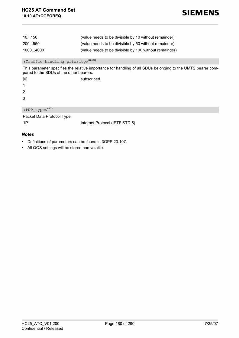
HC25 AT Command Set 10.10 AT+CGEQREQ s
HC25_ATC_V01.200 Page 180 of 290 7/25/07Confidential / Released
10...150 (value needs to be divisible by 10 without remainder)200...950 (value needs to be divisible by 50 without remainder)1000...4000 (value needs to be divisible by 100 without remainder)
This parameter specifies the relative importance for handling of all SDUs belonging to the UMTS bearer com-pared to the SDUs of the other bearers. [0] subscribed123
Packet Data Protocol Type“IP“ Internet Protocol (IETF STD 5)
Notes• Definitions of parameters can be found in 3GPP 23.107.• All QOS settings will be stored non volatile.
<Traffic handling priority>(num)
<PDP_type>(str)

HC25 AT Command Set 10.11 AT+CGSMS s
HC25_ATC_V01.200 Page 181 of 290 7/25/07Confidential / Released
10.11 AT+CGSMS Select service for MO SMS messages
Syntax
Command DescriptionThe test command is used for requesting information on which services and service preferences can be set byusing the AT+CGSMS write command The read command returns the currently selected service or service preference. The write command is used to specify the service or service preference that the MT will use to send MO SMSmessages.
Parameter Description
A numeric parameter which indicates the service or service preference to be used. Parameter is global for allinterfaces and non-volatile. 0 GPRS1 Circuit switched2(D) GPRS preferred (use circuit switched SMS transfer if mobile is not GPRS
attached) 3 Circuit switched preferred (use GPRS if circuit switched is not available)
Test Command
AT+CGSMS=?Response(s)
+CGSMS: (list of supported <service>s)OK
Read Command
AT+CGSMS?Response(s)
+CGSMS: <service>OK
Write Command
AT+CGSMS=<service>Response(s)
OKERROR+CME ERROR
Reference(s) PIN USB0-MDM USB0-APP Last
3GPP 27.007 + + + -
<service>(num)
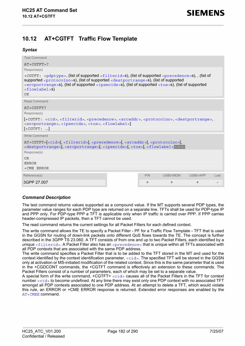
HC25 AT Command Set 10.12 AT+CGTFT s
HC25_ATC_V01.200 Page 182 of 290 7/25/07Confidential / Released
10.12 AT+CGTFT Traffic Flow Template
Syntax
Command DescriptionThe test command returns values supported as a compound value. If the MT supports several PDP types, theparameter value ranges for each PDP type are returned on a separate line. TFTs shall be used for PDP-type IPand PPP only. For PDP-type PPP a TFT is applicable only when IP traffic is carried over PPP. If PPP carriesheader-compressed IP packets, then a TFT cannot be used. The read command returns the current settings for all Packet Filters for each defined context. The write command allows the TE to specify a Packet Filter - PF for a Traffic Flow Template - TFT that is usedin the GGSN for routing of down-link packets onto different QoS flows towards the TE. The concept is furtherdescribed in the 3GPP TS 23.060. A TFT consists of from one and up to two Packet Filters, each identified by aunique <filterid>. A Packet Filter also has an <precedence> that is unique within all TFTs associated withall PDP contexts that are associated with the same PDP address. The write command specifies a Packet Filter that is to be added to the TFT stored in the MT and used for thecontext identified by the context identification parameter, <cid>. The specified TFT will be stored in the GGSNonly at activation or MS-initiated modification of the related context. Since this is the same parameter that is usedin the +CGDCONT commands, the +CGTFT command is effectively an extension to these commands. ThePacket Filters consist of a number of parameters, each of which may be set to a separate value. A special form of the write command, +CGTFT= <cid> causes all of the Packet Filters in the TFT for contextnumber <cid> to become undefined. At any time there may exist only one PDP context with no associated TFTamongst all PDP contexts associated to one PDP address. At an attempt to delete a TFT, which would violatethis rule, an ERROR or +CME ERROR response is returned. Extended error responses are enabled by theAT+CMEE command.
Test Command
AT+CGTFT=?Response(s)
+CGTFT: <pdptype>, (list of supported <filterid>s), (list of supported <precedence>s), , (list of supported <protocolno>s), (list of supported <destportrange>s), (list of supported <srcportrange>s), (list of supported <ipsecidx>s), (list of supported <tos>s), (list of supported <flowlabel>s)OK
Read Command
AT+CGTFT?Response(s)
[+CGTFT: <cid>, <filterid>, <precedence>, <srcaddr>, <protocolno>, <destportrange>, <srcportrange>, <ipsecidx>, <tos>, <flowlabel>][+CGTFT: ...]
Write Command
AT+CGTFT=[<cid>[, <filterid>[, <precedence>[, <srcaddr>[, <protocolno>[, <destportrange>[, <srcportrange>[, <ipsecidx>[, <tos>[, <flowlabel>]]]]]]]]]]Response(s)
OKERROR+CME ERROR
Reference(s) PIN USB0-MDM USB0-APP Last
3GPP 27.007 + + + -

HC25 AT Command Set 10.12 AT+CGTFT s
HC25_ATC_V01.200 Page 183 of 290 7/25/07Confidential / Released
Parameter Description
Parameter specifies a particular PDP context definition. The parameter is local to the TE-MT interface and isused in other PDP context-related commands. 1...16
Packet filter identifierParameter specifies a packet filter identifier. 1...2
Evaluation Precedence IndexParameter specifies a evaluation precedence index. 0...255
Source address and subnet maskParameter specifies a source address and subnet mask. 0.0.0.0.0.0.0.0...255.255.255.255.255.255.255.255
Protocol numberParameter specifies the protocol number (ipv4) / next header (ipv6). 0...255
Destination port rangeParameter specifies the destination port range. 0.0...65535.65535
Source port rangeParameter specifies the source port range. 0.0...65535.65535
IPsec security parameter indexParameter specifies the IPsec security parameter index (spi). 0...FFFFFFFF
Type of service and mask/traffic classParameter specifies the type of service (tos)(ipv4) and mask/traffic class (ipv6). 0.0...255.255
<cid>(num)
<filterid>(num)
<precedence>(num)
<srcaddr>(str)
<protocolno>(num)
<destportrange>(str)
<srcportrange>(str)
<ipsecidx>(str)
<tos>(str)

HC25 AT Command Set 10.12 AT+CGTFT s
HC25_ATC_V01.200 Page 184 of 290 7/25/07Confidential / Released
Flow labelParameter specifies the flow label (ipv6). 0...FFFFF
PDP typeParameter specifies the PDP type. “IP“
Note• Some of the above listed attributes may coexist in a Packet Filter while others mutually exclude each other,
the possible combinations are shown in 3GPP TS 23.060.
<flowlabel>(str)
<pdptype>(str)

HC25 AT Command Set 10.13 ATD*99# s
HC25_ATC_V01.200 Page 185 of 290 7/25/07Confidential / Released
10.13 ATD*99# Request GPRS service
This command causes the MT to perform whatever actions are necessary to establish a communication betweenthe TE and the external PDN.The V.250 'D' (Dial) command causes the MT to enter the V.250 online data state and, with the TE, to start thespecified layer 2 protocol. No further commands may follow on the AT command line. GPRS attachment andPDP context activation procedures may take place prior to or during the PDP startup if they have not alreadybeen performed using the AT+CGATT and AT+CGACT commands. To confirm acceptance of the command before entering the V.250 online data state command will respond withCONNECT. The application that initiates the PPP mode must be designed to start all LCP configure requests in accordancewith TS 27.060 par 9.1. Otherwise the MT remains, after the CONNECT, infinitely in a waiting state. When the layer 2 protocol has terminated, either as a result of an orderly shut down of the PDP or an error, theMT enters V.250 command state and returns NO CARRIER (for details refer to Section 10.3.1, Automatic deac-tivation of PDP context during dial-up PPP).
Syntax
Parameter Description
IP V4 address in the form w.x.y.z, which identifies the called party; if it is provided, the MT will automatically setup a virtual call to the specified address after the context has been activated.
Layer 2 protocol to be used between the TE and MT. “PPP“ layer 2 protocol PPP“1“ layer 2 protocol PPP
Parameter specifies a particular PDP context definition (see AT+CGDCONT command). [1]...16
Exec Command
ATD*99[* [<called_address>][* [<L2P>][* [<cid>]]]]# Response(s)
CONNECTNO CARRIER
Reference(s) PIN USB0-MDM USB0-APP Last
3GPP TS 27.007 + + - +
<called_address>(str)
<L2P>(str)
<cid>(num)

HC25 AT Command Set 10.14 AT^SGAUTH s
HC25_ATC_V01.200 Page 186 of 290 7/25/07Confidential / Released
10.14 AT^SGAUTH Set type of authentication for PDP-IP connections
Syntax
Parameter Description
Parameter specifies a particular PDP context definition. This is also used in other PDP context-related com-mands. 1...16
Indicates the types of authentication to be used for the specified context. If CHAP is selected another parameter<passwd> needs to be specified. If PAP is selected two additional parameters <passwd> and <user> need tospecified. [0] none1 PAP2 CHAP
Parameter specifies the password used for authentication. It is required for the authentication types PAP andCHAP.
Test Command
AT^SGAUTH=?Response(s)
^SGAUTH:(range of supported<cid>s), (list of supported <auth_type>s), , OKERROR+CME ERROR
Read Command
AT^SGAUTH?Response(s)
^SGAUTH:<cid>, <auth_type>[, <user>]^SGAUTH:<cid>, <auth_type>[, <user>]...OKERROR+CME ERROR
Write Command
AT^SGAUTH=<cid>[, <auth_type>[, <passwd>[, <user>]]]Response(s)
OKERROR+CME ERROR
PIN USB0-MDM USB0-APP Last
+ + + -
<cid>(num)
<auth_type>(num)
<passwd>(str)
HC25 AT Command Set 10.14 AT^SGAUTH s
HC25_ATC_V01.200 Page 187 of 290 7/25/07Confidential / Released
Parameter specifies the user name used for authentication. It is required for the authentication type PAP.
Note• All settings will be stored non volatile.
<user>(str)

HC25 AT Command Set 11. FAX Commands s
HC25_ATC_V01.200 Page 188 of 290 7/25/07Confidential / Released
11. FAX Commands
This chapter describes the AT commands used for fax communications. If the ME is acting as a fax modem for a PC based fax application (e.g. "WinFax") it is necessary to select theproper Service Class (Fax Class) provided by the ME. The ME reports its Service Class capabilities, i.e. the cur-rent setting and the range of services available. This is provided by the AT+FCLASS command.
11.1 AT+FCLASS Set the Service Class of a facsimile DCE
AT+FCLASS sets the ME to a particular mode of operation (data, fax). This allows the ME to process informationin a manner suitable for that type of information.
Syntax
Parameter Description
0 Data (e.g. EIA/TIA-602 or ITU V.250)1 Fax class 1 (EIA/TIA-578-A, Service Class 1)
Test Command
AT+FCLASS=?Response(s)
(list of supported <n>s)OK
Read Command
AT+FCLASS?Response(s)
<n>OK
Write Command
AT+FCLASS=<n>Response(s)
OK
Reference(s) PIN USB0-MDM USB0-APP Last
EIA/TIA-592-A + + + -
<n>(num)

HC25 AT Command Set 11.2 AT+FAR s
HC25_ATC_V01.200 Page 189 of 290 7/25/07Confidential / Released
11.2 AT+FAR Adaptive Rate Control
The AT+FAR command can be used to disable the DCE's ability to adaptively detect the selected message carrieror V.21 control message and to adjust +FRM processing accordingly.
Syntax
Parameter Description
0 Adaptive reception disabled.
Test Command
AT+FAR=?Response(s)
+FAR: (list of supported <n>s)OK
Read Command
AT+FAR?Response(s)
+FAR: <n>OK
Exec Command
AT+FARResponse(s)
OK
Write Command
AT+FAR=<n>Response(s)
OK
Reference(s) PIN USB0-MDM USB0-APP Last
EIA/TIA-592-A + + + -
<n>(num)

HC25 AT Command Set 11.3 AT+FDD s
HC25_ATC_V01.200 Page 190 of 290 7/25/07Confidential / Released
11.3 AT+FDD Double Escape Character Replacement
The AT+FDD command specifies how to use the (DLE) (SUB) pair to encode consecutive (1/0) (1/0) in data.
Syntax
Parameter Description
0-1
Test Command
AT+FDD=?Response(s)
+FDD: (list of supported <v>s)OK
Read Command
AT+FDD?Response(s)
+FDD: <v>OK
Exec Command
AT+FDDResponse(s)
OK
Write Command
AT+FDD=<v>Response(s)
OK
Reference(s) PIN USB0-MDM USB0-APP Last
EIA/TIA-592-A + + + -
<v>(num)

HC25 AT Command Set 11.4 AT+FCL s
HC25_ATC_V01.200 Page 191 of 290 7/25/07Confidential / Released
11.4 AT+FCL Carrier Loss Timeout
The AT+FCL command specifies the duration (time*100 millisecond) used by DCE to terminate the session if noactivity is detected on the carrier, i.e. the OTA interface.
Syntax
Parameter Description
Time0-255
Test Command
AT+FCL=?Response(s)
+FCL: (list of supported <n>s)OK
Read Command
AT+FCL?Response(s)
+FCL: <n>OK
Exec Command
AT+FCLResponse(s)
OK
Write Command
AT+FCL=<n>Response(s)
OK
Reference(s) PIN USB0-MDM USB0-APP Last
EIA/TIA-592-A + + + -
<n>(num)

HC25 AT Command Set 11.5 AT+FIT s
HC25_ATC_V01.200 Page 192 of 290 7/25/07Confidential / Released
11.5 AT+FIT DTE Inactivity Timeout
The AT+FIT command specifies the duration (in second) used by the DCE to terminate the session if the DTEfails to respond.
Syntax
Parameter Description
Time0-255
Action0, 1; Action 0 and 1 are treated the same, i.e. terminate the T.31 session
Test Command
AT+FIT=?Response(s)
+FIT: (list of supported <t>s), (list of supported <a>s)OK
Read Command
AT+FIT?Response(s)
+FIT: <t>, <a>OK
Exec Command
AT+FITResponse(s)
OK
Write Command
AT+FIT=<t><a>Response(s)
OK
Reference(s) PIN USB0-MDM USB0-APP Last
EIA/TIA-592-A + + + -
<t>(num)
<a>(num)

HC25 AT Command Set 11.6 AT+FTS s
HC25_ATC_V01.200 Page 193 of 290 7/25/07Confidential / Released
11.6 AT+FTS Transmit silence
AT+FTS directs DCE to stop the transmission for the specified amount of time (in 10 millisecond increments).
Syntax
Parameter Description
No. of 10 millisecond intervals 0...255
Note• Used for Fax Class 1 only
Test Command
AT+FTS=?Response(s)
+FTS: (list of supported <Time>s)OKERROR
Write Command
AT+FTS=<Time>Response(s)
OKIn on-hook mode:ERROR
Reference(s) PIN USB0-MDM USB0-APP Last
TIA/EIA-578 + + + -
<Time>(num)

HC25 AT Command Set 11.7 AT+FRS s
HC25_ATC_V01.200 Page 194 of 290 7/25/07Confidential / Released
11.7 AT+FRS Receive Silence
AT+FRS directs the DCE to listen for silence from the remote end and report back OK when silence has beendetected for the specified amount of time (in 10 millisecond increments). Command is abortable.
Syntax
Parameter Description
Number of 10 millisecond intervals 0...255
Note• Used for Fax Class 1 only
Test Command
AT+FRS=?Response(s)
+FRS: (list of supported <Time>s)OKERROR
Write Command
AT+FRS=<Time>Response(s)
OKIf error is related to ME functionality:ERROR
Reference(s) PIN USB0-MDM USB0-APP Last
TIA/EIA-578 + + + -
<Time>(num)

HC25 AT Command Set 11.8 AT+FTM s
HC25_ATC_V01.200 Page 195 of 290 7/25/07Confidential / Released
11.8 AT+FTM Transmit message
AT+FTM directs the DCE to transmit T.30 facsimile message data using the specified modulation scheme.
Syntax
Parameter Description
Modulation scheme 72 V.29 - 7200 bps 73 V.17 - 7200 bps 74 V.17 - 7200 bps 96 V.29 - 9600 bps 97 V.17 - 9600 bps 98 V.17 - 9600 bps
Test Command
AT+FTM=?Response(s)
(list of <mod>s)OK
Write Command
AT+FTM=<mod>Response(s)
CONNECTIf error is related to ME functionality:ERROR
Reference(s) PIN USB0-MDM USB0-APP Last
TIA/EIA-578 + + - -
<mod>(num)

HC25 AT Command Set 11.9 AT+FRM s
HC25_ATC_V01.200 Page 196 of 290 7/25/07Confidential / Released
11.9 AT+FRM Receive message
AT+FRM directs the DCE to receive T.30 facsimile message data using the specified modulation scheme. Com-mand is abortable.
Syntax
Parameter Description
Modulation scheme 72 V.29 - 7200 bps 73 V.17 - 7200 bps 74 V.17 - 7200 bps 96 V.29 - 9600 bps 97 V.17 - 9600 bps 98 V.17 - 9600 bps
Test Command
AT+FRM=?Response(s)
(list of <mod>s)OK
Write Command
AT+FRM=<mod>Response(s)
CONNECTIf error is related to ME functionality:ERROR
Reference(s) PIN USB0-MDM USB0-APP Last
TIA/EIA-578 + + - -
<mod>(num)

HC25 AT Command Set 11.10 AT+FTH s
HC25_ATC_V01.200 Page 197 of 290 7/25/07Confidential / Released
11.10 AT+FTH Transmit Data Using HDLC Framing
AT+FTH directs the DCE to transmit T.30 HDLC data using the modulation scheme "3".
Syntax
Parameter Description
Modulation scheme 3 Clause 2/V.21 - 300 bps
Test Command
AT+FTH=?Response(s)
In off-hook mode only:+FTH:(list of <mod>s)OKIn on-hook mode:ERROR
Write Command
AT+FTH=<mod>Response(s)
CONNECT
Reference(s) PIN USB0-MDM USB0-APP Last
TIA/EIA-578 + + - -
<mod>(num)

HC25 AT Command Set 11.11 AT+FRH s
HC25_ATC_V01.200 Page 198 of 290 7/25/07Confidential / Released
11.11 AT+FRH Receive Data Using HDLC Framing
AT+FRH directs the DCE to transmit T.30 HDLC data using the specified modulation scheme "3".
Syntax
Parameter Description
Modulation scheme 3 Clause 2/V.21 - 300 bps
Note• Used for Fax Class 1 only.
Test Command
AT+FRH=?Response(s)
In off-hook mode only:+FRH:(list of <mod>s)OKIn on-hook mode:ERROR
Write Command
AT+FRH=<mod>Response(s)
CONNECTIf error is related to ME functionalityERROR
Reference(s) PIN USB0-MDM USB0-APP Last
TIA/EIA-578 + + - -
<mod>(num)

HC25 AT Command Set 12. Short Message Service (SMS) Commands s
HC25_ATC_V01.200 Page 199 of 290 7/25/07Confidential / Released
12. Short Message Service (SMS) Commands
The AT Commands described in this chapter allow an external application to use the Short Message Service withthe HC25.
12.1 SMS parameters
Parameter Description
Format is same for <pdu> in case of SMS, but without GSM 24.11 SC address field and parameter shall bebounded by double quote characters like a normal string type rarameter
String type alphanumeric representation of <da> or <oa> corresponding to the entry found in phonebook; imple-mentation of this feature is manufacturer specific
Command TypeGSM 03.40 TP-Command-Type in integer format [0]...255
Destination AddressGSM 03.40 TP- Destination-Address Address-Value field in string format; BCD numbers (or GSM default alpha-bet characters) are converted into characters; type of address given by <toda>
User DataIn case of SMS: GSM 03.40 TP-User-Data in text mode responses; format:• If <dcs> indicates that GSM 03.38 default alphabet is used and <fo> indicates that GSM 03.40 TP-User-
Data-Header-Indication is not set: ME/TA converts GSM alphabet into current TE character set according torules covered in Annex A.
• If <dcs> indicates that 8-bit or UCS2 data coding scheme is used, or <fo> indicates that GSM 03.40 TP-User-Data-Header-Indication is set: ME/TA converts each 8-bit octet into hexadecimal numbers con-tainingtwo IRA characters (e.g. octet with integer value 42 is presented to TE as two characters 2A (IRA 50 and 65).
In case of CBS: GSM 03.41 CBM Content of Message in text mode responses; format:• If <dcs> indicates that GSM 03.38 default alphabet is used: ME/TA converts GSM alphabet into current TE
character set according to rules covered in Annex A.• If <dcs> indicates that 8-bit or UCS2 data coding scheme is used: ME/TA converts each 8-bit octet into hexa-
decimal numbers containing two IRA characters.
Discharge TimeGSM 03.40 TP-Discharge-Time in time-string format: "yy/MM/dd,hh:mm:ss+zz", where characters indicate year(two last digits), month, day, hour, minutes, seconds and time zone. For example, 6th of May 1994, 22:10:00GMT+2 hours equals "94/05/06,22:10:00+08"
<ackpdu>(num)
<alpha>(str)(+CSCS)
<ct>(num)
<da>(str)(+CSCS)
<data>(num)(+CSCS)
<dt>(num)

HC25 AT Command Set 12.1 SMS parameters s
HC25_ATC_V01.200 Page 200 of 290 7/25/07Confidential / Released
Integer type; value in the range of location numbers supported by the associated memory. Indexing starts from0.
Message LengthInteger type value indicating in PDU mode (AT+CMGF=0), the length of the actual TP data unit in octets (i.e. theRP layer SMSC address octets are not counted in the length).
Memory to be used when listing, reading and deleting messages: “SM“ SIM message storage“ME“ Mobile Equipment message storage“MT“ Same as "ME" storage
Memory to be used when writing and sending messages: “SM“ SIM message storage“ME“ Mobile Equipment message storage“MT“ Same as "ME" storage
Received messages will be placed in this memory storage if routing to TE is not set. See command AT+CNMIwith parameter <mt>=2. “SM“ SIM message storage“ME“ Mobile Equipment message storage“MT“ Same as "ME" storage
Message IdentifierGSM 03.41 CBM Message Identifier in integer format
Message NumberGSM 03.40 TP-Message-Number in integer format
Message ReferenceGSM 03.40 TP-Message-Reference in integer format
Originating AddressGSM 03.40 TP-Originating-Address Address-Value field in string format; BCD numbers (or GSM default alpha-bet characters) are converted into characters; type of address given by <tooa>
<index>(num)
<length>(num)
<mem1>(str)
<mem2>(str)
<mem3>(str)
<mid>(num)
<mn>(num)
<mr>(num)
<oa>(str)(+CSCS)

HC25 AT Command Set 12.1 SMS parameters s
HC25_ATC_V01.200 Page 201 of 290 7/25/07Confidential / Released
Page ParameterGSM 03.41 CBM Page Parameter bits 4-7 in integer format
Page ParameterGSM 03.41 CBM Page Parameter bits 0-3 in integer format
In the case of SMS: GSM 04.11 SC address followed by GSM 03.40 TPDU in hexadecimal format: ME/TA con-verts each octet of TP data unit into hexadecimal numbers containing two IRA characters (e.g. octet with integervalue 42 is presented to TE as two characters 2A (IRA 50 and 65)). In the case of CBS: <ra> GSM 03.40 TP-Recipient-Address Ad-dress-Value field in string format; BCD numbers (or GSM default alphabet characters)are converted into characters; type of address given by <tora>
Recipient AddressGSM 03.40 TP-Recipient-Address Address-Value field in string format; BCD numbers (or GSM default alphabetcharacters) are converted to characters of the currently selected TE character set (refer to commandAT+CSCS.); type of address given by <tora>
Service Center AddressGSM 04.11 RP SC address Address-Value field in string format; BCD numbers (or GSM default alphabet char-acters) are converted to characters of the currently selected TE character set (refer to command AT+CSCS); typeof address given by <tosca>
Service Centre Time StampGSM 03.40 TP-Service-Centre-Time-Stamp in time-string format (refer <dt>)
Serial NumberGSM 03.41 CBM Serial Number in integer format
StatusGSM 03.40 TP-Status in integer format 0...255
Message status3GPP 27.005 Interface of SMS and CB. Indicates the status of message in memory.
<page>(num)
<pages>(num)
<pdu>(num)
<ra>(str)(+CSCS)
<sca>(str)(+CSCS)
<scts>(num)
<sn>(num)
<st>(num)
<stat>(str)

HC25 AT Command Set 12.1 SMS parameters s
HC25_ATC_V01.200 Page 202 of 290 7/25/07Confidential / Released
Type of Destination AddressGSM 04.11 TP-Destination-Address Type-of-Address octet in integer format (when first character of <da> is +(IRA 43) default is 145, otherwise default is 129) 0...255
Type of Originating AddressGSM 04.11 TP-Originating-Address Type-of-Address octet in integer format (default refer <toda>)
Type of Recipient AddressGSM 04.11 TP-Recipient-Address Type-of-Address octet in integer format (default refer <toda>)
Type of Service Center AddressGSM 04.11 RP SC address Type-of-Address octet in integer format (default refer <toda>)
Description text mode (<mode>=1) PDU mode (<mode>=0) DefaultReceived unread mes-sages
"REC UNREAD" 0 for SMS reading com-mands
Received read messages "REC READ" 1 Stored unsent messages "STO UNSENT" 2 for SMS writing com-
mands Stored sent messages "STO SENT" 3 All messages "ALL" 4
<toda>(num)
<tooa>(num)
<tora>(num)
<tosca>(num)

HC25 AT Command Set 12.2 AT+CMGC s
HC25_ATC_V01.200 Page 203 of 290 7/25/07Confidential / Released
12.2 AT+CMGC Send an SMS command
Syntax
Note• After invoking the commands AT+CMGW, AT+CMGS or AT+CMGC it is necessary to wait for the prompt ">"
before entering text or PDU. After the prompt a timer will be started to observe the input.
Test Command
AT+CMGC=?Response(s)
OK
Write Command
If text mode (see AT+CMGF=1) AT+CMGC=<fo>, <ct>[, <pid>[, <mn>[, <da>[, <toda>]]]]<CR> Text can be entered <CTRL-Z>/<ESC>Response(s)
+CMGC: <mr>[, <scts>]If sending failsERROR+CMS ERROR
Write Command
If PDU mode (see AT+CMGF=0) AT+CMGC=<length><CR> PDU can be entered <CTRL-Z>/<ESC>Response(s)
+CMGC: <mr>[, <ackpdu>]OKERROR+CMS ERROR
Reference(s) PIN USB0-MDM USB0-APP Last
GSM 07.05 + + + -

HC25 AT Command Set 12.3 AT+CMGD s
HC25_ATC_V01.200 Page 204 of 290 7/25/07Confidential / Released
12.3 AT+CMGD Delete short message
The write command deletes a short message from the preferred message storage <mem1> location <index>.
Syntax
Notes• If there is no short message stored at the selected index, the response is OK too. • Users should be aware that error will occur when using this AT command quickly after SIM PIN authentication
due to the fact the SIM data may not yet be accessible.
Test Command
AT+CMGD=?Response(s)
OK
Write Command
AT+CMGD=<index>Response(s)
OKERROR+CMS ERROR
Reference(s) PIN USB0-MDM USB0-APP Last
GSM 07.05 + + + -

HC25 AT Command Set 12.4 AT+CMGF s
HC25_ATC_V01.200 Page 205 of 290 7/25/07Confidential / Released
12.4 AT+CMGF Select SMS message format
Syntax
Command DescriptionThe write command specifies the input and output format of the short messages.
Parameter Description
[0](&F) PDU mode 1 Text mode
Test Command
AT+CMGF=?Response(s)
+CMGF: (list of supported<mode>s)OK
Read Command
AT+CMGF?Response(s)
+CMGF: <mode>OK
Write Command
AT+CMGF=<mode>Response(s)
OK
Reference(s) PIN USB0-MDM USB0-APP Last
GSM 07.05 + + + -
<mode>(num)

HC25 AT Command Set 12.5 AT+CMGL s
HC25_ATC_V01.200 Page 206 of 290 7/25/07Confidential / Released
12.5 AT+CMGL List SMS messages from preferred store
The write command returns messages with status value <stat> from message storage <mem1> to the TE. If thestatus of the message is 'received unread', the status in the storage changes to 'received read'.The execute command is the same as the write command with the given default for <stat>.
SyntaxTest Command
AT+CMGL=?Response(s)
+CMGL: (list of supported <stat>s)OK
Exec Command
AT+CMGLResponse(s)
+CMGL: (see write command for default of <stat>)OK
Write Command
AT+CMGL=<stat>Response(s)
Output if text mode (AT+CMGF=1) and command successful: For SMS- SUBMITs and/or SMS-DELIVERs +CMGL: <index>, <stat>, <oa>/<da>, [<alpha>], [<scts>][, <tooa>/<toda>, <length>]<data>[... ]OK
For SMS-STATUS-REPORTs +CMGL: <index>, <stat>, <fo>, <mr>, [<ra>], [<tora>], <scts>, <dt>, <st>[... ]OK
For SMS-Commands +CMGL: <index>, <stat>, <fo>, <ct>[... ]OK
Output if PDU mode AT+CMGF=0 and command successful: For SMS-SUBMITs and/or SMS-DELIVERs +CMGL: <index>, <stat>, [<alpha>], <length><pdu>[... ]OK
If error is related to ME functionalityERROR +CMS ERROR
Reference(s) PIN USB0-MDM USB0-APP Last
GSM 07.05 + + + -

HC25 AT Command Set 12.5 AT+CMGL s
HC25_ATC_V01.200 Page 207 of 290 7/25/07Confidential / Released
Notes• The selected <mem1> can contain different types of SMs (e.g. SMS-DELIVERs, SMS-SUBMITs, SMS-STA-
TUS-REPORTs and SMS-COMMANDs), the response may be a mix of the responses of different SM types.TE application can recognize the response format by examining the third response parameter.
• Users should be aware that error will occur when using this AT command quickly after SIM PIN authenticationdue to the fact the SIM data may not yet be accessible.

HC25 AT Command Set 12.6 AT+CMGR s
HC25_ATC_V01.200 Page 208 of 290 7/25/07Confidential / Released
12.6 AT+CMGR Read SMS messages
The write command returns SMS message with location value <index> from message storage <mem1> to theTE. If status of the message is 'received unread', status in the storage changes to 'received read'.
SyntaxTest Command
AT+CMGR=?Response(s)
OK
Write Command
AT+CMGR=<index>Response(s)
Output if text mode (AT+CMGF=1) and command successful: For SMS-DELIVER +CMGR: <stat>, <oa>, [<alpha>], <scts>[, <tooa>, <fo>, <pid>, <dcs>, <sca>, <tosca>, <length>]<data>[... ]OK
For SMS-SUBMIT +CMGR: <stat>, <da>, [<alpha>][, <toda>, <fo>, <pid>, <dcs>, [<vp>], <sca>, <tosca>, <length>]<data>[... ]OK
For SMS-STATUS-REPORT +CMGR: <stat>, <fo>, <mr>, [<ra>], [<tora>], <scts>, <dt>, <st><data>[... ]OK
For SMS-Commands +CMGR: <stat>, <fo>, <ct>[, <pid>, [<mn>], [<da>], [<toda>], <length>]<data>[... ]OK
Output if PDU mode (AT+CMGF=0) and command successful: For SMS-SUBMITs and/or SMS-DELIVERs +CMGR: <stat>, [<alpha>], <length><pdu>[... ]OKERROR+CMS ERROR
Reference(s) PIN USB0-MDM USB0-APP Last
GSM 07.05 + + + -

HC25 AT Command Set 12.6 AT+CMGR s
HC25_ATC_V01.200 Page 209 of 290 7/25/07Confidential / Released
Notes• If AT+CMGR is used to read an empty record the response is: OK. • If AT+CMGR is used to read a non-existent record index the response is: +CMS ERROR: 321 (invalid memory
index). • Users should be aware that error will occur when using this AT command quickly after SIM PIN authentication
due to the fact the SIM data may not yet be accessible.

HC25 AT Command Set 12.7 AT+CMGS s
HC25_ATC_V01.200 Page 210 of 290 7/25/07Confidential / Released
12.7 AT+CMGS Send Short Message
The write command transmits a short message from TE to network (SMS-SUBMIT).After invoking the write command wait for the prompt ">" and then start to write the message. To send the mes-sage simply enter <CTRL-Z>. After the prompt a timer will be started to observe the input.To abort sending use <ESC>. Abortion is acknowledged with "OK", though the message will not be sent.The message reference <mr> is returned to the TE on successful message delivery. The value can be used toidentify the message in a delivery status report provided as an unsolicited result code.
Syntax
Notes• Note that some providers do not recognize an @ symbol used in a short message. A widely used alternative
is typing "*" as defined in GSM 03.40 (GPP TS 23.40). • Message Length in Text Mode
The maximum length of a short message depends on the used coding scheme: It is 160 characters if the 7bit GSM coding scheme is used, and 140 characters according to the 8 bit GSM coding scheme.
Test Command
AT+CMGS=?Response(s)
OK
Write Command
If text mode (see AT+CMGF=1) AT+CMGS=<da>[, <toda>]<CR> Text can be entered. <CTRL-Z>/<ESC>Response(s)
+CMGS: <mr>[, <scts>]OKERROR+CMS ERROR
Write Command
If PDU mode (see AT+CMGF=0) AT+CMGS=<length><CR> PDU can be entered. <CTRL-Z>/<ESC>Response(s)
+CMGS: <mr>[, <ackpdu>]OKERROR+CMS ERROR
Reference(s) PIN USB0-MDM USB0-APP Last
GSM 07.05 + + + -

HC25 AT Command Set 12.8 AT+CMGW s
HC25_ATC_V01.200 Page 211 of 290 7/25/07Confidential / Released
12.8 AT+CMGW Write Short Messages to Memory
The execute and write commands transmit a short message (either SMS-DELIVER or SMS-SUBMIT) from TEto memory storage <mem2>. Memory location <index> of the stored message is returned. Message status willbe set to 'stored unsent' unless otherwise given in parameter <stat>.After invoking the execute or write command wait for the prompt ">" and then start to write the message. To savethe message simply enter <CTRL-Z>. To abort writing use <ESC>. Abortion is acknowledged with "OK", though the message will not be saved.
Syntax
Notes• Note that some providers do not recognize an @ symbol used in a short message. A widely used alternative
is typing "*" as defined in GSM 03.40 (GPP TS 23.40). • Message Length in Text Mode
The maximum length of a short message depends on the used coding scheme: It is 160 characters if the 7bit GSM coding scheme is used, and 140 characters according to the 8 bit GSM coding scheme.
Test Command
AT+CMGW=?Response(s)
OK
Exec Command
If text mode (see AT+CMGF=1): AT+CMGWResponse(s)
<CR> Text can be entered. <CTRL-Z>/<ESC> +CMGW: <index>OKERROR+CMS ERROR
Write Command
If text mode (see AT+CMGF=1): AT+CMGW=<oa>/<da>[, [<tooa>/<toda>][, <stat>]]<CR> Text can be entered. <CTRL-Z>/<ESC>Response(s)
+CMGW: <index>OKERROR+CMS ERROR
Write Command
If PDU mode (see AT+CMGF=0): AT+CMGW=<length>[, <stat>]<CR> PDU can be entered. <CTRL-Z>/<ESC>Response(s)
+CMGW: <index>OKIf writing fails see notes below.
Reference(s) PIN USB0-MDM USB0-APP Last
GSM 07.05 + + + -

HC25 AT Command Set 12.9 AT+CMMS s
HC25_ATC_V01.200 Page 212 of 290 7/25/07Confidential / Released
12.9 AT+CMMS More Messages to Send
The AT+CMMS write command controls the continuity of the SMS relay protocol link. When the feature is enabled(and supported by network) multiple messages can be sent much faster as the link is kept open.
Syntax
Parameter Description
[0] Disable 1 Keep link enabled until the time between the response of the latest message
send command (AT+CMGS, AT+CMSS, etc.) and the next send commandexceeds 1-5 seconds. Then the ME will close the link and TA switch <mode>automatically back to <mode> 0.
2 Enable (if the time between the response of the latest message send commandand the next send command exceeds 1-5 seconds. Then the ME will close thelink, but TA will not switch automatically back to <mode>=0).
Note• After issuing the read command a delay of 5-10 seconds is required before issuing the write command, oth-
erwise the "+CMS ERROR: 500" will appear.
Test Command
AT+CMMS=?Response(s)
+CMMS: (list of supported) <mode>s
Read Command
AT+CMMS?Response(s)
+CMMS: <mode>OK
Write Command
AT+CMMS=<mode>Response(s)
OKERROR+CMS ERROR
Reference(s) PIN USB0-MDM USB0-APP Last
GSM 07.05 + + + -
<mode>(num)

HC25 AT Command Set 12.10 AT+CMSS s
HC25_ATC_V01.200 Page 213 of 290 7/25/07Confidential / Released
12.10 AT+CMSS Send short messages from storage
The write command sends message with location value <index> from message storage <mem2> to the network(SMS-SUBMIT or SMS-COMMAND). If new recipient address <da> is given for SMS-SUBMIT, it shall be usedinstead of the one stored with the message. Reference value <mr> is returned to the TE on successful messagedelivery. Value can be used to identify message upon unsolicited delivery status report result code.If the optional parameter <da> is given, the old status of the short message at <index> remains unchanged(see <stat>).
SyntaxTest Command
AT+CMSS=?Response(s)
OK
Write Command
If text mode (AT+CMGF=1): AT+CMSS=<index>[, <da>[, <toda>]]Response(s)
+CMSS: <mr>[, <scts>]OKIf sending failsERROR+CMS ERROR
Write Command
If PDU mode (AT+CMGF=0): AT+CMSS=<index>[, <da>[, <toda>]]Response(s)
+CMSS: <mr>[, <ackpdu>]OKERROR+CMS ERROR
Reference(s) PIN USB0-MDM USB0-APP Last
GSM 07.05 + + + -

HC25 AT Command Set 12.11 AT+CNMA s
HC25_ATC_V01.200 Page 214 of 290 7/25/07Confidential / Released
12.11 AT+CNMA New Message Acknowledgement to ME/TE, only phase 2+
The write / execute command confirms successful receipt of a new message (SMS-DELIVER or SMS-STATUS-REPORT) routed directly to the TE. If ME does not receive acknowledgement within required time (network time-out), it will send RP-ERROR to the network. In this case routing to the TE will be disabled automatically by settingboth <mt> and <ds> values of AT+CNMI to zero.
Syntax
Parameter Description
Parameter required only for PDU mode.0 Command operates similarly as in text mode. 1 Send positive (RP-ACK) acknowledgement to the network. Accepted only in
PDU mode. 2 Send negative (RP-ERROR) acknowledgement to the network. Accepted only
in PDU mode.
Note• The execute / write command shall only be used when AT+CSMS parameter <service> equals 1 (= phase
2+) and appropriate URC has been issued by the module, i.e.: <+CMT> for <mt>=2 incoming message classes 0,1,3 and none;<+CMT> for <mt>=3 incoming message classes 0 and 3;<+CDS> for <ds>=1.
Test Command
AT+CNMA=?Response(s)
+CNMA: (list of supported <n>s)OK
Exec Command
AT+CNMAResponse(s)
OKERROR+CMS ERROR
Write Command
AT+CNMA=<n>Response(s)
OKERROR+CMS ERROR
Reference(s) PIN USB0-MDM USB0-APP Last
GSM 07.05 + + + -
<n>(num)

HC25 AT Command Set 12.12 AT+CNMI s
HC25_ATC_V01.200 Page 215 of 290 7/25/07Confidential / Released
12.12 AT+CNMI New short Message Indication
The write command selects the procedure how the receipt of new short messages from the network is indicatedto the TE when TE is active, e.g. DTR signal is ON. If TE is inactive (e.g. DTR signal is OFF), message receivingshould be done as specified in GSM 03.38. If the DTR signal is not available or the state of the signal is ignored,reliable message transfer can be assured by using AT+CNMA acknowledgment procedure. The rules <mt>=2 and<mt>=3 for storing received messages are possible only if phase 2+ compatibility is activated with AT+CSMS=1.The parameter <ds>=1 is also only available in phase 2+.
Syntax
Unsolicited Result Codes
URC 1
<mt>=1,2 or 3 - indication only: +CMTI: <mem3>, <index>
Indicates that new message has been received
URC 2
<mt>=1,2 or 3 - directly routed message (PDU mode enabled): +CMT: <length><CR><LF><pdu>
Indicates that new message has been received
URC 3
<mt>=1,2 or 3 - directly routed message (text mode enabled): +CMT: <oa>, <scts>[, <tooa>, <fo>, <pid>, <dcs>, <sca>, <tosca>, <length>]<CR><LF><data>
Indicates that new message has been received
Test Command
AT+CNMI=?Response(s)
+CNMI: (list of supported<mode>s), (list of supported <mt>s), (list of supported <bm>s), (list of supported <ds>s), (list of supported <bfr>s)OK
Read Command
AT+CNMI?Response(s)
+CNMI: <mode>, <mt>, <bm>, <ds>, <bfr>OK
Write Command
AT+CNMI=[<mode>][, <mt>][, <bm>][, <ds>][, <bfr>]Response(s)
OKERROR+CMS ERROR
Reference(s) PIN USB0-MDM USB0-APP Last
GSM 07.05 + + + -

HC25 AT Command Set 12.12 AT+CNMI s
HC25_ATC_V01.200 Page 216 of 290 7/25/07Confidential / Released
URC 4
<bm>=2 (PDU mode enabled): +CBM: <length><CR><LF><pdu>
Indicates that new cell broadcast message has been received
URC 5
<bm>=2 (text mode enabled): +CBM: <sn>, <mid>, <dcs>, <page>, <pages><CR><LF><data>
Indicates that new cell broadcast message has been received
URC 6
<ds>=1 (PDU mode enabled): +CDS: <length><CR><LF><pdu>
Indicates that new SMS status report has been received
URC 7
<ds>=1 (text mode enabled): +CDS: <fo>, <mr>[, <ra>][, <tora>], <scts>, <dt>, <st>
Indicates that new SMS status report has been received
URC 8
<ds>=2: +CDSI: <mem3>, <index>
Indicates that new SMS status report has been received
Parameter Description
[0](&F) Buffer unsolicited result codes in the TA. If TA result code buffer is full, indica-tions can be buffered in some other place or the oldest indications may be dis-carded and replaced with the new received indications.
1 Discard indication and reject new received message unsolicited result codeswhen TA-TE link is reserved (e.g. in on-line data mode). Otherwise forwardthem directly to the TE.
2 Buffer unsolicited result codes in the TA when TA-TE link is reserved (e.g. inonline data mode) and flush them to the TE after reservation. Otherwise for-ward them directly to the TE.
Rules for storing received short messages depend on the relevant data coding method (refer to GSM 03.38),preferred memory storage setting (AT+CPMS) and this value. [0](&F) No SMS-DELIVER indications are routed to the TE.1 Class 0 SMS-DELIVERs are routed directly to the TE using unsolicited result
codes. For all other messages the following applies: If SMS-DELIVER is stored in ME/TA, indication of the memory location is routed to the TE using unsolicitedresult code.
<mode>(num)
<mt>(num)

HC25 AT Command Set 12.12 AT+CNMI s
HC25_ATC_V01.200 Page 217 of 290 7/25/07Confidential / Released
2 SMS-DELIVERs, except class 2 messages and messages in the messagewaiting indication group (store message) are routed directly to the TE usingunsolicited result code.
3 Class 0 and 3 SMS-DELIVERs are routed directly to the TE using unsolicitedresult codes defined in <mt>=2. Messages of other data coding schemes resultin indication as defined in <mt>=1.
Rules for storing received CBMs depend on the relevant data coding method (refer to GSM 03.38), the settingof Select CBM Types (AT+CSCB) and this value: [0](&F) No CBM indications are routed to the TE.2 New CBMs are routed directly to the TE using unsolicited result code.
[0](&F) No SMS-STATUS-REPORTs are routed to the TE. 1 SMS-STATUS-REPORTs are routed to the TE using unsolicited result code. 2 If SMS-STATUS-REPORT is routed into ME/TA, indication of the memory
location is routed to the TE using unsolicited result code.
[1](&F) TA buffer of unsolicited result codes defined within this command is clearedwhen <mode> changes from 0 to 1...3.
Integer type; value in the range of location numbers supported by the associated memory
Notes• With <mt>=2,3 and <ds>=1 messages routed directly to the TE (either short messages or status reports)
have to be acknowledged with AT+CNMA. To do this, GSM Phase 2+ has to be enabled (see AT+CSMS). • If Phase 2+ is enabled and either a short message or a status report is not acknowledged within the required
time, then <mt> and <ds> will be set to zero. See AT+CNMA for further detail.
<bm>(num)
<ds>(num)
<bfr>(num)
<index>(num)
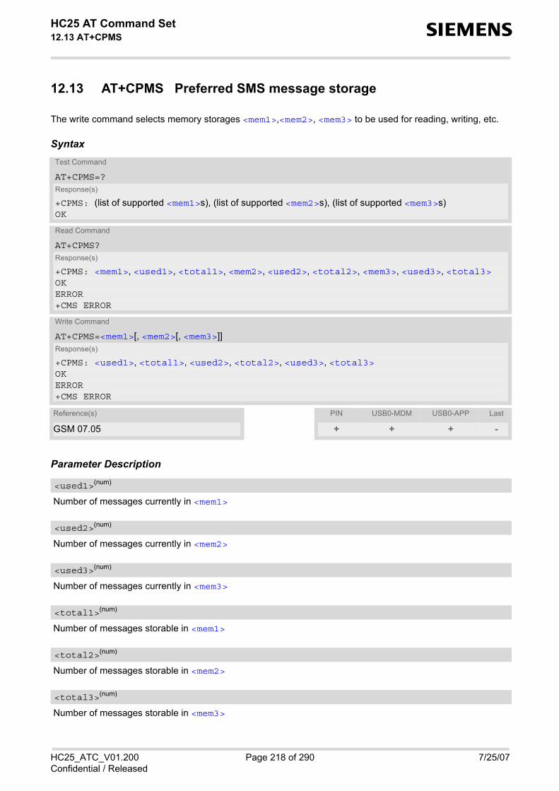
HC25 AT Command Set 12.13 AT+CPMS s
HC25_ATC_V01.200 Page 218 of 290 7/25/07Confidential / Released
12.13 AT+CPMS Preferred SMS message storage
The write command selects memory storages <mem1>,<mem2>, <mem3> to be used for reading, writing, etc.
Syntax
Parameter Description
Number of messages currently in <mem1>
Number of messages currently in <mem2>
Number of messages currently in <mem3>
Number of messages storable in <mem1>
Number of messages storable in <mem2>
Number of messages storable in <mem3>
Test Command
AT+CPMS=?Response(s)
+CPMS: (list of supported <mem1>s), (list of supported <mem2>s), (list of supported <mem3>s)OK
Read Command
AT+CPMS?Response(s)
+CPMS: <mem1>, <used1>, <total1>, <mem2>, <used2>, <total2>, <mem3>, <used3>, <total3>OKERROR+CMS ERROR
Write Command
AT+CPMS=<mem1>[, <mem2>[, <mem3>]]Response(s)
+CPMS: <used1>, <total1>, <used2>, <total2>, <used3>, <total3>OKERROR+CMS ERROR
Reference(s) PIN USB0-MDM USB0-APP Last
GSM 07.05 + + + -
<used1>(num)
<used2>(num)
<used3>(num)
<total1>(num)
<total2>(num)
<total3>(num)

HC25 AT Command Set 12.13 AT+CPMS s
HC25_ATC_V01.200 Page 219 of 290 7/25/07Confidential / Released
Notes• The Mobile Equipment storage ''ME'' offers space for 255 short messages, see <mem1>. • The <mem1>, <mem2> and <mem3> parameter will be stored in non-volatile memory. • Incoming Class 1 short messages (ME specific) will be preferably stored to ''ME'' and may be transferred to
the ''SM'' storage if ''ME'' is used up. Incoming Class 2 messages (SIM specific) will be stored to the SIM card only, no matter whether or not thereis free ''ME'' space. For more information regarding SIM and ME specific message classes refer to the follow-ing specifications: GSM 03.38 and 3GPP TS23038.
• While <mem3> equals ''SM'' and <mem1> equals ''ME'' it is possible that, after deleting short messages from''ME'', the freed space on ''ME'' is reclaimed for new incoming short messages, when there is no space left onthe ''SM'' storage. As it is often the clients concern to have received short messages stored only to the SIMcard, inconsistent settings should be generally avoided. This can be achieved simply by using the sameparameter for all memory indices.
• Users should be aware that error will occur when using this AT command quickly after SIM PIN authenticationdue to the fact the SIM data may not yet be accessible.

HC25 AT Command Set 12.14 AT+CSCA s
HC25_ATC_V01.200 Page 220 of 290 7/25/07Confidential / Released
12.14 AT+CSCA SMS Service Center Address
Write command updates the SMSC address, through which mobile originated SMs are transmitted. In text mode,setting is used by send and write commands. In PDU mode, setting is used by the same commands, but onlywhen the length of the SMSC address coded into the <pdu> parameter equals zero.
Syntax
Notes• This command writes the service center address to non-volatile memory. • The SMS service center address should be entered as specified by the service provider.
Test Command
AT+CSCA=?Response(s)
OK
Read Command
AT+CSCA?Response(s)
+CSCA: <sca>, <tosca>OK
Write Command
AT+CSCA=<sca>[, <tosca>]Response(s)
OK
Reference(s) PIN USB0-MDM USB0-APP Last
GSM 07.05 + + + -

HC25 AT Command Set 12.15 AT+CSCB s
HC25_ATC_V01.200 Page 221 of 290 7/25/07Confidential / Released
12.15 AT+CSCB Select Cell Broadcast Message Indication
The test command returns the supported <operation>s as a compound value.The read command displays the accepted message types.Depending on the <operation> parameter, the write command adds or deletes the message types acceptedby the ME.
Syntax
Parameter Description
Add/delete operation0(&F) Add new message types defined in <mids> to the list of accepted message
types by ME and replace types defined in <dcss>.In case of using this operation code without parameters default (0-65535)range will be added to the list of <mids>.
1 Delete message types defined in <mids> from the list of accepted messagetypes by ME and replace types defined in <dcss>.In case of using this operation code without parameters all <mids>s and<dcss>s will be deleted. (for more see notes)
Cell Broadcast Message ID specificationAll different possible combinations of CBM message identifiers; e.g. "0,1,5,320-478,922".
Test Command
AT+CSCB=?Response(s)
+CSCB: (list of supported <operation>s)OKERROR
Read Command
AT+CSCB?Response(s)
+CSCB: <operation>, <mids>, <dcss>OKERROR
Write Command
AT+CSCB=[<operation>[, <mids>[, <dcss>]]]Response(s)
OKERROR+CMS ERROR
Reference(s) PIN USB0-MDM USB0-APP Last
GSM 07.05 + + + -
<operation>(num)
<mids>(str)

HC25 AT Command Set 12.15 AT+CSCB s
HC25_ATC_V01.200 Page 222 of 290 7/25/07Confidential / Released
CBM data coding scheme specificationAll different possible combinations of CBM data coding schemes (e.g. "0-3,5"). If default empty string is used allCBMs are received independent of their dcss. A given <dcss> replaces any former value and is used for consecutive requests.
Note• The <operation> parameter shown in the AT+CSCB read command response retains the value last used in
the write command. This way, the read command response always reflects the last action done: 0 means thatthe last action was adding new channel(s), 1 means that the last action was deleting channel(s).
<dcss>(str)

HC25 AT Command Set 12.16 AT+CSMP s
HC25_ATC_V01.200 Page 223 of 290 7/25/07Confidential / Released
12.16 AT+CSMP Set SMS text Mode Parameters
The write command selects values for additional parameters needed when the short message is sent to the net-work or placed in a storage when text format message mode is selected. It is possible to set the validity period starting from the time when the short message is received by the SMSC(<vp> is in range 0... 255) or define the absolute time of the validity period termination (<vp> is a string). Theformat of <vp> is given by <fo>. If TA supports the enhanced validity period format, see GSM 03.40), it shall begiven as a hexadecimal coded string (e.g. <pdu>) with quotes.
Syntax
Parameter Description
First Octetdepending on the command or result code: first octet of GSM 03.40 SMS-DELIVER, SMS-SUBMIT, SMS-STA-TUS-REPORT, or SMS-COMMAND in integer format 0...255
Depending on SMS-SUBMIT <fo> setting: GSM 03.40 TP-Validity-Period either in integer format or in time-string format (refer <dt>) 0...255
Data Coding SchemeGSM 03.38 SMS Data Coding Scheme, or Cell Broadcast Data Coding Scheme in integer format 0(&F)...247
Test Command
AT+CSMP=?Response(s)
OK
Read Command
AT+CSMP?Response(s)
+CSMP:<fo>, <vp>/ <scts>, <pid>, <dcs>OK
Write Command
AT+CSMP=<fo>[, <vp>/<scts>[, <pid>[, <dcs>]]]Response(s)
+CSMP: <index>OKIf sending failsERROR+CMS ERROR
Reference(s) PIN USB0-MDM USB0-APP Last
GSM 07.05 + + + -
<fo>(num)
<vp>(num)
<dcs>(num)

HC25 AT Command Set 12.16 AT+CSMP s
HC25_ATC_V01.200 Page 224 of 290 7/25/07Confidential / Released
Protocol IdentifierGSM 03.40 TP-Protocol-Identifier in integer format 0(&F)...255
Notes• When storing a SMS DELIVER from the TE to the preferred memory storage in text mode (using the AT+CMGW
write command), <vp> field can be used for <scts>. • The command writes the parameters to the non-volatile memory.
<pid>(num)

HC25 AT Command Set 12.17 AT+CSMS s
HC25_ATC_V01.200 Page 225 of 290 7/25/07Confidential / Released
12.17 AT+CSMS Select Message Service
Syntax
Parameter Description
0(&F) GSM 03.40 and GSM 03.41 (the syntax of SMS AT commands is compatiblewith GSM 07.05 Phase 2 version 4.7.0; Phase 2+ features which do not requirenew command syntax may be supported, e.g. correct routing of messages withnew Phase 2+ data coding schemes)
1 GSM 03.40 and GSM 03.41 (the syntax of SMS AT commands is compatiblewith GSM 07.05 Phase 2+ version; the requirement of <service> setting 1 ismentioned under corresponding command descriptions).
Mobile Terminated Messages:0 Type not supported 1 Type supported
Mobile Originated Messages:0 Type not supported 1 Type supported
Test Command
AT+CSMS=?Response(s)
+CSMS: (list of supported<service>s)OK
Read Command
AT+CSMS?Response(s)
+CSMS: <service>, <mt>, <mo>, <bm>OK
Write Command
AT+CSMS=<service>Response(s)
+CSMS: <mt>, <mo>, <bm>OKERROR+CMS ERROR
Reference(s) PIN USB0-MDM USB0-APP Last
GSM 07.05 + + + -
<service>(num)
<mt>(num)
<mo>(num)

HC25 AT Command Set 12.17 AT+CSMS s
HC25_ATC_V01.200 Page 226 of 290 7/25/07Confidential / Released
Broadcast Type Messages:0 Type not supported 1 Type supported
Note• Phase 2+ (<service>=1) must be set before acknowledging incoming short messages with AT+CNMA is
possible. Acknowledgements are required for directly routed messages delivered using "+CMT" and "+CDS"URCs. Direct routing is used for certain message classes when <mt>=2, <mt>=3 or <ds>=1.
<bm>(num)

HC25 AT Command Set 12.18 AT^SMGL s
HC25_ATC_V01.200 Page 227 of 290 7/25/07Confidential / Released
12.18 AT^SMGL List Short Messages from preferred store without set-ting status to REC READ
The write command lists messages stored in <mem1> without changing their status to "read". The execute com-mand is identical to the write command with default <stat> (for defaults see "Section 12.1, SMS parameters).
Syntax
Notes• The selected <mem1> can contain different types of SMs (e.g. SMS-DELIVERs, SMS-SUBMITs, SMS-STA-
TUS-REPORTs and SMS-COMMANDs), the response may be a mix of the responses of different SM types.TE application can recognize the response format by examining the third response parameter.
• Users should be aware that error will occur when using this AT command quickly after SIM PIN authenticationdue to the fact the SIM data may not yet be accessible.
Test Command
AT^SMGL=?Response(s)
(list of supported <stat>s)
Exec Command
AT^SMGLResponse(s)
^SMGL: (same as write command with default <stat>)OK
Write Command
AT^SMGL=[<stat>]Response(s)
same as AT+CMGL
Reference(s) PIN USB0-MDM USB0-APP Last
SIEMENS + + + -

HC25 AT Command Set 13. SIM related Commands s
HC25_ATC_V01.200 Page 228 of 290 7/25/07Confidential / Released
13. SIM related Commands
The AT commands described in this chapter are related to the Subscriber Identity Module (SIM) connected toHC25.
Note:If using data from the SIM please bear in mind that the content of all Elementary Files is subject to change at anymoment!This is because the network can change the SIM's data in the background via the SIM Application Toolkit (SAT)procedure "Data download to SIM". For a detailed description please refer to GSM 11.14, [20]. To get informed that changing Elementary Files has taken place the TA needs to hook to the SAT Proactive Com-mand "REFRESH". To achieve this, the AT command interface of SAT, i.e. Remote-SAT, needs to be activated.An overview is given at Chapter 14., SIM Application Toolkit (SAT) Commands, additional information is availablewith the document "Remote-SAT User Guide" [4].
13.1 AT+CRSM Restricted SIM Access
AT+CRSM offers easy access of the Elementary Files on the SIM. Access to the SIM database is restricted to thecommands which are listed at <command>. All parameters of AT+CRSM are used as specified by the specifications listed below. HC25 handles internally allrequired SIM interface locking and file selection routines. As response to the command, the HC25 sends the actual SIM information parameters and response data. Errorresult code "+CME ERROR" may be returned if the command cannot be passed to the SIM, e.g. if the SIM is notinserted. However, failure in the execution of the command in the SIM is reported in <sw1> and <sw2> param-eters.
Please beware of possible changes to Elementary Files by the network at any time, refer Chapter 13., SIMrelated Commands.
SyntaxTest Command
AT+CRSM=?Response(s)
OK
Write Command
AT+CRSM=<command>[, <fileID>[, <P1>, <P2>, <P3>[, <data>]]]Response(s)
+CRSM: <sw1>,<sw2>[,<response>] OK ERROR +CME ERROR: <err>
Reference(s) PIN USB0-MDM USB0-APP Last
3GPP TS 27.007, 3GPP TS 31.102, ETSI TS 102 221, GSM 11.11
- + + -

HC25 AT Command Set 13.1 AT+CRSM s
HC25_ATC_V01.200 Page 229 of 290 7/25/07Confidential / Released
Parameter Description
SIM command number.176 READ BINARY178 READ RECORD192 GET RESPONSE214 UPDATE BINARY220 UPDATE RECORD242 STATUS
Identifier for an elementary data file on SIM, if used by <command>.
Parameter to be passed on by the HC25 to the SIM. 0...255
Parameter to be passed on by the HC25 to the SIM. 0...255
Parameter to be passed on by the HC25 to the SIM. 0...255
Information which shall be written to the SIM (hexadecimal character format).
Status information from the SIM about the execution of the actual command. It is returned in both cases, on suc-cessful or failed execution of the command. 0...255
Status information from the SIM about the execution of the actual command. It is returned in both cases, on suc-cessful or failed execution of the command. 0...255
Response data in case of a successful completion of the previously issued command. "STATUS" and "GET RESPONSE" commands return data, which gives information about the currently selectedelementary data field. This information includes the type of file and its size. After "READ BINARY" or "READ RECORD" commands the requested data will be returned. <response> is empty after "UPDATE BINARY" or "UPDATE RECORD" commands.
<command>(num)
<fileID>(num)
<P1>(num)
<P2>(num)
<P3>(num)
<data>(str)
<sw1>(num)
<sw2>(num)
<response>(str)

HC25 AT Command Set 13.2 AT+CSIM s
HC25_ATC_V01.200 Page 230 of 290 7/25/07Confidential / Released
13.2 AT+CSIM Generic SIM Access
AT+CSIM allows direct control of the SIM. Compared to Restricted SIM Access command AT+CRSM, the definition of AT+CSIM allows the ME to take morecontrol over the SIM interface. However, the SIM Application Toolkit functionality is not supported by AT+CSIM. Therefore the following SIMcommands cannot be used: TERMINAL PROFILE, ENVELOPE, FETCH and TEMINAL RESPONSE.
Syntax
Parameter Description
Length of <command> or <response> string.
Command passed on by the ME to the SIM. Parameter length: maximum 260 Bytes.
Response data of the command returned by the SIM. Parameter length: maximum 257 Bytes.
Example
The following examples explain how to use AT+CSIM.
Test Command
AT+CSIM=?Response(s)
OK
Write Command
AT+CSIM=<length>, <command>Response(s)
+CSIM: <length>,<response>OK ERROR +CME ERROR: <err>
Reference(s) PIN USB0-MDM USB0-APP Last
3GPP TS 27.007, 3GPP TS 31.102, ETSI TS 102 221, GSM 11.11
- + + -
<length>(num)
<command>(str)
<response>(str)
AT+CSIM=14,"A0A40000027F10" Select DF-Telecom+CSIM: 4,"9F19" Command successful, length '19' of the response
dataOKAT+CSIM=14,"A0A40000026F3A" Select EF-ADN (Abbreviated dialling numbers)+CSIM: 4,"9F0F" Command successful, length '0F' of the response
dataOKAT+CSIM=16,"A0C000000F000000" Get Response

HC25 AT Command Set 13.2 AT+CSIM s
HC25_ATC_V01.200 Page 231 of 290 7/25/07Confidential / Released
+CSIM: 34,"000002306F3A040011F0220102011C9000"OK
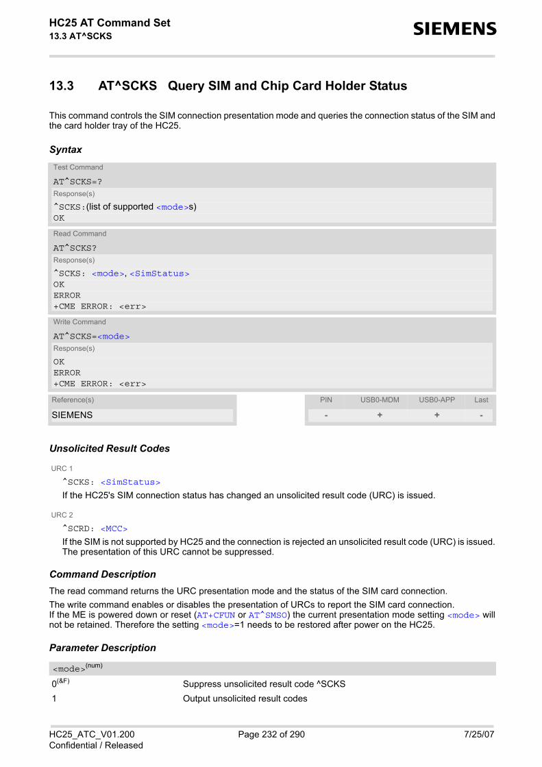
HC25 AT Command Set 13.3 AT^SCKS s
HC25_ATC_V01.200 Page 232 of 290 7/25/07Confidential / Released
13.3 AT^SCKS Query SIM and Chip Card Holder Status
This command controls the SIM connection presentation mode and queries the connection status of the SIM andthe card holder tray of the HC25.
Syntax
Unsolicited Result Codes
URC 1
^SCKS: <SimStatus>
If the HC25's SIM connection status has changed an unsolicited result code (URC) is issued.
URC 2
^SCRD: <MCC>
If the SIM is not supported by HC25 and the connection is rejected an unsolicited result code (URC) is issued.The presentation of this URC cannot be suppressed.
Command DescriptionThe read command returns the URC presentation mode and the status of the SIM card connection. The write command enables or disables the presentation of URCs to report the SIM card connection.If the ME is powered down or reset (AT+CFUN or AT^SMSO) the current presentation mode setting <mode> willnot be retained. Therefore the setting <mode>=1 needs to be restored after power on the HC25.
Parameter Description
0(&F) Suppress unsolicited result code ^SCKS1 Output unsolicited result codes
Test Command
AT^SCKS=?Response(s)
^SCKS:(list of supported <mode>s)OK
Read Command
AT^SCKS?Response(s)
^SCKS: <mode>, <SimStatus>OKERROR+CME ERROR: <err>
Write Command
AT^SCKS=<mode>Response(s)
OKERROR+CME ERROR: <err>
Reference(s) PIN USB0-MDM USB0-APP Last
SIEMENS - + + -
<mode>(num)

HC25 AT Command Set 13.3 AT^SCKS s
HC25_ATC_V01.200 Page 233 of 290 7/25/07Confidential / Released
0 SIM connection error 1 SIM inserted (refer to note)
The MCC (Mobile Country Code) of a SIM that is not supported by HC25.
Notes• <SimStatus> reflects the status of the SIM and the card holder tray.• <MCC> specifies the MCC (Mobile Country Code) of a SIM that is not supported by HC25.
Example
Now, after removing a card tray the following URCs appear:
<SimStatus>(num)
<MCC>(num)
AT^SCKS=1 Activates the presentation of unsolicited result code ^SCKSOK
^SCKS: 0 No SIM card found

HC25 AT Command Set 14. SIM Application Toolkit (SAT) Commands s
HC25_ATC_V01.200 Page 234 of 290 7/25/07Confidential / Released
14. SIM Application Toolkit (SAT) Commands
This chapter offers a brief reference to AT commands and responses related to the HC25's SIM Application Tool-kit (SAT) implementation. A consistent and detailed description can be found in the "Remote-SAT User's Guide"[4]. For further advice please contact the Wireless Modules Application Engineering Department at Siemens AG.
ETSI specification GSM 11.14 [20] defines SAT in detail.
SIM Application Toolkit (SAT) is a technology that allows an application running on the SIM/UICC to control theMobile Equipment (ME). Remote-SAT (RSAT) provides a link between applications located on the SIM/UICCand a customer application (TA). The purpose of RSAT is to allow the TA to send AT commands to the SAT inter-face and to display all SAT activities on the user interface of the customer application.
Two groups of commands are exchanged between the SAT located on the HC25 and the SIM Application run-ning on the SIM/UICC: • Proactive commands are sent from the SIM application to the HC25's SAT, such as "DISPLAY TEXT". • Envelope commands are sent from the HC25's SAT to the SIM application, such as "MENU SELECTION".
14.1 AT^SSTA SAT Interface Activation
The AT^SSTA write command can be used to specify the Remote-SAT activation mode <mode> and, if ER modeis enabled, to explicitly activate the Remote SAT interface. Removing and inserting the SIM does not affect theactivation status. SAT commands which are not using the AT interface (non MMI related SAT commands , e.g. PROVIDE LOCALINFORMATION) are executed without activating Remote-SAT. The read command can be used to request the current operating status and the used alphabet of the Remote-SAT interface.
SyntaxTest Command
AT^SSTA=?Response(s)
^SSTA:(list of supported <state>s), (list of supported <Alphabet>s)OK
Read Command
AT^SSTA?Response(s)
^SSTA: <state>, <Alphabet>, <allowedInstance>, <SatProfile>, <userTOut>OK
Write Command
AT^SSTA=<mode>[, <Alphabet>]Response(s)
OK
Reference(s) PIN USB0-MDM USB0-APP Last
SIEMENS - + + -

HC25 AT Command Set 14.1 AT^SSTA s
HC25_ATC_V01.200 Page 235 of 290 7/25/07Confidential / Released
Parameter Description
HC25 Remote-SAT interface states 0 RESET 1 OFF 2 IDLE 3 PAC 4 WAIT
Parameter is stored non-volatile and takes effect after next restart of the ME. 0(D) GSM character set
Input of a character requests one byte, e.g. "Y".1 UCS2
To display the 16 bit value of characters represented in UCS2 alphabet a 4 bytestring is required, e.g. "0059" is coding the character "Y". For details pleaserefer to ISO/IEC 10646.
0 Not applicable 1 SAT may be started on this instance via the write version of this command.
SAT profile according to GSM 11.14 [20]. The profile tells the SIM Application which features (e.g. proactive commands) are supported by the SIM Appli-cation Toolkit implementation of the HC25.
User timeout in seconds.To limit the time Remote-SAT is kept in states PAC or WAIT, any ongoing (but unanswered) proactive commandwill be aborted automatically after 5 minutes. In this case, the terminal response is either "ME currently unableto process command", or if applicable, "No response from user". In addition a URC "Terminate Proactive Com-mand" will be sent to the external application. This value shall not be changed by the TA.
Select Remote SAT activation mode.Parameter is stored non-volatile and takes effect after next restart of the ME. Removing and inserting the SIMdoes not affect the activation status. 0(D) Automatic response (AR) mode.
All commands and responses are exchanged automatically between the MEand the SIM application. This eliminates the need to enter any Remote SAT ATcommands incl. the AT^SSTA command. If AR mode is enabled the ME enters the OFF state (<state>=1) after reboot.
1 Explicit response (ER) mode.This mode is intended for use with an MMI. If ER mode is enabled the MMI isrequired to handle, via the module's Remote-SAT interface, all commands andresponses transmitted to or from the SIM. If ER mode is enabled the ME enters the IDLE state (<state>= 2) after reboot.
<state>(num)
<Alphabet>(num)
<allowedInstance>(num)
<SatProfile>(str)
<userTOut>(str)
<mode>(num)

HC25 AT Command Set 14.2 ^SSTN s
HC25_ATC_V01.200 Page 236 of 290 7/25/07Confidential / Released
14.2 ^SSTN SAT Notification
Unsolicited Result Codes
URC 1
Proactive Command notification ^SSTN: <cmdType>
Every time the SIM Application issues a Proactive Command, via the ME, the TA will receive a notification.This indicates the type of Proactive Command issued.AT^SSTGI must then be used by the TA to request the parameters of the Proactive Command from the ME.Upon receiving the ^SSTGI response from the ME, the TA must send AT^SSTR to confirm the execution ofthe Proactive Command and provide any required user response, e.g. a selected menu item.
URC 2
Terminate Proactive Command notification ^SSTN: <cmdTerminateValue>
When the SIM application has issued a Proactive Command to the ME, it is possible that this command willbe terminated later. URC "^SSTN" is sent with a different Proactive Command type number (added terminateoffset 100) to indicate the termination of the specified command.The state changes to idle. Therefore the TA should avoid sending any further commands related to the ter-minated Proactive Command, e.g. AT^SSTGI or AT^SSTR.
URC 3
Notification that SIM Application has returned to main menu ^SSTN: 254
Notification to the TA when the SIM Application has finished a command cycle and again enters its mainmenue, which was transferred with an URC "^SSTN: 37" (SET UP MENU) at start up.This URC should be used to open this menue on the sreen.The TA does not need to respond directly, i.e. AT^SSTR is not required.
URC 4
SIM reset notification ^SSTN: 255
Notification to the TA if a Proactive Command "REFRESH - SIM Reset" has been issued by the SIM Applica-tion, please refer to AT^SSTGI.This URC should be used to set the TAs application to its initial state since the SIM Application will start fromthe beginning, too.The TA does not need to respond directly, i.e. related AT^SSTGI and AT^SSTR are neither required norallowed.Since the ME is still busy on SIM access the ME may respond with "+CME ERROR: SIM blocked" or "+CMEERROR: SIM busy" on following PIN required AT Commands for a while. Then TA shall retry until the MEresponds with "OK". The time needed for this process depends on the SIM and may take more than 10 sec-onds.
Parameter Description
Proactive Command number
Defined as <cmdType> + terminate offset. The terminate offset equals 100.
<cmdType>(num)
<cmdTerminateValue>(num)

HC25 AT Command Set 14.3 AT^SSTGI s
HC25_ATC_V01.200 Page 237 of 290 7/25/07Confidential / Released
14.3 AT^SSTGI SAT Get Information
Regularly this command is used upon receipt of an URC "^SSTN" to request the parameters of the ProactiveCommand. Then the TA is expected to acknowledge the AT^SSTGI response with AT^SSTR to confirm that the ProactiveCommand has been executed. AT^SSTR will also provide any user information, e.g. a selected menu item. The Proactive Command type value specifies to which "^SSTN" the command is related.
Syntax
Parameter Description
HC25 Remote-SAT interface states 0 RESET 1 OFF 2 IDLE 3 PAC 4 WAIT
Related Proactive Command
Test Command
AT^SSTGI=?Response(s)
^SSTGI:(list of supported <state>s), (list of supported <cmdType>s)OK
Read Command
AT^SSTGI?Response(s)
^SSTGI: <state>, <cmdType>OK
Write Command
AT^SSTGI=<cmdType>Response(s)
OKERROR+CME ERROR
Reference(s) PIN USB0-MDM USB0-APP Last
SIEMENS - + + -
<state>(num)
<cmdType>(num)

HC25 AT Command Set 14.4 AT^SSTR s
HC25_ATC_V01.200 Page 238 of 290 7/25/07Confidential / Released
14.4 AT^SSTR SAT Response
The TA is expected to acknowledge the AT^SSTGI response with AT^SSTR to confirm that the Proactive Com-mand has been executed. AT^SSTR will also provide any user information, e.g. a selected menu item.
Syntax
Parameter Description
HC25 Remote-SAT interface states 0 RESET 1 OFF 2 IDLE 3 PAC 4 WAIT
Number related to Proactive Command or event type according to GSM 11.14 [20].
Command status return regarding the type of action that has taken place, e.g. action performed by the user.Values are in accordance with GSM 11.14 [20].
Response number entered by user
Response string entered by user
Test Command
AT^SSTR=?Response(s)
^SSTR:(list of supported <state>s), (list of supported <cmdType>s)OK
Read Command
AT^SSTR?Response(s)
^SSTR: <state>, <cmdType>OK
Write Command
AT^SSTR=<cmdType>, <status>[, <inputNumber>][, <inputString>]Response(s)
OK
Reference(s) PIN USB0-MDM USB0-APP Last
SIEMENS - + + -
<state>(num)
<cmdType>(num)
<status>(num)
<inputNumber>(num)
<inputString>(str)
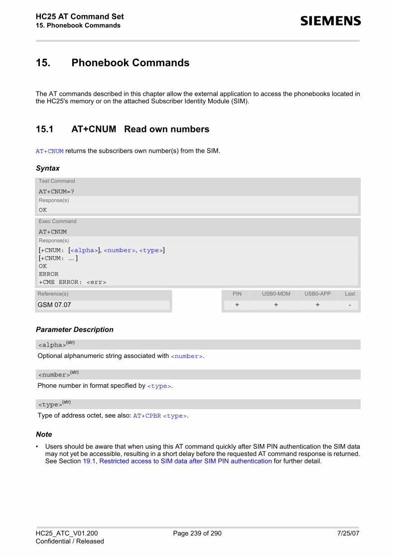
HC25 AT Command Set 15. Phonebook Commands s
HC25_ATC_V01.200 Page 239 of 290 7/25/07Confidential / Released
15. Phonebook Commands
The AT commands described in this chapter allow the external application to access the phonebooks located inthe HC25's memory or on the attached Subscriber Identity Module (SIM).
15.1 AT+CNUM Read own numbers
AT+CNUM returns the subscribers own number(s) from the SIM.
Syntax
Parameter Description
Optional alphanumeric string associated with <number>.
Phone number in format specified by <type>.
Type of address octet, see also: AT+CPBR <type>.
Note• Users should be aware that when using this AT command quickly after SIM PIN authentication the SIM data
may not yet be accessible, resulting in a short delay before the requested AT command response is returned.See Section 19.1, Restricted access to SIM data after SIM PIN authentication for further detail.
Test Command
AT+CNUM=?Response(s)
OK
Exec Command
AT+CNUMResponse(s)
[+CNUM: [<alpha>], <number>, <type>][+CNUM: ... ]OKERROR+CME ERROR: <err>
Reference(s) PIN USB0-MDM USB0-APP Last
GSM 07.07 + + + -
<alpha>(str)
<number>(str)
<type>(str)

HC25 AT Command Set 15.2 AT+CPBF s
HC25_ATC_V01.200 Page 240 of 290 7/25/07Confidential / Released
15.2 AT+CPBF Find phonebook entries
The AT+CPBF write command returns phonebook entries (from the current phonebook memory storage selectedwith AT+CPBS) which alphanumeric field start with string <findtext>.Entry fields returned are location number <location>, phone number stored there <number> (of format<type>) and text <text> associated with the number.The AT+CPBF test command returns the maximum lengths of <nlength> and <tlength> fields.
Syntax
Parameter Description
The location number in the range of location numbers of phonebook memory.
Phone number in format specified by <type>, it may be an empty string.
Type of address octet, which defines the used type of number (ton) and the numbering plan identification (npi).Please consider that for types other than 129 or 145 dialing from phonebook with ATD><mem><n> is, dependingon the network, not always possible (refer to GSM 04.08 subclause 10.5.4.7 for details). See also <type> ofAT+CPBW. Possible values are: 128 Restricted <number> includes unknown type and format.145 Dialing string <number> includes international access code character '+'.161 National number. Network support of this type is optional.177 Network specific number, ISDN format.209 Dialing string <number> has been saved as ASCII string and includes non-
digit characters other than "*", "#" or "+". Note that phonebook entries savedwith this type cannot be dialed.
Test Command
AT+CPBF=?Response(s)
+CPBF: <nlength>, <tlength>OKERROR+CME ERROR
Write Command
AT+CPBF=<findtext>Response(s)
+CPBF: <location>, <number>, <type>, <text>OKERROR+CME ERROR
Reference(s) PIN USB0-MDM USB0-APP Last
SIEMENS + + + -
<location>(num)
<number>(str)
<type>(num)

HC25 AT Command Set 15.2 AT+CPBF s
HC25_ATC_V01.200 Page 241 of 290 7/25/07Confidential / Released
255 Dialing string <number> is a command to control a Supplementary Service,i.e. "*", "#" codes are contained. Network support of this type is optional.
129 Otherwise.
Text assigned to a phone number. The maximum length for this parameter is given with test command responseparameter <tlength>.If using an ASCII terminal characters which are coded differently in ASCII and GSM have to be entered viaescape sequences as described in Section 1.6, Supported character sets.
String for finding the <text> in the active phonebook.
Maximum length of phone number for "normal" locations. Depending on the storage a limited number of loca-tions with extended memory is available per phonebook. These locations allow storing numbers with twice thestandard length, which is 2*<nlength> digits for normal numbers, but only <nlength> digits for numberssaved with <type>=209.
Maximum length of <text> assigned to the telephone number. The value indicated by the test command isgiven in octets. If <text> is given as GSM characters each character corresponds to one octet. If the <text>string is given in UCS2, the maximum number of characters depends on the coding scheme used for the alphafield of the SIM according to GSM 11.11, Annex B [17]. In the worst case the number of UCS2 characters is atleast one less than half the number of GSM characters.
Notes• Users should be aware that when using this AT command quickly after SIM PIN authentication the SIM data
may not yet be accessible, resulting in a short delay before the requested AT command response is returned.See Section 19.1, Restricted access to SIM data after SIM PIN authentication for further detail.
• The search in the dialled calls (DC) phonebook is not supported.
<text>(str)(+CSCS)
<findtext>(str)(+CSCS)
<nlength>(num)
<tlength>(num)
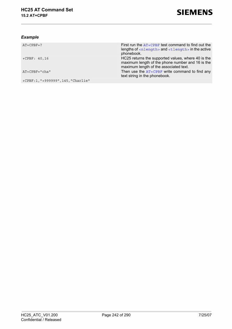
HC25 AT Command Set 15.2 AT+CPBF s
HC25_ATC_V01.200 Page 242 of 290 7/25/07Confidential / Released
Example
AT+CPBF=? First run the AT+CPBF test command to find out thelengths of <nlength> and <tlength> in the activephonebook.
+CPBF: 40,16 HC25 returns the supported values, where 40 is themaximum length of the phone number and 16 is themaximum length of the associated text.
AT+CPBF="cha" Then use the AT+CPBF write command to find anytext string in the phonebook.
+CPBF:1,"+999999",145,"Charlie"

HC25 AT Command Set 15.3 AT+CPBR s
HC25_ATC_V01.200 Page 243 of 290 7/25/07Confidential / Released
15.3 AT+CPBR Read from phonebook
AT+CPBR serves to read one or more entries from the phonebook selected with AT command AT+CPBS.
The AT+CPBR test command returns the location range supported by the current phonebook storage, the maxi-mum length of <number> field and the maximum length of <text> field.Note: Length information may not be available while SIM storage is selected. If storage does not offer formatinformation, the format list contains empty parenthesizes.
The AT+CPBR write command determines the phonebook entry to be displayed with <location1> or a locationrange from <location1> to <location2>. Hence, if no <location2> is given only the entry at<location1> will be displayed. If no entries are found at the selected location "+CME ERROR: not found" will be returned.
Syntax
Parameter Description
The first (lowest) location number within phonebook memory where to start reading. The maximum range sup-ported by the current phonebook is given in the test command response. If <location1> exceeds the upper bound <maxloc> (as indicated by the test command), command willrespond with "+CME ERROR: invalid index".
The last (highest) location number within phonebook memory where to stop reading. The maximum range sup-ported by the current phonebook is given in the test command response. If both <location1> and <location2> are in the range indicated by the test command parameter <max-loc>, the list of entries will be output and terminated with "OK". If <location2> exceeds the range indicated by the test command parameter <maxloc>, no list of entries willbe shown and the output is terminated with "+CME ERROR: invalid index".
Phone number in format specified by <type>, it may be an empty string.
Test Command
AT+CPBR=?Response(s)
+CPBR: (1-<maxloc>), <nlength>, <tlength>OK+CME ERROR
Write Command
AT+CPBR=<location1>[, <location2>]Response(s)
[+CPBR: <location1>, <number>, <type>, <text>][+CPBR: <location2>, <number>, <type>, <text>]OK+CME ERROR
Reference(s) PIN USB0-MDM USB0-APP Last
GSM 07.07, GSM 11.11 + + + -
<location1>(num)
<location2>(num)
<number>(str)

HC25 AT Command Set 15.3 AT+CPBR s
HC25_ATC_V01.200 Page 244 of 290 7/25/07Confidential / Released
Type of address octet, which defines the used type of number (ton) and the numbering plan identification (npi).Please consider that for types other than 129 or 145 dialing from phonebook with ATD><mem><n> is, dependingon the network, not always possible (refer to GSM 04.08 subclause 10.5.4.7 for details). See also <type> ofAT+CPBW. Possible values are: 128 Restricted <number> includes unknown type and format.145 Dialing string <number> includes international access code character '+'.161 National number. Network support of this type is optional.177 Network specific number, ISDN format.209 Dialing string <number> has been saved as ASCII string and includes non-
digit characters other than "*", "#" or "+". Note that phonebook entries savedwith this type cannot be dialed.
255 Dialing string <number> is a command to control a Supplementary Service,i.e. "*", "#" codes are contained. Network support of this type is optional.
129 Otherwise.
Text assigned to a phone number. The maximum length for this parameter is given with test command responseparameter <tlength>. If using an ASCII terminal characters which are coded differently in ASCII and GSM have to be entered viaescape sequences as described in Section 1.6, Supported character sets.
Maximum location number for the currently selected storage. For phonebooks located on the SIM this valuedepends on the SIM card type.
Maximum length of phone number for "normal" locations. Depending on the storage a limited number of loca-tions with extended memory is available per phonebook. These locations allow storing numbers with twice thestandard length, which is 2*<nlength> digits for normal numbers, but only <nlength> digits for numberssaved with <type>=209.
Maximum length of <text> assigned to the telephone number. The value indicated by the test command isgiven in octets. If <text> is given as GSM characters each character corresponds to one octet. If the <text>string is given in UCS2, the maximum number of characters depends on the coding scheme used for the alphafield of the SIM according to GSM 11.11, Annex B [17]. In the worst case the number of UCS2 characters is atleast one less than half the number of GSM characters.
Notes• Users should be aware that when using this AT command quickly after SIM PIN authentication the SIM data
may not yet be accessible, resulting in a short delay before the requested AT command response is returned.See Section 19.1, Restricted access to SIM data after SIM PIN authentication for further detail.
• When storing a supplementary service command to the phonebook along with a "+" within the phone numberplease note that the ME will not display the "+" after restart, but correctly handles the phone number as inter-national type.
<type>(num)
<text>(str)(+CSCS)
<maxloc>(num)
<nlength>(num)
<tlength>(num)

HC25 AT Command Set 15.3 AT+CPBR s
HC25_ATC_V01.200 Page 245 of 290 7/25/07Confidential / Released
Example
AT+CPBR=? First run the AT+CPBR test command to find out themaximum range of entries stored in the activephonebook.
+CPBR:(1-100),20,17 HC25 returns the supported values, where 100 is thesupported range of location numbers, 20 is thelength of the phone number and 17 is the maximumlength of the associated text.
AT+CPBR =1,3 Then use the AT+CPBR write command to displaythe phonebook entries sorted by location numbers. +CPBR:1,"+999999",145,"Charlie"
+CPBR:2,"+777777",145,"Bill" +CPBR:3,"+888888",145,"Arthur"

HC25 AT Command Set 15.4 AT+CPBS s
HC25_ATC_V01.200 Page 246 of 290 7/25/07Confidential / Released
15.4 AT+CPBS Select phonebook memory storage
AT+CPBS selects the active phonebook storage, i.e. the phonebook storage that all subsequent phonebook com-mands will be operating on.The read command returns the currently selected <storage>, the number of <used> entries and the <total>number of entries available for this storage. The test command returns all supported <storage>s as compoundvalue.
Syntax
Parameter Description
“SM“(&F) SIM phonebookCapacity: depending on SIM cardLocation: SIM
Test Command
AT+CPBS=?Response(s)
+CPBS: (list of supported <storage>s)OK+CME ERROR
Read Command
AT+CPBS?Response(s)
+CPBS: <storage>, <used>, <total>OK+CME ERROR
Exec Command
All records of the "MC", "RC", "DC" and "LD" phonebooks stored on the ME will be deleted.AT+CPBSResponse(s)
OK+CME ERROR
Write Command
AT+CPBS=<storage>Response(s)
OK+CME ERROR:
Write Command
For write access to FD phonebookAT+CPBS=<storage>, <pin>Response(s)
OK+CME ERROR:
Reference(s) PIN USB0-MDM USB0-APP Last
GSM07.07 + + + -
<storage>(str)

HC25 AT Command Set 15.4 AT+CPBS s
HC25_ATC_V01.200 Page 247 of 290 7/25/07Confidential / Released
“DC“ Dialled calls listCapacity: max. 10 entriesLocation: MEAT+CPBW command is not applicable to this storage.
“FD“ Fixed dialing phonebookCapacity: depending on SIM cardLocation: SIM
“LD“ Last number dialed phonebook. Stores all call numbers dialed with ATD.Capacity: max. 10 entriesLocation: depending on SIM this phonebook may reside partly or completely inME.AT+CPBW command is not applicable to this storage.
“MC“ Missed (unanswered received) calls listCapacity: max. 10 entriesLocation: MEAT+CPBW command is not applicable to this storage.
“ME“ Mobile Equipment PhonebookCapacity: max. 250 entriesLocation: ME
“RC“ Received calls listCapacity: max. 10 entriesLocation: MEAT+CPBW command is not applicable to this storage.
“EN“ Emergency numberCapacity: max. 50 entriesLocation: SIM or MEAT+CPBW command is not applicable to this storage.
“ON“ MSISDN listCapacity: depending on SIM cardLocation: SIM
Value indicating the number of used locations in selected memory storage.
Value indicating the maximum number of locations allowed in the selected memory storage.
Notes• Users should be aware that when using this AT command quickly after SIM PIN authentication the SIM data
may not yet be accessible, resulting in a short delay before the requested AT command response is returned.See Section 19.1, Restricted access to SIM data after SIM PIN authentication for further detail.
• To get write access to the "FD" phonebook the following input is required: AT+CPBS="FD","PIN2"
<used>(num)
<total>(num)

HC25 AT Command Set 15.5 AT+CPBW s
HC25_ATC_V01.200 Page 248 of 290 7/25/07Confidential / Released
15.5 AT+CPBW Write into phonebook
The AT+CPBW write command can be used to create, edit and delete a phonebook entry at a <location> ofthe active storage selected with AT+CPBS.If <storage>="FD" (SIM fixed dialing numbers) is selected, PIN2 authentication has to be performed prior toany write access.
The AT+CPBW test command returns the location range supported by the current storage, the maximum lengthof the <number> field, the range of supported <type> values and the maximum length of the <text> field.Note: The length may not be available while SIM storage is selected. If storage does not offer format information,the format list contains empty parenthesizes.
Syntax
Parameter Description
Location number within phonebook memory. The maximum range supported by each storage type is indicatedin the test command response. If <location> is not given, the first free entry will be used.If <location> is given as the only parameter, the phonebook entry specified by <location> is deleted.
Phone number in format specified by <type>. Parameter must be present, although it may be an empty string.Alphabetic characters are not permitted. <number> may contain dialstring modifiers "*", "#" or "+".If other printable non-alphabetic characters are used the entry needs to be saved with <type>=209. Otherwise,if <type>=209 is not used any non-digit characters other than "*", "#" or "+" will be removed from the string andonly accepted modifiers from the GSM alphabet will be saved.A <number> saved with <type>=209 requires double memory. In order to fit into a standard location, the num-ber needs to be reduced to a maximum length of <nlength>/2, including all digits and dial string modifiers.Extended locations may be used as stated below for <nlength>.
Test Command
AT+CPBW=?Response(s)
+CPBW: (1-<maxloc>), <nlength>, (list of supported <type>s), <tlength>OKERROR+CME ERROR
Write Command
AT+CPBW=[<location>][, <number>[[, <type>][, <text>]]]Response(s)
OKERROR+CME ERROR
Reference(s) PIN USB0-MDM USB0-APP Last
GSM 07.07, GSM 04.08 + + + -
<location>(num)
<number>(str)

HC25 AT Command Set 15.5 AT+CPBW s
HC25_ATC_V01.200 Page 249 of 290 7/25/07Confidential / Released
Type of address octet, which defines the used type of number (ton) and the numbering plan identification (npi).Please consider that for types other than 129 or 145 dialing from phonebook with ATD><mem><n> is, dependingon the network, not always possible (refer GSM 04.08 subclause 10.5.4.7 for details).If <type> is not specified the unknown <type>=129 is used. If <number> contains a leading "+" <type>=145(international) is used.Supported values are: 128 Restricted <number> includes unknown type and format.145 Dialing string <number> includes international access code character "+".161 National number. The network support for this type is optional.177 Network specific number, ISDN format.209 Dialing string <number> will be saved as ASCII string.
This is the default value, if <type> is not specified explicitly and charactersother than "*", "#" or "+" are included in <number>.Note that phonebook entries saved with this type cannot be dialed.
255 Dialing string <number> is a command to control a Supplementary Service,i.e. "*", "#" codes are contained. Network support of this type is optional.
129 Unknown number. If <type> is unknown and the <number> contains a lead-ing "+", then this sign is removed.
Text assigned to the phone number. The maximum length of this parameter is given in the test commandresponse <tlength>. When using an ASCII terminal, characters which are coded differently in ASCII and GSMhave to be entered via escape sequences as described in Section 1.6, Supported character sets.
Maximum number of locations supported by the currently selected storage. For phonebooks located on SIM,this value varies depending on the SIM card. See AT+CPBS for typical values.
Maximum length of phone number for "normal" locations. Depending on the storage, a limited number of loca-tions with extended memory is available per phonebook. These locations allow storing numbers with twice thestandard length, which is 2*<nlength> digits for normal numbers, but only <nlength> digits for numberssaved with parameter <type>= 209. If all extended locations of the selected phonebook are used up, then anyattempt to write a number which requires extended memory will be denied with +CME ERROR: memory full.
Maximum length of <text> assigned to the telephone number. The value indicated by the test command isgiven in octets. If the <text> string is given in GSM characters, each character corresponds to one octet. If the<text> string is given in UCS2, the maximum number of characters depends on the coding scheme used forthe alpha field of the SIM. In the worst case the number of UCS2 characters is at least one less than half thenumber of GSM characters.For a detailed description please refer to GSM 11.11, Annex B [17].
Note• Users should be aware that when using this AT command quickly after SIM PIN authentication the SIM data
may not yet be accessible, resulting in a short delay before the requested AT command response is returned.See Section 19.1, Restricted access to SIM data after SIM PIN authentication for further detail.
<type>(num)
<text>(str)(+CSCS)
<maxloc>(num)
<nlength>(num)
<tlength>(num)

HC25 AT Command Set 15.5 AT+CPBW s
HC25_ATC_V01.200 Page 250 of 290 7/25/07Confidential / Released
ExamplesEXAMPLE 1
Make a new phonebook entry at the first free location
EXAMPLE 2
Delete entry at location 1
EXAMPLE 3
The following examples are provided to illustrate the effect of writing phonebook entries with different typesof dial string modifiers in <number>
EXAMPLE 4
Read phonebook entries from locations 5 - 9 via AT+CPBR
AT+CPBW=,"+431234567",145,"international"
AT+CPBW=1
AT+CPBW=5,"12345678",,"Arthur" AT+CPBW=6,"432!+-765()&54*654#",,"John" AT+CPBW=7,"432!+-765()&54*654#",129,"Eve" AT+CPBW=8,"432!+-765()&54*654#",145,"Tom" AT+CPBW=9,"432!+-765()&54*654#",209,"Richard"
+CPBR:5,"12345678",129,"Arthur" +CPBR:6,"432!+-765()&54*654#",209,"John" +CPBR:7,"432+76554*654#",129,"Eve" +CPBR:8,"+432+76554*654#",145,"Tom" +CPBR:9,"432!+-765()&54*654#",209,"Richard"

HC25 AT Command Set 16. Audio Commands s
HC25_ATC_V01.200 Page 251 of 290 7/25/07Confidential / Released
16. Audio Commands
The AT Commands described in this chapter are related to the HC25's audio interface.
16.1 ATL Set monitor speaker loudness
ATL is implemented for V.250ter compatibility reasons only, and has no effect.
Syntax
Parameter Description
16.2 ATM Set monitor speaker mode
ATM is implemented for V.250ter compatibility reasons only, and has no effect.
Syntax
Parameter Description
Exec Command
ATL[<val>]Response(s)
OK
Reference(s) PIN USB0-MDM USB0-APP Last
V.250 + + + -
<val>(num)
Exec Command
ATM[<val>]Response(s)
OK
Reference(s) PIN USB0-MDM USB0-APP Last
V.250 + + + -
<val>(num)

HC25 AT Command Set 16.3 AT+CMUT s
HC25_ATC_V01.200 Page 252 of 290 7/25/07Confidential / Released
16.3 AT+CMUT Mute control
The AT+CMUT command mutes the microphone input. The command can be used in all audio modes (1 to 6) andduring a voice call only. See AT^SNFS for more details on the various audio modes.During an active call, users should be aware that when they switch back and forth between different audio modesthe value of <mute> does change.
Syntax
Parameter Description
0 Mute off1 Mute on
Note• When a voice connection will be established or an other audio mode will be started by AT^SNFS command
during an active voice call then mute will be switched off.
Test Command
AT+CMUT=?Response(s)
+CMUT: (list of supported<mute>s)OK
Read Command
AT+CMUT?Response(s)
+CMUT: <mute>OKERROR
Write Command
AT+CMUT=<mute>Response(s)
OKERROR
Reference(s) PIN USB0-MDM USB0-APP Last
GSM 07.07 - + + -
<mute>(num)

HC25 AT Command Set 16.4 AT+VTS s
HC25_ATC_V01.200 Page 253 of 290 7/25/07Confidential / Released
16.4 AT+VTS DTMF and tone generation
AT+VTS is intended to send ASCII characters which cause the Mobile Switching Center (MSC) to transmit DTMFtones to a remote subscriber. The command can only be used during active voice calls and offers the followingvariant: • AT+VTS=<dtmf>[,<duration>] allows to send a single DTMF tone. The duration can be indvidually deter-
mined during the call.
Syntax
Parameter Description
ASCII character in the set 0...9,#,*, A, B, C, D. The string must be enclosed in quotation marks ("...").
Tone duration in 1/10 seconds with tolerance. If not specified the default value (300 ms) is used. The minimum duration of DTMF signals is 300ms. DTMF tones below 300ms cannot be generated. 1...[3]...255
Test Command
AT+VTS=?Response(s)
+VTS: (list of supported<dtmf>s), (list of supported<duration>s)OK
Write Command
AT+VTS=<dtmf>[, <duration>]Response(s)
OKERROR+CME ERROR
Reference(s) PIN USB0-MDM USB0-APP Last
GSM 07.07 - + + -
<dtmf>(str)
<duration>(num)

HC25 AT Command Set 16.5 AT^SNFI s
HC25_ATC_V01.200 Page 254 of 290 7/25/07Confidential / Released
16.5 AT^SNFI Set microphone path parameters
AT^SNFI controls the microphone settings. Read and write parameters of this command are related to the cur-rent audio mode. The write command works only in audio modes 2 to 6 to configure with AT^SNFS. Audio mode1 is write protected for AT^SNFI.
Syntax
Parameter Description
First analogue amplifier, 0 dB or +24 dB.0(D) 0 dB 1 24 dB
Second analogue amplifier, adjustable in 22 steps of 1.5 dB from -6 dB to +25.5 dB. (0 = -6 dB, 21 = +25.5 dB, 22 steps of 1.5 dB). 0...21
Multiplication factor for digital gain of uplink speech. The digital gain has a valid range from -84 dB to +12 dB and can be calculated according to following formula: Gain = 20 * LOG( <micTxVol> / 16384 ) The value 16384 for <micTxVol> corresponds to unity gain and the value 0 to mute state. 0...65535
Test Command
AT^SNFI=?Response(s)
^SNFI: (list of supported <micAmp1>s), (list of supported <micAmp2>s), (list of supported <micTxVol>s)OK
Read Command
AT^SNFI?Response(s)
^SNFI: <micAmp1>, <micAmp2>, <micTxVol>OK
Write Command
AT^SNFI=<micAmp1>, <micAmp2>, <micTxVol>Response(s)
OKERROR
Reference(s) PIN USB0-MDM USB0-APP Last
SIEMENS - + + -
<micAmp1>(num)
<micAmp2>(num)
<micTxVol>(num)

HC25 AT Command Set 16.5 AT^SNFI s
HC25_ATC_V01.200 Page 255 of 290 7/25/07Confidential / Released
Notes• CAUTION! When you adjust audio parameters avoid exceeding the maximum allowed level. Bear in mind that
exposure to excessive levels of noise can cause physical damage to users! • All audio parameters handled by AT^SNFI and AT^SNFO will be stored volatile for the current audio mode. • When current audio mode is changing by AT^SNFS all parameters handled by AT^SNFI and AT^SNFO will
be set to start values of new audio mode. The same behaviour is noticed for customer specific audio modes.
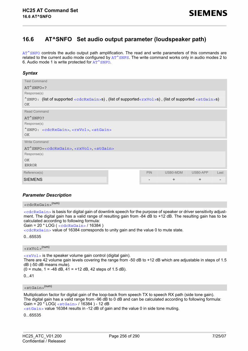
HC25 AT Command Set 16.6 AT^SNFO s
HC25_ATC_V01.200 Page 256 of 290 7/25/07Confidential / Released
16.6 AT^SNFO Set audio output parameter (loudspeaker path)
AT^SNFO controls the audio output path amplification. The read and write parameters of this commands arerelated to the current audio mode configured by AT^SNFS. The write command works only in audio modes 2 to6. Audio mode 1 is write protected for AT^SNFO.
Syntax
Parameter Description
<cdcRxGain> is basis for digital gain of downlink speech for the purpose of speaker or driver sensitivity adjust-ment. The digital gain has a valid range of resulting gain from -84 dB to +12 dB. The resulting gain has to becalculated according to following formula:Gain = 20 * LOG ( <cdcRxGain> / 16384 )<cdcRxGain> value of 16384 corresponds to unity gain and the value 0 to mute state. 0...65535
<rxVol> is the speaker volume gain control (digital gain).There are 42 volume gain levels covering the range from -50 dB to +12 dB which are adjustable in steps of 1.5dB (-50 dB means mute).(0 = mute, 1 = -48 dB, 41 = +12 dB, 42 steps of 1.5 dB). 0...41
Multiplication factor for digital gain of the loop-back from speech TX to speech RX path (side tone gain).The digital gain has a valid range from -96 dB to 0 dB and can be calculated according to following formula:Gain = 20 * LOG( <stGain> / 16384 ) - 12 dB<stGain> value 16384 results in -12 dB of gain and the value 0 in side tone muting. 0...65535
Test Command
AT^SNFO=?Response(s)
^SNFO: (list of supported <cdcRxGain>s) , (list of supported<rxVol>s) , (list of supported <stGain>s) OK
Read Command
AT^SNFO?Response(s)
^SNFO: <cdcRxGain>, <rxVol>, <stGain>OK
Write Command
AT^SNFO=<cdcRxGain>, <rxVol>, <stGain>Response(s)
OKERROR
Reference(s) PIN USB0-MDM USB0-APP Last
SIEMENS - + + -
<cdcRxGain>(num)
<rxVol>(num)
<stGain>(num)

HC25 AT Command Set 16.6 AT^SNFO s
HC25_ATC_V01.200 Page 257 of 290 7/25/07Confidential / Released
Notes• CAUTION! When you adjust audio parameters avoid exceeding the maximum allowed level. Bear in mind that
exposure to excessive levels of noise can cause physical damage to users! • All audio parameters handled by AT^SNFI and AT^SNFO will be stored volatile for the current audio mode. • When current audio mode is changing by AT^SNFS all parameters handled by AT^SNFI and AT^SNFO will
be set to start values of new audio mode. The same behaviour is noticed for customer specific audio modes.

HC25 AT Command Set 16.7 AT^SNFS s
HC25_ATC_V01.200 Page 258 of 290 7/25/07Confidential / Released
16.7 AT^SNFS Select audio hardware set
The AT^SNFS write command serves to set the audio mode required for the connected equipment. Each audiomode can be assigned to a specific interface.The AT^SNFS read command delivers the last configured audio mode. When TTY/CTM mode is activated byAT^SNFTTY configured and delivered audio mode is invalid, because TTY/CTM mode is defined as an own inter-nal audio mode.
Syntax
Parameter Description
[1] Audio mode 1: Standard mode optimized for the reference handset, that canbe connected to the analog interface (see "HC25 Hardware Interface Descrip-tion" for information on this handset).Note: The default parameters are determined for type approval and are notadjustable with AT commands.
2 Audio mode 2: Customer specific mode. This mode will be used for routerapplications.
3 Audio mode 3: Customer specific mode.This mode will be used for a user handset.
4 Audio mode 4: Customer specific mode.This mode will be used for a mono-headset.
5 Audio mode 5: Customer specific mode. This mode will be used for a speakerphone.
6 Audio mode 6: Customer specific mode.This mode will be used for a transparent application.
Test Command
AT^SNFS=?Response(s)
^SNFS: (list of supported <audMode>s) OK
Read Command
AT^SNFS?Response(s)
^SNFS: <audMode>OK
Write Command
AT^SNFS=<audMode>Response(s)
OKERROR
Reference(s) PIN USB0-MDM USB0-APP Last
SIEMENS - + + -
<audMode>(num)

HC25 AT Command Set 16.7 AT^SNFS s
HC25_ATC_V01.200 Page 259 of 290 7/25/07Confidential / Released
Notes• Audio mode 1 will be active each time after module is powered up.• The write command can be used during a voice call to switch back and forth between different modes. This
allows the user, for example, to switch handsfree operation (speakerphone) on and off.• After the sequence AT^SNFTTY=1 has been invoked the AT^SNFS read command does still indicate the last
active audio mode.• Value returned by the AT^SNFS read command is however no more valid if HC25 is operating in TTY/CTM
mode after invoking the AT^SNFTTY=1 AT sequence.• After switching back from TTY/CTM mode to the no-TTY/CTM mode the audio mode in use before activating
TTY/CTM mode becomes back active.

HC25 AT Command Set 16.8 AT^SNFTTY s
HC25_ATC_V01.200 Page 260 of 290 7/25/07Confidential / Released
16.8 AT^SNFTTY Signal TTY/CTM audio mode capability
HC25 offers an integrated implementation of CTM modem (Cellular Text Telephone Modems). The benefit ofCTM is that text characters typed on a TTY device (Text Telephone Type-writer) can be transformed into specialaudio burst signals for reliable transmission via the existing speech channels of a cellular phone system. Theinternal CTM modem supports a baud rate of 45.45bps. An automatic recognition of TTY devices isn't supported.If CTM mode is activated, the ME will set the necessary bearer capability bit on outgoing (mobile originated) callsand incoming calls with this bearer capability bit set are accepted. The TE needs to decode the special audioburst signals.If CTM mode is disabled, the ME will clear the bearer capability bit on mobile originated calls and incoming callswith the bearer capability bit set are rejected because the HC25 expects that CTM coded speech data cannot bedecoded by the TE.Designed to set the module's speech system into CTM mode, the AT^SNFTTY command allows a TTY deviceto be connected to the audio interfaces of HC25.Related documents: Refer to the relevant standards, such as 3GPP TS 26.226 (ETSI TS 126 226) and 3GPPTS 26.231 (ETSI TS 126 231). 3GPP documentation can be retrieved, for example, from http://www.3gpp.org/specs/specs.htm. Application Note 22 "Using TTY/CTM equipment" supplies information needed to connectTTY/CTM equipment to the HC25.
Requirements for using TTY/CTM features:• TTY/CTM functionality requires an own audio mode with all audio parameters set to their factory default. This
will be reached by an own internal audio mode for TTY/CTM use case which will be activated by AT^SNFTTYwrite command.When TTY/CTM mode is activated the delivered audio mode from AT^SNFS read command is invalid.
Syntax
Parameter Description
0(P) Audio path is in normal speech mode.1 Audio path is in TTY/CTM mode.
Test Command
AT^SNFTTY=?Response(s)
^SNFTTY: (list of supported <audioState>s) OK
Read Command
AT^SNFTTY?Response(s)
^SNFTTY: <audioState>OK
Write Command
AT^SNFTTY=<audioState>Response(s)
OKERROR
Reference(s) PIN USB0-MDM USB0-APP Last
SIEMENS - + + -
<audioState>(num)

HC25 AT Command Set 16.8 AT^SNFTTY s
HC25_ATC_V01.200 Page 261 of 290 7/25/07Confidential / Released
Notes• TTY/CTM mode 0 will be active each time after module is powered up.• The AT^SNFTTY=1 write command has to be set before ATD invocation.

HC25 AT Command Set 16.9 AT^SRTC s
HC25_ATC_V01.200 Page 262 of 290 7/25/07Confidential / Released
16.9 AT^SRTC Ring tone configuration
The AT^SRTC test command returns a list of ranges for parameter <event>, <number> and <volume>.
The AT^SRTC read command returns the current ring tone configuration parameter ring tone melody <number>and ring tone volume <volume> for the incoming <event>s voice call, fax call and SMS.
The AT^SRTC write command allows to configure parameter ring tone melody <number> and ring tone volume<volume> for ring tone events <event> voice call, fax call and SMS.
The AT^SRTC execution command starts the ring tone test using current settings for fax calls. Please callAT^SRTC execution command again to stop ring tone test.The settings can be changed no matter whether or not the ME is ringing. The selected parameters are saved inthe volatile RAM memory and, thus, to select again after each Power Down.
Syntax
Parameter Description
Ring tone melodies for incoming Voice calls, Fax calls or SMS messages are supported. Melody will be playedfrom the audio output. 0 Ringing alert for incoming Voice calls. 1 Ringing alert for incoming Fax calls. 2 Ringing alert for incoming SMS messages.
Test Command
AT^SRTC=?Response(s)
^SRTC:(list of supported <event>s) , (list of supported <number>s) , (list of supported <volume>s) OK
Read Command
AT^SRTC?Response(s)
^SRTC: 0, <number>, <volume>^SRTC: 1, <number>, <volume>^SRTC: 2, <number>, <volume>OK
Exec Command
AT^SRTCResponse(s)
OK
Write Command
AT^SRTC=<event>, <number>, <volume>Response(s)
OKERROR
Reference(s) PIN USB0-MDM USB0-APP Last
SIEMENS - + + -
<event>(num)

HC25 AT Command Set 16.9 AT^SRTC s
HC25_ATC_V01.200 Page 263 of 290 7/25/07Confidential / Released
Type or number of ring tone melody. You have a choice of ring tone melody or mute. Ring tone melody will beplayed from the audio output. <number>=0 is only intended for muting. 0(D) No ringing alert melody. 1 Melody #1 active. 2 Melody #2 active. 3 Melody #3 active. 4 Melody #4 active. 5 Melody #5 active. 6 Melody #6 active. 7 Melody #7 active. 8 Melody #8 active. 9 Melody #9 active.
The volume of ring tone melodies varies from 0 dB to mute. 0(D) Mute. 1 Volume level 1, set to -12dB. 2 Volume level 2, set to -8dB. 3 Volume level 3, set to -4dB. 4 Volume level 4, set to 0dB.
Note• The ring tone factory setting are AT^SRTC=0,0,0 (ring tones for incoming voice call is muted), AT^SRTC=1,0,0
(ring tones for incoming fax call is muted) and AT^SRTC=2,0,0 (ring tones for incoming SMS is muted). Toactivate ring tones please use the write command. After applying a firmware update or a new start of moduleplease activate ring tone again because it is stored in the volatile memory.When the incoming fax call event was configured before with <number>=0 it's possible to mute a runningtone (for example during a incoming call) by calling of AT^SRTC execution command. Otherwise please callAT^SRTC execution command two times.
<number>(num)
<volume>(num)

HC25 AT Command Set 17. Hardware Related Commands s
HC25_ATC_V01.200 Page 264 of 290 7/25/07Confidential / Released
17. Hardware Related Commands
The AT commands described in this chapter are related to the hardware interface of the HC25. Further informa-tion regarding this interface is available in the "HC25 Hardware Interface Description"[2].
17.1 AT^SLED LED Feature
The AT^SLED command controls the LED function provided by the two status pins (STATUS0 and STATUS1)of the HC25. Each pin acts as a current sink and can be used to control a connected LED. The electrical speci-fications of the status pins and advice on how to install the LED circuit can be found in [2]. The LEDs indicate thestates listed below:
LED connected to STATUS0 line: • Lights steadily (if <mode>=1) or flashes (depending on <flash_period> if <mode>=2) when the ME is reg-
istered to the GSM network and either awake or in power saving state. • Flashes at 1Hz and 50% duty cycle (0.5s on, 0.5s off) when the ME is awake and not registered to any net-
work. • Flashes at approx. 0.25 Hz and approx. 50% duty cycle (2s on, 2s off) when the ME is in power saving state
and not registered to any network. When the ME is in power saving state and not registered, the flashing frequency may be less than 0.25Hzand the duty cycle may vary, for example between 45% and 55%. These variations are not regular.
• If not registered the ME checks, at the beginning of each flash period, whether it is awake or in power savingstate, ie. whether to flash at 1Hz or at 0.25Hz. This means that a 1Hz or at 0.25Hz flash period always reflectsthe state that was valid before flashing has started. If a state transition occurs during a flash period (fromawake to power saving or vice versa) then the flash period may vary. In the worst case, the LED will indicatea transition from power saving to awake after 4s.
• Is off if the ME is not registered to the GSM network, but registered to the UMTS, or if <mode>=0. • While the STATUS0 signal is active the STATUS1 signal is inactive.
LED connected to STATUS1 line: • Lights steadily (if <mode>=1) or flashes (depending on <flash_period> if <mode>=2) when the ME is reg-
istered to the UMTS network and either awake or in power saving state. • Is off if the ME is not registered to the UMTS network, or if <mode>=0. • While the STATUS1 signal is active the STATUS0 signal is inactive.
SyntaxTest Command
AT^SLED=?Response(s)
^SLED: (list of supported <mode>s), (range of supported <flash_period>s)OK
Read Command
AT^SLED?Response(s)
^SLED: <mode>[, <flash_period>]OK

HC25 AT Command Set 17.1 AT^SLED s
HC25_ATC_V01.200 Page 265 of 290 7/25/07Confidential / Released
Parameter Description
LED operating mode0(P) LED feature is disabled.1 LED lights steadily when the ME is registered to the network and either awake
or in power saving state. 2 LED is flashing when the ME is registered to the network and either awake or
in power saving state. The duration of flashing can be configured using theparameter <flash_period>.
LED flash period1...10(P)...50 LED flash period (in milliseconds) if <mode>=2. LED off-time between flashing
is approximately 4 seconds and is not configurable.
Write Command
AT^SLED=<mode>[, <flash_period>]Response(s)
OK ERROR +CME ERROR: <err>
Reference(s) PIN USB0-MDM USB0-APP Last
SIEMENS - + + -
<mode>(num)
<flash_period>(num)

HC25 AT Command Set 17.2 AT^SBV s
HC25_ATC_V01.200 Page 266 of 290 7/25/07Confidential / Released
17.2 AT^SBV Battery/Supply Voltage
The AT^SBV execute command allows to monitor the supply (or battery) voltage of the module. The voltage iscontinuously measured at intervals depending on the operating mode of the RF interface. The duration of a mea-surement period ranges from 0.5s in TALK / DATA mode up to 50s when HC25 is in IDLE mode or Limited Ser-vice (deregistered). The displayed value is averaged over the last measuring period before the AT^SBVcommand was executed.
The measurement is related to the test points of BATT+ and GND, both accessible on the bottom of the module.Refer to [1] for information on the module's test points.
Syntax
Parameter Description
Supply (or battery) voltage in mV
Test Command
AT^SBV=?Response(s)
OKERROR+CME ERROR:
Exec Command
AT^SBVResponse(s)
^SBV: <value>OKERROR+CME ERROR:
Reference(s) PIN USB0-MDM USB0-APP Last
SIEMENS - + + -
<value>(num)

HC25 AT Command Set 17.3 AT^SCTM s
HC25_ATC_V01.200 Page 267 of 290 7/25/07Confidential / Released
17.3 AT^SCTM Set critical operating temperature presentation mode or query temperature
Use this command to monitor the temperature range of the module. The write command enables or disables thepresentation of URCs to report critical temperature limits.CAUTION: During the first 15 seconds after start-up, the module operates in an automatic report mode: URCscan be always displayed regardless of the selected mode <n>.
Syntax
Unsolicited Result CodeURCs will be automatically sent to the TA when the temperature reaches or exceeds the critical level, or when itis back to normal. ^SCTM_B: <m>
for module (board) temperature
Command DescriptionThe read command returns: • the URC presentation mode• information about the current temperature range of the moduleSelect <n> to enable or disable the presentation of the URCs. Please note that the setting will not be stored uponPower Down, i.e. after restart or reset, the default <n>=0 will be restored. To benefit from the URCs <n>=1 needsto be selected every time you reboot the GSM engine.
Test Command
AT^SCTM=?Response(s)
^SCTM:(list of supported <n>s)OK
Read Command
AT^SCTM?Response(s)
^SCTM: <n>, <m>OKERROR+CME ERROR
Write Command
AT^SCTM=<n>Response(s)
OKERROR+CME ERROR
Reference(s) PIN USB0-MDM USB0-APP Last
SIEMENS - + + -

HC25 AT Command Set 17.3 AT^SCTM s
HC25_ATC_V01.200 Page 268 of 290 7/25/07Confidential / Released
Parameter Description
0(&F)(P) Presentation of URCs is disabled (except for <m> equal to -2 or +2). 1 Presentation of URCs is enabled.
-2 Below lowest temperature limit (causes immediate switch-off) -1 Below low temperature alert limit0 Normal operating temperature1 Above upper temperature alert limit2 Above uppermost temperature limit (causes immediate switch-off)
Notes• Please refer to the "Hardware Interface Description" for specifications on critical temperature ranges. • To avoid damage the module will shut down once the critical temperature is exceeded.
The procedure is equivalent to the power-down initiated with AT^SMSO. • URCs indicating the alert level "1" or "-1" are intended to enable the user to take appropriate precautions,
such as protect the module from exposure to extreme conditions, or save or back up data etc. The presenta-tion of "1" or "-1" URCs depends on the settings selected with the write command:If <n>=0: Presentation is enabled for 15 s time after the module was switched on. After 15 s operation, thepresentation will be disabled, i.e. no URCs will be generated.If <n>= 1: Presentation of "1" or "-1" URCs is always enabled.
• Level "2" or "-2" URCs are followed by immediate shutdown. The presentation of these URCs is alwaysenabled, i.e. they will be output even though the factory setting AT^SCTM=0 was never changed.
• If the temperature limit is exceeded while an emergency call is in progress the engine continues to measurethe temperature and to deliver alert messages, but deactivates the shutdown functionality. Once the call isterminated full temperature control will be resumed. If the temperature is still out of range ME switches offimmediately.
ExamplesEXAMPLE 1
URCs issued when the operating temperature is out of range:
EXAMPLE 2
URCs issued when the temperature is back to normal (URC is output once):
<n>(num)
<m>(num)
^SCTM_B: 1 Caution: Module close to overtemperature limit. ^SCTM_B: 2 Alert: Module is above overtemperature limit and switches off. ^SCTM_B: -1 Caution: Module close to undertemperature limit. ^SCTM_B: -2 Alert: Module is below undertemperature limit and switches off.
^SCTM_B: 0 Module back to normal temperature.

HC25 AT Command Set 18. Miscellaneous Commands s
HC25_ATC_V01.200 Page 269 of 290 7/25/07Confidential / Released
18. Miscellaneous Commands
The AT Commands described in this chapter are related to various areas.
18.1 ATS3 Set command line termination character
The ATS3 command determines the character recognized by the TA to terminate an incoming command line. Itis also generated for result codes and information text, along with the ATS4 parameter.
Syntax
Parameter Description
command line termination character000...13(&F)...127
Note• Using a value other than the default 13 may cause problems when entering commands.
Read Command
ATS3?Response(s)
<n>OK
Write Command
ATS3=<n>Response(s)
OKERROR
Reference(s) PIN USB0-MDM USB0-APP Last
V.250 - + + -
<n>(num)
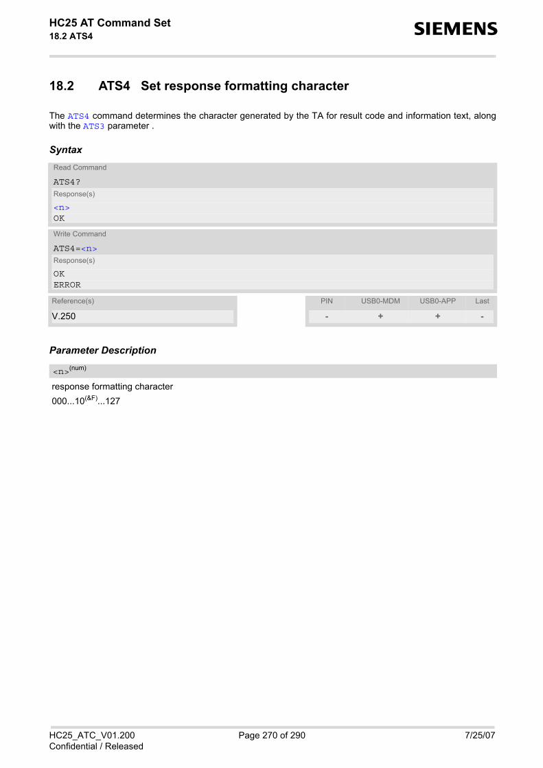
HC25 AT Command Set 18.2 ATS4 s
HC25_ATC_V01.200 Page 270 of 290 7/25/07Confidential / Released
18.2 ATS4 Set response formatting character
The ATS4 command determines the character generated by the TA for result code and information text, alongwith the ATS3 parameter .
Syntax
Parameter Description
response formatting character000...10(&F)...127
Read Command
ATS4?Response(s)
<n>OK
Write Command
ATS4=<n>Response(s)
OKERROR
Reference(s) PIN USB0-MDM USB0-APP Last
V.250 - + + -
<n>(num)

HC25 AT Command Set 18.3 ATS5 s
HC25_ATC_V01.200 Page 271 of 290 7/25/07Confidential / Released
18.3 ATS5 Write command line editing character
Syntax
Command DescriptionThis parameter setting determines the character recognized by TA as a request to delete the immediately pre-ceding character from the command line.
Parameter Description
command line editing character000...8(&F)...127
Read Command
ATS5?Response(s)
<n>OK
Write Command
ATS5=<n>Response(s)
OKERROR
Reference(s) PIN USB0-MDM USB0-APP Last
V.250 - + + -
<n>(num)

HC25 AT Command Set 18.4 AT^SFDL s
HC25_ATC_V01.200 Page 272 of 290 7/25/07Confidential / Released
18.4 AT^SFDL Enter Firmware Download Mode
The AT^SFDL command allows the application manufacturer to download HC25 firmware into the module bystarting the download process from the host application or a customer-designed download program. The down-load can be done over the USB interface.
For this purpose, the HC25 firmware update file must be available in the format *.USF. The file can be requestedfrom Siemens. The firmware file consists of records to be transferred one by one from the host application to themodule.
This manual only describes the handling of the AT^SFDL command. All technical requirements and steps to pre-pare the host application for this download solution can be found in the Application Note "Updating Firmware".An example for developing an appropriate download program is included.
The AT^SFDL execute command causes the module to enter the firmware download mode (this may take somemilliseconds). After entering the download mode the module sends the start pattern HEX 0x01 ("ANSWER_OK")to the application to indicate its ready state. Next, the application shall start to send the records of the firmwarefile. Each record received on the module is acknowledged to the host application. Once all records are success-fully received, the module shuts down automatically.
If a valid firmware is still installed, but the AT^SFDL command is issued without sending any firmware afterwardsthe module will stay in ready state. In this case it must be switched off.
SyntaxTest Command
AT^SFDL=?Response(s)
OK
Exec Command
AT^SFDLResponse(s)
OK
Reference(s) PIN USB0-MDM USB0-APP Last
SIEMENS - + + +

HC25 AT Command Set 19. Appendix s
HC25_ATC_V01.200 Page 273 of 290 7/25/07Confidential / Released
19. Appendix
19.1 Restricted access to SIM data after SIM PIN authentication
The following commands can be used only after data from the SIM have been read successfully for the first time.Reading starts after successful SIM authentication has been performed, and may take up to 30 seconds depend-ing on the SIM used. While the read process is in progress, an attempt to use any of the following commandswill result in "+CME Error: 14" (SIM busy).
The "^SIND: simstatus" URC enabled with AT^SIND can be used to notify the user when the ME has finishedreading the SIM card and SIM data are accessible after SIM PIN authentication.
ø ... AT Command not available- ... AT command accessible immediately after PIN entry has returned OK+ ... AT command fully accessible after SIM PIN authentication has been completed
AT Command Exec Test Read WriteAT+CMGL + - ø +AT+CMGR ø - ø +AT+CSCA ø - + -AT+CNUM + + ø øAT+CPBF ø + ø +AT+CPBR ø + ø +AT+CPBS ø + + +AT+CPBW ø + ø +

HC25 AT Command Set 19.2 Star-Hash (*#) Network Commands s
HC25_ATC_V01.200 Page 274 of 290 7/25/07Confidential / Released
19.2 Star-Hash (*#) Network Commands
The following command strings can be sent to the network via ATD and have to be terminated with a semicolon.The command strings are defined with GSM 2.30 [12].
Table 19.1: Star-Hash (*#) Command Overview
Star-Hash Code Functionality Response, also refer to Table 19.3
Phone Security*#06# Query IMEI <IMEI> OK **04[2]*oldPin[2]*newPin[2]*new-Pin[2]#
Change SIM pwd +CME ERROR: <err> / OK
**05[2]*unblKey[2]*newPin[2]*new-Pin[2]#
Change/Unblocking SIM pwd +CME ERROR: <err> / OK
*[*]03*[ZZ]*oldPw*newPw*newPw# Registration of net password +CME ERROR: <err> / OK
Phone number presentation*#30# Check status of CLIP (Calling Line
Identification Presentation) +CLIP : <n>,<m> OK (see AT+CLIP)
*#31# Check status of CLIR (Calling Line Identification Restriction)
+CLIR : <n>,<m> OK (see AT+CLIR)
*31#<Phonenumber>[;] Suppress CLIR (see AT+CLIR) #31#<Phonenumber>[;] Activate CLIR (see AT+CLIR) *#76# Check status of COLP (Connected
Line Identification Presentation) +COLP : 0,<m> OK (where <m> = active or not active)
*#77# Check status of COLR (Connected Line Identification Restriction)
+COLR : 0,<m> OK (where <m> = active or not active)
Call forwarding(choice of *,#,*#,**,##)21*DN*BS# Act/deact/int/reg/eras CFU +CCFC : <status>, <class> [,...]
(see: AT+CCFC)(choice of *,#,*#,**,##)67*DN*BS# Act/deact/int/reg/eras CF busy see above(choice of *,#,*#,**,##)61*DN*BS*T#
Act/deact/int/reg/eras CF no reply see above
(choice of *,#,*#,**,##)62*DN*BS# Act/deact/int/reg/eras CF no reach see above(choice of *,#,*#,**,##)002*DN*BS*T#
Act/deact/int/reg/eras CF all see above
(choice of *,#,*#,**,##)004*DN*BS*T#
Act/deact/int/reg/eras CF all cond. see above
Call waiting(choice of *,#,*#)43*BS# Activation/deactivation/int WAIT +CCWA : <status>, <class> [,...].
(Refer to AT+CCWA)
Call barring(choice of *,#,*#)33*Pw*BS# Act/deact/int BAOC +CLCK : <status>, <class> [,
...].(Refer to AT+CLCK)(choice of *,#,*#)331*Pw*BS# Act/deact/int BAOIC see above(choice of *,#,*#)332*Pw*BS# Act/deact/int BAOIC exc.home see above

HC25 AT Command Set 19.2 Star-Hash (*#) Network Commands s
HC25_ATC_V01.200 Page 275 of 290 7/25/07Confidential / Released
Table 19.2: Abbreviations of Codes and Parameters used in Table 19.1
Table 19.3: Star-Hash Command Response Parameters
(choice of *,#,*#)35*Pw*BS# Act/deact/int. BAIC see above(choice of *,#,*#)351*Pw*BS# Act/deact/int BAIC roaming see above#330*Pw*BS# Deact. All Barring Services see above#333*Pw*BS# Deact. All Outg.Barring Services see above#353*Pw*BS# Deact. All Inc.Barring Services see above
Call Hold / MultipartyC[C] in call Call hold and multiparty +CME ERROR: <err> / OK
USSD messages[C]...[C]# Send USSD message +CME ERROR: <err> / OK C[C] (excluded 1[C]) Send USSD message +CME ERROR: <err> / OK
Abbreviation Meaning ValueZZ Type of supplementary services:
Barring servicesAll services
330Not specified
DN Dialing number String of digits 0-9BS Basic service equivalent to parameter class:
VoiceFAXSMSSMS+FAXData circuit asynchronData circuit synchronDedicated PAD accessDedicated Packet accessData circuit asynchron+PADData circuit synchron+PacketData circuit asynchron+synchron+Packet+PADAll Services
1113161225242726212220--
T Time in seconds In contrast to AT+CCFC, parameter T has no default value. If T is not specified, an operator defined default or the last known value may be used, depending on the network operator.
PW Password -- C Character of TE character set (e.g. asterics, hash
or digit in case of USSD, or digits in case of held calls or multiparty calls)
--
Parameter Meaning<m> Mode: 0 = not active, 1 = active <n> Unsolicited result code: 0 = presentation disabled, 1 = presentation enabled <status> Status: 0 = not active, 1 = active <class> Represents BS = basic service, refer to AT+CCFC, AT+CLCK
Star-Hash Code Functionality Response, also refer to Table 19.3

HC25 AT Command Set 19.2 Star-Hash (*#) Network Commands s
HC25_ATC_V01.200 Page 276 of 290 7/25/07Confidential / Released
For exact specification of format and parameters for Star-Hash commands refer to GSM 02.04, Table 3.2 [11]and GSM 02.30, Annex C [12].
Table 19.4: Star-Hash Commands for Supplementary Services
<fac> Facility lock, refer to AT+CLCK <reason> Call forwarding reason
Star-Hash Code Abbreviations in Table 19.1 Functionality * act Activate (except for CLIR, see list above)** reg Register and activate*# int Check status (interrogate)# deact Deactivate (except for CLIR, see list above)## eras Unregister and deactivate
Parameter Meaning

HC25 AT Command Set 19.3 Available AT Commands and Dependency on SIM PIN s
HC25_ATC_V01.200 Page 277 of 290 7/25/07Confidential / Released
19.3 Available AT Commands and Dependency on SIM PIN
ø ... Command not available- ... Command does not require PIN1+ ... Command requires PIN1± ... Command sometimes requires PIN1
Table 19.5: Available AT Commands and Dependency on SIM PIN
AT Command Exec Test Read Write
Configuration CommandsAT&F + ø ø øAT&V + ø ø øATQ + ø ø øATV - ø ø øATX + ø ø øATZ + ø ø øAT+CFUN ø - - -AT+CMEE - - - -AT+CSCS ø + + +AT+GCAP + + ø øAT^SCFG ø - - -AT^SMSO - - ø øAT^SUSB ø ø - -
Status Control CommandsAT^SIND ø - - -AT+CEER + + ø øAT+CPAS - - ø øAT+WS46 ø - - -
Serial Interface Control CommandsAT^SQPORT - - - øAT&C + ø ø øAT&D + ø ø øAT&S - ø ø øATE - ø ø ø
Security CommandsAT+CLCK ø + ø +AT+CPIN ø - - -AT+CPWD ø + ø +AT^SCSL ø - ø -

HC25 AT Command Set 19.3 Available AT Commands and Dependency on SIM PIN s
HC25_ATC_V01.200 Page 278 of 290 7/25/07Confidential / Released
Identification CommandsATI - ø ø øAT+CGMI - - ø øAT+GMI - - ø øAT+CGMM - - ø øAT+GMM - - ø øAT+CGMR - - ø øAT+GMR - - ø øAT+CGSN - - ø øAT+GSN - - ø øAT+CIMI + + ø ø
Call related CommandsATA + ø ø øATD ± ø ø øATD><mem><n> + ø ø øATD><n> + ø ø øATD><str> + ø ø øATH + ø ø øAT+CHUP - - ø øATS0 ø ø + +ATS6 ø ø + +ATS7 ø ø + +ATS8 ø ø + +ATS10 ø ø + +ATO + ø ø ø+++ - ø ø øAT+CLCC + + ø øAT+CR ø + + +AT+CRC + + + +AT+CBST ø + + +AT+CRLP ø + + +ATP + ø ø øATT + ø ø øAT+ES ø - ± ±AT+ESA ø - + +AT+CSTA ø + + +
Network Service CommandsAT+COPN + + ø øAT+COPS + + + +AT^SOPS ø + ø ø
AT Command Exec Test Read Write

HC25 AT Command Set 19.3 Available AT Commands and Dependency on SIM PIN s
HC25_ATC_V01.200 Page 279 of 290 7/25/07Confidential / Released
AT+CREG - - - -AT+CSQ + + ø øAT^SMONI - - ø øAT^SMONP - - ø øAT^SNWS ø + ø +
Supplementary Service CommandsAT+CACM ø + + +AT+CAMM ø + + +AT+CAOC + + + +AT+CCUG ø + + +AT+CCFC ø + ø +AT+CCWA ø + + +AT+CHLD ø + ø +AT+CLIP ø - + -AT+CLIR ø + + +AT+COLP ø + + +AT+CPUC ø + + +AT+CSSN ø + + +AT+CUSD ø + + +
GPRS CommandsAT+CGATT ø + + +AT+CGACT ø + + +AT+CGDATA ø + ø +AT+CGDCONT ø + + +AT+CGPADDR + + ø +AT+CGQMIN ø + + +AT+CGEQMIN ø + + +AT+CGREG ø + + +AT+CGQREQ ø + + +AT+CGEQREQ ø + + +AT+CGSMS ø + + +AT+CGTFT ø + + +ATD*99# + ø ø øAT^SGAUTH ø + + +
FAX CommandsAT+FCLASS ø + + +AT+FAR + + + +AT+FDD + + + +AT+FCL + + + +AT+FIT + + + +
AT Command Exec Test Read Write

HC25 AT Command Set 19.3 Available AT Commands and Dependency on SIM PIN s
HC25_ATC_V01.200 Page 280 of 290 7/25/07Confidential / Released
AT+FTS ø + ø +AT+FRS ø + ø +AT+FTM ø + ø +AT+FRM ø + ø +AT+FTH ø + ø +AT+FRH ø + ø +
Short Message Service (SMS) CommandsAT+CMGC ø + ø +AT+CMGD ø + ø +AT+CMGF ø + + +AT+CMGL + + ø +AT+CMGR ø + ø +AT+CMGS ø + ø +AT+CMGW + + ø +AT+CMMS ø + + +AT+CMSS ø + ø +AT+CNMA + + ø +AT+CNMI ø + + +AT+CPMS ø + + +AT+CSCA ø + + +AT+CSCB ø + + +AT+CSMP ø + + +AT+CSMS ø + + +AT^SMGL + + ø +
SIM related CommandsAT+CRSM ø - ø -AT+CSIM ø - ø -AT^SCKS ø - - -
SIM Application Toolkit (SAT) CommandsAT^SSTA ø - - -^SSTN ø ø ø øAT^SSTGI ø - - -AT^SSTR ø - - -
Phonebook CommandsAT+CNUM + + ø øAT+CPBF ø + ø +AT+CPBR ø + ø +AT+CPBS + + + +AT+CPBW ø + ø +
AT Command Exec Test Read Write

HC25 AT Command Set 19.3 Available AT Commands and Dependency on SIM PIN s
HC25_ATC_V01.200 Page 281 of 290 7/25/07Confidential / Released
Audio CommandsATL + ø ø øATM + ø ø øAT+CMUT ø - - -AT+VTS ø - ø -AT^SNFI ø - - -AT^SNFO ø - - -AT^SNFS ø - - -AT^SNFTTY ø - - -AT^SRTC - - - -
Hardware Related CommandsAT^SLED ø - - -AT^SBV - - ø øAT^SCTM ø - - -
Miscellaneous CommandsATS3 ø ø - -ATS4 ø ø - -ATS5 ø ø - -AT^SFDL - - ø ø
AT Command Exec Test Read Write

HC25 AT Command Set 19.4 Factory Default Settings Restorable with AT&F s
HC25_ATC_V01.200 Page 282 of 290 7/25/07Confidential / Released
19.4 Factory Default Settings Restorable with AT&F
Table 19.6: Factory Default Settings Restorable with AT&F
AT Command Factory Defaults
Configuration CommandsATQ <n>=0ATV <value>=1ATX <value>=0AT+CMEE <errMode>=0AT+CSCS <chset>="IRA"
Status Control CommandsAT^SIND <mode>=0
Serial Interface Control CommandsAT&C <value>=2AT&D <value>=2AT&S <value>=0ATE <value>=1
Call related CommandsATS0 <n>=000ATS6 <n>=2ATS7 <n>=050ATS8 <n>=2ATS10 <n>=014AT+CR <mode>=0AT+CRC <mode>=0AT+CBST <speed>=0, <name>=0, <ce>=1AT+CRLP <iws>=61, <mws>=61, <T1>=48, <N2>=6
Network Service CommandsAT+COPS <format>=0AT+CREG <n>=0
Supplementary Service CommandsAT+CLIP <n>=0AT+CSSN <n>=0, <m>=0AT+CUSD <n>=0
GPRS CommandsAT+CGREG <n>=0

HC25 AT Command Set 19.4 Factory Default Settings Restorable with AT&F s
HC25_ATC_V01.200 Page 283 of 290 7/25/07Confidential / Released
Short Message Service (SMS) CommandsAT+CMGF <mode>=0AT+CNMI <mode>=0, <mt>=0, <bm>=0, <ds>=0, <bfr>=1AT+CSCB <operation>=0AT+CSMP <dcs>=0, <pid>=0AT+CSMS <service>=0
SIM related CommandsAT^SCKS <mode>=0
Phonebook CommandsAT+CPBS <storage>="SM"
Hardware Related CommandsAT^SCTM <n>=0
Miscellaneous CommandsATS3 <n>=013ATS4 <n>=010ATS5 <n>=008
AT Command Factory Defaults

HC25 AT Command Set 19.5 Summary of Unsolicited Result Codes (URC) s
HC25_ATC_V01.200 Page 284 of 290 7/25/07Confidential / Released
19.5 Summary of Unsolicited Result Codes (URC)
Table 19.7: Summary of Unsolicited Result Codes (URC)
AT Command URC
Unsolicited Result Code Presentation^SBC: Undervoltage^SBC: Overvoltage Warning^SBC: Overvoltage Shutdown
Status Control CommandsAT^SIND +CIEV: <indDescr>, <indValue>AT^SIND +CIEV: <indDescr>, <indValue>, <eonsOperator>, <servProvider>,
<servProviderType>
AT^SIND +CIEV: <indDescr>, <nitzUT>, <nitzTZ>, <nitzDST>AT+CRC RING
AT+CRC +CRING: <type>
Network Service CommandsAT+CREG +CREG: <stat>AT+CREG +CREG: <stat>[, <lac>, <ci>]
Supplementary Service CommandsAT+CAOC +CCCM: <ccm>AT+CCWA +CCWA: <calling number>, <type of number>[, <class>], [, <CLI validity>]AT+CLIP +CLIP: <number>, <type>, , [, <alpha>][, <CLI validity>]AT+COLP +COLP: <number>, <type>[, <sub-number>][, <sub-type>][, <alpha>]AT+CSSN +CSSI: <code 1>AT+CSSN +CSSU: <code 2>AT+CUSD +CUSD: <m>[<str_urc>[<dcs>]]
GPRS CommandsAT+CGREG +CGREG: <stat>
Short Message Service (SMS) CommandsAT+CNMI +CMTI: <mem3>, <index>AT+CNMI +CMT: <length><CR><LF><pdu>AT+CNMI +CMT: <oa>, <scts>[, <tooa>, <fo>, <pid>, <dcs>, <sca>, <tosca>,
<length>]<CR><LF><data>AT+CNMI +CBM: <length><CR><LF><pdu>AT+CNMI +CBM: <sn>, <mid>, <dcs>, <page>, <pages><CR><LF><data>AT+CNMI +CDS: <length><CR><LF><pdu>AT+CNMI +CDS: <fo>, <mr>[, <ra>][, <tora>], <scts>, <dt>, <st>AT+CNMI +CDSI: <mem3>, <index>

HC25 AT Command Set 19.5 Summary of Unsolicited Result Codes (URC) s
HC25_ATC_V01.200 Page 285 of 290 7/25/07Confidential / Released
SIM related CommandsAT^SCKS ^SCKS: <SimStatus>AT^SCKS ^SCRD: <MCC>
SIM Application Toolkit (SAT) Commands^SSTN ^SSTN: <cmdType>^SSTN ^SSTN: <cmdTerminateValue>^SSTN ^SSTN: 254^SSTN ^SSTN: 255
Hardware Related CommandsAT^SCTM ^SCTM_B: <m>
AT Command URC

HC25 AT Command Set 19.6 AT Commands Supported Only on the Modem Interface s
HC25_ATC_V01.200 Page 286 of 290 7/25/07Confidential / Released
19.6 AT Commands Supported Only on the Modem Interface
Table 19.8: AT Commands Supported Only on the Modem Interface
AT Command
Call related CommandsATO
+++
GPRS CommandsAT+CGDATA
ATD*99#
FAX CommandsAT+FTM
AT+FRM
AT+FTH
AT+FRH
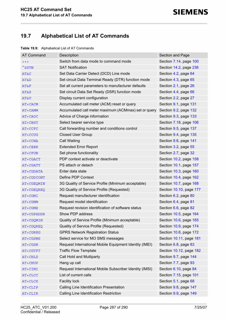
HC25 AT Command Set 19.7 Alphabetical List of AT Commands s
HC25_ATC_V01.200 Page 287 of 290 7/25/07Confidential / Released
19.7 Alphabetical List of AT Commands
Table 19.9: Alphabetical List of AT Commands
AT Command Description Section and Page+++ Switch from data mode to command mode Section 7.14, page 100^SSTN SAT Notification Section 14.2, page 236AT&C Set Data Carrier Detect (DCD) Line mode Section 4.2, page 64AT&D Set circuit Data Terminal Ready (DTR) function mode Section 4.3, page 65AT&F Set all current parameters to manufacturer defaults Section 2.1, page 26AT&S Set circuit Data Set Ready (DSR) function mode Section 4.4, page 66AT&V Display current configuration Section 2.2, page 27AT+CACM Accumulated call meter (ACM) reset or query Section 9.1, page 131AT+CAMM Accumulated call meter maximum (ACMmax) set or query Section 9.2, page 132AT+CAOC Advice of Charge information Section 9.3, page 133AT+CBST Select bearer service type Section 7.18, page 106AT+CCFC Call forwarding number and conditions control Section 9.5, page 137AT+CCUG Closed User Group Section 9.4, page 135AT+CCWA Call Waiting Section 9.6, page 141AT+CEER Extended Error Report Section 3.2, page 55AT+CFUN Set phone functionality Section 2.7, page 32AT+CGACT PDP context activate or deactivate Section 10.2, page 158AT+CGATT PS attach or detach Section 10.1, page 157AT+CGDATA Enter data state Section 10.3, page 160AT+CGDCONT Define PDP Context Section 10.4, page 162AT+CGEQMIN 3G Quality of Service Profile (Minimum acceptable) Section 10.7, page 168AT+CGEQREQ 3G Quality of Service Profile (Requested) Section 10.10, page 177AT+CGMI Request manufacturer identification Section 6.2, page 80AT+CGMM Request model identification Section 6.4, page 81AT+CGMR Request revision identification of software status Section 6.6, page 82AT+CGPADDR Show PDP address Section 10.5, page 164AT+CGQMIN Quality of Service Profile (Minimum acceptable) Section 10.6, page 165AT+CGQREQ Quality of Service Profile (Requested) Section 10.9, page 174AT+CGREG GPRS Network Registration Status Section 10.8, page 172AT+CGSMS Select service for MO SMS messages Section 10.11, page 181AT+CGSN Request International Mobile Equipment Identity (IMEI) Section 6.8, page 83AT+CGTFT Traffic Flow Template Section 10.12, page 182AT+CHLD Call Hold and Multiparty Section 9.7, page 144AT+CHUP Hang up call Section 7.7, page 93AT+CIMI Request International Mobile Subscriber Identity (IMSI) Section 6.10, page 84AT+CLCC List of current calls Section 7.15, page 101AT+CLCK Facility lock Section 5.1, page 68AT+CLIP Calling Line Identification Presentation Section 9.8, page 147AT+CLIR Calling Line Identification Restriction Section 9.9, page 149

HC25 AT Command Set 19.7 Alphabetical List of AT Commands s
HC25_ATC_V01.200 Page 288 of 290 7/25/07Confidential / Released
AT+CMEE Mobile Equipment Error Message Format Section 2.8, page 33AT+CMGC Send an SMS command Section 12.2, page 203AT+CMGD Delete short message Section 12.3, page 204AT+CMGF Select SMS message format Section 12.4, page 205AT+CMGL List SMS messages from preferred store Section 12.5, page 206AT+CMGR Read SMS messages Section 12.6, page 208AT+CMGS Send Short Message Section 12.7, page 210AT+CMGW Write Short Messages to Memory Section 12.8, page 211AT+CMMS More Messages to Send Section 12.9, page 212AT+CMSS Send short messages from storage Section 12.10, page 213AT+CMUT Mute control Section 16.3, page 252AT+CNMA New Message Acknowledgement to ME/TE, only phase
2+Section 12.11, page 214
AT+CNMI New short Message Indication Section 12.12, page 215AT+CNUM Read own numbers Section 15.1, page 239AT+COLP Connected Line Identification Presentation Section 9.10, page 150AT+COPN Read operator names Section 8.1, page 115AT+COPS Operator Selection Section 8.2, page 116AT+CPAS Mobile equipment activity status Section 3.3, page 61AT+CPBF Find phonebook entries Section 15.2, page 240AT+CPBR Read from phonebook Section 15.3, page 243AT+CPBS Select phonebook memory storage Section 15.4, page 246AT+CPBW Write into phonebook Section 15.5, page 248AT+CPIN PIN Authentication Section 5.2, page 72AT+CPMS Preferred SMS message storage Section 12.13, page 218AT+CPUC Price per unit and currency table Section 9.11, page 152AT+CPWD Change Password Section 5.3, page 75AT+CR Service reporting control Section 7.16, page 103AT+CRC Set Cellular Result Codes for incoming call indication Section 7.17, page 104AT+CREG Network Registration Section 8.4, page 121AT+CRLP Select radio link protocol parameters for originated non-
transparent data callsSection 7.19, page 108
AT+CRSM Restricted SIM Access Section 13.1, page 228AT+CSCA SMS Service Center Address Section 12.14, page 220AT+CSCB Select Cell Broadcast Message Indication Section 12.15, page 221AT+CSCS Select TE character set Section 2.9, page 37AT+CSIM Generic SIM Access Section 13.2, page 230AT+CSMP Set SMS text Mode Parameters Section 12.16, page 223AT+CSMS Select Message Service Section 12.17, page 225AT+CSQ Signal quality Section 8.5, page 124AT+CSSN Supplementary service notifications Section 9.12, page 153AT+CSTA Select type of address Section 7.24, page 114
AT Command Description Section and Page

HC25 AT Command Set 19.7 Alphabetical List of AT Commands s
HC25_ATC_V01.200 Page 289 of 290 7/25/07Confidential / Released
AT+CUSD Unstructured supplementary service data Section 9.13, page 155AT+ES Synchronous Data Mode Configuration Section 7.22, page 111AT+ESA Synchronous access mode configuration Section 7.23, page 112AT+FAR Adaptive Rate Control Section 11.2, page 189AT+FCL Carrier Loss Timeout Section 11.4, page 191AT+FCLASS Set the Service Class of a facsimile DCE Section 11.1, page 188AT+FDD Double Escape Character Replacement Section 11.3, page 190AT+FIT DTE Inactivity Timeout Section 11.5, page 192AT+FRH Receive Data Using HDLC Framing Section 11.11, page 198AT+FRM Receive message Section 11.9, page 196AT+FRS Receive Silence Section 11.7, page 194AT+FTH Transmit Data Using HDLC Framing Section 11.10, page 197AT+FTM Transmit message Section 11.8, page 195AT+FTS Transmit silence Section 11.6, page 193AT+GCAP Request complete TA capabilities list Section 2.10, page 38AT+GMI Request manufacturer identification Section 6.3, page 80AT+GMM Request model identification Section 6.5, page 81AT+GMR Request revision identification of software status Section 6.7, page 82AT+GSN Request International Mobile Equipment Identity (IMEI) Section 6.9, page 83AT+VTS DTMF and tone generation Section 16.4, page 253AT+WS46 Select wireless network Section 3.4, page 62AT^SBV Battery/Supply Voltage Section 17.2, page 266AT^SCFG Extended Configuration Settings Section 2.11, page 39AT^SCKS Query SIM and Chip Card Holder Status Section 13.3, page 232AT^SCSL Customer SIM Lock Section 5.4, page 77AT^SCTM Set critical operating temperature presentation mode or
query temperatureSection 17.3, page 267
AT^SFDL Enter Firmware Download Mode Section 18.4, page 272AT^SGAUTH Set type of authentication for PDP-IP connections Section 10.14, page 186AT^SIND Extended Indicator Control Section 3.1, page 50AT^SLED LED Feature Section 17.1, page 264AT^SMGL List Short Messages from preferred store without setting
status to REC READSection 12.18, page 227
AT^SMONI Monitor idle mode Section 8.6, page 125AT^SMONP Monitor neighbour cells Section 8.7, page 127AT^SMSO Switch off mobile station Section 2.12, page 44AT^SNFI Set microphone path parameters Section 16.5, page 254AT^SNFO Set audio output parameter (loudspeaker path) Section 16.6, page 256AT^SNFS Select audio hardware set Section 16.7, page 258AT^SNFTTY Signal TTY/CTM audio mode capability Section 16.8, page 260AT^SNWS Network Selection Section 8.8, page 129AT^SOPS Extended Operator Selection Section 8.3, page 119
AT Command Description Section and Page

HC25 AT Command Set 19.7 Alphabetical List of AT Commands s
HC25_ATC_V01.200 Page 290 of 290 7/25/07Confidential / Released
AT^SQPORT Query Port Type Section 4.1, page 63AT^SRTC Ring tone configuration Section 16.9, page 262AT^SSTA SAT Interface Activation Section 14.1, page 234AT^SSTGI SAT Get Information Section 14.3, page 237AT^SSTR SAT Response Section 14.4, page 238AT^SUSB USB Configuration Section 2.13, page 45ATA Answer a call Section 7.1, page 85ATD Mobile originated call to specified number Section 7.2, page 86ATD*99# Request GPRS service Section 10.13, page 185ATD><mem><n> Mobile originated call using specific memory and index
numberSection 7.3, page 88
ATD><n> Mobile originated call from active memory using index number
Section 7.4, page 90
ATD><str> Mobile originated call from active memory using corre-sponding field
Section 7.5, page 91
ATE Enable command echo Section 4.5, page 67ATH Disconnect existing data connection Section 7.6, page 92ATI Display product identification information Section 6.1, page 79ATL Set monitor speaker loudness Section 16.1, page 251ATM Set monitor speaker mode Section 16.2, page 251ATO Switch from command mode to data mode Section 7.13, page 99ATP Select pulse dialing Section 7.20, page 110ATQ Set result code presentation mode Section 2.3, page 28ATS0 Set number of rings before automatically answering a call Section 7.8, page 94ATS10 Set disconnect delay after indicating the absence of data
carrierSection 7.12, page 98
ATS3 Set command line termination character Section 18.1, page 269ATS4 Set response formatting character Section 18.2, page 270ATS5 Write command line editing character Section 18.3, page 271ATS6 Set pause before blind dialing Section 7.9, page 95ATS7 Set number of seconds to wait for connection completion Section 7.10, page 96ATS8 Set number of seconds to wait for comma dialing modifier Section 7.11, page 97ATT Select tone dialing Section 7.21, page 110ATV Set result code format mode Section 2.4, page 29ATX Set CONNECT result code format Section 2.5, page 30ATZ Reset all current parameters to the default configuration Section 2.6, page 31
AT Command Description Section and Page