
Naval Survivability and Susceptibility Reduction StudySurface ...
138
Calhoun: The NPS Institutional Archive Theses and Dissertations Thesis Collection 2012-09 Naval Survivability and Susceptibility Reduction StudySurface Ship Kok, Steven Loke Yew Monterey, California. Naval Postgraduate School http://hdl.handle.net/10945/17404
-
Upload
khangminh22 -
Category
Documents
-
view
1 -
download
0
Transcript of Naval Survivability and Susceptibility Reduction StudySurface ...

Calhoun: The NPS Institutional Archive
Theses and Dissertations Thesis Collection
2012-09
Naval Survivability and Susceptibility Reduction
StudySurface Ship
Kok, Steven Loke Yew
Monterey, California. Naval Postgraduate School
http://hdl.handle.net/10945/17404

NAVAL POSTGRADUATE
SCHOOL
MONTEREY, CALIFORNIA
THESIS
Approved for public release; distribution is unlimited.
NAVAL SURVIVABILITY AND SUSCEPTIBILITY REDUCTION STUDY—SURFACE SHIP
By
Steven Loke Yew Kok
September 2012
Thesis Advisor: Christopher Adams Second Reader: Fotis Papoulias

THIS PAGE INTENTIONALLY LEFT BLANK
i
REPORT DOCUMENTATION PAGE Form Approved OMB No. 0704-0188 Public reporting burden for this collection of information is estimated to average 1 hour per response, including the time for reviewing instruction, searching existing data sources, gathering and maintaining the data needed, and completing and reviewing the collection of information. Send comments regarding this burden estimate or any other aspect of this collection of information, including suggestions for reducing this burden, to Washington headquarters Services, Directorate for Information Operations and Reports, 1215 Jefferson Davis Highway, Suite 1204, Arlington, VA 22202-4302, and to the Office of Management and Budget, Paperwork Reduction Project (0704-0188) Washington DC 20503.
1. AGENCY USE ONLY (Leave blank)
2. REPORT DATE September 2012
3. REPORT TYPE AND DATES COVERED Master’s Thesis
4. TITLE AND SUBTITLE Naval Survivability and Susceptibility Reduction Study—Surface Ship
5. FUNDING NUMBERS
6. AUTHOR(S) Steven Loke Yew Kok
7. PERFORMING ORGANIZATION NAME(S) AND ADDRESS(ES) Naval Postgraduate School Monterey, CA 93943-5000
8. PERFORMING ORGANIZATION REPORT NUMBER
9. SPONSORING /MONITORING AGENCY NAME(S) AND ADDRESS(ES) N/A
10. SPONSORING/MONITORING AGENCY REPORT NUMBER
11. SUPPLEMENTARY NOTES The views expressed in this thesis are those of the author and do not reflect the official policy or position of the Department of Defense or the U.S. Government. IRB Protocol number ______N/A______.
12a. DISTRIBUTION / AVAILABILITY STATEMENT Approved for public release; distribution is unlimited.
12b. DISTRIBUTION CODE A
13. ABSTRACT (maximum 200 words) Survivability has always been a main concern in naval warfare. The objectives of this thesis are to analyze the combat survivability components of a surface ship, and to look at the how each of the component’s design and implementation would affect the overall survivability of the ship. This thesis will take an overview look on survivability with regards to the threats that today’s warships would be facing, and the vulnerability and susceptibility reduction techniques, designs and implementations. The main focus of the thesis would be on susceptibility reduction, through signature management, threat warnings, threat suppressions, tactics and integrated networks. Finally, this thesis would illustrate the effects of applying the survivability enhancement techniques in a possible engagement scenario. As the techniques involved many cross-discipline fields in engineering, this thesis also aims to prepare a foundation for the development of a naval survivability discipline in NPS for the future.
14. SUBJECT TERMS Survivability, Susceptibility, Vulnerability, Ship Combat Survivability 15. NUMBER OF
PAGES 137
16. PRICE CODE
17. SECURITY CLASSIFICATION OF REPORT
Unclassified
18. SECURITY CLASSIFICATION OF THIS PAGE
Unclassified
19. SECURITY CLASSIFICATION OF ABSTRACT
Unclassified
20. LIMITATION OF ABSTRACT
UU
NSN 7540-01-280-5500 Standard Form 298 (Rev. 2-89) Prescribed by ANSI Std. 239-18

ii
THIS PAGE INTENTIONALLY LEFT BLANK
iii
Approved for public release; distribution is unlimited.
NAVAL SURVIVABILITY AND SUSCEPTIBILITY REDUCTION STUDY—SURFACE SHIP
Steven Loke Yew Kok Government of Singapore
B.Eng. (Mechanical), University of Leicester, 2000
Submitted in partial fulfillment of the requirements for the degree of
MASTER OF SCIENCE IN MECHANICAL ENGINEERING
from the
NAVAL POSTGRADUATE SCHOOL September 2012
Author: Steven Loke Yew Kok
Approved by: Christopher Adams Thesis Advisor
Fotis Papoulias Second Reader
Knox Millsaps Chair, Department of Mechanical and Aerospace

iv
THIS PAGE INTENTIONALLY LEFT BLANK
v
ABSTRACT
Survivability has always been a main concern in naval warfare. The objectives of this
thesis are to analyze the combat survivability components of a surface ship, and to look at
the how each of the component’s design and implementation would affect the overall
survivability of the ship.
This thesis will take an overview look on survivability with regards to the threats
that today’s warships would be facing, and the vulnerability and susceptibility reduction
techniques, designs and implementations. The main focus of the thesis would be on
susceptibility reduction, through signature management, threat warnings, threat
suppressions, tactics and integrated networks.
Finally, this thesis would illustrate the effects of applying the survivability
enhancement techniques in a possible engagement scenario. As the techniques involved
many cross-discipline fields in engineering, this thesis also aims to prepare a foundation
for the development of a naval survivability discipline in NPS for the future.

vi
THIS PAGE INTENTIONALLY LEFT BLANK

vii
TABLE OF CONTENTS
I. SURVIVABILITY OVERVIEW ................................................................................1 A. VULNERABILITY ..........................................................................................3 B. SUSCEPTIBILITY ..........................................................................................4 C. DAMAGE CONTROL AND RECOVERABILITY.....................................5
II. THREATS ....................................................................................................................7 A. DETECTION....................................................................................................7
1. Radar .....................................................................................................7 2. Infra-Red Sensor ..................................................................................8 3. Electro-Optics .......................................................................................8 4. Acoustic Sensor ....................................................................................9 5. Magnetism ............................................................................................9
B. WEAPONS .....................................................................................................10 1. Ballistically Launched Projectiles ....................................................12 2. Cruise Missiles ....................................................................................14 3. Torpedoes............................................................................................17 4. Bombs ..................................................................................................20 5. Naval Mines ........................................................................................22 6. Others ..................................................................................................23
a. Small Arms ..............................................................................23 b. Rocket-Propelled Grenades (RPGs) .......................................24 c. Anti-Tank Weapons ................................................................25 d. Land-based Artilleries .............................................................26 e. Suicide Boats ...........................................................................27
7. Nuclear Effects ...................................................................................27
III. VULNERABILITY REDUCTION ..........................................................................31 A. STRUCTURAL/HULL INTEGRITY ..........................................................31
1. Material ...............................................................................................31 2. Armor ..................................................................................................32
B. CRITICAL EQUIPMENT ............................................................................33 1. Critical Chain Reduction/Elimination .............................................33 2. Equipment Placement ........................................................................33 3. Equipment Protection ........................................................................34 4. Equipment Redundancy (with Separation) .....................................34
C. DAMAGE CONTROL ..................................................................................35 1. Active ...................................................................................................35
a. Fire Suppression Systems .......................................................35 b. Water/ Flood Pumps ...............................................................35 c. Firefighting Teams .................................................................36 d. Damage Control/ Repair Teams .............................................37
2. Passive .................................................................................................37 a. Insensitive Munitions ..............................................................37 b. Self-sealing Fuel System .........................................................38
viii
c. Low Flammability Hydraulics/Lubricants .............................38 d. Watertight and Fire Retardant Bulkheads .............................38 e. Fire Resistant Electrical and Signal Cables ..........................39 f. Fire Retardant Materials ........................................................39
IV. SUSCEPTIBILITY REDUCTION...........................................................................41 A. SIGNATURE REDUCTION ........................................................................41
1. Radar Cross-Section ..........................................................................41 a. Radar Absorbing Material ......................................................51 b. Shaping ....................................................................................59 c. Active and Passive Cancellation .............................................62
2. Acoustic ...............................................................................................62 3. Infra-Red ............................................................................................76 4. Magnetism ..........................................................................................79 5. Optical .................................................................................................82
B. DETECTION/THREAT WARNING ..........................................................83 1. Radar Warning Receiver ..................................................................84 2. Laser Warning System ......................................................................84 3. Sonar System ......................................................................................85 4. Infra-Red Sensor ................................................................................85 5. Electro-Optics .....................................................................................86
C. THREAT SUPPRESSION ............................................................................86 1. Hardkill ...............................................................................................86 2. Softkill .................................................................................................88
D. INTEGRATED FORCE NETWORK .........................................................89
V. EFFECTIVENESS ANALYSIS ...............................................................................95 A. ENGAGEMENT SCENARIO ......................................................................95 B. COST EFFECTIVENESS .............................................................................97
VI. CONCLUSION ..........................................................................................................99
LIST OF REFERENCES ....................................................................................................101
INITIAL DISTRIBUTION LIST .......................................................................................113

ix
LIST OF FIGURES
Figure 1. HMS Victory From [1] ............................................................................... xix Figure 2. The Chinese Junk From [2] .......................................................................... xx Figure 3. USS Monitor and CSS Virginia From [3]................................................... xxi Figure 4. IJN Yamato From [4] ................................................................................. xxii Figure 5. Scenario Kill Chain After [7] ......................................................................... 2 Figure 6. Herakles Multifunction Radar From [13] ...................................................... 7 Figure 7. Unshielded IR Signature (left), Shielded IR Signature (right) From [14] ..... 8 Figure 8. Mirador Electro-Optical Multi-Sensor From [15] ......................................... 8 Figure 9. EDO Towed Array Sonar From [16] ............................................................. 9 Figure 10. A Somalia Pirate with a RPG From [17] ..................................................... 10 Figure 11. GAU-8/A Avenger 30mm Cannon From [47] ............................................. 12 Figure 12. Oto Melara 127/64 Lightweight Vulcano From [45] ................................... 12 Figure 13. A BAE “Test” Railgun From [46] ............................................................... 13 Figure 14. China’s YJ-91 Supersonic ASM From [51]................................................. 15 Figure 15. India/Russia PJ-10 BrahMos Supersonic ASM From [48] .......................... 15 Figure 16. China’s YU-6 Torpedo From [56] ............................................................... 17 Figure 17. VA-111 Shkval Super-Cavitation Rocket-Propelled Torpedo From [57] ... 17 Figure 18. Beneath Keel Explosion From [69] ............................................................. 18 Figure 19. GBU-24 Paveway III Laser Guided Bomb From [61] ................................. 20 Figure 20. GBU-39 Small Diameter Bomb From [64] ................................................. 20 Figure 21. A Sub-surface Mine From [66] .................................................................... 22 Figure 22. Mark 60 CAPTOR Mine From [68 (left), 69 (right)] .................................. 23 Figure 23. L7 General-purpose machine gun From [73] ............................................... 24 Figure 24. 7.62mm Copper-jacketed ball rounds From [74] ......................................... 24 Figure 25. Russian RPG-7 From [75] ........................................................................... 25 Figure 26. Firing of SPIKE Missile From [76] ............................................................. 25 Figure 27. M777 Battery firing From [80] .................................................................... 26 Figure 28. BM-21 Rocket artillary firing From [81] ..................................................... 26 Figure 29. USS Cole Damages After Suicide Attack in Port of Aden From [82] ......... 27 Figure 30. Operation Crossroads – Test Baker From [85] ............................................ 28 Figure 31. Double-walled Bulkhead From [7] .............................................................. 33 Figure 32. Wet and Dry Fire Suppression Systems From [88 (left), 89 (right)] ........... 35 Figure 33. Bilge Pump Outlet of a Ship From [90] ....................................................... 36 Figure 34. Firefighting Equipment Checks From [89] .................................................. 36 Figure 35. Damage Control Team Practicing K-type Shoring From [91] ..................... 37 Figure 36. Water-tight Door and Bulkhead From [92] ................................................. 38 Figure 37. Fire Resistant Cable From [93] .................................................................... 39 Figure 38. Simple Reflectors From [97] ....................................................................... 42 Figure 39. RCS vs Radar Detection, Burn-through, & Jammer Power From [100] ..... 47 Figure 40. Backscatter From Shapes From [100].......................................................... 50 Figure 41. Corner Reflectors From [102] ...................................................................... 50 Figure 42. Dallenbach Layer From [103] ...................................................................... 54 Figure 43. Salisbury Screen From [103] ....................................................................... 55

x
Figure 44. Jaumann Layers. From [103] ....................................................................... 56 Figure 45. Electromagnetic Absorption through RAM From [106] ............................. 58 Figure 46. Carbon Foam Radar Absorbing Material From [107] ................................. 59 Figure 47. Radar Absorbing Honeycomb Structure From [108] ................................... 59 Figure 48. RCS profile, without Shaping (left), with Shaping (right) From [19] ......... 60 Figure 49. USS Chafee, RSS Intrepid and RSS Victory From [109] ............................ 61 Figure 50. Machinery Noise Sources on a Diesel-electric Vessel From [111] ............. 63 Figure 51. Cavitating Propeller Model in a Water Tunnel Experiment From [111] ..... 64 Figure 52. 10-knot Sound Level by Vessel From [117] ................................................ 65 Figure 53. Spherical Spreading From [123] .................................................................. 67 Figure 54. Cylindrical Spreading From [123] ............................................................... 68 Figure 55. Absorption as a function of Frequency From [110]..................................... 69 Figure 56. Volumetric adsorption including all known relaxation processes From
[110] ............................................................................................................. 70 Figure 57. Determining Maximum Detection Range from FOM From [123] .............. 71 Figure 58. Resilient Mounts (left) and Flexible Pipe Connections (right) From [119] . 72 Figure 59. Masker Air System on DDG-963 From [120] ............................................. 73 Figure 60. Prairie Air System (left), System being Tested (right) From [120 (left),
121 (right)] ................................................................................................... 74 Figure 61. Alberich Tile (left), Anechoic tile on hull of HMS Triumph From [115] ... 75 Figure 62. Infrared Transmission through Atmospheric After [126] ............................ 76 Figure 63. Black-body Spectrum for Temperature between 300 K and 10000 K From
[127] ............................................................................................................. 78 Figure 64. Engine Exhaust IRSS Devices From [130] .................................................. 79 Figure 65. Hysteresis Curve for Ferromagnetic Material From [131] .......................... 80 Figure 66. HMS Argus with a coat of Dazzle Camouflage From [136] ....................... 82 Figure 67. Chinese Houbei Class Missile Boat From [139] ......................................... 83 Figure 68. SAAB’s Naval Laser Warning System From [140] .................................... 85 Figure 69. Aster 15 firing From [141] ........................................................................... 86 Figure 70. Phalanx CIWS From [142] .......................................................................... 87 Figure 71. Experimental Naval Laser CIWS From [143] ............................................. 88 Figure 72. WASS C310 Anti-torpedo Countermeasure System From [144] ................ 88 Figure 73. Sagem NGDS Decoy Launcher From [145] ................................................ 89 Figure 74. Cooperative Engagement Capability (CEC) Concept From [147] .............. 91 Figure 75. IKC2 Network Concept From [148] ............................................................ 92 Figure 76. Cost Analysis ............................................................................................... 98

xi
LIST OF TABLES
Table 1. Twelve concepts of survivability enhancement ............................................. 3 Table 2. Causes of Warship Losses in World War II (1939–1945) From [22] .......... 11 Table 3. GAU-8/A Avenger 30mm cannon From [42, 43] ........................................ 13 Table 4. Oto Melara 127/64 Light Weight Vulcano From [44, 45] ........................... 14 Table 5. PJ-10 BrahMos ASM From [48,49] ............................................................. 16 Table 6. YJ-91ASM/ARM From [50, 52, 53]............................................................ 16 Table 7. YU-6/8 Torpedo From [54, 55, 56] ............................................................. 19 Table 8. VA-111 Shkval Torpedo From [57, 58, 59] ................................................ 19 Table 9. GBU-24 Enhanced Paveway III From [60, 62] ........................................... 21 Table 10. GBU-39/B Small Diameter Bomb (SDB I) From [63, 65] .......................... 21 Table 11. Radar Bands and Frequencies From [98]..................................................... 43 Table 12. RCS of Non-Stealthy Targets of Interest From [98] .................................... 43 Table 13. Single Pulse SNR (dB) From [99] ............................................................... 46 Table 14. Ship RCS Table From [101] ........................................................................ 49 Table 15. Jaumann Layers vs Fractional Bandwidth (based on 10 GHz) From [104] 57 Table 16. Comparison between an Enhanced and Non-Enhanced Design .................. 95

xii
THIS PAGE INTENTIONALLY LEFT BLANK

xiii
LIST OF ACRONYMS AND ABBREVIATIONS
AP Armor-Piercing
AMM Anti-Missile Missile
ARM Anti-Radiation Missile
ASM Anti-Ship Missile
ASW Anti-Submarine Warfare
ASuW Anti-Surface Warfare
B Radar Bandwidth
c Speed of Light
C4I Command, Control, Communication, Computer and Intelligence
CEC Cooperative Engagement Capability
CIWS Close-In Weapon System
CSS Confederate States’ Ship
DI Directivity Index
DT Detection Threshold
ECM Electronic Countermeasures
ELF Extremely Low Frequency
EMP Electromagnetic Pulse
EO Electro-Optics
F Noise Figure of Radar Receiver
FLIR Forward Looking Infra-Red
fo Radar Operating Frequency
FOM Figure of Merit

xiv
G Transmitter/Receiver Gain
GPMG General-Purpose Machine Gun
GPS Global Positioning System
HE High Explosive
HEAT High Explosive Anti-Tank
HMCS Her Majesty's Canadian Ship
HMS Her Majesty’s Ship
HSwMS His Swedish Majesty's Ship
IJN Imperial Japanese Navy
IKC2 Integrated Knowledge-Based Command and Control
INS Inertial Guidance System
IR Infra-Red
ISR Intelligence, Surveillance and Reconnaissance
k Boltzmann’s Constant (1.38×10⁻²³ J/K)
L Radar Losses
λ Wavelength of Radar Frequency
LWIR Longwave Infrared
MIWR Midwave Infrared
NL Noise Level
PA Probability of an Active Threat
PD Radar Probability of Detection
PD|A Probability of Detection given an Active Threat
Pfa Radar Probability of False Alarm

xv
PH Probability of Hit (Susceptibility)
PH|L Probability of Hit given a launch
PK|H Probability of Kill given a Hit (Vulnerability)
PL|T Probability of Launch given being Tracked/Identified/Classified
PK Probability of Kill (Killability)
PS Probability of Survival (Survivability)
PT|D Probability of being Tracked/Identified/Classified given detection
PT Radar Peak Power
RAM Radar Absorbing Material
RAS Radar Absorbing Structure
RCS Radar Cross-Section
RHA Rolled Homogeneous Armor
RL Reverberation Level
Rmax Maximum Detection Range
RPG Rocket-Propelled Grenades
RSN Republic of Singapore Navy
RSS Republic of Singapore Ship
SAP Semi-Armor-Piercing
SDB Small Diameter Bomb
σ Radar Cross-Section of Target
SL Source Level
SNR Signal to Noise Ratio
SNRmin Radar Threshold for Detection

xvi
SWIR Shortwave Infrared
τ Radar Pulse Width
Tfa Radar Time of False Alarm
TL Transmission Loss
To Temperature of Radar (in Kelvin)
TS Target Strength
UAV Unmanned Aerial Vehicle
ULF Ultra-Low Frequency
USS United States’ Ship
USV Unmanned Surface Vessel
UUV Unmanned Underwater Vehicle

xvii
ACKNOWLEDGMENTS
I would like to express my appreciation to the following people for their
contributions and support. This work would not have been completed without their kind
understanding and generous assistance.
First, I would like to express my very great appreciation to the staff and faculty of
Naval Postgraduate School for making all these possible. I would like to thank in
particular, Christopher Adams, who gave his support as my thesis advisor and provided
many valuable insights and directions on the thesis, and also for his trust and confidence
in my work.
I also want to thank my second advisor and thesis reader, Professor Fotis
Papoulias, who offered his time and knowledge on the subject. I would also like to give
my gratitude to Professor Morris Driels and Professor Daphne Kapolka for their time and
insightful advice on the subject.
I would like acknowledge the help provided by the staff of Dudley Knox Library
during the course of my research. I would also like to give my thanks to the authors and
publishers of the books, papers and works that had given me the much needed
understanding and knowledge in this broad fielded subject
Lastly, I would like to thank my family, friends and colleagues for their support
and understanding provided throughout this course. Their thoughts and encouragement
had kept me going through those challenging periods.

xviii
THIS PAGE INTENTIONALLY LEFT BLANK

xix
PROLOGUE—A BRIEF HISTORY OF NAVAL COMBAT SURVIVABILITY
Since the Age of Exploration in the early 15th century, the great powers of
Europe had sent ships to explore and colonize new lands and set up profitable trade
routes. Where there are profits to be made, tension and conflicts became inevitable. Ships
in the age of exploration were built to battle and sink the opposing nations’ vessels, and
nations were finding ways to build “better” ships to win those battles. The desired
outcome of any battle was to survive and emerge victoriously, because not only were the
ships expensive and time consuming to build, a skilled crew would also require time and
experience. Hence improvements were made to existing and newer ship designs.
Figure 1. HMS Victory From [1]
Many of these improvements were in fact by design, to improve the “survivability”
of the ships. Bigger and more guns were placed onboard the ships (e.g. HMS Victory,
Figure 1, is a 104-gun first-rate ship of the line of the Royal Navy), giving longer range
and more firepower, a form of threat suppression concept, “taking down the enemy
before they can take you down”. Other forms of improvements includes better hull design
and using stronger hardwood and metal claddings, thus increasing armor protection,
reducing vulnerability. Going big was not the only to survival in battle, another way to
xx
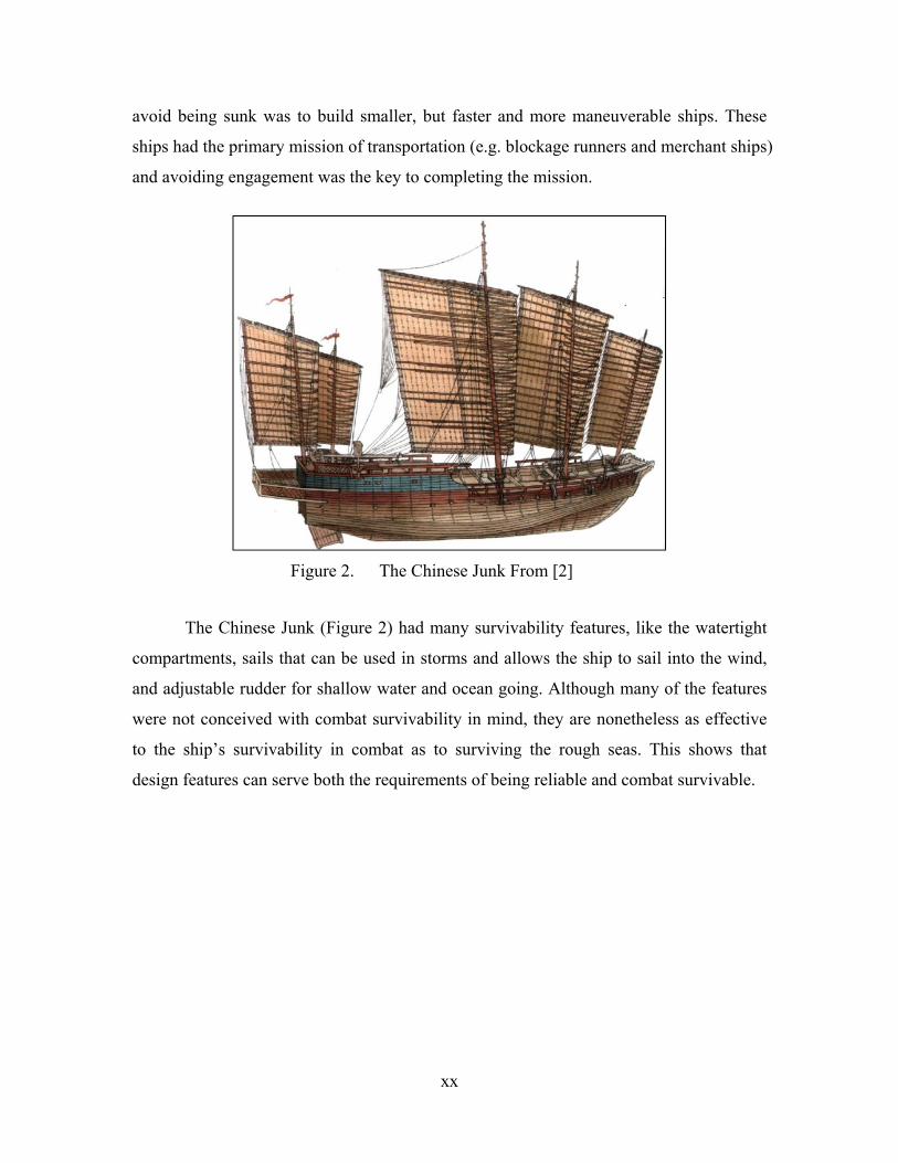
avoid being sunk was to build smaller, but faster and more maneuverable ships. These
ships had the primary mission of transportation (e.g. blockage runners and merchant ships)
and avoiding engagement was the key to completing the mission.
Figure 2. The Chinese Junk From [2]
The Chinese Junk (Figure 2) had many survivability features, like the watertight
compartments, sails that can be used in storms and allows the ship to sail into the wind,
and adjustable rudder for shallow water and ocean going. Although many of the features
were not conceived with combat survivability in mind, they are nonetheless as effective
to the ship’s survivability in combat as to surviving the rough seas. This shows that
design features can serve both the requirements of being reliable and combat survivable.
xxi
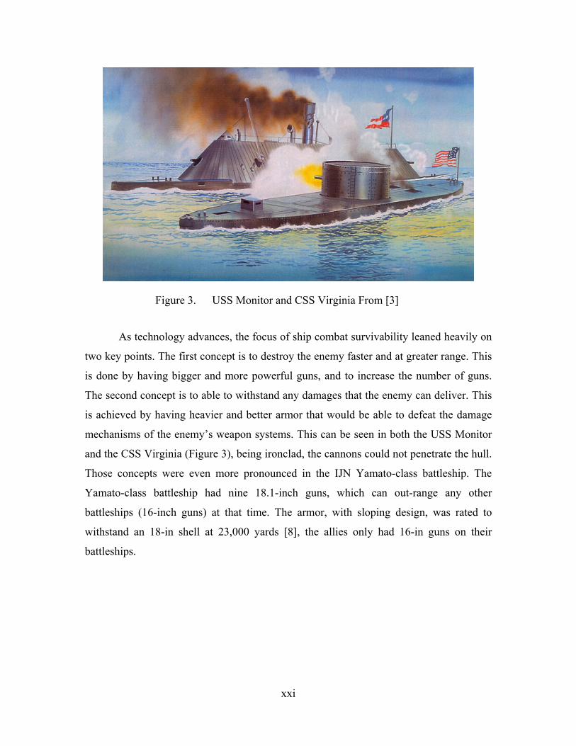
Figure 3. USS Monitor and CSS Virginia From [3]
As technology advances, the focus of ship combat survivability leaned heavily on
two key points. The first concept is to destroy the enemy faster and at greater range. This
is done by having bigger and more powerful guns, and to increase the number of guns.
The second concept is to able to withstand any damages that the enemy can deliver. This
is achieved by having heavier and better armor that would be able to defeat the damage
mechanisms of the enemy’s weapon systems. This can be seen in both the USS Monitor
and the CSS Virginia (Figure 3), being ironclad, the cannons could not penetrate the hull.
Those concepts were even more pronounced in the IJN Yamato-class battleship. The
Yamato-class battleship had nine 18.1-inch guns, which can out-range any other
battleships (16-inch guns) at that time. The armor, with sloping design, was rated to
withstand an 18-in shell at 23,000 yards [8], the allies only had 16-in guns on their
battleships.

xxii
Figure 4. IJN Yamato From [4]
With today’s technology advances, there is more than one way to design and build
ships that will be more combat survivable. This thesis will analysis the modern threats
environments and the ways to improve combat survivability of surface ships through
design and tactics.

1
I. SURVIVABILITY OVERVIEW
Every combat ship ever designed and built had one main purpose in mind, and
that is to complete her mission. In order to accomplish her mission, a ship has to survive
the possible mission engagements and fulfill her mission. In order for the mission to be
considered a success, the ship must also be able to return home safely. Thus survivability
is crucial to the mission success of a ship.
The definition of a surface ship combat survivability can be defined as the
capability of a surface ship to avoid and/or withstand a man-made hostile environment
while performing its mission [5]. The inverse of survivability is killability, which can be
defined as the ease with which a surface ship can be killed by the man-made hostile
environment [6]. There are two categories in which a ship can be considered killed. (1) A
total kill, the total destruction of the ship (i.e. sinking or abandonment), in which the ship
is considered unrecoverable and a total loss. (2) A mission kill, where the ship loses one
or more of her critical components which renders the ship unable to complete her mission.
This could be the loss of mobility, mission specific systems (e.g. radar system), and/or
primary systems (e.g. power plant). A mission kill may sometime be recoverable by the
crew at sea (recoverability), and the ship may return to her mission.
Survivability is not a deterministic concept; many random parameters will affect the
mission survivability of the ship (e.g. weather, human reaction, etc.). Therefore a ship’s
survivability is measured in probabilities.
, 1 ,
And killability can be further divided into two categories, vulnerability and susceptibility.
, , , |
Therefore
1 |
Thus, the probability of survival increases when vulnerability and susceptibility
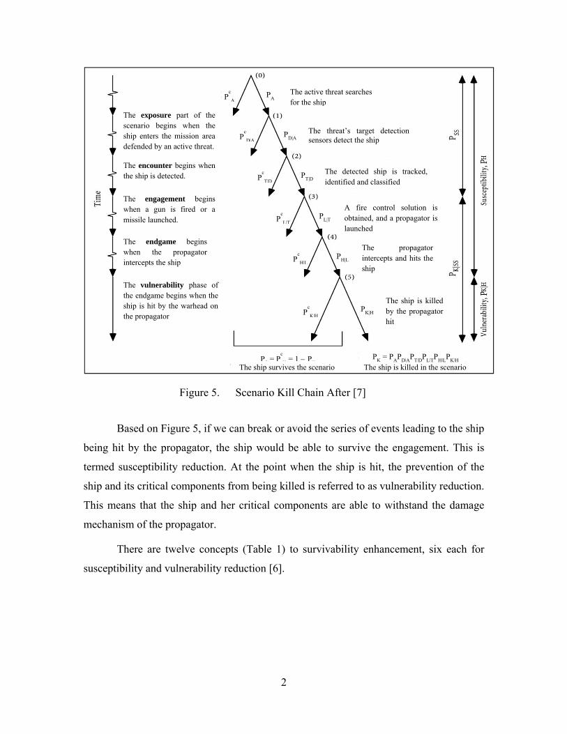
decrease. Figure 5 shows the kill chain for a single-shot engagement, and the relationship
between survivability, vulnerability and susceptibility.
2
Figure 5. Scenario Kill Chain After [7]
Based on Figure 5, if we can break or avoid the series of events leading to the ship
being hit by the propagator, the ship would be able to survive the engagement. This is
termed susceptibility reduction. At the point when the ship is hit, the prevention of the
ship and its critical components from being killed is referred to as vulnerability reduction.
This means that the ship and her critical components are able to withstand the damage
mechanism of the propagator.
There are twelve concepts (Table 1) to survivability enhancement, six each for
susceptibility and vulnerability reduction [6].
The exposure part of the scenario begins when the ship enters the mission area defended by an active threat.
The encounter begins when the ship is detected.
The engagement begins when a gun is fired or a missile launched.
The endgame begins when the propagator intercepts the ship
The vulnerability phase of the endgame begins when the ship is hit by the warhead on the propagator
The detected ship is tracked, identified and classified
The active weapon searches for the ship
The weapon’s target detection sensor detects the ship
The ship is killed by the propagator hit
A fire control solution is obtained, and a propagator is launched
The propagator intercepts and hits the ship
The ship survives the scenario The ship is killed in the scenarioPS = P
c
K = 1 – PKPK = PAPD|APT|DPL|TPH|LPK|H
PA PcA
PD|A PcD|A
PT|D PcT|D
PL|T PcL|T
PH|L PcH|L
PK|H PcK|H
The exposure part of the scenario begins when the ship enters the mission area defended by an active threat.
The encounter begins when the ship is detected.
The engagement begins when a gun is fired or a missile launched.
The endgame begins when the propagator intercepts the ship
The vulnerability phase of the endgame begins when the ship is hit by the warhead on the propagator
The detected ship is tracked, identified and classified
The active threat searches for the ship
The threat’s target detection sensors detect the ship
The ship is killed by the propagator hit
A fire control solution is obtained, and a propagator is launched
The propagator intercepts and hits the ship
The ship survives the scenario The ship is killed in the scenarioPS = P
c
K = 1 – PKPK = PAPD|APT|DPL|TPH|LPK|H
PAPc
A
PD|APc
D|A
PT|DPc
T|D
PL|TPc
L|T
PH|LPc
H|L
PK|HPc
K|H
3
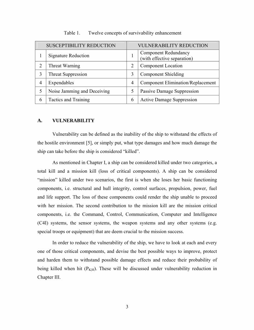
Table 1. Twelve concepts of survivability enhancement
SUSCEPTIBILITY REDUCTION VULNERABILITY REDUCTION
1 Signature Reduction 1 Component Redundancy (with effective separation)
2 Threat Warning 2 Component Location
3 Threat Suppression 3 Component Shielding
4 Expendables 4 Component Elimination/Replacement
5 Noise Jamming and Deceiving 5 Passive Damage Suppression
6 Tactics and Training 6 Active Damage Suppression
A. VULNERABILITY
Vulnerability can be defined as the inability of the ship to withstand the effects of
the hostile environment [5], or simply put, what type damages and how much damage the
ship can take before the ship is considered “killed”.
As mentioned in Chapter I, a ship can be considered killed under two categories, a
total kill and a mission kill (loss of critical components). A ship can be considered
“mission” killed under two scenarios, the first is when she loses her basic functioning
components, i.e. structural and hull integrity, control surfaces, propulsion, power, fuel
and life support. The loss of these components could render the ship unable to proceed
with her mission. The second contribution to the mission kill are the mission critical
components, i.e. the Command, Control, Communication, Computer and Intelligence
(C4I) systems, the sensor systems, the weapon systems and any other systems (e.g.
special troops or equipment) that are deem crucial to the mission success.
In order to reduce the vulnerability of the ship, we have to look at each and every
one of those critical components, and devise the best possible ways to improve, protect
and harden them to withstand possible damage effects and reduce their probability of
being killed when hit (PK|H). These will be discussed under vulnerability reduction in
Chapter III.

4
B. SUSCEPTIBILITY
Susceptibility can be defined as the inability of the ship to avoid the sensors,
weapons and weapons effect of that man-made hostile environment [5]. This means that
the ship is detected and tracked by the attacker, an intercept solution is achieved by the
attacker for launching an attack, and the weapon is able to reach and impact the ship,
causing damage.
There are four properties affecting the susceptibility of a ship. The first property is
the ease at which the ship can be detected by any sensing system, or the probability of
being of being detected when an active sensor is searching (PD|A). The signatures of a
ship will affect how easily she can be detected.
The second property is the ease at which the ship can be effective tracked,
identified and classified by any targeting system. This is different from detection, as
tracking, identification and classification require constant and consistent signal strength
from the sensor over a period of time so that the recognition and tracking system can
perform its calculations on the target. Again, the signature of the ship will determine how
easily she can be tracked, and the signature pattern will enable identification. This is the
probability of the ship being tracked by the active sensor after the she had been detected
(PT|D).
The third property is the ability to avoid being targeted. Again this is different
from the first two properties. To enable a target-lock and launching of a weapon, the ship
must be within the range of the weapon, and a clear and exact picture of the location of
the ship is required. This is represented by the probability of launching of weapons
against the ship when the she is being tracked (PL|T).
The last property is the ability to avoid being hit by the weapon, either through
means of evasion or by destroying the weapon before it can hit the ship. It is the
probability of the weapon or the damage mechanism hitting the ship upon launching
(PH|L).
5
C. DAMAGE CONTROL AND RECOVERABILITY
Damage control is the follow-on action after the ship had been hit by a weapon,
and suffers damages to parts of the ship. Usually it would involve firefighting and flood
control. The job of firefighting is to stop cascading damages than can be caused by the
fires, for example, fires reaching fuel tanks, or fuel lines, and the ammunitions storage,
thus preventing explosions and worsening of the damages. The fires, if not managed, will
also sever power and electrical lines, bringing down the power and signal connections to
the critical combat systems of the ship, thus killing the ship.
The flooding of the ship will cause the ship to list, and reduces the ships mobility
and maneuverability. With serious flooding, the electrical and electronics rooms could be
inundated with water, shorting and killing the power and critical combat systems. If the
flooding reaches the engines rooms and generators, the ship will lose her propulsion and
power completely. In a way, damage control is to prevent and reduce the probability of
the ship being killed; hence it is categorized as one of the vulnerability reduction concept.
Damage control also precedes the ship’s recovery process.
The recovery process starts when the damages done to the ship had been assessed;
initial damage assessments are usually done in conjunction with the damage control
phase. The final damage assessment can only be done when the fire and flooding are
under control or had stopped. The initial phase of recovery is to make whatever minor
repairs, by-passes, and getting the redundancy systems to work, while the ship is still in
combat. This is done so that the ship and its critical components are brought up to combat
and mission capable, although the systems may be operating in a degraded mode. This
will allow the ship to at least be in the condition to fight her way out of the battle. Very
often the line between this recovery phase and damage control is blurred, as both of them
are executed at in the same period of time. Furthermore, systems redundancies are also
part of vulnerability reduction techniques, the recovery phase is about getting them to
work.
The second phase of the recovery process is to make repairs to the systems that
were damaged or “killed”. This phase is more about the reparability of the ship. This
includes replacing the damaged equipment with spares or making equipment repairs in

6
the ship’s workshop. Major repair have to be done when the ship is out of the
engagement zone, as such repairing would require shutting down of the systems. The idea
is to try and recovery the systems to working condition, either full functioning or at least
at a degraded mode. This is done so that although a critical system might be considered
killed during the engagement, there exists a possibility of getting the system back to
working condition again, and thus enabling the mission to be continued. This would
mean that the ship critical components should be designed such that operator level repair
can be carried out at sea, i.e. changing of damaged wirings, or computing modules. This
would also mean that adequate spares would be needed to be carried onboard the ship and
the operators must be trained to assess and carried out such repairs.
7
II. THREATS
As discussed in Chapter I, the kill scenario of a ship can be broken up into two
different parts. The threats to any combat ship are the risk of being detected, tracked,
targeted and destroyed. Sensors play the part of detecting, tracking and targeting, and
weapons are the kill vehicles, which sometime also includes some form of sensors for the
final tracking and targeting.
A. DETECTION
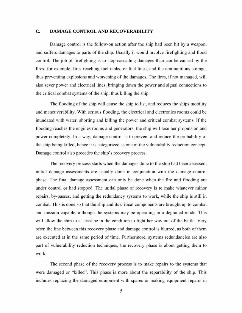
1. Radar
Radar presents the most threat to a ship. It is used by most of the threats from the
air, surface and land. Many anti-ship missiles employ radar (active/passive). Radar has
long range detection capability and can see through smoke as well as in the dark. Radar is
“a double-edged sword”; the radio wave transmitted by the propagator will be detectable
by the target using a radar receiver. If the ship is constantly emitting the radio wave, she
could be picked up at twice the distance or at an earlier time by the target than she could
detect the target, as the radio wave will have to travel to the target and back to the
receiver, covering twice the distance. This means that the target can actually detect an
active radar search against it.
Figure 6. Herakles Multifunction Radar From [13]
8
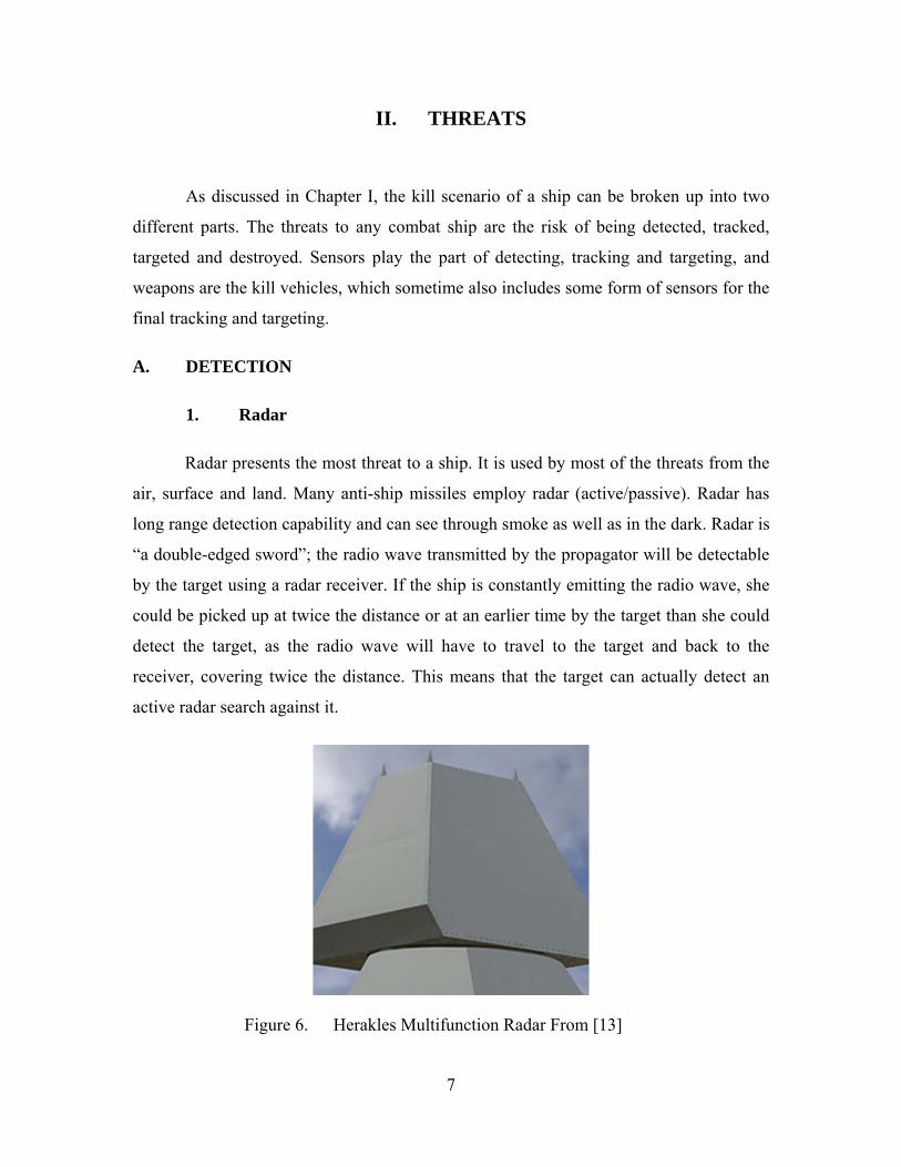
2. Infra-Red Sensor
The heat from an unshielded exhaust of a ship can be easily detected using an
infra-red (IR) sensor. The surface of the ship will also absorb the solar radiation and emit
an IR signature. The heat from the inside of the ship can also show up on the IR sensor.
Many missiles used such heat source for targeting and tracking.
Figure 7. Unshielded IR Signature (left), Shielded IR Signature (right) From [14]
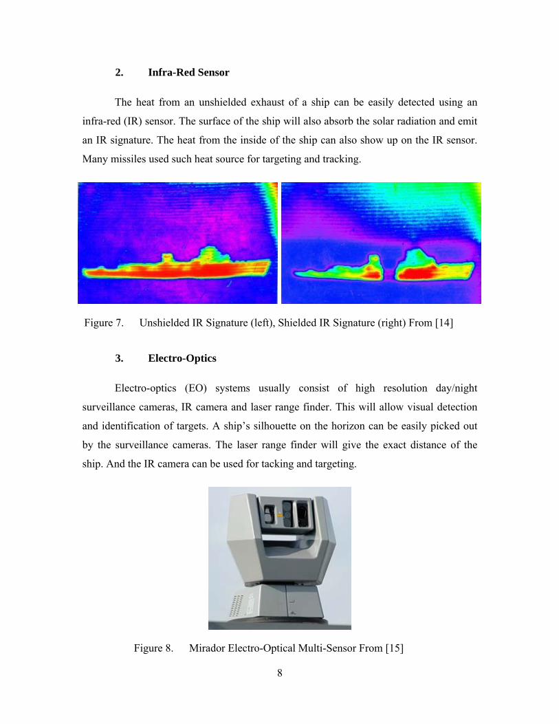
3. Electro-Optics
Electro-optics (EO) systems usually consist of high resolution day/night
surveillance cameras, IR camera and laser range finder. This will allow visual detection
and identification of targets. A ship’s silhouette on the horizon can be easily picked out
by the surveillance cameras. The laser range finder will give the exact distance of the
ship. And the IR camera can be used for tacking and targeting.
Figure 8. Mirador Electro-Optical Multi-Sensor From [15]

9
4. Acoustic Sensor
Acoustic sensors work in a similar concept as radar. In the passive mode, the
sensors will “listen” for any noise anomalies from the surrounding. A ship’s propeller
will create such noise as cavitation occurs at the edge of the blade. Any other noise from
within the ship could also propagate to the water through the ship structure and hull.
In the active mode, the sensor will sent out a sound wave, and any object in the
water will reflect the sound wave back to the receiver. However, like the electromagnetic
wave of radar, the sound wave can be detectable by the target using passive sonar. If the
ship “pings” her sonar, she could be picked up at twice the distance or at an earlier time
by the target than she could detect the target. There are different types of acoustic sensors
used for detection, e.g. towed array sonars and underwater laid acoustic sensors. Some
naval mines also use acoustic sensors as the detonation sensor.
Figure 9. EDO Towed Array Sonar From [16]
5. Magnetism
The Earth’s magnetic field can be measured, as the ship cuts sails through the
water, the ferromagnetic material in the ship will cause a disturbance to the magnetic
field. Magnetic Anomaly Detectors, passive sensors, are used to detect the change in
magnetic field. Such sensors are usually used on naval mines and in coastal underwater
detection systems.
10
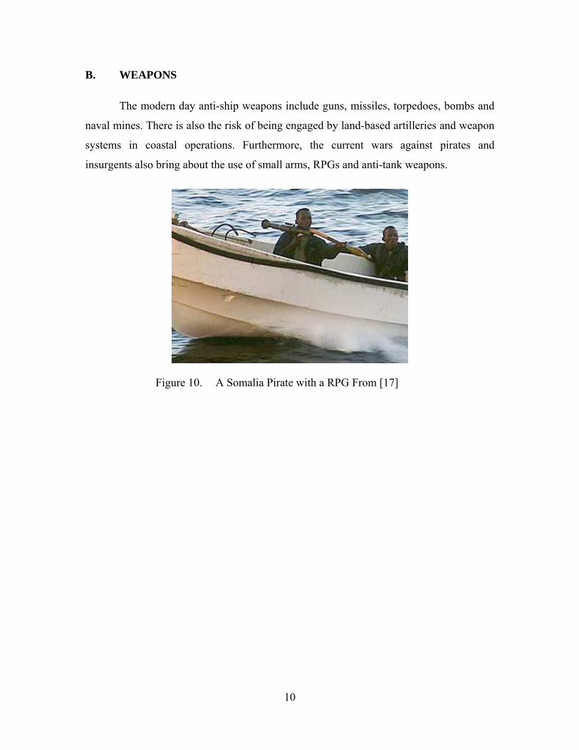
B. WEAPONS
The modern day anti-ship weapons include guns, missiles, torpedoes, bombs and
naval mines. There is also the risk of being engaged by land-based artilleries and weapon
systems in coastal operations. Furthermore, the current wars against pirates and
insurgents also bring about the use of small arms, RPGs and anti-tank weapons.
Figure 10. A Somalia Pirate with a RPG From [17]
11
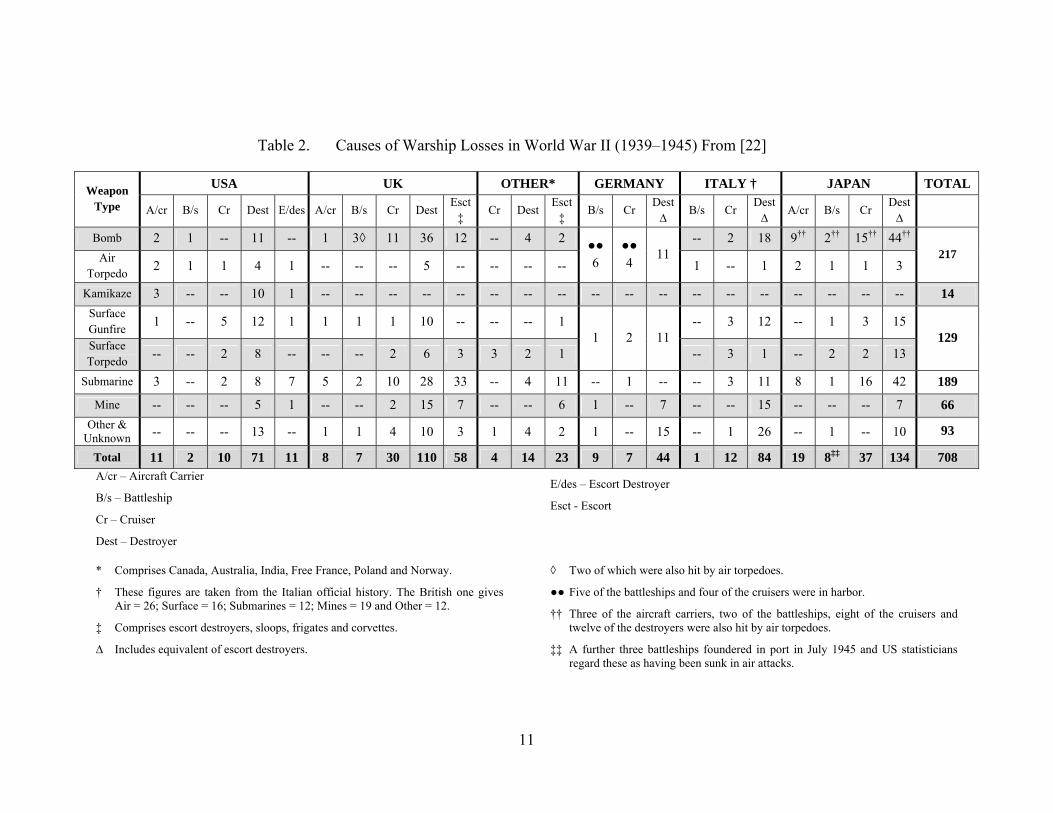
Table 2. Causes of Warship Losses in World War II (1939–1945) From [22]
Weapon Type
USA UK OTHER* GERMANY ITALY † JAPAN TOTAL
A/cr B/s Cr Dest E/des A/cr B/s Cr DestEsct
‡ Cr Dest
Esct ‡
B/s Cr Dest ∆
B/s Cr Dest ∆
A/cr B/s Cr Dest ∆
Bomb 2 1 -- 11 -- 1 3◊ 11 36 12 -- 4 2 ●● 6
●● 4
11 -- 2 18 9†† 2†† 15†† 44††
217 Air Torpedo
2 1 1 4 1 -- -- -- 5 -- -- -- -- 1 -- 1 2 1 1 3
Kamikaze 3 -- -- 10 1 -- -- -- -- -- -- -- -- -- -- -- -- -- -- -- -- -- -- 14
Surface Gunfire
1 -- 5 12 1 1 1 1 10 -- -- -- 1 1 2 11
-- 3 12 -- 1 3 15 129
Surface Torpedo
-- -- 2 8 -- -- -- 2 6 3 3 2 1 -- 3 1 -- 2 2 13
Submarine 3 -- 2 8 7 5 2 10 28 33 -- 4 11 -- 1 -- -- 3 11 8 1 16 42 189
Mine -- -- -- 5 1 -- -- 2 15 7 -- -- 6 1 -- 7 -- -- 15 -- -- -- 7 66
Other & Unknown -- -- -- 13 -- 1 1 4 10 3 1 4 2 1 -- 15 -- 1 26 -- 1 -- 10 93
Total 11 2 10 71 11 8 7 30 110 58 4 14 23 9 7 44 1 12 84 19 8‡‡ 37 134 708 A/cr – Aircraft Carrier
B/s – Battleship
Cr – Cruiser
Dest – Destroyer
E/des – Escort Destroyer
Esct - Escort
* Comprises Canada, Australia, India, Free France, Poland and Norway.
† These figures are taken from the Italian official history. The British one gives Air = 26; Surface = 16; Submarines = 12; Mines = 19 and Other = 12.
‡ Comprises escort destroyers, sloops, frigates and corvettes.
∆ Includes equivalent of escort destroyers.
◊ Two of which were also hit by air torpedoes.
●● Five of the battleships and four of the cruisers were in harbor.
†† Three of the aircraft carriers, two of the battleships, eight of the cruisers and twelve of the destroyers were also hit by air torpedoes.
‡‡ A further three battleships foundered in port in July 1945 and US statisticians regard these as having been sunk in air attacks.

12
1. Ballistically Launched Projectiles
Guns from both aircraft and other surface ships can do damage to the ship’s hull
and equipment. Aircraft Guns usually have range of around 1000 to 2000 meters, and can
have substantial penetrating power
Figure 11. GAU-8/A Avenger 30mm Cannon From [47]
Figure 12. Oto Melara 127/64 Lightweight Vulcano From [45]
Naval guns are of a much larger caliber than that of the aircraft guns. They usually
have maximum range of around 20 to 30 kilometers, and can do substantial damage to the
ship. Newer guided projectiles can extend the range to around 70 kilometers.
13
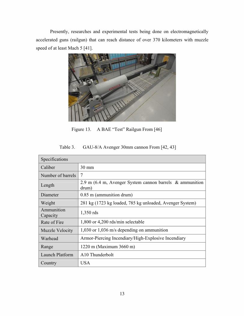
Presently, researches and experimental tests being done on electromagnetically
accelerated guns (railgun) that can reach distance of over 370 kilometers with muzzle
speed of at least Mach 5 [41].
Figure 13. A BAE “Test” Railgun From [46]
Table 3. GAU-8/A Avenger 30mm cannon From [42, 43]
Specifications
Caliber 30 mm
Number of barrels 7
Length 2.9 m (6.4 m, Avenger System cannon barrels & ammunition drum)
Diameter 0.85 m (ammunition drum)
Weight 281 kg (1723 kg loaded, 785 kg unloaded, Avenger System)
Ammunition Capacity
1,350 rds
Rate of Fire 1,800 or 4,200 rds/min selectable
Muzzle Velocity 1,030 or 1,036 m/s depending on ammunition
Warhead Armor-Piercing Incendiary/High-Explosive Incendiary
Range 1220 m (Maximum 3660 m)
Launch Platform A10 Thunderbolt
Country USA

14
Table 4. Oto Melara 127/64 Light Weight Vulcano From [44, 45]
Specifications
Caliber 127 mm
Number of barrels 1
Length 64 Caliber
Diameter Not Available
Weight Mounting weight (empty) 29 ton
Ammunition Capacity
56 (4 magazines)
Rate of Fire 35 rds/min
Muzzle Velocity 820 m/s (>1,000 m/s with Vulcano ammunition)
Warhead
HE-PD = High Explosive, Point Detonating Fuze Illum - MT = Illumination, Mechanical Time Fuze HE-VT = High Explosive, Variable Time Fuze HE-CVT = High Explosive, Controlled Variable Time Fuze
Range >100 km
Launch Platform Surface Ships
Country Italy and Germany
2. Cruise Missiles
Cruise missiles or anti-ship missiles (ASM) are now the primary kill weapon used
against ships. They can be launched from the land, air, sea, or underwater. Most of the
ASMs currently in use are subsonic missiles, with speeds around Mach 0.8. However,
there are also a few ASMs that operate in supersonic speeds, with speeds ranging
between Mach 2.5–4.5. Presently under development is the BrahMos II hypersonic ASM
with design speed in excess of Mach 5. At such high speed, there is limited response time
for defensive maneuvers and effective countermeasures.
15
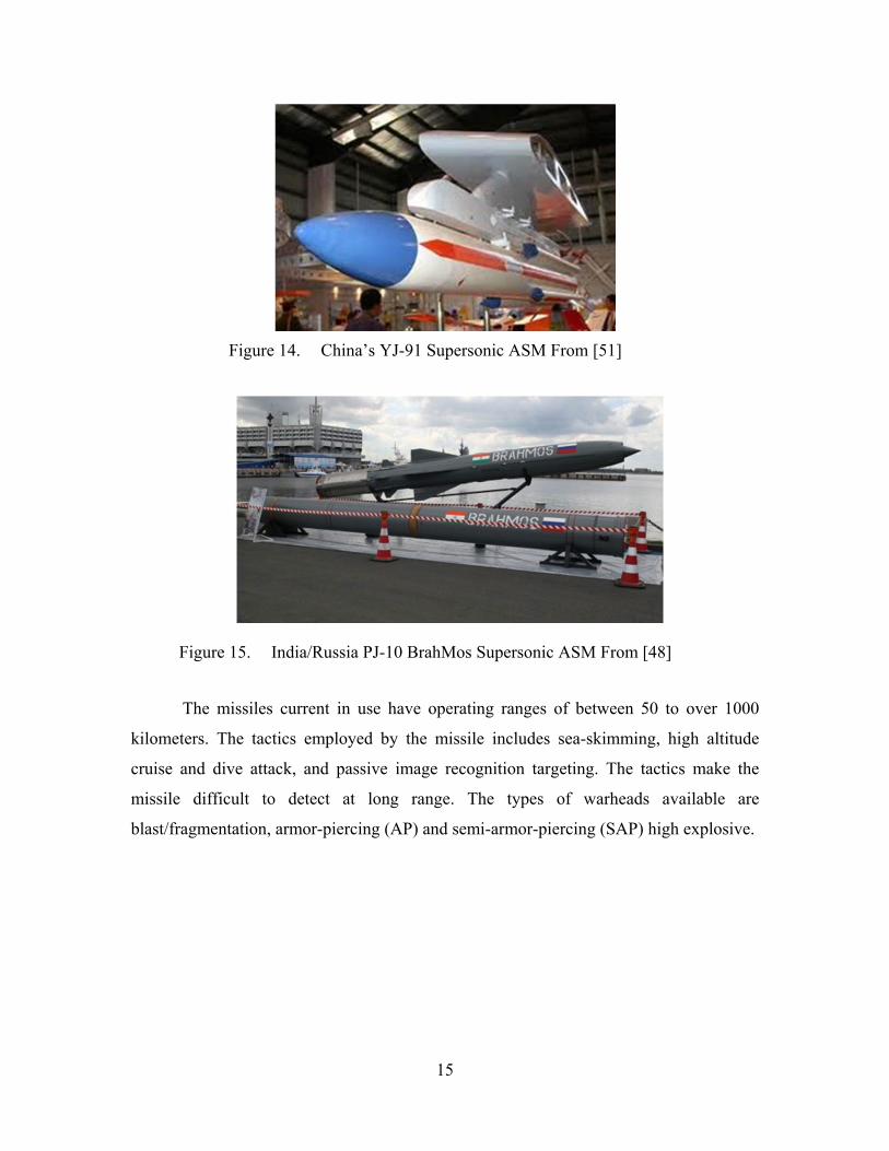
Figure 14. China’s YJ-91 Supersonic ASM From [51]
Figure 15. India/Russia PJ-10 BrahMos Supersonic ASM From [48]
The missiles current in use have operating ranges of between 50 to over 1000
kilometers. The tactics employed by the missile includes sea-skimming, high altitude
cruise and dive attack, and passive image recognition targeting. The tactics make the
missile difficult to detect at long range. The types of warheads available are
blast/fragmentation, armor-piercing (AP) and semi-armor-piercing (SAP) high explosive.
16
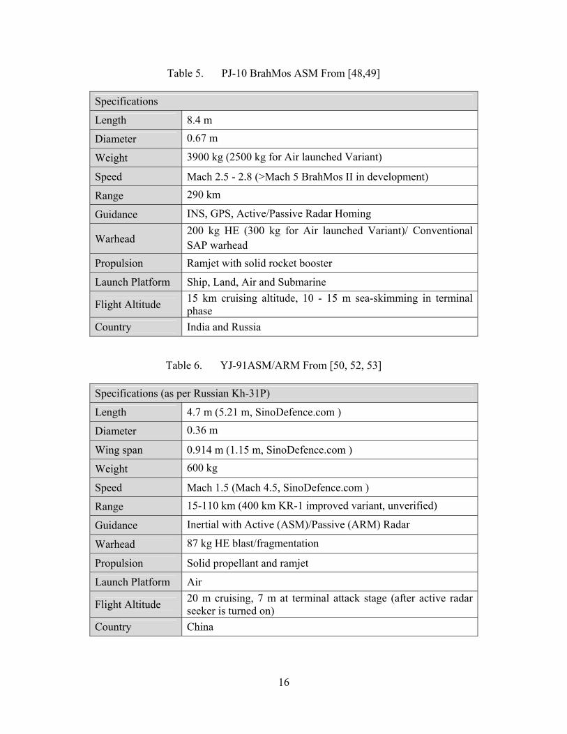
Table 5. PJ-10 BrahMos ASM From [48,49]
Specifications
Length 8.4 m
Diameter 0.67 m
Weight 3900 kg (2500 kg for Air launched Variant)
Speed Mach 2.5 - 2.8 (>Mach 5 BrahMos II in development)
Range 290 km
Guidance INS, GPS, Active/Passive Radar Homing
Warhead 200 kg HE (300 kg for Air launched Variant)/ Conventional SAP warhead
Propulsion Ramjet with solid rocket booster
Launch Platform Ship, Land, Air and Submarine
Flight Altitude 15 km cruising altitude, 10 - 15 m sea-skimming in terminal phase
Country India and Russia
Table 6. YJ-91ASM/ARM From [50, 52, 53]
Specifications (as per Russian Kh-31P)
Length 4.7 m (5.21 m, SinoDefence.com )
Diameter 0.36 m
Wing span 0.914 m (1.15 m, SinoDefence.com )
Weight 600 kg
Speed Mach 1.5 (Mach 4.5, SinoDefence.com )
Range 15-110 km (400 km KR-1 improved variant, unverified)
Guidance Inertial with Active (ASM)/Passive (ARM) Radar
Warhead 87 kg HE blast/fragmentation
Propulsion Solid propellant and ramjet
Launch Platform Air
Flight Altitude 20 m cruising, 7 m at terminal attack stage (after active radar seeker is turned on)
Country China

17
3. Torpedoes
Torpedoes are one of the most feared weapons for ships. With the torpedo
technology of the modern day, a single torpedo has the capability to sink a ship.
Torpedoes can be launched from the air, ships, or submarines. The submarine launched
torpedoes are usually the heavyweight torpedoes, with longer range and in excess of 500
kg warhead. Air dropped lightweight Torpedoes have shorter range and have warheads of
around 50 kg. Modern day torpedoes can travel at a speed greater than 60 nautical miles,
with a range of over 50 kilometers.
Figure 16. China’s YU-6 Torpedo From [56]
Figure 17. VA-111 Shkval Super-Cavitation Rocket-Propelled Torpedo From [57]
18
A unique super-cavitation rocket-propelled torpedo, Shkval, was developed in
Russia. Shkval has a top speed of over 200 nautical miles, but because of its special
propulsion system, it has a limited range of about 10 kilometers.
The torpedo damage mechanism is by either a direct impact to the ship’s hull, or a
beneath keel explosion. A direct impact explosion would have cause damage to the ship’s
hull under the waterline, the rudder and the propellers could be damaged. The damaged
hull would cause flooding, damaging the electrical systems, and flooding of the engine
rooms might occur. Damaged rudder and propellers would cause the ship to lose her
maneuverability and mobility.
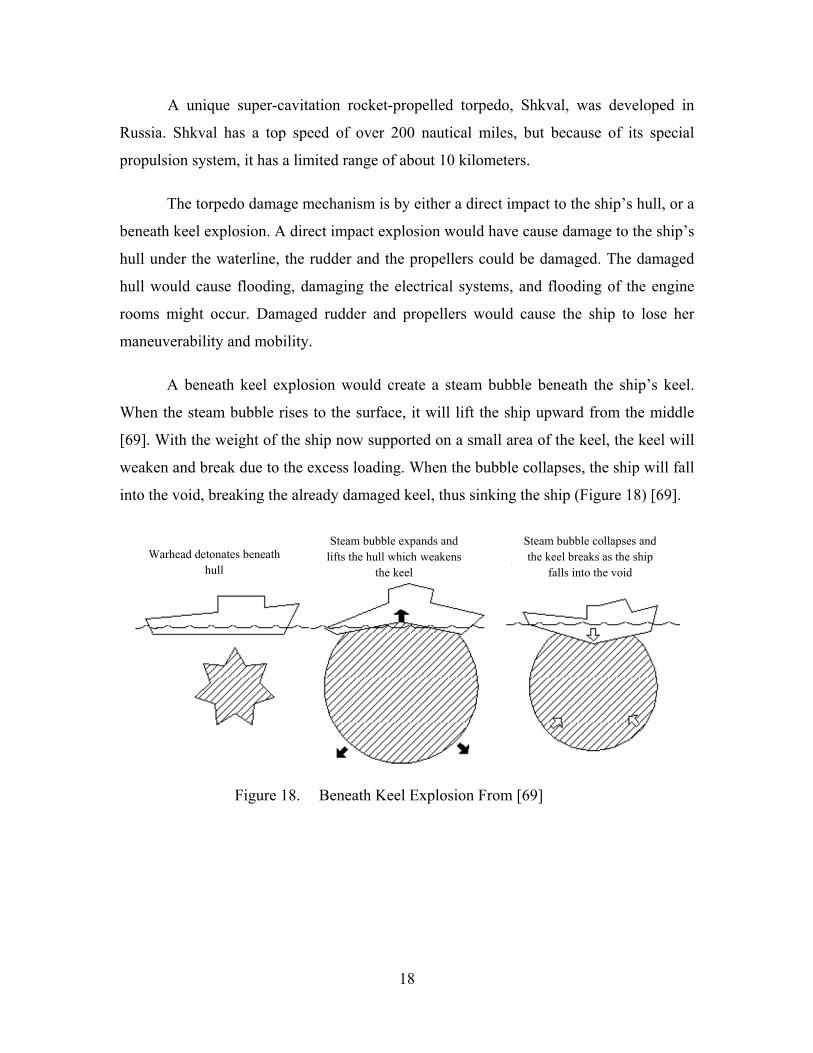
A beneath keel explosion would create a steam bubble beneath the ship’s keel.
When the steam bubble rises to the surface, it will lift the ship upward from the middle
[69]. With the weight of the ship now supported on a small area of the keel, the keel will
weaken and break due to the excess loading. When the bubble collapses, the ship will fall
into the void, breaking the already damaged keel, thus sinking the ship (Figure 18) [69].
Figure 18. Beneath Keel Explosion From [69]
Steam bubble expands and lifts the hull which weakens
the keel
Warhead detonates beneath hull
Steam bubble collapses and the keel breaks as the ship
falls into the void
19
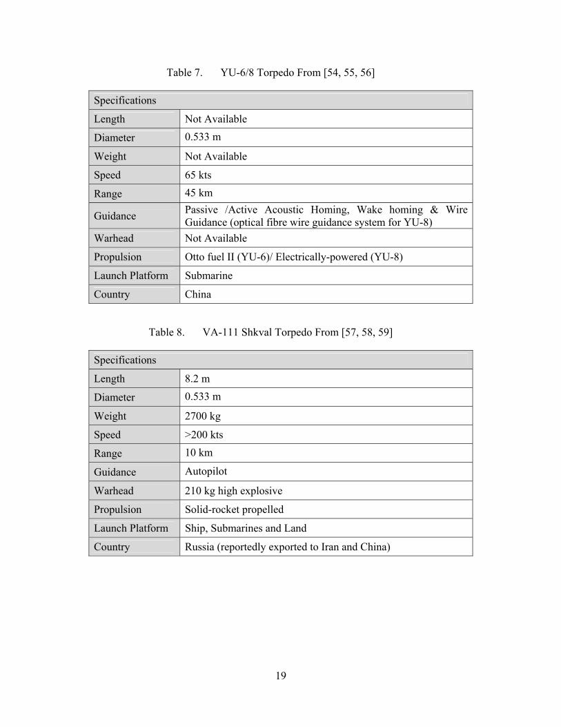
Table 7. YU-6/8 Torpedo From [54, 55, 56]
Specifications
Length Not Available
Diameter 0.533 m
Weight Not Available
Speed 65 kts
Range 45 km
Guidance Passive /Active Acoustic Homing, Wake homing & Wire Guidance (optical fibre wire guidance system for YU-8)
Warhead Not Available
Propulsion Otto fuel II (YU-6)/ Electrically-powered (YU-8)
Launch Platform Submarine
Country China
Table 8. VA-111 Shkval Torpedo From [57, 58, 59]
Specifications
Length 8.2 m
Diameter 0.533 m
Weight 2700 kg
Speed >200 kts
Range 10 km
Guidance Autopilot
Warhead 210 kg high explosive
Propulsion Solid-rocket propelled
Launch Platform Ship, Submarines and Land
Country Russia (reportedly exported to Iran and China)
20
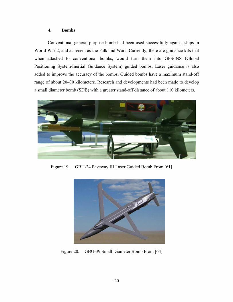
4. Bombs
Conventional general-purpose bomb had been used successfully against ships in
World War 2, and as recent as the Falkland Wars. Currently, there are guidance kits that
when attached to conventional bombs, would turn them into GPS/INS (Global
Positioning System/Inertial Guidance System) guided bombs. Laser guidance is also
added to improve the accuracy of the bombs. Guided bombs have a maximum stand-off
range of about 20–30 kilometers. Research and developments had been made to develop
a small diameter bomb (SDB) with a greater stand-off distance of about 110 kilometers.
Figure 19. GBU-24 Paveway III Laser Guided Bomb From [61]
Figure 20. GBU-39 Small Diameter Bomb From [64]
21
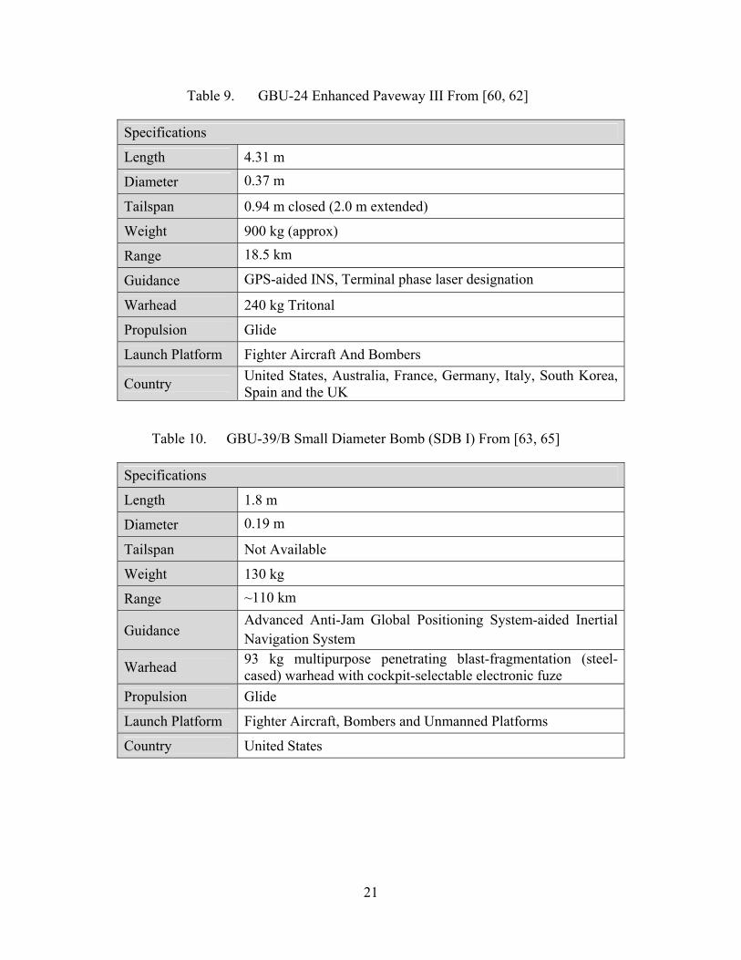
Table 9. GBU-24 Enhanced Paveway III From [60, 62]
Specifications
Length 4.31 m
Diameter 0.37 m
Tailspan 0.94 m closed (2.0 m extended)
Weight 900 kg (approx)
Range 18.5 km
Guidance GPS-aided INS, Terminal phase laser designation
Warhead 240 kg Tritonal
Propulsion Glide
Launch Platform Fighter Aircraft And Bombers
Country United States, Australia, France, Germany, Italy, South Korea, Spain and the UK
Table 10. GBU-39/B Small Diameter Bomb (SDB I) From [63, 65]
Specifications
Length 1.8 m
Diameter 0.19 m
Tailspan Not Available
Weight 130 kg
Range ~110 km
Guidance Advanced Anti-Jam Global Positioning System-aided Inertial Navigation System
Warhead 93 kg multipurpose penetrating blast-fragmentation (steel-cased) warhead with cockpit-selectable electronic fuze
Propulsion Glide
Launch Platform Fighter Aircraft, Bombers and Unmanned Platforms
Country United States
22
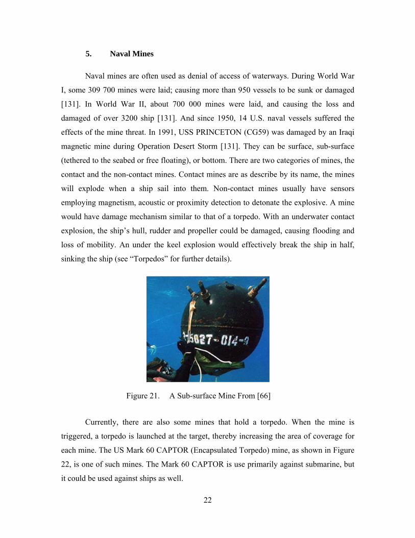
5. Naval Mines
Naval mines are often used as denial of access of waterways. During World War
I, some 309 700 mines were laid; causing more than 950 vessels to be sunk or damaged
[131]. In World War II, about 700 000 mines were laid, and causing the loss and
damaged of over 3200 ship [131]. And since 1950, 14 U.S. naval vessels suffered the
effects of the mine threat. In 1991, USS PRINCETON (CG59) was damaged by an Iraqi
magnetic mine during Operation Desert Storm [131]. They can be surface, sub-surface
(tethered to the seabed or free floating), or bottom. There are two categories of mines, the
contact and the non-contact mines. Contact mines are as describe by its name, the mines
will explode when a ship sail into them. Non-contact mines usually have sensors
employing magnetism, acoustic or proximity detection to detonate the explosive. A mine
would have damage mechanism similar to that of a torpedo. With an underwater contact
explosion, the ship’s hull, rudder and propeller could be damaged, causing flooding and
loss of mobility. An under the keel explosion would effectively break the ship in half,
sinking the ship (see “Torpedos” for further details).
Figure 21. A Sub-surface Mine From [66]
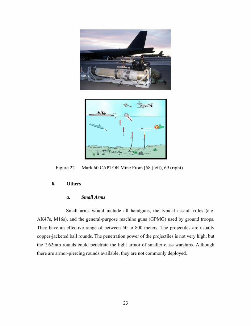
Currently, there are also some mines that hold a torpedo. When the mine is
triggered, a torpedo is launched at the target, thereby increasing the area of coverage for
each mine. The US Mark 60 CAPTOR (Encapsulated Torpedo) mine, as shown in Figure
22, is one of such mines. The Mark 60 CAPTOR is use primarily against submarine, but
it could be used against ships as well.
23
Figure 22. Mark 60 CAPTOR Mine From [68 (left), 69 (right)]
6. Others
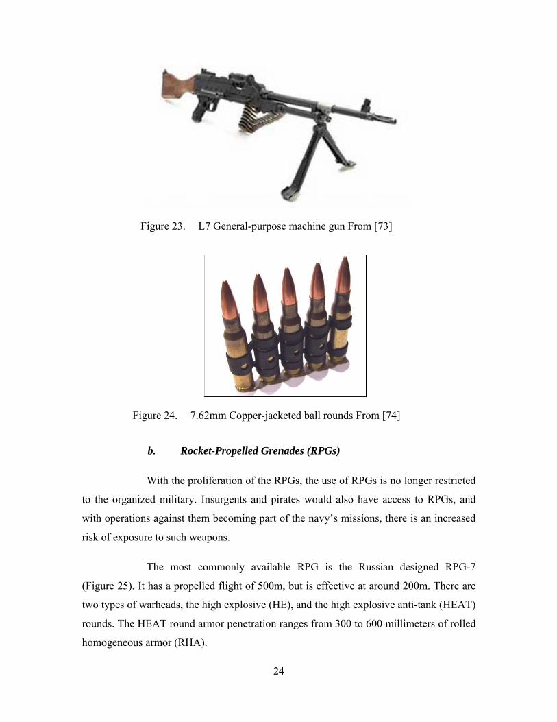
a. Small Arms
Small arms would include all handguns, the typical assault rifles (e.g.
AK47s, M16s), and the general-purpose machine guns (GPMG) used by ground troops.
They have an effective range of between 50 to 800 meters. The projectiles are usually
copper-jacketed ball rounds. The penetration power of the projectiles is not very high, but
the 7.62mm rounds could penetrate the light armor of smaller class warships. Although
there are armor-piercing rounds available, they are not commonly deployed.
24
Figure 23. L7 General-purpose machine gun From [73]
Figure 24. 7.62mm Copper-jacketed ball rounds From [74]
b. Rocket-Propelled Grenades (RPGs)
With the proliferation of the RPGs, the use of RPGs is no longer restricted
to the organized military. Insurgents and pirates would also have access to RPGs, and
with operations against them becoming part of the navy’s missions, there is an increased
risk of exposure to such weapons.
The most commonly available RPG is the Russian designed RPG-7
(Figure 25). It has a propelled flight of 500m, but is effective at around 200m. There are
two types of warheads, the high explosive (HE), and the high explosive anti-tank (HEAT)
rounds. The HEAT round armor penetration ranges from 300 to 600 millimeters of rolled
homogeneous armor (RHA).
25
Figure 25. Russian RPG-7 From [75]
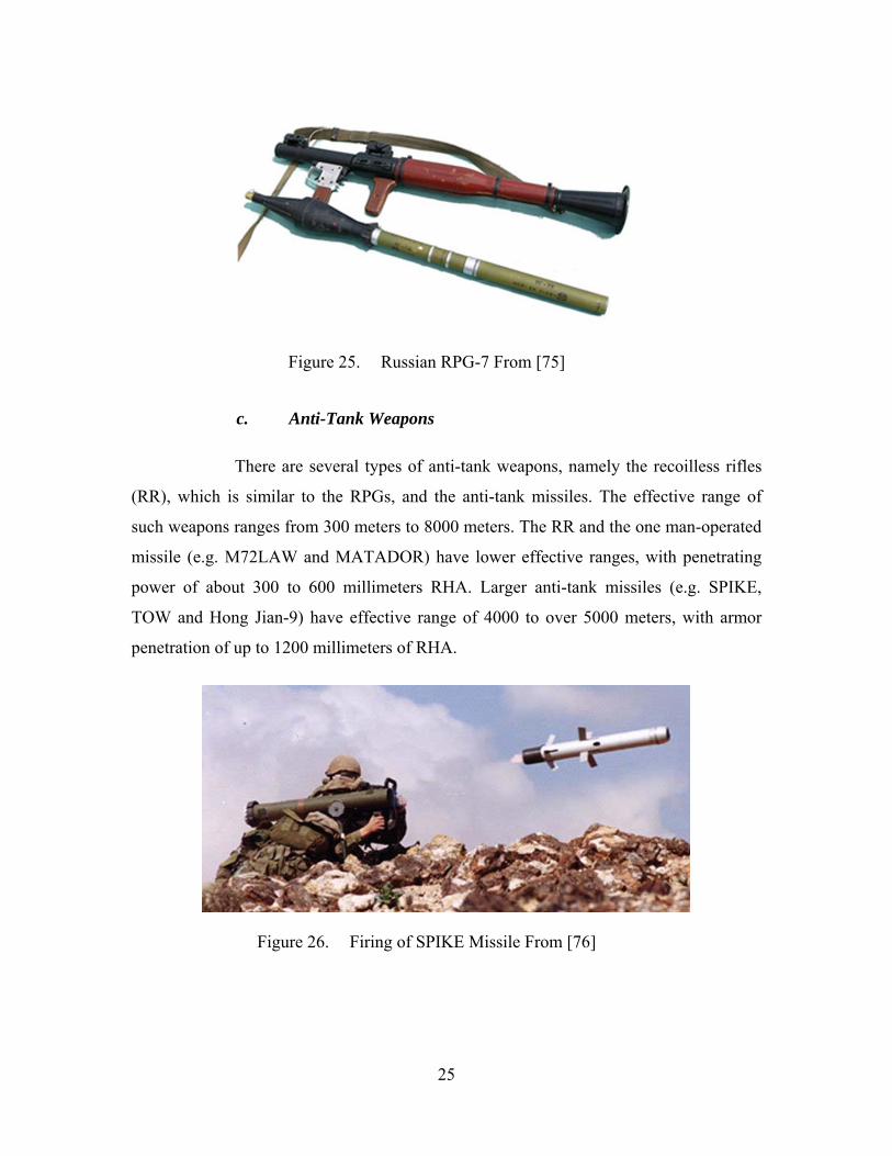
c. Anti-Tank Weapons
There are several types of anti-tank weapons, namely the recoilless rifles
(RR), which is similar to the RPGs, and the anti-tank missiles. The effective range of
such weapons ranges from 300 meters to 8000 meters. The RR and the one man-operated
missile (e.g. M72LAW and MATADOR) have lower effective ranges, with penetrating
power of about 300 to 600 millimeters RHA. Larger anti-tank missiles (e.g. SPIKE,
TOW and Hong Jian-9) have effective range of 4000 to over 5000 meters, with armor
penetration of up to 1200 millimeters of RHA.
Figure 26. Firing of SPIKE Missile From [76]
26
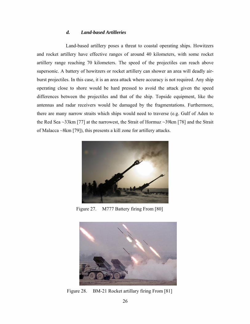
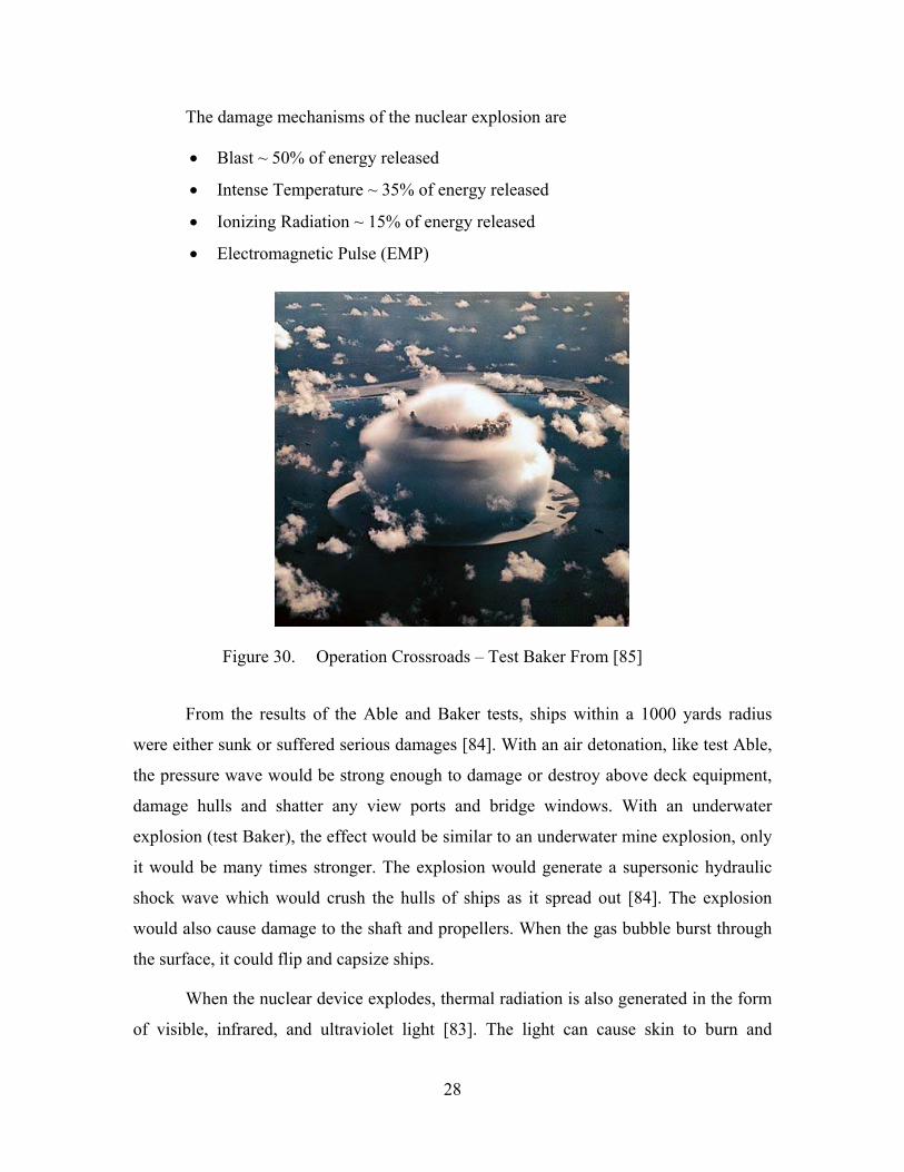
d. Land-based Artilleries
Land-based artillery poses a threat to coastal operating ships. Howitzers
and rocket artillery have effective ranges of around 40 kilometers, with some rocket
artillery range reaching 70 kilometers. The speed of the projectiles can reach above
supersonic. A battery of howitzers or rocket artillery can shower an area will deadly air-
burst projectiles. In this case, it is an area attack where accuracy is not required. Any ship
operating close to shore would be hard pressed to avoid the attack given the speed
differences between the projectiles and that of the ship. Topside equipment, like the
antennas and radar receivers would be damaged by the fragmentations. Furthermore,
there are many narrow straits which ships would need to traverse (e.g. Gulf of Aden to
the Red Sea ~33km [77] at the narrowest, the Strait of Hormuz ~39km [78] and the Strait
of Malacca ~8km [79]), this presents a kill zone for artillery attacks.
Figure 27. M777 Battery firing From [80]
Figure 28. BM-21 Rocket artillary firing From [81]

27
e. Suicide Boats
With the threats of terrorists facing the world, warships are increasing
being tasked and sent to the hot zones to provide support. The threats of suicide attacks
would forever increase, as a success attack could be used by the terrorist group as a
propaganda tool to further their cause. This makes the warship a valuable and much
sought after target.
Figure 29. USS Cole Damages After Suicide Attack in Port of Aden From [82]
With terrorist actions mingled with the daily civilian activities, it would be
difficult to distinguish between a terrorist suicide boat and the many pleasure and
commercial small crafts plying the water. This is especially so in the many narrow
shipping lanes and harbors.
7. Nuclear Effects
The probability of surviving a direct nuclear attack is almost impossible for any
surface ship, as demonstrated in “Operation Crossroads” tests at the Bikini Atoll. Two
tests, “Able” and “Baker” were conducted. “Able” was an atmospheric explosion test.
The nuclear device was detonated at an altitude of 520 feet [84]. Whereas “Baker” was an
underwater explosion test, it was detonated at 90 feet underwater [84].
28
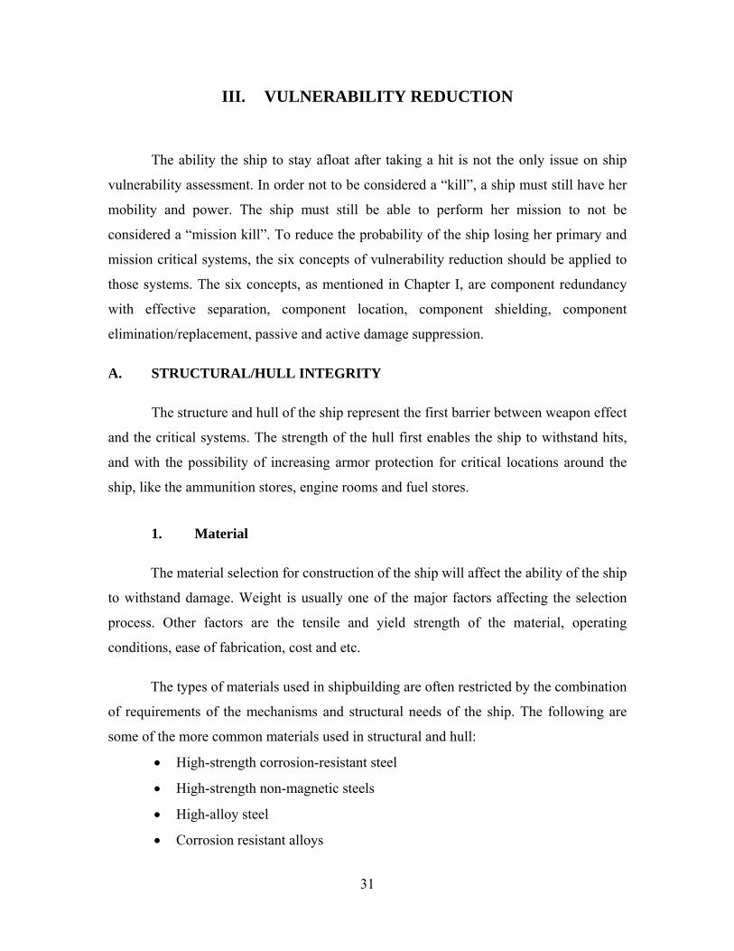
The damage mechanisms of the nuclear explosion are
Blast ~ 50% of energy released
Intense Temperature ~ 35% of energy released
Ionizing Radiation ~ 15% of energy released
Electromagnetic Pulse (EMP)
Figure 30. Operation Crossroads – Test Baker From [85]
From the results of the Able and Baker tests, ships within a 1000 yards radius
were either sunk or suffered serious damages [84]. With an air detonation, like test Able,
the pressure wave would be strong enough to damage or destroy above deck equipment,
damage hulls and shatter any view ports and bridge windows. With an underwater
explosion (test Baker), the effect would be similar to an underwater mine explosion, only
it would be many times stronger. The explosion would generate a supersonic hydraulic
shock wave which would crush the hulls of ships as it spread out [84]. The explosion
would also cause damage to the shaft and propellers. When the gas bubble burst through
the surface, it could flip and capsize ships.
When the nuclear device explodes, thermal radiation is also generated in the form
of visible, infrared, and ultraviolet light [83]. The light can cause skin to burn and

29
damage eyes. These injuries can occur well past the blast ranges [83]. The thermal
radiation can also cause fire to fuel and ordnance and anything flammable. Fine
structures, like whip antenna and composite materials could also melt under the heat.
With an underwater blast, the water would vaporize under the intense heat and create a
cloud of radioactive material and water mixture, coating the ship with radioactive fallout.
The radioactive fallout would be a hazard to personnel after prolonged exposure as
radiation from a contaminated environment is continuous and cumulative [84].
The nuclear explosion would also create ionizing radiation, which could penetrate
the hull. Ships close to the explosion would have received doses of neutron and gamma
radiation that could have been lethal to anyone on the ships [84]. During test Able, about
15 percent of the test animals were killed in the initial radiation blast with another 10
more percent dying from radiation sickness a few days later [84]. Ships are seldom built
to protect the crew from such high level of radiation.
Lastly, with a high-altitude explosion, due to the thin atmosphere, the blast wave
is converted to electromagnetic radiation. This electromagnetic radiation can cause
damage to electrical and electronic equipment. If the systems on board the ship are not
hardened and protected, the electronic circuits and cards could be damaged and
destroyed.
There is no appropriate defense mechanism for ships to defend against the damage
effect of a close-range nuclear explosion. The only way for a ship to escape a nuclear
attack is to destroy the nuclear device before it explodes. In this case, only the nuclear
materials scattered by the destruction of the device may reach the ship. With the
radioactive material covering the topside of the ship, some radiation risk will still be
present to the crew and sensitive equipment.

30
THIS PAGE INTENTIONALLY LEFT BLANK
31
III. VULNERABILITY REDUCTION
The ability the ship to stay afloat after taking a hit is not the only issue on ship
vulnerability assessment. In order not to be considered a “kill”, a ship must still have her
mobility and power. The ship must still be able to perform her mission to not be
considered a “mission kill”. To reduce the probability of the ship losing her primary and
mission critical systems, the six concepts of vulnerability reduction should be applied to
those systems. The six concepts, as mentioned in Chapter I, are component redundancy
with effective separation, component location, component shielding, component
elimination/replacement, passive and active damage suppression.
A. STRUCTURAL/HULL INTEGRITY
The structure and hull of the ship represent the first barrier between weapon effect
and the critical systems. The strength of the hull first enables the ship to withstand hits,
and with the possibility of increasing armor protection for critical locations around the
ship, like the ammunition stores, engine rooms and fuel stores.
1. Material
The material selection for construction of the ship will affect the ability of the ship
to withstand damage. Weight is usually one of the major factors affecting the selection
process. Other factors are the tensile and yield strength of the material, operating
conditions, ease of fabrication, cost and etc.
The types of materials used in shipbuilding are often restricted by the combination
of requirements of the mechanisms and structural needs of the ship. The following are
some of the more common materials used in structural and hull:
High-strength corrosion-resistant steel
High-strength non-magnetic steels
High-alloy steel
Corrosion resistant alloys
32
Titanium alloys
Aluminum alloys
Metal-based composite materials
Polymer-based composite materials
Non-metallic materials
The equipment loading of the ship must be designed so that the loads are
distributed evenly across all load bearing structures, strengthening of the structures when
needed. Load tolerance must be given to allow adjacent structures to fail and yet able to
maintain the structure integrity. The structural design must also be able to withstand high
temperature without losing its structural strength.
2. Armor
Placing very thick armor plates or belts on modern day warship are almost
unheard of any more. The additional weight of the armor would have greatly slowed
down the speed of the ship. More fuel and a bigger propulsion system would be required
to move the ship at the desired speed. Furthermore, with the modern day threats, the
amount of armor plating required to defeat the damage mechanism would have been
enormous. Hence, most warships are now built with little armor, opting for speed, and
reserving the weight for more equipment and combat systems.
However, there is still a need to place enough armor protection on the ship to
defeat small arms, blast and fragmentation attacks. This is to give adequate protection to
the crews and critical components housed within the ship. Armoring a ship is still
possible, by designing the hull to improve armor protection, e.g. having sloping structure
like the slope armor employ by tanks would increase armor protection yet keeps the
weight down. The use of composite materials that gives a higher strength to weight ratio
than the typical steel would also improve the protection level, while keeping the weight
low.
A better fragmentation protection can be achieved by redesigning bulkheads with
double-walled plating (Figure 31). The first plate of the double-walled bulkhead will

33
cause the fragments from weapons and spalling to break up and thus losing energy [7].
The lower energy fragments can then be stopped by the second plate, preventing
penetration and further damages to the equipment and personnel in the ship.
Figure 31. Double-walled Bulkhead From [7]
B. CRITICAL EQUIPMENT
1. Critical Chain Reduction/Elimination
A system can be made less vulnerable by redesigning to reduce or eliminate the
number critical components, i.e. reducing the number of parts that when damaged would
cause the system as a whole to fail. For example, a gas turbine generator with less
moving parts and simplified design would not only reduce the risk of damaging the
critical parts, but also if it were to be damaged, repairing it would be easier.
2. Equipment Placement
The placement of critical equipment would affect the probability of being hit. By
having the equipment presented in such a way as to minimize exposure to the possibility
of damage, the system would effectively have a lower possibility of being killed. By
34
placing non-critical equipment around the critical equipment, thus having additional
shielding protection (sacrificial armor) without increasing weight and space required for
armor.
3. Equipment Protection
If the equipment is deem critical to the mission, additional armor protection might
be required. For example, the magazine for the gun or the missile silo onboard would
require additional armor protection. A kill would not only cause the ship to lose the
weapon system, the exploding ammunitions might cause more damage to the ship and
even kill it. Adequate protection should be designed for any critical systems, especially
the weapon systems, to prevent cascading damages.
4. Equipment Redundancy (with Separation)
The primary systems onboard the ship should be designed with redundancy, e.g.
the electrical system should have at least two independent lines running on each side of
the ship. In the event that the ship is hit on one side, the other line must still be able to
support the load usage. Similarly, redundancy must be catered for the signal and
communication lines, and the firefighting system.
Having equipment redundancy only improves the equipment reliability. The two
set of equipment must be physically separated with sufficient distance apart to offer
vulnerability reduction. For example, in order to have two sets of command and control
computing system for redundancy. The placement of one set should be at the forward
starboard section and the other at the aft port section. In the event that damage are done to
the area of the first set of equipment, the second set would be far away enough to not to
suffer any damage. Furthermore, with redundancy for the power or signal cables, if the
ship were to be damage on one side, having the system placed one on each side would
have enabled the system to still function.
35
From the command and control computing system example, equipment
redundancy does not belong to just that independent system. With systems needing to
integrate with each other, for power and communication, the redundancy plan must be
though out as a whole.
C. DAMAGE CONTROL
1. Active
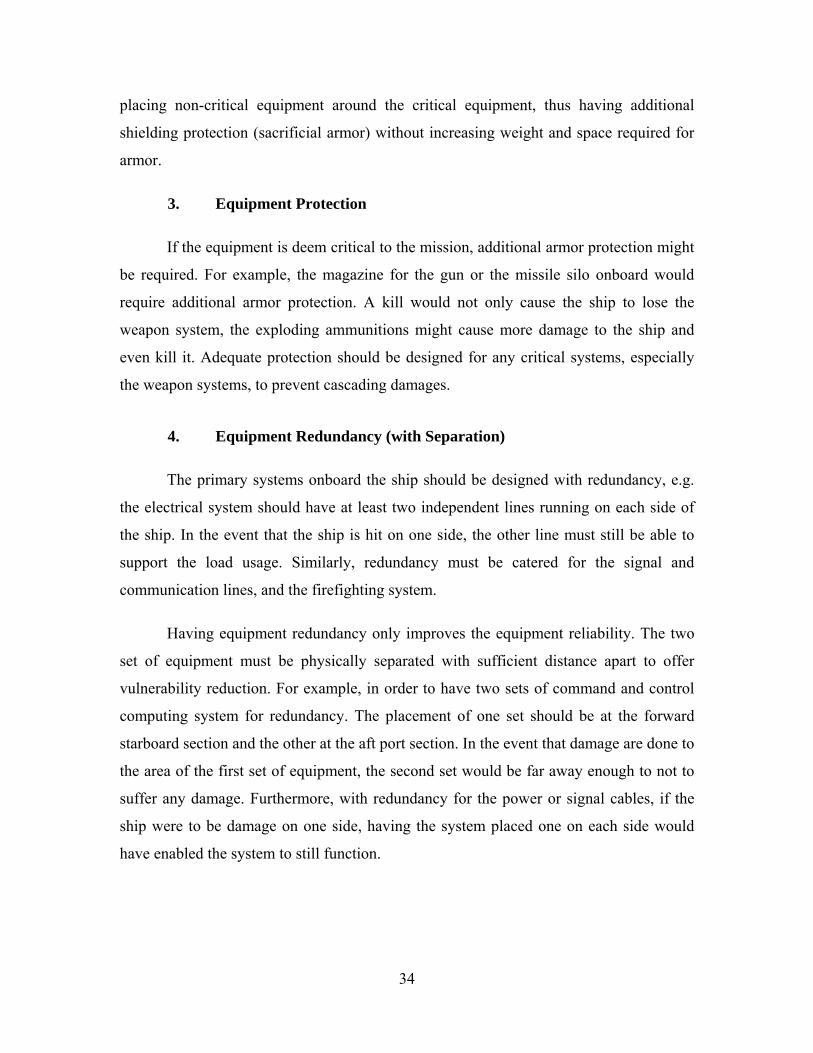
a. Fire Suppression Systems
Onboard fire, if not managed properly can cascade into a total kill of the
ship. There can be different types of fire occurring onboard, dry, electrical and liquid-
fuelled fire. Dealing with each of them requires different type of suppressant. In the
electronic rooms, dry suppressant is to be used. This is so that by putting out the fire, it
will not lead to the failure of the electronics as when using water.
Figure 32. Wet and Dry Fire Suppression Systems From [88 (left), 89 (right)]
b. Water/ Flood Pumps
Flooding is one of the major concerns onboard any ship. Heavy flooding
could cause sinking, listing and capsizing of the ship. The water pumping system should
be design to handle not just the regular leakage of the ship, but for the flooding from
damaged condition which the ship is still expected to operate in. The water extraction rate

36
of the pumping system must be sized sufficiently. Portable pumps that run on either
batteries or shipboard power should be available for localized flood control. This would
allow the damaged areas to be accessible for the damaged control team to do repairs.
Figure 33. Bilge Pump Outlet of a Ship From [90]
c. Firefighting Teams
Firefighting teams must be well equipped and well trained to handle all
sorts of fire scenario. The teams must be protected from the hazards of firefighting.
Adequate firefighting equipment must be located throughout the ship. Equipment must be
maintained and serviceability checks must be done.
Figure 34. Firefighting Equipment Checks From [89]
37
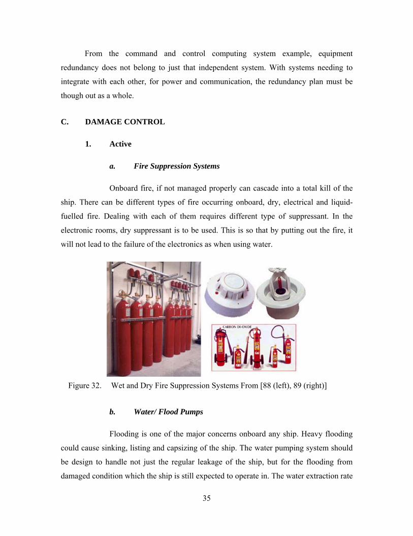
d. Damage Control/ Repair Teams
Damage control and repair teams must be trained to for their particular
roles. The teams must be protected equipped for them to perform their jobs. Adequate
spares and shoring equipment must be available, maintenance and serviceability checks
must be done to ensure their usability.
Figure 35. Damage Control Team Practicing K-type Shoring From [91]
2. Passive
a. Insensitive Munitions
The ammunitions for the ship’s weapon systems, especially the missiles,
should be design and tested to withstand against fragmentation, bullet and spall impacts,
fast and slow cookoff, shaped charged jet and sympathetic detonation under MIL-STD-
2105C. If the ammunitions are not certified, then appropriate protection and blast venting
should be installed. These would prevent cascading damages from ammunition
detonating when hit or under high temperature conditions.
38
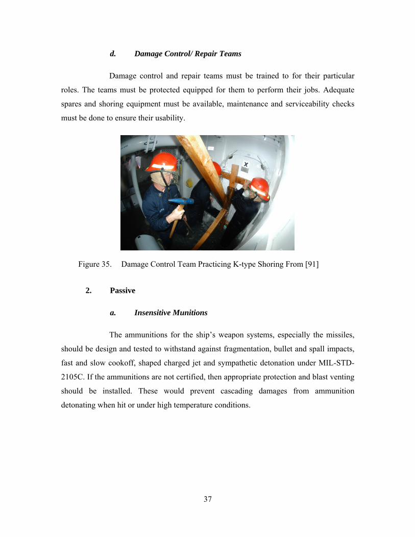
b. Self-sealing Fuel System
Self-sealing fuel tanks and reservoir, negative pressure feed pump and auto
cut-off valves should be incorporated in the design for stopping fuel and flammable
liquids from spewing into the surrounding upon damage. This would prevent the addition
of fuel to areas that are already on fire, and reduce fire outbreaks due to pooling of the
flammable liquids.
c. Low Flammability Hydraulics/Lubricants
Low flammability hydraulics and lubricants should be used in place of the
more highly flammable version. By having such characteristic in the hydraulics and
lubricants used, in the event of a damaged system, the chance of having fire outbreaks
could be reduced and prevented.
d. Watertight and Fire Retardant Bulkheads
Watertight bulkheads with watertight doors (Figure 36) could be used to
separate each compartments when dealing with flooding and fire. All watertight seals
should be checked and maintained regularly to ensure that the seals are tight. Fire
Retardant Bulkheads are used to contain and restrict the spreading of fire in sensitive
areas and fire doors are fitted in fire retardant bulkheads to provide access [89].
Figure 36. Water-tight Door and Bulkhead From [92]

39
e. Fire Resistant Electrical and Signal Cables
All cables, electrical and signal, especially those of critical systems, should
be of fire and high heat resistant. This will ensure functionality in case of fire. The cable
insulation should not produce toxic fumes when subject to high temperature or
combustion.
Figure 37. Fire Resistant Cable From [93]
f. Fire Retardant Materials
Fittings and other materials onboard the ship should be of fire retardant
material, so as not to be the source of fuel for sustaining any fire outbreaks. Also any
material that is used should not produce toxic fumes when subject to high temperature or
combustion.

40
THIS PAGE INTENTIONALLY LEFT BLANK

41
IV. SUSCEPTIBILITY REDUCTION
The main attribute to survivability is not just about being able to withstand
damages, for even the strongest system would fail if enough damages were done to it.
Another method to improve the ship’s survivability is to avoid being hit in the first place,
and this is referred as the susceptibility reduction. Under susceptibility reduction, there
are six concepts, signature reduction, threat warning, threat suppression, expendables,
jamming and deceiving, and tactics and training.
A. SIGNATURE REDUCTION
The word “Stealth” has always been associated with radar stealth by the general
public. In actual fact, radar signature is just one of the many signatures reduction required
to achieve stealth. Stealth is not invisibility or cloaking, stealth technology is about
having low observables. The many signatures of a ship include radar, infra-red, acoustic,
magnetism, optical and electromagnetic transmission. In order to achieve low
observability, all these signatures must be managed and reduced. With reduced
signatures, the detectability of the ship is reduced, making it harder for the enemy to
detect it. The range at which the ship could be detected is also reduced.
1. Radar Cross-Section
The definition of radar cross-section (RCS) as according to Skolnik [94], the radar
cross section σ is said to be a (fictional) area that intercepts a part of the power incident at
the target which, if scattered uniformly in all directions, produces an echo power at the
radar equal to that produced at the radar by the real target. The word “fictional” means
that the RCS area can be much bigger compared to the actual geometric area.
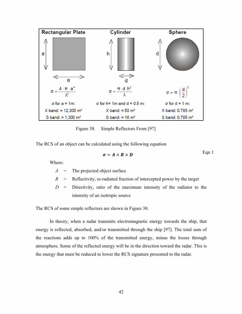
42
Figure 38. Simple Reflectors From [97]
The RCS of an object can be calculated using the following equation
Eqn 1
Where:
A = The projected object surface
R = Reflectivity, re-radiated fraction of intercepted power by the target
D = Directivity, ratio of the maximum intensity of the radiator to the
intensity of an isotropic source
The RCS of some simple reflectors are shown in Figure 38.
In theory, when a radar transmits electromagnetic energy towards the ship, that
energy is reflected, absorbed, and/or transmitted through the ship [97]. The total sum of
the reactions adds up to 100% of the transmitted energy, minus the losses through
atmosphere. Some of the reflected energy will be in the direction toward the radar. This is
the energy that must be reduced to lower the RCS signature presented to the radar.
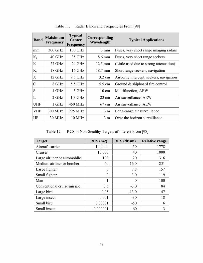
43
Table 11. Radar Bands and Frequencies From [98]
Band Maiximum Frequency
Typical Center
Frequency
Corresponding Wavelength
Typical Applications
mm 300 GHz 100 GHz 3 mm Fuses, very short range imaging radars
Ka 40 GHz 35 GHz 8.6 mm Fuses, very short range seekers
K 27 GHz 24 GHz 12.5 mm (Little used due to strong attenuation)
Ku 18 GHz 16 GHz 18.7 mm Short range seekers, navigation
X 12 GHz 9.5 GHz 3.2 cm Airborne intercept, seekers, navigation
C 8 GHz 5.5 GHz 5.5 cm Ground & shipboard fire control
S 4 GHz 3 GHz 10 cm Multifunction, AEW
L 2 GHz 1.3 GHz 23 cm Air surveillance, AEW
UHF 1 GHz 450 MHz 67 cm Air surveillance, AEW
VHF 300 MHz 225 MHz 1.3 m Long-range air surveillance
HF 30 MHz 10 MHz 3 m Over the horizon surveillance
Table 12. RCS of Non-Stealthy Targets of Interest From [98]
Target RCS (m2) RCS (dBsm) Relative range
Aircraft carrier 100,000 50 1778
Cruiser 10,000 40 1000
Large airliner or automobile 100 20 316
Medium airliner or bomber 40 16.0 251
Large fighter 6 7.8 157
Small fighter 2 3.0 119
Man 1 0 100
Conventional cruise missile 0.5 -3.0 84
Large bird 0.05 -13.0 47
Large insect 0.001 -30 18
Small bird 0.00001 -50 6
Small insect 0.000001 -60 3
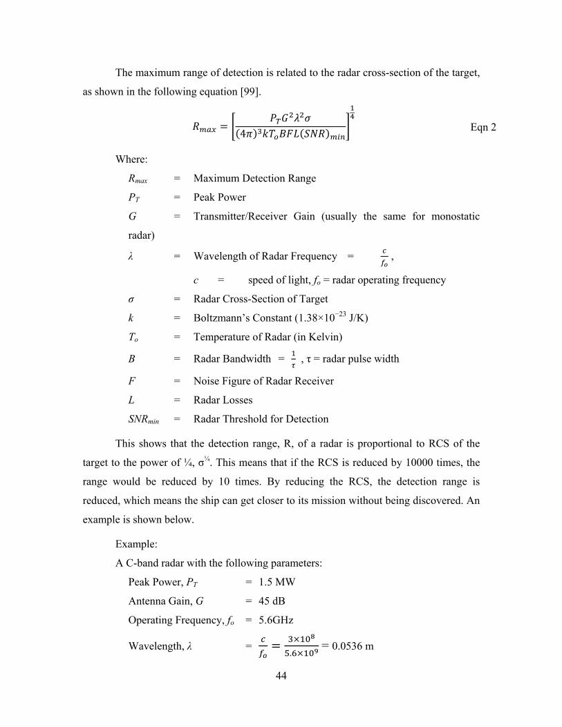
44
The maximum range of detection is related to the radar cross-section of the target,
as shown in the following equation [99].
4 Eqn 2
Where:
Rmax = Maximum Detection Range
PT = Peak Power
G = Transmitter/Receiver Gain (usually the same for monostatic
radar)
λ = Wavelength of Radar Frequency = ,
c = speed of light, fo = radar operating frequency
σ = Radar Cross-Section of Target
k = Boltzmann’s Constant (1.38×10⁻²³ J/K)
To = Temperature of Radar (in Kelvin)
B = Radar Bandwidth = , τ = radar pulse width
F = Noise Figure of Radar Receiver
L = Radar Losses
SNRmin = Radar Threshold for Detection
This shows that the detection range, R, of a radar is proportional to RCS of the
target to the power of ¼, σ¼. This means that if the RCS is reduced by 10000 times, the
range would be reduced by 10 times. By reducing the RCS, the detection range is
reduced, which means the ship can get closer to its mission without being discovered. An
example is shown below.
Example:
A C-band radar with the following parameters:
Peak Power, PT = 1.5 MW
Antenna Gain, G = 45 dB
Operating Frequency, fo = 5.6GHz
Wavelength, λ = .
= 0.0536 m
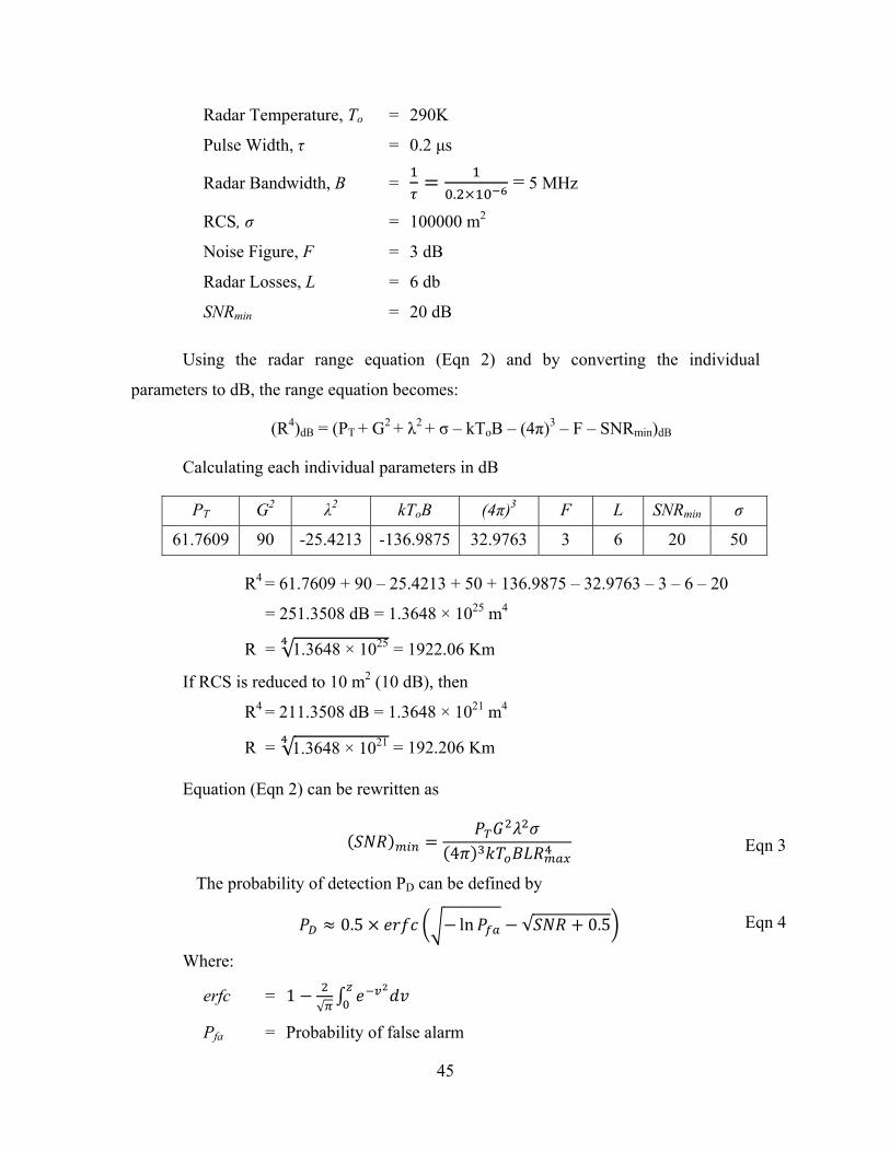
45
Radar Temperature, To = 290K
Pulse Width, τ = 0.2 μs
Radar Bandwidth, B = .
= 5 MHz
RCS, σ = 100000 m2
Noise Figure, F = 3 dB
Radar Losses, L = 6 db
SNRmin = 20 dB
Using the radar range equation (Eqn 2) and by converting the individual
parameters to dB, the range equation becomes:
(R4)dB = (PT + G2 + λ2 + σ – kToB – (4π)3 – F – SNRmin)dB
Calculating each individual parameters in dB
PT G2 λ2 kToB (4π)3 F L SNRmin σ
61.7609 90 -25.4213 -136.9875 32.9763 3 6 20 50
R4 = 61.7609 + 90 – 25.4213 + 50 + 136.9875 – 32.9763 – 3 – 6 – 20
= 251.3508 dB = 1.3648 × 1025 m4
R = √ = 1922.06 Km
If RCS is reduced to 10 m2 (10 dB), then
R4 = 211.3508 dB = 1.3648 × 10²¹ m4
R = √ = 192.206 Km
Equation (Eqn 2) can be rewritten as
4 Eqn 3
The probability of detection PD can be defined by
0.5 ln √ 0.5 Eqn 4
Where:
erfc = 1√
Pfa = Probability of false alarm
1.3648 × 10²¹
1.3648 × 1025
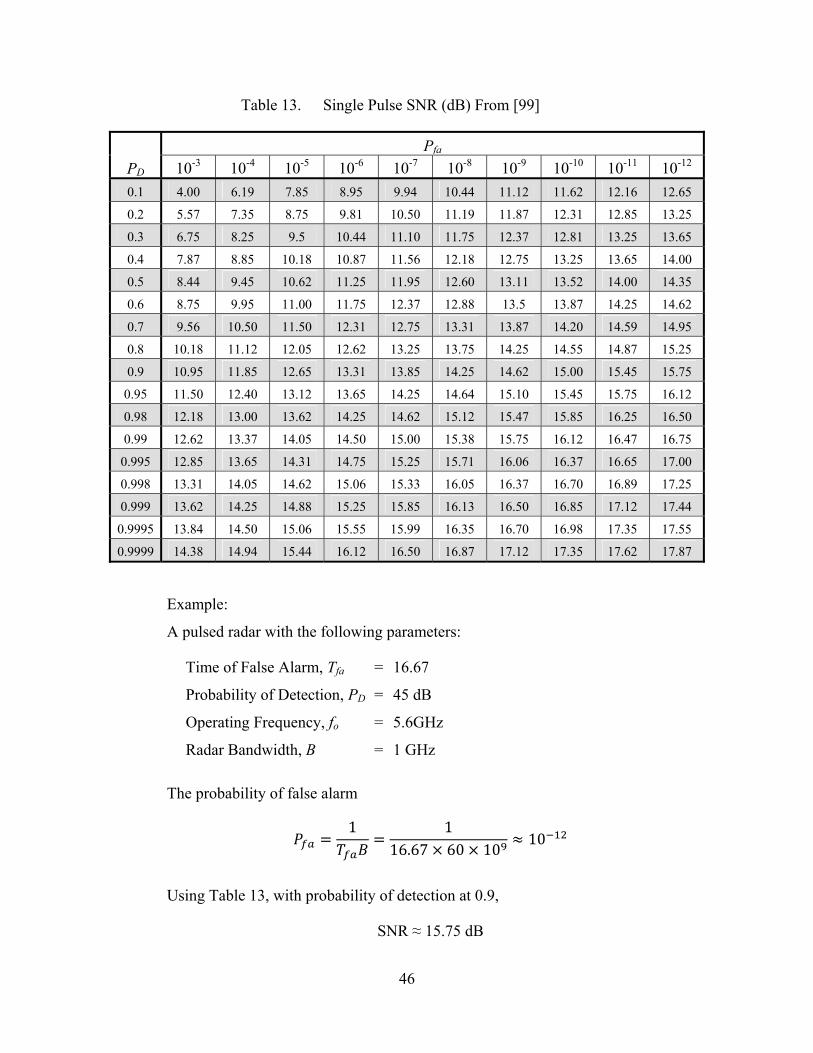
46
Table 13. Single Pulse SNR (dB) From [99]
PD
Pfa
10-3 10-4 10-5 10-6 10-7 10-8 10-9 10-10 10-11 10-12
0.1 4.00 6.19 7.85 8.95 9.94 10.44 11.12 11.62 12.16 12.65
0.2 5.57 7.35 8.75 9.81 10.50 11.19 11.87 12.31 12.85 13.25
0.3 6.75 8.25 9.5 10.44 11.10 11.75 12.37 12.81 13.25 13.65
0.4 7.87 8.85 10.18 10.87 11.56 12.18 12.75 13.25 13.65 14.00
0.5 8.44 9.45 10.62 11.25 11.95 12.60 13.11 13.52 14.00 14.35
0.6 8.75 9.95 11.00 11.75 12.37 12.88 13.5 13.87 14.25 14.62
0.7 9.56 10.50 11.50 12.31 12.75 13.31 13.87 14.20 14.59 14.95
0.8 10.18 11.12 12.05 12.62 13.25 13.75 14.25 14.55 14.87 15.25
0.9 10.95 11.85 12.65 13.31 13.85 14.25 14.62 15.00 15.45 15.75
0.95 11.50 12.40 13.12 13.65 14.25 14.64 15.10 15.45 15.75 16.12
0.98 12.18 13.00 13.62 14.25 14.62 15.12 15.47 15.85 16.25 16.50
0.99 12.62 13.37 14.05 14.50 15.00 15.38 15.75 16.12 16.47 16.75
0.995 12.85 13.65 14.31 14.75 15.25 15.71 16.06 16.37 16.65 17.00
0.998 13.31 14.05 14.62 15.06 15.33 16.05 16.37 16.70 16.89 17.25
0.999 13.62 14.25 14.88 15.25 15.85 16.13 16.50 16.85 17.12 17.44
0.9995 13.84 14.50 15.06 15.55 15.99 16.35 16.70 16.98 17.35 17.55
0.9999 14.38 14.94 15.44 16.12 16.50 16.87 17.12 17.35 17.62 17.87
Example:
A pulsed radar with the following parameters:
Time of False Alarm, Tfa = 16.67
Probability of Detection, PD = 45 dB
Operating Frequency, fo = 5.6GHz
Radar Bandwidth, B = 1 GHz
The probability of false alarm
1 116.67 60 10
10
Using Table 13, with probability of detection at 0.9,
SNR ≈ 15.75 dB

47
From equation 3, we can derive that a reduction in the ship RCS would result in a
lower signal-to-noise ratio. From Table 13, a radar with the same false alarm rate, and a
reduced SNR would then translate to a lower probability of detection. This would mean
that at a particular range, the probability a low RCS ship would be lower compared to the
probability of detecting a conventional RCS ship. The low RCS ship can therefore
perform her mission with a reduced risk of being detected.
Reducing the RCS of the ship not only reduces its detectability. In the event that
the ship is targeted and a radar-guided missile is launched at her, decoys and electronic
countermeasures would be used to deceive and evade the missile. With low RCS, the
ECM jammer used would require lesser power to operate, and the burn-through range
would also be reduced, as presented in Figure 39. In the case of using chaff decoys, the
decoy would present a more attractive RCS target for the missile to home-in to. The
reduced RCS effects on ECM jammer and decoys would be discussed in the later
sections.
Figure 39. RCS vs Radar Detection, Burn-through, & Jammer Power From [100]

48
From the two examples above, by reducing the ship’s RCS, we can get the ship
closer to its mission objective without her being detected. The ship can also perform her
mission in an environment with lower probability of detection. So how do we reduce the
inherently large RCS of the ship? Table 12 and Table 14 show the typical RCS of ships.
A conventional ship with all her above-deck weapons, equipment, mast and
antennas would create a very huge reflector which will cause a lot of the radar energy to
backscatter toward the radar receiver. This would create a high RCS profile for the ship.
Figure 40 and Figure 41 show how the different shapes and corners on a ship could
reflect the radar energy and the RCS they would present. With the exception to the sphere,
all other shapes tends to have a larger RCS surface that their actual physical area, as
defined by Skolnik [101].
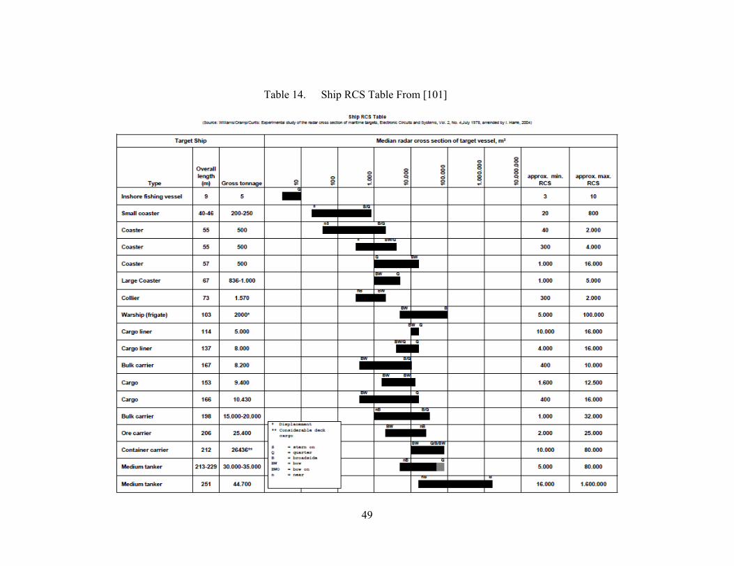
49
Table 14. Ship RCS Table From [101]
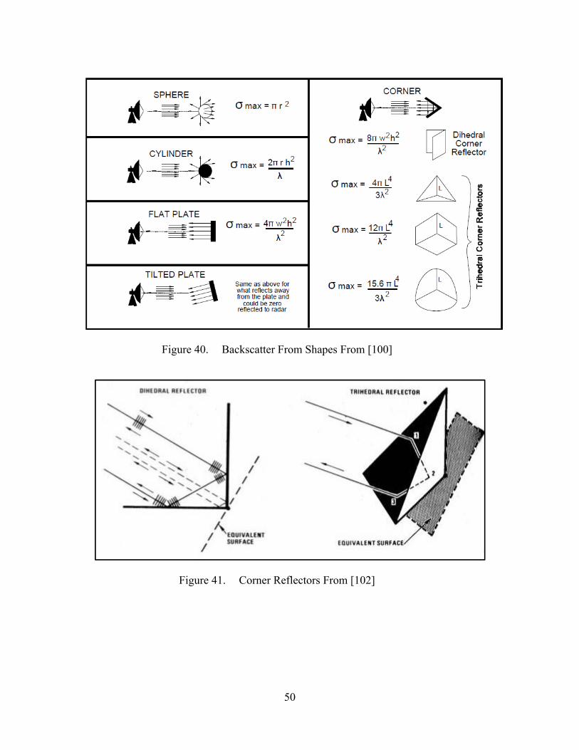
50
Figure 40. Backscatter From Shapes From [100]
Figure 41. Corner Reflectors From [102]

51
The radar cross-section of a ship can be reduced or altered in three ways:
The use of radar absorbing materials (RAM) and structures (RAS).
Shaping.
Active and passive cancellation.
a. Radar Absorbing Material
The first method is through absorption, by using radar absorbing materials
or paint. The RAM absorbs some of the radar energy by converting them into heat, thus
reducing the reflected energy, causing the radar to “see” a smaller target. The heat
dissipated by the RAM would not significantly increase the heat signature of the ship,
thus neglecting issue of reducing RCS by transferring to the heat signature.
There are three conditions that would result in minimum reflectivity [103].
The first equation is the reflection coefficient of a surface
Γ Eqn 5
Where:
η = The admittance of the propagating medium (ηo for incident
medium or air and ηM for the substrate)
Z = Intrinsic impedance which is equal to
The reflection coefficient is equal to zero when ηM = ηo, or the impedance
of the material matches that of the impedance of the incident medium [103, 104]. This
means that no energy is reflected back to the radar receiver, RCS would be equal to zero,
and the ship would be totally invisible to radar. This is the ideal theoretical result desired,
although in reality, zero RCS is next to impossible to achieve.
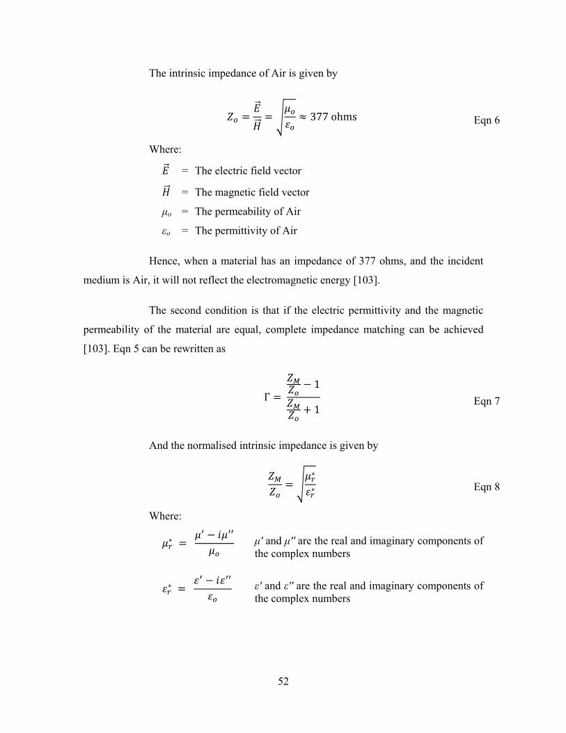
52
The intrinsic impedance of Air is given by
377ohms Eqn 6
Where:
= The electric field vector
= The magnetic field vector
μo = The permeability of Air
εo = The permittivity of Air
Hence, when a material has an impedance of 377 ohms, and the incident
medium is Air, it will not reflect the electromagnetic energy [103].
The second condition is that if the electric permittivity and the magnetic
permeability of the material are equal, complete impedance matching can be achieved
[103]. Eqn 5 can be rewritten as
Γ 1
1 Eqn 7
And the normalised intrinsic impedance is given by
∗
∗ Eqn 8
Where:
∗
∗
μ' and μ'' are the real and imaginary components of the complex numbers
ε' and ε'' are the real and imaginary components of the complex numbers
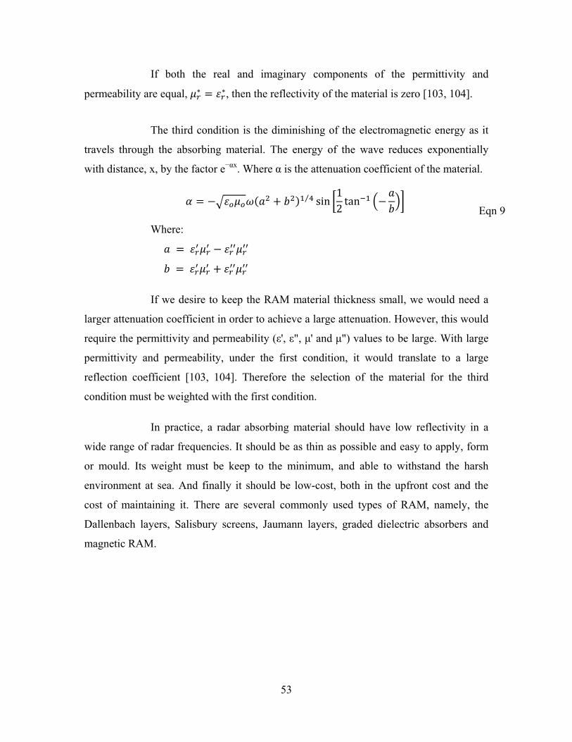
53
If both the real and imaginary components of the permittivity and
permeability are equal, ∗ ∗, then the reflectivity of the material is zero [103, 104].
The third condition is the diminishing of the electromagnetic energy as it
travels through the absorbing material. The energy of the wave reduces exponentially
with distance, x, by the factor e−αx. Where α is the attenuation coefficient of the material.
⁄ sin12tan
Eqn 9
Where:
If we desire to keep the RAM material thickness small, we would need a
larger attenuation coefficient in order to achieve a large attenuation. However, this would
require the permittivity and permeability (ε', ε", μ' and μ") values to be large. With large
permittivity and permeability, under the first condition, it would translate to a large
reflection coefficient [103, 104]. Therefore the selection of the material for the third
condition must be weighted with the first condition.
In practice, a radar absorbing material should have low reflectivity in a
wide range of radar frequencies. It should be as thin as possible and easy to apply, form
or mould. Its weight must be keep to the minimum, and able to withstand the harsh
environment at sea. And finally it should be low-cost, both in the upfront cost and the
cost of maintaining it. There are several commonly used types of RAM, namely, the
Dallenbach layers, Salisbury screens, Jaumann layers, graded dielectric absorbers and
magnetic RAM.

54
Figure 42. Dallenbach Layer From [103]
A Dallenbach layer, as shown in Figure 42, consists of a homogeneous
dielectric absorber layer placed on a grounded metal conducting plane [103, 104]. The
thickness, permittivity and permeability are attuned for the desired wavelength that the
reflectivity is to be minimized. Dallenbach screen of two or more layers with different
absorption bands will increase the absorption bandwidth [103].
The energy absorption of the layer is accomplished by the interference of
electromagnetic waves reflected from the air/absorber interface and absorber/metal
interface. In order for the reflectivity to be minimized, the impedance of the Dallenbach
layer, ZL, must be equal or close to the incident impedance [103, 104], Zo, as shown in
Eqn 5.
tanhtanh
Eqn 10
Where:
Z1 = The impedance of the layer material
= ⁄
Z2 = The impedance of the back material
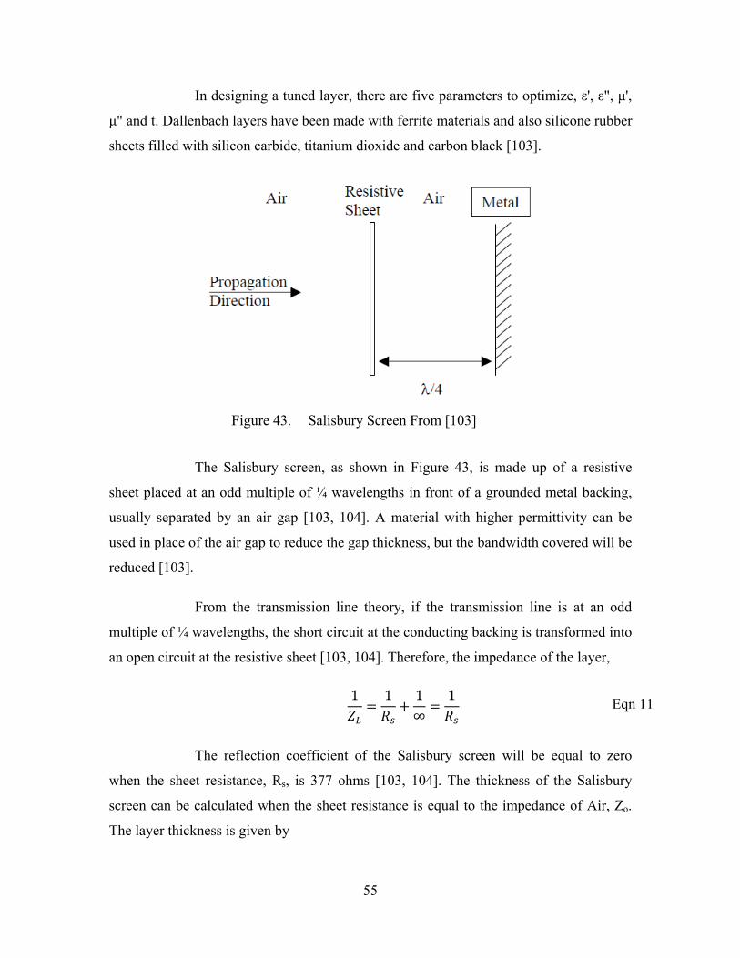
55
In designing a tuned layer, there are five parameters to optimize, ε', ε", μ',
μ" and t. Dallenbach layers have been made with ferrite materials and also silicone rubber
sheets filled with silicon carbide, titanium dioxide and carbon black [103].
Figure 43. Salisbury Screen From [103]
The Salisbury screen, as shown in Figure 43, is made up of a resistive
sheet placed at an odd multiple of ¼ wavelengths in front of a grounded metal backing,
usually separated by an air gap [103, 104]. A material with higher permittivity can be
used in place of the air gap to reduce the gap thickness, but the bandwidth covered will be
reduced [103].
From the transmission line theory, if the transmission line is at an odd
multiple of ¼ wavelengths, the short circuit at the conducting backing is transformed into
an open circuit at the resistive sheet [103, 104]. Therefore, the impedance of the layer,
1 1 1∞
1 Eqn 11
The reflection coefficient of the Salisbury screen will be equal to zero
when the sheet resistance, Rs, is 377 ohms [103, 104]. The thickness of the Salisbury
screen can be calculated when the sheet resistance is equal to the impedance of Air, Zo.
The layer thickness is given by
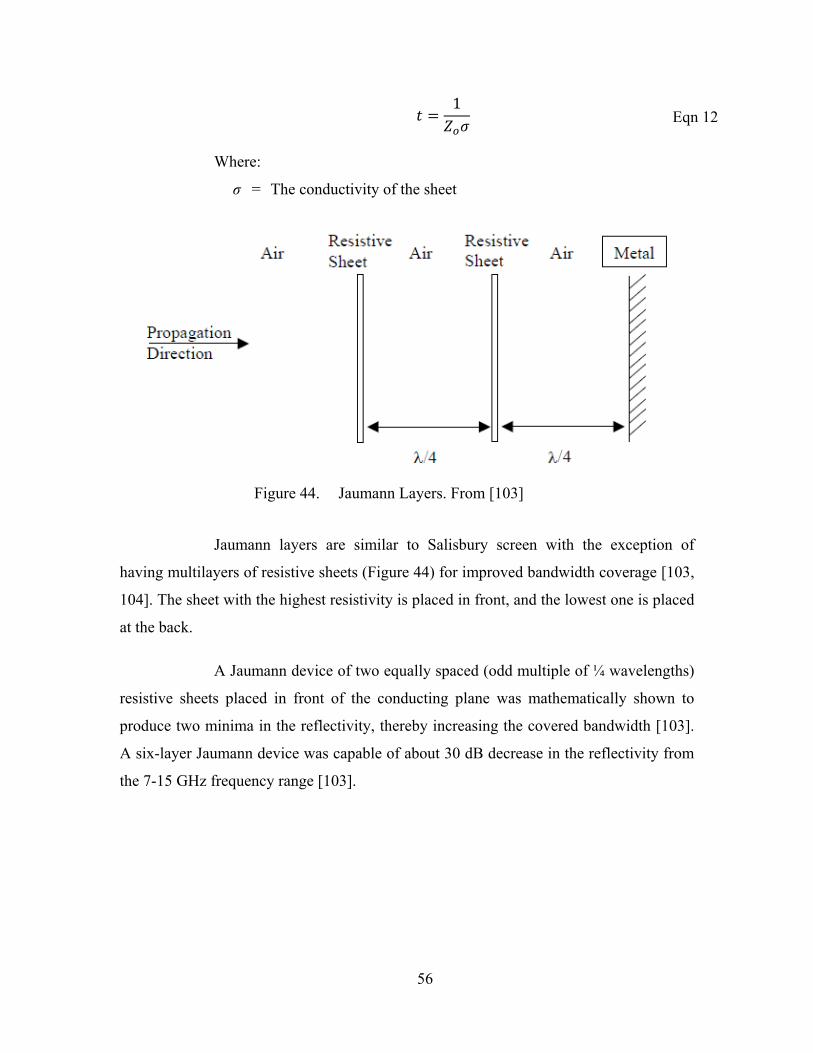
56
1 Eqn 12
Where:
σ = The conductivity of the sheet
Figure 44. Jaumann Layers. From [103]
Jaumann layers are similar to Salisbury screen with the exception of
having multilayers of resistive sheets (Figure 44) for improved bandwidth coverage [103,
104]. The sheet with the highest resistivity is placed in front, and the lowest one is placed
at the back.
A Jaumann device of two equally spaced (odd multiple of ¼ wavelengths)
resistive sheets placed in front of the conducting plane was mathematically shown to
produce two minima in the reflectivity, thereby increasing the covered bandwidth [103].
A six-layer Jaumann device was capable of about 30 dB decrease in the reflectivity from
the 7-15 GHz frequency range [103].

57
Table 15. Jaumann Layers vs Fractional Bandwidth (based on 10 GHz) From [104]
Bandwidth of Jaumann Absorbers
Number of Sheets Fractional Bandwidth Total Thickness (cm)
1 0.27 0.75
2 0.55 1.50
3 0.95 2.25
4 1.16 3.00
The design and optimisation of Jaumann absorbers are difficult. The
numbers of variable parameters involved are high and they increases as the number of
layers increases.
The graded dielectric absorbers are made of multi-layered materials, each
with different properties [104]. Absorption of the energy is achieved by a gradual
lowering of impedance from that of free space to that of a lossy medium, thus having a
low initial reflection in the material, and a gradual transition from free space to lossy
state, resulting in attenuation of the electromagnetic energy. Graded dielectric absorbers
are usually made of carbon-loaded low density foam.
Magnetic radar absorbing materials are made of carbonyl iron and
hexaferrites based materials [103]. Magnetic RAMs have great advantages as compared
to the dielectric absorbers. It is able to cover a wide range of frequencies with a relatively
smaller thickness, especially in the low frequency ranges (down to 100MHz) [103,
104].The thickness required of the magnetic RAM can be much less than 10% that of the
dielectric absorbers [104]. Although the density of a magnetic RAM is significantly
higher, due to the iron content, the reduced thickness compensated for the increase.
Magnetic RAMs are usually constructed with carbonyl iron and
hexaferrites embedded in a dielectric, for example, in Dallenbach layers [103, 104]. The
frequencies coverage can be designed by controlling the magnetic and dielectric loading
and the thickness of each of the layers [105].

58
In magnetic RAM, RCS reduction is achieved by phase cancellation. The
electromagnetic energy is partially reflected and partially transmitted through the
material. The transmitted energy hits the many particles within the material, and causes
multiple internal reflections to create a series of emergent waves [105]. The sum of the
emergent waves is equal in amplitude to (by 180 degrees out of phase with) the initial
reflection portion at the design frequency, in theory, there will be no reflection [105].
Figure 45. Electromagnetic Absorption through RAM From [106]
The use of RAM would incur additional cost, as the additional weight and
dimension of materials would have to be factored in the design, and the material upfront
cost would be higher. The operational and support cost through the life cycle of the ship
would also increase, as regular maintenance would be needed to ensure that the RAM and
paint function as desired.
When there is a need for an opening, for example air intake/exhaust or
boat davit access, the RCS reduction profile would be broken. In order to prevent the
increase in RCS, a honeycomb structure or mesh screen can be used to cover the opening,
and yet allow access. The mesh and honeycomb will deflect the energy away, preventing
energy from entering the opening and reflecting off the internal surfaces back out toward
the radar.

59
Figure 46. Carbon Foam Radar Absorbing Material From [107]
Figure 47. Radar Absorbing Honeycomb Structure From [108]
b. Shaping
The second method is by reflection. The ship’s hull and structure are
shaped such that the electromagnetic waves are reflected in directions away from the
radar. This cannot be accomplished for all aspect angles, as there will always be angles at
which the surfaces are normal to the radar, and at these angles the RCS will be high
(Figure 48). Those angles are the sacrificial angles of the ship, where all components
would reflect the electromagnetic waves at those angles, while keeping the RCS of other
the angles low.

60
Figure 48. RCS profile, without Shaping (left), with Shaping (right) From [19]
Shaping works by eliminating and reducing the back scatter caused by the
surfaces of the ship in the direction of the radar. The objective is to reduce detection by
enemy ships, aircrafts and missiles and other radar equipped system on the horizon and/or
at low level altitude. This equates to reflection angles from the horizon up to angles of
about 30 degrees that RCS should be minimized. Optimally, RCS should be reduced 360
degrees around the ship, but this is not normally possible, hence there will always be
some sacrificial angles, where the RCS would be higher.
By reducing the clutter on the surface of the ship, for example, antenna
mast and arrays, the reflection angles can be controlled and reflection strength reduced.
Making the surfaces of the ship smooth will also enable angular control and strength
reduction of the reflections. The surfaces should avoid having corners and no two
surfaces should be aligned at 90 degree angles. This is to prevent the radio wave from
reflecting off one surface to another surface and back in the direction of the radar, this is
illustrated previously in Figure 41.
Although a curved or round surface, as compared to a flat plate, reflects a
smaller portion of the back in the direction of the radar, there is no control over the
reflection angles. The electromagnetic radiation will be scattered in all direction, and
other radar receiver would be able to receive those back scattered radiation. This means
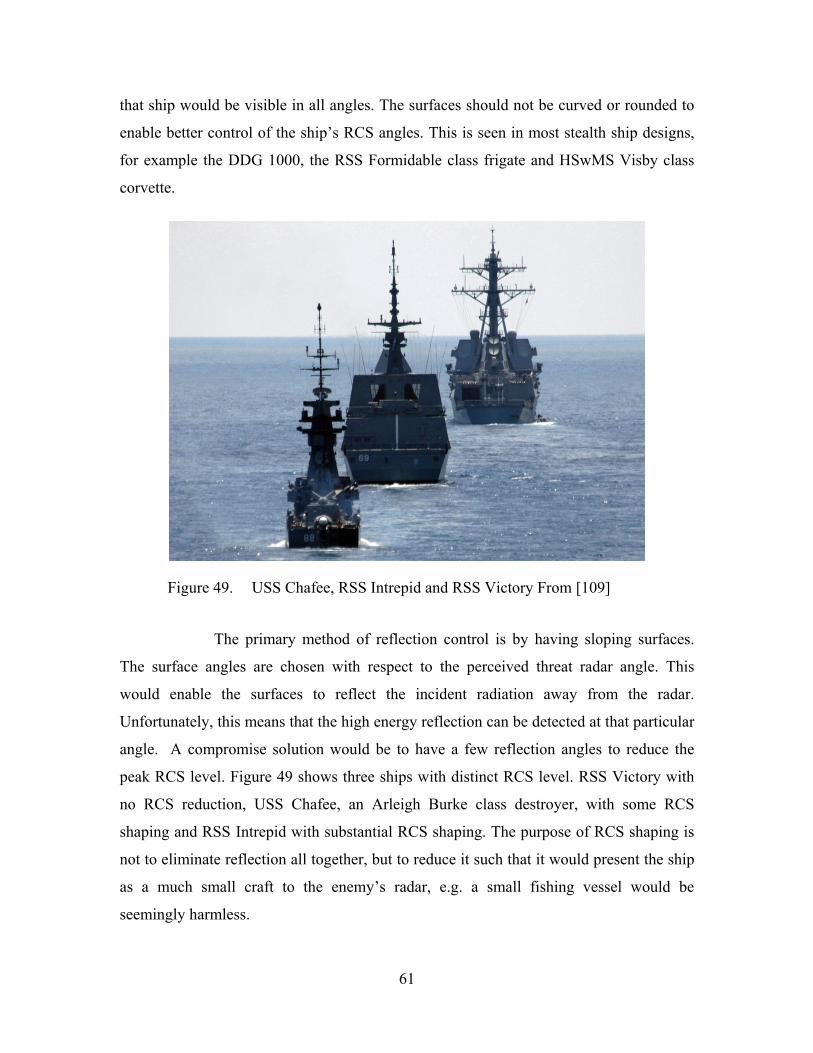
61
that ship would be visible in all angles. The surfaces should not be curved or rounded to
enable better control of the ship’s RCS angles. This is seen in most stealth ship designs,
for example the DDG 1000, the RSS Formidable class frigate and HSwMS Visby class
corvette.
Figure 49. USS Chafee, RSS Intrepid and RSS Victory From [109]
The primary method of reflection control is by having sloping surfaces.
The surface angles are chosen with respect to the perceived threat radar angle. This
would enable the surfaces to reflect the incident radiation away from the radar.
Unfortunately, this means that the high energy reflection can be detected at that particular
angle. A compromise solution would be to have a few reflection angles to reduce the
peak RCS level. Figure 49 shows three ships with distinct RCS level. RSS Victory with
no RCS reduction, USS Chafee, an Arleigh Burke class destroyer, with some RCS
shaping and RSS Intrepid with substantial RCS shaping. The purpose of RCS shaping is
not to eliminate reflection all together, but to reduce it such that it would present the ship
as a much small craft to the enemy’s radar, e.g. a small fishing vessel would be
seemingly harmless.

62
c. Active and Passive Cancellation
The third method is by interference or cancellation. The passive
cancellation method is achieved by creating a structure to introduce a secondary scatter
that would cancel or with the reflection of the primary signal. This is called impedance
loading [104]. The idea of this is to create a source whose amplitude and phase can
cancel that of primary backscatter. However it is generally not possible to cover the entire
range of frequencies, as the design for such structure is normally wavelength dependent.
As the frequency changes, the RCS reduction is lost.
With an active system, interference is created by applying a current to the
surface, changing the flow of electrons, thus disrupting the electromagnetic waves [7].
This is called reactive loading. Another method for cancelling the radar electromagnetic
energy is by generating an electromagnetic field of equal intensity and in opposite phase
(180○) to reflected radar signal [96]. The generated field interferes and cancels out the
reflected energy (similar to noise cancelling earphone concept), thus reducing the RCS.
To enable active cancellation to work, the details about the incoming radar signal must be
known. The signal amplitude, phase, frequency, polarization, bearing and elevation must
be known for the system to process and transmit the cancelling signal [104].
The requirements for such systems to work are so excessive that it is
almost impractical to use them. They require detection in all angles and frequencies and
the retransmission of the canceling signal must coincide with the returns from the ship.
This is almost impossible to anticipate with the multitude of hull structures, thus it is not
a recommended RCS reduction method.
2. Acoustic
When sound wave is created, either on the surface or in the water, it travels
through the water, and can be picked up by a hydrophone. This is the acoustic noise. The
acoustic signature of a ship is a combination of all the sounds created by the ship in the
form of machinery noise, propeller noise, hydrodynamic noise, and if any, the ship’s

63
sonar noise. The radiated noise can provide a means for the enemy to detect the ship. The
noise would also interfere with the effectiveness of the ship’s sonar.
Machinery noises are generated by the vibrations of the ship’s engines, propeller
shafts, compressors and any impacting machineries. The vibration is transmitted through
the ship’s structure to the water. Other machinery noises are crew related, for example,
dropping of a pot in the galley, closing of a water-tight door, and even water hammering
in hydraulics and plumbing systems.
Figure 50. Machinery Noise Sources on a Diesel-electric Vessel From [111]
Propeller noise is created outside the hull of the ship, as the propellers and the
ship cut through the water. The primary source of the noise is generated by cavitation.
Cavitation can be subdivided into two categories, tip-vortex cavitation and blade-surface
cavitation. Bubbles are formed in areas of low pressure where the water can vaporize.
When the bubble collapses, a sharp pulse of sound is emitted. Cavitation usually occurs
above a certain speed, between 9-15 knots, for ships with constant pitch propellers [118].
For variable pitch propellers, cavitation occurs in both high and low speed, with
cavitation free speed at around 12 knots [118]. Another propeller noise is due to the blade
resonance; however this happens at only a small range of speeds.
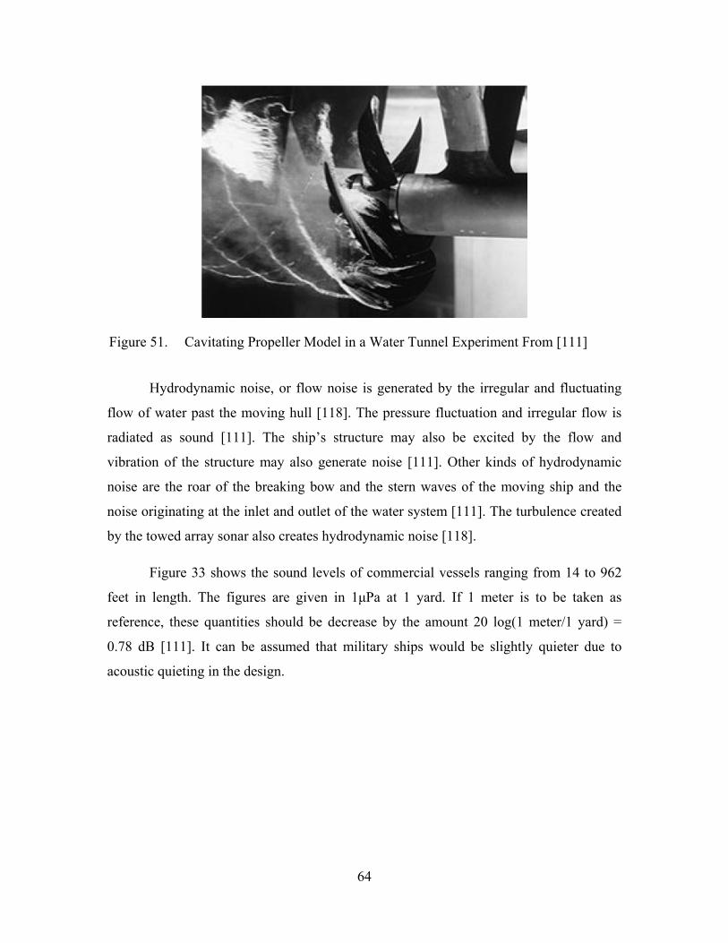
64
Figure 51. Cavitating Propeller Model in a Water Tunnel Experiment From [111]
Hydrodynamic noise, or flow noise is generated by the irregular and fluctuating
flow of water past the moving hull [118]. The pressure fluctuation and irregular flow is
radiated as sound [111]. The ship’s structure may also be excited by the flow and
vibration of the structure may also generate noise [111]. Other kinds of hydrodynamic
noise are the roar of the breaking bow and the stern waves of the moving ship and the
noise originating at the inlet and outlet of the water system [111]. The turbulence created
by the towed array sonar also creates hydrodynamic noise [118].
Figure 33 shows the sound levels of commercial vessels ranging from 14 to 962
feet in length. The figures are given in 1μPa at 1 yard. If 1 meter is to be taken as
reference, these quantities should be decrease by the amount 20 log(1 meter/1 yard) =
0.78 dB [111]. It can be assumed that military ships would be slightly quieter due to
acoustic quieting in the design.

65
Figure 52. 10-knot Sound Level by Vessel From [117]
Passive Sonar Equations
SNR = SL − TL − (NL − DI) > DT
TL = FOM = SL − DT − (NL − DI)
Where:
SL = Source Level
TL = Transmission Loss
NL = Noise Level, 10 log 10 / 10 /
DI = Directivity Index
DT = Detection Threshold, is the min SNR required for accurate detection
FOM = Figure of Merit, is the allowable TL given a DT
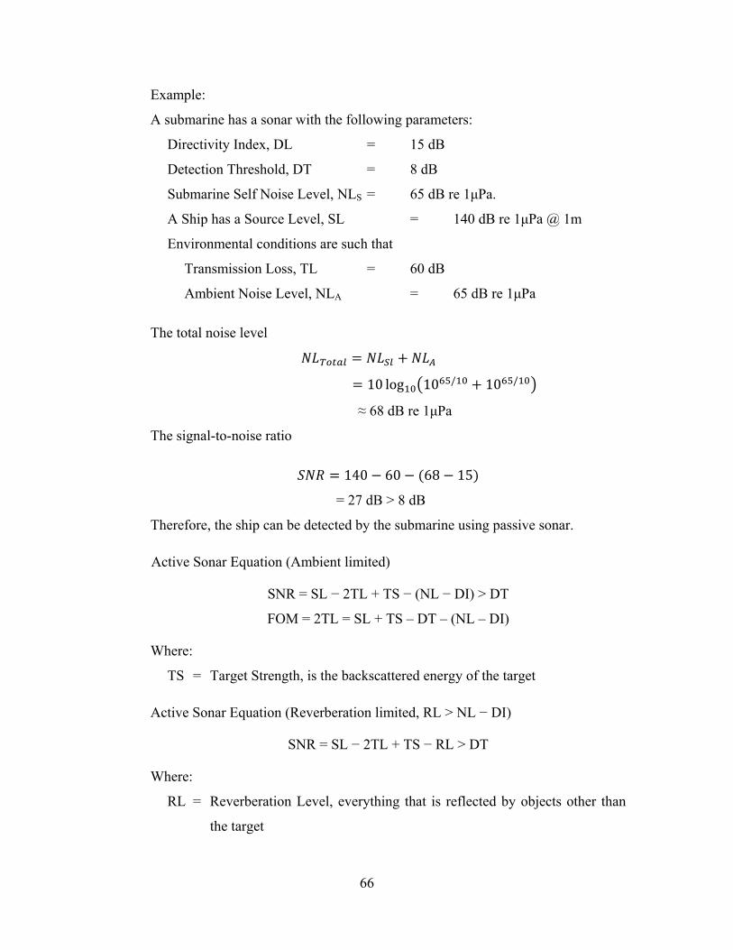
66
Example:
A submarine has a sonar with the following parameters:
Directivity Index, DL = 15 dB
Detection Threshold, DT = 8 dB
Submarine Self Noise Level, NLS = 65 dB re 1μPa.
A Ship has a Source Level, SL = 140 dB re 1μPa @ 1m
Environmental conditions are such that
Transmission Loss, TL = 60 dB
Ambient Noise Level, NLA = 65 dB re 1μPa
The total noise level
10 log 10 / 10 /
≈ 68 dB re 1μPa
The signal-to-noise ratio
140 60 68 15
= 27 dB > 8 dB
Therefore, the ship can be detected by the submarine using passive sonar.
Active Sonar Equation (Ambient limited)
SNR = SL − 2TL + TS − (NL − DI) > DT
FOM = 2TL = SL + TS – DT – (NL – DI)
Where:
TS = Target Strength, is the backscattered energy of the target
Active Sonar Equation (Reverberation limited, RL > NL − DI)
SNR = SL − 2TL + TS − RL > DT
Where:
RL = Reverberation Level, everything that is reflected by objects other than
the target
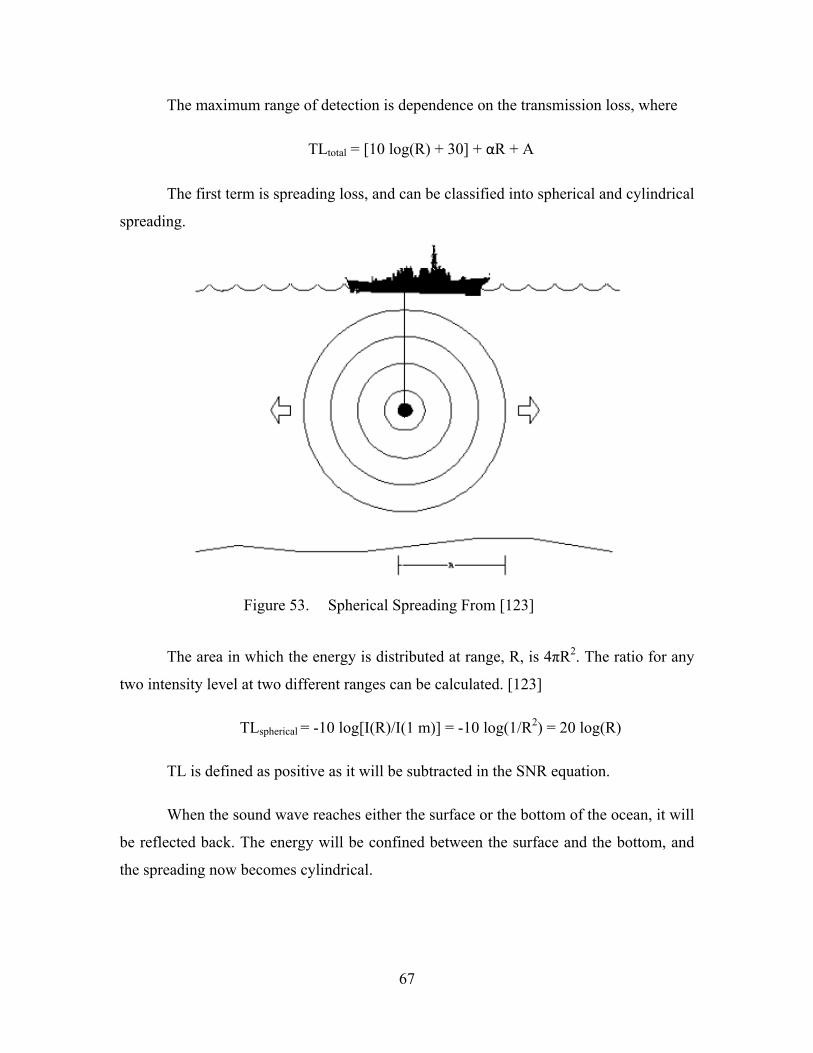
67
The maximum range of detection is dependence on the transmission loss, where
TLtotal = [10 log(R) + 30] + αR + A
The first term is spreading loss, and can be classified into spherical and cylindrical
spreading.
Figure 53. Spherical Spreading From [123]
The area in which the energy is distributed at range, R, is 4πR2. The ratio for any
two intensity level at two different ranges can be calculated. [123]
TLspherical = -10 log[I(R)/I(1 m)] = -10 log(1/R2) = 20 log(R)
TL is defined as positive as it will be subtracted in the SNR equation.
When the sound wave reaches either the surface or the bottom of the ocean, it will
be reflected back. The energy will be confined between the surface and the bottom, and
the spreading now becomes cylindrical.
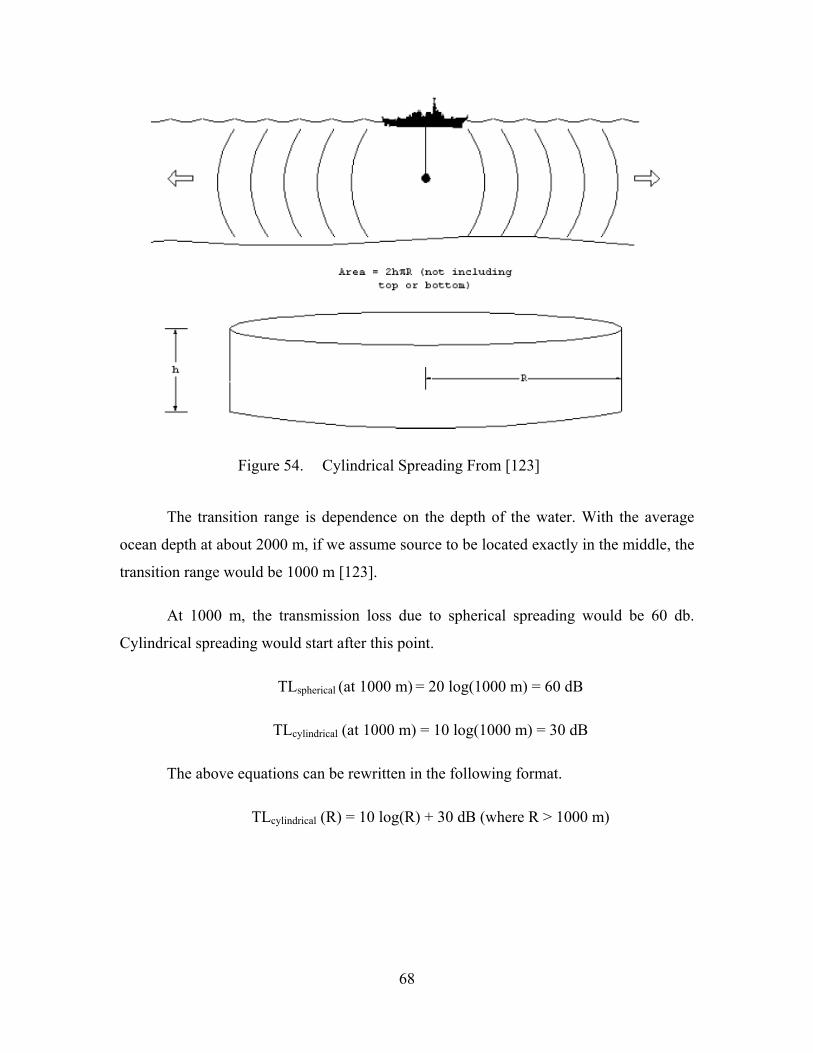
68
Figure 54. Cylindrical Spreading From [123]
The transition range is dependence on the depth of the water. With the average
ocean depth at about 2000 m, if we assume source to be located exactly in the middle, the
transition range would be 1000 m [123].
At 1000 m, the transmission loss due to spherical spreading would be 60 db.
Cylindrical spreading would start after this point.
TLspherical (at 1000 m) = 20 log(1000 m) = 60 dB
TLcylindrical (at 1000 m) = 10 log(1000 m) = 30 dB
The above equations can be rewritten in the following format.
TLcylindrical (R) = 10 log(R) + 30 dB (where R > 1000 m)

69
The second term in the total transmission loss equation is the absorption loss.
Absorption is the effect of the transformation of acoustic energy into heat during the
sound propagation over the ocean and depends on the source frequency [110].
TLabsorption = αR
Where :
α = (0.11 f2/1+ f2) + (44 f2/4100 + f2) + 0.000275 f2 + 0.003 (dB/km)
and
f is the frequency of the sound wave
Figure 55. Absorption as a function of Frequency From [110]
Figure 55 shows the absorption coefficient of the ocean as a function of
frequency. The absorption increase as the frequency goes up.
Example:
From Figure 55, at 9 kHz, the absorption, α, is about 1 dB/km in the Pacific
Ocean.
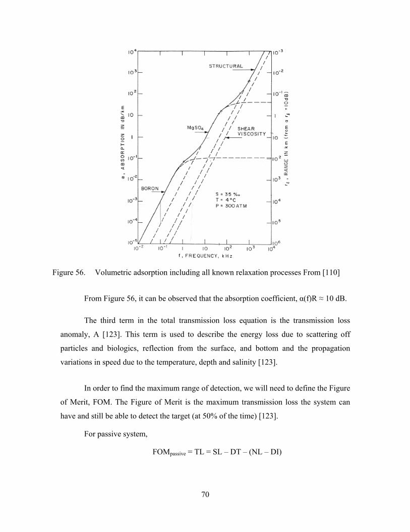
70
Figure 56. Volumetric adsorption including all known relaxation processes From [110]
From Figure 56, it can be observed that the absorption coefficient, α(f)R ≈ 10 dB.
The third term in the total transmission loss equation is the transmission loss
anomaly, A [123]. This term is used to describe the energy loss due to scattering off
particles and biologics, reflection from the surface, and bottom and the propagation
variations in speed due to the temperature, depth and salinity [123].
In order to find the maximum range of detection, we will need to define the Figure
of Merit, FOM. The Figure of Merit is the maximum transmission loss the system can
have and still be able to detect the target (at 50% of the time) [123].
For passive system,
FOMpassive = TL = SL – DT – (NL – DI)

71
For active system,
FOMactive = 2TL = SL + TS – DT – (NL – DI)
The maximum range of detection can then be determine from the Figure of Merit,
as shown in Figure 57.
Example:
With FOM = 75 dB, the maximum detection range is 18 km. If the transmission
lose is greater than the FOM, then the ship is not detectable.
Figure 57. Determining Maximum Detection Range from FOM From [123]
In order to reduce the acoustic signature of the ship, there are two areas we need
to manage. Firstly, for reducing detection by passive sonar, the ship generated noise level
should be kept low or masked from transmitting to the surrounding. Secondly, in the case
of active sonar, the sound reflection or “Target Strength”, of the ship should be
minimized.

72
Acoustic quieting or ship silencing is the process of reducing the ship generated
noise, by preventing the three sources of noise, machinery noise, propeller noise and
hydrodynamic noise, from reaching the detector. Machinery noise can be controlled by
isolating the path of transmission using resilient mounts, distributed isolation material
(DIM) and flexible piping connections [[119]].
Figure 58. Resilient Mounts (left) and Flexible Pipe Connections (right) From [119]
Machinery vibration can also be reduced by preventing aerodynamic stall [114].
For example, an engine going into stall will vibrate violently. Hydraulics and plumbing
system may be fitted to minimize water hammering [114]. The natural frequencies of
machinery can be managed to reduce resonance [114]. A resonating machine will create
noise. And in some machines, a vacuum barrier can be created to prevent noise
transmission.
Reducing the noise generate by the ship is one of the method of acoustic
management. The second method is preventing the noise from reaching the passive sonar
detector. This can be done by creating a wall of air bubbles enveloping the hull of the
ship. The large difference in impedance (speed of sound) between the air bubble and the
surrounding water makes them good reflectors of acoustic energy [120]. Acoustic waves
travelling from one medium to the next which has a significantly different speed of sound
do not penetrate, but is reflected back [121]. The speed of sound in a cloud of bubbles in
water is a factor of ten slower than in water itself and a factor of three slower than in air

73
[121]. Sounds generated within the ship hull which are transmitted into the water and
which would otherwise propagate for a long distance are reflected back into the hull and
dissipated [121].
The Masker air system seen in Figure 59, forms a screen of air bubbles around the
ship’s hull where there are heavy machinery located (e.g. engine room), minimizing the
transmission of the machinery noise to the surrounding water.
Although the Masker system reduces the machinery noise transmission, it creates
another problem. The Masker system increases the wake of the ship, thus creating a
bigger visual signature for the ship [122]. It also presents a bigger signature for wake-
homing torpedoes [122].
Figure 59. Masker Air System on DDG-963 From [120]
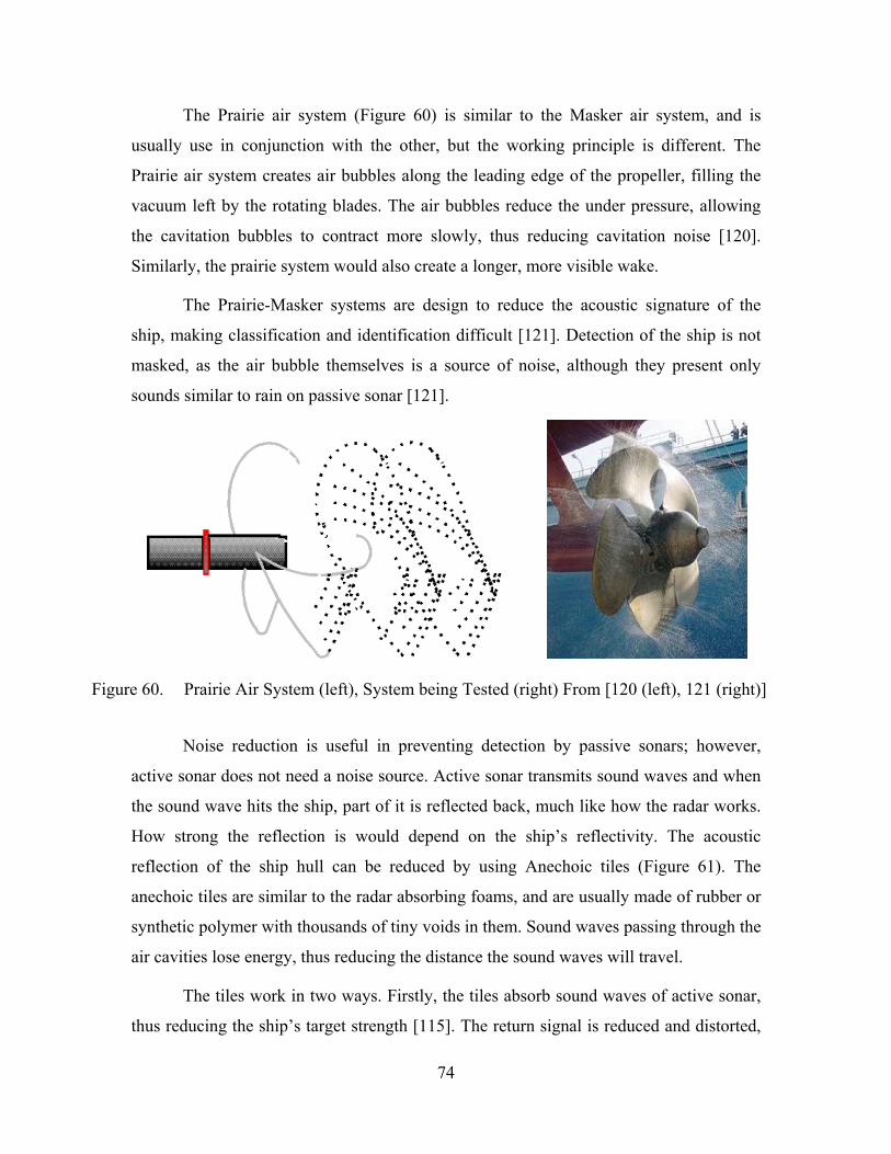
74
The Prairie air system (Figure 60) is similar to the Masker air system, and is
usually use in conjunction with the other, but the working principle is different. The
Prairie air system creates air bubbles along the leading edge of the propeller, filling the
vacuum left by the rotating blades. The air bubbles reduce the under pressure, allowing
the cavitation bubbles to contract more slowly, thus reducing cavitation noise [120].
Similarly, the prairie system would also create a longer, more visible wake.
The Prairie-Masker systems are design to reduce the acoustic signature of the
ship, making classification and identification difficult [121]. Detection of the ship is not
masked, as the air bubble themselves is a source of noise, although they present only
sounds similar to rain on passive sonar [121].
Figure 60. Prairie Air System (left), System being Tested (right) From [120 (left), 121 (right)]
Noise reduction is useful in preventing detection by passive sonars; however,
active sonar does not need a noise source. Active sonar transmits sound waves and when
the sound wave hits the ship, part of it is reflected back, much like how the radar works.
How strong the reflection is would depend on the ship’s reflectivity. The acoustic
reflection of the ship hull can be reduced by using Anechoic tiles (Figure 61). The
anechoic tiles are similar to the radar absorbing foams, and are usually made of rubber or
synthetic polymer with thousands of tiny voids in them. Sound waves passing through the
air cavities lose energy, thus reducing the distance the sound waves will travel.
The tiles work in two ways. Firstly, the tiles absorb sound waves of active sonar,
thus reducing the ship’s target strength [115]. The return signal is reduced and distorted,
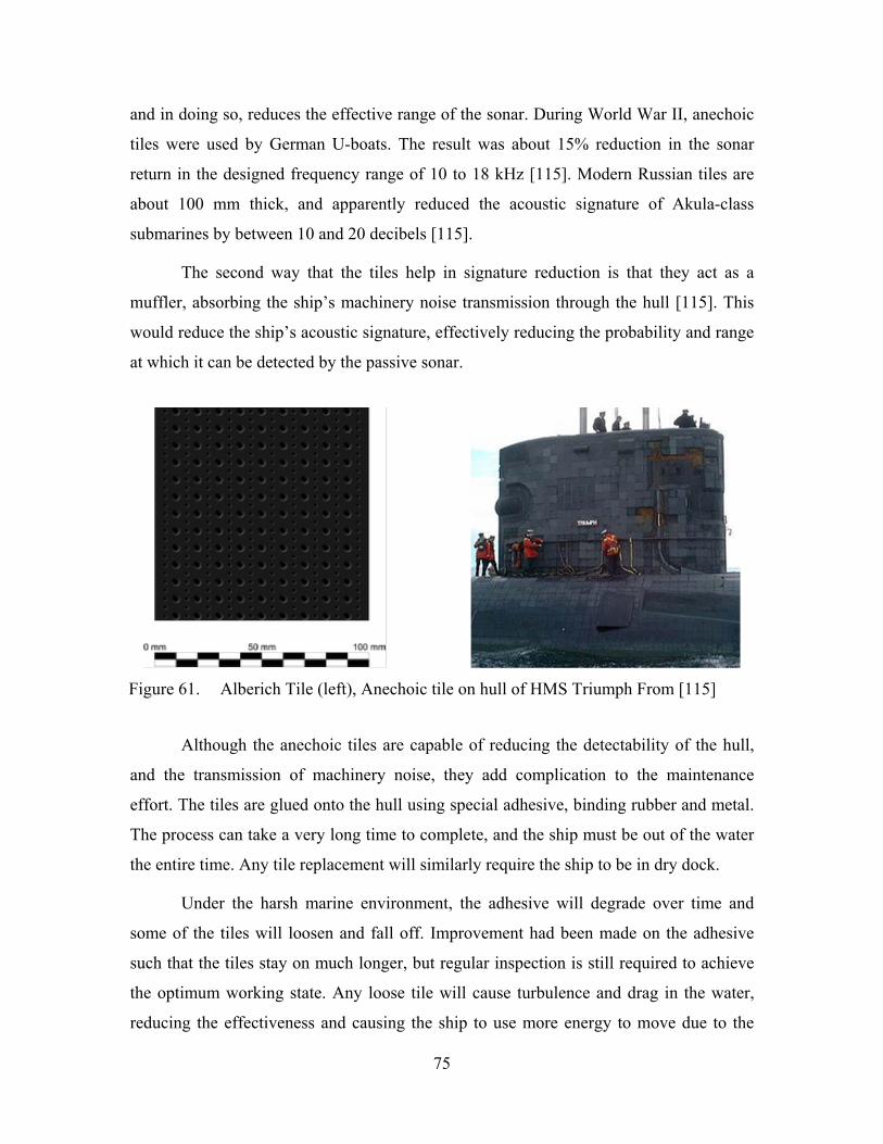
75
and in doing so, reduces the effective range of the sonar. During World War II, anechoic
tiles were used by German U-boats. The result was about 15% reduction in the sonar
return in the designed frequency range of 10 to 18 kHz [115]. Modern Russian tiles are
about 100 mm thick, and apparently reduced the acoustic signature of Akula-class
submarines by between 10 and 20 decibels [115].
The second way that the tiles help in signature reduction is that they act as a
muffler, absorbing the ship’s machinery noise transmission through the hull [115]. This
would reduce the ship’s acoustic signature, effectively reducing the probability and range
at which it can be detected by the passive sonar.
Figure 61. Alberich Tile (left), Anechoic tile on hull of HMS Triumph From [115]
Although the anechoic tiles are capable of reducing the detectability of the hull,
and the transmission of machinery noise, they add complication to the maintenance
effort. The tiles are glued onto the hull using special adhesive, binding rubber and metal.
The process can take a very long time to complete, and the ship must be out of the water
the entire time. Any tile replacement will similarly require the ship to be in dry dock.
Under the harsh marine environment, the adhesive will degrade over time and
some of the tiles will loosen and fall off. Improvement had been made on the adhesive
such that the tiles stay on much longer, but regular inspection is still required to achieve
the optimum working state. Any loose tile will cause turbulence and drag in the water,
reducing the effectiveness and causing the ship to use more energy to move due to the

76
increased drag on the hull. Royal Canadian Navy’s ship, HMCS Montréal (FFH 336), has
12,500 synthetic rubber anechoic tiles on the exterior of the underwater hull in the
vicinity of the machinery space to reduce the radiated noise [116].
3. Infra-Red
All bodies with temperature above the absolute zero (> 0 degree Kelvin) will emit
thermal radiation. The amount of radiation that is emitted is dependent on the temperature
and the emissivity of the body [124]. A hotter body emits more radiation than a cooler
body, and a rough-surface emits more radiation than a smooth surface [124]. The
electromagnetic radiation can also be reflected off a surface. For example, the Sun’s
radiation reflecting off the ship’s superstructure. The general rule is that the solar
radiation reflection is lesser in the LWIR spectrum than in the MWIR spectrum [124].
Figure 62. Infrared Transmission through Atmospheric After [126]
The infrared wavelength is between 0.75μm and 1,000μm. The Near Infrared
(NIR), from 0.7μm to 1.4μm [128], and the Shortwave Infrared (SWIR), 1.4μm to 3μm
[128], are used in short range optics, for example the night vision goggles’ image
intensifiers works within this ranges. There are two primary transmission windows
through the atmosphere for long distance imaging, the Midwave Infrared (MWIR) and
NIR & SWIR MWIR LWIR

77
the Longwave Infrared (LWIR). MWIR wavelength band is between 3μm to 8μm, and
LWIR band is between 8μm to 15μm [128]. For military applications, the atmospheric
windows for NIR is between 0.7 μm to 1.1 μm, SWIR is between 1.1 μm to 2.5 μm,
MWIR is between 3 μm to 5 μm and LWIR is between 8 μm to 14 μm [125]. The rest of
the wavelengths are effectively absorbed by the different gases, and water molecules in
the atmosphere, see Figure 62, and thus are not sufficient for the IR sensors to pick up.
The spectral emittance of a body can be calculated using the Planck’s Radiation
Law,
SpectralEmittance, ,, 2
1
watts/mm
Where:
ε = Emissivity of body (ε = 1 represents a perfect blackbody)
h = Planck’s constant (6.626 × 10⁻³⁴ J-s)
c = Velocity of light in free space (2.998 × 10⁸ m/s)
λ = Wavelength (m)
k = Boltzmann constant (1.381 × 10⁻²³ J/K)
T = Temperature (K)
The wavelength can be estimated using Wein’s Displacement Law,
Wavelength, 2898
μm
And the power emitted per unit area can be obtained by
watt/cm
Where:
σe = Stefan-Boltzmann constant (5.67 × 10⁻¹² watt/cm2K4)
Figure 63 shows the Black-body Spectrum for Temperature between 300 K and
10000 K.

78
Figure 63. Black-body Spectrum for Temperature between 300 K and 10000 K From [127]
The heat signature of a ship comes mainly from the waste heat of the engines and
other equipment through the exhaust and ventilation, and the solar, sky radiance, and sea
radiance absorption and reflection by the ship’s surfaces [130]. These heat signatures can
be picked up using an infra-red (IR) receiver. As the IR sensor will be receiving the
electromagnetic energy from both the ship and the background, the concept of IR
management is not about completely eliminating the radiation emissions, but by reducing
the IR emission contrast between the ship and the surrounding. The contrast can be
reduced by reducing the temperature differences between the ship and her background.
This can be done by cooling the exhaust system (Figure 64), a layer of cool
ambient air is used to suppress the visible metal, resulting in metal temperatures of
approximately 20-30°C above ambient [130]. This is considered to be a sufficient level of
suppression to protect against today’s threats [130]. All Compartments should be
ventilated to keep the temperatures at below 50°C [130]. Thermal insulation should be
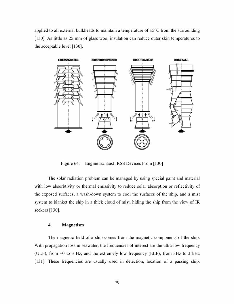
79
applied to all external bulkheads to maintain a temperature of ±5°C from the surrounding
[130]. As little as 25 mm of glass wool insulation can reduce outer skin temperatures to
the acceptable level [130].
Figure 64. Engine Exhaust IRSS Devices From [130]
The solar radiation problem can be managed by using special paint and material
with low absorbtivity or thermal emissivity to reduce solar absorption or reflectivity of
the exposed surfaces, a wash-down system to cool the surfaces of the ship, and a mist
system to blanket the ship in a thick cloud of mist, hiding the ship from the view of IR
seekers [130].
4. Magnetism
The magnetic field of a ship comes from the magnetic components of the ship.
With propagation loss in seawater, the frequencies of interest are the ultra-low frequency
(ULF), from ~0 to 3 Hz, and the extremely low frequency (ELF), from 3Hz to 3 kHz
[131]. These frequencies are usually used in detection, location of a passing ship.

80
Magnetic influence mines and torpedoes could also use the magnetic anomaly caused by
the passing ship to detonate and attack the ship. There are four primary magnetic field
sources from a ship.
The main magnetic source of a ship is the ferromagnetic signature. As ships
are built under the influence of the Earth’s magnetic field [133], the ferrous
materials used in the construction are induced with magnetism by the Earth’s
natural magnetic field. The magnetism is acquired when the metals are being
shaped and welded (stress and temperature) under the Earth’s magnetic field
[7, 131]. When the induced magnetic field strength reaches point 3 in Figure
64, even if the field is removed, the metal will retain some magnetism [7,
131]. This is the permanent magnetism of the ship. The ship’s magnetism can
be magnetized in three orthogonal directions, producing three magnetic
signature vectors called the vertical component (positive down), longitudinal
component (positive toward the bow), and athwartship component (positive
toward the starboard side) [131].
Figure 65. Hysteresis Curve for Ferromagnetic Material From [131]
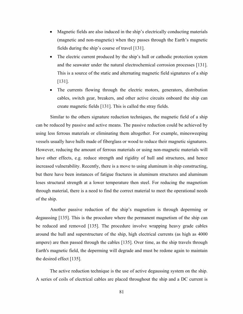
81
Magnetic fields are also induced in the ship’s electrically conducting materials
(magnetic and non-magnetic) when they passes through the Earth’s magnetic
fields during the ship’s course of travel [131].
The electric current produced by the ship’s hull or cathodic protection system
and the seawater under the natural electrochemical corrosion processes [131].
This is a source of the static and alternating magnetic field signatures of a ship
[131].
The currents flowing through the electric motors, generators, distribution
cables, switch gear, breakers, and other active circuits onboard the ship can
create magnetic fields [131]. This is called the stray fields.
Similar to the others signature reduction techniques, the magnetic field of a ship
can be reduced by passive and active means. The passive reduction could be achieved by
using less ferrous materials or eliminating them altogether. For example, minesweeping
vessels usually have hulls made of fiberglass or wood to reduce their magnetic signatures.
However, reducing the amount of ferrous materials or using non-magnetic materials will
have other effects, e.g. reduce strength and rigidity of hull and structures, and hence
increased vulnerability. Recently, there is a move to using aluminum in ship constructing,
but there have been instances of fatigue fractures in aluminum structures and aluminum
loses structural strength at a lower temperature then steel. For reducing the magnetism
through material, there is a need to find the correct material to meet the operational needs
of the ship.
Another passive reduction of the ship’s magnetism is through deperming or
degaussing [135]. This is the procedure where the permanent magnetism of the ship can
be reduced and removed [135]. The procedure involve wrapping heavy grade cables
around the hull and superstructure of the ship, high electrical currents (as high as 4000
ampere) are then passed through the cables [135]. Over time, as the ship travels through
Earth's magnetic field, the deperming will degrade and must be redone again to maintain
the desired effect [135].
The active reduction technique is the use of active degaussing system on the ship.
A series of coils of electrical cables are placed throughout the ship and a DC current is

82
passed through them, creating a field equal and opposite to the ship’s magnetic field,
making the ship magnetically invisible [7, 133]. As the magnetic signature of the ship
caused by the Earth’s magnetic field changes with latitude and heading requires, an
automated control system would be required to sense the Earth’s magnetic field and
compensates for the heading, pitch, roll and geographic location of the ship [7, 133].
5. Optical
The visual sighting of a ship can be from sea level or from the air. From sea level,
the silhouette of the ship against the horizon can be easily seen, especially when there is a
great contrast in shades and colors. Electro-optics systems will also increase the
detectability of the contrast. By keeping the height of the ship to the minimum required
and having some form of camouflage paint scheme to break the solid shade and color,
would reduce the detectability.
Figure 66. HMS Argus with a coat of Dazzle Camouflage From [136]
During World War I, Norman Wilkinson, a British artist and naval officer came
out with a new camouflage scheme called “Dazzle” (Figure 66), also known as Razzle
Dazzle in the United States) [137]. Instead of trying to conceal the ship, the camouflage
scheme was used to mislead the attacker on the exact course of the vessel to be attacked,
making it more difficult for the attacker to determine the ship's course. The colors mostly
use were black, white, blue and green and sloping lines, curves and stripes give the best
distortion [137]. With the advancement in sensor technology, this no longer works.

83
However, many modern warships, like the Swedish Navy's Visby-class corvettes and the
Chinese Houbei class missile boat (Figure 67), still use paint camouflage. The
camouflage scheme can still cause disruption the human vision, especially to shore
batteries using optical rangefinders [138].
Figure 67. Chinese Houbei Class Missile Boat From [139]
Visual sighting of the ship can also be done from the air. The most visible part of
the ship from the air is not the ship itself, but the long wake of disturbed water left behind
the ship when it cruises through the water. By designing hull forms that creates shorter
and less wake effect, coupled with camouflage paint scheme that matches the sea surface
clutters, visual sighting probability would be reduced.
B. DETECTION/THREAT WARNING
With advanced passive and active sensor systems, the ship would be able to gather
information about her surroundings. These information would provide her with
intelligence and advance warning about enemy movements and actions. If an enemy
should start searching or launch an attack, the ship would be in a better position to avoid
and evade such actions. With early warning on incoming missiles or torpedoes,

84
appropriate actions can be taken. As it takes time for the decision making and evasive
actions to take place, every second gained in detection would increase the possibility of
surviving the attack.
For example, a Mach 2 ASM is detected 3 km away would reach the ship in
approximately 4.4 seconds. This means that the ship has only 4 seconds to decide what
the next course of action is and to implement it. If the missile is detected earlier, at 5 km,
the ship has about 7 seconds of reaction time, giving more time for decision making and
for the defensive systems to engage the missile.
1. Radar Warning Receiver
By having a radar warning system, the receivers of the system would be listening
to any radio wave propagated by the attacker. The distance that attacker can be picked up
is about twice the distance that the attacker can “see” with its radar. The time of picking
up the attacker would also be earlier by almost twice that of the attacker acquiring the
ship, as the radio wave travel a distance to the ship and is pick up, but it will need to
travel the same distance back for the attacker to receiver it. This gives the ship an early
warning to the threat and time to response. The direction of the incoming threat can also
be determined.
2. Laser Warning System
A laser warning system consists of many laser detectors scattered throughout the
ship to provide a 360 degree of detection coverage. When the ship is being lased, one or
more of the detectors would detect the laser and gives a warning to the ship. The
direction on the laser could also be determined by interpolating the detectors’ position.

85
Figure 68. SAAB’s Naval Laser Warning System From [140]
3. Sonar System
As with the ship own acoustic noise, by employing a sonar system, the ship can
pick up acoustic noise from the surrounding. The passive mode of the sonar system
should be used to prevent the ship’s location from being discovered. Any incoming
threats could be picked up by the sonar system and possibly determine. For example, the
flooding of a torpedo launcher in preparation for launch would create some acoustic
noise, or the propeller cavitation of another ship, submarine or torpedo.
4. Infra-Red Sensor
The Infra-red sensors could be used to scan the vicinity of the ship; any hot spot
detected could be a muzzle flash, or missile launch. The ship could be warned of such
activities. The IR sensor can also be used to detect air and surface targets in low light
conditions.
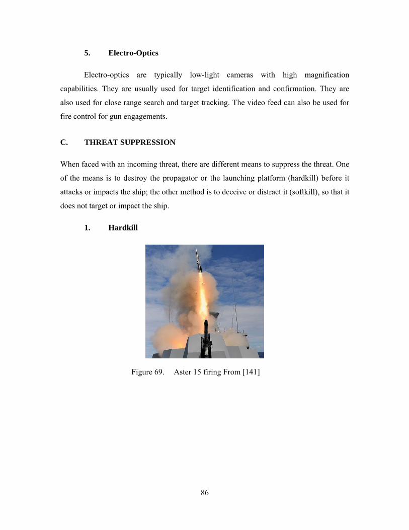
86
5. Electro-Optics
Electro-optics are typically low-light cameras with high magnification
capabilities. They are usually used for target identification and confirmation. They are
also used for close range search and target tracking. The video feed can also be used for
fire control for gun engagements.
C. THREAT SUPPRESSION
When faced with an incoming threat, there are different means to suppress the threat. One
of the means is to destroy the propagator or the launching platform (hardkill) before it
attacks or impacts the ship; the other method is to deceive or distract it (softkill), so that it
does not target or impact the ship.
1. Hardkill
Figure 69. Aster 15 firing From [141]

87
Figure 70. Phalanx CIWS From [142]
The common surface threat to ship comes mainly in projectile form, e.g. missiles
and gun projectiles. These can be shot down and destroyed by onboard defense system.
The defensive systems for a ship should be layered, with different system for different
range of engagement. For example, an anti-missile missile (AMM) system is used for
medium to long range defenses. A close-in weapon system (CIWS) can be used to cover
the short to medium ranges, so that if the threat were detected at a distance too close for
the AMM to be effective, another defense is available.
Shooting down incoming projectile is not the only form of defense. When the
enemy had been identified, the first to strike would most likely win the day. Having a
long range, high speed, anti-ship missile or torpedo would mean that the ship can destroy
a hostile vessel at a stand-off distance, without putting itself in range of being attacked.
An AMM is usually also an anti-air missile; this would mean that the ship can take down
and air target before the aircraft can launch its attack. The CIWS can also be used to
target small, fast boats that had gone below the minimum engagement distance of the
other weapons.

88
Figure 71. Experimental Naval Laser CIWS From [143]
Under development is the laser CIWS. With a laser system, high speed threats
(e.g. supersonic or hypersonic missiles) could be countered more effectively.
2. Softkill
The second method of suppression is by deceiving the sensors of the threat. This
can be done by having decoy systems and electronic jammers. Currently, torpedo threats
cannot be destroyed (although the Russian rocket-propelled torpedo, Shkval, is said to be
able to). The only way is to try and deceive the torpedoes by launching decoys that mimic
the ships acoustic signature and then out running them. Therefore the ship’s speed and
maneuverability is also important.
Figure 72. WASS C310 Anti-torpedo Countermeasure System From [144]
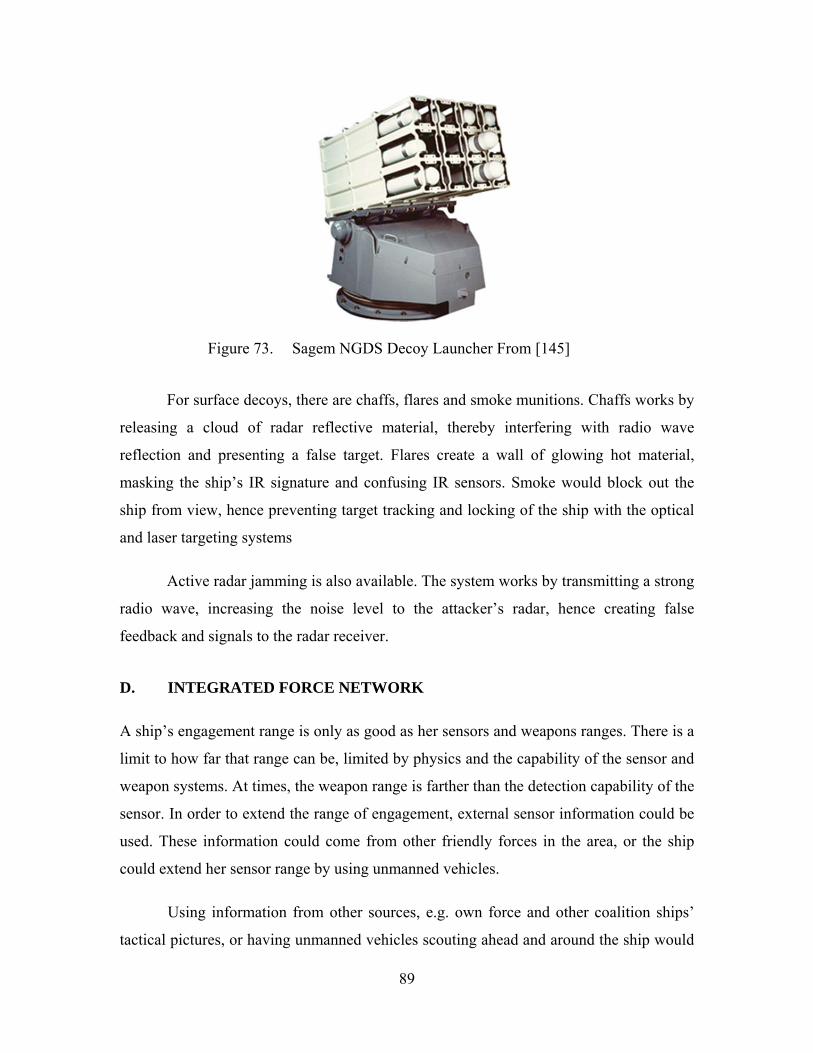
89
Figure 73. Sagem NGDS Decoy Launcher From [145]
For surface decoys, there are chaffs, flares and smoke munitions. Chaffs works by
releasing a cloud of radar reflective material, thereby interfering with radio wave
reflection and presenting a false target. Flares create a wall of glowing hot material,
masking the ship’s IR signature and confusing IR sensors. Smoke would block out the
ship from view, hence preventing target tracking and locking of the ship with the optical
and laser targeting systems
Active radar jamming is also available. The system works by transmitting a strong
radio wave, increasing the noise level to the attacker’s radar, hence creating false
feedback and signals to the radar receiver.
D. INTEGRATED FORCE NETWORK
A ship’s engagement range is only as good as her sensors and weapons ranges. There is a
limit to how far that range can be, limited by physics and the capability of the sensor and
weapon systems. At times, the weapon range is farther than the detection capability of the
sensor. In order to extend the range of engagement, external sensor information could be
used. These information could come from other friendly forces in the area, or the ship
could extend her sensor range by using unmanned vehicles.
Using information from other sources, e.g. own force and other coalition ships’
tactical pictures, or having unmanned vehicles scouting ahead and around the ship would

90
require standardization in protocols and data specifications. Secured, high-speed and
wide data bandwidth would be required for data transfer and communications. High
power computation and algorithms would be required to fuse and manage the massive
inflow of information. For all these to work, a strong and robust Command, Control,
Communication, Computer and Intelligence (C4I) system would be required. Good
operator training would be required to operate the various communications and combat
management systems. The command staffs must also be trained in the situation
awareness and tactics to maximize the effectiveness of such network. The network design
must be so that information displayed must not cause “data overload” to the operators,
and commanders.
The US Cooperative Engagement Capability (CEC) program [146] is one of such
network. CEC enables an integrated naval anti-air warfare to detect, track and engage all
air threats in the area of operation. The CEC system consists of raw sensor data
distribution system, the antenna and the cooperative engagement SDP-S processor. [147]
It works by bringing together; radar, sensor and tracking data from a number of widely
separated platforms together in one big picture [147] (Figure 74), enabling multiple ships,
aircraft, and land-based air-defense systems to develop a consistent, precise, and reliable
air-track picture [146].
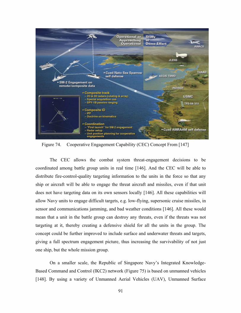
91
Figure 74. Cooperative Engagement Capability (CEC) Concept From [147]
The CEC allows the combat system threat-engagement decisions to be
coordinated among battle group units in real time [146]. And the CEC will be able to
distribute fire-control-quality targeting information to the units in the force so that any
ship or aircraft will be able to engage the threat aircraft and missiles, even if that unit
does not have targeting data on its own sensors locally [146]. All these capabilities will
allow Navy units to engage difficult targets, e.g. low-flying, supersonic cruise missiles, in
sensor and communications jamming, and bad weather conditions [146]. All these would
mean that a unit in the battle group can destroy any threats, even if the threats was not
targeting at it, thereby creating a defensive shield for all the units in the group. The
concept could be further improved to include surface and underwater threats and targets,
giving a full spectrum engagement picture, thus increasing the survivability of not just
one ship, but the whole mission group.
On a smaller scale, the Republic of Singapore Navy’s Integrated Knowledge-
Based Command and Control (IKC2) network (Figure 75) is based on unmanned vehicles
[148]. By using a variety of Unmanned Aerial Vehicles (UAV), Unmanned Surface

92
Vessels (USV), and Unmanned Underwater Vehicles (UUV), the range of detection and
engagement can be increased for a smaller task group or a single ship. UAVs launched
from the ship could provide maritime air surveillance, extending the ship’s visual and
radar coverage, overcoming the physical limitation (horizon limit) of similar surface
sensor systems.
Figure 75. IKC2 Network Concept From [148]
The UAVs and USVs could also be configured to perform Intelligence,
Surveillance and Reconnaissance (ISR) missions [148]. UUVs could perform underwater
ISR, for example, mapping a safe route through a mine field. Using UAVs as the uplink
to the mother ship, the USVs could be deployed beyond line-of-sight communication
range, providing information in advance. And with autonomous operating algorithms, the
USVs could navigate in shallow waterways where the mother ship cannot maneuver in.
By having 'plug-and-play' mission modules, the UAVs, USVs and UUVs can be
93
deployed for Anti-Submarine Warfare (ASW), Anti-Surface Warfare (ASuW) and Mine
Warfare (MIW) [148], without the mother ship coming into close contact with the targets.
All these flexibilities and combination use of unmanned vehicles enable greater
detection range, advance intelligence gathering and increased engagement range. All
these capabilities will greatly enhance the ship’s survivability, reducing susceptibility
through early threat detection, threat suppression, improved situation awareness, and
increase “stand-off” range.
With information coming in from that many unmanned vehicles, there comes the
risk of data overloading on the operators and the commanders. The information display
for the above systems must be carefully design to show the only the critical data at the
first layer, and secondary data can be toggled through tabs, to reduce overwhelming
information. Appropriate training must also be given to the operators and commanders to
optimize the effectiveness of the systems. Finally, tactics and doctrines must be thought
through for autonomous vehicles weapon engagement and also to allow the commanders
to make response quickly under the heat of combat.

94
THIS PAGE INTENTIONALLY LEFT BLANK

95
V. EFFECTIVENESS ANALYSIS
A. ENGAGEMENT SCENARIO
Mission: Patrolling/traversing narrow waterways and coastal waters
Threats: Missile boats with radar-guided ASM and shore-based naval radar and
IR systems
The ship, a frigate-size vessel, is to perform a coastal patrol on a commercially
busy waterway. The possible threats are from enemy missile boats and shore-based naval
radar and IR systems providing additional detection capability. A comparison between a
non- survivability enhanced (ship A) and a survivability enhanced ship (ship B) is
analyzed. Table 16 shows the differences between an enhanced and a non-enhanced
design.
Table 16. Comparison between an Enhanced and Non-Enhanced Design
Non-Survivability Enhanced Ship (A) Survivability Enhanced Ship (B)
PA 67% PcA
33% PA 15% PcA 85%
PD|A 85% PcD|A 15% PD|A 50% Pc
D|A 50%
PT|D 95% PcT|D 5% PT|D 70% Pc
T|D 30%
PL|T 95% PcL|T 5% PL|T 90% Pc
L|T 10%
PH|L 95% PcH|L 5% PH|L 10% Pc
H|L 90%
PK|H 20% PcK|H 80% PK|H 10% Pc
K|H 90%
PK 9.7655% PS 90.2345% PK 0.0472% PS 99.9528%
PS20 12.8071% PS
20 99.0602%
All most modern day warships carry some form of radar, fire control, and weapon
system. The probability that Ship A can detect and destroy a missile boat before it can
become active is about 33%, the probability of an active threat, PA, is about 67%. Ship B
with the use of enhanced sensors, like over-the-horizon radar, FLIR and advanced optics
would be able to detect and classified the missile boat earlier (threat warning). The use of
96
unmanned vehicles would also increase the probability of early detection. With the use of
long range ASM and armed unmanned vehicles, the missile boat can be taken out before
it becomes active (threat suppression). Therefore the probability of an active, PA, threat
drops to about 15%.
Like most warships, Ship A would be painted with some form of paint scheme to
reduce visual signature. But a missile boat usually have a radar system, therefore the
probability of detection, PD|A, is about 85%. For Ship B, using shaping and RAM, her
RCS signature would be reduced significantly (signature reduction), making her look like
another small, harmless vessel in the busy waterway. By managing the IR signature, Ship
B also reduces the probability of detect from any FLIR. By reducing her signatures, Ship
B also reduces the probability of detection from shore-based sensors, allowing her to
operate closer to the coastline. Hence, the probability of detection, PD|A, for Ship B is
reduced to 50%.
Once Ship A has been detected, tracking her would be quite an ease with active
radar, the probability of tracking, would be about 95%. For Ship B, the radar warning
system (threat warning) would alert her of the situation. Using her ECM (noise jamming)
and chaffs (expendables), Ship B could mask herself from the missile boat, reducing the
probability of tracking, PT|D, to 70%. For both ships, once they are tracked, the possibility
of a ASM being launched at them is high, but due to the advance threat warning, Ship B
could also have launched an attack at the missile boat, killing it first. Hence the
probability of a missile launched, PL|T, at Ship A is 95%, and Ship B is 90%.
With the ASM being radar-guided, the probability of hit, PH|L, on Ship A is about
95%. For Ship B with defensive systems, like the long range anti-missile missiles, close-
in weapon system (hardkill), and decoys and ECM (softkill), the ASM could be destroyed
or confused, lowering the chance that it will hit the ship. These defensive systems will
reduce the probability of hit for Ship B to about 10%.
When the ASM hits the ships, Ship A, without any survivability enhancements,
would most probably be more vulnerable to the damage mechanisms, and easier to lose
her mission critical components. Ship B, with redundancies in her systems, better passive
97
and active damage controls, critical components shielding, and structure and hull
protection, would fare better after being hit. Hence the probability of kill, PK|H, for Ship
A is 20% and Ship B is 10%.
From the analysis in Table 16, the survivability of Ship A is ~90% after one
engagement, which seems quite good. But if the ship was to encounter 20 engagements,
her survivability dropped to just 12.8%. This means that the Ship A has only about a 1 in
8 chance of surviving 20 engagements. With Survivability enhancement, Ship B has a
survivability of ~99.95% for a single engagement. With 20 engagements, Ship B still has
~99% survivability. This shows that with survivability enhancements, a ship has a higher
chance of survival, and can survive more engagements.
B. COST EFFECTIVENESS
Survivability enhancements should be part of the initial design requirements of
any new build. Although the upfront cost of having the additional requirements might
increase the initial capital cost, implementing the enhancements later in the design or
lifecycle of the ship would only incur more cost (see Figure 75). Many of the
survivability enhancement systems can have dual functionality, like the defensive and
offensive uses of an AMM or CIWS. When integrated in the operation needs of the initial
design, the additional cost could be minimized.
If survivability concept is to be implemented later in the design phase, major
changes might be needed, for example, the shaping of the hull to reduce RCS, or the
additional placement of decoy launchers. The size, space and weight allocation might not
be sufficient, thus redesign would be needed, and this would have both time and
monetary impact on the project. Similarly, if the ship had been built, and survivability
enhancements are to be part of the upgrades later on in the lifecycle, more cost would be
incurred, as the ship would need major rework and reconstruction to integrate the
survivability enhancement systems onto the ship. This means that the ship would be out
of service for a longer period, the operation of the whole navy might be affected.
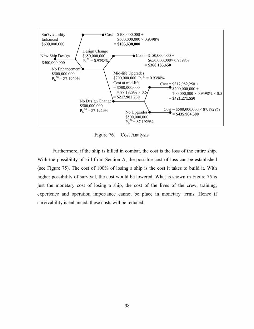
98
Figure 76. Cost Analysis
Furthermore, if the ship is killed in combat, the cost is the loss of the entire ship.
With the possibility of kill from Section A, the possible cost of loss can be established
(see Figure 75). The cost of 100% of losing a ship is the cost it takes to build it. With
higher possibility of survival, the cost would be lowered. What is shown in Figure 75 is
just the monetary cost of losing a ship, the cost of the lives of the crew, training,
experience and operation importance cannot be place in monetary terms. Hence if
survivability is enhanced, these costs will be reduced.
Cost = $150,000,000 + $650,000,000× 0.9398%
= $368,135,650
Cost = $100,000,000 + $600,000,000 × 0.9398%
= $105,638,800
No Upgrades $500,000,000 PK
20 = 87.1929%
Sur7vivability Enhanced $600,000,000
Design Change $650,000,000 PK
20 = 0.9398%New Ship Design
$500,000,000
Mid-life Upgrades $700,000,000, PK
20 = 0.9398% Cost at mid-life = $500,000,000 × 87.1929% × 0.5 = $217,982,250
Cost = $500,000,000 × 87.1929% = $435,964,500
Cost = $217,982,250 + $200,000,000 + 700,000,000 × 0.9398% × 0.5
= $421,271,550
No Enhancement $500,000,000 PK
20 = 87.1929%
No Design Change $500,000,000 PK
20 = 87.1929%
99
VI. CONCLUSION
Survivability is important; it allows a greater chance of mission success and
reduces the loss of lives. It had long been recognized that in order to improve the chance
of surviving any engagement, the ship must be able to see and reach further, and faster,
react and maneuver at the quickest of time, and it must be sufficiently protected.
Survivability should be taken as an integrated part of the design process; it should
be given as a requirement, like any other combat systems early in the design stages.
Upgrading or retrofitting a ship to add in survivability features after construction often
results in higher cost, both in term of monetary and of time. Furthermore, space and
weight constraints would make such modifications even more difficult. Many
survivability enhancement features usually have functions other than just to improve
survivability. For example, a defensive anti-missile missile system can also be used
offensively against air targets, or a radar system would provide sensor data for both
offensive and defensive uses.
Survivability is not about implementing a single system to reduce killability. A
total survivability concept is required, where we have to look at all the improvements that
can be made to reduce susceptibility. For example, a reduction in signatures would
present a smaller and less detectable target. And having better sensors lead to better
situation awareness, coupled with multi-layered defense and countermeasures would
allow a better management against anti-ship missiles. By having long range sensors and
weapons, the ship can detect earlier and attack without getting into weapon range of the
enemy.
This thesis covers the signature reduction techniques and the use of integrated
networks and tactics with both manned and unmanned platforms. The effectiveness of
using decoys and defensive weapons were not studied in details due to the classification
of such systems. The thesis also did not cover in details the vulnerability reduction
techniques. Further research on the effectiveness of advanced threat warning, threat

100
suppression could be done as a classified work due to the sensitive nature of the
information. The vulnerability reduction techniques should also be further explored to
give a full rounded view on the survivability concept.

101
LIST OF REFERENCES
[1] Merchant Royal, “HMS Victory”, accessed 06 March 2012, http://www.merchantroyalshipwreck.com.
[2] War and Game, “The Chinese Junk”, accessed 04 March 2012,
http://warandgame.files.wordpress.com/2009/12. [3] Harry Turtledove Wiki, “Monitor.jpg”, accessed 04 March 2012,
http://turtledove.wikia.com/wiki/File:Monitor.jpg. [4] Desktop Nexus, “Battleship Yamato”, accessed 05 March 2012,
http://boats.desktopnexus.com/get/601404/. [5] R. E. Ball and C. N. Calvano, “Establishing the Fundamentals of a Surface Ship
Survivability Design Discipline”, Naval Engineers Journal, January 1994, Issue 1. [6] R. E. Ball, “The Fundamentals of Aircraft Combat Survivability Analysis and
Design”, 2nd Edition, AIAA, Virginia, 2003. [7] C. A. Adams, “ME 4751 (Combat Survivability Engineering) Class Notes”, Naval
Postgraduate School, Winter 2012 (unpublished). [8] B. Ireland, “Jane’s Battleships of the 20th Century”, HarperCollinsPublishers,
New York, 1996. [9] Wikipedia, “Yamato Class Battleship”, accessed 04 February 2012,
http://en.wikipedia.org/wiki/Yamato_class_battleship#cite_note-23. [10] Chief of Naval Operations, Ship Safety and Survivability Office, OPNAV P-86-4-
99, “U.S. Navy Survivability Design Handbook for Surface Ships”, Washington, DC, 2000.
[11] Chief of Naval Operations, Office of the Chief of Naval Operations,
OPNAVINST 9070.2, “Signature Control Policy for Ships and Craft of the U.S. Navy”, Washington, DC, 1996.
[12] F.B. Fassnacht, “A Top Level Flow Chart for Surface Ship Combat Survivability
Assessment”, NSWC TR 79-393, Naval Surface Weapons Center, Maryland, 1979.
[13] Thales, “Herakles – Multifunction Radar”, accessed 23 March 2012,
http://www.thalesgroup.com/herakles/?pid=1205.
102
[14] Krylov Institute, “Radar, Infra-Red and Laser Signature Control”, accessed 19 March 2012, http://www.ksri.ru/eng1/ins/struct/physic/radar.htm.
[15] Thales, “Mirador - Electro-optical multi-sensor”, accessed 23 March 2012, http://www.thalesgroup.com/mirador.
[16] Ministry of Defence, Singapore, “Combat Systems of the Frigate”, accessed on 23
March 2012, http://www.mindef.gov.sg/weapons/frigate/combatsystems.asp#sonar.
[17] BBC News, “I beat pirates with a hose and sonic cannon”, accessed 23 March
2012, http://news.bbc.co.uk/2/hi/uk_news/6664677.stm [18] Federation of American Scientists, “Fundamentals of Naval Weapon System”,
accessed 02 February 2012, http://www.fas.org/man/dod-101/navy/docs/fun/index.html.
[19] F. Vilchez and J. Tejedor, “Survivability Enhancing Measures in Modern Frigate
Designs”, IZAR de Construcciones Navales S.A., Madrid, 2003. [20] M. O. Said, “Theory and Practice of Total Ship Survivability for Ship Design”,
Naval Engineers Journal, July 1995, Issue 4. [21] J. A. Lillis, “Analysis of the Application of Aircraft Vulnerability Assessment and
Reduction Techniques to Small Surface Craft”, Naval Postgraduate School Thesis, June 2002.
[22] J. Ellis, “World War II : A Statistical Survey” , Facts On File Inc., New York,
1993. [23] Naval History & Heritage Command, “Casualties: U.S. Navy and Coast Guard
Vessels, Sunk or Damaged Beyond Repair during World War II, 7 December 1941-1 October 1945”, accessed 06 March 2012, http://www.history.navy.mil/faqs/faq82-1.htm.
[24] Naval History & Heritage Command, “U.S. Navy Ships: Sunk & Damaged in
Action during the Korean Conflict (Partial)”, accessed 06 March 2012, http://www.history.navy.mil/faqs/faq82-3.htm.
[25] Wikipedia, “List of Anti-ship Missiles”, accessed 08 February 2012,
http://en.wikipedia.org/wiki/List_of_anti-ship_missiles. [26] Wikipedia, “List of Naval Guns”, accessed 08 February 2012,
http://en.wikipedia.org/wiki/List_of_naval_guns. [27] Wikipedia, “List of Torpedoes”, accessed 08 February 2012,
http://en.wikipedia.org/wiki/List_of_torpedoes.

103
[28] Wikipedia, “List of Bombs”, accessed 08 February 2012,
http://en.wikipedia.org/wiki/List_of_bombs. [29] Wikipedia, “Rocket-Propelled Grenade”, accessed 08 February 2012,
http://en.wikipedia.org/wiki/Rocket-propelled_grenade. [30] Wikipedia, “List of Rocket Artillery”, accessed 08 February 2012,
http://en.wikipedia.org/wiki/List_of_rocket_artillery. [31] Wikipedia, “List of Howitzer”, accessed 08 February 2012,
http://en.wikipedia.org/wiki/List_of_howitzers. [32] Wikipedia, “Close-in Weapon System”, accessed 10 February 2012,
http://en.wikipedia.org/wiki/Close-in_weapon_system. [33] Wikipedia, “Electronic Countermeasure”, accessed 10 February 2012,
http://en.wikipedia.org/wiki/Electronic_countermeasure. [34] Wikipedia, “List of Missiles”, accessed 10 February 2012,
http://en.wikipedia.org/wiki/List_of_missiles. [35] Wikipedia, “List of Naval Weapon Systems”, accessed 10 February 2012,
http://en.wikipedia.org/wiki/List_of_naval_weapon_systems. [36] Wikipedia, “Tactical High Energy Laser”, accessed 10 February 2012,
http://en.wikipedia.org/wiki/Tactical_High_Energy_Laser. [37] Wikipedia, “Railgun”, accessed 10 February 2012,
http://en.wikipedia.org/wiki/Railgun. [38] Encyclopedia Britannica Online, s. v. "naval warfare," accessed 13 February,
2012, http://www.britannica.com/EBchecked/topic/406883/naval-warfare. [39] Naval Undersea Museum, “The History of the Sea Mine and its Continued
Importance in Today’s Navy”, Diana Schroeder, accessed 14 February, 2012, http://www.history.navy.mil/museums/keyport/The_History_of_the_Sea_Mine.pdf.
[40] Defense Update, “Guided Naval Gun Projectiles”, accessed 10 March 2012,
http://defense-update.com/products/d/davide-vulcano.htm. [41] Wikipedia, “Railgun”, accessed 23 March 2012,
http://en.wikipedia.org/wiki/Railgun.
104
[42] Jane's Air-Launched Weapons, “GAU-8/A Avenger 30 mm cannon, A-10 armament system”, accessed 15 April 2012, http://www4.janes.com.libproxy.nps.edu/subscribe/jalw/doc_view.jsp?K2DocKey=/content1/janesdata/binder/jalw/jalw2941.htm@current&Prod_Name=JALW&QueryText=%3CAND%3E%28%3COR%3E%28%28%5B80%5DGAU-8%2FA+%3CIN%3E+body%29%2C+%28%5B100%5D+%28%5B100%5DGAU-8%2FA+%3CIN%3E+title%29+%3CAND%3E+%28%5B100%5DGAU-8%2FA+%3CIN%3E+body%29%29%29%29.
[43] Wikipedia, “GAU-8 Avenger”, accessed 15 April 2012,
http://en.wikipedia.org/wiki/GAU-8_Avenger. [44] Jane's Naval Weapon Systems, “Oto Melara 127/54 'Compatto'/Oto Melara
127/54 'Alleggerito'/Oto Melara 127/64 Light Weight Vulcano”, accessed 16 April 2012, http://www4.janes.com.libproxy.nps.edu/subscribe/jnws/doc_view.jsp?K2DocKey=/content1/janesdata/binder/jnws/jnws0246.htm@current&Prod_Name=JNWS&QueryText=%3CAND%3E%28%3COR%3E%28%28%5B80%5DOto+%3CIN%3E+body%29%2C+%28%5B100%5D+%28%5B100%5DOto+%3CIN%3E+title%29+%3CAND%3E+%28%5B100%5DOto+%3CIN%3E+body%29%29%29%29.
[45] NavWeaps.com, “Italy, 127 mm/64 (5") LW”, accessed 16 April 2012,
http://www.navweaps.com/Weapons/WNIT_5-64_LW.htm. [46] Gizmag, “U.S. Navy set to test first industry railgun prototype”, accessed 24 April
2012, http://www.gizmag.com/first-industry-railgun-prototype-launcher/21377/. [47] The Brigade, “Let the A-10’s high-res GAU-8 Avenger times roll (37 HQ Photos)
» GAU-8-a-10-920-6”, accessed 18 April 2012, http://thebrigade.thechive.com/2012/04/08/let-the-a-10s-high-res-gau-8-avenger-times-roll-37-hq-photos/gau-8-a-10-920-6.
[48] Indian Military, “Brahmos Supersonic Cruise missile”, accessed 12 March 2012,
http://www.indian-military.org/strategic-weapons/cruise-missiles/186-brahmos-supersonic-cruise-missile.html.
[49] Jane's Naval Weapon Systems, “BrahMos (PJ-10)”, accessed 05 April 2012,
http://www4.janes.com.libproxy.nps.edu/subscribe/jnws/doc_view.jsp?K2DocKey=/content1/janesdata/binder/jnws/jnwsa010.htm@current&Prod_Name=JNWS&QueryText=%3CAND%3E%28%3COR%3E%28%28%5B80%5DBrahMos+%3CIN%3E+body%29%2C+%28%5B100%5D+%28%5B100%5DBrahMos+%3CIN%3E+title%29+%3CAND%3E+%28%5B100%5DBrahMos+%3CIN%3E+body%29%29%29%29.
[50] Wikipedia, “YJ-91”, accessed 12 March 2012, http://en.wikipedia.org/wiki/YJ-91.

105
[51] Sino Defence, “KH-31P / YJ-91 ANTI-RADIATION MISSILE”, accessed 24
March 2012, http://www.sinodefence.com/airforce/weapon/kh313.asp. [52] Jane's Air-Launched Weapons, “YJ-91, KR-1 (Kh-31)”, accessed 06 April 2012,
http://www4.janes.com.libproxy.nps.edu/subscribe/jalw/doc_view.jsp?K2DocKey=/content1/janesdata/binder/jalw/jalw3680.htm@current&Prod_Name=JALW&QueryText=%3CAND%3E%28%3COR%3E%28%28%5B80%5DYJ-91+%3CIN%3E+body%29%2C+%28%5B100%5D+%28%5B100%5DYJ-91+%3CIN%3E+title%29+%3CAND%3E+%28%5B100%5DYJ-91+%3CIN%3E+body%29%29%29%29.
[53] Sino Defence, “YingJi-91 (Kh-31P) Anti-Radiation Missile”, accessed 15 April
2012, http://www.sinodefence.com/airforce/weapon/kh31.asp. [54] Wikipedia, “Yu-6 torpedo”, accessed 15 April 2012,
http://en.wikipedia.org/wiki/Yu-6_torpedo. [55] Jane's Naval Weapon Systems, “Chinese Heavyweight Torpedoes”, accessed 15
April 2012, http://www4.janes.com.libproxy.nps.edu/subscribe/jnws/doc_view.jsp?K2DocKey=/content1/janesdata/binder/jnws/jnwsa044.htm@current&Prod_Name=JNWS&QueryText=%3CAND%3E%28%3COR%3E%28%28%5B80%5DChinese+%3CIN%3E+body%29%2C+%28%5B100%5D+%28%5B100%5DChinese+%3CIN%3E+title%29+%3CAND%3E+%28%5B100%5DChinese+%3CIN%3E+body%29%29%29%29.
[56] Sino Defence, “Yu-6 Torpedo”, accessed 15 April 2012,
http://www.sinodefence.com/navy/weapon/yu6.asp. [57] Wikipedia, “VA-111 Shkval”, accessed 12 March 2012,
http://en.wikipedia.org/wiki/VA-111_Shkval. [58] Jane's Naval Weapon Systems, “VA-111/Shkval/Shkval-E”, accessed 15 April
2012, http://www4.janes.com.libproxy.nps.edu/subscribe/jnws/doc_view.jsp?K2DocKey=/content1/janesdata/binder/jnws/jnwsa032.htm@current&Prod_Name=JNWS&QueryText=%3CAND%3E%28%3COR%3E%28%28%5B80%5DVA-111+%3CIN%3E+body%29%2C+%28%5B100%5D+%28%5B100%5DVA-111+%3CIN%3E+title%29+%3CAND%3E+%28%5B100%5DVA-111+%3CIN%3E+body%29%29%29%29.
[59] Military Periscope, “VA-111 Shkval torpedo”, accessed 15 April 2012,
http://www.periscope.ucg.com/mdb-smpl/weapons/minetorp/torpedo/w0004768.shtml.

106
[60] Wikipedia, “GBU-24 Paveway III”, accessed 14 March 2012, http://en.wikipedia.org/wiki/GBU-24.
[61] Wikipedia, “File:Paveway III laser guided bomb.jpg”, accessed 24 March 2012,
http://en.wikipedia.org/wiki/File:Paveway_III_laser_guided_bomb.jpg. [62] Jane's Air-Launched Weapons, “GBU-22, GBU-24, GBU-27 Paveway III and
Enhanced Paveway III”, accessed 17 April 2012, http://www4.janes.com.libproxy.nps.edu/subscribe/jalw/doc_view.jsp?K2DocKey=/content1/janesdata/binder/jalw/jalw3671.htm@current&Prod_Name=JALW&QueryText=%3CAND%3E%28%3COR%3E%28%28%5B80%5Dpaveway+%3CIN%3E+body%29%2C+%28%5B100%5D+%28%5B100%5Dpaveway+%3CIN%3E+title%29+%3CAND%3E+%28%5B100%5Dpaveway+%3CIN%3E+body%29%29%29%29.
[63] Wikipedia, “Small Diameter Bomb”, accessed 14 March 2012,
http://en.wikipedia.org/wiki/Small_Diameter_Bomb. [64] Defence Professionals, “U.S. Air Force Selects Raytheon's GBU-53/B for Small
Diameter Bomb II Program”, accessed 19 March 2012, http://www.defpro.com/news/details/17457.
[65] Jane's Air-Launched Weapons, “GBU-39/B Small Diameter Bomb (SDB I)”,
accessed 17 April 2012, http://www4.janes.com.libproxy.nps.edu/subscribe/jalw/doc_view.jsp?K2DocKey=/content1/janesdata/binder/jalw/jalw9077.htm@current&Prod_Name=JALW&QueryText=%3CAND%3E%28%3COR%3E%28%28%5B80%5DSDB+%3CIN%3E+body%29%2C+%28%5B100%5D+%28%5B100%5DSDB+%3CIN%3E+title%29+%3CAND%3E+%28%5B100%5DSDB+%3CIN%3E+body%29%29%29%29.
[66] Wired, “Sea Mines: An Explosive Problem”, accessed 13 March 2012,
http://www.wired.com/science/discoveries/news/2001/05/42929?currentPage=all. [67] J. J. Rios, “Naval Mines in the 21st Century: Can NATO Navies Meet the
Challenge?”, Naval Postgraduate School Thesis, June 2005. [68] Wikipedia, “Mark 60 CAPTOR”, accessed 15 April 2012,
http://en.wikipedia.org/wiki/Mark_60_CAPTOR. [69] Federation of American Scientists, “Introduction to Naval Weapons Engineering
– Underwater Weapons”, accessed 17 April 2012, http://www.fas.org/man/dod-101/navy/docs/es310/uw_wpns/uw_wpns.htm.
[70] Federation of American Scientists, “Mines”, accessed 17 April 2012,
http://www.fas.org/man/dod-101/sys/ship/weaps/mines.htm.
107
[71] Federation of American Scientists, “MK 60 Encapsulated Torpedo (CAPTOR)”, accessed 17 April 2012, http://www.fas.org/man/dod-101/sys/dumb/mk60.htm.
[72] Jane's Air-Launched Weapons, “Mk 60 Captor ASW Mine”, accessed 17 April
2012, http://www4.janes.com.libproxy.nps.edu/subscribe/jalw/doc_view.jsp?K2DocKey=/content1/janesdata/binder/jalw/jalw3121.htm@current&Prod_Name=JALW&QueryText=%3CAND%3E%28%3COR%3E%28%28%5B80%5DCAPTOR+%3CIN%3E+body%29%2C+%28%5B100%5D+%28%5B100%5DCAPTOR+%3CIN%3E+title%29+%3CAND%3E+%28%5B100%5DCAPTOR+%3CIN%3E+body%29%29%29%29.
[73] Special Boat Service, “L7A1 GPGM Machine Gun”, accessed 23 March 2012,
http://www.specialboatservice.co.uk/sbs-weapons-gpmg.php. [74] Surplus & Outdoors, “5 rounds of Inert GPMG 7.62mm Bullets in Belt Links”,
accessed 23 March 2012, http://www.surplusandoutdoors.com/shop/survival-accessories/true-survival-gadgets/5-rounds-of-inert-gpmg-7-62mm-438625.html.
[75] Wikipedia, “RPG-7”, accessed 23 March 2012, http://en.wikipedia.org/wiki/RPG-
7. [76] Defense Industry Daily, “Spike Missiles for Spain”, accessed 23 March 2012,
http://www.defenseindustrydaily.com/spike-missiles-for-spain-04420. [77] Wikipedia, “Gulf of Aden”, last accessed 31 July 2012,
http://en.wikipedia.org/wiki/Gulf_of_Aden. [78] Wikipedia, “Strait of Hormuz”, last accessed 31 July 2012,
http://en.wikipedia.org/wiki/Strait_of_Hormuz. [79] SimPlus Pte. Ltd., Singapore, “Working Paper for Carriage Capacity of the Straits
of Malacca and Singapore”, Commissioned by the Maritime and Port Authority of Singapore, 2009, available online at http://www.news.gov.sg/public/sgpc/en/media_releases/agencies/mpa/press_release/P-20091028-2.html.
[80] WallChan, “M777 Howitzer USA Wallpaper”, accessed 23 March 2012,
http://www.wallchan.com/wallpaper/76449. [81] Wikia, “Workers' Armed Forces”, accessed 23 March 2012,
http://ronwrongturn.wikia.com/wiki/Workers'_Armed_Forces. [82] Examiner.com, “Gitmo terrorist arraigned in USS Cole case”, accessed 6 May
2012, http://www.examiner.com/article/gitmo-terrorist-arraigned-uss-cole-case.
108
[83] Wikipedia, “Effects of nuclear explosions”, accessed 13 March 2012, http://en.wikipedia.org/wiki/Effects_of_nuclear_explosions.
[84] Wikipedia, “Operation Crossroads”, accessed 18 April 2012,
http://en.wikipedia.org/wiki/Operation_Crossroads.
[85] Atlas Missile Silo, “Nuclear Testing – Crossroads Baker”, accessed 13 March 2012, http://www.atlasmissilesilo.com/nuclear_testing_crossroads_baker.htm.
[86] A. Glaser, “Effects of Nuclear Weapons”, Princeton University, 12 February
2007. [87] A.R.M. Jaffary CB. Deputy Under-Secretary of State (Navy), “Board of Inquiry –
Report into the Loss of HMS Coventry”, Ministry of Defence, Whitehall, London, 21 December 1982.
[88] Gannett Fleming, “Fire Protection”, accessed 19 March 2012,
http://www.gannettfleming.com/mechanical/mech-fireprotection.aspx. [89] Marine Insight, “16 Fire Fighting Appliances and Preventive Measures Onboard
Ships”, accessed 23 March 2012, http://www.marineinsight.com/misc/marine-safety/16-fire-fighting-appliances-and-preventive-measures-present-onboard-ship/#ixzz24RiUI2Xy.
[90] Master Marf, “Cruise Ship Watch: Spirit of Glacier Bay”, accessed 6 May 2012,
http://www.mastermarf.com/2008/07/cruise-ship-watch-spirit-of-glacier-bay.html. [91] Navy.mil, “Sailors secure the K-type shoring during damage control training at
the Center of Naval Engineering Learning Site Pearl Harbor”, accessed 6 May 2012, http://www.navy.mil/view_single.asp?id=77546.
[92] Martin's Marine Engineering Page, “The Watertight Door”, accessed 19 March
2012, http://www.dieselduck.net/machine/04%20auxiliary/watertight/watertigth.htm.
[93] Centurion Power Cables Pvt Ltd, “Fire Survival High Temp Cable”, accessed 23
March 2012, http://www.centurioncables.net/fire-survival-high-temp-cable.htm. [94] M. I. Skolnik, “Introduction to Radar Systems”, 3rd Edition, McGraw-Hill,
Singapore, 2001. [95] Y. H. Tan and M. K. Loke, “DTS5709 (Sensor Technology and Systems) Class
Notes”, Temasek Defence Systems Institute, 2011(unpublished). [96] Wikipedia, “Radar Cross-section”, accessed 11 April 2012,
http://en.wikipedia.org/wiki/Radar_cross-section.
109
[97] I. Harre, “RCS in Radar Range Calculations for Maritime Targets”, Bremen, Germany, available online at http://www.mar-it.de/Radar/RCS/RCS_xx.pdf.
[98] W. D. O’Neil, “Stealth – Radar stealth”, 2001, available online at
http://www.analysis.williamdoneil.com/Stealth.pdf. [99] B. R. Mahafza, “Radar systems analysis and design using MATLAB”, 2nd
Edition, Chapman & Hali/CRC, Florida, 2005. [100] “Radar Cross Section (RCS)”, available online at
http://www.ece.nus.edu.sg/asl/welcome/Db/Publication/Microwave%20101/RCS%20basics.pdf.
[101] Williams/Cramp/Curtis, “Experimental study of the radar cross section of
maritime targets”, Electronic Circuits and Systems, Vol. 2, No. 4,July 1978, amended by I. Harre, 2004, available online at http://www.mar-it.de/Radar/RCS/Ship_RCS_Table.pdf.
[102] UC Santa Barbara Department of Geography, “Radar (Microwave) Remote
Sensing” accessed 29 May 2012, http://www.geog.ucsb.edu/~jeff/115a/remote_sensing/radar/radar2.html.
[103] P. Saville, “Review of Radar Absorbing Materials”, Defence Research and
Development Canada, January 2005. [104] C. K. Yuzcelik, “Radar Absorbing Material Design”, Naval Postgraduate School
Thesis, September 2003. [105] MAST Technologies, “Magnetic vs. Dielectric Absorber Selection” accessed 05
June 2012, http://www.masttechnologies.com/magnetic-vs-dielectric-absorber-selection.
[106] F-22raptor.com, “How to become Stealthy” accessed 4 June 2012, http://www.f-
22raptor.com/st_getstealthy.php. [107] CFOAM, “Carbon Foam Radar Absorbing Material (RAM)” accessed 4 June
2012, http://www.cfoam.com/radar.htm. [108] SI2 Technologies, Inc., “Low Observables (LO)” accessed 4 June 2012,
http://www.si2technologies.com/low-observables. [109] Maritime Quest, “RSS Intrepid 69” accessed 31 July 2012,
http://www.maritimequest.com/warship_directory/singapore/pages/intrepid_page_1.htm.
110
[110] C. Pelekanakis, “DTS5709 (Sensor Technology and Systems – Acoustics) Class Notes”, Temasek Defence Systems Institute, 2011(unpublished).
[111] R. J. Urick, “Principle of Underwater Sound”, 3rd Edition, Peninsula Publishing,
California, 1983. [112] D. Ross, “Mechanics of Underwater Noise”, Pergamon Press, New York, 1976. [113] Wikipedia, “Acoustic Signature”, accessed 29 May 2012,
http://en.wikipedia.org/wiki/Acoustic_signature. [114] Wikipedia, “Acoustic Quieting”, accessed 29 May 2012,
http://en.wikipedia.org/wiki/Acoustic_quieting. [115] Wikipedia, “Anechoic Tile”, accessed 29 May 2012,
http://en.wikipedia.org/wiki/Anechoic_tile. [116] E. Wertheim, The Naval Institute Guide to Combat Fleets of the World: Their
Ships, Aircrafts, and System, 15th Edition, Naval Institute Press, Annapolis, 2007 [117] B. Kipple and C. Gabriele, “Underwater Noise from Skiffs to Ships”, Proceedings
of the Fourth Glacier Bay Science Symposium, U.S. Department of the Interior & U.S. Geological Survey, 2007, available online at http://pubs.usgs.gov/sir/2007/5047/pdf/sir20075047.pdf.
[118] Federation of American Scientists, “Ship’s Silencing Program”, accessed 6 July
2012, http://www.fas.org/man/dod-101/navy/docs/swos/stu2/NEWIS9_7.html. [119] Federation of American Scientists, “Ship’s Silencing Program”, accessed 6 July
2012, http://www.fas.org/man/dod-101/navy/docs/swos/stu2/NEWIS9_7.html. [120] Federation of American Scientists, “Prairie/Masker”, accessed 6 July 2012,
http://www.fas.org/man/dod-101/sys/ship/weaps/prairie.htm. [121] Wikipedia, “Prairie-Masker”, accessed 6 July 2012,
http://en.wikipedia.org/wiki/Prairie-Masker. [122] GlobalSecurity.org, “Masker”, accessed 1 August 2012,
http://www.globalsecurity.org/military/systems/ship/systems/masker.htm. [123] Federation of American Scientists, “Sonar Propagation”, accessed 11 July 2012,
http://www.fas.org/man/dod-101/navy/docs/es310/SNR_PROP/snr_prop.htm. [124] R. G. Driggers and P. Cox, “Introduction to Infrared and Electro-Optical
Systems”, Artech House, Boston, 1999.

111
[125] G. Karunasiri, “PH 3204 (Principles of Electro-Optic Sensor Systems) Class Notes”, Naval Postgraduate School, Fall 2011 (unpublished).
[126] Wikipedia, “File:Atmospheric.transmittance.IR.jpg”, accessed 8 August 2012,
http://en.wikipedia.org/wiki/File:Atmospheric.transmittance.IR.jpg. [127] Wikimedia, “File:BlackbodySpectrum loglog 150dpi”, accessed 8 August 2012,
http://commons.wikimedia.org/wiki/File:BlackbodySpectrum_loglog_150dpi_en.png.
[128] Wikipedia, “Infrared”, accessed 8 August 2012,
http://en.wikipedia.org/wiki/Infrared. [129] A. Richards, “Infrared Spectral Selection – It Begins with the Detector’,
Photonics Handbook, accessed 8 August 2012, http://photonics.com/edu/Handbook.aspx.
[130] J. Thompson and D. Vaitekunas, “IR Signature Suppression of Modern Naval
Ships’, ASNE 21st Century Combatant Technology Symposium, 1998, available online at http://www.wrdavis.com/docs/pub/irss_paper.pdf.
[131] J. J. Holmes, “Exploitation of A Ship's Magnetic Field Signatures”, 1st Edition,
Morgan & Claypool Publishers, California, 2006. [132] J. J. Holmes, “Reduction of a Ship's Magnetic Field Signatures”, Morgan &
Claypool Publishers, California, 2008. [133] Federation of American Scientists, “Degaussing”, accessed 24 August 2012,
http://www.fas.org/man/dod-101/navy/docs/swos/cmd/basys/Mr3-1-13/index.htm. [134] Wikipedia, “Degaussing”, accessed 24 August 2012,
http://en.wikipedia.org/wiki/Degaussing. [135] Wikipedia, “Deperming”, accessed 24 August 2012,
http://en.wikipedia.org/wiki/Deperming. [136] Twisted Sifter, “You are the Fleet Admiral of the Navy in WWI what do you
do?”, accessed 18 March 2012, http://twistedsifter.com/2010/02/razzle-dazzle-camouflage.
[137] Wikipedia, “Dazzle camouflage”, accessed 20 August 2012,
http://en.wikipedia.org/wiki/Dazzle_camouflage. [138] Wikipedia, “Ship camouflage”, accessed 20 August 2012,
http://en.wikipedia.org/wiki/Ship_camouflage.
112
[139] DefenseTech, “First Look: PLA Navy Live Fire Exercises in East China Sea”, accessed 20 August 2012, http://defensetech.org/2010/07/07/first-look-plan-live-fire-exercises-in-east-china-sea/.
[140] SAAB, “Electronic Warfare”, accessed 19 March 2012,
http://www.saabgroup.com/en/Naval/Electronic-Warfare/?tab=158. [141] Defense Studies, “RSN Frigate Participates in Multilateral Exercise in Hawaii”,
16 July 2010, accessed 15 March 2012, http://defense-studies.blogspot.com/2010/07/rsn-frigate-participates-in.html.
[142] Military Times, “CIWS beefed up, looking littoral”, 7 April 2010, accessed 15
March 2012, http://militarytimes.com/blogs/scoopdeck/2010/04/07/ciws-beefed-up-looking-littoral.
[143] NAVSEA, Naval Surface Warfare Center Dahlgren Division, “Dahlgren
Environmental Impact Statement – The EIS to Date”, accessed 15 March 2012, http://www.navsea.navy.mil/nswc/dahlgren/default.aspx.
[144] WASS, “C310 Anti-Torpedo Countermeasure System for Surface Ships”,
accessed 24 March 2012, http://www.wass.it/WASSWEB/brochure/C310.pdf. [145] Safran, “Optronics for surface vessels – NGDS”, accessed 24 March 2012,
http://www.safran-group.com/site-safran-en/defense-303/naval-defense/optronics-for-surface-vessels.
[146] D. Busch and Co. J. Grant, “Changing the Face of War”, Seapower Magazine,
Navy League of the United States, March 2000, available online at http://www.navyleague.org/sea_power/mar_00_09.php#top.
[147] Defense Industry Daily, “CEC: Cooperative Engagement for Fleet Defense”,
accessed 14 August 2012, http://www.defenseindustrydaily.com/cec-coooperative-enagagement-for-fleet-defense-updated-03120/#more.
[148] K. L. Cheng, Cyberpioneer, “The Next Wave”, Singapore Armed Forces, May
2005, accessed 14 August 2012, http://www.mindef.gov.sg/content/imindef/publications/cyberpioneer/features/2005/may05_cs.html.

113
INITIAL DISTRIBUTION LIST
1. Defense Technical Information Center Ft. Belvoir, Virginia 2. Dudley Knox Library Naval Postgraduate School Monterey, California 3. Christopher A. Adams Director of the Center for Survivability and Lethality, Department of Mechanical
and Aerospace Engineering, Naval Postgraduate School Monterey, California 4. Professor Fotis A. Papoulias Department of Mechanical and Aerospace Engineering, Naval Postgraduate
School Monterey, California 5. Professor Robert E. Ball Department of Mechanical and Aerospace Engineering, Naval Postgraduate School 642 Toyon Drive Monterey, California 93940 6. Professor Yeo Tat Soon Director, Temasek Defence Systems Institute National University of Singapore, Singapore 7. Ms. Tan Lai Poh Senior Manager, Temasek Defence Systems Institute National University of Singapore, Singapore 8. Mr. Fong Saik Hay
Chief Technology Officer, Singapore Technologies Engineering Singapore 9. Mr. Kum Chee Meng Chief Technology Officer, Singapore Technologies Electronics Limited Singapore 10. Mr. Steven Loke Yew Kok Assistant Principle Engineer, Singapore Technologies Electronics Limited Singapore