National Plumbing Code of Canada 2015 - NRC Publications ...
243
National Plumbing Code of Canada 2015 Issued by the Canadian Commission on Building and Fire Codes National Research Council of Canada Copyright © NRC 1941 - 2019 World Rights Reserved © CNRC 1941-2019 Droits réservés pour tous pays
-
Upload
khangminh22 -
Category
Documents
-
view
4 -
download
0
Transcript of National Plumbing Code of Canada 2015 - NRC Publications ...

National Plumbing Codeof Canada2015
Issued by the
Canadian Commission on Building and Fire Codes
National Research Council of Canada
Cop
yrig
ht ©
NR
C 1
941
- 201
9 W
orld
Rig
hts
Res
erve
d ©
CN
RC
194
1-20
19 D
roits
rése
rvés
pou
r tou
s pa
ys

First Edition 1970Second Edition 1975Third Edition 1977Fourth Edition 1980Fifth Edition 1985Sixth Edition 1990
Seventh Edition 1995Eighth Edition 2005Ninth Edition 2010Tenth Edition 2015
ISBN 0-660-03637-3
NR24-29/2015E
NRCC 56193
© National Research Council of Canada 2015Ottawa
World Rights Reserved
Printed in Canada
Second PrintingIncludes Revisions and Errata released on September 28, 2018.
2 4 6 8 10 9 7 5 3 1
Aussi disponible en français :
Code national de la plomberie – Canada 2015CNRC 56193F
ISBN 0-660-03639-7
Cop
yrig
ht ©
NR
C 1
941
- 201
9 W
orld
Rig
hts
Res
erve
d ©
CN
RC
194
1-20
19 D
roits
rése
rvés
pou
r tou
s pa
ys

Table of Contents
Preface
Relationship of the NPC to Standards Development and Conformity Assessment
Canadian Commission on Building and Fire Codes and Standing Committees
Revisions and Errata
Division A Compliance, Objectives and Functional Statements
Part 1 CompliancePart 2 ObjectivesPart 3 Functional Statements
Division B Acceptable Solutions
Part 1 GeneralPart 2 Plumbing Systems
Division C Administrative Provisions
Part 1 GeneralPart 2 Administrative Provisions
Index
National Plumbing Code of Canada 2015
Cop
yrig
ht ©
NR
C 1
941
- 201
9 W
orld
Rig
hts
Res
erve
d ©
CN
RC
194
1-20
19 D
roits
rése
rvés
pou
r tou
s pa
ys

National Plumbing Code of Canada 2015
Cop
yrig
ht ©
NR
C 1
941
- 201
9 W
orld
Rig
hts
Res
erve
d ©
CN
RC
194
1-20
19 D
roits
rése
rvés
pou
r tou
s pa
ys

Preface
The National Plumbing Code of Canada 2015, together with the National Building Code ofCanada 2015, the National Energy Code of Canada for Buildings 2017 and the NationalFire Code of Canada 2015, is an objective-based National Model Code that can be adoptedby provincial and territorial governments. Codes Canada(1) are developed by the CanadianCommission on Building and Fire Codes (CCBFC).
In Canada, provincial and territorial governments have the authority to enact legislationthat regulates the design and installation of plumbing systems within their jurisdictions.This legislation may include the adoption of the National Plumbing Code (NPC) withoutchange or with modifications to suit local needs, and the enactment of other laws andregulations regarding plumbing system design and installation, including the requirementsfor professional involvement.
The NPC is a model code in the sense that it helps promote consistency among provincialand territorial plumbing codes. Persons involved in the design or installation of plumbingsystems should consult the provincial or territorial government concerned to find out whichplumbing code is applicable.
This edition of the NPC succeeds the 2010 edition.
Code Development
Development of Codes Canada
The Canadian Commission on Building and Fire Codes (CCBFC) is responsible for thecontent of the National Model Codes. The CCBFC is an independent body made upof volunteers from across the country and from all facets of the code-user community.Members of the CCBFC and its standing committees include builders, engineers, skilledtrade workers, architects, building owners, building operators, fire and building officials,manufacturers and representatives of general interests.
The CCBFC is advised on scope, policy and technical issues pertaining to the Codes bythe Provincial/Territorial Policy Advisory Committee on Codes (PTPACC), which is acommittee of senior representatives from provincial/territorial ministries responsible forthe regulation of buildings, fire safety and plumbing in their jurisdictions. The PTPACCwas created by the provinces and territories, with provision of guidance to the CCBFCas one of its main functions. Through the PTPACC and its subcommittees on building,fire and plumbing regulation, the provinces and territories are engaged in every phaseof the model Code development process.
Codes Canada (formerly named the Canadian Codes Centre) of the National ResearchCouncil (NRC) provides technical and administrative support to the CCBFC and itsstanding committees. NRC publishes Codes Canada and periodic revisions to the Codesto address pressing issues.
The broader code-user community also makes a significant contribution to the modelCode development process by submitting requests for changes or additions to the Codes
(1) The National Model Codes are now collectively referred to as “Codes Canada.”
National Plumbing Code of Canada 2015 v
Cop
yrig
ht ©
NR
C 1
941
- 201
9 W
orld
Rig
hts
Res
erve
d ©
CN
RC
194
1-20
19 D
roits
rése
rvés
pou
r tou
s pa
ys

Preface
and by commenting on the proposed changes during the public reviews that precedeeach new edition.
The CCBFC takes into consideration the advice received from the provinces and territoriesas well as code users' comments at each stage of Code development. The scope and contentof Codes Canada are determined on a consensus basis, which involves the review oftechnical, policy and practical concerns and debate on the implications of these concerns.
More information on the Code development process is available on NRC's Web site.Printed copies of this information may also be requested from the Secretary of the CCBFC,whose address is provided at the end of this Preface.
National Plumbing Code of Canada 2015
The National Plumbing Code (NPC) sets out technical provisions for the design andinstallation of new plumbing systems. It also applies to the extension, alteration, renewaland repair of existing plumbing systems.
The NPC establishes requirements to address the following four objectives, which are fullydescribed in Division A of the Code:
• safety• health• protection of buildings and facilities from water and sewage damage• environment
Code provisions do not necessarily address all the characteristics of buildings and facilitiesthat might be considered to have a bearing on the Code's objectives. Through the extensiveconsensus process used to develop and maintain Codes Canada (see the section entitledDevelopment of Codes Canada), the code-user community has decided which characteristicsshould be regulated through the NPC.
Because the NPC is a model code, its requirements can be considered as the minimumacceptable measures required to adequately achieve the above-listed objectives, asrecommended by the Canadian Commission on Building and Fire Codes. They becomeminimum acceptable requirements once they are adopted and passed into law or regulationby an authority having jurisdiction: i.e., the requirements represent the minimum level ofperformance required to achieve the objectives that is acceptable to the adopting authority.
Plumbing code users are also involved in the development of the NPC and they helpdetermine the content. The Code development process is described in the section entitledDevelopment of Codes Canada.
The NPC is a model code which, when adopted or adapted by a province or territory,becomes a regulation. It is not a textbook on plumbing system design or installation. Thedesign of a technically sound plumbing system depends upon many factors beyond simplecompliance with plumbing regulations. Such factors include the availability of knowledgeablepractitioners who have received appropriate education, training and experience and whohave some degree of familiarity with the principles of good plumbing practice and experienceusing textbooks, reference manuals and technical guides.
The NPC does not list acceptable proprietary plumbing products. It establishes the criteriathat plumbing materials, products and assemblies must meet. Some of these criteria areexplicitly stated in the NPC while others are incorporated by reference to material or productstandards published by standards development organizations. Only those portions of thestandards related to the objectives of this Code are mandatory parts of the NPC.
Code Requirements
Every NPC requirement must address at least one of the Code's four stated objectives,namely:
• safety
vi National Plumbing Code of Canada 2015
Cop
yrig
ht ©
NR
C 1
941
- 201
9 W
orld
Rig
hts
Res
erve
d ©
CN
RC
194
1-20
19 D
roits
rése
rvés
pou
r tou
s pa
ys

Preface
• health• protection of buildings and facilities from water and sewage damage• environment
In dealing with proposed changes or additions to any Codes Canada, the CCBFCconsiders many issues such as the following:
• Does the proposed requirement provide the minimum level of performance—andno more than the minimum—needed to achieve the Code's objectives?
• Will persons responsible for Code compliance be able to act on or implement therequirement using commonly accepted practices?
• Will enforcement agencies be able to enforce the requirement?• Are the costs of implementing the requirement justifiable?• Have the potential policy implications of the requirement been identified and
addressed?• Is there broad consensus on this requirement among Code users representing all
facets of the plumbing system design and construction industries, as well as amongprovincial and territorial governments?
Guidelines for requesting changes to the NPC are available on NRC's Web site. Printedcopies of the guidelines may also be requested from the Secretary of the CCBFC, whoseaddress is provided at the end of this Preface.
Objective-Based Code Format
The National Plumbing Code (NPC) was published in an objective-based code format forthe first time in 2005. This was the result of ten years of work on an initiative that aroseout of the strategic plan adopted by the Canadian Commission on Building and Fire Codes(CCBFC) in 1995.
The NPC comprises three Divisions:• Division A, which defines the scope of the Code and contains the objectives, the
functional statements and the conditions necessary to achieve compliance;• Division B, which contains acceptable solutions (commonly referred to as “technical
requirements”) deemed to satisfy the objectives and functional statements listed inDivision A; and
• Division C, which contains administrative provisions.
A more complete description of this division-based structure is included in the sectionentitled Structure of Objective-Based Codes.
Each requirement in Division B is linked to three types of information:• objectives (such as safety or health), which individual requirements help to address,• functional statements (statements on the functions of the plumbing system that a
particular requirement helps to achieve), and• intent statements (detailed statements of the specific intent of the provision).
Objectives
The NPC's objectives are fully defined in Section 2.2. of Division A. Most of the top-levelobjectives have two levels of sub-objectives.
The objectives describe, in very broad terms, the overall goals that the NPC's requirementsare intended to achieve. They serve to define the boundaries of the subject areas the Codeaddresses. However, the Code does not deal with all the issues that might be consideredto fall within those boundaries.
The objectives describe undesirable situations and their consequences, which the Codeaims to avoid occurring in plumbing systems. The wording of most of the definitions ofthe objectives includes two key phrases: “limit the probability” and “unacceptable risk.”The phrase “limit the probability” is used to acknowledge that the NPC cannot entirelyprevent those undesirable situations from happening. The phrase “unacceptable risk”
National Plumbing Code of Canada 2015 vii
Cop
yrig
ht ©
NR
C 1
941
- 201
9 W
orld
Rig
hts
Res
erve
d ©
CN
RC
194
1-20
19 D
roits
rése
rvés
pou
r tou
s pa
ys

Preface
acknowledges that the NPC cannot eliminate all risk: the “acceptable risk” is the riskremaining once compliance with the Code has been achieved.
The objectives are entirely qualitative and are not intended to be used on their own in thedesign and approval processes.
The objectives attributed to the requirements or portions of requirements in Division Bare listed in a table in Section 2.8. of Division B.
Functional Statements
The NPC's functional statements are defined in Section 3.2. of Division A.
The functional statements are more detailed than the objectives: they describe conditionsin the plumbing system that help satisfy the objectives. The functional statements and theobjectives are interconnected: there may be several functional statements related to anyone objective and a given functional statement may describe a function of the plumbingsystem that serves to achieve more than one objective.
Like objectives, functional statements are entirely qualitative and are not intended to beused on their own in the design and approval processes.
The functional statements attributed to the requirements or portions of requirements inDivision B are listed in a table in Section 2.8. of Division B.
Intent Statements
Intent statements explain, in plain language, the basic thinking behind each Codeprovision contained in Division B. Intent statements, each of which is unique to theprovision with which it is associated, explain how requirements help to achieve theirattributed objectives and functional statements. Like the objectives, the intent statementsare expressed in terms of risk avoidance and expected performance. They offer insightinto the views of the responsible standing committees on what the Code provisionsare intended to achieve.
The intent statements serve explanatory purposes only and do not form an integral partof the Code provisions: as such, they are similar in function to the explanatory notes atthe end of Part 2. Due to the sheer volume of intent statements—hundreds for the NPCalone—they are only available as part of an online Code subscription and as a separateelectronic document entitled “Supplement to the NPC 2015: Intent Statements,” which isposted on NRC's Web site.
All this additional information—objectives, functional statements and intent statements—isintended to facilitate the implementation of the Code in two ways:
• Clarity of intent: The objectives, functional statements and intent statements linkedto a Code requirement clarify the reasoning behind that requirement and facilitateunderstanding of what must be done to satisfy that requirement. This added informationmay also help avoid disputes between practitioners and officials over these typesof issues.
• Flexibility: The additional information allows for flexibility in Code compliance. Aperson seeking to propose a new method or material not described or covered in theCode will be able to use the added information to understand the expected level ofperformance that their alternative solution must achieve to satisfy the Code.
Structure of Objective-Based Codes
The National Plumbing Code (NPC) is organized into three Divisions.
viii National Plumbing Code of Canada 2015
Cop
yrig
ht ©
NR
C 1
941
- 201
9 W
orld
Rig
hts
Res
erve
d ©
CN
RC
194
1-20
19 D
roits
rése
rvés
pou
r tou
s pa
ys

Preface
Division A: Compliance, Objectives and Functional Statements
Division A defines the scope of the NPC and presents the objectives that the Codeaddresses and the functions the plumbing system must perform to help to satisfy thoseobjectives.
Division A cannot be used on its own as a basis for designing and installing a plumbingsystem or for evaluating a plumbing system's compliance with the Code.
Division B: Acceptable Solutions
The term “acceptable solutions” refers to the technical provisions contained in theCode. It reflects the principle that plumbing codes establish an acceptable level of riskor performance and underlines the fact that a code cannot describe all possible validdesign and installation options. The term provokes the question “To whom are thesesolutions considered acceptable?” Acceptable solutions represent the minimum level ofperformance that will satisfy the NPC's objectives and that is acceptable to an authoritythat adopts the NPC into law or regulation.
The requirements in Division B—the acceptable solutions—are linked to at least oneobjective and functional statement found in Division A. These linkages play an importantrole in allowing objective-based codes to accommodate innovation.
It is expected that the majority of Code users will primarily follow the acceptablesolutions presented in Division B and that they will consult Division A only when seekingclarification on the application of Division B's requirements to a particular situation,when considering an alternative solution, or to read the definition of selected terms inthe context of the NPC.
Division C: Administrative Provisions
Division C contains administrative provisions relating to the application of the Code.Many provinces and territories establish their own administrative provisions uponadopting or adapting the NPC; having all the administrative provisions in one Divisionfacilitates their customization to suit jurisdictional needs.
Relationship between Division A and Division B
Sentence 1.2.1.1.(1) of Division A is a very important sentence: it is a precise statement ofthe relationship between Divisions A and B and is central to the concept of objective-basedcodes.
1) Compliance with this Code shall be achieved bya) complying with the applicable acceptable solutions in Division B (see Note
A-1.2.1.1.(1)(a)), orb) using alternative solutions that will achieve at least the minimum level of
performance required by Division B in the areas defined by the objectivesand functional statements attributed to the applicable acceptable solutions(see Note A-1.2.1.1.(1)(b)).
Clause (a) makes it clear that the acceptable solutions in Division B are automaticallydeemed to satisfy the linked objectives and functional statements of Division A.
Clause (b) makes it clear that alternative solutions can be used in lieu of compliancewith the acceptable solutions. However, to do something different from the acceptablesolutions described in Division B, a proponent must show that their proposed alternativesolution will perform at least as well as the acceptable solution(s) it is replacing. Theobjectives and functional statements attributed to the acceptable solution(s) identify theareas of performance where this equivalence must be demonstrated.
National Plumbing Code of Canada 2015 ix
Cop
yrig
ht ©
NR
C 1
941
- 201
9 W
orld
Rig
hts
Res
erve
d ©
CN
RC
194
1-20
19 D
roits
rése
rvés
pou
r tou
s pa
ys

Preface
Additional Information
Numbering System
A consistent numbering system has been used throughout Codes Canada. The firstnumber indicates the Part of the Code; the second, the Section in the Part; the third, theSubsection; and the fourth, the Article in the Subsection. The detailed provisions arefound at the Sentence level (indicated by numbers in brackets), and Sentences may bebroken down into Clauses and Subclauses. This structure is illustrated as follows:
3 Part3.5. Section3.5.2. Subsection3.5.2.1. Article3.5.2.1.(2) Sentence3.5.2.1.(2)(a) Clause3.5.2.1.(2)(a)(i) Subclause
Change Indication
Where a technical change or addition has been made relative to the 2010 edition, avertical line has been added in the margin next to the affected provision to indicate theapproximate location of new or modified content. No change indication is provided forrenumbered or deleted content.
Meaning of the words “and” and “or” between the Clauses and Subclausesof a Sentence
Multiple Clauses and Subclauses are connected by the word “and” or “or” at the end ofthe second last Clause or Subclause in the series. Although this connecting word appearsonly once, it is meant to apply to all the preceding Clauses or Subclauses within that series.
For example, in a series of five Clauses—a) to (e)—in a Code Sentence, the appearanceof the word “and” at the end of Clause d) means that all Clauses in the Sentence areconnected to each other with the word “and.” Similarly, in a series of five Clauses—a) toe)—in a Code Sentence, the appearance of the word “or” at the end of Clause d) meansthat all Clauses in the Sentence are connected to each other with the word “or.”
In all cases, it is important to note that a Clause (and its Subclauses, if any) must always beread in conjunction with its introductory text appearing at the beginning of the Sentence.
Administration
A separate CCBFC document entitled Administrative Requirements for Use with theNational Building Code of Canada 1985 is also published by the National ResearchCouncil. It is automatically adopted as per Article 2.2.1.1. of Division C if the adoptingauthority does not provide other administrative requirements.
Metric Conversion
All values in the NPC, other than nominal sizes, are given in metric units. A conversiontable of imperial equivalents for the most common units used in plumbing system designand installation is located at the end of the Code.
x National Plumbing Code of Canada 2015
Cop
yrig
ht ©
NR
C 1
941
- 201
9 W
orld
Rig
hts
Res
erve
d ©
CN
RC
194
1-20
19 D
roits
rése
rvés
pou
r tou
s pa
ys

Preface
Commercial Rights to Reproduce the National Plumbing Code
Copyright for the National Plumbing Code is owned by the National Research Council ofCanada (NRC). All rights are reserved. Reproduction by any means of NRC's copyrightmaterial is prohibited without the written consent of NRC. Request for permission toreproduce the National Plumbing Code must be sent to:
Production and Marketing ManagerCodes CanadaNational Research Council of CanadaOttawa, Ontario K1A 0R6E-mail: [email protected]
Contact Information
The CCBFC welcomes comments and suggestions for improvements to the NationalPlumbing Code. Persons interested in requesting a change to an NPC provision should referto the guidelines available on NRC's Web site.
To submit comments or suggestions or to request printed copies of Internet material referredto in this Preface, contact:
The SecretaryCanadian Commission on Building and Fire CodesCodes CanadaNational Research Council of CanadaOttawa, Ontario K1A 0R6Telephone: 613-993-9960Fax: 613-952-4040E-mail: [email protected]
National Plumbing Code of Canada 2015 xi
Cop
yrig
ht ©
NR
C 1
941
- 201
9 W
orld
Rig
hts
Res
erve
d ©
CN
RC
194
1-20
19 D
roits
rése
rvés
pou
r tou
s pa
ys

xii National Plumbing Code of Canada 2015
Cop
yrig
ht ©
NR
C 1
941
- 201
9 W
orld
Rig
hts
Res
erve
d ©
CN
RC
194
1-20
19 D
roits
rése
rvés
pou
r tou
s pa
ys

Relationship of the NPC to StandardsDevelopment and ConformityAssessment
The development of many provisions in the National Plumbing Code (NPC) and theassessment of conformity to those provisions are supported by several of the memberorganizations of Canada's National Standards System (NSS).
The NSS is a federation of accredited organizations concerned with standards development,certification, testing, inspection, personnel and management systems registration that isestablished under the auspices of the Standards Council of Canada Act. Activities of the NSSare coordinated by the Standards Council of Canada (SCC), which has accredited 8 standardsdevelopment organizations, 36 certification organizations, 21 registration organizations,and 344 calibration and testing laboratories.
The SCC is a federal non-profit Crown corporation responsible for the coordination ofvoluntary standardization in Canada. It also has responsibilities for Canada's activities involuntary international standardization.
Canadian Standards
The NPC contains many references to standards published by accredited standardsdevelopment organizations in Canada. As part of the accreditation requirements, theseorganizations adhere to the principles of consensus. This generally means substantialmajority agreement of a committee comprising a balance of producer, user and generalinterest members, and the consideration of all negative comments. The organizations alsohave formal procedures for the second-level review of the technical preparation and ballotingof standards prepared under their auspices. (The Canadian Commission on Building andFire Codes (CCBFC) follows these same principles of consensus in the operation of its Codedevelopment process.)
The following organizations are accredited as standards development organizations inCanada:
• American Society for Testing and Materials International (ASTM)• Bureau de normalisation du Québec (BNQ)• Canadian General Standards Board (CGSB)• Canadian Standards Association (CSA)• ULC Standards (ULC)• Underwriters' Laboratories (UL)
Table 1.3.1.2. of Division B lists the standards referenced in the NPC. Standards proposed tobe referenced in the NPC are reviewed to ensure their content is compatible with the Code.Thereafter, referenced standards are reviewed as needed during each Code cycle. Standardsdevelopment organizations are asked to provide information on any changes in the status oftheir standards referenced in the NPC—withdrawals, amendments, new editions, etc. Thisinformation is passed on to the CCBFC, its standing committees, the provinces and territories,and interested stakeholders on particular issues, all of whom are given the opportunity toidentify any problems associated with the changes. These bodies do not necessarily review indetail the revised standards; rather, the approach relies on the consensus process involvedin the maintenance of the standards and on the extensive knowledge and backgrounds ofcommittee members, provincial or territorial staff, NRC staff, and consulted stakeholders toidentify changes in the standards that might create problems in the Code.
National Plumbing Code of Canada 2015 xiii
Cop
yrig
ht ©
NR
C 1
941
- 201
9 W
orld
Rig
hts
Res
erve
d ©
CN
RC
194
1-20
19 D
roits
rése
rvés
pou
r tou
s pa
ys

Preface
Non-Canadian Standards
A number of subject areas for which the Canadian standards development organizations havenot developed standards are covered in the NPC. In these cases, the Code often referencesstandards developed by organizations in other countries, such as the American Society ofHeating, Refrigerating and Air-Conditioning Engineers (ASHRAE) and the National FireProtection Association (NFPA). These standards are developed using processes that maydiffer from those used by the Canadian standards development organizations; nevertheless,these standards have been reviewed by the relevant standing committees and found to beacceptable.
Conformity Assessment
The NPC establishes minimum measures, either within its own text or that of referencedstandards. However, the NPC does not deal with the question of who is responsible forassessing conformity to the measures or how those with this responsibility might carry itout. This responsibility is usually established by the governing legislation of the adoptingprovinces or territories. Provincial or territorial authorities should be consulted to determinewho is responsible for conformity assessment within their jurisdiction.
Those persons responsible for ensuring that a material, appliance, system or equipment meetsthe performance requirements of this Code have several means available to assist them. Thesemeans vary from on-site inspection to the use of certification services provided by accreditedthird-party organizations. Test reports or mill certificates provided by manufacturers orsuppliers can also assist in the acceptance of products. Engineering reports may be requiredfor more complex products.
Testing
The accreditation programs of the SCC include many organizations accredited fortesting and calibration that are capable of reliably testing building products to specifiedstandards. The test results produced by these organizations can be used in the evaluation,qualification and certification of building products to Code provisions. The SCC's Website (www.scc.ca) lists accredited certification bodies and allows users to search the scopeof accreditation for each of these organizations.
Certification
Certification is the confirmation by an independent organization that a product or servicemeets a requirement. Certification of a product, process, or system entails physicalexamination, testing as specified in the appropriate standards, plant examination, andfollow-up unannounced plant inspections. This procedure leads to the issuing of a formalassurance or declaration, by means of a certification mark or certificate, that the product,process or system is in full conformity with specified provisions.
In some cases, a product for which no standard exists can be certified using proceduresand criteria developed by the accredited certifying organization and specifically designedto measure the performance of that product. Certification bodies publish lists of certifiedproducts and companies.
Registration
Quality Registration Organizations assess a company's conformance to quality assurancestandards like the International Organization for Standardization ISO 9000.
Evaluation
An evaluation is a written opinion by an independent professional organization that aproduct will perform its intended function in a building. An evaluation is very often doneto determine the ability of an innovative product, for which no standards exist, to satisfy
xiv National Plumbing Code of Canada 2015
Cop
yrig
ht ©
NR
C 1
941
- 201
9 W
orld
Rig
hts
Res
erve
d ©
CN
RC
194
1-20
19 D
roits
rése
rvés
pou
r tou
s pa
ys

Preface
the intent of a Code requirement. Follow-up plant inspections are not normally part of theevaluation process. Several organizations, including the Canadian Construction MaterialsCentre (CCMC), offer such evaluation services.
Qualification
The qualification of building products also evaluates the ability of a product to perform itsintended function by verifying that it meets the requirements of a standard. Qualificationnormally includes some follow-up plant inspection. Some organizations publish lists ofqualified products that meet the specified requirements. Some organizations qualifymanufacturing and/or testing facilities for building products for compliance with theCode and relevant standards.
National Plumbing Code of Canada 2015 xv
Cop
yrig
ht ©
NR
C 1
941
- 201
9 W
orld
Rig
hts
Res
erve
d ©
CN
RC
194
1-20
19 D
roits
rése
rvés
pou
r tou
s pa
ys

xvi National Plumbing Code of Canada 2015
Cop
yrig
ht ©
NR
C 1
941
- 201
9 W
orld
Rig
hts
Res
erve
d ©
CN
RC
194
1-20
19 D
roits
rése
rvés
pou
r tou
s pa
ys

Canadian Commission on Building andFire Codes and Standing Committees
Canadian Commission on Building and Fire Codes
C. Fillingham (Chair) K. Gloge J. Orr C. TyeD. Crawford (Vice Chair) H. Griffin R. Owens R. VincentR. Bartlett J. Hackett R. Riffel D. WattsA. Beaumont L. Holmen T. Ross B. WynessA. Borooah J. Huzar R. RymellT. Cochren D. Ieroncig J. SherstobitoffA. Crimi P. Jago B. SimR. DeVall M. Kuzyk G. StasynecB. Dion L. Leduc B. StebbingE. Domingo B. Lorne D. Stewart
Codes Canada staffwho provided assistanceto the Commission
S. Dufresne D. MacKinnon G. Tessier D. BergeronR. Dulmage M. McSweeney P. Thorkelsson G. GosselinG. Fawcett D. Miller D. Thorsteinson A. GribbonL. Francescutti K.W. Newbert M. Tovey P. Rizcallah (Deputy Chair)
Standing Committee on Buildingand Plumbing Services
G.D. Stasynec (Chair) R. MoultonR.K. Armstrong C.O. MullerG.D. Burrill K.W. NewbertP.T. Chang D.A. PopeJ. Clark S.A. RemediosC. Côté R. RobertsA.R. Dallaway C.R. RoyB.G. Diggens A.J. SpurrellY. Duchesne E.M. SterlingL. Gill T.D. UnderwoodR. Gill T.T. WhiteN. GrusnickD.C. HickertyD.K.S. HuiG. Jensen
Codes Canada staffwho provided assistanceto the Committee
A.A. Knapp D. Green
Technical Translation VerificationCommittee
G. Harvey (Chair)F. GenestA. Gobeil
Codes Canada staffwho provided assistanceto the Committee
B. Lagueux I. BastienM.C. Ratté I. LanteigneI. Wagner G. Mougeot-Lemay
National Plumbing Code of Canada 2015 xvii
Cop
yrig
ht ©
NR
C 1
941
- 201
9 W
orld
Rig
hts
Res
erve
d ©
CN
RC
194
1-20
19 D
roits
rése
rvés
pou
r tou
s pa
ys

xviii National Plumbing Code of Canada 2015
Cop
yrig
ht ©
NR
C 1
941
- 201
9 W
orld
Rig
hts
Res
erve
d ©
CN
RC
194
1-20
19 D
roits
rése
rvés
pou
r tou
s pa
ys

Revisions and Errata
Issued by the Canadian Commission on Building and Fire Codes
The Change Summary table that follows describes revisions, errata and editorial updates thatapply to the National Plumbing Code of Canada 2015:
• Revisions are changes deemed urgent that were posted for public review fromNovember 6, 2017 to January 2, 2018 and have been approved by the CanadianCommission on Building and Fire Codes.
• Errata are corrections to existing text.• Editorial updates are provided for information purposes only.
Code pages containing revisions and/or errata are identified with the words “Amended Page”in the footer; pages with editorial updates and index pages with changes are not flagged.
Code users should contact their local authority having jurisdiction to find out if theserevisions and errata apply in their province or territory.
Change Summary — National Plumbing Code of Canada 2015
Division Code Reference Change Date(Y-M-D) Description of Change
A FigureA-1.4.1.2.(1)-F
erratum 2018-09-28 Figure was corrected to show the storm and sanitary building drains sloping down tostreet level
FigureA-1.4.1.2.(1)-G
erratum 2018-09-28 Figure was corrected to show the storm and sanitary building drains sloping down tostreet level
B 1.3.1.1.(1) revision 2018-09-28 Date stated in Sentence was revised to read “30 June 2017”
Table 1.3.1.2. revision 2018-09-28 Document references were updated as applicable to reflect more recent editionspublished as of June 30, 2017
2.2.5. revision 2018-09-28 Article 2.2.5.1. was deleted
2.2.6. revision 2018-09-28 Article 2.2.6.3. was deleted
Table 2.3.4.5. revision 2018-09-28 Entries for "Asbestos-cement pipe" and "Asbestos-cement pipe that is ≤ 300 mm longbetween adjacent fittings" were deleted, and Table Note (1) was deleted
2.3.5. revision 2018-09-28 Article 2.3.5.1. was revised, and Article 2.3.5.2. was deleted
2.5.6.5.(4) erratum 2018-09-28 Clauses (a) and (b) were corrected to read "… and not less than 3.5 m in any otherdirection ..."
2.5.7.2.(2) erratum 2018-09-28 The term "Building drains" was corrected to read "Sanitary building drains"
2.5.8.4. erratum 2018-09-28 Sentence (5) was deleted to correct the duplication of Sentence 2.5.7.2.(2)
2.6.1.11.(1) erratum 2018-09-28 Sentence was restructured, revised to clarify the intent, and corrected to read "backflowpreventers required by Sentence 2.6.2.1.(3), ..."
Table 2.8.1.1. 2018-09-28 Table was corrected as follows:
Article 2.2.2.4.: entry was corrected to read "2.2.2.3."
Article 2.2.2.5.: entry was corrected to read "2.2.2.4."
errata(unless
otherwiseindicated)
Article 2.2.2.6.: entry was corrected to read "2.2.2.5."
National Plumbing Code of Canada 2015 xix
Cop
yrig
ht ©
NR
C 1
941
- 201
9 W
orld
Rig
hts
Res
erve
d ©
CN
RC
194
1-20
19 D
roits
rése
rvés
pou
r tou
s pa
ys

Preface
Change Summary — National Plumbing Code of Canada 2015 (Continued)
Division Code Reference Change Date(Y-M-D) Description of Change
B(continued)
Table 2.8.1.1.(continued)
2018-09-28 Sentence 2.2.3.2.(3): "[F81-OP5]" was added
revision Article 2.2.5.1.: entry was deleted
Sentence 2.2.5.9.(1): "[F20,F80,F81-OH2.1,OH2.3]" was corrected toread "[F20,F80,F81-OH2.1]", and "[F20,F80-OP5]" was corrected to read"[F20,F80,F81-OP5]"
Sentence 2.2.6.2.(1): "[F40,F81-OH1.1]" was corrected to read "[F81-OH1.1]","[F20,F30-OS2.1]" was deleted, and "[F20,F30-OS3.1]" was corrected to read"[F20-OS3.1]"
revision Article 2.2.6.3.: entry was deleted
Articles 2.2.6.11. to 2.2.6.13., Sentences (1) and (2): "[F71,F80-OH2.1,OH2.3]" wascorrected to read "[F80-OH2.1]", "[F46-OH2.2]" was corrected to read "[F46,F80-OH2.2]",and the term "water systems" was italicized
Sentences 2.2.6.14.(1) and (2): "[F80-OH2.1] Applies to drainage systems and ventingsystems. [F46,F80-OH2.2] Applies to water systems." was added
Sentences 2.2.6.15.(1) and (2): "[F80-OP5]" was added
Sentence 2.2.10.17.(1): "[F46,F70-OH2.2]" was corrected to read "[F46-OH2.2]"
revision Article 2.3.5.1.: entry was revised to read "Protection of Piping"
revision Sentence 2.3.5.1.(1): "[F81-OP5]" was revised to read "(a) [F81-OP5]"
revision Article 2.3.5.2.: entry was deleted
Article 2.3.5.4.: entry was corrected to read "Protection Against Freezing"
Sentence 2.3.6.2.(1): "[F81-OP5]" was added
Sentence 2.3.6.2.(2): "[F81-OH2.1,OH2.3]" was corrected to read "[F81-OH2.1]"
Sentence 2.4.3.6.(1): "[F62-OP5]" was corrected to read "(a) [F62-OP5]", and "(b)[F81-OH2.1]" was added
Sentence 2.4.5.3.(1): "[F81-OH1.1]" was added
Sentence 2.5.2.1.(1): "[F40,F81-OH1.1]" was corrected to read "[F81-OH1.1]"
Sentence 2.5.6.2.(1): "[F81-OS1.1]" was corrected to read "[F81-OH1.1]"
Sentence 2.5.7.5.(1): "[F81-OH2.1]" was corrected to read "[F81-OH1.1]"
Sentence 2.5.8.1.(2): entry was deleted
Sentence 2.5.8.4.(5): entry was deleted
Table A-2.2.5,2.2.6. and 2.2.7.
revision 2018-09-28 Entries for "Asbestos-cement DWV pipe" were deleted
Figure A-2.3.3.9. revision 2018-09-28 Legend was revised to read "12. mild steel and cast iron"
NoteA-2.3.5.1.(1)
revision 2018-09-28 Note was renumbered "A-2.3.5.1.(1)(a)" and label for arrow indicating backfill in Figurewas revised to read "Backfill complying with Clause 2.3.5.1.(1)(a)"
A-2.3.5.2.(1) revision 2018-09-28 Note was deleted
FigureA-2.4.9.3.(3)
erratum 2018-09-28 Depiction of the measurement of the standpipes was corrected
TableA-2.6.2.4.(2)
erratum 2018-09-28 Subtitle was corrected to read "Forming Part of Note A-2.6.2.4.(2)"
A-2.6.3.1.(2) errata 2018-09-28 Text in the second paragraph was corrected to read "... (Small Building Method) …", anddivision title was corrected to read "Small Building Method"
TableA-2.6.3.1.(2)-A
erratum 2018-09-28 Title was corrected to read "… Using the Small Building Method(1)"
FigureA-2.6.3.1.(2)-A
erratum 2018-09-28 Label "HWT" under the service water heater was corrected to read "SWH", and text atthe bottom of the Figure was corrected to read "For use with Small Building and …"
xx National Plumbing Code of Canada 2015
Cop
yrig
ht ©
NR
C 1
941
- 201
9 W
orld
Rig
hts
Res
erve
d ©
CN
RC
194
1-20
19 D
roits
rése
rvés
pou
r tou
s pa
ys

Preface
Change Summary — National Plumbing Code of Canada 2015 (Continued)
Division Code Reference Change Date(Y-M-D) Description of Change
B(continued)
FigureA-2.6.3.4.(5)-B
erratum 2018-09-28 Label "SWH" was corrected to read "SHWR", load on Pipe A was corrected to read"2.8 FU", and label "HWT" under the service water heater was corrected to read "SWH"
Letter A revision 2018-09-28 Asbestos-cement pipe and fittings: entry was deleted
Letter D revision 2018-09-28 Drainage piping: "asbestos-cement, 2.2.5.1." was deleted
Letter F revision 2018-09-28 Fittings: "asbestos-cement, 2.2.5.1." was deleted
Index
Letter P revision 2018-09-28 Pipe: "asbestos-cement, 2.2.5.1., 2.2.6.3., 2.3.4.5., 2.3.5.2." was deleted
n/a Symbols andAbbreviations
editorialupdate
2018-09-28 Entry for "HWT" was deleted, and entry for "SHWR" was added
National Plumbing Code of Canada 2015 xxi
Cop
yrig
ht ©
NR
C 1
941
- 201
9 W
orld
Rig
hts
Res
erve
d ©
CN
RC
194
1-20
19 D
roits
rése
rvés
pou
r tou
s pa
ys

xxii National Plumbing Code of Canada 2015
Cop
yrig
ht ©
NR
C 1
941
- 201
9 W
orld
Rig
hts
Res
erve
d ©
CN
RC
194
1-20
19 D
roits
rése
rvés
pou
r tou
s pa
ys

Division A
Compliance, Objectives andFunctional Statements
Cop
yrig
ht ©
NR
C 1
941
- 201
9 W
orld
Rig
hts
Res
erve
d ©
CN
RC
194
1-20
19 D
roits
rése
rvés
pou
r tou
s pa
ys

Cop
yrig
ht ©
NR
C 1
941
- 201
9 W
orld
Rig
hts
Res
erve
d ©
CN
RC
194
1-20
19 D
roits
rése
rvés
pou
r tou
s pa
ys

Division A
Part 1Compliance
1.1. General1.1.1. Application of this Code .................. 1-1
1.2. Compliance1.2.1. Compliance with this Code ............. 1-11.2.2. Materials, Systems and
Equipment ......................................... 1-1
1.3. Divisions A, B and C ofthis Code
1.3.1. General .............................................. 1-21.3.2. Application of Division A ................. 1-21.3.3. Application of Division B ................. 1-21.3.4. Application of Division C ................. 1-2
1.4. Terms and Abbreviations1.4.1. Definitions of Words and Phrases .. 1-21.4.2. Symbols and Other Abbreviations .. 1-8
1.5. Referenced Documentsand Organizations
1.5.1. Referenced Documents ................... 1-91.5.2. Organizations ................................... 1-9
Notes to Part 1 ................ 1-11
National Plumbing Code of Canada 2015
Cop
yrig
ht ©
NR
C 1
941
- 201
9 W
orld
Rig
hts
Res
erve
d ©
CN
RC
194
1-20
19 D
roits
rése
rvés
pou
r tou
s pa
ys

National Plumbing Code of Canada 2015
Cop
yrig
ht ©
NR
C 1
941
- 201
9 W
orld
Rig
hts
Res
erve
d ©
CN
RC
194
1-20
19 D
roits
rése
rvés
pou
r tou
s pa
ys

Division A
Part 1Compliance
Section 1.1. General1.1.1. Application of this Code
1.1.1.1. Application of this Code
1) This Code applies to the design, installation, extension, alteration, renewal orrepair of plumbing systems.
2) This Code specifies the minimum requirements fora) drainage systems for water-borne wastes and storm water for buildings to the
point of connection with public services,b) venting systems,c) water service pipes, andd) water distribution systems.
3) Plumbing facilities in buildings shall be provided in accordance with Part 7 ofDivision B of the National Building Code of Canada 2015.
Section 1.2. Compliance1.2.1. Compliance with this Code
1.2.1.1. Compliance with this Code
1) Compliance with this Code shall be achieved bya) complying with the applicable acceptable solutions in Division B (see
Note A-1.2.1.1.(1)(a)), orb) using alternative solutions that will achieve at least the minimum level of
performance required by Division B in the areas defined by the objectivesand functional statements attributed to the applicable acceptable solutions(see Note A-1.2.1.1.(1)(b)).
2) For the purposes of compliance with this Code as required inClause 1.2.1.1.(1)(b), the objectives and functional statements attributed to theacceptable solutions in Division B shall be the objectives and functional statementsreferred to in Subsection 1.1.2. of Division B.
1.2.2. Materials, Systems and Equipment
1.2.2.1. Characteristics of Materials, Systems and Equipment
1) All materials, systems and equipment installed to meet the requirements ofthis Code shall be free of defects and possess the necessary characteristics to performtheir intended functions when installed.
1.2.2.2. Used Materials and Equipment
1) Used materials and equipment, including fixtures, shall not be reused unlessthey meet the requirements of this Code for new materials and equipment and areotherwise satisfactory for their intended use.
National Plumbing Code of Canada 2015 Division A 1-1
Cop
yrig
ht ©
NR
C 1
941
- 201
9 W
orld
Rig
hts
Res
erve
d ©
CN
RC
194
1-20
19 D
roits
rése
rvés
pou
r tou
s pa
ys

1.3.1.1. Division A
Section 1.3. Divisions A, B and C of this Code1.3.1. General
1.3.1.1. Scope of Division A
1) Division A contains the compliance and application provisions, objectivesand functional statements of this Code.
1.3.1.2. Scope of Division B
1) Division B contains the acceptable solutions of this Code.
1.3.1.3. Scope of Division C
1) Division C contains the administrative provisions of this Code.
1.3.1.4. Internal Cross-references
1) Where the Division of a referenced provision is not specified in this Code, it shallmean that the referenced provision is in the same Division as the referencing provision.
1.3.2. Application of Division A
1.3.2.1. Application of Parts 1, 2 and 3
1) Parts 1, 2 and 3 of Division A apply to all plumbing systems covered in thisCode. (See Article 1.1.1.1.)
1.3.3. Application of Division B
1.3.3.1. Application of Parts 1 and 2
1) Parts 1 and 2 of Division B apply to all plumbing systems covered in this Code.(See Article 1.1.1.1.)
1.3.4. Application of Division C
1.3.4.1. Application of Parts 1 and 2
1) Parts 1 and 2 of Division C apply to all plumbing systems covered in this Code.(See Article 1.1.1.1.)
Section 1.4. Terms and Abbreviations1.4.1. Definitions of Words and Phrases
1.4.1.1. Non-defined Terms
1) Words and phrases used in this Code that are not included in the list ofdefinitions in Article 1.4.1.2. shall have the meanings that are commonly assigned tothem in the context in which they are used, taking into account the specialized use ofterms by the various trades and professions to which the terminology applies.
2) Where objectives and functional statements are referred to in this Code, theyshall be the objectives and functional statements described in Parts 2 and 3.
3) Where acceptable solutions are referred to in this Code, they shall be theprovisions stated in Part 2 of Division B.
4) Where alternative solutions are referred to in this Code, they shall be thealternative solutions mentioned in Clause 1.2.1.1.(1)(b).
1-2 Division A National Plumbing Code of Canada 2015
Cop
yrig
ht ©
NR
C 1
941
- 201
9 W
orld
Rig
hts
Res
erve
d ©
CN
RC
194
1-20
19 D
roits
rése
rvés
pou
r tou
s pa
ys

Division A 1.4.1.2.
1.4.1.2. Defined Terms
1) The words and terms in italics in this Code shall have the following meanings(an asterisk (*) following a defined word or term indicates that the definition for thatword or term is taken from the NBC):Additional circuit ventmeans a vent pipe that is installed between a circuit vent and a reliefvent to provide additional air circulation.
Air admittance valve means a one-way valve designed to allow air to enter the drainagesystem when the pressure in the plumbing system is less than the atmosphericpressure. (See Note A-2.2.10.16.(1) of Division B.)
Air break means the unobstructed vertical distance between the lowest point of anindirectly connected soil-or-waste pipe and the flood level rim of the fixture into whichit discharges. (See Note A-2.3.3.11.(2) of Division B.)
Air gapmeans the unobstructed vertical distance through air between the lowest pointof a water supply outlet and the flood level rim of the fixture or device into which theoutlet discharges. (See Note A-2.6.2.9.(2) of Division B.)
Alloyed zinc means an alloy of zinc having the corrosion resistance and physicalproperties of an alloy containing 0.15% titanium, 0.74% copper and 99.11% zinc,and so tempered as to be capable of being formed into the shape required fora watertight joint.
Auxiliary water supply means any water supply on or available to the premises otherthan the primary potable water supply. (See Note A-1.4.1.2.(1).)
Backflow means a flowing back or reversal of the normal direction of the flow.Backflow preventer means a device or a method that prevents backflow. (See
Figure A-1.4.1.2.(1)-A in Note A-1.4.1.2.(1).)Back pressure means pressure higher than the supply pressure.Back-siphonagemeans backflow caused by a negative pressure in the supply system. (See
Figure A-1.4.1.2.(1)-B in Note A-1.4.1.2.(1).)Back-siphonage preventer (or vacuum breaker) means a device or a method that preventsback-siphonage. (See Figure A-1.4.1.2.(1)-C in Note A-1.4.1.2.(1).)
Backwater valvemeans a check valve designed for use in a gravity drainage system.Bathroom group means a group of plumbing fixtures installed in the same room,
consisting of one domestic-type lavatory, one water closet and either one bathtub(with or without a shower) or one one-head shower.
Branch means a soil-or-waste pipe connected at its upstream end to the junction of 2 ormore soil-or-waste pipes or to a soil-or-waste stack, and connected at its downstreamend to another branch, a sump, a soil-or-waste stack or a building drain. (SeeFigure A-1.4.1.2.(1)-F in Note A-1.4.1.2.(1).)
Branch vent means a vent pipe that is connected at its lower end to the junction of 2 ormore vent pipes, and at its upper end, either to another branch vent or to a stack vent,vent stack or vent header, or terminates in open air. (See Figure A-1.4.1.2.(1)-D inNote A-1.4.1.2.(1).)
Building* means any structure used or intended for supporting or sheltering any useor occupancy.
Building drain means the lowest horizontal piping, including any vertical offset, thatconducts sewage, clear-water waste or storm water by gravity to a building sewer. (SeeFigure A-1.4.1.2.(1)-F in Note A-1.4.1.2.(1).)
Building sewermeans a pipe that is connected to a building drain 1 m outside a wall of abuilding and that leads to a public sewer or private sewage disposal system.
Building trap means a trap that is installed in a building drain or building sewer toprevent the circulation of air between a drainage system and a public sewer. (SeeNote A-2.4.5.4.(1) of Division B.)
Care or detention occupancy means the occupancy or use of a building or part thereofby persons who require special care or treatment because of cognitive or
National Plumbing Code of Canada 2015 Division A 1-3
Cop
yrig
ht ©
NR
C 1
941
- 201
9 W
orld
Rig
hts
Res
erve
d ©
CN
RC
194
1-20
19 D
roits
rése
rvés
pou
r tou
s pa
ys

1.4.1.2. Division A
physical limitations or by persons who are restrained from, or are incapable of,self-preservation because of security measures not under their control.
Check valvemeans a valve that permits flow in one direction but prevents a return flow.Circuit ventmeans a vent pipe that serves a number of fixtures and connects to the fixturedrain of the most upstream fixture.
Class 1 fire sprinkler/standpipe system means an assembly of pipes and fittings thatconveys water from the water service pipe to the sprinkler/standpipe system'soutlets, is directly connected to the public water supply main only, has no pumps orreservoirs, and in which the sprinkler drains discharge to the atmosphere, to drywells or to other safe outlets.
Class 2 fire sprinkler/standpipe system means a Class 1 fire sprinkler/standpipe system thatincludes a booster pump in its connection to the public water supply main.
Class 3 fire sprinkler/standpipe system means an assembly of pipes and fittings thatconveys water from the water service pipe to the sprinkler/standpipe system's outletsand is directly connected to the public water supply main as well as to one or moreof the following storage facilities, which are filled from the public water supplymain only: elevated water storage, fire pumps supplying water from abovegroundcovered reservoirs, or pressure tanks. The water in this sprinkler/standpipe systemmust be maintained in potable condition. (See Note A-1.4.1.2.(1).)
Class 4 fire sprinkler/standpipe system means an assembly of pipes and fittings thatconveys water from the water service pipe to the sprinkler/standpipe system's outletsand is directly connected to the public water supply main (similar to Class 1 andClass 2 fire sprinkler/standpipe systems) and to an auxiliary water supply dedicated tofire department use that is located within 520 m of a pumper connection.
Class 5 fire sprinkler/standpipe system means an assembly of pipes and fittings thatconveys water from the water service pipe to the sprinkler/standpipe system's outletsand is directly connected to the public water supply main and also interconnectedwith an auxiliary water supply.
Class 6 fire sprinkler/standpipe system means an assembly of pipes and fittings thatconveys water from the water service pipe to the sprinkler/standpipe system's outletsand acts as a combined industrial water supply and fire protection system suppliedfrom the public water supply main only, with or without gravity storage or pumpsuction tanks.
Cleanout means an access provided in drainage and venting systems to provide forcleaning and inspection services.
Clear-water waste means waste water with impurity levels that will not be harmful tohealth and may include cooling water and condensate drainage from refrigerationand air-conditioning equipment and cooled condensate from steam heating systems,but does not include storm water. (See Note A-1.4.1.2.(1).)
Combined building drain means a building drain that is intended to conduct sewage andstorm water.
Combined building sewermeans a building sewer that is intended to conduct sewage andstorm water.
Combined sewermeans a sewer that is intended to conduct sewage and storm water.Combustible* means that a material fails to meet the acceptance criteria of
CAN/ULC-S114, “Test for Determination of Non-Combustibility in BuildingMaterials.”
Continuous ventmeans a vent pipe that is an extension of a vertical section of a branch orfixture drain. (See Figure A-1.4.1.2.(1)-E in Note A-1.4.1.2.(1).)
Critical level means the level of submergence at which the back-siphonage preventerceases to prevent back-siphonage.
Dead end means a pipe that terminates with a closed fitting.Developed length means the length along the centre line of the pipe and fittings. (See
Note A-2.5.6.3.(1) of Division B.)
1-4 Division A National Plumbing Code of Canada 2015
Cop
yrig
ht ©
NR
C 1
941
- 201
9 W
orld
Rig
hts
Res
erve
d ©
CN
RC
194
1-20
19 D
roits
rése
rvés
pou
r tou
s pa
ys

Division A 1.4.1.2.
Directly connected means physically connected in such a way that water or gas cannotescape from the connection.
Drainage system means an assembly of pipes, fittings, fixtures, traps and appurtenancesthat is used to convey sewage, clear-water waste or storm water to a public sewer ora private sewage disposal system, but does not include subsoil drainage pipes. (SeeFigure A-1.4.1.2.(1)-F in Note A-1.4.1.2.(1).)
Dual ventmeans a vent pipe that serves 2 fixtures and connects at the junction of the traparms. (See Figure A-1.4.1.2.(1)-G in Note A-1.4.1.2.(1).)
Dwelling unit* means a suite operated as a housekeeping unit used or intended tobe used by one or more persons and usually containing cooking, eating, living,sleeping and sanitary facilities.
Emergency floor drainmeans a fixture for the purposes of overflow protection that doesnot receive regular discharge from other fixtures, other than from a trap primer.(See Note A-1.4.1.2.(1).)
Fire separation* means a construction assembly that acts as a barrier against the spreadof fire.
Fire service pipe means a pipe that conveys water from a public water main or privatewater source to the inside of a building for the purpose of supplying the fire sprinkleror standpipe systems.
Fixturemeans a receptacle, appliance, apparatus or other device that discharges sewageor clear-water waste, and includes a floor drain.
Fixture drain means the pipe that connects a trap serving a fixture to another part ofa drainage system.
Fixture outlet pipe means a pipe that connects the waste opening of a fixture to the trapserving the fixture. (See Figure A-1.4.1.2.(1)-H in Note A-1.4.1.2.(1).)
Fixture unit (as applying to drainage systems) means the unit of measure based on therate of discharge, time of operation and frequency of use of a fixture that expressesthe hydraulic load that is imposed by that fixture on the drainage system.
Fixture unit (as applying to water distribution systems) means the unit of measure basedon the rate of supply, time of operation and frequency of use of a fixture or outletthat expresses the hydraulic load that is imposed by that fixture or outlet on thesupply system.
Flood level rimmeans the top edge at which water can overflow from a fixture or device.(See Figure A-1.4.1.2.(1)-B in Note A-1.4.1.2.(1).)
Flow control roof drain means a roof drain that restricts the flow of storm water into thestorm drainage system.
Fresh air inlet means a vent pipe that is installed in conjunction with a building trap andterminates outdoors. (See Note A-2.4.5.4.(1) of Division B.)
Indirect service water heater* means a service water heater that derives its heat from aheating medium such as warm air, steam or hot water.
Indirectly connectedmeans not directly connected. (See Note A-2.3.3.11.(2) of Division B.)Individual vent means a vent pipe that serves one fixture.Interceptor means a receptacle that is installed to prevent oil, grease, sand or other
materials from passing into a drainage system.Leader means a pipe that is installed to carry storm water from a roof to a storm buildingdrain or sewer or other place of disposal.
Nominally horizontal means at an angle of less than 45° with the horizontal. (SeeFigure A-1.4.1.2.(1)-J in Note A-1.4.1.2.(1).)
Nominally vertical means at an angle of not more than 45° with the vertical. (SeeFigure A-1.4.1.2.(1)-J in Note A-1.4.1.2.(1).)
Noncombustible*means that a material meets the acceptance criteria of CAN/ULC-S114,“Test for Determination of Non-Combustibility in Building Materials.”
National Plumbing Code of Canada 2015 Division A 1-5
Cop
yrig
ht ©
NR
C 1
941
- 201
9 W
orld
Rig
hts
Res
erve
d ©
CN
RC
194
1-20
19 D
roits
rése
rvés
pou
r tou
s pa
ys

1.4.1.2. Division A
Occupancy*means the use or intended use of a building or part thereof for the shelter orsupport of persons, animals or property.
Offset means the piping that connects the ends of 2 pipes that are parallel. (SeeFigure A-1.4.1.2.(1)-K in Note A-1.4.1.2.(1).)
Offset relief ventmeans a relief vent that provides additional air circulation upstream anddownstream of an offset in a soil-or-waste stack. (See Note A-2.5.4.4.(1) of Division B.)
Plumbing system* means a drainage system, a venting system and a water system or partsthereof. (See Figure A-1.4.1.2.(1)-L in Note A-1.4.1.2.(1).)
Potable means safe for human consumption.Private sewage disposal system* means a privately owned plant for the treatment and
disposal of sewage (such as a septic tank with an absorption field).Private use (as applying to the classification of plumbing fixtures) means fixtures
in residences and apartments, in private bathrooms of hotels, and in similarinstallations in other buildings for one family or an individual.
Private water supply system means an assembly of pipes, fittings, valves, equipment andappurtenances that supplies water from a private source to a water distribution system.
Public use (as applying to the classification of plumbing fixtures) means fixtures ingeneral washrooms of schools, gymnasiums, hotels, bars, public comfort stationsand other installations where fixtures are installed so that their use is unrestricted.
Relief vent means a vent pipe that is used in conjunction with a circuit vent to provideadditional air circulation between a drainage system and a venting system.
Residential full flow-through fire sprinkler/standpipe system means an assembly of pipesand fittings installed in a one- or two-family dwelling that conveys water from thewater service pipe to the sprinkler/standpipe system's outlets and is fully integratedinto the potable water system to ensure a regular flow of water through all parts ofboth systems.
Residential partial flow-through fire sprinkler/standpipe systemmeans an assembly of pipesand fittings installed in a one- or two-family dwelling that conveys water from thewater service pipe to the sprinkler/standpipe system's outlets and in which flow,during inactive periods of the sprinkler/standpipe system, occurs only through themain header to the water closet located at the farthest point of the two systems.
Risermeans a water distribution pipe that extends through at least one full storey.Roof drain means a fitting or device that is installed in the roof to permit storm water to
discharge into a leader.Roof gutter means an exterior channel installed at the base of a sloped roof to conveystorm water.
Sanitary building drain means a building drain that conducts sewage to a building sewerfrom the most upstream soil-or-waste stack, branch or fixture drain serving a watercloset.
Sanitary building sewermeans a building sewer that conducts sewage.Sanitary drainage system* means a drainage system that conducts sewage.Sanitary sewer means a sewer that conducts sewage.Service water heater*means a device for heating water for plumbing services.Sewagemeans any liquid waste other than clear-water waste or storm water.Size means the nominal diameter by which a pipe, fitting, trap or other similar item is
commercially designated.Soil-or-waste pipe or waste pipe means a pipe in a sanitary drainage system.Soil-or-waste stack means a vertical soil-or-waste pipe that passes through one or morestoreys, and includes any offset that is part of the stack.
Stack ventmeans a vent pipe that connects the top of a soil-or-waste stack to a vent headeror to outside air. (See Figure A-1.4.1.2.(1)-G in Note A-1.4.1.2.(1).)
1-6 Division A National Plumbing Code of Canada 2015
Cop
yrig
ht ©
NR
C 1
941
- 201
9 W
orld
Rig
hts
Res
erve
d ©
CN
RC
194
1-20
19 D
roits
rése
rvés
pou
r tou
s pa
ys
Division A 1.4.1.2.
Storage-type service water heater* means a service water heater with an integral hot waterstorage tank.
Storey for the purposes of this Code, means the interval between 2 successive floorlevels, including mezzanine floors that contain plumbing fixtures, or betweena floor level and roof.
Storm building drainmeans a building drain that conducts storm water and is connected atits upstream end to a leader, sump or catch basin, and at its downstream end to abuilding sewer or a designated storm water disposal location.
Storm building sewer means a building sewer that conveys storm water.Storm drainage system means a drainage system that conveys storm water.Storm sewer means a sewer that conveys storm water.Storm water means water that is discharged from a surface as a result of rainfall or
snowfall.Subsoil drainage pipemeans a pipe that is installed underground to intercept and convey
subsurface water.Suite*means a single room or series of rooms of complementary use, operated under a
single tenancy and includes dwelling units, individual guest rooms in motels, hotels,boarding houses, rooming houses and dormitories, as well as individual stores andindividual or complementary rooms for business and personal services occupancies.
Trapmeans a fitting or device that is designed to hold a liquid seal that will prevent thepassage of gas but will not materially affect the flow of a liquid.
Trap arm means that portion of a fixture drain between the trap weir and the vent pipefitting. (See Note A-2.5.6.3.(1) of Division B.)
Trap dip means the lowest part of the upper interior surface of a trap.Trap seal depth means the vertical distance between the trap dip and the trap weir. (See
Note A-2.2.3.1.(1) and (3) of Division B.)Trap standardmeans the trap for a fixture that is integral with the support for the fixture.Trap weir means the highest part of the lower interior surface of a trap. (See
Note A-2.2.3.1.(1) and (3) of Division B.)Vacuum breaker (see back-siphonage preventer).Vent headermeans a vent pipe that connects any combination of stack vents or vent stacks
to outside air. (See Figure A-1.4.1.2.(1)-I in Note A-1.4.1.2.(1).)Vent pipe means a pipe that is part of a venting system.Vent stack means a vent pipe that is connected at its upper end to a vent header or that
terminates in outside air and is connected at its lower end to the soil-or-waste stackat or below the lowest soil-or-waste pipe connection. (See Figure A-1.4.1.2.(1)-G inNote A-1.4.1.2.(1).)
Venting systemmeans an assembly of pipes and fittings that connects a drainage systemwith outside air for circulation of air and the protection of trap seals in the drainagesystem. (See Figures A-1.4.1.2.(1)-F and A-1.4.1.2.(1)-G in Note A-1.4.1.2.(1).)
Waste pipe (see soil-or-waste pipe).Water distribution systemmeans an assembly of pipes, fittings, valves and appurtenances
that conveys water from the water service pipe or private water supply system to watersupply outlets, fixtures, appliances and devices.
Water service pipemeans a pipe that conveys water from a public water main or privatewater source to the inside of the building.
Water systemmeans a private water supply system, a water service pipe, a water distributionsystem or parts thereof.
Wet vent means a soil-or-waste pipe that also serves as a vent pipe and extends fromthe most downstream wet-vented fixture connection to the most upstream fixtureconnection. (See Note A-2.5.8.1.(2) of Division B.)
National Plumbing Code of Canada 2015 Division A 1-7
Cop
yrig
ht ©
NR
C 1
941
- 201
9 W
orld
Rig
hts
Res
erve
d ©
CN
RC
194
1-20
19 D
roits
rése
rvés
pou
r tou
s pa
ys

1.4.2.1. Division A
Yoke ventmeans a vent pipe that is connected at its lower end to a soil-or-waste stack andat its upper end to a vent stack or to a branch vent connected to a vent stack. (SeeNote A-2.5.4.3. of Division B.)
1.4.2. Symbols and Other Abbreviations
1.4.2.1. Symbols and Other Abbreviations
1) The symbols and other abbreviations in this Code shall have the meaningsassigned to them in this Article and in Article 1.3.2.1. of Division B.
ABS .............. acrylonitrile-butadiene-styrene
AL ................ aluminum
cm2 ............... square centimetre(s)
CPVC ........... chlorinated polyvinyl chloride
° .................... degree(s)
°C ................. degree(s) Celsius
diam ............. diameter
DWV ............ drain, waste and vent
h .................... hour(s)
in. ................. inch(es)
kg/m3 ........... kilogram(s) per cubic metre
kPa ............... kilopascal(s)
L ................... litre(s)
Lpf ................ litre(s) per flush
L/s ................ litre(s) per second
m .................. metre(s)
m2 ................. square metre(s)
max. ............. maximum
min. .............. minimum
min ............... minute(s)
mm ............... millimetre(s)
n/a ................ not applicable
No. ............... number(s)
PE ................. polyethylene
PEX .............. crosslinked polyethylene
PP-R ............. polypropylene
PVC .............. polyvinyl chloride
1 in 50 .......... slope of 1 vertical to 50 horizontal
1-8 Division A National Plumbing Code of Canada 2015
Cop
yrig
ht ©
NR
C 1
941
- 201
9 W
orld
Rig
hts
Res
erve
d ©
CN
RC
194
1-20
19 D
roits
rése
rvés
pou
r tou
s pa
ys

Division A 1.5.2.1.
Section 1.5. Referenced Documents andOrganizations1.5.1. Referenced Documents
1.5.1.1. Application of Referenced Documents
1) Except as provided in Sentence (2), the provisions of documents referenced inthis Code, and of any documents referenced within those documents, apply onlyto the extent that they relate to
a) plumbing systems, andb) the objectives and functional statements attributed to the applicable
acceptable solutions in Division B where the documents are referenced.(See Note A-1.5.1.1.(1).)
2) Where a provision of this Code references another National Model Code, theapplicable objectives and functional statements shall include those found in thatreferenced National Model Code.
1.5.1.2. Conflicting Requirements
1) In case of conflict between the provisions of this Code and those of a referenceddocument, the provisions of this Code shall govern.
1.5.1.3. Applicable Editions
1) Where documents are referenced in this Code, they shall be the editionsdesignated in Subsection 1.3.1. of Division B.
1.5.2. Organizations
1.5.2.1. Abbreviations of Proper Names
1) The abbreviations of proper names in this Code shall have the meaningsassigned to them in Article 1.3.2.1. of Division B.
National Plumbing Code of Canada 2015 Division A 1-9
Cop
yrig
ht ©
NR
C 1
941
- 201
9 W
orld
Rig
hts
Res
erve
d ©
CN
RC
194
1-20
19 D
roits
rése
rvés
pou
r tou
s pa
ys

1-10 Division A National Plumbing Code of Canada 2015
Cop
yrig
ht ©
NR
C 1
941
- 201
9 W
orld
Rig
hts
Res
erve
d ©
CN
RC
194
1-20
19 D
roits
rése
rvés
pou
r tou
s pa
ys

Division A
Notes to Part 1Compliance
A-1.2.1.1.(1)(a) Code Compliance via Acceptable Solutions. If a plumbing system design (e.g.,material, component, assembly or system) can be shown to meet all provisions of the applicable acceptablesolutions in Division B (e.g., it complies with the applicable provisions of a referenced standard), it is deemed tohave satisfied the objectives and functional statements linked to those provisions and thus to have compliedwith that part of the Code. In fact, if it can be determined that a design meets all the applicable acceptablesolutions in Division B, there is no need to consult the objectives and functional statements in Division A todetermine its compliance.
A-1.2.1.1.(1)(b) Code Compliance via Alternative Solutions. Where a design differs from theacceptable solutions in Division B, then it should be treated as an “alternative solution.” A proponent of analternative solution must demonstrate that the alternative solution addresses the same issues as the applicableacceptable solutions in Division B and their attributed objectives and functional statements. However, becausethe objectives and functional statements are entirely qualitative, demonstrating compliance with them inisolation is not possible. Therefore, Clause 1.2.1.1.(1)(b) identifies the principle that Division B establishes thequantitative performance targets that alternative solutions must meet. In many cases, these targets are notdefined very precisely by the acceptable solutions—certainly far less precisely than would be the case witha true performance code, which would have quantitative performance targets and prescribed methods ofperformance measurement for all aspects of building performance. Nevertheless, Clause 1.2.1.1.(1)(b) makes itclear that an effort must be made to demonstrate that an alternative solution will perform as well as a designthat would satisfy the applicable acceptable solutions in Division B—not “well enough” but “as well as.”
In this sense, it is Division B that defines the boundaries between acceptable risks and the “unacceptable” risksreferred to in the statements of the Code's objectives, i.e., the risk remaining once the applicable acceptablesolutions in Division B have been implemented represents the residual level of risk deemed to be acceptable bythe broad base of Canadians who have taken part in the consensus process used to develop the Code.
Level of Performance
Where Division B offers a choice between several possible designs, it is likely that these designs maynot all provide exactly the same level of performance. Among a number of possible designs satisfyingacceptable solutions in Division B, the design providing the lowest level of performance should generallybe considered to establish the minimum acceptable level of performance to be used in evaluating alternativesolutions for compliance with the Code.
Sometimes a single design will be used as an alternative solution to several sets of acceptable solutionsin Division B. In this case, the level of performance required of the alternative solution should be at leastequivalent to the overall level of performance established by all the applicable sets of acceptable solutionstaken as a whole.
Each provision in Division B has been analyzed to determine what it is intended to achieve. The resultantintent statements clarify what undesirable results each provision seeks to preclude. These statementsare not a legal component of the Code, but are advisory in nature, and can help Code users establishperformance targets for alternative solutions. They are published as part of the online Code subscriptionsand as a separate electronic document entitled “Supplement to the NPC 2015: Intent Statements,” which isavailable on NRC's Web site.
These Notes are included for explanatory purposes only and do not form part of the requirements. The numberthat introduces each Note corresponds to the applicable requirement in this Part.The figures are schematic only; they depict various parts of the plumbing system but do not include details. For anexplanation of the symbols and abbreviations used in the figures, refer to the list provided at the end of the Code.
National Plumbing Code of Canada 2015 Division A 1-11
Cop
yrig
ht ©
NR
C 1
941
- 201
9 W
orld
Rig
hts
Res
erve
d ©
CN
RC
194
1-20
19 D
roits
rése
rvés
pou
r tou
s pa
ys

A-1.4.1.2.(1) Division A
Areas of Performance
A subset of the acceptable solutions in Division B may establish criteria for particular types of designs (e.g.certain types of materials, components, assemblies, or systems). Often such subsets of acceptable solutionsare all attributed to the same objective: Sanitation for example. In some cases, the designs that are normallyused to satisfy this subset of acceptable solutions might also provide some benefits that could be related tosome other objective: Protection of the Building or Facility from Water and Sewage Damage for example.However, if none of the applicable acceptable solutions are linked to Objective OP5, Protection of theBuilding or Facility from Water and Sewage Damage, it is not necessary that alternative solutions proposedto replace these acceptable solutions provide a similar benefit related to Protection of the Building orFacility from Water and Sewage Damage. In other words, the acceptable solutions in Division B establishacceptable levels of performance for compliance with the Code only in those areas defined by the objectivesand functional statements attributed to the acceptable solutions.
Applicable Acceptable Solutions
In demonstrating that an alternative solution will perform as well as a design that would satisfy theapplicable acceptable solutions in Division B, its evaluation should not be limited to comparison with theacceptable solutions to which an alternative is proposed. It is possible that acceptable solutions elsewherein the Code also apply. The proposed alternative solution may be shown to perform as well as the mostapparent acceptable solution, which it is replacing, but may not perform as well as other relevant acceptablesolutions. For example, an innovative piping material may perform adequately in a drainage system butmay not meet combustibility requirements elsewhere in the Code. All applicable acceptable solutionsshould be taken into consideration in demonstrating the compliance of an alternative solution.
A-1.4.1.2.(1) Defined Terms.
Auxiliary Water Supply
The auxiliary water supply may include water from a secondary potable water supply or from any naturalsource, such as a well, lake, spring, stream or harbour. It may also include waste water (but not sanitarydrainage) from industrial processes, such as cooling towers, or from storm retention ponds. These sourcesmay be polluted or contaminated and constitute an unacceptable water source over which the primarywater purveyor does not have sanitary control. It is generally accepted that there are two categories ofauxiliary water supply:(a) any public potable water supply over which the primary water purveyor does not have sanitary
control, or(b) any private water supply, other than the primary potable water supply, that is on or available to the
premises.
Class 3 Fire Sprinkler/Standpipe Systems
In Class 3 fire sprinkler/standpipe systems, water is supplied to the storage facilities from the public watersupply and is maintained in potable condition. Class 3 fire sprinkler/standpipe systems resemble Class 1fire sprinkler/standpipe systems in all other respects.
Clear-Water Waste
Examples of clear-water waste are the waste waters discharged from a drinking fountain, cooling jacket, airconditioner or relief valve outlet.
Emergency Floor Drains
There are two types of floor drains. One is an emergency floor drain installed to avoid flooding in abuilding from any pipe or fixture failure. The other encompasses floor drains installed to receive dischargefrom specific pieces of equipment; this type is defined as a fixture.
1-12 Division A National Plumbing Code of Canada 2015
Cop
yrig
ht ©
NR
C 1
941
- 201
9 W
orld
Rig
hts
Res
erve
d ©
CN
RC
194
1-20
19 D
roits
rése
rvés
pou
r tou
s pa
ys

Division A A-1.4.1.2.(1)
Illustrations for Defined Terms
Normal flow conditions
Backflow conditions
leakage port
(a) Reduced pressure backflow preventer
inlet
water supply pipe gate valve check valve
leakage port
gate valve check valve
EG01117A
differential relief valve
Assembly of differential valves and check valves used as a backflow preventer
(b)
Figure A-1.4.1.2.(1)-ABackflow Preventer
National Plumbing Code of Canada 2015 Division A 1-13
Cop
yrig
ht ©
NR
C 1
941
- 201
9 W
orld
Rig
hts
Res
erve
d ©
CN
RC
194
1-20
19 D
roits
rése
rvés
pou
r tou
s pa
ys

A-1.4.1.2.(1) Division A
sink or lavatory
flood level rim
bathtub
flush valve water closet
flood level rim
flood level rim
EC01118A
Figure A-1.4.1.2.(1)-BBack-siphonageNotes to Figure A-1.4.1.2.(1)-B:(1) Figure A-1.4.1.2.(1)-B shows a situation that is fairly common in old buildings. If the bathtub is filled to a level above the faucet outlet,
or if the flush valve of the water closet is faulty, and if the faucet at the sink or lavatory on the lower floor is opened, water canbe drawn (siphoned) from the bathtub or the water closet into the water system when the pressure in the water system is low orthe water supply has been shut off.
(2) Back-siphonage can be prevented in the above situations by providing an air gap or a back-siphonage preventer (see Subsection 2.6.2. ofDivision B).
water flowing under pressure
(a) Normal operation with air valve open
pressure (below atmospheric)
air (atmospheric pressure)
(b) No back flow - valve closed by atmospheric pressure
EG01119B
Figure A-1.4.1.2.(1)-CBack-siphonage Preventer
1-14 Division A National Plumbing Code of Canada 2015
Cop
yrig
ht ©
NR
C 1
941
- 201
9 W
orld
Rig
hts
Res
erve
d ©
CN
RC
194
1-20
19 D
roits
rése
rvés
pou
r tou
s pa
ys

Division A A-1.4.1.2.(1)
vent stack
This end of the branch vent could be connected to a stack vent or vent header or lead directly to outside air.
branch vent – joins junction of circuit vent and individual and continuous vent to the vent stack
circuit vent
individual and continuous vent
LA V
WCs
EG01120B
Figure A-1.4.1.2.(1)-DBranch VentNote to Figure A-1.4.1.2.(1)-D:(1) See also the definitions of header and drainage system in Article 1.4.1.2.
EG01121B
Figure A-1.4.1.2.(1)-EContinuous Vent
National Plumbing Code of Canada 2015 Amended Page Division A 1-15
Cop
yrig
ht ©
NR
C 1
941
- 201
9 W
orld
Rig
hts
Res
erve
d ©
CN
RC
194
1-20
19 D
roits
rése
rvés
pou
r tou
s pa
ys

A-1.4.1.2.(1) Division A
streetlevel
Figure A-1.4.1.2.(1)-FDrainage System
1-16 Division A Amended Page National Plumbing Code of Canada 2015
Cop
yrig
ht ©
NR
C 1
941
- 201
9 W
orld
Rig
hts
Res
erve
d ©
CN
RC
194
1-20
19 D
roits
rése
rvés
pou
r tou
s pa
ys

Division A A-1.4.1.2.(1)
street level
Figure A-1.4.1.2.(1)-GVenting System
National Plumbing Code of Canada 2015 Amended Page Division A 1-17
Cop
yrig
ht ©
NR
C 1
941
- 201
9 W
orld
Rig
hts
Res
erve
d ©
CN
RC
194
1-20
19 D
roits
rése
rvés
pou
r tou
s pa
ys

A-1.4.1.2.(1) Division A
EG01124C
Figure A-1.4.1.2.(1)-HFixture Outlet Pipe and Trap Arm
vent header
upper end of vent header terminates in outside air
vent stacks or stack vents
vent header
upper end of vent header terminates in outside air
vent stacks or stack vents
stack vent
EG01125A
Figure A-1.4.1.2.(1)-IVent HeaderNote to Figure A-1.4.1.2.(1)-I:(1) Although a vent header is similar to a branch vent, it serves the special purpose of connecting the tops of stack vents or vent stacks. To
make certain that it is adequate for that purpose, it is made larger than a branch vent. The developed length used to determine its size isthe total length from the most distant soil-or-waste pipe to outside air, rather than the shorter length used to size a branch vent.
1-18 Division A National Plumbing Code of Canada 2015
Cop
yrig
ht ©
NR
C 1
941
- 201
9 W
orld
Rig
hts
Res
erve
d ©
CN
RC
194
1-20
19 D
roits
rése
rvés
pou
r tou
s pa
ys

Division A A-1.4.1.2.(1)
45° 45°
horizontal horizontal
vertical
nominallyvertical
nominallyhorizontal
nominallyvertical
nominallyhorizontal
sloped to drain
1/8 bend(45° change in direction)
nominallyhorizontal
nominallyvertical
Y fitting
EC01126A
Figure A-1.4.1.2.(1)-JNominally Horizontal and Nominally Vertical
National Plumbing Code of Canada 2015 Division A 1-19
Cop
yrig
ht ©
NR
C 1
941
- 201
9 W
orld
Rig
hts
Res
erve
d ©
CN
RC
194
1-20
19 D
roits
rése
rvés
pou
r tou
s pa
ys

A-1.4.1.2.(1) Division A
< 45°
< 45°
< 45°
< 45°
EG01127A
Figure A-1.4.1.2.(1)-KOffset
1-20 Division A National Plumbing Code of Canada 2015
Cop
yrig
ht ©
NR
C 1
941
- 201
9 W
orld
Rig
hts
Res
erve
d ©
CN
RC
194
1-20
19 D
roits
rése
rvés
pou
r tou
s pa
ys

Division A A-1.5.1.1.(1)
����������
����� ��������
����� � ���
���� � ���
������ � ���
��������
����� ����
������ ����������������� �� ��� � ����
�������������������������������� ������
��
��
�������������� � ���
��
�� !!"#�
!��
Figure A-1.4.1.2.(1)-LPlumbing System
A-1.5.1.1.(1) Application of Referenced Documents. Documents referenced in the NPC maycontain provisions covering a wide range of issues, including issues that are unrelated to the objectives andfunctional statements stated in Parts 2 and 3 of Division A respectively; e.g. conservation of water resources.Sentence 1.5.1.1.(1) is intended to make it clear that, whereas referencing these documents in the NPC generallyhas the effect of making the provisions of those documents part of the Code, provisions that are unrelated toplumbing systems or to the objectives and functional statements attributed to the provisions in DivisionB where the document is referenced are excluded.
Furthermore, many documents referenced in the NPC contain references to other documents, which mayalso, in turn, refer to other documents. These secondary and tertiary referenced documents may containprovisions that are unrelated to plumbing systems or to the objectives and functional statements of the NPC:such provisions—no matter how far down the chain of references they occur—are not included in the intentof Sentence 1.5.1.1.(1).
National Plumbing Code of Canada 2015 Division A 1-21
Cop
yrig
ht ©
NR
C 1
941
- 201
9 W
orld
Rig
hts
Res
erve
d ©
CN
RC
194
1-20
19 D
roits
rése
rvés
pou
r tou
s pa
ys
1-22 Division A National Plumbing Code of Canada 2015
Cop
yrig
ht ©
NR
C 1
941
- 201
9 W
orld
Rig
hts
Res
erve
d ©
CN
RC
194
1-20
19 D
roits
rése
rvés
pou
r tou
s pa
ys

Division A
Part 2Objectives
2.1. Application2.1.1. Application ........................................ 2-1
2.2. Objectives2.2.1. Objectives ......................................... 2-1
Notes to Part 2 .................. 2-5
National Plumbing Code of Canada 2015
Cop
yrig
ht ©
NR
C 1
941
- 201
9 W
orld
Rig
hts
Res
erve
d ©
CN
RC
194
1-20
19 D
roits
rése
rvés
pou
r tou
s pa
ys

National Plumbing Code of Canada 2015
Cop
yrig
ht ©
NR
C 1
941
- 201
9 W
orld
Rig
hts
Res
erve
d ©
CN
RC
194
1-20
19 D
roits
rése
rvés
pou
r tou
s pa
ys

Division A
Part 2Objectives
Section 2.1. Application
2.1.1. Application
2.1.1.1. Application
1) This Part applies to all plumbing systems covered in this Code. (SeeArticle 1.1.1.1.)
2.1.1.2. Application of Objectives
1) The objectives described in this Part applya) to all plumbing systems covered in this Code (see Article 1.1.1.1.), andb) only to the extent that they relate to compliance with this Code as required
in Article 1.2.1.1.
Section 2.2. Objectives
2.2.1. Objectives
2.2.1.1. Objectives
1) The objectives of this Code are as follows (see Note A-2.2.1.1.(1)):
OS SafetyAn objective of this Code is to limit the probability that, as a result of thedesign or installation of the plumbing system, a person in or adjacent tothe building or facility will be exposed to an unacceptable risk of injury.
OS1 Fire SafetyAn objective of this Code is to limit the probability that, as aresult of the design or installation of the plumbing system, aperson in or adjacent to the building or facility will be exposed toan unacceptable risk of injury due to fire. The risks of injury dueto fire addressed in this Code are those caused by—
OS1.1 – fire or explosion occurringOS1.4 – fire safety systems failing to function as expected
OS2 Structural SafetyAn objective of this Code is to limit the probability that, as aresult of the design or installation of the plumbing system, a personin or adjacent to the building will be exposed to an unacceptablerisk of injury due to structural failure. The risks of injury due tostructural failure addressed in this Code are those caused by—
OS2.1 – loads bearing on the building elements that exceedtheir load-bearing capacity
National Plumbing Code of Canada 2015 Division A 2-1
Cop
yrig
ht ©
NR
C 1
941
- 201
9 W
orld
Rig
hts
Res
erve
d ©
CN
RC
194
1-20
19 D
roits
rése
rvés
pou
r tou
s pa
ys

2.2.1.1. Division A
OS3 Safety in UseAn objective of this Code is to limit the probability that, as aresult of the design or installation of the plumbing system, aperson in or adjacent to the building or facility will be exposed toan unacceptable risk of injury due to hazards. The risks of injurydue to hazards addressed in this Code are those caused by—
OS3.1 – tripping, slipping, falling, contact, drowning orcollision
OS3.2 – contact with hot surfaces or substancesOS3.4 – exposure to hazardous substances
OH HealthAn objective of this Code is to limit the probability that, as a result of thedesign or installation of the plumbing system, a person will be exposedto an unacceptable risk of illness.
OH1 Indoor ConditionsAn objective of this Code is to limit the probability that, as aresult of the design or installation of the plumbing system, a personin the building or facility will be exposed to an unacceptable riskof illness due to indoor conditions. The risks of illness due toindoor conditions addressed in this Code are those caused by—
OH1.1 – inadequate indoor air quality
OH2 SanitationAn objective of this Code is to limit the probability that, as aresult of the design or installation of the plumbing system, a personin the building or facility will be exposed to an unacceptable riskof illness due to unsanitary conditions. The risks of illness due tounsanitary conditions addressed in this Code are those causedby—
OH2.1 – exposure to human or domestic wasteOH2.2 – consumption of contaminated waterOH2.3 – inadequate facilities for personal hygieneOH2.4 – contact with contaminated surfaces
OH5 Hazardous Substances ContainmentAn objective of this Code is to limit the probability that, as aresult of the design or installation of the plumbing system, thepublic will be exposed to an unacceptable risk of illness due tothe release of hazardous substances from the building or facility.
OP Protection of the Building or Facility from Water andSewage Damage
OP5 Protection of the Building or Facility from Water and SewageDamageAn objective of this Code is to limit the probability that, as aresult of the design or installation of the plumbing system, thebuilding or facility will be exposed to an unacceptable risk ofdamage due to the leakage of service water or sewage.
OE EnvironmentAn objective of this Code is to limit the probability that, as a result of thedesign or installation of the plumbing system, the environment will beaffected in an unacceptable manner.
2-2 Division A National Plumbing Code of Canada 2015
Cop
yrig
ht ©
NR
C 1
941
- 201
9 W
orld
Rig
hts
Res
erve
d ©
CN
RC
194
1-20
19 D
roits
rése
rvés
pou
r tou
s pa
ys

Division A 2.2.1.1.
OE1 ResourcesAn objective of this Code is to limit the probability that, asa result of the design or installation of the plumbing system,resources will be used in a manner that will have an unacceptableeffect on the environment. The risks of unacceptable effect on theenvironment due to use of resources addressed in this Code arethose caused by—
OE1.2 – excessive use of water
National Plumbing Code of Canada 2015 Division A 2-3
Cop
yrig
ht ©
NR
C 1
941
- 201
9 W
orld
Rig
hts
Res
erve
d ©
CN
RC
194
1-20
19 D
roits
rése
rvés
pou
r tou
s pa
ys

2-4 Division A National Plumbing Code of Canada 2015
Cop
yrig
ht ©
NR
C 1
941
- 201
9 W
orld
Rig
hts
Res
erve
d ©
CN
RC
194
1-20
19 D
roits
rése
rvés
pou
r tou
s pa
ys
Division A
Notes to Part 2Objectives
A-2.2.1.1.(1) Objectives.
Listing of objectives
Any gaps in the numbering sequence of the objectives are due to the fact that there is a master list ofobjectives covering the four principal National Code Documents—the National Building Code, theNational Energy Code for Buildings, the National Fire Code and the National Plumbing Code—but not allobjectives are pertinent to all Codes.
The building or facility
Where the term “the building or facility” is used in the wording of the objectives, it refers to the building orfacility for which compliance with the National Plumbing Code is being assessed.
These Notes are included for explanatory purposes only and do not form part of the requirements. The numberthat introduces each Note corresponds to the applicable requirement in this Part.
National Plumbing Code of Canada 2015 Division A 2-5
Cop
yrig
ht ©
NR
C 1
941
- 201
9 W
orld
Rig
hts
Res
erve
d ©
CN
RC
194
1-20
19 D
roits
rése
rvés
pou
r tou
s pa
ys

2-6 Division A National Plumbing Code of Canada 2015
Cop
yrig
ht ©
NR
C 1
941
- 201
9 W
orld
Rig
hts
Res
erve
d ©
CN
RC
194
1-20
19 D
roits
rése
rvés
pou
r tou
s pa
ys

Division A
Part 3Functional Statements
3.1. Application3.1.1. Application ........................................ 3-1
3.2. Functional Statements3.2.1. Functional Statements ..................... 3-1
Notes to Part 3 .................. 3-3
National Plumbing Code of Canada 2015
Cop
yrig
ht ©
NR
C 1
941
- 201
9 W
orld
Rig
hts
Res
erve
d ©
CN
RC
194
1-20
19 D
roits
rése
rvés
pou
r tou
s pa
ys

National Plumbing Code of Canada 2015
Cop
yrig
ht ©
NR
C 1
941
- 201
9 W
orld
Rig
hts
Res
erve
d ©
CN
RC
194
1-20
19 D
roits
rése
rvés
pou
r tou
s pa
ys

Division A
Part 3Functional Statements
Section 3.1. Application3.1.1. Application
3.1.1.1. Application
1) This Part applies to all plumbing systems covered in this Code. (SeeArticle 1.1.1.1.)
3.1.1.2. Application of Functional Statements
1) The functional statements described in this Part applya) to all plumbing systems covered in this Code (see Article 1.1.1.1.), andb) only to the extent that they relate to compliance with this Code as required
in Article 1.2.1.1.
Section 3.2. Functional Statements3.2.1. Functional Statements
3.2.1.1. Functional Statements
1) The objectives of this Code are achieved by measures, such as those describedin the acceptable solutions in Division B, that are intended to allow the plumbing systemto perform the following functions (see Note A-3.2.1.1.(1)):
F01 To minimize the risk of accidental ignition.F02 To limit the severity and effects of fire or explosions.
F20 To support and withstand expected loads and forces.F21 To limit or accommodate dimensional change.
F30 To minimize the risk of injury to persons as a result of tripping,slipping, falling, contact, drowning or collision.
F31 To minimize the risk of injury to persons as a result of contactwith hot surfaces or substances.
F40 To limit the level of contaminants.F41 To minimize the risk of generation of contaminants.F43 To minimize the risk of release of hazardous substances.F45 To minimize the risk of the spread of disease through communal
shower facilities.F46 To minimize the risk of contamination of potable water.
F62 To facilitate the dissipation of water and moisture from thebuilding.
F70 To provide potable water.
National Plumbing Code of Canada 2015 Division A 3-1
Cop
yrig
ht ©
NR
C 1
941
- 201
9 W
orld
Rig
hts
Res
erve
d ©
CN
RC
194
1-20
19 D
roits
rése
rvés
pou
r tou
s pa
ys

3.2.1.1. Division A
F71 To provide facilities for personal hygiene.F72 To provide facilities for the sanitary disposal of human and
domestic wastes.
F80 To resist deterioration resulting from expected service conditions.F81 To minimize the risk of malfunction, interference, damage,
tampering, lack of use or misuse.F82 To minimize the risk of inadequate performance due to improper
maintenance or lack of maintenance.
F130 To limit the unnecessary demand and/or consumption of waterfor fixtures.
F131 To limit the unnecessary demand and/or consumption of waterfor fittings.
3-2 Division A National Plumbing Code of Canada 2015
Cop
yrig
ht ©
NR
C 1
941
- 201
9 W
orld
Rig
hts
Res
erve
d ©
CN
RC
194
1-20
19 D
roits
rése
rvés
pou
r tou
s pa
ys

Division A
Notes to Part 3Functional Statements
A-3.2.1.1.(1) Listing of Functional Statements. The numbered functional statements are groupedaccording to functions that deal with closely related subjects. For example, the first group deals with firerisks, the second group deals with the structural properties of piping materials, etc. There may be gaps inthe numbering sequence for the following reasons:
• Each group has unused numbers which allows for the possible future creation of additional functionalstatements within any one group.
• There is a master list of functional statements covering the four principal National Code Documents—theNational Building Code, the National Energy Code for Buildings, the National Fire Code and the NationalPlumbing Code—but not all functional statements are pertinent to all Codes.
These Notes are included for explanatory purposes only and do not form part of the requirements. The numberthat introduces each Note corresponds to the applicable requirement in this Part.
National Plumbing Code of Canada 2015 Division A 3-3
Cop
yrig
ht ©
NR
C 1
941
- 201
9 W
orld
Rig
hts
Res
erve
d ©
CN
RC
194
1-20
19 D
roits
rése
rvés
pou
r tou
s pa
ys

3-4 Division A National Plumbing Code of Canada 2015
Cop
yrig
ht ©
NR
C 1
941
- 201
9 W
orld
Rig
hts
Res
erve
d ©
CN
RC
194
1-20
19 D
roits
rése
rvés
pou
r tou
s pa
ys

Division B
Acceptable Solutions
Cop
yrig
ht ©
NR
C 1
941
- 201
9 W
orld
Rig
hts
Res
erve
d ©
CN
RC
194
1-20
19 D
roits
rése
rvés
pou
r tou
s pa
ys

Cop
yrig
ht ©
NR
C 1
941
- 201
9 W
orld
Rig
hts
Res
erve
d ©
CN
RC
194
1-20
19 D
roits
rése
rvés
pou
r tou
s pa
ys

Division B
Part 1General
1.1. General1.1.1. Application ........................................ 1-11.1.2. Objectives and Functional
Statements ........................................ 1-1
1.2. Terms and Abbreviations1.2.1. Definitions of Words and Phrases .. 1-11.2.2. Symbols and Other Abbreviations .. 1-1
1.3. Referenced Documentsand Organizations
1.3.1. Referenced Documents ................... 1-21.3.2. Organizations ................................... 1-8
Notes to Part 1 .................. 1-9
National Plumbing Code of Canada 2015
Cop
yrig
ht ©
NR
C 1
941
- 201
9 W
orld
Rig
hts
Res
erve
d ©
CN
RC
194
1-20
19 D
roits
rése
rvés
pou
r tou
s pa
ys

National Plumbing Code of Canada 2015
Cop
yrig
ht ©
NR
C 1
941
- 201
9 W
orld
Rig
hts
Res
erve
d ©
CN
RC
194
1-20
19 D
roits
rése
rvés
pou
r tou
s pa
ys

Division B
Part 1General
Section 1.1. General1.1.1. Application
1.1.1.1. Application
1) This Part applies to all plumbing systems covered in this Code. (SeeArticle 1.1.1.1. of Division A.)
1.1.2. Objectives and Functional Statements
1.1.2.1. Attribution to Acceptable Solutions
1) For the purposes of compliance with this Code as required inClause 1.2.1.1.(1)(b) of Division A, the objectives and functional statements attributedto the acceptable solutions in Division B shall be the objectives and functionalstatements identified in Section 2.8. (See Note A-1.1.2.1.(1).)
Section 1.2. Terms and Abbreviations1.2.1. Definitions of Words and Phrases
1.2.1.1. Non-defined Terms
1) Words and phrases used in Division B that are not included in the list ofdefinitions in Article 1.4.1.2. of Division A shall have the meanings that are commonlyassigned to them in the context in which they are used, taking into account thespecialized use of terms by the various trades and professions to which the terminologyapplies.
2) Where objectives and functional statements are referred to in Division B, theyshall be the objectives and functional statements described in Parts 2 and 3 of DivisionA.
3) Where acceptable solutions are referred to in Division B, they shall be theprovisions stated in Part 2.
1.2.1.2. Defined Terms
1) The words and terms in italics in Division B shall have the meanings assignedto them in Article 1.4.1.2. of Division A.
1.2.2. Symbols and Other Abbreviations
1.2.2.1. Symbols and Other Abbreviations
1) The symbols and other abbreviations in Division B shall have the meaningsassigned to them in Article 1.4.2.1. of Division A and Article 1.3.2.1.
National Plumbing Code of Canada 2015 Division B 1-1
Cop
yrig
ht ©
NR
C 1
941
- 201
9 W
orld
Rig
hts
Res
erve
d ©
CN
RC
194
1-20
19 D
roits
rése
rvés
pou
r tou
s pa
ys

1.3.1.1. Division B
Section 1.3. Referenced Documents andOrganizations1.3.1. Referenced Documents
1.3.1.1. Effective Date
1) Unless otherwise specified herein, the documents referenced in this Codeshall include all amendments, revisions, reaffirmations, reapprovals, addenda andsupplements effective to 30 June 2017.
1.3.1.2. Applicable Editions
1) Where documents are referenced in this Code, they shall be the editionsdesignated in Table 1.3.1.2.
Table 1.3.1.2.Documents Referenced in the National Plumbing Code of Canada 2015
Forming Part of Sentence 1.3.1.2.(1)
IssuingAgency Document Number(1) Title of Document(2) Code Reference
ANSI/CSA ANSI Z21.22-2015/CSA 4.4-2015 Relief Valves for Hot Water Supply Systems 2.2.10.11.(1)
ASHRAE 2013 ASHRAE Handbook – Fundamentals A-2.6.3.1.(2)
ASHRAE 2011 ASHRAE Handbook – HVAC Applications A-2.6.3.1.(2)
ASME/CSA ASME A112.3.4-2013/CSAB45.9-13
Plumbing Fixtures with Pumped Waste and Macerating Toilet Systems 2.2.2.2.(1)
ASME/CSA ASME A112.18.1-2012/CSAB125.1-12
Plumbing Supply Fittings 2.2.10.6.(1)2.2.10.7.(1)
ASME/CSA ASME A112.18.2-2015/CSAB125.2-15
Plumbing Waste Fittings 2.2.3.3.(1)2.2.10.6.(6)
ASME/CSA ASME A112.19.1-2013/CSAB45.2-13
Enamelled Cast Iron and Enamelled Steel Plumbing Fixtures 2.2.2.2.(1)
ASME/CSA ASME A112.19.2-2013/CSAB45.1-13
Ceramic Plumbing Fixtures 2.2.2.2.(1)
ASME/CSA ASME A112.19.3-2017/CSAB45.4-17
Stainless Steel Plumbing Fixtures 2.2.2.2.(1)
ASME/CSA ASME A112.19.7-2012/CSAB45.10-12
Hydromassage Bathtub Systems 2.2.2.2.(1)
ASME B16.3-2016 Malleable Iron Threaded Fittings: Classes 150 and 300 2.2.6.6.(1)A-2.2.5., 2.2.6. and2.2.7.
ASME B16.4-2011 Gray Iron Threaded Fittings: Classes 125 and 250 2.2.6.5.(1)A-2.2.5., 2.2.6. and2.2.7.
ASME B16.5-2017 Pipe Flanges and Flanged Fittings: NPS ½ Through NPS 24Metric/Inch Standard
2.2.6.12.(1)
ASME B16.9-2012 Factory Made Wrought Buttwelding Fittings 2.2.6.11.(1)2.2.6.14.(1)
ASME B16.12-2009 Cast Iron Threaded Drainage Fittings 2.2.6.3.(1)
ASME B16.15-2013 Cast Copper Alloy Threaded Fittings: Classes 125 and 250 2.2.7.3.(1)A-2.2.5., 2.2.6. and2.2.7.
1-2 Division B Amended Page National Plumbing Code of Canada 2015
Cop
yrig
ht ©
NR
C 1
941
- 201
9 W
orld
Rig
hts
Res
erve
d ©
CN
RC
194
1-20
19 D
roits
rése
rvés
pou
r tou
s pa
ys

Division B 1.3.1.2.
Table 1.3.1.2. (Continued)
IssuingAgency Document Number(1) Title of Document(2) Code Reference
ASME B16.18-2012 Cast Copper Alloy Solder-Joint Pressure Fittings 2.2.7.6.(1)2.2.7.6.(2)A-2.2.5., 2.2.6. and2.2.7.
ASME B16.22-2013 Wrought Copper and Copper Alloy Solder Joint Pressure Fittings 2.2.7.6.(1)A-2.2.5., 2.2.6. and2.2.7.
ASME B16.23-2016 Cast Copper Alloy Solder Joint Drainage Fittings: DWV 2.2.7.5.(1)A-2.2.5., 2.2.6. and2.2.7.
ASME B16.24-2016 Cast Copper Alloy Pipe Flanges and Flanged Fittings: Classes 150,300, 600, 900, 1500, and 2500
2.2.7.2.(1)
ASME B16.26-2013 Cast Copper Alloy Fittings for Flared Copper Tubes 2.2.7.7.(1)2.2.7.7.(2)
ASME B16.29-2012 Wrought Copper and Wrought Copper Alloy Solder-Joint DrainageFittings – DWV
2.2.7.5.(1)A-2.2.5., 2.2.6. and2.2.7.
ASME B31.9-2014 Building Services Piping 2.3.2.8.(1)
ASME B36.19M-2004 Stainless Steel Pipe 2.2.6.10.(1)
ASPE 2010 Plumbing Engineering Design Handbook, Volume 2 A-2.6.3.1.(2)
ASPE 2012 Plumbing Engineering Design Handbook, Volume 4, Chapter 8,Grease Interceptors
A-2.4.4.3.(1)
ASSE ANSI/ASSE 1010-2004 Water Hammer Arresters 2.2.10.15.(1)
ASSE ASSE 1016-2011/ASME112.1016-2011/CSA B125.16-11
Performance Requirements for Automatic Compensating Valves forIndividual Showers and Tub/Shower Combinations
A-2.2.10.6.(3)
ASSE 1051-2009G Individual and Branch Type Air Admittance Valves (AAVs) for SanitaryDrainage Systems
2.2.10.16.(1)
ASTM A 53/A 53M-12 Pipe, Steel, Black and Hot-Dipped, Zinc-Coated, Welded andSeamless
2.2.6.7.(4)A-2.2.5., 2.2.6. and2.2.7.
ASTM A 182/A 182M-16a Forged or Rolled Alloy and Stainless Steel Pipe Flanges, ForgedFittings, and Valves and Parts for High-Temperature Service
2.2.6.12.(1)2.2.6.13.(1)
ASTM A 269-15a Seamless and Welded Austenitic Stainless Steel Tubing for GeneralService
2.2.6.14.(1)A-2.2.5., 2.2.6. and2.2.7.
ASTM A 312/A 312M-17 Seamless, Welded, and Heavily Cold Worked Stainless Steel Pipes 2.2.6.10.(1)A-2.2.5., 2.2.6. and2.2.7.
ASTM A 351/A 351M-16 Castings, Austenitic, for Pressure-Containing Parts 2.2.6.13.(1)
ASTM A 403/A 403M-16 Wrought Austenitic Stainless Steel Piping Fittings 2.2.6.11.(1)
ASTM A 518/A 518M-99 Corrosion-Resistant High-Silicon Iron Castings 2.2.8.1.(1)
ASTM B 32-08 Solder Metal 2.2.9.2.(1)
ASTM B 42-15a Seamless Copper Pipe, Standard Sizes 2.2.7.1.(1)A-2.2.5., 2.2.6. and2.2.7.
ASTM B 43-15 Seamless Red Brass Pipe, Standard Sizes 2.2.7.1.(2)A-2.2.5., 2.2.6. and2.2.7.
ASTM B 88-16 Seamless Copper Water Tube 2.2.7.4.(1)A-2.2.5., 2.2.6. and2.2.7.
National Plumbing Code of Canada 2015 Amended Page Division B 1-3
Cop
yrig
ht ©
NR
C 1
941
- 201
9 W
orld
Rig
hts
Res
erve
d ©
CN
RC
194
1-20
19 D
roits
rése
rvés
pou
r tou
s pa
ys

1.3.1.2. Division B
Table 1.3.1.2. (Continued)
IssuingAgency Document Number(1) Title of Document(2) Code Reference
ASTM B 306-13 Copper Drainage Tube (DWV) 2.2.7.4.(1)A-2.2.5., 2.2.6. and2.2.7.
ASTM B 813-16 Liquid and Paste Fluxes for Soldering of Copper and Copper AlloyTube
2.2.9.2.(3)
ASTM B 828-16 Making Capillary Joints by Soldering of Copper and Copper AlloyTube and Fittings
2.3.2.4.(1)
ASTM C 1053-00 Borosilicate Glass Pipe and Fittings for Drain, Waste, and Vent (DWV)Applications
2.2.8.1.(1)
ASTM D 2466-15 Poly(Vinyl Chloride) (PVC) Plastic Pipe Fittings, Schedule 40 2.2.5.6.(2)A-2.2.5., 2.2.6. and2.2.7.
ASTM D 2467-15 Poly(Vinyl Chloride) (PVC) Plastic Pipe Fittings, Schedule 80 2.2.5.6.(2)A-2.2.5., 2.2.6. and2.2.7.
ASTM D 3138-04 Solvent Cements for Transition Joints BetweenAcrylonitrile-Butadiene-Styrene (ABS) and Poly(VinylChloride) (PVC) Non-Pressure Piping Components
A-2.2.5.8. to 2.2.5.10.
ASTM D 3261-16 Butt Heat Fusion Polyethylene (PE) Plastic Fittings for Polyethylene(PE) Plastic Pipe and Tubing
2.2.5.3.(3)
ASTM F 628-12e2 Acrylonitrile-Butadiene-Styrene (ABS) Schedule 40 Plastic Drain,Waste, and Vent Pipe With a Cellular Core
2.2.5.8.(1)2.2.5.10.(1)A-2.2.5., 2.2.6. and2.2.7.
ASTM F 714-13 Polyethylene (PE) Plastic Pipe (DR-PR) Based on Outside Diameter 2.2.5.4.(1)A-2.2.5., 2.2.6. and2.2.7.
AWS ANSI/AWS A5.8M/A5.8:2011 Filler Metals for Brazing and Braze Welding 2.2.9.2.(4)
AWWA M14-2004 Recommended Practice for Backflow Prevention andCross-Connection Control
A-2.6.2.4.(2)
AWWA ANSI/AWWA C104/A21.4-13 Cement-Mortar Lining for Ductile-Iron Pipe and Fittings 2.2.6.4.(2)
AWWA ANSI/AWWA C110/A21.10-12 Ductile-Iron and Gray-Iron Fittings 2.2.6.4.(3)
AWWA ANSI/AWWA C111/A21.11-12 Rubber-Gasket Joints for Ductile-Iron Pressure Pipe and Fittings 2.2.6.4.(4)
AWWA ANSI/AWWA C151/A21.51-09 Ductile-Iron Pipe, Centrifugally Cast 2.2.6.4.(1)A-2.2.5., 2.2.6. and2.2.7.
AWWA ANSI/AWWA C228-08 Stainless-Steel Pipe Flanges for Water Service – Sizes 2 in. through72 in. (50 mm through 1,800 mm)
2.2.6.12.(1)
CCBFC NRCC 56190 National Building Code of Canada 2015 1.1.1.1.(3)(3)1.4.1.2.(1)(3)2.1.3.1.(1)2.2.5.10.(2)2.2.5.10.(3)2.2.6.7.(3)2.4.3.1.(1)2.4.10.4.(1)A-2.2.1.1.(1)(3)A-2.2.5., 2.2.6. and2.2.7.A-2.4.10.A-2.4.10.4.(1)A-3.2.1.1.(1)(3)
CCBFC NRC-CONST-56215 National Energy Code of Canada for Buildings 2017 A-2.2.1.1.(1)(3)A-3.2.1.1.(1)(3)
1-4 Division B Amended Page National Plumbing Code of Canada 2015
Cop
yrig
ht ©
NR
C 1
941
- 201
9 W
orld
Rig
hts
Res
erve
d ©
CN
RC
194
1-20
19 D
roits
rése
rvés
pou
r tou
s pa
ys

Division B 1.3.1.2.
Table 1.3.1.2. (Continued)
IssuingAgency Document Number(1) Title of Document(2) Code Reference
CCBFC NRCC 56192 National Fire Code of Canada 2015 2.5.5.2.A-2.2.1.1.(1)(3)A-3.2.1.1.(1)(3)
CSA A60.1-M1976 Vitrified Clay Pipe 2.2.5.2.(1)A-2.2.5., 2.2.6. and2.2.7.
CSA A60.3-M1976 Vitrified Clay Pipe Joints 2.2.5.2.(2)
CSA A257.1-14 Non-Reinforced Circular Concrete Culvert, Storm Drain, Sewer Pipe,and Fittings
2.2.5.1.(1)A-2.2.5., 2.2.6. and2.2.7.
CSA A257.2-14 Reinforced Circular Concrete Culvert, Storm Drain, Sewer Pipe, andFittings
2.2.5.1.(1)A-2.2.5., 2.2.6. and2.2.7.
CSA A257.3-14 Joints for Circular Concrete Sewer and Culvert Pipe, ManholeSections, and Fittings Using Rubber Gaskets
2.2.5.1.(2)
CSA A257.4-14 Precast Reinforced Circular Concrete Manhole Sections, CatchBasins, and Fittings
2.2.5.1.(5)
CSA CAN/CSA-B45 Series-02 Plumbing Fixtures 2.2.2.2.(1)
CSA B45.5-11/IAPMO Z124-2011 Plastic Plumbing Fixtures 2.2.2.2.(1)
CSA B64.0-11 Definitions, General Requirements, and Test Methods for VacuumBreakers and Backflow Preventers
2.2.10.10.(1)
CSA B64.1.1-11 Atmospheric Vacuum Breakers (AVB) 2.2.10.10.(1)
CSA B64.1.2-11 Pressure Vacuum Breakers (PVB) 2.2.10.10.(1)
CSA B64.1.3-11 Spill-Resistant Pressure Vacuum Breakers (SRPVB)) 2.2.10.10.(1)
CSA B64.2-11 Hose Connection Vacuum Breakers (HCVB) 2.2.10.10.(1)
CSA B64.2.1-11 Hose Connection Vacuum Breakers (HCVB) with Manual DrainingFeature
2.2.10.10.(1)
CSA B64.2.2-11 Hose Connection Vacuum Breakers (HCVB) with Automatic DrainingFeature
2.2.10.10.(1)
CSA B64.3-11 Dual Check Valve Backflow Preventers with Atmospheric Port (DCAP) 2.2.10.10.(1)
CSA B64.4-11 Reduced Pressure Principle (RP) Backflow Preventers 2.2.10.10.(1)
CSA B64.4.1-11 Reduced Pressure Principle Backflow Preventers for Fire ProtectionSystems (RPF)
2.6.2.4.(2)2.6.2.4.(4)A-2.6.2.4.(2)
CSA B64.5-11 Double Check Valve (DCVA) Backflow Preventers 2.2.10.10.(1)
CSA B64.5.1-11 Double Check Valve Backflow Preventers for Fire Protection Systems(DCVAF)
2.6.2.4.(2)A-2.6.2.4.(2)
CSA B64.6-11 Dual Check Valve (DuC) Backflow Preventers 2.2.10.10.(1)
CSA B64.6.1-11 Dual Check Valve Backflow Preventers for Fire Protection Systems(DuCF)
2.6.2.4.(2)A-2.6.2.4.(2)
CSA B64.7-11 Laboratory Faucet Vacuum Breakers (LFVB) 2.2.10.10.(1)
CSA B64.8-11 Dual Check Valve Backflow Preventers with Intermediate Vent (DuCV) 2.2.10.10.(1)
CSA B64.9-11 Single Check Valve Backflow Preventers for Fire Protection Systems(SCVAF)
2.6.2.4.(2)A-2.6.2.4.(2)
CSA B64.10-17 Selection and Installation of Backflow Preventers 2.6.2.1.(3)
CSA B64.10.1-17 Maintenance and Field Testing of Backflow Preventers A-2.6.2.1.(3)
National Plumbing Code of Canada 2015 Amended Page Division B 1-5
Cop
yrig
ht ©
NR
C 1
941
- 201
9 W
orld
Rig
hts
Res
erve
d ©
CN
RC
194
1-20
19 D
roits
rése
rvés
pou
r tou
s pa
ys

1.3.1.2. Division B
Table 1.3.1.2. (Continued)
IssuingAgency Document Number(1) Title of Document(2) Code Reference
CSA B70-12 Cast Iron Soil Pipe, Fittings, and Means of Joining 2.2.6.1.(1)2.4.6.4.(2)A-2.2.5., 2.2.6. and2.2.7.
CSA B70.1-03 Frames and Covers for Maintenance Holes and Catchbasins 2.2.6.2.(1)
CSA B125.3-12 Plumbing Fittings 2.2.10.6.(1)2.2.10.7.(2)2.2.10.10.(2)A-2.6.1.11.(1)
CSA CAN/CSA-B128.1-06 Design and Installation of Non-Potable Water Systems 2.7.4.1.(1)
CSA B137.1-17 Polyethylene (PE) Pipe, Tubing, and Fittings for Cold-Water PressureServices
2.2.5.3.(1)A-2.2.5., 2.2.6. and2.2.7.
CSA B137.2-17 Polyvinylchloride (PVC) Injection-Moulded Gasketed Fittings forPressure Applications
2.2.5.6.(3)A-2.2.5., 2.2.6. and2.2.7.
CSA B137.3-17 Rigid Polyvinylchloride (PVC) Pipe and Fittings for PressureApplications
2.2.5.6.(1)A-2.2.5., 2.2.6. and2.2.7.
CSA B137.5-17 Crosslinked Polyethylene (PEX) Tubing Systems for PressureApplications
2.2.5.5.(1)A-2.2.5., 2.2.6. and2.2.7.A-2.2.5.5.(1)
CSA B137.6-17 Chlorinated Polyvinylchloride (CPVC) Pipe, Tubing, and Fittings forHot- and Cold-Water Distribution Systems
2.2.5.7.(1)A-2.2.5., 2.2.6. and2.2.7.A-2.2.5.8. to 2.2.5.10.
CSA B137.9-17 Polyethylene/Aluminum/Polyethylene (PE-AL-PE) CompositePressure-Pipe Systems
2.2.5.11.(1)A-2.2.5., 2.2.6. and2.2.7.A-2.2.5.11.(1)
CSA B137.10-17 Crosslinked Polyethylene/Aluminum/Crosslinked Polyethylene(PEX-AL-PEX) Composite Pressure-Pipe Systems
2.2.5.11.(4)2.2.5.12.(1)A-2.2.5., 2.2.6. and2.2.7.A-2.2.5.12.(1)
CSA B137.11-17 Polypropylene (PP-R) Pipe and Fittings for Pressure Applications 2.2.5.13.(1)A-2.2.5., 2.2.6. and2.2.7.A-2.2.5.13.(1)
CSA B158.1-1976 Cast Brass Solder Joint Drainage, Waste and Vent Fittings 2.2.10.1.(1)
CSA CAN/CSA-B181.1-15 Acrylonitrile-Butadiene-Styrene (ABS) Drain, Waste, and Vent Pipeand Pipe Fittings
2.2.5.8.(1)2.2.5.9.(1)2.2.5.10.(1)2.4.6.4.(2)A-2.2.5., 2.2.6. and2.2.7.A-2.2.5.8. to 2.2.5.10.
CSA CAN/CSA-B181.2-15 Polyvinylchloride (PVC) and Chlorinated Polyvinylchloride (CPVC)Drain, Waste, and Vent Pipe and Pipe Fittings
2.2.5.8.(1)2.2.5.9.(1)2.2.5.10.(1)2.4.6.4.(2)A-2.2.5., 2.2.6. and2.2.7.A-2.2.5.8. to 2.2.5.10.
1-6 Division B Amended Page National Plumbing Code of Canada 2015
Cop
yrig
ht ©
NR
C 1
941
- 201
9 W
orld
Rig
hts
Res
erve
d ©
CN
RC
194
1-20
19 D
roits
rése
rvés
pou
r tou
s pa
ys

Division B 1.3.1.2.
Table 1.3.1.2. (Continued)
IssuingAgency Document Number(1) Title of Document(2) Code Reference
CSA CAN/CSA-B181.3-15 Polyolefin and Polyvinylidene Fluoride (PVDF) Laboratory DrainageSystems
2.2.8.1.(1)A-2.2.5., 2.2.6. and2.2.7.
CSA CAN/CSA-B182.1-15 Plastic Drain and Sewer Pipe and Pipe Fittings 2.2.5.8.(1)2.4.6.4.(2)A-2.2.5., 2.2.6. and2.2.7.
CSA CAN/CSA-B182.2-15 PSM Type Polyvinylchloride (PVC) Sewer Pipe and Fittings 2.2.5.8.(1)A-2.2.5., 2.2.6. and2.2.7.
CSA CAN/CSA-B182.4-15 Profile Polyvinylchloride (PVC) Sewer Pipe and Fittings 2.2.5.8.(1)A-2.2.5., 2.2.6. and2.2.7.
CSA CAN/CSA-B182.6-15 Profile Polyethylene (PE) Sewer Pipe and Fittings For Leak-ProofSewer Applications
2.2.5.8.(1)A-2.2.5., 2.2.6. and2.2.7.
CSA CAN/CSA-B182.8-15 Profile Polyethylene (PE) Storm Sewer and Drainage Pipe and Fittings 2.2.5.8.(1)
CSA B242-05 Groove- and Shoulder-Type Mechanical Pipe Couplings 2.2.10.4.(1)
CSA B272-93 Prefabricated Self-Sealing Roof Vent Flashings 2.2.10.14.(2)
CSA CAN/CSA-B356-10 Water Pressure Reducing Valves for Domestic Water Supply Systems 2.2.10.12.(1)
CSA B481.0-12 Material, Design, and Construction Requirements for GreaseInterceptors
2.2.3.2.(3)
CSA B481.3-12 Sizing, Selection, Location, and Installation of Grease Interceptors 2.2.3.2.(3)
CSA B481.4-12 Maintenance of Grease Interceptors A-2.2.3.2.(3)
CSA CAN/CSA-B483.1-07 Drinking Water Treatment Systems 2.2.10.17.(1)
CSA B602-16 Mechanical Couplings for Drain, Waste, and Vent Pipe and Sewer Pipe 2.2.10.4.(2)
CSA CAN/CSA-F379 SERIES-09(excluding SupplementF379S1-11)
Packaged Solar Domestic Hot Water Systems (Liquid-to-Liquid HeatTransfer)
2.2.10.13.(1)
CSA CAN/CSA-F383-08 Installation of Packaged Solar Domestic Hot Water Systems 2.6.1.8.(1)
CSA G401-14 Corrugated Steel Pipe Products 2.2.6.8.(1)A-2.2.5., 2.2.6. and2.2.7.
McGraw-Hill 2009 International Plumbing Codes Handbook A-2.6.3.
NFPA 13D-2016 Installation of Sprinkler Systems in One- and Two-Family Dwellingsand Manufactured Homes
2.6.3.1.(3)
NIST Building Materials and StructuresReport BMS-79, 1941
Water-Distributing Systems for Buildings A-2.6.3.
TIAC 2013 Mechanical Insulation Best Practices Guide A-2.3.5.3.
ULC CAN/ULC-S114-05 Test for Determination of Non-Combustibility in Building Materials 1.4.1.2.(1)(3)
Notes to Table 1.3.1.2.:(1) Some documents may have been reaffirmed or reapproved. Check with the applicable issuing agency for up-to-date information.(2) Some titles have been abridged to omit superfluous wording.(3) Code reference is in Division A.
National Plumbing Code of Canada 2015 Amended Page Division B 1-7
Cop
yrig
ht ©
NR
C 1
941
- 201
9 W
orld
Rig
hts
Res
erve
d ©
CN
RC
194
1-20
19 D
roits
rése
rvés
pou
r tou
s pa
ys

1.3.2.1. Division B
1.3.2. Organizations
1.3.2.1. Abbreviations of Proper Names
1) The abbreviations of proper names in this Code shall have the meaningsassigned to them in this Article.
ANSI ............ American National Standards Institute (www.ansi.org)
ASHRAE ..... American Society of Heating, Refrigerating and Air-ConditioningEngineers (www.ashrae.org)
ASME .......... American Society of Mechanical Engineers (www.asme.org)
ASPE ............ American Society of Plumbing Engineers (www.aspe.org)
ASSE ............ American Society of Sanitary Engineering (www.asse-plumbing.org)
ASTM .......... American Society for Testing and Materials International(www.astm.org)
AWS ............. American Welding Society (www.aws.org)
AWWA ........ American Water Works Association (www.awwa.org)
CAN ............. National Standard of Canada designation
CCBFC ......... Canadian Commission on Building and Fire Codes (see NRC)
CGSB ........... Canadian General Standards Board(www.tpsgc-pwgsc.gc.ca/ongc-cgsb/index-eng.html)
CSA .............. CSA Group (www.csagroup.org)
NBC ............. National Building Code of Canada 2015
NFC .............. National Fire Code of Canada 2015
NFPA ........... National Fire Protection Association (www.nfpa.org)
NIST ............. National Institute of Standards and Technology (www.nist.gov)
NPC ............. National Plumbing Code of Canada 2015
NRC ............. National Research Council of Canada (Ottawa, Ontario K1A 0R6;www.nrc-cnrc.gc.ca)
NRC-IRC ..... National Research Council of Canada, Institute for Research inConstruction (former name of the NRC Construction Research Centre)
ULC .............. ULC Standards (canada.ul.com/ulcstandards)
1-8 Division B National Plumbing Code of Canada 2015
Cop
yrig
ht ©
NR
C 1
941
- 201
9 W
orld
Rig
hts
Res
erve
d ©
CN
RC
194
1-20
19 D
roits
rése
rvés
pou
r tou
s pa
ys

Division B
Notes to Part 1General
A-1.1.2.1.(1) Objectives and Functional Statements Attributed to AcceptableSolutions. The objectives and functional statements attributed to each Code provision are shown inTable 2.8.1.1.
Many provisions in Division B serve as modifiers of or pointers to other provisions or serve other clarificationor explanatory purposes. In most cases, no objectives and functional statements have been attributed to suchprovisions, which therefore do not appear in the above-mentioned table.
For provisions that serve as modifiers of or pointers to other referenced provisions and that do not have anyobjectives and functional statements attributed to them, the objectives and functional statements that should beused are those attributed to the provisions they reference.
These Notes are included for explanatory purposes only and do not form part of the requirements. The numberthat introduces each Note corresponds to the applicable requirement in this Part.
National Plumbing Code of Canada 2015 Division B 1-9
Cop
yrig
ht ©
NR
C 1
941
- 201
9 W
orld
Rig
hts
Res
erve
d ©
CN
RC
194
1-20
19 D
roits
rése
rvés
pou
r tou
s pa
ys

1-10 Division B National Plumbing Code of Canada 2015
Cop
yrig
ht ©
NR
C 1
941
- 201
9 W
orld
Rig
hts
Res
erve
d ©
CN
RC
194
1-20
19 D
roits
rése
rvés
pou
r tou
s pa
ys

Division B
Part 2Plumbing Systems
2.1. General2.1.1. Application ........................................ 2-12.1.2. Service Connections ....................... 2-12.1.3. Location of Fixtures ......................... 2-1
2.2. Materials and Equipment2.2.1. General .............................................. 2-22.2.2. Fixtures ............................................. 2-22.2.3. Traps and Interceptors ..................... 2-32.2.4. Pipe Fittings ...................................... 2-42.2.5. Non-Metallic Pipe and Fittings ........ 2-42.2.6. Ferrous Pipe and Fittings ................ 2-72.2.7. Non-Ferrous Pipe and Fittings ...... 2-102.2.8. Corrosion-Resistant Materials ...... 2-112.2.9. Jointing Materials ........................... 2-112.2.10. Miscellaneous Materials ................ 2-11
2.3. Piping2.3.1. Application ...................................... 2-142.3.2. Construction and Use of Joints .... 2-152.3.3. Joints and Connections ................ 2-162.3.4. Support of Piping ........................... 2-172.3.5. Protection of Piping ....................... 2-192.3.6. Testing of Drainage or Venting
Systems ........................................... 2-202.3.7. Testing of Potable Water
Systems ........................................... 2-21
2.4. Drainage Systems2.4.1. Application ...................................... 2-212.4.2. Connections to Drainage
Systems ........................................... 2-222.4.3. Location of Fixtures ....................... 2-232.4.4. Treatment of Sewage and Waste ... 2-232.4.5. Traps ................................................ 2-242.4.6. Arrangement of Drainage Piping .. 2-252.4.7. Cleanouts ........................................ 2-272.4.8. Minimum Slope and Length of
Drainage Pipes ............................... 2-282.4.9. Size of Drainage Pipes ................... 2-282.4.10. Hydraulic Loads ............................. 2-31
National Plumbing Code of Canada 2015
Cop
yrig
ht ©
NR
C 1
941
- 201
9 W
orld
Rig
hts
Res
erve
d ©
CN
RC
194
1-20
19 D
roits
rése
rvés
pou
r tou
s pa
ys

Division B
2.5. Venting Systems2.5.1. Vent Pipes for Traps ....................... 2-352.5.2. Wet Venting ..................................... 2-362.5.3. Circuit Venting ................................ 2-362.5.4. Vent Pipes for Soil-or-Waste
Stacks .............................................. 2-372.5.5. Miscellaneous Vent Pipes ............. 2-382.5.6. Arrangement of Vent Pipes ........... 2-392.5.7. Minimum Size of Vent Pipes .......... 2-412.5.8. Sizing of Vent Pipes ....................... 2-422.5.9. Air Admittance Valves .................... 2-45
2.6. Potable Water Systems2.6.1. Arrangement of Piping .................. 2-452.6.2. Protection from Contamination .... 2-482.6.3. Size and Capacity of Pipes ........... 2-51
2.7. Non-Potable WaterSystems
2.7.1. Connection ..................................... 2-542.7.2. Identification ................................... 2-542.7.3. Location .......................................... 2-542.7.4. Non-potable Water Systems .......... 2-55
2.8. Objectives andFunctional Statements
2.8.1. Objectives and FunctionalStatements ...................................... 2-55
Notes to Part 2 ................ 2-67
National Plumbing Code of Canada 2015
Cop
yrig
ht ©
NR
C 1
941
- 201
9 W
orld
Rig
hts
Res
erve
d ©
CN
RC
194
1-20
19 D
roits
rése
rvés
pou
r tou
s pa
ys

Division B
Part 2Plumbing Systems
Section 2.1. General
2.1.1. Application
2.1.1.1. Application
1) This Part applies to all plumbing systems covered in this Code. (SeeArticle 1.1.1.1. of Division A.)
2.1.2. Service Connections
2.1.2.1. Sanitary Drainage Systems
1) Except as provided in Subsection 2.7.4., every sanitary drainage system shall beconnected to a public sanitary sewer, a public combined sewer or a private sewage disposalsystem.
2) A combined building drain shall not be installed. (See Note A-2.1.2.1.(2).)
2.1.2.2. Storm Drainage Systems
1) Except as provided in Subsection 2.7.4., every storm drainage system shall beconnected to a public storm sewer, a public combined sewer or a designated storm waterdisposal location.
2.1.2.3. Water Distribution Systems
1) Except as provided in Subsection 2.7.4., every water distribution system shall beconnected to a public water main or a potable private water supply system.
2.1.2.4. Separate Services
1) Piping in any building connected to the public services shall be connectedseparately from piping of any other building, except that an ancillary building on thesame property may be served by the same service. (See Note A-2.1.2.4.(1).)
2.1.3. Location of Fixtures
2.1.3.1. Lighting and Ventilation Requirements
1) Plumbing fixtures shall not be installed in a room that is not lighted andventilated in accordance with the appropriate requirements in Parts 3, 6 and 9 ofDivision B of the NBC.
2.1.3.2. Accessibility
1) Every fixture, appliance, interceptor, cleanout, valve, device or piece of equipmentshall be located so that it is readily accessible for use, cleaning and maintenance.
National Plumbing Code of Canada 2015 Division B 2-1
Cop
yrig
ht ©
NR
C 1
941
- 201
9 W
orld
Rig
hts
Res
erve
d ©
CN
RC
194
1-20
19 D
roits
rése
rvés
pou
r tou
s pa
ys

2.2.1.1. Division B
Section 2.2. Materials and Equipment2.2.1. General
2.2.1.1. Exposure of Materials
1) Where unusual conditions exist, such as excessively corrosive soil or water, onlymaterials suited for use in such locations shall be used.
2) Materials and equipment used in a drainage system where excessively corrosivewastes are present shall be suitable for the purpose.
2.2.1.2. Restrictions on Re-Use
1) Materials and equipment that have been used for a purpose other than thedistribution of potable water shall not be subsequently used in a potable water system.
2.2.1.3. Identification
1) Every length of pipe and every fitting shalla) have cast, stamped or indelibly marked on it the maker's name or mark and
the weight or class or quality of the product, orb) be marked in accordance with the relevant standard.
2) Markings required in Sentence (1) shall be visible after installation.
2.2.1.4. Pipe or Piping
1) Where the term pipe or piping is used, it shall also apply to tube or tubingunless otherwise stated.
2.2.1.5. Withstanding Pressure
1) Piping, fittings and joints used in pressure sewer, forcemain or sump pumpdischarge applications shall be capable of withstanding at least one and one-half timesthe maximum potential pressure.
2.2.1.6. Working Pressure of a Water Service Pipe
1) The working pressure rating of a water service pipe shall not be less than themaximum water main pressure at their point of connection as established by the watersupply authority.
2.2.2. Fixtures
2.2.2.1. Surface Requirements
1) Every fixture shall have a smooth, hard, corrosion-resistant surface free of flawsand blemishes that may interfere with cleaning.
2.2.2.2. Conformance to Standards
1) Except as provided in Article 2.2.2.3.,a) fixtures shall conform to CAN/CSA-B45 Series, “Plumbing Fixtures,”b) vitreous china fixtures shall conform to ASME A112.19.2/CSA B45.1,
“Ceramic Plumbing Fixtures,”c) enamelled cast-iron fixtures shall conform to ASME A112.19.1/CSA B45.2,
“Enamelled Cast Iron and Enamelled Steel Plumbing Fixtures,”d) porcelain-enamelled steel fixtures shall conform to ASME A112.19.1/CSA
B45.2, “Enamelled Cast Iron and Enamelled Steel Plumbing Fixtures,”e) stainless steel fixtures shall conform to ASME A112.19.3/CSA B45.4,
“Stainless Steel Plumbing Fixtures,”f) plastic fixtures shall conform to CSA B45.5/IAPMO Z124, “Plastic Plumbing
Fixtures,”
2-2 Division B National Plumbing Code of Canada 2015
Cop
yrig
ht ©
NR
C 1
941
- 201
9 W
orld
Rig
hts
Res
erve
d ©
CN
RC
194
1-20
19 D
roits
rése
rvés
pou
r tou
s pa
ys

Division B 2.2.3.2.
g) hydromassage bathtubs shall conform to ASME A112.19.7/CSA B45.10,“Hydromassage Bathtub Systems,”and
h) macerating toilet systems shall conform to ASME A112.3.4/CSA B45.9,“Plumbing Fixtures with Pumped Waste and Macerating Toilet Systems.”
2.2.2.3. Showers
1) Shower receptors shall be constructed and arranged so that water cannot leakthrough the walls or floor.
2) Not more than 6 shower heads shall be served by a single shower drain.
3) Where 2 or more shower heads are served by a shower drain, the floor shall besloped and the drain located so that water from one head cannot flow over the areathat serves another head. (See Note A-2.2.2.3.(3).)
4) Except for column showers, when a battery of shower heads is installed, thehorizontal distance between 2 adjacent shower heads shall be not less than 750 mm.
2.2.2.4. Concealed Overflows
1) A dishwashing sink and a food preparation sink shall not have concealedoverflows. (See Note A-2.2.2.4.(1).)
2.2.2.5. Water Closets in Public Washrooms
1) When a water closet is installed in a washroom for public use, it shall be of theelongated type and provided with a seat of the open front type.
2.2.3. Traps and Interceptors
2.2.3.1. Traps
1) Except as provided for in Sentence (2), traps shalla) have a trap seal depth of not less than 38 mm,b) be so designed that failure of the seal walls will cause exterior leakage, andc) have a water seal that does not depend on the action of moving parts.
(See Note A-2.2.3.1.(1) and (3).)
2) The trap seal depth on fixtures draining to an acid waste system shall be aminimum of 50 mm.
3) Except for a floor-mounted service sink, every trap that serves a lavatory, a sinkor a laundry tray shall
a) be provided with a cleanout plug located at the lowest point of the trap andof the same material as the trap, except that a cast-iron trap shall be providedwith a brass cleanout plug, or
b) be designed so that part of the trap can be removed for cleaning purposes.(See Note A-2.2.3.1.(1) and (3).)
4) A bell trap shall not be installed in a drainage system. (See Note A-2.2.3.1.(4).)
5) A drum trap shall not be used as a fixture trap unless required to serve as aninterceptor and access for servicing is provided.
2.2.3.2. Interceptors
1) Interceptors shall be designed so that they can be readily cleaned.
2) Grease interceptors shalla) be designed so that they do not become air bound, andb) not have a water jacket.
National Plumbing Code of Canada 2015 Division B 2-3
Cop
yrig
ht ©
NR
C 1
941
- 201
9 W
orld
Rig
hts
Res
erve
d ©
CN
RC
194
1-20
19 D
roits
rése
rvés
pou
r tou
s pa
ys

2.2.3.3. Division B
3) Grease interceptors shall be selected and installed in conformance witha) CSA B481.0, “Material, Design, and Construction Requirements for Grease
Interceptors,” andb) CSA B481.3, “Sizing, Selection, Location, and Installation of Grease
Interceptors.”(See Note A-2.2.3.2.(3).)
2.2.3.3. Tubular Traps
1) Tubular metal or plastic traps conforming to ASME A112.18.2/CSA B125.2,“Plumbing Waste Fittings,” shall be used only in accessible locations.
2.2.4. Pipe Fittings
2.2.4.1. T and Cross Fittings(See Note A-2.2.4.1.)
1) A T fitting shall not be used in a drainage system, except to connect a vent pipe.
2) A cross fitting shall not be used in a drainage system.
2.2.4.2. Sanitary T Fittings(See Note A-2.2.4.2.)
1) A single or double sanitary T fitting shall not be used in a nominally horizontalsoil-or-waste pipe, except that a single sanitary T fitting may be used to connect a ventpipe.
2) A double sanitary T fitting shall not be used to connect the trap arms ofa) back outlet water closets installed back-to-back, orb) 2 urinals where no cleanout fitting is provided above the connection.
2.2.4.3. 90° Elbows
1) Except as permitted in Sentence (2), 90° elbows of 4 inch size or lesswhose centre-line radius is less than the size of the pipe shall not be used to join2 soil-or-waste pipes.
2) For sanitary drainage systems of 4 inch size or less, 90° elbows described inSentence (1) shall only be permitted
a) to change the direction of piping from horizontal to vertical, in the directionof flow,
b) where a trap arm enters a wall, orc) to connect trap arms as permitted by Sentence 2.5.6.3.(2).
2.2.5. Non-Metallic Pipe and Fittings(For a summary of pipe applications, see Note A-2.2.5., 2.2.6. and 2.2.7.)
2.2.5.1. Concrete Pipe and Fittings
1) Concrete pipe shall conform toa) CSA A257.1, “Non-Reinforced Circular Concrete Culvert, Storm Drain,
Sewer Pipe, and Fittings,” orb) CSA A257.2, “Reinforced Circular Concrete Culvert, Storm Drain, Sewer
Pipe, and Fittings.”
2) Joints with internal elastomeric gaskets shall conform to CSA A257.3, “Jointsfor Circular Concrete Sewer and Culvert Pipe, Manhole Sections, and Fittings UsingRubber Gaskets.”
3) Concrete fittings fabricated on the site from lengths of pipe shall not be used.(See Note A-2.2.5.1.(3).)
4) Concrete pipe shall not be used above ground inside a building.
2-4 Division B Amended Page National Plumbing Code of Canada 2015
Cop
yrig
ht ©
NR
C 1
941
- 201
9 W
orld
Rig
hts
Res
erve
d ©
CN
RC
194
1-20
19 D
roits
rése
rvés
pou
r tou
s pa
ys

Division B 2.2.5.7.
5) Precast reinforced circular concrete manhole sections, catch basins and fittingsshall conform to CSA A257.4, “Precast Reinforced Circular Concrete Manhole Sections,Catch Basins, and Fittings.”
2.2.5.2. Vitrified Clay Pipe and Fittings
1) Vitrified clay pipe and fittings shall conform to CSA A60.1-M, “Vitrified ClayPipe.”
2) Couplings and joints for vitrified clay pipe shall conform to CSA A60.3-M,“Vitrified Clay Pipe Joints.”
3) Vitrified clay pipe and fittings shall not be used except for an undergroundpart of a drainage system.
2.2.5.3. Polyethylene Pipe and Fittings
1) Polyethylene water pipe, tubing and fittings shall conform to Series 160 ofCSA B137.1, “Polyethylene (PE) Pipe, Tubing, and Fittings for Cold-Water PressureServices.”
2) Polyethylene water pipe shall not be used except for a water service pipe.
3) Butt fusion fittings for polyethylene pipe shall conform to ASTM D 3261, “ButtHeat Fusion Polyethylene (PE) Plastic Fittings for Polyethylene (PE) Plastic Pipe andTubing.”
2.2.5.4. Polyethylene Pipe Used Underground
1) Polyethylene pipe used underground outside a building for the rehabilitation ofexisting drainage systems using trenchless technology shall conform to ASTM F 714,“Polyethylene (PE) Plastic Pipe (DR-PR) Based on Outside Diameter,” and shall beHDPE 3408 and SDR 11 or heavier. (See Note A-2.2.5.4.(1).)
2.2.5.5. Crosslinked Polyethylene Pipe and Fittings
1) Crosslinked polyethylene pipe and its associated fittings used in hot and coldpotable water systems shall conform to CSA B137.5, “Crosslinked Polyethylene (PEX)Tubing Systems for Pressure Applications.” (See Note A-2.2.5.5.(1).)
2.2.5.6. PVC Pipe and Fittings
1) PVC water pipe, fittings and solvent cement shalla) conform to CSA B137.3, “Rigid Polyvinylchloride (PVC) Pipe and Fittings
for Pressure Applications,” andb) have a pressure rating of not less than 1 100 kPa.
2) PVC water pipe fittings shall conform toa) ASTM D 2466, “Poly(Vinyl Chloride) (PVC) Plastic Pipe Fittings, Schedule
40,” orb) ASTM D 2467, “Poly(Vinyl Chloride) (PVC) Plastic Pipe Fittings, Schedule
80.”
3) PVC injection-moulded gasketed fittings shall conform to CSA B137.2,“Polyvinylchloride (PVC) Injection-Moulded Gasketed Fittings for PressureApplications.”
4) PVC water pipe and fittings referred to in Sentences (1), (2) and (3) shall not beused in a hot water system.
2.2.5.7. CPVC Pipe, Fittings and Solvent Cements
1) CPVC hot and cold water pipe, fittings and solvent cements shall conform toCSA B137.6, “Chlorinated Polyvinylchloride (CPVC) Pipe, Tubing, and Fittings forHot- and Cold-Water Distribution Systems.”
2) The design temperature and design pressure of a CPVC piping system shallconform to Table 2.2.5.7.
National Plumbing Code of Canada 2015 Amended Page Division B 2-5
Cop
yrig
ht ©
NR
C 1
941
- 201
9 W
orld
Rig
hts
Res
erve
d ©
CN
RC
194
1-20
19 D
roits
rése
rvés
pou
r tou
s pa
ys

2.2.5.8. Division B
Table 2.2.5.7.Maximum Permitted Pressure for CPVC Piping at Various Temperatures
Forming Part of Sentence 2.2.5.7.(2)
Maximum Temperature of Water, °C Maximum Permitted Pressures, kPa
10 3 150
20 2 900
30 2 500
40 2 100
50 1 700
60 1 300
70 1 000
82 690
2.2.5.8. Plastic Pipe, Fittings and Solvent Cement Used Underground(See Note A-2.2.5.8. to 2.2.5.10.)
1) Plastic pipe, fittings and solvent cement used underground outside a buildingor under a building in a drainage system shall conform to
a) ASTM F 628, “Acrylonitrile-Butadiene-Styrene (ABS) Schedule 40 PlasticDrain, Waste, and Vent Pipe With a Cellular Core,”
b) CAN/CSA-B181.1, “Acrylonitrile-Butadiene-Styrene (ABS) Drain, Waste,and Vent Pipe and Pipe Fittings,”
c) CAN/CSA-B181.2, “Polyvinylchloride (PVC) and ChlorinatedPolyvinylchloride (CPVC) Drain, Waste, and Vent Pipe and Pipe Fittings,”
d) CAN/CSA-B182.1, “Plastic Drain and Sewer Pipe and Pipe Fittings,” with apipe stiffness not less than 320 kPa,
e) CAN/CSA-B182.2, “PSM Type Polyvinylchloride (PVC) Sewer Pipe andFittings,” with a pipe stiffness not less than 320 kPa,
f) CAN/CSA-B182.4, “Profile Polyvinylchloride (PVC) Sewer Pipe andFittings,” with a pipe stiffness not less than 320 kPa,
g) CAN/CSA-B182.6, “Profile Polyethylene (PE) Sewer Pipe and Fittings ForLeak-Proof Sewer Applications,” with a pipe stiffness of not less than320 kPa, or
h) CAN/CSA-B182.8, “Profile Polyethylene (PE) Storm Sewer and DrainagePipe and Fittings,” for Type 1 joints and non-perforated pipes.
2.2.5.9. Transition Solvent Cement(See Note A-2.2.5.8. to 2.2.5.10.)
1) Solvent cement for transition joints shall conform toa) CAN/CSA-B181.1, “Acrylonitrile-Butadiene-Styrene (ABS) Drain, Waste,
and Vent Pipe and Pipe Fittings,” orb) CAN/CSA-B181.2, “Polyvinylchloride (PVC) and Chlorinated
Polyvinylchloride (CPVC) Drain, Waste, and Vent Pipe and Pipe Fittings.”
2) Transition solvent cement shall only be used for joining an ABS drainage systemto a PVC drainage system.
2.2.5.10. Plastic Pipe, Fittings and Solvent Cement Used in Buildings(See Note A-2.2.5.8. to 2.2.5.10.)
1) Plastic pipe, fittings and solvent cement used inside or under a building in adrainage or venting system shall conform to
a) ASTM F 628, “Acrylonitrile-Butadiene-Styrene (ABS) Schedule 40 PlasticDrain, Waste, and Vent Pipe With a Cellular Core,”
b) CAN/CSA-B181.1, “Acrylonitrile-Butadiene-Styrene (ABS) Drain, Waste,and Vent Pipe and Pipe Fittings,” or
c) CAN/CSA-B181.2, “Polyvinylchloride (PVC) and ChlorinatedPolyvinylchloride (CPVC) Drain, Waste, and Vent Pipe and Pipe Fittings.”
2-6 Division B Amended Page National Plumbing Code of Canada 2015
Cop
yrig
ht ©
NR
C 1
941
- 201
9 W
orld
Rig
hts
Res
erve
d ©
CN
RC
194
1-20
19 D
roits
rése
rvés
pou
r tou
s pa
ys

Division B 2.2.6.4.
2) Requirements for combustible piping in relation to fire safety shall conformto Sentences 3.1.5.19.(1) and 9.10.9.6.(3) to (11), and Articles 3.1.9.5. and 9.10.9.7. ofDivision B of the NBC.
3) Where noncombustible piping pierces a fire separation or a fire stop, therequirements of fire stopping of Subsection 3.1.9., Sentence 9.10.9.6.(1) and Article9.10.16.4. of Division B of the NBC shall apply.
2.2.5.11. Polyethylene/Aluminum/Polyethylene Composite Pipe and Fittings
1) PE/AL/PE composite pipe and fittings shall conform to CSA B137.9,“Polyethylene/Aluminum/Polyethylene (PE-AL-PE) Composite Pressure-PipeSystems.” (See Note A-2.2.5.11.(1).)
2) Except as provided in Sentences (3) and (4), PE/AL/PE pipe and fittings shallnot be used in hot water systems.
3) PE/AL/PE pipe with a pressure rating of 690 kPa or greater at 82°C shall bepermitted for hot water systems.
4) PE/AL/PE pipe with a pressure rating of 690 kPa or greater at 82°Cshall be used with fittings that conform to CSA B137.10, “CrosslinkedPolyethylene/Aluminum/Crosslinked Polyethylene (PEX-AL-PEX) CompositePressure-Pipe Systems,” in hot water systems.
2.2.5.12. Crosslinked Polyethylene/Aluminum/Crosslinked PolyethyleneComposite Pressure Pipe and Fittings
1) PEX/AL/PEX composite pipe and fittings used in hot andcold potable water systems shall conform to CSA B137.10, “CrosslinkedPolyethylene/Aluminum/Crosslinked Polyethylene (PEX-AL-PEX) CompositePressure-Pipe Systems.” (See Note A-2.2.5.12.(1).)
2.2.5.13. Polypropylene Pipe and Fittings
1) Polypropylene pipe and fittings used for hot and cold potable water systemsshall conform to CSA B137.11, “Polypropylene (PP-R) Pipe and Fittings for PressureApplications.” (See Note A-2.2.5.13.(1).)
2.2.6. Ferrous Pipe and Fittings(For a summary of pipe applications, see Note A-2.2.5., 2.2.6. and 2.2.7.)
2.2.6.1. Cast-Iron Drainage and Vent Pipe and Fittings
1) Drainage piping, vent piping and fittings made of cast iron shall conform toCSA B70, “Cast Iron Soil Pipe, Fittings, and Means of Joining.”
2) Cast-iron soil pipe and fittings shall not be used in a water system.
2.2.6.2. Maintenance Holes and Catch Basins
1) Cast-iron frames and covers for maintenance holes and catch basins shallconform to CSA B70.1, “Frames and Covers for Maintenance Holes and Catchbasins.”
2.2.6.3. Threaded Cast-Iron Drainage Fittings
1) Threaded cast-iron drainage fittings shall conform to ASME B16.12, “Cast IronThreaded Drainage Fittings.”
2) Threaded cast-iron drainage fittings shall not be used in a water system.
2.2.6.4. Cast-Iron Water Pipes
1) Cast-iron water pipes shall conform to ANSI/AWWA C151/A21.51,“Ductile-Iron Pipe, Centrifugally Cast.”
2) Cement mortar lining for cast-iron water pipes shall conform to ANSI/AWWAC104/A21.4, “Cement-Mortar Lining for Ductile-Iron Pipe and Fittings.”
National Plumbing Code of Canada 2015 Amended Page Division B 2-7
Cop
yrig
ht ©
NR
C 1
941
- 201
9 W
orld
Rig
hts
Res
erve
d ©
CN
RC
194
1-20
19 D
roits
rése
rvés
pou
r tou
s pa
ys

2.2.6.5. Division B
3) Cast-iron fittings for cast-iron or ductile-iron water pipes shall conform toANSI/AWWA C110/A21.10, “Ductile-Iron and Gray-Iron Fittings.”
4) Rubber gasket joints for cast-iron and ductile-iron pressure pipe for watershall conform to ANSI/AWWA C111/A21.11, “Rubber-Gasket Joints for Ductile-IronPressure Pipe and Fittings.”
2.2.6.5. Screwed Cast-Iron Water Fittings
1) Screwed cast-iron water fittings shall conform to ASME B16.4, “Gray IronThreaded Fittings: Classes 125 and 250.”
2) Screwed cast-iron water fittings used in a water system shall be cement-mortarlined or galvanized.
3) Screwed cast-iron water fittings shall not be used in a drainage system.
2.2.6.6. Screwed Malleable Iron Water Fittings
1) Screwed malleable iron water fittings shall conform to ASME B16.3, “MalleableIron Threaded Fittings: Classes 150 and 300.”
2) Screwed malleable iron water fittings used in a water system shall becement-mortar lined or galvanized.
3) Screwed malleable iron water fittings shall not be used in a drainage system.
2.2.6.7. Steel Pipe
1) Except as provided in Sentences (2) and (3), welded and seamless steel pipeshall not be used in a plumbing system.
2) Galvanized steel pipe is permitted to be used in a drainage system or a ventingsystem above ground inside a building.
3) Galvanized steel pipe and fittings shall not be used in a water distributionsystem except
a) in buildings of industrial occupancy as described in the NBC, orb) for the repair of existing galvanized steel piping systems.
(See Note A-2.2.6.7.(3).)
4) Galvanized steel pipe and fittings shall conform to ASTM A 53/A 53M, “Pipe,Steel, Black and Hot-Dipped, Zinc-Coated, Welded and Seamless.”
2.2.6.8. Corrugated Steel Pipe and Couplings
1) Corrugated steel pipe and couplings shall conform to CSA G401, “CorrugatedSteel Pipe Products.”
2) Corrugated steel pipe shall only be used underground outside a building ina storm drainage system.
3) Couplings for corrugated steel pipe shall be constructed so that when installedthey shall
a) maintain the pipe alignment,b) resist the separation of adjoining lengths of pipe,c) prevent root penetration, andd) prevent the infiltration of surrounding material.
2.2.6.9. Sheet Metal Leaders
1) A sheet metal leader shall not be used except above ground outside a building.
2.2.6.10. Stainless Steel Pipe
1) Stainless steel pipe shall conform toa) ASME B36.19M, “Stainless Steel Pipe,” andb) ASTM A 312/A 312M, “Seamless, Welded, and Heavily Cold Worked
Stainless Steel Pipes.”
2-8 Division B Amended Page National Plumbing Code of Canada 2015
Cop
yrig
ht ©
NR
C 1
941
- 201
9 W
orld
Rig
hts
Res
erve
d ©
CN
RC
194
1-20
19 D
roits
rése
rvés
pou
r tou
s pa
ys

Division B 2.2.6.15.
2) Only grade 304/304L or 316/316L stainless steel pipe shall be used.
2.2.6.11. Stainless Steel Butt Weld Pipe Fittings
1) Stainless steel butt weld pipe fittings shall conform toa) ASME B16.9, “Factory Made Wrought Buttwelding Fittings,” andb) ASTM A 403/A 403M, “Wrought Austenitic Stainless Steel Piping Fittings.”
2) Stainless steel butt weld pipe fittings shall be made of a material that matchesthe grade of the pipe material used.
2.2.6.12. Stainless Steel Pipe Flanges
1) Stainless steel pipe flanges shall conform to ASME B16.5, “Pipe Flanges andFlanged Fittings: NPS ½ Through NPS 24 Metric/Inch Standard,” and
a) ASTM A 182/A 182M, “Forged or Rolled Alloy and Stainless Steel PipeFlanges, Forged Fittings, and Valves and Parts for High-TemperatureService,” or
b) AWWA C228, “Stainless-Steel Pipe Flanges for Water Service – Sizes 2 in.through 72 in. (50 mm through 1,800 mm).”
2) Stainless steel pipe flanges shall be made of a material that matches the grade ofthe pipe material used.
2.2.6.13. Stainless Steel Threaded Fittings
1) Stainless steel threaded fittings shall be schedule 40s or greater conforming toa) ASTM A 182/A 182M, “Forged or Rolled Alloy and Stainless Steel Pipe
Flanges, Forged Fittings, and Valves and Parts for High-TemperatureService,” or
b) ASTM A 351/A 351M, “Castings, Austenitic, for Pressure-Containing Parts.”
2) Stainless steel threaded fittings shall be made of a material that matches thegrade of the pipe material used.
2.2.6.14. Stainless Steel Tube
1) Stainless steel tube shall conform toa) ASME B16.9, “Factory Made Wrought Buttwelding Fittings,” andb) ASTM A 269, “Seamless and Welded Austenitic Stainless Steel Tubing for
General Service.”
2) Only grade 304/304L or 316/316L stainless steel tube shall be used.
2.2.6.15. Stainless Steel Pipe and Tube
1) The use of stainless steel pipe and tube shall conform to Table 2.2.6.15.
Table 2.2.6.15.Permitted Uses of Stainless Steel Pipe and Tube
Forming Part of Sentence 2.2.6.15.(1)
Plumbing Purposes
Water Distribution System Drainage System Venting SystemStainless Steel Pipeor Tube
Underground AbovegroundBuilding Sewer
Underground Aboveground Underground Aboveground
Stainless steel pipe P P P P P P P
Stainless steel tube P P N N N N N
P = Permitted N = Not Permitted
National Plumbing Code of Canada 2015 Amended Page Division B 2-9
Cop
yrig
ht ©
NR
C 1
941
- 201
9 W
orld
Rig
hts
Res
erve
d ©
CN
RC
194
1-20
19 D
roits
rése
rvés
pou
r tou
s pa
ys

2.2.7.1. Division B
2.2.7. Non-Ferrous Pipe and Fittings(For a summary of pipe applications, see Note A-2.2.5., 2.2.6. and 2.2.7.)
2.2.7.1. Copper and Brass Pipe
1) Copper pipe shall conform to ASTM B 42, “Seamless Copper Pipe, StandardSizes.”
2) Brass pipe shall conform to ASTM B 43, “Seamless Red Brass Pipe, StandardSizes.”
2.2.7.2. Brass or Bronze Pipe Flanges and Flanged Fittings
1) Brass or bronze pipe flanges and flanged fittings shall conform to ASME B16.24,“Cast Copper Alloy Pipe Flanges and Flanged Fittings: Classes 150, 300, 600, 900,1500, and 2500.”
2.2.7.3. Brass or Bronze Threaded Water Fittings
1) Brass or bronze threaded water fittings shall conform to ASME B16.15, “CastCopper Alloy Threaded Fittings: Classes 125 and 250.”
2) Brass or bronze threaded water fittings shall not be used in a drainage system.
2.2.7.4. Copper Tube
1) Copper tube shall conform toa) ASTM B 88, “Seamless Copper Water Tube,” orb) ASTM B 306, “Copper Drainage Tube (DWV).”
2) Except as provided in Sentence (3), the use of copper tube shall conform toTable 2.2.7.4.
3) Copper tube shall not be used for the fixture drain or the portion of the vent pipebelow the flood level rim of manually flushing or waterless urinals.
Table 2.2.7.4.Permitted Use of Copper Tube and Pipe
Forming Part of Sentence 2.2.7.4.(2)
Plumbing Purposes
Water Distribution System Drainage System Venting SystemType of CopperTube or Pipe Water
Service Pipe Under-ground
Above-ground
BuildingSewer Under-
groundAbove-ground
Under-ground
Above-ground
K & L hard temper N N P P P P P P
K & L soft temper P P P N N N N N
M hard temper N N P N N P N P
M soft temper N N N N N N N N
DWV N N N N N P N P
P = Permitted N = Not Permitted
2.2.7.5. Solder-Joint Drainage Fittings
1) Solder-joint fittings for drainage systems shall conform toa) ASME B16.23, “Cast Copper Alloy Solder Joint Drainage Fittings: DWV,” orb) ASME B16.29, “Wrought Copper and Wrought Copper Alloy Solder-Joint
Drainage Fittings – DWV.”
2) Solder-joint fittings for drainage systems shall not be used in a water system.
2-10 Division B Amended Page National Plumbing Code of Canada 2015
Cop
yrig
ht ©
NR
C 1
941
- 201
9 W
orld
Rig
hts
Res
erve
d ©
CN
RC
194
1-20
19 D
roits
rése
rvés
pou
r tou
s pa
ys

Division B 2.2.10.1.
2.2.7.6. Solder-Joint Water Fittings
1) Except as provided in Sentence (2), solder-joint fittings for water systems shallconform to
a) ASME B16.18, “Cast Copper Alloy Solder-Joint Pressure Fittings,” orb) ASME B16.22, “Wrought Copper and Copper Alloy Solder Joint Pressure
Fittings.”2) Solder-joint fittings for water systems not made by casting or the wrought
process shall conform to the applicable requirements of ASME B16.18, “Cast CopperAlloy Solder-Joint Pressure Fittings.”
2.2.7.7. Flared-Joint Fittings for Copper Water Systems
1) Flared-joint fittings for copper tube water systems shall conform to ASME B16.26,“Cast Copper Alloy Fittings for Flared Copper Tubes.”
2) Flared-joint fittings for copper tube water systems not made by casting shallconform to the applicable requirements of ASME B16.26, “Cast Copper Alloy Fittingsfor Flared Copper Tubes.”
2.2.7.8. Lead Waste Pipe and Fittings
1) Lead waste pipe and fittings shall not be used in a water system or as a buildingsewer.
2) When there is a change in size of a lead closet bend, the change shall be inthe vertical section of the bend or made in a manner that prevents the retention ofliquid in the bend.
2.2.8. Corrosion-Resistant Materials
2.2.8.1. Pipes and Fittings
1) Pipes and fittings to be used for drainage and venting of acid and corrosivewastes shall conform to
a) ASTM A 518/A 518M, “Corrosion-Resistant High-Silicon Iron Castings,”b) ASTM C 1053, “Borosilicate Glass Pipe and Fittings for Drain, Waste, and
Vent (DWV) Applications,” orc) CAN/CSA-B181.3, “Polyolefin and Polyvinylidene Fluoride (PVDF)
Laboratory Drainage Systems.”
2.2.9. Jointing Materials
2.2.9.1. Cement Mortar
1) Cement mortar shall not be used for jointing.
2.2.9.2. Solders and Fluxes
1) Solders for solder joint fittings shall conform to ASTM B 32, “Solder Metal.”2) Solders and fluxes having a lead content in excess of 0.2% shall not be used
in a potable water system.3) Fluxes for soldered joints shall conform to ASTM B 813, “Liquid and Paste
Fluxes for Soldering of Copper and Copper Alloy Tube.”4) Brazing alloys shall conform to ANSI/AWS A5.8M/A5.8, “Filler Metals for
Brazing and Braze Welding,” BCuP range.
2.2.10. Miscellaneous Materials
2.2.10.1. Brass Floor Flanges
1) Brass floor flanges shall conform to CSA B158.1, “Cast Brass Solder JointDrainage, Waste and Vent Fittings.”
National Plumbing Code of Canada 2015 Division B 2-11
Cop
yrig
ht ©
NR
C 1
941
- 201
9 W
orld
Rig
hts
Res
erve
d ©
CN
RC
194
1-20
19 D
roits
rése
rvés
pou
r tou
s pa
ys

2.2.10.2. Division B
2.2.10.2. Screws, Bolts, Nuts and Washers1) Every screw, bolt, nut and washer shall be of corrosion-resistant materials
when useda) to connect a water closet to a floor flange,b) to anchor the floor flange to the floor, orc) to anchor the water closet to the floor.
2.2.10.3. Cleanout Fittings1) Every plug, cap, nut or bolt that is intended to be removable from a ferrous
fitting shall be of a non-ferrous material.2) A cleanout fitting that, as a result of normal maintenance operations, cannot
withstand the physical stresses of removal and reinstallation or cannot ensure agas-tight seal shall not be installed.
2.2.10.4. Mechanical Couplings1) Groove- and shoulder-type mechanical couplings for pressure applications
shall conform to CSA B242, “Groove- and Shoulder-Type Mechanical Pipe Couplings.”2) Mechanical couplings for non-pressure applications shall conform to CSA B602,
“Mechanical Couplings for Drain, Waste, and Vent Pipe and Sewer Pipe.”
2.2.10.5. Saddle Hubs1) A saddle hub or fitting shall not be installed in drainage, venting or water systems.
(See Note A-2.2.10.5.(1).)
2.2.10.6. Supply and Waste Fittings1) Supply fittings shall conform toa) ASME A112.18.1/CSA B125.1, “Plumbing Supply Fittings,” orb) CSA B125.3, “Plumbing Fittings.”2) Except for lavatories in health care facilities, emergency eye washes, and
emergency showers, supply fittings and individual shower heads shall have an integralmeans of limiting the maximum water flow rate to that specified in Table 2.2.10.6.(See Note A-2.2.10.6.(2).)
Table 2.2.10.6.Water Flow Rates from Supply FittingsForming Part of Sentence 2.2.10.6.(2)
Supply Fittings Maximum Water Flow Rate, L/min
Lavatory supply fittings
private 5.7
public 1.9
Kitchen supply fittings (except those in industrial, commercial or institutional kitchens) 8.3
Shower heads 7.6
3) An automatic compensating valve serving an individual shower headaddressed in Sentence (1) shall have a water flow rate equal to or less than the showerhead it serves. (See Note A-2.2.10.6.(3).)
4) Where multiple shower heads installed in a public showering facility are servedby one temperature control, each shower head shall be equipped with a device capableof automatically shutting off the flow of water when the shower head is not in use.(See Note A-2.2.10.6.(4) and (5).)
5) Each lavatory in a public washroom shall be equipped with a device capableof automatically shutting off the flow of water when the lavatory is not in use. (SeeNote A-2.2.10.6.(4) and (5).)
2-12 Division B National Plumbing Code of Canada 2015
Cop
yrig
ht ©
NR
C 1
941
- 201
9 W
orld
Rig
hts
Res
erve
d ©
CN
RC
194
1-20
19 D
roits
rése
rvés
pou
r tou
s pa
ys

Division B 2.2.10.10.
6) Waste fittings shall conform to ASME A112.18.2/CSA B125.2, “Plumbing WasteFittings.”
2.2.10.7. Water Temperature Control(See Note A-2.2.10.7.)
1) Except as provided in Sentence (2), valves supplying fixed-location showerheads shall be individual pressure-balanced or thermostatic-mixing valves conformingto ASME A112.18.1/CSA B125.1, “Plumbing Supply Fittings.”
2) Individual pressure-balanced or thermostatic-mixing valves shall not berequired for shower heads having a single tempered water supply that is controlled byan automatic compensating valve conforming to CSA B125.3, “Plumbing Fittings.”
3) Mixing valves that supply shower heads shall be of the pressure-balanced,thermostatic, or combination pressure-balanced/thermostatic type capable of
a) maintaining a water outlet temperature that does not exceed 49°C, andb) limiting thermal shock.
4) The temperature of water discharging into a bathtub shall not exceed 49°C.
2.2.10.8. Direct Flush Valves
1) Direct flush valves shalla) open fully and close positively under service pressure,b) complete their cycle of operation automatically,c) be provided with a means of regulating the volume of water that they
discharge, andd) be provided with a vacuum breaker unless the fixture is designed so that
back-siphonage cannot occur.
2.2.10.9. Drinking Fountain Bubblers
1) The orifice of drinking fountain bubblers shalla) be of the shielded type, andb) direct the water upward at an angle of approximately 45°.
2) Drinking fountain bubblers shall include a means of regulating the flow tothe orifice.
3) Bubblers shall be installed only on drinking fountains. (See Note A-2.2.10.9.(3).)
2.2.10.10. Back-Siphonage Preventers and Backflow Preventers
1) Except as provided in Sentence (2), back-siphonage preventers and backflowpreventers shall conform to
a) CSA B64.0, “Definitions, General Requirements, and Test Methods forVacuum Breakers and Backflow Preventers,”
b) CSA B64.1.1, “Atmospheric Vacuum Breakers (AVB),”c) CSA B64.1.2, “Pressure Vacuum Breakers (PVB),”d) CSA B64.1.3, “Spill-Resistant Pressure Vacuum Breakers (SRPVB),”e) CSA B64.2, “Hose Connection Vacuum Breakers (HCVB),”f) CSA B64.2.1, “Hose Connection Vacuum Breakers (HCVB) with Manual
Draining Feature,”g) CSA B64.2.2, “Hose Connection Vacuum Breakers (HCVB) with Automatic
Draining Feature,”h) CSA B64.3, “Dual Check Valve Backflow Preventers with Atmospheric Port
(DCAP),”i) CSA B64.4, “Reduced Pressure Principle (RP) Backflow Preventers,”j) CSA B64.5, “Double Check Valve (DCVA) Backflow Preventers,”k) CSA B64.6, “Dual Check Valve (DuC) Backflow Preventers ,”l) CSA B64.7, “Laboratory Faucet Vacuum Breakers (LFVB),” or
m) CSA B64.8, “Dual Check Valve Backflow Preventers with Intermediate Vent(DuCV).”
National Plumbing Code of Canada 2015 Division B 2-13
Cop
yrig
ht ©
NR
C 1
941
- 201
9 W
orld
Rig
hts
Res
erve
d ©
CN
RC
194
1-20
19 D
roits
rése
rvés
pou
r tou
s pa
ys

2.2.10.11. Division B
2) Back-siphonage preventers for tank-type water closets (anti-siphon fill valves)shall conform to CSA B125.3, “Plumbing Fittings.”
2.2.10.11. Relief Valves
1) Temperature-relief, pressure-relief, combined temperature- and pressure-relief,and vacuum-relief valves shall conform to ANSI Z21.22/CSA 4.4, “Relief Valves for HotWater Supply Systems.”
2.2.10.12. Reducing Valves
1) Direct-acting water-pressure-reducing valves for domestic water supplysystems shall conform to CAN/CSA-B356, “Water Pressure Reducing Valves forDomestic Water Supply Systems.”
2.2.10.13. Solar Domestic Hot Water
1) Equipment for solar heating of potable water shall conform to CAN/CSA-F379SERIES, “Packaged Solar Domestic Hot Water Systems (Liquid-to-Liquid HeatTransfer).”
2.2.10.14. Vent Pipe Flashing
1) Flashing fabricated on-site for vent pipes shall be fabricated froma) copper sheet not less than 0.33 mm thick,b) aluminum sheet not less than 0.48 mm thick,c) alloyed zinc sheet not less than 0.35 mm thick,d) lead sheet not less than 1.73 mm thick,e) galvanized steel sheet not less than 0.33 mm thick, orf) polychloroprene (neoprene) not less than 2.89 mm thick.
2) Prefabricated flashing for vent pipes shall conform to CSA B272, “PrefabricatedSelf-Sealing Roof Vent Flashings.” (See Article 2.5.6.5. for location of vent pipeterminals.)
2.2.10.15. Water Hammer Arresters
1) Water hammer arresters shall conform to ANSI/ASSE 1010, “Water HammerArresters.”
2.2.10.16. Air Admittance Valves
1) Air admittance valves shall conform to ASSE 1051, “Individual and BranchType Air Admittance Valves (AAVs) for Sanitary Drainage Systems.” (SeeNote A-2.2.10.16.(1).)
2.2.10.17. Water Treatment Systems
1) Point-of-use devices, including their disposable parts, used in potable watertreatment systems shall conform to CAN/CSA-B483.1, “Drinking Water TreatmentSystems.”
Section 2.3. Piping2.3.1. Application
2.3.1.1. General
1) This Section applies to the construction and use of joints and connections, andthe arrangement, protection, support and testing of piping.
2-14 Division B National Plumbing Code of Canada 2015
Cop
yrig
ht ©
NR
C 1
941
- 201
9 W
orld
Rig
hts
Res
erve
d ©
CN
RC
194
1-20
19 D
roits
rése
rvés
pou
r tou
s pa
ys

Division B 2.3.2.7.
2.3.2. Construction and Use of Joints
2.3.2.1. Caulked Lead Drainage Joints
1) Caulked lead drainage joints shall not be used except for cast-iron pipe in adrainage system or venting system, or between such pipe and
a) other ferrous pipe,b) brass and copper pipe,c) a caulking ferrule, ord) a trap standard.
2) Every caulked lead drainage joint shall be firmly packed with oakum andtightly caulked with lead to a depth of not less than 25 mm.
3) No paint, varnish or other coating shall be applied on the lead until after thejoint has been tested.
4) A length of hub and spigot pipe and pipe fittings in a drainage system shall beinstalled with the hub at the upstream end.
2.3.2.2. Wiped Joints
1) Wiped joints shall not be used except for sheet lead or lead pipe, or betweensuch pipe and copper pipe or a ferrule.
2) Wiped joints in straight pipe shalla) be made of solder,b) have an exposed surface on each side of the joint at least 19 mm wide, andc) be not less than 10 mm thick at the thickest part.
3) Wiped flanged joints shall be reinforced with a lead flange that is not less than19 mm wide.
2.3.2.3. Screwed Joints
1) In making a screwed joint, the ends of the pipe shall be reamed or filed out tothe size of the bore and all chips and cuttings shall be removed.
2) No pipe-joint cement or paint shall be applied to the internal threads.
2.3.2.4. Soldered Joints
1) Soldered joints shall be made in accordance with ASTM B 828, “MakingCapillary Joints by Soldering of Copper and Copper Alloy Tube and Fittings.”
2.3.2.5. Flared Joints
1) In making a flared joint, the pipe shall be expanded with a proper flaring tool.
2) Flared joints shall not be used for hard (drawn) copper tube.
2.3.2.6. Mechanical Joints
1) Mechanical joints shall be made with compounded elastomeric rings that areheld in compression by
a) stainless steel or cast-iron clamps, orb) groove and shoulder type mechanical couplings.
(See Note A-2.3.2.6.(1).)
2.3.2.7. Cold-Caulked Joints
1) Cold-caulked joints shall not be used except for bell and spigot pipe in a watersystem, a drainage system or a venting system.
2) Caulking compound used in cold-caulked joints shall be applied according tothe manufacturer's directions.
3) Cold-caulked joints in a drainage system shall be firmly packed with oakum andtightly caulked with cold caulking compound to a depth of not less than 25 mm.
National Plumbing Code of Canada 2015 Division B 2-15
Cop
yrig
ht ©
NR
C 1
941
- 201
9 W
orld
Rig
hts
Res
erve
d ©
CN
RC
194
1-20
19 D
roits
rése
rvés
pou
r tou
s pa
ys

2.3.2.8. Division B
2.3.2.8. Stainless Steel Welded Joints
1) Stainless steel welded joints shall conform to ASME B31.9, “Building ServicesPiping.”
2) Butt weld pipe fittings shall be at least as thick as the wall of the pipe used.
2.3.3. Joints and Connections
2.3.3.1. Drilled and Tapped Joints
1) Drilled and tapped joints shall not be made in a soil-or-waste pipe or vent pipeand fittings unless suitable provision has been made for drilling and tapping.
2.3.3.2. Extracted Tees
1) Tees may be extracted from the wall thickness of Types K and L copper tubeused in a water distribution system provided that
a) a tool specifically designed for the purpose is used,b) the branch is at least one size smaller than the tube in which the tee is formed,c) the end of the branch incorporates a means to prevent it from penetrating
into the run and thereby obstructing flow, andd) the joint at the tee is brazed with a filler metal having a melting point not
below 540°C.
2.3.3.3. Prohibition of Welding of Pipes and Fittings
1) Cast-iron soil pipe and fittings shall not be welded.
2) Galvanized steel pipe and fittings shall not be welded.
2.3.3.4. Unions and Slip Joints(See Note A-2.2.3.1.(1) and (3).)
1) Running thread and packing nut connections and unions with a gasket sealshall not be used downstream of a trap weir in a drainage system or in a venting system.
2) Slip joints shall not be useda) in a venting system, orb) in a drainage system, except to connect a fixture trap to a fixture drain in an
accessible location.
2.3.3.5. Increaser or Reducer
1) Connections between 2 pipes of different sizes shall be made with an increaseror a reducer fitting installed so that it permits the system to be completely drained.
2.3.3.6. Dissimilar Materials
1) Adaptors, connectors or mechanical joints used to join dissimilar materials shallbe designed to accommodate the required transition.
2.3.3.7. Connection of Roof Drain to Leader
1) Roof drains shall be securely connected to a leader and provision shall be madefor expansion.
2.3.3.8. Connection of Floor Outlet Fixtures
1) Pedestal urinals, floor-mounted water closets and S-trap standards shall beconnected to a fixture drain by a floor flange or other means of connection, except that acast-iron trap standard may be caulked to a cast-iron pipe.
2) Except as provided in Sentence (3), floor flanges shall be brass.
3) Where cast-iron or plastic pipe is used, a floor flange of the same materialis permitted to be used.
2-16 Division B National Plumbing Code of Canada 2015
Cop
yrig
ht ©
NR
C 1
941
- 201
9 W
orld
Rig
hts
Res
erve
d ©
CN
RC
194
1-20
19 D
roits
rése
rvés
pou
r tou
s pa
ys

Division B 2.3.4.3.
4) Floor flanges and fixtures shall be securely set on a firm base and fastenedto the floor or trap flange of the fixture.
5) Joints in a floor flange or between a fixture and the drainage system shall besealed with a resilient watertight and gas-tight seal.
6) Where a lead water-closet stub is used, the length of the stub below the floorflange shall be not less than 75 mm.
2.3.3.9. Expansion and Contraction(See Note A-2.3.3.9.)
1) The design and installation of every piping system shall include means toaccommodate its expansion and contraction caused by temperature changes, movementof the soil, building shrinkage or structural settlement. (See Note A-2.3.3.9.(1).)
2.3.3.10. Copper Tube
1) Types M and DWV copper tube shall not be bent.
2.3.3.11. Indirect Connections
1) Where a fixture or device is indirectly connected, the connections shall be madeby terminating the fixture drain above the flood level rim of a directly connected fixture toform an air break.
2) The size of the air break shall at least equal the size of the fixture drain, branchor pipe that terminates above the directly connected fixture, and it shall be not less than25 mm. (See Note A-2.3.3.11.(2).)
2.3.3.12. Copper Joints Used Underground
1) Except as provided in Sentence (2), joints in copper tubes installed undergroundshall be made with either flared or compression fittings, or be brazed using a brazingalloy within the American Welding Society's AWS-BCuP range.
2) Compression fittings shall not be used underground under a building.
2.3.4. Support of Piping
2.3.4.1. Capability of Support
1) Piping shall be provided with support that is capable of keeping the pipe inalignment and bearing the weight of the pipe and its contents.
2) Floor-mounted and wall-mounted water-closet bowls shall be securely attachedto the floor or wall by means of a flange and shall be stable.
3) Wall-mounted fixtures shall be supported so that no strain is transmitted tothe piping.
2.3.4.2. Independence of Support
1) Piping, fixtures, tanks or devices shall be supported independently of each other.
2.3.4.3. Insulation of Support
1) Where a hanger or support for copper tube or brass or copper pipe is of amaterial other than brass or copper, it shall be suitably separated and electricallyinsulated from the pipe or tube.
2) Where a hanger or support for stainless steel pipe or tube is of a material otherthan stainless steel, it shall be suitably separated and electrically insulated from thepipe or tube.
National Plumbing Code of Canada 2015 Division B 2-17
Cop
yrig
ht ©
NR
C 1
941
- 201
9 W
orld
Rig
hts
Res
erve
d ©
CN
RC
194
1-20
19 D
roits
rése
rvés
pou
r tou
s pa
ys

2.3.4.4. Division B
2.3.4.4. Support for Vertical Piping
1) Except as provided in Sentence (2), vertical piping shall be supported at its baseand at the floor level of alternate storeys by rests, each of which can bear the weight ofpipe that is between it and the rest above it.
2) The maximum spacing of supports shall be 7.5 m.
2.3.4.5. Support for Horizontal Piping
1) Nominally horizontal piping that is inside a building shall be braced to preventswaying and buckling and to control the effects of thrust.
2) Nominally horizontal piping shall be supported as stated in Table 2.3.4.5.
3) Where PVC, CPVC or ABS plastic pipe is installeda) the pipe shall be aligned without added strain on the piping,b) the pipe shall not be bent or pulled into position after being welded, andc) hangers shall not compress, cut or abrade the pipe.
4) Where PEX, PP-R, PE/AL/PE or PEX/AL/PEX plastic pipe is installed, hangersshall not compress, cut or abrade the pipe.
Table 2.3.4.5.Support for Nominally Horizontal Piping
Forming Part of Sentence 2.3.4.5.(2)
Piping Material Maximum Horizontal Spacingof Supports, m Additional Support Conditions
Galvanized iron or steel pipe
• diameter ≥ 6 inches 3.75
• diameter < 6 inches 2.5None
Stainless steel pipe
• diameter ≥ 1 inch 3.0
• diameter < 1 inch 2.5None
Stainless steel tube
• diameter ≥ 1 inch 3.0
• diameter < 1 inch 2.5None
Lead pipe Throughout length of pipe None
Cast-iron pipe 3 At or adjacent to each hub or joint
Cast-iron pipe with mechanical joints that is ≤ 300 mmlong between adjacent fittings 1 None
ABS or PVC plastic pipe 1.2 At the end of branches or fixture drains and atchanges in direction and elevation
ABS or PVC plastic trap arm or fixture drain pipe > 1 mlong n/a As close as possible to the trap
CPVC pipe 1 None
Copper tube or copper and brass pipe, hard temper,diameter > 1 inch 3 None
Copper tube or copper and brass pipe, hard temper,diameter ≤ 1 inch 2.5 None
Copper tube, soft temper 2.5 None
PE/AL/PE composite pipe 1 None
PEX/AL/PEX composite pipe 1 None
PEX plastic pipe 0.8 None
PP-R plastic pipe 1 At the end of branches and at changes indirection and elevation
2-18 Division B Amended Page National Plumbing Code of Canada 2015
Cop
yrig
ht ©
NR
C 1
941
- 201
9 W
orld
Rig
hts
Res
erve
d ©
CN
RC
194
1-20
19 D
roits
rése
rvés
pou
r tou
s pa
ys

Division B 2.3.5.4.
5) Where hangers are used to support nominally horizontal piping, the hangersshall be
a) supported by metal rods of not less thani) 6 mm diam to support piping 2 inches or less in size,ii) 8 mm diam to support piping 4 inches or less in size, andiii) 13 mm diam to support piping over 4 inches in size, or
b) solid or perforated metal straps of not less thani) 0.6 mm nominal thickness and 12 mm wide to support
piping 2 inches or less in size, andii) 0.8 mm nominal thickness and 18 mm wide to support
piping 4 inches or less in size.6) Where a hanger is attached to concrete or masonry, it shall be fastened by metal
or expansion-type plugs that are inserted or built into the concrete or masonry.
2.3.4.6. Support for Underground Horizontal Piping
1) Except as provided in Sentence (2), nominally horizontal piping that isunderground shall be supported on a base that is firm and continuous under the wholeof the pipe. (See Note A-2.3.4.6.(1).)
2) Nominally horizontal piping installed underground that is not supported asdescribed in Sentence (1) may be installed using hangers fixed to a foundation orstructural slab provided that the hangers are capable of
a) keeping the pipe in alignment, andb) supporting the weight of
i) the pipe,ii) its contents, andiii) the fill over the pipe.
2.3.4.7. Support for Vent Pipe above a Roof
1) Where a vent pipe that may be subject to misalignment terminates above thesurface of a roof, it shall be supported or braced. (See Article 2.5.6.5. for location ofvent pipe terminals.)
2.3.5. Protection of Piping
2.3.5.1. Protection of Piping
1) Underground piping shall be protecteda) in the absence of the pipe manufacturer’s instructions for backfill, by backfill
that is (see Note A-2.3.5.1.(1)(a))i) placed and compacted to a height of 300 mm over the top
of the pipe, andii) free of stones, boulders, cinders and frozen earth or other
material capable of damaging the piping, orb) by concrete that is at least 75 mm thick and at least 200 mm wider than
the pipe.
2.3.5.2. Isolation from Loads
1) Where piping passes through or under a wall, it shall be installed so that thewall does not bear on the pipe.
2.3.5.3. Protection Against Freezing(See Note A-2.3.5.3.)
1) Where piping may be exposed to freezing conditions, it shall be protectedfrom the effects of freezing.
2.3.5.4. Protection from Mechanical Damage
1) Plumbing, piping and equipment exposed to mechanical damage shall beprotected.
National Plumbing Code of Canada 2015 Amended Page Division B 2-19
Cop
yrig
ht ©
NR
C 1
941
- 201
9 W
orld
Rig
hts
Res
erve
d ©
CN
RC
194
1-20
19 D
roits
rése
rvés
pou
r tou
s pa
ys

2.3.5.5. Division B
2.3.5.5. Protection from Condensation(See Note A-2.3.5.3.)
1) Piping used as an internal leader, which may be subject to condensation, shall beinstalled in a manner that limits the risk of damage to the building due to condensation.
2.3.6. Testing of Drainage or Venting Systems
2.3.6.1. Tests and Inspection of Drainage or Venting Systems
1) Except in the case of an external leader, after a section of a drainage system or aventing system has been roughed in, and before any fixture is installed or piping iscovered, a water pressure test or an air pressure test shall be conducted.
2) After every fixture is installed and before any part of the drainage system orventing system is placed in operation, a final test shall be carried out when requested.
3) Where a prefabricated system is assembled off the building site in such amanner that it cannot be inspected and tested on site, off-site inspections and testsshall be conducted.
4) Where a prefabricated system is installed as part of a drainage system or ventingsystem, all other plumbing work shall be tested and inspected and a final test shall becarried out on the complete system when requested.
5) When requested, a ball test shall be made to any pipe in a drainage system.
2.3.6.2. Tests of Pipes in Drainage Systems
1) Pipes in a drainage system, except an external leader or fixture outlet pipe, shallbe capable of withstanding without leakage a water pressure test, air pressure testand final test.
2) Pipes in a drainage system shall be capable of meeting a ball test.
2.3.6.3. Tests of Venting Systems
1) Venting systems shall be capable of withstanding without leakage a waterpressure test, air pressure test and final test.
2.3.6.4. Water Pressure Tests
1) A water pressure test shall consist in applying a water column of at least 3 m toall joints.
2) In making a water pressure test,a) every opening except the highest shall be tightly closed with a testing plug
or a screw cap, andb) the system or the section shall be kept filled with water for 15 min.
2.3.6.5. Air Pressure Tests
1) Air pressure tests shall be conducted in accordance with the manufacturer'sinstructions for each piping material, and
a) air shall be forced into the system until a pressure of 35 kPa is created, andb) this pressure shall be maintained for at least 15 min without a drop in
pressure.
2.3.6.6. Final Tests
1) Where a final test is made,a) every trap shall be filled with water,b) the bottom of the system being tested shall terminate at a building trap, test
plug or cap,c) except as provided in Sentence (2), smoke from smoke-generating machines
shall be forced into the system,
2-20 Division B Amended Page National Plumbing Code of Canada 2015
Cop
yrig
ht ©
NR
C 1
941
- 201
9 W
orld
Rig
hts
Res
erve
d ©
CN
RC
194
1-20
19 D
roits
rése
rvés
pou
r tou
s pa
ys

Division B 2.4.1.1.
d) when the smoke appears from all roof terminals they shall be closed, ande) a pressure equivalent to a 25 mm water column shall be maintained for
15 min without the addition of more smoke.
2) The smoke referred to in Clauses (1)(c) and (d) is permitted to be omitted,provided the roof terminals are closed and the system is subjected to an air pressureequivalent to a 25 mm water column maintained for 15 min without the addition ofmore air.
2.3.6.7. Ball Tests
1) Where a ball test is made, a hard ball dense enough not to float shall be rolledthrough the pipe.
2) The diameter of the ball shall be not less thana) 50 mm where the size of the pipe is 3 inches or more, orb) 25 mm where the size of the pipe is less than 3 inches.
2.3.7. Testing of Potable Water Systems
2.3.7.1. Application of Tests
1) After a section of a potable water system has been completed, and before itis placed in operation, a water pressure test shall be conducted, except that an airpressure test may be used in freezing conditions.
2) A pressure test may be applied to each section of the system or to the system asa whole.
3) Where a prefabricated system is assembled off the building site in such a mannerthat it cannot be inspected and tested on site, off-site inspections and pressure testsshall be conducted.
4) Where a prefabricated system is installed as part of a water system,a) all other plumbing work shall be tested and inspected, andb) the complete system shall be pressure tested when requested.
2.3.7.2. Pressure Tests of Potable Water Systems
1) Except as required in Sentence (2), potable water systems shall be able towithstand
a) without leaking, a water pressure that is at least equal to the maximumin-service pressure, or
b) an air pressure of not less than 700 kPa for at least 2 h without a drop inpressure.
2) If a manufacturer states that an air pressure test is not recommended, a waterpressure test shall be performed. (See Note A-2.3.7.2.(2).)
2.3.7.3. Water Pressure Tests
1) Where a water pressure test is made, all air shall be expelled from the systembefore fixture control valves or faucets are closed.
2) Potable water shall be used to test a potable water system.
Section 2.4. Drainage Systems2.4.1. Application
2.4.1.1. General
1) This Section applies to sanitary drainage systems, storm drainage systems, combinedbuilding drains or combined building sewers.
National Plumbing Code of Canada 2015 Division B 2-21
Cop
yrig
ht ©
NR
C 1
941
- 201
9 W
orld
Rig
hts
Res
erve
d ©
CN
RC
194
1-20
19 D
roits
rése
rvés
pou
r tou
s pa
ys

2.4.2.1. Division B
2.4.2. Connections to Drainage Systems
2.4.2.1. Connections to Sanitary Drainage Systems
1) Fixtures shall be directly connected to a sanitary drainage system, except thata) drinking fountains are permitted to be
i) indirectly connected to a sanitary drainage system, orii) connected to a storm drainage system provided that where
the system is subject to backflow, a backwater valve is installedin the fountain waste pipe (see Note A-2.4.2.1.(1)(a)(ii) and(e)(vi)),
b) drainage pans on heating/cooling units are permitted to be connected to astorm drainage system, provided that where the system is subject to backflow,a backwater valve is installed,
c) a floor drain is permitted to be connected to a storm drainage system, providedit is located where it can receive only clear-water waste or storm water,
d) fixtures or appliances that discharge only clear-water waste are permitted tobe connected to a storm drainage system or be drained onto a roof, and
e) the following devices shall be indirectly connected to a drainage system:i) a device for the display, storage, preparation or processing
of food or drink,ii) a sterilizer,iii) a device that uses water as a cooling or heating medium,iv) a water operated device,v) a water treatment device, orvi) a drain or overflow from a water system or a heating system
(see Note A-2.4.2.1.(1)(a)(ii) and (e)(vi)).2) The connection of a soil-or-waste pipe to a nominally horizontal soil-or-waste pipe
or to a nominally horizontal offset in a soil-or-waste stack shall be not less than 1.5 mmeasured horizontally from the bottom of a soil-or-waste stack or from the bottom ofthe upper vertical section of the soil-or-waste stack that
a) receives a discharge of 30 or more fixture units, orb) receives a discharge from fixtures located on 2 or more storeys.
(See Note A-2.4.2.1.(2).)3) No other fixture shall be connected to a lead bend or stub that serves a water
closet.4) Where a change in direction of more than 45° occurs in a soil-or-waste pipe that
serves more than one clothes washer, and in which pressure zones are created bydetergent suds, no other soil-or-waste pipe shall be connected to it within a length lessthan
a) 40 times the size of the soil-or-waste pipe or 2.44 m maximum vertical,whichever is less, before changing direction, and
b) 10 times the size of the nominally horizontal soil-or-waste pipe after changingdirection.
(See Note A-2.4.2.1.(4).)5) Where a vent pipe is connected into the suds pressure zone referred to in
Sentence (4), no other vent pipe shall be connected to that vent pipe within the height ofthe suds pressure zone. (See Note A-2.4.2.1.(4).)
2.4.2.2. Connection of Overflows from Rainwater Tanks
1) An overflow from a rainwater tank shall not be directly connected to a drainagesystem.
2.4.2.3. Direct Connections
1) Two or more fixture outlet pipes that serve outlets from a single fixture that islisted in Clause 2.4.2.1.(1)(e) are permitted to be directly connected to a branch that
a) has a size of not less than 1.25 inches, andb) is terminated above the flood level rim of a directly connected fixture to form
an air break.
2-22 Division B National Plumbing Code of Canada 2015
Cop
yrig
ht ©
NR
C 1
941
- 201
9 W
orld
Rig
hts
Res
erve
d ©
CN
RC
194
1-20
19 D
roits
rése
rvés
pou
r tou
s pa
ys
Division B 2.4.4.2.
2) Fixture drains from fixtures that are listed in Subclauses 2.4.2.1.(1)(e)(i) and (ii)are permitted to be directly connected to a pipe that
a) is terminated to form an air break above the flood level rim of a fixture that isdirectly connected to a sanitary drainage system, and
b) is extended through the roof when fixtures on 3 or more storeys are connectedto it (see A-2.4.2.1.(1)(a)(ii) and (e)(vi)).
3) Fixture drains from fixtures that are listed in Subclauses 2.4.2.1.(1)(e)(iii) to (vi)are permitted to be directly connected to a pipe that
a) is terminated to form an air break above the flood level rim of a fixture that isdirectly connected to a storm drainage system, and
b) is extended through the roof when fixtures on 3 or more storeys are connectedto it.
2.4.3. Location of Fixtures
2.4.3.1. Urinals
1) Urinals shall not be installed adjacent to wall and floor surfaces that arepervious to water. (See Article 3.7.2.6. of Division B of the NBC.)
2.4.3.2. Restricted Locations of Indirect Connections and Traps
1) Indirect connections or any trap that may overflow shall not be located in acrawl space or any other unfrequented area.
2.4.3.3. Equipment Restrictions Upstream of Grease Interceptors
1) Except as provided in Sentence (2), equipment discharging waste with organicsolids shall not be located upstream of a grease interceptor. (See Note A-2.4.3.3.(1).)
2) An organic solids interceptor is permitted to be installed upstream of a greaseinterceptor.
2.4.3.4. Fixtures Located in Chemical Storage Locations
1) A floor drain or other fixture located in an oil transformer vault, a high voltageroom or any room where flammable, dangerous or toxic chemicals are stored orhandled shall not be connected to a drainage system.
2.4.3.5. Macerating Toilet Systems
1) A macerating toilet system shall only be installed where no connection to agravity sanitary drainage system is available.
2.4.3.6. Drains Serving Elevator Pits
1) Where a drain is provided in an elevator pit,a) it shall be connected directly to a sump located outside the elevator pit, andb) the drain pipe that connects the sump to the drainage system shall have a
backwater valve.
2.4.4. Treatment of Sewage and Waste
2.4.4.1. Sewage Treatment
1) Where a fixture or equipment discharges sewage or waste that may damageor impair the sanitary drainage system or the functioning of a public or private sewagedisposal system, provision shall be made for treatment of the sewage or waste before it isdischarged to the sanitary drainage system.
2.4.4.2. Cooling of Hot Water or Sewage
1) Where a fixture discharges sewage or clear-water waste that is at a temperatureabove 75°C, provision shall be made for cooling of the waste to 75°C or less before it isdischarged to the drainage system.
National Plumbing Code of Canada 2015 Division B 2-23
Cop
yrig
ht ©
NR
C 1
941
- 201
9 W
orld
Rig
hts
Res
erve
d ©
CN
RC
194
1-20
19 D
roits
rése
rvés
pou
r tou
s pa
ys

2.4.4.3. Division B
2.4.4.3. Interceptors
1) Where a fixture discharges sewage that includes fats, oils or grease and is locatedin a public kitchen, in a restaurant or in a care or detention occupancy, it shall dischargethrough a grease interceptor. (See Note A-2.4.4.3.(1).)
2) Where the discharge from a fixturemay contain oil or gasoline, an oil interceptorshall be installed. (See Article 2.5.5.2. for venting requirements for oil interceptors.)
3) Where a fixture discharges sand, grit or similar materials, an interceptor designedfor the purpose of trapping such discharges shall be installed.
4) Interceptors shall have sufficient capacity to perform the service for whichit is provided.
2.4.4.4. Neutralizing and Dilution Tanks
1) Where a fixture or equipment discharges corrosive or acid waste, it shalldischarge into a neutralizing or dilution tank that is connected to the sanitary drainagesystem through
a) a trap, orb) an indirect connection.
(See Note A-2.4.4.4.(1).)
2) Neutralizing and dilution tanks shall have a method for neutralizing the liquid.
2.4.5. Traps
2.4.5.1. Traps for Sanitary Drainage Systems
1) Except as provided in Sentences (2) to (5) and in Article 2.4.5.2., fixtures shallbe protected by a separate trap.
2) One trap is permitted to protecta) all the trays or compartments of a 2- or 3-compartment sink,b) a 2-compartment laundry tray, orc) 2 similar single compartment fixtures located in the same room.
(See Note A-2.4.5.1.(2).)
3) One trap is permitted to serve a group of floor drains or shower drains, a groupof washing machines or a group of laboratory sinks if the fixtures
a) are in the same room, andb) are not located where they can receive food or other organic matter.
(See Note A-2.4.5.1.(3).)
4) An indirectly connected fixture that can discharge only clear-water waste otherthan a drinking fountain need not be protected by a trap. (See Clause 2.4.2.1.(1)(e)for indirect connections.)
5) An interceptor with an effective water seal of not less than 38 mm is permitted toserve as a trap. (See Note A-2.4.5.1.(5).)
6) Where a domestic dishwashing machine equipped with a drainage pumpdischarges through a direct connection into the fixture outlet pipe of an adjacent kitchensink or disposal unit, the pump discharge line shall rise as high as possible to justunder the counter and connect
a) on the inlet side of the sink trap by means of a Y fitting, orb) to the disposal unit.
2.4.5.2. Traps for Storm Drainage Systems
1) Where a storm drainage system is connected to a combined building sewer or apublic combined sewer, a trap shall be installed between any opening in the system andthe drain or sewer, except that no trap is required if the opening is the upper end ofa leader that terminates
a) at a roof that is used only for weather protection,
2-24 Division B National Plumbing Code of Canada 2015
Cop
yrig
ht ©
NR
C 1
941
- 201
9 W
orld
Rig
hts
Res
erve
d ©
CN
RC
194
1-20
19 D
roits
rése
rvés
pou
r tou
s pa
ys

Division B 2.4.6.3.
b) not less than 1 m above or not less than 3.5 m in any other direction fromany air inlet, openable window or door, and
c) not less than 1.8 m from a property line.(See Note A-2.4.5.2.(1).)
2) A floor drain that drains to a storm drainage system shall be protected by atrap that
a) is located between the floor drain and a leader, storm building drain or stormbuilding sewer,
b) may serve all floor drains located in the same room, andc) need not be protected by a vent pipe.3) Where freezing conditions could cause storm drainage systems to freeze due to
air circulation within the piping, a trap with a cleanout shall be installed in a heatedlocation.
2.4.5.3. Connection of Subsoil Drainage Pipe to a Sanitary Drainage System
1) Where a subsoil drainage pipe is connected to a sanitary drainage system, theconnection shall be made on the upstream side of a trap with a cleanout or a trappedsump. (See Note A-2.4.5.3.(1).)
2.4.5.4. Location and Cleanout for Building Traps
1) Where a building trap is installed, it shalla) be provided with a cleanout fitting on the upstream side of and directly
over the trap,b) be located upstream of the building cleanout, andc) be located
i) inside the building as close as practical to the place wherethe building drain leaves the building, or
ii) outside the building in a manhole.(See Note A-2.4.5.4.(1).)
2.4.5.5. Trap Seals
1) Provision shall be made for maintaining the trap seal of a floor drain bya) the use of a trap seal primer,b) using the drain as a receptacle for an indirectly connected drinking fountain,
orc) other equally effective means.
(See Note A-2.4.5.5.(1).)
2.4.6. Arrangement of Drainage Piping
2.4.6.1. Separate Systems
1) No vertical soil-or-waste pipe shall conduct both sewage and storm water.2) A combined building drain shall not be installed. (See Note A-2.1.2.1.(2).)3) There shall be no unused open ends in a drainage system and dead ends shall be
so graded that water will not collect in them.
2.4.6.2. Location of Soil-or-Waste Pipes
1) A soil-or-waste pipe shall not be located directly abovea) non-pressure potable water storage tanks,b) manholes in pressure potable water storage tanks, orc) food-handling or food-processing equipment.
2.4.6.3. Sumps or Tanks(See Note A-2.4.6.3.)
1) Piping that is too low to drain into a building sewer by gravity shall be drained toa sump or receiving tank.
National Plumbing Code of Canada 2015 Division B 2-25
Cop
yrig
ht ©
NR
C 1
941
- 201
9 W
orld
Rig
hts
Res
erve
d ©
CN
RC
194
1-20
19 D
roits
rése
rvés
pou
r tou
s pa
ys

2.4.6.4. Division B
2) Where the sump or tank receives sewage, it shall be water- and air-tight andshall be vented.
3) Equipment such as a pump or ejector that can lift the contents of the sump ortank and discharge it into the building drain or building sewer shall be installed.
4) Where the equipment does not operate automatically, the capacity of the sumpshall be sufficient to hold at least a 24 h accumulation of liquid.
5) Where there is a building trap, the discharge pipe from the equipment shall beconnected to the building drain downstream of the trap.
6) The discharge pipe from every pumped sump shall be equipped with a union,a backwater valve and a shut-off valve installed in that sequence in the direction ofdischarge.
7) The discharge piping from a pump or ejector shall be sized for optimum flowvelocities at pump design conditions.
2.4.6.4. Protection from Backflow
1) Except as permitted in Sentence (2), a backwater valve or a gate valve that wouldprevent the free circulation of air shall not be installed in a building drain or in a buildingsewer. (See Note A-2.4.6.4.(1).)
2) A backwater valve is permitted to be installed in a building drain provided thata) it is a “normally open” design conforming to
i) CSA B70, “Cast Iron Soil Pipe, Fittings, and Means ofJoining,”
ii) CAN/CSA-B181.1, “Acrylonitrile-Butadiene-Styrene (ABS)Drain, Waste, and Vent Pipe and Pipe Fittings,”
iii) CAN/CSA-B181.2, “Polyvinylchloride (PVC) andChlorinated Polyvinylchloride (CPVC) Drain, Waste, andVent Pipe and Pipe Fittings,” or
iv) CAN/CSA-B182.1, “Plastic Drain and Sewer Pipe and PipeFittings,” and
b) it does not serve more than one dwelling unit.
3) Except as provided in Sentences (4) to (6), where a building drain or a branchmay be subject to backflow, a gate valve or a backwater valve shall be installed onevery fixture drain connected to them when the fixture is located below the level ofthe adjoining street.
4) Where the fixture is a floor drain, a removable screw cap is permitted to beinstalled on the upstream side of the trap.
5) Where more than one fixture is located on a storey and all are connected to thesame branch, the gate valve or backwater valve is permitted to be installed on the branch.
6) A subsoil drainage pipe that drains into a sanitary drainage system that is subjectto surcharge shall be connected in such a manner that sewage cannot back up into thesubsoil drainage pipe. (See Note A-2.4.6.4.(6).)
2.4.6.5. Mobile Home Sewer Service
1) A building sewer intended to serve a mobile home shall bea) not less than 4 inches in size,b) terminated above ground,c) provided with
i) a tamperproof terminal connection that is capable of beingrepeatedly connected, disconnected and sealed,
ii) a protective concrete pad, andiii) a means to protect it from frost heave, and
d) designed and constructed in accordance with good engineering practice.
2-26 Division B National Plumbing Code of Canada 2015
Cop
yrig
ht ©
NR
C 1
941
- 201
9 W
orld
Rig
hts
Res
erve
d ©
CN
RC
194
1-20
19 D
roits
rése
rvés
pou
r tou
s pa
ys

Division B 2.4.7.2.
2.4.7. Cleanouts
2.4.7.1. Cleanouts for Drainage Systems
1) Sanitary drainage systems and storm drainage systems shall be provided withcleanouts that will permit cleaning of the entire system.
2) A cleanout fitting shall be provided on the upstream side and directly overevery running trap.
3) Interior leaders shall be provided with a cleanout fitting at the bottom of theleader or not more than 3 m upstream from the bottom of the leader.
4) Where a cleanout is required on a building sewer 8 inches or larger in size, itshall be a manhole.
5) A building sewer shall not change direction or slope between the building andpublic sewer or between cleanouts, except that pipes not more than 6 inches in sizemay change direction
a) by not more than 5° every 3 m, orb) by the use of fittings with a cumulative change in direction of not more
than 45°.
6) Building drains shall be provided with a cleanout fitting conforming toSentence 2.4.7.2.(2) that is located as close as practical to the place where the buildingdrain leaves the building. (See Note A-2.4.7.1.(6).)
7) Soil-or-waste stacks shall be provided with a cleanout fittinga) at the bottom of the stack,b) not more than 3 m upstream of the bottom of the stack, orc) on a Y fitting connecting the stack to the building drain or branch.
8) A cleanout shall be provided to permit the cleaning of the piping downstream ofan interceptor.
9) Cleanouts shall be installed so that the cumulative change in direction is notmore than 90° between cleanouts in a drip pipe from a food receptacle or in a fixturedrain serving a kitchen sink in a non-residential occupancy. (See Note A-2.4.7.1.(9).)
10) A fixture outlet pipe, a trap with a removable trap dip, or a separate cleanout shallbe used as a cleanout for a fixture drain. (See Note A-2.4.7.1.(10).)
11) Building drains shall be provided with an additional cleanout for each cumulativehorizontal change in direction exceeding 135°.
2.4.7.2. Size and Spacing of Cleanouts
1) Except as provided in Sentences (2) to (4), the size and spacing of cleanouts innominally horizontal pipes of a drainage system shall conform to Table 2.4.7.2.
Table 2.4.7.2.Permitted Size and Spacing of Cleanouts
Forming Part of Sentence 2.4.7.2.(1)
Maximum Spacing, mSize of Drainage Pipe, inches Minimum Size of Cleanout, inches
One-Way Rodding Two-Way Rodding
less than 3 Same size as drainage pipe 7.5 15
3 and 4 3 15 30
over 4 4 26 52
2) Cleanout fittings for building drains shall be at least 4 inches in size.
3) The spacing between manholes serving a building sewera) 24 inches or less in size shall not exceed 90 m, andb) over 24 inches in size shall not exceed 150 m.
National Plumbing Code of Canada 2015 Division B 2-27
Cop
yrig
ht ©
NR
C 1
941
- 201
9 W
orld
Rig
hts
Res
erve
d ©
CN
RC
194
1-20
19 D
roits
rése
rvés
pou
r tou
s pa
ys

2.4.7.3. Division B
4) The developed length of a building sewer between the building and the firstmanhole to which the building sewer connects shall not exceed 75 m.
5) Where a building sewer connects to another building sewer other than by amanhole, the developed length between the building and the building sewer to which itconnects shall not exceed 30 m.
6) Cleanouts that allow rodding in one direction only shall be installed to permitrodding in the direction of flow.
2.4.7.3. Manholes
1) A manhole, including the cover, shall be designed to support all loads imposedupon it.
2) A manhole shall be provided witha) a cover that provides an airtight seal if located within a building,b) a rigid ladder of a corrosion-resistant material where the depth exceeds
1 m, andc) a vent to the exterior if the manhole is located within a building.
3) A manhole shall have a minimum horizontal dimension of 1 m, except that thetop 1.5 m may be tapered from 1 m down to a minimum of 600 mm at the top.
4) A manhole in a sanitary drainage system shall be channeled to direct the flow ofeffluent.
2.4.7.4. Location of Cleanouts
1) Cleanouts and access covers shall be located so that their openings are readilyaccessible for drain cleaning purposes.
2) A cleanout shall not bea) located in a floor assembly in a manner that may constitute a hazard, orb) used as a floor drain.
3) There shall be no change of direction between a cleanout fitting and the trapthat it serves.
4) The piping between a cleanout fitting and the drainage system it serves shallnot change direction by more than 45°.
5) Cleanouts serving fixtures in health care facilities, mortuaries, laboratories andsimilar occupancies, where contamination by body fluids is likely, shall be located aminimum of 150 mm above the flood level rim of the fixture.
2.4.8. Minimum Slope and Length of Drainage Pipes
2.4.8.1. Minimum Slope
1) Except as provided in Articles 2.4.10.8. and 2.4.10.9., drainage pipes that are3 inches or less in size shall have a downward slope in the direction of flow of at least1 in 50. (See Note A-2.4.8.1.(1).)
2.4.8.2. Length of Fixture Outlet Pipes
1) Except for fixture outlet pipes installed in conformance with Sentence 2.4.5.1.(3),the developed length of fixture outlet pipes shall not exceed 1 200 mm. (SeeNote A-2.4.8.2.(1).) (See also Note A-2.4.5.1.(2).)
2.4.9. Size of Drainage Pipes
2.4.9.1. No Reduction in Size
1) A soil-or-waste pipe shall be of a size not less than the size ofa) a vent pipe that is connected to it, orb) the largest soil-or-waste pipe that drains into it.
2-28 Division B National Plumbing Code of Canada 2015
Cop
yrig
ht ©
NR
C 1
941
- 201
9 W
orld
Rig
hts
Res
erve
d ©
CN
RC
194
1-20
19 D
roits
rése
rvés
pou
r tou
s pa
ys

Division B 2.4.9.3.
2.4.9.2. Serving Water Closets
1) Drainage pipes that serve a water closet shall be not less than 3 inches in size.
2) Branch and building drains downstream of the third water closet fixture drainconnection shall be not less than 4 inches in size.
3) Soil-or-waste stacks that serve more than 6 water closets shall be not less than4 inches in size.
4) Discharge pipes serving a macerating toilet system shall be not less than ¾ inchin size.
2.4.9.3. Size of Fixture Outlet Pipes
1) Except as provided in Sentence (2), the size of fixture outlet pipes shall conform toTable 2.4.9.3.
2) The part of the fixture outlet pipe that is common to 3 compartments of a sinkshall be one size larger than the largest fixture outlet pipe of the compartments that itserves. (See Note A-2.4.9.3.(2).)
Table 2.4.9.3.Minimum Permitted Size of Fixture Outlet Pipe and Hydraulic Loads for Fixtures(1)
Forming Part of Sentences 2.4.9.3.(1) and 2.4.10.2.(1)
Fixture Minimum Size of FixtureOutlet Pipe, inches Hydraulic Load, fixture units
Autopsy table 1½ 2
Bathroom group
(a) with flush tank n/a 6
(b) with direct flush valve n/a 8
Bathtub (with or without shower) 1½ 1½
Bath: foot, sitz or slab 1½ 1½
Beer cabinet 1½ 1½
Bidet 1¼ 1
Clothes washer
(a) domestic(1) n/a 2 with 2-in. trap
(b) commercial n/a 2 with 2-in. trap
Dental unit or cuspidor 1¼ 1
Dishwasher
(a) domestic type 1½ 1½ no load when connected to garbage grinderor domestic sink
(b) commercial type 2 3
Drinking fountain 1¼ ½
Floor drain(2) 2 2 with 2-in. trap
3 with 3-in. trap
Garbage grinder, commercial type 2 3
Icebox 1¼ 1
Laundry tray
(a) single or double units or 2 single units withcommon trap 1½ 1½
(b) 3 compartments 1½ 2
National Plumbing Code of Canada 2015 Division B 2-29
Cop
yrig
ht ©
NR
C 1
941
- 201
9 W
orld
Rig
hts
Res
erve
d ©
CN
RC
194
1-20
19 D
roits
rése
rvés
pou
r tou
s pa
ys

2.4.9.4. Division B
Table 2.4.9.3. (Continued)
Fixture Minimum Size of FixtureOutlet Pipe, inches Hydraulic Load, fixture units
Lavatory
(a) barber or beauty parlor 1½ 1½
(b) dental 1¼ 1
(c) domestic type, single or 1¼ 1 with 1¼-in. trap
2 single with common trap 1½ with 1½-in. trap
(d) multiple or industrial type 1½ according to Table 2.4.10.2.
Macerating toilet system ¾ 4
Potato peeler 2 3
Shower drain
(a) from 1 head 1½ 1½
(b) from 2 or 3 heads 2 3
(c) from 4 to 6 heads 3 6
Sink
(a) domestic and other small types with or withoutgarbage grinders, single, double or 2 single with acommon trap
1½ 1½
(b) Other sinks 1½ 1½ with 1½-in. trap
2 with 2-in. trap
3 with 3-in. trap
Urinal
(a) pedestal, siphon-jet or blowout type 2 4
(b) stall, washout type 2 2
(c) wall
(i) washout type 1½ 1½
(ii) other types 2 3
Water closet
(a) with flush tank 3 4
(b) with direct flush valve 3 6
Notes to Table 2.4.9.3.:(1) See Note A-Table 2.4.9.3.(2) No hydraulic load for emergency floor drains.
3) Where clothes washers do not drain to a laundry tray, the trap inlet shall be fittedwith a vertical standpipe that is not less than 600 mm long measured from the trap weirand terminates above the flood level rim of the clothes washer. (See Note A-2.4.9.3.(3).)
2.4.9.4. Size of Building Drain and Building Sewer
1) Building drains and building sewers connected to the public sewer systemdownstream of the main cleanout (see Sentence 2.4.7.1.(6)) shall be not less than4 inches in size.
2.4.9.5. Offset in Leaders
1) No change in the size of a leader with a nominally horizontal offset is required ifthe offset
a) is located immediately under the roof,
2-30 Division B National Plumbing Code of Canada 2015
Cop
yrig
ht ©
NR
C 1
941
- 201
9 W
orld
Rig
hts
Res
erve
d ©
CN
RC
194
1-20
19 D
roits
rése
rvés
pou
r tou
s pa
ys

Division B 2.4.10.4.
b) is not more than 6 m long, andc) has a slope of not less than 1 in 50.
2) If the horizontal offset is more than 6 m long, the leader shall conform toTable 2.4.10.9.
2.4.10. Hydraulic Loads(See Note A-2.4.10. for determination of hydraulic loads and drainage pipe sizes.)
2.4.10.1. Total Load on a Pipe
1) The hydraulic load on a pipe is the total load froma) every fixture that is connected to the system upstream of the pipe,b) every fixture for which provision is made for future connection upstream
of the pipe, andc) all roofs and paved surfaces that drain into the system upstream of the pipe.
2.4.10.2. Hydraulic Loads for Fixtures
1) The hydraulic load from a fixture that is listed in Table 2.4.9.3. is the number offixture units set forth in the Table.
2) Except as provided in Sentence (1), the hydraulic load from a fixture that isnot listed in Table 2.4.9.3. is the number of fixture units set forth in Table 2.4.10.2. forthe trap of the size that serves the fixture.
Table 2.4.10.2.Permitted Hydraulic Load from a Fixture Based on Size of Trap
Forming Part of Sentence 2.4.10.2.(2)
Size of trap, inches Hydraulic Load, fixture units
1¼ 1
1½ 2
2 3
2½ 4
3 5
4 6
2.4.10.3. Hydraulic Loads from Fixtures with a Continuous Flow
1) Except as provided in Sentence (2), the hydraulic load from a fixture thatproduces a continuous flow, such as a pump or an air-conditioning fixture, is31.7 fixture units for each litre per second of flow.
2) Where a fixture or equipment that produces a continuous or semi-continuousflow drains to a combined sewer or to a storm sewer, the hydraulic load from the fixture is900 L for each litre per second of flow.
2.4.10.4. Hydraulic Loads from Roofs or Paved Surfaces
1) Except as provided in Sentence (2), the hydraulic load in litres from a roofor paved surface is the maximum 15 min rainfall determined in conformance withSubsection 1.1.3. of Division B of the NBC, multiplied by the sum of
a) the area in square metres of the horizontal projection of the surface drained,and
b) one-half the area in square metres of the largest adjoining vertical surface.(See Note A-2.4.10.4.(1).)
2) Flow control roof drains may be installed, provideda) the maximum drain down time does not exceed 24 h,b) the roof structure is designed to carry the load of the stored water,
National Plumbing Code of Canada 2015 Division B 2-31
Cop
yrig
ht ©
NR
C 1
941
- 201
9 W
orld
Rig
hts
Res
erve
d ©
CN
RC
194
1-20
19 D
roits
rése
rvés
pou
r tou
s pa
ys

2.4.10.5. Division B
c) one or more scuppers are installed not more than 30 m apart along theperimeter of the building so that
i) up to 200% of the 15-minute rainfall intensity can behandled, and
ii) the maximum depth of controlled water is limited to150 mm,
d) they are located not more than 15 m from the edge of the roof and not morethan 30 m from adjacent drains, and
e) there is at least one drain for each 900 m2.
3) Hydraulic loads, in litres per second, for flow control roof drains and restrictedpaved area drains shall be determined according to rain intensity-duration frequencycurves as compiled by Environment Canada using 25-year frequencies.
4) Where the height of the parapet is more than 150 mm or exceeds the height ofthe adjacent wall flashing,
a) emergency roof overflows or scuppers described in Clause (2)(c) shall beprovided, and
b) there shall be a minimum of 2 roof drains.
2.4.10.5. Conversion of Fixture Units to Litres
1) Except as provided in Sentence 2.4.10.3.(2), where the hydraulic load is to beexpressed in litres, fixture units shall be converted as follows:
a) when the number of fixture units is 260 or fewer, the load is 2 360 L, andb) when the number of fixture units exceeds 260, the load is 9.1 L for each
fixture unit.
2.4.10.6. Hydraulic Loads to Soil-or-Waste Pipes
1) Except as provided in Sentence (2), the hydraulic load that is drained to everysoil-or-waste stack shall conform to Table 2.4.10.6.-A.
2) Where the nominally horizontal offset in a soil-or-waste stack is 1.5 m or more, thehydraulic load that is served by it shall conform to Table 2.4.10.6.-B or Table 2.4.10.6.-C,whichever is the less restrictive.
Table 2.4.10.6.-AMaximum Permitted Hydraulic Load Drained to a Soil-or-Waste Stack
Forming Part of Sentence 2.4.10.6.(1)
Size of Stack, inches Maximum Hydraulic Load, fixture units Maximum Fixture Units Drained from any 1 Storey
1¼ 2 2
1½ 8 2
2 24 6
3 102 18
4 540 100
5 1 400 250
6 2 900 500
8 7 600 830
10 15 000 2 700
12 26 000 4 680
15 50 000 9 000
2-32 Division B National Plumbing Code of Canada 2015
Cop
yrig
ht ©
NR
C 1
941
- 201
9 W
orld
Rig
hts
Res
erve
d ©
CN
RC
194
1-20
19 D
roits
rése
rvés
pou
r tou
s pa
ys

Division B 2.4.10.9.
Table 2.4.10.6.-BMaximum Permitted Hydraulic Load Drained to a BranchForming Part of Sentence 2.4.10.6.(2) and Article 2.4.10.7.
Size of Branch, inches Maximum Hydraulic Load, fixture units
1¼ 2
1½ 3
2 6
2½ 12
3 27
4 180
5 390
6 700
8 1 600
10 2 500
12 3 900
Table 2.4.10.6.-CMaximum Permitted Hydraulic Load Drained to a Sanitary Building Drain or Sewer
Forming Part of Sentence 2.4.10.6.(2) and Article 2.4.10.8.
Maximum Hydraulic Load, fixture units
SlopeSize of Drain orSewer, inches
1 in 400 1 in 200 1 in 133 1 in 100 1 in 50 1 in 25
3 — — — — 27 36
4 — — — 180 240 300
5 — — 380 390 480 670
6 — — 600 700 840 1 300
8 — 1 400 1 500 1 600 2 250 3 370
10 — 2 500 2 700 3 000 4 500 6 500
12 2 240 3 900 4 500 5 400 8 300 13 000
15 4 800 7 000 9 300 10 400 16 300 22 500
2.4.10.7. Hydraulic Loads on Branches
1) The hydraulic load that is drained to a branch shall conform to Table 2.4.10.6.-B.
2.4.10.8. Hydraulic Loads on Sanitary Building Drains or Sewers
1) The hydraulic load that is drained to a sanitary building drain or a sanitarybuilding sewer shall conform to Table 2.4.10.6.-C.
2.4.10.9. Hydraulic Loads on Storm or Combined Building Drains or Sewers
1) The hydraulic load that is drained to a storm building drain, a storm building seweror a combined building sewer shall conform to Table 2.4.10.9.
National Plumbing Code of Canada 2015 Division B 2-33
Cop
yrig
ht ©
NR
C 1
941
- 201
9 W
orld
Rig
hts
Res
erve
d ©
CN
RC
194
1-20
19 D
roits
rése
rvés
pou
r tou
s pa
ys
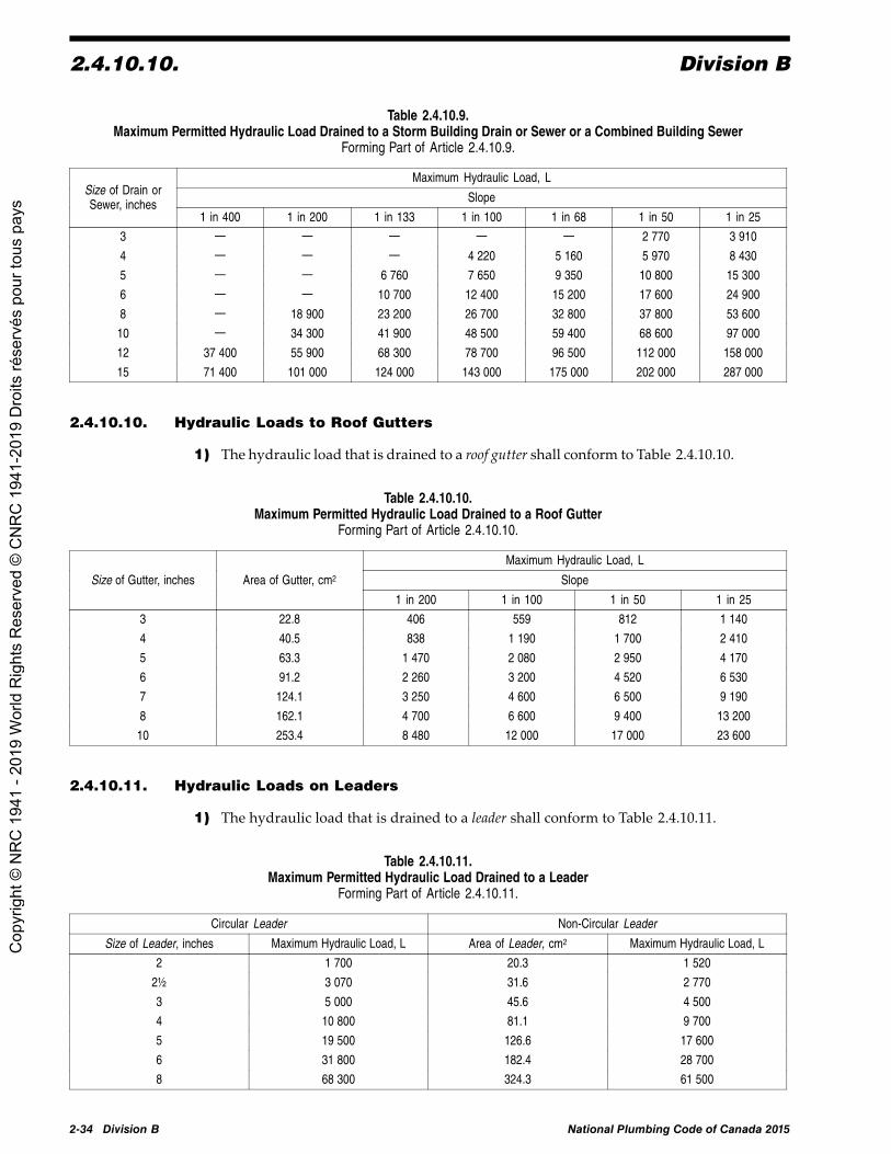
2.4.10.10. Division B
Table 2.4.10.9.Maximum Permitted Hydraulic Load Drained to a Storm Building Drain or Sewer or a Combined Building Sewer
Forming Part of Article 2.4.10.9.
Maximum Hydraulic Load, L
SlopeSize of Drain orSewer, inches
1 in 400 1 in 200 1 in 133 1 in 100 1 in 68 1 in 50 1 in 25
3 — — — — — 2 770 3 910
4 — — — 4 220 5 160 5 970 8 430
5 — — 6 760 7 650 9 350 10 800 15 300
6 — — 10 700 12 400 15 200 17 600 24 900
8 — 18 900 23 200 26 700 32 800 37 800 53 600
10 — 34 300 41 900 48 500 59 400 68 600 97 000
12 37 400 55 900 68 300 78 700 96 500 112 000 158 000
15 71 400 101 000 124 000 143 000 175 000 202 000 287 000
2.4.10.10. Hydraulic Loads to Roof Gutters
1) The hydraulic load that is drained to a roof gutter shall conform to Table 2.4.10.10.
Table 2.4.10.10.Maximum Permitted Hydraulic Load Drained to a Roof Gutter
Forming Part of Article 2.4.10.10.
Maximum Hydraulic Load, L
SlopeSize of Gutter, inches Area of Gutter, cm2
1 in 200 1 in 100 1 in 50 1 in 25
3 22.8 406 559 812 1 140
4 40.5 838 1 190 1 700 2 410
5 63.3 1 470 2 080 2 950 4 170
6 91.2 2 260 3 200 4 520 6 530
7 124.1 3 250 4 600 6 500 9 190
8 162.1 4 700 6 600 9 400 13 200
10 253.4 8 480 12 000 17 000 23 600
2.4.10.11. Hydraulic Loads on Leaders
1) The hydraulic load that is drained to a leader shall conform to Table 2.4.10.11.
Table 2.4.10.11.Maximum Permitted Hydraulic Load Drained to a Leader
Forming Part of Article 2.4.10.11.
Circular Leader Non-Circular Leader
Size of Leader, inches Maximum Hydraulic Load, L Area of Leader, cm2 Maximum Hydraulic Load, L
2 1 700 20.3 1 520
2½ 3 070 31.6 2 770
3 5 000 45.6 4 500
4 10 800 81.1 9 700
5 19 500 126.6 17 600
6 31 800 182.4 28 700
8 68 300 324.3 61 500
2-34 Division B National Plumbing Code of Canada 2015
Cop
yrig
ht ©
NR
C 1
941
- 201
9 W
orld
Rig
hts
Res
erve
d ©
CN
RC
194
1-20
19 D
roits
rése
rvés
pou
r tou
s pa
ys

Division B 2.5.1.1.
2.4.10.12. Hydraulic Loads from Fixtures with a Semi-continuous Flow
1) The hydraulic load from a fixture or equipment that produces a semi-continuousflow shall conform to Table 2.4.10.12.
Table 2.4.10.12.Maximum Permitted Hydraulic Load from Fixtures with a Semi-continuous Flow
Forming Part of Sentence 2.4.10.12.(1)
Trap Size, inches Flow, L/s Hydraulic Load, fixture units
1½ 0.00 - 0.090 3
2 0.091 - 0.190 6
3 0.191 - 0.850 27
4 0.851 - 5.700 180
2.4.10.13. Design of Storm Sewers
1) Except as provided in Sentences 2.4.10.4.(1) and (2), and Article 2.4.10.9., stormsewers may be designed in accordance with good engineering practice.
Section 2.5. Venting Systems2.5.1. Vent Pipes for Traps
2.5.1.1. Venting for Traps
1) Except as provided in Sentences (3) and (4), traps shall be protected by a ventpipe.
2) Drainage systems may require additional protection as provided inSubsections 2.5.4. and 2.5.5. by the installation of
a) branch vents,b) vent stacks,c) stack vents,d) vent headers,e) fresh air inlets,f) relief vents,g) circuit vents,h) yoke vents,i) offset relief vents,j) additional circuit vents,k) wet vents,l) individual vents,
m) dual vents, orn) continuous vents.
3) A trap that serves a floor drain need not be protected wherea) the size of the trap is not less than 3 inches,b) the length of the fixture drain is not less than 450 mm, andc) the fall on the fixture drain does not exceed its size.
(See Note A-2.5.1.1.(3).)
4) A trap need not be protected by a vent pipea) where it serves
i) a subsoil drainage pipe, orii) a storm drainage system, or
b) where it forms part of an indirect drainage system. (See alsoClause 2.4.2.3.(2)(b).)
(See Note A-2.5.1.1.(4).)
National Plumbing Code of Canada 2015 Division B 2-35
Cop
yrig
ht ©
NR
C 1
941
- 201
9 W
orld
Rig
hts
Res
erve
d ©
CN
RC
194
1-20
19 D
roits
rése
rvés
pou
r tou
s pa
ys

2.5.2.1. Division B
2.5.2. Wet Venting
2.5.2.1. Wet Venting(See Note A-2.5.2.1.)
1) A soil-or-waste pipe is permitted to serve as a wet vent, provideda) the hydraulic load is in accordance with Table 2.5.8.1.,b) the number of wet-vented water closets does not exceed 2,c) where 2 water closets are installed, they are connected at the same level by
means of a double sanitary T fitting if the vent pipe is vertical and by meansof a double Y fitting if the vent pipe is horizontal,
d) the water closets are installed downstream of all other fixtures,e) trap arms and fixture drains connected to the wet vent do not exceed 2 inches
in size, except for connections from emergency floor drains in accordance withSentence 2.5.1.1.(3),
f) the total hydraulic load on the wet vent does not exceed the limits stated inTable 2.5.8.1. when separately vented branches or fixture drains in the samestorey, having a total hydraulic load not greater than 2 fixture units, areconnected to the wet vent or a wet-vented water closet trap arm,
g) the hydraulic load of separately vented fixtures that drain into the wet ventare not included when sizing the continuous vent that serves the wet vent,
h) where a wet vent extends through more than one storey, the total dischargefrom any one storey above the first storey does not exceed 4 fixture units,
i) there is not more than one nominally horizontal offset in the wet vent, andi) the offset does not exceed 1.2 m for pipes 2 inches or less
in size, orii) the offset does not exceed 2.5 m for pipes larger than 2 inches
in size,j) the wet-vented portion is not reduced in size except for the portion that is
upstream of emergency floor drains in accordance with Sentence 2.5.1.1.(3),and
k) the length of the wet vent is not limited.
2.5.3. Circuit Venting
2.5.3.1. Circuit Venting(See Note A-2.5.3.1.)
1) A section of horizontal branch is permitted to be circuit-vented, provideda) a circuit vent is connected to it,b) all fixtures served by the circuit vent are located in the same storey, andc) no soil-or-waste stack is connected to it upstream of a circuit-vented fixture.
2) Fixtures with fixture outlet pipes less than 2 inches in size shall be separatelyvented or separately circuit-vented.
3) Except as provided in Sentences (4) and (5), a relief vent shall be connected tothe branch that forms part of a circuit-vented system, downstream of the connection ofthe most downstream circuit-vented fixture.
4) A soil-or-waste pipe having a hydraulic load not greater than 6 fixture units ispermitted to act as a relief vent for a branch that is circuit-vented.
5) A symmetrically connected relief vent is permitted to serve as a combined reliefvent for a maximum of 2 branches that are circuit-vented, provided there are not morethan 8 circuit-vented fixtures connected between the combined relief vent and eachcircuit vent.
6) Additional circuit vents shall be requireda) where each cumulative horizontal change in direction of a branch served by
a circuit vent exceeds 45° between vent pipe connections, orb) where more than 8 circuit-vented fixtures are connected to a branch between
vent pipe connections.
2-36 Division B National Plumbing Code of Canada 2015
Cop
yrig
ht ©
NR
C 1
941
- 201
9 W
orld
Rig
hts
Res
erve
d ©
CN
RC
194
1-20
19 D
roits
rése
rvés
pou
r tou
s pa
ys

Division B 2.5.4.3.
7) A soil-or-waste pipe is permitted to serve as an additional circuit vent in accordancewith Sentence (6), provided the soil-or-waste pipe is sized as a wet vent in conformancewith Article 2.5.8.1. and is not less than 2 inches in size.
8) Connections to circuit vents and additional circuit vents in accordance withSentence (6) shall conform to Sentence 2.5.4.5.(1).
9) A circuit-vented branch, including the fixture drain downstream of the circuitvent connection, shall be sized in accordance with Article 2.4.10.7., except that it shallbe not less than
a) 2 inches, where traps less than 2 inches in size are circuit-vented, orb) 3 inches, where traps 2 inches in size or larger are circuit-vented.
10) Additional circuit vents shall be sized in accordance with Table 2.5.7.1. andSentence 2.5.7.3.(1).
11) The hydraulic load on a circuit vent shall include the hydraulic load from fixturesconnected to the branch served by the circuit vent, but shall not include the hydraulicload from fixtures permitted by Sentences (3), (4) and (5).
2.5.4. Vent Pipes for Soil-or-Waste Stacks
2.5.4.1. Stack Vents
1) The upper end of every soil-or-waste stack shall terminate in a stack vent.
2.5.4.2. Vent Stacks
1) Except as provided in Sentence (2), every soil-or-waste stack draining fixturesfrom more than 4 storeys that contain plumbing fixtures shall have a vent stack.
2) A soil-or-waste stack that serves as a wet vent does not require a vent stack.
3) The vent stack required by Sentence (1) shall be connected to a vertical section ofthe soil-or-waste stack at or immediately below the lowest soil-or-waste pipe connectedto the soil-or-waste stack.
4) Fixtures are permitted to be connected to a vent stack, provideda) the total hydraulic load of the connected fixtures does not exceed
8 fixture units,b) at least one fixture is connected to a vertical portion of the vent stack and
upstream of any other fixtures,c) no other fixture is connected downstream of a water closet,d) all fixtures are located in the lowest storey served by the vent stack, ande) the section of the vent pipe that acts as a wet vent conforms to the
requirements regarding wet vents.
2.5.4.3. Yoke Vents(See Note A-2.5.4.3.)
1) Except as provided in Sentence (4), where a soil-or-waste stack receives thedischarge from fixtures located on more than 11 storeys, a yoke vent shall be installed
a) for each section of 5 storeys or part thereof counted from the top down, andb) at or immediately above each offset or double offset.
2) The yoke vent shall be connected to the soil-or-waste stack by means of a drainagefitting at or immediately below the lowest soil-or-waste pipe from the lowest storeyof the sections described in Sentence (1).
3) The yoke vent shall connect to the vent stack at least 1 m above the floor level ofthe lowest storey in the section described in Sentence (1).
4) A yoke vent need not be installed provided the soil-or-waste stack is interconnectedwith the vent stack in each storey of the section in which fixtures are located by meansof a vent pipe equal in size to the branch or fixture drain or 2 inches in size, whicheveris smaller.
National Plumbing Code of Canada 2015 Division B 2-37
Cop
yrig
ht ©
NR
C 1
941
- 201
9 W
orld
Rig
hts
Res
erve
d ©
CN
RC
194
1-20
19 D
roits
rése
rvés
pou
r tou
s pa
ys

2.5.4.4. Division B
2.5.4.4. Offset Relief Vents
1) A soil-or-waste stack that has a nominally horizontal offset more than 1.5 m longand above which the upper vertical portion of the stack passes through more than2 storeys and receives a hydraulic load of more than 100 fixture units shall be ventedby an offset relief vent connected to the vertical section immediately above the offsetand by another offset relief vent
a) connected to the lower vertical section at or above the highest soil-or-wastepipe connection, or
b) extended as a vertical continuation of the lower section.(See Note A-2.5.4.4.(1).)
2.5.4.5. Fixtures Draining into Vent Pipes
1) The trap arm of a fixture that has a hydraulic load of not more than1½ fixture units may be connected to the vertical section of a circuit vent, additionalcircuit vent, offset relief vent or yoke vent, provided
a) not more than 2 fixtures are connected to the vent pipe,b) where 2 fixtures are connected to the vent pipe, the connection is made by
means of a double sanitary T fitting, andc) the section of the vent pipe that acts as a wet vent is not less than 2 inches insize.
(See Note A-2.5.4.5.(1).)
2.5.5. Miscellaneous Vent Pipes
2.5.5.1. Venting of Sewage Sumps
1) Every sump that receives sewage shall be provided with a vent pipe that isconnected to the top of the sump. (See Article 2.5.7.7. for sizing of these vents.)
2.5.5.2. Venting of Oil Interceptors(See Note A-2.5.5.2.) (See also Article 4.3.5.2. of Division B of the NFC.)
1) Every oil interceptor shall be provided with 2 vent pipes thata) connect to the interceptor at opposite ends,b) extend independently to outside air, andc) terminate not less than 2 m above ground and at elevations differing by
at least 300 mm.
2) Adjacent compartments within an oil interceptor shall be connected to eachother by a vent opening.
3) Where a secondary receiver for oil is installed in conjunction with an oilinterceptor, it shall be vented in accordance with the manufacturer's recommendations,and the vent pipe shall
a) in no case be less than 1½ inches in size,b) extend independently to outside air, andc) terminate not less than 2 m above ground.
4) The vent pipes referred to in Sentence (1) are permitted to be one size smallerthan the largest connected drainage pipe but not less than 1¼ inches in size, or can besized in accordance with the manufacturer's recommendations.
5) A vent pipe that serves an oil interceptor and is located outside a building shall benot less than 3 inches in size in areas where it may be subject to frost closure.
2.5.5.3. Venting of Drain Piping and Dilution Tanks for Corrosive Waste
1) Venting systems for drain piping or dilution tanks conveying corrosive wasteshall extend independently and terminate in outside air. (See Article 2.5.7.7. for sizingof these vents.)
2-38 Division B National Plumbing Code of Canada 2015
Cop
yrig
ht ©
NR
C 1
941
- 201
9 W
orld
Rig
hts
Res
erve
d ©
CN
RC
194
1-20
19 D
roits
rése
rvés
pou
r tou
s pa
ys

Division B 2.5.6.3.
2.5.5.4. Fresh Air Inlets
1) Where a building trap is installed, a fresh air inlet not less than 4 inches in sizeshall be connected upstream and within 1.2 m of the building trap and downstream ofany other connection. (See Note A-2.4.5.4.(1).)
2.5.5.5. Provision for Future Installations
1) Where provision is made for a fixture to be installed in the future, the drainagesystem and venting system shall be sized accordingly and provision shall be made forthe necessary future connections.
2) Except as required in Sentence 2.5.7.7.(2), where a plumbing system is installedin a building, every storey in which plumbing is or may be installed, including thebasement of a single-family dwelling, shall have extended into it or passing through ita vent pipe that is at least 1½ inches in size for the provision of future connections.
2.5.6. Arrangement of Vent Pipes
2.5.6.1. Drainage of Vent Pipes
1) Vent pipes shall be installed without depressions in which moisture can collect.
2.5.6.2. Vent Pipe Connections
1) Vent pipes shall be installed in a nominally vertical position where it is practicalto do so.
2) Except for wet vents, where a vent pipe is connected to a nominally horizontalsoil-or-waste pipe, the connection shall be above the horizontal centre line of thesoil-or-waste pipe. (See Note A-2.5.6.2.(2).)
3) Unused vent pipes installed for future connections shall be permanently cappedwith an end cleanout or an adapter and plug.
2.5.6.3. Location of Vent Pipes
1) Except as provided in Sentences (2) and (3), vent pipes that protect a fixture trapshall be located so that
a) the developed length of the trap arm is not less than twice the size of the fixturedrain,
b) the total fall of the trap arm is not greater than its inside diameter, andc) the trap arm does not have a cumulative change in direction of more than
135°.(See Note A-2.5.6.3.(1).)
2) The trap arm of water closets, of S-trap standards or of any other fixture that alsodischarges vertically and depends on siphonic action for its proper functioning shallnot have a cumulative change in direction of more than 225°. (See Note A-2.5.6.3.(2).)
3) A vent pipe that protects a water closet or any other fixture that also depends onsiphonic action for its proper functioning shall be located so that the distance betweenthe connections of the fixture drain to the fixture and the vent pipe does not exceed
a) 1 m in the vertical plane, andb) 3 m in the horizontal plane.
(See Note A-2.5.6.3.(3).)
4) The maximum length of every trap arm shall conform to Table 2.5.6.3.
National Plumbing Code of Canada 2015 Division B 2-39
Cop
yrig
ht ©
NR
C 1
941
- 201
9 W
orld
Rig
hts
Res
erve
d ©
CN
RC
194
1-20
19 D
roits
rése
rvés
pou
r tou
s pa
ys

2.5.6.4. Division B
Table 2.5.6.3.Length of Trap Arm
Forming Part of Sentence 2.5.6.3.(4)
Size of Trap Served, inches Maximum Length of Trap Arm, m Minimum Slope
1¼ 1.5 1/50
1½ 1.8 1/50
2 2.4 1/50
3 3.6 1/50
4 9.8 1/100
2.5.6.4. Connection of Vents above Fixtures Served
1) Except for a wet vent, every vent pipe shall extend above the flood level rim ofevery fixture that it serves before being connected to another vent pipe.
2) No vent pipe shall be connected in such a manner that a blockage in a soil-or-wastepipe would cause waste to drain through the vent pipe to the drainage system.
2.5.6.5. Terminals
1) Except as provided in Sentence (3), the upper end of every vent pipe that is notterminated in outside air shall be connected to a venting system that terminates througha roof to outside air.
2) The upper end of every vent pipe that is terminated in outside air, other than avent pipe that serves an oil interceptor or a fresh air inlet, shall be extended above the roof.
3) A vent pipe is permitted to be erected outside a building, provided thata) no single change in direction of the vent pipe exceeds 45°,b) all parts of the vent pipe are nominally vertical,c) in areas where the vent pipemay be subject to frost closure, it is increased to
not less than 3 inches in size before penetrating a wall or roof, andd) where the building is 4 storeys or less in height, the vent pipe terminates above
the roof of the building.
4) Except for a fresh air inlet, where a vent pipe is terminated in outside air, theterminal shall be located
a) not less than 1 m above and not less than 3.5 m in any other direction fromevery air inlet, openable window or door,
b) not less than 2 m above and not less than 3.5 m in any other direction froma roof that supports an occupancy,
c) not less than 2 m above ground, andd) not less than 1.8 m from every property line.
(See Note A-2.5.6.5.(4).)
5) Where a vent pipe passes through a roof, it shalla) be terminated high enough to prevent the entry of roof drainage but not less
than 150 mm above the roof or above the surface of storm water, which couldpond on the roof (see Note A-2.5.6.5.(4)), and
b) be provided with flashing to prevent the entry of water between the ventpipe and the roof (see Article 2.2.10.14.).
6) Where a vent pipe passes through a roof and may be subject to frost closure, itshall be protected from frost closure by
a) increasing its diameter at least one size, but not less than 3 inches in size,immediately before it penetrates the roof,
b) insulating the pipe, orc) protecting it in some other manner.
(See Article 2.3.4.7.)
2-40 Division B Amended Page National Plumbing Code of Canada 2015
Cop
yrig
ht ©
NR
C 1
941
- 201
9 W
orld
Rig
hts
Res
erve
d ©
CN
RC
194
1-20
19 D
roits
rése
rvés
pou
r tou
s pa
ys

Division B 2.5.7.7.
2.5.7. Minimum Size of Vent Pipes
2.5.7.1. General
1) The size of every vent pipe shall conform to Table 2.5.7.1.
Table 2.5.7.1.Minimum Permitted Size of Vent Pipe Based on Size of Trap Served
Forming Part of Sentences 2.5.7.1.(1) and 2.5.8.2.(1)
Size of Trap Served, inches Minimum Size of Vent Pipe, inches
1¼ 1¼
1½ 1¼
2 1½
3 1½
4 1½
5 2
6 2
2.5.7.2. Size Restriction
1) The size of a branch vent, stack vent, vent stack or vent header shall be not less thanthe size of the vent pipe to which it is connected.
2) Sanitary building drains shall be provided with at least one vent that is not lessthan 3 inches in size.
2.5.7.3. Additional Circuit Vents and Relief Vents
1) Except as provided in Article 2.5.7.1. and Sentence 2.5.3.1.(7), the minimum sizeof an additional circuit vent or relief vent installed in conjunction with a circuit vent ispermitted to be one size smaller than the required size of the circuit vent, but need notbe larger than 2 inches.
2) The size of the soil-or-waste pipe acting as a relief vent in accordance withSentence 2.5.3.1.(4) shall be in conformance with Tables 2.4.10.6.-A, 2.4.10.6.-Bor 2.5.8.1., and Article 2.5.7.1., whichever size is the largest considering the hydraulicload drained into the soil-or-waste pipe.
2.5.7.4. Offset Relief Vents
1) Except as provided in Article 2.5.7.1., the minimum size of an offset relief vent ispermitted to be one size smaller than the size of the stack vent.
2.5.7.5. Yoke Vents
1) Yoke vents required by Sentence 2.5.4.3.(1) are permitted to be one size smallerthan the size of the smallest pipe to which they are connected.
2.5.7.6. Vent Pipes for Manholes
1) The minimum size of a vent pipe that serves a manhole within a building shall be2 inches.
2.5.7.7. Vents for Sewage Sumps, Dilution Tanks and Macerating ToiletSystems
1) Except as provided in Sentences (2) and (3), the minimum size of the vent pipefor a sewage sump or dilution tank shall be one size smaller than the size of the largestbranch or fixture drain draining to the sump.
2) The size of every vent pipe for a sewage sump or dilution tank shall be not lessthan 2 inches, but need not be greater than 4 inches.
National Plumbing Code of Canada 2015 Amended Page Division B 2-41
Cop
yrig
ht ©
NR
C 1
941
- 201
9 W
orld
Rig
hts
Res
erve
d ©
CN
RC
194
1-20
19 D
roits
rése
rvés
pou
r tou
s pa
ys
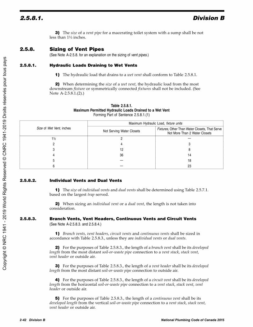
2.5.8.1. Division B
3) The size of a vent pipe for a macerating toilet system with a sump shall be notless than 1½ inches.
2.5.8. Sizing of Vent Pipes(See Note A-2.5.8. for an explanation on the sizing of vent pipes.)
2.5.8.1. Hydraulic Loads Draining to Wet Vents
1) The hydraulic load that drains to a wet vent shall conform to Table 2.5.8.1.
2) When determining the size of a wet vent, the hydraulic load from the mostdownstream fixture or symmetrically connected fixtures shall not be included. (SeeNote A-2.5.8.1.(2).)
Table 2.5.8.1.Maximum Permitted Hydraulic Loads Drained to a Wet Vent
Forming Part of Sentence 2.5.8.1.(1)
Maximum Hydraulic Load, fixture unitsSize of Wet Vent, inches
Not Serving Water Closets Fixtures, Other Than Water Closets, That ServeNot More Than 2 Water Closets
1½ 2 —
2 4 3
3 12 8
4 36 14
5 — 18
6 — 23
2.5.8.2. Individual Vents and Dual Vents
1) The size of individual vents and dual vents shall be determined using Table 2.5.7.1.based on the largest trap served.
2) When sizing an individual vent or a dual vent, the length is not taken intoconsideration.
2.5.8.3. Branch Vents, Vent Headers, Continuous Vents and Circuit Vents(See Note A-2.5.8.3. and 2.5.8.4.)
1) Branch vents, vent headers, circuit vents and continuous vents shall be sized inaccordance with Table 2.5.8.3., unless they are individual vents or dual vents.
2) For the purposes of Table 2.5.8.3., the length of a branch vent shall be its developedlength from the most distant soil-or-waste pipe connection to a vent stack, stack vent,vent header or outside air.
3) For the purposes of Table 2.5.8.3., the length of a vent header shall be its developedlength from the most distant soil-or-waste pipe connection to outside air.
4) For the purposes of Table 2.5.8.3., the length of a circuit vent shall be its developedlength from the horizontal soil-or-waste pipe connection to a vent stack, stack vent, ventheader or outside air.
5) For the purposes of Table 2.5.8.3., the length of a continuous vent shall be itsdeveloped length from the vertical soil-or-waste pipe connection to a vent stack, stack vent,vent header or outside air.
2-42 Division B National Plumbing Code of Canada 2015
Cop
yrig
ht ©
NR
C 1
941
- 201
9 W
orld
Rig
hts
Res
erve
d ©
CN
RC
194
1-20
19 D
roits
rése
rvés
pou
r tou
s pa
ys

Division B 2.5.8.4.
Table 2.5.8.3.Sizing of Branch Vents, Vent Headers, Circuit Vents and Continuous Vents
Forming Part of Article 2.5.8.3.
Size of Vent Pipe, inches
1¼ 1½ 2 3 4 5 6 8Total Hydraulic LoadServed by Vent Pipe,
fixture units Maximum Length of Vent Pipe, m
2 9
8 9 30 61
20 7.5 15 46 Not Limited
24 4.5 9 30
42 9 30
60 4.5 15 120
100 11 79 305
200 9 76 275
500 6 55 215
1 100 15 61 215
1 900 6 21 61 215
2 200 Not Permitted 9 27 105 335
3 600 7.5 18 76 245
5 600 7.5 18 76
2.5.8.4. Vent Stacks or Stack Vents(See Note A-2.5.8.3. and 2.5.8.4.)
1) A vent stack or stack vent shall be sized in accordance with Table 2.5.8.4. based ona) the length of the vent stack or stack vent, andb) the total hydraulic load that is drained to the lowest section of soil-or-waste
stack or stacks served by the vent pipe, plus any additional vent loadsconnected to the vent stack or stack vent.
2) For the purposes of Table 2.5.8.4., the length of a stack vent or vent stack shallbe its developed length from its lower end to outside air.
3) The minimum size of a vent stack or stack vent shall be one-half the size of thesoil-or-waste stack at its base.
4) A stack vent serving a wet vent stack that is over 4 storeys high shall extendthe full size of the wet vent to outside air.
National Plumbing Code of Canada 2015 Amended Page Division B 2-43
Cop
yrig
ht ©
NR
C 1
941
- 201
9 W
orld
Rig
hts
Res
erve
d ©
CN
RC
194
1-20
19 D
roits
rése
rvés
pou
r tou
s pa
ys

2.5.8.4. Division B
Table 2.5.8.4.Size and Developed Length of Stack Vents and Vent Stacks
Forming Part of Sentences 2.5.8.4.(1) and (2)
Size of Stack Vent or Vent Stack, inches
1¼ 1½ 2 3 4 5 6 8 10 12Size ofSoil-or-
waste stack,inches(1)
TotalHydraulicLoad BeingVented,
fixture unitsMaximum Length of Stack Vent or Vent Stack, m
1¼ 2 9
1½ 8 15 46
12 9 23 612
24 8 15 46
10 13 46 317
21 10 33.5 247 Not Limited
53 8 28.5 2073
102 7.5 26 189
43 10.5 76 299
140 8 61 229
320 7 52 1954
540 6.5 46 177
190 25 97.5 302
490 19 76 232
940 16 64 2045
1 400 15 58 180
500 10 39.5 122 305
1 100 8 30.5 94.5 238
2 000 6.5 25.5 79 2016
2 900 6 23.5 73 183
1 800 9.5 29 73 287
3 400 7 22 58 219.5
5 600 6 19 49 1868
7 600 5.5 17 43 170.5
4 000 9.5 24 94.5 292.5
7 200 7 18 73 225.5
11 000 6 15.5 61 19210
15 000 5.5 14 55 174
7 300 9.5 36.5 116 287
13 000 7 28.5 91 219.5
20 000 Not Permitted 6 24 76 18612
26 000 5.5 22 70 152
15 000 12 39.5 94.5
25 000 9.5 29 73
38 000 8 24.5 6115
50 000 7 22.5 55
Notes to Table 2.5.8.4.:(1) Soil-or-waste stacks shall be sized using Table 2.4.10.6.-A.
2-44 Division B Amended Page National Plumbing Code of Canada 2015
Cop
yrig
ht ©
NR
C 1
941
- 201
9 W
orld
Rig
hts
Res
erve
d ©
CN
RC
194
1-20
19 D
roits
rése
rvés
pou
r tou
s pa
ys

Division B 2.6.1.2.
2.5.8.5. Lengths of Other Vent Pipes
1) When sizing an additional circuit vent, offset relief vent, relief vent, yoke vent, andthe vent pipe for an interceptor, dilution tank, sewage tank, sump, or manhole, lengthis not taken into consideration.
2.5.9. Air Admittance Valves(See Note A-2.2.10.16.(1).)
2.5.9.1. Air Admittance Valve as a Vent Terminal
1) Individual vents and dual vents are permitted to terminate with a connectionto an air admittance valve as provided in Articles 2.5.9.2. and 2.5.9.3. (See alsoSentence 2.2.10.16.(1).)
2.5.9.2. Air Admittance Valves
1) Air admittance valves shall only be used to venta) fixtures located in island counters,b) fixtures that may be affected by frost closure of the vent due to local climatic
conditions,c) fixtures in one- and two-family dwellings undergoing renovation, ord) installations where connection to a vent may not be practical.
2) Air admittance valves shall be locateda) not less than 100 mm above the fixture drain being vented,b) within the maximum developed length permitted for the vent, andc) not less than 150 mm above insulation materials.
2.5.9.3. Installation Conditions
1) Air admittance valves shall not be installed in supply or return air plenums, or inlocations where they may be exposed to freezing temperatures.
2) Air admittance valves shall be installed in accordance with the manufacturer'sinstallation instructions.
3) Air admittance valves shall be rated for the size of vent pipe to which they areconnected.
4) Installed air admittance valves shall bea) accessible, andb) located in a space that allows air to enter the valve.
5) Drainage systems shall have at least one vent that terminates to the outdoors inconformance with Sentence 2.5.6.5.(1).
Section 2.6. Potable Water Systems2.6.1. Arrangement of Piping
2.6.1.1. Design
1) Fixtures supplied with separate hot and cold water controls shall have the hotwater control on the left and the cold on the right.
2) In a hot water distribution system of a developed length of more than 30 m orsupplying more than 4 storeys, the water temperature shall be maintained by
a) recirculation, orb) a self-regulating heat tracing system.
2.6.1.2. Drainage
1) A water distribution system shall be installed so that the system can be drained orblown out with air.
National Plumbing Code of Canada 2015 Division B 2-45
Cop
yrig
ht ©
NR
C 1
941
- 201
9 W
orld
Rig
hts
Res
erve
d ©
CN
RC
194
1-20
19 D
roits
rése
rvés
pou
r tou
s pa
ys

2.6.1.3. Division B
2.6.1.3. Shut-off Valves1) Water service pipes shall be provided with an accessible shut-off valve located as
close as possible to where the water service pipe enters the building.2) Pipes that convey water from a gravity water tank or from a private water supply
system shall be fitted with a shut-off valve at the source of supply.3) Except for risers that serve only one dwelling unit, risers shall be provided with a
shut-off valve located at the source of supply.4) Water closets shall be provided with a shut-off valve on their water supply pipe.5) In buildings of residential occupancy that contain more than one dwelling unit, a
shut-off valve shall be installed where the water supply enters each dwelling unit, sothat, when the water supply to one suite is shut off, the water supply to the remainderof the building is not interrupted. (See Note A-2.6.1.3.(5).)
6) In buildings of other than residential occupancy, shut-off valves shall be providedon the water supply to
a) every fixture, orb) any group of fixtures in the same room, except as provided in Sentence (4).7) Pipes that supply water to a hot water tank shall be provided with a shut-off
valve located close to the tank.
2.6.1.4. Protection for Exterior Water Supply1) Pipes that pass through an exterior wall to supply water to the exterior of the
building shall be provided witha) a frost-proof hydrant, orb) a stop-and-waste cock located inside the building and close to the wall.
2.6.1.5. Check Valves1) A check valve shall be installed at the building end of a water service pipe where
the pipe is made of plastic that is suitable for cold water use only.
2.6.1.6. Flushing Devices1) Flushing devices that serve water closets or urinals shall have sufficient capacity
and be adjusted to deliver at each operation a volume of water that will thoroughlyflush the fixture or fixtures they serve.
2) Where a manually operated flushing device is installed, it shall serve onlyone fixture.
3) Except as provided in Sentence (4), water closets and urinals shall have anintegral means of limiting the maximum amount of water used in each flush cycle tothat specified in Table 2.6.1.6.
Table 2.6.1.6.Water Usage per Flush Cycle
Forming Part of Sentence 2.6.1.6.(3)
Fixtures Maximum Water Usage per Flush Cycle, Lpf
Water closets – residential
single-flush 4.8
dual-flush: 6.0/4.1 Lpf 4.8
Water closets – industrial, commercial, institutional 6.0
Urinals 1.9
4) In residential retrofits, a maximum water usage of 6.0 Lpf shall be permitted forsingle-flush water closets where it can be demonstrated that a maximum water usage of4.8 Lpf would be impracticable given the existing building or municipal infrastructure.
2-46 Division B National Plumbing Code of Canada 2015
Cop
yrig
ht ©
NR
C 1
941
- 201
9 W
orld
Rig
hts
Res
erve
d ©
CN
RC
194
1-20
19 D
roits
rése
rvés
pou
r tou
s pa
ys

Division B 2.6.1.8.
5) Except where installed in buildings not intended to be occupied year-round,flush-tank-type urinals shall be equipped with a device capable of preventing flushcycles when they are not in use. (See Note A-2.6.1.6.(5).)
2.6.1.7. Relief Valves
1) In addition to the requirements in Sentence (2), the hot water tank of astorage-type service water heater shall be equipped with a pressure-relief valve
a) designed to open when the water pressure in the tank reaches the ratedworking pressure of the tank, and
b) so located that the pressure in the tank shall not exceed the pressure at therelief valve by more than 35 kPa under any condition of flow within thedistribution system.
2) The hot water tank of a storage-type service water heater shall be equipped with atemperature-relief valve with a temperature-sensing element
a) located within the top 150 mm of the tank, andb) designed to open and discharge sufficient water from the tank to keep
the temperature of the water in the tank from exceeding 99°C under alloperating conditions.
3) A pressure-relief valve and temperature-relief valve may be combined whereSentences (1) and (2) are complied with.
4) Indirect service water heaters shall be equipped witha) a pressure-relief valve, andb) a temperature-relief valve on every storage tank that forms part of the
system.
5) Pipes that convey water from a temperature-relief, pressure-relief or combinedtemperature- and pressure-relief valve shall
a) be of a size at least equal to the size of the outlet of the valve,b) be rigid, slope downward from the valve, and terminate with an indirect
connection above a floor drain, sump, or other safe location, with an air breakof not more than 300 mm,
c) have no thread at its outlet, andd) be capable of operating at a temperature of not less than 99°C.
(See Note A-2.6.1.7.(5).)
6) The temperature-relief valve required in Clause (4)(b) shalla) have a temperature-sensing element located within the top 150 mm of the
tank, andb) be designed to open and discharge sufficient water to keep the temperature
of the water in the tank from exceeding 99°C under all operating conditions.
7) No shut-off valve shall be installed on the pipe between any tank and the reliefvalves or on the discharge lines from such relief valves.
8) A vacuum-relief valve shall be installed when any tank may be subject toback-siphonage.
9) Storage-type service water heaters that are located in a ceiling or roof space, or overa floor of wood construction, shall be installed within a corrosion-resistant watertightdrain pan, as described in Sentence (10).
10) The drain pan referred to in Sentence (9) shalla) be not less than 50 mm larger than the tank and have side walls not less
than 25 mm high,b) be drained by a pipe two sizes larger than the relief valve discharge pipe, andc) have a drain that is located directly under the relief valve discharge pipe
and that discharges directly to a floor drain or other acceptable location.
2.6.1.8. Solar Domestic Hot Water Systems
1) Systems for solar heating of potable water shall be installed in conformance withCAN/CSA-F383, “Installation of Packaged Solar Domestic Hot Water Systems.”
National Plumbing Code of Canada 2015 Division B 2-47
Cop
yrig
ht ©
NR
C 1
941
- 201
9 W
orld
Rig
hts
Res
erve
d ©
CN
RC
194
1-20
19 D
roits
rése
rvés
pou
r tou
s pa
ys

2.6.1.9. Division B
2.6.1.9. Water Hammer
1) Provision shall be made to protect the water distribution system from the adverseeffects of water hammer. (See Note A-2.6.1.9.(1).)
2.6.1.10. Mobile Home Water Service
1) A water service pipe intended to serve a mobile home shalla) be not less than ¾ inch in size,b) terminate above ground, andc) be provided with
i) a tamperproof terminal connection that is capable of beingrepeatedly connected, disconnected and sealed,
ii) a protective concrete pad,iii) a means to protect it from frost heave, andiv) a curb stop and a means of draining that part of the pipe
located above the frost line when not in use.
2.6.1.11. Thermal Expansion
1) Where thermal expansion can occur, protection shall be provided fora) check valves required by Article 2.6.1.5.,b) backflow preventers required by Sentence 2.6.2.1.(3), andc) pressure-reducing valves required by Article 2.6.3.3.
(See Note A-2.6.1.11.(1).)
2.6.1.12. Service Water Heaters
1) Thermostat controls for electric storage-type service water heaters shall be set at atemperature of 60°C. (See Note A-2.6.1.12.(1).)
2.6.2. Protection from Contamination
2.6.2.1. Connection of Systems
1) Except as provided in Sentence (2), connections to potable water systems shallbe designed and installed so that non-potable water or substances that may render thewater non-potable cannot enter the system.
2) A water treatment device or apparatus shall not be installed unless it can bedemonstrated that the device or apparatus will not introduce substances into thesystem that may endanger health.
3) Backflow preventers shall be selected and installed in conformance with CSAB64.10, “Selection and Installation of Backflow Preventers.” (See Note A-2.6.2.1.(3).)
2.6.2.2. Back-Siphonage
1) Potable water connections to fixtures, tanks, vats or other devices not subject topressure above atmospheric and containing other than potable water shall be installedso as to prevent back-siphonage in conformance with Sentence (2).
2) Except as provided in Sentence 2.6.2.10.(2), back-siphonage shall be prevented bythe installation of
a) an air gap,b) an atmospheric vacuum breaker,c) a pressure vacuum breaker,d) a spill-resistant pressure vacuum breaker,e) a hose connection vacuum breaker,f) a dual check valve backflow preventer with atmospheric port,g) a double check valve assembly,h) a reduced pressure principle backflow preventer,i) a dual check valve backflow preventer,j) a laboratory faucet type vacuum breaker, ork) a dual check valve backflow preventer with vent.
2-48 Division B Amended Page National Plumbing Code of Canada 2015
Cop
yrig
ht ©
NR
C 1
941
- 201
9 W
orld
Rig
hts
Res
erve
d ©
CN
RC
194
1-20
19 D
roits
rése
rvés
pou
r tou
s pa
ys

Division B 2.6.2.4.
2.6.2.3. Backflow Caused by Back Pressure
1) Potable water connections to fixtures, tanks, vats, boilers or other devicescontaining other than potable water and subject to pressure above atmospheric shall bearranged to prevent backflow caused by back pressure in conformance with Sentences (2)and (3).
2) Except as provided in Article 2.6.2.4., backflow caused by back pressure ofnon-toxic substances into a potable water system shall be prevented by the installation of
a) an air gap,b) a dual check valve backflow preventer with atmospheric port,c) a dual check valve backflow preventer,d) a dual check valve backflow preventer with vent,e) a double check valve assembly, orf) a reduced pressure principle backflow preventer.
3) Backflow caused by back pressure of toxic substances into a potable water systemshall be prevented by the installation of
a) an air gap, orb) a reduced pressure principle backflow preventer.
2.6.2.4. Backflow from Fire Protection Systems
1) A backflow preventer shall not be required in residential full flow-through firesprinkler/standpipe systems in which the pipes and fittings are constructed of potablewater system materials.
2) Except as required by Sentence (4), potable water system connections to firesprinkler and standpipe systems shall be protected against backflow caused byback-siphonage or back pressure in conformance with Clauses (a) to (f):
a) residential partial flow-through fire sprinkler/standpipe systems in which thepipes and fittings are constructed of potable water system materials shallbe protected by a dual check valve backflow preventer conforming to CSAB64.6.1, “Dual Check Valve Backflow Preventers for Fire Protection Systems(DuCF),”
b) Class 1 fire sprinkler/standpipe systems shall be protected by a single check valvebackflow preventer conforming to CSA B64.9, “Single Check Valve BackflowPreventers for Fire Protection Systems (SCVAF),” provided that the systemsdo not use antifreeze or other additives of any kind and that all pipes andfittings are constructed of potable water system materials,
c) Class 1 fire sprinkler/standpipe systems not covered by Clause (b) as well asClass 2 and Class 3 fire sprinkler/standpipe systems shall be protected by adouble check valve backflow preventer conforming to CSA B64.5.1, “DoubleCheck Valve Backflow Preventers for Fire Protection Systems (DCVAF),”provided that the systems do not use antifreeze or other additives of anykind,
d) Class 1, Class 2 and Class 3 fire sprinkler/standpipe systems in which antifreezeor other additives are used shall be protected by a reduced pressureprinciple backflow preventer conforming to CSA B64.4.1, “Reduced PressurePrinciple Backflow Preventers for Fire Protection Systems (RPF),” installedon the portion of the system that uses the additives and the balance of thesystem shall be protected as required by Clause (b) or (c),
e) Class 4 and Class 5 fire sprinkler/standpipe systems shall be protected by areduced pressure principle backflow preventer conforming to CSA B64.4.1,“Reduced Pressure Principle Backflow Preventers for Fire ProtectionSystems (RPF),” or
f) Class 6 fire sprinkler/standpipe systems shall be protectedi) by a double check valve backflow preventer conforming to CSA
B64.5.1, “Double Check Valve Backflow Preventers for FireProtection Systems (DCVAF),” or
National Plumbing Code of Canada 2015 Division B 2-49
Cop
yrig
ht ©
NR
C 1
941
- 201
9 W
orld
Rig
hts
Res
erve
d ©
CN
RC
194
1-20
19 D
roits
rése
rvés
pou
r tou
s pa
ys

2.6.2.5. Division B
ii) where a potentially severe health hazard may be caused bybackflow, by a reduced pressure principle backflow preventerconforming to CSA B64.4.1, “Reduced Pressure PrincipleBackflow Preventers for Fire Protection Systems (RPF).”
(See Note A-2.6.2.4.(2).)
3) Backflow preventers required by Sentence (2) shall be installed upstream of thefire department pumper connection. (See Note A-2.6.2.4.(3).)
4) Where a reduced pressure principle backflow preventer is required on a waterservice pipe at a fire service connection located on the same premises as the fire servicepipe in Class 3, 4, 5 and 6 fire sprinkler/standpipe systems, a reduced pressure principlebackflow preventer conforming to CSA B64.4.1, “Reduced Pressure Principle BackflowPreventers for Fire Protection Systems (RPF),” shall also be required on the fire serviceconnection.
2.6.2.5. Separation of Water Supply Systems
1) No private water supply system shall be interconnected with a public watersupply system.
2.6.2.6. Premise Isolation
1) In addition to the backflow preventer required by this Subsection for buildingsor facilities where a potentially severe health hazard may be caused by backflow, thepotable water system shall be provided with premise isolation by the installation of areduced pressure principle backflow preventer. (See Note A-2.6.2.6.(1).)
2.6.2.7. Hose Bibb
1) Where a hose bibb is installed outside a building, inside a garage or in an areawhere there is an identifiable risk of contamination, the potable water system shall beprotected against backflow through the hose bibb.
2.6.2.8. Cleaning of Systems
1) A newly installed part of a potable water system shall be cleaned and then flushedwith potable water before the system is put into operation.
2.6.2.9. Air Gap
1) Air gaps shall not be located in a noxious environment.
2) Air gaps shall be not less than 25 mm high and at least twice the diameter of theopening of the water supply outlet in height. (See Note A-2.6.2.9.(2).)
2.6.2.10. Vacuum Breakers
1) Where the critical level is not marked on an atmospheric vacuum breaker, pressurevacuum breaker, or spill-resistant pressure vacuum breaker, the critical level shall be takenas the lowest point on the device.
2) Where an atmospheric vacuum breaker is installed, it shall be located on thedownstream side of the fixture control valve or faucet so that it will be subject towater supply pressure
a) only when the valve or faucet is open, andb) for periods of continuous use not exceeding 12 h.
(See Note A-2.6.2.10.(2).)
3) An atmospheric vacuum breaker shall be installed so that the critical level is atleast the distance specified by the manufacturer at which the device will operate safelybut not less than 25 mm above
a) the flood level rim of a fixture or tank, orb) the highest point open to atmosphere in an irrigation system.
2-50 Division B National Plumbing Code of Canada 2015
Cop
yrig
ht ©
NR
C 1
941
- 201
9 W
orld
Rig
hts
Res
erve
d ©
CN
RC
194
1-20
19 D
roits
rése
rvés
pou
r tou
s pa
ys

Division B 2.6.3.2.
4) A pressure vacuum breaker or spill-resistant pressure vacuum breaker shall beinstalled so that the critical level is not less than 300 mm above
a) the flood level rim of a fixture or tank, orb) the highest point open to atmosphere in an irrigation system.
2.6.2.11. Tank-Type Water Closets
1) Tank-type water closets shall be provided with a back-siphonage preventer inconformance with Sentence 2.2.10.10.(2).
2.6.2.12. Backflow Preventers
1) No bypass piping or other device capable of reducing the effectiveness of abackflow preventer shall be installed in a water supply system.
2.6.3. Size and Capacity of Pipes(See Note A-2.6.3.)
2.6.3.1. Design, Fabrication and Installation(See Note A-2.6.3.1.)
1) Water distribution systems shall be designed to provide peak demand flow whenthe flow pressures at the supply openings conform to the plumbing supply fittingmanufacturer's specifications.
2) Potable water systems shall be designed, fabricated and installed in accordancewith good engineering practice, such as that described in the ASHRAE Handbooksand ASPE Data Books. (See Note A-2.6.3.1.(2).)
3) In one- and two-family dwelling units and manufactured homes, multi-purposesystems that combine potable water systems and residential fire sprinkler systems shallbe designed, fabricated and installed in accordance with NFPA 13D, “Installation ofSprinkler Systems in One- and Two-Family Dwellings and Manufactured Homes.”
2.6.3.2. Hydraulic Load
1) Except as provided in Sentence (3), the hydraulic load of a fixture or device thatis listed in Table 2.6.3.2.-A shall be the number of fixture units given in the Table.
2) Except as provided in Sentences (1) and (3), the hydraulic load of a fixture thatis not listed in Table 2.6.3.2.-A is the number of fixture units listed in Table 2.6.3.2.-D.
3) Where fixtures are supplied with both hot and cold water, the hydraulic loads formaximum separate demands shall be 75% of the hydraulic load of the fixture units givenin Tables 2.6.3.2.-A and 2.6.3.2.-D when using a detailed engineering design method.
4) The hydraulic load of urinals and water closets with direct flush valvesshall be the number of fixture units listed in Tables 2.6.3.2.-B and 2.6.3.2.-C. (SeeNote A-2.6.3.2.(4).)
Table 2.6.3.2.-ASizing of Water Distribution Systems(1)(2)
Forming Part of Sentences 2.6.3.2.(1), (2) and (3), and 2.6.3.4.(2), (3) and (5)
Private Use Hydraulic Load,fixture units Public Use Hydraulic Load, fixture units
Fixture or Device Minimum Size ofSupply Pipe, inches
Cold Hot Total Cold Hot Total
Bathroom group with 6 LPF flush tank(3) n/a 2.7 1.5 3.6 - - -
Bathroom group with greater than 6 LPFflush tank(3)
n/a 4 3 6 - - -
Bathroom group with more than 3 fixtures - - - (4) - - -
Bathtub with or without shower head ½ 1 1 1.4 3 3 4
Bathtub with ¾ inch spout ¾ 7.5 7.5 10 7.5 7.5 10
National Plumbing Code of Canada 2015 Division B 2-51
Cop
yrig
ht ©
NR
C 1
941
- 201
9 W
orld
Rig
hts
Res
erve
d ©
CN
RC
194
1-20
19 D
roits
rése
rvés
pou
r tou
s pa
ys

2.6.3.2. Division B
Table 2.6.3.2.-A (Continued)
Private Use Hydraulic Load,fixture units Public Use Hydraulic Load, fixture units
Fixture or Device Minimum Size ofSupply Pipe, inches
Cold Hot Total Cold Hot Total
Bedpan washer 1 - - - 7.5 7.5 10
Bidet 3/8 1.5 1.5 2 - - -
Clothes washer 3.5 kg ½ 1 1 1.4 2.25 2.25 3
Clothes washer 6.8 kg ½ - - - 3 3 4
Clothes washer, commercial(5) - - - - - - -
Dental lavatory 3/8 - - - 1.5 1.5 2
Dental unit, cuspidor 3/8 - - - 1 - 1
Dishwasher, commercial(5) - - - - - - -
Dishwasher, domestic 3/8 - 1.4 1.4 - - -
Drinking fountain or water cooler 3/8 - - - 0.25 - 0.25
Hose bibb ½ 2.5 - 2.5 2.5 - 2.5
Hose bibb ¾ 3 - 3 6 - 6
Hose bibb, combination hot and cold ½ 1.9 1.9 2.5 1.9 1.9 2.5
Lavatory, 8.3 LPM or less 3/8 0.5 0.5 0.7 1.5 1.5 2
Lavatory, greater than 8.3 LPM 3/8 0.75 0.75 1 1.5 1.5 2
Sink, bar 3/8 0.75 0.75 1 1.5 1.5 2
Sink, clinic service faucet ½ - - - 2.25 2.25 3
Sink, clinic service with direct flush valve 1 - - - 6 - 6
Sink, kitchen commercial, per faucet ½ - - - 3 3 4
Sink, kitchen domestic, 8.3 LPM 3/8 1 1 1.4 1 1 1.4
Sink, kitchen domestic, greater than 8.3LPM
3/8 1.5 1.5 2 1.5 1.5 2
Sink, laboratory 3/8 - - - 1.5 1.5 2
Sink, laundry (1 or 2 compartments) 3/8 1 1 1.4 1 1 1.4
Sink, service or mop basin ½ - - - 2.25 2.25 3
Sink, washup, per faucet ½ - - - 1.5 1.5 2
Shower head, 9.5 LPM or less per head ½ 1 1 1.4 3 3 4
Shower head, greater than 9.5 LPM perhead
½ 1.5 1.5 2 3 3 4
Shower, spray, multi-head, fixture unit perhead
(5) 1 1 1.4 3 3 4
Urinal, with direct flush valve ¾ (6) - (6) (6) - (6)
Urinal, with flush tank 3/8 3 - 3 3 - 3
Urinal, with self-closing metering valve ½ 2 - 2 4 _ 4
Water closet, 6 LPF or less with flush tank 3/8 2.2 - 2.2 2.2 - 2.2
Water closet, greater than 6 LPF with flushtank
3/8 3 - 3 5 - 5
Water closet, with direct flush valve 1 (6) - (6) (6) - (6)
Notes to Table 2.6.3.2.-A:(1) The fixture unit values in this Table are not applicable in certain assembly occupancies because of surges in use by the occupants. For such
occupancies, refer to specific design information.(2) For fixtures not indicated in this Table, refer to Table 2.6.3.2.-D.(3) Bathroom group is based on a ½-inch size bathtub supply pipe.(4) Add additional fixture to the fixture load for bathroom group.(5) Refer to manufacturer's recommendations.(6) For fixture unit values for fixtures with direct flush valves, see Sentence 2.6.3.2.(4) and Tables 2.6.3.2.-B and 2.6.3.2.-C.
2-52 Division B National Plumbing Code of Canada 2015
Cop
yrig
ht ©
NR
C 1
941
- 201
9 W
orld
Rig
hts
Res
erve
d ©
CN
RC
194
1-20
19 D
roits
rése
rvés
pou
r tou
s pa
ys

Division B 2.6.3.4.
Table 2.6.3.2.-BSizing of Water Distribution Systems for Urinals with Direct Flush Valves
Forming Part of Sentences 2.6.3.2.(4) and 2.6.3.4.(5)
Number of Valves Individual Fixture Unit Assigned inDecreasing Values Fixture Units in Accumulative Values(1)
1 20 20
2 15 35
3 10 45
4 8 53
5 or more 5 each 58, plus 5 for each additional fixture in excess of 5
Notes to Table 2.6.3.2.-B:(1) The accumulative fixture unit values are the total values to be used in conjunction with Table 2.6.3.2.-A.
Table 2.6.3.2.-CSizing of Water Distribution Systems for Water Closets with Direct Flush Valves
Forming Part of Sentences 2.6.3.2.(4) and 2.6.3.4.(5)
Number of Valves Individual Fixture Unit Assigned inDecreasing Values Fixture Units in Accumulative Values(1)
1 40 40
2 30 70
3 20 90
4 15 105
5 or more10 for each public use
and6 for each private use
115, plus 10 for each public useadditional fixture in excess of 5
and111, plus 6 for each private use additional
fixture in excess of 5
Notes to Table 2.6.3.2.-C:(1) The accumulative fixture unit values are the total values to be used in conjunction with Table 2.6.3.2.-A.
Table 2.6.3.2.-DHydraulic Loads of Fixtures Not Listed in Table 2.6.3.2.A.Forming Part of Sentences 2.6.3.2.(2) and (3) and 2.6.3.4.(5)
Hydraulic Load, fixture unitsSize of Supply Pipe, inches
Private Use Public Use3/8 1 2
½ 2 4
¾ 3 6
1 6 10
2.6.3.3. Static Pressure
1) Where the static pressure at any fixturemay exceed 550 kPa, a pressure-reducingvalve shall be installed to limit the maximum static pressure at the fixture to 550 kPa.
2.6.3.4. Size
1) Water service pipes shall be sized according to the peak demand flow but shallnot be less than ¾ inch size.
2) Except as provided in Sentence (3), the size of a supply pipe that serves a fixtureshall conform to Table 2.6.3.2.-A.
National Plumbing Code of Canada 2015 Division B 2-53
Cop
yrig
ht ©
NR
C 1
941
- 201
9 W
orld
Rig
hts
Res
erve
d ©
CN
RC
194
1-20
19 D
roits
rése
rvés
pou
r tou
s pa
ys

2.6.3.5. Division B
3) For fixtures listed in Table 2.6.3.2.-A that are permitted to have a supply pipe3/8 inch in size, a connector not more than 750 mm long and not less than 6.3 mminside diameter may be used to supply water to the fixture.
4) No water system between the point of connection with the water service pipe orthe water meter and the first branch that supplies a water heater that serves more thanone fixture shall be sized less than ¾ inch.
5) Where both hot and cold water is supplied to fixtures in residential buildingscontaining one or two dwelling units or row houses with separate water service pipes, thewater system may be sized in accordance with Table 2.6.3.4., where
a) the hydraulic loads for maximum separate demands on water distributionsystem piping are not less than 100% of the total hydraulic load of the fixtureunits given in Table 2.6.3.2.-A, 2.6.3.2.-B, 2.6.3.2.-C or 2.6.3.2.-D for privateuse,
b) the minimum water pressure at the entry to the building is 200 kPa, andc) the total maximum length of water system is 90 m.
(See Note A-2.6.3.4.(5).)
Table 2.6.3.4.Water Pipe Sizing for Buildings Containing One or Two Dwelling Units or Row Houses with Separate Water Service Pipes
Forming Part of Sentence 2.6.3.4.(5)
Water Velocity, m/s(1)
3.0 2.4 1.5Size of Water Pipe, inches
Hydraulic Load, fixture units
½ 8 7 4
¾ 21 16 9
1 43 31 18
1¼ 83 57 30
Notes to Table 2.6.3.4.:(1) Table 2.6.3.4. is not intended to limit water velocities that are permitted by Sentence 2.6.3.5.(1).
2.6.3.5. Velocity
1) The maximum permitted water velocities shall be those recommended by thepipe and fitting manufacturer.
Section 2.7. Non-Potable Water Systems2.7.1. Connection
2.7.1.1. Not Permitted
1) A non-potable water system shall not be connected to a potable water system.
2.7.2. Identification
2.7.2.1. Markings Required
1) Non-potable water piping shall be identified by markings that are permanent,distinct and easily recognized.
2.7.3. Location
2.7.3.1. Pipes
1) Non-potable water piping shall not be locateda) where food is prepared in a food-processing plant,
2-54 Division B National Plumbing Code of Canada 2015
Cop
yrig
ht ©
NR
C 1
941
- 201
9 W
orld
Rig
hts
Res
erve
d ©
CN
RC
194
1-20
19 D
roits
rése
rvés
pou
r tou
s pa
ys

Division B 2.8.1.1.
b) above food-handling equipment,c) above a non-pressurized potable water tank, ord) above a cover of a pressurized potable water tank.
2.7.3.2. Outlets
1) An outlet from a non-potable water system shall not be located where it candischarge into
a) a sink or lavatory,b) a fixture into which an outlet from a potable water system is discharged, orc) a fixture that is used for the preparation, handling or dispensing of food,
drink or products that are intended for human consumption.(See Note A-2.7.3.2.(1).)
2.7.4. Non-potable Water Systems
2.7.4.1. Non-potable Water System Design(See Note A-2.7.4.1.)
1) Except as provided in Sentence (2), non-potable water systems shall be designed,fabricated and installed in accordance with good engineering practice, such as thatdescribed in the ASHRAE Handbooks, ASPE Handbooks and CAN/CSA-B128.1,“Design and Installation of Non-Potable Water Systems.”
2) Non-potable water systems shall only be used to supply water closets, urinals,and directly connected underground irrigation systems that only dispense water belowthe surface of the ground.
Section 2.8. Objectives and Functional Statements2.8.1. Objectives and Functional Statements
2.8.1.1. Attribution to Acceptable Solutions
1) For the purposes of compliance with this Code as required inClause 1.2.1.1.(1)(b) of Division A, the objectives and functional statements attributedto the acceptable solutions in this Part shall be the objectives and functional statementslisted in Table 2.8.1.1. (See Note A-1.1.2.1.(1).)
National Plumbing Code of Canada 2015 Division B 2-55
Cop
yrig
ht ©
NR
C 1
941
- 201
9 W
orld
Rig
hts
Res
erve
d ©
CN
RC
194
1-20
19 D
roits
rése
rvés
pou
r tou
s pa
ys
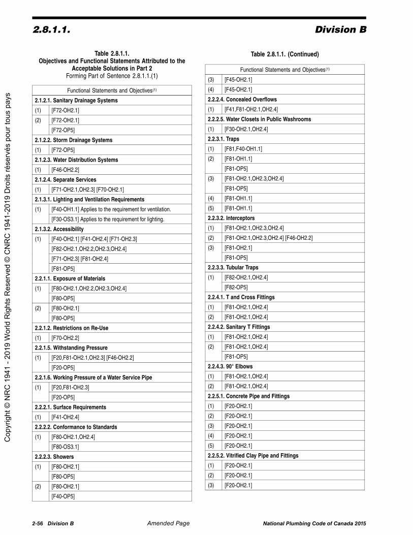
2.8.1.1. Division B
Table 2.8.1.1.Objectives and Functional Statements Attributed to the
Acceptable Solutions in Part 2Forming Part of Sentence 2.8.1.1.(1)
Functional Statements and Objectives(1)
2.1.2.1. Sanitary Drainage Systems
(1) [F72-OH2.1]
[F72-OH2.1](2)
[F72-OP5]
2.1.2.2. Storm Drainage Systems
(1) [F72-OP5]
2.1.2.3. Water Distribution Systems
(1) [F46-OH2.2]
2.1.2.4. Separate Services
(1) [F71-OH2.1,OH2.3] [F70-OH2.1]
2.1.3.1. Lighting and Ventilation Requirements
[F40-OH1.1] Applies to the requirement for ventilation.(1)
[F30-OS3.1] Applies to the requirement for lighting.
2.1.3.2. Accessibility
[F40-OH2.1] [F41-OH2.4] [F71-OH2.3]
[F82-OH2.1,OH2.2,OH2.3,OH2.4]
[F71-OH2.3] [F81-OH2.4]
(1)
[F81-OP5]
2.2.1.1. Exposure of Materials
[F80-OH2.1,OH2.2,OH2.3,OH2.4](1)
[F80-OP5]
[F80-OH2.1](2)
[F80-OP5]
2.2.1.2. Restrictions on Re-Use
(1) [F70-OH2.2]
2.2.1.5. Withstanding Pressure
[F20,F81-OH2.1,OH2.3] [F46-OH2.2](1)
[F20-OP5]
2.2.1.6. Working Pressure of a Water Service Pipe
[F20,F81-OH2.3](1)
[F20-OP5]
2.2.2.1. Surface Requirements
(1) [F41-OH2.4]
2.2.2.2. Conformance to Standards
[F80-OH2.1,OH2.4](1)
[F80-OS3.1]
2.2.2.3. Showers
[F80-OH2.1](1)
[F80-OP5]
[F80-OH2.1](2)
[F40-OP5]
Table 2.8.1.1. (Continued)
Functional Statements and Objectives(1)
(3) [F45-OH2.1]
(4) [F45-OH2.1]
2.2.2.4. Concealed Overflows
(1) [F41,F81-OH2.1,OH2.4]
2.2.2.5. Water Closets in Public Washrooms
(1) [F30-OH2.1,OH2.4]
2.2.3.1. Traps
(1) [F81,F40-OH1.1]
[F81-OH1.1](2)
[F81-OP5]
[F81-OH2.1,OH2.3,OH2.4](3)
[F81-OP5]
(4) [F81-OH1.1]
(5) [F81-OH1.1]
2.2.3.2. Interceptors
(1) [F81-OH2.1,OH2.3,OH2.4]
(2) [F81-OH2.1,OH2.3,OH2.4] [F46-OH2.2]
[F81-OH2.1](3)
[F81-OP5]
2.2.3.3. Tubular Traps
[F82-OH2.1,OH2.4](1)
[F82-OP5]
2.2.4.1. T and Cross Fittings
(1) [F81-OH2.1,OH2.4]
(2) [F81-OH2.1,OH2.4]
2.2.4.2. Sanitary T Fittings
(1) [F81-OH2.1,OH2.4]
[F81-OH2.1,OH2.4](2)
[F81-OP5]
2.2.4.3. 90° Elbows
(1) [F81-OH2.1,OH2.4]
(2) [F81-OH2.1,OH2.4]
2.2.5.1. Concrete Pipe and Fittings
(1) [F20-OH2.1]
(2) [F20-OH2.1]
(3) [F20-OH2.1]
(4) [F20-OH2.1]
(5) [F20-OH2.1]
2.2.5.2. Vitrified Clay Pipe and Fittings
(1) [F20-OH2.1]
(2) [F20-OH2.1]
(3) [F20-OH2.1]
2-56 Division B Amended Page National Plumbing Code of Canada 2015
Cop
yrig
ht ©
NR
C 1
941
- 201
9 W
orld
Rig
hts
Res
erve
d ©
CN
RC
194
1-20
19 D
roits
rése
rvés
pou
r tou
s pa
ys
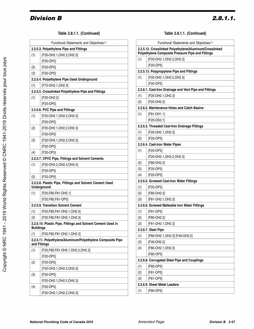
Division B 2.8.1.1.
Table 2.8.1.1. (Continued)
Functional Statements and Objectives(1)
2.2.5.3. Polyethylene Pipe and Fittings
[F20-OH2.1,OH2.2,OH2.3](1)
[F20-OP5]
(2) [F20-OP5]
(3) [F20-OP5]
2.2.5.4. Polyethylene Pipe Used Underground
(1) [F72-OH2.1,OH2.3]
2.2.5.5. Crosslinked Polyethylene Pipe and Fittings
[F20-OH2.2](1)
[F20-OP5]
2.2.5.6. PVC Pipe and Fittings
[F20-OH2.1,OH2.2,OH2.3](1)
[F20-OP5]
[F20-OH2.1,OH2.2,OH2.3](2)
[F20-OP5]
[F20-OH2.1,OH2.2,OH2.3](3)
[F20-OP5]
(4) [F20-OP5]
2.2.5.7. CPVC Pipe, Fittings and Solvent Cements
[F20-OH2.2,OH2.3,OH2.4](1)
[F20-OP5]
(2) [F20-OP5]
2.2.5.8. Plastic Pipe, Fittings and Solvent Cement UsedUnderground
[F20,F80,F81-OH2.1](1)
[F20,F80,F81-OP5]
2.2.5.9. Transition Solvent Cement
(1) [F20,F80,F81-OH2.1,OH2.3]
(2) [F20,F80,F81-OH2.1,OH2.3]
2.2.5.10. Plastic Pipe, Fittings and Solvent Cement Used inBuildings
(1) [F20,F80,F81-OH2.1,OH2.3]
2.2.5.11. Polyethylene/Aluminum/Polyethylene Composite Pipeand Fittings
[F20,F80,F81-OH2.1,OH2.2,OH2.3](1)
[F20-OP5]
[F20-OP5](2)
[F20-OH2.1,OH2.2,OH2.3]
[F20-OP5](3)
[F20-OH2.1,OH2.2,OH2.3]
[F20-OP5](4)
[F20-OH2.1,OH2.2,OH2.3]
Table 2.8.1.1. (Continued)
Functional Statements and Objectives(1)
2.2.5.12. Crosslinked Polyethylene/Aluminum/CrosslinkedPolyethylene Composite Pressure Pipe and Fittings
[F20-OH2.1,OH2.2,OH2.3](1)
[F20-OP5]
2.2.5.13. Polypropylene Pipe and Fittings
[F20-OH2.1,OH2.2,OH2.3](1)
[F20-OP5]
2.2.6.1. Cast-Iron Drainage and Vent Pipe and Fittings
(1) [F20-OH2.1,OH2.3]
(2) [F20-OH2.2]
2.2.6.2. Maintenance Holes and Catch Basins
[F81-OH1.1](1)
[F20-OS3.1]
2.2.6.3. Threaded Cast-Iron Drainage Fittings
(1) [F20-OH2.1,OH2.3]
(2) [F20-OP5]
2.2.6.4. Cast-Iron Water Pipes
[F20-OP5](1)
[F20-OH2.1,OH2.2,OH2.3]
(2) [F80-OH2.2]
(3) [F20-OP5]
(4) [F20-OP5]
2.2.6.5. Screwed Cast-Iron Water Fittings
(1) [F20-OP5]
(2) [F80-OH2.2]
(3) [F81-OH2.1,OH2.3]
2.2.6.6. Screwed Malleable Iron Water Fittings
(1) [F81-OP5]
(2) [F80-OH2.2]
(3) [F81-OH2.1,OH2.3]
2.2.6.7. Steel Pipe
(1) [F80-OH2.1,OH2.3] [F46-OH2.2]
(3) [F46-OH2.2]
[F80-OH2.1,OH2.3](4)
[F80-OP5]
2.2.6.8. Corrugated Steel Pipe and Couplings
(1) [F80-OP5]
(2) [F81-OP5]
(3) [F81-OP5]
2.2.6.9. Sheet Metal Leaders
(1) [F80-OP5]
National Plumbing Code of Canada 2015 Amended Page Division B 2-57
Cop
yrig
ht ©
NR
C 1
941
- 201
9 W
orld
Rig
hts
Res
erve
d ©
CN
RC
194
1-20
19 D
roits
rése
rvés
pou
r tou
s pa
ys

2.8.1.1. Division B
Table 2.8.1.1. (Continued)
Functional Statements and Objectives(1)
2.2.6.10. Stainless Steel Pipe
[F80-OH2.1] Applies to drainage systems and ventingsystems.[F46,F80-OH2.2] Applies to water systems.
(1)
[F80-OP5]
[F80-OH2.1] Applies to drainage systems and ventingsystems.[F46,F80-OH2.2] Applies to water systems.
(2)
[F80-OP5]
2.2.6.11. Stainless Steel Butt Weld Pipe Fittings
[F80-OH2.1] Applies to drainage systems and ventingsystems.[F46,F80-OH2.2] Applies to water systems.
(1)
[F80-OP5]
[F80-OH2.1] Applies to drainage systems and ventingsystems.[F46,F80-OH2.2] Applies to water systems.
(2)
[F80-OP5]
2.2.6.12. Stainless Steel Pipe Flanges
[F80-OH2.1] Applies to drainage systems and ventingsystems.[F46,F80-OH2.2] Applies to water systems.
(1)
[F80-OP5]
[F80-OH2.1] Applies to drainage systems and ventingsystems.[F46,F80-OH2.2] Applies to water systems.
(2)
[F80-OP5]
2.2.6.13. Stainless Steel Threaded Fittings
[F80-OH2.1] Applies to drainage systems and ventingsystems.[F46,F80-OH2.2] Applies to water systems.
(1)
[F20-OP5]
[F80-OH2.1] Applies to drainage systems and ventingsystems.[F46,F80-OH2.2] Applies to water systems.
(2)
[F20-OP5]
2.2.6.14. Stainless Steel Tube
[F46-OH2.2](1)
[F80-OP5]
[F46-OH2.2](2)
[F80-OP5]
2.2.6.15. Stainless Steel Pipe and Tube
(1) [F80-OH2.1,OH2.2,OH2.3]
2.2.7.1. Copper and Brass Pipe
[F80-OH2.1,OH2.3] Applies to drainage systems and ventingsystems.[F46-OH2.2] Applies to water systems.
(1)
[F80-OP5]
Table 2.8.1.1. (Continued)
Functional Statements and Objectives(1)
[F80-OH2.1,OH2.3] Applies to drainage systems and ventingsystems.[F46-OH2.2] Applies to water systems.
(2)
[F80-OP5]
2.2.7.2. Brass or Bronze Pipe Flanges and Flanged Fittings
[F80-OH2.1,OH2.3] Applies to drainage systems and ventingsystems.[F46-OH2.2] Applies to water systems.
(1)
[F80-OP5]
2.2.7.3. Brass or Bronze Threaded Water Fittings
(1) [F80-OP5]
(2) [F80-OH2.1,OH2.3]
2.2.7.4. Copper Tube
[F80-OH2.1,OH2.3] Applies to drainage systems and ventingsystems.[F46-OH2.2] Applies to water systems.
(1)
[F80-OP5]
(2) [F80-OH2.1,OH2.2,OH2.3]
(3) [F80-OH2.1,OH2.4]
2.2.7.5. Solder-Joint Drainage Fittings
(1) [F80-OH2.1,OH2.4]
(2) [F20-OP5]
2.2.7.6. Solder-Joint Water Fittings
(1) [F20-OP5]
(2) [F20-OP5]
2.2.7.7. Flared-Joint Fittings for Copper Water Systems
(1) [F20-OP5]
(2) [F20-OP5]
2.2.7.8. Lead Waste Pipe and Fittings
(1) [F46,F20-OH2.2,OH2.3]
(2) [F81-OH2.1,OH2.3,OH2.4]
2.2.8.1. Pipes and Fittings
[F80,F81-OH2.1](1)
[F80,F81-OS3.2,OS3.4]
2.2.9.1. Cement Mortar
[F80-OP5](1)
[F80-OH2.1,OH2.3]
2.2.9.2. Solders and Fluxes
[F80-OP5](1)
[F80-OH2.1,OH2.3]
(2) [F46-OH2.2]
(3) [F80-OH2.1,OH2.3]
(4) [F20,F80,F81-OH2.1,OH2.3]
2.2.10.1. Brass Floor Flanges
(1) [F80-OH2.1]
2-58 Division B Amended Page National Plumbing Code of Canada 2015
Cop
yrig
ht ©
NR
C 1
941
- 201
9 W
orld
Rig
hts
Res
erve
d ©
CN
RC
194
1-20
19 D
roits
rése
rvés
pou
r tou
s pa
ys

Division B 2.8.1.1.
Table 2.8.1.1. (Continued)
Functional Statements and Objectives(1)
2.2.10.2. Screws, Bolts, Nuts and Washers
(1) [F80-OH2.1,OH2.3]
2.2.10.3. Cleanout Fittings
(1) [F80-OH2.1,OH2.3] Applies to drainage systems.[F46-OH2.2] Applies to water systems.
(2) [F80-OH2.1]
2.2.10.4. Mechanical Couplings
(1) [F80-OP5]
(2) [F80-OH2.1,OH2.3]
2.2.10.5. Saddle Hubs
[F81-OH2.1,OH2.3](1)
[F81-OP5]
2.2.10.6. Supply and Waste Fittings
(1) [F80-OP5]
(2) [F131-OE1.2]
[F30-OS3.1](3)
[F31-OS3.2]
(4) [F131-OE1.2]
(5) [F131-OE1.2]
(6) [F80-OH2.1,OH2.3]
2.2.10.7. Water Temperature Control
(1) [F80-OS3.2]
(3) (a) [F31-OS3.2](b) [F30-OS3.1]
(4) [F31-OS3.2]
2.2.10.8. Direct Flush Valves
(c) and (d) [F80-OH2.1] [F81-OH2.4](1)
(a) and (b) [F80,F81-OP5]
2.2.10.9. Drinking Fountain Bubblers
(1) [F40,F46-OH2.4]
(2) [F41,F46-OH2.2]
(3) [F41,F46-OH2.2]
2.2.10.10. Back-Siphonage Preventers and Backflow Preventers
(1) [F46-OH2.2]
(2) [F46-OH2.2]
2.2.10.11. Relief Valves
[F31-OS3.2](1)
[F31-OP5]
2.2.10.12. Reducing Valves
(1) [F81-OP5]
2.2.10.13. Solar Domestic Hot Water
[F81-OS3.2]
[F46-OH2.2]
(1)
[F80,F81-OP5]
Table 2.8.1.1. (Continued)
Functional Statements and Objectives(1)
2.2.10.14. Vent Pipe Flashing
(1) [F80,F81-OP5]
(2) [F80,F81-OP5]
2.2.10.15. Water Hammer Arresters
(1) [F20,F80-OP5]
2.2.10.16. Air Admittance Valves
(1) [F81-OH1.1]
2.2.10.17. Water Treatment Systems
[F46-OH2.2]
[F30-OS3.1][F46,F70-OS3.4]
(1)
[F20,F30-OS2.1]
2.3.2.1. Caulked Lead Drainage Joints
(1) [F80-OH2.1,OH2.3]
(2) [F80-OH2.1]
(3) [F81-OH2.1]
(4) [F81-OH2.1]
2.3.2.2. Wiped Joints
[F80,F81-OH2.1](1)
[F80,F81-OP5]
(2) [F80,F81-OH2.1,OH2.2,OH2.3]
(3) [F80,F81-OH2.1,OH2.2,OH2.3]
2.3.2.3. Screwed Joints
(1) [F80,F81-OH2.1,OH2.2,OH2.3]
(2) [F70-OH2.2]
2.3.2.4. Soldered Joints
(1) [F20,F81-OH2.1,OH2.2,OH2.3]
2.3.2.5. Flared Joints
[F20,F81-OH2.1,OH2.2,OH2.3](1)
[F20,F81-OP5]
[F20,F81-OH2.1,OH2.2,OH2.3](2)
[F20,F81-OP5]
2.3.2.6. Mechanical Joints
[F20-OH2.1,OH2.2,OH2.3](1)
[F20-OP5]
2.3.2.7. Cold-Caulked Joints
[F20,F81-OH1.1] Applies to bell and spigot joints in ventingsystems.
[F20,F81-OH2.1,OH2.3] Applies to bell and spigot joints indrainage systems or venting systems.
(1)
[F20,F81-OP5]
[F20,F81-OH1.1]
[F20,F81-OP5]
(2)
[F20,F81-OH2.1,OH2.2,OH2.3]
National Plumbing Code of Canada 2015 Amended Page Division B 2-59
Cop
yrig
ht ©
NR
C 1
941
- 201
9 W
orld
Rig
hts
Res
erve
d ©
CN
RC
194
1-20
19 D
roits
rése
rvés
pou
r tou
s pa
ys

2.8.1.1. Division B
Table 2.8.1.1. (Continued)
Functional Statements and Objectives(1)
(3) [F20-OH2.1,OH2.3]
2.3.2.8. Stainless Steel Welded Joints
(1) [F20,F81-OH2.1,OH2.2,OH2.3]
(2) [F20,F81-OH2.1,OH2.2,OH2.3]
2.3.3.1. Drilled and Tapped Joints
[F81-OH1.1](1)
[F20,F81-OH2.2,OH2.3]
2.3.3.2. Extracted Tees
[F81-OH2.1,OH2.3](1)
[F20-OP5]
2.3.3.3. Prohibition of Welding of Pipes and Fittings
[F20-OH1.1](1)
[F20-OH2.1,OH2.2,OH2.3]
[F80-OH2.2](2)
[F80-OP5]
2.3.3.4. Unions and Slip Joints
[F81-OH1.1](1)
[F81-OH2.1,OH2.3]
[F81-OH1.1](2)
[F81-OH2.1,OH2.3]
2.3.3.5. Increaser or Reducer
[F81-OH1.1](1)
[F70,F80-OH2.2]
2.3.3.6. Dissimilar Materials
[F80-OH1.1]
[F80-OP5]
(1)
[F80-OH2.1]
2.3.3.7. Connection of Roof Drain to Leader
(1) [F21,F81-OP5]
2.3.3.8. Connection of Floor Outlet Fixtures
(1) [F80-OH2.1,OH2.3]
(2) [F80-OH2.1]
[F20-OH2.1](4)
[F20-OS3.1]
(5) [F81-OH2.1]
(6) [F21-OH2.1]
2.3.3.9. Expansion and Contraction
[F21-OH1.1]
[F21-OH2.1]
(1)
[F21-OP5]
2.3.3.10. Copper Tube
[F20-OH1.1](1)
[F20-OP5]
Table 2.8.1.1. (Continued)
Functional Statements and Objectives(1)
2.3.3.11. Indirect Connections
(1) [F81-OH2.2,OH2.4]
(2) [F81-OH2.2,OH2.4]
2.3.3.12. Copper Joints Used Underground
(1) [F20,F80-OP5]
(2) [F20,F80-OP5]
2.3.4.1. Capability of Support
[F20-OH2.1,OH2.4]
[F20-OS3.1]
(1)
[F20-OP5]
[F20-OH2.1,OH2.3](2)
[F20-OS3.1]
[F20-OS3.1](3)
[F20-OH2.1,OH2.3]
2.3.4.2. Independence of Support
[F20-OS3.1]
[F20-OH2.1,OH2.3]
(1)
[F20-OP5]
2.3.4.3. Insulation of Support
[F80-OH2.1,OH2.3]
[F80-OS3.1]
(1)
[F80-OP5]
[F80-OH2.1,OH2.3]
[F80-OS3.1]
(2)
[F80-OP5]
2.3.4.4. Support for Vertical Piping
[F20-OH2.1](1)
[F20-OS3.1]
[F20-OH2.1]
[F20-OS3.1]
(2)
[F20-OP5]
2.3.4.5. Support for Horizontal Piping
[F20-OS3.1]
[F20-OH2.1,OH2.3]
(1)
[F20-OP5]
[F20-OS3.1]
[F20-OH2.1]
(2)
[F20-OP5]
[F20-OP5]
[F20,F81-OS3.1]
(3)
[F20-OH2.1]
[F81-OP5](4)
[F81-OS3.1]
2-60 Division B National Plumbing Code of Canada 2015
Cop
yrig
ht ©
NR
C 1
941
- 201
9 W
orld
Rig
hts
Res
erve
d ©
CN
RC
194
1-20
19 D
roits
rése
rvés
pou
r tou
s pa
ys

Division B 2.8.1.1.
Table 2.8.1.1. (Continued)
Functional Statements and Objectives(1)
[F20,F21-OP5]
[F20-OS3.1]
(5)
[F20-OH2.1]
[F20-OP5]
[F20-OS3.1]
(6)
[F20-OH2.1]
2.3.4.6. Support for Underground Horizontal Piping
[F20-OP5](1)
[F81-OH2.1]
2.3.4.7. Support for Vent Pipe above a Roof
[F81-OS3.1](1)
[F81-OP5]
2.3.5.1. Protection of Piping
(a) [F81-OP5](1)
[F81-OH2.1,OH2.3]
2.3.5.2. Isolation from Loads
[F81-OH2.1,OH2.3](1)
[F81-OP5]
2.3.5.3. Protection Against Freezing
[F81-OP5](1)
[F81-OH2.1,OH2.3]
2.3.5.4. Protection from Mechanical Damage
[F81-OH2.1,OH2.3](1)
[F81-OP5]
2.3.5.5. Protection from Condensation
(1) [F81-OP5]
2.3.6.1. Tests and Inspection of Drainage or Venting Systems
[F81-OH2.1,OH2.3] Applies to drainage systems.(1)
[F81-OH1.1] Applies to venting systems.
[F81-OH1.1] Applies to venting systems.(2)
[F81-OH2.1,OH2.3] Applies to drainage systems.
[F81-OH1.1](3)
[F81-OH2.1,OH2.3]
[F81-OH1.1] Applies to venting systems.(4)
[F81-OH2.1,OH2.3] Applies to drainage systems.
(5) [F81-OH2.1,OH2.3]
2.3.6.2. Tests of Pipes in Drainage Systems
[F81-OH2.1,OH2.3](1)
[F81-OP5]
(2) [F81-OH2.1]
2.3.6.3. Tests of Venting Systems
(1) [F81-OH1.1]
Table 2.8.1.1. (Continued)
Functional Statements and Objectives(1)
2.3.6.4. Water Pressure Tests
[F81-OH1.1](1)
[F81-OH2.1,OH2.3]
[F81-OH1.1](2)
[F81-OH2.1,OH2.3]
2.3.6.5. Air Pressure Tests
[F81-OH1.1](1)
[F81-OH2.1,OH2.3]
2.3.6.6. Final Tests
[F81-OH1.1](1)
[F81-OH2.1,OH2.3]
[F81-OH1.1](2)
[F81-OH2.1,OH2.3]
2.3.6.7. Ball Tests
(1) [F81-OH2.1,OH2.3]
(2) [F81-OH2.1,OH2.3]
2.3.7.1. Application of Tests
(1) [F81-OP5]
(3) [F81-OP5]
(4) [F81-OP5]
2.3.7.2. Pressure Tests of Potable Water Systems
(1) [F20-OP5]
(2) [F20,F81-OS3.1]
2.3.7.3. Water Pressure Tests
(1) [F81-OP5]
(2) [F70-OH2.2]
2.4.2.1. Connections to Sanitary Drainage Systems
[F72-OH2.1] Applies to fixtures that are directly connectedto sanitary drainage systems.
(a) [F81-OH2.2]
(b) [F81-OH2.2]
(c) [F81-OH2.1]
(d) [F81-OH2.1]
(1)
(e) [F81-OH2.1]
(2) [F81-OH1.1]
(3) [F81-OH1.1]
(4) [F81-OH1.1]
(5) [F81-OH1.1]
2.4.2.2. Connection of Overflows from Rainwater Tanks
(1) [F81-OH2.2]
2.4.2.3. Direct Connections
(1) [F81-OH2.2]
(2) [F81-OH2.1,OH2.4]
National Plumbing Code of Canada 2015 Amended Page Division B 2-61
Cop
yrig
ht ©
NR
C 1
941
- 201
9 W
orld
Rig
hts
Res
erve
d ©
CN
RC
194
1-20
19 D
roits
rése
rvés
pou
r tou
s pa
ys

2.8.1.1. Division B
Table 2.8.1.1. (Continued)
Functional Statements and Objectives(1)
(3) [F81-OH2.4]
2.4.3.1. Urinals
(1) [F81-OH2.4]
2.4.3.2. Restricted Locations of Indirect Connections and Traps
(1) [F81-OH2.1,OH2.4]
2.4.3.3. Equipment Restrictions Upstream of Grease Interceptors
(1) [F81-OH2.1]
2.4.3.4. Fixtures Located in Chemical Storage Locations
[F81-OS1.1](1)
[F43-OH5]
2.4.3.5. Macerating Toilet Systems
(1) [F72-OH2.1]
2.4.3.6. Drains Serving Elevator Pits
(a) [F62-OP5](1)
(b) [F81-OH2.1]
2.4.4.1. Sewage Treatment
(1) [F81-OH2.1]
2.4.4.2. Cooling of Hot Water or Sewage
(1) [F81-OH2.1]
2.4.4.3. Interceptors
(1) [F81-OH2.1]
[F81-OS1.1](2)
[F43-OH5]
(3) [F81-OH2.1]
(4) [F81-OH2.1]
2.4.4.4. Neutralizing and Dilution Tanks
(1) [F80-OS3.4]
[F43-OH5](2)
[F80-OH2.1]
2.4.5.1. Traps for Sanitary Drainage Systems
(1) [F81-OH1.1]
[F81-OH1.1](6)
[F81-OP5]
2.4.5.2. Traps for Storm Drainage Systems
(1) [F81-OH1.1]
(2) [F81-OH1.1]
(3) [F81-OP5]
2.4.5.3. Connection of Subsoil Drainage Pipe to a SanitaryDrainage System
[F81-OH2.1](1)
[F81-OH1.1]
2.4.5.4. Location and Cleanout for Building Traps
(1) [F81-OH2.1]
Table 2.8.1.1. (Continued)
Functional Statements and Objectives(1)
2.4.5.5. Trap Seals
(1) [F81-OH1.1]
2.4.6.1. Separate Systems
(1) [F81-OH2.1]
(2) [F81-OH2.1]
(3) [F81-OH1.1]
2.4.6.2. Location of Soil-or-Waste Pipes
(1) [F81-OH2.2]
2.4.6.3. Sumps or Tanks
(1) [F81-OH2.1]
[F81-OH2.1] Applies to the watertightness of sumps or tanks.(2)
[F81-OH1.1]
(3) [F81-OH2.1]
(4) [F81-OH2.1]
(5) [F81-OH2.1]
(6) [F81-OH2.1]
(7) [F81-OH2.1]
2.4.6.4. Protection from Backflow
[F81-OH2.1](1)
[F81-OH1.1]
[F81-OH1.1](2)
[F81-OH2.1]
(3) [F81-OH2.1]
(6) [F81-OH2.1]
2.4.6.5. Mobile Home Sewer Service
(1) [F81-OH2.1]
2.4.7.1. Cleanouts for Drainage Systems
(1) [F81-OH2.1]
(2) [F81-OH2.1]
(3) [F81-OH2.1]
(4) [F81-OH2.1]
(5) [F81-OH2.1]
(6) [F81-OH2.1]
(7) [F81-OH2.1]
(8) [F81-OH2.1]
(9) [F81-OH2.1]
[F82-OH2.1](10)
[F82-OP5]
[F81-OH2.1](11)
[F81-OP5]
2.4.7.2. Size and Spacing of Cleanouts
(1) [F81-OH2.1]
(2) [F81-OH2.1]
2-62 Division B Amended Page National Plumbing Code of Canada 2015
Cop
yrig
ht ©
NR
C 1
941
- 201
9 W
orld
Rig
hts
Res
erve
d ©
CN
RC
194
1-20
19 D
roits
rése
rvés
pou
r tou
s pa
ys

Division B 2.8.1.1.
Table 2.8.1.1. (Continued)
Functional Statements and Objectives(1)
(3) [F81-OH2.1]
(4) [F81-OH2.1]
(5) [F81-OH2.1]
(6) [F81-OH2.1]
2.4.7.3. Manholes
(1) [F20-OS3.1]
(a) and (c) [F81-OH1.1]
(a) and (c) [F81-OS1.1]
(2)
(b) [F20-OS3.1]
(3) [F30-OS3.1]
(4) [F81-OH2.1]
2.4.7.4. Location of Cleanouts
(1) [F81-OH2.1]
(a) [F81-OS3.1](2)
(b) [F81-OH2.1]
(3) [F81-OH2.1]
[F81-OH2.1] Applies to drainage piping.(4)
[F81-OH1.1] Applies to vent piping.
(5) [F43-OH2.1]
2.4.8.1. Minimum Slope
(1) [F81-OH2.1]
2.4.8.2. Length of Fixture Outlet Pipes
(1) [F81-OH1.1]
2.4.9.1. No Reduction in Size
[F81-OH2.1](1)
[F81-OH1.1]
2.4.9.2. Serving Water Closets
(1) [F81-OH2.1]
(2) [F81-OH2.1]
(3) [F81-OH2.1]
(4) [F81-OH2.1]
2.4.9.3. Size of Fixture Outlet Pipes
(1) [F81-OH2.1]
(2) [F81-OH2.1]
[F81-OP5](3)
[F81-OH1.1]
2.4.9.4. Size of Building Drain and Building Sewer
(1) [F81-OH2.1]
2.4.9.5. Offset in Leaders
(1) [F81-OH2.1,OH2.3]
(2) [F81-OH2.1]
2.4.10.1. Total Load on a Pipe
(1) [F81-OH2.1]
Table 2.8.1.1. (Continued)
Functional Statements and Objectives(1)
2.4.10.2. Hydraulic Loads for Fixtures
(2) [F81-OH2.1]
2.4.10.3. Hydraulic Loads from Fixtures with a Continuous Flow
(1) [F81-OH2.1]
(2) [F81-OH2.1]
2.4.10.4. Hydraulic Loads from Roofs or Paved Surfaces
[F81-OP5](1)
[F20,F81-OS2.1]
[F20,F81-OP5]
(a), (d) and (e) [F41,F81-OH2.4]
(2)
(b) and (c) [F20,F81-OS2.1]
[F20,F81-OP5](3)
[F20,F81-OS2.1]
[F21,F81-OP5](4)
[F20,F81-OS2.1]
2.4.10.5. Conversion of Fixture Units to Litres
(1) [F81-OH2.1]
2.4.10.6. Hydraulic Loads to Soil-or-Waste Pipes
(1) [F72-OH2.1,OH2.3]
(2) [F72-OH2.1,OH2.3]
2.4.10.7. Hydraulic Loads on Branches
(1) [F72-OH2.1,OH2.3]
2.4.10.8. Hydraulic Loads on Sanitary Building Drains or Sewers
(1) [F81-OH2.1,OH2.3]
2.4.10.9. Hydraulic Loads on Storm or Combined Building Drainsor Sewers
(1) [F81-OH2.1,OH2.3]
2.4.10.10. Hydraulic Loads to Roof Gutters
(1) [F81-OP5]
2.4.10.11. Hydraulic Loads on Leaders
(1) [F81-OP5]
2.4.10.12. Hydraulic Loads from Fixtures with a Semi-continuousFlow
(1) [F81-OP5]
2.4.10.13. Design of Storm Sewers
(1) [F81-OH2.1]
2.5.1.1. Venting for Traps
(1) [F81-OH1.1]
(2) [F81-OH1.1]
2.5.2.1. Wet Venting
(1) [F81-OH1.1]
2.5.3.1. Circuit Venting
(1) [F40,F81-OH1.1]
(2) [F40,F81-OH1.1]
National Plumbing Code of Canada 2015 Amended Page Division B 2-63
Cop
yrig
ht ©
NR
C 1
941
- 201
9 W
orld
Rig
hts
Res
erve
d ©
CN
RC
194
1-20
19 D
roits
rése
rvés
pou
r tou
s pa
ys

2.8.1.1. Division B
Table 2.8.1.1. (Continued)
Functional Statements and Objectives(1)
(3) [F40,F81-OH1.1]
(4) [F40,F81-OH1.1]
(5) [F40,F81-OH1.1]
(6) [F40,F81-OH1.1]
(7) [F40,F81-OH1.1]
(8) [F40,F81-OH1.1]
(9) [F40,F81-OH1.1]
(10) [F40,F81-OH1.1]
(11) [F40,F81-OH1.1]
2.5.4.1. Stack Vents
(1) [F40,F81-OH1.1]
2.5.4.2. Vent Stacks
(1) [F40,F81-OH1.1]
(3) [F40,F81-OH1.1]
(4) [F40,F81-OH1.1]
2.5.4.3. Yoke Vents
(1) [F40,F81-OH1.1]
(2) [F40,F81-OH1.1]
(3) [F40,F81-OH1.1]
(4) [F40,F81-OH1.1]
2.5.4.4. Offset Relief Vents
(1) [F40,F81-OH1.1]
2.5.4.5. Fixtures Draining into Vent Pipes
(1) [F40,F81-OH1.1]
2.5.5.1. Venting of Sewage Sumps
(1) [F40,F81-OH1.1]
2.5.5.2. Venting of Oil Interceptors
[F40,F81-OS1.1]
[F72,F81-OH2.1,OH2.3]
(1)
[F40,F81-OH1.1]
[F40,F81-OS1.1](2)
[F40,F81-OH1.1]
(3) [F40,F81-OS1.1]
(4) [F40,F81-OS1.1]
(5) [F40,F81-OS1.1]
2.5.5.3. Venting of Drain Piping and Dilution Tanks for CorrosiveWaste
(1) [F80,F81-OS3.4]
2.5.5.4. Fresh Air Inlets
(1) [F81-OH1.1]
2.5.5.5. Provision for Future Installations
[F81-OH1.1] Applies to venting systems.(1)
[F81-OH2.1,OH2.3] Applies to drainage systems.
Table 2.8.1.1. (Continued)
Functional Statements and Objectives(1)
(2) [F40,F81-OH1.1]
2.5.6.1. Drainage of Vent Pipes
[F81-OH1.1](1)
[F81-OS1.1]
2.5.6.2. Vent Pipe Connections
(1) [F81-OH1.1]
(2) [F81-OH1.1]
(3) [F40,F81-OH1.1]
2.5.6.3. Location of Vent Pipes
(1) [F81-OH1.1]
(2) [F81-OH2.1,OH2.3]
(3) [F81-OH1.1]
(4) [F40,F81-OH1.1]
2.5.6.4. Connection of Vents above Fixtures Served
(1) [F81-OH1.1]
(2) [F81-OH1.1]
2.5.6.5. Terminals
(1) [F81-OH1.1]
(2) [F81-OH1.1]
(3) [F81-OH1.1]
(4) [F81-OH1.1]
(5) [F81-OH1.1]
(6) [F81-OH1.1]
2.5.7.1. General
(1) [F81-OH1.1]
2.5.7.2. Size Restriction
(1) [F81-OH1.1]
(2) [F81-OH1.1]
2.5.7.3. Additional Circuit Vents and Relief Vents
(1) [F81-OH1.1]
(2) [F81-OH1.1]
2.5.7.4. Offset Relief Vents
(1) [F81-OH1.1]
2.5.7.5. Yoke Vents
(1) [F81-OH1.1]
2.5.7.6. Vent Pipes for Manholes
(1) [F81-OH2.1]
2.5.7.7. Vents for Sewage Sumps, Dilution Tanks and MaceratingToilet Systems
(1) [F81-OH2.1]
(2) [F81-OH2.1]
(3) [F81-OH1.1]
2-64 Division B Amended Page National Plumbing Code of Canada 2015
Cop
yrig
ht ©
NR
C 1
941
- 201
9 W
orld
Rig
hts
Res
erve
d ©
CN
RC
194
1-20
19 D
roits
rése
rvés
pou
r tou
s pa
ys

Division B 2.8.1.1.
Table 2.8.1.1. (Continued)
Functional Statements and Objectives(1)
2.5.8.1. Hydraulic Loads Draining to Wet Vents
(1) [F81-OH1.1]
2.5.8.2. Individual Vents and Dual Vents
(1) [F81-OH1.1]
2.5.8.3. Branch Vents, Vent Headers, Continuous Vents andCircuit Vents
(1) [F81-OH1.1]
2.5.8.4. Vent Stacks or Stack Vents
(3) [F81-OH1.1]
(4) [F81-OH1.1]
2.5.9.2. Air Admittance Valves
(1) [F40,F81-OH1.1]
(2) [F40,F81-OH1.1]
2.5.9.3. Installation Conditions
(1) [F40,F81-OH1.1]
(2) [F40,F81-OH1.1]
(3) [F40,F81-OH1.1]
(4) [F40,F81-OH1.1]
(5) [F40,F81-OH1.1]
2.6.1.1. Design
(1) [F31-OS3.2]
(2) [F71-OH2.3]
2.6.1.2. Drainage
(1) [F81-OP5]
2.6.1.3. Shut-off Valves
(1) [F81-OP5]
(2) [F81-OP5]
(3) [F81-OP5]
(4) [F81-OP5]
(5) [F70,F72-OH2.1,OH2.3]
(6) [F70,F72-OH2.1,OH2.3]
(7) [F70,F81-OH2.1,OH2.3]
2.6.1.4. Protection for Exterior Water Supply
(1) [F81-OP5]
2.6.1.5. Check Valves
(1) [F20,F81-OP5]
2.6.1.6. Flushing Devices
(1) [F72-OH2.1]
(2) [F72-OH2.1]
(3) [F130-OE1.2]
(4) [F81-OH2.1]
(5) [F130-OE1.2]
Table 2.8.1.1. (Continued)
Functional Statements and Objectives(1)
2.6.1.7. Relief Valves
(1) [F31,F81-OS3.2]
(2) [F81-OS3.1,OS3.2]
(4) (a) [F31-OS3.2] [F81-OS1.1](b) [F81-OS3.1,OS3.2]
[F31-OS3.2](5)
(b) [F81-OH2.2] Applies to the size of air breaks.
(6) [F31-OS3.2]
(7) [F31-OS3.2]
(8) [F81-OS3.2]
(9) [F81-OP5]
(10) [F81-OP5]
2.6.1.8. Solar Domestic Hot Water Systems
[F31-OS3.2] [F81-OS3.4](1)
[F70-OH2.2]
2.6.1.9. Water Hammer
[F20,F81-OS3.2](1)
[F20,F81-OP5]
2.6.1.10. Mobile Home Water Service
(1) [F71,F70,F46-OH2.2,OH2.3]
2.6.1.11. Thermal Expansion
(1) [F20,F81,F46-OP5]
2.6.1.12. Service Water Heaters
(1) [F40-OS3.4]
2.6.2.1. Connection of Systems
(1) [F70,F81,F46-OH2.1,OH2.2,OH2.3]
(2) [F70,F81,F46-OH2.1,OH2.2,OH2.3]
(3) [F70,F81,F82-OH2.2,OH2.3]
2.6.2.2. Back-Siphonage
(1) [F70,F81,F46-OH2.1,OH2.2,OH2.3]
(2) [F70,F81,F46-OH2.1,OH2.2,OH2.3]
2.6.2.3. Backflow Caused by Back Pressure
(1) [F70,F81,F46-OH2.1,OH2.2,OH2.3]
(2) [F70,F81,F46-OH2.1,OH2.2,OH2.3]
(3) [F70,F81,F46-OH2.1,OH2.2,OH2.3]
2.6.2.4. Backflow from Fire Protection Systems
(2) [F46,F70,F81-OH2.1,OH2.2,OH2.3]
(3) [F46,F70,F81-OH2.1,OH2.2,OH2.3]
(4) [F46,F70,F81-OH2.1,OH2.2,OH2.3]
2.6.2.5. Separation of Water Supply Systems
(1) [F70,F81,F46-OH2.1,OH2.2,OH2.3]
2.6.2.6. Premise Isolation
(1) [F70,F81,F82-OH2.1,OH2.2,OH2.3]
National Plumbing Code of Canada 2015 Amended Page Division B 2-65
Cop
yrig
ht ©
NR
C 1
941
- 201
9 W
orld
Rig
hts
Res
erve
d ©
CN
RC
194
1-20
19 D
roits
rése
rvés
pou
r tou
s pa
ys

2.8.1.1. Division B
Table 2.8.1.1. (Continued)
Functional Statements and Objectives(1)
2.6.2.7. Hose Bibb
(1) [F70,F81,F46-OH2.1,OH2.2,OH2.3]
2.6.2.8. Cleaning of Systems
(1) [F70,F81,F46-OH2.1,OH2.2,OH2.3]
2.6.2.9. Air Gap
(1) [F70,F81,F46-OH2.1,OH2.2,OH2.3]
(2) [F70,F81,F46-OH2.1,OH2.2,OH2.3]
2.6.2.10. Vacuum Breakers
(2) [F70,F81,F46-OH2.1,OH2.2,OH2.3]
(3) [F70,F81,F46-OH2.1,OH2.2,OH2.3]
(4) [F70,F81,F46-OH2.1,OH2.2,OH2.3]
2.6.2.11. Tank-Type Water Closets
(1) [F70,F81,F46-OH2.1,OH2.2,OH2.3]
2.6.2.12. Backflow Preventers
(1) [F70,F81,F46-OH2.1,OH2.2,OH2.3]
2.6.3.1. Design, Fabrication and Installation
(1) [F71,F72-OH2.1,OH2.3]
(2) [F72-OH2.1] [F70-OH2.2] [F71-OH2.3]
[F81-OS1.4]
[F70,F71-OH2.1,OH2.3]
(3)
[F81-OP5]
2.6.3.2. Hydraulic Load
(1) [F71,F72-OH2.1,OH2.3]
(2) [F71,F72-OH2.1,OH2.3]
(3) [F71,F72-OH2.1,OH2.3]
(4) [F81-OH2.1,OH2.2]
2.6.3.3. Static Pressure
(1) [F81-OS3.2]
2.6.3.4. Size
(1) [F71,F72-OH2.1,OH2.3]
(2) [F71,F72-OH2.1,OH2.3]
(3) [F71,F72-OH2.1,OH2.3]
(4) [F81-OH2.3]
(5) [F71,F72-OH2.1,OH2.3]
2.6.3.5. Velocity
[F81-OH2.1,OH2.3]
[F81-OP5]
(1)
[F81-OS3.1]
2.7.1.1. Not Permitted
(1) [F46-OH2.2]
2.7.2.1. Markings Required
(1) [F46-OH2.2]
Table 2.8.1.1. (Continued)
Functional Statements and Objectives(1)
2.7.3.1. Pipes
(1) [F46-OH2.2]
2.7.3.2. Outlets
(1) [F46-OH2.2]
2.7.4.1. Non-potable Water System Design
(1) [F81-OH2.1]
(2) [F82-OH2.2]
Notes to Table 2.8.1.1.:(1) See Parts 2 and 3 of Division A.
2-66 Division B National Plumbing Code of Canada 2015
Cop
yrig
ht ©
NR
C 1
941
- 201
9 W
orld
Rig
hts
Res
erve
d ©
CN
RC
194
1-20
19 D
roits
rése
rvés
pou
r tou
s pa
ys

Division B
Notes to Part 2Plumbing Systems
A-2.1.2.1.(2) Combined Building Drains. Combined building drains may have proven acceptable onthe basis of past performance in some localities and their acceptance under this Code may be warranted.
A-2.1.2.4.(1) Service Piping. The layout as shown in Figure A-2.1.2.4.(1)(c) may require special legalarrangements in some jurisdictions to ensure that access can be provided to all parts of the service pipes.
These Notes are included for explanatory purposes only and do not form part of the requirements. The numberthat introduces each Note corresponds to the applicable requirement in this Part.The figures are schematic only; they depict various parts of the plumbing system but do not include details. For anexplanation of the symbols and abbreviations used in the figures, refer to the list provided at the end of the Code.
National Plumbing Code of Canada 2015 Division B 2-67
Cop
yrig
ht ©
NR
C 1
941
- 201
9 W
orld
Rig
hts
Res
erve
d ©
CN
RC
194
1-20
19 D
roits
rése
rvés
pou
r tou
s pa
ys

A-2.1.2.4.(1) Division B
property line
(a) Permitted
(b) Permitted
(c) Permitted
water service pipe
property line
building sewer
public water main public sewer
public sewerpublic water main
building sewer
water servicepipe
water service pipebuilding sewer
public water main public sewer
water service pipe building sewer
public water main public sewer
(d) Not permitted
Semi-detached Row housing
Row housingSemi-detached
EG01129A
Figure A-2.1.2.4.(1)Service Piping
2-68 Division B National Plumbing Code of Canada 2015
Cop
yrig
ht ©
NR
C 1
941
- 201
9 W
orld
Rig
hts
Res
erve
d ©
CN
RC
194
1-20
19 D
roits
rése
rvés
pou
r tou
s pa
ys

Division B A-2.2.3.1.(1) and (3)
A-2.2.2.3.(3) Shower Drainage (Plan View).
EG01130B
Figure A-2.2.2.3.(3)Shower Drainage (Plan View)
A-2.2.2.4.(1) Concealed Overflows. The use of concealed overflows does not preclude the use ofa standing waste.
A-2.2.3.1.(1) and (3) Trap Seal Depth and Trap Connections.
This joint may be a slip joint but not a gasket union. (NPC Article 2.3.3.4.)
[NPC Clause 2.2.3.1.(3)(a)] EG01131B
Because these joints are upstream of the trap weir, they may be slip joints or gasket unions. (NPC Article 2.3.3.4.)
cleanout plug
outlet
trap seal depth
trap weir
inlet
trap dip
Figure A-2.2.3.1.(1) and (3)Trap Seal Depth and Trap Connections
National Plumbing Code of Canada 2015 Division B 2-69
Cop
yrig
ht ©
NR
C 1
941
- 201
9 W
orld
Rig
hts
Res
erve
d ©
CN
RC
194
1-20
19 D
roits
rése
rvés
pou
r tou
s pa
ys

A-2.2.3.1.(4) Division B
A-2.2.3.1.(4) Prohibited Traps. Except for an S-trap standard, the S trap shown in Figure A-2.2.3.1.(4)(b)is prohibited by Clause 2.5.6.3.(1)(b), which limits the fall on fixture drains. Crown vented traps shown inFigure A-2.2.3.1.(4)(c) are prohibited by Clause 2.5.6.3.(1)(a), which requires that the distance from the trapweir to the vent be not less than twice the size of the fixture drain.
(a) Bell trap (b) S trap
crown vent
(c) Crown vented trap
EG01132A
Figure A-2.2.3.1.(4)Prohibited Traps
A-2.2.3.2.(3) Grease Interceptors. CSA B481.4, “Maintenance of Grease Interceptors,” is considered torepresent good practice regarding procedures for the maintenance of grease interceptors.
A-2.2.4.1. T Fittings in Drainage Systems. The use of a cross fitting in a drainage system isprohibited, but such fitting may be used in a venting system to connect 4 vent pipes. In a drainage system, a Tfitting can only be used as shown in Figure A-2.2.4.1.(a), and cannot be used as shown in Figure A-2.2.4.1.(b)because the T or cross fitting would change the direction of flow in the drainage system.
vent pipe
horizontal soil-or-waste pipe
(a) Permitted
vent pipe vent pipe
(c) Not permitted
EG01133B
soil-or-waste pipe
soil-or-waste pipe
(b) Not permitted
Figure A-2.2.4.1.T Fittings in Drainage Systems
2-70 Division B National Plumbing Code of Canada 2015
Cop
yrig
ht ©
NR
C 1
941
- 201
9 W
orld
Rig
hts
Res
erve
d ©
CN
RC
194
1-20
19 D
roits
rése
rvés
pou
r tou
s pa
ys

Division B A-2.2.5., 2.2.6. and 2.2.7.
A-2.2.4.2. Sanitary T Fittings in Drainage Systems. A sanitary T fitting may be used to changethe direction of flow in a drainage system from horizontal to vertical, but may not be used to change thedirection of flow in a nominally horizontal drainage system. A combination Y and 1/8th bend fitting may alsobe used as shown in Figure A-2.2.4.2.(b).
(c) Not permitted (use combination Y and 1/8 bend)
EG01134A
Figure A-2.2.4.2.Sanitary T Fittings in Drainage Systems
A-2.2.5., 2.2.6. and 2.2.7. Pipe and Fitting Applications.
National Plumbing Code of Canada 2015 Division B 2-71
Cop
yrig
ht ©
NR
C 1
941
- 201
9 W
orld
Rig
hts
Res
erve
d ©
CN
RC
194
1-20
19 D
roits
rése
rvés
pou
r tou
s pa
ys

A-2.2.5., 2.2.6. and 2.2.7. Division BTa
bleA-
2.2.5.,2
.2.6.a
nd2.2.7.
Summaryof
Pipe
andFitting
Applications
Form
ingPa
rtof
NoteA-2.2.5.,2
.2.6.a
nd2.2.7.
Use
ofPiping
andFitting
s(1)
Drainag
eSy
stem
VentingSy
stem
PotableWater
System
Above-grou
ndUnd
ergrou
ndType
sof
Piping
andFitting
sStan
dard
Referenc
esNP
CReferen
ces
Above-
grou
ndinside
building
Und
er-
grou
ndun
der
building
Building
sewe
rAb
ove-
grou
ndUnd
er-
grou
ndCold
Hot
Und
erbu
ilding
Outside
building
Con
cretese
werp
ipe
CSA
Serie
sA2
57
Sewe
r,storm
drainan
dcu
lvert
CSA
A257
.12.2.5.1.
NP(
2)P
NN
NN
NN
Reinforce
dcu
lvert,
storm
drainan
dse
wer
CSA
A257
.22.2.5.1.
NP(
2)P
NN
NN
NN
Vitrifie
dclay
pipe
CSA
A60.1-M
2.2.5.2.
NP
PN
PN
NN
N
Polye
thyle
newa
terp
ipean
dtubing
Serie
s16
0size
swith
compres
sion
fittin
gsCSA
B137
.12.2.5.3.
NN
NN
NN
NP(
3)P
(3)
Serie
s50
,75,
100an
d12
52.2.5.3.
NN
NN
NN
NN
N
Polye
thyle
ne(PE)
plas
ticpipe
(SDR-PR)b
ased
onou
tside
diam
eter
ASTM
F71
42.2.5.4.(1)
NP
PN
PN
NN
N
Polyv
inyl
chlorid
e(PVC
)pres
sure
fittin
gsCSA
B137
.22.2.5.6.
NN
NN
NP
(4)(5)
NP
P
Polyviny
lchloride(PVC
)water
pipe
Dim
ension
ratio
s(D
R)or
stan
dard
dimen
sion
ratio
s(SDR)1
4,17
,18,
21,2
5an
d26
CSA
B137
.32.2.5.6.
NN
NN
NP
NP(
6)P
(6)
Sche
dule
40in
size
sfro
m½
inch
to2½
inch
esinclus
ively
Sche
dule
80in
size
sfro
m½
inch
to6inch
esinclu
sively
PVCfittin
gs,S
ched
ule40
ASTM
D24
662.2.5.6.(2)
NN
NN
NP
(4)(5)
NN
N
PVCfittin
gs,S
ched
ule80
ASTM
D24
672.2.5.6.(2)
NN
NN
NP
(4)(5)
NP
P
2-72 Division B Amended Page National Plumbing Code of Canada 2015
Cop
yrig
ht ©
NR
C 1
941
- 201
9 W
orld
Rig
hts
Res
erve
d ©
CN
RC
194
1-20
19 D
roits
rése
rvés
pou
r tou
s pa
ys

Division B A-2.2.5., 2.2.6. and 2.2.7.
TableA-
2.2.5.,2
.2.6.a
nd2.2.7.
(Con
tinue
d)
Use
ofPiping
andFitting
s(1)
Drainag
eSy
stem
VentingSy
stem
PotableWater
System
Above-grou
ndUnd
ergrou
ndType
sof
Piping
andFitting
sStan
dard
Referenc
esNP
CReferen
ces
Above-
grou
ndinside
building
Und
er-
grou
ndun
der
building
Building
sewe
rAb
ove-
grou
ndUnd
er-
grou
ndCold
Hot
Und
erbu
ilding
Outside
building
Crosslinke
dpo
lyethylen
e(PEX
)pres
sure
tubing
CSA
B137
.52.2.5.5.
NN
NN
NP
(4)(5)
P(4)(5)
PP
Chlorinated
polyv
inyl
chlorid
e(C
PVC)w
ater
pipe
CSA
B137
.62.2.5.7.
NN
NN
NP
(4)(5)(7)
P(4)(5)(7)
P(7)
P(7)
Polye
thyle
ne/aluminum
/po
lyethyle
ne(PE/AL
/PE)
pres
sure
pipe
CSA
B137
.92.2.5.11
.N
NN
NN
P(4)(5)
NP
P
Crosslinke
dpo
lyethyle
ne/aluminum
/cros
slink
edpo
lyethyle
ne(PEX
/AL/PE
X)pres
sure
pipe
CSA
B137
.10
2.2.5.12
.N
NN
NN
P(4)(5)
P(4)(5)
PP
Polyprop
ylene
(PP-R)p
ressure
pipe
CSA
B137
.11
2.2.5.13
.N
NN
NN
P(4)(5)
P(4)(5)
PP
Plas
ticse
werp
ipePS
≥32
0kP
aCA
N/CSA
-B18
2.1
2.2.5.8.
NP
PN
NN
NN
N
CAN/CSA
-B18
1.1
2.2.5.8.
P(4)(5)
PP
P(4)(5)
PN
NN
NAc
rylonitrile-butad
iene
-styrene
(ABS
)DWVpipe
2.2.5.9.
ABSSc
hedu
le40
DWVpipe
with
ace
llularc
ore
ASTM
F62
82.2.5.8.
P(4)(5)
PP
P(4)(5)
PN
NN
N
CAN/CSA
-B18
1.2
2.2.5.8.
P(4)(5)
PP
P(4)(5)
PN
NN
NPo
lyvinyl
chlorid
e(PVC
)DWV
pipe
2.2.5.9.
PVC
sewe
rpipe(PSM
type
)≤35
-SDR
CAN/CSA
-B18
2.2
2.2.5.8.
NP
PN
PN
NN
N
Profile
polyviny
lchloride(PVC
)se
werp
ipePS
≥32
0kP
aCA
N/CSA
-B18
2.4
2.2.5.8.(1)(f)
NP
PN
PN
NN
N
Profile
polye
thylen
ese
werp
ipe
PS≥32
0kP
aCA
N/CSA
-B18
2.6
2.2.5.8.(1)(g
)N
PP
NP
NN
NN
Polyo
lefin
labo
ratory
draina
gesystem
sCA
N/CSA
-B18
1.3
2.2.8.1.
P(4)(5)
PP
P(4)(5)
PN
NN
N
Cas
t-ironso
ilpipe
CSA
B70
2.2.6.1.
PP
PP
PN
NN
N
National Plumbing Code of Canada 2015 Amended Page Division B 2-73
Cop
yrig
ht ©
NR
C 1
941
- 201
9 W
orld
Rig
hts
Res
erve
d ©
CN
RC
194
1-20
19 D
roits
rése
rvés
pou
r tou
s pa
ys

A-2.2.5., 2.2.6. and 2.2.7. Division BTa
bleA-
2.2.5.,2
.2.6.a
nd2.2.7.
(Con
tinue
d)
Use
ofPiping
andFitting
s(1)
Drainag
eSy
stem
VentingSy
stem
PotableWater
System
Above-grou
ndUnd
ergrou
ndType
sof
Piping
andFitting
sStan
dard
Referenc
esNP
CReferen
ces
Above-
grou
ndinside
building
Und
er-
grou
ndun
der
building
Building
sewe
rAb
ove-
grou
ndUnd
er-
grou
ndCold
Hot
Und
erbu
ilding
Outside
building
Cas
t-ironwa
terp
ipe
ANSI/AWWAC15
1/A2
1.51
(Duc
tileiro
n)2.2.6.4.
PP
PP
PP
PP
P
Cas
t-ironscrewe
dfittin
gsAS
MEB1
6.4(C
astiron)
2.2.6.5.
NN
NN
NP
PP
P
ASMEB1
6.3(M
alleab
leiro
n)2.2.6.6.
NN
NN
NP
PP
P
Stainles
sstee
lpipe
ASTM
A31
2/A31
2M2.2.6.10
.P
PP
PP
PP
PP
Stainles
sstee
ltub
eAS
TMA
269
2.2.6.14
.N
NN
NN
PP
PP
Welde
dan
dse
amless
stee
lga
lvanize
dpipe
ASTM
A53
/A53
M2.2.6.7.
PN
NP
NP
(8)
P(8)
P(8)
P(8)
Corruga
tedstee
lgalvanize
dpipe
CSA
G40
12.2.6.8.
NN
P(9)
NN
NN
NN
Shee
tmetal
pipe
(10)
—2.2.6.9.
NN
NN
NN
NN
N
Cop
pera
ndbras
spipe
ASTM
B42
(Cop
per)
2.2.7.1.
PP
PP
PP
PP
P
ASTM
B43
(Red
bras
s)2.2.7.1.
PP
PP
PP
PP
P
Bras
sor
bron
zethread
edwa
ter
fittin
gsAS
ME
B16.15
2.2.7.3.
NN
NN
NP
PP
P
Cop
pertub
e
Type
sKan
dLha
rdtempe
rAS
TMB
882.2.7.4.
PP
PP
PP
PN
N
Type
sKan
dLso
fttempe
rAS
TMB
882.2.7.4.
NN
NN
NP
PP
P
Type
Mha
rdtempe
rAS
TMB
882.2.7.4.
PN
NP
NP
PN
N
Type
Mso
fttempe
rAS
TMB
882.2.7.4.
NN
NN
NN
NN
N
Type
DWV
ASTM
B30
62.2.7.4.
P(11)
NN
P(11)
NN
NN
N
Solder-jo
intd
rainag
efittin
gsAS
ME
B16.23
2.2.7.5.
PP
PP
PN
NN
N
ASME
B16.29
Solder-jo
intw
ater
fittin
gsAS
ME
B16.18
2.2.7.6.
NN
NP
PP
PP
P
ASME
B16.22
Lead
wastepipe
—2.2.7.8.
P(4)(5)
PN
P(4)(5)
PN
NN
N
N=Not
perm
itted
P=Pe
rmitted
2-74 Division B Amended Page National Plumbing Code of Canada 2015
Cop
yrig
ht ©
NR
C 1
941
- 201
9 W
orld
Rig
hts
Res
erve
d ©
CN
RC
194
1-20
19 D
roits
rése
rvés
pou
r tou
s pa
ys

Division B A-2.2.5., 2.2.6. and 2.2.7.
TableA-
2.2.5.,2
.2.6.a
nd2.2.7.
(Con
tinue
d)
Notesto
TableA-
2.2.5.,2
.2.6.a
nd2.2.7.:
(1)
Whe
refirestop
sarepierce
dby
pipe
s,theintegrity
ofthefirestop
mus
tbemaintaine
d.(2)
Gas
kette
djoints
requ
ired.
(3)
Perm
itted
only
forw
ater
servicepipe
.(4)
Com
bustible
piping
inno
ncom
bustible
cons
tructionissu
bjec
ttotherequ
iremen
tsof
Senten
ce3.1.5.19
.(1)o
fDivision
Bof
theNBC
.(5)
Com
bustible
piping
that
pene
tratesafirese
paratio
nissu
bjec
ttotherequ
iremen
tsin
Articles3.1.9.1.,9
.10.9.6.
and9.10
.9.7.o
fDivision
Bof
theNB
C.(6)
Not
perm
itted
inho
twater
system
s.(7)
Not
toexce
edde
sign
tempe
rature
andde
sign
pres
sure
stated
inSe
nten
ce2.2.5.7.(2).
(8)
Perm
itted
onlyin
buildings
ofindu
stria
loccup
ancy
asde
scrib
edin
theNB
C,or
forthe
repa
irof
existin
gga
lvanize
dstee
lpipingsystem
s.(9)
Perm
itted
unde
rgroun
don
lyin
astorm
draina
gesystem
.(10)
Perm
itted
only
fora
nexternal
lead
er.
(11)
Not
perm
itted
forthe
fixture
drainor
vent
below
theflo
odlevelrim
ofaflu
sh-valve
-ope
ratedurinal.
National Plumbing Code of Canada 2015 Amended Page Division B 2-75
Cop
yrig
ht ©
NR
C 1
941
- 201
9 W
orld
Rig
hts
Res
erve
d ©
CN
RC
194
1-20
19 D
roits
rése
rvés
pou
r tou
s pa
ys

A-2.2.5.1.(3) Division B
A-2.2.5.1.(3) Concrete Fittings. Concrete fittings fabricated on the site from lengths of pipe mayhave proven acceptable on the basis of past performance in some localities and their acceptance under thisCode may be warranted.
A-2.2.5.4.(1) Polyethylene Pipe Used Underground. Joints within the high-density polyethylenepipe (HDPE) shall be heat-fused according to the manufacturer's instructions. Joints between HDPE pipes andother materials shall be made with a suitable hubless coupling.
A-2.2.5.5.(1) Crosslinked Polyethylene Pipe and Fittings. There are some special installationrequirements for the use of crosslinked polyethylene pipe and its associated fittings. Reference should,therefore, be made to the installation information in CSA B137.5, “Crosslinked Polyethylene (PEX) TubingSystems for Pressure Applications.”
A-2.2.5.8. to 2.2.5.10. Solvent Cement. CSA B137.6, “Chlorinated Polyvinylchloride(CPVC) Pipe, Tubing, and Fittings for Hot- and Cold-Water Distribution Systems,” CAN/CSA-B181.1,“Acrylonitrile-Butadiene-Styrene (ABS) Drain, Waste, and Vent Pipe and Pipe Fittings,” andCAN/CSA-B181.2, “Polyvinylchloride (PVC) and Chlorinated Polyvinylchloride (CPVC) Drain, Waste, andVent Pipe and Pipe Fittings,” reference ASTM D 3138, “Solvent Cements for Transition Joints BetweenAcrylonitrile-Butadiene-Styrene (ABS) and Poly(Vinyl Chloride) (PVC) Non-Pressure Piping Components,”which specifies the colour of the solvent cement. PVC cement shall be grey, ABS cement shall be yellow,CPVC cement shall be clear and transition cement shall be white. The standard colour allows Code users toreadily determine if the correct solvent cement has been used. It should be noted that a transition cementis not an all-purpose cement.
A-2.2.5.11.(1) Polyethylene/Aluminum/Polyethylene Composite Pipe and Fittings. Thereare some special installation requirements for the use of polyethylene/aluminum/polyethylene compositepipe and fittings. Reference should, therefore, be made to the installation information in CSA B137.9,“Polyethylene/Aluminum/Polyethylene (PE-AL-PE) Composite Pressure-Pipe Systems.”
A-2.2.5.12.(1) Crosslinked Polyethylene/Aluminum/Crosslinked Polyethylene CompositePressure Pipe and Fittings. There are some special installation requirements for the use of crosslinkedpolyethylene/aluminum/crosslinked polyethylene composite pipe and fittings. Reference should, therefore,be made to the installation information in CSA B137.10, “Crosslinked Polyethylene/Aluminum/CrosslinkedPolyethylene (PEX-AL-PEX) Composite Pressure-Pipe Systems.”
A-2.2.5.13.(1) Polypropylene Pipe and Fittings. There are some special installation requirements forthe use of polypropylene pipe and fittings. Reference should, therefore, be made to the installation informationin CSA B137.11, “Polypropylene (PP-R) Pipe and Fittings for Pressure Applications.”
A-2.2.6.7.(3) Galvanized Steel Pipe. The use of galvanized steel pipe and fittings in a waterdistribution system may have proven acceptable on the basis of past performance in some localities andits acceptance under this Code may be warranted.
A-2.2.10.5.(1) Saddle Hubs or Fittings. Saddle hubs or fittings may have proven acceptable on thebasis of past performance in some localities and their acceptance under this Code may be warranted.
A-2.2.10.6.(2) Supply Fittings and Individual Shower Heads. Flow restriction devices withinsupply fittings should not be removed.
Due to the low flow rate of public lavatory faucets, design consideration should be given to the wait time forhot water to be delivered to each fixture.
A-2.2.10.6.(3) Automatic Compensating Valves. When replacing a shower head, the appropriateshower valve with a suitable compensating feature matching the flow rate should be chosen to decreasethe possibility that users will suffer thermal shock. The water flow rate of automatic compensating mixingvalves can be found in ASSE 1016/ASME 112.1016/CSA B125.16, “Performance Requirements for AutomaticCompensating Valves for Individual Showers and Tub/Shower Combinations.”
A-2.2.10.6.(4) and (5) Automatic Shut-off of Water Flow. Examples of water shut-off devicesinclude occupant sensors and self-closing valves.
2-76 Division B National Plumbing Code of Canada 2015
Cop
yrig
ht ©
NR
C 1
941
- 201
9 W
orld
Rig
hts
Res
erve
d ©
CN
RC
194
1-20
19 D
roits
rése
rvés
pou
r tou
s pa
ys
Division B A-2.3.2.6.(1)
A-2.2.10.7. Hot Water Temperature. Hot water delivered at 60°C will severely burn human skin in1 to 5 seconds. At 49°C, the time for a full thickness scald burn to occur is 10 minutes. Children, the elderlyand persons with disabilities are particularly at risk of scald burns. Compliance with Article 2.2.10.7. willreduce the risk of scalding in showers and bathtubs, and reduce the risk of thermal shock from wall-mountedshower heads.
These requirements apply to all occupancies, not just residential occupancies.
The water outlet temperature at other fixtures, such as lavatories, sinks, laundry trays or bidets, is not addressedby Article 2.2.10.7., but a scald risk may exist at such fixtures nonetheless.
A-2.2.10.9.(3) Bubblers. Bubblers installed on other than drinking fountains may have proven acceptableon the basis of past performance in some localities and their acceptance under this Code may be warranted.
A-2.2.10.16.(1) Air Admittance Valve. An air admittance valve is a device that is closed by gravityand seals the vent terminal at zero differential pressure (no flow conditions) and under positive internalpressures. The valve allows air to enter the drainage system without the use of a vent extended to outside airand prevents trap siphonage.
The material of the diaphragm can be damaged by exposure to acidic or corrosive fumes in the ambientatmosphere; therefore, air admittance valves should not be installed in locations where there is a potential forexposure to such fumes.
A-2.3.2.6.(1) Mechanical Joints. Storm sewer blockage can cause mechanical joints at the base ofleaders to fail, which results in flooding. The failure occurs because the cleanout joints at the base of therainwater leaders are not able to withstand the water column pressure. To avoid such failures, it is necessaryto ensure that storm water systems installed using mechanical joints be braced and/or restrained at theends of branches, changes in direction and elevation, at dead ends and at other locations as required by themanufacturer to prevent the separation of joints due to internal pressure, mechanical stress or seismic events.Care should be taken to replace cleanouts properly after maintenance or testing.
National Plumbing Code of Canada 2015 Division B 2-77
Cop
yrig
ht ©
NR
C 1
941
- 201
9 W
orld
Rig
hts
Res
erve
d ©
CN
RC
194
1-20
19 D
roits
rése
rvés
pou
r tou
s pa
ys

A-2.3.3.9. Division B
A-2.3.3.9. Linear Expansion.
4
5
6
7
891011
1213
EG00661CTemperature change, °C
1. polyethylene (1404)2. PEX & PP-R3. polyethylene (2305-3306)4. ABS5. CPVC6. PVC (DWV)7. PVC (rigid)8. PE/AL/PE & PEX/AL/PEX9. copper10. stainless steel11. concrete12. mild steel and cast iron13. brick
Line
ar e
xpan
sion
of 1
0 m
of p
ipe,
mm
Figure A-2.3.3.9.Linear Expansion
Example: To determine the expansion of 20 m of ABS pipe for a temperature change from 10°C to 60°C.Temperature change = 60 – 10 = 50°C,Enter the chart at 50°C, read up to ABS line, and then across to the mm scale = 47 mm/10 m of pipe,∴ change in length of 20 m of pipe =
A-2.3.3.9.(1) Expansion and Contraction. Expansion and contraction in piping systems may beaccommodated in a number of ways including, but not limited to, piping design and layout, material selection,and the inclusion of expansion joints.
2-78 Division B Amended Page National Plumbing Code of Canada 2015
Cop
yrig
ht ©
NR
C 1
941
- 201
9 W
orld
Rig
hts
Res
erve
d ©
CN
RC
194
1-20
19 D
roits
rése
rvés
pou
r tou
s pa
ys
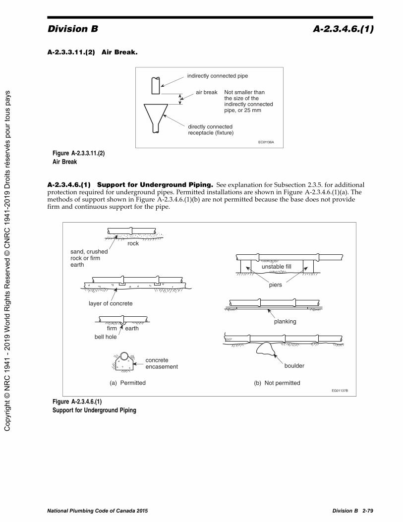
Division B A-2.3.4.6.(1)
A-2.3.3.11.(2) Air Break.
indirectly connected pipe
air break
directly connectedreceptacle (fixture)
Not smaller thanthe size of theindirectly connectedpipe, or 25 mm
EC01136A
Figure A-2.3.3.11.(2)Air Break
A-2.3.4.6.(1) Support for Underground Piping. See explanation for Subsection 2.3.5. for additionalprotection required for underground pipes. Permitted installations are shown in Figure A-2.3.4.6.(1)(a). Themethods of support shown in Figure A-2.3.4.6.(1)(b) are not permitted because the base does not providefirm and continuous support for the pipe.
EG01137B
Figure A-2.3.4.6.(1)Support for Underground Piping
National Plumbing Code of Canada 2015 Division B 2-79
Cop
yrig
ht ©
NR
C 1
941
- 201
9 W
orld
Rig
hts
Res
erve
d ©
CN
RC
194
1-20
19 D
roits
rése
rvés
pou
r tou
s pa
ys

A-2.3.5.1.(1)(a) Division B
A-2.3.5.1.(1)(a) Backfilling of Pipe Trench. Stronger pipes may be required in deep fill or underdriveways, parking lots, etc., and compaction for the full depth of the trench may be necessary.
Backfill complying withClause 2.3.5.1.(1)(a)
This part of the trench should be as narrow as proper jointing and backfill will permit.
300mm
EG01138B
Figure A-2.3.5.1.(1)(a)Backfilling of Pipe Trench
A-2.3.5.3. Protection of Piping Against Freezing. The TIAC “Mechanical Insulation Best PracticesGuide” is a comprehensive source of information on the selection, installation and proper use of thermalinsulation materials. (Note that Section 4 of this Guide is not included in the scope of this Note as it containsinformation on proprietary products, which are not within the mandate of the Code.)
A-2.3.7.2.(2) Pressure-Testing of Potable Water Systems. The plastic piping manufacturershould be consulted to determine the appropriateness of using air to pressure-test the piping system.
A-2.4.2.1.(1)(a)(ii) and (e)(vi) Indirect Connections. See Sentence 2.4.5.1.(4) for trappingrequirements for indirectly connected fixtures.
See Sentence 2.4.7.1.(9) for cleanouts on drip pipes for food receptacles or display cases.
2-80 Division B Amended Page National Plumbing Code of Canada 2015
Cop
yrig
ht ©
NR
C 1
941
- 201
9 W
orld
Rig
hts
Res
erve
d ©
CN
RC
194
1-20
19 D
roits
rése
rvés
pou
r tou
s pa
ys

Division B A-2.4.2.1.(2)
sanitary building drain
air break
COgreaseinterceptor
sink glas
s fil
ler
ice
crea
m s
coop
sco
ffee
drip
s
frig
.fo
odco
mpa
rtm
ent
food display
CO
air break
discharge from relief valve
soil-or-waste stack DF
DF
DF
leaderclear-water waste
air break
installationof backwatervalverecommended
RD
extended to outside air when fixtures on 3 or more storeys are connected
stormbuildingdrain
CO
trap for leader (serves receptaclesdraining indirect connections)
FD
max. height300 mm
EG01140B
Figure A-2.4.2.1.(1)(a)(ii) and (e)(vi)Indirect Connections
A-2.4.2.1.(2) Soil-or-Waste Pipe Connections.
1.5 m
branch or building drain
(b) Connection to nominally horizontal soil-or-waste pipe
(a) Connection to nominally horizontal offset
(a)
soil-or-waste stack
1.5 m
no soil-or-waste pipe to connect in this area
no soil-or-waste pipe to connect in this area
soil-or-waste stack
soil-or-waste stack
horizontal offset
EG01141A
Figure A-2.4.2.1.(2)Soil-or-Waste Pipe Connections
National Plumbing Code of Canada 2015 Division B 2-81
Cop
yrig
ht ©
NR
C 1
941
- 201
9 W
orld
Rig
hts
Res
erve
d ©
CN
RC
194
1-20
19 D
roits
rése
rvés
pou
r tou
s pa
ys

A-2.4.2.1.(4) Division B
A-2.4.2.1.(4) Suds Pressure Zones. High sudsing detergents used in clothes washers produce sudsthat tend to disrupt the venting action of venting systems and can also spread through the lower portions ofmulti-storey drainage systems. The more turbulence, the greater the suds. One solution that avoids the creationof suds pressure zones involves connecting the suds-producing stack downstream of all other stacks andincreasing the size of the horizontal building drain to achieve a greater flow of air and water. Using streamlinedfittings, such as wyes, tends to reduce suds formation. Check valves or backwater valves in fixture outlet pipeshave also been used to correct problem installations.
nominally horizontal offset
EG00675A
clothes washer
clothes washer
40 x stack size or 2.44 m (whichever is less)
10 x stack size
40 x stack size
10 x stack size
40 x stack size or 2.44 m (whichever is less)
see Sentence 2.4.2.1.(5)
40 x branch or sanitarybuilding drain size
branch or sanitary building drain
10 x branch or sanitary building drain size
= detergent suds zone
Figure A-2.4.2.1.(4)Suds Pressure Zones
A-2.4.3.3.(1) Waste with Organic Solids. Equipment such as garbage grinders and potato peelersproduces waste with organic solids. These devices reduce most waste into small-sized particles that will floweasily through the drainage system. However, if they are located upstream of the interceptor, the particlescould block the interceptor.
A-2.4.4.3.(1) Grease Interceptors. Grease interceptors may be required when it is considered thatthe discharge of fats, oil or grease may impair the drainage system. Information on the design and sizing ofgrease interceptors can be found in ASPE 2012, “Plumbing Engineering Design Handbook, Volume 4, Chapter8, Grease Interceptors.”
2-82 Division B National Plumbing Code of Canada 2015
Cop
yrig
ht ©
NR
C 1
941
- 201
9 W
orld
Rig
hts
Res
erve
d ©
CN
RC
194
1-20
19 D
roits
rése
rvés
pou
r tou
s pa
ys

Division B A-2.4.5.1.(2)
A-2.4.4.4.(1) Bio-hazardous Waste. Chemically loaded and bio-hazardous wastes can be dangerousto private or public sewer systems and hazardous to people. The treatment of corrosive and acid waste ismandated by this Code. The treatment of chemically loaded effluents is usually regulated by sewage collectingand treatment authorities. The treatment of bio-hazardous waste should follow “good engineering practice,”such as that described in Laboratory Biosafety Guidelines published by Health Canada. It should be notedthat bio-hazardous waste disposal systems require specific engineering expertise and remain outside thescope of this Code.
A-2.4.5.1.(2) Trapping of Sinks and Laundry Trays.
sink with 3 compartments
The fitting and trap are one size larger than the largest waste outlet pipe.(1)
(a)
(c)
sink sink
(b)
sink
sink with 2 compartments
EG01142B
developed length(2)
developed length(2)
developed length(2)
developed length(2)
Figure A-2.4.5.1.(2)Trapping of Sinks and Laundry TraysNotes to Figure A-2.4.5.1.(2):(1) See Sentence 2.4.9.3.(2).(2) The developed length of the fixture outlet pipe shall not exceed 1 200 mm. See Article 2.4.8.2.
National Plumbing Code of Canada 2015 Division B 2-83
Cop
yrig
ht ©
NR
C 1
941
- 201
9 W
orld
Rig
hts
Res
erve
d ©
CN
RC
194
1-20
19 D
roits
rése
rvés
pou
r tou
s pa
ys

A-2.4.5.1.(3) Division B
A-2.4.5.1.(3) Single Traps for Fixture Groups.
vent not required for floor drains if the installation conforms to NPC Sentence 2.5.1.1.(3)
(b) Floor drains and shower drains
fixture outlet pipe
(a) Laboratory sinks or washing machines
floor or shower drains
fixture drain
vent fixture outlet pipes
CO
CO
EG01143A
Figure A-2.4.5.1.(3)Single Traps for Fixture Groups
A-2.4.5.1.(5) Location of Trap or Interceptor. An interceptor that replaces a trap must be ventedin the same way as the trap it replaces. (See Note A-2.4.2.1.(1)(a)(ii) and (e)(vi).) Where an interceptor otherthan an oil interceptor serves a group of fixtures requiring more than one trap, each fixture must be properlytrapped and vented. (See Article 2.5.5.2. for venting of oil interceptors.)
minimum 38-mm water seal vent
developed length of fixture outlet pipe not to exceed 1 200 mm [see NPC Sentence 2.4.8.2.(1)]
interceptor
EG01144B
Figure A-2.4.5.1.(5)Location of Trap or Interceptor
A-2.4.5.2.(1) Untrapped Leader. When an untrapped leader drains to a combined building sewer,clearance requirements are the same as for vent terminals. (See also Note A-2.5.6.5.(4).)
2-84 Division B National Plumbing Code of Canada 2015
Cop
yrig
ht ©
NR
C 1
941
- 201
9 W
orld
Rig
hts
Res
erve
d ©
CN
RC
194
1-20
19 D
roits
rése
rvés
pou
r tou
s pa
ys

Division B A-2.4.5.4.(1)
A-2.4.5.3.(1) Subsoil Drainage Connections. This Code does not regulate the installation of subsoildrainage pipes, but does regulate the connection of such pipes to the plumbing system. The intent of thisArticle is to place a trap between the subsoil drainage pipe and the sanitary drainage system. The cleanoutmust be installed in accordance with Sentence 2.4.7.1.(2). A trap or sump may be provided specifically forthe subsoil drains, or advantage may be taken of the trap of a floor drain or storm water sump as shownin Figure A-2.4.5.3.(1).
sanitary building drain
may require backwater valves [see NPC Sentence 2.4.6.4.(2)]
may require backwater valves [see NPC Sentence 2.4.6.4.(2)]
separate trap (with cleanout) for subsoil drains
(a) Connections to sanitary drainage system (plan view)
trapped floor drain acts as trap and cleanout for subsoil drains
may require backwater valves [see NPC Sentence 2.4.6.4.(2)]
soil-or-waste stack
EG01145B (b) Trapped sump
Figure A-2.4.5.3.(1)Subsoil Drainage Connections
A-2.4.5.4.(1) Location of Building Traps.
size of fresh air inlet not to be less than 4 inches
EG01146A
Figure A-2.4.5.4.(1)Location of Building Traps
National Plumbing Code of Canada 2015 Division B 2-85
Cop
yrig
ht ©
NR
C 1
941
- 201
9 W
orld
Rig
hts
Res
erve
d ©
CN
RC
194
1-20
19 D
roits
rése
rvés
pou
r tou
s pa
ys

A-2.4.5.5.(1) Division B
A-2.4.5.5.(1) Maintaining Trap Seals. Periodic manual replenishment of the water in a trap isconsidered to be an equally effective means of maintaining the trap seal in floor drains in residences. Underpressure differential conditions, special measures are necessary to maintain trap seals.
EG01147A
Figure A-2.4.5.5.(1)Maintaining Trap Seals
A-2.4.6.3. Arrangement of Piping at Sump. In most installations, controls will be installed inconjunction with a float to automatically empty the sump. If such controls are not provided, the capacity of thesump should equal the maximum inflow to the sump that is expected to occur during any 24 h period.
G
pump or ejector
sump
union
approved pressure pipe and fittings
check valve shut-off valve
to building sewer (downstream of building trap if one is installed)
see NPC Article 2.5.7.7. for sizing of required vent if sump receives sewage
watertight and airtight cover to be provided if sump receives sewage
sub-drainage system
Figure A-2.4.6.3.Arrangement of Piping at Sump
2-86 Division B National Plumbing Code of Canada 2015
Cop
yrig
ht ©
NR
C 1
941
- 201
9 W
orld
Rig
hts
Res
erve
d ©
CN
RC
194
1-20
19 D
roits
rése
rvés
pou
r tou
s pa
ys

Division B A-2.4.7.1.(6)
A-2.4.6.4.(1) Backwater Valve or Gate Valve. The installation of a backwater valve or a gate valvein a building drain or in a building sewer may have proven acceptable on the basis of past performance insome localities, and their acceptance under this Code may be warranted.
A-2.4.6.4.(6) Protection from Backflow Caused by Surcharge. These requirements are intendedto apply when in the opinion of the authority having jurisdiction there is danger of backup from a public sewer.
gate valve or backwater valve on individual fixture drains
Either of these arrangements may be used. [see NPC Sentence 2.4.6.4.(5)] gate valve or
backwater valve on branch
removable cap if backflow protection required for floor drain [see NPC Sentence 2.4.6.4.(4)]
Subsoil drains connect to the upstream side of a trapped backwater valve or a separate trap and backwater valve. [see NPC Sentence 2.4.6.4.(6)]
soil-or-waste stack
subsoil drains
G
Figure A-2.4.6.4.(6)Protection from Backflow Caused by Surcharge
A-2.4.7.1.(6) Cleanouts for Drainage Systems. To accommodate the limitations of sewer cleaningequipment, the cleanout should be located as close as possible to the exterior wall of the building, either insideor outside, and be accessible for sewer cleaning equipment.
National Plumbing Code of Canada 2015 Division B 2-87
Cop
yrig
ht ©
NR
C 1
941
- 201
9 W
orld
Rig
hts
Res
erve
d ©
CN
RC
194
1-20
19 D
roits
rése
rvés
pou
r tou
s pa
ys

A-2.4.7.1.(9) Division B
A-2.4.7.1.(9) Cleanouts for Food Receptacle Drip Pipes.
indirect connection(1)
sanitary drainage systemEG01150B
food receptacle
drip pipe
CO
Figure A-2.4.7.1.(9)Cleanouts for Food Receptacle Drip PipesNote to Figure A-2.4.7.1.(9):(1) See Article 2.4.2.1.
A-2.4.7.1.(10) Cleanouts for Fixture Drains. A trap cleanout plug cannot be used as a cleanoutfor a fixture drain.
A-2.4.8.1.(1) Minimum Slope. Although slopes below 1 in 100 are permitted for pipes over 4 inches,they should be used only where necessary. Steeper slopes and higher velocities will help to keep pipes clean bymoving heavier solids that might tend to clog the pipes.
2-88 Division B National Plumbing Code of Canada 2015
Cop
yrig
ht ©
NR
C 1
941
- 201
9 W
orld
Rig
hts
Res
erve
d ©
CN
RC
194
1-20
19 D
roits
rése
rvés
pou
r tou
s pa
ys

Division B A-2.4.9.3.(2)
A-2.4.8.2.(1) Island Fixture Installation.
2
sink
fixture outlet pipe
floor
trap access required
vent(1) one size larger than trap size
counter sink
floor
fixture outlet pipe
(a) (b)
1 20
0 m
m
1½ ,
Figure A-2.4.8.2.(1)Island Fixture Installation(3)
Notes to Figure A-2.4.8.2.(1):(1) Vent size to be in accordance with Article 2.5.6.3.(2) Length of A depends on trap size. Fall cannot exceed size.(3) See also Article 2.5.1.1.
A-Table 2.4.9.3. Hydraulic Loads for Laundry Traps and Floor Drains. When determiningthe hydraulic load on a pipe, no allowance need be made for a load from a domestic clothes washer whendischarged to a laundry tray since the hydraulic load from the laundry tray is sufficient. Also no hydraulic loadis required from a floor drain in a washroom since it is for emergency use only.
A-2.4.9.3.(2) Continuous Wastes. Fixture outlet pipes that are common to 2 or 3 compartments orfixtures are sometimes referred to as continuous wastes and are not considered to be branches. (See alsoNote A-2.4.5.1.(2).)
National Plumbing Code of Canada 2015 Division B 2-89
Cop
yrig
ht ©
NR
C 1
941
- 201
9 W
orld
Rig
hts
Res
erve
d ©
CN
RC
194
1-20
19 D
roits
rése
rvés
pou
r tou
s pa
ys

A-2.4.9.3.(3) Division B
A-2.4.9.3.(3) Standpipe Illustration.
Figure A-2.4.9.3.(3)Standpipe Installation for Clothes Washers
A-2.4.10. Determination of Hydraulic Loads and Drainage Pipe Sizes.
Hydraulic Loads
The hydraulic load that is imposed by a fixture is represented by a factor called a fixture unit. Fixtureunits are dimensionless and take into account the rate of discharge, time of discharge and frequency ofdischarge of the fixture.
Confusion often arises when attempts are made to convert fixture units to litres per second because there isno straightforward relationship between the two. The proportion of the total number of fixtures that can beexpected to discharge simultaneously in a large system is smaller than in a small system. For example,doubling the number of fixtures in a system will not double the peak flow that the system must carry,although of course the flow will be increased somewhat. Figure A-2.4.10.-A shows the relationship thatwas used in constructing the tables of capacities of stacks, branches, sanitary building drains and sanitarybuilding sewers (Tables 2.4.10.6.-A to 2.4.10.6.-C).
Although the curve in Figure A-2.4.10.-A was used to prepare the Code tables, it was not included in theNational Plumbing Code. Instead, a single approximate conversion factor is given in the Code so thata continuous flow from a fixture may be converted from litres per second to fixture units in order todetermine the total hydraulic load on the sanitary drainage system. The conversion factor, which is given inSentence 2.4.10.3.(1), is 31.7 fixture units per litres per second. The discharge from a continuous flow fixturein litres per second when multiplied by 31.7 gives the hydraulic load in fixture units, and that load is addedto the fixture unit load from other fixtures to give the total load that the sanitary drainage pipe must carry.
The hydraulic load that is produced by storm water runoff depends both on the size of the area thatis drained and local rainfall intensity. The capacities of storm drainage pipes and combined sewers inTables 2.4.10.9., 2.4.10.10. and 2.4.10.11. have been expressed in terms of the number of litres that they cancarry when the local rainfall intensity is 1 mm in 15 min. The hydraulic load for a particular location isobtained by simply multiplying the rainfall intensity figure given in Appendix C of Division B of the NBCby the actual area drained as specified in Sentence 2.4.10.4.(1).
2-90 Division B Amended Page National Plumbing Code of Canada 2015
Cop
yrig
ht ©
NR
C 1
941
- 201
9 W
orld
Rig
hts
Res
erve
d ©
CN
RC
194
1-20
19 D
roits
rése
rvés
pou
r tou
s pa
ys

Division B A-2.4.10.
0
10
20
30
40
0 500 1000 1500 2000 2500 3000
Fixture units
Dem
and,
L/s
EG01151A
Figure A-2.4.10.-ARelationship between Fixture Units and Demand
In the case of restricted-flow drains, the hydraulic load from storm water runoff must be calculated usingmanufacturer discharge flow rates of specific drains in the case of roofs, and water-flow restrictors inthe case of paved areas.
When plumbing fixtures are connected to a combined sewer, the hydraulic load from the fixtures must beconverted from fixture units to litres or, in the case of continuous flow, from litres per second to litres sothat these loads can be added to the hydraulic loads from roofs and paved surfaces. As already pointed out,the relationship between fixture units and litres per second and, consequently, the relationship betweenfixture units and litres is not straightforward, and an approximate conversion factor has been adopted. Theconversion factor given in Sentence 2.4.10.5.(1) is 9.1 L/fixture unit, except where the load is less than 260fixture units in which case a round figure of 2 360 L is to be used. In the case of continuous-flow fixturesthat are connected to combined sewers or storm sewers, the conversion factor given in Sentence 2.4.10.3.(2)is 900 L per L/s. This conversion factor is not an approximation but an exact calculation.
The conversion factors given in Sentences 2.4.10.3.(1) and 2.4.10.5.(1) are designed to convert in onedirection only, and must not be used to convert from fixture units to litres per second in the one instance,nor from litres to fixture units in the other instance.
In summary, it should be noted that(a) in sanitary drainage systems, all hydraulic loads are converted to fixture units, and(b) in storm drainage systems or combined drainage systems, all hydraulic loads are converted to litres.
Procedure for Selecting Pipe Sizes
The following is an outline, with examples, of the procedures to be followed in determining the size ofeach section of drainage piping.(1) Sanitary drainage pipes, such as branches, stacks, building drains or building sewers:
(a) Determine the load in fixture units from all fixtures except continuous-flow fixtures;(b) Determine the load in litres per second from all continuous-flow fixtures and multiply the
number of litres per second by 31.7 to obtain the number of fixture units;(c) Add loads (a) and (b) to obtain the total hydraulic load on the pipe in fixture units; and(d) Consult the appropriate table from Table 2.4.10.6.-A, 2.4.10.6.-B or 2.4.10.6.-C to select the pipe
size.(Note that no pipe size may be smaller than that permitted in Subsection 2.4.9.)
National Plumbing Code of Canada 2015 Division B 2-91
Cop
yrig
ht ©
NR
C 1
941
- 201
9 W
orld
Rig
hts
Res
erve
d ©
CN
RC
194
1-20
19 D
roits
rése
rvés
pou
r tou
s pa
ys

A-2.4.10. Division B
(2) Storm drainage pipes, such as gutters, leaders, horizontal pipes, building drains or building sewers:(a) Determine the area in square metres of roofs and paved surfaces according to
Sentence 2.4.10.4.(1);(b) Determine the local rainfall intensity (15 min rainfall) from Appendix C of Division B of the NBC;(c) Multiply (a) by (b) to obtain the hydraulic load in litres;(d) If a fixture discharges a continuous flow to the storm system, multiply its load in litres per
second by 900 to obtain the hydraulic load in litres;(e) If flow control roof drains are used, compute the discharge rate based on rain intensity, retention
duration, accumulation height and roof area from the roof drain manufacturers' data;(f) Add loads (c) or (e), and (d) to obtain the total hydraulic load on the pipe in litres; and(g) Consult the appropriate table from Table 2.4.10.9., 2.4.10.10. or 2.4.10.11. to select the pipe
or gutter size.
(Note that no pipe may be smaller than that permitted in Subsection 2.4.9.)(3) Combined drainage pipes, such as building sewers:
(a) Determine the total load in fixture units from all fixtures except continuous-flow fixtures;(b) If the fixture unit load exceeds 260, multiply it by 9.1 to determine the equivalent hydraulic load
in litres. If the fixture unit load is 260 or fewer fixture units, the hydraulic load is 2 360 L;(c) Obtain the hydraulic load from roofs and paved surfaces in the same manner as for storm drains
(see 2(a), (b), (c) and (e));(d) Obtain the hydraulic load in litres from any continuous-flow source that is connected to the
sanitary or storm drainage system in the same manner as for storm drainage pipes (see 2(d));(e) Add hydraulic loads (b), (c) and (d) to obtain the total hydraulic load on the pipe in litres; and(f) Consult Table 2.4.10.9. to select the pipe size.
(Note that no pipe may be smaller than that permitted in Subsection 2.4.9.)
Examples
Example 1: Determination of the size of storm drainage components for the building shown in FiguresA-2.4.10.-B and A-2.4.10.-C
Step No. 1: Determine the hydraulic load from the roofs.
Area drained by gutter = 162 m2
Area drained by roof drain = 230.4 m2
If the local rainfall intensity is 25 mm:the load on the gutter (leader No. 2) is (25 × 162) = 4 050 Lthe load on the roof drain (leader No. 1) is (25 × 230.4) = 5 760 L
If the local rainfall intensity is 15 mm:the load on the gutter (leader No. 2) is (15 × 162) = 2 430 Lthe load on the roof drain (leader No. 1) is (15 × 230.4) = 3 456 L
Step No. 2: Determine the size of storm drainage components.
Using the appropriate hydraulic loads, the size of storm drainage components can be determined fromTables 2.4.10.9., 2.4.10.10. and 2.4.10.11. These values are tabulated in Table A-2.4.10. for rainfall intensitiesof 25 mm and 15 mm in 15 min.
2-92 Division B National Plumbing Code of Canada 2015
Cop
yrig
ht ©
NR
C 1
941
- 201
9 W
orld
Rig
hts
Res
erve
d ©
CN
RC
194
1-20
19 D
roits
rése
rvés
pou
r tou
s pa
ys

Division B A-2.4.10.
9 m
3.6 m
RD
18 m
area of horizontal projection surface 18 x 9 = 162 m2
gutter
leader
11 m
area drained by RD 198 + 32.4 = 230.4 m2
1/2 area of largest adjacent vertical surface 1/2 x 3.6 x 18 = 32.4 m2
area of roof 11 x 18 = 198 m2
EG01152A
Figure A-2.4.10.-BStorm Drainage Areas (Example 1)
162 m2
230.4 m2
leader 1 leader 2
gutter1 in 200
storm building drain,1 in 100
storm building sewer,1 in 100
EC01153A
Figure A-2.4.10.-CStorm Drainage Components (Example 1) (Elevation View)
Table A-2.4.10.Storm Drainage Pipe Sizes (Example 1)
Forming Part of Note A-2.4.10.
15-min Rainfall Intensity, mm
25 15Area Drained,m2
Hydraulic Load,L Size, inches Hydraulic Load,
L Size, inches
NPC ReferenceTable No.
Roof drain leader 230.4 5 760 4 3 456 3 2.4.10.11.
Gutter 162 4 050 8 2 430 7 2.4.10.10.
Gutter leader 162 4 050 3 2 430 2½ 2.4.10.11.
Storm building drain 230.4 5 760 5 3 456 4 2.4.10.9.
Storm building sewer 395.8 9 895 6 5 936 5 2.4.10.9.
Example 2: Determination of the size of drainage pipes for buildings
Figure A-2.4.10.-D represents an office building with washrooms for men and women, a drinking fountainand cleaner's closet on each typical floor. The equipment room with facilities is located in the basement.The building is 18 m by 30 m and is to be built in Kitchener, Ontario.
National Plumbing Code of Canada 2015 Division B 2-93
Cop
yrig
ht ©
NR
C 1
941
- 201
9 W
orld
Rig
hts
Res
erve
d ©
CN
RC
194
1-20
19 D
roits
rése
rvés
pou
r tou
s pa
ys

A-2.4.10. Division B
A. Hydraulic Load per Typical Floor
5 WC @ 6 = 30 fixture units
2 UR @ 1½ = 3 fixture units
4 LAV @ 1½ = 6 fixture units
2 FD @ 3 = 6 fixture units
1 FS @ 3 = 3 fixture units
1 DF @ 1 = 1 fixture unit
49 fixture units
The reader is left to calculate the size of the branches, one of which must be 4 inches and another3 inches (see Subsection 2.4.9.). Therefore the smallest part of the stack must be 4 inches.
B. Hydraulic Load on Stack
5 storeys @ 49 fixture units = 245 fixture units
Table 2.4.10.6.-A permits 4-inch pipe. Use 4-inch pipe.
C. Hydraulic Load on Basement Branch
1 WC @ 6 = 6 fixture units
1 LAV @ 1 = 1 fixture unit
2 FD @ 3 = 6 fixture units
1 FS @ 3 = 3 fixture units
Semi-continuous Flow
0.23 L/s × 31.7 = 7 fixture units
23 fixture units
Table 2.4.10.6.-B permits 3-inch pipe. Use 3-inch pipe.
D. Hydraulic Load on Building Drain
From soil-or-wastestack 245 fixture unitsFrom basementbranch 23 fixture units
268 fixture units
Referring to Table 2.4.10.6.-C, at a slope of 1 in 50, a 4-inch pipe will carry 240 fixture units.
Referring to Table 2.4.10.6.-C, at a slope of 1 in 25, a 4-inch pipe will carry 300 fixture units.
For practical reasons, use a 4-inch pipe at a slope of not less than 1 in 32.
2-94 Division B National Plumbing Code of Canada 2015
Cop
yrig
ht ©
NR
C 1
941
- 201
9 W
orld
Rig
hts
Res
erve
d ©
CN
RC
194
1-20
19 D
roits
rése
rvés
pou
r tou
s pa
ys

Division B A-2.4.10.
FS DF
WC UR
WC
LA V
FD
LA V
WC FD WC
typical floor configuration
LA V
WC 3 in. FDs FS
semi-continuous flow 0.23 L/s
ditto ditto
ditto ditto
ditto ditto
ditto ditto
RD RD
roof 18 m x 30 m
EG01154A
Figure A-2.4.10.-DBuilding Drainage System (Example 2)
E. Storm Load
Area of roof 18 × 30 = 540 m 2
Rainfall intensity for Kitchener, taken from Appendix C of Division B of the NBC, is 28 mm in 15 min
Total hydraulic storm load = 28 × 540 = 15 120 L
Storm load on each roof drain = 15 120/2 = 7 560 L
F. Size of Horizontal Leaders
Referring to Table 2.4.10.9., at a slope of 1 in 25, a 4-inch pipe will carry a load of 8 430 L.
Referring to Table 2.4.10.9., at a slope of 1 in 100, a 5-inch pipe will carry a load of 7 650 L.
Referring to Table 2.4.10.9., at a slope of 1 in 133, a 6-inch pipe will carry a load of 10 700 L.
Therefore, use a 5-inch pipe at a slope of 1 in 100.
G. Size of Vertical Leader
Table 2.4.10.11. would permit a 5-inch pipe (19 500 L) but this size is not readily available. Forpractical reasons, use a 6-inch pipe.
H. Size of Storm Building Drains
Since a drainage pipe cannot be any smaller than any upstream pipes, the storm building drain mustbe at least 6 inches. Referring again to Table 2.4.10.9., a 6-inch pipe will carry a hydraulic load of17 600 L at a slope of 1 in 50. Therefore use a 6-inch pipe at a slightly higher slope.
National Plumbing Code of Canada 2015 Division B 2-95
Cop
yrig
ht ©
NR
C 1
941
- 201
9 W
orld
Rig
hts
Res
erve
d ©
CN
RC
194
1-20
19 D
roits
rése
rvés
pou
r tou
s pa
ys

A-2.4.10.4.(1) Division B
I. Size of Combined Building Sewer(a) Total sanitary load excluding semi-continuous flow 260 fixture units converted to litres
(Clause 2.4.10.5.(1)(b)) × 9.1 = 2 366 L(b) Semi-continuous flow 0.23 L/s converted to litres (Sentence 2.4.10.3.(2)) × 900 = 207 L(c) Storm load 15 120 L
Total hydraulic load 17 693 L
Referring to Table 2.4.10.9., at a slope of 1 in 50, a 6-inch pipe will carry 17 600 L.
Referring to Table 2.4.10.9., at a slope of 1 in 25, a 6-inch pipe will carry 24 900 L.
Therefore, use a 6-inch pipe at a slope of not less than 1 in 32.
A-2.4.10.4.(1) Rainfall Intensities. Climate information on rainfall intensities for various cities canbe found in Appendix C of Division B of the NBC.
When calculating the hydraulic load from a roof or paved surface, it should be noted that a 1 mm depth ofwater on 1 m2 of surface is equivalent to 1 L.
A-2.5.1.1.(3) Trapping of Floor Drains.
Length of “A” must be at least 450 mm and its fall shall not exceed the size of the pipe. See also the explanation given in Sentence 2.5.6.3.(1) regarding the fall on fixture drains.
building drain, branch or nominally horizontal offset in a soil-or-waste stack
fixture drain, branch or soil-or-waste stack
fixture drain
floor drain trap 3 inches or larger
fixture drain
floor drain trap 3 inches or larger
EG01155B
Figure A-2.5.1.1.(3)Trapping of Floor Drains
2-96 Division B National Plumbing Code of Canada 2015
Cop
yrig
ht ©
NR
C 1
941
- 201
9 W
orld
Rig
hts
Res
erve
d ©
CN
RC
194
1-20
19 D
roits
rése
rvés
pou
r tou
s pa
ys

Division B A-2.5.1.1.(4)
A-2.5.1.1.(4) Venting not Required.
EG01156B
subsoil drainage pipe
basement
sanitary building drain
vent not required for trap serving subsoil drainage pipe [NPC Subclause 2.5.1.1.(4)(a)(i)]
(a)
storm building drain leader
vent not required for trap serving a storm drainage system [NPC Subclause 2.5.1.1.(4)(a)(ii)] sanitary building
drain
combined building sewer
(b) vent not required for traps that form part of an indirect drainage system [NPC Clause 2.5.1.1.(4)(b)]
this trap to be vented in an approved manner
(c)
Figure A-2.5.1.1.(4)Venting not Required
National Plumbing Code of Canada 2015 Division B 2-97
Cop
yrig
ht ©
NR
C 1
941
- 201
9 W
orld
Rig
hts
Res
erve
d ©
CN
RC
194
1-20
19 D
roits
rése
rvés
pou
r tou
s pa
ys

A-2.5.2.1. Division B
A-2.5.2.1. Wet Venting. Single-storey and multi-storey wet venting has been replaced with wet venting(Article 2.5.2.1.) and circuit venting (Article 2.5.3.1.).
The information and figures presented in this Note are examples of the most common installation practices thatmeet NPC requirements. However, the examples shown do not preclude other installations that would alsoconform to NPC requirements.
�����������
�����������������
������������
��������������
�����������
����������������
�� ���
������������
Figure A-2.5.2.1.-AExample of Wet Venting Described in Clause 2.5.2.1.(1)(b)
EG02014A
Figure A-2.5.2.1.-BExample of Wet Venting Described in Clause 2.5.2.1.(1)(c)Note to Figure A-2.5.2.1.-B:(1) A symmetrical connection is accomplished with a manufactured fitting that has two or more inlets and connects two or more waste lines
to a vent or wet vent.
2-98 Division B National Plumbing Code of Canada 2015
Cop
yrig
ht ©
NR
C 1
941
- 201
9 W
orld
Rig
hts
Res
erve
d ©
CN
RC
194
1-20
19 D
roits
rése
rvés
pou
r tou
s pa
ys

Division B A-2.5.2.1.
����� ������������
�����
�����������
��������������
������������
�����
�����������
��������������
������������������������������ ����!
�� �"�
Figure A-2.5.2.1.-CExample of Wet Venting Described in Clause 2.5.2.1.(1)(d)
continuous vent
lavatorybasin
branch(wet vent)
lavatorybasin
bathtub
branch
3-inchemergencyfloor drain
EC02016A
Figure A-2.5.2.1.-DExample of Wet Venting Described in Clause 2.5.2.1.(1)(e)
National Plumbing Code of Canada 2015 Division B 2-99
Cop
yrig
ht ©
NR
C 1
941
- 201
9 W
orld
Rig
hts
Res
erve
d ©
CN
RC
194
1-20
19 D
roits
rése
rvés
pou
r tou
s pa
ys

A-2.5.2.1. Division B
Figure A-2.5.2.1.-EExample of Wet Venting Described in Clause 2.5.2.1.(1)(f)Note to Figure A-2.5.2.1.-E:(1) The load from the separately vented kitchen sink is included when sizing this pipe.
2-100 Division B National Plumbing Code of Canada 2015
Cop
yrig
ht ©
NR
C 1
941
- 201
9 W
orld
Rig
hts
Res
erve
d ©
CN
RC
194
1-20
19 D
roits
rése
rvés
pou
r tou
s pa
ys

Division B A-2.5.2.1.
maximum 3 m
lavatory basin
EG02018C
Figure A-2.5.2.1.-FExample of Wet Venting Described in Clause 2.5.2.1.(1)(f)Note to Figure A-2.5.2.1.-F:(1) The load from the separately vented lavatory basin is included when sizing this pipe.
National Plumbing Code of Canada 2015 Division B 2-101
Cop
yrig
ht ©
NR
C 1
941
- 201
9 W
orld
Rig
hts
Res
erve
d ©
CN
RC
194
1-20
19 D
roits
rése
rvés
pou
r tou
s pa
ys

A-2.5.2.1. Division B
EG02019B
branch or soil-or-waste stack (wet vent) (3.5 fixture units; 2-inch pipe)
(1) (1)
ice box stack vent or
continuous vent
lavatory basin
individual and continuous vent
bar sink (1 1/2-inch trap)
separately vented fixture drain commercial
dishwasher
branch or sanitary building drain (3-inch pipe)
Figure A-2.5.2.1.-GExample of Wet Venting Described in Clause 2.5.2.1.(1)(f)Note to Figure A-2.5.2.1.-G:(1) The load from the separately vented bar sink is included when sizing this pipe.
2-102 Division B National Plumbing Code of Canada 2015
Cop
yrig
ht ©
NR
C 1
941
- 201
9 W
orld
Rig
hts
Res
erve
d ©
CN
RC
194
1-20
19 D
roits
rése
rvés
pou
r tou
s pa
ys

Division B A-2.5.2.1.
�� �
��������������#�$#%���&���������'���( ������ � �$
�����������
��&����������#��������$
����������
��&����������#�!"���&���������'���( ������ � �$
� ����������������&����������
�����#��������$
������������
�����
��������)��� �*�%���&�������������������������� *��!"����&���������
������*�+!"���&���������
��������������������������
������#������� � �$
Figure A-2.5.2.1.-HExample of Wet Venting Described in Clause 2.5.2.1.(1)(g)Note to Figure A-2.5.2.1.-H:(1) The load from the separately vented kitchen sink is not included when sizing this pipe.
stack vent
soil-or-waste stack
(wet vent)
kitchen sink
lavatory basin
drinking fountain
flush tank WC
bathtub
nominally horizontal of fset(1)
EG02022A
Figure A-2.5.2.1.-IExample of Wet Venting Described in Clause 2.5.2.1.(1)(i)Note to Figure A-2.5.2.1.-I:(1) “Offset” means the piping that connects the ends of 2 pipes that are parallel.
National Plumbing Code of Canada 2015 Division B 2-103
Cop
yrig
ht ©
NR
C 1
941
- 201
9 W
orld
Rig
hts
Res
erve
d ©
CN
RC
194
1-20
19 D
roits
rése
rvés
pou
r tou
s pa
ys
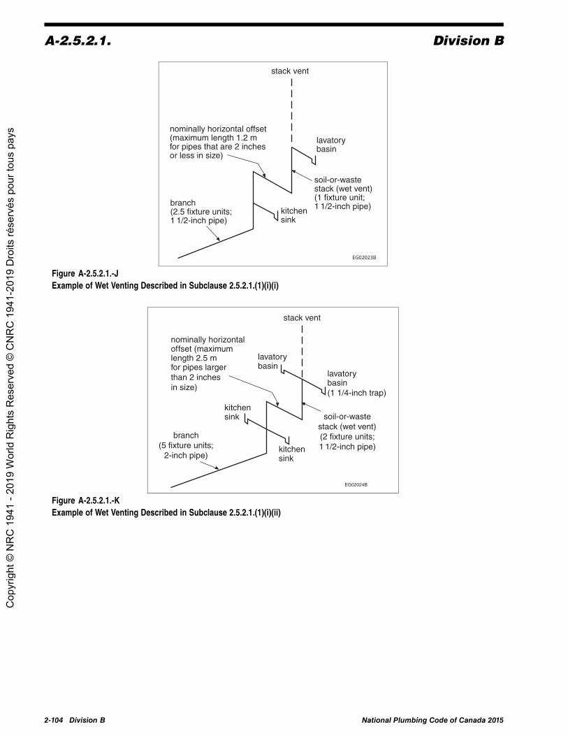
A-2.5.2.1. Division B
soil-or-waste stack (wet vent) (1 fixture unit; 1 1/2-inch pipe) branch
(2.5 fixture units; 1 1/2-inch pipe)
nominally horizontal offset (maximum length 1.2 m for pipes that are 2 inches or less in size)
EG02023B
kitchen sink
lavatory basin
Figure A-2.5.2.1.-JExample of Wet Venting Described in Subclause 2.5.2.1.(1)(i)(i)
EG02024B
stack vent
lavatory basin (1 1/4-inch trap)
soil-or-waste stack (wet vent) (2 fixture units; 1 1/2-inch pipe)
kitchen sink
lavatory basin
kitchen sink
nominally horizontal of fset (maximum length 2.5 m for pipes larger than 2 inches in size)
branch (5 fixture units;
2-inch pipe)
Figure A-2.5.2.1.-KExample of Wet Venting Described in Subclause 2.5.2.1.(1)(i)(ii)
2-104 Division B National Plumbing Code of Canada 2015
Cop
yrig
ht ©
NR
C 1
941
- 201
9 W
orld
Rig
hts
Res
erve
d ©
CN
RC
194
1-20
19 D
roits
rése
rvés
pou
r tou
s pa
ys

Division B A-2.5.2.1.
EG02025C
continuous vent
lavatory basin
bathtub
branch
branch (wet vent) (2 fixture units; 3-inch pipe)
3-inch emergency floor drain
lavatory basin (1 1/4-inch trap)
branch (wet vent) (2 fixture units; 1 1/2-inch pipe)
Figure A-2.5.2.1.-LExample of Wet Venting Described in Clause 2.5.2.1.(1)(j)
�� %�
������������
�����
��������������
��������������)������
���������
Figure A-2.5.2.1.-MExample of Wet Venting Described in Clause 2.5.2.1.(1)(k)
National Plumbing Code of Canada 2015 Division B 2-105
Cop
yrig
ht ©
NR
C 1
941
- 201
9 W
orld
Rig
hts
Res
erve
d ©
CN
RC
194
1-20
19 D
roits
rése
rvés
pou
r tou
s pa
ys

A-2.5.3.1. Division B
A-2.5.3.1. Circuit Venting. Single-storey and multi-storey wet venting has been replaced with wetventing (Article 2.5.2.1.) and circuit venting (Article 2.5.3.1.).
The information and figures presented in this Note are examples of the most common installation practices thatmeet NPC requirements. However, the examples shown do not preclude other installations that would alsoconform to NPC requirements.
�� +�
�����������
����������
Figure A-2.5.3.1.-AExample of Circuit Venting Described in Sentence 2.5.3.1.(1)
�� ,�
���������������
�����������
������������
����
������������������ �����������������������������������������������������������������������������������&����#�!�!����������������$!
Figure A-2.5.3.1.-BExample of Circuit Venting Described in Clause 2.5.3.1.(1)(c)
2-106 Division B National Plumbing Code of Canada 2015
Cop
yrig
ht ©
NR
C 1
941
- 201
9 W
orld
Rig
hts
Res
erve
d ©
CN
RC
194
1-20
19 D
roits
rése
rvés
pou
r tou
s pa
ys

Division B A-2.5.3.1.
��������
���(-���������
�������������
��������������
������������������������� ���������������������(-��������� ��
�����������
������������
� ��������������!
�����������
������������
���( ���������
���������
��������� ����������������� ���������������������)����� ���������������� ����� ����������������������!
���(-���������
������������
����������
�����������
������������
���( �������� �����
���
���������������
������� � ����������������� ���������������������( ��������� ��� ��������������!
�� � �
Figure A-2.5.3.1.-CExample of Circuit Venting Described in Sentence 2.5.3.1.(2), which refers to fixture outlet pipe size
National Plumbing Code of Canada 2015 Division B 2-107
Cop
yrig
ht ©
NR
C 1
941
- 201
9 W
orld
Rig
hts
Res
erve
d ©
CN
RC
194
1-20
19 D
roits
rése
rvés
pou
r tou
s pa
ys

A-2.5.3.1. Division B
EG02031B
relief vent
circuit vent
A relief vent is requiredwhen fixtures arecircuit-vented.
circuit-ventedbranch
Figure A-2.5.3.1.-DExample of Circuit Venting Described in Sentence 2.5.3.1.(3)
2-108 Division B National Plumbing Code of Canada 2015
Cop
yrig
ht ©
NR
C 1
941
- 201
9 W
orld
Rig
hts
Res
erve
d ©
CN
RC
194
1-20
19 D
roits
rése
rvés
pou
r tou
s pa
ys

Division B A-2.5.3.1.
����������������#����������%���&���������$
���������������������������������������������#�� � �������)�������������������������������������.�����$!
�� � �
�������
������������
�����������
����������������#����������%���&���������$
��������
��#%���&��������������$
����������������#���������%��&���������$
������������#�%���&���������' ������ � �$
�����#�!"���&����
����$
���������#�����)���������������$
�� #-���&���������$
����������������#�����)����������������$#"!"���&���������'������� � �$
�������
������������
���&��������
���������#�����)����������������$
-���&��������������������
����#�������������)��
�������������$
��������
������������# ���&���������$
�������������#�����)���������������$
��&�����������#�������������)����������������$
�������� ������ � �
����������-���&���������
�����#�����)���������������$
����
Figure A-2.5.3.1.-EExample of Circuit Venting Described in Sentence 2.5.3.1.(4)
National Plumbing Code of Canada 2015 Division B 2-109
Cop
yrig
ht ©
NR
C 1
941
- 201
9 W
orld
Rig
hts
Res
erve
d ©
CN
RC
194
1-20
19 D
roits
rése
rvés
pou
r tou
s pa
ys

A-2.5.3.1. Division B
soil-or-wastestack (more than
6 fixture units)combinedrelief vent
circuit vent
symmetricalconnection(1)
circuitvent
Figure A-2.5.3.1.-FExample of Circuit Venting Described in Sentence 2.5.3.1.(5)Note to Figure A-2.5.3.1.-F:(1) A symmetrical connection is accomplished with a manufactured fitting that has two or more inlets and connects two or more waste lines
to a vent or wet vent.
EG02034B
reliefvent
This is the preferred locationfor the additional circuit vent.
circuitvent
45°
45°
circuit-ventedbranch
Figure A-2.5.3.1.-GExample of Circuit Venting Described in Clause 2.5.3.1.(6)(a)
EG02035B
relief vent
This is the preferred locationfor the additional circuit vent.
circuitvent
circuit-ventedbranch
branch
Figure A-2.5.3.1.-HExample of Circuit Venting Described in Clause 2.5.3.1.(6)(b)
2-110 Division B National Plumbing Code of Canada 2015
Cop
yrig
ht ©
NR
C 1
941
- 201
9 W
orld
Rig
hts
Res
erve
d ©
CN
RC
194
1-20
19 D
roits
rése
rvés
pou
r tou
s pa
ys

Division B A-2.5.3.1.
soil-or-waste stack (more than 6 fixture units) relief vent
circuit vent
minimum 2-inch pipe(2)
additional circuit vent(1)
soil-or-waste stack (more than 6 fixture units)
additional circuit vent(1)
relief vent circuit vent
minimum 2-inch pipe(2)
circuit vent additional circuit vent(1)
soil-or-waste stack (more than 6 fixture units)
relief vent
minimum 2-inch pipe(2)
EG02036A
Figure A-2.5.3.1.-IExample of Circuit Venting Described in Sentence 2.5.3.1.(7)Notes to Figure A-2.5.3.1.-I:(1) Size as per Article 2.5.7.1. and Sentence 2.5.7.3.(1).(2) See Sentence 2.5.3.1.(7).
National Plumbing Code of Canada 2015 Division B 2-111
Cop
yrig
ht ©
NR
C 1
941
- 201
9 W
orld
Rig
hts
Res
erve
d ©
CN
RC
194
1-20
19 D
roits
rése
rvés
pou
r tou
s pa
ys

A-2.5.3.1. Division B
Connections to circuit vents and to additional circuit vents in accordance with Sentence 2.5.3.1.(6) shall conform to Sentence 2.5.4.5.(1), which states that a maximum of 2 fixtures (1.5 fixture units each) shall be connected to the vertical section by means of a double sanitary T.
EG02037A
relief vent
circuit vent additional circuit vent
soil-or-waste stack (more than
6 fixture units)
Figure A-2.5.3.1.-JExample of Circuit Venting Described in Sentence 2.5.3.1.(8)
EG02038A
1 1/4-inch trap
1 1/4-inch trap
1 1/4-inch trap
1 1/4-inch trap
1 1/4-inch trap
soil-or-waste stack (more than 6 fixture units)
relief vent minimum 2 inches
circuit vent
drain(1)
Figure A-2.5.3.1.-KExample of Circuit Venting Described in Sentence 2.5.3.1.(9)Note to Figure A-2.5.3.1.-K:(1) The drain is sized as a branch. The size of the drain should be increased as the load increases.
2-112 Division B National Plumbing Code of Canada 2015
Cop
yrig
ht ©
NR
C 1
941
- 201
9 W
orld
Rig
hts
Res
erve
d ©
CN
RC
194
1-20
19 D
roits
rése
rvés
pou
r tou
s pa
ys

Division B A-2.5.3.1.
relief vent(1)
(1 1/2-inch pipe)
This is the preferred location for the additional
circuit vent.(1)(2)
(1 1/2-inch pipe)
circuit-vented branch
EG02039B
circuit vent (44 fixture units; 2-inch pipe; 10-m long circuit vent)
branch
Figure A-2.5.3.1.-LExample of Circuit Venting Described in Sentence 2.5.3.1.(10)Notes to Figure A-2.5.3.1.-L:(1) The relief vent and the additional circuit vent are one size smaller than the circuit vent.(2) See Sentence 2.5.7.3.(1).
National Plumbing Code of Canada 2015 Division B 2-113
Cop
yrig
ht ©
NR
C 1
941
- 201
9 W
orld
Rig
hts
Res
erve
d ©
CN
RC
194
1-20
19 D
roits
rése
rvés
pou
r tou
s pa
ys

A-2.5.3.1. Division B
circuit vent(1)
(45 fixture units; 2-inch pipe)
Figure A-2.5.3.1.-MExample of Circuit Venting Described in Sentence 2.5.3.1.(11)Note to Figure A-2.5.3.1.-M:(1) When sizing the circuit vent, do not include fixtures with a hydraulic load of 2 fixture units that are connected downstream of the most
downstream water closets.
2-114 Division B National Plumbing Code of Canada 2015
Cop
yrig
ht ©
NR
C 1
941
- 201
9 W
orld
Rig
hts
Res
erve
d ©
CN
RC
194
1-20
19 D
roits
rése
rvés
pou
r tou
s pa
ys

Division B A-2.5.4.3.
A-2.5.4.3. Yoke Vent. In Ontario, yoke vents have traditionally been referred to as modified stack vents.
EG02041A
vent stack
yokevent
vent stack
vent stack
vent header
stack vent
12branches
Figure A-2.5.4.3.Yoke Vent
National Plumbing Code of Canada 2015 Division B 2-115
Cop
yrig
ht ©
NR
C 1
941
- 201
9 W
orld
Rig
hts
Res
erve
d ©
CN
RC
194
1-20
19 D
roits
rése
rvés
pou
r tou
s pa
ys
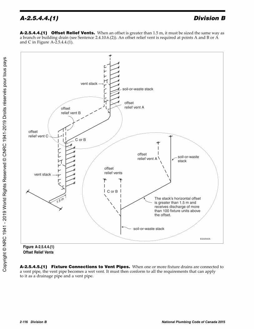
A-2.5.4.4.(1) Division B
A-2.5.4.4.(1) Offset Relief Vents. When an offset is greater than 1.5 m, it must be sized the same way asa branch or building drain (see Sentence 2.4.10.6.(2)). An offset relief vent is required at points A and B or Aand C in Figure A-2.5.4.4.(1).
vent stack soil-or-waste stack
The stack's horizontal offset is greater than 1.5 m and receives discharge of more than 100 fixture units above the of fset.
C or B
soil-or-waste stack
vent stack
1.5 m
C or B
soil-or-waste stack
EG02042A
offset relief vent A offset
relief vent B
offset relief vent C
offset relief vents
offset relief vent A
Figure A-2.5.4.4.(1)Offset Relief Vents
A-2.5.4.5.(1) Fixture Connections to Vent Pipes. When one or more fixture drains are connected toa vent pipe, the vent pipe becomes a wet vent. It must then conform to all the requirements that can applyto it as a drainage pipe and a vent pipe.
2-116 Division B National Plumbing Code of Canada 2015
Cop
yrig
ht ©
NR
C 1
941
- 201
9 W
orld
Rig
hts
Res
erve
d ©
CN
RC
194
1-20
19 D
roits
rése
rvés
pou
r tou
s pa
ys

Division B A-2.5.6.2.(2)
A-2.5.5.2. Venting of Oil Interceptors.
EG02006B
minimum 1 1/4-inch pipe (see 2.5.5.2.(4))
inlet
minimum 1 1/4-inch pipe (see 2.5.5.2.(4))
connect to plumbing vent system
outlet
cross-section of oil interceptor
vent opening between compartments
inside piping drops, baffles, etc. to be provided in accordance with manufacturer’s recommendations
Figure A-2.5.5.2.Venting of Oil Interceptors
A-2.5.6.2.(2) Vent Pipe Connections. Fittings used to connect vent pipes to nominally horizontalsoil-or-waste pipes are specified in Subsection 2.2.4.
EC01164B
horizontal centrelineof soil-or-waste pipe
Except for wet vents,vent pipes must beconnected above thehorizontal centreline.
Figure A-2.5.6.2.(2)Vent Pipe Connections
National Plumbing Code of Canada 2015 Division B 2-117
Cop
yrig
ht ©
NR
C 1
941
- 201
9 W
orld
Rig
hts
Res
erve
d ©
CN
RC
194
1-20
19 D
roits
rése
rvés
pou
r tou
s pa
ys

A-2.5.6.3.(1) Division B
A-2.5.6.3.(1) Vent Connection and Location of Vent Pipes.
A
B
trap arm/fixture drain
vent pipe(1)
Developed length “A” must be at least twicethe size of the trap arm/fixture drain.
Fall “B” must not be greater than theinside diameter of the trap arm/fixture drain.
EG01165C
Figure A-2.5.6.3.(1)-AVent ConnectionNote to Figure A-2.5.6.3.(1)-A:(1) The vent pipe must be connected in accordance with Article 2.5.6.2.
45°90°sanitary T
Total change in direction: 135°
max. fall of trap arm equal to its inside diametermin. developed length 2 times the size
(a)
wet vent
Y
45°
FD
45°45°
(b)EG01166D
Total change in direction: 135°
vent pipe
Figure A-2.5.6.3.(1)-BLocation of Vent Pipes That Protect Fixture Traps and Maximum Change in Direction of Trap Arms
A-2.5.6.3.(2) Location of Vent Pipes.
(a)
WC
45°
90°
(b)
Total change in direction: 225°
90°
Y
45°
90°
90°
WCwetvent
sanitary T
ventpipe
EG01166C
Total change in direction: 225°
Figure A-2.5.6.3.(2)Location of Vent Pipes and Maximum Change in Direction of Trap Arms for Fixtures That Depend on Siphonic Action
2-118 Division B National Plumbing Code of Canada 2015
Cop
yrig
ht ©
NR
C 1
941
- 201
9 W
orld
Rig
hts
Res
erve
d ©
CN
RC
194
1-20
19 D
roits
rése
rvés
pou
r tou
s pa
ys

Division B A-2.5.6.3.(3)
A-2.5.6.3.(3) Length of WC Fixture Drain.
�� !!$%&
��������������
��'(�)��
��*��*�� ��� ���+
��'(�!��
��������������
��'(�)��
��*��*�� ��� ���+
��'(�!��
Figure A-2.5.6.3.(3)Length of WC Fixture DrainNote to Figure A-2.5.6.3.(3):(1) Fall and length of WC fixture drain applies to floor-mounted and wall-hung WC's.
National Plumbing Code of Canada 2015 Division B 2-119
Cop
yrig
ht ©
NR
C 1
941
- 201
9 W
orld
Rig
hts
Res
erve
d ©
CN
RC
194
1-20
19 D
roits
rése
rvés
pou
r tou
s pa
ys

A-2.5.6.5.(4) Division B
A-2.5.6.5.(4) Vent Terminals. No vent pipe other than a fresh air inlet may terminate within thelimits indicated.
EC00664B
property line
3.5 m minimum
vent
1 mminimum
openable window or door(typical)
vent
150 mm minimum
vent terminal to behigh enough to prevententry of roof drainage
vent
3.5 m minimumvent
vent2 mminimum
roof sun deck
150 mmminimum
vent
vent
1.8 mminimum
1 m minimum
3.5 m minimum
air intake
vent
Figure A-2.5.6.5.(4)Vent Terminals
A-2.5.8. Sizing of Venting Systems. Vent pipes are connected to the drainage system and terminateoutside the building. They allow air to enter and circulate and they protect the trap seals in the drainage system.Except as permitted in Subsection 2.5.1., a trap shall always be protected by a vent pipe.
Sizing of Vent Pipes
The sizes stated in Table 2.5.7.1. take precedence over all other venting tables.
Sizing of Relief Vents
Length is not taken into consideration when sizing a relief vent and an additional circuit vent. A relief ventconnected to a circuit-vented branch is sized according to Sentences 2.5.7.3.(1) and (2).
2-120 Division B National Plumbing Code of Canada 2015
Cop
yrig
ht ©
NR
C 1
941
- 201
9 W
orld
Rig
hts
Res
erve
d ©
CN
RC
194
1-20
19 D
roits
rése
rvés
pou
r tou
s pa
ys

Division B A-2.5.8.
An offset relief vent is sized according to Sentence 2.5.7.4.(1), which permits the offset relief vent to be onesize smaller than the stack vent.
S (1 m) T (2 m)
Q (2 m)
P (4 m)
R (6 m)
O (1 m) drinkingfountain
WCs
N (5 m)
J (4 m) M (3 m)
K (1 m) L (1 m)
WCs I (2 m)
H (2 m)lavatorybasins
lavatorybasin
G (3 m)
bathtub
F (2 m)E (3 m)
drinkingfountain
lavatorybasin
C (6 m)
2 m
2 mD (3 m)
B (2 m)
A (7 m)
EG02043A
lavatorybasin
Y (2 m)
X (1 m)
W (3 m)
V (3 m)lavatorybasins
U (5 m)
cleanout
kitchensinks
WC
cleanout
WC
Figure A-2.5.8.Sizing of a Venting SystemNotes to Figure A-2.5.8.:(1) All water closets are 4 fixture units each.(2) The letters in columns 1 and 3 of Table A-2.5.8. correspond to the letters in this Figure.
National Plumbing Code of Canada 2015 Division B 2-121
Cop
yrig
ht ©
NR
C 1
941
- 201
9 W
orld
Rig
hts
Res
erve
d ©
CN
RC
194
1-20
19 D
roits
rése
rvés
pou
r tou
s pa
ys

A-2.5.8. Division B
Table A-2.5.8.Sizing of Venting SystemsForming Part of Note A-2.5.8.
Vent Pipe(1) Vent Name Developed Length Used toDetermine Size, m(1)
Hydraulic Load Usedto Determine Size,
fixture unitsCode Reference Minimum Size,
inches
A Continuous vent A+C=13 5 2.5.7.1. 1½
B Sump vent n/a n/a 2.5.7.7.(1) 2
C Branch vent A+C=13 5 2.5.7.7.(2) 2
D Vent stack 2+D+F+I+N+S+T=17 66 2.5.7.1.2.5.7.2. 3
E Individual andcontinuous vent n/a n/a 2.5.7.1. 1¼
F Vent stack Same as D=17 71 Same as D 3
G Continuous vent G=3 6 2.5.8.3.(5)2.5.7.1. 1½
H Dual and continuousvent n/a n/a 2.5.7.1. 1¼
I Vent stack Same as D=17 71 Same as D 3
J Circuit vent J+M=7 40 2.5.7.1.2.5.8.3.(4) 1½
K Additional circuit vent n/a n/a 2.5.7.1.2.5.7.3.(1) 1½
L Relief vent n/a n/a 2.5.7.1.2.5.7.3.(1) 1½
M Branch vent J+M=7 40 2.5.7.1.2.5.7.2. 1½
N Vent stack Same as D=17 71 Same as D 3
O Stack vent O+Q+T=5 66 2.5.7.1.2.5.8.4. 2
P Circuit vent P=4 16 2.5.7.1.2.5.8.3.(4) 1½
Q Stack vent Same as O=5 66 2.5.7.1.2.5.8.4. 2
R Stack vent R+S+T=9 7.5 2.5.2.1.(1)(a) 3
S Vent header A+C+F+I+N+S+T=25 78.5 2.5.8.3.(3) 3
T Vent header Same as S=25 78.5 2.5.8.3.(3) 3
U Individual vent n/a n/a 2.5.7.1. 1¼
V Branch vent U+V+W=11 2 2.5.7.1.2.5.7.2. 1¼
W Branch vent Same as V=11 3 2.5.7.1.2.5.7.2. 1¼
X Stack vent X+Y=3 4 2.5.7.1.2.5.8.4. 1¼
Y Stack vent Same as X=3 4 2.5.7.1.2.5.8.4. 1¼
Notes to Table A-2.5.8.:(1) The letters in columns 1 and 3 correspond to the letters in Figure A-2.5.8.
2-122 Division B National Plumbing Code of Canada 2015
Cop
yrig
ht ©
NR
C 1
941
- 201
9 W
orld
Rig
hts
Res
erve
d ©
CN
RC
194
1-20
19 D
roits
rése
rvés
pou
r tou
s pa
ys

Division B A-2.5.8.1.(2)
A-2.5.8.1.(2) Sizing of Wet Vent Systems.
stackvent
wet ventportion
soil-or-waste stack
(a)Not serving water closets
stackvent
wet ventportion
soil-or-wastestack may serve1 or 2 water closets
(b)Serving water closets
EG01171B
(1)(1)
Figure A-2.5.8.1.(2)Sizing of Wet Vent SystemsNote to Figure A-2.5.8.1.(2):(1) These two fixtures are not included when determining the size of the wet vent portion using Table 2.5.8.1.
National Plumbing Code of Canada 2015 Division B 2-123
Cop
yrig
ht ©
NR
C 1
941
- 201
9 W
orld
Rig
hts
Res
erve
d ©
CN
RC
194
1-20
19 D
roits
rése
rvés
pou
r tou
s pa
ys

A-2.5.8.3. and 2.5.8.4. Division B
A-2.5.8.3. and 2.5.8.4. Lengths to be Considered When Sizing Vent Pipes.
Note 1Note 2Note 1Note 2Note 1Note 2Note 2
Vent length not applicableBCEGH 1.2 + 1.8 + 2.1 + 2.0 + 0.6 = 7.7Vent length not applicableBCEGH 1.2 + 1.8 + 2.1 + 2.0 + 0.6 = 7.7Vent length not applicableBCEGH 1.2 + 1.8 + 2.1 + 2.0 + 0.6 = 7.7BCEGH 1.2 + 1.8 + 2.1 + 2.0 + 0.6 = 7.7
Dual vent (A-G)Continuous vent (B-C)Individual and continuous vent (D-C)Branch vent (C-E)Dual and continuous vent (F-E)Branch vent (E-G)Branch vent (G-H)
Vent Length (for sizing purposes) NPC Reference
stackvent
branchvent
branchvent
branchvent
continuousvent
individualandcontinuousvent
dual andcontinuousvent
dualvent
vent
Figure A-2.5.8.3. and 2.5.8.4.-ALengths to be Considered When Sizing Vent PipesNotes to Figure A-2.5.8.3. and 2.5.8.4.-A:(1) See Article 2.5.8.2.(2) See Article 2.5.8.3.
2-124 Division B National Plumbing Code of Canada 2015
Cop
yrig
ht ©
NR
C 1
941
- 201
9 W
orld
Rig
hts
Res
erve
d ©
CN
RC
194
1-20
19 D
roits
rése
rvés
pou
r tou
s pa
ys

Division B A-2.6.1.7.(5)
Vent pipe
Vent stack (A-C)Vent stack (B-C)Vent stack (H-I)Stack vent (D-E)Stack vent (F-G)Stack vent (J-K)Vent header orany section of it(CEGIKL)
ACEGIKL(1)
BCEGIKL(1)
HIKL(1)
DEGIKL(1)
FGIKL(1)
JKL(1)
ACEGIKL(2)
Length to be considered
EG01173B
branch
stack vent
branchvent
branchvent
branchvent
branchvent
branch
branchvent
branch
roof
building drain or branch
L
K
J
H
G E
F
B A
D
C
vent header
Figure A-2.5.8.3. and 2.5.8.4.-BLengths to be Considered When Sizing Vent PipesNotes to Figure A-2.5.8.3. and 2.5.8.4.-B:(1) See Sentence 2.5.8.4.(2).(2) See Sentence 2.5.8.3.(3).
A-2.6.1.3.(5) Shut-off Valves. Where multiple risers convey the water supply to dwelling units,each dwelling unit's water distribution system shall be provided with a shut-off valve located immediatelywhere the water piping enters the suite so as to isolate the fixtures as well as the water distribution pipingserving the dwelling unit's fixtures. Fixture stopcocks or shut-off valves located immediately adjacent toa fixture may not be adequate to protect the water distribution piping. Where a dwelling unit is served by asingle shut-off valve on the water supply, additional shut-off valves may be required to achieve compliancewith Sentences 2.6.1.3.(4) and (7).
A-2.6.1.6.(5) Flush-Tank-Type Urinals in Seasonal Buildings. Flush-tank-type urinals that arenot in use for an extended period of time, such as those in seasonal buildings, are permitted to be set up toflush automatically at predetermined intervals. Automatic flushing prevents the depletion of the water sealdue to evaporation or backflow conditions. The trap seal restricts the infiltration of gases, which can posehealth and safety concerns.
A-2.6.1.7.(5) Relief Valves. If the discharge piping is longer than 2 m or more than two 90° elbows areused, the valve manufacturer's installation instructions should be followed to ensure that the piping does notaffect the relief valves' discharge capacity.
National Plumbing Code of Canada 2015 Division B 2-125
Cop
yrig
ht ©
NR
C 1
941
- 201
9 W
orld
Rig
hts
Res
erve
d ©
CN
RC
194
1-20
19 D
roits
rése
rvés
pou
r tou
s pa
ys

A-2.6.1.9.(1) Division B
A-2.6.1.9.(1) Water Hammer Prevention. Water hammer is a buildup of pressure in a length ofhorizontal or vertical pipe that occurs when a valve or faucet is closed suddenly. The longer the pipe and thegreater the water velocity, the greater the pressure exerted on the pipe, which can be many times the normalstatic water pressure and be sufficient to damage the piping system. Since air chambers made from a piece ofvertical pipe do not provide acceptable protection, pre-manufactured water hammer arresters are requiredto address this potential problem. Water hammer arresters need not be installed at every valve or faucet, norin every piping system.
A-2.6.1.11.(1) Thermal Expansion. To accommodate the increase in pressure caused by thermalexpansion within a closed water distribution system, one of the following should be installed:(1) a suitably sized diaphragm expansion tank designed for use within a potable water system,(2) an auxiliary thermal expansion relief valve (T.E.R. valve) conforming to CSA B125.3, “Plumbing Fittings,”
set at a pressure of 550 kPa or less and designed for repeated use, or(3) other means acceptable to the authority having jurisdiction.
A-2.6.1.12.(1) Service Water Heaters. Storing hot water at temperatures below 60°C in the hot watertank or in the delivery system may lead to the growth of legionella bacteria. Contemporary electric water heatertanks experience temperature stratification and thus tend to have legionella bacteria in the lower parts of thetank. Article 2.6.1.12. specifies a thermostat setting of 60°C, which addresses the concern over the growth oflegionella bacteria in electric hot water storage tanks and is enforceable without introducing unnecessarycomplications. The growth of legionella bacteria is not a concern for other types of water heaters with differentdesigns that use different fuels.
Electrically heated water heaters are shipped with the thermostat set at 60°C. Article 2.6.1.12. is included inthe NPC to formalize this de facto temperature setting as a requirement. The thermostats have graduatedtemperature markings to allow such a setting, which is not the case with gas- or oil-heated water heaters.
A-2.6.2.1.(3) Backflow Preventers. CSA B64.10.1, “Maintenance and Field Testing of BackflowPreventers,” is considered to represent good practice as regards procedures for the maintenance and fieldtesting of backflow preventers.
A-2.6.2.4.(2) Backflow from Fire Protection Systems. The following document is considered to begood engineering practice when selecting a backflow preventer for installation on a fire protection system:AWWAM14, “Recommended Practice for Backflow Prevention and Cross-Connection Control.”
Table A-2.6.2.4.(2)Selection Guide for Backflow Prevention Devices on Fire Sprinkler and Standpipe Systems
Forming Part of Note A-2.6.2.4.(2)
Systems Made with Potable WaterSystem Materials
Systems Not Made with Potable WaterSystem Materials
CSA StandardNumber Type of Device(1) Minor Hazard —
Residential PartialFlow-Through System
Minor Hazard — Class1 System
Moderate Hazard —Class 1, 2, 3 and
6 Systems
Severe Hazard —Any Class of Systemin which Antifreezeor Other Additives
Are Used
CSA B64.6.1 DuCF P NP NP NP
CSA B64.9 SCVAF P P NP NP
CSA B64.5.1 DCVAF P P P NP
CSA B64.4.1 RPF P P P P
NP = Not permitted
P = Permitted
Notes to Table A-2.6.2.4.(2):(1) The “F” indicates that the product is only recommended for use on fire sprinkler and standpipe systems.
2-126 Division B Amended Page National Plumbing Code of Canada 2015
Cop
yrig
ht ©
NR
C 1
941
- 201
9 W
orld
Rig
hts
Res
erve
d ©
CN
RC
194
1-20
19 D
roits
rése
rvés
pou
r tou
s pa
ys

Division B A-2.6.2.6.(1)
A-2.6.2.4.(3) Fire Department Pumper Connection and Backflow Protection.
shut-off valve
Figure A-2.6.2.4.(3)Fire Department Pumper Connection and Backflow Protection
A-2.6.2.6.(1) Locations Requiring Premise Isolation. The following list is a guide to locationswhere premise isolation may be required:
• hospital buildings with operating, mortuary or laboratory facilities• radioactive material processing plants• petroleum processing facilities• premises where inspection is restricted• sewage treatment plants• commercial laundries (excluding laundromats)• plating or chemical plants• docks and dockside facilities• food and beverage processing plants• steam plants• trackside facilities for trains
An assessment of the hazard must be carried out to determine the need, if any, for a backflow prevention device.
National Plumbing Code of Canada 2015 Division B 2-127
Cop
yrig
ht ©
NR
C 1
941
- 201
9 W
orld
Rig
hts
Res
erve
d ©
CN
RC
194
1-20
19 D
roits
rése
rvés
pou
r tou
s pa
ys

A-2.6.2.9.(2) Division B
A-2.6.2.9.(2) Installation of Air Gaps.
flood level rim
air gap control valve
EG01176A
water supply
Figure A-2.6.2.9.(2)Installation of Air Gaps
A-2.6.2.10.(2) Installation of Atmospheric Vacuum Breakers.
height of atmospheric vacuum breaker
control valve
outlet of atmosphericvacuum breaker (critical level, unless marked otherwise by the manufacturer)
tank
outlet
flood level rim
overflow
indirect connection [NPC Sentence 2.3.3.11.(1)]
EG01177A
Figure A-2.6.2.10.(2)Installation of Atmospheric Vacuum Breakers
A-2.6.3. Water Systems. Subsection 2.6.3. contains performance requirements for water systems. Twowidely used references for the design of water systems are:
NIST Building Materials and Structures Report BMS-79, “Water-Distributing Systems for Buildings,” UnitedStates Department of Commerce, National Bureau of Standards, Washington, D.C., and
McGraw-Hill 2009, “International Plumbing Codes Handbook,” edited by V.T. Manas, McGraw-Hill BookCompany, New York, U.S.A.
A-2.6.3.1. Water Quality. Water destined for use as potable water can originate from a variety of sourcesthat are generally classified as surface waters or well waters, such as lakes, rivers, streams and aquifers. Insome localities, there may be seasonal variations in the water supply, and surface and well waters may beblended at times.
Water composition is the primary consideration in determining the cause of corrosion in potable water systems.If the water has corrosive characteristics, water treatment may be necessary to control its corrosiveness: thismay be as straightforward as adjusting the pH of the water at the treatment plant, or it may involve moreextensive corrosion-control treatment methods. Water purveyors normally consult treatment specialists todevelop methods suitable for specific conditions. The treatment of water from private wells may also requireexpert consultation.
The past performance of plumbing materials and products in different localities often provides insight intowhat can be expected with new installations. In areas where water-related corrosion is known to occur,adjustment of water chemistry may be sufficient or it may be necessary to select alternative piping and fittingmaterials or more robust products.
It is important to note that not all corrosion can be attributed to water conditions: the improper design andinstallation of potable water systems may result in erosion corrosion, galvanic corrosion, fatigue cracking,and so forth.
2-128 Division B National Plumbing Code of Canada 2015
Cop
yrig
ht ©
NR
C 1
941
- 201
9 W
orld
Rig
hts
Res
erve
d ©
CN
RC
194
1-20
19 D
roits
rése
rvés
pou
r tou
s pa
ys

Division B A-2.6.3.1.(2)
A-2.6.3.1.(2) Potable Water Systems. The design procedures contained in the following documentsare considered good engineering practice in the field of potable water systems:(a) ASHRAE 2011, “ASHRAE Handbook – HVAC Applications,” chapter on Service Water Heating,(b) ASHRAE 2013, “ASHRAE Handbook – Fundamentals,” chapter on Pipe Sizing,(c) ASPE 2010, “Plumbing Engineering Design Handbook, Volume 2,”chapter on Cold Water Systems, and(d) ASPE 2010, “Plumbing Engineering Design Handbook, Volume 2,” chapter on Domestic Water Heating
Systems.
Alternatively, the following methods, which apply to both public and private water supplies, may be used indetermining the size of each section of the water system using Table A-2.6.3.1.(2)-A (Small Building Method)and Table A-2.6.3.1.(2)-F (Average Pressure Loss Method). Where these methods are considered an alternativeto a detailed engineering design method, the hydraulic loads shall be the sum of the total fixture units given inTables 2.6.3.2.-A, 2.6.3.2.-B, 2.6.3.2.-C and 2.6.3.2.-D.
Small Building Method
Information required if using this method:(a) The developed length:
(i) from the property line or private water supply system when located outside the building to thewater service entry point to the building, and
(ii) from the water service entry point to the building to the most remote water outlet.(b) Minimum static pressure:
(i) the minimum static pressure available at the property line or other water source (private watersupply system), or
(ii) where there is a wide fluctuation of pressure in the main throughout the day, the minimumstatic pressure available.
(c) Pressure losses:(i) losses for meters, pressure-reducing valves, backflow preventers, water treatment systems,
and any other devices, and(ii) losses or gains due to changes in elevation.
(d) The number of fixture units (FU) as determined by using the sum of the total values given inTables 2.6.3.2.-A, 2.6.3.2.-B, 2.6.3.2.-C and 2.6.3.2.-D.
(e) The maximum velocities permitted in accordance with the manufacturer's recommendations forthe pipe and fittings chosen for the installation.
Note that a private water supply system must be capable of meeting the demands of the water distributionsystem.
Pipe Sizing Procedures (see Figure A-2.6.3.1.(2)-A)
Step 1: Water Service Piping (see Table A-2.6.3.1.(2)-B)(a) Obtain the total fixture units required for the installation using the sum of the total
values given in Tables 2.6.3.2.-A, 2.6.3.2.-B, 2.6.3.2.-C and 2.6.3.2.-D and consider allother demands on the water supply.
(b) Determine the minimum static pressure available at the property line or private watersupply system and consider all pressure losses for the water service.
(c) Select the pressure range group in Table A-2.6.3.1.(2)-A that is consistent with theminimum static pressure available including any other losses.
(d) Select the length column in Table A-2.6.3.1.(2)-A that is equal to or greater than thedeveloped length from the property line or private water supply system to the waterservice entry point to the building.
(e) In that column, find the fixture unit value that is equal to or greater than the fixture unitdemand for the installation and follow the row back to the first column to locate thewater service pipe size.
(f) To establish the adjusted static pressure available where the water service enters thebuilding for sizing the water distribution system, subtract the actual static pressure lossesfor the water service from the minimum static pressure available at the property line.
(g) The adjusted static pressure available where a private water supply system is installedshould be the static pressure available from such a system at the entry to the building.
Step 2: Hot Water Piping (see Table A-2.6.3.1.(2)-C)(a) Start with the most remote outlet in the most distant occupancy that requires hot water.
National Plumbing Code of Canada 2015 Amended Page Division B 2-129
Cop
yrig
ht ©
NR
C 1
941
- 201
9 W
orld
Rig
hts
Res
erve
d ©
CN
RC
194
1-20
19 D
roits
rése
rvés
pou
r tou
s pa
ys

A-2.6.3.1.(2) Division B
(b) Use the sum of the total fixture unit values given in Tables 2.6.3.2.-A, 2.6.3.2.-B, 2.6.3.2.-Cand 2.6.3.2.-D and work back toward the service water heater, adding in the fixtureunit values as they occur.
(c) Select the pressure range group in Table A-2.6.3.1.(2)-A that is consistent with theminimum static pressure available at the water service entry and any other losses (e.g.elevation or devices such as backflow preventers, etc.). Use this pressure range group forall portions (hot and cold) of the water distribution system.
(d) Select the length column that is equal to or greater than the developed length from thewater service entry point to the building to the most remote outlet served with eitherhot or cold water.
(e) In that column, find the fixture unit value that is equal to or greater than the fixtureunit demand at each pipe and follow the row back to the second column to locate thewater distribution system pipe size.
Step 3: Cold Water Piping (see Table A-2.6.3.1.(2)-D)(a) Start with the most remote outlet on the cold water piping using the established total
developed length column and pressure range group in Table A-2.6.3.1.(2)-A and workthrough Steps 2(c), (d) and (e) for hot water piping.
(b) Use the sum of the total fixture unit values given in Tables 2.6.3.2.-A, 2.6.3.2.-B, 2.6.3.2.-Cand 2.6.3.2.-D and work back toward the water service entry.
(c) Where the service water heater distribution pipe occurs, add in the fixture unit demandof the fixtures served only with hot water and those that have not yet been added inas served to the cold water side of the most remote fixtures requiring both a hot andcold water supply.
(d) Continue by sizing the cold water main between the service water heater distributionpipe and the water service entry.
(e) Add in the fixtures served with cold water only from the main within the most remoteoccupancy as they occur and all common distribution piping serving hot and cold waterto other occupancies as they occur.
(f) Complete by sizing all distribution piping served by the main within the most remoteoccupancy and then the other occupancies not yet sized using the previously establishedtotal developed length and pressure range group in Table A-2.6.3.1.(2)-A.
Table A-2.6.3.1.(2)-APipe Sizes for Water Systems Based on Number of Fixture Units Served Using the Small Building Method(1)
Maximum Allowable Length, m
12 18 24 30 46 61 76 91 122 152 183 213 244 274 305
Number of Fixture Units Served
WaterServicePipe,inches
Water Dis-tributionSystem,inches
Flow Velocity, m/s 3.0 2.4 1.5
Pressure Range 200 to 310 kPa
¾ ½ 6 5 4 3 2 1 1 1 0 0 0 0 0 0 0
¾ 5/8 12 10 9 7 5 3 3 3 2 2 1 1 1 1 0
¾ ¾ 18 16 14 12 9 6 5 5 4 4 3 2 2 2 1
1 1 36 31 27 25 20 17 15 13 12 10 8 6 6 6 6
1½ 1¼ 83 68 57 48 38 32 28 25 21 18 15 12 12 11 11
1½ 1½ 151 124 105 91 70 57 49 45 36 31 26 23 21 20 20
2 1½ 151 151 132 110 80 64 53 46 38 32 27 23 21 20 20
2 2 359 329 292 265 217 185 164 147 124 96 70 61 57 54 51
2½ 2½ 445 418 390 370 330 300 280 265 240 220 198 175 158 143 133
2-130 Division B Amended Page National Plumbing Code of Canada 2015
Cop
yrig
ht ©
NR
C 1
941
- 201
9 W
orld
Rig
hts
Res
erve
d ©
CN
RC
194
1-20
19 D
roits
rése
rvés
pou
r tou
s pa
ys

Division B A-2.6.3.1.(2)
Table A-2.6.3.1.(2)-A (Continued)
Maximum Allowable Length, m
12 18 24 30 46 61 76 91 122 152 183 213 244 274 305
Number of Fixture Units Served
WaterServicePipe,inches
Water Dis-tributionSystem,inches
Flow Velocity, m/s 3.0 2.4 1.5
Pressure Range 311 to 413 kPa
¾ ½ 8 7 6 5 4 3 2 2 1 1 1 0 0 0 0
¾ 5/8 13 13 12 11 9 7 5 5 3 3 2 2 1 1 1
¾ ¾ 21 21 19 17 14 11 9 8 6 5 4 4 3 3 3
1 1 42 42 41 36 30 25 23 20 18 15 12 10 9 8 8
1½ 1¼ 83 83 83 83 66 52 44 39 33 29 24 20 19 17 16
1½ 1½ 151 151 151 151 128 105 90 78 62 52 42 38 35 32 30
2 1½ 151 151 151 151 150 117 98 84 67 55 42 38 35 32 30
2 2 359 359 359 359 359 318 280 250 205 165 142 123 110 102 94
2½ 2½ 611 611 610 580 535 500 470 440 400 365 335 315 285 267 250
Pressure Over 413 kPa
¾ ½ 8 8 7 6 5 4 3 3 2 1 1 1 1 1 0
¾ 5/8 13 13 13 13 11 8 7 6 5 4 3 3 3 2 2
¾ ¾ 21 21 21 21 17 13 11 10 8 7 6 6 5 4 4
1 1 42 42 42 42 38 32 29 26 22 18 14 13 12 12 11
1½ 1¼ 83 83 83 83 83 74 62 54 43 34 26 25 23 22 21
1½ 1½ 151 151 151 151 151 151 130 113 88 73 51 51 46 43 40
2 1½ 151 151 151 151 151 151 142 122 98 82 64 51 46 43 40
2 2 359 359 359 359 359 359 359 340 288 245 204 172 153 141 129
2½ 2½ 611 611 611 611 611 611 610 570 510 460 430 404 380 356 329
Notes to Table A-2.6.3.1.(2)-A:(1) Where total fixture unit values exceed those given in this Table, the system must be designed according to a detailed engineering design method.
Table A-2.6.3.1.(2)-BSizing of Water Service Pipe Using Figure A-2.6.3.1.(2)-A and Table A-2.6.3.1.(2)-A(1)
Fixture Units Pipe Size, inches
Total demand from Table A-2.6.3.1.(2)-E 210.8 –
Add in fixture units for fire sprinkler system, irrigation system and any other demands onwater service n/a in this example –
Total demand in this example 210.8 2
Notes to Table A-2.6.3.1.(2)-B:(1) Based on 30 m developed length and minimum static pressure at property line of 565 kPa.
National Plumbing Code of Canada 2015 Amended Page Division B 2-131
Cop
yrig
ht ©
NR
C 1
941
- 201
9 W
orld
Rig
hts
Res
erve
d ©
CN
RC
194
1-20
19 D
roits
rése
rvés
pou
r tou
s pa
ys

A-2.6.3.1.(2) Division B
Table A-2.6.3.1.(2)-CSizing of Hot Water System Using Figure A-2.6.3.1.(2)-A and Table A-2.6.3.1.(2)-A with Pressure Drop(1)
Pipe Number Fixture Units Pipe Size, inches
1 8 ¾
2 11 ¾
3 15 1
4 6 5/8
5 21 1
Total Fixture Units 21 1
Notes to Table A-2.6.3.1.(2)-C:(1) Based on 76 m developed length and adjusted static pressure at building entry of 540 kPa.
Table A-2.6.3.1.(2)-DSizing of Cold Water System Using Figure A-2.6.3.1.(2)-A and Table A-2.6.3.1.(2)-A(1)
Pipe Letter Cold Water, fixture units Pipe Size, inches
A 11 ¾
B 21 1
C 21 1
D 29.8 1¼
E 20 1
F 49.8 1¼
G 20 1
H 69.8 1½
I 20 1
J 89.8 1½
K 20 1
L 109.8 1½
M 60 1¼
N 169.8 2
O 20 1
P 189.8 2
Q 21 1
R 210.8 2
Total Fixture Units 210.8 2
Notes to Table A-2.6.3.1.(2)-D:(1) Based on 76 m developed length and minimum adjusted static pressure at building entry of 540 kPa.
2-132 Division B National Plumbing Code of Canada 2015
Cop
yrig
ht ©
NR
C 1
941
- 201
9 W
orld
Rig
hts
Res
erve
d ©
CN
RC
194
1-20
19 D
roits
rése
rvés
pou
r tou
s pa
ys

Division B A-2.6.3.1.(2)
EG00672A
Pipe P = 189.8 FUPipe Q + 21.0 FU Total = 210.8 FU
SWH
P/L
indicates hot waterindicates cold water
(R)
(Q)21 FU
(P)
(O)20 FU
(L)
(N)
(J)
(K)20 FU
(I)20 FU
(H)
(G)20 FU
(E)20 FU
(C)
(D)
(B)
21 FU(5)(4)
6 FU
(3)15 FU (2)
11 FU
(1)8 FU
(A) 11 FU
(F)
Residential20 FU
Residential20 FU
Residential20 FU
Commercial44 FU
Commercial16 FU
Commercial21 FU
Adjusted pressure atwater service entry540 kPa (78 PSI)
Water meter
Minimum pressure atproperty line565 kPa (82 PSI)
Pipe N = 169.8 FUPipe O + 20.0 FU Total = 189.8 FU
Pipe L = 109.8 FUPipe M + 60.0 FU Total = 169.8 FU
Pipe H = 69.8 FUPipe I + 20.0 FU Total = 89.8 FU
Pipe J = 89.8 FUPipe K + 20.0 FU Total = 109.8 FU
(M)60 FU
Pipe F = 49.8 FUPipe G + 20.0 FU Total = 69.8 FU
Pipe D = 29.8 FUPipe E + 20.0 FU Total = 49.8 FU
Pipe C = 21.0 FU4 WC + 8.8 FU Total = 29.8 FU
4 WC6 L each
2.2 FU each
Pipe A = 11.0 FUHot + 10.0 FU Total = 21.0 FU
Commercial DW = 4 FU(per manufacturer’s data)
Water service210.8 FU
3 Lavatories2 FU each
Service sink3 FU
Pipe B = 21.0 FUNo additions Total = 21.0 FU
For use with Small Building and Average Pressure Loss Methods of water pipe sizing
4 FU2 Commercial sinks
each
Figure A-2.6.3.1.(2)-AExample of Commercial and Residential Development to be Used with Water Pipe Sizing MethodsNotes to Figure A-2.6.3.1.(2)-A:(1) This example is a development with 4 commercial occupancies on the lower floor and 5 residential occupancies on the upper floor, all
with separate service water heaters.(2) For the purpose of water pipe sizing:
• the minimum adjusted pressure available at building entry is 540 kPa (78 PSI);• the developed length of the water service is 30 m (98 ft); and• the developed length of the water distribution system is 76 m (249 ft).
National Plumbing Code of Canada 2015 Amended Page Division B 2-133
Cop
yrig
ht ©
NR
C 1
941
- 201
9 W
orld
Rig
hts
Res
erve
d ©
CN
RC
194
1-20
19 D
roits
rése
rvés
pou
r tou
s pa
ys

A-2.6.3.1.(2) Division B
Table A-2.6.3.1.(2)-EFixture Units Summary for Figure A-2.6.3.1.(2)-A Using Tables 2.6.3.2.-A, -B, -C and -D
Fixtures Quantity 100% Fixture Unit Values Total Demand (Quantity x FixtureUnit Values)
Lavatory, 8.3 LPM or less 3 2 6
Commercial sink 2 4 8
Service sink 1 3 3
W.C., 6 LPF or less 4 2.2 8.8
Other – – –
Commercial dishwasher 1 4 4
Commercial occupancy 1 16 16
Commercial occupancy 1 44 44
Commercial occupancy 1 21 21
Residential occupancy 5 20 100
Total Fixture Units 210.8
Average Pressure Loss Method
Information required if using this method:(a) The developed length:
(i) from the property line or private water system when located outside the building to the waterservice entry point to the building, and
(ii) from the building entry of the water service to the most remote water outlet.(b) Minimum static pressure:
(i) the minimum static pressure available at the property line or other water source (private watersupply system), or
(ii) where there is a wide fluctuation of pressure in the main throughout the day, the minimumstatic pressure available.
(c) Pressure losses:(i) losses for meters, pressure-reducing valves, backflow preventers, water treatment systems,
and any other devices, and(ii) losses or gains due to changes in elevation.
(d) The number of fixture units as determined by using the sum of the total values given inTables 2.6.3.2.-A, 2.6.3.2.-B, 2.6.3.2.-C and 2.6.3.2.-D.
(e) The maximum velocities permitted in accordance with the manufacturer's recommendations forthe pipe and fittings chosen for the installation.
Note: The private water supply system must be capable of meeting the demands of the water distributionsystem.
To use this method, calculate the pressure available for friction loss which must be 2.6 kPa per metre ormore; if it is less than that, the system must be designed according to a detailed engineering design method.
Calculating Pressure Available for Friction Loss (see Figure A-2.6.3.1.(2)-B)
(a) Obtain the water service size, including pressure losses, and the design of the privatewater supply system if it is separate from the water distribution system.
(b) To calculate the total equivalent length for the water distribution system, determinethe developed length from the water service entry point to the building to the mostremote water outlet, and(i) where fitting inside diameter dimensions are at least equal to the pipe size,
multiply the developed length by 1.5 to allow for friction losses, and(ii) where insert fittings are used, apply additional losses in accordance with the fitting
manufacturer's data.(c) To determine the adjusted pressure available at the water service entry for sizing the
water distribution system, deduct the pressure losses for the water service from theminimum static pressure available at the property line or private water source.
2-134 Division B National Plumbing Code of Canada 2015
Cop
yrig
ht ©
NR
C 1
941
- 201
9 W
orld
Rig
hts
Res
erve
d ©
CN
RC
194
1-20
19 D
roits
rése
rvés
pou
r tou
s pa
ys

Division B A-2.6.3.1.(2)
(d) To obtain the pressure available for friction loss, use the minimum adjusted staticpressure available at the water service entry and deduct the minimum operating pressurenecessary at the most remote water outlet, and losses for meters, pressure-reducingvalves, backflow preventers, water treatment systems, and any other devices. Includepressure losses or gains due to changes in elevation between the water service entryand the most remote water outlet.
(e) Divide the static pressure available for friction loss by the total equivalent length toobtain the pressure available for friction loss per metre.
EG00673A
Step 1(c)
Minimum static pressure
565 kPa – = 25 kPa 540 kPa
Pressure losses for service
Adjusted pressure at water service entry to the building
Adjusted pressure
540 kPa – = 20 kPa 380 kPa
Meter, PRV, BFP and other
losses
Total pressure available for friction loss
from the water service entry to the most remote
water supply outlet
Total pressure available for friction loss
380 kPa ÷ = 114 m 3.3 kPa per metre
Average pressure loss must be
minimum 2.6 kPa per metre
Developed length x 1.5 for fittings
and/or additional losses if insert fittings are used
Step 1(d)
Step 1(e)
+ 35 kPa
Losses for system height
+ 105 kPa
Minimum pressure necessary at the
fixture for operation
( )
Figure A-2.6.3.1.(2)-BDetermination of Pressure Available for Friction Loss
Pipe Sizing Procedures (see Figure A-2.6.3.1.(2)-A)
Step 1: Water Service Piping (see Table A-2.6.3.1.(2)-G)(a) Obtain the total fixture units required for the installation using the sum of the total
values given in Tables 2.6.3.2.-A, 2.6.3.2.-B, 2.6.3.2.-C and 2.6.3.2.-D and consider allother demands on the water supply.
(b) Select the water service pipe size from Table A-2.6.3.1.(2)-F using the velocity columnthat is consistent with the pipe and fittings chosen for the installation.
(c) Determine the minimum static pressure available at the property line or private watersource and consider all pressure losses for the water service.
(d) To establish the adjusted static pressure available where the water service enters thebuilding for sizing the water distribution system, subtract the actual static pressure lossesfor the water service from the minimum static pressure available at the property line.
(e) The adjusted static pressure available where a private water supply system is installedshould be the static pressure available from such a system at the entry to the building.
Step 2: Hot Water Piping (see Table A-2.6.3.1.(2)-H)(a) Start with the most remote outlet in the most distant occupancy that requires hot water.(b) Use the sum of the total fixture unit values given in Tables 2.6.3.2.-A, 2.6.3.2.-B, 2.6.3.2.-C
and 2.6.3.2.-D and work back toward the service water heater, adding in the fixtureunit values as they occur.
(c) Size the hot water system according to Table A-2.6.3.1.(2)-F using the velocity columnthat is consistent with the manufacturer's requirements for the pipe and fittings chosenwhen serving a hot water system.
National Plumbing Code of Canada 2015 Division B 2-135
Cop
yrig
ht ©
NR
C 1
941
- 201
9 W
orld
Rig
hts
Res
erve
d ©
CN
RC
194
1-20
19 D
roits
rése
rvés
pou
r tou
s pa
ys

A-2.6.3.1.(2) Division B
Step 3: Cold Water Piping (see Table A-2.6.3.1.(2)-I)(a) Start with the most remote outlet requiring cold water in the most distant occupancy
and working back towards the water service entry adding in the fixture unit valuesas they occur.
(b) Obtain the fixture units using the sum of the total fixture unit values given inTables 2.6.3.2.-A, 2.6.3.2.-B, 2.6.3.2.-C and 2.6.3.2.-D.
(c) Size the cold water system to Table A-2.6.3.1.(2)-F using the velocity column that isconsistent with the manufacturer's requirements for the pipe and fittings chosen whenserving a cold water system.
(d) Where the service water heater distribution pipe occurs, add in the fixture unit demandof the fixtures served with only hot water and those that have not yet been added inas served to the cold water side of the most remote fixtures requiring both hot andcold water supply.
(e) Continue by sizing the cold water main between the service water heater distributionpipe and the water service entry.
(f) Add in the fixtures served with only cold water from the main within the most remoteoccupancy as they occur and then all common distribution piping serving hot and coldwater to other occupancies as they occur.
(g) Complete by sizing all distribution piping served by the main in the most remoteoccupancy and then the other occupancies not yet sized using Table A-2.6.3.1.(2)-F.
Table A-2.6.3.1.(2)-FPipe Sizes for Water Systems Based on Number of Fixture Units Served Using the Average Pressure Loss Method
Water Velocity
3.0 m/s (10 ft/s) 2.4 m/s (8 ft/s) 1.5 m/s (5 ft/s) 1.2 m/s (4 ft/s)
Flow and Fixture Units ServedPipe Size,inches
L/s Fixture Units L/s Fixture Units L/s Fixture Units L/s Fixture Units
½ 0.46 8 0.36 7 0.23 3.5 0.18 2.55/8 0.68 13 0.54 11 0.34 6.5 0.27 4.5
¾ 0.95 21 0.77 17 0.48 9 0.38 7.5
1 1.62 42 1.26 30 0.81 18 0.65 14
1¼ 2.47 83 1.8 54 1.24 29 0.99 22
1½ 3.5 146 2.8 102 1.75 46 1.4 34
2 6.08 337 4.92 265 3.04 120 2.43 81
2½ 9.39 692 7.89 500 4.69 245 3.75 170
3 13.23 1 018 10.73 750 6.7 400 5.36 295
4 23.94 2 480 18.9 1 800 11.78 850 9.42 600
5 37 4 400 29 3 350 18.35 1 625 14.68 1 125
6 52.1 6 600 42 4 800 26.38 2 875 21.11 2 125
Table A-2.6.3.1.(2)-GSizing of Water Service Pipe Using Figure A-2.6.3.1.(2)-A and Table A-2.6.3.1.(2)-F(1)
Fixture Units Pipe Size, inches
Total demand from Table A-2.6.3.1.(2)-E 210.8 –
Add in fixture units for fire sprinkler system, irrigation system and any otherdemands on water service n/a in this example –
Total demand in this example 210.8 2
Notes to Table A-2.6.3.1.(2)-G:(1) Based on 30 m developed length and minimum static pressure at property line of 565 kPa.
2-136 Division B National Plumbing Code of Canada 2015
Cop
yrig
ht ©
NR
C 1
941
- 201
9 W
orld
Rig
hts
Res
erve
d ©
CN
RC
194
1-20
19 D
roits
rése
rvés
pou
r tou
s pa
ys

Division B A-2.6.3.2.(4)
Table A-2.6.3.1.(2)-HSizing of Hot Water System Using Figure A-2.6.3.1.(2)-A and Table A-2.6.3.1.(2)-F with Flow Velocity(1)
Pipe Number Fixture Units Pipe Size, inches
1 8 ¾
2 11 1
3 15 1
4 6 5/8
5 21 1¼
Total Fixture Units 21 1¼
Notes to Table A-2.6.3.1.(2)-H:(1) Based on 1.5 m/s and adjusted static pressure at building entry of 540 kPa.
Table A-2.6.3.1.(2)-ISizing of Cold Water System Using Figure A-2.6.3.1.(2)-A and Table A-2.6.3.1.(2)-F(1)
Pipe Letter Cold Water, fixture units Pipe Size, inches
A 11 5/8
B 21 1
C 21 1
D 29.8 1
E 20 1
F 49.8 1¼
G 20 1
H 69.8 1½
I 20 1
J 89.8 1½
K 20 1
L 109.8 2
M 60 1½
N 169.8 2
O 20 1
P 189.8 2
Q 21 1
R 210.8 2
Total Fixture Units 210.8 2
Notes to Table A-2.6.3.1.(2)-I:(1) Based on 2.4 m/s velocity and adjusted static pressure at water service entry of 540 kPa.
A-2.6.3.2.(4) Sizing for Flush Valves. Distribution piping and water mains serving flush valves maybe sized using the values assigned in Tables 2.6.3.2.-B and 2.6.3.2.-C, beginning with the most remote flushvalve on each section of distribution piping served by the water main.
National Plumbing Code of Canada 2015 Division B 2-137
Cop
yrig
ht ©
NR
C 1
941
- 201
9 W
orld
Rig
hts
Res
erve
d ©
CN
RC
194
1-20
19 D
roits
rése
rvés
pou
r tou
s pa
ys

A-2.6.3.4.(5) Division B
A-2.6.3.4.(5) Sizing of Water Systems. Sentence 2.6.3.4.(5) and Table 2.6.3.4. present a simplifiedmethod of water system sizing, which is permitted in buildings containing one or two dwelling units orrow houses with separate water services.
Simplified Method
This sizing method may be used in the buildings noted, where:(a) the total developed length from the property line to the most remote fixture is not more than 90 m, and(b) the static pressure available at the water service entry to the building is not less than 200 kPa.
Where either the developed length is exceeded or the minimum static pressure required is not known, adetailed engineering design method must be used to size the water service piping. The design must ensurea minimum static pressure of 200 kPa is available at the water service entry to the building.
Information required when using this method:(a) The total number of fixture units (FU) as determined by using the sum of the total fixture unit values
given in Tables 2.6.3.2.-A, 2.6.3.2.-B, 2.6.3.2.-C and 2.6.3.2.-D.(b) Where the water service also serves a fire sprinkler system, irrigation system, or any other system,
these demands must be added to the water service sizing.
Pipe Sizing Procedures
Step 1: Water Service Pipe(a) Obtain the total fixture units required for the installation using the sum of the total
values given in Tables 2.6.3.2.-A, 2.6.3.2.-B, 2.6.3.2.-C and 2.6.3.2.-D and consider allother demands on the water supply.
(b) Determine the water service pipe size using the water velocity column in Table 2.6.3.4.that is consistent with the pipe material chosen for the installation.
Step 2: Hot Water Piping(a) Start with the most remote fixture requiring a supply of hot water and work back toward
the service water heater, adding in the fixture unit loads as they occur.(b) Determine the fixture units using the sum of the total fixture unit values given in
Tables 2.6.3.2.-A, 2.6.3.2.-B, 2.6.3.2.-C and 2.6.3.2.-D.(c) Size the hot water system using the water velocity column in Table 2.6.3.4. that is
consistent with the manufacturer's recommendations for the pipe and fittings chosenwhen serving a hot water system.
Step 3: Cold Water Piping(a) Start with the most remote fixture requiring a supply of cold water and work back
toward the water service entry, adding in the fixture unit loads as they occur.(b) Obtain the fixture units using the sum of the total fixture unit values given in
Tables 2.6.3.2.-A, 2.6.3.2.-B, 2.6.3.2.-C and 2.6.3.2.-D.(c) Size the cold water system using the water velocity column in Table 2.6.3.4. that is
consistent with the manufacturer's recommendations for the pipe chosen when servinga cold water system.
(d) Where the service water heater distribution pipe occurs, add in the fixture unit demandof the fixtures served with only hot water and those that have not yet been added in asserved to the cold water side of the fixtures requiring both a hot and cold water supply.
(e) Continue sizing the cold water main between the service water heater distributionpipe and the water service entry by adding all fixtures served with only a cold watersupply as they occur.
(f) Complete by sizing all cold water distribution piping served by the main between thewater heater distribution pipe and the water service entry.
2-138 Division B National Plumbing Code of Canada 2015
Cop
yrig
ht ©
NR
C 1
941
- 201
9 W
orld
Rig
hts
Res
erve
d ©
CN
RC
194
1-20
19 D
roits
rése
rvés
pou
r tou
s pa
ys

Division B A-2.6.3.4.(5)
EG00671A
water service entry to the building
service water heater
common supply = 2.0 FU 1 hose bibb + 2.5 FU Total = 4.5 FU
common supply for hot and cold maximum 2.0 FU
indicates hot water indicates cold water
hose bibb 2.5 FU
cold supply 2.0 FU
fixture spout maximum 2.0 FU
hot supply 2.0 FU
(3)
(2)
(1)
(2)
Figure A-2.6.3.4.(5)-ADetermining the Hydraulic Needs of a FixtureNotes to Figure A-2.6.3.4.(5)-A:(1) The fixture spout delivers a maximum of 2.0 fixture units.(2) This would apply if only the hot side or the cold side were fully opened.(3) The common pipe that serves both the hot and cold sides of the faucet also delivers a maximum of 2.0 fixture units even if both the hot
and cold valves at the faucet are fully opened at the same time.
Table A-2.6.3.4.(5)-AFixture Units Summary Using Figure A-2.6.3.4.(5)-B and Tables 2.6.3.2.-A, -B, -C and -D
Fixtures Number of Fixtures 100% Fixture Unit Values Total Demand(Quantity x Fixture Unit Values)
Bathtub 2 1.4 2.8
Clothes washer 2 1.4 2.8
Dishwasher 2 1.4 2.8
Hose bibb 1 2.5 2.5
Lavatory, 8.3 LPM or less 3 0.7 2.1
Shower, 9.5 LPM or less 1 1.4 1.4
Sink, 8.3 LPM or less 2 1.4 2.8
W.C., 6 LPF or less 3 2.2 6.6
Other
Total Fixture Units 23.8
National Plumbing Code of Canada 2015 Division B 2-139
Cop
yrig
ht ©
NR
C 1
941
- 201
9 W
orld
Rig
hts
Res
erve
d ©
CN
RC
194
1-20
19 D
roits
rése
rvés
pou
r tou
s pa
ys

A-2.6.3.4.(5) Division B
EG00670A
Include load on Pipe H = 21.3 FU 1 HB (cold) + 2.5 FU Total = 23.8 FU
I
J
WC
SWH
LAVSHWR
DW
KS
LAVBT
CW
WC
KS
CW
DWWC
LAVBTHB
H
G
F
D
C
E
B
K
A
1
2
3
6
5
4
Water serviceentry = 23.8 FU
Include load on Pipe G = 19.1 FU 1 WC (cold) + 2.2 FU Total = 21.3 FU
Include load on Pipe F = 19.1 FU No cold-only fixtures occurred on Pipe J + 0.0 FU Total = 19.1 FU
2.1 FU
3.6 FU
2.8 FU
14.7 FU
5.7 FU
5.7 FU
11.4 FU
2.8 FU
3.5 FU
6.3 FU
Fixtures served
Fixtures served
Total = 8.4 FU
indicates hot waterindicates cold water
1 DW (hot only) + 1.4 FU
1 DW (hot only) + 1.4 FUTotal = 6.3 FU
with hot and cold = 7.0 FU
with hot and cold = 4.9 FU
Fixtures served
Total hot = 14.7 FU2 DW (hot only) + 2.8 FU
with hot and cold = 11.9 FU
Include load on Pipe DAdd fixtures on Pipe 5 (hot)
served by Pipe FAdd 1 DW on Pipe 3
served by Pipe F(Note: Fixtures on Pipe 3already served by Pipe F
on cold side not added again)
= 11.4 FU
+ 6.3 FU
+ 1.4 FU
= 19.1 FUTotal
Figure A-2.6.3.4.(5)-BExample of Water Pipe Sizing for Buildings Containing One or Two Dwelling Units or Row Houses with SeparateWater Services
Table A-2.6.3.4.(5)-BSizing of Water Service Pipe Using Figure A-2.6.3.4.(5)-B and Table 2.6.3.4.
Water Velocity, m/s
3.0 2.4 1.5Fixture Units
Pipe Size, inches
Total fixture units 23.8 – – –
Fire sprinkler system n/a – – –
Irrigation system n/a – – –
Other n/a – – –
Total demand on water service 23.8 1 1 1¼
2-140 Division B Amended Page National Plumbing Code of Canada 2015
Cop
yrig
ht ©
NR
C 1
941
- 201
9 W
orld
Rig
hts
Res
erve
d ©
CN
RC
194
1-20
19 D
roits
rése
rvés
pou
r tou
s pa
ys

Division B A-2.7.4.1.
Table A-2.6.3.4.(5)-CSizing of Hot Water System Using Figure A-2.6.3.4.(5)-B and Table 2.6.3.4.
Water Velocity, m/s
3.0 2.4 1.5Pipe Number Hot WaterFixture Units
Pipe Size, inches
1 3.5 ½ ½ ½
2 6.3 ½ ½ ¾
3 8.4 ¾ ¾ ¾
4 2.1 ½ ½ ½
5 6.3 ½ ½ ¾
6 14.7 ¾ ¾ 1
Total Fixture Units 14.7
Table A-2.6.3.4.(5)-DSizing of Cold Water System Using Figure A-2.6.3.4.(5)-B and Table 2.6.3.4.
Water Velocity, m/s
3.0 2.4 1.5Pipe Letter Cold WaterFixture Units
Pipe Size, inches
A 2.8 ½ ½ ½
B 5.7 ½ ½ ¾
C 5.7 ½ ½ ¾
D 11.4 ¾ ¾ 1
E 14.7 ¾ ¾ 1
F 19.1 ¾ 1 1¼
G 19.1 ¾ 1 1¼
H 21.3 1 1 1¼
I 23.8 1 1 1¼
J 2.8 ½ ½ ½
K 3.6 ½ ½ ½
Total Fixture Units 23.8
A-2.7.3.2.(1) Outlets from Non-Potable Water Systems. The location of outlets from non-potablewater systems where they can be discharged into a sink or lavatory, a fixture into which an outlet from apotable water system is discharged, or a fixture that is used for the preparation, handling or dispensing of food,drink or products that are intended for human consumption, may have proven acceptable on the basis of pastperformance in some localities, and its acceptance under this Code may be warranted.
A-2.7.4.1. Non-potable Water System Design. There is a growing interest in Canada in usingavailable non-potable water supplies in the place of potable ones for selected purposes such as flushing toiletsand irrigating lawns and gardens. Article 2.7.4.1. applies to non-potable water systems regardless of theorigin of the water. The non-potable water must meet applicable water quality standards as determined by anauthority having jurisdiction.
National Plumbing Code of Canada 2015 Division B 2-141
Cop
yrig
ht ©
NR
C 1
941
- 201
9 W
orld
Rig
hts
Res
erve
d ©
CN
RC
194
1-20
19 D
roits
rése
rvés
pou
r tou
s pa
ys

2-142 Division B National Plumbing Code of Canada 2015
Cop
yrig
ht ©
NR
C 1
941
- 201
9 W
orld
Rig
hts
Res
erve
d ©
CN
RC
194
1-20
19 D
roits
rése
rvés
pou
r tou
s pa
ys

Division C
Administrative Provisions
Cop
yrig
ht ©
NR
C 1
941
- 201
9 W
orld
Rig
hts
Res
erve
d ©
CN
RC
194
1-20
19 D
roits
rése
rvés
pou
r tou
s pa
ys

Cop
yrig
ht ©
NR
C 1
941
- 201
9 W
orld
Rig
hts
Res
erve
d ©
CN
RC
194
1-20
19 D
roits
rése
rvés
pou
r tou
s pa
ys

Division C
Part 1General
1.1. Application1.1.1. Application ........................................ 1-1
1.2. Terms and Abbreviations1.2.1. Definitions of Words and Phrases .. 1-11.2.2. Symbols and Other Abbreviations .. 1-1
National Plumbing Code of Canada 2015
Cop
yrig
ht ©
NR
C 1
941
- 201
9 W
orld
Rig
hts
Res
erve
d ©
CN
RC
194
1-20
19 D
roits
rése
rvés
pou
r tou
s pa
ys
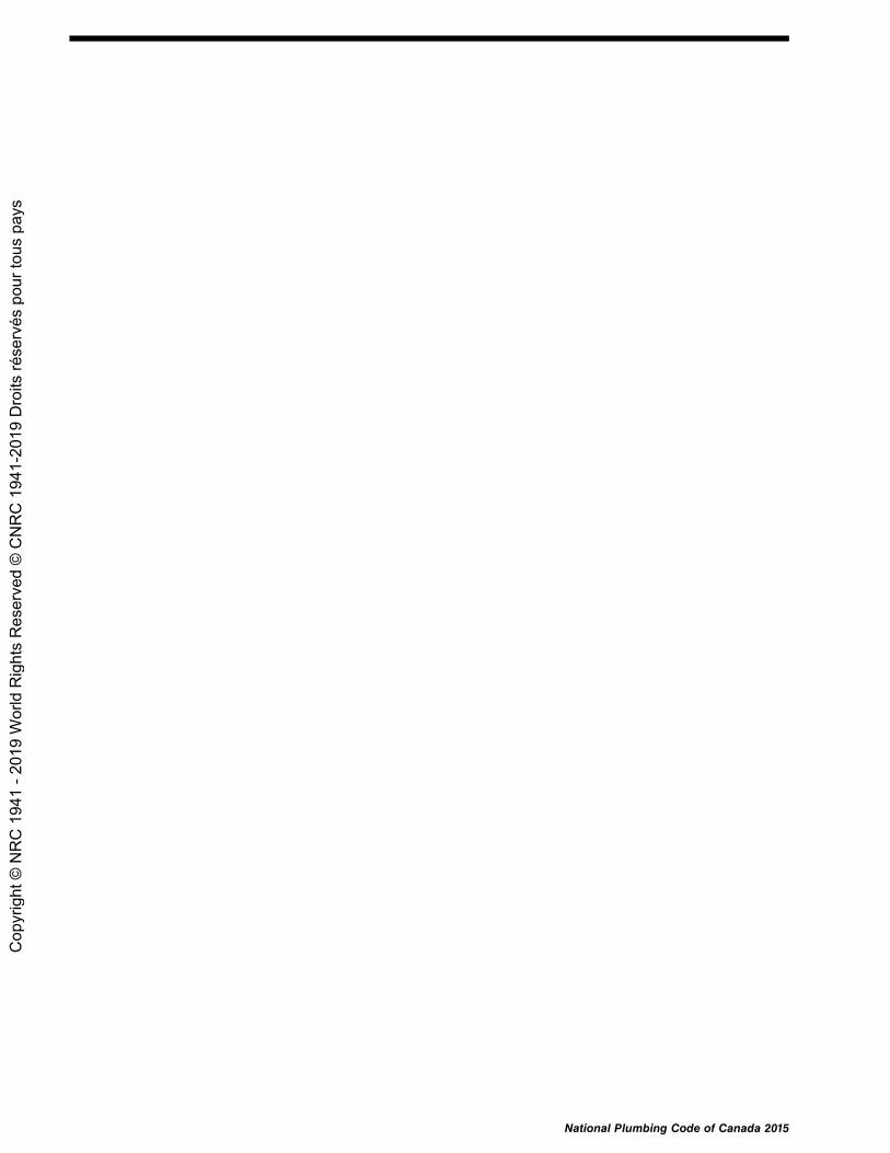
National Plumbing Code of Canada 2015
Cop
yrig
ht ©
NR
C 1
941
- 201
9 W
orld
Rig
hts
Res
erve
d ©
CN
RC
194
1-20
19 D
roits
rése
rvés
pou
r tou
s pa
ys

Division C
Part 1General
Section 1.1. Application1.1.1. Application
1.1.1.1. Application
1) This Part applies to all plumbing systems covered in this Code. (SeeArticle 1.1.1.1. of Division A.)
Section 1.2. Terms and Abbreviations1.2.1. Definitions of Words and Phrases
1.2.1.1. Non-defined Terms
1) Words and phrases used in Division C that are not included in the list ofdefinitions in Article 1.4.1.2. of Division A shall have the meanings that are commonlyassigned to them in the context in which they are used, taking into account thespecialized use of terms by the various trades and professions to which the terminologyapplies.
2) Where objectives and functional statements are referred to in Division C, theyshall be the objectives and functional statements described in Parts 2 and 3 of DivisionA.
3) Where acceptable solutions are referred to in Division C, they shall be theprovisions stated in Part 2 of Division B.
4) Where alternative solutions are referred to in Division C, they shall be thealternative solutions mentioned in Clause 1.2.1.1.(1)(b) of Division A.
1.2.1.2. Defined Terms
1) The words and terms in italics in Division C shall have the meanings assignedto them in Article 1.4.1.2. of Division A.
1.2.2. Symbols and Other Abbreviations
1.2.2.1. Symbols and Other Abbreviations
1) The symbols and other abbreviations in Division C shall have the meaningsassigned to them in Article 1.4.2.1. of Division A.
National Plumbing Code of Canada 2015 Division C 1-1
Cop
yrig
ht ©
NR
C 1
941
- 201
9 W
orld
Rig
hts
Res
erve
d ©
CN
RC
194
1-20
19 D
roits
rése
rvés
pou
r tou
s pa
ys

1-2 Division C National Plumbing Code of Canada 2015
Cop
yrig
ht ©
NR
C 1
941
- 201
9 W
orld
Rig
hts
Res
erve
d ©
CN
RC
194
1-20
19 D
roits
rése
rvés
pou
r tou
s pa
ys

Division C
Part 2Administrative Provisions
2.1. Application2.1.1. Application ........................................ 2-1
2.2. Administration2.2.1. Administration .................................. 2-12.2.2. Plumbing Drawings and Related
Documents ........................................ 2-1
2.3. Alternative Solutions2.3.1. Documentation of Alternative
Solutions ........................................... 2-1
Notes to Part 2 .................. 2-3
National Plumbing Code of Canada 2015
Cop
yrig
ht ©
NR
C 1
941
- 201
9 W
orld
Rig
hts
Res
erve
d ©
CN
RC
194
1-20
19 D
roits
rése
rvés
pou
r tou
s pa
ys

National Plumbing Code of Canada 2015
Cop
yrig
ht ©
NR
C 1
941
- 201
9 W
orld
Rig
hts
Res
erve
d ©
CN
RC
194
1-20
19 D
roits
rése
rvés
pou
r tou
s pa
ys
Division C
Part 2Administrative Provisions
Section 2.1. Application
2.1.1. Application
2.1.1.1. Application
1) This Part applies to all plumbing systems covered in this Code. (SeeArticle 1.1.1.1. of Division A.)
Section 2.2. Administration
2.2.1. Administration
2.2.1.1. Administrative Requirements
1) This Code shall be administered in conformance with the appropriate provincialor territorial regulations, municipal bylaws or, in the absence of such regulationsor bylaws, in conformance with the applicable requirements in the AdministrativeRequirements for Use with the National Building Code of Canada 1985.
2.2.2. Plumbing Drawings and Related Documents
2.2.2.1. Information Required on Plumbing Drawings and Related Documents
1) Plumbing drawings and related documents submitted with the application fora plumbing permit shall show
a) the location and size of every building drain and of every trap and cleanoutfitting that is on a building drain,
b) the size and location of every soil-or-waste pipe, trap and vent pipe, andc) a layout of the potable water distribution system, including pipe sizes and
valves.
Section 2.3. Alternative Solutions
2.3.1. Documentation of Alternative Solutions(See Note A-2.3.1.)
2.3.1.1. Documentation
1) Documentation conforming to this Subsection shall be provided by the personrequesting the use of an alternative solution to demonstrate that the proposedalternative solution complies with this Code.
National Plumbing Code of Canada 2015 Division C 2-1
Cop
yrig
ht ©
NR
C 1
941
- 201
9 W
orld
Rig
hts
Res
erve
d ©
CN
RC
194
1-20
19 D
roits
rése
rvés
pou
r tou
s pa
ys

2.3.1.1. Division C
2) The documentation referred to in Sentence (1) shall includea) a Code analysis outlining the analytical methods and rationales used to
determine that the proposed alternative solution will achieve at least thelevel of performance required by Clause 1.2.1.1.(1)(b) of Division A, and
b) information concerning any special maintenance or operation requirements,including any plumbing system component commissioning requirements,that are necessary for the alternative solution to achieve compliance withthe Code after the plumbing system is installed.
3) The Code analysis referred to in Clause (2)(a) shall identify the applicableobjectives, functional statements and acceptable solutions, and any assumptions,limiting or restricting factors, testing procedures, engineering studies or performanceparameters that will support a Code compliance assessment.
4) The Code analysis referred to in Clause (2)(a) shall include informationabout the qualifications, experience and background of the person or persons takingresponsibility for the design.
5) The information provided under Sentence (3) shall be in sufficient detail toconvey the design intent and to support the validity, accuracy, relevance and precisionof the Code analysis.
6) Where the design of a plumbing system includes proposed alternative solutionsthat involve more than one person taking responsibility for different aspects of thedesign, the applicant for the permit shall identify a single person to co-ordinatethe preparation of the design, Code analysis and documentation referred to in thisSubsection.
2-2 Division C National Plumbing Code of Canada 2015
Cop
yrig
ht ©
NR
C 1
941
- 201
9 W
orld
Rig
hts
Res
erve
d ©
CN
RC
194
1-20
19 D
roits
rése
rvés
pou
r tou
s pa
ys

Division C
Notes to Part 2Administrative Provisions
A-2.3.1. Documentation of Alternative Solutions. Beyond the purposes of demonstratingcompliance and acquiring an installation permit, there are other important reasons for requiring that theproponent of an alternative solution submit project documentation (i.e. a compliance report) to the authorityhaving jurisdiction and for the authority having jurisdiction to retain that documentation for a substantialperiod following the installation of a plumbing system:
• Most jurisdictions require that a plumbing system be maintained in compliance with the codes underwhich it was installed. Alternative solutions made possible by objective-based codes may have specialmaintenance requirements, which would be described in the documentation.
• Documentation helps consultants perform code compliance assessments of existing buildings or facilitiesbefore they are sold and informs current owners or prospective buyers of existing buildings or facilities ofany limitations pertaining to their future use or development.
• Documentation provides design professionals with the basic information necessary to design changes toan existing plumbing system.
• An alternative solution could be invalidated by a proposed alteration to a plumbing system. Designersand regulators must therefore know the details of the particular alternative solutions that were integral tothe original design. Complete documentation should provide insight as to why one alternative solutionwas chosen over another.
• Documentation is the “paper trail” of the alternative solution negotiated between the designer and theregulator and should demonstrate that a rational process led to the acceptance of the alternative solutionas an equivalency.
• It is possible that over time a particular alternative solution may be shown to be inadequate. It would beadvantageous for a jurisdiction to know which plumbing systems included that alternative solution aspart of their design: documentation will facilitate this type of analysis.
• Project documentation provides important information to a forensic team that is called to investigate anaccident or why a design failed to provide the level of performance expected.
This subject is discussed in further detail in “Recommended Documentation Requirements for Projects UsingAlternative Solutions in the Context of Objective-Based Codes,” which was prepared for the CCBFC TaskGroup on Implementation of Objective-Based Codes and is available on NRC's Web site.
These Notes are included for explanatory purposes only and do not form part of the requirements. The numberthat introduces each Note corresponds to the applicable requirement in this Part.
National Plumbing Code of Canada 2015 Division C 2-3
Cop
yrig
ht ©
NR
C 1
941
- 201
9 W
orld
Rig
hts
Res
erve
d ©
CN
RC
194
1-20
19 D
roits
rése
rvés
pou
r tou
s pa
ys

2-4 Division C National Plumbing Code of Canada 2015
Cop
yrig
ht ©
NR
C 1
941
- 201
9 W
orld
Rig
hts
Res
erve
d ©
CN
RC
194
1-20
19 D
roits
rése
rvés
pou
r tou
s pa
ys

Index
A
Abbreviationsproper names, 1.3.2.1.symbols, 1.4.2.1.[A]
Acceptable solutions, 1.1.2.1., 1.2.1.1.[A]Accessibility of fixtures and equipment, 2.1.3.2.Acrylonitrile-butadiene-styrene (ABS) pipe and
fittings, 2.2.5.8., 2.3.4.5.Additional circuit vents
for branches, 2.4.3.1.definition, 1.4.1.2.[A]for fixtures, 2.5.3.1.for fixtures draining into vent pipes, 2.5.4.5.sizing, 2.5.7.3., 2.5.8.5.for traps, 2.5.1.1.
Administration of Code, 2.2.[C]Air admittance valves, 1.4.1.2.[A], 2.2.10.16., 2.5.9.Air breaks, 1.4.1.2.[A], 2.3.3.11., 2.4.2.3., 2.6.1.7.Air gaps, 1.4.1.2.[A], 2.6.2.2., 2.6.2.3., 2.6.2.9.Air pressure tests, 2.3.6.1. - 2.3.6.3., 2.3.6.5., 2.3.7.1.,
2.3.7.2.Alloyed zinc, 1.4.1.2.[A], 2.2.10.14.Alternative solutions
compliance with Code, 1.2.1.1.[A]documentation, 2.3.1.[C]
Ancillary buildings, 2.1.2.4.Application of Code
Division A, 1.3.2.[A]Division B, 1.3.3.[A]Division C, 1.3.4.[A]general, 1.1.1.1.[A]
Autopsy tables, 2.4.9.3.Auxiliary water supply, 1.4.1.2.[A]
B
Backfilling of pipe trench, 2.3.5.1.Backflow
caused by back pressure, 2.6.2.3.definition, 1.4.1.2.[A]from fire protection systems, 2.6.2.4.protection of building drains, 2.4.6.4.protection of drinking fountains, 2.4.2.1.protection of potable water system, 2.6.2.6., 2.6.2.7.
Backflow preventersfor back-siphonage prevention, 2.6.2.2.definition, 1.4.1.2.[A]installation, 2.6.2.1.maintenance of effectiveness, 2.6.2.12.for premise isolation, 2.6.2.6.protection against thermal expansion, 2.6.1.11.standards for, 2.2.10.10.
Back pressurebackflow caused by, 2.6.2.3.definition, 1.4.1.2.[A]fire protection systems, 2.6.2.4.
Back-siphonagedefinition, 1.4.1.2.[A]with direct flush valves, 2.2.10.8.fire protection systems, 2.6.2.4.prevention, 2.6.2.2.with relief valves, 2.6.1.7.
Back-siphonage preventers, 1.4.1.2.[A], 2.2.10.10.,2.6.2.2., 2.6.2.10., 2.6.2.11.
Backwater valves, 1.4.1.2.[A], 2.4.2.1., 2.4.3.6., 2.4.6.4.Ball tests, 2.3.6.1., 2.3.6.2., 2.3.6.7.Bathroom group, 1.4.1.2.[A], 2.4.9.3., 2.6.3.2.Bathtubs, 2.4.9.3., 2.6.3.2.Bedpan washers, 2.6.3.2.Beer cabinets, 2.4.9.3.Bell and spigot pipe, 2.3.2.7.Bell traps, 2.2.3.1.Bidets, 2.2.10.7., 2.4.9.3., 2.6.3.2.Bolts, 2.2.10.2.Branches
definition, 1.4.1.2.[A]hydraulic loads, 2.4.10.6., 2.4.10.7.protection from backflow, 2.4.6.4.serving water closets, 2.4.9.2.size, 2.4.9.2.
Branch vents, 1.4.1.2.[A], 2.5.1.1., 2.5.7.2., 2.5.8.3.Brass floor flanges, 2.2.10.1.Brass pipe, 2.2.7.1., 2.2.7.2., 2.3.4.5.Brass pipe flanges and fittings, 2.2.7.2., 2.2.7.3.Brazing alloys, 2.2.9.2.Bronze pipe flanges and fittings, 2.2.7.2., 2.2.7.3.Building drains
cleanouts, 2.4.7.1.combined, 1.4.1.2.[A], 2.1.2.1., 2.4.6.1.definition, 1.4.1.2.[A]drawings for plumbing permit, 2.2.2.1.[C]hydraulic loads, 2.4.10.6., 2.4.10.8., 2.4.10.9.
[A] – Reference occurs in Division A. [C] – Reference occurs in Division C. All other references occur in Division B.
National Plumbing Code of Canada 2015 Index
Cop
yrig
ht ©
NR
C 1
941
- 201
9 W
orld
Rig
hts
Res
erve
d ©
CN
RC
194
1-20
19 D
roits
rése
rvés
pou
r tou
s pa
ys

protection from backflow, 2.4.6.4.protection from damage, 2.3.5.sanitary, 1.4.1.2.[A], 2.4.10.8.size, 2.4.9.2., 2.4.9.4., 2.4.10.9.storm, 1.4.1.2.[A], 2.4.10.9.venting, 2.5.8.4.
Buildingsancillary, 2.1.2.4.definition, 1.4.1.2.[A]
Building sewerscleanouts, 2.4.7.1.combined, 1.4.1.2.[A], 2.4.5.2., 2.4.10.9.definition, 1.4.1.2.[A]developed length, 2.4.7.2.hydraulic loads, 2.4.10.6., 2.4.10.8., 2.4.10.9.mobile homes, 2.4.6.5.sanitary, 1.4.1.2.[A], 2.4.7., 2.4.10.8., 2.4.10.9.size, 2.4.9.4.storm, 1.4.1.2.[A], 2.4.10.9.
Building trapscleanouts, 2.4.5.4.definition, 1.4.1.2.[A]fresh air inlets, 2.5.1.1., 2.5.5.4.location, 2.4.5.4.for sanitary drainage systems, 2.4.5.1., 2.4.5.3.seals, 2.4.5.5.for storm drainage systems, 2.4.5.2.
Butt fusion fittings, 2.2.5.3.
CCare or detention occupancy, 1.4.1.2.[A], 2.4.4.3.Cast-iron drainage and vent pipe and fittings, 2.2.6.1.,
2.2.6.3., 2.3.3.3., 2.3.4.5.Cast-iron fittings, 2.2.6.1., 2.2.6.2., 2.2.6.3., 2.2.6.5.Cast-iron fixtures, 2.2.2.2.Cast-iron water pipe and fittings, 2.2.6.4., 2.2.6.5.,
2.3.4.5.Catch basins
cast-iron frames and covers for, 2.2.6.2.concrete, 2.2.5.1.
Caulked lead drainage joints, 2.3.2.1.Caulking compounds, 2.3.2.7.Cement mortar, 2.2.9.1.Cement-mortar pipe lining, 2.2.6.4.Ceramic china fixtures, 2.2.2.2.Check valves, 1.4.1.2.[A], 2.4.2.1., 2.4.6.3., 2.6.1.5.,
2.6.1.11.Chemical storage locations, 2.4.3.4.Chlorinated polyvinyl chloride (CPVC) pipe and
fittings, 2.2.5.7., 2.3.4.5.Circuit vents
additional (see Additional circuit vents)for branches, 2.5.3.1.definition, 1.4.1.2.[A]for fixtures, 2.5.3.1.for fixtures draining into vent pipes, 2.5.4.5.sizing, 2.5.7.3., 2.5.8.3.for traps, 2.5.1.1.
Classes of fire sprinkler/standpipe systems, 1.4.1.2.[A]
Cleaning of water systems, 2.6.2.8.Cleanouts
definition, 1.4.1.2.[A]drawings for plumbing permit, 2.2.2.1.[C]fittings, 2.2.10.3., 2.4.7.1.installation, 2.4.7.location, 2.4.7.1., 2.4.7.4.manholes as, 2.4.7.1., 2.4.7.3., 2.5.7.6.rodding, 2.4.7.2., 2.4.7.4.size and spacing, 2.4.7.2.for traps, 2.4.5.4., 2.4.7.1., 2.4.7.4.
Clear-water waste, 1.4.1.2.[A], 2.4.2.1.Climatic data, for hydraulic load determination,
2.4.10.4.Clothes washers, 2.4.5.1., 2.4.9.3., 2.6.3.2.Cold-caulked joints, 2.3.2.7.Combined building drains
definition, 1.4.1.2.[A]hydraulic loads, 2.4.10.9.restrictions on use, 2.1.2.1., 2.4.6.1.
Combined sewers, 1.4.1.2.[A], 2.4.5.2., 2.4.10.9.Combined temperature- and pressure-relief valves,
2.2.10.11.Combustible, definition, 1.4.1.2.[A]Combustible piping, 2.2.5.10.Compliance
with Code, 1.2.1.1.[A]materials, systems and equipment, 1.2.2.[A]
Concrete pipe and fittings, 2.2.5.1.Condensation, protection against, 2.3.5.5.Conflicting requirements, 1.5.1.2.[A]Connections
direct, 1.4.1.2.[A], 2.4.2.1., 2.4.2.3.of dissimilar materials, 2.3.3.6.drainage systems, 2.1.2.1., 2.1.2.2., 2.4.2., 2.4.3.4.fixtures, 2.4.2.1. - 2.4.2.3., 2.5.5.5., 2.5.6.4.increasers, 2.3.3.5.indirect, 1.4.1.2.[A], 2.3.3.11., 2.4.2.1., 2.4.3.2.lead bend, 2.4.2.1.nominally horizontal offset, 2.4.2.1.nominally horizontal soil-or-waste pipe, 2.4.2.1.reducers, 2.3.3.5.running thread and packing nut, 2.3.3.4.service, 2.1.2.traps, 2.2.3.1.unions and slip joints, 2.3.3.4.vent pipes, 2.5.6.2.
Contamination protectionbody fluids, 2.4.7.4.potable water systems, 2.6.2.
Continuous vents, 1.4.1.2.[A], 2.5.1.1., 2.5.2.1., 2.5.8.3.Cooling of hot waste, 2.4.4.2.Copper joints, 2.3.3.12.Copper pipe, 2.2.7.1., 2.3.4.3., 2.3.4.5.Copper tube, 2.2.7.4., 2.3.3.2., 2.3.3.10., 2.3.4.5.Corrosion-resistant materials, 2.2.8., 2.2.10.2.Corrugated steel pipe and couplings, 2.2.6.8.Couplings
corrugated steel, 2.2.6.8.mechanical, 2.2.10.4.
Index National Plumbing Code of Canada 2015
Cop
yrig
ht ©
NR
C 1
941
- 201
9 W
orld
Rig
hts
Res
erve
d ©
CN
RC
194
1-20
19 D
roits
rése
rvés
pou
r tou
s pa
ys

CPVC (Chlorinated polyvinyl chloride) pipe andfittings, 2.2.5.7., 2.3.4.5.
Critical level, 1.4.1.2.[A]Cross fittings, 2.2.4.1.Crosslinked polyethylene/aluminum/crosslinked
polyethylene (PEX/AL/PEX) pipe and fittings,2.2.5.12., 2.3.4.5.
Crosslinked polyethylene pipe and fittings, 2.2.5.5.,2.3.4.5.
Cuspidors, 2.4.9.3., 2.6.3.2.
DDead ends in piping, 1.4.1.2.[A], 2.4.6.1.Definitions
defined terms, 1.4.1.2.[A]non-defined terms, 1.4.1.1.[A]
Dental units, 2.4.9.3., 2.6.3.2.Developed length
branch vents, 2.5.8.3.building sewers, 2.4.7.2.circuit vents, 2.5.8.3.continuous vents, 2.5.8.3.definition, 1.4.1.2.[A]fixture outlet pipes, 1.4.1.2.[A], 2.4.5.1., 2.4.8.2.potable water systems, 2.6.1.1., 2.6.3.1.stack vents, 2.5.8.4.trap arm for vent pipes, 2.5.6.3.vent headers, 2.5.8.3.
Dilution tanks, 2.4.4.4., 2.5.5.3., 2.5.7.7.Direct connections, 2.4.2.1., 2.4.2.3.Direct flush valves, 2.2.10.8.Directly connected, 1.4.1.2.[A]Dishwashers, 2.4.5.1., 2.4.9.3., 2.6.3.2.Dishwashing sinks, overflows, 2.2.2.4.Dissimilar materials, joints and connections for,
2.3.3.6.Documents
plumbing drawings and related documents,2.2.2.1.[C]
referenced, 1.3.1., 1.5.1.[A]Downspouts (see Leaders)Drainage equipment, 2.4.6.3.Drainage joints, caulked lead, 2.3.2.1.Drainage pans, 2.4.2.1., 2.6.1.7.Drainage piping
arrangement, 2.4.6.cast iron, 2.2.6.1.hydraulic loads, 2.4.10.location, 2.4.6.2.minimum slope and length, 2.4.8.potable water systems, 2.6.1.2.sizing, 2.4.9.
Drainage systemsarrangement of piping, 2.4.6.cleanouts, 2.4.7.connections, 2.1.2.1., 2.1.2.2., 2.4.2., 2.4.3.4.definition, 1.4.1.2.[A]hydraulic loads, 2.4.1.location of fixtures, 2.4.3.
minimum slope and length of pipes, 2.4.8.sanitary, 2.1.2.1., 2.4.4.1., 2.4.5.1., 2.4.7.1.size of pipes, 2.4.9.storm, 2.1.2.2., 2.4.2.1., 2.4.5.2., 2.4.7.1., 2.4.10.9.testing, 2.3.6.traps, 2.4.5.treatment of sewage and wastes, 2.4.4.
Drains (see Building drains; Fixture drains; Floordrains; Roof drains)
Drawings and related documents, 2.2.2.[C]Drilled and tapped joints, 2.3.3.1.Drinking fountain bubblers, 2.2.10.9.Drinking fountains, 2.4.2.1., 2.4.9.3., 2.6.3.2.Drum traps, 2.2.3.1.Dual vents, 1.4.1.2.[A], 2.5.1.1., 2.5.8.2., 2.5.9.1.Dwelling units, 1.4.1.2.[A], 2.6.3.1.
EEavestroughs (see Roof gutters)Ejectors for sumps, 2.4.6.3.Elbow (90°) fittings, 2.2.4.3.Electrical insulation of piping supports, 2.3.4.3.Elevator pits, 2.4.3.6.Emergency floor drains, 1.4.1.2.[A], 2.5.2.1.Enamelled fixtures, 2.2.2.2.Expansion and contraction, piping system, 2.3.3.9.,
2.6.1.11.Exposure of materials, 2.2.1.1.Extracted tees, 2.3.3.2.
FFerrous pipe and fittings, 2.2.6.Final tests, 2.3.6.1. - 2.3.6.3., 2.3.6.6.Fire protection systems, backflow, 2.6.2.4.Fire separations, 1.4.1.2.[A]Fire service pipes, 1.4.1.2.[A], 2.6.2.4.Fittings
90° elbows, 2.2.4.3.ABS, 2.2.5.8.brass or bronze, 2.2.7.2., 2.2.7.3.butt-fusion, 2.2.5.3.cast-iron, 2.2.6.1., 2.2.6.2., 2.2.6.3., 2.2.6.5.cleanouts, 2.2.10.3.concrete, 2.2.5.1.corrosion-resistant, 2.2.8., 2.2.10.2.corrugated steel, 2.2.6.8.couplings, 2.2.6.8.CPVC, 2.2.5.7.cross, 2.2.4.1.crosslinked polyethylene, 2.2.5.5.decreasers, 2.3.3.5.drawings for plumbing permit, 2.2.2.1.[C]ferrous, 2.2.6., 2.2.10.3.flared joint, 2.2.7.7.increasers, 2.3.3.5.installation of pipe, 2.3.2.1.lead, 2.2.7.8.
National Plumbing Code of Canada 2015 Index
Cop
yrig
ht ©
NR
C 1
941
- 201
9 W
orld
Rig
hts
Res
erve
d ©
CN
RC
194
1-20
19 D
roits
rése
rvés
pou
r tou
s pa
ys

malleable iron, 2.2.6.6.marking, 2.2.1.3.maximum pressure, 2.2.1.5.non-ferrous, 2.2.7.non-metallic, 2.2.5.PE/AL/PE, 2.2.5.11.PEX/AL/PEX, 2.2.5.12.plastic, 2.2.5.8., 2.2.5.10.polyethylene, 2.2.5.3.polypropylene, 2.2.5.13.PVC, 2.2.5.6.restrictions on use, 2.2.4., 2.2.5.1., 2.2.5.2.screwed, 2.2.6.5., 2.2.6.6.single or double sanitary T, 2.2.4.2.solder-joint, 2.2.7.5., 2.2.7.6.stainless steel butt weld, 2.2.6.11.stainless steel threaded, 2.2.6.13.supply and waste, 2.2.10.6.T, 2.2.4.1.vitrified clay, 2.2.5.2.
Fixture drainscleanouts, 2.4.7.1.connections to circuit vents, 2.5.3.1.connections to wet vents, 2.5.2.1.definition, 1.4.1.2.[A]directly connected, 2.4.2.3.fixture traps, 2.5.6.3.for floor outlet fixtures, 2.3.3.8.indirectly connected, 2.3.3.11.minimum slope, 2.4.8.1.protection from backflow, 2.4.6.4.venting of traps, 2.5.1.1.
Fixture outlet pipesas cleanouts, 2.4.7.1.definition, 1.4.1.2.[A]developed length, 1.4.1.2.[A], 2.4.5.1., 2.4.8.2.for indirectly connected fixtures, 2.4.2.3.size, 2.4.9.3.
Fixturesbody fluid contamination, 2.4.7.4.in chemical storage locations, 2.4.3.4.conformance to standards, 2.2.2.2.connections, 2.4.2.1. - 2.4.2.3., 2.5.5.5.construction, 2.2.2.definition, 1.4.1.2.[A]directly connected, 2.4.2.1.draining into vent pipes, 2.5.4.5.hydraulic loads, 2.4.9.3., 2.4.10.2., 2.4.10.3.,
2.4.10.12., 2.6.3.2.indirectly connected, 2.3.3.11., 2.4.2.1., 2.4.5.1.installation, 2.1.3., 2.3.4.1., 2.3.4.2., 2.4.3., 2.6.1.3.,
2.6.1.7.location, 2.1.3.2., 2.4.3.provision for future installation, 2.5.5.5.surface requirements, 2.2.2.1.trap arms, 2.5.6.3.used, 2.2.1.2.vent pipes, 2.5.6.4.vent stacks for, 2.5.4.2.
Fixture unitsconversion to litres, 2.4.10.5.definitions, 1.4.1.2.[A]
Flangesfloor, 2.2.10.1., 2.2.10.2., 2.3.3.8.pipes, brass or bronze, 2.2.7.2.pipes, stainless steel, 2.2.6.12.
Flared joint fittings, 2.2.7.7.Flared joints, 2.3.2.5.Flashing, vent pipe, 2.2.10.14.Flood level rim, 1.4.1.2.[A]Floor drains
connections to drainage system, 2.4.2.1., 2.4.3.4.emergency, 1.4.1.2.[A], 2.5.2.1.size of outlet pipes, 2.4.9.3.traps, 2.4.5.1., 2.4.5.2., 2.5.1.1.
Floor flanges, 2.2.10.1., 2.2.10.2., 2.3.3.8.Floor outlet fixtures, drain connections, 2.3.3.8.Flow control roof drains, 1.4.1.2.[A], 2.4.10.4.Flushing devices, 2.2.10.8., 2.6.1.6.Fluxes, 2.2.9.2.Food preparation sinks, overflows, 2.2.2.4.Freezing
air admittance valves, 2.5.9.3.protection against, 2.3.5.3.storm drainage systems, 2.4.5.2.
Fresh air inlets, 1.4.1.2.[A], 2.5.1.1., 2.5.5.4.Functional statements
application, 3.1.1.2.[A]list of, 3.2.1.1.[A]
GGalvanized steel or iron pipe and fittings, 2.2.6.7.,
2.3.3.3., 2.3.4.5.Garbage grinders, 2.4.3.3., 2.4.9.3.Grease interceptors (see Interceptors)Groove and shoulder mechanical couplings, 2.2.10.4.Gutters, roof, 1.4.1.2.[A], 2.4.10.10.
HHangers, pipe, 2.3.4.3., 2.3.4.5.Health care facilities, 2.4.7.4.Horizontal offsets, 1.4.1.2.[A], 2.4.2.1., 2.4.10.6., 2.5.4.4.Horizontal piping, support, 2.3.4.5., 2.3.4.6.Hose bibbs, 2.6.2.7., 2.6.3.2.Hot water systems, solar, 2.2.10.13., 2.6.1.8.Hot water waste, cooling of, 2.4.4.2.Hub and spigot pipe, 2.3.2.1.Hydrants, frost-proof, 2.6.1.4.Hydraulic loads
determination, 2.4.10.sizing of fixture outlet pipes, 2.4.9.3.sizing of water distribution systems, 2.6.3.2.wet vents, 2.5.8.1.
Index National Plumbing Code of Canada 2015
Cop
yrig
ht ©
NR
C 1
941
- 201
9 W
orld
Rig
hts
Res
erve
d ©
CN
RC
194
1-20
19 D
roits
rése
rvés
pou
r tou
s pa
ys

Hydromassage bathtubs, 2.2.2.2.
IIceboxes, 2.4.9.3.Identification
materials and equipment, 2.2.1.3., 2.7.2.1.non-potable water systems, 2.7.2.1.
Increaser fittings, 2.3.3.5.Indirect connections, 2.3.3.11., 2.4.2.1., 2.4.3.2.Indirectly connected, 1.4.1.2.[A], 2.3.3.11., 2.4.2.1.,
2.4.5.1., 2.4.5.5.Indirect service water heaters, 1.4.1.2.[A], 2.6.1.7.,
2.6.1.12.Individual vents, 1.4.1.2.[A], 2.5.1.1., 2.5.8.2., 2.5.9.1.Inlets, fresh air, 1.4.1.2.[A], 2.5.1.1., 2.5.5.4.Inspection (see Testing)Installation of fixtures
location, 2.1.3., 2.4.3.provision for future, 2.5.5.5.relief valves, 2.6.1.7.shut-off valves, 2.6.1.3.support of piping, 2.3.4.1., 2.3.4.2.
Insulation, electrical, 2.3.4.3.Insulation, thermal, 2.3.5.3.Interceptors
capacity, 2.4.4.3.cleanouts, 2.4.7.1.definition, 1.4.1.2.[A]design, 2.2.3.2.drum trap, 2.2.3.1.gasoline, 2.4.4.3.grease, 2.2.3.2., 2.4.4.3.oil, 2.4.4.3.replacing traps, 2.4.5.1.restrictions on use, 2.4.3.3.sand or grit, 2.4.4.3.venting, 2.5.5.2.where required, 2.4.4.3.
JJointing materials, 2.2.9.Joints, pipe, 2.2.1.5., 2.2.5.1., 2.3.2., 2.3.3.
LLaboratories
body fluid cleanouts, 2.4.7.4.sinks, 2.4.5.1.sizing of water distribution systems, 2.6.3.2.
Laundry trays, 2.2.3.1., 2.2.10.7., 2.4.5.1., 2.4.9.3.Lavatories, 2.2.3.1., 2.2.10.7., 2.6.3.2.Lead bends, 2.4.2.1.Lead content of solders and fluxes, 2.2.9.2.Leaders (downspouts)
cleanouts, 2.4.7.1.
connections to roof drains, 2.3.3.7.definition, 1.4.1.2.[A]hydraulic loads, 2.4.10.11.internal, 2.3.5.5.sheet metal, 2.2.6.9.size, 2.4.9.5.traps, 2.4.5.2.
Lead waste pipe and fittings, 2.2.7.8., 2.3.4.5.Lighting of rooms, 2.1.3.1.Loads
hydraulic, 2.4.10.from walls, isolation of piping from, 2.3.5.2.
MMacerating toilets, 2.2.2.2., 2.4.3.5., 2.4.9.2., 2.4.9.3.,
2.5.7.7.Maintenance holes (see Manholes)Malleable iron water fittings, screwed, 2.2.6.6.Manholes
cast-iron frames and covers for, 2.2.6.2.as cleanouts, 2.4.7.1., 2.4.7.3.concrete, 2.2.5.1.vent pipes for, 2.5.7.6.
Marking of pipes and fittings, 2.2.1.3., 2.7.2.1.Materials and equipment
characteristics, 1.2.2.1.[A]corrosion-resistant, 2.2.8., 2.2.10.2.defects, 1.2.2.1.[A]exposure, 2.2.1.1.fixtures, 2.2.2.identification, 2.2.1.3., 2.7.2.1.for jointing, 2.2.9.maximum pressure, 2.2.1.5.miscellaneous, 2.2.10.pipe fittings, 2.2.4.pipe and fittings, ferrous, 2.2.6.pipe and fittings, non-ferrous, 2.2.7.pipe and fittings, non-metallic, 2.2.5.traps and interceptors, 2.2.3.used, 1.2.2.2.[A], 2.2.1.2.
Mechanical damage, protection against, 2.3.5.4.Mechanical joints
construction and use, 2.3.2.6., 2.3.3.6.pipe couplings, 2.2.10.4.
Mobile homessewer service, 2.4.6.5.water service pipes, 2.6.1.10.
Moisture, protection against, 2.3.5.5.Mortar, cement, 2.2.9.1.Mortuaries, 2.4.7.4., 2.4.9.3.
NNeutralizing tanks for waste, 2.4.4.4.Nominally horizontal
definition, 1.4.1.2.[A]piping, 2.3.4.5., 2.3.4.6.
Nominally vertical piping, 1.4.1.2.[A]
National Plumbing Code of Canada 2015 Index
Cop
yrig
ht ©
NR
C 1
941
- 201
9 W
orld
Rig
hts
Res
erve
d ©
CN
RC
194
1-20
19 D
roits
rése
rvés
pou
r tou
s pa
ys

Noncombustibledefinition, 1.4.1.2.[A]piping, 2.2.5.10.
Non-ferrous pipe and fittings, 2.2.7.Non-metallic pipe and fittings, 2.2.5.Non-potable water systems
connections to potable water systems, 2.6.2.1.,2.7.1.1.
design, 2.4.7.1., 2.7.4.1.identification, 2.7.2.1.location of pipes and outlets, 2.7.3.
Nuts, 2.2.10.2.
OObjectives
application, 2.1.1.2.[A]list of, 2.2.1.1.[A]
Occupancy, 1.4.1.2.[A]Offset relief vents
definition, 1.4.1.2.[A]for fixtures draining into vent pipes, 2.5.4.5.sizing, 2.5.7.4., 2.5.8.5.for soil-or-waste stacks, 2.5.4.4.for traps, 2.5.1.1.
Offsets in pipingdefinition, 1.4.1.2.[A]leaders, 2.4.9.5.soil-or-waste stacks, 2.4.2.1., 2.4.10.6., 2.5.4.4.
Oil interceptors (see Interceptors)Organizations, 1.3.2., 1.5.2.[A]Outlets from non-potable water systems, 2.7.3.2.Overflows
rainwater tanks, 2.4.2.2.sinks, 2.2.2.4.
PPaved surfaces, hydraulic loads, 2.4.10.4.PE/AL/PE (polyethylene/aluminum/polyethylene)
pipe and fittings, 2.2.5.11., 2.3.4.5.Permits, plumbing, 2.2.2.1.[C]PEX/AL/PEX (crosslinked polyethylene/aluminum/
cross-linked polyethylene) composite pipe andfittings, 2.2.5.12., 2.3.4.5.
PipeABS, 2.2.5.8., 2.3.4.5.applications, summary, 2.2.5., 2.2.6., 2.2.7.bell and spigot, 2.3.2.7.brass, 2.2.7.1., 2.2.7.2., 2.3.4.5.cast-iron, 2.2.6.1., 2.2.6.4., 2.3.3.3., 2.3.4.5.combustible, 2.2.5.10.concrete, 2.2.5.1.copper, 2.2.7.1., 2.3.4.3., 2.3.4.5.corrosion-resistant, 2.2.8.CPVC, 2.2.5.7., 2.3.4.5.crosslinked polyethylene, 2.2.5.5.ductile-iron water, 2.2.6.4.ferrous, 2.2.6.
hangers, 2.3.4.3., 2.3.4.5.hub and spigot, 2.3.2.1.hydraulic loads, 2.4.10.1.joints and connections, 2.3.2., 2.3.3.lead, 2.2.7.8., 2.3.4.5.leaders, 2.2.6.9.marking, 2.2.1.3., 2.7.2.1.noncombustible, 2.2.5.10.non-ferrous, 2.2.7.non-metallic, 2.2.5.open ended, 2.4.6.1.PE/AL/PE, 2.2.5.11., 2.3.4.5.PEX/AL/PEX, 2.2.5.12., 2.3.4.5.plastic, 2.2.5.8., 2.2.5.10., 2.3.4.5.polyethylene, 2.2.5.3., 2.2.5.4.polypropylene, 2.2.5.13., 2.3.4.5.protection, 2.3.5.PVC, 2.2.5.6., 2.3.4.5.size, 2.4.9.steel, 2.2.6.7., 2.2.6.8., 2.2.6.10., 2.2.6.15., 2.3.3.3.,
2.3.4.5.subsoil drainage, 2.4.5.3., 2.4.6.4.underground, 2.3.4.6., 2.3.5.1.vitrified clay, 2.2.5.2.water supply, 2.6., 2.7.
Pipe fittings (see Fittings)Pipe flanges
brass or bronze, 2.2.7.2., 2.2.7.3.stainless steel, 2.2.6.12.
Pipingconstruction and use of joints, 2.3.2.contraction accommodation, 2.3.3.9.CPVC design temperature and pressure, 2.2.5.7.drainage, 2.4.6., 2.6.1.2.expansion accommodation, 2.3.3.9., 2.6.1.11.horizontal, 2.3.4.5., 2.3.4.6.installation, 2.3.5.2.joints and connections, 2.3.3.maximum pressure, 2.2.1.5.protection, 2.3.5.service, 1.4.1.2.[A], 2.1.2.4.support, 2.3.4.testing of drainage and venting systems, 2.3.6.testing of potable water systems, 2.3.7.vertical, 2.3.4.4.
Plastic fixtures, 2.2.2.2.Plastic pipe and fittings, 2.2.5.8., 2.2.5.10.Plumbing drawings and related documents,
2.2.2.1.[C]Plumbing facilities, 1.1.1.1.[A]Plumbing permits, drawing requirements, 2.2.2.1.[C]Plumbing systems
application of Code, 1.1.1.1.[A]definition, 1.4.1.2.[A]
Polyethylene/aluminum/polyethylene (PE/AL/PE)pipe and fittings, 2.2.5.11., 2.3.4.5.
Polyethylene pipe and fittings, 2.2.5.3., 2.2.5.4., 2.3.4.5.Polyethylene water pipe, 2.2.5.3.Polypropylene pipe and fittings, 2.2.5.13., 2.3.4.5.Polyvinyl chloride (PVC) pipe and fittings, 2.2.5.6.,
2.3.4.5.
Index National Plumbing Code of Canada 2015
Cop
yrig
ht ©
NR
C 1
941
- 201
9 W
orld
Rig
hts
Res
erve
d ©
CN
RC
194
1-20
19 D
roits
rése
rvés
pou
r tou
s pa
ys

Porcelain-enamelled fixtures, 2.2.2.2.Potable, definition, 1.4.1.2.[A]Potable water systems
arrangement of piping, 2.6.1.cleaning before use, 2.6.2.8.connections, 2.1.2.3., 2.6.2.1., 2.7.1.1.design, fabrication and installation, 2.6.1.1., 2.6.3.1.developed length, 2.6.1.1., 2.6.3.1.drainage, 2.6.1.2.drawings for plumbing permit, 2.2.2.1.[C]protection from contamination, 2.6.2.size and capacity of pipes, 2.6.3.testing, 2.3.7.
Potato peelers, 2.4.3.3., 2.4.9.3.Premise isolation, 2.6.2.6.Pressure (see also Back pressure)
CPVC piping, 2.2.5.7.piping, fittings and joints, 2.2.1.5.static, at fixtures, 2.6.3.3.from suds, 2.4.2.1.water service pipe, 2.2.1.6.
Pressure-balanced valves, 2.2.10.7.Pressure-reducing valves, 2.6.1.11., 2.6.3.3.Pressure-relief valves, 2.2.10.11., 2.6.1.7.Private sewage disposal systems, 1.4.1.2.[A], 2.4.4.1.Private use, 1.4.1.2.[A]Private water supply system, 1.4.1.2.[A], 2.6.2.5.Protection of piping, 2.3.5.Public use, 1.4.1.2.[A]Public washrooms, 2.2.2.5., 2.2.10.6.Pumps for sumps, 2.4.6.3.PVC (polyvinyl chloride) pipe and fittings, 2.2.5.6.,
2.3.4.5.
RRainfall, and hydraulic load, 2.4.10.4.Rainwater tanks, overflows, 2.4.2.2.Receiving tanks, 2.4.6.3.Reducer fittings, 2.3.3.5.Reducing valves, 2.2.10.12.Referenced documents, 1.3.1., 1.5.1.[A]Relief valves
discharge pipe, 2.6.1.7.specifications, 2.2.10.11.where required, 2.6.1.7.
Relief ventsconnections, 2.5.3.1., 2.5.6.4., 2.5.7.3.definition, 1.4.1.2.[A]offset, 1.4.1.2.[A], 2.5.1.1., 2.5.4.4., 2.5.4.5., 2.5.7.4.,
2.5.8.5.sizing, 2.5.7.3., 2.5.8.5.for traps, 2.5.1.1.
Residential full flow-through fire sprinkler/standpipesystem, 1.4.1.2.[A], 2.6.2.4.
Residential partial flow-through firesprinkler/standpipe system, 1.4.1.2.[A],2.6.2.4.
Risersdefinition, 1.4.1.2.[A]shut-off valves, 2.6.1.3.
Roof drainsconnections to leaders, 2.3.3.7.definition, 1.4.1.2.[A]flow control, 2.4.10.4.
Roof gutters, 1.4.1.2.[A], 2.4.10.10.Roofs, hydraulic load from, 2.4.10.4.Rubber gasket joints, 2.2.5.1., 2.2.6.4.
SSaddle hubs or fittings, 2.2.10.5.Sanitary building drains (see also Building drains)
definition, 1.4.1.2.[A]Sanitary building sewers (see also Building sewers)
definition, 1.4.1.2.[A]Sanitary drainage systems, 1.4.1.2.[A], 2.4.2.1., 2.4.4.1.,
2.4.4.4., 2.4.7.1.connections, 2.1.2.1.
Sanitary sewers, 1.4.1.2.[A]Sanitary T fittings, 2.2.4.2.Scope of Code, 1.3.1.[A]Screwed cast-iron water fittings, 2.2.6.5.Screwed joints, 2.3.2.3.Screwed malleable iron water fittings, 2.2.6.6.Screws, 2.2.10.2.Service piping, 1.4.1.2.[A], 2.1.2.4.Service water heaters, 1.4.1.2.[A], 2.6.1.7., 2.6.1.12.Sewage
cooling of, 2.4.4.2.definition, 1.4.1.2.[A]including corrosive or acid waste, 2.4.4.4., 2.5.5.3.including fats, oils or grease, 2.4.4.3.including oil or gasoline, 2.4.4.3.including sand or grit, 2.4.4.3.received by sumps or tanks, 2.4.6.3.treatment, 2.4.4.1.
Sewage disposal system, private, 1.4.1.2.[A], 2.4.4.1.Sewage sumps, venting, 2.5.5.1., 2.5.7.7.Sewers (see Building sewers)Sheet metal leaders, 2.2.6.9.Showers and shower heads
construction and arrangement, 2.2.2.3.hydraulic loads, 2.6.3.2.size of fixture outlet pipes, 2.4.9.3.sizing of water distribution systems, 2.6.3.2.temperature control, 2.2.10.7.traps, 2.4.5.1.water flow rates, 2.2.10.6.
Shut-off valves, 2.4.6.3., 2.6.1.3.Sinks
dishwashing and food preparation, 2.2.2.4.hot water temperature, 2.2.10.7.size of outlet pipes, 2.4.9.3.sizing of water distribution systems, 2.6.3.2.traps, 2.2.3.1., 2.4.5.1.
Sizebuilding drains, 2.4.9.4.
National Plumbing Code of Canada 2015 Index
Cop
yrig
ht ©
NR
C 1
941
- 201
9 W
orld
Rig
hts
Res
erve
d ©
CN
RC
194
1-20
19 D
roits
rése
rvés
pou
r tou
s pa
ys

building sewers, 2.4.9.4.cleanouts, 2.4.7.2.definition, 1.4.1.2.[A]drainage pipes, 2.4.9.fixture outlet pipes, 2.4.9.3.leaders, 2.4.9.5.vent pipes, 2.5.7., 2.5.8.water distribution systems, 2.6.3.2.water service pipes, 2.6.3.4.water supply pipes, 2.6.3.
Slip joints, 2.3.3.4.Slope of drainage pipes, 2.4.8.1.Soil-or-waste pipes
connections, 2.4.2.1.definition, 1.4.1.2.[A]drawings for plumbing permit, 2.2.2.1.[C]lead, 2.2.7.8., 2.3.4.5.location, 2.4.6.2.size, 2.4.9.1.
Soil-or-waste stackscleanouts, 2.4.7.1.definition, 1.4.1.2.[A]hydraulic loads, 2.4.10.6.size, 2.4.9.2.vent pipes, 2.5.4.as wet vents, 2.5.2.1.
Soil pipe, cast-iron, 2.2.6.1., 2.3.3.3., 2.3.4.5.Solar domestic hot water systems, 2.2.10.13., 2.6.1.8.Soldered joints, 2.3.2.4.Solder-joint fittings, 2.2.7.5., 2.2.7.6.Solders, 2.2.9.2.Solvent cement, 2.2.5.9., 2.2.5.10.Sprinkler/standpipe systems, 1.4.1.2.[A], 2.6.2.4.,
2.6.3.1.Stacks, hydraulic loads, 2.4.10.6.Stack vents
definition, 1.4.1.2.[A]length, 2.5.8.3.size, 2.4.7.4., 2.5.7.2., 2.5.8.4.for soil-or-waste stacks, 2.5.4.1.for traps, 2.5.1.1.
Stainless steel butt weld pipe fittings, 2.2.6.11.Stainless steel fixtures, 2.2.2.2.Stainless steel pipe, 2.2.6.10., 2.2.6.15., 2.3.4.5.Stainless steel pipe flanges, 2.2.6.12.Stainless steel threaded fittings, 2.2.6.13.Stainless steel tube, 2.2.6.14., 2.2.6.15., 2.3.4.5.Stainless steel welded joints, 2.3.2.8.Standpipe system, 1.4.1.2.[A]Static pressure, 2.6.3.3.Steel pipe
corrugated, 2.2.6.8.galvanized, 2.2.6.7., 2.3.3.3., 2.3.4.5.stainless, 2.2.6.10.welded and seamless, 2.2.6.7.
Stop-and-waste cocks, 2.6.1.4.Storage-type service water heaters, 1.4.1.2.[A], 2.6.1.7.,
2.6.1.12.Storey, definition, 1.4.1.2.[A]Storm building drains (see also Building drains),
1.4.1.2.[A], 2.4.5.2., 2.4.10.9.
Storm building sewers (see also Building sewers),1.4.1.2.[A], 2.4.5.2., 2.4.10.9.
Storm drainage systemscleanouts, 2.4.7.1.connections, 2.1.2.2., 2.4.2.1.definition, 1.4.1.2.[A]design, 2.4.10.13.hydraulic loads, 2.4.10.9.sizing, 2.4.10.sumps, 2.4.6.3.traps, 2.4.5.2.
Storm sewers, 1.4.1.2.[A], 2.4.10.13.Storm water, 1.4.1.2.[A], 2.1.2.2., 2.4.2.1., 2.4.6.1.,
2.5.6.5.Stubs, lead, water closet, 2.3.3.8., 2.4.2.1.Subsoil drainage pipes
connections, 2.4.5.3., 2.4.6.4.definition, 1.4.1.2.[A]
Suds pressure zones, 2.4.2.1.Suites, 1.4.1.2.[A], 2.6.1.3.Sumps
arrangement of drainage piping, 2.4.6.3.elevator pits, 2.4.3.6.venting, 2.5.5.1., 2.5.7.7.
Supply and waste fittings, 2.2.10.6.Supports for piping, 2.3.4.Symbols, 1.4.2.1.[A]Systems, characteristics, 1.2.2.1.[A]
T
Tanks (drainage), 2.4.6.3.Tee joints, extracted, 2.3.3.2.Temperature limit controls, 2.2.10.7., 2.6.1.7., 2.6.1.12.Temperature-relief valves
specifications, 2.2.10.11.where required, 2.6.1.7.
Terminals, vent pipes, 2.5.6.5., 2.5.9.1.Testing
drainage and venting systems, 2.3.6.potable water systems, 2.3.7.
T fittings, 2.2.4.1., 2.2.4.2.Thermal expansion of piping, 2.3.3.9., 2.6.1.11.Thermostatic valves, 2.2.10.7.Threaded cast-iron drainage fittings, 2.2.6.3.Transition solvent cement, 2.2.5.9.Trap arms, 1.4.1.2.[A], 2.5.2.1., 2.5.4.5., 2.5.6.3.Trap dips, 1.4.1.2.[A], 2.4.7.1.Traps
bell, 2.2.3.1.cleanouts, 2.2.3.1., 2.4.5.4., 2.4.7.1.connections, 2.2.3.1.definition, 1.4.1.2.[A]design, 2.2.3.1.drawings for plumbing permit, 2.2.2.1.[C]drum, 2.2.3.1.for fixtures, 2.4.5.1.interceptors used as, 2.4.5.1.for leaders, 2.4.5.2.
Index National Plumbing Code of Canada 2015
Cop
yrig
ht ©
NR
C 1
941
- 201
9 W
orld
Rig
hts
Res
erve
d ©
CN
RC
194
1-20
19 D
roits
rése
rvés
pou
r tou
s pa
ys

location, 2.4.5.4.materials, 2.2.3.1.restricted locations, 2.4.3.2.for sanitary drainage systems, 2.4.4.4., 2.4.5.1.seals, 2.4.5.5.for storm drainage systems, 2.4.5.2.for subsoil drains, 2.4.5.3.tubular, 2.2.3.3.venting, 2.5.1., 2.5.6.3.
Trap seal depth, 1.4.1.2.[A], 2.2.3.1.Trap seals
maintaining, 2.4.5.5.size, 2.2.3.1.
Trap standardsdefinition, 1.4.1.2.[A]installation, 2.3.3.8.trap arms, 2.5.6.3.
Trap weirs, 1.4.1.2.[A], 2.3.3.4., 2.4.9.3.Treatment of sewage and wastes, 2.4.4.Trenchless technology, 2.2.5.4.TubeTube
copper, 2.2.7.4., 2.3.3.2., 2.3.3.10., 2.3.4.5.stainless steel, 2.2.6.14., 2.2.6.15., 2.3.4.5.
Tubing (see Piping)
UUnderground pipes
copper joints, 2.3.3.12.protection, 2.3.5.1.support, 2.3.4.6.
Unions, 2.3.3.4., 2.4.6.3.Urinals
connections, 2.3.3.8.flushing devices, 2.6.1.6.hydraulic loads, 2.6.3.2.location, 2.4.3.1.size of fixture outlet pipes, 2.4.9.3.
Used materials and equipment, 1.2.2.2.[A], 2.2.1.2.
VVacuum breakers (see also Back-siphonage
preventers), 2.6.2.10.Vacuum-relief valves, 2.2.10.11.Valves
air admittance, 1.4.1.2.[A], 2.2.10.16., 2.5.9.backflow preventers, 1.4.1.2.[A], 2.2.10.10., 2.6.1.11.,
2.6.2.1., 2.6.2.2., 2.6.2.12.backwater, 1.4.1.2.[A], 2.4.2.1., 2.4.3.6., 2.4.6.3.,
2.4.6.4.check, 1.4.1.2.[A], 2.4.2.1., 2.4.6.3., 2.6.1.5., 2.6.1.11.direct flush, 2.2.10.8.gate, 2.4.6.4.pressure-reducing, 2.6.1.11., 2.6.3.3.pressure-relief, 2.2.10.11., 2.6.1.7.reducing, 2.2.10.12.showers, 2.2.10.6., 2.2.10.7.
shut-off, 2.4.6.3., 2.6.1.3.tank-type water closet, 2.6.2.11.temperature-relief, 2.2.10.11., 2.6.1.7.vacuum-relief, 2.2.10.11., 2.6.1.7.
Velocity, water service pipes, 2.6.3.5.Vent headers, 1.4.1.2.[A], 2.5.1.1., 2.5.7.2., 2.5.8.3.Ventilation of rooms, 2.1.3.1.Venting
circuit, 2.5.3.corrosive drain piping, 2.5.5.3.dilution tanks, 2.5.5.3.floor drains, 2.5.1.1.interceptors, 2.5.5.2.sewage sumps, 2.5.5.1.wet, 2.5.2., 2.5.8.1.
Venting systemsdefinition, 1.4.1.2.[A]design and installation, 2.5.testing, 2.3.6.
Vent pipesarrangement, 2.5.6.cast-iron, 2.2.6.1.connections, 2.5.6.2.definition, 1.4.1.2.[A]for dilution tanks, 2.5.7.7.drainage, 2.5.6.1.drawings for plumbing permit, 2.2.2.1.[C]flashing, 2.2.10.14.location, 2.5.6.3.for macerating toilets, 2.5.7.7.for manholes, 2.5.7.6.miscellaneous, 2.5.5.for sewage sumps, 2.5.7.7.sizing, 2.5.7., 2.5.8.for soil-or-waste stacks, 2.5.4.suds pressure zones, 2.4.2.1.support above roof, 2.3.4.7.terminals, 2.5.6.5.for traps, 2.5.1.1.
Ventsadditional circuit, 1.4.1.2.[A], 2.5.1.1., 2.5.3.1.,
2.5.4.5., 2.5.7.3., 2.5.8.5.branch, 1.4.1.2.[A], 2.5.1.1., 2.5.7.2., 2.5.8.3.circuit, 1.4.1.2.[A], 2.5.1.1., 2.5.3.1., 2.5.4.5., 2.5.7.3.,
2.5.8.3.continuous, 1.4.1.2.[A], 2.5.1.1., 2.5.2.1., 2.5.8.3.dual, 1.4.1.2.[A], 2.5.1.1., 2.5.8.2., 2.5.9.1.individual, 1.4.1.2.[A], 2.5.1.1., 2.5.8.2., 2.5.8.3.,
2.5.9.1.offset relief, 1.4.1.2.[A], 2.5.1.1., 2.5.4.4., 2.5.4.5.,
2.5.7.4., 2.5.8.5.relief, 1.4.1.2.[A], 2.5.1.1., 2.5.3.1., 2.5.6.4., 2.5.7.3.,
2.5.8.5.stack, 1.4.1.2.[A], 2.5.1.1., 2.5.4.1., 2.5.7.2., 2.5.8.4.wet, 1.4.1.2.[A], 2.5.1.1., 2.5.2.1., 2.5.8.1.yoke, 1.4.1.2.[A], 2.5.1.1., 2.5.4.3., 2.5.4.5., 2.5.7.5.,
2.5.8.5.Vent stacks
definition, 1.4.1.2.[A]sizing, 2.5.7.2., 2.5.8.4.
National Plumbing Code of Canada 2015 Index
Cop
yrig
ht ©
NR
C 1
941
- 201
9 W
orld
Rig
hts
Res
erve
d ©
CN
RC
194
1-20
19 D
roits
rése
rvés
pou
r tou
s pa
ys

for soil-or-waste stacks, 2.5.4.2.for traps, 2.5.1.1.
Vertical piping, support, 2.3.4.4.Vitreous china fixtures, 2.2.2.2.Vitrified clay pipe and fittings, 2.2.5.2.
W
Washers, 2.2.10.2.Washing machines, 2.4.5.1., 2.4.9.3., 2.6.3.2.Waste, cooling, 2.4.4.2.Waste pipes (see Soil-or-waste pipes)Water closets
fixture drains, 2.3.3.8.floor- or wall-mounted bowls, 2.3.4.1.flushing devices, 2.6.1.6.hydraulic loads, 2.6.3.2.in public washrooms, 2.2.2.5.screws, bolts, nuts and washers, 2.2.1.2.size of pipes serving, 2.4.9.2., 2.4.9.3.tank-type, 2.6.2.11.trap arms, 2.5.6.3.
Water coolers, 2.6.3.2.Water distribution systems, 1.4.1.2.[A], 2.1.2.3., 2.6.1.2.Water flow rates, 2.2.10.6.Water hammer arresters, 2.2.10.15.Water hammer, prevention, 2.6.1.9.Water heaters
indirect service, 1.4.1.2.[A], 2.6.1.7., 2.6.1.12.storage-type, 1.4.1.2.[A], 2.6.1.7., 2.6.1.12.
Water pipesCPVC, 2.2.5.7.polyethylene, 2.2.5.3.PVC, 2.2.5.6.size and capacity, 2.6.3.
Water pressure tests, 2.3.6.1. - 2.3.6.4., 2.3.7.1. - 2.3.7.3.Water service pipes
definition, 1.4.1.2.[A]mobile home, 2.6.1.10.sizing, 2.6.3.4.velocity, 2.6.3.5.working pressure, 2.2.1.6.
Water supplyauxiliary, 1.4.1.2.[A]design, fabrication and installation, 2.6.3.1.private, 1.4.1.2.[A], 2.6.2.5.protection, 2.6.1.4.separation of public and private systems, 2.6.2.5.
Water systems, 1.4.1.2.[A]Water temperature control, 2.2.10.7.Water treatment devices, 2.2.10.17., 2.6.2.1.Water usage per flush cycle, 2.6.1.6.Welded joints
restrictions on use, 2.3.3.3.stainless steel, 2.3.2.8.
Welded and seamless steel pipe, 2.2.6.7.Wet venting, 2.5.2., 2.5.8.1.Wet vents, 1.4.1.2.[A], 2.5.1.1., 2.5.2.1., 2.5.8.1.Wiped joints, 2.3.2.2.
YYoke vents
definition, 1.4.1.2.[A]for fixtures draining into vent pipes, 2.5.4.5.sizing, 2.5.7.5., 2.5.8.5.for soil-or-waste stacks, 2.5.4.3.for traps, 2.5.1.1.
ZZinc, alloyed, 1.4.1.2.[A], 2.2.10.14.
Index National Plumbing Code of Canada 2015
Cop
yrig
ht ©
NR
C 1
941
- 201
9 W
orld
Rig
hts
Res
erve
d ©
CN
RC
194
1-20
19 D
roits
rése
rvés
pou
r tou
s pa
ys
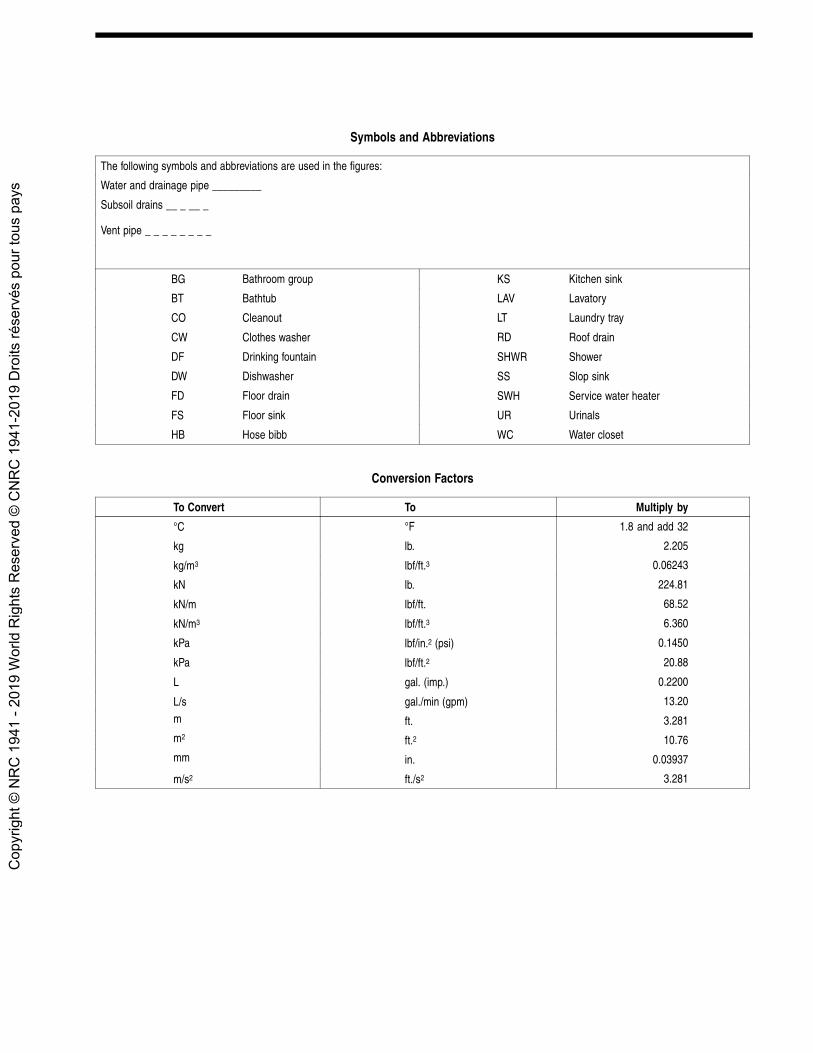
Symbols and Abbreviations
The following symbols and abbreviations are used in the figures:
Water and drainage pipe _________
Subsoil drains __ _ __ _
Vent pipe _ _ _ _ _ _ _ _
BG Bathroom group KS Kitchen sink
BT Bathtub LAV Lavatory
CO Cleanout LT Laundry tray
CW Clothes washer RD Roof drain
DF Drinking fountain SHWR Shower
DW Dishwasher SS Slop sink
FD Floor drain SWH Service water heater
FS Floor sink UR Urinals
HB Hose bibb WC Water closet
Conversion Factors
To Convert To Multiply by
°C °F 1.8 and add 32
kg lb. 2.205
kg/m3 lbf/ft.3 0.06243
kN lb. 224.81
kN/m lbf/ft. 68.52
kN/m3 lbf/ft.3 6.360
kPa lbf/in.2 (psi) 0.1450
kPa lbf/ft.2 20.88
L gal. (imp.) 0.2200
L/s gal./min (gpm) 13.20
m ft. 3.281m2 ft.2 10.76mm in. 0.03937
m/s2 ft./s2 3.281
Cop
yrig
ht ©
NR
C 1
941
- 201
9 W
orld
Rig
hts
Res
erve
d ©
CN
RC
194
1-20
19 D
roits
rése
rvés
pou
r tou
s pa
ys