
Computer-Aided Design of Traditional Jigs and Fixtures - MDPI
Upload
khangminh22Category
view
1download
0
Overview, Installation and Maintenance
of Plumbing Fixtures
Course No: M05-028
Credit: 5 PDH
Elie Tawil, P.E., LEED AP
Continuing Education and Development, Inc. 22 Stonewall Court
Woodcliff Lake, NJ 07677
P: (877) 322-5800

Addendum Sheet Overview, Installation and Maintenance of Plumbing Fixtures
Course # M05-028
ADDENDUM SHEET FOR OVERVIEW, INSTALLATION AND MAINTENANCE OF
PLUMBING FIXTURES - COURSE # M05-028
The modifications listed in this addendum sheet apply to the Naval Education and Training
Professional Development and Technology Center “Plumbing Fixtures” NAVEDTRA 14265A
training course, chapter 6.
Corrections as of December, 2020:
To prevent compatibility issues, and to ensure that the content of this document is accessible in its
entirety, the interactive educational clips that are part of the original document have been disabled.
The items listed below have been added/modified to preserve the information presented in the
original document.
Page Correction
6-6 1.1.0. Rough-In Measurements. In line 1, changed “Figure 6-1 shows general
rough-in measurements for various fixtures” to “Figure 6-1 shows general rough-
in measurements for a tank-type water closet”.
6-6 Figure 6-1. Changed the title “Figure 6-1 – Rough-in measurements for various
fixtures” to “Figure 6-1 – Rough-in measurements for a tank-type water closet”.
6-8 Figure 6-4 – Wall mounted water closet. Replaced figure shows all the original
frames in a single image.
6-14 Figure 6-14 – Lavatory drains. Replaced figure shows all the original frames in a
single image.
6-15 Figure 6-15 – Lavatory water supply and waste hookups. Replaced figure shows
all the original frames in a single image.
6-15 Figure 6-16 – Types of faucets. Replaced figure shows all the original frames in a
single image.
6-19 Figure 6-22 – Shower mixing valves. Replaced figure shows all the original
frames in a single image.
6-20 Figure 6-23 – Types of shower heads. Replaced figure shows all the original
frames in a single image.
6-22 Figure 6-27 – Integral trap with ball check valve. Replaced figure shows all the
original frames in a single image.

Addendum Sheet Overview, Installation and Maintenance of Plumbing Fixtures
Course # M05-028
6-30 Figure 6-31 – Replacing a leaking section of pipe. Interactive clip is disabled.
6-31 Paragraph 1. In line 4, change “Figure 6-32, View B” to “Figure 6-33, View B”.
6-31 Paragraph 2. In line 3, change “Figure 6-32, View B” to “Figure 6-33, View B”.
6-31 Paragraph 3. In line 2, change “Figure 6-32, View C” to “Figure 6-33, View C”.
6-31 Figure 6-33 – Adding connections to an outside vitrified clay sewer pipe.
Interactive clip is disabled.
6-33 Figure 6-36 – Flush tank process. Interactive clip is disabled.
6-35 Figure 6-38 – Operation of diaphragm flushometer. Replaced figure shows all
the original frames in a single image.
6-37 Figure 6-41 – Compression faucet. Interactive clip is disabled.
6-44 Figure 6-49 – Tools for clearing stoppages in plumbing fixtures. Replaced
figure shows all the original frames in a single image.
6-52 Figure 6-52 – Types of lavatories. Replaced figure shows all the original frames
in a single image.
6-53 Figure 6-53 – Types of stoppers. Replaced figure shows all the original frames in
a single image.
6-57 Figure 6-57 – Types of flushometers. Replaced figure shows all the original
frames in a single image.
All Text alignment and justification.

NAVEDTRA 14265A 6-1
Chapter 6
Plumbing Fixtures
Topics
1.0.0 Plumbing Fixtures
2.0.0 Plumbing Repairs
3.0.0 Pipe Leaks
4.0.0 Water Closets
5.0.0 Flushometers
6.0.0 Faucets
7.0.0 Sewer Maintenance and Repair
8.0.0 Clearing Stoppages in Fixtures
9.0.0 Water Heater Installation
10.0.0 Lavatory Installation and Replacement
11.0.0 Water Closet Installation and Replacement
12.0.0 Urinal Installation and Replacement
13.0.0 Shower Installation
Overview
"Roughing-in," as applied to plumbing and pipe fitting, is a term used for the installation of concealed piping and fittings at the time a building is being constructed or remodeled. As the building nears completion, the final connection of the plumbing fixtures is made. Once construction is complete, continuous maintenance and repair on the entire water and sewer systems will be necessary. In this chapter, you will be introduced to various procedures and methods to install, maintain, and repair water and sewage systems.
Use the information given here as a foundation on which to build a wider and broader knowledge of the Utilitiesman rating.

NAVEDTRA 14265A 6-2
Objectives
When you have completed this chapter, you will be able to do the following:
1. Describe the different types of plumbing fixtures.
2. Describe the procedures associated with plumbing repairs.
3. Describe the procedures for locating pipe leakage.
4. Describe water closet installation and repair.
5. Describe flushometer installation and repair.
6. Describe faucet installation and repair.
7. Describe procedures associated with sewer maintenance and repair.
8. Describe procedures for clearing stoppages in plumbing fixtures.
9. Describe water heater installation and replacement.
10. Describe lavatory installation and replacement.
11. Describe water closet installation and replacement.
12. Describe urinal installation and replacement.
13. Describe shower installation and replacement.
Prerequisites
None
NAVEDTRA 14265A 6-3
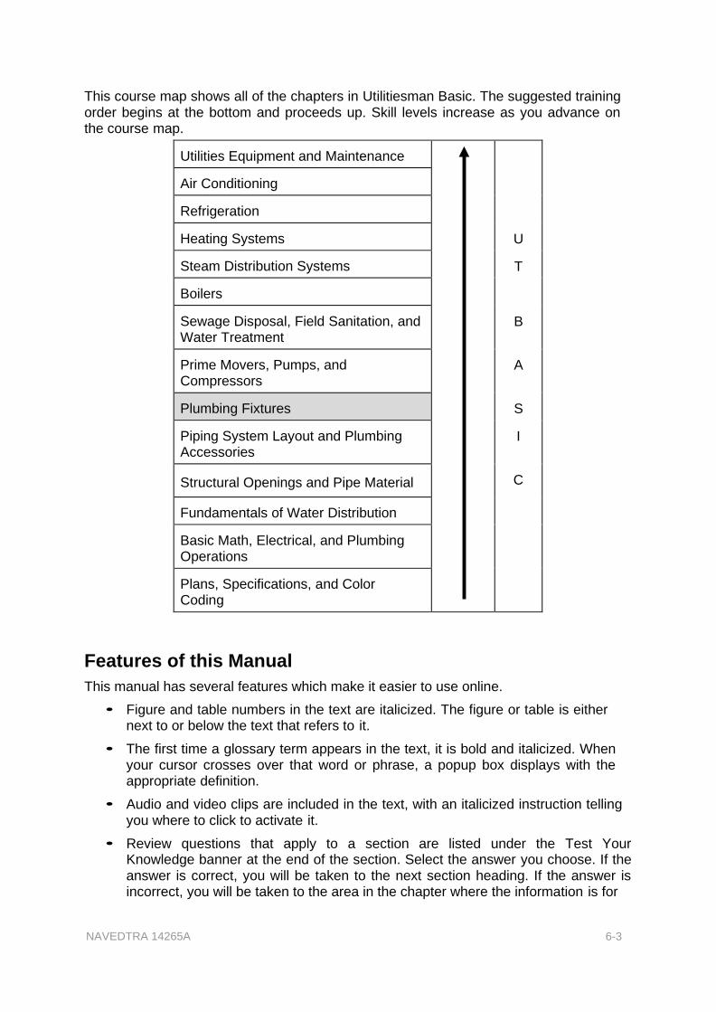
This course map shows all of the chapters in Utilitiesman Basic. The suggested training order begins at the bottom and proceeds up. Skill levels increase as you advance on the course map.
Utilities Equipment and Maintenance
U
T
B
A
S
I
C
Air Conditioning
Refrigeration
Heating Systems
Steam Distribution Systems
Boilers
Sewage Disposal, Field Sanitation, and Water Treatment
Prime Movers, Pumps, and Compressors
Plumbing Fixtures
Piping System Layout and Plumbing Accessories
Structural Openings and Pipe Material
Fundamentals of Water Distribution
Basic Math, Electrical, and Plumbing Operations
Plans, Specifications, and Color Coding
Features of this Manual
This manual has several features which make it easier to use online.
• Figure and table numbers in the text are italicized. The figure or table is either next to or below the text that refers to it.
• The first time a glossary term appears in the text, it is bold and italicized. When your cursor crosses over that word or phrase, a popup box displays with the appropriate definition.
• Audio and video clips are included in the text, with an italicized instruction telling you where to click to activate it.
• Review questions that apply to a section are listed under the Test Your Knowledge banner at the end of the section. Select the answer you choose. If the answer is correct, you will be taken to the next section heading. If the answer is incorrect, you will be taken to the area in the chapter where the information is for

NAVEDTRA 14265A 6-4
review. When you have completed your review, select anywhere in that area to return to the review question. Try to answer the question again.
• Review questions are included at the end of this chapter. Select the answer you choose. If the answer is correct, you will be taken to the next question. If the answer is incorrect, you will be taken to the area in the chapter where the information is for review. When you have completed your review, select anywhere in that area to return to the review question. Try to answer the question again.

NAVEDTRA 14265A 6-5
1.0.0 PLUMBING FIXTURES
Plumbing fixtures include faucets, tanks, and receptacles in kitchens and bathrooms. There are many types and styles of fixtures; some are general, while others have been adapted to meet special applications, such as for hospitals, prisons, and similar institutions. Military installations usually are planned to house large numbers of personnel, and the plumbing fixtures ordinarily are installed in batteries. Instructions for installing fixtures are given either by the manufacturer or by specifications. Sometimes you may have to design and lay out a fixture or battery of fixtures. You must know what water supplies and stack sizes are needed and work these into your design.
Standard plumbing fixtures are individually tested so that the amount of liquid waste that can be discharged through their outlet orifices in a given interval is measured. The fixture unit value for different plumbing fixtures is shown in Table 6-1. The basis for the fixture unit system comes from the fact that the washbasin, one of the smaller fixtures discharges 1 cubic foot of water per minute.
Table 6-1 - Plumbing Fixture Unit Values.
FIXTURE UNITS
Lavatory or washbasin 1
Kitchen sink 2
Bathtub 2
Laundry tub 2
Combination fixture 3
Urinal 5
Shower bath 2
Floor drain 1
Slop sink 3
Water closet 6
180 square feet of roof drained 1
Plumbing fixtures must be furnished with water at a rate of flow that will fill it within a reasonable time, as well as, with a waste pipe of sufficient capacity to carry off all water supplied to it quickly and quietly.
Table 6-2 shows the minimum supply pipe diameters, according to the National Standard Plumbing Code

NAVEDTRA 14265A 6-6
Table 6-2 - Minimum Size Fixture Supply.
FIXTURE Supply Pipe Diameter Min. Size
Water closet (tank type) 1/2 inch
Water closet 1 inch
Flushometer urinal with flushing valve 3/4 inch
Laundry tubs 1/2 inch
Kitchen sink 1/2 inch
Lavatory 1/2 inch
Slop sink 1/2 inch
Drinking fountain 1/2 inch
Shower 1/2 inch
1.1.0 Rough-In Measurements
Figure 6-1 shows general rough-in measurements for a tank-type water closet. These measurements vary depending on the type of fixture and the manufacturer. It is your responsibility to identify the fixtures you will be using so you can obtain the proper rough-in measurements.
Figure 6-1 - Rough-in measurements for a tank-type water closet

Service connections for steam radiators depend upon their sizes and location. The same holds true for water tanks used for storing or heating.
After roughing-in, you can easily install the plumbing fixtures and trim work. Instructions are given here for the installation of various fixtures and accessories. Even though not every type of fixture is included. if you learn to install the fixtures covered in Figure 6-1, you should not have any problems with other types.
1.2.0 Water Closets
Water closets, devices designed to receive human waste and dispose of it properly in a sanitary sewer system, come in various shapes, designs, and colors. Most water closets mount on the floor, but some models are wall-hung. Modem water closets have various design features which create
different flushing actions.
1.2.1 Installation
To install a water closet, shown in Figure 6-2, follow these procedures as a general guide.
1. Slip the water closet flange over the closet bend and slide it down until it is level with the finish floor.
2. With a hammer and cold chisel, break off the portion of the closet bend that projects above the water closet flange. Do not break the closet bend below the flange.
3. Place the two brass closet hold-down bolt heads in the slots of the flange.
4. On the bottom of the water closet, as shown in Figure 6-3, View A, slip the preformed sealing ring over the horn to form a sealing gasket for the water closet against the face of the
Figure 6-2 - Water closet (tank type).
flange. Do not use putty as it will dry out and leave a possible sewer gas leak.
5. Turn the water closet bowl right side up and set it on the flange with the horn projecting down into the flange. Place a wedge under the low side of the water closet if unlevel. In setting the bowl on the flange, as shown in Figure 6-3, View B, guide the two hold-down bolts up through the bolt holes on either side of the base of the water closet. Use your full weight to press down and twist
NAVEDTRA 14265A
Figure 6-3 - Setting a closet bowl.
6-7

NAVEDTRA 14265A 6-8
slightly to settle the bowl and the wax ring into position. The bowl should be perfectly level when settled.
6. Install nuts on the hold-down bolts and tighten them alternately. Do not over tighten them as this may crack the base of the water closet.
7. A wall-mounted water closet is attached to the wall by a chair carrier, similar to the one shown in Figure 6-4. The chair carrier is positioned and bolted to the floor. A standard fitting is used to connect between the drain and the closet bowl after the chair carrier is bolted down. The fittings are for 4-inch iron or soil pipe. The bolt holes in the chair carrier are slotted to facilitate installation of the closet bowl.
When mounting a close-coupled tank on a closet bowl, note that two bolts hold the tank on the bowl, as Figure 6-5 illustrates. The water supply pipe is between the bolts and drops the water directly into the bowl. A specially designed gasket is installed
between the tank and bowl to make the connection waterproof. The bolts are tightened from underneath the closet bowl. Do not apply too much pressure when you tighten these bolts, because you may crack the bottom of the tank or the back of the bowl.
Figure 6-4 - Wall-mounted water closet.
Figure 6-5 - Mounting a close coupled tank.

NAVEDTRA 14265A 6-9
After the tank is firmly attached to the bowl, connect the water supply pipe to the tank inlet with a riser tube, as shown in Figure 6- 6. The jiffy connector used here is the same as the connector used to connect the water supply to the faucets of a lavatory. The rubber washer shown in Figure 6-6 is commonly referred to as a doughnut washer because of its thickness.
1.2.2 Flushometer Valves
Because of how they operate, flushometers are referred to in two categories, piston and diaphragm. In some applications they are used in place of a tank-type valve. When a flush valve is used, no tank to hold the flushing mechanism or water is required, therefore, larger pipe diameters are required.
Figure 6-6 - Closet tank water supply line.
Flush valves require less water volume per flush than a tank-type valve, provide quicker multiple flushing capability, and lower maintenance costs in commercial applications; however, they are noisier, initially cost more, and require a higher operating pressure than tank-type valves. These items usually require larger pipe sizes. Basically, the flush valve is suited more for the commercial or industrial application, and the flush tank is used in small buildings or single family dwellings.
A backflow preventer or vacuum breaker, such as the type shown in Figure 6-7, should be installed on the discharge side of a flushometer and on the supply line of a float valve in a water closet tank, if the tank outlet is below the flood level rim of the closet bowl.
Figure 6-7 - Flushometer valve showing a backflow preventer.

NAVEDTRA 14265A 6-10
A detail of a diaphragm type of flushing valve is shown in Figure 6-8. The diaphragm type of valve consists of an upper and lower chamber. These chambers are separated by the diaphragm and relief valve. The lower chamber is connected directly to the incoming water supply. This incoming water is the flushing water and also shuts the valve off after the flushing period. The valve is flushed by the diaphragm and the water pressure in the upper chamber. Water is forced into the upper chamber through a small orifice (hole) in the diaphragm. Water pressure, passing through this orifice into the upper chamber, creates the pressure required to force the diaphragm down and shuts off the flushing water. When the flushing handle is moved, the relief valve tilts open. Then
Figure 6-8 - Diaphragm type of
flushing valve.
pressure decreases in the upper chamber to less than that of the incoming and flushing water. The action allows the flushing water pressure to raise the diaphragm off the flushing seat and recycle.
Figure 6-9 shows a piston type of valve. With this type of flush valve, the piston is drawn up when the flushing begins, then to its closed position by the filling of the upper chamber
through the expeller orifice tube.
Flush valve assemblies on urinals and water closets may be protected from unnecessary damage and wear by installing a grip handle or guard firmly over the handle housing. This grip handle increases the operating life of flush valves and thereby reduces service calls on the repair of flush valve assemblies and plumbing fixtures.
1.3.0 Urinals
Two major types of urinals in Figure 6-9 - Piston type of flushing valve.
use are the floor-mounted and wall-mounted urinals. We will discuss some of the main items relating to the installation of the wall-hung urinal (Figure 6-10). Before installing a floor-mounted urinal, refer to local codes to ensure it is legal.

NAVEDTRA 14265A 6-11
In setting the wall-mounted urinal, see that the rough-in of the waste pipe and water supply are at the correct height from the finished floor so after installation the urinal is within reach of the user. Commonly the lip of the urinal should be from 20 to 25 inches from the floor. If the rough-in already installed in the building places the height of the urinal above or below these general measurements, the rough-in should be removed then the water supply and waste pipe should be brought in at the proper height. It is imperative to refer to manufactures rough in drawings or make you own rough in drawings from prints, details, specs, and measurements from the flush valves and fixtures to avoid rework.
Since the wall-hung urinal sometimes has an integral trap (a trap contained in the
Figure 6-10 - Wall-mounted
urinal.
fixture), it is not always necessary to provide the waste pipe with a separate chrome or iron trap. Integral trap urinals have a back spud fitting that connects the waste pipe and urinal together with a rubber seal in between. Install a mounting board on the wall where a urinal is to hang. This board will provide firm support for the urinal, and should be used for installing fixtures on hollow wall, like dry wall, not concrete or masonry structures. The last step in the installation of the wall-hung urinal is the connection of a flushing mechanism, such as the diaphragm type of flushing valve.
1.4.0 Bidets
A bidet is equipped with running cold and hot water and is used for bathing external genitals and posterior parts of the body. The bidet is installed mainly overseas; however, the bidet is becoming very popular in the United States.
The water is controlled by faucets similar to those found on many lavatories. The flow of water may rise from the center of the bowl or around the rim. The bowl contains a stopper which holds water in the bowl if desired.
1.5.0 Sinks
Sinks are made in different patterns, each intended to serve specific purposes. Two common types of sinks are the kitchen sink and the service sink (slop sink).
1.5.1 Kitchen Sink
The kitchen sink is available in different sizes and may have either a single or a double bowl made of various materials like stainless steel, enameled steel, plastics, or cast iron.
A kitchen sink must be built into a cabinet or hung from a bracket that is screwed to a mounting board. The bracket should be screwed into the mounting board in a position where the sink, when mounted, is at a convenient height for use. As a rule of thumb, the distance between the top of the drain board and finished floor should not be less than 36 inches.
After screwing the bracket into place, lower the sink into position on the bracket, so the lugs, cast into the back of the sink, fit down into the corresponding notches in the

NAVEDTRA 14265A 6-12
bracket. Screw the strainer and tailpiece into the sink bowl and connect the trap to the rough-in waste. To complete the installation, select a suitable faucet. Install the faucet on the sink and connect the water supply to it, as shown in Figure 6-11.
Figure 6-11 - Kitchen sink water supply hookup.

NAVEDTRA 14265A 6-13
Then install and connect the waste lines to the sink, as shown in Figure 6-12.
Figure 6-12 - Kitchen sink waste hookup.
1.5.2 Service Sink
A service sink, also referred to as a slop sink, is especially useful for filling a bucket or washing out a swab. It has a deep bowl and is generally constructed of cast iron and finished in enamel, but can also be made of other various materials.
The slop sink installation is similar to the kitchen sink installation. The slop sink is also mounted on a bracket and mounting board. In addition to the hanger, the slop sink has a built-in adjustable stand trap that bolts to the floor and provides a pedestal support (Figure 6-13). The stand trap should be adjusted to take most of the weight off the hanger and prevent the unit from sagging.
Figure 6-13 - Service (slop) sink.

NAVEDTRA 14265A 6-14
After the fixture has been set in place and the waste supply has been connected, suitable faucets are installed and connected to the water supply, and the unit is ready for use.
1.5.3 Lavatories
The wall-hung lavatory, the most common type in use, is suspended from a bracket screwed to the wall. It may or may not be additionally supported by legs. Refer to the manufacture's instructions to install this fixture, and complete the following steps:
1. Mark the wall at the correct height for a lavatory and secure a hanger to the wall.
2. Position the lavatory on the hanger.
3. Install the lavatory faucets using a basin wrench.
4. Install the permanent opening (P.O.) plug drain, as shown in Figure 6-14, View A, or the
pop-up type of drain, as shown in Figure 6-14, View B.
Figure 6-14 - Lavatory drains.
5. Connect the water-supply lines to the faucets, as shown in Figure 6-15, View A.
6. Connect the waste-supply line to the lavatory, as shown in Figure 6-15, View B.

NAVEDTRA 14265A 6-15
1.5.4 Faucets
As an Utilitiesman, you may often be called upon to install or make repairs to faucets. There are many types of faucets in general use, such as the bib, lavatory, bath, and kitchen combinations.
The hose bib faucet, shown in Figure 6-16, View A, is used where outside hose connections are needed.
You probably recognize the combination faucets shown in Views B, C, and D of the figure. These faucets generally are used to combine the flow from hot-and cold water pipes. A main feature of these faucets enables the water to be tempered as it is discharged through a single spout. They are commonly used on lavatories, and in baths and kitchens.
Figure 6-16 - Types of faucets.
Figure 6-15 - Lavatory water supply and waste
hookups.

NAVEDTRA 14265A 6-16
1.6.0 Shower and Tub Combination
Several types of bathtubs are on the market today, such as the recessed, the corner recessed, the sunken, and the leg type. Tubs sizes range from 4 to 6 feet in length, and they are designed as right- or left-hand tubs, depending on the location of the drain.
When you face the tub, if the drain is on the right end, it is a right-hand tub; if on the left end, a left-hand tub. Most
bathtubs today are made of enameled cast iron, enameled pressed steel, or fiberglass, which is most commonly used for the built-in type.
The installation of both the bathtub and shower is simple. Tubs and showers come in many different applications:
tubs, showers, tub-and-shower combinations, and gang showers (large room with no privacy partitions or dividers).
To install a tub, like the type shown in Figure 6-17, View A, place the rim of the tub on the 2- by 4-inch support nailed to the 2- by 4-inch studs, as shown in Figure 6-17, View B. Check to be sure the tub is
level. Figure 6-17 - Bathtub and support.

NAVEDTRA 14265A 6-17
Once the tub is in place, hook up the water-supply lines, as shown in Figure 6-18. In a
bathtub and shower combination, water is furnished by a faucet and spray nozzle. Two valves usually control the flow of water to these units. Ordinarily, when the valves are opened, the water runs into the bathtub from the bathtub faucet. However, for water to run through the shower head, the valves are opened as for filling the bathtub; the diverter, which is located in the bathtub faucet, must be raised. This combination allows the bather to take a bath or a shower.
Figure 6-18 - Bathtub and shower piping combination.

NAVEDTRA 14265A 6-18
A tub drain and overflow are usually similar to that shown in Figure 6-19. The drain assembly is installed in the space provided by the studs at the end of the tub. The overflow and waste drains are made of chrome. The fittings are 1 l/2 inches in diameter and come with a pop-up waste or a rubber stopper fastened to the overflow by a chrome chain. This drain and overflow combination is connected to the P trap with slip-joint nuts and rubber washers to seal off the leaks. The drain in the bottom of the tub is sealed against leaks with plumber's putty and rubber rings.
The wastewater supply lines, as shown in Figure 6-20, are then connected to the tub.
Figure 6-19 - Bathtub combination waste
and overflow.
Figure 6-20 - Tub waste hookup.
The faucet and shower combination for a bathtub and shower is connected to the hot and cold waterlines that were installed when the piping was roughed-in. The manufacturer's specifications should be used to determine the height of the riser. The height, however, may be specified by the user. The shower and bathtub piping and fittings installed within the wall are made of rough brass; those that extend through the finished wall have a chrome finish. A typical bathtub and shower piping arrangement is shown in Figure 6-21. When you make this type of bathtub and shower installation, be

sure to locate the bathtub spout from 2 to 4 inches above the rim of the tub. Spacing the spout above the rim of the tub prevents siphoning of the water from the tub in case the valve is left open and the water drops at the same time. This installation prevents cross-connection between potable and non- potable water.
The mixing valves in the shower system supply a uniform temperature of water for the shower or tub. The temperature of the water may be regulated between the limits of the temperature of the cold-water supply and the hot-water supply. The manual, pressure, and thermostatic mixing valves control the temperature of the water.
The manually controlled mixing
Figure 6-21 - Bathtub and shower piping
arrangement.
valves consist of two hand-operated valves in one body with outlets for both valves that feed the shower head. The valves are turned by hand to control the temperature of the water. Manually controlled valves require a piping arrangement similar to the one shown in Figure 6-21. This water tempering setup does not protect against sudden changes of temperatures due to slugs of hot or cold water from varying pressures or water temperatures in the supply lines.
The pressure-controlled mixing valve, like the one shown in Figure 6-22, View A, consists of a mixing chamber that contains a sliding piston. The piston has jets to allow hot and cold water to pass through them and mix when the handle of the valve is operated. The setting of the handle controls the water temperature by establishing the mixing ratio. A change in pressure on one side of the piston causes the piston to move and increases the flow from the low-pressure supply to maintain a nearly constant pressure.
The thermostatically controlled mixing valve, similar to the one
NAVEDTRA 14265A Figure 6-22 - Shower mixing valves. 6-19

shown in Figure 6-22, View B, is sensitive to changes in both temperature and pressure.
The temperature of the water delivered by the valve remains constant regardless of the temperature and pressure changes in the hot and cold waterlines. The thermostatic mixing valve is used for showers only.
The shower head is attached to a 45- degree fitting mounted on a chrome pipe. There are two general types of shower heads: circular and economy. The circular spray head, shown in Figure 6-23, has notches or grooves around the outer edge of its face. The spray in this type of head can be regulated. The economy head, also shown in Figure 6-23, has a restricted nozzle that provides a finer spray and uses less water. Both shower heads have a ball- and-socket joint for adjusting the direction of the spray.
Shower heads are usually made of chrome- or nickel-plated brass. Newer types of shower heads are made of noncorrosive plastic. Deposits tend to form on the shower head because of the chemical content of the water; therefore, occasional
Figure 6-23 - Types of shower
heads.
maintenance using cleaning and soaking solutions is required to keep them functioning properly.
The most important requirement in a shower installation is the absolute waterproofing of walls and floors. Walls are less of a problem than floors since they are subject only to splashing of water and do not have water standing or collecting on them. Careful installation of tile or other impervious material with waterproof cement generally suffices to provide a waterproof wall installation. In the installation of the floor, an impervious waterproof subbase must be put under the shower floor, or water standing on the floor will gradually seep through and cause leaks.
Concrete shower pans, used with prefabricated steel shower stalls, are relatively easy to install. In many cases, steel shower stalls are set up after the original construction. In this case, the cement base is usually not recessed into the floor but is laid directly on top of the floor.
Generally, steel fabricated shower stalls are being replaced with fiberglass and plastics. All of the units are installed in the same manner. The dimension for the finished interior of a shower stall should be at least 30 inches. The shower head should be a minimum of 68 inches above the level of the drain on the shower pan (Figure 6-24).
NAVEDTRA 14265A 6-20

Figure 6-24 - Shower stalls and sections.
Figure 6-25 shows a cutaway view of a shower pan. All pipe openings in the wall of the stall should be sealed. Be sure to follow the manufacturer's instructions that accompany the fixtures and trim. The shower
pan is connected to a P trap following the shower pan manufacturer's instructions.
1.7.0 Drinking Fountains
Most types of drinking fountains should be installed with the orifice located from 30 to 40 inches above the floor, depending upon the general height of the users or specific requirements for a facility. One type of wall-hung drinking fountain is shown in Figure 6-26.
NAVEDTRA 14265A
Figure 6-25 - Cutaway view of a shower
pan drain.
6-21

NAVEDTRA 14265A 6-22
The mounting of the fixture should be sturdy and strong enough to hold more weight than that of the fixture itself. Most drinking fountains are installed with a 1 1/4- inch P trap, but a few are available with integral traps. The electrically cooled drinking fountain requires an electrical outlet nearby for power. Because of the many variations in style of drinking fountains, the manufacturer's installation procedures and specifications should be followed in each case.
1.8.0 Floor Drains
Floor drains are used to carry contaminated water to the sanitary or storm sewer. Sanitary sewage very rarely passes through a floor drain, unless other fixtures in a system overflow and sewage backs up into the floor drains.
Floor drains are divided up into two groups: those that are designed with a water seal and those that are not. Floor drains used in connection with a sanitary sewer by code must have a water seal (Figure 6-27, Views A and B). The water seal prevents gases and odors from the sewer from coming into the building or structure containing the floor drain. Drains without a water seal (Figure 6-28) may be used when the floor drains are connected in a system that feeds into a storm sewer system.
A floor drain that is 2 inches in diameter is rated at two drainage fixture units. A floor
Figure 6-26 - Wall-mounted
drinking fountain.
drain that is 3 inches is rated at three drainage fixture units. The load of fixture units for floor
Figure 6-27 - Integral trap with ball check
valve.
drains is added to the sanitary system, not the vent system. Most code requirements do not require floor drains to be vented if they are installed within 25 feet of a vented drainage pipe line.

NAVEDTRA 14265A 6-23
Figure 6-28 - Drain without a
water seal.
1.9.0 Water Heaters
Clean, hot water is required in many installations for domestic and industrial use. Since boiler water cannot be used for this purpose because of the chemicals added, it is necessary to heat additional water. The water may be heated in tanks equipped with coiled piping through which the boiler water or steam circulates. Or it may be heated in independent units that heat by electricity, gas, solar, or oil.
Domestic water heaters are built in various sizes from zero capacity instant heat to 50- gallon storage capacities. Industrial type water heaters are designed to heat thousands of gallons of water, depending upon the use.
Modern water heaters are self-contained and require very little attention, since they are fully automatic. These units are cylindrical in shape and have diameters ranging from about 12 to 30, 40, and 50 inches, depending upon their capacity. The tank is constructed of galvanized sheet metal, which may be lined with a composition of glass to resist corrosion of the tank lining and prevent contamination of the water. The combustion chamber is in the lower section, which is vented by a baffled flue that extends through and ends at the top of the tank. The entire tank is insulated to prevent the escape of heat. It is also equipped with a thermostat which can be adjusted to maintain a certain water temperature. Automatic safety features are built into the units.
Both the cold-water inlet and the warm-water outlet are at the top of the tank. These tappings are usually marked "INLET" and "OUTLET." However, if there is a question in your mind as to which is which, just remember that the cold-water inlet pipe extends over halfway into the tank, but the outlet pipe does not. There is usually a drain valve at the bottom of the tank.
You must ensure the dip tube is installed on the cold-water side or inlet to allow the cold water to go to the bottom of the heater and not cool the water at the top.
Gas water heaters must be installed with a Pressure Temperature Release Valve (PTRV), which is a safety device, is normally located in the top of the shell. The PTRV is set to open on a temperature or a pressure rise of an unsafe limit. PTRVs differ from

NAVEDTRA 14265A 6-24
safety valves in that a PTRV opens gradually at a set point. Normally the valve opens at 210 degrees or at 125 psi at a minimum. The pipe that carries the relieved water or steam from the tank must extend to within 18 inches of the deck to prevent a hazardous condition.
Always remember that water in a closed vessel will expand when heated and cause the pressure to rise. If, for some reason, a control fails to turn the heat source off, the pressure will be relieved by the PTRV. The water that comes out of the outlet of a PTRV will flash off due to the pressure change; steam along with scalding water will be discharged from the tank.
Test your Knowledge (Select the Correct Response)
1. What two types of urinals are most commonly used by the Seabees?
A. Floor- and wall-mounted B. Floor- and side beam-mounted C. Parallel and perpendicular mounted D. Wall- and diagonal mounted
2.0.0 PLUMBING REPAIRS
This portion of the chapter will deal with some of the more common plumbing repairs that will be necessary from time to time to keep plumbing systems operating properly. Proper repairs and maintenance techniques save money by extending the life of plumbing systems. For example, one water faucet that is leaking one drop of water each second wastes about 2,300 gallons of water per year.
2.1.0 Water Breaks
Water distribution piping at one time or another will require repair on a leak or a break in the line. The following are problems you may have during a waterline break:
• The water supply for fire protection is reduced or does not exist.
• Escaping water under pressure undermines structures, damages foundations, destroys landscaping, or causes a serious erosion problem.
• A broken pipe causes a health hazard because the distribution system can become contaminated by external sources.
• The water supply for normal domestic or industrial use can be completely cut off.
To ensure proper repair of a water break, keep red line prints and as built drawings on hand that show the water distribution system, existing conditions, and locations. Ensure that you red line your set of prints every time you make a repair or line change.
Additionally, notify engineering of your line repair or line change, and they will update the master set of base prints.
At some activities, electronic devices are available for subsurface survey and pipe location work. Sometimes you may have to find points of interconnection, pipe diameters, and the condition of exterior surfaces or coatings. For future use, make notes on the maintenance prints to show the general condition of the system. Use a symbol that stands out to show the approximate age of the installation or its parts. Prints should be complete and up-to-date. In maintenance or repair, these prints help in planning maintenance. Many times they offer clues to the most probable location and

NAVEDTRA 14265A 6-25
probable cause of trouble. Now and then, the system should be flushed through hydrants and blow-offs to remove scale and accumulation in pipes and fittings. When performing this operation, start at the hydrants or blow-offs nearest the source of supply to conserve water and to stir up less of the distribution system. Each point should be flushed until the water comes out reasonably clear. All valves should be in their normal operating positions before you go on to the next point. Flushing dead ends is vital.
When flushing does not induce enough velocity to scour the mains clean, night flush them with a large discharge. Night operation lessens work disruption caused by water shutoff or decreased water pressure.
2.2.0 Water Mains
Since water main breaks must be repaired as fast as possible, personnel must be trained and repair plans made in advance. The following procedures are essential:
1. Post the telephone numbers of the fire department and key personnel and have alternate personnel available in case members of the regular repair crew cannot be reached at the time of a break. Notify the public works officer at the time the break is reported.
2. Always keep the following items readily available: valve keys, hand tools, digging tools, pavement breakers, trench shoring, a portable centrifugal or diaphragm pump, floodlights, an emergency chlorinator, and calcium hypochlorite powder.
3. Maintain enough pipe repair materials and supplies. As a temporary measure, wooden plugs can be used to stop small holes in a main. These plugs can be replaced later with metal plugs, or repairs may be made by other means. Wooden plugs can also be used temporarily to plug the ends of a pipe up to 8 inches in diameter, but such plugs must be braced to withstand existing main pressure. After repairs are completed, the main must be disinfected.
2.3.0 Thawing Frozen Pipes
In cold weather, a water-supply system can freeze. Because of the lack of protection against freezing, and sometimes regardless of it, pipes frequently freeze in temperate zones. When this happens, the pipes must be thawed. Breaks must be found, if possible, before natural thawing to prevent damage to material and property. Alert personnel to watch for the signs of a broken line. The prevention of freezing pipes can sometimes be accomplished by using heat tapes and cables.
Before starting to thaw a frozen pipe, open faucets affected by the freeze. Frozen pipes can be thawed by applying heat at the lowest open end of the frozen section. (Do NOT start in the middle of a frozen section because a pocket of steam could develop and an explosion or damage to the pipe can occur.) Where there is no danger of fire, simply heat the pipe with a blowtorch, applying the flame on the outside of the pipe.
Using hot water is the preferred method for thawing frozen water pipes or heating pipes inside of buildings. Do NOT use an open flame. A safe method is to wrap the frozen section of pipe with cloth and pour hot water on it until the ice gives way. Remember to protect the floor by catching the water in buckets or by covering the floor with material to absorb the water.

NAVEDTRA 14265A 6-26
A good method of thawing water pipes that are underground or otherwise hard to get to is shown in Figure 6-29. When using this method, remove the fittings (see illustration) and insert one end of the small pipe or tube into the frozen pipe. Now add an elbow and a piece of vertical pipe to the outer end of the thaw pipe. Place a bucket under the opening to the frozen pipe and insert a funnel in the open end of the vertical pipe.
With that done, start pouring boiling water through the funnel into the pipe. As the ice melts, push the thawed pipe forward. Where necessary, add pipe at the outer end until a passage is made through the ice.
Withdraw the thaw pipe quickly after the flow starts and do not stop the flow until the thaw pipe
Figure 6-29 - Thawing an underground or
otherwise inaccessible pipe.
is fully removed and the pipe cleared of ice.
Instead of a funnel, a small force pump can be used. This pump is useful for thawing a long piece of pipe. When available, you can use steam in place of hot water. The above method can also be used without the elbow and piece of vertical pipe, as shown in Figure 6-29. Simply connect the funnel to the outer end of the thaw pipe with rubber tubing. Have the tubing long enough so you can hold the funnel above the level of the frozen pipe. In this way, you give the hot water a head, forcing the cooled water back to the opening where it runs out into the pail. The advantage of the elbow and vertical pipe is that they increase the head of the water and make the use of the funnel easier.
2.3.1 Electrical Thawing
Electrical thawing of frozen service lines is quick and cheap. The electrical current for the thawing operation consists of a source of current (a DC generator, such as a welding outfit, or a transformer connected to an AC outlet) and two insulated wires connecting the current source and the pipe (Figure 6-30).

NAVEDTRA 14265A 6-27
Figure 6-30 - Connection points for thawing frozen service lines.
Only qualified personnel should use power lines as a source of current. As current flows through the pipe, heat is generated, and the ice within the pipe begins to melt. As the water starts to flow, the rest of the ice is melted by contact with the flowing water. The wires from the current source may be connected to nearby hydrants, valves, or exposed points at the ends of the frozen sections. Some data on current and voltage required for electrical thawing of various sizes of wrought-iron and cast-iron pipes are presented in Table 6-3.

NAVEDTRA 14265A 6-28
Table 6-3 - Relation of current and voltage required for thawing.
Type of pipe Pipe Size (in.) Pipe Length (ft.) Approximate Approximate (amps)
Wrought Iron 3/4 600 60 250
1 600 60 300
1 600 60 350
1/2 500 55 400
2 400 40 450
3 400 50 500
Cast Iron 4 400 50 600
6 300 40 600
8
The time for electrical thawing may vary from 5 minutes to over 2 hours, depending on pipe size and length, intensity of freezing, and other factors. The best practice is to apply current until the water flows freely.
Use the following procedures in electrical thawing:
1. DC Generator. To thaw pipes with a welding generator or similar DC source, set the generator to the correct amperage for the pipe to be thawed and connect the leads to the pipe.
2. AC Circuit. Transformers are required to adjust amperage of an AC circuit to the pipe being thawed. To reduce hazards, have a competent Construction Electrician (CE) set and connect transformers, make the connections, and assist in the thawing process. Where frequent thawing is necessary at different points, the transformers may be mounted on a trailer for ready use.
Some precautions in electrical thawing are given below:
• Avoid a higher current than listed in Table 6-3. When in doubt, use low current for a longer period.
• Select contact points on the pipe as close as possible to the frozen section.
• Assure that contact points are free of rust, grease, or scale.
• Remove meters, electrical ground connections, and couplings to buildings with plumbing in the pipeline to be thawed.
• If there are gaskets or other insulation at pipe joints, thaw the pipe in sections between such joints, or use copper jumpers to close the circuit across insulated points.
2.3.2 Steam Thawing
Steam thawing of frozen systems is slower than electrical thawing and should be used only when insulating materials in pipes (plastic, transite, and wood), pipe joints, or couplings make the use of electricity impractical. In steam thawing, a hose connected to a boiler is inserted through a disconnected fitting and gradually advanced as the steam melts the ice.

NAVEDTRA 14265A 6-29
2.3.3 Variation of Water Pressure
A change of water pressure can cause much discomfort to persons using the plumbing system. The mixture of hot and cold water from a shower can suddenly vary in temperature or rate of flow when water is turned on at another outlet. Failure to remedy this condition could injure somebody, especially if the temperature is scalding.
When a switch in pressure and water flow occurs often, look at the water pipes. Check the pipes to see if they are the proper size in diameter for their length and height as originally installed. Also look for liming and corrosion inside the pipes. Enough liming and corrosion can reduce the diameter of the pipe, causing restrictions that lead to low pressure and slow water flow.
Sometimes the trouble occurs after more fixtures have been installed in the system. When this happens, the piping is probably overloaded because of the extra fixtures. Pressure and water flow may also change when there is too much friction in the pipe, too many fittings, or changes in the direction of the piping.
If the pressure in showers changes only when other outlets are open, you can usually correct the trouble by installing automatic mixing valves. The only answer to an increase in the water flow from pipes that are too small is to replace them with larger pipes.
Test your Knowledge (Select the Correct Response)
2. When thawing frozen water pipes or heating pipes inside buildings, which method is preferred?
A. Open flame
B. Hot Water C. Electrical thawing unit D. Steam thawing unit
3.0.0 PIPE LEAKS
When a leak develops at a threaded joint of pipe, one of the most likely suspects is a fractured or ruptured pipe. Fractures often occur at the end of a length of pipe because of strain imposed by vibration of water hammer. It occurs at the end of the pipe because the wall thickness is decreased and weakened by threading. The risk of fracture becomes even greater when the threads are not cut true. In cold climates, freezing sometimes causes pipes to rupture, in which case replacement becomes necessary. A loose or cracked fitting can also cause leakage at the threaded joint of a pipe. These and other common failures resulting in pipe leakage make it important for you to determine the exact location and cause of failure before beginning any repairs to the piping.
3.1.0 Locating Leaks
Find and repair leaks in the water piping system as quickly as possible to prevent serious damage to footings, walls, floors, plaster, and other parts of the structure, and to conserve water. Also, sanitation and hygiene issues are associated with water leaks, such as mold, insect's sanitary system and disease. Find leaks systematically by inspecting exposed piping and valves and by examining walls, floors, and ceilings around concealed piping. You should also check gauges, meters, and other water flow recording devices for evidence of abnormal flow, which might reveal loss through leakage.

NAVEDTRA 14265A 6-30
In galvanized pipe installations, where the fittings on either side of the leak are not readily available, the leaking section may be cut out (Figure 6-31). In this operation, one person holds the pipe with a backup wrench to keep it from being over tightened or loosened in the adjacent fittings, and another person cuts a thread on it while it is in place using a hand type of pipe threader. The cutout section is then replaced with a coupling, a pipe section of the required length, and a union.
Figure 6-31 - Replacing a leaking section of pipe.
You may also have to repair leaks in copper piping. If a copper pipe leaks, cut out the damaged section and replace it with a new section, using either soldered joints or compression fittings. When a piece of cast- iron pipe less than full length is needed for replacement, cut it from a double-hub pipe, so the remaining piece has a hub left for use in other work.
If you need a fitting for a short space or if existing work cannot be removed easily, use short spigot ends for sleeves. Closely observe Figure 6-32. This figure shows how to install a fitting in a restricted space.
When the job calls for adding connections to an outside vitrified clay sewer line, here is one step-by-step method, shown in Figure 6-33.
Figure 6-32 - Installing a fitting in a
restricted space.
1. Remove a section of the existing sewer pipe that is long enough to receive a new Y-fitting.
2. Break half of the hub rim of the new Y-fitting, as shown in Figure 6-33, View A.

NAVEDTRA 14265A 6-31
3. Insert the spigot end of the Y-fitting into the hub of the existing pipe. At the same time, place the remaining half of the hub end of the Y-fitting over the cut end of the existing pipe with the Y-branch pointing away from the new inlet. (See the first position of Figure 6-33, View B).
4. Rotate the Y-fitting, so the broken half of the hub is up and the Y-branch is in the correct position to receive the new inlet connection. (See the final position Figure 6-33, View B).
5. Pour the joint carefully; round over the broken half of the hub with plenty of concrete or mastic compound, as shown in Figure 6-33, View C.
Figure 6-33 - Adding connections to an outside vitrified clay sewer pipe.
3.2.0 Emergency Temporary Repairs
At times, a pipe may start leaking and the materials needed to repair it permanently are not on hand. Here, you may have to use a temporary or emergency repair. Keep in mind that a permanent repair should always be made when the proper tools or materials are available.
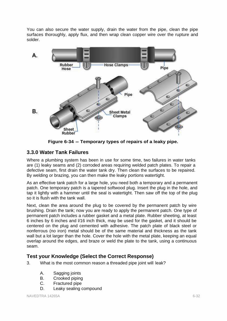
One simple method of making a temporary repair of a leaky pipe is to use a length of rubber hose. After turning off the water supply, remove the defective section of the pipe by cutting it with a hacksaw. Then take a piece of rubber hose, slightly longer than the section of pipe you removed, and slip it over the ends where the cut was made (Figure 6-34, View A). Ensure the inside diameter of the hose matches the outside diameter of the pipe. Use hose clamps to hold the hose securely in place.
Another temporary method of repair for a leaky pipe is to wrap the leaky area with sheet rubber, and then place two sheet metal clamps, one on each side of the pipe, on the sheet rubber covering, as shown in Figure 6-34, View B. Fasten the clamps with bolts and nuts. Sheet metal clamps for this type of repair can be made from scrap material from the sheet metal shop. You may want to make up a few of these clamps to keep on hand for an emergency repair job.
NAVEDTRA 14265A 6-32
You can also secure the water supply, drain the water from the pipe, clean the pipe surfaces thoroughly, apply flux, and then wrap clean copper wire over the rupture and solder.
Figure 6-34 - Temporary types of repairs of a leaky pipe.
3.3.0 Water Tank Failures
Where a plumbing system has been in use for some time, two failures in water tanks are (1) leaky seams and (2) corroded areas requiring welded patch plates. To repair a defective seam, first drain the water tank dry. Then clean the surfaces to be repaired. By welding or brazing, you can then make the leaky portions watertight.
As an effective tank patch for a large hole, you need both a temporary and a permanent patch. One temporary patch is a tapered softwood plug. Insert the plug in the hole, and tap it lightly with a hammer until the seal is watertight. Then saw off the top of the plug so it is flush with the tank wall.
Next, clean the area around the plug to be covered by the permanent patch by wire brushing. Drain the tank; now you are ready to apply the permanent patch. One type of permanent patch includes a rubber gasket and a metal plate. Rubber sheeting, at least 6 inches by 6 inches and l/16 inch thick, may be used for the gasket, and it should be centered on the plug and cemented with adhesive. The patch plate of black steel or nonferrous (no iron) metal should be of the same material and thickness as the tank wall but a lot larger than the hole. Cover the hole with the metal plate, keeping an equal overlap around the edges, and braze or weld the plate to the tank, using a continuous seam.
Test your Knowledge (Select the Correct Response)
3. What is the most common reason a threaded pipe joint will leak?
A. Sagging joints B. Crooked piping C. Fractured pipe
D. Leaky sealing compound

NAVEDTRA 14265A 6-33
4.0.0 WATER CLOSETS
Moisture on the floor at the base of a water closet bowl usually means the seal or gasket between the closet and its outlet has failed; however, it can result from condensation on the tank or piping or from leakage of the tank, flush valve, or piping. When the seal leaks, remove the water closet bowl and install a new seal to prevent damage to the building. This also prevents entry of sewer gas into the room.
In servicing plumbing fixtures, you have the job of clearing stoppages in water closets. Information on tools and chemicals used in clearing stoppages in water closets and other fixtures is given later in this chapter.
4.1.0 Flush Tank
Knowing the principles of operation of a flush tank will enable you to find the source of trouble when a flush-type water closet tank is not operating properly. Figure 6-35 shows the parts of a flush tank, though in different types of flush tanks you may find some changes in the method of operation.
Figure 6-36 explains the principal
operations of a water closet flush tank. Simple though it may seem, you must understand the operation in order to troubleshoot an inoperative flush tank.
Stage 1
When the flush handle is pushed downward, the rubber stopper ball or flap valve is raised from the valve seat to allow the water from the tank to go into the discharge pipe.
Stage 2
As the water lowers in the tank, the ball or flap lowers and the movement of the float arm opens the inlet valve, allowing water to start flowing into the tank slowly.
Stage 3
As the water flows from the tank to the discharge pipe, the ball or flap seats and incoming water holds the ball or flap in place and the tank fills.
Stage 4
As the water continues to fill the tank, the ball or flap rises until
Figure 6-35 - Water closet flush
tank.
Figure 6-36 - Flush tank process.

NAVEDTRA 14265A 6-34
the arm allows the valve to close.
4.2.0 Flush Tank Repairs
When water continues to run into the closet bowl after the flush tank is full, the trouble is in some part of the inlet valve assembly (ball cock assembly) or the stopper valve is not seated. The plunger has failed to close the inlet valve as it should, and thus the excess water that continues to flow in (after the tank has reached the proper level) is being discharged through the overflow pipe into the bowl.
In checking for the source of trouble, several defects you should look for are a leak in the float ball, a bent float arm, a worn washer on the bottom of the plunger, or a worn valve seat. Start with the float ball, keeping in mind that a leaky, waterlogged float prevents the plunger from closing properly. A small leak in a copper float ball can be remedied by soldering. If it has a large leak, though, simply replace the float ball with a new one. A damaged float arm should also be replaced with a new one. Sometimes the float arm is bent or does not
allow the valve to close. In this case, bend the float arm downward a bit to push the valve tighter into its seat. To replace the washer on the bottom of the plunger, start by shutting off the water (Figure 6- 37, View B). Then unscrew the two thumbscrews that pivot the float rod lever and the plunger lever (Figure 6-37, View A).
Push the two levers to the left, drawing the plunger lever through the head of the plunger. Lift out the plunger, unscrew the cap on the bottom, insert the new washer, and reassemble the parts. If the cap is badly corroded, replace it with a new one. When replacing the washer, examine the seat for
nicks and grit. The seat may need regrinding.
If water continues to run into the
Figure 6-37 - A. Ball cock. B. Plunger
washer and cap.
closet bowl after flushing, yet the tank does not refill, some part of the flush valve assembly is at fault because the flush valve is not closing properly. To locate the trouble and get the tank back in order, proceed as follows.
First, stop the inflow to the tank by holding up the float ball or supporting it with a stick. Then drain the tank by raising the rubber stopper ball or the flapper. Examine the stopper ball to see if it is worn or out of shape, or has lost its elasticity. If so, unscrew the lower lift wire from the ball and replace the ball with a new one; if it is a flapper valve, remove the flapper and replace it. There are no lift wires or wire guides to adjust on the flapper valve type of flush valve. Ensure the lift wire is easily fitted over the center of the valve by means of the adjustable guide holder. By loosening the thumbscrew, you can raise, lower, or locate the holder over the overflow tube. The

NAVEDTRA 14265A 6-35
horizontal position of the guide is fixed exactly over the center of the valve by loosening the locknut and turning the guide screw.
The upper lift wire should loop into the lever arm hole directly above the center of the valve. The tank should empty within 10 seconds. Because of lengthening of the upper lift wire and insufficient rise from its seat, emptying the tank may be longer than 10 seconds and the flush weak. In this case, shorten the loop in the upper lift wire. Also, a drop or two of lubricating oil on the lever mechanism makes it work more smoothly.
If you have a water closet tank that sweats and drops water on the deck, check the temperature of the water in the tank. If the temperature is very cold, this is the problem. The moisture in the air surrounding the tank is condensing on the tank. Solutions to the problem are placing a terry cloth on the tank to catch the water, placing a styrofoam insert in the tank, or installing a water tempering valve, which places some warm water in the tank while the tank is filling.
5.0.0 FLUSHOMETERS
Two major problems with flush valves are that the valve runs continuously, instead of shutting off at the right time, or that it fails to deliver the desired amount of water (short flushing). Since flush valves are installed to avoid waste, they must be properly maintained. Once you understand the operation of a valve, you can keep a flushometer in good repair.
5.1.0 Operation of Diaphragm Flushometer
Figure 6-38 shows the operation of a diaphragm-type flushometer.
Stage 1
The diaphragm valve is in the ready position. In this position the upper and lower chambers contain the same amount of pressure. Therefore, the diaphragm remains seated on the seat.
Stage 2
When the handle is moved in any direction, the plunger opens the relief valve, which allows the water from the upper chamber to flow into the lower chamber and causes the diaphragm to rise off its seat. Water now
continues to flow down the barrel and into the fixture.
Stage 3
Figure 6-38 - Operation of diaphragm
flushometer.
As the valve lifts the diaphragm, water begins to flow slowly through the bypass orifice until the pressure rises enough to equalize the pressure in the upper and lower chambers, seating the valve.

NAVEDTRA 14265A 6-36
5.2.0 Operation of a Piston Type Flushometer
The piston-type flushometer valve, shown in Figure 6-39, is opened by a lever which discharges the water from the dashpot chamber. The reduced water pressure in the dashpot chamber then forces the piston assembly upward, which allows the water to enter the fixture. The closing of the valve is automatically controlled with a bypass through which the water enters the dashpot chamber. This forces the piston assembly down onto its seat and stops the water flow. The closing of the valve is regulated by a screw that controls the amount of time the valve stays open.
5.3.0 Repairs
Flush valves give years of adequate and trouble-free operation when they are properly installed and maintained.
Figure 6-39 - Piston type
flushometer valve.
Continuous flow of water through a piston type of flush valve is almost always caused by failure of the relief valve to seat properly or by corrosion of the bypass valve. In both cases, there is not enough force on the piston to force it to seat. If the relief valve fails to seat as it should, the leakage may be enough to prevent the upper chamber of the valve from filling, and the piston remains in the open position.
Inspect the relief valve seat for dirt or other foreign substances that may be causing the relief valve to tilt; disassemble the piston, wash the parts thoroughly, and reassemble. Replace washers that are worn, making sure that the surface upon which the washer sets is perfectly clean; scrape off old rubber if any sticks to the metal surface.
Corrosion of the bypass valve in the center of the top plate also causes continuous flow; the water cannot pass into the upper chamber of the valve, and no force is exerted on the piston to move it downward to its seat. Very dirty water passing through the system can clog the bypass and deprive the upper chamber of water. When pipelines in a new installation are not thoroughly flushed before they are placed in operation, the pipe dope or dirt in them can stop up the bypass valve.
Likewise, in a diaphragm valve, if chips or dirt carried by the water lodge between the relief valve and the valve seat, the relief valve cannot seat securely. The water leakage prevents the upper chamber of the valve from filling with water. The valve then remains in the open position since there is no pressure to force the diaphragm to its seat.
Short flushing can occur in a diaphragm type of valve. If the valve seat, diaphragm, and guide cover have not been tightly assembled, you should reassemble the valve to ensure proper operation. Sometimes you may find the bypass tube has been tampered with, enlarging it so the water passes rapidly into the upper chamber and closes the valve before the desired volume is delivered.
Avoid getting oil or grease on the valve parts, which can lead to swelling of the rubber parts causing them to become unserviceable.

NAVEDTRA 14265A 6-37
Another commonly used unit is the pressure valve- head flushometer (Figure 6-40). The most common problem with this type of flushometer is the rubber cap. To replace the rubber cap is a simple task; remove the retaining screws, lift out the plate, and remove and replace the cap.
6.0.0 FAUCETS
Different types of faucets are used in plumbing installations. If you can repair the compression washer faucet, you should have no trouble in repairing other types of faucets. A cutaway view of a compression faucet is shown in Figure 6-41. This faucet, with a disc washer and a solid or removable seat, requires frequent attention to maintain tight closure against water pressure.
When a faucet is turned off, the washer on the end of the stem rubs against the seat. Frequent use wears down the washer and eventually causes the faucet to drip. A small, steady leak in a faucet wastes water. The remedy for a dripping faucet is simply to replace the washer. Be sure to replace flat or beveled washers with washers of the same design.
Figure 6-41 - Compression
faucet.
Figure 6-40 - Pressure
valve head flushometer.

NAVEDTRA 14265A 6-38
6.1.0 Standard Faucets
To repair a standard washer faucet, follow these steps.
1. Shut off the water supply to the faucet and open the faucet all the way.
2. Remove the faucet handle, bonnet, and stem.
3. Remove the brass screw holding the washer to the bottom of the spindle. Replace the washer with a new one which is flat on one side and slightly rounded on the other so it can get both horizontal and vertical pressure and provide a firm seat. Use a good quality hard-composition washer because leather or soft washers do not give long service, particularly in hot water lines.
4. If the brass screw is in poor condition, replace it with a new one (Figure 6-42, View A).
5. Examine the valve seat and repair or replace it with a new one (Figure 6-42, View B), if necessary, before replacing the spindle; otherwise, a new washer provides adequate service for only a short time.
6. Reface or ream solid seats (Figure 6-42, View C) with a standard reseating tool consisting of a cutter, stem, and handle. Rotate the tool with the cutter centered and held firmly on the worn or scored seat. Take care to prevent excessive reaming. Remove all grinding residue before reassembly. A solid seat can be replaced with a renewable seat by tapping a standard thread into the old solid seat and inserting a renewable seat.
7. Remove renewable seats with a regular seat-removing tool or Allen wrench. When the seat is frozen to the body, apply penetrating oil to loosen it. Faucet seats can usually be tapped, reseated, or replaced without removing the faucet from its fixture.
8. To stop leakage at the bonnet, replace the stem packing and the bib gasket.

NAVEDTRA 14265A 6-39
Figure 6-42 - Inspecting, removing, and refacing faucet seats.
Occasionally, you may find ball-bearing washer holders installed in faucets at some activities. The ball bearings between the stem and washer holder permit movement of the "washer" free of the movement of the stem. This allows the washer to stop its rotation on the slightest contact with the seat, thereby reducing the frictional wear of the washer.
6.2.0 Shower Heads
Shower heads that supply an uneven or distorted stream can usually be repaired by removing the perforated faceplate and cleaning the mineral deposits from the back of the plate with fine sandpaper or steel wool. You can open clogged holes with a coarse needle or compressed air.
7.0.0 SEWER MAINTENANCE and REPAIR
Remember, before entering a manhole, ensure the air is safe. You are NOT permitted to enter a manhole or any confined space until you have an entry permit identifying all of the conditions that must be satisfied before the entry begins. Additionally, an attendant person must be stationed outside the manhole at all times. The attendant's sole responsibility is to observe those working in the manhole. The attendant should have no other responsibilities or duties during the observation. For more information on entering confined spaces, refer to 29 CFR Part 1926, Construction Safety Standards.

NAVEDTRA 14265A 6-40
When you are working with sewers, most of your troubles are with stoppages and breaks. A common cause of a stoppage in a sewer system is tree roots. Other causes include sand, gravel, and greasy or tar-related materials. A lot of sand, gravel, or just plain mud reveals a broken or loose sewer joint or pipe.
Trouble calls concerning stoppages or slow drainage are received occasionally. The first step in correcting the trouble is to determine the cause. A sewer line can be inspected from manhole to manhole by using a flashlight or a reflecting mirror or both. One person acting as an observer can look up the sewer line toward the flashlight held by the second person in a preceding manhole. Thus the condition of the line can be noted to determine whether roots or other obstructions need cleaning out.
Explosions in sewers are not uncommon and should be prevented. Check with your safety officer for the most current regulations and information. Systematic inspection and maintenance permit early correction of faults before major defects and failures develop. Sewage gases are very toxic as well as explosive. Routine sewer maintenance includes flushing, cleaning, and immediate repair of defective sewers. Information pertaining to flushing, cleaning, and repairing sewers is given below.
7.1.0 Flushing
Flushing helps remove loose organic solids and sand or grit deposits from sewers. Flushing is not an efficient method of sewer cleaning unless a high velocity can be maintained between manholes on a short run; in other words, you depend on the high velocity for complete scouring action of the sewer. Flushing may be done by a number of methods, two of which are with a fire hose and with a pneumatic ball. When flushing with a fire hose, you need enough fire hose to reach between manholes. When using this method, string a rope or light cable through the sewer with sewer rods if a plain fire nozzle is used. Start at the upper end of the system and draw the flowing nozzle through the sewer. If a self-propelling turbine type of nozzle is used, the rope is not required. Try to use a 2 1/2-inch fire hose. Paint the sewer-flushing hose at the ends with an identifying color (yellow, non-potable water) to prevent use for emergency potable water connections.
In pneumatic-ball flushing, inflate a light rubber ball, such as a beach ball or volleyball bladder, to fit snugly in the sewer, and place it in a small canvas or burlap bag with a light rope attached. Place the ball in the sewer, hold the line until the sewage backs up in the manhole, and allow the ball to move to the next manhole.

NAVEDTRA 14265A 6-41
When an obstruction is reached, the pressure pushes the ball against the crown of the sewer, causing a jet at the bottom (Figure 6-43). As much as 4 miles of sewer can be cleaned in 8 hours by this method, and it works for sewers up to 30 inches in diameter. A wooden ball with a diameter of 1 inch less than the sewer can also be used. Where sewage flow is low, the addition of water to the upper manhole may be required. In the sand cup method, a sand cup with an auger is attached to flexible steel sewer rods to run through the sewer. The rubber cup is perforated to provide flushing action.
7.2.0 Water Pressure Bag (Blow Bag)
Water pressure bags are made of various
Figure 6-43 - Ball method of
sewer flushing.
types of rubber and canvas material. The blow bag is very efficient and requires less time to operate than other types of drain cleaning equipment. Various sizes of the blow bags are available. To operate a blow bag, connect a water source to one end and insert the blow bag into the line to be cleared or flushed. Ensure that you are using a blow bag that is compressed when placed into the line. When the water pressure is turned on, the blow bag will expand in size, increasing the pressure and holding the blow bag in the line. Keep in mind that once the water is turned on, any lines connected will receive high-pressure water. We do NOT want to turn water closets and lavatories into cool water geysers or bidets.
7.3.0 Cleaning
Routine sewer cleaning includes putting a tool through the line to indicate a clean sewer, removing partial obstructions, or determining the necessity for a detailed job, such as grease removal, root cutting, or
sand removal.
Sectional wooden sewer rods, to which a variety of end tools may be attached, have been used in sewer cleaning for many years. End tools for piercing an obstruction first, and cutters and scrapers for root and grease removal are available. Rods are pushed into the sewer from the bottom of a manhole. A device, as shown in Figure 6- 44, is useful for pushing the rods. Wooden rods are useful for stringing a cable through a partially obstructed sewer.
Another method of sewer cleaning is to use lightweight, spring-steel sectional rods coupled into a continuous line with several
types of augers and sand cups as end tools Figure 6-44 - Pushing device for
wooden sewer rod.

NAVEDTRA 14265A 6-42
(Figure 6-45). The tool and rod
are fed into the sewer until the obstruction is reached; then the obstruction is removed by either by twisting the rod by hand, or using a small gasoline engine or electric motor drive unit.
NOTE
When using power-driven equipment, ensure that it is maintained under the manufacturer's recommendations.
Flushing methods described in the previous section remove all but heavy sand deposits.
Accumulated sand and grit dislocated by flushing should be removed from the sewer at a manhole. A sand trap, made from a stovepipe ell and sheet metal to fit the sewer pipe, may be used, as shown in Figure 6- 46, to collect the sand.
Commercial traps are available with adjustable slots to lower the water level below the top of the trap. Sand is removed by scoops or buckets.
For heavy sand deposits, a cable-drawn bucket is used, especially for storm sewers and larger sanitary sewers. The cable may be pulled by a hand winch, a power winch, or a truck with the cable through an anchored sheave. The sewer can be damaged if the bucket catches on misaligned joints, improper house connections, or other fixed obstructions, especially with power-driven buckets.
Figure 6-45 - Root removal by steel rod
and auger, manual operation.
Figure 6-46 - Sand trap.

NAVEDTRA 14265A 6-43
Turbine-driven tools (Figure 6-47) clean sewers with difficult obstructions and grease
coatings. These tools are powered by water under pressure from a fire hose. The tool and hose are pulled through the sewer by a cable.
Figure 6-47 - Turbine-driven tools.
Various types of power-driven sewer-cleaning machines are available. These machines normally have a 3/4-horsepower electrically reversible motor and weigh about 90 pounds. They are especially designed for clearing sewer pipelines ranging from 1 l/2 inches to 10 inches in diameter and up to 200 feet in length. Some have a cable counter indicator so the operator knows the distance the tool is in the line. Others have a headlight to aid you in working the dark areas.
A major difficulty with sewer systems buried in the ground is caused by tree roots in the line. These are hard to detect just by looking in the manholes. With trees growing rather close to a sewer line, you can expect roots to cause a break in the line. Such trees as poplars, willows, and elms are the most troublesome when it comes to root growth. When these trees are growing within 100 feet of a line, you can look for trouble from roots sooner or later. Take a close look at Figure 6-48, which shows tree roots penetrating a line.
One method for removing roots in a sewer is to apply copper sulfate (blue vitriol). Another method is to use cable drawn scrappers; these may be homemade or equipment as shown in Figure 6-45. Try copper sulfate first since this is the most economical solution.
Figure 6-48 - Roots growing into
sewer pipe.

NAVEDTRA 14265A 6-44
7.4.0 Repairing
Sewer breaks and obstructions must be repaired at once. Sewers under roadways, crushed by settling, must be encased in concrete or sleeved with steel piping. In difficult situations get technical assistance from higher authority or specifications, codes and requests for information (RFI).
Bypassing the sewage flow is usually required during repairs. The usual method is by blocking the upper manhole outlet with sand bags or an expandable rubber test plug, using portable pumps to discharge the sewage to a lower manhole through a fire hose or a temporary pipeline.
Excavations over 5 feet must be shored and ladders provided under safety requirements for excavation, building, and construction. Adequate guards and warning signs must be placed around the excavations in roadways. Details on the requirements mentioned are found in 29 CFR Part 1926, Construction Safety Standards.
8.0.0 CLEARING STOPPAGES in FIXTURES
Stoppages in fixtures are usually caused by materials lodged in the drain, trap, or waste line. Obstructions often can be removed by manually operated devices, chemicals, or both.
The method depends upon the seriousness and nature of the stoppage. The obstruction should be entirely removed and not merely moved from one place to another in the line. After the stoppage has been relieved, pour boiling water into the fixture to ensure complete clearance. Some of the methods used in clearing stoppages in fixtures are explained below.
When using a snake or sewer tape, keep track of the length of tape in the pipe so you can determine the break or stoppage location. Also, with plastic pipe, exercise care not to use sharp ends that could cut through the wall of a pipe or fitting.
The force cup plunger is commonly used for clearing stoppages in service sinks, lavatories, bathtubs, and water closets. One type of force cup has a round, rubber suction cup, about 5 inches in diameter, fastened to a wooden handle, as shown in Figure 6-49, View A. When using the force cup, partly fill the fixture with water. Place the force cup over the drain opening and work the handle up and down to provide alternate compression and suction. Take care not to raise the cup off of the drain opening. The downward pressure or upward suction often clears the stoppage.
Another type of force cup, shaped to fit the opening of a
Figure 6-49 - Tools for clearing
stoppages in plumbing fixtures.

NAVEDTRA 14265A 6-45
water closet drain, works more efficiently than the round type in clearing stoppages in water closets.
The closet auger and plumber's snake are used for opening clogged water closet traps, drains, and long sections of waste lines (Figure 6-49, Views B and C). The closet auger is a cane-shaped tube with a coiled spring or "snake" inside and a handle for rotating the coiled hook on the end of the snake. To insert the closet auger into the trap of the water closet, retract the coiled spring all the way up into the cane line curve of the closet auger. Hook the cane end, with its projecting hook, into the trap. Then start turning the handle to rotate the coiled spring as it is pushed down into the trap of the water closet. Rotate the handle continuously until the snake reaches the obstruction in the drain. Turn the handle slowly until the obstruction is caught on the coiled hook of the closet auger.
Continue rotating the handle and pull back at the same time to bring the obstruction up into the water closet where you can remove it.
NEVER assume that the water closet is clear after one object is brought up and removed. Insert the snake of the closet auger again and repeat the procedure until the closet auger passes down into the closet bend and branch. Withdraw the closet auger. Put four or five pieces of toilet paper in the water closet and flush them through the fixture to make sure that it is completely open. Look for remnants or tattered pieces of toilet paper remaining in the bowl, this is a tell tale sign of an obstruction still remaining in the fixture.
Trap and drain augers, such as the one shown in Figure 6-49, View D, are used in
clearing obstructions in traps and waste pipes. Trap and drain augers, also known as sink snakes, are made of coiled, tempered wire in various lengths and diameters. They are very flexible and easily follow bends in traps and waste lines when pushed into them. In clearing stoppages from lavatories, service sinks, and bathtubs, first use a plumber's force cup. When the obstruction is in the trap and is not cleared by the action of the plunger, clear the trap by inserting a wire or snake through the cleanout plug at the bottom of the trap. If the trap is not fitted with such a plug, remove the trap. Protect the finish of the packing nut with adhesive tape or wrap a cloth around the jaws of the wrench.
Do not use a heavy steel-spring coil snake to clear traps under lavatories, sinks, or bathtubs. Use a flexible wire or spring snake that easily follows the bends in the trap. Use a spring snake for clearing stoppages in floor drains. Remove the strainer or grate and work through the drain, or insert the snake through the cleanout plug opening nearest the obstruction. Stoppage clearance tools should be used with caution.
One reason why safety is so important is that a caustic chemical may have been poured into the stopped-up fixture in an effort to clear it. Caustic agents can cause serious injury if splashed into your face by a force cup. These caustic agents can also burn your hands while using a sink snake. When manually operated devices fail to clear stoppages, however, there are several types of chemicals that you can use to dissolve or burn them out. These chemicals are discussed briefly below.
8.1.0 Caustic Potash (Potassium Hydroxide)
Stoppages can be burned out by pouring a strong solution of caustic potash (potassium hydroxide) and hot water into the line through the fixture opening. Pour the mixture slowly into the pipe through a funnel. Since this solution can cause serious bums, personnel must wear goggles and rubber gloves. This chemical damages glazed earthenware, porcelain, and porcelain-enameled surfaces.

NAVEDTRA 14265A 6-46
8.2.0 Caustic Soda (Sodium Hydroxide)
Kitchen and scullery sink stoppages are often tough problems because of grease, oil, or fat washed into the drain along with coffee grounds and small bits of garbage. Grease congeals and acts as a binder for solid particles but can usually be cleared by successive applications of a chemical cleaner. Effective cleaners include caustic soda (sodium hydroxide) with bauxite (an aluminum compound or ore) and other ingredients to intensify their action, or sodium hydroxide mixed with sodium nitrate and aluminum turnings. Adding water creates ammonia gas, which helps change grease to soap. This gas causes boiling and heating and helps dissolve the grease. When clearing a partially blocked drain, drop a small quantity of cleaner (2 to 8 ounces) into the open drain and follow with scalding hot water. Such cleaning agents cannot be satisfactorily used when the drain is completely plugged, since some flow is required to loosen the obstruction. A completely blocked drain must first be partially cleared with a plumber's snake before you can use the chemical cleaner effectively.
9.0.0 WATER HEATER INSTALLATION
The hot-water system is the part of the plumbing installation that heats water and distributes it to various fixtures. There are a number of ways to heat water; whichever system is used must be able to supply maximum demand. Copper tubing is the most popular material used for the installation of a hot-water supply system. Using copper in a hot-water system is especially desirable because of its ability to resist corrosion, which increases in proportion to the temperature of the water.
There was a time when hot water delivered to plumbing fixtures was a luxury, and very few people, even those who were considered affluent, were provided with this convenience. Current sanitation standards require some type of hot water system for all residences, so that even the humblest dwelling is provided with this convenience.
9.1.0 Install Water Heater
9.1.1 Electric Water Heater Components and Functions
An electric water heater does not require a flue or a gas line. Electrical wiring is required for the heating elements. The electric water heater is quieter and cleaner in operation than the gas heater.

NAVEDTRA 14265A 6-47
9.1.1.1 Cold Water Inlet
The cold water inlet is normally located at the top (right side) of the tank. It will have a dip tube extending from it to direct the cold water to the bottom of the tank. The cold water inlet is 3/4" in diameter and has a shut off valve installed on it. Figure 6-50 shows the components of a water heater.
Figure 6-50 - Electric water heater components.
9.1.1.2 Hot Water Outlet
The hot water outlet is also located at the top of heater. It is the same size as the inlet.
9.1.1.3 Temperature and Pressure Relief Valve
Few people realize that a single pound of water, under certain pressure and temperature conditions, can release over 2 million foot-pounds of explosive energy. This is more than could be released by a pound of nitroglycerin, and is more than enough force to shatter a building. Water heaters are equipped with a safety valve called a temperature and pressure (T&P) relief valve. This valve is set to discharge at 125 psi or 210° F. T&P relief valves protect the water heater against excessive temperatures and pressures.
When a temperature and pressure relief valve is installed, the valve stem or thermal element extends into the tank. The valve should be installed within six inches from the top of the tank. The element of the valve should be in direct contact with the hot water

NAVEDTRA 14265A 6-48
flow. The outlet of a temperature and pressure relief valve must not be connected to the drainage system. The extension tube must be at least 12" from the floor or directed outside the building, and the outlet should be turned downward.
9.1.1.4 Thermostat
The thermostat measures the temperature of the water inside the tank and ensures that the heating elements heat the water to the pre-set temperature. The temperature control knob is used to set the water temperature; it is part of the thermostat. The thermostat controls both the upper and lower heating elements.
9.1.1.5 Heating Elements
The heating elements are powered by electric current. They are similar to the heating elements on an electric stove. The elements protrude into the tank to heat the water. There are usually two heating elements in electric water heaters. The upper heating element heats the water at the top of the tank, and the lower heating element heats the water at the bottom of the tank.
9.1.1.6 Tank
The tank is made of steel with a glass liner and has fiberglass insulation wrapped around the tank to keep the water hot. The tank and insulation are covered by a thin metal shell that has been coated with baked-on enamel paint. A drain valve is located at the bottom of the tank.
9.1.1.7 Quiet and Clean Operation
The electric water heater is quieter and cleaner in operation than the gas water heater because there is no burner or flue .When the burner of a gas water heater is operating properly, the thermostat will cause the burner flame to enlarge, which will produce some noise. The flue of the gas water heater collects and channels burned fumes to the outside of the building.

NAVEDTRA 14265A 6-49
9.1.2 Gas Water Heater Components and Functions
The gas water heater, shown in Figure 6-51, consists of a steel tank, a burner, and a flue. All gas water heaters are tested to operate at a pressure of approximately 300 psi. However, the normal working pressure of the water heater will be approximately the same as the water pressure in the distribution system. The steel tank is covered with insulation which in turn is covered with a sheet metal casing coated with a baked enamel finish. The flue in the tank has a spiral shaped diverter which baffles the burned gases to extract as much heat energy as possible before exiting the flue. The draft diverter is designed to prevent down drafts and updrafts. It also eliminates excessive cooling drafts through the heater flue. An anode, usually made of magnesium, extends into the water heater to prevent corrosion inside the tank.
Figure 6-51 - Gas water heater components.
9.1.2.1 Temperature and Pressure Relief Valve
Gas water heaters also have a temperature and pressure relief valve. It serves the same purpose on both types of water heaters.
9.1.2.2 Cold Water Inlet
A "dip tube" installed on the cold water inlet extends from the top (right side) of the tank to within a few inches of the bottom of the tank. It keeps the incoming cold water from mixing with the hot water at the top of the tank and directs it to the bottom of the tank to

NAVEDTRA 14265A 6-50
be heated by the burner. The inlet pipe is 3/4" in diameter and has a shut-off valve installed on it.
9.1.2.3 Hot Water Outlet
The hot water outlet is located at the top of the tank.
9.1.2.4 Thermostat
The thermostat, as in electric heaters, is used to control the temperature of the water.
9.1.2.5 Drain Valve
A drain valve with a hose connection should be located near the bottom of the tank. It is used to drain the tank for maintenance or to flush any accumulation of debris from the heater.
9.1.2.6 Burner Assembly
The burner assembly heats the water in a gas-fired water heater. It has several components. One component is the pilot light, which is used to light the burner. It produces a small flame that warms a thermocouple, a safety device connected to the main gas valve of the assembly. As long as the pilot light heats the thermocouple, gas flows through the main valve and fuels the burner. If the pilot light goes out and the thermocouple cools down, gas flow through the main valve and pilot light ceases. This prevents gas from accumulating in the building if the pilot light goes out. The pilot light can be adjusted by either the air shutter or the pilot light adjustment screw. The pilot light is adjusted properly when it has a soft blue flame approximately 3/4" high. The air shutter also adjusts the burner flame. The main valve controls the burner assembly. It consists of a control knob that has three settings: On, Off, and Pilot; a "thermostat adjusting dial" is used to set the water temperature.
9.2.0 Piping Requirements
There are many different types of piping that you can use for the installation of water supply lines to a water heater. Galvanized pipe can be used for the cold and hot water supply lines; however, because of its tendency to corrode internally, it is not used in most new installations. The minimum size pipe that can be installed is 3/4 inch. All piping is connected using threaded pipe and fittings.
Copper pipe is very popular for interior water lines, and is preferred over galvanized iron pipe. The minimum size copper pipe that can be installed is also 3/4 inch. All connections should be soldered together for a leak-proof installation. Ensure that all the connected copper joints are clean when making the soldered connection.
NOTE
When installing copper water lines, ensure you use dielectric fittings (i.e., dielectric unions) when connecting to the water heater inlet and outlet. All transitions from copper to iron or vice versa, require dielectric unions or fittings, to prevent accelerated corrosion.
CPVC pipe is a very flexible and durable material. It can withstand pressures up to 100 psi and temperatures up to 180 degrees. All connections should be solvent glued. Additional guidelines pertaining to gas piping can be found in Chapter 12 of the UPC.
Piping used to provide natural gas to a gas water heater should normally be black iron, steel, or copper tube. All copper tubing should be brazed, flared, or screwed joints.

NAVEDTRA 14265A 6-51
Flared joints should be made with approved gas tubing fittings, and should not be used in concealed or inaccessible locations. The minimum size iron or steel pipe used for a gas line is 1/2 inch.
9.3.0 Water Heater Location
When you install a water heater, you must first determine the size of pipe used for the hot and cold water lines and then determine where the heater is to be located within the structure. You must also determine the location of the electrical wiring that will supply power to the unit. After you install the heater, you must check it for proper operation.
In a new installation, check the blueprints or plans for the correct location of the water heater. You should install water heaters as close as possible to piping which supplies the fixtures. When hot water is drawn, all the cold water in the pipes must flow before the hot water will reach the fixture. After the fixture is turned off, the water in the pipes will cool. If the water heater cannot be placed near the fixtures, the efficiency of the hot water system can be improved by covering long runs of piping with some type of insulation. Remember that anytime you install a water heater; be sure to refer to the manufacturer's specifications and the Uniform Plumbing Code. Water heaters are authorized in mechanical rooms, utility rooms, garages (if raised 18" above the floor), and other approved locations. Because gas water heaters require combustion air, they are prohibited in locations like bathrooms that open to a bedroom, sleeping area, or clothes closets. There are other parameters pertaining to the location and installation of water heaters that are specifically defined in the UPC.
9.4.0 Installation Procedures
9.4.1 Electric Water Heaters
Refer to the manufacturer's specifications and the uniform plumbing code. Place a water heater at the approved location. Install all nipples into the top of the water heater and connect the elbows and unions. Install a water supply shut-off valve near the top inlet to the water heater (usually a gate or ball valve). Install a temperature and pressure (T&P) relief valve. Install the overflow line; ensure the line is able to safely drain from the facility. Make wiring connections (electric water heaters only). The wiring is normally 220 volts. Fill the tank with water (open the relief valve to expel air from tank). If the air is not expelled from an electric water heater, the heating elements will burn open.
Check for leaks. Turn on the electrical power to the water heater and regulate the temperature by adjusting the temperature control knob.
9.4.2 Gas Water Heaters
Refer to the manufacturers specifications. Install the water heater in much the same manner as the electric water heater, except for gas as opposed to electrical wiring, and adequate combustion air. Once you have installed the gas line and valve, install the flexible gas connection to the control box. Ensure all gas fittings are tight. Place a soapy solution on the gas line fittings to check for any leaks. To light the heater, turn the knob to the pilot position, press and hold down the pilot control knob, and light the pilot. After approximately 30-60 seconds you should release the button. The pilot light should stay lit. Turn the control knob to the ON position.

NAVEDTRA 14265A 6-52
10.0.0 LAVATORY INSTALLATION and REPLACEMENT
Lavatories are available in many different shapes and sizes. Likewise, the installation procedures are not the same. Always refer to the manufacturer's specifications for guidance prior to installation.
10.1.0 Types of Lavatories
10.1.1 Wall Hung
Lavatories are manufactured in many styles and colors. They may be oblong, circular, square, or oval in shape and are made of vitreous china, porcelain, steel, or enameled cast iron.
The wall-hung lavatory illustrated in Figure 6-52, View A is the one used most often. It has an integral soap receptacle, overflow, and shelf-back that contribute to the convenience of the user and to sanitation as well. A special wall mount must be used with a wall-hung lavatory to secure it to the wall. A wall-hung lavatory is easy to clean and is widely used in public facilities.
10.1.2 Counter Top
A popular trend in lavatories is Figure 6-52 - Types of lavatories.
the built-in or vanity design. This style provides more top surface area and is more attractive than most other designs. Counter top lavatories (also called flat rim) are available in various sizes, shapes, and colors (Figure 6-52, View B). Therefore, it is necessary to refer to the manufacturer's rough-in specifications before you begin installation. A vanity or cabinet surrounds this type of lavatory. The lavatory is held firmly in place in the cabinet by retaining clips. Counter top lavatories can be customized to match the design of a bathroom or kitchen. The attractive design of the counter top lavatory makes it a favorite among hotels and private homeowners.
10.1.3 Pedestal
Pedestal lavatories are bolted, cemented to the floor, or held in place by drainage piping that passes through the floor instead of the walls (Figure 6-52, View C). It is commonly used in barbershops and beauty salons. Pedestal lavatories usually drain through S- traps. S-traps are subject to direct siphonage and are prohibited. Pedestal type lavatories are being replaced by wall-hung or countertop lavatories as modifications are made to facilities.
10.1.4 Trough
A trough lavatory is manufactured in a circular and a semi-circular shape (Figure 6-52, View D). A trough lavatory is used in metal and wood shops, automobile garages, and

other work areas where multiple users are washing at the same time. A trough lavatory is also called an industrial lavatory or "birdbath."
10.2.0 Installation/Replacement of Lavatories
10.2.1 Manufacturer's Rough-In Specifications
A special mounting bracket is used to secure a wall-hung fixture to the wall. The bracket is fastened by brass screws to a 2 inch x 6 inch board (called a backing board). This board is nailed securely between two studs at a height recommended by the manufacturer; they are used in wood framed construction and should be installed before walls are finished. The backing board is normally installed when the waste outlet and water supply lines are roughed in.
10.2.2 Lip Height
The bracket must be level. If there are no manufacturer's specifications available, the bracket must be installed so the lavatory rim is 31 inches above the finished floor. If possible, it should be centered over the waste outlet.
10.2.3 Drain
The minimum size drain for a lavatory is 1 1/4 inches.
10.2.4 Tailpiece
The tailpiece extends down through the lavatory drain opening. It is used to connect the lavatory to the P-trap.
10.3.0 Installation of Traps
10.3.1 P-Trap
A P-trap provides a water seal against sewer gases and is located below the lavatory. The vertical distance from the fixture outlet to the trap weir should not exceed 24 inches. The trap inlet connects to the tailpiece, and the outlet connects to the trap arm which extends from the P-trap to the drain. Slip joints are used to assemble the components of a P-trap. The components consist of a hex nut (slip nut) and a slip nut washer. Do not over tighten any slip joint.
10.3.2 Types of Stoppers
There are two types of stoppers commonly used in lavatories: the chain stopper (Figure 6-53, View A) and the mechanical pop-up type (Figure 6-53, View B).
The chain stopper has a chain connected to the faucet on one end and a cup or plug type stopper on the other end. It is inserted into the drain opening by hand and is removed by pulling on the chain.
The mechanical pop-up stopper has a lever arrangement built into the faucet that is used to open or close the stopper. Other items such as cabinets and trim for fixtures
NAVEDTRA 14265A Figure 6-53 - Types of stoppers.
6-53

NAVEDTRA 14265A 6-54
may be added for convenience or appearance, but they have no effect on fixture operation.
10.3.3 Pre-Mounting Procedures
Prior to mounting a fixture to the wall, it is recommended that the faucet, tailpiece and pop-up stopper (if used) be installed on the lavatory first. This will save time and eliminate having to work in tight confined spaces. Follow these steps for pre-mounting procedures:
• Measure and cut tailpiece. Lavatory tailpieces may have to be shortened to accommodate the trap. A fine-tooth hacksaw should be used to cut the chrome tailpiece. This will prevent having a ragged edge which may interfere with assembly. A large tubing cutter could also be used.
• Insert tailpiece. Place a strip of plumber's putty around the underside of the tailpiece flange to form a water tight seal between the tailpiece and the lavatory opening. Insert the tailpiece into the lavatory opening and press firmly on the flange to evenly distribute the putty. Place a cone washer on the tailpiece and install a lock nut.
CAUTION
Do not over-tighten the lock nut because it may crack the lavatory.
• Connect tailpiece to inlet side of trap. It is important that the tailpiece to trap connection be as straight as possible to preclude the development of a leak. Ensure that the tailpiece is centered in the P-trap opening. If it is inserted at an angle, the connection will probably leak at that joint. The same principle applies when connecting the outlet side of the trap to the drainage system.
10.4.0 Installation of Faucets
There are many styles and makes of faucets. Most faucets have the same components and are usually installed the same way. First, look at the manufacturer's instructions for any details.
10.5.0 Water Supply Connections
10.5.1 Supply Lines
Flexible water supply lines are used extensively. These lines supply the lavatory with hot and cold water, and connect the lavatory faucet to the angle stop valve. Flexible supply lines are normally made of a flexible steel mesh exterior with a soft plastic interior that can be routed to make connections to fittings very easy.
Another type of flexible line is made of plastic. It is not as flexible as the steel mesh type but it can be bent to make the necessary connections.
Supply lines can also be made of 3/8 inch copper tubing or chrome plated copper tubing for a more luxurious appearance. Although they are more rigid than steel mesh or plastic, they can be configured to make fitting connections easier.
10.5.2 Types of Connections
There are three types of joints used on flexible supplies: flared, ferrule, and cone washer. Use a basin wrench to tighten the nuts at the back of the lavatory.

NAVEDTRA 14265A 6-55
10.6.0 Inspection of Completed Work
10.6.1 Water Supplies and Controls
Check flexible water supply lines and fitting connections for leaks. Operate the faucet several times to determine if it operates properly and does not leak.
10.6.2 Drain
Inspect the drain for leaks and proper alignment while the water is running. Check all slip joints to make sure they are not over tightened and slip joint nuts are not cracked.
11.0.0 WATER CLOSET INSTALLATION and REPLACEMENT
The water closet is a plumbing fixture designed to receive human waste directly from the user. Water closets are made of vitreous china and are extremely fragile. Caution must be observed during installation to prevent damage to the fixture.
11.1.0 Types of Closet Bowls
The water closet is the most commonly used fixture. From the standpoint of sanitation, it is also the most efficient. It is cast in about thirteen pieces which are molded together by skilled craftsmen to form a closet bowl. The bowl is then treated with liquid glaze, placed in dry kilns, and fired at a temperature of 2500°F. This process renders vitreous china impervious to moisture. Water closets are available according to the type of flushing action desired.
11.1.1 Flushing Actions
Flushing actions include the siphon jet bowl, wash down bowl, wash down bowl with jet, reverse trap bowl, and the pressure-assisted type. All of these types are installed in the same basic manner.
11.1.1.1 Siphon Jet
The flushing action in a siphon jet bowl is accomplished by a jet of water (Figure 6- 54). Water enters the closet by way of the rim holes and jet. As the water level rises in the bowl, it flows over what is called a "dam" and proceeds down a passageway to the drain. When the passageway completely fills with water, the downward flow of water creates a siphoning action which draws all the water from the bowl. As air again enters the passageway, the siphoning action is broken and flushing stops. With its strong quick flushing action, it is considered the best closet bowl in existence.
Figure 6-54 - Siphon jet bowl.

NAVEDTRA 14265A 6-56
11.1.1.2 Wash Down Bowl
The proper function of this bowl is dependent upon siphoning action alone. Considered the simplest type of water closet, the trap is located at the front of the water closet. Water flows from under the rim, down the side of the bowl, through the trap and out of the fixture (Figure 6-55).
11.1.1.3 Wash Down with Jet
This type is similar to the common wash down, but it has a jet that adds to the siphoning action.
11.1.1.4 Reverse Trap
This type is similar to the wash down bowl except for the location of the trap. The trap is located in the rear of the water closet.
This water closet is quieter in operation and holds more water than the wash down.
11.1.1.5 Pressure Assisted
Figure 6-55 - Common wash
down bowl.
This is a fairly new type that relies on water pressure rather than water volume to provide the necessary flushing action. There are relatively few of this type in use; however, its use is increasing.
11.2.0 Flushing Devices
Cold water for flushing a water closet is supplied by a closet tank or a flushometer- type flushing valve (Figure 6-56). The closet tank is used in residences because it is not as noisy as the flushometer and does not require a large water supply line. A minimum amount of water is effective in quietly and efficiently flushing the closet bowl. Water closets equipped with a tank require a 1/2 inch waterline. Flushometer type flush valves are the best type to use in installations where noise and economy are not a concern. The required size waterline for a water closet equipped with a flushometer is 1 inch.
Figure 6-56 - Flushometer.

11.3.0 Tank Components and Functions
Generally there are two types of tanks, the wall-hung and the close-coupled tank. The wall-hung tank will hang on the wall above the closet bowl. A close-couple tank will connect directly to the closet bowl.
11.3.1 Installation/Replacement Procedures
11.3.1.1 Flushometers
There are two types of flushometers used on water closets: the piston type and the diaphragm type. A one- inch supply line is needed for a flushometer type water closet. The flushometer is connected to the water supply with an angle valve. The outlet of the flushometer connects to the water closet with a tail piece and a spud (Figure 5-57).
To install a water closet properly, you should refer to the manufacturer's instructions furnished with the fixture. The need for instructions for each separate installation is important because there are so many different designs and models.
11.3.1.2 Attachment of Water Closet
11.3.1.2.1 Wall-Hung
The wall-hung water closet allows easier
Figure 6-57 - Types of
flushometers.
cleaning of the floor. To support the wall-hung water closet, either a horizontal or vertical chair carrier is used. This adjustable combined fitting and chair carrier permits each wall-hung closet to be set at a uniform height from the floor when installed with a battery of similar fixtures.
11.3.1.2.2 Floor-Mounted
All drawings indicate how far the opening must be from the wall or floor. Even though you should follow the measurements, some manufacturers allow up to 1/2 inch variation in their installation. Most of the water closets used in the Navy are floor-mounted. To set the floor-mounted bowl, you simply place two closet bolts in the slots provided in the closet flange.(Figure 6-58). If, however, a particular bowl design requires four bolts, then place the closet on the floor over the flange. Mark the locations on the floor for the additional front closet screws. Install the closet screws into the floor at the place marked. (These screws have threads
Figure 6-58 - Water closet bolts
NAVEDTRA 14265A and screws.
6-57

NAVEDTRA 14265A 6-58
for wood at one end and machine threads at the other.)
11.4.0 Inspection of Completed Work
Once all the components have been installed, pressurize the system and inspect the operation of the water closet. Look for any leaks or malfunctions. Flush the water closet once or twice. Any leaks will be visible at this time.
12.0.0 URINAL INSTALLATION and REPLACEMENT
Urinals are fairly simple to install. The most important thing to remember is to always follow the manufacturer's rough-in specifications.
12.1.0 Types of Urinals
There are four basic types of urinals: wall-hung, pedestal, trough, and stall. The wall- hung and the pedestal types are the ones most commonly used by the military. The trough and stall type urinals are not approved for use in new construction or if the fixture is to be replaced.
12.1.1 Wall-Hung
The wall-hung urinal (Figure 6- 59) is made of solid porcelain, cast iron with enamel finish, or vitreous china and is suspended from the wall with four bolts or brass screws.
Wall-hung urinals come in different designs, such as a (1) siphon jet fixture with integral trap, (2) urinal with an outside or exposed trap, and (3) siphon jet urinal with side shields. All of these designs are proper for installations having tile or other kinds of impervious flooring in which a drain may be installed.
Figure 6-59 - Wall- hung urinals.

NAVEDTRA 14265A 6-59
12.1.2 Pedestal
The pedestal-type urinal is shown in Figure 6-60. The rough-in is made with a 4-inch closet bend and floor flange. The urinal is sealed to the floor flange by using a wax ring in the same manner that you would install a water closet bowl. The fixture is then fastened to the floor flange with brass bolts and brass chrome-plated nuts.
12.1.3 Trough
The trough urinal (Figure 6-61) is installed similar to the wall-hung urinal. The main difference is the trough type provides a large area where several people may use it at the same time. This fixture cannot be properly flushed to wash the entire surface area of the fixture. Therefore, it is considered unsanitary.
12.1.4 Stall
Figure 6-60 - Pedestal urinal.
Stall type urinals (Figure 6-62) are used in public buildings where the height of the personnel using it will vary and would require the installation of several wall-hung urinals at different heights. The stall-type urinal, like the trough type, is not as sanitary as the wall-hung or pedestal type.
Figure 6-61 - Trough urinal. Figure 6-62 - Stall urinal.

NAVEDTRA 14265A 6-60
12.2.0 Traps
Wall-hung and pedestal urinals have either a wash down or a siphon jet flushing action. Siphon jet urinals have integral traps. The wash down type may have an external or integral trap. Trough and stall urinals are always wash down, and therefore have external traps. The stall urinal's external trap is in or under the floor.
12.3.0 Flushometers
Flushometers are used to flush urinals and water closets in public facilities. There are two types of flushometers: the piston type and the diaphragm type.
12.3.1 Piston
The piston type flushometer has a piston with a bypass which controls the amount of time the fixture will flush. This type of flushing device is an alternative to tank type flushing. The piston type flushometer requires a 3/4 inch supply line due to the amount of water it discharges.
12.3.2 Diaphragm
The diaphragm type flushometer uses a flat rubber diaphragm to control water entering and leaving the device. It is very similar to the piston type flushometer. It also requires a 3/4 inch supply line.
12.4.0 Installation and Replacement Procedures
12.4.1 Wall Hung
Use the manufacturer's specifications because the tolerance during installation is much closer than with other models. This fixture is fastened to the wall and must have supports. The lip height of a wall hung urinal is between 20 to 25 inches from the finished floor. A 2 inch x 6 inch backing board is used to support the urinal. It is nailed between the studs before the sheet rock is put in place. Because they do not corrode easily, brass screws and bolts are used to fasten the urinal in place.
The minimum size drain for a urinal is 2 inches in diameter and should not be lower than 24 inches from the fixture in order to prevent direct siphonage of the trap. A spud (short piece of pipe) is used to connect the porcelain urinal to a tailpiece. The tailpiece connects to a P-trap (when the urinal has an exposed trap). The P-trap connects to the drain. The minimum size P-trap for a urinal is 1 1/2 inches. P-traps usually use slip-joint connections.
12.4.2 Pedestal
Refer to the manufacturer's specifications when installing pedestal urinals. Pedestal urinals are normally installed like a water closet. (1) Install a wax ring on the underside of the fixture. (2) Install flange bolts. (3) Place pedestal over flange (flange bolts will protrude through the openings at the bottom of the fixture). (4) Gently rock pedestal in place. (5) Tighten bolts; do not over tighten. (6) Install a spud in the top of the fixture. (7) Attach a tailpiece and flushometer to the angle valve.
12.4.3 Trough
The trough urinal is to unsanitary for use. They should not be used in new construction. When possible, a trough urinal should be replaced by a battery of wall-hung urinals.

NAVEDTRA 14265A 6-61
12.4.4 Stall
The stall urinal is considered to be unsanitary for use because urine could splatter on the shoes and clothing of the people using it. They should not be used in new construction or as maintenance replacements. When possible, replace stall urinals with a battery of wall-hung or pedestal urinals.
12.4.5 Minimum Water Supply
The minimum size supply for a flushometer type urinal is 3/4 inch.
12.4.6 Angle Water Supply
An angle valve is screwed onto the 3/4 inch supply line. The flushometer is then connected to the angle valve. This connection must be leak-proof. A compression joint (metal-to-metal) is used in this area. A rubber O-ring may also be present. It will be located on the end of the inlet of the flushometer and inserted inside the angle valve.
12.4.7 Tailpiece
A chrome plated tailpiece is used on the outlet side of the flushometer. The top of the tailpiece is large and has openings. This area is to accommodate a vacuum breaker. The tailpiece then tapers down to 3/4 inch.
12.4.8 Vacuum Breaker
The vacuum breaker is installed inside the tailpiece. This component prevents contaminated water from being siphoned into the potable water supply. The vacuum breaker has a flexible opening that opens and allows water to pass through during the flush cycle, but closes when the cycle is complete.
12.4.9 Spud
A 3/4-inch spud is used to connect the flushometer tailpiece to the urinal. A spud wrench is needed to tighten the spud onto the urinal. Make sure that a friction ring is installed between the flanged nut and the spud gasket to prevent binding. If binding occurs, it could cause a leak.
12.5.0 Inspection of Completed Work
12.5.1 Piston
An operational inspection of the flushometer should be made once you have finished installation or repairs. Activate the flushometer and time the flush cycle; it should be between 7 to 10 seconds. To make adjustments, use the adjustment screw at the top of the flushometer.
12.5.2 Diaphragm
Check the volume. If the volume is too high, the water could splatter on the user or overflow onto the floor. Use the screw on the angle valve to adjust the volume of water. As stated before, there should be no leaks when you finish installing the urinal.
Let's now discuss some areas that could leak and some remedies for the situation. If a leak occurs at the angle valve connection that uses a compression joint, check the alignment between the flushometer and angle valve. Make sure they are parallel with each other before they are joined together. If an O-ring is used, check the O-ring for wear and replace it if necessary. A new vacuum breaker is required if there is leakage

NAVEDTRA 14265A 6-62
through the vent openings during the flush cycle. For leaks at the bottom of the tailpiece, check the tightness of the spud nut or change the rubber washer.
Leaks at the spud can be very annoying. First, check the tightness of the flange nut. If that does not stop the leak, change the spud gasket. Be careful when using the spud wrench. You could pull the spud out of the fixture with the wrench.
Leaks at the trap can be stopped by tightening slip joint nuts or changing the slip joint washer. Over-tightening nuts may also cause leaks.
Leaks at the flushometer handle could occur. These can be stopped by replacing the cone shaped seal at the end of the handle. This is called the hycar seal.
13.0.0 SHOWER INSTALLATION
Bathtubs and showers are basically simple in design with few moving parts. The mixing valve is the most complicated component of the system, followed by the drain assembly. These components will be discussed in the following section.
Showers are essential fixtures. For this reason, we will discuss the shower and the shower mixing valve which furnishes the water. Ordinarily, when the mixing valve is opened, water runs into the bathtub through the spout. However, when it is desired for the water to run through the shower head, the diverter (which is located in the bathtub faucet or spout) is repositioned.
13.1.0 Types of Showers
There are many manufacturers of tubs and showers, which vary in shapes, sizes, and materials. You must carefully read the manufacturer's specifications before you attempt to install one.
13.1.1 General Classes
There are two general classes of showers: those that discharge into a bathtub and those that discharges into a separate receptor.
Tub and shower combinations serve as both a bathtub and a shower. Gang showers consist of multiple shower heads to accommodate more than one individual. An individual shower arrangement accommodates one individual. The most important parts of the shower are the mixing valve and shower head.

NAVEDTRA 14265A 6-63
13.2.0 Types of Mixing Valves
A manual mixing valve allows for individual operation of either hot or cold water. The pressure-controlled mixing valve (Figure 6- 63) compensates for a change in pressure in the system but does not control water temperature. Only one handle protrudes through the wall to control both the hot and cold water. The thermostatic mixing valve is similar to the pressure controlled valve. It is sensitive to both temperature and pressure. This valve maintains a constant temperature regardless of temperature or pressure changes in the system. The thermostatic mixing valve is used on showers only.
13.2.1 Shower Head
The shower head is connected to a 45° chrome-plated pipe called a shower arm. The two general types of shower heads are circular and economy. The circular (Figure 6- 64) has notches or grooves around the outer edge of the face that allow regulation of the spray. The economy head has a restricted nozzle that provides a fine spray. The economy head uses less water than other types of heads.
13.3.0 Installation
Procedures
13.3.1 Tub and Shower
Bath, shower, and bathtub/shower combination mixing valves come with different styles of trim. The mixing valve may have one, two, or three handles. The style of
Figure 6-63 - Pressure
controlled mixing valve.
Figure 6-64 - Shower heads.
the faucet trim will vary with the type of faucet. Different manufacturers use different escutcheons and adjustable trim around the valve stems and diverters. A diverter in the spout directs the water to the shower head. This valve will return to its normal position when the water is turned off. A third valve located between the mixing valves could take the place of the diverter at the spout. This valve will remain in position to direct the flow of water to the shower head or to the spout even if the water is turned off. The spout is located from 2 to 4 inches above the rim of the tub. This prevents the water

NAVEDTRA 14265A 6-64
in the tub from being siphoned into the water supply system. Mixing valves with shutoff valves have oblong escutcheons on the hot and cold valve stems to allow the water to be shut off in that area for maintenance. This eliminates the need to shut off a large area.
13.3.2 Prefabricated Stall
Many modern homes and apartments use prefabricated shower stalls. These stalls are made of many different materials, plastic and fiberglass being the most popular. The stalls are considered as a rough-in item and should be thoroughly supported during installation. They can be bolted, screwed, or nailed to the studs in the walls.
13.3.3 Tiled Shower
The shower pan is part of the rough-in. The pan will be constructed of fiberglass, plastic, or asphalt. The sides of the pan that are against the shower walls must be at least 3 inches above the height of the finished dam or threshold. The dam or threshold is the portion of the shower that prevents the water from spilling onto the bathroom floor while at the same time providing access. The height of the dam must be at least 2 inches but not more than 9 inches above the shower drain.
13.4.0 Inspection of Completed Work
Once the work has been completed, inspect for any visual defects, leaks, or malfunctions. When the job is finished, put away all tools and clean the job site.

NAVEDTRA 14265A 6-65
Summary
As a UT, you will be involved with the installation, operation, and maintenance of various plumbing fixtures such as water closets, urinals, sinks, showers, water heaters, or drinking fountains. You must be capable of identifying and correcting plumbing and piping leaks by utilizing the most current manufacturer specification and maintenance procedures.
You will also be involved in sewer maintenance and repair such as flushing, cleaning, removing stoppages, and repairing water mains for supply and drainage.

NAVEDTRA 14265A 6-66
Review Questions (Select the Correct Response) 1. The mechanisms used to transport body wastes into a sanitary sewer system are
known as what type of fixtures?
A. Plumbing B. Collection C. Sanitary D. Excavation
2. Liquid waste is discharged through which piece of equipment?
A. Branch line B. Orifice C. Vent stack D. Drain cortex
3. What type of hold-down bolts are used in the installation of water closets?
A. Steel B. Copper C. Brass D. Soft iron
4. How is a wall-mounted water closet attached to a wall?
A. Hold-down flange B. Foot connection C. Backboard D. Chair carrier
5. Which piece of equipment associated with water closets carries the weight of the
entire closet independent of the walls?
A. Foot B. Hold-down flange C. Back brace D. Stem support
6. What item is not required to be installed on a water closet if a flush valve is
used?
A. Drain trap B. Tank C. Chair carrier D. Hold-down flange

NAVEDTRA 14265A 6-67
7. Which application is best suited for flush valve usage?
A. Medical B. Residential C. Commercial D. Theater
8. What item is installed on the supply line of a float valve in a water closet tank if
the outlet is below the flood level rim?
A. Check valve B. Restrictor plate C. Locknut D. Backflow preventer
9. What shuts off the flushing water during a flushing cycle?
A. Water pressure passing through the upper chamber B. Flushing handle being released C. Float ball reaching predetermined level D. One gallon of water being sensed by inlet valve
10. The lip of the wall mounted urinal is how many inches from the floor?
A. 10 to 15 B. 20 to 25 C. 25 to 30 D. 35 to 50
11. Along with the kitchen sink, which other sink is most commonly installed?
A. Recessed B. Deep well C. Slop D. Self-draining
12. As a rule of thumb, the distance between the top of the drain board of a kitchen
sink and the finished floor should not be less than how many inches?
A. 6 B. 12 C. 24 D. 36
13. A service sink is also known as what?
A. Slop B. Common C. Standard D. Deep well

NAVEDTRA 14265A 6-68
14. What type of faucet is used where outside hose connections are needed?
A. Bath B. Hose bib C. Lavatory
D. Combination
15. What is the main feature of a combination faucet?
A. Faucet's use as a hose connection B. Leak guard installation C. Capability of the water to be tempered D. Resistance of water spray
16. When you are facing the tub and the drain is on the right end, what type of tub is
it?
A. Water-tempered B. Left-handed
C. Tub/shower combination D. Right-handed
17. What piece of equipment allows water flow from the shower head when the
faucet is turned on?
A. Diverter B. Bypass valve C. Spray nozzle D. Drain plug
18. When installing a bathtub/shower combination plumbing fixture, where should
you place the bathtub spout ?
A. 1 to 3 inches above rim of tub B. 2 to 4 inches above rim of tub C. 1 to 3 inches below rim of tub D. 1 to 3 inches below rim of tub
19. Thermostatic mixing valves are only used in which plumbing fixture?
A. Bathtub only B. Bathtub/shower combination C. Shower only D. Sink
20. How many types of shower heads are generally used when installing a shower?
A. 8 B. 6 C. 4 D. 2

NAVEDTRA 14265A 6-69
21. (True or False) The shower head should be a minimum of 68 inches above the level of the drain on the shower pan.
A. True B. False
22. How many inches above the floor should the orifice of a drinking fountain be
located?
A. 20 to 30 B. 30 to 40 C. 40 to 50 D. 50 to 60
23. Floor drains used in connection with a sanitary sewer must contain what piece of
equipment?
A. Positive suction inlet B. Discharge outlet C. Water seal D. Storm filter screen
24. A floor drain that is 2 inches is rated at how many drainage fixture units?
A. 5 B. 4 C. 3 D. 2
25. Where is the combustion chamber in a water heater located?
A. Lower section B. Top of unit C. Upper section D. Suction inlet side
26. Where are the cold and warm water inlets located on a water heater?
A. Suction inlet valve B. Top of tank C. Discharge manifold D. Bottom of tank
27. On a gas water heater, at what temperature, in degrees, does the relief valve
open?
A. 165 B. 186 C. 210
D. 225

NAVEDTRA 14265A 6-70
28. Wooden plugs can also be used temporarily to plug the ends of a pipe up to how many inches in diameter?
A. 2 B. 4 C. 6 D. 8
29. What is the first step before starting to thaw a frozen pipe?
A. Open all faucets affected by the freeze. B. Remove the section of the piping that is frozen. C. Shut all faucets affected by the freeze. D. Secure the entire line the frozen piping is connected to.
30. Where is the heat applied to commence thawing operations?
A. Highest closed end B. Lowest open end C. Highest open end D. Lowest closed end
31. Which thawing application is the quickest and cheapest?
A. Hot water
B. Steam C. Electrical D. Chemical
32. Steam thawing is used dependent upon what condition?
A. Type of steam-generating equipment employed. B. Type of piping material. C. Type of material to be pumped. D. Type of insulating material inside piping.
33. What can cause low water pressure and flow in piping?
A. Liming B. Removal of plumbing fixtures from system C. Increase in water temperature D. Water density
34. What type of valve will correct the problem of shower pressure dropping when
other fixture outlets are opened?
A. Vent B. Automatic mixing C. Discharge stop D. Turbine supply

NAVEDTRA 14265A 6-71
35. Fractures often occur at which location of a pipe?
A. Middle B. Top C. End D. Bottom
36. What is installed after a section of copper piping is replaced for a leak?
A. Vertical stroke enhancer
B. Copper mesh sleeving C. Discharge stop valve D. Compression type joint
37. What is the first step when making a temporary repair on a pipe using a rubber
hose?
A. Turn off water supply. B. Open faucets on piping. C. Shut all faucets on piping. D. Decrease temperature of inlet water.
38. Moisture on the floor at the base of a water closet indicates the failure of what
part?
A. Float arm B. Seal gasket C. Diaphragm D. Flush valve
39. What opens the inlet valve on a water closet flushing cycle?
A. Rubber stop ball action B. Flush handle position C. Movement of float arm D. Water pressure
40. What assembly is the likely cause for water to continue to run in a water closet
even after the flushing cycle is completed?
A. Sensor output
B. Flush tank C. Suction/Discharge D. Flush valve
41. What causes the diaphragm to remain seated on the seat?
A. Upper and lower chambers contain the same amount of pressure. B. Upper chamber holds more pressure than lower chamber. C. Lower chamber holds more pressure than upper chamber. D. Flush handle is in the down position.
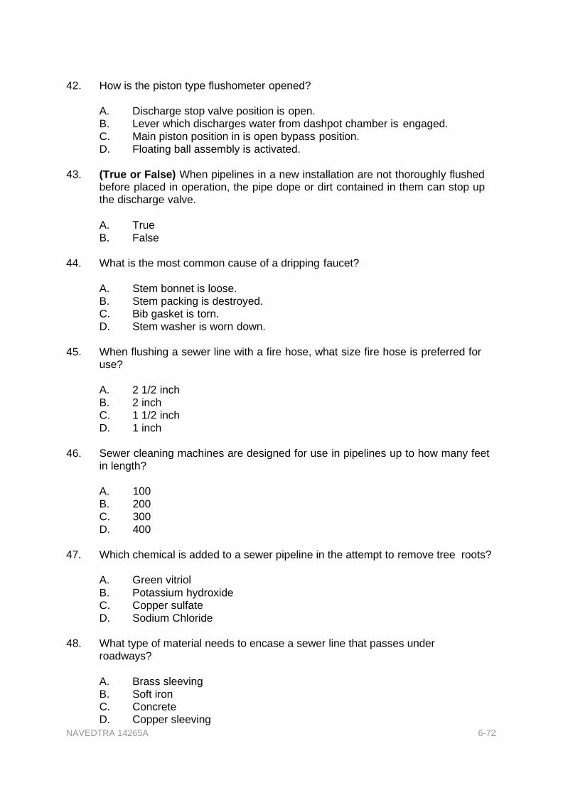
NAVEDTRA 14265A 6-72
42. How is the piston type flushometer opened?
A. Discharge stop valve position is open. B. Lever which discharges water from dashpot chamber is engaged. C. Main piston position in is open bypass position. D. Floating ball assembly is activated.
43. (True or False) When pipelines in a new installation are not thoroughly flushed
before placed in operation, the pipe dope or dirt contained in them can stop up the discharge valve.
A. True B. False
44. What is the most common cause of a dripping faucet?
A. Stem bonnet is loose. B. Stem packing is destroyed. C. Bib gasket is torn. D. Stem washer is worn down.
45. When flushing a sewer line with a fire hose, what size fire hose is preferred for
use?
A. 2 1/2 inch B. 2 inch C. 1 1/2 inch D. 1 inch
46. Sewer cleaning machines are designed for use in pipelines up to how many feet
in length?
A. 100 B. 200 C. 300 D. 400
47. Which chemical is added to a sewer pipeline in the attempt to remove tree roots?
A. Green vitriol
B. Potassium hydroxide C. Copper sulfate D. Sodium Chloride
48. What type of material needs to encase a sewer line that passes under
roadways?
A. Brass sleeving B. Soft iron C. Concrete D. Copper sleeving
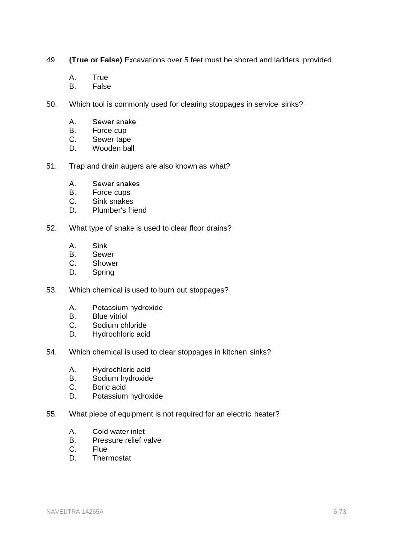
NAVEDTRA 14265A 6-73
49. (True or False) Excavations over 5 feet must be shored and ladders provided.
A. True B. False
50. Which tool is commonly used for clearing stoppages in service sinks?
A. Sewer snake B. Force cup C. Sewer tape D. Wooden ball
51. Trap and drain augers are also known as what?
A. Sewer snakes B. Force cups C. Sink snakes D. Plumber's friend
52. What type of snake is used to clear floor drains?
A. Sink B. Sewer C. Shower D. Spring
53. Which chemical is used to burn out stoppages?
A. Potassium hydroxide B. Blue vitriol
C. Sodium chloride D. Hydrochloric acid
54. Which chemical is used to clear stoppages in kitchen sinks?
A. Hydrochloric acid B. Sodium hydroxide C. Boric acid D. Potassium hydroxide
55. What piece of equipment is not required for an electric heater?
A. Cold water inlet B. Pressure relief valve C. Flue D. Thermostat
NAVEDTRA 14265A 6-74
56. What is the diameter, in inches, of the cold water inlet for an electric inlet?
A. 1/8 B. 1/4 C. 1/2 D. 3/4
57. Where is the hot water inlet valve located on an electric heater?
A. Top
B. Rear C. Bottom D. Front
58. The temperature and pressure relief on an electric heater is set to lift at what
pressure, in psi?
A. 100 B. 125 C. 150 D. 175
59. All gas water heaters are tested to operate at what pressure, in psi?
A. 100 B. 200 C. 300 D. 400
60. By what means is the pilot light adjusted on a gas water heater?
A. Pilot light valve B. Air exciter C. Inlet steam valve D. Air shutter
61. What type of fittings is used when installing copper water lines?
A. Dielectric
B. Copper C. Brass D. Steel
62. CPVC piping can withstand temperatures up to how many degrees?
A. 150 B. 180 C. 275 D. 525
NAVEDTRA 14265A 6-75
63. What is the minimum diameter, in inches, of steel piping used for a gas line?
A. 1/8 B. 1/4 C. 1/2 D. 1
64. What is the minimum size drain, in inches, used for a lavatory installation?
A. 1/4
B. 1/2 C. 1 D. 1 1/4
65. How many types of joints are associated with flexible supply lines for lavatories?
A. 3 B. 4 C. 5 D. 6
66. Which bowl is NOT a type of flushing action?
A. Pressure assisted B. Reverse jet C. Siphon jet D. Wash down
67. Where on a water closet is the trap located when the water closet uses a reverse
trap flushing action?
A. Front B. Top C. Rear D. Bottom
68. (True or False) Water closets equipped with a tank require a 3/4-inch
waterline.
A. True B. False
69. What is the required waterline size, in inches, for a water closet equipped
with a flushometer?
A. 1/4 B. 1/2 C. 3/4 D. 1

NAVEDTRA 14265A 6-76
70. Which is NOT a type of urinal?
A. Gang B. Wall-hung C. Stall D. Trough
71. How many different designs are associated with the wall-hung type urinal?
A. 2 B. 3 C.4 D.5
72. By what means is the pedestal urinal sealed to the floor flange?
A. Excessive glue B. Brass hold-down bolts C. Wax ring
D. Epoxy sealant compound
73. What type of trap is installed on siphon jet urinals?
A. External B. Interconnection C. Diffuser D. Integral
74. The lip height of a wall-hung urinal is between how many inches from the
finished floor?
A. 20 to 25 B. 14 to 29 C. 10 to 15
D. 25 to 30
75. What is the minimum diameter, in inches, of a drain used for wall-hung urinals?
A. 1 B. 2 C.3 D.4
76. What component prevents contaminated water from being siphoned into the
potable water supply through the flushometer?
A. Diffuser B. Moisture separator C. Vacuum breaker D. Diverter

NAVEDTRA 14265A 6-77
77. What is the average time, in seconds, of a flush cycle?
A. 1 to 4 B. 4 to 7 C. 5 to 8
D. 7 to 10
78. How many general types of shower heads are associated with shower
installations?
A. 2 B. 3 C.4 D.5
79. Which shower head has a restricted nozzle?
A. Flat head B. Economy head C. Circular head D. Spray head
80. The sides of the pan that are against the shower walls must be how many inches
above the height of the finished dam or threshold?
A. 1 B. 2 C.3 D.4

NAVEDTRA 14265A 6-78
Trade Terms Introduced in this Chapter
Vitreous Of the nature of or resembling glass, as in transparency, brittleness, hardness, glossiness.
Orifices An opening or aperture, as of a tube or pipe; a mouth-like opening or hole; mouth; vent.
Dashpot A device for cushioning, damping, or reversing the motion of a piece of machinery, consisting of a cylinder in which a piston operates to create a pressure or vacuum on an enclosed gas or to force a fluid in or out of the chamber through narrow openings.
Escutcheons A protective plate around plumbing fixtures.

NAVEDTRA 14265A 6-79
Additional Resources and References
This chapter is intended to present thorough resources for task training. The following reference works are suggested for further study. This is optional material for continued education rather than for task training.
Basic Machines, NAVEDTRA 12199, Naval Education and Training Professional Development and Technology Center, Pensacola, FL, 1994.
OSHA Regulations (Standards - 29 CFR)
Construction Safety Standards, 29 CFR, Part 1929
Naval Construction Force Manual, NAVFAC P-315, Naval Facilities Engineering Command, Washington, D.C., 1985.
McPortland, J.E, and Brian J. McPortland, National Electrical Code® Handbook, 22d Ed, McGraw-Hill, NY, 2008.
Facilities Planning Guide, NAVFAC P-437, Volumes 1 and 2, Naval Facilities Engineering Command, Alexandria, VA, 1982.
National Standard Plumbing Code-Illustrated, National Association of Plumbing- Heating-Cooling Contractors, Washington, DC, 2006.
Safety and Health Requirements Manual, EM-385-1-1, Department of the Army, U.S. Army Corps of Engineers, Washington, DC, 1992.
International Plumbing Code 2009, International Code Council
International Mechanical Code 2009, International Code Council
R. Dodge Woodson, Plumber’s Quick-Reference Manual Tables, Charts, and Calculations, 1st edition, McGraw-Hill, NY, 1996.
Fire Protection Handbook, 17th ed., National Fire Protection Association, Quincy, MA, 1991.

NAVEDTRA 14265A 6-80
CSFE Nonresident Training Course - User Update
CSFE makes every effort to keep their manuals up-to-date and free of technical errors. We appreciate your help in this process. If you have an idea for improving this manual, or if you find an error, a typographical mistake, or an inaccuracy in CSFE manuals, please write or email us, using this form or a photocopy. Be sure to include the exact chapter number, topic, detailed description, and correction, if applicable. Your input will be brought to the attention of the Technical Review Committee. Thank you for your assistance.
Write: CSFE N7A 3502 Goodspeed St. Port Hueneme, CA 93130
FAX: 805/982-5508
E-mail: CSFE [email protected]
Rate Course Name
Revision Date Chapter Number Page Number(s)
Description
(Optional) Correction
(Optional) Your Name and Address
Copyright © 2022 FDOKUMEN