Fire and the spatial separation of buildings - NRC Publications ...

NRC Publications Archive (NPArC)Archives des publications du CNRC (NPArC)
Publisher’s version / la version de l'éditeur: Journal of Materials Science: Materials in Medicine, 19, 2, pp. 683-693, 2007-07-10
Performance of CF/PA 12 composite femoral stemsCampbell, Melissa; Bureau, Martin N.; Yahia, L'Hocine
Contact us / Contactez nous: [email protected].
http://nparc.cisti-icist.nrc-cnrc.gc.ca/npsi/jsp/nparc_cp.jsp?lang=frL’accès à ce site Web et l’utilisation de son contenu sont assujettis aux conditions présentées dans le site
Web page / page Webhttp://dx.doi.org/10.1007/s10856-007-3073-yhttp://nparc.cisti-icist.nrc-cnrc.gc.ca/npsi/ctrl?action=rtdoc&an=15812390&lang=enhttp://nparc.cisti-icist.nrc-cnrc.gc.ca/npsi/ctrl?action=rtdoc&an=15812390&lang=fr
LISEZ CES CONDITIONS ATTENTIVEMENT AVANT D’UTILISER CE SITE WEB.
READ THESE TERMS AND CONDITIONS CAREFULLY BEFORE USING THIS WEBSITE.
Access and use of this website and the material on it are subject to the Terms and Conditions set forth athttp://nparc.cisti-icist.nrc-cnrc.gc.ca/npsi/jsp/nparc_cp.jsp?lang=en

Performance of CF/PA12 composite femoral stems
Melissa Campbell Æ Martin N. Bureau Æ
L’Hocine Yahia
Received: 19 September 2006 / Accepted: 2 April 2007 / Published online: 10 July 2007
� Springer Science+Business Media, LLC 2007
Abstract This study presents the microstructural and
mechanical behavior of the CF/PA12 composite material
developed as well as its biomechanical performance when
used for the fabrication of femoral stems. The static tests
were performed to evaluate the compressive and flexural
modulus as well as the ultimate compressive and bending
strength. It was found that CF/PA12 composite had bone-
matching properties in the same order of magnitude as
cortical bone in the femur. Density and void content
measurements were also done to assess the consolidation
quality. Dynamic fatigue testing was conducted on both
CF/PA12 cylinders and femoral stems to evaluate the long
term durability and mechanical reliability of the composite.
Compression–compression cyclic loading was used at a
frequency of 6 Hz with loads varying between 17 kN and
22 kN for the composite cylinders while a frequency of
10 Hz and load of 2300 N was employed for the femoral
stems. Results indicate that the fatigue performance of CF/
PA12 composite surpasses by far the required fatigue
performance for total hip prosthesis (THP) stems. The
overall performance of the CF/PA12 femoral stems con-
firms that this composite is an excellent candidate material
for orthopedic applications such as THP stems.
Introduction
Primary total hip arthroplasty (THA) in the United States is
estimated to grow by 174%, from 208,600 in 2005 to
572,100 in 2030 [1]. Recent studies have shown that this
surgery is becoming more frequent in younger and more
active patients, hence the need to increase the rate of sur-
vivorship of these implants. A few decades ago, stem
breakage, gross acetabular wear or total fatigue failure of
metallic femoral stems were considered as major causes of
failure for THAs [2]. Nowadays, aseptic loosening, related
to osteolysis of wear debris created at the articular joint and
to micromotions at the bone-implant interface, is consid-
ered as the predominant cause of metallic hip implant
revision. When revision surgeries are performed, bone
resorption, related to the difference in rigidity between the
implant and the host tissue (i.e., femur) is a concern since
the host bone becomes weaker and less capable of
receiving larger hip implants. This phenomenon is known
as ‘‘stress shielding’’ and is frequently seen with metallic
implants. In addition, this stress shielding might contribute
to the stress concentration at the bone-implant interface
that lead to micromotions, as recently indicated by a finite
element simulation study of total hip prosthesis (THP)
stems [3]. To date, it has not been demonstrated that stress
shielding is not a factor in the prevalence of bone-implant
interface weakening.
Despite the relative success of currently used metallic
implants, evidence has shown that improved and more
durable hip prostheses are still in demand. Because hip
prostheses are submitted to complex and high mechanical
loadings and to a corrosive environment, candidate mate-
rials other than metallic alloys are however very limited.
The corrosion resistance, mechanical reliability and tail-
orability of thermoplastic polymer-based composites make
M. Campbell � L’HocineYahiaEcole Polytechnique de Montreal, Montreal, QC, Canada
M. N. Bureau (&)
Industrial Materials Institute, National Research Council
Canada, Montreal, QC, Canada
e-mail: [email protected]
123
J Mater Sci: Mater Med (2008) 19:683–693
DOI 10.1007/s10856-007-3073-y

them a potential substitute for metallic materials, with a
wider range of bone-matching properties. In fact employ-
ing advanced composite materials has become a common
trend in the development of novel hip stems [4–11].
Previous studies on polymer composite materials de-
signed for hip prostheses include the work from Reinhardt
et al. [4], Simoes and Marques [5–7] as well as many other
investigators [8–11]. Reinhardt et al. designed a thermo-
setting polymer-based composite hip prosthesis made by
resin transfer molding (RTM). In this study, a new manu-
facturing technique was used to fabricate a hip prosthesis
with stiffness similar to that of the surrounding bone. Even
though, a certain similarity in mechanical properties with
respect to bone was reached, further revisions were needed
to improve the performance of the prosthesis and the fab-
rication process. Simoes et al. designed a composite hip
femoral prosthesis with an internal Co–Cr core and a
flexible composite outer layer. The prosthesis was manu-
factured using compression molding and results obtained
show how adequate this material is to manufacture a con-
trolled stiffness composite proximal femoral prosthesis. A
composite hip prosthesis made from polyetherimide with
carbon and glass fiber reinforcement was fabricated by De
Santis et al. [9]. The effect of fiber organization on the
mechanical properties was evaluated and results show that
in tension, the strength and tensile modulus of the stem are
respectively, 600 MPa and 40 GPa, while the flexural
modulus in bending varies from 10 GPa to 60 GPa in the
tip-head direction. Akay and Aslan [11] manufactured a
short carbon fiber-reinforced polyetheretherketone (PEEK)
prosthesis by injection molding and compared it with a
titanium alloy (Ti–6Al–4V) prosthesis of the same geom-
etry. Further studies were conducted concerning the clini-
cal validity of composite stems. Adam et al. [10]
conducted a human clinical study of a press-fit carbon fiber
hip prosthesis with a smooth surface. The modulus of a
carbon fiber-reinforced carbon stem is about three times
lower compared with metal stems and closer to the mod-
ulus of cortical bone (ranging from 12GPa to 20 GPa). This
study revealed that carbon fiber composite material has the
mechanical properties to resist the physiologic stress of a
hip joint, but that insufficient bone fixation due to the
smooth surface of the prosthesis caused early loosening of
the implant. From this survey of recent advancements in
THPs, it is apparent that a biomimetic hip prosthesis with
good bone fixation has not yet been developed.
To achieve this goal, a good understanding of bone’s
structure and properties in necessary. Bone forms the pro-
tective load-bearing skeletal framework of the body and it
has an excellent capacity for self-repair. It is an anisotropic,
heterogeneous material that is able to adapt to changes in
mechanical usage patterns by remodeling, i.e., by density,
porosity and thickness accordingly [12]. It is proposed here
that, since the hip implant acts as a substitute for the femur,
it must have similar mechanical properties. The mechanical
properties of the femur, the longest bone in the human body
composed for 80% of its mass of cortical bone (external
dense and hard layer of the femur), are reported in Table 1.
The objective of this study is to demonstrate the
mechanical reliability of THP stems made of advanced
composite materials, especially in long-term testing con-
ditions reproducing physiological stress state. Specifically,
carbon fiber-reinforced polymer composites with a cylin-
drical configuration will be tested in repeated compression
testing (fatigue) in physiological and non-physiological
(extreme) loading conditions and with a THP stem con-
figuration in physiological conditions reproducing normal
gait. The composite envisaged is polyamide 12 (PA12)
with a carbon-fiber (CF) reinforcement. A recent investi-
gation of the biocompatibility of this material showed good
osteoblastic cell adhesion and no adverse cytotoxic re-
sponse in the peri-prosthetic tissues [13].
The current paper presents a thorough analysis of the
mechanical properties and an evaluation of the performance
of this innovative biomimetic design for femoral stems
made from a carbon-fiber reinforced polymer composite.
Both short and long term mechanical testing of the hip stem
will be discussed in detail during this work. Emphasis is
however put on long term fatigue testing since the fatigue
behavior of bone resembles composite materials. They ex-
hibit a gradual loss of stiffness and strength throughout the
cyclic loading due to fatigue damage accumulation [14].
Determining the fatigue properties of this composite is thus
important to better understand its mechanical and physio-
logical behavior as well as its response when used in
orthopedic procedures such as total hip arthroplasty.
Materials and methods
Design concept and preparation
The novel THP stem consists of a hollow structure made of
a 3-mm thick CF-reinforced polymer composite coated, in
Table 1 General mechanical characteristics of different materials
and living tissues
Material/
Tissue
Density (g/
cm3)
Modulus
(GPa)
Ultimate strength
(MPa)
Poisson’s
ratio
Cancellous
bone
0.03–0.12 0.04–1.0 1.0–7.0 0.01–0.35
Cortical
bone
1.6–2.0 12–20 150 0.28–0.45
Titanium
alloys
4.4–4.7 105 780–1050 0.33
Stainless
steel
7.9 210 230–1150 0.27–0.30
684 J Mater Sci: Mater Med (2008) 19:683–693
123

the proximal region, by a thin crystalline hydroxyapatite
layer that promotes bone growth and integration. The THP
stem is typical of modular designs that are implanted by
press-fitting into the contiguous bone without the use of an
acrylic bone cement anchor. The stem is straight, follows
the natural curve of the femoral bone, has an oval cross-
section, and a shaft angle of 135� [3].
A PA12/CF reinforced composite in the form of braided
sleeves of commingled fibers of PA12 and carbon was used
in this study. Respective contents of composite in PA12
and CF were 68 and 32% (wt.). Theoretical density was
1.443 g/cm3. Cylindrical PA12/CF specimens with a
22 mm diameter and a 3-mm wall thickness were molded
for short and long-term testing. The prototype composite
stems (3-mm thick wall) proposed in this study were fab-
ricated using an inflatable bladder compression molding
method. Six layers of braided sleeves were mounted on a
bladder and placed in an in house designed and produced
steel mold. The mold was then inserted in a heated press at
250�C, maintained for 5 min with an applied internal
pressure of 480 kPa. These prototypes were tested in fati-
gue according to ISO recommendations for testing stem-
med femoral components. An example of the final
prototype is shown in Fig. 1.
Microstructural characterization methods
Cross sections along the length of the stem were cut, pol-
ished and observed under optical microscopy. The micro-
scope was used to observe the quality of consolidation,
evaluate the percentage of porosities apparent in the sam-
ples and approximate the fiber/matrix volume content.
Samples were also taken at different locations along the
stem in order to measure the change in density and void
content. Density measurements were completed using
Archimedes’ water immersion method and void content
was calculated using the following equation:
Void (% ) ¼qt � qi
qt� 100 ð1Þ
where qt and qi are the theoretical and measured densities
respectively. The CF/PA12 composite has a theoretical
density of 1.443 g/cm3. Results reported are averages of
three specimens.
Mechanical testing method
Short-term mechanical tests (static testing)
Compression tests were carried out according to the gen-
eral recommendations of ASTM D348–00 standard test
method [15]. The static load tests were performed with an
electromechanical Instron 5500R1125 tester with computer
data acquisition. The compression specimens were care-
fully machined to 44 mm in length with parallel extremi-
ties. Uniaxial compression tests were done at room
temperature with a crosshead speed of 5 mm/min and a
100 kN load cell. Parallel plates were utilized in order to
help keep the composite cylinders leveled and ultimately
prevent premature buckling. The compressive modulus of
elasticity and ultimate compressive strength of the CF/
PA12 composite cylinders were determined from the
engineering curves. The standard deviation of the reported
values is within 5%.
Flexural tests were executed according to ASTM
D790M-03 [16] standard test method on flat specimens
molded in the same conditions as the cylindrical speci-
mens. This standard is designed for plastics but applies
well to bone for three point bending tests and since our
reference will be cortical bone throughout this study, tests
were performed following this standard. The specimens
were also carefully machined to a length of 100 mm and
tested as recommended in ASTM D790M-03 with a span-
to-thickness ratio of 32:1. The flexural tests were done at
room temperature with a constant crosshead speed of
5 mm/min and a 25 KN load cell. The flexural modulus
and strength of the CF/PA12 composite cylinders were
determined from the load–deflection curves. Tests were
ended when the first sign (cracks, fissures and/or breaks) of
rupture was apparent.
Long-term tests (dynamic testing)
Cylindrical configuration: Cyclic fatigue testing was car-
ried out on CF/PA12 composite cylindrical specimensFig. 1 CF/PA12 composite femoral stem
J Mater Sci: Mater Med (2008) 19:683–693 685
123
using an Instron 8874 axial-torsional table model fatigue
system with a digital controller and computer-data acqui-
sition. The geometry and setup of the specimen followed
general recommendations from ASTM E2207-02 standard
test method [17]. Tests were performed under load-con-
trolled mode and using a sinusoidal waveform at 23�C and
50% R.H. Fatigue testing was done at room temperature
under repeated (compression–compression) cyclic loading
at a frequency of 6 Hz. The specimens were machined to a
total length of 220 mm but the nominal gauge length of the
fatigue specimens was 69 mm. Specimens tested were first
inserted into metal cylinders in order to facilitate the grip
on the composite tube and to prevent sliding once the test
had begun, and then attached to the load frame using a
three-jawed chuck.
In order to evaluate the mechanical durability of the
composite, the specimens were subjected to four different
levels of maximum stress loading of 95, 101, 112 and
123 MPa (17, 18, 20 and 22 kN), i.e. 50, 55, 60 and 70% of
the pre-determined ultimate compressive strength. At least
three specimens were tested for each fatigue load level.
Cyclic fatigue testing ended when specimens showed a
crack or sign of rupture. No magnifying device was used to
observe the first sign of failure. When fatigue failure could
not be obtained after 10 · 106 cycles or more for a specific
set of conditions, an indefinite fatigue life was reported.
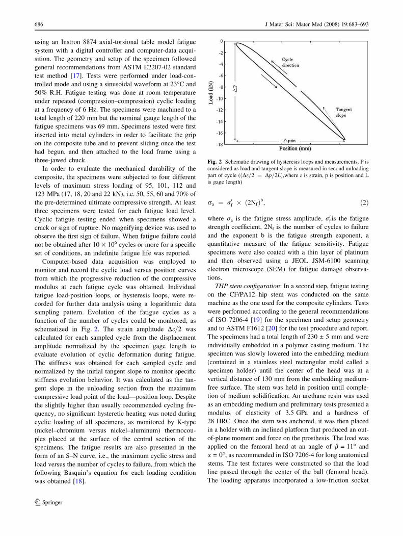
Computer-based data acquisition was employed to
monitor and record the cyclic load versus position curves
from which the progressive reduction of the compressive
modulus at each fatigue cycle was obtained. Individual
fatigue load-position loops, or hysteresis loops, were re-
corded for further data analysis using a logarithmic data
sampling pattern. Evolution of the fatigue cycles as a
function of the number of cycles could be monitored, as
schematized in Fig. 2. The strain amplitude De=2 was
calculated for each sampled cycle from the displacement
amplitude normalized by the specimen gage length to
evaluate evolution of cyclic deformation during fatigue.
The stiffness was obtained for each sampled cycle and
normalized by the initial tangent slope to monitor specific
stiffness evolution behavior. It was calculated as the tan-
gent slope in the unloading section from the maximum
compressive load point of the load—position loop. Despite
the slightly higher than usually recommended cycling fre-
quency, no significant hysteretic heating was noted during
cyclic loading of all specimens, as monitored by K-type
(nickel–chromium versus nickel–aluminum) thermocou-
ples placed at the surface of the central section of the
specimens. The fatigue results are also presented in the
form of an S–N curve, i.e., the maximum cyclic stress and
load versus the number of cycles to failure, from which the
following Basquin’s equation for each loading condition
was obtained [18].
ra ¼ r0f � 2Nfð Þb, ð2Þ
where ra is the fatigue stress amplitude, r0f is the fatigue
strength coefficient, 2Nf is the number of cycles to failure
and the exponent b is the fatigue strength exponent, a
quantitative measure of the fatigue sensitivity. Fatigue
specimens were also coated with a thin layer of platinum
and then observed using a JEOL JSM-6100 scanning
electron microscope (SEM) for fatigue damage observa-
tions.
THP stem configuration: In a second step, fatigue testing
on the CF/PA12 hip stem was conducted on the same
machine as the one used for the composite cylinders. Tests
were performed according to the general recommendations
of ISO 7206-4 [19] for the specimen and setup geometry
and to ASTM F1612 [20] for the test procedure and report.
The specimens had a total length of 230 ± 5 mm and were
individually embedded in a polymer casting medium. The
specimen was slowly lowered into the embedding medium
(contained in a stainless steel rectangular mold called a
specimen holder) until the center of the head was at a
vertical distance of 130 mm from the embedding medium-
free surface. The stem was held in position until comple-
tion of medium solidification. An urethane resin was used
as an embedding medium and preliminary tests presented a
modulus of elasticity of 3.5 GPa and a hardness of
28 HRC. Once the stem was anchored, it was then placed
in a holder with an inclined platform that produced an out-
of-plane moment and force on the prosthesis. The load was
applied on the femoral head at an angle of b = 11� and
a = 0�, as recommended in ISO 7206-4 for long anatomical
stems. The test fixtures were constructed so that the load
line passed through the center of the ball (femoral head).
The loading apparatus incorporated a low-friction socket
Fig. 2 Schematic drawing of hysteresis loops and measurements. P is
considered as load and tangent slope is measured in second unloading
part of cycle (ðDe=2 ¼ Dp=2LÞ,where e is strain, p is position and L
is gage length)
686 J Mater Sci: Mater Med (2008) 19:683–693
123

applying the loads on the femoral head, as recommended in
ISO 7206-4. The head of the prosthesis (hollow ball) was
manufactured in house from stainless steel (316L) and in-
serted on the neck of the prosthesis. Tests were performed
at 23�C and 50% R.H, with a sinusoidal waveform cycling
at 10 Hz and with a load of 2,300 N. The same data
acquisition was employed but data sampling was at a lower
rate to reduce the number of data collected and a similar
analysis of the results was done for the femoral stems. No
significant hysteretic heating during cyclic loading was
noted, as monitored by the same type of thermocouples as
those used for the cylindrical configuration testing and an
indefinite fatigue life was reported for specimens that ex-
ceeded 10 · 106 cycles. Results are reported as load–dis-
placement curves.
Results and discussion
Microstructure
Micrographs of the cut and polished CF/PA12 composite
stems are shown in Fig. 3. These images show that excellent
consolidation quality and almost void-free samples were
observed from the section between the proximal and distal
part of the stem, whereas for the extremities (i.e., close to
the neck and near the tip of the stem), small-sized voids and
only fair consolidation quality was observed. Void content
and density measurements at different locations of the
molded stems are reported in Fig. 1. Low void contents
(<2%) were obtained for samples from the mid-section of
the stem. Slightly higher void contents (2–3%) were ob-
tained for samples from the distal region of the stem. The
highest void contents (3–4%) were obtained from the
proximal region closest to the neck of the stem. More
porosities and voids are visible at both extremities than in
the central part of the stem, in agreement with micrographs
in Fig. 3. These slight variations in microstructural char-
acteristics along the length of the molded stems are attrib-
uted to the fabrication process of the femoral stem. These
limited void contents of <2% to �4% are however com-
parable to typical void contents reported for processes used
in long or continuous fiber-reinforced thermoplastic com-
posites manufacturing, for which both static and fatigue
behavior are close to optimal and only show slight varia-
tions in the void content range measured [21].
Mechanical properties
In this section, the mechanical properties of the CF/PA12
composite are compared to those of cortical bone. Since
this composite is meant to be used for bone replacement
and repair applications, in particular for a THP, the
ultimate goal is to obtain a biomechanical performance
similar to that of bone in order to prevent stress
shielding and eventually bone resorption. All values for
mechanical properties of cortical bone were taken from
Wirtz et al. [22], Reilly et al. [23, 24] and Snyder and
Schneider [25].
Fig. 3 Micrographs of samples taken from CF/PA12 femoral stems
at various places along the stem’s length: (a) proximal region near the
neck of the stem with high void content (3–4%); (b) mid-section of
the stem with low void content (<2%); (c) distal region of the stem
with fairly high void content (2–3%). White spots in micrographs
represent carbon fibers. Dark gray patches represent the polymer
matrix and black spots indicate pockets of air
J Mater Sci: Mater Med (2008) 19:683–693 687
123

Static testing results
The compressive and flexural results of the CF/PA12
composites cylinders are reported in Table 2. Results in
this table are compared to those of cortical bone found in
the human femur. The calculated bending stiffness for the
composite cylinders, based on the product of the modulus
of elasticity and the moment of inertia, and reported
bending stiffness for human cortical bone are also com-
pared in Table 2. These results indicate that both the
modulus and ultimate strength in flexural and compressive
testing of CF/PA12 composite are either within or close to
the reported range of properties of the femur. As expected
from its design, the composite stem shows a bending
stiffness ranging from 180 N m2 to 425 N m2 depending
on stem diameter, very close to reported values of 170–
500 N m2 for human cortical femoral bone. Also, the
composite cylinders, which had a nominal outer diameter
(22 mm) and wall thickness (3 mm) comparable to the
THP stems designed [3] failed at an absolute compressive
maximum load of 28.6 kN. This load at failure is consid-
erably above (close to three times) the maximum physio-
logical load to which the femoral bone is subjected
(10,000 N) when jumping on one leg [27], indicating the
high level of performance expected from the composite
THP stems. A comparison of the compressive modulus and
strength values obtained from the CF/PA12 composite to
those of cortical bone is presented in Table 2. They can be
compared to those of commonly-used metallic materials
for the fabrication of THP stems in Table 1. This com-
parison illustrates the advantages of fiber-reinforced poly-
mer composites for replacing or substituting bone in place
of metallic alloys showing very different properties.
Dynamic testing results
Fatigue of cylindrical specimens: Four different loading
conditions were evaluated in fatigue and two different
frequencies were used. The fatigue testing conditions are
reported in Table 3. The maximum compressive loads
range from 17 kN to 22 kN, respectively between 50% and
70% of the maximum load before rupture. These conditions
are considerably more severe that the loading conditions in
ASTM standard [27] for testing femoral stems recom-
mending loading between 300 N and 3,000 N for a fatigue
life of the femoral stem of at least 5 million cycles.
The S–N curves obtained are illustrated in Fig. 4 and
reported in Table 3 both in terms of maximum fatigue
stress and maximum fatigue load. As shown in Fig. 4 and
Table 3, fatigue failures occurred after approximately 104
cycles for maximum fatigue load of 22 kN (i.e., 123 MPa),
105 cycles for maximum fatigue load of 20 kN (i.e.,
112 MPa), 106 cycles for maximum fatigue load of 18 kN
(i.e., 101 MPa) and close to 107 cycles and more for
maximum fatigue load of 17 kN (i.e., 95 MPa). These re-
sults show fatigue life of 106 and more at load levels at
least six times greater than load levels of 3,000 N recom-
mended in ASTM standards [28], in agreement with the
expected high level of performance from compressive load
at failure.
Figure 5 illustrates the evolution of the hysteresis loops
for two testing condition. This figure indicates that for a
load level of 17 kN (Fig. 5a), showing fatigue life above
106 cycles, the surface, or opening, of the hysteresis loops
progressively decreased as the number of cycles increased.
This indicates that total cyclic deformation decreases dur-
ing the fatigue life. A similar trend is noted for load levels
of 18 kN. For load levels of 20 kN (Fig. 5b), for which
fatigue life is approximately 105 cycles, the surface of the
hysteresis loops did not appear to change as the number of
cycles increased, indicating that total cyclic deformation
was more or less constant throughout the fatigue test. A
similar trend is noted for load levels of 22 kN, with the
exception of the cycles close to fatigue failure which
showed increasing hysteresis loop opening. The results
thus indicate that for load levels of 20 kN and below,
plastic deformation at each fatigue cycle was small, leading
to fatigue endurance conditions, in which plastic defor-
Table 2 Mechanical results of the CF/PA12 composite (with human cortical bone values added for comparison)
Materials Compressive Flexural Bending stiffness
(N m2)Maximum load
(kN)
Modulus
(GPa)
Ultimate strength
(MPa)
Modulus
(GPa)
Ultimate strength
(MPa)
CF/PA12
Composite
28.6 ± 3.8 12.2 ± 1.3 155 ± 27 16.4 ± 1.5 188 ± 15 180–425
Cortical bone – 7.0–18.7a 175–265a 14.3–21.1b 178–250b 170–500c
a After [22]b After [25]c After [26], for outer cortex diameter of 25–30 mm; compared values for outer composite stem diameter of 20–25 mm
688 J Mater Sci: Mater Med (2008) 19:683–693
123

mation is limited, characterized by extended fatigue life
(‡105 cycles). However, for a load level of 22 kN, plastic
deformation at each fatigue cycle was important, leading to
rapidly increasing cumulative deformation, close to low-
cycle fatigue conditions, and therefore fairly short fatigue
life (104 and below).
Consistently with Fig. 5, Fig. 6 reports the relative
stiffness of the composite specimens as function of the
number of cycles for each fatigue load levels. As shown in
Fig. 6, relative stiffness is reported from cycle 30, at which
the load-position cycles became stable. The relative stiff-
ness is thus calculated with the initial tangent slope on the
unloading section of the hysteresis loops at cycle 30. For
all load conditions, the relative stiffness increased as the
Table 3 Test conditions for compression fatigue testing (repeated cyclic loading) of CF/PA12 cylindrical tubes
Maximum
load (kN)
Mean
load (kN)
Maximum
stress (MPa)
Cycles to failure Decrease in strain
amplitudea (mm/mm)
Constant strain
amplitude ratea (/cycle)
17 –8.65 95 5,802,422 1.11 · 10–3 –2.1 · 10–10
1,764,000
6,132,716
>10,272,465
18 –9.15 101 1,328,721 9.1 · 10–4 –8.2 · 10–10
1,262,408
930,070
20 –10.15 112 221,788 8.5 · 10–4 –8.70 · 10–9
122,117
158,160
803,642
22 –11.15 123 9,015 4.4 · 10–4 –2.247 · 10–7
4,332
13,658
a During second phase shown in Fig. 8
Fig. 4 Maximum cyclic stress in MPa (s) and maximum load in N
(d) as a function of cycles to failure. Arrows indicate indefinite
fatigue life
Fig. 5 Evolution of hysteresis loops for two different tested load
conditions: (a) 17 kN (for cycle 30, 105, 106 and 5.5 · 106) and (b)
20 kN (for cycle 30, 5000 and 2 · 105)
J Mater Sci: Mater Med (2008) 19:683–693 689
123

number of cycles increased. Towards the end of the tests
(at high number of cycles), at least for load levels of 17 and
18 kN, the relative stiffness abruptly increased and then
rapidly collapsed at the end of the tests. These results
indicate that for most of the fatigue life, the fatigued
specimen exhibited a behavior that resembles well known
cyclic hardening in metallic alloys subjected to fatigue,
since stiffness increased as cumulative deformation in-
creased. This behavior appeared more important for load
levels of 17 and 18 kN than for higher load levels of 20 and
22 kN, although the slopes of the curves in Fig. 6 appear
more or less the same. This probably account for the fact
that fatigue failure occurs faster at higher load levels
because cyclic strain amplitude are higher (thus cumulative
strain increases faster), limiting the extent to which this
apparent cyclic hardening occur.
It is possible that this apparent cyclic hardening
behavior is caused by local rearrangements of carbon fiber
under the action of the cyclic compressive loads. In this
case, fibers initially at an approximate ±45� orientation in
the cylindrical specimens would progressively rotate to
accommodate for the cumulative strain, which would cause
the polymer matrix to be progressively compressed as well
as neighboring fibers to get closer to each other. This
cumulative strain in a restricted plane strain state results in
a progressive increase in stiffness. At a certain level of
cumulative strain (and local rotation of fibers), the fibers
and matrix would reach the maximum level of rearrange-
ments, leading to rapid increase in stiffness, interfiber
contact and eventually interfiber damage, namely by mi-
crobuckling. Within the scope and means of this study, it is
not possible to confirm whether this cascade of events is
effectively taking place. However, it is possible to confirm
whether microbuckling of fibers can be observed in the
fatigued specimens after failure at locations far from the
final fatigue failure site (several mm from the latter), i.e., in
the general, non-concentrated cyclic deformation region.
SEM observations were made to assess the presence of
fiber microbuckling far from the high cumulative strain
region. An example of microbuckling of fibers observed
several mm from the final fatigue failure region is shown in
Fig. 7. This figure demonstrates that at sites where fatigue
failure did not occur, i.e., representative of earlier fatigue
life, microbuckling occurred. This microbuckling of fibers
is caused by their progressive rotation leading to com-
pression stresses along fiber direction due to their con-
finement (plane strain). Although it cannot be considered as
a confirmation of this proposed origin of stiffness increase
(cyclic hardening), observation of this phenomenon is in
agreement with this proposition.
The hysteresis loops for each load conditions were also
analyzed to obtain the cyclic strain amplitude as a function
of the number of cycles. Figure 8 illustrates the cyclic
strain amplitude evolution in the fatigued specimens. The
curves is this figure show three phases: a first stabilization
phase during which the load-position cycles became stable;
a second phase during most of the fatigue life showing a
slightly negative constant strain amplitude rate; and a final
Fig. 6 Relative stiffness as a function of number of cycles to failure
for 17 kN (d), 18 kN (s), 20 kN (.) and 22 kN(M). Lines show
linear regression for each tested condition
Fig. 7 SEM micrographs of fibers damaged by microbuckling for:
(a) 18 kN and (b) 22 kN
690 J Mater Sci: Mater Med (2008) 19:683–693
123

third phase during which the cyclic strain amplitude in-
creased suddenly until fatigue failure occurred. The slightly
negative constant strain amplitude rate in the second phase
indicates a weak but significant decrease in total strain
amplitude as the number of cycle increases. This obser-
vation is in agreement with the observed increase in stiff-
ness during fatigue life: in constant load conditions, an
increase in stiffness results in a reduction in deformation.
The constant strain amplitude rate obtained in each loading
condition as well as the corresponding decrease in cyclic
strain amplitude during this second phase are also reported
in Table 3. As shown in this table, both the decrease in
cyclic strain amplitude and the constant strain amplitude
rate steadily decreases when changing from maximum fa-
tigue load of 17–22 kN. This observation that strain
amplitude decreases more and faster at lower fatigue loads
suggests that the increase in stiffness during fatigue cy-
cling, or cyclic hardening, is more important at lower fa-
tigue loads, in agreement with the extent to which relative
stiffness increases depending on the maximum load level
(Fig. 6). These strain amplitude related values indicate that
fatigue failure occurs faster at higher load levels only be-
cause strain amplitude are higher, and therefore cumulative
strain increases faster, and also that the mechanisms that
lead to the increases in stiffness are independent from those
that lead to final failure, since they occur less and slower at
higher load levels.
Fatigue of THP stems: Conditions for the fatigue testing
of the CF/PA12 composite femoral stems are summarized
in Table 4. All specimens were ended after a fatigue life of
10 · 106 cycles, showing their long durability and
mechanical reliability. Further analysis of the fatigue data
in Fig. 9 revealed that the relative stiffness as a function of
the cycles to failure slightly increased as expected, due to
the same apparent cyclic hardening behavior observed for
fatigued cylindrical specimens. As shown in this figure, the
relative stiffness of the THP stems progressively increases
from 1.0 to approximately 1.2 upon cyclic loading, in
agreement with increases noted for fatigued cylindrical
specimens (Fig. 6). In this case however stiffness was
normalized using stiffness of cycle 100 because load cycles
took more time to stabilize.
In order to further correlate the fatigue behavior of the
fatigued cylindrical specimens to that of the THP stems,
hysteresis loops for relevant cycles are reported in Fig. 10.
The evolution of the hysteresis loops upon cyclic loading is
very similar to that observed for fatigued cylindrical
specimens at lower load levels (our case for THP stem
testing); surface of hysteresis loops is larger initially, but
progressively stabilized as the number of cycles increased
as a result of the (very) low loads levels employed. This
observation is in agreement with the fact that THP stems in
the fatigue load conditions used did not fail after
10 · 106 cycles. It indicates that not only did they not fail,
but their cumulative deformation did not lead them to be
substantially damaged. This observation is in agreement
with the lack of evidence of fatigue damage found from
SEM.
Fig. 8 Strain amplitude as a function of number of cycles to failure
for 17 kN (d), 18 kN (s), 20 kN (.) and 22 kN(M). Line represents
cycle 30 where test was stabilized
Table 4 Test conditions for compression fatigue testing of CF/PA12
femoral stems
Specimen Frequency
(Hz)
Offset
angle (�)
Amplitude
(N)
Mean
level (N)
Maximum
load (N)
PTH 1
PTH 2 10 11 1000 –1300 2300
PTH 3
Fig. 9 Relative stiffness as a function of cycles to failure for THP
stem. Error bars represent ±5% standard error
J Mater Sci: Mater Med (2008) 19:683–693 691
123

While all results found in literature recently include a
modulus variation in their design, generally too high in
value and very limited in range, none of the designs
mentioned previously address the need for a match of the
bone modulus, bone density and bone structure for the
stem. De Santis et al. measured tensile properties that were
uniform along the stem but considerably too high to match
bone properties and in bending, again values were far from
the cortical bone range. Adam et al. presented an ana-
tomically shaped carbon–carbon hip stem but their clinical
results show a high incidence of early aseptic loosening
due to the lack of a hydroxyapatite coating or proximal
macrotexturing. As for Akay and Aslan, their numerical
and experimental study concerned a cemented CF/PEEK
composite hip prosthesis, while this femoral stem is non-
cemented. Simoes et al. also developed a composite fem-
oral prosthesis; however they chose to combine a flexible
outer layer with a metal core, which significantly increases
their overall mechanical properties. Finally, none of the
above have demonstrated the long term properties of their
designs with fatigue testing. This study demonstrated just
that; a polymer composite femoral stem with bone-
matching properties that would eliminate stress shielding
and excellent fatigue results that show potential for an in-
creased life span.
Since CF/PA12 composites have excellent mechanical
performance and can be produced with great versatility in
complex shapes with tailored properties, their static and
dynamic mechanical behavior can be adjusted to be quite
close to those of cortical femoral bone. This combination
of bone-matching short-term properties and excellent fati-
gue performance, coupled with the fact that they are
chemically inert and potentially biocompatible [13] makes
them valuable materials in orthopedic applications such as
the hip prosthesis and a the potential to reduce stress
shielding and in the long run prevent bone resorption.
Summary and conclusion
The mechanical properties of the CF/PA12 composite were
analyzed both in static and dynamic tests. The CF/PA12
cylinders were subjected to a variety of mechanical tests in
order to obtain a detailed characterization of the material
and how it behaved both in short and long terms. Short
terms mechanical properties were shown to be very similar
to cortical bone’s properties. Fatigue testing revealed that
the composite-made stems have excellent fatigue resis-
tance, indicating fatigue life at load levels recommended
by ISO standards for testing THP stems exceeding by far
the normal life expectancy from these stems of
10 · 106 cycles. In fact, fatigue failure at load levels also 6
times higher than load levels recommended occurred at
5 · 106 to 10 · 106 cycles. Monitoring of cyclic strain
amplitude and stiffness evolution during fatigue testing
revealed that an apparent cyclic hardening occurred upon
cycling, which was more important at lower load levels. In
the load level range employed, fatigue damage was related
to cumulative strain and local rotation of carbon fibers, as
matrix and interfiber damage and fiber microbuckling.
Bone-matching properties of this composite-made THP
and its excellent fatigue performance by far surpassing
required fatigue life make PA12/CF candidate material of
choice for orthopedic devices such as total hip prostheses
and might offer a long term solution to stress shielding and
bone resorption.
Acknowledgments The collaboration of Terray Corporation for
financial participation and for providing materials as well as the
financial support of project by NSERC (STP 306867-04) and the
National Research Council of Canada are gratefully acknowledged.
References
1. S. KURTZ, E. LAU, K. ZHAO, F. MOWAT, K. ONG, and M.
HALPERN, in 73rd Annual Meeting of the American Academy
of Orthopaedic Surgeons (Chicago, IL, 2006)
2. D. TAYLOR, C. MARTIN, B. CORNELIS and M. E. B. JONES,
J. Eng. Med. 207(2) (1993) 121
3. H. BOUGHERARA, M. N. BUREAU, M. CAMPBELL, A.
VADEAN and L’H. YAHIA, J. Biomed. Mater. Res. A. 82A(1)
(2007) 27
4. A. REINHARDT, S. G. ADVANI, M. H. SANTARE and F.
MILLER, J. Compos. Mater. 33(9) (1999) 853
5. J. A. SIMOES and A. T. MARQUES, Comp. Sci. Tech. 60 (2000)
559
6. J. A. SIMOES and A. T. MARQUES, Compos. Part A 32 (2001)
655
7. J. A. SIMOES and A. T. MARQUES, Mater. Des. 26 (2005) 391
8. F. K. CHANG, J. L. PEREZ and J. A. DAVIDSON, J. Biomed.
Mater. Res. 24(7) (1990) 873
9. R. DE SANTIS, L. AMBROSIO and L. NICOLAIS, J. Inorg.
Biochem. 79(1–4) (2000) 97
10. F. ADAM, D. S. HAMMER, S. PFAUTSCH and K. WESTER-
MANN, J. Arthroplasty 17(2) (2002) 217
Fig. 10 Evolution of hysteresis loops for a THP stem for cycle 100,
105, 106 and 10 · 106
692 J Mater Sci: Mater Med (2008) 19:683–693
123

11. M. AKAY and N. ASLAN, J. Biomed. Mater. Res. 31 (1996) 167
12. J. R. BRITTON, C. G. C. LYONS and P. J. PRENDERGAST,
Strain 40 (2004) 193
13. J.-G. LEGOUX, F. CHELLAT, R. LIMA, B. MARPLE, M. N.
BUREAU, H. SHEN and G. A. CANDELIERE, J. Thermal Spray
Technol. 15(4) (2006) 629
14. K. CHOI and S. A. GOLDSTEIN, J. Biomech. 25(12) (1992)
1371
15. American Society for Testing and Materials, ‘‘ASTM D348-00’’,
Standard Test Methods for Rigid Tubes Used for Electrical
Insulation
16. American Society for Testing and Materials, ‘‘ASTM D790-03’’,
Standard Test Methods for Flexural Properties of Unreinforced
and Reinforced Plastics and Electrical Insulating Materials p. 6
17. American Society for Testing and Materials, ‘‘ASTM E2207–
02’’, Standard Practice for Strain-Controlled Axial-Torsional
Fatigue Testing with Thin-walled Tubular Specimens
18. O. H. BASQUIN, in ‘‘Proceedings of the American Society for
Testing and Materials’’, Vol 10 (1910)
19. International Standard Organization, ‘‘ISO7206–4’’, Implants for
Surgery-Partial and Total Hip Joint Prostheses-Part 4: Determi-
nation of Endurance Properties of Stemmed Femoral Components
20. American Society for Testing and Materials, ‘‘ASTM F1612–
95’’, Standard Practice For Cyclic Fatigue Testing of Metallic
Stemmed Hip Arthroplasty Femoral Components with Torsion
21. M. N. BUREAU and J. DENAULT, Comp. Sci. Tech. 64 (2004)
1785
22. D. C. WIRTZ, N. SCHIFFERS, T. PANDORF, K. RADERM-
ACHER, D. WEICHERT and R. FORST, J. Biomech. 33 (2000)
1325
23. D. T. REILLY and A. H. BURSTEIN, J. Biomech. 8(6) (1975)
393
24. D. T. REILLY, A. H. BURSTEIN and V. H. FRANKEL, J.
Biomech. 7(3) (1974) 271
25. S. M. SNYDER and E. SCHNEIDER, J. Orthop. Res. 9 (1991)
422
26. H. B. SKINNER, Orthopedics 14(3) (1991) 323
27. G. BERGMANN, F. GRAICHEN and A. ROHLMANN, J.
Biomech. 26(8) (1993) 969
28. American Society for Testing and Materials, ‘‘ASTM F1440–
92’’, Standard Practice for Cyclic Fatigue Testing of Metallic
Stemmed Hip Arthroplasty Femoral Components Without Tor-
sion
J Mater Sci: Mater Med (2008) 19:683–693 693
123
Copyright © 2022 FDOKUMEN