Plumbing Engineering Design Handbook - Mepengineerings -
408
American Society of Plumbing Engineers Plumbing Engineering Design Handbook A Plumbing Engineer’s Guide to System Design and Specifications American Society of Plumbing Engineers 2980 S. River Road Des Plaines, IL 60018 Plumbing Systems Volume 2
-
Upload
khangminh22 -
Category
Documents
-
view
0 -
download
0
Transcript of Plumbing Engineering Design Handbook - Mepengineerings -
American Society of Plumbing Engineers
Plumbing Engineering Design Handbook
A Plumbing Engineer’s Guide to System Design and Specifications
American Society of Plumbing Engineers2980 S. River Road
Des Plaines, IL 60018
Plumbing Systems
Volume 2
Copyright © 2010 by American Society of Plumbing Engineers
All rights reserved, including rights of reproduction and use in any form or by any means, including the making of copies by any photographic process, or by any electronic or mechanical device, printed or written or oral, or recording for sound or visual reproduction, or for use in any knowledge or retrieval system or device, unless permission in writing is obtained from the publisher.
The ASPE Plumbing Engineering Design Handbook is designed to provide accurate and authoritative information for the design and specification of plumbing systems. The publisher makes no guarantees or warranties, expressed or implied, regarding the data and infor-mation contained in this publication. All data and information are provided with the understanding that the publisher is not engaged in rendering legal, consulting, engineering, or other professional services. If legal, consulting, or engineering advice or other expert assistance is required, the services of a competent professional should be engaged.
American Society of Plumbing Engineers2980 S. River Road
Des Plaines, IL 60018(847) 296-0002 • Fax: (847) 296-2963
E-mail: [email protected] • Internet: www.aspe.org
ISBN 978-1-891255-17-5Printed in China
10 9 8 7 6 5 4 3 2 1
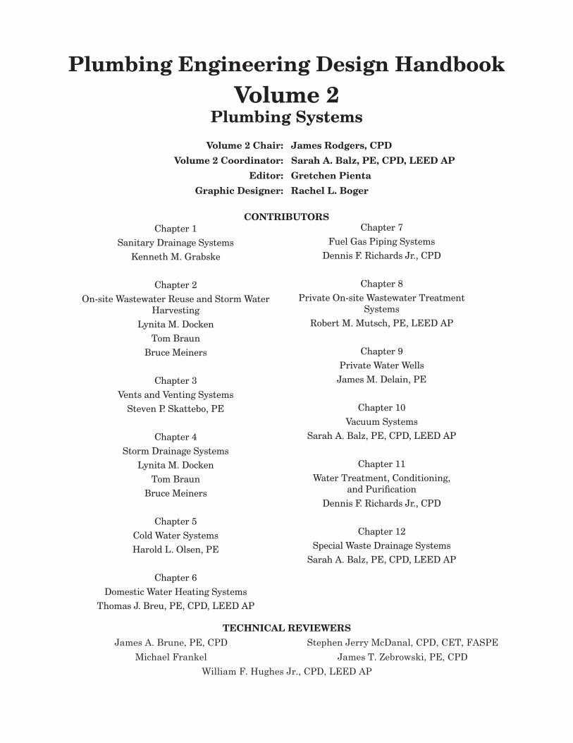
Plumbing Engineering Design HandbookVolume 2
Plumbing Systems
Volume 2 Chair: James Rodgers, CPD
Volume 2 Coordinator: Sarah A. Balz, PE, CPD, LEED AP
Editor: Gretchen Pienta
Graphic Designer: Rachel L. Boger
CONTRIBUTORSChapter 1
Sanitary Drainage SystemsKenneth M. Grabske
Chapter 2On-site Wastewater Reuse and Storm Water
HarvestingLynita M. Docken
Tom BraunBruce Meiners
Chapter 3Vents and Venting Systems
Steven P. Skattebo, PE
Chapter 4Storm Drainage Systems
Lynita M. DockenTom Braun
Bruce Meiners
Chapter 5Cold Water SystemsHarold L. Olsen, PE
Chapter 6Domestic Water Heating Systems
Thomas J. Breu, PE, CPD, LEED AP
Chapter 7Fuel Gas Piping Systems
Dennis F. Richards Jr., CPD
Chapter 8Private On-site Wastewater Treatment
SystemsRobert M. Mutsch, PE, LEED AP
Chapter 9Private Water WellsJames M. Delain, PE
Chapter 10Vacuum Systems
Sarah A. Balz, PE, CPD, LEED AP
Chapter 11Water Treatment, Conditioning,
and PurificationDennis F. Richards Jr., CPD
Chapter 12Special Waste Drainage Systems
Sarah A. Balz, PE, CPD, LEED AP
TECHNICAL REVIEWERS
James A. Brune, PE, CPD Stephen Jerry McDanal, CPD, CET, FASPEMichael Frankel James T. Zebrowski, PE, CPD
William F. Hughes Jr., CPD, LEED AP
About ASPEThe American Society of Plumbing Engineers (ASPE) is the international organization for professionals skilled in the design and specification of plumbing systems. ASPE is dedicated to the advancement of the science of plumbing engineering, to the professional growth and advancement of its members, and to the health, welfare, and safety of the public.
The Society disseminates technical data and information, sponsors activities that facilitate interaction with fellow professionals, and, through research and education programs, expands the base of knowledge of the plumbing engineering industry. ASPE members are leaders in innovative plumbing design, effective materials and energy use, and the application of advanced techniques from around the world.
WorldWide MeMbership — ASPE was founded in 1964 and currently has 6,500 members. Spanning the globe, members are located in the United States, Canada, Asia, Mexico, South America, the South Pacific, Australia, and Europe. They represent an extensive network of experienced engineers, designers, contractors, educators, code officials, and manufacturers interested in furthering their careers, their profession, and the industry. ASPE is at the forefront of technology. In addition, ASPE represents members and promotes the profession among all segments of the construction industry.
Aspe MeMbership CoMMuniCAtion — All members belong to ASPE worldwide and have the opportunity to belong and participate in one of the 61 state, provincial or local chapters throughout the U.S. and Canada. ASPE chapters provide the major communication links and the first line of services and programs for the individual member. Communications with the membership is enhanced through the Society’s magazine, Plumbing Systems and Design, the newsletter ASPE Report, which is incorporated as part of the magazine, and the e-newsletter "ASPE Pipeline."
teChniCAl publiCAtions — The Society maintains a comprehensive publishing program, spearheaded by the profession’s basic reference text, the ASPE Plumbing Engineering Design Handbook. The Plumbing Engineering Design Handbook, encompassing approximately 50 chapters in four volumes, provides comprehensive details of the accepted practices and design criteria used in the field of plumbing engineering. Recent additions to ASPE’s published library of professional technical manuals and handbooks include the Plumbineering Dictionary, Engineered Plumbing Design II, and The Hunter Papers.
Convention And teChniCAl syMposiuM — The Society hosts biennial Conventions in even-numbered years and Technical Symposia in odd-numbered years to allow professional plumbing engineers and designers to improve their skills, learn original concepts, and make important networking contacts to help them stay abreast of current trends and technologies. In conjunction with each Convention there is an Engineered Plumbing Exposition, the greatest, largest gathering of plumbing engineering and design products, equipment, and services. Everything from pipes to pumps to fixtures, from compressors to computers to consulting services is on display, giving engineers and specifiers the opportunity to view the newest and most innovative materials and equipment available to them.
Certified in pluMbing design — ASPE sponsors a national certification program for engineers and designers of plumbing systems, which carries the designation “Certified in Plumbing Design” or CPD. The certification program provides the profession, the plumbing industry, and the general public with a single, comprehensive qualification of professional competence for engineers and designers of plumbing systems. The CPD, designed exclusively by and for plumbing engineers, tests hundreds of engineers and designers at centers throughout the United States biennially. Created to provide a single, uniform national credential in the field of engineered plumbing systems, the CPD program is not in any way connected to state-regulated Professional Engineer (P.E.) registration.
Aspe reseArCh foundAtion — The ASPE Research Foundation, established in 1976, is the only independent, impartial organization involved in plumbing engineering and design research. The science of plumbing engineering affects everything… from the quality of our drinking water to the conservation of our water resources to the building codes for plumbing systems. Our lives are impacted daily by the advances made in plumbing engineering technology through the Foundation’s research and development.
American Society of Plumbing Engineers
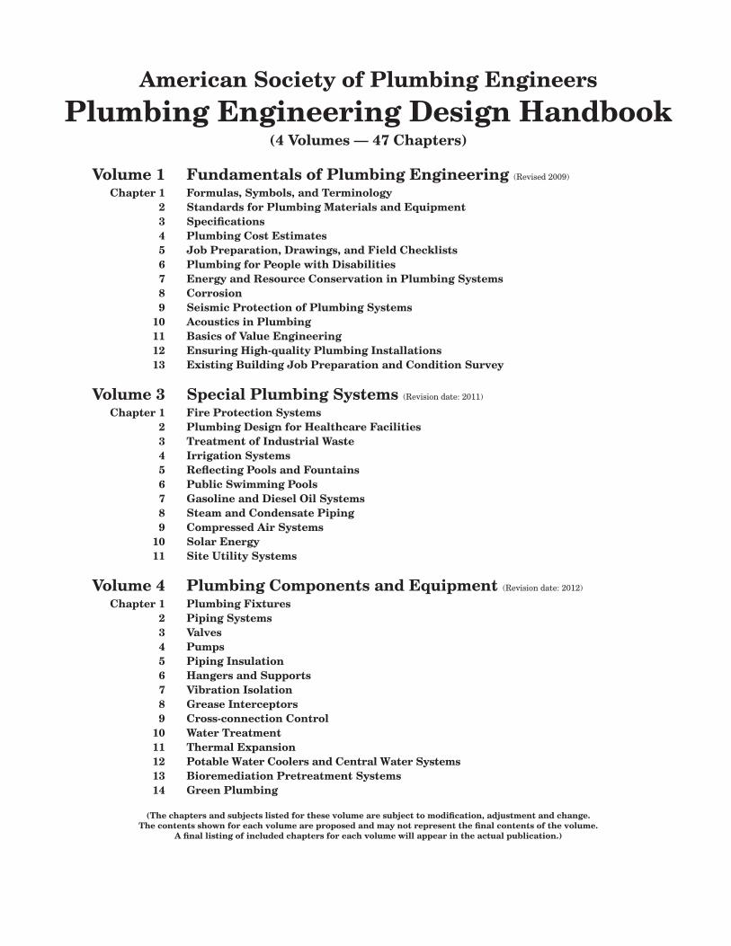
Plumbing Engineering Design Handbook(4 Volumes — 47 Chapters)
Volume 1 Fundamentals of Plumbing Engineering (Revised 2009)
Chapter 1 Formulas, Symbols, and Terminology 2 Standards for Plumbing Materials and Equipment 3 Specifications 4 Plumbing Cost Estimates 5 Job Preparation, Drawings, and Field Checklists 6 Plumbing for People with Disabilities 7 Energy and Resource Conservation in Plumbing Systems 8 Corrosion 9 Seismic Protection of Plumbing Systems 10 Acoustics in Plumbing 11 Basics of Value Engineering 12 Ensuring High-quality Plumbing Installations 13 Existing Building Job Preparation and Condition Survey
Volume 3 Special Plumbing Systems (Revision date: 2011)
Chapter 1 Fire Protection Systems 2 Plumbing Design for Healthcare Facilities 3 Treatment of Industrial Waste 4 Irrigation Systems 5 Reflecting Pools and Fountains 6 Public Swimming Pools 7 Gasoline and Diesel Oil Systems 8 Steam and Condensate Piping 9 Compressed Air Systems 10 Solar Energy 11 Site Utility Systems
Volume 4 Plumbing Components and Equipment (Revision date: 2012)
Chapter 1 Plumbing Fixtures 2 Piping Systems 3 Valves 4 Pumps 5 Piping Insulation 6 Hangers and Supports 7 Vibration Isolation 8 Grease Interceptors 9 Cross-connection Control 10 Water Treatment 11 Thermal Expansion 12 Potable Water Coolers and Central Water Systems 13 Bioremediation Pretreatment Systems 14 Green Plumbing
(The chapters and subjects listed for these volume are subject to modification, adjustment and change.The contents shown for each volume are proposed and may not represent the final contents of the volume.
A final listing of included chapters for each volume will appear in the actual publication.)

1 Sanitary Drainage Systems . . . . . . . . . . . . . . . . . . . . . . . . . . . . . . . . . . .1Codes and Standards . . . . . . . . . . . . . . . . . . . . . . . . . . . . . . . . . . . . . . . . . . . . . . . . . . . . . . 1Flow in Stacks . . . . . . . . . . . . . . . . . . . . . . . . . . . . . . . . . . . . . . . . . . . . . . . . . . . . . . . . . . . 1
Flow in Building Drains . . . . . . . . . . . . . . . . . . . . . . . . . . . . . . . . . . . . . . . . . . . . . . . . 2Flow in Fixture Drains . . . . . . . . . . . . . . . . . . . . . . . . . . . . . . . . . . . . . . . . . . . . . . . . . 2
Pneumatic Pressures in a Sanitary Drainage System . . . . . . . . . . . . . . . . . . . . . . . . . . . . 2Fixture Discharge Characteristics. . . . . . . . . . . . . . . . . . . . . . . . . . . . . . . . . . . . . . . . . . . . 3
Drainage Loads . . . . . . . . . . . . . . . . . . . . . . . . . . . . . . . . . . . . . . . . . . . . . . . . . . . . . . . 3Stack Capacities . . . . . . . . . . . . . . . . . . . . . . . . . . . . . . . . . . . . . . . . . . . . . . . . . . . . . . . 3
Capacities of Sloping Drains . . . . . . . . . . . . . . . . . . . . . . . . . . . . . . . . . . . . . . . . . . . . . . . . 5Steady, Uniform Flow Conditions in Sloping Drains. . . . . . . . . . . . . . . . . . . . . . . . . . 6Slope of Horizontal Drainage Piping . . . . . . . . . . . . . . . . . . . . . . . . . . . . . . . . . . . . . . 7Loads for Drainage Piping . . . . . . . . . . . . . . . . . . . . . . . . . . . . . . . . . . . . . . . . . . . . . . 8
Components of Sanitary Drainage Systems . . . . . . . . . . . . . . . . . . . . . . . . . . . . . . . . . . . . 8Sumps and Ejectors . . . . . . . . . . . . . . . . . . . . . . . . . . . . . . . . . . . . . . . . . . . . . . . . . . . . 8Cleanouts . . . . . . . . . . . . . . . . . . . . . . . . . . . . . . . . . . . . . . . . . . . . . . . . . . . . . . . . . . . . 9Floor Drains and Floor Sinks . . . . . . . . . . . . . . . . . . . . . . . . . . . . . . . . . . . . . . . . . . . 10Grates/Strainers. . . . . . . . . . . . . . . . . . . . . . . . . . . . . . . . . . . . . . . . . . . . . . . . . . . . . . 11Flashing Ring. . . . . . . . . . . . . . . . . . . . . . . . . . . . . . . . . . . . . . . . . . . . . . . . . . . . . . . . 11Sediment Bucket . . . . . . . . . . . . . . . . . . . . . . . . . . . . . . . . . . . . . . . . . . . . . . . . . . . . . 11Accessories . . . . . . . . . . . . . . . . . . . . . . . . . . . . . . . . . . . . . . . . . . . . . . . . . . . . . . . . . . 12Backwater Valves . . . . . . . . . . . . . . . . . . . . . . . . . . . . . . . . . . . . . . . . . . . . . . . . . . . . . 12Oil Interceptors . . . . . . . . . . . . . . . . . . . . . . . . . . . . . . . . . . . . . . . . . . . . . . . . . . . . . . 12Fixture Wastewater Type . . . . . . . . . . . . . . . . . . . . . . . . . . . . . . . . . . . . . . . . . . . . . . 12Supports . . . . . . . . . . . . . . . . . . . . . . . . . . . . . . . . . . . . . . . . . . . . . . . . . . . . . . . . . . . . 12
Piping Materials . . . . . . . . . . . . . . . . . . . . . . . . . . . . . . . . . . . . . . . . . . . . . . . . . . . . . . . . . 12Joining Methods . . . . . . . . . . . . . . . . . . . . . . . . . . . . . . . . . . . . . . . . . . . . . . . . . . . . . . . . . 13
Noise Transmission . . . . . . . . . . . . . . . . . . . . . . . . . . . . . . . . . . . . . . . . . . . . . . . . . . . 13Building Sewer Installation . . . . . . . . . . . . . . . . . . . . . . . . . . . . . . . . . . . . . . . . . . . . . . . . 14Sanitation . . . . . . . . . . . . . . . . . . . . . . . . . . . . . . . . . . . . . . . . . . . . . . . . . . . . . . . . . . . . . . 15Kitchen Areas . . . . . . . . . . . . . . . . . . . . . . . . . . . . . . . . . . . . . . . . . . . . . . . . . . . . . . . . . . . 15Waterproofing . . . . . . . . . . . . . . . . . . . . . . . . . . . . . . . . . . . . . . . . . . . . . . . . . . . . . . . . . . . 15Floor Leveling. . . . . . . . . . . . . . . . . . . . . . . . . . . . . . . . . . . . . . . . . . . . . . . . . . . . . . . . . . . 16
Table of Contents
ii ASPE Plumbing Engineering Design Handbook — Volume 2
Thermal Expansion . . . . . . . . . . . . . . . . . . . . . . . . . . . . . . . . . . . . . . . . . . . . . . . . . . . . . . 16Protection from Damage . . . . . . . . . . . . . . . . . . . . . . . . . . . . . . . . . . . . . . . . . . . . . . . . . . 16Alternate Sanitary Systems. . . . . . . . . . . . . . . . . . . . . . . . . . . . . . . . . . . . . . . . . . . . . . . . 16Sovent and Provent . . . . . . . . . . . . . . . . . . . . . . . . . . . . . . . . . . . . . . . . . . . . . . . . . . . . . . 17Single-stack System . . . . . . . . . . . . . . . . . . . . . . . . . . . . . . . . . . . . . . . . . . . . . . . . . . . . . . 18Reduced-size Venting . . . . . . . . . . . . . . . . . . . . . . . . . . . . . . . . . . . . . . . . . . . . . . . . . . . . . 18Vacuum Drainage System . . . . . . . . . . . . . . . . . . . . . . . . . . . . . . . . . . . . . . . . . . . . . . . . . 19References. . . . . . . . . . . . . . . . . . . . . . . . . . . . . . . . . . . . . . . . . . . . . . . . . . . . . . . . . . . . . . 19
2 On-site Wastewater Reuse and Storm Water Harvesting . . . . . . . . . .21Terminology . . . . . . . . . . . . . . . . . . . . . . . . . . . . . . . . . . . . . . . . . . . . . . . . . . . . . . . . . . . . 21The Water Balance Equation. . . . . . . . . . . . . . . . . . . . . . . . . . . . . . . . . . . . . . . . . . . . . . . 21Codes and Standards . . . . . . . . . . . . . . . . . . . . . . . . . . . . . . . . . . . . . . . . . . . . . . . . . . . . . 22Graywater Reuse . . . . . . . . . . . . . . . . . . . . . . . . . . . . . . . . . . . . . . . . . . . . . . . . . . . . . . . . 22
System Components . . . . . . . . . . . . . . . . . . . . . . . . . . . . . . . . . . . . . . . . . . . . . . . . . . 22Design Criteria for Graywater Supply and Consumption . . . . . . . . . . . . . . . . . . . . . 22Design Estimates for Commercial Buildings . . . . . . . . . . . . . . . . . . . . . . . . . . . . . . . 23Graywater Design Estimates for Residential Buildings . . . . . . . . . . . . . . . . . . . . . . 24Design Estimates for Graywater Irrigation Systems . . . . . . . . . . . . . . . . . . . . . . . . 24Graywater Treatment Systems. . . . . . . . . . . . . . . . . . . . . . . . . . . . . . . . . . . . . . . . . . 25Economic Analysis . . . . . . . . . . . . . . . . . . . . . . . . . . . . . . . . . . . . . . . . . . . . . . . . . . . . 27Precautions . . . . . . . . . . . . . . . . . . . . . . . . . . . . . . . . . . . . . . . . . . . . . . . . . . . . . . . . . 27Public Concerns and Acceptance . . . . . . . . . . . . . . . . . . . . . . . . . . . . . . . . . . . . . . . . 27
Storm Water Harvesting . . . . . . . . . . . . . . . . . . . . . . . . . . . . . . . . . . . . . . . . . . . . . . . . . . 28References. . . . . . . . . . . . . . . . . . . . . . . . . . . . . . . . . . . . . . . . . . . . . . . . . . . . . . . . . . . . . . 29
3 Vents and Venting . . . . . . . . . . . . . . . . . . . . . . . . . . . . . . . . . . . . . . . . . .31Trap Design . . . . . . . . . . . . . . . . . . . . . . . . . . . . . . . . . . . . . . . . . . . . . . . . . . . . . . . . . . . . 31 Types of Fixture Vents . . . . . . . . . . . . . . . . . . . . . . . . . . . . . . . . . . . . . . . . . . . . . . . . . . . . 32
Common Vent. . . . . . . . . . . . . . . . . . . . . . . . . . . . . . . . . . . . . . . . . . . . . . . . . . . . . . . . 32Wet Venting . . . . . . . . . . . . . . . . . . . . . . . . . . . . . . . . . . . . . . . . . . . . . . . . . . . . . . . . . 32Circuit Vent . . . . . . . . . . . . . . . . . . . . . . . . . . . . . . . . . . . . . . . . . . . . . . . . . . . . . . . . . 32Waste Stack . . . . . . . . . . . . . . . . . . . . . . . . . . . . . . . . . . . . . . . . . . . . . . . . . . . . . . . . . 33Combination Drain and Vent . . . . . . . . . . . . . . . . . . . . . . . . . . . . . . . . . . . . . . . . . . . 33Island Vent . . . . . . . . . . . . . . . . . . . . . . . . . . . . . . . . . . . . . . . . . . . . . . . . . . . . . . . . . . 34
Vent Systems. . . . . . . . . . . . . . . . . . . . . . . . . . . . . . . . . . . . . . . . . . . . . . . . . . . . . . . . . . . . 34Vent Stack Design. . . . . . . . . . . . . . . . . . . . . . . . . . . . . . . . . . . . . . . . . . . . . . . . . . . . . . . . 35
Sizing a Vent Stack . . . . . . . . . . . . . . . . . . . . . . . . . . . . . . . . . . . . . . . . . . . . . . . . . . . 35Offsets. . . . . . . . . . . . . . . . . . . . . . . . . . . . . . . . . . . . . . . . . . . . . . . . . . . . . . . . . . . . . . 37Suds Pressure Zones . . . . . . . . . . . . . . . . . . . . . . . . . . . . . . . . . . . . . . . . . . . . . . . . . . 37Main Vent . . . . . . . . . . . . . . . . . . . . . . . . . . . . . . . . . . . . . . . . . . . . . . . . . . . . . . . . . . . 37
Fixture Vent Design . . . . . . . . . . . . . . . . . . . . . . . . . . . . . . . . . . . . . . . . . . . . . . . . . . . . . . 38Alternative Vent Systems. . . . . . . . . . . . . . . . . . . . . . . . . . . . . . . . . . . . . . . . . . . . . . . . . . 39
Air-admittance Valves . . . . . . . . . . . . . . . . . . . . . . . . . . . . . . . . . . . . . . . . . . . . . . . . . 39Sovent Systems . . . . . . . . . . . . . . . . . . . . . . . . . . . . . . . . . . . . . . . . . . . . . . . . . . . . . . 39Single Stack . . . . . . . . . . . . . . . . . . . . . . . . . . . . . . . . . . . . . . . . . . . . . . . . . . . . . . . . . 39
Table of Contents iii
Jurisdictions . . . . . . . . . . . . . . . . . . . . . . . . . . . . . . . . . . . . . . . . . . . . . . . . . . . . . . . . . . . . 39Conclusion . . . . . . . . . . . . . . . . . . . . . . . . . . . . . . . . . . . . . . . . . . . . . . . . . . . . . . . . . . . . . 40
4 Storm Drainage Systems. . . . . . . . . . . . . . . . . . . . . . . . . . . . . . . . . . . . .41Code and Standards . . . . . . . . . . . . . . . . . . . . . . . . . . . . . . . . . . . . . . . . . . . . . . . . . . . . . . 41Materials . . . . . . . . . . . . . . . . . . . . . . . . . . . . . . . . . . . . . . . . . . . . . . . . . . . . . . . . . . . . . . . 42Site Drainage and Infitration . . . . . . . . . . . . . . . . . . . . . . . . . . . . . . . . . . . . . . . . . . . . . . 42
The Rational Method. . . . . . . . . . . . . . . . . . . . . . . . . . . . . . . . . . . . . . . . . . . . . . . . . . 43Runoff Patterns . . . . . . . . . . . . . . . . . . . . . . . . . . . . . . . . . . . . . . . . . . . . . . . . . . . . . . 43Storm Water Quality . . . . . . . . . . . . . . . . . . . . . . . . . . . . . . . . . . . . . . . . . . . . . . . . . . 43Estimating Time of Concentration and Rainfall Intensity . . . . . . . . . . . . . . . . . . . . 44Collection Systems. . . . . . . . . . . . . . . . . . . . . . . . . . . . . . . . . . . . . . . . . . . . . . . . . . . . 46Conveyance . . . . . . . . . . . . . . . . . . . . . . . . . . . . . . . . . . . . . . . . . . . . . . . . . . . . . . . . . 46Detention . . . . . . . . . . . . . . . . . . . . . . . . . . . . . . . . . . . . . . . . . . . . . . . . . . . . . . . . . . . 47Infiltration . . . . . . . . . . . . . . . . . . . . . . . . . . . . . . . . . . . . . . . . . . . . . . . . . . . . . . . . . . 48Treatment . . . . . . . . . . . . . . . . . . . . . . . . . . . . . . . . . . . . . . . . . . . . . . . . . . . . . . . . . . 48Accessibility and Maintenance . . . . . . . . . . . . . . . . . . . . . . . . . . . . . . . . . . . . . . . . . . 48Vector Control . . . . . . . . . . . . . . . . . . . . . . . . . . . . . . . . . . . . . . . . . . . . . . . . . . . . . . . 49
Interior Building Drainage System Design. . . . . . . . . . . . . . . . . . . . . . . . . . . . . . . . . . . . 49General Design Criteria . . . . . . . . . . . . . . . . . . . . . . . . . . . . . . . . . . . . . . . . . . . . . . . 49Roof Drainage . . . . . . . . . . . . . . . . . . . . . . . . . . . . . . . . . . . . . . . . . . . . . . . . . . . . . . . 51Rainfall Rates. . . . . . . . . . . . . . . . . . . . . . . . . . . . . . . . . . . . . . . . . . . . . . . . . . . . . . . . 53Interior Pipe Sizing and Layout Criteria . . . . . . . . . . . . . . . . . . . . . . . . . . . . . . . . . 53
References. . . . . . . . . . . . . . . . . . . . . . . . . . . . . . . . . . . . . . . . . . . . . . . . . . . . . . . . . . . . . . 54Appendix 4-A . . . . . . . . . . . . . . . . . . . . . . . . . . . . . . . . . . . . . . . . . . . . . . . . . . . . . . . . . . . 56
Runoff Volume Calculation for Typical Wisconsin Commercial Sites . . . . . . . . . . . 56Definitions . . . . . . . . . . . . . . . . . . . . . . . . . . . . . . . . . . . . . . . . . . . . . . . . . . . . . . . . . . 56Assumptions and Notes. . . . . . . . . . . . . . . . . . . . . . . . . . . . . . . . . . . . . . . . . . . . . . . . 56
5 Cold Water Systems . . . . . . . . . . . . . . . . . . . . . . . . . . . . . . . . . . . . . . . . .59Codes and Standards . . . . . . . . . . . . . . . . . . . . . . . . . . . . . . . . . . . . . . . . . . . . . . . . . . . . . 59Domestic Cold Water Meters . . . . . . . . . . . . . . . . . . . . . . . . . . . . . . . . . . . . . . . . . . . . . . . 59
Meter Types . . . . . . . . . . . . . . . . . . . . . . . . . . . . . . . . . . . . . . . . . . . . . . . . . . . . . . . . 59Sizing the Water Meter . . . . . . . . . . . . . . . . . . . . . . . . . . . . . . . . . . . . . . . . . . . . . . . . 60
Cross-connection Controls . . . . . . . . . . . . . . . . . . . . . . . . . . . . . . . . . . . . . . . . . . . . . . . . . 60Design Guidelines for Cross-connection Controls . . . . . . . . . . . . . . . . . . . . . . . . . . . 60
Booster Pump Systems . . . . . . . . . . . . . . . . . . . . . . . . . . . . . . . . . . . . . . . . . . . . . . . . . . . 61Pump Economy . . . . . . . . . . . . . . . . . . . . . . . . . . . . . . . . . . . . . . . . . . . . . . . . . . . . . . 63Booster Pump Features . . . . . . . . . . . . . . . . . . . . . . . . . . . . . . . . . . . . . . . . . . . . . . . . 63Alternate Applications. . . . . . . . . . . . . . . . . . . . . . . . . . . . . . . . . . . . . . . . . . . . . . . . . 64Hydropneumatic Tank. . . . . . . . . . . . . . . . . . . . . . . . . . . . . . . . . . . . . . . . . . . . . . . . . 64Elevated Water Tank System . . . . . . . . . . . . . . . . . . . . . . . . . . . . . . . . . . . . . . . . . . . 65Expansion Tank . . . . . . . . . . . . . . . . . . . . . . . . . . . . . . . . . . . . . . . . . . . . . . . . . . . . . . 67
Excess Water Pressure . . . . . . . . . . . . . . . . . . . . . . . . . . . . . . . . . . . . . . . . . . . . . . . . . . . . 68Pressure-regulating Valves . . . . . . . . . . . . . . . . . . . . . . . . . . . . . . . . . . . . . . . . . . . . . 69
Water Hammer . . . . . . . . . . . . . . . . . . . . . . . . . . . . . . . . . . . . . . . . . . . . . . . . . . . . . . . . . . 70

iv ASPE Plumbing Engineering Design Handbook — Volume 2
Shock Intensity . . . . . . . . . . . . . . . . . . . . . . . . . . . . . . . . . . . . . . . . . . . . . . . . . . . . . . 70System Protection . . . . . . . . . . . . . . . . . . . . . . . . . . . . . . . . . . . . . . . . . . . . . . . . . . . . 72
Sizing Water Piping . . . . . . . . . . . . . . . . . . . . . . . . . . . . . . . . . . . . . . . . . . . . . . . . . . . . . . 73Hazen-Williams Formula. . . . . . . . . . . . . . . . . . . . . . . . . . . . . . . . . . . . . . . . . . . . . . . 73Darcy-Weisbach Formula. . . . . . . . . . . . . . . . . . . . . . . . . . . . . . . . . . . . . . . . . . . . . . . 74Factors Affecting Domestic Water Pipe Sizing. . . . . . . . . . . . . . . . . . . . . . . . . . . . . . 75Step-by-Step Guide to Sizing Water Pipe . . . . . . . . . . . . . . . . . . . . . . . . . . . . . . . . . . 84Velocity Method . . . . . . . . . . . . . . . . . . . . . . . . . . . . . . . . . . . . . . . . . . . . . . . . . . . . . . 89Pressure Loss in Pipe Fittings and Valves . . . . . . . . . . . . . . . . . . . . . . . . . . . . . . . . . 89
Testing . . . . . . . . . . . . . . . . . . . . . . . . . . . . . . . . . . . . . . . . . . . . . . . . . . . . . . . . . . . . . . . . 90Cleaning and Disinfecting . . . . . . . . . . . . . . . . . . . . . . . . . . . . . . . . . . . . . . . . . . . . . . . . . 90Glossary . . . . . . . . . . . . . . . . . . . . . . . . . . . . . . . . . . . . . . . . . . . . . . . . . . . . . . . . . . . . . . . 94References. . . . . . . . . . . . . . . . . . . . . . . . . . . . . . . . . . . . . . . . . . . . . . . . . . . . . . . . . . . . . . 95
6 Domestic Water Heating Systems . . . . . . . . . . . . . . . . . . . . . . . . . . . . .97Domestic Water Heater Sizing. . . . . . . . . . . . . . . . . . . . . . . . . . . . . . . . . . . . . . . . . . . . . . 98
Information Gathering . . . . . . . . . . . . . . . . . . . . . . . . . . . . . . . . . . . . . . . . . . . . . . . . 98Water Heater Sizing Methods . . . . . . . . . . . . . . . . . . . . . . . . . . . . . . . . . . . . . . . . . . . 98
Basic Formulae and Units . . . . . . . . . . . . . . . . . . . . . . . . . . . . . . . . . . . . . . . . . . . . . . . . 100Heat Recovery—Electric Water Heaters. . . . . . . . . . . . . . . . . . . . . . . . . . . . . . . . . . . . . 100Hot Water Temperature. . . . . . . . . . . . . . . . . . . . . . . . . . . . . . . . . . . . . . . . . . . . . . . . . . 101Mixed Water Temperature. . . . . . . . . . . . . . . . . . . . . . . . . . . . . . . . . . . . . . . . . . . . . . . . 101Water Heaters. . . . . . . . . . . . . . . . . . . . . . . . . . . . . . . . . . . . . . . . . . . . . . . . . . . . . . . . . . 101
Controls . . . . . . . . . . . . . . . . . . . . . . . . . . . . . . . . . . . . . . . . . . . . . . . . . . . . . . . . . . . 104Stratification in Storage-type Heaters and Tanks . . . . . . . . . . . . . . . . . . . . . . . . . . 105
Hot Water Temperature Maintenance . . . . . . . . . . . . . . . . . . . . . . . . . . . . . . . . . . . . . . 105Hot Water Circulation Systems . . . . . . . . . . . . . . . . . . . . . . . . . . . . . . . . . . . . . . . . 105Self-regulating Heat Trace Systems . . . . . . . . . . . . . . . . . . . . . . . . . . . . . . . . . . . . . 105
Relief Valves . . . . . . . . . . . . . . . . . . . . . . . . . . . . . . . . . . . . . . . . . . . . . . . . . . . . . . . . . . . 106Sizing Pressure and Temperature Relief Valves . . . . . . . . . . . . . . . . . . . . . . . . . . . 106
Thermal Expansion . . . . . . . . . . . . . . . . . . . . . . . . . . . . . . . . . . . . . . . . . . . . . . . . . . . . . 106Thermal Efficiency . . . . . . . . . . . . . . . . . . . . . . . . . . . . . . . . . . . . . . . . . . . . . . . . . . . . . . 107Legionnaires' Disease . . . . . . . . . . . . . . . . . . . . . . . . . . . . . . . . . . . . . . . . . . . . . . . . . . . . 108
Varying Standards . . . . . . . . . . . . . . . . . . . . . . . . . . . . . . . . . . . . . . . . . . . . . . . . . . . 109Legionella Hot Spots . . . . . . . . . . . . . . . . . . . . . . . . . . . . . . . . . . . . . . . . . . . . . . . . . 109Controlling Legionella . . . . . . . . . . . . . . . . . . . . . . . . . . . . . . . . . . . . . . . . . . . . . . . . 109Legionella Control Recommendations . . . . . . . . . . . . . . . . . . . . . . . . . . . . . . . . . . . 111
Scalding. . . . . . . . . . . . . . . . . . . . . . . . . . . . . . . . . . . . . . . . . . . . . . . . . . . . . . . . . . . . . . . 111Codes and Standards . . . . . . . . . . . . . . . . . . . . . . . . . . . . . . . . . . . . . . . . . . . . . . . . . . . . 112
7 Fuel Gas Piping Systems. . . . . . . . . . . . . . . . . . . . . . . . . . . . . . . . . . . .113Types of Gas Service . . . . . . . . . . . . . . . . . . . . . . . . . . . . . . . . . . . . . . . . . . . . . . . . . . . . 113Approvals . . . . . . . . . . . . . . . . . . . . . . . . . . . . . . . . . . . . . . . . . . . . . . . . . . . . . . . . . . . . . 114System Opperating Pressure . . . . . . . . . . . . . . . . . . . . . . . . . . . . . . . . . . . . . . . . . . . . . . 115Efficiency. . . . . . . . . . . . . . . . . . . . . . . . . . . . . . . . . . . . . . . . . . . . . . . . . . . . . . . . . . . . . . 115Codes and Standards . . . . . . . . . . . . . . . . . . . . . . . . . . . . . . . . . . . . . . . . . . . . . . . . . . . . 115
Table of Contents v
Gas Meters . . . . . . . . . . . . . . . . . . . . . . . . . . . . . . . . . . . . . . . . . . . . . . . . . . . . . . . . . . . . 115Meter Types . . . . . . . . . . . . . . . . . . . . . . . . . . . . . . . . . . . . . . . . . . . . . . . . . . . . . . . . 116Meter Selection . . . . . . . . . . . . . . . . . . . . . . . . . . . . . . . . . . . . . . . . . . . . . . . . . . . . . 116
Pressure-regulating Valves . . . . . . . . . . . . . . . . . . . . . . . . . . . . . . . . . . . . . . . . . . . . . . . 117Gas Regulator Relief Vents . . . . . . . . . . . . . . . . . . . . . . . . . . . . . . . . . . . . . . . . . . . 117
Control Valves. . . . . . . . . . . . . . . . . . . . . . . . . . . . . . . . . . . . . . . . . . . . . . . . . . . . . . . . . . 118Excess Flow Valves . . . . . . . . . . . . . . . . . . . . . . . . . . . . . . . . . . . . . . . . . . . . . . . . . . 118Appliance Control Valves . . . . . . . . . . . . . . . . . . . . . . . . . . . . . . . . . . . . . . . . . . . . . 118Interlocks and Solenoid Valves . . . . . . . . . . . . . . . . . . . . . . . . . . . . . . . . . . . . . . . . . 118
Appliances. . . . . . . . . . . . . . . . . . . . . . . . . . . . . . . . . . . . . . . . . . . . . . . . . . . . . . . . . . . . . 118Venting . . . . . . . . . . . . . . . . . . . . . . . . . . . . . . . . . . . . . . . . . . . . . . . . . . . . . . . . . . . . . . . 118Allowable Gas Pressure . . . . . . . . . . . . . . . . . . . . . . . . . . . . . . . . . . . . . . . . . . . . . . . . . . 119Laboratory Use. . . . . . . . . . . . . . . . . . . . . . . . . . . . . . . . . . . . . . . . . . . . . . . . . . . . . . . . . 121Altitude Derating Factor . . . . . . . . . . . . . . . . . . . . . . . . . . . . . . . . . . . . . . . . . . . . . . . . . 121Piping System Materials . . . . . . . . . . . . . . . . . . . . . . . . . . . . . . . . . . . . . . . . . . . . . . . . . 121
Metallic Pipe . . . . . . . . . . . . . . . . . . . . . . . . . . . . . . . . . . . . . . . . . . . . . . . . . . . . . . . 122Metallic Tubing . . . . . . . . . . . . . . . . . . . . . . . . . . . . . . . . . . . . . . . . . . . . . . . . . . . . . 122Plastic Pipe and Tubing . . . . . . . . . . . . . . . . . . . . . . . . . . . . . . . . . . . . . . . . . . . . . . 123Fittings and Joints. . . . . . . . . . . . . . . . . . . . . . . . . . . . . . . . . . . . . . . . . . . . . . . . . . . 124Flexible Hose Connections . . . . . . . . . . . . . . . . . . . . . . . . . . . . . . . . . . . . . . . . . . . . 124Grounding . . . . . . . . . . . . . . . . . . . . . . . . . . . . . . . . . . . . . . . . . . . . . . . . . . . . . . . . . 125
Natural Gas Boosters . . . . . . . . . . . . . . . . . . . . . . . . . . . . . . . . . . . . . . . . . . . . . . . . . . . . 125Materials and Construction . . . . . . . . . . . . . . . . . . . . . . . . . . . . . . . . . . . . . . . . . . . 125Gas Laws for Boosters . . . . . . . . . . . . . . . . . . . . . . . . . . . . . . . . . . . . . . . . . . . . . . . . 126High-rise Building Issues . . . . . . . . . . . . . . . . . . . . . . . . . . . . . . . . . . . . . . . . . . . . . 126Design Considerations . . . . . . . . . . . . . . . . . . . . . . . . . . . . . . . . . . . . . . . . . . . . . . . 126Sizing a Gas Booster . . . . . . . . . . . . . . . . . . . . . . . . . . . . . . . . . . . . . . . . . . . . . . . . . 127Pressure Droop and Peak Consumption . . . . . . . . . . . . . . . . . . . . . . . . . . . . . . . . . 128
Interior Natural Gas Pipe Sizing . . . . . . . . . . . . . . . . . . . . . . . . . . . . . . . . . . . . . . . . . . 128Data to Be Obtained . . . . . . . . . . . . . . . . . . . . . . . . . . . . . . . . . . . . . . . . . . . . . . . . . 128Natural Gas Pipe Sizing Methods . . . . . . . . . . . . . . . . . . . . . . . . . . . . . . . . . . . . . . 130
Liquefied Petroleum Gas . . . . . . . . . . . . . . . . . . . . . . . . . . . . . . . . . . . . . . . . . . . . . . . . . 131Environmental Effects of Propane . . . . . . . . . . . . . . . . . . . . . . . . . . . . . . . . . . . . . . 131Propane Storage Tanks . . . . . . . . . . . . . . . . . . . . . . . . . . . . . . . . . . . . . . . . . . . . . . . 131Propane Vaporization Requirements . . . . . . . . . . . . . . . . . . . . . . . . . . . . . . . . . . . . 134Design Considerations . . . . . . . . . . . . . . . . . . . . . . . . . . . . . . . . . . . . . . . . . . . . . . . 134Liquefied Petroleum Gas Sizing . . . . . . . . . . . . . . . . . . . . . . . . . . . . . . . . . . . . . . . . 135
Glossary . . . . . . . . . . . . . . . . . . . . . . . . . . . . . . . . . . . . . . . . . . . . . . . . . . . . . . . . . . . . . . 135References. . . . . . . . . . . . . . . . . . . . . . . . . . . . . . . . . . . . . . . . . . . . . . . . . . . . . . . . . . . . . 136
8 Private On-site Wastewater Treatment Systems. . . . . . . . . . . . . . . .139Primary Treatment . . . . . . . . . . . . . . . . . . . . . . . . . . . . . . . . . . . . . . . . . . . . . . . . . . . . . 139Soil Absorption Systems . . . . . . . . . . . . . . . . . . . . . . . . . . . . . . . . . . . . . . . . . . . . . . . . . 139
Estimating Soil Absorption Rates. . . . . . . . . . . . . . . . . . . . . . . . . . . . . . . . . . . . . . . 140Soil Absorption System Selection . . . . . . . . . . . . . . . . . . . . . . . . . . . . . . . . . . . . . . . 142In-ground Conventional Soil Absorption System . . . . . . . . . . . . . . . . . . . . . . . . . . 142
vi ASPE Plumbing Engineering Design Handbook — Volume 2
Site Preparation and Construction. . . . . . . . . . . . . . . . . . . . . . . . . . . . . . . . . . . . . . 143Collection and Treatment Alternatives . . . . . . . . . . . . . . . . . . . . . . . . . . . . . . . . . . . . . 144
Alternatives to Gravity Collection and Distribution . . . . . . . . . . . . . . . . . . . . . . . . 144Alternatives to Conventional Primary and Secondary Treatment. . . . . . . . . . . . . 145
Septic Tanks . . . . . . . . . . . . . . . . . . . . . . . . . . . . . . . . . . . . . . . . . . . . . . . . . . . . . . . . . . . 145Functions of the Septic Tank . . . . . . . . . . . . . . . . . . . . . . . . . . . . . . . . . . . . . . . . . . 145Septic Tank Materials . . . . . . . . . . . . . . . . . . . . . . . . . . . . . . . . . . . . . . . . . . . . . . . . 145Septic Tank Construction, Installation, and Operation . . . . . . . . . . . . . . . . . . . . . 146Cleaning Septic Tanks . . . . . . . . . . . . . . . . . . . . . . . . . . . . . . . . . . . . . . . . . . . . . . . . 148Distribution Boxes . . . . . . . . . . . . . . . . . . . . . . . . . . . . . . . . . . . . . . . . . . . . . . . . . . . 148
Sewage Disposal Systems for Institutions and Small Establishments . . . . . . . . . . . . . 149Water Conservation . . . . . . . . . . . . . . . . . . . . . . . . . . . . . . . . . . . . . . . . . . . . . . . . . . 149Special Fixtures . . . . . . . . . . . . . . . . . . . . . . . . . . . . . . . . . . . . . . . . . . . . . . . . . . . . . 149Alternative Systems. . . . . . . . . . . . . . . . . . . . . . . . . . . . . . . . . . . . . . . . . . . . . . . . . . 149Special Design . . . . . . . . . . . . . . . . . . . . . . . . . . . . . . . . . . . . . . . . . . . . . . . . . . . . . . 149Individual Aerobic Wastewater Treatment Plants . . . . . . . . . . . . . . . . . . . . . . . . . 150
Estimating Sewage Quantities . . . . . . . . . . . . . . . . . . . . . . . . . . . . . . . . . . . . . . . . . . . . 150Inspection . . . . . . . . . . . . . . . . . . . . . . . . . . . . . . . . . . . . . . . . . . . . . . . . . . . . . . . . . . . . . 153References. . . . . . . . . . . . . . . . . . . . . . . . . . . . . . . . . . . . . . . . . . . . . . . . . . . . . . . . . . . . . 154
9 Private Water Wells . . . . . . . . . . . . . . . . . . . . . . . . . . . . . . . . . . . . . . . .155Codes and Standards . . . . . . . . . . . . . . . . . . . . . . . . . . . . . . . . . . . . . . . . . . . . . . . . . . . . 155Sources of Supply . . . . . . . . . . . . . . . . . . . . . . . . . . . . . . . . . . . . . . . . . . . . . . . . . . . . . . . 155Wells . . . . . . . . . . . . . . . . . . . . . . . . . . . . . . . . . . . . . . . . . . . . . . . . . . . . . . . . . . . . . . . . . 155
Dug and Augered Wells . . . . . . . . . . . . . . . . . . . . . . . . . . . . . . . . . . . . . . . . . . . . . . . 156Bored Wells . . . . . . . . . . . . . . . . . . . . . . . . . . . . . . . . . . . . . . . . . . . . . . . . . . . . . . . . 156Driven Wells . . . . . . . . . . . . . . . . . . . . . . . . . . . . . . . . . . . . . . . . . . . . . . . . . . . . . . . 157Jetted Wells . . . . . . . . . . . . . . . . . . . . . . . . . . . . . . . . . . . . . . . . . . . . . . . . . . . . . . . . 157
Hydraulics of Wells. . . . . . . . . . . . . . . . . . . . . . . . . . . . . . . . . . . . . . . . . . . . . . . . . . . . . . 157Protection of Wells . . . . . . . . . . . . . . . . . . . . . . . . . . . . . . . . . . . . . . . . . . . . . . . . . . . . . . 158Water Demand . . . . . . . . . . . . . . . . . . . . . . . . . . . . . . . . . . . . . . . . . . . . . . . . . . . . . . . . . 159Water Quality . . . . . . . . . . . . . . . . . . . . . . . . . . . . . . . . . . . . . . . . . . . . . . . . . . . . . . . . . . 159
Filtration . . . . . . . . . . . . . . . . . . . . . . . . . . . . . . . . . . . . . . . . . . . . . . . . . . . . . . . . . . 159Softening . . . . . . . . . . . . . . . . . . . . . . . . . . . . . . . . . . . . . . . . . . . . . . . . . . . . . . . . . . 160Scale and Corrosion Control . . . . . . . . . . . . . . . . . . . . . . . . . . . . . . . . . . . . . . . . . . 160Taste and Odor Control . . . . . . . . . . . . . . . . . . . . . . . . . . . . . . . . . . . . . . . . . . . . . . 160Prophylaxis . . . . . . . . . . . . . . . . . . . . . . . . . . . . . . . . . . . . . . . . . . . . . . . . . . . . . . . . 160Disinfection . . . . . . . . . . . . . . . . . . . . . . . . . . . . . . . . . . . . . . . . . . . . . . . . . . . . . . . . 160Radon Contamination . . . . . . . . . . . . . . . . . . . . . . . . . . . . . . . . . . . . . . . . . . . . . . . 160
System Elements . . . . . . . . . . . . . . . . . . . . . . . . . . . . . . . . . . . . . . . . . . . . . . . . . . . . . . . 160Pumps . . . . . . . . . . . . . . . . . . . . . . . . . . . . . . . . . . . . . . . . . . . . . . . . . . . . . . . . . . . . 160Submersible Well Pumps . . . . . . . . . . . . . . . . . . . . . . . . . . . . . . . . . . . . . . . . . . . . . 161Storage Tanks . . . . . . . . . . . . . . . . . . . . . . . . . . . . . . . . . . . . . . . . . . . . . . . . . . . . . . 162Storage Tank Suction Piping . . . . . . . . . . . . . . . . . . . . . . . . . . . . . . . . . . . . . . . . . . 163Pressure Regulators . . . . . . . . . . . . . . . . . . . . . . . . . . . . . . . . . . . . . . . . . . . . . . . . . 163
Performance Specifications . . . . . . . . . . . . . . . . . . . . . . . . . . . . . . . . . . . . . . . . . . . . . . . 164
Table of Contents vii
Corrosion Protection . . . . . . . . . . . . . . . . . . . . . . . . . . . . . . . . . . . . . . . . . . . . . . . . . . . . 164Initial Operation and Maintenance. . . . . . . . . . . . . . . . . . . . . . . . . . . . . . . . . . . . . . . . . 164Additional Information . . . . . . . . . . . . . . . . . . . . . . . . . . . . . . . . . . . . . . . . . . . . . . . . . . 164
10 Vacuum Systems. . . . . . . . . . . . . . . . . . . . . . . . . . . . . . . . . . . . . . . . . . .165Fundamentals. . . . . . . . . . . . . . . . . . . . . . . . . . . . . . . . . . . . . . . . . . . . . . . . . . . . . . . . . . 165Pressure Measurement . . . . . . . . . . . . . . . . . . . . . . . . . . . . . . . . . . . . . . . . . . . . . . . . . . 165
Units of Measurement . . . . . . . . . . . . . . . . . . . . . . . . . . . . . . . . . . . . . . . . . . . . . . . 165Standard Reference Points and Conversions . . . . . . . . . . . . . . . . . . . . . . . . . . . . . 166Flow Rate Measurement . . . . . . . . . . . . . . . . . . . . . . . . . . . . . . . . . . . . . . . . . . . . . 166
General Vacuum Criteria . . . . . . . . . . . . . . . . . . . . . . . . . . . . . . . . . . . . . . . . . . . . . . . . . 166Adjusting the Vacuum Pump Rating for Altitude . . . . . . . . . . . . . . . . . . . . . . . . . . 166Time for a Pump to Reach the Rated Vacuum. . . . . . . . . . . . . . . . . . . . . . . . . . . . . 167Adjusting Pressure Drop for Different Vacuum Pressures . . . . . . . . . . . . . . . . . . . 168Simplified Method of Calculating Velocity . . . . . . . . . . . . . . . . . . . . . . . . . . . . . . . . 169Vacuum Work Forces . . . . . . . . . . . . . . . . . . . . . . . . . . . . . . . . . . . . . . . . . . . . . . . . . 169
Vacuum Pumps and Source Equipment . . . . . . . . . . . . . . . . . . . . . . . . . . . . . . . . . . . . . 169Vacuum Pumps . . . . . . . . . . . . . . . . . . . . . . . . . . . . . . . . . . . . . . . . . . . . . . . . . . . . . 169Receivers . . . . . . . . . . . . . . . . . . . . . . . . . . . . . . . . . . . . . . . . . . . . . . . . . . . . . . . . . . 170Seal Liquids . . . . . . . . . . . . . . . . . . . . . . . . . . . . . . . . . . . . . . . . . . . . . . . . . . . . . . . . 170Vacuum Pressure Gauges . . . . . . . . . . . . . . . . . . . . . . . . . . . . . . . . . . . . . . . . . . . . . 171Ancillary Equipment . . . . . . . . . . . . . . . . . . . . . . . . . . . . . . . . . . . . . . . . . . . . . . . . . 171
Laboratory Vacuum Systems . . . . . . . . . . . . . . . . . . . . . . . . . . . . . . . . . . . . . . . . . . . . . . 171Codes and Standards . . . . . . . . . . . . . . . . . . . . . . . . . . . . . . . . . . . . . . . . . . . . . . . . . 172Vacuum Source. . . . . . . . . . . . . . . . . . . . . . . . . . . . . . . . . . . . . . . . . . . . . . . . . . . . . . 173Distribution Network . . . . . . . . . . . . . . . . . . . . . . . . . . . . . . . . . . . . . . . . . . . . . . . . 173General System Layout . . . . . . . . . . . . . . . . . . . . . . . . . . . . . . . . . . . . . . . . . . . . . . . 174Pipe Sizing Criteria . . . . . . . . . . . . . . . . . . . . . . . . . . . . . . . . . . . . . . . . . . . . . . . . . . 174Piping Network Sizing . . . . . . . . . . . . . . . . . . . . . . . . . . . . . . . . . . . . . . . . . . . . . . 176
Vacuum Cleaning Systems. . . . . . . . . . . . . . . . . . . . . . . . . . . . . . . . . . . . . . . . . . . . . . . . 178Types of Systems and Equipment. . . . . . . . . . . . . . . . . . . . . . . . . . . . . . . . . . . . . . . 178Codes and Standards . . . . . . . . . . . . . . . . . . . . . . . . . . . . . . . . . . . . . . . . . . . . . . . . . 178System Components . . . . . . . . . . . . . . . . . . . . . . . . . . . . . . . . . . . . . . . . . . . . . . . . . 178Detailed System Design. . . . . . . . . . . . . . . . . . . . . . . . . . . . . . . . . . . . . . . . . . . . . . . 180Sizing the Piping Network . . . . . . . . . . . . . . . . . . . . . . . . . . . . . . . . . . . . . . . . . . . . 181Piping System Friction Losses . . . . . . . . . . . . . . . . . . . . . . . . . . . . . . . . . . . . . . . . 183Vacuum Producer Sizing . . . . . . . . . . . . . . . . . . . . . . . . . . . . . . . . . . . . . . . . . . . . . . 184Separator Selection and Sizing . . . . . . . . . . . . . . . . . . . . . . . . . . . . . . . . . . . . . . . . 186
References. . . . . . . . . . . . . . . . . . . . . . . . . . . . . . . . . . . . . . . . . . . . . . . . . . . . . . . . . . . . . 186
11 Water Treatment, Conditioning, and Purification . . . . . . . . . . . . . .187Codes and Standards . . . . . . . . . . . . . . . . . . . . . . . . . . . . . . . . . . . . . . . . . . . . . . . . . . . . 187Basic Water Chemistry. . . . . . . . . . . . . . . . . . . . . . . . . . . . . . . . . . . . . . . . . . . . . . . . . . . 187Water Impurities . . . . . . . . . . . . . . . . . . . . . . . . . . . . . . . . . . . . . . . . . . . . . . . . . . . . . . . 188
Turbidity . . . . . . . . . . . . . . . . . . . . . . . . . . . . . . . . . . . . . . . . . . . . . . . . . . . . . . . . . . 188Microorganisms . . . . . . . . . . . . . . . . . . . . . . . . . . . . . . . . . . . . . . . . . . . . . . . . . . . . 188
viii ASPE Plumbing Engineering Design Handbook — Volume 2
Other Organisms . . . . . . . . . . . . . . . . . . . . . . . . . . . . . . . . . . . . . . . . . . . . . . . . . . . 188Dissolved Minerals and Organics . . . . . . . . . . . . . . . . . . . . . . . . . . . . . . . . . . . . . . . 189Alkalinity . . . . . . . . . . . . . . . . . . . . . . . . . . . . . . . . . . . . . . . . . . . . . . . . . . . . . . . . . . 189Hardness . . . . . . . . . . . . . . . . . . . . . . . . . . . . . . . . . . . . . . . . . . . . . . . . . . . . . . . . . . 189Iron . . . . . . . . . . . . . . . . . . . . . . . . . . . . . . . . . . . . . . . . . . . . . . . . . . . . . . . . . . . . . . 189Calcium . . . . . . . . . . . . . . . . . . . . . . . . . . . . . . . . . . . . . . . . . . . . . . . . . . . . . . . . . . . 190Magnesium . . . . . . . . . . . . . . . . . . . . . . . . . . . . . . . . . . . . . . . . . . . . . . . . . . . . . . . . 190Silica . . . . . . . . . . . . . . . . . . . . . . . . . . . . . . . . . . . . . . . . . . . . . . . . . . . . . . . . . . . . . 190Sodium and Potassium . . . . . . . . . . . . . . . . . . . . . . . . . . . . . . . . . . . . . . . . . . . . . . . 190Chlorides and Sulfates . . . . . . . . . . . . . . . . . . . . . . . . . . . . . . . . . . . . . . . . . . . . . . . 190Nitrates . . . . . . . . . . . . . . . . . . . . . . . . . . . . . . . . . . . . . . . . . . . . . . . . . . . . . . . . . . . 190Trace Elements . . . . . . . . . . . . . . . . . . . . . . . . . . . . . . . . . . . . . . . . . . . . . . . . . . . . . 190Dissolved Gases . . . . . . . . . . . . . . . . . . . . . . . . . . . . . . . . . . . . . . . . . . . . . . . . . . . . . 190Volatile Organic Compounds . . . . . . . . . . . . . . . . . . . . . . . . . . . . . . . . . . . . . . . . . . 190
Water Analysis and Impurity Measurement. . . . . . . . . . . . . . . . . . . . . . . . . . . . . . . . . . 191pH . . . . . . . . . . . . . . . . . . . . . . . . . . . . . . . . . . . . . . . . . . . . . . . . . . . . . . . . . . . . . . . 191Specific Resistance . . . . . . . . . . . . . . . . . . . . . . . . . . . . . . . . . . . . . . . . . . . . . . . . . . 192Specific Conductance . . . . . . . . . . . . . . . . . . . . . . . . . . . . . . . . . . . . . . . . . . . . . . . . 193Total Suspended Solids . . . . . . . . . . . . . . . . . . . . . . . . . . . . . . . . . . . . . . . . . . . . . . . 193Total Dissolved Solids . . . . . . . . . . . . . . . . . . . . . . . . . . . . . . . . . . . . . . . . . . . . . . . . 193Total Organic Carbon . . . . . . . . . . . . . . . . . . . . . . . . . . . . . . . . . . . . . . . . . . . . . . . . 194Silt Density Index . . . . . . . . . . . . . . . . . . . . . . . . . . . . . . . . . . . . . . . . . . . . . . . . . . . 194
Deposits and Corrosion . . . . . . . . . . . . . . . . . . . . . . . . . . . . . . . . . . . . . . . . . . . . . . . . . . 194Scale . . . . . . . . . . . . . . . . . . . . . . . . . . . . . . . . . . . . . . . . . . . . . . . . . . . . . . . . . . . . . . 195Sludge . . . . . . . . . . . . . . . . . . . . . . . . . . . . . . . . . . . . . . . . . . . . . . . . . . . . . . . . . . . . . 195Biological Fouling. . . . . . . . . . . . . . . . . . . . . . . . . . . . . . . . . . . . . . . . . . . . . . . . . . . . 195Corrosion . . . . . . . . . . . . . . . . . . . . . . . . . . . . . . . . . . . . . . . . . . . . . . . . . . . . . . . . . . 195
Prediction Scale Formations and Corrosion Tendencies . . . . . . . . . . . . . . . . . . . . . . . . 196Langelier Saturation Index . . . . . . . . . . . . . . . . . . . . . . . . . . . . . . . . . . . . . . . . . . . 196Ryzner Stability Index . . . . . . . . . . . . . . . . . . . . . . . . . . . . . . . . . . . . . . . . . . . . . . . 196Aggressiveness Index . . . . . . . . . . . . . . . . . . . . . . . . . . . . . . . . . . . . . . . . . . . . . . . . 196
Treatment Methodologies . . . . . . . . . . . . . . . . . . . . . . . . . . . . . . . . . . . . . . . . . . . . . . . . 197Aeration . . . . . . . . . . . . . . . . . . . . . . . . . . . . . . . . . . . . . . . . . . . . . . . . . . . . . . . . . . . 197Clarification . . . . . . . . . . . . . . . . . . . . . . . . . . . . . . . . . . . . . . . . . . . . . . . . . . . . . . . . 198Deaeration . . . . . . . . . . . . . . . . . . . . . . . . . . . . . . . . . . . . . . . . . . . . . . . . . . . . . . . . . 199Dealkalizing . . . . . . . . . . . . . . . . . . . . . . . . . . . . . . . . . . . . . . . . . . . . . . . . . . . . . . . 199Decarbonation . . . . . . . . . . . . . . . . . . . . . . . . . . . . . . . . . . . . . . . . . . . . . . . . . . . . . . 199Distillation . . . . . . . . . . . . . . . . . . . . . . . . . . . . . . . . . . . . . . . . . . . . . . . . . . . . . . . . . 199Filtration . . . . . . . . . . . . . . . . . . . . . . . . . . . . . . . . . . . . . . . . . . . . . . . . . . . . . . . . . . 201Ion Exchange and Removal . . . . . . . . . . . . . . . . . . . . . . . . . . . . . . . . . . . . . . . . . . . 201Service Deionization . . . . . . . . . . . . . . . . . . . . . . . . . . . . . . . . . . . . . . . . . . . . . . . . . 208Membrane Filtration and Separation . . . . . . . . . . . . . . . . . . . . . . . . . . . . . . . . . . . 211Microbial Control . . . . . . . . . . . . . . . . . . . . . . . . . . . . . . . . . . . . . . . . . . . . . . . . . . . 213Chemicals . . . . . . . . . . . . . . . . . . . . . . . . . . . . . . . . . . . . . . . . . . . . . . . . . . . . . . . . . 213
Water Treatment . . . . . . . . . . . . . . . . . . . . . . . . . . . . . . . . . . . . . . . . . . . . . . . . . . . . . . . 214
Table of Contents ix
Utility Water Treatment . . . . . . . . . . . . . . . . . . . . . . . . . . . . . . . . . . . . . . . . . . . . . 214Boiler Feed Water Conditioning . . . . . . . . . . . . . . . . . . . . . . . . . . . . . . . . . . . . . . . . 215Cooling Water Conditioning . . . . . . . . . . . . . . . . . . . . . . . . . . . . . . . . . . . . . . . . . . . 216Potable Water Treatment . . . . . . . . . . . . . . . . . . . . . . . . . . . . . . . . . . . . . . . . . . . . . 217
Water Purification . . . . . . . . . . . . . . . . . . . . . . . . . . . . . . . . . . . . . . . . . . . . . . . . . . . . . . 217Codes and Standards . . . . . . . . . . . . . . . . . . . . . . . . . . . . . . . . . . . . . . . . . . . . . . . . 218Laboratory Systems . . . . . . . . . . . . . . . . . . . . . . . . . . . . . . . . . . . . . . . . . . . . . . . . . 218Pharmaceutical Systems . . . . . . . . . . . . . . . . . . . . . . . . . . . . . . . . . . . . . . . . . . . . . 219Feed Water . . . . . . . . . . . . . . . . . . . . . . . . . . . . . . . . . . . . . . . . . . . . . . . . . . . . . . . . . 219Purification System Design . . . . . . . . . . . . . . . . . . . . . . . . . . . . . . . . . . . . . . . . . . . 221Pretreatment . . . . . . . . . . . . . . . . . . . . . . . . . . . . . . . . . . . . . . . . . . . . . . . . . . . . . . . 221Central Purification Equipment . . . . . . . . . . . . . . . . . . . . . . . . . . . . . . . . . . . . . . . 223
References. . . . . . . . . . . . . . . . . . . . . . . . . . . . . . . . . . . . . . . . . . . . . . . . . . . . . . . . . . . . . 224
12 Special Waste Drainage Systems . . . . . . . . . . . . . . . . . . . . . . . . . . . . .227Codes and Standards . . . . . . . . . . . . . . . . . . . . . . . . . . . . . . . . . . . . . . . . . . . . . . . . . . . . 227System Approval Requirements . . . . . . . . . . . . . . . . . . . . . . . . . . . . . . . . . . . . . . . . . . . 227Pipe Material and Joint Selection Considerations . . . . . . . . . . . . . . . . . . . . . . . . . . . . . 228Pipe Sizing Considerations . . . . . . . . . . . . . . . . . . . . . . . . . . . . . . . . . . . . . . . . . . . . . . . 228pH Definiton . . . . . . . . . . . . . . . . . . . . . . . . . . . . . . . . . . . . . . . . . . . . . . . . . . . . . . . . . . . 228General System Design Considerations . . . . . . . . . . . . . . . . . . . . . . . . . . . . . . . . . . . . . 229Acid Waste Drainage and Vent Systems . . . . . . . . . . . . . . . . . . . . . . . . . . . . . . . . . . . . . 229
Health and Safety Concerns . . . . . . . . . . . . . . . . . . . . . . . . . . . . . . . . . . . . . . . . . . . 229Common Types of Acid . . . . . . . . . . . . . . . . . . . . . . . . . . . . . . . . . . . . . . . . . . . . . . . 230Selection of Laboratory Waste Piping and Joint Material . . . . . . . . . . . . . . . . . . . 232System Design Considerations . . . . . . . . . . . . . . . . . . . . . . . . . . . . . . . . . . . . . . . . . 234Acid Waste Treatment . . . . . . . . . . . . . . . . . . . . . . . . . . . . . . . . . . . . . . . . . . . . . . . 235
Radioactive Waste Drainage and Vent Systems . . . . . . . . . . . . . . . . . . . . . . . . . . . . . . . 235The Nature of Radiation . . . . . . . . . . . . . . . . . . . . . . . . . . . . . . . . . . . . . . . . . . . . . 236Radiation Measurement . . . . . . . . . . . . . . . . . . . . . . . . . . . . . . . . . . . . . . . . . . . . . . 237Allowable Radiation Levels . . . . . . . . . . . . . . . . . . . . . . . . . . . . . . . . . . . . . . . . . . . 237Shielding . . . . . . . . . . . . . . . . . . . . . . . . . . . . . . . . . . . . . . . . . . . . . . . . . . . . . . . . . . 238Radioactive Materials . . . . . . . . . . . . . . . . . . . . . . . . . . . . . . . . . . . . . . . . . . . . . . . . 238System Design Criteria . . . . . . . . . . . . . . . . . . . . . . . . . . . . . . . . . . . . . . . . . . . . . . . 238
Infectious and Biological Waste Drainage Systems . . . . . . . . . . . . . . . . . . . . . . . . . . . . 240Codes and Standards . . . . . . . . . . . . . . . . . . . . . . . . . . . . . . . . . . . . . . . . . . . . . . . . 241Biological Safety Levels . . . . . . . . . . . . . . . . . . . . . . . . . . . . . . . . . . . . . . . . . . . . . . 241Effluent Decontamination System . . . . . . . . . . . . . . . . . . . . . . . . . . . . . . . . . . . . . . 241System Components . . . . . . . . . . . . . . . . . . . . . . . . . . . . . . . . . . . . . . . . . . . . . . . . . 242System Design Considerations . . . . . . . . . . . . . . . . . . . . . . . . . . . . . . . . . . . . . . . . . 242
Chemical Waste Systems . . . . . . . . . . . . . . . . . . . . . . . . . . . . . . . . . . . . . . . . . . . . . . . . . 242Codes and Standards . . . . . . . . . . . . . . . . . . . . . . . . . . . . . . . . . . . . . . . . . . . . . . . . 242Pipe Material and Joint Selection . . . . . . . . . . . . . . . . . . . . . . . . . . . . . . . . . . . . . . 242System Design Considerations . . . . . . . . . . . . . . . . . . . . . . . . . . . . . . . . . . . . . . . . . 243
Fire Suppression Water Drainage . . . . . . . . . . . . . . . . . . . . . . . . . . . . . . . . . . . . . . . . . . 243System Description . . . . . . . . . . . . . . . . . . . . . . . . . . . . . . . . . . . . . . . . . . . . . . . . . . 243

x ASPE Plumbing Engineering Design Handbook — Volume 2
Flammable and Volatile Liquids . . . . . . . . . . . . . . . . . . . . . . . . . . . . . . . . . . . . . . . . . . . 244Oil in Water . . . . . . . . . . . . . . . . . . . . . . . . . . . . . . . . . . . . . . . . . . . . . . . . . . . . . . . . . . . 244
Methods of Separation and Treatment . . . . . . . . . . . . . . . . . . . . . . . . . . . . . . . . . . 245References. . . . . . . . . . . . . . . . . . . . . . . . . . . . . . . . . . . . . . . . . . . . . . . . . . . . . . . . . . . . . 246
Index . . . . . . . . . . . . . . . . . . . . . . . . . . . . . . . . . . . . . . . . . . . . . . . . . . . . . . .247
Table of Contents xi
Figure 1-1 Procedure for Sizing an Offset Stack . . . . . . . . . . . . . . . . . . . . . . . . . . . . . . . 5Figure 1-2 Typical Ejector Pump Installation . . . . . . . . . . . . . . . . . . . . . . . . . . . . . . . . . 8Figure 1-3 Typical Submerged Sump Pump Installation . . . . . . . . . . . . . . . . . . . . . . . . 9Figure 1-4 Basic Floor-Drain Components: (A) Removable Grate; (B) Rust-resistant Bolts; (C)
Integral, One-piece Flashing Ring; (D) Cast Drain Body with Sump; (E) Sediment Bucket (op-tional) . . . . . . . . . . . . . . . . . . . . . . . . . . . . . . . . . . . . . . . . . . . . . . . . . . . . . . . . . . . . . . 10
Figure 1-5 Types of Floor Drain: (A) Typical Drain with Integral Trap that May Be Cleaned Through Removable Strainer at Floor Level; (B) Floor Drain with Combination Cleanout and Backwater Valve, for Use Where Possibility of Backflow Exists; (C) Drain with Combined Clea-nout, Backwater Valve, and Sediment Bucket . . . . . . . . . . . . . . . . . . . . . . . . . . . . . . 11
Figure 1-6 Types of Backwater Valve . . . . . . . . . . . . . . . . . . . . . . . . . . . . . . . . . . . . . . . 12Figure 1-7 Inside Caulk Drain Body. . . . . . . . . . . . . . . . . . . . . . . . . . . . . . . . . . . . . . . . 13Figure 1-8 Spigot Outlet Drain Body . . . . . . . . . . . . . . . . . . . . . . . . . . . . . . . . . . . . . . . 13Figure 1-9 No-hub Outlet Drain Body . . . . . . . . . . . . . . . . . . . . . . . . . . . . . . . . . . . . . . 14Figure 1-10 IPS or Threaded Outlet Drain Body . . . . . . . . . . . . . . . . . . . . . . . . . . . . . 14Figure 1-11 Combination Floor Drain and Indirect Waste Receptor . . . . . . . . . . . . . . 16Figure 1-12 Typical Sovent Single-stack System . . . . . . . . . . . . . . . . . . . . . . . . . . . . . 18Figure 2-1 Wastewater Designations. . . . . . . . . . . . . . . . . . . . . . . . . . . . . . . . . . . . . . . . . 23 Figure 2-2 The Constructed Environment Water Balance . . . . . . . . . . . . . . . . . . . . . . . 23Figure 3-1 Sink Trap with Three Different Pressure Levels . . . . . . . . . . . . . . . . . . . . . 32Figure 3-2 Common Vent for Two Sinks or Lavatories. . . . . . . . . . . . . . . . . . . . . . . . . 33Figure 3-3 Circuit Vent Designs . . . . . . . . . . . . . . . . . . . . . . . . . . . . . . . . . . . . . . . . . . . 33Figure 3-4 Vent Blocked by a Wye Fitting . . . . . . . . . . . . . . . . . . . . . . . . . . . . . . . . . . . 33Figure 3-5 Two Vent Pipes Joined Above the Sink Rim . . . . . . . . . . . . . . . . . . . . . . . . 34Figure 3-6 Stack Vent Joined to a Drain Stack . . . . . . . . . . . . . . . . . . . . . . . . . . . . . . . 35Figure 3-7 Vent Stack Joined to a Drain Stack . . . . . . . . . . . . . . . . . . . . . . . . . . . . . . . 35Figure 3-8 Drain Stack Offsets . . . . . . . . . . . . . . . . . . . . . . . . . . . . . . . . . . . . . . . . . . . . 36Figure 3-9 Relief Vents at a Drain Stack Offset. . . . . . . . . . . . . . . . . . . . . . . . . . . . . . . 37Figure 3-10 Suds Pressure Zones . . . . . . . . . . . . . . . . . . . . . . . . . . . . . . . . . . . . . . . . . . 38Figure 4-1 Pre- and Post-construction Hydrographs . . . . . . . . . . . . . . . . . . . . . . . . . . . . 43Figure 4-2 Time of Concentration. . . . . . . . . . . . . . . . . . . . . . . . . . . . . . . . . . . . . . . . . . . 44Figure 4-3 Intensity-Duration-Frequency Curve . . . . . . . . . . . . . . . . . . . . . . . . . . . . . . . 45Figure 4-4 Inlet Control Shown for a Pipe or Culvert . . . . . . . . . . . . . . . . . . . . . . . . . . 46Figure 4-5 Outlet Control Shown for a Pipe or Culvert . . . . . . . . . . . . . . . . . . . . . . . . . 46Figure 4-6 Crown Alignments on Storm Sewer Piping. . . . . . . . . . . . . . . . . . . . . . . . . . 48
Figures
xii ASPE Plumbing Engineering Design Handbook — Volume 2
Figure 4-7 Clear Water Waste Branches forConnection to Storm System. . . . . . . . . . 50Figure 4-8 Typical Roof Drain and Roof Leader . . . . . . . . . . . . . . . . . . . . . . . . . . . . . . 51Figure 4-9 Example of a Controlled-flow Drain. . . . . . . . . . . . . . . . . . . . . . . . . . . . . . . 53Figure 5-1 RPZ Discharge Flow Rate . . . . . . . . . . . . . . . . . . . . . . . . . . . . . . . . . . . . . . . 62Figure 5-2 Simplified Downfeed Water Supply System with Simplified Elevated
Water Tank. . . . . . . . . . . . . . . . . . . . . . . . . . . . . . . . . . . . . . . . . . . . . . . . . . . . . . . . . . 66Figure 5-3 Piping Arrangement of an Elevated Water Tank . . . . . . . . . . . . . . . . . . . . 67Figure 5-4 Estimated Water House Tank Storage Capacity, Multiple Dwellings . . . . 67Figure 5-5 Illustrations of a Shock Wave . . . . . . . . . . . . . . . . . . . . . . . . . . . . . . . . . . . . 71Figure 5-6 (a, b) Plain Air Chambers, (c) Standpipe Air Chamber, (d) Rechargeable
Air Chamber. . . . . . . . . . . . . . . . . . . . . . . . . . . . . . . . . . . . . . . . . . . . . . . . . . . . . . . . . 73Figure 5-7(a) Bellows. . . . . . . . . . . . . . . . . . . . . . . . . . . . . . . . . . . . . . . . . . . . . . . . . . . . 74Figure 5-7(b) Piston. . . . . . . . . . . . . . . . . . . . . . . . . . . . . . . . . . . . . . . . . . . . . . . . . . . . . 74Figure 5-8 Water Supply Graph . . . . . . . . . . . . . . . . . . . . . . . . . . . . . . . . . . . . . . . . . . . 76Figure 5-9 Kinematic Viscosity and Reynolds Number Chart . . . . . . . . . . . . . . . . . . . 77Figure 5-10 Friction Factors for Any Kind and Size of Pipe . . . . . . . . . . . . . . . . . . . . . 78Figure 5-11 Pipe Sizing Data, Smooth Pipe. . . . . . . . . . . . . . . . . . . . . . . . . . . . . . . . . . 79Figure 5-12 Pipe Sizing Data, Fairly Smooth Pipe . . . . . . . . . . . . . . . . . . . . . . . . . . . . 80Figure 5-13 Pipe Sizing Data, Fairly Rough Pipe . . . . . . . . . . . . . . . . . . . . . . . . . . . . . 81Figure 5-14 Pipe Sizing Data, Rough Pipe. . . . . . . . . . . . . . . . . . . . . . . . . . . . . . . . . . . 82Figure 5-15 Conversion of Fixture Units, fu, to gpm (L/s) . . . . . . . . . . . . . . . . . . . . . . 85Figure 5-16 Form to Track WFSU and Other Data. . . . . . . . . . . . . . . . . . . . . . . . . . . . 86Figure 5-17 Domestic Water Piping Sketch . . . . . . . . . . . . . . . . . . . . . . . . . . . . . . . . . . 87Figure 5-18 Method for Conducting a Water Flow Test . . . . . . . . . . . . . . . . . . . . . . . . 87Figure 5-19(a) Disc-type Positive Displacement Magnetic Drive Meter . . . . . . . . . . . 88Figure 5-19(b) Compound Magnetic Drive Meter . . . . . . . . . . . . . . . . . . . . . . . . . . . . . 88Figure 5-19(c) Horizontal Turbine Meter . . . . . . . . . . . . . . . . . . . . . . . . . . . . . . . . . . . 88Figure 5-20 Establishing the Governing Fixture or Appliance. . . . . . . . . . . . . . . . . . . 89Figure 5-21 Determining Pressure Available for Friction . . . . . . . . . . . . . . . . . . . . . . 90Figure 5-22 Typical Resistance Coefficients for Valves and Fittings . . . . . . . . . . . . . . 92Figure 5-22 (cont.) Typical Resistance Coefficients for Valves and Fittings . . . . . . . . 93Figure 5-23 Flow Data, CV Values for Valves . . . . . . . . . . . . . . . . . . . . . . . . . . . . . . . . . 95Figure 6-1 Occupant Demographic Classifications . . . . . . . . . . . . . . . . . . . . . . . . . . . . 99Figure 7-1 Altitude Correction Factor . . . . . . . . . . . . . . . . . . . . . . . . . . . . . . . . . . . . . 117Figure 7-2 Variations of a Basic Simplex Booster System: (Standby Generator Application with
Accumulator Tank Having a Limitation on Maximum Pressure . . . . . . . . . . . . . . 119Figure 7-2 (cont.) Variations of a Basic Simplex Booster System: (B) Dual Booster System for
Critical Systems Like Those in Hospitals; (C) Heat Exchanger Loop Example—Required for High Flow Range with Low Minimum Flow . . . . . . . . . . . . . . . . . . . . . . . . . . . . . . 120
Figure 7-3 Gas Demand for Multiple-unit Dwellings with More than 50 Apartments 123Figure 7-4 Gas Demand for Multiple-unit Dwellings with Less than 50 Apartments 124Figure 8-1 Three Legs of Disposal FieldFed from Cross Fitting Laid on Its Side . . . 142Figure 8-2 Disposal Lines Connected by Headers to Circumvent Stoppages. . . . . . . 142Figure 8-3 Transverse and Lineal Sections of Drain FieldShowing Rock and Earth Backfill
around Drain Tile . . . . . . . . . . . . . . . . . . . . . . . . . . . . . . . . . . . . . . . . . . . . . . . . . . . 143Figure 8-4 Graph Showing RelationBetween Percolation Rate and AllowableRate at Sewage Ap-
plication . . . . . . . . . . . . . . . . . . . . . . . . . . . . . . . . . . . . . . . . . . . . . . . . . . . . . . . . . . . 153
Table of Contents xiii
Figure 9-1 Well Under (A) Static and (B) Pumping Conditions . . . . . . . . . . . . . . . . . 158Figure 9-2 Typical Pitless Adaptor . . . . . . . . . . . . . . . . . . . . . . . . . . . . . . . . . . . . . . . . 159Figure 9-3 Typical Gravel Filter Well with a Vertical Turbine Pump(Note the concrete seal adja-
cent to the outer well casing) . . . . . . . . . . . . . . . . . . . . . . . . . . . . . . . . . . . . . . . . . . 161Figure 9-4 Graph Indicating Minimum Storage Tank Size . . . . . . . . . . . . . . . . . . . . 163Figure 9-5 Storage Tank Suction Piping Detail: (A) Sump Suction Alternate, (B) Anti-vortex
Alternate . . . . . . . . . . . . . . . . . . . . . . . . . . . . . . . . . . . . . . . . . . . . . . . . . . . . . . . . . . 163Figure 10-1 Conversion of Vacuum Pressure Measurements . . . . . . . . . . . . . . . . . . . 167Figure 10-2 Schematic Detail of a Typical Laboratory Vacuum Pump Assembly . 172Figure 10-3 Typical Process Vacuum Pump Duplex Arrangement . . . . . . . . . . . . . . 173Figure 10-4 Direct Reading Chart Showing Diversity for Laboratory Vacuum. . . . . 175Figure 10-5 Acceptable Leakage in Vacuum Systems . . . . . . . . . . . . . . . . . . . . . . . . . 177Figure 10-6 Vacuum Cleaning Piping Friction Loss Chart . . . . . . . . . . . . . . . . . . . . . 182Figure 10-7 Schematic of a Typical Wet Vacuum Cleaning Pump Assembly . . . . . . . 185Figure 11-1 Typical Water Analysis Report . . . . . . . . . . . . . . . . . . . . . . . . . . . . . . . . . 192Figure 11-2 pH of Saturation for Water . . . . . . . . . . . . . . . . . . . . . . . . . . . . . . . . . . . . 197Figure 11-3 Detail of Vapor Compression Still. . . . . . . . . . . . . . . . . . . . . . . . . . . . . . . 202Figure 11-4 Detail of Multi-effect Still . . . . . . . . . . . . . . . . . . . . . . . . . . . . . . . . . . . . . 204Figure 11-5 Schematic Detail of Large-scale, Granular-activated Carbon Filter . . . 205Figure 11-6 Typical Single-bed Ion Exchanger . . . . . . . . . . . . . . . . . . . . . . . . . . . . . . 206Figure 11-7 Typical Dual-bed Ion Exchanger . . . . . . . . . . . . . . . . . . . . . . . . . . . . . . . 207Figure 11-8 Typical Mixed-bed Ion Exchanger . . . . . . . . . . . . . . . . . . . . . . . . . . . . . . 208Figure 11-9 Schematic Operation of a Continuous Deionization Unit. . . . . . . . . . . . 209Figure 11-10 Hollow-fiber Reverse Osmosis Configuration . . . . . . . . . . . . . . . . . . . . 212Figure 11-11 Spiral-wound Reverse Osmosis Configuration . . . . . . . . . . . . . . . . . . . 212Figure 11-12 Tubular Reverse Osmosis Configuration . . . . . . . . . . . . . . . . . . . . . . . . 212Figure 11-13 Plate-and-Frame Reverse Osmosis Configuration . . . . . . . . . . . . . . . . 212Figure 11-14 UV Wavelength Spectrum. . . . . . . . . . . . . . . . . . . . . . . . . . . . . . . . . . . . 214Figure 11-15 Principle of Corona Discharge Ozone Generator . . . . . . . . . . . . . . . . . 215Figure 11-16 Typical Pharmaceutical Water Flow Diagram. . . . . . . . . . . . . . . . . . . . 222Figure 12-1 Typical Acid-resistant Manhole . . . . . . . . . . . . . . . . . . . . . . . . . . . . . . . . 233Figure 12-2 Typical Large Acid-neutralizing Basin. . . . . . . . . . . . . . . . . . . . . . . . . . . 234Figure 12-3 Typical Continuous Acid Waste Treatment System . . . . . . . . . . . . . . . . 236Figure 12-4 Typical Oil Interceptor . . . . . . . . . . . . . . . . . . . . . . . . . . . . . . . . . . . . . . . 244Figure 12-5 Typical Gravity Drawoff Installation: (A) Plan and (B) Isometric. . . . . 245

xiv ASPE Plumbing Engineering Design Handbook — Volume 2
Table of Contents xv
Table 1-1 Residential Drainage Fixture Unit (dfu) Loads . . . . . . . . . . . . . . . . . . . . . . . 3Table 1-2 Capacities of Stacks. . . . . . . . . . . . . . . . . . . . . . . . . . . . . . . . . . . . . . . . . . . . . . 4Table 1-3 Maximum Permissible Fixture Unit Loads for Sanitary Stacks . . . . . . . . . . 4Table 1-4 Values of R, R2/3, AF , and AH . . . . . . . . . . . . . . . . . . . . . . . . . . . . . . . . . . . . . . . 6Table 1-5 Approximate Discharge Rates and Velocities in Sloping Drains, n = 0.015. . 7Table 1-6 Slopes of Cast Iron Soil Pipe Sanitary Sewer Required to Obtain Self-cleansing Veloci-
ties of 2.0 and 2.5 ft/sec. (based on Manning formula with n = 0.012) . . . . . . . . . . . . 7Table 1-7 Building Drains and Sewers . . . . . . . . . . . . . . . . . . . . . . . . . . . . . . . . . . . . . . . 7Table 1-8 Recommended Grate Open Areas for Various Floor Drains with Outlet
Pipe Sizes . . . . . . . . . . . . . . . . . . . . . . . . . . . . . . . . . . . . . . . . . . . . . . . . . . . . . . . . . . . 10Table 1-9 Relative Properties of Selected Plumbing Materials for Drainage Systems 14Table 2-1 Water Reuse Issues of Concerns . . . . . . . . . . . . . . . . . . . . . . . . . . . . . . . . . . . . 24Table 2-2 LEED 2009 Baseline for Plumbing Fixtures . . . . . . . . . . . . . . . . . . . . . . . . . . 25Table 2-3 Design Criteria for Graywater Irrigation of Six Typical Soils . . . . . . . . . . . . 25Table 2-4 Minimum Horizontal Distances for Graywater System Elements . . . . . . . . . 26Table 2-5 Graywater Treatment Processes for Normal Process Efficiency . . . . . . . . . 26Table 2-6 Comparison of Graywater System Applications . . . . . . . . . . . . . . . . . . . . . . 26Table 2-7 Contaminant Concentration in Urban Storm Water . . . . . . . . . . . . . . . . . . . 27Table 2-8 Water Balance Worksheet. . . . . . . . . . . . . . . . . . . . . . . . . . . . . . . . . . . . . . . . . 28Table 3-1 Maximum Distance of a Fixture Trap from a Vent Connection. . . . . . . . . . . 34Table 3-2 IPC Sizes of Individual Vents and Vent Branches . . . . . . . . . . . . . . . . . . . . . 39Table 3-3 UPC Sizes of Any Vent . . . . . . . . . . . . . . . . . . . . . . . . . . . . . . . . . . . . . . . . . . . 40Table 4-1 Coefficients for Use with the Rational Method. . . . . . . . . . . . . . . . . . . . . . . . 42Table 4-2 Contaminant Concentrations in Urban Storm Water . . . . . . . . . . . . . . . . . . 44Table 4-3 Sources of Pollutants in Wisconsin Storm Water . . . . . . . . . . . . . . . . . . . . . . 45Table 4-4 Windows TR-55 Capabilities and Limitations. . . . . . . . . . . . . . . . . . . . . . . . . 46Table 4-5 Design Infiltration Rates for Soil Textures Receiving Storm Water . . . . . . . 48Table 4-6 Sizes of Roof Drains and Vertical Pipes . . . . . . . . . . . . . . . . . . . . . . . . . . . . . 51Table 4-7 Size of Horizontal Storm Drains . . . . . . . . . . . . . . . . . . . . . . . . . . . . . . . . . . 54Appendix A Table 1 Rainfall (inches) for Selected Municipalities . . . . . . . . . . . . . . . . 57Table 5-1 Displacement-type Meters Meeting AWWA Specifications—Flow Pressure Loss
Averages . . . . . . . . . . . . . . . . . . . . . . . . . . . . . . . . . . . . . . . . . . . . . . . . . . . . . . . . . . . . 61Table 5-2 Compound-type Meters Meeting AWWA Specifications—Flow Pressure Loss
Averages . . . . . . . . . . . . . . . . . . . . . . . . . . . . . . . . . . . . . . . . . . . . . . . . . . . . . . . . . . . . 61Table 5-3 Turbine-type Meters Meeting AWWA Specifications—Flow Pressure Loss
Averages . . . . . . . . . . . . . . . . . . . . . . . . . . . . . . . . . . . . . . . . . . . . . . . . . . . . . . . . . . . . 61
Tables
xvi ASPE Plumbing Engineering Design Handbook — Volume 2
Table 5-4 BFP Flow Rate . . . . . . . . . . . . . . . . . . . . . . . . . . . . . . . . . . . . . . . . . . . . . . . . 62Table 5-5 Pressure Losses Through RPZs . . . . . . . . . . . . . . . . . . . . . . . . . . . . . . . . . . . 63Table 5-6 Hydropneumatic Tank Volume Ratios. . . . . . . . . . . . . . . . . . . . . . . . . . . . . . 64Table 5-6(SI) Hydropneumatic Tank Volume Ratios. . . . . . . . . . . . . . . . . . . . . . . . . . . 64Table 5-7 Tank Size Varying by Its Location in a Building. . . . . . . . . . . . . . . . . . . . . . 66Table 5-8 Size of Gravity Tanks . . . . . . . . . . . . . . . . . . . . . . . . . . . . . . . . . . . . . . . . . . . 68Table 5-9 Standard Wood House Tanks . . . . . . . . . . . . . . . . . . . . . . . . . . . . . . . . . . . . . 68Table 5-10 Water Expansion Above 40°F . . . . . . . . . . . . . . . . . . . . . . . . . . . . . . . . . . . . 69Table 5-11 Expansion Tank Pressure Ratios . . . . . . . . . . . . . . . . . . . . . . . . . . . . . . . . . 69Table 5-12 Required Air Chambers . . . . . . . . . . . . . . . . . . . . . . . . . . . . . . . . . . . . . . . . 73Table 5-13 Water Hammer Arrester Sizing . . . . . . . . . . . . . . . . . . . . . . . . . . . . . . . . . . 74Table 5-14 Densities of Pure Waterat Various Temperatures. . . . . . . . . . . . . . . . . . . . 74Table 5-15 Surface Roughness Coefficient (C) Values for Various Types of Pipe . . . . 75Table 5-16 Values of ε (Absolute Roughness). . . . . . . . . . . . . . . . . . . . . . . . . . . . . . . . . 78Table 5-17 Average Values for Coefficient of Friction, f . . . . . . . . . . . . . . . . . . . . . . . . 78Table 5-18 Load Values Assigned to Fixtures . . . . . . . . . . . . . . . . . . . . . . . . . . . . . . . . 83Table 5-19 Estimating Demand . . . . . . . . . . . . . . . . . . . . . . . . . . . . . . . . . . . . . . . . . . . 83Table 5-20 Minimum Sizes of Fixture Water Supply Pipes. . . . . . . . . . . . . . . . . . . . . . 86Table 5-21 Water Distribution System Design Criteria Required Capacity at Fixture Supply Pipe
Outlets . . . . . . . . . . . . . . . . . . . . . . . . . . . . . . . . . . . . . . . . . . . . . . . . . . . . . . . . . . . . . 86Table 5-22 Allowance for Friction Loss in Valves and Threaded Fittings . . . . . . . . . . 91Table 6-1 Hot Water Demand per Fixture for Various Types of Buildings . . . . . . . . . 99Table 6-2 Low, Medium, and High Guidelines: Hot Water Demand and Use for Multifamily Build-
ings . . . . . . . . . . . . . . . . . . . . . . . . . . . . . . . . . . . . . . . . . . . . . . . . . . . . . . . . . . . . . . . 100Table 6-3 Typical Hot Water Temperatures for Plumbing Fixtures and Equipment 101Table 6-4 Hot Water Multiplier, P . . . . . . . . . . . . . . . . . . . . . . . . . . . . . . . . . . . . . . . . 102Table 6-4 Hot Water Multiplier, P (continued) . . . . . . . . . . . . . . . . . . . . . . . . . . . . . . 103Table 6-4 Hot Water Multiplier, P (continued) . . . . . . . . . . . . . . . . . . . . . . . . . . . . . . 104Table 6-5 Thermal Properties of Water . . . . . . . . . . . . . . . . . . . . . . . . . . . . . . . . . . . . 107Table 6-6 Recommended Water System Temperatures. . . . . . . . . . . . . . . . . . . . . . . . 108Table 6-7 Time/Water Temperature Combinations Producing Skin Damage . . . . . . 111Table 7-1 Average Physical Properties of Natural Gas and Propane . . . . . . . . . . . . . 113Table 7-2 Physical and Combustion Properties of Commonly Available Fuel Gases 114Table 7-3 Approximate Gas Demand for Common Appliances. . . . . . . . . . . . . . . . . . 116Table 7-4 Equivalent Lengths for Various Valve and Fitting Sizes . . . . . . . . . . . . . . 123Table 7-5 Pipe Sizing for Pressure Less than 2 psi (14 kPa) and Loss of 0.3 inch (7.5 mm) of Wa-
ter Column . . . . . . . . . . . . . . . . . . . . . . . . . . . . . . . . . . . . . . . . . . . . . . . . . . . . . . . . . 126Table 7-6 Specific Gravity Multipliers . . . . . . . . . . . . . . . . . . . . . . . . . . . . . . . . . . . . . 126Table 7-7 Conversion of Gas Pressure to Various Designations . . . . . . . . . . . . . . . . . 127Table 8-1 Maximum Soil Application Rates Based on Morphological Soil Evaluation (in gals./
sq.ft./day) . . . . . . . . . . . . . . . . . . . . . . . . . . . . . . . . . . . . . . . . . . . . . . . . . . . . . . . . . . 140Table 8-2 Maximum Soil Application Rates Based onPercolation Rates . . . . . . . . . . 140Table 8-3 Recommended Setbacks for Soil Absorption Systems . . . . . . . . . . . . . . . . 142Table 8-4 Liquid Capacity of Tank . . . . . . . . . . . . . . . . . . . . . . . . . . . . . . . . . . . . . . . . 146Table 8-5 Allowable Sludge Accumulation . . . . . . . . . . . . . . . . . . . . . . . . . . . . . . . . . . 147Table 8-6 Average Wastewater Flowsfrom Residential Sources . . . . . . . . . . . . . . . . . 150
Table of Contents xvii
Table 8-7 Typical Wastewater Flows from Commercial Sources . . . . . . . . . . . . . . . . 150Table 8-8 Typical Wastewater Flows from Institutional Sources . . . . . . . . . . . . . . . . 151Table 8-9 Typical Wastewater Flows from Recreational Sources . . . . . . . . . . . . . . . . 151Table 8-10 Quantities of Sewage Flows . . . . . . . . . . . . . . . . . . . . . . . . . . . . . . . . . . . . 152Table 8-11 Estimated Distribution of Sewage Flows. . . . . . . . . . . . . . . . . . . . . . . . . . 153Table 8-12 Allowable Rate of Sewage Application to a Soil Absorption System . . . . 153Table 10-1 Conversions fromTorr to Various Vacuum Pressure Units . . . . . . . . . . . 166Table 10-2 Expanded Air Ratio, 29.92/P,as a Function of Pressure, P (in. Hg) . . . . . 168Table 10-3 Direct Ratio for Converting scfm to acfm (sL/s to aL/s) . . . . . . . . . . . . . . 168Table 10-4 Barometric Pressure Corresponding to Altitude. . . . . . . . . . . . . . . . . . . . 168Table 10-5 Factor for Flow Rate Reduction Due to Altitude. . . . . . . . . . . . . . . . . . . . 168Table 10-6 Constant, C, for Finding Mean Air Velocity. . . . . . . . . . . . . . . . . . . . . . . . 169Table 10-7 IP and SI Pressure Conversion . . . . . . . . . . . . . . . . . . . . . . . . . . . . . . . . . 170Table 10-8 Diversity Factor for LaboratoryVacuum Air Systems . . . . . . . . . . . . . . . . 174Table 10-9 Pressure Loss Data for Sizing Vacuum Pipe, Low Pressure Vacuum
System . . . . . . . . . . . . . . . . . . . . . . . . . . . . . . . . . . . . . . . . . . . . . . . . . . . . . . . . . . . . 175Table 10-9(A) Pressure Loss Data for Sizing vacuum Pipe, High Vacuum Pressure
System . . . . . . . . . . . . . . . . . . . . . . . . . . . . . . . . . . . . . . . . . . . . . . . . . . . . . . . . . . . . 176Table 10-10 Vacuum Pump Exhaust Pipe Sizing. . . . . . . . . . . . . . . . . . . . . . . . . . . . . 176Table 10-11 Recommended Sizes of Hand Tools and Hose . . . . . . . . . . . . . . . . . . . . . 180Table 10-12 Flow Rate and Friction Loss for Vacuum Cleaning Tools and Hoses. . . 181Table 10-13 Recommended Velocities for Vacuum Cleaning Systems . . . . . . . . . . . . 181Table 10-14 Pipe Size Based on Simultaneous Usage . . . . . . . . . . . . . . . . . . . . . . . . . 183Table 10-15 Equivalent Length (ft) ofVacuum Cleaning Pipe Fittings . . . . . . . . . . . 183Table 10-16 Classification of Material for Separator Selection. . . . . . . . . . . . . . . . . . 184Table 11-1 Important Elements, Acid Radicals, andAcids in Water Chemistry . . . . 189Table 11-2 Converting ppm of Impurities to ppm of Calcium Carbonate . . . . . . . . . 192Table 11-3 Resistivity and Conductivity Conversion. . . . . . . . . . . . . . . . . . . . . . . . . . 193Table 11-4 Prediction of Water Tendencies by the Langelier Index. . . . . . . . . . . . . . 196Table 11-5 Numerical Values for Substitution in Equation 11-3 to Find the pHs of Saturation for
Water . . . . . . . . . . . . . . . . . . . . . . . . . . . . . . . . . . . . . . . . . . . . . . . . . . . . . . . . . . . . . 197Table 11-6 Prediction of Water Tendenciesby the Ryzner Index . . . . . . . . . . . . . . . . 198Table 11-7 Typical Cations and Anions Found in Water . . . . . . . . . . . . . . . . . . . . . . . 205Table 11-8 Comparison of Reverse Osmosis Polymers . . . . . . . . . . . . . . . . . . . . . . . . 213Table 11-9 Recommended Boiler Feed Water Limits and Steam Purity . . . . . . . . . . 216Table 11-10 Water Treatment Technology for Small Potable Water Systems . . . . . . 218Table 11-11 CAP and ASTM Reagent-grade Water Specifications . . . . . . . . . . . . . . . 219Table 11-12 NCCLS Reagent-grade Water Specifications . . . . . . . . . . . . . . . . . . . . . . 220Table 11-13 AAMI/ANSI Water Quality Standards . . . . . . . . . . . . . . . . . . . . . . . . . . . 220Table 11-14 ASTM Electronics-grade Water Standard . . . . . . . . . . . . . . . . . . . . . . . . 220Table 11-15 USP XXII Purified Water andWFI Water Purity Standards . . . . . . . . . 221Table 12-1 Drainage Pipe Sizing. . . . . . . . . . . . . . . . . . . . . . . . . . . . . . . . . . . . . . . . . . 230Table 12-1(M) Drainage Pipe Sizing. . . . . . . . . . . . . . . . . . . . . . . . . . . . . . . . . . . . . . . 231
100% recycled.
Over the decades, we’ve recycled millions of tons of scrap iron into quality cast iron pipe and ttings. So while green construction
might be relatively new, it’s nothing new to us. charlottepipe.com
47039 CPF PS&D.indd 1 8/31/10 11:44 AM
Sanitary Drainage Systems1
The purpose of the sanitary drainage system is to remove effluent discharged from plumbing fixtures and other equipment to an approved point of disposal. A sanitary drainage system generally consists of horizontal branches, vertical stacks, a building drain inside the building, and a building sewer from the building wall to the point of disposal.
To economically design a sanitary drainage system, the designer should use the smallest pipes possible according to the applicable code that can rapidly carry away the soiled water from individual fixtures without clogging the pipes, leaving solids in the piping, generating excessive pneumatic pressures at points where the fixture drains connect to the stack (which might cause the reduction of trap water seals and force sewer gases back through inhabitable areas), and creating undue noise.
Since vents and venting systems are described in Chapter 3 of this volume, the following discussion cen-ters only on the design of drain and waste systems.
CODES AND STANDARDSPlumbing codes establish a minimum acceptable standard for the design and installation of systems, including sanitary drainage. There are various model codes, but some states and large cities have adopted their own plumbing codes, rather than the ones usually associated with the region. Because of this non-standardization, the actual plumbing code used for each specific project must be obtained from a responsible code official.
A variety of different codes are used to lay out and size interior sanitary drainage systems, and the information pertaining to sanitary design for a spe-cific project appears in the approved local plumbing code, which must be the primary method used for the accepted methods and sizing. The tables and charts appearing in this chapter are used only to illustrate and augment discussions of sizing methods, sizing procedures, and design methods and should not be used for actual design purposes.
FLOW IN STACKSA stack is the main vertical pipe that carries away discharge from water closets and urinals (soil stack) or other clear water waste from equipment and non-sanitary fixtures (waste stack). Flow in the drain empties into the vertical stack fitting, which may be a long-turn tee-wye or a short-turn or sanitary tee. Each of these fittings permits flow from the drain to enter the stack with a component directed vertically downward. Depending on the rate of flow out of the drain into the stack, the diameter of the stack, the type of stack fitting, and the flow down the stack from higher levels (if any), the discharge from the fixture drain may or may not fill the cross-section of the stack at the level of entry. In any event, as soon as the water enters the stack, the force of gravity rapidly accelerates it downward, and before it falls very far, it assumes the form of a sheet around the wall of the stack, leaving the center of the pipe open for the flow of air.
This sheet of water continues to accelerate until the frictional force exerted by the wall of the stack on the falling sheet of water equals the force of gravity. From that point on, if the distance the water falls is sufficient enough and provided that no flow enters the stack at lower levels to interfere with the sheet, the sheet remains unchanged in thickness and velocity until it reaches the bottom of the stack. The ultimate vertical velocity the sheet attains is called the “ter-minal velocity.” The distance the sheet must fall to attain this terminal velocity is called the “terminal length.”
Following are the formulae developed for calculat-ing the terminal velocity and terminal length:
Equation 1-1a (terminal velocity)VT = 3.0(Q/d)2/5
Equation 1-1b (terminal length)LT = 0.052VT
2
where
2 ASPE Plumbing Engineering Design Handbook — Volume 2
VT = Terminal velocity in the stack, feet per second (fps) (meters per second)
LT = Terminal length below the point of flow entry, feet (meters)
Q = Quantity rate of flow, gallons per minute (gpm) (liters per second)
d = Diameter of stack, inches (millimeters)
Terminal velocity is approximately 10 to 15 fps (3.05 to 4.57 meters per second), and this velocity is attained within 10 to 15 feet (3.05 to 4.57 meters) of fall from the point of entry.
At the center of the stack is a core of air that is dragged along with the water by friction. A supply source of air must be provided to avoid excessive pres-sures in the stack. The usual means of supplying this air are through the stack vent or vent stack. The entrained air in the stack causes a pressure reduction inside the stack, which is caused by the frictional effect of the fall-ing sheet of water dragging the core of air with it.
If the sheet of water falling down the stack passes a stack fitting through which the discharge from a fix-ture is entering the stack, the water from the branch mixes with or deflects the rapidly moving sheet of water. An excess pressure in the drain from which the water is entering the stack is required to deflect the sheet of water flowing downward or to mix the branch water with it. The result is a back-pressure created in the branch, which increases with the flow rate and flow velocity down the stack and with the flow rate out of the drain.
The importance of this knowledge is that it con-clusively abolishes the myth that water falling from a great height will destroy the fittings at the base of a stack. The velocity at the base of a 100-story stack is only slightly and insignificantly greater than the velocity at the base of a three-story stack. The concern is the weight of the stack, which must be supported by clamps at each floor level.
Flow in Building DrainsWhen the sheet of water reaches the bend at the base of the stack, it turns at approximately right angles into the building drain. Flow enters the horizontal drain at a relatively high velocity compared to the flow velocity in a horizontal drain under uniform flow conditions. The slope of the building drain is not adequate to maintain the velocity that existed in the vertical sheet when it reached the base of the stack and must flow horizontally. The velocity of the water flowing along the building drain and sewer decreases slowly and then increases suddenly as the depth of flow increases and completely fills the cross-section of the drain. This phenomenon is called a “hydraulic jump.”
The critical distance at which the hydraulic jump may occur varies from immediately at the stack fitting to 10 times the diameter of the stack downstream.
Less hydraulic jump occurs if the horizontal drain is larger than the stack. After the hydraulic jump occurs and water fills the drain, the pipe tends to flow full until the friction resistance of the pipe retards the flow to that of uniform flow conditions.
Flow in Fixture DrainsDetermination of the required drain size is a rela-tively simple matter, since the fixture drain must be adequate only to carry the discharge from the fixture to which it is attached. Because of the problem of self-siphonage, however, it is advisable to select a diameter large enough that the drain flows little more than half-full under the maximum discharge conditions likely to be imposed by the fixture.
For example, a lavatory drain capable of carrying the flow discharged from a lavatory may still flow full over part or all of its length. This occurs for several reasons. The vertical component of the flow out of the trap into the drain tends to make the water attach to the upper elements of the drain, and a slug of water is formed, filling the drain at that point. If insufficient air is aspirated through the overflow, the pipe will flow full for part of its length, with the average flow velocity being less than the normal velocity for the flow rate in the drain at a given slope.
In the past, with a fixture such as a toilet, the surge of water from the toilet continued almost without change even along a very long drain until it reached the stack. This still is generally true, but the use of low-flow and dual-flush toilets requires the design of the hori-zontal piping to be reconsidered. It cannot be assumed, for all practical purposes, that the surge caused by the discharge of a toilet through a fixture drain reaches the stack or horizontal branch with practically the same velocity it had when it left the fixture.
PNEUMATIC PRESSURES IN A SANITARY DRAINAGE SYSTEMDue to the pressure conditions in a stack and a build-ing drain, wastewater does not fill the cross-section anywhere, so the air can flow freely with the water. The water flowing down the wall of the stack drags air with it by friction and carries the air through the building drain to the street sewer. The air is then vented through the main street sewer system so dangerous pressures do not build up. The generally accepted pressure is ±1 inch of water column.
When air enters the top of the stack to replace the air being carried with the water, the pressure inside the stack decreases. However, because of the head loss necessary to accelerate the air and to provide for the energy loss at the entrance, this pressure reduction is negligible, amounting to only a small fraction of an inch of water. Appreciable pressure reductions are caused by the partial or complete blocking of the
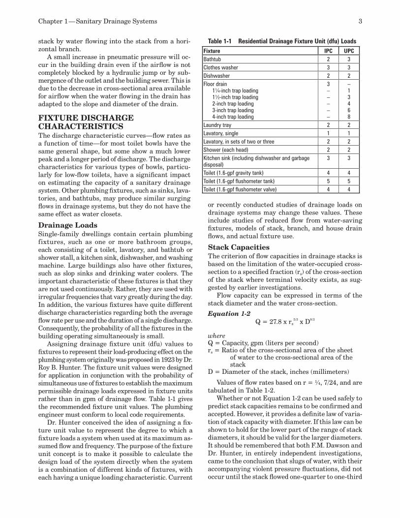
Chapter 1 — Sanitary Drainage Systems 3
or recently conducted studies of drainage loads on drainage systems may change these values. These include studies of reduced flow from water-saving fixtures, models of stack, branch, and house drain flows, and actual fixture use.
Stack CapacitiesThe criterion of flow capacities in drainage stacks is based on the limitation of the water-occupied cross-section to a specified fraction (rs) of the cross-section of the stack where terminal velocity exists, as sug-gested by earlier investigations.
Flow capacity can be expressed in terms of the stack diameter and the water cross-section.
Equation 1-2Q = 27.8 x rs
5/3 x D8/3
whereQ = Capacity, gpm (liters per second)rs = Ratio of the cross-sectional area of the sheet
of water to the cross-sectional area of the stack
D = Diameter of the stack, inches (millimeters)
Values of flow rates based on r = ¼, 7/24, and are tabulated in Table 1-2.
Whether or not Equation 1-2 can be used safely to predict stack capacities remains to be confirmed and accepted. However, it provides a definite law of varia-tion of stack capacity with diameter. If this law can be shown to hold for the lower part of the range of stack diameters, it should be valid for the larger diameters. It should be remembered that both F.M. Dawson and Dr. Hunter, in entirely independent investigations, came to the conclusion that slugs of water, with their accompanying violent pressure fluctuations, did not occur until the stack flowed one-quarter to one-third
stack by water flowing into the stack from a hori-zontal branch.
A small increase in pneumatic pressure will oc-cur in the building drain even if the airflow is not completely blocked by a hydraulic jump or by sub-mergence of the outlet and the building sewer. This is due to the decrease in cross-sectional area available for airflow when the water flowing in the drain has adapted to the slope and diameter of the drain.
FIXTURE DISCHARGE CHARACTERISTICSThe discharge characteristic curves—flow rates as a function of time—for most toilet bowls have the same general shape, but some show a much lower peak and a longer period of discharge. The discharge characteristics for various types of bowls, particu-larly for low-flow toilets, have a significant impact on estimating the capacity of a sanitary drainage system. Other plumbing fixtures, such as sinks, lava-tories, and bathtubs, may produce similar surging flows in drainage systems, but they do not have the same effect as water closets.
Drainage Loads Single-family dwellings contain certain plumbing fixtures, such as one or more bathroom groups, each consisting of a toilet, lavatory, and bathtub or shower stall, a kitchen sink, dishwasher, and washing machine. Large buildings also have other fixtures, such as slop sinks and drinking water coolers. The important characteristic of these fixtures is that they are not used continuously. Rather, they are used with irregular frequencies that vary greatly during the day. In addition, the various fixtures have quite different discharge characteristics regarding both the average flow rate per use and the duration of a single discharge. Consequently, the probability of all the fixtures in the building operating simultaneously is small.
Assigning drainage fixture unit (dfu) values to fixtures to represent their load-producing effect on the plumbing system originally was proposed in 1923 by Dr. Roy B. Hunter. The fixture unit values were designed for application in conjunction with the probability of simultaneous use of fixtures to establish the maximum permissible drainage loads expressed in fixture units rather than in gpm of drainage flow. Table 1-1 gives the recommended fixture unit values. The plumbing engineer must conform to local code requirements.
Dr. Hunter conceived the idea of assigning a fix-ture unit value to represent the degree to which a fixture loads a system when used at its maximum as-sumed flow and frequency. The purpose of the fixture unit concept is to make it possible to calculate the design load of the system directly when the system is a combination of different kinds of fixtures, with each having a unique loading characteristic. Current
Table 1-1 Residential Drainage Fixture Unit (dfu) LoadsFixture IPC UPCBathtub 2 3Clothes washer 3 3Dishwasher 2 2Floor drain
1¼-inch trap loading1½-inch trap loading2-inch trap loading3-inch trap loading4-inch trap loading
3–––––
–13468
Laundry tray 2 2Lavatory, single 1 1Lavatory, in sets of two or three 2 2Shower (each head) 2 2Kitchen sink (including dishwasher and garbage disposal)
3 3
Toilet (1.6-gpf gravity tank) 4 4Toilet (1.6-gpf flushometer tank) 5 5Toilet (1.6-gpf flushometer valve) 4 4
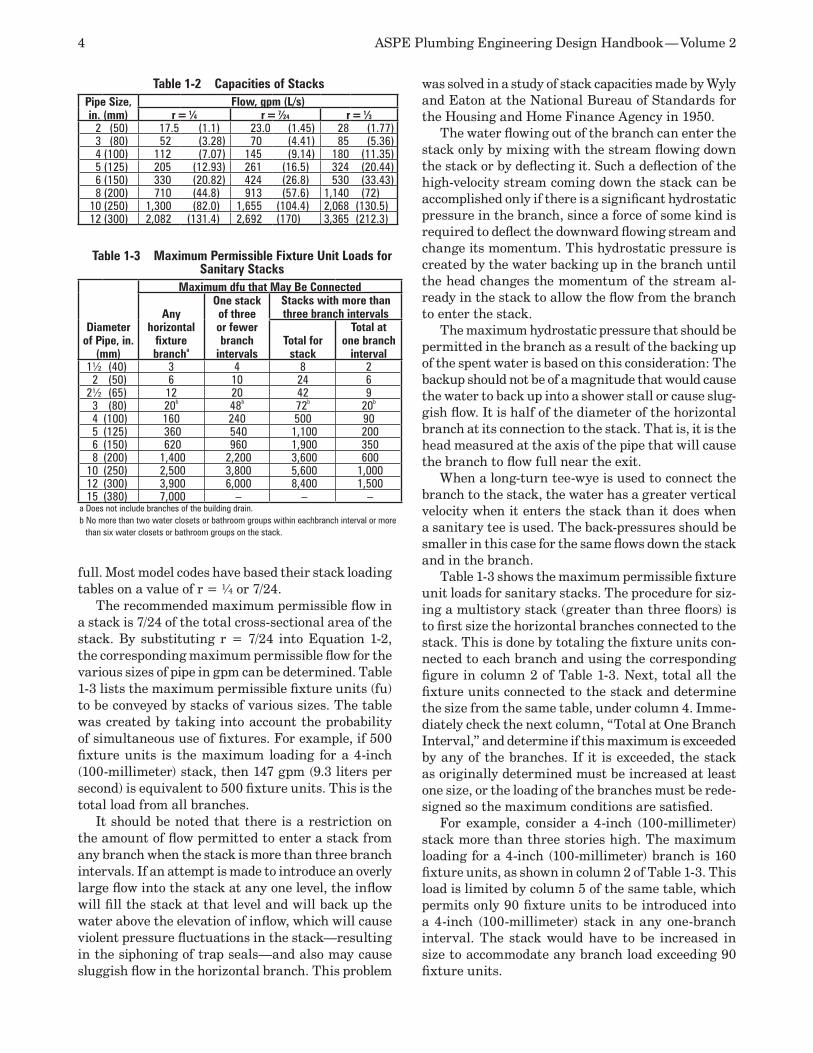
4 ASPE Plumbing Engineering Design Handbook — Volume 2
full. Most model codes have based their stack loading tables on a value of r = ¼ or 7/24.
The recommended maximum permissible flow in a stack is 7/24 of the total cross-sectional area of the stack. By substituting r = 7/24 into Equation 1-2, the corresponding maximum permissible flow for the various sizes of pipe in gpm can be determined. Table 1-3 lists the maximum permissible fixture units (fu) to be conveyed by stacks of various sizes. The table was created by taking into account the probability of simultaneous use of fixtures. For example, if 500 fixture units is the maximum loading for a 4-inch (100-millimeter) stack, then 147 gpm (9.3 liters per second) is equivalent to 500 fixture units. This is the total load from all branches.
It should be noted that there is a restriction on the amount of flow permitted to enter a stack from any branch when the stack is more than three branch intervals. If an attempt is made to introduce an overly large flow into the stack at any one level, the inflow will fill the stack at that level and will back up the water above the elevation of inflow, which will cause violent pressure fluctuations in the stack—resulting in the siphoning of trap seals—and also may cause sluggish flow in the horizontal branch. This problem
was solved in a study of stack capacities made by Wyly and Eaton at the National Bureau of Standards for the Housing and Home Finance Agency in 1950.
The water flowing out of the branch can enter the stack only by mixing with the stream flowing down the stack or by deflecting it. Such a deflection of the high-velocity stream coming down the stack can be accomplished only if there is a significant hydrostatic pressure in the branch, since a force of some kind is required to deflect the downward flowing stream and change its momentum. This hydrostatic pressure is created by the water backing up in the branch until the head changes the momentum of the stream al-ready in the stack to allow the flow from the branch to enter the stack.
The maximum hydrostatic pressure that should be permitted in the branch as a result of the backing up of the spent water is based on this consideration: The backup should not be of a magnitude that would cause the water to back up into a shower stall or cause slug-gish flow. It is half of the diameter of the horizontal branch at its connection to the stack. That is, it is the head measured at the axis of the pipe that will cause the branch to flow full near the exit.
When a long-turn tee-wye is used to connect the branch to the stack, the water has a greater vertical velocity when it enters the stack than it does when a sanitary tee is used. The back-pressures should be smaller in this case for the same flows down the stack and in the branch.
Table 1-3 shows the maximum permissible fixture unit loads for sanitary stacks. The procedure for siz-ing a multistory stack (greater than three floors) is to first size the horizontal branches connected to the stack. This is done by totaling the fixture units con-nected to each branch and using the corresponding figure in column 2 of Table 1-3. Next, total all the fixture units connected to the stack and determine the size from the same table, under column 4. Imme-diately check the next column, “Total at One Branch Interval,” and determine if this maximum is exceeded by any of the branches. If it is exceeded, the stack as originally determined must be increased at least one size, or the loading of the branches must be rede-signed so the maximum conditions are satisfied.
For example, consider a 4-inch (100-millimeter) stack more than three stories high. The maximum loading for a 4-inch (100-millimeter) branch is 160 fixture units, as shown in column 2 of Table 1-3. This load is limited by column 5 of the same table, which permits only 90 fixture units to be introduced into a 4-inch (100-millimeter) stack in any one-branch interval. The stack would have to be increased in size to accommodate any branch load exceeding 90 fixture units.
Table 1-2 Capacities of StacksPipe Size, in. (mm)
Flow, gpm (L/s)r = 1⁄4 r = 7⁄24 r = 1⁄3
2 (50) 17.5 (1.1) 23.0 (1.45) 28 (1.77)3 (80) 52 (3.28) 70 (4.41) 85 (5.36)4 (100) 112 (7.07) 145 (9.14) 180 (11.35)5 (125) 205 (12.93) 261 (16.5) 324 (20.44)6 (150) 330 (20.82) 424 (26.8) 530 (33.43)8 (200) 710 (44.8) 913 (57.6) 1,140 (72)
10 (250) 1,300 (82.0) 1,655 (104.4) 2,068 (130.5)12 (300) 2,082 (131.4) 2,692 (170) 3,365 (212.3)
Table 1-3 Maximum Permissible Fixture Unit Loads for Sanitary Stacks
Diameter of Pipe, in.
(mm)
Maximum dfu that May Be Connected
Any horizontal
fixture brancha
One stack of three or fewer branch
intervals
Stacks with more than three branch intervals
Total for stack
Total at one branch
interval1½ (40) 3 4 8 2
2 (50) 6 10 24 62½ (65) 12 20 42 9
3 (80) 20b 48b 72b 20b
4 (100) 160 240 500 905 (125) 360 540 1,100 2006 (150) 620 960 1,900 3508 (200) 1,400 2,200 3,600 600
10 (250) 2,500 3,800 5,600 1,00012 (300) 3,900 6,000 8,400 1,50015 (380) 7,000 – – –
a Does not include branches of the building drain.b No more than two water closets or bathroom groups within eachbranch interval or more
than six water closets or bathroom groups on the stack.
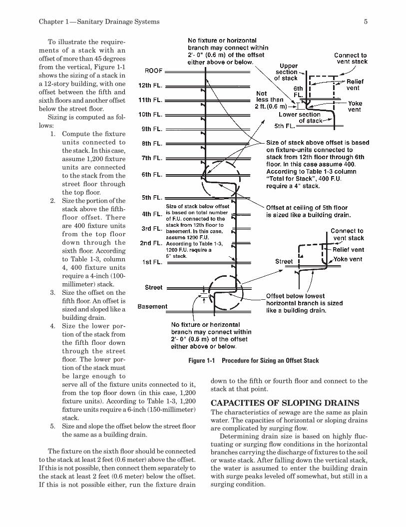
Chapter 1 — Sanitary Drainage Systems 5
To illustrate the require-ments of a stack with an offset of more than 45 degrees from the vertical, Figure 1-1 shows the sizing of a stack in a 12-story building, with one offset between the fifth and sixth floors and another offset below the street floor.
Sizing is computed as fol-lows:
Compute the fixture 1. units connected to the stack. In this case, assume 1,200 fixture units are connected to the stack from the street floor through the top floor.Size the portion of the 2. stack above the fifth-floor offset. There are 400 fixture units from the top floor down through the sixth floor. According to Table 1-3, column 4, 400 fixture units require a 4-inch (100-millimeter) stack.Size the offset on the 3. fifth floor. An offset is sized and sloped like a building drain.Size the lower por-4. tion of the stack from the fifth floor down through the street floor. The lower por-tion of the stack must be large enough to serve all of the fixture units connected to it, from the top floor down (in this case, 1,200 fixture units). According to Table 1-3, 1,200 fixture units require a 6-inch (150-millimeter) stack.Size and slope the offset below the street floor 5. the same as a building drain.
The fixture on the sixth floor should be connected to the stack at least 2 feet (0.6 meter) above the offset. If this is not possible, then connect them separately to the stack at least 2 feet (0.6 meter) below the offset. If this is not possible either, run the fixture drain
down to the fifth or fourth floor and connect to the stack at that point.
CAPACITIES OF SLOPING DRAINSThe characteristics of sewage are the same as plain water. The capacities of horizontal or sloping drains are complicated by surging flow.
Determining drain size is based on highly fluc-tuating or surging flow conditions in the horizontal branches carrying the discharge of fixtures to the soil or waste stack. After falling down the vertical stack, the water is assumed to enter the building drain with surge peaks leveled off somewhat, but still in a surging condition.
Figure 1-1 Procedure for Sizing an Offset Stack
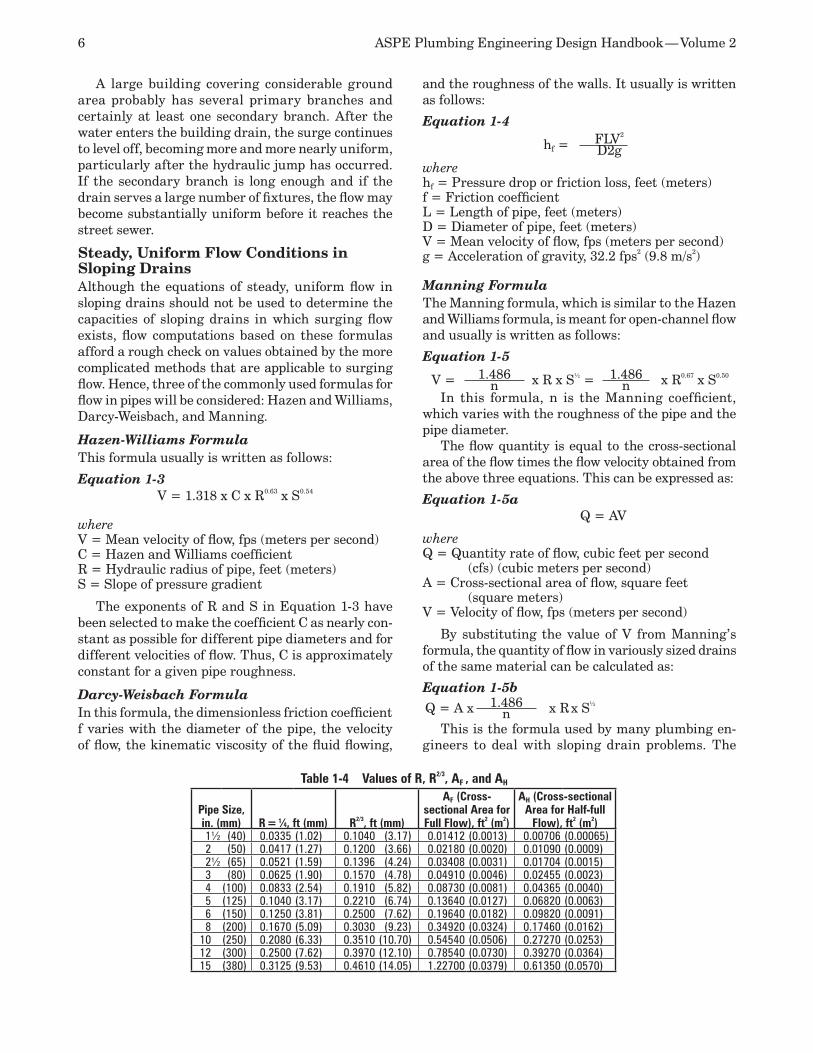
6 ASPE Plumbing Engineering Design Handbook — Volume 2
and the roughness of the walls. It usually is written as follows:
Equation 1-4
hf =FLV2
D2gwherehf = Pressure drop or friction loss, feet (meters)f = Friction coefficient L = Length of pipe, feet (meters)D = Diameter of pipe, feet (meters)V = Mean velocity of flow, fps (meters per second)g = Acceleration of gravity, 32.2 fps2 (9.8 m/s2)
Manning Formula The Manning formula, which is similar to the Hazen and Williams formula, is meant for open-channel flow and usually is written as follows:
Equation 1-5
V = 1.486 x R⅔ x S½ = 1.486 x R0.67 x S0.50
n nIn this formula, n is the Manning coefficient,
which varies with the roughness of the pipe and the pipe diameter.
The flow quantity is equal to the cross-sectional area of the flow times the flow velocity obtained from the above three equations. This can be expressed as:
Equation 1-5a Q = AV
whereQ = Quantity rate of flow, cubic feet per second
(cfs) (cubic meters per second)A = Cross-sectional area of flow, square feet
(square meters)V = Velocity of flow, fps (meters per second)
By substituting the value of V from Manning’s formula, the quantity of flow in variously sized drains of the same material can be calculated as:
Equation 1-5b
Q = A x 1.486 x R x S½
nThis is the formula used by many plumbing en-
gineers to deal with sloping drain problems. The
A large building covering considerable ground area probably has several primary branches and certainly at least one secondary branch. After the water enters the building drain, the surge continues to level off, becoming more and more nearly uniform, particularly after the hydraulic jump has occurred. If the secondary branch is long enough and if the drain serves a large number of fixtures, the flow may become substantially uniform before it reaches the street sewer.
Steady, Uniform Flow Conditions in Sloping DrainsAlthough the equations of steady, uniform flow in sloping drains should not be used to determine the capacities of sloping drains in which surging flow exists, flow computations based on these formulas afford a rough check on values obtained by the more complicated methods that are applicable to surging flow. Hence, three of the commonly used formulas for flow in pipes will be considered: Hazen and Williams, Darcy-Weisbach, and Manning.
Hazen-Williams Formula This formula usually is written as follows:
Equation 1-3V = 1.318 x C x R0.63 x S0.54
whereV = Mean velocity of flow, fps (meters per second)C = Hazen and Williams coefficientR = Hydraulic radius of pipe, feet (meters)S = Slope of pressure gradient
The exponents of R and S in Equation 1-3 have been selected to make the coefficient C as nearly con-stant as possible for different pipe diameters and for different velocities of flow. Thus, C is approximately constant for a given pipe roughness.
Darcy-Weisbach Formula In this formula, the dimensionless friction coefficient f varies with the diameter of the pipe, the velocity of flow, the kinematic viscosity of the fluid flowing,
Table 1-4 Values of R, R2/3, AF , and AH
Pipe Size, in. (mm) R = 1⁄4, ft (mm) R2/3, ft (mm)
AF (Cross-sectional Area for Full Flow), ft2 (m2)
AH (Cross-sectional Area for Half-full
Flow), ft2 (m2)1½ (40) 0.0335 (1.02) 0.1040 (3.17) 0.01412 (0.0013) 0.00706 (0.00065)2 (50) 0.0417 (1.27) 0.1200 (3.66) 0.02180 (0.0020) 0.01090 (0.0009)2½ (65) 0.0521 (1.59) 0.1396 (4.24) 0.03408 (0.0031) 0.01704 (0.0015)3 (80) 0.0625 (1.90) 0.1570 (4.78) 0.04910 (0.0046) 0.02455 (0.0023)4 (100) 0.0833 (2.54) 0.1910 (5.82) 0.08730 (0.0081) 0.04365 (0.0040)5 (125) 0.1040 (3.17) 0.2210 (6.74) 0.13640 (0.0127) 0.06820 (0.0063)6 (150) 0.1250 (3.81) 0.2500 (7.62) 0.19640 (0.0182) 0.09820 (0.0091)8 (200) 0.1670 (5.09) 0.3030 (9.23) 0.34920 (0.0324) 0.17460 (0.0162)
10 (250) 0.2080 (6.33) 0.3510 (10.70) 0.54540 (0.0506) 0.27270 (0.0253)12 (300) 0.2500 (7.62) 0.3970 (12.10) 0.78540 (0.0730) 0.39270 (0.0364)15 (380) 0.3125 (9.53) 0.4610 (14.05) 1.22700 (0.0379) 0.61350 (0.0570)
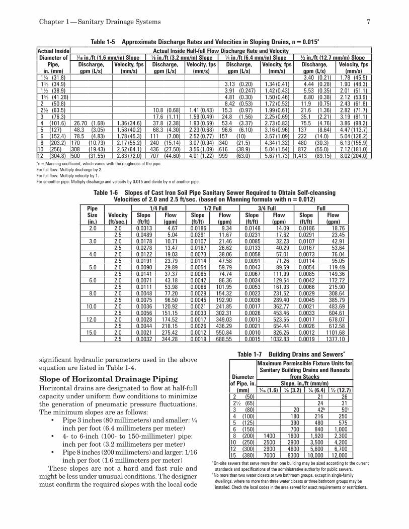
Chapter 1 — Sanitary Drainage Systems 7
significant hydraulic parameters used in the above equation are listed in Table 1-4.
Slope of Horizontal Drainage PipingHorizontal drains are designated to flow at half-full capacity under uniform flow conditions to minimize the generation of pneumatic pressure fluctuations. The minimum slopes are as follows:
Pipe 3 inches (80 millimeters) and smaller: ¼ •inch per foot (6.4 millimeters per meter) 4- to 6-inch (100- to 150-millimeter) pipe: ⅔ •inch per foot (3.2 millimeters per meter) Pipe 8 inches (200 millimeters) and larger: 1/16 •inch per foot (1.6 millimeters per meter)
These slopes are not a hard and fast rule and might be less under unusual conditions. The designer must confirm the required slopes with the local code
Table 1-5 Approximate Discharge Rates and Velocities in Sloping Drains, n = 0.015a
Actual Inside Diameter of
Pipe, in. (mm)
Actual Inside Half-full Flow Discharge Rate and Velocity1⁄16 in./ft (1.6 mm/m) Slope 1⁄8 in./ft (3.2 mm/m) Slope 1⁄4 in./ft (6.4 mm/m) Slope 1⁄2 in./ft (12.7 mm/m) SlopeDischarge, gpm (L/s)
Velocity, fps (mm/s)
Discharge, gpm (L/s)
Velocity, fps (mm/s)
Discharge, gpm (L/s)
Velocity, fps (mm/s)
Discharge, gpm (L/s)
Velocity, fps (mm/s)
1¼ (31.8) 3.40 (0.21) 1.78 (45.5)13⁄8 (34.9) 3.13 (0.20) 1.34 (0.41) 4.44 (0.28) 1.90 (48.3)1½ (38.9) 3.91 (0.247) 1.42 (0.43) 5.53 (0.35) 2.01 (51.1)15⁄8 (41.28) 4.81 (0.30) 1.50 (0.46) 6.80 (0.38) 2.12 (53.9)2 (50.8) 8.42 (0.53) 1.72 (0.52) 11.9 (0.75) 2.43 (61.8)2½ (63.5) 10.8 (0.68) 1.41 (0.43) 15.3 (0.97) 1.99 (0.61) 21.6 (1.36) 2.82 (71.7)3 (76.3) 17.6 (1.11) 1.59 (0.49) 24.8 (1.56) 2.25 (0.69) 35.1 (2.21) 3.19 (81.1)4 (101.6) 26.70 (1.68) 1.36 (34.6) 37.8 (2.38) 1.93 (0.59) 53.4 (3.37) 2.73 (0.83) 75.5 (4.76) 3.86 (98.2)5 (127) 48.3 (3.05) 1.58 (40.2) 68.3 (4.30) 2.23 (0.68) 96.6 (6.10) 3.16 (0.96) 137 (8.64) 4.47 (113.7)6 (152.4) 78.5 (4.83) 1.78 (45.3) 111 (7.00) 2.52 (0.77) 157 (10) 3.57 (1.09) 222 (14.0) 5.04 (128.2)8 (203.2) 170 (10.73) 2.17 (55.2) 240 (15.14) 3.07 (0.94) 340 (21.5) 4.34 (1.32) 480 (30.3) 6.13 (155.9)
10 (256) 308 (19.43) 2.52 (64.1) 436 (27.50) 3.56 (1.09) 616 (38.9) 5.04 (1.54) 872 (55.0) 7.12 (181.0)12 (304.8) 500 (31.55) 2.83 (72.0) 707 (44.60) 4.01 (1.22) 999 (63.0) 5.67 (1.73) 1,413 (89.15) 8.02 (204.0)
a n = Manning coefficient, which varies with the roughness of the pipe.For full flow: Multiply discharge by 2.For full flow: Multiply velocity by 1.For smoother pipe: Multiply discharge and velocity by 0.015 and divide by n of another pipe.
Table 1-7 Building Drains and Sewersa
Diameter of Pipe, in.
(mm)
Maximum Permissible Fixture Units for Sanitary Building Drains and Runouts
from StacksSlope, in./ft (mm/m)
1⁄16 (1.6) 1⁄8 (3.2) 1⁄4 (6.4) 1⁄2 (12.7)2 (50) 21 262½ (65) 24 313 (80) 20 42b 50b
4 (100) 180 216 2505 (125) 390 480 5756 (150) 700 840 1,0008 (200) 1400 1600 1,920 2,300
10 (250) 2500 2900 3,500 4,20012 (300) 2900 4600 5,600 6,70015 (380) 7000 8300 10,000 12,000
a On-site sewers that serve more than one building may be sized according to the current standards and specifications of the administrative authority for public sewers.
b No more than two water closets or two bathroom groups, except in single-family dwellings, where no more than three water closets or three bathroom groups may be installed. Check the local codes in the area served for exact requirements or restrictions.
Table 1-6 Slopes of Cast Iron Soil Pipe Sanitary Sewer Required to Obtain Self-cleansing Velocities of 2.0 and 2.5 ft/sec. (based on Manning formula with n = 0.012)
Pipe Size (in.)
Velocity (ft/sec.)
1/4 Full 1/2 Full 3/4 Full FullSlope (ft/ft)
Flow (gpm)
Slope (ft/ft)
Flow (gpm)
Slope (ft/ft)
Flow (gpm)
Slope (ft/ft)
Flow (gpm)
2.0 2.0 0.0313 4.67 0.0186 9.34 0.0148 14.09 0.0186 18.762.5 0.0489 5.04 0.0291 11.67 0.0231 17.62 0.0291 23.45
3.0 2.0 0.0178 10.71 0.0107 21.46 0.0085 32.23 0,0107 42.912.5 0.0278 13.47 0.0167 26.62 0.0133 40.29 0.0167 53.64
4.0 2.0 0.0122 19.03 0.0073 38.06 0.0058 57.01 0.0073 76.042.5 0.0191 23.79 0.0114 47.58 0.0091 71.26 0.0114 95.05
5.0 2.0 0.0090 29.89 0.0054 59.79 0.0043 89.59 0.0054 119.492.5 0.0141 37.37 0.0085 74.74 0.0067 111.99 0.0085 149.36
6.0 2.0 0.0071 43.18 0.0042 86.36 0.0034 129.54 0.0042 172.722.5 0.0111 53.98 0.0066 101.95 0.0053 161.93 0.0066 215.90
8.0 2.0 0.0048 77.20 0.0029 154.32 0.0023 231.52 0.0029 308.642.5 0.0075 96.50 0.0045 192.90 0.0036 289.40 0.0045 385.79
10.0 2.0 0.0036 120.92 0.0021 241.85 0.0017 362.77 0.0021 483.692.5 0.0056 151.15 0.0033 302.31 0.0026 453.46 0.0033 604.61
12.0 2.0 0.0028 174.52 0.0017 349.03 0.0013 523.55 0.0017 678.072.5 0.0044 218.15 0.0026 436.29 0.0021 654.44 0.0026 612.58
15.0 2.0 0.0021 275.42 0.0012 550.84 0.0010 826.26 0.0012 1101.682.5 0.0032 344.28 0.0019 688.55 0.0015 1032.83 0.0019 1377.10
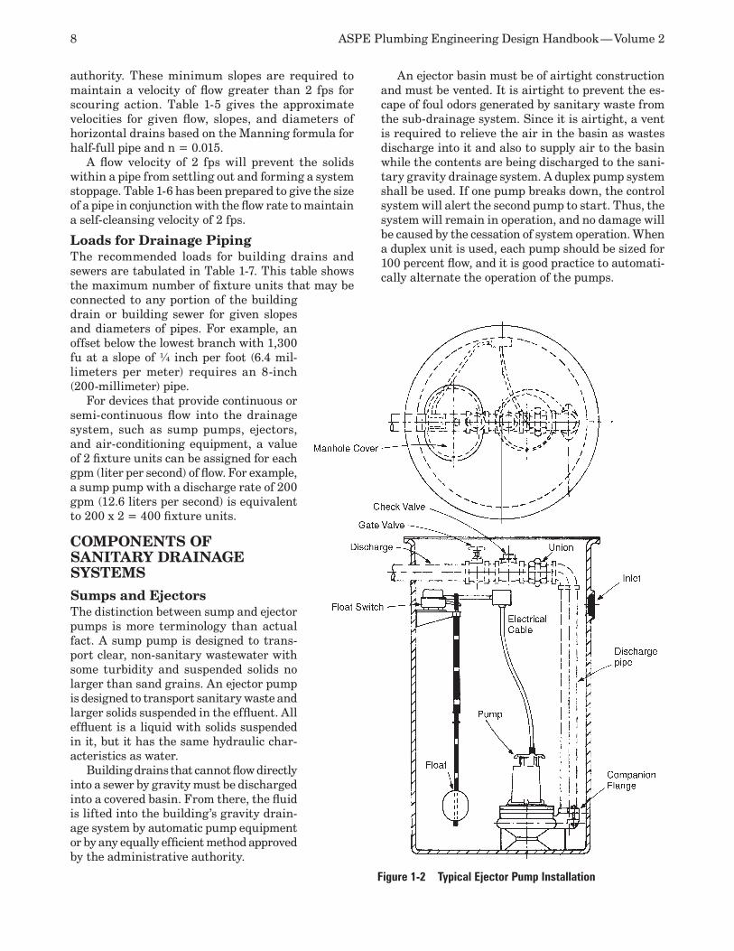
8 ASPE Plumbing Engineering Design Handbook — Volume 2
authority. These minimum slopes are required to maintain a velocity of flow greater than 2 fps for scouring action. Table 1-5 gives the approximate velocities for given flow, slopes, and diameters of horizontal drains based on the Manning formula for half-full pipe and n = 0.015.
A flow velocity of 2 fps will prevent the solids within a pipe from settling out and forming a system stoppage. Table 1-6 has been prepared to give the size of a pipe in conjunction with the flow rate to maintain a self-cleansing velocity of 2 fps.
Loads for Drainage PipingThe recommended loads for building drains and sewers are tabulated in Table 1-7. This table shows the maximum number of fixture units that may be connected to any portion of the building drain or building sewer for given slopes and diameters of pipes. For example, an offset below the lowest branch with 1,300 fu at a slope of ¼ inch per foot (6.4 mil-limeters per meter) requires an 8-inch (200-millimeter) pipe.
For devices that provide continuous or semi-continuous flow into the drainage system, such as sump pumps, ejectors, and air-conditioning equipment, a value of 2 fixture units can be assigned for each gpm (liter per second) of flow. For example, a sump pump with a discharge rate of 200 gpm (12.6 liters per second) is equivalent to 200 x 2 = 400 fixture units.
COMPONENTS OF SANITARY DRAINAGE SYSTEMS
Sumps and EjectorsThe distinction between sump and ejector pumps is more terminology than actual fact. A sump pump is designed to trans-port clear, non-sanitary wastewater with some turbidity and suspended solids no larger than sand grains. An ejector pump is designed to transport sanitary waste and larger solids suspended in the effluent. All effluent is a liquid with solids suspended in it, but it has the same hydraulic char-acteristics as water.
Building drains that cannot flow directly into a sewer by gravity must be discharged into a covered basin. From there, the fluid is lifted into the building’s gravity drain-age system by automatic pump equipment or by any equally efficient method approved by the administrative authority.
An ejector basin must be of airtight construction and must be vented. It is airtight to prevent the es-cape of foul odors generated by sanitary waste from the sub-drainage system. Since it is airtight, a vent is required to relieve the air in the basin as wastes discharge into it and also to supply air to the basin while the contents are being discharged to the sani-tary gravity drainage system. A duplex pump system shall be used. If one pump breaks down, the control system will alert the second pump to start. Thus, the system will remain in operation, and no damage will be caused by the cessation of system operation. When a duplex unit is used, each pump should be sized for 100 percent flow, and it is good practice to automati-cally alternate the operation of the pumps.
Figure 1-2 Typical Ejector Pump Installation
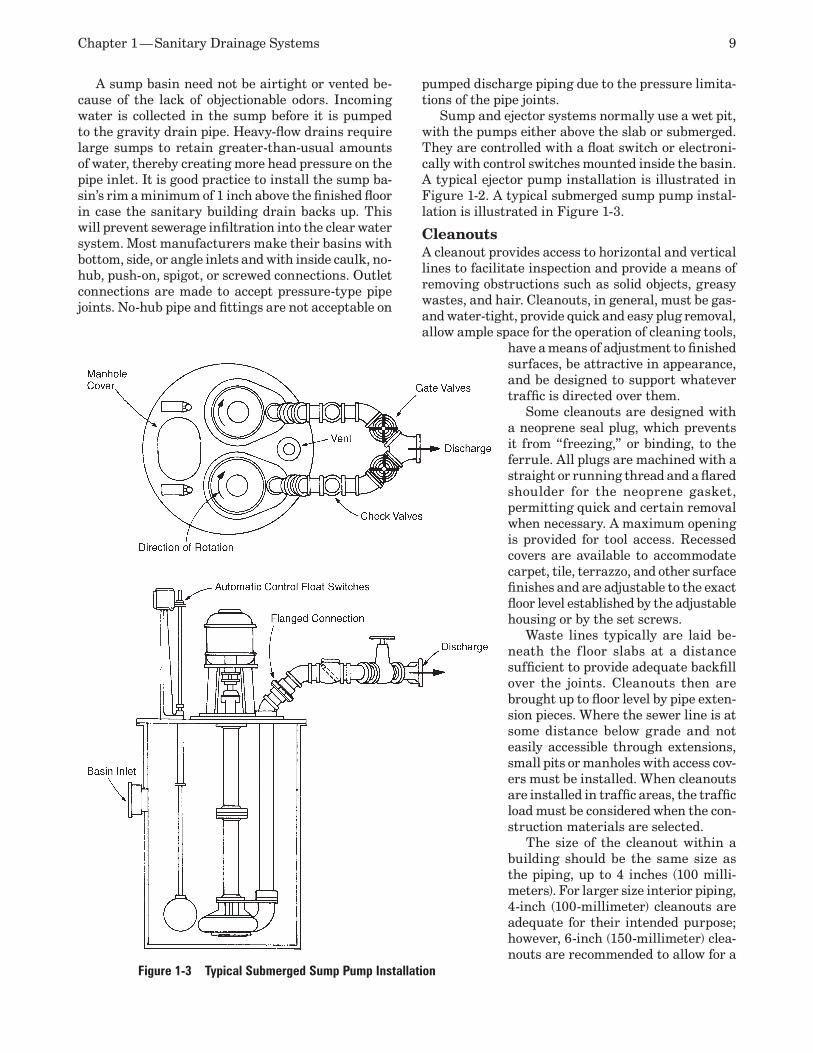
Chapter 1 — Sanitary Drainage Systems 9
A sump basin need not be airtight or vented be-cause of the lack of objectionable odors. Incoming water is collected in the sump before it is pumped to the gravity drain pipe. Heavy-flow drains require large sumps to retain greater-than-usual amounts of water, thereby creating more head pressure on the pipe inlet. It is good practice to install the sump ba-sin’s rim a minimum of 1 inch above the finished floor in case the sanitary building drain backs up. This will prevent sewerage infiltration into the clear water system. Most manufacturers make their basins with bottom, side, or angle inlets and with inside caulk, no-hub, push-on, spigot, or screwed connections. Outlet connections are made to accept pressure-type pipe joints. No-hub pipe and fittings are not acceptable on
pumped discharge piping due to the pressure limita-tions of the pipe joints.
Sump and ejector systems normally use a wet pit, with the pumps either above the slab or submerged. They are controlled with a float switch or electroni-cally with control switches mounted inside the basin. A typical ejector pump installation is illustrated in Figure 1-2. A typical submerged sump pump instal-lation is illustrated in Figure 1-3.
CleanoutsA cleanout provides access to horizontal and vertical lines to facilitate inspection and provide a means of removing obstructions such as solid objects, greasy wastes, and hair. Cleanouts, in general, must be gas- and water-tight, provide quick and easy plug removal, allow ample space for the operation of cleaning tools,
have a means of adjustment to finished surfaces, be attractive in appearance, and be designed to support whatever traffic is directed over them.
Some cleanouts are designed with a neoprene seal plug, which prevents it from “freezing,” or binding, to the ferrule. All plugs are machined with a straight or running thread and a flared shoulder for the neoprene gasket, permitting quick and certain removal when necessary. A maximum opening is provided for tool access. Recessed covers are available to accommodate carpet, tile, terrazzo, and other surface finishes and are adjustable to the exact floor level established by the adjustable housing or by the set screws.
Waste lines typically are laid be-neath the floor slabs at a distance sufficient to provide adequate backfill over the joints. Cleanouts then are brought up to floor level by pipe exten-sion pieces. Where the sewer line is at some distance below grade and not easily accessible through extensions, small pits or manholes with access cov-ers must be installed. When cleanouts are installed in traffic areas, the traffic load must be considered when the con-struction materials are selected.
The size of the cleanout within a building should be the same size as the piping, up to 4 inches (100 milli-meters). For larger size interior piping, 4-inch (100-millimeter) cleanouts are adequate for their intended purpose; however, 6-inch (150-millimeter) clea-nouts are recommended to allow for a
Figure 1-3 Typical Submerged Sump Pump Installation
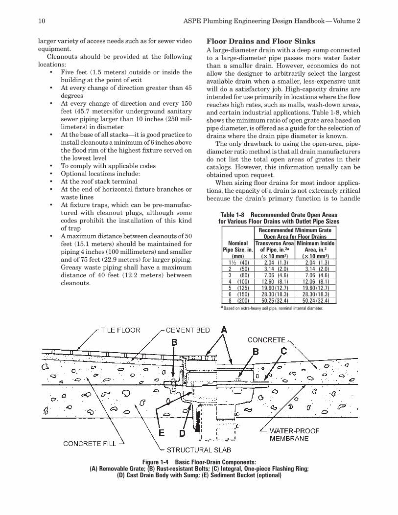
10 ASPE Plumbing Engineering Design Handbook — Volume 2
larger variety of access needs such as for sewer video equipment.
Cleanouts should be provided at the following locations:
Five feet (1.5 meters) outside or inside the •building at the point of exitAt every change of direction greater than 45 •degreesAt every change of direction and every 150 •feet (45.7 meters)for underground sanitary sewer piping larger than 10 inches (250 mil-limeters) in diameter At the base of all stacks—it is good practice to •install cleanouts a minimum of 6 inches above the flood rim of the highest fixture served on the lowest levelTo comply with applicable codes•Optional locations include:•At the roof stack terminal•At the end of horizontal fixture branches or •waste linesAt fixture traps, which can be pre-manufac-•tured with cleanout plugs, although some codes prohibit the installation of this kind of trapA maximum distance between cleanouts of 50 •feet (15.1 meters) should be maintained for piping 4 inches (100 millimeters) and smaller and of 75 feet (22.9 meters) for larger piping. Greasy waste piping shall have a maximum distance of 40 feet (12.2 meters) between cleanouts.
Floor Drains and Floor SinksA large-diameter drain with a deep sump connected to a large-diameter pipe passes more water faster than a smaller drain. However, economics do not allow the designer to arbitrarily select the largest available drain when a smaller, less-expensive unit will do a satisfactory job. High-capacity drains are intended for use primarily in locations where the flow reaches high rates, such as malls, wash-down areas, and certain industrial applications. Table 1-8, which shows the minimum ratio of open grate area based on pipe diameter, is offered as a guide for the selection of drains where the drain pipe diameter is known.
The only drawback to using the open-area, pipe-diameter ratio method is that all drain manufacturers do not list the total open areas of grates in their catalogs. However, this information usually can be obtained upon request.
When sizing floor drains for most indoor applica-tions, the capacity of a drain is not extremely critical because the drain’s primary function is to handle
Table 1-8 Recommended Grate Open Areas for Various Floor Drains with Outlet Pipe Sizes
Nominal Pipe Size, in.
(mm)
Recommended Minimum Grate Open Area for Floor Drains
Transverse Area of Pipe, in.2a
(× 10 mm2)
Minimum Inside Area, in.2
(× 10 mm2)1½ (40) 2.04 (1.3) 2.04 (1.3)2 (50) 3.14 (2.0) 3.14 (2.0)3 (80) 7.06 (4.6) 7.06 (4.6)4 (100) 12.60 (8.1) 12.06 (8.1)5 (125) 19.60 (12.7) 19.60 (12.7)6 (150) 28.30 (18.3) 28.30 (18.3)8 (200) 50.25 (32.4) 50.24 (32.4)
a Based on extra-heavy soil pipe, nominal internal diameter.
Figure 1-4 Basic Floor-Drain Components: (A) Removable Grate; (B) Rust-resistant Bolts; (C) Integral, One-piece Flashing Ring;
(D) Cast Drain Body with Sump; (E) Sediment Bucket (optional)

Chapter 1 — Sanitary Drainage Systems 11
minor spillage or fixture overflow. The exceptions are, of course, cases where equipment discharges to the drain, where automatic fire sprinklers may deluge an area with large amounts of water, and where flushing of the floor is required for sanitation.
Floor drains or drains installed to anticipate a failure may not receive sufficient water flow to pre-vent the protective water seal or plumbing trap from evaporating. If the seal does evaporate, sewer gases will enter the space. Thus, automatic or manual trap primers should be installed to maintain a proper trap seal. (A small amount of vegetable oil will dramati-cally reduce the evaporation rate of infrequently used floor drains and floor sinks.)
Figure 1-4 shows the basic components of a floor drain.
Floor drains shall connect to a trap that can be readily cleaned and sized to efficiently serve the purpose for which it is intended. A deep-seal trap or an approved automatic priming device should be provided. The trap shall be accessible either from the floor-drain inlet or by a separate cleanout within the drain. Figure 1-5 illustrates several types of drains that meet these conditions.
Grates/StrainersThe selection of grates is based on use and the amount of flow. Light-traffic areas may have a nickel-bronze grate, while mechanical areas may have a large, heavy-duty, ductile iron grate.
The wearing of spike-heeled shoes prompted the replacement of grates with a heel-proof, ¼-inch (6.4-millimeter) square grate design in public toilet rooms, corridors, passageways, promenade decks, patios, stores, theaters, and markets. Though this type of grating has less drainage capacity than typi-cal grates, its safety feature makes it well worth the change.
Grates or strainers should be secured with stain-less-steel screws in nickel-bronze tops. If the public may access the roof, consideration must be given to pro-
tecting vent openings from vandals, and vandal-proof fasteners are available from most manufacturers.
In school gymnasium shower rooms, where the blocking of flat-top shower drains with paper towels can cause flooding, dome grates in the corners of the room or angle grates against the walls can be specified in addition to the regular shower drains. Shower-room gutters and curbs have become undesirable because of code requirements and the obvious dangers involved. Therefore, the passageways from shower areas into locker areas need extended-length drains to prevent runoff water from entering the locker areas.
Where grates are not secured and are subject to vehicular traffic, it is recommended to install non-tilting and/or tractor-type grates. With these grates, when it moves out of position the skirt catches the side of the drain body, and the grate slides back into its original position. Ramp-drain gratings should be slightly convex because rapidly flowing ramp water has a tendency to flow across flat grates. A better solution to this problem is to place flat-top grates on a level surface at the bottom of the ramp, rather than on the ramp slope.
Flashing RingThis component makes an effective seal, which pre-vents water from passing around the drain to the area below.
Sediment BucketA sediment bucket is an additional internal strainer designed to collect debris that gets by the regular strainer. It is required wherever the drain can receive solids, trash, or grit that could plug piping, such as the following situations:
Toilet rooms in industrial/manufacturing •buildings should be equipped with floor drains with sediment buckets to facilitate cleaning.Floor drains with sediment buckets must be •provided in mechanical equipment rooms, where pumps, boilers, water chillers, heat exchangers, and HVAC equipment regularly discharge and/or must be periodically drained for maintenance and repairs. HVAC equip-ment requires the drainage of condensate from cooling coils using indirect drains.Boilers require drains with sediment buckets. •Strategically located floor drains also are re-quired in buildings with wet sprinkler systems to drain water in case the sprinkler heads are activated. The maximum temperature of liq-uids discharged should be 140°F (60°C).Where a residential garage requires a floor •drain, a sediment bucket shall be used.
Figure 1-5 Types of Floor Drain: (A) Typical Drain with Integral Trap
that May Be Cleaned Through Removable Strainer at Floor Level;
(B) Floor Drain with Combination Cleanout and Backwater Valve, for Use Where
Possibility of Backflow Exists; (C) Drain with Combined Cleanout,
Backwater Valve, and Sediment Bucket
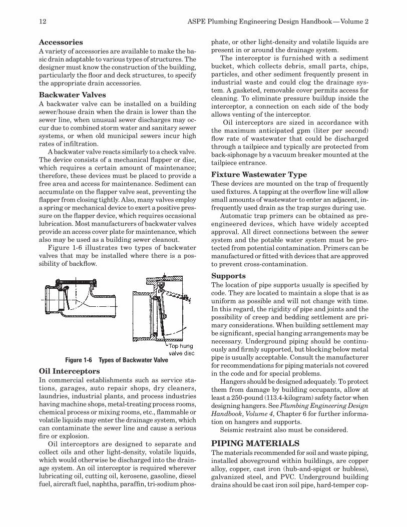
12 ASPE Plumbing Engineering Design Handbook — Volume 2
AccessoriesA variety of accessories are available to make the ba-sic drain adaptable to various types of structures. The designer must know the construction of the building, particularly the floor and deck structures, to specify the appropriate drain accessories.
Backwater ValvesA backwater valve can be installed on a building sewer/house drain when the drain is lower than the sewer line, when unusual sewer discharges may oc-cur due to combined storm water and sanitary sewer systems, or when old municipal sewers incur high rates of infiltration.
A backwater valve reacts similarly to a check valve. The device consists of a mechanical flapper or disc, which requires a certain amount of maintenance; therefore, these devices must be placed to provide a free area and access for maintenance. Sediment can accumulate on the flapper valve seat, preventing the flapper from closing tightly. Also, many valves employ a spring or mechanical device to exert a positive pres-sure on the flapper device, which requires occasional lubrication. Most manufacturers of backwater valves provide an access cover plate for maintenance, which also may be used as a building sewer cleanout.
Figure 1-6 illustrates two types of backwater valves that may be installed where there is a pos-sibility of backflow.
Oil InterceptorsIn commercial establishments such as service sta-tions, garages, auto repair shops, dry cleaners, laundries, industrial plants, and process industries having machine shops, metal-treating process rooms, chemical process or mixing rooms, etc., flammable or volatile liquids may enter the drainage system, which can contaminate the sewer line and cause a serious fire or explosion.
Oil interceptors are designed to separate and collect oils and other light-density, volatile liquids, which would otherwise be discharged into the drain-age system. An oil interceptor is required wherever lubricating oil, cutting oil, kerosene, gasoline, diesel fuel, aircraft fuel, naphtha, paraffin, tri-sodium phos-
phate, or other light-density and volatile liquids are present in or around the drainage system.
The interceptor is furnished with a sediment bucket, which collects debris, small parts, chips, particles, and other sediment frequently present in industrial waste and could clog the drainage sys-tem. A gasketed, removable cover permits access for cleaning. To eliminate pressure buildup inside the interceptor, a connection on each side of the body allows venting of the interceptor.
Oil interceptors are sized in accordance with the maximum anticipated gpm (liter per second) flow rate of wastewater that could be discharged through a tailpiece and typically are protected from back-siphonage by a vacuum breaker mounted at the tailpiece entrance.
Fixture Wastewater TypeThese devices are mounted on the trap of frequently used fixtures. A tapping at the overflow line will allow small amounts of wastewater to enter an adjacent, in-frequently used drain as the trap surges during use.
Automatic trap primers can be obtained as pre-engineered devices, which have widely accepted approval. All direct connections between the sewer system and the potable water system must be pro-tected from potential contamination. Primers can be manufactured or fitted with devices that are approved to prevent cross-contamination.
SupportsThe location of pipe supports usually is specified by code. They are located to maintain a slope that is as uniform as possible and will not change with time. In this regard, the rigidity of pipe and joints and the possibility of creep and bedding settlement are pri-mary considerations. When building settlement may be significant, special hanging arrangements may be necessary. Underground piping should be continu-ously and firmly supported, but blocking below metal pipe is usually acceptable. Consult the manufacturer for recommendations for piping materials not covered in the code and for special problems.
Hangers should be designed adequately. To protect them from damage by building occupants, allow at least a 250-pound (113.4-kilogram) safety factor when designing hangers. See Plumbing Engineering Design Handbook, Volume 4, Chapter 6 for further informa-tion on hangers and supports.
Seismic restraint also must be considered.
PIPING MATERIALSThe materials recommended for soil and waste piping, installed aboveground within buildings, are copper alloy, copper, cast iron (hub-and-spigot or hubless), galvanized steel, and PVC. Underground building drains should be cast iron soil pipe, hard-temper cop-
Figure 1-6 Types of Backwater Valve
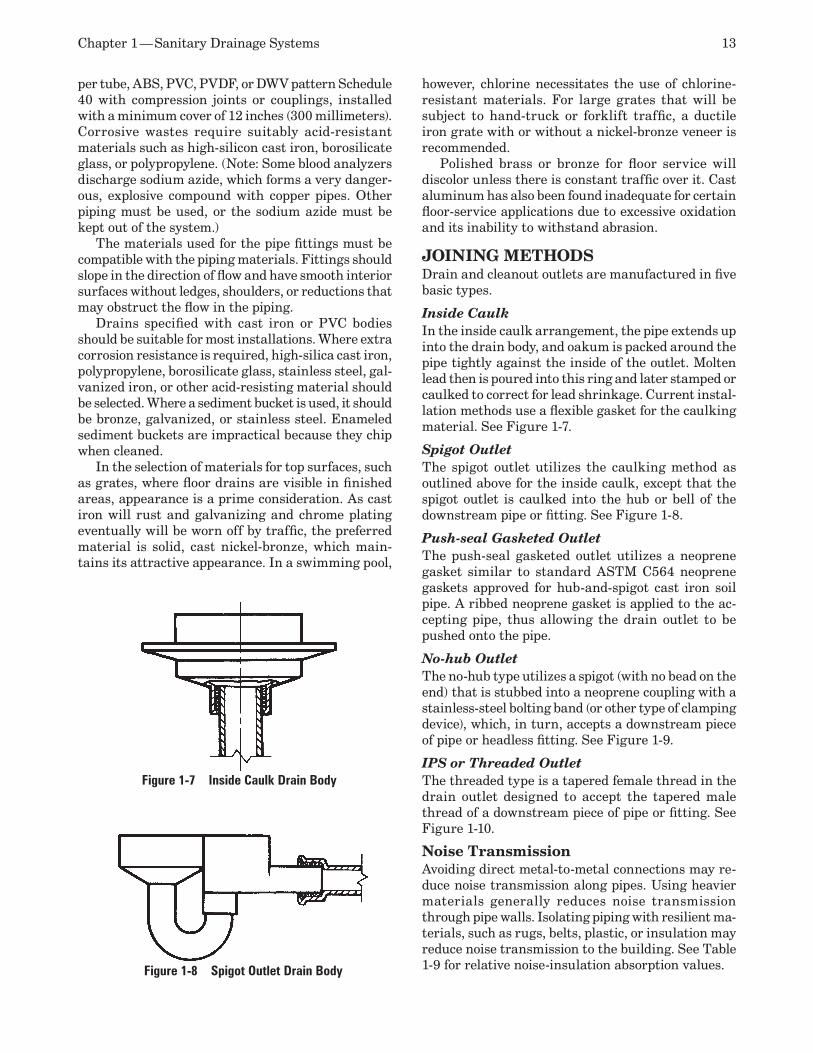
Chapter 1 — Sanitary Drainage Systems 13
per tube, ABS, PVC, PVDF, or DWV pattern Schedule 40 with compression joints or couplings, installed with a minimum cover of 12 inches (300 millimeters). Corrosive wastes require suitably acid-resistant materials such as high-silicon cast iron, borosilicate glass, or polypropylene. (Note: Some blood analyzers discharge sodium azide, which forms a very danger-ous, explosive compound with copper pipes. Other piping must be used, or the sodium azide must be kept out of the system.)
The materials used for the pipe fittings must be compatible with the piping materials. Fittings should slope in the direction of flow and have smooth interior surfaces without ledges, shoulders, or reductions that may obstruct the flow in the piping.
Drains specified with cast iron or PVC bodies should be suitable for most installations. Where extra corrosion resistance is required, high-silica cast iron, polypropylene, borosilicate glass, stainless steel, gal-vanized iron, or other acid-resisting material should be selected. Where a sediment bucket is used, it should be bronze, galvanized, or stainless steel. Enameled sediment buckets are impractical because they chip when cleaned.
In the selection of materials for top surfaces, such as grates, where floor drains are visible in finished areas, appearance is a prime consideration. As cast iron will rust and galvanizing and chrome plating eventually will be worn off by traffic, the preferred material is solid, cast nickel-bronze, which main-tains its attractive appearance. In a swimming pool,
however, chlorine necessitates the use of chlorine-resistant materials. For large grates that will be subject to hand-truck or forklift traffic, a ductile iron grate with or without a nickel-bronze veneer is recommended.
Polished brass or bronze for floor service will discolor unless there is constant traffic over it. Cast aluminum has also been found inadequate for certain floor-service applications due to excessive oxidation and its inability to withstand abrasion.
JOINING METHODSDrain and cleanout outlets are manufactured in five basic types.
Inside CaulkIn the inside caulk arrangement, the pipe extends up into the drain body, and oakum is packed around the pipe tightly against the inside of the outlet. Molten lead then is poured into this ring and later stamped or caulked to correct for lead shrinkage. Current instal-lation methods use a flexible gasket for the caulking material. See Figure 1-7.
Spigot OutletThe spigot outlet utilizes the caulking method as outlined above for the inside caulk, except that the spigot outlet is caulked into the hub or bell of the downstream pipe or fitting. See Figure 1-8.
Push-seal Gasketed OutletThe push-seal gasketed outlet utilizes a neoprene gasket similar to standard ASTM C564 neoprene gaskets approved for hub-and-spigot cast iron soil pipe. A ribbed neoprene gasket is applied to the ac-cepting pipe, thus allowing the drain outlet to be pushed onto the pipe.
No-hub OutletThe no-hub type utilizes a spigot (with no bead on the end) that is stubbed into a neoprene coupling with a stainless-steel bolting band (or other type of clamping device), which, in turn, accepts a downstream piece of pipe or headless fitting. See Figure 1-9.
IPS or Threaded OutletThe threaded type is a tapered female thread in the drain outlet designed to accept the tapered male thread of a downstream piece of pipe or fitting. See Figure 1-10.
Noise TransmissionAvoiding direct metal-to-metal connections may re-duce noise transmission along pipes. Using heavier materials generally reduces noise transmission through pipe walls. Isolating piping with resilient ma-terials, such as rugs, belts, plastic, or insulation may reduce noise transmission to the building. See Table 1-9 for relative noise-insulation absorption values.
Figure 1-7 Inside Caulk Drain Body
Figure 1-8 Spigot Outlet Drain Body
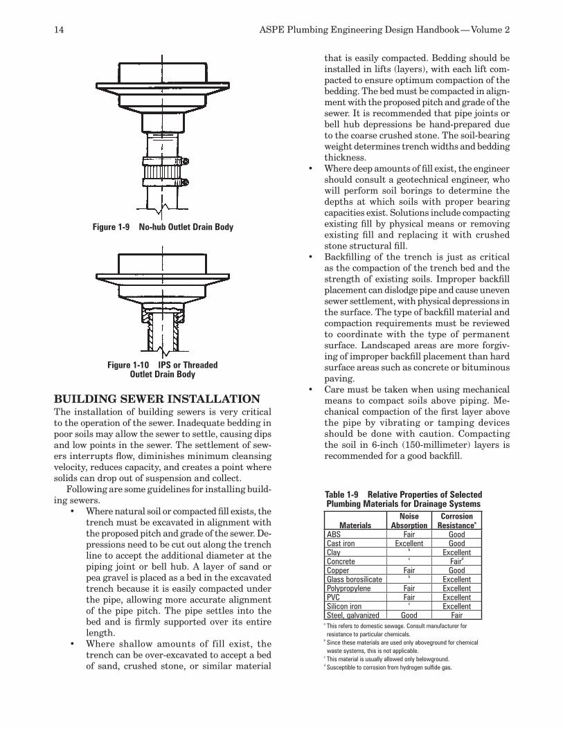
14 ASPE Plumbing Engineering Design Handbook — Volume 2
BUILDING SEWER INSTALLATIONThe installation of building sewers is very critical to the operation of the sewer. Inadequate bedding in poor soils may allow the sewer to settle, causing dips and low points in the sewer. The settlement of sew-ers interrupts flow, diminishes minimum cleansing velocity, reduces capacity, and creates a point where solids can drop out of suspension and collect.
Following are some guidelines for installing build-ing sewers.
Where natural soil or compacted fill exists, the •trench must be excavated in alignment with the proposed pitch and grade of the sewer. De-pressions need to be cut out along the trench line to accept the additional diameter at the piping joint or bell hub. A layer of sand or pea gravel is placed as a bed in the excavated trench because it is easily compacted under the pipe, allowing more accurate alignment of the pipe pitch. The pipe settles into the bed and is firmly supported over its entire length.Where shallow amounts of fill exist, the •trench can be over-excavated to accept a bed of sand, crushed stone, or similar material
that is easily compacted. Bedding should be installed in lifts (layers), with each lift com-pacted to ensure optimum compaction of the bedding. The bed must be compacted in align-ment with the proposed pitch and grade of the sewer. It is recommended that pipe joints or bell hub depressions be hand-prepared due to the coarse crushed stone. The soil-bearing weight determines trench widths and bedding thickness.Where deep amounts of fill exist, the engineer •should consult a geotechnical engineer, who will perform soil borings to determine the depths at which soils with proper bearing capacities exist. Solutions include compacting existing fill by physical means or removing existing fill and replacing it with crushed stone structural fill.Backfilling of the trench is just as critical •as the compaction of the trench bed and the strength of existing soils. Improper backfill placement can dislodge pipe and cause uneven sewer settlement, with physical depressions in the surface. The type of backfill material and compaction requirements must be reviewed to coordinate with the type of permanent surface. Landscaped areas are more forgiv-ing of improper backfill placement than hard surface areas such as concrete or bituminous paving. Care must be taken when using mechanical •means to compact soils above piping. Me-chanical compaction of the first layer above the pipe by vibrating or tamping devices should be done with caution. Compacting the soil in 6-inch (150-millimeter) layers is recommended for a good backfill.
Figure 1-10 IPS or Threaded Outlet Drain Body
Figure 1-9 No-hub Outlet Drain Body
Table 1-9 Relative Properties of Selected Plumbing Materials for Drainage Systems
MaterialsNoise
AbsorptionCorrosion
Resistancea
ABS Fair GoodCast iron Excellent GoodClay b ExcellentConcrete c Faird
Copper Fair GoodGlass borosilicate b ExcellentPolypropylene Fair ExcellentPVC Fair ExcellentSilicon iron c ExcellentSteel, galvanized Good Fair
a This refers to domestic sewage. Consult manufacturer for resistance to particular chemicals.
b Since these materials are used only aboveground for chemical waste systems, this is not applicable.
c This material is usually allowed only belowground.d Susceptible to corrosion from hydrogen sulfide gas.
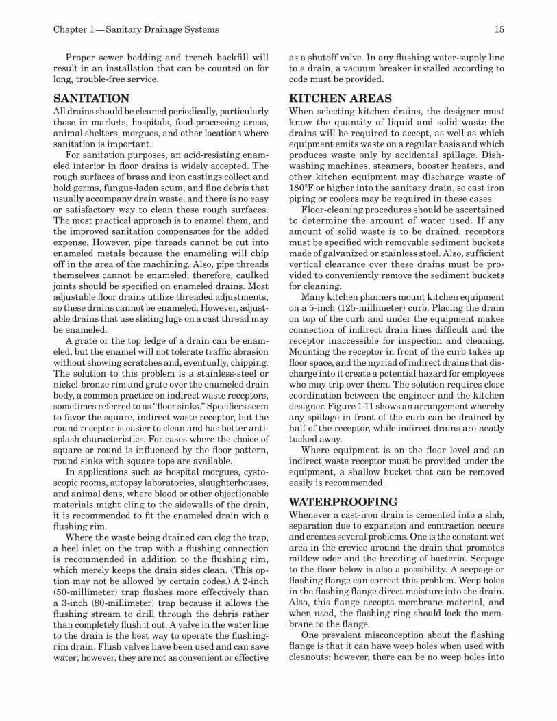
Chapter 1 — Sanitary Drainage Systems 15
Proper sewer bedding and trench backfill will result in an installation that can be counted on for long, trouble-free service.
SANITATIONAll drains should be cleaned periodically, particularly those in markets, hospitals, food-processing areas, animal shelters, morgues, and other locations where sanitation is important.
For sanitation purposes, an acid-resisting enam-eled interior in floor drains is widely accepted. The rough surfaces of brass and iron castings collect and hold germs, fungus-laden scum, and fine debris that usually accompany drain waste, and there is no easy or satisfactory way to clean these rough surfaces. The most practical approach is to enamel them, and the improved sanitation compensates for the added expense. However, pipe threads cannot be cut into enameled metals because the enameling will chip off in the area of the machining. Also, pipe threads themselves cannot be enameled; therefore, caulked joints should be specified on enameled drains. Most adjustable floor drains utilize threaded adjustments, so these drains cannot be enameled. However, adjust-able drains that use sliding lugs on a cast thread may be enameled.
A grate or the top ledge of a drain can be enam-eled, but the enamel will not tolerate traffic abrasion without showing scratches and, eventually, chipping. The solution to this problem is a stainless-steel or nickel-bronze rim and grate over the enameled drain body, a common practice on indirect waste receptors, sometimes referred to as “floor sinks.” Specifiers seem to favor the square, indirect waste receptor, but the round receptor is easier to clean and has better anti-splash characteristics. For cases where the choice of square or round is influenced by the floor pattern, round sinks with square tops are available.
In applications such as hospital morgues, cysto-scopic rooms, autopsy laboratories, slaughterhouses, and animal dens, where blood or other objectionable materials might cling to the sidewalls of the drain, it is recommended to fit the enameled drain with a flushing rim.
Where the waste being drained can clog the trap, a heel inlet on the trap with a flushing connection is recommended in addition to the flushing rim, which merely keeps the drain sides clean. (This op-tion may not be allowed by certain codes.) A 2-inch (50-millimeter) trap flushes more effectively than a 3-inch (80-millimeter) trap because it allows the flushing stream to drill through the debris rather than completely flush it out. A valve in the water line to the drain is the best way to operate the flushing-rim drain. Flush valves have been used and can save water; however, they are not as convenient or effective
as a shutoff valve. In any flushing water-supply line to a drain, a vacuum breaker installed according to code must be provided.
KITCHEN AREASWhen selecting kitchen drains, the designer must know the quantity of liquid and solid waste the drains will be required to accept, as well as which equipment emits waste on a regular basis and which produces waste only by accidental spillage. Dish-washing machines, steamers, booster heaters, and other kitchen equipment may discharge waste of 180°F or higher into the sanitary drain, so cast iron piping or coolers may be required in these cases.
Floor-cleaning procedures should be ascertained to determine the amount of water used. If any amount of solid waste is to be drained, receptors must be specified with removable sediment buckets made of galvanized or stainless steel. Also, sufficient vertical clearance over these drains must be pro-vided to conveniently remove the sediment buckets for cleaning.
Many kitchen planners mount kitchen equipment on a 5-inch (125-millimeter) curb. Placing the drain on top of the curb and under the equipment makes connection of indirect drain lines difficult and the receptor inaccessible for inspection and cleaning. Mounting the receptor in front of the curb takes up floor space, and the myriad of indirect drains that dis-charge into it create a potential hazard for employees who may trip over them. The solution requires close coordination between the engineer and the kitchen designer. Figure 1-11 shows an arrangement whereby any spillage in front of the curb can be drained by half of the receptor, while indirect drains are neatly tucked away.
Where equipment is on the floor level and an indirect waste receptor must be provided under the equipment, a shallow bucket that can be removed easily is recommended.
WATERPROOFINGWhenever a cast-iron drain is cemented into a slab, separation due to expansion and contraction occurs and creates several problems. One is the constant wet area in the crevice around the drain that promotes mildew odor and the breeding of bacteria. Seepage to the floor below is also a possibility. A seepage or flashing flange can correct this problem. Weep holes in the flashing flange direct moisture into the drain. Also, this flange accepts membrane material, and when used, the flashing ring should lock the mem-brane to the flange.
One prevalent misconception about the flashing flange is that it can have weep holes when used with cleanouts; however, there can be no weep holes into
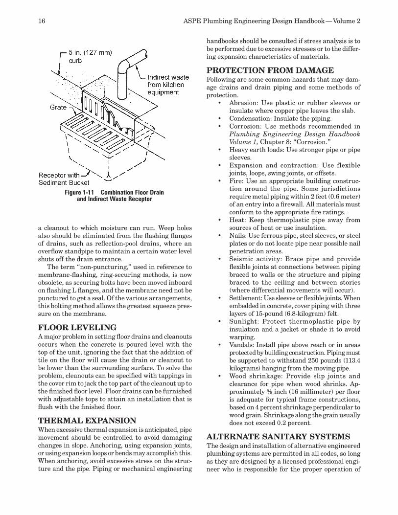
16 ASPE Plumbing Engineering Design Handbook — Volume 2
a cleanout to which moisture can run. Weep holes also should be eliminated from the flashing flanges of drains, such as reflection-pool drains, where an overflow standpipe to maintain a certain water level shuts off the drain entrance.
The term “non-puncturing,” used in reference to membrane-flashing, ring-securing methods, is now obsolete, as securing bolts have been moved inboard on flashing L flanges, and the membrane need not be punctured to get a seal. Of the various arrangements, this bolting method allows the greatest squeeze pres-sure on the membrane.
FLOOR LEVELINGA major problem in setting floor drains and cleanouts occurs when the concrete is poured level with the top of the unit, ignoring the fact that the addition of tile on the floor will cause the drain or cleanout to be lower than the surrounding surface. To solve the problem, cleanouts can be specified with tappings in the cover rim to jack the top part of the cleanout up to the finished floor level. Floor drains can be furnished with adjustable tops to attain an installation that is flush with the finished floor.
THERMAL EXPANSIONWhen excessive thermal expansion is anticipated, pipe movement should be controlled to avoid damaging changes in slope. Anchoring, using expansion joints, or using expansion loops or bends may accomplish this. When anchoring, avoid excessive stress on the struc-ture and the pipe. Piping or mechanical engineering
handbooks should be consulted if stress analysis is to be performed due to excessive stresses or to the differ-ing expansion characteristics of materials.
PROTECTION FROM DAMAGEFollowing are some common hazards that may dam-age drains and drain piping and some methods of protection.
Abrasion: Use plastic or rubber sleeves or •insulate where copper pipe leaves the slab.Condensation: Insulate the piping. •Corrosion: Use methods recommended in •Plumbing Engineering Design Handbook Volume 1, Chapter 8: “Corrosion.”Heavy earth loads: Use stronger pipe or pipe •sleeves. Expansion and contraction: Use flexible •joints, loops, swing joints, or offsets.Fire: Use an appropriate building construc-•tion around the pipe. Some jurisdictions require metal piping within 2 feet (0.6 meter) of an entry into a firewall. All materials must conform to the appropriate fire ratings.Heat: Keep thermoplastic pipe away from •sources of heat or use insulation. Nails: Use ferrous pipe, steel sleeves, or steel •plates or do not locate pipe near possible nail penetration areas. Seismic activity: Brace pipe and provide •flexible joints at connections between piping braced to walls or the structure and piping braced to the ceiling and between stories (where differential movements will occur).Settlement: Use sleeves or flexible joints. When •embedded in concrete, cover piping with three layers of 15-pound (6.8-kilogram) felt.Sunlight: Protect thermoplastic pipe by •insulation and a jacket or shade it to avoid warping. Vandals: Install pipe above reach or in areas •protected by building construction. Piping must be supported to withstand 250 pounds (113.4 kilograms) hanging from the moving pipe.Wood shrinkage: Provide slip joints and •clearance for pipe when wood shrinks. Ap-proximately s inch (16 millimeter) per floor is adequate for typical frame constructions, based on 4 percent shrinkage perpendicular to wood grain. Shrinkage along the grain usually does not exceed 0.2 percent.
ALTERNATE SANITARY SYSTEMSThe design and installation of alternative engineered plumbing systems are permitted in all codes, so long as they are designed by a licensed professional engi-neer who is responsible for the proper operation of
Figure 1-11 Combination Floor Drain and Indirect Waste Receptor
Chapter 1 — Sanitary Drainage Systems 17
lines connect to the stack, and a deaerator fitting at the base of the stack where it enters the house drain.
The starting point is the horizontal soil and waste branches. The fixture units and branch sizes are simi-lar to those figures found in conventional systems. The maximum fixture units that may be connected to a branch or stack are also similar to that of con-ventional systems.
Branch sizes must be adjusted according to the following.
A second vertical drop or a vertical drop of •more than 3 feet (0.9 meter) requires an increase in the downstream side of the con-nection. When three 90-degree changes in direction •occur in a horizontal branch, the horizontal branch shall be increased in size at the up-stream side of the third change. When a branch serves two water closets and •one or more additional fixtures, the soil line shall be increased to 4 inches (100 millime-ters) at the point where one water closet and one additional fixture are connected. The branch must be increased one size when •a soil branch exceeds 12 feet (3.7 meters) in horizontal length. The branch must be increased one size when •a waste line exceeds 15 feet (4.6 meters) in horizontal length.
Stacks must be carried full size through the roof. Two stacks can be connected at the top above the highest fixture or at the bottom prior to entering the building drain. The size is based on the total fixture units. Fixtures may be connected into a horizontal offset in a stack below the deaerator fitting.
An aerator fitting is required at each level where a soil branch, a waste line the same size as the stack, or a waste branch one size smaller than the stack is con-nected. The aerator consists of an upper stack inlet, a mixing chamber, and a baffle in the center of the fitting. This provides a chamber where the flow from the branches may gradually mix smoothly with the air and liquid already flowing in the stack. It also limits the turbulence and velocity of the incoming water. A 2-inch (50-millimeter) horizontal branch may enter the stack with no fitting. Two basic styles of aerator fitting meet the needs of most design conditions: the double-side entry fitting and the single-entry fitting. Face entry and top entry are used in special cases.
A deaerator fitting is required at the bottom of the stack and is designed to overcome the tendency of the falling waste to build up excessive back pressure at the bottom of the stack when the flow is decelerated by the bend into the horizontal drain. The deaerator consists of an air separation chamber, a nose piece, a pressure relief outlet at the top connected to the
the systems. If an alternative system is contemplated, submission to and approval by the authority having jurisdiction must be obtained. To expedite approval, the following steps are suggested.
Indicate on the design documents that the 1. plumbing system (or parts thereof) is an al-ternative design.Submit enough technical data to support the 2. proposed alternative design and prove that the system conforms to the intent of the code. This shall include suitability for the intended purpose, strength, equivalent level of perfor-mance compared to traditional installations, safety, and quality of materials. Include floor plans, riser diagrams, and an 3. indication of the proposed flow. Provide assurance that the manufacturer’s 4. installation instructions will be followed. If approval is given, indicate on the permit and 5. all construction applications that an alterna-tive engineered design is part of the approved installation. Alternative systems are characterized by, but 6. not limited to, using a single stack for both sanitary and vent or no vent at all. One excep-tion is a conventional drainage, reduced-vent system. All of the following systems have been used successfully in the United States and around the world for many years and have proven effective in actual use. All of the alternative systems discussed have combined sanitary and vent systems.
SOVENT AND PROVENT The Sovent system was developed in 1959 in Swit-zerland. It is a patented, combination drainage and vent system that uses a single stack instead of a conventional two-pipe drainage and vent stack. The Sovent system uses cast iron and/or copper pipe and is suitable only for multistory buildings because it allows substantial economy in piping installation.
The Provent system is similar to the Sovent sys-tem, but it uses PVC. Although installed in many countries throughout the world, it remains an alterna-tive, unconventional system with only limited usage in the United States.
It is not the intent of this chapter to provide specific design criteria for a Sovent or Provent system, but rather to discuss the individual component character-istics that will enable a plumbing engineer to obtain a working knowledge of how these systems work. A typical Sovent single-stack system is illustrated in Figure 1-12.
A Sovent or Provent system consists of three prin-cipal parts: piping for all branch wastes and stacks, an aerator fitting at each floor level where the branch waste
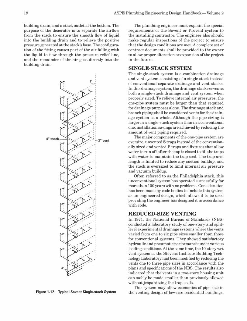
18 ASPE Plumbing Engineering Design Handbook — Volume 2
The plumbing engineer must explain the special requirements of the Sovent or Provent system to the installing contractor. The engineer also should make regular inspections of the project to ensure that the design conditions are met. A complete set of contract documents shall be provided to the owner to allow proper alteration or expansion of the project in the future.
SINGLE-STACK SYSTEMThe single-stack system is a combination drainage and vent system consisting of a single stack instead of conventional separate drainage and vent stacks. In this drainage system, the drainage stack serves as both a single-stack drainage and vent system when properly sized. To relieve internal air pressures, the one-pipe system must be larger than that required for drainage purposes alone. The drainage stack and branch piping shall be considered vents for the drain-age system as a whole. Although the pipe sizing is larger in a single-stack system than in a conventional one, installation savings are achieved by reducing the amount of vent piping required.
The major components of the one-pipe system are oversize, unvented S traps instead of the convention-ally sized and vented P traps and fixtures that allow water to run off after the tap is closed to fill the traps with water to maintain the trap seal. The trap arm length is limited to reduce any suction buildup, and the stack is oversized to limit internal air pressure and vacuum buildup.
Often referred to as the Philadelphia stack, this unconventional system has operated successfully for more than 100 years with no problems. Consideration has been made by code bodies to include this system as an engineered design, which allows it to be used providing the engineer has designed it in accordance with code.
REDUCED-SIzE VENTINGIn 1974, the National Bureau of Standards (NBS) conducted a laboratory study of one-story and split-level experimental drainage systems where the vents varied from one to six pipe sizes smaller than those for conventional systems. They showed satisfactory hydraulic and pneumatic performance under various loading conditions. At the same time, the 10-story wet vent system at the Stevens Institute Building Tech-nology Laboratory had been modified by reducing the vents one to three pipe sizes in accordance with the plans and specifications of the NBS. The results also indicated that the vents in a two-story housing unit can safely be made smaller than previously allowed without jeopardizing the trap seals.
This system may allow economies of pipe size in the venting design of low-rise residential buildings,
building drain, and a stack outlet at the bottom. The purpose of the deaerator is to separate the airflow from the stack to ensure the smooth flow of liquid into the building drain and to relieve the positive pressure generated at the stack’s base. The configura-tion of the fitting causes part of the air falling with the liquid to flow through the pressure relief line, and the remainder of the air goes directly into the building drain.
Figure 1-12 Typical Sovent Single-stack System
Chapter 1 — Sanitary Drainage Systems 19
although this particular system has not been accepted by authorities. It is limited to special conditions and requires the vent pipes to be of a material such as copper or plastic that will resist the buildup of cor-rosion products.
VACUUM DRAINAGE SYSTEMVacuum drainage operates on the principle that the majority of the system is under a continuous vacuum. The system is proprietary and is made by various manufacturers, all of which have different names for devices performing similar operations, so generic identification is used here. Various designs are ca-pable of sanitary and waste disposal, either separate or in combination, and are used for various projects such as prisons, supermarkets, and ships. There is no direct connection from the sanitary waste to the vacuum system. The one big advantage is that piping is installed overhead and no pipe is required to be placed underground.
The system consists of three basic components: a vacuum network of piping and other devices that collects and transports waste from its origin, vacuum generation pumps, and a vacuum interface device at the point of origin that isolates the vacuum piping from atmospheric pressure. When the system serves water closets, the water closets must be purpose made, designed to rinse and refill with 0.5 gallon (2.2 liters) of water.
The piping network for a vacuum waste system is held under a constant vacuum between 12 and 18 inches of mercury (in Hg) (40–65 kilopascals) and generally is fabricated from PVC, copper, or other nonporous, smooth-bore material. Horizontal piping shall slope at a rate of 8 inch per foot (1.18 millimeter per meter) toward the vacuum center. This piping slope is the same as in conventional systems. If this slope cannot be maintained, the traps created in the piping runs when routed around obstacles would be cleared because of the differential pressure that exists between the vacuum center and the point of origin. The discharge of the piping system is into the waste storage tanks.
The vacuum generation system includes vacuum pumps, which create a vacuum in the piping and storage tanks that collect and discharge the waste into the sewer system. The vacuum pumps run only on demand, and redundancy is provided. They also have sewage pumps that pump the drainage from the storage tanks into the sewer.
The vacuum interface is different for sanitary drainage than for clear waste. Vacuum toilets op-erate instantly upon flushing, and when a vacuum toilet is cycled, a discharge control panel assembly is activated, sending the discharge to the tank. A valve acts as an interface between the vacuum and the atmosphere. The tank will discharge into the sewer when a predetermined level of discharge is reached.
When clear water is discharged, the water goes into an accumulator. When a controller senses that sufficient waste is present, it opens the normally closed extraction valve, which separates the atmo-spheric pressure from the vacuum and removes the waste from the accumulator.
Because vacuum toilets use 0.5 gallon per flush, the holding tanks can be smaller than those for con-ventional toilets. A flush control panel is designed to provide all of the control functions associated with the vacuum toilet. The control panel consists of a flush valve, flush controller, water valve, and vacuum breaker. All controls are pneumatically operated. The flush controller controls the opening of the flush valve and the rinse valve as well as the duration of the time the flush valve is open.
REFERENCESDaugherty, Robert L., Joseph B. Franzini, and 1. E. John Finnemore, Fluid Mechanics with En-gineering Applications, McGraw-Hill, 1985. Dawson, F.M. and A.A. Kalinske. 2. Report on Hydraulics and Pneumatics of Plumbing Drainage Systems, State University of Iowa Studies in Engineering, Bulletin No. 10, 1937.

20 ASPE Plumbing Engineering Design Handbook — Volume 2

On-site Wastewater Reuse and Storm Water Harvesting
2In many regions, water is a limited natural resource, so extreme measures to optimize the use of water are necessary. Water reuse and storm water use offer considerable savings of water resources, which is ap-pealing in localities where underground aquifers are in danger of depletion or where adequate supplies of water are not available. Storm water use (and waste-water reuse) is sometimes attractive when compared to the treatment required for groundwater sources to achieve potable or drinking water standards. For example, numerous Wisconsin wells contain some of the highest arsenic concentrations in the world (15,000 parts per billion [ppb], when the drinking water standard is 5 ppb). In such an instance it may be more reasonable to treat storm water for potable use. Wastewater management is also a significant reason for water reuse and storm water use systems.
On-site recycling of relatively clean, nonpotable water and storm water use are considered for the following reasons.
The availability of potable water is in short •supply or restricted, and codes require reuse or storm water use. The public liquid sewage disposal capacity is •either limited or inadequate.Obtaining potable water or disposing of liquid •waste is very costly.Payback typically occurs in less than five •years, and the system can reduce sewer and water usage fees, electrical costs, or water heating costs, resulting in operating cost savings.The 2009 LEED certification has options for •plumbing. Reuse could earn a facility up to four points in the LEED system by reducing water usage by 40 percent. A 35 percent re-duction earns three points, and a 30 percent reduction earns two points.
The most common reuse of water is for the flushing of urinals and water closets, especially in high-rises, hotels, schools, office buildings, and large dwellings.
Appropriately treated water also may be used for the following proposes:
Flushing water for water closets and urinals•Landscape irrigation •Cooling tower makeup•Decorative pool and fountain fill water•Floor and general hard-surface washdown•Laundry water supply•
Less frequently, storm water is collected and used for potable purposes, but the public does not widely accept this process.
Note: This chapter is written primarily to famil-iarize the reader with the general subject area. It is not intended for system design without reference and adherence to other technical data and local code requirements.
TERMINOLOGYIn plumbing, wastewater is the general term for water that has been discharged or collected from a fixture, receptor, or appliance (see Figure 2-1).
The terms for a variety of recycled waters often are used interchangeably. In general, graywater is intended to include appropriately treated water that has been recovered from fixtures such as lavatories, bathtubs, showers, and clothes washers. In some juris-dictions, waste potentially containing grease, such as that from dishwashers, and waste from food disposals in kitchens are excluded due to the possibility of solid particles in the water. Black water, on the other hand, is water recovered from plumbing fixtures discharging human excrement, such as water closets and urinals. Storm water includes the wastewater from precipita-tion events (and sometimes groundwater).
THE WATER BALANCE EQUATIONOn-site water efficiency, whether mandated or an ecologically minded choice, requires plumbing system designers to evaluate the constructed environment water balance prior to completing a plumbing design (see Figure 2-2).
22 ASPE Plumbing Engineering Design Handbook — Volume 2
The constructed environment water balance equa-tion is:
Equation 2-1P + PS + NPS + GW = E + T + U + TP + SW +
STW + R + I
whereP = PrecipitationPS = Potable sourceNPS = Nonpotable sourceGW = GroundwaterE = EvaporationT = TranspirationU = Usage in product (personal use carried off site) TP = Treated product water (as marketable water)SW = Sanitary sewerSTW = Storm water sewerR = Storm water runoffI = Infiltration
The water balance is impacted by storage; however, the long-term balance is always maintained.
When reuse or storm water harvesting is included in the plumbing design, the water balance equation can be modified to:
Equation 2-2
CODES AND STANDARDSThe number of jurisdictions requiring water reuse or storm water harvesting is increasing. Even the Great Lakes areas are considering supplementing withdrawals from the lakes with these and other conservation practices. However, no national model codes mandate storm water use or wastewater reuse. The Uniform Plumbing Code discusses graywater, but limits the discussion to single-family dwellings. The International Plumbing Code includes graywater recycling systems in an appendix.
Many specific local areas have established stan-dards and guidelines for the use of graywater in facilities and homes. Where graywater use is per-mitted, the authority having jurisdiction may have established minimum treatment standards. In these localities, you must check for regulations applicable to reuse and storm water use as is done for plumbing and building codes.
Table 2-1 is from the Canadian Mortgage and Hous-ing Corporation’s Research Report, which includes a summary of international treatment standards for water reuse. The limitations represented in Table 2-1 illustrate concerns that you should address when de-veloping a water reuse plan. Since such requirements are constantly undergoing revision, you must contact the local authorities for current standards.
Some jurisdictions allow irrigation with untreated graywater, and this typically is accomplished subsur-face. This chapter assumes that the irrigation system is provided with treated graywater to the standards listed in Table 2-1.
GRAYWATER REUSEGraywater reuse systems collect water discharged from fixtures, devices, and appliances that do not con-tain human excrement. This water can be treated to a level of quality consistent with its intended use.
A graywater system requires modifications to the standard plumbing systems throughout a facility—in particular, duplicate drainage systems and duplicate water supplies. Rather than all plumbing fixture dis-charge going to the sanitary sewer, the effluent from selected fixtures is routed for recovery by the graywater treatment system. The remainder goes to the sanitary sewer. Potable water goes to lavatories, sinks, and showers, and the graywater supplies water closets, uri-nals, irrigation systems, and other fixtures, depending on the quality of the graywater treatment.
Special care must be taken during the installation of a graywater system. Clear identification and labeling of the graywater system and piping are mandatory to minimize the risk of cross-connection during installation or repair of the system.
Many newly formed, planned communities have adopted graywater systems for their irrigation systems. Warning “nonpotable water” signs or colored piping is now visible across city landscapes. Blue dye has become a clear identification of the use of graywater.
System ComponentsThe following components generally are used for most systems. Their arrangement and type depend on the specific treatment system selected.
A separate graywater collection piping system•A primary waste treatment system consist-•ing of turbidity removal, storage, biological treatment, and filteringDisinfecting systems consisting of ozone, ul-•traviolet irradiation, chlorine, or iodineTreated water storage and system distribu-•tion pressure pumps and piping
Design Criteria for Graywater Supply and ConsumptionIt is estimated that two-thirds of the wastewater discharged from a typical household in one day is gray-water. The remaining wastewater is black water from water closets. The discharge from the separate piping systems supplying the graywater system should be sized based on the applicable plumbing code.
The following issues should be considered in the design of any graywater system:
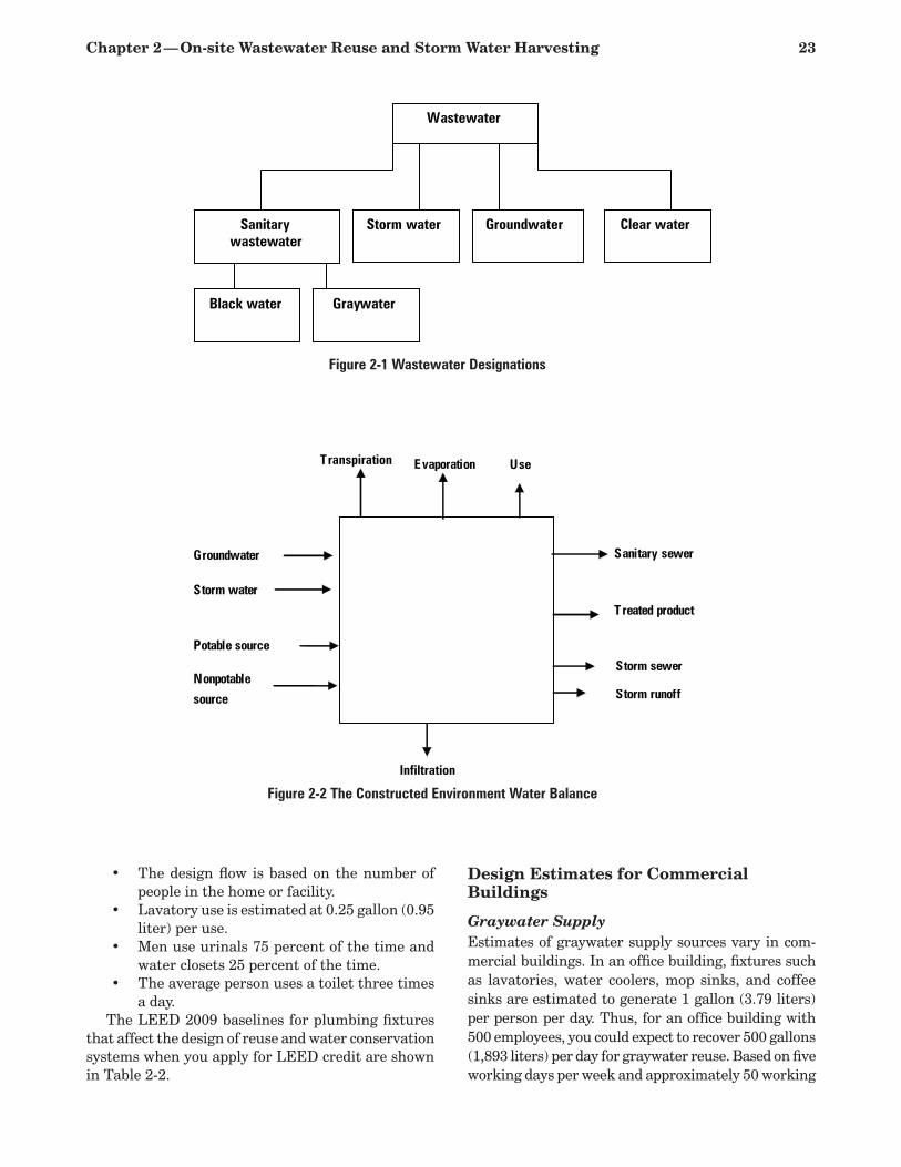
Chapter 2 — On-site Wastewater Reuse and Storm Water Harvesting 23
Wastewater
Sanitary wastewater
Storm water Groundwater Clear water
Black water Graywater
Figure 2-1 Wastewater Designations
Transpiration Evaporation Use
Sanitary sewer
Treated product
Storm sewer
Storm runoff
Groundwater
Storm water
Potable source
Nonpotable
source
Infiltration
Figure 2-2 The Constructed Environment Water Balance
The design flow is based on the number of •people in the home or facility.Lavatory use is estimated at 0.25 gallon (0.95 •liter) per use.Men use urinals 75 percent of the time and •water closets 25 percent of the time.The average person uses a toilet three times •a day.
The LEED 2009 baselines for plumbing fixtures that affect the design of reuse and water conservation systems when you apply for LEED credit are shown in Table 2-2.
Design Estimates for Commercial Buildings
Graywater Supply Estimates of graywater supply sources vary in com-mercial buildings. In an office building, fixtures such as lavatories, water coolers, mop sinks, and coffee sinks are estimated to generate 1 gallon (3.79 liters) per person per day. Thus, for an office building with 500 employees, you could expect to recover 500 gallons (1,893 liters) per day for graywater reuse. Based on five working days per week and approximately 50 working
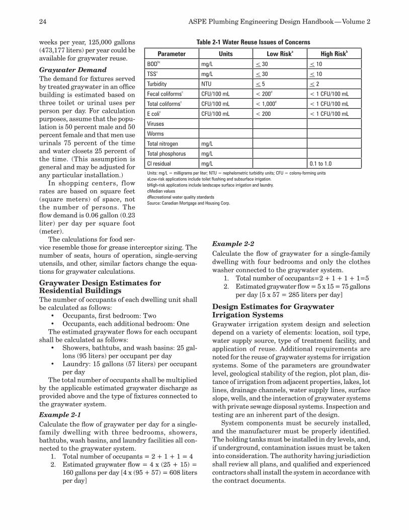
24 ASPE Plumbing Engineering Design Handbook — Volume 2
weeks per year, 125,000 gallons (473,177 liters) per year could be available for graywater reuse.
Graywater Demand The demand for fixtures served by treated graywater in an office building is estimated based on three toilet or urinal uses per person per day. For calculation purposes, assume that the popu-lation is 50 percent male and 50 percent female and that men use urinals 75 percent of the time and water closets 25 percent of the time. (This assumption is general and may be adjusted for any particular installation.)
In shopping centers, flow rates are based on square feet (square meters) of space, not the number of persons. The flow demand is 0.06 gallon (0.23 liter) per day per square foot (meter).
The calculations for food ser-vice resemble those for grease interceptor sizing. The number of seats, hours of operation, single-serving utensils, and other, similar factors change the equa-tions for graywater calculations.
Graywater Design Estimates for Residential BuildingsThe number of occupants of each dwelling unit shall be calculated as follows:
Occupants, first bedroom: Two•Occupants, each additional bedroom: One•
The estimated graywater flows for each occupant shall be calculated as follows:
Showers, bathtubs, and wash basins: 25 gal-•lons (95 liters) per occupant per dayLaundry: 15 gallons (57 liters) per occupant •per day
The total number of occupants shall be multiplied by the applicable estimated graywater discharge as provided above and the type of fixtures connected to the graywater system.
Example 2-1 Calculate the flow of graywater per day for a single-family dwelling with three bedrooms, showers, bathtubs, wash basins, and laundry facilities all con-nected to the graywater system.
Total number of occupants = 2 + 1 + 1 = 41. Estimated graywater flow = 4 x (25 + 15) = 2. 160 gallons per day [4 x (95 + 57) = 608 liters per day]
Example 2-2 Calculate the flow of graywater for a single-family dwelling with four bedrooms and only the clothes washer connected to the graywater system.
Total number of occupants=2 + 1 + 1 + 1=51. Estimated graywater flow = 5 x 15 = 75 gallons 2. per day [5 x 57 = 285 liters per day]
Design Estimates for Graywater Irrigation SystemsGraywater irrigation system design and selection depend on a variety of elements: location, soil type, water supply source, type of treatment facility, and application of reuse. Additional requirements are noted for the reuse of graywater systems for irrigation systems. Some of the parameters are groundwater level, geological stability of the region, plot plan, dis-tance of irrigation from adjacent properties, lakes, lot lines, drainage channels, water supply lines, surface slope, wells, and the interaction of graywater systems with private sewage disposal systems. Inspection and testing are an inherent part of the design.
System components must be securely installed, and the manufacturer must be properly identified. The holding tanks must be installed in dry levels, and, if underground, contamination issues must be taken into consideration. The authority having jurisdiction shall review all plans, and qualified and experienced contractors shall install the system in accordance with the contract documents.
Parameter Units Low Riska High Riskb
BOD5c mg/L < 30 < 10
TSSc mg/L < 30 < 10
Turbidity NTU < 5 < 2
Fecal coliformsc CFU/100 mL < 200d < 1 CFU/100 mL
Total coliformsc CFU/100 mL < 1,000d < 1 CFU/100 mL
E colic CFU/100 mL < 200 < 1 CFU/100 mL
Viruses
Worms
Total nitrogen mg/L
Total phosphorus mg/L
Cl residual mg/L 0.1 to 1.0Units: mg/L = milligrams per liter; NTU = nephelometric turbidity units; CFU = colony-forming unitsaLow-risk applications include toilet flushing and subsurface irrigation.bHigh-risk applications include landscape surface irrigation and laundry.cMedian valuesdRecreational water quality standardsSource: Canadian Mortgage and Housing Corp.
Table 2-1 Water Reuse Issues of Concerns

Chapter 2 — On-site Wastewater Reuse and Storm Water Harvesting 25
To design a graywater system, you must estimate the water supply source. Separate design parameters become important for reuse in buildings or in irriga-tion systems. For irrigation systems, the required area of subsurface must be designed based on soil analysis.
Table 2-3 gives an example of the design criteria for the use of graywater systems in various soil types (coarse sand or gravel, fine sand, sandy loam, sandy clay, and mixed clay). As the soil weight decreases and the soil becomes less porous, the minimum square feet (square meters) needed for leaching increases. Coarse sand or gravel needs a 20-square foot irrigation area per 100 gallons (1.86 square meters per 379 liters) of estimated graywater discharge per day. Clay with a small amount of sand or gravel requires 120 square feet per 100 gallons (11.15 square meters per 379 liters) of estimated graywater per day.
The area of the irrigation field shall be equal to the aggregate length of the perforated pipe sections within the valved zone times the width of the proposed irrigation field. Each proposed graywater system shall include at least three valved zones. No excavation for an irrigation field shall extend within 5 vertical feet
(1.5 meters) of the highest known seasonal groundwater table, and it shall not extend to a depth where graywater may contami-nate the groundwater or ocean water.
The design of the graywater distribu-tion in subsurface drip systems is based on the emitter manufacturer’s recommenda-tions. The soil type and loading criteria from Table 2-3 are also applicable to drip irrigation systems.
Table 2-4 identifies the location and separation distance from a variety of struc-tures and environments. For example, any building or structure shall be a minimum of 5 feet (1.5 meters) from a graywater surge tank. The minimum distance from any property line to a graywater surge tank is also 5 feet (1.5 meters). Critical areas such as streams, lakes, seepage pits, and cesspools shall be a minimum of 50 feet (15.2 meters) from surge tanks and 100 feet (30.5 meters) from irrigation fields. Similarly, the distance from the public water main to a surge tank shall be a mini-mum of 10 feet (3.1 meters). The table also identifies additional restrictions.
Graywater Treatment SystemsThe graywater treatment system conditions the recovered water to a level consistent with both the intended use of the condi-tioned water and the design requirements of the design engineer, applicable code, or responsible code official—whichever is the
most stringent. Typical wastewater (graywater and black water) treatments used for various types of projects include sedimentation, aeration, filtration, and disinfection.
The size of the treatment systems available vary from those installed for individual private dwellings to those serving multiple facilities. As the treatment facility becomes more complex, the number of treat-ment activities increases, and the quality of the water improves. Some of the treatment activities are basic screening, flow equalization, biological treatment, filtration, coagulation, sedimentation, disinfections, reclaimed water tank, membrane filtration, and ac-tivated carbon filtration.
The selection of a treatment system also depends on the quality and type of the influent water. To decide which treatment method is most appropriate, the type of fixture discharge to be reclaimed and the treatment requirements of the authority having jurisdiction must be determined.
Table 2-5 describes the types of filtration and water treatment processes most commonly used for graywater treatment. Depending on the type of filtra-
Table 2-2 LEED 2009 Baseline for Plumbing Fixtures
Fixture LEED 2009 BaselineToilets 1.6 gpf (3.5 gpf for blowout closets)
Urinals 1.0 gpf
Lavatory faucets, privatea 2.2 gpm at 60 psig
Lavatory faucets, public 0.5 gpm at 60 psig
Lavatory faucets, metering 0.25 gallons per cycle
Residential kitchen faucets 2.2 gpm at 60 psig
Showerheads 2.5 gpm at 80 psig
Pre-rinse spray valves 1.6 gpm (no psig specified)aPrivate lavatory faucets include both residential and private commercial applications such as hotel guest rooms and hospital patient rooms.
Table 2-3 Design Criteria for Graywater Irrigation of Six Typical Soils
Soil TypeMinimum Irrigation Area per
100 Gallons of Estimated Graywater Discharge per Day,
square feetCoarse sand or gravel 20
Fine sand 25
Sandy loam 40
Sandy clay 60
Clay with considerable sand or gravel 90
Clay with small amounts of sand or gravel 120
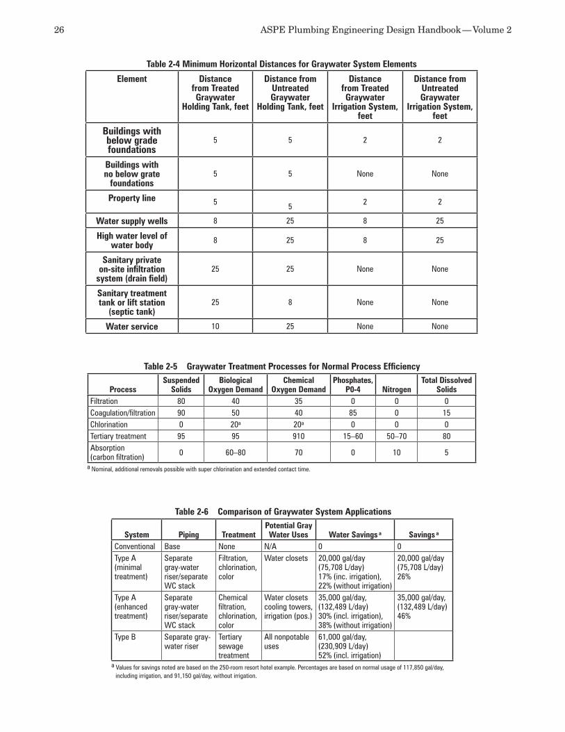
26 ASPE Plumbing Engineering Design Handbook — Volume 2
Table 2-5 Graywater Treatment Processes for Normal Process Efficiency
ProcessSuspended
SolidsBiological
Oxygen DemandChemical
Oxygen DemandPhosphates,
P0-4 NitrogenTotal Dissolved
SolidsFiltration 80 40 35 0 0 0Coagulation/filtration 90 50 40 85 0 15Chlorination 0 20a 20a 0 0 0Tertiary treatment 95 95 910 15–60 50–70 80Absorption (carbon filtration) 0 60–80 70 0 10 5
a Nominal, additional removals possible with super chlorination and extended contact time.
Table 2-6 Comparison of Graywater System Applications
System Piping TreatmentPotential Gray Water Uses Water Savings a Savings a
Conventional Base None N/A 0 0Type A(minimal treatment)
Separate gray-water riser/separate WC stack
Filtration, chlorination, color
Water closets 20,000 gal/day(75,708 L/day)17% (inc. irrigation),22% (without irrigation)
20,000 gal/day(75,708 L/day)26%
Type A(enhanced treatment)
Separate gray-water riser/separate WC stack
Chemical filtration, chlorination, color
Water closets cooling towers, irrigation (pos.)
35,000 gal/day,(132,489 L/day)30% (incl. irrigation),38% (without irrigation)
35,000 gal/day,(132,489 L/day)46%
Type B Separate gray-water riser
Tertiary sewage treatment
All nonpotable uses
61,000 gal/day,(230,909 L/day)52% (incl. irrigation)
a Values for savings noted are based on the 250-room resort hotel example. Percentages are based on normal usage of 117,850 gal/day, including irrigation, and 91,150 gal/day, without irrigation.
Table 2-4 Minimum Horizontal Distances for Graywater System Elements
Element Distance from Treated Graywater
Holding Tank, feet
Distance from Untreated Graywater
Holding Tank, feet
Distance from Treated Graywater
Irrigation System, feet
Distance from Untreated Graywater
Irrigation System, feet
Buildings with below grade foundations
5 5 2 2
Buildings with no below grate
foundations5 5 None None
Property line 5 5 2 2
Water supply wells 8 25 8 25
High water level of water body 8 25 8 25
Sanitary private on-site infiltration
system (drain field)25 25 None None
Sanitary treatment tank or lift station
(septic tank)25 8 None None
Water service 10 25 None None
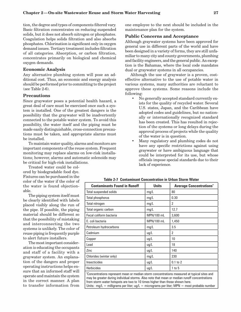
Chapter 2 — On-site Wastewater Reuse and Storm Water Harvesting 27
tion, the degree and types of components filtered vary. Basic filtration concentrates on reducing suspended solids, but it does not absorb nitrogen or phosphates. Coagulation helps solids filtration and also absorbs phosphates. Chlorination is significant only in oxygen demand issues. Tertiary treatment includes filtration of all categories. Absorption, or carbon filtration, concentrates primarily on biological and chemical oxygen demands.
Economic AnalysisAny alternative plumbing system will pose an ad-ditional cost. Thus, an economic and energy analysis should be performed prior to committing to the project (see Table 2-6).
PrecautionsSince graywater poses a potential health hazard, a great deal of care must be exercised once such a sys-tem is installed. One of the greatest dangers is the possibility that the graywater will be inadvertently connected to the potable water system. To avoid this possibility, the water itself and the piping must be made easily distinguishable, cross-connection precau-tions must be taken, and appropriate alarms must be installed.
To maintain water quality, alarms and monitors are important components of the reuse system. Frequent monitoring may replace alarms on low-risk installa-tions; however, alarms and automatic solenoids may be critical for high-risk installations.
Treated water could be col-ored by biodegradable food dye. Fixtures can be purchased in the color of the water if the color of the water is found objection-able.
The piping system itself must be clearly identified with labels placed visibly along the run of the pipe. If possible, the piping material should be different so that the possibility of mistaking and interconnecting the two systems is unlikely. The color of reuse piping is frequently purple to alert future installers.
The most important consider-ation is educating the occupants and staff of a facility with a graywater system. An explana-tion of the dangers and proper operating instructions helps en-sure that an informed staff will operate and maintain the system in the correct manner. A plan to transfer information from
one employee to the next should be included in the maintenance plan for the system.
Public Concerns and AcceptanceAlthough graywater systems have been approved for general use in different parts of the world and have been designed in a variety of forms, they are still unfa-miliar to many city and county governments, plumbing and facility engineers, and the general public. An excep-tion is the Bahamas, where the local code mandates dual or graywater systems in all occupancies.
Although the use of graywater is a proven, cost-effective alternative to the use of potable water in various systems, many authorities are reluctant to approve these systems. Some reasons include the following:
No generally accepted standard currently ex-•ists for the quality of recycled water. Several U.S. states, Japan, and the Caribbean have adopted codes and guidelines, but no nation-ally or internationally recognized standard has been created. This has resulted in rejec-tion of the systems or long delays during the approval process of projects while the quality of the water is in question.Many regulatory and plumbing codes do not •have any specific restrictions against using graywater or have ambiguous language that could be interpreted for its use, but whose officials impose special standards due to their lack of experience.
Table 2-7 Contaminant Concentration in Urban Storm Water
Contaminants Found in Runoff Units Average Concentrationsa
Total suspended solids mg/L 80
Total phosphorus mg/L 0.30
Total nitrogen mg/L 2
Total organic carbon mg/L 12.7
Fecal coliform bacteria MPN/100 mL 3,600
E. coli bacteria MPN/100 mL 1,450
Petroleum hydrocarbons mg/L 3.5
Cadmium ug/L 2
Copper ug/L 10
Lead ug/L 18
Zinc ug/L 140
Chlorides (winter only) mg/L 230
Insecticides ug/L 0.1 to 2
Herbicides ug/L 1 to 5aConcentrations represent mean or median storm concentrations measured at typical sites and may be greater during individual storms. Also note that mean or median runoff concentrations from storm water hotspots are two to 10 times higher than those shown here.Units: mg/L = milligrams per liter; ug/L = micrograms per liter; MPN = most probable number
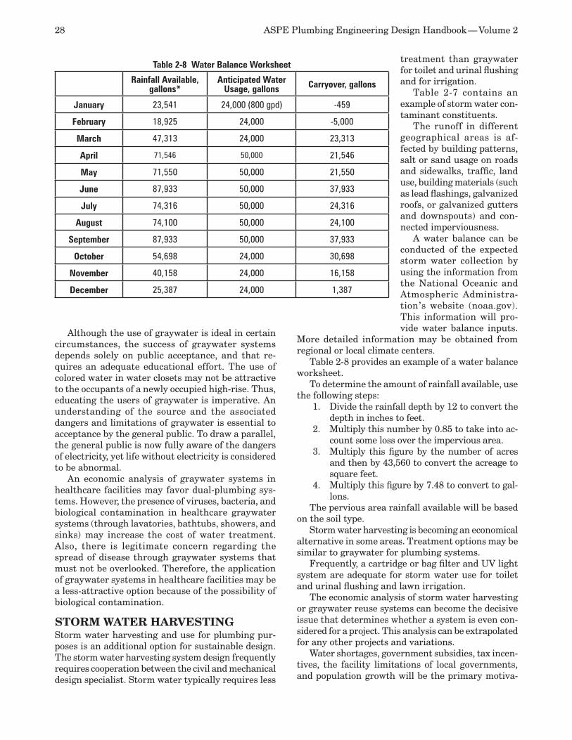
28 ASPE Plumbing Engineering Design Handbook — Volume 2
Although the use of graywater is ideal in certain circumstances, the success of graywater systems depends solely on public acceptance, and that re-quires an adequate educational effort. The use of colored water in water closets may not be attractive to the occupants of a newly occupied high-rise. Thus, educating the users of graywater is imperative. An understanding of the source and the associated dangers and limitations of graywater is essential to acceptance by the general public. To draw a parallel, the general public is now fully aware of the dangers of electricity, yet life without electricity is considered to be abnormal.
An economic analysis of graywater systems in healthcare facilities may favor dual-plumbing sys-tems. However, the presence of viruses, bacteria, and biological contamination in healthcare graywater systems (through lavatories, bathtubs, showers, and sinks) may increase the cost of water treatment. Also, there is legitimate concern regarding the spread of disease through graywater systems that must not be overlooked. Therefore, the application of graywater systems in healthcare facilities may be a less-attractive option because of the possibility of biological contamination.
STORM WATER HARVESTINGStorm water harvesting and use for plumbing pur-poses is an additional option for sustainable design. The storm water harvesting system design frequently requires cooperation between the civil and mechanical design specialist. Storm water typically requires less
treatment than graywater for toilet and urinal flushing and for irrigation.
Table 2-7 contains an example of storm water con-taminant constituents.
The runoff in different geographical areas is af-fected by building patterns, salt or sand usage on roads and sidewalks, traffic, land use, building materials (such as lead flashings, galvanized roofs, or galvanized gutters and downspouts) and con-nected imperviousness.
A water balance can be conducted of the expected storm water collection by using the information from the National Oceanic and Atmospheric Administra-tion’s website (noaa.gov). This information will pro-vide water balance inputs.
More detailed information may be obtained from regional or local climate centers.
Table 2-8 provides an example of a water balance worksheet.
To determine the amount of rainfall available, use the following steps:
Divide the rainfall depth by 12 to convert the 1. depth in inches to feet.Multiply this number by 0.85 to take into ac-2. count some loss over the impervious area.Multiply this figure by the number of acres 3. and then by 43,560 to convert the acreage to square feet.Multiply this figure by 7.48 to convert to gal-4. lons.
The pervious area rainfall available will be based on the soil type.
Storm water harvesting is becoming an economical alternative in some areas. Treatment options may be similar to graywater for plumbing systems.
Frequently, a cartridge or bag filter and UV light system are adequate for storm water use for toilet and urinal flushing and lawn irrigation.
The economic analysis of storm water harvesting or graywater reuse systems can become the decisive issue that determines whether a system is even con-sidered for a project. This analysis can be extrapolated for any other projects and variations.
Water shortages, government subsidies, tax incen-tives, the facility limitations of local governments, and population growth will be the primary motiva-
Table 2-8 Water Balance Worksheet
Rainfall Available, gallons*
Anticipated Water Usage, gallons Carryover, gallons
January 23,541 24,000 (800 gpd) -459
February 18,925 24,000 -5,000
March 47,313 24,000 23,313
April 71,546 50,000 21,546
May 71,550 50,000 21,550
June 87,933 50,000 37,933
July 74,316 50,000 24,316
August 74,100 50,000 24,100
September 87,933 50,000 37,933
October 54,698 24,000 30,698
November 40,158 24,000 16,158
December 25,387 24,000 1,387
Chapter 2 — On-site Wastewater Reuse and Storm Water Harvesting 29
tors for designers and project engineers to consider reuse or storm water harvesting system selections in their designs.
REFERENCESAtienze, J. and J. Craytor, “Plumbing Efficiency 1. Through Graywater Recycling,” Consulting-Specifying Engineer, March 1995. Canadian Mortgage and Housing Corporation, 2. “Research Report: Water Reuse Standards and Verification Protocol.”Gray, G. D., and J. J. Woodcock, 3. Water Uses Study, Dumfries Triangle and Occoquan-Woodbridge Sanitary District.Huff, Winston, CPD, LEED AP, “Changes in 4. LEED 2009 for Plumbing Fixtures and Pro-cess Water,” Plumbing Systems and Design, June 2009.International Plumbing Code, International 5. Code Council.Konen, Thomas P., “Water Use in Office 6. Buildings,” Plumbing Engineer, July/August 1986.
Lehr, Valentine A., “Graywater Systems,” 7. Heating/Piping/Air Conditioning, January 1987.“Naturally Occurring Arsenic in Well Water in 8. Wisconsin,” Wisconsin DNR.Siegrist, R., and W. C. Boyle, “Characteristics 9. of Rural Household Waste Water,” Journal of the Environmental Engineering Division, June 1976.Uniform Plumbing Code, International Associ-10. ation of Plumbing and Mechanical Officials.U.S. Department of Commerce, National Infor-11. mation Services, Management of Small Waste Flows, by Wisconsin University, 1978. U.S. General Services Administration, Water 12. Management: A Comprehensive Approach for Facility Managers, 1995.“Water: Use of Treated Sewage on Rise in 13. State.” Los Angeles Times, August 1997.Wolf, J. B., F. P. Linaweaver, and J.C. Center, 14. Commercial Water Use Research Project, Baltimore Department of Public Works, June 1966.

30 ASPE Plumbing Engineering Design Handbook — Volume 2
Vents and Venting 3
A component of a gravity drainage system, venting is a parallel arrangement of piping that limits the air pressure within the drain. By definition, venting is a separate piping system joined to the drainage system at certain connection points and sized to keep the air pressure in the drain from disturbing the water seals of fixture traps. Generally, the air pressure limit is 1 inch (25.4 millimeters) of water column, above or below atmospheric pressure. When the vent piping is of a sufficient diameter or limited in length, the permissible air pressure can be achieved.
Venting also allows air circulation, which prevents the accumulation of volatile substances in a drainage system. Such circulation is necessary for the installa-tion of an interceptor, and some municipalities that have sewer problems warranting a house trap for each building require it.
Venting is not limited to sanitary drainage systems. Venting design principles are applicable to other drainage systems such as those for chemical waste, graywater waste, and clear water waste.
The design of a venting system is closely tied to the design of the drainage system. That is, the permissible velocities in the drainage system and its peak flow rates affect the diameters in the venting system. If sink drains are nonstandard or if the vertical distance between a fixture outlet and its trap outlet is exces-sive, then velocities in the entire drainage system will be greater than those assumed when vent sizing tables were tabulated.
Because they have no moving parts, vent systems are quiet, and they generally operate flawlessly for decades. However, these two virtues can disguise a fault in a drain and vent system if particular errors in the venting are unknown. These errors typically are related to the elevation of the horizontal portion of the venting.
The development of plumbing occurred across many broad geographical areas and at a time when communication was slow. Hence, a variety of inter-pretations exist regarding the details of venting, and the venting portions of plumbing codes vary greatly.
Typically, vent sizing requirements are expressed as ratios of a vent diameter to the drain diameter. This design handbook, however, presents the engineering basis for venting, as well as the sizing tables of some model plumbing codes commonly enforced in the United States. Nonetheless, local plumbing codes should be consulted for the final requirements of a vent system design.
TRAP DESIGNA fixture trap provides a water seal without signifi-cantly impairing flow. Figure 3-1 illustrates a sink trap with three pressure levels within a drain system, with no drainage occurring from the sinks and a fully open sink outlet. The principles of its trap design can apply to most other fixtures, except those with an intentional siphon action, such as a water closet.
In the first trap in Figure 3-1, the water level is even on both sides of the trap. That is, the air above the water on the drain system side has an atmospheric pressure identical to the air inside the room. The next trap shows the effect on the water levels if the atmo-spheric pressure on the drain system side increases by an amount that displaces the water downward by a ½ inch (12.5 millimeters). The water level rises on the room side by an equal amount, giving a 1-inch (25-millimeter) pressure difference. If the pressure increases to more than 2 inches (50.8 millimeters), air and other sewer gases will pass into the room.
The last trap in the figure shows the effect of nega-tive pressure in the drainage system, which allows the atmospheric pressure of the room side of the trap to depress the water level by 1 inch (25 millimeters). The 1 inch of water on the other side is lost down the drain. When the pressure in the drainage system returns to neutral, the water levels will be 1½ inches (38 millimeters) above the dip point. If the negative pressure is subsequently more than 1½ inches (38 millimeters), air will be pulled from the room.
Another trap issue occurs when the momentum of water flowing from the sink causes most of the water to evacuate from the trap. When the pressure in the
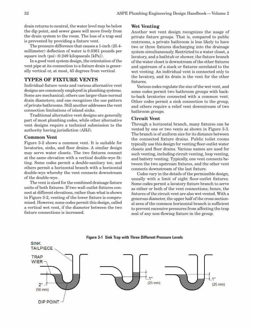
32 ASPE Plumbing Engineering Design Handbook — Volume 2
drain returns to neutral, the water level may be below the dip point, and sewer gases will move freely from the drain system to the room. The loss of a trap seal is prevented by providing a fixture vent.
The pressure difference that causes a 1-inch (25.4-millimeter) deflection of water is 0.0361 pounds per square inch (psi) (0.249 kilopascals [kPa]).
In a good vent system design, the orientation of the vent pipe at its connection to a fixture drain is gener-ally vertical or, at most, 45 degrees from vertical.
TYPES OF FIXTURE VENTSIndividual fixture vents and various alternative vent designs are commonly employed in plumbing systems. Some are mechanical; others use larger-than-normal drain diameters; and one recognizes the use pattern of private bathrooms. Still another addresses the vent connection limitations of island sinks.
Traditional alternative vent designs are generally part of most plumbing codes, while other alternative vent designs require a technical submission to the authority having jurisdiction (AHJ).
Common VentFigure 3-2 shows a common vent. It is suitable for lavatories, sinks, and floor drains. A similar design may serve water closets. The two fixtures connect at the same elevation with a vertical double-wye fit-ting. Some codes permit a double-sanitary tee, and others permit a horizontal branch with a horizontal double-wye whereby the vent connects downstream of the double-wye.
The vent is sized for the combined drainage fixture units of both fixtures. If two wall-outlet fixtures con-nect at different elevations, rather than what is shown in Figure 3-2, venting of the lower fixture is compro-mised. However, some codes permit this design, called a vertical wet vent, if the diameter between the two fixture connections is increased.
Wet Venting Another wet vent design recognizes the usage of private fixture groups. That is, compared to public restrooms, a private bathroom is less likely to have two or three fixtures discharging into the drainage system simultaneously. Restricted to a water closet, a lavatory, and a bathtub or shower, the fixture branch of the water closet is downstream of the other fixtures and upstream of a stack or fixtures unrelated to the wet venting. An individual vent is connected only to the lavatory, and its drain is the vent for the other fixtures.
Various codes regulate the size of the wet vent, and some codes permit two bathroom groups with back-to-back lavatories connected with a common vent. Other codes permit a sink connection to the group, and others require a relief vent downstream of two bathroom groups.
Circuit VentThrough a horizontal branch, many fixtures can be vented by one or two vents as shown in Figure 3-3. The branch is of uniform size for its distance between the connected fixture drains. Public toilet rooms typically use this design for venting floor-outlet water closets and floor drains. Various names are used for such venting, including circuit venting, loop venting, and battery venting. Typically, one vent connects be-tween the two upstream fixtures, and the other vent connects downstream of the last fixture.
Codes vary in the details of the permissible design, usually with a limit of eight floor-outlet fixtures. Some codes permit a lavatory fixture branch to serve as either or both of the vent connections; hence, the fixtures of the circuit vent are also wet vented. With a generous diameter, the upper half of the cross-section-al area of the common horizontal branch is sufficient to prevent excessive pressures from affecting the trap seal of any non-flowing fixture in the group.
Figure 3-1 Sink Trap with Three Different Pressure Levels
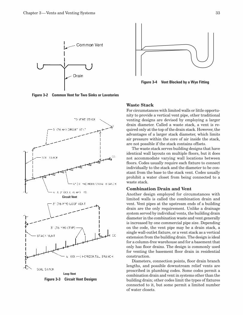
Chapter 3 — Vents and Venting Systems 33
Waste StackFor circumstances with limited walls or little opportu-nity to provide a vertical vent pipe, other traditional venting designs are devised by employing a larger drain diameter. Called a waste stack, a vent is re-quired only at the top of the drain stack. However, the advantages of a larger stack diameter, which limits air pressure within the core of air inside the stack, are not possible if the stack contains offsets.
The waste stack serves building designs that have identical wall layouts on multiple floors, but it does not accommodate varying wall locations between floors. Codes usually require each fixture to connect individually to the stack and the diameter to be con-stant from the base to the stack vent. Codes usually prohibit a water closet from being connected to a waste stack.
Combination Drain and VentAnother design employed for circumstances with limited walls is called the combination drain and vent. Vent pipes at the upstream ends of a building drain are the only requirement. Unlike a drainage system served by individual vents, the building drain diameter in the combination waste and vent generally is increased by one commercial pipe size. Depending on the code, the vent pipe may be a drain stack, a single wall-outlet fixture, or a vent stack as a vertical extension from the building drain. The design is ideal for a column-free warehouse and for a basement that only has floor drains. The design is commonly used for venting the basement floor drain in residential construction.
Diameters, connection points, floor drain branch lengths, and possible downstream relief vents are prescribed in plumbing codes. Some codes permit a combination drain and vent in systems other than the building drain; other codes limit the types of fixtures connected to it, but some permit a limited number of water closets.
Figure 3-2 Common Vent for Two Sinks or Lavatories
Figure 3-3 Circuit Vent Designs
Circuit Vent
Loop Vent
Figure 3-4 Vent Blocked by a Wye Fitting
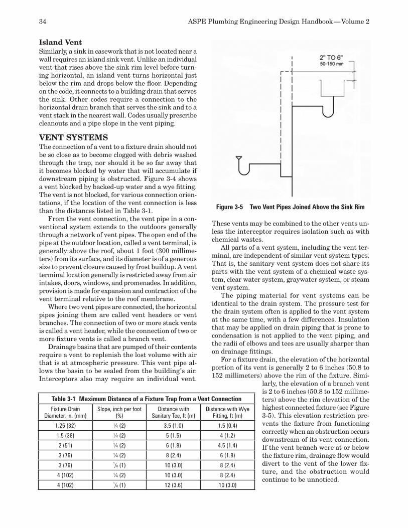
34 ASPE Plumbing Engineering Design Handbook — Volume 2
Island VentSimilarly, a sink in casework that is not located near a wall requires an island sink vent. Unlike an individual vent that rises above the sink rim level before turn-ing horizontal, an island vent turns horizontal just below the rim and drops below the floor. Depending on the code, it connects to a building drain that serves the sink. Other codes require a connection to the horizontal drain branch that serves the sink and to a vent stack in the nearest wall. Codes usually prescribe cleanouts and a pipe slope in the vent piping.
VENT SYSTEMSThe connection of a vent to a fixture drain should not be so close as to become clogged with debris washed through the trap, nor should it be so far away that it becomes blocked by water that will accumulate if downstream piping is obstructed. Figure 3-4 shows a vent blocked by backed-up water and a wye fitting. The vent is not blocked, for various connection orien-tations, if the location of the vent connection is less than the distances listed in Table 3-1.
From the vent connection, the vent pipe in a con-ventional system extends to the outdoors generally through a network of vent pipes. The open end of the pipe at the outdoor location, called a vent terminal, is generally above the roof, about 1 foot (300 millime-ters) from its surface, and its diameter is of a generous size to prevent closure caused by frost buildup. A vent terminal location generally is restricted away from air intakes, doors, windows, and promenades. In addition, provision is made for expansion and contraction of the vent terminal relative to the roof membrane.
Where two vent pipes are connected, the horizontal pipes joining them are called vent headers or vent branches. The connection of two or more stack vents is called a vent header, while the connection of two or more fixture vents is called a branch vent.
Drainage basins that are pumped of their contents require a vent to replenish the lost volume with air that is at atmospheric pressure. This vent pipe al-lows the basin to be sealed from the building’s air. Interceptors also may require an individual vent.
These vents may be combined to the other vents un-less the interceptor requires isolation such as with chemical wastes.
All parts of a vent system, including the vent ter-minal, are independent of similar vent system types. That is, the sanitary vent system does not share its parts with the vent system of a chemical waste sys-tem, clear water system, graywater system, or steam vent system.
The piping material for vent systems can be identical to the drain system. The pressure test for the drain system often is applied to the vent system at the same time, with a few differences. Insulation that may be applied on drain piping that is prone to condensation is not applied to the vent piping, and the radii of elbows and tees are usually sharper than on drainage fittings.
For a fixture drain, the elevation of the horizontal portion of its vent is generally 2 to 6 inches (50.8 to 152 millimeters) above the rim of the fixture. Simi-
larly, the elevation of a branch vent is 2 to 6 inches (50.8 to 152 millime-ters) above the rim elevation of the highest connected fixture (see Figure 3-5). This elevation restriction pre-vents the fixture from functioning correctly when an obstruction occurs downstream of its vent connection. If the vent branch were at or below the fixture rim, drainage flow would divert to the vent of the lower fix-ture, and the obstruction would continue to be unnoticed.
Table 3-1 Maximum Distance of a Fixture Trap from a Vent ConnectionFixture Drain
Diameter, in. (mm)Slope, inch per foot
(%)Distance with
Sanitary Tee, ft (m)Distance with Wye
Fitting, ft (m)
1.25 (32) ¼ (2) 3.5 (1.0) 1.5 (0.4)
1.5 (38) ¼ (2) 5 (1.5) 4 (1.2)
2 (51) ¼ (2) 6 (1.8) 4.5 (1.4)
3 (76) ¼ (2) 8 (2.4) 6 (1.8)
3 (76) 1/8 (1) 10 (3.0) 8 (2.4)
4 (102) ¼ (2) 10 (3.0) 8 (2.4)
4 (102) 1/8 (1) 12 (3.6) 10 (3.0)
Figure 3-5 Two Vent Pipes Joined Above the Sink Rim
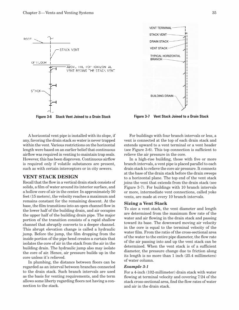
Chapter 3 — Vents and Venting Systems 35
A horizontal vent pipe is installed with its slope, if any, favoring the drain stack so water is never trapped within the vent. Various restrictions on the horizontal length were based on an earlier belief that continuous airflow was required in venting to maintain trap seals. However, this has been disproven. Continuous airflow is required only if volatile substances are present, such as with certain interceptors or in city sewers.
VENT STACK DESIGNRecall that the flow in a vertical drain stack consists of solids, a film of water around its interior surface, and a hollow core of air in the center. In approximately 50 feet (15 meters), the velocity reaches a maximum and remains constant for the remaining descent. At the base, the film transitions into an open channel flow in the lower half of the building drain, and air occupies the upper half of the building drain pipe. The major portion of the transition consists of a rapid shallow channel that abruptly converts to a deeper channel. This abrupt elevation change is called a hydraulic jump. Before the jump, the film dropping from the inside portion of the pipe bend creates a curtain that isolates the core of air in the stack from the air in the building drain. The hydraulic jump also may isolate the core of air. Hence, air pressure builds up in the core unless it’s relieved.
In plumbing, the distance between floors can be regarded as an interval between branches connected to the drain stack. Such branch intervals are used as the basis for venting requirements, and the term allows some liberty regarding floors not having a con-nection to the stack.
For buildings with four branch intervals or less, a vent is connected at the top of each drain stack and extends upward to a vent terminal or a vent header (see Figure 3-6). This top connection is sufficient to relieve the air pressure in the core.
In a high-rise building, those with five or more branch intervals, a vent pipe is placed parallel to each drain stack to relieve the core air pressure. It connects at the base of the drain stack before the drain sweeps to a horizontal plane. The top end of the vent stack joins the vent that extends from the drain stack (see Figure 3-7). For buildings with 10 branch intervals or more, intermediate vent connections, called yoke vents, are made at every 10 branch intervals.
Sizing a Vent StackTo size a vent stack, the vent diameter and length are determined from the maximum flow rate of the water and air flowing in the drain stack and passing toward its base. The downward moving air velocity in the core is equal to the terminal velocity of the water film. From the ratio of the cross-sectional area of the water to the entire pipe diameter, the flow rate of the air passing into and up the vent stack can be determined. When the vent stack is of a sufficient diameter, the pressure change due to friction along its length is no more than 1 inch (25.4 millimeters) of water column.
Example 3-1For a 4-inch (102-millimeter) drain stack with water flowing at terminal velocity and covering 7/24 of the stack cross-sectional area, find the flow rates of water and air in the drain stack.
Figure 3-6 Stack Vent Joined to a Drain Stack Figure 3-7 Vent Stack Joined to a Drain Stack
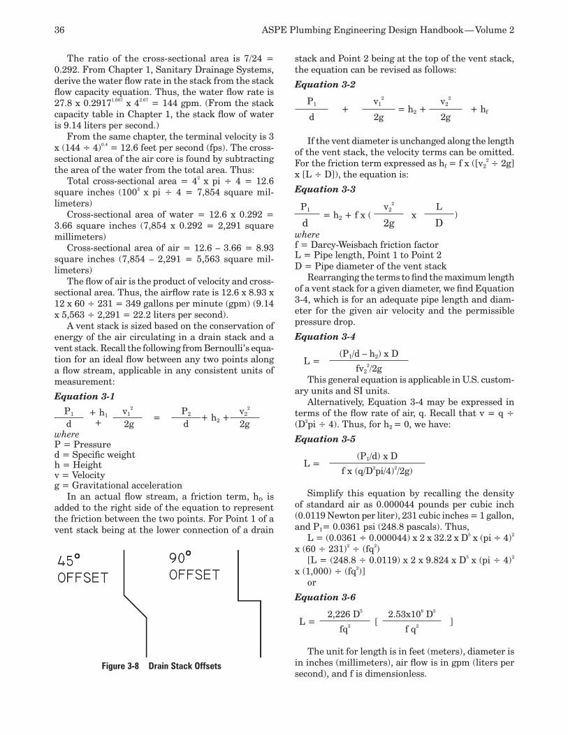
36 ASPE Plumbing Engineering Design Handbook — Volume 2
The ratio of the cross-sectional area is 7/24 = 0.292. From Chapter 1, Sanitary Drainage Systems, derive the water flow rate in the stack from the stack flow capacity equation. Thus, the water flow rate is 27.8 x 0.29171.667 x 42.67 = 144 gpm. (From the stack capacity table in Chapter 1, the stack flow of water is 9.14 liters per second.)
From the same chapter, the terminal velocity is 3 x (144 ÷ 4)0.4 = 12.6 feet per second (fps). The cross-sectional area of the air core is found by subtracting the area of the water from the total area. Thus:
Total cross-sectional area = 42 x pi ÷ 4 = 12.6 square inches (1002 x pi ÷ 4 = 7,854 square mil-limeters)
Cross-sectional area of water = 12.6 x 0.292 = 3.66 square inches (7,854 x 0.292 = 2,291 square millimeters)
Cross-sectional area of air = 12.6 – 3.66 = 8.93 square inches (7,854 – 2,291 = 5,563 square mil-limeters)
The flow of air is the product of velocity and cross-sectional area. Thus, the airflow rate is 12.6 x 8.93 x 12 x 60 ÷ 231 = 349 gallons per minute (gpm) (9.14 x 5,563 ÷ 2,291 = 22.2 liters per second).
A vent stack is sized based on the conservation of energy of the air circulating in a drain stack and a vent stack. Recall the following from Bernoulli’s equa-tion for an ideal flow between any two points along a flow stream, applicable in any consistent units of measurement:
Equation 3-1
P1 + h1 +
v12
=P2 + h2 +
v22
d 2g d 2gwhereP = Pressured = Specific weighth = Heightv = Velocityg = Gravitational acceleration
In an actual flow stream, a friction term, hf, is added to the right side of the equation to represent the friction between the two points. For Point 1 of a vent stack being at the lower connection of a drain
stack and Point 2 being at the top of the vent stack, the equation can be revised as follows:
Equation 3-2
P1+
v12
= h2 +v2
2
+ hfd 2g 2g
If the vent diameter is unchanged along the length of the vent stack, the velocity terms can be omitted. For the friction term expressed as hf = f x ([v2
2 ÷ 2g] x [L ÷ D]), the equation is:
Equation 3-3
P1= h2 + f x (
v22
xL
)d 2g D
wheref = Darcy-Weisbach friction factorL = Pipe length, Point 1 to Point 2D = Pipe diameter of the vent stack
Rearranging the terms to find the maximum length of a vent stack for a given diameter, we find Equation 3-4, which is for an adequate pipe length and diam-eter for the given air velocity and the permissible pressure drop.
Equation 3-4
L =(P1/d – h2) x D
fv22/2g
This general equation is applicable in U.S. custom-ary units and SI units.
Alternatively, Equation 3-4 may be expressed in terms of the flow rate of air, q. Recall that v = q ÷ (D2pi ÷ 4). Thus, for h2 = 0, we have:
Equation 3-5
L =(P1/d) x D
f x (q/D2pi/4)2/2g)
Simplify this equation by recalling the density of standard air as 0.000044 pounds per cubic inch (0.0119 Newton per liter), 231 cubic inches = 1 gallon, and P1= 0.0361 psi (248.8 pascals). Thus,
L = (0.0361 ÷ 0.000044) x 2 x 32.2 x D5 x (pi ÷ 4)2 x (60 ÷ 231)2 ÷ (fq2)
[L = (248.8 ÷ 0.0119) x 2 x 9.824 x D5 x (pi ÷ 4)2 x (1,000) ÷ (fq2)]
or
Equation 3-6
L =2,226 D5
[2.53x10⁸ D5
]fq2 f q2
The unit for length is in feet (meters), diameter is in inches (millimeters), air flow is in gpm (liters per second), and f is dimensionless.
Figure 3-8 Drain Stack Offsets
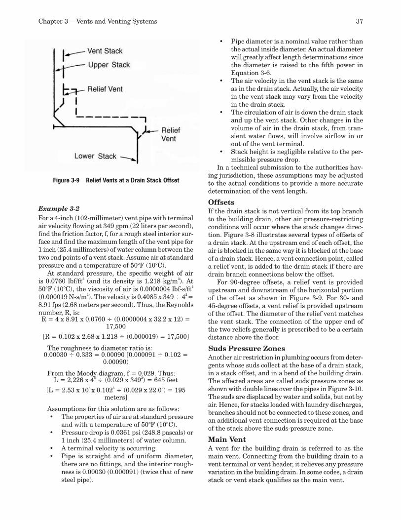
Chapter 3 — Vents and Venting Systems 37
Example 3-2For a 4-inch (102-millimeter) vent pipe with terminal air velocity flowing at 349 gpm (22 liters per second), find the friction factor, f, for a rough steel interior sur-face and find the maximum length of the vent pipe for 1 inch (25.4 millimeters) of water column between the two end points of a vent stack. Assume air at standard pressure and a temperature of 50°F (10°C).
At standard pressure, the specific weight of air is 0.0760 lbf/ft3 (and its density is 1.218 kg/m3). At 50°F (10°C), the viscosity of air is 0.0000004 lbf-s/ft2 (0.000019 N-s/m2). The velocity is 0.4085 x 349 ÷ 42 = 8.91 fps (2.68 meters per second). Thus, the Reynolds number, R, is: R = 4 x 8.91 x 0.0760 ÷ (0.0000004 x 32.2 x 12) =
17,500
[R = 0.102 x 2.68 x 1.218 ÷ (0.000019) = 17,500]
The roughness to diameter ratio is: 0.00030 ÷ 0.333 = 0.00090 [0.000091 ÷ 0.102 =
0.00090)
From the Moody diagram, f = 0.029. Thus:L = 2,226 x 45 ÷ (0.029 x 3492) = 645 feet
[L = 2.53 x 108 x 0.1025 ÷ (0.029 x 22.02) = 195 meters]
Assumptions for this solution are as follows:The properties of air are at standard pressure •and with a temperature of 50°F (10°C).Pressure drop is 0.0361 psi (248.8 pascals) or •1 inch (25.4 millimeters) of water column.A terminal velocity is occurring.•Pipe is straight and of uniform diameter, •there are no fittings, and the interior rough-ness is 0.00030 (0.000091) (twice that of new steel pipe).
Pipe diameter is a nominal value rather than •the actual inside diameter. An actual diameter will greatly affect length determinations since the diameter is raised to the fifth power in Equation 3-6.The air velocity in the vent stack is the same •as in the drain stack. Actually, the air velocity in the vent stack may vary from the velocity in the drain stack. The circulation of air is down the drain stack •and up the vent stack. Other changes in the volume of air in the drain stack, from tran-sient water flows, will involve airflow in or out of the vent terminal.Stack height is negligible relative to the per-•missible pressure drop.
In a technical submission to the authorities hav-ing jurisdiction, these assumptions may be adjusted to the actual conditions to provide a more accurate determination of the vent length.
OffsetsIf the drain stack is not vertical from its top branch to the building drain, other air pressure-restricting conditions will occur where the stack changes direc-tion. Figure 3-8 illustrates several types of offsets of a drain stack. At the upstream end of each offset, the air is blocked in the same way it is blocked at the base of a drain stack. Hence, a vent connection point, called a relief vent, is added to the drain stack if there are drain branch connections below the offset.
For 90-degree offsets, a relief vent is provided upstream and downstream of the horizontal portion of the offset as shown in Figure 3-9. For 30- and 45-degree offsets, a vent relief is provided upstream of the offset. The diameter of the relief vent matches the vent stack. The connection of the upper end of the two reliefs generally is prescribed to be a certain distance above the floor.
Suds Pressure zonesAnother air restriction in plumbing occurs from deter-gents whose suds collect at the base of a drain stack, in a stack offset, and in a bend of the building drain. The affected areas are called suds pressure zones as shown with double lines over the pipes in Figure 3-10. The suds are displaced by water and solids, but not by air. Hence, for stacks loaded with laundry discharges, branches should not be connected to these zones, and an additional vent connection is required at the base of the stack above the suds-pressure zone.
Main VentA vent for the building drain is referred to as the main vent. Connecting from the building drain to a vent terminal or vent header, it relieves any pressure variation in the building drain. In some codes, a drain stack or vent stack qualifies as the main vent.
Figure 3-9 Relief Vents at a Drain Stack Offset
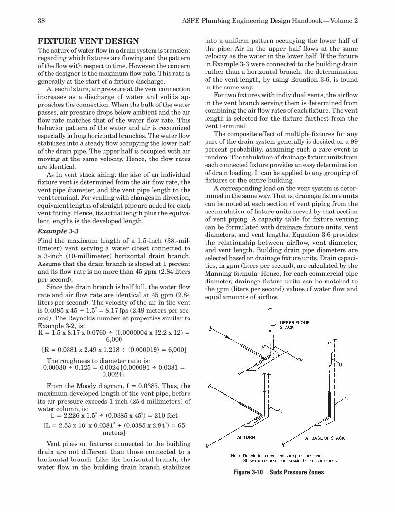
38 ASPE Plumbing Engineering Design Handbook — Volume 2
FIXTURE VENT DESIGNThe nature of water flow in a drain system is transient regarding which fixtures are flowing and the pattern of the flow with respect to time. However, the concern of the designer is the maximum flow rate. This rate is generally at the start of a fixture discharge.
At each fixture, air pressure at the vent connection increases as a discharge of water and solids ap-proaches the connection. When the bulk of the water passes, air pressure drops below ambient and the air flow rate matches that of the water flow rate. This behavior pattern of the water and air is recognized especially in long horizontal branches. The water flow stabilizes into a steady flow occupying the lower half of the drain pipe. The upper half is occupied with air moving at the same velocity. Hence, the flow rates are identical.
As in vent stack sizing, the size of an individual fixture vent is determined from the air flow rate, the vent pipe diameter, and the vent pipe length to the vent terminal. For venting with changes in direction, equivalent lengths of straight pipe are added for each vent fitting. Hence, its actual length plus the equiva-lent lengths is the developed length.
Example 3-3Find the maximum length of a 1.5-inch (38.-mil-limeter) vent serving a water closet connected to a 3-inch (10-millimeter) horizontal drain branch. Assume that the drain branch is sloped at 1 percent and its flow rate is no more than 45 gpm (2.84 liters per second).
Since the drain branch is half full, the water flow rate and air flow rate are identical at 45 gpm (2.84 liters per second). The velocity of the air in the vent is 0.4085 x 45 ÷ 1.52 = 8.17 fps (2.49 meters per sec-ond). The Reynolds number, at properties similar to Example 3-2, is:R = 1.5 x 8.17 x 0.0760 ÷ (0.0000004 x 32.2 x 12) =
6,000
[R = 0.0381 x 2.49 x 1.218 ÷ (0.000019) = 6,000]
The roughness to diameter ratio is: 0.00030 ÷ 0.125 = 0.0024 [0.000091 ÷ 0.0381 =
0.0024].
From the Moody diagram, f = 0.0385. Thus, the maximum developed length of the vent pipe, before its air pressure exceeds 1 inch (25.4 millimeters) of water column, is:
L = 2,226 x 1.55 ÷ (0.0385 x 452) = 210 feet
[L = 2.53 x 108 x 0.03815 ÷ (0.0385 x 2.842) = 65 meters]
Vent pipes on fixtures connected to the building drain are not different than those connected to a horizontal branch. Like the horizontal branch, the water flow in the building drain branch stabilizes
into a uniform pattern occupying the lower half of the pipe. Air in the upper half flows at the same velocity as the water in the lower half. If the fixture in Example 3-3 were connected to the building drain rather than a horizontal branch, the determination of the vent length, by using Equation 3-6, is found in the same way.
For two fixtures with individual vents, the airflow in the vent branch serving them is determined from combining the air flow rates of each fixture. The vent length is selected for the fixture furthest from the vent terminal.
The composite effect of multiple fixtures for any part of the drain system generally is decided on a 99 percent probability, assuming such a rare event is random. The tabulation of drainage fixture units from each connected fixture provides an easy determination of drain loading. It can be applied to any grouping of fixtures or the entire building.
A corresponding load on the vent system is deter-mined in the same way. That is, drainage fixture units can be noted at each section of vent piping from the accumulation of fixture units served by that section of vent piping. A capacity table for fixture venting can be formulated with drainage fixture units, vent diameters, and vent lengths. Equation 3-6 provides the relationship between airflow, vent diameter, and vent length. Building drain pipe diameters are selected based on drainage fixture units. Drain capaci-ties, in gpm (liters per second), are calculated by the Manning formula. Hence, for each commercial pipe diameter, drainage fixture units can be matched to the gpm (liters per second) values of water flow and equal amounts of airflow.
Figure 3-10 Suds Pressure Zones
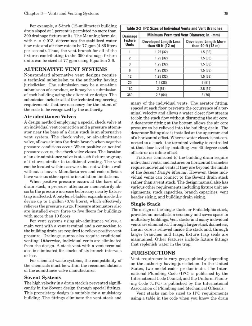
Chapter 3 — Vents and Venting Systems 39
For example, a 5-inch (12-millimeter) building drain sloped at 1 percent is permitted no more than 390 drainage fixture units. The Manning formula, with n = 0.013, determines the stabilized water flow rate and air flow rate to be 77 gpm (4.86 liters per second). Thus, the vent branch for all of the fixtures contributing to the 390 drainage fixture units can be sized at 77 gpm using Equation 3-6.
ALTERNATIVE VENT SYSTEMSNonstandard alternative vent designs require a technical submission to the authority having jurisdiction. The submission may be a one-time submission of a product, or it may be a submission of each building using the alternative design. The submission includes all of the technical engineering requirements that are necessary for the intent of the code to be recognized by the authority.
Air-admittance ValvesA design method employing a special check valve at an individual vent connection and a pressure attenu-ator near the base of a drain stack is an alternative vent system. The check valve, or air-admittance valve, allows air into the drain branch when negative pressure conditions occur. When positive or neutral pressure occurs, the check valve closes. The location of an air-admittance valve is at each fixture or group of fixtures, similar to traditional venting. The vent can be located within casework but not within a wall without a louver. Manufacturers and code officials have various other specific installation limitations.
When positive pressure occurs at the base of a drain stack, a pressure attenuator momentarily ab-sorbs the pressure increase before any nearby fixture trap is affected. A butylene bladder expands inside the device up to 1 gallon (3.78 liters), which effectively relieves the pressure surge. Pressure attenuators also are installed every three to five floors for buildings with more than 10 floors.
For vent systems using air-admittance valves, a main vent with a vent terminal and a connection to the building drain are required to relieve positive vent pressure. Drainage sumps also require traditional venting. Otherwise, individual vents are eliminated from the design. A stack vent with a vent terminal also is eliminated for stacks of six branch intervals or less.
For chemical waste systems, the compatibility of the chemicals must be within the recommendations of the admittance valve manufacturer.
Sovent SystemsThe high velocity in a drain stack is prevented signifi-cantly in the Sovent design through special fittings. This proprietary design is suitable for a multistory building. The fittings eliminate the vent stack and
many of the individual vents. The aerator fitting, spaced at each floor, prevents the occurrence of a ter-minal velocity and allows a water closet flow stream to join the stack flow without disrupting the air core. A deaerator fitting at the bottom allows the air core pressure to be relieved into the building drain. The deaerator fitting also is installed at the upstream end of a horizontal offset. Where a water closet is not con-nected to a stack, the terminal velocity is controlled at that floor level by installing two 45-degree stack offsets or an inline offset.
Fixtures connected to the building drain require individual vents, and fixtures on horizontal branches require individual vents if they are beyond the limits of the Sovent Design Manual. However, these indi-vidual vents can connect to the Sovent drain stack rather than a vent stack. The design manual also has various other requirements including fixture unit as-signments, stack capacities, branch capacities, vent header sizing, and building drain sizing.
Single StackThe design of the single stack, or Philadelphia stack, provides an installation economy and saves space in multistory buildings. Vent stacks and many individual vents are eliminated. Through larger stack diameters, the air core is relieved inside the stack and, through larger branches and traps, fixture trap seals are maintained. Other features include fixture fittings that replenish water in the trap.
JURISDICTIONSVent requirements vary geographically depending on the authority having jurisdiction. In the United States, two model codes predominate. The Inter-national Plumbing Code (IPC) is published by the International Code Council, and the Uniform Plumb-ing Code (UPC) is published by the International Association of Plumbing and Mechanical Officials.
Vent stacks can be sized to IPC requirements using a table in the code when you know the drain
Table 3-2 IPC Sizes of Individual Vents and Vent Branches
Drainage Fixture Units
Minimum Permitted Vent Diameter, in. (mm)
Developed Length Less than 40 ft (12 m)
Developed Length More than 40 ft (12 m)
1 1.25 (32) 1.5 (38)
2 1.25 (32) 1.5 (38)
3 1.25 (32) 1.5 (38)
6 1.25 (32) 1.5 (38)
12 1.25 (32) 1.5 (38)
20 1.5 (38) 2 (51)
160 2 (51) 2.5 (64)
360 2.5 (64) 3 (76)
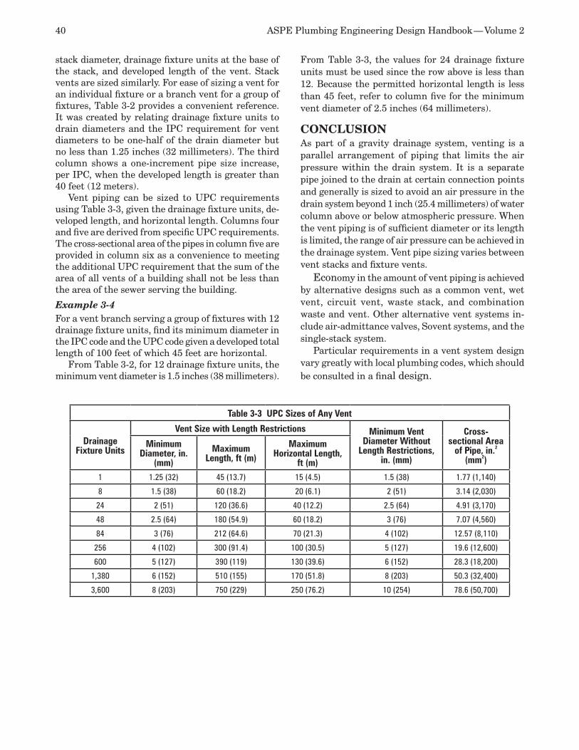
40 ASPE Plumbing Engineering Design Handbook — Volume 2
stack diameter, drainage fixture units at the base of the stack, and developed length of the vent. Stack vents are sized similarly. For ease of sizing a vent for an individual fixture or a branch vent for a group of fixtures, Table 3-2 provides a convenient reference. It was created by relating drainage fixture units to drain diameters and the IPC requirement for vent diameters to be one-half of the drain diameter but no less than 1.25 inches (32 millimeters). The third column shows a one-increment pipe size increase, per IPC, when the developed length is greater than 40 feet (12 meters).
Vent piping can be sized to UPC requirements using Table 3-3, given the drainage fixture units, de-veloped length, and horizontal length. Columns four and five are derived from specific UPC requirements. The cross-sectional area of the pipes in column five are provided in column six as a convenience to meeting the additional UPC requirement that the sum of the area of all vents of a building shall not be less than the area of the sewer serving the building.
Example 3-4For a vent branch serving a group of fixtures with 12 drainage fixture units, find its minimum diameter in the IPC code and the UPC code given a developed total length of 100 feet of which 45 feet are horizontal.
From Table 3-2, for 12 drainage fixture units, the minimum vent diameter is 1.5 inches (38 millimeters).
From Table 3-3, the values for 24 drainage fixture units must be used since the row above is less than 12. Because the permitted horizontal length is less than 45 feet, refer to column five for the minimum vent diameter of 2.5 inches (64 millimeters).
CONCLUSIONAs part of a gravity drainage system, venting is a parallel arrangement of piping that limits the air pressure within the drain system. It is a separate pipe joined to the drain at certain connection points and generally is sized to avoid an air pressure in the drain system beyond 1 inch (25.4 millimeters) of water column above or below atmospheric pressure. When the vent piping is of sufficient diameter or its length is limited, the range of air pressure can be achieved in the drainage system. Vent pipe sizing varies between vent stacks and fixture vents.
Economy in the amount of vent piping is achieved by alternative designs such as a common vent, wet vent, circuit vent, waste stack, and combination waste and vent. Other alternative vent systems in-clude air-admittance valves, Sovent systems, and the single-stack system.
Particular requirements in a vent system design vary greatly with local plumbing codes, which should be consulted in a final design.
Table 3-3 UPC Sizes of Any Vent
Drainage Fixture Units
Vent Size with Length Restrictions Minimum Vent Diameter Without
Length Restrictions, in. (mm)
Cross-sectional Area
of Pipe, in.2 (mm2)
Minimum Diameter, in.
(mm)Maximum
Length, ft (m)Maximum
Horizontal Length, ft (m)
1 1.25 (32) 45 (13.7) 15 (4.5) 1.5 (38) 1.77 (1,140)
8 1.5 (38) 60 (18.2) 20 (6.1) 2 (51) 3.14 (2,030)
24 2 (51) 120 (36.6) 40 (12.2) 2.5 (64) 4.91 (3,170)
48 2.5 (64) 180 (54.9) 60 (18.2) 3 (76) 7.07 (4,560)
84 3 (76) 212 (64.6) 70 (21.3) 4 (102) 12.57 (8,110)
256 4 (102) 300 (91.4) 100 (30.5) 5 (127) 19.6 (12,600)
600 5 (127) 390 (119) 130 (39.6) 6 (152) 28.3 (18,200)
1,380 6 (152) 510 (155) 170 (51.8) 8 (203) 50.3 (32,400)
3,600 8 (203) 750 (229) 250 (76.2) 10 (254) 78.6 (50,700)
Storm Drainage Systems4
Storm water systems may convey rainwater from building roof drains, area drains, subsoil drains, and foundation drains to a point of discharge, sub-surface dispersal, or reuse. Some jurisdictions allow (or require) the discharge from clear water drainage systems to be included in the storm water system. These discharges should not include contaminants that exceed applicable ground or surface water stan-dards established by the authority having jurisdiction (AHJ).
Building sites may be provided with conveyance piping for draining paved areas, parking lots, veg-etated areas, and all other areas where the storm water could damage a structure or present a health or safety hazard to the public.
Storm water subsurface dispersal is controlled to protect groundwater quality and sometimes to en-hance groundwater quantity (aquifer recharge).
The Clean Water Act, implemented by the U.S. Environmental Protection Agency (EPA), impacts construction site owners where one or more acres of land are disturbed during a construction project or where the land disturbance is part of a common plan of development. These owners are required to file a Notice of Intent to obtain a National Pollutant Discharge Elimination System (NPDES) permit prior to land disturbance. The NPDES permit includes the erosion control requirements to be used during the construction phase until final stabilization of the building is achieved. During the construction period, all storm water inlets are protected from construction site sediment.
The NPDES permit language includes a re-quirement for a post-construction storm water management plan. The plan must address the control of overland runoff from the site and of storm water within the storm water conveyance and infiltration systems (as these systems also provide a means for the storm water to exit the property). Some AHJs require a system to be provided to safely pass the 100-year, 24-hour storm, so the plumbing engineer must verify and review any local requirements during the design
phase of the project. For more information on the NPDES system and the Clean Water Act, contact the AHJ or visit the EPA websites (cfpub.epa.gov/npdes and epa.gov/watertrain/cwa).
The AHJ also regulates the discharge point (municipal sewer, combined sewer, ground surface, subsurface, etc.) for storm water systems. Storm water systems may be designed for gravity flow to a point of discharge. Where this is not possible, elevat-ing the storm water for discharge (using a pump, ejector, etc.), on-site infiltration, or storm water har-vesting may be considered. Depending on the AHJ’s requirements, a redundant (or backup) pump system may be mandatory. Some AHJs allow depressed areas on the site where the storm water is collected and al-lowed to remain until evaporation, transpiration, or infiltration allows the storm water to disperse into the environment. Detention basins, tanks, roof systems, or piping also are used to store rainfall and release the storm water over a designed period. Frequently these releases are required to replicate the hydrograph for the pre-construction site.
CODES AND STANDARDSStorm water system design is one area of plumbing en-gineering that relies on several different types of laws, codes, and standards. The environmental protection laws establish authority for groundwater and surface water protection. Environmental agencies regulate watersheds based on specific local conditions. Local ordinances and the design of the municipal sewer, as well as approved management plans, may impact storm water designs. Building codes and the architec-tural design of the structure are limiting factors in the storm water design. The plumbing engineer is part of a design team that uses all of the codes and standards to comply with site-specific conditions and rules.
The model plumbing codes establish a minimum acceptable standard for the design and installation of storm water systems. Some states and large cities have adopted plumbing codes other than those usu-ally associated with the region, and because of this

42 ASPE Plumbing Engineering Design Handbook — Volume 2
lack of standardization, the actual plumbing code used for each specific project must be obtained from the AHJ.
The applicable local codes, ordinances, and laws are the primary sources used for the storm water de-sign. The tables and charts appearing in this chapter are used only to illustrate and augment this discus-sion and may not be appropriate for actual design purposes.
MATERIALS Materials include piping, fittings, bedding, supports and hangers, fixtures, and treatment devices. Materi-als must be acceptable to the AHJ.
While creating the material specifications, re-search and follow all manufacturer requirements and limitations. Exposed leaders or downspouts should be capable of withstanding all anticipated abuses, corrosion, weather, and expected expansion and contraction.
See other Plumbing Engineering Design Handbook chapters on materials and joining methods for more information.
SITE DRAINAGE AND INFILTRATIONIn the past, one of the basic plumbing principles required system designs to conduct storm water quickly from the site inlet to the point of discharge. However, that principle does not adequately address current storm water issues. Codes are being revised to change the drain system requirement from “quickly” to “efficiently.”
The plumbing engineer’s involvement with storm water management has been expanded to address the evaluation of the precipitation and runoff from the site. Thus, to design infiltration, detention, or small-diameter piping systems, the science of hydrology and the calculation of runoff for each particular site are necessary considerations.
The hydrology of a storm event is the basis for all storm system designs including pipe sizing, treatment devices and methods, detention systems, infiltration systems, and every combination imaginable. Web-ster’s defines hydrology as “a science dealing with the properties, distribution, and circulation of water.” The hydrology of a storm event limits this study to a particular precipitation event and the fate of the water that falls during that event.
All methods used to determine volumes and peak flows use historical data. Such precipitation and frequency information can be found on the National Oceanic and Atmospheric Administration’s National Weather Service website (nws.noaa.gov).
Rainfalls and snowstorms occur as a series of events that have characteristics including rainfall
amount, intensity, and duration. To design a storm water system, a particular storm event must be cho-sen. This is known as the design storm. Fortunately, most plumbing codes provide pipe sizing charts based on geographic area and time of concentration, so the designer does not need to calculate the peak flow rate. However, infiltration and reuse systems require the volume of the storm event to be determined.
When no typical conditions exist, a design fre-quency of 10 years typically is used for an average site. For the purpose of system design, when recom-mending a 10-year storm, it’s necessary to also specify the duration of the storm. For example, an intensity-duration-frequency curve for Madison, Wisconsin, may show that a 10-year, 60-minute storm has a rainfall intensity of 2 inches per hour. In the same city, a 10-year, 15-minute storm has a rainfall intensity of approximately 4 inches per hour. For small sites, this is probably a logical number for estimation, as the time of concentration for a small site may be 10 to 20 minutes. However, many design manuals recommend a smaller time of concentration for small sites, such as 5 minutes.
Different design storms also are used for varying situations or purposes. For instance, the Minnesota Urban Small Sites Best Management Practice Manual states that two- and 10-year storms are used for sub-divisions, industrial, and commercial design. One- and two-year storms are used to protect channels from sedimentation and erosion. Five- and 10-year events are used for adequate flow conveyance and minor flooding consideration. The 100-year storm defines the limits and flood plains and is used to consider the impacts of major floods.
Table 4-1 Coefficients for Use with the Rational Method
Type of Surface or Land Use Coefficient of Runoff (c value)
Individual soil coversForest 0.1 – 0.3
Turf or meadow 0.1 – 0.4
Cultivated field 0.3 – 0.4
Steep grassed area (2:1) 0.5 – 0.7
Bare earth 0.2 – 0.9
Gravel or macadam pavement 0.35 – 0.7
Concrete or asphalt pavement 0.8 – 0.9
Composite land usesFlat residential, about 30% impervious 0.40
Flat residential, about 60% impervious 0.55
Sloping residential, about 50% impervious 0.65
Flat commercial, about 90% impervious 0.80

Chapter 4 — Storm Drainage Systems 43
The Rational MethodMany jurisdictions accept the Rational Method for calculating peak flow rates. The Rational Method was developed to identify peak flow for pipe and culvert sizing. It translates peak intensity of rainfall directly into peak intensity of runoff. When using the Ratio-nal Method for pipe sizing on small sites, the time of concentration should equal the intensity, as those parameters create the highest peak flow rate.
For a small site, a rate in cubic feet per second (cfs) can be calculated once the intensity is entered into the Rational Method formula.
The Rational Method is illustrated in Equation 4-1.
Equation 4-1Q = Aci
whereQ = Runoff, cfsA = Drainage area, acres (1 acre = 43,560 square
feet)c = Coefficient of runoff, a dimensionless numberi = Rainfall intensity, inches per hour
(There’s a hidden correction factor of 1.008 cfs per a-in./hr.)
Example 4-1As an example, consider a 1.5-acre site with a concrete or pavement cover (0.90 runoff coefficient) and a 4-inches/hour rainfall. The equation would be:Q = 1.5 x 0.90 x 4 = 5.4 cfs (448.8 x 5.4 = 2,423.5
gallons per minute [gpm])
The Rational Method provides a peak flow rate. Using it, a designer can size a piping system to safely carry the peak flow to a treatment device or to a point of dispersal or discharge. The Rational Method was not intended to be used to calculate volume, so it does not provide any information for the designer of a detention or infiltration system.
Runoff PatternsThe runoff coefficient, or c value, can be found in the applicable local code or design manual. Table 4-1 is an example of such a table.
Figure 4-1 illustrates two hydrographs. One shows the runoff pattern prior to construction, and the other shows the runoff pattern after development on the same site. It’s evident that the flow rate increases and decreases more quickly in areas that have been developed. It’s also evident in Figure 4-1 that the peak flows are higher in a developed area than in predevelopment conditions.
Typically, these changes in hydrology affect the local environment in the following ways:
The frequency and severity of flooding in-•creases because peak flows are two to five times higher than before development.
Nearby streams become “flashy,” or tend to •flash flood because high flows occur quickly and affect stream levels.Base flow is reduced because the infiltration •of storm water into shallow aquifers that provide the dry period feed for small streams is reduced. Streams that once flowed year-round disappear.
Flooding occurs downstream at higher elevations than prior to urbanization. Under normal conditions, a stream develops a channel to accommodate a two-year storm (a storm that usually occurs no more than once every two years). Development along the stream increases impervious area and runoff. As peak flows increase, the banks of the stream widen.
Storm Water QualityImpervious areas such as roofs, parking lots, and roads accumulate contaminants from vehicles, the atmosphere, and animals. Rainfall washes these con-taminants from the impervious surface and deposits them into the groundwater, surface water, or soil unless a treatment device is used.
Table 4-2 lists common urban contaminant levels in runoff. The runoff in a specific geographical area is affected by building patterns, salt or sand usage on roads and sidewalks, traffic, land use, building materials (such as lead flashings, galvanized roofs, or galvanized gutters and downspouts), and connected imperviousness. For example, Table 4-3 contains mean values that are specific to the state of Wisconsin.
As illustrated by Tables 4-2 and 4-3, the number of bacteria in storm water is lower than the number in domestic wastewater. However, storm water does contain pathogenic (disease-causing) bacteria such as Shigella (causes bacillary dysentery), Pseudomo-nas aeruginosa (causes swimmer’s ear and skin infections), and pathogenic E. coli. Viruses also can travel in storm water runoff. In fact, according to Groundwater Contamination from Storm Water In-filtration, viruses have been found in groundwater below infiltration ponds where no indicator bacteria are present.
Figure 4-1 Pre- and Post-construction Hydrographs
Post-construction
Pre-constructionFlow Rate
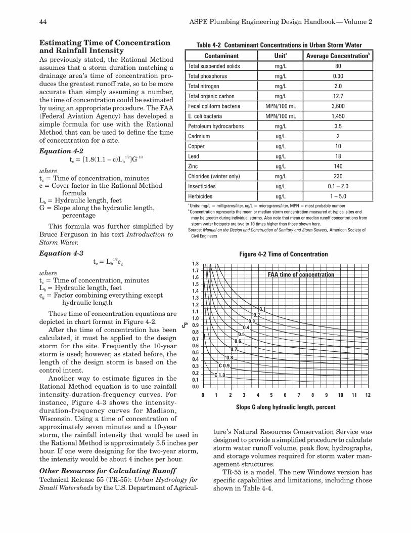
44 ASPE Plumbing Engineering Design Handbook — Volume 2
Estimating Time of Concentration and Rainfall IntensityAs previously stated, the Rational Method assumes that a storm duration matching a drainage area’s time of concentration pro-duces the greatest runoff rate, so to be more accurate than simply assuming a number, the time of concentration could be estimated by using an appropriate procedure. The FAA (Federal Aviation Agency) has developed a simple formula for use with the Rational Method that can be used to define the time of concentration for a site.
Equation 4-2tc = [1.8(1.1 – c)Lh
1/2]G-1/3
wheretc = Time of concentration, minutes c = Cover factor in the Rational Method
formulaLh = Hydraulic length, feetG = Slope along the hydraulic length,
percentage
This formula was further simplified by Bruce Ferguson in his text Introduction to Storm Water.
Equation 4-3tc = Lh
1/2cg
wheretc = Time of concentration, minutesLh = Hydraulic length, feetcg = Factor combining everything except
hydraulic length
These time of concentration equations are depicted in chart format in Figure 4-2.
After the time of concentration has been calculated, it must be applied to the design storm for the site. Frequently the 10-year storm is used; however, as stated before, the length of the design storm is based on the control intent.
Another way to estimate figures in the Rational Method equation is to use rainfall intensity-duration-frequency curves. For instance, Figure 4-3 shows the intensity-duration-frequency curves for Madison, Wisconsin. Using a time of concentration of approximately seven minutes and a 10-year storm, the rainfall intensity that would be used in the Rational Method is approximately 5.5 inches per hour. If one were designing for the two-year storm, the intensity would be about 4 inches per hour.
Other Resources for Calculating RunoffTechnical Release 55 (TR-55): Urban Hydrology for Small Watersheds by the U.S. Department of Agricul-
ture’s Natural Resources Conservation Service was designed to provide a simplified procedure to calculate storm water runoff volume, peak flow, hydrographs, and storage volumes required for storm water man-agement structures.
TR-55 is a model. The new Windows version has specific capabilities and limitations, including those shown in Table 4-4.
Table 4-2 Contaminant Concentrations in Urban Storm Water
Contaminant Unita Average Concentrationb
Total suspended solids mg/L 80
Total phosphorus mg/L 0.30
Total nitrogen mg/L 2.0
Total organic carbon mg/L 12.7
Fecal coliform bacteria MPN/100 mL 3,600
E. coli bacteria MPN/100 mL 1,450
Petroleum hydrocarbons mg/L 3.5
Cadmium ug/L 2
Copper ug/L 10
Lead ug/L 18
Zinc ug/L 140
Chlorides (winter only) mg/L 230
Insecticides ug/L 0.1 – 2.0
Herbicides ug/L 1 – 5.0a Units: mg/L = milligrams/liter, ug/L = micrograms/liter, MPN = most probable numberb Concentration represents the mean or median storm concentration measured at typical sites and
may be greater during individual storms. Also note that mean or median runoff concentrations from storm water hotspots are two to 10 times higher than those shown here.
Source: Manual on the Design and Construction of Sanitary and Storm Sewers, American Society of Civil Engineers
0 1 2 3 4 5 6 7 8 9 10 11 12
1.81.71.61.51.41.31.21.11.00.90.80.70.60.50.40.30.20.10.0
Slope G along hydraulic length, percent
c g
0.10.2
0.30.4
0.50.6
0.7
0.8
C 0.9
C 1.0
FAA time of concentration
Figure 4-2 Time of Concentration
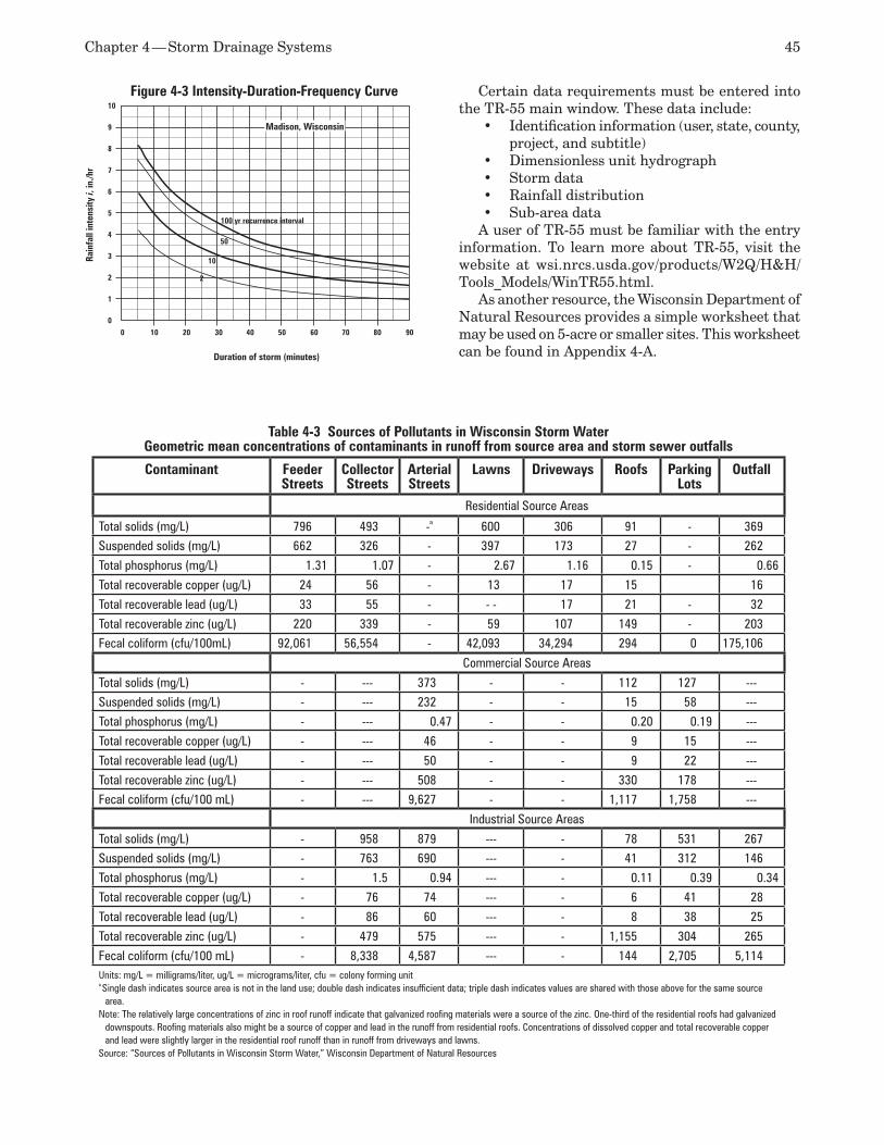
Chapter 4 — Storm Drainage Systems 45
Certain data requirements must be entered into the TR-55 main window. These data include:
Identification information (user, state, county, •project, and subtitle)Dimensionless unit hydrograph•Storm data•Rainfall distribution•Sub-area data•
A user of TR-55 must be familiar with the entry information. To learn more about TR-55, visit the website at wsi.nrcs.usda.gov/products/W2Q/H&H/Tools_Models/WinTR55.html.
As another resource, the Wisconsin Department of Natural Resources provides a simple worksheet that may be used on 5-acre or smaller sites. This worksheet can be found in Appendix 4-A.
Table 4-3 Sources of Pollutants in Wisconsin Storm WaterGeometric mean concentrations of contaminants in runoff from source area and storm sewer outfalls
Contaminant Feeder Streets
Collector Streets
Arterial Streets
Lawns Driveways Roofs Parking Lots
Outfall
Residential Source Areas
Total solids (mg/L) 796 493 -a 600 306 91 - 369Suspended solids (mg/L) 662 326 - 397 173 27 - 262
Total phosphorus (mg/L) 1.31 1.07 - 2.67 1.16 0.15 - 0.66
Total recoverable copper (ug/L) 24 56 - 13 17 15 16
Total recoverable lead (ug/L) 33 55 - - - 17 21 - 32
Total recoverable zinc (ug/L) 220 339 - 59 107 149 - 203Fecal coliform (cfu/100mL) 92,061 56,554 - 42,093 34,294 294 0 175,106
Commercial Source Areas
Total solids (mg/L) - --- 373 - - 112 127 ---Suspended solids (mg/L) - --- 232 - - 15 58 ---
Total phosphorus (mg/L) - --- 0.47 - - 0.20 0.19 ---
Total recoverable copper (ug/L) - --- 46 - - 9 15 ---
Total recoverable lead (ug/L) - --- 50 - - 9 22 ---
Total recoverable zinc (ug/L) - --- 508 - - 330 178 ---Fecal coliform (cfu/100 mL) - --- 9,627 - - 1,117 1,758 ---
Industrial Source Areas
Total solids (mg/L) - 958 879 --- - 78 531 267Suspended solids (mg/L) - 763 690 --- - 41 312 146
Total phosphorus (mg/L) - 1.5 0.94 --- - 0.11 0.39 0.34
Total recoverable copper (ug/L) - 76 74 --- - 6 41 28
Total recoverable lead (ug/L) - 86 60 --- - 8 38 25
Total recoverable zinc (ug/L) - 479 575 --- - 1,155 304 265
Fecal coliform (cfu/100 mL) - 8,338 4,587 --- - 144 2,705 5,114Units: mg/L = milligrams/liter, ug/L = micrograms/liter, cfu = colony forming unita Single dash indicates source area is not in the land use; double dash indicates insufficient data; triple dash indicates values are shared with those above for the same source
area. Note: The relatively large concentrations of zinc in roof runoff indicate that galvanized roofing materials were a source of the zinc. One-third of the residential roofs had galvanized
downspouts. Roofing materials also might be a source of copper and lead in the runoff from residential roofs. Concentrations of dissolved copper and total recoverable copper and lead were slightly larger in the residential roof runoff than in runoff from driveways and lawns.
Source: “Sources of Pollutants in Wisconsin Storm Water,” Wisconsin Department of Natural Resources
Duration of storm (minutes)
Rain
fall
inte
nsity
i, in
./hr
0 10 20 30 40 50 60 70 80 90
10
9
8
7
6
5
4
3
2
1
0
100 yr recurrence interval
50
10
2
Madison, Wisconsin
Figure 4-3 Intensity-Duration-Frequency Curve
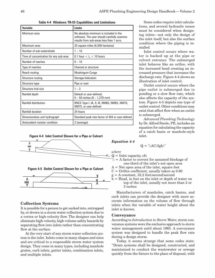
46 ASPE Plumbing Engineering Design Handbook — Volume 2
Collection SystemsIt is possible for a person to get sucked into, entrapped by, or drown in a storm water collection system due to a vortex or high-velocity flow. The designer can help eliminate high-velocity, high-volume safety hazards by separating flow into inlets rather than concentrating flow at the surface.
At the very start of any storm water collection sys-tem is the inlet. Inlets come in many shapes and sizes and are critical to a responsible storm water system design. They come in many types, including manhole grates, curb inlets, gutter inlets, combination inlets, and multiple inlets.
Some codes require inlet calcula-tions, and several hydraulic issues must be considered when design-ing inlets—not only the design of the inlet itself, but also the surface condition where the piping is in-stalled.
Inlet control occurs where wa-ter is backed up at the pipe or culvert entrance. The submerged inlet behaves like an orifice, with the increased head creating an in-creased pressure that increases the discharge rate. Figure 4-4 shows an illustration of inlet control.
Outlet control occurs where the pipe outlet is submerged due to ponding or a slow flow rate, which also affects the capacity of the sys-tem. Figure 4-5 depicts one type of outlet control. Other conditions may exist that affect flow when an outlet is submerged.
Advanced Plumbing Technology by Dr. Alfred Steele, PE, includes an equation for calculating the capacity of a catch basin or manhole-style inlet.
Equation 4-4Q = 2/3AC(2gh)½
whereQ = Inlet capacity, cfs2/3 = A factor to correct for assumed blockage of
one-third of the inlet’s net open areaA = Net open area of the inlet, square feetC = Orifice coefficient, usually taken as 0.60g = A constant, 32.2 feet/second/secondh = Head, in feet on the inlet or depth of water on
top of the inlet, usually not more than 2 or 3 inches
Manufacturers of manholes, catch basins, and curb inlets can provide the designer with more ac-curate information on the volume of flow through inlets when the variable of water height about the inlet is known.
Conveyance According to Introduction to Storm Water, storm con-veyance systems were the exclusive approach to storm water management until about 1965. A conveyance system was designed to handle the peak flow rate during a design storm.
Today, it seems strange that some codes state: “Drain systems shall be designed, constructed, and maintained to conduct the wastewater or sewage quickly from the fixture to the place of disposal, with
Figure 4-4 Inlet Control Shown for a Pipe or Culvert
HW
HWH
Figure 4-5 Outlet Control Shown for a Pipe or Culvert
Table 4-4 Windows TR-55 Capabilities and Limitations
Variable Limits
Minimum area No absolute minimum is included in the software. The user should carefully examine results from sub-areas less than 1 acre.
Maximum area 25 square miles (6,500 hectares)
Number of sub-watersheds 1 – 10
Time of concentration for any sub-area 0.1 hour < tc < 10 hours
Number of reaches 0 – 10
Type of reaches Channel or structure
Reach routing Muskingum-Cunge
Structure routing Storage-Indication
Structure type Pipe or weir
Structure trial size 1 – 3
Rainfall depth Default or user-defined;0 – 50 inches (0 – 1,270 mm)
Rainfall distribution RNCS Type I, IA, II, III, NM60, NM65, NM70, NM75, or user-defined
Rainfall duration 24 hours
Dimensionless unit hydrograph Standard peak rate factor of 484 or user-defined
Antecedent moister condition 2 (average)
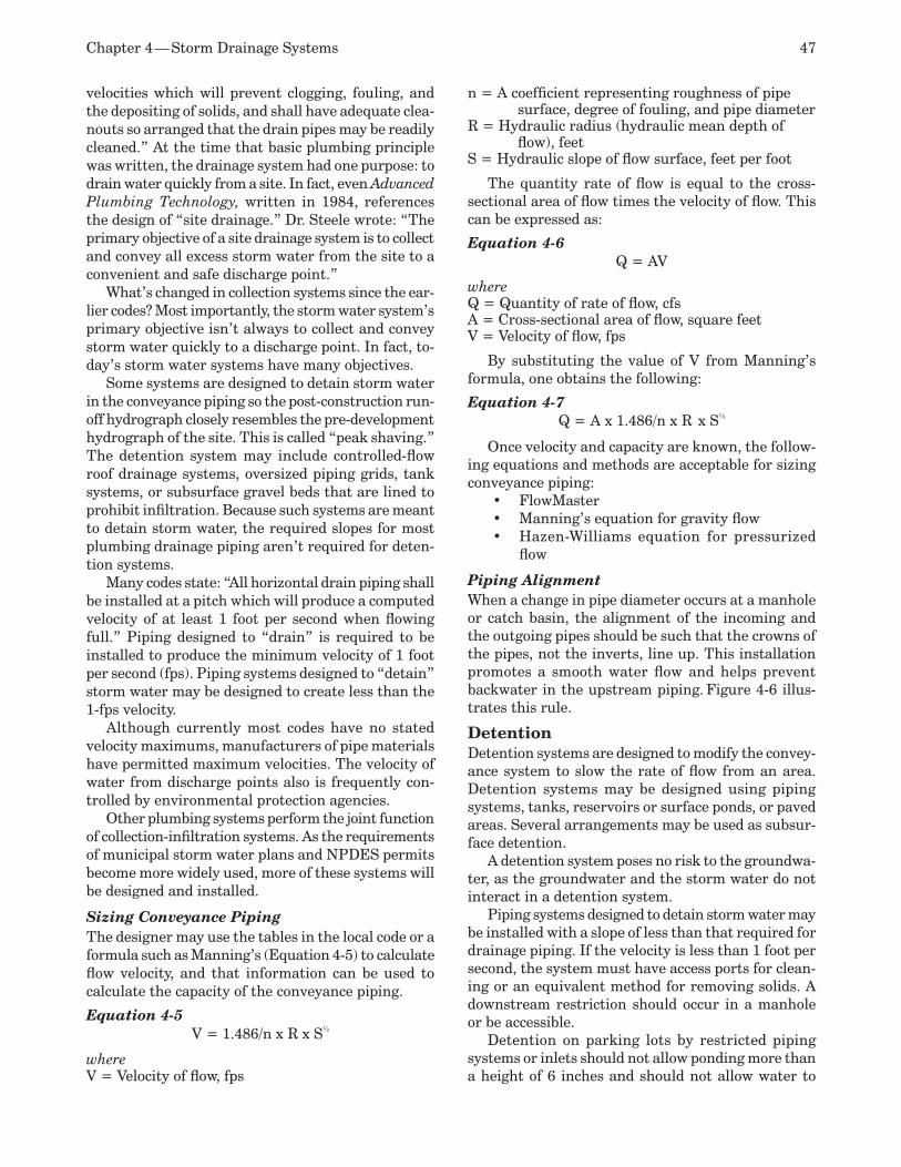
Chapter 4 — Storm Drainage Systems 47
velocities which will prevent clogging, fouling, and the depositing of solids, and shall have adequate clea-nouts so arranged that the drain pipes may be readily cleaned.” At the time that basic plumbing principle was written, the drainage system had one purpose: to drain water quickly from a site. In fact, even Advanced Plumbing Technology, written in 1984, references the design of “site drainage.” Dr. Steele wrote: “The primary objective of a site drainage system is to collect and convey all excess storm water from the site to a convenient and safe discharge point.”
What’s changed in collection systems since the ear-lier codes? Most importantly, the storm water system’s primary objective isn’t always to collect and convey storm water quickly to a discharge point. In fact, to-day’s storm water systems have many objectives.
Some systems are designed to detain storm water in the conveyance piping so the post-construction run-off hydrograph closely resembles the pre-development hydrograph of the site. This is called “peak shaving.” The detention system may include controlled-flow roof drainage systems, oversized piping grids, tank systems, or subsurface gravel beds that are lined to prohibit infiltration. Because such systems are meant to detain storm water, the required slopes for most plumbing drainage piping aren’t required for deten-tion systems.
Many codes state: “All horizontal drain piping shall be installed at a pitch which will produce a computed velocity of at least 1 foot per second when flowing full.” Piping designed to “drain” is required to be installed to produce the minimum velocity of 1 foot per second (fps). Piping systems designed to “detain” storm water may be designed to create less than the 1-fps velocity.
Although currently most codes have no stated velocity maximums, manufacturers of pipe materials have permitted maximum velocities. The velocity of water from discharge points also is frequently con-trolled by environmental protection agencies.
Other plumbing systems perform the joint function of collection-infiltration systems. As the requirements of municipal storm water plans and NPDES permits become more widely used, more of these systems will be designed and installed.
Sizing Conveyance PipingThe designer may use the tables in the local code or a formula such as Manning’s (Equation 4-5) to calculate flow velocity, and that information can be used to calculate the capacity of the conveyance piping.
Equation 4-5V = 1.486/n x R⅔ x S½
whereV = Velocity of flow, fps
n = A coefficient representing roughness of pipe surface, degree of fouling, and pipe diameter
R = Hydraulic radius (hydraulic mean depth of flow), feet
S = Hydraulic slope of flow surface, feet per foot
The quantity rate of flow is equal to the cross-sectional area of flow times the velocity of flow. This can be expressed as:
Equation 4-6Q = AV
whereQ = Quantity of rate of flow, cfsA = Cross-sectional area of flow, square feetV = Velocity of flow, fps
By substituting the value of V from Manning’s formula, one obtains the following:
Equation 4-7Q = A x 1.486/n x R⅔ x S½
Once velocity and capacity are known, the follow-ing equations and methods are acceptable for sizing conveyance piping:
FlowMaster•Manning’s equation for gravity flow•Hazen-Williams equation for pressurized •flow
Piping AlignmentWhen a change in pipe diameter occurs at a manhole or catch basin, the alignment of the incoming and the outgoing pipes should be such that the crowns of the pipes, not the inverts, line up. This installation promotes a smooth water flow and helps prevent backwater in the upstream piping. Figure 4-6 illus-trates this rule.
Detention Detention systems are designed to modify the convey-ance system to slow the rate of flow from an area. Detention systems may be designed using piping systems, tanks, reservoirs or surface ponds, or paved areas. Several arrangements may be used as subsur-face detention.
A detention system poses no risk to the groundwa-ter, as the groundwater and the storm water do not interact in a detention system.
Piping systems designed to detain storm water may be installed with a slope of less than that required for drainage piping. If the velocity is less than 1 foot per second, the system must have access ports for clean-ing or an equivalent method for removing solids. A downstream restriction should occur in a manhole or be accessible.
Detention on parking lots by restricted piping systems or inlets should not allow ponding more than a height of 6 inches and should not allow water to
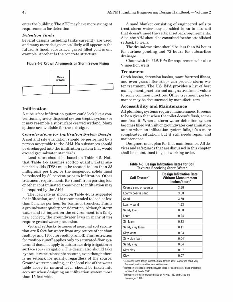
48 ASPE Plumbing Engineering Design Handbook — Volume 2
enter the building. The AHJ may have more stringent requirements for detention.
Detention Tanks Several designs including tanks currently are used, and many more designs most likely will appear in the future. A lined, subsurface, gravel-filled void is one example. Another is the concrete structure.
InfiltrationA subsurface infiltration system could look like a con-ventional gravity dispersal system (septic system) or it may resemble a subsurface created wetland. Many options are available for these designs.
Considerations for Infiltration System DesignA soil and site evaluation should be performed by a person acceptable to the AHJ. No substances should be discharged into the infiltration system that would exceed groundwater standards.
Load rates should be based on Table 4-5. Note that Table 4-5 assumes rooftop quality. Total sus-pended solids (TSS) must be treated to less than 35 milligrams per liter, or the suspended solids must be reduced by 80 percent prior to infiltration. Other treatment requirements for runoff from parking lots or other contaminated areas prior to infiltration may be required by the AHJ.
The load rate as shown on Table 4-5 is suggested for infiltration, and it is recommended to load at less than 5 inches per hour for basins or trenches. This is a groundwater quality consideration. Although storm water and its impact on the environment is a fairly new concept, the groundwater laws in many states require groundwater protection.
Vertical setbacks to zones of seasonal soil satura-tion are 5 feet for water from any source other than rooftops and 1 foot for rooftop runoff. This restriction for rooftop runoff applies only to saturated-flow sys-tems. It does not apply to subsurface drip irrigation or surface spray irrigation. The design also should take hydraulic restrictions into account, even though there is no setback for quality, regardless of the source. Groundwater mounding, or the local rise of the water table above its natural level, should be taken into account when designing an infiltration system more than 15 feet wide.
A sand blanket consisting of engineered soils to treat storm water may be added to an in situ soil that doesn’t meet the vertical setback requirements. Also, the AHJ should be consulted for the established setback to wells.
The draindown time should be less than 24 hours for surface ponding and 72 hours for subsurface drainage.
Check with the U.S. EPA for requirements for class V injection wells.
TreatmentCatch basins, detention basins, manufactured filters, and even grass filter strips can provide storm wa-ter treatment. The U.S. EPA provides a list of best management practices and assigns treatment values to some common practices. Other treatment perfor-mance may be documented by manufacturers.
Accessibility and MaintenanceAll plumbing systems require maintenance. It seems to be a given that when the toilet doesn’t flush, some-one fixes it. When a storm water detention system becomes filled with silt or groundwater contamination occurs when an infiltration system fails, it’s a more complicated situation, but it still needs repair and maintenance.
Designers must plan for that maintenance. All de-vices and safeguards that are discussed in this chapter shall be maintained in good working order.
Match crowns
Figure 4-6 Crown Alignments on Storm Sewer Piping
Table 4-5 Design Infiltration Rates for Soil Textures Receiving Storm Water
Soil TextureaDesign Infiltration Rate Without Measurement
(inches/hour)b
Coarse sand or coarser 3.60
Loamy coarse sand 3.60
Sand 3.60
Loamy sand 1.63
Sandy loam 0.50
Loam 0.24
Silt loam 0.13
Sandy clay loam 0.11
Clay loam 0.03
Silty clay loam 0.04c
Sandy clay 0.04
Silty clay 0.07
Clay 0.07aUse sandy loam design infiltration rate for fine sand, loamy fine sand, very
fine sand, and loamy fine sand soil textures.bInfiltration rates represent the lowest value for each textural class presented
in Table 2 of Rawls, 1998.cInfiltration rate is an average based on Rawls, 1982 and Clapp and
Hornberger, 1978.
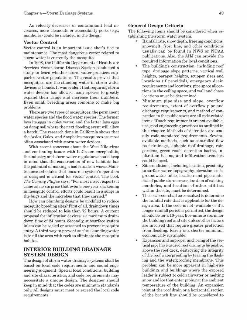
Chapter 4 — Storm Drainage Systems 49
As velocity decreases or contaminant load in-creases, more cleanouts or accessibility ports (e.g., manholes) could be included in the design.
Vector ControlVector control is an important issue that’s tied to maintenance. The most dangerous vector related to storm water is currently the mosquito.
In 1998, the California Department of Healthcare Services Vector-borne Disease Section conducted a study to learn whether storm water practices sup-ported vector populations. The results proved that mosquitoes use the standing water in storm water devices as homes. It was evident that requiring storm water devices has allowed many species to greatly expand their range and increase their numbers. Even small breeding areas combine to make big problems.
There are two types of mosquitoes: the permanent water species and the flood water species. The former lays its eggs in quiet water, and the latter lays eggs on damp soil where the next flooding event will allow a hatch. The research done in California shows that the Aedes, Culex, and Anopheles mosquitoes are most often associated with storm water devices.
With recent concerns about the West Nile virus and continuing issues with LaCrosse encephalitis, the industry and storm water regulators should keep in mind that the construction of new habitats has the potential of making a bad situation worse. Main-tenance schedules that ensure a system’s operation as designed is critical for vector control. The book The Coming Plague says: “For most insect experts it came as no surprise that even a one-year slackening in mosquito control efforts could result in a surge in the bugs and the microbes that they carried.”
How can plumbing designs be modified to reduce mosquito breeding sites? First of all, draindown times should be reduced to less than 72 hours. A current proposal for infiltration devices is a maximum drain-down time of 24 hours. Secondly, subsurface system inlets can be sealed or screened to prevent mosquito entry. A third way to prevent surface standing water is to fill the area with rock to eliminate the mosquito habitat.
INTERIOR BUILDING DRAINAGE SYSTEM DESIGN The design of storm water drainage systems shall be based on local code requirements and sound engi-neering judgment. Special local conditions, building and site characteristics, and code requirements may necessitate a unique design. The designer should keep in mind that the codes are minimum standards only. All designs must meet or exceed the local code requirements.
General Design Criteria The following items should be considered when es-tablishing the storm water system.
Rainfall rate, snow depth, freezing conditions, •snowmelt, frost line, and other conditions usually can be found in NWS or NOAA publications. Also, the AHJ can provide the required information for local conditions.The building’s construction, including roof •type, drainage slope patterns, vertical wall heights, parapet heights, scupper sizes and locations (if provided), emergency drain requirements and locations, pipe space alloca-tions in the ceiling space, and wall and chase locations must be determined. Minimum pipe size and slope, overflow •requirements, extent of overflow pipe and discharge requirements, and method of con-nection to the public sewer are all code-related items. If such requirements are not available, use good engineering practices as outlined in this chapter. Methods of detention are usu-ally code-mandated requirements. Several available methods, such as controlled-flow roof drainage, siphonic roof drainage, rain gardens, green roofs, detention basins, in-filtration basins, and infiltration trenches could be used.Site conditions, including location, proximity •to surface water, topography, elevation, soils, groundwater table, location and pipe mate-rial of public storm sewer, location of existing manholes, and location of other utilities within the site, must be determined. The local code shall be consulted to determine •the rainfall rate that is applicable for the de-sign area. If the code is not available or if a longer rainfall period is permitted, the design should be for a 10-year, five-minute storm for the building roof and site unless other factors are involved that require greater protection from flooding. Rarely is a shorter minimum economically justifiable. Expansion and improper anchoring of the ver-•tical pipe have caused roof drains to be pushed above the roof deck, destroying the integrity of the roof waterproofing by tearing the flash-ing and the waterproofing membrane. This problem can be more apparent in high-rise buildings and buildings where the exposed leader is subject to cold rainwater or melting snow and ice that enter piping at the ambient temperature of the building. An expansion joint at the roof drain or a horizontal section of the branch line should be considered to

50 ASPE Plumbing Engineering Design Handbook — Volume 2
accommodate the movement of the leader without affecting the roof drain.The horizontal section of the pipe and the roof •drain body should be insulated, per cold water installations with a vapor barrier, to control condensation. Low-temperature liquid flow in the piping causes condensation to form on the outside of the piping, possibly causing stain damage to the ceilings or, where exposed, drip marks on the flooring. This condensation usually extends 15 feet from the roof drain. Past this distance, the water is no longer cold enough to cause condensation. Locating the vertical leaders within the build-•ing has several advantages: convenience, safety, appearance, and freeze protection. However, leaders located on the exterior can be installed at a much lower cost and do not take up valuable floor space. The piping layout must be coordinated with •other design team disciplines that are af-fected, such as the architect providing chase locations at proper columns for vertical lead-ers (also known as conductors or downspouts) and the structural engineer for pipe support and footing depths. Other utilities, such as ductwork and conduit runs, also may be af-fected. If interior floor/hub drains, drains from lower •roofs, clear water wastes, or areaway drains are connected to the storm system inside the building (if allowed by the AHJ), the drains must connect at least 10 pipe diameters (10 feet [3.05 meters] minimum) downstream of the last offset fitting. Clear water wastes should be properly trapped and vented. Traps must be the same size as the horizontal drain to which they are connected and should be provided with at least 4-inch (102-millimeter) deep-seal P-traps. See Figure 4-7.
Because of the excessive pressure that may •exist in the leader, drains sometimes con-nect to a stack at a lower level. Above an offset, the drain becomes the vent to relieve the pressure, blowing water, and air. These drains are subject to backflow and should be routed separately to tie to the system 10 feet (3.05 meters) beyond the elbow or offset. If backwater valves are used, they can cause the areas affected to not drain, and a buildup of water may occur. Horizontal piping of clear water wastes and vents should be sized as a sanitary drainage branch. When such piping is tied to a leader, an upright wye should be utilized if possible. See Figure 4-8To keep the number of leaders to a minimum, •combine flows from more than one roof drain, clear water wastes, or any combina-tion thereof. The plumbing engineer must include the additional flows when calculat-ing the leader size. This method is especially beneficial in keeping the costs of high-rise buildings contained.If leaders are to be located at building col-•umns, the column footing design must be coordinated with the structural engineer to take into consideration the leader location. The base elbow should be a long sweep bend to help alleviate any excess pressures in the downstream pipe, and the elbow should be properly supported. The elbow may rest di-rectly on the column footing, which acts as a support. A riser clamp should be provided at each floor •line to support the leader. Also, a cleanout shall be provided at the base of all stacks (although caution must be exercised when opening these cleanouts because full leaders create a high hydraulic pressure situation).If blockage occurs in the drainage system •and backs up in the vertical leader, the pip-ing system may be subject to a head pressure greater than the joining system is designed to withstand. To prevent joint failure, pressure pipe may be considered for the piping system. At the lower floors, all exterior leaders that may be damaged, such as occurs in parking or truck-loading areas, should be protected by metal or concrete guards or recessed in the wall and constructed of a ferrous alloy pipe, such as cast iron, to 5 feet (1.5 meters) above the paving or loading platforms. If an offset is 45 degrees or less, the leader •can be sized as a vertical pipe. If the offset is greater than 45 degrees, the pipe must be sized as a horizontal pipe. To avoid stoppages,
Figure 4-7 Clear Water Waste Branches for Connection to Storm System
Source: Reprinted, by permission, from The Illustrated National Plumbing Code Design Manual (Ballanco & Shumann 1987)
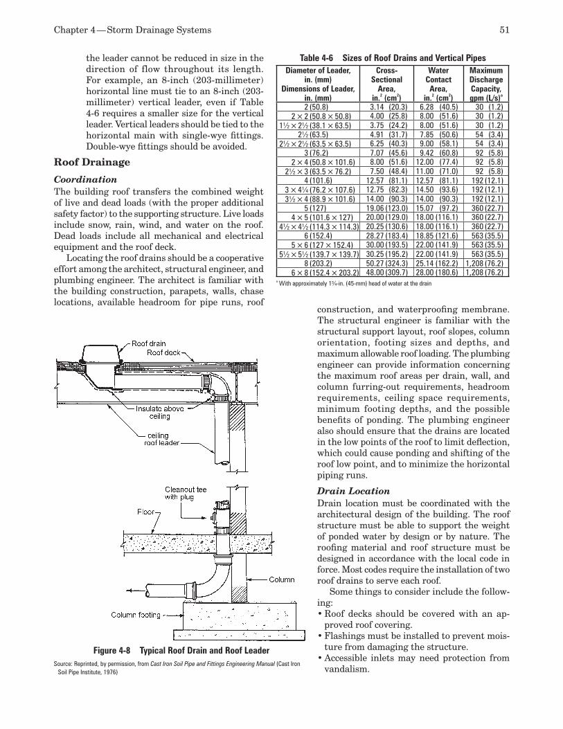
Chapter 4 — Storm Drainage Systems 51
the leader cannot be reduced in size in the direction of flow throughout its length. For example, an 8-inch (203-millimeter) horizontal line must tie to an 8-inch (203-millimeter) vertical leader, even if Table 4-6 requires a smaller size for the vertical leader. Vertical leaders should be tied to the horizontal main with single-wye fittings. Double-wye fittings should be avoided.
Roof Drainage
Coordination The building roof transfers the combined weight of live and dead loads (with the proper additional safety factor) to the supporting structure. Live loads include snow, rain, wind, and water on the roof. Dead loads include all mechanical and electrical equipment and the roof deck.
Locating the roof drains should be a cooperative effort among the architect, structural engineer, and plumbing engineer. The architect is familiar with the building construction, parapets, walls, chase locations, available headroom for pipe runs, roof
construction, and waterproofing membrane. The structural engineer is familiar with the structural support layout, roof slopes, column orientation, footing sizes and depths, and maximum allowable roof loading. The plumbing engineer can provide information concerning the maximum roof areas per drain, wall, and column furring-out requirements, headroom requirements, ceiling space requirements, minimum footing depths, and the possible benefits of ponding. The plumbing engineer also should ensure that the drains are located in the low points of the roof to limit deflection, which could cause ponding and shifting of the roof low point, and to minimize the horizontal piping runs.
Drain LocationDrain location must be coordinated with the architectural design of the building. The roof structure must be able to support the weight of ponded water by design or by nature. The roofing material and roof structure must be designed in accordance with the local code in force. Most codes require the installation of two roof drains to serve each roof.
Some things to consider include the follow-ing:
Roof decks should be covered with an ap-•proved roof covering.Flashings must be installed to prevent mois-•ture from damaging the structure.Accessible inlets may need protection from •vandalism.
Figure 4-8 Typical Roof Drain and Roof LeaderSource: Reprinted, by permission, from Cast Iron Soil Pipe and Fittings Engineering Manual (Cast Iron
Soil Pipe Institute, 1976)
Table 4-6 Sizes of Roof Drains and Vertical PipesDiameter of Leader,
in. (mm)Dimensions of Leader,
in. (mm)
Cross-Sectional
Area, in.2 (cm2)
Water Contact Area,
in.2 (cm2)
Maximum Discharge Capacity, gpm (L/s)a
2 (50.8) 3.14 (20.3) 6.28 (40.5) 30 (1.2)2 × 2 (50.8 × 50.8) 4.00 (25.8) 8.00 (51.6) 30 (1.2)
1½ × 2½ (38.1 × 63.5) 3.75 (24.2) 8.00 (51.6) 30 (1.2)2½ (63.5) 4.91 (31.7) 7.85 (50.6) 54 (3.4)
2½ × 2½ (63.5 × 63.5) 6.25 (40.3) 9.00 (58.1) 54 (3.4)3 (76.2) 7.07 (45.6) 9.42 (60.8) 92 (5.8)
2 × 4 (50.8 × 101.6) 8.00 (51.6) 12.00 (77.4) 92 (5.8)2½ × 3 (63.5 × 76.2) 7.50 (48.4) 11.00 (71.0) 92 (5.8)
4 (101.6) 12.57 (81.1) 12.57 (81.1) 192 (12.1)3 × 4¼ (76.2 × 107.6) 12.75 (82.3) 14.50 (93.6) 192 (12.1)3½ × 4 (88.9 × 101.6) 14.00 (90.3) 14.00 (90.3) 192 (12.1)
5 (127) 19.06 (123.0) 15.07 (97.2) 360 (22.7)4 × 5 (101.6 × 127) 20.00 (129.0) 18.00 (116.1) 360 (22.7)
4½ × 4½ (114.3 × 114.3) 20.25 (130.6) 18.00 (116.1) 360 (22.7)6 (152.4) 28.27 (183.4) 18.85 (121.6) 563 (35.5)
5 × 6 (127 × 152.4) 30.00 (193.5) 22.00 (141.9) 563 (35.5)5½ × 5½ (139.7 × 139.7) 30.25 (195.2) 22.00 (141.9) 563 (35.5)
8 (203.2) 50.27 (324.3) 25.14 (162.2) 1,208 (76.2)6 × 8 (152.4 × 203.2) 48.00 (309.7) 28.00 (180.6) 1,208 (76.2)
a With approximately 1¾-in. (45-mm) head of water at the drain
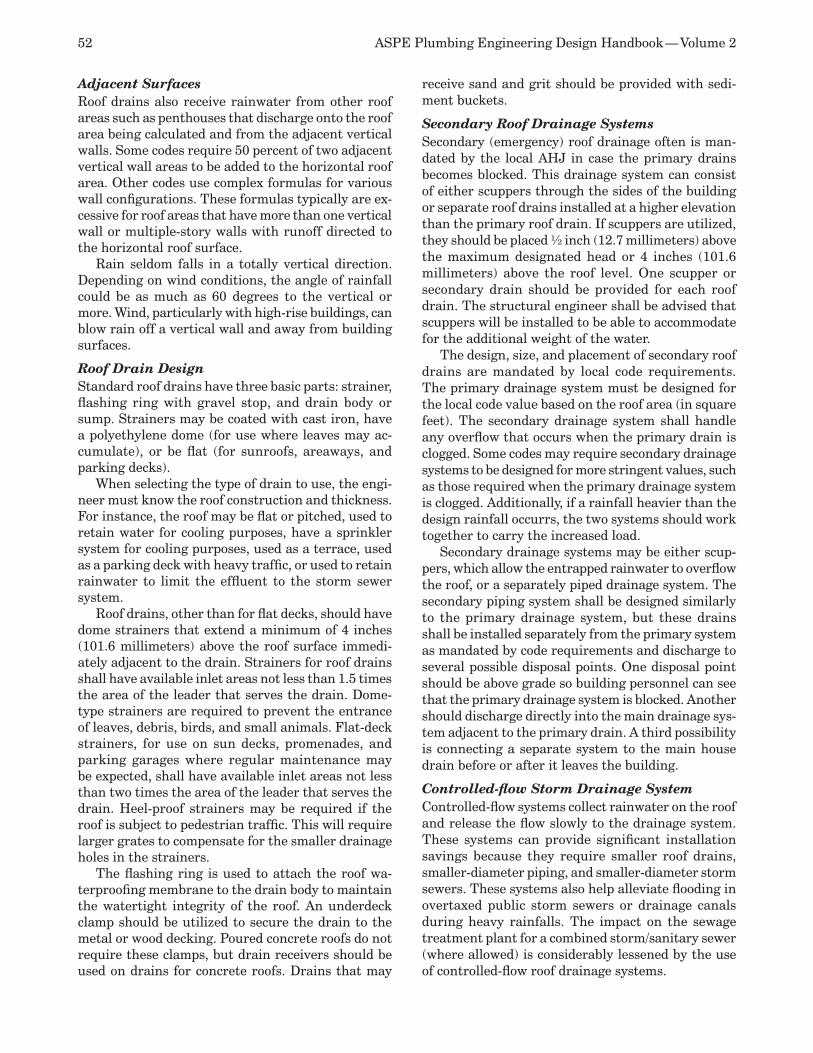
52 ASPE Plumbing Engineering Design Handbook — Volume 2
Adjacent Surfaces Roof drains also receive rainwater from other roof areas such as penthouses that discharge onto the roof area being calculated and from the adjacent vertical walls. Some codes require 50 percent of two adjacent vertical wall areas to be added to the horizontal roof area. Other codes use complex formulas for various wall configurations. These formulas typically are ex-cessive for roof areas that have more than one vertical wall or multiple-story walls with runoff directed to the horizontal roof surface.
Rain seldom falls in a totally vertical direction. Depending on wind conditions, the angle of rainfall could be as much as 60 degrees to the vertical or more. Wind, particularly with high-rise buildings, can blow rain off a vertical wall and away from building surfaces.
Roof Drain Design Standard roof drains have three basic parts: strainer, flashing ring with gravel stop, and drain body or sump. Strainers may be coated with cast iron, have a polyethylene dome (for use where leaves may ac-cumulate), or be flat (for sunroofs, areaways, and parking decks).
When selecting the type of drain to use, the engi-neer must know the roof construction and thickness. For instance, the roof may be flat or pitched, used to retain water for cooling purposes, have a sprinkler system for cooling purposes, used as a terrace, used as a parking deck with heavy traffic, or used to retain rainwater to limit the effluent to the storm sewer system.
Roof drains, other than for flat decks, should have dome strainers that extend a minimum of 4 inches (101.6 millimeters) above the roof surface immedi-ately adjacent to the drain. Strainers for roof drains shall have available inlet areas not less than 1.5 times the area of the leader that serves the drain. Dome-type strainers are required to prevent the entrance of leaves, debris, birds, and small animals. Flat-deck strainers, for use on sun decks, promenades, and parking garages where regular maintenance may be expected, shall have available inlet areas not less than two times the area of the leader that serves the drain. Heel-proof strainers may be required if the roof is subject to pedestrian traffic. This will require larger grates to compensate for the smaller drainage holes in the strainers.
The flashing ring is used to attach the roof wa-terproofing membrane to the drain body to maintain the watertight integrity of the roof. An underdeck clamp should be utilized to secure the drain to the metal or wood decking. Poured concrete roofs do not require these clamps, but drain receivers should be used on drains for concrete roofs. Drains that may
receive sand and grit should be provided with sedi-ment buckets.
Secondary Roof Drainage Systems Secondary (emergency) roof drainage often is man-dated by the local AHJ in case the primary drains becomes blocked. This drainage system can consist of either scuppers through the sides of the building or separate roof drains installed at a higher elevation than the primary roof drain. If scuppers are utilized, they should be placed ½ inch (12.7 millimeters) above the maximum designated head or 4 inches (101.6 millimeters) above the roof level. One scupper or secondary drain should be provided for each roof drain. The structural engineer shall be advised that scuppers will be installed to be able to accommodate for the additional weight of the water.
The design, size, and placement of secondary roof drains are mandated by local code requirements. The primary drainage system must be designed for the local code value based on the roof area (in square feet). The secondary drainage system shall handle any overflow that occurs when the primary drain is clogged. Some codes may require secondary drainage systems to be designed for more stringent values, such as those required when the primary drainage system is clogged. Additionally, if a rainfall heavier than the design rainfall occurrs, the two systems should work together to carry the increased load.
Secondary drainage systems may be either scup-pers, which allow the entrapped rainwater to overflow the roof, or a separately piped drainage system. The secondary piping system shall be designed similarly to the primary drainage system, but these drains shall be installed separately from the primary system as mandated by code requirements and discharge to several possible disposal points. One disposal point should be above grade so building personnel can see that the primary drainage system is blocked. Another should discharge directly into the main drainage sys-tem adjacent to the primary drain. A third possibility is connecting a separate system to the main house drain before or after it leaves the building.
Controlled-flow Storm Drainage System Controlled-flow systems collect rainwater on the roof and release the flow slowly to the drainage system. These systems can provide significant installation savings because they require smaller roof drains, smaller-diameter piping, and smaller-diameter storm sewers. These systems also help alleviate flooding in overtaxed public storm sewers or drainage canals during heavy rainfalls. The impact on the sewage treatment plant for a combined storm/sanitary sewer (where allowed) is considerably lessened by the use of controlled-flow roof drainage systems.
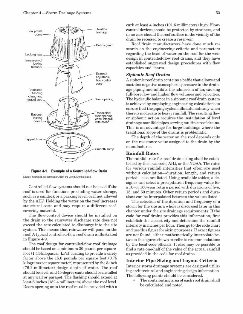
Chapter 4 — Storm Drainage Systems 53
Figure 4-9 Example of a Controlled-flow DrainSource: Reprinted, by permission, from the Jay R. Smith catalog
Controlled-flow systems should not be used if the roof is used for functions precluding water storage, such as a sundeck or a parking level, or if not allowed by the AHJ. Holding the water on the roof increases structural costs and may require a different roof-covering material.
The flow-control device should be installed on the drain so the rainwater discharge rate does not exceed the rate calculated to discharge into the site system. This means that rainwater will pond on the roof. A typical controlled-flow roof drain is illustrated in Figure 4-9.
The roof design for controlled-flow roof drainage should be based on a minimum 30-pound-per-square-foot (1.44-kilopascal [kPa]) loading to provide a safety factor above the 15.6 pounds per square foot (0.75 kilograms per square meter) represented by the 3-inch (76.2-millimeter) design depth of water. The roof should be level, and 45-degree cants should be installed at any wall or parapet. The flashing should extend at least 6 inches (152.4 millimeters) above the roof level. Doors opening onto the roof must be provided with a
curb at least 4 inches (101.6 millimeters) high. Flow-control devices should be protected by strainers, and in no case should the roof surface in the vicinity of the drain be recessed to create a reservoir.
Roof drain manufacturers have done much re-search on the engineering criteria and parameters regarding the head of water on the roof for the weir design in controlled-flow roof drains, and they have established suggested design procedures with flow capacities and charts.
Siphonic Roof DrainsA siphonic roof drain contains a baffle that allows and sustains negative atmospheric pressure in the drain-age piping and inhibits the admission of air, causing full-bore flow and higher flow volumes and velocities. The hydraulic balance in a siphonic roof drain system is achieved by employing engineering calculations to ensure that the piping system fills automatically when there is moderate to heavy rainfall. The resulting flow or siphonic action requires the installation of level drainage manifold pipes serving multiple roof drains. This is an advantage for large buildings where the traditional slope of the drains is problematic.
The depth of the water on the roof depends only on the resistance value assigned to the drain by the manufacturer.
Rainfall RatesThe rainfall rate for roof drain sizing shall be estab-lished by the local code, AHJ, or the NOAA. The rates for various rainfall intensities that often are used without calculation—duration, length, and return period—also are listed. Using available tables, a de-signer can select a precipitation frequency value for a 10- or 100-year return period with durations of five, 15, and 60 minutes. Other return periods and dura-tions can be interpolated between the values listed.
The selection of the duration and frequency of a storm for the site as a whole is discussed later in this chapter under the site drainage requirements. If the code for roof drains provides this information, first establish the closest city and determine the rainfall intensity in inches per hour. Then go to the code chart and use this figure for sizing purposes. If exact figures are not found, either mathematically interpolate be-tween the figures shown or refer to recommendations by the local code officials. It also may be possible to find a rate one-half of the value of the actual rainfall as provided in the code for roof drains.
Interior Pipe Sizing and Layout Criteria Interior storm drainage systems are designed utiliz-ing architectural and engineering design information. The following points should be considered.
The contributing area of each roof drain shall •be calculated and noted.
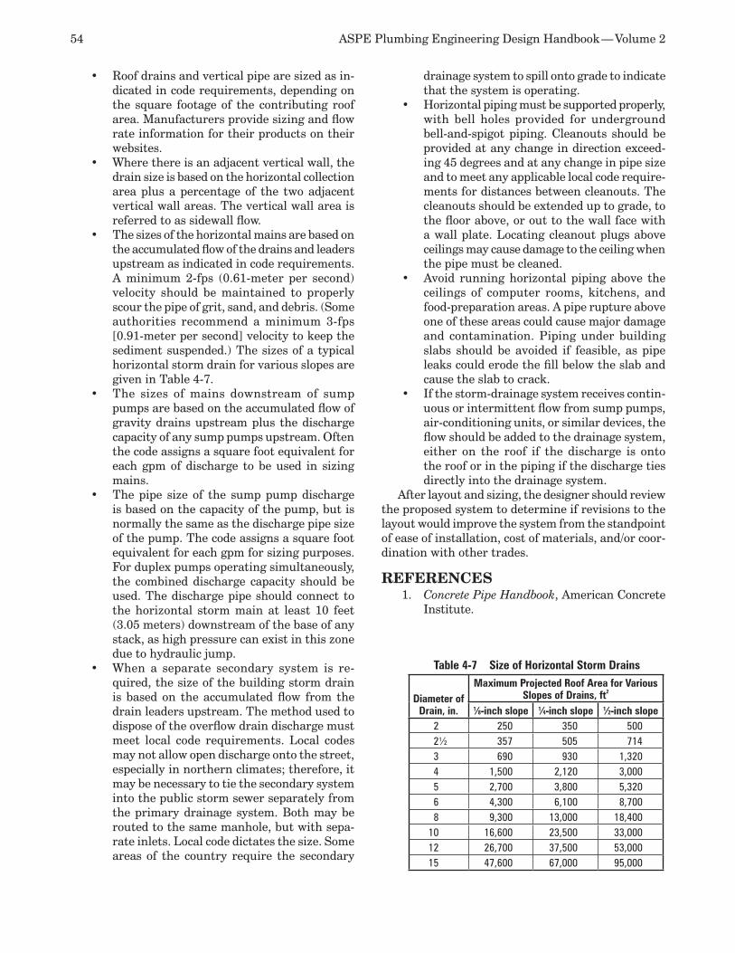
54 ASPE Plumbing Engineering Design Handbook — Volume 2
Roof drains and vertical pipe are sized as in-•dicated in code requirements, depending on the square footage of the contributing roof area. Manufacturers provide sizing and flow rate information for their products on their websites.Where there is an adjacent vertical wall, the •drain size is based on the horizontal collection area plus a percentage of the two adjacent vertical wall areas. The vertical wall area is referred to as sidewall flow.The sizes of the horizontal mains are based on •the accumulated flow of the drains and leaders upstream as indicated in code requirements. A minimum 2-fps (0.61-meter per second) velocity should be maintained to properly scour the pipe of grit, sand, and debris. (Some authorities recommend a minimum 3-fps [0.91-meter per second] velocity to keep the sediment suspended.) The sizes of a typical horizontal storm drain for various slopes are given in Table 4-7.The sizes of mains downstream of sump •pumps are based on the accumulated flow of gravity drains upstream plus the discharge capacity of any sump pumps upstream. Often the code assigns a square foot equivalent for each gpm of discharge to be used in sizing mains.The pipe size of the sump pump discharge •is based on the capacity of the pump, but is normally the same as the discharge pipe size of the pump. The code assigns a square foot equivalent for each gpm for sizing purposes. For duplex pumps operating simultaneously, the combined discharge capacity should be used. The discharge pipe should connect to the horizontal storm main at least 10 feet (3.05 meters) downstream of the base of any stack, as high pressure can exist in this zone due to hydraulic jump.When a separate secondary system is re-•quired, the size of the building storm drain is based on the accumulated flow from the drain leaders upstream. The method used to dispose of the overflow drain discharge must meet local code requirements. Local codes may not allow open discharge onto the street, especially in northern climates; therefore, it may be necessary to tie the secondary system into the public storm sewer separately from the primary drainage system. Both may be routed to the same manhole, but with sepa-rate inlets. Local code dictates the size. Some areas of the country require the secondary
drainage system to spill onto grade to indicate that the system is operating.Horizontal piping must be supported properly, •with bell holes provided for underground bell-and-spigot piping. Cleanouts should be provided at any change in direction exceed-ing 45 degrees and at any change in pipe size and to meet any applicable local code require-ments for distances between cleanouts. The cleanouts should be extended up to grade, to the floor above, or out to the wall face with a wall plate. Locating cleanout plugs above ceilings may cause damage to the ceiling when the pipe must be cleaned.Avoid running horizontal piping above the •ceilings of computer rooms, kitchens, and food-preparation areas. A pipe rupture above one of these areas could cause major damage and contamination. Piping under building slabs should be avoided if feasible, as pipe leaks could erode the fill below the slab and cause the slab to crack.If the storm-drainage system receives contin-•uous or intermittent flow from sump pumps, air-conditioning units, or similar devices, the flow should be added to the drainage system, either on the roof if the discharge is onto the roof or in the piping if the discharge ties directly into the drainage system.
After layout and sizing, the designer should review the proposed system to determine if revisions to the layout would improve the system from the standpoint of ease of installation, cost of materials, and/or coor-dination with other trades.
REFERENCESConcrete Pipe Handbook1. , American Concrete Institute.
Table 4-7 Size of Horizontal Storm Drains
Diameter of Drain, in.
Maximum Projected Roof Area for Various Slopes of Drains, ft2
1⁄8-inch slope 1⁄4-inch slope 1⁄2-inch slope 2 250 350 5002½ 357 505 7143 690 930 1,3204 1,500 2,120 3,0005 2,700 3,800 5,3206 4,300 6,100 8,7008 9,300 13,000 18,400
10 16,600 23,500 33,00012 26,700 37,500 53,00015 47,600 67,000 95,000
Chapter 4 — Storm Drainage Systems 55
Manual on the Design and Construction of 2. Sanitary and Storm Sewers, American Society of Civil Engineers. Ballanco, Julius and Eugene R. Shumann, 3. The Illustrated National Plumbing Code Design Manual, Ballanco and Shumann—Illustrated Plumbing Codes Inc., 1987.BOCA Basic Plumbing Code4. , Building Officials and Code Administration, 1981. Cast Iron Soil Pipe and Fittings Engineering 5. Manual, Volume 1, Cast Iron Soil Pipe Insti-tute, 1976. Church, James C., 6. Practical Plumbing Design Guide, McGraw-Hill, 1979.Frankel, Michael, 7. Facility Piping Systems Handbook, McGraw-Hill, 2002.Frankel, Michael, “Stormwater Retention 8. Methods,” Plumbing Engineer, March/April and May/June 1981. Frederick, Ralph H., Vance A. Meyers, and 9. Eugene P. Auciello, “NOAA, National Weather Service 5-60 Minute Precipitation Frequency for the Eastern and Central United States,” NWS Technical Memo HYDRO-35, NTIS Publication PB-272 112, National Technical Information Service. Plumbing Design and Installation Reference 10. Guide, McGraw-Hill, 1986.Manas, Vincent T., 11. National Plumbing Code, Illustrated, Manas Publications, 1968. Sansone, John R. “Storm Drainage Design 12. and Detention Using the Rational Method,” Plumbing Engineer, July/August 1978.Standard Plumbing Code13. , SBCCI, 1988.Urban Hydrology for Small Watersheds,14. Technical Release No. 55, NTIS Publication PB87-101580, National Technical Information Service. Steele, Alfred, 15. Engineered Plumbing Design, Delta Communications, 1982. Engineering Manual of the War Department,16. Misc. Publication No. 204, U.S. War Depart-ment. Plumbing Design Manual,17. No. 3.01, U.S. De-partment of the Army. Yrjanainen, Glen and Alan W. Warren, “A 18. Simple Method for Retention Basin Design,” Water and Sewage Works, December 1973.“Siphonic Roof Drains,” SPM 1104, Jay R. 19. Smith Mfg. Co.
Gribbin, PE, John E., 20. Hydraulics and Hy-drology for Stormwater Management, Delmar Publishers, 1994. Maryland Stormwater Design Manual,21. Mary-land Department of the Environment.“Sources of Pollutants in Wisconsin Storm-22. water,” Wisconsin Department of Natural Resources, 1993. Minnesota Urban Small Sites Best Manage-23. ment Practice Manual, Metropolitan Council/Barr Engineering Co.Stormwater: The Dark Side of Stormwater 24. Runoff Management. Forester Communica-tions Inc., 2002. Thornton, PE, Larry, “Filling In the Miss-25. ing Rainfall Data,” Plumbing Engineer, May 1992.Ballanco, PE, Julius, “Rainfall Rates: How 26. Much Rain Is Enough in Design?” Plumbing Engineer. Groundwater Contamination from Stormwater 27. Infiltration, Ann Arbor Press Inc., 1996. Ferguson, Bruce K.,28. Introduction to Stormwa-ter, John Wiley & Sons Inc. Steele, PE, Alfred, 29. Advanced Plumbing Tech-nology, Construction Industry Press, 1984.Claytor, Richard A. and Thomas R. Schueler, 30. Design of Stormwater Filtering Systems, The Center for Watershed Protection, 1996.Garrett, Laurie, 31. The Coming Plague, Penguin Books, 1994.“Estimation of Soil Water Properties, Transac-32. tions of the American Society of Agricultural Engineers,” Vol. 25, No. 5, pp. 1316–1320, 1328.Musgrave, G.W. and H.N. Holtan, 33. Handbook of Applied Hydrology. McGraw-Hill, 1964.“Estimating wastewater loading rates using 34. soil morphological descriptions,” Proceedings of the Sixth National Symposium on Individual and Small Community Sewage Systems, pp. 192–200, ASAE, 1991. “Hydraulic loading rates for soil absorption 35. systems based on wastewater quality,” Pro-ceedings of the Fifth National Symposium on Individual and Small Community Sewage Systems, pp. 179–190, ASAE, 1987. Plumbing Engineering and Design Standard 36. 45: Siphonic Roof Drainage, American Society of Plumbing Engineers, 2007.
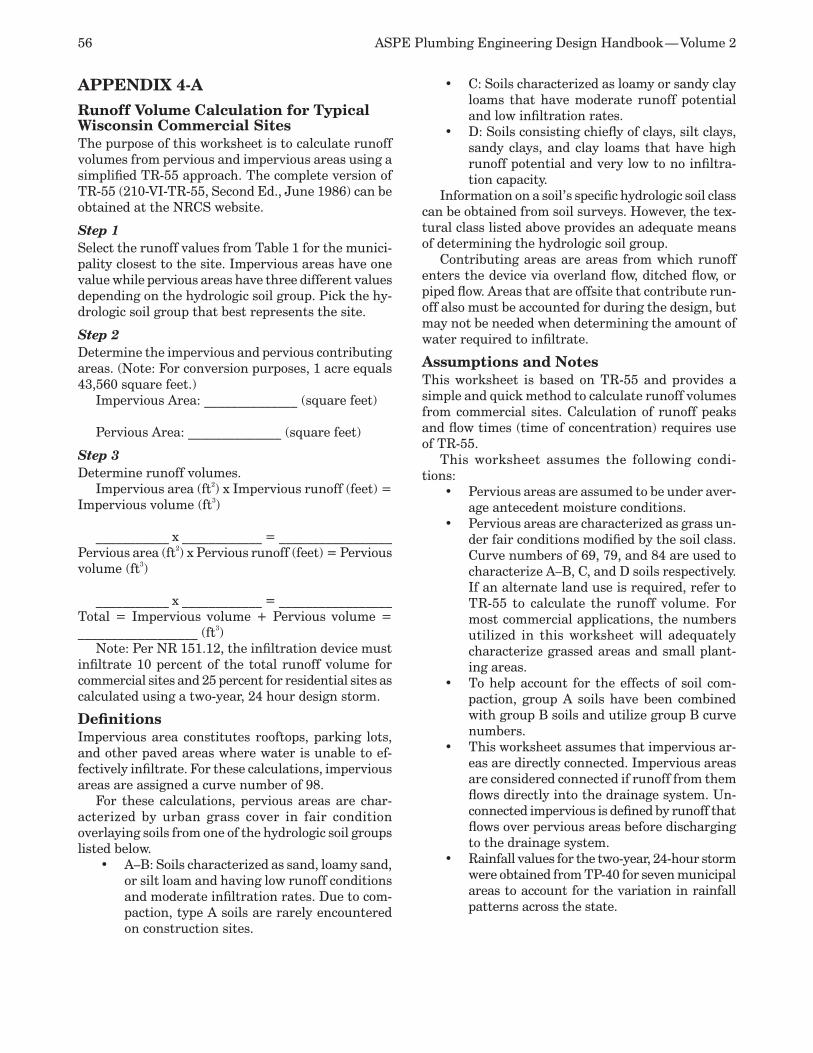
56 ASPE Plumbing Engineering Design Handbook — Volume 2
APPENDIX 4-A
Runoff Volume Calculation for Typical Wisconsin Commercial SitesThe purpose of this worksheet is to calculate runoff volumes from pervious and impervious areas using a simplified TR-55 approach. The complete version of TR-55 (210-VI-TR-55, Second Ed., June 1986) can be obtained at the NRCS website.
Step 1Select the runoff values from Table 1 for the munici-pality closest to the site. Impervious areas have one value while pervious areas have three different values depending on the hydrologic soil group. Pick the hy-drologic soil group that best represents the site.
Step 2Determine the impervious and pervious contributing areas. (Note: For conversion purposes, 1 acre equals 43,560 square feet.)
Impervious Area: ______________ (square feet)
Pervious Area: ______________ (square feet)
Step 3Determine runoff volumes.
Impervious area (ft2) x Impervious runoff (feet) = Impervious volume (ft3)
___________ x ____________ = _________________Pervious area (ft2) x Pervious runoff (feet) = Pervious volume (ft3)
___________ x ____________ = _________________Total = Impervious volume + Pervious volume = __________________ (ft3)
Note: Per NR 151.12, the infiltration device must infiltrate 10 percent of the total runoff volume for commercial sites and 25 percent for residential sites as calculated using a two-year, 24 hour design storm.
DefinitionsImpervious area constitutes rooftops, parking lots, and other paved areas where water is unable to ef-fectively infiltrate. For these calculations, impervious areas are assigned a curve number of 98.
For these calculations, pervious areas are char-acterized by urban grass cover in fair condition overlaying soils from one of the hydrologic soil groups listed below.
A–B: Soils characterized as sand, loamy sand, •or silt loam and having low runoff conditions and moderate infiltration rates. Due to com-paction, type A soils are rarely encountered on construction sites.
C: Soils characterized as loamy or sandy clay •loams that have moderate runoff potential and low infiltration rates. D: Soils consisting chiefly of clays, silt clays, •sandy clays, and clay loams that have high runoff potential and very low to no infiltra-tion capacity.
Information on a soil’s specific hydrologic soil class can be obtained from soil surveys. However, the tex-tural class listed above provides an adequate means of determining the hydrologic soil group.
Contributing areas are areas from which runoff enters the device via overland flow, ditched flow, or piped flow. Areas that are offsite that contribute run-off also must be accounted for during the design, but may not be needed when determining the amount of water required to infiltrate.
Assumptions and NotesThis worksheet is based on TR-55 and provides a simple and quick method to calculate runoff volumes from commercial sites. Calculation of runoff peaks and flow times (time of concentration) requires use of TR-55.
This worksheet assumes the following condi-tions:
Pervious areas are assumed to be under aver-•age antecedent moisture conditions. Pervious areas are characterized as grass un-•der fair conditions modified by the soil class. Curve numbers of 69, 79, and 84 are used to characterize A–B, C, and D soils respectively. If an alternate land use is required, refer to TR-55 to calculate the runoff volume. For most commercial applications, the numbers utilized in this worksheet will adequately characterize grassed areas and small plant-ing areas.To help account for the effects of soil com-•paction, group A soils have been combined with group B soils and utilize group B curve numbers.This worksheet assumes that impervious ar-•eas are directly connected. Impervious areas are considered connected if runoff from them flows directly into the drainage system. Un-connected impervious is defined by runoff that flows over pervious areas before discharging to the drainage system.Rainfall values for the two-year, 24-hour storm •were obtained from TP-40 for seven municipal areas to account for the variation in rainfall patterns across the state.
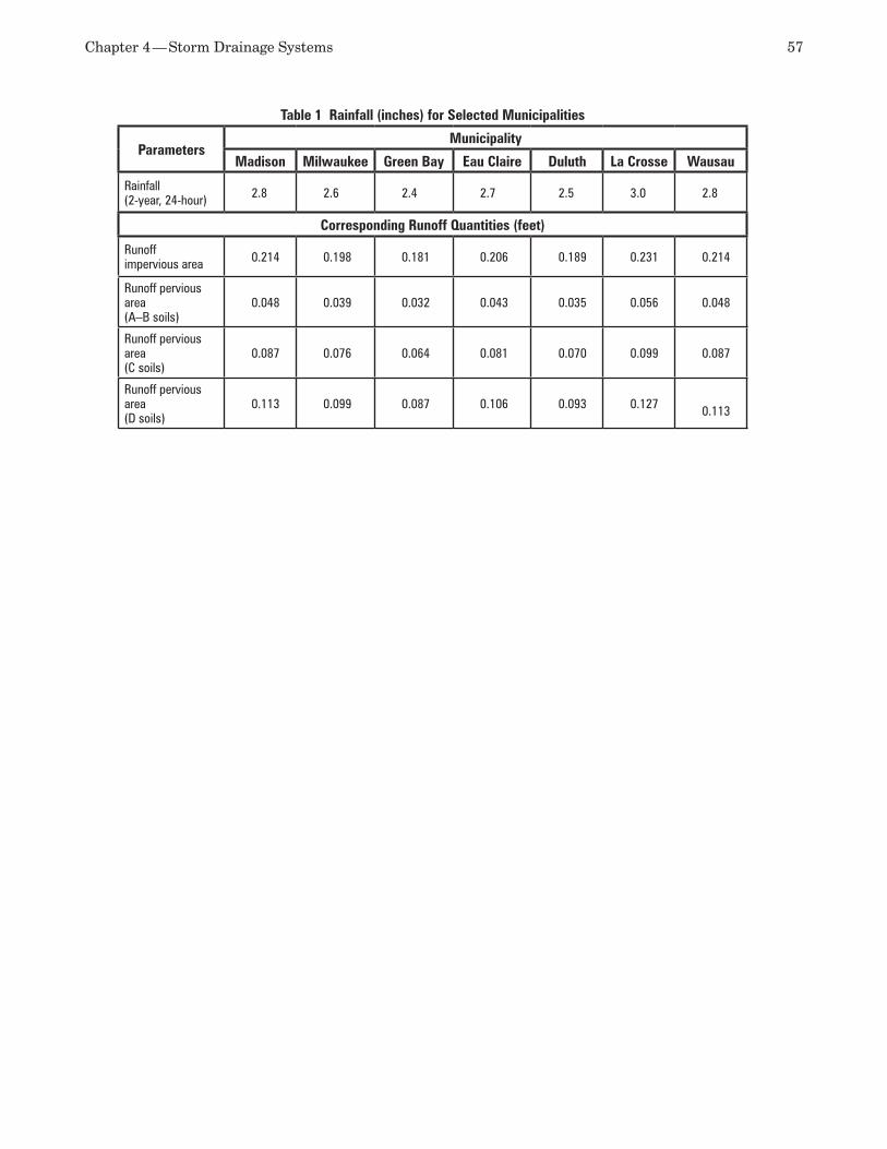
Chapter 4 — Storm Drainage Systems 57
Table 1 Rainfall (inches) for Selected Municipalities
ParametersMunicipality
Madison Milwaukee Green Bay Eau Claire Duluth La Crosse Wausau
Rainfall (2-year, 24-hour) 2.8 2.6 2.4 2.7 2.5 3.0 2.8
Corresponding Runoff Quantities (feet)
Runoffimpervious area 0.214 0.198 0.181 0.206 0.189 0.231 0.214
Runoff pervious area(A–B soils)
0.048 0.039 0.032 0.043 0.035 0.056 0.048
Runoff pervious area(C soils)
0.087 0.076 0.064 0.081 0.070 0.099 0.087
Runoff pervious area(D soils)
0.113 0.099 0.087 0.106 0.093 0.127 0.113
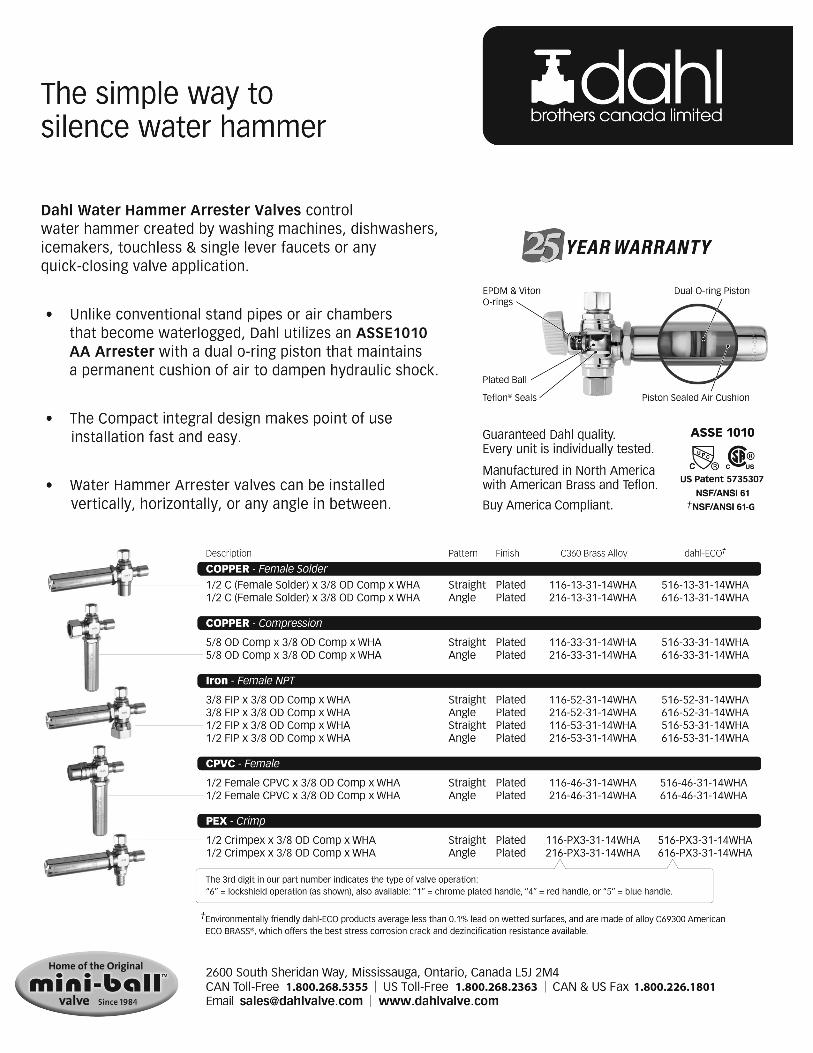
Cold Water Systems5
The primary task of a building cold water service and distribution system is to provide adequate flow, pressure, and volume suitable for use at every device that uses water, even when the system is at peak demand. The designer’s task is to ensure that this is done in a reliable, cost-effective, code compliant, and safe manner.
This chapter presents the major flow and pres-sure-related components of a cold water distribution system, from the utility water meter and backflow prevention to inadequate or excessive pressures, velocity and sizing issues, and final testing and cleaning.
CODES AND STANDARDSPlumbing codes establish a minimum acceptable standard for the design and installation of various systems, including cold water. There are various model codes, but some states and large cities have adapted plumbing codes other than the ones usually associated with the region. Because of this non-stan-dardization, the actual plumbing code used for each specific project must be obtained from a responsible code official.
The information pertaining to cold water design appears in the approved local plumbing code and must be the primary method used for the accepted methods and sizing. The tables and charts appear-ing in this chapter are used only to illustrate and augment discussions of sizing methods, sizing pro-cedures, and design methods and should not be used for actual design purposes.
DOMESTIC COLD WATER METERS Many major municipalities furnish and/or install a particular type of water meter. In such locations, the meter characteristics (type, size, flow, pressure drop, remote readouts, costs, etc.) can be obtained from the local water department. Depending on the type of project being contemplated, a utility may request a particular type of meter (e.g., compound meter vs. turbine meter).
Whether a utility company’s meter or a meter from another source is used, the above-mentioned characteristics must be taken into consideration. The location of the meter is of prime importance. The meter shall not be subjected to freezing or submerged conditions. To discourage tapping of the piping ahead of the meter, the meter may be located directly inside the building wall. Some jurisdictions want the meter immediately adjacent to the tap to prevent illegal connections between the meter and the tap. Where job conditions mandate such a location, a meter in an outside pit or manhole should be watertight against both surface and groundwater conditions. Electric tape heating also may be required.
Backflow prevention at the building meter dis-charge is required by most codes and municipalities. This is common whether the water service and fire protection use the same water lateral or not.
Water meters for plumbing use usually are classified as the positive-displacement type, which indicates direct flow and records water passage in gallons (liters) or square feet (square meters).
Meter Types Domestic cold water meters are available in the fol-lowing types.
Disc meter:• These meters are normally ½, ¾, 1, 1½, and 2 inches (16, 19.1, 25, 40, and 50 millimeters) in size; are manufactured to have a 150-pounds-per-square-inch (psi) (1,034-kilopascal [kPa]) maximum working pressure; and measure flow in one direction. This type of meter is common for residential and small commercial installations and is adaptable for remote readout systems. Compound meter:• These meters are normally 2, 3, 4, and 6 inches (50, 80, 100, and 150 millimeters) in size; are manufactured to meet the requirements of 150-psi (1,034-kPa) maximum working pressure; and measure flow in one direction. This type of meter is used when most of the flow is low, but high
60 ASPE Plumbing Engineering Design Handbook — Volume 2
flows are anticipated. It is capable of record-ing low flows and has the capacity for high flow rates. Turbine meter:• The sizes of this meter are 2, 3, 4, 6, and 10 inches (50, 80, 100, 150, and 250 millimeters). This type of meter has the characteristics of a compound meter, but it is more suitable for encountering a variety of flows. (A strainer should be installed up-stream of the meter.) Propeller meter:• The sizes of this meter are 2–72 inches (50–1,830 millimeters). Propel-ler meters are used where low flows never occur. Fire-line meter or detector-check meter:• One of these types of meter may be required by local codes in a water service that feeds a fire-protection sprinkler system or fire-hydrant system. In such a case, the installation must meet the requirements of the local fire offi-cial and the appropriate insurance company. The design should include a minimum of 8 pipe diameters of straight pipe upstream of the meter before any change in direction or connections.
Various types of meter can be equipped with optional accessories. Remote-readout systems, strip-chart recorders, etc. are available for specific applications.
Water meters are listed in American Water Works Association (AWWA) standards.
Sizing the Water Meter The following design criteria may be used as a guide for selecting the proper meter:
Building occupancy type•Minimum and maximum demand (in gallons •per minute [gpm]) Water pressure available at meter •Size of building service•Piping, valve, and elevation pressure losses•Meter costs and tap fees •Maintenance costs and fees •
Tables 5-1 through 5-3 from AWWA M22: Sizing Water Service Lines and Meters are provided here as additional guidelines for water meter sizing and selection.
CROSS-CONNECTION CONTROLSPreventing reverse flows at hazardous connection points of a water supply system is referred to as cross-connection control. Since the topic is covered in its own chapter in this series (PEDH Volume 4, Chapter 9), it is only briefly described here as it relates to cold water systems.
The fundamental principle for selecting a cross-con-nection control is based on the sciences of hydrostatics
and hydrodynamics. When water is motionless, hy-drostatics applies, and the pressure within a given volume depends only on elevation. When water is in motion, viscous forces, velocity, and momentum add other factors to consider. Controls to prevent reverse flows recognize basic static pressure conditions while accommodating for dynamic factors.
When water supply pressure is lost, low pres-sures may occur that can draw contaminants into the supply piping if no controls are provided. These contaminants then may emerge in other parts of the piping when the pressure is restored. Controls, how-ever, prevent contaminants from being drawn into the piping by devices or piping design. If pressure immediately downstream of the device is less than at-mospheric (a situation defined as back-siphonage), the control device may be a vacuum breaker. If pressure immediately downstream of the device is greater than atmospheric (a situation defined as back-pressure), the control device may be a backflow preventer. If the outlet from a water supply is located above its recep-tor, as in a faucet spout, the type of control typically used is called an air gap.
Design Guidelines for Cross-connection ControlsThoughtful consideration should be given to the an-ticipated emergency discharge of backflow preventers, such as the reduced-pressure zone (RPZ) and reduced-pressure detector assemblies. Conditions such as a leaking check valve, clogged sensing line, ruptured relief valve diaphragm, or dislodged relief valve O-ring will cause the RPZ to discharge from the atmospheric vent (located on the relief valve).
First, the designer should consider how to mini-mize these potential conditions. In most cases, with the exception of fire protection due to the overriding urgency of not compromising water flow to the sprin-kler system, the use of a Y-type strainer is strongly encouraged to help prevent debris from entering the valve and fouling the checks. The strainer body material should be consistent with the valve to pre-vent electrolysis. (The ½- through 2-inch strainers typically are bronze, and valves 2½ to 10 inches are stainless steel or cast iron with an FDA coating.) For ½- through 2-inch strainers, the screen should be 20 mesh, and the perforated screen for 2½- to 10-inch strainers should be no larger than ⅔ inch. The designer may wish to include a blowdown valve with the strainer to make maintenance easier. A strainer with only a pipe plug may not be cleaned regularly and needlessly adds to the pressure drop.
In some cases, such as industrial facilities and car washes, water hammer can cause a spitting type of discharge. This can be avoided with a properly installed and selected mechanical shock arrestor or the use of supplemental checks. It is recommended
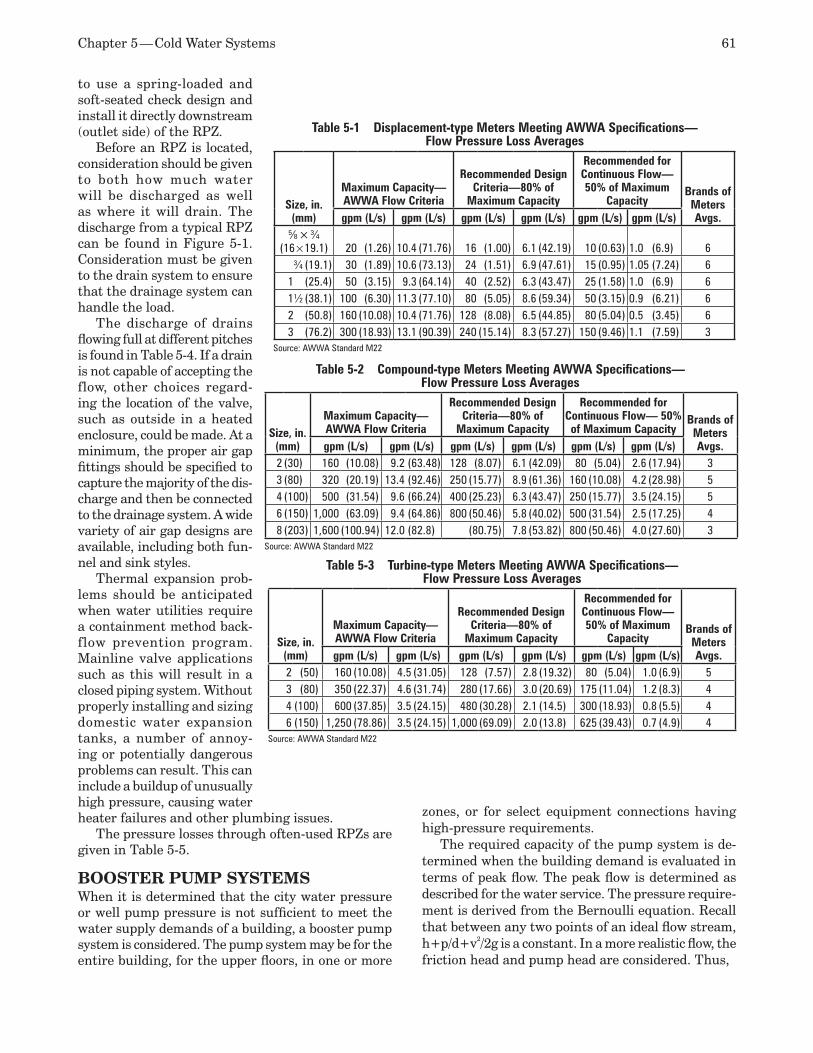
Chapter 5 — Cold Water Systems 61
to use a spring-loaded and soft-seated check design and install it directly downstream (outlet side) of the RPZ.
Before an RPZ is located, consideration should be given to both how much water will be discharged as well as where it will drain. The discharge from a typical RPZ can be found in Figure 5-1. Consideration must be given to the drain system to ensure that the drainage system can handle the load.
The discharge of drains flowing full at different pitches is found in Table 5-4. If a drain is not capable of accepting the flow, other choices regard-ing the location of the valve, such as outside in a heated enclosure, could be made. At a minimum, the proper air gap fittings should be specified to capture the majority of the dis-charge and then be connected to the drainage system. A wide variety of air gap designs are available, including both fun-nel and sink styles.
Thermal expansion prob-lems should be anticipated when water utilities require a containment method back-flow prevention program. Mainline valve applications such as this will result in a closed piping system. Without properly installing and sizing domestic water expansion tanks, a number of annoy-ing or potentially dangerous problems can result. This can include a buildup of unusually high pressure, causing water heater failures and other plumbing issues.
The pressure losses through often-used RPZs are given in Table 5-5.
BOOSTER PUMP SYSTEMSWhen it is determined that the city water pressure or well pump pressure is not sufficient to meet the water supply demands of a building, a booster pump system is considered. The pump system may be for the entire building, for the upper floors, in one or more
zones, or for select equipment connections having high-pressure requirements.
The required capacity of the pump system is de-termined when the building demand is evaluated in terms of peak flow. The peak flow is determined as described for the water service. The pressure require-ment is derived from the Bernoulli equation. Recall that between any two points of an ideal flow stream, h+p/d+v2/2g is a constant. In a more realistic flow, the friction head and pump head are considered. Thus,
Table 5-1 Displacement-type Meters Meeting AWWA Specifications— Flow Pressure Loss Averages
Size, in. (mm)
Maximum Capacity— AWWA Flow Criteria
Recommended Design Criteria—80% of
Maximum Capacity
Recommended for Continuous Flow— 50% of Maximum
CapacityBrands of
Meters Avgs.gpm (L/s) gpm (L/s) gpm (L/s) gpm (L/s) gpm (L/s) gpm (L/s)
5⁄8 × 3⁄4(16 × 19.1) 20 (1.26) 10.4 (71.76) 16 (1.00) 6.1 (42.19) 10 (0.63) 1.0 (6.9) 6
¾ (19.1) 30 (1.89) 10.6 (73.13) 24 (1.51) 6.9 (47.61) 15 (0.95) 1.05 (7.24) 61 (25.4) 50 (3.15) 9.3 (64.14) 40 (2.52) 6.3 (43.47) 25 (1.58) 1.0 (6.9) 61½ (38.1) 100 (6.30) 11.3 (77.10) 80 (5.05) 8.6 (59.34) 50 (3.15) 0.9 (6.21) 62 (50.8) 160 (10.08) 10.4 (71.76) 128 (8.08) 6.5 (44.85) 80 (5.04) 0.5 (3.45) 63 (76.2) 300 (18.93) 13.1 (90.39) 240 (15.14) 8.3 (57.27) 150 (9.46) 1.1 (7.59) 3
Source: AWWA Standard M22
Table 5-2 Compound-type Meters Meeting AWWA Specifications— Flow Pressure Loss Averages
Size, in. (mm)
Maximum Capacity— AWWA Flow Criteria
Recommended Design Criteria—80% of
Maximum Capacity
Recommended for Continuous Flow— 50% of Maximum Capacity
Brands of Meters Avgs.gpm (L/s) gpm (L/s) gpm (L/s) gpm (L/s) gpm (L/s) gpm (L/s)
2 (30) 160 (10.08) 9.2 (63.48) 128 (8.07) 6.1 (42.09) 80 (5.04) 2.6 (17.94) 33 (80) 320 (20.19) 13.4 (92.46) 250 (15.77) 8.9 (61.36) 160 (10.08) 4.2 (28.98) 54 (100) 500 (31.54) 9.6 (66.24) 400 (25.23) 6.3 (43.47) 250 (15.77) 3.5 (24.15) 56 (150) 1,000 (63.09) 9.4 (64.86) 800 (50.46) 5.8 (40.02) 500 (31.54) 2.5 (17.25) 48 (203) 1,600 (100.94) 12.0 (82.8) (80.75) 7.8 (53.82) 800 (50.46) 4.0 (27.60) 3
Source: AWWA Standard M22
Table 5-3 Turbine-type Meters Meeting AWWA Specifications— Flow Pressure Loss Averages
Size, in. (mm)
Maximum Capacity— AWWA Flow Criteria
Recommended Design Criteria—80% of
Maximum Capacity
Recommended for Continuous Flow— 50% of Maximum
CapacityBrands of
Meters Avgs.gpm (L/s) gpm (L/s) gpm (L/s) gpm (L/s) gpm (L/s) gpm (L/s)
2 (50) 160 (10.08) 4.5 (31.05) 128 (7.57) 2.8 (19.32) 80 (5.04) 1.0 (6.9) 53 (80) 350 (22.37) 4.6 (31.74) 280 (17.66) 3.0 (20.69) 175 (11.04) 1.2 (8.3) 44 (100) 600 (37.85) 3.5 (24.15) 480 (30.28) 2.1 (14.5) 300 (18.93) 0.8 (5.5) 46 (150) 1,250 (78.86) 3.5 (24.15) 1,000 (69.09) 2.0 (13.8) 625 (39.43) 0.7 (4.9) 4
Source: AWWA Standard M22
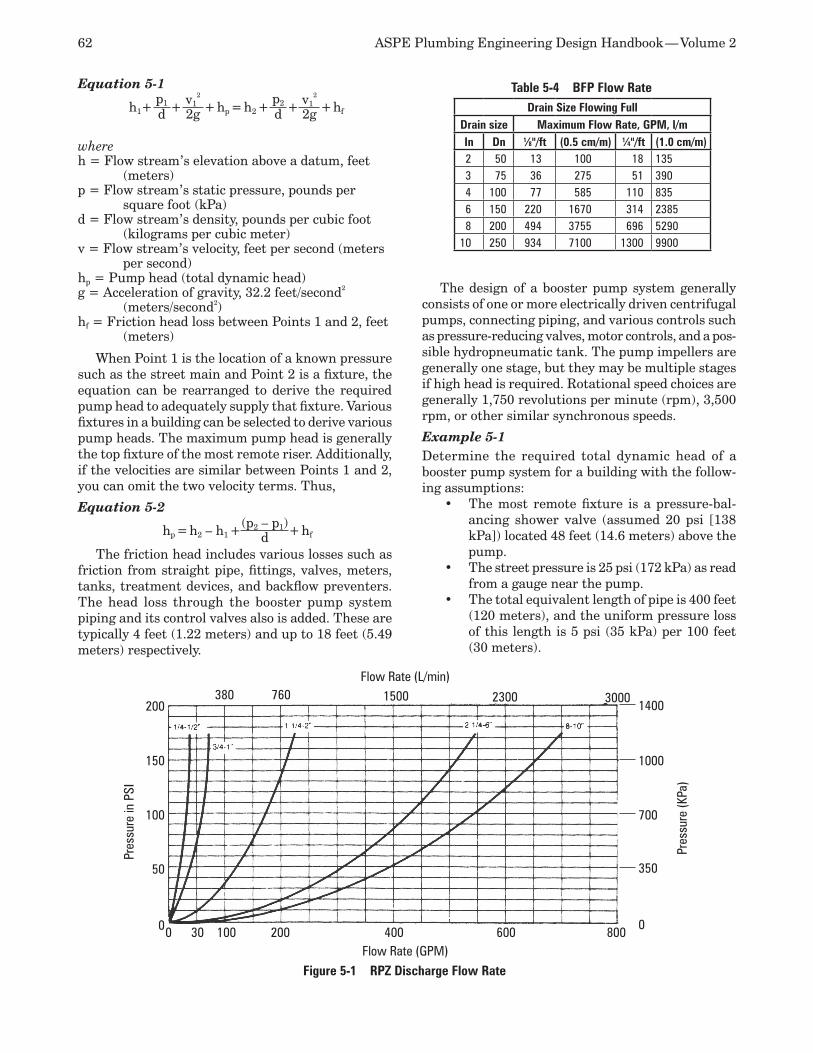
62 ASPE Plumbing Engineering Design Handbook — Volume 2
Equation 5-1
h1+p1 + v1
2
+ hp = h2 +p2 + v1
2
+ hfd 2g d 2g
where h = Flow stream’s elevation above a datum, feet
(meters)p = Flow stream’s static pressure, pounds per
square foot (kPa)d = Flow stream’s density, pounds per cubic foot
(kilograms per cubic meter)v = Flow stream’s velocity, feet per second (meters
per second)hp = Pump head (total dynamic head)g = Acceleration of gravity, 32.2 feet/second2
(meters/second2)hf = Friction head loss between Points 1 and 2, feet
(meters)
When Point 1 is the location of a known pressure such as the street main and Point 2 is a fixture, the equation can be rearranged to derive the required pump head to adequately supply that fixture. Various fixtures in a building can be selected to derive various pump heads. The maximum pump head is generally the top fixture of the most remote riser. Additionally, if the velocities are similar between Points 1 and 2, you can omit the two velocity terms. Thus,
Equation 5-2
hp = h2 – h1 +(p2 – p1)+ hfd
The friction head includes various losses such as friction from straight pipe, fittings, valves, meters, tanks, treatment devices, and backflow preventers. The head loss through the booster pump system piping and its control valves also is added. These are typically 4 feet (1.22 meters) and up to 18 feet (5.49 meters) respectively.
The design of a booster pump system generally consists of one or more electrically driven centrifugal pumps, connecting piping, and various controls such as pressure-reducing valves, motor controls, and a pos-sible hydropneumatic tank. The pump impellers are generally one stage, but they may be multiple stages if high head is required. Rotational speed choices are generally 1,750 revolutions per minute (rpm), 3,500 rpm, or other similar synchronous speeds.
Example 5-1Determine the required total dynamic head of a booster pump system for a building with the follow-ing assumptions:
The most remote fixture is a pressure-bal-•ancing shower valve (assumed 20 psi [138 kPa]) located 48 feet (14.6 meters) above the pump. The street pressure is 25 psi (172 kPa) as read •from a gauge near the pump. The total equivalent length of pipe is 400 feet •(120 meters), and the uniform pressure loss of this length is 5 psi (35 kPa) per 100 feet (30 meters).
Table 5-4 BFP Flow RateDrain Size Flowing Full
Drain size Maximum Flow Rate, GPM, l/mIn Dn 1⁄8"/ft (0.5 cm/m) 1⁄4"/ft (1.0 cm/m)2 50 13 100 18 1353 75 36 275 51 3904 100 77 585 110 8356 150 220 1670 314 23858 200 494 3755 696 5290
10 250 934 7100 1300 9900
0 30 100 200 400 600 8000
50
100
150
200380 760 1500 2300 3000
350
700
1000
1400
0
Flow Rate (GPM)
Pres
sure
in P
SI
Flow Rate (L/min)Pr
essu
re (K
Pa)
Figure 5-1 RPZ Discharge Flow Rate
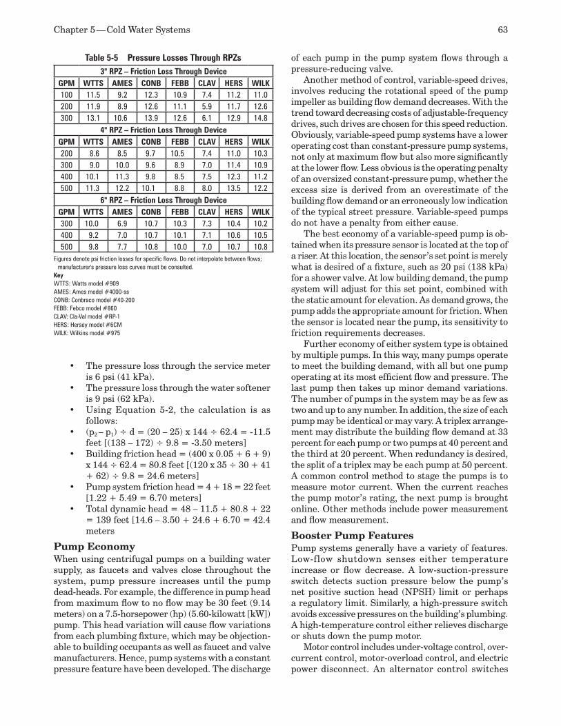
Chapter 5 — Cold Water Systems 63
The pressure loss through the service meter •is 6 psi (41 kPa).The pressure loss through the water softener •is 9 psi (62 kPa).Using Equation 5-2, the calculation is as •follows: (p• 2 – p1) ÷ d = (20 – 25) x 144 ÷ 62.4 = -11.5 feet [(138 – 172) ÷ 9.8 = -3.50 meters]Building friction head = (400 x 0.05 + 6 + 9) •x 144 ÷ 62.4 = 80.8 feet [(120 x 35 ÷ 30 + 41 + 62) ÷ 9.8 = 24.6 meters]Pump system friction head = 4 + 18 = 22 feet •[1.22 + 5.49 = 6.70 meters]Total dynamic head = 48 – 11.5 + 80.8 + 22 •= 139 feet [14.6 – 3.50 + 24.6 + 6.70 = 42.4 meters
Pump EconomyWhen using centrifugal pumps on a building water supply, as faucets and valves close throughout the system, pump pressure increases until the pump dead-heads. For example, the difference in pump head from maximum flow to no flow may be 30 feet (9.14 meters) on a 7.5-horsepower (hp) (5.60-kilowatt [kW]) pump. This head variation will cause flow variations from each plumbing fixture, which may be objection-able to building occupants as well as faucet and valve manufacturers. Hence, pump systems with a constant pressure feature have been developed. The discharge
of each pump in the pump system flows through a pressure-reducing valve.
Another method of control, variable-speed drives, involves reducing the rotational speed of the pump impeller as building flow demand decreases. With the trend toward decreasing costs of adjustable-frequency drives, such drives are chosen for this speed reduction. Obviously, variable-speed pump systems have a lower operating cost than constant-pressure pump systems, not only at maximum flow but also more significantly at the lower flow. Less obvious is the operating penalty of an oversized constant-pressure pump, whether the excess size is derived from an overestimate of the building flow demand or an erroneously low indication of the typical street pressure. Variable-speed pumps do not have a penalty from either cause.
The best economy of a variable-speed pump is ob-tained when its pressure sensor is located at the top of a riser. At this location, the sensor’s set point is merely what is desired of a fixture, such as 20 psi (138 kPa) for a shower valve. At low building demand, the pump system will adjust for this set point, combined with the static amount for elevation. As demand grows, the pump adds the appropriate amount for friction. When the sensor is located near the pump, its sensitivity to friction requirements decreases.
Further economy of either system type is obtained by multiple pumps. In this way, many pumps operate to meet the building demand, with all but one pump operating at its most efficient flow and pressure. The last pump then takes up minor demand variations. The number of pumps in the system may be as few as two and up to any number. In addition, the size of each pump may be identical or may vary. A triplex arrange-ment may distribute the building flow demand at 33 percent for each pump or two pumps at 40 percent and the third at 20 percent. When redundancy is desired, the split of a triplex may be each pump at 50 percent. A common control method to stage the pumps is to measure motor current. When the current reaches the pump motor’s rating, the next pump is brought online. Other methods include power measurement and flow measurement.
Booster Pump FeaturesPump systems generally have a variety of features. Low-flow shutdown senses either temperature increase or flow decrease. A low-suction-pressure switch detects suction pressure below the pump’s net positive suction head (NPSH) limit or perhaps a regulatory limit. Similarly, a high-pressure switch avoids excessive pressures on the building’s plumbing. A high-temperature control either relieves discharge or shuts down the pump motor.
Motor control includes under-voltage control, over-current control, motor-overload control, and electric power disconnect. An alternator control switches
Table 5-5 Pressure Losses Through RPZs3" RPZ – Friction Loss Through Device
GPM WTTS AMES CONB FEBB CLAV HERS WILK100 11.5 9.2 12.3 10.9 7.4 11.2 11.0200 11.9 8.9 12.6 11.1 5.9 11.7 12.6300 13.1 10.6 13.9 12.6 6.1 12.9 14.8
4" RPZ – Friction Loss Through DeviceGPM WTTS AMES CONB FEBB CLAV HERS WILK200 8.6 8.5 9.7 10.5 7.4 11.0 10.3300 9.0 10.0 9.6 8.9 7.0 11.4 10.9400 10.1 11.3 9.8 8.5 7.5 12.3 11.2500 11.3 12.2 10.1 8.8 8.0 13.5 12.2
6" RPZ – Friction Loss Through DeviceGPM WTTS AMES CONB FEBB CLAV HERS WILK300 10.0 6.9 10.7 10.3 7.3 10.4 10.2400 9.2 7.0 10.7 10.1 7.1 10.6 10.5500 9.8 7.7 10.8 10.0 7.0 10.7 10.8
Figures denote psi friction losses for specific flows. Do not interpolate between flows; manufacturer's pressure loss curves must be consulted.
KeyWTTS: Watts model #909AMES: Ames model #4000-ssCONB: Conbraco model #40-200FEBB: Febco model #860CLAV: Cla-Val model #RP-1HERS: Hersey model #6CMWILK: Wilkins model #975
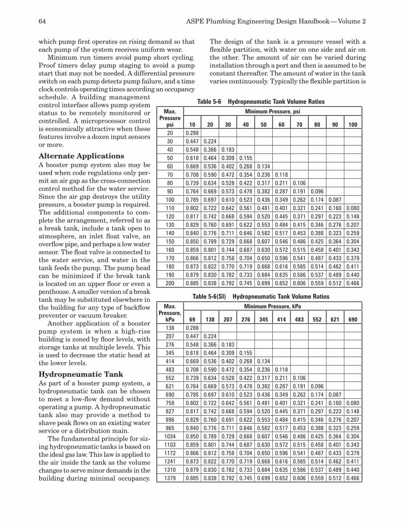
64 ASPE Plumbing Engineering Design Handbook — Volume 2
which pump first operates on rising demand so that each pump of the system receives uniform wear.
Minimum run timers avoid pump short cycling. Proof timers delay pump staging to avoid a pump start that may not be needed. A differential pressure switch on each pump detects pump failure, and a time clock controls operating times according an occupancy schedule. A building management control interface allows pump system status to be remotely monitored or controlled. A microprocessor control is economically attractive when these features involve a dozen input sensors or more.
Alternate ApplicationsA booster pump system also may be used when code regulations only per-mit an air gap as the cross-connection control method for the water service. Since the air gap destroys the utility pressure, a booster pump is required. The additional components to com-plete the arrangement, referred to as a break tank, include a tank open to atmosphere, an inlet float valve, an overflow pipe, and perhaps a low water sensor. The float valve is connected to the water service, and water in the tank feeds the pump. The pump head can be minimized if the break tank is located on an upper floor or even a penthouse. A smaller version of a break tank may be substituted elsewhere in the building for any type of backflow preventer or vacuum breaker.
Another application of a booster pump system is when a high-rise building is zoned by floor levels, with storage tanks at multiple levels. This is used to decrease the static head at the lower levels.
Hydropneumatic TankAs part of a booster pump system, a hydropneumatic tank can be chosen to meet a low-flow demand without operating a pump. A hydropneumatic tank also may provide a method to shave peak flows on an existing water service or a distribution main.
The fundamental principle for siz-ing hydropneumatic tanks is based on the ideal gas law. This law is applied to the air inside the tank as the volume changes to serve minor demands in the building during minimal occupancy.
The design of the tank is a pressure vessel with a flexible partition, with water on one side and air on the other. The amount of air can be varied during installation through a port and then is assumed to be constant thereafter. The amount of water in the tank varies continuously. Typically the flexible partition is
Table 5-6 Hydropneumatic Tank Volume RatiosMax.
Pressure psi
Minimum Pressure, psi
10 20 30 40 50 60 70 80 90 10020 0.28830 0.447 0.22440 0.548 0.366 0.18350 0.618 0.464 0.309 0.15560 0.669 0.536 0.402 0.268 0.13470 0.708 0.590 0.472 0.354 0.236 0.11880 0.739 0.634 0.528 0.422 0.317 0.211 0.10690 0.764 0.669 0.573 0.478 0.382 0.287 0.191 0.096100 0.785 0.697 0.610 0.523 0.436 0.349 0.262 0.174 0.087110 0.802 0.722 0.642 0.561 0.481 0.401 0.321 0.241 0.160 0.080120 0.817 0.742 0.668 0.594 0.520 0.445 0.371 0.297 0.223 0.148130 0.829 0.760 0.691 0.622 0.553 0.484 0.415 0.346 0.276 0.207140 0.840 0.776 0.711 0.646 0.582 0.517 0.453 0.388 0.323 0.259150 0.850 0.789 0.729 0.668 0.607 0.546 0.486 0.425 0.364 0.304160 0.859 0.801 0.744 0.687 0.630 0.572 0.515 0.458 0.401 0.343170 0.866 0.812 0.758 0.704 0.650 0.596 0.541 0.487 0.433 0.379180 0.873 0.822 0.770 0.719 0.668 0.616 0.565 0.514 0.462 0.411190 0.879 0.830 0.782 0.733 0.684 0.635 0.586 0.537 0.489 0.440200 0.885 0.838 0.792 0.745 0.699 0.652 0.606 0.559 0.512 0.466
Table 5-6(SI) Hydropneumatic Tank Volume RatiosMax.
Pressure, kPa
Minimum Pressure, kPa
69 138 207 276 345 414 483 552 621 690138 0.288207 0.447 0.224276 0.548 0.366 0.183345 0.618 0.464 0.309 0.155414 0.669 0.536 0.402 0.268 0.134483 0.708 0.590 0.472 0.354 0.236 0.118552 0.739 0.634 0.528 0.422 0.317 0.211 0.106621 0.764 0.669 0.573 0.478 0.382 0.287 0.191 0.096690 0.785 0.697 0.610 0.523 0.436 0.349 0.262 0.174 0.087758 0.802 0.722 0.642 0.561 0.481 0.401 0.321 0.241 0.160 0.080827 0.817 0.742 0.668 0.594 0.520 0.445 0.371 0.297 0.223 0.148896 0.829 0.760 0.691 0.622 0.553 0.484 0.415 0.346 0.276 0.207965 0.840 0.776 0.711 0.646 0.582 0.517 0.453 0.388 0.323 0.2591034 0.850 0.789 0.729 0.668 0.607 0.546 0.486 0.425 0.364 0.3041103 0.859 0.801 0.744 0.687 0.630 0.572 0.515 0.458 0.401 0.3431172 0.866 0.812 0.758 0.704 0.650 0.596 0.541 0.487 0.433 0.3791241 0.873 0.822 0.770 0.719 0.668 0.616 0.565 0.514 0.462 0.4111310 0.879 0.830 0.782 0.733 0.684 0.635 0.586 0.537 0.489 0.4401379 0.885 0.838 0.792 0.745 0.699 0.652 0.606 0.559 0.512 0.466
Chapter 5 — Cold Water Systems 65
a rubber diaphragm, which moves as pressure varies. It effectively isolates the air from the water.
The product of pressure and volume of an ideal gas is proportional to its mass and temperature. Since the air is captured in the tank, its mass is constant, and its temperature is assumed to be constant. Hence, pV = a constant, or:
Equation 5-3 (Boyle’s Law)
p1V1 = p2V2
where p = Tank air pressure, pounds per square inch
absolute (psia) (kPa)V = Volume of air in the tank, cubic feet (cubic
meters)Vt = Total tank volume, cubic feet (cubic meters)dV/dt = Average flow over time period tp during low
system demand
Then, when you define (dV/dt)(tp) as the drawdown volume Vd, you can examine the tank volume between two pressure levels in the tank and equate it to the drawdown volume. That is,
V1 – V2 = Vd
Designating V1 as the tank with all water expelled from it and applying the ideal gas law, you have:
V1 – V2 = V1 – V1( p1 )=V1(1 – p1)=Vt(1 – p1), orp2 p2 p2
V1 – V2 = Vt(p2 – p1)p2
Rearranging and combining this with the average low flow, you get the tank volume formula:
Equation 5-4
Vt =Vd
(p2 – p1 )p2The pressure ratio is a convenient volume ratio
of drawdown volume to tank volume. For average near-sea-level conditions, Table 5-6 shows this ratio
between any two levels of air pressure in a tank. For example, two pressure levels of 50 psi (345
kPa) and 40 psi (276 kPa) for a tank to draw out 60 gallons (227 liters) require a tank volume of 60 ÷ 0.155 = 387 gallons (227 ÷ 0.155 = 1,465 liters).
In practice, tanks are chosen larger than as calcu-lated to avoid a completely empty tank. The average flow during low system demand is taken as a frac-tion of the building’s peak flow, typically 0.5 percent for apartment buildings and 4 percent for hospitals. Other buildings generally fall in between these ex-tremes. The time period typically is chosen to be 10 to 30 minutes, and p2 – p1 is 10 psi (69 kPa). For tanks on private wells, p2 – p1 typically is taken to be 20 psi (138 kPa). Note that since p2 is derived from the ideal gas law, it is an absolute pressure and must include the local prevailing atmospheric pressure (14.7 psi [100 kPa] at sea level).
In Table 5-7, an example of a four-story building with a 10-gpm (37.8-liter-per-minute) requirement for 10 minutes is shown with a hydropneumatic tank selected in three different locations. When it is located at a high elevation, the tank is smaller than it is when located at a low elevation such as near the booster pump. The tank is smaller when positioned upstream of the pump’s pressure-reducing valve than when downstream because of the larger range of pres-sures upstream of the valve.
Elevated Water Tank SystemIn an elevated water tank system, such as that illus-trated in Figure 5-2, water is pumped from the street main to an elevated water storage tank (commonly called a gravity tank or house tank) located above the highest and most hydraulically remote point in the water supply system of the building. The height of the tank provides additional static head, which results in a higher pressure in the water distribution system. For each 2.31 feet (0.7 meter) of elevation, the pressure increases 1 psi (6.9 kPa).
An elevated water tank is made up of the following components:
A gravity tank, which stores water at atmo-•spheric pressurePumps (commonly called house pumps), •which fill the tank by pumping water into it from the sourceControls, which turn the pump on and off •when the water inside the tank reaches pre-set levelsAlarms, which alert operating personnel that •a malfunction existsSafety devices, which operate when a mal-•function occurs to avoid potential accidents
The piping arrangements between the various components of an elevated water tank system are illustrated in Figure 5-3.
The advantages of an elevated water tank system are as follows:
It is less complex than either of the other two •systems.The least number of components is required •to control and operate the system.The efficiency is greater and operating costs •are lower than for the other systems.A smaller pump capacity is required than for •either of the other two systems.Pressure fluctuation in the system is mini-•mal.Maintenance requirements are minimized.•
The disadvantages of the elevated water tank system compared with the other two systems are as follows:
An exposed tank (or the enclosure around it) •may be considered unsightly.
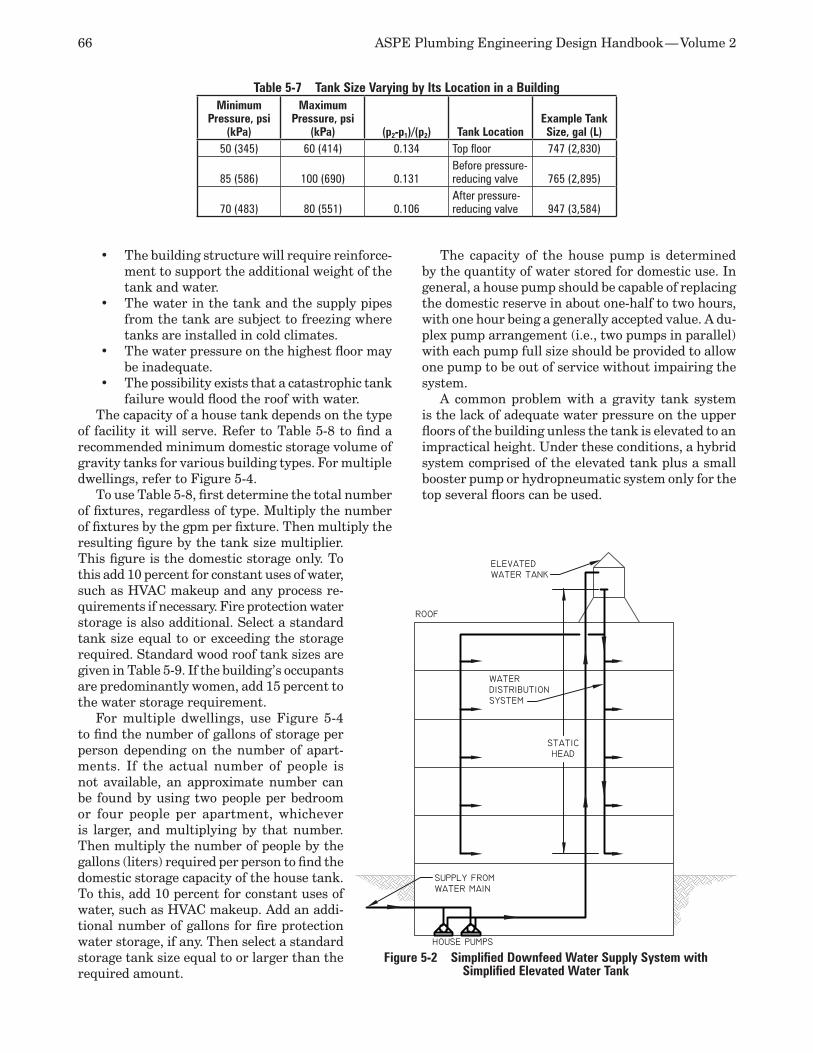
66 ASPE Plumbing Engineering Design Handbook — Volume 2
The building structure will require reinforce-•ment to support the additional weight of the tank and water.The water in the tank and the supply pipes •from the tank are subject to freezing where tanks are installed in cold climates.The water pressure on the highest floor may •be inadequate.The possibility exists that a catastrophic tank •failure would flood the roof with water.
The capacity of a house tank depends on the type of facility it will serve. Refer to Table 5-8 to find a recommended minimum domestic storage volume of gravity tanks for various building types. For multiple dwellings, refer to Figure 5-4.
To use Table 5-8, first determine the total number of fixtures, regardless of type. Multiply the number of fixtures by the gpm per fixture. Then multiply the resulting figure by the tank size multiplier. This figure is the domestic storage only. To this add 10 percent for constant uses of water, such as HVAC makeup and any process re-quirements if necessary. Fire protection water storage is also additional. Select a standard tank size equal to or exceeding the storage required. Standard wood roof tank sizes are given in Table 5-9. If the building’s occupants are predominantly women, add 15 percent to the water storage requirement.
For multiple dwellings, use Figure 5-4 to find the number of gallons of storage per person depending on the number of apart-ments. If the actual number of people is not available, an approximate number can be found by using two people per bedroom or four people per apartment, whichever is larger, and multiplying by that number. Then multiply the number of people by the gallons (liters) required per person to find the domestic storage capacity of the house tank. To this, add 10 percent for constant uses of water, such as HVAC makeup. Add an addi-tional number of gallons for fire protection water storage, if any. Then select a standard storage tank size equal to or larger than the required amount.
The capacity of the house pump is determined by the quantity of water stored for domestic use. In general, a house pump should be capable of replacing the domestic reserve in about one-half to two hours, with one hour being a generally accepted value. A du-plex pump arrangement (i.e., two pumps in parallel) with each pump full size should be provided to allow one pump to be out of service without impairing the system.
A common problem with a gravity tank system is the lack of adequate water pressure on the upper floors of the building unless the tank is elevated to an impractical height. Under these conditions, a hybrid system comprised of the elevated tank plus a small booster pump or hydropneumatic system only for the top several floors can be used.
Table 5-7 Tank Size Varying by Its Location in a BuildingMinimum
Pressure, psi (kPa)
Maximum Pressure, psi
(kPa) (p2-p1)/(p2) Tank LocationExample Tank Size, gal (L)
50 (345) 60 (414) 0.134 Top floor 747 (2,830)
85 (586) 100 (690) 0.131Before pressure-reducing valve 765 (2,895)
70 (483) 80 (551) 0.106After pressure-reducing valve 947 (3,584)
Figure 5-2 Simplified Downfeed Water Supply System with Simplified Elevated Water Tank
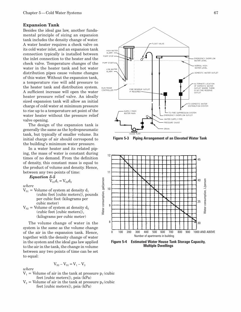
Chapter 5 — Cold Water Systems 67
Expansion TankBesides the ideal gas law, another funda-mental principle of sizing an expansion tank includes the density change of water. A water heater requires a check valve on its cold water inlet, and an expansion tank connection typically is installed between the inlet connection to the heater and the check valve. Temperature changes of the water in the heater tank and hot water distribution pipes cause volume changes of this water. Without the expansion tank, a temperature rise will add pressure to the heater tank and distribution system. A sufficient increase will open the water heater pressure relief valve. An ideally sized expansion tank will allow an initial charge of cold water at minimum pressure to rise up to a temperature set point of the water heater without the pressure relief valve opening.
The design of the expansion tank is generally the same as the hydropneumatic tank, but typically of smaller volume. Its initial charge of air should correspond to the building’s minimum water pressure.
In a water heater and its related pip-ing, the mass of water is constant during times of no demand. From the definition of density, this constant mass is equal to the product of volume and density. Hence, between any two points of time:
Equation 5-5VS1d1 = VS2d2
where VS1 = Volume of system at density d1
(cubic feet [cubic meters]), pounds per cubic foot (kilograms per cubic meter)
VS2 = Volume of system at density d2
(cubic feet [cubic meters]), (kilograms per cubic meter)
The volume change of water in the system is the same as the volume change of the air in the expansion tank. Hence, together with the density change of water in the system and the ideal gas law applied to the air in the tank, the change in volume between any two points of time can be set to equal:
VS2 – VS1 = V1 – V2
where V1 = Volume of air in the tank at pressure p1 (cubic
feet [cubic meters]), psia (kPa)V2 = Volume of air in the tank at pressure p2 (cubic
feet [cubic meters]), psia (kPa)
Figure 5-3 Piping Arrangement of an Elevated Water Tank
Figure 5-4 Estimated Water House Tank Storage Capacity, Multiple Dwellings
0 100 200 300 400 500 600 700 800 900 1000 AND ABOVE
8
9
10
11
12
30
35
40
45
Wat
er c
onsu
mpt
ion,
L/p
erso
n
Wat
er c
onsu
mpt
ion,
gal
/per
son
Number of apartments in building
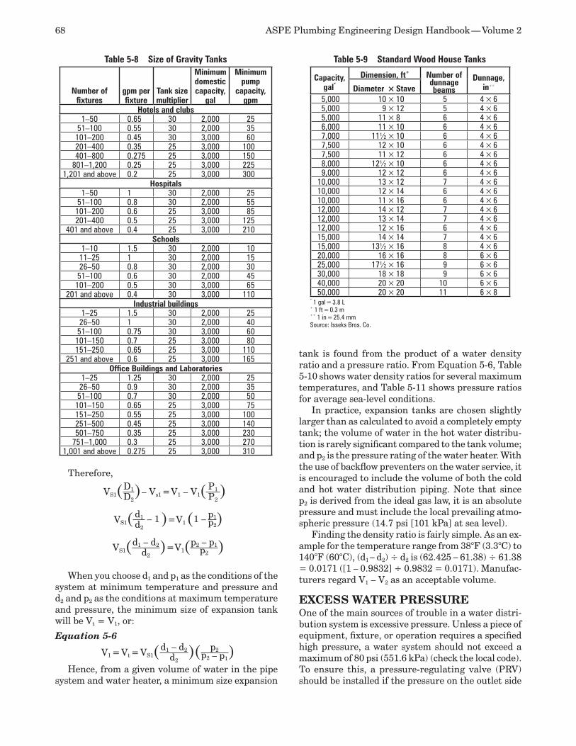
68 ASPE Plumbing Engineering Design Handbook — Volume 2
Therefore,
VS1(D1)– Vs1 =V1 – V1( P1 )D2 P2
VS1( d1 – 1 )=V1 (1 – p1)d2p2
VS1(d1 – d2)=V1(p2 – p1)d2p2
When you choose d1 and p1 as the conditions of the system at minimum temperature and pressure and d2 and p2 as the conditions at maximum temperature and pressure, the minimum size of expansion tank will be Vt = V1, or:
Equation 5-6
V1 = Vt = VS1(d1 – d2)( p2 )d2p2 – p1
Hence, from a given volume of water in the pipe system and water heater, a minimum size expansion
tank is found from the product of a water density ratio and a pressure ratio. From Equation 5-6, Table 5-10 shows water density ratios for several maximum temperatures, and Table 5-11 shows pressure ratios for average sea-level conditions.
In practice, expansion tanks are chosen slightly larger than as calculated to avoid a completely empty tank; the volume of water in the hot water distribu-tion is rarely significant compared to the tank volume; and p2 is the pressure rating of the water heater. With the use of backflow preventers on the water service, it is encouraged to include the volume of both the cold and hot water distribution piping. Note that since p2 is derived from the ideal gas law, it is an absolute pressure and must include the local prevailing atmo-spheric pressure (14.7 psi [101 kPa] at sea level).
Finding the density ratio is fairly simple. As an ex-ample for the temperature range from 38°F (3.3°C) to 140°F (60°C), (d1 – d2) ÷ d2 is (62.425 – 61.38) ÷ 61.38 = 0.0171 ([1 – 0.9832] ÷ 0.9832 = 0.0171). Manufac-turers regard V1 – V2 as an acceptable volume.
EXCESS WATER PRESSURE One of the main sources of trouble in a water distri-bution system is excessive pressure. Unless a piece of equipment, fixture, or operation requires a specified high pressure, a water system should not exceed a maximum of 80 psi (551.6 kPa) (check the local code). To ensure this, a pressure-regulating valve (PRV) should be installed if the pressure on the outlet side
Table 5-8 Size of Gravity Tanks
Number of fixtures
gpm per fixture
Tank size multiplier
Minimum domestic capacity,
gal
Minimum pump
capacity, gpm
Hotels and clubs1–50 0.65 30 2,000 25
51–100 0.55 30 2,000 35101–200 0.45 30 3,000 60201–400 0.35 25 3,000 100401–800 0.275 25 3,000 150
801–1,200 0.25 25 3,000 2251,201 and above 0.2 25 3,000 300
Hospitals1–50 1 30 2,000 25
51–100 0.8 30 2,000 55101–200 0.6 25 3,000 85201–400 0.5 25 3,000 125
401 and above 0.4 25 3,000 210Schools
1–10 1.5 30 2,000 1011–25 1 30 2,000 1526–50 0.8 30 2,000 3051–100 0.6 30 2,000 45101–200 0.5 30 3,000 65
201 and above 0.4 30 3,000 110Industrial buildings
1–25 1.5 30 2,000 2526–50 1 30 2,000 4051–100 0.75 30 3,000 60101–150 0.7 25 3,000 80151–250 0.65 25 3,000 110
251 and above 0.6 25 3,000 165Office Buildings and Laboratories
1–25 1.25 30 2,000 2526–50 0.9 30 2,000 3551–100 0.7 30 2,000 50101–150 0.65 25 3,000 75151–250 0.55 25 3,000 100251–500 0.45 25 3,000 140501–750 0.35 25 3,000 230
751–1,000 0.3 25 3,000 2701,001 and above 0.275 25 3,000 310
Table 5-9 Standard Wood House Tanks
Capacity, gal*
Dimension, ft+ Number of dunnage beams
Dunnage, in++Diameter × Stave
5,000 10 × 10 5 4 × 6 5,000 9 × 12 5 4 × 6 5,000 11 × 8 6 4 × 6 6,000 11 × 10 6 4 × 6 7,000 11½ × 10 6 4 × 6 7,500 12 × 10 6 4 × 6 7,500 11 × 12 6 4 × 6 8,000 12½ × 10 6 4 × 6 9,000 12 × 12 6 4 × 6
10,000 13 × 12 7 4 × 6 10,000 12 × 14 6 4 × 6 10,000 11 × 16 6 4 × 6 12,000 14 × 12 7 4 × 6 12,000 13 × 14 7 4 × 6 12,000 12 × 16 6 4 × 6 15,000 14 × 14 7 4 × 6 15,000 13½ × 16 8 4 × 6 20,000 16 × 16 8 6 × 625,000 17½ × 16 9 6 × 630,000 18 × 18 9 6 × 640,000 20 × 20 10 6 × 650,000 20 × 20 11 6 × 8
* 1 gal = 3.8 L+ 1 ft = 0.3 m++ 1 in = 25.4 mmSource: Isseks Bros. Co.
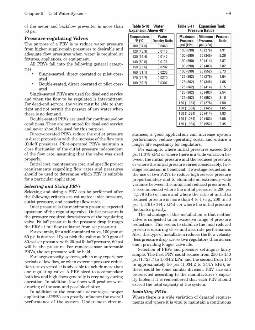
Chapter 5 — Cold Water Systems 69
of the meter and backflow preventer is more than 80 psi.
Pressure-regulating Valves The purpose of a PRV is to reduce water pressure from higher supply-main pressures to desirable and adequate flow pressures when water is required at fixtures, appliances, or equipment.
All PRVs fall into the following general catego-ries:
Single-seated, direct operated or pilot oper-•ated Double-seated, direct operated or pilot oper-•ated
Single-seated PRVs are used for dead-end service and when the flow to be regulated is intermittent. For dead-end service, the valve must be able to shut tight and not permit the passage of any water when there is no demand.
Double-seated PRVs are used for continuous-flow conditions. They are not suited for dead-end service and never should be used for this purpose.
Direct-operated PRVs reduce the outlet pressure in direct proportion with the increase of the flow rate (falloff pressure). Pilot-operated PRVs maintain a close fluctuation of the outlet pressure independent of the flow rate, assuming that the valve was sized properly.
Initial cost, maintenance cost, and specific project requirements regarding flow rates and pressures should be used to determine which PRV is suitable for a particular application.
Selecting and Sizing PRVs Selecting and sizing a PRV can be performed after the following criteria are estimated: inlet pressure, outlet pressure, and capacity (flow rate).
Inlet pressure is the maximum pressure expected upstream of the regulating valve. Outlet pressure is the pressure required downstream of the regulating valve. Falloff pressure is the pressure drop through the PRV at full flow (subtract from set pressure).
For example, for a self-contained valve, 100 gpm at 60 psi is desired. If you pick the value at 100 gpm of 80-psi set pressure with 20-psi falloff pressure, 60 psi will be the pressure. For remote-sensor automatic PRVs, the set pressure will be held.
For large-capacity systems, which may experience periods of low flow, or when extreme pressure reduc-tions are expected, it is advisable to include more than one regulating valve. A PRV sized to accommodate both low and high flows generally is very noisy during operation. In addition, low flows will produce wire-drawing of the seat and possible chatter.
In addition to the economic advantages, proper application of PRVs can greatly influence the overall performance of the system. Under most circum-
stances, a good application can increase system performance, reduce operating costs, and ensure a longer life expectancy for regulators.
For example, where initial pressures exceed 200 psi (1,379 kPa) or where there is a wide variation be-tween the initial pressure and the reduced pressure, or where the initial pressure varies considerably, two-stage reduction is beneficial. Two-stage reduction is the use of two PRVs to reduce high service pressure proportionately and to eliminate an extremely wide variance between the initial and reduced pressures. It is recommended where the initial pressure is 200 psi (1,379 kPa) or more and where the ratio of initial to reduced pressure is more than 4 to 1 (e.g., 200 to 50 psi [1,379 to 344.7 kPa]), or where the initial pressure fluctuates greatly.
The advantage of this installation is that neither valve is subjected to an excessive range of pressure reductions. This seems to stabilize the final reduced pressure, ensuring close and accurate performance. Also, this type of installation reduces the flow velocity (less pressure drop across two regulators than across one), providing longer valve life.
Selection of PRVs and pressure settings is fairly simple. The first PRV could reduce from 250 to 150 psi (1,723.7 to 1,034.2 kPa) and the second from 150 to approximately 50 psi (1,034.2 to 344.7 kPa), or there could be some similar division. PRV size can be selected according to the manufacturer’s capac-ity tables if it is remembered that each PRV should exceed the total capacity of the system.
Installing PRVsWhere there is a wide variation of demand require-ments and where it is vital to maintain a continuous
Table 5-10 Water Expansion Above 40°FTemperature,
°F (°C)Water
Density Ratio100 (37.8) 0.0069120 (48.9) 0.0115130 (54.4) 0.0142140 (60.0) 0.0171150 (65.6) 0.0202160 (71.1) 0.0235170 (76.7) 0.0270180 (82.2) 0.0307
Table 5-11 Expansion Tank Pressure Ratios
Maximum Pressure, psi (kPa)
Minimum Pressure, psi (kPa)
Pressure Ratio
100 (690) 40 (276) 1.91100 (690) 50 (345) 2.29100 (690) 60 (414) 2.87100 (690) 70 (483) 3.82100 (690) 80 (552) 5.73125 (862) 40 (276) 1.64125 (862) 50 (345) 1.86125 (862) 60 (414) 2.15125 (862) 70 (483) 2.54125 (862) 80 (552) 3.10
150 (1,034) 40 (276) 1.50150 (1,034) 50 (345) 1.65150 (1,034) 60 (414) 1.83150 (1,034) 70 (483) 2.06150 (1,034) 80 (552) 2.35
70 ASPE Plumbing Engineering Design Handbook — Volume 2
water supply as well as provide greater capacity, parallel installation is recommended. Parallel instal-lation is the use of two or more small PRVs serving a larger supply main. This type of installation should be employed wherever there is a wide variation of reduced-pressure requirements and where it is vital to maintain a continuous water supply. It also has the advantage of providing increased capacity beyond that provided by a single valve where needed. This installation improves valve performance for widely variable demands and permits the servicing of an individual valve without the complete shutdown of the line, thus preventing costly shutdowns.
For a two-valve parallel installation, the total capacity of the valves should equal or exceed the capacity required by the system. One valve should be set at a 10-psi (69-kPa) higher delivery pressure than the other.
For example, assume that the system requires 400 gpm (25.2 liters per second) and the set pressure required is 50 psi (344.7 kPa). Select two valves, each rated at 200 gpm (12.6 liters per second), with one valve set at 50 psi (344.7 kPa) and the other valve set 10 psi (69.0 kPa) higher at 60 psi (413.7 kPa). Thus, when low volume is required, the higher-set valve operates alone. When a larger volume is demanded, both valves open, delivering full-line capacity.
Another possible choice is to install two PRV combinations of different sizes. This is practical on large installations where supply lines are 2 inches (50 millimeters) and larger and where there are frequent periods of small demand. The smaller PRV would have the 10-psi (69-kPa) higher delivery pressure and thus operate alone to satisfy small demands, such as urinals and drinking fountains. When a larger volume is needed, the main PRV would open to satisfy the system demand.
For example, take an apartment building requiring 300 gpm (18.9 liters per second) at a 60-psi (413.7-kPa) set pressure. The selection might be a 4-inch (100-millimeter) PRV rated for 240 gpm (15.1 liters per second) (80 percent of total maximum flow rate) and set at 60 psi (413.7 kPa) and a 1½-inch (40-mil-limeter) PRV rated for 60 gpm (3.8 liters per second) and set at 70 psi (482.6 kPa).
Manufacturers provide tables indicating the recommended capacities and valve sizes for use in parallel installations.
WATER HAMMERA well-designed cold water distribution system mini-mizes velocity-related problems in a cost-effective manner. For an open system, every time a valve opens or a fixture is used, both flow and pressure change, but when excessive velocity is also present, these hydrodynamic changes can be destructive.
Excessive velocity-related problems include erosion, cavitation, entrained air separation, whistling, and water hammer.
Water hammer (or more formally hydraulic shock, which reminds the designer that there are non-audible components) is the term commonly used to describe the destructive forces, pounding noises, and vibrations that develop in a piping system when a column of non-compressible liquid flowing at a given velocity is stopped abruptly. The dynamic pressure wave generated at the point of impact travels back and forth through the piping system until the wave energy is dissipated (see Figure 5-5), producing the charac-teristic sound associated with this phenomenon, as if someone was hitting the pipe with a hammer.
Water hammer can occur in any non-compressible liquid piping system. A pumped waste system, closed hydronic system, or purified water system, as ex-amples, all will exhibit water hammer for the same reasons as a cold water distribution system. Steam systems can produce sounds similar to that caused by hydraulic shock, and these sounds also are commonly known as water hammer. However, steam system water hammer is caused by either a too rapid con-densation of steam or a slug of condensate captured by high-velocity steam and then forced through the pipe until slammed into an elbow.
Any device that abruptly stops the flow of water will generate a shock wave and, depending on installation circumstances, may cause water hammer. Common devices of concern include quick-closing electrical solenoid valves and pneumatic valves and pumps, as well as the quick hand closure of quarter-turn valves or fixture trim. Because of their high instantaneous flow and therefore accompanying high fluid velocity, water closet flushometer valves (flush valves) also frequently act as the source of water hammer.
Although sound generally is associated with the occurrence of hydraulic shock, the absence of such noise does not necessarily prove that hydraulic shock is nonexistent. The sound may be annoying, but it is not inherently dangerous; like thunder and lightning, the cause of the sound is the dangerous part. For a given piped system, the designer should verify that the circumstances that produce water hammer are either not present or, if present, are effectively controlled.
Shock Intensity The intensity of a pressure wave is related directly to valve closure time. As valve closure time from full-open position to full-closed position approaches zero, the maximum pressure rise is reached, calculated by Equation 5-7, known as Joukowsky’s formula:
Equation 5-7 (Joukowsky’s formula)
Pr =wav144g
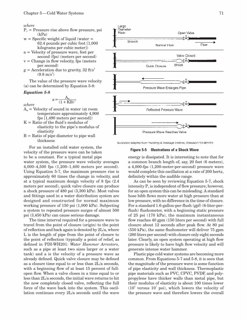
Chapter 5 — Cold Water Systems 71
wherePr = Pressure rise above flow pressure, psi
(kPa)w = Specific weight of liquid (water =
62.4 pounds per cubic foot [1,000 kilograms per cubic meter])
a = Velocity of pressure wave, feet per second (fps) (meters per second)
v = Change in flow velocity, fps (meters per second)
g = Acceleration due to gravity, 32 ft/s2 (9.8 m/s2)
The value of the pressure wave velocity (a) can be determined by Equation 5-8:
Equation 5-8
a = Aw
(1 + KB)½
whereAw = Velocity of sound in water (at room
temperature approximately 4,900 fps [1,490 meters per second])
K = Ratio of the fluid’s modulus of elasticity to the pipe’s modulus of elasticity
B = Ratio of pipe diameter to pipe wall thickness
For an installed cold water system, the velocity of the pressure wave can be taken to be a constant. For a typical metal pipe water system, the pressure wave velocity averages 4,000–4,500 fps (1,200–1,400 meters per second). Using Equation 5-7, the maximum pressure rise is approximately 60 times the change in velocity, and at a typical maximum design velocity of 8 fps (2.4 meters per second), quick valve closure can produce a shock pressure of 480 psi (3,300 kPa). Most valves and fittings used in a water distribution system are designed and constructed for normal maximum working pressure of 150 psi (1,000 kPa). Subjecting a system to repeated pressure surges of almost 500 psi (3,450 kPa) can cause serious damage.
The time interval required for a pressure wave to travel from the point of closure (origin) to the point of reflection and back again is denoted by 2L/a, where L is the length of pipe from the point of closure to the point of reflection (typically a point of relief, as defined in PDI-WH201: Water Hammer Arrestors, such as a pipe at least two sizes larger or a water tank) and a is the velocity of a pressure wave as already defined. Quick valve closure may be defined as a closure time equal to or less than 2L/a seconds, with a beginning flow of at least 15 percent of full-open flow. When a valve closes in a time equal to or less than 2L/a seconds, the initial wave returns to hit the now completely closed valve, reflecting the full force of the wave back into the system. This oscil-lation continues every 2L/a seconds until the wave
energy is dissipated. It is interesting to note that for a common branch length of, say, 20 feet (6 meters), a 4,000-fps (1,200-meter-per-second) pressure wave would complete this oscillation at a rate of 200 hertz, definitely within the audible range.
As can be seen by reviewing Equation 5-7, shock intensity Pr is independent of flow pressure; however, for an open system this can be misleading. A standard hose bibb flows more water at high pressure than at low pressure, with no difference in the time of closure. For a standard 1.6-gallon-per-flush (gpf) (6-liter-per-flush) flushometer, with a beginning static pressure of 25 psi (170 kPa), the maximum instantaneous flow reaches 40 gpm (150 liters per second) with full closure about 12 seconds after peak flow. At 80 psi (550 kPa), the same flushometer will deliver 75 gpm (280 liters per second) with closure only eight seconds later. Clearly, an open system operating at high flow pressure is likely to have high flow velocity and will generate intense water hammer.
Plastic pipe cold water systems are becoming more common. From Equations 5-7 and 5-8, it is seen that the magnitude of the pressure wave is some function of pipe elasticity and wall thickness. Thermoplastic pipe materials such as PVC, CPVC, PVDF, and poly-propylene have thicker walls than metal pipe, but their modulus of elasticity is about 100 times lower (105 versus 107 psi), which lowers the velocity of the pressure wave and therefore lowers the overall
Figure 5-5 Illustrations of a Shock Wave
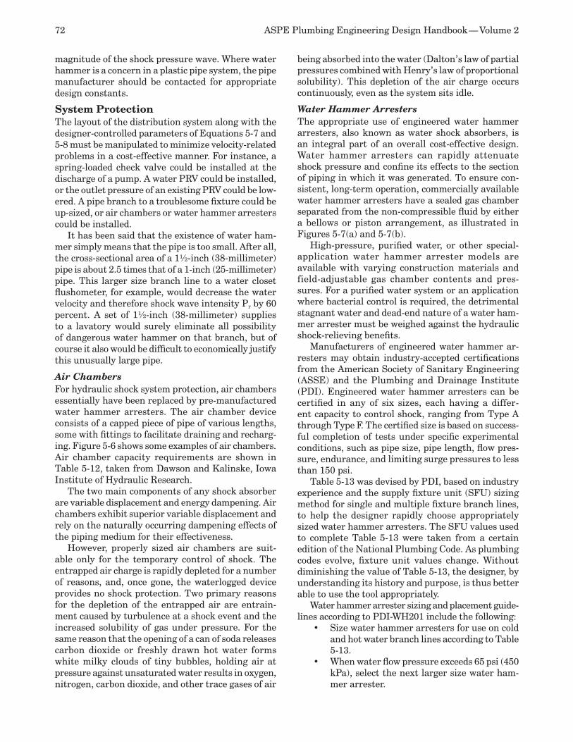
72 ASPE Plumbing Engineering Design Handbook — Volume 2
magnitude of the shock pressure wave. Where water hammer is a concern in a plastic pipe system, the pipe manufacturer should be contacted for appropriate design constants.
System ProtectionThe layout of the distribution system along with the designer-controlled parameters of Equations 5-7 and 5-8 must be manipulated to minimize velocity-related problems in a cost-effective manner. For instance, a spring-loaded check valve could be installed at the discharge of a pump. A water PRV could be installed, or the outlet pressure of an existing PRV could be low-ered. A pipe branch to a troublesome fixture could be up-sized, or air chambers or water hammer arresters could be installed.
It has been said that the existence of water ham-mer simply means that the pipe is too small. After all, the cross-sectional area of a 1½-inch (38-millimeter) pipe is about 2.5 times that of a 1-inch (25-millimeter) pipe. This larger size branch line to a water closet flushometer, for example, would decrease the water velocity and therefore shock wave intensity Pr by 60 percent. A set of 1½-inch (38-millimeter) supplies to a lavatory would surely eliminate all possibility of dangerous water hammer on that branch, but of course it also would be difficult to economically justify this unusually large pipe.
Air Chambers For hydraulic shock system protection, air chambers essentially have been replaced by pre-manufactured water hammer arresters. The air chamber device consists of a capped piece of pipe of various lengths, some with fittings to facilitate draining and recharg-ing. Figure 5-6 shows some examples of air chambers. Air chamber capacity requirements are shown in Table 5-12, taken from Dawson and Kalinske, Iowa Institute of Hydraulic Research.
The two main components of any shock absorber are variable displacement and energy dampening. Air chambers exhibit superior variable displacement and rely on the naturally occurring dampening effects of the piping medium for their effectiveness.
However, properly sized air chambers are suit-able only for the temporary control of shock. The entrapped air charge is rapidly depleted for a number of reasons, and, once gone, the waterlogged device provides no shock protection. Two primary reasons for the depletion of the entrapped air are entrain-ment caused by turbulence at a shock event and the increased solubility of gas under pressure. For the same reason that the opening of a can of soda releases carbon dioxide or freshly drawn hot water forms white milky clouds of tiny bubbles, holding air at pressure against unsaturated water results in oxygen, nitrogen, carbon dioxide, and other trace gases of air
being absorbed into the water (Dalton’s law of partial pressures combined with Henry’s law of proportional solubility). This depletion of the air charge occurs continuously, even as the system sits idle.
Water Hammer Arresters The appropriate use of engineered water hammer arresters, also known as water shock absorbers, is an integral part of an overall cost-effective design. Water hammer arresters can rapidly attenuate shock pressure and confine its effects to the section of piping in which it was generated. To ensure con-sistent, long-term operation, commercially available water hammer arresters have a sealed gas chamber separated from the non-compressible fluid by either a bellows or piston arrangement, as illustrated in Figures 5-7(a) and 5-7(b).
High-pressure, purified water, or other special-application water hammer arrester models are available with varying construction materials and field-adjustable gas chamber contents and pres-sures. For a purified water system or an application where bacterial control is required, the detrimental stagnant water and dead-end nature of a water ham-mer arrester must be weighed against the hydraulic shock-relieving benefits.
Manufacturers of engineered water hammer ar-resters may obtain industry-accepted certifications from the American Society of Sanitary Engineering (ASSE) and the Plumbing and Drainage Institute (PDI). Engineered water hammer arresters can be certified in any of six sizes, each having a differ-ent capacity to control shock, ranging from Type A through Type F. The certified size is based on success-ful completion of tests under specific experimental conditions, such as pipe size, pipe length, flow pres-sure, endurance, and limiting surge pressures to less than 150 psi.
Table 5-13 was devised by PDI, based on industry experience and the supply fixture unit (SFU) sizing method for single and multiple fixture branch lines, to help the designer rapidly choose appropriately sized water hammer arresters. The SFU values used to complete Table 5-13 were taken from a certain edition of the National Plumbing Code. As plumbing codes evolve, fixture unit values change. Without diminishing the value of Table 5-13, the designer, by understanding its history and purpose, is thus better able to use the tool appropriately.
Water hammer arrester sizing and placement guide-lines according to PDI-WH201 include the following:
Size water hammer arresters for use on cold •and hot water branch lines according to Table 5-13.When water flow pressure exceeds 65 psi (450 •kPa), select the next larger size water ham-mer arrester.

Chapter 5 — Cold Water Systems 73
When the branch line exceeds 20 feet (6 me-•ters) in length, an additional water hammer arrester should be used, each sized for half the total fixture unit load.The preferred location for the water ham-•mer arrester is at the end of the branch line between the last two fixtures served.The preferred location for the second water •hammer arrester, when required, is approxi-mately midway along the branch line.A water hammer arrester for a branch serv-•ing a piece of equipment with a quick-closing valve should be placed as close as possible to the equipment isolation valve.
SIzING WATER PIPINGWater can be regarded as a non-compressible fluid, and, for calculations, it is customary to assume that water has a uniform density of 62.4 pounds per cu-bic foot (1 kilogram per liter), which holds nearly constant through a temperature range of 32–60°F (0–15.6°C).
For calculations involving high temperature (above 200°F [93.3°C]), it is desirable to take into account the changes in density, vapor pressure, and viscosity with temperature.
Hazen-Williams FormulaAmong the empirical formulae for piping friction losses that have been developed, the Hazen-Williams equa-tion is widely used for fire protection and city water systems. In a convenient form, it reads as follows:
Equation 5-9 (Hazen-Williams Formula)
f = 0.2082(100)1.85 ( q1.85 )C d4.8655
wheref = Friction head, feet of liquid per 100 feet of pipe
(meters of liquid per 100 meters of pipe)C = Surface roughness constant (dimensionless, see
Table 5-14)q = Fluid flow, gpm (liters per second)d = Inside diameter of pipe, inches (millimeters)
This formula is most accurate for water flow in pipes larger than 2 inches (50.8 millimeters) and at velocities less than 10 fps (3 meters per second).
Equation 5-9 yields accurate results only when the kinematic viscosity of the liquid is about 1.1 cen-tistokes, which is the case for water at 60°F (15.6°C). However, the kinematic viscosity of water varies with temperature, from 1.8 centistokes at 32°F (0°C) to 0.29 centistokes at 212°F (100°C); therefore, the tables using Hazen-Williams are subject to this error, which
may increase the friction loss by as much as 20 percent at 32°F (0°C) and decrease it by as much as 20 percent at 212°F (100°C). Values of C, for various types of pipes, are shown in Table 5-15 with the corresponding multipliers that should apply to the values of the head loss, f, for various temperatures.
Figure 5-8 is a copy of N 1.85 graph paper used to analyze water flow at various velocities. If you know two points on the graph and connect a line between them, you can determine the pressure at any other flow in gpm. Static head at 0 gpm typically is used as one of the points, and the other point is at a residual pressure with a certain gpm flowing.
Table 5-12 Required Air Chambers
Nominal Pipe Diam.,
in. (mm)Pipe Length,
ft (m)
Flow Pressure, psi (kPa)
Velocity, fps (m/s)
Required Air ChamberVolume, in.3
(cm3) Phys. Size, in. (cm) ½ (12.71) 25 (7.62) 30 (207) 10 (3.04) 8 (1.3) ¾ × 15 (1.9 × 38.1)½ (12.71) 100 (30.5) 60 (414) 10 (3.04) 60 (9.8) 1 × 69½ (2.5 × 176.5)¾ (19.1) 50 (15.25) 60 (414) 5 (1.52) 13 (2.1) 1 × 5 (2.5 × 12.7) ¾ (19.1) 200 (61.0) 30 (207) 10 (3.04) 108 (17.7) 1¼ × 72½ (3.2 × 184.2)
1 (25.4) 100 (30.5) 60 (414) 5 (1.52) 19 (3.1) 1¼ × 12 7⁄10 (3.2 × 32.3)1 (25.4) 50 (15.25) 30 (207) 10 (3.04) 40 (6.6) 1¼ × 27 (3.2 × 68.6)1¼ (31.8) 50 (15.25) 60 (414) 10 (3.04) 110 (18.0) 1¼ × 54 (3.2 × 137.2)1½ (38.1) 200 (61.0) 30 (207) 5 (1.52) 90 (14.8) 2 × 27 (5.1 × 68.6)1½ (38.1) 50 (15.25) 60 (414) 10 (3.04) 170 (27.9) 2 × 50½ (5.1 × 128.3)2 (50.8) 100 (30.5) 30 (207) 10 (3.04) 329 (53.9) 3 × 44½ (7.6 × 113.0)2 (50.8) 25 (7.62) 60 (414) 10 (3.04) 150 (24.6) 2½ × 31 (6.4 × 78.7)2 (50.8) 200 (61.0) 60 (414) 5 (1.52) 300 (49.2) 3 × 40½ (7.6 × 102.9)
Figure 5-6 (a, b) Plain Air Chambers, (c) Standpipe Air Chamber, (d) Rechargeable Air Chamber
a b c d
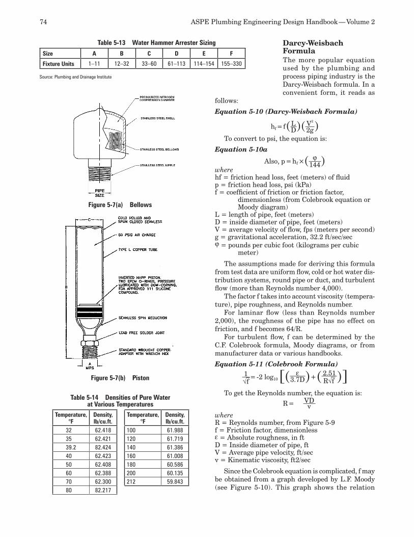
74 ASPE Plumbing Engineering Design Handbook — Volume 2
Darcy-Weisbach FormulaThe more popular equation used by the plumbing and process piping industry is the Darcy-Weisbach formula. In a convenient form, it reads as
follows:
Equation 5-10 (Darcy-Weisbach Formula)
hf = f(L)(V2
)D 2gTo convert to psi, the equation is:
Equation 5-10a
Also, p = hf ×( ϕ )144wherehf = friction head loss, feet (meters) of fluidp = friction head loss, psi (kPa)f = coefficient of friction or friction factor,
dimensionless (from Colebrook equation or Moody diagram)
L = length of pipe, feet (meters)D = inside diameter of pipe, feet (meters)V = average velocity of flow, fps (meters per second)g = gravitational acceleration, 32.2 ft/sec/secϕ = pounds per cubic foot (kilograms per cubic
meter)
The assumptions made for deriving this formula from test data are uniform flow, cold or hot water dis-tribution systems, round pipe or duct, and turbulent flow (more than Reynolds number 4,000).
The factor f takes into account viscosity (tempera-ture), pipe roughness, and Reynolds number.
For laminar flow (less than Reynolds number 2,000), the roughness of the pipe has no effect on friction, and f becomes 64/R.
For turbulent flow, f can be determined by the C.F. Colebrook formula, Moody diagrams, or from manufacturer data or various handbooks.
Equation 5-11 (Colebrook Formula)1√f
= -2 log10[( ε )+(2.51)]3.7D R√f
To get the Reynolds number, the equation is:
R = VDv
where R = Reynolds number, from Figure 5-9 f = Friction factor, dimensionlessε = Absolute roughness, in ftD = Inside diameter of pipe, ftV = Average pipe velocity, ft/secv = Kinematic viscosity, ft2/sec
Since the Colebrook equation is complicated, f may be obtained from a graph developed by L.F. Moody (see Figure 5-10). This graph shows the relation
Table 5-13 Water Hammer Arrester Sizing
Size A B C D E F
Fixture Units 1–11 12–32 33–60 61–113 114–154 155–330
Source: Plumbing and Drainage Institute
Temperature, °F
Density, lb/cu.ft.
32 62.41835 62.42139.2 82.42440 62.42350 62.40860 62.38870 62.30080 82.217
Temperature, °F
Density, lb/cu.ft.
100 61.988120 61.719140 61.386160 61.008180 60.586200 60.135212 59.843
Table 5-14 Densities of Pure Water at Various Temperatures
Figure 5-7(a) Bellows
Figure 5-7(b) Piston
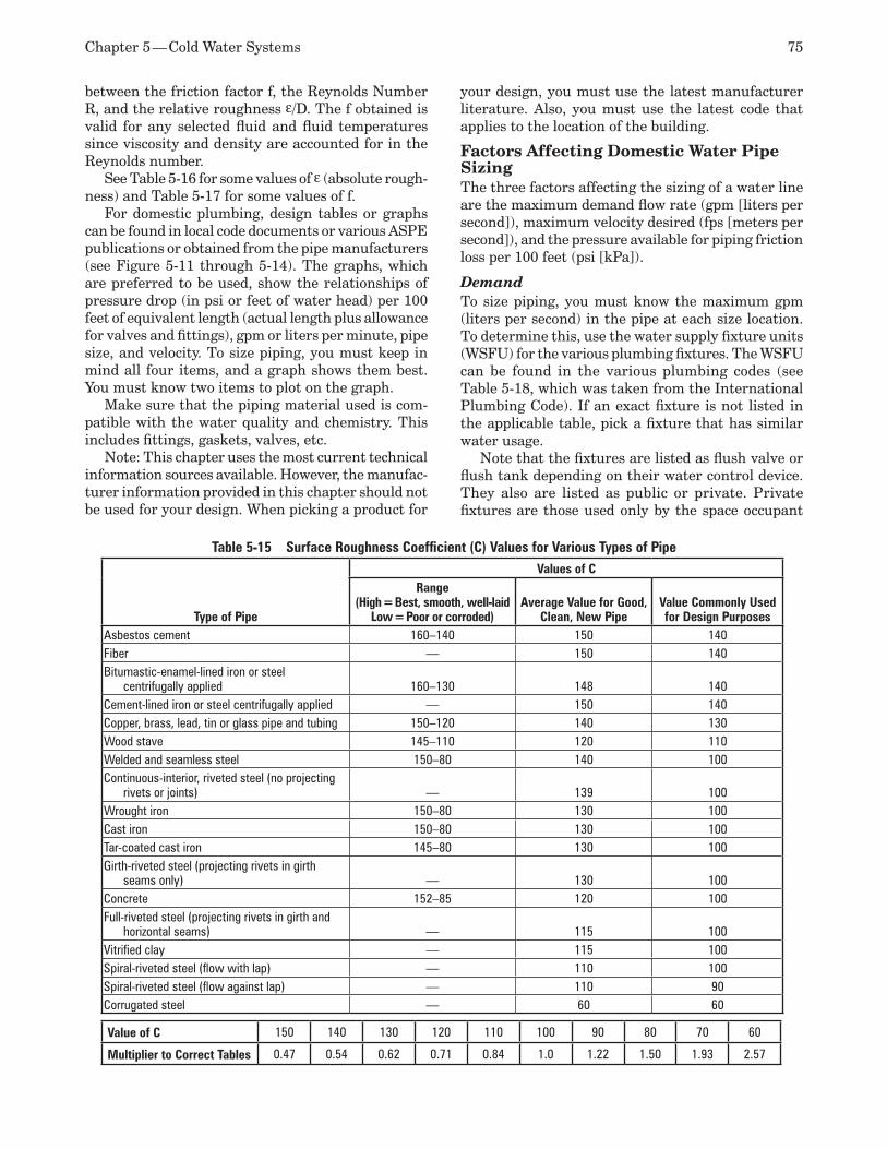
Chapter 5 — Cold Water Systems 75
between the friction factor f, the Reynolds Number R, and the relative roughness ε/D. The f obtained is valid for any selected fluid and fluid temperatures since viscosity and density are accounted for in the Reynolds number.
See Table 5-16 for some values of ε (absolute rough-ness) and Table 5-17 for some values of f.
For domestic plumbing, design tables or graphs can be found in local code documents or various ASPE publications or obtained from the pipe manufacturers (see Figure 5-11 through 5-14). The graphs, which are preferred to be used, show the relationships of pressure drop (in psi or feet of water head) per 100 feet of equivalent length (actual length plus allowance for valves and fittings), gpm or liters per minute, pipe size, and velocity. To size piping, you must keep in mind all four items, and a graph shows them best. You must know two items to plot on the graph.
Make sure that the piping material used is com-patible with the water quality and chemistry. This includes fittings, gaskets, valves, etc.
Note: This chapter uses the most current technical information sources available. However, the manufac-turer information provided in this chapter should not be used for your design. When picking a product for
your design, you must use the latest manufacturer literature. Also, you must use the latest code that applies to the location of the building.
Factors Affecting Domestic Water Pipe SizingThe three factors affecting the sizing of a water line are the maximum demand flow rate (gpm [liters per second]), maximum velocity desired (fps [meters per second]), and the pressure available for piping friction loss per 100 feet (psi [kPa]).
Demand To size piping, you must know the maximum gpm (liters per second) in the pipe at each size location. To determine this, use the water supply fixture units (WSFU) for the various plumbing fixtures. The WSFU can be found in the various plumbing codes (see Table 5-18, which was taken from the International Plumbing Code). If an exact fixture is not listed in the applicable table, pick a fixture that has similar water usage.
Note that the fixtures are listed as flush valve or flush tank depending on their water control device. They also are listed as public or private. Private fixtures are those used only by the space occupant
Table 5-15 Surface Roughness Coefficient (C) Values for Various Types of Pipe
Type of Pipe
Values of CRange
(High = Best, smooth, well-laidLow = Poor or corroded)
Average Value for Good, Clean, New Pipe
Value Commonly Used for Design Purposes
Asbestos cement 160–140 150 140Fiber — 150 140Bitumastic-enamel-lined iron or steel
centrifugally applied 160–130 148 140Cement-lined iron or steel centrifugally applied — 150 140Copper, brass, lead, tin or glass pipe and tubing 150–120 140 130Wood stave 145–110 120 110Welded and seamless steel 150–80 140 100Continuous-interior, riveted steel (no projecting
rivets or joints) — 139 100Wrought iron 150–80 130 100Cast iron 150–80 130 100Tar-coated cast iron 145–80 130 100Girth-riveted steel (projecting rivets in girth
seams only) — 130 100Concrete 152–85 120 100Full-riveted steel (projecting rivets in girth and
horizontal seams) — 115 100Vitrified clay — 115 100Spiral-riveted steel (flow with lap) — 110 100Spiral-riveted steel (flow against lap) — 110 90Corrugated steel — 60 60
Value of C 150 140 130 120 110 100 90 80 70 60
Multiplier to Correct Tables 0.47 0.54 0.62 0.71 0.84 1.0 1.22 1.50 1.93 2.57
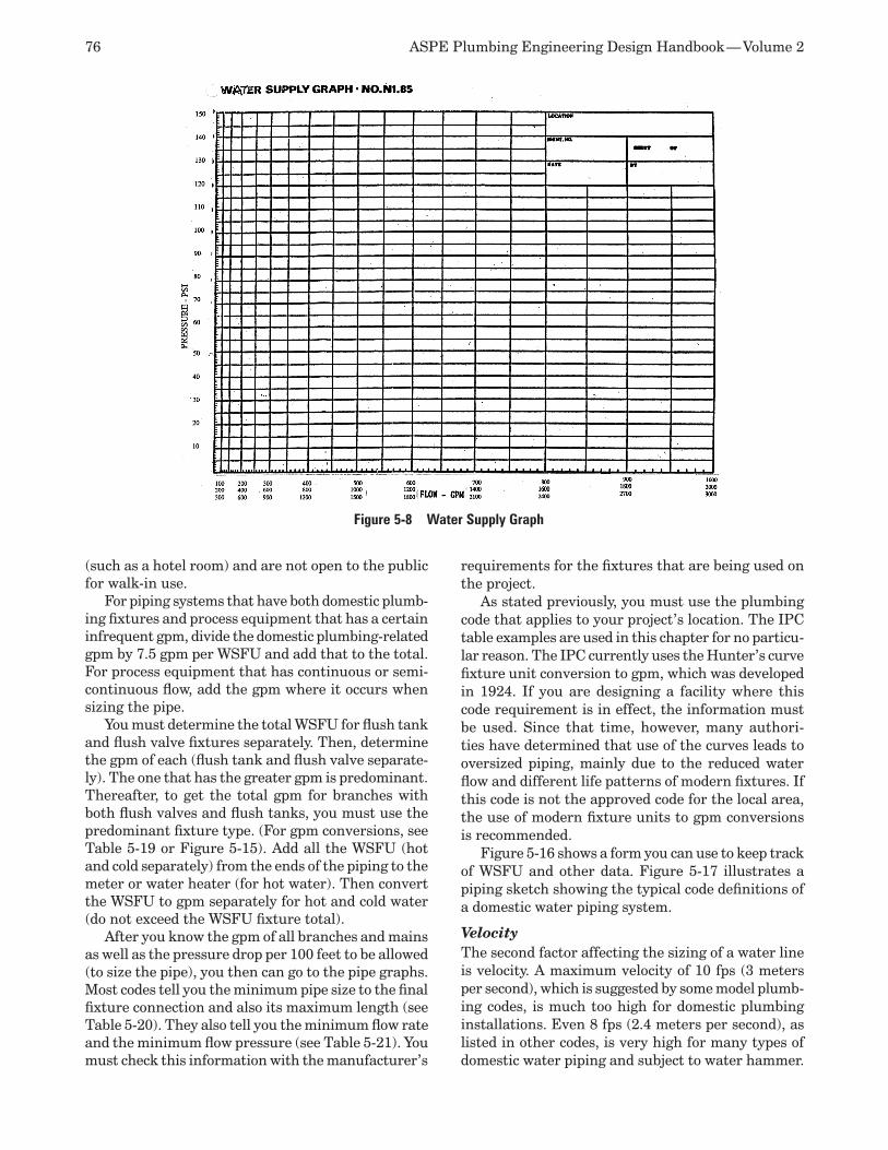
76 ASPE Plumbing Engineering Design Handbook — Volume 2
(such as a hotel room) and are not open to the public for walk-in use.
For piping systems that have both domestic plumb-ing fixtures and process equipment that has a certain infrequent gpm, divide the domestic plumbing-related gpm by 7.5 gpm per WSFU and add that to the total. For process equipment that has continuous or semi-continuous flow, add the gpm where it occurs when sizing the pipe.
You must determine the total WSFU for flush tank and flush valve fixtures separately. Then, determine the gpm of each (flush tank and flush valve separate-ly). The one that has the greater gpm is predominant. Thereafter, to get the total gpm for branches with both flush valves and flush tanks, you must use the predominant fixture type. (For gpm conversions, see Table 5-19 or Figure 5-15). Add all the WSFU (hot and cold separately) from the ends of the piping to the meter or water heater (for hot water). Then convert the WSFU to gpm separately for hot and cold water (do not exceed the WSFU fixture total).
After you know the gpm of all branches and mains as well as the pressure drop per 100 feet to be allowed (to size the pipe), you then can go to the pipe graphs. Most codes tell you the minimum pipe size to the final fixture connection and also its maximum length (see Table 5-20). They also tell you the minimum flow rate and the minimum flow pressure (see Table 5-21). You must check this information with the manufacturer’s
requirements for the fixtures that are being used on the project.
As stated previously, you must use the plumbing code that applies to your project’s location. The IPC table examples are used in this chapter for no particu-lar reason. The IPC currently uses the Hunter’s curve fixture unit conversion to gpm, which was developed in 1924. If you are designing a facility where this code requirement is in effect, the information must be used. Since that time, however, many authori-ties have determined that use of the curves leads to oversized piping, mainly due to the reduced water flow and different life patterns of modern fixtures. If this code is not the approved code for the local area, the use of modern fixture units to gpm conversions is recommended.
Figure 5-16 shows a form you can use to keep track of WSFU and other data. Figure 5-17 illustrates a piping sketch showing the typical code definitions of a domestic water piping system.
Velocity The second factor affecting the sizing of a water line is velocity. A maximum velocity of 10 fps (3 meters per second), which is suggested by some model plumb-ing codes, is much too high for domestic plumbing installations. Even 8 fps (2.4 meters per second), as listed in other codes, is very high for many types of domestic water piping and subject to water hammer.
Figure 5-8 Water Supply Graph
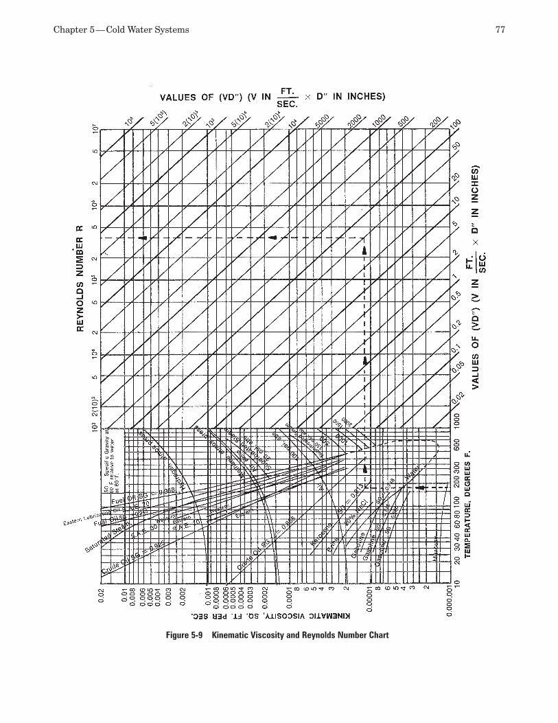
Chapter 5 — Cold Water Systems 77
Figure 5-9 Kinematic Viscosity and Reynolds Number Chart
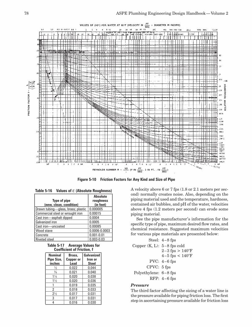
78 ASPE Plumbing Engineering Design Handbook — Volume 2
A velocity above 6 or 7 fps (1.8 or 2.1 meters per sec-ond) normally creates noise. Also, depending on the piping material used and the temperature, hardness, contained air bubbles, and pH of the water, velocities above 4 fps (1.2 meters per second) can erode some piping material.
See the pipe manufacturer’s information for the specific type of pipe, maximum desired flow rates, and chemical resistance. Suggested maximum velocities for various pipe materials are presented below:
Steel: 4 – 8 fpsCopper (K, L): 5 – 8 fps cold
2 – 3 fps > 140°F4 – 5 fps < 140°F
PVC: 4 – 6 fpsCPVC: 5 fps
Polyethylene: 6 – 8 fpsRFP: 4 – 6 fps
Pressure The third factor affecting the sizing of a water line is the pressure available for piping friction loss. The first step in ascertaining pressure available for friction loss
Figure 5-10 Friction Factors for Any Kind and Size of Pipe
Table 5-17 Average Values for Coefficient of Friction, f
Nominal Pipe Size,
inches
Brass, Copper or
Lead
Galvanized Iron or Steel
½ 0.022 0.044¾ 0.021 0.040
1¼ 0.020 0.0381½ 0.020 0.0361 0.019 0.0352 0.018 0.0332½ 0.017 0.0313 0.017 0.0314 0.016 0.030
Table 5-16 Values of ε (Absolute Roughness)
Type of pipe(new, clean, condition)
Absolute roughness
(in feet)Drawn tubing—glass, brass; plastic 0.000005Commercial steel or wrought iron 0.00015Cast iron—asphalt dipped 0.0004Galvanized iron 0.0005Cast iron—uncoated 0.00085Wood stave 0.0006-0.0003Concrete 0.001-0.01Riveted steel 0.003-0.03
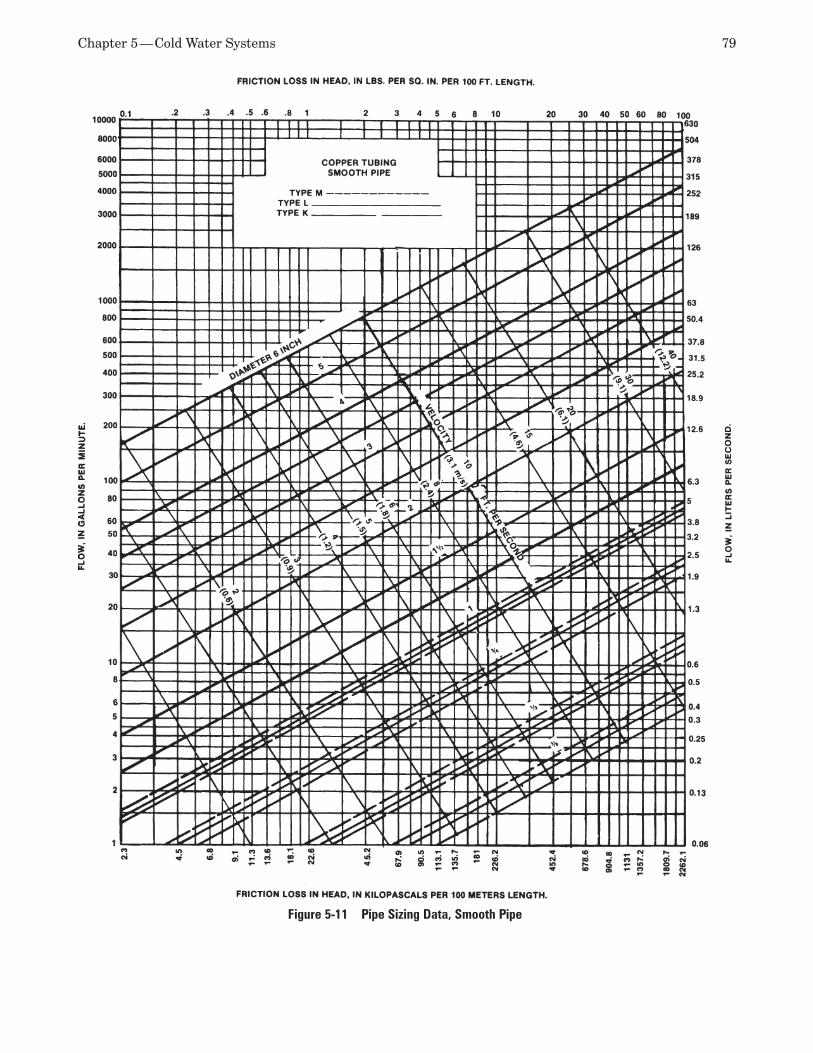
Chapter 5 — Cold Water Systems 79
Figure 5-11 Pipe Sizing Data, Smooth Pipe
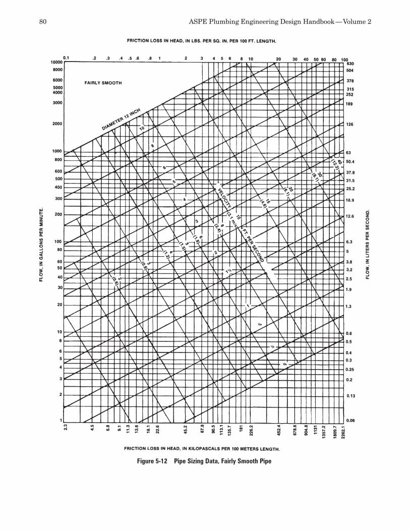
80 ASPE Plumbing Engineering Design Handbook — Volume 2
Figure 5-12 Pipe Sizing Data, Fairly Smooth Pipe
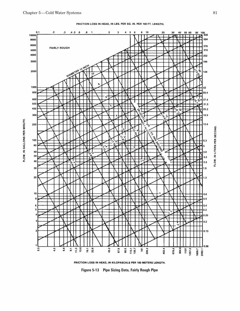
Chapter 5 — Cold Water Systems 81
Figure 5-13 Pipe Sizing Data, Fairly Rough Pipe
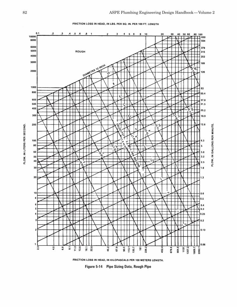
82 ASPE Plumbing Engineering Design Handbook — Volume 2
Figure 5-14 Pipe Sizing Data, Rough Pipe
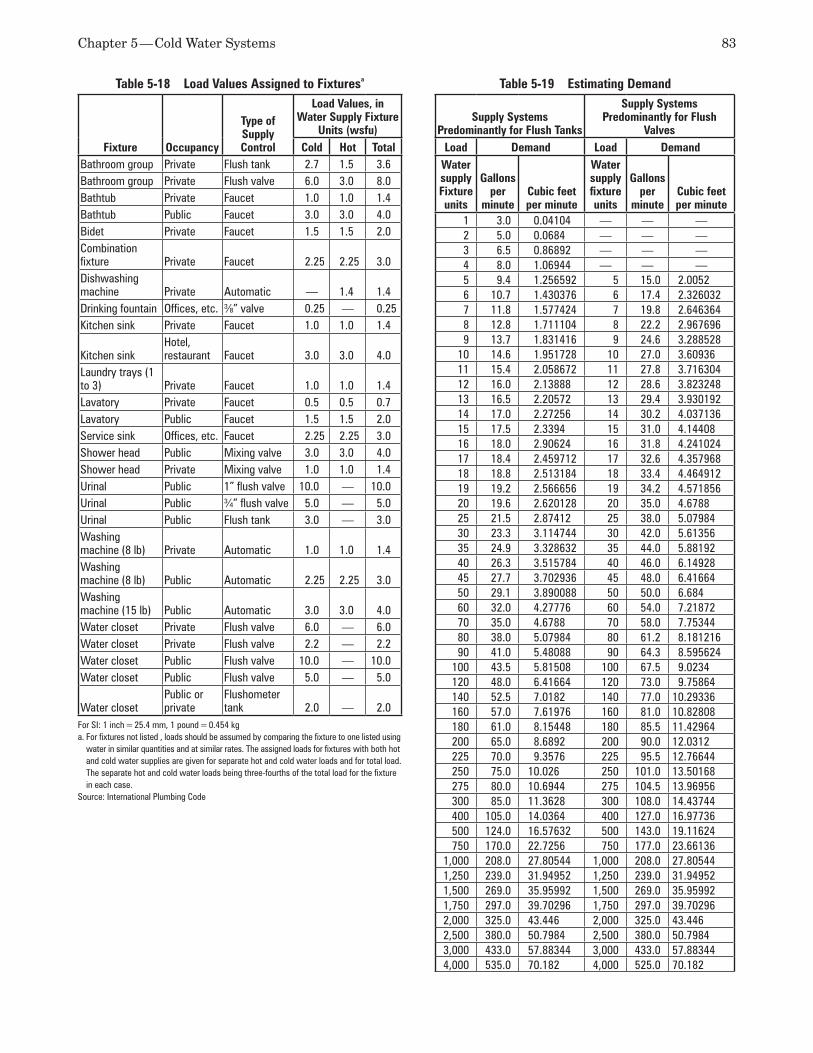
Chapter 5 — Cold Water Systems 83
Table 5-18 Load Values Assigned to Fixturesa
Fixture Occupancy
Type of Supply Control
Load Values, in Water Supply Fixture
Units (wsfu)Cold Hot Total
Bathroom group Private Flush tank 2.7 1.5 3.6Bathroom group Private Flush valve 6.0 3.0 8.0Bathtub Private Faucet 1.0 1.0 1.4Bathtub Public Faucet 3.0 3.0 4.0Bidet Private Faucet 1.5 1.5 2.0Combination fixture Private Faucet 2.25 2.25 3.0Dishwashing machine Private Automatic — 1.4 1.4Drinking fountain Offices, etc. 3⁄8” valve 0.25 — 0.25Kitchen sink Private Faucet 1.0 1.0 1.4
Kitchen sinkHotel, restaurant Faucet 3.0 3.0 4.0
Laundry trays (1 to 3) Private Faucet 1.0 1.0 1.4Lavatory Private Faucet 0.5 0.5 0.7Lavatory Public Faucet 1.5 1.5 2.0Service sink Offices, etc. Faucet 2.25 2.25 3.0Shower head Public Mixing valve 3.0 3.0 4.0Shower head Private Mixing valve 1.0 1.0 1.4Urinal Public 1” flush valve 10.0 — 10.0Urinal Public 3⁄4” flush valve 5.0 — 5.0Urinal Public Flush tank 3.0 — 3.0Washing machine (8 lb) Private Automatic 1.0 1.0 1.4Washing machine (8 lb) Public Automatic 2.25 2.25 3.0Washing machine (15 lb) Public Automatic 3.0 3.0 4.0Water closet Private Flush valve 6.0 — 6.0Water closet Private Flush valve 2.2 — 2.2Water closet Public Flush valve 10.0 — 10.0Water closet Public Flush valve 5.0 — 5.0
Water closetPublic or private
Flushometer tank 2.0 — 2.0
For SI: 1 inch = 25.4 mm, 1 pound = 0.454 kga. For fixtures not listed , loads should be assumed by comparing the fixture to one listed using
water in similar quantities and at similar rates. The assigned loads for fixtures with both hot and cold water supplies are given for separate hot and cold water loads and for total load. The separate hot and cold water loads being three-fourths of the total load for the fixture in each case.
Source: International Plumbing Code
Table 5-19 Estimating Demand
Supply Systems Predominantly for Flush Tanks
Supply Systems Predominantly for Flush
ValvesLoad Demand Load Demand
Water supply Fixture units
Gallons per
minuteCubic feet per minute
Water supplyfixture units
Gallons per
minuteCubic feet per minute
1 3.0 0.04104 — — —2 5.0 0.0684 — — —3 6.5 0.86892 — — —4 8.0 1.06944 — — —5 9.4 1.256592 5 15.0 2.00526 10.7 1.430376 6 17.4 2.3260327 11.8 1.577424 7 19.8 2.6463648 12.8 1.711104 8 22.2 2.9676969 13.7 1.831416 9 24.6 3.288528
10 14.6 1.951728 10 27.0 3.6093611 15.4 2.058672 11 27.8 3.71630412 16.0 2.13888 12 28.6 3.82324813 16.5 2.20572 13 29.4 3.93019214 17.0 2.27256 14 30.2 4.03713615 17.5 2.3394 15 31.0 4.1440816 18.0 2.90624 16 31.8 4.24102417 18.4 2.459712 17 32.6 4.35796818 18.8 2.513184 18 33.4 4.46491219 19.2 2.566656 19 34.2 4.57185620 19.6 2.620128 20 35.0 4.678825 21.5 2.87412 25 38.0 5.0798430 23.3 3.114744 30 42.0 5.6135635 24.9 3.328632 35 44.0 5.8819240 26.3 3.515784 40 46.0 6.1492845 27.7 3.702936 45 48.0 6.4166450 29.1 3.890088 50 50.0 6.68460 32.0 4.27776 60 54.0 7.2187270 35.0 4.6788 70 58.0 7.7534480 38.0 5.07984 80 61.2 8.18121690 41.0 5.48088 90 64.3 8.595624
100 43.5 5.81508 100 67.5 9.0234120 48.0 6.41664 120 73.0 9.75864140 52.5 7.0182 140 77.0 10.29336160 57.0 7.61976 160 81.0 10.82808180 61.0 8.15448 180 85.5 11.42964200 65.0 8.6892 200 90.0 12.0312225 70.0 9.3576 225 95.5 12.76644250 75.0 10.026 250 101.0 13.50168275 80.0 10.6944 275 104.5 13.96956300 85.0 11.3628 300 108.0 14.43744400 105.0 14.0364 400 127.0 16.97736500 124.0 16.57632 500 143.0 19.11624750 170.0 22.7256 750 177.0 23.66136
1,000 208.0 27.80544 1,000 208.0 27.805441,250 239.0 31.94952 1,250 239.0 31.949521,500 269.0 35.95992 1,500 269.0 35.959921,750 297.0 39.70296 1,750 297.0 39.702962,000 325.0 43.446 2,000 325.0 43.4462,500 380.0 50.7984 2,500 380.0 50.79843,000 433.0 57.88344 3,000 433.0 57.883444,000 535.0 70.182 4,000 525.0 70.182
84 ASPE Plumbing Engineering Design Handbook — Volume 2
is determining (from the local water department or by a hydrant flow test) the maximum and minimum water pressures at the street connection (or the stop valve at a well system) at the flow rate to be encoun-tered at the project site. The maximum and minimum pressures may be nearly the same or they may vary greatly depending on the time of year, hour of the day, type of adjacent buildings, etc. Care must be taken to handle the high pressure as well as the low pressure. If the maximum pressure is more than 80 psi and a pressure-regulating device is installed, the pressure regulator will introduce an additional pressure loss (falloff) in the piping system when water is flowing.
The city water pressure should be determined from a fire hydrant flow test, which is taken as close to the site as possible and includes static and residual pres-sures at the desired flow rate (above normal use with your building added) (see Figure 5-18). The residual pressure, with all of the above considerations taken into account, is the pressure to be used as a starting point in calculating other pressure requirements. The effective pressure point is where flowing and non-flowing water meet.
If a pressure-regulating device is installed, the avail-able pressure after the falloff pressure must be used (on outlet side of meter or backflow preventer).
The water meter creates a loss of pressure, and the pressure drop is available from the manufacturer’s flow charts. See samples of such charts in Figures 5-19(a), 5-19(b), and 5-19(c). You must decide if you want to lose or preserve the water pressure available at the street.
You also must determine the flow rate from the most hydraulically remote fixture or piece of equip-ment that has the highest total pressure drop from the outlet of the meter when all flow pressure losses are added, excluding that for the piping. Some iteration will be required to find the one place with the highest pressure drop. For example, see the system shown in Figure 5-20. To find the critical circuit, determine which final fixture or device requires the most pres-sure (from the meter outlet). The flush valve water closet needs 15 psi (103.4 kPa) and has no static loss. The backflow preventer has a 16-psi (110.3-kPa) pres-sure drop and a 8.66-psi (59.7-kPa) static loss for a total loss of 24.66 psi (170 kPa). The dishwasher has a total loss of 40 psi (275.8 kPa)—25 psi (172.4 kPa) for the dishwasher plus a 5-psi (34.5-kPa) loss through the water heater plus a 10-psi (69-kPa) loss through the softener. Therefore, the piping to the dishwasher is the governing critical circuit because it has the highest total pressure required when the needed flow pressures and static losses are added.
The pressure required at each fixture or appliance can be determined from the applicable code and/or the manufacturer’s information (refer back to Table
5-21). Manufacturer’s information governs. If there is an elevation difference between the meter and the governing fixture or appliance, the static pressure loss required to reach the governing fixture or appliance must be calculated. The static loss (or gain) is figured at 0.433 psi per foot (9.8 kPa per meter) of elevation difference, above or below the meter. The difference in elevation is usually a pressure loss to the system, as fixtures are normally at a higher elevation than the source. If the fixture is lower than the source, the pressure will increase, so the static pressure is added to the initial pressure. This holds true when you calculate the meter outlet pressure. You must account for the elevation difference between the city main and the meter.
Step-by-Step Guide to Sizing Water PipeDetermine the lowest effective pressure avail-1. able at the city water main connection. This is known as the residual pressure of the main.Select a water service pipe size and type (to 2. the meter) and calculate its pressure drop. (Do you want the drop to be high or low?) Also determine any pressure drop or increase due to elevation change (water main to water meter) plus the service losses through the service pipe, which includes the tapping sleeve and valve or a curb stop. An allowance should be made for future development of the area where the project is located, generally 5 psi.Select (or obtain from the jurisdiction) the 3. water meter type and size and determine its pressure drop. (Do you want the drop to be high or low?)Determine the outlet pressure at the meter from 4. the values obtained in Steps 1 through 3. You now must determine the most hydrau-5. lically remote point (the piping main and branch) using the greatest amount of needed end pressure and the total pressure drops of the appliances and devices in the circuit piping to the end fixture or appliance when flowing. Several circuits may need to be analyzed. Valves and fittings are omitted at this step. To do so, add the flow pressure drops of all appliances and devices in the critical circuit. Examples include the water softener or other water treatment devices, water heater, PRV, control valve or solenoid, and reduced-pressure backflow preventer.Determine the pressure needed at the final 6. fixture or appliance, as well as the static pres-sure drop or increase due to elevations.Calculate the pressure drop allowed for the 7. piping using the values obtained in Steps 5 and 6.
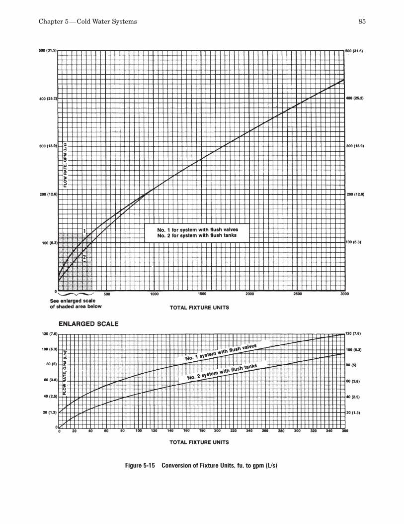
Chapter 5 — Cold Water Systems 85
Figure 5-15 Conversion of Fixture Units, fu, to gpm (L/s)
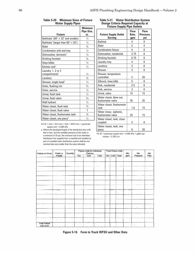
86 ASPE Plumbing Engineering Design Handbook — Volume 2
Figure 5-16 Form to Track WFSU and Other Data
Table 5-20 Minimum Sizes of Fixture Water Supply Pipes
Fixture
Minimum Pipe Size,
in.Bathtubsa (60" × 32" and smaller) ½Bathtubsa (larger than 60" × 32") ½Bidet 3⁄8Combination sink and tray ½Dishwasher, domestica ½Drinking fountain 3⁄8Hose bibbs ½Kitchen sinka ½Laundry, 1, 2 or 3compartmentsa ½Lavatory 3⁄8Shower, single heada ½Sinks, flushing rim ¾Sinks, service ½Urinal, flush tank ½Urinal, flush valve ¾Wall hydrant ½Water closet, flush tank 3⁄8Water closet, flush valve 1Water closet, flushometer tank 3⁄8Water closet, one piecea ½
For SI: 1 inch = 25.4 mm, 1 foot = 304.8 mm, 1 pound per square inch = 6.895 kPa
a. Where the developed length of the distribution line is 60 feet or less, and the available pressure at the meter is a minimum of 35 psi, the minimum size of an individual distribution line supplied from a manifold and installed as part of a parallel water distribution system shall be one nominal tube size smaller than the sizes indicated.
Table 5-21 Water Distribution System Design Criteria Required Capacity at
Fixture Supply Pipe Outlets
Fixture Supply Outlet Serving
Flow Rate, gpm
Flow Pressure,
psiBathtub 4 8Bidet 2 4Combination fixture 4 8Dishwasher, residential 2.75 8Drinking fountain 0.75 8Laundry tray 4 8Lavatory 2 8Shower 3 8Shower, temperature controlled 3 20Sillcock, hose bibb 5 8Sink, residential 2.5 8Sink, service 3 8Urinal, valve 15 15Water closet, blow out, flushometer valve 35 25Water closet, flushometer tank 1.6 15Water close;, siphonic, flushometer valve 25 15Water closet, tank, close coupled 3 8Water closet, tank, one piece 6 20
For SI: 1 pound per square inch = 6.895 kPa, 1 gallon per minute = 3.785 L/m
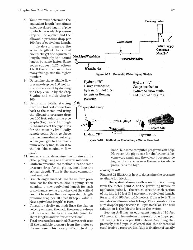
Chapter 5 — Cold Water Systems 87
You now must determine the 8. equivalent length (sometimes called developed length) of pipe to which the available pressure drop will be applied and the allowable pressure drop per 100 feet of equivalent length. To do so, measure the actual length of the critical circuit. To get the equivalent length, multiply the actual length by some factor. Some codes suggest 1.25, others 1.5. If the critical circuit has many fittings, use the higher number.Determine the available flow 9. pressure drop per 100 feet for the critical circuit by dividing the Step 7 value by the Step 8 value and multiplying by 100.Using gpm totals, starting 10. from the farthest connection back to the meter, and using the allowable pressure drop per 100 feet, refer to the pipe graphs (Figures 5-11 through 5-14) and select the pipe sizes for the most hydraulically remote point. Don’t go above the maximum desired velocity. When you get to the maxi-mum velocity line, follow it to the left (the maximum flow rate).You now must determine how to size all the 11. other piping using one of several methods:Uniform pressure loss method: Use the same •pressure drop for all piping, including the critical circuit. This is the most commonly used method. Branch length method: Use the uniform pres-•sure loss for the critical circuit piping. Then calculate a new equivalent length for each branch and size the branches (not the critical circuit) based on the new equivalent length pressure drop per 100 feet ([Step 7 value ÷ New equivalent length] x 100).Constant velocity method: Base the size on •velocity only, and then add the pressure drops not to exceed the total allowable (used for short lengths and/or few connections).Total pressure loss method: Every circuit uses •all the available pressure from the meter to the end user. This is very difficult to do by
hand, but some computer programs can help. However, the pipe sizes for the branches be-come very small, and the velocity becomes too high at the branches near the meter (available pressure is too high).
Example 5-2Figure 5-21 illustrates how to determine the pressure available for friction.
In the system shown (with a main line running from the meter, point A, to the governing fixture or appliance, point L—the critical circuit), each section of the line is 10 feet (3.1 meters) in equivalent length, for a total of 100 feet (30.5 meters) from A to L. This includes an allowance for fittings. The allowable pres-sure drop for pipe friction is 10 psi (69 kPa). The first tabulation is the friction loss in the system.
Section A–B has an equivalent length of 10 feet (3.1 meters). The uniform pressure drop is 10 psi per 100 feet (226.2 kPa per 100 meters). Assuming that precisely sized pipe is selected (for this theoretical case) to give a pressure loss (due to friction) of exactly
Figure 5-17 Domestic Water Piping Sketch
Figure 5-18 Method for Conducting a Water Flow Test
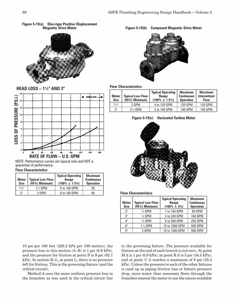
88 ASPE Plumbing Engineering Design Handbook — Volume 2
10 psi per 100 feet (226.2 kPa per 100 meters), the pressure loss in this section (A–B) is 1 psi (6.9 kPa), and the pressure for friction at point B is 9 psi (62.1 kPa). In section K–L, at point L, there is no pressure left for friction. This is the governing fixture (and the critical circuit).
Method A uses the same uniform pressure loss in the branches as was used in the critical circuit line
to the governing fixture. The pressure available for friction at the end of each branch is not zero. At point M it is 1 psi (6.9 kPa); at point R it is 5 psi (34.5 kPa); and at point U it reaches a maximum of 8 psi (55.2 kPa). Unless the pressure to each of the other fixtures is used up as piping friction loss or fixture pressure drop, more water than necessary flows through the branches nearest the meter to use the excess available
Figure 5-19(b) Compound Magnetic Drive Meter
Flow Characteristics
Meter Size
Typical Low Flow(95%) Minimum)
Typical Operating Range
(100% ± 1.5%)
Maximum Continuous Operation
Maximum Intermittent
Flow1½" 2 GPM 4 to 120 GPM 120 GPM 120 GPM2" 2½ GPM 4 to 160 GPM 160 GPM 160 GPM
Figure 5-19(c) Horizontal Turbine Meter
Flow Characteristics
Meter Size
Typical Low Flow(95%) Minimum)
Typical Operating Range
(100% ± 3%)
Maximum Continuous Operation
2" ¼ GPM 1 to 160 GPM 80 GPM3" ½ GPM 4 to 320 GPM 160 GPM4" ¾ GPM 6 to 500 GPM 250 GPM6" 1½ GPM 10 to 1000 GPM 500 GPM8" 2 GPM 16 to 1600 GPM 800 GPM
Flow Characteristics
Meter Size
Typical Low Flow(95%) Minimum)
Typical Operating Range
(100% ± 1.5%)
Maximum Continuous Operation
1½" 1½ GPM 5 to 100 GPM 502" 2 GPM 8 to 160 GPM 80
LOSS
OF
PRES
SURE
(P.S
.I.)
RATE OF FLOW – U.S. GPM
HEAD LOSS – 1½" AND 2"
NOTE: Performance curves are typical only and NOT a guarantee of performance.
Figure 5-19(a) Disc-type Positive Displacement Magnetic Drive Meter
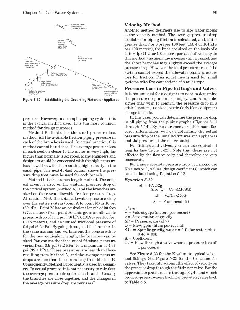
Chapter 5 — Cold Water Systems 89
pressure. However, in a complex piping system this is the typical method used. It is the most common method for design purposes.
Method B illustrates the total pressure loss method. All the available friction piping pressure in each of the branches is used. In actual practice, this method cannot be utilized. The average pressure loss in each section closer to the meter is very high, far higher than normally is accepted. Many engineers and designers would be concerned with the high pressure loss as well as with the resulting high velocity in the small pipe. The next-to-last column shows the pres-sure drop that must be used for each branch.
Method C is the branch length method. The criti-cal circuit is sized on the uniform pressure drop of the critical system (Method A), and the branches are sized on their own allowable friction pressure drop. At section M–J, the total allowable pressure drop over the entire system (point A to point M) is 10 psi (69 kPa). Point M has an equivalent length of 90 feet (27.4 meters) from point A. This gives an allowable pressure drop of 11.1 psi (7.6 kPa), (10/90) per 100 feet (30.5 meters), and an unused frictional pressure of 0.9 psi (6.2 kPa). By going through all the branches in the same manner and working out the pressure drop for the new equivalent length, the branches can be sized. You can see that the unused frictional pressure varies from 0.9 psi (6.2 kPa) to a maximum of 4.66 psi (32.1 kPa). These pressures are less than those resulting from Method A, and the average pressure drops are less than those resulting from Method B. Consequently, Method C frequently is used by design-ers. In actual practice, it is not necessary to calculate the average pressure drop for each branch. Usually the branches are close together, and the changes in the average pressure drop are very small.
Velocity Method Another method designers use to size water piping is the velocity method. The average pressure drop available for piping friction is calculated, and, if it is greater than 7 or 8 psi per 100 feet (158.4 or 181 kPa per 100 meters), the lines are sized on the basis of a 4- to 6-fps (1.2- or 1.8-meters-per-second) velocity. In this method, the main line is conservatively sized, and the short branches may slightly exceed the average pressure drop. However, the total pressure drop of the system cannot exceed the allowable piping pressure loss for friction. This sometimes is used for small systems with few connections of similar type.
Pressure Loss in Pipe Fittings and ValvesIt is not unusual for a designer to need to determine the pressure drop in an existing system. Also, a de-signer may wish to confirm the pressure drop in a critical system just sized, particularly if an equipment change is made.
In this case, you can determine the pressure drop in all piping from the piping graphs (Figures 5-11 through 5-14). By measurement or other manufac-turer information, you can determine the actual pressure drop of the installed fixtures and appliances and the pressure at the meter outlet.
For fittings and valves, you can use equivalent lengths (see Table 5-22). Note that these are not affected by the flow velocity and therefore are very inaccurate.
For a more accurate pressure drop, you should use K values or Cv values (design coefficients), which can be calculated using Equation 5-12.
Equation 5-12 Dh = KV2/2g
Also, Q = Cv √(DP/SG)
DP = (Q/Cv)2 S.G.
Dh = Fluid head (ft)
whereV = Velocity, fps (meters per second)g = Acceleration of gravity DP = Pressure, psi (kPa)Q = Flow, gpm (liters per second)S.G. = Specific gravity, water = 1.0 (for water, Dh x
0.43 = psi) K = Coefficient Cv = Flow through a valve where a pressure loss of
1 psi occurs
See Figure 5-22 for the K values to typical valves and fittings. See Figure 5-23 for the Cv values for valves. They take into account the effect of velocity on the pressure drop through the fitting or valve. For the approximate pressure loss through 3-, 4-, and 6-inch reduced-pressure-zone backflow preveters, refer back to Table 5-5.
Figure 5-20 Establishing the Governing Fixture or Appliance
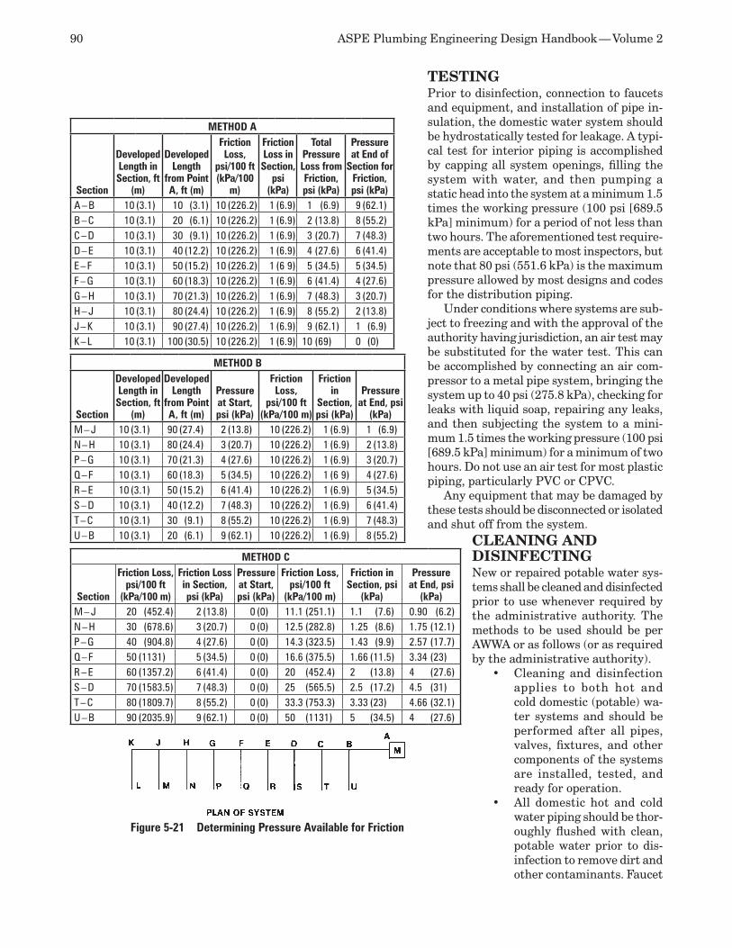
90 ASPE Plumbing Engineering Design Handbook — Volume 2
TESTING Prior to disinfection, connection to faucets and equipment, and installation of pipe in-sulation, the domestic water system should be hydrostatically tested for leakage. A typi-cal test for interior piping is accomplished by capping all system openings, filling the system with water, and then pumping a static head into the system at a minimum 1.5 times the working pressure (100 psi [689.5 kPa] minimum) for a period of not less than two hours. The aforementioned test require-ments are acceptable to most inspectors, but note that 80 psi (551.6 kPa) is the maximum pressure allowed by most designs and codes for the distribution piping.
Under conditions where systems are sub-ject to freezing and with the approval of the authority having jurisdiction, an air test may be substituted for the water test. This can be accomplished by connecting an air com-pressor to a metal pipe system, bringing the system up to 40 psi (275.8 kPa), checking for leaks with liquid soap, repairing any leaks, and then subjecting the system to a mini-mum 1.5 times the working pressure (100 psi [689.5 kPa] minimum) for a minimum of two hours. Do not use an air test for most plastic piping, particularly PVC or CPVC.
Any equipment that may be damaged by these tests should be disconnected or isolated and shut off from the system.
METHOD A
Section
Developed Length in Section, ft
(m)
Developed Length
from Point A, ft (m)
Friction Loss,
psi/100 ft (kPa/100
m)
Friction Loss in Section,
psi (kPa)
Total Pressure Loss from Friction, psi (kPa)
Pressure at End of
Section for Friction, psi (kPa)
A – B 10 (3.1) 10 (3.1) 10 (226.2) 1 (6.9) 1 (6.9) 9 (62.1)B – C 10 (3.1) 20 (6.1) 10 (226.2) 1 (6.9) 2 (13.8) 8 (55.2)C – D 10 (3.1) 30 (9.1) 10 (226.2) 1 (6.9) 3 (20.7) 7 (48.3)D – E 10 (3.1) 40 (12.2) 10 (226.2) 1 (6.9) 4 (27.6) 6 (41.4)E – F 10 (3.1) 50 (15.2) 10 (226.2) 1 (6 9) 5 (34.5) 5 (34.5)F – G 10 (3.1) 60 (18.3) 10 (226.2) 1 (6.9) 6 (41.4) 4 (27.6)G – H 10 (3.1) 70 (21.3) 10 (226.2) 1 (6.9) 7 (48.3) 3 (20.7)H – J 10 (3.1) 80 (24.4) 10 (226.2) 1 (6.9) 8 (55.2) 2 (13.8)J – K 10 (3.1) 90 (27.4) 10 (226.2) 1 (6.9) 9 (62.1) 1 (6.9)K – L 10 (3.1) 100 (30.5) 10 (226.2) 1 (6.9) 10 (69) 0 (0)
METHOD B
Section
Developed Length in Section, ft
(m)
Developed Length
from Point A, ft (m)
Pressure at Start, psi (kPa)
Friction Loss,
psi/100 ft (kPa/100 m)
Friction in
Section, psi (kPa)
Pressure at End, psi
(kPa)M – J 10 (3.1) 90 (27.4) 2 (13.8) 10 (226.2) 1 (6.9) 1 (6.9)N – H 10 (3.1) 80 (24.4) 3 (20.7) 10 (226.2) 1 (6.9) 2 (13.8)P – G 10 (3.1) 70 (21.3) 4 (27.6) 10 (226.2) 1 (6.9) 3 (20.7)Q – F 10 (3.1) 60 (18.3) 5 (34.5) 10 (226.2) 1 (6 9) 4 (27.6)R – E 10 (3.1) 50 (15.2) 6 (41.4) 10 (226.2) 1 (6.9) 5 (34.5)S – D 10 (3.1) 40 (12.2) 7 (48.3) 10 (226.2) 1 (6.9) 6 (41.4)T – C 10 (3.1) 30 (9.1) 8 (55.2) 10 (226.2) 1 (6.9) 7 (48.3)U – B 10 (3.1) 20 (6.1) 9 (62.1) 10 (226.2) 1 (6.9) 8 (55.2)
METHOD C
Section
Friction Loss, psi/100 ft
(kPa/100 m)
Friction Loss in Section, psi (kPa)
Pressure at Start, psi (kPa)
Friction Loss, psi/100 ft
(kPa/100 m)
Friction in Section, psi
(kPa)
Pressure at End, psi
(kPa)M – J 20 (452.4) 2 (13.8) 0 (0) 11.1 (251.1) 1.1 (7.6) 0.90 (6.2)N – H 30 (678.6) 3 (20.7) 0 (0) 12.5 (282.8) 1.25 (8.6) 1.75 (12.1)P – G 40 (904.8) 4 (27.6) 0 (0) 14.3 (323.5) 1.43 (9.9) 2.57 (17.7)Q – F 50 (1131) 5 (34.5) 0 (0) 16.6 (375.5) 1.66 (11.5) 3.34 (23)R – E 60 (1357.2) 6 (41.4) 0 (0) 20 (452.4) 2 (13.8) 4 (27.6)S – D 70 (1583.5) 7 (48.3) 0 (0) 25 (565.5) 2.5 (17.2) 4.5 (31)T – C 80 (1809.7) 8 (55.2) 0 (0) 33.3 (753.3) 3.33 (23) 4.66 (32.1) U – B 90 (2035.9) 9 (62.1) 0 (0) 50 (1131) 5 (34.5) 4 (27.6)
Figure 5-21 Determining Pressure Available for Friction
CLEANING AND DISINFECTING New or repaired potable water sys-tems shall be cleaned and disinfected prior to use whenever required by the administrative authority. The methods to be used should be per AWWA or as follows (or as required by the administrative authority).
Cleaning and disinfection •applies to both hot and cold domestic (potable) wa-ter systems and should be performed after all pipes, valves, fixtures, and other components of the systems are installed, tested, and ready for operation. All domestic hot and cold •water piping should be thor-oughly flushed with clean, potable water prior to dis-infection to remove dirt and other contaminants. Faucet
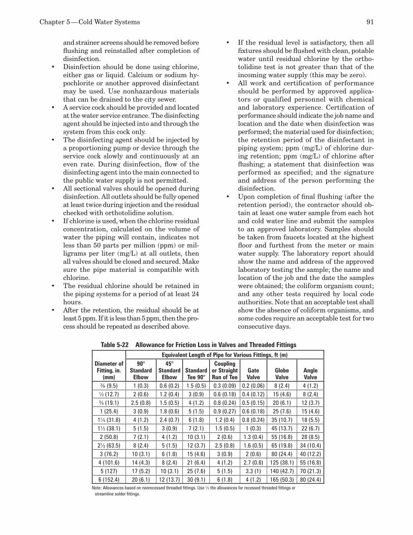
Chapter 5 — Cold Water Systems 91
and strainer screens should be removed before flushing and reinstalled after completion of disinfection. Disinfection should be done using chlorine, •either gas or liquid. Calcium or sodium hy-pochlorite or another approved disinfectant may be used. Use nonhazardous materials that can be drained to the city sewer.A service cock should be provided and located •at the water service entrance. The disinfecting agent should be injected into and through the system from this cock only. The disinfecting agent should be injected by •a proportioning pump or device through the service cock slowly and continuously at an even rate. During disinfection, flow of the disinfecting agent into the main connected to the public water supply is not permitted. All sectional valves should be opened during •disinfection. All outlets should be fully opened at least twice during injection and the residual checked with orthotolidine solution. If chlorine is used, when the chlorine residual •concentration, calculated on the volume of water the piping will contain, indicates not less than 50 parts per million (ppm) or mil-ligrams per liter (mg/L) at all outlets, then all valves should be closed and secured. Make sure the pipe material is compatible with chlorine. The residual chlorine should be retained in •the piping systems for a period of at least 24 hours. After the retention, the residual should be at •least 5 ppm. If it is less than 5 ppm, then the pro-cess should be repeated as described above.
If the residual level is satisfactory, then all •fixtures should be flushed with clean, potable water until residual chlorine by the ortho-tolidine test is not greater than that of the incoming water supply (this may be zero). All work and certification of performance •should be performed by approved applica-tors or qualified personnel with chemical and laboratory experience. Certification of performance should indicate the job name and location and the date when disinfection was performed; the material used for disinfection; the retention period of the disinfectant in piping system; ppm (mg/L) of chlorine dur-ing retention; ppm (mg/L) of chlorine after flushing; a statement that disinfection was performed as specified; and the signature and address of the person performing the disinfection. Upon completion of final flushing (after the •retention period), the contractor should ob-tain at least one water sample from each hot and cold water line and submit the samples to an approved laboratory. Samples should be taken from faucets located at the highest floor and furthest from the meter or main water supply. The laboratory report should show the name and address of the approved laboratory testing the sample; the name and location of the job and the date the samples were obtained; the coliform organism count; and any other tests required by local code authorities. Note that an acceptable test shall show the absence of coliform organisms, and some codes require an acceptable test for two consecutive days.
Table 5-22 Allowance for Friction Loss in Valves and Threaded Fittings
Diameter of Fitting, in.
(mm)
Equivalent Length of Pipe for Various Fittings, ft (m)90°
Standard Elbow
45° Standard
ElbowStandard Tee 90°
Coupling or Straight Run of Tee
Gate Valve
Globe Valve
Angle Valve
3⁄8 (9.5) 1 (0.3) 0.6 (0.2) 1.5 (0.5) 0.3 (0.09) 0.2 (0.06) 8 (2.4) 4 (1.2)½ (12.7) 2 (0.6) 1.2 (0.4) 3 (0.9) 0.6 (0.18) 0.4 (0.12) 15 (4.6) 8 (2.4)¾ (19.1) 2.5 (0.8) 1.5 (0.5) 4 (1.2) 0.8 (0.24) 0.5 (0.15) 20 (6.1) 12 (3.7)1 (25.4) 3 (0.9) 1.8 (0.6) 5 (1.5) 0.9 (0.27) 0.6 (0.18) 25 (7.6) 15 (4.6)
1¼ (31.8) 4 (1.2) 2.4 (0.7) 6 (1.8) 1.2 (0.4) 0.8 (0.24) 35 (10.7) 18 (5.5)1½ (38.1) 5 (1.5) 3 (0.9) 7 (2.1) 1.5 (0.5) 1 (0.3) 45 (13.7) 22 (6.7)2 (50.8) 7 (2.1) 4 (1.2) 10 (3.1) 2 (0.6) 1.3 (0.4) 55 (16.8) 28 (8.5)
2½ (63.5) 8 (2.4) 5 (1.5) 12 (3.7) 2.5 (0.8) 1.6 (0.5) 65 (19.8) 34 (10.4)3 (76.2) 10 (3.1) 6 (1.8) 15 (4.6) 3 (0.9) 2 (0.6) 80 (24.4) 40 (12.2)4 (101.6) 14 (4.3) 8 (2.4) 21 (6.4) 4 (1.2) 2.7 (0.8) 125 (38.1) 55 (16.8)5 (127) 17 (5.2) 10 (3.1) 25 (7.6) 5 (1.5) 3.3 (1) 140 (42.7) 70 (21.3)
6 (152.4) 20 (6.1) 12 (13.7) 30 (9.1) 6 (1.8) 4 (1.2) 165 (50.3) 80 (24.4)Note: Allowances based on nonrecessed threaded fittings. Use ½ the allowances for recessed threaded fittings or
streamline solder fittings.
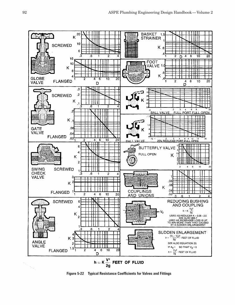
92 ASPE Plumbing Engineering Design Handbook — Volume 2
Figure 5-22 Typical Resistance Coefficients for Valves and Fittings
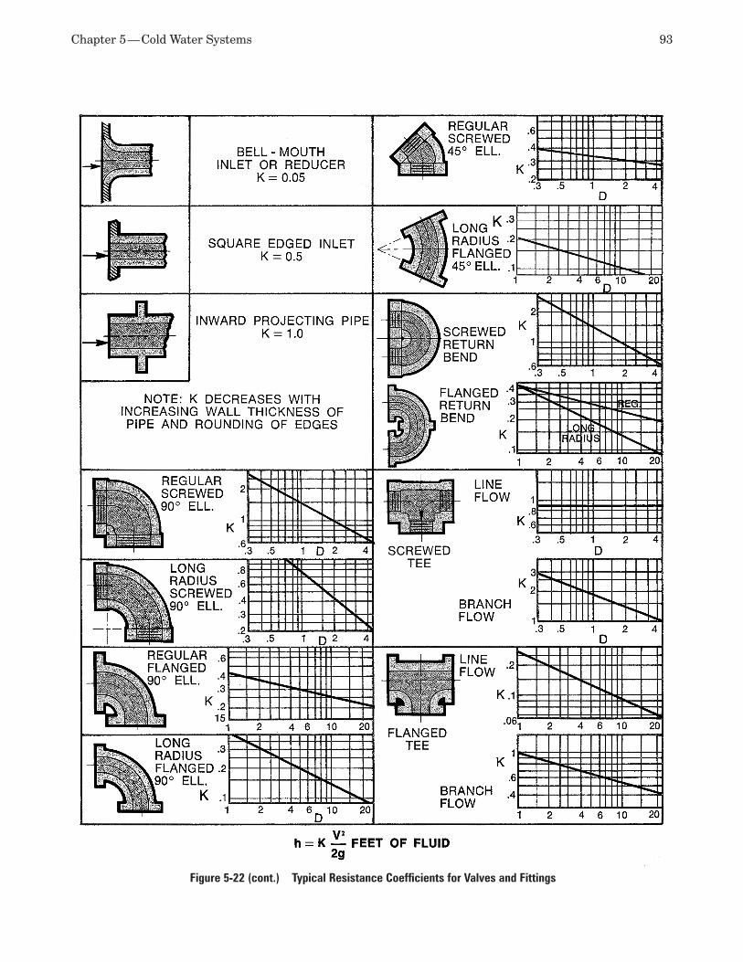
Chapter 5 — Cold Water Systems 93
Figure 5-22 (cont.) Typical Resistance Coefficients for Valves and Fittings
94 ASPE Plumbing Engineering Design Handbook — Volume 2
If the analysis does not satisfy the minimum •requirements, the disinfection procedure must be repeated. Before acceptance of the systems, the contrac-•tor should submit to the architect (engineer) for his review three copies of the laboratory report and three copies of the certification of performance as specified. Under no circumstances should the contractor •permit the use of any portion of the domestic water system until it is properly disinfected, flushed, and certified.
Note: It should be understood that local code re-quirements, if more stringent than above suggested procedures, shall be included in the specifications.
GLOSSARYAccuracy (regarding pressure-regulating valves) The degree of falloff in the outlet pressure from the set pressure at full-flow capacity. Also the capability of producing the same results for repetitive operations with identical conditions of flow.
AWWA Acronym for the American Water Works As-sociation.
Backflow Any reversal of the flow of water from its intended direction.
Back-siphonage Backflow caused by a lowering of normal pressure on the upstream side.
Branch length method A pipe sizing methodology that uses the uniform pressure loss for the critical circuit piping to calculate a new equivalent length for each branch and then size the branches (not the critical circuit) based on the new equivalent length pressure drop per 100 feet.
Constant velocity method A pipe sizing methodol-ogy based on velocity only plus the pressure drop not to exceed the total allowable (used for short lengths and/or few connections).
CPVC Abbreviation for Chlorinated polyvinyl chlo-ride.
Dead-end service A type of service in which the pressure-regulating valve is required to close bottle-tight when there is no demand on the system.
Effective pressure The lowest anticipated residual pressure at the connection to the city water main (or the stop valve at a well system) when water is flowing.
Elevation pressure The pressure change due to a change of elevation (0.433 psi per foot or 2.31 feet per psi for water).
Falloff The amount that the pressure-regulating valve pressure is decreased from set pressure to
meet demand. The amount of falloff depends on the quantity of flow: the greater the flow, the greater the falloff. A falloff of 20 psi (137.9 kPa) is considered to be the maximum desirable.
Fixture supply The final piping connection from the water distribution system to the plumbing fixture.
Flow pressure The pressure required at the fixture or appliance.
Flow pressure drop The pressure drop through a device or fitting in a flowing system. Sometimes called dynamic pressure drop as compared to pipe friction pressure drop.
No-flow pressure The pressure maintained in the system when the pressure-regulating valve is shut tight so that high pressure at the inlet of the valve is not permitted to enter the system.
PRV Abbreviation for pressure-regulating valve.
PVC Abbreviation for polyvinyl chloride.
Reduced-flow pressure The pressure maintained at the pressure-regulating valve outlet when water is flowing. The no-flow (closed), set-point pressure of a pressure-regulating valve is always higher than the reduced-flow (open) pressure. A pressure-regulating valve that is set to open at 45-psi (310.3-kPa) pressure (no flow) would deliver a reduced-flow pressure of 30 psi (206.8 kPa) at peak demand if a 15-psi (103.4-kPa) falloff had been selected.
Residual pressure The pressure measured at any point in the system when water is flowing.
Response (regarding pressure-regulating valves) The capability of a pressure-regulating valve to respond to changes in outlet pressure.
RFP Abbreviation for reinforced fiberglass plastic.
RPz Abbreviation for reduced pressure zone backflow preventer.
Sensitivity The ability of a pressure-regulating valve to sense a change in pressure. If the valve is too sensi-tive and quick to respond, the results are over-control and a hunting effect. Not enough sensitivity results in operation that is sluggish and has great variations in the outlet pressure.
Set pressure (regarding pressure-regulating valves) The pressure at the outlet of the pressure-regulating valve at which the valve will start to open.
Static pressure The pressure measured at any point in a system when no water is flowing.
Total pressure loss method A pipe sizing methodol-ogy in which every circuit uses up all of the available pressure from the meter to the end user. It is very dif-
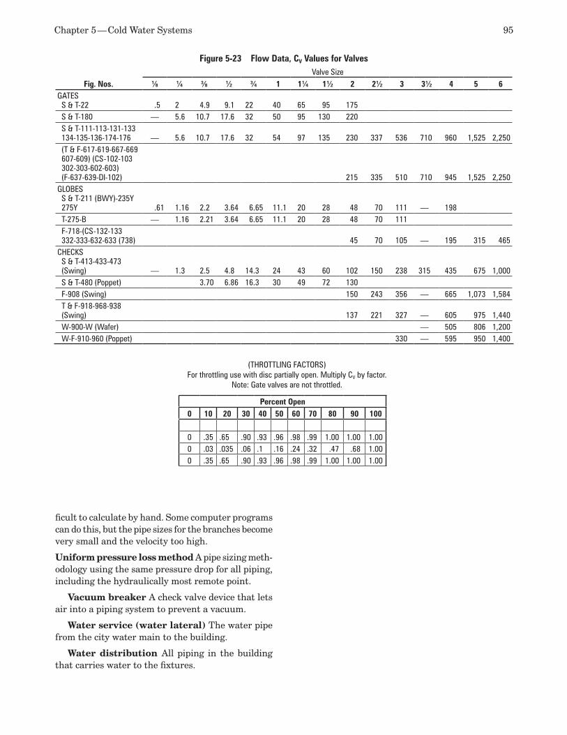
Chapter 5 — Cold Water Systems 95
ficult to calculate by hand. Some computer programs can do this, but the pipe sizes for the branches become very small and the velocity too high.
Uniform pressure loss method A pipe sizing meth-odology using the same pressure drop for all piping, including the hydraulically most remote point.
Vacuum breaker A check valve device that lets air into a piping system to prevent a vacuum.
Water service (water lateral) The water pipe from the city water main to the building.
Water distribution All piping in the building that carries water to the fixtures.
(THROTTLING FACTORS) For throttling use with disc partially open. Multiply CV by factor.
Note: Gate valves are not throttled.
Percent Open0 10 20 30 40 50 60 70 80 90 100
0 .35 .65 .90 .93 .96 .98 .99 1.00 1.00 1.000 .03 .035 .06 .1 .16 .24 .32 .47 .68 1.000 .35 .65 .90 .93 .96 .98 .99 1.00 1.00 1.00
Figure 5-23 Flow Data, CV Values for Valves
Fig. Nos.Valve Size
1⁄8 1⁄4 3⁄8 1⁄2 3⁄4 1 11⁄4 11⁄2 2 21⁄2 3 31⁄2 4 5 6GATES
S & T-22 .5 2 4.9 9.1 22 40 65 95 175S & T-180 — 5.6 10.7 17.6 32 50 95 130 220S & T-111-113-131-133134-135-136-174-176 — 5.6 10.7 17.6 32 54 97 135 230 337 536 710 960 1,525 2,250(T & F-617-619-667-669607-609) (CS-102-103302-303-602-603)(F-637-639-DI-102) 215 335 510 710 945 1,525 2,250
GLOBESS & T-211 (BWY)-235Y275Y .61 1.16 2.2 3.64 6.65 11.1 20 28 48 70 111 — 198T-275-B — 1.16 2.21 3.64 6.65 11.1 20 28 48 70 111F-718-(CS-132-133332-333-632-633 (738) 45 70 105 — 195 315 465
CHECKSS & T-413-433-473(Swing) — 1.3 2.5 4.8 14.3 24 43 60 102 150 238 315 435 675 1,000S & T-480 (Poppet) 3.70 6.86 16.3 30 49 72 130F-908 (Swing) 150 243 356 — 665 1,073 1,584T & F-918-968-938(Swing) 137 221 327 — 605 975 1,440W-900-W (Wafer) — 505 806 1,200W-F-910-960 (Poppet) 330 — 595 950 1,400

Domestic Water Heating Systems6
Proper design of the domestic hot water supply sys-tem for any building is extremely important. Careful planning on the basis of all available data will ensure a safe and adequate supply of hot water. A properly designed system must, of course, conform to all ap-plicable codes plus the regulations of the authority having jurisdiction (AHJ).
The objectives for a domestic hot water design and distri bution system include the following:
Provide adequate amounts of water at the 1. prescribed temperature to all fixtures and equipment at all times of use.Provide a system that will perform its func-2. tion safely.Utilize an economical heat source.3. Provide a cost-effective, efficient, and durable 4. installation.Provide an economical operating system with 5. reasonable maintenance.
A well-designed system should deliver hot water at the prescribed temperature to the outlet with very little delay, thereby satisfying the users plus avoid-ing the wasteful running of water until the desired temperature is achieved. The hot water should be available at any time of use, day or night, and during low-demand periods as well as peak flows. Plumbing codes provide some guidance here—for example, uncirculated hot water dead-end legs should be 100 feet or shorter. However, meeting this code minimum may be unsatisfactory to users. The balance between near-instantaneous hot water delivery and incremen-tal project cost must be maintained.
Safety must be built into any hot water system, and the plumbing codes require specific methods that must be used to achieve certain levels of safety. National standards recommend additional methods, which, while not having the force of law, nevertheless are accepted as good engineering design practices.
The three paramount dangers to be guarded against are excessive pressure, excessive tempera-ture, and contamination. Excessive temperatures and pressures are avoided by using correctly sized
temperature and pressure (T&P) relief valves at water heaters. Where check valves are present, as on hot water circulation systems and backflow preventers, thermal expansion tanks are to be used. The risk of scalding and thermal shock can be reduced by using many types of mechanical, pressure-balanced, or thermostatic mixing valves, installed at the hot water source and/or the point of use.
As with the domestic cold water system, wa-ter hammer arresters should be used to mitigate anticipated pressure spikes at quick-closing solenoid-operated valves. Strategically placed pressure gauges and thermometers, perhaps wired back to the building automation system (BAS), allow easy monitoring of the system.
Contamination of the domestic hot water system is prevented by many of the same methods used with the domestic cold water system. Cross-contamination is prevented by using appropriately selected backflow preventers for both hazard type and temperature. Double-wall heat exchangers are required for use with indirect-fired water heaters.
Warm water, such as that present in dead-end legs, low-temperature circulating loops, and storage-type water heaters at low temperatures, provides the ideal environment for waterborne bacterial growth, most notably Legionella pneumophila. Health concerns from waterborne bacterial growth must be considered in all hot water designs. Waterborne bacterial control measures should be included in the design whenever hot water is supplied to high-risk occupancies, such as hospitals or nursing homes. It is also good en-gineering practice to address waterborne bacterial control in hotels. Again, the designer must balance the need for reasonable public safety with excessive project costs.
An economical heat source will save money. Typical energy sources include natural gas, lique-fied petroleum gas, oil, electricity, steam, boiler hot water (hydronics), waste heat, and solar thermal. The availabil ity and cost of any of these sources or combinations of these sources dictate equipment and
98 ASPE Plumbing Engineering Design Handbook — Volume 2
system selection. Where an especially economical energy source is available but not adequate to satisfy the total demand, it might be used to preheat the cold water supply to the heater.
A cost-effective and durable installation begins with the judicious selection of the proper materials and equipment. As with the domestic cold water sys-tem, the pipe materials and layout, joining methods, hangers, and insulation all must match the project’s needs and will determine the cost as well as the ease of replacement and repair.
An economical operating system with reasonable maintenance depends on all of these considerations. The location of piping, ease of circulation, bypasses around pumps and tanks, adequate valving, accessibil-ity and provisions for the future all are items affecting the operation and maintenance of a system.
Finally, extra capacity and redundancy need to be tailored to each application.
DOMESTIC WATER HEATER SIzINGSizing a domestic water heater is as much an art as a science. For anything other than a small residential system, it’s not reasonable to simply go to a table or chart and make a selection. Codes do not indicate how much hot water is required. Instead, they contain only generalizations such as “Provide adequate amounts of hot and cold water to all sinks, lavatories, showers, etc.” Codes do, however, provide information about minimum and maximum flow rates to fixtures and ad-dress safety concerns such as maximum temperatures and required water heater safety devices.
The design of a domestic water-heating system begins with estimating the facility’s load profile and identifying the peak demands. To accomplish these steps, you must talk to the users of the space, determine the building type, and learn any owner requirements. The information thus gathered will establish the re-quired capacity of the water-heating equipment and the general type of system to be used.
A number of factors must be considered when siz-ing a system, and experience plays a big part. Every system is different, so the path that leads to final selection varies for each system. Two buildings might have the same number and type of fixtures, but the water requirements could be vastly different. For instance, an apartment building for retired people would have different hot water needs than one that primarily houses families or college students.
To help with sizing, water heater manufacturers maintain substantial water heater sizing guidelines and instructional manuals, all kept current with in-dustry standards and trends. ASPE’s Domestic Water Heating Design Manual covers virtually every type of facility and heating system available.
Information GatheringThe first step to sizing a domestic hot water heater system is to collect the information needed to define the system parameters. Some of the information will be readily available, already gathered as part of the domestic cold water system design, but some may require further investigation. Following is a partial list of sample questions.
In what type of building will the system be •installed?Where is the building located? •What codes should be followed?•Do any local code amendments apply?•Does the owner or operator of the building •have any unusual requirements?Does the owner or operator of the building •prefer a particular type of system?Are there any other hot water systems in the •building?What area of the building will the system •serve?What is the area used for?•How many plumbing fixtures will there be?•Who will be using the plumbing fixtures?•Are there any high-usage fixtures, such as •hot tubs?Are there plans to expand the facility in the •future?Will there be laundry, food service, or health •club areas?How many areas will be used simultane-•ously?How much space is available for the system?•What energy sources are available?•Where in the building will the equipment be •placed?Will flues or combustion air be a problem due •to the location?What is the building cold water source?•What are the water hardness, pH, total •dissolved solids and other water quality pa-rameters?Will the system be inactive for long periods?•How far from the heater will the furthest •fixture be?How many showers will be used simultane-•ously and for what duration?
Water Heater Sizing MethodsWith the correct information gathered, the load profile and peak demand can be calculated. Once again, this is not necessarily a straightforward process. Several methods for calculating the load of a building are available, and one method is not always better than another. Two methods from the American Society of Plumbing Engineers (ASPE) are outlined here. Other
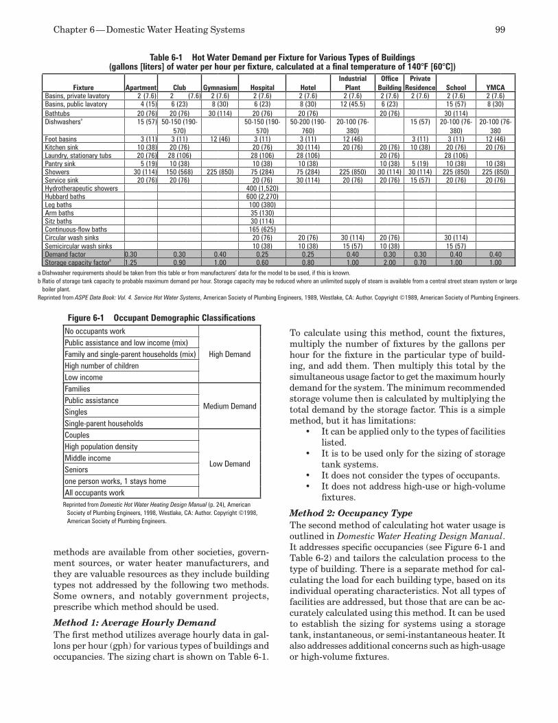
Chapter 6 — Domestic Water Heating Systems 99
methods are available from other societies, govern-ment sources, or water heater manufacturers, and they are valuable resources as they include building types not addressed by the following two methods. Some owners, and notably government projects, prescribe which method should be used.
Method 1: Average Hourly DemandThe first method utilizes average hourly data in gal-lons per hour (gph) for various types of buildings and occupancies. The sizing chart is shown on Table 6-1.
To calculate using this method, count the fixtures, multiply the number of fixtures by the gallons per hour for the fixture in the particular type of build-ing, and add them. Then multiply this total by the simultaneous usage factor to get the maximum hourly demand for the system. The minimum recommended storage volume then is calculated by multiplying the total demand by the storage factor. This is a simple method, but it has limitations:
It can be applied only to the types of facilities •listed.It is to be used only for the sizing of storage •tank systems.It does not consider the types of occupants.•It does not address high-use or high-volume •fixtures.
Method 2: Occupancy TypeThe second method of calculating hot water usage is outlined in Domestic Water Heating Design Manual. It addresses specific occupancies (see Figure 6-1 and Table 6-2) and tailors the calculation process to the type of building. There is a separate method for cal-culating the load for each building type, based on its individual operating characteristics. Not all types of facilities are addressed, but those that are can be ac-curately calculated using this method. It can be used to establish the sizing for systems using a storage tank, instantaneous, or semi-instantaneous heater. It also addresses additional concerns such as high-usage or high-volume fixtures.
Table 6-1 Hot Water Demand per Fixture for Various Types of Buildings (gallons [liters] of water per hour per fixture, calculated at a final temperature of 140°F [60°C])
Fixture Apartment Club Gymnasium Hospital HotelIndustrial
PlantOffice
BuildingPrivate
Residence School YMCABasins, private lavatory 2 (7.6) 2 (7.6) 2 (7.6) 2 (7.6) 2 (7.6) 2 (7.6) 2 (7.6) 2 (7.6) 2 (7.6) 2 (7.6)Basins, public lavatory 4 (15) 6 (23) 8 (30) 6 (23) 8 (30) 12 (45.5) 6 (23) 15 (57) 8 (30)Bathtubs 20 (76) 20 (76) 30 (114) 20 (76) 20 (76) 20 (76) 30 (114)Dishwashersa 15 (57) 50-150 (190-
570)50-150 (190-
570)50-200 (190-
760)20-100 (76-
380)15 (57) 20-100 (76-
380)20-100 (76-
380Foot basins 3 (11) 3 (11) 12 (46) 3 (11) 3 (11) 12 (46) 3 (11) 3 (11) 12 (46)Kitchen sink 10 (38) 20 (76) 20 (76) 30 (114) 20 (76) 20 (76) 10 (38) 20 (76) 20 (76)Laundry, stationary tubs 20 (76) 28 (106) 28 (106) 28 (106) 20 (76) 28 (106)Pantry sink 5 (19) 10 (38) 10 (38) 10 (38) 10 (38) 5 (19) 10 (38) 10 (38)Showers 30 (114) 150 (568) 225 (850) 75 (284) 75 (284) 225 (850) 30 (114) 30 (114) 225 (850) 225 (850)Service sink 20 (76) 20 (76) 20 (76) 30 (114) 20 (76) 20 (76) 15 (57) 20 (76) 20 (76)Hydrotherapeutic showers 400 (1,520)Hubbard baths 600 (2,270)Leg baths 100 (380)Arm baths 35 (130)Sitz baths 30 (114)Continuous-flow baths 165 (625)Circular wash sinks 20 (76) 20 (76) 30 (114) 20 (76) 30 (114)Semicircular wash sinks 10 (38) 10 (38) 15 (57) 10 (38) 15 (57)Demand factor 0.30 0.30 0.40 0.25 0.25 0.40 0.30 0.30 0.40 0.40Storage capacity factorb 1.25 0.90 1.00 0.60 0.80 1.00 2.00 0.70 1.00 1.00
a Dishwasher requirements should be taken from this table or from manufacturers’ data for the model to be used, if this is known.b Ratio of storage tank capacity to probable maximum demand per hour. Storage capacity may be reduced where an unlimited supply of steam is available from a central street steam system or large
boiler plant.Reprinted from ASPE Data Book: Vol. 4. Service Hot Water Systems, American Society of Plumbing Engineers, 1989, Westlake, CA: Author. Copyright ©1989, American Society of Plumbing Engineers.
Figure 6-1 Occupant Demographic ClassificationsNo occupants work
High DemandPublic assistance and low income (mix)Family and single-parent households (mix)High number of childrenLow incomeFamilies
Medium DemandPublic assistanceSinglesSingle-parent householdsCouples
Low Demand
High population densityMiddle incomeSeniorsone person works, 1 stays homeAll occupants work
Reprinted from Domestic Hot Water Heating Design Manual (p. 24), American Society of Plumbing Engineers, 1998, Westlake, CA: Author. Copyright ©1998, American Society of Plumbing Engineers.
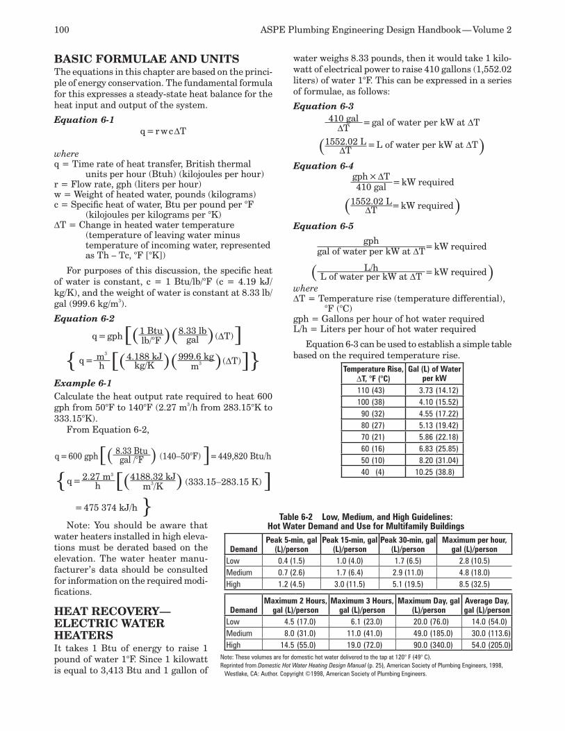
100 ASPE Plumbing Engineering Design Handbook — Volume 2
BASIC FORMULAE AND UNITS The equations in this chapter are based on the princi-ple of energy conservation. The fundamental formula for this expresses a steady-state heat balance for the heat input and output of the system.
Equation 6-1q = r w c DT
whereq = Time rate of heat transfer, British thermal
units per hour (Btuh) (kilojoules per hour)r = Flow rate, gph (liters per hour)w = Weight of heated water, pounds (kilograms)c = Specific heat of water, Btu per pound per °F
(kilojoules per kilograms per °K)DT = Change in heated water temperature
(temperature of leaving water minus temperature of incoming water, represented as Th – Tc, °F [°K])
For purposes of this discussion, the specific heat of water is constant, c = 1 Btu/lb/°F (c = 4.19 kJ/kg/K), and the weight of water is constant at 8.33 lb/gal (999.6 kg/m3).
Equation 6-2
q = gph[(1 Btu)(8.33 lb)(DT)]lb/°F gal
q = m3 [(4.188 kJ)(999.6 kg)(DT)]h kg/K m3
Example 6-1Calculate the heat output rate required to heat 600 gph from 50°F to 140°F (2.27 m3/h from 283.15°K to 333.15°K).
From Equation 6-2,
q = 600 gph[( 8.33 Btu ) (140−50°F) ]= 449,820 Btu/hgal /°F
q = 2.27 m3 [(4188.32 kJ) (333.15−283.15 K) ]h m3/K
= 475 374 kJ/h Note: You should be aware that
water heaters installed in high eleva-tions must be derated based on the elevation. The water heater manu-facturer’s data should be consulted for information on the required modi-fications.
HEAT RECOVERY—ELECTRIC WATER HEATERSIt takes 1 Btu of energy to raise 1 pound of water 1°F. Since 1 kilowatt is equal to 3,413 Btu and 1 gallon of
water weighs 8.33 pounds, then it would take 1 kilo-watt of electrical power to raise 410 gallons (1,552.02 liters) of water 1°F. This can be expressed in a series of formulae, as follows:
Equation 6-3410 gal = gal of water per kW at DTDT
(1552.02 L = L of water per kW at DT)DT
Equation 6-4gph × DT
= kW required410 gal
(1552.02 L= kW required)DT
Equation 6-5
gph= kW requiredgal of water per kW at DT
( L/h = kW required)L of water per kW at DTwhereDT = Temperature rise (temperature differential),
°F (°C)gph = Gallons per hour of hot water requiredL/h = Liters per hour of hot water required
Equation 6-3 can be used to establish a simple table based on the required temperature rise.
Temperature Rise, DT, °F (°C)
Gal (L) of Water per kW
110 (43) 3.73 (14.12)100 (38) 4.10 (15.52)90 (32) 4.55 (17.22)80 (27) 5.13 (19.42)70 (21) 5.86 (22.18)60 (16) 6.83 (25.85)50 (10) 8.20 (31.04)40 (4) 10.25 (38.8)
Table 6-2 Low, Medium, and High Guidelines: Hot Water Demand and Use for Multifamily Buildings
DemandPeak 5-min, gal
(L)/personPeak 15-min, gal
(L)/personPeak 30-min, gal
(L)/personMaximum per hour,
gal (L)/personLow 0.4 (1.5) 1.0 (4.0) 1.7 (6.5) 2.8 (10.5)Medium 0.7 (2.6) 1.7 (6.4) 2.9 (11.0) 4.8 (18.0)High 1.2 (4.5) 3.0 (11.5) 5.1 (19.5) 8.5 (32.5)
DemandMaximum 2 Hours,
gal (L)/personMaximum 3 Hours,
gal (L)/personMaximum Day, gal
(L)/personAverage Day, gal (L)/person
Low 4.5 (17.0) 6.1 (23.0) 20.0 (76.0) 14.0 (54.0)Medium 8.0 (31.0) 11.0 (41.0) 49.0 (185.0) 30.0 (113.6)High 14.5 (55.0) 19.0 (72.0) 90.0 (340.0) 54.0 (205.0)
Note: These volumes are for domestic hot water delivered to the tap at 120° F (49° C).Reprinted from Domestic Hot Water Heating Design Manual (p. 25), American Society of Plumbing Engineers, 1998,
Westlake, CA: Author. Copyright ©1998, American Society of Plumbing Engineers.
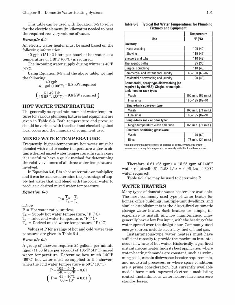
Chapter 6 — Domestic Water Heating Systems 101
This table can be used with Equation 6-5 to solve for the electric element (in kilowatts) needed to heat the required recovery volume of water.
Example 6-2An electric water heater must be sized based on the following information:
40 gph (151.42 liters per hour) of hot water at a temperature of 140°F (60°C) is required.
The incoming water supply during winter is 40°F (4°C).
Using Equation 6-5 and the above table, we find the following:
40 gph= 9.8 kW required4.1 gal (100°F)
( 151.42 L/h = 9.8 kW required )15.52 L (38°C)
HOT WATER TEMPERATUREThe generally accepted minimum hot water tempera-tures for various plumbing fixtures and equipment are given in Table 6-3. Both temperature and pressure should be verified with the client and checked against local codes and the manuals of equipment used.
MIXED WATER TEMPERATUREFrequently, higher-temperature hot water must be blended with cold or cooler-temperature water to ob-tain a desired mixed water temperature. In such a case it is useful to have a quick method for determining the relative volumes of all three water temperatures involved.
In Equation 6-6, P is a hot water ratio or multiplier, and it can be used to determine the percentage of sup-ply hot water that will blend with the cooler water to produce a desired mixed water temperature.
Equation 6-6
P = Tm – Tc
Th – Tc
whereP = Hot water ratio, unitlessTh = Supply hot water temperature, ˚F (˚C)Tc = Inlet cold water temperature, ˚F (˚C)Tm = Desired mixed water temperature, ˚F (˚C)
Values of P for a range of hot and cold water tem-peratures are given in Table 6-4.
Example 6-3A group of showers requires 25 gallons per minute (gpm) (1.58 liters per second) of 105°F (41°C) mixed water temperature. Determine how much 140°F (60°C) hot water must be supplied to the showers when the cold water temperature is 50°F (10°C).
P = 105 – 50°F = 0.61140 – 50°F
( P = 41 – 10°C = 0.61)60 – 10°
Therefore, 0.61 (25 gpm) = 15.25 gpm of 140°F water required[0.61 (1.58 L/s) = 0.96 L/s of 60°C water required].
Table 6-2 also may be used to determine P.
WATER HEATERSMany types of domestic water heaters are available. The most commonly used type of water heater for homes, office buildings, multiple-unit dwellings, and similar establishments is the direct-fired automatic storage water heater. Such heaters are simple, in-expensive to install, and low maintenance. They generally have a low Btu input, with the heating of the water spread over the design hour. Commonly used energy sources include electricity, fuel oil, and gas.
Instantaneous-type water heaters must have sufficient capacity to provide the maximum instanta-neous flow rate of hot water. Historically, a gas-fired instantaneous heater finds its best application where water-heating demands are constant, such as swim-ming pools, certain dishwasher booster requirements, and industrial processes, or where space conditions are a prime consideration, but currently available models have much improved electronic modulating control. Instantaneous water heaters have near zero standby losses.
Table 6-3 Typical Hot Water Temperatures for Plumbing Fixtures and Equipment
UseTemperature
°F (°C)Lavatory: Hand washing 105 (40) Shaving 115 (45)Showers and tubs 110 (43)Therapeutic baths 95 (35)Surgical scrubbing 110 (43)Commercial and institutional laundry 140–180 (60–82)Residential dishwashing and laundry 120 (48)Commercial, spray-type dishwashing (as required by the NSF): Single- or multiple-tank hood or rack type: Wash 150 min. (66 min.) Final rinse 180–195 (82–91) Single-tank conveyor type: Wash 160 min. (71 min.) Final rinse 180–195 (82–91) Single-tank rack or door type: Single-temperature wash and rinse 165 min. (74 min.) Chemical sanitizing glassware: Wash 140 (60) Rinse 75 min. (24 min.)
Note: Be aware that temperatures, as dictated by codes, owners, equipment manufacturers, or regulatory agencies, occasionally will differ from those shown.
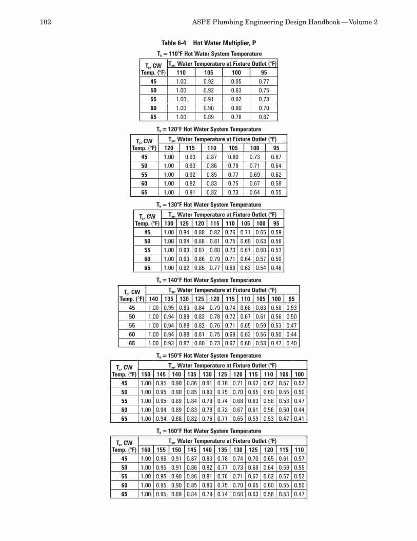
102 ASPE Plumbing Engineering Design Handbook — Volume 2
Th = 110°F Hot Water System Temperature
Tc, CW Temp. (°F)
Tm, Water Temperature at Fixture Outlet (°F)110 105 100 95
45 1.00 0.92 0.85 0.77 50 1.00 0.92 0.83 0.75 55 1.00 0.91 0.82 0.73 60 1.00 0.90 0.80 0.70 65 1.00 0.89 0.78 0.67
Th = 120°F Hot Water System Temperature
Tc, CW Temp. (°F)
Tm, Water Temperature at Fixture Outlet (°F)120 115 110 105 100 95
45 1.00 0.93 0.87 0.80 0.73 0.6750 1.00 0.93 0.86 0.79 0.71 0.6455 1.00 0.92 0.85 0.77 0.69 0.6260 1.00 0.92 0.83 0.75 0.67 0.5865 1.00 0.91 0.82 0.73 0.64 0.55
Th = 130°F Hot Water System Temperature
Tc, CW Temp. (°F)
Tm, Water Temperature at Fixture Outlet (°F)130 125 120 115 110 105 100 95
45 1.00 0.94 0.88 0.82 0.76 0.71 0.65 0.5950 1.00 0.94 0.88 0.81 0.75 0.69 0.63 0.5655 1.00 0.93 0.87 0.80 0.73 0.67 0.60 0.5360 1.00 0.93 0.86 0.79 0.71 0.64 0.57 0.5065 1.00 0.92 0.85 0.77 0.69 0.62 0.54 0.46
Th = 140°F Hot Water System Temperature
Tc, CW Temp. (°F)
Tm, Water Temperature at Fixture Outlet (°F)140 135 130 125 120 115 110 105 100 95
45 1.00 0.95 0.89 0.84 0.79 0.74 0.68 0.63 0.58 0.5350 1.00 0.94 0.89 0.83 0.78 0.72 0.67 0.61 0.56 0.5055 1.00 0.94 0.88 0.82 0.76 0.71 0.65 0.59 0.53 0.4760 1.00 0.94 0.88 0.81 0.75 0.69 0.63 0.56 0.50 0.4465 1.00 0.93 0.87 0.80 0.73 0.67 0.60 0.53 0.47 0.40
Th = 150°F Hot Water System Temperature
Tc, CW Temp. (°F)
Tm, Water Temperature at Fixture Outlet (°F)150 145 140 135 130 125 120 115 110 105 100
45 1.00 0.95 0.90 0.86 0.81 0.76 0.71 0.67 0.62 0.57 0.5250 1.00 0.95 0.90 0.85 0.80 0.75 0.70 0.65 0.60 0.55 0.5055 1.00 0.95 0.89 0.84 0.79 0.74 0.68 0.63 0.58 0.53 0.4760 1.00 0.94 0.89 0.83 0.78 0.72 0.67 0.61 0.56 0.50 0.4465 1.00 0.94 0.88 0.82 0.76 0.71 0.65 0.59 0.53 0.47 0.41
Th = 160°F Hot Water System Temperature
Tc, CW Temp. (°F)
Tm, Water Temperature at Fixture Outlet (°F)160 155 150 145 140 135 130 125 120 115 110
45 1.00 0.96 0.91 0.87 0.83 0.78 0.74 0.70 0.65 0.61 0.5750 1.00 0.95 0.91 0.86 0.82 0.77 0.73 0.68 0.64 0.59 0.5555 1.00 0.95 0.90 0.86 0.81 0.76 0.71 0.67 0.62 0.57 0.5260 1.00 0.95 0.90 0.85 0.80 0.75 0.70 0.65 0.60 0.55 0.5065 1.00 0.95 0.89 0.84 0.79 0.74 0.68 0.63 0.58 0.53 0.47
Table 6-4 Hot Water Multiplier, P
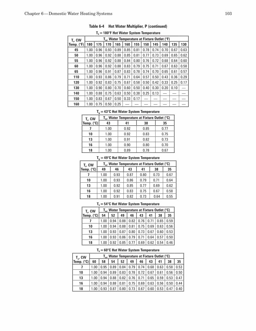
Chapter 6 — Domestic Water Heating Systems 103
Th = 180°F Hot Water System Temperature
Tc, CW Temp. (°F)
Tm, Water Temperature at Fixture Outlet (°F)180 175 170 165 160 155 150 145 140 135 130
45 1.00 0.96 0.93 0.89 0.85 0.81 0.78 0.74 0.70 0.67 0.6350 1.00 0.96 0.92 0.88 0.85 0.81 0.77 0.73 0.69 0.65 0.6255 1.00 0.96 0.92 0.88 0.84 0.80 0.76 0.72 0.68 0.64 0.6060 1.00 0.96 0.92 0.88 0.83 0.79 0.75 0.71 0.67 0.63 0.5865 1.00 0.96 0.91 0.87 0.83 0.78 0.74 0.70 0.65 0.61 0.57110 1.00 0.93 0.86 0.79 0.71 0.64 0.57 0.50 0.43 0.36 0.29120 1.00 0.92 0.83 0.75 0.67 0.58 0.50 0.42 0.33 0.25 0.17130 1.00 0.90 0.80 0.70 0.60 0.50 0.40 0.30 0.20 0.10 —140 1.00 0.88 0.75 0.63 0.50 0.38 0.25 0.13 — — —150 1.00 0.83 0.67 0.50 0.33 0.17 — — — — —160 1.00 0.75 0.50 0.25 — — — — — — —
Th = 43°C Hot Water System Temperature
Tc, CW Temp. (°C)
Tm, Water Temperature at Fixture Outlet (°C)43 41 38 35
7 1.00 0.92 0.85 0.7710 1.00 0.92 0.83 0.7513 1.00 0.91 0.82 0.7316 1.00 0.90 0.80 0.7018 1.00 0.89 0.78 0.67
Th = 49°C Hot Water System Temperature
Tc, CW Temp. (°C)
Tm, Water Temperature at Fixture Outlet (°C)49 46 43 41 38 35
7 1.00 0.93 0.87 0.80 0.73 0.6710 1.00 0.93 0.86 0.79 0.71 0.6413 1.00 0.92 0.85 0.77 0.69 0.6216 1.00 0.92 0.83 0.75 0.67 0.5818 1.00 0.91 0.82 0.73 0.64 0.55
Th = 54°C Hot Water System Temperature
Tc, CW Temp. (°C)
Tm, Water Temperature at Fixture Outlet (°C)54 52 49 46 43 41 38 35
7 1.00 0.94 0.88 0.82 0.76 0.71 0.65 0.5910 1.00 0.94 0.88 0.81 0.75 0.69 0.63 0.5613 1.00 0.93 0.87 0.80 0.73 0.67 0.60 0.5316 1.00 0.93 0.86 0.79 0.71 0.64 0.57 0.5018 1.00 0.92 0.85 0.77 0.69 0.62 0.54 0.46
Th = 60°C Hot Water System Temperature
Tc, CW Temp. (°C)
Tm, Water Temperature at Fixture Outlet (°C)60 58 54 52 49 46 43 41 38 35
7 1.00 0.95 0.89 0.84 0.79 0.74 0.68 0.63 0.58 0.5310 1.00 0.94 0.89 0.83 0.78 0.72 0.67 0.61 0.56 0.5013 1.00 0.94 0.88 0.82 0.76 0.71 0.65 0.59 0.53 0.4716 1.00 0.94 0.88 0.81 0.75 0.69 0.63 0.56 0.50 0.4418 1.00 0.93 0.87 0.80 0.73 0.67 0.60 0.53 0.47 0.40
Table 6-4 Hot Water Multiplier, P (continued)
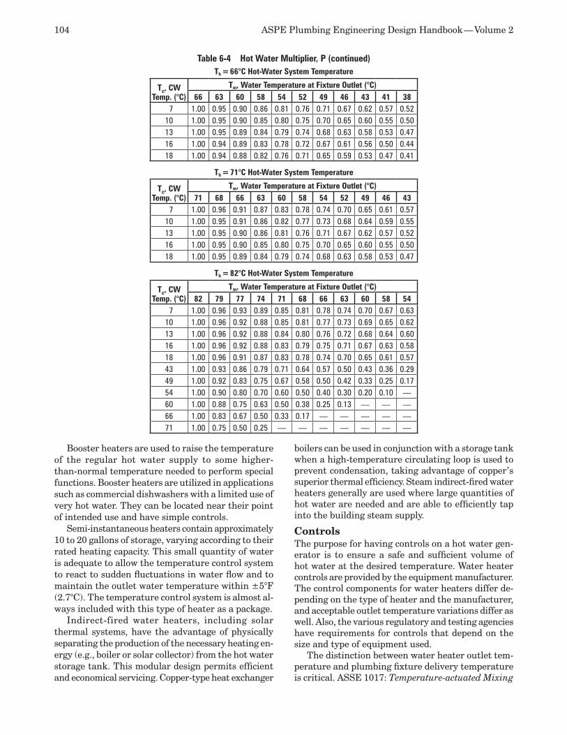
104 ASPE Plumbing Engineering Design Handbook — Volume 2
Booster heaters are used to raise the temperature of the regular hot water supply to some higher-than-normal temperature needed to perform special functions. Booster heaters are utilized in applications such as commercial dishwashers with a limited use of very hot water. They can be located near their point of intended use and have simple controls.
Semi-instantaneous heaters contain approximately 10 to 20 gallons of storage, varying according to their rated heating capacity. This small quantity of water is adequate to allow the temperature control system to react to sudden fluctuations in water flow and to maintain the outlet water temperature within ±5°F (2.7°C). The temperature control system is almost al-ways included with this type of heater as a package.
Indirect-fired water heaters, including solar thermal systems, have the advantage of physically separating the production of the necessary heating en-ergy (e.g., boiler or solar collector) from the hot water storage tank. This modular design permits efficient and economical servicing. Copper-type heat exchanger
boilers can be used in conjunction with a storage tank when a high-temperature circulating loop is used to prevent condensation, taking advantage of copper’s superior thermal efficiency. Steam indirect-fired water heaters generally are used where large quantities of hot water are needed and are able to efficiently tap into the building steam supply.
ControlsThe purpose for having controls on a hot water gen-erator is to ensure a safe and sufficient volume of hot water at the desired temperature. Water heater controls are provided by the equipment manufacturer. The control components for water heaters differ de-pending on the type of heater and the manufacturer, and acceptable outlet temperature variations differ as well. Also, the various regulatory and testing agencies have requirements for controls that depend on the size and type of equipment used.
The distinction between water heater outlet tem-perature and plumbing fixture delivery temperature is critical. ASSE 1017: Temperature-actuated Mixing
Th = 66°C Hot-Water System Temperature
Tc, CW Temp. (°C)
Tm, Water Temperature at Fixture Outlet (°C)66 63 60 58 54 52 49 46 43 41 38
7 1.00 0.95 0.90 0.86 0.81 0.76 0.71 0.67 0.62 0.57 0.5210 1.00 0.95 0.90 0.85 0.80 0.75 0.70 0.65 0.60 0.55 0.5013 1.00 0.95 0.89 0.84 0.79 0.74 0.68 0.63 0.58 0.53 0.4716 1.00 0.94 0.89 0.83 0.78 0.72 0.67 0.61 0.56 0.50 0.4418 1.00 0.94 0.88 0.82 0.76 0.71 0.65 0.59 0.53 0.47 0.41
Th = 71°C Hot-Water System Temperature
Tc, CW Temp. (°C)
Tm, Water Temperature at Fixture Outlet (°C)71 68 66 63 60 58 54 52 49 46 43
7 1.00 0.96 0.91 0.87 0.83 0.78 0.74 0.70 0.65 0.61 0.5710 1.00 0.95 0.91 0.86 0.82 0.77 0.73 0.68 0.64 0.59 0.5513 1.00 0.95 0.90 0.86 0.81 0.76 0.71 0.67 0.62 0.57 0.5216 1.00 0.95 0.90 0.85 0.80 0.75 0.70 0.65 0.60 0.55 0.5018 1.00 0.95 0.89 0.84 0.79 0.74 0.68 0.63 0.58 0.53 0.47
Th = 82°C Hot-Water System Temperature
Tc, CW Temp. (°C)
Tm, Water Temperature at Fixture Outlet (°C)82 79 77 74 71 68 66 63 60 58 54
7 1.00 0.96 0.93 0.89 0.85 0.81 0.78 0.74 0.70 0.67 0.6310 1.00 0.96 0.92 0.88 0.85 0.81 0.77 0.73 0.69 0.65 0.6213 1.00 0.96 0.92 0.88 0.84 0.80 0.76 0.72 0.68 0.64 0.6016 1.00 0.96 0.92 0.88 0.83 0.79 0.75 0.71 0.67 0.63 0.5818 1.00 0.96 0.91 0.87 0.83 0.78 0.74 0.70 0.65 0.61 0.5743 1.00 0.93 0.86 0.79 0.71 0.64 0.57 0.50 0.43 0.36 0.2949 1.00 0.92 0.83 0.75 0.67 0.58 0.50 0.42 0.33 0.25 0.1754 1.00 0.90 0.80 0.70 0.60 0.50 0.40 0.30 0.20 0.10 —60 1.00 0.88 0.75 0.63 0.50 0.38 0.25 0.13 — — —66 1.00 0.83 0.67 0.50 0.33 0.17 — — — — —71 1.00 0.75 0.50 0.25 — — — — — — —
Table 6-4 Hot Water Multiplier, P (continued)

Chapter 6 — Domestic Water Heating Systems 105
Valves for Hot Water Distribution Systems addresses source distribution temperature requirements, and other ASSE standards apply to the various plumbing fixtures. Three primary ASSE standards addressing fixture delivery temperature include ASSE 1016: Per-formance Requirements for Automatic Compensating Valves for Individual Showers and Tub/Shower Com-binations, ASSE 1069: Performance Requirements for Automatic Temperature Control Mixing Valves, and ASSE 1070: Performance Requirements for Water Temperature Limiting Devices. (Listings for ASSE 1016-1996 were deactivated and are superseded by the above standards.) ASSE 1071: Temperature-actuated Mixing Valves for Plumbed Emergency Equipment was established for emergency eyewashes, face washes, and drench showers.
Stratification in Storage-type Heaters and TanksBecause of its lighter density, warm water rises to the top of a storage tank. The result of this rising action, known as stratification, occurs in all uncirculated tanks. It has been found that the amount of usable water in stratified horizontal and vertical tanks could be as low as 65 percent and 75 percent respectively, depending on design.
Stratification during recovery periods can be re-duced significantly by mechanical circulation of the water in the tank. During periods of high demand, however, it might be useful to have stratification since this increases the availability of water at a us-able temperature. For example, if a tank were equally stratified between 140°F (60°C) at the top and 40°F (4°C) at the bottom, this tank, in theory, still could deliver half its volume at 140°F (60°C). If the two layers were completely mixed, the tank temperature would drop to 90°F (32°C), which in most cases is an unusable temperature.
HOT WATER TEMPERATURE MAINTENANCEHot water of a desired temperature should be read-ily available at any fixture. Hot water supply piping transmits heat to the surrounding lower-temperature air by conduction, convection, and radiation. Insula-tion reduces but does not eliminate this heat loss. In large systems, if the heat loss is not addressed, users may become frustrated waiting for the desired tem-perature water. Water is wasted, and the associated energy and wastewater utility costs are incurred. This is particularly true in systems using low-flow and electronic faucets where the wait time can be very long.
Two common methods used to achieve satisfactory remote temperature maintenance include a hot wa-ter circulation system or a self-regulated electrically heated system.
Hot Water Circulation SystemsThe sizing of the hot water circulation system includes selecting the pump, sizing the supply and recircula-tion piping, and selecting the insulation type and thickness. Proper sizing of the hot water circulating system is essential for the efficient and economical op-eration of the hot water system. Oversizing will cause the system to lose additional heat and result in unnec-essary expenditures on equipment and installation. Undersizing will hamper circulation and thus starve the fixtures of the desired water temperature.
The procedure for sizing the hot water circulating piping is as follows:
Calculate the heat loss rates of the hot water 1. supply piping.Calculate the heat loss rates of the hot water 2. circulating piping.Calculate the circulation rates for all parts of 3. the circulating piping and the total circulation rate required.Determine the allowable uniform friction head 4. loss and the total head required to overcome friction losses in the piping when the water is flowing at the required circulation rate.Calculate the rates of flow for various pipe sizes 5. that will give the uniform pressure drop estab-lished in Step 4, and tabulate the results.Size the system based on the tabulation set 6. up in Step 5.With the sizes as established in Step 6, repeat 7. Steps 2 through 6 as a check on the assump-tions made.
As a guide to sizing circulation piping and circu-lation pumps, the following empirical methods are given, but they are not recommended in lieu of the more accurate procedures outlined above.
An allowance of 0.5 gpm (1.8 liters per minute) 1. is assigned for each small hot water riser (¾–1 inch [1.9–2.54 centimeters]), 1 gpm (3.8 liters per minute) for each medium-size hot water riser (1¼–1½ inches [3.2–3.8 centimeters]), and 2 gpm (7.6 liters per minute) for each large-size hot water riser (2 inches [5 centi-meters] and larger).An allowance of 1 gpm (3.8 liters per minute) 2. is assigned for each group of 20 hot water-supplied fixtures.
Self-regulating Heat Trace SystemsA heat trace system is used for hot water temperature maintenance. This type of system utilizes self-regu-lating cable installed on the hot water supply pipes underneath the standard pipe insulation. The cable adjusts its power output to compensate for variations in water and ambient temperatures. It produces more heat if the temperature drops and less heat if
106 ASPE Plumbing Engineering Design Handbook — Volume 2
the temperature rises. The heating cable replaces supply pipe heat losses at the point where heat loss occurs, thereby providing continuous hot water tem-perature maintenance and eliminating the need for a recirculating system. Heat trace systems are practical for small systems, systems where added flexibility of terminal runs is needed, or situations where recircula-tion piping is impractical. Hybrid circulation and heat trace systems are possible.
Selection variables affecting the performance of the heat trace system include the system tempera-ture range, time to tap, water wastage, and energy efficiency. Installation and life-cycle costs also should be considered.
All heating cable components are UL listed for use as a part of the system to maintain hot water tempera-ture. Component enclosures are rated NEMA 4X to prevent water ingress and corrosion. Electronic con-trol modules are available, permitting programmed temperature profiles, including bacteria-killing high-temperature nighttime programs.
RELIEF VALVESWater-heating systems shall be protected from ex-cessive temperatures and pressures by relief valves. Temperature and pressure relief valves are available either separately or combined. A combination T&P re-lief valve offers economical and effective protection.
A relief valve on a water supply system is exposed to elements that may affect its performance, such as corrosive water that attacks materials and deposits of lime that close up waterways and flow passages. For these reasons, the minimum size of the valve should be ¾ inch (19 millimeters) for inlet and outlet con-nections, with the waterways within the valve of an area not less than the area of the inlet connection. Relief valves should be tested on a regular basis to ensure safe and proper operation.
All relief valves should have a discharge pipe connected to their outlets and terminate at a point where the discharge will cause no damage or injury. The discharge pipe size shall be at least the size of the valve discharge outlet, be as short as possible, and run down to its terminal without sags or traps.
Typically, T&P relief valves are tested to com-ply with the standards of the American Society of Mechanical Engineers (ASME), American Gas Associ-ation (AGA), or National Board of Boiler and Pressure Vessel Inspectors (NBBPVI) and are so labeled. The designer should verify which agency’s standards are applicable to the water-heating system being designed and follow those standards for the sizes, types, and locations of required relief valves.
Sizing Pressure and Temperature Relief ValvesThe following information applies to heaters with more than 200,000-Btu (211,000-kilojoule) input:
Temperature relief valves shall have the capacity to prevent water temperature from exceeding 210°F (99°C). They shall be water rated on the basis of 1,250 Btu (1,319 kilojoules) for each gph of water discharged at 30-pounds (13.6-kilograms) working pressure and a maximum temperature of 210°F (99°C).
The temperature rating is the maximum rate of heat input to a heater on which a temperature relief valve can be installed and is determined as follows:
Equation 6-7gph water heated × 8.33 × DT(°F) = Btu valve capacity
required0.8
(L/h water heated × 1 kg/L × DT(°C)= kJ valve capacity required )0.8
Pressure relief valves shall have the capacity to prevent a pressure rise in excess of 10 percent of the set opening pressure. They shall be set at a pressure not exceeding the working pressure of the tank or heater.
The pressure rating is the maximum output of a boiler or heater on which a pressure relief valve can be used and is determined as follows:
Equation 6-8
gph water heated × 8.33 × DT(°F) = Btu valve capacity required
[L/h water heated × 1.0 kg/L × DT(°C)= kJ valve capacity required ]
Determine the Btu capacity required and then refer to the manufacturer’s catalog for valve size se-lection. Note that on high Btu systems, multiple T&P relief valves may be required at the storage tank.
THERMAL EXPANSIONWater expands when heated, and this expansion must be accommodated in a domestic hot water system to avoid damage to the piping, fixtures, and accessories. Use of a properly sized thermal expansion tank will accomplish this. Plumbing codes require some type of thermal expansion compensation, especially when there is either a backflow prevention device on the cold water service to the building or a check valve in the system.
Relying only on the T&P relief valve to relieve the pressure is not good practice. Most local codes now require expansion tanks for systems more than 4 gallons (8.8 liters) in capacity.
The relevant properties of water are shown in Table 6-5.
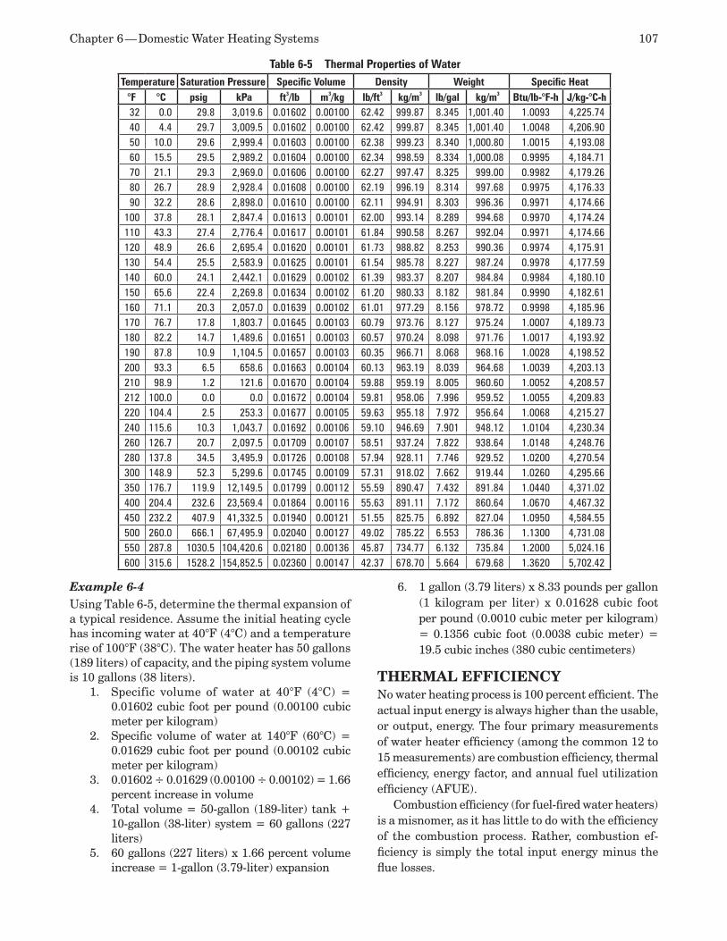
Chapter 6 — Domestic Water Heating Systems 107
Example 6-4Using Table 6-5, determine the thermal expansion of a typical residence. Assume the initial heating cycle has incoming water at 40°F (4°C) and a temperature rise of 100°F (38°C). The water heater has 50 gallons (189 liters) of capacity, and the piping system volume is 10 gallons (38 liters).
Specific volume of water at 40°F (4°C) = 1. 0.01602 cubic foot per pound (0.00100 cubic meter per kilogram)Specific volume of water at 140°F (60°C) = 2. 0.01629 cubic foot per pound (0.00102 cubic meter per kilogram)0.01602 ÷ 0.01629 (0.00100 ÷ 0.00102) = 1.66 3. percent increase in volumeTotal volume = 50-gallon (189-liter) tank + 4. 10-gallon (38-liter) system = 60 gallons (227 liters)60 gallons (227 liters) x 1.66 percent volume 5. increase = 1-gallon (3.79-liter) expansion
1 gallon (3.79 liters) x 8.33 pounds per gallon 6. (1 kilogram per liter) x 0.01628 cubic foot per pound (0.0010 cubic meter per kilogram) = 0.1356 cubic foot (0.0038 cubic meter) = 19.5 cubic inches (380 cubic centimeters)
THERMAL EFFICIENCYNo water heating process is 100 percent efficient. The actual input energy is always higher than the usable, or output, energy. The four primary measurements of water heater efficiency (among the common 12 to 15 measurements) are combustion efficiency, thermal efficiency, energy factor, and annual fuel utilization efficiency (AFUE).
Combustion efficiency (for fuel-fired water heaters) is a misnomer, as it has little to do with the efficiency of the combustion process. Rather, combustion ef-ficiency is simply the total input energy minus the flue losses.
Table 6-5 Thermal Properties of WaterTemperature Saturation Pressure Specific Volume Density Weight Specific Heat
°F °C psig kPa ft3/lb m3/kg lb/ft3 kg/m3 lb/gal kg/m3 Btu/lb-°F-h J/kg-°C-h32 0.0 29.8 3,019.6 0.01602 0.00100 62.42 999.87 8.345 1,001.40 1.0093 4,225.7440 4.4 29.7 3,009.5 0.01602 0.00100 62.42 999.87 8.345 1,001.40 1.0048 4,206.9050 10.0 29.6 2,999.4 0.01603 0.00100 62.38 999.23 8.340 1,000.80 1.0015 4,193.0860 15.5 29.5 2,989.2 0.01604 0.00100 62.34 998.59 8.334 1,000.08 0.9995 4,184.7170 21.1 29.3 2,969.0 0.01606 0.00100 62.27 997.47 8.325 999.00 0.9982 4,179.2680 26.7 28.9 2,928.4 0.01608 0.00100 62.19 996.19 8.314 997.68 0.9975 4,176.3390 32.2 28.6 2,898.0 0.01610 0.00100 62.11 994.91 8.303 996.36 0.9971 4,174.66
100 37.8 28.1 2,847.4 0.01613 0.00101 62.00 993.14 8.289 994.68 0.9970 4,174.24110 43.3 27.4 2,776.4 0.01617 0.00101 61.84 990.58 8.267 992.04 0.9971 4,174.66120 48.9 26.6 2,695.4 0.01620 0.00101 61.73 988.82 8.253 990.36 0.9974 4,175.91130 54.4 25.5 2,583.9 0.01625 0.00101 61.54 985.78 8.227 987.24 0.9978 4,177.59140 60.0 24.1 2,442.1 0.01629 0.00102 61.39 983.37 8.207 984.84 0.9984 4,180.10150 65.6 22.4 2,269.8 0.01634 0.00102 61.20 980.33 8.182 981.84 0.9990 4,182.61160 71.1 20.3 2,057.0 0.01639 0.00102 61.01 977.29 8.156 978.72 0.9998 4,185.96170 76.7 17.8 1,803.7 0.01645 0.00103 60.79 973.76 8.127 975.24 1.0007 4,189.73180 82.2 14.7 1,489.6 0.01651 0.00103 60.57 970.24 8.098 971.76 1.0017 4,193.92190 87.8 10.9 1,104.5 0.01657 0.00103 60.35 966.71 8.068 968.16 1.0028 4,198.52200 93.3 6.5 658.6 0.01663 0.00104 60.13 963.19 8.039 964.68 1.0039 4,203.13210 98.9 1.2 121.6 0.01670 0.00104 59.88 959.19 8.005 960.60 1.0052 4,208.57212 100.0 0.0 0.0 0.01672 0.00104 59.81 958.06 7.996 959.52 1.0055 4,209.83220 104.4 2.5 253.3 0.01677 0.00105 59.63 955.18 7.972 956.64 1.0068 4,215.27240 115.6 10.3 1,043.7 0.01692 0.00106 59.10 946.69 7.901 948.12 1.0104 4,230.34260 126.7 20.7 2,097.5 0.01709 0.00107 58.51 937.24 7.822 938.64 1.0148 4,248.76280 137.8 34.5 3,495.9 0.01726 0.00108 57.94 928.11 7.746 929.52 1.0200 4,270.54300 148.9 52.3 5,299.6 0.01745 0.00109 57.31 918.02 7.662 919.44 1.0260 4,295.66350 176.7 119.9 12,149.5 0.01799 0.00112 55.59 890.47 7.432 891.84 1.0440 4,371.02400 204.4 232.6 23,569.4 0.01864 0.00116 55.63 891.11 7.172 860.64 1.0670 4,467.32450 232.2 407.9 41,332.5 0.01940 0.00121 51.55 825.75 6.892 827.04 1.0950 4,584.55500 260.0 666.1 67,495.9 0.02040 0.00127 49.02 785.22 6.553 786.36 1.1300 4,731.08550 287.8 1030.5 104,420.6 0.02180 0.00136 45.87 734.77 6.132 735.84 1.2000 5,024.16600 315.6 1528.2 154,852.5 0.02360 0.00147 42.37 678.70 5.664 679.68 1.3620 5,702.42
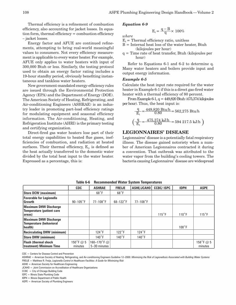
108 ASPE Plumbing Engineering Design Handbook — Volume 2
Thermal efficiency is a refinement of combustion efficiency, also accounting for jacket losses. In equa-tion form, thermal efficiency = combustion efficiency – jacket losses.
Energy factor and AFUE are continued refine-ments, attempting to bring real-world meaningful values to consumers. Not every efficiency measure-ment is applicable to every water heater. For example, AFUE only applies to water heaters with input of 300,000 Btuh or less. Similarly, the testing protocol used to obtain an energy factor rating includes a 19-hour standby period, obviously benefiting instan-taneous and tankless water heaters.
New government-mandated energy-efficiency rules are issued through the Environmental Protection Agency (EPA) and the Department of Energy (DOE). The American Society of Heating, Refrigerating, and Air-conditioning Engineers (ASHRAE) is an indus-try leader in promoting part-load efficiency ratings for modulating equipment and seasonal efficiency information. The Air-conditioning, Heating, and Refrigeration Institute (AHRI) is the primary testing and certifying organization.
Direct-fired gas water heaters lose part of their total energy capabilities to heated flue gases, inef-ficiencies of combustion, and radiation at heated surfaces. Their thermal efficiency, Et, is defined as the heat actually transferred to the domestic water divided by the total heat input to the water heater. Expressed as a percentage, this is:
Equation 6-9
Et =q − B × 100%q
whereEt = Thermal efficiency ratio, unitlessB = Internal heat loss of the water heater, Btuh
(kilojoules per hour)q = Time rate of heat transfer, Btuh (kilojoules per
hour)
Refer to Equations 6-1 and 6-2 to determine q. Many water heaters and boilers provide input and output energy information.
Example 6-5Calculate the heat input rate required for the water heater in Example 6-1 if this is a direct gas-fired water heater with a thermal efficiency of 80 percent.
From Example 6-1, q = 449,820 Btuh (475,374 kilojoules per hour). Thus, the heat input is:
q= 449,820 Btu/h = 562,275 Btu/hEt 0.80
( q= 475,374 kJ/h = 594 217.5 kJ/h )Et 0.80
LEGIONNAIRES’ DISEASELegionnaires’ disease is a potentially fatal respiratory illness. The disease gained notoriety when a num-ber of American Legionnaires contracted it during a convention. That outbreak was attributed to the water vapor from the building’s cooling towers. The bacteria causing Legionnaires’ disease are widespread
Table 6-6 Recommended Water System TemperaturesCDC ASHRAE FREIJE ASHE/JCAHO CCBC/ ISPC IDPH ASPE
Store DCW (maximum) 68˚F 68˚FFavorable for Legionella Growth 90–105˚F 77–108˚F 68–122˚F 77–108˚FMaximum DHW Discharge Temperature (patient care areas) 115˚F 110˚F 115˚FMaximum DHW Discharge Temperature (behavioral health) 100˚FRecirculating DHW (minimum) 124˚F 122˚F 124˚FStore DHW (minimum) 140˚F 140˚F 140˚FFlush (thermal shock treatment) Minimum Time
150˚F @ 5 minutes
160–170˚F @ 5–30 minutes
158˚F @ 5 minutes
CDC = Centers for Disease Control and PreventionASHRAE = American Society of Heating, Refrigerating, and Air-conditioning Engineers Guideline 12–2000: Minimizing the Risk of Legionellosis Associated with Building Water SystemsFREIJE = Matthew R. Freije, Legionella Control in Healthcare Facilities: A Guide for Minimizing RiskASHE = American Society for Healthcare Engineering JCAHO = Joint Commission on Accreditation of Healthcare Organizations CCBC = City of Chicago Building CodeISPC = Illinois State Plumbing CodeIDPH = Illinois Department of Public HealthASPE = American Society of Plumbing Engineers
Chapter 6 — Domestic Water Heating Systems 109
in natural sources of water, including rivers, lakes, streams, and ponds. In warm water, the bacteria can grow and multiply to high concentrations.
Prevention and control of Legionella bacteria is a major concern in healthcare facilities. While there are several potential sources of the bacteria in hospitals, for the purposes of this section, only Legionella in domestic hot water systems is addressed.
The Legionella bacteria can be found in many do-mestic hot and cold water systems in trace amounts. There are no health concerns with the bacteria until it colonizes (forming higher concentrations), and the bacteria are atomized and inhaled or aspirated. In most documented cases of Legionnaires’ disease, transmission occurred when water containing the organism was aerosolized in respirable droplets (1–5 micrometers in diameter) and inhaled or aspirated by a susceptible host. No data indicates that the bacteria are of concern when swallowed, and no data supports Legionella being spread through person-to-person transmission. Legionella has been shown to most greatly affect immunosuppressed people. In a hospital, the following patients are most susceptible to Legionella infection: organ transplant patients, cancer patients receiving radiation or chemotherapy, patients with HIV, and surgical patients.
Varying StandardsMany different temperature ranges for Legion-ella bacterial growth are published. The Centers for Disease Control and Prevention (CDC) lists a favor-able bacterial growth range of 90–113°F (32–45°C). ASHRAE lists a favorable bacterial growth range of 77–108°F (25–42°C), and Matthew Freije, author of Legionellae Control in Healthcare Facilities, lists the optimal temperature range for bacterial growth at 68–122°F (20–50°C) (95–115°F [35–46°C] ideal). The American Society for Healthcare Engineering (ASHE) and the Joint Commission list a range of 77–108°F (25–42°C). Combining these ranges would indicate a potential range of growth of 68–122°F (20–50°C).
All available information indicates that almost all bacteria die at temperatures above 130°F (54°C). The higher the temperature, the faster the bacteria die. Table 6-6 lists domestic water system temperatures as they relate to Legionella from the various agencies and organizations. Included on the table are three ad-ditional sources of temperature information: the City of Chicago Building Code, State of Illinois Plumbing Code, and ASPE. These were included as a sample of additional requirements from local jurisdictions and recommendations from plumbing organizations.
Legionella Hot SpotsAs mentioned, available information indicates al-most all Legionella bacteria die at temperatures above 130°F (54°C). Therefore, a common method
of Legionella control is to maintain the domestic hot water system temperature above 130°F (54°C), with a preferable distribution system temperature of 140°F (60°C) and a return hot water temperature of at least 124°F (51°C).
However, on older piping systems not having ther-mostatic mixing valves at all outlets, a system cannot be operated at 130°F (54°C) or above and still maintain code compliance. As mandated by most local codes, the maximum hot water temperature to plumbing fixtures in patient care areas is 115°F (46°C). This is to minimize scalding potential due to excessive water temperature. Often, the shower valves in a hospital facility are not of the thermostatic mixing valve type, which would allow the system to be operated at an elevated temperature. As a result, a hospital’s domes-tic hot water systems are operated at approximately 115°F (46°C), with a return hot water temperature of 105–110°F (41–43°C). Unfortunately, no matter what code you use, this temperature range is in the Legionella bacteria growth temperature range.
Bacterial growth is most prominent in stagnant areas such as storage tanks and dead ends of piping. Bacteria typically grow in the biofilm, scale, slime, and sediment found in these locations. It tends to not grow in sections of the piping distribution system that are actively flowing and have little biofilm or sediment buildup. Increased water velocity in a piping system can help reduce biofilm, but excessive water velocity can be detrimental to a piping system. Care should be taken to not exceed 7 feet per second of velocity in the pipe, or erosion could take place, causing pipe failure.
Legionella bacteria also can reside in the scale buildup on showerheads. The showerhead provides a sieve effect, and the additional rough surface of the scale provides additional area for biofilm. Other loca-tions of bacterial growth include spas and whirlpools. There also have been reports of bacterial growing on natural rubber washers.
Controlling LegionellaMany methods of controlling the colonization of Le-gionella bacteria are available. These include elevated temperature maintenance, heat and flush cycles, copper-silver ionization, chlorine dioxide injection, halogenization, ultraviolet (UV) radiation, ozonation, hyper-chlorination, filtration/rechlorination, and combinations of these.
Elevated Temperature MaintenanceThis involves keeping the system temperature con-tinually at or above 140°F (60°C), as recommended by several of the agencies noted previously. However, it is frequently impractical in large, old facilities.
110 ASPE Plumbing Engineering Design Handbook — Volume 2
Heat and Flush This is a method of disinfecting the piping system by elevating the system temperature to 150°F (66°C) or higher and flushing the high-temperature water through every outlet for at least 30 minutes. This method has proven effective in killing the bacteria present in most domestic hot water systems. Large quantities of biofilm in the piping system might require additional contact time with the high-tem-perature water.
The advantages of this method are that it involves no capital expenditures for equipment and can be implemented immediately. Disadvantages include increased labor, difficulty coordinating the flushing of the system without risking a scalding injury to patients, and inefficiency on fixtures having thermo-static mixing valves. There is no residual protection, so this is a non-permanent solution to Legionella contamination. The bacteria will eventually return and colonize in the system.
Copper-silver Ionization This method involves installing a flow-through ion-ization chamber containing copper-silver electrodes. As electrical current is applied to the electrodes, positively charged copper and silver ions are released into the water system. The positively charged ions bond to the microorganisms, causing them to die. The optimal concentration of copper-silver ions is said to be 400 parts per billion (ppb) for copper and 40 ppb for silver.
The advantages of this alternative are that the equipment is relatively easy to install and maintain and it provides permanent, continuous disinfection. The disadvantages are the initial equipment costs and continuing operating and maintenance costs. Copper-silver ionization often is recommended as an option for use on domestic hot water systems serving immunodeficient patient care areas.
Chlorine Dioxide Gas Injection This is effective in the control of Legionella bacteria in domestic hot water systems. It penetrates biofilm and slime and kills bacteria at its growth sites. Its advantages are that it stays in solution for long periods, and since it requires low concentrations, it minimizes chlorine-induced corrosion concerns. The disadvantages are that the equipment is best suited for use in small to medium-size applications; the equipment is fairly expensive; a chlorine dioxide gas generator is required for each hot water system; and water chemistry must be monitored closely. For large facilities, it might be necessary to install multiple in-jectors. Chlorine dioxide is a viable option for use on domestic hot water systems serving immunodeficient patient care areas if closely monitored.
HalogenizationThe use of halogens (chlorine, bromine, and iodine) at dosages ranging from 0.3–1 part per million (ppm) is a viable option only if the water pH is controlled precisely. As the water pH drops, so does the effi-ciency of the halogen as a biocide. A final but critical consideration is the issue of carcinogenic haloge-nated compounds being dumped into the waterway. A byproduct of chlorine treatment of water is total trihalomethanes (TTHM), which may elevate the risk of certain cancers. While the risk may be small, the EPA is attempting to reduce TTHM concentrations in U.S. water systems. Halogens therefore are seldom recommended for use in healthcare facilities.
Ultraviolet Radiation UV radiation is effective in killing the bacteria as it flows through a single point in the system. It is effec-tive only for use on small, localized systems and short runs of pipe. It is ineffective in large systems and does not eliminate the growth of existing colonies in other portions of the system. The effect of UV on Legionella within protozoan vesicles (protozoan bodies loaded with Legionella cells) is also not known.
OzonationOzone is effective in killing the bacteria in the im-mediate vicinity of the ozone generator. Its advantage is that TTHMs are not produced by ozone treatment. Its disadvantages are that decomposition of the ozone in the system quickly dissipates the concentrations required to kill bacteria; it can cause corrosion prob-lems in old piping; it is ineffective in large systems; and it does not eliminate the growth of existing colo-nies in other portions of the system. This is also an expensive option.
Hyper-chlorination This method is effective in killing the bacteria, but it has several very important negative aspects. First, high chlorine concentrations are required to kill the bacteria. Second, chlorine byproducts are TTHMs, which are potential carcinogens. Third, chlorine is cor-rosive and can cause degradation leading to potential failure of the piping. It therefore is not recommended for regular use in most hospital facilities.
Filtration/Rechlorination This involves the use of 5-micron filters in conjunction with a rechlorination system. It first filters foreign matter being introduced into the piping system from an unfiltered water supply, thus reducing the scale and sediments in which the biofilm can propagate. Rechlorination then is used to maintain a chlorine level more conducive to inhibiting biofilm growth. Chlorine concentrations should be closely monitored to prevent over-chlorination. This type of system typically is used on non-municipal-type water systems
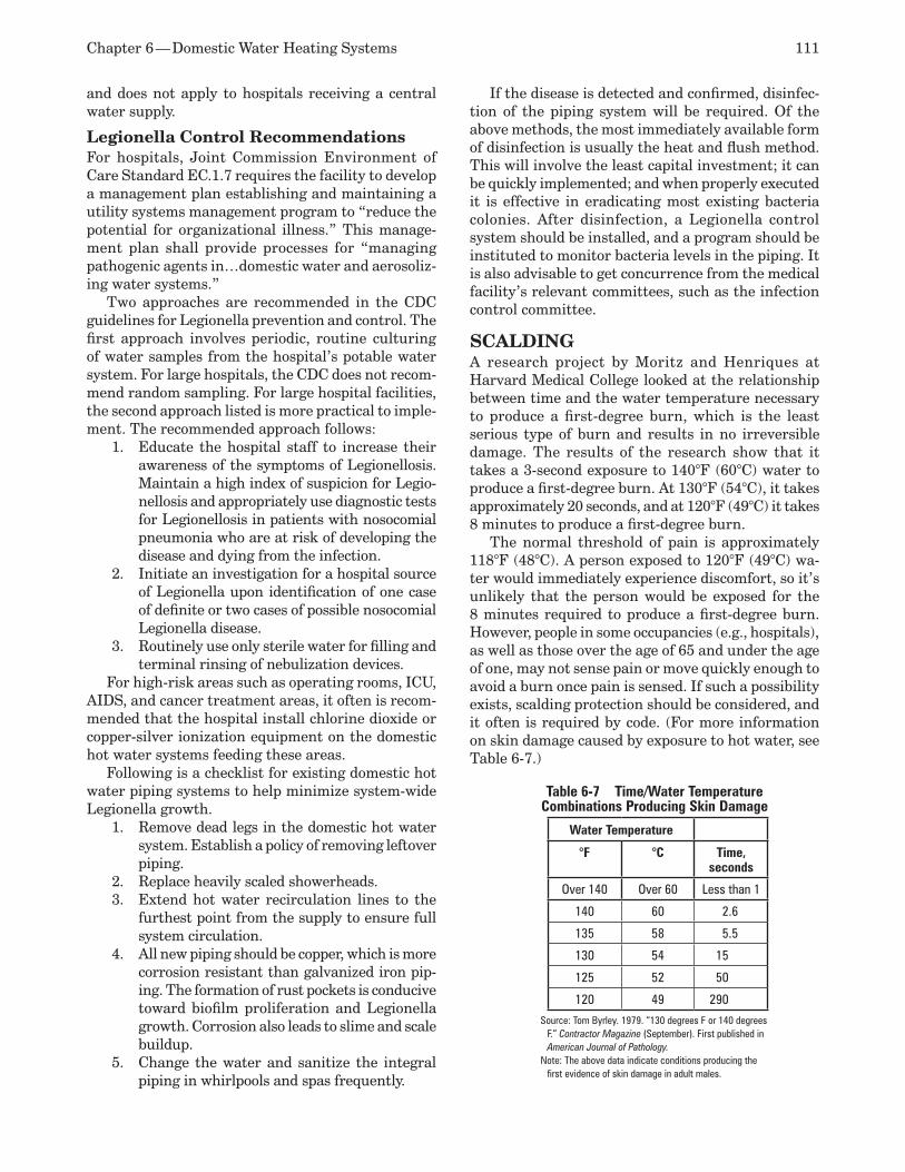
Chapter 6 — Domestic Water Heating Systems 111
and does not apply to hospitals receiving a central water supply.
Legionella Control Recommendations For hospitals, Joint Commission Environment of Care Standard EC.1.7 requires the facility to develop a management plan establishing and maintaining a utility systems management program to “reduce the potential for organizational illness.” This manage-ment plan shall provide processes for “managing pathogenic agents in…domestic water and aerosoliz-ing water systems.”
Two approaches are recommended in the CDC guidelines for Legionella prevention and control. The first approach involves periodic, routine culturing of water samples from the hospital’s potable water system. For large hospitals, the CDC does not recom-mend random sampling. For large hospital facilities, the second approach listed is more practical to imple-ment. The recommended approach follows:
Educate the hospital staff to increase their 1. awareness of the symptoms of Legionellosis. Maintain a high index of suspicion for Legio-nellosis and appropriately use diagnostic tests for Legionellosis in patients with nosocomial pneumonia who are at risk of developing the disease and dying from the infection. Initiate an investigation for a hospital source 2. of Legionella upon identification of one case of definite or two cases of possible nosocomial Legionella disease.Routinely use only sterile water for filling and 3. terminal rinsing of nebulization devices.
For high-risk areas such as operating rooms, ICU, AIDS, and cancer treatment areas, it often is recom-mended that the hospital install chlorine dioxide or copper-silver ionization equipment on the domestic hot water systems feeding these areas.
Following is a checklist for existing domestic hot water piping systems to help minimize system-wide Legionella growth.
Remove dead legs in the domestic hot water 1. system. Establish a policy of removing leftover piping.Replace heavily scaled showerheads.2. Extend hot water recirculation lines to the 3. furthest point from the supply to ensure full system circulation.All new piping should be copper, which is more 4. corrosion resistant than galvanized iron pip-ing. The formation of rust pockets is conducive toward biofilm proliferation and Legionella growth. Corrosion also leads to slime and scale buildup.Change the water and sanitize the integral 5. piping in whirlpools and spas frequently.
If the disease is detected and confirmed, disinfec-tion of the piping system will be required. Of the above methods, the most immediately available form of disinfection is usually the heat and flush method. This will involve the least capital investment; it can be quickly implemented; and when properly executed it is effective in eradicating most existing bacteria colonies. After disinfection, a Legionella control system should be installed, and a program should be instituted to monitor bacteria levels in the piping. It is also advisable to get concurrence from the medical facility’s relevant committees, such as the infection control committee.
SCALDINGA research project by Moritz and Henriques at Harvard Medical College looked at the relationship between time and the water temperature necessary to produce a first-degree burn, which is the least serious type of burn and results in no irreversible damage. The results of the research show that it takes a 3-second exposure to 140°F (60°C) water to produce a first-degree burn. At 130°F (54°C), it takes approximately 20 seconds, and at 120°F (49°C) it takes 8 minutes to produce a first-degree burn.
The normal threshold of pain is approximately 118°F (48°C). A person exposed to 120°F (49°C) wa-ter would immediately experience discomfort, so it’s unlikely that the person would be exposed for the 8 minutes required to produce a first-degree burn. However, people in some occupancies (e.g., hospitals), as well as those over the age of 65 and under the age of one, may not sense pain or move quickly enough to avoid a burn once pain is sensed. If such a possibility exists, scalding protection should be considered, and it often is required by code. (For more information on skin damage caused by exposure to hot water, see Table 6-7.)
Table 6-7 Time/Water Temperature Combinations Producing Skin Damage
Water Temperature
°F °C Time, seconds
Over 140 Over 60 Less than 1
140 60 2.6
135 58 5.5
130 54 15
125 52 50
120 49 290
Source: Tom Byrley. 1979. “130 degrees F or 140 degrees F.” Contractor Magazine (September). First published in American Journal of Pathology.
Note: The above data indicate conditions producing the first evidence of skin damage in adult males.
112 ASPE Plumbing Engineering Design Handbook — Volume 2
CODES AND STANDARDSThe need to conform to various codes and standards determines many aspects of the design of a domestic hot water system as well as the selection of compo-nents and equipment.
Some of the most often used codes and standards follow:
Regional, state, and local plumbing codes•ANSI/ASHRAE 90.1: • Energy Standard for Buildings Except Low-rise Residential Build-ingsASME Boiler and Pressure Vessel Code•ANSI Z21.22: • Relief Valves for Hot Water Supply SystemsUnderwriters’ Laboratories (UL) listings for •electrical components
National Sanitation Foundation (NSF) list-•ingsAGA listings for gas-burning components•National Fire Protection Association (NFPA) •standardsNational Electrical Code •U.S. Department of Health and Environmen-•tal Control American Society of Sanitation Engineers •(ASSE) standards
In addition, the federal government, agencies with jurisdiction over public schools and public housing, and many other agencies have specific requirements that must be observed when designing projects and selecting equipment for them.
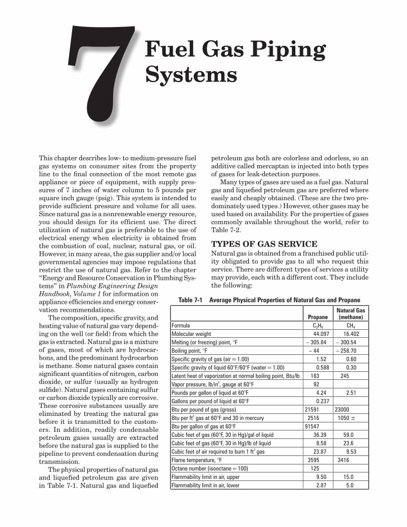
Fuel Gas Piping Systems7
This chapter describes low- to medium-pressure fuel gas systems on consumer sites from the property line to the final connection of the most remote gas appliance or piece of equipment, with supply pres-sures of 7 inches of water column to 5 pounds per square inch gauge (psig). This system is intended to provide sufficient pressure and volume for all uses. Since natural gas is a nonrenewable energy resource, you should design for its efficient use. The direct utilization of natural gas is preferable to the use of electrical energy when electricity is obtained from the combustion of coal, nuclear, natural gas, or oil. However, in many areas, the gas supplier and/or local governmental agencies may impose regulations that restrict the use of natural gas. Refer to the chapter “Energy and Resource Conservation in Plumbing Sys-tems” in Plumbing Engineering Design Handbook, Volume 1 for information on appliance efficiencies and energy conser-vation recommendations.
The composition, specific gravity, and heating value of natural gas vary depend-ing on the well (or field) from which the gas is extracted. Natural gas is a mixture of gases, most of which are hydrocar-bons, and the predominant hydrocarbon is methane. Some natural gases contain significant quantities of nitrogen, carbon dioxide, or sulfur (usually as hydrogen sulfide). Natural gases containing sulfur or carbon dioxide typically are corrosive. These corrosive substances usually are eliminated by treating the natural gas before it is transmitted to the custom-ers. In addition, readily condensable petroleum gases usually are extracted before the natural gas is supplied to the pipeline to prevent condensation during transmission.
The physical properties of natural gas and liquefied petroleum gas are given in Table 7-1. Natural gas and liquefied
petroleum gas both are colorless and odorless, so an additive called mercaptan is injected into both types of gases for leak-detection purposes.
Many types of gases are used as a fuel gas. Natural gas and liquefied petroleum gas are preferred where easily and cheaply obtained. (These are the two pre-dominately used types.) However, other gases may be used based on availability. For the properties of gases commonly available throughout the world, refer to Table 7-2.
TYPES OF GAS SERVICENatural gas is obtained from a franchised public util-ity obligated to provide gas to all who request this service. There are different types of services a utility may provide, each with a different cost. They include the following:
PropaneNatural Gas (methane)
Formula C3H8 CH4
Molecular weight 44.097 16.402Melting (or freezing) point, °F – 305.84 – 300.54Boiling point, °F – 44 – 258.70Specific gravity of gas (air = 1.00) 1.52 0.60Specific gravity of liquid 60°F/60°F (water = 1.00) 0.588 0.30Latent heat of vaporization at normal boiling point, Btu/lb 183 245Vapor pressure, lb/in2, gauge at 60°F 92Pounds per gallon of liquid at 60°F 4.24 2.51Gallons per pound of liquid at 60°F 0.237Btu per pound of gas (gross) 21591 23000Btu per ft3 gas at 60°F and 30 in mercury 2516 1050 ±Btu per gallon of gas at 60°F 91547Cubic feet of gas (60°F, 30 in Hg)/gal of liquid 36.39 59.0Cubic feet of gas (60°F, 30 in Hg)/lb of liquid 8.58 23.6Cubic feet of air required to burn 1 ft3 gas 23.87 9.53Flame temperature, °F 3595 3416Octane number (isooctane = 100) 125Flammability limit in air, upper 9.50 15.0Flammability limit in air, lower 2.87 5.0
Table 7-1 Average Physical Properties of Natural Gas and Propane
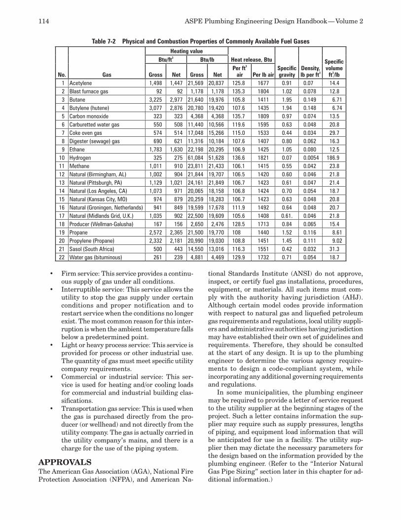
114 ASPE Plumbing Engineering Design Handbook — Volume 2
Firm service: This service provides a continu-•ous supply of gas under all conditions.Interruptible service: This service allows the •utility to stop the gas supply under certain conditions and proper notification and to restart service when the conditions no longer exist. The most common reason for this inter-ruption is when the ambient temperature falls below a predetermined point.Light or heavy process service: This service is •provided for process or other industrial use. The quantity of gas must meet specific utility company requirements.Commercial or industrial service: This ser-•vice is used for heating and/or cooling loads for commercial and industrial building clas-sifications. Transportation gas service: This is used when •the gas is purchased directly from the pro-ducer (or wellhead) and not directly from the utility company. The gas is actually carried in the utility company’s mains, and there is a charge for the use of the piping system.
APPROVALSThe American Gas Association (AGA), National Fire Protection Association (NFPA), and American Na-
tional Standards Institute (ANSI) do not approve, inspect, or certify fuel gas installations, procedures, equipment, or materials. All such items must com-ply with the authority having jurisdiction (AHJ). Although certain model codes provide information with respect to natural gas and liquefied petroleum gas requirements and regulations, local utility suppli-ers and administrative authorities having jurisdiction may have established their own set of guidelines and requirements. Therefore, they should be consulted at the start of any design. It is up to the plumbing engineer to determine the various agency require-ments to design a code-compliant system, while incorporating any additional governing requirements and regulations.
In some municipalities, the plumbing engineer may be required to provide a letter of service request to the utility supplier at the beginning stages of the project. Such a letter contains information the sup-plier may require such as supply pressures, lengths of piping, and equipment load information that will be anticipated for use in a facility. The utility sup-plier then may dictate the necessary parameters for the design based on the information provided by the plumbing engineer. (Refer to the “Interior Natural Gas Pipe Sizing” section later in this chapter for ad-ditional information.)
Table 7-2 Physical and Combustion Properties of Commonly Available Fuel Gases
No. Gas
Heating valueHeat release, Btu
Specificgravity
Density, lb per ft3
Specific volume
ft3/lb
Btu/ft3 Btu/lb
Gross Net Gross NetPer ft3
air Per lb air1 Acetylene 1,498 1,447 21,569 20,837 125.8 1677 0.91 0.07 14.42 Blast furnace gas 92 92 1,178 1,178 135.3 1804 1.02 0.078 12.83 Butane 3,225 2,977 21,640 19,976 105.8 1411 1.95 0.149 6.714 Butylene (hutene) 3,077 2,876 20,780 19,420 107.6 1435 1.94 0.148 6.745 Carbon monoxide 323 323 4,368 4,368 135.7 1809 0.97 0.074 13.56 Carburetted water gas 550 508 11,440 10,566 119.6 1595 0.63 0.048 20.87 Coke oven gas 574 514 17,048 15,266 115.0 1533 0.44 0.034 29.78 Digester (sewage) gas 690 621 11,316 10,184 107.6 1407 0.80 0.062 16.39 Ethane 1,783 1,630 22,198 20,295 106.9 1425 1.05 0.080 12.5
10 Hydrogen 325 275 61,084 51,628 136.6 1821 0.07 0.0054 186.911 Methane 1,011 910 23,811 21,433 106.1 1415 0.55 0.042 23.812 Natural (Birmingham, AL) 1,002 904 21,844 19,707 106.5 1420 0.60 0.046 21.813 Natural (Pittsburgh, PA) 1,129 1,021 24,161 21,849 106.7 1423 0.61 0.047 21.414 Natural (Los Angeles, CA) 1,073 971 20,065 18,158 106.8 1424 0.70 0.054 18.715 Natural (Kansas City, MO) 974 879 20,259 18,283 106.7 1423 0.63 0.048 20.816 Natural (Groningen, Netherlands) 941 849 19,599 17,678 111.9 1492 0.64 0.048 20.717 Natural (Midlands Grid, U.K.) 1,035 902 22,500 19,609 105.6 1408 0.61. 0.046 21.818 Producer (Wellman-Galusha) 167 156 2,650 2,476 128.5 1713 0.84 0.065 15.419 Propane 2,572 2,365 21,500 19,770 108 1440 1.52 0.116 8.6120 Propylene (Propane) 2,332 2,181 20,990 19,030 108.8 1451 1.45 0.111 9.0221 Sasol (South Africa) 500 443 14,550 13,016 116.3 1551 0.42 0.032 31.322 Water gas (bituminous) 261 239 4,881 4,469 129.9 1732 0.71 0.054 18.7
Chapter 7 — Fuel Gas Piping Systems 115
SYSTEM OPERATING PRESSUREThe gas pressure in the piping system downstream of the meter is usually 5 to 14 inches (125 to 356 mil-limeters) of water column, but in some cases it can be as much as 2 to 5 pounds per square inch (psi) (13.8 to 34.5 kilopascals [kPa]). Under certain conditions, engineering practice will limit the pressure losses due to friction in the piping system to a range between 0.2 and 0.5 inch (5 and 13 millimeters) of water column, but all model codes allow the engineer the opportunity to take a greater pressure drop. However, local codes may vary, and the engineer should consult the local AHJ prior to the design of any system.
Most appliances typically require approximately 3.5 inches (89 millimeters) or water column, but certain appliances such as water heaters and boilers may require higher gas pressures to operate properly. Where appliances require higher operating pressures and/or where long distribution lines are encountered, it may be necessary to select a higher pressure at the meter outlet to satisfy the appliance requirements or allow for greater pressure losses in the piping system, thereby allowing economy of pipe size.
Systems often are designed with meter outlet pres-sures of 2 to 5 psi (13.8 to 34.5 kPa), combined with pressure regulators to reduce the pressure for appli-ances as required. In most cases, the utility company will reduce the incoming pressure to a figure that is requested by the design engineer at the start of the project or to conform to local code requirements. In some areas of the country, gas pressures on both sides of the meter are in inches of water column.
The maximum allowable operating pressure for natural gas piping systems inside a building is based on NFPA 54: National Fuel Gas Code, except when approved by the AHJ or when insurance carriers have more stringent requirements. Natural gas system pressures generally are not permitted to exceed 5 psig (34.5 kPa) unless all the following are met:
The AHJ will allow a higher pressure.1. The distribution piping is welded. (Note: Some 2. jurisdictions also may require welded joints to be x-rayed to verify continuity.)Pipe runs are enclosed for protection and lo-3. cated in a ventilated place that will not allow gas to accumulate.The pipe is installed within areas used spe-4. cifically for industrial processes, research, warehousing, or mechanical equipment rooms.
A maximum liquefied petroleum gas pressure of 20 psig (138 kPa) generally is allowed, provided the building is used specifically for research or industrial purposes and is constructed in accordance with NFPA 58: Liquefied Petroleum Gas Code, Chapter 7.
EFFICIENCYThe difference between the input and the output of any equipment is the heat lost in the combustion process (burner), heat exchanger, and flue gases. Water-heating and space-heating equipment is usually 75 to 85 percent efficient (although high-efficiency equipment in the upper 90 percent range is also avail-able), and ratings are given for both input and output. Cooking and laundry equipment is typically 75 to 85 percent efficient, with input ratings that take into consideration internal losses. When only the output required for an appliance is known, it will be neces-sary to increase the volume of gas to account for the loss of its listed efficiency.
CODES AND STANDARDSAt the beginning of any given system design, the plumbing engineer shall determine the primary model code that will be referenced, along with the specific year edition of that code. The following model codes should be viewed for provisions regarding natural gas and liquefied petroleum gas regulations, require-ments, and standards:
Uniform Plumbing Code,• promulgated by the International Association of Plumbing and Mechanical Officials (IAPMO)International Fuel Gas Code,• promulgated by the International Code Council (ICC)National Standard Plumbing Code,• pro-mulgated by the National Association of Plumbing-Heating-Cooling Contractors
The primary code may reference NFPA 54. Other codes and standards that may be applicable are ANSI/NFPA 30: Flammable and Combustible Liquids Code, ANSI/NFPA 58, ANSI Z83.3: Gas Utilization Equipment for Large Boilers, ANSI/UL 144: Pressure-regulating Valves for Liquefied Petroleum Gas, NFPA 88A: Standard for Parking Structures, and American Gas Association standards.
Insurance carriers such as Industrial Risk Insur-ers and FM Global also may impose standards and requirements that may be more stringent than the applicable code.
GAS METERSMeters are required in all services. To achieve opti-mal accuracy, the pressure into the meter must be regulated. Requirements for various utility suppli-ers differ regarding the placement and arrangement of the meter assembly. The assembly could consist of filters, valves, regulators, and relief valves. It could be placed indoors or on a slab outdoors either aboveground or underground in a vented pit. The plumbing contractor is usually responsible for a pit, slab, telephone outlet, and electrical outlet adjacent
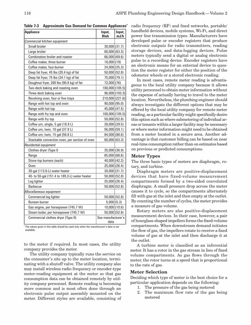
116 ASPE Plumbing Engineering Design Handbook — Volume 2
to the meter if required. In most cases, the utility company provides the meter.
The utility company typically runs the service on the consumer’s site up to the meter location, termi-nating with a shutoff valve. The utility company also may install wireless radio frequency or encoder-type meter-reading equipment at the meter so that gas consumption data can be obtained remotely by util-ity company personnel. Remote reading is becoming more common and is most often done through an electronic pulse output assembly mounted on the meter. Different styles are available, consisting of
radio frequency (RF) and fixed networks, portable/handheld devices, mobile systems, Wi-Fi, and direct power line transmission types. Manufacturers have developed pulse or encoder registers that produce electronic outputs for radio transmitters, reading storage devices, and data-logging devices. Pulse meters typically send a digital or analog electronic pulse to a recording device. Encoder registers have an electronic means for an external device to ques-tion the meter register for either the position of the odometer wheels or a stored electronic reading.
In most cases, remote meter reading is advanta-geous to the local utility company because it allows utility personnel to obtain meter information without the expense of actually having to travel to the meter location. Nevertheless, the plumbing engineer should always investigate the different options that may be offered by the local utility company for remote meter reading, as a particular facility might specifically desire this option such as where submetering of individual ar-eas or tenants within a larger facility may be necessary or where meter information might need to be obtained from a meter located in a secure area. Another ad-vantage is that customer billing can be based on near real-time consumption rather than on estimates based on previous or predicted consumptions.
Meter TypesThe three basic types of meters are diaphragm, ro-tary, and turbine.
Diaphragm meters are positive-displacement devices that have fixed-volume measurement compartments formed by a two-sided convoluted diaphragm. A small pressure drop across the meter causes it to cycle, so the compartments alternately fill with gas at the inlet and then empty at the outlet. By counting the number of cycles, the meter provides a measure of gas volume.
Rotary meters are also positive-displacement measurement devices. In their case, however, a pair of hourglass-shaped impellers forms the fixed-volume compartments. When downstream demand initiates the flow of gas, the impellers rotate to receive a fixed volume of gas at the inlet and then discharge it at the outlet.
A turbine meter is classified as an inferential meter. It has a rotor in the gas stream in lieu of fixed volume compartments. As gas flows through the meter, the rotor turns at a speed that is proportional to the rate of gas.
Meter SelectionDeciding which type of meter is the best choice for a particular application depends on the following:
The pressure of the gas being metered1. The maximum flow rate of the gas being 2. metered
Table 7-3 Approximate Gas Demand for Common Appliancesa
Appliance Input, Btuh
Input, mJ/h
Commercial kitchen equipmentSmall broiler 30,000 (31.7)Large broiler 60,000 (63.3)Combination broiler and roaster 66,000 (69.6)Coffee maker, three-burner 18,000 (19)Coffee maker, four-burner 24,000 (25.3)Deep fat fryer, 45 lbs (20.4 kg) of fat 50,000 (52.8)Deep fat fryer, 75 lbs (34.1 kg) of fat 75,000 (79.1)Doughnut fryer, 200 lbs (90.8 kg) of fat 72,000 (76)Two-deck baking and roasting oven 100,000 (105.5)Three-deck baking oven 96,000 (103.3)Revolving oven, four or five trays 210,000 (221.6)Range with hot top and oven 90,000 (95.0)Range with hot top 45,000 (47.5)Range with fry top and oven 100,000 (105.5)Range with fry top 50,000 (52.8)Coffee urn, single, 5 gal (18.9 L) 28,000 (29.5)Coffee urn, twin, 10 gal (37.9 L) 56,000 (59.1)Coffee urn, twin, 15 gal (56.8 L) 84,000 (88.6)Stackable convection oven, per section of oven 60,000 (63.3)
Residential equipmentClothes dryer (Type I) 35,000 (36.9)Range 65,000 (68.6)Stove-top burners (each) 40,000 (42.2)Oven 25,000 (26.4)30-gal (113.6-L) water heater 30,000 (31.7)40- to 50-gal (151.4 to 189.3-L) water heater 50,000 (52.8)Log lighter 25,000 (26.4)Barbecue 50,000 (52.8)
Miscellaneous equipmentCommercial log lighter 50,000 (52.8)Bunsen burner 5,000 (5.3)Gas engine, per horsepower (745.7 W) 10,000 (10.6)Steam boiler, per horsepower (745.7 W) 50,000 (52.8)Commercial clothes dryer (Type II) See manufacturer’s
dataa The values given in this table should be used only when the manufacturer’s data is not available.

Chapter 7 — Fuel Gas Piping Systems 117
The minimum flow rate of the gas to be me-3. tered
Depending on the specific model, diaphragm meters have pressure ratings up to 100 psig. Rotary meters can operate up to 285 psig. For applications more than 285 psig, a turbine meter should be selected.
Ratings for these meter types may overlap with respect to capacities and pressures. This overlap al-lows for versatility when selecting the correct meter for certain applications. For example, a project’s maximum flow rate may fit into the “typical” range indicated in a manufacturer’s product data listing for a diaphragm meter, but the pressure of the gas being metered may be more than 100 psig. In this case, a small rotary meter would be selected.
For most projects, the following meter choices are typical:
Diaphragm meters: 10 to 1,000 cubic feet per •hour (cfh), 100 psig or lessDiaphragm, rotary, and turbine meters: 1,000 •cfh to 50,000 cfh, 100 psig or lessRotary or turbine meters: 50,000 to 325,000 •cfh, 100 to 285 psigTurbine meters: 325,000 to 18,000,000 cfh, •285 to 1,440 psig
Range ability is another consideration when select-ing a gas meter for a given project. Range ability is the ratio of maximum flow rate to minimum flow rate that can be measured within the specified accuracy of the meter. For example, most diaphragm meters provide an accuracy of ±1 percent of reading with a range ability of more than 100:1. Therefore, a meter with a maximum rating of 250 cfh will provide ±1 percent accuracy for flow rates from 2.5 to 250 cfh.
PRESSURE-REGULATING VALVESA pressure regulator is a device used to reduce a variable high inlet pressure to a constant lower outlet pressure. The line regulator is used to reduce supply line pressures. If used, this regulator usually is installed outside, upstream of the meter assembly, and it is provided by the utility company. If installed inside a building, a dedicated relief vent pipe will need to be connected at the regulator’s vent connec-tion and routed to the exterior of the building per the local AHJ. An intermediate regulator located downstream of the meter assembly may be used to further reduce pressure from 2 to 5 psig (13 to 35 kPa) or to a pressure suitable for use by terminal equip-ment of approximately 7 inches (178 millimeters) of water column.
An appliance regulator connects the supply to equipment at the point of use and may be provided by the equipment manufacturer, specifically on equip-ment that may include a gas train. Types of appliance
regulators are zero governor, backpressure regulator, and a differential regulator.
When regulators are installed inside a building and require venting, these vents must be routed to the at-mosphere. The vents from individual regulators may not be combined. However, a vent to the outdoors is not required for regulators equipped with and labeled for utilization with an approved vent-limiting device installed in accordance with the manufacturer’s in-structions. Regardless, incorporating vent-limiting devices should be evaluated carefully for each spe-cific project design to ensure that the proper safety measures have been accounted for and that local ju-risdictional requirements have been met. Regulators with vent-limiting devices are in many cases allowed only within ventilated spaces to ensure that any gas escaping from the vent is dissipated safely.
When bottled gas is used, the tank can have as high as 150-psi (1,034.6-kPa) pressure to be reduced to the burner design pressure of 11 inches (279.4 mil-limeters) of water column. The regulator typically is located at the tank for this pressure reduction.
Gas Regulator Relief Vents Guidelines for the use of relief vents from pressure regulators, also referred to as gas-train vents, can be found in the latest editions of NFPA 54 and FM Global Loss Prevention Data Sheet 6-4: Oil- and Gas-fired Single-burner Boilers, as well as in other publications of industry standards, such as those is-sued by Industrial Risk Insurers and the American Gas Association.
Figure 7-1 Altitude Correction Factor
The Altitude Correction Factor (ACF) should be multiplied by the gas input at sea level to determine the corrected input. Sizing of the equipment is then performed utilizing this corrected input multiplied by the full load efficency.
118 ASPE Plumbing Engineering Design Handbook — Volume 2
It should be noted that when pressure regulators discharge (or the diaphragm in the regulator rup-tures), large amounts of fuel gas may be released. It is not uncommon for a local fire department to be summoned to investigate an odor of gas caused by a gas-train vent discharge. Every attempt should be made to locate the terminal point of the vents above the line of the roof and away from doors, windows, and fresh-air intakes. They should be located on a side of the building that is not protected from the wind. Refer to NFPA 54, local utility supplier requirements, and local codes for the exact requirements for vent termination locations.
CONTROL VALVES
Excess Flow ValvesAn excess flow valve is a device that shuts off the flow of gas if there is a much larger flow through the pipe or service than that for which it was designed. In some parts of the country, particularly in areas where earthquakes may occur, excess flow valves are necessary to guard against the possibility of a break during such an event. In other cases, where danger exists for equipment such as large boilers, installation should be considered.
A low-pressure cutoff shall be installed between the meter and the appliance where the operation of a device, such as a gas compressor, appliance, or boiler, could produce a vacuum or dangerous vacuum condi-tion in the piping system.
Appliance Control Valves An appliance shutoff valve shall be installed at all gas appliances. Valves at flexible hose connections are to be installed prior to the flexible connection that is used to connect the appliance to the building gas supply.
Interlocks and Solenoid ValvesAn automatic interlock or gas solenoid valve can be interconnected with the automatic fire extinguish-ing system when required to shut off the gas supply to all equipment in a kitchen when sprinklers dis-charge in the event of a fire. These valves typically are provided by the fire suppression equipment con-tractor and installed by the plumbing or mechanical contractor. (Note: Laboratories may utilize similar automatic shutoff capabilities. Refer to the “Labora-tory Use” section further in this chapter for more information.)
In earthquake-prone areas, a seismic shutoff valve is necessary to shut off the supply of gas if a seismic event is of sufficient magnitude to potentially rupture the gas supply pipe or separate the pipe from equipment.
APPLIANCESMost manufacturers of gas appliances rate their equipment with gas consumption values in British thermal units per hour (Btuh), which is used in de-termining the maximum gas flow rate to be supplied to the appliance via the piping system. Table 7-3 shows the approximate gas consumption for some common appliances (listed in Btuh). To find the flow rate of the gas required, always use the consumption data listed by the manufacturer and divide it by the Btu per cubic feet content of the gas as provided by the utility supplier. (Note: Natural gas is nominally rated at 1,000 Btu per cubic feet for design purposes. However, it is very important to verify the actual Btuh content or rating to be used, as well as the altitude/elevation necessary for deration purposes for a specific project design.)
VENTINGIntegral to the design of any natural gas system are the venting and combustion air requirements required for appliances to operate properly and effi-ciently. Appliances are listed by types and categories that shall be used in the design of flue/vent systems. Along with the requirements for natural gas systems, appliance venting requirements also are stipulated in NFPA 54, the International Fuel Gas Code (IFGC), and any specific requirements dictated by the local gas supplier as applicable. Although not within the scope of this chapter, it is mentioned here for reference purposes due to the fact that the plumbing engineer may be required to provide design input with respect to venting even though not responsible for the actual design of these systems.
It generally is not the plumbing engineer’s respon-sibility to design and specify gas vents. This is done by either the HVAC engineer or the manufacturer. However, water heater technologies that are currently available, such as non-condensing, high efficiency, and forced combustion, may require specific venting consideration, which in turn should be coordinated with the HVAC engineer to ensure that all aspects of the venting design have been coordinated.
The products of combustion from an appliance must be safely exhausted to the outside. This is accom-plished with a gas vent system in most cases. Where an appliance has a very low rate of gas consumption (e.g., Bunsen burner or countertop coffee maker) or where an appliance has an exhaust system associated with the appliance (e.g., gas clothes dryer or range) and the room size and ventilation are adequate, a sep-arate gas vent system may not be required. Current practice usually dictates the use of factory-fabricated and listed vents for small to medium-size appliances. Large appliances and equipment may require specially designed venting or exhaust systems.
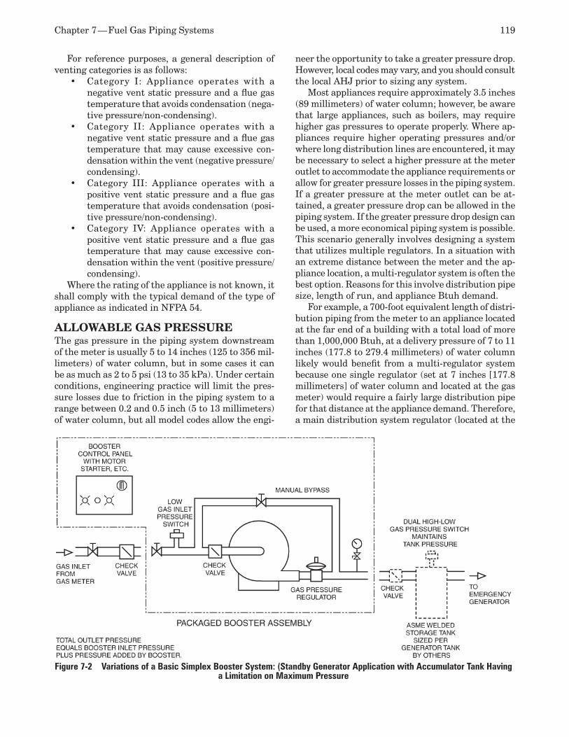
Chapter 7 — Fuel Gas Piping Systems 119
For reference purposes, a general description of venting categories is as follows:
Category I: Appliance operates with a •negative vent static pressure and a flue gas temperature that avoids condensation (nega-tive pressure/non-condensing).Category II: Appliance operates with a •negative vent static pressure and a flue gas temperature that may cause excessive con-densation within the vent (negative pressure/condensing).Category III: Appliance operates with a •positive vent static pressure and a flue gas temperature that avoids condensation (posi-tive pressure/non-condensing). Category IV: Appliance operates with a •positive vent static pressure and a flue gas temperature that may cause excessive con-densation within the vent (positive pressure/condensing).
Where the rating of the appliance is not known, it shall comply with the typical demand of the type of appliance as indicated in NFPA 54.
ALLOWABLE GAS PRESSUREThe gas pressure in the piping system downstream of the meter is usually 5 to 14 inches (125 to 356 mil-limeters) of water column, but in some cases it can be as much as 2 to 5 psi (13 to 35 kPa). Under certain conditions, engineering practice will limit the pres-sure losses due to friction in the piping system to a range between 0.2 and 0.5 inch (5 to 13 millimeters) of water column, but all model codes allow the engi-
neer the opportunity to take a greater pressure drop. However, local codes may vary, and you should consult the local AHJ prior to sizing any system.
Most appliances require approximately 3.5 inches (89 millimeters) of water column; however, be aware that large appliances, such as boilers, may require higher gas pressures to operate properly. Where ap-pliances require higher operating pressures and/or where long distribution lines are encountered, it may be necessary to select a higher pressure at the meter outlet to accommodate the appliance requirements or allow for greater pressure losses in the piping system. If a greater pressure at the meter outlet can be at-tained, a greater pressure drop can be allowed in the piping system. If the greater pressure drop design can be used, a more economical piping system is possible. This scenario generally involves designing a system that utilizes multiple regulators. In a situation with an extreme distance between the meter and the ap-pliance location, a multi-regulator system is often the best option. Reasons for this involve distribution pipe size, length of run, and appliance Btuh demand.
For example, a 700-foot equivalent length of distri-bution piping from the meter to an appliance located at the far end of a building with a total load of more than 1,000,000 Btuh, at a delivery pressure of 7 to 11 inches (177.8 to 279.4 millimeters) of water column likely would benefit from a multi-regulator system because one single regulator (set at 7 inches [177.8 millimeters] of water column and located at the gas meter) would require a fairly large distribution pipe for that distance at the appliance demand. Therefore, a main distribution system regulator (located at the
Figure 7-2 Variations of a Basic Simplex Booster System: (Standby Generator Application with Accumulator Tank Having a Limitation on Maximum Pressure
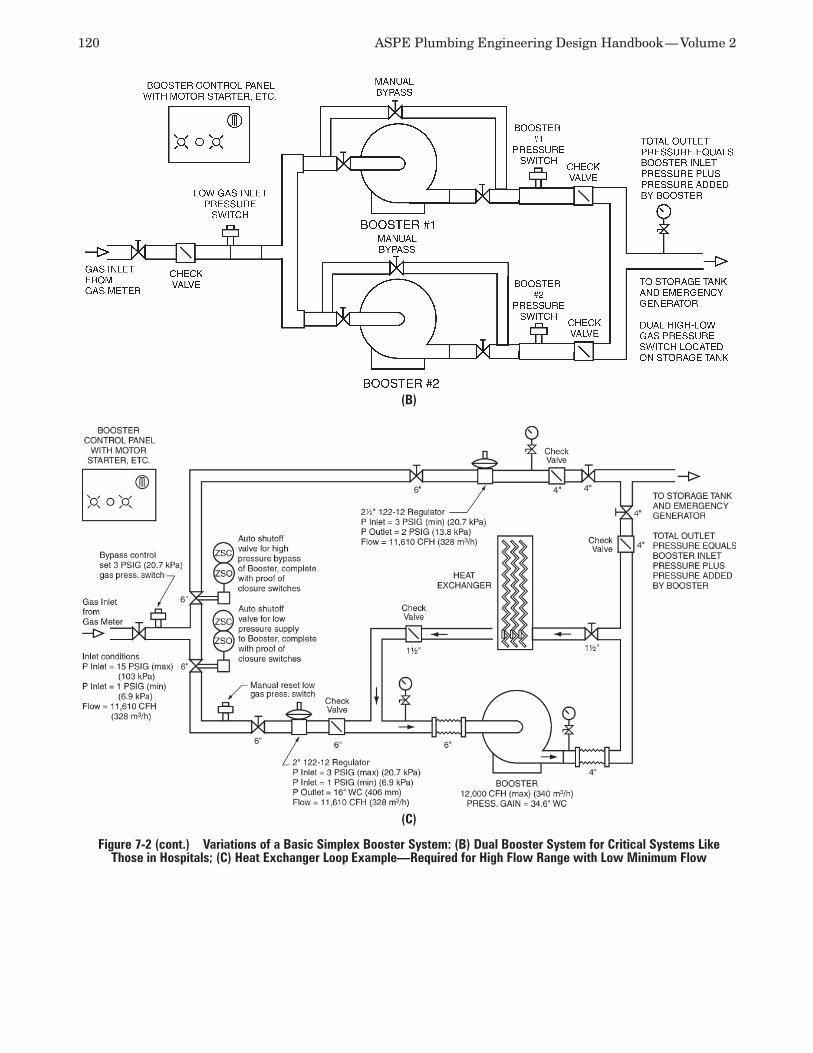
120 ASPE Plumbing Engineering Design Handbook — Volume 2
(C)
Figure 7-2 (cont.) Variations of a Basic Simplex Booster System: (B) Dual Booster System for Critical Systems Like Those in Hospitals; (C) Heat Exchanger Loop Example—Required for High Flow Range with Low Minimum Flow
(B)
Chapter 7 — Fuel Gas Piping Systems 121
meter and set at 5 psig [34.47 kPa]) would be used to supply a higher system pressure to the appliance, thus utilizing a smaller pipe size than would be required for a low-pressure delivery at the same length of pipe. The secondary, or step-down, regulator (located at the appliance) then would lower the gas supply pressure sufficient to supply the appliance.
Some additional issues need to be considered with respect to designing multi-regulator systems. Where most appliances are located within interior building spaces, secondary regulators need to be strategically located so they can be properly vented to the outdoors and be maintained efficiently. Other facilities may have a mix of both interior appliances and gas-fired rooftop equipment that is exposed to the outside. These systems can be designed such that secondary regulators are located at the roof, eliminating the need for associated vent piping and providing easy ac-cess for maintenance or replacement. Also, secondary regulators can be located in a manner in which they can supply several appliances within a specific zone or area, minimizing the number of secondary regulators needed for use, although requiring more low-pressure gas supply piping downstream of the secondary regula-tor. Simply stated, there are tradeoffs for every given situation, and you need to address all possible scenarios to design the most efficient system and accommodate the owner’s requirements as much as possible.
LABORATORY USE Natural gas is the primary gas used in laboratories at lab benches and within fume hoods for Bunsen burners. Where natural gas is not available, liquefied petroleum gas (propane) is used, but this generally requires the manufacturer to be advised due to the Bunsen burner requiring a smaller orifice. Typical Bunsen burners consume either 5 cfh (0.15 cubic me-ters per hour) for small burners or 10 cfh (0.30 cubic meters per hour) for larger burners. The maximum pressure at the burner should not exceed 14 inches (355.6 millimeters) of water column. The 10-cfh (0.30-cubic-meters-per-hour) capacity is most commonly used for design purposes.
Flow diversity can be applied (relative to de-termining system pipe sizes) where natural gas is supplied to Bunsen burners. However, both the acceptance and methodology for determining flow diversities for this purpose must be obtained by the local AHJ or utility supplier prior to the design of any system. Where flow diversity factors are allow-able for implementation, they shall be done so with careful judgment and sound engineering principles, based on each individual facility type and operational characteristics. Note that each type of facility con-tains its own unique operational characteristics and, with respect to natural gas, should not be assigned a
global or standard set of diversity guidelines typically seen in various charts and graphs for other services such as compressed air and vacuum. Prior to the start of any system design, you should consult with a facility’s owners (and users) to help determine the proper diversities that could be implemented, based on the facility’s unique programming requirements and use by its occupants.
Certain local jurisdictions may require labora-tory natural gas systems, especially those in schools or universities, to be provided with emergency gas shutoff valves located at the main supply piping to each laboratory. NFPA standards (45, 72 and 101) also contain requirements regarding emergency and automatic shutoff of gas systems. Valves for these applications should be normally closed and opened only when the gas is being supplied. They should be located inside the laboratory and used in conjunction with shutoff valves at the benches or equipment (which may be required by other codes). You should ensure that locations meet local code requirements.
Utility controllers and laboratory service panels are manufactured, pre-assembled safety devices that regulate the control of various services and devices such as domestic water, natural gas, and electrical outlets within science classrooms and instructional, research, and medical facilities. They typically contain solid-state electronic controllers with relays that acti-vate these services. A keyed service switch integrated into the design of the utility controller restricts the ability to activate services by unauthorized persons, resulting in a safe environment for students or other occupants. Utility controllers also typically are equipped with a panic button that would deactivate the gas service upon being pressed.
ALTITUDE DERATING FACTORNatural gas has a lower density at higher altitudes than at lower altitudes, which must be considered when a project location is more than 2,000 feet above sea level. This altitude correction factor shall be multiplied by the gas input ratings at sea level to determine the corrected input at full-load capacity. Refer to Figure 7-1 to determine the derating factors for natural gas.
PIPING SYSTEM MATERIALSThe International Fuel Gas Code (IFGC), model plumbing codes, and standards published by NFPA (54 and 58) list the approved materials for use in natural gas and liquefied petroleum gas (propane) piping systems. The most commonly used materials for these systems (along with additional notes and cautionary statements) are listed below for refer-ence purposes.
122 ASPE Plumbing Engineering Design Handbook — Volume 2
Metallic Pipe
Cast IronCast iron pipe shall not be used.
Steel and Wrought IronSteel and wrought-iron pipe shall be at least of stan-dard weight (Schedule 40) and shall comply with one of the following standards:
ANSI/ASME B36.10: • Welded and Seamless Wrought-Steel PipeASTM A53: • Standard Specification for Pipe, Steel, Black and Hot-dipped, Zinc-coated Welded and Seamless: Black or carbon steel piping is generally the most commonly se-lected steel pipe material for natural gas and propane piping systems. Galvanized steel pipe is covered with a protective coating of zinc that greatly reduces its tendency to corrode and extends its life expectancy. However, it should be noted that galvanized steel piping is not approved for use in many jurisdictions for natural gas service. In general, it should not be used in natural gas systems because corrosivity levels in natural gas can vary over time and can cause the zinc to flake off and clog the system.ASTM A106: • Standard Specification for Seamless Carbon Steel Pipe for High-temper-ature Service
Copper and BrassCopper and brass pipe is approved for use, but they shall not be used if the gas contains more than an average of 0.3 grains of hydrogen sulfide per 100 standard cubic feet (SCF) of gas (0.7 milligrams per 100 liters).
Threaded copper, brass, or aluminum alloy pipe is approved for use, but shall not be used with gases that are corrosive to such material.
Aluminum AlloyAluminum alloy pipe shall comply with ASTM B241: Specification for Aluminum-alloy Seamless Pipe and Seamless Extruded Tube (except that the use of alloy 5456 is prohibited) and shall be marked at each end of each length indicating compliance. Aluminum alloy pipe shall be coated to protect against external corro-sion where it is in contact with masonry, plaster, or insulation or is subject to repeated wettings by such liquids as water, detergents, or sewage. Aluminum alloy pipe shall not be used in exterior locations or underground.
Metallic TubingSeamless copper, aluminum alloy, or steel tubing shall not be used with gases corrosive to such materials.
SteelSteel tubing shall comply with ASTM A254: Standard Specification for Copper-brazed Steel Tubing.
Copper and BrassCopper and brass tubing shall not be used if the gas contains more than an average of 0.3 grains of hy-drogen sulfide per 100 SCF of gas (0.7 milligrams per 100 liters). Copper tubing shall comply with standard Type K or Type L of ASTM B88: Standard Specifica-tion for Seamless Copper Water Tube or ASTM B280: Specification for Seamless Copper Tube for Air-condi-tioning and Refrigeration Field Service.
AluminumAluminum alloy tubing shall comply with ASTM B210: Standard Specification for Aluminum and Aluminum-alloy Drawn Seamless Tubes or ASTM B 241. Aluminum alloy tubing shall be coated to pro-tect against external corrosion where it is in contact with masonry, plaster, or insulation or is subject to repeated wettings by such liquids as water, detergent, or sewage. Aluminum alloy tubing shall not be used in exterior locations or underground.
Corrugated Stainless Steel Tubing Corrugated stainless steel tubing (CSST) shall be listed in accordance with ANSI LC 1/CSA 6.26: Fuel Gas Piping Systems Using Corrugated Stainless Steel Tubing. The standard requires a contractor to be certified by the manufacturer before installing CSST. CSST is approved by all national plumbing and gas codes. However, some local jurisdictions and authori-ties may restrict its use.
As an alternative to the installation of rigid steel or copper piping systems, CSST systems can be used from a-inch up to 2-inch tube sizes. CSST systems consist of a continuous, flexible, stainless steel pipe with an exterior polyethylene (PE) jacket, which is ASTM E84: Standard Test Method for Surface Burning Charac-teristics of Building Materials rated (smoke and fire rated 25/50) to be installed in a plenum. The piping is produced in coils that are air-tested for leaks. It most often is installed in a central manifold configuration (also called parallel configuration) or extended from steel pipe mains with home run lines that extend to gas appliances (also called a hybrid system).
Flexible gas piping is lightweight and requires fewer connections than conventional gas piping because it can be bent easily and routed around ob-stacles. This can amount to a substantial reduction in labor costs as compared to a conventional rigid piping system installation. CSST piping systems can be a good choice for a retrofit or renovation project where existing conditions could render a rigid piping system installation very costly or disruptive to exist-ing building occupants.
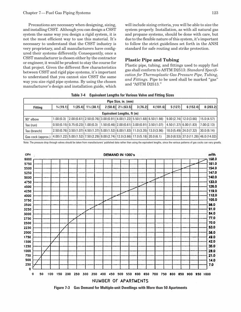
Chapter 7 — Fuel Gas Piping Systems 123
Precautions are necessary when designing, sizing, and installing CSST. Although you can design a CSST system the same way you design a rigid system, it is not the most efficient way to use this material. It’s necessary to understand that the CSST industry is very proprietary, and all manufacturers have config-ured their systems differently. Consequently, once a CSST manufacturer is chosen either by the contractor or engineer, it would be prudent to stay the course for that project. Given the different flow characteristics between CSST and rigid pipe systems, it’s important to understand that you cannot size CSST the same way you size rigid pipe systems. By using the chosen manufacturer’s design and installation guide, which
will include sizing criteria, you will be able to size the system properly. Installation, as with all natural gas and propane systems, should be done with care, but due to the flexible nature of this system, it’s important to follow the strict guidelines set forth in the ANSI standard for safe routing and strike protection.
Plastic Pipe and TubingPlastic pipe, tubing, and fittings used to supply fuel gas shall conform to ASTM D2513: Standard Specifi-cation for Thermoplastic Gas Pressure Pipe, Tubing, and Fittings. Pipe to be used shall be marked “gas” and “ASTM D2513.”
Table 7-4 Equivalent Lengths for Various Valve and Fitting Sizes
Pipe Size, in. (mm)
Fitting ¾ (19.1) 1 (25.4) 1½ (38.1) 2 (50.8) 2½ (63.5) 3 (76.2) 4 (101.6) 5 (127) 6 (152.4) 8 (203.2)
Equivalent Lengths, ft (m)
90° elbow 1.00 (0.3) 2.00 (0.61) 2.50 (0.76) 3.00 (0.91) 4.00 (1.22) 5.50 (1.68) 6.50 (1.98) 9.00 (2.74) 12.0 (3.66) 15.0 (4.57)
Tee (run) 0.50 (0.15) 0.75 (0.23) 1.00 (0.3) 1.50 (0.46) 2.00 (0.61) 3.00 (0.91) 3.50 (1.07) 4.50 (1.37) 6.00 (1.83) 7.00 (2.13)
Tee (branch) 2.50 (0.76) 3.50 (1.07) 4.50 (1.37) 5.00 (1.52) 6.00 (1.83) 11.0 (3.35) 13.0 (3.96) 18.0 (5.49) 24.0 (7.32) 30.0 (9.14)
Gas cock (approx.) 4.00 (1.22) 5.00 (1.52) 7.50 (2.29) 9.00 (2.74) 12.0 (3.66) 17.0 (5.18) 20.0 (6.1) 28.0 (8.53) 37.0 (11.28) 46.0 (14.02)
Note: The pressure drop through valves should be taken from manufacturers’ published data rather than using the equivalent lengths, since the various patterns of gas cocks can vary greatly.
Figure 7-3 Gas Demand for Multiple-unit Dwellings with More than 50 Apartments
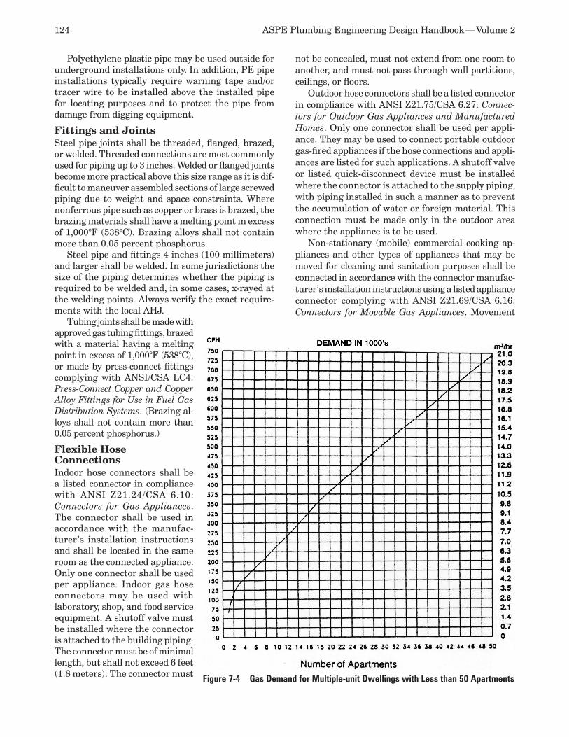
124 ASPE Plumbing Engineering Design Handbook — Volume 2
Polyethylene plastic pipe may be used outside for underground installations only. In addition, PE pipe installations typically require warning tape and/or tracer wire to be installed above the installed pipe for locating purposes and to protect the pipe from damage from digging equipment.
Fittings and JointsSteel pipe joints shall be threaded, flanged, brazed, or welded. Threaded connections are most commonly used for piping up to 3 inches. Welded or flanged joints become more practical above this size range as it is dif-ficult to maneuver assembled sections of large screwed piping due to weight and space constraints. Where nonferrous pipe such as copper or brass is brazed, the brazing materials shall have a melting point in excess of 1,000°F (538°C). Brazing alloys shall not contain more than 0.05 percent phosphorus.
Steel pipe and fittings 4 inches (100 millimeters) and larger shall be welded. In some jurisdictions the size of the piping determines whether the piping is required to be welded and, in some cases, x-rayed at the welding points. Always verify the exact require-ments with the local AHJ.
Tubing joints shall be made with approved gas tubing fittings, brazed with a material having a melting point in excess of 1,000°F (538°C), or made by press-connect fittings complying with ANSI/CSA LC4: Press-Connect Copper and Copper Alloy Fittings for Use in Fuel Gas Distribution Systems. (Brazing al-loys shall not contain more than 0.05 percent phosphorus.)
Flexible Hose ConnectionsIndoor hose connectors shall be a listed connector in compliance with ANSI Z21.24/CSA 6.10: Connectors for Gas Appliances. The connector shall be used in accordance with the manufac-turer’s installation instructions and shall be located in the same room as the connected appliance. Only one connector shall be used per appliance. Indoor gas hose connectors may be used with laboratory, shop, and food service equipment. A shutoff valve must be installed where the connector is attached to the building piping. The connector must be of minimal length, but shall not exceed 6 feet (1.8 meters). The connector must
not be concealed, must not extend from one room to another, and must not pass through wall partitions, ceilings, or floors.
Outdoor hose connectors shall be a listed connector in compliance with ANSI Z21.75/CSA 6.27: Connec-tors for Outdoor Gas Appliances and Manufactured Homes. Only one connector shall be used per appli-ance. They may be used to connect portable outdoor gas-fired appliances if the hose connections and appli-ances are listed for such applications. A shutoff valve or listed quick-disconnect device must be installed where the connector is attached to the supply piping, with piping installed in such a manner as to prevent the accumulation of water or foreign material. This connection must be made only in the outdoor area where the appliance is to be used.
Non-stationary (mobile) commercial cooking ap-pliances and other types of appliances that may be moved for cleaning and sanitation purposes shall be connected in accordance with the connector manufac-turer’s installation instructions using a listed appliance connector complying with ANSI Z21.69/CSA 6.16: Connectors for Movable Gas Appliances. Movement
Figure 7-4 Gas Demand for Multiple-unit Dwellings with Less than 50 Apartments
Chapter 7 — Fuel Gas Piping Systems 125
of appliances with casters (in all cases) shall be limited by a restraining device installed in accordance with the connector and appliance manufacturers’ installation instructions to prevent damage if the appliance should move while the gas supply is connected.
GroundingBonding and electrical grounding of all natural gas piping systems are required by NFPA 70: National Electrical Code and the International Fuel Gas Code. Additional consideration should be exercised where installations are located in regions prone to lightning. Electrical bonding is required to prevent damage that could occur during an electrical storm.
NATURAL GAS BOOSTERS A gas booster is a mechanical device that increases natural gas pressure. It is used when the gas utility does not provide adequate pressure. It is important to note that the gas service must be capable of the volu-metric flow rate required at the boosted pressure level. A gas booster cannot supplement quantity where an inadequate volumetric supply of gas may exist.
Gas boosters for natural gas are hermetically sealed and are equipped to deliver a specific volumet-ric flow rate (within the booster’s rated capacity) to an increased gas pressure beyond the supply pressure. The outlet pressure usually remains at a constant differential above the supply pressure within a rea-sonable range. The discharge pressure is the sum of the incoming gas pressure and the booster-added pressure at the selected flow rate. The incoming gas pressure typically has an upper safety limit as stipulated by the hermetic gas booster manufacturer. Therefore, you may encounter cautions or warnings about the upper limits of incoming pressure, approxi-mately 5 psi (34.5 kPa). Installation of gas boosters must be closely coordinated with the utility company or gas supplier.
Materials and Construction
Housing and Rotor Boosters used for fuel gas must be Underwriters Labora-tories (UL) listed for the specific duty intended and shall be hermetically sealed. Casings on standard boosters usually are constructed of carbon steel, but they also are available in stainless steel and aluminum. Inlet and outlet connections are threaded or flanged, depending on the pipe connection size and manufacturer selected, and the casings are leak-tight. Drive impellers are con-tained within the casing and always manufactured of a spark-resistant material such as aluminum.
Discharge check valves are furnished at the booster inlet and at the booster bypass. It is important that all valves used are listed and approved for use on gas piping systems. The fan, control panel, valves, piping, and inter-electrical connections can be specified as a
skid-mounted package at the discretion of the designer. This allows for a UL listing of the entire package, rather than of individual components.
Electrical Components Motor housings for gas booster systems are designed for explosion-proof (XP) construction and are rated per National Electrical Manufacturers Association (NEMA) Class 1, Division 1, Group D classification with thermal overload protection. A factory UL-listed junction box with a protected, sealed inlet is necessary for wiring connections.
Other Electrical Ancillary Equipment Boosters are equipped with low-pressure switches that monitor the incoming gas pressure. The switch is designed to shut down the booster should the utility-supplied pressure fall below a preset limit. The set point is usually about 3 inches (76 millimeters) of water column, but you should verify the limit with the local gas supplier. The switch must be UL listed for use with the gas service supplied. When the switch opens, it de-energizes the motor control circuit and simultaneously initiates both audible and visual signals, which require manual resetting.
The booster can be equipped with an optional high/low gas pressure switch. This feature allows the booster to run only when adequate supply pressure is available. The switch shuts down the booster when it reaches the maximum discharge set-point pressure at the output line pressure.
Minimum Gas Flow Gas boosters normally require a minimum gas flow that serves as an internal cooling medium. For example, a booster sized at a flow rate of 10,000 cfh (283.2 cubic meters per hour) has an inherent minimum turn-down based on the minimum flow required to cool the unit. This rate, for the booster in this example sized at 10,000 cfh, may be 2,000 cfh (566.3 cubic meters per hour). Should the unit be required to run below this turndown rate, additional supplemental cooling systems must be incorporated within the gas booster design. The heat exchangers normally rated for this use are water cooled.
Intrinsic Safety Electrical connections are made through a sealed, explosion-proof conduit to the XP junction box on the booster unit. Control panels are rated NEMA 4 for outdoor use and NEMA 12 for indoor use, unless the booster system is to be located in a hazardous area, which may have additional requirements. The panel (as an assembly) must display a UL label specific for its intended use.
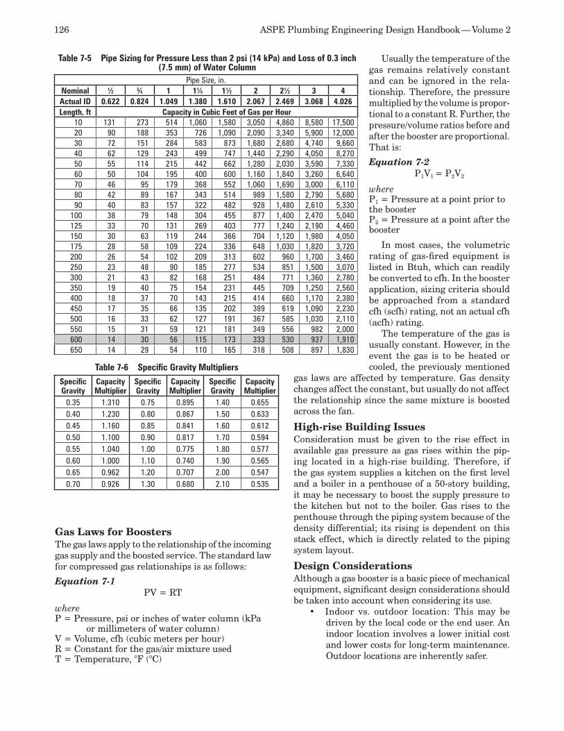
126 ASPE Plumbing Engineering Design Handbook — Volume 2
Table 7-5 Pipe Sizing for Pressure Less than 2 psi (14 kPa) and Loss of 0.3 inch (7.5 mm) of Water Column
Pipe Size, in.Nominal 1⁄2 3⁄4 1 11⁄4 11⁄2 2 21⁄2 3 4Actual ID 0.622 0.824 1.049 1.380 1.610 2.067 2.469 3.068 4.026Length, ft Capacity in Cubic Feet of Gas per Hour
10 131 273 514 1,060 1,580 3,050 4,860 8,580 17,50020 90 188 353 726 1,090 2,090 3,340 5,900 12,00030 72 151 284 583 873 1,680 2,680 4,740 9,66040 62 129 243 499 747 1,440 2,290 4,050 8,27050 55 114 215 442 662 1,280 2,030 3,590 7,33060 50 104 195 400 600 1,160 1,840 3,260 6,64070 46 95 179 368 552 1,060 1,690 3,000 6,11080 42 89 167 343 514 989 1,580 2,790 5,68090 40 83 157 322 482 928 1,480 2,610 5,330
100 38 79 148 304 455 877 1,400 2,470 5,040125 33 70 131 269 403 777 1,240 2,190 4,460150 30 63 119 244 366 704 1,120 1,980 4,050175 28 58 109 224 336 648 1,030 1,820 3,720200 26 54 102 209 313 602 960 1,700 3,460250 23 48 90 185 277 534 851 1,500 3,070300 21 43 82 168 251 484 771 1,360 2,780350 19 40 75 154 231 445 709 1,250 2,560400 18 37 70 143 215 414 660 1,170 2,380450 17 35 66 135 202 389 619 1,090 2,230500 16 33 62 127 191 367 585 1,030 2,110550 15 31 59 121 181 349 556 982 2,000600 14 30 56 115 173 333 530 937 1,910650 14 29 54 110 165 318 508 897 1,830
Table 7-6 Specific Gravity Multipliers
Specific Gravity
Capacity Multiplier
Specific Gravity
Capacity Multiplier
Specific Gravity
Capacity Multiplier
0.35 1.310 0.75 0.895 1.40 0.6550.40 1.230 0.80 0.867 1.50 0.6330.45 1.160 0.85 0.841 1.60 0.6120.50 1.100 0.90 0.817 1.70 0.5940.55 1.040 1.00 0.775 1.80 0.5770.60 1.000 1.10 0.740 1.90 0.5650.65 0.962 1.20 0.707 2.00 0.5470.70 0.926 1.30 0.680 2.10 0.535
Gas Laws for BoostersThe gas laws apply to the relationship of the incoming gas supply and the boosted service. The standard law for compressed gas relationships is as follows:
Equation 7-1 PV = RT
where P = Pressure, psi or inches of water column (kPa
or millimeters of water column) V = Volume, cfh (cubic meters per hour) R = Constant for the gas/air mixture used T = Temperature, °F (°C)
Usually the temperature of the gas remains relatively constant and can be ignored in the rela-tionship. Therefore, the pressure multiplied by the volume is propor-tional to a constant R. Further, the pressure/volume ratios before and after the booster are proportional. That is:
Equation 7-2 P1V1 = P2V2
where P1 = Pressure at a point prior to the booster P2 = Pressure at a point after the booster
In most cases, the volumetric rating of gas-fired equipment is listed in Btuh, which can readily be converted to cfh. In the booster application, sizing criteria should be approached from a standard cfh (scfh) rating, not an actual cfh (acfh) rating.
The temperature of the gas is usually constant. However, in the event the gas is to be heated or cooled, the previously mentioned
gas laws are affected by temperature. Gas density changes affect the constant, but usually do not affect the relationship since the same mixture is boosted across the fan.
High-rise Building Issues Consideration must be given to the rise effect in available gas pressure as gas rises within the pip-ing located in a high-rise building. Therefore, if the gas system supplies a kitchen on the first level and a boiler in a penthouse of a 50-story building, it may be necessary to boost the supply pressure to the kitchen but not to the boiler. Gas rises to the penthouse through the piping system because of the density differential; its rising is dependent on this stack effect, which is directly related to the piping system layout.
Design Considerations Although a gas booster is a basic piece of mechanical equipment, significant design considerations should be taken into account when considering its use.
Indoor vs. outdoor location:• This may be driven by the local code or the end user. An indoor location involves a lower initial cost and lower costs for long-term maintenance. Outdoor locations are inherently safer.
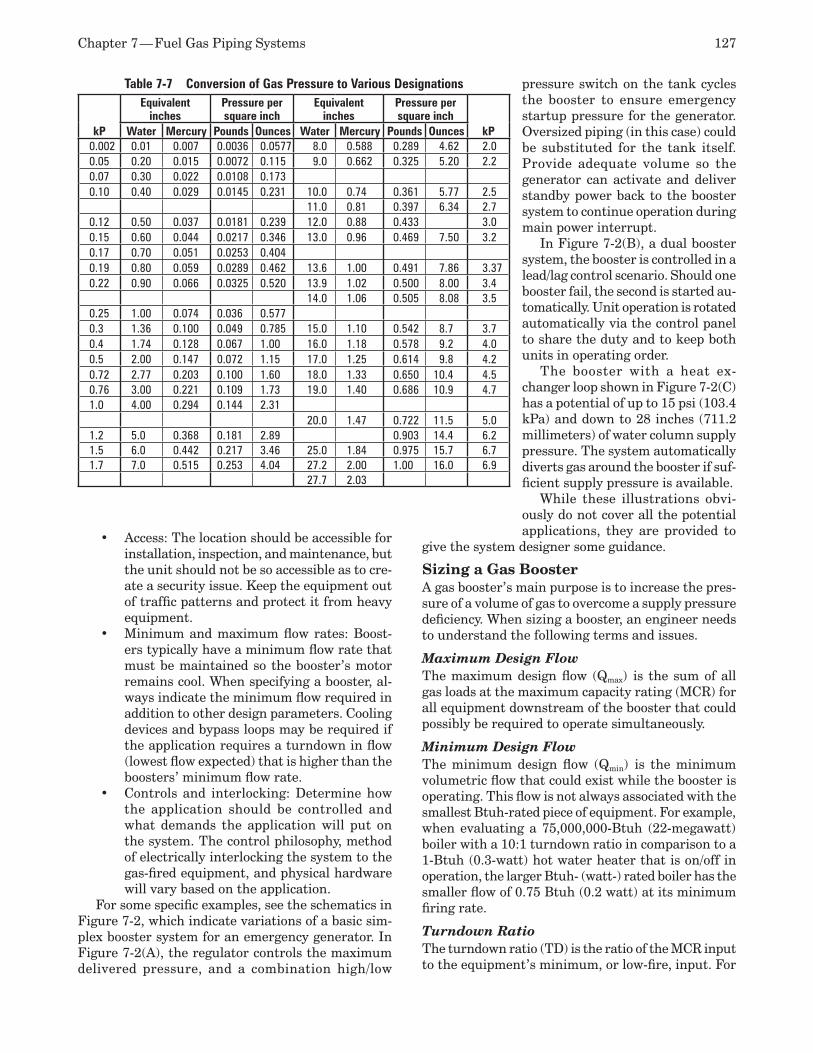
Chapter 7 — Fuel Gas Piping Systems 127
Table 7-7 Conversion of Gas Pressure to Various Designations
kP
Equivalent inches
Pressure per square inch
Equivalent inches
Pressure per square inch
kPWater Mercury Pounds Ounces Water Mercury Pounds Ounces0.002 0.01 0.007 0.0036 0.0577 8.0 0.588 0.289 4.62 2.00.05 0.20 0.015 0.0072 0.115 9.0 0.662 0.325 5.20 2.20.07 0.30 0.022 0.0108 0.1730.10 0.40 0.029 0.0145 0.231 10.0 0.74 0.361 5.77 2.5
11.0 0.81 0.397 6.34 2.70.12 0.50 0.037 0.0181 0.239 12.0 0.88 0.433 3.00.15 0.60 0.044 0.0217 0.346 13.0 0.96 0.469 7.50 3.20.17 0.70 0.051 0.0253 0.4040.19 0.80 0.059 0.0289 0.462 13.6 1.00 0.491 7.86 3.370.22 0.90 0.066 0.0325 0.520 13.9 1.02 0.500 8.00 3.4
14.0 1.06 0.505 8.08 3.50.25 1.00 0.074 0.036 0.5770.3 1.36 0.100 0.049 0.785 15.0 1.10 0.542 8.7 3.70.4 1.74 0.128 0.067 1.00 16.0 1.18 0.578 9.2 4.00.5 2.00 0.147 0.072 1.15 17.0 1.25 0.614 9.8 4.20.72 2.77 0.203 0.100 1.60 18.0 1.33 0.650 10.4 4.50.76 3.00 0.221 0.109 1.73 19.0 1.40 0.686 10.9 4.71.0 4.00 0.294 0.144 2.31
20.0 1.47 0.722 11.5 5.01.2 5.0 0.368 0.181 2.89 0.903 14.4 6.21.5 6.0 0.442 0.217 3.46 25.0 1.84 0.975 15.7 6.71.7 7.0 0.515 0.253 4.04 27.2 2.00 1.00 16.0 6.9
27.7 2.03
Access:• The location should be accessible for installation, inspection, and maintenance, but the unit should not be so accessible as to cre-ate a security issue. Keep the equipment out of traffic patterns and protect it from heavy equipment. Minimum and maximum flow rates:• Boost-ers typically have a minimum flow rate that must be maintained so the booster’s motor remains cool. When specifying a booster, al-ways indicate the minimum flow required in addition to other design parameters. Cooling devices and bypass loops may be required if the application requires a turndown in flow (lowest flow expected) that is higher than the boosters’ minimum flow rate.Controls and interlocking:• Determine how the application should be controlled and what demands the application will put on the system. The control philosophy, method of electrically interlocking the system to the gas-fired equipment, and physical hardware will vary based on the application.
For some specific examples, see the schematics in Figure 7-2, which indicate variations of a basic sim-plex booster system for an emergency generator. In Figure 7-2(A), the regulator controls the maximum delivered pressure, and a combination high/low
pressure switch on the tank cycles the booster to ensure emergency startup pressure for the generator. Oversized piping (in this case) could be substituted for the tank itself. Provide adequate volume so the generator can activate and deliver standby power back to the booster system to continue operation during main power interrupt.
In Figure 7-2(B), a dual booster system, the booster is controlled in a lead/lag control scenario. Should one booster fail, the second is started au-tomatically. Unit operation is rotated automatically via the control panel to share the duty and to keep both units in operating order.
The booster with a heat ex-changer loop shown in Figure 7-2(C) has a potential of up to 15 psi (103.4 kPa) and down to 28 inches (711.2 millimeters) of water column supply pressure. The system automatically diverts gas around the booster if suf-ficient supply pressure is available.
While these illustrations obvi-ously do not cover all the potential applications, they are provided to
give the system designer some guidance.
Sizing a Gas Booster A gas booster’s main purpose is to increase the pres-sure of a volume of gas to overcome a supply pressure deficiency. When sizing a booster, an engineer needs to understand the following terms and issues.
Maximum Design Flow The maximum design flow (Qmax) is the sum of all gas loads at the maximum capacity rating (MCR) for all equipment downstream of the booster that could possibly be required to operate simultaneously.
Minimum Design Flow The minimum design flow (Qmin) is the minimum volumetric flow that could exist while the booster is operating. This flow is not always associated with the smallest Btuh-rated piece of equipment. For example, when evaluating a 75,000,000-Btuh (22-megawatt) boiler with a 10:1 turndown ratio in comparison to a 1-Btuh (0.3-watt) hot water heater that is on/off in operation, the larger Btuh- (watt-) rated boiler has the smaller flow of 0.75 Btuh (0.2 watt) at its minimum firing rate.
Turndown Ratio The turndown ratio (TD) is the ratio of the MCR input to the equipment’s minimum, or low-fire, input. For
128 ASPE Plumbing Engineering Design Handbook — Volume 2
example, a 100-Btuh (29.3-watt) burner that can fire at a minimum rate of 20 Btuh (5.9 watts) has a TD ratio of 5:1.
Pressure Droop and Peak Consumption Pressure droop is the inability of a supply system to maintain a steady or consistent inlet pressure as an increase in volumetric flow is demanded. Often, in areas where boosters are applied, the supply pressure in off-peak months when gas is not in such demand can be sufficient to run a system. As the local demand for gas increases, the supply system no longer can provide the gas efficiently, and the pressure falls off, or droops. It is the booster’s function to overcome the droop (or excessive pressure drop) of the supply system during such times.
Flow Rate Relationships It is important that the flows for the separate pieces of equipment relate to each other. In other words, do the three boilers always operate in unison while another process machine always operates off peak and alone? Relationships among the equipment can significantly affect both maximum and minimum flow rates.
Test Block The test block is a factor of safety added to the de-sign criteria. Typically, a minimum 5 percent added volume and 10 percent added static pressure should be applied to the design criteria. When specifying the equipment, ensure that you note both the design and test block conditions. This ensures that safety fac-tors are not applied to criteria that already include safety factors.
Minimum and Maximum Inlet Pressure The minimum inlet pressure (PI-min) is the minimum supply pressure in inches (millimeters) of water col-umn gauge. This must be evaluated during peak flow demands for both the equipment and the local area. Always evaluate during flow, not static, conditions. It is also important to know how high the inlet pressure is expected to rise during off-peak periods. A booster is typically rated to about 5 psi (34.5 kPa). It may be possible to exceed this rating during off-peak demand periods; therefore, a bypass system or other means of protection is required. Often this pressure can be specified by the local gas company as the minimum guaranteed gas pressure from their supply system. Also, the maximum inlet pressure (PI-max) must be determined.
Maximum Outlet Pressure The maximum outlet pressure (PO-max) includes all maximum and required supply pressures for the vari-ous pieces of equipment being supplied with gas from the booster. Determine the differential between the highest expected gas pressure supply to the booster
(e.g., 8 inches [203.2 millimeters] of water column) and the lowest maximum supply pressure rating to a piece of equipment (e.g., 18 inches [457.2 millimeters] of water column). The booster’s pressure gain should not exceed this differential (for the above example, 18 – 8 = 10 inches [457.2 – 203.2 = 254 millimeters] of water column) unless other means of protecting the downstream equipment are provided.
Outlet Pressure Protection Several methods to protect equipment downstream of a booster are available if over-pressurization during off-peak periods occurs. If all the equipment being serviced operates at nominally the same pressure, install a regulator on the inlet or outlet of the booster to maintain a controlled maximum outlet pressure. If the equipment being serviced operates at various inlet pressures, it may be best to supply a regulator for each piece of equipment. Most often, packaged equipment is supplied with its own regulator. If this is the case, review the equipment regulator’s maximum inlet pressure.
To perform an evaluation of system requirements, the following procedure is suggested:
Establish the design Q1. min and Qmax per the pre-viously discussed definitions while evaluating TD requirements. Establish P2. I-min and PI-max per the previously discussed definitions. Define the maximum inlet pressure require-3. ments to the equipment (PI-eq). Define piping pressure losses (P4. PL in psi [kPa]) from the gas booster location to each piece of equipment. Determine the design flow rate (Q5. D): Qmin to Qmax in cfh (cubic meters per hour). Determine the design pressure boost (DP): 6. PI-eq + PPL – PI-min.Calculate the test block flow (Q7. TB): (1.05 x Qmin) to (1.05 x Qmax). Test the block pressure boost: 1.10 x DP = P8. I-eq + PPL – PI-min.
INTERIOR NATURAL GAS PIPE SIzING
Data to Be ObtainedTo accurately size all elements of the piping system, calculate or obtain the following information:
Information needed by both the utility com-1. pany and the engineerGas pressure available after the meter as-2. semblyAllowable friction loss through the piping 3. systemPressure required at the equipment and or 4. appliance
A piping layout that indicates all connected 5. equipment, allowing determination of the measured length of piping to the furthest connectionThe maximum demand6. A pipe sizing method acceptable to the AHJ 7. or local code
Information Needed by the Utility Company and the Engineer The following are intended to be complete lists of items. Not all items will be necessary for all projects.
The following criteria and information shall be obtained in writing from the public utility company and provided to the engineer:
Actual Btu content of the gas provided•Minimum pressure of the gas at the outlet •of the meterExtent of the installation work done by the •utility company and the point of connection to the meter by the facility construction contractor The location of the utility supply main and •the proposed run of pipe on the site by the utility company, in the form of a marked-up plan or description of the work, including the expected date of installation if no gas is availableAcceptable location of the meter and/or regu-•lator assembly or a request to locate the meter at a particular location Any work required by the owner/contractor •to allow the meter assembly to be installed (such as a meter pit or slab on grade)Types of gas service available and the cost •of each
For the utility company to provide this data, the following information must be provided to them:
Total connected load. The utility will use its •own diversity factor to calculate the size of the service line. For the design of the proj-ect’s interior piping, the design engineer will select the diversity factor involved (as allowable by the governing code and/or local jurisdiction). Minimum pressure requirements for the most •demanding equipmentA site plan indicating the location of the •proposed building orientation on the site and the specific area of the building where the proposed natural gas service will enter the buildingPreferred location of the meter/regulator •assemblyExpected date for the start of construction•All specific requirements for pressure•
Two site plans, one to be marked up and re-•turned to the engineerThe hours of operation for the different types •of equipmentA list of all future or anticipated equipment •and capacities
Pressure Available After the Meter This shall be established in writing from the utility at the start of the project. All gas–fired equipment and devices proposed for use on the project are to be submitted, and the pressure requirements and flow rates for each piece of equipment must be provided to the utility.
Allowable Friction Loss Through the Piping This shall be established by the engineer and shall be determined by the following criteria:
Pressure provide by the utility company (from •5 inches (125 millimeters) of water column to 5 psi (34.5 kPa) Required pressure at the equipment and or •appliance (typically a minimum 3.5 inches (89 millimeters) of water column for residential appliances and as much as 11 inches (280 millimeters) of water column for some rooftop equipment)Allowable pressure drop either by code or •the AHJ
After receiving the necessary criteria, the engineer can determine the allowable pressure drop for a par-ticular system. This conceivably could be from 0.3 inch (7.6 millimeters) of water column to 6 inches (152.4 millimeters) of water column (for a low-pressure system) and from 1 psi (7 kPa) to 3.5 psi (24.1 kPa) for medium- to high-pressure systems)
Piping LayoutThe equivalent length of piping is necessary to indicate the layout of the entire piping system and all connected appliances and equipment. The equivalent length of piping is calculated by measuring the actual length of the proposed piping from the meter to the furthest con-nection and then adding 50 percent (for fittings) of the measured length to obtain the total equivalent length. If a very accurate determination of the equivalent length is required, you must tabulate the fittings and valves and add those to the measured length. Refer to Table 7-4 for the equivalent amount of pipe length to be added for various valves and fittings.
It is common practice to omit the vertical length because natural gas is lighter than air. It expands at the rate of 1 inch (25.4 millimeters) of water column for each 15 feet (4.6 meters) of elevation as the gas rises. The increase in pressure due to the height will offset any friction loss in the piping. For example, if a high-rise building contained 100 feet of equivalent
horizontal pipe length and 200 feet of equivalent verti-cal pipe length, only the horizontal portion of piping (100 feet) would be considered for establishing the total equivalent length of pipe for design purposes, even though the actual equivalent pipe length in this example is 300 feet.
Maximum Demand The maximum demand is calculated by the engineer with input from the owner if necessary. For residen-tial use, Figure 7-3 (large multiple-unit residential projects) and Figure 7-4 (small multiple-unit resi-dential projects) give a direct reading of the usage in cfh (cubic meters per hour). These direct reading tables give flow rate use by using the number of apartments. For schools, use no diversity factor for individual classrooms. Use no diversity factor for groups of classrooms if information on the proposed use is not conclusive or available from the owner. For industrial use, a diversity factor generally is not used due to the possibility of simultaneous use by all connected equipment.
For a listing of input requirements for common appliances, refer to Table 7-3.
Natural Gas Pipe Sizing Methods A number of formulae can be used to calculate the capacity of natural gas piping based on such variables as delivery pressure, pressure drop through the piping system, pipe size, pipe material, and length of piping. These formulae are referenced in numerous model codes as well as NFPA 54.
The most commonly referenced formula for gas pressures below 1½ psi (10.3 kPa) is the Spitzglass formula. Another commonly referenced equation for pressures of 1½ psi (10.3 kPa) and above is the Weymouth formula. Using these formulae for sizing can be very tedious and time consuming, so they are rarely used. However, they were used as a basis for the sizing tables that are included in the model codes and NFPA standards. These tables are regarded as the most conservative method for sizing natural gas piping systems and should be referenced specifically for each project as dictated by the governing code.
The Plumbing Engineering and Design Hand-book of Tables, published by the American Society of Plumbing Engineers, contains pipe sizing tables for many systems, including natural gas and liqui-fied petroleum gas (propane) systems. These tables contain sizing information for most of the commonly used piping materials including pipe sizes at various pressures and cfh requirements.
In addition, proprietary tables and calculators are available from various organizations, and popular spreadsheet programs currently available on the market also can be used.
The methods used for sizing natural gas piping systems are as follows.
Longest Length MethodThis is the traditional method used to determine the longest equivalent piping length (from the meter or delivery point to the farthest outlet), which then is used in conjunction with the pipe sizing tables to determine the appropriate pipe diameter for all other sections of piping in the system. In simple terms, only the cfh quantities listed in the tables for this pipe length are used to size each and every branch and section of pipe. This method is the simplest to use, and it generally yields the most conservative sizing because the short runs of piping located close to the meter can be somewhat oversized. One advantage to using this method is that it can provide some cushion in the branch piping, allowing for future reconfigu-ration of the piping system without replacing entire branch lengths.
Branch Length MethodThis is an alternate sizing method that could permit slightly smaller pipe diameters in some segments of a piping system when compared with the longest length method. The pipe size of each section of the longest pipe length (from the meter or delivery point to the farthest outlet) shall be determined using the longest equivalent length of piping and the associ-ated cfh quantity listed in the tables for that section. Then, the pipe sizes of each section of branch pip-ing not previously sized shall be determined using the equivalent lengths of piping from the point of delivery to the most remote outlet of each individual branch and the associated cfh quantity listed for that particular section.
Hybrid Pressure MethodThis method is used when it is necessary to design a piping system that utilizes multiple supply pressures within a single distribution system. The pipe size for each section of high-pressure gas piping shall be determined using the longest equivalent length of piping from the meter or delivery point to the farthest pressure regulator. The pipe size from the pressure regulator to each outlet shall be determined using the length of piping from the regulator to the most remote outlet served by that regulator. With this method, medium-pressure gas tables (up to 5 psig) are used to size the piping upstream of the pressure regulators, and low-pressure gas tables (7 to 11 inches of water column) are used to size the piping downstream of each pressure regulator.
Sizing TablesTable 7-5 is based on Schedule 40 steel pipe, cubic feet per hour of gas, and a specific gravity of 0.60. The friction loss allowable is indicated. The table
Chapter 7 — Fuel Gas Piping Systems 131
has been provided as a supplement to the pipe sizing methods indicated, using the longest length method of pipe sizing.
To determine the size of each section of pipe in a gas supply system using the gas pipe sizing table, the following steps should be used:
Measure the length of the pipe from the gas 1. meter location to the most remote outlet on the system. Add a fitting allowance of 50 percent of the measured length. This represents the total equivalent length of pipe. (For natural gas, the vertical portion of piping is not considered due to the pressure gained as gas rises. This very closely approximates the friction loss in the piping.)Select the row showing the distance that is 2. equal to or greater than the equivalent length calculated. (In Table 7-6, the entire 600-foot row has been highlighted as an example.) Once chosen, it is the only row to use throughout the sizing process for all individual branches and cumulative sections of pipe.Use the columns in conjunction with the row 3. previously selected to locate all gas demand figures for this particular system. Starting at the most remote outlet, find in the table the calculated gas demand for that design point. If the exact figure is not shown, choose the figure closest to or greater than the calculated demand and select the associated pipe size. With the demand figure (and corresponding 4. length) selected, find the associated pipe size.Proceed for each design point and each branch 5. of pipe. For each section of pipe, determine the cumulative gas demand supplied by that section.
If the gas used for the system has a different spe-cific gravity than natural gas, obtain that figure from Table 7-6 and use this as a multiplier for the specific gas selected.
To convert gas pressure to various designations, refer to Table 7-7.
LIQUEFIED PETROLEUM GAS Liquefied petroleum gas (propane) is a refined natural gas developed mainly for use beyond the utility’s gas mains, but it has proven to be competitive in areas not covered by mains in rural areas. It is primarily a blend of propane and butane, with traces of other hydrocarbons remaining from the production method. The exact blend is controlled by the liquefied petro-leum gas distributor to match the climatic conditions of the area served. For this reason, you must confirm the heating value of the supplied gas. Unlike natural gas, 100 percent propane has a specific gravity of 1.53
and a nominal rating of 2,500 Btu per cubic foot (93 megajoules per cubic meter).
Easy storage for relatively large quantities of energy has led to widespread acceptance and use of liquefied petroleum gas in all areas previously served by utilities providing natural gas to users, including for automotive purposes. In addition, a principal use is for heating in industrial projects. It is not a substitute for natural gas, but it provides an alternative energy source when owners want to use a low, interruptible rate for heating purposes. When used for this pur-pose, experience has shown that the mixing with air should produce a gas with the heating value of 1,500 Btu per cubic foot (a specific gravity of 1.30) for ease of burning and ignition. Use Table 7-6 for the factor to be used for sizing.
Environmental Effects of PropaneFrom an environmental standpoint, propane is nontoxic and non-caustic and will not create an en-vironmental hazard if released as a liquid or vapor into water or soil. If spilled in large quantities, the only environmental damage that may occur is the freezing of any organism or plant life in the immedi-ate area. There are no long-term effects following a propane spill, even in large quantities. Potential damage and danger occur only if the vapor is ignited following a spill. Even then, there are no long-term effects of ignited propane that can be damaging to the environment. Propane liquid and vapor are both environmentally sound and friendly in their unused states (prior to combustion) if released.
Following are some environmental facts about propane:
Propane is not considered a greenhouse gas.•Propane is not damaging to freshwater or •saltwater ecosystems or underwater plant or marine life.Propane is not harmful to soil if spilled on the •ground. It will not cause harm to drinking water supplies.Propane vapor will not cause air pollution, •and it is not considered air pollution.Propane vapor is not harmful if accidentally •inhaled by animals or people.Propane will cause bodily harm only if the •liquid comes in contact with skin (boiling point -44°F).
Propane is listed as an approved clean fuel by U.S. energy policymakers and energy administrative bod-ies. Propane engine exhaust is clean and continues to power forklifts operated inside warehouses through-out the world.
Propane Storage TanksPropane storage tanks typically are provided by the vendor for the customer and are subject to the regula-
132 ASPE Plumbing Engineering Design Handbook — Volume 2
tions of the U.S. Department of Transportation (DOT) and the local authority, as well as NFPA standards. Tank manufacturers are required to adhere to ASME (American Society of Mechanical Engineers) regula-tions for construction of propane pressure vessels intended for use within the United States. ASME is the governing authority for all stationary propane tanks manufactured and used in the United States.
Propane tanks are considered either portable or stationary. Portable tanks, known as bottles or cylinders, are used as a fuel source for items such as gas grills and forklifts. Stationary propane tanks are located on facility sites and commercial businesses supplying multiple propane-powered appliances within the structures. Propane tanks, regardless of their size, store liquefied petroleum gas in liquid form until it is used as either a liquid or vapor. Propane tanks can be filled to only approximately 80 percent of total tank capacity and are for storing propane only.
Basic Propane Tank FunctionThe withdrawal of propane vapor from a tank lowers the contained pressure within the tank itself. This causes the liquid to boil, or vaporize, in an effort to restore pressure by generating vapor to replace the quantity that was removed. The required latent heat of vaporization is given up by the liquid and causes the liquid temperature to drop as a result of the ex-pended heat.
The heat lost due to the vaporization of the liquid is replaced by the heat in the air surrounding the tank. This heat is transferred from the air, through the metal surface of the tank, into the liquid. (The area of the tank in contact with the vapor is not considered because the heat absorbed by the vapor is negligible.) The surface area of the tank that is immersed in the liquid is referred to as the wetted surface. The greater this wetted surface (or amount of liquid in the tank), the greater the vaporization capacity of the tank. Con-sequently, tanks that have large wetted surface areas have greater vaporization capacities. If the liquid in the tank receives heat for vaporization from the out-side air, the higher the outside air temperature, the higher the vaporization rate of the tank. The worst conditions for vaporization rate occur when the tank contains a small amount of liquid, and the outside air temperature is low.
Propane Tank RequirementsListed below are tank-related safety and compliance items:
Manufacturer’s nameplate: Containers with-•out nameplates are not permitted to be filled. The nameplates are for identification and in-formation concerning ASME propane tanks. Tank color: All propane tanks are required •to be painted a reflective color. It is not un-
common for facility owners to want to paint their propane tanks a color that aesthetically blends with their facility. However, this can present a safety problem (as well as a service-ability problem) if the desired tank color is dark or non-reflective. Dark colors absorb heat, while lighter colors reflect it. Therefore, propane tanks need to be painted with colors that reflect heat. Also, rust is color and will contribute to the absorption of heat. Tanks that are rusted often need to be sanded or scraped with a wire brush before they can be repainted.
Propane Tank Regulators Propane tank pressures can range from less than 10 psig to more than 200 psig. The purpose of the regu-lator is to reduce the propane gas down to safe and usable system pressures.
A propane regulator must be covered and protected or pointed vertically down. Regulators generally are found under the tank dome (located on top of the storage tank). If located outside the tank dome, the regulator vent must be pointed down to prevent rain, ice, and debris from entering the regulator. In addi-tion, the vent should have a screen that keeps insects out of the regulator.
Types of regulators include the following:High-pressure• regulators are propane liquid or vapor service regulators designed to reduce the pressure from the tank to a lower pressure in excess of 1 psig. These regulators often are used in combination with a second-stage regulator in a two-stage regulator system. However, they also can be used independently in systems where appliance or gas equipment demands are high and the only way to satisfy demand requirements is with a high-pressure regulator.First-stage regulators sometimes are referred •to as high-pressure regulators, but they do not reduce variable tank pressures to appliance-level pressure. They simply lower the tank pressure before it enters the gas service line. The purpose of a first-stage regulator is to deliver propane at an adequate pressure to a downstream second-stage regulator. A first-stage regulator in a two-stage regulator system is installed at the propane tank and is connected directly to the service valve with a pigtail. If a first-stage regulator is used in a propane piping system, a second-stage regulator must be installed downstream (usu-ally at the building entrance). A first-stage regulator cannot be installed independently in a propane piping system (reference NFPA 58: Liquefied Petroleum Gas Code). A second-

Chapter 7 — Fuel Gas Piping Systems 133
stage regulator also must be installed where the piping system enters the facility. The first-stage regulator will compensate for fluc-tuating tank pressures and will deliver into the propane gas line at a pressure of 10 psig or less. First- and second-stage regulators must be properly matched to ensure that the entire gas system is safe and functional.Second-stage regulators work with propane •at a pressure supplied by the first-stage regulator (10 psig) and further decrease it to a pressure that can be used by the appliances (typically 11 inches of water column). Second-stage regulators are not used to decrease tank pressure and always must be installed downstream of a first-stage regulator for safe and proper operation. A regulator located at the propane entrance into a facility is al-ways a second-stage regulator. Second-stage regulators are designed only to operate in combination with first-stage regulators. One cannot be used without the other.Integral two-stage regulators are a combina-•tion of both first- and second-stage regulators assembled into one unit. Integral two-stage regulators are always installed at the tank and compensate for varying tank pressures on the inlet side, while delivering steady service-line pressure and compensating for varying appliance demand on the outlet side. Integral twin-stage regulators are used in propane vapor service only and are the most common type of regulators used in residential propane gas installations. These are used primarily when the gas service line to the facility or ap-pliance is a relatively short distance and Btuh load requirements are not extremely high.Adjustable high-pressure regulators: Propane •gas flow pressure adjustment in high-pres-sure propane systems is made possible by direct-operated regulators, another name for adjustable high-pressure regulators. The primary purpose of an adjustable regulator is to ensure that the required pressure is deliv-ered to the appliance when the liquid level of the tank is such that vaporization is not fast enough to meet the gas demands of the appli-ance. Simply stated, an adjustable regulator compensates for the lack of vaporization by allowing more pressure through the outlet and into the downstream gas line. Adjust-able high-pressure regulators are commonly seen attached to bottles and tanks supply-ing roofing tar kettles, asphalt mixers, and propane-powered torches. Direct-operated regulators are not designed to act as a service
valve, but rather to allow for the manual intervention in the regulation of delivery pressures as needed by the appliance.
Similar to natural gas systems, the reasoning behind having two separate regulators in a propane system is strictly for economy of the piping installa-tion as previously explained in the natural gas section of this chapter.
Propane Tank PartsAll of the parts listed below are attached to the tank by the manufacturer with threaded fittings. These specialized propane tank parts consist of the following replaceable fittings and connections:
Fill valve: The point at which a hose from •a delivery truck is attached to the tank for refuelingRelief valve: A safety relief assembly designed •to vent propane in an over-pressure situationService valve: The point at which propane is •converted to vapor for use with appliance(s). The propane service valve is the controlling mechanism allowing propane gas to flow into the facility by way of the gas piping system. Although other gas valves may be present throughout the gas piping system, the service valve on the propane tank is the valve that controls 100 percent of the gas flow into the piping system. Propane service valves are for vapor service only.Fixed liquid level gauge: A gauge indicating •that the level of propane is at or above 80 percent capacityFloat gauge: A gauge that presents a visible •indication of the propane volume in the tank (also referred to as a dial gauge)Vapor return valve: A connection used during •propane delivery to remove excess tank pres-sure. When propane companies fill tanks in hot weather, they often will connect the vapor hose to the vapor return valve. This allows vapor to be safely recovered and contained in the delivery truck.Liquid withdrawal valve: A valve used to •withdraw liquid propane from the tank.
Storage Tank LocationSmall tanks (those for residential cooking and heat-ing) are allowed to be located in close proximity to buildings. However, large tanks (for industrial or multiple building uses) have strict requirements governing their location in relation to buildings, public-use areas, and property lines. If large leaks occur, the heavier-than-air gas will accumulate close to ground level and form a fog, creating the potential for a hazardous condition.
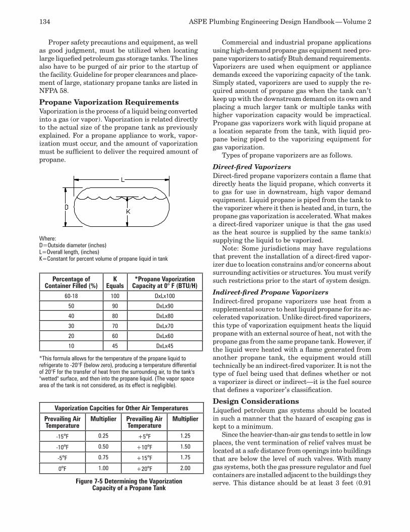
134 ASPE Plumbing Engineering Design Handbook — Volume 2
Proper safety precautions and equipment, as well as good judgment, must be utilized when locating large liquefied petroleum gas storage tanks. The lines also have to be purged of air prior to the startup of the facility. Guideline for proper clearances and place-ment of large, stationary propane tanks are listed in NFPA 58.
Propane Vaporization RequirementsVaporization is the process of a liquid being converted into a gas (or vapor). Vaporization is related directly to the actual size of the propane tank as previously explained. For a propane appliance to work, vapor-ization must occur, and the amount of vaporization must be sufficient to deliver the required amount of propane.
Commercial and industrial propane applications using high-demand propane gas equipment need pro-pane vaporizers to satisfy Btuh demand requirements. Vaporizers are used when equipment or appliance demands exceed the vaporizing capacity of the tank. Simply stated, vaporizers are used to supply the re-quired amount of propane gas when the tank can’t keep up with the downstream demand on its own and placing a much larger tank or multiple tanks with higher vaporization capacity would be impractical. Propane gas vaporizers work with liquid propane at a location separate from the tank, with liquid pro-pane being piped to the vaporizing equipment for gas vaporization.
Types of propane vaporizers are as follows.
Direct-fired VaporizersDirect-fired propane vaporizers contain a flame that directly heats the liquid propane, which converts it to gas for use in downstream, high vapor demand equipment. Liquid propane is piped from the tank to the vaporizer where it then is heated and, in turn, the propane gas vaporization is accelerated. What makes a direct-fired vaporizer unique is that the gas used as the heat source is supplied by the same tank(s) supplying the liquid to be vaporized.
Note: Some jurisdictions may have regulations that prevent the installation of a direct-fired vapor-izer due to location constrains and/or concerns about surrounding activities or structures. You must verify such restrictions prior to the start of system design.
Indirect-fired Propane VaporizersIndirect-fired propane vaporizers use heat from a supplemental source to heat liquid propane for its ac-celerated vaporization. Unlike direct-fired vaporizers, this type of vaporization equipment heats the liquid propane with an external source of heat, not with the propane gas from the same propane tank. However, if the liquid were heated with a flame generated from another propane tank, the equipment would still technically be an indirect-fired vaporizer. It is not the type of fuel being used that defines whether or not a vaporizer is direct or indirect—it is the fuel source that defines a vaporizer’s classification.
Design Considerations Liquefied petroleum gas systems should be located in such a manner that the hazard of escaping gas is kept to a minimum.
Since the heavier-than-air gas tends to settle in low places, the vent termination of relief valves must be located at a safe distance from openings into buildings that are below the level of such valves. With many gas systems, both the gas pressure regulator and fuel containers are installed adjacent to the buildings they serve. This distance should be at least 3 feet (0.91 Figure 7-5 Determining the Vaporization
Capacity of a Propane Tank
Percentage of Container Filled (%)
K Equals
*Propane Vaporization Capacity at 0° F (BTU/H)
60-18 100 DxLx100
50 90 DxLx90
40 80 DxLx80
30 70 DxLx70
20 60 DxLx60
10 45 DxLx45
Where: D=Outside diameter (inches)L=Overall length, (inches)K=Constant for percent volume of propane liquid in tank
Vaporization Capcities for Other Air Temperatures
Prevailing Air Temperature
Multiplier Prevailing Air Temperature
Multiplier
-15°F 0.25 +5°F 1.25
-10°F 0.50 +10°F 1.50
-5°F 0.75 +15°F 1.75
0°F 1.00 +20°F 2.00
*This formula allows for the temperature of the propane liquid to refrigerate to -20°F (below zero), producing a temperature differential of 20°F for the transfer of heat from the surrounding air, to the tank's "wetted" surface, and then into the propane liquid. (The vapor space area of the tank is not considered, as its effect is negligible).
Chapter 7 — Fuel Gas Piping Systems 135
meter) measured horizontally. However, the required clearances vary according to the tank size and adja-cent activities. Refer to local code requirements and NFPA 54 for these clearances.
When liquefied petroleum gas piping is proposed for installation within crawl spaces or utility pipe tunnels, you may consider secondary containment for the supply piping, whereby the gas pipe is installed within a larger pipe that is sealed and vented at both ends. A sniffer system also could be considered, which automatically shuts down the gas supply, sounds an alarm, and activates an exhaust system to purge the escaping gas from the area upon detection of gas in the space due to a breach in the piping system.
Liquefied Petroleum Gas SizingPropane gas piping systems shall be sized in accor-dance with the tables that have been developed by the model codes and NFPA 54 and 58. Tables based on an outlet pressure of 11 inches (280 millimeters) of water column would be suitable for interior piping. Tables based on higher outlet pressures are more suitable for site mains and distribution piping from the tank to the building entry point. Obtain or request the pressure provided by the supplier and determine the pressure drop in the piping system that would be appropriate. The AHJ shall be consulted regarding the acceptance of the pressure(s) selected.
For stationary propane tanks, sizing is accom-1. plished via the following steps:The total Btuh demand must be determined. 2. The total Btuh demand is the sum of all pro-pane gas usage in the system, determined by adding all of the Btu input ratings of the con-nected appliances. Future appliances also must be considered during this process and added to the system demand.Once the Btuh input quantities for all appli-3. ances are obtained, determine the Btu quantity used per day for each appliance. Then add up the total. The result will represent the Btu per day total for the system.Using the total Btu per day established in Step 4. 2, divide by approximately 91,502 (Btu per gallon of gas at 60°F) to obtain the gallons per day of propane required.The gallons per day quantity then is used to 5. establish the tank sizes in relation to tank fill-ing schedules. Typically, 14 days between tank fillings is acceptable; however, you will need to evaluate this figure based on the individual project requirements.Finally, once the tank sizes have been estab-6. lished, use the information contained in Figure 7-5 to determine (and verify) the vaporization capacity for the tank sizes proposed for use. If the tanks proposed for use cannot provide
sufficient vaporization, more tanks will need to be added or a vaporizer will need to be incorpo-rated to accommodate the appliance demands. (Note: This step can be performed first and, in conjunction with the Btuh demand, can be used to establish an estimation of the required tank size.)
For sizing propane piping distribution systems, the process is similar to natural gas as previously explained in the natural gas section of this chap-ter. Unlike natural gas systems, however, propane is heavier than air. Therefore, vertical sections of piping must be considered in the calculation of equivalent pipe lengths for determining allowable pressure drops.
GLOSSARYBoiling point The temperature of a liquid at which the internal vapor pressure is equal to the external pressure exerted on the surface of the liquid.
Btu Abbreviation for British thermal units, the quantity of heat required to raise the temperature of 1 pound of water by one degree Fahrenheit.
Burner A device used for the final conveyance of gas, or a mixture of gas and air, to the combustion zone.
Butane (C4H10) A saturated aliphatic hydrocarbon existing in two isomeric forms and used as a fuel and a chemical intermediate.
Caloric value See heating value.
Chimney A vertical shaft enclosing one or more flues for conveying flue gases to the outside atmosphere.
Condensate The liquid that separates from a gas (in-cluding flue gas) due to a reduction in temperature.
Cubic foot (meter) of gas The amount of gas that would occupy 1 cubic foot (cubic meter) at a tempera-ture of 60°F (15.6°C), saturated with water vapor, and under a pressure equivalent to that of 30 inches of mercury (101.3 kPa).
Demand The maximum amount of gas per unit time, usually expressed in cubic feet per hour (liters per minute) or Btu (watts) per hour, required for the operation of the appliance(s) supplied.
Dilution air Air that enters a draft hood or draft regulator and mixes with the flue gases.
Diversity factor The ratio of the maximum probable demand to the maximum possible demand.
Draft hood A device built into an appliance, or made a part of the vent connector from an appliance, that is designed to provide for the ready escape of the flue gases from the appliance in the event of no draft, back draft, or stoppage beyond the draft hood; prevent a back draft from entering the appliance; and neutralize
136 ASPE Plumbing Engineering Design Handbook — Volume 2
the effect of stack action of the chimney or gas vent upon the operation of the appliance.
Excess air Air passes through the combustion cham-ber and the appliance flues in excess of that which is theoretically required for complete combustion.
Flue gases The products of combustion plus the ex-cess air in appliance flues or heat exchangers (before the draft hood or draft regulator).
Fuel gas A gaseous compound used as fuel to gen-erate heat. It may be known variously as utility gas, natural gas, liquefied petroleum gas, propane, butane, methane, or a combination of the above. It has a caloric value that corresponds to the specific compound or combination of compounds. Care must be exercised in determining the caloric value for design purposes.
Gas log An unvented, open-flame room heater con-sisting of a metal frame or base supporting simulated logs designed for installation in a fireplace.
Gas train A series of devices pertaining to a fuel gas appliance located on the upstream side of the unit. Typically, it consists of a combination of devices and may include pipe, fittings, fuel, air-supervisory switches (pressure regulators), and safety shutoff valves.
Gas-train vent A piped vent to atmosphere from a device on a gas train.
Gas vent Factory-built vent piping and vent fittings listed by a nationally recognized testing agency, as-sembled and used in accordance with the terms of their listings, used for conveying flue gases to the outside atmosphere.
Type B gas vent A gas vent for venting gas appliances with draft hoods and other gas appliances listed for use with type B gas vents.
Type B-W gas vent A gas vent for venting listed gas-fired vented wall furnaces.
Type L gas vent A gas vent for venting gas appliances listed for use with type L vents.
Heating value (total) The number of British ther-mal units produced by the combustion, at constant pressure, of 1 cubic foot (cubic meter) of gas when the products of combustion are cooled to the initial tem-perature of the gas and air, the water vapor formed during combustion is condensed, and all the necessary corrections have been applied.
LPG Liquefied petroleum gas, a mixture of propane and butane.
Loads connected The sum of the rated Btu input to individual gas utilization equipment connected to
a piping system. It may be expressed in cubic feet (cubic meters) per hour.
Meter set assembly The piping and fittings installed by the gas supplier to connect the inlet side of the meter to the gas servi ce and the outlet side of the meter to the customer’s building or yard piping.
Pipe, equivalent length The resistance of valves, controls, and fittin gs to gas flow, expressed as equivalent length of straight pipe. In some cases, it is referred to as the developed pipe length.
Pressure drop The loss in static pressure due to fric-tion or obstruction during flow through pipe, valves, fittings, regulators, and burners.
Propane (C3H8) A gaseous hydrocarbon of the meth-ane series, found in petroleum.
Regulator, gas pressure A device for controlling and maintaining a uniform gas pressure. This pres-sure is always lower than the supply pressure at the inlet of the regulator.
Safety shutoff device A device that is designed to shut off the gas supply to the controlled burner or ap-pliance if the source of ignition fails. This device may interrupt the flow of gas to the main burner only or to the pilot and main burner under its supervision.
Specific gravity The ratio of the weight of a given volume of gas to that of the same volume of air, both measured under the same conditions.
Vent connector The portion of a venting system that connects the gas appliance to the gas vent, chimney, or single-wall metal pipe.
Vent gases The products of combustion from a gas appliance plus the excess air and the dilution air in the venting system above the draft hood or draft regulator.
REFERENCES ASHRAE Handbook—Fundamentals, 1. Ameri-can Society of Heating, Refrigerating, and Air-conditioning Engineers, 2009. ASME B31.2: 2. Fuel Gas Piping, American So-ciety of Mechanical Engineers. Compressed Air and Gas Data,3. Ingersoll-Rand Company, 1969. Uniform Plumbing Code, International Associ-4. ation of Plumbing and Mechanical Officials.Mechanical Engineering Reference Manual,5. 9th ed, Professional Publications, 1994. Piping Handbook6. , McGraw-Hill, 1998. NFPA 51B:7. Standard for Fire Prevention Dur-ing Welding, Cutting, and Other Hot Work, National Fire Protection Association.
Chapter 7 — Fuel Gas Piping Systems 137
NFPA 59: 8. Utility LP-Gas Plant Code, National Fire Protection Association.NFPA 54: 9. National Fuel Gas Code, National Fire Protection Association. NFPA 51: 10. Standard for the Design and Instal-lation of Oxygen-fuel Gas Systems for Welding, Cutting, and Allied Processes, National Fire Protection Association. NFPA 505: 11. Fire Safety Standard for Powered Industrial Trucks Including Type Designa-tions, Areas of Use, Conversions, Maintenance, and Operation, National Fire Protection As-sociation. U.S. Army Corps of Engineers Manual12. , EM-1110-34-166.
Frankel, M., 13. Facility Piping Systems Hand-book, McGraw Hill, 2002.NFPA 58: 14. Liquefied Petroleum Gas Code, Na-tional Fire Protection Association.Propane 101: propane101.com.15. LP-Gas Serviceman’s Manual16. , Engineered Controls International Inc.
DISCLAIMERThe material reproduced from the NFPA is not the official and complete position of the NFPA on the referenced subject, which is presented only by the standard in its entirety.

138 ASPE Plumbing Engineering Design Handbook — Volume 2
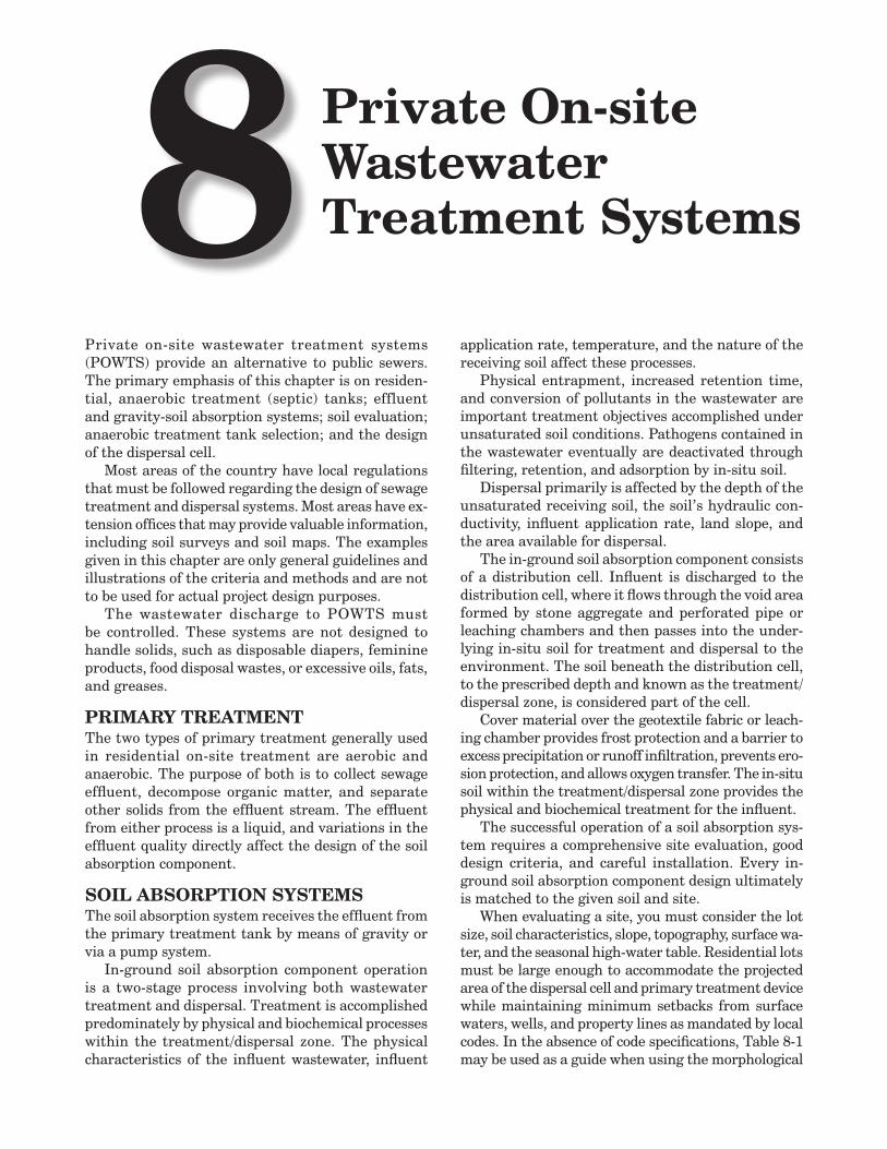
Private On-site Wastewater Treatment Systems8
Private on-site wastewater treatment systems (POWTS) provide an alternative to public sewers. The primary emphasis of this chapter is on residen-tial, anaerobic treatment (septic) tanks; effluent and gravity-soil absorption systems; soil evaluation; anaerobic treatment tank selection; and the design of the dispersal cell.
Most areas of the country have local regulations that must be followed regarding the design of sewage treatment and dispersal systems. Most areas have ex-tension offices that may provide valuable information, including soil surveys and soil maps. The examples given in this chapter are only general guidelines and illustrations of the criteria and methods and are not to be used for actual project design purposes.
The wastewater discharge to POWTS must be controlled. These systems are not designed to handle solids, such as disposable diapers, feminine products, food disposal wastes, or excessive oils, fats, and greases.
PRIMARY TREATMENTThe two types of primary treatment generally used in residential on-site treatment are aerobic and anaerobic. The purpose of both is to collect sewage effluent, decompose organic matter, and separate other solids from the effluent stream. The effluent from either process is a liquid, and variations in the effluent quality directly affect the design of the soil absorption component.
SOIL ABSORPTION SYSTEMSThe soil absorption system receives the effluent from the primary treatment tank by means of gravity or via a pump system.
In-ground soil absorption component operation is a two-stage process involving both wastewater treatment and dispersal. Treatment is accomplished predominately by physical and biochemical processes within the treatment/dispersal zone. The physical characteristics of the influent wastewater, influent
application rate, temperature, and the nature of the receiving soil affect these processes.
Physical entrapment, increased retention time, and conversion of pollutants in the wastewater are important treatment objectives accomplished under unsaturated soil conditions. Pathogens contained in the wastewater eventually are deactivated through filtering, retention, and adsorption by in-situ soil.
Dispersal primarily is affected by the depth of the unsaturated receiving soil, the soil’s hydraulic con-ductivity, influent application rate, land slope, and the area available for dispersal.
The in-ground soil absorption component consists of a distribution cell. Influent is discharged to the distribution cell, where it flows through the void area formed by stone aggregate and perforated pipe or leaching chambers and then passes into the under-lying in-situ soil for treatment and dispersal to the environment. The soil beneath the distribution cell, to the prescribed depth and known as the treatment/dispersal zone, is considered part of the cell.
Cover material over the geotextile fabric or leach-ing chamber provides frost protection and a barrier to excess precipitation or runoff infiltration, prevents ero-sion protection, and allows oxygen transfer. The in-situ soil within the treatment/dispersal zone provides the physical and biochemical treatment for the influent.
The successful operation of a soil absorption sys-tem requires a comprehensive site evaluation, good design criteria, and careful installation. Every in-ground soil absorption component design ultimately is matched to the given soil and site.
When evaluating a site, you must consider the lot size, soil characteristics, slope, topography, surface wa-ter, and the seasonal high-water table. Residential lots must be large enough to accommodate the projected area of the dispersal cell and primary treatment device while maintaining minimum setbacks from surface waters, wells, and property lines as mandated by local codes. In the absence of code specifications, Table 8-1 may be used as a guide when using the morphological
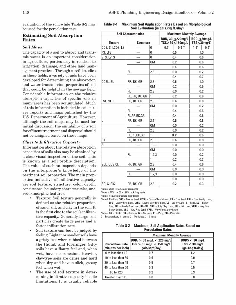
140 ASPE Plumbing Engineering Design Handbook — Volume 2
evaluation of the soil, while Table 8-2 may be used for the percolation test.
Estimating Soil Absorption Rates
Soil Maps The capacity of a soil to absorb and trans-mit water is an important consideration in agriculture, particularly in relation to irrigation, drainage, and other land man-agement practices. Through careful studies in these fields, a variety of aids have been developed for determining the absorption and water-transmission properties of soil that could be helpful in the sewage field. Considerable information on the relative absorption capacities of specific soils in many areas has been accumulated. Much of this information is included in soil sur-vey reports and maps published by the U.S. Department of Agriculture. However, although the soil maps may be used for initial discussion, the suitability of a soil for effluent treatment and dispersal should not be assigned based on these maps.
Clues to Infiltrative Capacity Information about the relative absorption capacities of soils also may be obtained by a close visual inspection of the soil. This is known as a soil profile description. The value of such an inspection depends on the interpreter’s knowledge of the pertinent soil properties. The main prop-erties indicative of infiltrative capacity are soil texture, structure, color, depth, consistence, boundary characteristics, and redoximorphic features.
Texture:• Soil texture generally is defined as the relative proportion of sand, silt, and clay in the soil. It is the first clue to the soil’s infiltra-tive capacity. Generally large soil particles create large pores and a faster infiltration rate.Soil texture can best be judged by •feeling. Lighter or sandier soils have a gritty feel when rubbed between the thumb and forefinger. Silty soils have a floury feel and, when wet, have no cohesion. Heavier, clay-type soils are dense and hard when dry and have a slick, greasy feel when wet.The use of soil texture in deter-•mining infiltrative capacity has its limitations. It is usually reliable
Table 8-1 Maximum Soil Application Rates Based on Morphological Soil Evaluation (in gals./sq.ft./day)
Soil Characteristics Maximum Monthly Average
Texture StructureBOD5 30-<220mg/LTSS>30<150mg/L
BOD5<30mg/LTSS<30mg/Lc
COS, S, LCOS, LS — 0 0.7a 0.5 b,c 1.6a 0.5b
FS, LFS — 0 0.5 1.0VFS, LVFS — 0 0.4 0.6
COSL, SL
— OM 0.2 0.6
PL1 0.4 0.62,3 0.0 0.2
PR, BK, GR1 0.4 0.72,3 0.6 1.0
FSL, VFSL
— OM 0.2 0.5PL 2,3 0.0 0.2PL, PR, BK, GR 1 0.2 0.6PR, BK, GR 2,3 0.6 0.8
L
— OM 0.0 0.2PL 1 0.4 0.6PL,PR,BK,GR 1 0.4 0.6PR, BK, GR 2,3 0.6 0.8
SIL
— OM 0.0 0.2PL 2,3 0.0 0.2PL,PR,BK,GR 1 0.4c 0.6PR, BK, GR 2,3 0.6 0.8
SI — — 0.0 0.0
SCL, CL SICL
— OM 0.0 0.0PL 1,2,3 0.0 0.2
PR, BK, GR1 0.2 0.32,3 0.4 0.6
SC, C, SIC
— OM 0.0 0.0PL 1,2,3 0.0 0.0
PR, BK, GR1 0.0 0.02,3 0.2 0.3
Note a: With < 60% rock fragmentsNotes b: With > 60 < 90% rock fragmentsNote c: Requires pressure distributionNote d: C – Clay, COS – Coarse Sand, COSL – Coarse Sandy Loam, FS – Fine Sand, FSL – Fine Sandy Loam,
LFS – Loamy Fine Sand, LVFS – Loamy Very Fine Sand, LS – Loamy Sand, S – Sand, SC – Sandy Clay, SCL – Sandy Clay Loam, SI – Silt, SICL – Silty Clay Loam, SIL – Silt Loam, VFSL – Very Fine Sandy Loam , VFS – Very Fine Sand, VFSL – Very Fine Sandy Loam
Note e: BK – Blocky, GR – Granular, M – Massive, PL – Platy, PR – Prismatic,0 – Structureless, 1– Weak, 2 – Moderate, 3 – Strong
Table 8-2 Maximum Soil Application Rates Based on Percolation Rates
Percolation Rate(minutes per inch)
Maximum Monthly AverageBOD5 > 30 mg/L < 220 mg/LTSS > 30 mg/L < 150 mg/L
(gals/sq ft/day)
BOD5 < 30 mg/LTSS < 30 mg/L(gals/sq ft/day)
0 to less than 10 0.7 1.210 to less than 30 0.6 0.930 to less than 45 0.5 0.745 to less than 60 0.3 0.5
60 to 120 0.2 0.3Greater than 120 0.0 0.0

Chapter 8 — Private On-site Wastewater Treatment Systems 141
for lighter soils. However, with heavier soils (including sandy soils containing appreciable amounts of silt or clay), you must look for additional clues, such as structure and soil color.Structure:• Soil structure is characterized by the aggregation (or grouping together) of textural particles to form secondary par-ticles of a larger size. The structure can be recognized by the manner in which a clod, or lump, breaks apart. If a soil has well defined structure, a clod will break with very little force, along well-defined cleavage planes, into uniformly sized units. If a soil has no structure, or is structureless, it may flow like beach sand or hold together like a massive block of clay.In general, the four fundamental structural •types, named according to the shape of the aggregate particles, are platy, prism-like, block-like, and spherical. The spherical structure tends to provide the most favorable infiltrative properties, and the platy structure tends to provide the least favorable. Although other factors, such as the size and stability of the aggregates in water, also influence the infiltrative capacity of the soil, recognition of the type of structure is probably sufficient for a general appraisal.Color:• Another clue to the infiltrative capac-ity of soil is its color. Most soils contain some iron compounds, which, if alternately exposed to air and water, oxidizes and takes on a reddish-brown or yellow color. Thus, if the soil has a uniform reddish-brown to yellow oxidized color, air and water most likely have been freely and alternatively moving in and through the soil. Such a soil has some desir-able infiltrative characteristics. At the other extreme, a dull gray or mottled soil coloring indicates a lack of oxidizing conditions or a very restricted movement of air and water through the soil. Mottled soils may indicate poor infiltrative characteristics.Depth (or thickness) of permeable strata:• The quantity of water that may be infiltrated into the soil frequently is proportional to the thick-ness (or volume) of the soil horizon. With a soil having 1 foot (0.3 meter) or more of perme-able material above tight clay, the infiltrative capacity is far greater than it is in a soil hav-ing the same kind of material lying within 2 inches (50.8 millimeters) of tight clay.
Procedure for Percolation Tests
Although the requirement for a percolation test is be-ing replaced by the soil evaluation report, you should
consult the authority having jurisdiction (AHJ) to ascertain whether the perc test is required. (Note: The procedure for percolation tests described in this chapter was developed at the Robert A. Taft Co.)
Several types (procedures) of percolation test may be acceptable to the AHJ, or there may be no standards. In the absence of standards, the following method of conducting a percolation test may be used.
Six or more tests should be made in separate test holes, spaced uniformly over the proposed absorp-tion field site.
Dig or bore a hole with horizontal dimensions varying from 4 to 12 inches (101.6 to 304.8 millime-ters) and vertical sides to the depth of the proposed absorption trench. To save time, labor, and water per test, the holes can be bored with a 4-inch (101.6-millimeter) auger.
Carefully scratch the bottom and sides of the hole with a knife blade or a sharp-pointed instrument to re-move any smeared soil surfaces and provide a natural soil interface into which water may percolate. Remove all loose material from the hole. Add 2 inches (50.8 millimeters) of coarse sand or fine gravel to protect the bottom from scouring and sediment.
To conduct the test, carefully fill the hole with clear water to a minimum depth of 12 inches (304.8 millimeters) over the gravel. In most soils, it is neces-sary to refill the hole by supplying a surplus reservoir of water, possibly by means of an automatic siphon, to keep water in the hole for at least four hours and preferably overnight. This procedure ensures that the soil is given ample opportunity to swell and to approach the condition it will have during the wettest season of the year. Thus, tests of the same soil give comparable results, whether they are made in a dry or wet season.
It is important to distinguish between saturation and swelling. Saturation means that the void spaces between soil particles are full of water. This can be accomplished in a short period. Swelling is caused by the intrusion of water into individual soil particles. This is a slow process, especially in clay-type soils, and it is the reason that a prolonged soaking period is required.
In sandy soils containing little or no clay, the swell-ing procedure is not essential. Therefore, in these soils there is no need to refill the hole with water.
With the exception of sandy soils, the percolation rate measurement should be made on the day following the procedure described above, 24 hours after water is first added to the hole. For sandy soils, the percolation rate measurement may be taken after the water from one filling of the hole has completely seeped away.
If the water remains in the test hole after the overnight swelling period, adjust the depth to approxi-mately 6 inches (152.4 millimeters) over the gravel.

142 ASPE Plumbing Engineering Design Handbook — Volume 2
From a fixed reference point, measure the drop in the water level over a 30-minute period. This drop is used to calculate the percolation rate.
If no water remains in the hole after the overnight swelling period, add clear water to bring the depth of the water in the hole to ap-proximately 6 inches (152.4 millimeters) over the gravel. From a fixed reference point, measure the drop in the wa-ter level at approximately 30-minute intervals for four hours, refilling to 6 inches (152.4 millimeters) over the gravel as necessary. The drop that occurs during the final 30-minute period is used to calculate the percola-tion rate of the soil. Any drop during the prior period provides the information for a possible modification of the procedure to suit local circumstances.
In sandy soils—and in types of soil in which the first 6 inches (152.4 millimeters) of water seep away in fewer than 30 minutes after the overnight swelling period—the time interval between the measurements should be 10 minutes and the test should be run for one hour. The drop that occurs during the final 10 minutes is used to calculate the percolation rate.
Soil Absorption System SelectionFor areas where the percolation rates and/or soil characteristics are acceptable, the next step after conducting a soil and site evaluation is to determine the absorption system suitable for the site.
For unsuitable sites, the installation of a tradi-tional soil absorption system is impossible, and you must consider alternative types of absorption systems, such as mounds, at-grades, or shallow subsurface ir-rigation. If none of these alternatives is acceptable, you may have to consider the use of a sewage lift sta-tion to pump the wastewater to a public sewer system or wastewater treatment plant, a holding tank, or a private wastewater treatment plant.
Selection of the appropriate absorption system de-pends to some extent on the location of the system in the area under consideration. A safe distance should be maintained between the system’s site and any wa-ter supply source or other physical feature that may be impacted by the POWTS or may impact the operation of the POWTS. Since the distance that pollution may travel underground depends on numerous factors, including the char-acteristics of subsoil formations and the quality of the sewage discharged, no specified distance is absolutely safe in all localities. Ordinarily, a greater
distance means greater safety provided. The location of the components of sewage disposal systems shall be as required by local codes. In their absence, Table 8-3 may be used as a guide.
Details pertaining to local water wells—such as depth, type of construction, and vertical zone of influence—and data on geological formations and the porosity of the subsoil strata should be considered when determining the allowable distance between wells and subsurface disposal systems.
In-ground Conventional Soil Absorption SystemAn in-ground soil absorption system routinely con-sists of a bed constructed of aggregate or placed within a chamber. In either installation, a void is created to allow for storage of the partially treated effluent. Piping may be installed within the void to serve as a
Figure 8-1 Three Legs of Disposal Field Fed from Cross Fitting Laid on Its Side
Figure 8-2 Disposal Lines Connected by Headers to Circumvent Stoppages
Table 8-3 Recommended Setbacks for Soil Absorption Systems
Physical FeaturePOWTS Soil
Absorption System
Exterior Subsurface Treatment Tank or
Holding Tank
Servicing, Suction Lines and Pump Discharge Lines
Building 10 feet 5 feet NoneProperty Line 5 feet 2 feet 2 feetSwimming Pool 15 feet None NoneHigh Water Mark of Navigable Water 50 feet 10 feet 10 feetWater Service or Private Water Main 10 feet 10 feet 10 feetPublic Water Main 8 feet 8 feet 8 feetPublic Well 400 feet 400 feet 200 feetPrivate Well 50 feet 25 feet 25 feet
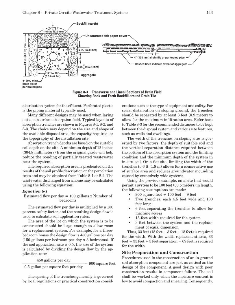
Chapter 8 — Private On-site Wastewater Treatment Systems 143
distribution system for the effluent. Perforated plastic is the piping material typically used.
Many different designs may be used when laying out a subsurface absorption field. Typical layouts of absorption trenches are shown in Figures 8-1, 8-2, and 8-3. The choice may depend on the size and shape of the available disposal area, the capacity required, or the topography of the installation site.
Absorption trench depths are based on the suitable soil depth on the site. A minimum depth of 12 inches (304.8 millimeters) from the original grade will help reduce the ponding of partially treated wastewater near the system.
The required absorption area is predicated on the results of the soil profile description or the percolation tests and may be obtained from Table 8-1 or 8-2. The wastewater discharged from a home may be calculated using the following equation:
Equation 8-1Estimated flow per day = 100 gallons x Number of
bedrooms
The estimated flow per day is multiplied by a 150 percent safety factor, and the resulting design flow is used to calculate soil application rates.
The area of the lot on which the system is to be constructed should be large enough to allow room for a replacement system. For example, for a three-bedroom house the design flow is 450 gallons per day (150 gallons per bedroom per day x 3 bedrooms). If the soil application rate is 0.5, the size of the system is calculated by dividing the design flow by the ap-plication rate:
450 gallons per day= 900 square feet
0.5 gallon per square foot per day
The spacing of the trenches generally is governed by local regulations or practical construction consid-
erations such as the type of equipment and safety. For serial distribution on sloping ground, the trenches should be separated by at least 3 feet (0.9 meter) to allow for the maximum infiltration area. Refer back to Table 8-3 for the recommended distances to be kept between the disposal system and various site features, such as wells and dwellings.
The width of the trenches on sloping sites is gov-erned by two factors: the depth of suitable soil and the vertical separation distance required between the bottom of the absorption system and the limiting condition and the minimum depth of the system in in-situ soil. On a flat site, limiting the width of the trenches to 6 ft (1.8 m) allows for a conservative use of surface area and reduces groundwater mounding caused by excessively wide systems.
Using the previous example, on a site that would permit a system to be 100 feet (30.5 meters) in length, the following assumptions are made:
900 square feet ÷ 100 feet = 9 feet•Two trenches, each 4.5 feet wide and 100 •feet long6 feet separating the trenches to allow for •machine access15-foot width required for the system•3 feet between the system and the replace-•ment of equal dimension
Thus, 33 feet (15 feet + 3 feet + 15 feet) is required for the width. With the width replacement area, 33 feet + 33 feet + 3 feet separation = 69 feet is required for the width.
Site Preparation and ConstructionProcedures used in the construction of an in-ground soil absorption component are just as critical as the design of the component. A good design with poor construction results in component failure. The soil shall be worked only when the moisture content is low to avoid compaction and smearing. Consequently,
Figure 8-3 Transverse and Lineal Sections of Drain Field Showing Rock and Earth Backfill around Drain Tile
144 ASPE Plumbing Engineering Design Handbook — Volume 2
installations are to be made only when the soil is dry enough to prevent compaction and smearing of the infiltrative surface. Proper equipment includes trac-tors or other equipment that will not compact the infiltrative surface. Foot traffic on the infiltrative surface should be minimal, and equipment traffic on or over the infiltrative surface should be avoided.
The construction plan to be followed includes the following procedures:
Check the moisture content and condition of 1. the soil. If the soil at the infiltrative surface can be rolled into a ¼-inch wire, the site is too wet. Smearing and compaction will result, thus reducing the infiltrative capacity of the soil. If the site is too wet, do not proceed until it dries out. If the soil at or below the infiltrative surface is frozen, do not proceed.Set up a construction level or similar device 2. and determine all relative elevations in rela-tionship to the benchmark. It is necessary to determine the bottom elevation of the distri-bution cell, land surface contour lines, and approximate component elevations critical to the installation.Lay out the absorption area within the tested 3. designated area. Where possible, lay out the absorption areas on the site so that the distri-bution cell runs parallel with the land surface contours. Reference stakes offset from the corner stakes are recommended in case corner stakes are disturbed during construction.Excavate the distribution cells to the correct 4. bottom elevations, taking care not to smear the infiltrative surface. If the infiltrative surface or sidewalls are smeared, loosen them with the use of a rake or similar device. The infiltration surface can be left rough and should not be raked smooth.Install observation pipes with the bottom 6 5. inches (152.4 millimeters) of the pipe slotted for components using stone aggregate. When leaching chambers are installed, the observa-tion pipe connects to the top of the leaching chamber. The observation pipes are located at opposite ends of the distribution cell. Each ob-servation pipe is located one-fifth to one-tenth the length of the distribution cell measured from the end of the cell. Installation of the observation pipe includes a suitable means of anchoring so the pipes are not dislodged dur-ing inspections.If stone aggregate is used, place it into the 6. excavated area until the top of the stone ag-gregate is at the elevation of the distribution piping. Placement of the stone aggregate is done in such a manner as not to compact the
infiltrative surface. If leaching chambers are used, install the leaching chambers in accor-dance with the manufacturer’s installation instructions.Place the distribution pipes, as determined 7. from the design, on the stone aggregate. Connect the distribution box, drop box, or manifold to the pipe from the treatment or dosing chamber.Install a vent pipe, if one is to be installed.8. If stone aggregate is used, place stone aggre-9. gate over the distribution pipe and the entire distribution cell until the elevation of the stone aggregate is at least 2 inches (50.8 millimeters) above the top of the distribution pipe.If stone aggregate is used, place geotextile 10. fabric over the stone aggregate.Place the cover material on top of the geotextile 11. fabric and/or leaching chamber. Avoid backfill-ing the first 12 inches (304.8 millimeters) with cobbles, stones, or frozen material that could damage the pipe, chamber, or fabric.
COLLECTION AND TREATMENT ALTERNATIVES
Alternatives to Gravity Collection and DistributionIf a gravity piping system is not possible, pumped systems are used. Alternatives to the typical grav-ity collection and distribution system that should be evaluated include small-diameter gravity sewers, pressure sewers, and vacuum sewers.
If the septic tank receives effluent other than raw wastes, small-diameter pipe (4 inches [101.6 milli-meters] nominal) may be used to reduce the cost of conventional gravity sewers. The individual septic tanks should partially treat the wastewater by decom-position of the larger particles and permit sand and grit to settle. The 4-inch (101.6-millimeter) mains should be installed at a minimum gradient of 0.67 percent based on a minimum velocity of 1.5 feet per second (0.5 meter per second) at half-pipe flow capacity. Under these conditions, using the Manning Formula, a 4-inch (101.6-millimeter) pipe can carry more than 2,000 gal-lons per hour (gph) (2.1 liters per second), sufficient to serve 670 people (assuming a peak flow of 3 gph [3.2 milliliters per second] per person).
Pressure sewer systems generally consist of septic tanks at each facility, a small submersible pump, and small-diameter plastic mains. Grinder pumps may be placed in the septic tank. Construction costs are re-duced because the sewer main can follow the contour of the land just below the frost line.
Vacuum transport systems consist of a vacuum pump, a receiving tank (held at approximately 7.5 pounds per square inch absolute (psia) [51.7 kilopascals
Chapter 8 — Private On-site Wastewater Treatment Systems 145
(kPa)]), and a vacuum valve. When there is sufficient sewage in the lateral and the vacuum is at the proper level, the valve will open, and the sewage will enter as a slug. The slug of wastewater will move toward the receiving tank until the dispersal of the slug results in a break in the seal, thus ending the vacuum effect. Traps should be placed at regular intervals in the mains to reshape the slugs. When the trap fills, the vacuum effect is reestablished, causing the slug to continue toward the receiving tank with the next operation of the valve. Vacuum sewers flow full and provide many of the advantages of pressure sewers.
Alternatives to Conventional Primary and Secondary TreatmentThe alternatives to conventional primary and secondary treatment include sand filtration and evapotranspiration. Sand filters have been used in sewage treatment for many years. More recently, standard systems have been modified to recirculating sand filter systems, which have demonstrated that, if properly designed, installed, and operated, they can produce effluents that meet stringent effluent and stream-quality standards. Evapotranspiration as a means of disposing of domestic wastes has been researched at several locations, and its use has been accepted by various local jurisdictions. However, this type of system is rarely used.
The use of self-contained sewage treatment plants, particularly the tertiary treatment type, has found wide acceptance for facilities. Though this method is outside the scope of this chapter, it is discussed briefly in the section on individual aerobic wastewater treatment plants.
SEPTIC TANKSIf the lot is large enough to accommodate one of the previously discussed types of absorption system and construction of the system is permitted by the AHJ, the next step is the selection of a suitable septic tank.
Functions of the Septic TankUntreated liquid household effluent consists of both solids and liquids. If both were discharged directly into the seepage beds or trenches, the beds or trenches eventually would clog. The septic tank is a device that protects the beds by separating solids from liquids. The solids are retained in the septic tank so that only liquid is discharged to be percolated into the ground.
To provide this protection, two functions take place within the septic tank:
Biological treatment:1. Sewage effluent (fecal matter) is subjected to decomposition by natu-ral, bacterial processes. The bacteria present in the liquid are anaerobic (i.e., they thrive in the absence of free oxygen). This decomposition, or treatment, of the sewage under anaerobic
conditions is termed septic, hence the name of the tank.Solids removal:2. Sludge is defined as an accu-mulation of solids at the bottom of the septic tank. Scum is a partially submerged mat of floating solids that forms at the surface of the fluid in the septic tank. Some sludge and scum are decomposed. The residual material, com-posed of inert solid materials, remains. After a period of time, these solids, including all types of grease, must be pumped out. Space must be provided in the septic tank to store this residue between cleanings; otherwise, sludge and scum eventually will be scoured from the septic tank and may clog the disposal field.
The heavier sewage solids settle to the bottom of the septic tank, forming a blanket of sludge. The lighter solids, including fat and grease, rise to the surface and form a layer of scum. A considerable amount of the sludge and scum is liquefied through decomposition or digestion. During this process, gas is liberated from the sludge and carries some solids to the surface, where they accumulate with the scum. Ordinarily, they undergo further digestion in the scum layer, and a portion settles again to the sludge blanket at the bottom. This action is retarded if a con-siderable amount of grease is in the scum layer. The settling also is retarded in small septic tanks because of the gasification due to fluctuations of flow, which are relatively wider in smaller septic tanks than in larger ones. This effect is reflected in Table 8-4, which shows the recommended minimum liquid capacities of household septic tanks.
As wastewater enters the septic tank, effluent is forced out of the tank into the drain field. Although the effluent is liquid, some solids remain in suspen-sion. These solids are digested further by the soil as the liquid effluent trickles out of the drain piping into trenches and the surrounding absorption field.
Septic Tank Materials Septic tanks should be watertight and constructed of materials not subject to excessive corrosion or decay. Concrete, fiberglass, and coated metal commonly are used. Properly cured, precast, and cast-in-place reinforced-concrete septic tanks are acceptable by most jurisdictions. Special attention should be given to job-built septic tanks to ensure that they are wa-tertight. Heavyweight concrete block should be laid on a solid concrete foundation. Mortar joints should be surfaced with two ¼-inch (6.4-millimeter) coats of portland cement/sand plaster.
Precast septic tanks should have a minimum wall thickness of 3 inches (76.2 millimeters) and should be adequately reinforced to facilitate their handling. When precast slabs are used as covers, they should be watertight, have a thickness of at least 4 inches
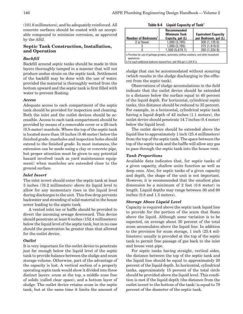
146 ASPE Plumbing Engineering Design Handbook — Volume 2
(101.6 millimeters), and be adequately reinforced. All concrete surfaces should be coated with an accept-able compound to minimize corrosion, as approved by the AHJ.
Septic Tank Construction, Installation, and Operation
BackfillBackfill around septic tanks should be made in thin layers thoroughly tamped in a manner that will not produce undue strain on the septic tank. Settlement of the backfill may be done with the use of water, provided the material is thoroughly wetted from the bottom upward and the septic tank is first filled with water to prevent floating.
AccessAdequate access to each compartment of the septic tank should be provided for inspection and cleaning. Both the inlet and the outlet devices should be ac-cessible. Access to each tank compartment should be provided by means of a removable cover or a 20-inch (0.5-meter) manhole. Where the top of the septic tank is located more than 18 inches (0.46 meter) below the finished grade, manholes and inspection holes should extend to the finished grade. In most instances, the extension can be made using a clay or concrete pipe, but proper attention must be given to any potential hazard involved (such as yard maintenance equip-ment) when manholes are extended close to the ground surface.
Inlet InvertThe inlet invert should enter the septic tank at least 3 inches (76.2 millimeters) above its liquid level to allow for any momentary rises in the liquid level during discharges to the unit. This free drop prevents backwater and stranding of solid material in the house sewer leading to the septic tank.
A vented inlet tee or baffle should be provided to divert the incoming sewage downward. This device should penetrate at least 6 inches (152.4 millimeters) below the liquid level of the septic tank, but in no case should the penetration be greater than that allowed for the outlet device.
Outlet It is very important for the outlet device to penetrate just far enough below the liquid level of the septic tank to provide balance between the sludge and scum storage volume. Otherwise, part of the advantage of the capacity is lost. A vertical section of a properly operating septic tank would show it divided into three distinct layers: scum at the top, a middle zone free of solids (called clear space), and a bottom layer of sludge. The outlet device retains scum in the septic tank, but at the same time it limits the amount of
sludge that can be accommodated without scouring (which results in the sludge discharging in the efflu-ent from the septic tank).
Observations of sludge accumulations in the field indicate that the outlet device should be extended to a distance below the surface equal to 40 percent of the liquid depth. For horizontal, cylindrical septic tanks, this distance should be reduced to 35 percent. For example, in a horizontal, cylindrical septic tank having a liquid depth of 42 inches (1.1 meters), the outlet device should penetrate 14.7 inches (0.4 meter) below the liquid level.
The outlet device should be extended above the liquid line to approximately 1 inch (25.4 millimeters) from the top of the septic tank. The space between the top of the septic tank and the baffle will allow any gas to pass through the septic tank into the house vent.
Tank Proportions Available data indicates that, for septic tanks of a given capacity, shallow units function as well as deep ones. Also, for septic tanks of a given capacity and depth, the shape of the unit is not important. However, it is recommended that the smallest plan dimension be a minimum of 2 feet (0.6 meter) in length. Liquid depths may range between 30 and 60 inches (0.8 and 1.5 meters).
Storage Above Liquid Level Capacity is required above the septic tank liquid line to provide for the portion of the scum that floats above the liquid. Although some variation is to be expected, on average about 30 percent of the total scum accumulates above the liquid line. In addition to the provision for scum storage, 1 inch (25.4 mil-limeters) usually is provided at the top of the septic tank to permit free passage of gas back to the inlet and house vent pipe.
For septic tanks having straight, vertical sides, the distance between the top of the septic tank and the liquid line should be equal to approximately 20 percent of the liquid depth. In horizontal, cylindrical tanks, approximately 15 percent of the total circle should be provided above the liquid level. This condi-tion is met if the liquid depth (the distance from the outlet invert to the bottom of the tank) is equal to 79 percent of the diameter of the septic tank.
Table 8-4 Liquid Capacity of Tanka
Number of Bedroomsb
Recommended Minimum Tank Capcity, gal (L)
Equivalent Capacity per Bedroom, gal (L)
2 or fewer 1,000 (3,785) 300 (1,135.6)3 1,000 (3,785) 375 (1,419.5)4 1,500 (5,678.1) 350 (1,324.9)
a Provides for use of garbage grinders, automatic clothes washers, and other household appliances.
b For each additional bedroom beyond four, add 350 gal (1,324.9 L).
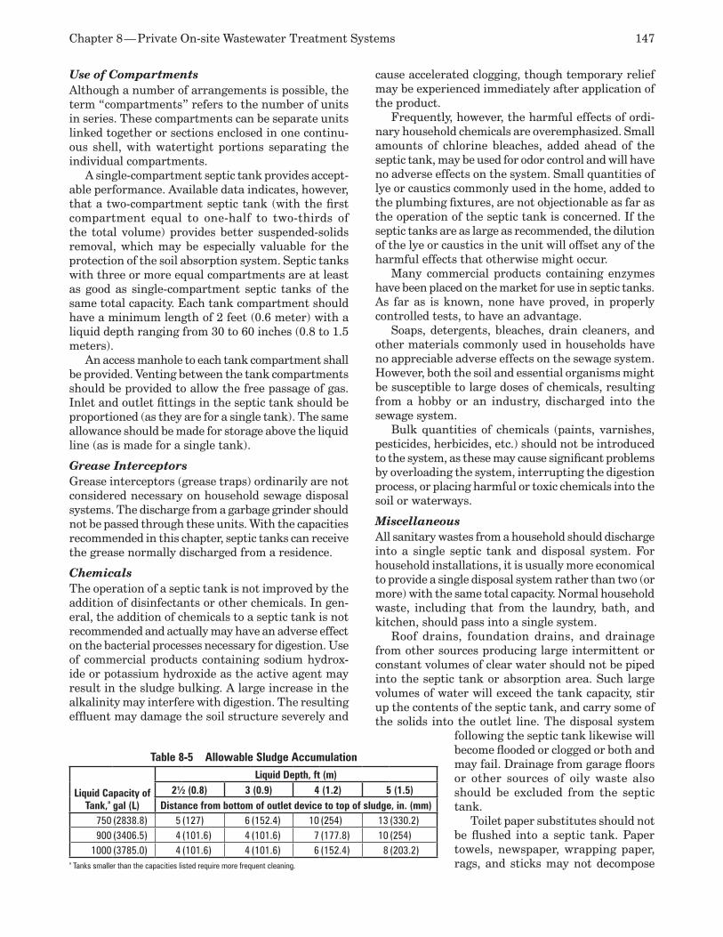
Chapter 8 — Private On-site Wastewater Treatment Systems 147
Use of Compartments Although a number of arrangements is possible, the term “compartments” refers to the number of units in series. These compartments can be separate units linked together or sections enclosed in one continu-ous shell, with watertight portions separating the individual compartments.
A single-compartment septic tank provides accept-able performance. Available data indicates, however, that a two-compartment septic tank (with the first compartment equal to one-half to two-thirds of the total volume) provides better suspended-solids removal, which may be especially valuable for the protection of the soil absorption system. Septic tanks with three or more equal compartments are at least as good as single-compartment septic tanks of the same total capacity. Each tank compartment should have a minimum length of 2 feet (0.6 meter) with a liquid depth ranging from 30 to 60 inches (0.8 to 1.5 meters).
An access manhole to each tank compartment shall be provided. Venting between the tank compartments should be provided to allow the free passage of gas. Inlet and outlet fittings in the septic tank should be proportioned (as they are for a single tank). The same allowance should be made for storage above the liquid line (as is made for a single tank).
Grease Interceptors Grease interceptors (grease traps) ordinarily are not considered necessary on household sewage disposal systems. The discharge from a garbage grinder should not be passed through these units. With the capacities recommended in this chapter, septic tanks can receive the grease normally discharged from a residence.
Chemicals The operation of a septic tank is not improved by the addition of disinfectants or other chemicals. In gen-eral, the addition of chemicals to a septic tank is not recommended and actually may have an adverse effect on the bacterial processes necessary for digestion. Use of commercial products containing sodium hydrox-ide or potassium hydroxide as the active agent may result in the sludge bulking. A large increase in the alkalinity may interfere with digestion. The resulting effluent may damage the soil structure severely and
cause accelerated clogging, though temporary relief may be experienced immediately after application of the product.
Frequently, however, the harmful effects of ordi-nary household chemicals are overemphasized. Small amounts of chlorine bleaches, added ahead of the septic tank, may be used for odor control and will have no adverse effects on the system. Small quantities of lye or caustics commonly used in the home, added to the plumbing fixtures, are not objectionable as far as the operation of the septic tank is concerned. If the septic tanks are as large as recommended, the dilution of the lye or caustics in the unit will offset any of the harmful effects that otherwise might occur.
Many commercial products containing enzymes have been placed on the market for use in septic tanks. As far as is known, none have proved, in properly controlled tests, to have an advantage.
Soaps, detergents, bleaches, drain cleaners, and other materials commonly used in households have no appreciable adverse effects on the sewage system. However, both the soil and essential organisms might be susceptible to large doses of chemicals, resulting from a hobby or an industry, discharged into the sewage system.
Bulk quantities of chemicals (paints, varnishes, pesticides, herbicides, etc.) should not be introduced to the system, as these may cause significant problems by overloading the system, interrupting the digestion process, or placing harmful or toxic chemicals into the soil or waterways.
Miscellaneous All sanitary wastes from a household should discharge into a single septic tank and disposal system. For household installations, it is usually more economical to provide a single disposal system rather than two (or more) with the same total capacity. Normal household waste, including that from the laundry, bath, and kitchen, should pass into a single system.
Roof drains, foundation drains, and drainage from other sources producing large intermittent or constant volumes of clear water should not be piped into the septic tank or absorption area. Such large volumes of water will exceed the tank capacity, stir up the contents of the septic tank, and carry some of the solids into the outlet line. The disposal system
following the septic tank likewise will become flooded or clogged or both and may fail. Drainage from garage floors or other sources of oily waste also should be excluded from the septic tank.
Toilet paper substitutes should not be flushed into a septic tank. Paper towels, newspaper, wrapping paper, rags, and sticks may not decompose
Table 8-5 Allowable Sludge Accumulation
Liquid Capacity of Tank,a gal (L)
Liquid Depth, ft (m)2½ (0.8) 3 (0.9) 4 (1.2) 5 (1.5)
Distance from bottom of outlet device to top of sludge, in. (mm)750 (2838.8) 5 (127) 6 (152.4) 10 (254) 13 (330.2)900 (3406.5) 4 (101.6) 4 (101.6) 7 (177.8) 10 (254)
1000 (3785.0) 4 (101.6) 4 (101.6) 6 (152.4) 8 (203.2)a Tanks smaller than the capacities listed require more frequent cleaning.
148 ASPE Plumbing Engineering Design Handbook — Volume 2
in the septic tank and are likely to lead to clogging of the plumbing and disposal systems.
Waste brines from household water softener units may have an adverse effect on the action of the septic tank, shortening the life of a sewage disposal field installed in a structured clay-type soil.
Adequate venting is obtained through the building plumbing system if the septic tank and the plumbing system are designed and installed properly. A separate vent on a septic tank is not necessary.
A chart showing the location of the septic tank and disposal system should be placed in a suitable loca-tion in the buildings served by the system. Whether furnished by the builder, septic tank installer, or local health department, the chart should contain instruc-tions on the inspection and maintenance required for the septic tank. This chart will help acquaint hom-eowners with the necessary maintenance procedures that septic tanks require, thus forestalling failures of the unit by ensuring satisfactory operation. Extension of the septic tank’s manholes or inspection holes to within 8 inches (203.2 millimeters) of the ground surface will simplify maintenance and cleaning. Records must be retained, including all performed maintenance.
Abandoned tanks should be filled with earth or rock.
Cleaning Septic TanksSeptic tanks should be cleaned before too much sludge or scum accumulates. If the sludge or scum approaches the bottom of the outlet pipe, solids will be discharged through the outlet device into the sew-age disposal field and will clog the system. When this condition occurs, eventually the liquid may break through to the ground surface, and the sewage may back up the plumbing fixtures. When a disposal field is clogged in this manner, it is necessary to clean the septic tank, and it also may be necessary to construct a new disposal field.
The tank capacities recommended in Table 8-4 provide a reasonable period of good operation before cleaning becomes necessary. However, due to the wide range in the rates at which sludge and scum ac-cumulate, the tank should be inspected at least once per year and cleaned as necessary.
Although it is a difficult task for most homeowners, actual inspection of sludge and scum accumulations is the only way to determine when a septic tank needs to be pumped. When a septic tank is inspected, the depth of the sludge and scum should be measured in the vicinity of the outlet baffle. The septic tank should be cleaned if the bottom of the scum mat is within 3 inches (76.2 millimeters) of the bottom of the outlet device or the sludge comes within the limits specified in Table 8-5.
Scum can be measured with a stick to which a weighted flap has been hinged or with a device used to feel the bottom of the scum mat. The stick is forced through the scum mat, and the hinged flap falls into a horizontal position. The stick then is raised until resistance from the bottom of the scum is felt. With the same tool, the distance to the bottom of the outlet device can be determined.
A long stick wrapped with rough, white toweling and lowered to the bottom of the septic tank will show the depth of sludge and the liquid level of the septic tank. The stick should be lowered behind the outlet device to avoid scum particles. After several minutes, if the stick is carefully removed, the sludge line can be distinguished by the sludge particles clinging to the toweling.
In most communities where septic tanks are used, companies are engaged in cleaning septic tanks. The local health department can make suggestions on how to obtain this service. (In some communities, the service is offered on a limited basis and paid for by property taxes.) Cleaning typically is accomplished by pumping the contents of the septic tank into a truck. Septic tanks should not be washed or disinfected after pumping. A small residue of sludge should be left in the septic tank for seeding purposes. The material removed from the septic tank is a regulated waste requiring proper handling according to laws and rules imposed by federal or state agencies. The tank should never be emptied into storm drains or discharged directly into any stream or watercourse. All methods of sewage disposal must be approved by the local health authority.
When a large septic tank is cleaned, the tank should not be entered until it has been ventilated thoroughly and all gases have been removed to prevent the possibility of explosion or asphyxiation. Anyone who must enter the septic tank should wear a self-contained breathing apparatus and be attached to the surface by a stout rope.
Distribution BoxesIt is recommended that distribution boxes not be used for individual sewage disposal systems for the following reasons:
The distribution boxes may be eliminated from 1. septic tank soil absorption systems for other methods of distribution without inducing an increased possibility of failure of the disposal field. Evidence indicates that distribution boxes may be harmful to a system.Data indicates that, on level ground, equal 2. distribution is unnecessary if the system is de-signed so that an overloaded trench drains back to other trenches before a failure occurs.On sloping ground, a method of distribution 3. is needed to prevent an excessive buildup of
Chapter 8 — Private On-site Wastewater Treatment Systems 149
head and the failure of any one trench before the capacity of the entire system is reached. It is doubtful that distribution boxes can provide an equal distribution.
SEWAGE DISPOSAL SYSTEMS FOR INSTITUTIONS AND SMALL ESTABLISHMENTSSeptic tank systems are used to provide sewage treatment and disposal in many types of small establishments—such as schools, institutions, motels, hotels, restaurants, trailer parks, housing projects, large private estates, and camps—where the quantities of sewage involved are larger than those discharged from an individual home. In general, the usefulness of a septic tank system decreases as the size of the facility served increases.
A lack of sanitary engineering advice during the design of such a system generally leads to failures, excessive costs, and a multitude of other problems. Anyone contemplating the use of such a system should employ an engineer qualified to design it. The first item to be determined from the AHJ is whether or not this method of sewage disposal is suitable for the type of establishment under consideration.
Any institutional septic tank system should in-corporate appurtenances and supplemental design features to meet the requirements of the establish-ment and the varying site conditions. Such systems can be successful when appropriate experience, study, and planning are employed in their choice and development. This section describes the most gener-ally successful procedures and practices as a guide for designing institutional systems. For occupancies covered by this section, under the federal Clean Water Act and related state water-quality regula-tions, it is common that applications must be made for discharge requirements in addition to obtaining the normal approvals. For instance, for restaurants, supermarkets, and other establishments producing appreciable amounts of grease, grease interceptors commonly are required, either as a central grease trap located outside the building or, preferably, as separate grease interceptors located at each grease-producing fixture. Because regulations at all levels changing frequently, requiring greater clarity of effluent, you should be sure to contact all of the agencies that may be involved.
Water ConservationIn most institutional systems, an important factor in preventing overload of wastewater disposal systems is water conservation. Means of conserving water include automatically closing faucets on all public wash basins; flow restrictors, where applicable; water closet and urinal fixtures designed to minimize water
consumption; preventive maintenance; and user edu-cation programs aimed at wastewater reduction. The use of 1.6-gallon- (6.1-liter-) per-flush water closets is certainly a major factor in wastewater reduction.
Numerous states and localities are implementing, or studying the implementation of, water (gray and/or black) recycling programs.
Special FixturesA number of failing septic tank systems at highway safety rest stops, parks, and service stations have been corrected by installing water closets that use 2 quarts (2.3 liters) per flush or less. This option should be evaluated in system design, especially for occupancies where water closets and urinals produce the majority of wastewater at sites where soil porosity is limited.
Some service stations and similar occupancies utilize specially designed units to effectively recycle wastewater so health officials permit its reuse for toilet flushing.
Alternative SystemsInstitutional wastewater management for sites without sewers presents unusual challenges. Jurisdictional authorities should develop policies whereby innovative, alternative systems can be evaluated to determine the conditions under which such systems may be accepted, based on the various factors involved.
Some effective alternatives to soil absorption-based systems are hydromechanical and membrane-based systems. Depending on the exact institutional or regional treatment requirements, the treatment op-tions are clarification, aerobic digestion, anaerobic digestion, microfiltration, ultrafiltration, disinfection, reverse osmosis, and discharge/dispersal. Special consideration should be given to the maintenance and operational needs of these systems as part of the selection process.
Special DesignSpecial design features are desirable for large institu-tional-type systems. Consideration should be given to providing larger-than-required tanks, and two or more properly designed baffles often are preferred over a dual-tank system. Openings should be conveniently accessible for tank cleaning and maintenance.
Seepage systems also must be properly designed. For gravity flow, each seepage trench should not exceed 100 feet (30.5 meters) in length. For systems designed for more than 2,000 gallons (7,570 liters) per day, auto-matic dosing by a siphon or pump is desirable to ensure that the whole system is effectively used. Special dosing should be designed to fill the entire seepage trench piping to about three-fourths capacity.
Allowing for 100 percent expansion or having two separate absorption areas for alternating between seepage systems also is a possibility for institutions.
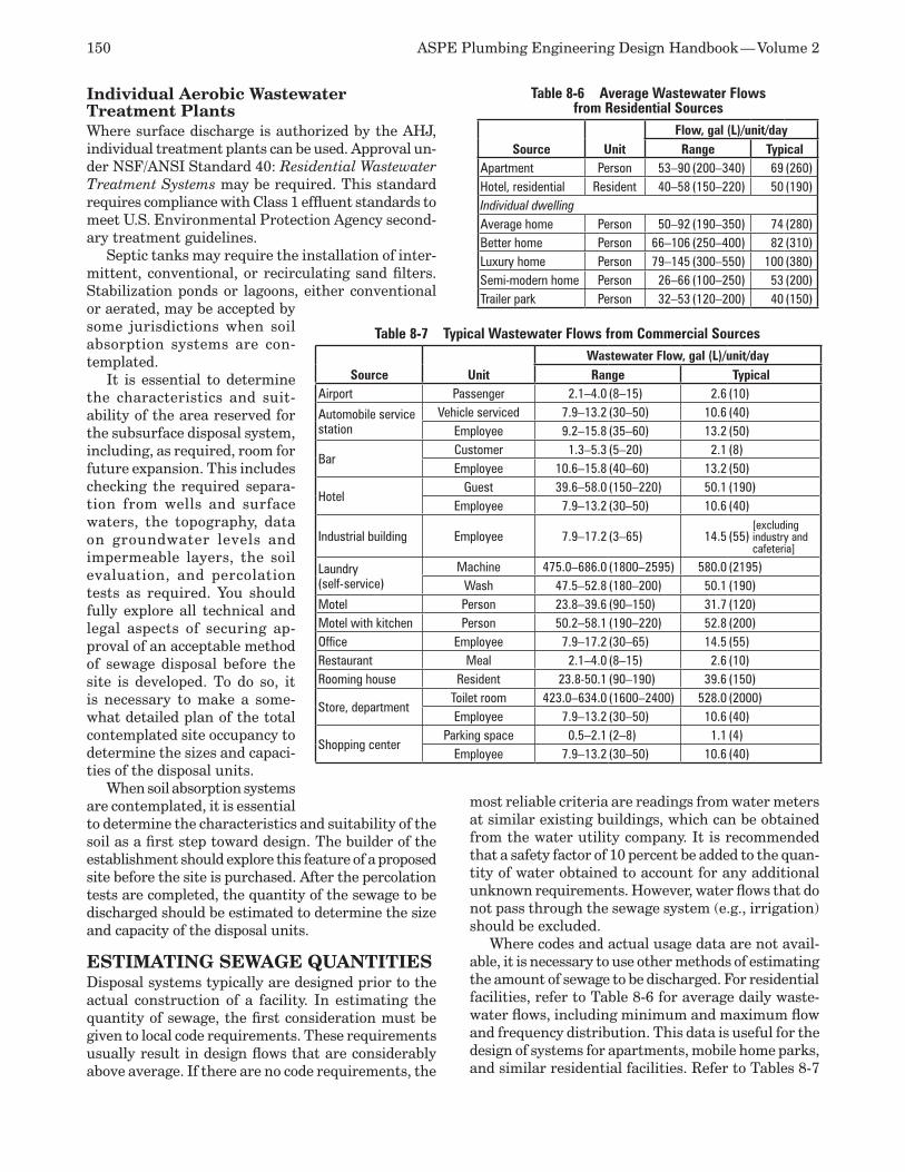
150 ASPE Plumbing Engineering Design Handbook — Volume 2
Individual Aerobic Wastewater Treatment PlantsWhere surface discharge is authorized by the AHJ, individual treatment plants can be used. Approval un-der NSF/ANSI Standard 40: Residential Wastewater Treatment Systems may be required. This standard requires compliance with Class 1 effluent standards to meet U.S. Environmental Protection Agency second-ary treatment guidelines.
Septic tanks may require the installation of inter-mittent, conventional, or recirculating sand filters. Stabilization ponds or lagoons, either conventional or aerated, may be accepted by some jurisdictions when soil absorption systems are con-templated.
It is essential to determine the characteristics and suit-ability of the area reserved for the subsurface disposal system, including, as required, room for future expansion. This includes checking the required separa-tion from wells and surface waters, the topography, data on groundwater levels and impermeable layers, the soil evaluation, and percolation tests as required. You should fully explore all technical and legal aspects of securing ap-proval of an acceptable method of sewage disposal before the site is developed. To do so, it is necessary to make a some-what detailed plan of the total contemplated site occupancy to determine the sizes and capaci-ties of the disposal units.
When soil absorption systems are contemplated, it is essential to determine the characteristics and suitability of the soil as a first step toward design. The builder of the establishment should explore this feature of a proposed site before the site is purchased. After the percolation tests are completed, the quantity of the sewage to be discharged should be estimated to determine the size and capacity of the disposal units.
ESTIMATING SEWAGE QUANTITIESDisposal systems typically are designed prior to the actual construction of a facility. In estimating the quantity of sewage, the first consideration must be given to local code requirements. These requirements usually result in design flows that are considerably above average. If there are no code requirements, the
most reliable criteria are readings from water meters at similar existing buildings, which can be obtained from the water utility company. It is recommended that a safety factor of 10 percent be added to the quan-tity of water obtained to account for any additional unknown requirements. However, water flows that do not pass through the sewage system (e.g., irrigation) should be excluded.
Where codes and actual usage data are not avail-able, it is necessary to use other methods of estimating the amount of sewage to be discharged. For residential facilities, refer to Table 8-6 for average daily waste-water flows, including minimum and maximum flow and frequency distribution. This data is useful for the design of systems for apartments, mobile home parks, and similar residential facilities. Refer to Tables 8-7
Table 8-7 Typical Wastewater Flows from Commercial Sources
Source UnitWastewater Flow, gal (L)/unit/dayRange Typical
Airport Passenger 2.1–4.0 (8–15) 2.6 (10)
Automobile service station
Vehicle serviced 7.9–13.2 (30–50) 10.6 (40)Employee 9.2–15.8 (35–60) 13.2 (50)
BarCustomer 1.3–5.3 (5–20) 2.1 (8)Employee 10.6–15.8 (40–60) 13.2 (50)
HotelGuest 39.6–58.0 (150–220) 50.1 (190)
Employee 7.9–13.2 (30–50) 10.6 (40)
Industrial building Employee 7.9–17.2 (3–65) 14.5 (55) [excluding industry and cafeteria]
Laundry (self-service)
Machine 475.0–686.0 (1800–2595) 580.0 (2195)Wash 47.5–52.8 (180–200) 50.1 (190)
Motel Person 23.8–39.6 (90–150) 31.7 (120)Motel with kitchen Person 50.2–58.1 (190–220) 52.8 (200)Office Employee 7.9–17.2 (30–65) 14.5 (55)Restaurant Meal 2.1–4.0 (8–15) 2.6 (10)Rooming house Resident 23.8-50.1 (90–190) 39.6 (150)
Store, departmentToilet room 423.0–634.0 (1600–2400) 528.0 (2000)Employee 7.9–13.2 (30–50) 10.6 (40)
Shopping centerParking space 0.5–2.1 (2–8) 1.1 (4)
Employee 7.9–13.2 (30–50) 10.6 (40)
Table 8-6 Average Wastewater Flows from Residential Sources
Source UnitFlow, gal (L)/unit/dayRange Typical
Apartment Person 53–90 (200–340) 69 (260)Hotel, residential Resident 40–58 (150–220) 50 (190)Individual dwellingAverage home Person 50–92 (190–350) 74 (280)Better home Person 66–106 (250–400) 82 (310)Luxury home Person 79–145 (300–550) 100 (380)Semi-modern home Person 26–66 (100–250) 53 (200)Trailer park Person 32–53 (120–200) 40 (150)
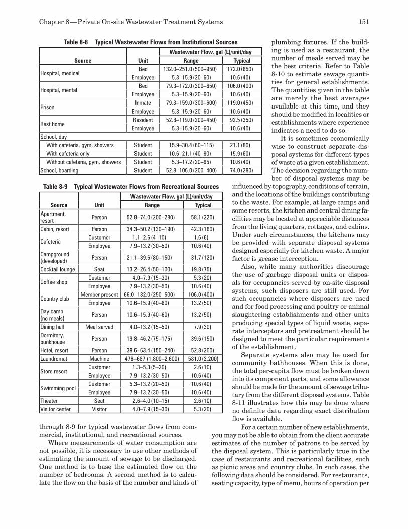
Chapter 8 — Private On-site Wastewater Treatment Systems 151
through 8-9 for typical wastewater flows from com-mercial, institutional, and recreational sources.
Where measurements of water consumption are not possible, it is necessary to use other methods of estimating the amount of sewage to be discharged. One method is to base the estimated flow on the number of bedrooms. A second method is to calcu-late the flow on the basis of the number and kinds of
plumbing fixtures. If the build-ing is used as a restaurant, the number of meals served may be the best criteria. Refer to Table 8-10 to estimate sewage quanti-ties for general establishments. The quantities given in the table are merely the best averages available at this time, and they should be modified in localities or establishments where experience indicates a need to do so.
It is sometimes economically wise to construct separate dis-posal systems for different types of waste at a given establishment. The decision regarding the num-ber of disposal systems may be
influenced by topography, conditions of terrain, and the locations of the buildings contributing to the waste. For example, at large camps and some resorts, the kitchen and central dining fa-cilities may be located at appreciable distances from the living quarters, cottages, and cabins. Under such circumstances, the kitchens may be provided with separate disposal systems designed especially for kitchen waste. A major factor is grease interception.
Also, while many authorities discourage the use of garbage disposal units or dispos-als for occupancies served by on-site disposal systems, such disposers are still used. For such occupancies where disposers are used and for food processing and poultry or animal slaughtering establishments and other units producing special types of liquid waste, sepa-rate interceptors and pretreatment should be designed to meet the particular requirements of the establishment.
Separate systems also may be used for community bathhouses. When this is done, the total per-capita flow must be broken down into its component parts, and some allowance should be made for the amount of sewage tribu-tary from the different disposal systems. Table 8-11 illustrates how this may be done where no definite data regarding exact distribution flow is available.
For a certain number of new establishments, you may not be able to obtain from the client accurate estimates of the number of patrons to be served by the disposal system. This is particularly true in the case of restaurants and recreational facilities, such as picnic areas and country clubs. In such cases, the following data should be considered. For restaurants, seating capacity, type of menu, hours of operation per
Table 8-8 Typical Wastewater Flows from Institutional Sources
Source UnitWastewater Flow, gal (L)/unit/day
Range Typical
Hospital, medicalBed 132.0–251.0 (500–950) 172.0 (650)
Employee 5.3–15.9 (20–60) 10.6 (40)
Hospital, mentalBed 79.3–172.0 (300–650) 106.0 (400)
Employee 5.3–15.9 (20–60) 10.6 (40)
PrisonInmate 79.3–159.0 (300–600) 119.0 (450)
Employee 5.3–15.9 (20–60) 10.6 (40)
Rest homeResident 52.8–119.0 (200–450) 92.5 (350)Employee 5.3–15.9 (20–60) 10.6 (40)
School, day With cafeteria, gym, showers Student 15.9–30.4 (60–115) 21.1 (80) With cafeteria only Student 10.6–21.1 (40–80) 15.9 (60) Without cafeteria, gym, showers Student 5.3–17.2 (20–65) 10.6 (40)School, boarding Student 52.8–106.0 (200–400) 74.0 (280)
Table 8-9 Typical Wastewater Flows from Recreational Sources
Source UnitWastewater Flow, gal (L)/unit/day
Range TypicalApartment, resort Person 52.8–74.0 (200–280) 58.1 (220)
Cabin, resort Person 34.3–50.2 (130–190) 42.3 (160)
CafeteriaCustomer 1.1–2.6 (4–10) 1.6 (6)Employee 7.9–13.2 (30–50) 10.6 (40)
Campground (developed) Person 21.1–39.6 (80–150) 31.7 (120)
Cocktail lounge Seat 13.2–26.4 (50–100) 19.8 (75)
Coffee shopCustomer 4.0–7.9 (15–30) 5.3 (20)Employee 7.9–13.2 (30–50) 10.6 (40)
Country clubMember present 66.0–132.0 (250–500) 106.0 (400)
Employee 10.6–15.9 (40–60) 13.2 (50)Day camp (no meals) Person 10.6–15.9 (40–60) 13.2 (50)
Dining hall Meal served 4.0–13.2 (15–50) 7.9 (30)Dormitory, bunkhouse Person 19.8–46.2 (75–175) 39.6 (150)
Hotel, resort Person 39.6–63.4 (150–240) 52.8 (200)Laundromat Machine 476–687 (1,800–2,600) 581.0 (2,200)
Store resortCustomer 1.3–5.3 (5–20) 2.6 (10)Employee 7.9–13.2 (30–50) 10.6 (40)
Swimming poolCustomer 5.3–13.2 (20–50) 10.6 (40)Employee 7.9–13.2 (30–50) 10.6 (40)
Theater Seat 2.6–4.0 (10–15) 2.6 (10)Visitor center Visitor 4.0–7.9 (15–30) 5.3 (20)
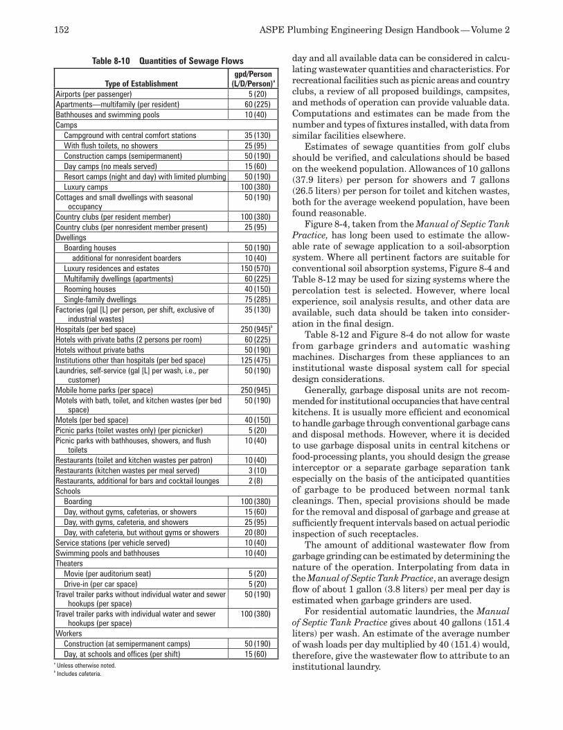
152 ASPE Plumbing Engineering Design Handbook — Volume 2
day and all available data can be considered in calcu-lating wastewater quantities and characteristics. For recreational facilities such as picnic areas and country clubs, a review of all proposed buildings, campsites, and methods of operation can provide valuable data. Computations and estimates can be made from the number and types of fixtures installed, with data from similar facilities elsewhere.
Estimates of sewage quantities from golf clubs should be verified, and calculations should be based on the weekend population. Allowances of 10 gallons (37.9 liters) per person for showers and 7 gallons (26.5 liters) per person for toilet and kitchen wastes, both for the average weekend population, have been found reasonable.
Figure 8-4, taken from the Manual of Septic Tank Practice, has long been used to estimate the allow-able rate of sewage application to a soil-absorption system. Where all pertinent factors are suitable for conventional soil absorption systems, Figure 8-4 and Table 8-12 may be used for sizing systems where the percolation test is selected. However, where local experience, soil analysis results, and other data are available, such data should be taken into consider-ation in the final design.
Table 8-12 and Figure 8-4 do not allow for waste from garbage grinders and automatic washing machines. Discharges from these appliances to an institutional waste disposal system call for special design considerations.
Generally, garbage disposal units are not recom-mended for institutional occupancies that have central kitchens. It is usually more efficient and economical to handle garbage through conventional garbage cans and disposal methods. However, where it is decided to use garbage disposal units in central kitchens or food-processing plants, you should design the grease interceptor or a separate garbage separation tank especially on the basis of the anticipated quantities of garbage to be produced between normal tank cleanings. Then, special provisions should be made for the removal and disposal of garbage and grease at sufficiently frequent intervals based on actual periodic inspection of such receptacles.
The amount of additional wastewater flow from garbage grinding can be estimated by determining the nature of the operation. Interpolating from data in the Manual of Septic Tank Practice, an average design flow of about 1 gallon (3.8 liters) per meal per day is estimated when garbage grinders are used.
For residential automatic laundries, the Manual of Septic Tank Practice gives about 40 gallons (151.4 liters) per wash. An estimate of the average number of wash loads per day multiplied by 40 (151.4) would, therefore, give the wastewater flow to attribute to an institutional laundry.
Table 8-10 Quantities of Sewage Flows
Type of Establishmentgpd/Person
(L/D/Person)a
Airports (per passenger) 5 (20)Apartments—multifamily (per resident) 60 (225)Bathhouses and swimming pools 10 (40)Camps Campground with central comfort stations 35 (130) With flush toilets, no showers 25 (95) Construction camps (semipermanent) 50 (190) Day camps (no meals served) 15 (60) Resort camps (night and day) with limited plumbing 50 (190) Luxury camps 100 (380)Cottages and small dwellings with seasonal
occupancy50 (190)
Country clubs (per resident member) 100 (380)Country clubs (per nonresident member present) 25 (95)Dwellings Boarding houses 50 (190) additional for nonresident boarders 10 (40) Luxury residences and estates 150 (570) Multifamily dwellings (apartments) 60 (225) Rooming houses 40 (150) Single-family dwellings 75 (285)Factories (gal [L] per person, per shift, exclusive of
industrial wastes)35 (130)
Hospitals (per bed space) 250 (945)b
Hotels with private baths (2 persons per room) 60 (225)Hotels without private baths 50 (190)Institutions other than hospitals (per bed space) 125 (475)Laundries, self-service (gal [L] per wash, i.e., per
customer)50 (190)
Mobile home parks (per space) 250 (945)Motels with bath, toilet, and kitchen wastes (per bed
space)50 (190)
Motels (per bed space) 40 (150)Picnic parks (toilet wastes only) (per picnicker) 5 (20)Picnic parks with bathhouses, showers, and flush
toilets10 (40)
Restaurants (toilet and kitchen wastes per patron) 10 (40)Restaurants (kitchen wastes per meal served) 3 (10)Restaurants, additional for bars and cocktail lounges 2 (8)Schools Boarding 100 (380) Day, without gyms, cafeterias, or showers 15 (60) Day, with gyms, cafeteria, and showers 25 (95) Day, with cafeteria, but without gyms or showers 20 (80)Service stations (per vehicle served) 10 (40)Swimming pools and bathhouses 10 (40)Theaters Movie (per auditorium seat) 5 (20) Drive-in (per car space) 5 (20)Travel trailer parks without individual water and sewer
hookups (per space)50 (190)
Travel trailer parks with individual water and sewer hookups (per space)
100 (380)
Workers Construction (at semipermanent camps) 50 (190) Day, at schools and offices (per shift) 15 (60)
a Unless otherwise noted.b Includes cafeteria.
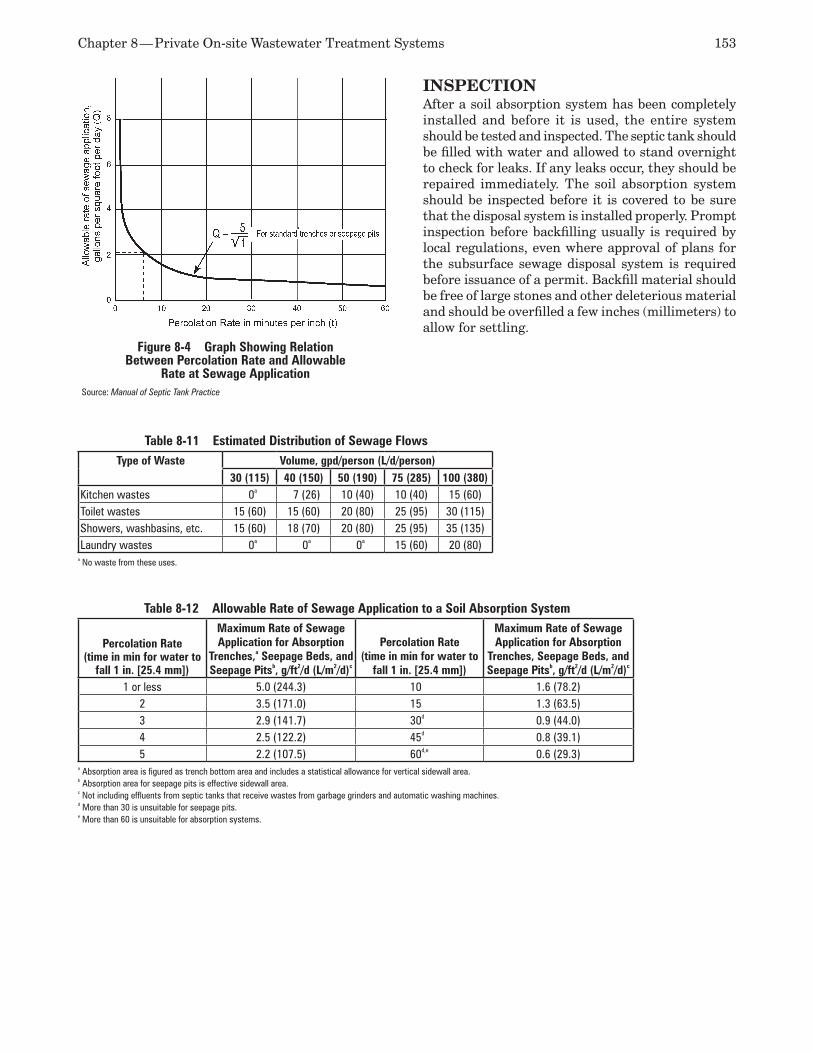
Chapter 8 — Private On-site Wastewater Treatment Systems 153
INSPECTIONAfter a soil absorption system has been completely installed and before it is used, the entire system should be tested and inspected. The septic tank should be filled with water and allowed to stand overnight to check for leaks. If any leaks occur, they should be repaired immediately. The soil absorption system should be inspected before it is covered to be sure that the disposal system is installed properly. Prompt inspection before backfilling usually is required by local regulations, even where approval of plans for the subsurface sewage disposal system is required before issuance of a permit. Backfill material should be free of large stones and other deleterious material and should be overfilled a few inches (millimeters) to allow for settling.
Table 8-11 Estimated Distribution of Sewage FlowsType of Waste Volume, gpd/person (L/d/person)
30 (115) 40 (150) 50 (190) 75 (285) 100 (380)Kitchen wastes 0a 7 (26) 10 (40) 10 (40) 15 (60)Toilet wastes 15 (60) 15 (60) 20 (80) 25 (95) 30 (115)Showers, washbasins, etc. 15 (60) 18 (70) 20 (80) 25 (95) 35 (135)Laundry wastes 0a 0a 0a 15 (60) 20 (80)
a No waste from these uses.
Table 8-12 Allowable Rate of Sewage Application to a Soil Absorption System
Percolation Rate (time in min for water to
fall 1 in. [25.4 mm])
Maximum Rate of Sewage Application for Absorption
Trenches,a Seepage Beds, and Seepage Pitsb, g/ft2/d (L/m2/d)c
Percolation Rate (time in min for water to
fall 1 in. [25.4 mm])
Maximum Rate of Sewage Application for Absorption
Trenches, Seepage Beds, and Seepage Pitsb, g/ft2/d (L/m2/d)c
1 or less 5.0 (244.3) 10 1.6 (78.2)2 3.5 (171.0) 15 1.3 (63.5)3 2.9 (141.7) 30d 0.9 (44.0)4 2.5 (122.2) 45d 0.8 (39.1)5 2.2 (107.5) 60d,e 0.6 (29.3)
a Absorption area is figured as trench bottom area and includes a statistical allowance for vertical sidewall area.b Absorption area for seepage pits is effective sidewall area.c Not including effluents from septic tanks that receive wastes from garbage grinders and automatic washing machines.d More than 30 is unsuitable for seepage pits.e More than 60 is unsuitable for absorption systems.
Figure 8-4 Graph Showing Relation Between Percolation Rate and Allowable
Rate at Sewage ApplicationSource: Manual of Septic Tank Practice
154 ASPE Plumbing Engineering Design Handbook — Volume 2
REFERENCESMacHatton, J.G., 1. Vacuum sewage collection, Joseph MacHatton Associates, 1972.Otis, Richard J., “On-site waste-water facili-2. ties for small communities and subdivisions,” Proceedings of the Third National Conference on Individual On-site Wastewater Systems, 1976.Pressure sewer demonstration at the borough of 3. Phoenixville, Pennsylvania, Report EPA 2-73-270, U.S. Environmental Protection Agency.Manual of Septic Tank Practice, 4. U.S. Public Health Service.“What future role for pressure sewers?” 5. Civil Engineering 44: 52-3, 1974.Bennett, E.R., and K.C. Linstedt, 6. Individual home wastewater characterization and treat-ment, Environmental Resources Center, Colo-rado State University.Boegly, W. J., 7. MIUS technology evaluation: Collection, treatment and disposal of liquid
wastes, ORNL-MIUS-16, National Technical Information Service.McClelland, Nina I., 8. Proceedings of the third national conference on individual on site waste-water systems, 1976.Wastewater engineering: Treatment/disposal/9. reuse, 2nd edition, Metcalf and Eddy Inc., 1979.Alternatives for small wastewater treatment 10. systems: Cost-effectiveness analysis, EPA Publication 625/4-77-011, U.S. Environmental Protection Agency.Alternatives for small wastewater treatment 11. systems: On-site disposal/seepage treatment and disposal, EPA publication 625/4-77-011, U.S. Environmental Protection Agency. Alternatives for small wastewater treatment 12. systems: Pressure sewers/vacuum sewers, EPA Publication 625/4-77-011, U.S. Environmental Protection Agency.
Private water wells are considered a type of private water supply because they are designed to provide potable water for a single building or facility of either residential or commercial construction. Normally, a water well that provides potable water to multiple buildings or facilities is considered a community wa-ter supply. Community water supply systems require more stringent design, a greater volume of reserve storage capacity, redundant pumping systems, a high-ly scrutinized permit process, and, for the most part, a full-time licensed water system operator. Conversely, a private water well system is installed, controlled, operated, and maintained by the user. Safe drinking water is the ultimate goal, and the methods described in this chapter are a means to that goal.
Engineering considerations in the design of pri-vate water wells include the following: the geology of the area, required demand, potential water quality, system elements, equipment, construction, initial operation, and maintenance procedures. In addition to addressing each of these areas, you should seek sources of local information and references, includ-ing drilling logs of previously constructed wells and their respective water quality test results. The re-gional governmental agency or health department responsible for water quality and protection is the preferred source of information for the quality of the water supply and approximate location of aquifers. This agency should be contacted as soon as possible to determine the adequacy and quality of the supply and any local regulations governing the construction of private water wells.
Wells often are classified as deep or shallow. A shal-low well is considered to be 50 to 100 feet (15 to 30 meters) deep. A deep well generally is considered to be a superior source because the water is less susceptible to contamination and the depth of the aquifer usually fluctuates less than that in a shallow well.
CODES AND STANDARDSThe Safe Drinking Water Act governs the quality of water from wells. U.S. Environmental Protection
Agency manuals include standards establishing maxi-mum contamination levels. The Association of State Drinking Water Administrators provides potable wa-ter information. State, local, and regional regulations provide minimum construction standards.
SOURCES OF SUPPLYThe source of water for private water well systems is groundwater, which by definition is subsurface water stored in a saturated state within certain types of geological formations beneath the Earth’s surface. The Earth’s crust is comprised of multiple layers of various geological formations of different minerals and many different substrates. Water-filled voids occur in both bedrock and regolith formations. The glacial drift (sand and gravel) and sandstone regions are examples of shallow water-bearing zones, whereas shale and dolomite regions do not contain any satu-rated water properties.
The water-saturated voids or regions are con-sidered aquifers, and it is possible to find multiple aquifers at various elevations at the same location. Aquifers store subsurface water that can be yielded in a usable quality and quantity through the use of water wells. The water quality and volume that can be obtained from aquifers substantially change from region to region and elevation to elevation. Ground-water supply is recharged through surface runoff that soaks into the ground and is not absorbed by surface agriculture. Commercial development and drought reduce the available recharge water for ap-plicable aquifers. Thus, aquifer recharge is necessary to preserve the well’s water source. Protecting our environment from pollution is critical to the quality of future groundwater supplies.
A further explanation of subsurface water is given in Chapter 4: “Storm Water Drainage,” in this volume.
WELLS A water well is a cased hole (usually vertical) that is drilled through the Earth’s substrate to access water that is stored within the Earth’s aquifers. Modern
Private Water Wells9

156 ASPE Plumbing Engineering Design Handbook — Volume 2
wells generally are drilled using a machine that advances a bore hole to an aquifer, where a casing is installed to prevent collapse of the boring. This casing also prevents the well’s aquifer from being contami-nated by surface water or other sources of surface pollution at or near the surface of the ground.
The size of the well is determined by the build-ing’s water demand, equipment size (pump and pipe), and static pumping elevation. Deeper wells typically require larger-diameter pumps and impellers, thus requiring larger-diameter casings. Residential wells providing water for a single dwelling generally range from 2 to 6 inches (5 to 15 centimeters) in diameter and produce several hundred gallons of water per day. High-capacity wells, such as wells for industry or mu-nicipal water supplies, may range from 6 to 36 inches (15 to 91 centimeters) in diameter or larger and may produce several million gallons of water per day.
Shallow wells of 50 to 100 feet (15 to 30 meters) or less can be installed in loose formations of sand by driving or jetting (a high-pressure jet of water) a 2-inch (5-centimeter) pipe into the ground until an adequate depth is reached to provide the required water. Shallow wells more than 50 feet (15 meters) in depth generally are drilled using mud or air rotary. These techniques use a fluid, such as water, drilling mud, or compressed air, to clean the soil cuttings from the bore hole as the well is drilled. Water or drilling mud is used in loose formations of sand and gravel to stabilize the bore hole, whereas deeper wells through clay and bedrock formations generally are drilled us-ing air and water to clean the bore hole since these formations are fairly stable.
The bore hole is advanced until either adequate water is encountered or bedrock is reached. In either case, the bore hole must be of a significant depth to isolate the well so it is not contaminated from surface water and pollutants. In porous formations of sand or gravel, casing is installed with a well screen to allow the water to easily enter the well from the aquifer. If bedrock is encountered before water, the bore hole is advanced into the bedrock a few feet, a casing is installed, and the well is advanced into the bedrock until water is encountered. The annulus between the casing and bore hole must be sealed with an impervi-ous material to prevent infiltration of surface water into the aquifer.
Specific state, local, and regional regulations provide minimum construction standards for wells regarding potential sources of contamination, structures, surface features, and property lines. Ad-ditionally, state regulations may specify a minimum depth of the well, minimum amount of casing, type of casing, and grouting specifications for the annulus of the casing to prevent surface contamination. Typi-
cally, well permits are required before actual drilling can begin, with follow-up jurisdictional inspections.
Dug and Augered WellsDepths of dug and augured wells can be 65 feet (20 meters) or more, depending on the position of the wa-ter table, while diameters are usually 3 to 30 feet (1 to 9 meters). Dug and augered wells can yield relatively large quantities of water from shallow sources. They are the most common type of well used for individual water supplies. Their large diameters permit storage of considerable quantities of water if the well extends some distance below the water table. Some large municipal wells called collectors are dug wells with lateral, screened horizontal pipes.
In the past, all dug wells were excavated by hand; today, the auger method is becoming more widely uti-lized. The auger pulls loose material to the surface for distribution as fill. Large dug wells can be constructed rapidly with portable excavating and augering equip-ment. For safety and to prevent caving, a lining of shoring or sheet piling should be placed in the hole to brace the walls.
A dug well must be permanently lined with a casing of wood staves, brick, rock, concrete, or metal to sup-port it from cave-in. A properly constructed dug well penetrating a permeable aquifer can yield approxi-mately 200 to 1,000 gallons per minute (gpm) (757 to 3,785 liters per minute), although most domestic dug wells yield less than 18,000 cubic feet per day (510 cubic meters per day). It is difficult to provide a proper sanitary seal on a dug well, whereas augering allows the installation of a welded steel casing to prevent ground source contamination. Construction of dug wells is prohibited or at least discouraged in some areas because of the increased possibility of surface contamination compared to deeper wells constructed by other means.
Bored Wells Bored wells are constructed with hand-operated (shal-low depths) or power-driven earth augers similar to those previously described. Augers are available in several shapes and sizes, all operating with cutting blades at the bottom that bore through the Earth’s substrate in a rotary motion. Hand-boring operations rarely exceed 50 feet (15 meters) in depth, whereas power drilling/augering equipment can exceed 1,000-foot (305-meter) depths.
Deep well construction requires casing pipe insula-tion to contain and prevent contamination but also to protect the well shaft from collapsing. The drilling operation may pass through loose gravel or unstable strata before it reaches an aquifer to support the necessary water quality and quantity required for the project under design.
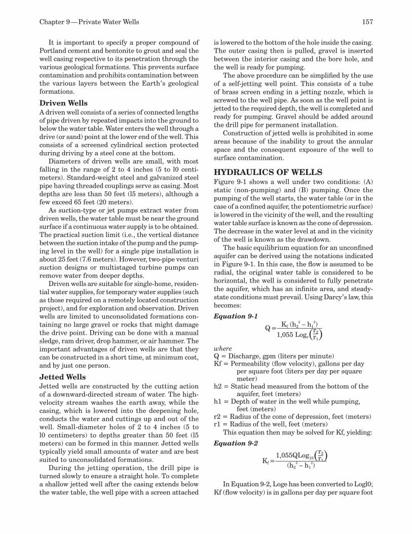
Chapter 9 — Private Water Wells 157
It is important to specify a proper compound of Portland cement and bentonite to grout and seal the well casing respective to its penetration through the various geological formations. This prevents surface contamination and prohibits contamination between the various layers between the Earth’s geological formations.
Driven Wells A driven well consists of a series of connected lengths of pipe driven by repeated impacts into the ground to below the water table. Water enters the well through a drive (or sand) point at the lower end of the well. This consists of a screened cylindrical section protected during driving by a steel cone at the bottom.
Diameters of driven wells are small, with most falling in the range of 2 to 4 inches (5 to l0 centi-meters). Standard-weight steel and galvanized steel pipe having threaded couplings serve as casing. Most depths are less than 50 feet (l5 meters), although a few exceed 65 feet (20 meters).
As suction-type or jet pumps extract water from driven wells, the water table must be near the ground surface if a continuous water supply is to be obtained. The practical suction limit (i.e., the vertical distance between the suction intake of the pump and the pump-ing level in the well) for a single pipe installation is about 25 feet (7.6 meters). However, two-pipe venturi suction designs or multistaged turbine pumps can remove water from deeper depths.
Driven wells are suitable for single-home, residen-tial water supplies, for temporary water supplies (such as those required on a remotely located construction project), and for exploration and observation. Driven wells are limited to unconsolidated formations con-taining no large gravel or rocks that might damage the drive point. Driving can be done with a manual sledge, ram driver, drop hammer, or air hammer. The important advantages of driven wells are that they can be constructed in a short time, at minimum cost, and by just one person.
Jetted Wells Jetted wells are constructed by the cutting action of a downward-directed stream of water. The high-velocity stream washes the earth away, while the casing, which is lowered into the deepening hole, conducts the water and cuttings up and out of the well. Small-diameter holes of 2 to 4 inches (5 to l0 centimeters) to depths greater than 50 feet (l5 meters) can be formed in this manner. Jetted wells typically yield small amounts of water and are best suited to unconsolidated formations.
During the jetting operation, the drill pipe is turned slowly to ensure a straight hole. To complete a shallow jetted well after the casing extends below the water table, the well pipe with a screen attached
is lowered to the bottom of the hole inside the casing. The outer casing then is pulled, gravel is inserted between the interior casing and the bore hole, and the well is ready for pumping.
The above procedure can be simplified by the use of a self-jetting well point. This consists of a tube of brass screen ending in a jetting nozzle, which is screwed to the well pipe. As soon as the well point is jetted to the required depth, the well is completed and ready for pumping. Gravel should be added around the drill pipe for permanent installation.
Construction of jetted wells is prohibited in some areas because of the inability to grout the annular space and the consequent exposure of the well to surface contamination.
HYDRAULICS OF WELLS Figure 9-1 shows a well under two conditions: (A) static (non-pumping) and (B) pumping. Once the pumping of the well starts, the water table (or in the case of a confined aquifer, the potentiometric surface) is lowered in the vicinity of the well, and the resulting water table surface is known as the cone of depression. The decrease in the water level at and in the vicinity of the well is known as the drawdown.
The basic equilibrium equation for an unconfined aquifer can be derived using the notations indicated in Figure 9-1. In this case, the flow is assumed to be radial, the original water table is considered to be horizontal, the well is considered to fully penetrate the aquifer, which has an infinite area, and steady-state conditions must prevail. Using Darcy’s law, this becomes:
Equation 9-1
Q = Kf (h22 – h1
2)
1,055 Loge(r2)r1
where Q = Discharge, gpm (liters per minute) Kf = Permeability (flow velocity), gallons per day
per square foot (liters per day per square meter)
h2 = Static head measured from the bottom of the aquifer, feet (meters)
h1 = Depth of water in the well while pumping, feet (meters)
r2 = Radius of the cone of depression, feet (meters) r1 = Radius of the well, feet (meters)
This equation then may be solved for Kf, yielding:
Equation 9-2
Kf =1,055QLog10(r2)r1
(h22 – h1
2)
In Equation 9-2, Loge has been converted to Logl0; Kf (flow velocity) is in gallons per day per square foot
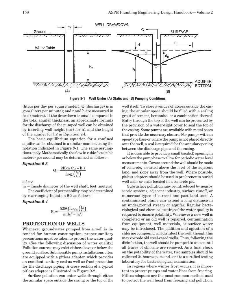
158 ASPE Plumbing Engineering Design Handbook — Volume 2
(liters per day per square meter); Q (discharge) is in gpm (liters per minute); and r and h are measured in feet (meters). If the drawdown is small compared to the total aquifer thickness, an approximate formula for the discharge of the pumped well can be obtained by inserting wall height (hw) for h1 and the height of the aquifer for h2 in Equation 9-l.
The basic equilibrium equation for a confined aquifer can be obtained in a similar manner, using the notation indicated in Figure 9-1. The same assump-tions apply. Mathematically, the flow in cubic feet (cubic meters) per second may be determined as follows:
Equation 9-3
Q =2Kfm (h2 – h1)
Loge(r2)r1
where m = Inside diameter of the well shaft, feet (meters)
The coefficient of permeability may be determined by rearranging Equation 9-3 as follows:
Equation 9-4
Kf =528QLog10(r2)r1
m(h22 – h1
2)
PROTECTION OF WELLS Whenever groundwater pumped from a well is in-tended for human consumption, proper sanitary precautions must be taken to protect the water qual-ity. (See the following discussion of water quality.) Pollution sources may exist either above or below the ground surface. Submersible pump installations often are equipped with a pitless adapter, which provides an excellent sanitary seal as well as frost protection for the discharge piping. A cross-section of a typical pitless adaptor is illustrated in Figure 9-2.
Surface pollution can enter wells through either the annular space outside the casing or the top of the
well itself. To close avenues of access outside the cas-ing, the annular space should be filled with a sealing grout of cement, bentonite, or a combination thereof. Entry through the top of the well can be prevented by the provision of a water-tight cover to seal the top of the casing. Some pumps are available with metal bases that provide the necessary closure. For pumps with an open-type base or where the pump is not placed directly over the well, a seal is required for the annular opening between the discharge pipe and the casing.
It is desirable to provide a small (sealed) opening in or below the pump base to allow for periodic water level measurements. Covers around the well should be made of concrete, elevated above the level of the adjacent land, and slope away from the well. Where possible, pitless adapters should be used in preference to buried well seals or seals located in a concrete pit.
Subsurface pollution may be introduced by nearby septic systems, adjacent industry, surface runoff, or numerous types of current and past land uses. A contaminated plume can extend a long distance in an underground stream or aquifer. Regular bacte-riological and chemical testing of the water quality is required to ensure potability. Whenever a new well is completed or an old well is repaired, contamination from equipment, well materials, or surface water may be introduced. The addition and agitation of a chlorine compound will disinfect the well, though this may corrode old steel-cased wells. Thus, following the disinfection, the well should be pumped to waste until all traces of chlorine are removed. As a final check on the potability of the water, two samples should be collected 24 hours apart and sent to a certified testing laboratory for bacteriological examination.
In regions where winter frost occurs, it is impor-tant to protect pumps and water lines from freezing. Pitless adapters are the most common method used to protect the well head from freezing and pollution.
Figure 9-1 Well Under (A) Static and (B) Pumping Conditions
(B)(A)
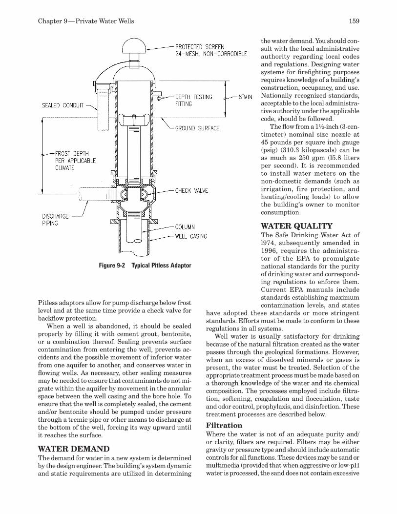
Chapter 9 — Private Water Wells 159
Pitless adaptors allow for pump discharge below frost level and at the same time provide a check valve for backflow protection.
When a well is abandoned, it should be sealed properly by filling it with cement grout, bentonite, or a combination thereof. Sealing prevents surface contamination from entering the well, prevents ac-cidents and the possible movement of inferior water from one aquifer to another, and conserves water in flowing wells. As necessary, other sealing measures may be needed to ensure that contaminants do not mi-grate within the aquifer by movement in the annular space between the well casing and the bore hole. To ensure that the well is completely sealed, the cement and/or bentonite should be pumped under pressure through a tremie pipe or other means to discharge at the bottom of the well, forcing its way upward until it reaches the surface.
WATER DEMANDThe demand for water in a new system is determined by the design engineer. The building’s system dynamic and static requirements are utilized in determining
the water demand. You should con-sult with the local administrative authority regarding local codes and regulations. Designing water systems for firefighting purposes requires knowledge of a building’s construction, occupancy, and use. Nationally recognized standards, acceptable to the local administra-tive authority under the applicable code, should be followed.
The flow from a 1½-inch (3-cen-timeter) nominal size nozzle at 45 pounds per square inch gauge (psig) (310.3 kilopascals) can be as much as 250 gpm (l5.8 liters per second). It is recommended to install water meters on the non-domestic demands (such as irrigation, fire protection, and heating/cooling loads) to allow the building’s owner to monitor consumption.
WATER QUALITYThe Safe Drinking Water Act of l974, subsequently amended in 1996, requires the administra-tor of the EPA to promulgate national standards for the purity of drinking water and correspond-ing regulations to enforce them. Current EPA manuals include standards establishing maximum contamination levels, and states
have adopted these standards or more stringent standards. Efforts must be made to conform to these regulations in all systems.
Well water is usually satisfactory for drinking because of the natural filtration created as the water passes through the geological formations. However, when an excess of dissolved minerals or gases is present, the water must be treated. Selection of the appropriate treatment process must be made based on a thorough knowledge of the water and its chemical composition. The processes employed include filtra-tion, softening, coagulation and flocculation, taste and odor control, prophylaxis, and disinfection. These treatment processes are described below.
FiltrationWhere the water is not of an adequate purity and/or clarity, filters are required. Filters may be either gravity or pressure type and should include automatic controls for all functions. These devices may be sand or multimedia (provided that when aggressive or low-pH water is processed, the sand does not contain excessive
Figure 9-2 Typical Pitless Adaptor

160 ASPE Plumbing Engineering Design Handbook — Volume 2
amounts of limestone or shells). The grade of the sand and/or type of media depends on local conditions.
Coarse sand is less effective in the removal of tur-bidity and bacteria, while fine sand requires a shorter period between washings. Filters may use layers of various grades of sand and gravel to minimize filter gravel upset and loss of sand. These units may include anthracite coal particles or activated carbon, both of which are often effective in removing objectionable tastes, odors, and other impurities. Filters should be backwashed and disinfected before being placed back in service. Parallel filtration prevents interruption of the supply water during backwash and/or cleaning.
Softening The two methods of reducing any dissolved calcium and magnesium that are suitable for large water supplies are the zeolite process and the lime soda method. The zeolite process replaces the calcium and magnesium chlorides, and all residues (backwash) must be disposed of in locations where the groundwa-ter will not be contaminated. Zeolite systems may be automated or manual. When iron is removed by this process, the oxides may clog the filter beds. Cleaning the beds requires high-velocity washing.
The lime soda method removes calcium, magne-sium, manganese, iron, and carbon dioxide. The pH is raised, and most units effectively destroy any harm-ful organisms. This method produces considerable quantities of sludge, which require proper disposal. The lime soda method involves a large installation and skilled operation. Equipment is needed to mix and feed chemicals and for flocculation and settling, recar-bonating and filtering. When iron is not removed, it may be held in solution in cool water up to 72 hours by the addition of hexametaphosphate. This chemical may prevent incrustation in water with a high pH.
Scale and Corrosion Control Elimination of any excessive scale and corrosion of the piping system is important. This may be accomplished by the proper choice of piping materials or by chemical treatment of the water. Specifying a plastic distribu-tion system will not protect the metallic piping and equipment in buildings. The control of hardness, dissolved oxygen and carbon dioxide, and acidity may be necessary. Sodium hexametaphosphate commonly is used for corrosion control, scale prevention, and removal of hardness.
Taste and Odor Control Potassium permanganate oxidizes iron and man-ganese, forming a precipitate. This compound also acts as an algaecide. Oxygenation is another way to treat the water, which may (in some cases) be more effective than treating it with potassium permangan-ate. Activated carbon has been found to be effective
in removing phenolic compounds as well as certain other undesirable materials. Sodium thiosulfate or sodium bisulfate has been used to remove chlorine from water, and copper sulfate will destroy living organic matter.
Prophylaxis Fluoride sometimes is added to the water with the intent of reducing dental cavities. Where amounts of fluoride are excessive, tooth enamel will become mottled. Some waters have adequate or even excessive fluoride in their natural state.
Disinfection Disinfection should be the last step in the water treat-ment process. Chlorination has been shown to prevent epidemics of waterborne disease, and it also destroys ammonia. It is an inexpensive method compared to ultraviolet radiation and ozone treatment. Gaseous chlorine is used in large installations, while calcium and sodium hypochlorite are satisfactory for small systems. Water from a properly constructed modern well seldom needs to be disinfected once the well and pumping equipment are initially disinfected.
Radon Contamination In areas where radon (a radioactive gas) is present in low quantities in the ground, the water might be contaminated. Treatment may be necessary to elimi-nate radon from the water, and water softening often is used to accomplish this.
SYSTEM ELEMENTS
Pumps The three most common well pump systems are vertical turbine pumps, jet pumps, and submersible pumps.
The vertical turbine pump is a centrifugal pump with the motor on the ground surface over the bore hole and the shaft and impeller suspended in the aquifer. It is well suited for large flow rates, deep wells, and high discharge heads.
The jet pump is a centrifugal pump with the motor and the impeller on the ground surface. It uses a jet of water flowing down the bore hole to create a partial vacuum at the bottom that, with a special fitting, draws an additional amount of water into the discharge pipe. This pump is used for small flow rates.
A submerged pump is a centrifugal pump that is entirely self-contained in a housing. It contains an electrical motor close-coupled with an impeller and an attached discharge pipe to the surface. This pump is well suited for a wide variety of flow rates and pressures.
The design of a pumping system should take into consideration maintenance and the possible failure of one pump in the system. It is sometimes necessary to have a backup (second) pump, which can be expensive.
Chapter 9 — Private Water Wells 161
However, if the system serves fire hydrants or fire protection equipment within a building without the use of a storage tank, it may be essential.
Pumps for residential or light commercial ap-plications may be readily in stock at local supply companies in areas where many private water wells are prevalent. On the other hand, it is common to have large well drilling companies keep and maintain a large-diameter submersible well pump for large ap-plications within their inventories for your emergency use at a cost.
A cross-section of a vertical turbine pump is illus-trated in Figure 9-3. You should give more attention to the pump base (or foundation) than is shown in this figure. If the pump is in an unheated building, the foundation must be below the frost line to avoid any movement, and there must be sufficient mass to eliminate any vibration. Also, extreme care must be taken in setting the anchor bolts and aligning the pump and the shaft to prevent any misalignment.
The vertical turbine pump shown in Figure 9-3 is very practical for large-capacity, relatively straight and plumb shallow wells. Where deep wells or misaligned wells are encountered, it may be more practical to use a submersible pump. These units can be fitted with almost any number of stages (sections) and, depending upon the size of the well, can exceed the capacity and efficiency of the surface-mounted vertical turbine pump.
Submersible Well Pumps Well pumps produce flow by transforming mechanical energy to hydraulic energy. Manufacturers produce a wide variety of pumps. The selection of a particular size and type of pump depends on several factors:
Required pumping capacity•Well diameter and depth•Depth and variability of pumping level•Straightness of the well•Sand pumping•Total pumping head•Duration of pumping•Type of power available•Costs •
The total pumping head, or total dynamic head, of a pump represents the total vertical lift and pumped distance of the water from the well. The total head consists of three components:
Drawdown inside the well (including aquifer 1. and well losses)Static head, or the difference between the 2. static groundwater level and the static dis-charge elevationFriction losses due to flow through the intake 3. and discharge pipes. The total pumping head increases with the discharge rate.
Figure 9-3 Typical Gravel Filter Well with a Vertical Turbine Pump (Note the concrete seal adjacent to the outer well casing)
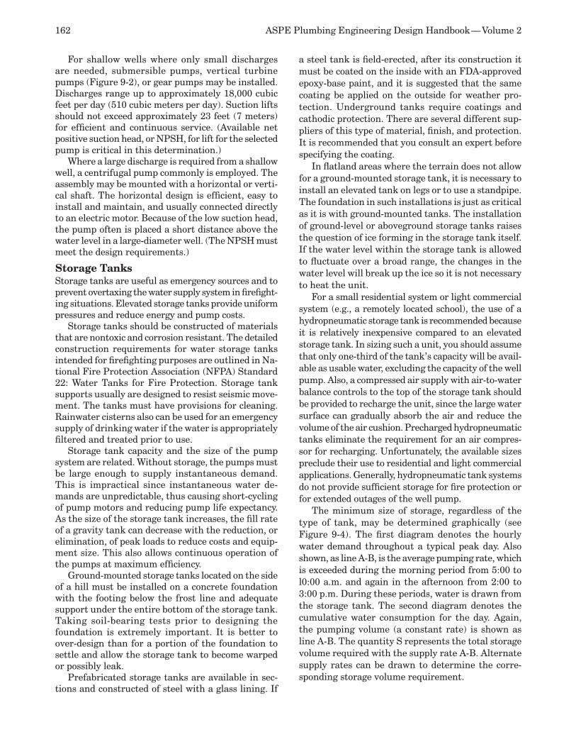
162 ASPE Plumbing Engineering Design Handbook — Volume 2
For shallow wells where only small discharges are needed, submersible pumps, vertical turbine pumps (Figure 9-2), or gear pumps may be installed. Discharges range up to approximately 18,000 cubic feet per day (510 cubic meters per day). Suction lifts should not exceed approximately 23 feet (7 meters) for efficient and continuous service. (Available net positive suction head, or NPSH, for lift for the selected pump is critical in this determination.)
Where a large discharge is required from a shallow well, a centrifugal pump commonly is employed. The assembly may be mounted with a horizontal or verti-cal shaft. The horizontal design is efficient, easy to install and maintain, and usually connected directly to an electric motor. Because of the low suction head, the pump often is placed a short distance above the water level in a large-diameter well. (The NPSH must meet the design requirements.)
Storage Tanks Storage tanks are useful as emergency sources and to prevent overtaxing the water supply system in firefight-ing situations. Elevated storage tanks provide uniform pressures and reduce energy and pump costs.
Storage tanks should be constructed of materials that are nontoxic and corrosion resistant. The detailed construction requirements for water storage tanks intended for firefighting purposes are outlined in Na-tional Fire Protection Association (NFPA) Standard 22: Water Tanks for Fire Protection. Storage tank supports usually are designed to resist seismic move-ment. The tanks must have provisions for cleaning. Rainwater cisterns also can be used for an emergency supply of drinking water if the water is appropriately filtered and treated prior to use.
Storage tank capacity and the size of the pump system are related. Without storage, the pumps must be large enough to supply instantaneous demand. This is impractical since instantaneous water de-mands are unpredictable, thus causing short-cycling of pump motors and reducing pump life expectancy. As the size of the storage tank increases, the fill rate of a gravity tank can decrease with the reduction, or elimination, of peak loads to reduce costs and equip-ment size. This also allows continuous operation of the pumps at maximum efficiency.
Ground-mounted storage tanks located on the side of a hill must be installed on a concrete foundation with the footing below the frost line and adequate support under the entire bottom of the storage tank. Taking soil-bearing tests prior to designing the foundation is extremely important. It is better to over-design than for a portion of the foundation to settle and allow the storage tank to become warped or possibly leak.
Prefabricated storage tanks are available in sec-tions and constructed of steel with a glass lining. If
a steel tank is field-erected, after its construction it must be coated on the inside with an FDA-approved epoxy-base paint, and it is suggested that the same coating be applied on the outside for weather pro-tection. Underground tanks require coatings and cathodic protection. There are several different sup-pliers of this type of material, finish, and protection. It is recommended that you consult an expert before specifying the coating.
In flatland areas where the terrain does not allow for a ground-mounted storage tank, it is necessary to install an elevated tank on legs or to use a standpipe. The foundation in such installations is just as critical as it is with ground-mounted tanks. The installation of ground-level or aboveground storage tanks raises the question of ice forming in the storage tank itself. If the water level within the storage tank is allowed to fluctuate over a broad range, the changes in the water level will break up the ice so it is not necessary to heat the unit.
For a small residential system or light commercial system (e.g., a remotely located school), the use of a hydropneumatic storage tank is recommended because it is relatively inexpensive compared to an elevated storage tank. In sizing such a unit, you should assume that only one-third of the tank’s capacity will be avail-able as usable water, excluding the capacity of the well pump. Also, a compressed air supply with air-to-water balance controls to the top of the storage tank should be provided to recharge the unit, since the large water surface can gradually absorb the air and reduce the volume of the air cushion. Precharged hydropneumatic tanks eliminate the requirement for an air compres-sor for recharging. Unfortunately, the available sizes preclude their use to residential and light commercial applications. Generally, hydropneumatic tank systems do not provide sufficient storage for fire protection or for extended outages of the well pump.
The minimum size of storage, regardless of the type of tank, may be determined graphically (see Figure 9-4). The first diagram denotes the hourly water demand throughout a typical peak day. Also shown, as line A-B, is the average pumping rate, which is exceeded during the morning period from 5:00 to l0:00 a.m. and again in the afternoon from 2:00 to 3:00 p.m. During these periods, water is drawn from the storage tank. The second diagram denotes the cumulative water consumption for the day. Again, the pumping volume (a constant rate) is shown as line A-B. The quantity S represents the total storage volume required with the supply rate A-B. Alternate supply rates can be drawn to determine the corre-sponding storage volume requirement.
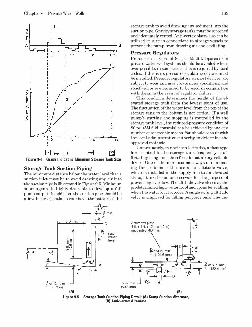
Chapter 9 — Private Water Wells 163
Storage Tank Suction Piping The minimum distance below the water level that a suction inlet must be to avoid drawing any air into the suction pipe is illustrated in Figure 9-5. Minimum submergence is highly desirable to develop a full pump output. In addition, the suction pipe should be a few inches (centimeters) above the bottom of the
storage tank to avoid drawing any sediment into the suction pipe. Gravity storage tanks must be screened and adequately vented. Anti-vortex plates also can be utilized at suction connections to storage vessels to prevent the pump from drawing air and cavitating.
Pressure Regulators Pressures in excess of 80 psi (55l.6 kilopascals) in private water well systems should be avoided when-ever possible; in some cases, this is required by local codes. If this is so, pressure-regulating devices must be installed. Pressure regulators, as most devices, are subject to wear and may create noisy conditions, and relief valves are required to be used in conjunction with them, in the event of regulator failure.
This condition determines the height of the el-evated storage tank from the lowest point of use. The fluctuation of the water level from the top of the storage tank to the bottom is not critical. If a well pump’s starting and stopping is controlled by the storage tank level, the reduced-pressure condition of 80 psi (55l.6 kilopascals) can be achieved by one of a number of acceptable means. You should consult with the local administrative authority to determine the approved methods.
Unfortunately, in northern latitudes, a float-type level control in the storage tank frequently is af-fected by icing and, therefore, is not a very reliable device. One of the more common ways of eliminat-ing the problem is the use of an altitude valve, which is installed in the supply line to an elevated storage tank, basin, or reservoir for the purpose of preventing overflow. The altitude valve closes at the predetermined high-water level and opens for refilling when the water level recedes. A single-acting altitude valve is employed for filling purposes only. The dis-
Figure 9-5 Storage Tank Suction Piping Detail: (A) Sump Suction Alternate, (B) Anti-vortex Alternate
(B)(A)
Figure 9-4 Graph Indicating Minimum Storage Tank Size
164 ASPE Plumbing Engineering Design Handbook — Volume 2
charge from the storage tank is handled by a swing check valve in a bypass around the altitude valve. A double-acting altitude valve is designed for two-way flows and eliminates the need for a bypass. Without additional controls, the well pump or system pump will run continuously.
Another type of system currently available controls the well pump and the storage tank level by sensing the system’s pressure at the point of pump discharge.
PERFORMANCE SPECIFICATIONS The design and specification of private water wells is not an exact science. You can consult with all of the regulatory agencies and review previous well drilling logs within the region to find no place where X marks the spot. On the other hand, you may shift your drill hole 10 feet north and 30 feet west to find a sand and gravel vein that can be test-pumped at 200 gpm (757 liters per minute) for 24 hours and barely impact the elevation of the aquifer. On large-diameter wells, it may be prudent to drill an inexpensive, small-diam-eter (2-inch [5-centimeter]) test hole to determine if water is available at the proposed location. Test pumping on a small-diameter well will determine the availability of large volumes of water, as required for large-diameter wells, utilizing the equations listed within this chapter.
It is recommended to write your specifications on performance-based conditions. List estimated drilling depths through the various anticipated geographical formations, and require the installing well contractor to give a plus or minus unit cost basis for penetrating through these anticipated formations. In the event they penetrate through in a lesser depth, a legitimate credit can be received; if it is a greater depth, a prenegotiated cost already is established. It also is recommended to establish a unit cost basis for well test pumping (per-hour basis), installed casing pipe material (per-diameter and per-foot basis), installed grout or sealing material (per pound or bag), and hourly rates for well development and clearing using shots similar to nitroglycerine blasts. Bid-form unit pricing will keep all parties on a level playing field when unexpected circumstances arise, a periodic occurrence when dig-ging or drilling private water wells.
CORROSION PROTECTION Metallic piping generally is chosen because of the high pressure requirements. Plastic pipes, when used, usu-ally are not subject to corrosion. The occurrence of corrosion depends on the soil and water conditions.
Proper water treatment and pipe linings can minimize interior attack; exterior attack may be reduced by coat-ings, cathodic protection, and careful selection of the backfill. Coatings must remain intact, and protection must be inspected and maintained periodically.
Require a one-year warranty and a follow-up one-year inspection of all cathodic protection devices (anodes) and protective coatings by the installing contractor for additional quality control.
INITIAL OPERATION AND MAINTENANCEAfter the well has been dug, it must be developed. Every type of drilling causes some disturbance to the aquifer by clogging the pores of the formation where it exists. After the bore hole has been completed, the casing is inserted, the intake attached, and the gravel packing installed.
Development is the process of removing loose ma-terial from the natural formation around the intake and enlarging it. This is the last stage of construction and is regarded as an art rather than a science.
Following development of a well, the next proce-dure is testing for yield by measuring the flow rate of pumping and observing the lowering of the water level. This is called drawdown and is the quantity of water that can be withdrawn on a continuing basis without depletion of the aquifer.
All private water wells and potable water piping must be disinfected prior to being placed in service. This process may be accomplished by introducing a solution of chlorine followed by a thorough flushing of the system with clear water. Well-kept records of the piping and connections will facilitate good opera-tion and maintenance. Periodic flushing, particularly of dead ends and low-velocity branches, will prevent sedimentation and fouling. Regularly scheduled valve exercising will ready the system for shutdown during an emergency. Leakage may be controlled by inspec-tion. Installation of approved backflow prevention devices will protect the private water supply from nonpotable sources. Inspections during and after construction will guard against cross-connections.
ADDITIONAL INFORMATION For additional information on groundwater protec-tion, contact the National Ground Water Association at ngwa.org. For additional information on safe drink-ing water standards, contact the Association of State Drinking Water Administrators at asdwa.org.
Vacuum Systems10This chapter describes the design criteria, source equipment, and piping distribution networks for vacuum systems used for general and laboratory ap-plications and central vacuum-cleaning systems.
For the purposes of the discussion in this chapter, references to inch-pound (IP) units and international standard (SI), or metric, units shall follow the follow-ing conventions:
Flow-rate measurements referring to standard 1. conditions shall be preceded by the prefix “s” for IP units and “n” for SI units.Pressure designations using standard atmo-2. spheric conditions as the base shall be followed by the suffix “g” for gauge pressure in IP units. (No suffix is used with SI units.)Pressure designations using absolute zero 3. pressure conditions as the base shall be fol-lowed by the suffix “abs” in both IP and SI units.Pipe sizes using nominal pipe-diameter dimen-4. sions in IP units shall be designated as nominal pipe size (NPS) and based on inches and frac-tions of an inch (e.g., 2 and 1½ inches). In SI units, the size shall be expressed as nominal diameter (DN), based on millimeters (e.g., 50 and 40 DN).
Unless otherwise noted, measurements used in this chapter are in inch-pound (IP) units, with metric (SI) units given in parenthesis.
FUNDAMENTALSFor the purposes of this discussion, vacuum is any air pressure lower than atmospheric pressure. Vacuum is created when air at atmospheric pressure enters a piping system that has a lower pressure. In most vacuum systems, the air becomes the transporting medium for any gas or suspended solids, and the negative pressure provides the energy for transporta-tion. These two essential factors operate in inverse proportion: as the airflow increases, the vacuum pressure decreases.
Systems must be designed to produce the specific vacuum pressure and airflow levels that have been determined, often by experience and experimentation, to be most effective in performing their respective tasks. The exception is where vacuum pressure is intended to produce a force to lift objects or simply to evacuate and maintain a vacuum in an enclosed space. For these uses, airflow is only a function of how long it takes the system to achieve its ultimate vacuum pressure. Vacuum used for lift is outside the scope of this chapter.
The vacuum piping network is sized using the fol-lowing four criteria: total connected load/flow rate, diversity factor, equivalent length of piping, and al-lowable friction loss.
The vacuum level is the difference in pressure between the evacuated system and the atmosphere. Vacuum pressures fall into four general categories:
Rough (or coarse) vacuum: 28 to 0.098 inches 1. of mercury (711.2 to 25 torr; 3.326 to 94.8 kilopascals [kPa])Medium (or fine) vacuum: 0.098 inches of 2. mercury to 1 micrometer (µm) of mercury (25 to 0.0010 torr; 3.326 to 0.0075 kPa) High vacuum: 1 to 1 x 10³. -6 micrometer of mercury (0.0010 to 1 x 10⁻⁹ torr; 0.0075 to 7.5 x 10⁻⁹ kPa)Ultra-high vacuum: 1 x 10⁴. -6 to 1 x 10⁻⁹ microm-eter of mercury (1 x 10⁻⁹ to 1 x 10-12 torr; 7.5 x 10⁻⁹ to 7.5 x 10⁻¹² kPa)
PRESSURE MEASUREMENTWhile defining vacuum is straightforward, measuring a vacuum level (or force) is not. Several methods of measurement are used, each depending on a different reference point.
Units of Measurement The two basic reference points for measuring vacuum are standard atmospheric pressure and perfect vacuum. When the point of reference is standard atmospheric pressure, the measurement from that
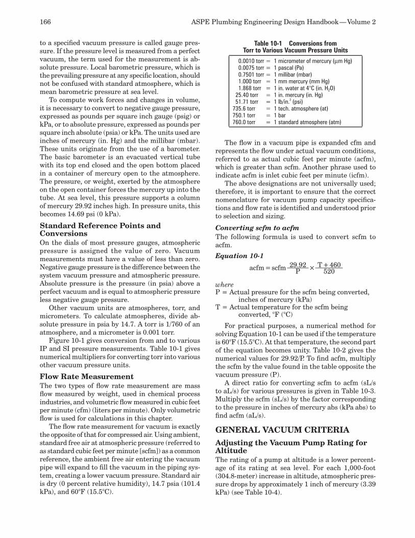
166 ASPE Plumbing Engineering Design Handbook — Volume 2
to a specified vacuum pressure is called gauge pres-sure. If the pressure level is measured from a perfect vacuum, the term used for the measurement is ab-solute pressure. Local barometric pressure, which is the prevailing pressure at any specific location, should not be confused with standard atmosphere, which is mean barometric pressure at sea level.
To compute work forces and changes in volume, it is necessary to convert to negative gauge pressure, expressed as pounds per square inch gauge (psig) or kPa, or to absolute pressure, expressed as pounds per square inch absolute (psia) or kPa. The units used are inches of mercury (in. Hg) and the millibar (mbar). These units originate from the use of a barometer. The basic barometer is an evacuated vertical tube with its top end closed and the open bottom placed in a container of mercury open to the atmosphere. The pressure, or weight, exerted by the atmosphere on the open container forces the mercury up into the tube. At sea level, this pressure supports a column of mercury 29.92 inches high. In pressure units, this becomes 14.69 psi (0 kPa).
Standard Reference Points and Conversions On the dials of most pressure gauges, atmospheric pressure is assigned the value of zero. Vacuum measurements must have a value of less than zero. Negative gauge pressure is the difference between the system vacuum pressure and atmospheric pressure. Absolute pressure is the pressure (in psia) above a perfect vacuum and is equal to atmospheric pressure less negative gauge pressure.
Other vacuum units are atmospheres, torr, and micrometers. To calculate atmospheres, divide ab-solute pressure in psia by 14.7. A torr is 1/760 of an atmosphere, and a micrometer is 0.001 torr.
Figure 10-1 gives conversion from and to various IP and SI pressure measurements. Table 10-1 gives numerical multipliers for converting torr into various other vacuum pressure units.
Flow Rate Measurement The two types of flow rate measurement are mass flow measured by weight, used in chemical process industries, and volumetric flow measured in cubic feet per minute (cfm) (liters per minute). Only volumetric flow is used for calculations in this chapter.
The flow rate measurement for vacuum is exactly the opposite of that for compressed air. Using ambient, standard free air at atmospheric pressure (referred to as standard cubic feet per minute [scfm]) as a common reference, the ambient free air entering the vacuum pipe will expand to fill the vacuum in the piping sys-tem, creating a lower vacuum pressure. Standard air is dry (0 percent relative humidity), 14.7 psia (101.4 kPa), and 60°F (15.5°C).
The flow in a vacuum pipe is expanded cfm and represents the flow under actual vacuum conditions, referred to as actual cubic feet per minute (acfm), which is greater than scfm. Another phrase used to indicate acfm is inlet cubic feet per minute (icfm).
The above designations are not universally used; therefore, it is important to ensure that the correct nomenclature for vacuum pump capacity specifica-tions and flow rate is identified and understood prior to selection and sizing.
Converting scfm to acfm The following formula is used to convert scfm to acfm.
Equation 10-1
acfm = scfm 29.92 × T + 460P 520
whereP = Actual pressure for the scfm being converted,
inches of mercury (kPa)T = Actual temperature for the scfm being
converted, °F (°C)
For practical purposes, a numerical method for solving Equation 10-1 can be used if the temperature is 60°F (15.5°C). At that temperature, the second part of the equation becomes unity. Table 10-2 gives the numerical values for 29.92/P. To find acfm, multiply the scfm by the value found in the table opposite the vacuum pressure (P).
A direct ratio for converting scfm to acfm (sL/s to aL/s) for various pressures is given in Table 10-3. Multiply the scfm (sL/s) by the factor corresponding to the pressure in inches of mercury abs (kPa abs) to find acfm (aL/s).
GENERAL VACUUM CRITERIA
Adjusting the Vacuum Pump Rating for AltitudeThe rating of a pump at altitude is a lower percent-age of its rating at sea level. For each 1,000-foot (304.8-meter) increase in altitude, atmospheric pres-sure drops by approximately 1 inch of mercury (3.39 kPa) (see Table 10-4).
Table 10-1 Conversions from Torr to Various Vacuum Pressure Units
0.0010 torr = 1 micrometer of mercury (µm Hg) 0.0075 torr = 1 pascal (Pa) 0.7501 torr = 1 millibar (mbar) 1.000 torr = 1 mm mercury (mm Hg) 1.868 torr = 1 in. water at 4°C (in. H2O) 25.40 torr = 1 in. mercury (in. Hg) 51.71 torr = 1 lb/in.2 (psi) 735.6 torr = 1 tech. atmosphere (at) 750.1 torr = 1 bar 760.0 torr = 1 standard atmosphere (atm)
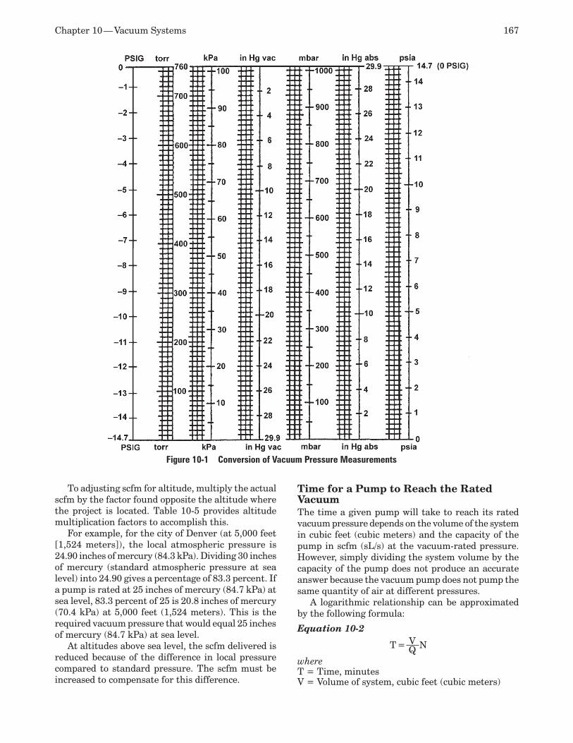
Chapter 10 — Vacuum Systems 167
To adjusting scfm for altitude, multiply the actual scfm by the factor found opposite the altitude where the project is located. Table 10-5 provides altitude multiplication factors to accomplish this.
For example, for the city of Denver (at 5,000 feet [1,524 meters]), the local atmospheric pressure is 24.90 inches of mercury (84.3 kPa). Dividing 30 inches of mercury (standard atmospheric pressure at sea level) into 24.90 gives a percentage of 83.3 percent. If a pump is rated at 25 inches of mercury (84.7 kPa) at sea level, 83.3 percent of 25 is 20.8 inches of mercury (70.4 kPa) at 5,000 feet (1,524 meters). This is the required vacuum pressure that would equal 25 inches of mercury (84.7 kPa) at sea level.
At altitudes above sea level, the scfm delivered is reduced because of the difference in local pressure compared to standard pressure. The scfm must be increased to compensate for this difference.
Time for a Pump to Reach the Rated VacuumThe time a given pump will take to reach its rated vacuum pressure depends on the volume of the system in cubic feet (cubic meters) and the capacity of the pump in scfm (sL/s) at the vacuum-rated pressure. However, simply dividing the system volume by the capacity of the pump does not produce an accurate answer because the vacuum pump does not pump the same quantity of air at different pressures.
A logarithmic relationship can be approximated by the following formula:
Equation 10-2
T = V NQwhereT = Time, minutesV = Volume of system, cubic feet (cubic meters)
Figure 10-1 Conversion of Vacuum Pressure Measurements
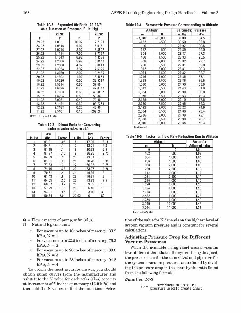
168 ASPE Plumbing Engineering Design Handbook — Volume 2
Q = Flow capacity of pump, scfm (sL/s)N = Natural log constant:
For vacuum up to 10 inches of mercury (33.9 •kPa), N = 1For vacuum up to 22.5 inches of mercury (76.2 •kPa), N = 2For vacuum up to 26 inches of mercury (88.0 •kPa), N = 3For vacuum up to 28 inches of mercury (94.8 •kPa), N = 4
To obtain the most accurate answer, you should obtain pump curves from the manufacturer and substitute the N value for each scfm (sL/s) capacity at increments of 5 inches of mercury (16.9 kPa) and then add the N values to find the total time. Selec-
tion of the value for N depends on the highest level of system vacuum pressure and is constant for several calculations.
Adjusting Pressure Drop for Different Vacuum Pressures
When the available sizing chart uses a vacuum level different than that of the system being designed, the pressure loss for the scfm (sL/s) and pipe size for the system’s vacuum pressure can be found by divid-ing the pressure drop in the chart by the ratio found from the following formula:
Equation 10-3
30 – new vacuum pressurepressure used to create chart
Table 10-2 Expanded Air Ratio, 29.92/P, as a Function of Pressure, P (in. Hg)
P29.92
P P29.92
P29.92 1.00 10.92 2.739928.92 1.0346 9.92 3.016127.92 1.0716 8.92 3.354226.92 1.1114 7.92 3.777725.92 1.1543 6.92 4.323624.92 1.2006 5.92 5.054023.92 1.2508 4.92 6.081322.92 1.3054 3.92 7.632621.92 1.3650 2.92 10.246520.92 1.4302 1.92 15.583319.92 1.5020 0.92 32.521718.92 1.5814 0.80 37.4017.92 1.6696 0.70 42.074216.92 1.7683 0.60 49.866715.92 1.8794 0.50 59.8414.92 2.0054 0.40 74.8013.92 2.1494 0.30 99.733412.92 2.3158 0.20 149.6011.92 2.5101 0.10 299.20
Note: 1 in. Hg = 3.39 kPa
Table 10-3 Direct Ratio for Converting scfm to acfm (sL/s to aL/s)
In. HgkPa Abs. Factor In. Hg
kPa Abs. Factor
1 97.9 1.05 16 47.09 2.152 94.5 1.1 17 43.71 2.33 91.15 1.1 18 40.33 2.54 87.77 1.15 19 36.95 2.735 84.39 1.2 20 33.57 36 81.01 1.25 21 30.20 3.337 77.63 1.3 22 26.82 3.758 74.19 1.35 23 23.37 4.289 70.81 1.4 24 19.99 5
10 67.43 1.5 25 16.61 611 64.05 1.55 26 13.23 7.512 60.67 1.62 27 9.85 1013 57.29 1.75 28 6.48 1514 53.91 1.85 29 3.10 3015 50.54 2.0 29.92 0 60
Table 10-4 Barometric Pressure Corresponding to AltitudeAltitudea Barometric Pressure
m ft in. Hg kPa–3,040 –10,000 31.00 104.5
–152 –500 30.50 102.80 0 29.92 100.8
152 500 29.39 99.0304 1,000 28.87 97.3456 1,500 28.33 95.5608 2,000 27.82 93.7760 2,500 27.31 92.0912 3,000 26.81 90.3
1,064 3,500 26.32 88.71,216 4,000 25.85 87.11,368 4,500 25.36 85.51,520 5,000 24.90 83.91,672 5,500 24.43 81.91,824 6,000 23.98 80.81,976 6,500 23.53 79.32,128 7,000 23.10 77.82,280 7,500 22.65 76.32,432 8,000 22.22 74.92,584 8,500 21.80 73.42,736 9,000 21.39 72.12,888 9,500 20.98 70.73,040 10,000 20.58 69.3
a Sea level = 0
Table 10-5 Factor for Flow Rate Reduction Due to AltitudeAltitude Factor for
Adjusted scfmm ft0 0 1.0
152 500 1.02304 1,000 1.04456 1,500 1.06608 2,000 1.08760 2,500 1.10912 3,000 1.12
1,064 3,500 1.141,216 4,000 1.161,520 5,000 1.201,824 6,000 1.252,128 7,000 1.302,432 8,000 1.352,736 9,000 1.403,040 10,000 1.453,344 11,000 1.51
1scfm = 0.472 sL/s
Chapter 10 — Vacuum Systems 169
Simplified Method of Calculating VelocityThe following formula can be used to find the velocity of a gas stream under a vacuum.
Equation 10-4V = C × Q
whereV = Velocity, feet per second (fps) (meters per
second)C = Constant for velocity based on pipe size (refer
to Table 10-6)Q = Flow rate based on an absolute vacuum
pressure, acfm (aL/s)
Example 10-1Calculate the velocity of 100 scfm (47.2 sL/s) through a 2-inch (50-DN) pipe with a pressure of 20 inches of mercury (67.7 kPa).
Find the equivalent absolute pressure of 20 inches of mercury (67.7 kPa). Using Table 10-7, read 9.92 inches of mercury abs (33.57 kPa abs).
Convert 100 scfm (47.2 sL/s) to acfm (aL/s) at a pressure of 9.92 inches of mercury abs (33.57 kPa abs) by using Table 10-3. Opposite 10 inches of mercury (33.9 kPa) is 1.5. Thus, 100 scfm x 1.5 = 150 acfm (70.8 aL/s).
Refer to Table 10-6 to obtain C. This table has been developed from the flow characteristics of air in Schedule 40 pipe. Opposite 2-inch (50-millimeter) pipe is 42.92.
Solving for velocity, V = 150 acfm x 42.92 = 6,438 fps (1,962 meters per second).
Vacuum Work ForcesThe total force of a vacuum system acting on a load is based on the vacuum pressure and the surface area on which the vacuum is acting. This is expressed in the following formula:
Equation 10-5F = P × A
whereF = Force, pounds (Newtons)P = Vacuum pressure, psig (Pa or Newtons per
square meter)A = Area, square inches (square meters)
Since the above formula is theoretical, it is com-mon practice to use a safety factor in the range of three to five times the calculated force to compensate for the quality of the air seal and other factors such as configuration of the load and outside forces such as acceleration.
VACUUM PUMPS AND SOURCE EQUIPMENTVacuum is produced by a single or multiple vacuum pump drawing air from remote vacuum inlets or
equipment. Except for some rare industrial applica-tions, vacuum pumps withdraw air from a receiver to produce the vacuum in the system.
Air exhausted from the system must be discharged to the atmosphere by means of an exhaust piping system. The pipe size shall be large enough to not restrict operation of the vacuum pump. (See the sepa-rate discussions under the “Laboratory and Vacuum Systems” and “Vacuum Cleaning Systems” sections, which follow.)
Alarms are required for maintenance purposes or to annunciate trouble, generally inadequate vacuum pressure, in the system.
Vacuum PumpsThe majority of vacuum pumps are divided into two general groups: gas transfer and capture. Capture-type pumps are outside the scope of this chapter.
Gas-transfer pumps are essentially air compres-sors that use the vacuum system as their inlet and discharge compressed air to the atmosphere. The majority of pumps used for most applications are gas-transfer pumps. They operate by removing gas from the lower pressure of the system and conveying it to the higher pressure of the free-air environment through one or more stages of compression provided by a vacuum pump. These pumps also are known as mechanical rotary-type pumps and are the type used most often for industrial and laboratory purposes.
These pumps can be divided into two categories: liquid sealed and dry. Liquid-sealed pumps use liquid, typically water or oil, to create a seal between the rotor and casing to produce a vacuum. Examples of liquid sealed gas-transfer pumps include rotary vane, once-through oil (OTO); rotary vane, recirculating oil sealed; oil-sealed reciprocating (rotary) piston; and liquid ring.
Dry vacuum pumps use tight tolerances to seal the pump chamber to produce vacuum. This can be done us-ing closely machined tolerances or replaceable wearing sealing elements. These types of pumps generally run hotter than liquid-sealed pumps. Examples of dry pumps are rotary sliding vane, oil-less; reciprocating (rotary) dry piston; rotary lobe (roots), ordinary lobe or claw; rotary screw; diaphragm; and centrifugal (turbo).
Table 10-6 Constant, C, for Finding Mean Air Velocity
DN
40 Sched. Pipe Size,
in. C DN
40 Sched. Pipe Size,
in. C12 3⁄8 740.9 65 2½ 30.1215 ½ 481.9 75 3 19.5320 ¾ 270.0 90 3½ 14.725 1 168.0 100 4 11.3232 1¼ 96.15 125 5 7.2740 1½ 71.43 150 6 5.050 2 42.92 200 8 2.95
1 in. = 25.4 mm
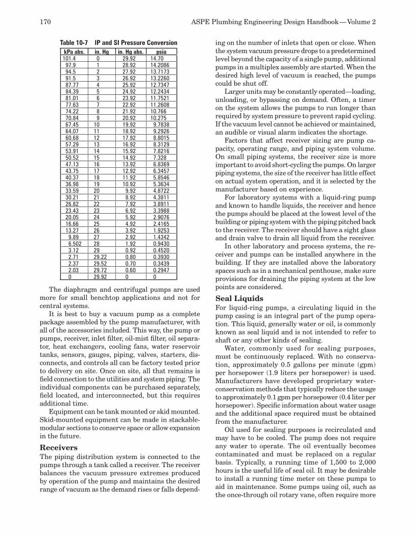
170 ASPE Plumbing Engineering Design Handbook — Volume 2
The diaphragm and centrifugal pumps are used more for small benchtop applications and not for central systems.
It is best to buy a vacuum pump as a complete package assembled by the pump manufacturer, with all of the accessories included. This way, the pump or pumps, receiver, inlet filter, oil-mist filter, oil separa-tor, heat exchangers, cooling fans, water reservoir tanks, sensors, gauges, piping, valves, starters, dis-connects, and controls all can be factory tested prior to delivery on site. Once on site, all that remains is field connection to the utilities and system piping. The individual components can be purchased separately, field located, and interconnected, but this requires additional time.
Equipment can be tank mounted or skid mounted. Skid-mounted equipment can be made in stackable-modular sections to conserve space or allow expansion in the future.
ReceiversThe piping distribution system is connected to the pumps through a tank called a receiver. The receiver balances the vacuum pressure extremes produced by operation of the pump and maintains the desired range of vacuum as the demand rises or falls depend-
ing on the number of inlets that open or close. When the system vacuum pressure drops to a predetermined level beyond the capacity of a single pump, additional pumps in a multiplex assembly are started. When the desired high level of vacuum is reached, the pumps could be shut off.
Larger units may be constantly operated—loading, unloading, or bypassing on demand. Often, a timer on the system allows the pumps to run longer than required by system pressure to prevent rapid cycling. If the vacuum level cannot be achieved or maintained, an audible or visual alarm indicates the shortage.
Factors that affect receiver sizing are pump ca-pacity, operating range, and piping system volume. On small piping systems, the receiver size is more important to avoid short-cycling the pumps. On larger piping systems, the size of the receiver has little effect on actual system operation, and it is selected by the manufacturer based on experience.
For laboratory systems with a liquid-ring pump and known to handle liquids, the receiver and hence the pumps should be placed at the lowest level of the building or piping system with the piping pitched back to the receiver. The receiver should have a sight glass and drain valve to drain all liquid from the receiver.
In other laboratory and process systems, the re-ceiver and pumps can be installed anywhere in the building. If they are installed above the laboratory spaces such as in a mechanical penthouse, make sure provisions for draining the piping system at the low points are considered.
Seal LiquidsFor liquid-ring pumps, a circulating liquid in the pump casing is an integral part of the pump opera-tion. This liquid, generally water or oil, is commonly known as seal liquid and is not intended to refer to shaft or any other kinds of sealing.
Water, commonly used for sealing purposes, must be continuously replaced. With no conserva-tion, approximately 0.5 gallons per minute (gpm) per horsepower (1.9 liters per horsepower) is used. Manufacturers have developed proprietary water-conservation methods that typically reduce the usage to approximately 0.1 gpm per horsepower (0.4 liter per horsepower). Specific information about water usage and the additional space required must be obtained from the manufacturer.
Oil used for sealing purposes is recirculated and may have to be cooled. The pump does not require any water to operate. The oil eventually becomes contaminated and must be replaced on a regular basis. Typically, a running time of 1,500 to 2,000 hours is the useful life of seal oil. It may be desirable to install a running time meter on these pumps to aid in maintenance. Some pumps using oil, such as the once-through oil rotary vane, often require more
Table 10-7 IP and SI Pressure ConversionkPa abs. in. Hg in. Hg abs. psia101.4 0 29.92 14.7097.9 1 28.92 14.208694.5 2 27.92 13.717391.5 3 26.92 13.226087.77 4 25.92 12.734784.39 5 24.92 12.243481.01 6 23.92 11.752177.63 7 22.92 11.260874.22 8 21.92 10.76670.84 9 20.92 10.27567.45 10 19.92 9.783864.07 11 18.92 9.292660.68 12 17.92 8.801557.29 13 16.92 8.312953.91 14 15.92 7.821650.52 15 14.92 7.32847.13 16 13.92 6.836943.75 17 12.92 6.345740.37 18 11.92 5.854636.98 19 10.92 5.363433.59 20 9.92 4.872230.21 21 8.92 4.381126.82 22 7.92 3.891123.43 23 6.92 3.398820.05 24 5.92 2.907616.66 25 4.92 2.416513.27 26 3.92 1.92539.89 27 2.92 1.43426.502 28 1.92 0.94303.12 29 0.92 0.45202.71 29.22 0.80 0.39302.37 29.52 0.70 0.34392.03 29.72 0.60 0.29470 29.92 0 0
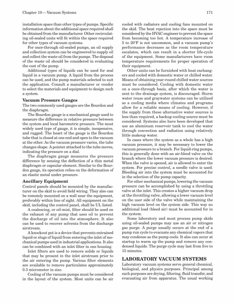
Chapter 10 — Vacuum Systems 171
installation space than other types of pumps. Specific information about the additional space required shall be obtained from the manufacturer. Other recirculat-ing oil-sealed units will fit within the space required for other types of vacuum systems.
For once-through oil-sealed pumps, an oil supply and collection system can be engineered to supply oil and collect the waste oil from the pumps. The disposal of the waste oil should be considered in evaluating the cost of the pump.
Additional types of liquids can be used for seal liquid in a vacuum pump. A liquid from the process can be used, and the pump materials selected to suit the application. Consult a manufacturer or vendor to select the materials and equipment to design such a system.
Vacuum Pressure GaugesThe two commonly used gauges are the Bourdon and the diaphragm.
The Bourdon gauge is a mechanical gauge used to measure the difference in relative pressure between the system and local barometric pressure. The most widely used type of gauge, it is simple, inexpensive, and rugged. The heart of the gauge is the Bourdon tube that is closed at one end and open to the vacuum at the other. As the vacuum pressure varies, the tube changes shape. A pointer attached to the tube moves, indicating the pressure on a dial.
The diaphragm gauge measures the pressure difference by sensing the deflection of a thin metal diaphragm or capsular element. Similar to the Bour-don gauge, its operation relies on the deformation of an elastic metal under pressure.
Ancillary EquipmentControl panels should be mounted by the manufac-turer on the skid to avoid field wiring. They also can be remotely mounted on a wall near the equipment, preferably within line of sight. All equipment on the skid, including the control panel, shall be UL listed.
A coalescing, or oil-mist, filter should be used on the exhaust of any pump that uses oil to prevent the discharge of oil into the atmosphere. It also can be used to recover solvents from the discharge airstream.
A knockout pot is a device that prevents entrained liquid or slugs of liquid from entering the inlet of me-chanical pumps used in industrial applications. It also can be combined with an inlet filter in one housing.
Inlet filters are used to remove solids or liquids that may be present in the inlet airstream prior to the air entering the pump. Various filter elements are available to remove particulates approximately 0.3 micrometer in size.
Cooling of the vacuum pumps must be considered in the layout of the system. Most units can be air
cooled with radiators and cooling fans mounted on the skid. The heat rejection into the space must be considered by the HVAC engineer to prevent the space from becoming too hot. A temperature increase of 5 to 20°F is not uncommon, and a vacuum pump’s performance decreases as the room temperature escalates, which can result in a shorter life-cycle of the equipment. Some manufacturers have room temperature requirements for proper operation of their equipment.
Other units can be furnished with heat exchang-ers and cooled with domestic water or chilled water. Means of obtaining year-round chilled water sources must be considered. Cooling with domestic water on a once-through basis, after which the water is sent to the drainage system, is discouraged. Storm water reuse and graywater systems can be utilized as a cooling media where climates and programs allow for a reliable means of cooling. However, if the supply from these alternative water sources is less than required, a backup cooling source must be considered. Systems also have been developed that use an aluminum reservoir tank to cool the water through convection and radiation using relatively little makeup water.
In cases where the system as a whole has a high vacuum pressure, it may be necessary to lower the vacuum pressure to a branch. For liquid-ring pumps, this is generally done with an air-bleed valve on the branch where the lower vacuum pressure is desired. When the valve is opened, air is allowed to enter the system. For precise control, a needle valve is used. Bleeding air into the system must be accounted for in the selection of the pump capacity.
For other mechanical pumps, lowering the vacuum pressure can be accomplished by using a throttling valve at the inlet. This creates a higher vacuum drop at the throttling valve, allowing a lower vacuum level on the user side of the valve while maintaining the high vacuum level on the system side. This way no additional load (bleed air) must be accounted for in the system.
Some laboratory and most process pump skids using oil-sealed pumps may use an air or nitrogen gas purge. A purge usually occurs at the end of a pump run cycle to evacuate any chemical vapors that may condense as the pump cools. It also can occur at startup to warm up the pump and remove any con-densed liquids. The purge cycle may last from five to 15 minutes.
LABORATORY VACUUM SYSTEMS Laboratory vacuum systems serve general chemical, biological, and physics purposes. Principal among such purposes are drying, filtering, fluid transfer, and evacuating air from apparatus. The usual working
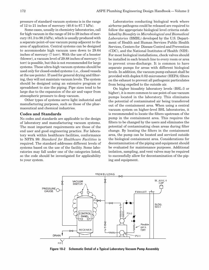
172 ASPE Plumbing Engineering Design Handbook — Volume 2
pressure of standard vacuum systems is in the range of 12 to 21 inches of mercury (40.6 to 67.7 kPa).
Some cases, usually in chemistry laboratories, call for high vacuum in the range of 24 to 29 inches of mer-cury (81.3 to 98.2 kPa), which is usually produced with a separate point-of-use vacuum pump adjacent to the area of application. Central systems can be designed to accommodate high vacuum uses down to 29.64 inches of mercury (7 torr). With the use of a booster (blower), a vacuum level of 29.88 inches of mercury (1 torr) is possible, but this is not recommended for large systems. These ultra-high vacuum systems should be used only for closed-ended systems (i.e., closed vessels at the use points). If used for general drying and filter-ing, they will not maintain vacuum levels. The system should be designed using an extensive program or spreadsheet to size the piping. Pipe sizes tend to be large due to the expansion of the air and vapor from atmospheric pressure to deep vacuum.
Other types of systems serve light industrial and manufacturing purposes, such as those of the phar-maceutical and chemical industries.
Codes and StandardsNo codes and standards are applicable to the design of laboratory and manufacturing vacuum systems. The most important requirements are those of the end user and good engineering practice. For labora-tory work within healthcare facilities, conformance to NFPA 99: Standard for Healthcare Facilities is required. The standard addresses different levels of systems based on the use of the facility. Some labo-ratories may fall under one of the categories listed, so the code should be investigated for applicability to your system.
Laboratories conducting biological work where airborne pathogens could be released are required to follow the appropriate biological level criteria estab-lished by Biosafety in Microbiological and Biomedical Laboratories (BMBL) developed by the U.S. Depart-ment of Health and Human Services Public Health Services, Centers for Disease Control and Prevention (CDC), and the National Institutes of Health (NIH). For most biological installations, check valves should be installed in each branch line to every room or area to prevent cross-discharge. It is common to have separate pumps for areas with different biological levels. In addition, the vacuum pump exhaust shall be provided with duplex 0.02-micrometer (HEPA) filters on the exhaust to prevent all pathogenic particulates from being expelled to the outside air.
On higher biosafety laboratory levels (BSL-3 or higher), it is more common to use point-of-use vacuum pumps located in the laboratory. This eliminates the potential of contaminated air being transferred out of the containment area. When using a central vacuum system on higher-level BSL laboratories, it is recommended to locate the filters upstream of the pump in the containment area. This requires the filters to be changed by the users and eliminates the potential of contaminating clean areas during filter change. By locating the filters in the containment area, the pump can be located and serviced outside the biological containment area. Considerations for decontamination of the piping and equipment should be evaluated for maintenance purposes. Additional isolation, sampling, and vent valves may be required to successfully allow for decontamination of the pip-ing and equipment.
Figure 10-2 Schematic Detail of a Typical Laboratory Vacuum Pump Assembly
Chapter 10 — Vacuum Systems 173
Vacuum SourceThe vacuum source usually consists of two or more pumps that are designed to operate as system de-mand requires, a receiver used to provide a vacuum reservoir and to separate liquids from the vacuum air-stream, the interconnecting piping around the pumps and receiver, and alarms. A duplex system, with each pump capable of assuming the entire load, typically is selected if the system is critical to the operation of the laboratory. In some smaller installations where the vacuum system is not critical, it may be acceptable to have a single vacuum pump or two pumps designed to handle a percentage of the total load. This allows some level of capacity when one pump fails or needs to be maintained.
The pumps selection should be based on the antici-pated design conditions consisting of vacuum level, process gases or liquids, first cost, maintenance cost, utility cost, and reliability. No single pump type will suit all applications; they each have strong and weak points.
The two most often used pump types in labora-tories are liquid ring and sliding vane. A common configuration for more than one pump is a rack
mounting one above the other and both pumps in-stalled over the receiver for a compact footprint. A schematic detail of a typical laboratory vacuum pump assembly is illustrated in Figure 10-2. A schematic detail of a typical process vacuum pump duplex as-sembly is illustrated in Figure 10-3.
Dry pump technology has gained prominence over the past years due to water conservation concerns and waste oil disposal. These pumps have moved from strictly chemical duty into the laboratory and medi-cal industry. Since they do run hot, they need to be evaluated for use on a laboratory or medical system so auto-ignition of the vapors does not happen.
Distribution NetworkPiping for the distribution system shall be a corro-sion-resistant material such as copper tube type K or L, stainless steel, galvanized steel pipe (usually Schedule 40 ASTM A53), or even plastic such as PVC, polypropylene, or high-density polyethylene. Copper tube shall be hard tempered except when installed underground, where soft tempered should be used. Although cost has a major influence on the selection of the piping material, the most commonly used is copper tube type L, ASTM B88, up to 4 inches (100
Figure 10-3 Typical Process Vacuum Pump Duplex Arrangement
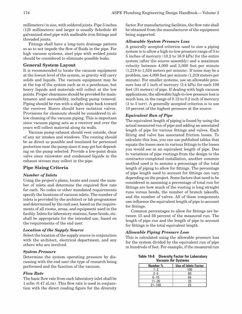
174 ASPE Plumbing Engineering Design Handbook — Volume 2
millimeters) in size, with soldered joints. Pipe 5 inches (125 millimeters) and larger is usually Schedule 40 galvanized steel pipe with malleable iron fittings and threaded joints.
Fittings shall have a long-turn drainage pattern so as to not impede the flow of fluids in the pipe. For high vacuum systems, steel pipe with welded joints should be considered to eliminate possible leaks.
General System LayoutIt is recommended to locate the vacuum equipment at the lowest level of the system, so gravity will carry solids and liquids. The vacuum equipment may be at the top of the system such as in a penthouse, but heavy liquids and materials will collect at the low points. Proper clearances should be provided for main-tenance and accessibility, including pump removal. Piping should be run with a slight slope back toward the receiver. Risers should have isolation valves. Provisions for cleanouts should be considered to al-low cleaning of the vacuum piping. This is important since vacuum piping acts as a receiver and over the years will collect material along its walls.
Vacuum pump exhaust should vent outside, clear of any air intakes and windows. The routing should be as direct as possible and insulated for personnel protection near the pump since it may get hot depend-ing on the pump selected. Provide a low-point drain valve since rainwater and condensed liquids in the exhaust stream may collect in the pipe.
Pipe Sizing Criteria
Number of Inlets Using the project’s plans, locate and count the num-ber of inlets and determine the required flow rate for each. No codes or other mandated requirements specify the locations of vacuum inlets. The number of inlets is provided by the architect or lab programmer and determined by the end user, based on the require-ments of all rooms, areas, and equipment used in the facility. Inlets for laboratory stations, fume hoods, etc. shall be appropriate for the intended use, based on the requirements of the end user.
Location of the Supply Source Select the location of the supply source in conjunction with the architect, electrical department, and any others who are involved.
System Pressure Determine the system operating pressure by dis-cussing with the end user the type of research being performed and the function of the vacuum.
Flow Rate The basic flow rate from each laboratory inlet shall be 1 scfm (0.47 sL/m). This flow rate is used in conjunc-tion with the direct reading figure for the diversity
factor. For manufacturing facilities, the flow rate shall be obtained from the manufacturer of the equipment being supported.
Allowable System Pressure Loss A generally accepted criterion used to size a piping system is to allow a high-to-low pressure range of 3 to 5 inches of mercury (10.2 to 16.9 kPa) for the entire system (after the source assembly) and a maximum velocity between 4,000 and 5,000 feet per minute (1,219 to 1,524 meters per minute). If noise may be a problem, use 4,000 feet per minute (1,219 meters per minute). For smaller systems, use an allowable pres-sure loss of 1 inch of mercury (3.4 kPa) for each 100 feet (31 meters) of pipe. If dealing with high vacuum applications, the allowable high-to-low pressure loss is much less, in the range of 0.12 to 0.2 inch of mercury (3 to 5 torr). A generally accepted criterion is to use 10 percent of the highest pressure at the source.
Equivalent Run of Pipe The equivalent length of piping is found by using the actual measured run of pipe and adding an associated length of pipe for various fittings and valves. Each fitting and valve has associated friction losses. To calculate this loss, you can use published tables that equate the losses seen in various fittings to the losses you would see in an equivalent length of pipe. Due to variations of pipe routings from the design to the contractor-completed installation, another common method used is to assume a percentage of the total length of piping to allow for fittings. The percentage of pipe length used to account for fittings can vary depending on the project. Some factors that need to be considered in assuming a percentage of total run for fittings are how much of the routing is long straight runs versus bends, the number of branch takeoffs, and the number of valves. All of these components can influence the equivalent length of pipe to account for fittings.
Common percentages to allow for fittings are be-tween 15 and 50 percent of the measured run. The length of pipe run and the length of pipe to account for fittings is the total equivalent length.
Allowable Piping Pressure Loss This is calculated using the allowable pressure loss for the system divided by the equivalent run of pipe in hundreds of feet. For example, if the measured run
Table 10-8 Diversity Factor for Laboratory Vacuum Air Systems
Number % Use of Inlets Factor1–2 1003–5 806–10 6611–20 3521–100 25
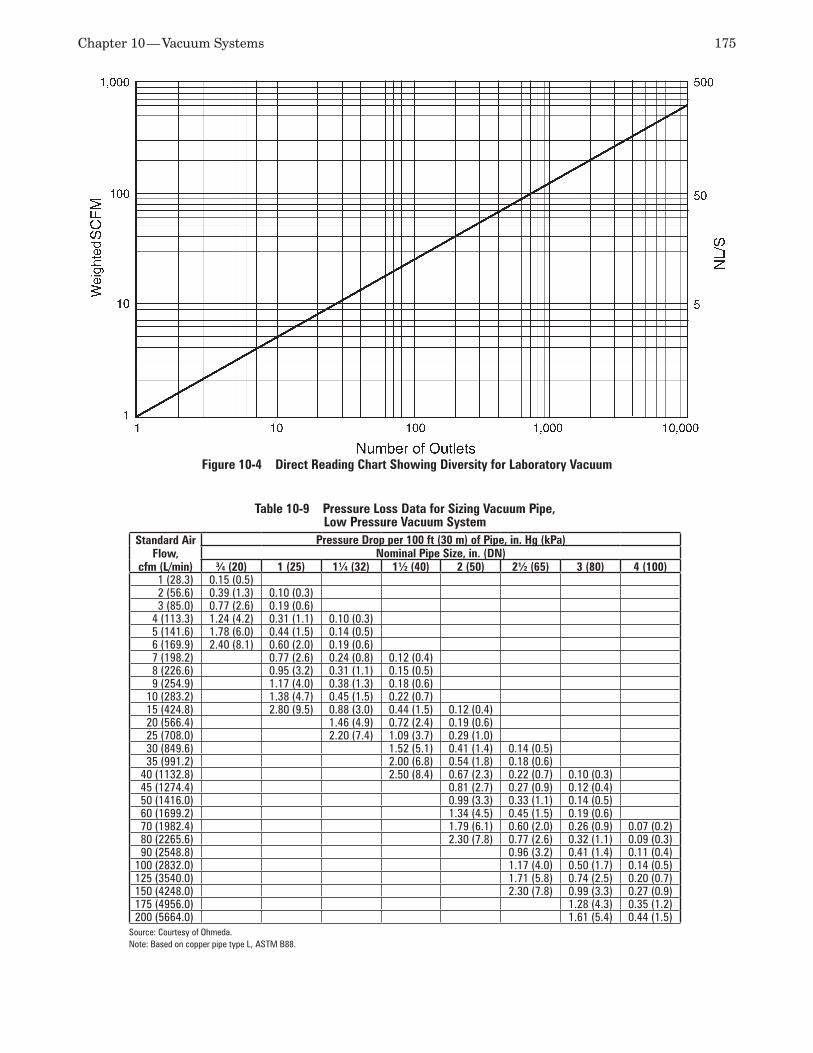
Chapter 10 — Vacuum Systems 175
Figure 10-4 Direct Reading Chart Showing Diversity for Laboratory Vacuum
Table 10-9 Pressure Loss Data for Sizing Vacuum Pipe, Low Pressure Vacuum System
Standard Air Flow,
cfm (L/min)
Pressure Drop per 100 ft (30 m) of Pipe, in. Hg (kPa)Nominal Pipe Size, in. (DN)
¾ (20) 1 (25) 1¼ (32) 1½ (40) 2 (50) 2½ (65) 3 (80) 4 (100)1 (28.3) 0.15 (0.5)2 (56.6) 0.39 (1.3) 0.10 (0.3)3 (85.0) 0.77 (2.6) 0.19 (0.6)
4 (113.3) 1.24 (4.2) 0.31 (1.1) 0.10 (0.3)5 (141.6) 1.78 (6.0) 0.44 (1.5) 0.14 (0.5)6 (169.9) 2.40 (8.1) 0.60 (2.0) 0.19 (0.6)7 (198.2) 0.77 (2.6) 0.24 (0.8) 0.12 (0.4)8 (226.6) 0.95 (3.2) 0.31 (1.1) 0.15 (0.5)9 (254.9) 1.17 (4.0) 0.38 (1.3) 0.18 (0.6)
10 (283.2) 1.38 (4.7) 0.45 (1.5) 0.22 (0.7)15 (424.8) 2.80 (9.5) 0.88 (3.0) 0.44 (1.5) 0.12 (0.4)20 (566.4) 1.46 (4.9) 0.72 (2.4) 0.19 (0.6)25 (708.0) 2.20 (7.4) 1.09 (3.7) 0.29 (1.0)30 (849.6) 1.52 (5.1) 0.41 (1.4) 0.14 (0.5)35 (991.2) 2.00 (6.8) 0.54 (1.8) 0.18 (0.6)
40 (1132.8) 2.50 (8.4) 0.67 (2.3) 0.22 (0.7) 0.10 (0.3)45 (1274.4) 0.81 (2.7) 0.27 (0.9) 0.12 (0.4)50 (1416.0) 0.99 (3.3) 0.33 (1.1) 0.14 (0.5)60 (1699.2) 1.34 (4.5) 0.45 (1.5) 0.19 (0.6)70 (1982.4) 1.79 (6.1) 0.60 (2.0) 0.26 (0.9) 0.07 (0.2)80 (2265.6) 2.30 (7.8) 0.77 (2.6) 0.32 (1.1) 0.09 (0.3)90 (2548.8) 0.96 (3.2) 0.41 (1.4) 0.11 (0.4)
100 (2832.0) 1.17 (4.0) 0.50 (1.7) 0.14 (0.5)125 (3540.0) 1.71 (5.8) 0.74 (2.5) 0.20 (0.7)150 (4248.0) 2.30 (7.8) 0.99 (3.3) 0.27 (0.9)175 (4956.0) 1.28 (4.3) 0.35 (1.2)200 (5664.0) 1.61 (5.4) 0.44 (1.5)
Source: Courtesy of Ohmeda.Note: Based on copper pipe type L, ASTM B88.
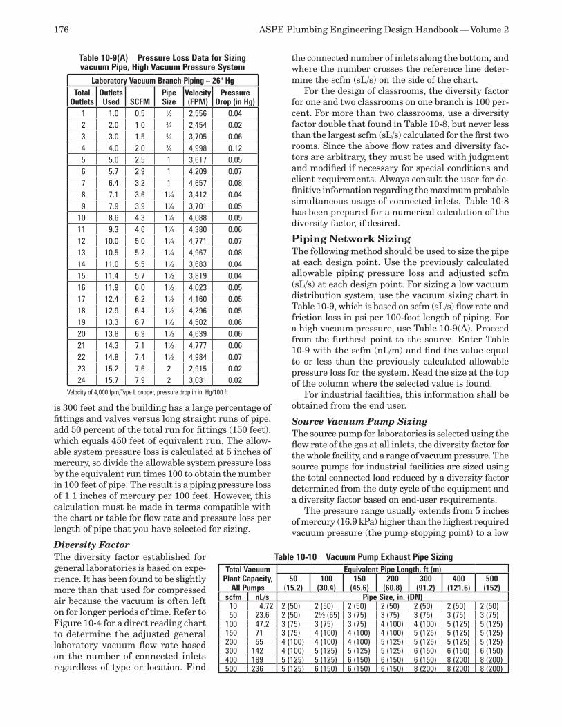
176 ASPE Plumbing Engineering Design Handbook — Volume 2
is 300 feet and the building has a large percentage of fittings and valves versus long straight runs of pipe, add 50 percent of the total run for fittings (150 feet), which equals 450 feet of equivalent run. The allow-able system pressure loss is calculated at 5 inches of mercury, so divide the allowable system pressure loss by the equivalent run times 100 to obtain the number in 100 feet of pipe. The result is a piping pressure loss of 1.1 inches of mercury per 100 feet. However, this calculation must be made in terms compatible with the chart or table for flow rate and pressure loss per length of pipe that you have selected for sizing.
Diversity Factor The diversity factor established for general laboratories is based on expe-rience. It has been found to be slightly more than that used for compressed air because the vacuum is often left on for longer periods of time. Refer to Figure 10-4 for a direct reading chart to determine the adjusted general laboratory vacuum flow rate based on the number of connected inlets regardless of type or location. Find
the connected number of inlets along the bottom, and where the number crosses the reference line deter-mine the scfm (sL/s) on the side of the chart.
For the design of classrooms, the diversity factor for one and two classrooms on one branch is 100 per-cent. For more than two classrooms, use a diversity factor double that found in Table 10-8, but never less than the largest scfm (sL/s) calculated for the first two rooms. Since the above flow rates and diversity fac-tors are arbitrary, they must be used with judgment and modified if necessary for special conditions and client requirements. Always consult the user for de-finitive information regarding the maximum probable simultaneous usage of connected inlets. Table 10-8 has been prepared for a numerical calculation of the diversity factor, if desired.
Piping Network Sizing The following method should be used to size the pipe at each design point. Use the previously calculated allowable piping pressure loss and adjusted scfm (sL/s) at each design point. For sizing a low vacuum distribution system, use the vacuum sizing chart in Table 10-9, which is based on scfm (sL/s) flow rate and friction loss in psi per 100-foot length of piping. For a high vacuum pressure, use Table 10-9(A). Proceed from the furthest point to the source. Enter Table 10-9 with the scfm (nL/m) and find the value equal to or less than the previously calculated allowable pressure loss for the system. Read the size at the top of the column where the selected value is found.
For industrial facilities, this information shall be obtained from the end user.
Source Vacuum Pump Sizing The source pump for laboratories is selected using the flow rate of the gas at all inlets, the diversity factor for the whole facility, and a range of vacuum pressure. The source pumps for industrial facilities are sized using the total connected load reduced by a diversity factor determined from the duty cycle of the equipment and a diversity factor based on end-user requirements.
The pressure range usually extends from 5 inches of mercury (16.9 kPa) higher than the highest required vacuum pressure (the pump stopping point) to a low
Table 10-10 Vacuum Pump Exhaust Pipe SizingTotal Vacuum
Plant Capacity, All Pumps
Equivalent Pipe Length, ft (m)50
(15.2)100
(30.4)150
(45.6)200
(60.8)300
(91.2)400
(121.6)500
(152)scfm nL/s Pipe Size, in. (DN)
10 4.72 2 (50) 2 (50) 2 (50) 2 (50) 2 (50) 2 (50) 2 (50)50 23.6 2 (50) 2½ (65) 3 (75) 3 (75) 3 (75) 3 (75) 3 (75)
100 47.2 3 (75) 3 (75) 3 (75) 4 (100) 4 (100) 5 (125) 5 (125)150 71 3 (75) 4 (100) 4 (100) 4 (100) 5 (125) 5 (125) 5 (125)200 55 4 (100) 4 (100) 4 (100) 5 (125) 5 (125) 5 (125) 5 (125)300 142 4 (100) 5 (125) 5 (125) 5 (125) 6 (150) 6 (150) 6 (150)400 189 5 (125) 5 (125) 6 (150) 6 (150) 6 (150) 8 (200) 8 (200)500 236 5 (125) 6 (150) 6 (150) 6 (150) 8 (200) 8 (200) 8 (200)
Table 10-9(A) Pressure Loss Data for Sizing vacuum Pipe, High Vacuum Pressure System
Laboratory Vacuum Branch Piping – 26" HgTotal
OutletsOutletsUsed SCFM
PipeSize
Velocity(FPM)
Pressure Drop (in Hg)
1 1.0 0.5 1⁄2 2,556 0.042 2.0 1.0 3⁄4 2,454 0.023 3.0 1.5 3⁄4 3,705 0.064 4.0 2.0 3⁄4 4,998 0.125 5.0 2.5 1 3,617 0.056 5.7 2.9 1 4,209 0.077 6.4 3.2 1 4,657 0.088 7.1 3.6 11⁄4 3,412 0.049 7.9 3.9 11⁄4 3,701 0.05
10 8.6 4.3 11⁄4 4,088 0.0511 9.3 4.6 11⁄4 4,380 0.0612 10.0 5.0 11⁄4 4,771 0.0713 10.5 5.2 11⁄4 4,967 0.0814 11.0 5.5 11⁄2 3,683 0.0415 11.4 5.7 11⁄2 3,819 0.0416 11.9 6.0 11⁄2 4,023 0.0517 12.4 6.2 11⁄2 4,160 0.0518 12.9 6.4 11⁄2 4,296 0.0519 13.3 6.7 11⁄2 4,502 0.0620 13.8 6.9 11⁄2 4,639 0.0621 14.3 7.1 11⁄2 4,777 0.0622 14.8 7.4 11⁄2 4,984 0.0723 15.2 7.6 2 2,915 0.0224 15.7 7.9 2 3,031 0.02
Velocity of 4,000 fpm,Type L copper, pressure drop in in. Hg/100 ft
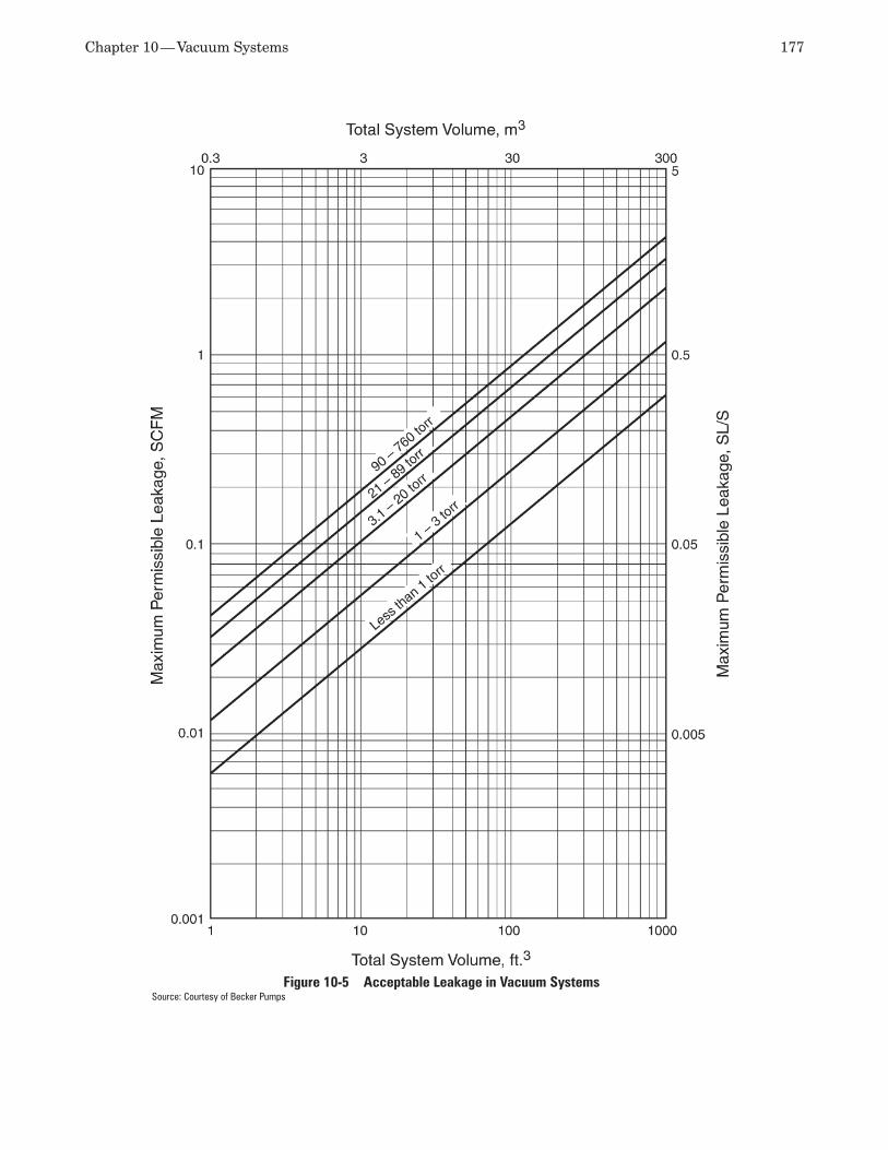
Chapter 10 — Vacuum Systems 177
Figure 10-5 Acceptable Leakage in Vacuum SystemsSource: Courtesy of Becker Pumps
178 ASPE Plumbing Engineering Design Handbook — Volume 2
figure equal to the lowest acceptable system pressure (the pump starting point). For duplex and triplex pump arrangements, the intermediate vacuum settings for multiple pumps shall be adjusted accordingly.
Vacuum Pump Exhaust Pipe Sizing For sizing the exhaust piping from the vacuum pump source assembly, refer to Table 10-10, using the equivalent length of exhaust piping as the length of piping. (See the “Piping Network Sizing” section below for a definition of equivalent length.)
System Leakage There is a difference between desirable and accept-able leakage in a vacuum system. Ideally, no leakage should occur. It is common practice to test labora-tory vacuum piping systems, section by section, at the rated maximum working pressure for 24 hours with no loss of pressure permitted. Yet it is almost impossible to install a large system that does not have small leaks. If such is the case, what is an acceptable amount of leakage?
There is no generally accepted value for allowable leakage in a vacuum system, which should be related to the volume of the piping network to be meaningful. However, the Heat Exchange Institute has developed a standard based on system volume. This formula, transposed to solve for leakage, is:
Equation 10-6
L =0.15 × V
T4.5
whereL = Leakage, scfm (sL/s)(To convert to metric,
multiply L by 0.4719.)V = Total piping system volume, cubic feet (cubic
meters)T = Time for vacuum pressure to drop 1 inch of
mercury, minutes
After calculating the system volume and the leak-age from the system, use Figure 10-5 to determine if the intersection of the two values falls within the acceptable portion of the chart.
VACUUM CLEANING SYSTEMSVacuum cleaning systems are used to remove un-wanted dirt, dust, and liquids from floors, walls, and ceilings. This involves the use of either a permanent, centrally located system or portable, self-contained, electric-powered units. A central system transports the unwanted debris to a central location where it can be disposed of or recovered easily. Portable units can be moved throughout all areas of a facility. The design of portable units is outside the scope of this chapter.
Types of Systems and EquipmentThe three types of permanent systems are dry, wet, and combination. The dry system is intended exclu-
sively for free-flowing dry material. It is the most commonly used type of system, with cleaning capa-bilities ranging from cleaning carpets to removing potentially toxic and explosive product spills from the floors of an industrial facility. Equipment consists of a vacuum producer, one or more separators that remove collected materials from the airstream, tubing to convey the air and materials to the separator, and inlets located throughout the facility. A wide variety of separators is available to allow disposal and recovery of the collected materials.
The wet system is intended exclusively for liq-uid handling and pickup. It is commonly found in healthcare, industrial, and laboratory facilities where sanitation is important and frequent washings are required. Equipment consists of a vacuum producer, a wet separator constructed to resist the chemical action of the liquids involved, piping or tubing of a material resistant to the chemical action of the liquid, and inlets located throughout the facility.
A combination system is capable of both wet and dry pickup. Equipment consists of a vacuum producer, a wet separator constructed to resist the chemical action of the liquid mixtures involved, pipe or tubing of a material resistant to the chemical action of the combined solid/liquid, and inlets located throughout the facility.
Codes and StandardsNo codes and standards directly govern the design and installation of vacuum cleaning systems. If deal-ing with explosive powders, NFPA 68: Standard on Explosion Protection by Deflagration Venting and NFPA 69: Standard on Explosion Prevention Systems may apply.
System Components
Vacuum Producer Vacuum producers for typical vacuum cleaning sys-tems consist of a single or multistage centrifugal-type unit powered by an electric motor. The housing can be constructed of various materials to handle special chemicals and nonsparking aluminum for poten-tially explosive dust. The discharge of the unit can be positioned at various points to accommodate the requirements of the exhaust piping system. Silenc-ers, sound-attenuating enclosures, or rooms can be provided to attenuate the noise.
Separator Separators are used to remove the solid particulates in the airstream generated by the vacuum producer. For dry systems, tubular-bag and centrifugal-type separators can be used.
If only dust and other fine materials are expected, a tubular-bag type is adequate. The bag is permanently installed and cannot be removed. It functions as an
Chapter 10 — Vacuum Systems 179
air filter for fine particles and collects a majority of the dirt. This dirt eventually falls into a hopper or a dirt can at the bottom of the unit. To empty the entire unit, the system must be shut down. The bag must be shaken to remove as much of the collected material as possible and emptied into the dirt can. The dirt can is removed (or the hopper is emptied into a separate container) to clean out the unit. The dirt can should be sized to hold at least one full day’s storage. Units are available with multiple bags to increase filter bag area. Shaking can be done either manually or by mo-tor. The motor-operated shaker has adjustable timers to start operation after shut down of the system and to shake the bags. If continuous operation is required, compressed air can be blown through the bag to re-move the dirt without requiring a shutdown.
The centrifugal-type separator is designed to re-move coarse, dry particles from the airstream. It also is recommended when more than six simultaneous operators are anticipated to remove the bulk of the dirt. The air enters the separator tangential to the unit, and the air containing particulates is forced into a circular motion within the unit. Centrifugal force accomplishes separation.
The wet separator system collects the liquid, sepa-rates the water from the airstream, and discharges the waste to the drain. This type of separator can be equipped with an automatic overflow shutoff that stops the system if the water level reaches a predetermined high-water level and with automatic emptying features.
Immersion-type separators are used to collect explo-sive or flammable materials in a water compartment. If there is a potential for explosion, such as exists in a grain or flour-handling facility, the separator shall be provided with an integral explosion relief/rupture device that is vented to the outside of the building.
Filter Vacuum producers typically are exhausted to the out-side air and do not require any filtration. However, when substances removed from the facility are consid-ered harmful to the environment, a HEPA filter must be installed in the discharge line to prevent contamina-tion of the outside air. The recommended location is between the separator and the vacuum producer, but an alternate location immediately prior to penetration of the building wall or roof is also acceptable.
Silencer When the exhaust from the vacuum producer is con-sidered too noisy, a silencer shall be installed in the exhaust to reduce the noise to an acceptable level. Pulsating airflow requires special design consider-ations. The connection to the silencer shall be made with a flexible connection. Additional support for the
silencer is recommended. Filters and silencers can be economically combined into a single, integral unit.
Inlets Inlets are female inlet valves and are equipped with self-closing covers. They provide a quick connection for any male hose or equipment. The covers can be locked as an option. Many different inlet types are available, in sizes ranging from 1½ to 4 inches (40 to 100 millimeters) and of various materials.
Control and Check Valves Valves for vacuum cleaning systems are different than standard valves. They are used to control the flow or stop the reverse flow of air in the system. When used only fully open or closed, they generally are referred to as blast gates. When used as regulating valves, they are called wafer butterfly valves. A less costly substitute for a blast gate is an air gate valve, which operates using a sliding plate in a channel. The plate has a hole that matches the size of the opening in the channel, with room to close off the opening completely. Air gates can be used only in low-pressure systems and are generally available in sizes from 2 to 6 inches (50 to 150 millimeters).
Check valves are typically spring-loaded, swing-type valves hinged in the center.
Air-bleed Control If the exhauster is constantly operated with low or no inlet air, the exhauster motor might become hot enough to require shutdown due to overheating. To avoid this, an air-bleed device can be installed on the inlet to the exhauster that will automatically allow air to enter the piping system. If the facility indicates that this may be a possibility, the manufacturer of the unit should be consulted to determine the need for this device for the system selected.
Pipe and Fittings The pipe material most often used is thin-wall tubing, generally in the range of 12 to 16 gauge. This tubing is available in plain carbon steel, zinc-coated steel, aluminum, and stainless steel. In some cases PVC can be used; however, you should verify with the pipe manufacturer that it can be used for the intended vacuum level of your system.
Fittings are specially designed for a vacuum clean-ing system. Tubing typically is joined using shrink sleeves over the joints. Compression fittings and flex-ible rubber sleeves and clamps also are used. Tubing shall be supported every 8 to 10 feet (2.4 to 3.1 me-ters), depending on size, under normal conditions.
Standard steel pipe often is used in areas where the additional strength is required. In special areas where leakage prevention and strength are mandatory, the tubing joints can be welded if required.
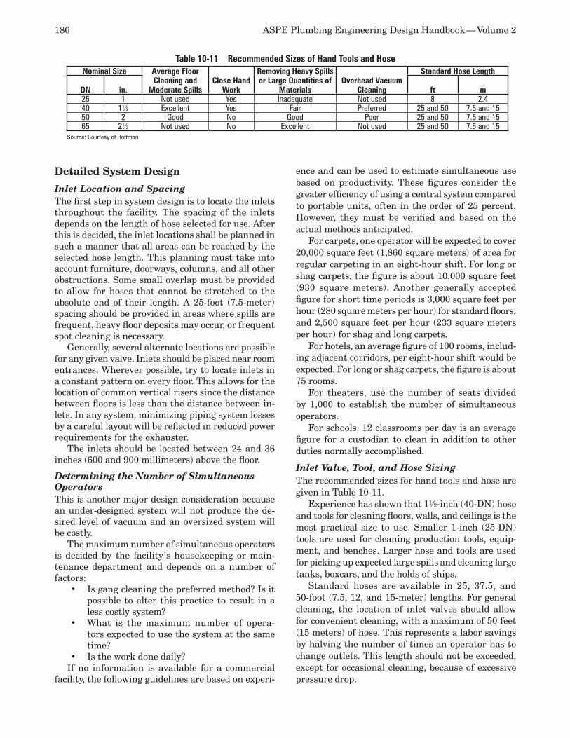
180 ASPE Plumbing Engineering Design Handbook — Volume 2
Detailed System Design
Inlet Location and Spacing The first step in system design is to locate the inlets throughout the facility. The spacing of the inlets depends on the length of hose selected for use. After this is decided, the inlet locations shall be planned in such a manner that all areas can be reached by the selected hose length. This planning must take into account furniture, doorways, columns, and all other obstructions. Some small overlap must be provided to allow for hoses that cannot be stretched to the absolute end of their length. A 25-foot (7.5-meter) spacing should be provided in areas where spills are frequent, heavy floor deposits may occur, or frequent spot cleaning is necessary.
Generally, several alternate locations are possible for any given valve. Inlets should be placed near room entrances. Wherever possible, try to locate inlets in a constant pattern on every floor. This allows for the location of common vertical risers since the distance between floors is less than the distance between in-lets. In any system, minimizing piping system losses by a careful layout will be reflected in reduced power requirements for the exhauster.
The inlets should be located between 24 and 36 inches (600 and 900 millimeters) above the floor.
Determining the Number of Simultaneous Operators This is another major design consideration because an under-designed system will not produce the de-sired level of vacuum and an oversized system will be costly.
The maximum number of simultaneous operators is decided by the facility’s housekeeping or main-tenance department and depends on a number of factors:
Is gang cleaning the preferred method? Is it •possible to alter this practice to result in a less costly system?What is the maximum number of opera-•tors expected to use the system at the same time?Is the work done daily?•
If no information is available for a commercial facility, the following guidelines are based on experi-
ence and can be used to estimate simultaneous use based on productivity. These figures consider the greater efficiency of using a central system compared to portable units, often in the order of 25 percent. However, they must be verified and based on the actual methods anticipated.
For carpets, one operator will be expected to cover 20,000 square feet (1,860 square meters) of area for regular carpeting in an eight-hour shift. For long or shag carpets, the figure is about 10,000 square feet (930 square meters). Another generally accepted figure for short time periods is 3,000 square feet per hour (280 square meters per hour) for standard floors, and 2,500 square feet per hour (233 square meters per hour) for shag and long carpets.
For hotels, an average figure of 100 rooms, includ-ing adjacent corridors, per eight-hour shift would be expected. For long or shag carpets, the figure is about 75 rooms.
For theaters, use the number of seats divided by 1,000 to establish the number of simultaneous operators.
For schools, 12 classrooms per day is an average figure for a custodian to clean in addition to other duties normally accomplished.
Inlet Valve, Tool, and Hose Sizing The recommended sizes for hand tools and hose are given in Table 10-11.
Experience has shown that 1½-inch (40-DN) hose and tools for cleaning floors, walls, and ceilings is the most practical size to use. Smaller 1-inch (25-DN) tools are used for cleaning production tools, equip-ment, and benches. Larger hose and tools are used for picking up expected large spills and cleaning large tanks, boxcars, and the holds of ships.
Standard hoses are available in 25, 37.5, and 50-foot (7.5, 12, and 15-meter) lengths. For general cleaning, the location of inlet valves should allow for convenient cleaning, with a maximum of 50 feet (15 meters) of hose. This represents a labor savings by halving the number of times an operator has to change outlets. This length should not be exceeded, except for occasional cleaning, because of excessive pressure drop.
Table 10-11 Recommended Sizes of Hand Tools and HoseNominal Size Average Floor
Cleaning and Moderate Spills
Close Hand Work
Removing Heavy Spills or Large Quantities of
MaterialsOverhead Vacuum
Cleaning
Standard Hose Length
DN in. ft m25 1 Not used Yes Inadequate Not used 8 2.440 1½ Excellent Yes Fair Preferred 25 and 50 7.5 and 1550 2 Good No Good Poor 25 and 50 7.5 and 1565 2½ Not used No Excellent Not used 25 and 50 7.5 and 15
Source: Courtesy of Hoffman
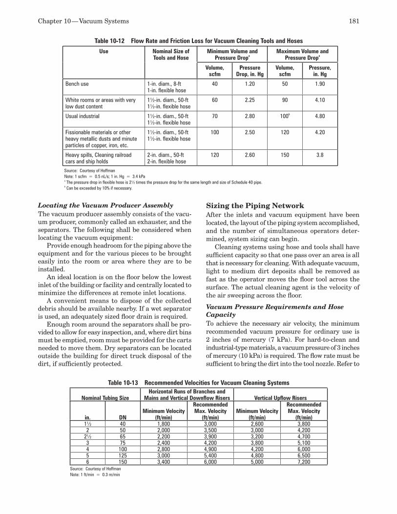
Chapter 10 — Vacuum Systems 181
Locating the Vacuum Producer Assembly The vacuum producer assembly consists of the vacu-um producer, commonly called an exhauster, and the separators. The following shall be considered when locating the vacuum equipment:
Provide enough headroom for the piping above the equipment and for the various pieces to be brought easily into the room or area where they are to be installed.
An ideal location is on the floor below the lowest inlet of the building or facility and centrally located to minimize the differences at remote inlet locations.
A convenient means to dispose of the collected debris should be available nearby. If a wet separator is used, an adequately sized floor drain is required.
Enough room around the separators shall be pro-vided to allow for easy inspection, and, where dirt bins must be emptied, room must be provided for the carts needed to move them. Dry separators can be located outside the building for direct truck disposal of the dirt, if sufficiently protected.
Sizing the Piping NetworkAfter the inlets and vacuum equipment have been located, the layout of the piping system accomplished, and the number of simultaneous operators deter-mined, system sizing can begin.
Cleaning systems using hose and tools shall have sufficient capacity so that one pass over an area is all that is necessary for cleaning. With adequate vacuum, light to medium dirt deposits shall be removed as fast as the operator moves the floor tool across the surface. The actual cleaning agent is the velocity of the air sweeping across the floor.
Vacuum Pressure Requirements and Hose Capacity To achieve the necessary air velocity, the minimum recommended vacuum pressure for ordinary use is 2 inches of mercury (7 kPa). For hard-to-clean and industrial-type materials, a vacuum pressure of 3 inches of mercury (10 kPa) is required. The flow rate must be sufficient to bring the dirt into the tool nozzle. Refer to
Table 10-12 Flow Rate and Friction Loss for Vacuum Cleaning Tools and Hoses
Use Nominal Size of Tools and Hose
Minimum Volume and Pressure Dropa
Maximum Volume and Pressure Dropa
Volume, scfm
Pressure Drop, in. Hg
Volume, scfm
Pressure, in. Hg
Bench use 1-in. diam., 8-ft1-in. flexible hose
40 1.20 50 1.90
White rooms or areas with very low dust content
1½-in. diam., 50-ft1½-in. flexible hose
60 2.25 90 4.10
Usual industrial 1½-in. diam., 50-ft1½-in. flexible hose
70 2.80 100b 4.80
Fissionable materials or other heavy metallic dusts and minute particles of copper, iron, etc.
1½-in. diam., 50-ft1½-in. flexible hose
100 2.50 120 4.20
Heavy spills, Cleaning railroad cars and ship holds
2-in. diam., 50-ft2-in. flexible hose
120 2.60 150 3.8
Source: Courtesy of HoffmanNote: 1 scfm = 0.5 nL/s; 1 in. Hg = 3.4 kPaa The pressure drop in flexible hose is 2½ times the pressure drop for the same length and size of Schedule 40 pipe.b Can be exceeded by 10% if necessary.
Table 10-13 Recommended Velocities for Vacuum Cleaning Systems
Nominal Tubing SizeHorizontal Runs of Branches and
Mains and Vertical Downflow Risers Vertical Upflow Risers
in. DNMinimum Velocity
(ft/min)
Recommended Max. Velocity
(ft/min)Minimum Velocity
(ft/min)
Recommended Max. Velocity
(ft/min)1½ 40 1,800 3,000 2,600 3,8002 50 2,000 3,500 3,000 4,200
2½ 65 2,200 3,900 3,200 4,7003 75 2,400 4,200 3,800 5,1004 100 2,800 4,900 4,200 6,0005 125 3,000 5,400 4,800 6,5006 150 3,400 6,000 5,000 7,200
Source: Courtesy of HoffmanNote: 1 ft/min = 0.3 m/min
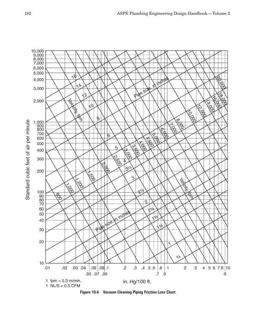
182 ASPE Plumbing Engineering Design Handbook — Volume 2
Figure 10-6 Vacuum Cleaning Piping Friction Loss Chart
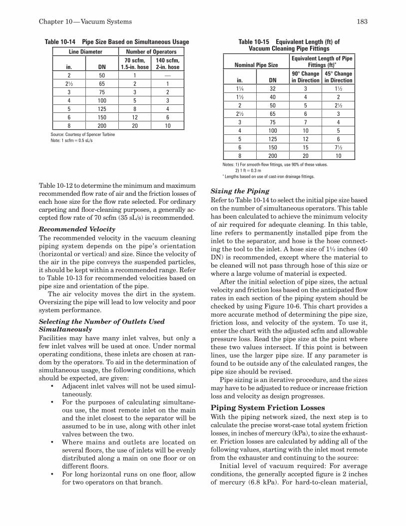
Chapter 10 — Vacuum Systems 183
Table 10-12 to determine the minimum and maximum recommended flow rate of air and the friction losses of each hose size for the flow rate selected. For ordinary carpeting and floor-cleaning purposes, a generally ac-cepted flow rate of 70 scfm (35 sL/s) is recommended.
Recommended Velocity The recommended velocity in the vacuum cleaning piping system depends on the pipe’s orientation (horizontal or vertical) and size. Since the velocity of the air in the pipe conveys the suspended particles, it should be kept within a recommended range. Refer to Table 10-13 for recommended velocities based on pipe size and orientation of the pipe.
The air velocity moves the dirt in the system. Oversizing the pipe will lead to low velocity and poor system performance.
Selecting the Number of Outlets Used Simultaneously Facilities may have many inlet valves, but only a few inlet valves will be used at once. Under normal operating conditions, these inlets are chosen at ran-dom by the operators. To aid in the determination of simultaneous usage, the following conditions, which should be expected, are given:
Adjacent inlet valves will not be used simul-•taneously.For the purposes of calculating simultane-•ous use, the most remote inlet on the main and the inlet closest to the separator will be assumed to be in use, along with other inlet valves between the two.Where mains and outlets are located on •several floors, the use of inlets will be evenly distributed along a main on one floor or on different floors.For long horizontal runs on one floor, allow •for two operators on that branch.
Sizing the Piping Refer to Table 10-14 to select the initial pipe size based on the number of simultaneous operators. This table has been calculated to achieve the minimum velocity of air required for adequate cleaning. In this table, line refers to permanently installed pipe from the inlet to the separator, and hose is the hose connect-ing the tool to the inlet. A hose size of 1½ inches (40 DN) is recommended, except where the material to be cleaned will not pass through hose of this size or where a large volume of material is expected.
After the initial selection of pipe sizes, the actual velocity and friction loss based on the anticipated flow rates in each section of the piping system should be checked by using Figure 10-6. This chart provides a more accurate method of determining the pipe size, friction loss, and velocity of the system. To use it, enter the chart with the adjusted scfm and allowable pressure loss. Read the pipe size at the point where these two values intersect. If this point is between lines, use the larger pipe size. If any parameter is found to be outside any of the calculated ranges, the pipe size should be revised.
Pipe sizing is an iterative procedure, and the sizes may have to be adjusted to reduce or increase friction loss and velocity as design progresses.
Piping System Friction Losses With the piping network sized, the next step is to calculate the precise worst-case total system friction losses, in inches of mercury (kPa), to size the exhaust-er. Friction losses are calculated by adding all of the following values, starting with the inlet most remote from the exhauster and continuing to the source:
Initial level of vacuum required: For average conditions, the generally accepted figure is 2 inches of mercury (6.8 kPa). For hard-to-clean material,
Table 10-15 Equivalent Length (ft) of Vacuum Cleaning Pipe Fittings
Nominal Pipe SizeEquivalent Length of Pipe
Fittings (ft)a
in. DN90° Change in Direction
45° Change in Direction
1¼ 32 3 1½1½ 40 4 22 50 5 2½
2½ 65 6 33 75 7 44 100 10 55 125 12 66 150 15 7½8 200 20 10
Notes: 1) For smooth-flow fittings, use 90% of these values. 2) 1 ft = 0.3 m
a Lengths based on use of cast-iron drainage fittings.
Table 10-14 Pipe Size Based on Simultaneous UsageLine Diameter Number of Operators
in. DN70 scfm,
1.5-in. hose140 scfm, 2-in. hose
2 50 1 —2½ 65 2 13 75 3 24 100 5 35 125 8 46 150 12 68 200 20 10
Source: Courtesy of Spencer TurbineNote: 1 scfm = 0.5 sL/s
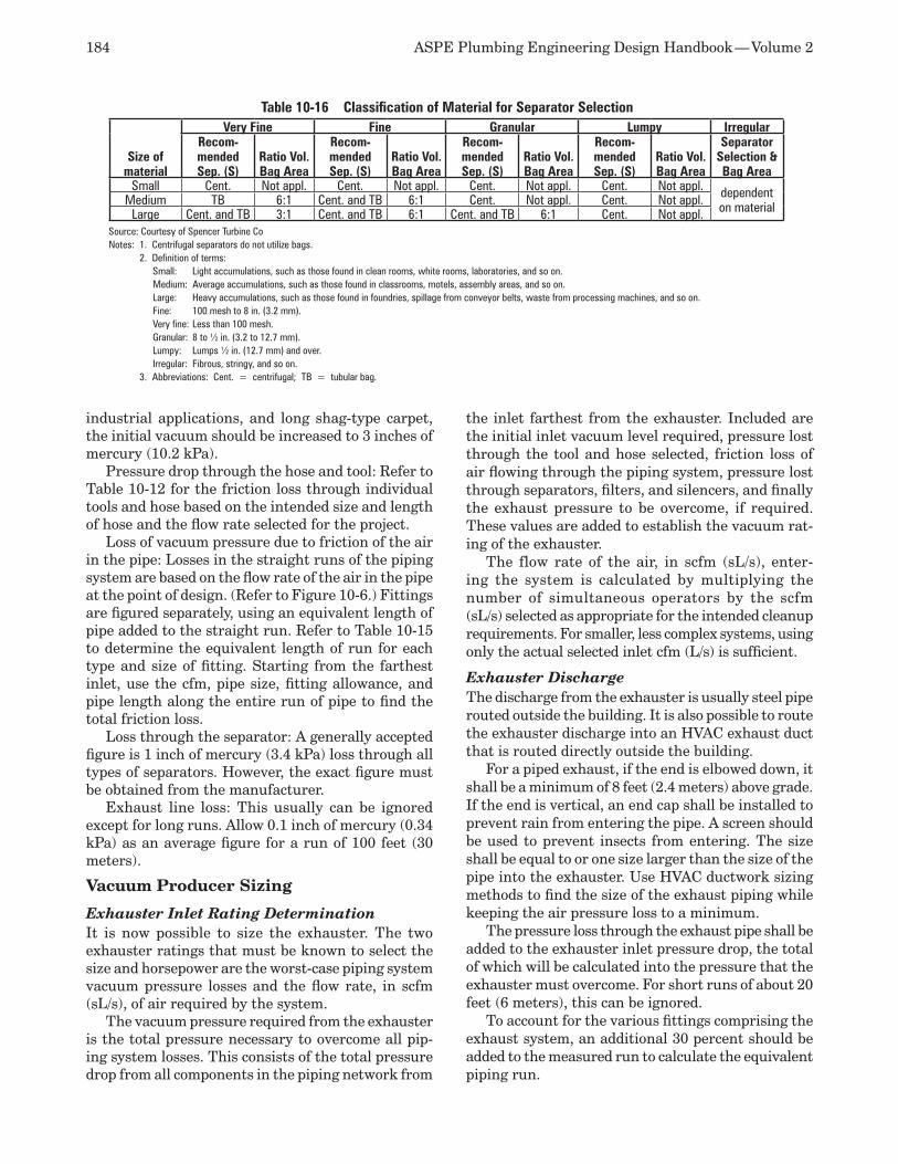
184 ASPE Plumbing Engineering Design Handbook — Volume 2
industrial applications, and long shag-type carpet, the initial vacuum should be increased to 3 inches of mercury (10.2 kPa).
Pressure drop through the hose and tool: Refer to Table 10-12 for the friction loss through individual tools and hose based on the intended size and length of hose and the flow rate selected for the project.
Loss of vacuum pressure due to friction of the air in the pipe: Losses in the straight runs of the piping system are based on the flow rate of the air in the pipe at the point of design. (Refer to Figure 10-6.) Fittings are figured separately, using an equivalent length of pipe added to the straight run. Refer to Table 10-15 to determine the equivalent length of run for each type and size of fitting. Starting from the farthest inlet, use the cfm, pipe size, fitting allowance, and pipe length along the entire run of pipe to find the total friction loss.
Loss through the separator: A generally accepted figure is 1 inch of mercury (3.4 kPa) loss through all types of separators. However, the exact figure must be obtained from the manufacturer.
Exhaust line loss: This usually can be ignored except for long runs. Allow 0.1 inch of mercury (0.34 kPa) as an average figure for a run of 100 feet (30 meters).
Vacuum Producer Sizing
Exhauster Inlet Rating Determination It is now possible to size the exhauster. The two exhauster ratings that must be known to select the size and horsepower are the worst-case piping system vacuum pressure losses and the flow rate, in scfm (sL/s), of air required by the system.
The vacuum pressure required from the exhauster is the total pressure necessary to overcome all pip-ing system losses. This consists of the total pressure drop from all components in the piping network from
the inlet farthest from the exhauster. Included are the initial inlet vacuum level required, pressure lost through the tool and hose selected, friction loss of air flowing through the piping system, pressure lost through separators, filters, and silencers, and finally the exhaust pressure to be overcome, if required. These values are added to establish the vacuum rat-ing of the exhauster.
The flow rate of the air, in scfm (sL/s), enter-ing the system is calculated by multiplying the number of simultaneous operators by the scfm (sL/s) selected as appropriate for the intended cleanup requirements. For smaller, less complex systems, using only the actual selected inlet cfm (L/s) is sufficient.
Exhauster Discharge The discharge from the exhauster is usually steel pipe routed outside the building. It is also possible to route the exhauster discharge into an HVAC exhaust duct that is routed directly outside the building.
For a piped exhaust, if the end is elbowed down, it shall be a minimum of 8 feet (2.4 meters) above grade. If the end is vertical, an end cap shall be installed to prevent rain from entering the pipe. A screen should be used to prevent insects from entering. The size shall be equal to or one size larger than the size of the pipe into the exhauster. Use HVAC ductwork sizing methods to find the size of the exhaust piping while keeping the air pressure loss to a minimum.
The pressure loss through the exhaust pipe shall be added to the exhauster inlet pressure drop, the total of which will be calculated into the pressure that the exhauster must overcome. For short runs of about 20 feet (6 meters), this can be ignored.
To account for the various fittings comprising the exhaust system, an additional 30 percent should be added to the measured run to calculate the equivalent piping run.
Table 10-16 Classification of Material for Separator Selection
Size of material
Very Fine Fine Granular Lumpy IrregularRecom-mended Sep. (S)
Ratio Vol. Bag Area
Recom-mended Sep. (S)
Ratio Vol. Bag Area
Recom-mended Sep. (S)
Ratio Vol. Bag Area
Recom-mended Sep. (S)
Ratio Vol. Bag Area
Separator Selection & Bag Area
Small Cent. Not appl. Cent. Not appl. Cent. Not appl. Cent. Not appl. dependent on materialMedium TB 6:1 Cent. and TB 6:1 Cent. Not appl. Cent. Not appl.
Large Cent. and TB 3:1 Cent. and TB 6:1 Cent. and TB 6:1 Cent. Not appl.Source: Courtesy of Spencer Turbine CoNotes: 1. Centrifugal separators do not utilize bags. 2. Definition of terms: Small: Light accumulations, such as those found in clean rooms, white rooms, laboratories, and so on. Medium: Average accumulations, such as those found in classrooms, motels, assembly areas, and so on. Large: Heavy accumulations, such as those found in foundries, spillage from conveyor belts, waste from processing machines, and so on. Fine: 100 mesh to 8 in. (3.2 mm). Very fine: Less than 100 mesh. Granular: 8 to ½ in. (3.2 to 12.7 mm). Lumpy: Lumps ½ in. (12.7 mm) and over. Irregular: Fibrous, stringy, and so on. 3. Abbreviations: Cent. = centrifugal; TB = tubular bag.
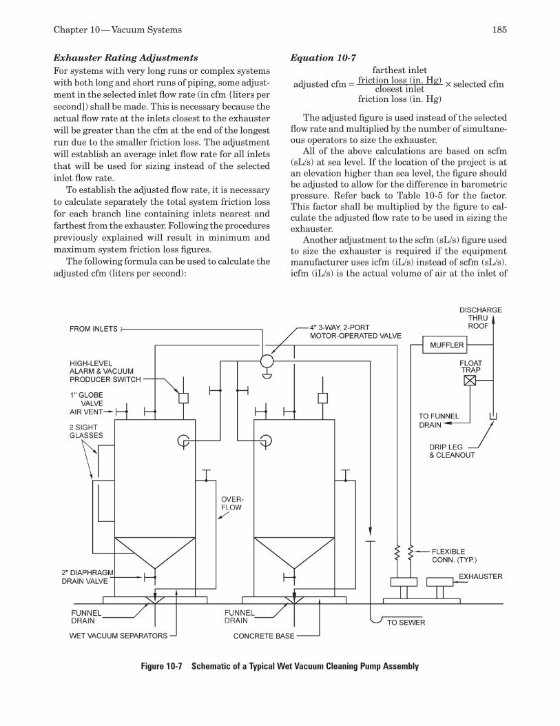
Chapter 10 — Vacuum Systems 185
Exhauster Rating AdjustmentsFor systems with very long runs or complex systems with both long and short runs of piping, some adjust-ment in the selected inlet flow rate (in cfm liters per second]) shall be made. This is necessary because the actual flow rate at the inlets closest to the exhauster will be greater than the cfm at the end of the longest run due to the smaller friction loss. The adjustment will establish an average inlet flow rate for all inlets that will be used for sizing instead of the selected inlet flow rate.
To establish the adjusted flow rate, it is necessary to calculate separately the total system friction loss for each branch line containing inlets nearest and farthest from the exhauster. Following the procedures previously explained will result in minimum and maximum system friction loss figures.
The following formula can be used to calculate the adjusted cfm (liters per second):
Equation 10-7
adjusted cfm =
farthest inlet friction loss (in. Hg) × selected cfmclosest inlet friction loss (in. Hg)
The adjusted figure is used instead of the selected flow rate and multiplied by the number of simultane-ous operators to size the exhauster.
All of the above calculations are based on scfm (sL/s) at sea level. If the location of the project is at an elevation higher than sea level, the figure should be adjusted to allow for the difference in barometric pressure. Refer back to Table 10-5 for the factor. This factor shall be multiplied by the figure to cal-culate the adjusted flow rate to be used in sizing the exhauster.
Another adjustment to the scfm (sL/s) figure used to size the exhauster is required if the equipment manufacturer uses icfm (iL/s) instead of scfm (sL/s). icfm (iL/s) is the actual volume of air at the inlet of
Figure 10-7 Schematic of a Typical Wet Vacuum Cleaning Pump Assembly
186 ASPE Plumbing Engineering Design Handbook — Volume 2
the exhauster using local temperature and barometric conditions. Previously discussed temperature and barometric conversions shall be used.
Separator Selection and Sizing The separator is sized based on the cfm (liters per second) of the vacuum producer and the type of mate-rial expected to be collected. Refer to Table 10-16 for a classification of such material.
For dry separators, a starting point for sizing would provide a 6:1 ratio of filter bag area to bag vol-ume for smaller volumes of coarse material and a 3:1 ratio for fine dust and larger quantities of all material. Wet and centrifugal separator sizing is proprietary to each manufacturer and depends on the quantity and type of material expected to be removed.
Some automatic separator cleaning systems use compressed air to aid in the dislodging of dust. The air pressure recommended is generally in the range of 100 to 125 psig (689 to 1,034 kPa).
General Design Considerations Abrasion is the wearing away of the interior of the
pipe wall by large, hard particles at the point where these particles strike the pipe. The effects are great-est at changes of direction, such as at elbows and tees and under the bag plates of separators. When abrasive particles are expected, it is recommended that either cast iron drainage fittings or Schedule 40 steel pipe fittings using sanitary pattern sweeps and tees be substituted for normally used tubing materials.
It is good practice to provide a safety factor to ensure that additional capacity is available from the exhauster without affecting the available vacuum. This should not exceed 5 percent of the total cfm (liters per second) and is used only when selecting the exhauster, not for sizing the piping system. The exhauster size should be selected and then the safety factor added. The unit selected should have that extra flow available.
The piping shall be pitched toward the separator. Plugged cleanouts should be installed at the base of all risers and at 90-degree changes in direction to al-low any blockages to be easily cleared.
Piping geometry in the design of wet system piping could become critical. Every effort shall be made to keep the piping below the inlet valves to prevent any liquid from running out of the inlet after completion of the cleaning routines and to ease the flow of liquid into the pipe. Wet system pipe should pitch back to the separator at about 8 inches per foot (1 centimeter per meter). All drops should be no larger than 2 inches (50 millimeters) in size, and only one inlet shall be placed on a single drop. Each drop should terminate in a plugged tee facing down. This will allow any liquid still clinging to the sides of the pipe to collect at the bottom of the riser and be carried away the next time the system is used. A typical wet vacuum cleaning system is shown in Figure 10-7.
In facilities using controlled substances, there is always a possibility that a spill will occur. For clean-ing this type of spill, a portable vacuum cleaning unit should be selected so that the filter can easily be weighed both before and after cleanup to account for the controlled substances picked up in the clean-ing unit.
REFERENCESAlbern, W. F., “Vacuum Piping Systems,” 1. Building Systems Design, 1972.Frankel, M., 2. Facility Piping Systems Hand-book, McGraw-Hill, 1996.Harris, Nigel S., 3. Modern Vacuum Practice, McGraw-Hill, 1990.Hesser, Henry H., “Vacuum Sources,” 4. Pumps and Systems Magazine, August 1993.Design of Hoffman Industrial Vacuum Clean-5. ing Systems, Hoffman Industries.McSweeney, D.P., and R. Glidden, “Vacuum 6. Cleaning Systems,” (unpublished manuscript), 1993. Moffat, R., “Putting Industrial Vacuum to 7. Work,” Hydraulics and Pneumatics Magazine, 1987.“How to Design Spencer Central Vacuum 8. Systems,” Spencer Turbine Co.
Water Treatment, Conditioning, and Purification 11
For the purposes of discussion in this chapter, water treatment means the chemical or mechanical removal and/or replacement of ionic or nonionic substances in feed water to produce water for a predefined use. Wa-ter conditioning is the addition of chemicals to water to inhibit corrosion, chelate hardness, chelate trace metals, suspend colloids, and adjust pH. Pure water systems are systems designed to produce water pure enough for use in pharmaceutical plants, laboratories, high-density semiconductor manufacturing, and very high-pressure boilers. The explanations and defini-tions given are simplified but suffice for the purposes of this chapter.
CODES AND STANDARDSMany codes and standards apply to the various water systems. Potable water treatment shall comply with the 1986 Safe Drinking Water Act and amendments. The U.S. Environmental Protection Agency (EPA) also has identified treatment technologies with given contaminant removal efficiencies for potable water.
Pure water treatment shall comply with one or more of the following, depending on the purity of the water desired.
College of American Pathologists (CAP) and •American Society for Testing and Materials (ASTM) reagent grade waterU.S. Pharmacopeia (USP) standards for water •purityAssociation for the Advancement of Medical •Instrumentation (AAMI) standards Clinical and Laboratory Standards Institute •(CLSI) standardsSemiconductor Equipment and Materials •International (SEMI) and ASTM electronics-grade water
BASIC WATER CHEMISTRYWater to be treated is known generally as raw water, feed water, or source water. Water that has been treated is known as treated water, product water, and solute. Chemicals or substances that dissolve in water can be
electrolytes or non-electrolytes. Electrolytes are chemi-cals that dissolve in water to form ions, such as sodium chloride⅔Na+Cl- and magnesium sulfate⅔Mg2+SO4
2-. Non-electrolytes are chemicals that dissolve in water but do not break down, such as ethanol (C2H5OH), sugars, and many organics. The positively charged atoms are called cations because they migrate to the cathode electrode, and the negatively charged atoms are called anions because they migrate to the anode electrode. The ions in solution act almost independently. For ex-ample, magnesium sulfate dissociates to form positive magnesium ions and negative sulfate ions. Ions often are referred to as salts in reference to reverse osmosis water production.
When an electrolyte compound dissolves in water, the molecules of the compound separate, disperse among the water molecules, and are held in sus-pension, which is when colloids, particles, etc. are suspended in solution and do not settle under the influence of just gravity. When the limit of solubility is reached, those same compounds become suspended solids, and no chemical reaction occurs. Dissolved materials cannot be removed by filtration.
Some types of liquids cannot be dissolved. They break down into extremely small particles and then disperse into the water, even though they are not soluble. These liquids are called immiscible liquids. The resulting small particles are known as colloids. Colloidal material is at the upper end of the size range for ions and molecules, in the general range of 0.001 to 1.0 micrometer (µm). In most cases, other liquids, such as oil and grease, cannot separate into smaller-sized particles and become dispersed, but simply remain in suspension. If they are lighter than water, they float on top. If heavier, they sink below the surface.
All acid compounds referred to in water chemistry consist of hydrogen combined with an acid radical. Since the acid radical moves around as a unit, it is convenient to view the acid radicals as an integral anion unit. When a metal radical and an acid radical combine, they form a class of chemicals called salts.
188 ASPE Plumbing Engineering Design Handbook — Volume 2
If a metal cation and a hydroxide anion combine, a base results.
An acid is any compound capable of giving up a hydrogen ion (H+) or proton. The acid’s conjugate base, or anion, is the compound remaining after the loss of the H+:
HClgconjugate base = Cl-
A base is any compound capable of accepting a hydrogen ion or giving up a hydroxide (OH-) ion:
NaOHgconjugate acid = Na+
The valence of any element is a measure of its chemical-combining power compared to that of a hy-drogen atom, which has the assigned value of 1. The valence is the number of electrons in an atom that are free to share, give, or take from other atoms. An element with a value of +2 can replace two hydrogen atoms in a compound, or an element with a valence of -2 can react with two hydrogen atoms. When atoms combine to form compounds, a cation atom must com-bine with an anion atom, and in addition, the valence of the two basic elements must equal one another to form the compound.
Most of the basic chemical reactions in water treat-ment consist of rearranging cation and anion atoms using their valence. As can be seen in Table 11-1, hy-drogen has a valence of 1, and sulfate has a valence of 2. When combined to form sulfuric acid, two hydrogen atoms are required to form the combination, resulting in the formula H2SO4. The chief exception is the case where carbonates and bicarbonates are destroyed by heating or aeration, giving off carbon dioxide.
Equivalent weight is the weight, in grams, of any element that could combine with or displace 1.008 grams of hydrogen or 8 grams of oxygen. Since the valence of an element is proportional to its combining power, the equivalent weight is based on its valence. This is illustrated in Table 11-1.
WATER IMPURITIES Natural, or source, water is never chemically pure H2O. Water dissolves ionic compounds as it comes in contact with the ground surface or mineral forma-tions when it percolates through the earth. It also contains dissolved gases and dust picked up when falling through the air as rain, snow, or hail or when surface water is in contact with the air above the water level. Water is classified as surface water when obtained from sources such as lakes and rivers and groundwater when obtained from streams, wells, or other aquifers originating underground.
Turbidity Turbidity (also called suspended solids) is a general term used to describe any form of insoluble matter suspended in water. Color is a chemical phenomenon often associated with turbidity. Color may be an indication of water containing decaying vegetation.
However, the term “turbidity” is most often used when referring to mineral particulates because they are usually the most plentiful. Other commonly oc-curring impurities are liquids, such as oil, and the residue caused by decaying vegetation.
Coarse particles that settle rapidly when water is standing are referred to as sediment, and fine particles that mostly remain in suspension are called silt.
Microorganisms Microorganisms are bacteria and viruses. They are living forms of particulate matter. Their unusual physiology allows them to grow and multiply in water containing only trace levels of nutrients. The presence of these nutrients in untreated water is an indicator of the presence of microorganisms, if the temperature is favorable for their growth. Although microorgan-isms are a suspended solid, the treatment required for their removal or neutralization puts them in a separate category.
Pyrogens cause fever, and pathogenic organisms (such as Legionella) cause diseases of all kinds. Endotoxins, which are fragments derived from the cell walls of gram-negative bacteria, are considered the most important and widely occurring group of pyrogen. Other organic growths include algae (a primitive form of plant life), fungi (plants lacking the chlorophyll required for photosynthesis), and bacteria, which exhibit both plant and animal char-acteristics. Bacteria are further subdivided into slime bacteria, which secrete slime; iron bacteria, which thrive on iron; sulfate-reducing bacteria, which live by consuming sulfate and converting it to hydrogen sulfide gas; and nitrifying bacteria, which use am-monia and whose by-product results in the formation of nitric acid.
Several methods of measurement are used, includ-ing viable-count essays, direct-count epifluorescent microscopy, scanning electron microscopy, and bio-chemical techniques. The most common means of measuring bacterial contamination is the viable-count method. This is done by passing the water being mea-sured through a sterile nutrient medium and counting the number of colonies appearing on the medium after a period of time is allowed for growth. These are called colony forming units (cfu). Endotoxins are measured in endotoxin units per milliliter (eu/mL). An often-used form of measurement for endotoxins is the limulus amoebocyte lysate (LAL) test, wherein a blood extract of the horseshoe crab becomes turbid in the presence of bacterial endotoxins. This detec-tion technique uses optical density (turbidity level) measured over a period of time.
Other Organisms This term for biological life is applied to larger liv-ing things, such as clams, mussels, their larvae, and
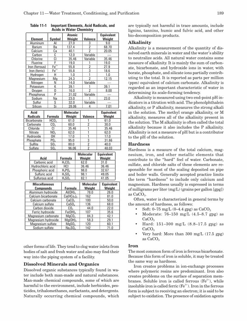
Chapter 11 — Water Treatment, Conditioning, and Purification 189
other forms of life. They tend to clog water inlets from bodies of salt and fresh water and also may find their way into the piping system of a facility.
Dissolved Minerals and Organics Dissolved organic substances typically found in wa-ter include both man-made and natural substances. Man-made chemical compounds, some of which are harmful to the environment, include herbicides, pes-ticides, trihalomethanes, surfactants, and detergents. Naturally occurring chemical compounds, which
are typically not harmful in trace amounts, include lignins, tannins, humic and fulvic acid, and other bio-decomposition products.
Alkalinity Alkalinity is a measurement of the quantity of dis-solved earth minerals in water and the water’s ability to neutralize acids. All natural water contains some measure of alkalinity. It is mainly the sum of carbon-ate, bicarbonate, and hydroxide ions in water, with borate, phosphate, and silicate ions partially contrib-uting to the total. It is reported as parts per million (ppm) equivalent of calcium carbonate. Alkalinity is regarded as an important characteristic of water in determining its scale-forming tendency.
Alkalinity is measured using two end-point pH in-dicators in a titration with acid. The phenolphthalein alkalinity, or P alkalinity, measures the strong alkali in the solution. The methyl orange alkalinity, or M alkalinity, measures all of the alkalinity present in the solution. The M alkalinity is often called the total alkalinity because it also includes the P alkalinity. Alkalinity is not a measure of pH but is a contributor to the pH of the solution.
Hardness Hardness is a measure of the total calcium, mag-nesium, iron, and other metallic elements that contribute to the “hard” feel of water. Carbonate, sulfate, and chloride salts of these elements are re-sponsible for most of the scaling deposited on pipe and boiler walls. Generally accepted practice limits the term “hardness” to include only calcium and magnesium. Hardness usually is expressed in terms of milligrams per liter (mg/L) (grains per gallon [gpg]) as CaCO3.
Often, water is characterized in general terms by the amount of hardness, as follows:
Soft: 0–75 mg/L (0–4.4 gpg) as CaCO• 3 Moderate: 76–150 mg/L (4.5–8.7 gpg) as •CaCO3 Hard: 151–300 mg/L (8.8–17.5 gpg) as •CaCO3 Very hard: More than 300 mg/L (17.5 gpg) •as CaCO3
Iron The most common form of iron is ferrous bicarbonate. Because this form of iron is soluble, it may be treated the same way as hardness.
Iron creates problems in ion-exchange processes where polymeric resins are predominant. Iron also creates problems on the surface of separation mem-branes. Soluble iron is called ferrous (Fe2+), while insoluble iron is called ferric (Fe3+). Iron in the ferrous form is subject to receiving an electron; it is said to be subject to oxidation. The presence of oxidation agents
Table 11-1 Important Elements, Acid Radicals, and Acids in Water Chemistry
Element SymbolAtomic Weight Valence
Equivalent Weight
Aluminum Al 27.0 3 9.0Barium Ba 137.4 2 68.70Calcium Ca 40.1 2 20.05Carbon C 12.0 Variable —Chlorine Cl 35.46 Variable 35.46Fluorine F 19.0 1 19.0
Iron (ferrous) Fe2+ 55.8 2 27.9Iron (ferric) Fe3+ 55.8 3 18.6Hydrogen H 1.0 1 1.0
Magnesium Mg 24.3 2 12.15Nitrogen N 14.0 Variable —
Potassium K 39.1 1 39.1Oxygen O 16.0 2 8.00
Phosphorus P 31.02 Variable —Sodium Na 23.0 1 23.0Sulfur S 32.0 Variable —Silicon Si 28.06 4 7.01
Acid Radicals Formula
Molecular Weight Valence
Equivalent Weight
Bicarbonate HCO3 61.0 1 61.0Carbonate CO3 60.0 2 30.0Chloride Cl 35.46 1 35.46Nitrate NO3 62.0 1 62.0
Hydroxide OH 17.0 1 17.0Phosphate PO4 95.0 3 31.66
Sulfite SO3 80.0 2 40.0Sulfate SO4 96.06 2 48.03
Acid FormulaMolecular
WeightEquivalent
WeightCarbonic acid H2CO3 62.0 31.0
Hydrochloric acid HCI 36.46 36.46Phosphoric acid H3PO4 98.0 32.67
Sulfuric acid H2SO4 98.1 49.05Sulfurous acid H2SO3 82.1 41.05
Miscellaneous Compounds Formula
Molecular Weight
Equivalent Weight
Aluminum hydroxide Al(OH)3 78.0 26.0Calcium bicarbonate Ca(HCo3)2 162 81.0Calcium carbonate CaCO3 100 50.0
Calcium sulfate CaSO4 136 68.0Carbon dioxide CO2 44.0 22.0Ferric hydroxide Fe(OH)3 107 35.6
Magnesium carbonate MgCO3 84.3 42.1Magnesium hydroxide Mg(OH)2 58.3 29.1
Magnesium sulfate MgSO4 120 60.1Sodium sulfate Na2SO4 142 71.0
190 ASPE Plumbing Engineering Design Handbook — Volume 2
in water with ferrous iron is the root of the problems. Common oxidants are oxygen and chlorine.
If it were possible for iron to stay in the ferrous form throughout the ion-exchange process, including regeneration of softening resin and the shutdown of membrane systems, it would not present a problem. However, for all practical purposes, it is impossible to prevent some of the ferrous substance from oxidizing to the ferric substance. During the oxidation process, other ionic substances are involved. Typically a long hydrocarbon chain results when resin or separation membranes are made. In these long chains are sites where the ferric iron connects to the polymer. The ferric connection point acts as a catalyst for further crystallization or chemical reactions with the iron or related substances, thereby creating a snowball effect for further chemical reactions.
Calcium Calcium is a silver-white, bivalent, metallic element of the alkaline-earth group occurring only in combina-tion. Common combinations are calcium carbonate, calcium chloride, calcium hydroxide, calcium phos-phate, and calcium silicates.
Magnesium The most common forms of magnesium are mag-nesium carbonate, magnesium bicarbonate, and magnesium chloride. These impurities tend to deposit scale on surfaces with which they come in contact.
Silica The three common kinds of silica are soluble, colloidal, and particulate. Soluble silica often is referred to as reactive silica, and colloidal silica sometimes is called non-reactive or polymeric. The most common form in solution is silicon oxide, and in suspension it is found as a fine colloid. These impurities tend to deposit a scale on surfaces they come in contact with and form a gelatinous mass on reverse osmosis membranes.
Sodium and Potassium Sodium and potassium form similar salts, with the most common being sodium or potassium chloride, sodium or potassium carbonate, and sodium or potas-sium bicarbonate.
Chlorides and Sulfates The most common forms of chlorides and sulfates are dissolved salts of sodium, potassium, calcium, and magnesium. These impurities tend to deposit a scale on surfaces with which they come in contact.
Nitrates The EPA has set drinking water limits for nitrates at 10 milligrams per liter. Though water with a high nitrate level is treatable, limits are placed on the discharge nitrate concentration if neutralized ion-exchange re-generation waste or membrane-separation concentrate
is discharged directly into the environment or into a municipal treatment system. Thus, knowing the con-centration of the supply and the local discharge limits is critical to the selection of the appropriate treatment equipment and system design.
Trace Elements Trace elements are present in very small quantities and are considered problematic only if the amount is above an accepted level for the intended use of the water. Examples are lead, cadmium, copper, barium, silver, lithium, zinc, chromium, mercury, arsenic, and selenium.
When a supply-water treatment system is selected, the waste products must be considered. Many munici-palities sell the sludge created by their process to local farms as fertilizer or cattle feed, so they place consid-erable restrictions on treatment discharges. Though elements may be identified as trace by analysis of the supply water, in concentration they may exceed local, state, and federal discharge limits.
Dissolved Gases The most common dissolved gases in natural raw water are oxygen, carbon dioxide, nitrogen, and hydrogen sulfide. Potable water supplies usually also have chlo-rine and fluorides added for public health purposes. Of increasing concern is the presence of radon gas in many water supplies obtained from wells.
Oxygen is the basic factor in the corrosion process; it must be present for the corrosion of metals. Thus, its removal or reduction reduces the corrosiveness of the water. Carbon dioxide, nitrogen oxides, sulfur oxides, and hydrogen sulfide also contribute to cor-rosion by making water acidic.
No pretreatment is typically necessary for feed wa-ter with less than 1 part per million of chlorine. When more than 1 part per million of chlorine is present, an activated carbon filter is recommended.
Volatile Organic Compounds Volatile organic compounds (VOCs) are those compounds that evaporate readily at ambient tem-peratures and pressures. Swamp gas is an example of a naturally occurring VOC. However, most of the compounds that are a concern regarding the produc-tion of chemically pure water are man-made. The EPA lists 21 regulated VOC compounds and 34 more unregulated VOC compounds.
Most of the VOCs that concern the user of chemi-cally pure water originate from the treatment process itself. VOCs may originate from the following typical treatment components:
Polyvinyl chloride (PVC) and chlorinated •polyvinyl chloride (CPVC) pipe Polypropylene and polyethylene pipe•
Chapter 11 — Water Treatment, Conditioning, and Purification 191
Cation ion-exchange resin, the solvent used •to make the polymerAnion ion-exchange resin, the solvent and the •organic amines Reverse osmosis membrane, the solvent used •to create the barrier polymer Ultrafiltration and nanofiltration membranes, •the solvent used to create the polymer Fiberglass-reinforced plastic (FRP), poly-•propylene, and polyethylene-treated water-storage tanks Filter and ion-exchange vessel linings•Pipe solvents, glues, and dopes•Cross-flow filter media •Other plastic wetted materials used in the •construction of the system
Many of the items listed above can be substituted or treated to remove serious VOCs. To determine the best approach for avoiding serious contamina-tion, contact the supplier of the treatment products considered. However, these organic compounds are volatile, meaning that with use they will dissipate dramatically. Flushing solutions used to rinse high-purity installations before they are commissioned are available. These solutions kill bacteria and rinse VOCs without severely damaging the system. To determine the best approach for the materials selected, always consult with the vendor before proceeding. Further-more, consult the user to determine the impact of VOCs given off by the treatment. Consultation can save considerable effort, time, and money.
WATER ANALYSIS AND IMPURITY MEASUREMENTWater samples are analyzed to determine the quan-tities of various impurities. The quantities must be presented in a logical and understandable manner to allow for easy and practical interpretation. The ini-tial analysis of incoming water must be accurate and contain a worst-case scenario, and the desired output quality must be established prior to the selection of any treatment system.
The most accurate analyses of water samples are done by laboratories specializing in this type of work. Sterile containers must be used, and several samples must be taken over a period of time to ensure that peak readings and average values are obtained. Field tests of water samples, while not as accurate as labo-ratory tests, may provide accuracy levels acceptable to the user.
The results of the analysis are expressed in many ways. A common method used to report the concentra-tion of ions in solution is the weight of an element or compound per liter of water, expressed as milligrams per liter of water. Another method is parts per million, which can be expressed either by the weight of an
impurity compared to the weight of water (abbrevi-ated w/w, weight to weight) or by the volume of the impurity to the volume of water (abbreviated v/v). Other units also are used, such as grains per gallon and equivalents per million (epm).
Milligrams per liter differs from parts per million in that it expresses a proportion in weight per volume. This finds specific use in the analysis of saline waters. For common supplies where the specific gravity of the liquid is approximately 1, milligrams per liter and parts per million are equal.
Grains per gallon often is used in discussion of ion-exchange equipment capabilities, where 1 grain per gallon equals 17.1 parts per million.
As previously explained, compounds break down into ions when dissolved. Although chemists can measure the amount of each ion present in a sample, it is not practical to find the total amount of each compound that actually went into solution. In prac-tice, the actual method of analysis measures only ions. Using the ionic measurement when reporting impurities makes it easier and more convenient to interpret the results.
To further simplify reporting, it is desirable to reduce all ions present in solution to a common denominator, which is calcium carbonate. This is accomplished by comparing the equivalent weight of all ions present and expressing them as the part-per-million anion and cation equivalent of calcium carbonate. This method of expression is a widely ac-cepted standard for reporting a water analysis, but it is not universal.
Table 11-2 presents the conversion factors used for major impurities. Figure 11-1 illustrates a typi-cal water analysis report indicating impurities in parts per million, equivalents useful in calculating reacting chemicals, and a comparison of positive and negative ions.
pH Potential hydrogen (pH) is a measurement of the hydrogen ion concentration in water and, therefore, a measure of the water’s acidity. pH is calculated from the logarithmic reciprocal of the hydrogen ion concentration in water.
The pH scale ranges from 0 to 14, with values lower than 7 being acid, values higher than 7 being alkaline, and 7 being neutral. When an acid is added to water, the concentration of hydrogen ions increases, resulting in a lower pH. When an alkaline is added to water, the hydrogen ions decrease, resulting in a higher pH. The change of a pH unit represents a ten-fold increase (or decrease) in strength. The pH is not a measure of alkalinity.
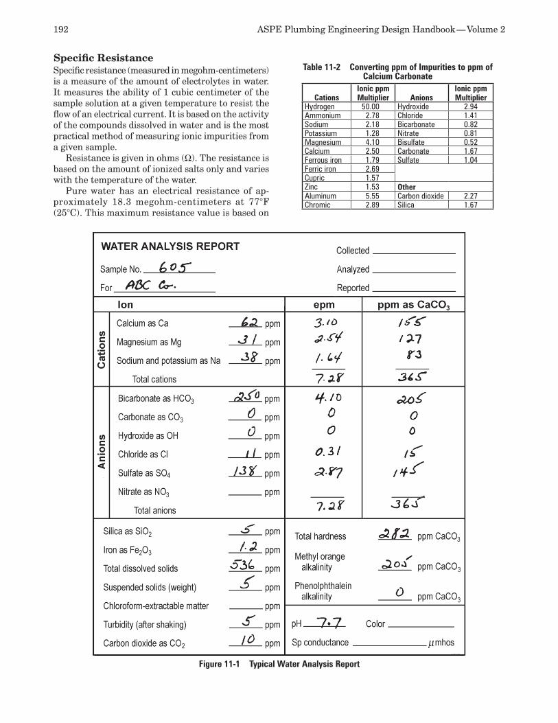
192 ASPE Plumbing Engineering Design Handbook — Volume 2
Specific Resistance Specific resistance (measured in megohm-centimeters) is a measure of the amount of electrolytes in water. It measures the ability of 1 cubic centimeter of the sample solution at a given temperature to resist the flow of an electrical current. It is based on the activity of the compounds dissolved in water and is the most practical method of measuring ionic impurities from a given sample.
Resistance is given in ohms (Ω). The resistance is based on the amount of ionized salts only and varies with the temperature of the water.
Pure water has an electrical resistance of ap-proximately 18.3 megohm-centimeters at 77°F (25°C). This maximum resistance value is based on
Table 11-2 Converting ppm of Impurities to ppm of Calcium Carbonate
CationsIonic ppm Multiplier Anions
Ionic ppm Multiplier
Hydrogen 50.00 Hydroxide 2.94Ammonium 2.78 Chloride 1.41Sodium 2.18 Bicarbonate 0.82Potassium 1.28 Nitrate 0.81Magnesium 4.10 Bisulfate 0.52Calcium 2.50 Carbonate 1.67Ferrous iron 1.79 Sulfate 1.04Ferric iron 2.69Cupric 1.57Zinc 1.53 OtherAluminum 5.55 Carbon dioxide 2.27Chromic 2.89 Silica 1.67
Figure 11-1 Typical Water Analysis Report
Chapter 11 — Water Treatment, Conditioning, and Purification 193
the electrical resistance from the very small concen-trations of hydrogen and hydroxide ions from the slight dissociation of water. This dissociation yields concentrations of 1 x 10⁻⁷ moles per liter for each hydrogen and hydroxide.
Temperature is a significant factor in the mea-surement of the electrical resistance of water, with warmer temperatures producing higher values. For example, the electrical resistance of water at 50°F (10°C) is 8.8 megohm-centimeters and at 104°F (40°C) is 43.3 megohm-centimeters.
Instruments, referred to as water resistivity me-ters, are available to accurately measure the electrical resistance of water. Because of the significant impact of temperature, these meters typically report electri-cal resistance normalized to 77°F (25°C). Resistivity meters typically are used as a measure of the total amount of electrolytes in purified water when the concentrations are very low. Resistivity conversions are given in Table 11-3.
Specific Conductance Specific conductance (measured in micromhos per centimeter) measures the ability of 1 cubic centime-ter of the sample solution at a given temperature to conduct an electrical current. It is the reciprocal of the resistance, in ohms. Since it is the opposite of resistance, it is given the name mho, which is ohm spelled backwards. The actual conductance is so small that it is measured in micromhos (µmho), which is one millionth of a mho.
As an example, at 70°F (19°C) demineralized water with 0.5 part per million dissolved salt has a conductance of 1 micromho. Pure water has a specific conductance of 0.055 micromho per centimeter at 77°F (25°C).
Conductivity conversions are given in Table 11-3. Specific conductance in actual practice typically is mea-sured by probes suspended in the stream of water.
Total Suspended Solids Total suspended solids is the sum of all the suspended material found in the water sample and commonly is measured in either parts per million or milligrams per liter.
Turbidity in water is classified by the size of the particulates in microns (1/1,000 inch [0.03 millimeter] diameter) and tested by a light interference method known as a nephelometric. This test compares the water sample by color to a standard color scale. This measurement is obtained by comparing the sample being tested with a known color reference, and the total suspended solids are indicated based on this comparison. The most common reporting method is the nephelometric turbidity unit, with higher units indicating increased turbidity.
An often-used standard for potable water is the method for the examination of water and wastewater developed by the American Public Health Service, which uses formazin to produce a known volume of turbidity. The standard color scale to which it is compared is derived from the platinum cobalt unit. Other methods less frequently used are the com-parator tube determination using formazin, called the formazin turbidity unit, and the original test, the Jackson turbidity unit, named for the man who devel-oped a method that compares the color of candlelight through a sample to a color standard. The most ac-curate method of measuring solids is gravimeterically, wherein a known quantity of water is evaporated and the resulting solids weighed.
The most effective method of removing turbidity is by the use of filters and strainers. The equipment chosen to accomplish this task depends for the most part on the sizes and types of the solids to be retained. Other factors include the materials of construction, the nature of the raw water, flow rate requirements, the particle removal target, initial and operating costs, and maintenance requirements.
Total Dissolved Solids Often referred to as dissolved inorganics and mineral salts, total dissolved solids (TDS) is generally the sum of all dissolved minerals, including chlorides, sul-fates, and carbonates. Dissolved solids contribute to scale deposit and corrosion of piping and equipment.
Table 11-3 Resistivity and Conductivity ConversionGrains/gala as CaCO3
ppm as CaCO3
ppm NaCI
Conductivity, µmho/cm
Resistivity, MΩ/cm
99.3 1700 2000 3860 0.0002674.5 1275 1500 2930 0.0003449.6 850 1000 1990 0.0005024.8 425 500 1020 0.000999.93 170 200 415 0.00247.45 127.5 150 315 0.00324.96 85.0 100 210 0.00482.48 42.5 50 105 0.00950.992 17.0 20 42.7 0.0230.742 12.7 15 32.1 0.0310.496 8.5 10 21.4 0.0470.248 4.25 5.0 10.8 0.0930.099 1.70 2.0 4.35 0.230.074 1.27 1.5 3.28 0.300.048 0.85 1.00 2.21 0.450.025 0.42 0.50 1.13 0.880.0099 0.17 0.20 0.49 2.050.0076 0.13 0.15 0.38 2.650.0050 0.085 0.10 0.27 3.700.0025 0.042 0.05 0.16 6.150.00099 0.017 0.02 0.098 10.20.00070 0.012 0.015 0.087 11.50.00047 0.008 0.010 0.076 13.10.00023 0.004 0.005 0.066 15.20.00012 0.002 0.002 0.059 16.90.00006 0.001 0.001 0.057 17.6
none none none 0.055 18.3b
a Grains per gal = 17.1 ppm (CaCO3).b Theoretical maximum.
194 ASPE Plumbing Engineering Design Handbook — Volume 2
When dissolved in water, mineral salts form positively charged ions, mostly sodium and calcium, and nega-tively charged ions, mostly chlorides and sulfates.
Engineers designing ion-exchange systems con-sider total dissolved solids differently than those designing membrane-separation systems. Neither ap-proach is incorrect, but if the approach is not defined, design errors will occur. Quantitatively, total dissolved solids is the difference in the weight between the tare weight of a crucible and the residue remaining after filtered water is evaporated. The quantitative chemical definition is used by membrane-separation system designers. The analytic, ionic definition is used by ion-exchange system designers. Since ion-exchange by definition is an ionic chemical process, the system designer must consider a balanced ionic solution when determining capacity and equipment size. When designing a treatment system consisting of both membrane separation and ion exchange, care must be taken when moving from the separation unit’s product water analysis to that of the ion-exchange system.
Separation system analysis reports, as well as most laboratory water analysis reports, are shown as parts per million as CaCO3. For example, sodium would be reported as Na+, and calcium would be reported as Ca2+. However, to simplify the task, when designing an ion-exchange system the “as ion” is converted to CaCO3. The conversion is done by considering the equivalent weight of the ion, or the atomic weight divided by the ion’s existing exchange valance. The equivalent weight then is converted to CaCO3 by divid-ing the ion’s equivalent by itself and multiplying the product by the equivalent weight of CaCO3, or 50.
Total Organic Carbon Total organic carbon (TOC) is a measurement of the organic carbon compounds found dissolved in water. These compounds contribute to corrosion, cause problems in manufacturing, and usually indicate the presence of endotoxins in water for pharmaceutical use. The test is requested to determine the contamina-tion of water by trace organic compounds that could produce a residue or interfere in laboratory apparatus tests or provide trace contamination in a pharmaceu-tical product.
The measurement is generally complicated and depends on the expected level. For higher levels, the organic compound first is converted to carbon diox-ide, which is measured by infrared absorption. Gas stripping is required to remove other forms of carbon ions from dissolved mineral compounds. For parts per billion (ppb) levels, photolytic oxidation is used, and the resulting carbon dioxide then is measured.
Silt Density Index The silt density index (SDI) is a measure of the foul-ing potential of a feed water source. Since colloids and other solids can be any size in the sub-micrometer range, there is no direct method to measure their concentration in feed water. The silt density index is found by passing the feed water through a 0.45-micrometer filter at 30 pounds per square inch (psi) (207 kilopascals [kPa]). The silt density is found from the following formula:
Equation 11-1
SDI =1 – t1 × 100t2
Twhere t1 = Initial time needed to collect a 500-milliliter
sample of water through a fresh 0.45-micrometer filter, 47 millimeters in diameter, in seconds
t2 = Time to filter and collect a second 500-milliliter sample after exposing the same filter as above to the flow of feed water for 15 minutes, in seconds
T = Total test time, in minutes (typically 15 minutes, but may be less for high silt density index)
To obtain an accurate test, at the end of the elapsed time the filter should not become more than approxi-mately 74 percent plugged. If this figure is exceeded, the test should be repeated using a shorter overall elapsed time.
(Note: A Millipore filter is the only membrane currently approved by ASTM International for de-termining silt density index.)
Many manufacturers of reverse osmosis (RO) cartridges recommend allowable silt density index figures for feed water. Typically, the maximum silt density index for hollow-fiber modules is 3, and for spiral-wound modules the allowable silt density index figure is 4. For continuous deionization, an silt density index of 4 or less is recommended. In practice, when water has a silt density index greater than 4, a pre-filter with a 4-micrometer depth is recommended. In addition to the 4-micrometer filter, an additional 1-micrometer filter is recommended downstream. The use of a 4-micrometer filter on the feed water stream is always recommended as a precaution against fouling, regardless of the potential silt density index.
DEPOSITS AND CORROSIONThe contaminants previously discussed will cause piping system fouling by depositing material on the walls of the pipe, thereby reducing the efficiency of the system, and reduce the thickness of the pipe wall by corrosion, which will cause failure of the piping system. Following is a brief discussion of these cat-
Chapter 11 — Water Treatment, Conditioning, and Purification 195
egories of problems and treatment methods as they generally apply to most systems.
Scale Scale is a solid deposit on the walls of a pipe result-ing from the precipitation of dissolved mineral solids in the fluid stream. This scale reduces heat transfer and interferes with the flow of water by increasing the friction of the fluid with the walls of the pipe. Boiler scale consists of calcium, magnesium, iron, and silica minerals. It can be substantially minimized by pretreating water prior to its entering the boiler to remove much of the scale-forming ingredients and adding effective chemicals to the feed water to adjust pH, prevent corrosion, and prevent deposits from occurring.
Condenser scale deposits consist of calcium car-bonate, calcium sulfate, or silica minerals. They form when the minerals’ concentration in water reaches a level where their solubility or the pH of saturation is exceeded and the minerals come out of solution. This can be prevented by controlling the pH, diluting the circulating water to prevent concentration, and adding chemicals to inhibit and prevent scale formation.
SludgeSludge is a sticky, adherent deposit in the feed water resulting from the settling out of suspended matter from several sources. One source is an excess of iron in the liquid, generally iron oxide (rust) and iron carbonate (a corrosion product). Other sources are mud, dirt, and clay that tend to collect and adhere in areas of low circulation. Sludge is prevented by filtering the incoming feed water and adding chemical dispersants to keep the solids in suspension, which then are removed by blowdown. Mud, dirt, and clay are rarely encountered except when the feed water is from surface sources.
Biological FoulingMicrobiological fouling is caused by the growth of bac-teria, algae, fungi, and other organisms. Their growth is aided by a favorable water temperature, favorable pH, the presence of oxygen, and food. The buildup of microbes and their waste products, which also include dust and other suspended matter, is called slime.
Microbial control is achieved by sterilization, dis-infection, and sanitation. Sterilization is the lethal disruption of all bacteria, mold, and yeast. It elimi-nates biofilm and spores, and numerically it is a 12 log reduction in bacteria. Disinfection is a 6 log reduction of microbials. Sanitation generally is considered a killing of the vegetative organisms. It minimizes the presence of bacteria and endotoxins, and numerically it is a 3 log reduction in bacteria.
There are different methods of controlling biofoul-ing. Chemicals, ultraviolet radiation, heat, filtering,
and ozone are the ones most commonly used. The method selected depends on the intended use of the treated water and the proposed materials of the sys-tem components.
Corrosion Corrosion is the loss and eventual failure of metals and alloys from the electrochemical reaction between water and the pipe material. It is separated into two basic types: general and localized. General corrosion describes the potential dissolution of pipe over its entire exposed surface. Localized corrosion affects only a small area of the pipe surface. Conventional corrosion treatment of feed water for boilers and cooling water systems consists of pH control and the use of chemical corrosion inhibitors.
General CorrosionGeneral corrosion is a breakdown of the pipe ma-terial at a uniform rate over its entire surface by direct chemical attack. It is caused by the loss of the protective passive film that forms on the surface of a pipe coupled with a chemical reaction occurring between the pipe material and the chemicals in the fluid. Particular types of general corrosion include the following:
Galvanic corrosion occurs in a liquid medium •(called an electrolyte) when a more active met-al (anode) and a less active metal (cathode) come in contact with one another and form an electrode potential. When this occurs, the more active (noble) metal tends to dissolve in the electrolyte and go into solution. Intergranular corrosion occurs in a pipe wall •when material in the grain boundary of some alloys is less resistant to the corroding agent than the grains themselves, and the bonds between the grains are destroyed. Erosion corrosion is caused by a wearing of a •pipe wall, usually as a result of excessive fluid velocity or constant wearing by solids in the water striking the walls of the pipe.
Localized CorrosionLocalized corrosion takes place on small areas of the surface, usually at high rates. It takes the following forms:
Stress-corrosion cracking is a physical deterio-•ration and cracking of a pipe wall caused by a combination of high operating temperature, tensile stress on the pipe, and chemicals in the fluid stream. Pitting is characterized by deep penetration •of the metal at small areas of the surface, concentrating in small cells without affecting the entire surface.

196 ASPE Plumbing Engineering Design Handbook — Volume 2
Crevice attack corrosion occurs at junctions •between surfaces (often called crud traps) where a crack exists that allows an accumula-tion of a corroding agent.
PREDICTING SCALE FORMATION AND CORROSION TENDENCIESA common and costly water-caused problem is the formation and deposit of mineral scale. Although scale deposits may contain a complex mixture of mineral salts, the primary constituent is calcium carbonate.
Most salts are more soluble in hot water than in cold water. Calcium and magnesium salts, on the other hand, dissolve more readily in cold water than in hot water. As a result, they tend to deposit on surfaces when a rise in temperature occurs. As the temperature rises, the tendency of dissolved solids to precipitate out of solution increases because of their property of inverse solubility. This is particularly true of calcium carbonate.
Alkalinity and pH are other factors that contribute to mineral scale formation. The pH value reflects the concentration of hydrogen protons (H+) or hydroxyl ions (OH-) in aqueous solutions. The level of this concentration, as indicated by pH, defines the ratio of bicarbonate to carbonate alkalinity. The measure of pH is made on a logarithmic scale. One end of the scale is the hydrogen proton, and the other end is the hydroxyl ion. When the pH is 7, there is an exact balance of hydrogen protons to hydroxyl ions in the water. A pH below 7 indicates an acid or a predomi-nance of hydrogen protons. A pH above 7 indicates a basic solution or a predominance of hydroxyl ions. A pH below 5 indicates 100 percent carbonic and other mineral acids. A pH between 5.3 and 8.2 indicates a bicarbonate/carbonate relationship of the water. A pH above 8.2 indicates carbonate and hydroxyl alkalin-ity. As the pH proceeds upward from acidic to basic, the increase in carbonates increases the tendency for calcium and magnesium carbonates to precipitate out of solution.
Langelier Saturation Index In the 1930s, W. F. Langelier studied the primary fac-tors that affect the tendency of water to form deposits of mineral scale on heat-transfer equipment. As a result of this work, the Langelier Index, best known as the Langelier Saturation Index (LSI), was created. This index is based on numerical values given to the factors that affect deposits.
The index is actually a calcium carbonate satura-tion index. It is based on the assumption that water with a scaling tendency will deposit a corrosion-inhibiting film of calcium carbonate and thus be less corrosive. Water with a non-scaling tendency will dissolve protective films and thus be more corrosive.
The interpretation of the LSI is based on the numeri-cal values given in Table 11-4.
The LSI is calculated as follows:
Equation 11-2 LSI = pH – pHs
where LSI = Langelier Saturation Index number pH = pH value obtained from testing the water in
question pHs = Calculated pH of saturation for the calcium
carbonate present in the water in question The most accurate method is to use the following
formula:
Equation 11-3 pHs = (9.3 + A + B) – (C + D)
The numerical values of A, B, C, and D for substitu-tion into Equation 11-3 are found in Table 11-5. A more empirical method to find pHs is to use Figure 11-2.
Ryzner Stability Index The Ryzner Stability Index (RI), often referred to as the stability index, is an empirical method used to predict the scale-forming tendencies of water. The RI is calculated from the following formula, applying the same definitions used for the LSI.
Equation 11-4 RI = 2 pHs – pH
The RI is always positive. When it falls below 6, scale formation is possible. Lower numbers of the index indicate more probable scale formation. For an interpretation of the RI, refer to Table 11-6.
Aggressiveness Index
Developed by the EPA, the Aggressiveness Index (AI) is used as a guideline parameter to find the corrosive tendency of potable water. This index is calculated as follows:
Equation 11-5 AI = pH + Log 10 (Alkalinity×Hardness)
Values lower than 10 indicate an aggressive water; values between 10 and 12 indicate a moderately ag-
Table 11-4 Prediction of Water Tendencies by the Langelier Index
Langelier Saturation Index Tendency of Water
2.0Scale-forming and for practical purposes noncorrosive.
0.5 Slightly corrosive and scale - forming.0.0 Balanced, but pitting corrosion possible.
–0.5 Slightly corrosive and nonscale-forming.–2.0 Serious corrosion.
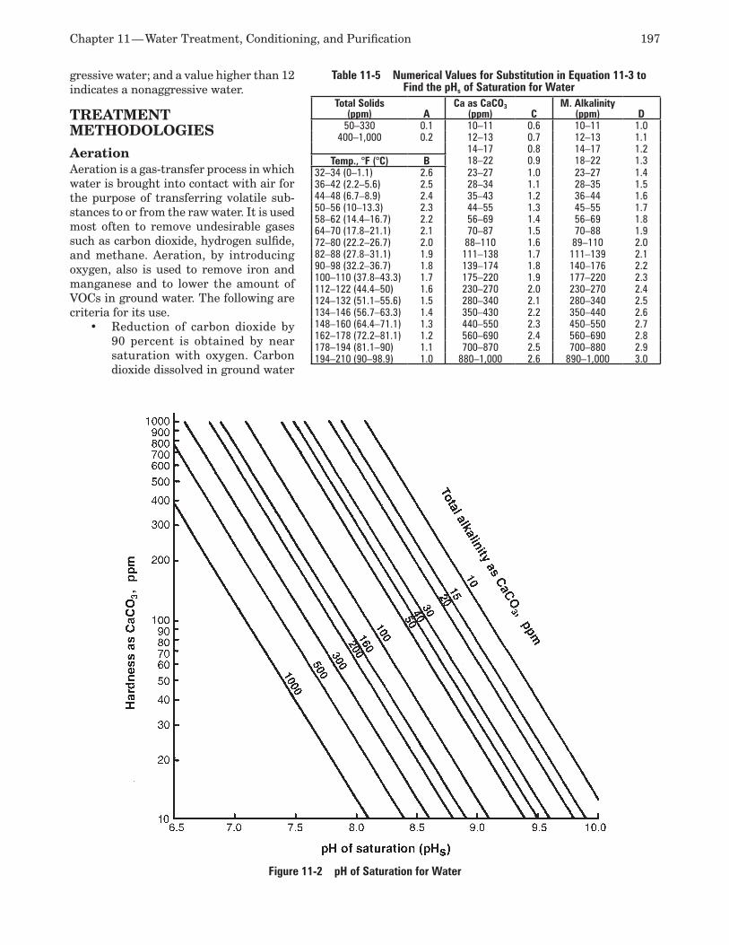
Chapter 11 — Water Treatment, Conditioning, and Purification 197
gressive water; and a value higher than 12 indicates a nonaggressive water.
TREATMENT METHODOLOGIES
Aeration Aeration is a gas-transfer process in which water is brought into contact with air for the purpose of transferring volatile sub-stances to or from the raw water. It is used most often to remove undesirable gases such as carbon dioxide, hydrogen sulfide, and methane. Aeration, by introducing oxygen, also is used to remove iron and manganese and to lower the amount of VOCs in ground water. The following are criteria for its use.
Reduction of carbon dioxide by •90 percent is obtained by near saturation with oxygen. Carbon dioxide dissolved in ground water
Table 11-5 Numerical Values for Substitution in Equation 11-3 to Find the pHs of Saturation for Water
Total Solids (ppm) A
Ca as CaCO3 (ppm) C
M. Alkalinity (ppm) D
50–330 0.1 10–11 0.6 10–11 1.0400–1,000 0.2 12–13 0.7 12–13 1.1
14–17 0.8 14–17 1.2Temp., °F (°C) B 18–22 0.9 18–22 1.3
32–34 (0–1.1) 2.6 23–27 1.0 23–27 1.436–42 (2.2–5.6) 2.5 28–34 1.1 28–35 1.544–48 (6.7–8.9) 2.4 35–43 1.2 36–44 1.650–56 (10–13.3) 2.3 44–55 1.3 45–55 1.758–62 (14.4–16.7) 2.2 56–69 1.4 56–69 1.864–70 (17.8–21.1) 2.1 70–87 1.5 70–88 1.972–80 (22.2–26.7) 2.0 88–110 1.6 89–110 2.082–88 (27.8–31.1) 1.9 111–138 1.7 111–139 2.190–98 (32.2–36.7) 1.8 139–174 1.8 140–176 2.2100–110 (37.8–43.3) 1.7 175–220 1.9 177–220 2.3112–122 (44.4–50) 1.6 230–270 2.0 230–270 2.4124–132 (51.1–55.6) 1.5 280–340 2.1 280–340 2.5134–146 (56.7–63.3) 1.4 350–430 2.2 350–440 2.6148–160 (64.4–71.1) 1.3 440–550 2.3 450–550 2.7162–178 (72.2–81.1) 1.2 560–690 2.4 560–690 2.8178–194 (81.1–90) 1.1 700–870 2.5 700–880 2.9194–210 (90–98.9) 1.0 880–1,000 2.6 890–1,000 3.0
Figure 11-2 pH of Saturation for Water
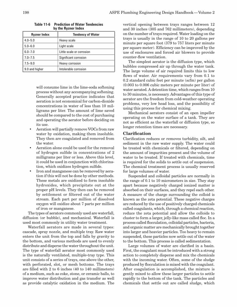
198 ASPE Plumbing Engineering Design Handbook — Volume 2
will consume lime in the lime-soda softening process without any accompanying softening. Generally accepted practice indicates that aeration is not economical for carbon-dioxide concentrations in water of less than 10 mil-ligrams per liter. The amount of lime saved should be compared to the cost of purchasing and operating the aerator before deciding on its use. Aeration will partially remove VOCs from raw •water by oxidation, making them insoluble. They then are coagulated and removed from the water. Aeration alone could be used for the removal •of hydrogen sulfide in concentrations of 2 milligrams per liter or less. Above this level, it could be used in conjunction with chlorina-tion, which oxidizes hydrogen sulfide. Iron and manganese can be removed by aera-•tion if this will not be done by other methods. These metals are oxidized to form insoluble hydroxides, which precipitate out at the proper pH levels. They then can be removed by settlement or filtered out of the water stream. Each part per million of dissolved oxygen will oxidize about 7 parts per million of iron or manganese.
The types of aerators commonly used are waterfall, diffusion (or bubble), and mechanical. Waterfall is used most commonly in utility water treatment.
Waterfall aerators are made in several types: cascade, spray nozzle, and multiple tray. Raw water enters the unit from the top and falls by gravity to the bottom, and various methods are used to evenly distribute and disperse the water throughout the unit. The type of waterfall aerator most commonly used is the naturally ventilated, multiple-tray type. This unit consists of a series of trays, one above the other, with perforated, slot, or mesh bottoms. The trays are filled with 2 to 6 inches (40 to 140 millimeters) of a medium, such as coke, stone, or ceramic balls, to improve water distribution and gas transfer as well as provide catalytic oxidation in the medium. The
vertical opening between trays ranges between 12 and 30 inches (305 and 762 millimeters), depending on the number of trays required. Water loading on the trays is usually in the range of 10 to 20 gallons per minute per square foot (379 to 757 liters per minute per square meter). Efficiency can be improved by the use of enclosures and forced air blowers to provide counter-flow ventilation.
The simplest aerator is the diffusion type, which bubbles compressed air up through the water tank. The large volume of air required limits this to low flows of water. Air requirements vary from 0.1 to 0.2 standard cubic feet per minute (scfm) per gallon (0.003 to 0.006 cubic meters per minute per liter) of water aerated. A detention time, which ranges from 10 to 30 minutes, is necessary. Advantages of this type of aerator are the freedom from cold-weather operating problems, very low head loss, and the possibility of using this process for chemical mixing.
Mechanical aerators consist of an open impeller operating on the water surface of a tank. They are not as efficient as the waterfall or diffusion type, so longer retention times are necessary.
Clarification Clarification reduces or removes turbidity, silt, and sediment in the raw water supply. The water could be treated with chemicals or filtered, depending on the amount of impurities present and the volume of water to be treated. If treated with chemicals, time is required for the solids to settle out of suspension. The chemical treatment process is usually reserved for large volumes of water.
Suspended and colloidal particles are normally in the range of 0.1 to 10 micrometers in size. They stay apart because negatively charged ionized matter is absorbed on their surfaces, and they repel each other. A measure of the charge surrounding the colloid is known as the zeta potential. These negative charges are reduced by the use of positively charged chemicals called coagulants, which, through a chemical reaction, reduce the zeta potential and allow the colloids to cluster to form a larger, jelly-like mass called floc. In a process called flocculation, colloidal particles, bacteria, and organic matter are mechanically brought together into larger and heavier particles. Too heavy to remain suspended, these particles now settle out of the water to the bottom. This process is called sedimentation.
Large volumes of water are clarified in a basin. First, the coagulant must be introduced with a strong action to completely disperse and mix the chemicals with the incoming water. Often, some of the sludge produced by flocculation is mixed with the coagulant. After coagulation is accomplished, the mixture is gently mixed to allow these larger particles to settle rapidly to the bottom of the tank. The particles and chemicals that settle out are called sludge, which
Table 11-6 Prediction of Water Tendencies by the Ryzner Index
Ryzner Index Tendency of Water
4.0–5.0 Heavy scale
5.0–6.0 Light scale
6.0–7.0 Little scale or corrosion
7.0–7.5 Significant corrosion
7.5–9.0 Heavy corrosion
9.0 and higher Intolerable corrosion
Chapter 11 — Water Treatment, Conditioning, and Purification 199
must be removed from the tank and disposed of. In most clarifier designs, these processes are done in the same operating unit.
The most frequently used chemical coagulant is aluminum sulfate, called alum or filter alum. Other frequently used coagulants are sodium aluminate and potash alum. Iron coagulants include ferric sulfate, ferris sulfate, and ferric chloride. Organic polyelectro-lytes, which are polymers of high molecular weight, also are employed in low dosages to increase the ef-fectiveness of treatment.
It is usually a matter of trial and error to find the correct amount of alum. This is because the amount depends on the size and quantity of the suspended solids in the raw water, retention time prior to floccu-lation, water temperature, and amount of mixing.
When the demand for water is low, one alternative flocculation method is to produce a finer floc, which can be removed by an appropriate filter system. By elimi-nating a large settling basin, high-quality water can be produced more quickly with smaller equipment.
Deaeration Dissolved gases in the water supply, such as oxygen, carbon dioxide, hydrogen sulfide, and ammonia, can produce corrosion and pitting. They must be removed prior to using the water for most purposes. Although carbon dioxide and hydrogen sulfide can be removed by aeration, in many cases it is easier and less expen-sive to remove them by deaeration. In this process, the water temperature is raised to the saturation point for the existing pressure.
The two types of deaerators are steam and vacuum. When heated water is needed, such as for boilers, the steam type is preferred. When cold water is required, the vacuum type is used.
Steam deaerators break up water into a spray or thin film and then sweep steam across and through it to force out the dissolved gases. With this method, oxygen can be reduced to near the limit of detection. Design use is spread evenly among spray, tray, and combination units. Typical deaerators have a heating and deaeration section and a storage section for hot, deareated water. Often, a separate tank is provided to hold an additional 10-minute supply of deaerated water. The direction of steam may be crossflow, down-flow, or countercurrent. The majority of the steam condenses in the first section of the unit. The remain-ing mixture of noncondensable gases is discharged to atmosphere through a vent condenser.
Vacuum deaerators use a steam jet or mechanical vacuum pump to develop the vacuum required to draw off the unwanted gases. The vessel has a pack-ing material inside, and the inlet water is introduced to the top of the unit and passed down through this packing. Deaerated water is stored at the bottom of the vessel. The steam or vapor vacuum located at the
top of the unit discharges the unwanted gases. The vacuum unit is far less efficient than the steam unit, and it most often is used in demineralizer systems to reduce the chemical operating cost and the demineral-izer size and to protect anion-exchange resins from possible oxidation damage.
Dealkalizing Dealkalizing is a process that reduces the alkalinity of feed water. This can be done either with or without the use of acid regenerant. Without the use of acid, the regenerant used is salt, and the process often is called salt splitting. The salt-splitting process exchanges all bicarbonate, sulfate, and nitrate anions for chloride anions. For best results, it is recommended that deionized water be used as feed water. Where hard, alkaline, and low-sodium water is available, the use of a weak acid resin should be considered.
The entire regeneration cycle is similar to water softening (described later in this chapter). It is not uncommon to use the same salt and regenerant piping to accommodate both the softener and the dealkalizer. Some caustic soda may be added (one part caustic soda to nine parts salt) to reduce the leakage of alkalinity and carbon dioxide. Since this can cause hardness leakage from the dealkalizer, a filter downstream of the processed water is necessary.
A weak acid resin also can be used. The process transfers the alkaline salts of calcium and magnesium to the weak acid resin and should include degasifica-tion if required by the product water. The weak acid process operates at a very high utilization factor, near the theoretically required amount. Hydrochloric acid, rather than sulfuric acid, is preferred for regenera-tion. This process is very sensitive to the flow rate, temperature, and contaminant level of the feed water. These changing conditions must be considered by the manufacturer in the design of the process. The entire regeneration cycle is similar to that of a cation ion-exchange column.
Decarbonation Decarbonation is rarely used, but it should be consid-ered if the bicarbonate level in the feed water is in the range of 14 to 20 milligrams per liter or higher. De-carbonation usually is accomplished in small systems by the use of filtered air flowing through the water stream and stripping out the carbon dioxide.
Distillation In its basic form, distillation is the process of boil-ing feed water, condensing the steam produced from the feed water, and collecting the condensate, which yields product water theoretically free from nonvolatile impurities.
200 ASPE Plumbing Engineering Design Handbook — Volume 2
Three methods currently are used to produce distilled water: single-stage distillation, vapor com-pression, and multi-effect distillation.
Single-stage DistillationThe still used for single-stage distillation is the sim-plest type of still. Feed water enters the still and is evaporated and condensed in a single stage. Cooling water is required to condense the steam produced. This type of still produces water of approximately 1 megohm-centimeter, with higher purity possible with optional equipment that removes dissolved gaseous impurities. This method has a small footprint, is less labor intensive than the other methods, and tolerates feed water with a high level of impurity.
Vapor CompressionSometimes called thermocompression distillation, va-por compression is a method of evaporation in which a liquid is boiled inside a bank of tubes. The vapor generated then passes through a mist eliminator that removes any water droplets. The pure vapor is with-drawn by a compressor in which the energy imparted results in a compressed steam with increased pres-sure and temperature. The higher-energy compressed steam is discharged into an evaporator. At this point, the steam gives up most of its energy (latent heat) to the water inside the tubes. More vapor is generated and the process is repeated. The condensate (distilled water) is withdrawn by the distillate pump and is discharged through a two-stream heat exchanger.
The excess feed water that did not evaporate also is pumped through an exchanger. Both the distillate and the blowdown are cooled, and the feed water is preheated prior to its entering the evaporator. These exchangers minimize the energy consumption of the system and eliminate the need for additional cooling water. The system operates continuously once it is started. Additional makeup heat, usually supplied by steam, is required for continuous operation. Vapor compression generally is considered more economi-cal for large quantities of water and does not require high-quality feed water for proper operation. It has moderate first and operating costs.
Refer to Figure 11-3 for a typical flow diagram of a vapor compression unit.
Multi-effect Distillation Multi-effect distillation units use staged evaporation and condensation to generate distilled water. Each stage is called an effect. Distilled water is produced in each effect when the steam generated by the evaporation of high-purity feed water in the previous stage is condensed. The initial driving force for the evaporation is power steam applied to the shell side of the first effect vessel. The multi-effect method has the highest initial cost and the lowest operating cost
of the three distillation methods, and it requires the highest quality feed water.
The feed water enters the vessel, and its pressure is boosted by the feed pump. The feed water flows through a coil in the condenser, which allows it to pick up heat from the condensing steam. This preheated feed water flows through the feed control valve and into the tube side of the first effect. The first effect level controller senses the feed water level and signals the feed control valve to maintain the desired level. Power steam is introduced into the unit and flows through the steam control valve and into the shell side of the first effect.
Temperature sensors sense the temperature on the tube side of the first effect and signal the steam control valve to maintain the required temperature. This steam condenses on the outside of the tubes of the first effect, giving up its latent heat of vaporiza-tion to the feed water inside the tubes, causing it to boil and generate vapor.
The pure steam generated in the first effect is introduced into the shell side of the second effect. The pure steam condenses, producing distilled water while giving up its latent heat to the high-purity feed water inside the second effect tubes, causing the feed water to boil and generate vapor. Each effect operates at a lower pressure than the previous effect to provide the temperature difference that allows the transfer of heat. The pure steam generated in the tube side of the first effect by the condensing power steam passes through the mist eliminator to remove any entrained water droplets. Feed water from the first effect passes through an orifice and into the tube side of the second effect. The first effect pure steam enters the shell side of the second effect and is condensed on the outside of the tubes.
The condensate (distilled water) passes through an orifice and enters the shell side of the third effect. Feed water in the second effect passes through an orifice and into the tube side of the third effect.
After passing through the mist eliminator, the last effect, pure steam enters the condenser and condenses on the outside of the condenser coils. This distilled water from the last effect and the distilled water from the previous effects is cooled by the cooling water of the condenser. The distilled water exits the con-denser and enters the distillate pump. The distillate is pumped through the distillate control valve and through the storage/dump valve. The condenser level controller senses the distillate level and signals the control valve to maintain the desired level.
Noncondensable gases in the condenser are vented to the atmosphere. The condenser temperature is maintained at a predetermined level by the cooling water flow. The unit is protected by pressure-relief valves along with high- and low-level alarms.
Chapter 11 — Water Treatment, Conditioning, and Purification 201
Refer to Figure 11-4 for a typical flow diagram of a multi-effect distillation unit.
Filtration
Deep-bed Sand Filtration Deep-bed filters are designed to remove coarse suspend-ed particulates larger than 10 micrometers. They are a pressure-type filter using either multi-graded sand or multimedia as the filter medium. Particulate removal in the range of 98 percent should be expected.
Sand-only filters for laboratory water systems generally operate at a velocity of about 4 gpm per square foot (192 liters per minute per square meter) of cross-sectional bed area. Multimedia filters operate at about 6 gpm per square foot (228 liters per minute per square meter) of cross-sectional bed area. Keep in mind that these values are general in nature, and it is important to operate these units at the velocities recommended by the individual manufacturer.
The multimedia filter achieves a more uniform distribution of filter media throughout the bed than the sand-only filter and is considered a more effective type of filter. A typical multimedia filter for labora-tory use consists of a top layer of anthracite having a 1.1-millimeter-diameter grain size and a 1.5 specific gravity, a middle layer of sand having a 0.5-millimeter-diameter grain size and a specific gravity of 26, and a bottom layer of garnet having a 0.2-millimeter-diam-eter grain size and a 4.2 specific gravity. The normal operational flow rate ranges from 6 to 15 gpm per square foot (228 to 570 liters per minute per square meter) of bed area.
Backwashing is required to clean the filter, with the effluent discharged to the sanitary drainage sys-tem. A backwash flow rate of 10 to 15 gpm per square foot (380 to 570 liters per minute per square meter) generally is required for effective cleaning.
Cross-flow and Tangential-flow Filtration In the past 10 years, a number of membrane filters have appeared on the market, and membrane sys-tems have greatly expanded the field of mechanical filtration. Following are several typical media and membrane-filtration systems:
Bag filter gross filtration, including limited •membrane applications Standard cartridge depth filtration•Hurricane• (a trademark of the Harmsco Corp.), a cross between a standard tangential cartridge application and a cross-flow filterHorizontal and vertical pressure media filters, •with or without a precoatSubmicron cartridge filtration, including •point-of-use ultrafiltration cartridgesCross-flow membrane systems designed for •particulate removal in the concentrate
Ultra-filtration to less than 10,000 molecular •weight compoundsNano-filtration with a very low molecular •weight filtration, to ionic levels of calcium sulfate Reverse-osmosis waste-treatment applica-•tions
These filtration systems typically are used in conjunction with ion-exchange and reverse-osmosis, high-purity systems to remove bacteria, pyrogens, and nonvolatile total organic carbon compounds. These filtration systems are used in waste-treatment applications, including the concentrated waste of reverse-osmosis systems and ion-exchange waste.
Activated Carbon Filtration Activated carbon is used to remove residual chlorine, chloramine disinfectants, dissolved organics such as trihalomethanes, and a major portion of naturally occurring dissolved organic material from municipal water supplies. The nonionic organics tend to coat ion-exchange resins and all types of membranes.
Some system designers are reluctant to use the activated carbon filter in the generation of pure water because of the possible development of significant lev-els of bacteria in the unit itself. This can be controlled by periodically sanitizing the unit with pure steam or hot water with a temperature greater than 176°F (80°C). The need for sanitizing can be determined only by testing the water. Because of this need for steril-ization, the interior of the filter housing should be lined or coated. When using pure water as feed water, stainless-steel housings should be avoided because of possible chloride stress corrosion and chloride pitting resulting from the chlorine in the feed water.
A typical detail of a packed-bed, activated-carbon unit is illustrated in Figure 11-5.
Ion Exchange and Removal Ion exchange is the basic process in which specific ions in a feed water stream are transferred into an exchange medium called resin and exchanged for different ions of equal charge. When the ion-exchange process is used to treat water only for the removal of hardness, it generally is known as water softening. When the ion-exchange process is used to treat water for the removal of ions to produce pure water, it often is referred to as deionization (DI) or demineralization.
The deionization/demineralization process uses different types of resin to exchange first anions and then cations, resulting in the removal of all ions from feed water when the process is carried to completion. When all of the ionic components involved in water are removed by ion exchange, the water is said to be deionized or demineralized. The ion-exchange process also is used to remove dissolved inorganics. Water softening only exchanges some types of ions
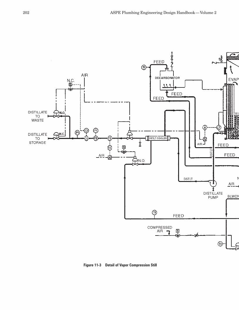
202 ASPE Plumbing Engineering Design Handbook — Volume 2
Figure 11-3 Detail of Vapor Compression Still
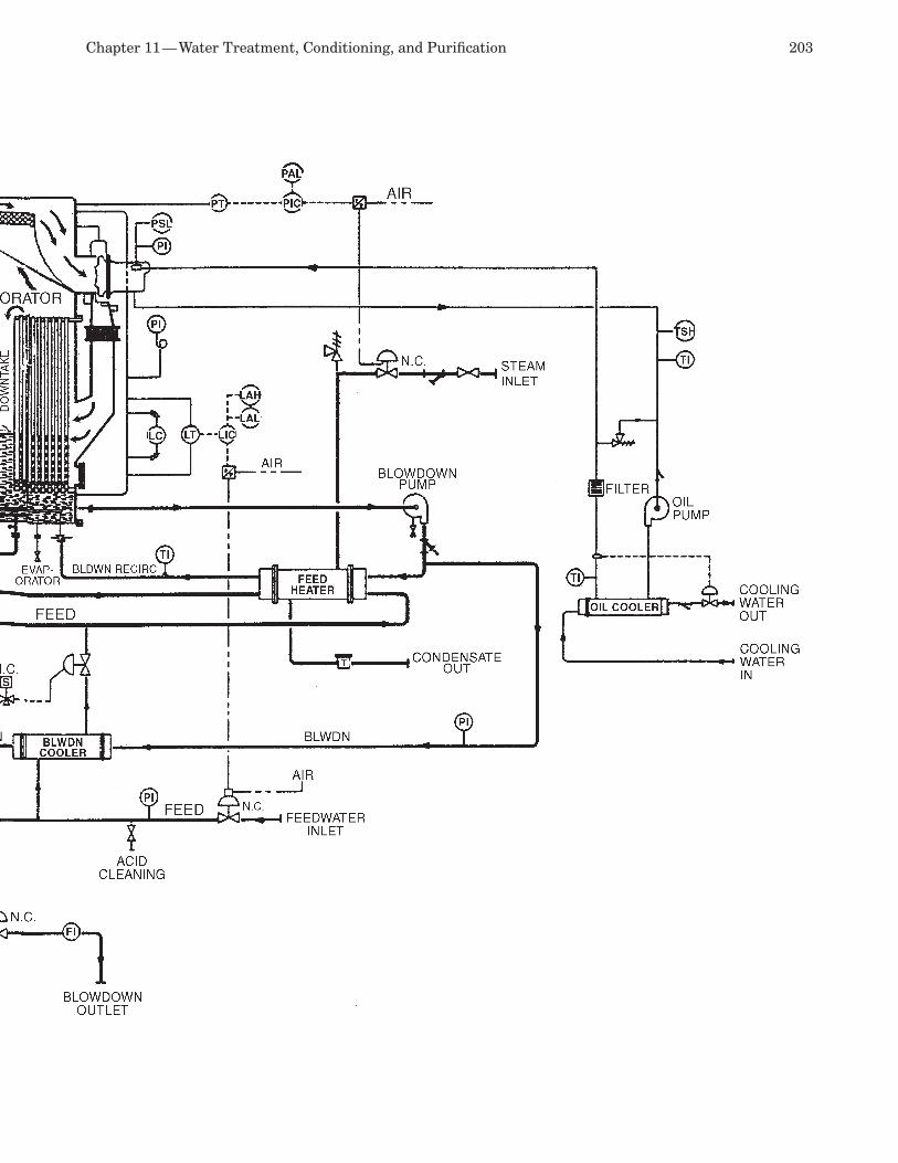
Chapter 11 — Water Treatment, Conditioning, and Purification 203
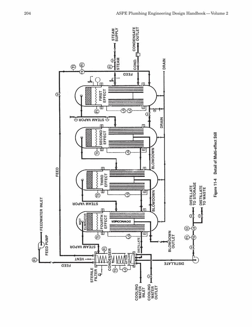
204 ASPE Plumbing Engineering Design Handbook — Volume 2
Figu
re 1
1-4
Det
ail o
f Mul
ti-ef
fect
Stil
l

Chapter 11 — Water Treatment, Conditioning, and Purification 205
for others that are less detrimental for the intended end use of the water.
Table 11-7 lists the common anions and cations typically found in water. Ion exchange does not remove significant amounts of organics, bacteria, particles, colloids, or turbidity.
Regenerable Ion Exchange Regenerable ion exchange is a batch process in which ions in raw water are transferred onto a resin medium in exchange for other ions bonded to that medium as the raw water percolates through it. The ions in the raw water are adsorbed onto a bed of exchange resins and replaced with an equivalent amount of another ion of the same charge. This action continues until the medium has reached its exchange capacity and it no longer is capable of exchanging ions.
The two general types of deionizers are working and polishing. The working type is used for the initial removal of the bulk of ions from feed water or as only an ion-exchange process (such as hardness removal) if the purification is a single process. The polishing type is used to purify feed water after an initial run through a working ion-exchange system.
Resins Resin-exchange media include natural inorganic alu-minum silicates (sometimes called zeolites or green sands), bentonite clay, and synthetic, gelatinous and
synthetic, organic resins. Most processes use the synthetic resins. Resins are graded by purity and consistency in size.
Resin is manufactured in the form of a large num-ber of spherical beads, typically about 0.4 millimeter in diameter. Weakly bonded ions on these beads’ surfaces are used for the exchange process. Because the process must exchange ions of the same charge, ion-exchange resins are composed of either anion or cation exchange resins. Manufacturers are con-stantly making new resins for different ion-removal purposes.
Traditional deionization exchanges cations with hydrogen (H+) ions (an acid) and anions with hydroxyl (OH-) ions (a base). Although not 100 percent effec-tive, these two exchange processes together remove cations and anions from water, and the remaining H+ and OH- ions combine to form water. When all
of the ionized impurities are removed, the water is said to be deionized, which is also re-ferred to as demineralized.
A large number of ion-exchange resins is available. Each resin is formulated to obtain optimum performance for different impurities. The affinity for different ions in solution is termed selectivity coefficients. The number of charges (valence) available on a particular ionic medium is a major factor in the selection of specific resins to remove the desired impurities and is based on an analysis of raw water. The resins are contained in a vessel, often referred to as a column. The actual resin bed could be supported by a mat of graded gravel, screen-wrapped pipe, or perforated plates, which also act to evenly distribute feed water over the entire resin bed. The resin beads in the vessel also create
Table 11-7 Typical Cations and Anions Found in Water
Cations Anions
Calcium Carbonates
Magnesium Bicarbonates
Sodium Sulfates
Potassium Chlorides
Iron Nitrates
Manganese Silica
Figure 11-5 Schematic Detail of Large-scale, Granular-activated Carbon Filter
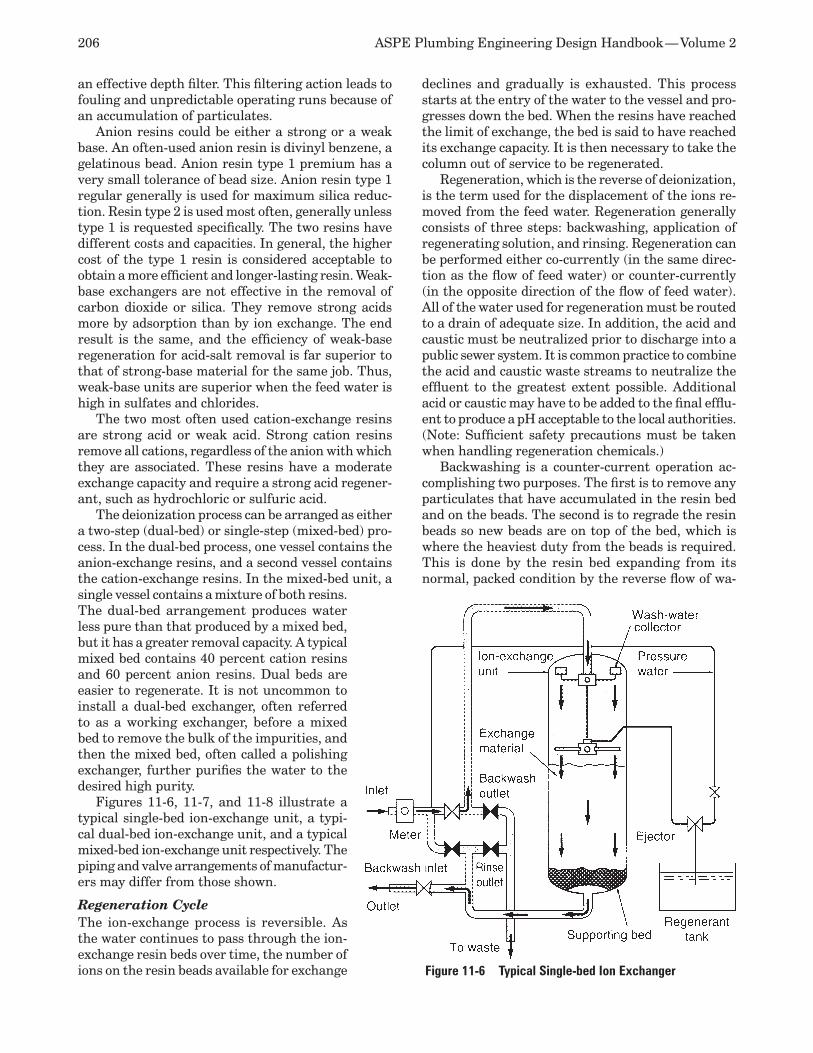
206 ASPE Plumbing Engineering Design Handbook — Volume 2
an effective depth filter. This filtering action leads to fouling and unpredictable operating runs because of an accumulation of particulates.
Anion resins could be either a strong or a weak base. An often-used anion resin is divinyl benzene, a gelatinous bead. Anion resin type 1 premium has a very small tolerance of bead size. Anion resin type 1 regular generally is used for maximum silica reduc-tion. Resin type 2 is used most often, generally unless type 1 is requested specifically. The two resins have different costs and capacities. In general, the higher cost of the type 1 resin is considered acceptable to obtain a more efficient and longer-lasting resin. Weak-base exchangers are not effective in the removal of carbon dioxide or silica. They remove strong acids more by adsorption than by ion exchange. The end result is the same, and the efficiency of weak-base regeneration for acid-salt removal is far superior to that of strong-base material for the same job. Thus, weak-base units are superior when the feed water is high in sulfates and chlorides.
The two most often used cation-exchange resins are strong acid or weak acid. Strong cation resins remove all cations, regardless of the anion with which they are associated. These resins have a moderate exchange capacity and require a strong acid regener-ant, such as hydrochloric or sulfuric acid.
The deionization process can be arranged as either a two-step (dual-bed) or single-step (mixed-bed) pro-cess. In the dual-bed process, one vessel contains the anion-exchange resins, and a second vessel contains the cation-exchange resins. In the mixed-bed unit, a single vessel contains a mixture of both resins. The dual-bed arrangement produces water less pure than that produced by a mixed bed, but it has a greater removal capacity. A typical mixed bed contains 40 percent cation resins and 60 percent anion resins. Dual beds are easier to regenerate. It is not uncommon to install a dual-bed exchanger, often referred to as a working exchanger, before a mixed bed to remove the bulk of the impurities, and then the mixed bed, often called a polishing exchanger, further purifies the water to the desired high purity.
Figures 11-6, 11-7, and 11-8 illustrate a typical single-bed ion-exchange unit, a typi-cal dual-bed ion-exchange unit, and a typical mixed-bed ion-exchange unit respectively. The piping and valve arrangements of manufactur-ers may differ from those shown.
Regeneration Cycle The ion-exchange process is reversible. As the water continues to pass through the ion-exchange resin beds over time, the number of ions on the resin beads available for exchange
declines and gradually is exhausted. This process starts at the entry of the water to the vessel and pro-gresses down the bed. When the resins have reached the limit of exchange, the bed is said to have reached its exchange capacity. It is then necessary to take the column out of service to be regenerated.
Regeneration, which is the reverse of deionization, is the term used for the displacement of the ions re-moved from the feed water. Regeneration generally consists of three steps: backwashing, application of regenerating solution, and rinsing. Regeneration can be performed either co-currently (in the same direc-tion as the flow of feed water) or counter-currently (in the opposite direction of the flow of feed water). All of the water used for regeneration must be routed to a drain of adequate size. In addition, the acid and caustic must be neutralized prior to discharge into a public sewer system. It is common practice to combine the acid and caustic waste streams to neutralize the effluent to the greatest extent possible. Additional acid or caustic may have to be added to the final efflu-ent to produce a pH acceptable to the local authorities. (Note: Sufficient safety precautions must be taken when handling regeneration chemicals.)
Backwashing is a counter-current operation ac-complishing two purposes. The first is to remove any particulates that have accumulated in the resin bed and on the beads. The second is to regrade the resin beads so new beads are on top of the bed, which is where the heaviest duty from the beads is required. This is done by the resin bed expanding from its normal, packed condition by the reverse flow of wa-
Figure 11-6 Typical Single-bed Ion Exchanger
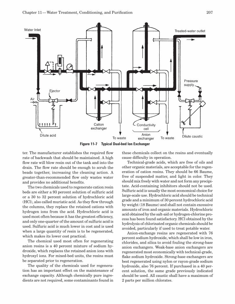
Chapter 11 — Water Treatment, Conditioning, and Purification 207
ter. The manufacturer establishes the required flow rate of backwash that should be maintained. A high flow rate will blow resin out of the tank and into the drain. The flow rate should be enough to scrub the beads together, increasing the cleaning action. A greater-than-recommended flow only wastes water and provides no additional benefits.
The two chemicals used to regenerate cation resin beds are either a 93 percent solution of sulfuric acid or a 30 to 32 percent solution of hydrochloric acid (HCl), also called muriatic acid. As they flow through the columns, they replace the retained cations with hydrogen ions from the acid. Hydrochloric acid is used most often because it has the greatest efficiency, and only one-quarter of the amount of sulfuric acid is used. Sulfuric acid is much lower in cost and is used when a large quantity of resin is to be regenerated, which makes its lower cost practical.
The chemical used most often for regenerating anion resins is a 40 percent mixture of sodium hy-droxide, which replaces the retained anion ions with hydroxyl ions. For mixed-bed units, the resins must be separated prior to regeneration.
The quality of the chemicals used for regenera-tion has an important effect on the maintenance of exchange capacity. Although chemically pure ingre-dients are not required, some contaminants found in
these chemicals collect on the resins and eventually cause difficulty in operation.
Technical-grade acids, which are free of oils and other organic materials, are acceptable for the regen-eration of cation resins. They should be 66 Baume, free of suspended matter, and light in color. They should mix freely with water and not form any precipi-tate. Acid-containing inhibitors should not be used. Sulfuric acid is usually the most economical choice for large-scale use. Hydrochloric acid should be technical grade and a minimum of 30 percent hydrochloric acid by weight (18 Baume) and shall not contain excessive amounts of iron and organic materials. Hydrochloric acid obtained by the salt-aid or hydrogen-chlorine pro-cess has been found satisfactory. HCl obtained by the hydrolysis of chlorinated organic chemicals should be avoided, particularly if used to treat potable water.
Anion-exchange resins are regenerated with 76 percent sodium hydroxide, which shall be low in iron, chlorides, and silica to avoid fouling the strong-base anion exchangers. Weak-base anion exchangers are regenerated most economically with technical-grade, flake sodium hydroxide. Strong-base exchangers are best regenerated using nylon or rayon-grade sodium hydroxide, also 76 percent. If purchased in a 40 per-cent solution, the same grade previously indicated should be used. All caustic shall have a maximum of 2 parts per million chlorates.
Figure 11-7 Typical Dual-bed Ion Exchanger
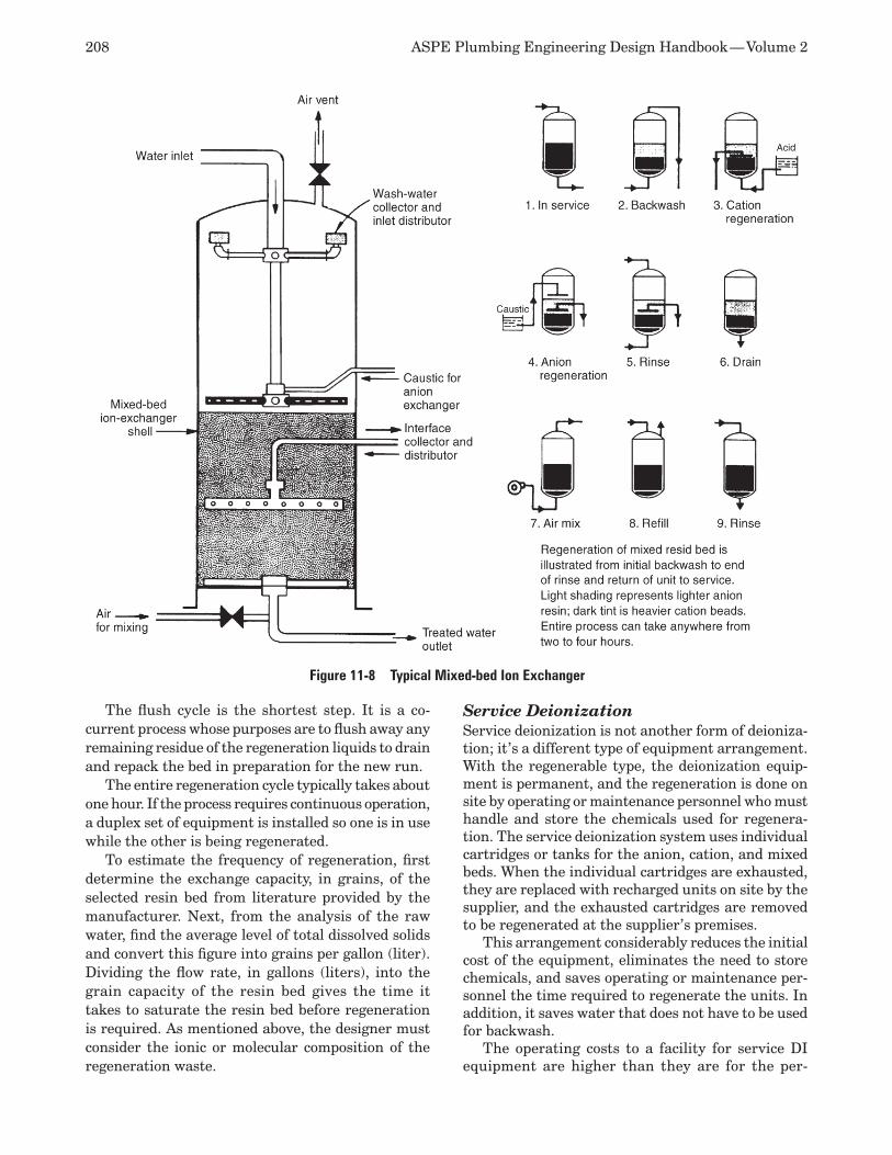
208 ASPE Plumbing Engineering Design Handbook — Volume 2
The flush cycle is the shortest step. It is a co-current process whose purposes are to flush away any remaining residue of the regeneration liquids to drain and repack the bed in preparation for the new run.
The entire regeneration cycle typically takes about one hour. If the process requires continuous operation, a duplex set of equipment is installed so one is in use while the other is being regenerated.
To estimate the frequency of regeneration, first determine the exchange capacity, in grains, of the selected resin bed from literature provided by the manufacturer. Next, from the analysis of the raw water, find the average level of total dissolved solids and convert this figure into grains per gallon (liter). Dividing the flow rate, in gallons (liters), into the grain capacity of the resin bed gives the time it takes to saturate the resin bed before regeneration is required. As mentioned above, the designer must consider the ionic or molecular composition of the regeneration waste.
Service Deionization Service deionization is not another form of deioniza-tion; it’s a different type of equipment arrangement. With the regenerable type, the deionization equip-ment is permanent, and the regeneration is done on site by operating or maintenance personnel who must handle and store the chemicals used for regenera-tion. The service deionization system uses individual cartridges or tanks for the anion, cation, and mixed beds. When the individual cartridges are exhausted, they are replaced with recharged units on site by the supplier, and the exhausted cartridges are removed to be regenerated at the supplier’s premises.
This arrangement considerably reduces the initial cost of the equipment, eliminates the need to store chemicals, and saves operating or maintenance per-sonnel the time required to regenerate the units. In addition, it saves water that does not have to be used for backwash.
The operating costs to a facility for service DI equipment are higher than they are for the per-
Figure 11-8 Typical Mixed-bed Ion Exchanger
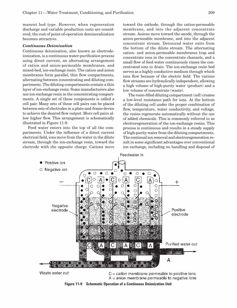
Chapter 11 — Water Treatment, Conditioning, and Purification 209
manent bed type. However, when regeneration discharge and variable production costs are consid-ered, the cost of point-of-operation demineralization becomes attractive.
Continuous Deionization Continuous deionization, also known as electrode-ionization, is a continuous water-purification process using direct current, an alternating arrangement of cation and anion-permeable membranes, and mixed-bed, ion-exchange resin. The cation and anion membranes form parallel, thin flow compartments, alternating between concentrating and diluting com-partments. The diluting compartments contain a thin layer of ion-exchange resin. Some manufacturers also use ion-exchange resin in the concentrating compart-ments. A single set of these components is called a cell pair. Many sets of these cell pairs can be placed between sets of electrodes in a plate-and-frame device to achieve the desired flow output. More cell pairs al-low higher flow. This arrangement is schematically illustrated in Figure 11-9.
Feed water enters into the top of all the com-partments. Under the influence of a direct current electrical field, ions move from the water in the dilute stream, through the ion-exchange resin, toward the electrode with the opposite charge. Cations move
toward the cathode, through the cation-permeable membrane, and into the adjacent concentrate stream. Anions move toward the anode, through the anion-permeable membrane, and into the adjacent concentrate stream. Deionized water exits from the bottom of the dilute stream. The alternating cation- and anion-permeable membranes trap and concentrate ions in the concentrate channels, and a small flow of feed water continuously rinses the con-centrated ions to drain. The ion-exchange resin bed serves as a highly conductive medium through which ions flow because of the electric field. The various flow streams are hydraulically independent, allowing a high volume of high-purity water (product) and a low volume of concentrate (waste).
The resin-filled diluting compartment (cell) creates a low-level resistance path for ions. At the bottom of the diluting cell under the proper combination of flow, temperature, water conductivity, and voltage, the resins regenerate automatically without the use of added chemicals. This is commonly referred to as electroregeneration of the ion-exchange resins. This process is continuous and results in a steady supply of high-purity water from the diluting compartments. The continual ion removal and electroregeneration re-sult in some significant advantages over conventional ion exchange, including no handling and disposal of
Figure 11-9 Schematic Operation of a Continuous Deionization Unit
210 ASPE Plumbing Engineering Design Handbook — Volume 2
hazardous regeneration chemicals, no interruptions due to exhaustion of the resins’ ion-exchange capacity, and low operating costs.
Continuous deionization is sensitive to feed water impurities, and very few natural potable feed water supplies can meet the required feed water specifica-tions without softening and additional pretreatment. Because of this limitation, most processes are now using continuous deionization for polishing purposes after reverse osmosis. The use of reverse osmosis and continuous deionization results in a complimentary combination of purification technologies, with the reverse osmosis removing the bulk of contaminants and the continuous deionization polishing the water to high purity levels.
Another disadvantage of continuous deionization is that the membranes and resins are incompatible with most sanitizing agents. Manufacturer specifica-tions and guidelines should be checked and followed. However, when continuous deionization is used in combination with reserve osmosis, the reverse osmo-sis process effectively provides efficient removal of bacteria, and the sanitization of the reverse osmosis can reduce the risk of downstream bacteria growth. Furthermore, continuous deionization can provide water consistently low in bacteria, and the continuous deionization process can have a germicidal effect due to local pH shifts associated with electroregeneration.
Water Softening Water softening is a process that reduces or removes dissolved impurities that cause hardness in water. This is done by one of two methods: adding lime-soda ash to the raw water for very large volumes or passing the raw water through an ion-exchange process.
The lime-soda ash method uses either hydrated lime or quicklime along with soda ash. When added to water, these chemicals react with the dissolved calcium and magnesium carbonate to form insoluble compounds. These compounds precipitate out of solution, are passed through a filter to be removed, and then are discharged to drain. This process usually is carried out during the clarification process rather than separately and is reserved for large volumes of water.
The ion-exchange method of water softening is a cation-exchange process used to remove insoluble and scale-forming iron and other multivalent cations, which are the primary causes of hardness, and to replace them with sodium ions, which do not con-tribute to hardness. The removal of these impurities prevents the buildup of insoluble scale precipitates on piping and the reverse-osmosis membrane. It is accomplished by passing the water through a bed of granular sodium cation-exchange resin. This process commonly is called sodium cycle ion exchange.
The resin bed typically occupies about two-thirds of the tank. The other one-third is needed for expan-
sion of the resin bed during backwash. A generally accepted range of 0.4 to 3 gpm per cubic foot (50 to 380 liters per minute per cubic meter) of resin is used to determine the volume of resin and the cycle time of the unit.
Microbial growth inside the unit is a concern in softening systems used for pharmaceutical and some laboratory purposes. The water softener is regener-ated with a brine solution, which does not destroy bacteria. The storage and regeneration equipment for the liquid brine solution also allows microbial growth in storage tanks exposed to the atmosphere. An alternative is to use a dry storage system, which generates a salt solution from water mixed with salt pellets only when necessary for regeneration. This controls microbial growth better than wet systems, but constant maintenance is required to monitor the brine tank. The quality of the salt in all systems should be determined periodically to ensure that no added substances are present.
The regeneration cycle is similar to that previ-ously discussed. The difference is that salt is used to regenerate the resin bed. Industrial water softeners use rock salt for economy. Rock salt, because of its high mineral content, requires a special tank called a desolver to dissolve the rock salt in water prior to use. The water softener is similar to the schematic single-bed ion exchanger illustrated in Figure 11-6.
Ion-exchange System Design Considerations Leakage is the presence of undesired ions in the final treated water. One of the major decisions that must be made when selecting an ion-exchange system is al-lowable leakage. The amount of leakage is a function of the completeness of regeneration of the resin. For water softening, generally accepted leakage amounts range between 0.1 and 1 part per million. Since total regeneration of the resin bed is inefficient and very costly, most water softeners operate at one-half to two-thirds of the ultimate capacity of the softener. There is sodium leakage from cation exchangers and silica leakage from anion exchangers. Normally, mixed-bed units have negligible leakage.
In general, for high-purity applications a single pass cannot give adequate purification of the water stream; therefore, a polisher is necessary. A mixed-bed ion-ex-change system, when used as a polisher, in general has a 74 percent lower initial cost than a two-bed system. A single-pass reverse osmosis system is approximately equal to a two-bed ion-exchange system.
Usually, if the water demand for a facility is less than 40 gpm (151 liters per minute), the greatest benefit will be derived from the simpler, less costly equipment with higher operating costs. For this quan-tity, it is common to have a mixed-bed unit without a degasifier, which is not required. For systems with a requirement of 200 gpm (757 liters per minute) or
Chapter 11 — Water Treatment, Conditioning, and Purification 211
more, the majority of the systems installed will have multiple-bed units and a degasifier. Manufacturers must be contacted for specific system and resin selec-tion and required equipment.
Where applicable, the use of weakly acidic and weakly basic resins minimizes chemical costs and reduces losses to waste because of the high regenera-tive capacity.
Some problems, such as microbial growth, are as-sociated with water softeners. Sanitation usually is accomplished during regeneration. Iron buildup in the unit could pass through to downstream purification equipment unless operating personnel constantly monitor the water quality.
Membrane Filtration and Separation Membrane filtration and separation is a general term for any water-purification process that removes contaminants from feed water by means of a thin, porous barrier called a membrane. When used as a filter, a membrane is capable of removing impurities of a much smaller size than other types of filters. Filters of this nature often are called ultrafilters and nanofilters. When membrane filtration and separation is used to produce pure water, the feed water flows parallel to the membrane (often called tangential flow), and not all of the feed water is recovered.
The two general categories of membrane filtration are reverse osmosis using a semipermeable membrane and filtration using ultrafiltration and nanofiltration membranes.
Reverse Osmosis Reverse osmosis is a broad-based water-purifying process involving osmosis and ionic repulsion.
Osmosis is the spontaneous passage of a solvent (such as water) through a semipermeable membrane until there is an equal concentration of solute mol-ecules (impurities such as sodium chloride) on both sides of the membrane. This membrane is called semi-permeable because it allows the solvent to diffuse, or pass through, but it is impervious to the solute.
In the natural osmosis process, when two solu-tions of different concentrations are separated by a semipermeable membrane, water molecules from the less concentrated solution will spontaneously pass through the membrane to dilute the more concen-trated solution. This occurs until a rough equilibrium is achieved. The driving force is a difference of pres-sure, called the osmotic pressure or concentration gradient, that exists across the membrane, and it is based on the degree of concentration of contaminants. This pressure is what drives the flow of the solvent. The flow (or flux) will continue until the osmotic pressure is equalized, which then results in a higher pressure on the concentrated solution side equal to the osmotic pressure.
Reverse osmosis is the flow of a solvent in the direc-tion opposite the direction of flow of natural osmosis. If enough pressure is applied to the more concentrated solution, which in this discussion is water, pure water is diffused through the membrane, leaving behind the bulk of the contaminants. This concentration of contaminants is flushed to drain continuously and thereby removed from the system. The purified water is called permeate and the contaminant containing water reject or the reject stream. In some cases, the reject stream is referred to as salt. The performance characteristics of the selected membrane determine how large a system is required. The flow rate is mea-sured in membrane flux, which is a measurement of the flow rate of permeate that will pass through a given area of the membrane at a specific temperature and pressure. The ratio of purified water flow to the feed water flow is called recovery. Most applications require a minimum 40 percent recovery rate to be considered practical. Rejection characteristics are ex-pressed as a percent of the specific impurities removed and depend on ionic charge and size.
Four types of membrane module configuration are used for reverse osmosis applications: hollow fiber, spiral wound, tubular, and plate and frame. Spiral wound is the most commonly used configuration. In each design, maximum turbulence is necessary to avoid concentration polarization.
The hollow-fiber configuration, illustrated in Fig-ure 11-10, consists of a perforated tube manufactured from ceramic, carbon, or porous plastic with inside diameters ranging from 1 to 6 inches (8 to 25 millime-ter). It requires rigid support when mounted inside the pressure vessel. Feed water could be introduced into either the center or the outside, depending on the manufacturer of the module. Fouling resistance is low.
The spiral-wound configuration, illustrated in Fig-ure 11-11, typically achieves a large surface area per unit volume. In this design, a flat membrane is formed around a fabric spacer closed on three sides, with the open side terminating in a perforated product water tube. The unit is placed in a pressure vessel. Feed water permeates through the membrane and flows radially inside the enclosure toward the product tube.
The tubular configuration, illustrated in Figure 11-12, consists of a perforated tube manufactured from ceramic, carbon, or porous plastic with larger inside diameters than the hollow-fiber configuration. The membrane is installed on the inside of the tube, and a number of tubes are installed inside a pressure vessel. Feed water enters the tube and permeates the mem-brane to be collected on the outside. The feed water channels are much more open than those of the spiral-wound configuration and less subject to fouling.
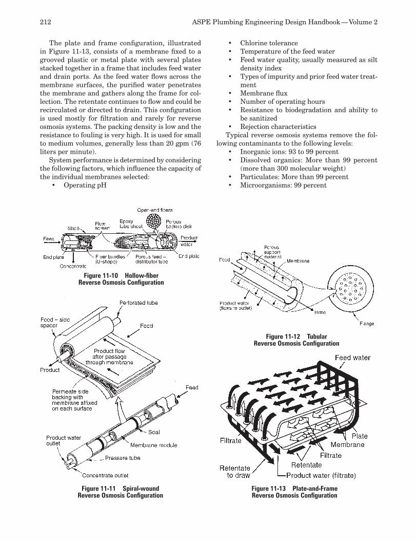
212 ASPE Plumbing Engineering Design Handbook — Volume 2
The plate and frame configuration, illustrated in Figure 11-13, consists of a membrane fixed to a grooved plastic or metal plate with several plates stacked together in a frame that includes feed water and drain ports. As the feed water flows across the membrane surfaces, the purified water penetrates the membrane and gathers along the frame for col-lection. The retentate continues to flow and could be recirculated or directed to drain. This configuration is used mostly for filtration and rarely for reverse osmosis systems. The packing density is low and the resistance to fouling is very high. It is used for small to medium volumes, generally less than 20 gpm (76 liters per minute).
System performance is determined by considering the following factors, which influence the capacity of the individual membranes selected:
Operating pH •
Chlorine tolerance •Temperature of the feed water •Feed water quality, usually measured as silt •density indexTypes of impurity and prior feed water treat-•ment Membrane flux•Number of operating hours •Resistance to biodegradation and ability to •be sanitized Rejection characteristics •
Typical reverse osmosis systems remove the fol-lowing contaminants to the following levels:
Inorganic ions: 93 to 99 percent •Dissolved organics: More than 99 percent •(more than 300 molecular weight) Particulates: More than 99 percent•Microorganisms: 99 percent•
Figure 11-11 Spiral-wound Reverse Osmosis Configuration
Figure 11-10 Hollow-fiber Reverse Osmosis Configuration
Figure 11-12 Tubular Reverse Osmosis Configuration
Figure 11-13 Plate-and-Frame Reverse Osmosis Configuration
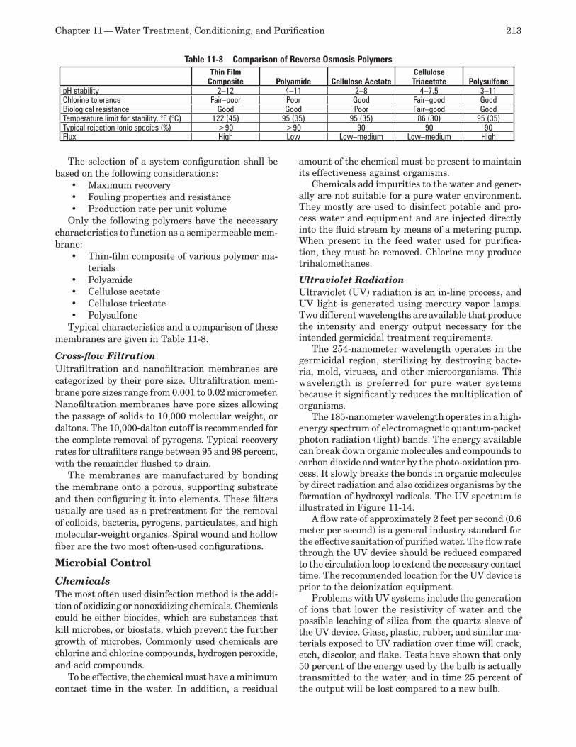
Chapter 11 — Water Treatment, Conditioning, and Purification 213
The selection of a system configuration shall be based on the following considerations:
Maximum recovery •Fouling properties and resistance •Production rate per unit volume•
Only the following polymers have the necessary characteristics to function as a semipermeable mem-brane:
Thin-film composite of various polymer ma-•terials Polyamide•Cellulose acetate •Cellulose tricetate •Polysulfone•
Typical characteristics and a comparison of these membranes are given in Table 11-8.
Cross-flow Filtration Ultrafiltration and nanofiltration membranes are categorized by their pore size. Ultrafiltration mem-brane pore sizes range from 0.001 to 0.02 micrometer. Nanofiltration membranes have pore sizes allowing the passage of solids to 10,000 molecular weight, or daltons. The 10,000-dalton cutoff is recommended for the complete removal of pyrogens. Typical recovery rates for ultrafilters range between 95 and 98 percent, with the remainder flushed to drain.
The membranes are manufactured by bonding the membrane onto a porous, supporting substrate and then configuring it into elements. These filters usually are used as a pretreatment for the removal of colloids, bacteria, pyrogens, particulates, and high molecular-weight organics. Spiral wound and hollow fiber are the two most often-used configurations.
Microbial Control
Chemicals The most often used disinfection method is the addi-tion of oxidizing or nonoxidizing chemicals. Chemicals could be either biocides, which are substances that kill microbes, or biostats, which prevent the further growth of microbes. Commonly used chemicals are chlorine and chlorine compounds, hydrogen peroxide, and acid compounds.
To be effective, the chemical must have a minimum contact time in the water. In addition, a residual
amount of the chemical must be present to maintain its effectiveness against organisms.
Chemicals add impurities to the water and gener-ally are not suitable for a pure water environment. They mostly are used to disinfect potable and pro-cess water and equipment and are injected directly into the fluid stream by means of a metering pump. When present in the feed water used for purifica-tion, they must be removed. Chlorine may produce trihalomethanes.
Ultraviolet Radiation Ultraviolet (UV) radiation is an in-line process, and UV light is generated using mercury vapor lamps. Two different wavelengths are available that produce the intensity and energy output necessary for the intended germicidal treatment requirements.
The 254-nanometer wavelength operates in the germicidal region, sterilizing by destroying bacte-ria, mold, viruses, and other microorganisms. This wavelength is preferred for pure water systems because it significantly reduces the multiplication of organisms.
The 185-nanometer wavelength operates in a high-energy spectrum of electromagnetic quantum-packet photon radiation (light) bands. The energy available can break down organic molecules and compounds to carbon dioxide and water by the photo-oxidation pro-cess. It slowly breaks the bonds in organic molecules by direct radiation and also oxidizes organisms by the formation of hydroxyl radicals. The UV spectrum is illustrated in Figure 11-14.
A flow rate of approximately 2 feet per second (0.6 meter per second) is a general industry standard for the effective sanitation of purified water. The flow rate through the UV device should be reduced compared to the circulation loop to extend the necessary contact time. The recommended location for the UV device is prior to the deionization equipment.
Problems with UV systems include the generation of ions that lower the resistivity of water and the possible leaching of silica from the quartz sleeve of the UV device. Glass, plastic, rubber, and similar ma-terials exposed to UV radiation over time will crack, etch, discolor, and flake. Tests have shown that only 50 percent of the energy used by the bulb is actually transmitted to the water, and in time 25 percent of the output will be lost compared to a new bulb.
Table 11-8 Comparison of Reverse Osmosis PolymersThin Film
Composite Polyamide Cellulose AcetateCellulose Triacetate Polysulfone
pH stability 2–12 4–11 2–8 4–7.5 3–11Chlorine tolerance Fair–poor Poor Good Fair–good GoodBiological resistance Good Good Poor Fair–good GoodTemperature limit for stability, °F (°C) 122 (45) 95 (35) 95 (35) 86 (30) 95 (35)Typical rejection ionic species (%) >90 >90 90 90 90Flux High Low Low–medium Low–medium High
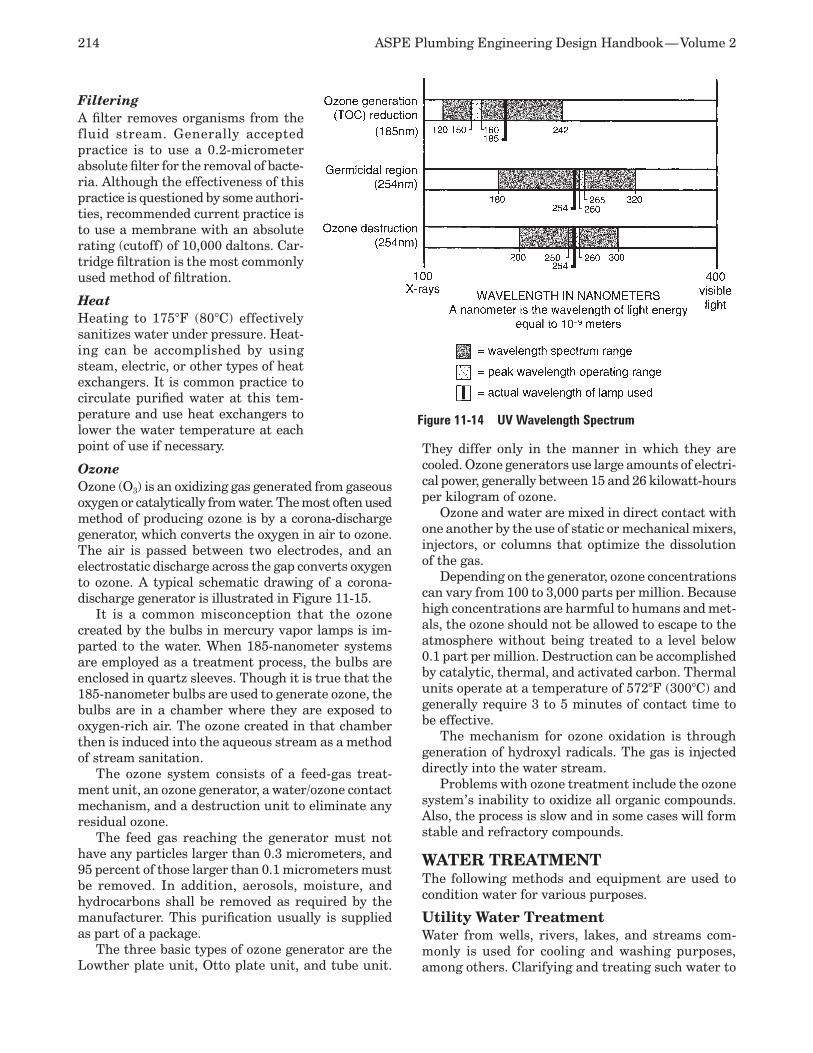
214 ASPE Plumbing Engineering Design Handbook — Volume 2
Filtering A filter removes organisms from the fluid stream. Generally accepted practice is to use a 0.2-micrometer absolute filter for the removal of bacte-ria. Although the effectiveness of this practice is questioned by some authori-ties, recommended current practice is to use a membrane with an absolute rating (cutoff) of 10,000 daltons. Car-tridge filtration is the most commonly used method of filtration.
Heat Heating to 175°F (80°C) effectively sanitizes water under pressure. Heat-ing can be accomplished by using steam, electric, or other types of heat exchangers. It is common practice to circulate purified water at this tem-perature and use heat exchangers to lower the water temperature at each point of use if necessary.
Ozone Ozone (O3) is an oxidizing gas generated from gaseous oxygen or catalytically from water. The most often used method of producing ozone is by a corona-discharge generator, which converts the oxygen in air to ozone. The air is passed between two electrodes, and an electrostatic discharge across the gap converts oxygen to ozone. A typical schematic drawing of a corona-discharge generator is illustrated in Figure 11-15.
It is a common misconception that the ozone created by the bulbs in mercury vapor lamps is im-parted to the water. When 185-nanometer systems are employed as a treatment process, the bulbs are enclosed in quartz sleeves. Though it is true that the 185-nanometer bulbs are used to generate ozone, the bulbs are in a chamber where they are exposed to oxygen-rich air. The ozone created in that chamber then is induced into the aqueous stream as a method of stream sanitation.
The ozone system consists of a feed-gas treat-ment unit, an ozone generator, a water/ozone contact mechanism, and a destruction unit to eliminate any residual ozone.
The feed gas reaching the generator must not have any particles larger than 0.3 micrometers, and 95 percent of those larger than 0.1 micrometers must be removed. In addition, aerosols, moisture, and hydrocarbons shall be removed as required by the manufacturer. This purification usually is supplied as part of a package.
The three basic types of ozone generator are the Lowther plate unit, Otto plate unit, and tube unit.
They differ only in the manner in which they are cooled. Ozone generators use large amounts of electri-cal power, generally between 15 and 26 kilowatt-hours per kilogram of ozone.
Ozone and water are mixed in direct contact with one another by the use of static or mechanical mixers, injectors, or columns that optimize the dissolution of the gas.
Depending on the generator, ozone concentrations can vary from 100 to 3,000 parts per million. Because high concentrations are harmful to humans and met-als, the ozone should not be allowed to escape to the atmosphere without being treated to a level below 0.1 part per million. Destruction can be accomplished by catalytic, thermal, and activated carbon. Thermal units operate at a temperature of 572°F (300°C) and generally require 3 to 5 minutes of contact time to be effective.
The mechanism for ozone oxidation is through generation of hydroxyl radicals. The gas is injected directly into the water stream.
Problems with ozone treatment include the ozone system’s inability to oxidize all organic compounds. Also, the process is slow and in some cases will form stable and refractory compounds.
WATER TREATMENTThe following methods and equipment are used to condition water for various purposes.
Utility Water Treatment Water from wells, rivers, lakes, and streams com-monly is used for cooling and washing purposes, among others. Clarifying and treating such water to
Figure 11-14 UV Wavelength Spectrum
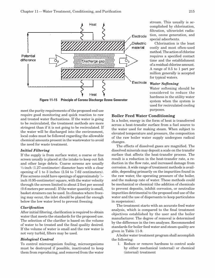
Chapter 11 — Water Treatment, Conditioning, and Purification 215
meet the purity requirements of the proposed end use require good monitoring and quick reaction to raw and treated water fluctuations. If the water is going to be recirculated, the treatment methods are more stringent than if it is not going to be recirculated. If the water will be discharged into the environment, local codes must be followed regarding the allowable chemical amounts present in the wastewater to avoid the need for waste treatment.
Initial Filtering If the supply is from surface water, a coarse or fine screen usually is placed at the intake to keep out fish and other large debris. Coarse screens are usually ½-inch (1.27-centimeter) diameter bars with a clear opening of 1 to 3 inches (2.54 to 7.62 centimeters). Fine screens could have openings of approximately 3/8-inch (0.95-centimeter) square, with the water velocity through the screen limited to about 2 feet per second (0.6 meters per second). If the water quantity is small, basket strainers can be used. In climates where freez-ing may occur, the inlet should be placed far enough below the low water level to prevent freezing.
Clarification After initial filtering, clarification is required to obtain water that meets the standards for the proposed use. The selection of the clarifier is based on the volume of water to be treated and the final quality desired. If the volume of water is small and the raw water is not very turbid, filters may be used.
Biological Control To control microorganism fouling, microorganisms must be destroyed if possible, inactivated to keep them from reproducing, and removed from the water
stream. This usually is ac-complished by chlorination, filtration, ultraviolet radia-tion, ozone generation, and special adsorbents.
Chlorination is the least costly and most often-used method. The action of chlorine requires a specified contact time and the establishment of a residual chlorine amount. A range of 0.5 to 1 part per million generally is accepted for typical waters.
Water Softening Water softening should be considered to reduce the hardness in the utility water system when the system is used for recirculated cooling purposes.
Boiler Feed Water Conditioning In a boiler, energy in the form of heat is transferred across a heat-transfer surface from a fuel source to the water used for making steam. When subject to elevated temperature and pressure, the composition of the raw boiler water supply undergoes radical changes.
The effects of dissolved gases are magnified. The dissolved minerals may deposit a scale on the transfer surface that affects the heat-transfer process. The result is a reduction in the heat-transfer rate, a re-duction in the flow rate, and increased damage from corrosion. A wide range of treatment methods is avail-able, depending primarily on the impurities found in the raw water, the operating pressure of the boiler, and the makeup rate of water. These methods could be mechanical or chemical (the addition of chemicals to prevent deposits, inhibit corrosion, or neutralize impurities detrimental to the proposed end use of the water and the use of dispersants to keep particulates in suspension).
The treatment starts with an accurate feed water analysis, which is compared to the final treatment objectives established by the user and the boiler manufacturer. The degree of removal is determined by the difference in the two analyses. Recommended standards for boiler feed water and steam quality are given in Table 11-9.
A boiler water treatment program shall accomplish the following:
Reduce or remove hardness to control scale 1. by either mechanical (external) or chemical (internal) treatment
Figure 11-15 Principle of Corona Discharge Ozone Generator
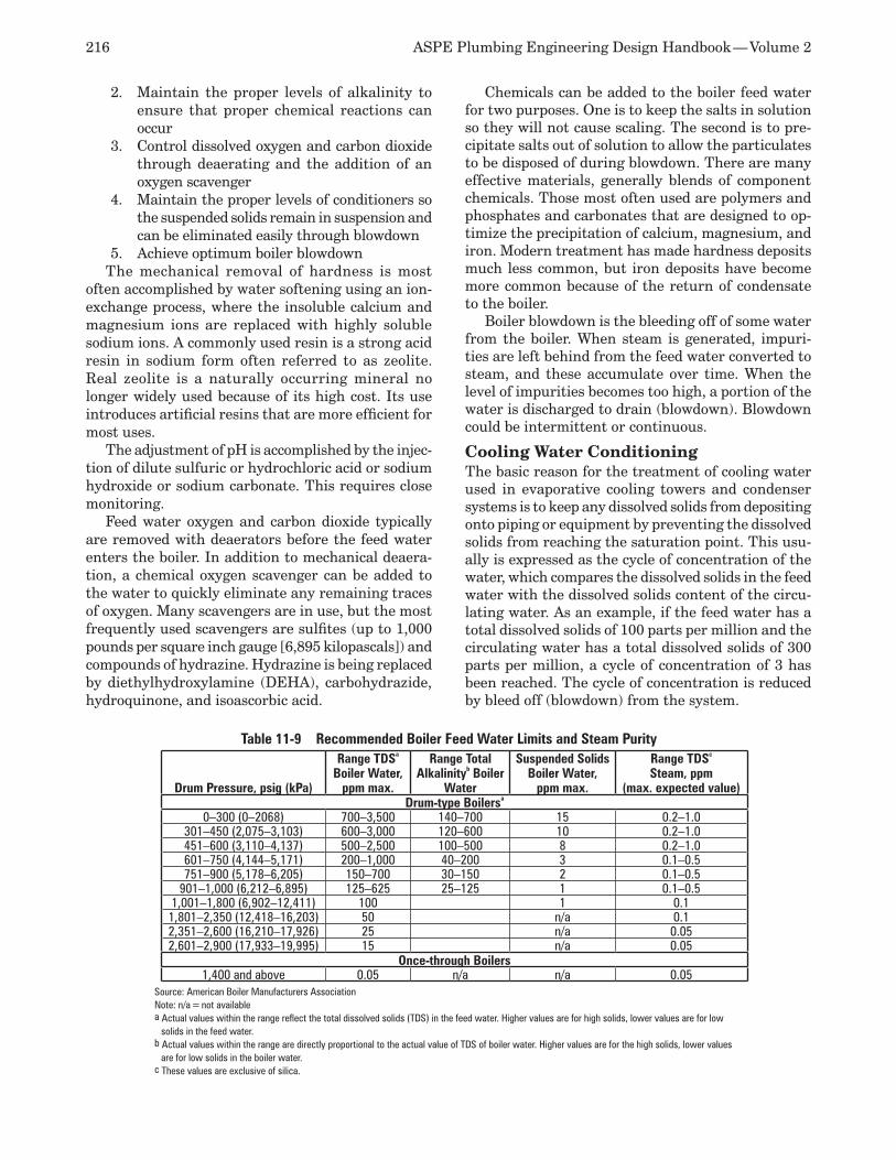
216 ASPE Plumbing Engineering Design Handbook — Volume 2
Maintain the proper levels of alkalinity to 2. ensure that proper chemical reactions can occurControl dissolved oxygen and carbon dioxide 3. through deaerating and the addition of an oxygen scavenger Maintain the proper levels of conditioners so 4. the suspended solids remain in suspension and can be eliminated easily through blowdown Achieve optimum boiler blowdown5.
The mechanical removal of hardness is most often accomplished by water softening using an ion-exchange process, where the insoluble calcium and magnesium ions are replaced with highly soluble sodium ions. A commonly used resin is a strong acid resin in sodium form often referred to as zeolite. Real zeolite is a naturally occurring mineral no longer widely used because of its high cost. Its use introduces artificial resins that are more efficient for most uses.
The adjustment of pH is accomplished by the injec-tion of dilute sulfuric or hydrochloric acid or sodium hydroxide or sodium carbonate. This requires close monitoring.
Feed water oxygen and carbon dioxide typically are removed with deaerators before the feed water enters the boiler. In addition to mechanical deaera-tion, a chemical oxygen scavenger can be added to the water to quickly eliminate any remaining traces of oxygen. Many scavengers are in use, but the most frequently used scavengers are sulfites (up to 1,000 pounds per square inch gauge [6,895 kilopascals]) and compounds of hydrazine. Hydrazine is being replaced by diethylhydroxylamine (DEHA), carbohydrazide, hydroquinone, and isoascorbic acid.
Chemicals can be added to the boiler feed water for two purposes. One is to keep the salts in solution so they will not cause scaling. The second is to pre-cipitate salts out of solution to allow the particulates to be disposed of during blowdown. There are many effective materials, generally blends of component chemicals. Those most often used are polymers and phosphates and carbonates that are designed to op-timize the precipitation of calcium, magnesium, and iron. Modern treatment has made hardness deposits much less common, but iron deposits have become more common because of the return of condensate to the boiler.
Boiler blowdown is the bleeding off of some water from the boiler. When steam is generated, impuri-ties are left behind from the feed water converted to steam, and these accumulate over time. When the level of impurities becomes too high, a portion of the water is discharged to drain (blowdown). Blowdown could be intermittent or continuous.
Cooling Water Conditioning The basic reason for the treatment of cooling water used in evaporative cooling towers and condenser systems is to keep any dissolved solids from depositing onto piping or equipment by preventing the dissolved solids from reaching the saturation point. This usu-ally is expressed as the cycle of concentration of the water, which compares the dissolved solids in the feed water with the dissolved solids content of the circu-lating water. As an example, if the feed water has a total dissolved solids of 100 parts per million and the circulating water has a total dissolved solids of 300 parts per million, a cycle of concentration of 3 has been reached. The cycle of concentration is reduced by bleed off (blowdown) from the system.
Table 11-9 Recommended Boiler Feed Water Limits and Steam Purity
Drum Pressure, psig (kPa)
Range TDSa Boiler Water,
ppm max.
Range Total Alkalinityb Boiler
Water
Suspended Solids Boiler Water,
ppm max.
Range TDSc Steam, ppm
(max. expected value)Drum-type Boilersa
0–300 (0–2068) 700–3,500 140–700 15 0.2–1.0301–450 (2,075–3,103) 600–3,000 120–600 10 0.2–1.0451–600 (3,110–4,137) 500–2,500 100–500 8 0.2–1.0601–750 (4,144–5,171) 200–1,000 40–200 3 0.1–0.5751–900 (5,178–6,205) 150–700 30–150 2 0.1–0.5
901–1,000 (6,212–6,895) 125–625 25–125 1 0.1–0.51,001–1,800 (6,902–12,411) 100 1 0.11,801–2,350 (12,418–16,203) 50 n/a 0.12,351–2,600 (16,210–17,926) 25 n/a 0.052,601–2,900 (17,933–19,995) 15 n/a 0.05
Once-through Boilers1,400 and above 0.05 n/a n/a 0.05
Source: American Boiler Manufacturers AssociationNote: n/a = not availablea Actual values within the range reflect the total dissolved solids (TDS) in the feed water. Higher values are for high solids, lower values are for low
solids in the feed water.b Actual values within the range are directly proportional to the actual value of TDS of boiler water. Higher values are for the high solids, lower values
are for low solids in the boiler water.c These values are exclusive of silica.

Chapter 11 — Water Treatment, Conditioning, and Purification 217
Scale The basic treatment for scale in cooling water systems is to add inhibitors that keep the scale from depositing on the walls of the pipe. They are similar to those used for boiler water treatment, but with the addition of surfactants, which change the surface characteristics of the pipe to prevent deposits and aid in removal if deposits occur.
Corrosion Broadly defined as an electrochemical process, cor-rosion takes place when an electrical potential is possible between two surfaces common to an elec-trolyte. The factors impacting corrosion in aquatic systems include:
Dissolved oxygen •Total dissolved solids •Alkalinity and pH•Total hardness •Temperature•Flow velocity •Types of metal used in the process •Condition of the interior surface of the plumb-•ing systemExtraneous electrical current•Bacteria•
Simple tools used to predict the propensity of an aqueous solution to be corrosive are the Langelier, Stiff and Davis, and Ryznar indexes. Corrosion treat-ments consist of:
pH control •Chemical inhibitors •Oxygen scavengers such as hydrazine, sodium •bisulfate, and morphine Ensuring proper flow rates by correctly sizing •metal pipe Sacrificial anodes •Polishing and passivation of interior sur-•faces Biocide treatment •
These shall be recommended by the manufacturer of both the chemicals and the equipment to ensure compatibility. The pH of the circulating water usu-ally is controlled to a point near 7.5 to decrease its scale-forming tendency. The addition of a dilute acid is the most often-used method of control. A corrosion inhibitor often adds compounds that increase the tendency of scale to occur; therefore, a balance must be reached.
Biological Fouling Microbial control is achieved with the addition of biocides, either oxidizing or nonoxidizing depending on their chemistry and killing action. Ozone also is commonly used.
Biocide treatment initially shocks microbes with a heavy dose, and then the concentration of the com-
pounds is allowed to fall to a level of 25 percent of the initial dose. This is a generally accepted lower limit below which the biocide is not considered effective. Often, because of the presence of several different strains of microbes, more than one biocide may be required. A contact time approved by the chemical manufacturer is required.
These chemicals are added by means of a chemi-cal feed pump discharging directly into the piping system. The levels must be closely monitored with alarms established by performance indicators based on operating experience.
Potable Water Treatment Water used for human consumption or intended to be part of food products must be treated to comply with the Safe Drinking Water Act, the Surface Water Treatment Rule (which is part of the Safe Drinking Water Act), and local regulations. Substances that affect the quality of potable water are classified in four major headings.
Physical: Physical characteristics, such as 1. color, turbidity, taste, and odor, often are re-lated to the appearance of the water. Physical quality is corrected through the use of various types of filters. Chemical: The chemical characteristics of 2. water are related to dissolved minerals (mostly hardness), gases, and organics. The chemical quality of water is adjusted by the use of water softeners, ion exchange, reverse osmosis units, and activated charcoal units to remove organic impurities. Biological: These characteristics are concerned 3. with microorganisms that affect the health of the consumer. Biological treatment requires the use of biocides and biostats to eliminate and reduce the number of microorganisms present in the water and to create a residual amount of the chemical to maintain the re-quired level of action required by code. Radiological: This category is concerned pri-4. marily with radon in areas where the water may have come in contact with radioactive substances. Retention and aeration lower the radon count to acceptable limits in approxi-mately eight hours.
A synopsis of general treatment methods for small potable water systems, including a discussion of general advantages and disadvantages, is given in Table 11-10.
WATER PURIFICATIONA total water treatment system for pure water used for laboratory and pharmaceutical purposes consists of three general, interrelated phases: pretreatment, purification, and distribution (including post-treat-
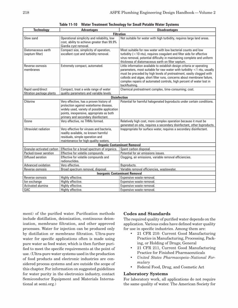
218 ASPE Plumbing Engineering Design Handbook — Volume 2
ment) of the purified water. Purification methods include distillation, deionization, continuous deion-ization, membrane filtration, and other approved processes. Water for injection can be produced only by distillation or membrane filtration. Ultra-pure water for specific applications often is made using pure water as feed water, which is then further puri-fied to meet the specific requirements at the point of use. (Ultra-pure water systems used in the production of food products and electronic industries are con-sidered process systems and are outside the scope of this chapter. For information on suggested guidelines for water purity in the electronics industry, contact Semiconductor Equipment and Materials Interna-tional at semi.org.)
Codes and Standards The required quality of purified water depends on the application. Various codes have defined water quality for use in specific industries. Among them are:
21 CFR 210: Current Good Manufacturing •Practice in Manufacturing, Processing, Pack-ing, or Holding of Drugs; General 21 CFR 211, Current Good Manufacturing •Practice for Finished Pharmaceuticals United States Pharmacopeia–National For-•mulary Federal Food, Drug, and Cosmetic Act •
Laboratory Systems For laboratory work, all applications do not require the same quality of water. The American Society for
Table 11-10 Water Treatment Technology for Small Potable Water SystemsTechnology Advantages Disadvantages
FiltrationSlow sand Operational simplicity and reliability, low
cost, ability to achieve greater than 99.9% Giardia cyst removal.
Not suitable for water with high turbidity, requires large land areas.
Diatomaceous earth (septum filter)
Compact size, simplicity of operation, excellent cyst and turbidity removal.
Most suitable for raw water with low bacterial counts and low turbidity (<10 ntu), requires coagulant and filter aids for effective virus removal, potential difficulty in maintaining complete and uniform thickness of diatomaceous earth on filter septum.
Reverse osmosis membranes
Extremely compact, automated. Little information available to establish design criteria or operating parameters, most suitable for raw water with turbidity <1 ntu, usually must be preceded by high levels of pretreatment, easily clogged with colloids and algae, short filter runs, concerns about membrane failure, complex repairs of automated controls, high percent of water lost in backflushing.
Rapid sand/direct filtration package plants
Compact, treat a wide range of water quality parameters and variable levels.
Chemical pretreatment complex, time-consuming; cost.
DisinfectionChlorine Very effective, has a proven history of
protection against waterborne disease, widely used, variety of possible application points, inexpensive, appropriate as both primary and secondary disinfectant.
Potential for harmful halogenated byproducts under certain conditions.
Ozone Very effective, no THMs formed. Relatively high cost, more complex operation because it must be generated on-site, requires a secondary disinfectant, other byproducts.
Ultraviolet radiation Very effective for viruses and bacteria, readily available, no known harmful residuals, simple opera tion and maintenance for high-quality waters.
Inappropriate for surface water, requires a secondary disinfectant.
Organic Contaminant RemovalGranular-activated carbon Effective for a broad spectrum of organics. Spent carbon disposal.Packed-tower aeration Effective for volatile compounds. Potential for air emissions issues.Diffused aeration Effective for volatile compounds and
radionuclides.Clogging, air emissions, variable removal efficiencies.
Advanced oxidation Very effective. Byproducts.Reverse osmosis Broad spectrum removal, disposal. Variable removal efficiencies, wastewater.
Inorganic Contaminant RemovalReverse osmosis Highly effective. Expensive waste removal.Ion exchange Highly effective. Expensive waste removal.Activated alumina Highly effective. Expensive waste removal.GAC Highly effective. Expensive waste removal.
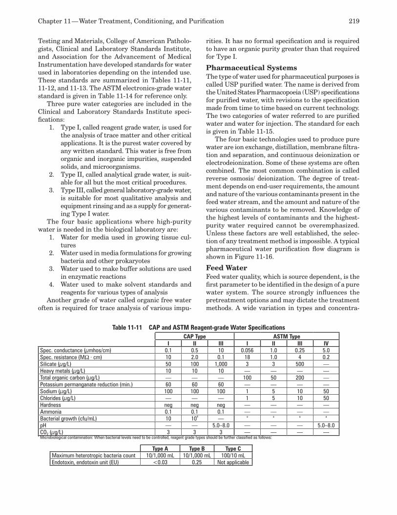
Chapter 11 — Water Treatment, Conditioning, and Purification 219
Testing and Materials, College of American Patholo-gists, Clinical and Laboratory Standards Institute, and Association for the Advancement of Medical Instrumentation have developed standards for water used in laboratories depending on the intended use. These standards are summarized in Tables 11-11, 11-12, and 11-13. The ASTM electronics-grade water standard is given in Table 11-14 for reference only.
Three pure water categories are included in the Clinical and Laboratory Standards Institute speci-fications:
Type I, called reagent grade water, is used for 1. the analysis of trace matter and other critical applications. It is the purest water covered by any written standard. This water is free from organic and inorganic impurities, suspended solids, and microorganisms. Type II, called analytical grade water, is suit-2. able for all but the most critical procedures. Type III, called general laboratory-grade water, 3. is suitable for most qualitative analysis and equipment rinsing and as a supply for generat-ing Type I water.
The four basic applications where high-purity water is needed in the biological laboratory are:
Water for media used in growing tissue cul-1. turesWater used in media formulations for growing 2. bacteria and other prokaryotesWater used to make buffer solutions are used 3. in enzymatic reactionsWater used to make solvent standards and 4. reagents for various types of analysis
Another grade of water called organic free water often is required for trace analysis of various impu-
rities. It has no formal specification and is required to have an organic purity greater than that required for Type I.
Pharmaceutical Systems The type of water used for pharmaceutical purposes is called USP purified water. The name is derived from the United States Pharmacopoeia (USP) specifications for purified water, with revisions to the specification made from time to time based on current technology. The two categories of water referred to are purified water and water for injection. The standard for each is given in Table 11-15.
The four basic technologies used to produce pure water are ion exchange, distillation, membrane filtra-tion and separation, and continuous deionization or electrodeionization. Some of these systems are often combined. The most common combination is called reverse osmosis/ deionization. The degree of treat-ment depends on end-user requirements, the amount and nature of the various contaminants present in the feed water stream, and the amount and nature of the various contaminants to be removed. Knowledge of the highest levels of contaminants and the highest-purity water required cannot be overemphasized. Unless these factors are well established, the selec-tion of any treatment method is impossible. A typical pharmaceutical water purification flow diagram is shown in Figure 11-16.
Feed Water Feed water quality, which is source dependent, is the first parameter to be identified in the design of a pure water system. The source strongly influences the pretreatment options and may dictate the treatment methods. A wide variation in types and concentra-
Table 11-11 CAP and ASTM Reagent-grade Water SpecificationsCAP Type ASTM Type
I II III I II III IVSpec. conductance (µmhos/cm) 0.1 0.5 10 0.056 1.0 0.25 5.0Spec. resistance (MΩ · cm) 10 2.0 0.1 18 1.0 4 0.2Silicate (µg/L) 50 100 1,000 3 3 500 —Heavy metals (µg/L) 10 10 10 — — — —Total organic carbon (µg/L) — — — 100 50 200 —Potassium permanganate reduction (min.) 60 60 60 — — — —Sodium (µg/L) 100 100 100 1 5 10 50Chlorides (µg/L) — — — 1 5 10 50Hardness neg neg neg — — — —Ammonia 0.1 0.1 0.1 — — — —Bacterial growth (cfu/mL) 10 104 — a a a a
pH — — 5.0–8.0 — — — 5.0–8.0CO2 (µg/L) 3 3 3 — — — —
a Microbiological contamination: When bacterial levels need to be controlled, reagent grade types should be further classified as follows:
Type A Type B Type CMaximum heterotropic bacteria count 10/1,000 mL 10/1,000 mL 100/10 mLEndotoxin, endotoxin unit (EU) <0.03 0.25 Not applicable
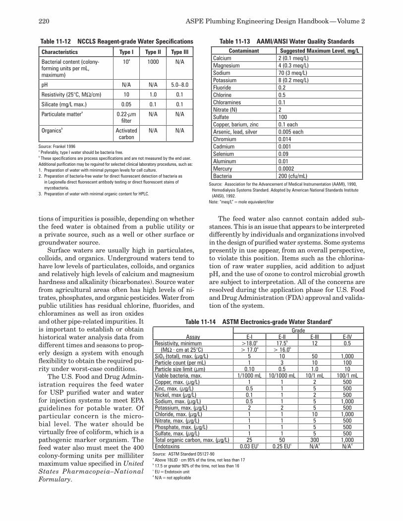
220 ASPE Plumbing Engineering Design Handbook — Volume 2
tions of impurities is possible, depending on whether the feed water is obtained from a public utility or a private source, such as a well or other surface or groundwater source.
Surface waters are usually high in particulates, colloids, and organics. Underground waters tend to have low levels of particulates, colloids, and organics and relatively high levels of calcium and magnesium hardness and alkalinity (bicarbonates). Source water from agricultural areas often has high levels of ni-trates, phosphates, and organic pesticides. Water from public utilities has residual chlorine, fluorides, and chloramines as well as iron oxides and other pipe-related impurities. It is important to establish or obtain historical water analysis data from different times and seasons to prop-erly design a system with enough flexibility to obtain the required pu-rity under worst-case conditions.
The U.S. Food and Drug Admin-istration requires the feed water for USP purified water and water for injection systems to meet EPA guidelines for potable water. Of particular concern is the micro-bial level. The water should be virtually free of coliform, which is a pathogenic marker organism. The feed water also must meet the 400 colony-forming units per milliliter maximum value specified in United States Pharmacopeia–National Formulary.
The feed water also cannot contain added sub-stances. This is an issue that appears to be interpreted differently by individuals and organizations involved in the design of purified water systems. Some systems presently in use appear, from an overall perspective, to violate this position. Items such as the chlorina-tion of raw water supplies, acid addition to adjust pH, and the use of ozone to control microbial growth are subject to interpretation. All of the concerns are resolved during the application phase for U.S. Food and Drug Administration (FDA) approval and valida-tion of the system.
Table 11-14 ASTM Electronics-grade Water Standarda
AssayGrade
E-I E-II E-III E-IVResistivity, minimum >18.0a 17.5b 12 0.5 (MΩ · cm at 25°C) > 17.0a > 16.0b
SiO2 (total), max. (µg/L) 5 10 50 1,000Particle count (per mL) 1 3 10 100Particle size limit (µm) 0.10 0.5 1.0 10Viable bacteria, max. 1/1000 mL 10/1000 mL 10/1 mL 100/1 mLCopper, max. (µg/L) 1 1 2 500Zinc, max. (µg/L) 0.5 1 5 500Nickel, max (µg/L) 0.1 1 2 500Sodium, max. (µg/L) 0.5 1 5 1,000Potassium, max. (µg/L) 2 2 5 500Chloride, max. (µg/L) 1 1 10 1,000Nitrate, max. (µg/L) 1 1 5 500Phosphate, max. (µg/L) 1 1 5 500Sulfate, max. (µg/L) 1 1 5 500Total organic carbon, max. (µg/L) 25 50 300 1,000Endotoxins 0.03 EUc 0.25 EUc N/Ad N/Ad
Source: ASTM Standard D5127-90a Above 18ΩD · cm 95% of the time, not less than 17b 17.5 or greater 90% of the time, not less than 16c EU = Endotoxin unitd N/A = not applicable
Table 11-12 NCCLS Reagent-grade Water Specifications
Characteristics Type I Type II Type III
Bacterial content (colony-forming units per mL, maximum)
10a 1000 N/A
pH N/A N/A 5.0–8.0
Resistivity (25°C, MΩ/cm) 10 1.0 0.1
Silicate (mg/L max.) 0.05 0.1 0.1
Particulate mattera 0.22-µm filter
N/A N/A
Organicsb Activated carbon
N/A N/A
Source: Frankel 1996a Preferably, type I water should be bacteria free.b These specifications are process specifications and are not measured by the end user.Additional purification may be reguired for selected clinical laboratory procedures, such as:1. Preparation of water with minimal pyrogen levels for cell culture.2. Preparation of bacteria-free water for direct fluorescent detection of bacteria as
in Legionella direct fluorescent antibody testing or direct fluorescent stains of mycobacteria.
3. Preparation of water with minimal organic content for HPLC.
Table 11-13 AAMI/ANSI Water Quality StandardsContaminant Suggested Maximum Level, mg/L
Calcium 2 (0.1 meq/L)Magnesium 4 (0.3 meq/L)Sodium 70 (3 meq/L)Potassium 8 (0.2 meq/L)Fluoride 0.2Chlorine 0.5Chloramines 0.1Nitrate (N) 2Sulfate 100Copper, barium, zinc 0.1 eachArsenic, lead, silver 0.005 eachChromium 0.014Cadmium 0.001Selenium 0.09Aluminum 0.01Mercury 0.0002Bacteria 200 (cfu/mL)
Source: Association for the Advancement of Medical Instrumentation (AAMl), 1990, Hemodialysis Systems Standard. Adopted by American National Standards Institute (ANSI), 1992.
Note: “meq/L” = mole equivalent/liter
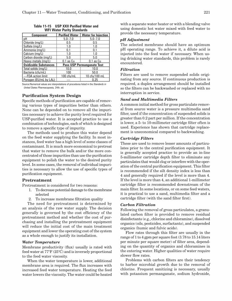
Chapter 11 — Water Treatment, Conditioning, and Purification 221
Purification System Design Specific methods of purification are capable of remov-ing various types of impurities better than others. None can be depended on to remove all the impuri-ties necessary to achieve the purity level required for USP-purified water. It is accepted practice to use a combination of technologies, each of which is designed to remove a specific type of impurity.
The methods used to produce this water depend on the feed water supplying the facility. In most in-stances, feed water has a high level of some classes of contaminant. It is much more economical to pretreat that water to remove the bulk and/or the more con-centrated of those impurities than use the purification equipment to polish the water to the desired purity level. In some cases, the removal of individual impuri-ties is necessary to allow the use of specific types of purification equipment.
PretreatmentPretreatment is considered for two reasons:
To decrease potential damage to the membrane 1. selected To increase membrane filtration quality2.
The need for pretreatment is determined by an analysis of the raw water supply. The decision generally is governed by the cost efficiency of the pretreatment method and whether the cost of pur-chasing and installing the pretreatment equipment will reduce the initial cost of the main treatment equipment and lower the operating cost of the system as a whole enough to justify its installation.
Water Temperature Membrane productivity (flux) usually is rated with feed water at 77°F (25°C) and is inversely proportional to the feed water viscosity.
When the water temperature is lower, additional membrane area is required. The flux increases with increased feed water temperature. Heating the feed water lowers the viscosity. The water could be heated
with a separate water heater or with a blending valve using domestic hot water mixed with feed water to provide the necessary temperature.
pH Adjustment The selected membrane should have an optimum pH operating range. To achieve it, a dilute acid is injected into the feed water if necessary. When us-ing drinking water standards, this problem is rarely encountered.
Filtration Filters are used to remove suspended solids origi-nating from any source. If continuous production is required, a duplex arrangement should be installed so the filters can be backwashed or replaced with no interruption in service.
Sand and Multimedia Filters A common initial method for gross particulate remov-al from source water is a pressure multimedia sand filter, used if the concentration of suspended solids is greater than 0.2 part per million. If the concentration is lower, a 5- to 10-millimeter cartridge filter often is used. Experience has shown that cartridge replace-ment is uneconomical compared to backwashing.
Cartridge Filters These are used to remove lesser amounts of particu-lates prior to the central purification equipment. It is generally accepted practice to provide an in-line 5-millimeter cartridge depth filter to eliminate any particulates that would clog or interfere with the oper-ation of the central purification equipment. This filter is recommended if the silt density index is less than 4 and generally required if the level is more than 4. If the level is more than 4, an additional 1-millimeter cartridge filter is recommended downstream of the main filter. In some locations, or on some feed waters, it is practical to use a sand, multimedia filter and a cartridge filter (with the sand filter first).
Carbon Filtration Following the removal of gross particulates, a granu-lated carbon filter is provided to remove residual disinfectants (e.g., chlorine and chloramine), dissolved organics (oils, pesticides, surfactants), and suspended organics (humic and fulvic acids).
Flow rates through this filter are usually in the range of 1 to 4 gpm per square foot (3.78 to 15.14 liters per minute per square meter) of filter area, depend-ing on the quantity of organics and chloramines in the entering water. Higher qualities of water require slower flow rates.
Problems with carbon filters are their tendency to harbor microbial growth due to the removal of chlorine. Frequent sanitizing is necessary, usually with potassium permanganate, sodium hydroxide,
Table 11-15 USP XXII Purified Water and WFI Water Purity Standards
Component Purified Water Water for InjectionpH 5.0–7.0 5.0–7.0Chloride (mg/L) 0.5 0.5Sulfate (mg/L) 1.0 1.0Ammonia (mg/L) 0.1 0.1Calcium (mg/L) 1.0 1.0Carbon dioxide (mg/L) 5.0 5.0Heavy metals (mg/L) 0.1 as Cu 0.1 as CuOxidizable Substances Pass USP Permanganate TestTotal solids (mg/L) 10.0 10.0Bacteria (cfu/mL) 100 50.0—FDA action limit 100 cfu/mL 10 cfu/100 mLPyrogen (EU/mL by LAL) — 0.25
Source:Numerical values are interpretations of procedures listed in the Standards in United States Pharmacopoeia, 24th. ed.
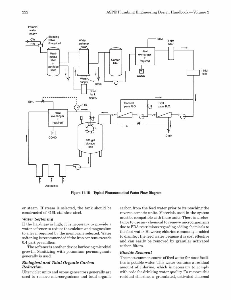
222 ASPE Plumbing Engineering Design Handbook — Volume 2
or steam. If steam is selected, the tank should be constructed of 316L stainless steel.
Water Softening If the hardness is high, it is necessary to provide a water softener to reduce the calcium and magnesium to a level required by the membrane selected. Water softening is recommended if the iron content exceeds 0.4 part per million.
The softener is another device harboring microbial growth. Sanitizing with potassium permanganate generally is used.
Biological and Total Organic Carbon Reduction Ultraviolet units and ozone generators generally are used to remove microorganisms and total organic
carbon from the feed water prior to its reaching the reverse osmosis units. Materials used in the system must be compatible with these units. There is a reluc-tance to use any chemical to remove microorganisms due to FDA restrictions regarding adding chemicals to the feed water. However, chlorine commonly is added to disinfect the feed water because it is cost effective and can easily be removed by granular activated carbon filters.
Biocide Removal The most common source of feed water for most facili-ties is potable water. This water contains a residual amount of chlorine, which is necessary to comply with code for drinking water quality. To remove this residual chlorine, a granulated, activated-charcoal
Figure 11-16 Typical Pharmaceutical Water Flow Diagram

Chapter 11 — Water Treatment, Conditioning, and Purification 223
filter is provided. An organic trap also may be required if organics are very high.
Central Purification Equipment The basic methods used to produce high-purity water are distillation, ion exchange, continuous deioniza-tion or electrodeionization, and reverse osmosis. The method used will depend on the purity desired and limitations on initial or operating cost.
Storage The storage of water reduces the size of the purifica-tion equipment. Storage tanks could be constructed from fiberglass-reinforced plastic with an internal vial suitable for the purpose, polypropylene (high-density or cross-linked with a minimum specific gravity of 1.5), polyethylene, or stainless steel (finish specified by user or process). The bottom of the tank shall be dished or conical to aid in complete drainage. It is an established fact that high-purity water degrades in storage because:
Water extracts contamination from any con-1. tainer.Bacteria grow and secrete waste products. 2. Organics from solvents and the shedding of 3. clothing can diffuse through the air and dis-solve in the water. Laboratory personnel secrete urea in per-4. spiration and respiration that can cause the formation of ammonia in stored laboratory water.
The tank for USP water should be airtight and equipped with a non-shedding, 0.2-millimeter hy-drophobic filter for venting. For water for injection systems, the tank should be type 304L or 316L stainless steel, pressure rated to a minimum of 35-psig (241-kilopascal) pressure and 3 inches (760 millimeters) of mercury vacuum, 180 grit, and electro-polished. It is common practice to have a nitrogen gas blanket in the vapor space above the water in the storage tank to reduce the possibility of airborne contamination and reduce the formation of carbonic acid from the reaction of carbon dioxide and water in the tank. The tank shall have a jacket to maintain a temperature of 177ºF (80°C) and be insulated and provided with a rupture disk.
It should be noted that the design of a nitrogen blanket system is critical and should be specific to each individual situation. A special regulator is used in conjunction with a special tank vent to allow a very low flow rate of nitrogen to enter the tank as the tank is drawn down during a demand scenario. This keeps the tank from imploding as nitrogen is supplied to fill the empty portion of the tank caused by the stored water being removed. At the same time, as the demand for process water decreases and the tank fills, the regulator will close when the pressure
in the tank reaches a predetermined level sufficient to provide the nitrogen blanket, while keeping the tank from bursting due to over-pressurization. Controlling the nitrogen blanket in this way helps conserve the amount of nitrogen needed to maintain the required blanket, which can be very costly depending on the size of the system. In addition, the storage tanks selected for this service should be pressure rated for the intended application in lieu of the atmospheric duty-rated tanks commonly selected for systems not requiring nitrogen blanket protection.
The discharge should be from the center bottom of the tank to allow complete circulation of the stored water. The water return should be at the top of the tank and be equipped with a spray ball or spray ring. This minimizes microbial growth by continuously washing the upper areas of the tank.
Sterilization It is common practice to provide an in-line ultraviolet sterilization device to reduce microorganisms that may be present in the water. Another often-used method is to heat purified water to a temperature of 177°F (80°C) to prevent microorganism growth and then circulate it to maintain the sterile condition. Another possibility is the installation of a filter that will remove any organic particulates.
Piping Distribution Network The piping material for USP water should be fabri-cated from either virgin polypropylene, polyvinylidene fluoride (PVDF), or stainless steel. Plastic pipe should be butt-joint heat-fused, and stainless steel pipe should be orbital welded.
Piping material for water for injection should be stainless steel, 180 grit, and electro-polished. Fittings shall have extended ends for orbital welding. All cou-plings shall be sanitary tri-clamp. Insulation shall be non-chloride bearing and designed for a temperature of 176°F (80°C).
Velocity in the distribution piping system should be sufficient to maintain turbulent flow, approximately 3 to 5 feet per second (0.91 to 1.5 meters per second). Piping system design and pump selection is critical to ensure the correct velocity throughout the entire loop. Following is a rule of thumb formula used to select the correct pipe diameter:
V =gpm(L)× 0.4085s
ID2
or
ID =[ gpm(L)× 0.4085s ]½
V where V = Velocity, feet per second (meters per second) ID = Actual inside diameter, inches (millimeters)
224 ASPE Plumbing Engineering Design Handbook — Volume 2
(Note: Check for the actual inside diameter of various pipes based on schedules. Verify the impact of various linings. Know the impact of surface finish inside the pipe being considered.)
Pump selection can be made after pressure losses are calculated through the entire system. A booster pump may be required to keep the flow at the correct velocity.
Piping shall be sloped at a 1/8-inch (3.2-millimeter) pitch per foot (meter) to allow complete drainage of the network. Dead legs of more than six pipe di-ameters should be avoided at all costs. Distribution loop piping also should be designed to incorporate sanitizing inlets, complete with fittings and a valve ar-rangement that would facilitate sanitizing of specific areas of the system, thus minimizing entire system shutdown or drainage in the event a piping repair or lab reconfiguration were to occur. To prevent future plastic pipe sagging and interference with drainage, continuous support of piping is recommended.
When comparing polypropylene, PVDF, and stain-less steel from a cost standpoint, polypropylene is usually the least expensive, followed by PVDF, and stainless steel is the most expensive. In addition, while polypropylene and PVDF both have similar operating characteristics from a purity standpoint, PVDF can be selected in lieu of polypropylene in a condition where the piping may be required to meet ASTM E84: Standard Test Method for Surface Burn-ing Characteristics of Building Materials and UL 723: Test for Surface Burning Characteristics of Building Materials, the standards for flame spread and smoke generation, such as in a return air plenum area.
Valves shall be consistent with the piping materi-als. Prior to the reverse osmosis or deionization units, full-bore ball valves are recommended. In the purified loop, use stainless steel diaphragm valves with an ethylene propylene diene monomer (EPDM) or Teflon diaphragm and a backing ring. Provide sample valves (usually needle type) at strategic points in the system to allow samples to be taken.
Pumps for purified water should be of sanitary design using a double mechanical seal with product water as the lubricant for the seals. Water for injection pumps should be type 316L stainless steel, 180 grit, and electro-polished. A casing drain should be provided.
System Design Considerations USP water and water for injection are used in the pharmaceutical manufacturing process and often be-come part of the product. Because of this, all aspects of the purification system and distribution network are subject to inspection and validation by the FDA, which is responsible for determining if water quality used is adequate.
The FDA has specific guidelines for the selection of stills and reverse osmosis equipment used for pro-
duction of water for injection. In contrast, purified water systems can utilize different types of purifica-tion equipment, since the microbial and chemical quality can vary depending on the proposed use of the water.
The purpose of any guidelines or standards is to verify that all pertinent purity requirements of the equipment and distribution system conform to current good manufacturing practice, are capable of consistently producing water of the required quality, and are capable of delivering water to the use point that meets the acceptance criteria for water coming in contact with the product. This investigation also includes verification that the purification equipment selected is capable of producing water of the required purity, the quality of installation for the distribution network produces a piping network capable of deliver-ing water of the required quality to all outlets, and the continuing quality of system operation, maintenance, and ongoing testing will consistently provide water of the desired purity.
REFERENCES Blake, Richard T., 1. Water Treatment for HVAC and Potable Water Systems, McGraw-Hill. Brown, J., N. Jayawardena, and Y. Zelmanovich, 2. “Water Systems for Pharmaceutical Facilities,” Pharmaceutical Engineering Magazine, July/August 1991. Cartwright, Peter S., “Reverse Osmosis and 3. Nanofiltration System Design,” Plumbing Engineer, March 1994. Collentro, W.V., “Pharmaceutical Water,” 4. Ul-trapure Water Magazine, November/December 1992. Denoncourt and Egozy, “Trace Level Analysis 5. of High Purity Water,” Ultrapure Water Maga-zine, July/August 1986. Water Conditioning Manual,6. Dow Chemical Corp. Dunleavy, M., “Membrane technologies in 7. the power industry,” presented at The Ninth Annual Membrane Technology/Planning Con-ference and Second High-Tech Separations Symposium, November 1991. Frankel, M., 8. Facility Piping System Handbook, McGraw-Hill, 2002. Gorry, M., P. Amin, and D.W. Richardson Sr., 9. “Take the Guesswork Out of Demineralizer Design,” Chemical Engineering Magazine, March 1994. Janoschek, R., and G.C. du Moulin, “Ultra-10. violet Disinfection in Biotechnology: Myth vs. Practice,” BioPharm Magazine, January/February 1994.
Chapter 11 — Water Treatment, Conditioning, and Purification 225
Meyrick, C.E., “Practical Design of a High-11. purity Water System,” Pharmaceutical Engineering Magazine, September/October 1989. The Nalco Water Handbook, 12. Second Edition, Nalco Chemical Co. Nussbaum, O.J., “Treating Cooling Water,” 13. Heating, Piping, Air Conditioning Magazine, February 1992. Otten, Gerald, “Measuring Water Purity by 14. Specific Resistance,” American Laboratory Magazine, July 1992. Parekh, B.S., “Get Your Process Water to Come 15. Clean,” Chemical Engineering Magazine, January 1991. Sendelbach, M.G., “Boiler Water Treatment,” 16. Chemical Engineering Magazine, August 1998.
Stenzel, Mark H., “Remove Organics by 17. Activated Carbon Adsorption,” Chemical En-gineering Progress Magazine, April 1993. Tanaka, T., “Disinfection of Escherichia Coli 18. by Using Water Dissociation Effect on Ion Exchange Membranes,” In Proceedings of the European-Japan Congress on Membrane and Membrane Processes, June 1984. Yeh, K.L., and S.H. Lin., “Looking to Treat 19. Wastewater? Try Ozone,” Chemical Engineer-ing Magazine, May 1993.Paul, D., “Pharmaceutical Waters,” 20. Ultra-pure Water Magazine, 1999.

Special waste includes liquid effluent other than discharge from sanitary and storm water sources, such as acid waste, radioactive waste, biological and infectious waste, chemical waste, and fire suppression water drainage. This chapter describes the collection and criteria necessary for the design of various special waste drainage systems. Except for the neutralization of acid effluent, treatment methods for special waste are outside the scope of this chapter.
Each special waste system has unique properties that must be separately addressed. These systems generally route the waste from fixtures and equip-ment into a facility waste treatment system, with the treated effluent discharging directly into the public sanitary drainage sewer system. Very often, untreated waste is stored on site and collected by approved waste-removal contractors for disposal.
Unless specifically noted otherwise, all of the waste streams are assumed to have the approximate flow characteristics of water. Pipe sizing criteria are based on this assumption.
CODES AND STANDARDS Two general jurisdictional bodies regulate different aspects of special waste systems. The first is the lo-cal or regional authority, which creates and enforces plumbing and health codes, including the local au-thorities charged with the review and approval of plumbing system designs and discharges into the public sewer system. Although such authorities are concerned with regulating the size and design of plumbing systems within a building, they also restrict the introduction of any type of waste into the sani-tary sewer that may degrade the public sewer piping system or is incapable of being easily treated in the public waste treatment facility.
The second jurisdictional body, which has far more stringent regulations, includes the various agencies concerned with protecting workers, the public, and the environment from the discharge of toxic substanc-es. Included in this group are federal, state, and local authorities responsible for preventing toxic discharge
of any substances considered harmful into the general environment, public sewers, and public treatment sys-tems. Such discharges can occur either as a result of spills and accidents or by deliberate, illegal discharge. To prevent such discharge, it is common practice for these agencies to inspect facilities, mandate on-site facility treatment systems, and require the use of double-wall piping and leak detection to prevent and mitigate any leakage from piping.
Other regulations, such as current good manufac-turing practice (cGMP) from the U.S. Food and Drug Administration (FDA), the regulations of the federal Environmental Protection Agency (EPA), and facility validation protocols, are constantly being revised due to technological and design changes.
The services of an experienced environmental consultant who is familiar with the latest applicable rules and regulations and their interpretations should be consulted for system compliance with the maze of regulations.
SYSTEM APPROVAL REQUIREMENTS Authorities make a distinction between drainage effluent that can be treated locally within a building (such as by biological waste sterilization, pH adjust-ment of chemical waste, or oil separation) and other effluent that requires a larger and more complex waste treatment system outside a building. Accep-tance of such local treatment can be obtained only after conferences with the authorities responsible for issuing contamination limits for such discharge. If the local treatment system provides the appropriate level of contaminant removal, direct discharge into the public sanitary sewer is acceptable. If the levels of contaminant removal are beyond the capability of such local treatment, a more sophisticated system that demonstrates contaminant removal to the levels desired by the authority having jurisdiction (AHJ) must be chosen.
Any special drainage system effluent routed for treatment inside a facility or on site typically does
12 Special Waste Drainage Systems
228 ASPE Plumbing Engineering Design Handbook — Volume 2
not require examination or approval by the local plumbing official. However, you should verify approval requirements with the governing code authority. If any effluent is routed to the public sewer system for eventual treatment, the discharge must conform to lo-cal regulations for the maximum concentration of any contaminant or pH level. If the only required method of treatment is pH adjustment prior to discharging into the building’s sanitary drainage system or the public sewer system, most authorities require the installation of an acid drainage system. A pH value of 5 generally is viewed as the lowest acceptable level for direct discharge into a public sewer system, and a pH value of 10 is typically the highest acceptable level.
PIPE MATERIAL AND JOINT SELECTION CONSIDERATIONS Important factors in the selection of the appropriate pipe material, gaskets, joining methods, and other piping components for any special waste drainage system are cost, temperature and composition of the effluent, the type of chemicals, and the concentration of each chemical that will enter the pipe. For some systems, the smoothness of the pipe interior or the lack of a crud trap is also an important factor. This also applies to any associated vent system.
Selection is accomplished by first establishing the flow rate, temperature range, and concentration and composition of all effluent and chemicals that are expected. All pipe manufacturers publish chemical compatibility charts that provide the effects of various chemicals on a particular pipe and include recom-mendations for acceptance using these chemicals. For conditions not listed on these charts, you should contact the manufacturer of the material and ask for technical assistance.
When the compatibility of various pipe systems is the same, the total installed cost and possible ease of assembly are the deciding factors. Even if a client’s standard operating procedure (SOP) states that no chemicals or lab waste can be discharged down the drain, they still may require or benefit from a special waste piping system to protect the integrity of the drainage system in the event of an accidental spill or discharge.
PIPE SIzING CONSIDERATIONS System design is concerned only with the adequacy of the pipe to carry away the design flow. System configuration usually requires traps to be provided on fixtures and floor drains and the venting system to conform to good plumbing design practice, which limits the pressure inside the system. All the ele-ments of system design are left to the judgment of the design engineer.
The various plumbing codes generally use only satisfactory performance as a sizing guide for special waste system pipe sizing, compared to the specific drainage requirements mandated for sizing sanitary drainage systems. A common exception is for labora-tory fixtures, in which case the drainage and vent systems may be required to be sized on a fixture unit basis. The reason for the lack of code requirements is that special drainage systems do not have a predict-able or documented usage history, as do standard plumbing fixtures in sanitary drainage systems. Equipment drainage, spills, discharge from produc-tion facilities, and discharge from fixtures within the facilities are not always planned. They occur mostly at random intervals dictated by cleaning, production, maintenance schedules, and often accidents.
In addition, special drainage systems completely within the property of the facility do not fall under the plumbing code requirements for piping size or design, although they may fall under the jurisdiction of agencies such as the EPA or similar local environ-mental regulation bodies. Because of these factors, the special drainage piping system is sized on the basis of good engineering practice, which uses system slope, composition of the effluent, and expected flow rates rather than fixture units.
From each point in the system, the flow rate and pitch of the piping must be known to size the pipe. Pipe size should be determined based on the follow-ing criteria:
Effluent has the characteristics of water. (If •the effluent contains large concentrations of solids, the pitch should be adjusted accord-ingly.)The drainage system is sized on the basis of •gravity drainage and maintenance of a mini-mum velocity of 2 feet per second (fps) (0.61 meters per second), using the anticipated maximum flow rate and pitch of the pipe at each point of design and a maximum velocity of 10 fps (3.05 meters per second) if the waste contains any solids. Gravity drainage pipe size is based on flow •rate, slope, and velocity. Refer to Table 12-1 to find the velocity and size of pipe based on flow rate and slope. Depending on the sys-tem, piping should be sized to flow between one-half to three-fourths full to allow for unexpected large discharges, future changes, and accidents.
pH DEFINITION Any dissolved impurity in water separates to form negatively and positively charged atoms called ions. Negative ions are called cations because they migrate
Chapter 12 — Special Waste Drainage Systems 229
to the cathode, and positive ions are called anions because they migrate to the anode.
All acid compounds consist of hydrogen combined with an acid radical. In a mixture of acid and water, hydrogen ions result. pH is a measurement of the hydrogen ion concentration of a solution. Since the balance of hydroxyl (cation) and hydrogen (anion) ions must be constant, changes in one ion concentration produce corresponding changes in the other.
The pH value is calculated from the logarithmic reciprocal of the hydrogen ion concentration in water. The pH scale ranges from 0 to 14, with 0 being acid and 14 being alkaline; 7 is neutral. A change of one unit represents a tenfold increase (or decrease) in strength. pH is not a measure of alkalinity.
GENERAL SYSTEM DESIGN CONSIDERATIONS It is good practice to separate each of the different sys-tems inside the facility to a point outside the building so the individual services can be isolated and tested or sampled as may be required in the future by any local or national authority. Also, at some point in the future one system may require separate treatment because of a new substance that may be discharged.
One of the more constant aspects of special waste drainage systems is future change. In time, processes will change, equipment will be more efficient, facilities will become larger, and technology will be improved so the effluent will be different than it was at the time a system was originally designed. Thus, the design must allow for such change. It is common practice to size the drain one size larger than the design figures indicate or not to size the drainline to the exact point on the sizing chart indicated by the figures, especially where future expansion is probable. Thus, consider-ation should be given to selecting a pipe size slightly larger than required for the immediate flow rate or a material capable of resisting a greater selection of chemicals than necessary at the time of design. This must be verified with the client, of course, to ensure that the extra cost incurred by these options is ac-ceptable.
ACID WASTE DRAINAGE AND VENT SYSTEMS An acid waste drainage system collects and transports liquid wastes with a pH lower than 7 from laboratory fixtures, equipment, and all areas of a facility for dis-charge into an appropriate treatment facility or the sanitary drainage system after local treatment. The vent system equalizes flow in the drainage system in the same manner as in a sanitary drainage system.
For the purposes of this chapter, acid waste is di-vided into two general categories: laboratory waste and industrial waste. Laboratory waste consists
primarily of dilute and concentrated mixtures of water and liquid chemical substances of mineral and organic origin. Many types of acid are usually pres-ent. Laboratory waste is discharged from sinks, cup sinks, fume hoods, and other similar fixtures and equipment. Discharge from floor drains, autoclaves, and glass washers and condensed water from various sources also are included.
Acid waste from industrial facilities consists of waste from accidental spills originating from tanks and piping and anticipated waste discharged from equipment into drains. Very often, the drainage piping must carry any of the acids used as part of the process. Where spills are directed into holding tanks, the drainage piping, tanks, pumps, and pip-ing necessary to convey the effluent to treatment facilities is normally part of the plumbing engineer’s responsibility.
The most important considerations in the selection of piping, valves, drains, and tanks for acid waste are the concentration and temperature of the acid. Acid wastewater from chemical and other facilities must be neutralized to a pH of 5 or higher prior to discharge into the sanitary system.
Health and Safety Concerns All grades and concentrations of acids can severely damage the eyes and tissues of the body. Contact with the eyes can cause blindness. Contact with the skin causes irritation and burns. Inhaling the mist or vapors can cause lung irritation or burns. Inges-tion destroys the tissues of the mouth, throat, and stomach.
Extreme care should be exercised in the handling and cleanup of all acids. Emergency drench equipment must be provided immediately adjacent to all hazards and locations where spills and other accidents could occur. If several people are normally present at a haz-ardous location, multiple pieces of drench equipment should be provided. Where fumes may be given off, emergency breathing apparatus must be provided.
For the laboratory environment, emergency show-ers shall be provided immediately inside or outside every room depending on travel distance. Some ju-risdictions consider exiting the lab through a door an obstruction and will require an emergency shower inside the lab module. Where rooms are adjacent as in an open lab condition, a single shower is acceptable to serve multiple lab modules, provided it falls within the maximum allowable travel distance. Floor drains are not required in most jurisdictions, but the drain will help prevent the floor area surrounding the shower from becoming wet and slippery. Every room shall have an emergency eyewash, usually mounted on a sink or freestanding if sink mounting is not practical.
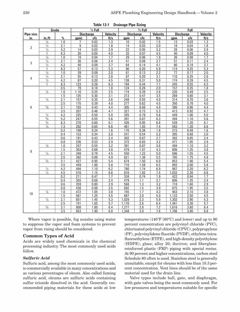
230 ASPE Plumbing Engineering Design Handbook — Volume 2
Where vapor is possible, fog nozzles using water to suppress the vapor and foam systems to prevent vapor from rising should be considered.
Common Types of Acid Acids are widely used chemicals in the chemical processing industry. The most commonly used acids follow.
Sulfuric Acid Sulfuric acid, among the most commonly used acids, is commercially available in many concentrations and as various percentages of oleum. Also called fuming sulfuric acid, oleums are sulfuric acids containing sulfur trioxide dissolved in the acid. Generally rec-ommended piping materials for these acids at low
temperatures (140°F [60°C] and lower) and up to 90 percent concentration are polyvinyl chloride (PVC), chlorinated polyvinyl chloride (CPVC), polypropylene (PP), polyvinylidene fluoride (PVDF), ethylene tetra-fluoroethylene (ETFE), and high-density polyethylene (HDPE); glass; alloy 20; duriron; and fiberglass-reinforced plastic (FRP) piping with special resins. At 90 percent and higher concentrations, carbon steel Schedule 80 often is used. Stainless steel is generally unsuitable, except for oleums with less than 10.3 per-cent concentration. Vent lines should be of the same material used for the drain line.
Valve types include ball, gate, and diaphragm, with gate valves being the most commonly used. For low pressures and temperatures suitable for specific
Table 12-1 Drainage Pipe Sizing
Pipe size, in.
Grade 1⁄2 Full 2⁄3 Full Full
in./ft %Discharge Velocity Discharge Velocity Discharge Velocity
gpm) cfs ft/s gpm cfs ft/s gpm cfs ft/s
2
1⁄8 1.0 7 0.02 1.3 10 0.02 1.5 13 0.03 1.31⁄4 2.1 9 0.02 1.8 14 0.03 2.0 18 0.04 1.81⁄2 4.2 14 0.03 2.9 22 0.05 3.2 28 0.06 2.91 8.3 20 0.05 4.0 32 0.07 4.5 40 0.09 4.0
3
1⁄8 1.0 18 0.04 1.7 29 0.06 1.9 36 0.08 1.71⁄4 2.1 26 0.06 2.4 41 0.09 2.7 51 0.11 2.41⁄2 4.2 40 0.09 3.7 64 0.14 4.1 80 0.18 3.71 8.3 57 0.13 5.3 90 0.20 5.9 114 0.25 5.3
4
1⁄8 1.0 39 0.09 2.0 61 0.13 2.2 77 0.17 2.01⁄4 2.1 55 0.13 2.8 87 0.20 3.1 110 0.25 2.81⁄2 4.2 87 0.20 4.5 138 0.31 5.0 174 0.39 4.51 8.3 123 0.28 6.3 194 0.44 7.1 245 0.55 6.3
6
0.5 79 0.18 1.8 124 0.28 2.0 157 0.35 1.81⁄8 1.0 1 10 0.25 2.5 174 0.39 2.8 220 0.49 2.5
1.5 135 0.30 3.1 213 0.47 3.5 269 0.60 3.11⁄4 2.1 157 0.35 3.6 248 0.55 4.0 314 0.70 3.6
2.5 175 0.39 4.0 277 0.62 4.5 350 0.78 4.03⁄8 3.1 193 0.43 4.4 305 0.68 4.9 386 0.86 4.4
3.5 207 0.46 4.7 327 0.73 5.3 413 0.92 4.71⁄2 4.2 225 0.50 5.0 355 0.79 5.6 449 1.00 5.05⁄8 5.2 247 0.55 5.6 391 0.87 6.3 494 1.10 5.63⁄4 6.3 270 0.60 6.1 426 0.95 6.8 539 1.20 6.17⁄8 7.3 292 0.65 6.6 461 1.03 7.4 583 1.30 6.6
8
0.2 108 0.24 1.6 170 0.38 1.8 215 0.48 1.60.4 153 0.34 2.0 241 0.54 2.2 305 0.68 2.00.6 191 0.43 2.4 302 0.67 2.7 382 0.85 2.40.8 236 0.53 2.9 372 0.83 3.2 471 1.05 2.9
1⁄8 1.0 247 0.55 3.2 391 0.87 3.6 494 1.10 3.21.5 303 0.68 3.8 479 1.07 4.3 606 1.35 3.8
1⁄4 2.1 348 0.78 4.5 550 1.22 5.0 696 1.55 4.52.5 392 0.88 4.9 621 1.38 5.5 785 1.75 4.9
3⁄8 3.1 427 0.95 5.4 674 1.50 6.0 853 1.90 5.43.5 449 1.00 5.8 710 1.58 6.5 893 2.00 5.8
1⁄2 4.2 494 1.10 6.2 780 1.74 6.9 987 2.20 6.21⁄2 4.5 516 1.15 6.6 816 1.82 7.4 1,032 2.30 6.6
10
0.2 211 0.47 1.7 334 0.74 1.9 422 0.94 1.70.4 303 0.68 2.4 479 1.1 2.7 606 1.35 2.40.6 359 0.80 2.9 568 1.3 3.2 718 1.60 2.90.8 438 0.98 3.5 692 1.5 3.9 875 1.95 3.5
1⁄8 1.0 472 1.05 3.8 745 1.7 4.3 943 2.10 3.81.5 561 1.25 4.5 887 2.0 5.0 1,122 2.50 4.5
1⁄4 2.1 651 1.45 5.3 1,029 2.3 5.9 1,302 2.90 5.32.5 741 1.65 5.7 1,170 2.6 6.4 1,481 3.30 5.7
3⁄8 3.1 808 1.80 6.4 1,277 2.8 7.2 1,616 3.60 6.43.5 853 1.90 6.8 1,348 3.0 7.6 1,706 3.80 6.8
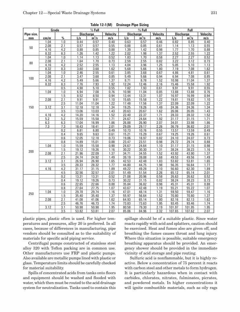
Chapter 12 — Special Waste Drainage Systems 231
plastic pipes, plastic often is used. For higher tem-peratures and pressures, alloy 20 is preferred. In all cases, because of differences in manufacturing, pipe vendors should be consulted as to the suitability of materials for specific acid piping service.
Centrifugal pumps constructed of stainless steel alloy 320 with Teflon packing are in common use. Other manufacturers use FRP and plastic pumps. Also available are metallic pumps lined with plastic or glass. Temperature limits should be carefully checked for material suitability.
Spills of concentrated acids from tanks onto floors and equipment should be washed and flooded with water, which then must be routed to the acid drainage system for neutralization. Tanks used to contain this
spillage should be of a suitable plastic. Since water reacts rapidly with acid and splatters, caution should be exercised. Heat and fumes also are given off, and breathing the fumes causes throat and lung injury. Where this situation is possible, suitable emergency breathing apparatus should be provided. An emer-gency shower should be provided in the immediate vicinity of acid storage and pipe routing.
Sulfuric acid is nonflammable, but it is highly re-active. Below a concentration of 75 percent it reacts with carbon steel and other metals to form hydrogen. It is particularly hazardous when in contact with carbides, chlorates, nitrates, fulminates, picrates, and powdered metals. In higher concentrations it will ignite combustible materials, such as oily rags
Table 12-1(M) Drainage Pipe Sizing
Pipe size, mm
Grade 1⁄2 Full 2⁄3 Full Full
cm/m %Discharge Velocity Discharge Velocity Discharge Velocity
L/s m3/s m/s L/s m3/s m/s L/s m3/s m/s
50
1.04 1.0 0.44 0.57 0.40 0.63 0.57 0.46 0.82 0.85 0.402.08 2.1 0.57 0.57 0.55 0.88 0.85 0.61 1.14 1.13 0.554.16 4.2 0.88 0.85 0.88 1.39 1.42 0.98 1.77 1.70 0.888.32 8.3 1.26 1.42 1.22 2.02 1.98 1.37 2.52 2.55 1.22
80
1.04 1.0 1.14 1.13 0.52 1.83 1.70 0.58 2.27 2.27 0.522.08 2.1 1.64 1.70 0.73 2.59 2.55 0.82 3.22 3.12 0.734.16 4.2 2.52 2.55 1.13 4.04 3.96 1.25 5.05 5.10 1.138.32 8.3 3.60 3.68 1.62 5.68 5.66 1.80 7.19 7.08 1.62
100
1.04 1.0 2.46 2.55 0.61 3.85 3.68 0.67 4.86 4.81 0.612.08 2.1 3.47 3.68 0.85 5.49 5.66 0.94 6.94 7.08 0.854.16 4.2 5.49 5.66 1.37 8.71 8.78 1.52 10.98 11.04 1.378.32 8.3 7.76 7.93 1.92 12.24 12.46 2.16 15.46 15.58 1.92
150
0.5 4.98 5.10 0.55 7.82 7.93 0.61 9.91 9.91 0.551.04 1.0 6.94 7.08 0.76 10.98 11.04 0.85 13.88 13.88 0.76
1.5 8.52 8.50 0.94 13.44 13.31 1.07 16.97 16.99 0.942.08 2.1 9.91 9.91 1.10 15.65 15.58 1.22 19.81 19.82 1.10
2.5 11.04 11.04 1.22 17.48 17.56 1.37 22.09 22.09 1.223.12 3.1 12.18 12.18 1.34 19.25 19.26 1.49 24.36 24.36 1.34
3.5 13.06 13.03 1.43 20.63 20.67 1.62 26.06 26.05 1.434.16 4.2 14.20 14.16 1.52 22.40 22.37 1.71 28.33 28.32 1.525.2 5.2 15.59 15.58 1.71 24.67 24.64 1.92 31.17 31.15 1.716.3 6.3 17.04 16.99 1.86 26.88 26.90 2.07 34.01 33.98 1.867.3 7.3 18.43 18.41 2.01 29.09 29.17 2.26 36.79 36.82 2.01
200
0.2 6.81 6.80 0.49 10.73 10.76 0.55 13.57 13.59 0.490.4 9.65 9.63 0.61 15.21 15.29 0.67 19.25 19.26 0.610.6 12.05 12.18 0.73 19.06 18.97 0.82 24.10 24.07 0.730.8 14.89 15.01 0.88 23.47 23.51 0.98 29.72 29.74 0.88
1.04 1.0 15.59 15.58 0.98 24.67 24.64 1.10 31.17 31.15 0.981.5 19.12 19.26 1.16 30.22 30.30 1.31 38.24 38.23 1.16
2.08 2.1 21.96 22.09 1.37 34.71 34.55 1.52 43.92 43.90 1.372.5 24.74 24.92 1.49 39.19 39.08 1.68 49.53 49.56 1.49
3.12 3.1 26.94 26.90 1.65 42.53 42.48 1.83 53.82 53.81 1.653.5 28.33 28.32 1.77 44.80 44.75 1.98 56.35 56.64 1.77
4.16 4.2 31.17 31.15 1.89 49.22 49.28 2.10 56.60 62.30 1.894.5 32.56 32.57 2.01 51.49 51.54 2.26 65.12 65.14 2.01
250
0.2 13.31 13.31 0.52 21.08 20.96 0.58 26.63 26.62 0.520.4 19.12 19.26 0.73 30.22 31.15 0.82 38.24 38.23 0.730.6 22.65 22.66 0.88 35.84 36.82 0.98 45.31 45.31 0.880.8 27.64 27.75 1.07 43.67 42.48 1.19 55.21 55.22 1.07
1.04 1.0 29.78 29.74 1.16 47.01 48.14 1.31 59.50 59.47 1.161.5 35.40 35.40 1.37 55.97 56.64 1.52 70.80 70.80 1.37
2.08 2.1 41.08 41.06 1.62 64.93 65.14 1.80 82.16 82.13 1.622.5 46.76 46.73 1.74 73.83 73.63 1.95 93.45 93.46 1.74
3.12 3.1 50.98 50.98 1.95 80.58 79.30 2.19 101.97 101.95 1.953.5 53.82 53.81 2.07 85.06 84.96 2.32 107.65 107.62 2.07
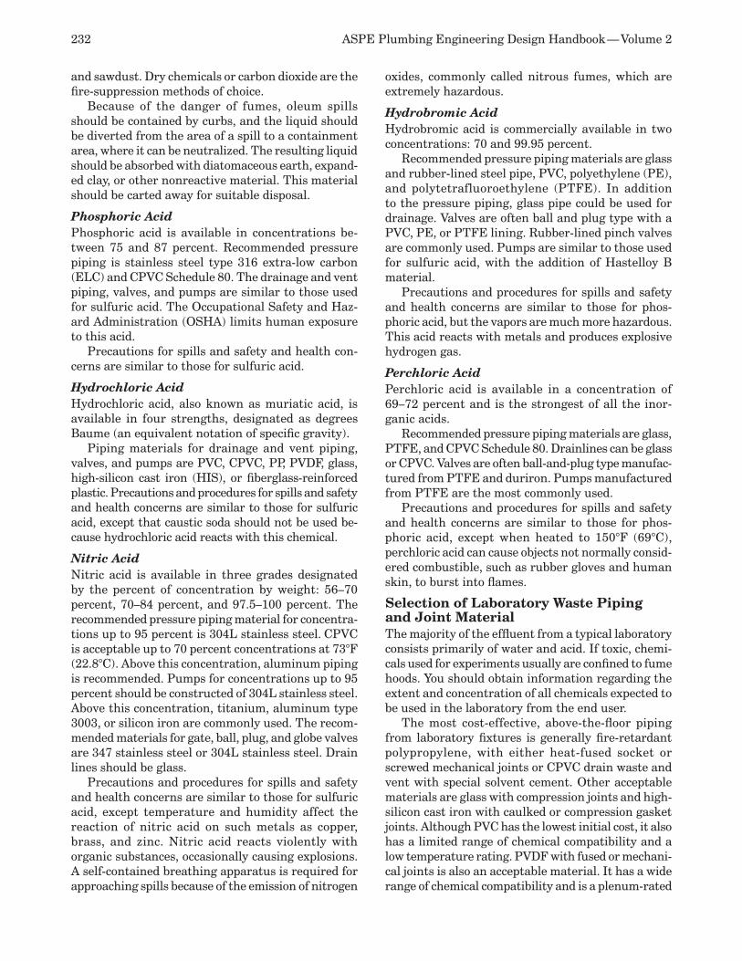
232 ASPE Plumbing Engineering Design Handbook — Volume 2
and sawdust. Dry chemicals or carbon dioxide are the fire-suppression methods of choice.
Because of the danger of fumes, oleum spills should be contained by curbs, and the liquid should be diverted from the area of a spill to a containment area, where it can be neutralized. The resulting liquid should be absorbed with diatomaceous earth, expand-ed clay, or other nonreactive material. This material should be carted away for suitable disposal.
Phosphoric Acid Phosphoric acid is available in concentrations be-tween 75 and 87 percent. Recommended pressure piping is stainless steel type 316 extra-low carbon (ELC) and CPVC Schedule 80. The drainage and vent piping, valves, and pumps are similar to those used for sulfuric acid. The Occupational Safety and Haz-ard Administration (OSHA) limits human exposure to this acid.
Precautions for spills and safety and health con-cerns are similar to those for sulfuric acid.
Hydrochloric Acid Hydrochloric acid, also known as muriatic acid, is available in four strengths, designated as degrees Baume (an equivalent notation of specific gravity).
Piping materials for drainage and vent piping, valves, and pumps are PVC, CPVC, PP, PVDF, glass, high-silicon cast iron (HIS), or fiberglass-reinforced plastic. Precautions and procedures for spills and safety and health concerns are similar to those for sulfuric acid, except that caustic soda should not be used be-cause hydrochloric acid reacts with this chemical.
Nitric Acid Nitric acid is available in three grades designated by the percent of concentration by weight: 56–70 percent, 70–84 percent, and 97.5–100 percent. The recommended pressure piping material for concentra-tions up to 95 percent is 304L stainless steel. CPVC is acceptable up to 70 percent concentrations at 73°F (22.8°C). Above this concentration, aluminum piping is recommended. Pumps for concentrations up to 95 percent should be constructed of 304L stainless steel. Above this concentration, titanium, aluminum type 3003, or silicon iron are commonly used. The recom-mended materials for gate, ball, plug, and globe valves are 347 stainless steel or 304L stainless steel. Drain lines should be glass.
Precautions and procedures for spills and safety and health concerns are similar to those for sulfuric acid, except temperature and humidity affect the reaction of nitric acid on such metals as copper, brass, and zinc. Nitric acid reacts violently with organic substances, occasionally causing explosions. A self-contained breathing apparatus is required for approaching spills because of the emission of nitrogen
oxides, commonly called nitrous fumes, which are extremely hazardous.
Hydrobromic Acid Hydrobromic acid is commercially available in two concentrations: 70 and 99.95 percent.
Recommended pressure piping materials are glass and rubber-lined steel pipe, PVC, polyethylene (PE), and polytetrafluoroethylene (PTFE). In addition to the pressure piping, glass pipe could be used for drainage. Valves are often ball and plug type with a PVC, PE, or PTFE lining. Rubber-lined pinch valves are commonly used. Pumps are similar to those used for sulfuric acid, with the addition of Hastelloy B material.
Precautions and procedures for spills and safety and health concerns are similar to those for phos-phoric acid, but the vapors are much more hazardous. This acid reacts with metals and produces explosive hydrogen gas.
Perchloric Acid Perchloric acid is available in a concentration of 69–72 percent and is the strongest of all the inor-ganic acids.
Recommended pressure piping materials are glass, PTFE, and CPVC Schedule 80. Drainlines can be glass or CPVC. Valves are often ball-and-plug type manufac-tured from PTFE and duriron. Pumps manufactured from PTFE are the most commonly used.
Precautions and procedures for spills and safety and health concerns are similar to those for phos-phoric acid, except when heated to 150°F (69°C), perchloric acid can cause objects not normally consid-ered combustible, such as rubber gloves and human skin, to burst into flames.
Selection of Laboratory Waste Piping and Joint Material The majority of the effluent from a typical laboratory consists primarily of water and acid. If toxic, chemi-cals used for experiments usually are confined to fume hoods. You should obtain information regarding the extent and concentration of all chemicals expected to be used in the laboratory from the end user.
The most cost-effective, above-the-floor piping from laboratory fixtures is generally fire-retardant polypropylene, with either heat-fused socket or screwed mechanical joints or CPVC drain waste and vent with special solvent cement. Other acceptable materials are glass with compression joints and high-silicon cast iron with caulked or compression gasket joints. Although PVC has the lowest initial cost, it also has a limited range of chemical compatibility and a low temperature rating. PVDF with fused or mechani-cal joints is also an acceptable material. It has a wide range of chemical compatibility and is a plenum-rated
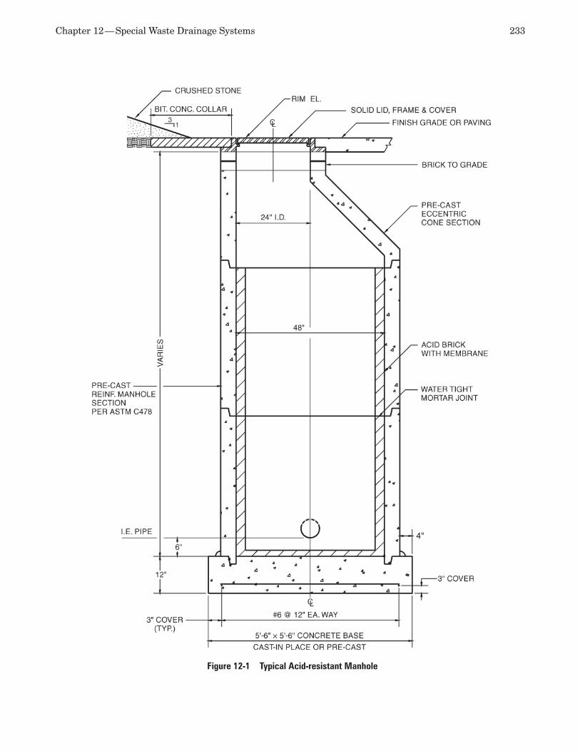
Chapter 12 — Special Waste Drainage Systems 233
Figure 12-1 Typical Acid-resistant Manhole
234 ASPE Plumbing Engineering Design Handbook — Volume 2
material; however, it is rarely used due to its higher cost versus PP. PTFE is resistant to the widest variety of chemicals and has the highest temperature rating and highest cost. CPVC is suitable to 210°F (98.9°C) and is resistant to a wide variety of chemicals.
Piping underground, subject to local codes, also could be polypropylene with heat-fused socket joints or high-silicon cast iron with compression gasket joints. Glass piping should be encased in a sleeve of polyethylene for protection.
Vent pipe shall be the same material as the drain pipe. The vent shall be carried above the roof level. Vent piping penetrating the roof shall not be glass. An adapter should be used and any other acceptable acid-resistant pipe material should be provided through the penetration.
System Design Considerations General system design considerations for the labora-tory drainage system shall be the same as those for the sanitary drainage system, including placement of cleanouts. Each fixture shall be individually trapped and vented. Clean water, such as that discharged from air compressors and other condensate drains, can spill into the laboratory drainage system when convenient and allowed per code. Because of possible stoppages that could flood all piping, the entire labora-tory waste system shall be of the same acid-resistant piping material.
Where the only waste discharge is from laboratory fixtures, the use of fixture-unit schedules for pipe sizing is acceptable, but simultaneous use should be factored into the sizing process. When the effluent
Figure 12-2 Typical Large Acid-neutralizing Basin
Chapter 12 — Special Waste Drainage Systems 235
is expressed in gallons per minute (gpm) (liters per second) from a known discharge, base the size on this value and the equivalent value from the fixtures. The pipe shall be sized using the pitch and a three-fourths-full pipe.
The laboratory drainage and vent system shall be separate from all other systems until the effluent is adequately treated. Then it may be combined on the site with other waste lines. If a manhole is required in the acid waste line, it should be acid resistant. A typical acid-resistant manhole is illustrated in Figure 12-1.
Acid Waste Treatment All acid waste requires neutralization to a pH between 7.5 and 5 before it is permitted to be discharged into any public sewer for disposal. Commonly accepted practice permits local authorities to allow primary-treated effluent to discharge directly into the public sanitary sewer system after only pH treatment. The most often-used primary procedures are dilution, direct continuous contact with limestone chips in an acid-neutralizing basin, and continuous or batch treatment in an automated neutralization system utilizing chemical feed neutralizing.
A dilution basin dilutes chemicals to a neutral pH. This works if the facility has a large volume of water used for handwashing or other operations that do not introduce chemicals into the waste stream. If the volume of clean waste is low compared to the volume of acid waste, this method will not work sufficiently.
In an acid-neutralizing basin, a chemical reaction occurs between the acid and the limestone chips. Each basin shall be designed by the manufacturer to allow sufficient contact time for the chemical reaction to accomplish complete neutralization based on the maximum flow rate anticipated. Approximately 100 pounds (45 kilograms) of limestone chips treat 97 pounds (44 kilograms) of sulfuric acid and 75 pounds (34 kilograms) of hydrochloric acid. Effluent consist-ing primarily of sulfuric acid should be treated with dolomite limestone chips. This method of treatment requires periodic replacement and disposal of the spent limestone chips.
For general laboratory waste, several methods of treatment using limestone chips are available. For single isolated sinks, an acid-neutralizing trap should be considered. For a small number of sinks in a cluster, a shelf-mounted, small-diameter basin could be used. It should be confined to treating the discharge of acids from a small number of fixtures in remote locations or from individual sinks where the timely maintenance needed to fill the basin may not be possible. Larger basins, such as the one illustrated in Figure 12-2, are available to treat the effluent from a large number of laboratory sinks. If the discharge of oil or grease is expected in the laboratory waste stream, the instal-lation of an interceptor basin before the acid sump is
recommended. Some objectionable contaminants can coat individual chips and prevent the chemical action needed to neutralize the acid.
For a larger number of fixtures or equipment and where treatment by limestone chips alone is not prac-tical, a continuous waste-treatment system consisting of a single or multiple basins and/or a mixing tank should be installed. This type of system automatically adds proper amounts of caustic to the incoming acid waste, thereby neutralizing the acid. A sophisticated arrangement of probes, chemical feed pumps, level in-dicators, and alarms is required. An agitator or mixer may be installed in the basin to mix the acid with the caustic, and the addition of a recorder may be desired. A probe is connected to an automatic caustic feed pump that introduces the proper amount of neutral-izing liquid (commonly caustic soda) into the basin or mixing tank. Continuous treatment also may require additional downstream sensing probes and chemical additive locations to ensure that the discharge is within acceptable limits. If the system is located at a low level, a pump is required to bring the discharge up to the level of the sewer. Figure 12-3 illustrates a typical continuous waste-treatment system.
It is good engineering practice to route the dis-charge from the neutralizer separately into the sanitary house drain outside of the building for dilu-tion prior to discharge into the public sewer. This also may be necessary for local authorities to monitor the waste stream without entering the building.
For preliminary determination of the number of sinks required for average laboratories, allow one sink for each 200 square feet (18.6 square meters) of laboratory area. Each sink will discharge 1 gpm (3.8 liters per minute). Cup sinks will discharge 0.5 gpm (1.9 liters per minute). For a maximum flow rate, assume that 50 percent of the sinks could discharge simultaneously.
RADIOACTIVE WASTE DRAINAGE AND VENT SYSTEMSMany commercial facilities have low quantities and levels of radioactive waste. Because of the small amount of radioactive material present at these facilities, large storage and treatment systems and severe safety requirements are not necessary. Facili-ties with higher quantities of radioactive material and radiation levels fall under a different, much more stringent set of regulatory requirements. For such facilities, documentation regarding the protection of the public and workers in the event of an accident is considerably more complex.
The requirements for handling radioisotopes in laboratories are essentially no different than the re-quirements for handling toxic chemicals or pathogens, with the exception of providing radiation shielding if
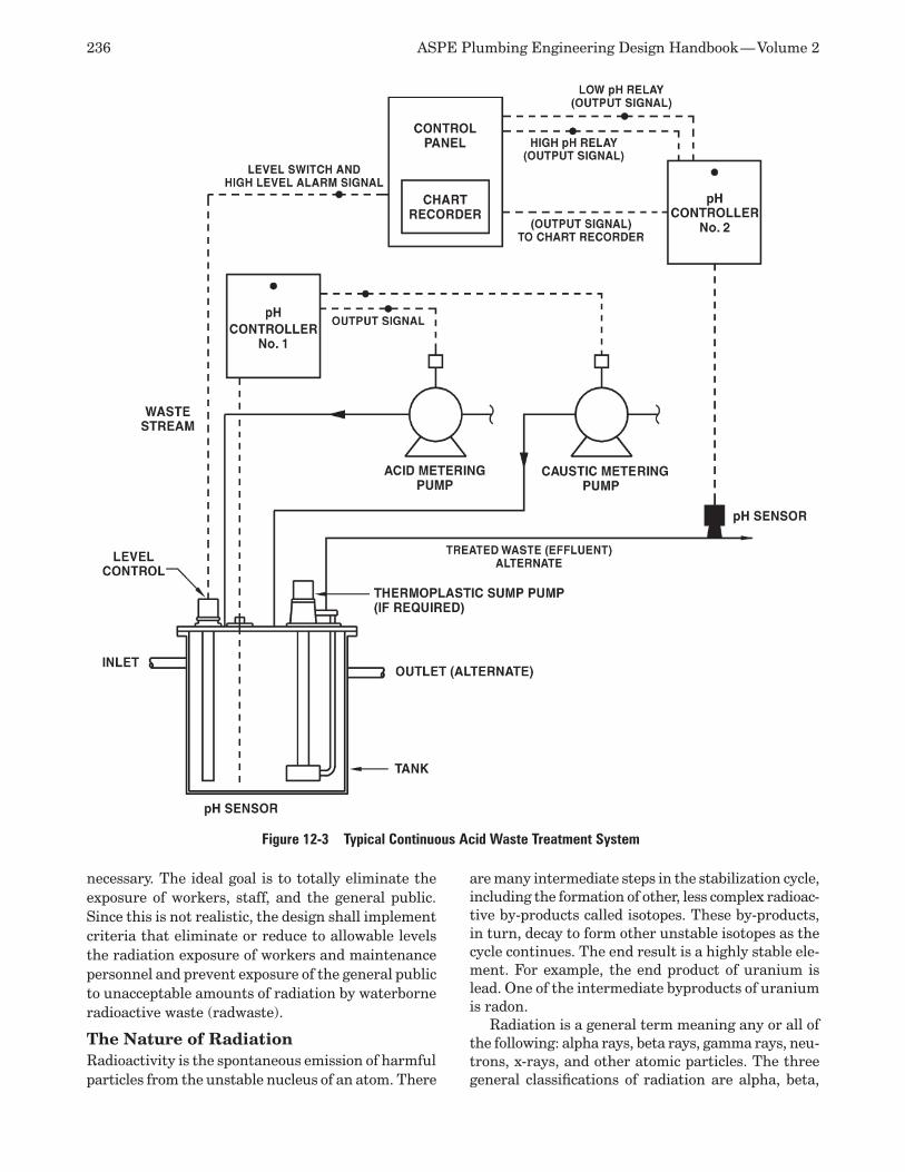
236 ASPE Plumbing Engineering Design Handbook — Volume 2
necessary. The ideal goal is to totally eliminate the exposure of workers, staff, and the general public. Since this is not realistic, the design shall implement criteria that eliminate or reduce to allowable levels the radiation exposure of workers and maintenance personnel and prevent exposure of the general public to unacceptable amounts of radiation by waterborne radioactive waste (radwaste).
The Nature of Radiation Radioactivity is the spontaneous emission of harmful particles from the unstable nucleus of an atom. There
are many intermediate steps in the stabilization cycle, including the formation of other, less complex radioac-tive by-products called isotopes. These by-products, in turn, decay to form other unstable isotopes as the cycle continues. The end result is a highly stable ele-ment. For example, the end product of uranium is lead. One of the intermediate byproducts of uranium is radon.
Radiation is a general term meaning any or all of the following: alpha rays, beta rays, gamma rays, neu-trons, x-rays, and other atomic particles. The three general classifications of radiation are alpha, beta,
Figure 12-3 Typical Continuous Acid Waste Treatment System
Chapter 12 — Special Waste Drainage Systems 237
and gamma. Alpha radiation is actually a helium atom with a high velocity. Beta radiation is an electron with a high velocity. Gamma radiation is a particle similar to a photon, which is light.
Alpha and beta radiation generally can be stopped by the skin or clothing, paper, or another similar, light material. Alpha loses energy very quickly in air and is no practical concern for distances greater than 12 inches (305 millimeters). High-energy beta radiation is commonly contained by only 1 inch (25 millimeter) of solid, dense plastic. Beta is denser and carries more energy greater distances than alpha, and it will burn bare skin and, in particular, damage the eye. However, it generally does not penetrate into the body to cause any internal damage. The greatest danger with beta radiation is to the eyes, particularly when the eye is directly exposed close to the source.
Gamma radiation is electromagnetic in nature. It carries the most energy and therefore is the most dangerous to humans. Its wavelength is shorter than light waves. When generated, it is similar to x-rays and behaves in a manner similar to light waves. When released from a source, gamma rays have a mass and velocity that are a measurable energy potential.
Radiation Measurement Radioactivity is a general term used for the total release of radiation of all types from a source. Its measurement is in disintegrations per second (dps). This measurement is possible for gamma radiation because in most radioactive materials, it also produces a known amount of gamma radiation. However, the best manner of measuring gamma radiation is to measure the energy it produces per kilogram (pound) of air. Because the instruments needed to measure radiation in this way are very expensive, it is not widely used outside of the laboratory. The so-called Geiger-Mueller counter is the most common device for measuring radiation. It measures the penetration of the particles entering a tube, where the particles react with a gas to create a measurable electrical charge. If an amplification device is used, it can be heard in the form of static. The more modern instruments have a digital readout.
Units of Radiation Particulate radiation is measured by the number of disintegrations per unit of time. A curie (c) is equal to 3.7 x 10¹⁰ disintegrations per unit. One millicurie (mc) is 0.001 curie, or 3.7 x 10⁷ disintegrations per unit. One rad is defined as the dose corresponding to the absorption of 100 ergs per gram of tissue. A Roentgen measures ions carrying a total of 2.58 x 10⁴ coulombs (C) of electrical energy.
Since the term radiation is a general one, a more specific method must be used to measure its effect on humans. The measurement is called a dose and is
defined as the total quantity of radiation absorbed by the body or any portion of the body. Much of the time, the dose is modified by reference to a unit of time. This differs from radioactivity because all radiation is not absorbed by the body.
A rad is a measure of the dose to body tissue in terms of energy absorbed per unit mass. Gamma radiation is the type of radiation most commonly measured this way.
The most important measurement is the radiation equivalent to man, or rem. A rem is the measure of ionizing radiation passing through or absorbed by the body in terms of the biological effect relative to a dose of 1 roentgen of x-rays. The relation of the rem to other dose units depends on the actual biological effect to the particular part of the body being studied and the actual conditions and amount of time of the ir-radiation. One rem is the equivalent of 1 roentgen due to x-ray or gamma radiation, and also 1 rad due to x-ray or gamma or beta radiation. One rem of high-flux neutrons is roughly equivalent to 14 million neutrons per square centimeter incident to the body.
Allowable Radiation Levels Many scientists believe that no exact radiation level is certain to cause permanent harm to an individual. Other scientists believe no level is harmless. A term called background level of radiation exists all over the world. The most common source of this is the sun, and it is called cosmic radiation. In addition, many substances, such as fly ash from burning organic fuels (particularly coal), granite, and many other natural substances contain trace isotopes of elements, emit radiation. One of the most common of these trace elements is carbon 14, used by scientists to date many materials.
The Nuclear Regulatory Commission (NRC) is a governmental body that establishes criteria for the field of radioactivity. These criteria appear in the fed-eral government’s Code of Federal Regulations.
All personnel working at any site where the pos-sibility of exposure to radiation exists are required to wear some type of exposure-detection device that gives an accurate determination of their actual exposure. The photographic badge is the most common and is used where sensitivity is required. A pen-shaped device called a dosimeter is commonly used where there is less need for accuracy. It is used where instant determination of dose is necessary.
An unrestricted area is any area within a facility that is not specifically controlled for the purpose of protecting an individual from radiation or radioac-tive materials. A restricted area is access controlled. The term environs also may be used to describe areas adjacent to a restricted or high-radiation area, which is any accessible area within a facility capable of al-
238 ASPE Plumbing Engineering Design Handbook — Volume 2
lowing the body to receive 100 millirem (mrem) of radiation in one hour.
Shielding The purpose of shielding is to reduce or eliminate radiation emanating from any source within the facility. The most effective material has the greatest density, so lead has been universally used for this purpose. Another commonly used material is concrete. In describing the shielding thickness between con-crete and lead, 1/6 inch (4 millimeters) of lead is the equivalent of 12 inches (305 millimeters) of concrete. The use of concrete as a structural element of a build-ing serves a supplementary purpose as a very good shielding material. It is up to the radiological safety officer, whose responsibilities are discussed later, to determine the type of shielding and its placement to lower radiation in specific areas. Radiation travels in a straight line; therefore, if a tank or a length of pipe must be shielded, the proper manner is to form a labyrinth, so the shine from the tank can’t escape in a straight line.
The materials most commonly used for shielding purposes are concrete and sheet lead. Other materi-als that have proven effective are lead-lined concrete blocks, lead-lined lath for plaster, and lead-lined pan-els and gypsum boards.
The barriers set up to reduce radiation levels are primary barriers, which are the first line of defense, and secondary barriers, which are used to eliminate leakage radiation and scattered radiation where it may possibly exist.
Radioactive Materials Radioactive materials are used for the following five general categories of work:
Imaging sciences 1. Diagnostic purposes 2. Treatment purposes 3. Industrial uses4. Research5.
Almost all of the materials used are isotopes. An isotope is a form of an element with a different (or excess) number of neutrons in its nucleus. Because of this, the atom is unstable. Isotopes are identified by their atomic weight, which is the number of neutrons and protons in the nucleus.
A great number of isotopes are in use today. Some of the more common are:
Iodine 131 (eight-day half-life) •Phosphorus 32•Technetium 99 (six-hour half-life) •Calcium 45•Carbon 14 •Strontium 90 •Radium 226•
Since given amounts of radioactive material re-main active for different periods, it is not possible to predict when any material will become completely stable. The method used to determine when a spe-cific material loses half of its radioactivity is called its half life.
System Design Criteria
Approval Process and Application Requirements The use of any radioactive material requires the li-censing of the site for a specific purpose, quantity, and amount of radioactive material. Application for this license is made to either the Nuclear Regulatory Com-mission or a particular state. Those states that have elected to adopt NRC regulations and provide their own staff for the purpose of issuing and approving licenses are called agreement states. In some cases, these states make additional regulations of their own. Those states relying on the NRC to review and issue licenses are non-agreement states. In such states, the application is made to the appropriate party.
The duties of the radiological safety officer include administration, monitoring personnel exposure lim-its, and controlling any release of radionuclides to the sewer system. In addition, the radiological safety officer works with the engineers in the design phase of the facility to ensure that the piping runs and all other mechanical work will result in a low exposure to people within the facility. For the most part, this work is aimed at ensuring that facility personnel do not exceed the maximum permissible radiation dose allowed under the applicable codes for any particular type of radioactive material present and that non-staff members are not subject to unacceptable levels of radiation. The radiological safety officer is also responsible for the following:
Teaching facility staff about potential dan-•gers Keeping the necessary records for the facil-•ity Keeping an inventory of material and records •disposal Maintaining the concentration of materials •at the facilityDesignating areas within the facility to be •restricted
General Design Criteria The prime consideration in the design of any facility is controlling the exposure of personnel to radiation, a concept called ALARA, or as low as reasonably achievable. This requires every reasonable design method to limit the possible exposure of personnel inside the facility and to keep the presence of radio-activity in any unrestricted area to a figure as low
Chapter 12 — Special Waste Drainage Systems 239
as reasonably achievable. Among the things that must be taken into account are the current state of technology, the economics of further improvements in relation to the benefits to the public’s health and safety, and other socioeconomic considerations relat-ing to the utilization of radioactive material in the general public interest.
The designer of the facility also must make a rea-sonable effort to eliminate residual radiation. One of the overriding concepts is the worst-case possibility, where the worst possible combination of circumstanc-es is used to determine the possible level of radiation and the period of exposure. This concept should not be overused, and a general rule is to consider only one accident at a time. As an example, a serious spill and a fire would not be considered as likely to occur simultaneously.
Pipe Material Selection The pipe selected for the radioactive drainage sys-tem depends on the type of radiation and the level of radioactivity expected, which, in turn, depend on the amount and type of radioactive material at the facility. In general, an ideal radwaste drainage pipe should have the following properties:
It must be nonporous. •It must be easy to clean and decontaminate. •It should be acid resistant. •It should be non-oxidizing. •The joints should not form a crud trap. •Joint materials must not be affected by radia-•tion exposure.
In very high radiation areas, a pipe may be af-fected by the radiation present. The oxides of the pipe can become radioactive, or the pipe itself can be weakened. Plastic piping is not acceptable for radiation waste systems because the plastic may be affected by the radiation, causing weakening of elastomeric seals or gaskets. For this reason, Teflon is never used where anything more than a very low level of radiation is present. Other materials should be investigated regarding their suitability for use for the levels anticipated.
All of the commonly used materials (cast iron, ductile iron, copper, steel, and glass) and joints fall far short of the ideal. However, they are suitable for low-level waste and radioactive source materials found in facilities with low radiation levels. When the waste materials have a high radiation level, these materials and joints fail. As a result, stainless steel with welded joints has emerged as the material of choice for all industrial-type waste products. Type 316L is the type most commonly used.
A welded joint is the only type of joint that does not allow a crud trap to form. The orbital welding process often is used since it produces the cleanest interior weld surface. The proper weld end preparation is
critical to proper welding and must be diagrammed or described in the specifications.
The two types of joint used for drainage pipe are butt welding and socket welding. Butt welding is when two pipes are placed end to end and joined with no overlapping. A socket weld is when one pipe is placed inside the other and only one end of the exposed pipe is actually welded around the exterior of the pipe. This is similar to a coupling, with only the joint on the outside of the pipe welded. In general, only pipe 2 inches (50 millimeters) and less is socket welded. Pipe this small is called small bore pipe.
Specifications for, and approval of, the entire weld-ing process for both shop welding and field welding are necessary. Welding personnel must be qualified to ensure that they have sufficient training and knowl-edge to produce a weld of the required quality, but the qualifications of welding personnel are difficult to assess. High-temperature, high-pressure pipe is covered by ASME codes that specify the selection of successive welding type passes, filler metal composi-tion, joint preparation, movement and handling of the pipe, tack welding and clamping, welding currents, metal deposit rates, and weld inspection. However, none of these code requirements apply to welded non-pressure drainage pipe. If the engineer does not have the knowledge to specify the minimum require-ments for welders and the welding process, it could be left up to the contractor to determine the correct specifications for the project and recommend them to the engineer for approval. When this is done, the con-tractor establishes minimum criteria that will qualify any individual for welding on this particular project. It is then up to the contractor to test a welder’s abil-ity to make sound welds under the actual working conditions and using the same equipment expected to be used on the job and certify that person as being qualified. These criteria should be reviewed by the engineer for acceptability. It is common practice to use an outside, knowledgeable third party for this review process.
Any defects in welded piping, such as cracks or voids in a joint, must be found and corrected. All of them arise from the fact that the weld does not ac-tually create a monolithic piece of pipe. The testing methods are of the non-destructive type, including visual inspection of the weld, dye penetration, mag-netic testing, ultrasonic testing, and x-ray
Design Considerations Human or animal waste, even that contaminated with radioactivity, is exempt from all Nuclear Regulatory Commission regulations, requiring only compliance with local codes as far as disposal, sizing, and all other criteria applicable to standard drainage systems. Many isotopes also are exempt from regulations re-garding disposal into the public sewer.
240 ASPE Plumbing Engineering Design Handbook — Volume 2
Liquid radwaste to be discharged shall be diluted with the ordinary waste effluent from the rest of the facility before being discharged to the public sewer system. Thus, the radwaste piping first must be kept separate from the rest of the facility’s efflu-ent, but then combined before leaving the building for discharge into a public sewer. A method, such as a valved outlet from both the radwaste line and the combined discharge, should be provided for the radio-logical safety officer to sample the radwaste stream if desired. The pitch of the piping should be kept as steep as possible to empty the pipe quickly and to allow a scouring action to keep the radioactive solids in suspension.
It is common practice to confine high levels of radia-tion to glove boxes, protected fume hoods, or hot boxes. The small amount of liquid waste produced from this equipment should be stored in shielded containers below the equipment and removed periodically. If the storage of larger quantities of low-level radwaste is re-quired, the waste is piped to a holding tank. A common holding time is ten half-lives of the effluent. Usually, radwaste is stored for disposal on the site, outside of the building and where easy transfer of the liquid is possible. The removal must be done by licensed waste-disposal contractors who transfer the waste from the holding tank into a special truck, which transports the liquid waste to a designated site suitable for disposal. Solid wastes such as gloves and wipes are stored in special containers, which are removed to the disposal area with the liquid radwaste.
Floor drains are normally not desired in labo-ratories using radioactive isotopes. If radioactive material spills, it is wiped up by hand using absorbent material, and the solid containing the spill is put in a special radwaste holding container within the lab. If a floor drain is installed, it should be constructed of stainless steel. For testing purposes and to close off a drain when it is not being used, each drain should be supplied with a closure plug. If a spill is possible, the floor must be pitched to the floor drain. A generally accepted value for the pitch of the floor is 1 inch per 20 feet (2.54 centimeters per 6.10 meters). The thick-ness of the slab must be closely coordinated because the slab is thinnest at the drain and made thicker at the ends of the area served to make up the pitch. It is not practical to cast the slab evenly and add a top-ping, because if the topping is chipped, a radioactive spill may get under the top coating. Since the slab depth is greater the longer the run to the drain, it is necessary to indicate the top of the drain elevation at each drain. This also makes it easier for the shop fabricator to make up accurate pipe spools.
Drains also require special treatment. They should be manufactured of stainless steel. Since different types of drains may be installed at different elevations
and the piping may be made in spools (preassembled sections of piping), it is a good idea to number all of the individual drains on the design drawings. A box next to each drain can be used to provide information regarding type, number, and elevation.
Since fittings are a natural crud trap, running pip-ing in, under, over, or adjacent to unrestricted areas in a facility should be avoided. If this is not possible, the line should be placed where additional shielding can be added, either at the time of construction or after the start of actual use, when the radiological safety officer may determine by survey where ad-ditional shielding is necessary. Much of the time, the ability to take the joint apart and flush out any crud is an advantage. Any of the popular joints for no-hub or grooved pipe are acceptable, as well as those for glass pipe if that is used in a laboratory for chemical resistance.
Cleanouts should be provided generously. They may be needed to flush out the line to reduce spots of high radiation rather than rodding out the entire line.
INFECTIOUS AND BIOLOGICAL WASTE DRAINAGE SYSTEMS Biological waste has the same basic characteristics as other types of laboratory and production facility waste, but with the addition of biohazardous mate-rial, which is material suspended in the waste stream with live organisms that, if not contained, have the potential to cause infection, sickness, and very serious diseases. This waste may be discharged by gravity and under pressure from many sources, including:
Fermentation tanks and equipment •Process centrifuges•Sinks, both handwashing and process •Containment area floor drains•Janitor closet drains•Necropsy table drains •Autoclave drains •Contaminated condensate drains •
Containment is the method used to isolate and confine biohazardous material. The facility equipment and design shall conform to acceptable and appro-priate containment practices based on the hazard potential. A containment category is used to describe an assembly of both primary and secondary preven-tive measures that provide personnel, environmental, and experimental protection. Primary barriers are specific pieces of equipment such as the biological safety cabinet (which is the biologist’s equivalent of the chemist’s fume hood) and glove boxes. Secondary containment refers to features of the facility design surrounding and supporting the primary contain-ment. These features are described and classified in Biosafety in Microbiological and Biomedical Labora-tories (BMBL) developed by the U.S. Department of
Chapter 12 — Special Waste Drainage Systems 241
Health and Human Services Public Health Services, Centers for Disease Control and Prevention (CDC), and the National Institutes of Health (NIH).
The classifications for biological containment in laboratories consist of four biosafety levels, BSL-1 through BSL-4. There are also corresponding BSL classifications for vivarium facilities depending on the agent and animal species used for research. The BMBL describes the work practices, equipment, and BSL selection criteria based on the activity of a particular laboratory. If the laboratory or production facility produces or uses greater than 2.6 gallons (10 liters) involving viable organisms, the facility may become large scale (LS). This is noted as BSL2 LS.
Manufacturing standards shall conform to good large-scale production (GLSP) standards. The same standards apply to both small and large-scale facili-ties.
Facility type of work is outlined later in this chap-ter in a very abbreviated and simplified form.
Codes and Standards Mandated guidelines and regulations include the following:
OSHA blood-borne pathogen regulations •National Institutes of Health guidelines for •the use of recombinant microorganisms FDA current good manufacturing practice •regulations Centers for Disease Control and Prevention •and National Institutes of Health guidelines for biosafety in microbiological and biomedi-cal laboratories
Biological Safety Levels The laboratory containment levels described in the BMBL are summarized as follows.
Biosafety Level 1 BSL-1 is the typical biological research facility clas-sification for work with low-hazard agents. Viable microorganisms not known to cause disease in healthy adults are used at this level. Work is done on an open bench, and any hazard present can be controlled by using standard laboratory practice. Standard features consist of easily cleaned, impervious bench surfaces and handwash sinks, and the work area is separated from general offices, animal rooms, and production areas.
Contaminated liquid and solid waste shall be treated to remove biological hazards before disposal. Wastes containing DNA material or potentially in-fectious microorganisms shall be decontaminated before disposal. Facilities to wash hands are required in each laboratory.
Biosafety Level 2 Facility construction for BSL-2 is similar to that for BSL-1, except the microorganisms may pose some
risk, and safety cabinets are often present. Equip-ment and work surfaces shall be wiped down with a suitable disinfectant. Sinks shall be scrubbed daily with a chlorine-containing abrasive and flushed with a suitable disinfectant. All liquid waste shall be immediately decontaminated by mixing it with a suitable disinfectant.
Nearly all laboratories operate under BSL-1 or BSL-2. At these levels, the facility is engaged in re-search, diagnostic, or production activities thought to pose little or minimal risk to workers.
Biosafety Level 3 BSL-3 activity involves organisms posing a significant risk or representing a potentially serious threat to health and safety. Biosafety cabinets are required, and all penetrations to the exterior the facility must be sealed to prevent leakage. These seals must be capable of being cleaned. Liquid waste is kept within the laboratory or facility and steam sterilized prior to discharge or disposal. Vacuum inlets must be pro-tected by appropriate filters and/or disinfectant traps. Laboratory animals require special housing, or if conventional housing is used, personnel must be ap-propriately protected with full suits and respirators. A handwashing sink routed to sterilization shall be located adjacent to the facility exit. Vents from plumb-ing fixtures must be filtered.
Biosafety Level 4 BSL-4 is a rarely used classification because activities in this type of facility require a very high level of con-tainment. The organisms present have life-threatening potential and may initiate a serious epidemic disease. All of the BSL-3 requirements apply. In addition, show-ers shall be provided for personnel at the airlock where clothes are changed upon entry or exit.
A biowaste treatment system shall be provided within the facility to sterilize liquid waste.
Effluent Decontamination System A liquid-waste decontamination system collects and sterilizes (decontaminates) liquid waste. Effluent con-taining potentially hazardous bio-matter is collected in a dedicated drainage system, generally discharging by gravity into a collection tank below the floor level within the facility. From the collection tank, effluent is drained or pumped into a kill tank where the actual sterilization occurs. A kill tank is a vessel into which steam or chemical disinfectant is injected to kill any organism. The kill tank system shall be qualified to the same biosafety level as the facility from which it receives discharge. The kill tank system must be a batch process since time is needed to complete the sterilization and decontamination, based on the agent and sterilization process used.
242 ASPE Plumbing Engineering Design Handbook — Volume 2
System Components The collection tank into which the effluent drains shall have a gasketed, waterproof manway for inspec-tion and maintenance. The tank shall be capable of being chemically or steam sterilized. The sizing of the collection tank is done in conjunction with the sizing of the kill tank cycles and the estimated amount of biowaste being generated by the facility. The collection tank must be able to receive the projected waste being generated when the kill tank is in the decontamina-tion cycle. If a pump is required to transfer biowaste from the collection tank to the kill tanks, it should be sized so it stays on for a minimum of one minute to avoid short-cycling and to protect the equipment.
The kill tank assembly commonly consists of a duplex tank arrangement, allowing one batch to be decontaminated while the other tank is filling. The size of the tanks varies based on the individual facility, but common practice is for each tank to be capable of containing one day’s effluent plus the chemicals used for decontamination. The tanks must be large enough to hold a catastrophic spill and any potential sprinkler discharge that may result in the area. An agitator mixes the effluent with the deactivation chemicals.
In addition to the kill tanks, tanks containing disinfectant chemicals to be injected are required. A fully automatic control system must be provided to ensure the timely addition of the required chemicals in the correct amounts and for the required duration for deactivation of the bio-matter. Alarms and status shall be displayed in an appropriate panel located in a facility control room or other area.
The drainage system must be closed, which re-quires sealed floor drains and valved connections to equipment when not in use. Since the HVAC system maintains a negative pressure, the traps on all floor drains must have a seal 2½ inches (65 millimeters) deeper than the negative difference in air pressure. Floor drain traps shall be filled with a disinfectant solution when not used to eliminate the possibil-ity of spreading organisms between different areas served by the same connected sections of the piping system.
The drainage piping material is based on the ex-pected chemical composition of the effluent and the sterilization method. If the local authority considers the biowaste to be hazardous, a double-contained piping system with leak detection may be required. Stainless steel or PTFE pipe usually is chosen where high-temperature effluent may be discharged or steam sterilization may be required. PVC, CPVC, polypro-pylene, or lined FRP pipe can be used where effluent temperatures are low and also where chemicals will provide the method of sterilization.
If waste from pressurized equipment is dis-charged into a gravity system, the system must
be adequately sized to carry away the waste at the proposed flow rate with pipe flowing one-half full, and adequate vents must be provided to equalize the internal pressure and ensure that the pipe is always at atmospheric pressure.
Valves shall be diaphragm type and capable of be-ing sterilized using the same method as for the pipe. After appropriate decontamination, the kill tank effluent shall be discharged to drain. This effluent must be treated prior to discharge into a public sewer system for disposal.
Vents from pipe, fixtures, sealed sump pits, and kill tanks must be filter-sterilized prior to leaving the system using a HEPA or a 0.2-micrometer filter.
In the event of an accident, OSHA has rules to aid personnel responding to emergencies involving any hazardous material.
System Design Considerations The treated discharge from any containment treat-ment shall be separately routed to the sanitary system outside the building to allow for monitoring and sampling.
CHEMICAL WASTE SYSTEMS Industrial waste drainage systems can contain a wide variety of waterborne wastes, such as chemicals, solvents, suspended solids, and flammable liquids, as well as wastewater, many of which are considered haz-ardous. The purpose of the industrial waste drainage system is to collect and transport these wastes from inside a facility to a point on site where disposal or treatment can be accomplished.
Codes and Standards A great body of regulations affects the design of any industrial drainage system. Among them are the federal Clean Water Act (CWA) and Resource Conservation and Recovery Act (RCRA), which are administered by the federal EPA as well as state and other local agencies. Local authorities also are em-powered to create regulations that are stricter than federal regulations.
Where production and manufacturing facilities discharge waste, it is a general practice to engage the services of professionals experienced in wastewater treatment and environmental issues to ensure com-pliance with all of the latest applicable regulations. The major regulatory factor is whether or not any particular waste stream is hazardous. If so, protective measures, such as double-contained piping systems and leak detection, may be required.
Pipe Material and Joint Selection Because of the vast diversity of manufacturing processes, it is impossible to make any general char-acterization of industrial wastewater. It is common for
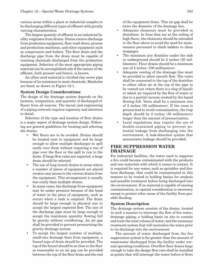
Chapter 12 — Special Waste Drainage Systems 243
various areas within a plant or industrial complex to be discharging different types of effluent with greatly varying characteristics.
The largest quantity of effluent in an industrial fa-cility originates from drains. Drains receive discharge from production equipment, floor wash down, process and production machines, and other equipment such as compressors and boilers. The floor drain and the discharge pipe from the drain must be capable of resisting chemicals discharged from the production equipment. Selection of the most appropriate piping material can be accomplished only if the nature of the effluent, both present and future, is known.
An often-used material is vitrified clay sewer pipe because of its resistance to most chemicals. Manholes are lined, as shown in Figure 12-1.
System Design Considerations The design of the drainage system depends on the location, composition, and quantity of discharged ef-fluent from all sources. The layout and engineering of a piping network requires ingenuity and attention to detail.
Selection of the type and location of floor drains is a major aspect of drainage system design. Follow-ing are general guidelines for locating and selecting the drains:
Wet floors are to be avoided. Drains should •be located next to equipment and be large enough to allow multiple discharges to spill easily over them without requiring a run of pipe over the floor or the spill to run to the drain. If large flow rates are expected, a large drain should be selected. The use of long trench drains in areas where •a number of pieces of equipment are placed creates easy access to the various drains from the equipment. This arrangement is usually less costly than multiple drains. In many cases, the discharge from equipment •may be under pressure because of the head of water in the piece of equipment, such as occurs when a tank is emptied. The drain should be large enough in physical size to accept the largest expected flow. The size of the discharge pipe must be large enough to accept the maximum quantity flowing full by gravity without overflowing. An air gap shall be provided to prevent pressurizing the gravity drainage system. To accept the largest number of multiple, •small-size drainage lines from equipment, a funnel type of drain should be provided. The top of the funnel should be as close to the floor as reasonable so an air gap can be provided between the top of the floor drain and the end
of the equipment drain. This air gap shall be twice the diameter of the drainage line. Adequate cleanouts must be provided in •drainlines. In lines that are at the ceiling of high floors, the cleanouts should be extended to the floor above to avoid the need for main-tenance personnel to climb ladders to clean stoppages. The minimum size drainline under the slab •or underground should be 2 inches (50 mil-limeters). Floor drains should be a minimum size of 4 inches (100 millimeters). Adequate venting of the drainage line must •be provided to allow smooth flow. The vents shall be connected to the top of the drainline to either allow air at the top of the pipe to be vented out (when there is a slug of liquid) or admit air required by the flow of water or due to a partial vacuum created by the liquid flowing full. Vents shall be a minimum size of 2 inches (50 millimeters). If the room is pressurized to avoid contamination, the trap depth should be 2 inches (50 millimeters) longer than the amount of pressurization.Local regulations may require the use of •double-contained piping to prevent po-tential leakage from discharging into the environment. A leak-detection system that annunciates leakage should be provided.
FIRE SUPPRESSION WATER DRAINAGE For industrial facilities, the water used to suppress a fire could become contaminated with the products and raw materials with which it comes in contact. It is required for any water, such as sprinkler and fire-hose discharge, that could be contaminated in this manner to be routed to holding basins for analysis and possible treatment before being discharged into the environment. If no material is capable of causing contamination, no special consideration is necessary except to protect other areas of the facility from pos-sible flooding.
System Description The drainage system consists of the drains, located in such a manner to intercept the flow of fire water; drainage piping; a holding basin on site to contain and treat the total volume of water; and the necessary treatment system that will neutralize the water prior to its discharge into the environment.
The amount of water discharged from the fire suppression system is far greater than the amount of wastewater discharged from the facility under nor-mal operating conditions. Overflow floor drains large enough to take the design flow rate shall be installed at points that will intercept the water before it flows

244 ASPE Plumbing Engineering Design Handbook — Volume 2
out of doorways or drive bays and route it to holding basins. The placement of these overflow drains shall be selected to intercept all of the water discharged and prevent it from damaging other parts of the facility or escaping from the property or into the ground.
The drainage piping is sized based on flow rate and pitch from the facility to the detention basin. The effluent is essentially clear water with a few solids, with possible contamination of the wastewater from whatever is stored in the area where the fire was pres-ent. The flow rate of water required to be disposed of is determined by first calculating the sprinkler water density over the area used for hydraulic calculations and then adding to this the flow rate from the number of fire standpipe hose streams possible. Velocity in the drainage pipe is not a major consideration because the system will be rarely used. A shallow pitch results in a low velocity, potentially causing the deposit of some material that could be flushed out after the event of a fire. A high velocity will not affect the life of the piping system because of the short amount of time the system will be in operation. Pipe size is selected based on the actual pitch of the pipe and the capacity flowing full. Refer to Table 12-1.
Venting of the system is required to allow the free flow of effluent. Each individual drain need not be vented, but each branch should have a loop vent of at least 2 inches (50 millimeters) in size. The vent could be connected to the sanitary vent system or carried through the roof independently.
The pipe material selected shall be compatible with the possible chemicals it may carry.
FLAMMABLE AND VOLATILE LIQUIDS Federal, state, and local regulations have established standards for the discharge of volatile liquids, particu-larly oil, into storm water and sanitary sewers. These standards vary, and the responsible enforcement and code authorities must be consulted to determine the level of treatment required.
The most common flammable liquid is oil. The common characteristic of all volatile liquids is they are lighter than water. Their removal from water, there-fore, is similar to the removal of oil outlined below.
OIL IN WATER Oil is considered immiscible, which means it will
not be dissolved in water. Since it cannot be dissolved, oil in water exists in several forms:
Free oil •Mechanically dispersed oil, which is fine drop-•lets that are stable due to electrical charges and other forces but not due to the presence of surface active agents Chemically stabilized emulsions, which are •fine droplets that are stable due to surface active agents Dissolved and dispersed oil, which is sus-•pended in such a small size (typically 5 micrometers or smaller) that ordinary filtra-tion is not possible Oil/wet solids, which are oils that adhere to •the surfaces of solids such as particulates or sediment
Figure 12-4 Typical Oil InterceptorSource: Courtesy of Rockford Co.

Chapter 12 — Special Waste Drainage Systems 245
Methods of Separation and Treatment Oil spills and leaks are best treated in their most con-centrated state, which is at their source or as close to their source as reasonable. The primary methods used to separate and remove free oil and oil/wet solids are flotation and centrifugation. Secondary treatment, such as chemical treatment/coalescence and filtra-tion, then is used to break up oil/water emulsions and remove dispersed oil. Finally, tertiary treatment, such as ultrafiltration, biological treatment, and carbon adsorption, removes the oil to required levels prior to discharge. This chapter discusses only the general principles of the primary and secondary separation methods and devices.
The American Petroleum Institute (API) has established criteria for the large-scale removal of globules larger than 150 micrometers. In abbreviated form, they are as follows.
The horizontal velocity through the separator •may be up to 15 times the rise velocity of the slowest-rising globule, up to a maximum of 3 fps (0.91 meters per second). The depth of flow in the separator shall be •within 3 to 8 feet (0.9 to 2.4 meters). The width of the separator shall be between •6 and 20 feet (1.8 to 6.1 meters). The depth-to-width ratio shall be between •0.3 and 0.5. An oil-retention baffle should be located no •less than 12 inches (305 millimeters) down-stream from a skimming device.
Gravity Separators Gravity separation is the primary and most often-used separation method. It is based on the specific gravity difference between immiscible oil globules and water. Since all volatile liquids are lighter than
(B)Figure 12-5 Typical Gravity Drawoff Installation: (A) Plan and (B) Isometric
Source: Frankel 1996
(A)
246 ASPE Plumbing Engineering Design Handbook — Volume 2
an equal volume of water, gravity separators operate on the principle of flotation. As the water and oil flow through the unit, the oil floats to the top and is trapped inside by a series of internal baffles. Since the oil remains liquid, it is easily drawn off.
Flotation Devices For larger-scale service, the flotation of oil and oil-wet solids to the top of the flotation chamber can be increased by the attachment of small bubbles of air to the surface of the slow-rising oil globules. This is done by adding compressed air to the bottom of the flotation chamber in a special manner creating small bubbles that mix with and attach to the oil globules.
Centrifugal Separators For larger-scale service, the centrifugal separator is used. This device induces the combined oil and water mixture to flow around a circular separation chamber. The lighter oil globules collect around the central vor-tex, which contains the oil-removal mechanism, and the clear water collects at the outer radial portion of the separation chamber. Methods have evolved that produce effluent water with only 50 to 70 parts per million of oil, and proprietary devices exist that lower oil content to 10 parts per million.
Filtration Chemical methods used to break oil/water emulsions followed by depth-type filters to remove the destabi-lized mixture have proven effective in the removal of oil globules between 1 and 50 micrometers. The velocity and flow rate of the mixture must be care-fully controlled to allow optimum effectiveness of the system.
Oil InterceptorsOil separators for small flows usually take the form of a single unit consisting of a drain grating into which
the effluent flows, is trapped and separated by gravity, and then is diverted to an accumulator chamber to be drawn off manually or automatically. Another type of unit uses an overflow arrangement that sends the trapped oil to a remote oil-storage tank.
Because the vapor given off by the flammable liquid could ignite, it is important to provide a separator vent that terminates in the open air at an approved location above the highest part of the structure. Some codes require a flame arrestor to be installed on the vent.
Most commonly used for an oil interceptor is a coated steel vessel. Gratings, if used, must have the strength to withstand the type of vehicle expected to pass over the interceptor. A collection basket may be specified where debris, such as metal chips, can be intercepted before entering the interceptor.
Refer to Figure 12-4 for an illustration of a typi-cal small oil interceptor. Figure 12-5 illustrates the installation of a typical oil interceptor with gravity oil drawoff for multiple-floor drain inlets.
REFERENCESFrankel, M., Facility Piping Systems Hand-1. book, McGraw-Hill, 1996. Geogehegan, R.F., and H.W. Meslar, “Contain-2. ment Control in Biotechnology Environments,” Pharmaceutical Engineering, 1993. Grossel, S.F., “Safe Handling of Acids,” Chemi-3. cal Engineering Magazine July 1998. Kaminsky, G., “Failsafe Neutralization of 4. Wastewater Effluent,” Plant Services Maga-zine, May 1998.Mermel, H., “pH Control of Chemical Waste,” 5. Heating/Piping/Air-Conditioning Magazine, 1988.
Index
µ (micro) prefix, 2009 V1: 34S (ohms), 2009 V1: 34S cm (ohm-centimeter units), 2007 V3: 47, 2008 V4: 195S m (ohm-meters), 2009 V1: 341-compartment sinks, 2008 V4: 101-family dwellings, numbers of fixtures for, 2008 V4: 19, 201-occupant toilet rooms, 2008 V4: 17–181-piece water closets, 2008 V4: 31-stage distillation, 2010 V2: 2001-time costs, defined, 2009 V1: 2171-wall tanks, 2007 V3: 1352-bed deionizing units, 2007 V3: 482-compartment sinks, 2008 V4: 10, 11–122-family dwellings, numbers of fixtures for, 2008 V4: 192-pipe venturi suction pumps, 2010 V2: 1572-point vapor recovery, 2007 V3: 1422-step deionization (dual-bed), 2010 V2: 206, 2072-valve parallel pressure-regulated valves, 2010 V2: 69–702-way braces, 2008 V4: 1422-word expressions of functions, 2009 V1: 218, 2252,4-D
levels in drinking water, 2008 V4: 186treating in water, 2008 V4: 187
3-bolt pipe clamps, 2008 V4: 1423-compartment sinks, 2008 V4: 10, 11–123E Plus, 2009 V1: 1184-way braces, 2008 V4: 13610-year storms, 2010 V2: 4218-8 SS, 2009 V1: 13218-8-3 SS, 2009 V1: 13228 CFR Part 36, 2009 V1: 9870:30 Cu Ni, 2009 V1: 13280/20 rule, 2009 V1: 218, 24990:10 Cu Ni, 2009 V1: 132100% area (full port), 2008 V4: 74, 84100-year storms, 2010 V2: 421964 Alaska Earthquake, 2009 V1: 1521971 San Francisco Earthquake, 2009 V1: 1523408 HDPE. See HDPE (high density polyethylene)
AA, X#, X#A (compressed air). See compressed airA/m (amperes per meter), 2009 V1: 33A (amperes). See amperesA (area). See area (A)a (atto) prefix, 2009 V1: 34
A-53 standard, 2008 V4: 48A-106 standard, 2008 V4: 48A-135 standard, 2008 V4: 48AAMI (Association for the Advancement of Medical
Instrumentation), 2010 V2: 187, 219, 220AAV (automatic air vents), 2009 V1: 10abandoned septic tanks, 2010 V2: 148abandoned wells, 2010 V2: 159abbreviations
existing building survey reports, 2009 V1: 269–270International System of Units, 2009 V1: 33plumbing and piping symbols, 2009 V1: 7–15text, drawings, and computer programs, 2009 V1:
14–15The ABC’s of Lawn Sprinkler Systems, 2007 V3: 96above-finished floor (AFF), 2009 V1: 14above-slab grease interceptors, 2008 V4: 162aboveground piping
inspection checklist, 2009 V1: 95materials for, 2010 V2: 12–13thermal expansion and contraction, 2008 V4: 227–229
aboveground sanitary piping codes, 2009 V1: 42aboveground tank systems
codes and standards, 2007 V3: 134connections and access, 2007 V3: 145construction, 2007 V3: 144–145corrosion protection, 2007 V3: 145electronic tank gauging, 2007 V3: 139filling and spills, 2007 V3: 145industrial wastes, 2007 V3: 83–84leak prevention and monitoring, 2007 V3: 145–146liquid fuel systems, 2007 V3: 144–147materials for, 2007 V3: 144overfill prevention, 2007 V3: 145product-dispensing systems, 2007 V3: 146tank protection, 2007 V3: 146testing, 2007 V3: 149vapor recovery, 2007 V3: 146venting, 2007 V3: 145
abrasion, 2008 V4: 105corrosion and, 2009 V1: 136defined, 2009 V1: 16drain pipes, 2010 V2: 16specifications to prevent, 2009 V1: 256–258vacuum piping, 2010 V2: 186
ABS. See acrylonitrile-butadiene-styrene (ABS)

248 ASPE Plumbing Engineering Design Handbook — Volume 2
abs, ABS (absolute), 2009 V1: 14absolute (abs, ABS), 2009 V1: 14absolute pressure
Boyle’s law, 2008 V4: 233–234defined, 2009 V1: 16, 2007 V3: 166, 169, 2008 V4: 177formulas, 2008 V4: 169–170in vacuums, 2010 V2: 166
absolute temperature, 2009 V1: 16, 2007 V3: 166absolute zero, 2009 V1: 16absorber (plate), defined, 2007 V3: 183absorber area, defined, 2007 V3: 183absorphan (carbon filtration). See activated carbon
filtration (absorphan)absorptance, defined, 2007 V3: 183absorption
air drying, 2007 V3: 172defined, 2009 V1: 16, 2008 V4: 220rates for soils, 2007 V3: 91trenches. See soil-absorption sewage systems
absorptive silencers, 2007 V3: 171AC (air chambers). See air chambers (AC)ac, AC (alternating current), 2009 V1: 14AC-DC rectifiers, 2009 V1: 139, 140acc (accumulate or accumulators), 2009 V1: 16acceleration
earthquakes, 2009 V1: 149, 150linear, 2009 V1: 34, 35measurements, 2009 V1: 34
acceleration limiters, 2008 V4: 134accelerators (dry-pipe systems), 2007 V3: 8, 9accellerograms, 2009 V1: 150access. See also people with disabilities
aboveground tank systems, 2007 V3: 145bioremediation pretreatment systems, 2008 V4: 252clean agent gas fire containers, 2007 V3: 27storm drainage and, 2010 V2: 48–49to equipment, piping and, 2008 V4: 23underground liquid fuel tanks, 2007 V3: 136–137
access channels for pipes, 2008 V4: 134access doors, 2009 V1: 16access openings for pipes, 2008 V4: 134access to (defined), 2009 V1: 16accessibility, 2009 V1: 16. See also people with disabilitiesAccessibility Guidelines for Buildings and Facilities, 2009
V1: 97Accessible and Usable Buildings and Facilities, 2009 V1:
97, 115, 2008 V4: 2accessories
as source of plumbing noise, 2009 V1: 189in plumbing cost estimation, 2009 V1: 85, 88section in specifications, 2009 V1: 71
accreditation of health care facilities, 2007 V3: 51accumulation, defined, 2009 V1: 16accumulators (acc, ACCUM), 2009 V1: 16, 2008 V4: 134accuracy
defined, 2009 V1: 16in measurements, 2009 V1: 33of pressure-regulating valves, 2010 V2: 94
ACEC (American Consulting Engineers Council), 2009 V1: 56
acetone, 2009 V1: 141acetylene, 2010 V2: 114
ACF (altitude correction factor), 2010 V2: 117acfh (actual cfh), 2010 V2: 126acfm (actual cubic feet per minute)
defined, 2007 V3: 76, 169medical air compressors, 2007 V3: 62, 63medical vacuum systems, 2007 V3: 64–65vacuum systems, 2010 V2: 166
ACI (American Concrete Institute), 2008 V4: 252acid absorbers in ion exchange, 2008 V4: 197acid-containing inhibitors, 2010 V2: 207acid dilution tanks, 2008 V4: 197acid feed pumps, 2007 V3: 125–126acid fumes, 2007 V3: 46acid manholes, 2007 V3: 223acid neutralization, 2007 V3: 43–45, 84acid-neutralization tanks, 2007 V3: 44–45acid pickling, 2008 V4: 59acid radicals, 2010 V2: 189acid regenerants, 2010 V2: 199, 206, 207acid resins, 2010 V2: 199acid-resistant fixtures, 2008 V4: 1–2acid-resistant floor drains, 2010 V2: 15acid-resistant glass foam insulation, 2008 V4: 107acid-resistant piping, 2010 V2: 13, 239acid-resistant sinks, 2007 V3: 41acid vents (AV), 2009 V1: 8, 16acid-waste systemsacid-waste treatment, 2010 V2: 235
continuous systems, 2010 V2: 236health and safety concerns, 2010 V2: 229–230health care facilities, 2007 V3: 42–46introduction, 2010 V2: 229large facilities, 2010 V2: 235metering, 2007 V3: 45piping and joint material, 2010 V2: 232–234, 2008 V4:
54solids interceptors, 2007 V3: 44–45system design considerations, 2010 V2: 234–235types of acid, 2010 V2: 230–232
acid wastes (AW), 2009 V1: 8, 16, 2007 V3: 42–46acidity
in corrosion rates, 2009 V1: 134pH control, 2007 V3: 84–85in water, 2010 V2: 160, 189, 192
acidsdefined, 2009 V1: 16, 2010 V2: 188feed water treatment, 2010 V2: 220acoustics in plumbing systemscork insulation, 2008 V4: 149–150costs of mitigation, 2009 V1: 188critical problems with noise, 2008 V4: 145design and construction issues, 2009 V1: 201–202drainage system mitigation, 2009 V1: 189–190hangers and supports, 2008 V4: 120insulation and, 2008 V4: 105, 115introduction, 2009 V1: 187–188mitigating fixture noise, 2009 V1: 193–194neoprene vibration control, 2008 V4: 149–150noise-related lawsuits, 2009 V1: 263pumps, 2009 V1: 194–201silencers on vacuum systems, 2010 V2: 179sources of noise, 2009 V1: 188–189

Index 249
STC (Sound Transmission Class), 2009 V1: 187transmission in pipes, 2010 V2: 13–14vacuum systems, 2010 V2: 174valves, pumps and equipment, 2009 V1: 194–201water distribution system noise mitigation, 2009 V1:
190–193water hammer, 2010 V2: 70–73
acoustics in swimming pools, 2007 V3: 107acquisition costs
acquisition prices defined, 2009 V1: 210base acquisition costs, 2009 V1: 217
ACR/MED pipes, 2008 V4: 31ACR piping, 2008 V4: 31acres, converting to SI units, 2009 V1: 38acrylic fixtures, 2008 V4: 2acrylic insulation jackets, 2008 V4: 108acrylonitrile-butadiene rubber (ABR), 2007 V3: 147acrylonitrile-butadiene-styrene (ABS)
corrosion, 2009 V1: 141defined, 2009 V1: 32fixtures, 2008 V4: 2insulation jackets, 2008 V4: 108pipe characteristics, 2008 V4: 49–50, 54piping, 2010 V2: 13, 14, 2007 V3: 49stress and strain figures, 2008 V4: 228–229thermal expansion or contraction, 2008 V4: 227
activated alumina air dryers, 2007 V3: 172activated alumina water treatment, 2010 V2: 218, 2008
V4: 187activated carbon filtration (absorphan)
in gray-water systems, 2010 V2: 25illustrated, 2010 V2: 205overview, 2010 V2: 201–204pure-water systems, 2010 V2: 221RO treatments, 2008 V4: 219small water systems, 2010 V2: 218water problems, 2008 V4: 187well water, 2010 V2: 160
Activated Carbon Process for Treatment of Wastewater Containing Hexavalent Chromium (EPA 600/2-79-130), 2007 V3: 88
activated sludge, 2009 V1: 16activated sludge systems, 2007 V3: 88active, defined, 2009 V1: 141active controls, cross-connections, 2008 V4: 173–175active potential, defined, 2009 V1: 141Active Solar Energy System Design Practice Manual, 2007
V3: 194active solar systems, 2007 V3: 185active solar water heaters, 2009 V1: 122active verbs in function analysis, 2009 V1: 218activities in FAST approach, 2009 V1: 223actual capacity, 2009 V1: 16actual cfh (acfh), 2010 V2: 126actual cubic feet per minute. See acfm (actual cubic feet
per minute)actual flow rates, 2007 V3: 4, 202actual liters per minute (aL/min), 2007 V3: 64–65, 169actual pressure. See static pressure (SP)actuators, 2009 V1: 16ad (area drains). See area drainsADA. See Americans with Disabilities Act
ADAAG (Americans with Disabilities Act Accessibility Guidelines), 2009 V1: 97, 98
ADAAG Review Federal Advisory Committee, 2009 V1: 115
adapter fittings, 2009 V1: 16addenda in contract documents, 2009 V1: 56–57additions to buildings, 2009 V1: 265–266adhesives, 2009 V1: 16adiabatic compression, 2009 V1: 16adiabatic processes, 2007 V3: 165adjustable, defined, 2008 V4: 134adjustable diverter plate, fountains, 2007 V3: 103adjustable high-pressure propane regulators, 2010 V2: 133adjustment devices, 2008 V4: 134adjustment section in specifications, 2009 V1: 64, 72administrative and operation costs in value engineering.
See overheadadministrative authorities, 2009 V1: 16admiralty brass, 2009 V1: 132adsorption, 2009 V1: 16, 2007 V3: 172, 2008 V4: 220adult-sized wheelchairs, dimensions, 2009 V1: 100. See
also wheelchairsAdvanced Chem, 2008 V4: 224advanced oxidation water treatment, 2010 V2: 218Advanced Plumbing Technology, 2010 V2: 46, 47, 55aerated lagoons, 2007 V3: 88aeration, 2009 V1: 16, 2008 V4: 196–197aeration cells, 2009 V1: 141aerators
aeration treatment, 2010 V2: 197–198, 218lavatories and sinks, 2007 V3: 35Provent aerators, 2010 V2: 17–18Sovent aerators, 2010 V2: 17–18
aerobic, defined, 2009 V1: 16aerobic bioremediation, 2008 V4: 249aerobic digestion, biosolids, 2008 V4: 263aerobic wastewater treatment plants, 2010 V2: 150aerosols, 2009 V1: 16AFF (above-finished floor), 2009 V1: 14AFFF foam concentrates, 2007 V3: 25after cold pull elevation, 2008 V4: 134after-coolers, 2009 V1: 16
air compressors, 2007 V3: 171air dryers and, 2007 V3: 175medical air compressors, 2007 V3: 63
after-cooling, defined, 2007 V3: 166after-filters, 2007 V3: 171AGA (American Gas Association)
defined, 2009 V1: 32relief valve standards, 2010 V2: 106water heating standards, 2010 V2: 112
age of water mains, 2007 V3: 6age-related disabilities, 2009 V1: 99agglomeration, 2008 V4: 157aggressiveness index, 2010 V2: 196aging, 2009 V1: 16aging disabilities, 2009 V1: 99aging water mains, 2007 V3: 6agitators in kill tanks, 2010 V2: 242agreement documents, 2009 V1: 56agreement states, 2010 V2: 238AHJ. See authorities having jurisdiction
250 ASPE Plumbing Engineering Design Handbook — Volume 2
AHRI (Air Conditioning, Heating, and Refrigeration Institute), 2009 V1: 46
AI (aggressiveness index), 2010 V2: 196AIA (American Institute of Architects). See American
Institute of Architectsair
compressed, 2009 V1: 16depleted in air chambers, 2010 V2: 72expansion and contraction, 2008 V4: 233–234free, 2009 V1: 16, 2007 V3: 165, 167, 169–170oil-free, 2007 V3: 76in pipes, 2010 V2: 2properties, 2007 V3: 165standard, 2009 V1: 16water vapor in, 2007 V3: 169–170
air, compressed. See compressed airair, free, 2009 V1: 16, 2007 V3: 165, 167, 169–170air, oil-free, 2007 V3: 76air, standard, 2009 V1: 16air-admittance valves, 2009 V1: 16, 43, 2010 V2: 39air-bleed vacuum controls, 2010 V2: 179air-bleed valves, 2010 V2: 171air breaks. See air gapsair chambers (AC)
defined, 2009 V1: 16symbols for, 2009 V1: 11water hammer arresters, 2010 V2: 72
air circuits in instrumentation, 2007 V3: 165air compressorsaccessories, 2007 V3: 171–172
compressed air systems, 2007 V3: 170–171dry-pipe systems, 2007 V3: 9medical systems, 2007 V3: 62pulsation, 2007 V3: 173selection factors, 2007 V3: 178–179sizing, 2007 V3: 177–179types of, 2007 V3: 170–171vacuum pumps, 2010 V2: 169–170
AIR COND (air conditioning). See air-conditioning systems
Air-Conditioning and Refrigeration Institute (ARI), 2008 V4: 243
air-conditioning cooling towers. See cooling-tower waterair-conditioning engineers, 2007 V3: 29Air-Conditioning, Heating, and Refrigeration Institute
(AHRI), 2009 V1: 46air-conditioning systems (AIR COND)
direct water connections, 2008 V4: 184fixture-unit values, 2010 V2: 8pipes, 2008 V4: 31waste heat usage, 2009 V1: 123water chillers, 2008 V4: 237
air-consuming devices, 2007 V3: 174air-cooled after-coolers, 2007 V3: 171air densities, calculating, 2009 V1: 5air dryers
compressed air systems, 2007 V3: 172–173deliquescent dryers, 2007 V3: 174–175desiccant dryers, 2007 V3: 175medical air compressors, 2007 V3: 63refrigerated air dryers, 2007 V3: 175selection, 2007 V3: 173
air ducts, 2007 V3: 27air filters
hydrophilic and hydrophobic, 2008 V4: 213–214stills, 2008 V4: 213–214
air gaps. See also effective openingsapplications, 2008 V4: 185booster pumps and, 2010 V2: 64defined, 2009 V1: 16, 2008 V4: 177, 180shortfalls, 2008 V4: 176standards, 2008 V4: 172
air-gate valves, 2010 V2: 179air intakes, 2007 V3: 178, 2008 V4: 163air lines
ABS pipe, 2008 V4: 54direct connection hazards, 2008 V4: 184
air locks, 2009 V1: 16air pressure, 2010 V2: 166, 2007 V3: 9air purges in vacuum pumps, 2010 V2: 171air receivers, 2007 V3: 173–174air solar systems, 2007 V3: 185air springs in noise mitigation, 2009 V1: 197air temperatures, swimming pools and, 2007 V3: 107air tests
in cold-water systems, 2010 V2: 90defined, 2009 V1: 16
air velocity in vacuum cleaning systems, 2010 V2: 183air vents in centralized drinking-water systems, 2008 V4:
246airborne contamination, 2008 V4: 213airborne noise, 2009 V1: 187, 190aircraft cable bracing method, 2009 V1: 160aircraft fuel, 2010 V2: 12airgaps. See air gapsairport runways, piping underneath, 2008 V4: 120AISC. See American Institute of Steel Construction (AISC)aL/min (actual liters per minute), 2007 V3: 64–65, 169alachlor levels in drinking water, 2008 V4: 186ALARA (as low as reasonably achievable), 2010 V2: 238alarm check valves, 2009 V1: 13, 16, 2007 V3: 6–7alarm lines on sprinklers, 2007 V3: 6–7alarm relays, 2007 V3: 27–28alarms
aboveground tank leakage, 2007 V3: 146defined, 2009 V1: 16, 2007 V3: 76on bulk oxygen supply, 2007 V3: 59on corrosive-waste systems, 2007 V3: 43on hazardous waste systems, 2007 V3: 84on kill tanks, 2010 V2: 242on medical gas systems
area alarms, 2007 V3: 67–68master alarms, 2007 V3: 67testing, 2007 V3: 75
on vacuum systems, 2010 V2: 169, 173overfill prevention, 2007 V3: 137, 145pressurized fuel delivery systems, 2007 V3: 141
Alaska Earthquake, 2009 V1: 152Albern, W.F., 2010 V2: 186alcohol-resistant AFFF foam concentrates, 2007 V3: 25algae, 2010 V2: 188, 195, 2008 V4: 199, 220–221alignment, storm drainage piping, 2010 V2: 47alkali, 2009 V1: 16alkali neutralization, 2008 V4: 196

Index 251
alkalinityafter ion exchange, 2008 V4: 198–199alkaline solutions in corrosion rates, 2009 V1: 134boiler feed water, 2010 V2: 216cork and, 2008 V4: 149dealkalizing treatment, 2010 V2: 199defined, 2008 V4: 221distillation feed water, 2008 V4: 212low-alkalinity water, 2008 V4: 198measuring, 2010 V2: 189neutralization of water, 2008 V4: 196pH and, 2010 V2: 192, 228–229, 2007 V3: 84predicting scale and corrosion, 2010 V2: 196swimming pools, 2007 V3: 123–127water saturation, 2010 V2: 196
all-service jackets (ASJ), 2008 V4: 108, 110allowable gas pressure, 2010 V2: 119–121allowable leakage in compressed air systems, 2007 V3: 176allowable radiation levels, 2010 V2: 237allowable vacuum system pressure loss, 2010 V2: 174alloy pipes, 2009 V1: 17alloys, 2009 V1: 16, 2008 V4: 134alpha ray radiation, 2010 V2: 236–237alterations (altrn, ALTRN), 2009 V1: 265–266alternate bracing attachments for pipes, 2009 V1: 167alternating current (ac, AC), 2009 V1: 14alternative collection and treatment of waste water, 2010
V2: 144–145, 149alternative energy sources, 2009 V1: 121–126alternative sanitary drainage systems, 2010 V2: 16–19Alternatives for Small Wastewater Treatment Systems:
Cost-Effectiveness Analysis, 2010 V2: 154Alternatives for Small Wastewater Treatment Systems:
On-site Disposal/Seepage Treatment and Disposal, 2010 V2: 154
Alternatives for Small Wastewater Treatment Systems: Pressure Sewers/Vacuum Sewers, 2010 V2: 154
alternatorsmedical air compressors, 2007 V3: 63vacuum systems, 2007 V3: 65
altitude (alt, ALT), 2007 V3: 166. See also elevationnatural gas and, 2010 V2: 121
altitude correction factor (ACF), 2010 V2: 117, 121altitude valves, 2010 V2: 163–164alum, 2010 V2: 199, 2008 V4: 201aluminosilicates, 2007 V3: 172aluminum, 2009 V1: 129, 132, 2010 V2: 189, 2007 V3: 26,
2008 V4: 187aluminum 1100, 2009 V1: 132aluminum 2017 and 2024, 2009 V1: 132aluminum hydroxide, 2010 V2: 189aluminum jackets, 2008 V4: 108aluminum piping, 2010 V2: 122, 2007 V3: 49, 176, 2008
V4: 59aluminum silicates, 2010 V2: 205aluminum sulfate, 2010 V2: 199, 2008 V4: 201aluminum tubing, 2010 V2: 122ambient temperature
defined, 2009 V1: 17drinking-water coolers and, 2008 V4: 238hangers and supports for systems, 2008 V4: 126piping for ambient temperatures, 2008 V4: 125
ambulatory accessible stalls, 2009 V1: 106American Association of State Highway and
Transportation Officials (AASHTO)H20-44 standard, 2008 V4: 252
American Chemical Society, 2009 V1: 142American Concrete Institute (ACI), 2010 V2: 54, 2008 V4:
252American Consulting Engineers Council (ACEC), 2009 V1:
56American Gas Association (AGA)
abbreviation for, 2009 V1: 14, 32codes and standards, 2010 V2: 114, 115gas regulator relief valves, 2010 V2: 117relief valve standards, 2010 V2: 106water heating standards, 2010 V2: 112
American Institute of Architects (AIA)General Conditions of the Contract for Construction,
2009 V1: 56Masterspec, 2009 V1: 65medical gas guidelines, 2007 V3: 51specifications format, 2009 V1: 57
American Institute of Steel Construction (AISC), 2009 V1: 14
American National Standards Institute (ANSI)abbreviation for, 2009 V1: 14, 32consensus process, 2009 V1: 41gas approvals, 2010 V2: 114list of standards, 2009 V1: 45–46MSS standards and, 2008 V4: 73publications, 2009 V1: 41
ANSI A112.2.1, 2008 V4: 184ANSI A112.6.1, 2008 V4: 6ANSI A112.18.3, 2008 V4: 13ANSI A112.19.6, 2008 V4: 5, 9ANSI A117.1-1980, 2009 V1: 97ANSI A117.1-1986, 2009 V1: 97ANSI A117.1-1998, 2009 V1: 97, 98, 99–115, 2008
V4: 2, 13ANSI/ASME B16.18 Cast Copper Alloy Solder
Joint Pressure Fittings, 2008 V4: 32ANSI/ASME B16.22 Wrought Copper and Copper
Alloy Solder Joint Pressure Fittings, 2008 V4: 32
ANSI/ASME B36.10: Welded and Seamless Wrought-Steel Pipe, 2010 V2: 122
ANSI/AWWA C104/A21.4 Cement Mortar Lining, 2008 V4: 28
ANSI/AWWA C105/A21.5 Polyethylene Encasement, 2008 V4: 28
ANSI/AWWA C110/A21.10 Fitting, 2008 V4: 28ANSI/AWWA C111/A21.11 Rubber-Gasket Joints,
2008 V4: 28ANSI/AWWA C115/A21.15 Flanged Pipe, 2008 V4:
28ANSI/AWWA C116/A21.16 Fusion-Bonded Epoxy
Coating, 2008 V4: 28ANSI/AWWA C150/A21.50 Thickness Design, 2008
V4: 28ANSI/AWWA C151/A21.51 Manufacturing, 2008
V4: 28ANSI/AWWA C153/A21.53 Compact Fittings, 2008
V4: 28
252 ASPE Plumbing Engineering Design Handbook — Volume 2
ANSI/AWWA C600 Installation, 2008 V4: 28ANSI B-3.13: Chemical Plant and Petroleum
Refinery Piping, 2007 V3: 88ANSI B16.10, 2008 V4: 89ANSI B16.21, 2008 V4: 65ANSI B31.9: Building Services Plumbing, 2008
V4: 61ANSI LC/CSA 6.26: Fuel Gas Piping Systems
Using Corrugated Stainless Steel Tubing, 2010 V2: 122
ANSI/NFPA 30: Flammable and Combustible Liquids Code, 2010 V2: 115
ANSI/NFPA 54: National Fuel Gas Code, 2007 V3: 35, 235, 239
ANSI/NFPA 58: Liquefied Petroleum Gas Code, 2007 V3: 35
ANSI/UL 144: Pressure Regulating Values for Liquefied Petroleum Gas, 2010 V2: 115
ANSI Z21.75/CSA 6.27: Connectors for Outdoor Gas Appliances and Manufactured Homes, 2010 V2: 124
ANSI Z83.3: Gas Utilization Equipment for Large Boilers, 2010 V2: 115
ANSI Z358.1, 2008 V4: 17ANSI ZE 86.1: Commodity Specification for Air,
2007 V3: 62, 78ASA A117.1-1961, 2009 V1: 97ASME/ANSI B16.23 Cast Copper Alloy Solder-
Joint Drainage Fittings, 2008 V4: 42ASME/ANSI B16.26 Cast Copper Alloy Fittings for
Flared Copper Tube, 2008 V4: 32ASME/ANSI B16.29 Wrought Copper and Wrought
Copper Alloy Solder-Joint Drainage Fittings, 2008 V4: 42
Connectors for Movable Gas Appliances, 2010 V2: 124
NSF Standard no. 61, 2008 V4: 56Z1001 standard, 2008 V4: 153
standard air definition, 2007 V3: 168–169water quality standards, 2010 V2: 220web site, 2007 V3: 89
American Petroleum Institute (API)API abbreviation, 2009 V1: 14emergency vent standards, 2007 V3: 145fiberglass pipe standards, 2008 V4: 56publications
AOIRP 1004: Bottom Loading and Vapor Recovery for MC-306 Tank Motor Vehicles, 2007 V3: 151
API Bulletin no. 1611: Service Station Tankage Guide, 2007 V3: 151
API Bulletin no. 1615: Installation of Underground Gasoline Tanks and Piping at Service Stations, 2007 V3: 151
API Specification 12D: Large Welded Petroleum Tanks, 2007 V3: 88
API Specification 12F: Small Welded Petroleum Tanks, 2007 V3: 88
API Standard 250: Steel Tanks for Oil Storage, 2007 V3: 88
removal of globules standards, 2010 V2: 245separators, 2007 V3: 87
valve standards, 2008 V4: 73web site, 2007 V3: 89, 151
American Public Health Service, 2010 V2: 193American Rainwater Catchment Systems Association,
2008 V4: 265American Society for Healthcare Engineering (ASHE),
2010 V2: 108–109American Society for Testing and Materials (ASTM)
abbreviation for, 2009 V1: 14, 32ASTM A53 piping, 2007 V3: 239ASTM A106 piping, 2007 V3: 239ASTM B819 tubing, 2007 V3: 69consensus process, 2009 V1: 41electronics-grade water standards, 2010 V2: 219, 220high-purity water standards, 2010 V2: 218–219list of standards, 2009 V1: 41, 49–51membrane filters, 2010 V2: 194plastic pipe and tubing standards, 2010 V2: 123–124publications
A-53 standard, 2008 V4: 48A-74 standard, 2008 V4: 23, 24A-106 standard, 2008 V4: 48A-126 standard, 2008 V4: 78, 85A-135 standard, 2008 V4: 48A-240 standard, 2008 V4: 108A-304 standard, 2008 V4: 108A-518 standard, 2008 V4: 59A-536 standard, 2008 V4: 85A-716: Culvert Pipe, 2008 V4: 28A-746: Gravity Sewer Pipe, 2008 V4: 28A-861 standard, 2008 V4: 59A-888 standard, 2008 V4: 24B-16.9 standard, 2008 V4: 48B-16.11 standard, 2008 V4: 48B-16.23: Cast Copper Alloy Solder-Joint Drainage
Fittings, 2008 V4: 42B-16.28 standard, 2008 V4: 48B-16.50: Wrought Copper Braze Fittings, 2008 V4:
42B-62 standard, 2008 V4: 85B-75: Specification for Seamless Copper Tube, 2008
V4: 32B-88: Specification for Seamless Copper Water
Tube, 2008 V4: 32B-99 standard, 2008 V4: 85B-209 standard, 2008 V4: 108B-280: Specification for Seamless Copper Tube for
Air-conditioning and Refrigeration Field Service, 2008 V4: 32
B-306: Standard Specification for Copper Drainage Tube (DWV), 2008 V4: 32, 41
B-371 standard, 2008 V4: 85B-584: Specification for Copper Alloy Sand
Castings for General Applications, 2008 V4: 32
B-813: Standard Specification for Liquid and Paste Fluxes for Soldering Applications of Copper and Copper Alloy Tube, 2008 V4: 32, 62
B-819: Specification for Seamless Copper Tube for Medical Gas Systems, 2008 V4: 32
B-828: Standard Practice for Making Capillary Joints by Soldering of Copper and Copper
Index 253
Alloy Tube and Fittings, 2008 V4: 32, 62B-837: Specification for Seamless Copper Tube for
Natural Gas and Liquefied Petroleum (LP) Gas Fuel Distribution Systems, 2008 V4: 32
C-12 standard, 2008 V4: 56C-14: Standard Specification for Concrete Sewer,
Storm Drain, and Culvert Pipe for Non-reinforced Concrete, 2008 V4: 28
C-33: Specification for Concrete Aggregates, 2008 V4: 252
C-76: Standard Specification for Reinforced Concrete Culverts, Storm Drain, and Sewer Pipe, 2008 V4: 38
C-94: Specification for Ready Mix Concrete, 2008 V4: 252
C-150: Specification for Portland Cement, 2008 V4: 252
C-260: Specification for Air Entraining Admixtures for Concrete, 2008 V4: 252
C-301 standard, 2008 V4: 56C-425 standard, 2008 V4: 56C-443: Standard Specification for Joints for
Circular Concrete Sewer and Culvert Pipe, Using Rubber Gaskets, 2008 V4: 32
C-533 standard, 2008 V4: 107C-534 standard, 2008 V4: 106–107C-547 standard, 2008 V4: 106C-552 standard, 2008 V4: 107C-564 standard, 2008 V4: 24, 60C-578 standard, 2008 V4: 107C-591 standard, 2008 V4: 107C-655: Standard Specification for Reinforced
Concrete D-Load Culvert Storm Drain and Sewer Pipe for Reinforced Concrete Pipe, 2008 V4: 28
C-700 standard, 2008 V4: 56C-828 standard, 2008 V4: 56C-896 standard, 2008 V4: 56C-1091 standard, 2008 V4: 56C-1208 standard, 2008 V4: 56C-1277 standard, 2008 V4: 61C-1540 standard, 2008 V4: 24D-638 standard, 2008 V4: 55D-696 standard, 2008 V4: 227D-1527 standard, 2008 V4: 54D-1785 standard, 2008 V4: 53D-2235 standard, 2008 V4: 54D-2239 standard, 2008 V4: 51D-2241 standard, 2008 V4: 53D-2464 standard, 2008 V4: 53D-2466 standard, 2008 V4: 53D-2467 standard, 2008 V4: 53D-2564 standard, 2008 V4: 53D-2609 standard, 2008 V4: 51D-2661 standard, 2008 V4: 54D-2665 standard, 2008 V4: 53D-2672 standard, 2008 V4: 53D-2680 standard, 2008 V4: 54D-2729 standard, 2008 V4: 53D-2737 standard, 2008 V4: 51D-2751 standard, 2008 V4: 54D-2846 standard, 2008 V4: 53
D-2863: Method for Measuring the Minimum Oxygen Concentration to Support Candle-like Combustion of Plastics, 2007 V3: 78
D-2996 standard, 2008 V4: 56D-3035 standard, 2008 V4: 51D-3222 standard, 2008 V4: 55D-3309 standard, 2008 V4: 51D-5127 standard, 2008 V4: 55E-84 standard, 2008 V4: 106F-437 standard, 2008 V4: 53F-438 standard, 2008 V4: 53F-439 standard, 2008 V4: 53F-441 standard, 2008 V4: 53F-442 standard, 2008 V4: 54F 628 standard, 2008 V4: 54F-771 standard, 2008 V4: 51F-810 standard, 2008 V4: 51F-876 standard, 2008 V4: 52F-877 standard, 2008 V4: 52F-894 standard, 2008 V4: 51F-1055 standard, 2008 V4: 55F-1056 standard, 2008 V4: 55F-1281 standard, 2008 V4: 52F-1282 standard, 2008 V4: 52F-1290-989: Electrofusion Joining Polyolefin Pipe
and Fittings, 2008 V4: 63F-1290 standard, 2008 V4: 55F-1412 standard, 2008 V4: 55F-1673 standard, 2008 V4: 55F-2014 standard, 2008 V4: 61F-2389 standard, 2008 V4: 55
reagent-grade water standards, 2010 V2: 187, 218–219, 2008 V4: 218
steel gas pipe specifications, 2010 V2: 122surface burning pipe characteristics, 2010 V2: 224
American Society of Civil EngineersMinimum Design Loads for Buildings and Other
Structures, 2009 V1: 147, 174, 185American Society of Civil Engineers (ASCE)
contract publications, 2009 V1: 56sewer publications, 2010 V2: 55
American Society of Heating, Refrigerating and Air-Conditioning Engineers, Inc. (ASHRAE)
abbreviation for, 2009 V1: 14, 32list of standards, 2009 V1: 46publications, 2007 V3: 194
Equipment Handbook, 2007 V3: 194Handbook of Fundamentals, 2009 V1: 2, 5, 6, 39,
2007 V3: 162, 194Standard 15, 2008 V4: 247Standard 18: Methods of Testing for Rating
Drinking Water Coolers with Self-Contained Mechanical Refrigeration Systems, 2008 V4: 243, 247
Standard 90.1, 2008 V4: 116Systems and Applications Handbook, 2007 V3: 194
American Society of Heating, Refrigerating and Air-conditioning Engineers, Inc. (ASHRAE)
cold water systems, 2010 V2: 96Legionella standards, 2010 V2: 108–109publicationsASHRAE Handbook - Fundamentals, 2010 V2: 136

254 ASPE Plumbing Engineering Design Handbook — Volume 2
water heating codes and standards, 2010 V2: 112American Society of Mechanical Engineers (ASME)
abbreviation for, 2009 V1: 14, 32air receivers, 2007 V3: 173Boiler and Pressure Vessel Code, 2010 V2: 112drinking water cooler standards, 2008 V4: 247list of standards, 2009 V1: 46–48propane tank specifications, 2010 V2: 132publications
ANSI/ASME A112.6.1, 2008 V4: 6ANSI/ASME A112.18.1, 2008 V4: 13ANSI/ASME A112.19.6, 2008 V4: 5, 9ANSI/ASME B16.18: Cast Copper Alloy Solder
Joint Pressure Fittings, 2008 V4: 32ANSI/ASME B16.22: Wrought Copper and Copper
Alloy Solder Joint Pressure Fittings, 2008 V4: 32
ANSI/ASME B16.23: Cast Copper Alloy Solder Joint Pressure Fittings (DWV), 2008 V4: 32
ANSI/ASME B16.24: Cast Copper Alloy Pipe Flanges and Flanged Fittings, 2008 V4: 32
ANSI/ASME B16.26: Cast Copper Alloy Fittings for Flared Copper Tube, 2008 V4: 32
ANSI/ASME B16.29: Wrought Copper and Copper Alloy Solder Joint Pressure Fittings (DWV), 2008 V4: 32, 42
ANSI/ASME B16.39: Cast Copper Alloy Solder Joint Pressure Fittings (DWV), 2008 V4: 32
ASME A17.1: Safety Code for Elevators and Escalators, 2007 V3: 29
ASME Boiler and Pressure Vessel Code, 2007 V3: 88
Fuel-Gas Piping, 2010 V2: 136Grease Removal Devices, 2008 V4: 166Welded and Seamless Wrought-Steel Pipe, 2010 V2:
122relief valve standards, 2010 V2: 106web site, 2007 V3: 89
American Society of Plumbing Engineers (ASPE)abbreviation for, 2009 V1: 14, 32ASPE Solar Energy System Design Handbook, 2007
V3: 194Domestic Water Heating Design Manual, 2010 V2: 96,
2007 V3: 47list of standards, 2009 V1: 48medical gas station guidelines, 2007 V3: 51, 52–53Plumbing Engineering and Design Handbook of
Tables, 2010 V2: 130Siphonic Roof Drainage, 2010 V2: 55
American Society of Plumbing Engineers Research Foundation (ASPERF), 2009 V1: 32
American Society of Sanitary Engineering (ASSE)abbreviation for, 2009 V1: 14, 32ASSE 1001 standard, 2008 V4: 185ASSE 1002, 2008 V4: 8ASSE 1011 standard, 2008 V4: 185ASSE 1012 standard, 2008 V4: 185ASSE 1013 standard, 2008 V4: 185ASSE 1015 standard, 2008 V4: 185ASSE 1020 standard, 2008 V4: 185ASSE 1024 standard, 2008 V4: 185ASSE 1035 standard, 2008 V4: 185
ASSE 1056 standard, 2008 V4: 185cross connection control, 2008 V4: 179list of standards, 2009 V1: 48–49water hammer arrester certification, 2010 V2: 72
American standard pipe threads, 2009 V1: 17American Standard Specifications for Making Buildings
and Facilities Usable by the Physically Handicapped, 2009 V1: 97
American Standards Association. See American National Standards Institute (ANSI)
American Water Works Association (AWWA)abbreviation for, 2009 V1: 14, 32cold water systems, 2010 V2: 94cross connection control, 2008 V4: 179list of standards, 2009 V1: 51publications
ANSI/AWWA C104/A21.4: Cement Mortar Lining, 2008 V4: 28
ANSI/AWWA C105/A21.5: Polyethylene Encasement, 2008 V4: 28
ANSI/AWWA C110/A21.10: Fittings, 2008 V4: 28ANSI/AWWA C111/A21.11: Rubber-Gasket Joints,
2008 V4: 28ANSI/AWWA C115/A21.15: Flanged Pipe, 2008 V4:
28ANSI/AWWA C116/A21.16: Fusion-Bonded Epoxy
Coating, 2008 V4: 28ANSI/AWWA C150/A21.50: Thickness Design, 2008
V4: 28ANSI/AWWA C151/A21.51: Manufacturing, 2008
V4: 28ANSI/AWWA C153/A21.53: Compact Fittings, 2008
V4: 28ANSI/AWWA C509-89: Standard for Resilient-
Seated Gate Valves, 2008 V4: 85ANSI/AWWA C509: Standard for Resilient-Seated
Gate Valves, 2008 V4: 90ANSI/AWWA C550-90: Standard for Protective
Epoxy Interior Coating for Valves, 2008 V4: 85
ANSI/AWWA C550: Standard for Protective Epoxy Interior Coating for Valves, 2008 V4: 90
ANSI/AWWA C600: Installation, 2008 V4: 28ANSI/AWWA C651: Disinfecting, 2008 V4: 28AWWA Standard for Disinfecting Water Mains,
2010 V2: 95AWWA Standard for Disinfection of Water Storage
Facilities, 2010 V2: 95AWWA Standard for Hypochlorites, 2010 V2: 95AWWA Standard for Liquid Chlorine, 2010 V2: 95Recommended Practice for Backflow Prevention
and Cross-connection Control, 2010 V2: 95water purveyor responsibility statement, 2008 V4: 184water usage data, 2008 V4: 255web site, 2008 V4: 224
American Welding Society (AWS), 2009 V1: 51, 159, 2008 V4: 61
Americans with Disabilities Act (ADA)ADAAG Review Federal Advisory Committee, 2009 V1:
115faucet flow rates, 2009 V1: 128fixture standards, 2008 V4: 2

Index 255
history, 2009 V1: 98–99overview, 2009 V1: 97, 98–99swimming pool guidelines, 2007 V3: 130
Americans with Disabilities Act Accessibility Guidelines (ADAAG), 2009 V1: 98–99
Amin, P., 2010 V2: 224amines in boiler feed water, 2008 V4: 214ammonia (NH3), 2010 V2: 189, 199, 2008 V4: 211–212ammonium alum, 2008 V4: 201ammonium hydroxide (NH4OH), 2008 V4: 211–212amoebic dysentery, 2008 V4: 171amp, AMP, AMPS (ampere). See amperesampacity, 2007 V3: 76amperes (A, amp, AMP, AMPS)
amperes per meter, 2009 V1: 33corrosion, 2009 V1: 129measurement conversions, 2009 V1: 33symbols for, 2009 V1: 14
amphoteric corrosion, defined, 2009 V1: 141amphoteric materials, 2009 V1: 134amplification factor in seismic protection, 2009 V1: 177amplifiers, 2009 V1: 17amplitude, 2009 V1: 17amusement parks
drinking fountain usage, 2008 V4: 245numbers of fixtures for, 2008 V4: 18
anaerobic, defined, 2009 V1: 17, 141anaerobic bacteria in septic tanks, 2010 V2: 145anaerobic bioremediation, 2008 V4: 249anaerobic digestion, biosolids, 2008 V4: 263anaerobic wastewater treatment, 2007 V3: 88analysis, 2009 V1: 17Analysis phase of value engineering, 2009 V1: 209, 218–
223. See also Function Analysis phase in value engineering
analytical grade water, 2010 V2: 219anchor bolts, 2008 V4: 134anchoring equipment
anchorage forces in earthquakes, 2009 V1: 180anchors, defined, 2009 V1: 185fire-protection equipment, 2007 V3: 27seismic protection, 2009 V1: 153
anchoring pipes, 2010 V2: 16, 54anchors, defined, 2008 V4: 134anchors for hangers and supports, 2008 V4: 127–131DWV stacks, 2008 V4: 229hangers and supports, 2008 V4: 125types of anchors, 2008 V4: 63–65, 123water hammer and, 2008 V4: 119
anchors, defined, 2009 V1: 17, 2008 V4: 134anesthesia workrooms
fixtures, 2007 V3: 39health care facilities, 2007 V3: 36medical air, 2007 V3: 53medical gas stations, 2007 V3: 52
anesthetic gas management, 2007 V3: 66–67anesthetics, 2007 V3: 76anesthetizing locations, 2007 V3: 76ANG (angle). See angles (ANG)angle-globe valves, 2008 V4: 83angle of incidence, defined, 2007 V3: 183angle of reflection, defined, 2007 V3: 183
angle of refraction, defined, 2007 V3: 183angle snubbers, 2009 V1: 156angle stops, 2009 V1: 17angle valves (AV), 2009 V1: 9, 17
abbreviation for, 2009 V1: 14defined, 2008 V4: 76resistance coefficients, 2010 V2: 92stems, 2008 V4: 79
angled grates in school shower rooms, 2010 V2: 11angles (ANG), measurements, 2009 V1: 34angles of bend, 2009 V1: 17angular acceleration measurements, 2009 V1: 34angular velocity measurements, 2009 V1: 34animal research centers, 2010 V2: 241, 2007 V3: 52animal shelters, 2010 V2: 15animal treatment rooms, 2007 V3: 47anion exchange
anion exchangers defined, 2008 V4: 197in water treatment, 2008 V4: 187
anionsanion resins, 2010 V2: 191, 207defined, 2009 V1: 17, 141, 2010 V2: 187, 2008 V4: 197,
221in electromotive force series, 2009 V1: 134in ion exchange, 2010 V2: 205in pH values, 2010 V2: 229
annealed temper (soft), 2008 V4: 32annealing, 2009 V1: 17annual costs. See costs and economic concernsannular chambers in dry-pipe systems, 2007 V3: 8annular spaces in wells, 2010 V2: 156, 158anodes
anode expected life, 2009 V1: 138anodic protection, 2009 V1: 141defined, 2009 V1: 129, 141galvanic series of metals, 2009 V1: 132sacrificial anodes, 2009 V1: 137
anodic inhibitors, 2009 V1: 141anodic potential (electronegative potential), 2009 V1: 14anodic protection, defined, 2009 V1: 141ANSI. See American National Standards Institute (ANSI)anthracite coal filters, 2010 V2: 160, 201anthropometrics for wheelchairs, 2009 V1: 99–101anti-cross-connection precautions, 2010 V2: 27anti-siphon ballcocks, 2008 V4: 8antifreeze, 2009 V1: 122, 2008 V4: 189–190antisiphons, 2009 V1: 17apartment buildings
firefighting demand flow rates, 2007 V3: 216gas demand, 2010 V2: 123, 124, 130hot water demand, 2010 V2: 99, 100natural gas demand, 2010 V2: 123numbers of fixtures for, 2008 V4: 19, 20plumbing noise, 2009 V1: 187water consumption, 2008 V4: 208
API. See American Petroleum Instituteappearance functions
defined, 2009 V1: 218in value engineering, 2009 V1: 223
appearance of pipes, 2009 V1: 262–263, 2008 V4: 105, 107appliance gas regulators, 2010 V2: 117appliances. See also fixtures
256 ASPE Plumbing Engineering Design Handbook — Volume 2
appliance regulators, 2010 V2: 117as source of plumbing noise, 2009 V1: 189codes and standards, 2009 V1: 43–44flexible gas connections, 2010 V2: 124gas control valves, 2010 V2: 115, 118gas demand, 2010 V2: 115, 116gas regulators, 2010 V2: 117, 2007 V3: 237propane vaporizers, 2010 V2: 134venting systems, 2010 V2: 118
Applied Polymer Science, 2008 V4: 224Applied Technology Council (ATC), 2009 V1: 174, 185approaches (heat), 2009 V1: 17approaches to toilet compartments, 2009 V1: 106approvals
for radioactive materials systems, 2010 V2: 238for special-waste drainage systems, 2010 V2: 227–228
approved, defined, 2009 V1: 17, 2008 V4: 180approved testing agencies, 2009 V1: 17approximate values, 2009 V1: 33aquastats, 2009 V1: 10Aqueous Film-Forming Foam (AFFF), 2007 V3: 25aquifers
defined, 2009 V1: 17, 2010 V2: 155formation of, 2010 V2: 155potentiometric surfaces, 2010 V2: 157unconsolidated aquifers, 2010 V2: 157
Arabic numerals, 2009 V1: 33arcades, numbers of fixtures for, 2008 V4: 18Architect-engineers Turf Sprinkler Manual, 2007 V3: 96architect’s supplemental instructions (ASI), 2009 V1: 57Architectural Barriers Act (90-480), 2009 V1: 98area (A)
calculating, 2009 V1: 3–5conversion factors, 2009 V1: 35measurements, 2009 V1: 34non-SI units, 2009 V1: 34
area, aperture, defined, 2007 V3: 183area, gross collector, defined, 2007 V3: 183area alarms, 2007 V3: 50, 67–68, 75area drains (ad), 2009 V1: 14, 17areas of sprinkler operation, 2007 V3: 12areaways, 2009 V1: 17arenas, numbers of fixtures for, 2008 V4: 18ARI (Air Conditioning and Refrigeration Institute), 2008
V4: 243arm baths, 2010 V2: 99, 2007 V3: 36, 38, 40Army Corps of Engineers, 2009 V1: 57arresters for water hammer. See water hammer arrestersarsenic
levels in drinking water, 2008 V4: 186treating in water, 2008 V4: 187
articulated-ceiling medical gas systems, 2007 V3: 57“as built,” defined, 2008 V4: 134“as low as reasonably achievable” (ALARA), 2010 V2: 238ASA. See American National Standards Institute (ANSI)ASA A117.1-1961, 2009 V1: 97asbestos cement piping, 2010 V2: 75, 2007 V3: 232asbestos in water, 2008 V4: 187ASCE. See American Society of Civil Engineers (ASCE)ASHE (American Society for Healthcare Engineering),
2010 V2: 108–109
ASHRAE. See American Society of Heating, Refrigerating and Air-Conditioning Engineers, Inc. (ASHRAE)
ASHRAE Handbook - Fundamentals, 2010 V2: 136ASI (architect’s supplemental instructions), 2009 V1: 57ASJ (all-service jackets), 2008 V4: 108, 110ASME. See American Society of Mechanical Engineers
(ASME)ASPE. See American Society of Plumbing Engineers
(ASPE)ASPERF (American Society of Plumbing Engineers
Research Foundation), 2009 V1: 32asphalt-dipped piping, 2010 V2: 78asphalt mixers, 2010 V2: 133asphalt pavement, runoff, 2010 V2: 42asphyxiant gases, 2009 V1: 17aspirators, 2009 V1: 17, 2007 V3: 40, 2008 V4: 184ASSE. See American Society of Sanitary Engineering
(ASSE)assemblies, defined, 2008 V4: 134assembly costs, 2009 V1: 210assembly halls
drinking fountain usage, 2008 V4: 245numbers of fixtures for, 2008 V4: 18, 20single-occupant toilet rooms, 2008 V4: 18
assisted creativity, 2009 V1: 227assisted living facilities, numbers of fixtures for, 2008 V4:
19Association for the Advancement of Medical
Instrumentation (AAMI), 2010 V2: 187, 219, 220Association of Pool and Spa Professionals (APSP), 2007
V3: 105Association of State Drinking Water Administrators, 2010
V2: 155ASTM. See American Society for Testing and Materials
(ASTM)ASTs (aboveground storage tanks). See aboveground tank
systemsasynchronous, defined, 2009 V1: 17ATBCB (U.S. Architectural and Transportation Barriers
Compliance Board), 2009 V1: 98, 99ATC-3 (Tentative Provisions for the Development of
Seismic Regulations for Buildings), 2009 V1: 174, 185
Atienze, J., 2010 V2: 29atm, ATM (atmospheres). See atmospheresatmospheres (atm, ATM)
converting to SI units, 2009 V1: 38vacuum units, 2010 V2: 166
atmospheric backflow preventers, 2008 V4: 185atmospheric pressure
Boyle’s law, 2008 V4: 233–234defined, 2008 V4: 177
atmospheric pressure breakers, 2008 V4: 177atmospheric pressure in vacuum, 2010 V2: 165atmospheric regulators, 2007 V3: 237atmospheric tanks
defined, 2007 V3: 133foam, 2007 V3: 25venting, 2007 V3: 137
atmospheric vacuum breakers (AVB)defined, 2009 V1: 17, 2008 V4: 177, 180
Index 257
dual check with atmospheric vent devices, 2008 V4: 180, 185
faucets, 2008 V4: 13illustrated, 2008 V4: 175irrigation sprinklers, 2007 V3: 95
atmospheric vaporizers, 2007 V3: 59atmospheric vent devices, 2008 V4: 180, 185atmospheric vents (steam or hot vapor) (ATV), 2009 V1: 9atomic absorption spectrophotometry, 2008 V4: 218atomic weight, 2009 V1: 17atrazine levels in drinking water, 2008 V4: 186attachments, 2009 V1: 185“atto” prefix, 2009 V1: 34ATV (atmospheric vents), 2009 V1: 9Auciello, Eugene P., 2010 V2: 55auditoriums, numbers of fixtures for, 2008 V4: 18, 20augered wells, 2010 V2: 156austenitic stainless steel, 2008 V4: 59authorities having jurisdiction
alterations to existing buildings, 2009 V1: 266alternative sanitary systems, 2010 V2: 16cross-connection programs, 2008 V4: 177defined, 2009 V1: 17, 2007 V3: 76fire-protection system design, 2007 V3: 1fixture vents, 2010 V2: 32gas approvals, 2010 V2: 114gaseous fire-suppression systems, 2007 V3: 26laboratory gas systems, 2010 V2: 121manholes, 2007 V3: 217medical gas stations, 2007 V3: 51public sewer availability, 2007 V3: 217swimming pools, 2007 V3: 105vent stacks, 2010 V2: 39–40
autoclaves, 2008 V4: 184autoignition, 2009 V1: 17automatic air vents (AAV), 2009 V1: 10automatic alternators, 2007 V3: 65automatic controls on ion exchangers, 2008 V4: 198automatic drain valves, 2007 V3: 95automatic drains in vacuum systems, 2007 V3: 65automatic fire-detection devices, 2007 V3: 9automatic fire-protection systems
history and objectives, 2007 V3: 1–2pipes and hangers, 2007 V3: 18–19
automatic flushometer valves, 2008 V4: 8automatic grease interceptors, 2008 V4: 159–160automatic grease recovery devices, 2008 V4: 185automatic heat-up method, condensate drainage, 2007 V3:
160automatic overfill prevention, 2007 V3: 145automatic overrides for irrigation controllers, 2007 V3: 95automatic purity monitors, 2008 V4: 214automatic softeners, 2008 V4: 221automatic sprinkler systems
combined dry-pipe and pre-action, 2007 V3: 10–11design density, 2007 V3: 11–12elevator shafts, 2007 V3: 29fire hazard evaluation, 2007 V3: 2fire pumps for, 2007 V3: 21–22gaseous fire-suppression systems and, 2007 V3: 26history, 2007 V3: 1–2hydraulic design, 2007 V3: 11–17
numbers of sprinklers in operation, 2007 V3: 12pipes and hangers, 2007 V3: 9, 18–19pre-action systems, 2007 V3: 9system design, 2007 V3: 2–20types, 2009 V1: 28–29, 2007 V3: 6–11water supplies, 2007 V3: 2–6
Automatic Sprinkler Systems Handbook, 2009 V1: 185automatic storage water heaters, 2010 V2: 101automatic tank gauging, 2007 V3: 139–140automatic trap primers, 2010 V2: 11automotive traffic, 2010 V2: 11autopsy rooms
fixtures, 2007 V3: 38, 40health care facilities, 2007 V3: 36medical gas stations, 2007 V3: 52, 56medical vacuum, 2007 V3: 54non-potable water, 2007 V3: 47
auxiliary energy subsystems, 2007 V3: 183auxiliary stops, 2008 V4: 134auxiliary water supplies
defined, 2008 V4: 180direct connection hazards, 2008 V4: 184
AV (acid vents), 2009 V1: 8, 16AV (angle valves). See angle valves (AV)availability. See demandavailability of water, 2009 V1: 17available vacuum, safety factors and, 2010 V2: 186AVB. See atmospheric vacuum breakers (AVB)average flow rates for fixtures, 2008 V4: 207average water use, 2009 V1: 117AW (acid wastes), 2009 V1: 8, 16, 2007 V3: 42–46, 2008 V4:
54AWS. See American Welding Society (AWS)AWWA. See American Water Works Association (AWWA)axial braces, 2008 V4: 134axial motions, hangers and supports and, 2008 V4: 119,
124axial pumps, 2008 V4: 93–97Ayres, J.M., 2009 V1: 185
BB-16.9 standard, 2008 V4: 48B-16.11 standard, 2008 V4: 48B-16.28 standard, 2008 V4: 48back pressure tests, 2008 V4: 5back pressures in pipes, 2010 V2: 2, 4, 2007 V3: 237, 2008
V4: 170–171, 171back-siphonage, 2007 V3: 95. See also backflow; siphonage
defined, 2009 V1: 17, 2010 V2: 94, 2008 V4: 177, 180devices for, 2008 V4: 185reverse flow, cause of, 2008 V4: 170–171
back-spud water closets, 2008 V4: 3back-to-back water closets, 2008 V4: 6backfilling
around septic tanks, 2010 V2: 146backfill defined, 2009 V1: 17building sewers and, 2010 V2: 14–15labor productivity rates, 2009 V1: 87, 88in plumbing cost estimation, 2009 V1: 85storage tanks, 2007 V3: 135, 150
backflow. See also back-siphonagebackflow connections, defined, 2009 V1: 17

258 ASPE Plumbing Engineering Design Handbook — Volume 2
defined, 2009 V1: 17, 2010 V2: 94, 2008 V4: 177, 180devices for, 2008 V4: 185prevention, 2008 V4: 173–176, 177swing check valves, 2008 V4: 77testing devices, 2008 V4: 183
backflow preventers (BFP)applications, 2008 V4: 185codes, 2009 V1: 42cold-water systems, 2010 V2: 60cross-connection control devices, 2010 V2: 60–61defined, 2009 V1: 14, 17, 2008 V4: 177, 178–179, 180domestic cold water systems, 2010 V2: 60domestic water supply, 2007 V3: 206–208existing devices, 2008 V4: 183faucets, 2008 V4: 13–14fire-protection connections, 2007 V3: 209, 212fixtures in health care facilities, 2007 V3: 35pressure loss, 2007 V3: 207–208reduced pressure zones, 2007 V3: 207–208spill proof indoors, 2008 V4: 185thermal expansion compensation and, 2010 V2: 106vacuum breakers, 2007 V3: 35, 46–47
background levels of radiation, 2010 V2: 237backing rings, 2009 V1: 17backpressure, 2009 V1: 17backpressure appliance regulators, 2010 V2: 117backup, defined, 2009 V1: 17backup demineralizers, 2007 V3: 48backup storm-drainage systems, 2010 V2: 52backwash from water softeners, 2010 V2: 160, 210backwashing
defined, 2008 V4: 221filters, 2010 V2: 201, 2008 V4: 203pressure differential switches, 2008 V4: 203in regeneration cycle, 2010 V2: 206
backwater valves, 2009 V1: 17, 43, 2010 V2: 12bacteria
biological fouling, 2010 V2: 195, 217chemical control, 2010 V2: 213copper-silver ionization, 2008 V4: 220defined, 2008 V4: 221demineralizer systems, 2007 V3: 48distilled water and, 2007 V3: 48, 2008 V4: 195, 212in drinking water, 2010 V2: 160, 2008 V4: 186in feed water, 2010 V2: 188in filters, 2010 V2: 201in hot water, 2007 V3: 47killing in water systems, 2010 V2: 109–111laboratory grade water and, 2008 V4: 218ozone treatments and, 2008 V4: 215–216in septic tanks, 2010 V2: 145solar water heating and, 2007 V3: 189in storm water, 2010 V2: 27, 43in water-heating systems, 2010 V2: 108–111in wells, 2010 V2: 158
bacteriological examination, 2008 V4: 221baffle systems, 2007 V3: 48
bioremediation pretreatment systems, 2008 V4: 252bioremediation systems, 2008 V4: 250grease interceptors, 2008 V4: 158in stills, 2008 V4: 213
baffleplates, 2009 V1: 17
bag-filter gross filtration, 2010 V2: 201Bahamas, gray-water systems in, 2010 V2: 27bailers, 2007 V3: 140baking soda, 2008 V4: 193balanced-piston valves, 2008 V4: 81balancing cocks, 2008 V4: 246balancing valves (BLV), 2009 V1: 9ball check valves, 2009 V1: 18ball joints, 2009 V1: 18, 161, 2008 V4: 64ball removal tests, 2008 V4: 5Ball Valves, 2008 V4: 85, 86, 87, 90ball valves (BV), 2009 V1: 9, 14, 18, 2007 V3: 67
acid piping, 2010 V2: 230compressed-air systems, 2008 V4: 86defined, 2008 V4: 76–77high-rise service, 2008 V4: 90hot and cold water supply service, 2008 V4: 85illustrated, 2010 V2: 92low-pressure steam systems, 2008 V4: 87medical gas service, 2008 V4: 87noise mitigation, 2009 V1: 194quarter-turn, 2008 V4: 84vacuum system service, 2008 V4: 87
Ballanco, Julius, 2010 V2: 55ballast pads, 2007 V3: 150ballcocks, 2008 V4: 8Baltimore Dept. of Public Works, 2010 V2: 29band hangers, 2008 V4: 126, 134banquet halls, numbers of fixtures for, 2008 V4: 18baptismal fonts, 2008 V4: 184bar joist hangers, 2008 V4: 129bar joists, 2008 V4: 130barber shop water consumption, 2008 V4: 208bare earth, runoff, 2010 V2: 42bare pipe, 2009 V1: 139bariatric water closets (WC), 2008 V4: 5, 7barium, 2010 V2: 189, 2008 V4: 186, 187baro pr, BARO PR (barometric pressure). See barometric
pressurebarometers (baro, BARO), 2010 V2: 166barometric loops, 2008 V4: 180barometric pressure (baro pr, BARO PR, BP)
altitude adjustments, 2010 V2: 166–167defined, 2007 V3: 166, 167, 169in vacuums, 2010 V2: 166, 185
barrelsconverting to SI units, 2009 V1: 38dimensions, 2008 V4: 25–27
“barrier free,” 2009 V1: 18. See also people with disabilities
barrier-free water coolers, 2008 V4: 239barriers around tanks, 2007 V3: 146bars, converting to SI units, 2009 V1: 38bars, numbers of fixtures for, 2008 V4: 18base acquisition costs, 2009 V1: 217base materials
base defined, 2009 V1: 18compounds in water, 2010 V2: 188pH control, 2007 V3: 84–85
base supports, 2008 V4: 134base units, 2009 V1: 33basic functions in value engineering, 2009 V1: 219, 221

Index 259
basic material standards, 2009 V1: 61Basic Plumbing Code (BOCA), 2007 V3: 134basket strainers, 2010 V2: 92bathhouses, 2010 V2: 151, 2007 V3: 107–109bathing rooms, 2009 V1: 104–105bathroom groups, 2009 V1: 18, 2007 V3: 198bathtub fill valves, 2008 V4: 16bathtub spout noise mitigation, 2009 V1: 200bathtubs (BT)
abbreviations for, 2009 V1: 14accessibility design, 2009 V1: 109–110acoustic ratings of, 2009 V1: 194bathtub enclosures, 2009 V1: 110fill valves, 2008 V4: 185fixture pipe sizes and demand, 2010 V2: 86fixture-unit loads, 2010 V2: 3grab bars, 2009 V1: 109gray-water systems and, 2009 V1: 126health care facilities, 2007 V3: 36hot water demand, 2010 V2: 99infant bathtubs, 2007 V3: 38minimum numbers of, 2008 V4: 18–21noise mitigation, 2009 V1: 194, 198, 201overflows, 2008 V4: 15patient rooms, 2007 V3: 37seats, 2009 V1: 114–115standards, 2008 V4: 2submerged inlet hazards, 2008 V4: 184temperatures, 2007 V3: 47types and requirements, 2008 V4: 15–16water fixture unit values, 2007 V3: 198
batteries, corrosion cells in sacrificial anodes, 2009 V1: 137batteries of fixtures
defined, 2009 V1: 18battery installations of water-pressure regulators, 2008
V4: 82Baumeister, Theodore, 2009 V1: 1, 2, 3, 5, 39BCMC (Board for Coordination of Model Codes), 2009 V1:
98BCuP brazing, 2008 V4: 42beach components in pools, 2007 V3: 107bead-to-bead joints, 2008 V4: 48, 63bead-to-cut-glass end joints, 2008 V4: 48bead-to-plain-end joints, 2008 V4: 63beads, ion exchange, 2008 V4: 197–199beam attachments, 2008 V4: 129beam clamps, 2009 V1: 182, 2008 V4: 122, 126, 129, 134bearing plates. See roll plates; slide platesbeauty shops, 2008 V4: 208Beckman, W.A., 2007 V3: 194bed depths, 2008 V4: 221bed locator units, 2007 V3: 55bedding and settlement
building sewers and, 2010 V2: 14–15defined, 2009 V1: 18, 2007 V3: 217–218illustrated, 2007 V3: 219pipe supports and, 2010 V2: 12protecting against settlement, 2010 V2: 16settlement loads, 2009 V1: 180
bedpan washers, 2007 V3: 36, 37, 39, 40, 2008 V4: 184beer, 2009 V1: 141
bell-and-spigot joints and piping. See also hub-and-spigot piping and joints
defined, 2009 V1: 18earthquake protection and, 2009 V1: 160
bell-hub depressions, 2010 V2: 14bell-mouth inlets or reducers, 2010 V2: 93bellows expansion joints, 2008 V4: 229bellows-style water hammer arresters, 2010 V2: 72–74bellows traps, 2007 V3: 158bells, defined, 2009 V1: 18belt-driven compressors, 2008 V4: 242bending moments, 2008 V4: 228bending movements, 2009 V1: 35bending pipes, 2008 V4: 63bending presses, 2008 V4: 63benefits in value engineering presentations, 2009 V1: 249Bennett, E.R., 2010 V2: 154bentonite clay, 2010 V2: 205bentonite grout, 2010 V2: 157bents, 2008 V4: 134benzene levels in drinking water, 2008 V4: 186Bernoulli’s equation, 2009 V1: 5–6beta oxidation, 2008 V4: 251beta ray radiation, 2010 V2: 236–237beveling edges for welding, 2008 V4: 63BFP (backflow preventers). See backflow preventersBFV (butterfly valves). See butterfly valvesbhp, BHP (brake horsepower), 2009 V1: 6, 14, 2007 V3: 22bicarbonate ions (HCO3), 2008 V4: 193, 197bicarbonate of soda, 2008 V4: 193bicarbonates, 2010 V2: 189, 196, 199, 2008 V4: 196, 199bid bonds, 2009 V1: 56bid by invitation, 2009 V1: 56bid shopping, 2009 V1: 62bidders
defined, 2009 V1: 55information in project manuals, 2009 V1: 55well construction, 2010 V2: 164
bidding documents, 2009 V1: 55bidding requirements, 2009 V1: 55Biddison, 2009 V1: 185bidets, 2010 V2: 86, 2007 V3: 198, 2008 V4: 2, 16, 184bilge pumps, 2008 V4: 99bimetallic traps, 2007 V3: 158binding, preventing in cleanouts, 2010 V2: 9biochemical measurements of microorganisms, 2010 V2:
188biocides, 2010 V2: 213, 217, 222–223biodegradable foam extinguishers, 2007 V3: 25biofilm, 2010 V2: 109, 2008 V4: 250–251biofouling, 2010 V2: 195, 217biohazardous materials. See infectious and biological waste
systemsbiological and biomedical laboratories. See laboratoriesbiological characteristics of drinking water, 2010 V2: 217biological control in pure water systems. See microbial
growth and controlbiological fouling, 2010 V2: 195, 217biological oxygen demand (BOD), 2007 V3: 25, 87, 2008
V4: 221, 250biological treatment
in gray-water treatment, 2010 V2: 27
260 ASPE Plumbing Engineering Design Handbook — Volume 2
of oil spills, 2010 V2: 245in pure water systems, 2010 V2: 222–223of sewage in septic tanks, 2010 V2: 145wastewater treatment plants, 2007 V3: 87–88
biological waste systems. See infectious and biological waste systems
biopure water, 2007 V3: 47–48defined, 2008 V4: 195distillation, 2008 V4: 195
bioreactors, 2008 V4: 249bioremediation grease interceptor, 2008 V4: 160bioremediation pretreatment systems
codes and standards, 2008 V4: 251–252defined, 2008 V4: 249dimensions and performance, 2008 V4: 253flow control, 2008 V4: 251materials and structure, 2008 V4: 252–253principles, 2008 V4: 249–251retention system, 2008 V4: 250separation, 2008 V4: 249–250sizing, 2008 V4: 251types of, 2008 V4: 249
biosafety cabinets, 2010 V2: 240Biosafety in Microbiological and Biomedical Laboratories,
2010 V2: 172biosafety levels (BL1-BL4), 2010 V2: 172, 241biosolids, 2008 V4: 261–264biostats, 2010 V2: 213, 217birthing rooms, 2007 V3: 39, 52, 56bitumastic-enamel-lined piping, 2010 V2: 75BL1-4 levels, 2010 V2: 241Black, A. P., 2008 V4: 224black iron coated pipe, 2008 V4: 48black pipes, 2009 V1: 18black steel piping, 2010 V2: 122, 2007 V3: 145, 239black-water systems
amount of generated black water, 2008 V4: 261compared to gray water, 2010 V2: 21defined, 2010 V2: 21estimating sewage quantities, 2010 V2: 150–152sources, 2008 V4: 262types of, 2008 V4: 260
bladder bags, 2009 V1: 108bladder tanks, 2007 V3: 25, 2008 V4: 232Blake, Richard T., 2010 V2: 224blank flanges, 2009 V1: 18blast furnace gas, 2010 V2: 114blast gates, 2010 V2: 179bleach, 2009 V1: 141bleachers, numbers of fixtures for, 2008 V4: 18bleaches, 2010 V2: 147bleaching powder, 2008 V4: 193bleed air, 2010 V2: 171bleed cocks, 2007 V3: 3bleed throughs, 2008 V4: 221block-like soils, 2010 V2: 141block-method irrigation, 2007 V3: 92blocking creativity, 2009 V1: 225blood analyzers, 2010 V2: 13blood or other objectionable materials, 2010 V2: 15, 2008
V4: 187. See also infectious and biological waste systems
blood-type floor drains, 2007 V3: 38blow-off in air compressors, 2007 V3: 173blowdown
boiler blowdown, 2010 V2: 216cooling towers, 2010 V2: 216removing sludge, 2010 V2: 195
blowout urinals, 2008 V4: 8–9blowout water closets, 2008 V4: 3blue dyes in gray water, 2010 V2: 27BLV (balancing valves), 2009 V1: 9Board for Coordination of Model Codes (BCMC), 2009 V1:
98boarding houses, numbers of fixtures for, 2008 V4: 19BOCA. See Building Officials and Code Administrators
International, Inc. (BOCA)BOD (biological oxygen demand), 2007 V3: 25, 87, 2008
V4: 221, 250bodies of valves, 2008 V4: 73body sprays, 2008 V4: 15Boegly, W.J., 2010 V2: 154Boiler and Pressure Vessel Code, 2007 V3: 88boiler blow-offs, 2009 V1: 18boiler room earthquake protection, 2009 V1: 158Boiler Water Treatment, 2010 V2: 224boilers
allowable pressure, 2010 V2: 119backflow prevention, 2008 V4: 185boiler steam as distillation feed water, 2008 V4: 214cast-iron supports for, 2009 V1: 152central heating, 2007 V3: 122–123codes and standards, 2009 V1: 42direct connection hazards, 2008 V4: 184earthquake protection, 2009 V1: 153feed lines, 2008 V4: 32feed water corrosion inhibitors, 2009 V1: 140feed water treatments, 2010 V2: 215–216gas demand, 2010 V2: 116gas train arrangements, 2007 V3: 237scaling, 2010 V2: 195sediment buckets in drains, 2010 V2: 11water cross contamination case, 2008 V4: 188
boiling points (bp, BP)defined, 2009 V1: 18, 2010 V2: 135liquid fuels, 2007 V3: 133liquid oxygen, 2007 V3: 59
bollards, 2007 V3: 146, 150bolted bonnet joints, 2008 V4: 80bolts and bolting
defined, 2008 V4: 134lubricating, 2008 V4: 62problems in seismic protection, 2009 V1: 184types of bolts, 2008 V4: 127water closets, 2008 V4: 6
bonded joints, 2009 V1: 140bonding, electrical, 2010 V2: 125bonds and certificates, 2009 V1: 56bonnets, 2009 V1: 18, 2008 V4: 73, 79–80booster pump control valves, 2008 V4: 82booster pump controls, 2008 V4: 101booster-pump systems
cold-water supplies, 2010 V2: 61–68connections, 2007 V3: 209

Index 261
domestic water service, 2007 V3: 198fire-protection systems, 2007 V3: 6in health care facilities, 2007 V3: 46vacuum systems, 2010 V2: 172
booster systems, gas, 2010 V2: 119booster water heaters, 2009 V1: 18, 121, 2010 V2: 104borate, 2010 V2: 189bored wells, 2010 V2: 156–157borosilicate glass piping, 2010 V2: 13, 14, 75, 2007 V3: 42,
2008 V4: 48Bosich, Joseph F., 2009 V1: 144bottle water coolers, 2008 V4: 237, 238bottled gas regulators, 2010 V2: 117bottled water, 2008 V4: 14, 238Bottom Loading and Vapor Recovery for MC-306 Tank
Motor Vehicles (AOIRP 1004), 2007 V3: 151Bourdon gauges, 2010 V2: 171bowl depth of sinks, 2009 V1: 109bowling alleys, 2008 V4: 208Boyle’s law, 2010 V2: 65, 2008 V4: 233–234BP (barometric pressure). See barometric pressurebp, BP (boiling points). See boiling points (bp, BP)BR (butadiene), 2009 V1: 32braces (walking aids), 2009 V1: 99bracing
aircraft cable method, 2009 V1: 160alternate attachments for pipes, 2009 V1: 167brace assemblies, 2008 V4: 134brace, hanger, or support drawings, 2008 V4: 134defined, 2009 V1: 185, 2008 V4: 134hanger rod connections, 2009 V1: 170hanger rods, 2009 V1: 158hubless cast-iron pipe, 2009 V1: 170lateral sway bracing, 2009 V1: 175–176longitudinal and transverse bracing, 2009 V1: 173longitudinal-only bracing, 2009 V1: 165, 173open-web steel joists, 2009 V1: 169pipes on trapeze and, 2009 V1: 168, 171piping systems for seismic protection, 2009 V1: 158–
179riser bracing for hubless pipes, 2009 V1: 171self bracing, 2009 V1: 184spacing of, 2009 V1: 177steel beam connections, 2009 V1: 168structural angle bracing, 2009 V1: 160structural channel bracing, 2009 V1: 160strut bracing, 2009 V1: 166, 168superstrut, 2009 V1: 163sway bracing, 2009 V1: 172, 173, 175–176, 178–179,
181Tension 360 bracing, 2009 V1: 162transverse bracing, 2009 V1: 160, 172truss-type actions, 2009 V1: 182typical earthquake bracing, 2009 V1: 161
bracketsdefined, 2008 V4: 135hangers and supports, 2008 V4: 126illustrated, 2008 V4: 68, 122, 128securing pipes, 2008 V4: 67
brainstorming in creativity, 2009 V1: 227brake horsepower (bhp, BHP)
fire pumps, 2007 V3: 22
pumps, 2009 V1: 6symbols for, 2009 V1: 14
branch-bottom connections, 2009 V1: 11branch intervals, 2009 V1: 18, 2010 V2: 35branch length gas pipe sizing method, 2010 V2: 130branch length method, 2010 V2: 87, 89, 94branch lines, 2007 V3: 78branch-side connections, 2009 V1: 11branch tees, 2009 V1: 18branch-top connections, 2009 V1: 11branch vents
air admittance valves, 2010 V2: 39defined, 2009 V1: 18
branchesclear water waste, 2010 V2: 50defined, 2009 V1: 18thermal expansion and contraction in, 2008 V4: 228
brand names in specifications, 2009 V1: 60, 62brass
corrosion, 2008 V4: 196dezincification, 2009 V1: 132in electromotive force series, 2009 V1: 132in galvanic series, 2009 V1: 132stress and strain figures, 2008 V4: 228–229thermal expansion or contraction, 2008 V4: 227valves, 2008 V4: 78
brass floor drains, 2010 V2: 15brass (copper alloy) pipe, 2010 V2: 12–13brass pipes, 2010 V2: 75, 78, 122, 2007 V3: 102brass tubing, 2010 V2: 122brazed ends on valves, 2008 V4: 80brazed joints
earthquake protection and, 2009 V1: 160inspection, 2007 V3: 74medical gas tubing, 2007 V3: 69, 2008 V4: 42
brazing, defined, 2009 V1: 18, 2008 V4: 62brazing ends, 2009 V1: 18Brazing Joints for Copper and Copper Alloy Pressure
Fittings, 2008 V4: 42break tanks, 2010 V2: 64, 2008 V4: 176breathing apparatus for emergencies, 2010 V2: 229, 231BREEAM (Building Research Establishment
Environmental Assessment Method), 2008 V4: 256Breton, E. J., 2008 V4: 224brine tanks
defined, 2008 V4: 221submerged inlet hazards, 2008 V4: 184
brines, 2008 V4: 211, 221hydrostatic monitoring systems, 2007 V3: 139–140refrigerants, 2009 V1: 140in water softening, 2010 V2: 210
British thermal units (Btu, BTU)British thermal units per hour (Btu/h), 2009 V1: 18Btu (J) (fire loads), 2007 V3: 2calculating hot water savings, 2009 V1: 118converting to SI units, 2009 V1: 38defined, 2009 V1: 18, 128, 2008 V4: 105natural gas services, 2007 V3: 236solar energy, 2007 V3: 185–186symbols for, 2009 V1: 14
bromine, 2010 V2: 110, 2007 V3: 126–127bromtrifluoro-methane CBrF3 (halon 1301), 2009 V1: 24
262 ASPE Plumbing Engineering Design Handbook — Volume 2
Bronze Gate, Globe, Angle and Check Valves, 2008 V4: 85bronze-mounted, defined, 2009 V1: 18bronze seats for valves, 2008 V4: 83bronze sediment buckets, 2010 V2: 13bronze valves, 2008 V4: 78bronze, in electromotive force series, 2009 V1: 132Brown, F.R., 2009 V1: 185Brown, J., 2010 V2: 224Brundtland Commission, 2008 V4: 256BT (bathtubs), 2009 V1: 14Btu, BTU (British Thermal units). See British Thermal
unitsBtu (J) (fire loads), 2007 V3: 2Btu/h (British thermal units per hour), 2009 V1: 18bubble aerators, 2010 V2: 198bubble tight, defined, 2009 V1: 18bubbler irrigation heads, 2007 V3: 94bubbler system, 2007 V3: 127bubblers on water coolers, 2008 V4: 240, 244
pressure-type water coolers, 2008 V4: 238stream regulators, 2008 V4: 242wastage, 2008 V4: 242water consumption, 2008 V4: 245
bubbles, 2007 V3: 24. See also detergents; soaps; sudsbucket traps, 2007 V3: 158–159Budnick, J., 2007 V3: 194building code list of agencies, 2009 V1: 42building drains
combined, 2009 V1: 18cross-sections of, 2010 V2: 2defined, 2009 V1: 18flow in, 2010 V2: 2house drains, 2009 V1: 25inspection checklist, 2009 V1: 95installation, 2010 V2: 14–15pneumatic pressure in, 2010 V2: 2–3sanitary. See sanitary drainage systemsstorm. See storm-drainage systems
Building Officials and Code Administrators International, Inc. (BOCA), 2007 V3: 134
BOCA Basic Plumbing Code, 2010 V2: 55, 2007 V3: 134Building Research Establishment Environmental
Assessment Method, 2008 V4: 256building sewers (house drains), 2009 V1: 18, 2010 V2:
14–15building sites. See site utilities; sitesbuilding storm-sewer pipe codes, 2009 V1: 42building structure attachments, 2008 V4: 126building subdrains, 2009 V1: 18building traps
defined, 2009 V1: 18design, 2010 V2: 31–32house traps, 2009 V1: 25
buildingsconstruction and fire hazards, 2007 V3: 2defined, 2009 V1: 18dwellings, defined, 2009 V1: 22essential facilities, 2009 V1: 185expansion, 2007 V3: 50minimum numbers of fixtures, 2008 V4: 18–21plumbing noise issues, 2009 V1: 187–188standard fire tests, 2007 V3: 2
storm-drainage systems. See storm-drainage systemssubdrains, 2009 V1: 18surveying existing conditions, 2009 V1: 265–270,
267–270traps, 2009 V1: 18type of structure and earthquake protection, 2009 V1:
159utilities. See site utilitiesvibration and, 2008 V4: 145
built-in showers, 2008 V4: 14bulk media tests, 2008 V4: 5–6bulk oxygen systems, 2007 V3: 57–59bulkhead fittings, 2007 V3: 141bull head tees, 2009 V1: 18bumpers, 2007 V3: 212–213Buna-N (nitrile butadiene), 2007 V3: 147, 2008 V4: 83, 86Bunsen burners, 2010 V2: 116, 121burat ochre, 2008 V4: 193buried piping. See underground pipingburners, defined, 2010 V2: 135burning methane, 2009 V1: 122burning rates of plastic pipe, 2008 V4: 49–50burrs, 2009 V1: 18burst pressure, 2009 V1: 18bushels, converting to SI units, 2009 V1: 38bushings, 2009 V1: 18, 2010 V2: 92businesses, numbers of fixtures for, 2008 V4: 18butadiene (BR), 2009 V1: 32butadiene and acrylonitrile (Buna-N), 2008 V4: 83, 86butane, 2010 V2: 114, 135. See also fuel-gas piping systemsbutt caps on fire hydrants, 2007 V3: 3butt-end welding, 2008 V4: 80butt-welded standard weight pipe, 2008 V4: 48butt welding
butt-weld end connections, 2009 V1: 22butt weld joints, 2009 V1: 19butt weld pipes, 2009 V1: 19defined, 2008 V4: 62radioactive drainage systems, 2010 V2: 239
Butterfield, C. T., 2008 V4: 224Butterfly Valves, 2008 V4: 85, 86, 90butterfly valves (BFV), 2009 V1: 9, 14, 18, 2010 V2: 92,
2007 V3: 121, 127–128compressed-air service, 2008 V4: 86defined, 2008 V4: 73, 76–77design details, 2008 V4: 84high-rise service, 2008 V4: 90hot and cold water supply service, 2008 V4: 85–86low-pressure steam systems, 2008 V4: 87medium-pressure steam service, 2008V4: 88vacuum service, 2008 V4: 87
butylene, 2010 V2: 114BV (ball valves), 2009 V1: 9, 14, 18, 2010 V2: 230bypass systems for water-pressure regulators, 2008 V4: 81bypass valves, 2009 V1: 19, 2008 V4: 17, 75bypasses, 2009 V1: 19, 2008 V4: 221
CC, °C (Celsius), 2009 V1: 14, 30, 34c (centi) prefix, 2009 V1: 34C (coulombs), 2009 V1: 34, 129c (curies), 2010 V2: 237
Index 263
C (specific heat). See specific heatC-12 standard, 2008 V4: 56C-301 standard, 2008 V4: 56C-425 standard, 2008 V4: 56C-700 standard, 2008 V4: 56C-828 standard, 2008 V4: 56C-896 standard, 2008 V4: 56C-1091 standard, 2008 V4: 56C-1208 standard, 2008 V4: 56C clamps, 2008 V4: 122, 126, 129, 135C/m3 (coulombs per cubic meter), 2009 V1: 34CA. See compressed air (A, CA, X#, X#A)CA (cellulose acetate), 2009 V1: 32CAAA (Clean Air Act Amendments), 2007 V3: 134CAB (cellulose acetate butyrate), 2009 V1: 32cable sway braces, 2008 V4: 130, 135cables
defined, 2008 V4: 135earthquake protection and, 2009 V1: 158
cadmium, 2009 V1: 132, 2010 V2: 27, 2008 V4: 186, 187cafeterias
cafeteria-type water coolers, 2008 V4: 239drinking fountain usage, 2008 V4: 245
calcined natural pozzolan, 2008 V4: 252calcium
defined, 2010 V2: 190, 2008 V4: 221in hardness, 2008 V4: 198laboratory grade water, 2008 V4: 218metal (Ca2+), 2008 V4: 193nanofiltration, 2008 V4: 220scale formation and corrosion, 2010 V2: 196in water, 2010 V2: 160, 189water hardness and, 2008 V4: 196
calcium 45, 2010 V2: 238calcium bicarbonate, 2010 V2: 189, 2008 V4: 193calcium carbonate (lime), 2010 V2: 189, 190, 191, 196,
2008 V4: 193calcium chloride, 2010 V2: 190calcium hardness, swimming pools, 2007 V3: 123–127calcium hydroxide, 2010 V2: 190calcium hypochlorite, 2010 V2: 160, 2008 V4: 193calcium phosphate, 2010 V2: 190calcium salts, 2008 V4: 196calcium silicates, 2010 V2: 190, 2008 V4: 111calcium sulfate, 2010 V2: 189, 2008 V4: 193calculations. See equationscalendars for irrigation controllers, 2007 V3: 95calibrations, 2009 V1: 19California Code of Regulations, 2009 V1: 174, 185California Office of Statewide Health Planning and
Development (OSHPD), 2008 V4: 138calories, converting to SI units, 2009 V1: 38calorific values in fire loads, 2007 V3: 2calsil, 2008 V4: 111Cameron Hydraulic Data, 2010 V2: 96, 2007 V3: 206Camp, Thomas, 2008 V4: 166camps, septic tank systems for, 2010 V2: 151–152CAN/CSA-B137.1 standard, 2008 V4: 52CAN/CSA-B137.10 standard, 2008 V4: 52, 53, 54can pumps, 2009 V1: 23CAN3-B137.8 standard, 2008 V4: 51, 52Canadian Mortgage and Housing Corporation
Research Report: Water Reuse Standards and Verification Protocol, 2010 V2: 29
wastewater issues of concern, 2010 V2: 22, 24The Canadian Renewable Energy Guide, 2007 V3: 194Canadian Solar Industries Association web site, 2007 V3:
194Canadian Standards Association (CSA), 2009 V1: 14
consensus process, 2009 V1: 41list of standards, 2009 V1: 52medical compressed air standards, 2007 V3: 63publications
CAN/CSA-B137.1 standard, 2008 V4: 52CAN/CSA-B137.10 standard, 2008 V4: 52, 53, 54CAN3-B137.8 standard, 2008 V4: 51, 52CSA Z-305.1: Non-flammable Medical Gas Piping
Systems, 2007 V3: 78water closet standards, 2008 V4: 6web site, 2007 V3: 79
canals, piping systems near, 2008 V4: 120candelas (cd), 2009 V1: 33candelas per meter squared (cd/m2), 2009 V1: 33canopies, 2009 V1: 19cantilevered drinking fountains, 2009 V1: 104cantilevers, 2008 V4: 135CAP (cellulose acetate propionate), 2009 V1: 32CAP (College of American Pathologists), 2010 V2: 187,
219, 2008 V4: 218, 221capacitance
measurements, 2009 V1: 34tank gauging, 2007 V3: 139
capacityair, defined, 2007 V3: 166defined, 2009 V1: 19swimming pools, 2007 V3: 105–106, 109–110water conditioners, 2008 V4: 221water coolers, 2008 V4: 237water softeners, 2008 V4: 206
capacity (flow). See flow ratescapacity coefficient, defined, 2008 V4: 98capillaries, 2009 V1: 19capillary tubes (water coolers), 2008 V4: 242Capitol Dome, Washington, D.C., 2008 V4: 119caps on ends of pipes, 2009 V1: 11caps on valves, 2008 V4: 73capture-type vacuum pumps, 2010 V2: 169capturing rainwater, 2008 V4: 260–261car traffic, 2010 V2: 11car wash cross-connections, 2008 V4: 188–189carbifuran levels in drinking water, 2008 V4: 186carbohydrazide, 2010 V2: 216carbon
adsorption of oil spills, 2010 V2: 245corrosion, 2009 V1: 129, 134storm water, 2010 V2: 27total organic carbon, 2010 V2: 194in water, 2010 V2: 189, 2008 V4: 193
carbon 14, 2010 V2: 238carbon dioxide (CO2)biofilms and, 2008 V4: 251color coding, 2007 V3: 55decarbonation, 2010 V2: 199defined, 2008 V4: 221
264 ASPE Plumbing Engineering Design Handbook — Volume 2
distillation and, 2008 V4: 211–212extinguishing systems, 2007 V3: 25–26feed system, 2007 V3: 125–126formula, 2008 V4: 193from cation exchange, 2008 V4: 198medical gas system tests, 2007 V3: 76portable fire extinguishers, 2007 V3: 28symbols for, 2009 V1: 9in water, 2010 V2: 189, 190, 199, 2008 V4: 196
Carbon Dioxide Extinguishing Systems (NFPA 12), 2007 V3: 25, 29
carbon filtration (absorphan). See activated carbon filtration (absorphan)
carbon monoxide, 2010 V2: 114, 2007 V3: 76carbon steel, 2009 V1: 132, 2007 V3: 84, 85, 176, 2008 V4:
132carbon steel piping, 2010 V2: 122carbon tetrachloride, 2008 V4: 186carbonate films, 2009 V1: 140carbonate ions, 2008 V4: 193carbonate salts, 2008 V4: 198carbonates, 2010 V2: 189, 196, 2008 V4: 199–200, 218carbonic acid (H2CO3), 2010 V2: 189, 2008 V4: 196, 212carboxymethyl cellulose, 2009 V1: 32carburetted water gas, 2010 V2: 114carcinogens, diatomaceous earth as, 2007 V3: 116carpets, vacuum calculations for, 2010 V2: 180carrier support system noise mitigation, 2009 V1: 197cartridge filtration, 2010 V2: 201, 208, 214, 221, 2008 V4:
221Cartwright, Peter, 2010 V2: 224cascade waterfall aerators, 2010 V2: 198case studies of cross connections, 2008 V4: 187–190casein, 2009 V1: 32casings
driven wells, 2010 V2: 157jetted wells, 2010 V2: 157pumps, 2008 V4: 94well casings, 2010 V2: 156
Cassidy, Victor M., 2009 V1: 128Cast Copper Alloy Fittings for Flared Copper Tube, 2008
V4: 32Cast Copper Alloy Pipe Flanges and Flanged Fittings,
2008 V4: 32Cast Copper Alloy Solder-Joint Drainage Fittings, 2008
V4: 42Cast Copper Alloy Solder Joint Pressure Fittings (DWV),
2008 V4: 32cast-filled acrylic fixtures, 2008 V4: 2cast-filled fiberglass fixtures, 2008 V4: 2cast glands, 2007 V3: 213cast-in-place anchor bolts, 2009 V1: 154cast iron (CI)
in electromotive series, 2009 V1: 132fixtures. See cast-iron fixturesin galvanic series, 2009 V1: 132graphitization, 2009 V1: 132hanging rolls, 2008 V4: 126noise mitigation and, 2009 V1: 189–190, 192pipe sleeves, 2008 V4: 69piping. See cast-iron soil pipepumps, 2007 V3: 119
stanchions, 2008 V4: 126stress and strain figures, 2008 V4: 228–229supporting rolls, 2008 V4: 126thermal expansion or contraction, 2008 V4: 227
cast-iron boiler supports, 2009 V1: 152cast-iron fixtures
enameled, 2008 V4: 1in health care facilities, 2007 V3: 35standards, 2008 V4: 2
cast-iron floor drains, 2010 V2: 15Cast Iron Gate Valves, Flanged and Threaded Ends, 2008
V4: 85, 88, 90cast-iron piping
bracing, 2009 V1: 170corrosion and, 2009 V1: 140gas systems and, 2010 V2: 122laboratories, 2007 V3: 42Manning formula and, 2007 V3: 232natural gas, 2007 V3: 239radioactive materials systems and, 2010 V2: 239roughness, 2010 V2: 75, 78sanitary drainage systems, 2010 V2: 12–13
cast-iron soil pipedimensions of hubs, spigots and barrels, 2008 V4:
25–27gaskets, 2008 V4: 60hangers, 2008 V4: 132lead and oakum joints, 2008 V4: 61shielded hubless coupling, 2008 V4: 61telescoping and laying lengths, 2008 V4: 24types, 2008 V4: 25–27
Cast-iron Soil Pipe and Fittings Engineering Manual, 2010 V2: 55
Cast Iron Soil Pipe Institute (CISPI), 2009 V1: 32, 51, 2010 V2: 55
CISPI 301 standard, 2008 V4: 24CISPI 310 standard, 2008 V4: 24, 61
Cast Iron Swing Check Valves, Flanged and Threaded Ends, 2008 V4: 86, 88, 90
cast-iron tank legs, 2009 V1: 154Cast Iron Valves, 2008 V4: 85, 87, 88, 89catch basins, 2009 V1: 19, 2010 V2: 48Category I-IV gas venting, 2010 V2: 119Category II, III, or IV vent systems, 2009 V1: 43cathodes
defined, 2009 V1: 129, 141galvanic series of metals, 2009 V1: 132
cathodic, defined, 2009 V1: 141cathodic corrosion, 2009 V1: 141cathodic inhibitors, 2009 V1: 141cathodic potential (electropositive potential), 2009 V1: 14cathodic protection
criteria, 2009 V1: 140defined, 2009 V1: 19, 141introduction, 2009 V1: 129liquid fuel tanks, 2007 V3: 135methods, 2009 V1: 137–140wells, 2010 V2: 164
cation exchangersdefined, 2008 V4: 197hydrogen-sodium ion exchange plants, 2008 V4: 198–
199
Index 265
water problems, 2008 V4: 187cations
cation resins, 2010 V2: 191, 206defined, 2009 V1: 141, 2010 V2: 187, 2008 V4: 221in ion exchange, 2010 V2: 205, 2008 V4: 197in pH values, 2010 V2: 229
caulked joints, defined, 2008 V4: 61caulking
caulked joints on floor drains, 2010 V2: 15defined, 2009 V1: 19drains, 2010 V2: 13pipe sleeves, 2008 V4: 69
causes and effectsin creativity checklist, 2009 V1: 227of earthquakes, 2009 V1: 148–149
caustic embrittlement, 2009 V1: 141caustic soda, 2010 V2: 235, 2007 V3: 85. See also sodium
hydroxide (lye or caustic soda)caustic waste from regeneration cycle, 2010 V2: 206cavitation
cavitation corrosion, 2009 V1: 142defined, 2009 V1: 19, 142
CCS (Certified Construction Specifier), 2009 V1: 65CD. See construction contract documents (CD)cd (candelas), 2009 V1: 33CD (condensate drains), 2009 V1: 8CDA (Copper Development Association), 2009 V1: 32CDC (Centers for Disease Control and Prevention), 2009
V1: 14, 2010 V2: 108–109CDI (continuous deionization), 2010 V2: 209–210CE (coefficient of expansion), 2008 V4: 69ceiling-mounted medical gas systems, 2007 V3: 55–57ceiling plates, 2008 V4: 129ceiling-with-gas-stacks systems, 2007 V3: 56ceilings, piping in, 2009 V1: 202cell pairs, 2010 V2: 209cells, defined, 2009 V1: 142cellular glass insulation, 2008 V4: 107, 111cellular urethane, 2008 V4: 111cellulose, 2007 V3: 116cellulose acetate, 2009 V1: 32cellulose acetate butyrate (Celcon), 2009 V1: 32cellulose acetate membranes, 2010 V2: 213, 2008 V4: 217,
219cellulose acetate propionate, 2009 V1: 32cellulose gas filters, 2007 V3: 236cellulose nitrate, 2009 V1: 32cellulose propionate, 2009 V1: 32cellulose tricetate membranes, 2010 V2: 213Celsius (°C), 2009 V1: 14, 30cement grout, 2010 V2: 157cement joints, 2009 V1: 19cement-lined piping
Manning formula and, 2007 V3: 232pressure classes, 2008 V4: 28roughness, 2010 V2: 75in sprinkler hydraulic calculations, 2007 V3: 13water pipes, 2008 V4: 25–38
Cement Mortar Lining, 2008 V4: 28cement plaster joints, 2008 V4: 32center beam clamps, 2008 V4: 135Center for Biofilm Engineering, 2008 V4: 251, 253
center-guided check valves, 2008 V4: 83Center, J.C., 2010 V2: 29centerline spacing of gas outlets, 2007 V3: 55Centers for Disease Control and Prevention, 2009 V1: 14,
2010 V2: 108–109centersets for faucets, 2008 V4: 10“centi” prefix, 2009 V1: 34Centigrade conversion factors, 2009 V1: 37. See also
Celsiuscentipoise, 2009 V1: 38, 2007 V3: 134central heating boiler, 2007 V3: 122–123central manifold gas system configurations, 2010 V2: 122central-supply rooms, 2007 V3: 47central-water purification equipment, 2010 V2: 223–234centralized distillation, 2008 V4: 213centralized drinking-water cooler systems, 2008 V4:
243–247chillers, 2008 V4: 243–244circulating pumps, 2008 V4: 245codes and standard, 2008 V4: 247design layout and example, 2008 V4: 246–247fountains, 2008 V4: 244pipes and piping, 2008 V4: 243–244, 246refrigeration, 2008 V4: 244–245storage tanks, 2008 V4: 246
centrally-located vacuum cleaning systems. See vacuum cleaning systems
centrifugal air compressors, 2007 V3: 62, 171, 173centrifugal drum traps, 2007 V3: 45–46centrifugal pumps
acid wastes and, 2010 V2: 231defined, 2009 V1: 23end-suction, 2007 V3: 119pump pressure and, 2010 V2: 62shallow well discharge, 2010 V2: 162types, 2008 V4: 93–98vacuum pumps, 2010 V2: 169
centrifugal separatorscentrifugal-type vacuum separators, 2010 V2: 178for oil spills, 2010 V2: 246
centrifugal vacuum cleaning systems, 2010 V2: 184, 186centrifugation in FOG separation, 2008 V4: 250centrifugation of oil, 2010 V2: 245ceramic fixtures
standards, 2008 V4: 2types of, 2008 V4: 1
CERCLA (Comprehensive Environmental Response Compensation and Liability Act), 2007 V3: 81, 83
certificates of insurance, 2009 V1: 56certification
cold water systems, 2010 V2: 91LEED program, 2008 V4: 257medical gas systems, 2007 V3: 69–76medical gas zones, 2007 V3: 67storage tanks, 2007 V3: 149
Certified Construction Specifier (CCS), 2009 V1: 65Certified Plumbing Designer (CPD), 2009 V1: 65cesspools
defined, 2009 V1: 19irrigation systems and, 2010 V2: 25
CFCs (chlorofluorocarbons), 2007 V3: 26cfh (cubic feet per hour), 2007 V3: 169, 235
266 ASPE Plumbing Engineering Design Handbook — Volume 2
cfm (cubic feet per minute). See cubic feet per minuteCFR (Code of Federal Regulations), 2007 V3: 81cfus (colony forming units), 2010 V2: 188CGA. See Compressed Gas Association, Inc.cGMP (current good manufacturing practices), 2009 V1:
14, 2010 V2: 224, 227CGPM (General Conference of Weights and Measures),
2009 V1: 32, 33chain hangers, 2008 V4: 67chainwheel-operated valves, 2009 V1: 19chalk, 2008 V4: 193chambers (air chambers). See air chambers (AC)Chan, Wen-Yung W., 2009 V1: 39change orders, 2009 V1: 57, 254changed standpipes, 2009 V1: 13Changes in LEED 2009 for Plumbing Fixtures and Process
Water, 2010 V2: 29channel clamps, 2008 V4: 135channels, 2009 V1: 19character in creativity checklist, 2009 V1: 227characteristic curves for pumps, 2008 V4: 97–98Characteristics and Safe Handling of Medical Gases (CGA
P-2), 2007 V3: 78Characteristics of Rural Household Waste Water, 2010 V2:
29chases, 2009 V1: 19, 2008 V4: 7, 10, 11check valves (CV)
compressed-air service, 2008 V4: 86–87defined, 2009 V1: 19, 2008 V4: 74design details, 2008 V4: 83dry-pipe systems, 2007 V3: 8flow data, 2010 V2: 95globe valves, 2008 V4: 83high-pressure steam service, 2008 V4: 89high-rise service, 2008 V4: 90hot and cold water supply service, 2008 V4: 86irrigation systems, 2007 V3: 95low-pressure steam systems, 2008 V4: 88medium-pressure steam service, 2008 V4: 88swing check and lift check valves, 2008 V4: 77symbols for, 2009 V1: 9, 14thermal expansion compensation and, 2010 V2: 106vacuum systems, 2010 V2: 179
checklists and formscreativity worksheets, 2009 V1: 226, 228designs and drawings, 2009 V1: 92–94detail/product/material specification checklist, 2009 V1:
215evaluation checklists, 2009 V1: 230–231field checklists, 2000 V1: 95–96final checklist, 2009 V1: 96forms of agreement, 2009 V1: 56fuel systems, 2007 V3: 148function definitions, 2009 V1: 219–224functional evaluation worksheets, 2009 V1: 236–247general checklists for jobs, 2009 V1: 91–92health care facility medical gas and vacuum systems,
2007 V3: 50–51idea development and estimated cost forms, 2009 V1:
234idea evaluation worksheet, 2009 V1: 245project information checklists, 2009 V1: 211–216
project information sources checklists, 2009 V1: 216recommendations worksheets, 2009 V1: 249, 250storage tanks, 2007 V3: 150–151surveying existing buildings, 2009 V1: 265–266value engineering checklists, 2009 V1: 209
Chemical and Petroleum Industry, 2009 V1: 14chemical cleaning connections, 2007 V3: 48–49chemical coagulants
in filtration, 2008 V4: 201–202functions of, 2008 V4: 196mechanical clarifiers, 2008 V4: 201
chemical descaling, 2008 V4: 59chemical feed pumps, 2007 V3: 125–126chemical feeders, 2008 V4: 184chemical fumes, 2008 V4: 120chemical oxygen demand (COD), 2008 V4: 221Chemical Plant and Petroleum Refinery Piping (ANSI
B3.13), 2007 V3: 88chemical plants, 2007 V3: 81chemical pre-treatment with sand filters, 2008 V4: 202chemical pretreatment of oils, 2007 V3: 87chemical reactions, hangers and supports and, 2008 V4:
120chemical regeneration in demineralizers, 2007 V3: 48chemical-resistance testing, 2008 V4: 2chemical spill emergency fixtures, 2008 V4: 17chemical tanks, 2008 V4: 185chemical-waste drains
glass pipe, 2008 V4: 48plastic pipes, 2008 V4: 48–49
chemical-waste systemsair admittance valves, 2010 V2: 39codes and standards, 2010 V2: 242defined, 2009 V1: 19design considerations, 2010 V2: 243pipe and joint selection, 2010 V2: 242–243
chemically-stabilized emulsions, 2010 V2: 244chemicals. See also names of specific chemicals
chemical characteristics of drinking water, 2010 V2: 217
chemical control of microbes in water, 2010 V2: 213chemical treatment of oil spills, 2010 V2: 245emulsions, 2007 V3: 87laboratory vacuum systems, 2010 V2: 171material safety data sheets, 2007 V3: 83in septic tanks, 2010 V2: 147in special-waste effluent, 2010 V2: 228swimming pools, 2007 V3: 113–114, 123–127water softeners, 2008 V4: 193, 194
chemistry of water. See water chemistryThe Chemistry, Technology and Physiology of Iodine in
Water Disinfection, 2008 V4: 224Chicago
case of cross connections, 2008 V4: 171city building code, 2010 V2: 108–109
children, fixtures andfixture heights, 2009 V1: 99in hot water demand classifications, 2010 V2: 99water closets, 2008 V4: 5water coolers, 2008 V4: 14
chilled drinking water recirculating (DWR), 2009 V1: 8
Index 267
chilled drinking water supply (DWS), 2009 V1: 8, 2007 V3: 37
chilled water returns (CWR), 2009 V1: 8chilled water supply (CWS), 2009 V1: 8, 191, 2008 V4: 185chilling systems
centralized drinking-water systems, 2008 V4: 243–244laser machine cross contamination case, 2008 V4: 189
chimney liners, 2009 V1: 43chimneys
codes, 2009 V1: 43defined, 2010 V2: 135
china fixtures, 2008 V4: 1. See also ceramic fixtureschips in acid-neutralization tanks, 2007 V3: 44, 45chloramines
in chlorination, 2008 V4: 215defined, 2008 V4: 199removing, 2010 V2: 201
chlordane, 2008 V4: 186chloride (Cl)
defined, 2008 V4: 221laboratory grade water, 2008 V4: 218levels in drinking water, 2008 V4: 186nanofiltration, 2008 V4: 220treating in water, 2008 V4: 187water hardness and, 2008 V4: 196
chloride of lime, 2008 V4: 193chlorides, 2009 V1: 136, 2010 V2: 27, 189, 190, 206, 2008
V4: 59chlorinated isobutene isoprene, 2009 V1: 32chlorinated polyethylene, 2009 V1: 32chlorinated polyethylene sheet shower pans, 2008 V4: 14chlorinated polyvinyl-chloride (CPVC), 2009 V1: 32
corrosion, 2009 V1: 141defined, 2010 V2: 94industrial waste usage, 2007 V3: 85pipe characteristics, 2007 V3: 49, 2008 V4: 49–50pipes, 2010 V2: 190, 2008 V4: 53–54thermal expansion or contraction, 2008 V4: 227velocity and, 2010 V2: 78VOCs and, 2010 V2: 190
chlorinationautomatic chlorinators, 2008 V4: 200defined, 2008 V4: 199–201, 215direct connection hazards, 2008 V4: 184domestic water systems, 2010 V2: 91drinking water, 2010 V2: 160economic concerns, 2008 V4: 200feed water, 2010 V2: 220gray water, 2010 V2: 22manual control chlorinators, 2008 V4: 201wells, 2010 V2: 158
chlorineas biocides, 2010 V2: 109bleaches, 2010 V2: 147chlorine-resistant grates, 2010 V2: 13cyanide and, 2007 V3: 87formation of hypochlorous and hydrochlorous acids,
2008 V4: 199–200formula, 2008 V4: 193hyperchlorination, 2010 V2: 110microbial control, 2010 V2: 213pure water systems, 2010 V2: 221
reflecting pools and fountains, 2007 V3: 99–100removing, 2010 V2: 201reverse osmosis and, 2007 V3: 48small drinking water systems, 2010 V2: 218swimming pools, 2007 V3: 123–127in water chemistry, 2010 V2: 189, 190
chlorine dioxide gas injection, 2010 V2: 109chlorine dioxide treatment, 2010 V2: 110chlorine sulphonyl polyethylene, 2009 V1: 32chlorofluorocarbons (CFCs), 2007 V3: 26chloroform, 2007 V3: 66chloroprene rubber (Neoprene), 2009 V1: 32Chlorox bleach, 2009 V1: 141cholera, 2008 V4: 199chromium
boiler water contamination case, 2008 V4: 188levels in drinking water, 2008 V4: 186treating in water, 2008 V4: 187
chromium III, 2007 V3: 87chromium-iron, 2009 V1: 132chromium VI, 2007 V3: 87Church, James, 2010 V2: 55churches, numbers of fixtures for, 2008 V4: 18, 20churn, defined, 2008 V4: 98CI. See cast iron (CI)cigarette burn testing, 2008 V4: 2CIIR (chlorinated isobutene isoprene), 2009 V1: 32circles, calculating area, 2009 V1: 5circuit venting, 2009 V1: 19, 2010 V2: 32–33circuits (ckt, CKT), 2009 V1: 19circular concrete piping, 2008 V4: 30circular lavatories, 2008 V4: 10circulating pumps
centralized drinking-water coolers, 2008 V4: 245, 247chilled drinking-water systems, 2008 V4: 243controls, 2008 V4: 101
circulating water systemsin geothermal energy systems, 2009 V1: 123hot water systems, 2010 V2: 105standby losses in, 2009 V1: 119
circulationpumps, 2007 V3: 119–120swimming pools, 2007 V3: 111–114
circulation loops, 2007 V3: 48Circulation System Components and Related Materials for
Swimming Pools, Spas/Hot Tubs, 2007 V3: 109CISPI (Cast Iron Soil Pipe Institute)
abbreviation, 2009 V1: 32Cast Iron Soil Pipe and Fittings Engineering Manual,
2010 V2: 55CISPI 301 standard, 2008 V4: 24CISPI 310 standard, 2008 V4: 24publications, 2009 V1: 51
cisterns, 2009 V1: 19, 2010 V2: 162, 2008 V4: 260–262citing codes and standards, 2009 V1: 61citric acid, 2009 V1: 136, 141City of Chicago Building Code, 2010 V2: 108–109city rainfall rate table, 2010 V2: 57city water. See municipal water supplyckt, CKT (circuits), 2009 V1: 19CL, C/L (critical level), 2009 V1: 20clad steel tanks, 2007 V3: 135, 144, 150
268 ASPE Plumbing Engineering Design Handbook — Volume 2
Claes, 2009 V1: 144clamp joints, 2008 V4: 24clamping tools, 2008 V4: 61clamps
beam clamps, 2008 V4: 122defined, 2008 V4: 135hangers and supports, 2008 V4: 126noise mitigation, 2009 V1: 193pipe clamps, 2008 V4: 121types of, 2008 V4: 68
clams, 2010 V2: 188clappers, 2007 V3: 8, 2008 V4: 74clarification treatments for water, 2010 V2: 198–199, 215,
2008 V4: 200–201clarifiers
defined, 2008 V4: 221turbidity and, 2008 V4: 196
clarifying tanks, 2007 V3: 43Class 2 & Class 3 Transformers, 2008 V4: 252classes, biosolids, 2008 V4: 262–263classes of service, standpipe systems, 2009 V1: 30, 2007
V3: 20classifications
bedding, 2007 V3: 217–218, 219disabilities, 2009 V1: 99fires, 2007 V3: 2, 20, 28liquid fuel, 2007 V3: 133–134
claw-type pumps, 2010 V2: 169clay loams, 2007 V3: 91, 229clay piping
industrial discharge piping, 2010 V2: 243noise insulation, 2010 V2: 13–14surface roughness, 2010 V2: 75vitrified clay pipe, 2008 V4: 56–57, 57–58
clay soils, 2010 V2: 25clays
in feed water, 2010 V2: 195in soil texture, 2010 V2: 140, 141
Claytor, Richard A., 2010 V2: 55Clean Agent Extinguishing Systems (NFPA 2001), 2007
V3: 26, 28, 30clean agent fire suppression systems, 2007 V3: 26–28Clean Air Act Amendments (CAAA), 2007 V3: 134clean extinguishing agents, 2007 V3: 26clean rooms, 2009 V1: 19Clean Water Act, 2010 V2: 41, 242, 2007 V3: 81, 82, 88cleaning
cold-water systems, 2010 V2: 90–94fixtures, 2008 V4: 1insulation, 2008 V4: 106, 108medical gas pipes, 2007 V3: 69, 74pipes and piping, 2008 V4: 23pure-water systems, 2007 V3: 48–49radioactive waste piping, 2010 V2: 239section in specifications, 2009 V1: 64, 72septic tanks, 2010 V2: 148
cleaning liquids, 2008 V4: 120cleanout deck plates (codp), 2009 V1: 14cleanout plugs (CO), 2009 V1: 11cleanouts (CO)
chemical-waste systems, 2010 V2: 243cleaning drains, 2010 V2: 15
defined, 2009 V1: 14, 19manholes, 2007 V3: 221, 226radioactive waste systems, 2010 V2: 240sanitary drainage systems, 2010 V2: 9–10storm drainage, 2010 V2: 48–49vacuum cleaning systems, 2010 V2: 186
cleanouts to grade (CO), 2009 V1: 11cleanup/utility rooms, 2007 V3: 36clear floor space
bathtub accessibility, 2009 V1: 109drinking fountains and water coolers, 2009 V1: 104,
2008 V4: 239–240insulation in confined spaces, 2008 V4: 116laundry equipment, 2009 V1: 115lavatories and sinks, 2009 V1: 108urinal design, 2009 V1: 108water closet and toilet accessibility, 2009 V1: 105–108water softeners and, 2008 V4: 207, 208for wheelchairs, 2009 V1: 99–101, 102, 2008 V4: 239–
240clear space in septic tanks, 2010 V2: 146clear-water waste, 2009 V1: 19clear-water waste branches, 2010 V2: 50clearance
clean agent gas fire containers, 2007 V3: 27fixtures in health care facilities, 2007 V3: 35piping and, 2008 V4: 23
clevis devices and clevis hangersdefined, 2008 V4: 135functions, 2008 V4: 67illustrated, 2008 V4: 121insulating, 2008 V4: 110selecting, 2008 V4: 126
clevis plates, 2008 V4: 128climate
regional requirements for plumbing installations, 2009 V1: 262
clinic sinks, 2007 V3: 36clinics, 2007 V3: 76clips, 2008 V4: 122, 126clo, converting to SI units, 2009 V1: 38clogging in grease interceptors, 2008 V4: 162, 166close-coupled water closets, 2008 V4: 3close nipples, 2009 V1: 19closed-circuit cooling systems, 2009 V1: 140closed proprietary specifications, 2009 V1: 62closed solar systems, 2007 V3: 185closed systems, dangerous pressures in, 2008 V4: 231closed-type sprinklers, 2007 V3: 6cloth lagging, 2008 V4: 108clothes washers. See laundry systems and washersclubs, hot water demand, 2010 V2: 99CMC (carboxymethyl cellulose), 2009 V1: 32CMPR (compressors). See compressorsCN (cellulose nitrate), 2009 V1: 32cndct, CNDCT (conductivity), 2009 V1: 34CO (cleanout plugs), 2009 V1: 11CO (yard cleanouts or cleanouts to grade). See cleanouts;
cleanouts to gradeCO2 (carbon dioxide). See carbon dioxidecoagulation

Index 269
coagulants in clarification, 2010 V2: 198–199, 2008 V4: 201, 221
in filtration, 2008 V4: 201–202flow rates and, 2008 V4: 202FOG separation, 2008 V4: 250in gray-water treatment, 2010 V2: 25–26turbidity and, 2008 V4: 196
coal tar epoxy, 2007 V3: 135coalescence
bioremediation pretreatment systems, 2008 V4: 252coalescing, defined, 2008 V4: 221filtration of oil spills, 2010 V2: 245FOG separation, 2008 V4: 250
coalescing, defined, 2009 V1: 19coalescing filters in vacuum systems, 2010 V2: 171coalescing media, 2007 V3: 87coarse sands, 2010 V2: 25, 2007 V3: 91coarse vacuum, 2010 V2: 165coat hooks
accessibility in toilet and bathing rooms, 2009 V1: 105ambulatory accessible toilet compartments, 2009 V1:
107coated metal
cathodic protection, 2009 V1: 140corrosion protection, 2009 V1: 136–137passivation, 2009 V1: 136sprinkler head ratings, 2007 V3: 13storage tanks, 2007 V3: 150
coaxial vapor recovery, 2007 V3: 142, 145cocks, 2009 V1: 19COD (chemical oxygen demand), 2008 V4: 221Code for Motor Fuel Dispensing Facilities and Repair
Garages (NFPA 30A), 2007 V3: 151Code of Federal Regulations (CFR), 2010 V2: 218, 2007 V3:
81, 88, 134codes and standards
alterations to existing buildings, 2009 V1: 266bioremediation pretreatment systems, 2008 V4: 251–
252building sound isolation, 2009 V1: 188centralized drinking-water cooler systems, 2008 V4:
247chemical-waste systems, 2010 V2: 242citing, 2009 V1: 61codes, defined, 2009 V1: 19cold water systems, 2010 V2: 59concrete pipe, 2008 V4: 28–32cross-connections, 2008 V4: 176domestic water supply, 2007 V3: 198ductile iron pipe, 2008 V4: 25–28fire protection, 2007 V3: 1, 210fixtures, 2008 V4: 2gasoline and diesel-oil systems, 2007 V3: 134gray-water systems, 2010 V2: 22grease interceptors, 2008 V4: 162, 164–165hangers and supports, 2008 V4: 117–118health care facilities, 2007 V3: 33, 35hot-water systems, 2010 V2: 112industrial wastewater treatment, 2007 V3: 81–83infectious and biological waste systems, 2010 V2: 241medical gas systems, 2007 V3: 76natural gas services, 2007 V3: 235
natural gas systems, 2010 V2: 115NFPA standards, 2007 V3: 1plumbing codes, defined, 2008 V4: 178plumbing materials and equipment, 2009 V1: 41–54plumbing standards for people with disabilities, 2009
V1: 97–98preventing Legionella growth, 2010 V2: 108–109private water systems, 2010 V2: 155reference-based standards, 2009 V1: 61sanitary drainage systems, 2010 V2: 1searching, 2007 V3: 197seismic protection, 2009 V1: 147, 155, 161, 174special-waste drainage systems, 2010 V2: 227standards, defined, 2009 V1: 29storm-drainage systems, 2010 V2: 41–42storm sewers, 2007 V3: 227sustainable design, 2008 V4: 256swimming pools, 2007 V3: 105vacuum-cleaning systems, 2010 V2: 178vacuum systems, 2010 V2: 172valves, 2008 V4: 73water analysis, treatment and purification, 2010 V2:
187, 218, 219water heaters, 2009 V1: 121, 155
codp (cleanout deck plates), 2009 V1: 14coefficient, runoff, 2010 V2: 43coefficients of expansion (CE), 2009 V1: 19, 2008 V4: 69,
227, 233coefficients of hydrant discharge, 2007 V3: 3, 4coefficients of permeability (K factor), 2010 V2: 158coefficients of volumetric expansion, 2008 V4: 233coffee sinks. See sinks and wash basinscoffee urns, 2008 V4: 184cogeneration systems, waste heat usage, 2009 V1: 123coherent unit systems, 2009 V1: 33coke oven gas, 2010 V2: 114cold elevation. See after cold pull elevation; design
elevationscold flow, 2009 V1: 19cold fluids
hangers and supports for systems, 2008 V4: 126piping for, 2008 V4: 125cold hanger location, 2008 V4: 135cold loads, 2008 V4: 135cold settings, 2008 V4: 135cold shoes, 2008 V4: 135cold spring, 2008 V4: 135cold water (CW), 2009 V1: 8, 14cold-water systems
backflow prevention, 2010 V2: 60booster pump systems, 2010 V2: 61–68chilled drinking-water systems, 2008 V4: 244codes and standards, 2010 V2: 59constant pressure in, 2010 V2: 63cross connection controls, 2010 V2: 60–61domestic water meters, 2010 V2: 59–60examples for pipe sizing, 2010 V2: 87–89excess water pressure, 2010 V2: 68–70glossaries, 2010 V2: 94–95heat loss, 2008 V4: 113introduction, 2010 V2: 59noise mitigation, 2009 V1: 191
270 ASPE Plumbing Engineering Design Handbook — Volume 2
pipe codes, 2009 V1: 45pipe sizing, 2010 V2: 75–84potable water systems, 2007 V3: 47references, 2010 V2: 95–96sizing, 2010 V2: 84–89testing, cleaning, and disinfection, 2010 V2: 90–94valves for, 2008 V4: 85–86water flow tests, 2010 V2: 84–87water hammer, 2010 V2: 70–73water line sizing, 2010 V2: 73–90water pressure, 2008 V4: 86water supply graph, 2007 V3: 204
cold working pressure (CWP), 2008 V4: 85Colebrook formula, 2010 V2: 74–75coliform, 2009 V1: 19coliform group of bacteria, 2009 V1: 19, 2008 V4: 186coliform organism tests, 2010 V2: 91coliseums, numbers of fixtures for, 2008 V4: 18collective bargaining agreements, cost estimates and, 2009
V1: 90collectors (dug wells), 2010 V2: 156collectors (solar)
concentrating, 2007 V3: 183, 186–187cover, defined, 2007 V3: 184defined, 2007 V3: 183efficiency, defined, 2007 V3: 184evacuated tube (vacuum tube), 2007 V3: 183flat-plate, 2007 V3: 183, 186–188subsystem, defined, 2007 V3: 184tilt, defined, 2007 V3: 184transpired, defined, 2007 V3: 184trickle, defined, 2007 V3: 184vacuum tube, 2007 V3: 183, 186
College of American Pathologists (CAP), 2010 V2: 187, 219, 2008 V4: 218, 221
Collentro, W.V., 2010 V2: 224colloidal particles
laboratory grade water, 2008 V4: 218removing, 2010 V2: 198–199, 2007 V3: 87
colloidal silica, 2010 V2: 190colony forming units (cfus), 2010 V2: 188color
of drinking water, 2010 V2: 217, 2008 V4: 186of feed water, 2010 V2: 188, 193of gray water, 2010 V2: 27of soils, 2010 V2: 140, 141treating in water, 2008 V4: 187
color codescopper drainage tube, 2008 V4: 41copper pipes, 2008 V4: 30–31medical gas codes, 2007 V3: 51, 55medical gas tube, 2008 V4: 42seamless copper water tube, 2008 V4: 32
colored finishes, 2008 V4: 135columns in ion exchange systems, 2010 V2: 205combination building water supplies, 2007 V3: 210–212combination drain and vent, 2010 V2: 33combination dry-pipe and pre-action systems, 2009 V1: 28,
2007 V3: 10–11combination fixtures, 2009 V1: 19combination storm-drainage and sanitary sewers, 2010 V2:
12, 2007 V3: 233
combination temperature and pressure relief valves, 2010 V2: 106
combination thermostatic and pressure balancing valves, 2008 V4: 14–15
combination vacuum-cleaning systems, 2010 V2: 178combination waste and vent systems, 2009 V1: 19combined residuals, 2008 V4: 199–200Combustible Metals, Metal Powders, and Metal (NFPA
484), 2007 V3: 30combustibles
defined, 2007 V3: 76, 133fire loads, 2007 V3: 2metal fires, 2007 V3: 23
combustion efficiency, 2009 V1: 19combustion products, 2007 V3: 76combustion properties of gases, 2010 V2: 114The Coming Plague, 2010 V2: 49, 55Commercial and Industrial Insulation Standards, 2008
V4: 116Commercial Energy Conservation Manual, 2009 V1: 128commercial facilities
commercial/industrial gas service, 2007 V3: 235estimating sewage quantities, 2010 V2: 150–152firefighting demand flow rates, 2007 V3: 216gray-water systems, 2010 V2: 23–24grease interceptors, 2010 V2: 12oil interceptors in drains, 2010 V2: 12radioactive waste drainage and vents, 2010 V2: 235
commercial kitchen sinks, 2008 V4: 12commercial land use, runoff, 2010 V2: 42commercial laundries. See laundry systems and washerscommercial piping systems, 2008 V4: 135commercial service gas, 2010 V2: 114commercial sites, runoff volume calculation, 2010 V2: 56Commercial Standards (CS), 2009 V1: 32Commercial Water Use Research Project, 2010 V2: 29commissioning section in specifications, 2009 V1: 64–65,
72Commodity Specification for Air (CGA G-7.1/ANSI ZE
86.1), 2007 V3: 62, 76, 78Commodity Specification for Nitrogen (CGA G-10.1), 2007
V3: 78commodity tube, 2008 V4: 30common vents (dual vents), 2009 V1: 19, 2010 V2: 32–33community bathhouses, 2010 V2: 151Compact Fittings, 2008 V4: 28compacted fill, building sewers and, 2010 V2: 14comparing functions in value engineering, 2009 V1: 235compartment coolers, 2008 V4: 238, 242compartmentalization in bioremediation systems, 2008
V4: 250, 252compartments in septic tanks, 2010 V2: 147competition swimming pools, 2007 V3: 106, 107competitive swimming meets, 2007 V3: 106components
defined, 2008 V4: 135section in specifications, 2009 V1: 71
composite land use, runoff, 2010 V2: 42composite tanks, 2007 V3: 135composition disc valves
angle valves, 2008 V4: 76gate valves, 2008 V4: 83
Index 271
globe valves, 2008 V4: 75composting biosolids, 2008 V4: 262–263composting toilets, 2009 V1: 127compound magnetic drive meters, 2010 V2: 88Compound Parabolic Concentrator (CPC) system, 2007
V3: 189compound water meters, 2010 V2: 59–60, 59–61compounds in water, 2010 V2: 189Comprehensive Environmental Response Compensation
and Liability Act (CERCLA), 2007 V3: 81, 83, 88compressed air (A, CA, X#, X#A). See also compressed air
systemscompared to free air, 2007 V3: 165defined, 2007 V3: 166laboratory or medical compressed air, 2009 V1: 8, 2007
V3: 41–42, 61–64, 70, 75–76overview, 2007 V3: 165–166supplies to water tanks, 2010 V2: 162symbols for, 2009 V1: 8, 16tools and equipment, 2007 V3: 175uses, 2007 V3: 165water vapor in air, 2007 V3: 169–170
Compressed Air and Gas Data, 2010 V2: 136Compressed Air and Gas Handbook, 2007 V3: 179“Compressed Air Data,” 2007 V3: 179“Compressed Air Design for Industrial Plants,” 2007 V3:
179Compressed Air for Human Respiration (CGA G-7.0), 2007
V3: 78Compressed Air Fundamentals, 2007 V3: 179Compressed Air Handbook, 2007 V3: 179Compressed Air Magazine, 2007 V3: 179compressed air systems
accessories, 2007 V3: 171–172air dryers, 2007 V3: 172–173, 174–175air receivers, 2007 V3: 173–174compressors, 2007 V3: 170–171, 177–179condensate removal, 2007 V3: 179contaminants, 2007 V3: 170definitions, 2007 V3: 165–169glossary, 2007 V3: 165–169gravity filters, 2008 V4: 202measurement units, 2007 V3: 169–170overview, 2007 V3: 165piping system design
air-consuming devices, 2007 V3: 174–175air dryers, 2007 V3: 174–175design sequence, 2007 V3: 174duty cycles, 2007 V3: 175earthquake bracing, 2009 V1: 158filters, 2007 V3: 174future expansion, 2007 V3: 176leakage, 2007 V3: 176materials, 2007 V3: 176–177sizing piping, 2007 V3: 69, 72–73, 177–178use factors, 2007 V3: 175–176
pressure drops, 2007 V3: 178references, 2007 V3: 179regulation methods, 2007 V3: 173starting unloaders, 2007 V3: 173tools and equipment, 2007 V3: 175valves, 2008 V4: 86–87
water vapor in air, 2007 V3: 169–170compressed cork, 2008 V4: 149compressed gas. See natural gas systemsCompressed Gas Association, Inc. (CGA), 2009 V1: 14,
2007 V3: 55list of standards, 2009 V1: 52publications
CGA C-9: Standard for Color-marking of Compressed Gas Cylinders Intended for Medical Use, 2007 V3: 79
CGA G-7.0: Compressed Air for Human Respiration, 2007 V3: 78
CGA G-7.1/ANSI ZE 86.1: Commodity Specification for Air, 2007 V3: 76, 78
CGA G-8.1: Standard for the Installation of Nitrous Oxide Systems at Consumer Sites, 2007 V3: 79
CGA G-10.1: Commodity Specification for Nitrogen, 2007 V3: 78
CGA P-2: Characteristics and Safe Handling of Medical Gases, 2007 V3: 78
CGA P-9: Inert Gases: Argon, Nitrogen and Helium, 2007 V3: 75, 76, 79
CGA V-5: Diameter-Index Safety System, 2007 V3: 76, 78
Compressed Air and Gas Handbook, 2007 V3: 179standard air definition, 2007 V3: 168–169web site, 2007 V3: 79
compressibility, 2007 V3: 166compressibility factor (Z), 2007 V3: 166compression couplings
clay pipe, 2008 V4: 57flexible couplings, 2008 V4: 64–65glass pipe, 2008 V4: 48mechanical joints, 2008 V4: 60
compression efficiency, 2007 V3: 166compression fittings
cast iron, 2008 V4: 24, 25defined, 2009 V1: 23
compression ratio, 2007 V3: 166compressive strength of plastic pipe, 2008 V4: 50compressive stresses
piping, 2008 V4: 69stacks, 2008 V4: 229with temperature change, 2008 V4: 228
compressors (cprsr, CMPR)centralized drinking-water systems, 2008 V4: 243defined, 2009 V1: 19earthquake protection, 2009 V1: 157vibration and noise problems, 2008 V4: 145water coolers, 2008 V4: 242
computer-controlled grease interceptors, 2008 V4: 159–160computer processing of specifications, 2009 V1: 65computer programs
3E Plus, 2009 V1: 118abbreviations in, 2009 V1: 14–15computer analysis of piping systems, 2009 V1: 180plumbing cost estimation, 2009 V1: 85, 89specifications programs, 2009 V1: 65
computer room waste heat usage, 2009 V1: 123computerization of specifications programs, 2009 V1: 65concealed piping, 2007 V3: 68

272 ASPE Plumbing Engineering Design Handbook — Volume 2
concealed sprinklers, 2009 V1: 29concentrates, cross flow filtration and, 2008 V4: 221concentrating collectors, 2007 V3: 183, 186–187concentrating ratio, defined, 2007 V3: 184concentration cells
attack corrosion, 2009 V1: 129, 131–132defined, 2009 V1: 142
concentration gradients, 2010 V2: 211concentration polarization, 2009 V1: 142, 2008 V4: 217concentration, rainfall, 2010 V2: 44–46concentration tests, 2007 V3: 76concentrators, defined, 2007 V3: 184concentric reducers, 2009 V1: 10concrete
anchoring to, 2008 V4: 125–132bioremediation pretreatment systems, 2008 V4: 252noise mitigation and, 2009 V1: 201
concrete aggregates, 2008 V4: 252concrete anchors
anchoring pipes to, 2008 V4: 125–132concrete block anchors, 2008 V4: 63–65floor-mounted equipment, 2009 V1: 154problems in seismic protection, 2009 V1: 182
concrete ballast pads, 2007 V3: 150concrete barriers around tanks, 2007 V3: 146concrete block anchors, 2008 V4: 63–65concrete embedments, 2009 V1: 184concrete fasteners, 2008 V4: 135concrete floors, leveling around, 2010 V2: 16concrete grease interceptors, field-formed, 2008 V4: 161concrete gutters, 2007 V3: 111–112concrete insert boxes, 2008 V4: 135concrete inserts, 2008 V4: 121, 127, 128, 135concrete pavement, runoff, 2010 V2: 42Concrete Pipe Handbook, 2010 V2: 54concrete piping
circular, 2008 V4: 30flow rate, 2007 V3: 232noise insulation, 2010 V2: 13–14roughness, 2010 V2: 78standards, 2008 V4: 28–32surface roughness, 2010 V2: 75underground piping, 2008 V4: 28–32
concrete restraints, 2007 V3: 213concrete shielding from radiation, 2010 V2: 238concrete slab hangers, 2008 V4: 67concrete-tank saddles, 2009 V1: 154concrete tanks, 2007 V3: 84, 144concurrent regeneration, 2008 V4: 221cond, COND (condensers, condensation). See
condensation; condenserscondensate drains (CD), 2009 V1: 8
as source of plumbing noise, 2009 V1: 188poor examples of, 2009 V1: 255, 257
condensates. See also steam and condensate systemsas feed water for distillation, 2008 V4: 214corrosion inhibitors, 2009 V1: 141defined, 2009 V1: 19, 2010 V2: 135, 2007 V3: 153–155drainage, 2007 V3: 159–162high-pressure piping, 2007 V3: 162removal, 2007 V3: 157–158
condensation (cond, COND)
air drying, 2007 V3: 172compressed air systems, 2007 V3: 179corrosion and, 2009 V1: 136dew points, 2007 V3: 170earthquakes and, 2009 V1: 160formation of, 2008 V4: 113insulation and, 2009 V1: 118, 2008 V4: 105protecting against, 2010 V2: 16regional requirements for plumbing installations, 2009
V1: 262swimming pools, 2007 V3: 107vacuum piping, 2010 V2: 174
condensed steamdefined, 2007 V3: 153–155removal, 2007 V3: 157–158
condenserscentralized drinking-water systems, 2008 V4: 243condenser system water treatments, 2010 V2: 216distilled water systems, 2007 V3: 48noise mitigation, 2009 V1: 191scale deposits, 2010 V2: 195waste heat reclamation, 2009 V1: 124, 125
condensing gas water heaters, 2009 V1: 121conditioning compressed air, 2007 V3: 174–175, 178conditioning water. See water treatmentconditions in creativity checklist, 2009 V1: 227conditions of existing buildings, 2009 V1: 267–270conductance (C), 2008 V4: 105conductance (S), 2009 V1: 34conduction, defined, 2007 V3: 184conductivity (cndct, CNDCT, K). See also thermal
conductivity (k, K)defined, 2009 V1: 20, 2008 V4: 105, 221–222hangers and supports and, 2008 V4: 120insulation, 2008 V4: 105laboratory grade water, 2008 V4: 218measurements, 2009 V1: 34mho (specific conductivity), 2010 V2: 193
conductivity cells, 2008 V4: 198, 214conductivity/resistivity meters, 2008 V4: 198, 212, 218conductors, 2009 V1: 20conduits
defined, 2009 V1: 20seismic protection, 2009 V1: 145
conescalculating volume, 2009 V1: 4of depression, 2010 V2: 157
“Conference Generale de Poids et Measures,” 2009 V1: 33confluent vents, 2009 V1: 20connected loads, 2009 V1: 20, 2010 V2: 136connected standbys, 2007 V3: 27connection strainers, 2007 V3: 120connections section in specifications, 2009 V1: 72connectors, flexible gas hose, 2010 V2: 124–125Connectors for Gas Appliances, 2010 V2: 124Connectors for Movable Gas Appliances, 2010 V2: 124conserving energy
alternate energy sources, 2009 V1: 121–126Bernoulli’s equation, 2009 V1: 5–6domestic water temperatures, 2009 V1: 117–120glossary, 2009 V1: 128hot water system improvements, 2009 V1: 118

Index 273
insulation thickness and, 2008 V4: 109–113introduction, 2009 V1: 117off-peak power, 2009 V1: 119reduced water flow rates, 2009 V1: 118references, 2009 V1: 128saving utility costs, 2009 V1: 119standby losses in circulating systems, 2009 V1: 119thermal insulation thickness, 2009 V1: 118waste heat usage, 2009 V1: 123–126
conserving waterdesign techniques, 2009 V1: 126domestic water supply, 2007 V3: 46institutional wastewater systems, 2010 V2: 149introduction, 2009 V1: 117urinals, 2008 V4: 8–9water closet fixtures, 2008 V4: 3
constant-pressure pumps, 2010 V2: 63constant support hangers and indicators, 2008 V4: 135constant supports, 2008 V4: 124constant velocity method, 2010 V2: 87, 94Constructed Science Research Foundation Spectext, 2009
V1: 65construction change directives, 2009 V1: 57construction contract documents (CD)
checklists for existing buildings, 2009 V1: 270contract documents defined, 2009 V1: 55defined, 2009 V1: 20, 55overview, 2009 V1: 55project manuals, 2009 V1: 56–57value engineering clauses in, 2009 V1: 251
construction costs in value engineering, 2009 V1: 207–208Construction Specifications Canada (CSC) Uniformat,
2009 V1: 57–58Construction Specifications Institute (CSI)
classes, 2009 V1: 65Constructed Science Research Foundation, 2009 V1: 65general conditions documents, 2009 V1: 56Manual of Practice, 2009 V1: 55MasterFormat, 2009 V1: 57MasterFormat 2004, 2009 V1: 58–59, 72–83MasterFormat Level Four (1995), 2009 V1: 68–69MasterFormat Level One (1995), 2009 V1: 66MasterFormat Level Three (1995), 2009 V1: 68MasterFormat Level Two (1995), 2009 V1: 66–68section shell outline, 2009 V1: 68–72Sectionformat, 2009 V1: 59solar energy specifications, 2007 V3: 192–194Uniformat, 2009 V1: 57–58, 64–65web site, 2009 V1: 58
consumption. See demandcontact corrosion, defined, 2009 V1: 142contact sheets, 2007 V3: 197contact time for microbial control, 2010 V2: 213containmentbiological wastes, 2010 V2: 240defined, 2008 V4: 177, 181gas piping, 2010 V2: 135Containment Control in Biotechnology Environments,
2010 V2: 246containment floors or dikes, 2007 V3: 84containment sumps, 2007 V3: 136, 141, 145contaminants
concentration, storm water, 2010 V2: 27defined, 2008 V4: 177Safe Drinking Water Act levels, 2008 V4: 186treating in water, 2008 V4: 187urban storm water, 2010 V2: 43–44
contamination issuesbackflow prevention, 2010 V2: 60bored wells, 2010 V2: 157compressed air, 2007 V3: 170contaminant classification, 2007 V3: 207contaminators, defined, 2009 V1: 20dug wells, 2010 V2: 156gray-water irrigation systems and, 2010 V2: 27–28well protection, 2010 V2: 158–159
contingencyplans for industrial wastes, 2007 V3: 83in plumbing cost estimation, 2009 V1: 86
continuing education, 2009 V1: 65continuous acid-waste treatment systems, 2010 V2: 236continuous deionization (CDI), 2010 V2: 209–210continuous duty pumps, 2007 V3: 22continuous flow. See steady flowcontinuous inserts, 2008 V4: 135continuous vents, defined, 2009 V1: 20continuous waste, 2009 V1: 20continuous wastewater treatment, 2007 V3: 87continuous welding technique, 2008 V4: 48contract documents. See construction contract documentscontraction of materials, 2009 V1: 189, 2008 V4: 231–235contraction of pipes
aboveground piping, 2008 V4: 227–229anchors, 2008 V4: 63–65calculating, 2009 V1: 3hangers and supports, 2008 V4: 119noise mitigation, 2009 V1: 189overview, 2008 V4: 69protecting against, 2010 V2: 16underground piping, 2008 V4: 231
contractorsmakeshift installations, 2009 V1: 254–257quality requirements and, 2009 V1: 262
Control of Pipeline Corrosion, 2009 V1: 144control panels
clean gas systems, 2007 V3: 27–28fire alarm, 2009 V1: 12vacuum systems, 2010 V2: 171
control systems in geothermal energy systems, 2009 V1: 123
control valvesdefined, 2008 V4: 222medical gas systems, 2007 V3: 67
controlled-flow storm-drainage systems, 2010 V2: 52–53controlled-substance spills, 2010 V2: 186controllers
chemical, 2007 V3: 124–127defined, 2009 V1: 20differential-pressure, 2007 V3: 127–128for irrigation systems, 2007 V3: 95–96
controlsin accessible shower compartments, 2009 V1: 112in bathtubs, 2009 V1: 109defined, 2009 V1: 20
274 ASPE Plumbing Engineering Design Handbook — Volume 2
on gas boosters, 2010 V2: 125on water heaters, 2010 V2: 104–105pumps, 2008 V4: 101for vacuum systems, 2010 V2: 171, 179, 2007 V3: 65water level, fountains, 2007 V3: 102–103
convection, 2007 V3: 184, 2008 V4: 105convention halls, numbers of fixtures for, 2008 V4: 20conventional angle valves, 2008 V4: 76conventional disc globe valves, 2008 V4: 76conventional port valves, 2008 V4: 84converging seismic plates, 2009 V1: 148conversion factors and converting
Fahrenheit and Centigrade, 2009 V1: 37feet of head to pounds per square inch, 2009 V1: 2gas pressure to destinations, 2010 V2: 127, 130IP and metric units, 2007 V3: 20IP and SI, 2009 V1: 38–39, 2010 V2: 170measurements, 2009 V1: 33meters of head to pressure in kilopascals, 2009 V1: 2vacuum acfm and scfm, 2010 V2: 166–167vacuum pressures, 2010 V2: 166water impurity measurements, 2010 V2: 191
converting parts per million to grains per gallon, 2008 V4: 222
conveyance, storm water, 2010 V2: 46–47cooling compressors, 2007 V3: 170cooling fire areas, 2007 V3: 25cooling grease, 2008 V4: 162cooling loads (clg load, CLG LOAD, CLOAD), 2008 V4: 245cooling systems
direct connection hazards, 2008 V4: 184solar, 2007 V3: 184
cooling-tower waterbackflow prevention, 2008 V4: 185corrosion inhibitors, 2009 V1: 140cross contamination case, 2008 V4: 189–190exclusion from gray-water systems, 2010 V2: 21Legionella pneumophila, 2010 V2: 108monitoring, 2008 V4: 194submerged inlet hazards, 2008 V4: 184use of gray water in, 2010 V2: 21waste heat usage, 2009 V1: 123water treatments, 2010 V2: 216–217
cooling vacuum pumps, 2010 V2: 171coordination disabilities, 2009 V1: 99coordination with other designers, 2010 V2: 50, 54COP (coefficient of performance), 2009 V1: 128copper
coefficient of linear expansion, 2008 V4: 233corrosion, 2009 V1: 129in electromotive series, 2009 V1: 132in galvanic series, 2009 V1: 132levels in drinking water, 2008 V4: 186storm water, 2010 V2: 27stress and strain figures, 2008 V4: 228–229thermal expansion or contraction, 2008 V4: 227treating in water, 2008 V4: 187
copper alloy piping, 2010 V2: 12–13copper-copper sulfite half-cells, 2009 V1: 132Copper Development Association, 2010 V2: 96Copper Development Association (CDA), 2009 V1: 32
Copper Tube Handbook, 2008 V4: 61, 62, 235
copper drainage tube, 2008 V4: 40, 41–42copper-nickel alloys, 2009 V1: 132copper-phosphorous-silver brazing (BCuP), 2008 V4: 42copper-phosphorus brazing, 2008 V4: 42copper piping
aboveground piping, 2010 V2: 12bending, 2008 V4: 63commodity tube, 2008 V4: 30compressed air systems, 2007 V3: 176conserving energy, 2009 V1: 120copper alloy piping, 2010 V2: 12–13copper K piping, 2010 V2: 173copper L piping, 2010 V2: 173copper tubing, 2010 V2: 122hangers and supports, 2008 V4: 67Legionella control and, 2010 V2: 111mechanical joints, 2008 V4: 61–62natural gas systems, 2010 V2: 122pure-water system, 2007 V3: 49radioactive waste systems, 2010 V2: 239roughness, 2010 V2: 75sprinkler systems, 2007 V3: 13tape wrapping, 2008 V4: 67types, 2008 V4: 30–32velocity and, 2010 V2: 78
copper plating, 2008 V4: 135copper-silver ionization, 2010 V2: 110, 111, 2008 V4: 220copper-sulfate electrodes, 2009 V1: 140Copper Tube Handbook, 2008 V4: 61, 62, 235copper tube size (CTS), 2008 V4: 51copper tubing, 2010 V2: 122copper water tube, 2008 V4: 30–42, 61, 132Copson, H.R., 2009 V1: 144cork
elastomer-cork mountings, 2008 V4: 150speed and vibration control, 2008 V4: 146, 149, 151
corona-discharge generators, 2010 V2: 214corona discharge ozone system, 2007 V3: 129corporation cocks, 2009 V1: 20correctional centers, numbers of fixtures for, 2008 V4: 19corroded end of galvanic series, 2009 V1: 132corrosion
calcium carbonate and, 2010 V2: 196cathodic protection, 2009 V1: 137–140causes, 2010 V2: 195–196coatings, 2009 V1: 136–137control of, 2009 V1: 135–141, 2010 V2: 16, 160corrosion cells, 2009 V1: 129, 130, 137corrosion mitigation, 2009 V1: 142corrosion potential, 2009 V1: 142corrosion-resistant materials, 2009 V1: 135, 2010 V2:
14corrosion-resistant sprinklers, 2009 V1: 29corrosive wastes, 2010 V2: 13deaeration and, 2010 V2: 199defined, 2009 V1: 129, 142, 2008 V4: 136, 222electromotive force series, 2009 V1: 134factors in rate of, 2009 V1: 134–135fatigue and fatigue limits, 2009 V1: 142glossary, 2009 V1: 141–143impure water and, 2008 V4: 194inhibitors, 2009 V1: 141

Index 275
insulation and, 2008 V4: 107introduction, 2009 V1: 129oxygen and carbon dioxide, 2008 V4: 196passivation, 2009 V1: 136plastic, 2009 V1: 141predicting water deposits and corrosion, 2010 V2:
196–197prevention, 2009 V1: 142protection, 2007 V3: 145references, 2009 V1: 144sacrificial anodes, 2009 V1: 137soldering and, 2008 V4: 62in specific applications
boilers, 2010 V2: 215cooling towers, 2010 V2: 217hot-water relief valves, 2010 V2: 106plastic water pipes, 2010 V2: 164storage tanks, 2007 V3: 84, 135, 145water mains, 2007 V3: 6
specifications to prevent, 2009 V1: 256–258total organic carbon and, 2010 V2: 193types of, 2009 V1: 129–132
Corrosion, 2009 V1: 144Corrosion and Resistance of Metals and Alloys, 2009 V1:
144Corrosion Causes and Prevention, 2009 V1: 144Corrosion Control, 2009 V1: 144Corrosion Engineering, 2009 V1: 144corrosion fatigue, 2009 V1: 142Corrosion Handbook, 2009 V1: 144corrosion mitigation, 2009 V1: 142corrosion potential, 2009 V1: 142corrosion prevention, 2009 V1: 142Corrosion Prevention for Practicing Engineers, 2009 V1:
144corrosion-resistant materials, 2009 V1: 135, 2010 V2: 14Corrosion Resistant Materials Handbook, 2007 V3: 89corrosion-resistant sprinklers, 2009 V1: 29corrosive atmospheres, insulation and, 2008 V4: 116corrosive wastes, 2007 V3: 42
double containment, 2008 V4: 60duriron pipe, 2008 V4: 57sanitary drainage systems, 2010 V2: 13stainless steel valves, 2008 V4: 79
corrosives, 2009 V1: 20corrosivity levels in drinking water, 2008 V4: 186corrugated bends in pipes, 2008 V4: 63corrugated stainless steel tubing (CSST), 2008 V4: 60corrugated steel piping, 2010 V2: 75, 122–123, 2007 V3:
232cosmic radiation, 2010 V2: 237Cost Analysis phase in value engineering, 2009 V1: 229costs and economic concerns
administrative and operation costs, 2009 V1: 208collecting data on, 2009 V1: 217–218construction costs, 2009 V1: 208cost fitting, defined, 2009 V1: 249cost information in value engineering, 2009 V1: 217–
218cost of goods, 2009 V1: 217cost-to-function relationship, 2009 V1: 219defined, 2009 V1: 209, 210, 217–218
development costs, 2009 V1: 208economic values, 2009 V1: 209engineering and design costs, 2009 V1: 208estimating costs, 2009 V1: 85–90gas pressure and, 2010 V2: 119idea development and estimated cost forms, 2009 V1:
234labor costs, 2009 V1: 208life-cycle costs, 2009 V1: 128material costs, 2009 V1: 208noise mitigation products, 2009 V1: 203overhead, 2009 V1: 208Pareto principle, 2009 V1: 218quality engineering and, 2009 V1: 253relationships, 2009 V1: 217specific applications
air dryers, 2007 V3: 174–175cathodic protection costs, 2009 V1: 140centralized or decentralized stills, 2008 V4: 213chlorination, 2008 V4: 200, 215corrosion resistant materials, 2009 V1: 135diatomaceous earth filters, 2008 V4: 204double containment, 2008 V4: 60feed water disinfection, 2010 V2: 222flexible gas piping, 2010 V2: 122fuel product dispensing systems, 2007 V3: 143gas booster location, 2010 V2: 126grease interceptors, 2008 V4: 166green plumbing benefits, 2008 V4: 258hardness treatments, 2008 V4: 196horizontal pressure sand filters, 2008 V4: 202hot-water systems, 2010 V2: 97–98insulation, 2008 V4: 113–115insulation thickness, 2008 V4: 109–113ion-exchange cartridges, 2010 V2: 208ion-exchange resins, 2010 V2: 206, 207iron and bronze valves, 2008 V4: 78–79laboratory acid-waste drainage, 2010 V2: 232plumbing noise mitigation, 2009 V1: 188pure water piping systems, 2010 V2: 224pure water storage systems, 2010 V2: 223sanitary drainage systems, 2010 V2: 1seismic protection costs, 2009 V1: 147solar energy, 2007 V3: 182–183, 186special-waste drainage systems, 2010 V2: 228utility costs, 2009 V1: 119vacuum system piping, 2010 V2: 173–174vibration control, 2008 V4: 151water distillers, 2010 V2: 200water softeners, 2008 V4: 209water treatments, 2008 V4: 194water usage, 2008 V4: 256well construction, 2010 V2: 157, 164
in specifications, 2009 V1: 63supporting details for, 2009 V1: 249true costs of makeshift installations, 2009 V1: 263–264types of, 2009 V1: 210, 217–218value engineering process and, 2009 V1: 207vs. prices, 2009 V1: 210
cotton gin, creativity and, 2009 V1: 225coulombs (C)
corrosion, 2009 V1: 129

276 ASPE Plumbing Engineering Design Handbook — Volume 2
SI units, 2009 V1: 34coulombs per cubic meter (C/m3), 2009 V1: 34countdown timer delays, 2007 V3: 27–28counter-mounted kitchen sinks, 2008 V4: 12counter-mounted lavatories, 2008 V4: 11counter sinks, 2007 V3: 36countercurrent regeneration, 2008 V4: 222counterzoning, 2007 V3: 27–28couple action. See galvanic corrosioncouples, defined, 2009 V1: 142couplings. See jointscoverings. See jacketingcovers, collector, defined, 2007 V3: 184CP (cellulose propionate), 2009 V1: 32CPC (Compound Parabolic Concentrator) system, 2007
V3: 189CPD (Certified Plumbing Designer), 2009 V1: 65CPE (chlorinated polyethylene), 2009 V1: 32CPI (Chemical and Petroleum Industry), 2009 V1: 14cprsr (compressors). See compressorsCPVC (chlorinated polyvinyl chloride). See chlorinated
polyvinyl-chloride (CPVC)CR (chloroprene rubber), 2009 V1: 32cracking, defined, 2009 V1: 142Craytor, J., 2010 V2: 29creativity
assisted and unassisted, 2009 V1: 227creativity worksheets, 2009 V1: 226, 228first phase in value engineering, 2009 V1: 209, 223–229questions for, 2009 V1: 227
creep, 2009 V1: 20, 2010 V2: 12crevice-attack corrosion
crud traps in radioactive-waste piping, 2010 V2: 239, 240
defined, 2009 V1: 131, 142, 2010 V2: 196reducing, 2009 V1: 136
crimping tools, 2008 V4: 32critical care areas, 2007 V3: 36, 55critical flows, defined, 2009 V1: 2critical level, defined, 2009 V1: 20critical path functions, 2009 V1: 221critical points, 2009 V1: 20critical pressure, defined, 2007 V3: 166critical temperature, defined, 2007 V3: 166Cross-connection Control Manual, 2008 V4: 179cross connections. See also back-siphonage; backflow
active control, 2008 V4: 173–175air gaps, 2008 V4: 172–173authorities having jurisdiction, 2008 V4: 177backflow prevention, 2010 V2: 60barometric loops, 2008 V4: 172–173break tanks, 2008 V4: 176case studies, 2008 V4: 187–190Chicago example, 2008 V4: 171cold-water systems, 2010 V2: 60–61control paradox, 2008 V4: 172defined, 2009 V1: 20, 2008 V4: 177–178, 181field testing, 2008 V4: 176flood hazard, 2008 V4: 176glossary, 2008 V4: 177–179health care facilities, 2007 V3: 46–47installation, 2008 V4: 175–176
medical gas pipe tests, 2007 V3: 74model ordinances, 2008 V4: 179–183overview, 2008 V4: 169–171passive control techniques, 2008 V4: 172–173product standards, 2008 V4: 176quality control, 2008 V4: 176–177reverse flow, causes, 2008 V4: 170–171splashing, 2008 V4: 176taking precautions against, 2010 V2: 27types of prevention devices, 2010 V2: 60–61vacuum breakers, 2008 V4: 173–174, 175, 176water distribution hazards, 2008 V4: 171–172
cross-country pipe lines, 2009 V1: 139cross-flow filter media, 2010 V2: 191, 201cross-flow membrane filtration, 2008 V4: 222cross-linked polyethylene (PEX), 2009 V1: 32, 2008 V4: 52cross-linked polyethylene/aluminum/cross-linked
polyethylene (PEX-AL-PEX), 2008 V4: 52cross-sections of ditches, 2007 V3: 234cross-sections of drains, 2010 V2: 2, 3cross valves, 2009 V1: 20crosses, defined, 2009 V1: 20crossovers, 2009 V1: 20crown vents, 2009 V1: 20crowns, 2009 V1: 20crud traps, 2010 V2: 196, 239, 240crutches, 2009 V1: 99cryogenic, defined, 2009 V1: 20cryogenic systems, 2008 V4: 59, 107cryogenic tanks, 2007 V3: 59CS (casein), 2009 V1: 32CS (Commercial Standards), 2009 V1: 32CSA. See Canadian Standards Association (CSA)CSC (Construction Specifications Canada) Uniformat,
2009 V1: 57–58CSI and CSI format. See Construction Specifications
Institute (CSI)CSP (chlorine sulphonyl polyethylene), 2009 V1: 32CSST. See corrugated steel pipingCSST (corrugated stainless steel tubing), 2008 V4: 60CTS (copper tube size), 2008 V4: 51CU FT (cubic feet), 2009 V1: 14, 2007 V3: 30cubes, calculating volume, 2009 V1: 4cubic feet (ft3, CU FT, CUFT, CFT), 2009 V1: 14, 2007 V3:
30cubic feet per hour (cfh), 2007 V3: 169, 235cubic feet per minute (cfm, CFM), 2007 V3: 169. See also
scfm, SCFM (standard cubic feet per minute)compressed air systems, 2007 V3: 178converting to metric units, 2007 V3: 30defined, 2010 V2: 135medical vacuum systems, 2007 V3: 64–65symbols for, 2009 V1: 14vacuum measurements, 2010 V2: 166
cubic feet per second, standard (scfs, SCFS), 2009 V1: 14cubic foot meters (cfms)
defined, 2010 V2: 135vacuum measurements, 2010 V2: 166
cubic meters, 2009 V1: 34cubic meters per kilogram, 2009 V1: 34cubic meters per minute, 2007 V3: 169cubic meters per second, 2009 V1: 34
Index 277
CUFT (cubic feet), 2007 V3: 30cUL (Underwriters Laboratories of Canada), 2009 V1:
41–42cultivated fields, runoff, 2010 V2: 42cultured marble acrylic fixtures, 2008 V4: 2cultured marble fixtures, 2008 V4: 2Culvert Pipe, 2008 V4: 28cup service for drinking water, 2008 V4: 245cup sinks, 2007 V3: 36, 40, 41curb boxes, 2009 V1: 20curb inlets, 2009 V1: 20curb valves, 2009 V1: 20curies (c), 2010 V2: 237current
cathodic protection, 2009 V1: 137in corrosion, 2009 V1: 129, 134electromotive force series, 2009 V1: 134large anode current requirements, 2009 V1: 139measurements, 2009 V1: 33
current good manufacturing practices (cGMP), 2009 V1: 14, 2010 V2: 224, 227
cuspidors, dental, 2007 V3: 40, 2008 V4: 184custom-made grease interceptors, 2008 V4: 161cut-in sleeves, 2008 V4: 69cutting oils, 2010 V2: 12, 2008 V4: 62cutting short, 2008 V4: 136cutting threads, 2008 V4: 62CV (check valves). See check valvesCVOL (specific volume). See specific volumecw (cold water). See cold water (CW)CWA. See Clean Water ActCWP (cold working pressure), 2008 V4: 85CWR (chilled water return), 2009 V1: 8CWS (chilled water supply), 2009 V1: 8cyanide, 2007 V3: 87cycle of concentration in cooling towers, 2010 V2: 216cycles and cycle operation in water softeners, 2008 V4: 222cyclopropane, 2007 V3: 55cylinder-manifold-supply systems, 2007 V3: 57, 58, 59–60,
61, 62, 64–65cylinder snubbers, 2009 V1: 155cylinders
calculating volume, 2009 V1: 4carbon dioxide extinguishing systems, 2007 V3: 25–26clean agent gas fire suppression, 2007 V3: 27
cystoscopic roomsfixtures, 2007 V3: 38health care facilities, 2007 V3: 36medical gas stations, 2007 V3: 52, 56
Dd (deci) prefix, 2009 V1: 34D (difference or delta), 2009 V1: 14D (drains). See drainsD (indirect drains), 2009 V1: 8D-1527 standard, 2008 V4: 54D-1785 standard, 2008 V4: 53D-2209 standard, 2008 V4: 51D-2235 standard, 2008 V4: 54D-2239 standard, 2008 V4: 51D-2241 standard, 2008 V4: 53D-2464 standard, 2008 V4: 53
D-2466 standard, 2008 V4: 53D-2467 standard, 2008 V4: 53D-2564 standard, 2008 V4: 53D-2609 standard, 2008 V4: 51D-2661 standard, 2008 V4: 54D-2665 standard, 2008 V4: 53D-2672 standard, 2008 V4: 53D-2680 standard, 2008 V4: 54D-2729 standard, 2008 V4: 53D-2737 standard, 2008 V4: 51D-2751 standard, 2008 V4: 54D-2846 standard, 2008 V4: 53D-3035 standard, 2008 V4: 51D-3222 standard, 2008 V4: 55da (deka) prefix, 2009 V1: 34Dalton’s law, 2010 V2: 72damage. See bedding and settlement; corrosion; creep;
hazards; scale and scale formation; seismic protection; water damage
dampen, defined, 2009 V1: 20damping
defined, 2008 V4: 146in earthquakes, 2009 V1: 150, 177, 180
dance halls, numbers of fixtures for, 2008 V4: 18Darcy’s law, 2009 V1: 2, 3, 2010 V2: 6, 74, 157–158data storage for specifications programs, 2009 V1: 65databases of plumbing costs, 2009 V1: 85, 89Daugherty, Robert L., 2010 V2: 19Davis, Calvin V., 2008 V4: 166Dawson, F.M., 2010 V2: 3, 19, 72DB (dry-bulb temperature), 2009 V1: 21dbt, DBT (dry-bulb temperature), 2009 V1: 21DC (double containment systems), 2008 V4: 60DC current, 2009 V1: 14, 137, 2010 V2: 209dc, DC (direct current), 2009 V1: 14, 137, 2010 V2: 209DCV (double-check valves), 2009 V1: 14, 2007 V3: 207–208DD (design development phase), 2009 V1: 58DE (deionized water), 2009 V1: 8DE (diatomaceous earth). See diatomaceous earthDe Renzo, D.J., 2007 V3: 89deactivation, defined, 2009 V1: 142dead-end pressure, 2007 V3: 166dead-end service in pressure-regulated valves, 2010 V2: 94dead ends
centralized drinking-water cooler systems, 2008 V4: 246
defined, 2009 V1: 20valves in, 2008 V4: 86
dead legs in pure water systems, 2010 V2: 224dead loads on roof, 2010 V2: 51“dead-man” abort stations, 2007 V3: 27–28deadweight loads, 2008 V4: 136deaerators
boiler feed water, 2010 V2: 216deaeration, defined, 2008 V4: 196–197deaeration water treatment, 2010 V2: 199pressure and vacuum, 2008 V4: 197Provent deaerators, 2010 V2: 17–18Sovent deaerators, 2010 V2: 17–18
dealkalizing treatment, 2010 V2: 199dealloying, defined, 2009 V1: 142decarbonation, 2010 V2: 199

278 ASPE Plumbing Engineering Design Handbook — Volume 2
decentralized distillation, 2008 V4: 213“deci” prefix, 2009 V1: 34decomposition potential, 2009 V1: 142decontaminating radioactive waste piping, 2010 V2: 239decontamination area, 2007 V3: 39, 52decorative pools, wastewater and, 2010 V2: 21deep (dp, DP, DPTH). See depthdeep-bed sand filtration, 2010 V2: 201deep ends of swimming pools, 2007 V3: 106deep fill, building sewers and, 2010 V2: 14deep seal traps, 2009 V1: 20deep-seated fires, 2007 V3: 27deep wells, 2010 V2: 155, 156, 161deficiency reports, 2009 V1: 267–269definitions. See glossariesdefinitions section in specifications, 2009 V1: 63, 69deflection
joints, 2008 V4: 61natural frequencies and, 2008 V4: 146steel spring isolators, 2008 V4: 149–150thermal expansion and contraction, 2008 V4: 228–229
deformation, joints resistant to, 2008 V4: 61deg., °, DEG (degrees), 2009 V1: 14degasification, 2010 V2: 199, 2008 V4: 196, 198degradation of pure water, 2010 V2: 223degreasers, 2008 V4: 185degree of saturation, defined, 2007 V3: 168degrees (deg., °, DEG), 2009 V1: 14degrees Celsius, 2009 V1: 34, 2008 V4: 105degrees Fahrenheit, 2008 V4: 105degrees Kelvin (°K), defined, 2007 V3: 166degrees Rankine (°R), defined, 2007 V3: 166DEHA (diethylhydroxylamine), 2010 V2: 216dehumidification, swimming pools, 2007 V3: 123deionization, 2010 V2: 201. See also demineralizer
systems; service deionizationdeionized water (DE), 2009 V1: 8, 2008 V4: 195“deka” prefix, 2009 V1: 34delay relays, 2007 V3: 27–28delays in clean gas extinguishing systems, 2007 V3: 27–28deliquescent dryers, 2007 V3: 174–175deliquescent materials, 2009 V1: 20delivery rooms. See birthing roomsdelivery section in specifications, 2009 V1: 63–64, 70Dell’Isola, Alphonse J., 2009 V1: 252Delphia method of evaluation, 2009 V1: 248delta (diff., ), DIFF, D, DELTA), 2009 V1: 14delta t (temperature differential), 2009 V1: 128DELTP (pressure drops or differences). See pressure drops
or differencesDeluge Foam-water Sprinkler Systems and Foam-water
Spray Systems (NFPA 16), 2007 V3: 25deluge systems, 2009 V1: 28, 2007 V3: 9–11deluge valves, 2009 V1: 13, 2007 V3: 9–10demand
average flow rates for fixtures, 2008 V4: 207centralized chilled water systems, 2008 V4: 244–245cold-water systems, 2010 V2: 73defined, 2009 V1: 20, 2010 V2: 135drinking fountains, 2008 V4: 244–245drinking water, 2010 V2: 159estimating, 2010 V2: 83
estimation guide, 2008 V4: 208fire demand, 2007 V3: 3fire hydrant water demand, 2007 V3: 4–6flow rates, 2007 V3: 214–217gas appliances, 2010 V2: 116hot water, 2009 V1: 128, 2010 V2: 97hydropneumatic-tank systems, 2010 V2: 62, 64–65medical air systems, 2007 V3: 63medical gas systems, 2007 V3: 50, 51, 53, 57medical school-laboratory water demand, 2007 V3: 46natural gas, 2010 V2: 124, 130, 2007 V3: 239natural gas systems, 2010 V2: 123, 129pipe sizing and, 2010 V2: 75–76, 78sizing water heaters, 2010 V2: 98–99sprinkler systems, 2007 V3: 2–6, 13vacuum systems, 2007 V3: 55, 66water conservation and paybacks, 2009 V1: 118water heater types and, 2010 V2: 101–104water softeners and, 2008 V4: 206water treatment methods and, 2010 V2: 210
demineralizer systems, 2007 V3: 48activated carbon, mixed bed deionization, 2008 V4: 219cation and anion tanks, 2008 V4: 197compared to distillation, 2008 V4: 197compared to reverse osmosis, 2008 V4: 218defined, 2008 V4: 195for distillation, 2008 V4: 214ion-exchange, 2010 V2: 201laboratory grade water comparison, 2008 V4: 218using with distillation, 2008 V4: 212water softening pretreatment, 2008 V4: 206water treatment, 2010 V2: 199
demographics in hot water demand classifications, 2010 V2: 99
demolition work, in plumbing cost estimation, 2009 V1: 85Denoncourt, 2010 V2: 224dens, DENS (density). See densitydensity (dens, DENS, RHO)
defined, 2009 V1: 20gas, defined, 2007 V3: 166grease particles, 2008 V4: 154–156measurements, 2009 V1: 34natural gas, 2010 V2: 126purified water, 2010 V2: 72–74settling velocity and, 2008 V4: 200
dental equipment, 2007 V3: 42, 52, 2008 V4: 185department connections, 2009 V1: 12departments having jurisdiction, 2009 V1: 20dependent functionality
defined, 2009 V1: 219in FAST approach, 2009 V1: 221–223
depolarization, defined, 2009 V1: 142depolarizing cathodes, 2009 V1: 134deposit attacks, 2009 V1: 142deposition corrosion, defined, 2009 V1: 142deposits from feed water, 2010 V2: 196. See also scale and
scale formation; sediment; slime; sludgedepth (dp, DP, DPTH)
grease interceptors, 2008 V4: 157of liquids in septic tanks, 2010 V2: 146of reflecting pools, 2007 V3: 101of septic tanks, 2010 V2: 146

Index 279
of soils, 2010 V2: 141of wells, 2010 V2: 156
depth filters, 2010 V2: 206, 2008 V4: 202Depth of Freeze and Thaw in Soils, 2008 V4: 116derived units of measurement, 2009 V1: 34descriptive specifications, 2009 V1: 60–61desiccant air dryers, 2007 V3: 172, 175desiccants, 2009 V1: 20design
alterations to buildings, 2009 V1: 265–266ensuring good quality during, 2009 V1: 255LEED (Leadership in Energy and Environmental
Design), 2008 V4: 2–3noise mitigation and, 2009 V1: 201–202for people with disabilities, 2009 V1: 99reducing corrosion, 2009 V1: 135–136seismic, 2009 V1: 151, 180–182sustainable, 2008 V4: 256value engineering and, 2009 V1: 208
design areas for sprinkler systems, 2007 V3: 12design (built-in) compression ratio, 2007 V3: 166design density, 2007 V3: 11–12design development phase (DD), 2009 V1: 58design elevations, 2008 V4: 136Design Information for Large Turf Irrigation Systems,
2007 V3: 96design loads, 2008 V4: 136Design of Hoffman Industrial Vacuum Cleaning Systems,
2010 V2: 186Design of Stormwater Filtering Systems, 2010 V2: 55design points, 2009 V1: 20design standards, 2009 V1: 61design storms, 2007 V3: 228–229desolver tanks, 2010 V2: 210destruction phase in ozonation, 2010 V2: 214destructive forces in pipes. See water hammerdetails in projects, checklists, 2009 V1: 215detector-check water meters, 2010 V2: 60detectors, smoke, 2009 V1: 20detention centers, numbers of fixtures for, 2008 V4: 19detention periods
grease interceptors, 2008 V4: 157storm drainage, 2010 V2: 47–48treated water, 2010 V2: 198
detergent cross contamination case, 2008 V4: 188–189detergents
defined, 2009 V1: 141factors in trap seal loss, 2010 V2: 37high-expansion foam, 2007 V3: 25in septic tanks, 2010 V2: 147
deterioration, 2009 V1: 267–270Deutsches Institut fur Normung (DIN), 2009 V1: 14developed length, 2009 V1: 20developers
perception of engineering, 2009 V1: 251value engineering and, 2009 V1: 208
development costsdefined, 2009 V1: 210in value engineering, 2009 V1: 208
Development phase in value engineeringactivities, 2009 V1: 235–248
idea development and estimated cost forms, 2009 V1: 234
in process, 2009 V1: 209sketches, 2009 V1: 246
Development Presentation phase in value engineering, 2009 V1: 209
deviations in measurements, 2009 V1: 33, 2008 V4: 136dew points
defined, 2009 V1: 20, 2007 V3: 166, 170, 2008 V4: 113lowering, 2007 V3: 172medical gas system tests, 2007 V3: 76monitors, 2007 V3: 63refrigerated air dryers, 2007 V3: 175table, 2008 V4: 112
dewatering pumps, 2008 V4: 99dezincification of brass, 2009 V1: 132, 2008 V4: 78DF. See drinking fountains (DF)dfu (drainage fixture units), 2009 V1: 14, 21DHEC (Department of Health and Environmental
Control), 2010 V2: 112DI (deionization), 2010 V2: 201DI (distilled water), 2009 V1: 8DI (drainage inlets), 2009 V1: 14dia., DIA (diameters). See diametersdiagnostic facilities, 2010 V2: 238dialogue in FAST approach, 2009 V1: 223dialysis machines, 2007 V3: 42, 2008 V4: 189–190, 219Diameter-Index Safety System (CGA V-5), 2007 V3: 76, 78diameters (dia., DIA)
defined, 2009 V1: 20inside (ID), 2009 V1: 14outside (OD), 2009 V1: 14symbols for, 2009 V1: 14
diaper changing stations, 2008 V4: 18diaphragm-actuated valves, 2007 V3: 121–122diaphragm gas meters, 2010 V2: 116–117diaphragm gauges, 2010 V2: 171diaphragm pumps, 2010 V2: 169, 2007 V3: 125–126diaphragm reciprocating compressors, 2007 V3: 170diaphragm tanks, 2007 V3: 25, 2008 V4: 232diaphragm valves, 2010 V2: 230, 2008 V4: 81diaphragms
defined, 2009 V1: 21water-pressure regulators, 2008 V4: 80
diatomaceous earth filtration, 2008 V4: 203–205. See also silica
advantages and disadvantages, 2010 V2: 218diatomaceous earth filters, 2007 V3: 112–113, 116–119swimming pool usage, 2007 V3: 108
diatomes, 2008 V4: 2221,2-dibromo-3-chloropropane (DBCP), 2008 V4: 186dichlor, 2007 V3: 124dichlorobenzenes levels in drinking water, 2008 V4: 186dichloroethanes levels in drinking water, 2008 V4: 186dichloropropane levels in drinking water, 2008 V4: 186Dictionary of Bioscience, 2008 V4: 253die-cast metals, 2007 V3: 35dielectric fittings, 2009 V1: 21dielectric insulation, 2009 V1: 136, 140dielectric unions, 2007 V3: 135, 2008 V4: 64–65diesel drivers, 2007 V3: 22diesel engines, 2007 V3: 22

280 ASPE Plumbing Engineering Design Handbook — Volume 2
diesel fuel, 2010 V2: 12diesel-oil systems
aboveground tank systems, 2007 V3: 144–147connections and access, 2007 V3: 145construction, 2007 V3: 144–145corrosion protection, 2007 V3: 145filling and spills, 2007 V3: 145leak prevention and monitoring, 2007 V3: 145–146materials, 2007 V3: 144overfill prevention, 2007 V3: 145product dispensing systems, 2007 V3: 146tank protection, 2007 V3: 146vapor recovery, 2007 V3: 146venting, 2007 V3: 145
codes and standards, 2007 V3: 134components, 2007 V3: 135definitions and classifications, 2007 V3: 133–134designing
installation considerations, 2007 V3: 150–151piping materials, 2007 V3: 146–147piping sizing, 2007 V3: 147–148submersible pump sizing, 2007 V3: 148–149testing, 2007 V3: 149–150
overview, 2007 V3: 133references, 2007 V3: 151resources, 2007 V3: 151underground tank systems, 2007 V3: 135–144
leak detection and system monitoring, 2007 V3: 138–141
product dispensing systems, 2007 V3: 142–143storage tanks, 2007 V3: 135–138vapor recovery systems, 2007 V3: 141–142
dietary services in health care facilities, 2007 V3: 36diethylhydroxylamine, 2010 V2: 216diff., DIFF (difference or delta), 2009 V1: 14difference (diff., (, DIFF, D, DELTA), 2009 V1: 14differential aeration cells, 2009 V1: 142differential environmental conditions, corrosion by, 2009
V1: 132differential flow sensors, 2007 V3: 121differential gas regulators, 2010 V2: 117differential movement in earthquakes, 2009 V1: 152differential pressure
controllers, 2007 V3: 127–128water-pressure regulators, 2008 V4: 81
differential regulators, 2007 V3: 237differentials, defined, 2009 V1: 21difficulties in value engineering presentations, 2009 V1:
249diffusion aerators, 2010 V2: 198, 218digester gas, 2010 V2: 114digesting biosolids, 2008 V4: 263–264digestion, 2009 V1: 21digits, 2009 V1: 33dikes
for aboveground storage tanks, 2007 V3: 144, 145–146for hazardous waste areas, 2007 V3: 84
dilution air, defined, 2010 V2: 135dilution, pollution and, 2007 V3: 81dimensions
in creativity checklist, 2009 V1: 227defined, 2009 V1: 33
nominal, 2009 V1: 14wheelchairs, 2009 V1: 100
dimple/depth stops, 2008 V4: 61DIN (Deutsches Institut fur Normung), 2009 V1: 14direct-acting, balanced-piston valves, 2008 V4: 81direct-acting, diaphragm-actuated valves, 2008 V4: 81direct-acting gas regulators, 2007 V3: 237direct-circulation solar systems, 2009 V1: 122direct connections, 2008 V4: 184direct-count epifluorescent microscopy, 2010 V2: 188direct current (dc, DC)
cathodic protection, 2009 V1: 137in deionization, 2010 V2: 209symbols for, 2009 V1: 14
direct discharge of effluent, 2008 V4: 249direct fill ports, 2007 V3: 136direct-filtration package plants, 2010 V2: 218direct-fired gas water heaters, 2009 V1: 121, 2007 V3: 122direct-fired propane vaporizers, 2010 V2: 134direct-operated pressure-regulated valves, 2010 V2: 69–70direct-operated propane regulators, 2010 V2: 133direct pump water supplies, 2007 V3: 6directly-heated, automatic storage water heaters, 2010 V2:
101dirt cans for vacuum systems, 2010 V2: 179dirt in feed water, 2010 V2: 195dirty gas, 2007 V3: 236disabled individuals. See people with disabilitiesdisc-type positive displacement meters, 2010 V2: 88disc water meters, 2010 V2: 59discharge characteristic fixture curves, 2010 V2: 3discharge coefficients, 2009 V1: 5discharge curves, 2007 V3: 203discharge permits, 2007 V3: 81–83discharge piping for vacuum cleaning systems, 2010 V2:
184discharge pressure, defined, 2007 V3: 166discharge rates in sizing bioremediation systems, 2008 V4:
251discharge temperature, defined, 2007 V3: 166discharge times in fire suppression, 2007 V3: 27discontinuous regulation in air compressors, 2007 V3: 173discsdefined, 2009 V1: 21, 2008 V4: 74
gate valves, 2008 V4: 83globe/angle-globe valves, 2008 V4: 83globe valves, 2008 V4: 75–76
discussions in FAST approach, 2009 V1: 223disease, 2008 V4: 256dished ends on tanks, 2007 V3: 135dishwashers
backflow prevention, 2008 V4: 185defined, 2009 V1: 21direct connection hazards, 2008 V4: 184fixture pipe sizes and demand, 2010 V2: 86fixture-unit loads, 2010 V2: 3grades of water for, 2008 V4: 219graywater, 2008 V4: 261grease interceptors and, 2008 V4: 162health care facilities, 2007 V3: 39hot water demand, 2010 V2: 99water fixture unit values, 2007 V3: 198

Index 281
water temperatures, 2007 V3: 47disinfecting. See also sterilization
codes for, 2009 V1: 43cold-water systems, 2010 V2: 90–94decontaminating infectious wastes, 2010 V2: 241–242drinking water, 2010 V2: 160feed water, 2010 V2: 195, 213gray water, 2010 V2: 22, 27–28septic tanks, 2010 V2: 148small drinking water systems, 2010 V2: 218wastewater, 2008 V4: 261water systems, 2010 V2: 164
Disinfecting, 2008 V4: 28Disinfection of Escherichia Coli by Using Water
Dissociation Effect on Ion Exchange Membranes, 2010 V2: 225
disintegrations per second (dps), 2010 V2: 237dispenser pans, 2007 V3: 143dispensers
aboveground tanks, 2007 V3: 146–147high-rate dispensers, 2007 V3: 148multiple dispenser flow rates, 2007 V3: 148
dispersed oil, 2010 V2: 244displacement
defined, 2009 V1: 21, 2007 V3: 166in earthquakes, 2009 V1: 150water meters, 2010 V2: 61
disposal fields (sewage). See soil-absorption sewage systems
disposal of greaseapproved methods, 2008 V4: 165–166bioremediation systems, 2008 V4: 250, 251
disposal wells in geothermal energy, 2009 V1: 123disposals, 2009 V1: 21disposers. See food waste grindersDISS connectors, 2007 V3: 76dissociation, 2009 V1: 21dissolved air flotation, 2008 V4: 250dissolved elements and materials in water
dissolved gases, 2010 V2: 190, 199, 215dissolved inorganics, 2010 V2: 193dissolved iron, 2008 V4: 222dissolved metals, 2007 V3: 85–87dissolved minerals, 2010 V2: 215dissolved oil, 2010 V2: 244dissolved organics, 2010 V2: 201dissolved oxygen, 2007 V3: 87dissolved solids, 2010 V2: 193, 2008 V4: 222laboratory grade water, 2008 V4: 218removing, 2008 V4: 197
dissolved gases, 2009 V1: 21, 2010 V2: 190, 199, 215distances in standpipe systems, 2007 V3: 20distilled water (DI, DW)
applications, 2008 V4: 212corrosion, 2009 V1: 141decentralized or centralized, 2008 V4: 213defined, 2008 V4: 195distillation compared to demineralizer systems, 2008
V4: 197distillation compared to reverse osmosis, 2008 V4: 219distillation treatment, 2010 V2: 199–201, 202–204distribution systems for water, 2008 V4: 213, 215
feed water, 2008 V4: 214–215feedback purifiers, 2008 V4: 214health care facility stills, 2007 V3: 42laboratory grade water comparison, 2008 V4: 218overview, 2008 V4: 211–212producing, 2007 V3: 48purity monitors, 2008 V4: 214sizing equipment, 2008 V4: 212, 213storage reservoirs, 2008 V4: 213symbols for, 2009 V1: 8, 14types of equipment, 2008 V4: 213ultraviolet light, 2008 V4: 213water problems, 2008 V4: 187
distribution of wealth, 2009 V1: 218distribution piping, steam, 2007 V3: 155–157distribution subsystems, solar, defined, 2007 V3: 184distributors in water softeners, 2008 V4: 222disturbing forces, 2008 V4: 146disturbing frequency (fd), defined, 2008 V4: 146ditches, 2007 V3: 233–234divergent thinking
in creativity, 2009 V1: 225diversity factor
compressed air tools, 2007 V3: 175defined, 2009 V1: 21, 2010 V2: 135health care facility systems, 2007 V3: 46liquid fuel piping, 2007 V3: 148medical gas, 2007 V3: 51, 70medical vacuum, 2007 V3: 51, 55, 70natural gas systems, 2007 V3: 235, 239nitrogen systems, 2007 V3: 69–70nitrous oxide, 2007 V3: 70oxygen, 2007 V3: 70vacuum systems, 2010 V2: 176
diverter plate, fountains, 2007 V3: 103diverters, spray accessories on sinks, 2008 V4: 13–14diving pools, 2007 V3: 106divinyl benzene, 2010 V2: 206division in SI units, 2009 V1: 35Divisions in MasterFormat 2004, 2009 V1: 58–60, 72–83DL. See distilled waterDMH (drop manholes), 2009 V1: 14DN (dimensional, nominal), 2009 V1: 14DN (down), 2009 V1: 14DN (nominal diameter), 2010 V2: 165DNA materials, 2010 V2: 241, 2008 V4: 215dolomite limestone chips, 2010 V2: 235dome grates in shower rooms, 2010 V2: 11dome roof drains, 2010 V2: 52domestic booster pumps, 2008 V4: 99domestic sewage, 2009 V1: 21domestic systems. See domestic water supply; residential
systemsDomestic Water Heating Design Manual, 2010 V2: 96, 99,
2007 V3: 47domestic water meters, 2010 V2: 59–60domestic water supply
as source of plumbing noise, 2009 V1: 189codes and standards, 2007 V3: 198combined with fire-protection supply, 2007 V3: 210–212defined, 2009 V1: 21fixtures, usage reduction, 2008 V4: 258–259

282 ASPE Plumbing Engineering Design Handbook — Volume 2
health care facilities, 2007 V3: 46–50irrigation, usage reduction, 2008 V4: 258noise mitigation, 2009 V1: 190–193overview, 2007 V3: 198preliminary information, 2007 V3: 197–198service components and design, 2007 V3: 202–210
backflow prevention, 2007 V3: 206–208elevation differences, 2007 V3: 208–210piping runs, 2007 V3: 206strainer losses, 2007 V3: 208taps, 2007 V3: 206valves and fittings, 2007 V3: 206water meters, 2007 V3: 208water pressure, 2007 V3: 202–206
service connection, 2007 V3: 206system requirements, 2007 V3: 198–200valves for, 2008 V4: 85–86water fixture unit values, 2007 V3: 198water mains, 2007 V3: 198water utility letters, 2007 V3: 200, 243
doors, accessibility and, 2009 V1: 104, 106dope, pipe, 2010 V2: 191dormant water freezing points (fp, FP), 2008 V4: 114dormitories, numbers of fixtures for, 2008 V4: 19, 20doses of radiation, 2010 V2: 237dosimeters, 2010 V2: 237dosing tanks, 2009 V1: 21dot products, defined, 2009 V1: 85DOTn. See U.S. Department of Transportation (DOTn)double. See also entries beginning with dual-, multiple-, or
two-double-acting altitude valves, 2010 V2: 164double-acting cylinders in compressors, 2007 V3: 170double-acting devices, 2008 V4: 136double-bolt pipe clamps, 2008 V4: 142double-check valves (DCV), 2007 V3: 207–208
assemblies, 2008 V4: 174, 178, 185defined, 2009 V1: 14with intermediate atmospheric vents, 2008 V4: 180
double-compartment sinks, 2008 V4: 11–12double-contained piping systems, 2010 V2: 242, 2007 V3:
43, 141double-contained tanks, 2007 V3: 135–136double-containment systems, 2008 V4: 55, 60double discs
check valves, 2008 V4: 83defined, 2009 V1: 21gate valves, 2008 V4: 75, 83
double extra-strong steel pipe, 2008 V4: 48double offsets, 2009 V1: 21double-ported valves, 2009 V1: 21double-seated pressure-regulated valves, 2010 V2: 69–70double-sweep tees, 2009 V1: 21double tees, 2008 V4: 6–7double-wall piping, 2010 V2: 227double-wall tanks, 2007 V3: 135–136Dow Chemical Corp., 2010 V2: 224down
defined, 2009 V1: 21symbol, 2009 V1: 14
down flow, defined, 2008 V4: 222downfeed risers, 2008 V4: 243
downspouts and leaders (l). See also vertical stackscalculating flows, 2010 V2: 53defined, 2009 V1: 21, 25roof drainage systems, 2010 V2: 49roof expansion and, 2010 V2: 49roof leaders, 2010 V2: 49
downstream, defined, 2009 V1: 21downward-tapered weirs, 2007 V3: 101dp, DP (depth). See depthdps (disintegrations per second), 2010 V2: 237DPTH (depth). See depthdraft hoods, 2010 V2: 135–136drag coefficients, 2008 V4: 154drag force, 2008 V4: 136drag, frictional, 2008 V4: 154drain bodies. See sumps and sump pumpsdrain cleaners in septic tanks, 2010 V2: 147drain fields. See soil-absorption sewage systemsdrain line carry tests, 2008 V4: 5drain tiles, 2010 V2: 143drain valves, 2007 V3: 95, 2008 V4: 222drain, waste, and vent pipes (DWV)
combination drain and vent, 2010 V2: 33copper drainage tube, 2008 V4: 41–42copper pipe, 2008 V4: 31defined, 2009 V1: 22, 32, 2008 V4: 136dimensions, 2008 V4: 38DWV pattern schedule 40 plastic piping, 2010 V2: 13glass pipe, 2008 V4: 48plastic pipe, 2008 V4: 48–49polypropylene, 2008 V4: 54Provent systems, 2010 V2: 17–18PVC pipe, 2008 V4: 53–54Sovent systems, 2010 V2: 17–18thermal expansion or contraction, 2008 V4: 227, 229
drain, waste, and vent stacks (DWV)copper, 2008 V4: 32Provent systems, 2010 V2: 17–18Sovent systems, 2010 V2: 17
drainage (corrosion), defined, 2009 V1: 142drainage channels, irrigation systems and, 2010 V2: 24drainage fittings, 2009 V1: 21drainage fixture units (dfu), 2009 V1: 14, 21, 23. See also
fixture units and unit valuesdrainage inlets (DI), 2009 V1: 14drainage piping
copper pipe, 2008 V4: 32double containment, 2008 V4: 60glass pipe, 2008 V4: 48nonreinforced concrete pipe, 2008 V4: 28
drainage structuresdefined, 2007 V3: 218manholes, 2007 V3: 220
drainage systems. See also specific types of drainage systems
air compressor systems, 2007 V3: 178as source of plumbing noise, 2009 V1: 188–189condensate, 2007 V3: 159–162defined, 2009 V1: 21, 2010 V2: 1health care facilities, 2007 V3: 42–46laboratories
acid-waste drainage, 2007 V3: 42–46

Index 283
acid-waste metering, 2007 V3: 45acid-waste solids interceptors, 2007 V3: 44–45, 45acidic-waste neutralization, 2007 V3: 43–45corrosive-waste piping materials, 2007 V3: 45–46discharge to sewers, 2007 V3: 43sink traps, 2007 V3: 45–46waste and vent piping, 2007 V3: 45–46
mitigating noise, 2009 V1: 189–190pumps, 2008 V4: 99–100storm water, 2007 V3: 233
drainage, waste, and vents (DWV). See drain, waste, and vent
drainback solar systems, 2009 V1: 122drainless water coolers, 2008 V4: 239drainline heat reclamation, 2009 V1: 123–126drains (D). See also building drains; horizontal drains;
specific types of drainsbutterfly valves, float-operated main, 2007 V3: 127–128defined, 2009 V1: 21grease interceptors, 2008 V4: 154main, piping, swimming pools, 2007 V3: 110secondary containment areas, 2007 V3: 84swimming pools, 2007 V3: 127–128symbols for, 2009 V1: 11for water softeners, 2008 V4: 207
drawdowns (wells), 2010 V2: 158, 161, 164drawings, plumbing. See plumbing drawingsdrawn temper (hard), 2008 V4: 32, 41, 42drawoff installations. See specific kinds of interceptorsdrench equipment for emergencies, 2010 V2: 229drench showers, 2007 V3: 36, 41. See also emergency
fixturesdressing facilities, 2007 V3: 108–109drift
defined, 2009 V1: 21problems in seismic protection, 2009 V1: 184
drilled anchor bolts, 2009 V1: 154, 184drilling wells, 2010 V2: 164drink dispensers, 2008 V4: 185drinking fountains (DF)
access to, 2009 V1: 101–105backflow prevention, 2008 V4: 185centralized systems, 2008 V4: 243–247estimating water usage, 2008 V4: 246fixture pipe sizes and demand, 2010 V2: 86graywater systems, 2009 V1: 126health care facilities, 2007 V3: 36, 37, 40materials and components, 2008 V4: 245minimum numbers of, 2008 V4: 18–21office building usage, 2008 V4: 244stand-alone water coolers, 2008 V4: 237–240standards, 2008 V4: 2submerged inlet hazards, 2008 V4: 184swimming pool bathhouses, 2007 V3: 108symbols, 2009 V1: 14types, 2008 V4: 14water fixture unit values, 2007 V3: 198wheelchair approaches, 2009 V1: 104
drinking waterblood contamination in, 2008 V4: 187boiler water contamination case, 2008 V4: 188contaminant levels, 2008 V4: 186
cross connections to nonpotable water, 2008 V4: 170drinking water supply (DWS), 2009 V1: 8drinking water supply recirculating (DWR), 2009 V1: 8drinking water systems. See private water systemsfountains vs. cup service, 2008 V4: 245health care facilities, 2007 V3: 46, 47material codes, 2009 V1: 43potable water, 2009 V1: 27, 2008 V4: 178, 179–183, 194Safe Drinking Water Act, 2008 V4: 186shipyard cross contamination case, 2008 V4: 189supply as source of plumbing noise, 2009 V1: 189system noise mitigation, 2009 V1: 190–193treatments for, 2010 V2: 218, 2008 V4: 187typical usage in offices, 2008 V4: 244–245
drinking-water coolersaccess to, 2009 V1: 101–105accessories, 2008 V4: 240centralized systems, 2008 V4: 243–247compared to water chillers, 2008 V4: 237defined, 2008 V4: 237features, 2008 V4: 240–241health care facilities, 2007 V3: 36heating functions, 2008 V4: 240installing, 2008 V4: 247invention of, 2008 V4: 237options, 2008 V4: 240public areas in health care facilities, 2007 V3: 37ratings, 2008 V4: 238refrigeration systems, 2008 V4: 242standards, 2008 V4: 2stream regulators, 2008 V4: 242types, 2008 V4: 14, 237–240water conditioning for, 2008 V4: 242–243wheelchair space around, 2009 V1: 104
drip legs, condensate drainage, 2007 V3: 160drip pots, 2007 V3: 238drive points, 2010 V2: 157driven wells, 2010 V2: 157drives, variable-frequency (VFD), 2007 V3: 122droop, 2009 V1: 21, 2008 V4: 80drop elbows, 2009 V1: 21drop manholes (DMH), 2009 V1: 14, 21, 2007 V3: 220, 224drop nipples on pendant sprinklers, 2009 V1: 13drop tees, 2009 V1: 21drop tubes, 2007 V3: 136–137, 142drops, 2009 V1: 11, 21, 2007 V3: 136drug rooms, 2007 V3: 38drum traps, 2007 V3: 45–46dry-bulb temperature (dbt, DBT, DB), 2009 V1: 21, 2007
V3: 167, 2008 V4: 112, 113dry-chemical extinguishing systems, 2007 V3: 23, 28Dry Chemical Extinguishing Systems (NFPA 17), 2007 V3:
23, 30dry gas, 2007 V3: 167, 239dry hose stations, 2009 V1: 13dry ice, 2007 V3: 26dry nitrogen, 2007 V3: 241dry pendent sprinklers, 2009 V1: 29dry-pipe systems
accelerators, 2007 V3: 9air compressors, 2007 V3: 9
284 ASPE Plumbing Engineering Design Handbook — Volume 2
combined dry-pipe and pre-action systems, 2007 V3: 10–11
defined, 2009 V1: 28normal conditions, 2007 V3: 8–9riser diagram, 2007 V3: 8sprinklers, 2007 V3: 7–9
dry-pipe valves, 2009 V1: 13, 21dry-pit pumps, 2008 V4: 100dry-powder extinguishing systems, 2007 V3: 23dry pumps, 2010 V2: 173dry standpipes, 2009 V1: 13, 30dry-storage water softeners, 2010 V2: 210dry units, defined, 2007 V3: 167dry upright sprinklers, 2009 V1: 29dry-vacuum cleaning systems (DVC), 2009 V1: 9, 2010 V2:
178, 186, 2007 V3: 65dry-weather flows, 2009 V1: 21dry wells (leaching wells), 2007 V3: 233dryers in laundry facilities, 2007 V3: 39du Moulin, G.C., 2010 V2: 224dual. See also entries beginning with double-, multiple-, or
two-dual-bed deionization (two-step), 2010 V2: 206, 207dual-check valve assemblies
applications, 2008 V4: 185with atmospheric vents, 2008 V4: 185defined, 2008 V4: 174–175, 180
dual-flush water closets, 2009 V1: 127, 2010 V2: 2dual fuel devices, 2009 V1: 21dual-gas booster systems, 2010 V2: 120dual-height water coolers, 2008 V4: 239dual vents (common vents), 2009 V1: 19. See also common
ventsdual water-supply systems, 2007 V3: 46ductile action of building systems, 2009 V1: 174ductile iron grates, 2010 V2: 13ductile iron piping
characteristics and standards, 2008 V4: 28–29hangers, 2008 V4: 132pressure classes, 2008 V4: 28radioactive waste and, 2010 V2: 239sizing, 2007 V3: 232
ducts. See vents and venting systemsDuffie, J.A., 2007 V3: 194dug wells, 2010 V2: 156Dumfries Triangle and Occoquan-Woodbridge Sanitary
District, 2010 V2: 29dump loads, 2007 V3: 47Dunleavy, M., 2010 V2: 224duplex. See also entries beginning with double-, dual-, or
two-duplex air compressors, 2007 V3: 63, 179duplex bed pressure swing dryers, 2007 V3: 172duplex manifolds, 2007 V3: 60, 62duplex sump pump systems, 2010 V2: 8duplex vacuum pump arrangements, 2010 V2: 173, 178duration
defined, 2009 V1: 22rainfall, 2010 V2: 53, 2007 V3: 231
Durham systems, 2009 V1: 22durion, 2009 V1: 22duriron pipe, 2008 V4: 57–59
duty cycles, 2009 V1: 22, 2007 V3: 174, 175, 178duty-cycling controls, 2007 V3: 63, 65DVC (dry vacuum cleaning), 2009 V1: 9, 2010 V2: 178, 186DW. See distilled water (DI, DW)dwellings. See buildingsDWG (drawings), 2009 V1: 14. See also plumbing drawingsDWR (drinking water supply recirculating), 2009 V1: 8DWS (drinking water supply), 2009 V1: 8DWV. See drain, waste, and vent pipes (DWV); drain,
waste, and vent stacks (DWV)dye tests, 2008 V4: 5, 9dyes in gray water, 2010 V2: 27dynamic air compressors, 2007 V3: 62, 63, 170dynamic force (dynamic loading), 2008 V4: 136dynamic head, 2010 V2: 161dynamic loads, 2008 V4: 136dynamic properties of piping, defined, 2009 V1: 185dynamic response (K) to ground shaking, 2009 V1: 149,
152dynamic viscosity
converting to SI units, 2009 V1: 38measurements, 2009 V1: 34
dyne, converting to SI units, 2009 V1: 38dysentery, 2008 V4: 171
EE (roughness). See roughness of pipesE (volts). See voltsE. coli bacteria, 2010 V2: 27, 43E (exa) prefix, 2009 V1: 34early flame knockdown, 2007 V3: 23earth loads
bioremediation pretreatment systems, 2008 V4: 252defined, 2009 V1: 22protecting against, 2010 V2: 16
earthquake protection of plumbing equipment. See seismic protection
Earthquake Resistance of Buildings, 2009 V1: 185Earthquake Resistant Design Requirements Handbook,
2009 V1: 185Eaton, Herbert N., 2010 V2: 4eccentric fittings, 2009 V1: 22eccentric reducers, 2009 V1: 10economic concerns. See costs and economic concernseconomic values, 2009 V1: 209economizers in drinking water coolers, 2008 V4: 242ECTFE (ethylenechlorotrifluoroethylene), 2009 V1: 32Eddy, 2010 V2: 154edge distances, problems in seismic protection, 2009 V1:
184edr, EDR (equivalent direct radiation), 2009 V1: 38educating public on graywater systems, 2010 V2: 27–28educational facilities. See schoolseff, EFF (efficiency). See efficiencyeffective openings, 2009 V1: 22, 2008 V4: 178effective pressure, 2010 V2: 94effects in multi-effect distillation, 2010 V2: 200effects of earthquakes, 2009 V1: 148–149efficiency (eff, EFF)
energy, 2008 V4: 264grease interceptors, 2008 V4: 157heat transfer, 2007 V3: 158

Index 285
pumps, 2008 V4: 94–96thermal, 2009 V1: 128water softeners, 2008 V4: 209
efficiency quotient (Eq), defined, 2008 V4: 145effluent. See also private onsite wastewater treatment
systems (POWTS)bioremediation pretreatment. See bioremediation
pretreatment systemschemicals in special-waste effluent, 2010 V2: 228defined, 2009 V1: 22, 2008 V4: 222estimating sewage quantities, 2010 V2: 150–152layers of in septic tanks, 2010 V2: 145pumps, 2008 V4: 99samples of radioactive waste effluent, 2010 V2: 240special-waste drainage systems, 2010 V2: 227temperature of special-waste effluent, 2010 V2: 228treatment of sewage effluent, 2010 V2: 145
Effluent Guideline program, 2007 V3: 82–83Egozy, 2010 V2: 224EJ (expansion joints). See expansion jointsEJCDC (Engineers Joint Contract Documents
Committee), 2009 V1: 57ejector pumps and pits, 2009 V1: 22, 2007 V3: 220ejectors
defined, 2010 V2: 8in sanitary drainage systems, 2010 V2: 8–9
EL (elevation). See elevationelastic limits, 2009 V1: 22elastic rebound theory, 2009 V1: 148elastic vibration in pipes, 2009 V1: 6elasticity
flexural modulus of, 2008 V4: 228plastic pipes, 2006 V4: 50
elastomeric insulationdefined, 2008 V4: 106–107elastomer-cork mountings, 2008 V4: 150heat loss, 2008 V4: 111vibration insulation, 2008 V4: 149–150
elastomeric seals or gasketsreinforced concrete pipe, 2008 V4: 32slip expansion joints, 2008 V4: 229water closets, 2008 V4: 6
elastomers, 2009 V1: 22, 32elbow lugs, 2008 V4: 136elbow offsets, 2008 V4: 229elbows
angle valves and, 2008 V4: 76ells, 2009 V1: 22risers up or down, 2009 V1: 10–11
elderlyaging disabilities, 2009 V1: 99fixtures and, 2009 V1: 99in hot water demand classifications, 2010 V2: 99
electric arc welding, 2008 V4: 62–63electric capacitance measurements, 2009 V1: 34electric charge density measurements, 2009 V1: 34electric components in gas boosters, 2010 V2: 125electric equipment
fires, 2007 V3: 25installation of pipe and, 2008 V4: 23
electric fire pumps, 2007 V3: 22electric hot-water heaters, 2009 V1: 120
electric inductance, 2009 V1: 34electric irrigation valves, 2007 V3: 94electric permeability measurements, 2009 V1: 34electric permitivity measurements, 2009 V1: 34electric resistance, 2009 V1: 34electric-resistance welding (ERW), 2008 V4: 48electric resistivity measurements, 2009 V1: 34electric solenoid level-sensing systems, 2007 V3: 127–128electric vaporizers, 2007 V3: 59electric water heaters, 2010 V2: 100–101electrical bonding, 2010 V2: 125electrical engineers, 2007 V3: 29electrical leakage, 2008 V4: 120electricity
conversion factors, 2009 V1: 35electric current, 2008 V4: 64–65measurements, 2009 V1: 34off-peak power savings, 2009 V1: 119
electrochemical equivalents in corrosion, 2009 V1: 129Electrochemical Society, 2009 V1: 142electrodeionization, 2010 V2: 209–210electrodes
in conductivity meters, 2008 V4: 198defined, 2009 V1: 142
electrofusion joining, 2008 V4: 63Electrofusion Joining Polyolefin Pipe and Fittings, 2008
V4: 63electrogalvanization, 2008 V4: 136electrolysis. See also galvanic action
defined, 2009 V1: 22, 2008 V4: 136dezincification of brass, 2008 V4: 78
electrolytesdefined, 2009 V1: 22, 129, 142, 2010 V2: 187specific resistance, 2010 V2: 192
electromagnetic radiation, 2010 V2: 237, 2008 V4: 216electrometric compression liners, 2008 V4: 48electromotive force (emf, EMF)
electromotive force series, 2009 V1: 134measurements, 2009 V1: 34
electromotive force series, 2009 V1: 134, 142electron microscopes, 2007 V3: 40, 42, 47, 52electronegative potential, 2009 V1: 142electronic grade water, 2008 V4: 49, 55electronic pressure differential switches, 2008 V4: 203electronic product level gauges, 2007 V3: 146electronic tank gauging, 2007 V3: 139electronics-grade water, 2010 V2: 219, 220electroplating
defined, 2008 V4: 136wastewater treatment, 2007 V3: 86
electropositive potential, 2009 V1: 142electroregeneration, 2010 V2: 210elemental bromine, 2007 V3: 126–127elements in water, 2010 V2: 189elev., ELEV (elevation). See elevationelevated water storage tanks, 2010 V2: 162elevated water supplies, 2010 V2: 65–66, 2007 V3: 6elevation (elev., EL, ELEV)
adjustments for vacuum, 2010 V2: 166–167, 185air compressors and, 2007 V3: 63altitude valves, 2010 V2: 163–164compressed air and, 2007 V3: 165, 178
286 ASPE Plumbing Engineering Design Handbook — Volume 2
defined, 2008 V4: 136elevation pressure, 2010 V2: 94medical vacuum systems and, 2007 V3: 64–65natural gas and, 2010 V2: 117, 121pressure drops and, 2010 V2: 84pressure losses and, 2007 V3: 208–210regional requirements for plumbing installations, 2009
V1: 262in sprinkler hydraulic calculations, 2007 V3: 13symbols for, 2009 V1: 14
elevation pressure, 2010 V2: 94elevator shafts
medical gas piping and, 2007 V3: 68protection systems, 2007 V3: 29
ellipses, calculating area, 2009 V1: 4ells (elbows), 2009 V1: 22. See also elbowselongated bowls on water closets, 2008 V4: 3–4elutriation, 2009 V1: 22embedding, defined, 2008 V4: 136embedments, problems in seismic protection, 2009 V1: 184emergency equipment for acid spills, 2010 V2: 229, 231emergency fixtures
emergency eyewashes, 2008 V4: 17emergency showers, 2008 V4: 17standards, 2008 V4: 2
emergency gas shutoffs, 2010 V2: 121Emergency Planning and Community Right-To-Know Act
(EPCRA) (SARA Title III), 2007 V3: 134emergency power for fire pumps, 2007 V3: 22emergency rooms
fixtures, 2007 V3: 36, 38medical gas stations, 2007 V3: 52, 56medical vacuum, 2007 V3: 54water demand, 2007 V3: 46
emergency showers, 2007 V3: 35, 36, 41emergency shutoffs for fuel dispensers, 2007 V3: 143emergency tank vents, 2007 V3: 145e.m.f. series, 2009 V1: 134, 142emissivity, defined, 2007 V3: 184emittance, defined, 2007 V3: 184emitters in irrigation systems, 2010 V2: 25Empire State Building, 2008 V4: 119employee facilities, numbers of fixtures for, 2008 V4: 19, 20emulsions, 2010 V2: 244enameled cast iron fixtures
defined, 2008 V4: 1health care facilities, 2007 V3: 35standards, 2008 V4: 2
enameled floor drains, 2010 V2: 15enameled sediment buckets, 2010 V2: 13encephalitis, 2010 V2: 49enclosed impellers, 2008 V4: 95, 99enclosures for showers, 2009 V1: 112encoder remote-readout gas meters, 2010 V2: 116end connections, 2009 V1: 22end-head flows, 2007 V3: 13, 20end-suction pumps, 2009 V1: 23, 2007 V3: 119end-use water restrictions, 2009 V1: 118endotoxins, 2010 V2: 188, 194, 2008 V4: 222endrin
levels in drinking water, 2008 V4: 186treating in water, 2008 V4: 187
energyalternate energy sources, 2009 V1: 121–126conservation. See conserving energyconversion factors, 2009 V1: 35defined, 2009 V1: 128, 2007 V3: 167efficiency, green plumbing, 2008 V4: 264measurements, 2009 V1: 34non-SI units, 2009 V1: 34nondepletable, 2009 V1: 128recovered, 2009 V1: 128requirements, wastewater management, 2008 V4: 264solar. See solar energyuse, 2007 V3: 181
energy code list of agencies, 2009 V1: 42energy conservation. See conserving energyenergy efficiency. See conserving energyEnergy Efficiency and Renewable Energy web site, 2007
V3: 194Energy Policy Act (EPACT), 2009 V1: 117, 127, 2008 V4:
3, 8, 10, 11Energy Policy and Conservation Act (EPCA), 2009 V1: 117Energy Saving and the Plumbing System, 2009 V1: 128Energy Star web site, 2007 V3: 194energy transport subsystem, defined, 2007 V3: 184enflurane, 2007 V3: 66Engineered Controls International, Inc., 2010 V2: 137engineered drawings, 2008 V4: 136engineered dry-chemical systems, 2007 V3: 23engineered hanger assemblies, 2008 V4: 136Engineered Plumbing Design, 2009 V1: 39, 2010 V2: 55Engineered Plumbing Design II, 2010 V2: 96, 2008 V4: 235engineered plumbing systems, 2009 V1: 22engineering and design costs, 2009 V1: 208Engineering Manual of the War Department, 2010 V2: 55Engineering Resource Binder, 2009 V1: 206Engineers Joint Contract Documents Committee
(EJCDC), 2009 V1: 57engineers of record, 2009 V1: 253engines, earthquake protection for, 2009 V1: 157enthalpy (H), 2007 V3: 167entrainment ratios, 2007 V3: 167entropy (S), 2009 V1: 34, 2007 V3: 167environmental concerns. See green building and plumbingenvironmental conditions
corrosion by, 2009 V1: 132hangers and supports and, 2008 V4: 117, 119
environmental impact of propane, 2010 V2: 131Environmental Protection Agency. See U.S. Environmental
Protection Agencyenvirons (facilities with radiation), 2010 V2: 237EP (epoxy, epoxides), 2009 V1: 32EPA. See U.S. Environmental Protection AgencyThe EPA Effluent Guidelines Series (EPA 440), 2007 V3:
88EPACT (Energy Policy Act), 2009 V1: 117, 127EPCA (Energy Policy and Conservation Act), 2009 V1: 117EPCRA (Emergency Planning and Community Right-To-
Know Act) (SARA Title III), 2007 V3: 134EPDM (ethylene-propylene diene monomer), 2009 V1: 32,
2008 V4: 41, 86epicenters of earthquakes, 2009 V1: 147epm (equivalents per million), 2010 V2: 191

Index 287
EPM (ethylene propylene terpolyment), 2009 V1: 32epoxy, 2009 V1: 32
as thermoset, 2008 V4: 49coatings, 2009 V1: 136, 2007 V3: 147fiberglass pipe and, 2008 V4: 56valve coatings, 2008 V4: 86
epsom salt, 2008 V4: 193. See also magnesium sulfateequations
absolute, atmospheric, and gage pressure, 2008 V4: 169acfm to scfm, 2007 V3: 62–63air receiver sizing, 2007 V3: 173–174anode expected life, 2009 V1: 138areas and volumes, 2009 V1: 3–5Bernoulli’s equation, 2009 V1: 5–6bioremediation system size, 2008 V4: 251Boyle’s law, 2010 V2: 65, 2008 V4: 233–234calculating seismic forces, 2009 V1: 179–180chemical formulas, 2008 V4: 193clean agent weight, 2007 V3: 27coefficients of expansion, 2008 V4: 233Colebrook formula, 2010 V2: 74–75corrosion rates, 2009 V1: 134CPC system, 2007 V3: 189Darcy’s Law, 2009 V1: 2, 3, 2010 V2: 6, 74drinking fountain requirements, 2008 V4: 246drinking water usage and refrigeration loads, 2008 V4:
244–245Faraday’s Law, 2009 V1: 134fixture flow rates and water softeners, 2008 V4: 207fixture vent design, 2010 V2: 38flash steam, 2007 V3: 153–155flow at outlets, 2009 V1: 3, 5flow capacity in vertical stacks, 2010 V2: 3flow from outlets, velocity of, 2009 V1: 6flow rates, 2009 V1: 1freezing in pipes, 2008 V4: 114–115friction head, 2009 V1: 6, 2010 V2: 61–63friction head loss, 2009 V1: 2gas expansion and contraction, 2008 V4: 233–234gas laws, 2010 V2: 126gravity circulation, 2009 V1: 5grease interceptors, 2008 V4: 154–156, 163–164Hazen-Williams formula, 2009 V1: 2, 2010 V2: 6, 73hot-water systems, 2010 V2: 100–101hydrant flow tests, 2007 V3: 4hydraulic shock, 2009 V1: 6insulation and heat loss, 2008 V4: 113–115International System of Units (SI), 2009 V1: 1Joukowsky’s formula, 2010 V2: 70–71kinetic energy, 2009 V1: 2Manning formula
alternative sewage-disposal systems, 2010 V2: 144open-channel flow, 2009 V1: 1, 2010 V2: 6sloping drains, 2010 V2: 7
maximum allowable strain, 2008 V4: 228–229medical gas pipe sizing, 2007 V3: 68–69mixing flows of water, 2009 V1: 118natural gas pipe sizing, 2010 V2: 130Newton’s equation, 2008 V4: 154Ohm’s Law, 2009 V1: 134pipe expansion and contraction, 2009 V1: 3, 2008 V4:
227
plumbing cost estimation, 2009 V1: 85–90potential energy, 2009 V1: 2pump affinity laws, 2009 V1: 6pump efficiency, 2009 V1: 6–7pump head, 2010 V2: 61–63pump head/capacity curves, 2008 V4: 97rainfall concentration and intensity, 2010 V2: 44Rational Method, 2010 V2: 43Rational Method formulas, 2009 V1: 7, 2007 V3: 228references, 2009 V1: 39Reynold’s number, 2009 V1: 2, 2008 V4: 154sizing conveyance piping, 2010 V2: 47soil resistivity, 2009 V1: 138solar energy, 2007 V3: 185–186Spitzglass formula, 2009 V1: 7, 2010 V2: 130sprinkler demand, 2007 V3: 13sprinkler design density, 2007 V3: 12sprinkler end-head pressures, 2007 V3: 14SRTA absorber, 2007 V3: 188stack terminal velocity and length, 2009 V1: 3steady-state heat balance equations, 2010 V2: 100steam velocity, 2007 V3: 155Stoke’s law, 2008 V4: 154, 200storm drainage, 2009 V1: 7, 2010 V2: 46tank volume, 2008 V4: 154terminal velocity and terminal length, 2010 V2: 1–2thermal efficiency, 2007 V3: 187–188thermal expansion and contraction, 2008 V4: 228–229vacuum system demand, 2007 V3: 66value, worth and cost, 2009 V1: 208velocity head, 2009 V1: 5vent piping length, 2009 V1: 3vent stack sizing, 2010 V2: 36–37vibration transmission, 2008 V4: 146–149water balance, 2010 V2: 21–22water expansion, 2008 V4: 232–235water flow in pipes, 2009 V1: 2water heating, swimming pools, 2007 V3: 122water mass and volume, 2010 V2: 67–68water vapor transmission, 2008 V4: 106well equilibrium equations, 2010 V2: 157–158Weymouth formula, 2009 V1: 7, 2010 V2: 130
equilibrium equations for wells, 2010 V2: 157–158equipment
as source of plumbing noise, 2009 V1: 189defined, 2009 V1: 185noise mitigation, 2009 V1: 194–201quality support systems for, 2009 V1: 258section in specifications, 2009 V1: 71seismic protection, 2009 V1: 153–158suspended, 2009 V1: 259
Equipment Handbook, ASHRAE, 2007 V3: 194equivalent air, defined, 2007 V3: 167equivalent direct radiation (edr, EDR)
EDR hot water, 2009 V1: 38EDR steam, 2009 V1: 38
equivalent lengthcompressed air piping, 2007 V3: 176defined, 2010 V2: 136medical gas piping, 2007 V3: 68natural gas piping, 2010 V2: 129
equivalent run, 2009 V1: 22
288 ASPE Plumbing Engineering Design Handbook — Volume 2
equivalent static force, calculating, 2009 V1: 174equivalent weight, 2010 V2: 188, 189equivalents per million, 2010 V2: 191erected elevations, 2008 V4: 136erosion, 2009 V1: 22, 2007 V3: 49, 91, 157, 2008 V4: 194erosion corrosion, 2010 V2: 195erosion feeders, 2007 V3: 126ERW (electric-resistance welding), 2008 V4: 48essential facilities, defined, 2009 V1: 185estates, septic tank systems for, 2010 V2: 149estimating calculations, solar energy, 2007 V3: 185–186estimating costs. See also costs and economic concerns
factors in estimates, 2009 V1: 89–90idea development and estimated cost forms, 2009 V1:
234overestimating, 2009 V1: 218per-area costs, 2009 V1: 89per-fixture or per-accessory estimates, 2009 V1: 88plumbing cost estimation, 2009 V1: 85–90software for cost estimation, 2009 V1: 89in value engineering, 2009 V1: 235
estimating medical gas and vacuum stations, 2007 V3: 51, 52–53
Estimating Wastewater Loading Rates using Soil Morphological Descriptions, 2010 V2: 55
Estimation of Soil Water Properties, Transactions of the American Society of Agricultural Engineers, 2010 V2: 55
ethane, 2010 V2: 114ethylbenzene levels in drinking water, 2008 V4: 186ethylene dibromide levels in drinking water, 2008 V4: 186ethylene glycol, 2009 V1: 141, 2008 V4: 189–190ethylene-propylene diene monomer (EPDM), 2009 V1: 32,
2008 V4: 41, 86ethylene propylene terpolymet, 2009 V1: 32ethylenechlorotrifluoroethylene, 2009 V1: 32EVAC stations, 2007 V3: 52–53Evaluation phase in value engineering
activities, 2009 V1: 229–235checklists, 2009 V1: 230–231comparing functions, 2009 V1: 235functional evaluation worksheets, 2009 V1: 236–247idea evaluation checklist, 2009 V1: 245in process, 2009 V1: 209second creativity, cost, and evaluation analysis, 2009
V1: 235evap, EVAP. See evaporation; evaporatorsevaporation (evap, EVAP)
staged, 2010 V2: 200storage tanks, 2007 V3: 149
evaporative coolers. See cooling-tower waterevaporative cooling, defined, 2007 V3: 167evaporators (evap, EVAP), 2007 V3: 48
centralized chilled water systems, 2008 V4: 243drinking water coolers, 2008 V4: 242flushing in stills, 2008 V4: 214
evapotranspirationdefined, 2009 V1: 22in irrigation, 2007 V3: 96sewage treatment, 2010 V2: 145
events, storm, 2010 V2: 42“exa” prefix, 2009 V1: 34
exact conversions, 2009 V1: 33exam/treatment rooms
fixtures, 2007 V3: 38health care facilities, 2007 V3: 36medical gas stations, 2007 V3: 52medical vacuum, 2007 V3: 54
examination section in specifications, 2009 V1: 64, 71excavation
labor productivity rates, 2009 V1: 87–88plumbing cost estimation, 2009 V1: 85
excess air, defined, 2010 V2: 136excess flow gas valves, 2010 V2: 118excess pressure pumps, 2009 V1: 23excess water pressure, 2010 V2: 68–70excessive costs, value engineering and, 2009 V1: 208exchange capacity of resins, 2010 V2: 206exchangers in distillers, 2010 V2: 200Execution section in specifications, 2009 V1: 63, 71exfiltration, 2009 V1: 22exhaust
filters on vacuum systems, 2010 V2: 172from vacuum, 2010 V2: 174gas venting systems, 2010 V2: 118pressure loss in vacuum systems, 2010 V2: 184vacuum exhaust pipe sizing, 2010 V2: 178vacuum system piping, 2010 V2: 169, 2007 V3: 65–66vacuum system stacks, 2007 V3: 65–66
exhausted cartridges in ion exchange, 2010 V2: 208exhausters (dry-pipe systems), 2007 V3: 8exhausters (vacuum)
air-bleed controls, 2010 V2: 179defined, 2010 V2: 179locating, 2010 V2: 181sizing, 2010 V2: 184
exhaustion, defined, 2008 V4: 222exhibition halls, numbers of fixtures for, 2008 V4: 18existing work
defined, 2009 V1: 22surveying existing buildings, 2009 V1: 265–270
exp, EXP (expansion). See expansionexpanded air in vacuums, 2010 V2: 168expanded perlite, 2008 V4: 111expanded system volumes, 2008 V4: 232expansion (exp, EXP, XPAN)
aboveground piping, 2008 V4: 227–229ABS pipes, 2008 V4: 54anchors, 2008 V4: 63–65as source of plumbing noise, 2009 V1: 189backflow prevention and, 2010 V2: 61buildings, 2007 V3: 50calculating pipe expansion, 2009 V1: 3Capitol Dome, Washington, D.C., 2008 V4: 119converting to SI units, 2009 V1: 38copper, 2008 V4: 233defined, 2008 V4: 227expansion tanks, 2008 V4: 231–235fiberglass pipe, 2008 V4: 56foam extinguishing agents, 2007 V3: 25future expansion of compressed air systems, 2007 V3:
176glass pipe, 2008 V4: 48hangers and supports, 2008 V4: 119
Index 289
HDPE pipe, 2008 V4: 51hot-water systems and, 2010 V2: 106–107insulation, 2008 V4: 116linear expansion in PVC pipe, 2008 V4: 53materials expansion, 2008 V4: 232–233pipes, 2008 V4: 69plastic pipe, 2008 V4: 50protecting against pipe expansion, 2010 V2: 16PVDF pipe, 2008 V4: 55sanitary drainage systems, 2010 V2: 16stainless steel, 2008 V4: 59–60storage tanks and piping, 2007 V3: 149thermal expansion loops, 2009 V1: 152thermal expansion tanks, 2010 V2: 106water expansion formulas, 2008 V4: 232–235water-pressure regulators, 2008 V4: 81
expansion bends, 2010 V2: 16expansion hook plates, 2008 V4: 67expansion joints (EJ)
anchoring, 2008 V4: 63–65defined, 2009 V1: 22DWV pipes, 2008 V4: 229roofs, 2010 V2: 49spacing, 2008 V4: 229symbols for, 2009 V1: 10thermal expansion and, 2010 V2: 16, 2008 V4: 228–229types of, 2008 V4: 64–65, 229use of, 2008 V4: 69
expansion loopsbracing and, 2009 V1: 161defined, 2009 V1: 22loops and offsets, 2008 V4: 228–229protecting against thermal expansion, 2010 V2: 16use of, 2008 V4: 69
expansion tanks, 2010 V2: 67–68air cushion expansion and contraction, 2008 V4:
233–234effects of, 2008 V4: 231materials expansion, 2008 V4: 232–233overview, 2008 V4: 231–232sizing, 2008 V4: 231, 234
expert costs, 2009 V1: 218explosion-proof water coolers, 2008 V4: 239explosions
explosion-proof (XP) construction, 2010 V2: 125explosion-relief devices for vacuums, 2010 V2: 179fire-protection systems, 2007 V3: 26hot-water heaters, 2010 V2: 97nitric acid, 2010 V2: 232
exposed ends of piping, 2008 V4: 23extended-coverage sidewall sprinklers, 2009 V1: 29extended handles, 2008 V4: 84, 87extension riser clamps, 2008 V4: 136external energy, defined, 2007 V3: 167external water treatments, 2008 V4: 194extinguishing systems, 2009 V1: 12extra-hazard occupancies
defined, 2009 V1: 28–29deluge systems, 2007 V3: 9–10firefighting hose streams, 2007 V3: 217portable fire extinguishers, 2007 V3: 28, 29
extra-heavy cast-iron soil pipe (XH), 2008 V4: 24–26
extra-heavy gaskets, 2008 V4: 60extra-heavy piping, 2009 V1: 22extra materials section in specifications, 2009 V1: 64, 71extra-strong steel pipe, 2008 V4: 48extractors in laundry facilities, 2007 V3: 39extruded steel piping, 2008 V4: 48eye nuts, 2008 V4: 121eye rods, 2008 V4: 136eye sockets, 2008 V4: 127, 136eyeball fittings, fountains, 2007 V3: 103eyewashes for emergencies, 2010 V2: 229, 2007 V3: 35, 41,
2008 V4: 17
F°F, F (Fahrenheit), 2009 V1: 14, 30, 37F (farads), 2009 V1: 34f (femto) prefix, 2009 V1: 34F (fire-protection water supply). See fire-protection
systemsf to f, F TO F (face to face), 2009 V1: 22f-chart sizing method, solar energy, 2007 V3: 189–192F/m (farads per meter), 2009 V1: 34F-437 standard, 2008 V4: 53F-438 standard, 2008 V4: 53F-439 standard, 2008 V4: 53F-441 standard, 2008 V4: 53F-442 standard, 2008 V4: 54F-477 standard, 2008 V4: 53F-628 standard, 2008 V4: 54F-771 standard, 2008 V4: 51F-810 standard, 2008 V4: 51F-876 standard, 2008 V4: 52F-877 standard, 2008 V4: 52F-894 standard, 2008 V4: 51F-1055 standard, 2008 V4: 55F-1056 standard, 2008 V4: 55F-1281 standard, 2008 V4: 52F-1282 standard, 2008 V4: 52F-1290 standard, 2008 V4: 55F-1412 standard, 2008 V4: 55F-1673 standard, 2008 V4: 55F-2389 standard, 2008 V4: 55fabricated steel parts, 2008 V4: 136fabrication, defined, 2008 V4: 136fabrication section in specifications, 2009 V1: 71fabricators, 2008 V4: 136face-to-face dimensions, defined, 2009 V1: 22face washes, 2007 V3: 35, 41Facility Piping System Handbook, 2010 V2: 96, 137, 186,
224, 246, 2007 V3: 151, 179, 2008 V4: 116Facility Piping Systems Handbook, 2010 V2: 55factories
numbers of fixtures for, 2008 V4: 18water consumption, 2008 V4: 208
factory-beaded pipe, 2008 V4: 63Factory Mutual Research Corporation (FM)
abbreviation for, 2009 V1: 32air compressors in dry-pipe systems, 2007 V3: 9design density requirements, 2007 V3: 12Factory Mutual (FM) Loss Prevention Data Sheets,
2007 V3: 210FM Global, 2010 V2: 115

290 ASPE Plumbing Engineering Design Handbook — Volume 2
Global Loss Prevention Data Sheet 6-4: Oil and Gas-fired Single-burner Boilers, 2010 V2: 117–118
seismic protection recommendations, 2009 V1: 177valve standards, 2008 V4: 73, 90
Fahrenheit (°F, F)conversion factors, 2009 V1: 37defined, 2009 V1: 30symbols for, 2009 V1: 14
fail-safe mixing valves, 2008 V4: 17Failsafe Neutralization of Wastewater Effluent, 2010 V2:
246failure values of anchors, 2009 V1: 184Fair Housing Accessibility Guidelines, 2009 V1: 98fairly-rough piping, 2010 V2: 81fairly-smooth piping, 2010 V2: 80fall-off pressure, 2008 V4: 80falloff pressure, 2010 V2: 94Fallon, Carlos, 2009 V1: 252false alarms for sprinkler systems, 2007 V3: 7families, in hot water demand classifications, 2010 V2: 99fan pressurization tests, 2007 V3: 28Faraday’s Law, 2009 V1: 129, 134farads, 2009 V1: 34farads per meter, 2009 V1: 34farm animal water consumption, 2008 V4: 208FAST approach to function analysis, 2009 V1: 219–223fats, oils, and grease (FOG). See also grease interceptors
bioremediation systems, 2008 V4: 249disposal systems, 2008 V4: 160exclusion from wastewater systems, 2010 V2: 21fats in kitchens, 2007 V3: 39grease traps, defined, 2009 V1: 24grease waste drains, 2008 V4: 249interceptors. See grease interceptorsrecombined FOG (fats, oil, and grease), 2008 V4: 249removing grease, 2008 V4: 165–166
faucetsaccessible shower compartments, 2009 V1: 112as source of plumbing noise, 2009 V1: 189backflow prevention, 2008 V4: 13–14centersets, 2008 V4: 10defined, 2009 V1: 22flow rates, 2008 V4: 10, 13health care facilities, 2007 V3: 35–37leakage, 2009 V1: 126LEED 2009 baselines, 2010 V2: 25low flow, 2009 V1: 127–128noise mitigation, 2009 V1: 193–194patient rooms, 2007 V3: 37reduced water usage, 2009 V1: 118reducing flow rates, 2009 V1: 126residential kitchen sinks, 2008 V4: 11self-metering, 2008 V4: 13sinks, 2009 V1: 109standards, 2008 V4: 2types of, 2008 V4: 13–14wasted water, 2009 V1: 128water usage reduction, 2008 V4: 258
faults and fault zones, 2009 V1: 148FC (flexible connectors). See flexible connectorsFCO (floor cleanouts), 2009 V1: 11
FD (floor drains with p-traps), 2009 V1: 11. See also floor drains (FD)
FDA (Food and Drug Administration), 2010 V2: 220, 224, 227
FE (fire extinguishers), 2009 V1: 14. See also under fire-protection systems
features, defined, 2009 V1: 33fecal coliform bacteria, 2010 V2: 27fecal matter. See black-water systems; effluentfederal agencies. See specific agencies under “US”Federal Energy Management Improvement Act (FEMIA),
2009 V1: 117Federal Food, Drug and Cosmetic Act, 2010 V2: 218Federal Register (FR), 2007 V3: 81federal specifications (FS), 2009 V1: 32. See also U.S.
Federal SpecificationsFédération Internationale de Natatíon Amateur (FINA),
2007 V3: 105feed-gas treatment units in ozone generators, 2010 V2:
214feed systems, swimming pools, 2007 V3: 123–127feed water
condensate as, 2008 V4: 214defined, 2010 V2: 187distillation, 2008 V4: 214–215pure-water systems, 2010 V2: 219raw water, defined, 2008 V4: 194raw water as cooling water for stills, 2008 V4: 214
feedback purifiers, 2008 V4: 214feet (ft, FT)
converting to metric units, 2007 V3: 30converting to SI units, 2009 V1: 38feet per minute (fpm, FPM), 2009 V1: 14, 2007 V3: 30feet per second (fps, FPS), 2009 V1: 14foot-pounds (ft-lb, FT LB), 2009 V1: 14of head, converting, 2009 V1: 2symbols for, 2009 V1: 14
female threads, 2009 V1: 22FEMIA (Federal Energy Management Improvement Act),
2009 V1: 117“femto” prefix, 2009 V1: 34Ferguson, Bruce K., 2010 V2: 55ferric chloride, 2008 V4: 201ferric hydroxide, 2010 V2: 189ferric iron, 2010 V2: 189, 2008 V4: 222ferric oxide, 2008 V4: 193ferric sulfate, 2008 V4: 196, 201ferritic stainless steel, 2008 V4: 59ferrous bicarbonate, 2010 V2: 189ferrous carbonate, 2008 V4: 193ferrous iron, 2010 V2: 189, 2008 V4: 222ferrous oxide, 2008 V4: 193ferrous pipes, 2007 V3: 101FF (full-flow conditions), 2009 V1: 1FHR (fire hose racks), 2009 V1: 14FHV (fire hose valves), 2009 V1: 14fiber piping, 2010 V2: 75fiber stress in bending, 2008 V4: 228fiberglass
insulation, 2008 V4: 106–107tank insulation, 2008 V4: 109

Index 291
fiberglass cloth, skrim, and kraft paper (FSK), 2008 V4: 108
fiberglass fixtures, 2008 V4: 2fiberglass insulation, 2008 V4: 106–107
chilled drinking-water systems, 2008 V4: 244freezing points and, 2008 V4: 114–115heat loss, 2008 V4: 110, 111
fiberglass lagging, 2008 V4: 108fiberglass pipe hangers, 2008 V4: 132fiberglass-reinforced plastic (FRP)
cold water systems, 2010 V2: 94exposed piping on storage tanks, 2007 V3: 145fixtures, 2008 V4: 2fuel product dispensing, 2007 V3: 147liquid fuel tanks, 2007 V3: 135plastic pipe, 2008 V4: 56storage tanks, 2007 V3: 144, 150sulfuric acid and, 2007 V3: 85velocity, 2007 V3: 148VOCs and, 2010 V2: 190
fiberglass-reinforced polyester, 2008 V4: 252fiberglass-reinforced storage tanks
aboveground storage tanks, 2007 V3: 144high-purity water, 2010 V2: 223liquid fuel tanks, 2007 V3: 135storage tanks, 2007 V3: 150storage tanks and hazardous wastes, 2007 V3: 84
field-beaded pipe, 2008 V4: 63field checklists, 2009 V1: 95–96field-devised installations, 2009 V1: 254–257field-formed concrete grease interceptors, 2008 V4: 161field orders, 2009 V1: 57field quality control section in specifications, 2009 V1: 64,
72field testing cross-connection controls, 2008 V4: 176fill
sewers, 2010 V2: 14–15types of, around building sewers, 2010 V2: 14–15
fill hoses, 2007 V3: 137fill ports, 2007 V3: 145fill valves on propane tanks, 2010 V2: 133filling
aboveground tank systems, 2007 V3: 145underground liquid fuel tanks, 2007 V3: 136–137
Filling in the Missing Rainfall Data, 2010 V2: 55film-processing areas, 2007 V3: 42, 47films
carbonate, 2009 V1: 140film formation in rate of corrosion, 2009 V1: 135sodium hexametaphosphate, 2009 V1: 140sodium silicate, 2009 V1: 140
filter-ag, 2008 V4: 222filter alum, 2010 V2: 199filter beds
defined, 2008 V4: 201problems, 2008 V4: 203–204
filter cloths, 2008 V4: 204filter intakes, 2007 V3: 63filters and filtration
air compressors, 2007 V3: 171–172air filters, 2008 V4: 213–214backsplash cycles, 2008 V4: 203
backwashing, 2008 V4: 203chilled drinking-water systems, 2008 V4: 244compressed air systems, 2007 V3: 175defined, 2009 V1: 22, 2008 V4: 196, 222diatomaceous earth filters, 2008 V4: 203–205filter elements or media, 2009 V1: 22filtration water systems, 2007 V3: 48fuel dispensers, 2007 V3: 143gas line filters, 2007 V3: 236gravity filters, 2008 V4: 202gray water, 2010 V2: 25–27infectious waste systems, 2010 V2: 241iron filters, 2008 V4: 208Legionella control, 2010 V2: 110–111membrane filtration and separation, 2010 V2: 211–213microorganisms, 2010 V2: 214nanofiltration, 2008 V4: 220oil spills, 2010 V2: 245, 246organic removal filters, 2008 V4: 214pressure filters, 2008 V4: 202–203pure water systems, 2010 V2: 221rainwater, 2008 V4: 260–261small drinking water systems, 2010 V2: 218storm drainage treatment, 2010 V2: 48swimming pools
diatomaceous earth filters, 2007 V3: 116–119filter media rate, 2007 V3: 109high-rate sand filters, 2007 V3: 115–116return piping, 2007 V3: 110–111types, 2007 V3: 112–113vacuum sand filters, 2007 V3: 116
turbidity and, 2008 V4: 196, 200utility water, 2010 V2: 215vacuum systems, 2010 V2: 172, 179water quality and, 2010 V2: 159–160water treatment, 2010 V2: 201–204, 2008 V4: 187,
201–205FINA (Fédération Internationale de Natatíon Amateur),
2007 V3: 105final checklists, 2009 V1: 96fine sands
graywater irrigation systems and, 2010 V2: 25irrigating, 2007 V3: 91
fine vacuum, 2010 V2: 165finish coats, 2009 V1: 136Finnemore, E. John, 2010 V2: 19fire areas, 2007 V3: 12fire departments, 2007 V3: 197fire extinguishers (FE), 2009 V1: 14. See also under fire-
protection systemsfire hose racks (FHR), 2009 V1: 14fire hose valves (FHV), 2009 V1: 14fire hydrants. See hydrantsfire loads, 2007 V3: 2fire marshals, 2007 V3: 197Fire Protection Handbook, 2007 V3: 29fire-protection systems. See also sprinkler systems (fire
protection)alarms
electric gongs, 2007 V3: 8fire alarm control panels, 2009 V1: 12, 2007 V3:
27–28
292 ASPE Plumbing Engineering Design Handbook — Volume 2
fire alarm systems, 2009 V1: 22codes and standards, 2009 V1: 42–43detection, 2007 V3: 9, 27extinguishers, 2009 V1: 13, 2007 V3: 28fire department connections, 2009 V1: 12, 22, 2007 V3:
8fire extinguishers, 2007 V3: 28fire hazards
defined, 2009 V1: 22evaluation, 2007 V3: 2fire loads and resistance ratings, 2007 V3: 2flammable or volatile liquids, 2010 V2: 12, 244–246oxygen storage areas, 2007 V3: 60
fire linesdefined, 2009 V1: 23fire-line water meters, 2010 V2: 60
fire mains, 2007 V3: 6fire-protection engineers, 2007 V3: 29fire pumps, 2009 V1: 12, 23, 2007 V3: 21–22, 209firefighting equipment, 2009 V1: 13firefighting water drainage, 2010 V2: 243–244flow tests, 2007 V3: 3–6hydrants, 2009 V1: 12, 23, 2007 V3: 212–213other trades and, 2007 V3: 29overview, 2007 V3: 1references, 2007 V3: 29–30sanitary systems and, 2010 V2: 16seismic protection, 2009 V1: 177special extinguishing systems, 2007 V3: 23–29
carbon-dioxide systems, 2007 V3: 25–26dry-chemical extinguishing systems, 2007 V3: 23dry-powder extinguishing systems, 2007 V3: 23elevator shaft protection systems, 2007 V3: 29foam extinguishing systems, 2007 V3: 24–26gaseous fire-suppression systems, 2007 V3: 26–28water mist extinguishing systems, 2007 V3: 24water spray fixed extinguishing systems, 2007 V3:
24wet chemical extinguishing systems, 2007 V3: 24
sprinkler systems. See sprinkler systems (fire protection)
standpipe systems, 2007 V3: 20–21symbols, 2009 V1: 12–13terminology, 2009 V1: 16–21water lines, 2008 V4: 30–31water supply for
building water supply, 2007 V3: 210–212codes and standards, 2007 V3: 210fire risers, 2007 V3: 12flow rates, 2007 V3: 214–217graphs, 2007 V3: 4, 5guard posts, 2007 V3: 212–213hydrants, 2007 V3: 212–213hydraulic calculations, 2007 V3: 13joint restrainers, 2007 V3: 213overview, 2007 V3: 210–212piping system layout, 2007 V3: 6post indicator valves, 2007 V3: 212–213preliminary information, 2007 V3: 197–198quantity and availability, 2007 V3: 2–6reliability, 2007 V3: 6sizing system, 2007 V3: 213–217
standpipe systems, 2007 V3: 21, 2008 V4: 184symbols for water supply (F), 2009 V1: 8tank capacity, 2007 V3: 217valves, 2008 V4: 89–90water demands, 2010 V2: 159, 162
Fire Resistance (UL 2085), 2007 V3: 134fire resistance, insulation and, 2008 V4: 106, 107fire-retardant jackets for pipes, 2008 V4: 60Fire Safety Standard for Powered Industrial Trucks
Including Type Designations, Areas of Use, Conversions, Maintenance, and Operation, 2010 V2: 137
fire sprinklers. See sprinkler systems (fire protection)fire suppression pumps, 2008 V4: 99, 101fire suppression, underground tank systems, 2007 V3: 143fires
classes of, 2007 V3: 2growth rate, 2007 V3: 2
firm gas services, 2007 V3: 235first aid kit, 2007 V3: 131first-degree burns, 2010 V2: 111first-stage propane regulators, 2010 V2: 132fissures in filter beds, 2008 V4: 203–204fittings. See also specific types of fittings
ABS pipe, 2008 V4: 54codes and standards, 2009 V1: 44compressed air, 2007 V3: 176, 177compression, 2009 V1: 23copper and bronze, 2008 V4: 32, 39–40copper drainage tubes, 2008 V4: 40, 42copper pipe, 2008 V4: 39–40cross-linked polyethylene, 2008 V4: 52defined, 2009 V1: 23dielectric unions or flanges, 2008 V4: 64–65domestic pressure drops and, 2007 V3: 206ductile iron water and sewer pipe, 2008 V4: 28–29duriron pipe, 2008 V4: 59earthquake damage, 2009 V1: 152earthquake protection, 2009 V1: 158equivalent lengths for natural gas, 2010 V2: 123erosion, 2007 V3: 157flanged, 2009 V1: 23friction loss and, 2010 V2: 90–91glass pipe, 2008 V4: 42–43, 48grab bars, 2009 V1: 112–114hub and spigot, 2008 V4: 24–25hubless pipe and fittings, 2008 V4: 24installing insulation, 2008 V4: 108–109medical gas tube, 2008 V4: 42natural gas pipes, 2007 V3: 238plastic pipes, 2008 V4: 49polypropylene pipe, 2008 V4: 54–55PVC piping, 2008 V4: 52–53, 56PVDF pipe, 2008 V4: 55radioactive waste systems, 2010 V2: 240screwed fittings, 2009 V1: 152seamless copper water tube, 2008 V4: 32, 39stainless steel pipe, 2008 V4: 60standards, 2008 V4: 2steel or galvanized piping, 2008 V4: 48steel pipe, 2008 V4: 48tank manways, 2007 V3: 136
Index 293
thermal contraction and expansion failures, 2008 V4: 228
types of, 2008 V4: 1vacuum cleaning systems, 2010 V2: 179weight of, 2008 V4: 118–119welded, 2008 V4: 63
Fittings, 2008 V4: 28Fitzgerald, 2009 V1: 144fixed compression ratio, defined, 2007 V3: 167fixed costs, in plumbing cost estimation, 2009 V1: 85fixed floor-mounted equipment, 2009 V1: 153–157fixed liquid level gauges (propane tanks), 2010 V2: 133fixed shower heads, 2009 V1: 112fixed suspended equipment, 2009 V1: 157fixture branches, 2009 V1: 23fixture carriers, 2009 V1: 23fixture drains
defined, 2009 V1: 23discharge characteristics, 2010 V2: 3flow in, 2010 V2: 2flow rate in, 2009 V1: 3simultaneous use of fixtures, 2010 V2: 3, 4
fixture supplies, 2009 V1: 23fixture supply, defined, 2010 V2: 94fixture traps, distance from vent connections, 2010 V2:
32–34fixture units and unit values
abbreviations for, 2009 V1: 14cold-water system demand, 2010 V2: 75–76conversion to gpm, 2010 V2: 85, 2007 V3: 201, 218drainage fixture units (dfu), 2009 V1: 23forms for charting, 2010 V2: 86governing fixtures, 2010 V2: 84–89maximum for vertical stacks, 2010 V2: 4minimum sizes of pipes for fixtures, 2010 V2: 86pipe sizing and, 2010 V2: 83sanitary drainage system loads, 2010 V2: 3sizing bioremediation pretreatment systems, 2008 V4:
251slope of drains, 2010 V2: 6–7, 7–8steady flow in horizontal drains, 2010 V2: 8–9water fixture units (wfu), 2009 V1: 23water hammer and, 2010 V2: 72–73
fixture vents. See also vents and venting systems (V, vent, VENT)
design, 2010 V2: 38–39types, 2010 V2: 32–34
fixtures and fixture outlets. See also specific types of fixtures (water closets, showers, etc.)
accessibility standards, 2008 V4: 2as source of plumbing noise, 2009 V1: 189batteries of fixtures, 2009 V1: 18building requirement tables, 2008 V4: 18–21codes and standards, 2009 V1: 43–44cold-water system demand, 2010 V2: 75–76defined, 2008 V4: 1domestic water supply and, 2007 V3: 200fittings, 2008 V4: 1fixture inventories, 2008 V4: 251fixture isolation, 2008 V4: 178, 181flow rates for water softeners, 2008 V4: 207–208health care facilities, 2007 V3: 35–42
installation productivity rates, 2009 V1: 88laboratory acid-waste drainage systems, 2010 V2: 235LEED (Leadership in Energy and Environmental
Design), 2008 V4: 2–3LEED 2009 baselines, 2010 V2: 25materials, 2008 V4: 1–2minimum numbers of, 2008 V4: 18–21noise mitigation, 2009 V1: 193–194per-fixture cost estimation, 2009 V1: 88plumbing cost estimation, 2009 V1: 85plumbing fixtures, defined, 2009 V1: 26reduced water usage, 2009 V1: 118reducing flow rates, 2009 V1: 126sizing vents, 2010 V2: 35–37soft water for, 2008 V4: 205standards, 2008 V4: 2types of, 2008 V4: 1water fixture unit values, 2007 V3: 198water-saving fixtures, 2009 V1: 118
flame arresters, 2007 V3: 137flame-retardant pipe (FRPP), 2008 V4: 55Flammable and Combustible Liquids Code (NFPA 30),
2007 V3: 88, 151dike construction, 2007 V3: 146fuel gas piping systems, 2010 V2: 115liquid fuel system codes, 2007 V3: 134liquid fuel system definitions, 2007 V3: 133tank construction, 2007 V3: 144
flammable, defined, 2009 V1: 23flammable gases, 2007 V3: 77flammable or volatile liquids, 2010 V2: 12, 244–246, 2007
V3: 133flanged ells, 2010 V2: 93flanged end connections, 2009 V1: 23Flanged Pipe, 2008 V4: 28flanged tees, 2010 V2: 93flanges
assembling flanged joints, 2008 V4: 62defined, 2009 V1: 23dielectric unions or flanges, 2008 V4: 64–65flange ends, 2009 V1: 23flange faces, 2009 V1: 23flanged bonnets, 2008 V4: 74flanged connections, 2008 V4: 67flanged end connections, 2008 V4: 80gaskets, 2008 V4: 65problems in seismic protection, 2009 V1: 184
flared ends on valves, 2008 V4: 80flared fittings, 2008 V4: 39flash attacks, 2009 V1: 136, 143flash fires, 2007 V3: 12flash flood runoff patterns, 2010 V2: 43flash points
defined, 2009 V1: 23, 2007 V3: 77, 133foam extinguishing systems and, 2007 V3: 24liquid fuels, 2007 V3: 133
flash steam, 2007 V3: 153–155, 162flash tanks, 2007 V3: 162flashing, 2009 V1: 23flashing flanges, 2010 V2: 16flashing L flanges, 2010 V2: 16flashing rings, 2010 V2: 11, 16, 52

294 ASPE Plumbing Engineering Design Handbook — Volume 2
flat-plate collectors, 2007 V3: 183, 186–188flat-plate solar collectors, 2009 V1: 121flat roof drains, 2010 V2: 52flat-spray irrigation sprinklers, 2007 V3: 94flexibility
couplings, 2008 V4: 64–65hangers and supports, 2008 V4: 119vibration control and, 2008 V4: 151
flexible bubblers, 2008 V4: 240flexible connectors (FC)
noise mitigation and, 2009 V1: 201, 205symbols for, 2009 V1: 10vibration control devices, 2009 V1: 205
flexible gas piping, 2010 V2: 122flexible hose connections, 2010 V2: 124–125, 2008 V4: 13flexible plastic piping, 2007 V3: 147, 2008 V4: 230flexural modulus of elasticity, 2008 V4: 228flexural offsets or loops, 2008 V4: 228flexural strength of plastic pipe, 2008 V4: 50float gauges (propane tanks), 2010 V2: 133float-operated main drain butterfly valves, 2007 V3:
127–128float traps, 2007 V3: 158float-type level controls, 2010 V2: 163float valves, 2009 V1: 23, 2010 V2: 64, 2008 V4: 214floatation, 2009 V1: 24floatation devices for oil spills, 2010 V2: 246floatation of oil in spills, 2010 V2: 246floatation vibration isolation, 2009 V1: 157floating ball devices in tanks, 2007 V3: 137floating velocity, 2008 V4: 154floc, 2010 V2: 198, 2008 V4: 222flocculation, 2010 V2: 198, 2008 V4: 157flood hazard cross-connection controls, 2008 V4: 176flood level rims, 2009 V1: 23, 2008 V4: 178flooded, defined, 2009 V1: 23flooding
mosquitoes, 2010 V2: 49runoff patterns, 2010 V2: 43
flooding factorsclean agent gas fire suppression, 2007 V3: 27rainfall, 2007 V3: 230underground storage tanks and, 2007 V3: 135
floor cleanouts (FCO), 2009 V1: 11floor drains (FD)
acid-resistant floor drains, 2010 V2: 15blood-type, 2007 V3: 38chemical-waste systems, 2010 V2: 243components, 2010 V2: 10fire-suppression drainage and, 2010 V2: 243–244fixture-unit loads, 2010 V2: 3floor leveling around, 2010 V2: 16food-preparation areas, 2007 V3: 39grate open areas, 2010 V2: 10grease interceptors and, 2008 V4: 162health care facilities, 2007 V3: 36, 40infectious and biological waste systems, 2010 V2: 242kitchen areas, 2010 V2: 15–16with p-traps, 2009 V1: 11public areas in health care facilities, 2007 V3: 37radioactive waste systems, 2010 V2: 240rated discharge, 2008 V4: 251
sanitary drainage systems, 2010 V2: 10–11standards, 2008 V4: 2submerged inlet hazards, 2008 V4: 184swimming pool bathhouses, 2007 V3: 108types, 2008 V4: 16–17waterproofing, 2010 V2: 15–16
floor inlets, swimming pools, 2007 V3: 131floor-mounted back-outlet water closets, 2008 V4: 4floor-mounted bidets, 2008 V4: 16floor-mounted urinals, 2008 V4: 10floor-mounted vibration-isolated equipment, 2009 V1:
157–158floor-mounted water closets, 2008 V4: 4, 6floor sinks, 2010 V2: 10–11, 15, 2008 V4: 251floors
bathhouses, 2007 V3: 108design considerations in seismic protection, 2009 V1:
180leveling, 2010 V2: 16motions in earthquakes, 2009 V1: 151noise mitigation, 2009 V1: 190, 191noise mitigation design, 2009 V1: 202shaking in earthquakes, 2009 V1: 152
flotationin automatic grease skimming devices, 2008 V4: 159custom-made grease interceptors, 2008 V4: 161density and particle size, 2008 V4: 155factors in, 2008 V4: 155–156forced flotation, 2008 V4: 158grease separation, 2008 V4: 155–156turbulence and, 2008 V4: 157
flotation basins, 2008 V4: 155–156flow. See also flow rates
at outlet, 2009 V1: 3building drains, 2010 V2: 2critical flows, defined, 2009 V1: 2equalization in graywater treatment, 2010 V2: 25fixture drains, 2009 V1: 3, 2010 V2: 2flow pressure, 2009 V1: 23, 2010 V2: 94flow pressure drop, 2010 V2: 94fluctuating flows in horizontal drains, 2010 V2: 5hydraulic jumps in, 2010 V2: 2, 6, 2010 V2:35open-channel flow, 2009 V1: 1, 2010 V2: 6outlet velocity, 2009 V1: 6rate of flow, calculating, 2009 V1: 1Rational Method, 2010 V2: 43stacks, 2010 V2: 1–2steady flow, 2010 V2: 6surging flows, 2010 V2: 5symbols for, 2009 V1: 11velocity of uniform flow, 2009 V1: 1water flow in pipes, calculating, 2009 V1: 2
flow controlbioremediation pretreatment systems, 2008 V4: 251devices, swimming pools, 2007 V3: 121–122grease interceptors, 2008 V4: 163swimming pools, 2007 V3: 113
flow diversity factors (gas systems), 2010 V2: 121flow hydrants, 2007 V3: 4flow rates
air flow in vacuum pressure, 2010 V2: 165altitude and, 2010 V2: 167

Index 295
at outlets, 2009 V1: 5capacity, 2009 V1: 19, 34coagulation and, 2008 V4: 202cold-water systems, 2010 V2: 69–70, 73compressed air systems, 2007 V3: 177
air compressors, 2007 V3: 173air-consuming devices, 2007 V3: 174measurements, 2007 V3: 169tools and equipment, 2007 V3: 175
conserving energy, 2009 V1: 118conversion factors, 2009 V1: 36defined, 2008 V4: 222domestic water supply, 2007 V3: 198drinking fountains, 2008 V4: 244emergency showers and eyewashes, 2008 V4: 17faucets, 2008 V4: 13filtration and, 2008 V4: 202fire-protection demand, 2007 V3: 214–217fixture drains, 2009 V1: 3fixture rate averages, 2008 V4: 207–208fluctuating flows in horizontal drains, 2010 V2: 5fountain systems, 2007 V3: 101freezing points and, 2008 V4: 114–115fuel product dispensers, 2007 V3: 143gas boosters, 2010 V2: 125, 127gas meters, 2010 V2: 116–117grease interceptor capacity, 2008 V4: 158high-rate dispensers, 2007 V3: 148hydrants, 2007 V3: 202kitchen sinks, 2008 V4: 11lavatories, 2008 V4: 10liquid fuel piping, 2007 V3: 147–148measurements, 2009 V1: 34, 2010 V2: 166medical air, 2007 V3: 69medical gas, 2007 V3: 51medical oxygen, 2007 V3: 69medical vacuum, 2007 V3: 69, 73natural gas systems, 2010 V2: 127–128, 2007 V3: 238nitrogen, 2007 V3: 64, 69nitrous oxide, 2007 V3: 69pump capacity, 2009 V1: 6pump head/capacity curves, 2008 V4: 96–98rate of flow, calculating, 2009 V1: 1reducing for fixtures, 2009 V1: 126resin bead regeneration, 2010 V2: 207retention periods and, 2008 V4: 154–155RPZ discharge, 2010 V2: 60–61sand filters, 2008 V4: 202showers, 2008 V4: 14special-waste drainage systems, 2010 V2: 228sprinkler hydraulic calculations, 2007 V3: 12steam, 2007 V3: 155–157submersible fuel pumps, 2007 V3: 148–149swimming pool, 2007 V3: 109tables, 2007 V3: 14–17urinals, 2008 V4: 10vacuum cleaning systems, 2010 V2: 181vacuum exhauster sizing, 2010 V2: 184vacuum systems, 2010 V2: 166, 174valves and fittings, 2010 V2: 95water closets, 2008 V4: 7–8water coolers, 2008 V4: 238
water fountains, 2009 V1: 101water heater types and, 2010 V2: 101–104water-pressure regulators, 2008 V4: 81water softeners, 2008 V4: 205–206, 207–208weirs and waterfalls, 2007 V3: 101wells, 2010 V2: 164
flow regulators, 2008 V4: 222flow restrictors, 2009 V1: 118flow sensors, swimming pools, 2007 V3: 113, 120–121flow switches (FS), 2009 V1: 10flow tests
equations, 2007 V3: 4fire-protection systems, 2007 V3: 3–6hydrants, 2007 V3: 202–206medical gas systems, 2007 V3: 74–75
flow-through periods for grease interceptors, 2008 V4: 155FlowGuard Gold Connection, 2009 V1: 206flowing pressure. See residual pressureFlowserve, 2010 V2: 96fluctuating flows in horizontal drains, 2010 V2: 5flue gases, 2010 V2: 118–119, 136flues, 2009 V1: 24Fluid Mechanics with Engineering Applications, 2010 V2:
19flumes, 2007 V3: 130fluoride, 2010 V2: 160, 190, 2008 V4: 186, 187fluorine, 2010 V2: 189fluorine rubber, 2009 V1: 32fluoroprotein-mixed chemical concentrates, 2007 V3: 25flurine rubber, 2009 V1: 32flush controls
urinals, 2009 V1: 108water closet and toilet accessibility, 2009 V1: 106water closet requirements, 2009 V1: 108
flush sprinklers, 2009 V1: 29flush tanks, 2010 V2: 75–76flush valves. See also flushometer valves
defined, 2009 V1: 24fixture units and, 2010 V2: 75–76noise mitigation, 2009 V1: 198vacuum breakers, 2008 V4: 175wasted water and, 2009 V1: 127
flushingcold-water systems, 2010 V2: 90–91performance testing, 2008 V4: 5–6resin beds, 2010 V2: 208in reverse osmosis, 2008 V4: 217urinal tests, 2008 V4: 9water closet system types, 2008 V4: 7–8water conservation and toilets, 2008 V4: 3water systems, 2010 V2: 164
flushing rim sinks, 2010 V2: 86flushing rims, 2010 V2: 15flushing-type floor drains, 2009 V1: 24flushometer tanks, 2008 V4: 3–4, 8flushometer valves
defined, 2009 V1: 24, 2008 V4: 3–4, 8, 178sanitation and, 2010 V2: 15urinals, 2008 V4: 10
flushometer water closets, 2008 V4: 3–4, 8flux (filtration)
defined, 2008 V4: 223

296 ASPE Plumbing Engineering Design Handbook — Volume 2
membrane productivity, 2010 V2: 221natural osmosis, 2010 V2: 211reverse osmosis, 2008 V4: 217
flux (soldering), 2008 V4: 62defined, 2009 V1: 24standards, 2008 V4: 32
fly ash, 2008 V4: 252FM. See Factory Mutual Research Corporation (FM)FMRC (Factory Mutual). See Factory Mutual Research
Corporation (FM)foam extinguishing systems, 2007 V3: 24–26, 28foam noise isolation, 2009 V1: 194foam-water sprinkler heads, 2007 V3: 25Foam-water Sprinkler Systems and Foam-water Spray
Systems (NFPA 16), 2007 V3: 30foamed elastomer insulation, 2008 V4: 111foamed plastic insulation, 2008 V4: 107, 114foaming agents in drinking water, 2008 V4: 186FOG (fats, oil, and grease). See fats, oils, and grease (FOG)fog nozzles, 2010 V2: 230fogging in swimming pools, 2007 V3: 107Follow-up phase in value engineering, 2009 V1: 209Fontana, Mars G., 2009 V1: 144Food and Drug Administration (FDA), 2010 V2: 220, 224,
227food courts, numbers of fixtures for, 2008 V4: 18food dyes in gray water, 2010 V2: 27food-processing areas and kitchens
backflow prevention, 2008 V4: 185drains, 2010 V2: 15–16fixture pipe sizes and demand, 2010 V2: 86flexible gas connections, 2010 V2: 124gas demands for appliances, 2010 V2: 116gas efficiency, 2010 V2: 115health care facility fixtures, 2007 V3: 39medical gas piping and, 2007 V3: 68numbers of fixtures for, 2008 V4: 18rates of sewage flows, 2010 V2: 151sanitation, 2010 V2: 15sewage estimates, 2010 V2: 151typical graywater demand, 2010 V2: 24water fixture-unit values, 2007 V3: 198water temperatures, 2007 V3: 47
food-processing plants, 2010 V2: 218, 2008 V4: 185food solids removal in bioremediation systems, 2008 V4:
250food waste grinders (disposals)
bioremediation systems and, 2008 V4: 250defined, 2009 V1: 21fixture-unit loads, 2010 V2: 3grease interceptors and, 2008 V4: 162, 165sewage flows and, 2010 V2: 152sink outlets and, 2008 V4: 11
foot (FT), 2009 V1: 14. See also feet (ft, FT)foot basins, 2010 V2: 99foot controls on faucets, 2007 V3: 35foot head (ft.hd), 2009 V1: 14foot pedals
nitrogen systems, 2007 V3: 64water coolers, 2008 V4: 240
foot-pounds (ft-lb, FT LB), 2009 V1: 14foot valves, 2009 V1: 24, 2010 V2: 92
footing drains (subsoil drains, SSD), 2009 V1: 8, 24, 30footings of buildings
defined, 2009 V1: 24FOR (fuel oil return), 2009 V1: 8force
conversion factors, 2009 V1: 35factors in seismic force calculations, 2009 V1: 174–177measurements, 2009 V1: 34in seismic design, 2009 V1: 182in vibration transmission, 2008 V4: 146
force mains, 2009 V1: 24, 2007 V3: 217, 220–221, 226–227forced-air-cooled compressors, 2008 V4: 242forced-air vaporizers, 2007 V3: 59forced convection, defined, 2007 V3: 184forced distortions of piping, 2009 V1: 152forced drainage (corrosion), defined, 2009 V1: 143forced flotation, 2008 V4: 158forcing functions in earthquakes, 2009 V1: 150forcing pipes, 2008 V4: 23forests, runoff, 2010 V2: 42forged clevises, 2008 V4: 136formazin turbidity unit, 2010 V2: 193forms. See checklists and formsformula rooms, 2007 V3: 36formulas. See equationsforward approaches and reaches
approaches for wheelchairs, 2009 V1: 102drinking fountains and water coolers, 2009 V1: 99reach for wheelchairs, 2009 V1: 99–101, 103
FOS (fuel oil supply), 2009 V1: 8fossil fuel use, 2007 V3: 181fouling factor, 2009 V1: 24fouling of water, 2010 V2: 195, 217, 2007 V3: 158Foundation for Cross-Connection Control and Hydraulic
Research, 2007 V3: 208foundations of pumps, 2010 V2: 158, 161fountains
direct connections, 2008 V4: 184drinking. See drinking fountainsequipment location, 2007 V3: 99–101overview, 2007 V3: 99pool design, 2007 V3: 99pumps, 2007 V3: 100–101safety, 2007 V3: 101sump pumps, 2007 V3: 102surface skimmer, 2007 V3: 103wastewater in, 2010 V2: 21
four-way braces, 2008 V4: 136FOV (fuel oil vents), 2009 V1: 8FPM (fluorine rubber), 2009 V1: 32fpm, FPM (feet per minute), 2009 V1: 14, 2007 V3: 30fps, FPS (feet per second), 2009 V1: 14FR (Federal Register), 2007 V3: 81fracture rooms, 2007 V3: 36, 39framing drawings for facilities, 2007 V3: 35framing steel, 2008 V4: 136Frankel, Michael, 2010 V2: 55, 96, 137, 186, 224, 246, 2007
V3: 151, 179, 2008 V4: 116Franzini, Joseph B., 2010 V2: 19fraternities and sororities, numbers of fixtures for, 2008
V4: 19Frederick, Ralph H., 2010 V2: 55

Index 297
free airdefined, 2007 V3: 167properties, 2007 V3: 165water vapor in, 2007 V3: 169–170
free board, 2008 V4: 223free convection, defined, 2007 V3: 184free-floating oils, 2007 V3: 87free oil, 2010 V2: 244free residuals, 2008 V4: 200free-standing surge vessels, 2007 V3: 114free-standing water coolers, 2008 V4: 240free vibration, 2009 V1: 150free water surface, 2008 V4: 178freeboard in ditches, 2007 V3: 234freestanding siamese fire-department connections, 2009
V1: 12freestanding sprinklers in irrigation, 2007 V3: 94freezing points (fp, FP), 2008 V4: 51
insulation and, 2008 V4: 114–115prevention calculations, 2008 V4: 114–115regional requirements for plumbing installations, 2009
V1: 262“freezing,” preventing in cleanouts, 2010 V2: 9freezing temperatures
calculations for, 2008 V4: 114–115chilled drinking-water systems, 2008 V4: 243dry-pipe sprinkler systems and, 2007 V3: 7, 8frost lines, 2007 V3: 210–212ice and oxygen storage, 2007 V3: 59ice as part of total load, 2008 V4: 119ice inside water storage tanks, 2010 V2: 162insulation and, 2008 V4: 114–115irrigation system valves and, 2007 V3: 95testing of cold-water systems, 2010 V2: 90water meters and, 2010 V2: 59well heads and, 2010 V2: 158–159
Freije, M., 2010 V2: 108–109french drains, 2009 V1: 24frequencies (Hz, HZ)
defined, 2008 V4: 145disturbing vibrations, 2008 V4: 146frequency ratios in vibration control, 2008 V4: 146–149measurements, 2009 V1: 34natural frequency of resilient mounted systems, 2008
V4: 146frequency of ion regeneration cycles, 2010 V2: 208fresh-air inlets, 2009 V1: 24fresh water makeup, swimming pools, 2007 V3: 113–114,
127–128friction clamps, 2007 V3: 213friction factor, 2009 V1: 24friction head
calculating, 2009 V1: 6centralized drinking-water cooler systems, 2008 V4:
246friction loads, 2008 V4: 137friction losses in flow
bends in pipe and, 2008 V4: 63calculating friction head loss, 2009 V1: 2compressed air, 2007 V3: 72–73, 177, 178examples for pipe sizing, 2010 V2: 87–89fuel dispensers, 2007 V3: 148
Hazen-Williams formula, 2009 V1: 2, 2010 V2: 73liquid fuel piping, 2007 V3: 148medical air, 2007 V3: 64, 69, 72–73medical gas piping, 2007 V3: 68medical vacuum systems, 2007 V3: 69, 73natural gas systems, 2010 V2: 127–128, 2007 V3: 238nitrogen systems, 2007 V3: 69, 71nitrous oxide, 2007 V3: 69, 71oxygen, 2007 V3: 69, 71pipe pressure and, 2010 V2: 78–84pressure and, 2010 V2: 87reduced pressure zones, 2010 V2: 61–63sizing pipes and, 2010 V2: 78–84standpipe systems, 2007 V3: 21submersible fuel pumps, 2007 V3: 148–149vacuum cleaning systems, 2010 V2: 181–184vacuum exhauster sizing, 2010 V2: 184valves and threaded fittings, 2010 V2: 90–91vent systems, 2010 V2: 35water in pipes, tables, 2008 V4: 246water mains, 2007 V3: 6well pumps, 2010 V2: 161
front-end documents, 2009 V1: 57, 58frost. See freezing temperaturesfrost lines, 2007 V3: 210–212frostproof devices, 2009 V1: 24FRP. See fiberglass-reinforced plasticFRPP (flame-retardant pipe), 2008 V4: 55FS (federal specifications), 2009 V1: 32FS (flow switches), 2009 V1: 10FSK (fiberglass cloth, skrim and kraft paper), 2008 V4:
108ft, FT (feet). See feetft-lb, FT LB (foot-pounds), 2009 V1: 14FT3 (cubic feet), 2009 V1: 14ft.hd (foot head), 2009 V1: 14FTUs (formazin turbidity units), 2010 V2: 193fu values. See fixture units and unit valuesfuel double containment systems, 2008 V4: 49fuel gas codes, list of agencies, 2009 V1: 42Fuel Gas Piping, 2010 V2: 136fuel-gas piping systems. See also diesel-oil systems;
gasoline systemsfuel gas, defined, 2010 V2: 136glossary, 2010 V2: 135–136liquefied petroleum gas, 2010 V2: 131–135, 135methane, 2009 V1: 122natural gas systems, 2010 V2: 113–131, 2008 V4: 30–31
fuel island, 2007 V3: 143fuel loads (fire hazards), 2007 V3: 2fuel oil
calculation, solar energy and, 2007 V3: 185–186copper pipe, 2008 V4: 30–31fuel oil return (FOR), 2009 V1: 8fuel oil supply (FOS), 2009 V1: 8fuel oil vents (FOV), 2009 V1: 8pipe bracing, 2009 V1: 158, 159
full-flow conditions (FF), 2009 V1: 1full port (100% area), 2008 V4: 74, 84, 91full-port ball valves, 2007 V3: 67fully recessed water coolers, 2008 V4: 239–240, 241fully-sprinklered spaces, 2009 V1: 12
298 ASPE Plumbing Engineering Design Handbook — Volume 2
fume hoods, 2010 V2: 240fumes, hazardous. See also gases
acid-waste drainage systems, 2007 V3: 42acids, 2010 V2: 229, 231in soil profiles, 2007 V3: 141vent piping, 2007 V3: 46VOCs, 2010 V2: 190
fuming grade sulfuric acid, 2010 V2: 230Function Analysis phase in value engineering
defined, 2009 V1: 218–223FAST approach, 2009 V1: 219–223function definitions forms, 2009 V1: 219–224, 222in process, 2009 V1: 209rules, 2009 V1: 218–223
Function phase in value engineering, 2009 V1: 209Functional Analysis System Technique (FAST), 2009 V1:
219–223functions
basic or secondary, 2009 V1: 219comparing in evaluation phase, 2009 V1: 235cost-to-function relationship, 2009 V1: 219defined, 2009 V1: 218evaluation checklists, 2009 V1: 230–231in evaluation phase, 2009 V1: 229in FAST approach, 2009 V1: 223interrelationships, 2009 V1: 219levels of importance, 2009 V1: 218ranking and comparing, 2009 V1: 235sketches of, 2009 V1: 232–233specific and dependent, 2009 V1: 219two-word expressions, 2009 V1: 218
fundamental corrosion cells, defined, 2009 V1: 129Fundamentals Handbook, 2007 V3: 162, 194Fundamentals of Underground Corrosion Control, 2009
V1: 144fungi, 2010 V2: 188, 195funnel-type drains, 2010 V2: 243, 2007 V3: 42furring-out requirements for roofs, 2010 V2: 51fusible link sprinklers, 2007 V3: 6Fusion-Bonded Epoxy Coating, 2008 V4: 28fusion-joint plastic piping systems, 2007 V3: 46future construction, planning impacts of, 2008 V4: 120future expansion of compressed air systems, 2007 V3: 176
GG (giga) prefix, 2009 V1: 34G (low-pressure gas), 2009 V1: 8G pipes, 2008 V4: 31ga, GA (gauges). See gaugesGACs (granulated carbon filters), 2010 V2: 218, 221. See
also activated carbon filtrationGAGE (gages). See gagesgages (ga, GA, GAGE). See also gauges
Boyle’s law, 2008 V4: 233–234pressure, 2007 V3: 169
gal, GAL (gallons). See gallons (gal, GAL)galleries, numbers of fixtures for, 2008 V4: 18gallons (gal, GAL)
converting to metric units, 2007 V3: 30converting to SI units, 2009 V1: 38gallons per day (gpd, GPD), 2009 V1: 14
gallons per hour (gph, GPH), 2009 V1: 14, 38, 2010 V2: 98–99
gallons per minute (gpm), 2009 V1: 14, 2010 V2: 85, 156
converting to fixture units, 2007 V3: 201, 218converting to metric units, 2007 V3: 30estimating demand, 2010 V2: 76pressure and, 2010 V2: 73, 74
grains per gallon (gpg), 2010 V2: 191symbols for, 2009 V1: 14
galvanic action, 2009 V1: 24, 2008 V4: 67. See also electrolysis
galvanic anodes, 2009 V1: 137–139galvanic cells, defined, 2009 V1: 143galvanic corrosion, 2009 V1: 130, 143, 256, 2010 V2: 195galvanic series of metals
defined, 2009 V1: 143dielectric insulation and, 2009 V1: 136listing, 2009 V1: 132
galvanized coatings, 2009 V1: 136galvanized-iron piping, 2010 V2: 13, 78galvanized-steel piping, 2010 V2: 122aboveground piping, 2010 V2: 12fuel product dispensing and, 2007 V3: 147vacuum systems, 2010 V2: 173galvanizing, defined, 2009 V1: 24, 2008 V4: 137galvomag alloy, 2009 V1: 132gamma ray radiation, 2010 V2: 236–237, 237gang hangers, 2008 V4: 137garages, residential
sediment buckets, 2010 V2: 11garbage can washers, 2008 V4: 184garbage disposers. See food waste grindersgarnet in filters, 2010 V2: 201Garrett, Laurie, 2010 V2: 55gas. See gases; medical gas systems; natural gas systems;
specific types of gasesgas boosters, 2010 V2: 119, 125–128gas chlorinators, 2008 V4: 215gas expansion and contraction, 2008 V4: 233–234gas-fired water heaters
conserving energy, 2009 V1: 121defined, 2009 V1: 120efficiency, 2010 V2: 97–98net efficiency of, 2009 V1: 121
gas horsepower, defined, 2007 V3: 167gas laws, 2010 V2: 126gas logs, defined, 2010 V2: 136gas meters, 2010 V2: 115–117gas piping codes, 2009 V1: 42gas piping systems. See also fuel-gas piping systems;
gasoline systems; liquefied petroleum gas; natural gas systems
bracing, 2009 V1: 159defined, 2009 V1: 185gas cocks, 2009 V1: 9gas line earthquake-sensitive valves, 2009 V1: 153gas main inspection checklist, 2009 V1: 95gas pressure regulators, 2010 V2: 136, 2007 V3: 237–
238gas stops (gas cocks), 2009 V1: 9gas trains, 2010 V2: 136, 2007 V3: 237

Index 299
gas vents (GV), 2009 V1: 8high-pressure (HG), 2009 V1: 8line filters, 2007 V3: 236low-pressure (G), 2009 V1: 8medium-pressure (MG), 2009 V1: 8operating pressure, 2010 V2: 115plastic pipes, 2008 V4: 51services at laboratory outlets, 2007 V3: 41–42Spitzglass formula, 2009 V1: 7, 2010 V2: 130Weymouth formula, 2010 V2: 130
gas regulator relief vents, 2010 V2: 117–118gas regulators, 2010 V2: 119–121gas-shielded welding, 2008 V4: 62–63gas stations, 2007 V3: 144, 2008 V4: 19gas stripping, 2010 V2: 194gas-train vents, 2010 V2: 117–118gas-transfer vacuum pumps, 2010 V2: 169Gas Utilization Equipment for Large Boilers, 2010 V2: 115gas venting, 2010 V2: 118–119, 136gas water heating, 2007 V3: 122gaseous fire suppression systems, 2007 V3: 26–28gases. See also fuel-gas piping systems; liquefied petroleum
gas; natural gas systemsas fluids, 2007 V3: 165combustion properties, 2010 V2: 114contamination in compressed air, 2007 V3: 170dissolved gases in water, 2010 V2: 190gas laws, 2010 V2: 126hazardous, 2010 V2: 229heavier-than-air, 2010 V2: 134–135nitrous fumes, 2010 V2: 232sulfuric acid, 2010 V2: 232volatile organic compounds, 2010 V2: 190
gasketsdefined, 2008 V4: 65fire-protection water supply, 2007 V3: 213fuel piping, 2007 V3: 147special-waste systems, 2010 V2: 228
gasoline, 2010 V2: 12, 2007 V3: 133, 146gasoline blends, 2007 V3: 133, 146gasoline systems
aboveground tank systems, 2007 V3: 144–147connections and access, 2007 V3: 145construction, 2007 V3: 144–145corrosion protection, 2007 V3: 145filling and spills, 2007 V3: 145leak prevention and monitoring, 2007 V3: 145–146materials, 2007 V3: 144overfill prevention, 2007 V3: 145product dispensing systems, 2007 V3: 146tank protection, 2007 V3: 146vapor recovery, 2007 V3: 146venting, 2007 V3: 145
codes and standards, 2007 V3: 134components, 2007 V3: 135definitions and classifications, 2007 V3: 133–134designing
installation considerations, 2007 V3: 150–151piping materials, 2007 V3: 146–147piping sizing, 2007 V3: 147–148submersible pump sizing, 2007 V3: 148–149testing, 2007 V3: 149–150
overview, 2007 V3: 133references, 2007 V3: 151resources, 2007 V3: 151underground tank systems, 2007 V3: 135–144
leak detection and system monitoring, 2007 V3: 138–141
product dispensing systems, 2007 V3: 142–143storage tanks, 2007 V3: 135–138vapor recovery systems, 2007 V3: 141–142
valves, 2008 V4: 89gate valves (GV), 2009 V1: 9, 2010 V2: 92, 95, 230
defined, 2008 V4: 74design details, 2008 V4: 82–83fire-protection systems, 2008 V4: 89–90high-pressure steam service, 2008 V4: 88–89high-rise service, 2008 V4: 90hot and cold water supply service, 2008 V4: 85illustrated, 2008 V4: 75low-pressure steam systems, 2008 V4: 87medium-pressure steam service, 2008 V4: 88noise mitigation, 2009 V1: 194stems, 2008 V4: 79
gauges (ga, GA, GAGE). See also gages (ga, GA, GAGE)fuel product level gauging, 2007 V3: 145, 146gauge pressure, 2010 V2: 165, 2007 V3: 167, 169hazardous materials, 2007 V3: 84medical gas systems, 2007 V3: 67propane tanks, 2010 V2: 133
gear pumps, 2010 V2: 162Geiger-Mueller counters, 2010 V2: 237gel-coated plastic fixtures, 2008 V4: 2general conditions in contract documents, 2009 V1: 56General Conditions of the Contract for Construction, 2009
V1: 56General Conference of Weights and Measures (CGPM),
2009 V1: 32, 33general corrosion, 2009 V1: 143, 2010 V2: 195General Electric Company, 2009 V1: 207general laboratory-grade water, 2010 V2: 218General phase in value engineering, 2009 V1: 209General section in specifications, 2009 V1: 62–63general service system valves, 2008 V4: 87–88generalized total costs, 2009 V1: 217generally-accepted standards, defined, 2009 V1: 24Geogehegan, R.F., 2010 V2: 246geography
cost estimates and, 2009 V1: 90in plumbing cost estimation, 2009 V1: 86
geological stability of sites, 2010 V2: 24geothermal energy, 2009 V1: 122–123Get Your Process Water to Come Clean, 2010 V2: 225GFCI (government furnished, contractor installed), 2009
V1: 64giardia, 2008 V4: 187“giga” prefix, 2009 V1: 34gland bushing, 2008 V4: 74glass borosilicate piping, 2010 V2: 13, 14, 75glass-bulb sprinklers, 2007 V3: 6glass china fixtures, 2008 V4: 1glass-fiber pads, 2009 V1: 198glass-foam insulation, 2008 V4: 107glass-lined pipes, 2007 V3: 49
300 ASPE Plumbing Engineering Design Handbook — Volume 2
glass pipingcharacteristics, 2008 V4: 48expansion, 2008 V4: 48fittings, 2008 V4: 42–43, 48hangers, 2008 V4: 132joints, 2008 V4: 63roughness, 2010 V2: 78special wastes, 2010 V2: 234, 239
glass washersdemineralized water, 2007 V3: 48health care facilities, 2007 V3: 36, 39laboratory rooms, 2007 V3: 41pure water systems for, 2007 V3: 48
glauber’s soda, 2008 V4: 193glazed fixture surfaces, 2008 V4: 1Glidden, R., 2010 V2: 186global issues, green plumbing, 2008 V4: 255–256Global Loss Prevention Data Sheet 6-4: Oil and Gas-fired
Single-burner Boilers, 2010 V2: 117–118globe lift or stop valves, 2008 V4: 83globe valves (GLV), 2009 V1: 9
defined, 2008 V4: 74, 75–76design details, 2008 V4: 83flow data, 2010 V2: 95high-pressure steam service, 2008 V4: 89hot and cold water supply service, 2008 V4: 86illustrated, 2010 V2: 92low-pressure steam systems, 2008 V4: 87–88medium-pressure steam service, 2008 V4: 88stems, 2008 V4: 79
glossariescold water systems, 2010 V2: 94–95compressed air systems, 2007 V3: 165–169conserving energy, 2009 V1: 128corrosion, 2009 V1: 141–143cross connections, 2008 V4: 177–179fuel-gas systems, 2010 V2: 135–136hangers and supports, 2008 V4: 134–142health care facilities, 2007 V3: 76–78industrial wastewater, 2007 V3: 82insulation, 2008 V4: 105measurement units, 2009 V1: 33plumbing terminology, 2009 V1: 16–21pumps, 2008 V4: 98references for, 2009 V1: 39seismic protection, 2009 V1: 185solar energy, 2007 V3: 183–185valve terminology, 2008 V4: 73–75vibration and vibration isolation, 2008 V4: 145–146water conditioning, 2008 V4: 220–224
glove boxes, 2010 V2: 240GLSP (good large-scale production), 2010 V2: 241glues, 2010 V2: 191, 2008 V4: 56GLV (globe valves). See globe valves (GLV)GMP (good manufacturing practice), 2009 V1: 14gold, 2009 V1: 132good engineering practice, 2010 V2: 228good large-scale production (GLSP), 2010 V2: 241good manufacturing practice (GMP), 2009 V1: 14“good value,” defined, 2009 V1: 209goods, costs of, 2009 V1: 217gooseneck spouts, 2008 V4: 13, 185
Gorry, M., 2010 V2: 224governing fixtures, 2010 V2: 84–89government furnished, contractor installed (GFCI), 2009
V1: 64gpd, GPD (gallons per day), 2009 V1: 14gpg (grains per gallon). See grains per gallon (gpg)gph, GPH (gallons per hour), 2009 V1: 14gpm (gallons per minute)
converting to fixture units, 2010 V2: 85, 2007 V3: 201, 218
converting to metric units, 2007 V3: 30orifice size and, 2007 V3: 5symbols for, 2009 V1: 14wells, 2010 V2: 156
gr, GR (grains). See grainsgrab bars
ambulatory accessible toilet compartments, 2009 V1: 107
bathtub accessibility, 2009 V1: 109clearance, 2009 V1: 114health care facilities, 2007 V3: 37shower stalls, 2009 V1: 112–114standards for, 2009 V1: 106water closet and toilet accessibility, 2009 V1: 106
grab rings, 2008 V4: 60grades
defined, 2009 V1: 24maintaining for piping, 2008 V4: 23
grains (gr, GR)converting to SI units, 2009 V1: 38grains per gallon, 2010 V2: 191
grains capacitydefined, 2008 V4: 223water softeners, 2008 V4: 206
grains per gallon (gpg)converting parts per million to, 2008 V4: 222defined, 2008 V4: 223water impurity measurements, 2010 V2: 191water softener capacity, 2008 V4: 206
grandstands, numbers of fixtures for, 2008 V4: 18granulated carbon filters (GAC), 2010 V2: 218, 221. See
also activated carbon filtrationgranule tests, 2008 V4: 5graphic annunciators, 2007 V3: 27–28graphic conventions in plumbing drawings, 2009 V1: 100graphite, 2009 V1: 132, 2008 V4: 62, 69, 193graphite anodes, 2009 V1: 139graphitic corrosion, 2009 V1: 143graphitization
cast iron, 2009 V1: 132defined, 2009 V1: 143
graphs, water supply, 2007 V3: 4, 5grass filter strips, 2010 V2: 48grassed areas, runoff, 2010 V2: 42grates
grate open areas for floor drains, 2010 V2: 11main drain piping, swimming pools, 2007 V3: 110materials for, 2010 V2: 13sanitary drainage systems, 2010 V2: 11
grating, 2009 V1: 24gravel, 2009 V1: 24, 2010 V2: 25, 42gravimetric measurement of solids, 2010 V2: 193

Index 301
gravitational acceleration units, 2009 V1: 1gravitational constants (g, G), 2009 V1: 1, 2008 V4: 154gravity
acceleration of water, 2010 V2: 1–2forces in earthquakes, 2009 V1: 180loads, 2009 V1: 145
gravity circulation, 2009 V1: 5gravity drainage, 2010 V2: 228gravity drops, 2007 V3: 136gravity filters, 2008 V4: 202gravity flotation, 2008 V4: 250gravity-flow systems, 2008 V4: 57, 215gravity flushes, 2008 V4: 7–8gravity grease interceptors (GGIs), 2008 V4: 153, 160–161gravity separators in oil spills, 2010 V2: 245–246Gravity Sewer Pipe, 2008 V4: 28gravity sewers, 2010 V2: 144gravity tank systems
fire-protection connections, 2007 V3: 209, 211fire-protection water supply, 2007 V3: 217operation of, 2010 V2: 65–66suction piping and, 2010 V2: 163
gravity water filters, 2010 V2: 159Gray, G.D., 2010 V2: 29graywater. See also storm water; wastewater
defined, 2010 V2: 21horizontal distances, 2010 V2: 26LEED certification, 2010 V2: 21water balance, 2010 V2: 21–23
graywater systemsamount of generated gray water, 2010 V2: 21benefits of water reuse, 2009 V1: 126codes and standards, 2010 V2: 22contents, 2008 V4: 262cross connections, 2008 V4: 169designing for supply and consumption, 2010 V2: 24–45economic analysis of, 2010 V2: 26–27health care facilities, 2007 V3: 46, 47introduction, 2010 V2: 21precautions, 2010 V2: 27public concerns and acceptance, 2010 V2: 27–28reasons for using, 2010 V2: 21reclaimed water, 2009 V1: 126references, 2010 V2: 29sources of, 2008 V4: 261system description and components, 2010 V2: 22treatment systems, 2010 V2: 25–27, 2008 V4: 259–260
GRD (grease/oil recovery devices), 2008 V4: 159–160, 185grease. See fats, oils, and grease (FOG)grease-extracting hoods, 2008 V4: 162, 163grease interceptors
applications, 2008 V4: 162bioremediation, 2008 V4: 160bioremediation systems and, 2008 V4: 249codes and standards, 2009 V1: 43, 2008 V4: 162, 164–
165commercial kitchen sinks and, 2008 V4: 12custom-made, 2008 V4: 161defined, 2009 V1: 24design characteristics
flotation factors, 2008 V4: 155–156flow-through periods, 2008 V4: 155
practical design, 2008 V4: 158retention periods, 2008 V4: 154–155
economic concerns, 2008 V4: 166field-formed concrete, 2008 V4: 161flow control, 2008 V4: 163FOG disposal systems, 2008 V4: 160formulas for operation, 2008 V4: 154–156, 163–164gravity (GGIs), 2008 V4: 153, 160–161hydromechanical (HGIs), 2008 V4: 153, 158–159, 165operation and maintenance, 2008 V4: 165–166overview, 2008 V4: 153removing grease, 2008 V4: 165–166single- and multiple-fixture design, 2008 V4: 163–164sizing, 2008 V4: 163–164types of
automatic computer-controlled units, 2008 V4: 159–160
automatic power-operated units, 2008 V4: 159–160custom-made units, 2008 V4: 161manually operated units, 2008 V4: 159semiautomatic units, 2008 V4: 159
grease/oil recovery devices (GRD), 2008 V4: 159–160Grease Removal Devices, 2008 V4: 166grease traps
bioremediation systems and, 2008 V4: 249codes, 2009 V1: 43commercial kitchen sinks and, 2008 V4: 12defined, 2009 V1: 24
green building and plumbingbiosolids, 2008 V4: 261–264disease, 2008 V4: 256economic benefits, 2008 V4: 258economic growth, 2008 V4: 256energy efficiency, 2008 V4: 264global issues, 2008 V4: 255–256irrigation, 2008 V4: 258LEED (Leadership in Energy and Environmental
Design), 2008 V4: 2–3, 255, 257–258, 265objections to, 2008 V4: 258pumps, 2008 V4: 100–101quality perceptions and, 2009 V1: 263references, 2008 V4: 265sanitation, 2008 V4: 255–256sustainable design, 2008 V4: 256vacuum-operated waste transport system, 2008 V4: 259wastewater management, 2008 V4: 259–264water use, 2008 V4: 255
green sands, 2010 V2: 205Greene, Norbert D., 2009 V1: 144Greening Federal Facilities Guide, 2009 V1: 126Gribbin, PE, John. E., 2010 V2: 55gridded systems, 2007 V3: 6grinder pumps, 2008 V4: 99–100
defined, 2009 V1: 24in sewage tanks, 2010 V2: 144
groove butterfly valves, 2008 V4: 84grooved wheel and bar benders, 2008 V4: 63Grossel, S.F., 2010 V2: 246ground failure, 2009 V1: 149ground floor space. See clear floor spaceground-motion time history, 2009 V1: 150ground-mounted water storage tanks, 2010 V2: 162
302 ASPE Plumbing Engineering Design Handbook — Volume 2
ground ruptures, 2009 V1: 149ground shaking, 2009 V1: 149–150, 152grounding gas systems, 2010 V2: 125groundspace for wheelchairs. See clear floor spacegroundwater, 2009 V1: 24
carbon dioxide in, 2008 V4: 197defined, 2010 V2: 188feed water for pure water systems, 2010 V2: 220graywater irrigation systems and, 2010 V2: 21monitoring, 2007 V3: 140–141need for treatment, 2008 V4: 193–194private water systems, 2010 V2: 155storage tanks and, 2007 V3: 149storm drainage detention, 2010 V2: 47swimming pool locations and, 2007 V3: 106underground tanks and, 2007 V3: 135
Groundwater Contamination from Stormwater Infiltration, 2010 V2: 55
group washups, 2008 V4: 11grouts in wells, 2010 V2: 158growth rate of fires, 2007 V3: 2guaranty bonds, 2009 V1: 56Guard against Freezing in Water Lines, 2008 V4: 116guard posts for hydrants, 2007 V3: 212–213Guidelines Establishing Test Procedures for the Analysis
of Oil and Grease and Non-polar Material, 2008 V4: 252
Guidelines for Seismic Restraints of Mechanical Systems, 2009 V1: 180, 185
guides (pipe), 2009 V1: 24, 2008 V4: 137Gut Feel Index, 2009 V1: 235–248gutters (roofs), 2009 V1: 24, 2007 V3: 111–112, 114GV (gas vents), 2009 V1: 8GV (gate valves), 2009 V1: 9, 2010 V2: 230gymnasiums, 2010 V2: 99, 2008 V4: 18gypsum, 2008 V4: 193gypsum board, lining with lead, 2010 V2: 238
Hh (hecto) prefix, 2009 V1: 34H (henrys), 2009 V1: 34h (hours), 2009 V1: 34h (velocity head), 2009 V1: 5H-I alloy, 2009 V1: 132H/m (henrys per meter), 2009 V1: 34ha (hectares), 2009 V1: 34hair strainers, 2007 V3: 113, 120Halar, 2009 V1: 32, 2007 V3: 49–50half-circle rotary sprinklers, 2007 V3: 94half-dome ends on tanks, 2007 V3: 135half-full conditions (HF), 2009 V1: 1half lives, defined, 2010 V2: 238halogenated agents, 2007 V3: 26, 28, 66, 76halogens, 2010 V2: 109–110halon 1211, 2007 V3: 26halon 1301, 2009 V1: 24, 2007 V3: 26Halon 1301 Fire Extinguishing Systems (NFPA 12A), 2007
V3: 26, 29halothane, 2007 V3: 66hammer. See water hammerhand-held extinguishers, 2007 V3: 23hand-held shower heads, 2009 V1: 112
hand tools for vacuum cleaning systems, 2010 V2: 180hand trenching, labor productivity rates, 2009 V1: 87–88hand wheels, 2008 V4: 74Handbook for Mechanical Engineers, 2009 V1: 2, 3, 5, 39Handbook of Applied Hydraulics, 2008 V4: 166Handbook of Applied Hydrology, 2010 V2: 55Handbook of Corrosion Resistant Pipeline, 2007 V3: 89Handbook of Fundamentals, 2009 V1: 2, 5, 6, 39handicapped individuals. See people with disabilitieshandle extensions, 2008 V4: 84, 87handling section in specifications, 2009 V1: 63–64, 70hands-free controls on sinks, 2007 V3: 35–37, 37hands-free water coolers, 2008 V4: 240hands-off automatic (HOA), 2009 V1: 14handwashing lavatories, 2007 V3: 36, 39, 47hanger assemblies, 2008 V4: 137hanger drawings, 2008 V4: 135hanger loads. See pipe loads; support and hanger loadshanger rod fixtures, 2008 V4: 126hanger rods, 2008 V4: 137hangers. See supports and hangershanging rolls, 2008 V4: 126hard conversions, 2009 V1: 33hard-temper tubing, 2010 V2: 13, 2007 V3: 68Hardenberg, W. A., 2008 V4: 166hardness ions, 2008 V4: 196hardness of water
boiler feed water, 2010 V2: 216defined, 2008 V4: 223degrees of hardness, 2010 V2: 189grains exchange capacity, 2008 V4: 206hardness leakage, 2008 V4: 207, 223ion exchange treatment, 2010 V2: 201, 205–211maximum levels of, 2008 V4: 205pH and alkalinity, 2010 V2: 196private water systems, 2010 V2: 160scaling and, 2008 V4: 194temporary and permanent hardness, 2008 V4: 196water softener treatments, 2010 V2: 210, 2008 V4: 187,
196Harris, Nigel, 2010 V2: 186Hastelloy B, 2010 V2: 232Hastelloy C, 2009 V1: 132haunches, 2009 V1: 24Haws, Luther, 2008 V4: 237hazardous materials, emergency fixtures and, 2008 V4: 17hazardous wastes
defined, 2007 V3: 82permits, 2007 V3: 82–83
hazardsaccidental acid spills, 2010 V2: 229chemical material safety data sheets, 2007 V3: 83classes of hazard occupancies, 2009 V1: 28–29, 2007 V3:
13closed hot-water systems, 2008 V4: 231cold-water systems, 2010 V2: 59controlled substance spills, 2010 V2: 186degree of, defining, 2008 V4: 182direct connections, 2008 V4: 184exposed piping and accessibility, 2009 V1: 109fire hazards, 2009 V1: 22, 2007 V3: 2flammable and volatile liquids, 2010 V2: 244–246

Index 303
gas boosters, 2010 V2: 125gases in septic tanks, 2010 V2: 148graywater systems, 2010 V2: 27–28hazardous gases, 2010 V2: 229hazardous materials, defined, 2007 V3: 82hazardous substances, defined, 2007 V3: 82hazardous wastes, defined, 2007 V3: 82hot-water systems, 2010 V2: 97, 108–111insulation, 2008 V4: 114–115propane, 2010 V2: 131propane tanks, 2010 V2: 133–134radiation, 2010 V2: 237radioactive waste-drainage systems, 2010 V2: 239sanitary precautions for wells, 2010 V2: 159types of acids, 2010 V2: 230–232vacuum cleaning system issues, 2010 V2: 186water distribution, cross-connections, 2008 V4: 171–
172Hazen-Williams formula
defined, 2009 V1: 2, 2010 V2: 6pipe sizing and, 2010 V2: 73
HB (hose bibbs), 2009 V1: 10, 14HCFCs (hydrochlorofluorocarbons), 2007 V3: 26hd, HD (head). See pressure (PRESS, PRES, P)HDPE (high density polyethylene), 2009 V1: 32, 2007 V3:
238, 239, 2008 V4: 51head (hd, HD), 2009 V1: 24. See also pressure (PRESS,
PRES, P)head loss, 2009 V1: 24. See also pressure drops or
differences (PD, DELTP)headers, 2009 V1: 24headroom around pipes, 2008 V4: 23headwall gas systems, 2007 V3: 55health care facilities
defined, 2007 V3: 33–34, 77drainage systems, 2007 V3: 42–46fixtures and equipment, 2007 V3: 35–42
selection process, 2007 V3: 35glossary, 2007 V3: 76–78Legionella control in, 2010 V2: 108–111medical gas and vacuum systems, 2007 V3: 50–76plumbing overview, 2007 V3: 36references, 2007 V3: 78–79resources, 2007 V3: 79water-supply systems, 2007 V3: 46–50
Health-Care Facilities (NFPA 99), 2007 V3: 51, 63, 64, 69health hazards. See hazardshearing disabilities, 2009 V1: 99heart-and-lung machines, 2007 V3: 42heat (HT)
compression, 2007 V3: 172conversion factors, 2009 V1: 35defined, 2007 V3: 167, 2008 V4: 105distillation and, 2008 V4: 213grease interceptors, 2008 V4: 162heat detectors, 2007 V3: 29latent, 2009 V1: 128, 2007 V3: 153, 158measurements, 2009 V1: 34plastic corrosion, 2009 V1: 141protecting against, 2010 V2: 16sensible, 2009 V1: 128, 2007 V3: 153, 158thermal, defined, 2007 V3: 181–182
water-heater heat recovery, 2010 V2: 100–101heat-activated air dryers, 2007 V3: 172heat and flush method, 2010 V2: 109–110heat distortion of plastic pipe, 2008 V4: 50heat drying biosolids, 2008 V4: 263Heat Exchange Institute, 2010 V2: 178heat exchangers and exchange systems
air dryers, 2007 V3: 172backflow prevention, 2008 V4: 185corrosion inhibitors, 2009 V1: 141defined, 2009 V1: 24geothermal energy, 2009 V1: 122–123heat exchanger loop gas booster systems, 2010 V2: 120,
127solar systems, 2009 V1: 122, 2007 V3: 184for vacuum pumps, 2010 V2: 171waste heat usage, 2009 V1: 123–126
heat expansion. See expansionheat fusion joints
defined, 2008 V4: 63heat-fused socket joints, 2010 V2: 232PEX piping, 2008 V4: 52special wastes and, 2007 V3: 42
heat gain (HG, HEATG)storage tanks, 2008 V4: 247water systems, 2008 V4: 245
heat loss (HL, HEATL)calculating, 2008 V4: 113–115fiberglass insulation and, 2008 V4: 106insulation thickness, 2008 V4: 109–113water heater location and, 2009 V1: 120
heat pumpsbackflow prevention, 2008 V4: 185solar, defined, 2007 V3: 184waste heat usage, 2009 V1: 123
heat recovery systems, 2009 V1: 123–126, 2007 V3: 123heat-trace systems, 2009 V1: 24, 2010 V2: 105–106heat transfer (Q)
coefficients, 2008 V4: 106defined, 2009 V1: 24efficiency, 2007 V3: 158medium, 2007 V3: 184scaling and, 2008 V4: 194
heat-up method, condensate drainage, 2007 V3: 160heated water. See hot-water systemsheaters (HTR), 2009 V1: 14. See also water heatersHEATG (heat gain). See heat gainheating and cooling systems, solar, 2007 V3: 184heating engineers, 2007 V3: 29heating feed water
for microbial control, 2010 V2: 214for pure water systems, 2010 V2: 221
heating hot water return (HHWR), 2009 V1: 9heating hot water supply (HHWS), 2009 V1: 9heating systems
HVAC. See HVAC systemssolar, defined, 2007 V3: 184
heating, ventilation, and air-conditioning systems. See HVAC systems
heating water. See water heatersheavier-than-air gases, 2010 V2: 134–135heavy brackets, 2008 V4: 137
304 ASPE Plumbing Engineering Design Handbook — Volume 2
heavy clay loams, 2007 V3: 91heavy equipment earthquake recommendations, 2009 V1:
153–157heavy metals, 2007 V3: 87, 2008 V4: 218. See also names
of specific metalsheavy process gas service, 2010 V2: 114, 2007 V3: 235hectares, 2009 V1: 34“hecto” prefix, 2009 V1: 34heel inlets on traps, 2010 V2: 15heel-proof grates, 2010 V2: 11heel-proof strainers, 2010 V2: 52height (hgt, HGT, HT)
grab bars for accessibility, 2009 V1: 106laundry equipment, 2009 V1: 115sinks, 2009 V1: 109toilet seats, 2009 V1: 106
helium, 2007 V3: 55hemodialysis. See dialysis machinesHenriques, F.C., Jr., 2010 V2: 111henrys, 2009 V1: 34Henry’s law, 2010 V2: 72henrys per meter, 2009 V1: 34HEPA filters, 2010 V2: 172, 179, 242heptachlor, 2008 V4: 186heptachlor epoxide, 2008 V4: 186heptafluorocarbons (HFCs), 2007 V3: 26heptafluoropropane, 2007 V3: 26herbicides
private wastewater systems, 2010 V2: 147safe levels in drinking water, 2008 V4: 186storm water, 2010 V2: 27treating in water, 2008 V4: 187
Hersey Meters Co., 2010 V2: 96hertz, 2009 V1: 14, 34Hesser, Henry H., 2010 V2: 186HET (high-efficiency toilets), 2009 V1: 127hexachlorobenzene, 2008 V4: 186hexametaphosphate, 2010 V2: 160hexavalent chromium, 2008 V4: 189HF (half-full conditions), 2009 V1: 1HFCs (heptafluorocarbons), 2007 V3: 26HG (heat gain). See heat gainHG (high-pressure gas), 2009 V1: 8hgt, HGT (height). See heightHHWR (heating hot water return), 2009 V1: 9HHWS (heating hot water supply), 2009 V1: 9high-backflow hazard, 2007 V3: 207high-capacity resins, 2008 V4: 223high-capacity wells, 2010 V2: 156high-demand classifications, 2010 V2: 99, 100high-density polyethylene (HDPE), 2009 V1: 32, 2007 V3:
238, 239high-efficiency toilets (HET), 2009 V1: 127high-energy beta radiation, 2010 V2: 237high-expansion foam extinguishers, 2007 V3: 25high-grade water, 2008 V4: 195–196high-hazard fires, 2007 V3: 12high-hose retrievers, 2007 V3: 143high-level water tank alarms, 2007 V3: 84high-piled storage, 2007 V3: 217high-pressure carbon dioxide systems, 2007 V3: 26high pressure compressed air (HPCA), 2009 V1: 9
high-pressure condensate (HPC), 2009 V1: 9high-pressure cutouts, 2008 V4: 243–244high-pressure cylinders, 2007 V3: 50high-pressure gas (HG), 2009 V1: 8high-pressure liquid chromatography, 2008 V4: 218high-pressure nitrogen systems, 2007 V3: 64high-pressure propane regulators, 2010 V2: 132high-pressure relief devices, 2008 V4: 218high-pressure steam (hps, HPS), 2009 V1: 9, 2008 V4:
88–89high-pressurization air drying, 2007 V3: 172high-purity water. See water purificationhigh-radiation areas, 2010 V2: 237, 239high-rate dispensers, 2007 V3: 148high-rate sand filters, 2007 V3: 115–116high-rise buildings. See large buildingshigh-silicon cast iron piping, 2010 V2: 13, 14, 2007 V3: 42,
46high-silicon iron anodes, 2009 V1: 139high-suds detergents, 2010 V2: 37high-temperature hot water (hthw, HTHW), 2008 V4: 89high-to-low pressure loss in vacuum systems, 2010 V2: 174high vacuum, 2010 V2: 172, 176high-velocity jetted well digging, 2010 V2: 157high-volume sprinklers in irrigation, 2007 V3: 92high winds, 2008 V4: 119highest order functions, 2009 V1: 221Hillman, 2009 V1: 185hinge pins, 2008 V4: 74hinged pipe clamps, 2008 V4: 137hip baths, 2007 V3: 38history
of earthquake damage, 2009 V1: 152–153of fire-protection systems, 2007 V3: 1–2
HOA (hands-off automatic), 2009 V1: 14Hodnott, Robert M., 2009 V1: 185Hoffman Industries, 2010 V2: 186hoists for immersion baths, 2007 V3: 38hold-down straps on storage tanks, 2007 V3: 150holding rooms, 2007 V3: 56holes
in coatings, 2009 V1: 136for perc tests, 2010 V2: 141
holidaysin coatings, 2009 V1: 136, 2007 V3: 150in labor costs, 2009 V1: 86
hollow-fiber modulesin cross-flow filtration, 2010 V2: 212in reverse osmosis, 2010 V2: 194, 211–212
Holtan, H.N., 2010 V2: 55homogeneity in rate of corrosion, 2009 V1: 134horizontal branch hangers and supports, 2008 V4: 67horizontal distances for graywater system elements, 2010
V2: 26horizontal drains
cross-sections of, 2010 V2: 2fixture loads, 2010 V2: 6, 8–9flow in, 2010 V2: 2hydraulic jumps in, 2010 V2: 6minimum slope of piping, 2010 V2: 7–8sloping drains in sanitary drainage systems, 2010 V2:
5–8

Index 305
steady flow in, 2010 V2: 6horizontal end-suction centrifugal pumps, 2007 V3: 119horizontal high-rate sand filters, 2007 V3: 115horizontal loads of piping, 2009 V1: 177, 178–179horizontal movement of pipes, 2008 V4: 124horizontal natural frequencies, 2008 V4: 146horizontal pipe attachments, 2008 V4: 126horizontal pipes or fittings, 2009 V1: 24horizontal pressure-media filters, 2010 V2: 201, 2008 V4:
202horizontal pumps
defined, 2009 V1: 23split-case pumps, 2009 V1: 23, 2007 V3: 21
horizontal travelers, 2008 V4: 124, 137horizontal turbine meters, 2010 V2: 88horizontal velocity, 2008 V4: 155horsepower (hp, HP)
brake horsepower (bhp, BHP), 2009 V1: 6converting to SI units, 2009 V1: 38defined, 2007 V3: 167symbols for, 2009 V1: 14
hose bibb vacuum breakersapplications, 2008 V4: 185defined, 2008 V4: 180
hose bibbs (HB), 2009 V1: 10, 14, 24, 2007 V3: 39, 2008 V4: 185, 223
hose connection vacuum breakers, 2008 V4: 175hose demand, 2007 V3: 13hose outlets, 2009 V1: 12hose sprays, 2008 V4: 185hose stations, dry, 2009 V1: 13, 2007 V3: 28hose streams in firefighting, 2007 V3: 217hose thread outlets, 2008 V4: 13hose valves, 2007 V3: 20hoses
bed pans, 2007 V3: 40compressed air pipe sizing, 2007 V3: 178fuel dispensers, 2007 V3: 143medical gas tubing, 2007 V3: 69retrievers, 2007 V3: 143vacuum cleaning hose capacity, 2010 V2: 180vacuum cleaning systems. See tubing
hospitals, 2007 V3: 33. See also health care facilitiesbackflow prevention, 2008 V4: 185distilled water use, 2008 V4: 212drinking fountain usage, 2008 V4: 245fixtures, 2008 V4: 19, 20floor drains, 2010 V2: 15hot water demand, 2010 V2: 99Legionella prevention, 2010 V2: 109water consumption, 2008 V4: 208
hot dip galvanization, 2008 V4: 137hot elevations, 2008 V4: 137hot fluids
glass piping and, 2008 V4: 48hangers and supports for, 2008 V4: 126piping for, 2008 V4: 125
hot hanger locations, 2008 V4: 137hot loads, 2008 V4: 137hot settings, 2008 V4: 137hot shoes, 2008 V4: 137hot tubs, 2007 V3: 109, 2008 V4: 185
hot-vapor atmospheric vents, 2009 V1: 9hot water, defined, 2009 V1: 25hot water recirculating (HWR), 2009 V1: 8hot-water returns, 2009 V1: 8, 14hot-water supply (HW)
heating hot water supply, 2009 V1: 8high-temperature hot-water service, 2008 V4: 89potable water, 2007 V3: 47symbols for, 2009 V1: 8, 14temperature ranges for expansion or contraction, 2008
V4: 227hot-water systems
avoiding standby losses, 2009 V1: 119circulation systems, 2010 V2: 105codes and standards, 2010 V2: 112conserving energy, 2009 V1: 117–120, 119, 120corrosion rates, 2009 V1: 134earthquake damage, 2009 V1: 152equations, 2010 V2: 100–101exposed piping and accessibility, 2009 V1: 109heat loss, 2008 V4: 112–113high-temperature systems, 2008 V4: 89hot-water properties, 2010 V2: 107hot-water temperatures, 2009 V1: 112, 2010 V2: 101,
102–104, 2007 V3: 39, 47introduction, 2010 V2: 97–98Legionella pneumophila, 2010 V2: 108–111maintaining temperatures, 2010 V2: 105–106mixed-water temperatures, 2010 V2: 101noise mitigation, 2009 V1: 191pipe codes, 2009 V1: 45relief valves, 2010 V2: 106safety and health concerns, 2010 V2: 108–111scalding water, 2010 V2: 111sizing water heaters, 2010 V2: 98–99solar, 2007 V3: 189–192temperature ranges for expansion or contraction, 2008
V4: 227thermal efficiency, 2010 V2: 107–108thermal expansion, 2010 V2: 106–107, 2008 V4: 227types of domestic systems, 2009 V1: 120valves for, 2008 V4: 85–86, 89waste heat usage, 2009 V1: 123–126water heater heat recovery, 2010 V2: 100–101water heaters, 2010 V2: 101–105
hot-water temperaturesaccessible shower compartments, 2009 V1: 112charts, 2010 V2: 102–104health care facilities, 2007 V3: 39, 47high-temperature hot water, 2008 V4: 89maintaining temperatures, 2010 V2: 105–106mixed-water temperatures, 2010 V2: 101ranges for expansion or contraction, 2008 V4: 227scalding water, 2010 V2: 111
hotelsdrinking fountain usage, 2008 V4: 245grease interceptors, 2008 V4: 153hot water demand, 2010 V2: 99numbers of fixtures for, 2008 V4: 19septic tanks, 2010 V2: 149, 150vacuum calculations for, 2010 V2: 180water consumption, 2008 V4: 208

306 ASPE Plumbing Engineering Design Handbook — Volume 2
hourly data in sizing water heaters, 2010 V2: 99hours (h, HR), 2009 V1: 34house drains. See building drainshouse pumps, 2010 V2: 66house tanks, 2010 V2: 65–66, 68house traps. See building trapshouses. See buildingshousing project sewers, 2010 V2: 149, 150housings
for gas boosters, 2010 V2: 125for gas filters, 2007 V3: 236
HOW logic path, 2009 V1: 223, 224How to Design Spencer Central Vacuum Cleaners, 2010
V2: 186hp, HP (horsepower). See horsepowerHPC (high-pressure condensate), 2009 V1: 9HPCA (high pressure compressed air), 2009 V1: 9hps, HPS (high-pressure steam), 2009 V1: 9HR (hours), 2009 V1: 34HT (heat). See heatHT (height). See heighththw, HTHW (high-temperature hot water). See hot-water
temperaturesHTR (heaters), 2009 V1: 14. See also water heatershub-and-spigot piping and joints. See also bell-and-spigot
joints and pipingacid wastes and, 2007 V3: 46as compression joints, 2008 V4: 60cast-iron soil pipe, 2008 V4: 23–25, 25–27defined, 2009 V1: 25sanitary piping, 2010 V2: 12
hub ends on valves, 2008 V4: 80Hubbard baths, 2010 V2: 99Hubbard Enterprises-HOLDRITE, 2009 V1: 206hubless outlet drain body, 2010 V2: 14hubless piping
bracing cast-iron pipe, 2009 V1: 170cast-iron soil pipe, 2008 V4: 23–25, 24, 27hubless, defined, 2009 V1: 25riser bracing for hubless pipes, 2009 V1: 171sanitary piping, 2010 V2: 12shielded hubless coupling, 2008 V4: 61
HUD (Housing and Urban Development), 2009 V1: 97, 99Huff, Winston, 2010 V2: 29human blood in drinking water case, 2008 V4: 187human body, need for water, 2008 V4: 237humidity, 2009 V1: 25, 2007 V3: 167hungry water. See distilled waterHunter, Roy B., 2010 V2: 3, 95–96Hunter’s Curve, 2010 V2: 76Hurricane filters, 2010 V2: 201hurricanes, 2009 V1: 262, 2008 V4: 119hutene, 2010 V2: 114HVAC engineers, 2007 V3: 29, 179HVAC systems
backflow prevention, 2008 V4: 185copper pipes, 2008 V4: 30–31defined, 2008 V4: 137exhaust ducts, 2010 V2: 184glass pipes, 2008 V4: 48steel pipe, 2008 V4: 48symbols for, 2009 V1: 14
HW. See hot-water supply (HW)HWR (hot water recirculating), 2009 V1: 8, 14hybrid gas system configurations, 2010 V2: 122hybrid pressure gas pipe sizing method, 2010 V2: 130hybrid vaporizers, 2007 V3: 59hydrant wrenches, 2007 V3: 3hydrants
butt caps, 2007 V3: 3, 202coefficients of discharge, 2007 V3: 3, 4cross connections, 2008 V4: 185defined, 2009 V1: 23, 25fire-protection water supply, 2007 V3: 212–213flow tests, 2007 V3: 3–6, 4, 202–206guards, 2007 V3: 212–213outlets, 2007 V3: 4public hydrants, 2009 V1: 12wall hydrants, 2009 V1: 10, 12
hydraulic design of sprinkler systems, 2007 V3: 11–17hydraulic equipment direct connection hazards, 2008 V4:
184Hydraulic Institute, 2010 V2: 96Hydraulic Institute Standards for Centrifugal, Rotary, and
Reciprocating Pumps, 2007 V3: 120hydraulic irrigation valves, 2007 V3: 94hydraulic jumps in flow, 2010 V2: 2, 6, 35Hydraulic Loading Rates for Soil Absorption Systems
based on Wastewater Quality, 2010 V2: 55hydraulic mean depth of flow, 2009 V1: 1hydraulic pipe benders, 2008 V4: 63hydraulic pressure differential switches, 2008 V4: 203hydraulic radii (R), 2009 V1: 1hydraulic shock. See water hammerhydraulic snubbers, 2008 V4: 137hydraulic sway braces, 2008 V4: 137hydraulically remote, 2009 V1: 25Hydraulics and Hydrology for Stormwater Management,
2010 V2: 55hydraulics of wells, 2010 V2: 157–158hydrazine, 2010 V2: 216Hydro 35 (National Weather Service), 2007 V3: 229hydrobromic acid, 2010 V2: 232hydrocarbons
classifications, 2007 V3: 133–134contamination in compressed air, 2007 V3: 170medical gas system tests, 2007 V3: 76
hydrochloric acidcation regenerants, 2008 V4: 197formation and removal, 2008 V4: 199–200formula, 2008 V4: 193from cation exchange, 2008 V4: 198in laboratory wastes, 2010 V2: 232in regeneration, 2010 V2: 199, 207in water chemistry, 2010 V2: 189
hydrochlorofluorocarbons (HCFCs), 2007 V3: 26hydrodynamics, 2008 V4: 169–170hydrogen, 2010 V2: 114, 189, 205, 229, 2007 V3: 84, 2008
V4: 193hydrogen embrittlement, 2009 V1: 143hydrogen film buildup, 2009 V1: 129hydrogen fluoride, 2007 V3: 26hydrogen ions, 2008 V4: 193hydrogen overvoltage, 2009 V1: 143

Index 307
hydrogen peroxide, 2010 V2: 213, 2007 V3: 49hydrogen-sodium ion exchange plants, 2008 V4: 199hydrogen sulfide
defined, 2008 V4: 223formula, 2008 V4: 193in gas systems, 2010 V2: 122in raw water, 2010 V2: 190removing, 2010 V2: 198, 199
hydrographs, storm drainage, 2010 V2: 43hydromechanical grease interceptors (HGIs), 2008 V4:
153, 158–159, 165hydrophilic air filters, 2008 V4: 213–214hydrophobic air filters, 2008 V4: 213–214hydropneumatic-tank systems, 2010 V2: 62, 64–65, 162hydroquinone, 2010 V2: 216hydrostatic design stress table, 2008 V4: 228hydrostatic fundamentals, 2008 V4: 169–170hydrostatic loads, 2008 V4: 137hydrostatic locks, 2008 V4: 137hydrostatic monitoring systems, 2007 V3: 139–140hydrostatic pressure, 2010 V2: 4hydrostatic relief valves, 2007 V3: 110hydrostatic test loads, 2008 V4: 137hydrostatic tests, 2007 V3: 149, 2008 V4: 137hydrotherapeutic showers, 2010 V2: 99hydrotherapy immersion baths, 2007 V3: 38hydroxide salts, 2008 V4: 198hydroxides, 2010 V2: 189, 2007 V3: 84hydroxyl, 2010 V2: 205, 214, 229hygienic insulation jackets, 2008 V4: 108Hypalon, 2009 V1: 32hyperbaric pressures, 2007 V3: 77, 78hyperchlorination, 2010 V2: 110hypobaric pressures, 2007 V3: 77hypochlorite solutions, 2008 V4: 200hypochlorous acid, 2008 V4: 200Hz (hertz), 2009 V1: 14, 34Hz, HZ (frequencies), 2009 V1: 34
II-beams, 2008 V4: 68IAPMO. See International Association of Plumbing and
Mechanical Officials (IAPMO)IBBM (iron body bronze mounted), 2009 V1: 14ICBO (International Conference of Building Officials),
2009 V1: 185ICC (International Code Council), 2009 V1: 52ice. See freezing temperaturesice dispensers, 2008 V4: 240ice makers, 2009 V1: 199, 2007 V3: 36, 2008 V4: 184, 185icfm (inlet cubic feet per minute)
dynamic air compressors, 2007 V3: 63medical air compressors, 2007 V3: 62vacuum piping systems, 2010 V2: 166
ID (inside diameters), 2009 V1: 14idea evaluation checklists, 2009 V1: 230–231idea generators, 2009 V1: 227ideal gas law, 2010 V2: 64identifying parts of graywater systems, 2010 V2: 22, 27IE (invert elevations), 2009 V1: 14i.e. (that is), 2009 V1: 15ignition (torch) testing, 2008 V4: 2
IIC (Impact Isolation Class), 2009 V1: 188IIR (isobutene isoprene rubber), 2009 V1: 32illegal connections to water meters, 2010 V2: 59Illinois Plumbing Code, 2010 V2: 108–109illuminance
conversion factors, 2009 V1: 36measurements, 2009 V1: 34
Illustrated National Plumbing Code Design Manual, 2010 V2: 50, 55
imaginary costs, 2009 V1: 218imaging-science facilities, 2010 V2: 238immersion baths, 2007 V3: 36, 38, 40immersion heaters, 2008 V4: 159immersion-type vacuum separators, 2010 V2: 179immiscible liquids, 2009 V1: 25, 2010 V2: 187impact applications, neoprene and, 2008 V4: 149impact heads in sprinkler systems, 2007 V3: 93–94Impact Isolation Class (IIC), 2009 V1: 188impact noise (structure-borne sound), 2009 V1: 187impact type flow sensors, 2007 V3: 120–121impaired individuals. See people with disabilitiesimpellers
defined, 2009 V1: 25pump impeller diameters, 2009 V1: 6
imperviousness factor, 2007 V3: 229–230impingement attack corrosion, 2009 V1: 131, 143Implementation Follow-up phase in value engineering,
2009 V1: 209Implementation Presentation phase in value engineering,
2009 V1: 209importance
assigning in function analysis, 2009 V1: 218of equipment or systems in seismic force calculations,
2009 V1: 177impoundment basins, 2007 V3: 146impressed current systems, 2009 V1: 137, 139impurities
defined, 2009 V1: 25in water. See water impurities
in. See inchesin-ground vapor monitoring, 2007 V3: 141in. Hg (inches of mercury), 2010 V2: 165, 167in-line filters, 2007 V3: 63in-line life check valves, 2008 V4: 83in-line pumps, 2009 V1: 23in.hr (inches per hour), 2009 V1: 14inch-pound units (IP)
converting, 2010 V2: 170, 2007 V3: 30flow rates and pressure measurements, 2007 V3: 169symbols for, 2009 V1: 14use of, 2010 V2: 165
inchesconverting to metric units, 2007 V3: 30converting to SI units, 2009 V1: 38of mercury (in. Hg), 2009 V1: 38, 2010 V2: 165, 167per hour (in./h), 2009 V1: 14, 2007 V3: 91symbols for, 2009 V1: 14
incineration systems, 2009 V1: 122income, in hot water demand classifications, 2010 V2: 99inconel, 2009 V1: 132, 2008 V4: 108independent functions in FAST approach, 2009 V1: 223indicated horsepower, defined, 2007 V3: 167

308 ASPE Plumbing Engineering Design Handbook — Volume 2
indirect-circulation solar systems, 2009 V1: 122indirect discharges, 2007 V3: 83, 2008 V4: 249indirect drains (D), 2009 V1: 8indirect-fired propane vaporizers, 2010 V2: 134indirect-fired water heaters, 2010 V2: 104indirect waste pipes, 2009 V1: 25, 2008 V4: 12, 178indirect waste receptors, 2010 V2: 15–16, 2008 V4: 16. See
also floor sinksindirect water heating, 2007 V3: 122individual aerobic waste treatment plants, 2010 V2: 150Individual Home Wastewater Characterization and
Treatment, 2010 V2: 154individual vents. See also revent pipes
defined, 2009 V1: 25indoor gas boosters, 2010 V2: 126indoor swimming pools, 2007 V3: 107–108. See also
swimming poolsinduced siphonage, 2009 V1: 25industrial acid-waste drainage systems
acid-waste treatment, 2010 V2: 235continuous acid-waste treatment systems, 2010 V2: 236defined, 2010 V2: 229health and safety concerns, 2010 V2: 229–230large facilities, 2010 V2: 235types of acids, 2010 V2: 230–232
industrial chemical-waste systems, 2010 V2: 243industrial facilities
distilled water use, 2008 V4: 212firefighting demand flow rates, 2007 V3: 216firefighting water drainage, 2010 V2: 243–244hot water demand, 2010 V2: 99numbers of fixtures for, 2008 V4: 18, 20piping systems, 2008 V4: 137propane tanks, 2010 V2: 133–134radiation in, 2010 V2: 238water content in wastes, 2007 V3: 91
industrial laundries, 2008 V4: 205Industrial Plumbing Code (IPC), 2009 V1: 14Industrial Risk Insurers (IRI), 2009 V1: 14, 2010 V2: 115,
117, 2007 V3: 12industrial service gas, 2010 V2: 114industrial waste
defined, 2009 V1: 25pretreatment of, 2008 V4: 249
industrial wastewater treatmentcodes and standards, 2007 V3: 88definitions, 2007 V3: 82designing systems, 2007 V3: 83–84government publications, 2007 V3: 88–89industry and technical handbooks, 2007 V3: 89overview, 2007 V3: 81permits, 2007 V3: 81references, 2007 V3: 88–89regulatory framework, 2007 V3: 81–83resources, 2007 V3: 89system elements, 2007 V3: 84–88
inert gases, 2009 V1: 25, 2007 V3: 26Inert Gases: Argon, Nitrogen and Helium (CGA P-9), 2007
V3: 75, 76, 79inert materials, 2007 V3: 48inertia
conversion factors, 2009 V1: 36
measurements, 2009 V1: 34inerting atmospheres, 2007 V3: 26infant bathtubs, 2007 V3: 36, 38infectious and biological waste systems. See also
disinfecting; microorganismsbiosafety levels, 2010 V2: 241codes and standards, 2010 V2: 241components, 2010 V2: 242introduction, 2010 V2: 240–241liquid-waste decontamination systems, 2010 V2:
241–242infectious disease rooms, 2007 V3: 47infiltration, 2009 V1: 25, 2010 V2: 48inflexibility, creativity and, 2009 V1: 225inflow, defined, 2009 V1: 25influents, 2008 V4: 223Information phase in value engineering, 2009 V1: 209–218information sources in value engineering, 2009 V1: 209–
210, 216infrared controls on faucets and fixtures, 2009 V1: 128infrared radiation, defined, 2007 V3: 184Ingersoll-Rand Company, 2010 V2: 136, 2007 V3: 179inhibitors (corrosion), 2009 V1: 141, 143initial pressure in water-pressure regulators, 2008 V4: 81initial system volumes, 2008 V4: 232initial vacuum pressure, 2010 V2: 183injectable pharmaceuticals, 2008 V4: 218, 219ink tests, 2008 V4: 5, 9inlet cubic feet per minute (icfm), 2010 V2: 166, 2007 V3:
62inlet filters, 2009 V1: 25inlet pressure, defined, 2007 V3: 167inlet temperature, defined, 2007 V3: 167inlet valves, 2008 V4: 223inlets. See also outlets; stations
gas or vacuum. See stationsinlet filters in pools, 2007 V3: 171, 178inlet filters on vacuum systems, 2010 V2: 171inlet inverts on septic tanks, 2010 V2: 146inlet pressure in cold-water systems, 2010 V2: 69inlet pressure in gas boosters, 2010 V2: 128inlet times, 2007 V3: 231, 232louver velocity, 2007 V3: 178number of in vacuum systems, 2010 V2: 174for storage tanks, 2010 V2: 163storm drainage collection systems, 2010 V2: 46submerged, 2008 V4: 184swimming pools, 2007 V3: 131for vacuum cleaning systems, 2010 V2: 179, 180, 183,
184in vacuum sizing calculations, 2010 V2: 174, 176
inline shutoff valves, 2007 V3: 67innovations, 2009 V1: 262inorganic salts, 2008 V4: 220inorganic substances, 2009 V1: 25input motion of earthquakes, 2009 V1: 150inputs, 2009 V1: 25insecticides, 2010 V2: 27insert boxes, 2008 V4: 137insert nuts, 2008 V4: 127, 137inserts, 2008 V4: 64–65, 126, 137inside-caulk drains, 2010 V2: 13

Index 309
inside-caulk outlets, 2010 V2: 13inside diameters (ID), 2009 V1: 14, 2007 V3: 136insolation, defined, 2007 V3: 184inspecting. See also cleanouts
conditions of existing buildings, 2009 V1: 267–270hazardous waste systems, 2007 V3: 84sewage-disposal systems, 2010 V2: 153
installationanchor bolts, seismic problems, 2009 V1: 184appearance of, 2009 V1: 262–263bioremediation pretreatment systems, 2008 V4: 253cross-connection controls, 2008 V4: 175–176ensuring high quality with detailed specs, 2009 V1:
253–254estimating productivity rates, 2009 V1: 88flow sensors, 2007 V3: 121gas meters, 2010 V2: 115–116grab bars, 2009 V1: 113installation costs, 2009 V1: 217installation sequence in water treatment, 2008 V4: 223insulation on valves and fittings, 2008 V4: 108–109lavatories, 2008 V4: 10–11liquid fuel storage systems, 2007 V3: 150–151makeshift or substandard, 2009 V1: 254–257medical gas piping, 2007 V3: 68pressure-regulated valves, 2010 V2: 69–70pumps, 2008 V4: 101–102section in specifications, 2009 V1: 71showers, 2008 V4: 14storage tank checklist, 2007 V3: 150–151tank insulation, 2008 V4: 109urinals, 2008 V4: 9–10water closets, 2008 V4: 6–7water coolers, 2008 V4: 247water-pressure regulators, 2008 V4: 82
Installation, 2008 V4: 28Installation of Centrifugal Fire Pumps (NFPA 20), 2007
V3: 21Installation of Closed-head Foam-water Sprinkler Systems
(NFPA 16A), 2007 V3: 30Installation of Private Fire Mains (FM 3-10), 2007 V3: 210Installation of Private Fire Service Mains and Their
Appurtenances (NFPA 24), 2007 V3: 30, 210Installation of Sprinkler Systems (NFPA 13), 2007 V3: 2,
11, 12, 29, 217Installation of Standpipe and Hose Systems (NFPA 14),
2007 V3: 20, 29Installation of Stationary Pumps for Fire Protection (NFPA
20), 2007 V3: 29Installation of Underground Gasoline Tanks and Piping at
Service Stations (API 1615), 2007 V3: 151instantaneous water heaters, 2009 V1: 25, 2010 V2:
101–104institutional facilities
estimating sewage quantities, 2010 V2: 151grease interceptors, 2008 V4: 153numbers of fixtures for, 2008 V4: 19, 20piping systems, 2008 V4: 137–138septic tank systems for, 2010 V2: 149, 150
instructions to bidders, 2009 V1: 56instrument sterilizers, 2007 V3: 39, 40instruments, nitrogen-pressure-driven, 2007 V3: 64
insulated handle extensions, 2008 V4: 84insulated pipe supports, 2008 V4: 138insulating cement, 2008 V4: 107insulation
chilled drinking-water systems, 2008 V4: 244confined spaces, 2008 V4: 116dielectric insulation, 2009 V1: 136economic issues, 2008 V4: 113–115in geothermal energy systems, 2009 V1: 123hangers and supports and, 2008 V4: 120, 126hot-water systems, 2009 V1: 118insulation protection saddles, 2008 V4: 138noise insulation, 2010 V2: 13–14pipe. See pipe insulationpure water systems, 2010 V2: 223short-circuiting installations, 2009 V1: 140storage and handling, 2008 V4: 114–115tanks, 2008 V4: 109thickness and energy conservation, 2009 V1: 118for valves and fittings, 2008 V4: 108–109
insurancecarriers, 2007 V3: 1, 26, 197certificates, 2009 V1: 56in labor costs, 2009 V1: 86
intake silencers on compressors, 2007 V3: 171integral attachments, 2008 V4: 138integral two-stage propane regulators, 2010 V2: 133intensity (luminous), 2009 V1: 34intensity-duration-frequency curves, 2007 V3: 229intensity, rainfall, 2010 V2: 44–46intensive-care rooms
fixtures, 2007 V3: 38health care facilities, 2007 V3: 36medical gas stations, 2007 V3: 52, 56
interceptors, 2009 V1: 25. See also specific kinds of interceptors
intercooling, defined, 2007 V3: 168interface controls for medical gas systems, 2007 V3: 68intergranular corrosion, 2010 V2: 195interlocking, gas boosters and, 2010 V2: 127interlocks for gas shutoffs, 2010 V2: 118intermediate chambers in dry-pipe systems, 2007 V3: 8intermediate coats, 2009 V1: 136intermediate gas regulators, 2007 V3: 237intermediate hangers, 2008 V4: 68intermediate-level sprinklers, 2009 V1: 29intermittent flow in fixtures, 2008 V4: 207intermittent sand filters, 2010 V2: 150internal energy, defined, 2007 V3: 167Internal Revenue Service (IRS) web site, 2007 V3: 194internal water treatments, 2008 V4: 194International Agency for Research on Cancer (IARC), 2007
V3: 116International Association of Plumbing and Mechanical
Officials (IAPMO), 2009 V1: 52, 2010 V2: 29PS 1 Tank Risers, 2008 V4: 252Uniform Plumbing Code. See Uniform Plumbing CodeZ1001 Prefabricated Gravity Grease Interceptors, 2008
V4: 153International Building Code, 2009 V1: 174International Code Council (ICC), 2009 V1: 52, 2010 V2:
29, 96, 115
310 ASPE Plumbing Engineering Design Handbook — Volume 2
International Conference of Building Officials (ICBO), 2009 V1: 185
International Fuel Gas Code, 2010 V2: 115, 118, 121, 125International Plumbing Code, 2009 V1: 206, 2010 V2: 22,
29, 39–40, 2008 V4: 17–19, 164, 165International Safety Equipment Association (ISEA), 2009
V1: 52International Standards Organization
Laboratory Testing on the Noise Emitted by Valves, Fittings, and Appliances Used in Water Supply Installations, 2009 V1: 206
Laboratory Tests on Noise Emission by Appliances and Equipment Used in Water Supply Installations, 2009 V1: 193
international swimming meets, 2007 V3: 106International System of Units (SI)
conversion factors, 2009 V1: 38–39converting, 2009 V1: 38, 2010 V2: 170, 2007 V3: 30equations, 2009 V1: 1listing, 2009 V1: 33–39non-SI units, 2009 V1: 34prefixes and symbols, 2009 V1: 34pressure and flow rate measurements, 2007 V3: 169style and use, 2009 V1: 34–35, 2010 V2: 165
interrelationships of functions, 2009 V1: 219, 223interruptible fuel-gas service, 2010 V2: 114interruptible gas services, 2007 V3: 235interstitial monitoring, 2007 V3: 139–140interstitial spaces in tanks, 2007 V3: 136, 144intravenous injections, 2008 V4: 213Introduction to Stormwater, 2010 V2: 46, 55inventory control in storage tanks, 2007 V3: 139invert elevations, 2009 V1: 14invertebrates, 2010 V2: 188inverted, defined, 2008 V4: 138inverted bucket traps, 2007 V3: 158–159inverts
defined, 2009 V1: 25on septic tanks, 2010 V2: 146
Investigation phase in value engineering, 2009 V1: 209, 235–248
inward projecting pipes, 2010 V2: 93iodine, 2010 V2: 110iodine 131, 2010 V2: 238ion-exchange and removal systems
cartridges, 2008 V4: 214continuous deionization, 2010 V2: 209–210defined, 2008 V4: 223design considerations, 2010 V2: 210–211internal structure, 2008 V4: 198ion exchange with acid addition, 2008 V4: 199ion exchange with chloride dealkalizer, 2008 V4: 199overview, 2010 V2: 201–211regenerable ion exchange, 2010 V2: 205regeneration cycle, 2010 V2: 206–208resins, 2010 V2: 205–206, 2008 V4: 197–199service deionization, 2010 V2: 208–209small drinking water systems, 2010 V2: 218sodium cycle, 2008 V4: 196total dissolved solids and, 2010 V2: 194water softening, 2010 V2: 210, 2008 V4: 197–199,
198–199
ionization, copper-silver, 2010 V2: 11, 110, 2008 V4: 220ionized salts (NaCI), 2007 V3: 47, 2008 V4: 195ions
defined, 2009 V1: 25, 143, 2008 V4: 197, 223in electromotive force series, 2009 V1: 134in pH values, 2010 V2: 229
Iowa Institute of Hydraulic Research, 2010 V2: 72IP units, 2009 V1: 14, 2010 V2: 165, 170, 2007 V3: 169IPC (Industrial Plumbing Code), 2009 V1: 14IPC vent sizing, 2010 V2: 39–40IPS. See iron pipe size (IPS)IPS outlet drain body, 2010 V2: 14IPS outlets, 2010 V2: 13IR (polyisopryne), 2009 V1: 32IRI. See Industrial Risk Insurers (IRI)iron
corrosion, 2009 V1: 129, 2008 V4: 196defined, 2008 V4: 223in electromotive force series, 2009 V1: 132ferric ion formula, 2008 V4: 193ferrous ion formula, 2008 V4: 193in galvanic series, 2009 V1: 132removing, 2010 V2: 198sludge and, 2010 V2: 195in soils, 2010 V2: 141in water, 2010 V2: 160, 189, 2008 V4: 186, 187
iron bacteria, 2010 V2: 188iron body bronze mounted (IBBM), 2009 V1: 14iron coagulants, 2010 V2: 199iron filters, 2008 V4: 208iron oxide, 2009 V1: 129iron oxide films, 2009 V1: 134iron pipe size (IPS), 2009 V1: 14, 2008 V4: 51, 54iron piping
corrosion, 2009 V1: 129, 2008 V4: 196ductile iron water and sewer pipe, 2008 V4: 25–29
iron seats for valves, 2008 V4: 83iron valves, 2008 V4: 78–79irradiation (insolation), instantaneous, 2007 V3: 184irradiation treatment of water, 2010 V2: 160, 213, 218,
222, 223irregularity of shapes in velocity, 2008 V4: 154Irrigation Association, 2007 V3: 96irrigation systems
backflow prevention, 2008 V4: 185design information, 2007 V3: 96graywater systems and, 2010 V2: 22, 24–25, 27green plumbing, 2008 V4: 258lawn sprinkler submerged inlet hazards, 2008 V4: 184methods, 2007 V3: 92–93overview, 2007 V3: 91rainwater harvesting, 2009 V1: 126references, 2007 V3: 96resources, 2007 V3: 96sample information sheet, 2007 V3: 97soil considerations, 2007 V3: 91–92system components, 2007 V3: 92–96water quality and requirements, 2007 V3: 91water supply, 2007 V3: 96
ischoric processes, 2007 V3: 165ISEA (International Safety Equipment Association), 2009
V1: 52
Index 311
island vents, 2010 V2: 34, 2007 V3: 46isoascorbic acid, 2010 V2: 216isobaric processes, 2009 V1: 25, 2007 V3: 165isobutene isoprene rubber, 2009 V1: 32isochoric processes, 2009 V1: 25isolating copper pipes, 2009 V1: 256, 258isolating medical gas zones, 2007 V3: 67isolating noise
drainage system components, 2009 V1: 190pipes and piping, 2009 V1: 190–193quality and, 2009 V1: 263
isolation rooms, 2007 V3: 36, 47, 52isolation valves, 2007 V3: 50isolation, vibration
isolation springs, 2009 V1: 158isolators within hangers, 2009 V1: 158
isolators, 2009 V1: 194, 2007 V3: 179, 2008 V4: 149–150isosceles triangles, calculating area, 2009 V1: 4isothermal processes, 2009 V1: 25, 2007 V3: 165isotopes, 2010 V2: 236–237, 238Izod impact, 2008 V4: 50
JJ (joules), 2009 V1: 34J/K (joules per kelvin), 2009 V1: 34J/kg K (joules per kg per kelvin), 2009 V1: 34jacketing
coverings for insulation, 2008 V4: 107–108defined, 2008 V4: 138insulation, 2008 V4: 106on pipe insulation, 2008 V4: 106pipe insulation, 2008 V4: 107–108preformed plastic jackets for valves and fittings, 2008
V4: 108–109types of
all-service jackets, 2008 V4: 108aluminum jackets, 2008 V4: 108stainless steel, 2008 V4: 108
vapor barriers, 2008 V4: 113Jackson turbidity units (JTUs), 2010 V2: 193jam packing, 2008 V4: 74janitors’ closets, 2007 V3: 36, 2008 V4: 12Janoschek, R., 2010 V2: 224Jayawardena, N., 2010 V2: 224JCAHO (Joint Commission for the Accreditation of
Hospitals Organization), 2010 V2: 108–109, 111, 2007 V3: 35, 51, 2008 V4: 224
jet pumps, 2010 V2: 157jetted wells, 2010 V2: 157job preparation checklists, 2009 V1: 91–92jockey pumps, 2009 V1: 23, 2007 V3: 22Joint Commission for the Accreditation of Hospitals
Organization (JCAHO), 2010 V2: 108–109, 111, 2007 V3: 35, 51, 2008 V4: 224
joint responsibilities for drinking water purity, 2008 V4: 178
jointsacid-waste systems, 2010 V2: 232chemical-waste systems, 2010 V2: 242couplings, 2009 V1: 20deflection, 2008 V4: 61earthquake damage to, 2009 V1: 152
earthquake protection and, 2009 V1: 160inspection, 2007 V3: 74labor productivity rates, 2009 V1: 87, 88materials
ABS pipe, 2008 V4: 54aluminum pipe, 2008 V4: 59bronze joints and fittings, 2008 V4: 32, 39–40cast-iron hubless pipes, 2008 V4: 24cast-iron soil pipes, 2008 V4: 24–25codes and standards, 2009 V1: 43copper drainage tubes, 2008 V4: 40, 42copper joints, 2008 V4: 32, 39–40copper water tube, 2008 V4: 32–41, 61–62CPVC piping, 2008 V4: 53–54cross-linked polyethylene, 2008 V4: 52cross-linked polyethylene/aluminum/cross-linked
polyethylene (PEX-AL-PEX), 2008 V4: 52ductile iron water and sewer pipe, 2008 V4: 28–29duriron pipe, 2008 V4: 59fiberglass pipe, 2008 V4: 56glass pipe, 2008 V4: 41, 42–43, 48, 63lead and oakum joints, 2008 V4: 61plastic joints, 2008 V4: 62plastic pipe, 2008 V4: 49polypropylene pipe, 2008 V4: 54–55PVC pipe, 2008 V4: 56PVC piping, 2008 V4: 52–53PVDF pipe, 2008 V4: 55reinforced concrete pipe, 2008 V4: 32seamless copper pipe, 2008 V4: 39stainless steel pipe, 2008 V4: 60steel pipe, 2008 V4: 48
medical gas tubing, 2007 V3: 69, 2008 V4: 42natural gas systems, 2010 V2: 124, 2007 V3: 239pure-water systems, 2007 V3: 48–50radioactive waste systems, 2010 V2: 239resistance coefficients, 2010 V2: 92restrainers, 2007 V3: 213sanitary drainage systems, 2010 V2: 13–14special-waste drainage systems, 2010 V2: 228specifications to prevent failures, 2009 V1: 256–258thermal expansion and, 2008 V4: 228–229types of
ball joints, 2008 V4: 64bonded joints and cathodic protection, 2009 V1:
140brazing, 2008 V4: 62caulked joints, 2010 V2: 15, 2008 V4: 61compression joints, 2008 V4: 60dielectric unions or flanges, 2008 V4: 64–65electrofusion joining, 2008 V4: 63expansion joints, 2010 V2: 16, 49, 2008 V4: 64–66,
228–229fill and pipe joints, 2010 V2: 13flanged joints, 2008 V4: 62, 67flexible couplings, 2008 V4: 64–65glass pipe joints, 2008 V4: 63heat-fused socket joints, 2010 V2: 232lead and oakum joints, 2008 V4: 61mechanical couplings, 2008 V4: 65, 67mechanical joints, 2008 V4: 60, 61–62nonrigid couplings, 2009 V1: 180
312 ASPE Plumbing Engineering Design Handbook — Volume 2
plastic pipe joints, 2008 V4: 62sanitary, 2007 V3: 48–50screwed mechanical joints, 2010 V2: 232shielded hubless coupling, 2008 V4: 61soldered, 2008 V4: 62thread cutting, 2008 V4: 62threaded, 2008 V4: 62welded, 2010 V2: 239, 2008 V4: 62–63
joist hangers, 2008 V4: 129Joukowsky’s formula, 2010 V2: 70–71joules, 2009 V1: 34joules per kelvin, 2009 V1: 34joules per kg per kelvin, 2009 V1: 34JTUs (Jackson turbidity units), 2010 V2: 193Judgment phase in value engineering, 2009 V1: 209judgmentalism, 2009 V1: 227juveniles. See children, fixtures and
Kk, K (conductivity), 2009 V1: 33, 2008 V4: 105K (dynamic response to ground shaking), 2009 V1: 149,
152K (Kelvin), 2009 V1: 14, 30k (kilo) prefix, 2009 V1: 34K factor (coefficient of permeability), 2010 V2: 158K factor (conductivity), 2008 V4: 105K factor (sprinkler heads), 2007 V3: 13K piping. See Type K copperKalinske, A.A., 2010 V2: 19, 72Kaminsky, G., 2010 V2: 246Kaufman, Jerry J., 2009 V1: 252KE (kinetic energy), 2009 V1: 2, 5Kelvin (K), 2009 V1: 14, 30, 33, 2007 V3: 166kerosene, 2010 V2: 12, 2007 V3: 133keyboards, inflexible thinking and, 2009 V1: 225kg (kilograms). See kilogramskg/m (kilograms per meter), 2009 V1: 34kg/m2 (kilograms per meter squared), 2009 V1: 34kg/m3 (kilograms per meter cubed), 2009 V1: 34kg/ms (kilogram-meters per second), 2009 V1: 34kg/s (kilograms per second), 2009 V1: 34kidney dialysis. See dialysis machineskill tanks, 2010 V2: 241–242“kilo” prefix, 2009 V1: 34kilocalories
converting to SI units, 2009 V1: 38defined, 2008 V4: 105
kilograms (kg)defined, 2009 V1: 33kilograms per cubic meter, 2009 V1: 34kilograms per meter, 2009 V1: 34kilograms per meter squared, 2009 V1: 34kilograms per second, 2009 V1: 34
kilometers (km)converting to SI units, 2009 V1: 39kilometers per hour, 2009 V1: 34
kilopascals (kPa)converting meters of head loss to, 2009 V1: 2converting to psi, 2007 V3: 30in SI units, 2007 V3: 169vacuum pump ratings, 2010 V2: 167vacuum work forces, 2010 V2: 166
kiloponds, converting to SI units, 2009 V1: 38kilowatt hours (kWh, KWH), 2009 V1: 15, 34kilowatts (kW, KW), 2009 V1: 14kinematic viscosity
converting to SI units, 2009 V1: 38measurements, 2009 V1: 34water temperature variations, 2010 V2: 73, 74, 77
Kinematic Viscosity Centistokes, 2007 V3: 134kinetic energy (KE)
calculating, 2009 V1: 2defined, 2007 V3: 167velocity head and, 2009 V1: 5
kinetically-operated aerobic bioremediation systems, 2008 V4: 250
King, Thomas R., 2009 V1: 252kip, KIP (thousand pounds), 2009 V1: 15Kirk-Othmer Encyclopedia of Chemical Technology, 2007
V3: 89kitchen faucets. See faucetskitchen sinks
faucets, 2008 V4: 13fixture-unit loads, 2010 V2: 3grease interceptors, 2008 V4: 153hot water demand, 2010 V2: 99symbols, 2009 V1: 15types, 2008 V4: 11–12
kitchens. See food-processing areas and kitchensKlein, S.A., 2007 V3: 194km/h (kilometers per hour), 2009 V1: 34knee braces, 2008 V4: 138knee space for wheelchairs, 2009 V1: 99–101knockout pots in vacuum systems, 2010 V2: 171Konen, Thomas K., 2010 V2: 29Kortright Centre for Conservation web site, 2007 V3: 194kPa (kilopascals). See kilopascalsKreider, J.F., 2007 V3: 194Kreith, J., 2007 V3: 194KS. See kitchen sinksKullen, Howard P., 2009 V1: 144kW, KW (kilowatts), 2009 V1: 14kWh, KWH (kilowatt hours), 2009 V1: 15, 34, 2007 V3:
185–186KYNAR piping, 2007 V3: 49–50
Ll (leader). See downspouts and leadersL (length). See lengthL (liters). See litersL Cast Iron Gate Valves, Flanged and Threaded Ends,
2008 V4: 87L/min (liters per minute), 2007 V3: 64–65, 169L piping. See Type L copperL/s (liters per second), 2007 V3: 5, 169L-shaped bath seats, 2009 V1: 114LA (laboratory compressed air), 2009 V1: 8labels
labeled, defined, 2009 V1: 25labeled fire pumps, 2007 V3: 21medical gas tubing, 2007 V3: 69, 74medical gas valves, 2007 V3: 67parts of graywater systems, 2010 V2: 27
labor and materials payment bonds, 2009 V1: 56
Index 313
labor costsdefined, 2009 V1: 210factors in, 2009 V1: 86ongoing and one-time, 2009 V1: 217overtime, 2009 V1: 86in plumbing cost estimation, 2009 V1: 85productivity rates, 2009 V1: 87–88in take-off estimating method, 2009 V1: 86true costs of makeshift installations, 2009 V1: 263–264in value engineering, 2009 V1: 208
labor roomsfixtures, 2007 V3: 39health care facilities, 2007 V3: 36medical gas stations, 2007 V3: 52, 56
laboratoriesacid-waste drainage systems, 2010 V2: 229, 2007 V3:
42–46acid-waste treatment, 2010 V2: 235, 2007 V3:
43–45continuous acid-waste treatment systems, 2010
V2: 236discharge to sewers, 2007 V3: 43health and safety concerns, 2010 V2: 229–230large facilities, 2010 V2: 235metering, 2007 V3: 45piping and joint material, 2010 V2: 232–234sink traps, 2007 V3: 45–46solids interceptors, 2007 V3: 44–45system design considerations, 2010 V2: 234–235types of acids, 2010 V2: 230–232waste and vent piping, 2007 V3: 45–46
backflow prevention, 2008 V4: 185classroom water demand, 2007 V3: 46compressed air use factors, 2007 V3: 175–176defined, 2007 V3: 77direct connection hazards, 2008 V4: 184distilled water use, 2008 V4: 212emergency eyewash and showers, 2007 V3: 35, 41fixtures and pipe sizing, 2010 V2: 228gas service outlets, 2007 V3: 41–42grades of water for, 2008 V4: 219in health care facilities, 2007 V3: 36, 41–42infectious waste systems, 2010 V2: 240–241lab animals, 2010 V2: 241medical gas stations, 2007 V3: 52natural gas systems, 2010 V2: 121plastic pipes, 2008 V4: 48pure water systems for, 2010 V2: 218–219, 2007 V3: 48radioactive isotopes in, 2010 V2: 235sinks as submerged inlet hazards, 2008 V4: 184vacuum systems
codes and standards, 2010 V2: 172diversity factor calculations for vacuums, 2010 V2:
176leakage, 2010 V2: 177, 178piping, 2010 V2: 173pump assemblies, 2010 V2: 173sizing, 2010 V2: 174–176vacuum-pump systems, 2007 V3: 66
water systems filtration, 2010 V2: 201laboratory compressed air (LA), 2009 V1: 8laboratory grade water, 2008 V4: 218, 219
laboratory outlets, 2009 V1: 25laboratory service panels, 2010 V2: 121Laboratory Testing on the Noise Emitted by Valves,
Fittings, and Appliances Used in Water Supply Installations, 2009 V1: 206
Laboratory Tests on Noise Emission by Appliances and Equipment Used in Water Supply Installations, 2009 V1: 193
laboratory vacuum (LV), 2009 V1: 9, 2010 V2: 170LaCrosse encephalitis, 2010 V2: 49ladders
aboveground storage tanks, 2007 V3: 144swimming pools, 2007 V3: 130
lagging (pipe wrappings), 2008 V4: 108lagoons, 2010 V2: 150lakes, 2010 V2: 24LAL test, 2010 V2: 188laminar flow devices, 2007 V3: 35laminar flow in pipes, 2009 V1: 2, 2010 V2: 74landscaping irrigation. See irrigation systemslandslides, 2009 V1: 149lanes in swimming pools, 2007 V3: 106Langelier saturation index (LSI), 2010 V2: 196, 2007 V3:
123Langelier, W.F., 2010 V2: 196lap joint welds, 2008 V4: 61Laque, F.L., 2009 V1: 144large buildings
acid-waste systems, 2010 V2: 235fixture drainage loads, 2010 V2: 3high-rise buildings, 2010 V2: 126large private sewage-disposal systems, 2010 V2: 149,
150pipe expansion and contraction, 2008 V4: 227, 229Provent single-stack plumbing systems, 2010 V2: 17–18Sovent single-stack plumbing systems, 2010 V2: 17–18valves in systems, 2008 V4: 90
large-drop sprinklers, 2009 V1: 29large-scale biohazard facilities, 2010 V2: 241Large Welded Petroleum Tanks (API 12D), 2007 V3: 88laser machines, 2008 V4: 189latent heat (LH, LHEAT), 2009 V1: 128, 2007 V3: 153, 158lateral and longitudinal motion, 2008 V4: 119, 124lateral and longitudinal sway bracing, 2009 V1: 175–176,
178–179, 2008 V4: 138lateral force
calculating for seismic protection, 2009 V1: 174defined, 2009 V1: 185
lateral lines, 2007 V3: 78lateral sewers, 2009 V1: 25lateral stability
defined, 2008 V4: 138of suspended equipment, 2009 V1: 157
laundry machines. See laundry systems and washerslaundry sinks or trays, 2009 V1: 15, 2008 V4: 13laundry systems and washers
accessibility, 2009 V1: 115backflow prevention, 2008 V4: 185clothes washer fixture-unit loads, 2010 V2: 3fixture pipe sizes and demand, 2010 V2: 86gray water use, 2009 V1: 126, 2010 V2: 21health care facilities, 2007 V3: 36, 39
314 ASPE Plumbing Engineering Design Handbook — Volume 2
hot water demand, 2010 V2: 99laundry sinks and clothes washers, 2008 V4: 13laundry tray fixture-unit loads, 2010 V2: 3noise mitigation, 2009 V1: 199, 200rates of sewage flows, 2010 V2: 152submerged inlet hazards, 2008 V4: 184suds problems, 2010 V2: 37–38waste heat usage, 2009 V1: 123water fixture unit values, 2007 V3: 198water softening, 2008 V4: 205water temperatures, 2007 V3: 47
lavatories (lav). See also sinks and wash basinsabbreviations for, 2009 V1: 15accessibility, 2009 V1: 108–109backflow prevention, 2008 V4: 185chase size, 2008 V4: 11faucets and overflows, 2008 V4: 10, 13fixture pipe sizes and demand, 2010 V2: 86fixture-unit loads, 2010 V2: 3flow rates, 2008 V4: 10graywater systems, 2009 V1: 126, 2010 V2: 23health care facilities, 2007 V3: 35, 36, 40hot water demand, 2010 V2: 99installation requirements, 2008 V4: 10–11LEED 2009 baselines, 2010 V2: 25minimum numbers of, 2008 V4: 18–21noise mitigation, 2009 V1: 198patient rooms, 2007 V3: 37poor installations of, 2009 V1: 259recovery rooms, 2007 V3: 39reduced water usage, 2009 V1: 118shapes and sizes, 2008 V4: 10standards, 2008 V4: 2submerged inlet hazards, 2008 V4: 184temperatures, 2007 V3: 47typical graywater supply, 2010 V2: 23–24typical use, 2010 V2: 23
Law of Inverse Proportions, 2009 V1: 218lawn imperviousness factors, 2007 V3: 229lawn sprinkler supply (LS), 2009 V1: 8lawn sprinklers. See irrigation systems; sprinkler systems
(irrigation)lawsuits
moisture problems, 2009 V1: 263noise-related, 2009 V1: 263plumbing noise, 2009 V1: 187
layer-type dezincification, 2009 V1: 131layers of effluent in septic tanks, 2010 V2: 145layers of fill, 2010 V2: 14lb, LBS (pounds). See poundsleaching trenches. See soil-absorption sewage systemsleaching wells. See dry wellslead
corrosion, 2009 V1: 129in electromotive force series, 2009 V1: 132in galvanic series, 2009 V1: 132joint seals, 2008 V4: 24, 25levels in drinking water, 2008 V4: 186in older plumbing system solder, 2008 V4: 242–243storm water, 2010 V2: 27treating in water, 2008 V4: 187
lead-absorbant filters, 2008 V4: 243
lead and oakum joints, 2008 V4: 61lead-free solders, 2008 V4: 62lead-lined concrete blocks, 2010 V2: 238lead-lined lath for plaster, 2010 V2: 238lead piping, 2010 V2: 75lead shielding on radioactive drainage systems, 2010 V2:
238lead-tin solders, 2009 V1: 132leaders. See downspouts and leaders; vertical stacksLeadership in Energy and Environmental Design (LEED),
2009 V1: 32leaf design filters, 2008 V4: 204leakage
clean agent gas fire suppression, 2007 V3: 27compressed air systems, 2007 V3: 176, 178electrical leakage, 2008 V4: 120eliminating, 2009 V1: 126leaking oil into water, 2010 V2: 244–246propane tanks, 2010 V2: 133–134waste anesthetic gas management, 2007 V3: 67water conservation and, 2009 V1: 117
leakage detectionaboveground tank systems, 2007 V3: 145–146chemical wastes, 2010 V2: 243connectors, 2007 V3: 145industrial waste, 2007 V3: 84infectious waste drainage systems, 2010 V2: 241ion exchange systems, 2010 V2: 210special-waste drainage systems, 2010 V2: 227underground liquid fuel storage tanks, 2007 V3: 138–
141leakage detection cables, 2008 V4: 60leakage tests
cold-water systems, 2010 V2: 90private water systems, 2010 V2: 164storage tanks, 2007 V3: 149vacuum systems, 2010 V2: 177, 178
lecture halls, numbers of fixtures for, 2008 V4: 18LEED (Leadership in Energy and Environmental Design),
2009 V1: 32, 263, 2008 V4: 2–3, 255, 257–258, 2652009 baselines for plumbing fixtures, 2010 V2: 25certification and wastewater reuse, 2010 V2: 21
leg baths, 2010 V2: 99, 2007 V3: 36, 38, 40leg clearances
drinking fountains and water coolers, 2009 V1: 104toilet and bathing rooms, 2009 V1: 105
Legionella pneumophila, 2010 V2: 97, 108–111, 2007 V3: 189, 2008 V4: 220
Legionellae Control in Health Care Facilities, 2010 V2: 108–109
legislation regarding people with disabilities, 2009 V1: 98–99
legs in piping systems, 2007 V3: 48legs on tanks
cast-iron tank legs, 2009 V1: 154problems in seismic protection, 2009 V1: 182, 183
Lehr, Valentine A., 2010 V2: 29length (lg, LG, L)
conversion factors, 2009 V1: 35in measurements, 2009 V1: 33of stacks, 2009 V1: 3total developed length in pipes, 2008 V4: 229

Index 315
of vent piping, 2009 V1: 3letters of service requests (gas), 2010 V2: 114Level 1, 2, and 3 gas and vacuum systems, 2007 V3: 34–35level control systems, 2007 V3: 127–128level control valves, 2008 V4: 82Level I vacuum systems, 2007 V3: 78Level III alarm systems, 2007 V3: 76Level III vacuum systems, 2007 V3: 78level-sensing systems, 2007 V3: 127–128level sensors
hazardous materials, 2007 V3: 84tank gauges, 2007 V3: 137
leveling bolts, 2008 V4: 150levels in water tanks, 2010 V2: 163levels of radiation, 2010 V2: 237Lewis, G.N., 2009 V1: 142LF (linear feet), 2009 V1: 15lg, LG (length). See lengthLH (latent heat), 2009 V1: 128LHEAT (latent heat), 2009 V1: 128libraries, numbers of fixtures for, 2008 V4: 18life-cycle costs, 2009 V1: 128life hook, 2007 V3: 131life rings, 2007 V3: 131life safety in fire protection, 2007 V3: 1lift check valves, 2008 V4: 74, 77, 83lift station pumps, 2008 V4: 99lifts of fill, 2010 V2: 14light brackets, 2008 V4: 138light conversion factors, 2009 V1: 36light energy, defined, 2007 V3: 181–182light hazard occupancies
defined, 2009 V1: 29firefighting hose streams, 2007 V3: 217portable fire extinguishers, 2007 V3: 28, 29
light heating oil, 2007 V3: 133light process gas service, 2007 V3: 235light service gas, 2010 V2: 114light wall pipe (Schedule 10), 2008 V4: 48lighting protection, 2010 V2: 125lights, underwater, 2007 V3: 130lightwall pipes, 2007 V3: 13lime (calcium carbonate). See scale and scale formationlime-soda method of water softening, 2010 V2: 160, 210lime stabilization, biosolids, 2008 V4: 264limestone
calcium carbonate, 2008 V4: 193defined, 2008 V4: 223
limestone chips, 2010 V2: 235limit stops, 2008 V4: 138limited-care facilities, 2007 V3: 34, 77limited-discharge roof drains, 2007 V3: 233limiting conditions in seismic protection, 2009 V1: 183,
184limulus amoebocyte lysate test, 2010 V2: 188Lin, S.H., 2010 V2: 225Linaweaver, F.P., 2010 V2: 29lindane
levels in drinking water, 2008 V4: 186treating in water, 2008 V4: 187
line-pressure sensors, 2007 V3: 67line regulators, 2007 V3: 237
linear accelerationconversion factors, 2009 V1: 35measurements, 2009 V1: 34
linear expansionin ABS pipe, 2008 V4: 54in fiberglass pipe, 2008 V4: 56linear coefficients of thermal expansion, 2008 V4: 227of materials, 2008 V4: 232–233in PVC pipe, 2008 V4: 53
linear feet (lin ft, LF), 2009 V1: 15linear velocity measurements, 2009 V1: 34lined steel
storage tanks and hazardous wastes, 2007 V3: 84sulfuric acid and, 2007 V3: 85
linen holding areas, 2007 V3: 36liners, defined, 2008 V4: 138lining materials for dug wells, 2010 V2: 156Linstedt, K.C., 2010 V2: 154lint interceptors, 2007 V3: 39lint strainers, 2007 V3: 113, 120liquefaction, 2009 V1: 149liquefied petroleum gas (LPG). See also fuel-gas piping
systemsabbreviations for, 2009 V1: 15codes and standards, 2009 V1: 43defined, 2010 V2: 136design considerations, 2010 V2: 134–135environmental impacts, 2010 V2: 131gas boosters, 2010 V2: 125–128glossary, 2010 V2: 135–136overview, 2010 V2: 131physical properties, 2010 V2: 113pipes, 2008 V4: 30–31pressures, 2010 V2: 115propane regulators, 2010 V2: 132–133sizing systems, 2010 V2: 135sniffer systems, 2010 V2: 135specific gravity, 2010 V2: 131storage, 2010 V2: 131–134valves for systems, 2008 V4: 89vaporization requirements, 2010 V2: 134
Liquefied Petroleum Gas Code (NFPA 58), 2010 V2: 115, 132–133, 137, 2007 V3: 35
liquid contamination in compressed air, 2007 V3: 170liquid fuel systems. See diesel-oil systems; gasoline systemsliquid monitoring, 2007 V3: 139liquid oxygen (LO2, LOX)
defined, 2007 V3: 78fire hazards, 2007 V3: 57–59medical gas systems, 2007 V3: 58symbol, 2009 V1: 8
liquid petroleum, 2007 V3: 133liquid piston compressors, 2007 V3: 170liquid ring compressors, 2007 V3: 64, 170liquid ring pumps, 2010 V2: 169, 170, 171, 173liquid solar systems, 2007 V3: 185liquid waste
decontamination systems, 2010 V2: 241–242defined, 2009 V1: 25levels in septic tanks, 2010 V2: 146
liquid withdrawal valves (propane tanks), 2010 V2: 133liquids, vacuuming, 2010 V2: 178

316 ASPE Plumbing Engineering Design Handbook — Volume 2
listed, defined, 2009 V1: 25listing agencies, 2009 V1: 25listings, product, cross-connection control, 2008 V4: 176liters
converting to gallons units, 2007 V3: 30converting to SI units, 2009 V1: 38liters per minute (L/min, Lpm), 2010 V2: 166, 2007 V3:
64–65, 169liters per second (L/s), 2007 V3: 5, 169non-SI units, 2009 V1: 34
litigious society, impact on engineers, 2008 V4: 117live loads on roofs, 2010 V2: 51lm (lumens), 2009 V1: 34LO (lubricating oil), 2009 V1: 8, 2010 V2: 12LO2 (liquid oxygen). See liquid oxygenload adjustment scales, 2008 V4: 138load bolts or pins, 2008 V4: 138load couplings, 2008 V4: 138load indicators, 2008 V4: 138load rates, storm water infiltration, 2010 V2: 48load ratings
carbon steel threaded hanger rods, 2008 V4: 132concrete inserts, 2008 V4: 135defined, 2008 V4: 138hangers and supports, 2008 V4: 134suspended equipment supports, 2009 V1: 258
load scales, 2008 V4: 138load variations, 2008 V4: 138loading influences for bioremediation, 2008 V4: 251loading tables
fixture-unit values in drainage systems, 2010 V2: 3vertical stacks, 2010 V2: 4
loads. See also pipe loads; support and hanger loadscomputer analysis of loads, 2009 V1: 180connected loads, defined, 2010 V2: 136design considerations in seismic protection, 2009 V1:
180–182horizontal loads of piping, 2009 V1: 177live loads on roof, 2010 V2: 51load factors, defined, 2009 V1: 25settlement loads, 2009 V1: 180sway bracing, 2009 V1: 178–179vertical seismic load, 2009 V1: 177
loams, 2007 V3: 91local alarms, 2007 V3: 76. See also area alarmslocal application systems (carbon dioxide), 2007 V3: 26local authorities, 2010 V2: 24, 227local barometric pressure in vacuums, 2010 V2: 166local rainfall rate tables, 2010 V2: 57localized corrosion, 2010 V2: 195location of piping, earthquake protection and, 2009 V1:
159locations of hangers. See cold hanger location; hot hanger
locationslock-out regulators, 2007 V3: 238lock-up periods, 2008 V4: 138locker rooms, 2007 V3: 36Loeb, S., 2008 V4: 224Loevenguth, 2009 V1: 185long runs in vacuum cleaning systems, 2010 V2: 185long-turn tee-wyes, 2010 V2: 4longest length gas pipe sizing method, 2010 V2: 130
longitudinal bracing, 2008 V4: 138defined, 2009 V1: 185longitudinal and transverse bracing, 2009 V1: 173longitudinal brace points, 2009 V1: 160longitudinal-only bracing, 2009 V1: 173seismic protection, 2009 V1: 165sway bracing, 2009 V1: 178
longitudinal forces, 2009 V1: 185longitudinal motion
expansion and contraction, 2008 V4: 228hangers and supports, 2008 V4: 119, 124
Lonsdale, H., 2008 V4: 224Looking to Treat Wastewater? Try Ozone, 2010 V2: 225loop systems
expansion loops, 2008 V4: 228–229fire mains, 2007 V3: 6
loop vents, 2009 V1: 26, 31, 2010 V2: 32, 33, 2007 V3: 46louvers in air compression, 2007 V3: 178LOV (lubricating oil vents), 2009 V1: 8low-alkalinity water, 2008 V4: 198low backflow hazard, 2007 V3: 207low-demand classifications, 2010 V2: 100low-expansion borosilicate glass, 2008 V4: 48Low-expansion Foam (NFPA 11), 2007 V3: 25, 29low-expansion foams, 2007 V3: 25low-extractable PVC piping, 2008 V4: 56low-flow fixtures
low-flow control valves, 2007 V3: 95low-flush toilets and water closets, 2009 V1: 126water conservation estimates, 2009 V1: 117
low-flow shutdown systems, 2010 V2: 63low-flow toilets, 2010 V2: 2low-flush toilets and water closets, 2009 V1: 126low-pressure carbon dioxide systems, 2007 V3: 26low-pressure condensate (LPC), 2009 V1: 9low-pressure cutouts, 2008 V4: 243–244low-pressure gas (G), 2009 V1: 8low-pressure gas cutoffs, 2010 V2: 118low-pressure natural gas systems, 2010 V2: 113–125low-pressure steam (lps, LPS), 2009 V1: 9, 2008 V4: 87–88low-pressure tanks, 2007 V3: 133low-suction-pressure switches, 2010 V2: 63lower order functions, 2009 V1: 221Lowther plate units, 2010 V2: 214LP-Gas Serviceman’s Manual, 2010 V2: 137LPC (low-pressure condensate), 2009 V1: 9lpg. See liquefied petroleum gasLpm (liters per minute). See literslps, LPS (low-pressure steam), 2009 V1: 9, 2008 V4: 87–88LS (lawn sprinkler supply), 2009 V1: 8LSI (Langelier saturation index), 2010 V2: 196LT. See laundry sinks or trayslubricated plug cocks, 2008 V4: 84–85lubricating oil (LO), 2009 V1: 8, 2010 V2: 12, 2008 V4: 62lubricating oil vents (LOV), 2009 V1: 8lubrication, direct connection hazards and, 2008 V4: 184lubricators
in compressed air pipe sizing, 2007 V3: 178in compressed air systems, 2007 V3: 174
lug plates, 2008 V4: 128lug-style valves, 2008 V4: 84lugs, 2008 V4: 128, 138
Index 317
lumens, 2009 V1: 34luminance measurements, 2009 V1: 34luminous flux, 2009 V1: 34luminous measurements, 2009 V1: 34lux, 2009 V1: 34LV (laboratory vacuum), 2009 V1: 9LWDS (liquid-waste decontamination systems), 2010 V2:
241–242lx (lux), 2009 V1: 34lye. See sodium hydroxide (lye or caustic soda)lysing, 2008 V4: 215
Mm (meters). See meters (measurements)M alkalinity, 2010 V2: 189M piping. See Type M copperM (mega) prefix, 2009 V1: 34m (milli) prefix, 2009 V1: 34m/s (meters per second), 2009 V1: 34m/s2 (meters per second squared), 2009 V1: 34m2 (meters squared), 2009 V1: 34m2/s (meters squared per second), 2009 V1: 34m3 (cubic meters), 2009 V1: 34m3/kg (cubic meters per kilogram), 2009 V1: 34m3/min (cubic meters per minute), 2007 V3: 169m3/s (cubic meters per second), 2009 V1: 34MΩ (mega ohms), 2008 V4: 212MA. See medical compressed airmacadam pavement runoff rates, 2010 V2: 42MacHatton, J.G., 2010 V2: 154machine trenching, labor productivity rates, 2009 V1:
87–88magnesia, 2008 V4: 193magnesite, 2008 V4: 193magnesium
corrosion, 2009 V1: 129defined, 2008 V4: 223dry-power extinguishing systems, 2007 V3: 23in electromotive force series, 2009 V1: 132in galvanic series, 2009 V1: 132in hardness, 2008 V4: 198laboratory grade water, 2008 V4: 218lifespan of anodes, 2009 V1: 138nanofiltration, 2008 V4: 220sacrificial anodes, 2009 V1: 137in water, 2010 V2: 189, 190water hardness and, 2008 V4: 196zeolite process and, 2010 V2: 160
magnesium alloys, 2009 V1: 132magnesium bicarbonate, 2010 V2: 190, 2008 V4: 193magnesium carbonate, 2010 V2: 189, 190, 196, 2008 V4:
193magnesium chloride, 2010 V2: 190magnesium hydroxide, 2010 V2: 189magnesium oxide, 2008 V4: 193magnesium salts, 2008 V4: 196magnesium sulfate, 2010 V2: 189, 2008 V4: 193magnetic drive meters, 2010 V2: 88magnetic field strength measurements, 2009 V1: 34magnetic flux density, 2009 V1: 34magnetic flux measurements, 2009 V1: 34magnetism, conversion factors, 2009 V1: 35
magnetostrictive tank gauging, 2007 V3: 139main drain piping, swimming pools, 2007 V3: 110, 127–128main relief valves, 2007 V3: 22main shut-off valves, 2007 V3: 67main vents, 2009 V1: 26, 2010 V2: 37mains. See also water mains
defined, 2009 V1: 26, 2007 V3: 78fire mains, 2007 V3: 6force mains, 2007 V3: 217, 220–221, 226–227natural gas mains, 2007 V3: 238pipe, 2009 V1: 12thermal expansion and contraction, 2008 V4: 228
maintenanceair compressors, 2007 V3: 179costs, 2009 V1: 217fountains and pools, 2007 V3: 99grease interceptors, 2008 V4: 165–166pumps, 2008 V4: 100section in specifications, 2009 V1: 63–64, 71stills, 2008 V4: 212, 218storm drainage, 2010 V2: 48–49
maintenance hot-water temperatures, 2010 V2: 105–106major or prime costs, 2009 V1: 217makeshift installations, 2009 V1: 254–257, 263–264makeup, 2009 V1: 128makeup water systems, 2008 V4: 246malleable (mall), defined, 2009 V1: 26malleable iron rings, 2008 V4: 126malleable iron valves, 2008 V4: 79malls, 2010 V2: 24, 2008 V4: 19Management of Small Waste Flows, 2010 V2: 29Manas, Vincent T., 2010 V2: 55manganese, 2010 V2: 160, 198, 2008 V4: 186, 187, 193manholes
acid, 2007 V3: 223acid-waste systems, 2010 V2: 233, 235bioremediation pretreatment systems, 2008 V4: 252chemical-waste systems, 2010 V2: 243cleanouts, 2007 V3: 221, 226defined, 2009 V1: 26drop manholes, 2007 V3: 220, 224grease interceptors, 2008 V4: 161MH abbreviation, 2009 V1: 15precast manholes, 2007 V3: 220, 222sampling manholes, 2007 V3: 45sanitary sewer systems, 2007 V3: 220, 222shallow manholes, 2007 V3: 220, 224spacing, 2007 V3: 220, 225steps and covers, 2007 V3: 220storm drainage, 2010 V2: 48–49venting, 2007 V3: 220, 225waterproof, 2007 V3: 220, 225
manifoldscompressed air, 2007 V3: 62nitrogen systems, 2007 V3: 64–65nitrous oxide systems, 2007 V3: 60–61, 62oxygen, 2007 V3: 57, 59–60, 61
manmade environmental conditions, 2008 V4: 120Manning formula
alternative sewage-disposal systems, 2010 V2: 144circular pipes, 2007 V3: 218ditches, 2007 V3: 234

318 ASPE Plumbing Engineering Design Handbook — Volume 2
open-channel flow, 2009 V1: 1, 2010 V2: 6, 7sloping drains, 2010 V2: 7, 2007 V3: 216storm-drainage pipes, 2007 V3: 232
manual butterfly valves, 2007 V3: 121manual chlorinators, 2008 V4: 201manual-control irrigation valves, 2007 V3: 95manual controls on ion exchangers, 2008 V4: 197manual flushometer valves, 2008 V4: 8manual grease interceptors, 2008 V4: 159Manual of Practice
introduction, 2009 V1: 55section shell outline, 2009 V1: 68–72Uniformat, 2009 V1: 58
Manual of Septic Tank Practice, 2010 V2: 152Manual on the Design and Construction of Sanitary and
Storm Sewers, 2010 V2: 55manual overfill prevention, 2007 V3: 145manual overrides, 2007 V3: 95–96manual pull stations, 2007 V3: 23manual release stations, 2007 V3: 27–28manual tank gauging, 2007 V3: 138manual trap primers, 2010 V2: 11manufacturers
noise mitigation features of products, 2009 V1: 202–203, 205–206
in specifications, 2009 V1: 64, 71Manufacturers Standardization Society of the Valve and
Fittings Industry, Inc. (MSS)ANSI standards and, 2008 V4: 73MSS abbreviation, 2009 V1: 32, 52SP-25: Standard Marking System for Valves, Fittings,
Flanges and Unions, 2008 V4: 73SP-42: Class 150 Corrosion Resistant Cast Flanged
Valves, 2008 V4: 73SP-67: Butterfly Valves, 2008 V4: 73, 86, 87, 90SP-70: Cast Iron Gate Valves, Flanged and Threaded
Ends, 2008 V4: 73, 85, 87, 88, 90SP-71: Cast Iron Swing Check Valves, Flanged and
Threaded Ends, 2008 V4: 73, 86, 88, 90SP-72: Ball Valves with Flanged or Butt-Welding Ends
for General Service, 2008 V4: 73SP-73: Brazing Joints for Copper and Copper Alloy
Pressure Fittings, 2008 V4: 42SP-78: Cast Iron Plug Valves, 2008 V4: 73SP-80: Bronze Gate, Globe, Angle and Check Valves,
2008 V4: 73, 85, 86, 87, 88, 89SP-81: Stainless Steel, Bonnetless, Flanged, Wafer,
Knife Gate Valves, 2008 V4: 73SP-85: Cast Iron Globe and Angle Valves, 2008 V4: 73SP-85: Cast Iron Valves, 2008 V4: 85, 88, 89SP-110: Ball Valves, 2008 V4: 73, 86, 87, 90valve approvals, 2008 V4: 73
Manufacturing, 2008 V4: 28manufacturing facilities, 2007 V3: 81, 2008 V4: 245manways in tanks, 2007 V3: 136, 141, 147, 2008 V4: 252maps
frost lines, 2007 V3: 210–212seismic risk maps, 2009 V1: 145–146soils, 2010 V2: 140
marble acrylic fixtures, 2008 V4: 2marble as calcium carbonate, 2008 V4: 193marble fixtures, 2008 V4: 2
mark-ups, in plumbing cost estimation, 2009 V1: 85–86, 86markets
in creativity checklist, 2009 V1: 227sanitation in, 2010 V2: 15
markings, corrosion and, 2009 V1: 136Marks, Lionel S., 2009 V1: 1, 2, 3, 5, 39, 2008 V4: 69martensitic stainless steel, 2008 V4: 59Maryland Department of the Environment, 2010 V2: 55Maryland Stormwater Design Manual, 2010 V2: 55mass
conversion factors, 2009 V1: 36mass per unit area measurements, 2009 V1: 34mass per unit length measurements, 2009 V1: 34in measurements, 2009 V1: 33non-SI units, 2009 V1: 34
mass flow, 2010 V2: 166mass flow rates (mfr, MFR), 2009 V1: 34massive soil structure, 2010 V2: 140, 141master alarms
defined, 2007 V3: 76medical gas systems, 2007 V3: 50, 67, 75
master plumbers, 2009 V1: 26MasterFormat
comparisons and changes in 2004, 2009 V1: 59–60defined, 2009 V1: 58specifications sections, 2009 V1: 62–65
MasterFormat 2004, 2009 V1: 58–60, 72–83MasterFormat expansion task team (MFETT), 2009 V1: 58MasterFormat Level Four (1995), 2009 V1: 68–69MasterFormat Level One (1995), 2009 V1: 66MasterFormat Level Three (1995), 2009 V1: 68MasterFormat Level Two (1995), 2009 V1: 66–68Masterspec, 2009 V1: 65mastic, 2008 V4: 107mat zones in grease interceptors, 2008 V4: 155material costs
defined, 2009 V1: 210in plumbing cost estimation, 2009 V1: 85in take-off estimating method, 2009 V1: 86in value engineering, 2009 V1: 208
material safety data sheets, 2009 V1: 15, 2007 V3: 83materials. See also specific materials or system fixtures
detail/product/material specification checklist, 2009 V1: 215
fixtures, 2008 V4: 1–2materials section in specifications, 2009 V1: 64, 71ongoing and one-time costs, 2009 V1: 217piping, sprinkler systems (fire protection), 2007 V3: 20in plumbing cost estimation, 2009 V1: 85quality choices, 2009 V1: 254storm-drainage systems, 2007 V3: 227–228value engineering questions, 2009 V1: 209
materials expansion, 2008 V4: 232–233materials section in specifications, 2009 V1: 64, 71maximum allowable stress and strain, 2008 V4: 228–229maximum considered earthquake motion, 2009 V1: 147maximum contaminant levels (MCL), 2008 V4: 186maximum design flow, 2010 V2: 127maximum discharge pressure, defined, 2007 V3: 168maximum discharge rates, 2009 V1: 5maximum flow rates for fixtures, 2008 V4: 207maximum outlet pressure in gas boosters, 2010 V2: 128

Index 319
maximum probably demand, 2009 V1: 26maximum resistance values, 2010 V2: 192–193mbars (millibars), 2010 V2: 166mc (millicuries), 2010 V2: 237McAlister, Roy, 2007 V3: 194McClelland, Nina I., 2010 V2: 154MCE (maximum considered earthquake motion), 2009 V1:
147Mcf, MCF (thousand cubic feet), 2009 V1: 15MCL (maximum contaminant levels), 2008 V4: 186McSweeney, D.P., 2010 V2: 186MDPE (medium density) 2406 pipe, 2008 V4: 51MEA (New York City Materials and Equipment
Acceptance Division), 2008 V4: 90meadows, runoff, 2010 V2: 42measurable nouns in function analysis, 2009 V1: 218, 219measurement units
compressed air, 2007 V3: 169converting, 2007 V3: 30flow rates, 2010 V2: 166International System of Units, 2009 V1: 33–39microorganisms, 2010 V2: 188non-SI units, 2009 V1: 34pressure, 2007 V3: 169pure water, 2007 V3: 47radiation, 2010 V2: 237types of conversions, 2009 V1: 33units and symbols, 2009 V1: 33usage of, 2010 V2: 165–166vacuum pressure, 2010 V2: 166water impurities, 2010 V2: 191
measuring tank leakage, 2007 V3: 138–141Measuring Water Purity by Specific Resistance, 2010 V2:
225mechanical aerators, 2010 V2: 198mechanical areas
fountain equipment location, 2007 V3: 99–100sediment buckets, 2010 V2: 11trap primers in drains, 2010 V2: 12
mechanical clarifiers, 2008 V4: 201, 202mechanical code agencies, 2009 V1: 42mechanical couplings, 2008 V4: 65, 67mechanical efficiency, defined, 2007 V3: 168mechanical emulsions, 2007 V3: 87Mechanical Engineering Reference Manual, 2010 V2: 136mechanical equipment rooms (MER), 2009 V1: 15mechanical foam extinguishers, 2007 V3: 25mechanical joints, 2009 V1: 160, 2007 V3: 42, 213, 2008
V4: 60, 62mechanical rooms
as source of plumbing noise, 2009 V1: 188earthquake protection, 2009 V1: 158
mechanical rotary-type vacuum pumps, 2010 V2: 169mechanical snubbers, 2008 V4: 138mechanical steam traps, 2007 V3: 158–159mechanical sway bracing, 2008 V4: 138mechanical tank gauging, 2007 V3: 138mechanically-dispersed oil, 2010 V2: 244Meckler, Milton, 2009 V1: 39media (biofilms), 2008 V4: 250–251media rate, filter, 2007 V3: 109medical air systems. See also medical compressed air (MA)
color coding, 2007 V3: 55concentrations, 2007 V3: 76defined, 2007 V3: 77medical compressed air (MA)
altitude and, 2007 V3: 63compressors, 2007 V3: 50, 77storage, 2007 V3: 61–64surgical use, 2007 V3: 56symbol, 2009 V1: 8system description, 2007 V3: 62
peak demand, 2007 V3: 53pipe sizing, 2007 V3: 68–69stations, 2007 V3: 51, 52–53testing, 2007 V3: 75–76
medical cabinets, 2009 V1: 105medical compressed air (MA)
altitude and, 2007 V3: 63compressors, 2007 V3: 50, 77storage, 2007 V3: 61–64surgical use, 2007 V3: 56symbol, 2009 V1: 8system description, 2007 V3: 62
medical gas systemscertification, 2007 V3: 69–76codes and standards, 2007 V3: 76color coding, 2007 V3: 51, 55design checklist, 2007 V3: 50–51dispensing equipment, 2007 V3: 54–57diversity factors, 2007 V3: 70earthquake bracing for, 2009 V1: 158gas flow rates, 2007 V3: 51gas storage, 2007 V3: 57–64health care facilities, 2007 V3: 50–76levels, 2007 V3: 34–35number of stations, 2007 V3: 51piping, 2007 V3: 68–73system control valves, 2007 V3: 67typical storage layout, 2007 V3: 58valves for, 2008 V4: 87warning systems, 2007 V3: 67–68waste anesthetic gas management, 2007 V3: 66–67
medical-gas tube, 2007 V3: 69, 74, 2008 V4: 42medical-grade water, 2008 V4: 56medical laboratories. See health care facilities; laboratoriesmedical schools. See health care facilitiesmedical vacuum (MV), 2009 V1: 9medical waste systems. See infectious and biological waste
systemsMedicare taxes, in labor costs, 2009 V1: 86medicine sinks, 2007 V3: 38Medium and High-expansion Foam Systems (NFPA 11A),
2007 V3: 25, 29medium-backflow hazard, 2007 V3: 207medium brackets, 2008 V4: 138medium-demand classifications, 2010 V2: 99, 100medium-expansion foams, 2007 V3: 25medium-pressure condensate (MPC), 2009 V1: 9medium-pressure gas (MG), 2009 V1: 8, 2010 V2: 113–125medium-pressure steam (mps, MPS), 2009 V1: 9, 2008 V4:
88medium vacuum, 2010 V2: 165mega-ohm-cm, 2010 V2: 193, 2008 V4: 195
320 ASPE Plumbing Engineering Design Handbook — Volume 2
mega-ohms (MΩ), 2008 V4: 212"mega" prefix, 2009 V1: 34membrane filtration
cross-flow filters, 2010 V2: 201, 213graywater systems, 2010 V2: 25in health care facilities, 2007 V3: 48membrane flux, 2010 V2: 211membrane productivity, 2010 V2: 221membrane selection in reverse osmosis, 2010 V2: 213nanofiltration, 2008 V4: 196overview, 2010 V2: 211–213pure water systems, 2010 V2: 221reverse osmosis, 2010 V2: 211–213, 2008 V4: 216–217tangential-flow filters, 2010 V2: 201total dissolved solids and, 2010 V2: 194types of membranes, 2008 V4: 219
membrane flux, 2010 V2: 211membrane productivity, 2010 V2: 221Membrane Technologies in the Power Industry, 2010 V2:
224membranes in waterproofing, 2010 V2: 16memory metal couplings, 2007 V3: 69MER (mechanical equipment rooms), 2009 V1: 15mercantile facilities
numbers of fixtures for, 2008 V4: 19single-occupant toilet rooms, 2008 V4: 18
mercury (Hg, HG), 2008 V4: 186, 187mercury vapor lamps, 2010 V2: 213, 2008 V4: 216Mermel, H., 2010 V2: 246Meslar, H.W., 2010 V2: 246metal flashing on roof drains, 2010 V2: 49metal isolation, 2009 V1: 258metallic hose, 2008 V4: 151metallic inert gas (MIG), 2008 V4: 63metallic pipes. See also specific metals
bedding, 2007 V3: 217–218, 219pure-water systems, 2007 V3: 49
metals. See also specific metalscorrosion losses, 2009 V1: 129galvanic series table, 2009 V1: 132metallic coatings, 2009 V1: 136removing in effluent, 2008 V4: 249safe levels in drinking water, 2008 V4: 186
Metcalf, 2010 V2: 154meter-reading equipment, 2010 V2: 116meter set assemblies, 2010 V2: 136meters (gas)
installation, 2010 V2: 115–116meter-reading equipment, 2010 V2: 116outlet pressures, 2010 V2: 115
meters (general devices)acid wastes, 2007 V3: 45fuel dispensers, 2007 V3: 143natural gas, 2010 V2: 115–177, 2007 V3: 235, 236
meters (measurements)converting units, 2007 V3: 30meters, 2009 V1: 34meters of head, 2009 V1: 2meters per second, 2009 V1: 34meters per second squared, 2009 V1: 34meters squared, 2009 V1: 34meters squared per second, 2009 V1: 34
meters (water)domestic cold water systems, 2010 V2: 59–60flow pressure loss tables, 2010 V2: 61irrigation, 2007 V3: 96meter readings, 2008 V4: 208pressure and, 2010 V2: 84pressure losses, 2007 V3: 208
methane, 2010 V2: 114, 2008 V4: 193. See also fuel-gas piping systems
Method for Measuring the Minimum Oxygen Concentration to Support Candle-like Combustion of Plastics (ASTM D2863), 2007 V3: 78
Methods of Estimating Loads in Plumbing Systems, 2010 V2: 95–96
Methods of Testing for Rating Drinking Water Coolers with Self-Contained Mechanical Refrigeration Systems, 2008 V4: 243
methoxychlor, 2008 V4: 186, 187methoxyflurane, 2007 V3: 66methyl orange alkalinity, 2010 V2: 189Metric Conversion Act, 2009 V1: 33metric hangers, 2008 V4: 138metric tons, 2009 V1: 34metric units. See International System of UnitsMeyers, Vance A., 2010 V2: 55Meyrick, C.E., 2010 V2: 225MFETT (MasterFormat expansion task team), 2009 V1: 58mfr, MFR (mass flow rates), 2009 V1: 34MG (medium-pressure gas), 2009 V1: 8mg/L (milligrams per liter), 2010 V2: 191MGD (million gallons per day), 2009 V1: 15MH (manholes). See manholesmho (specific conductivity), 2010 V2: 193“micro” prefix, 2009 V1: 34microbial growth and control. See also bacteria;
microorganisms; virusescooling towers, 2010 V2: 217drinking water, 2010 V2: 217feed water, 2010 V2: 220pure water systems, 2010 V2: 222utility water, 2010 V2: 215water softeners, 2010 V2: 210, 211water treatments, 2010 V2: 213–214
microbiological fouling of water, 2010 V2: 195, 217microbiological laboratories, 2010 V2: 241. See also
laboratoriesmicrometers, 2010 V2: 166micromhos, 2010 V2: 193microns, 2009 V1: 39microorganisms. See also bacteria; microbial growth and
control; virusesbiofilms, 2008 V4: 250–251bioremediation systems, 2008 V4: 250–251chlorination systems, 2008 V4: 199–201infectious waste drainage systems, 2010 V2: 240–241laboratory grade water, 2008 V4: 218pure water systems, 2010 V2: 222, 2007 V3: 49safe levels in drinking water, 2008 V4: 186ultraviolet light and, 2008 V4: 216water analysis of, 2010 V2: 188water treatments, 2010 V2: 213–214, 218
microscopes, electron, 2007 V3: 40, 42, 47, 52
Index 321
microsiemens (µS), 2008 V4: 212Midwest Insulation Contractors Association, 2008 V4: 116MIG (metallic inert gas), 2008 V4: 63miles
converting to SI units, 2009 V1: 39miles per hour (mph, MPH), 2009 V1: 15
Miles, Lawrence D., 2009 V1: 252mill galvanization, 2008 V4: 138Millepore filters, 2010 V2: 194“milli” prefix, 2009 V1: 34millibars (mbar)
converting to SI units, 2009 V1: 39vacuum units, 2010 V2: 166
millicuries (mc), 2010 V2: 237milligrams per liter (mg/L), 2010 V2: 191millimeters
converting to inches, 2007 V3: 30converting to SI units, 2009 V1: 39
million gallons per day (MGD), 2009 V1: 15millirems (mrem), 2010 V2: 237Mills, Lawrence E., 2009 V1: 209min (minutes), 2009 V1: 34min., MIN (minimum), 2009 V1: 15mineral beds in water treatment, 2008 V4: 187mineral fiber blankets, 2008 V4: 111mineral salts, 2010 V2: 194, 196, 2008 V4: 197mineral solids, 2010 V2: 195minerals
removing from water, 2008 V4: 195in water, 2008 V4: 197
minimum (min., MIN), 2009 V1: 15minimum design flow, 2010 V2: 127Minimum Design Loads for Buildings and Other
Structures, 2009 V1: 147, 174, 185minimum outlet pressure in gas boosters, 2010 V2: 128Minimum Property Standards (HUD), 2009 V1: 99Minnesota Urban Small Sites Best Management Practice
Manual, 2010 V2: 42, 55minor backflow hazards, 2007 V3: 207minutes, 2009 V1: 34mirrors, 2009 V1: 105misaligned wells, pumps for, 2010 V2: 161miscellaneous gases, 2007 V3: 77mist, 2009 V1: 26mist eliminators, 2010 V2: 200mitigating noise
drainage systems, 2009 V1: 189–190fixtures and fixture outlets, 2009 V1: 193–194valves, pumps and equipment, 2009 V1: 194–201water distribution system noise mitigation, 2009 V1:
190–193MIUS Technology Evaluation: Collection, Treatment and
Disposal of Liquid Wastes, 2010 V2: 154mixed-bed deionization (single-step), 2010 V2: 206, 208,
2007 V3: 48mixed-flow pumps, 2008 V4: 93–96mixes in specifications, 2009 V1: 71mixing faucets, 2007 V3: 37mixing flows of water
conserving energy, 2009 V1: 118mixed-water temperatures, 2010 V2: 101
mixing stations, 2007 V3: 39
mobile home courts, 2008 V4: 208mock-ups, 2009 V1: 264moderate backflow hazard, 2007 V3: 207Modern Vacuum Practice, 2010 V2: 186modifications section in project manual, 2009 V1: 57modulating valves, pneumatically operated main drain,
2007 V3: 127Moffat, R., 2010 V2: 186moisture problems, 2009 V1: 263molded elastomer mounting, 2008 V4: 150mole (mol), 2009 V1: 33molecular weights of elements, 2010 V2: 189molybdenum-alloyed chromium-nickel steels, 2008 V4: 59moments of inertia
calculating, 2008 V4: 228conversion factors, 2009 V1: 36measurements, 2009 V1: 34
momentum measurements, 2009 V1: 34monel, 2009 V1: 132, 2008 V4: 108monitor-type intermediate gas regulators, 2007 V3: 237monitoring
aboveground tank systems, 2007 V3: 145–146defined, 2009 V1: 26ground water, 2007 V3: 140underground liquid fuel storage tanks, 2007 V3: 138–
141monobed demineralizers, 2008 V4: 197monochlorobenzene, 2008 V4: 186monovalent ions
laboratory grade water, 2008 V4: 218nanofiltration, 2008 V4: 196, 220
Montana State University Center for Biofilm Engineering, 2008 V4: 253
Montgomery, R.H., 2007 V3: 194monthly inventory tank tightness testing, 2007 V3: 139Montreal Protocol, 2007 V3: 26Moody, L. F., 2010 V2: 74mop basins or sinks, 2009 V1: 199, 2010 V2: 23, 2007 V3:
36, 37, 2008 V4: 12morgues and mortuaries, 2010 V2: 15Moritz, A.R., 2010 V2: 111mosquitoes, 2010 V2: 49motels. See hotelsmotion
in creativity checklist, 2009 V1: 227in earthquakes, 2009 V1: 149–150
motor compressors, 2008 V4: 242Motor Fuel Dispensing Facilities and Repair Garages Code
(NFPA 30A), 2007 V3: 134motor lubrication oil, 2007 V3: 133motor-operated filter bag shakers, 2010 V2: 179motor-operated valves, 2009 V1: 9motors
earthquake protection, 2009 V1: 157pump motor controls, 2010 V2: 63–64
mounting. See also installationelastomer-cork mountings, 2008 V4: 150fire extinguishers, 2007 V3: 28, 29resilient mounts. See resilient mountswater closets, 2008 V4: 4
mounting natural frequency, 2008 V4: 149movable gas appliances, 2010 V2: 124–125
322 ASPE Plumbing Engineering Design Handbook — Volume 2
MPC (medium-pressure condensate), 2009 V1: 9mph, MPH (miles per hour), 2009 V1: 15MPS (medium-pressure steam supply), 2009 V1: 9mrem (millerems), 2010 V2: 237MSDS (material safety data sheets), 2009 V1: 15, 2007 V3:
83MSS. See Manufacturers Standardization Society of the
Valve and Fittings Industry, Inc. (MSS)MU (viscosity), 2009 V1: 2, 34, 2007 V3: 133–134mudballing in filters, 2008 V4: 203–204Mudge, Arthur E., 2009 V1: 252muds in feed water, 2010 V2: 195mufflers on vacuum systems, 2007 V3: 65multi-cell vertical high-rate sand filters, 2007 V3: 115–116multi-effect distillation, 2010 V2: 200, 204, 2008 V4: 212multi-family buildings. See apartment buildingsmulti-graded sand filtration, 2010 V2: 201multimedia depth filters, 2008 V4: 202multimedia filtration, 2010 V2: 201, 221multiple. See also entries beginning with double-, multi-,
or two-multiple-compartment septic tanks, 2010 V2: 147multiple-degree-of-freedom systems, 2009 V1: 150, 151multiple-family dwellings. See apartment buildingsmultiple-gang-service outlets, 2007 V3: 55multiple pressure-regulated valve installation, 2010 V2:
69–70multiple-pump systems, 2010 V2: 63multiple supports, 2008 V4: 138multiple-tray waterfall aerators, 2010 V2: 198multiplication in SI units, 2009 V1: 35multipurpose dry chemicals, 2007 V3: 23, 28multistage pumps, 2008 V4: 98–99multistory buildings. See large buildingsmultivalent ions, 2008 V4: 218municipal sewers. See public sewersmunicipal water supply
city water, 2009 V1: 19cross connections and, 2008 V4: 170fire-protection connections, 2007 V3: 209irrigation usage, 2007 V3: 96model ordinances, 2008 V4: 179–183responsibilities, 2008 V4: 181–182sprinkler systems, 2007 V3: 2–3types of, 2007 V3: 6water mains and pressure, 2007 V3: 198
municipalities, rainfall, 2010 V2: 57muriatic acid, 2010 V2: 207, 232, 2008 V4: 193. See also
hydrochloric acidmuseums, numbers of fixtures for, 2008 V4: 18Musgrave, G.W., 2010 V2: 55mussels, 2010 V2: 188MV (medical vacuum), 2009 V1: 9
Nn (nano) prefix, 2009 V1: 34N (newtons), 2009 V1: 34n c, N C (normally closed), 2009 V1: 15n i c, N I C (not in contract), 2009 V1: 15N m (newton-meters), 2009 V1: 34n o, N O (normally open), 2009 V1: 15N1.84 graph paper, 2007 V3: 4
N2 (nitrogen). See nitrogen (N2)N2O (nitrous oxide), 2009 V1: 9NACE (National Association of Corrosion Engineers),
2009 V1: 140, 144NACE Basic Corrosion Course, 2009 V1: 144NACE Standard RP-01, 2009 V1: 140NaCI (ionized salts), 2007 V3: 47nails, protecting against, 2010 V2: 16NAIMA (North American Insulation Manufacturers
Association), 2009 V1: 118Nalco Chemical Co., 2010 V2: 225Nalco Water Handbook, 2010 V2: 225nameplates (propane tanks), 2010 V2: 132“nano” prefix, 2009 V1: 34nanofilter membranes, 2010 V2: 191, 201, 211, 213nanofiltration (NF), 2008 V4: 196, 220naphtha, 2010 V2: 12National Association of Corrosion Engineers (NACE),
2009 V1: 140, 144National Association of Plumbing-Heating-Cooling
Contractors. See Plumbing-Heating-Cooling Contractors–National Association (PHCC-NA)
National Board of Boiler and Pressure Vessel Inspectors (NBBPVI), 2010 V2: 106
National Bureau of Standards, 2009 V1: 15, 2010 V2: 18–19
electromotive force series, 2009 V1: 142publications, 2010 V2: 95–96stack capacities study, 2010 V2: 4
National Committee for Clinical Laboratory Standards, Inc. (NCCLS), 2010 V2: 220
National Easter Seal Society, 2009 V1: 97National Electrical Code (NEC), 2010 V2: 112, 125National Electrical Manufacturers Association (NEMA),
2009 V1: 15NEMA 4 listing, 2010 V2: 125NEMA 4X listing, 2010 V2: 106NEMA 12 listing, 2010 V2: 125NEMA Class 1, Division 1, Group D listing, 2010 V2:
125National Energy Conservation Policy Act, 2009 V1: 117National Fire Alarm Code (NFPA 72), 2007 V3: 27, 30National Fire Protection Association, Inc.
air compressors in dry-pipe systems, 2007 V3: 9design density requirements, 2007 V3: 12designing systems and, 2007 V3: 1firefighting water tanks, 2010 V2: 162gas approvals, 2010 V2: 114hot-water system standards, 2010 V2: 112liquefied petroleum pipe sizing, 2010 V2: 135list of standards, 2009 V1: 53medical gas station guidelines, 2007 V3: 51NFPA abbreviation, 2009 V1: 15, 32propane tank specifications, 2010 V2: 132publications, 2009 V1: 39
NFPA Fire Protection Handbook, 2007 V3: 29NFPA Standard no. 10: Standard for Portable Fire
Extinguishers, 2007 V3: 28, 29NFPA Standard no. 11: Low-expansion Foam, 2007
V3: 25, 29NFPA Standard no. 11A: Medium and High-
expansion Foam Systems, 2007 V3: 25, 29
Index 323
NFPA Standard no. 12: Carbon Dioxide Extinguishing Systems, 2007 V3: 25, 29
NFPA Standard no. 12A: Halon 1301 Fire Extinguishing Systems, 2007 V3: 26, 28, 29
NFPA Standard no. 13: Installation of Sprinkler Systems, 2009 V1: 185, 2007 V3: 2, 11, 12, 29, 217
NFPA Standard no. 13D: Standard for the Installation of Sprinkler Systems in One-and Two-Family Dwellings and Manufactured Homes, 2007 V3: 18
NFPA Standard no. 13R: Standard for the Installation of Sprinkler Systems in Residential Occupancies up to and Including Four Stories in Height, 2007 V3: 18
NFPA Standard no. 14: Installation of Standpipe and Hose Systems, 2007 V3: 20, 29
NFPA Standard no. 15: Water Spray Fixed Systems for Fire Protection, 2007 V3: 24, 29
NFPA Standard no. 16: Installation of Foam-water Sprinkler and Foam-water Spray Systems, 2007 V3: 25, 30
NFPA Standard no. 16A: Installation of Closed-head Foam-water Sprinkler Systems, 2007 V3: 30
NFPA Standard no. 17: Dry Chemical Extinguishing Systems, 2007 V3: 23, 30
NFPA Standard no. 17A: Standard for Wet Chemical Extinguishing Agents, 2007 V3: 24
NFPA Standard no. 20: Installation of Stationary Fire Pumps for Fire Protection, 2007 V3: 21, 30, 2008 V4: 32, 99
NFPA Standard no. 24: Installation of Private Fire Service Mains and Their Appurtenances, 2007 V3: 6, 30, 210
NFPA Standard no. 30: Flammable and Combustible Liquids Code, 2007 V3: 88, 133, 134, 144, 146, 151
NFPA Standard no. 30A: Motor Fuel Dispensing Facilities and Repair Garages, 2007 V3: 134, 151
NFPA Standard no. 50: Standard for Bulk Oxygen Systems at Consumer Sites, 2007 V3: 57, 79
NFPA Standard no. 51: Standard for the Design and Installation of Oxygen-fuel Gas Systems for Welding, Cutting, and Allied Processes, 2010 V2: 137
NFPA Standard no. 51B: Standard for Fire Prevention During Welding, Cutting, and Other Hot Work, 2010 V2: 136
NFPA Standard no. 54: National Fuel Gas Code, 2010 V2: 115, 117, 118, 121, 137, 2007 V3: 35, 235, 239
NFPA Standard no. 58: Liquefied Petroleum Gas Code, 2010 V2: 115, 132–133, 137, 2007 V3: 35
NFPA Standard no. 59: Utility LP-Gas Plant Code, 2010 V2: 137
NFPA Standard no. 70: National Electrical Code, 2010 V2: 125
NFPA Standard no. 72: National Fire Alarm Code, 2007 V3: 27, 29
NFPA Standard no. 88A: Standard for Parking Structures, 2010 V2: 115
NFPA Standard no. 99: Standard for Health-care Facilities, 2007 V3: 51, 63, 64, 69, 79
NFPA Standard no. 99C: Gas and Vacuum Systems, 2008 V4: 32
NFPA Standard no. 255: Standard Method of Test of Surface Burning Characteristics of Building Materials, 2007 V3: 69, 2008 V4: 106
NFPA Standard no. 291: Recommended Practice for Fire Flow Testing and Marking of Hydrants, 2007 V3: 3, 30
NFPA Standard no. 329: Recommended Practice for Handling Releases of Flammable and Combustible Liquids and Gases, 2007 V3: 134
NFPA Standard no. 385: Standard for Tank Vehicles for Flammable and Combustible Liquids, 2007 V3: 134
NFPA Standard no. 484: Combustible Metals, Metal Powders, and Metal, 2007 V3: 30
NFPA Standard no. 505: Fire Safety Standard for Powered Industrial Trucks Including Type Designations, Areas of Use, Conversions, Maintenance, and Operation, 2010 V2: 137
NFPA Standard no. 750: Water Mist Fire Protection Systems, 2007 V3: 24, 30
NFPA Standard no. 2001: Clean Agent Extinguishing Systems, 2007 V3: 26, 28, 30
sprinkler piping, 2009 V1: 177web site, 2007 V3: 79, 89
National Formulary (NF) USP nomographs, 2010 V2: 218National Fuel Gas Code (NFPA 54)
natural gas system design, 2010 V2: 115, 117, 118, 121, 137, 2007 V3: 35, 235
pipe materials, 2007 V3: 239National Ground Water Association (NGWA), 2010 V2:
164National Institutes of Health, 2010 V2: 172, 241National Oceanic and Atmospheric Administration
(NOAA), 2009 V1: 15, 2007 V3: 228NOAA, National Weather Service 5-60 Minute
Precipitation Frequency for the Eastern and Central United States, 2010 V2: 55
rainfall information, 2010 V2: 42national pipe thread (NPT), 2009 V1: 15National Plumbing Code, 2009 V1: 15National Plumbing Code, Illustrated, 2010 V2: 55National Pollutant Discharge Elimination System
(NPDES), 2007 V3: 81, 82National Sanitation Foundation (NSF)
abbreviation, 2009 V1: 32ANSI/NSF Standard no. 61, 2008 V4: 23, 56hot-water system requirements, 2010 V2: 112list of standards, 2009 V1: 53NSF Standard no. 14, 2008 V4: 56website, 2008 V4: 179
National Society of Professional Engineers (NSPE), 2009 V1: 56, 57

324 ASPE Plumbing Engineering Design Handbook — Volume 2
National Standard Plumbing Code, 2010 V2: 115, 2008 V4: 164
National Swimming Pool Foundation (NSPF), 2007 V3: 105
National Technical Information Service (NTIS), 2007 V3: 89
National Weather Service (NWS), 2010 V2: 42National Weather Service Hydro 35, 2007 V3: 229natural drainage (corrosion), 2009 V1: 143natural frequency (fn), defined, 2008 V4: 146natural frequency of vibration control materials, 2008 V4:
146, 147–148natural gas. See fuel-gas piping systems; natural gas
systemsnatural gas systems, 2007 V3: 235–241
altitude factors, 2010 V2: 117, 121appliance demand table, 2010 V2: 116appliances, 2010 V2: 116, 118approvals, 2010 V2: 114codes and standards, 2010 V2: 115, 2007 V3: 35, 235components
fittings and joints, 2010 V2: 124flexible hose connections, 2010 V2: 124–125piping, 2010 V2: 122tubing, 2010 V2: 122–124
compressed gas fires, 2007 V3: 25compressed gases, defined, 2007 V3: 165demand in multiple family dwellings, 2010 V2: 123,
124, 130design considerations, 2010 V2: 126–127efficiency, 2010 V2: 115equivalent lengths for valves and fittings, 2010 V2: 123gas expansion and contraction, 2008 V4: 233–234gas regulator relief vents, 2010 V2: 117–118glossary, 2010 V2: 135–136grounding, 2010 V2: 125high-rise buildings and, 2010 V2: 126laboratory usage, 2010 V2: 121liquefied petroleum gas, 2010 V2: 131–135low and medium pressure systems, 2010 V2: 113–125meters, 2010 V2: 115–117, 2007 V3: 236NG abbreviation, 2009 V1: 15operating pressures, 2010 V2: 115overview, 2007 V3: 235physical properties of gas and propane, 2010 V2: 113pipe sizing, 2010 V2: 123, 128–131, 2007 V3: 238–241preliminary information, 2007 V3: 197–198pressure, 2010 V2: 119–121sample gas utility letter, 2007 V3: 236, 245sizing methods, 2010 V2: 130–131specific gravity, 2010 V2: 126, 131storage tanks, 2010 V2: 131–134system components, 2007 V3: 236–238
control valves, 2010 V2: 118drip pots, 2007 V3: 238gas boosters, 2010 V2: 125–128gas line filters, 2007 V3: 236gas meters, 2007 V3: 236gas pressure regulators, 2007 V3: 237–238natural gas pipes, 2008 V4: 30–31piping and fittings materials, 2010 V2: 121–125pressure control valves, 2010 V2: 117–118
pressure regulating valves, 2010 V2: 118regulator relief vents, 2010 V2: 121
testing and purging, 2007 V3: 241types of, 2010 V2: 113–114types of services, 2007 V3: 235venting systems, 2010 V2: 118–119
natural gas water heaters. See gas-fired water heatersnatural osmosis, 2010 V2: 211natural period of vibration, 2009 V1: 150Natural Resources Canada, 2007 V3: 194Natural Resources Defense Council, 2007 V3: 82natural soil, building sewers and, 2010 V2: 14natural water, 2010 V2: 187, 2008 V4: 223. See also feed
waterNaturally Occurring Arsenic in Well Water in Wisconsin,
2010 V2: 29naturally-vented multiple tray aerators, 2010 V2: 198naval rolled brass, 2009 V1: 132NBBPVI (National Board of Boiler and Pressure Vessel
Inspectors), 2010 V2: 106NBR (acrylonitrile butadiene rubber), 2007 V3: 147NBS (National Bureau of Standards). See National Bureau
of StandardsNC (noise criteria), 2008 V4: 145NCCLS (National Committee for Clinical Laboratory
Standards, Inc.), 2010 V2: 220NEC (National Electrical Code), 2010 V2: 112negative gauge pressure, 2010 V2: 166negative pressure. See vacuumnegativity in value engineering presentations, 2009 V1:
249negligent acts, 2008 V4: 178negligible movement, 2008 V4: 138NEMA (National Electrical Manufacturers Association),
2009 V1: 15NEMA 4 listing, 2010 V2: 125NEMA 4X listing, 2010 V2: 106NEMA 12 listing, 2010 V2: 125NEMA Class 1, Division 1, Group D listing, 2010 V2: 125neoprene, 2009 V1: 32
compression gaskets, 2008 V4: 25gaskets, 2007 V3: 46, 2008 V4: 60, 61hanger isolators, 2009 V1: 203noise mitigation, 2009 V1: 190pad isolators, 2009 V1: 204vibration control, 2008 V4: 146, 149
nephelometric test, 2010 V2: 193nephelometric turbidity units (NTUs), 2010 V2: 193net positive suction head (NPSH), 2010 V2: 162, 2008 V4:
98neutralizing acid, 2008 V4: 196neutralizing acid in waste water
discharge from laboratories, 2007 V3: 42–44health care facility systems, 2007 V3: 42–44laboratories, 2007 V3: 43–45methods of treatment, 2010 V2: 235sizing tanks, 2007 V3: 44–46solids interceptors, 2007 V3: 44–45tank and pipe materials, 2007 V3: 84–85types of acids, 2010 V2: 230–232
neutralizing tanks, 2007 V3: 44–46neutrons, 2010 V2: 236–237

Index 325
New York City, ultra-low-flow toilets in, 2009 V1: 127New York City Materials and Equipment Acceptance
Division (MEA), 2008 V4: 90New York State Department of Environmental
ConservationTechnology for the Storage of Hazardous Liquids, 2007
V3: 88web site, 2007 V3: 89
newer buildings, 2008 V4: 145newton-meters, 2009 V1: 34newtons, 2009 V1: 34Newton’s equation, 2008 V4: 154NF. See nanofiltrationNF nomographs, 2010 V2: 218NFPA. See National Fire Protection Association, Inc.NFPP (nonflame pipe), 2008 V4: 55NG. See natural gas systemsNGWA (National Ground Water Association), 2010 V2:
164ni-resist cast iron, 2009 V1: 132ni-resist irons, 2009 V1: 132Nibco Inc., 2010 V2: 96niche lights, swimming pools, 2007 V3: 130nickel
corrosion, 2009 V1: 129electromotive force series, 2009 V1: 132galvanic series, 2009 V1: 132plastic corrosion and, 2009 V1: 141in stainless steel, 2008 V4: 1–2
nickel-bronze grates, 2010 V2: 13, 15nightclubs, numbers of fixtures for, 2008 V4: 18Nine Dots exercise, 2009 V1: 225, 252nippled-up sprinklers, 2009 V1: 13nitrates
characteristics, 2010 V2: 189defined, 2008 V4: 223–224levels in drinking water, 2010 V2: 190, 2008 V4: 186treating in water, 2008 V4: 187water hardness and, 2008 V4: 196
nitric acid, 2009 V1: 136, 2010 V2: 232nitrifying bacteria, 2010 V2: 188nitrile butadiene (Buna-N), 2007 V3: 147, 2008 V4: 83, 86nitrile rubber. See nitrile butadienenitrogen (N2)
color coding outlets, 2007 V3: 55control cabinets, 2007 V3: 56cylinder supplies, 2007 V3: 58defined, 2007 V3: 77dry nitrogen, 2007 V3: 241formula, 2008 V4: 193gas blankets in water tanks, 2010 V2: 223high-pressure dispensing equipment, 2007 V3: 57laboratory outlets, 2007 V3: 41–42medical gas pipe sizing, 2007 V3: 69, 70, 71medical gas stations, 2007 V3: 52–53medical gas storage, 2007 V3: 64oil-free, 2008 V4: 42purging vacuum pumps, 2010 V2: 171in raw water, 2010 V2: 190in storm water, 2010 V2: 27surgical use, 2007 V3: 56symbol, 2009 V1: 9
testing concentrations, 2007 V3: 76in water chemistry, 2010 V2: 189
nitrogen NF, 2007 V3: 62, 77nitrous fumes, 2010 V2: 232nitrous oxide (N2O)
color coding outlets, 2007 V3: 55cylinder supplies, 2007 V3: 58defined, 2007 V3: 77medical gas pipe sizing, 2007 V3: 69, 71medical gas storage, 2007 V3: 60–61surgical use, 2007 V3: 56symbol, 2009 V1: 9testing concentrations, 2007 V3: 76waste anesthetic gas management, 2007 V3: 66
nL/min (normal liters per minute), 2007 V3: 169nm3/min (normal cubic meters per minute), 2007 V3: 169no-flow pressure in pressure-regulated valves, 2010 V2: 94no-hub joints, earthquake protection and, 2009 V1: 160no-hub outlet drain bodies, 2010 V2: 14no-hub outlets, 2010 V2: 13no., NO (numbers), 2009 V1: 15“no observed adverse effect level,” 2007 V3: 26NOAA (National Oceanic and Atmospheric
Administration), 2009 V1: 15NOAA, National Weather Service 5-60 Minute
Precipitation Frequency for the Eastern and Central United States, 2010 V2: 55
rainfall records, 2010 V2: 42, 2007 V3: 228NOAEL (no observed adverse effect level), 2007 V3: 26Noble, Duncan, 2007 V3: 194noble potential, defined, 2009 V1: 143noise. See acoustics in plumbing systemsnoise criteria (NC), 2008 V4: 145nominal diameter (DN), 2010 V2: 165nominal pipe size (NPS), 2009 V1: 15, 2010 V2: 165, 2008
V4: 52nominal size, defined, 2008 V4: 138nominal values, 2009 V1: 33nominal volume of piping, 2008 V4: 233non-agreement states, 2010 V2: 238non-ambulatory disabilities, 2009 V1: 99non-aqueous liquid wastes, 2007 V3: 81non-carbonic salts, 2008 V4: 196non-circular grab bars, 2009 V1: 112non-clog pumps, 2008 V4: 99non-continuous joints, 2009 V1: 140non-depletable energy sources, 2009 V1: 128Nondiscrimination on the Basis of Disability by Public
Accommodations and in Commercial Facilities, 2009 V1: 98
non-electrolytes, 2010 V2: 187non-ferrous metals, 2008 V4: 63non-flammable medical gas, 2007 V3: 50Non-flammable Medical Gas Piping Systems (CSA
Z305.1), 2007 V3: 78non-flammable pipe, 2008 V4: 55, 59non-impact applications, 2008 V4: 149non-integral attachment, 2008 V4: 138non-looped piping systems, 2007 V3: 12non-lubricated plug valves, 2008 V4: 89non-measurable nouns in function analysis, 2009 V1: 218non-metallic coatings, 2009 V1: 136
326 ASPE Plumbing Engineering Design Handbook — Volume 2
non-metals in drinking water, 2008 V4: 186non-oxidizing chemicals in microbial control, 2010 V2: 213non-oxidizing piping, 2010 V2: 239non-pathogenic organisms, 2008 V4: 199non-porous piping, 2010 V2: 239non-porous soils, 2007 V3: 96non-potable cold water (NPCW), 2009 V1: 9non-potable hot water (NPHW), 2009 V1: 9non-potable hot water return (NPHWR), 2009 V1: 9non-potable water systems. See graywater systemsnon-pumping wells, 2010 V2: 157–158non-puncturing membrane flashing, 2010 V2: 16non-reactive silica, 2010 V2: 190non-reinforced concrete pipe, 2008 V4: 28non-residential owners, responsibilities, 2008 V4: 182non-rigid couplings, 2009 V1: 180non-rising stems on valves (NRS), 2008 V4: 79non-SI units, 2009 V1: 34non-sprinklered spaces, 2009 V1: 12Non-structural Damage to Buildings, 2009 V1: 185non-tilting grates, 2010 V2: 11non-vitreous china fixtures
defined, 2008 V4: 1standards, 2008 V4: 2
non-volatile substances, 2008 V4: 211normal air, defined, 2007 V3: 168“normal,” compared to “standard,” 2007 V3: 169normal cubic meters per minute (nm3/min), 2007 V3: 169normal liters per minute (nL/min), 2007 V3: 169normal pressure, 2009 V1: 26normally closed (n c, N C), 2009 V1: 15normally open (n o, N O), 2009 V1: 15North American Insulation Manufacturers Association
(NAIMA), 2009 V1: 118“not in contract” (n i c, N I C), 2009 V1: 15“not to scale” (NTS), 2009 V1: 15nouns in function analysis, 2009 V1: 218, 219, 225nourishment stations in health care facilities, 2007 V3: 36nozzles
defined, 2009 V1: 29dry-chemical systems, 2007 V3: 23fountains, 2007 V3: 101fuel dispensers, 2007 V3: 143irrigation sprinklers, 2007 V3: 94pressure, 2007 V3: 21, 202pressure flow tables, 2007 V3: 3, 5sprinklers, 2007 V3: 6standpipe systems, 2007 V3: 21
NPC. See National Plumbing CodeNPCW (non-potable cold water), 2009 V1: 9NPDES (National Pollutant Discharge Elimination
System), 2007 V3: 81, 82NPHW (non-potable hot water), 2009 V1: 9NPHWR (non-potable hot water return), 2009 V1: 9NPS (nominal pipe size), 2009 V1: 15, 2010 V2: 165NPSH (net positive suction head), 2010 V2: 63, 162, 2008
V4: 98NPT (national pipe thread), 2009 V1: 15NRC (Nuclear Regulatory Commission), 2010 V2: 237, 238NSF. See National Sanitation Foundation (NSF)NSPE (National Society of Professional Engineers), 2009
V1: 56, 57
NTIS (National Technical Information Service), 2007 V3: 89
NTS (not to scale), 2009 V1: 15NTUs (nephelometric turbidity units), 2010 V2: 193nuclear power plants
regulatory requirements, 2010 V2: 235seismic protection, 2009 V1: 148Nuclear Regulatory Commission, 2010 V2: 237, 238numbers (no., NO, N)
in CSI format, 2009 V1: 59in measurements, 2009 V1: 33of swimmers, 2007 V3: 105–106symbol, 2009 V1: 15
numerical weights in value engineering, 2009 V1: 235nurse stations, 2007 V3: 36nurseries
fixtures for, 2007 V3: 38health care facilities, 2007 V3: 36medical gas stations, 2007 V3: 52, 56sinks, 2007 V3: 40
nursing homes, 2007 V3: 33–34. See also health care facilities
Nussbaum, O.J., 2010 V2: 225nuts. See insert nutsNWS (National Weather Service), 2010 V2: 42
OO-rings, 2008 V4: 41O2. See oxygen (O2, OX)oakum seals, 2008 V4: 24, 25, 61objectives in FAST approach, 2009 V1: 221obstructions to wheelchairs, 2009 V1: 103, 104OC (on center), 2009 V1: 15occupancy, defined, 2009 V1: 26occupancy classification (sprinkler systems), 2009 V1:
28–29, 2007 V3: 2, 13occupancy of pools, 2007 V3: 105–106occupants
in hot water demand classifications, 2010 V2: 99loads of buildings, 2008 V4: 17–18perception of quality and, 2009 V1: 263
Occupational Safety and Health Administration (OSHA), 2009 V1: 15, 2010 V2: 232, 2007 V3: 133, 136
ocean water, irrigation systems and, 2010 V2: 25OD (outside diameters), 2009 V1: 15odor
gas pressure regulators and, 2010 V2: 118levels in drinking water, 2008 V4: 186odor control in drinking water, 2010 V2: 160, 217treating in water, 2008 V4: 187
OEM (original equipment manufacturers), 2009 V1: 15OFCI (owner furnished, contractor installed), 2009 V1: 64off-peak power usage, 2009 V1: 119office buildings
drinking fountain usage, 2008 V4: 244–245, 245hot water demand, 2010 V2: 99numbers of fixtures for, 2008 V4: 18, 20
Office of Statewide Health Planning and Development (OSHPD), 2009 V1: 185
offset connection strainers, 2007 V3: 120offset stack thermal expansion or contraction, 2008 V4:
229
Index 327
offset stacks, 2010 V2: 5, 37offsets
defined, 2009 V1: 26, 2008 V4: 138expansion offsets, 2008 V4: 228–229use of, 2008 V4: 69
offshore facilities, 2009 V1: 139ohm-centimeter units (Ω-cm), 2007 V3: 47, 2008 V4: 195ohm-meters, 2009 V1: 34OHMS (resistance or resistors), 2009 V1: 34, 2008 V4: 224Ohm's Law, 2009 V1: 134oil. See also fats, oils, and grease (FOG)
as seal liquid in liquid ring pumps, 2010 V2: 171contamination in compressed air, 2007 V3: 170intercepting in acid-waste systems, 2010 V2: 235intercepting in sanitary drainage systems, 2010 V2: 12neoprene and, 2008 V4: 149oil-water separation, 2007 V3: 87separating with ultrafiltration, 2008 V4: 220skimming, 2007 V3: 87spills and containment, 2010 V2: 244–246vegetable oil, 2010 V2: 10
oil-free compressors, 2007 V3: 64, 170oil interceptors, 2010 V2: 12, 244oil-mist filters in vacuums, 2010 V2: 171oil of vitriol. See sulfuric acidoil-removal filters, 2007 V3: 171–172oil systems. See diesel-oil systems; gasoline systemsoil-wet solids, 2010 V2: 244oilless compressors, 2007 V3: 64oilless pumps, 2010 V2: 169O’Keefe, W., 2008 V4: 116older buildings, 2008 V4: 145oleums, 2010 V2: 230on center (OC), 2009 V1: 15on-site facility treatment systems. See special-waste
drainage systemsOn Site Wastewater Facilities for Small Communities and
Subdivisions, 2010 V2: 154on-site water reclamation. See graywater systemsonce-thru-oil pumps, 2010 V2: 171one-compartment sinks, 2008 V4: 11one-family dwellings, numbers of fixtures for, 2008 V4: 19,
20one-occupant toilet rooms, 2008 V4: 17–18one-piece water closets, 2008 V4: 3one-stage distillation, 2010 V2: 200one-time costs, 2009 V1: 217one-wall tanks, 2007 V3: 135ongoing costs, 2009 V1: 217open air, 2009 V1: 26open-channel flow, 2009 V1: 1, 2010 V2: 6open-circuit potential, defined, 2009 V1: 143open proprietary specifications, 2009 V1: 62open solar systems, 2007 V3: 185open sprinklers, 2009 V1: 29open-type base pumps, 2010 V2: 158open-web steel joists in pipe bracing, 2009 V1: 169openings for tool access. See access; cleanoutsoperating costs, 2009 V1: 217operating efficiency of water softeners, 2008 V4: 209operating loads on pipes, 2008 V4: 138operating rooms
articulated ceiling medical gas systems, 2007 V3: 57fixtures, 2007 V3: 38–39medical gas stations, 2007 V3: 52, 56medical vacuum, 2007 V3: 54water demand, 2007 V3: 46
operational pressure tests, 2007 V3: 75–76operators of vacuum systems, 2010 V2: 180oral surgery equipment, 2007 V3: 42, 52orbital welding process, 2010 V2: 239orders in creativity checklist, 2009 V1: 227ordinary hazard occupancies
defined, 2009 V1: 29firefighting hose streams, 2007 V3: 217portable fire extinguishers, 2007 V3: 28, 29
ordinary lobe pumps, 2010 V2: 169organic chemicals
laboratory grade water, 2008 V4: 218removal in effluent, 2008 V4: 249safe levels in drinking water, 2008 V4: 186
organic free water, 2010 V2: 219organic material vibration control, 2008 V4: 146organic materials in water, 2007 V3: 47, 2008 V4: 199organic polyelectrolytes, 2010 V2: 199organic removal filters, 2008 V4: 214organisms in water, 2010 V2: 188–189, 2008 V4: 220. See
also microorganismsorifices
on hydrants, 2007 V3: 5on nozzles, 2007 V3: 5
original equipment manufacturers (OEM), 2009 V1: 15ornamental sprinklers, 2009 V1: 29orthotolidin tests, 2010 V2: 91OSHA (Occupational Safety and Health Administration),
2009 V1: 15, 2010 V2: 232, 2007 V3: 133, 136OSHPD (Office of Statewide Health Planning and
Development), 2009 V1: 185, 2008 V4: 138osmosis, defined, 2010 V2: 211osmotic pressure, 2010 V2: 211, 2008 V4: 217OS&Y (outside screw and yoke), 2008 V4: 74, 85Otis, Richard J., 2010 V2: 154OTO pumps, 2010 V2: 169, 171Otten, Gerald, 2010 V2: 225Otto plate units, 2010 V2: 214ounces (oz, OZ)
converting to SI units, 2009 V1: 39symbols for, 2009 V1: 15
out-of-sequence work conditions, cost estimates for projects and, 2009 V1: 90
outdoor gas booster installation, 2010 V2: 126outdoor swimming pools, 2007 V3: 107–108. See also
swimming poolsoutfall sewers, 2009 V1: 26outlet pressures
outlet pressure regulators, 2007 V3: 10standpipe systems, 2007 V3: 21
outlet valves, 2008 V4: 223outlets. See also inlets; stations
flow rates at outlets, 2009 V1: 3, 5gas or vacuum. See stationspressure in cold-water systems, 2010 V2: 69septic tanks, 2010 V2: 146storm drainage collection systems, 2010 V2: 46
328 ASPE Plumbing Engineering Design Handbook — Volume 2
symbols for, 2009 V1: 11velocity of flow from outlets, 2009 V1: 6
outpatient-services rooms, 2007 V3: 36, 46output, 2009 V1: 26outside diameters (OD), 2009 V1: 15outside screw and yoke (OS&Y), 2008 V4: 74, 85“outside the box” thinking, 2009 V1: 225“outstanding value,” defined, 2009 V1: 209overall system thermal efficiency, 2009 V1: 128overengineering, perception of, 2009 V1: 251overestimating needs, 2009 V1: 218overfill prevention, 2007 V3: 84, 145overflow
for bathtubs, 2008 V4: 15for lavatories, 2008 V4: 10rates for grease interceptors, 2008 V4: 158storm drains. See secondary storm-drainage systems
overflow fittings, fountains, 2007 V3: 102–103overflow roof drains, 2009 V1: 26overhead
costs in value engineering, 2009 V1: 208, 217in plumbing cost estimation, 2009 V1: 85
overhead equipment. See suspended equipmentoverheating protection in solar systems, 2009 V1: 122overheating vacuum exhausters, 2010 V2: 179overland flow rates for sites, 2007 V3: 228–229, 231overlap in toilet accessibility, 2009 V1: 105overspray areas in irrigation, 2007 V3: 96overtime labor costs, in take-off estimating method, 2009
V1: 86overturning, preventing, 2009 V1: 153, 183overvoltage, defined, 2009 V1: 143owner furnished, contractor installed (OFCI), 2009 V1: 64owners
defined, 2008 V4: 181perception of engineering, 2009 V1: 251quality requirements and, 2009 V1: 262responsibilities, 2008 V4: 182value engineering and, 2009 V1: 208
OX (oxygen). See oxygen (O2, OX)oxidants, 2009 V1: 26oxidation
joints resistant to, 2008 V4: 61ozone molecules and, 2008 V4: 215–216
oxidation, defined, 2009 V1: 143oxidation reduction potential (ORP), 2007 V3: 125oxidizing chemicals in microbial control, 2010 V2: 213oxidizing gases, 2007 V3: 77OXY/ACR pipes, 2008 V4: 31OXY/MED pipes, 2008 V4: 31oxyacetylene welding, 2008 V4: 62–63oxygen (O2, OX)
bulk oxygen systems, 2007 V3: 57–59, 60color coding outlets, 2007 V3: 55corrosion process, 2009 V1: 134, 2010 V2: 190cylinder-manifold supply systems, 2007 V3: 59–60, 61defined, 2007 V3: 77–78formula, 2008 V4: 193high contents in water, 2008 V4: 196medical gas pipe sizing, 2007 V3: 69, 70, 71medical gas stations, 2007 V3: 51, 52–53medical gas storage, 2007 V3: 57–60
medical gas systems, 2007 V3: 50medical reserve supply, 2007 V3: 58oxygen USP, 2007 V3: 62, 77–78oxygenated water, 2010 V2: 160reducing with carbon dioxide, 2007 V3: 25removing, 2010 V2: 199, 2008 V4: 197saturation with, 2010 V2: 197surgical use, 2007 V3: 56symbols for, 2009 V1: 8, 15testing concentrations, 2007 V3: 76in water, 2010 V2: 189
oxygen concentration cells, 2009 V1: 143oxygen-delivery equipment, 2007 V3: 78oxygen-enriched atmospheres, 2007 V3: 78oxygen index, 2007 V3: 78oxygen scavengers, 2010 V2: 216oxygen toxicity, 2007 V3: 78oz, OZ (ounces), 2009 V1: 15, 39ozonation
cooling tower water, 2010 V2: 217feed water, 2010 V2: 220Legionella and, 2010 V2: 111pure water systems, 2010 V2: 222small drinking water systems, 2010 V2: 218swimming pools, 2007 V3: 129water treatments, 2010 V2: 160, 214, 2008 V4: 215–216
ozonegenerators, 2010 V2: 214layer, 2007 V3: 26water treatments, 2008 V4: 215–216
Ozone, 2008 V4: 224Ozone Technology, Inc., 2008 V4: 224
PP (pressure). See pressureP & ID (piping and instrumentation diagrams), 2009 V1:
15P alkalinity, 2010 V2: 189P (peta) prefix, 2009 V1: 34p (pico) prefix, 2009 V1: 34p-traps
floor drains with, 2009 V1: 11laboratory sinks, 2007 V3: 45–46
Pa (pascals), 2009 V1: 34PA (pipe anchors), 2009 V1: 10PA (polyamide), 2009 V1: 32Pa s (pascal-seconds), 2009 V1: 34packed-bed, activated-carbon filters, 2010 V2: 201packed tower aeration, 2010 V2: 218packing, defined, 2008 V4: 74packing glands, 2008 V4: 74packing material in vacuum deaerators, 2010 V2: 199packing nuts, 2008 V4: 74pad elastomer isolation, 2008 V4: 149padding for glass pipe, 2008 V4: 48paddle wheel type flow sensors, 2007 V3: 121PAEK (polyaryl etherketone), 2009 V1: 32pain, thresholds of, 2010 V2: 111painted propane tanks, 2010 V2: 132paints in septic tanks, 2010 V2: 147Pair, Claude H., 2007 V3: 96panels, lining with lead, 2010 V2: 238

Index 329
panic buttons, 2010 V2: 121paper diatomaceous earth filters, 2008 V4: 204paper towel clogs, 2010 V2: 11paraffin, 2010 V2: 12paragraph numbering in CSI format, 2009 V1: 59parallel approaches for wheelchairs, 2009 V1: 99–101, 102parallel gas system configurations, 2010 V2: 122parallel installation of pressure-regulated valves, 2010 V2:
69–70, 2008 V4: 82parallel pump systems, 2008 V4: 99parapet wall scuppers, 2010 V2: 49, 52Parekh, B.S., 2010 V2: 225Pareto principle, 2009 V1: 218, 249Pareto, Vilfredo, 2009 V1: 218Park, Richard, 2009 V1: 252Parmalee heads, 2007 V3: 1part-circle rotary sprinklers, 2007 V3: 94partial pressures law, 2010 V2: 72partially-sprinklered spaces, 2009 V1: 12participation in value engineering presentations, 2009 V1:
249particle settling rates, 2008 V4: 200particulate radiation, 2010 V2: 237particulate silica, 2010 V2: 190particulates
contamination in compressed air, 2007 V3: 170treating, 2008 V4: 187in water, 2010 V2: 187, 193
Partnership for Safe Water, 2008 V4: 224parts per million (ppm, PPM), 2009 V1: 15, 2010 V2: 191,
2007 V3: 47converting to grains per gallon, 2008 V4: 222defined, 2008 V4: 224water purity, 2008 V4: 195
party walls, 2009 V1: 202pascal-seconds, 2009 V1: 34pascals, 2009 V1: 34passenger terminals, numbers of fixtures for, 2008 V4: 18passivation, 2009 V1: 136passive, defined, 2009 V1: 143passive control, cross-connections, 2008 V4: 172–173passive solar systems, 2007 V3: 185passive solar water heaters, 2009 V1: 122passive verbs in function analysis, 2009 V1: 218pasteurizing biosolids, 2008 V4: 263pathogenic organisms, 2008 V4: 199pathogens, 2010 V2: 139, 188paths of discharge, 2007 V3: 3patient rooms
bathing areas, 2007 V3: 36fixtures for, 2007 V3: 37health care facilities, 2007 V3: 36medical gas stations, 2007 V3: 53, 56medical vacuum, 2007 V3: 54patient head wall stations, 2007 V3: 56
patient vacuum (VAC), 2007 V3: 78Paul, D., 2010 V2: 225paved areas
imperviousness factors, 2007 V3: 229runoff, 2010 V2: 42storm drainage, 2010 V2: 41
PB (polybutylene). See polybutylene (PB)
PC (polycarbonate), 2009 V1: 32PCBs (polychlorinated biphenyls)
levels in drinking water, 2008 V4: 186safe levels in drinking water, 2008 V4: 186treating in water, 2008 V4: 187
PCTFE (polychlorotrifluoroethylene), 2009 V1: 32PCUs (platinum cobalt units), 2010 V2: 193PD (pressure drops or differences). See pressure drops or
differencesPD (pump discharge lines), 2009 V1: 8PDAP (polydiallyl phthalate), 2009 V1: 32PDI (Plumbing and Drainage Institute). See Plumbing and
Drainage Institute (PDI)PE (polyethylene). See polyethylene (PE)PE (potential energy), 2009 V1: 2, 5PE-AL-PE (polyethylene/aluminum/polyethylene), 2008
V4: 22pea gravel backfill, 2007 V3: 150Peabody, A.W., 2009 V1: 144peak consumption in gas boosters, 2010 V2: 128peak demand
flushometer valves and, 2008 V4: 8medical air, 2007 V3: 53, 63medical gas, 2007 V3: 50medical vacuum, 2007 V3: 55swimming pools, 2007 V3: 105–106urinals, 2008 V4: 10vacuum systems, 2007 V3: 66water softeners, 2008 V4: 206
peak flow, Rational Method and, 2010 V2: 43peak horsepower, defined, 2007 V3: 167peak loads, 2009 V1: 26peak shaving, 2010 V2: 47PEEK (polyether etherketone), 2009 V1: 32pendent sprinklers, 2009 V1: 13, 29penetration of irrigation water, 2007 V3: 91, 96penetrations of walls and floors, 2007 V3: 29pentachlorophenol, 2008 V4: 186people with disabilitiesambulatory-accessible toilet compartments, 2009 V1: 106
ANSI 117.1-1998, 2009 V1: 99–115bathing rooms, 2009 V1: 104–105bathtub and shower seats, 2009 V1: 114–115bathtub design, 2009 V1: 109–110design for, 2009 V1: 99drinking fountains and water coolers, 2009 V1: 101–
105exposed piping and accessibility, 2009 V1: 109fixture design standards and, 2008 V4: 2grab bars, 2009 V1: 106history of design and construction standards, 2009 V1:
97–98introduction to plumbing for, 2009 V1: 97laundry equipment, 2009 V1: 115lavatories and sinks, 2009 V1: 108–109legislation, 2009 V1: 98–99references, 2009 V1: 115shower compartments, 2009 V1: 110–112swimming pool bathhouses, 2007 V3: 108swimming pools and, 2007 V3: 106, 130urinal design, 2009 V1: 108water closets and toilets, 2009 V1: 105–108, 2008 V4: 5

330 ASPE Plumbing Engineering Design Handbook — Volume 2
water coolers for, 2008 V4: 239–240per-area costs, 2009 V1: 89per-fixture estimations, cost estimations, 2009 V1: 88percent transmissibility (T), defined, 2008 V4: 145perception of engineers, 2009 V1: 251perchloric acid, 2010 V2: 232percolation
defined, 2009 V1: 26rates for soils, 2010 V2: 139–142
perfect vacuums, 2010 V2: 165, 2007 V3: 169perfluorocarbons (PFCs), 2007 V3: 26perfluorohexane, 2007 V3: 26perforated strap irons, 2008 V4: 67performance bonds, 2009 V1: 56performance criteria in specifications, 2009 V1: 63, 69performance factor efficiency, solar, 2007 V3: 184Performance Requirements for Automatic Compensating
Valves for Individual Showers and Tub/Shower Combinations, 2010 V2: 105
Performance Requirements for Automatic Temperature Control Mixing Valves, 2010 V2: 105
Performance Requirements for Water Temperature Limiting Devices, 2010 V2: 105
performance specifications, 2009 V1: 61performance tests. See testingperfuoroalkoxy, 2009 V1: 32perimeter diking, 2007 V3: 84peristaltic pumps, 2007 V3: 125–126perlite, 2007 V3: 116perlite insulation, 2008 V4: 111permanent hardness, 2008 V4: 196permanganate of potash, 2008 V4: 193permeability
coefficient of (K factor), 2010 V2: 158converting to SI units, 2009 V1: 39permeable strata in soils, 2010 V2: 141
permeance, converting to SI units, 2009 V1: 39permits
cross connection permits, 2008 V4: 182–183defined, 2008 V4: 181industrial wastewater, 2007 V3: 81RCRA hazardous waste, 2007 V3: 83
Perry’s Chemical Engineer’s Handbook, 2007 V3: 89personnel protection, insulation and, 2008 V4: 105, 113,
114persons
defined, 2008 V4: 181persons with disabilities. See people with disabilities
pesticidessafe levels in drinking water, 2008 V4: 186in septic tanks, 2010 V2: 147treating in water, 2008 V4: 187
“peta” prefix, 2009 V1: 34petroleum-based fuel systems. See diesel-oil systems;
gasoline systemspetroleum hydrocarbons, 2010 V2: 27petroleum products, 2007 V3: 133–134PEX (cross-linked polyethylene), 2009 V1: 32, 2008 V4: 52PEX-AL-PEX (cross-linked polyethylene/aluminum/cross-
linked polyethylene), 2008 V4: 52PF (phenol formaldehyde), 2009 V1: 32PFA (perfuoroalkoxy), 2009 V1: 32
PFCs (perfluorocarbons), 2007 V3: 26PG (pressure gauges with gauge cocks), 2009 V1: 10pH
acid wastes, 2010 V2: 235adjustments to waste, 2010 V2: 227–228, 2008 V4: 249alkalinity and, 2010 V2: 189boiler feed water, 2010 V2: 216in corrosion rates, 2009 V1: 134defined, 2009 V1: 143discharge from laboratories, 2007 V3: 42–44feed water for pure water systems, 2010 V2: 221industrial wastewater systems, 2007 V3: 84–85levels in drinking water, 2008 V4: 186limits for sanitary drainage systems, 2007 V3: 46measuring, 2010 V2: 192pH values, defined, 2008 V4: 224predicting water deposits, 2010 V2: 196–197saturation, 2010 V2: 196swimming pools, 2007 V3: 123–127values in waste, 2010 V2: 229
pH Control of Chemical Waste, 2010 V2: 246pharmaceutical facilities, 2007 V3: 81, 2008 V4: 212pharmaceutical pure water, 2010 V2: 219, 2007 V3: 48,
2008 V4: 56Pharmaceutical Water, 2010 V2: 224pharmaceutical water pipe, 2008 V4: 49Pharmaceutical Waters, 2010 V2: 225pharmacies
fixtures, 2007 V3: 38health care facilities, 2007 V3: 36medical gas stations, 2007 V3: 53
Phase 1 and 2 vapor recovery, 2007 V3: 134, 141–142, 145, 146
PHCC-NA. See Plumbing-Heating-Cooling Contractors–National Association (PHCC-NA)
phenol formaldehyde, 2009 V1: 32phenolics
as thermoset, 2008 V4: 49ion exchange resins, 2008 V4: 197
phenolphthalein alkalinity, 2010 V2: 189phenols, 2008 V4: 186Philadelphia systems, 2010 V2: 18, 39phosphates, 2009 V1: 140, 2010 V2: 189phosphoric acid, 2010 V2: 189, 232phosphorus, 2010 V2: 27, 189phosphorus 32, 2010 V2: 238photo laboratories
backflow prevention, 2008 V4: 185submerged inlet hazards, 2008 V4: 184
photographic badges for radiation levels, 2010 V2: 237photolytic oxidation, 2010 V2: 194photostat equipment, 2008 V4: 184photovoltaics, defined, 2007 V3: 181–182physical characteristics of drinking water, 2010 V2: 217physical condition surveys, 2009 V1: 267–270physical therapy rooms, 2007 V3: 36, 38physically challenged people. See people with disabilitiesphysics laboratories, 2010 V2: 171. See also laboratoriesPIB (polyisobutylene), 2009 V1: 32“pico” prefix, 2009 V1: 34pilot-operated gas regulators, 2007 V3: 227, 237pilot-operated pressure-regulated valves, 2010 V2: 69

Index 331
pilot-operated valves, 2008 V4: 81pilot-valve discs, 2007 V3: 6pints, converting to SI units, 2009 V1: 39pipe anchors (PA), 2009 V1: 10pipe-applied vacuum breakers, 2008 V4: 185pipe attachments, 2008 V4: 138pipe braces. See bracingpipe channels, 2008 V4: 139pipe clamps, 2008 V4: 121, 139pipe clips, 2008 V4: 122, 139pipe-covering protection saddle, 2008 V4: 139pipe cutters, 2008 V4: 62pipe dope, 2010 V2: 191, 2008 V4: 62pipe elevations. See after cold pull elevation; design
elevationspipe glue, 2010 V2: 191pipe guides, 2009 V1: 10pipe hanger loads. See pipe loads; support and hanger
loadspipe hanger locations. See cold hanger location; hot hanger
locationspipe hangers. See supports and hangerspipe insulation
cleaning and sterilization, 2008 V4: 106damage, 2008 V4: 116design considerations, 2008 V4: 114–115expansion of pipes and insulation, 2008 V4: 116glossary, 2008 V4: 105high-density inserts, 2008 V4: 109–113installing on valves and fittings, 2008 V4: 108–109insulation shields, 2008 V4: 139insulation thickness, 2008 V4: 109–113jacketing, 2008 V4: 107–108noise, 2008 V4: 115purposes, 2008 V4: 105smoke and fire requirements, 2008 V4: 106storage and handling, 2008 V4: 115supports and hangers, 2008 V4: 109–112types of, 2008 V4: 106–107
calcium silicate, 2008 V4: 107cellular glass, 2008 V4: 107elastomeric, 2008 V4: 106–107fiberglass, 2008 V4: 106foamed plastic, 2008 V4: 107insulating cement, 2008 V4: 107lagging, 2008 V4: 108plastic jackets, 2008 V4: 108wire mesh, 2008 V4: 108
water vapor and, 2008 V4: 105–106weight of, 2008 V4: 118–119
pipe jointsacid-waste systems, 2010 V2: 232chemical-waste systems, 2010 V2: 242fill and, 2010 V2: 14heat-fused socket joints, 2010 V2: 232inspection, 2007 V3: 74material codes and standards, 2009 V1: 43natural gas systems, 2007 V3: 239pure-water systems, 2007 V3: 48–50radioactive waste systems, 2010 V2: 239restrainers, 2007 V3: 213sanitary, 2007 V3: 48–50
screwed mechanical joints, 2010 V2: 232special-waste drainage systems, 2010 V2: 228thermal expansion and, 2010 V2: 16welded joints, 2010 V2: 239
pipe loadscold loads, 2008 V4: 135deadweight loads, 2008 V4: 136design loads, 2008 V4: 136dynamic loads, 2008 V4: 136friction loads, 2008 V4: 137hot loads, 2008 V4: 137hydrostatic loads, 2008 V4: 137operating loads, 2008 V4: 139seismic loads, 2008 V4: 140thermal loads, 2008 V4: 141thrust loads, 2008 V4: 142trip-out loads, 2008 V4: 142water hammer loads, 2008 V4: 142wind loads, 2008 V4: 142
pipe nipple codes, 2009 V1: 43pipe openings, 2008 V4: 139pipe racks, 2008 V4: 139pipe rollers, 2008 V4: 123pipe rolls, 2008 V4: 139pipe saddle supports, 2008 V4: 139pipe shafts, 2007 V3: 68pipe shoes, 2008 V4: 139pipe sleeve hangers or supports, 2008 V4: 139pipe sleeves, 2009 V1: 153, 2008 V4: 67–70, 132, 139pipe slides, 2008 V4: 123, 139pipe solvents, 2010 V2: 191pipe straps, 2008 V4: 139pipe supports. See supports and hangerspipe system loads. See pipe loadspipe unions, 2008 V4: 67pipes and piping. See also sizing; specific kinds of piping or
piping functionsaccessories
anchors, 2008 V4: 63–65gaskets, 2008 V4: 65hangers and supports. See supports and hangerspipe sleeves, 2008 V4: 67–70pipe unions, 2008 V4: 67service connections for water piping, 2008 V4: 69
applicationscentralized drinking-water cooler systems, 2008
V4: 246chilled drinking-water systems, 2008 V4: 243–244compressed air systems, 2007 V3: 174–179condensate drainage, 2007 V3: 161corrosive wastes, 2007 V3: 46distilled water, 2008 V4: 212exposed piping on storage tanks, 2007 V3: 145fire-protection systems, 2007 V3: 6, 27fountains, 2007 V3: 101–102high-pressure condensate, 2007 V3: 162laboratory waste and vent piping, 2007 V3: 45–46liquid fuel systems, 2007 V3: 147–148medical gas systems, 2007 V3: 68–73natural gas, 2010 V2: 121–125, 123, 126, 128–131,
2007 V3: 238–241propane, 2010 V2: 135
332 ASPE Plumbing Engineering Design Handbook — Volume 2
pure-water systems, 2007 V3: 48–50roof drains and pipes, 2010 V2: 49sprinkler systems, 2007 V3: 9, 12, 13, 20steam, 2007 V3: 155–157swimming pools, 2007 V3: 110–111, 111vacuum piping, 2010 V2: 174–178
bedding, 2007 V3: 217–218, 219bending, 2008 V4: 63calculating water capacity per foot, 2007 V3: 9cleaning and covering exposed ends, 2008 V4: 23codes and standards, 2009 V1: 42–45computer analysis of piping systems, 2009 V1: 180corrosion, 2009 V1: 141cost estimation, 2009 V1: 85damage to pipes, 2008 V4: 23defined, 2007 V3: 78draining, 2008 V4: 23erosion, 2007 V3: 157friction pressure drop, 2010 V2: 94hazardous waste incompatibilities, 2007 V3: 83, 84installation requirements, 2008 V4: 23insulation. See pipe insulationjoints. See jointsleakage, 2009 V1: 126loads. See pipe loadsmaterials expansion, 2008 V4: 232–233monitoring leakage, 2007 V3: 141noise mitigation, 2009 V1: 190–193, 195nominal volumes, 2008 V4: 233openings, 2008 V4: 139pipe schedules, 2007 V3: 12, 14piping symbols, 2009 V1: 7–15pitch, 2007 V3: 161protection, 2009 V1: 255resonance and vibration transmission, 2008 V4: 151roughness, 2010 V2: 78seismic protection, 2009 V1: 145, 158–179size. See sizingsnaking in trenches, 2008 V4: 230, 231specifications, 2008 V4: 23temperature classification, 2008 V4: 125thermal expansion and contraction, 2008 V4: 69
aboveground piping, 2008 V4: 227–229underground piping, 2008 V4: 231
tightness testing, 2007 V3: 149total developed length, 2008 V4: 229total loads, 2008 V4: 118–119types
acrylonitrile butadiene styrene (ABS), 2008 V4: 54aluminum, 2008 V4: 59brass (copper alloy) pipe, 2010 V2: 13cast-iron soil pipe, 2008 V4: 25–27chlorinated polyvinyl-chloride (CPVC), 2010 V2:
190, 2007 V3: 49, 2008 V4: 49–50, 53–54concrete pipe. See concrete pipingcopper drainage tube, 2008 V4: 40, 41–42, 61copper pipe. See copper pipingcopper water tube, 2008 V4: 30–42cross-linked polyethylene (PEX), 2008 V4: 52cross-linked polyethylene/aluminum/cross-linked
polyethylene (PEX-AL-PEX), 2008 V4: 52double containment, 2008 V4: 55, 60
ductile iron water and sewer pipe. See ductile iron piping
duriron, 2008 V4: 57–59ferrous, 2007 V3: 101fiberglass pipe (FRP), 2008 V4: 56glass pipe, 2010 V2: 234, 239, 2008 V4: 41–43, 48lead piping, 2010 V2: 75low extractable PVC, 2008 V4: 56medical gas tubing, 2007 V3: 69, 74, 2008 V4: 42plastic. See plastic pipingpolybutylene pipes, 2008 V4: 49–51polyethylene/aluminum/polyethylene (PE-AL-PE),
2008 V4: 52polypropylene (PP), 2008 V4: 54–55polyvinyl chloride (PVC), 2010 V2: 190, 2008 V4:
49–50, 52–53polyvinylidene fluoride (PVDF), 2008 V4: 55reinforced thermosetting resin pipe (RTRP), 2008
V4: 56special purpose piping, 2008 V4: 59–60stainless steel, 2008 V4: 59–60steel pipe. See steel pipingTeflon, 2008 V4: 55–56vitrified clay piping, 2010 V2: 75, 243, 2007 V3:
232, 2008 V4: 56–57, 57–58unintended uses, 2008 V4: 118water flow tables, 2007 V3: 14–17
piping and instrumentation diagrams (P & IDs), 2009 V1: 15
Piping Handbook, 2010 V2: 136piston displacement, defined, 2007 V3: 168piston reciprocating compressors, 2007 V3: 170piston-style water hammer arresters, 2010 V2: 72, 74pistons
balanced-piston valves, 2008 V4: 81in water-pressure regulators, 2008 V4: 80
pit-type fire-department connections, 2009 V1: 12pitch
defined, 2009 V1: 26pipe, 2007 V3: 161pitch down or up, 2009 V1: 11radioactive waste systems, 2010 V2: 240special-waste drainage systems, 2010 V2: 228vacuum cleaning systems, 2010 V2: 186
pitcher fillers, 2008 V4: 240pitless adapters, 2010 V2: 158, 159pitot pressure, 2007 V3: 4, 5, 203pitot tubes, 2007 V3: 3–4, 202pitting, defined, 2009 V1: 143pitting corrosion, 2009 V1: 130, 2010 V2: 195, 2008 V4:
194PIV (post indicator valves), 2009 V1: 15, 2007 V3: 212–213PL (Public Laws). See Public Lawsplaces of worship, numbers of fixtures for, 2008 V4: 18, 21plain air chambers, 2010 V2: 73plane angles, 2009 V1: 34, 36plans. See construction contract documents; plumbing
drawingsplantings, types of, 2007 V3: 96plaster, lining with lead, 2010 V2: 238plaster of paris, 2008 V4: 193plaster traps, 2007 V3: 39
Index 333
plastic fixturesstandards, 2008 V4: 2types of, 2008 V4: 2
plastic insulation, 2008 V4: 107plastic jackets, 2008 V4: 108plastic piping
as source of plumbing noise, 2009 V1: 188bedding, 2007 V3: 217–218, 219codes, 2009 V1: 43compressed air systems, 2007 V3: 176corrosion, 2009 V1: 141, 2010 V2: 164electrofusion joints, 2008 V4: 63fittings, 2008 V4: 49fuel product dispensing and, 2007 V3: 147gas piping, 2007 V3: 239, 241hangers, 2008 V4: 132joints, 2008 V4: 49, 62laboratory wastes, 2007 V3: 45–46Manning formula and, 2007 V3: 232natural gas systems, 2010 V2: 123–124polyolefin piping, 2008 V4: 52porous surfaces, 2008 V4: 213roughness, 2010 V2: 78sanitary drainage systems, 2010 V2: 12–13types, 2008 V4: 48–56water hammer and, 2010 V2: 71–72
plastic pumps, 2007 V3: 119plastic wraps on toilet seats, 2008 V4: 5Plastics Pipe Institute (PPI), 2008 V4: 235
Thermal Expansion and Contraction in Plastic Piping Systems, 2009 V1: 206
plate and frame modules in reverse osmosis, 2010 V2: 211–212
plate lugs. See lugsplate tectonics, 2009 V1: 148plates for anchoring, 2008 V4: 128platform diving, 2007 V3: 106plating
defined, 2008 V4: 139demineralized water and, 2008 V4: 197
plating solutions, 2009 V1: 141platinum, 2009 V1: 132platinum cobalt units (PCUs), 2010 V2: 193platy soils, 2010 V2: 140, 141plenum-rated areas, 2009 V1: 259, 262plot plans, irrigation systems and, 2010 V2: 24plug angle valves, 2008 V4: 76plug cocks, 2008 V4: 84–85plug disc valves, 2008 V4: 76plug-type dezincification, 2009 V1: 131plug valves (PV), 2009 V1: 9, 15
defined, 2008 V4: 77hot-water service, 2008 V4: 89liquefied petroleum gas systems, 2008 V4: 89
plumber’s friends, 2008 V4: 184plumbing
appliances, 2009 V1: 26appurtenances, 2009 V1: 26code agencies, 2009 V1: 42cost estimation, 2009 V1: 85–90defined, 2009 V1: 26designs, 2009 V1: 92–94
fittings. See fittingsfixtures. See fixturesplumbing systems defined, 2009 V1: 26specifications. See specificationssymbols, 2009 V1: 7–15terminology, 2009 V1: 16–21
Plumbing and Drainage Institute (PDI), 2010 V2: 96abbreviation for, 2009 V1: 32G-101: Testing and Rating Procedure for Grease
Interceptors with Appendix of Sizing and Installation Data, 2008 V4: 153, 166, 250, 252, 253
list of standards, 2009 V1: 53PDI symbols for water hammer arresters, 2010 V2:
72–74Plumbing and Piping Industry Council (PPIC), 2009 V1:
160Plumbing Appliance Noise Measurements, 2009 V1: 206plumbing codes, defined, 2008 V4: 178. See also codes and
standardsPlumbing Design and Installation Reference Guide, 2010
V2: 55Plumbing Design Manual, 2010 V2: 55plumbing drawings
abbreviations, 2009 V1: 14–15checklists, 2009 V1: 92–94comprehensive, 2009 V1: 264costs analysis phase, 2009 V1: 234defined, 2009 V1: 55DWG abbreviation, 2009 V1: 14ensuring high quality with detailed specs, 2009 V1:
253–254existing building alterations, 2009 V1: 266function evaluation, 2009 V1: 232–233functional development, 2009 V1: 246graphic conventions, 2009 V1: 100introduction, 2009 V1: 55samples of clear specifications, 2009 V1: 255, 260–261in specifications, 2009 V1: 63
Plumbing Engineer, 2010 V2: 55plumbing engineering, 2007 V3: 29, 2008 V4: 117
changes in technology and products, 2009 V1: 262defined, 2009 V1: 26ensuring high quality in, 2009 V1: 253
Plumbing Engineering and Design Handbook of Tables, 2010 V2: 130
Plumbing Engineering and Design Standard 45, 2010 V2: 55
Plumbing Engineering Design Handbook, 2008 V4: 2, 265plumbing fittings. See fittingsplumbing fixtures. See fixtures and fixture outletsPlumbing-Heating-Cooling Contractors–National
Association (PHCC-NA), 2009 V1: 54, 87National Standard Plumbing Code, 2010 V2: 115
plumbing inspectors, 2009 V1: 26, 255Plumbing Manual, 2010 V2: 96plumbing specifications. See specificationsPlumbing Systems and Design, 2010 V2: 29pneumatic control system, fresh water makeup, 2007 V3:
128pneumatic pressure differential switches, 2008 V4: 203pneumatic pressures, 2010 V2: 2–3, 2007 V3: 64

334 ASPE Plumbing Engineering Design Handbook — Volume 2
pneumatic tank gauging, 2007 V3: 138–139pneumatically operated main drain modulating valves,
2007 V3: 127POC (points of connection), 2009 V1: 11Podall, T., 2008 V4: 224point loading, 2008 V4: 139point-of-use filters, 2007 V3: 171, 178point-of-use reverse osmosis, 2008 V4: 219point-of-use ultrafiltration, 2010 V2: 201point-of-use vacuum systems, 2010 V2: 172point-of-use water heating, 2009 V1: 121, 2007 V3: 47points of connection (POC), 2009 V1: 11polar solvents, 2007 V3: 25polarization
defined, 2009 V1: 143hydrogen film buildup, 2009 V1: 129
polishing deionizers, 2010 V2: 205, 210polishing exchangers, 2010 V2: 206polishing water in pure water systems, 2010 V2: 221, 2008
V4: 219pollution
contamination in compressed air, 2007 V3: 170dilution, 2007 V3: 81filtering air pollution, 2007 V3: 63pollutants defined, 2008 V4: 181priority pollutants, 2007 V3: 82rainwater and precipitation, 2010 V2: 45Safe Drinking Water Act levels, 2008 V4: 186sanitary precautions for wells, 2010 V2: 159solar water heaters, 2007 V3: 182storm-drainage systems and, 2010 V2: 41treating in water, 2008 V4: 187
polyamide, 2009 V1: 32polyamide membranes, 2010 V2: 213, 2008 V4: 219polyaryl etherketone, 2009 V1: 32polybutylene (PB), 2009 V1: 32, 2008 V4: 49–50, 227polycarbonate, 2009 V1: 32polychlorinated biphenyls (PCBs)
levels in drinking water, 2008 V4: 186safe levels in drinking water, 2008 V4: 186treating in water, 2008 V4: 187
polychlorotrifluroroethylene, 2009 V1: 32polydiallyl phthalate, 2009 V1: 32polyelectrolytes, 2010 V2: 199polyester fixtures, 2008 V4: 2polyether etherketone, 2009 V1: 32polyethylene (PE), 2007 V3: 239, 2008 V4: 51–52
bioremediation pretreatment systems, 2008 V4: 252gas systems, 2010 V2: 124insulation, 2008 V4: 107PE abbreviation, 2009 V1: 32pipe velocity recommendations, 2010 V2: 78storage tanks, 2010 V2: 223stress and strain figures, 2008 V4: 228–229thermal expansion or contraction, 2008 V4: 227VOCs and, 2010 V2: 191
polyethylene/aluminum/polyethylene (PE-AL-PE), 2008 V4: 52
Polyethylene Encasement, 2008 V4: 28polyethylene plastic pipe, 2010 V2: 124polyethylene storage tanks, 2010 V2: 223polyisobutylene, 2009 V1: 32
polyisopryne, 2009 V1: 32polymer membranes, 2010 V2: 213polymeric silica, 2010 V2: 190polymers, 2009 V1: 26polyolefin piping, 2008 V4: 52polyphenylene sulfide, 2009 V1: 32polypropylene, 2009 V1: 32
storage tanks, 2010 V2: 223, 2007 V3: 84polypropylene piping
double containment, 2008 V4: 55laboratories, 2010 V2: 232, 2007 V3: 42–43pipe characteristics, 2008 V4: 49–50pipe standards, 2008 V4: 54–55pure water systems, 2010 V2: 224pure-water systems, 2007 V3: 49soil and waste piping, 2010 V2: 13sulfuric acid and, 2007 V3: 85USP water, 2010 V2: 223VOCs and, 2010 V2: 190water hammer and, 2010 V2: 71–72
polypropylene storage tanks, 2010 V2: 223, 2007 V3: 84polystyrene insulation, 2008 V4: 107polystyrene resins, 2008 V4: 197polysulfone, 2009 V1: 32polysulfone membranes, 2010 V2: 213polytetrafluoroethylene. See Teflonpolytrophic processes, 2009 V1: 27, 2007 V3: 165polyurethane insulation, 2008 V4: 107polyvalent ions, 2008 V4: 196, 220polyvinyl acetate (PVA), 2008 V4: 108polyvinyl carbazol, 2009 V1: 32polyvinyl chloride (PVC), 2007 V3: 102
cold water systems, 2010 V2: 71corrosion, 2009 V1: 141defined, 2010 V2: 94distilled water piping, 2008 V4: 213fixtures, 2008 V4: 2insulation jackets, 2008 V4: 108low extractable PVC, 2008 V4: 56noise, 2010 V2: 14pipe characteristics, 2008 V4: 49–50piping, 2010 V2: 190pure-water systems, 2007 V3: 49PVC abbreviation, 2009 V1: 32sanitary drainage, 2010 V2: 12–13shower pans, 2008 V4: 14storage tanks and hazardous wastes, 2007 V3: 84stress and strain figures, 2008 V4: 228–229sulfuric acid and, 2007 V3: 85thermal expansion or contraction, 2008 V4: 227types of piping, 2008 V4: 52–53velocity recommendations, 2010 V2: 78volatile organic compounds, 2010 V2: 190
polyvinyl-fluoride. See polyvinylidene fluoride (PVDF)polyvinyl formal, 2009 V1: 32polyvinylidene chloride, 2009 V1: 32polyvinylidene fluoride (PVDF)cold water systems, 2010 V2: 71
distilled water piping, 2008 V4: 213insulation jackets, 2008 V4: 108piping, 2010 V2: 13, 223, 224, 2007 V3: 49–50, 2008 V4:
55

Index 335
PVDF abbreviation, 2009 V1: 32ponding, 2010 V2: 47, 51ponds, stabilization, 2010 V2: 150pools, 2009 V1: 27. See also reflecting pools; swimming
pools“poor value,” defined, 2009 V1: 209pop-up sprinklers, 2007 V3: 93, 94population density, 2010 V2: 99porcelain enameled steel fixtures
defined, 2008 V4: 1standards, 2008 V4: 2
pore size in filter membranes, 2010 V2: 213pores, 2009 V1: 27porous paper filters, 2008 V4: 204porous soils, 2007 V3: 91–92porous stone tubes, 2008 V4: 204port size in valves, 2008 V4: 84portable fire extinguishers, 2009 V1: 13, 2007 V3: 28portable propane tanks, 2010 V2: 132Portland cement, 2008 V4: 252positive attachments, defined, 2009 V1: 185positive-displacement air compressors, 2007 V3: 62, 170positive-displacement meters, 2010 V2: 59, 88positive-displacement pumps, 2008 V4: 93–98post indicator valves (PIV), 2009 V1: 15, 2007 V3: 212–213pot and pan sinks, 2007 V3: 39, 2008 V4: 162, 163potable water. See drinking water; private water systems;
wellspotash alum, 2010 V2: 199potassium, 2010 V2: 189, 190, 2008 V4: 193, 218potassium bicarbonate, 2010 V2: 190potassium carbonate, 2010 V2: 190, 2007 V3: 175potassium chloride, 2010 V2: 190potassium hydroxide, 2010 V2: 147potassium permanganate, 2010 V2: 160, 2008 V4: 193potential energy (PE)
calculating, 2009 V1: 2defined, 2007 V3: 167velocity head and, 2009 V1: 5
potentiometric surfaces of aquifers, 2010 V2: 157POTW (Publicly Owned Treatment Works), 2007 V3: 83,
2008 V4: 249POU filtration, 2010 V2: 201pounding forces in water. See water hammerpounds (lb, LBS)
converting to SI units, 2009 V1: 39pounds per cubic foot (lb/ft3), 2009 V1: 15pounds per square foot (psf, PSF), 2009 V1: 15pounds per square inch (psi, PSI), 2009 V1: 2, 15, 2007
V3: 30, 169pounds per square inch absolute (psia), 2009 V1: 15,
2010 V2: 166, 2007 V3: 78, 169pounds per square inch gauge (psig), 2009 V1: 15, 2010
V2: 166, 2007 V3: 64, 78, 169symbols for, 2009 V1: 15
powerconversion factors, 2009 V1: 36converting to SI units, 2009 V1: 38increased needs for plumbing, 2008 V4: 145measurements, 2009 V1: 34
power/capacity characteristic curves, 2008 V4: 97–98power company off-peak power savings, 2009 V1: 119
power plants, 2008 V4: 205power steam, 2010 V2: 200power usage, economizing on, 2009 V1: 119powered vaporizers, 2007 V3: 59POWTS. See private onsite wastewater treatment systemspozzolan, 2008 V4: 252PP. See polypropylene pipingPP (polypropylene), 2009 V1: 32PPI (Plastic Pipes Institute), 2008 V4: 235PPI-TR 21: Thermal Expansion and Contraction of Plastic
Pipe, 2008 V4: 235PPIC (Plumbing and Piping Industry Council), 2009 V1:
160ppm, PPM (parts per million). See parts per million (ppm,
PPM)PPS (polyphenylene sulfide), 2009 V1: 32Practical Design of a High-purity Water System, 2010 V2:
225Practical Plumbing Design Guide, 2010 V2: 55pre-action systems, 2009 V1: 28, 2007 V3: 9, 10–11, 29pre-action valves, 2009 V1: 13pre-bid information, 2009 V1: 56pre-cast manholes, 2007 V3: 220, 222pre-cast water storage tanks, 2010 V2: 162pre-coolers, 2007 V3: 168, 2008 V4: 242pre-engineered cathodically protected steel tanks, 2007 V3:
135pre-engineered dry-chemical systems, 2007 V3: 23pre-engineered fountains, 2007 V3: 99pre-engineered wet chemical systems, 2007 V3: 24pre-fabricated shower bases, 2008 V4: 14pre-fabricated shower enclosures, 2008 V4: 14pre-fabricated water storage tanks, 2010 V2: 162pre-formed insulation for valves and fittings, 2008 V4:
108–109pre-heated feed water, 2008 V4: 214pre-plumbed vaults, fountain equipment, 2007 V3: 101pre-rinse spray valves, 2010 V2: 25pre-softening distillation feed water, 2008 V4: 212pre-treatment in pure water systems, 2010 V2: 221pre-treatment ordinances, 2007 V3: 83precipitates in water, 2010 V2: 160, 198, 2008 V4: 224precipitation. See rainwater and precipitationprecision in measurements, 2009 V1: 33predicting water deposits and corrosion, 2010 V2: 196–197Prefabricated Gravity Grease Interceptors, 2008 V4: 153prefilters
air compressors, 2007 V3: 171feed water, 2010 V2: 194
prefixes in SI units, 2009 V1: 34premium grade PVC piping, 2007 V3: 49preparation
checklists, 2009 V1: 91–92in plumbing cost estimation, 2009 V1: 85section in specifications, 2009 V1: 71in value engineering presentations, 2009 V1: 249
Preparation phase in value engineering, 2009 V1: 209preparing for jobs, checklists, 2009 V1: 91–92PRES (pressure). See pressurePresentation phase in value engineering, 2009 V1: 209,
249presets, defined, 2008 V4: 140
336 ASPE Plumbing Engineering Design Handbook — Volume 2
President’s Committee on Employment of the Handicapped, 2009 V1: 97
PRESS (pressure). See pressurepress-fitted ends on valves, 2008 V4: 80pressure (PRESS, PRES, P). See also pressure drops or
differencesair-consuming devices, 2007 V3: 174barometric. See barometric pressurecompressed air, 2007 V3: 169, 172, 174conversion factors, 2009 V1: 36differential, trap, 2007 V3: 161fixture requirements, 2010 V2: 89flow and air, 2010 V2: 2fluctuation warnings, 2007 V3: 67fluctuations, 2008 V4: 119friction head, 2009 V1: 2, 6, 2010 V2: 61–63friction loss and, 2009 V1: 2, 2010 V2: 87head, defined, 2008 V4: 98head (hd), 2009 V1: 14head coefficient, defined, 2008 V4: 98hydraulic shock, 2009 V1: 6hydrostatic pressure, 2010 V2: 3–4interstitial tank monitoring, 2007 V3: 140measurements, 2009 V1: 34, 2010 V2: 3–4, 84, 165–166natural gas pressure, 2010 V2: 115, 119–121, 2007 V3:
236, 238–239nitrous oxide, 2007 V3: 61nozzle pressure flow tables, 2007 V3: 3pressure-regulating valves, 2010 V2: 69–70pressure sensors, 2010 V2: 63pressure-volume relationships (gas laws), 2010 V2: 126pressure waves. See water hammerpump affinity laws, 2009 V1: 6pump head, 2010 V2: 61–63relationship, hydrostatic fluids, 2008 V4: 169–170relative discharge curves, 2007 V3: 203relief valves, 2010 V2: 106sizing pipes and, 2010 V2: 78–84soil pressures, 2007 V3: 135specific applications
booster pump systems, 2010 V2: 61–68carbon dioxide extinguishing systems, 2007 V3: 25centralized chilled water systems, 2008 V4: 243,
246closed hot-water systems, 2008 V4: 231condensate piping, 2007 V3: 162distilled water distribution, 2008 V4: 215domestic water supply, 2007 V3: 202–206examples for pipe sizing, 2010 V2: 87–89expansion tanks, 2010 V2: 67–68fire pumps, 2007 V3: 21–22gas boosters, 2010 V2: 125–128gravity tank systems, 2010 V2: 66heavy flow drains, 2010 V2: 9hot-water system pressures, 2010 V2: 97natural gas systems, 2010 V2: 115, 119–121, 126,
127, 129nitrogen surgical instruments, 2007 V3: 57plastic piping systems, 2007 V3: 50pneumatic pressures in sanitary drains, 2010 V2:
2–3propane tanks, 2010 V2: 132
saturated steam, 2007 V3: 155–157sprinkler systems, 2007 V3: 3, 13, 14storm-drainage stacks, 2010 V2: 50submersible fuel pumps, 2007 V3: 148vacuum cleaning system requirements, 2010 V2:
181water mains, 2007 V3: 198water softeners, 2008 V4: 206
stack flow capacity and, 2010 V2: 3–4suds pressure zones, 2010 V2: 37–38tests
medical gas systems, 2007 V3: 74, 75–76storage tanks, 2007 V3: 149water flow tests, 2010 V2: 84–87
vacuum defined, 2010 V2: 165vacuum pressure measurement, 2010 V2: 166velocity head (h), 2009 V1: 5velocity of water in pipes and, 2010 V2: 75, 76–78, 78water hammer and, 2010 V2: 71–72water meters and, 2010 V2: 88water vapor in air and, 2007 V3: 169–170
pressure-assist water closets, 2009 V1: 127pressure-balancing fixtures. See pressure-regulating or
reducing valves (PRV)pressure classes, ductile iron cement-lined pipe, 2008 V4:
28pressure cookers, 2008 V4: 185pressure deaerators, 2008 V4: 197pressure diatomaceous earth filters, 2007 V3: 117–118pressure differential flow sensors, 2007 V3: 121pressure differential switches, 2008 V4: 203pressure drops or differences (PD, DELTP)
air filtration and, 2007 V3: 175backflow preventers and, 2007 V3: 207–208calculating, 2009 V1: 2compressed air systems, 2007 V3: 72–73, 174, 177–178defined, 2010 V2: 136, 2008 V4: 224double-check valves and, 2007 V3: 207–208examples for pipe sizing, 2010 V2: 87–89fittings, 2007 V3: 206fuel system checklist, 2007 V3: 148gas boosters, 2010 V2: 128gas line filters and, 2007 V3: 236gravity filters, 2008 V4: 202installing taps, 2007 V3: 206measuring in water flow tests, 2010 V2: 84medical air, 2007 V3: 68–69medical gas, 2007 V3: 68natural gas systems, 2010 V2: 115, 119–121piping runs, 2007 V3: 206pressure drop curves, 2008 V4: 206, 247sanitary drainage, 2010 V2: 2sprinkler hydraulic calculations, 2007 V3: 14steam, 2007 V3: 155–157strainers and, 2007 V3: 208vacuum cleaning systems, 2010 V2: 181–184vacuum exhauster sizing, 2010 V2: 184vacuum piping, 2010 V2: 174–176vacuum pressures, 2010 V2: 168valve sizing, 2008 V4: 85valves and fittings, 2010 V2: 90–91, 2007 V3: 206water meters, 2010 V2: 84, 2007 V3: 208
Index 337
water softeners and, 2008 V4: 205–206pressure filters
backwashing, 2008 V4: 203compared to diatomaceous earth, 2008 V4: 204defined, 2008 V4: 202–203horizontal pressure sand filters, 2008 V4: 202multimedia depth filters, 2008 V4: 202vertical pressure sand filters, 2008 V4: 203
pressure gaugesbackwashing, 2008 V4: 203with gauge cocks (PG), 2009 V1: 10measurements, 2010 V2: 166
pressure loss. See pressure dropspressure maintenance (jockey) pumps, 2009 V1: 23pressure media filters, 2010 V2: 201pressure piping
double containment, 2008 V4: 60expansion and contraction, 2008 V4: 227–229glass pipe, 2008 V4: 48
pressure product-dispensing systems, 2007 V3: 142–143pressure ratings, 2009 V1: 27pressure-regulating or reducing valves (PRV)
defined, 2010 V2: 94health care water supplies, 2007 V3: 46irrigation systems, 2007 V3: 95natural gas systems, 2010 V2: 115, 118pressure-relief valves (PV), 2009 V1: 10shower valves, 2010 V2: 62–63, 2008 V4: 14–15symbols for, 2009 V1: 9, 15tank size and, 2010 V2: 66tub valves, 2008 V4: 16types of, 2010 V2: 69–70
Pressure Regulating Values for Liquefied Petroleum Gas, 2010 V2: 115
pressure regulatorscompressed air systems, 2007 V3: 174deluge valves, 2007 V3: 10flushometer tanks, 2008 V4: 8natural gas systems, 2007 V3: 237–238water storage tanks, 2010 V2: 163–164
pressure relief valves (PV), 2009 V1: 10, 15Pressure Sewer Demonstration at the Borough of
Phoenixville, Pennsylvania, 2010 V2: 154pressure sewers, 2010 V2: 144pressure swing air dryers, 2007 V3: 175pressure switches (PS), 2009 V1: 10pressure tanks, 2007 V3: 133pressure vacuum breakers (PVBs), 2008 V4: 175, 178, 180,
185pressure-volume relationships (gas laws), 2010 V2: 126pressure water coolers, 2008 V4: 238, 239, 242pressure water filters, 2010 V2: 159pressure waves. See water hammerpressurized fuel delivery systems, 2007 V3: 141, 148–149pretreated feed water, 2008 V4: 214pretreating effluent. See bioremediation pretreatment
systemsprices, 2009 V1: 210. See also costs and economic concernsprimary barriers for infectious wastes, 2010 V2: 240primary tanks
aboveground types, 2007 V3: 144, 145construction, 2007 V3: 135–136
interstitial monitoring, 2007 V3: 139–140underground tanks, 2007 V3: 135
prime costs, 2009 V1: 217primers, 2009 V1: 136priming in dry-pipe systems, 2007 V3: 9priority pollutants, 2007 V3: 82prism-like soils, 2010 V2: 140, 141prisons, numbers of fixtures for, 2008 V4: 19, 20private onsite wastewater treatment systems (POWTS)
aerobic wastewater treatment plants, 2010 V2: 150collection and treatment alternatives, 2010 V2: 144–
145defined, 2009 V1: 27distribution boxes, 2010 V2: 148–149estimating sewage quantities, 2010 V2: 150–152inspection, 2010 V2: 153introduction, 2010 V2: 139large systems, 2010 V2: 149, 150primary collection and treatment systems, 2010 V2:
139private sewers, 2009 V1: 27septic tanks, 2010 V2: 145–149soil-absorption systems, 2010 V2: 139–142
private sewage disposal systems, 2009 V1: 27private unit weighting in fixture flow rate estimates, 2008
V4: 207private use
defined, 2009 V1: 27lavatories, 2008 V4: 10
private water systemscodes and standards, 2010 V2: 155drinking water demand, 2010 V2: 159initial operation and maintenance, 2010 V2: 164introduction, 2010 V2: 155matching water storage to pump flow, 2010 V2: 162performance specifications, 2010 V2: 164sources of supply, 2010 V2: 155system equipment, 2010 V2: 160–164water quality, 2010 V2: 159–160wells, 2010 V2: 155–157
Proceedings of the Third National Conference on Individual On Site Wastewater Systems, 2010 V2: 154
Procurement and Contracting Requirements Group, 2009 V1: 58, 72
producer costs, 2009 V1: 217producer gas, 2010 V2: 114producers (vacuum)
defined, 2010 V2: 178locating, 2010 V2: 181sizing, 2010 V2: 184
product costs, 2009 V1: 217product dispensing systems
aboveground tank systems, 2007 V3: 146underground tank systems, 2007 V3: 142–143
dispenser pans, 2007 V3: 143fire suppression, 2007 V3: 143fuel island, 2007 V3: 143fuel transactions, 2007 V3: 143–144pressure dispensing, 2007 V3: 143product dispensers, 2007 V3: 143
product level gauging, 2007 V3: 145, 146
338 ASPE Plumbing Engineering Design Handbook — Volume 2
product spec sheet examples, 2009 V1: 256product standards, 2009 V1: 61, 2008 V4: 176product substitutions, 2009 V1: 62product water. See treated waterproduction wells in geothermal energy, 2009 V1: 123productivity rates, in cost estimation, 2009 V1: 87–88products
costs, 2009 V1: 217detail/product/material specification checklist, 2009 V1:
215section in specifications, 2009 V1: 63, 71in specifications, 2009 V1: 64value engineering questions, 2009 V1: 209
professionals, defined, 2008 V4: 178profit markup in cost determinations, 2009 V1: 210programmers, irrigation systems, 2007 V3: 95project conditions section in specifications, 2009 V1: 64, 70project costs, 2009 V1: 210project manuals
contents of, 2009 V1: 56–57defined, 2009 V1: 55
propagation velocity, 2009 V1: 6propane. See also fuel-gas piping systems; liquified
petroleum gasglossary, 2010 V2: 135–136laboratory use, 2010 V2: 121physical properties, 2010 V2: 113–114sizing systems, 2010 V2: 135in water supply, 2008 V4: 188
Propane 101 (propane101.com), 2010 V2: 137propane regulators, 2010 V2: 132–133propane torches, 2010 V2: 133propane vaporizers, 2010 V2: 134propeller water meters, 2010 V2: 60property protection in fire protection, 2007 V3: 1prophylactic additives to water, 2010 V2: 160proportional solubility law, 2010 V2: 72proportions of septic tanks, 2010 V2: 146proprietary names in specifications, 2009 V1: 60, 61–62proprietary specifications, 2009 V1: 61–62propylene, 2010 V2: 114propylene glycol, 2009 V1: 141protected end of galvanic series, 2009 V1: 132protecting insulation, 2008 V4: 107–108protection
section in specifications, 2009 V1: 72storage tanks, 2007 V3: 146value engineering contract document clauses, 2009 V1:
251protection saddles, 2008 V4: 140protection shields
defined, 2008 V4: 140hangers and supports, 2008 V4: 123
pipe hangers, 2008 V4: 123protective coatings, 2009 V1: 136. See also coated metalprotective potential, defined, 2009 V1: 143protein-mixed chemical concentrates, 2007 V3: 25Provent single-stack plumbing systems, 2010 V2: 17–18PRV (pressure-regulating or reducing valves). See
pressure-regulating or reducing valvesprying actions in seismic protection, 2009 V1: 182PS (polysulfone), 2009 V1: 32
PS (pressure switches), 2009 V1: 10PS standards. See under International Association of
Plumbing and Mechanical Officials (IAPMO)pseudo-dynamic elastic analysis, 2009 V1: 151Pseudo Value Engineers, 2009 V1: 249Pseudomonas aeruginosa, 2010 V2: 43psf, PSF (pounds per square foot), 2009 V1: 15psi, PSI (pounds per square inch)
converting to metric units, 2007 V3: 30measurements, 2007 V3: 169psi absolute (psia, PSIA), 2009 V1: 15, 2010 V2: 166,
2007 V3: 78, 169psi gage (psig, PSIG), 2009 V1: 15, 2010 V2: 166, 2007
V3: 64, 78, 169symbols for, 2009 V1: 15
psia, PSIA (psi absolute), 2009 V1: 15, 2010 V2: 166, 2007 V3: 78, 169
psig, PSIG (psi gage), 2009 V1: 15, 2010 V2: 166, 2007 V3: 64, 78, 169
psychrometry, defined, 2007 V3: 168PTFE. See Teflon (PTFE)PTFE (polytetrafluoroethylene), 2009 V1: 32public, educating on graywater systems, 2010 V2: 27–28public areas
fixtures for, 2007 V3: 35–37heel-proof grates, 2010 V2: 11sediment buckets, 2010 V2: 11
public facilities, numbers of fixtures for, 2008 V4: 20public hydrants, 2009 V1: 12Public Law 90-480, 2009 V1: 98Public Law 93-112, 2009 V1: 98Public Law 98, 2007 V3: 134Public Law 616, 2007 V3: 134public sewers
availability of, 2007 V3: 217defined, 2009 V1: 27discharging into, 2010 V2: 227neutralizing acid wastes for, 2010 V2: 235public storm sewer systems, 2010 V2: 41, 2007 V3: 233radioactive waste systems and, 2010 V2: 240
public swimming pools. See swimming poolspublic unit weighting in fixture flow rate estimates, 2008
V4: 207public use
defined, 2009 V1: 27lavatories, 2008 V4: 10
public utilities, 2010 V2: 113, 116public water supply. See municipal water supplyPublicly Owned Treatment Works (POTW), 2007 V3: 83,
2008 V4: 249pubs, 2008 V4: 18, 20pull-out spray accessories, 2008 V4: 12, 13pulsation, air compressors, 2007 V3: 178pulse remote-readout gas meters, 2010 V2: 116pump discharge lines (PD), 2009 V1: 8pumper connections, 2009 V1: 12pumping
defined, 2007 V3: 168septic tanks, 2010 V2: 145wells, 2010 V2: 157–158
pumping head, 2010 V2: 161pumps

Index 339
acoustics, 2008 V4: 145applications
booster pump systems, 2010 V2: 61–68centralized drinking-water coolers, 2008 V4: 245,
247chemical feed, 2007 V3: 125–126chilled drinking-water systems, 2008 V4: 243circulation, swimming pools, 2007 V3: 113, 119–
120cooling vacuum pumps, 2010 V2: 171distilled water systems, 2008 V4: 212domestic booster, 2008 V4: 99drainage systems, 2008 V4: 99–100fire pumps, 2007 V3: 21–22fire suppression, 2008 V4: 99geothermal energy systems, 2009 V1: 123gravity tank systems, 2010 V2: 65–66house pumps, 2010 V2: 66hydropneumatic-tank systems, 2010 V2: 62, 64–65liquid fuel systems, 2007 V3: 148–149liquid-waste decontamination systems, 2010 V2:
240solar, circulating system, 2007 V3: 189–192specialty, 2008 V4: 99storm drainage backup systems, 2010 V2: 41sump pumps in sanitary drainage systems, 2010
V2: 8–9swimming pools, 2007 V3: 108systems for water supplies, 2010 V2: 160–162well pumps, 2010 V2: 160–162
as source of plumbing noise, 2009 V1: 189automatic shutdown, 2007 V3: 84bases, 2010 V2: 158, 161casings, 2008 V4: 94characteristic curves, 2008 V4: 97–98controls, 2008 V4: 101direct connection hazards, 2008 V4: 184earthquake protection, 2009 V1: 157efficiency, 2009 V1: 6–7, 2008 V4: 94–96environmental concerns, 2008 V4: 100–101glossary, 2008 V4: 98installation, 2008 V4: 101–102matching water storage to pump flow, 2010 V2: 162motor controls, 2010 V2: 63–64mounting details, 2009 V1: 204noise mitigation, 2009 V1: 194–201overview, 2008 V4: 93–94performance, 2008 V4: 97–98power/capacity characteristic curves, 2008 V4: 97–98pump affinity laws, 2009 V1: 6purging vacuum pumps, 2010 V2: 171repairing, 2008 V4: 100seals, 2008 V4: 94secondary containment areas, 2007 V3: 83–84staging, 2008 V4: 98–99sulfuric acid and, 2010 V2: 231temperature maintenance, 2008 V4: 99timers, 2010 V2: 64types of
acid feed, 2007 V3: 125–126axial, 2008 V4: 93–97centrifugal, 2008 V4: 93–98
ejector pumps, 2007 V3: 220mixed-flow, 2008 V4: 93–96multiple pump systems, 2010 V2: 63multistage, 2008 V4: 98–99parallel pump systems, 2008 V4: 99positive-displacement, 2008 V4: 93–98regenerative pumps, 2008 V4: 98–99submersible, 2010 V2: 158, 2007 V3: 148–149vertical, 2008 V4: 94, 98volute, 2008 V4: 93, 98–99
vibration isolation, 2009 V1: 202, 2008 V4: 145Pumps and Pump Systems, 2009 V1: 39purchasers in cost equation, 2009 V1: 217pure water, 2010 V2: 219, 2008 V4: 195, 218, 223pure-water systems. See also water purification
defined, 2010 V2: 187health care facilities, 2007 V3: 46, 47–50piping materials, 2007 V3: 48–50types of pure water, 2007 V3: 48
purgingmedical gas zones, 2007 V3: 67, 74, 75natural gas systems, 2007 V3: 241vacuum pumps, 2010 V2: 171
purified water (PW), 2010 V2: 72, 74, 219, 2008 V4: 48, 195. See also pure-water systems; water purification
puritycompressed air, 2007 V3: 175monitors, 2008 V4: 214testing medical gas systems, 2007 V3: 76
push-on joints, 2007 V3: 213push-seal gasketed drains, 2010 V2: 13push-seal gasketed outlets, 2010 V2: 13putrefaction, 2009 V1: 27Putting Industrial Vacuum to Work, 2010 V2: 186puzzles
Nine Dots exercise, 2009 V1: 225, 252Six Sticks exercise, 2009 V1: 225, 252
PV (plug valves). See plug valves (PV)PV (pressure relief valves), 2009 V1: 15PVA (polyvinyl acetate), 2008 V4: 108PVBs. See pressure vacuum breakers (PVBs)PVC. See polyvinyl chloride (PVC)PVDC (polyvinylidene chloride), 2009 V1: 32PVDF (polyvinyl-fluoridine). See polyvinylidene fluoride
(PVDF)PVDM (polyvinyl formal), 2009 V1: 32PVE (Pseudo Value Engineers), 2009 V1: 249PVK (polyvinyl carbazol), 2009 V1: 32PW (pure water). See pure-water systems; purified water;
water purificationpyramids, calculating volume, 2009 V1: 4pyrogens, 2007 V3: 48
distilled water and, 2008 V4: 195, 212intravenous injections and, 2008 V4: 213laboratory grade water, 2008 V4: 218removing, 2010 V2: 213in water, 2010 V2: 188
Qqt, QT (quarts), 2009 V1: 39quads, converting to SI units, 2009 V1: 39
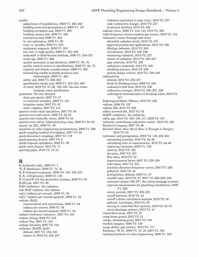
340 ASPE Plumbing Engineering Design Handbook — Volume 2
qualityappearance of installations, 2009 V1: 262–263building noise and perceptions of, 2009 V1: 187building occupants and, 2009 V1: 263building owners and, 2009 V1: 262contractors and, 2009 V1: 262in cost estimation, 2009 V1: 89costs vs. benefits, 2009 V1: 253equipment supports, 2009 V1: 258low cost vs. high quality, 2009 V1: 263–264makeshift or field-devised methods, 2009 V1: 254–257mock-ups, 2009 V1: 264quality assurance in specifications, 2009 V1: 63, 70quality control section in specifications, 2009 V1: 64, 72regional and climate considerations, 2009 V1: 262researching readily-available products and
technologies, 2009 V1: 262safety and, 2009 V1: 258–262specification clarity and, 2009 V1: 253–254, 264of water, 2010 V2: 27–28, 159–160. See also water
analysis; water purificationquantities. See also demand
clean gas agents, 2007 V3: 27in creativity checklist, 2009 V1: 227irrigation water, 2007 V3: 91water supplies, 2007 V3: 2–6
quarter-circle rotary sprinklers, 2007 V3: 94quarter-turn ball valves, 2008 V4: 83–84quarter-turn butterfly valves, 2008 V4: 84quarter-turn valves, lubricated plug cocks, 2008 V4: 84–85quarts (qt, QT), 2009 V1: 39questions in value engineering presentations, 2009 V1: 249quick-coupling method of irrigation, 2007 V3: 92quick-disconnect couplings, 2007 V3: 178quick-opening devices, 2007 V3: 9quick-response sprinklers, 2009 V1: 29quick valve closure, 2010 V2: 71quieting pipes, 2010 V2: 13–14
RR (hydraulic radii), 2009 V1: 1°R, R (Rankines), 2009 V1: 15, 30R, R (thermal resistance), 2008 V4: 105, 106–107R, R- (refrigerants), 2009 V1: 140R-13 and R-13A fire-protection systems, 2008 V4: 49R-595 gas, 2007 V3: 26RAD (radiation). See radiationrad, RAD (radians). See radiansrad/s (radians per second), 2009 V1: 34rad/s2 (radians per second squared), 2009 V1: 34radians (RAD)
measurement unit conversions, 2009 V1: 34radians per second, 2009 V1: 34radians per second squared, 2009 V1: 34
radiant emittance (exitance), 2007 V3: 184radiant energy, 2008 V4: 216radiant flux, 2007 V3: 184radiant intensity, 2007 V3: 184radiation (RADN, RAD)
defined, 2007 V3: 184–185nature of, 2010 V2: 236–237
radiation equivalent to man (rem), 2010 V2: 237rads (radioactive dosage), 2010 V2: 237treatment facilities, 2010 V2: 238
radicals (ions), 2009 V1: 134, 143, 2010 V2: 229radio frequency remote-readout gas meters, 2010 V2: 116radioactive waste drainage and vents
allowable radiation levels, 2010 V2: 237approval process and applications, 2010 V2: 238diluting radwaste, 2010 V2: 240introduction, 2010 V2: 235–236measuring radiation, 2010 V2: 237nature of radiation, 2010 V2: 236–237pipe selection, 2010 V2: 239radioactive materials, 2010 V2: 238shielding systems, 2010 V2: 238system design criteria, 2010 V2: 238–240
radioactivitydefined, 2010 V2: 236–237levels in drinking water, 2008 V4: 186radioactive half lives, 2010 V2: 238radioactive isotopes, 2010 V2: 236–237, 238radiological characteristics of drinking water, 2010 V2:
217Radiological Safety Officers, 2010 V2: 238radium, 2008 V4: 187radium 226, 2010 V2: 238radius screwed ells, 2010 V2: 93RADN (radiation). See radiationradon gas, 2010 V2: 160, 190, 217, 2008 V4: 187radwaste (waterborne radioactive waste), 2010 V2: 236Rainbird Company, 2007 V3: 96Rainfall Rates: How Much Rain Is Enough in Design?,
2010 V2: 55rainwater and precipitation, 2008 V4: 118, 259–261
calculating intensity, 2010 V2: 44–46calculating time of concentration, 2010 V2: 44–46capturing rainwater, 2009 V1: 126cisterns, 2010 V2: 162duration, 2007 V3: 231flow rates, 2010 V2: 53imperviousness factor, 2007 V3: 229–230inlet times, 2007 V3: 231intensity-duration-frequency curves, 2007 V3: 229pollution, 2010 V2: 45precipitation, defined, 2009 V1: 27rainfall rates, 2010 V2: 57, 2007 V3: 228–229, 230rainwater drains (SD, ST). See storm-drainage systemsregional requirements for plumbing installations, 2009
V1: 262return periods, 2007 V3: 230–231runoff patterns, 2010 V2: 43runoff volume calculation example, 2010 V2: 56siphonic roof drains, 2010 V2: 53storing in controlled flow systems, 2010 V2: 52–53storm-drainage systems, 2010 V2: 41
raised-floor areas, 2007 V3: 27ramp-drain grates, 2010 V2: 11ramps, swimming pools, 2007 V3: 130random hangers, 2008 V4: 140range ability (gas meters), 2010 V2: 117Rankines (°R, R), 2009 V1: 15, 30, 2007 V3: 166ranking functions in value engineering, 2009 V1: 235
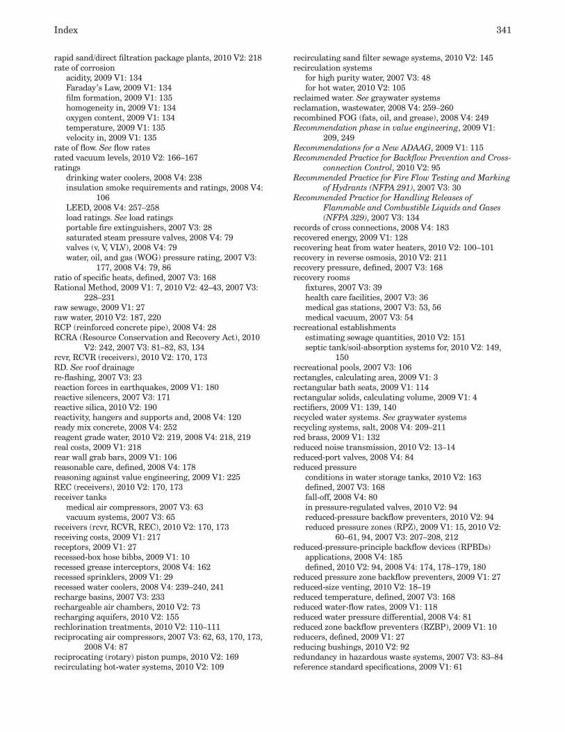
Index 341
rapid sand/direct filtration package plants, 2010 V2: 218rate of corrosion
acidity, 2009 V1: 134Faraday’s Law, 2009 V1: 134film formation, 2009 V1: 135homogeneity in, 2009 V1: 134oxygen content, 2009 V1: 134temperature, 2009 V1: 135velocity in, 2009 V1: 135
rate of flow. See flow ratesrated vacuum levels, 2010 V2: 166–167ratings
drinking water coolers, 2008 V4: 238insulation smoke requirements and ratings, 2008 V4:
106LEED, 2008 V4: 257–258load ratings. See load ratingsportable fire extinguishers, 2007 V3: 28saturated steam pressure valves, 2008 V4: 79valves (v, V, VLV), 2008 V4: 79water, oil, and gas (WOG) pressure rating, 2007 V3:
177, 2008 V4: 79, 86ratio of specific heats, defined, 2007 V3: 168Rational Method, 2009 V1: 7, 2010 V2: 42–43, 2007 V3:
228–231raw sewage, 2009 V1: 27raw water, 2010 V2: 187, 220RCP (reinforced concrete pipe), 2008 V4: 28RCRA (Resource Conservation and Recovery Act), 2010
V2: 242, 2007 V3: 81–82, 83, 134rcvr, RCVR (receivers), 2010 V2: 170, 173RD. See roof drainagere-flashing, 2007 V3: 23reaction forces in earthquakes, 2009 V1: 180reactive silencers, 2007 V3: 171reactive silica, 2010 V2: 190reactivity, hangers and supports and, 2008 V4: 120ready mix concrete, 2008 V4: 252reagent grade water, 2010 V2: 219, 2008 V4: 218, 219real costs, 2009 V1: 218rear wall grab bars, 2009 V1: 106reasonable care, defined, 2008 V4: 178reasoning against value engineering, 2009 V1: 225REC (receivers), 2010 V2: 170, 173receiver tanks
medical air compressors, 2007 V3: 63vacuum systems, 2007 V3: 65
receivers (rcvr, RCVR, REC), 2010 V2: 170, 173receiving costs, 2009 V1: 217receptors, 2009 V1: 27recessed-box hose bibbs, 2009 V1: 10recessed grease interceptors, 2008 V4: 162recessed sprinklers, 2009 V1: 29recessed water coolers, 2008 V4: 239–240, 241recharge basins, 2007 V3: 233rechargeable air chambers, 2010 V2: 73recharging aquifers, 2010 V2: 155rechlorination treatments, 2010 V2: 110–111reciprocating air compressors, 2007 V3: 62, 63, 170, 173,
2008 V4: 87reciprocating (rotary) piston pumps, 2010 V2: 169recirculating hot-water systems, 2010 V2: 109
recirculating sand filter sewage systems, 2010 V2: 145recirculation systems
for high purity water, 2007 V3: 48for hot water, 2010 V2: 105
reclaimed water. See graywater systemsreclamation, wastewater, 2008 V4: 259–260recombined FOG (fats, oil, and grease), 2008 V4: 249Recommendation phase in value engineering, 2009 V1:
209, 249Recommendations for a New ADAAG, 2009 V1: 115Recommended Practice for Backflow Prevention and Cross-
connection Control, 2010 V2: 95Recommended Practice for Fire Flow Testing and Marking
of Hydrants (NFPA 291), 2007 V3: 30Recommended Practice for Handling Releases of
Flammable and Combustible Liquids and Gases (NFPA 329), 2007 V3: 134
records of cross connections, 2008 V4: 183recovered energy, 2009 V1: 128recovering heat from water heaters, 2010 V2: 100–101recovery in reverse osmosis, 2010 V2: 211recovery pressure, defined, 2007 V3: 168recovery rooms
fixtures, 2007 V3: 39health care facilities, 2007 V3: 36medical gas stations, 2007 V3: 53, 56medical vacuum, 2007 V3: 54
recreational establishmentsestimating sewage quantities, 2010 V2: 151septic tank/soil-absorption systems for, 2010 V2: 149,
150recreational pools, 2007 V3: 106rectangles, calculating area, 2009 V1: 3rectangular bath seats, 2009 V1: 114rectangular solids, calculating volume, 2009 V1: 4rectifiers, 2009 V1: 139, 140recycled water systems. See graywater systemsrecycling systems, salt, 2008 V4: 209–211red brass, 2009 V1: 132reduced noise transmission, 2010 V2: 13–14reduced-port valves, 2008 V4: 84reduced pressure
conditions in water storage tanks, 2010 V2: 163defined, 2007 V3: 168fall-off, 2008 V4: 80in pressure-regulated valves, 2010 V2: 94reduced-pressure backflow preventers, 2010 V2: 94reduced pressure zones (RPZ), 2009 V1: 15, 2010 V2:
60–61, 94, 2007 V3: 207–208, 212reduced-pressure-principle backflow devices (RPBDs)
applications, 2008 V4: 185defined, 2010 V2: 94, 2008 V4: 174, 178–179, 180
reduced pressure zone backflow preventers, 2009 V1: 27reduced-size venting, 2010 V2: 18–19reduced temperature, defined, 2007 V3: 168reduced water-flow rates, 2009 V1: 118reduced water pressure differential, 2008 V4: 81reduced zone backflow preventers (RZBP), 2009 V1: 10reducers, defined, 2009 V1: 27reducing bushings, 2010 V2: 92redundancy in hazardous waste systems, 2007 V3: 83–84reference standard specifications, 2009 V1: 61

342 ASPE Plumbing Engineering Design Handbook — Volume 2
referencesbioremediation systems, 2008 V4: 253cold water systems, 2010 V2: 95–96compressed air systems, 2007 V3: 179conserving energy, 2009 V1: 128cross connections, 2008 V4: 179designing for people with disabilities, 2009 V1: 115fire-protection systems, 2007 V3: 29–30formulae, symbols, and terminology, 2009 V1: 39gasoline and diesel-oil systems, 2007 V3: 151graywater systems, 2010 V2: 29grease interceptors, 2008 V4: 166green plumbing, 2008 V4: 265health care facilities, 2007 V3: 78–79irrigation systems, 2007 V3: 96piping insulation, 2008 V4: 116sanitary drainage systems, 2010 V2: 19seismic protection, 2009 V1: 185special-waste drainage systems, 2010 V2: 246steam and condensate systems, 2007 V3: 162thermal expansion, 2008 V4: 235vacuum systems, 2010 V2: 186water treatment and purification, 2010 V2: 224–225,
2008 V4: 224references section in specifications, 2009 V1: 63, 69reflecting pools
defined, 2009 V1: 27design, 2007 V3: 99flow rates, 2007 V3: 101overview, 2007 V3: 99
reformatories, numbers of fixtures for, 2008 V4: 19refrigerant after-coolers, 2007 V3: 171refrigerants (R, R-), 2009 V1: 140refrigerated air dryers, 2007 V3: 172, 175refrigeration loads, 2008 V4: 245, 246refrigeration mechanical rooms, 2009 V1: 158refrigeration piping, 2008 V4: 31, 32refrigeration systems
centralized chilled water systems, 2008 V4: 244–245, 246
heat reclamation, 2009 V1: 123waste heat usage, 2009 V1: 123, 124water coolers, 2008 V4: 242
regenerable ion exchange, 2010 V2: 205regenerants, dealkalizing and, 2010 V2: 199regeneration controls on ion exchangers, 2008 V4: 198regeneration cycle
in dealkalizing, 2010 V2: 199defined, 2008 V4: 224in deionizing, 2010 V2: 206–208, 207in demineralizers, 2007 V3: 48, 2008 V4: 195in ion exchange, 2010 V2: 208, 2008 V4: 198salt recycling, 2008 V4: 211service deionization, 2008 V4: 195sodium chloride usage, 2008 V4: 199in water softeners, 2010 V2: 210, 2008 V4: 206, 209
regenerative diatomaceous earth filters, 2007 V3: 118–119regenerative pumps (turbines), 2008 V4: 98–99regional authorities, 2010 V2: 227regional requirements for plumbing installations, 2009 V1:
262registers in fuel dispensers, 2007 V3: 143
regulated substances, 2007 V3: 133regulations. See codes and standardsregulator relief vents, 2010 V2: 121regulators, 2009 V1: 27. See also specific types of
regulatorsregulators, propane, 2010 V2: 132–133Rehabilitation Act of 1973 (93-112), 2009 V1: 98Reid, D., 2008 V4: 224reinforced concrete pipe (RCP), 2008 V4: 28reinforced thermosetting resin pipe (RTRP), 2008 V4: 56reinforcing ribs in tanks, 2007 V3: 135reject stream from reverse osmosis, 2010 V2: 211relative discharge curves, 2007 V3: 203relative humidity (rh, RH), 2009 V1: 15, 2007 V3: 167, 170Relative Resistance of Escherichin coli and Eberthella
thyphosa to Chlorine and Chloramines, 2008 V4: 224
relative velocity, 2008 V4: 154relay interface controls, 2007 V3: 68reliability of water supplies, 2007 V3: 3, 6relief valves
centralized drinking-water systems, 2008 V4: 246fire pumps, 2007 V3: 22gas regulators, 2007 V3: 237hot-water systems, 2010 V2: 106, 2008 V4: 231propane tanks, 2010 V2: 133sizing, 2010 V2: 106water-pressure regulators and, 2008 V4: 81
Relief Valves for Hot Water Supply Systems, 2010 V2: 112relief vents
defined, 2009 V1: 27gas regulator relief vents, 2010 V2: 117–118gas systems, 2010 V2: 121gas trains, 2007 V3: 237offsets, 2010 V2: 37
remote-control irrigation valves, 2007 V3: 94remote earth (remote electrodes), 2009 V1: 143remote electrodes, 2009 V1: 143remote fill ports, 2007 V3: 136, 145remote leakage from tanks, 2007 V3: 140–141remote portions of fire design areas, 2007 V3: 12remote-readout gas meters, 2010 V2: 116remote-readout water meters, 2010 V2: 60remote secondary-containment enclosures, 2007 V3: 145remote water coolers, 2008 V4: 238removal ratios for grease interceptors, 2008 V4: 157Remove Organics by Activated Carbon Adsorption, 2010
V2: 225rems (radiation equivalent to man), 2010 V2: 237renovations, cost estimating and, 2009 V1: 90repetition in value engineering presentations, 2009 V1:
249replacements for Halon gases, 2007 V3: 26Report on Hydraulics and Pneumatics of Plumbing
Drainage Systems, 2010 V2: 19reports
cross connections, 2008 V4: 183physical condition of buildings, 2009 V1: 267–269
research facilities, radiation in, 2010 V2: 238Research Report: Water Reuse Standards and Verification
Protocol, 2010 V2: 29researching new technologies and products, 2009 V1: 262
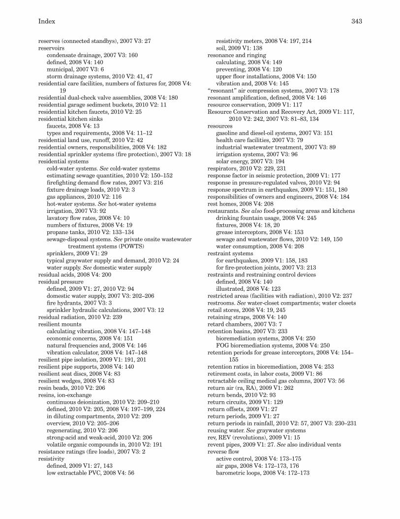
Index 343
reserves (connected standbys), 2007 V3: 27reservoirs
condensate drainage, 2007 V3: 160defined, 2008 V4: 140municipal, 2007 V3: 6storm drainage systems, 2010 V2: 41, 47
residential care facilities, numbers of fixtures for, 2008 V4: 19
residential dual-check valve assemblies, 2008 V4: 180residential garage sediment buckets, 2010 V2: 11residential kitchen faucets, 2010 V2: 25residential kitchen sinks
faucets, 2008 V4: 13types and requirements, 2008 V4: 11–12
residential land use, runoff, 2010 V2: 42residential owners, responsibilities, 2008 V4: 182residential sprinkler systems (fire protection), 2007 V3: 18residential systems
cold-water systems. See cold-water systemsestimating sewage quantities, 2010 V2: 150–152firefighting demand flow rates, 2007 V3: 216fixture drainage loads, 2010 V2: 3gas appliances, 2010 V2: 116hot-water systems. See hot-water systemsirrigation, 2007 V3: 92lavatory flow rates, 2008 V4: 10numbers of fixtures, 2008 V4: 19propane tanks, 2010 V2: 133–134sewage-disposal systems. See private onsite wastewater
treatment systems (POWTS)sprinklers, 2009 V1: 29typical graywater supply and demand, 2010 V2: 24water supply. See domestic water supply
residual acids, 2008 V4: 200residual pressure
defined, 2009 V1: 27, 2010 V2: 94domestic water supply, 2007 V3: 202–206fire hydrants, 2007 V3: 3sprinkler hydraulic calculations, 2007 V3: 12
residual radiation, 2010 V2: 239resilient mounts
calculating vibration, 2008 V4: 147–148economic concerns, 2008 V4: 151natural frequencies and, 2008 V4: 146vibration calculator, 2008 V4: 147–148
resilient pipe isolation, 2009 V1: 191, 201resilient pipe supports, 2008 V4: 140resilient seat discs, 2008 V4: 83resilient wedges, 2008 V4: 83resin beads, 2010 V2: 206resins, ion-exchange
continuous deionization, 2010 V2: 209–210defined, 2010 V2: 205, 2008 V4: 197–199, 224in diluting compartments, 2010 V2: 209overview, 2010 V2: 205–206regenerating, 2010 V2: 206strong-acid and weak-acid, 2010 V2: 206volatile organic compounds in, 2010 V2: 191
resistance ratings (fire loads), 2007 V3: 2resistivity
defined, 2009 V1: 27, 143low extractable PVC, 2008 V4: 56
resistivity meters, 2008 V4: 197, 214soil, 2009 V1: 138
resonance and ringingcalculating, 2008 V4: 149preventing, 2008 V4: 120upper floor installations, 2008 V4: 150vibration and, 2008 V4: 145
“resonant” air compression systems, 2007 V3: 178resonant amplification, defined, 2008 V4: 146resource conservation, 2009 V1: 117Resource Conservation and Recovery Act, 2009 V1: 117,
2010 V2: 242, 2007 V3: 81–83, 134resources
gasoline and diesel-oil systems, 2007 V3: 151health care facilities, 2007 V3: 79industrial wastewater treatment, 2007 V3: 89irrigation systems, 2007 V3: 96solar energy, 2007 V3: 194
respirators, 2010 V2: 229, 231response factor in seismic protection, 2009 V1: 177response in pressure-regulated valves, 2010 V2: 94response spectrum in earthquakes, 2009 V1: 151, 180responsibilities of owners and engineers, 2008 V4: 184rest homes, 2008 V4: 208restaurants. See also food-processing areas and kitchens
drinking fountain usage, 2008 V4: 245fixtures, 2008 V4: 18, 20grease interceptors, 2008 V4: 153sewage and wastewater flows, 2010 V2: 149, 150water consumption, 2008 V4: 208
restraint systemsfor earthquakes, 2009 V1: 158, 183for fire-protection joints, 2007 V3: 213
restraints and restraining control devicesdefined, 2008 V4: 140illustrated, 2008 V4: 123
restricted areas (facilities with radiation), 2010 V2: 237restrooms. See water-closet compartments; water closetsretail stores, 2008 V4: 19, 245retaining straps, 2008 V4: 140retard chambers, 2007 V3: 7retention basins, 2007 V3: 233
bioremediation systems, 2008 V4: 250FOG bioremediation systems, 2008 V4: 250
retention periods for grease interceptors, 2008 V4: 154–155
retention ratios in bioremediation, 2008 V4: 253retirement costs, in labor costs, 2009 V1: 86retractable ceiling medical gas columns, 2007 V3: 56return air (ra, RA), 2009 V1: 262return bends, 2010 V2: 93return circuits, 2009 V1: 129return offsets, 2009 V1: 27return periods, 2009 V1: 27return periods in rainfall, 2010 V2: 57, 2007 V3: 230–231reusing water. See graywater systemsrev, REV (revolutions), 2009 V1: 15revent pipes, 2009 V1: 27. See also individual ventsreverse flow
active control, 2008 V4: 173–175air gaps, 2008 V4: 172–173, 176barometric loops, 2008 V4: 172–173

344 ASPE Plumbing Engineering Design Handbook — Volume 2
causes, 2008 V4: 170–171passive control, 2008 V4: 172–173vacuum breakers, 2008 V4: 173–174, 175, 176water distribution hazards, 2008 V4: 171–172
reverse osmosis (RO)applications, 2008 V4: 219cartridges, 2010 V2: 194continuous deionization and, 2010 V2: 210defined, 2010 V2: 211–213, 2008 V4: 195–196drinking-water coolers, 2008 V4: 243health care facilities, 2007 V3: 48history and current technology, 2008 V4: 217laboratory grade water comparison, 2008 V4: 218membrane configurations, 2010 V2: 211–212membrane selection, 2010 V2: 213overview, 2008 V4: 216–217polishing systems, 2008 V4: 219polymer membranes, 2010 V2: 213silica and, 2010 V2: 190small drinking water systems, 2010 V2: 218VOCs in membranes, 2010 V2: 191water problems, 2008 V4: 187water quality, 2008 V4: 217–219water softening pretreatment, 2008 V4: 206water supply (RO), 2009 V1: 8
Reverse Osmosis and Nanofiltration System Design, 2010 V2: 224
Reverse Osmosis Membrane Research, 2008 V4: 224reverse-trap water closets, 2008 V4: 3reversible potential, defined, 2009 V1: 143revolutions (rev, REV)
revolutions per minute (rpm, RPM), 2009 V1: 15revolutions per second (rps, RPS), 2009 V1: 15
Reynold’s number for turbulence, 2009 V1: 2, 2010 V2: 74–75, 77, 2008 V4: 154
RF remote-readout gas meters, 2010 V2: 116RFP (fiberglass reinforced plastic), 2010 V2: 78, 94rgh, RGH (roughness). See roughness of pipesrh, RH (relative humidity). See relative humidityRHO (density). See densityrhomboids, calculating area, 2009 V1: 4rhombuses, calculating area, 2009 V1: 3RI (Ryzner stability index), 2010 V2: 196Richardson, D.W., Sr., 2010 V2: 224rigging, 2008 V4: 140right-angle triangles, calculating area, 2009 V1: 4rigid braces, 2008 V4: 140rigid ceiling medical gas columns, 2007 V3: 56rigid cellular urethane, 2008 V4: 111rigid hangers, 2008 V4: 140rigid pipes
expansion of, 2008 V4: 230plastic piping, 2007 V3: 147
rigid supports, 2008 V4: 140rim top test, 2008 V4: 5rims
defined, 2009 V1: 27on urinals, 2009 V1: 108rim top test, 2008 V4: 5water closets, 2008 V4: 4–5
ring bands, 2008 V4: 140ring buoys, 2007 V3: 131
ring hangers and supports, 2008 V4: 126ring-securing methods around drains, 2010 V2: 16ringing in pipes. See resonance and ringingrinsing in regeneration cycle, 2010 V2: 206, 208, 2008 V4:
224ripraps, 2009 V1: 27riser clamps, 2009 V1: 194, 2008 V4: 121, 123, 126, 140riser hangers, 2008 V4: 140riser-mounted sprinklers, 2007 V3: 93risers
bracing, 2009 V1: 161, 171checklists, 2009 V1: 94defined, 2009 V1: 27, 2007 V3: 78, 2008 V4: 140earthquake protection and joints, 2009 V1: 161hangers and supports, 2008 V4: 67natural gas piping, 2010 V2: 131noise mitigation, 2009 V1: 191riser clamps, 2008 V4: 121, 123, 140riser down (elbows), 2009 V1: 10riser hangers, 2008 V4: 140riser-mounted sprinklers, 2007 V3: 93riser up (elbows), 2009 V1: 11symbols for, 2009 V1: 12thermal expansion and contraction, 2008 V4: 228
rises or drops, 2009 V1: 11rising stems (RS), 2008 V4: 74
with inside screws, 2008 V4: 79with outside screws, 2008 V4: 79
Risk Guides in value engineering, 2009 V1: 248rivers
cross contamination case, 2008 V4: 189piping systems near, 2008 V4: 120
riveted steel piping, 2010 V2: 75, 78rms (root main square), 2009 V1: 15RNA materials, 2008 V4: 215RO (reverse osmosis). See reverse osmosisroadblocks to creativity, 2009 V1: 225rock salt, 2010 V2: 210rod couplings, 2008 V4: 140rod hangers, 2008 V4: 140rod stiffeners, 2008 V4: 127, 140Rodie, E. R., 2008 V4: 166rods and anchors, 2008 V4: 127, 140Roentgens, 2010 V2: 237roll and plate devices, 2008 V4: 140roll hangers, 2008 V4: 140roll-in shower compartments, 2009 V1: 110–111roll plates, 2008 V4: 140roll stands, 2008 V4: 140roll trapezes, 2008 V4: 140rollers, 2008 V4: 67, 68, 123roof drainage
as source of plumbing noise, 2009 V1: 188avoiding septic tank disposal, 2010 V2: 147controlled flow systems, 2010 V2: 52–53limited-discharge roof drains, 2007 V3: 233RD abbreviation, 2009 V1: 15roof drain sizes, 2010 V2: 54roof drains, defined, 2009 V1: 27siphonic roof drains, 2010 V2: 53storm water systems, 2010 V2: 41
roofing
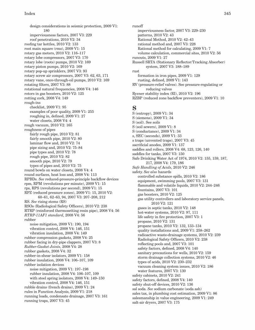
Index 345
design considerations in seismic protection, 2009 V1: 180
imperviousness factors, 2007 V3: 229roof penetrations, 2010 V2: 34
roofing tar kettles, 2010 V2: 133root main square (rms), 2009 V1: 15rotary gas meters, 2010 V2: 116–117rotary lobe compressors, 2007 V3: 170rotary lobe (roots) pumps, 2010 V2: 169rotary piston pumps, 2010 V2: 169rotary pop-up sprinklers, 2007 V3: 93rotary screw air compressors, 2007 V3: 62, 63, 171rotary vane, once-through-oil pumps, 2010 V2: 169rotating filters, 2007 V3: 88rotational natural frequencies, 2008 V4: 146rotors in gas boosters, 2010 V2: 125rotting cork, 2008 V4: 149rough-ins
checklist, 2009 V1: 95examples of poor quality, 2009 V1: 255roughing in, defined, 2009 V1: 27water closets, 2008 V4: 4
rough vacuum, 2010 V2: 165roughness of pipes
fairly rough pipe, 2010 V2: 81fairly smooth pipe, 2010 V2: 80laminar flow and, 2010 V2: 74pipe sizing and, 2010 V2: 75–84pipe types and, 2010 V2: 78rough pipe, 2010 V2: 82smooth pipe, 2010 V2: 79types of pipes and, 2010 V2: 75
round bowls on water closets, 2008 V4: 4round surfaces, heat loss and, 2008 V4: 113RPBDs. See reduced-pressure-principle backflow devicesrpm, RPM (revolutions per minute), 2009 V1: 15rps, RPS (revolutions per second), 2009 V1: 15RPZ (reduced pressure zones), 2009 V1: 15, 2010 V2:
60–61, 62–63, 94, 2007 V3: 207–208, 212RS. See rising stems (RS)RSOs (Radiological Safety Officers), 2010 V2: 238RTRP (reinforced thermosetting resin pipe), 2008 V4: 56RTRP-11AF1 standard, 2008 V4: 56rubber
noise mitigation, 2009 V1: 190, 194vibration control, 2008 V4: 146, 151vibration insulation, 2008 V4: 149
rubber compression gaskets, 2008 V4: 25rubber facing in dry-pipe clappers, 2007 V3: 8Rubber-Gasket Joints, 2008 V4: 28rubber gaskets, 2008 V4: 32rubber-in-shear isolators, 2009 V1: 158rubber insulation, 2008 V4: 106–107, 109rubber isolation devices
noise mitigation, 2009 V1: 197–198rubber insulation, 2008 V4: 106–107, 109with steel spring isolators, 2008 V4: 149–150vibration control, 2008 V4: 146, 151
rubble drains (french drains), 2009 V1: 24rules in Function Analysis, 2009 V1: 218running loads, condensate drainage, 2007 V3: 161running traps, 2007 V3: 45
runoffimperviousness factor, 2007 V3: 229–230patterns, 2010 V2: 43Rational Method, 2010 V2: 42–43rational method and, 2007 V3: 228Rational method for calculating, 2009 V1: 7volume calculation, commercial sites, 2010 V2: 56
runouts, 2009 V1: 27Russell SRTA (Stationary Reflector/Tracking Absorber)
system, 2007 V3: 188–189rust
formation in iron pipes, 2009 V1: 129rusting, defined, 2009 V1: 143
RV (pressure-relief valves). See pressure-regulating or reducing valves
Ryzner stability index (RI), 2010 V2: 196RZBP (reduced zone backflow preventers), 2009 V1: 10
SS (entropy), 2009 V1: 34S (siemens), 2009 V1: 34S (soil). See soilsS (soil sewers), 2009 V1: 8S (conductance), 2009 V1: 34s, SEC (seconds), 2009 V1: 33s traps (unvented traps), 2007 V3: 45sacrificial anodes, 2009 V1: 137saddles and rollers, 2008 V4: 68, 123, 126, 140saddles for tanks, 2007 V3: 150Safe Drinking Water Act of 1974, 2010 V2: 155, 159, 187,
217, 2008 V4: 179, 186Safe Handling of Acids, 2010 V2: 246safety. See also hazards
controlled substance spills, 2010 V2: 186equipment, swimming pools, 2007 V3: 131flammable and volatile liquids, 2010 V2: 244–246fountains, 2007 V3: 101gas boosters, 2010 V2: 125gas utility controllers and laboratory service panels,
2010 V2: 121gases in septic tanks, 2010 V2: 148hot-water systems, 2010 V2: 97, 111life safety in fire protection, 2007 V3: 1propane, 2010 V2: 131propane tanks, 2010 V2: 132, 133–134quality installations and, 2009 V1: 258–262radioactive waste-drainage systems, 2010 V2: 239Radiological Safety Officers, 2010 V2: 238reflecting pools and, 2007 V3: 101safety factors, defined, 2008 V4: 140sanitary precautions for wells, 2010 V2: 159storm drainage collection systems, 2010 V2: 46types of acids, 2010 V2: 230–232vacuum cleaning system issues, 2010 V2: 186water features, 2007 V3: 130
safety cabinets, 2010 V2: 241safety factors, defined, 2008 V4: 140safety shut-off devices, 2010 V2: 136sal soda. See sodium carbonate (soda ash)sales tax, in plumbing cost estimation, 2009 V1: 86salesmanship in value engineering, 2009 V1: 249salt-air dryers, 2007 V3: 175

346 ASPE Plumbing Engineering Design Handbook — Volume 2
salt-laden air, 2009 V1: 262salt splitting, 2010 V2: 199salt water, 2008 V4: 120salts. See also sodium chloride
defined, 2008 V4: 224in distilled water, 2008 V4: 212ions in reverse osmosis, 2010 V2: 187in irrigation water, 2007 V3: 91nanofiltration, 2008 V4: 220recycling systems, water softeners, 2008 V4: 209–211storage, 2008 V4: 211water hardness and, 2008 V4: 196water purity and, 2008 V4: 195water softener consumption, 2008 V4: 206–207, 209
samplesacid wastes, 2007 V3: 45infectious waste systems, 2010 V2: 242radioactive waste effluent, 2010 V2: 240
sampling manholes, 2007 V3: 45SAN (sanitary sewers), 2009 V1: 8, 28. See also sanitary
drainage systemsSan Diego Gas & Electric Company, 2009 V1: 128San Fernando Earthquake, 2009 V1: 152sand filters, 2007 V3: 112–113, 115–116sand filtration
drinking water, 2010 V2: 159–160, 218earthquake damage to filters, 2009 V1: 152horizontal pressure sand filters, 2008 V4: 202laboratory water, 2010 V2: 201pure water systems, 2010 V2: 221sand filters defined, 2009 V1: 28sewage treatment, 2010 V2: 145swimming pools, 2007 V3: 108vertical pressure sand filters, 2008 V4: 203
sand points, 2010 V2: 157sands
graywater irrigation systems and, 2010 V2: 25imperviousness factors, 2007 V3: 229porous soils, 2007 V3: 91–92, 96in soil texture, 2010 V2: 140storm water infiltration, 2010 V2: 48
sanistans, 2007 V3: 40sanitary building drains. See also sanitary drainage
systemsas source of plumbing noise, 2009 V1: 188cast-iron soil pipe, 2008 V4: 23
sanitary, defined, 2009 V1: 28sanitary drain system pumps, 2008 V4: 100sanitary drainage fitting codes, 2009 V1: 44sanitary drainage systems
alternative disposal methods, 2007 V3: 221alternative systems, 2010 V2: 16–19building sewers (house drains), 2010 V2: 14–15, 2008
V4: 23codes and standards, 2010 V2: 1components, 2010 V2: 8–12, 2007 V3: 217–220connections, 2007 V3: 218, 221defined, 2010 V2: 1drainage loads, 2010 V2: 3drainage structures, 2007 V3: 217–220fittings, 2009 V1: 44fixture discharge characteristics, 2010 V2: 3
floor leveling around drains, 2010 V2: 16flow in, 2010 V2: 1–2force mains
connections, 2007 V3: 226sizing, 2007 V3: 221sizing ejector pumps and pits, 2007 V3: 220–221
graywater systems and, 2010 V2: 27–28grease interceptors and, 2008 V4: 162health care facilities, 2007 V3: 42–46joining methods, 2010 V2: 13–14kitchen areas, 2010 V2: 15laboratories, 2007 V3: 43–46materials for, 2010 V2: 13overview, 2007 V3: 217pipes, 2009 V1: 44pneumatic pressures in, 2010 V2: 2–3preliminary information, 2007 V3: 197–198protection from damage, 2010 V2: 16Provent systems, 2010 V2: 17–18public sewer availability, 2007 V3: 217reduced-size venting, 2010 V2: 18–19sample letters, 2007 V3: 217sanitary sewers (SAN, SS), 2009 V1: 8, 28sanitation and cleaning, 2010 V2: 15self-cleansing velocities, 2010 V2: 7single-stack systems, 2010 V2: 18sizing, 2007 V3: 216–217sloping drain capacities, 2010 V2: 5–8Sovent systems, 2010 V2: 17–18stack capacities, 2010 V2: 3–5supports, 2010 V2: 12thermal expansion, 2010 V2: 16trenching and bedding, 2007 V3: 217–218, 219vacuum drainage systems, 2010 V2: 19waterproofing, 2010 V2: 15–16
sanitary fixture units (SFU), 2009 V1: 15sanitary joints, 2007 V3: 48–50sanitary sewer pipe codes, 2009 V1: 44sanitary sewer systems. See sanitary drainage systemssanitary tees
flow capacity and, 2010 V2: 4water closet installation, 2008 V4: 6
sanitaryware. See fixturessanitation. See also cleanouts
feed water, 2010 V2: 195fixture materials and, 2008 V4: 1floor drains, 2008 V4: 16precautions for wells, 2010 V2: 159sanitary seals on wells, 2010 V2: 156stainless steel piping, 2008 V4: 59underdeveloped nations, 2008 V4: 255–256water softeners, 2010 V2: 211
sanitizer levels, swimming pools, 2007 V3: 123sanitizers, 2007 V3: 40sanitizers/oxidizers
feed system, 2007 V3: 126–127ozone system, 2007 V3: 129UV system, 2007 V3: 129–130
Sansone, John T., 2010 V2: 55SARA Title III Act (Superfund Amendment and
Reauthorization Act of 1986), 2007 V3: 134sasol, 2010 V2: 114
Index 347
sat., SAT (saturation). See saturationsaturated air and vapor mixtures, 2007 V3: 168saturated steam
defined, 2007 V3: 153–154pressure, 2007 V3: 155–157valve ratings, 2008 V4: 79
saturated vapor pressure, 2007 V3: 168saturation (sat., SAT)
defined, 2007 V3: 168of soils, 2010 V2: 141of water with calcium carbonate, 2010 V2: 196
saturation pressure, 2007 V3: 168SAVE. See Society of American Value Engineeringsawcutting trenches, labor productivity rates, 2009 V1: 87Saybolt Seconds Furol (ssf, SSF), 2007 V3: 134Saybolt Seconds Universal (ssu, SSU), 2007 V3: 134SBCCI (Southern Building Code Congress International,
Inc.), 2007 V3: 134SBR (styrene butadiene), 2009 V1: 32SC (sillcocks), 2009 V1: 15scalars, defined, 2009 V1: 85scalding water, 2010 V2: 97, 111, 2008 V4: 113scale and scale formation
boilers, 2010 V2: 215chlorides and sulfates, 2010 V2: 190cooling towers, 2010 V2: 217distilled water and, 2008 V4: 212fixtures and appliances, 2008 V4: 205hardness and, 2010 V2: 189, 2008 V4: 196impure water and, 2008 V4: 194Langelier saturation index, 2010 V2: 196magnesium and, 2010 V2: 190predicting water deposits and corrosion, 2010 V2:
196–197removing with water softening, 2010 V2: 210Ryzner stability index, 2010 V2: 196in stills, 2008 V4: 213temperature and, 2008 V4: 205total dissolved solids and, 2010 V2: 193water deposits and corrosion, 2010 V2: 195–196water piping systems, 2010 V2: 160
scale plates, 2008 V4: 140scanning electron microscopy, 2010 V2: 188. See also
electron microscopesscavenging adapters, 2007 V3: 66–67scfh (standard cfh), 2010 V2: 126scfm, SCFM (standard cubic feet per minute)
ambient free air and, 2010 V2: 166compressed air pipe sizing, 2007 V3: 177compressed air tools, 2007 V3: 175defined, 2007 V3: 78, 169medical air compressors, 2007 V3: 62, 63medical vacuum systems, 2007 V3: 64–65
scfs, SCFS (cubic feet per second), 2009 V1: 34Schedule 10 steel pipe, 2008 V4: 48Schedule 40 ABS pipe, 2008 V4: 54Schedule 40 plastic pipe, 2008 V4: 62Schedule 40 polypropylene pipe, 2008 V4: 54Schedule 40 polyvinyl pipe, 2008 V4: 53Schedule 40 PVC plastic, 2007 V3: 13, 2008 V4: 53Schedule 40 PVDF pipe, 2008 V4: 55Schedule 40 steel pipe, 2008 V4: 44–45
Schedule 80 ABS pipe, 2008 V4: 54Schedule 80 plastic pipe, 2008 V4: 62Schedule 80 polypropylene pipe, 2008 V4: 54Schedule 80 polyvinyl pipe, 2008 V4: 53Schedule 80 PVC plastic, 2008 V4: 53Schedule 80 PVC plastic pipe, 2008 V4: 213Schedule 80 PVDF pipe, 2008 V4: 55Schedule 80 steel pipe, 2008 V4: 46–47schedules (pipe size), 2009 V1: 28schedules (project)
checklist, 2009 V1: 94–95section in specifications, 2009 V1: 64, 70, 72
school laboratories. See laboratoriesschools
hot water demand, 2010 V2: 99laboratory gas systems, 2010 V2: 121numbers of fixtures for, 2008 V4: 18, 21septic tank systems for, 2010 V2: 149, 150shower room grates, 2010 V2: 11swimming pools and, 2007 V3: 107vacuum calculations for, 2010 V2: 180water consumption, 2008 V4: 208, 245
Schueler, Thomas R., 2010 V2: 55scope lines, 2009 V1: 219scoring pipes and equipment, 2008 V4: 194screening
in graywater treatment, 2010 V2: 25vacuum exhaust piping, 2010 V2: 184
screw compressors, 2007 V3: 170, 173screw pumps, 2010 V2: 169screwed bonnets, 2008 V4: 74, 79screwed ells, 2010 V2: 93screwed ends of valves, 2008 V4: 79screwed fittings, 2009 V1: 152screwed-lug type valves, 2008 V4: 77screwed mechanical joints, 2010 V2: 232screwed tees, 2010 V2: 93screwed union-ring bonnets, 2008 V4: 79scrub-up sinks, 2007 V3: 36, 38–39, 40scum in septic tanks, 2010 V2: 145scuppers, 2009 V1: 28, 2010 V2: 52SCW (soft cold water), 2009 V1: 8SD (storm or rainwater drains). See storm-drainage
systemsSDI (service deionization), 2008 V4: 195SDI (silt density index), 2010 V2: 194SDR (standard dimension ratio)
abbreviation for, 2009 V1: 15HDPE pipe, 2008 V4: 51SDR21 PVC pipe, 2008 V4: 53SDR26 PVC pipe, 2008 V4: 53
SE (sea level). See sea levelsea level (sl, SL, SE)
atmospheric pressure, 2007 V3: 169vacuum ratings, 2010 V2: 166
sealed sprinklers, 2007 V3: 8sealing grouts in wells, 2010 V2: 158seals
butterfly valve seals, 2008 V4: 86elastomeric seals or gaskets, 2008 V4: 229flashing rings, 2010 V2: 11floor drains in infectious waste systems, 2010 V2: 242

348 ASPE Plumbing Engineering Design Handbook — Volume 2
pumps, 2008 V4: 94seal liquids in vacuum pumps, 2010 V2: 170trap seals in floor drains, 2010 V2: 11water closets, 2008 V4: 6well fixtures, 2010 V2: 158
seamless copper pipe, 2008 V4: 30–32seamless copper water tube, 2008 V4: 30–42seamless steel piping, 2008 V4: 48seasonal flow rates, 2008 V4: 207seats
accessible shower compartments, 2009 V1: 112bathtub and shower seats, 2009 V1: 109, 114–115seat fouling tests, 2008 V4: 5toilets, 2009 V1: 108water closets, 2008 V4: 5
seats (valves)gate valves, 2008 V4: 83globe/angle-globe valves, 2008 V4: 83seat erosion, 2008 V4: 75–76seat tests, 2008 V4: 89
seawater, 2009 V1: 141second-guessing designs, 2009 V1: 208second-stage propane regulators, 2010 V2: 132–133secondary containment
of hazardous wastes, 2007 V3: 83–84of infectious wastes, 2010 V2: 240
secondary containment tanksaboveground types, 2007 V3: 144–145interstitial monitoring, 2007 V3: 139–140interstitial spaces, 2007 V3: 136underground tanks, 2007 V3: 135
secondary functions, 2009 V1: 219, 223secondary gas regulators, 2010 V2: 121secondary pipe liquid monitoring, 2007 V3: 141secondary pipe vapor monitoring, 2007 V3: 141secondary roof drains, 2009 V1: 28secondary storm-drainage systems
controlled-flow systems, 2010 V2: 52–53planning for in design, 2010 V2: 52scuppers, 2010 V2: 52
seconds (s, SEC), 2009 V1: 33Seconds Redwood, 2007 V3: 134Seconds Saybolt Furol (SSF), 2007 V3: 134Seconds Saybolt Universal (SSU), 2007 V3: 134sectional modulus, 2008 V4: 228Sectionformat, 2009 V1: 59, 62–65sections
in Manual of Practice, 2009 V1: 68–72MasterFormat 2004, 2009 V1: 59–60of pump equipment, 2010 V2: 161in specifications, 2009 V1: 62–65
security of oxygen storage areas, 2007 V3: 60sediment
removing, 2010 V2: 198–199in water, 2010 V2: 188
sediment bucketskitchen drains, 2010 V2: 15–16materials, 2010 V2: 13in oil collectors, 2010 V2: 12in sanitary drainage systems, 2010 V2: 11
sedimentationbioremediation systems, 2008 V4: 250
in graywater treatment, 2010 V2: 25turbidity and, 2008 V4: 196in water treatment, 2010 V2: 198–199
Sedimentation and the Design of Settling Tanks, 2008 V4: 166
seepage beds. See soil-absorption sewage systemsseepage flanges, 2010 V2: 15–16seepage pits, 2009 V1: 28, 2010 V2: 25, 2007 V3: 221seiches, 2009 V1: 149seismic, defined, 2009 V1: 185seismic control devices, 2009 V1: 190, 2008 V4: 140seismic design categories, 2009 V1: 157Seismic Design for Buildings, 2009 V1: 174, 185seismic forces, hangers and supports, 2008 V4: 67, 119seismic joints, crossing, 2009 V1: 152seismic loads, 2008 V4: 140seismic pipe clamps, 2008 V4: 121seismic protection
air compressors and, 2007 V3: 179calculating seismic forces, 2009 V1: 179–180causes and effects of earthquakes, 2009 V1: 148–149codes and standards, 2009 V1: 147, 174computer analysis of piping systems, 2009 V1: 180damage from earthquakes, 2009 V1: 149design considerations, 2009 V1: 180–182earthquake measurement and seismic design, 2009 V1:
151–152equipment protection, 2009 V1: 153–158glossary, 2009 V1: 185introduction, 2009 V1: 145–148learning from past earthquakes, 2009 V1: 152–153pipe restraints, 2009 V1: 158–179, 2010 V2: 12, 16,
2007 V3: 20plumbing equipment, 2009 V1: 262potential problems, 2009 V1: 183references, 2009 V1: 185seismic loads, defined, 2009 V1: 145seismic risk maps, 2009 V1: 145–146underground storage tanks and, 2007 V3: 135
Seismic Restraint Manual Guidelines for Mechanical Systems, 2009 V1: 185
selective attack corrosion, 2009 V1: 131–132selective surfaces, 2007 V3: 185selectivity coefficients, 2010 V2: 205selenium, 2008 V4: 186, 187self-bracing problems in seismic protection, 2009 V1: 184self-cleansing velocities, 2010 V2: 7self-closing valves, 2007 V3: 35self-contained breathing units, 2010 V2: 229, 231self-contained fountains, 2007 V3: 99Self-Contained Mechanically-Refrigerated Drinking Water
Coolers, 2008 V4: 243self-extinguishing, defined, 2009 V1: 28self-jetting well points, 2010 V2: 157self-metering faucets, 2008 V4: 13self-priming pumps, 2007 V3: 108, 119self-regulating heat-trace systems, 2010 V2: 105–106self-scouring velocity in sewers, 2007 V3: 217self-siphonage, 2010 V2: 2self-venting in Provent systems, 2010 V2: 17–18self-venting in Sovent systems, 2010 V2: 17–18selling functions, 2009 V1: 218

Index 349
SEMI (Semiconductor Equipment and Materials Institute), 2010 V2: 187, 218
semi-ambulatory individualssemi-ambulatory disabilities, 2009 V1: 99water closet requirements, 2009 V1: 108
semi-automatic grease interceptors, 2008 V4: 159semi-circular lavatories, 2008 V4: 10semi-engineered drawings, 2008 V4: 141semi-engineered hanger assemblies, 2008 V4: 141semi-instantaneous water heaters, 2010 V2: 104semi-permeable membranes, 2007 V3: 48, 2008 V4: 217,
219semi-plug disc assemblies, 2008 V4: 83semi-recessed water coolers, 2008 V4: 240, 241Semiconductor Equipment and Materials Institute, 2010
V2: 187, 218Sendelbach, M.G., 2010 V2: 225seniors. See elderlysensible heat (SH)
defined, 2009 V1: 128, 2007 V3: 153heat transfer efficiency and, 2007 V3: 158
sensitivity in pressure-regulated valves, 2010 V2: 94sensors
corrosive-waste systems, 2007 V3: 43faucet controls, 2009 V1: 128flow, swimming pools, 2007 V3: 113, 120–121grease removal devices, 2008 V4: 159–160hazardous material level sensors, 2007 V3: 84level-sensing, swimming pools, 2007 V3: 127–128line-pressure sensors, 2007 V3: 67liquid fuel leakage, 2007 V3: 141pH sensors, 2007 V3: 44pressure sensors, 2010 V2: 63
separating systemsfor acid waste, 2010 V2: 229, 235bioremediation pretreatment systems, 2008 V4: 252FOG bioremediation systems, 2008 V4: 250grease interceptors, 2008 V4: 154–156for oil, 2010 V2: 245–246
separator/filters in air compressors, 2007 V3: 171–172separators in vacuum cleaning systems
kinds of materials, 2010 V2: 184location, 2010 V2: 181pressure loss, 2010 V2: 184types of systems, 2010 V2: 178–179
septic tanksbiological treatment of sewage in, 2010 V2: 145chemicals in, 2010 V2: 147cleaning, 2010 V2: 148clogging materials, 2010 V2: 147–148compartments, 2010 V2: 147defined, 2009 V1: 28estimating sewage quantities, 2010 V2: 150–152grease interceptors, 2010 V2: 147institutional and recreational establishments, 2010 V2:
149–150percolation rates and, 2010 V2: 153sanitary sewers and, 2007 V3: 221sizing, 2010 V2: 146solids removal, 2010 V2: 145specifications, 2010 V2: 145–147venting, 2010 V2: 148
septum filters, 2010 V2: 218sequence
of project phases, cost estimates and, 2009 V1: 90section in specifications, 2009 V1: 64, 70sequential functions in FAST approach, 2009 V1:
221–223sequential functions in FAST approach, 2009 V1: 221–223series of pumps, 2008 V4: 98–99series water conditioning equipment, 2008 V4: 208service cocks, 2010 V2: 91service conditions, defined, 2008 V4: 141service connections for water piping, 2008 V4: 69service deionization, 2010 V2: 208–209service deionization (SDI), 2008 V4: 195service factors, 2009 V1: 28service flow rates for water softeners, 2008 V4: 205–206service gaskets, 2008 V4: 60service hot water, 2009 V1: 28service runs, defined, 2008 V4: 224service sinks, 2008 V4: 12–13, 18–21
abbreviations, 2009 V1: 15hot water demand, 2010 V2: 99noise mitigation, 2009 V1: 199supply pipes and demand, 2010 V2: 86
Service Station Tankage Guide (API 1611), 2007 V3: 151service stations, 2007 V3: 144, 2008 V4: 19service valves (propane tanks), 2010 V2: 133service water heating, solar, 2007 V3: 189–192service-weight cast-iron soil pipe, 2008 V4: 23, 26–27services
costs, 2009 V1: 210ongoing and one-time costs, 2009 V1: 217
set pressure in pressure-regulated valves, 2010 V2: 94, 106settlement. See bedding and settlement; creep;
sedimentationsettling tanks, 2007 V3: 87, 2008 V4: 201settling velocity, 2008 V4: 154severe backflow hazards, 2007 V3: 207sewage, defined, 2009 V1: 28. See also effluentsewage effluent. See effluentsewage ejectors, 2009 V1: 28, 2008 V4: 99sewage pumps, 2008 V4: 99–100sewage systems. See sewer systemssewage treatment plants, 2010 V2: 27–28sewer gas, 2010 V2: 114sewer mains, 2008 V4: 28sewer systems. See also building sewers; private onsite
wastewater treatment systems (POWTS); public sewers; soil-absorption sewage systems; specific types of sewers
combined systems, 2007 V3: 233direct connection hazards, 2008 V4: 184discharge from laboratories, 2007 V3: 43preliminary information, 2007 V3: 197–198sample sewer services letter, 2007 V3: 244sanitary sewer systems, 2007 V3: 217–221. See also
sanitary drainage systemssewer manholes, 2008 V4: 184sewer video equipment, 2010 V2: 10storm sewers, 2007 V3: 221–234
SFU (sanitary fixture units), 2009 V1: 15SG. See specific gravity (SG)
350 ASPE Plumbing Engineering Design Handbook — Volume 2
SH (sensible heat), 2009 V1: 128SH (showers). See showersshaking vacuum filter bags, 2010 V2: 179shallow-end depth of swimming pools, 2007 V3: 106shallow fill, building sewers and, 2010 V2: 14shallow manholes, 2007 V3: 220, 224shallow wells, 2010 V2: 155, 156, 162shapes of swimming pools, 2007 V3: 107shear lugs, 2008 V4: 141shear motions, preventing, 2009 V1: 153, 183, 184sheet copper, 2008 V4: 14sheet flows, 2007 V3: 231sheet lead, 2008 V4: 14Sheet Metal and Air Conditioning Contractors’ National
Association (SMACNA), 2009 V1: 160, 185Sheet Metal Industry Fund, 2009 V1: 185
Guidelines for Seismic Restraints of Mechanical Systems, 2009 V1: 180
shell-and-coil compressors, 2008 V4: 243shell-and-tube condensers, 2008 V4: 243shell-and-tube heat exchangers, 2009 V1: 123shell tests, 2008 V4: 89shelving
accessibility in toilet and bathing rooms, 2009 V1: 105ambulatory accessible toilet compartments, 2009 V1:
107shielded hubless coupling, 2008 V4: 61shielding on radioactive drainage systems, 2010 V2: 238shields. See protection shieldsShigella, 2010 V2: 43shine. See radiationshipping costs, 2009 V1: 90, 217shipyard cross contamination case, 2008 V4: 189shock absorbers. See water hammer arrestersshock absorbers, cork as, 2008 V4: 149shock arrestors in noise mitigation, 2009 V1: 192shock intensity of water hammer, 2010 V2: 71Sholes, Christopher, 2009 V1: 225shopping centers, 2010 V2: 24, 2008 V4: 19. See also retail
storesshops. See retail storesshort circuiting in grease interceptors, 2008 V4: 158short-circuiting installations, 2009 V1: 140shot-in concrete anchors, 2009 V1: 154, 184shower pans, 2008 V4: 14shower valves
flow rates, 2008 V4: 15installation, 2008 V4: 15types, 2008 V4: 14–15
showerheadsLEED 2009 baselines, 2010 V2: 25low flow, 2009 V1: 127noise mitigation, 2009 V1: 194, 200poor installation of, 2009 V1: 255poor installations of, 2009 V1: 257scaling, 2010 V2: 111wasted water, 2009 V1: 127water usage reduction, 2008 V4: 259
showersabbreviation for, 2009 V1: 15body sprays, 2008 V4: 15emergency showers, 2010 V2: 229, 231, 2008 V4: 17
enclosures, 2009 V1: 112fixture pipe sizes and demand, 2010 V2: 86fixture-unit loads, 2010 V2: 3flow rates, 2008 V4: 14grab bars, 2009 V1: 112–114grates in school shower rooms, 2010 V2: 11graywater supply and demand, 2010 V2: 24graywater systems, 2009 V1: 126health care facilities, 2007 V3: 36, 40hot water demand, 2010 V2: 99hydrotherapy, 2007 V3: 38labor rooms, 2007 V3: 39minimum numbers of, 2008 V4: 18–21noise mitigation, 2009 V1: 198, 201patient rooms, 2007 V3: 37pressure reducing balancing valves and, 2010 V2: 62–63public areas in health care facilities, 2007 V3: 37rates of sewage flows, 2010 V2: 152, 153reduced water usage, 2009 V1: 118reducing flow rates, 2009 V1: 126requirements, 2008 V4: 14–15seats, 2009 V1: 114–115shower compartment accessibility, 2009 V1: 110–112sodium hydroxide cross contamination, 2008 V4:
187–188spray units, 2009 V1: 109–110, 112standards, 2008 V4: 2swimming pool bathhouses, 2007 V3: 108temperatures, 2007 V3: 47thresholds, 2009 V1: 112water fixture unit values, 2007 V3: 198
Shreir, L.L., 2009 V1: 144shrinkage of ceramic fixtures, 2008 V4: 1shrub sprinkler heads, 2007 V3: 94Shumann, Eugene R., 2010 V2: 55shut-off devices
defined, 2010 V2: 136fuel dispensers, 2007 V3: 143
shut-off valvesdesign details, 2008 V4: 83earthquake-sensitive valves, 2009 V1: 153medical gases, 2007 V3: 67
shutdown pump features, 2010 V2: 63shutdown relays, 2007 V3: 27–28Shweitzer, Philip A., 2007 V3: 89SI units. See International System of Unitssiamese fire-department connections, 2009 V1: 12, 28,
2007 V3: 8. See also fire-protection systemsside-beam brackets, 2008 V4: 141side-beam clamps, 2008 V4: 141side reach for wheelchairs, 2009 V1: 99–101, 104side spray accessories, 2008 V4: 12, 13–14sidesway prevention, 2009 V1: 183sidewalk fire-department connections, 2009 V1: 12sidewall areas, 2009 V1: 28sidewall grab bars, 2009 V1: 106sidewall sprinklers, 2009 V1: 13, 29Siegrist, R., 2010 V2: 29siemens, 2009 V1: 34sight disabilities, 2009 V1: 99signals for fire alarms, 2007 V3: 6significant digits, 2009 V1: 33
Index 351
significant movement, 2008 V4: 141silencers
on air compressors, 2007 V3: 171, 178on vacuum systems, 2010 V2: 179
silent check valves, 2008 V4: 83silfos, 2008 V4: 80silica, 2010 V2: 190, 2008 V4: 204silica gel, 2007 V3: 172silicates, 2010 V2: 189, 2008 V4: 218silicon, 2010 V2: 189silicon iron piping, 2010 V2: 14, 2008 V4: 57sill cocks, 2009 V1: 15, 2008 V4: 185silt
content of water, 2007 V3: 91loams, 2007 V3: 91removing, 2010 V2: 198–199silt density index, 2010 V2: 194in soil texture, 2010 V2: 140in water, 2010 V2: 188
silt density index (SDI), 2010 V2: 194silver, 2009 V1: 129, 132, 2008 V4: 187silver solder, 2009 V1: 132, 2008 V4: 80silvex
levels in drinking water, 2008 V4: 186treating in water, 2008 V4: 187
A Simple Method for Retention Basin Design, 2010 V2: 55simplex air compressors, 2007 V3: 179simplex gas booster systems, 2010 V2: 119, 120simultaneous operators of vacuum systems, 2010 V2: 180,
183simultaneous-use factors. See diversity factorsine wave configurations of pipe, 2008 V4: 231single. See also headings beginning with “one-”, “mono-”,
etc.single-acting altitude valves, 2010 V2: 163single-acting cylinders in compressors, 2007 V3: 170single-acting devices, 2008 V4: 141single-compartment septic tanks, 2010 V2: 147single-compartment sinks, 2008 V4: 11single-degree-of-freedom systems, 2009 V1: 150single-effect stills, 2008 V4: 212single-family dwellings, 2008 V4: 19, 20single-occupant toilet rooms, 2008 V4: 17–18single pipe rolls, 2008 V4: 141single-seated pressure-regulated valves, 2010 V2: 69–70single-stack systems, 2010 V2: 18single stacks, 2010 V2: 39single-stage distillation, 2010 V2: 200single-step deionization (mixed bed), 2010 V2: 206, 208single-wall tanks, 2007 V3: 135sink-disposal units. See food waste grinderssinks and wash basins. See also lavatories; service sinks
accessibility, 2009 V1: 108–109backflow prevention, 2008 V4: 185faucets, 2008 V4: 13fixture pipe sizes and demand, 2010 V2: 86fixture-unit loads, 2010 V2: 3food-preparation, 2007 V3: 39general category of, 2008 V4: 13graywater and, 2010 V2: 23–24, 2008 V4: 261health care facilities, 2007 V3: 36, 40hot water demand, 2010 V2: 99
infectious waste drainage, 2010 V2: 241kitchen sinks, 2008 V4: 11–12laboratory rooms, 2007 V3: 41laboratory sink drainage rates, 2010 V2: 235laundry sinks, 2008 V4: 13neutralizing acid from, 2010 V2: 235noise mitigation, 2009 V1: 193, 197, 198pharmacies and drug rooms, 2007 V3: 38poor installations of, 2009 V1: 257public areas in health care facilities, 2007 V3: 35rates of sewage flows, 2010 V2: 153service sinks, 2008 V4: 12–13standards, 2008 V4: 2surgical scrub-up areas, 2007 V3: 38–39traps and acid wastes, 2007 V3: 45–46water fixture unit values, 2007 V3: 198
siphon jet urinals, 2008 V4: 9siphon jet water closets, 2008 V4: 3siphonage. See also back-siphonageSiphonic Roof Drainage, 2010 V2: 55siphonic roof drains, 2010 V2: 53Siphonic Roof Drains, 2010 V2: 55siphons in secondary containment areas, 2007 V3: 84site coefficients in seismic force calculations, 2009 V1:
174–177site storm drainage, 2009 V1: 7site utilities
domestic water supply, 2007 V3: 198–210, 243fire-protection water supply, 2007 V3: 210–217natural gas services, 2007 V3: 35, 235–241, 245off-peak power savings, 2009 V1: 119overview, 2007 V3: 197preliminary information, 2007 V3: 197–198sample general notes, 2007 V3: 242sanitary sewer services, 2007 V3: 216–221, 244storm sewers, 2007 V3: 221–234, 244swimming pool locations and, 2007 V3: 106
sitesgeological stability of, 2010 V2: 24irrigation system plans, 2007 V3: 96obtaining plans, 2007 V3: 197
sitz baths, 2010 V2: 99, 2007 V3: 36, 40Six Sticks exercise, 2009 V1: 225, 252Sixth National Symposium on Individual and Small
Community Sewage Systems, 2010 V2: 55sizing
acid-neutralization tanks, 2007 V3: 44acid-waste drainage system pipes, 2010 V2: 235air compressors, 2007 V3: 64, 177–179air receivers, 2007 V3: 173–174bioremediation pretreatment systems, 2008 V4: 250,
251, 253centralized drinking-water coolers, 2008 V4: 244–245,
246clean agent gas pipes, 2007 V3: 27cleanouts, 2010 V2: 9–10cold-water system pipes, 2010 V2: 73–90, 75–84conveyance piping, storm drainage, 2010 V2: 47corrugated steel gas piping systems, 2010 V2: 123cryogenic tanks, 2007 V3: 59distillation systems, 2008 V4: 213domestic water heaters, 2010 V2: 98–99
352 ASPE Plumbing Engineering Design Handbook — Volume 2
elevated water tanks, 2010 V2: 65–66, 68expansion tanks, 2008 V4: 231, 234fire extinguishers, 2007 V3: 28, 29floor drains, 2010 V2: 10–11force mains, 2007 V3: 221gas boosters, 2010 V2: 127–128gas line filters, 2007 V3: 236gas meters, 2007 V3: 236gas piping, 2009 V1: 7gas regulators, 2007 V3: 237–238grab bars, 2009 V1: 112grease interceptors, 2008 V4: 163–164high-pressure condensate piping, 2007 V3: 162hot-water circulation systems, 2010 V2: 105hydropneumatic tanks, 2010 V2: 64–66irrigation, 2007 V3: 92liquefied petroleum gas systems, 2010 V2: 135liquid fuel piping, 2007 V3: 147–148medical air compressors, 2007 V3: 64medical air piping, 2007 V3: 177–178medical gas systems, 2007 V3: 50–51, 68–69, 70, 71medical vacuum systems, 2007 V3: 64–65, 70natural gas piping, 2010 V2: 123, 126, 128–131, 130–
131, 2007 V3: 238–241nitrogen gas systems, 2007 V3: 64–65, 70nitrous oxide systems, 2007 V3: 61, 70, 71nominal pipe size, 2010 V2: 165oxygen systems, 2007 V3: 60, 70, 71pipe examples for cold-water systems, 2010 V2: 87–89pressure and, 2010 V2: 78–84pressure and temperature relief valves, 2010 V2: 106pressure-regulated valves, 2010 V2: 69–70pressurized fuel product piping, 2007 V3: 149project size and cost estimates, 2009 V1: 89review of pipe procedures, 2010 V2: 84–87roof drainage systems, 2010 V2: 51, 53–54sanitary sewer systems, 2007 V3: 216–217septic tanks, 2010 V2: 146soil absorption systems, 2010 V2: 143solar energy, rules of thumb, 2007 V3: 186solar energy systems, 2007 V3: 189–192special-waste system pipes, 2010 V2: 228, 229, 230, 231sprinkler system pipes, 2007 V3: 12, 14standpipe systems, 2007 V3: 20–21steam distribution piping, 2007 V3: 155–157storm drainage systems, 2010 V2: 53–54, 54storm sewers, 2007 V3: 232storm water ditches, 2007 V3: 233–234submersible pumps, 2007 V3: 143, 148–149swimming pools, 2007 V3: 105–106toilet compartments, 2009 V1: 105–106vacuum system receivers, 2010 V2: 170vacuum systems, 2010 V2: 174–178, 2007 V3: 73
exhaust, 2007 V3: 65–66pumps, 2007 V3: 65–66vacuum cleaning inlets, tools, and tubing, 2010 V2:
180vacuum cleaning piping network, 2010 V2: 181–
183vacuum cleaning system separators, 2010 V2: 186vacuum exhaust pipes, 2010 V2: 178vacuum piping, 2010 V2: 174–176
vacuum producers (exhausters), 2010 V2: 184vacuum pumps, 2010 V2: 176
valves, 2008 V4: 85velocity and, 2010 V2: 76–78vents, 2010 V2: 35–37vertical stacks, 2010 V2: 5water hammer arresters, 2010 V2: 72–73water mains, 2007 V3: 6water meters, 2010 V2: 60–61water-pressure regulators, 2008 V4: 81water softeners, 2008 V4: 206, 209, 210water storage tanks, 2010 V2: 162wells, 2010 V2: 156
skating rinks, numbers of fixtures for, 2008 V4: 18sketches. See also plumbing drawings
costs analysis phase, 2009 V1: 234function evaluation, 2009 V1: 232–233functional development, 2009 V1: 246
skimmersFOG separation, 2008 V4: 250fountains, 2007 V3: 103grease interceptors, 2008 V4: 159skimming trays, 2008 V4: 159surge capacity, 2007 V3: 109–110swimming pools, 2007 V3: 112, 114–115
skimming oils, 2007 V3: 87sl, SL (sea level), 2010 V2: 166slabs, in radioactive waste systems, 2010 V2: 240slack cables in earthquake protection, 2009 V1: 158slaughterhouses, 2010 V2: 15sleepers, 2008 V4: 141sleeves, pipe, 2008 V4: 132slide plates, 2008 V4: 141slides, 2007 V3: 130sliding motions
preventing for pipes or equipment, 2009 V1: 153of seismic plates, 2009 V1: 148
sliding stems on valves, 2008 V4: 79sliding supports, 2008 V4: 141sliding vane compressors, 2007 V3: 170, 173sliding vane pumps, 2010 V2: 173slime, 2010 V2: 195, 2008 V4: 199slime bacteria, 2010 V2: 188slip, defined, 2007 V3: 168slip expansion joints, 2008 V4: 229slip fittings, 2008 V4: 141slip joints, 2009 V1: 28slip-resistant bases in baths, 2008 V4: 15slip RPM, defined, 2007 V3: 168slip type couplings, 2008 V4: 64–65slop sinks, 2008 V4: 184slope
of ditches, 2007 V3: 234of floors, 2007 V3: 108of sewers, 2007 V3: 216of sites, 2010 V2: 42, 2007 V3: 96, 231
sloping drainsfixture loads, 2010 V2: 6, 8–9Manning formula, 2009 V1: 1minimum slope of piping, 2010 V2: 6sanitary drainage systems, 2010 V2: 5–8self-cleansing velocities, 2010 V2: 7

Index 353
steady flow in, 2010 V2: 6slow sand filtration, 2010 V2: 218sludge
activated sludge systems, 2007 V3: 88defined, 2009 V1: 28, 2010 V2: 195from water softeners, 2010 V2: 160removal, 2007 V3: 87in septic tanks, 2010 V2: 145
slugs of water, 2010 V2: 2, 3slurry feed system, diatomaceous earth, 2007 V3: 117SMACNA (Sheet Metal and Air Conditioning Contractors’
National Association), 2009 V1: 160, 185small bore pipes, 2010 V2: 239small-diameter gravity sewers, 2010 V2: 144Small Welded Petroleum Tanks (API 12F), 2007 V3: 88smoke
requirements for insulation, 2008 V4: 106vacuum systems and, 2007 V3: 66
smoke detectors, 2009 V1: 20, 2007 V3: 27–28smooth piping, 2010 V2: 79smothering fires, 2007 V3: 23snaking pipes, 2008 V4: 230, 231sniffer systems (LPG), 2010 V2: 135snow
as part of total load, 2008 V4: 118regional requirements for plumbing installations, 2009
V1: 262snow melting piping, 2008 V4: 30–31
snubbers, 2008 V4: 141snubbing devices for earthquake protection, 2009 V1: 156,
157, 180soaking combustibles in inerting atmosphere, 2007 V3: 26soap, 2009 V1: 141soap dispensers, 2008 V4: 12soaps. See also suds
in gray water, 2010 V2: 27in septic tanks, 2010 V2: 147
soapstone fixtures, 2008 V4: 2, 13Social Security taxes, in labor costs, 2009 V1: 86Society of American Value Engineering (SAVE), 2009 V1:
207, 209socket-type joints, 2007 V3: 239socket welding
defined, 2010 V2: 239socket-end welding, 2008 V4: 80socket-joint welding, 2008 V4: 63socket-weld end connections, 2009 V1: 22
soda ash. See sodium carbonate (soda ash)sodium
defined, 2008 V4: 224formula, 2008 V4: 193laboratory grade water, 2008 V4: 218nanofiltration, 2008 V4: 220in water, 2010 V2: 189, 190
sodium aluminate, 2010 V2: 199, 2008 V4: 201sodium azide, 2010 V2: 13sodium bicarbonate, 2010 V2: 190, 2008 V4: 193sodium bisulfate, 2010 V2: 160, 2007 V3: 87sodium carbonate (soda ash), 2010 V2: 190, 2008 V4: 193,
197sodium chloride, 2010 V2: 190, 2008 V4: 193, 197sodium cycle ion exchange, 2010 V2: 210, 2008 V4: 196
sodium hexametaphosphate, 2009 V1: 140, 2010 V2: 160sodium hydroxide (lye or caustic soda), 2007 V3: 87
case of in water supply, 2008 V4: 187–188formula, 2008 V4: 193regeneration and, 2010 V2: 207, 2008 V4: 197, 199in septic tanks, 2010 V2: 147
sodium hypochlorite, 2010 V2: 160, 2007 V3: 87sodium ion exchange plants, 2008 V4: 198, 199sodium silicate, 2009 V1: 140sodium sulfate, 2010 V2: 189, 2008 V4: 193sodium thiosulfate, 2010 V2: 160soft cold water (SCW), 2009 V1: 8soft conversions, 2009 V1: 33soft soldered joints, 2008 V4: 62soft water (SW), 2008 V4: 195, 224. See also water
softenerssoftening membranes. See nanofiltrationsoftening water. See water softenerssoftware. See computer programssoil-absorption sewage systems
allowable rates of sewage application, 2010 V2: 153alternative components, 2010 V2: 144–145choosing absorption systems, 2010 V2: 142construction considerations, 2010 V2: 143–144drain fields, defined, 2009 V1: 21estimating sewage quantities, 2010 V2: 150–152estimating soil absorption potential, 2010 V2: 139–142individual wastewater treatment plants, 2010 V2: 150inspection, 2010 V2: 153institutional and recreational establishments, 2010 V2:
149–150mound systems, 2010 V2: 142percolation rates for soils, 2010 V2: 141–142setbacks, 2010 V2: 142sizing, 2010 V2: 143
soil-moisture monitors, 2007 V3: 96soil pipes, 2009 V1: 28soil sewers (S, SS), 2009 V1: 8soil stacks, 2010 V2: 1soil vents. See stack ventssoils
abbreviation for, 2009 V1: 15color, 2010 V2: 140, 141depth, 2010 V2: 141graywater irrigation systems and, 2010 V2: 24–25irrigation and, 2007 V3: 91–92, 96maps of, 2010 V2: 140percolation tests, 2010 V2: 141–142profiles, 2007 V3: 91–92, 197rainfall, municipalities, 2010 V2: 57resistivity, 2009 V1: 138runoff, 2010 V2: 42in seismic force calculations, 2009 V1: 174storm water infiltration, 2010 V2: 48structure, 2010 V2: 141swelling characteristics, 2010 V2: 141swimming pool locations and, 2007 V3: 106texture, 2010 V2: 140–141underground tanks and, 2007 V3: 135
solar absorptance, defined, 2007 V3: 185solar constants, 2007 V3: 185The Solar Decision Book, 2007 V3: 194
354 ASPE Plumbing Engineering Design Handbook — Volume 2
solar degradation, 2007 V3: 185Solar Design Workbook, 2007 V3: 194solar energy
backflow prevention, 2008 V4: 185collecting methods, 2007 V3: 186–189commercial applications, 2007 V3: 182–183Compound Parabolic Concentrator (CPC) system, 2007
V3: 189concentrating collectors, 2007 V3: 183, 186–187copper pipe, 2008 V4: 30–31costs, 2007 V3: 182–183, 186CPC equations, 2007 V3: 189definitions, 2007 V3: 181–182, 183–185estimating calculations, 2007 V3: 185–186f-chart sizing method, 2007 V3: 189–192flat-plate collectors, 2007 V3: 183, 186–188glossary, 2007 V3: 183–185home water heating, 2007 V3: 182, 189–192light, defined, 2007 V3: 181–182markets, 2007 V3: 183photovoltaics, 2007 V3: 181–182resources, 2007 V3: 194sizing, 2007 V3: 186, 189–192solar energy sources, 2009 V1: 128solar system definitions, 2007 V3: 185specifications, 2007 V3: 192–194SRTA equations, 2007 V3: 188Stationary Reflector/Tracking Absorber (SRTA)
system, 2007 V3: 188–189sun overview, 2007 V3: 181tax credits, 2007 V3: 183thermal, defined, 2007 V3: 181–182thermal efficiency equations, 2007 V3: 187–188thermal water heaters, 2010 V2: 104vacuum tube collectors, 2007 V3: 183, 186water heaters, 2009 V1: 121–122, 2010 V2: 104, 2008
V4: 264–265Solar Energy Industries Association web site, 2007 V3: 194Solar Energy Research Institute, 2007 V3: 194Solar Energy Society of Canada web site, 2007 V3: 194Solar Energy Systems Design, 2007 V3: 194Solar Energy Thermal Processes, 2007 V3: 194Solar Heating and Cooling, 2007 V3: 194Solar Heating Design by the f-Chart Method, 2007 V3: 194The Solar Heating Design Process, 2007 V3: 194Solar Heating Systems, 2007 V3: 194The Solar Hydrogen Civilization, 2007 V3: 194Solar Rating and Certification Corp. (SRCC), 2009 V1: 122Solar Rating and Certification Corporation (SRCC) web
site, 2007 V3: 194solar water heaters, 2008 V4: 264–265Solar Water Heaters: A Buyer’s Guide, 2007 V3: 194soldering
clearance for, 2008 V4: 23copper water tube, 2008 V4: 32–41corrosion and, 2009 V1: 136defined, 2009 V1: 28, 2008 V4: 62fluxes, 2008 V4: 62lead-free solders, 2008 V4: 62lead in solder, 2008 V4: 242soldered joints and earthquake protection, 2009 V1:
160
valve ends, 2008 V4: 80solenoid valves, 2009 V1: 9, 2010 V2: 118solid angles, 2009 V1: 34solid toilet seats, 2008 V4: 5solid waste disposal
as energy source, 2009 V1: 122solid waste incineration systems, 2009 V1: 122solids removal in septic tanks, 2010 V2: 145
solid wedge discs, 2008 V4: 75, 83solid wedges, 2008 V4: 74solids
rectangular, 2009 V1: 4solids interceptors, 2007 V3: 44–45in water, 2010 V2: 193
solids-handling pumps, 2008 V4: 99soluble silica, 2010 V2: 190solute. See treated watersolution sinks, 2007 V3: 38Solution Source for Steam, Air, and Hot Water Systems,
2007 V3: 162solutions to puzzles, 2009 V1: 252solvents
PEX piping and, 2008 V4: 52in pure-water systems, 2007 V3: 49
sonic cleaners, 2007 V3: 40sound isolation in building code requirements, 2009 V1:
188Sound Transmission Class (STC), 2009 V1: 187sounds. See acoustics in plumbing systemssour gas, 2007 V3: 236source shut-off valves, 2007 V3: 67source water
defined, 2010 V2: 187pure-water systems, 2010 V2: 220
sources of information in value engineering, 2009 V1: 209–210, 216
Sources of Pollutants in Wisconsin Stormwater, 2010 V2: 55
sources, vacuum, 2010 V2: 169–171, 173, 176Sourirajan, S., 2008 V4: 224Southern Building Code Congress International, Inc.
(SBCCI), 2007 V3: 134Sovent single-stack plumbing systems, 2010 V2: 17–18, 39SP-25: Standard Marking System for Valves, Fittings,
Flanges and Unions, 2008 V4: 73SP-42: Class 150 Corrosion Resistant Cast Flanged Valves,
2008 V4: 73SP-67: Butterfly Valves, 2008 V4: 73SP-70: Gray Iron Gate Valves, Flanged and Threaded
Ends, 2008 V4: 73SP-71: Gray Iron Swing Check Valves, Flanged and
Threaded Ends, 2008 V4: 73SP-72: Ball Valves with Flanged or Butt-Welding Ends for
General Service, 2008 V4: 73SP-78: Cast Iron Plug Valves, 2008 V4: 73SP-80: Bronze Gate, Globe, Angle and Check Valves, 2008
V4: 73SP-81: Stainless Steel, Bonnetless, Flanged, Wafer, Knife
Gate Valves, 2008 V4: 73SP-85: Cast Iron Globe and Angle Valves, 2008 V4: 73SP-110: Ball Valves, 2008 V4: 73sp ht, SP HT (specific heat), 2009 V1: 34
Index 355
sp vol, SP VOL (specific volume). See specific volumespace, confined
insulation and, 2008 V4: 116water softeners and, 2008 V4: 207, 208–209
space heating, solar, 2007 V3: 189–192spacing
around water closets, 2008 V4: 6drinking fountains, 2008 V4: 14expansion joints, 2008 V4: 229grab bars for accessibility, 2009 V1: 112–113hangers and supports, 2008 V4: 67–68, 118, 125lavatories, 2008 V4: 10manholes, 2007 V3: 220, 225urinals, 2008 V4: 9–10of vacuum inlets, 2010 V2: 180
spas, 2010 V2: 111, 2008 V4: 185spec, SPEC (specifications). See specificationsspecial components, defined, 2008 V4: 141special sprinklers, 2009 V1: 29special tools, defined, 2008 V4: 179special-waste drainage systems
acid-waste systems, 2010 V2: 229–236chemical-waste systems, 2010 V2: 242–243codes and standards, 2010 V2: 227fire-suppression water drainage, 2010 V2: 243–244flammable and volatile liquids, 2010 V2: 244–246future growth of systems, 2010 V2: 229general design considerations, 2010 V2: 229infectious and biological waste systems, 2010 V2:
240–242introduction, 2010 V2: 227pH values in waste, 2010 V2: 228–229piping and joint selection, 2010 V2: 228planning for larger systems, 2010 V2: 229radioactive waste drainage and vents, 2010 V2: 238–
240references, 2010 V2: 246separating systems, 2010 V2: 229sizing piping, 2010 V2: 228, 230, 231special wastes defined, 2009 V1: 28system approval requirements, 2010 V2: 227–228
specialty pumps, 2008 V4: 99specialty water closets, 2009 V1: 127specific conductance, 2010 V2: 193specific energy, converting to SI units, 2009 V1: 38specific functionality, defined, 2009 V1: 219specific gravity, 2009 V1: 28specific gravity (SG)
defined, 2010 V2: 136, 2007 V3: 133, 168natural gas, 2010 V2: 126, 131plastic pipe, 2008 V4: 50, 51propane, 2010 V2: 131PVC pipe, 2008 V4: 53symbols for, 2009 V1: 15
specific heat (sp ht, SP HT, C)defined, 2007 V3: 168measurements, 2009 V1: 34
specific humidity, 2007 V3: 167specific resistance in water, 2010 V2: 192, 2007 V3: 47,
2008 V4: 195specific speed, defined, 2008 V4: 98specific volume (sp vol, SP VOL, V, CVOL)
defined, 2007 V3: 168expansion and, 2008 V4: 232measurements, 2009 V1: 34saturated steam, 2007 V3: 153–154
Specification for Air Entraining Admixtures for Concrete, 2008 V4: 252
Specification for Aluminum-alloy Seamless Pipe and Seamless Extruded Tube, 2010 V2: 122
Specification for Concrete Aggregates, 2008 V4: 252Specification for Copper Alloy Sand Castings for General
Applications, 2008 V4: 32Specification for Copper Drainage Tube (DWV), 2008 V4:
32Specification for Portland Cement, 2008 V4: 252Specification for Ready Mix Concrete, 2008 V4: 252Specification for Seamless Copper Tube, 2008 V4: 32Specification for Seamless Copper Tube for Air-
conditioning and Refrigeration Field Service, 2010 V2: 122, 2008 V4: 32
Specification for Seamless Copper Tube for Medical Gas Systems, 2008 V4: 32
Specification for Seamless Copper Tube for Natural Gas and Liquefied Petroleum (LP) Gas Fuel Distribution Systems, 2008 V4: 32
Specification for Seamless Copper Water Tube, 2008 V4: 32specifications (spec, SPEC). See also construction contract
documents; project manuals; names of specific listing agencies; names under publishing agencies (American National Standards Institute, etc.); titles of specific documents
checklist, 2009 V1: 94–95comprehensive, 2009 V1: 264computer production of, 2009 V1: 65contents of sections, 2009 V1: 62–65costs associated with, 2009 V1: 217ensuring high quality with detailed specs, 2009 V1:
253–254in FAST approach, 2009 V1: 221formats, 2009 V1: 57introduction, 2009 V1: 55keeping up to date with products and technologies,
2009 V1: 262MasterFormat, 2009 V1: 58MasterFormat 2004, 2009 V1: 72–83MasterFormat Level Four (1995), 2009 V1: 68–69MasterFormat Level One (1995), 2009 V1: 66MasterFormat Level Three (1995), 2009 V1: 68MasterFormat Level Two (1995), 2009 V1: 66–68methods for creating, 2009 V1: 60–62noise specifications, 2009 V1: 205–206problems with reuse, 2009 V1: 57in project manuals, 2009 V1: 56questioning in value engineering, 2009 V1: 208solar energy, 2007 V3: 192–194specific language in, 2009 V1: 254“specifications” as incorrect term, 2009 V1: 55Uniformat, 2009 V1: 57–58, 65–66
Specifications for Making Buildings and Facilities Usable by the Physically Handicapped, 2009 V1: 97
Specifications Group, 2009 V1: 58, 72–74specimen-type water closets, 2007 V3: 38Spectext, 2009 V1: 65

356 ASPE Plumbing Engineering Design Handbook — Volume 2
speed of pumps, 2009 V1: 6Speller, Frank N., 2009 V1: 144Spencer Turbine Co., 2010 V2: 186spherical soil structure, 2010 V2: 140, 141spider guides, 2008 V4: 141spigot outlets, 2010 V2: 13Spill Containment Control and Countermeasure (40 CFR
112) (SCCC), 2007 V3: 134spill-proof indoor vacuum breakers, 2008 V4: 185spill-resistant vacuum breakers, 2008 V4: 175, 179spills
aboveground tank systems, 2007 V3: 145acids, 2010 V2: 229controlled substances, 2010 V2: 186industrial waste, 2007 V3: 83–84oil, 2010 V2: 244–246underground liquid fuel tanks, 2007 V3: 137
spineboard, 2007 V3: 131spiral wound modules
in cross-flow filtration, 2010 V2: 213in reverse osmosis (SWRO), 2010 V2: 194, 211–212
Spitzglass formula, 2009 V1: 7, 2010 V2: 130spkr. See sprinkler systems (fire protection)splashing, air gaps and, 2008 V4: 176split-case horizontal end-suction pumps, 2007 V3: 21split rim toilet seats, 2008 V4: 5split-ring hangers, 2008 V4: 109split rings, 2008 V4: 137split-wedge discs, 2008 V4: 75split wedges, 2008 V4: 74, 83sponge rubber isolators, 2009 V1: 198sports facilities, numbers of fixtures for, 2008 V4: 18spout location on water fountains, 2009 V1: 101spray heads on irrigation sprinklers, 2007 V3: 93–94spray nozzle waterfall aerators, 2010 V2: 198spray units
in bathtubs, 2009 V1: 109–110in showers, 2009 V1: 112
spray valves, pre-rinse, 2010 V2: 25spring-actuated check valves, 2008 V4: 83, 86spring cushion hangers or rolls, 2008 V4: 123, 141spring hangers, 2008 V4: 124, 141spring isolators
illustrated, 2009 V1: 204noise mitigation, 2009 V1: 194problems in seismic protection, 2009 V1: 182, 183pump isolation and, 2009 V1: 196stored energy in, 2009 V1: 158
spring lines, 2009 V1: 28spring-loaded pressure regulators, 2008 V4: 81spring supports, 2009 V1: 180spring-sway braces, 2008 V4: 141spring tube benders, 2008 V4: 63springing pipes, 2008 V4: 23Sprinkler Irrigation, 2007 V3: 96Sprinkler Irrigation Systems, 2007 V3: 96sprinkler systems (fire protection)
abbreviation for, 2009 V1: 15automatic sprinkler system types, 2009 V1: 28backflow prevention, 2008 V4: 185
combined dry-pipe and pre-action, 2007 V3: 10–11concealed sprinklers, 2009 V1: 29corrosion-resistant sprinklers, 2009 V1: 29defined, 2009 V1: 28–29deluge systems, 2007 V3: 9–11design density, 2007 V3: 11–12direct connection hazards, 2008 V4: 184drop nipples on pendent sprinklers, 2009 V1: 13dry upright sprinklers, 2009 V1: 29earthquake damage to, 2009 V1: 152in elevator shafts, 2007 V3: 29extended-coverage sidewall sprinklers, 2009 V1: 29fire hazard evaluation, 2007 V3: 2fire pumps for, 2007 V3: 21–22firefighting water drainage, 2010 V2: 243–244flush sprinklers, 2009 V1: 29foam extinguishers, 2007 V3: 25fully-sprinklered spaces, 2009 V1: 12gaseous fire-suppression systems and, 2007 V3: 26heads, 2009 V1: 13history of, 2007 V3: 1–2hydraulic design, 2007 V3: 11–17intermediate-level sprinklers, 2009 V1: 29large-drop sprinklers, 2009 V1: 29nippled-up sprinklers, 2009 V1: 13non-sprinklered spaces, 2009 V1: 12numbers of sprinklers in operation, 2007 V3: 12occupancy classification, 2009 V1: 28open sprinklers, 2009 V1: 29ornamental sprinklers, 2009 V1: 29partially-sprinklered spaces, 2009 V1: 12pendent sprinklers, 2009 V1: 13, 29pipe materials, 2007 V3: 20pre-action systems, 2007 V3: 9quick-response sprinklers, 2009 V1: 29recessed sprinklers, 2009 V1: 29residential, 2009 V1: 29, 2007 V3: 18sediment buckets in drains, 2010 V2: 11seismic protection and, 2009 V1: 177sidewall sprinklers, 2009 V1: 13, 29special sprinklers, 2009 V1: 29sprinkler types, 2009 V1: 28–29, 2007 V3: 6–11supports and hangers, 2007 V3: 18–19system design, 2007 V3: 2–20temperature rating, 2007 V3: 18usage, 2007 V3: 18water demands, 2010 V2: 159, 2007 V3: 2–6
sprinkler systems (irrigation), 2008 V4: 185concepts, 2007 V3: 92–93impact heads, 2007 V3: 93–94lawn sprinklers, 2009 V1: 8sample information sheet, 2007 V3: 97shrub heads, 2007 V3: 94spray heads, 2007 V3: 93–94trickle irrigation, 2007 V3: 94
spurs, 2007 V3: 218sq., SQ (squares). See squaressquare-edged inlets, 2010 V2: 93square feet, calculating, 2007 V3: 30square foot [m2] method, defined, 2009 V1: 89
Index 357
squares (sq., SQ)calculating area, 2009 V1: 3converting to SI units, 2009 V1: 39
sr (steradians), 2009 V1: 34SR (styrene rubber), 2008 V4: 227SRRC (Solar Rating and Certification Corp.), 2009 V1: 122SRTA (Stationary Reflector/Tracking Absorber) system,
2007 V3: 188–189SS (sanitary sewers), 2009 V1: 8, 28. See also sanitary
drainage systemsSS (service sinks). See service sinksSSD (subsoil or footing drains), 2009 V1: 8ssf, SSF (Saybolt Seconds Furol), 2007 V3: 134ssu, SSU (Saybolt Seconds Universal), 2007 V3: 134ST (storm or rainwater drains). See storm-drainage systemsstability index (Ryzner), 2010 V2: 196stabilization ponds, 2010 V2: 150stabilized chlorines, 2007 V3: 124stack vents
air in, 2010 V2: 2defined, 2009 V1: 29, 2010 V2: 33sizing, 2010 V2: 35–37stack venting defined, 2009 V1: 29
stacks. See vertical stacksstadiums, numbers of fixtures for, 2008 V4: 18staff areas (health care facilities), 2007 V3: 35–37staff lounges, 2007 V3: 36staged evaporation, 2010 V2: 200stages in pump equipment, 2010 V2: 161staging, pumps, 2008 V4: 98–99stagnant water, 2010 V2: 72stain-resistance testing, 2008 V4: 2staining fixtures and appliances with hard water, 2008 V4:
205stainless steel
bioremediation pretreatment systems, 2008 V4: 252commercial sinks, 2008 V4: 12drinking fountains, 2008 V4: 244electromotive force series, 2009 V1: 132fixtures, 2007 V3: 35, 2008 V4: 1–2glass pipe couplings, 2008 V4: 48gutters, 2007 V3: 111jackets, 2008 V4: 108mesh insulation jackets, 2008 V4: 108nickel content, 2008 V4: 1–2passivation, 2009 V1: 136pumps, 2007 V3: 119reverse osmosis equipment, 2008 V4: 218valve seats, 2008 V4: 83valves, 2008 V4: 79worm gear clamps, 2008 V4: 61
stainless-steel drains, 2010 V2: 240stainless-steel grates, 2010 V2: 15stainless-steel piping
compressed air systems, 2007 V3: 176distilled water piping, 2008 V4: 213exposed piping on storage tanks, 2007 V3: 145industrial waste pipe, 2010 V2: 239pure-water system, 2007 V3: 49soil and waste pipe, 2010 V2: 13special uses, 2008 V4: 59–60USP water, 2010 V2: 223, 224
vacuum systems, 2010 V2: 173stainless-steel storage tanks, 2010 V2: 223, 2007 V3: 84stairs and stairwells
aboveground storage tanks, 2007 V3: 144, 145standpipe systems, 2007 V3: 20
stall urinals, 2008 V4: 9stanchions, 2008 V4: 123, 126, 141stand pipes, 2008 V4: 128standard (std, STD), 2009 V1: 15standard air, 2007 V3: 167–169standard atmospheric pressure
defined, 2007 V3: 169in vacuums, 2010 V2: 165
standard cartridge depth filtration, 2010 V2: 201standard cfh (scfh), 2010 V2: 126standard cubic feet per minute (scfm). See scfm, SCFM
(standard cubic feet per minute)standard dimension ratio (SDR), 2009 V1: 15, 29, 2008 V4:
51standard fire-protection symbols, 2009 V1: 12–13standard fire tests, 2007 V3: 2Standard for Bulk Oxygen Systems at Consumer Sites
(NFPA 50), 2007 V3: 57, 79Standard for Color-marking of Compressed Gas Cylinders
Intended for Medical Use (CGA C-9), 2007 V3: 79Standard for Disinfecting Water Mains, 2010 V2: 95Standard for Disinfection of Water Storage Facilities, 2010
V2: 95Standard for Energy Conservation in New Building Design,
2007 V3: 194Standard for Fire Prevention During Welding, Cutting, and
Other Hot Work, 2010 V2: 136Standard for Health-care Facilities, 2010 V2: 172, 2007 V3:
79, 2008 V4: 32Standard for Hypochlorites, 2010 V2: 95Standard for Liquid Chlorine, 2010 V2: 95Standard for Parking Structures, 2010 V2: 115Standard for Portable Fire Extinguishers (NFPA 10), 2007
V3: 28, 29Standard for Protective Epoxy Interior Coating for Valves,
2008 V4: 85, 90Standard for Resilient-Seated Gate Valves, 2008 V4: 85, 90Standard for Tank Vehicles for Flammable and Combustible
Liquids (NFPA 385), 2007 V3: 134Standard for the Design and Installation of Oxygen-fuel Gas
Systems for Welding, Cutting, and Allied Processes, 2010 V2: 137
Standard for the Installation of Nitrous Oxide Systems at Consumer Sites (CGA G-8.1), 2007 V3: 79
Standard for the Installation of Private Fire Service Mains and their Appurtenances, 2007 V3: 6
Standard for the Installation of Sprinkler Systems, 2009 V1: 185
Standard for the Installation of Sprinkler Systems in One-and Two-Family Dwellings and Manufactured Homes, 2007 V3: 18
Standard for the Installation of Sprinkler Systems in Residential Occupancies up to and Including Four Stories in Height, 2007 V3: 18
Standard for Water Spray Systems for Fire Protection, 2007 V3: 24
358 ASPE Plumbing Engineering Design Handbook — Volume 2
Standard for Wet Chemical Extinguishing Agents, 2007 V3: 24
standard free airat atmospheric pressure (scfm). See scfm, SCFM
(standard cubic feet per minute)in vacuum sizing calculations, 2010 V2: 175
Standard Handbook for Mechanical Engineers, 2009 V1: 1, 2008 V4: 69
Standard Method of Test of Surface Burning Characteristics of Building Materials, 2008 V4: 106
Standard Method of Test of Surface Burning Characteristics of Building Materials (NFPA 255), 2007 V3: 69
Standard of Testing to Determine the Performance of Solar Collections, 2007 V3: 194
Standard on Flow Testing and Marking of Fire Hydrants (NFPA 291), 2007 V3: 3
Standard on Gas and Vacuum Systems, 2008 V4: 32Standard on Water Mist Fire Protection Systems, 2007 V3:
24standard plumbing and piping symbols, 2009 V1: 7–15Standard Plumbing Code, 2010 V2: 55standard port valves, 2008 V4: 84standard ports, 2008 V4: 74Standard Practice for Making Capillary Joints by Soldering
of Copper and Copper Alloy Tube and Fittings, 2008 V4: 32, 62
standard pressure and temperature (SPT), defined, 2007 V3: 169
standard reference points (compressed air), 2007 V3: 169Standard Specification for Aluminum and Aluminum-alloy
Drawn Seamless Tubes, 2010 V2: 122Standard Specification for Concrete Sewer, Storm Drain,
and Culvert Pipe for Non-reinforced Concrete, 2008 V4: 28
Standard Specification for Copper-brazed Steel Tubing, 2010 V2: 122
Standard Specification for Copper Drainage Tube (DWV), 2008 V4: 41
Standard Specification for Joints for Concrete Pipe and Manholes, Using Rubber Gasket, 2008 V4: 32
Standard Specification for Liquid and Paste Fluxes for Soldering Applications of Copper and Copper Alloy Tube, 2008 V4: 32, 62
Standard Specification for Pipe, Steel, Black and Hot-dipped, Zinc-coated Welded and Seamless, 2010 V2: 122
Standard Specification for Reinforced Concrete Culverts, Storm Drain, and Sewer Pipe, 2008 V4: 28
Standard Specification for Reinforced Concrete D-Load Culvert Storm Drain and Sewer Pipe for Reinforced Concrete Pipe, 2008 V4: 28
Standard Specification for Seamless Carbon Steel Pipe for High-Temperature Service, 2010 V2: 122
Standard Specification for Seamless Copper Water Tube, 2010 V2: 122
Standard Specification for Thermoplastic Gas Pressure Pipe, 2010 V2: 123–124
standard temperature and pressure, 2009 V1: 29Standard Text Method for Surface Burning Characteristics
of Building Materials, 2010 V2: 122, 224standard water closets, 2008 V4: 4
standard-weight steel pipe, 2008 V4: 48standards. See codes and standardsstandby losses in circulating systems, 2009 V1: 119standing water, 2010 V2: 49standpipe systems
classifications and characteristics, 2007 V3: 20–21defined, 2009 V1: 29–30fire pumps for, 2007 V3: 21flatland storage tanks, 2010 V2: 162standpipe air chambers, 2010 V2: 72, 73standpipes, defined, 2008 V4: 98symbols for, 2009 V1: 13system classes of service, 2009 V1: 30system types, 2009 V1: 30
starting unloaders, 2007 V3: 173startup loads, condensate drainage, 2007 V3: 159–160state agencies, 2010 V2: 227, 238, 2007 V3: 82state frost lines, 2007 V3: 210–212state, gas, 2007 V3: 169state rainfall rate tables, 2010 V2: 57states in creativity checklist, 2009 V1: 227static cake diatomaceous earth filters, 2007 V3: 118static deflection (d)
defined, 2008 V4: 145for pump vibration, 2008 V4: 146
static headcalculating, 2009 V1: 2defined, 2008 V4: 98gallons per minute and, 2010 V2: 73velocity head and, 2009 V1: 5well pumps, 2010 V2: 161
static pressure (SP)defined, 2010 V2: 94domestic water supply, 2007 V3: 202–206elevation and, 2010 V2: 84fire hydrants, 2007 V3: 3–4irrigation flow, 2007 V3: 96sprinkler hydraulic calculations, 2007 V3: 12water mains, 2007 V3: 198
static wells, 2010 V2: 157–158stationary propane tanks, 2010 V2: 132Stationary Reflector/Tracking Absorber (SRTA) system,
2007 V3: 188–189stations (medical gas and vacuum)
ceiling outlets, 2007 V3: 55–56estimating number, 2007 V3: 51, 52–53inlets, 2007 V3: 78medical gas diversity factors, 2007 V3: 70medical vacuum, 2007 V3: 54order of gas outlets, 2007 V3: 51outlets, 2007 V3: 78patient headwall gas systems, 2007 V3: 55surgical ceiling columns, 2007 V3: 56–57terminals, 2007 V3: 54–55types of, 2007 V3: 56
STC (Sound Transmission Class), 2009 V1: 187std, STD (standard), 2009 V1: 15steady flow
continuous flow rates, 2008 V4: 207drinking water coolers, 2008 V4: 238in horizontal drains, 2010 V2: 6–8, 8–9

Index 359
water softeners, 2008 V4: 206steady-state heat balance equations, 2010 V2: 100steam and condensate systems
condensate drainage, 2007 V3: 159–162condensate removal, 2007 V3: 157–158distilling water from steam, 2010 V2: 200distribution piping, 2007 V3: 155–157flash, 2007 V3: 153–155, 162fouling, 2007 V3: 158geothermal, 2009 V1: 123high-pressure steam, 2009 V1: 9, 2008 V4: 88–89low-pressure steam, 2009 V1: 9, 2008 V4: 87–88medium-pressure steam, 2009 V1: 9, 2008 V4: 88overview, 2007 V3: 153–155pressure drop, 2007 V3: 155–157references, 2007 V3: 162saturated steam, 2007 V3: 153–154, 155–157steam atmospheric vents, 2009 V1: 9steam heat in distillation, 2008 V4: 213steam traps, 2009 V1: 11traps, 2007 V3: 158–159velocity, 2007 V3: 155–156waste heat usage of condensate, 2009 V1: 123water hammer, 2007 V3: 158
steam deaerators, 2010 V2: 199steam-fired water heaters, 2009 V1: 121steam indirect-fired water heaters, 2010 V2: 104steam tables, 2008 V4: 184steam traps, 2009 V1: 11steam vaporizers, 2007 V3: 59steam working pressure (SWP), 2009 V1: 15, 2008 V4: 85steatite fixtures, 2008 V4: 2steel. See also stainless steel; steel piping
anchoring to, 2008 V4: 125–132beam connections in pipe bracing, 2009 V1: 168, 169in electromotive force series, 2009 V1: 132fixtures, 2008 V4: 1–2floor decks in earthquakes, 2009 V1: 160in galvanic series, 2009 V1: 132storage tanks, 2007 V3: 135stress and strain figures, 2008 V4: 228–229thermal expansion or contraction, 2008 V4: 227underground tanks, 2007 V3: 150water tanks, 2010 V2: 162
Steel Above Ground Tanks for Flammable and Combustible Liquids (UL 142), 2007 V3: 88, 134, 144
steel bands, 2008 V4: 126steel clamps, 2008 V4: 126steel clips, 2008 V4: 126Steel, Ernest W., 2008 V4: 166steel fixtures, 2008 V4: 1–2steel pipe sleeves, 2008 V4: 69steel piping. See also galvanized-steel piping; stainless-steel
pipingdimensions, 2008 V4: 44–47fittings, 2008 V4: 48fuel-product dispensing, 2007 V3: 146hangers, 2008 V4: 132Manning formula and, 2007 V3: 232natural gas, 2007 V3: 239natural gas systems, 2010 V2: 122radioactive wastes, 2010 V2: 239
roughness, 2010 V2: 78surface roughness, 2010 V2: 75Teflon lined, 2008 V4: 55–56types, 2008 V4: 44–47, 48velocity and, 2010 V2: 78welded joints, 2008 V4: 63
steel protection saddles and shields, 2008 V4: 126steel riser clamps, 2008 V4: 126steel spring isolators, 2009 V1: 196–197, 2008 V4: 149–150steel stanchions, 2008 V4: 126steel strap hangers, 2008 V4: 67Steel Tank Institute (STI), 2007 V3: 134Steel Tanks for Oil Storage (API 250), 2007 V3: 88steel trapezes, 2008 V4: 126steel tubing, 2010 V2: 122Steel Underground Tanks for Flammable and Combustible
Liquids (UL 58), 2007 V3: 88steel welded attachments, 2008 V4: 126Steele, Alfred, 2009 V1: 39, 2010 V2: 46, 47, 55, 96, 2008 V4:
235steep grass area, runoff, 2010 V2: 42stems
defined, 2008 V4: 74on valves, 2008 V4: 78–79
Stenzel, Mark H., 2010 V2: 225step-down gas regulators, 2010 V2: 121steradians, 2009 V1: 34sterilization
feed water, 2010 V2: 195infectious waste systems, 2010 V2: 242insulation on pipes, 2008 V4: 106pure water systems, 2010 V2: 223ultraviolet, 2007 V3: 48, 2008 V4: 216
sterilizers, 2007 V3: 39, 40, 42, 2008 V4: 184Stevens Building Technology Research Laboratory, 2010 V2:
18Steward SRTA (Stationary Reflector/Tracking Absorber)
system, 2007 V3: 188–189STI (Steel Tank Institute), 2007 V3: 134sticking (manual tank gauging), 2007 V3: 138stills, 2007 V3: 42, 48
baffle systems, 2008 V4: 213decentralized or centralized, 2008 V4: 212distillation, 2008 V4: 211–215heat sources for, 2008 V4: 195illustrated, 2010 V2: 202–204maintenance, 2008 V4: 218multiple-effect, 2008 V4: 212scaling in, 2008 V4: 213single-effect stills, 2008 V4: 212steam heating, 2008 V4: 213storage reservoirs, 2008 V4: 213types of, 2010 V2: 200, 2008 V4: 213vapor-compression, 2008 V4: 212
Stokes law, 2008 V4: 156, 200stop plugs, 2008 V4: 74stop valves, 2009 V1: 30, 2007 V3: 35stops, 2008 V4: 141storage
costs, 2009 V1: 217of distilled water, 2008 V4: 213fire hazard evaluation, 2007 V3: 2

360 ASPE Plumbing Engineering Design Handbook — Volume 2
gravity filters and, 2008 V4: 202of gray water, 2010 V2: 22, 27–28of medical gases
medical compressed air, 2007 V3: 61–64nitrogen, 2007 V3: 64nitrous oxide, 2007 V3: 60–61oxygen, 2007 V3: 57–60
propane tanks, 2010 V2: 131–134of pure water, 2010 V2: 223of rainwater, 2010 V2: 52–53salt, 2008 V4: 211section in specifications, 2009 V1: 63–64, 70of sewage in septic tanks, 2010 V2: 146tanks, rainwater, 2008 V4: 260–262
storage devices (thermal), 2007 V3: 185storage media (thermal), 2007 V3: 185storage plants, 2008 V4: 19storage reservoirs, 2007 V3: 83–84storage rooms, 2007 V3: 68storage subsystems, 2007 V3: 185storage tanks. See tanksstorage water heaters, 2009 V1: 121. See also tank-type
water heatersstores. See retail storesstorm building drains. See storm-drainage systemsstorm drainage
accessibility, 2010 V2: 48–49calculating intensity, 2010 V2: 44–46calculating time of concentration, 2010 V2: 44–46collection systems, 2010 V2: 46contaminants, 2010 V2: 43–44conveyance, 2010 V2: 46–47detention, 2010 V2: 47–48hydrographs, 2010 V2: 43infiltration, 2010 V2: 48introduction, 2010 V2: 42maintenance, 2010 V2: 48–49pollution, 2010 V2: 45rainfall for selected municipalities, 2010 V2: 57Rational Method, 2010 V2: 43runoff patterns, 2010 V2: 43runoff volume calculation example, 2010 V2: 56storm events, 2010 V2: 42treatment, 2010 V2: 48vector control, 2010 V2: 49water quality, 2010 V2: 43
Storm Drainage Design and Detention using the Rational Method, 2010 V2: 55
storm-drainage pipe codes, 2009 V1: 42storm-drainage systems, 2007 V3: 221–234. See also
rainwater and precipitationbuilding drainage systems, 2010 V2: 49–54calculations, 2010 V2: 53–54cast-iron soil-pipe building drains, 2008 V4: 23clear water waste branches, 2010 V2: 50codes, 2009 V1: 42–44, 2007 V3: 227codes and standards, 2010 V2: 41–42controlled-flow systems, 2010 V2: 52–53design criteria, 2010 V2: 49–54design storms, 2007 V3: 228–229disposal methods, 2007 V3: 233introduction, 2010 V2: 41
materials, 2010 V2: 42overview, 2007 V3: 221–227pipe sizing and layout, 2010 V2: 49–54preliminary information, 2007 V3: 197–198Rational method, 2009 V1: 7, 2007 V3: 228–231reinforced concrete pipe building drains, 2008 V4: 28roof drainage, 2010 V2: 51–53sample utility letters, 2007 V3: 227secondary drainage systems, 2010 V2: 52sizing, 2007 V3: 232sizing ditches, 2007 V3: 233–234storm drains (SD, ST), 2009 V1: 8storm sewers defined, 2009 V1: 30system design procedure, 2007 V3: 231–233
storm water, 2009 V1: 30. See also graywater; wastewatercodes and standards, 2010 V2: 22contaminant concentration, 2010 V2: 27defined, 2010 V2: 21introduction, 2010 V2: 21water balance, 2010 V2: 21–23, 28
Storm Water Retention Methods, 2010 V2: 55Stormwater: The Dark Side of Stormwater Runoff
Management, 2010 V2: 55STPs (sewage treatment plants), 2010 V2: 22, 27–28straight lobe compressors, 2007 V3: 170straight-reading volume meters, 2008 V4: 198strain
defined, 2009 V1: 30maximum allowable, 2008 V4: 228–229
strainersbasket strainers, 2010 V2: 92cold water systems, 2010 V2: 60distributors in water softeners, 2008 V4: 222pressure losses, 2007 V3: 208roof drains, 2010 V2: 53sanitary drainage systems, 2010 V2: 11sediment buckets, 2010 V2: 11swimming pools, 2007 V3: 120symbols for, 2009 V1: 10
strap hangers, 2008 V4: 134straps, 2008 V4: 141stratification in water heaters, 2010 V2: 105stray current corrosion, 2009 V1: 132, 143stream regulators for water coolers, 2008 V4: 242, 244stream-spray irrigation sprinklers, 2007 V3: 94streams, irrigation systems and, 2010 V2: 25street pressure, 2009 V1: 30stress
conversion factors, 2009 V1: 36defined, 2009 V1: 30maximum allowable, 2008 V4: 228–229measurements, 2009 V1: 34stress analysis, 2008 V4: 141
stress-accelerated corrosion, 2009 V1: 143stress corrosion, 2009 V1: 143stress-corrosion cracking, 2009 V1: 131, 143, 2010 V2: 195strip-chart recorder water meters, 2010 V2: 60strong-base regeneration, 2010 V2: 206, 207strongbacks, 2009 V1: 154strontium 90, 2010 V2: 238structural angle bracing, 2009 V1: 160structural attachments, 2008 V4: 141

Index 361
structural channel bracing, 2009 V1: 160structural strength
bath and shower seats, 2009 V1: 114–115grab bars, 2009 V1: 114–115
structural stresses on piping systems, 2008 V4: 119structure-borne sound, 2009 V1: 187structured biofilms, 2008 V4: 251strut bracing, 2009 V1: 166, 168strut clamps, 2008 V4: 141struts, 2008 V4: 141studs in noise mitigation, 2009 V1: 193styrene, 2008 V4: 186styrene butadiene, 2009 V1: 32styrene rubber (SR), 2008 V4: 227styrofoam blocking on glass pipe, 2008 V4: 48sub-micron cartridge filtration, 2010 V2: 201sub-sterilizing rooms, 2007 V3: 36, 39submerged inlet hazards, 2008 V4: 184submersible pumps
design, 2008 V4: 100mounting, 2008 V4: 101–102protection of wells, 2010 V2: 158shallow wells, 2010 V2: 162sizing, 2007 V3: 148–149underground storage tanks, 2007 V3: 143well pumps, 2010 V2: 160
submittals section in specifications, 2009 V1: 63, 69subsidence
basin design, 2008 V4: 201turbidity and, 2008 V4: 200
subsoil drainage pipe, 2009 V1: 44subsoil drains (SSD), 2009 V1: 8, 30substances, amount (moles), 2009 V1: 33substituting products
in proprietary specifications, 2009 V1: 62value engineering process and, 2009 V1: 207
subsurface drip irrigation systems, 2010 V2: 25subsurface obstructions, swimming pool locations and, 2007
V3: 106subsurface waste-disposal systems. See soil-absorption
sewage systemssubsurface water. See ground watersubsystems, solar, 2007 V3: 185subterranean vaults, fountain equipment, 2007 V3: 100–101subway vibration and resonance, 2008 V4: 120suction fuel-delivery systems, 2007 V3: 141suction head, defined, 2008 V4: 98suction inlets in storage tanks, 2010 V2: 163suction lift, defined, 2008 V4: 98suction piping, 2010 V2: 163suction pressure
defined, 2007 V3: 169fountains, 2007 V3: 101
suction sump pumps, 2007 V3: 102suction-type pumps, 2010 V2: 157sudden enlargements, 2010 V2: 92suds
pressure zones, 2010 V2: 37–38venting, 2010 V2: 37–38
suds pressure zone, 2009 V1: 30sulfate-reducing bacteria, 2010 V2: 188sulfates
defined, 2008 V4: 224ion-exchange and, 2010 V2: 206levels in drinking water, 2008 V4: 186nanofiltration, 2008 V4: 220sulfate ions, 2008 V4: 193in water, 2010 V2: 189, 190water hardness and, 2008 V4: 196
sulfides, 2009 V1: 136sulfites, 2010 V2: 189, 216sulfur, 2010 V2: 189sulfur dioxide, 2007 V3: 87sulfuric acid
demineralizers, 2008 V4: 197formula, 2008 V4: 193from cation exchange, 2008 V4: 199in regeneration, 2010 V2: 207special wastes, 2010 V2: 230–232storage tanks, 2007 V3: 84–85in water chemistry, 2010 V2: 189
sulfurous acid, 2010 V2: 189sulphate. See sulfatessummary section in specifications, 2009 V1: 63, 69sumps and sump pumps
containment sumps, 2007 V3: 136duplex sump pump systems, 2010 V2: 8elevation and, 2008 V4: 99fixture-unit values, 2010 V2: 8–9flexible pipe connectors, 2007 V3: 147floor drains and, 2010 V2: 10fountains, 2007 V3: 102liquid-waste decontamination systems, 2010 V2: 242noise mitigation, 2009 V1: 203roof drainage and, 2010 V2: 54sanitary drainage systems, 2010 V2: 8–9, 9–10sump pits, 2010 V2: 242sump pumps defined, 2009 V1: 30sumps defined, 2009 V1: 30swimming pools, 2007 V3: 110
Sun, T.Y., 2009 V1: 185sunlight
overview, 2007 V3: 181plastic corrosion, 2009 V1: 141protecting against, 2010 V2: 16, 2007 V3: 145solar energy. See solar energy
super-compressibility, 2007 V3: 166super flushes, 2009 V1: 30supercritical flow. See also hydraulic jumps in flowSuperfund Amendment and Reauthorization Act of 1986
(SARA Title III), 2007 V3: 81, 134superheated air and vapor mixtures, 2007 V3: 169superstrut bracing, 2009 V1: 163supervised heat-up method, condensate drainage, 2007 V3:
160supervisory (tamper) switches, 2009 V1: 30supplementary conditions, 2009 V1: 56supplementary units of measurement, 2009 V1: 34supplies (sply., SPLY, SUP), 2009 V1: 217support and hanger loads
calculating for hangers and supports, 2008 V4: 118–119cold loads, 2008 V4: 135deadweight loads, 2008 V4: 136design considerations, 2008 V4: 117–118

362 ASPE Plumbing Engineering Design Handbook — Volume 2
design loads, 2008 V4: 136dynamic loads, 2008 V4: 136friction loads, 2008 V4: 137hot loads, 2008 V4: 137hydrostatic loads, 2008 V4: 137load ratings, 2008 V4: 132–133operating loads, 2008 V4: 139seismic loads, 2008 V4: 140thermal loads, 2008 V4: 141thrust loads, 2008 V4: 142trip-out loads, 2008 V4: 142water hammer loads, 2008 V4: 142wind loads, 2008 V4: 142
support drawings, 2008 V4: 134, 141supporting rolls, 2008 V4: 126supports and hangers. See also support and hanger loads
allowing for expansion and contraction, 2008 V4: 227alternate attachment to hangers, 2009 V1: 167anchoring and anchor types, 2008 V4: 125–132, 127–131clean agent gas pipes, 2007 V3: 27clear specifications for, 2009 V1: 255codes and standards, 2009 V1: 43, 2008 V4: 117–118defined, 2009 V1: 30, 2008 V4: 137, 139, 141design considerations, 2008 V4: 117–118
acoustics, 2008 V4: 120loads, 2008 V4: 118–119manmade environmental conditions, 2008 V4: 120natural environmental conditions, 2008 V4: 119pressure fluctuations, 2008 V4: 119structural stresses, 2008 V4: 119thermal stresses, 2008 V4: 119
drawings and plans, 2008 V4: 134, 139, 141earthquake bracing, 2009 V1: 160engineering issues, 2008 V4: 117–120glossary, 2008 V4: 134–142hanger rod gravity forces in earthquakes, 2009 V1: 180hangers, defined, 2009 V1: 24illustrated, 2008 V4: 123installation productivity rates, 2009 V1: 86, 89insulation for, 2008 V4: 109–112load ratings, 2008 V4: 132–133materials, 2009 V1: 43, 2008 V4: 132–134medical gas piping, 2007 V3: 68noise mitigation, 2009 V1: 190, 191, 196, 203plan locations, 2008 V4: 139poor installations of, 2009 V1: 259reactivity and conductivity, 2008 V4: 120sanitary drainage systems, 2010 V2: 12selection criteria, 2008 V4: 124–125spacing, 2008 V4: 67, 118, 125sprinkler systems, 2007 V3: 18–19symbols for, 2009 V1: 13types of, 2008 V4: 67–68, 120–124
beam clamps, 2008 V4: 122brackets, 2008 V4: 122concrete inserts, 2008 V4: 121hanger assemblies, 2008 V4: 137, 139pipe clamps, 2008 V4: 121pipe rollers, 2008 V4: 123pipe slides, supports, anchors, and shields, 2008 V4:
123spring hangers and constant supports, 2008 V4: 124
threaded products, 2008 V4: 121vacuum cleaning tubing, 2010 V2: 179
surface abrasionscorrosion and, 2009 V1: 136grab bars, 2009 V1: 113
surface burning pipe characteristics, 2010 V2: 224surface fault slips, 2009 V1: 149surface fires, 2007 V3: 23surface-mounted pumps, 2010 V2: 160surface ponds, 2010 V2: 47surface runoff. See runoffsurface skimmers. See skimmerssurface temperature of insulation, 2008 V4: 113surface-type sprinkler spray heads, 2007 V3: 93surface water
as feed water for pure water systems, 2010 V2: 220carbon dioxide in, 2008 V4: 196defined, 2010 V2: 188discharge permits for, 2007 V3: 82need for treatment, 2008 V4: 193–194
Surface Water Treatment Rule, 2010 V2: 217surfaces of fixture materials, 2008 V4: 1surge capacity, swimming pools, 2007 V3: 109–110surge chambers, 2007 V3: 178surge pressure. See water hammersurge tanks, 2010 V2: 25surge vessels (tanks), swimming pools, 2007 V3: 111–112,
113, 114surges in horizontal drains, 2010 V2: 5surgical ceiling columns, 2007 V3: 56–57surgical clean-up areas, 2007 V3: 36surgical gas track systems, 2007 V3: 57surgical instruments, 2007 V3: 57, 64surgical scrub areas, 2007 V3: 36surgical supply areas, 2007 V3: 36surgical vacuum (SV), 2009 V1: 9surveys
cross connections, 2008 V4: 179existing buildings, 2009 V1: 265–270, 267–270plumbing cost estimation, 2009 V1: 85water softener data, 2008 V4: 209
suspended equipmentearthquake restraints, 2009 V1: 154fixed suspended equipment, 2009 V1: 157poor installations of, 2009 V1: 258, 259vibration-isolated, suspended equipment, 2009 V1: 158
suspended metals in wastes, 2007 V3: 85–87suspended pipingearthquake recommendations, 2009 V1: 152noise mitigation, 2009 V1: 192, 195suspended solids. See also turbidity
defined, 2010 V2: 188filtration, 2010 V2: 201removing, 2010 V2: 199total suspended solids, 2010 V2: 193turbidity, 2010 V2: 188
suspended tanks, 2009 V1: 153suspension, defined, 2010 V2: 188, 2008 V4: 224suspension hangers. See supports and hangerssustainable design, 2008 V4: 256SV (surgical vacuum), 2009 V1: 9SV (service) cast-iron soil pipe, 2008 V4: 23, 26–27
Index 363
swamp gas, 2010 V2: 190Swartman, Robert K., 2007 V3: 194sway bracing. See also lateral and longitudinal sway
bracing; restraints and restraining control devicesacceptable types, 2009 V1: 181horizontal loads for, 2009 V1: 178–179illustrated, 2008 V4: 124, 130lateral and longitudinal, 2009 V1: 175–176, 178longitudinal and transverse, 2009 V1: 172, 173noise mitigation and, 2009 V1: 190potential problems, illustrated, 2009 V1: 183
sway in piping, 2009 V1: 152sweep fittings, 2008 V4: 246swelling characteristics of soils, 2010 V2: 141swimming pools
backflow prevention, 2008 V4: 185bathhouses, toilets, and showers, 2007 V3: 108chemical controls, 2007 V3: 123–127chemistry, 2007 V3: 113–114circulation, 2007 V3: 111–114circulation pumps, 2007 V3: 119–120defined, 2009 V1: 30dehumidification, 2007 V3: 123design parameters, 2007 V3: 105–109direct connection hazards, 2008 V4: 184feed systems, 2007 V3: 123–127filters
diatomaceous earth, 2007 V3: 116–119overview, 2007 V3: 112–113sand, 2007 V3: 115–116
flow control devices, 2007 V3: 121–122flow sensors, 2007 V3: 120–121fresh water makeup, 2007 V3: 127–128grate materials, 2010 V2: 13handicapped access, 2007 V3: 130heat recovery, 2007 V3: 123inlets, 2007 V3: 131ladders, 2007 V3: 130level control systems, 2007 V3: 127–128location, 2007 V3: 106main drains, 2007 V3: 127–128numbers of fixtures for, 2008 V4: 18numbers of swimmers, 2007 V3: 105–106operating systems, 2007 V3: 109–111overview, 2007 V3: 105ozone system, 2007 V3: 129physical characteristics, 2007 V3: 106–109ramps, 2007 V3: 130safety equipment, 2007 V3: 131size and capacity, 2007 V3: 105–106skimmers, 2007 V3: 112, 114–115specialty systems, 2007 V3: 114, 128–130strainers, 2007 V3: 120surge vessels, 2007 V3: 111–112, 113, 114underwater lights, 2007 V3: 130UV system, 2007 V3: 129–130water features, 2007 V3: 130water heating, 2007 V3: 122–123
swing check valves, 2010 V2: 92, 164, 2008 V4: 74, 77, 86swing eyes, 2008 V4: 126swing loops, 2008 V4: 229swinging on pipes, 2008 V4: 118
switch-gear rooms, 2007 V3: 68swivel pipe rings, 2008 V4: 140swivel turnbuckles, 2008 V4: 141SWP (steam working pressure), 2009 V1: 15, 2008 V4: 85SWRO (spiral wound modules), 2010 V2: 194, 211–212SYGEF piping, 2007 V3: 49–50symbols
fire protection, 2009 V1: 12–13references, 2009 V1: 39standardized plumbing and piping symbols, 2009 V1:
7–15Synthesis phase in value engineering, 2009 V1: 209synthetic fiber gas filters, 2007 V3: 236synthetic resins, 2010 V2: 205SYS (systems), 2009 V1: 128system curve analysis for pumps, 2008 V4: 97–98system descriptions in specifications, 2009 V1: 63, 69system head curve, 2008 V4: 97system performance criteria in specifications, 2009 V1: 63,
69Systeme International d’Unites. See International System
of Units (SI)systems (SYS)
defined, 2009 V1: 128diagramming, 2009 V1: 223value engineering questions, 2009 V1: 209
Systems and Applications Handbook, ASHRAE, 2007 V3: 194
Tt (metric tons), 2009 V1: 34T (temperature). See temperatureT (teslas), 2009 V1: 34T (time). See timet-joints, 2008 V4: 61T (tera) prefix, 2009 V1: 34t, TD (temperature differences), 2009 V1: 128T&P valves (temperature and pressure relief), 2010 V2: 106tablespoons, converting to SI units, 2009 V1: 39tabular take-off sheets, in cost estimations, 2009 V1: 86take-off estimating method, cost estimating, 2009 V1: 86–87Take the Guesswork out of Demineralizer Design, 2010 V2:
224“taking pretty to the bank,” 2009 V1: 262–263tamper switches, 2009 V1: 30tamping fill, 2010 V2: 15Tanaka, T., 2010 V2: 225tangential-flow filtration, 2010 V2: 201, 211tank-mounted product dispensers, 2007 V3: 146Tank Risers, 2008 V4: 252tank-type water closets, 2009 V1: 127tank-type water heaters, 2009 V1: 121tankless water heaters, 2009 V1: 120tanks. See also septic tanks
aboveground tanks, 2007 V3: 83–84, 144–147break tanks, 2008 V4: 176calculating volume, 2010 V2: 64–66carbon dioxide extinguishing systems, 2007 V3: 25, 26chilled drinking-water systems, 2008 V4: 243–244, 246,
247connections and access, 2007 V3: 136–137, 145construction, 2007 V3: 135–136
364 ASPE Plumbing Engineering Design Handbook — Volume 2
corrosion protection, 2007 V3: 145cryogenic, 2007 V3: 59distilled water systems, 2007 V3: 48drinking water storage, 2010 V2: 162earthquake damage, 2009 V1: 152, 153earthquake protection, 2009 V1: 154–157, 182, 183expansion tanks, 2010 V2: 67–68, 2008 V4: 231–235filling and spills, 2007 V3: 136–137, 145fire-protection supplies, 2007 V3: 212firefighting drainage, 2010 V2: 244flow-through periods, 2008 V4: 155gauges, 2007 V3: 145gravity tank systems, 2010 V2: 65–66hazardous waste incompatibilities, 2007 V3: 83, 84hydropneumatic-tank systems, 2010 V2: 64–65, 64–66installation, 2007 V3: 150–151insulation, 2008 V4: 109kill tanks, 2010 V2: 241–242leak prevention and monitoring, 2007 V3: 145–146Legionella growth in, 2010 V2: 109liquefied petroleum gas, 2010 V2: 131–135liquid fuel tanks, 2007 V3:135–137materials, 2007 V3: 135, 144natural gas systems, 2010 V2: 131–135overfill prevention, 2007 V3: 137–138, 145product dispensing systems, 2007 V3: 146propane, 2010 V2: 131–134protection, 2007 V3: 146radioactive wastes, 2010 V2: 240rainwater, 2008 V4: 260–262settling tanks, 2007 V3: 87solar water heaters, 2009 V1: 121storage tanks, defined, 2007 V3: 133storm drainage detention, 2010 V2: 47–48suspended, 2009 V1: 157tank end deflection, 2007 V3: 150tank farms, 2009 V1: 139tank protection, 2007 V3: 146thermal expansion tanks, 2010 V2: 106tightness testing, 2007 V3: 139, 149underground tanks, 2007 V3: 83–84, 135–138, 142vapor recovery, 2007 V3: 146venting, 2007 V3: 137, 145volume calculations, 2008 V4: 154–155water storage tanks, 2010 V2: 223, 2007 V3: 46
tannic acid, 2008 V4: 187tannin in water, 2008 V4: 224tapping illegally into water lines, 2010 V2: 59tapping valves, 2008 V4: 69taps
large wet tap excavations, 2007 V3: 205pressure loss and, 2007 V3: 206
target areas in water closets, 2008 V4: 4taste of drinking water, 2010 V2: 160, 217, 2008 V4: 187taverns and bars, numbers of fixtures for, 2008 V4: 18, 20tax credits, solar energy, 2007 V3: 183Tax Incentives Assistance Project (TIAP) web site, 2007 V3:
194taxes
in labor costs, 2009 V1: 86in plumbing cost estimation, 2009 V1: 86
Taylor, Halsey Willard, 2008 V4: 237
TD (temperature differences), 2009 V1: 128TD (turndown ratio), 2010 V2: 127TDS (total dissolved solids). See total dissolved solids (TDS)TE (top elevation), 2009 V1: 15teaspoons, converting to SI units, 2009 V1: 39technetium 99, 2010 V2: 238Techniques of Value Analysis and Engineering, 2009 V1:
252technology advances, value engineering and, 2009 V1: 208Technology for the Storage of Hazardous Liquids, 2007 V3:
88tectonic plates, 2009 V1: 148tee-wyes, flow capacity and, 2010 V2: 4tees (TEE), 2009 V1: 10, 30Teflon (PTFE), 2007 V3: 46
discs, 2008 V4: 83pipes, 2008 V4: 55–56polytetrafluoroethylene, 2009 V1: 32radiation and, 2010 V2: 239seats, 2008 V4: 83
temp., TEMP (temperatures). See temperatureTEMP. HW (tempered hot water), 2009 V1: 8TEMP. HWR (tempered hot water recirculating), 2009 V1: 8temperature (temp., TEMP, T)
acid wastes, 2007 V3: 43bathtub water notes, 2009 V1: 110compressed air systems and, 2007 V3: 178conversion factors, 2009 V1: 36, 37cooling air compressors, 2007 V3: 171corrosion rates and, 2009 V1: 135CPVC vs. PVC piping, 2008 V4: 53deaeration water temperatures, 2010 V2: 199defined, 2007 V3: 169degree systems, 2009 V1: 30density and viscosity of water and, 2008 V4: 200dew points, 2007 V3: 170in double containment systems, 2008 V4: 55drinking-water coolers and, 2008 V4: 238drops in flowing water, 2008 V4: 115elevated temperatures for removing Legionella, 2010 V2:
109–110energy conservation, 2009 V1: 117–118expansion and contraction and, 2008 V4: 69feed water temperature and deposits, 2010 V2: 197, 214,
221flue gases, 2010 V2: 119hangers and supports and, 2008 V4: 126hot-water properties, 2010 V2: 107hot-water relief valves, 2010 V2: 106hot-water temperatures, 2010 V2: 101, 102–104, 105,
2007 V3: 39, 47insulation and temperature loss, 2008 V4: 105Legionella growth and, 2010 V2: 108–110maintenance hot-water temperatures, 2010 V2: 105–106maintenance, pumps, 2008 V4: 99measurements, 2009 V1: 33microbial control in water, 2010 V2: 214mixed-water temperatures, 2010 V2: 101natural gas, 2010 V2: 126non-SI units, 2009 V1: 34oxygen and corrosion implications, 2008 V4: 197pipe classification, 2008 V4: 125

Index 365
pipe expansion and contraction, 2009 V1: 3propane vaporization and, 2010 V2: 134PVC pipe and, 2008 V4: 53rating, sprinkler systems (fire protection), 2007 V3: 18scalding water, 2010 V2: 111scaling and, 2008 V4: 205settling velocity and, 2008 V4: 154shower compartments, 2009 V1: 112, 2008 V4: 14–15special-waste effluent, 2010 V2: 228specific resistance and, 2010 V2: 192sprinkler head ratings, 2007 V3: 13storage tanks and piping, 2007 V3: 149stratification, 2007 V3: 149surface temperature of insulation, 2008 V4: 113temperature differences (TD, )t, TDIF), 2009 V1: 128temperature stratification, 2007 V3: 149thermal expansion, 2008 V4: 227thermal support systems and earthquakes, 2009 V1: 160water heaters, 2010 V2: 97, 101water vapor in air and, 2007 V3: 169–170water volume and, 2010 V2: 67–68
Temperature-actuated Mixing Valves for Plumbed Emergency Equipment, 2010 V2: 105
Temperature-actuating Mixing Valves for Hot Water Distribution Systems, 2010 V2: 104–105
temperature-pressure-relief valves (TPV, TPRV), 2009 V1: 10, 2010 V2: 106
temperature stratification, 2007 V3: 149tempered water
abbreviation for, 2009 V1: 15defined, 2009 V1: 30tempered hot water (TEMP. HW, TW), 2009 V1: 8tempered hot water recirculating (TEMP. HWR, TWR),
2009 V1: 8temporary hardness, 2008 V4: 196tennis courts, numbers of fixtures for, 2008 V4: 18tensile strength
plastic pipe, 2008 V4: 50PVC pipe and, 2008 V4: 53
tensile stressesexpansion and contraction, 2008 V4: 69stacks, 2008 V4: 229with temperature change, 2008 V4: 228
Tension 360 bracing, 2009 V1: 162tension problems in seismic protection, 2009 V1: 184Tentative Provisions for the Development of Seismic
Regulations for Buildings, 2009 V1: 174, 185“tera” prefix, 2009 V1: 34terminal elements, defined, 2009 V1: 128terminal length, defined, 2010 V2: 1terminal velocity
defined, 2010 V2: 1stack capacities and, 2010 V2: 4stack terminal velocity, 2009 V1: 3
terminal vents, 2010 V2: 34terminals, passenger, 2008 V4: 18terra-cotta pipe sleeves, 2008 V4: 69tertiary treatment of gray water, 2010 V2: 26–27, 27–28teslas, 2009 V1: 34test block conditions in gas boosters, 2010 V2: 128Test for Surface Burning Characteristics of Building
Materials, 2010 V2: 224
test headers, 2009 V1: 12test-method standards, 2009 V1: 61test station cathodic protection, 2009 V1: 140testing
backflow devices, 2008 V4: 183cold-water systems, 2010 V2: 90gaseous fire-suppression systems, 2007 V3: 27hot-water relief valves, 2010 V2: 106hydrants, 2007 V3: 3–6hydraulic soil conditions, 2010 V2: 139–142insulation, 2008 V4: 106liquid fuel systems, 2007 V3: 149–150medical gas alarms, 2007 V3: 75medical gas systems, 2007 V3: 69–76natural gas services, 2007 V3: 241percolation rates for soils, 2010 V2: 141–142pipes for radioactive waste systems, 2010 V2: 239plastic fixtures, 2008 V4: 2seat tests (valves), 2008 V4: 89shell tests (valves), 2008 V4: 89tank tightness testing, 2007 V3: 139, 149urinal tests, 2008 V4: 9water closet flushing, 2008 V4: 5–6welders for radioactive pipe systems, 2010 V2: 239wells, 2010 V2: 158
Testing and Rating Procedure for Grease Interceptors with Appendix of Sizing and Installation Data, 2008 V4: 153, 166, 250, 252, 253
tetrachloroethylene, 2008 V4: 186tetrafluoroethylene (TFE), 2008 V4: 48, 86Texas Manual on Rainwater Harvesting, 2008 V4: 265Texas Water Development Board, 2008 V4: 265text, abbreviations in, 2009 V1: 14–15texture of soils, 2010 V2: 140–141TFE (tetrafluoroethylene), 2008 V4: 48, 86that is (i.e.), 2009 V1: 15theaters
drinking fountain usage, 2008 V4: 245numbers of fixtures for, 2008 V4: 18, 20vacuum calculations for, 2010 V2: 180
theoretical barometric pressure, 2007 V3: 169theoretical horsepower, 2007 V3: 167theoretical standard atmospheric pressure, 2007 V3: 169therapy pools, 2007 V3: 106, 109therm, converting to SI units, 2009 V1: 39thermal compressors, 2007 V3: 169thermal conductivity (k, K), 2008 V4: 105
measurements, 2009 V1: 34plastic pipe, 2008 V4: 50
thermal contraction and plumbing noise, 2009 V1: 189thermal efficiencydefined, 2009 V1: 30, 128water heaters and, 2010 V2: 107–108thermal energy, 2007 V3: 181–182thermal expansion. See expansion (exp, EXP, XPAN)Thermal Expansion and Contraction in Plastic Piping
Systems, 2009 V1: 206Thermal Expansion and Contraction of Plastic Pipe, 2008
V4: 235thermal-hydraulic irrigation valves, 2007 V3: 94Thermal Insulation, 2008 V4: 116thermal insulation thickness, 2009 V1: 118

366 ASPE Plumbing Engineering Design Handbook — Volume 2
thermal loads, 2008 V4: 141thermal resistance (R, R, RES), 2008 V4: 105thermal-shock protection, 2009 V1: 112thermal storage devices and media, 2007 V3: 185thermal stresses on piping systems, 2008 V4: 119thermal-support systems, earthquakes and, 2009 V1: 160thermal transmittance (U), 2008 V4: 105thermocompression distillation, 2010 V2: 200thermodynamic disc traps, 2007 V3: 159thermometers, 2009 V1: 10thermoplastic pipes, 2008 V4: 49thermoplastic piping, 2010 V2: 123thermoset plastic, 2007 V3: 135, 2008 V4: 49thermostatic bellows steam traps, 2007 V3: 158thermostatic-mixing shower valves, 2009 V1: 15, 2008 V4:
14–15, 17thermostatic-mixing tub valves, 2008 V4: 16thermostatic steam traps, 2007 V3: 158–159thermostats (T STAT)
chilled drinking-water systems, 2008 V4: 243drinking water coolers, 2008 V4: 242
thermosyphon in fluids, 2007 V3: 185thermosyphon solar systems, 2009 V1: 122thermosyphon systems, 2007 V3: 185, 190thickness (thkns, THKNS, THK)
insulation, 2008 V4: 109–113of soils, 2010 V2: 141
Thickness Design, 2008 V4: 28thin skin membranes, 2008 V4: 217thinking outside the box, 2009 V1: 225thkns, THKNS (thickness). See thicknessthousand cubic feet (Mcf, MCF), 2009 V1: 15thousand pounds (kip, KIP), 2009 V1: 15thread cutting, 2008 V4: 62thread lubricants, 2008 V4: 62threaded ball valves, 2008 V4: 84threaded end connections, 2009 V1: 22threaded hangers and supports, 2008 V4: 121threaded joints
earthquake protection, 2009 V1: 160mechanical joints, 2008 V4: 60preparing, 2008 V4: 62
threaded outlet drain body, 2010 V2: 14threaded outlets, 2010 V2: 13threaded rod couplings, 2008 V4: 142threaded rods, 2008 V4: 132, 141three-bolt pipe clamps, 2008 V4: 142three-compartment sinks, 2008 V4: 11, 12thresholds in shower compartments, 2009 V1: 112throttling valves, 2008 V4: 75, 83thrust blocks, 2009 V1: 30, 2007 V3: 215thrust loads, 2008 V4: 142tie-in tests, 2007 V3: 75tie rods, 2007 V3: 213TIG (tungsten inert gas), 2008 V4: 63“tight” piping systems, 2009 V1: 160tightness testing, 2007 V3: 139, 149tiles in absorption systems, 2010 V2: 143time (T)
clean agent gas fire suppression, 2007 V3: 27of concentration in runoff, 2007 V3: 231in creativity checklist, 2009 V1: 227
intervals in hydraulic shock, 2009 V1: 6in measurements, 2009 V1: 33non-SI units, 2009 V1: 34time in pipes, 2007 V3: 231time-temperature curves in fire tests, 2007 V3: 2–3
time delays in clean gas extinguishing systems, 2007 V3: 27–28
time historycomputer analysis, 2009 V1: 180earthquakes, 2009 V1: 150, 151
timers for pumps, 2010 V2: 64tin
coatings for distillers, 2008 V4: 212corrosion, 2009 V1: 129distillation systems, 2008 V4: 195galvanic series, 2009 V1: 132piping, 2010 V2: 75tin-lined copper pipes, 2007 V3: 49
tipping prevention, 2009 V1: 183tissue-culture rooms, 2007 V3: 47titanium, 2009 V1: 132, 2007 V3: 23, 2008 V4: 212titration, 2008 V4: 224TOC (total organic carbon), 2010 V2: 194TOC (total oxidizable carbon), 2008 V4: 56toe clearance in toilet compartments, 2009 V1: 105toilet compartments. See water-closet compartmentstoilet flanges, 2009 V1: 198toilet paper
dispensers, 2009 V1: 106in septic tanks, 2010 V2: 147
toilets. See also water closetsdual-flush fixture drain flow, 2010 V2: 2fixture-unit loads, 2010 V2: 3LEED 2009 baselines, 2010 V2: 25low-flow fixture drain flow, 2010 V2: 2vacuum toilets, 2010 V2: 19
tolerance, 2009 V1: 33toluene, 2008 V4: 186tons (TON), 2009 V1: 39tools
tool access in cleanouts, 2010 V2: 9–10for vacuum cleaning systems, 2010 V2: 180
top-beam clamps, 2008 V4: 142top coats, 2009 V1: 136top elevation (TE), 2009 V1: 15top-spud water closets, 2008 V4: 3torch testing, 2008 V4: 2torches, propane-powered, 2010 V2: 133tornados, 2009 V1: 262Toro Company, 2007 V3: 96torque
conversion factors, 2009 V1: 35converting to SI units, 2009 V1: 38measurements, 2009 V1: 34
Torr, 2009 V1: 30torrs, 2010 V2: 166total alkalinity, 2010 V2: 189total connected loads, 2007 V3: 51, 235, 239total costs
defined, 2009 V1: 217generalized, 2009 V1: 217
total developed lengths, 2008 V4: 229
Index 367
total discharge head, defined, 2008 V4: 98total dissolved solids (TDS)
corrosion and, 2010 V2: 217defined, 2010 V2: 193, 2008 V4: 224levels in drinking water, 2008 V4: 186treating in water, 2008 V4: 187
total dynamic head (TDH), 2010 V2: 161, 2007 V3: 119total fixture count weights, 2008 V4: 207total flooding systems
carbon dioxide systems, 2007 V3: 26dry-chemical extinguishing systems, 2007 V3: 23
total head, 2010 V2: 161, 2008 V4: 93, 96–97, 98total head/capacity curves, 2008 V4: 96–97total head curve, 2008 V4: 96–97total organic carbon (TOC), 2010 V2: 194total oxidizable carbon (TOC), 2008 V4: 56, 216total pressure loss method, 2010 V2: 87, 89, 94–95total pumping head, 2010 V2: 161total suspended solids, 2010 V2: 193total trihalomethanes (TTHM), 2010 V2: 110total work force in vacuum systems, 2010 V2: 169tower water. See cooling-tower watertowers in standpipe systems, 2007 V3: 20toxaphene
levels in drinking water, 2008 V4: 186treating in water, 2008 V4: 187
toxic, defined, 2009 V1: 31TPRV. See temperature-pressure-relief valves (TPV, TPRV)TPV (temperature-pressure-relief valves), 2009 V1: 10, 2010
V2: 106TR-55, 2010 V2: 44–46trace elements in water, 2010 V2: 190Trace Level Analysis of High Purity Water, 2010 V2: 224tractor-type grates, 2010 V2: 11traffic loads
automotive traffic and grates, 2010 V2: 11bioremediation pretreatment systems, 2008 V4: 252cleanouts and, 2010 V2: 9grates and strainers, 2010 V2: 11traffic vibration or resonance, 2008 V4: 120
trailer parksseptic tank systems for, 2010 V2: 149–150sewers, 2009 V1: 31water consumption, 2008 V4: 208
transactions, fuel, 2007 V3: 143–144transfer fluid, heat, 2007 V3: 185transfer-type showers, 2009 V1: 112transferring hazardous wastes, 2007 V3: 83–84transition fittings, 2007 V3: 238transition joints, 2008 V4: 60transmissibility of vibration
designing, 2008 V4: 145upper floor installation, 2008 V4: 150varying frequency ratios and, 2008 V4: 146–149
transmittance, 2007 V3: 185transmitted forces, 2008 V4: 146transport trucks, 2007 V3: 57Transportation Department. See U.S. Department of
Transportationtransportation gas service, 2010 V2: 114transportation gas services, 2007 V3: 235
transverse bracing, 2009 V1: 159, 160, 185. See also lateral and longitudinal sway bracing
transverse sway bracing, 2009 V1: 172trap design, 2010 V2: 31–32trap primers, 2009 V1: 31trap seals
defined, 2009 V1: 31factors in trap seal loss, 2010 V2: 31–32floor drains, 2010 V2: 11, 2008 V4: 16–17introduction, 2010 V2: 31–32primer devices, 2008 V4: 16–17reducing trap seal losses, 2010 V2: 31–32tests, 2008 V4: 5
trapeze hangersbracing pipes on trapeze, 2009 V1: 168, 171defined, 2008 V4: 142illustrated, 2008 V4: 68, 124noise isolation, 2009 V1: 196potential problems in bracing, 2009 V1: 183preference for, 2008 V4: 67selecting, 2008 V4: 126
trapeziums, calculating area, 2009 V1: 4trapezoids, calculating area, 2009 V1: 4traps. See also trap seals
building traps, defined, 2009 V1: 18condensate drainage, 2007 V3: 161–162defined, 2009 V1: 30, 31distance from vent connections, 2010 V2: 34grease interceptors, 2008 V4: 153, 162introduction, 2010 V2: 31–32sink traps, 2007 V3: 45–46special-waste drainage systems, 2010 V2: 228steam, 2007 V3: 158–159urinals, 2008 V4: 9
travel devices, 2008 V4: 142travel indicators, 2008 V4: 142travel scales, 2008 V4: 142travel stops, 2008 V4: 142TRC (tubular modules in reverse osmosis), 2010 V2: 211–
212treated water. See also water treatment
defined, 2010 V2: 187from reverse osmosis, 2010 V2: 211systems. See gray-water systems
Treating Cooling Water, 2010 V2: 225treatment
storm drainage, 2010 V2: 48treatment of biosolids, 2008 V4: 262–264treatment of gray water, 2010 V2: 25–27, 27–28treatment of oil in water, 2010 V2: 245–246Treatment of Organic Chemical Manufacturing Wastewater
for Reuse (EPA 600), 2007 V3: 88treatment plants, 2008 V4: 185. See also names of specific
treatment plants (chemical treatment, water treatment)
treatment roomsfixtures, 2007 V3: 38health care facilities, 2007 V3: 36medical gas stations, 2007 V3: 52medical vacuum, 2007 V3: 54water demand, 2007 V3: 46
tree piping systems, 2007 V3: 12
368 ASPE Plumbing Engineering Design Handbook — Volume 2
trench drainsin chemical plants, 2010 V2: 243defined, 2008 V4: 16
trenchesabsorption trenches. See soil-absorption sewage systemslabor productivity rates, 2009 V1: 87–88sanitary sewer services, 2007 V3: 217–218, 219storage tank piping, 2007 V3: 150
Tri-Services Manual, 2009 V1: 174, 180triage rooms, 2007 V3: 38triangles
calculating area, 2009 V1: 4–5exercise, 2009 V1: 225, 252rule for sink location, 2008 V4: 12
trichlor, 2007 V3: 124trichloroethanes, 2008 V4: 186trichloroethylene, 2007 V3: 66trickle collectors, 2007 V3: 184trickle irrigation, 2007 V3: 94trickling filters, 2007 V3: 88triggering clean agent gas fire suppression, 2007 V3: 27–28trihalomethanes, 2010 V2: 213, 2008 V4: 186, 187, 215trip-out loads, 2008 V4: 142triple points, 2009 V1: 31triplex air compressors, 2007 V3: 179triplex vacuum pump arrangements, 2010 V2: 178trisodium phosphate, 2010 V2: 12TROs (tubular modules in reverse osmosis), 2010 V2:
211–212truss-type bracing, 2009 V1: 182tsunamis, 2009 V1: 149TTHM (total trihalomethanes), 2010 V2: 110TU (turbidity units), 2008 V4: 196tub fillers, 2008 V4: 16, 185tube ozone units, 2010 V2: 214tube pulls, 2009 V1: 31tube washers, 2007 V3: 41tuberculation, 2009 V1: 143tubing
natural gas systems, 2010 V2: 122–124vacuum cleaning hose capacity, 2010 V2: 180
tubular-bag separators, 2010 V2: 178tubular membranes, 2008 V4: 219tubular modules in reverse osmosis, 2010 V2: 211–212Tully, G.F., 2007 V3: 194tungsten inert gas (TIG), 2008 V4: 63tunnel tests, 2008 V4: 106tunnels, vibration and resonance from, 2008 V4: 120turbidity
clarification of, 2010 V2: 198–199, 2008 V4: 200defined, 2009 V1: 31, 2010 V2: 188, 2008 V4: 224drinking water, 2010 V2: 217filter beds and, 2008 V4: 203measuring, 2010 V2: 193safe levels in drinking water, 2008 V4: 186treating in water, 2008 V4: 187, 196
turbidity units (TU), 2008 V4: 196turbine gas meters, 2010 V2: 116–117turbine meters, 2010 V2: 88turbine pumps, 2010 V2: 160–161, 162, 2007 V3: 119–120,
2008 V4: 98–99turbine water meters, 2010 V2: 60, 61
turbo machines. See pumpsturbo pumps, 2010 V2: 169turbo-surgical instruments, 2007 V3: 57turbulence
defined, 2009 V1: 31determining friction, 2010 V2: 74–75floatation and, 2008 V4: 157in grease interceptors, 2008 V4: 154in rate of corrosion, 2009 V1: 135turbulent flow in pipes, 2009 V1: 2
turf imperviousness factors, 2007 V3: 229turf, runoff, 2010 V2: 42turnbucklesdefined, 2008 V4: 142illustrated, 2008 V4: 68, 121, 126, 127use of, 2008 V4: 67turndown ratio (TD), 2010 V2: 127turnover rate, swimming pools, 2007 V3: 109TW (tempered hot water). See tempered watertwin-agent dry-chemical systems, 2007 V3: 23twin-stage propane regulators, 2010 V2: 133twin-tower air dryers, 2007 V3: 175twisting motions, hangers and, 2008 V4: 119two. See also entries beginning with double-, dual-, or
multiple-two-bed deionizing units, 2007 V3: 48two-compartment septic tanks, 2010 V2: 147two-compartment sinks, 2008 V4: 11, 12two-family dwellings, numbers of fixtures for, 2008 V4: 19two-pipe venturi suction pumps, 2010 V2: 157two-point vapor recovery, 2007 V3: 142two-stage propane regulators, 2010 V2: 133two-stage reduction, 2010 V2: 69two-step deionization (dual-bed), 2010 V2: 206, 207two-valve parallel pressure-regulated valves, 2010 V2:
69–70two-way braces, 2008 V4: 142two-word expressions of functions, 2009 V1: 218, 225TWR (tempered hot water recirculating), 2009 V1: 8TYP (typical), 2009 V1: 15Type 1 air compressors, 2007 V3: 62, 63Type 2 air compressors, 2007 V3: 62Type A gray-water systems, 2010 V2: 26Type ACR/MED pipes, 2008 V4: 31Type ACR pipes, 2008 V4: 31Type B gas vents, 2010 V2: 136Type B gray-water systems, 2010 V2: 26Type B vent codes, 2009 V1: 43Type B-W gas vents, 2010 V2: 136Type DWV pipes, 2008 V4: 31, 41–42Type G copper, 2008 V4: 31Type K copper
copper water tube, 2008 V4: 32dimensions and capacity, 2008 V4: 33–34lengths, standards, and applications, 2008 V4: 30medical gas tube, 2007 V3: 69, 2008 V4: 42
Type L coppercopper water tube, 2008 V4: 32dimensions and capacity, 2008 V4: 35–36lengths, standards, and applications, 2008 V4: 30medical gas tube, 2007 V3: 69, 2008 V4: 42natural gas, 2007 V3: 239
Index 369
Type L gas vents, 2010 V2: 136Type L vent codes, 2009 V1: 43Type M copper
copper water tube, 2008 V4: 32dimensions and capacity, 2008 V4: 37–38lengths, standards, and applications, 2008 V4: 31
Type OXY/ACR pipes, 2008 V4: 31Type OXY, MED pipes, 2008 V4: 31Type OXY/MED pipes, 2008 V4: 31typhoid, 2008 V4: 199typhoons, 2008 V4: 119typical (TYP), 2009 V1: 15
UU, U (heat transfer coefficients) (U factor), 2008 V4: 106U-bends, 2008 V4: 229U-bolts, 2008 V4: 68, 121, 142UF. See ultrafilters and ultrafiltrationUF membranes, 2010 V2: 191UFAS (Uniform Federal Accessibility Standard), 2009 V1:
97–98UFC (Uniform Fire Code), 2007 V3: 134Uhlig, Herbert H., 2009 V1: 144UL listings. See Underwriters Laboratories, Inc. (UL)ULC (Underwriters Laboratories of Canada), 2009 V1:
41–42ULF. See ultra-low-flow water closetsultra-high vacuum, 2010 V2: 165ultra-low-flow water closets
operation, 2009 V1: 127water usage rates, 2009 V1: 127
ultra-pure water (UPW), 2008 V4: 56ultra-pure water systems, 2010 V2: 218ultrafilters and ultrafiltration
cross-flow filtration, 2010 V2: 201, 213defined, 2008 V4: 196, 220membrane filters, 2010 V2: 211oil spills, 2010 V2: 245
Ultraviolet Disinfection in Biotechnology: Myth vs. Practice, 2010 V2: 224
ultraviolet rays. See UV (ultraviolet rays)ultraviolet sterilization, 2007 V3: 48U.N. World Commission on the Environment and
Development, 2008 V4: 256unassisted creativity, 2009 V1: 227unbalanced forces, vibration and, 2008 V4: 145, 146unconsolidated aquifers, 2010 V2: 157undamped mechanical systems, 2009 V1: 150under-counter grease interceptors, 2008 V4: 162under-counter mounted lavatories, 2008 V4: 11under-counter mounted sinks, 2008 V4: 12under-film corrosion, 2009 V1: 143under-floor areas, 2007 V3: 27under-table waste and vent piping, 2007 V3: 46underdeveloped nations, sanitation, 2008 V4: 255–256underground building sanitary pipe codes, 2009 V1: 44underground digging, planning impacts of, 2008 V4: 120underground inspections, 2009 V1: 95underground piping
acid-waste piping, 2010 V2: 234cast-iron soil pipe, 2008 V4: 23–25coatings, 2009 V1: 136
defined, 2009 V1: 31glass pipe, 2008 V4: 48materials for, 2010 V2: 12–13medical gas piping, 2007 V3: 68thermal expansion and contraction, 2008 V4: 231underground building sanitary pipe codes, 2009 V1: 44valves, 2008 V4: 90
underground pressurized fuel delivery systems, 2007 V3: 141
underground sprinklers, 2007 V3: 92underground storage tanks (USTs)
codes and standards, 2007 V3: 134connections and access, 2007 V3: 136–137construction, 2007 V3: 135–136defined, 2007 V3: 133dispenser pans, 2007 V3: 143filling and spills, 2007 V3: 136–137fire suppression, 2007 V3: 143fuel islands, 2007 V3: 143fuel transactions, 2007 V3: 143–144hazardous wastes, 2007 V3: 83–84illustrated, 2007 V3: 142leak detection and system monitoring, 2007 V3: 138–141liquid fuel storage tanks, 2007 V3: 135–141materials, 2007 V3: 135overfill prevention, 2007 V3: 137–138product dispensing systems, 2007 V3: 142–144testing, 2007 V3: 149vapor recovery systems, 2007 V3: 141–142venting, 2007 V3: 137
underground suction fuel delivery systems, 2007 V3: 141underground valves, 2008 V4: 90underwater pool lights, 2007 V3: 130underwriters. See insuranceUnderwriters Laboratories, Inc. (UL)
abbreviation for, 2009 V1: 32fiberglass pipe, 2008 V4: 56gas booster components, 2010 V2: 125hot-water components, 2010 V2: 106, 112list of standards, 2009 V1: 54pipe hangers, 2007 V3: 18surface burning pipe characteristics, 2010 V2: 224UL 58: Steel Underground Tanks for Flammable and
Combustible Liquids, 2007 V3: 88UL 142: Steel Above Ground Tanks for Flammable and
Combustible Liquids, 2007 V3: 88, 134, 144UL 723 standard, 2008 V4: 106UL 1585: Class 2 & Class 3 Transformers, 2008 V4: 252UL 2085: Insulated Aboveground Tanks for Flammable
and Combustible Liquids, 2007 V3: 134valve fire protection approvals, 2008 V4: 73, 90web site, 2007 V3: 89
Underwriters Laboratories of Canada, 2009 V1: 41–42unemployment taxes, in labor costs, 2009 V1: 86ungravel upheaval, 2008 V4: 203–204ungridded piping systems, 2007 V3: 12uniform attack corrosion, 2009 V1: 129–130Uniform Building Code (UBC), 2009 V1: 185, 2008 V4: 247Uniform Federal Accessibility Standard (UFAS), 2009 V1:
97–98Uniform Fire Code (UFC), 2007 V3: 134uniform flow
370 ASPE Plumbing Engineering Design Handbook — Volume 2
in horizontal drains, 2010 V2: 6–8Manning formula, 2009 V1: 1
Uniform Plumbing Code, 2009 V1: 206, 2010 V2: 136, 2008 V4: 17, 20–21, 164–165, 253
graywater, 2010 V2: 22natural gas systems, 2010 V2: 115vent sizing, 2010 V2: 39–40vent standards, 2010 V2: 39
uniform pressure loss method, 2010 V2: 87, 89, 95Uniformat specification system, 2009 V1: 57–58, 65–66unintended uses of piping, 2008 V4: 118uninterrupted water supplies, 2007 V3: 46uninterruptible gas services, 2007 V3: 235unions (joints)
defined, 2008 V4: 74–75flanged, 2009 V1: 10screwed, 2009 V1: 10union bonnets, 2008 V4: 75union rings, 2008 V4: 75, 79union shoulder pieces, 2008 V4: 75union threaded pieces, 2008 V4: 75
unions (labor), 2009 V1: 90, 2008 V4: 116unisex toilet rooms, 2008 V4: 17–18unit costs, in plumbing cost estimation, 2009 V1: 85United States agencies and departments. See U.S. agencies
and departmentsUnited States Pharmacopoeia. See U.S. Pharmacopoeia
(USP)units, measurement. See measurement unitsUniversal Plumbing Code (UPC), 2009 V1: 15universities. See also laboratories
diversity factor calculations, 2010 V2: 176laboratory gas systems, 2010 V2: 121
University of Southern California (USC) Foundations for Cross-Connection Control and Hydraulic Research, 2008 V4: 179
unknowns in value engineering presentations, 2009 V1: 249unloading in air compressors, 2007 V3: 173unobstructed reach for wheelchairs, 2009 V1: 103, 104unoccupied buildings, conserving energy in, 2009 V1: 119unrestricted areas (facilities with radiation), 2010 V2: 237unsanitary, defined, 2009 V1: 31untreated water. See water impuritiesup flow, defined, 2008 V4: 224UPC (Uniform Plumbing Code). See Uniform Plumbing
CodeUPC vent sizing, 2010 V2: 39–40upfeed risers, 2008 V4: 243upper-floor installations, 2008 V4: 150upright sprinklers, 2009 V1: 13, 29upstream, defined, 2009 V1: 31UPW (ultrapure water), 2008 V4: 56UR. See urinals (UR)Urban Hydrology for Small Watersheds, 2010 V2: 44, 55urban storm water contaminants, 2010 V2: 27urinals (UR). See also water closets
abbreviation for, 2009 V1: 15accessibility design, 2009 V1: 108chase size, 2008 V4: 10exclusion from gray-water systems, 2010 V2: 21fixture pipe sizes and demand, 2010 V2: 86flushing requirements, 2008 V4: 10
gray water use, 2010 V2: 23–24health care facilities, 2007 V3: 36, 37installation requirements, 2008 V4: 9–10LEED 2009 baselines, 2010 V2: 25minimum number for buildings, 2008 V4: 20noise mitigation, 2009 V1: 197reducing flow rates, 2009 V1: 126specialty urinals, 2009 V1: 127standards, 2008 V4: 2submerged inlet hazards, 2008 V4: 184testing, 2008 V4: 9traps, 2008 V4: 9types, 2008 V4: 8–9typical use, 2010 V2: 23ultra low flow, 2009 V1: 127water fixture unit values, 2007 V3: 198water usage reduction, 2008 V4: 258waterless, 2008 V4: 9
U.S. Architectural and Transportation Barriers Compliance Board (ATBCB), 2009 V1: 98, 99
U.S. Army Corps of Engineersspecifications, 2009 V1: 57U.S. Army Corps of Engineers Manual, 2010 V2: 137value engineering, 2009 V1: 207
U.S. Centers for Disease Control and Prevention, 2009 V1: 14, 2010 V2: 108–109
U.S. Department of Commerce, National Information Services, 2010 V2: 29
U.S. Department of Defense, 2009 V1: 185, 208Tri-Services Manual, 2009 V1: 180
U.S. Department of Energy, 2009 V1: 42Active Solar Energy System Design Practice Manual,
2007 V3: 194Energy Efficiency and Renewable Energy web site, 2007
V3: 194Greening Federal Facilities Guide, 2009 V1: 126
U.S. Department of Health and Environmental Control, 2010 V2: 112
U.S. Department of Health and Human Services, 2007 V3: 35
U.S. Department of Housing and Urban Development, 2009 V1: 97, 99
U.S. Department of the Army, 2010 V2: 55, 2008 V4: 116U.S. Department of Transportation (DOTn), 2009 V1: 14,
52, 2010 V2: 132, 2007 V3: 82U.S. Environmental Protection Agency
aggressiveness index, 2010 V2: 196bioremediation standards, 2008 V4: 249chemical waste system codes and, 2010 V2: 242Effluent Guideline program, 2007 V3: 82–83industrial waste water defined, 2007 V3: 81potable water treatment technologies, 2010 V2: 187private water wells, 2010 V2: 155publications
Alternatives for Small Wastewater Treatment Systems, 2010 V2: 154
Cross-connection Control Manual, 2008 V4: 179EPA 440: The EPA Effluent Guidelines Series, 2007
V3: 88EPA 600/2-79-130: Activated Carbon Process for
Treatment of Wastewater Containing Hexavalent Chromium, 2007 V3: 88
Index 371
EPA 600: Treatment of Organic Chemical Manufacturing Wastewater for Reuse, 2007 V3: 88
EPA 1664: Guidelines Establishing Test Procedures for the Analysis of Oil and Grease and Non-polar Material, 2008 V4: 252
regulations, 2007 V3: 81Safe Drinking Water Act and, 2010 V2: 159special waste drainage codes and, 2010 V2: 227storage tank regulations, 2007 V3: 134tank leak detection regulations, 2007 V3: 138water consumption statistics, 2009 V1: 127Water Quality Standards, 2008 V4: 224website, 2007 V3: 151, 2008 V4: 224, 265
U.S. Federal Specifications (FS), 2008 V4: 247U.S. Food and Drug Administration, 2010 V2: 220, 224, 227feed water components, 2010 V2: 220U.S. General Services Administration, 2009 V1: 185, 2010
V2: 29U.S. Government Printing Office, 2007 V3: 89U.S. Green Building Council (USGBC), 2009 V1: 32, 2008
V4: 2–3, 256, 265U.S. Occupational Safety and Health Administration, 2010
V2: 232U.S. Pharmacopoeia (USP)
feed water values, 2010 V2: 220USP nomographs, 2010 V2: 218USP purified water, 2010 V2: 219, 221water treatment standards, 2010 V2: 187
U.S. Public Health Service (USPHS), 2010 V2: 154U.S. Safe Drinking Water Act, 2008 V4: 171U.S. Veterans Administration, 2009 V1: 185U.S. War Department, 2010 V2: 55USACOE. See U.S. Army Corps of Engineersusage. See demandusages in swimming pools, 2007 V3: 106USC Foundation for Cross-Connection Control and
Hydraulic Research, 2008 V4: 179use factors
air compressors, 2007 V3: 174compressed air systems, 2007 V3: 175–176
USEPA. See U.S. Environmental Protection Agencyusers in cost equation, 2009 V1: 217USGBC. See U.S. Green Building Council (USGBC)USP. See U.S. Pharmacopoeia (USP)USPHS. See U.S. Public Health Service (USPHS)USTs. See underground storage tanks (USTs)utilities. See site utilitiesutility controllers (gas systems), 2010 V2: 121utility costs, lowering, 2009 V1: 119utility gas. See fuel-gas piping systemsUtility LP-Gas Plant Code, 2010 V2: 137utility sinks, 2007 V3: 36utility water treatment, 2010 V2: 214–215UV (ultraviolet rays), 2009 V1: 15
Legionella control, 2010 V2: 110sterilization, 2007 V3: 48swimming pool sterilization, 2007 V3: 129–130ultraviolet radiation, defined, 2007 V3: 185ultraviolet radiation treatment of water, 2010 V2: 110,
213, 218, 222, 223, 2008 V4: 213, 216ultraviolet sterilization, 2007 V3: 48
UV treatment of water, 2010 V2: 160
Vv, V (valves). See valvesV (specific volume). See specific volumeV (velocity of uniform flow), 2009 V1: 1V (velocity). See velocityV (vents). See vents and venting systemsV (volts). See voltsv/v (volume to volume), 2010 V2: 191vac, VAC (vacuum). See vacuum (vac, VAC)vacation pay, in labor costs, 2009 V1: 86vacuum (vac, VAC)
defined, 2009 V1: 31, 2010 V2: 165, 2008 V4: 179perfect vacuum, 2007 V3: 169surgical use, 2007 V3: 56symbols for, 2009 V1: 9, 15valves for systems, 2008 V4: 87
vacuum breaker, defined, 2010 V2: 95vacuum breakers, 2009 V1: 31, 2008 V4: 173–174, 175, 176,
179. See also backflow preventersvacuum cleaning systems. See also vacuum systems
cleanouts, 2010 V2: 186codes and standards, 2010 V2: 178components, 2010 V2: 178–179friction losses, 2010 V2: 181–184, 184inlet locations and spacing, 2010 V2: 180overview, 2010 V2: 178–186piping, 2010 V2: 179separators, 2010 V2: 184, 186simultaneous operators, 2010 V2: 180sizing exhausters, 2010 V2: 184types, 2010 V2: 178
Vacuum Cleaning Systems, 2010 V2: 186vacuum deaerators, 2010 V2: 199, 2008 V4: 197vacuum drainage systems, 2010 V2: 19vacuum levels
defined, 2010 V2: 165in exhauster sizing, 2010 V2: 184
vacuum-operated waste transport system, 2008 V4: 259Vacuum Piping Systems, 2010 V2: 186vacuum producers (exhausters), 2010 V2: 178, 181, 184vacuum product dispensers, 2007 V3: 142–143, 146vacuum pumps, 2010 V2: 169–170, 176, 2007 V3: 50, 65–66vacuum relief valves, 2009 V1: 31vacuum sand filters, 2007 V3: 116Vacuum Sewage Collection, 2010 V2: 154vacuum sewers, 2010 V2: 144vacuum sources, 2010 V2: 169–171, 173, 174, 176Vacuum Sources, 2010 V2: 186vacuum systems. See also vacuum cleaning systems
altitude adjustments, 2010 V2: 166–167codes and standards, 2010 V2: 172color coding, 2007 V3: 55fundamentals, 2010 V2: 165general layout, 2010 V2: 174introduction, 2010 V2: 165laboratory systems, 2010 V2: 173, 2007 V3: 41–42leakage, 2010 V2: 177, 178Level 1 defined, 2007 V3: 78Level 3 defined, 2007 V3: 78levels, 2007 V3: 34–35
372 ASPE Plumbing Engineering Design Handbook — Volume 2
medical gas system switches, 2007 V3: 67medical vacuum
design checklist, 2007 V3: 50–51diversity factors, 2007 V3: 70laboratory outlets, 2007 V3: 41–42number of stations, 2007 V3: 51, 52–53oral surgery equipment, 2007 V3: 42patient vacuum, 2007 V3: 78peak demand, 2007 V3: 55piping systems, 2007 V3: 54, 64–66
overview, 2010 V2: 178–186piping, 2010 V2: 173, 2007 V3: 69, 73pressure drop, 2010 V2: 168pressure measurement, 2010 V2: 166pump curves, 2010 V2: 168purchasing, 2010 V2: 170references, 2010 V2: 186sizing, 2010 V2: 174–178, 2007 V3: 69, 73time to reach rated vacuum, 2010 V2: 167–168vacuum-pressure gauges, 2010 V2: 171vacuum sources, 2010 V2: 169–171, 173, 176velocity calculations, 2010 V2: 169work forces, 2010 V2: 169
vacuum tube collectors, 2007 V3: 183, 186valence, 2010 V2: 188, 189, 205Value Analysis, 2009 V1: 252value, defined, 2009 V1: 209value engineering (VE)
arguments against, 2009 V1: 225checklists
creativity worksheets, 2009 V1: 226detail/product/material specification checklists, 2009
V1: 215evaluation checklists, 2009 V1: 230–231function definitions forms, 2009 V1: 219–224, 222functional evaluation worksheets, 2009 V1: 236–247idea development and estimated cost forms, 2009
V1: 234idea evaluation worksheets, 2009 V1: 245project information checklists, 2009 V1: 211–216project information sources checklists, 2009 V1: 216questions checklists, 2009 V1: 209recommendation worksheets, 2009 V1: 249, 250
compared to cost fitting, 2009 V1: 249contract document clauses, 2009 V1: 251cost information, 2009 V1: 217–218creativity process, 2009 V1: 223–229defined, 2009 V1: 207elements of, 2009 V1: 209Evaluation phase, 2009 V1: 229–235Function Analysis phase, 2009 V1: 218–223Functional Development sketches, 2009 V1: 232–233Gut Feel Index, 2009 V1: 235–248Information phase, 2009 V1: 209–218job plan phases, 2009 V1: 209overview, 2009 V1: 207–208pre-recommendation questions, 2009 V1: 248purpose, 2009 V1: 207–208qualitative results, 2009 V1: 208Recommendation/presentation phase, 2009 V1: 249results of, 2009 V1: 252Risk Guides, 2009 V1: 248
salesmanship in, 2009 V1: 249science of, 2009 V1: 251–252second creativity, cost, and evaluation analysis, 2009 V1:
235value changes, 2009 V1: 208“value” defined, 2009 V1: 209
Value Engineering, A Plan for Invention, 2009 V1: 252Value Engineering, A Systematic Approach, 2009 V1: 252Value Engineering Change Proposals (VECP), 2009 V1: 251Value Engineering for the Practitioner, 2009 V1: 252Value Engineering in the Construction Industry, 2009 V1:
252Value Engineering Job Plan (VEJP), 2009 V1: 209Value Engineering: Practical Applications, 2009 V1: 252Value Engineering, Theory and Practice in Industry, 2009
V1: 252valve-per-sprinkler irrigation, 2007 V3: 92–93valved zones in irrigation systems, 2010 V2: 25valves (v, V, VLV). See also specific types of valves
applicationscompressed air systems, 2007 V3: 176–177, 2008 V4:
86–87emergency gas shutoffs, 2010 V2: 121equivalent lengths for natural gas, 2010 V2: 123fire-protection systems, 2008 V4: 89–90gasoline and LPG service, 2008 V4: 89high-pressure steam service, 2008 V4: 88–89high-rise service, 2008 V4: 90high-temperature hot-water service, 2008 V4: 89hot and cold domestic water, 2008 V4: 85–86hydrostatic relief, swimming pools, 2007 V3: 110infectious waste systems, 2010 V2: 242irrigation systems, 2007 V3: 94–95low-pressure steam and general service, 2008 V4:
87–88medical air compressors, 2007 V3: 63medical gas control valves, 2007 V3: 67medical gas systems, 2008 V4: 87medium-pressure steam service, 2008 V4: 88propane tanks, 2010 V2: 133pure water systems, 2010 V2: 224steam traps, 2007 V3: 158–159testing in medical gas systems, 2007 V3: 75vacuum systems, 2007 V3: 65, 2008 V4: 87
as source of plumbing noise, 2009 V1: 189closing quickly, 2010 V2: 71codes and standards, 2009 V1: 44, 2008 V4: 73components, 2008 V4: 79–80defined, 2009 V1: 31design choices, 2008 V4: 82design details, 2008 V4: 82–85domestic pressure drops and, 2007 V3: 206end connections, 2008 V4: 80friction loss in, 2010 V2: 90–91functions, 2008 V4: 73glossary of terms, 2008 V4: 73–75installing insulation, 2008 V4: 108–109materials for, 2008 V4: 78–79noise mitigation, 2009 V1: 194–201pressure losses, 2008 V4: 85ratings, 2008 V4: 79in risers, 2009 V1: 10
Index 373
service considerations, 2008 V4: 73sizing, 2008 V4: 85stems, 2008 V4: 78–79sulfuric acid and, 2010 V2: 230types of, 2008 V4: 75–78
angle-globe valves, 2008 V4: 83angle valves, 2008 V4: 76automatic shutdown, 2007 V3: 84ball valves, 2008 V4: 76–77, 83–84, 86, 87, 90butterfly valves, 2008 V4: 76–77, 84, 90check valves, 2008 V4: 74, 83, 86–87, 88, 89, 90deluge, 2007 V3: 9–10diaphragm-actuated, 2007 V3: 121–122double-check valve assemblies, 2008 V4: 174float-operated main drain butterfly, 2007 V3: 127–
128flush valve vacuum breakers, 2008 V4: 175gate valves, 2008 V4: 74, 75, 82–83, 85, 87globe valves, 2008 V4: 74, 75–76, 83, 85, 89lift check valves, 2008 V4: 77, 83manual butterfly, 2007 V3: 121nonlubricated plug valves, 2008 V4: 89plug valves, 2008 V4: 77pneumatically operated main drain modulating,
2007 V3: 127quarter-turn valves, lubricated plug cocks, 2008 V4:
84–85swing check valves, 2008 V4: 77, 83water-pressure regulators. See water-pressure
regulatorswater-saving, 2009 V1: 127
weight of, 2008 V4: 118in yard boxes (YB), 2009 V1: 10
vandal-proof grates and strainers, 2010 V2: 11vandalism
dressing rooms, 2007 V3: 108fasteners on grates and strainers, 2010 V2: 11protecting against, 2010 V2: 16
vane-type water-flow indicators, 2007 V3: 7vapor barriers
defined, 2008 V4: 142insulation, 2008 V4: 107, 109–112perm rating, 2008 V4: 105–106types of, 2008 V4: 113
vapor-compression distillation, 2010 V2: 200, 2008 V4: 212vapor pressure, 2009 V1: 31, 2007 V3: 169vapor recovery systems
aboveground tank systems, 2007 V3: 146classifications, 2007 V3: 134hazardous wastes, 2007 V3: 84testing, 2007 V3: 149underground tank systems, 2007 V3: 141–142
vapor return valves (propane tanks), 2010 V2: 133vaporization in propane tanks, 2010 V2: 132, 134vaporizers, 2007 V3: 59vapors, hazardous
acid wastes and, 2010 V2: 229, 231atmospheric tank venting and, 2007 V3: 137contamination in compressed air, 2007 V3: 170hydrocarbons, 2007 V3: 133–134monitoring, 2007 V3: 139, 141vapor pockets, 2007 V3: 149
VOCs, 2010 V2: 190variability, defined, 2008 V4: 142variable-frequency drives (VFD), 2007 V3: 122variable-speed drivers, 2007 V3: 22variable-speed pumps, 2010 V2: 63variable spring hanger indicators, 2008 V4: 142variable spring hangers, 2008 V4: 142varnishes in septic tanks, 2010 V2: 147vaults, subterranean fountain, 2007 V3: 100–101VECP (Value Engineering Change Proposals), 2009 V1: 251vector control (storm drainage), 2010 V2: 49vegetable oil, 2010 V2: 11vegetable peelers, 2008 V4: 184vehicular traffic, 2010 V2: 11VEJP (Value Engineering Job Plan), 2009 V1: 209vel., VEL (velocity). See velocityvelocity (vel., VEL, V). See also dynamic pressure
air in vents and, 2010 V2: 35centralized drinking-water cooler systems, 2008 V4: 246cold-water systems, 2010 V2: 75, 76–78conversion factors, 2009 V1: 36defined, 2009 V1: 31earthquakes, 2009 V1: 150floating velocity, 2008 V4: 154flow from outlets, 2009 V1: 6hydraulic shock, 2009 V1: 6intake air in compression systems, 2007 V3: 178irregularity of shapes and, 2008 V4: 154Legionella growth in systems and, 2010 V2: 109liquid fuel piping, 2007 V3: 148measurements, 2009 V1: 34non-SI units, 2009 V1: 34open-channel flow, 2009 V1: 1in rate of corrosion, 2009 V1: 135self-scouring velocity in sewers, 2007 V3: 217settling, 2008 V4: 154sizing method for pipes, 2010 V2: 71–72steam, 2007 V3: 155–156storm water in ditches, 2007 V3: 234terminal velocity, defined, 2010 V2: 1types of piping and, 2010 V2: 78vacuum cleaning systems, 2010 V2: 181, 183vacuum systems, 2010 V2: 169water hammer and, 2010 V2: 71–72, 73, 76–78
velocity head (h), 2009 V1: 5, 2008 V4: 98velocity-limited devices, 2008 V4: 142velocity pipe sizing method, 2010 V2: 89vent connectors, defined, 2010 V2: 136vent gases, defined, 2010 V2: 136vent-limiting devices, 2010 V2: 117vent pipes
cast-iron soil pipe, 2008 V4: 23glass pipe, 2008 V4: 48
vent stack terminals, 2010 V2: 34vent stacks
air in, 2010 V2: 2defined, 2009 V1: 31, 2010 V2: 35design, 2010 V2: 35sizing, 2010 V2: 35–37
vent systems codes, 2009 V1: 43ventilation
mechanical area, fountain equipment, 2007 V3: 100
374 ASPE Plumbing Engineering Design Handbook — Volume 2
oxygen storage areas, 2007 V3: 60swimming pools, 2007 V3: 107
ventilators, 2007 V3: 69vents and venting systems (V, vent, VENT). See also vent
stack terminals; vent stacksair admittance valves, 2010 V2: 39alternative systems, 2010 V2: 39applications
aboveground tank systems, 2007 V3: 145acid-waste systems, 2010 V2: 229, 234, 2007 V3: 42atmospheric tank venting, 2007 V3: 145chemical-waste systems, 2010 V2: 243ducts in clean agent gas fire suppression, 2007 V3:
27gas appliances, 2010 V2: 117, 118grease interceptors, 2008 V4: 162, 163infectious waste systems, 2010 V2: 242laboratory waste and vent piping, 2007 V3: 46natural gas venting systems, 2010 V2: 118–119oil separators, 2010 V2: 246propane systems, 2010 V2: 134–135sanitary drainage systems, 2010 V2: 18–19septic tank vents, 2010 V2: 148Sovent systems, 2010 V2: 39special-waste drainage systems, 2010 V2: 228storm-drainage stacks, 2010 V2: 50suds venting, 2010 V2: 37–38underground liquid fuel tanks, 2007 V3: 137vented inlet tees in septic tanks, 2010 V2: 146waste anesthetic gas management, 2007 V3: 66
combination drain and vent, 2010 V2: 33duct seismic protection, 2009 V1: 145factors in trap seal loss, 2010 V2: 31–32fire-suppression drainage and, 2010 V2: 244fixture vent design, 2010 V2: 38–39fixture vents, types, 2010 V2: 32–34force mains, 2007 V3: 226–227gas regulator relief vents, 2010 V2: 117–118gas venting categories, 2010 V2: 119introduction, 2010 V2: 31, 34–35island vents, 2010 V2: 34jurisdictions, 2010 V2: 39–40loop venting, 2009 V1: 31main vents, 2010 V2: 37manholes, 2007 V3: 220, 225noise mitigation, 2009 V1: 195offsets, 2010 V2: 37Philadelphia stacks, 2010 V2: 39reduced-size venting, 2010 V2: 18–19single stack, 2010 V2: 39sizes and lengths, 2009 V1: 3, 2010 V2: 35–37sizing, 2010 V2: 39–40symbols for, 2009 V1: 8, 15testing, 2007 V3: 149thermal expansion and contraction, 2008 V4: 227–229traps and trap seals, 2010 V2: 31–32vent-limiting devices, 2010 V2: 117waste stacks, 2010 V2: 33
venturi suction pumps, 2010 V2: 157verbs in function analysis, 2009 V1: 218, 219, 225vert., VERT (vertical). See verticalvertical forces, 2009 V1: 183
vertical high-rate sand filters, 2007 V3: 115vertical leaders, 2010 V2: 50vertical movement of hangers and supports, 2008 V4: 124vertical natural frequencies, 2008 V4: 146vertical pipes, 2009 V1: 31, 2008 V4: 126vertical pressure media filters, 2010 V2: 201vertical pressure sand filters, 2008 V4: 203vertical pumps, 2008 V4: 94, 98vertical risers for vacuum systems, 2010 V2: 180vertical seismic load, 2009 V1: 177vertical shaft turbine pumps, 2009 V1: 23vertical stacks
anchors, 2008 V4: 229calculating terminal velocity and length, 2009 V1: 3defined, 2010 V2: 1fittings, 2010 V2: 1flow in, 2010 V2: 1–2hydraulic jumps and, 2010 V2: 2, 35loading tables, 2010 V2: 4maximum fixture-unit values, 2010 V2: 4multistory stacks, 2010 V2: 5noise mitigation, 2009 V1: 194pneumatic pressure in, 2010 V2: 2–3sizing, 2010 V2: 5stack capacities, 2010 V2: 3–5stacks, defined, 2009 V1: 29storm-drainage stacks, 2010 V2: 50thermal expansion or contraction, 2008 V4: 229weight of, 2010 V2: 2
vertical turbine pumps, 2007 V3: 119–120fire pumps, 2007 V3: 21illustrated, 2010 V2: 161private water systems, 2010 V2: 160–161shallow wells, 2010 V2: 162
viable-count essays, 2010 V2: 188vibrating fill above sewers, 2010 V2: 15vibration and vibration isolation
applications, 2008 V4: 150–151calculating, 2008 V4: 147–148compression joints, 2008 V4: 60critical problems with, 2008 V4: 145defined, 2008 V4: 145earthquakes
earthquake vibration periods, 2009 V1: 150floor-mounted equipment, 2009 V1: 157–158piping and, 2009 V1: 160suspended equipment, 2009 V1: 158
formulas for transmissability, 2008 V4: 146–149glossary, 2008 V4: 145–146hangers and supports and, 2008 V4: 120natural or free vibration, 2009 V1: 150noise-related lawsuits, 2009 V1: 263piping, 2009 V1: 160, 2008 V4: 151. See also water
hammerpumps, 2009 V1: 196, 202, 2008 V4: 100speed and vibration control, 2008 V4: 151types of vibration control devices
cork, 2008 V4: 149–150defined, 2008 V4: 142elastomers, 2008 V4: 149–150neoprene rubber, 2008 V4: 149steel spring isolators, 2008 V4: 149–150
Index 375
vibration isolation mounts, 2009 V1: 153vibration isolators, 2008 V4: 145water supply systems, 2009 V1: 191–192
vibration isolation devices. See vibration and vibration isolation
video equipment, 2010 V2: 10vinyl chloride, 2008 V4: 186vinyl coatings, 2009 V1: 136viruses
defined, 2008 V4: 224distilled water and, 2008 V4: 212in feed water, 2010 V2: 188, 213ozone treatments and, 2008 V4: 215in storm water, 2010 V2: 43, 49
visc. See viscosity (visc, VISC, MU)viscosity (visc, VISC, MU)
calculating values of, 2009 V1: 2defined, 2007 V3: 133kinematic, 2010 V2: 73, 74, 77measurements, 2009 V1: 34settling velocity and, 2008 V4: 200
visitors’ facilities, numbers of fixtures for, 2008 V4: 19, 20visual inspections, 2009 V1: 267–270visualization in function analysis, 2009 V1: 219Viton, 2009 V1: 32vitreous china fixtures, 2007 V3: 35, 2008 V4: 1, 2, 244vitrified clay, 2009 V1: 31vitrified clay piping, 2010 V2: 75, 243, 2007 V3: 232, 2008
V4: 56–57, 57–58VLV (valves). See valvesVOCs (volatile organic compounds). See volatile organic
compoundsvol., VOL (volume). See volumevolatile liquids, 2010 V2: 12, 244–246volatile organic compounds (VOCs), 2009 V1: 15, 2010 V2:
187, 190, 197, 2007 V3: 134, 141, 2008 V4: 186, 187volatile substances in distillation, 2008 V4: 211–212volcanoes, 2009 V1: 148volts (V, E, VOLTS)
decomposition potential defined, 2009 V1: 142measurement conversions, 2009 V1: 34
volume (vol., VOL)calculating, 2009 V1: 3–5conversion factors, 2009 V1: 36flow rate measurements, 2009 V1: 34, 2010 V2: 166formulas, 2008 V4: 154–155gas particles, 2007 V3: 165initial and expanded water volume, 2008 V4: 232nominal volume, 2008 V4: 233non-SI units, 2009 V1: 34saturated steam, 2007 V3: 153–154sink volume calculations, 2008 V4: 163–164volumetric expansion, 2008 V4: 233water calculations, 2010 V2: 67–68
volume to volume (v/v), 2010 V2: 191volumetric expansion, 2008 V4: 233volute pumps, 2008 V4: 93, 98–99vortexes in storm drainage, 2010 V2: 46
WW (walls). See wallsW (waste sewers), 2009 V1: 8, 15
W (watts). See wattsW/m K (watts per meter per kelvin), 2009 V1: 34w/w (weight to weight), 2010 V2: 191wading areas, 2007 V3: 106wading pools, 2007 V3: 109wafer butterfly valves, 2010 V2: 179, 2008 V4: 84WAG (waste anesthetic gases), 2007 V3: 66–67WAGD (waste anesthetic-gas disposal), 2007 V3: 56, 66–67,
78wages, in labor costs, 2009 V1: 86waiting rooms, 2007 V3: 36WAL (walls). See wallswalking, noise of, 2009 V1: 187–188wall carriers, 2008 V4: 6wall cleanouts (WCO), 2009 V1: 11wall-hung equipment
earthquake restraints, 2009 V1: 155quality installations, 2009 V1: 259
wall-hung fixtures, noise mitigation and, 2009 V1: 197wall-hung lavatories, 2008 V4: 11wall-hung urinals, 2008 V4: 9wall-hung water closets, 2009 V1: 197, 2008 V4: 4, 6wall-hung water coolers, 2008 V4: 240wall hydrants (WH), 2009 V1: 10, 12, 15, 31, 2010 V2: 86wall inlets, swimming pools, 2007 V3: 131wall-mounted medical gas stations, 2007 V3: 56walls (W, WAL), 2009 V1: 202ward rooms, 2007 V3: 37–38ware washers, 2008 V4: 251warehouses, numbers of fixtures for, 2008 V4: 19, 20warning systems (medical gas), 2007 V3: 67–68, 75warping, joints resistant to, 2008 V4: 61warranty section in specifications, 2009 V1: 64, 70–71Warren, Alan W., 2010 V2: 55wash basins. See sinks and wash basinswash-down urinals, 2008 V4: 9wash troughs, 2008 V4: 202washdown racks, 2008 V4: 185washdown water closets, 2008 V4: 3washing floors with gray water, 2010 V2: 21washing machines. See laundry systems and washersWashington Suburban Sanitary Commission (WSSC), 2008
V4: 179washout urinals, 2008 V4: 9washout water closets, 2008 V4: 3washrooms. See water-closet compartmentswaste, defined, 2009 V1: 31waste anesthetic-gas disposal, 2007 V3: 56, 66–67, 78waste brines, 2010 V2: 148, 210waste-disposal units. See food waste grinderswaste fitting standards, 2008 V4: 2waste grinders, 2007 V3: 36. See also food waste grinderswaste-heat usage, 2009 V1: 123–126waste-heat vaporizers, 2007 V3: 59waste oil (WO), 2009 V1: 8, 2007 V3: 133waste oil vents (WOV), 2009 V1: 8waste or soil vents. See stack ventswaste pipes, 2009 V1: 31, 2008 V4: 23waste sewers (W), 2009 V1: 8, 15waste stacks, 2010 V2: 1, 33waste streams
evaluation, 2007 V3: 83
376 ASPE Plumbing Engineering Design Handbook — Volume 2
segregating, 2007 V3: 86waste transport, vacuum-operated, 2008 V4: 259wastewater. See also graywater; storm water
codes and standards, 2010 V2: 22defined, 2010 V2: 21introduction, 2010 V2: 21issues of concern, 2010 V2: 22, 24LEED certification, 2010 V2: 21water balance, 2010 V2: 21–23, 28
Wastewater Engineering: Treatment/Disposal/Reuse, 2010 V2: 154
wastewater heat recovery, 2009 V1: 125wastewater management. See also gray-water systems;
private onsite wastewater treatment systems (POWTS)
biosolids, 2008 V4: 261–264black water, 2008 V4: 260, 261, 262energy requirements, 2008 V4: 264graywater, 2008 V4: 259–260, 261, 262individual aerobic wastewater treatment, 2010 V2: 150industrial wastewater treatment. See industrial
wastewater treatmentoverview, 2008 V4: 259–260rainwater, 2008 V4: 259–261reclaimed and gray water systems, 2009 V1: 126, 2010
V2: 25–27wastewater pumps, 2008 V4: 100WAT (watts). See wattswater (WTR). See also water analysis; water chemistry;
water-distribution pipes and systemsas seal liquid in liquid ring pumps, 2010 V2: 170average daily use, 2009 V1: 117contamination in compressed air, 2007 V3: 170distribution hazards, cross-connections, 2008 V4: 171–
172economic growth, 2008 V4: 256expansion formulas, 2008 V4: 232–235formula, 2008 V4: 193freezing points (fp, FP), 2008 V4: 114–115graywater. See graywater systemshuman body, need for, 2008 V4: 237kinematic viscosity, 2010 V2: 73, 74, 77mass and volume calculations, 2010 V2: 67–68methods for treatment, 2008 V4: 195–196oil-water separation, 2007 V3: 87plastic corrosion and, 2009 V1: 141portable fire extinguishers, 2007 V3: 28quality, storm drainage, 2010 V2: 43samples of, 2010 V2: 91sanitation, global issues, 2008 V4: 255–256specific volumes, 2008 V4: 233storm water harvesting. See storm water harvestingtemperature drop, 2008 V4: 115thermodynamic properties, 2008 V4: 233treatments for, 2008 V4: 187types of
deionized water, 2008 V4: 195distilled water (DL), 2008 V4: 195high purity water, 2008 V4: 217–219potable water, 2008 V4: 194purified water (PW), 2008 V4: 195raw water, 2008 V4: 194
reagent and laboratory grades, 2008 V4: 218soft water (SW), 2008 V4: 195tower water, 2008 V4: 194
usage, green plumbing, 2008 V4: 255wastewater. See wastewaterweight calculations, 2008 V4: 232–233
water absorption, plastic pipe and, 2008 V4: 50water analysis
aggressiveness index, 2010 V2: 196codes and standards, 2010 V2: 187example report, 2010 V2: 192introduction, 2010 V2: 191pH, 2010 V2: 192, 197predicting water deposits and corrosion, 2010 V2:
196–197references, 2010 V2: 224–225Ryzner stability index, 2010 V2: 196silt density index, 2010 V2: 194specific conductance, 2010 V2: 193total dissolved solids, 2010 V2: 193total organic carbon, 2010 V2: 194total suspended solids, 2010 V2: 193water softeners and, 2008 V4: 206
water balance, 2010 V2: 21–23, 28, 2007 V3: 123–124water chemistry
elements, acids, and radicals in water, 2010 V2: 189introduction, 2010 V2: 187–188
water chillers, 2008 V4: 237water-closet compartments
accessibility, 2009 V1: 105–108ambulatory-accessible toilet compartments, 2009 V1:
106kitchen areas, 2007 V3: 39patient rooms, 2007 V3: 37single-occupant unisex toilet rooms, 2008 V4: 17–18spacing, 2008 V4: 6swimming pool bathhouses, 2007 V3: 108
water-closet flanges, 2008 V4: 6water closets (WC). See also urinals
abbreviation for, 2009 V1: 15accessibility design, 2009 V1: 105–108bariatric, 2008 V4: 5, 7bolts, 2008 V4: 6chase size, 2008 V4: 7conserving water in, 2010 V2: 149exclusion from gray-water systems, 2010 V2: 21fixture pipe sizes and demand, 2010 V2: 86fixture-unit loads, 2010 V2: 3flushing performance testing, 2008 V4: 5–6flushing systems, 2008 V4: 7–8gray water usage, 2010 V2: 22–24in health care facilities, 2007 V3: 35, 36, 37high-efficiency toilets (HET), 2009 V1: 127installation requirements, 2008 V4: 6–7minimum numbers of, 2008 V4: 18–21mounting, 2008 V4: 4noise mitigation, 2009 V1: 192, 194poor installations of, 2009 V1: 255, 257rates of sewage flows, 2010 V2: 153reducing flow rates, 2009 V1: 126seats, 2008 V4: 5shapes and sizes, 2008 V4: 4–5

Index 377
specimen-type, 2007 V3: 38standards, 2008 V4: 2, 6submerged inlet hazards, 2008 V4: 184types of, 2009 V1: 127, 2008 V4: 3–4ultra-low-flow, 2009 V1: 127water conservation, 2009 V1: 127water fixture unit values, 2007 V3: 198water usage reduction, 2008 V4: 258
water column (wc), 2008 V4: 5water conditioning. See also water purification; water
softeners; water treatmentdefined, 2010 V2: 187glossary, 2008 V4: 220–224water-conditioning or treating devices, 2009 V1: 31
Water Conditioning Manual, 2010 V2: 224water conservation. See conserving waterwater consumption. See demandwater consumption tests, 2008 V4: 5, 9water-cooled after-coolers, 2007 V3: 171water-cooled condensers, 2008 V4: 242water coolers. See drinking-water coolerswater damage
insulation and, 2008 V4: 105, 107, 116sprinkler systems, 2007 V3: 2swimming pool bathhouses, 2007 V3: 108
water deposits, 2010 V2: 195, 196–197Water Distributing Systems for Buildings, 2010 V2: 96water distribution, defined, 2010 V2: 95water-distribution pipes and systems. See also cold-water
systems; hot-water systemscodes, 2009 V1: 45defined, 2009 V1: 31, 2008 V4: 179hazardous connections, 2008 V4: 184pipe codes, 2009 V1: 45service connections, 2008 V4: 69water supply and distribution symbols, 2009 V1: 12water supply systems, 2009 V1: 31weight of water-filled pipes, 2009 V1: 177
Water Efficiency design (LEED), 2008 V4: 2–3water features, 2007 V3: 130water fixture units (WFU), 2009 V1: 15water-flow indicators, 2007 V3: 7water flow tests, 2010 V2: 84–87water for injection (WFI), 2010 V2: 219, 221, 223, 2008 V4:
213, 218, 219Water for People, 2008 V4: 256, 265water gas, 2010 V2: 114water glass, 2009 V1: 140water hammer
as source of plumbing noise, 2009 V1: 189calculating hydraulic shock, 2009 V1: 6condensates and, 2007 V3: 158controlling water hammer, 2010 V2: 72–73defined, 2009 V1: 31, 2010 V2: 70–73fuel dispensers, 2007 V3: 148hangers and supports and, 2008 V4: 119noise mitigation, 2009 V1: 192shock intensity, 2010 V2: 71sizing of arresters, 2010 V2: 72–73symbols on arresters, 2010 V2: 72system protection and control, 2010 V2: 72–73velocity and, 2010 V2: 76–78
water hammer loads, 2008 V4: 142water hammer arresters (WHA)
as protection and control, 2010 V2: 72–73codes, 2009 V1: 43defined, 2009 V1: 31noise mitigation, 2009 V1: 192sizing, 2010 V2: 72–73symbols, 2009 V1: 10, 2010 V2: 72
water heaters. See also hot-water systemsavoiding standby losses, 2009 V1: 119booster water heaters, 2009 V1: 121, 2010 V2: 104codes, 2009 V1: 43conserving energy, 2009 V1: 117–120, 119earthquake damage, 2009 V1: 152earthquake protection, 2009 V1: 153, 154–157efficiency, 2010 V2: 97–98energy efficiency, 2008 V4: 264expansion tanks, 2010 V2: 67–68explosions, 2010 V2: 97gas efficiency, 2010 V2: 115gas water heaters, 2009 V1: 121hard water and, 2008 V4: 205heat recovery, 2010 V2: 100–101improper installations, 2009 V1: 253–254indirect-fired, 2010 V2: 104locations of, 2009 V1: 120materials expansion, 2008 V4: 232–233noise mitigation, 2009 V1: 199overview, 2010 V2: 101–105point-of-use booster heaters, 2007 V3: 47product spec sheets, 2009 V1: 256relief valves, 2008 V4: 231sizing, 2010 V2: 98–99solar, 2007 V3: 182, 189–192, 2008 V4: 264–265solar thermal, 2010 V2: 104steam indirect-fired, 2010 V2: 104stratification in water heaters, 2010 V2: 105suspended, 2009 V1: 258swimming pools, 2007 V3: 122–123temperature, 2010 V2: 97, 101thermal efficiency, 2010 V2: 107–108types of systems, 2009 V1: 120venting systems, 2010 V2: 118
water impurities, 2010 V2: 188–191alkalinity, 2010 V2: 189analysis and measurement, 2010 V2: 191–194biological fouling, 2010 V2: 195, 217conditions and recommended treatments, 2008 V4: 194,
196–197dissolved gases, 2010 V2: 190hardness, 2010 V2: 189microorganisms, 2010 V2: 188need for treatment, 2008 V4: 193–194specific resistance, 2010 V2: 192suspended solids, 2010 V2: 188treatment methods, 2010 V2: 197–214volatile organic compounds, 2010 V2: 190
water lateral, defined, 2010 V2: 95water levels, fountains, 2007 V3: 102–103water mains
age and size, 2007 V3: 6copper pipe, 2008 V4: 30–31, 32

378 ASPE Plumbing Engineering Design Handbook — Volume 2
defined, 2009 V1: 31fire-protection connections, 2007 V3: 209, 211inspection checklist, 2009 V1: 95pressure and, 2007 V3: 198sprinkler systems, 2007 V3: 3
water makeup. See makeup water systemsWater Management: A Comprehensive Approach for Facility
Managers, 2010 V2: 29water management plans, 2009 V1: 126water meters
domestic water meters, 2010 V2: 59–60flow-pressure loss averages, 2010 V2: 61irrigation, 2007 V3: 96loss of pressure, 2010 V2: 84pressure losses, 2007 V3: 208readings in consumption estimates, 2008 V4: 208
water mist extinguishing systems, 2007 V3: 24Water Mist Fire Protection Systems (NFPA 750), 2007 V3: 30water motor gongs, 2007 V3: 7water, oil, and gas (WOG) pressure rating, 2009 V1: 15,
2007 V3: 177, 2008 V4: 79, 86water pipes. See cold-water systems; hot-water systems;
water-distribution pipes and systemswater polishing, 2008 V4: 219water pressure
excess water pressure, 2010 V2: 68–70gravity-tank systems, 2010 V2: 65–66hydropneumatic-tank systems, 2010 V2: 64–65water hammer and, 2010 V2: 72
water-pressure regulatorsinstalling, 2008 V4: 82selection and sizing, 2008 V4: 81types of, 2008 V4: 81–82
water pumps. See pumpswater purging, 2008 V4: 188water purification and quality
central purification equipment, 2010 V2: 223–234Clean Water Act, 2007 V3: 82codes and standards, 2010 V2: 187, 218conductivity/resistivity meters, 2008 V4: 198glossary, 2008 V4: 220–224gray-water systems, 2010 V2: 27–28introduction, 2010 V2: 159measuring, 2008 V4: 195methods, 2007 V3: 48pharmaceutical systems, 2010 V2: 219polishers and, 2010 V2: 210pure-water systems defined, 2010 V2: 187references, 2010 V2: 224–225reverse osmosis and, 2008 V4: 217–219specific resistance of pure water, 2010 V2: 192system design, 2010 V2: 221types of water
biopure water, 2008 V4: 195deionized water, 2008 V4: 195distilled water (DL), 2008 V4: 195feed water, 2010 V2: 219grades of laboratory water, 2010 V2: 219high-purity water, 2007 V3: 47, 2008 V4: 195, 217–
219, 218, 223potable water, 2008 V4: 194reagent and laboratory grades, 2008 V4: 218
water impurities, 2010 V2: 188–191water quality. See water purification and qualitywater-resistivity meters, 2010 V2: 193water-reuse systems. See gray-water systemswater rise tests, 2008 V4: 5water risers, 2009 V1: 31water saver devices in reverse osmosis, 2008 V4: 219water seals, 2009 V1: 31water service, defined, 2010 V2: 95water service calculation worksheet, 2007 V3: 199water service entrances, 2008 V4: 181water-service pipes, defined, 2009 V1: 31water shock absorbers. See water hammer arresters (WHA)water slides, 2007 V3: 106water softeners
as pretreatments, 2008 V4: 206chemicals, 2008 V4: 193, 194for distillation, 2008 V4: 214earthquake damage, 2009 V1: 152efficiency, 2008 V4: 209exchanging contaminants, 2008 V4: 218fixture flow rates for, 2008 V4: 207–208hardness exchange ability, 2008 V4: 206hardness of water, 2010 V2: 189ion-exchange, 2010 V2: 201, 2008 V4: 197–199, 198–199leakage, 2010 V2: 210overview, 2008 V4: 205pure water systems, 2010 V2: 222regeneration, 2008 V4: 197, 206salt recycling systems, 2008 V4: 209–211salt storage, 2008 V4: 211selection factors, 2008 V4: 205single or multiple systems, 2008 V4: 208sizing, 2008 V4: 209, 210space needs, 2008 V4: 208–209survey data, 2008 V4: 209types of, 2010 V2: 160, 210utility water, 2010 V2: 215waste brines, 2010 V2: 148water consumption guide, 2008 V4: 208
water sports, 2007 V3: 106water spray fixed extinguishing systems, 2007 V3: 24Water Spray Fixed Systems for Fire Protection (NFPA 15),
2007 V3: 29water-storage tanks
earthquake damage, 2009 V1: 152fire-protection water supply, 2007 V3: 217pressure regulators, 2010 V2: 163–164types of, 2010 V2: 162water levels in, 2010 V2: 162
water suppliers/purveyors, 2008 V4: 184Water Supply and Sewage, 2008 V4: 166Water Supply and Waste Disposal, 2008 V4: 166water supply fixture units (WSFU), 2010 V2: 76water-supply systems. See cold-water systems; domestic
water supply; fire-protection systems; hot-water systems; private water systems; water-distribution pipes and systems; wells
Water Systems for Pharmaceutical Facilities, 2010 V2: 224water tables
underground storage tanks and, 2007 V3: 135wells, 2010 V2: 157–158
Index 379
Water Tanks for Fire Protection, 2010 V2: 162water temperature. See also hot-water temperatures
bathtub water notes, 2009 V1: 110chilled water systems, 2008 V4: 243deaeration water temperatures, 2010 V2: 199feed water temperature and deposits, 2010 V2: 197, 214,
221hot-water properties, 2010 V2: 107hot-water relief valves, 2010 V2: 106hot-water temperatures, 2010 V2: 101, 102–104, 2007
V3: 39, 47maintenance hot-water temperatures, 2010 V2: 105–106mixed-water temperatures, 2010 V2: 101scalding water, 2010 V2: 111shower compartments, 2009 V1: 112, 2008 V4: 14–15swimming pools, 2007 V3: 107water heaters, 2010 V2: 97, 101
water toys, 2007 V3: 106water treatment
boiler feed water, 2010 V2: 215–216chemicals, 2008 V4: 193codes and standards, 2010 V2: 187conditions and recommended treatments, 2008 V4:
196–197cooling towers, 2010 V2: 216–217corrosion inhibitors, 2009 V1: 141defined, 2010 V2: 187drinking water, 2010 V2: 218external and internal treatments, 2008 V4: 194fountains and pools, 2007 V3: 99–100methods of producing, 2008 V4: 195–196microbial control, 2010 V2: 213–214references, 2010 V2: 224–225series equipment, 2008 V4: 208for specific impurities, 2008 V4: 194surface and groundwater needs, 2008 V4: 193–194swimming pools, 2007 V3: 108types of
aeration, 2010 V2: 197–198chlorination, 2008 V4: 199–201, 215clarification, 2010 V2: 198–199, 2008 V4: 200–201copper-silver ionization, 2008 V4: 220deaeration, 2010 V2: 199dealkalizing, 2010 V2: 199decarbonation, 2010 V2: 199demineralization, 2008 V4: 195distillation, 2010 V2: 199–201, 2008 V4: 211–215filtration, 2010 V2: 201–204, 2008 V4: 196, 201–205ion-exchange and removal, 2010 V2: 201–211, 2008
V4: 197–199membrane filtration and separation, 2010 V2: 201,
211–213nanofiltration, 2008 V4: 196, 220ozonation, 2008 V4: 215–216reverse osmosis, 2008 V4: 195–196, 216–219service deionized water, 2008 V4: 195ultrafiltration, 2008 V4: 196, 220ultraviolet light, 2008 V4: 213water purification, 2010 V2: 218–219water softening, 2010 V2: 210, 2008 V4: 204–211
utility water treatment, 2010 V2: 214–215water impurities, 2010 V2: 188–191
Water Treatment for HVAC and Potable Water Systems, 2010 V2: 224
Water Use in Office Buildings, 2010 V2: 29Water: Use of Treated Sewage on Rise in State, 2010 V2: 29Water Uses Study, 2010 V2: 29water utility letters, 2007 V3: 200water vapor in air, 2007 V3: 169–170, 2008 V4: 105–106, 113water wells. See wellswater working pressure (WWP), 2009 V1: 15, 2008 V4: 90waterborne radioactive waste (radwaste), 2010 V2: 236waterfall aerators, 2010 V2: 198waterfalls, 2007 V3: 101waterless urinals, 2009 V1: 127, 2008 V4: 9waterproof manholes, 2007 V3: 220, 225waterproofing drains, 2010 V2: 15–16, 53watts (W, WAT)
converting to SI units, 2009 V1: 39measurement conversions, 2009 V1: 34W/m K (watts per meter per kelvin), 2009 V1: 34
wave actions in water (tsunamis), 2009 V1: 149wave pools, 2007 V3: 106wax ring seals, 2008 V4: 6Wb (webers), 2009 V1: 34WC. See water closets (WC)wc (water column), 2008 V4: 5WCO (wall cleanouts), 2009 V1: 11WD (wind). See windweak-base regeneration, 2010 V2: 206, 207weather conditions, 2009 V1: 90, 2007 V3: 91, 96, 145, 202,
2008 V4: 107, 118webers, 2009 V1: 34wedges
defined, 2008 V4: 75gate valves and, 2008 V4: 83
weep holes, 2010 V2: 16, 2008 V4: 14weight (wt, WT)
clean agent gas fire containers, 2007 V3: 27horizontal loads of piping, 2009 V1: 177piping, earthquake protection and, 2009 V1: 159in seismic force calculations, 2009 V1: 177water, 2008 V4: 232–233weight loss in corrosion, 2009 V1: 134
weight to weight (w/w), 2010 V2: 191weighted evaluations in value engineering, 2009 V1: 235weighting flow rates in fixture estimates, 2008 V4: 207weirs, 2007 V3: 101Welded and Seamless Wrought-Steel Pipe, 2010 V2: 122welded attachments and supports, 2008 V4: 122, 126welded beam attachments, 2008 V4: 142welded ends on valves, 2008 V4: 80welded joints, 2008 V4: 62–63, 63welded pipe attachments, 2008 V4: 142welded steel piping, 2008 V4: 48welding
clearance for, 2008 V4: 23corrosion and, 2009 V1: 136earthquake protection techniques, 2009 V1: 159problems in seismic protection, 2009 V1: 184types of, 2008 V4: 62–63weld decay defined, 2009 V1: 143welded joints in radioactive waste systems, 2010 V2: 239
weldless eye nuts, 2008 V4: 142

380 ASPE Plumbing Engineering Design Handbook — Volume 2
wellsbored wells, 2010 V2: 156–157driven wells, 2010 V2: 157dug and augered wells, 2010 V2: 156equilibrium equations for wells, 2010 V2: 157–158fire-protection connections, 2007 V3: 209gray-water irrigation systems and, 2010 V2: 24hydraulics of, 2010 V2: 157–158initial operation and maintenance, 2010 V2: 164introduction, 2010 V2: 155–156irrigation usage, 2007 V3: 96jetted wells, 2010 V2: 157matching water storage to pump flow, 2010 V2: 162monitoring fumes, 2007 V3: 141monitoring groundwater, 2007 V3: 140–141performance specifications, 2010 V2: 164protection of, 2010 V2: 159pumps, 2010 V2: 160–162system equipment, 2010 V2: 160–164types of, 2010 V2: 155water demand and, 2010 V2: 159water quality, 2010 V2: 159–160
West Nile virus, 2010 V2: 49wet-alarm valve risers, 2007 V3: 6, 7wet-bulb temperature (wbt, WBT), 2007 V3: 169wet chemical extinguishing systems, 2007 V3: 24wet floors in chemical plants, 2010 V2: 243wet gas, 2007 V3: 169, 236wet helical-lobe units, 2007 V3: 169wet niche lights, 2007 V3: 130wet-pipe systems, 2009 V1: 28, 2007 V3: 6–7wet standpipes, 2009 V1: 30wet-tap excavations, 2007 V3: 205wet vacuum-cleaning systems (WVC)
defined, 2010 V2: 178illustrated, 2010 V2: 185pitch, 2010 V2: 186separators, 2010 V2: 179symbols for, 2009 V1: 9
wet venting, 2009 V1: 31, 2010 V2: 32wetted surfaces (propane tanks), 2010 V2: 132Weymouth formula, 2009 V1: 7, 2010 V2: 130WFI (water for injection). See water for injectionWFU (water fixture units), 2009 V1: 15wfu (water fixture units), 2009 V1: 23WH (wall hydrants), 2009 V1: 10, 12, 15WHA (water hammer arresters). See water hammer
arrestersWhat Future Role for Pressure Sewers?, 2010 V2: 154wheel loads, 2008 V4: 252wheelchairs
adult-sized, dimensions, 2009 V1: 100anthropometrics for wheelchairs, 2009 V1: 99–101approaches and reaches, 2009 V1: 102clear space for, 2009 V1: 99–101toilet and bathing rooms, 2009 V1: 104–105water cooler accessibility, 2008 V4: 239–240
wheeled fire extinguishers, 2007 V3: 23, 29WHEN relationship, 2009 V1: 223whirlpool bathtubs, 2010 V2: 111, 2008 V4: 15whirlpools, 2007 V3: 109Whitney, Eli, 2009 V1: 225
WHY logic path, 2009 V1: 223wind (WD)
effect on irrigation sprinklers, 2007 V3: 94hangers and supports and, 2008 V4: 119wind loads, 2008 V4: 142
Windows TR-55, 2010 V2: 44–46wire drawing, 2008 V4: 75, 81wire hooks, 2008 V4: 142wire mesh insulation jackets, 2008 V4: 108wire ropes, 2008 V4: 135wire screens for diatomaceous earth filters, 2008 V4: 204wire wound tubes for diatomaceous earth filters, 2008 V4:
204wireless meter-reading equipment, 2010 V2: 116Wisconsin Department of Natural Resources, 2010 V2: 29,
55WO (waste oil), 2009 V1: 8WOG (water, oil, and gas pressure rating). See water, oil,
and gas (WOG) pressure ratingWolf, J.B., 2010 V2: 29wood, anchoring into, 2008 V4: 131wood shrinkage, protecting against, 2010 V2: 16wood stave piping, 2010 V2: 75, 78Woodcock, J.J., 2010 V2: 29word processing of specifications, 2009 V1: 65work
conversion factors, 2009 V1: 35converting to SI units, 2009 V1: 38defined, 2009 V1: 56, 2007 V3: 169measurements, 2009 V1: 35
work change directives, 2009 V1: 57work functions in value engineering, 2009 V1: 218working deionizers, 2010 V2: 205working hours, in cost estimation, 2009 V1: 90working occupants, 2010 V2: 99working pressure, vacuum systems, 2010 V2: 171workmanship standards, 2009 V1: 61, 253–254workmen’s compensation, in labor costs, 2009 V1: 86worksheets. See checklists and formsworst case possibilities, radiation and, 2010 V2: 239worth, defined, 2009 V1: 209WOV (waste oil vents), 2009 V1: 8wrist blades on faucets, 2007 V3: 35–37written amendments, 2009 V1: 57Wrought Copper and Copper Alloy Solder Joint Pressure
Fittings (DWV), 2008 V4: 32Wrought Copper and Wrought Copper Alloy Solder-Joint
Drainage Fittings, 2008 V4: 42Wrought Copper Braze Fittings, 2008 V4: 42wrought iron piping, 2010 V2: 75, 78, 122WSFU (water supply fixture units), 2010 V2: 76WSSC (Washington Suburban Sanitary Commission), 2008
V4: 179wt, WT (weight). See weightWVC (wet vacuum cleaning). See wet vacuum-cleaning
systemsWWP (water working pressure), 2009 V1: 15, 2008 V4: 90WWP-541 federal standard, 2008 V4: 247wye vents, 2010 V2: 32–33wyes, 2008 V4: 6Wyly, R.S., 2010 V2: 4
Index 381
Xx-ray areas, 2007 V3: 42, 52x-rays, 2010 V2: 236–237X#A (compressed air). See compressed airXH (extra heavy) cast iron soil pipe, 2008 V4: 24–26XH (extra heavy) cast-iron soil pipe, 2008 V4: 23XP explosion-proof construction, 2010 V2: 125XP junction boxes, 2010 V2: 125XPAN (expansion. See expansionxylenes, 2008 V4: 186
YY-pattern valves, 2008 V4: 83y (years), 2009 V1: 34yard hydrants (YD), 2009 V1: 15yards (yd, YD), 2009 V1: 39yards and lawns
lawn imperviousness factors, 2007 V3: 229lawn sprinkler supply (LS), 2009 V1: 8storm-drainage systems and, 2010 V2: 41yard cleanouts (CO), 2009 V1: 11
YB (valves in yard boxes), 2009 V1: 10YD (yard hydrants), 2009 V1: 15yd, YD (yards), 2009 V1: 39year-round pools, 2007 V3: 107years (yr, YR), 2009 V1: 34Yeh, K.L., 2010 V2: 225yellow brass, 2009 V1: 132YMCA facilities, 2010 V2: 99yoke vents, 2009 V1: 31, 2010 V2: 35Young, Virgil E., 2007 V3: 96yr, YR (years), 2009 V1: 34Yrjanainen, Glen, 2010 V2: 55
zz, Z (zones), 2009 V1: 174ZCV (zone control valves), 2009 V1: 15Zelmanovich, Y., 2010 V2: 224zeolite process, 2010 V2: 160zeolites, 2010 V2: 205zero-flow potential, 2009 V1: 143zero governor regulators, 2010 V2: 117zero governors, 2007 V3: 237zeta potential, 2010 V2: 198zinc
anodes, 2009 V1: 139brass and bronze, 2008 V4: 78corrosion, 2009 V1: 129, 2008 V4: 196electromotive force series, 2009 V1: 132galvanic series, 2009 V1: 132levels in drinking water, 2008 V4: 186storm water, 2010 V2: 27treating in water, 2008 V4: 187
zinc-coated piping, 2010 V2: 122ZN (zones), 2009 V1: 174zone control valves (ZCV), 2009 V1: 15zone valves, 2007 V3: 50, 67zones (z, Z, ZN), in seismic force calculations, 2009 V1: 174

382 ASPE Plumbing Engineering Design Handbook — Volume 2

Index 383