Ultra-narrow room-temperature emission from single CsPbBr3 ...

Narrow Energy Spread Protons and Ions from HighIntensity, HighContrastLaser Solid Target InteractionsFranklin Dollar, Takeshi Matsuoka, Christopher McGuffey, Stepan S. Bulanov, Vladimir Chvykov et al. Citation: AIP Conf. Proc. 1299, 710 (2010); doi: 10.1063/1.3520417 View online: http://dx.doi.org/10.1063/1.3520417 View Table of Contents: http://proceedings.aip.org/dbt/dbt.jsp?KEY=APCPCS&Volume=1299&Issue=1 Published by the AIP Publishing LLC. Additional information on AIP Conf. Proc.Journal Homepage: http://proceedings.aip.org/ Journal Information: http://proceedings.aip.org/about/about_the_proceedings Top downloads: http://proceedings.aip.org/dbt/most_downloaded.jsp?KEY=APCPCS Information for Authors: http://proceedings.aip.org/authors/information_for_authors
Downloaded 20 Aug 2013 to 141.213.19.93. This article is copyrighted as indicated in the abstract. Reuse of AIP content is subject to the terms at: http://proceedings.aip.org/about/rights_permissions

Narrow Energy Spread Protons and Ions fromHigh-Intensity, High-Contrast Laser Solid Target
InteractionsFranklin Dollar∗, Takeshi Matsuoka∗, Christopher McGuffey∗, Stepan S. Bulanov∗,
Vladimir Chvykov∗, Jack Davis†, Galina Kalintchenko∗, George Petrov†, AlecG. R. Thomas∗, Louise Willingale∗, Victor Yanovsky∗, Anatoly Maksimchuk∗ and
Karl Krushelnick∗
∗Center for Ultrafast Optical Science, Univ. Of Michigan, Ann Arbor,MI 48109 USA†Plasma Physics Division, Naval Research Laboratory, Washington, DC 20375 USA
Abstract. Recent simulations show that an idealized, high intensity, short pulse laser can generate quasi-monoenergeticproton beams with energies over 100 MeV in an interaction with a thin film [1]. However, most short pulse laser facilitieswith sufficient intensity have difficulty controlling the nanosecond and picosecond contrast necessary to realize such a regime.Experiments were performed to investigate proton and ion acceleration from a high contrast, short pulse laser by employingdual plasma mirrors along with a deformable mirror at the HERCULES laser facility at the Center for Ultrafast OpticalSciences, University of Michigan. Plasma mirrors were characterized, allowing a 50% throughput with an intensity contrastincrease of 105. The focal spot quality was also exceptional, showing a 1.1 micron full width at half maximum (FWHM) focaldiameter. Experiments were done using temporally cleaned 30 TW, 32 fs pulses to achieve an intensity of up to 1021Wcm−2
on Si3N4 and Mylar targets with thicknesses ranging 50 nm to 13 microns. Proton beams with energy spreads below 2 MeVwere observed from all thicknesses, peaking with energies up to 10.3 MeV and an energy spread of 0.8 MeV. Similar narrowenergy spreads were observed for oxygen, nitrogen, and carbon at the silicon nitride thickness of 50 nm with energies up to 24MeV with an energy spread of 3 MeV, whereas the energy spread is greatly increased at a larger thickness. Maximum energieswere confirmed with CR39 track detectors, while a Thomson ion spectrometer was used to gauge the monoenergetic natureof the beam.
Keywords: Laser produced plasma, ion accelerationPACS: 52.38.Kd, 52.50.Jm, 52.70.Nc, 41.75.Ak
INTRODUCTION
High energy, monoenergetic proton and ion beams have numerous applications ranging from use as an igniter forthe fast ignition scheme of inertial confinement fusion [2, 3] to a source for proton or ion cancer therapy [4, 5, 6].Short pulse laser solid target interactions provide a means to providing compact, cost-effective sources. In the mostestablished scheme, hot electrons are generated at the front surface and go through a planar target and form a sheathon the both surfaces, and this sheath ionizes and accelerates contaminants that adhere to the target surface in a processknown as target normal sheath acceleration (TNSA) [7]. The dynamics of this sheath determine the energy spectraof the accelerated species and are subject to experimental conditions, and the spectra are typically Boltzmann-like.Several experiments have been able to produce quasi-monoenergetic spectra, but involve carefully produced targets orrely on novel acceleration regimes involving ultra-thin targets [13, 14]. In ultrafast laser systems, temporal structurein the intensity profile can have a dramatic effect on the sheath dynamics. For example, nanosecond shocks driven byamplified spontaneous emission from the laser can strongly affect proton acceleration [15]. To isolate dynamics fromthe interaction as opposed to those from unwanted prepulses, methods of temporally cleaning the laser pulse havedeveloped.
710
Downloaded 20 Aug 2013 to 141.213.19.93. This article is copyrighted as indicated in the abstract. Reuse of AIP content is subject to the terms at: http://proceedings.aip.org/about/rights_permissions

TP
Energy Diode
CC
D
Laser Characterization Diagnostics
Thomson Parabola
SpectrometerPlasma Mirrors
60” SphericalMirror
60” Off AxisParabolicMirror
Target placed at 45degree of target normal
Deformable Mirror
F/1 Off AxisParabola
From Compressor
FIGURE 1. Experimental setup.
EXPERIMENTAL SETUP
Experiments were performed at the HERCULES laser system at the University of Michigan, Ann Arbor. The laseris a 30 fs, 800 nm beam producing 100 TW shots for this experiment. Various implementations allow for ultra-highcontrast and intensity experiments to take place. The beam is intercepted before the experimental chamber (Fig. 1)and sent through a pair of "plasma mirrors", glass coated with anti-reflective coating that is placed in such a mannersuch that the main pulse is strong enough to form a plasma and reflect, while prepulses and long duration pedestals aresuppressed. Plasma mirrors have been extensively studied in the literature [8, 9], and are also used at the HERCULESfacility. The dual plasma mirrors permit delivery of 45 TW laser pulses with 10−13 intensity contrast between themain pulse and the nanosecond level amplified spontaneous emission pedestal, and 10−9 intensity contrast for thepicosecond pedestal. The beam is then delivered to a deformable mirror (Xinetics, 177 actuators) and then to an F/1 off axis parabolic mirror. The deformable mirror corrects wavefront aberrations inherent in the beam and primaryfocusing optic. The beam is P polarized and focused onto a target 45 degrees to target normal. The wavefront correctionallows for a near diffraction limited spot size of 1.2 microns full width at half maximum (FWHM) that contains 60 % ofthe energy. A method for characterizing the beam in situ using the beam amplified only by the regenerative amplifier isoutlined in [10]. This method allows for an on target intensity of 2×10²¹Wcm−2. Imaging of the beam through a leakthrough of full power shots past plasma mirrors shows minimal distortion of the wavefront and negligible affect on thefocal spot when compared to the regenerative amplification level. The primary diagnostic is a Thomson Parabola ionspectrometer [12]. The Thomson spectrometer consists of a pair of parallel electric and magnetic fields which deflectthe ions along a parobilic profile according to solutions of the Lorentz force law. The slope of the parabolic traceis dependant on the charge to mass ratio, which allows for the ability to obtain energy spectra for not only differentelements, but also different ionization species as well. The ion detection method employed here utilizes a microchannelplate, which allows for real time analysis of the ion spectra [16]. Absolute proton energy was cross referenced withthe track detector CR-39.
RESULTS
The results are presented in two sets. In one series, the beam is cleaned to ultra-high contrast levels and interactedwith dielectric targets ranging from 50 nm to 13 microns. In another series, a weak yet also temporally clean prepulseis introduced 33 ps before the main pulse. The contrast of this prepulse is 10−5 with respect to the main pulse. Twodistinct spectra are seen for each case. In the discussion of mono-energetic spectra, we call the maximum energy thehighest signal detectable while the peak is the point of maximum signal. The FWHM values discussed are based onthe signal from the MCP, and are not necessarily the FWHM of the absolute number of ions. It is still an important
711
Downloaded 20 Aug 2013 to 141.213.19.93. This article is copyrighted as indicated in the abstract. Reuse of AIP content is subject to the terms at: http://proceedings.aip.org/about/rights_permissions
(a) (b)Increasing Energy
Protons
Light Ions
Neutral Point
0
1 1014
2 1014
3 1014
4 1014
5 1014
0 1 2 3 4 5 6 7Energy [MeV]
Pro
ton
# [A
.U.]
FIGURE 2. (a)Thomson Parabola trace along with (b)proton spectra for 50 nm silicon nitride membrane in the presence ofprepulse.
value, however, since the spectra quickly decay to below detectable limits, and we expect that after a calibration isperformed the values will be similar.
Prepulse
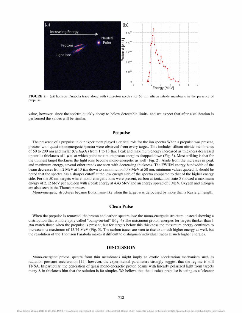
The presence of a prepulse in our experiment played a critical role for the ion spectra.When a prepulse was present,protons with quasi-monoenergetic spectra were observed from every target. This includes silicon nitride membranesof 50 to 200 nm and mylar (C10H8O4) from 1 to 13 µm. Peak and maximum energy increased as thickness decreasedup until a thickness of 1 µm, at which point maximum proton energies dropped down (Fig. 3). Most striking is that forthe thinnest target thickness the light ions become mono-energetic as well (Fig. 2). Aside from the increases in peakand maximum energy, several other trends are seen with decreasing thickness. The FWHM energy bandwidth of thebeam decreases from 2 MeV at 13 µm down to a minimum of 0.8 MeV at 50 nm, minimum values quoted. It should benoted that the spectra has a sharper cutoff at the low energy side of the spectra compared to that of the higher energyside. For the 50 nm targets where mono-energetic ions were present, carbon at ionization state 5 showed a maximumenergy of 2.12 MeV per nucleon with a peak energy at 4.43 MeV and an energy spread of 3 MeV. Oxygen and nitrogenare also seen in the Thomson traces.
Mono-energetic structures became Boltzmann-like when the target was defocused by more than a Rayleigh length.
Clean Pulse
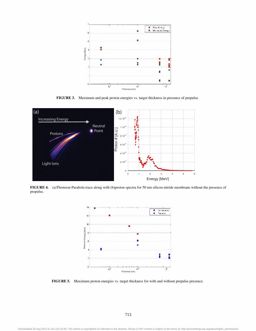
When the prepulse is removed, the proton and carbon spectra lose the mono-energetic structure, instead showing adistribution that is more aptly called "bump-on-tail" (Fig. 4) The maximum proton energies for targets thicker than 1µm match those when the prepulse is present, but for targets below this thickness the maximum energy continues toincrease to a maximum of 13.74 MeV (Fig. 5). The carbon traces are seen to rise to a much higher energy as well, butthe resolution of the Thomson Parabola makes it difficult to distinguish individual traces at such higher energies.
DISCUSSION
Mono-energetic proton spectra from thin membranes might imply an exotic acceleration mechanism such asradiation pressure acceleration [11]; however, the experimental parameters strongly suggest that the regime is stillTNSA. In particular, the generation of quasi mono-energetic proton beams with linearly polarized light from targetsmany λ in thickness hint that the solution is far simpler. We believe that the ultrafast prepulse is acting as a "cleaner
712
Downloaded 20 Aug 2013 to 141.213.19.93. This article is copyrighted as indicated in the abstract. Reuse of AIP content is subject to the terms at: http://proceedings.aip.org/about/rights_permissions
Ene
rgy
[MeV
]
Thickness [nm]
FIGURE 3. Maximum and peak proton energies vs. target thickness in presence of prepulse.
(a) (b)Increasing Energy
Protons
Light Ions
Neutral Point
Energy [MeV]
Pro
ton
# [A
.U.]
0
2 1013
4 1013
6 1013
8 1013
1 1014
1.2 1014
0 1 2 3 4 5 6
FIGURE 4. (a)Thomson Parabola trace along with (b)proton spectra for 50 nm silicon nitride membrane without the presence ofprepulse.
Max
imum
Ene
rgy
[MeV
]
Thickness [nm]
FIGURE 5. Maximum proton energies vs. target thickness for with and without prepulse presence.
713
Downloaded 20 Aug 2013 to 141.213.19.93. This article is copyrighted as indicated in the abstract. Reuse of AIP content is subject to the terms at: http://proceedings.aip.org/about/rights_permissions

beam," one that removes front-side contaminants from the target without disturbing the rest of the target. Then whenthe main pulse arrives it is only interacting with a target with contaminants on the rear surface. The difference of theproton energies for thicknesses below one micron suggests that the delay is too large to maintain an unperturbed rearsurface. In the case of no prepulse, contaminants from both surfaces are accelerated in the target normal direction.While simulations are needed to confirm what is taking place, it is believed that the front-side protons are spectrallybroadened and superimposed over the peaked rear surface protons, giving rise to the "bump-on-tail" distribution thatis a characteristic trait of the clean laser pulse interactions.
ACKNOWLEDGMENTS
This research was supported by NSF grant PHY-0114336.
REFERENCES
1. S. S. Bulanov, et al., Phys. Rev. E, 78, 026412 (2008).2. M. Roth, et al., Phys. Rev. Lett., 86, 436 (2001).3. V. Yu. Byschnkov, et al., Plas. Phys. Rep., 27, 1076 (2001).4. S. V. Bulanov, et al., Phys. Rev. A, 299, 240 (2002).5. E. Fourkal, et al., Med. Phys., 29, 1326 (2002).6. V. Malka, et al., Med. Phys., 31, 1587 (2004).7. S. C. Wilks, et al., Phys. Plas., 8, 542 (2001).8. G. Doumy, et al., Phys. Rev. E, 69, 026402 (2004).9. B. Dromey, et al., Rev. Sci. Inst., 75, 645 (2004).10. S.-W. Bahk, et al., Opt. Lett., 29, 2837-2839 (2004).11. A. P. L. Robinson, et al., New J. Phys., 10, 013021 (2008).12. J. J. Thomson, Phil. Mag., 21, 225 (1922).13. A. Henig, et al., Phys. Rev. Lett., 103, 045002 (2009).14. H. Schwoerer, et al., Nature, 439, 445 (2006).15. M. Kaluza, et al., Phys. Rev. Lett., 93, 045003 (2004).16. W. Mróz, et al., Rev. Sci. Inst., 71, 3 (2000).
714
Downloaded 20 Aug 2013 to 141.213.19.93. This article is copyrighted as indicated in the abstract. Reuse of AIP content is subject to the terms at: http://proceedings.aip.org/about/rights_permissions
Copyright © 2022 FDOKUMEN