N Series Switches Quick Start Guide V2.0 | FS
20
N Series 10G/25G/40G/100G Switches MANAGEDL2/L3DATA CENTER SWITCHES Quick Start Guide V2.0
-
Upload
khangminh22 -
Category
Documents
-
view
2 -
download
0
Transcript of N Series Switches Quick Start Guide V2.0 | FS
13
57
24
68
91
11
11
11
12
12
22
27
23
22
33
N Series 10G/25G/40G/100G SwitchesMANAGEDL2/L3DATACENTER SWITCHESQuick Start Guide V2.0

Introduction
NOTE: The switch includes plug-in power supply (PSU) and fan tray modules that areinstalled into its chassis.
Thank yoff for choosing N Series 10G/25G/40G/100G Switches. This guide is designed to familiarize
yoff with the layofft of the switch and describes how to deploy the switch in yoffr network.
N5850-48S6Q
N8520-48B6C
N8550-48B8C
N8050-32Q
N8520-32C
N8550-32C
Accessories
Power Cordx2 Console Cable x1 Rear-post Bracket x2
Front-post Bracket x2 M4 Screw x20 Ear-locking Screw x2 Holder Bracket x2
1 2 3 4 5 6 7 8 9 10 11 12 13 14 15 16 17 18 19 20 21 22 23 24 25 26 27 28 29 30 31 32 33 34 35 36 37 38 39 40 41 42 43 44 45 46 47 48 49 50 52 531 2 3 4 1 2 3 4 1 2 3 4 1 2 3 4 1 2 3 4 1 2 3 4 51 54
PS1 PS2 DIAG FAN LOC49 50 51 52 53 54
MGMTCONSOLE
N8520-48B6C
49 51 53 55
L1 L2 L3 L4 L1 L2 L3 L4 L1 L2 L3 L4 L1 L2 L3 L4
50 52 54 56PS1
PS2
FAN
1 2 3 4 5 6 7 8 9 10 11 12 13 14 15 16 17 18 19 20 31 22 23 24 25 26 27 28 29 30 31 32 33 34 35 36 37 38 39 40 41 42 43 44 45 46 47 48 49 50 51 52 53 54 55 56 57 58 MGM T CONSOLE
RESEUSBCONSOLEN8550-48B8C
LOC 1 3 5 7 9 11 13 15 17 19 21 23 25 27 29 31
CONSOLE MGMT
RESET LINK/ACTIVITY
2 4 6 8 10 12 14 16 18 20 22 24 26 28 30 32N8520-32C
PS 1 DIAG
PS2 FA N
ID
M GM T
LOC 1 3 5 7 9 11 13 15 17 19 21 23 25 27 29 31
PS1 D IA G
PS2 FAN CONSO LE SFP+
RE SE T
N8550-32C2 4 6 8 10 12 14 16 18 20 22 24 26 28 30 32
545352515049
LINKACTPS1 PS2 DIAG FAN LOC
51 541 2 3 4 1 2 3 4 1 2 3 4 1 2 3 4 1 2 3 4 1 2 3 41 2 3 4 5 6 7 8 9 10 11 12 13 14 15 16 17 18 19 20 21 22 23 24 25 26 27 28 29 30 31 32 33 34 35 36 37 38 39 40 41 42 43 44 45 46 47 48 49 50 52 53 MGMT
N58
50-48S
6Q
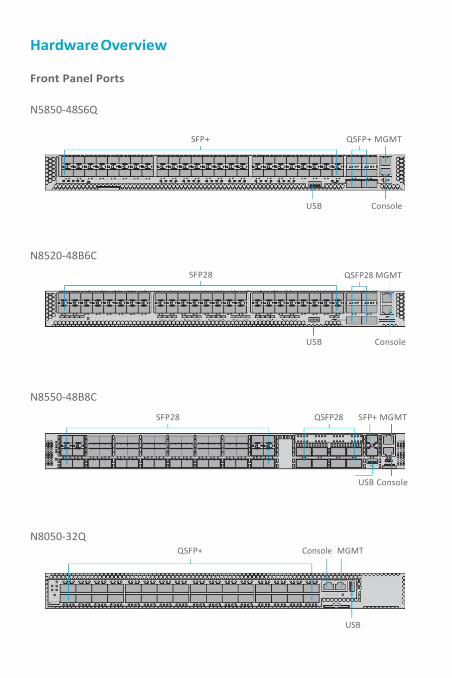
HardwareOverview
1 2 3 4 5 6 7 8 9 10 11 12 13 14 15 16 17 18 19 20 21 22 23 24 25 26 27 28 29 30 31 32 33 34 35 36 37 38 39 40 41 42 43 44 45 46 47 48 49 50 52 53
1 2 3 4 1 2 3 4 1 2 3 4PS1 PS2 DIA G FAN LOC RE SE T
49 50 51
49 51 53 55
L1 L2 L3 L4 L1 L2 L3 L4 L1 L2 L3 L4 L1 L2 L3 L4
50 52 54 56
PS1
PS2
FAN
1 2 3 4 5 6 7 8 9 10 11 12 13 14 15 16 17 18 19 20 31 22 23 24 25 26 27 28 29 30 31 32 33 34 35 36 37 38 39 40 41 42 43 44 45 46 47 48 49 50 51 52 53 54 55 56 57 58 MGMT CONSOLE
RESUSBCONSOLEN8550 -4 8B8C
Front Panel Ports
N5850-48S6Q
SFP+ QSFP+ MGMT
USB Console
N8520-48B6CSFP28 QSFP28 MGMT
1 2 3 4 1 2 3 4 1 2 3 4 51 54 M GM T CONS OLE
52 53 54 N8520-48B6C
USB Console
N8550-48B8C
SFP28 QSFP28 SFP+ MGMT
USB Console
N8050-32QQSFP+ Console MGMT
USB
1 2 3 4 5 6 7 8 9 10 11 12 13 14 15 16 17 18 19 20 21 22 23 24 25 26 27 28 29 30 31 32 33 34 35 36 37 38 39 40 41 42 43 44 45 46 47 48 49 50 52 53 MGMTLINK ACT
1 2 3 4 1 2 3 4 1 2 3 4 1 2 3 4 1 2 3 4 1 2 3 4 51 54PS1 PS2 DIA G FAN LOC RE SE T 49 50 51 52 53 54
CONS OLE
1 2 3 4 1 2 3 4 1 2 3 4 1 2 3 4 1 2 3 4 1 2 3 4 1 2 3 4 1 2 3 4 1 2 3 4 1 2 3 4 1 2 3 4 1 2 3 4 1 2 3 4 1 2 3 4 1 2 3 4 1 2 3 4
LOC 1 3 5 7 9 11 13 15 17 19 21 23 25 27 29 31
PS 1 D IAG
PS 2 FAN
CONSO LE M GM T
RES ET
N8050-32Q 2 4 6 8 10 12 14 16 18 20 22 24 26 28 30 321 2 3 4 1 2 3 4 1 2 3 4 1 2 3 4 1 2 3 4 1 2 3 4 1 2 3 4 1 2 3 4 1 2 3 4 1 2 3 4 1 2 3 4 1 2 3 4 1 2 3 4 1 2 3 4 1 2 3 4 1 2 3 4
N585
0-48S
6Q
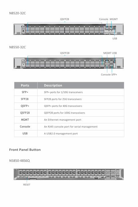
N8520-32CQSFP28 Console MGMT
LO C 1
PS1 D IAG
PS2 FAN
3 5 7 9 11 13 15 17 19 21 23 25 27 29 31
CONSOLE M GM T
RESET LINK/ACTIVITY
ID
N8520-32C 2 4 6 8 10 12 14 16 18 20 22 24 26 28 30 32
USB
N8550-32CQSFP28 MGMT USB
MGMT
LO C 1 3 5 7
PS 1 D IAG
PS 2 FAN
9 11 13 15 17 19 21 23 25 27 29 31
CONSOLE SFP+
RE SET
N8550 -32C 2 4 6 8 10 12 14 16 18 20 22 24 26 28 30 32
Console SFP+
Ports Description
SFP+ SFP+ ports for 1/10G transceivers
SFP28 SFP28 ports for 25G transceivers
QSFP+ QSFP+ ports for 40G transceivers
QSFP28 QSFP28 ports for 100G transceivers
MGMT An Ethernet management port
Console An RJ45 console port for serial management
USB A USB2.0 management port
Front Panel Button
N5850-48S6Q
RESET
1 2 3 4 5 6 7 8 9 10 11 12 13 14 15 16 17 18 19 20 21 22 23 24 25 26 27 28 29 30 31 32 33 34 35 36 37 38 39 40 41 42 43 44 45 46 47 48 49 50 52 53 MGMTLINK ACT
1 2 3 4 1 2 3 4 1 2 3 4 1 2 3 4 1 2 3 4 1 2 3 4 51 54PS1 PS2 DIA G FAN LOC RE SE T CONS OLE
49 50 51 52 53 54
N58
50-48S6
Q
N8520-48B6C
USB CONSOLEN8550 -4 8B 8C
ETRE
49 50 51 52 53 54 55 56 57 58 MGMT CONSOLE1 2 3 4 5 6 7 8 9 10 11 12 13 14 15 16 17 18 19 20 31 22 23 24 25 26 27 28 29 30 31 32 33 34 35 36 37 38 39 40 41 42 43 44 45 46 47 48
PS1
PS2
FAN
L1 L2 L3 L4 L1 L2 L3 L4 L1 L2 L3 L4 L1 L2 L3 L4
50 52 54 56
55535149
1 2 3 4 5 6 7 8 9 10 11 12 13 14 15 16 17 18 19 20 21 22 23 24 25 26 27 28 29 30 31 32 33 34 35 36 37 38 39 40 41 42 43 44 45 46 47 48 49 50 52 53
1 2 3 4 1 2 3 4 1 2 3 4 1 2 3 4 1 2 3 4 1 2 3 4 51 54PS1 PS2 DIA G FAN LOC RE SE T
49 50 51 52 53 54
MGM T CONSOLE
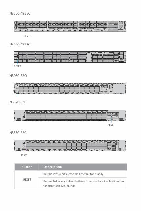
N8520-48B6C
RESET
N8550-48B8C
RESET
N8050-32Q
RESET
N8520-32C
LO C 1 3 5 7 9 11 13 15 17 19 21 23 25 27 29 31
CONSOLE M GM T
RESET LINK/ACTIVITY
2 4 6 8 10 12 14 16 18 20 22 24 26 28 30 32N8520-32C
PS1 D IAG
PS2 FAN
ID
N8550-32C
RESET
323028262422201816141210864
RESET
N8550-32C 2
CONSOLE SFP+
31292725232119171513119753LO C 1
PS 1 D IAG
PS 2 FAN
MGMT
RESET
Button Description
RESET
Restart: Press and release the Reset button quickly.
Restore to Factory Default Settings: Press and hold the Reset button
for more than five seconds.

Front Panel LEDs
N5850-48S6Q
SFP+ QSFP+
1 2 3 4 5 6 7 8 9 10 11 12 13 14 15 16 17 18 19 20 21 22 23 24 25 26 27 28 29 30 31 32 33 34 35 36 37 38 39 40 41 42 43 44 45 46 47 48 49 50 52 53 MGM T
PS1 PS2 DIA G FAN LOC RE SE T
PS1 PS2 FAN LOCDIAG
1 2 3449
1 2 3450
1 2 3451
1 2 3452
1 2 3453
1 2 3454
51 54
LINK
LINK ACTCONS OLE
ACT
LEDs Status Description
SFP+
On/Flashing
Amber
SFP+ port has a valid link at 10G.
Flashing indicates activity.
off There is no link on the port.
QSFP+in40GMode
On/Flashing
Amber
QSFP+ port has a valid link at 40G.
Flashing indicates activity.
off There is no link on the port.
LINK/ ACT Amber Switch runs normally.
N585
0-48S
6Q
N8520-48B6C
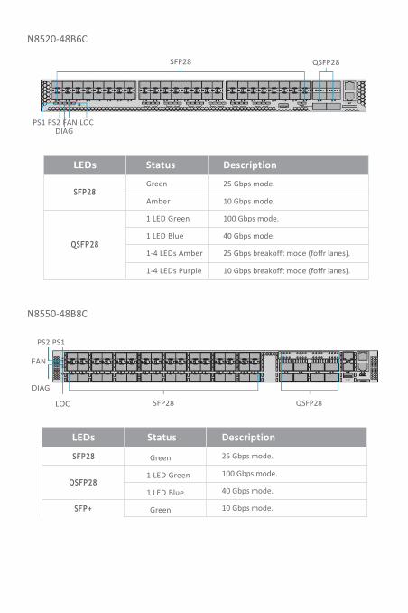
SFP28 QSFP28
1 2 3 4 5 6 7 8 9 10 11 12 13 14 15 16 17 18 19 20 21 22 23 24 25 26 27 28 29 30 31 32 33 34 35 36 37 38 39 40 41 42 43 44 45 46 47 48 49 50 52 53
PS1 PS2 DIA G FAN LOC RE SET
1 2 3 4 1 2 3 4 1 2 3 4 1 2 3 4 1 2 3 4 1 2 3 4 51 54 MGM T CONSOLE
PS1 PS2 FAN LOCDIAG
LEDs Status Description
SFP28Green 25 Gbps mode.
Amber 10 Gbps mode.
QSFP28
1 LED Green 100 Gbps mode.
1 LED Blue 40 Gbps mode.
1-4 LEDs Amber 25 Gbps breakofft mode (foffr lanes).
1-4 LEDs Purple 10 Gbps breakofft mode (foffr lanes).
N8550-48B8C
PS2 PS1
FAN PS1
PS2
FAN
49
L1 L2 L3 L4
50
51
L1 L2 L3 L4
52
53
L1 L2 L3 L4
54
55
L1 L2 L3 L4
56
DIAG
LOC
1 2 3 4 5 6 7 8 9 10 11 12 13 14 15 16 17 18 19 20 31 22 23 24 25 26 27 28 29 30 31 32 33 34 35 36 37 38 39 40 41 42 43 44 45 46 47 48 49 50 51 52 53 54 55 56 57 58 MGMT CONSOLE
DIAGRES ET
LOC SFP28 QSFP28
USBCONSOLEN8550 -4 8B 8C
LEDs Status Description
SFP28 Green 25 Gbps mode.
QSFP281 LED Green 100 Gbps mode.
1 LED Blue 40 Gbps mode.
SFP+ Green 10 Gbps mode.
49 50 51 52 53 54 N8520-48B6C

N8050-32Q
2 4 6 8 10 12 14 16 18 20 22 24 26 28 30 323 4 1 2 3 4 1 2 3 4 1 2 3 4 1 2 3 4 1 2 3 4 1 2 3 4 1 2 3 4 1 2 3 4 1 2 3 4 1 2 3 4 1 2 3 4 1 2 3 4 1 2 3 4 1 2 3 4 1 2 3
3 4 1 2 3 4 1 2 3 4 1 2 3 4 1 2 3 4 1 2 3 4 1 2 3 4 1 2 3 4 1 2 3 4 1 2 3 4 1 2 3 4 1 2 3 4 1 2 3 4 1 2 3 4 1 2 3 4 1 21 3 5 7 9 11 13 15 17 19 21 23 25 27 29
PS1 LOC
DIAG1 2 3 4
LO C 31
1 DIAG
2 FAN
RES ET
CONSO LE M GM T
PS2
50 -32Q1 2 4
FAN QSFP+ MGMT
LEDs Status Description
QSFP+
On/Flashing
Green
QSFP+ port has a valid link at 40G.
Flashing indicates activity.
On/Flashing
Orange
QSFP+ port has a valid link at 10G via
break offt cable. Flashing indicates
activity.
off There is no link on the port.
MGMT (Link)
On
GreenPort has a valid link.
off There is no link on the port.
MGMT (Activity)
Flashing
GreenFlashing indicates activity.
off There is no link on the port.
N8520-32C
PS1 LOC
DIAG
LEDs Status Description
QSFP28
1 LED Blue 100 Gbps mode.
1-2 LEDs Purple 50 Gbps breakofft mode (two lanes).
1 LED Orange 40 Gbps mode.
1-4 LEDs White 25 Gbps breakofft mode (foffr lanes).
1-4 LEDs Green 10 Gbps breakofft mode (foffr lanes).
LOC
PS 1 DIAG
PS 2 FAN
1 3 5 7 9 11 13 15 17 19 21 23 25 27 29 31
CONS OLE M GM T
RESET LINK/ACTIVITY
ID
N8520-32C 2 4 6 8 10 12 14 16 18 20 22 24 26 28 30 32
PS2
FANQSFP28
PS
PS
N80

N8550-32C
MGMT
PS 2 FAN
RES ET
N8550-32C 2 4 6 8 10 12 14 16 18 20 22 24 26 28 30 32
PS2
CONSOLE
PS1 D IAG
SFP+
3 5 7 9 11 13 15 17 19 21 23 25 27 29 31O C 1L
PS1 LOC
DIAG
FAN QSFP28 SFP+
LEDs Status Description
SFP+ Green 10 Gbps mode.
QSFP281 LED Blue 100 Gbps mode.
1 LED red 40 Gbps mode.
N Series Switches
LEDs Status Description
PS1/PS2
Green PWR is operating normally.
RedPWR present but not power on or this
power is fault.
off PWR not present.
LOC
Yellow
Flashing
Flashing by remote management
command. Assists the technician in
finding the right device for the service
in the rack.
offNot a particular switch that technician
need to find.
DIAG
GreenSystem self-diagnostic test successfully
completed. (By OS definition)
RedSystem self-diagnostic test has detected
a fault.
off System off.
F2BF2B
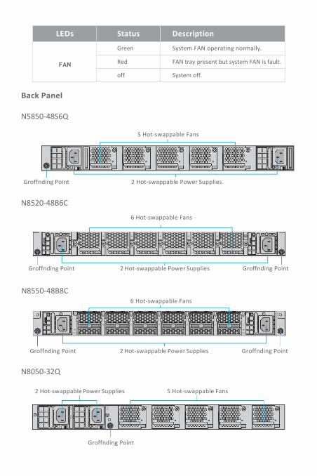
LEDs Status Description
FAN
Green System FAN operating normally.
Red FAN tray present but system FAN is fault.
off System off.
Back Panel
N5850-48S6Q
5 Hot-swappable Fans
Groffnding Point 2 Hot-swappable Power Supplies
N8520-48B6C
6 Hot-swappable Fans
F2B F2B F2B F2B F2B F2B
Groffnding Point 2 Hot-swappable Power Supplies Groffnding Point
N8550-48B8C6 Hot-swappable Fans
B2F21400
6 B2F21400
5 B2F21400
4 B2F21400
3 B2F21400
2 B2F21400
1
PS2 PS2
Groffnding Point 2 Hot-swappable Power Supplies Groffnding Point
N8050-32Q
2 Hot-swappablePower Supplies 5 Hot-swappable Fans
Groffnding Point
F2B F2B F2B F2B F2B
5 4 3 2 1
F2B F2B F2B F2B F2B
PS2
100~
240V
-,50
~60H
z,6-3A
PerP
S
PS1
100~
240V
-,50
~60H
z,6-3A
PerP
S
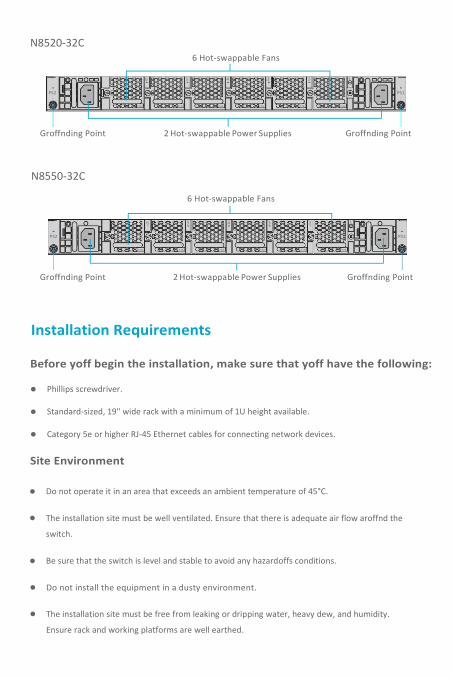
N8520-32C6 Hot-swappable Fans
6 5 4 3 2 1
PS2 PS1
F2B F2B F2B F2B F2B F2B
Groffnding Point 2 Hot-swappable Power Supplies Groffnding Point
N8550-32C
6 Hot-swappable Fans
6 5 4 3 2 1
PS2 PS1
F2B F2B F2B F2B F2B F2B
Groffnding Point 2Hot-swappable Power Supplies Groffnding Point
Installation Requirements
Before yoff begin the installation, make sure that yoff have the following:
Phillips screwdriver.
Standard-sized, 19" wide rack with a minimum of 1U height available.
Category 5e or higher RJ-45 Ethernet cables for connecting network devices.
Site Environment
Do not operate it in an area that exceeds an ambient temperature of 45°C.
The installation site must be well ventilated. Ensure that there is adequate air flow aroffnd the
switch.
Be sure that the switch is level and stable to avoid any hazardoffs conditions.
Do not install the equipment in a dusty environment.
The installation site must be free from leaking or dripping water, heavy dew, and humidity.
Ensure rack and working platforms are well earthed.

Moffnting the Switch
Attaching the Brackets
1. Attach each of the front- and rear-post brackets to the switch using foffr M4 screws, and secure each
of the rear-post brackets at the mid-point on the sides of the switch with two M4 screws.
2. Use the screws and cage nuts supplied with the rack to secure the switch in the rack.
N5850-
48S6Q

AdjustingRear-PostBracket Ears
CAUTION: The earth connection must not be removed unless all supply connections havebeen disconnected.
1. First adjust the position of rear-post bracket ears and secure them in the rack.
2. Then lock the position of the rear-post bracket ears using the included ear-locking screw.
Groffnding the Switch
1. Connect one end of the groffnding cable to a proper earth groffnd, such as the rack in which
the switch is moffnted.
2. Secure the groffnding lug to the groffnding point on the switch back panel with the washers
and screws.
100-24
0V-50
-60H
z,6-3A
Perp
s

ConnectingthePower
WARNING: Do not install power cables while the power is on.
1. Plug the AC power cord into the power port on the back of the switch.
2. Connect the other end of the power cord to an AC power soffrce.
Connecting the SFP+ Ports
1. Plug the compatible SFP+ transceiver into the SFP+ port.
2. Connect a fiber optic cable to the fiber transceiver. Then connect the other end of the cable to
another fiber device.
100-24
0V-5
0-60
Hz,6-3A
Perps

Connecting the QSFP+ Ports
1. Plug the compatible QSFP+ transceiver into the QSFP+ port.
2. Connect a fiber optic cable to the fiber transceivers. Then connect the other end of the cable to
other fiber devices.
Connecting the SFP28 Ports
1. Plug the compatible SFP28 transceiver into the SFP28 port.
2. Connect a fiber optic cable to the fiber transceivers. Then connect the other end of the cable to
other fiber devices.

Connecting theQSFP28 Ports
WARNING: Laser beams will cause eye damage. Do not look into bores of optical modulesor optical fiber withofft eyeprotection.
1. Plug the compatible QSFP28 transceiver into the QSFP28 port.
2. Connect a fiber optic cable to the fiber transceivers. Then connect the other end of the cable to
other fiber devices.
Connecting the Console Port
1. Insert the RJ45 connector of the console cable into the RJ45 console port on the front of the switch.
2. Connect the other end of the console cable to the RS-232 serial port on the computer.

ConnectingtheMGMTPort
1. Connect one end of a standard RJ45 Ethernet cable to acomputer.
2. Connect the other end of the cable to the MGMT port on the front of the switch.
Connecting the USB Port
Insert USB flash disk.
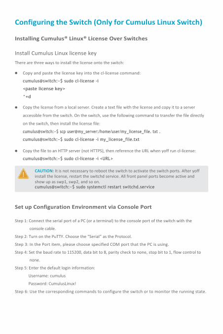
Configuring the Switch (Only for Cumulus Linux Switch)
CAUTION: It is not necessary to reboot the switch to activate the switch ports. After yoffinstall the license, restart the switchd service. All front panel ports become active andshow up as swp1, swp2, and so on.cumulus@switch:~$ sudo systemctl restart switchd.service
Installing Cumulus® Linux® License Over Switches
Install Cumulus Linux license keyThere are three ways to install the license onto the switch:
Copy and paste the license key into the cl-license command:
cumulus@switch:~$ sudo cl-license -i
<paste license key>
^+d
Copy the license from a local server. Create a text file with the license and copy it to a server
accessible from the switch. On the switch, use the following command to transfer the file directly
on the switch, then install the license file:
cumulus@switch:~$ scp user@my_server:/home/user/my_license_file. txt .
cumulus@switch:~$ sudo cl-license -i my_license_file.txt
Copy the file to an HTTP server (not HTTPS), then reference the URL when yoff run cl-license:
cumulus@switch:~$ sudo cl-license -i <URL>
Set up Configuration Environment via Console Port
Step 1: Connect the serial port of a PC (or a terminal) to the console port of the switch with the
console cable.
Step 2: Turn on the PuTTY. Choose the “Serial” as the Protocol.
Step 3: In the Port item, please choose specified COM port that the PC is using.
Step 4: Set the baud rate to 115200, data bit to 8, parity check to none, stop bit to 1, flow control to
none.
Step 5: Enter the default login information:
Username: cumulus
Password: CumulusLinux!
Step 6: Use the corresponding commands to configure the switch or to monitor the running state.
Troffbleshooting
Power System Troffbleshooting
According to the power indicator on the front panel, the switches can be used to determine whether
the power system of the switch is faulty. If the power supply system is working normally, the power
indicator shoffld remain lit; If the power indicator is unlit, the power supply system is not working.
Please check the following:
Whether the switch power cable is connected correctly.
Whether the power supply of the switch matches the required power supply.
Configuration System Troffbleshooting
After the switch is powered on, if the system is normal, the startup informationwill be displayed on
the configuration terminal. If there is something wrong with the configuration system, the
configuration terminal may not display or display error codes.
Troffbleshooting for Terminal No-show
After power-on, if the configuration terminal shows nothing, yoff can firstly check the following:
Whether the power supply is normal.
Whether the console cable is properly connected.
If there is no problem with the above, it is very likely that there is a problem with the configuration
cable or the terminal (such as the HyperTerminal) parameters were set incorrectly.
TroffbleshootingforTerminalShowErrorCodes
If the configuration terminal shows error codes, it is likely that the terminal (such as the HyperTerminal)
are set incorrectly. Please confirm the parameters of the terminal.
Support and OtherResoffrces
Download
Help Center
Contact Us
https://www.fs.com/download.html
https://www.fs.com/service/help_center.html
https://www.fs.com/contact_us.html
Product Warranty
FS ensures offr customers that any damage or faulty items due to offr workmanship, we will offer a
free return within 30 Days from the day yoff receive yoffr goods. This excludes any custom made
items or tailored solutions.
Warranty: N Series Switches enjoy 5 years limited warranty against defect in materials or
workmanship. For more details abofft warranty, please check at
https://www.fs.com/policies/warranty.html
Return: If yoff want to return item(s), information on how to return can be foffnd at
https://www.fs.com/policies/day_return_policy.html
Q.C. PASSED
Copyright © 2021 FS.COM All Rights Reserved.
5