FS-TER-006 - wateractionplan.com
27
FS-TER-006 TECHNICAL SHEETS FOR EFFLUENT TREATMENT PLANTS IN TEXTILE INDUSTRY ION EXCHANGE SERIES: TERTIARY TREATMENTS Title ION EXCHANGE (FS-TER-006) Last update September 2015 Last review
-
Upload
khangminh22 -
Category
Documents
-
view
4 -
download
0
Transcript of FS-TER-006 - wateractionplan.com
FS-TER-006
TECHNICAL SHEETS FOR EFFLUENT TREATMENT PLANTS IN TEXTILE INDUSTRY
ION EXCHANGE
SERIES: TERTIARY TREATMENTS
Title ION EXCHANGE (FS-TER-006)
Last update September 2015
Last review

ION EXCHANGE FS-TER-006
ION EXCHANGE Date September 2015
Authors Concepción Sánchez Ruiz
Revised by Last update
Date
Modified by:
Update main topics

ION EXCHANGE FS-TER-006 Page 1 of 25
INDEX
1.- INTRODUCTION 2.- ION EXCHANGE PROCESSES
2.1.- Foundations of ion exchange processes 2.2.- Types of ion exchange resins 2.3.- Ion exchange resins characteristics 2.4.- Kinetics of the ion exchange processes
3.- DESIGN 3.1.- Description of an ion exchange basic unit 3.2.- Duty cycle of an ion exchanger 3.3.- Types of ion exchange systems 3.4.- Design criteria of an ion exchange system
4.- SPECIFICATIONS AND REFERENCES IN THE EFFLUENT TREATMENT OF THE TEXTILE INDUSTRY 5.- PARAMETERS AND CONTROL STRATEGIES
5.1.- Composition of the inlet water to the system 5.2.- Salinity 5.3.- Suspended matter 5.4.- Temperature 5.5.- pH value
6.- OPERATING PROBLEMS BIBLIOGRAPHY TECHNOLOGY REFERENCES

ION EXCHANGE FS-TER-006 Page 2 of 25
1.- INTRODUCTION Ion exchange is the unit operation that allows the separation of dissolved ionic species through their transfer from the liquid phase to a solid exchanger material, where they replace other ions of the same electric sign that, in turn, pass to the liquid phase. In this reversible process, chemical transformations do not take place in the ionic species involved or in the exchanger material, enabling their recovery after the ion exchange. The interest for the applications of the ion exchange lies precisely in the possibility of reusing the exchanger material again and again. In order to do so, the material must previously undergo a regeneration process before recovering its initial conditions. Most applications of ion exchange aim at removing a particular ionic species from a liquid solution, resulting in their specific separation and concentration in the solid phase. Industrial applications for ion exchange processes are numerous: recovery of metal cations in solution, separation of ion mixtures, purification of liquids, controlled release of a chemical species, salts recovery, etc. In the field of water treatment, the most common uses of ion exchange are:
Water softening Water demineralization Alkalinity removal Removal of heavy metal cations dissolved in process water Removal of anions from strong acids, such as nitrate (NO3
-) and sulfate (SO4=)
Ammonia removal at low temperatures Also, inclusion of ion exchange as wastewater treatment and purification stage allows for removal (and eventual recovery) of ionic components in an effluent prior to final discharge or reuse, ensuring the required water quality in both cases. In addition to inorganic anions and metallic cations, many ionized organic molecules are also susceptible of being removed through ion exchange, including water-soluble dyes, resistant to conventional purification treatments and responsible for the color in the dyeing process effluents. Although various natural materials with exchange capacity are known, such as humus, clays and zeolites, synthetic exchange resins are normally used in ion exchange industrial practice, due to their operational advantages. Synthetic exchange resins are specifically designed for ion recovery under specific working conditions (aqueous medium, temperature, pressure, pH...). Ion exchange resins are typically presented in the form of spherical particles consisting of a cross-linked polymer in which specific functional groups are brought depending on the pursued application. Functional groups determine the nature of the ionic species exchanged between the resin and the aqueous solution. 2.- ION EXCHANGE PROCESSES 2.1.- Foundations of ion exchange processes An ion exchange system consists of a solid phase, insoluble (the ion exchanger material), surrounded by a liquid phase containing the solute of interest to be separated. Ion exchange process is established when the solid phase incorporates this solute to its structure without causing a permanent change. Ion exchange is always set between ionic species chemical equivalents of the same electric sign. The solid phase may be a crystalline lattice or a gel. If the exchanged ions are positive, the exchange material is called cationic, and anionic if the ionic species have a negative charge. Cations, such as calcium, magnesium, barium, strontium and radium, can be separated from an aqueous solution by using a cation-exchange resin. Similarly, anions like fluoride, nitrate, arsenate, selenate, chromate, as well as humic and fulvic acids can be separated by means of an anion-exchange resin.

ION EXCHANGE FS-TER-006 Page 3 of 25
Figure 1. Scanning electron microscope photographs showing the surface of a weak acid macroporous resin particle (left) and strong acid (right). (Ref.
http://dardel.info/IX/resin_pictures.html) Synthetic resins are the most widely applied ion exchange materials for water treatment. These are durable materials, whose structural and functional groups are designed according to the specific applications to be obtained through the ion exchange. In order to optimize the bed mechanical and hydraulic properties, they are usually presented in the form of sphere. Ion exchange resins are produced from a polymer cross-linked structure, either polystyrene or acrylic polymer, which serves as structural material. Certain ionizable functional groups are incorporated to the basic polymer structure; that is, with acid or base characteristics. In aqueous solution and depending on their selectivity towards the ions contained in the solution, resin functional groups carry out the exchange process by replacing their counterions with the ions of interest to be removed from the solution. The exchange process between the resin and the aqueous solution comprises phases of diffusion, adsorption, electrostatic attraction and acid-base balance. The process is entirely reversible and under the appropriate acid or base conditions, the equilibrium can be moved in an anti-clockwise direction, resulting in the original chemical form of the resin (acidic, basic, salt). This property allows ion exchange resins to be used through many load and regeneration cycles. The cost effectiveness of treatment processes based on ion exchange is due precisely to the number of regeneration cycles that can be obtained with a specific resin under certain operating conditions and constitutes a major design factor. 2.2.- Types of ion exchange resins Most ion exchange materials currently used in industrial applications are synthetic compounds traditionally known as resins. Exchange resins are obtained by styrene and vinylbenzene copolymerization, or from acrylic materials. On the basis of their porosity, the resins can be classified in gel-type or microporous resins, and macroporous-type resins, of less packed lattice. The porosity of gel-type resins is in the order of ionic sizes, whereas macroporous resins have a pipe network in their structural matrix, known as macropores, supporting adsorption and desorption of the larger molecular size substances, such as organic compounds. The higher degree of cross-linking of gel-type resins confers them a higher resistance to chemical degradation and better mechanical properties. Ion exchange resins are further classified according to their chemical structure and the acidic and basic properties shown by their functional groups. Accordingly, four resin categories are defined:
Strong-acid cation-exchange resins: they are characterized by sulphonic groups -SO3- as
functional groups. Sulphonic groups behave like strong acids, entirely hydrolyzed in aqueous solution. Resins in this category are monofunctional and their chemical and physical properties vary according to the copolymerization relation between divinylbenzene and styrene, ranging between 6 and 16 %. Strong acid resins attract positively charged ions exchanged for protons or sodium, depending on their presentation under acidic or sodium salt form.

ION EXCHANGE FS-TER-006 Page 4 of 25
Weak-acid cation-exchange resins: These resins are characterized by the presence of the carboxyl group –COO+ as functional group. They retain cations in balance with other weak acids in the solution, like bicarbonates, but they cannot exchange ions that are in balance with strong acid anions. Their regeneration is easier, achieving rates close to the maximum regeneration.
Strong-base anion-exchange resins: They contain quaternary ammonium ions in their structure
as functional groups. They bound to the dissolved anions, releasing alkalinity to the solution. They subdivide into two classes, known respectively as Type 1 and Type 2 depending on whether they incorporate alcohol groups –OH to their structure, which makes them differ in various aspects. Type 1 strong-base anion-exchange resins are strong bases with lower exchange capacity and low regeneration efficiency. Type 2 strong-base anion-exchange resins incorporate alcohol groups which render them slightly less basic, enhancing both their exchange capacity and regeneration efficiency with respect to Type 1.
Weak-base anion-exchange resins: They carry amino groups in their structure. They are not able
to retain weak acid anions, such as silicates and bicarbonates. They are sensitive to hydrolysis by water ions, which makes regeneration easier.
The main characteristics and exchange balance reactions for the above described resin categories, as well as their regenerant solutions and the type of ions they are able to exchange, are summarized in Table 1.
Table 1. Features of ion exchange resins used in water treatment processes (Crittenden et al., 2005). Terms in brackets indicate resin nature.
Resin type Main ion exchange reaction Regeneration
ions (X+) pK
Exchange capacity meq/mL
Removed ions
Strong-acid cation-exchange
n[RSO3-]X+ + Mn+ ↔
[nRSO3-]Mn+ + nX+ H+ or Na+ < 0 1,7 – 2,1
H+ form : any cation Na+ form: divalent cations
Weak-acid cation-exchange
n[RCOO-]X+ + Mn+ ↔ [nRCOO-]Mn+ + nX+ H+ 4 - 5 4 – 4,5
Divalent cations>> monovalent cations
Strong-base anion-exchange Type 1
n[R(CH3)3N+]X- + An- ↔ [nR(CH3)3N+]An- + nX- OH- or Cl- > 13 1 – 1,4
OH- form: any cation Cl- form: sulfate, nitrate, perchlorate, etc.
Strong-base anion-exchange Type 2
n[R(CH3)2(CH3CH2OH)N+]X- + An- ↔ [nR(CH3)2(CH3CH2OH)N+]An- + nX- OH- or Cl- > 13 2 – 2,5
OH- form: any cation Cl- form: sulfate, nitrate, perchlorate, etc.
Weak base anion
[R(CH3)2N]HX + HA ↔ [R(CH3)2N]HA + HX OH- 5,7 – 7,3 2 - 3
Divalent anions >> monovalent anions
X: non-metallic cation; M: Metallic cation; N: nitrogen; A: anion
2.3.- Ion exchange resins characteristics 2.3.1.- Presentation and physical properties of ion exchange resins Ion exchange resins are usually marketed as spheres or granules of certain grain size and distribution, adapted to the different specific application needs. For most of the applications, resins are presented as a Gaussian distribution of particle sizes ranging between 0,04 and 1,2 mm, or as uniform-sized particles. Under a microscope, the spheres show the typical aspects of Figure 2.

ION EXCHANGE FS-TER-006 Page 5 of 25
Figure 2. Microscope appearance of ionic exchange resin spheres. Left: Gaussian-distributed size spheres(Amberlite 252); Right: uniform-sized spheres (Amberjet 1200) (www.dow.com)
Manufacturers usually provide three specific parameters related to particle size: particle size range, effective particle size and uniformity coefficient. Sphere size determines numerous operational aspects, particularly the performance achieved during the ion exchange. Two circumstances stand out in particular: Ion exchange rate is reduced as sphere size increases. Reduction of particle size increases load loss along the bed, a condition that may cause their
breaking. Such opposed conditions require reaching a compromise solution when deciding on the appropriate size of resin particles for a given column and hydraulic regime. The sizes and particle size distributions of resins, together with typical parameters such as the void ratio, density or swelling in aqueous solution, are always provided by manufacturers in their data sheets. 2.3.2.- Ion exchange capacity The ion exchange capacity of a resin is a measurement of the ion amount that it is able to exchange under certain working conditions. Since the exchange processes take place between ionic species chemical equivalents, the resin exchange capacity is usually expressed in equivalents per unit mass or unit volume of resin. Other used units are alkalinity like CaCO3 per unit volume of resin, or the ion mass per unit volume of resin. The amount of ions that separate from water is expressed as equivalents per treated water volume. The exchange capacity of a resin is defined under different operational conditions: The maximum capacity of a resin represents the total number of exchangeable ions per unit mass
of resin (dry or wet). It is usually expressed as milliequivalents per gram (meq/g). The maximum exchange capacity is determined by the number of functional groups and their chemical nature. When the resin functional groups consist of weakly ionizable species (carboxyl group, amino group...), the maximum exchange capacity will also depend on the solution pH, which conditions the ionization degree of the functional groups.
The effective capacity of a resin pressume its possible incomplete ionization and is thereby a portion of the maximum capacity.
The dynamic capacity of a resin relates to the exchange capacity of a resin in which a balance between phases has not yet been established. Dynamic capacity is a function of contact time between the resin and the treated water.
The operational capacity, or useful capacity, quantifies the real response of the resin under operational conditions. It is estimated as the difference between the active sites of the resin at the end and at the beginning of a production phase. It is also expressed in equivalents of unit mass or unit volume of the resin. The operational capacity depends on a series of factors, such as the total capacity, the regeneration level of the resin, treated water composition, operating flow through the column, temperature, resin sphere size and distribution. Under normal operating conditions, the useful capacity of a resin usually ranges between 40 and 70 % of its total capacity.

ION EXCHANGE FS-TER-006 Page 6 of 25
Some typical values of exchange capacities for different ion exchange materials are shown in Table 2. Strong-acid and strong-base resins show lower exchange capacities than weak-acid and weak- base resins. However, the selection of the appropriate resin should take into consideration the balance between the exchange and regeneration capacity. The values of the different exchange capacities provided by manufacturers usually refer to wet resin volume, dependent on the hydration degree (amount of water that it retains in the interstices), which in turn varies with the chemical form of the resin (acid, base, salt). Resin hydration and swelling in aqueous solution can cause a noticeable volume change, being a factor to be taken into account when sizing the vessels (columns) that will contain them. Table 2. Some typical exchange ranges for diverse ionic exchange materials (Nalco Chemical Company,
1998)
Exchange material Capacity
(kg/m3 material)
CATIONIC Inorganic (zeolites)
Natural 100 – 175 Synthetic 420 – 565
Organic Sulfoned carbon 175 – 250 Synthetic
Phenolic 210 – 635 Styrene-based 700 – 1000
ANIONIC Inorganic
Metallic oxides Low use Organic
Synthetic resins 350 – 770
Table 3. Typical exchange capacity values of various exchange resins sorted by porosity (Dégremont, 2001)
Resin type Exchange capacity in eq/resin L
Gel Macroporous
Strong-acid cation-exchange
1,4 – 2,2 1,7 – 1,9
Weak-acid cation-exchange
3,5 – 4,2 2,7 – 4,8
Strong-base anion-exchange Type 1
1,2 – 1,4 1,0 – 1,1
Strong-base anion-exchange Type 2
1,3 – 1,5 1,1 – 1,2
Weak-base Anion-exchange
1,4 – 2,0 1,2 – 1,5
2.3.3.- Ion exchange resins selectivity

ION EXCHANGE FS-TER-006 Page 7 of 25
Ion exchange resins in contact with an aqueous solution establish a state of balance between the ions of interest contained in the solution and the ones retained by the resin. Such balance, in which the resin functional groups are considered as one of the reagents, are generally represented by the basic reactions shown in Table 1. From this point of view, the state of balance can be described by a constant called selectivity coefficient. The selectivity coefficient value is specific for a resin-ion pair and, for each ionic species, it is defined as the relation between the ions remaining in the solution with respect to the ones in the solid phase. It is a dimensionless coefficient that reflects the preference of a resin for a particular ionic species. In practice, ion exchange resins show a selective affinity with the ionic species present in the aqueous solution. Depending on the affinity degree either with one ion or the other, the exchange processes in the resin are encouraged or hindered, influencing the choice of the resins for specific applications. Resin selectivity is an intrinsic property dependent on the physical and chemical properties of both the resin and the ionic species of interest. On the ion side, ionic valence and ionic radius are limiting. Regarding the resins, their selectivity is determined by properties such as the pore size distribution in their structure and the type of monosubstituted or multisubstituted functional groups in their constituent polymer chains. In diluted aqueous solutions (SST< 1000 mg/L), ambient temperatures, and in the absence of steric hindrance arising from their porous structure or an ionic species oversize, the ion exchange resins usually show greater affinity for ions with the highest valence. The chromate anion is an exception to this rule: the selectivity towards this divalent anion is lower than towards monovalent anions, like iodide and nitrate. The preference for ions with higher charge diminishes as the ionic strength of the solution increases. For ions with same charge, the selectivity of a resin increases with the atomic number and ionic radius, and decreases with growing ion hydration sphere diameter.
Table 4.Some relative selectivity coefficients for strong-acid cation-exchange and strong-base anion-exchange resins (Dégremont, 2001)
Strong-acid cation-exchange resin
Strong-base anion-exchange resin
Cation Lithium-related
selectivity coefficient, KLi+
Anion
Chlorine-related selectivity coefficient,
KCl-
Li+ 1,0 HPO4= 0,01
H+ 1,3 CO3= 0,03
Na+ 2,0 OH- Type 1: 0,06
Type 2: 0,65
NH4+ 2,6 SO4= 0,15
K+ 2,9 CH3COO- 0,2
Mg2+ 3,3 HCO3- 0,4
Zn2+ 3,5 Cl- 1.0
Cu2+ 3,8 CN- 1,3
Cd2+ 3,9 Br- 3
Ca2+ 5,2 NO3- 4
Ba2+ 11.5 I- 8
Manufacturers provide specific selectivity values for each resin in terms of selectivity coefficient, which in turn depends on the valence, the resin type and its saturation degree, together with the nature of the ion of interest and its concentration in the aqueous solution. Table 4 presents some values of typical relative selectivity coefficients for strong-acid and strong-base type resins.

ION EXCHANGE FS-TER-006 Page 8 of 25
2.4.- Kinetics of the ion exchange processes The rate at which the ionic species exchange process takes place between the solid and liquid phases is regulated by both the differences of concentration between the two phases and the neutral electric balance that must be maintained between them. One major factor controlling ion exchange rate is the diffusion time necessary in order to achieve the ionic balance between liquid and solid phases. Ion transfer between both phases is controlled by diffusion, under a 3-step classical scheme:
a) Transfer from the solution to the stationary boundary layer surrounding the resin sphere. This process is independent of the resin sphere size.
b) Transfer through the boundary layer to the sphere surface. The rate of this process is inversely proportional to the sphere radius.
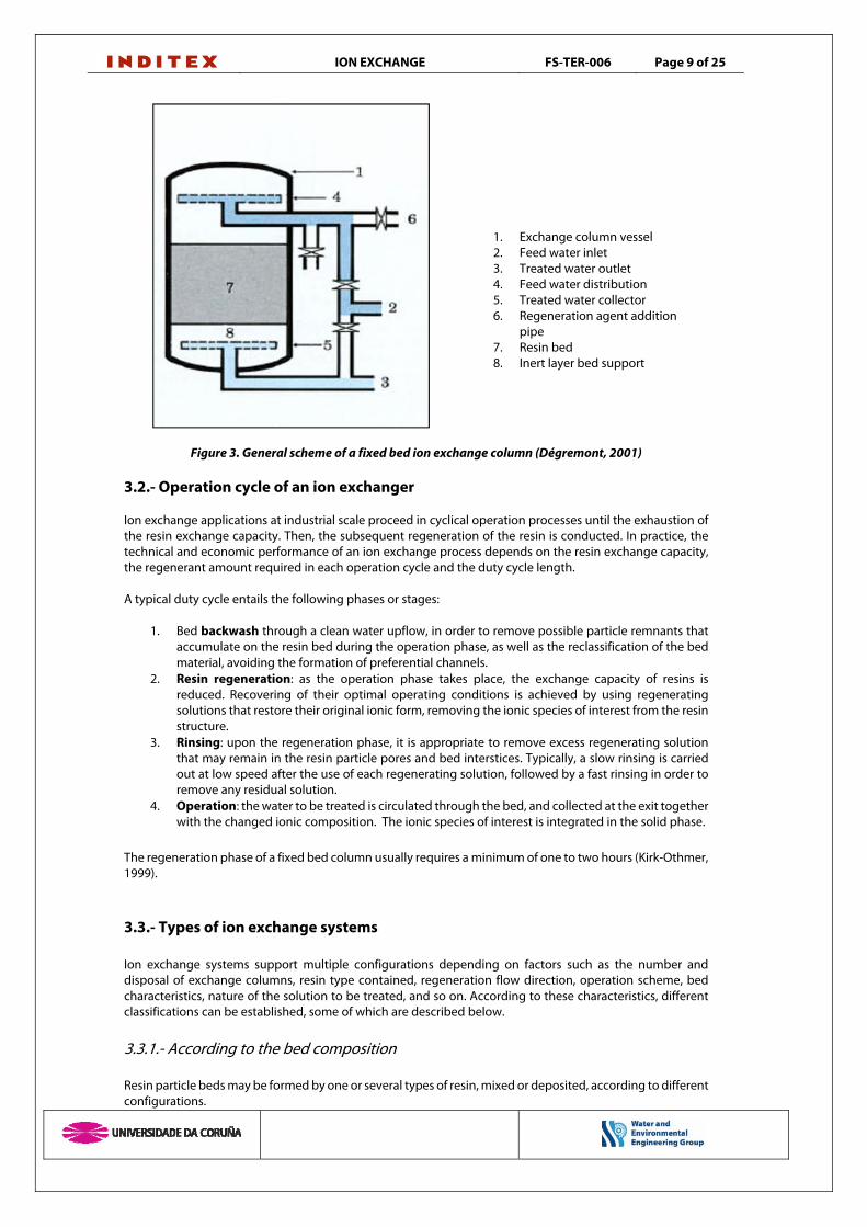
c) Ion transfer into the resin sphere. The rate of this phase is inversely proportional to 1/r2 During operation phase, step a) in the resin is faster than step b), which becomes limiting of the process. Use of smaller-sized resin spheres increases surface area, and thus the transfer through the boundary layer. During resin regeneration phase, a high ion concentration in the liquid phase increases the rate of step b), and thus intraparticle diffusion step c) becomes limiting. Smaller-sized spheres present the advantage of a smaller inside path, which is beneficial for step c). The result of choosing a smaller size of particle therefore favors the resin diffusion phases during the operation and regeneration periods. 3.- DESIGN 3.1.- Description of an ion exchange basic unit Ion exchange systems are usually operated under the configuration of bed, fixed or moving, contained in a properly configured tank in order to maximize the circulation of water inside. Treatment equipments consist of one or several closed cylindrical vessels, inside which the resin comes into contact with the water to be treated and the regenerating solution, alternatively. Figure 3 shows the simplified scheme of an ion exchange column. Typically, the column is not filled wholly with the resin, but sufficient free space is provided on the bed so as to enable its expansion, which can vary between 30 % and 100% of the packed bed volume depending on the resin types. The feed water to the exchanger, as well as the regenerating solutions, flow into the unit through the top, being uniformly distributed throughout the bed along the column section. Treated water is collected at the bottom by an appropriate drainage system. The equipment is also provided with the circuits, valves and pumps required for the resin operation-regeneration cycle. Exchange columns design must be based on the load loss that occurs along the bed, by optimizing section/height or carefully selecting the particle size. Homogenous distribution of the liquid (feed water or regenerating solution) should also be ensured in the overall bed through the right sizing of working flows and diffuser systems.
ION EXCHANGE FS-TER-006 Page 9 of 25
1. Exchange column vessel 2. Feed water inlet 3. Treated water outlet 4. Feed water distribution 5. Treated water collector 6. Regeneration agent addition
pipe 7. Resin bed 8. Inert layer bed support
Figure 3. General scheme of a fixed bed ion exchange column (Dégremont, 2001)
3.2.- Operation cycle of an ion exchanger Ion exchange applications at industrial scale proceed in cyclical operation processes until the exhaustion of the resin exchange capacity. Then, the subsequent regeneration of the resin is conducted. In practice, the technical and economic performance of an ion exchange process depends on the resin exchange capacity, the regenerant amount required in each operation cycle and the duty cycle length. A typical duty cycle entails the following phases or stages:
1. Bed backwash through a clean water upflow, in order to remove possible particle remnants that accumulate on the resin bed during the operation phase, as well as the reclassification of the bed material, avoiding the formation of preferential channels.
2. Resin regeneration: as the operation phase takes place, the exchange capacity of resins is reduced. Recovering of their optimal operating conditions is achieved by using regenerating solutions that restore their original ionic form, removing the ionic species of interest from the resin structure.
3. Rinsing: upon the regeneration phase, it is appropriate to remove excess regenerating solution that may remain in the resin particle pores and bed interstices. Typically, a slow rinsing is carried out at low speed after the use of each regenerating solution, followed by a fast rinsing in order to remove any residual solution.
4. Operation: the water to be treated is circulated through the bed, and collected at the exit together with the changed ionic composition. The ionic species of interest is integrated in the solid phase.
The regeneration phase of a fixed bed column usually requires a minimum of one to two hours (Kirk-Othmer, 1999). 3.3.- Types of ion exchange systems Ion exchange systems support multiple configurations depending on factors such as the number and disposal of exchange columns, resin type contained, regeneration flow direction, operation scheme, bed characteristics, nature of the solution to be treated, and so on. According to these characteristics, different classifications can be established, some of which are described below. 3.3.1.- According to the bed composition Resin particle beds may be formed by one or several types of resin, mixed or deposited, according to different configurations.

ION EXCHANGE FS-TER-006 Page 10 of 25
Unitary beds: Filled with a single type of resin. These are the conventional ion exchange beds.
Particles can be found in the form of packed beds, like in the Upcore™ systems from Dowex, or suspended beds, such as in the modern SIX® systems from PWN Technology, or MIEX® from Ixom Watercare, with magnetic particles.
Mixed beds: Filled with a strong-acid cation-exchange resin and a strong-base anion-exchange resin thoroughly mixed by shaking with compressed air in a single column. The mixture of both types of exchangers in a single bed is equivalent to two columns arranged in series although the water quality obtained in a mixed bed is higher than that achieved with two sequential unitary columns. Despite their higher efficiency, mixed beds have the disadvantage of being more sensitive to the presence of impurities in the feed water, in addition to requiring a more complex regeneration process than unitary columns. For these reasons, their preferential use is the polishing of previously treated water in a conventional two column system or in a reverse osmosis unit.
3.3.2.- According to the regeneration flow direction The resin regeneration phase is very important in the overall efficiency assessment of an ion exchange system. Many exchange columns operate by downflow and the regenerating solution does so in the same direction (co-current). Initially, ion exchange treatment systems operated in this way. Its main disadvantage is the greater ion leakage that occurs, as well as the possible ion accumulation on the lower bed layers, which may result in lower water quality for certain applications. A better regeneration performance is achieved when the regenerant flows counter-current to the operation flow. Regeneration can be done either by ascending or descending flow. Vacuum systems can be used with ascending flow. On the other hand, the ascending flow of the regenerating solution causes bed disruption and expansion, resulting in a poorer solution distribution due to little contact with the fluidized bed particles. Thus, in counter-current regeneration systems it is necessary to keep the bed packed during the injection of regenerating solution. Different bed blockage methods have been developed to avoid bed expansion, which can be grouped into three types: Bed blockage with water Bed blockage with compressed air Mechanical bed blockage with the use of diaphragms, plates and other devices. The use of a counter-current regeneration scheme promotes reagent savings, as less solution is required in order to achieve the resin regeneration, which means less washing water to be treated. Saving is estimated to be up to 20 % for anion-exchange resins and around 40 % for cation-exchange resins (Dégremont, 2001). Consequently, at equal reagent consumption, counter-current regeneration leads to the production of a better quality treated water than co-current regeneration. 3.3.3.- According to the number and nature of columns Depending on the objective, ion exchange processes may require from a single exchanger, with a single cation- or anion-exchange resin, to complex schemes requiring multiple columns to complete the treatment process. If positively and negatively charged ionic substances need to be removed, at least a cation exchanger must be used followed by an anion-exchange one. The number of units increases according to the treated water quality requirements. Depending on the resin choice made, different schemes are possible (Corbitt, 2003): Strong-acid resin / Strong-base resin Strong-acid resin / Weak-base resin Weak-acid resin / Weak-base resin Strong-acid resin / Weak-base resin / Strong base resin Strong-acid resin / Weak-base resin / Strong-base resin / Weak-base resin In addition, mixed bed columns for the polishing of produced water quality can be added to these unitary column systems. Combinations are plentiful and will depend on the particular system application. Account

ION EXCHANGE FS-TER-006 Page 11 of 25
must also be taken on specific spare lines to cover the exchange resins regeneration periods. Further information on this aspect can be found in Kirk-Othmer (1999), Dégremont (2001) or Crittenden et al. (2005). 3.3.4.- According to the system operation scheme Discontinuous processes (batch) in vertical columns produce a high dilution degree of ionic species. The alternation between operation and regeneration phases results in a concentration gradient within the bed. In addition, it requires the neutralization of abundant washing water. On the contrary, continuous operating ion exchange systems limit the dilution degree of species of interest to minimum levels, which is particularly interesting in the event that the ion exchange is applied for the recovery of a constituent present in the aqueous solution. In continuous operating systems, operation and regeneration phases take place through a closed circuit, along which the particle bed and the counter-current regenerating solution are transported. Asahi process, Higgins circuit and CIE-Dégremont process are among the most recognized continuous ion exchange systems. The use of such systems is regularly restricted to the recovery of added-value substances in industrial processes, such as hydrocarbon refining or radioactive ion concentration. 3.4.- Design criteria of an ion exchange system The purpose of an ion exchange system design is to ensure water production in terms of quality and quantity at the lowest investment costs and the minimum consumption of regenerating reagents. An optimum system design depends on the appropriate choice of multiple parameters described below. 3.4.1.- Initial considerations As a starting point for the design of an ion exchange system, Corbitt (2003) highlights the following considerations: Requirements for the feed water and its pre-treatment degree; in particular with regard to
dissolved solids. Quality requirements for the treated water The presence of colloidal matter or particles that can clog the system The type and configuration of the exchange columns, with particular emphasis on the
regeneration system. 3.4.2.- Selection of the resin regeneration system A counter-current regeneration system should provide water quality with a conductivity lower than 2 μS/cm and a residual silica concentration as SiO2 between 0.020 and 0.050 mg/l. Depending on the feed water composition and the regeneration conditions, conductivity can be reduced by up to 0.2 μS/cm. The resin is considered to be exhausted with a value of 4 μS/cm. Under the same conditions, counter-current regeneration systems produce water of very high conductivity and ionic losses about ten times higher (Dow Water & Process Solutions). 3.4.3.- Selection of the resin type and the treatment scheme The configuration of the ion exchange system depends on the feed water composition, the quality required for the produced water, and economic considerations. Strong-acid cation-exchange resins are mostly used for softening in form of sodium salt, and for water demineralization when the temporary feed water hardness is less than 40 % of the total cation content. This general rule can be disregarded in small treatment systems with HCI as resin regenerant. Weak-acid cation-exchange resins are used as unitary resins for removing alkalinity in its acid form, and for softening brackish water in its sodium salt form. The choice of a weak-acid cation-exchange resin is preferable to the strong-acid resin option when the temporary hardness exceeds 40 %, as it is an

ION EXCHANGE FS-TER-006 Page 12 of 25
advantageous option in terms of operation capacity and regeneration efficiency (Dow Water & Process Solutions). With respect to anion-exchange resins, Type 1 strong-base are recommended as unitary resins to treat water with low inorganic acid content and when low silica losses (< 20 ppb in counter-current operation) are required. The resin can be regenerated at temperatures up to 50 ºC for a more efficient removal of silica. Type 2 strong-base resins are particularly suited to small systems. While anions from Type 2 resins have greater efficiency in operation and regeneration than those of Type 1, they are limited to temperatures below 35 ºC and cause higher silica losses. Finally, weak-base anion-exchange resins serve as single phase to obtain partly deionized water without removing CO2 and SiO2. For the complete demineralization, use should be made of the system in two weak-base anion and strong-base anion-exchange phases that provide optimum operating costs. The weak-base and strong-base combination is ideal for treating water of low alkalinity or subject to degassing, in which the presence of inorganic acids (Cl- + NO3- + SO4=) exceeds 60 % of the total anion content. Weak-base anion-exchange resins are particularly suitable for the treatment of organic matter, high weight molecular compounds and species of weak acid nature. Table 5 shows some typical values of design for the different types of resins.
Table 5. Typical design values for a fixed bed ionic exchanger, applied to water treatment (Perry et al., 2001)
Resin type Min. Max hydraulic load (m/h)
Minimum bed height
(m)
Max. Operation temp (ºC)
Effective load (eq/l)
Regenerant (g/resin L)
Weak-acid cation-exchange 3 – 20 0,6 120 0,5 – 2,0
110% theoretically (HCl o H2SO4)
Weak-acid cation-exchange
3 – 30 0,6 120 0,5 – 1,5
80-250 NaCl 35-200 H2SO4
66 ºBé 80-500 HCl 20
ºBé Weak-base anion-
exchange 3 – 17 0,75 40 0,8 – 1,4 35 – 70 NaOH
Strong-base anion-exchange 3 – 17 0,75 50 0,35 – 0, 7 70 – 140 NaOH
Mixture between strong acid and base
Max. 40 1,2 50
0,2 – 0,35 (depending
on the mixture)
The same as anion and
cation separately
3.4.4.-Estimation of regenerating reagent consumption The regeneration chemical efficiency for an ion exchange resin is a dimensionless parameter that is defined from the relation:
Resin volume (liters) = (Water salinity (eq/m3)) · (Treated volume (m3) · (Operational capacity (eq/l))-1 [1] Given that the use of regenerant by the resin in practice differs from the theoretical value, the chemical efficiency is always greater than the unit, getting worse as its value increases. In percentages, common regeneration efficiency values range between 105 and 300 %, depending on the resin type, the regeneration flow adopted and the regenerating reagent used.

ION EXCHANGE FS-TER-006 Page 13 of 25
Table 6 includes guidance values of the necessary regenerating reagent consumption to restore resins to their operational status. Although higher regenerating reagent consumption increases the operational capacity and reduces ionic losses, the chemical efficiency of the whole system decreases.
Table 6. Regenerant consumption range for two types of strong resins (Dégremont, 2001)
Resin type Regenerant Pure product quantity, g/resin L
Strong-acid cation-exchange NaCl 80 -300 H2SO4 80 – 250 HCl 40 – 200 Strong-base anion-exchange NaOH 40 – 100 NH3 30 – 60 Na2CO3 60 – 130 NaOH 40 – 200
3.4.5.- Backwashings and bed expansion Exchange resin beds regularly undergo a backwashing in order to remove the accumulated particles in the gaps and reclassify resin spheres in the bed by shaking them. The column backwashing should be carried out in such a way as to guarantee the optimal hydraulic performance of the bed during the operation and regeneration cycles. The backwashing is done by ascending an uniform water flow in the column, so that enough fluidization occurs in the bed to separate particles and fines accumulated during the production cycles. A typical water volume for backwashing would be equivalent to two complete displacements of the column freeboard. The resin bed should be expanded along the column, up to a height close to the backwashing water outlet collector in the column upper side. The ion exchange resin expansion depends on the resin sphere size, their density and the backwashing water temperature, so this is a characteristic value for each commercial resin. The expansion percentage of an ion exchange column can be calculated according to the following formula:
% Bed expansion = 100 x (Fluidized bed height/Resting bed height) [2] The expansion curves in backwashing for each resin are provided by manufacturers in their data sheets. With their use, the appropriate backwashing flow value for the percentage of the pre-established bed expansion may be established. In water treatment processes, it is common to use bed expansion values between 50 and 80 % (Perry, 2001), with cases of 100 % possibly arising. 3.4.6.- System sizing Quality requirements for the treated water in exchange systems, as well as the chosen regeneration method (co-current and counter-current) determine the regenerant consumptions. These values, together with the feed water composition to the system, define the resin operational capacity according to equation [1]. More accurate estimates of the resin operational capacity can be obtained through pilot tests, either by using the characteristic curves provided by manufacturers or by resorting to specific design programs for ion exchange systems, such as PureDesign from Purolite (http://www.purolite.com/RelId/606742/ISvars/default/PureDesign_3_12_2_-_Download_Calculator.htm) or CADIX from Dow (http://www.dow.com/en-us/water-and-process-solutions/resources/design-software/cadix-software). In order to compensate the non-ideal operation conditions, as well as the resin ageing, it is advisable to apply a safety factor to the estimated operational capacity values. Typical values are 5 % for cation-exchange resins

ION EXCHANGE FS-TER-006 Page 14 of 25
and 10 % for anion-exchange resins. Once the resin operational capacity value is known, the required volume can be determined by the equation [1] from the treated water volume per cycle. Deposits should be constructed in appropriate materials, like carbon steel or fiberglass. Distribution and collection systems should ensure an optimal fluid distribution in all phases of the exchanger duty cycle, which will also be conditioned by the relation between the bed height and the column section. Tables 7 to 11 below specify a set of guidance values of different design parameters for an ion exchange system, optimized for the monodisperse resins Dowex Marathon. Such values must be considered as an approximate reference of the magnitudes. Specific values for each resin must be always provided by the manufacturer.
Table 7. Some typical values for a ion exchange column sizing (Dow Water and Process Solutions)
Parameter Reference valuesMaximum diameter 3,5 meters Maximum bed pressure drop 1 bar Bed height/diameter 2/3 – 3/2 Expansion overhead 80 – 100% of the bed height
Table 8. Resin swelling percentage (Dow Water and Process Solutions)
Resin type Swelling percentage Strong-acid cation-exchange 5 – 8% Weak-acid cation-exchange 15 – 20% Strong-base anion-exchange 15 – 25% Weak-base anion-exchange 15 – 25%
Table 9. Bed height at different ion exchange arrangements (Dow Water and Process Solutions)
System configuration Bed height, mmSingle resin, co-current 800 Single resin, counter-current 1200 Strong-base anion, stratified 800 Weak-base anion, stratified 600
Table 10. Flow velocities in several cycle steps (Dow Water and Process Solutions)
Flow velocity (m/h) Rinsing 5 – 60 Condensate refining 75 – 120 Co-current regeneration: rinsing 1 – 10 Counter-current regeneration: rinsing 5 – 20
Table 11. Rinsing operation water required volume (Dow Water and Process Solutions)
Resin type Rinsing water volume Strong-acid cation-exchange 2 – 6 BV Weak-acid cation-exchange 3 – 6 BV Strong-base anion-exchange 3 – 6 BV Weak-base anion-exchange 2 – 4 BV
BV: Bed volume 3.4.7.- Number of lines
ION EXCHANGE FS-TER-006 Page 15 of 25
The number of exchange lines operating simultaneously can be calculated on the basis of the feed flow and the treated volume per cycle. The simplest scheme consists of two lines, one being in operation and the other in reserve. This scheme is applicable to most of the cases. For large treatment plants, with flows above 400 m3/h, the scheme of two lines operating in parallel and a line in reserve may be more appropriate with a view to reduce the exchanger size and improve its hydrodynamic performance (Dow Water & Process Solutions). A estimate of the optimal number of lines can be carried out using the formula [3], rounding the result to the lesser whole number (Dow Water & Process Solutions).
No. of lines = (Operation time + Regeneration time) / Regeneration time [3] 3.4.8.- Economic considerations Ion exchange systems are usually purchased as tailored and turnkey systems, so it is not easy to make overall economic estimates. The investment costs of ion exchange systems are generally lower than those for other tertiary treatment systems based on membranes or requiring some type of special equipment. Regarding the operating costs, the system energy consumption will not have a preponderant influence, but the larger batches shall be intended for resin and reagent consumption for their regeneration. In the event that some sort of hazardous waste is obtained during the duty cycle, the costs associated with its final disposition shall be also included. In practice, the most important factors to be considered are the frequency and intensity of the resin regeneration phases. A too high regeneration frequency could make the system economically unviable. Corbitt (2003) has developed a list of aspects that should be considered during the economic analysis of the feasibility of an ion exchange process for waste-water treatment.
1. Shall the process allow the recovery and reuse of any reagent? 2. Is it possible to remove only the unwanted wastewater constituents that make their treatment
difficult in other facilities such as in a municipal treatment plant? 3. Are there other processes able to perform the same operation in a more economical way? 4. Has a management method for the concentrated waste coming from the periodic regeneration of
the ion exchange units been envisaged? 5. Have the purchasing and preparation costs for the regeneration reagents been included in the
economic system evaluation? 6. Have the treatment and management costs for the regeneration reagents been included in the
economic system evaluation? 7. For the exchange resin selected, what is the annual cost of the additives and periodic
replacements? (The resin life cycle is very dependent on its nature and on the wastewater characteristics)
8. What is the estimated cost of the equipment necessary to operate the ion exchange system? 4.- SPECIFICATIONS AND REFERENCES IN THE EFFLUENT TREATMENT OF THE TEXTILE INDUSTRY
The major disadvantage of the use of ion exchange systems in textile effluent treatment is that they are only suitable for treating ionizable and water-soluble molecules, which restricts its scope of application to certain dyes families. The results of tests carried out for color removal in textile effluents are quite rare in the literature and are limited to experiments performed in laboratories. The best results are obtained with weak-base anion-exchange resins, with which in some cases the complete color removal in solutions is achieved. The results of the experiments located in the literature have been summarized in Table 12. In any case, an ion exchange application to textile effluents requires their prior treatment so as to reduce the values of salinity, suspended solids and organic matter up to operational values for a system of such characteristics. In addition to effluent discoloration, already performed in other sectors such as the cane sugar refining, the ion exchange can be also used for process water softening and/or demineralization, for their regeneration

ION EXCHANGE FS-TER-006 Page 16 of 25
in the frame of a Zero Limit Discharge scheme. There is some reference thereon in India, where the treatment and regeneration plant Angeripalayam Common Effluent Treatment Plant, in Tamil Nadu, treats effluents from 75 different staining companies with a scheme consisting of a biological treatment of biomembranes followed by chlorination, ion exchange and reverse osmosis in two stages.
Table 12. Some experimental results on aqueous solutions decoloring by ion exchange.
Dye Resin Experimental
conditions Results Reference
C. I. Basic Blue 3 Cationic polystyrene (Lewatit MonoPlus SP 112)
Batch test. Initial concentration 100 – 1000 mg/l; contact time:1 – 96 min.
Operation capacity @ 20 ºC: 205 mg/g; Total solution discoloration in 1 h
Wawrzkiewicz, 2013
Various reactive dyes
Strong-base anion-exchange S6328 and weak-base MP62 (Bayer)
Batch tests. Various concentrations and pH
100 – 800 Bed volume until resin exhaustion
Karcher et al., 2002
Azo Lanasyn Navy y phtalocyanine Acid Blue 249
Weak-base anion-exchange (Purolite A847)
Simultaneous batch tests with acid pH.
Higher separately. Dynamic capacity estimated by FT-IR.
Kauspediene et al., 2013
Real textile effluent with physical-chemical treatment (4910 μmho/cm) and equalization (5200 μmho/cm)
Cationic (Amberlite IR 120) and anionic (Amberlite IRA 400) relation 1:2
Two laboratory columns
Elimination of chloride, nitrate and sulfate; total color removal; 48 μmho/cm
Raghu y Basha, 2006
The treatment scheme is intended for the complete regeneration of the whole feed flow so as to be reused in textile manufacturing processes, avoiding the problems associated with the effluent discharge. The added value of the high volume of water reclaimed for industrial use may compensate the operating costs related to treatment. Europrogetti Company (Italia; www.europrogetti-italy.com) designs and markets ion exchangers specifically aimed at tertiary treatment of textile effluents for reuse, in a Zero Limit Discharge scheme. The main objective underlying the ion exchange phase after the biological treatment is to remove all the remaining color so that produced water can be reused in dye baths, washings and rinsings, machinery cleaning, etc. The fully automated exchangers are equipped with macroporous weak-base anion-exchange resins. Factors determining the working cycle length, as well as the treated water quality, are: Dye color nature and concentration COD of secondary effluent must be between 100-120 mg/l. One part is adsorbed on the resin,
accelerating its exhaustion and competing with color removal. Higher COD values mean a reduced duty cycle length and may lead to a color increase in treated water.
Too alkaline pH values adversely impact the color reduction. Salinity over 15,000 mg/l causes color re-elution as a result of the competitive action from high
concentrations of chloride and sulfate anions. Wherever possible, ion exchange also allows the recovery of materials in solution that may be recaptured for the manufacturing process. This is the case, for example, with regard to sodium chloride and Glauber's salt.

ION EXCHANGE FS-TER-006 Page 17 of 25
5.- PARAMETERS AND CONTROL STRATEGIES
5.1.- Composition of the feed water to the system The nature and composition of the feed water is a conditioning factor for the performance of any ion exchange system. The parameters of feed water that must be taken into consideration and eventually controlled are: Total content of dissolved inorganic salts Suspended solids Temperature pH Dissolved organic matter Oils and greases Polyelectrolytes Iron, manganese and aluminum 5.2.- Salinity It is a critical factor for the proper operation of an ion exchange system and the most common cause of malfunction. Salt concentration effects on the system are summarized in Table 13. Table 13. Some effects of salt concentration fluctuations on a ion exchange system. Adapted from Dardel (2015).
Change Effect in the ion exchange systemChange in saline composition in feed water Variation in water treatment quality. The resin volume
unbalances. CO2 production can be modified. Silicate concentration arise Silica leakage in the effluent increases. Changes in
resin regeneration conditions may be needed. Higher dissolved salts content Shorter operation cycles. The water volume treated on
each cycle decreases. Treated water quality is altered. Lower dissolved salts content Longer operation cycles. The water volume treated on
each cycle increases. It becomes possible to space resin regeneration operations.
A permanent monitoring of feed water to the exchange columns, as well as its possible fluctuations, should be maintained. In case of a noticeable concentration modification of dissolved salts in the feed water, the system exchange capacity should be estimated again by adjusting its operation conditions (regeneration frequency) to the new conditions. Where periodic variations of salt concentration (linked to changes in the production phases, the factory work regime, the changing use of raw materials and so on) are envisaged, the system working conditions and the operation cycle length under all the cases shall be estimated and the system shall be readjusted accordingly (Dardel, 2015). Although they are able to resist very high salinities, ion exchange systems are not typically implemented for the treatment of water with a salt content higher than 20 meq/L, whilst some exceptions may occur in specific applications. The reason is the fast exhaustion of the resin exchange capacity, which implies very short operation cycles and the need to perform too frequent regeneration operations, with a high consumption of rinsing water and reagents that make the costs unaffordable. For high salinity water, other separation systems are more appropriate, such as reverse osmosis or multiple-effect evaporation.
ION EXCHANGE FS-TER-006 Page 18 of 25
5.3.- Suspended matter The feed water of an ion exchange system must be free of suspended matter, or at least must have lowered it to levels that do not cause the clogging of the resin bed, with the subsequent load loss and the need to increase the bed backwashing frequency. The tolerable amount of suspended matter in an ion exchange system varies depending on the regeneration scheme of exchange columns and the operation cycle length. Some tolerance criteria are as follow (Dardel, 2015): In co-current regenerating columns, bed backwashing is performed prior to each regeneration,
which allows the elimination of possible solid matter accumulated on the bed. With duty cycles not exceeding 24 hours, these columns may tolerate the presence of some milligrams per liter of suspended solids. However, if the cycle length is extended, the accumulation of suspended solids may generate bed load losses.
Columns regenerating in counter-current are not subject to backwashing after each cycle in order to maintain the right bed stratification. Therefore, in the presence of suspended solids the possible bed load loss needs to be monitored, in which case it would be necessary to carry out its backwashing.
Packed bed columns do not undergo backwashing in situ, so they are particularly sensitive to the presence of suspended matter. As an indicative value, their concentration should be below 1 mg/l.
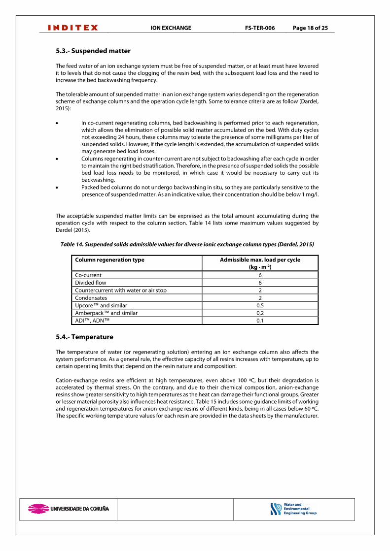
The acceptable suspended matter limits can be expressed as the total amount accumulating during the operation cycle with respect to the column section. Table 14 lists some maximum values suggested by Dardel (2015).
Table 14. Suspended solids admissible values for diverse ionic exchange column types (Dardel, 2015)
Column regeneration type Admissible max. load per cycle (kg · m-2)
Co-current 6 Divided flow 6 Countercurrent with water or air stop 2 Condensates 2 Upcore™ and similar 0,5 Amberpack™ and similar 0,2 ADI™, ADN™ 0,1
5.4.- Temperature The temperature of water (or regenerating solution) entering an ion exchange column also affects the system performance. As a general rule, the effective capacity of all resins increases with temperature, up to certain operating limits that depend on the resin nature and composition. Cation-exchange resins are efficient at high temperatures, even above 100 ºC, but their degradation is accelerated by thermal stress. On the contrary, and due to their chemical composition, anion-exchange resins show greater sensitivity to high temperatures as the heat can damage their functional groups. Greater or lesser material porosity also influences heat resistance. Table 15 includes some guidance limits of working and regeneration temperatures for anion-exchange resins of different kinds, being in all cases below 60 ºC. The specific working temperature values for each resin are provided in the data sheets by the manufacturer.

ION EXCHANGE FS-TER-006 Page 19 of 25
Table 15. Organic load and maximum work temperatures for different anionic-exchange resins (Dardel, 2015)
Type of anionic-exchange resin Maximum temperature (ºC)
Maximum organic load (g KMnO4/resin
L)
Maximum N fouling index
SB styrene type 1, gel 60 2 3 SB styrene type 2, gel 35 3 6 SB styrene type 1, macroporous 60 4 6 SB styrene type 2, macroporous 35 5 10 SB acrylic 35 8 15 SB acrylic macroporous 60 15 18 SB nitrate selective, macroporous 35 2 3 Acrylic bifunctional 25 10 15 WB styrene, macroporous 60 12 12 WB acrylic, gel 60 25 20 WB Boron-selective 40 5 6
SB: Strong base; WB: Weak base 5.5.- pH value Although most of the resins show chemical stability for any pH value between 0 and 14, their operation is affected by this parameter. Cation-exchange resins do not operate well at very low pH (excessive H+), while anion-exchange resins do not work properly at high pH (excessive OH-), as in both cases excess counterions would keep the system in a continuous regeneration state and would prevent the exchange. Exchange resins are designed to operate in an optimal pH range. Table 16 shows some typical pH ranges for the operating phase of the various generic resin types. Specific values for each individual resin are provided by the manufacturer in the data sheet.
Table 16. pH operation ranges for different ion exchange resin categories (Kirk-Othmer, 1999).
Resin type pH operation range Weak acid 6 – 14 Strong acid 4 – 14 Weak base 0 – 7 Strong base 0 – 9
6.- OPERATING PROBLEMS
The presence of certain chemical species in the feed water may provoke operating problems in the ion exchange systems. The presence of iron and manganese leads to the appearance of precipitates that cause gap clogging among particles and generate load losses, reduction of the exchange capacity and poorer treated water quality. Feed water must undergo a prior removal of these metals, assuring that their concentration remains below the recommended level. Resins should be washed with HCI in order to remove precipitates. Also, the presence of aluminum and barium in the feed water can cause the apparition of precipitates. Strong oxidants, like chlorine and ozone, degrade the resin structure, thus deteriorating the produced water quality. Their use as disinfectants for the disinfection and prevention of biofouling should be made in minimum dosage conditions. In case of not being precise, it is advisable to eliminate the excess oxidant by means of previous active carbon filters. Other compounds that may result in occlusions and clogging are oils and greases, and polyelectrolytes. Their presence in the feed water leads to the reduction of the resin exchange capacity, increasingly shorter cycles and quality loss in the produced water. Their removal requires a careful resin cleaning.
ION EXCHANGE FS-TER-006 Page 20 of 25
BIBLIOGRAPHY
Chougule, M. B., Sonaje, N. P. (2013). Cost-benefit analysis of wastewater recycling plant for textile wet processing. International Journal of Computational Engineering Research 3(2) 27-31 Corbitt, R. (2003). Manual de referencia de la ingeniería ambiental. McGraw-Hill/Interamericana de España. ISBN: 9788448135966 Coulson, J. M. (1999). Coulson & Richardson's Chemical Engineering. (6ª ed.) Oxford: Butterworth Heinemann. ISBN: 0-7506-4444-3 Crittenden, J. G., Trussell, R. R., Hand, D. W., Howe K. J., Tchobanoglous, G. (2005). “MWH’s Water Treatment: Principles and Design”, 2ª edición. John Wiley & Sons, Inc. ISBN: 978-0-471-11018-7 Dardel, F. (2015). “Ion Exchange”. En: http://dardel.info/IX/index.html (October, 2015) Dégremont (2001). Mémento technique de l'eau. Rueil-Malmaison (France): Ondeo Degrémont. Karcher, S., Kornmuller, A., Jekel, M. (2001). Anion exchange resins for removal of reactive dyes from textile wastewaters. Water Research, 36(19) 4717-4724. Kauspediene, D., Gefeniene, A., Kazlauskiene, F., Ragauskas, R., Selskiene, A. (2013). Simultaneous removal of azo and phtalocyanine dyes from aqueous solutions using weak base anion exchange resin. Water Air Soil Pollution 224, 1769-1782 Kirk-Othmer (1999). Encyclopedia of Chemical Technology (5ª ed.) “Ion Exchange”. New York: John Wiley and Sons. ISBN: 9780471238966 Nalco Chemical Company (1988). “The NALCO Water Handbook”. New York: McGraw-Hill ISBN 0-07-045872-3 Pang, Y. L., Abdullah, A. Z. (2013). Current status of textile industry wastewater management and research progress in Malaysia: A review. Clean Soil Air Water, 41(8) 751-764 Perry, R. H. (ed.) (2001). Manual del ingeniero químico. 7ª ed., (4ª ed. en español). Madrid: McGraw-Hill, 2001. ISBN: 84-481-3008-1 Raglu, S., Basha, C. A. (2007). Chemical or electrochemical techniques, followed by ion exchange, for recycle of textile dye wastewater. Journal of Hazardous Materials 149(2) 324-30 reactive dyes. Dyes and Pigments 51, 111–125 Seader, J. D., Henley, E. J. (1998). Separation Process Principles. New York: John Wiley & Sons. ISBN: 0-471-58626-9 Wawrzkiewicz, M. (2013). Removal of C.I. Basic Blue 3 dye by sorption onto cation exchange resin, functionalized and non-functionalized polymeric sorbents from aqueous solutions and wastewaters. Chemical Engineering Journal 217:414–425

ION EXCHANGE FS-TER-006 Page 21 of 25
TECHNOLOGY REFERENCES
Dowex Ion Exchange Resins. Dow Water and Process Solutions. www.dow.com/en-us/water-and-process-solutions Nalco Chemical Company. Ion Exchange Processes. www.nalco.com Indion Ion Exchange. www.indianionexchange.com Europrogetti Italy. Filtri a resine decoloranti. www.europrogeti-italy.com Purolite Corporation. www.purolite.com Rohm and Haas ion exchange resins. http://www.lenntech.es/productos/rohm-haas.htm Lanxess Lewatit ion exchange resins. http://lpt.lanxess.com/en/lewatit/ Mitshubishi ion exchange resins. http://www.diaion.com/ MIEX® Magnetic ion Exchange. http://www.miexresin.com/ SIX® Suspended ion Exchange. http://pwntechnologies.com/portfolio-item/six-suspended-ion-exchange-process/ Dégremont Technologies. http://www.degremont-technologies.com/Ion-Exchange-Skids
ION EXCHANGE FS-TER-006 Page 22 of 25
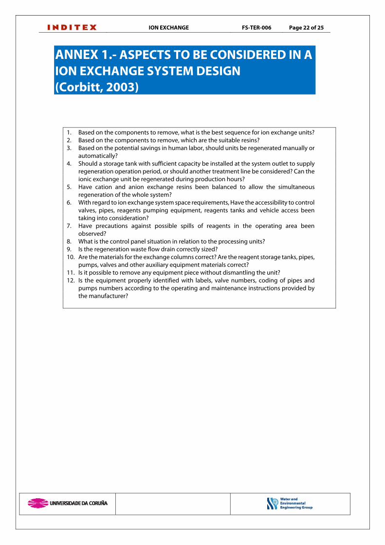
ANNEX 1.- ASPECTS TO BE CONSIDERED IN A ION EXCHANGE SYSTEM DESIGN (Corbitt, 2003)
1. Based on the components to remove, what is the best sequence for ion exchange units? 2. Based on the components to remove, which are the suitable resins? 3. Based on the potential savings in human labor, should units be regenerated manually or
automatically? 4. Should a storage tank with sufficient capacity be installed at the system outlet to supply
regeneration operation period, or should another treatment line be considered? Can the ionic exchange unit be regenerated during production hours?
5. Have cation and anion exchange resins been balanced to allow the simultaneous regeneration of the whole system?
6. With regard to ion exchange system space requirements, Have the accessibility to control valves, pipes, reagents pumping equipment, reagents tanks and vehicle access been taking into consideration?
7. Have precautions against possible spills of reagents in the operating area been observed?
8. What is the control panel situation in relation to the processing units? 9. Is the regeneration waste flow drain correctly sized? 10. Are the materials for the exchange columns correct? Are the reagent storage tanks, pipes,
pumps, valves and other auxiliary equipment materials correct? 11. Is it possible to remove any equipment piece without dismantling the unit? 12. Is the equipment properly identified with labels, valve numbers, coding of pipes and
pumps numbers according to the operating and maintenance instructions provided by the manufacturer?

ION EXCHANGE FS-TER-006 Page 23 of 25
ANNEX 2 UNIT SURFACE REQUIREMENTS
ION EXCHANGE UNIT SURFACE REQUIREMENTS This epigraph has intentionally left blank
ION EXCHANGE FS-TER-006 Page 24 of 25
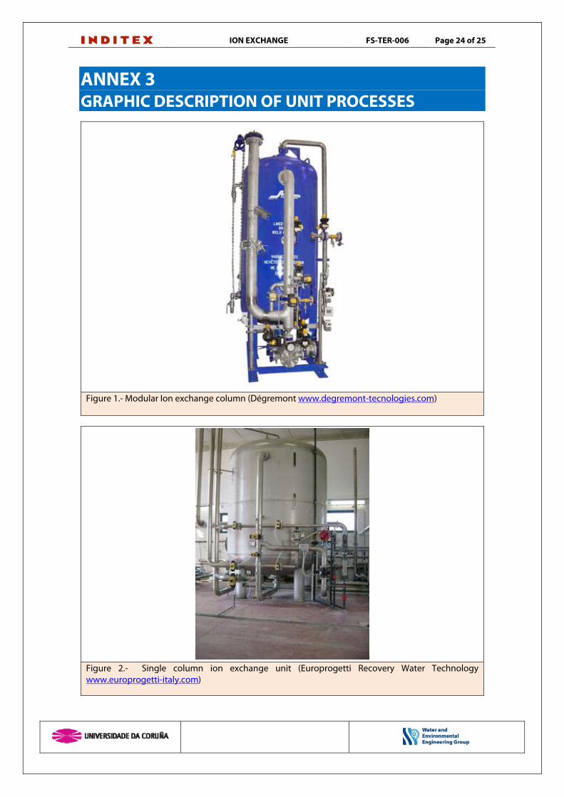
ANNEX 3 GRAPHIC DESCRIPTION OF UNIT PROCESSES
Figure 1.- Modular Ion exchange column (Dégremont www.degremont-tecnologies.com)
Figure 2.- Single column ion exchange unit (Europrogetti Recovery Water Technology www.europrogetti-italy.com)
ION EXCHANGE FS-TER-006 Page 25 of 25
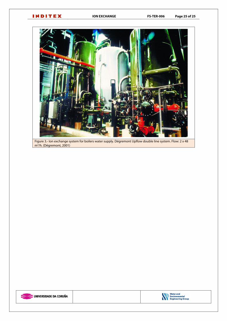
Figure 3.- Ion exchange system for boilers water supply. Dégremont Upflow double line system. Flow: 2 x 48 m3/h. (Dégremont, 2001)