Thea For SketchUp v2.0
46
Thea For SketchUp v2.0 www.thearender.com/sketchup User Manual Rev. 2.0 811
-
Upload
khangminh22 -
Category
Documents
-
view
1 -
download
0
Transcript of Thea For SketchUp v2.0

Thea For SketchUp v2.0www.thearender.com/sketchup
User ManualRev. 2.0 811

TABLE OF CONTENTS
1. INTRODUCTION 12. INSTALLATION 13. ACTIVATION 24. GENERAL LAYOUT OF THE PLUG‐IN (WINDOWS) 25. MAIN WINDOW 3 5.1. CONTROL PANEL (PRODUCTION MODE) 4 5.2. CONTROL PANEL (INTERACTIVE MODE) 46. THEA TOOL WINDOW 5 6.1. CAMERA TAB 5 6.2. MATERIAL TAB 6 6.3. LIGHTS TAB 19 6.4. ENVIRONMENT TAB 217. SETTINGS PANEL 23 7.1. DISPLAY TAB 23 7.2. RENDERING TAB 24 7.3. CHANNELS TAB 25 7.4. ANIMATION TAB 258. RENDER ENGINES 26 8.1. RENDERING MODES 26 8.2. PRESTO 26 8.3. UNBIASED TR1/TR2 27 8.4. ADAPTIVE BSD 27 8.5. ADAPTIVE AMC 289. NETWORK TAB 2810. CONSOLE TAB 2911. BATCH RENDERING TAB 2912. WINDOW SELECTION FOR INTERACTIVE RENDERING ‐ OVERLAY OPTION 3013. THEA BROWSER WINDOW 31 13.1. MODEL INFO 3214. PREFERENCES 3215. SECTION CUTS 3316. THEA CONTEXT MENU 3417. TROUBLESHOOTING 3418. CREATING EXTERNAL MODELS & THEIR PROXIES 3519. COPYRIGHT 3720. DISCLAIMER 3721. APPENDIX A ‐ MATERIAL PRESET TYPES 3822. APPENDIX B ‐ NETWORK RENDERING 4123. APPENDIX C ‐ INSTALLING THEA LIBRARIES 43
1 Copyright © 2018 ‐ Altair Engineering, Inc
1. INTRODUCTIONThea for SketchUp is an integrated version of Thea Render. It allows you to create stunning images right inside SketchUp and work interac vely with cameras, materials, and lights.
The extension supports SketchUp Make and Pro, versions 2015–2018, on Windows and Mac OS X. We highly recommend using a 64‐bit version of SketchUp 2015 or higher, because you can then access all of the available memory on 64‐bit opera ng systems.
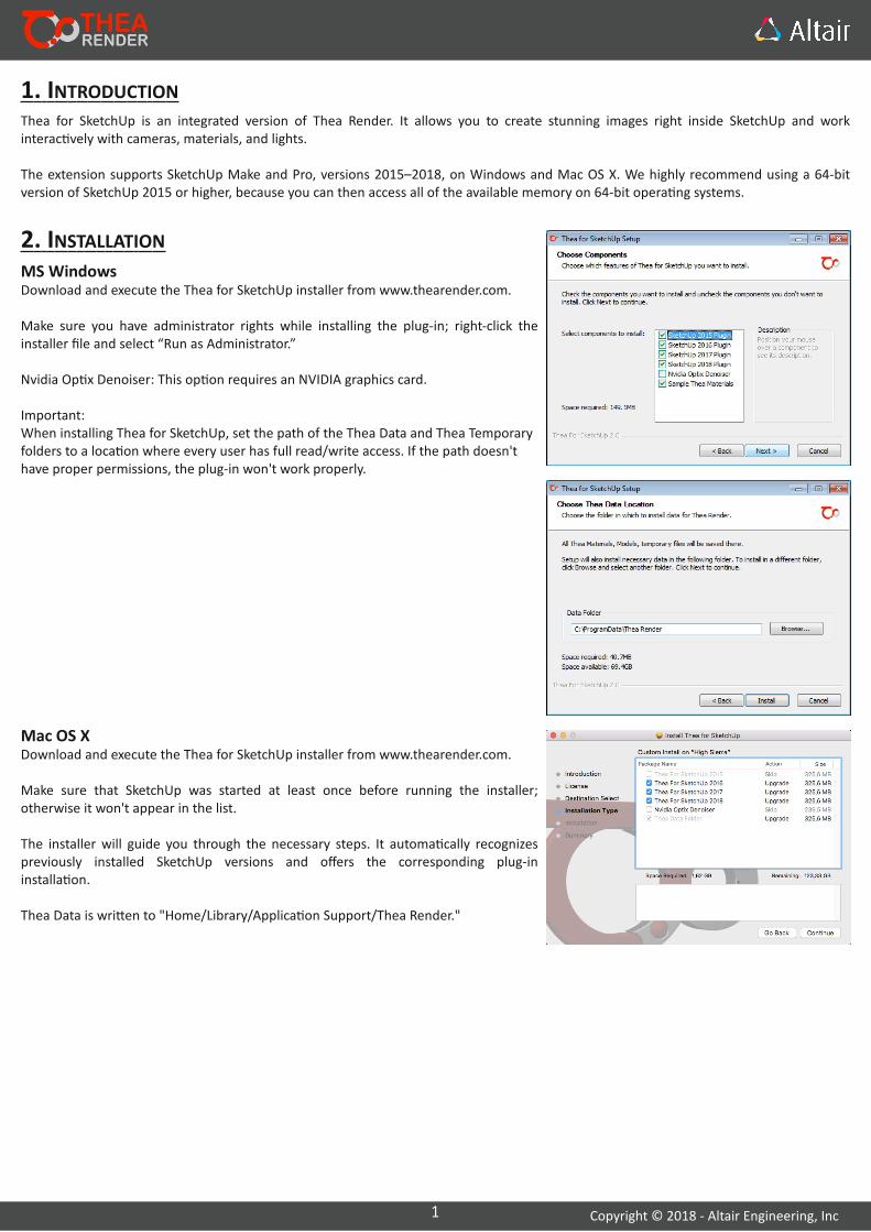
2. INSTALLATIONMS WindowsDownload and execute the Thea for SketchUp installer from www.thearender.com.
Make sure you have administrator rights while installing the plug‐in; right‐click the installer file and select “Run as Administrator.”
Nvidia Op x Denoiser: This op on requires an NVIDIA graphics card.
Important:When installing Thea for SketchUp, set the path of the Thea Data and Thea Temporary folders to a loca on where every user has full read/write access. If the path doesn't have proper permissions, the plug‐in won't work properly.
Mac OS XDownload and execute the Thea for SketchUp installer from www.thearender.com.
Make sure that SketchUp was started at least once before running the installer; otherwise it won't appear in the list.
The installer will guide you through the necessary steps. It automa cally recognizes previously installed SketchUp versions and offers the corresponding plug‐in installa on.
Thea Data is wri en to "Home/Library/Applica on Support/Thea Render."

2 Copyright © 2018 ‐ Altair Engineering, Inc
3. ACTIVATIONA er installing the plug‐in, open the license wizard from the main menu: Extensions > Thea Render > License Form.
Click "Register now" and complete the form to receive your license file by email.
To ac vate Thea, click "I have my license file. Ac vate now" and browse to your license file. Your license details are displayed at the top of the license form.
Note: If you don't ac vate your license, you will remain in Demo mode with certain limita ons.
Demo Version Limita onsPlease note that when the plug‐in is not licensed, the rendered image resolu on will be limited (1280x720) and watermarks will be added. All other features and func onali es are fully supported.
4. GENERAL LAYOUT OF THE PLUG‐IN WINDOWS
Once the plug‐in is installed, its name will appear in the Extensions menu:You can also access Thea for SketchUp through the tool pale e. Select 'Show Thea toolbar' from the Extensions menu. The following toolbar will appear.
Tip: If the plug‐in is not enabled, go to Preferences of SketchUp > Extensions to enable it.
The user interface consists of three windows:
THEA BROWSER WINDOW
THEA MAIN RENDERING WINDOW
Set up cameras, edit materials, place and edit lights, and set preferences. Insert Thea models, materials, skies,
and SketchUp components/proxies.
Displays the currently rendered image. Select engines and rendering modes, and adjust the display, channel, and environment se ngs.
THEA TOOL WINDOW

3 Copyright © 2018 ‐ Altair Engineering, Inc
5. MAIN WINDOW
Se ngs Panel
Modify the display, rendering, channel, and anima on se ngs.
Control Panel
Start/pause/stop rendering, save current image, and view current progress.
Rendering Panel ‐ "Darkroom"
Displays the rendered image with resolu on informa on and elapsed rendering me. Double‐click to maximize the window size.
4 Copyright © 2018 ‐ Altair Engineering, Inc
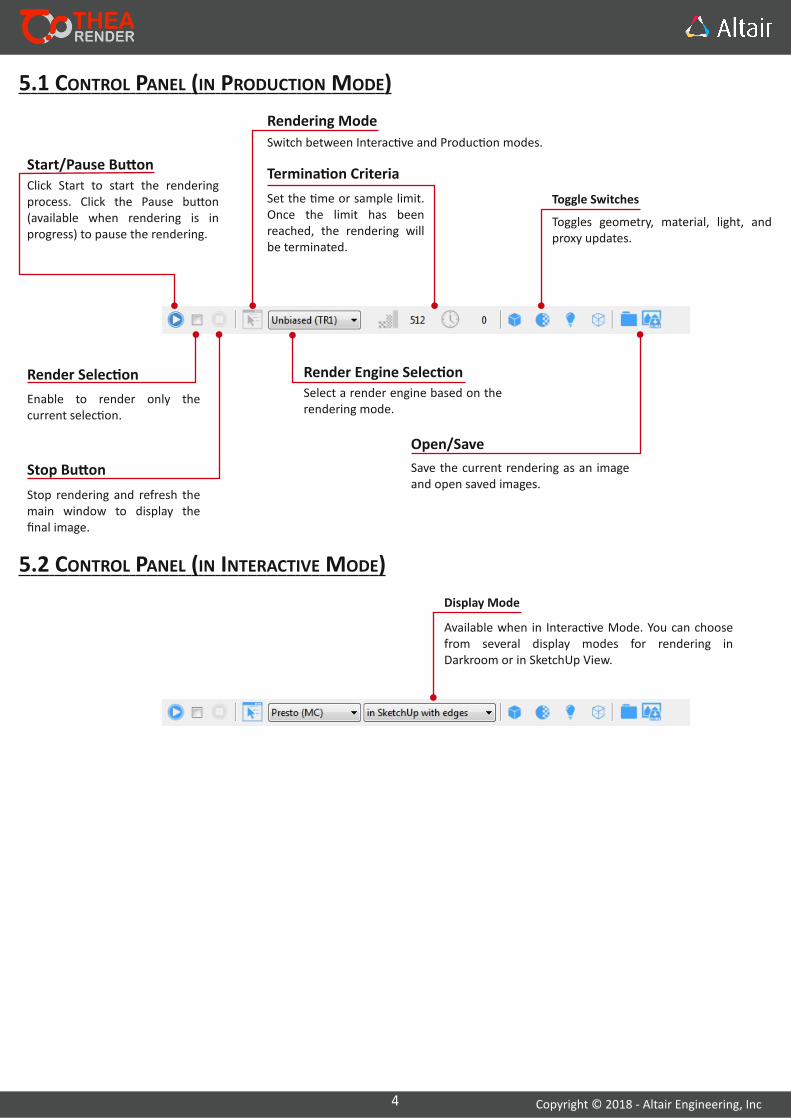
Enable to render only the current selec on.
Render Selec on
Click Start to start the rendering process. Click the Pause bu on (available when rendering is in progress) to pause the rendering.
Start/Pause Bu on
Stop rendering and refresh the main window to display the final image.
Stop Bu on
Switch between Interac ve and Produc on modes.
Rendering Mode
Select a render engine based on the rendering mode.
Render Engine Selec on
Toggles geometry, material, light, and proxy updates.
Toggle Switches
Save the current rendering as an image and open saved images.
Open/Save
Set the me or sample limit. Once the limit has been reached, the rendering will be terminated.
Termina on Criteria
5.1 CONTROL PANEL (IN PRODUCTION MODE)
Available when in Interac ve Mode. You can choose from several display modes for rendering in Darkroom or in SketchUp View.
Display Mode
5.2 CONTROL PANEL (IN INTERACTIVE MODE)
5 Copyright © 2018 ‐ Altair Engineering, Inc
6. THEA TOOL WINDOW
6.1. CAMERA TAB
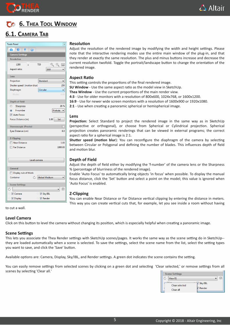
Resolu onAdjust the resolu on of the rendered image by modifying the width and height se ngs. Please note that the interac ve rendering modes use the en re main window of the plug‐in, and that they render at exactly the same resolu on. The plus and minus bu ons increase and decrease the current resolu on twofold. Toggle the portrait/landscape bu on to change the orienta on of the rendered image.
Aspect Ra oThis se ng controls the propor ons of the final rendered image.SU Window ‐ Use the same aspect ra o as the model view in SketchUp.Thea Window ‐ Use the current propor ons of the main render view.4:3 ‐ Use for older monitors with a resolu on of 800x600, 1024x768, or 1600x1200.16:9 ‐ Use for newer wide screen monitors with a resolu on of 1600x900 or 1920x1080.2:1 ‐ Use when crea ng a panoramic spherical or hemispherical image.
LensProjec on: Select Standard to project the rendered image in the same way as in SketchUp (perspec ve or orthogonal), or choose from Spherical or Cylindrical projec on. Spherical projec on creates panoramic renderings that can be viewed in external programs; the correct aspect ra o for a spherical image is 2:1.Shu er speed (mo on blur): You can reconfigure the diaphragm of the camera by selec ng between Circular or Polygonal and defining the number of blades. This influences depth of field and mo on blur.
Depth of FieldAdjust the depth of field either by modifying the 'f‐number' of the camera lens or the Sharpness % (percentage of blurriness of the rendered image).Enable 'Auto Focus' to automa cally bring objects 'in focus' when possible. To display the manual focus distance, click the 'Set' bu on and select a point on the model; this value is ignored when 'Auto Focus' is enabled.
Z‐ClippingYou can enable Near Distance or Far Distance ver cal clipping by entering the distance in meters. This way you can create ver cal cuts that, for example, let you see inside a room without having
to cut a wall.
Level CameraClick on this bu on to level the camera without changing its posi on, which is especially helpful when crea ng a panoramic image.
Scene Se ngsThis lets you associate the Thea Render se ngs with SketchUp scenes/pages. It works the same way as the scene se ng do in SketchUp‐‐they are loaded automa cally when a scene is selected. To save the se ngs, select the scene name from the list, select the se ng types you want to save, and click the 'Save' bu on.
Available op ons are: Camera, Display, Sky/IBL, and Render se ngs. A green dot indicates the scene contains the se ng.
You can easily remove se ngs from selected scenes by clicking on a green dot and selec ng 'Clear selected,' or remove se ngs from all scenes by selec ng 'Clear all.'

6 Copyright © 2018 ‐ Altair Engineering, Inc
6.2. MATERIAL TABIn the Material tab, you can click Preset or Editor.
Material PreviewYou can see a preview of the material in the top le of the Material tab by selec ng either Preset or Editor. The preview updates as you make changes. To view a full‐size preview, double‐click the image.
PresetsThis op on allows you to quickly transform a standard SketchUp material into a Thea material through a simplified interface.
You can choose from a list of ready to use materials like Metal, Car Paint, Glass, etc. Next to 'Default Preset,' click the hamburger menu icon, and then click a material.
Loading & Saving Thea materialsThea Materials can be saved as .mat.pack and .mat.thea files. Right‐click on the material preview area and select Load or Save Thea material.
.mat.thea: This file type includes only the material descrip on, without any bitmaps.
.mat.pack: This file type includes the material descrip on, bitmap files, and material preview.
Tip: When rendering interac vely in the Thea Window, the cursor changes to a cross‐hair, indica ng that you can select a material directly in the rendered image. Click once to open the Material tab and display the material proper es.
Customize a Preset MaterialAt the far right of a channel (Color, Reflec ons, Roughness, etc.), click the icon to choose from the following op ons:
•SketchUp: Use the color defined in SketchUp's material tray.•Color: Select a custom color.•Bitmap: Select a bitmap texture. You can preview the bitmap texture and edit the parameters (Tonemapping, UV Edi ng, etc.)
DEFAULT
Thea CursorWhen the Thea Tool window is open, the SketchUp cursor changes to the Thea cursor, indica ng that you can click on a face to pick the corresponding material for edi ng. The Thea Cursor can also be used to select and edit Thea Lights from the scene.
THIN TRANSLUCENT LACQUER CERAMIC CAR PAINT COLORED METAL MIRROR THIN GLASS GLASSGLASSLACQUER
EMITTERCLOUD
Tip: When switching from the Editor back to Presets a small popup will ask you whether you want to reset back to a default preset, making sure that you haven't accidentally clicked on it and lose your material modifica ons.

7 Copyright © 2018 ‐ Altair Engineering, Inc
EditorUse the full material editor to create a complex material with mul ple layers.
LayersYou can create mul ple layers of different types and weights.
•Create a layer: Click the plus (+) icon, and then click a type of layer (choose from Basic Layer, Metal Layer, Glass Layer, Thin Glass Layer, or SSS Layer).•Change the type of layer: Click the sphere icon, and then click a type of layer (choose from Basic, Metal, Glass, Thin Glass, or SSS).•Define the weight of the layer: To change the %, drag the colored horizontal bar. Or to select a bitmap, click the checkerboard icon.•Delete a layer: Click the layer, and then click the trash can icon.•Move a layer: Click the layer, and then click the up or down arrow.
Material PreviewThe material preview can be maximized by double‐clicking on it. More op ons can be found when right‐clicking on the preview:•Load Material: Loads a .mat.thea / .mat.pack Thea Material.•Save Material: Saves the current material to .mat.thea / .mat.pack files•Room Selec on: Select between different kind of room previews (e.g. cloth, direct, floor, etc)
Material formats explana on.mat.thea: This material file format contains the defini on of the Thea Material but not the textures used..mat.pack: Same as the .mat.thea format but packs all the textures in it.
Layer Proper esBelow the Layers sec on, you can find the parameters of the currently selected layer.
Display advanced parameters: To display advanced parameters (Translucency, Micro Roughness, etc.), click the hamburger menu icon.
Tip: Holding down the Control key in the keyboard allows you to select mul ple op ons.
Tip: Use drag and drop between channels with the le mouse bu on to copy a bitmap, color or procedural.

8 Copyright © 2018 ‐ Altair Engineering, Inc
Glass LayerYou can create a glass with perfect reflec on and refrac on (Roughness = 0), a very rough glass (Roughness = 100), or something in between. The Bidirec onal Sca ering Distribu on Func on (BSDF) uses Fresnel equa ons to balance reflec on and refrac on, which is controlled by the index of refrac on and the ex nc on coefficient. Set the Index of Refrac on to around 1 to make the material less reflec ve and more refrac ve. Set the value to exactly 1 to make the glass perfectly transparent. As you increase the value, reflec on becomes stronger and stronger; at very high values, the reflected light takes on the color of the selected color.
Tip: To achieve perfect transparency, we recommend that you create a Thin Glass Layer instead of a Glass Layer with Transmi ance enabled and the Index of Refrac on set to 1.
Important: Fresnel coefficients are based on both the index of refrac on and the angle of incidence. Even with a very small index of refrac on, the BSDF will be quite reflec ve for grazing angles. A real world example is a swimming pool. When you look straight into the pool, the water is transparent; however, when you look at the pool from afar, the water reflects the environment.
Coa ng LayerThe coa ng layer uses a special reflec on model with only the specular component. It is useful for simula ng varnishes and paints on a layered material.
You can use several coa ng layers to simulate mul ple varnishes and paints. The coa ng itself reflects some light, while any layers of material underneath absorb the rest of the light.
You can change the Ex nc on Coefficient to modify the reflectance (based on Fresnel equa ons) and define the absorp on density of the layers of material underneath. Both the Ex nc on Coefficient and the Thickness of the layered material are used to calculate absorp on at a microscopic level.
Basic LayerThe basic layer consists of a diffuse, translucent, and Fresnel based specular component. It is a highly energy efficient material designed to be used mostly for ma e and plas c materials.
You might also use basic layers to create metals and translucent materials. Metals, in most cases, have a non‐zero ex nc on coefficient, which corresponds to a high Fresnel coefficient under any viewing angle.
Metal LayerYou can create a metal with perfect reflec on (Roughness = 0), a very rough metal (Roughness = 100), or something in between.
The Bidirec onal Sca ering Distribu on Func on (BSDF) uses Fresnel equa ons for reflec ons, which is controlled by the index of refrac on and the ex nc on coefficient.
Set the Index of Refrac on to around 1 to make the material less reflec ve. As you increase the value, reflec on becomes stronger and stronger; at very high values, the reflected light takes on the color of the selected color.
Use a non‐zero value for the Ex nc on Coefficient to amplify reflec on.
9 Copyright © 2018 ‐ Altair Engineering, Inc
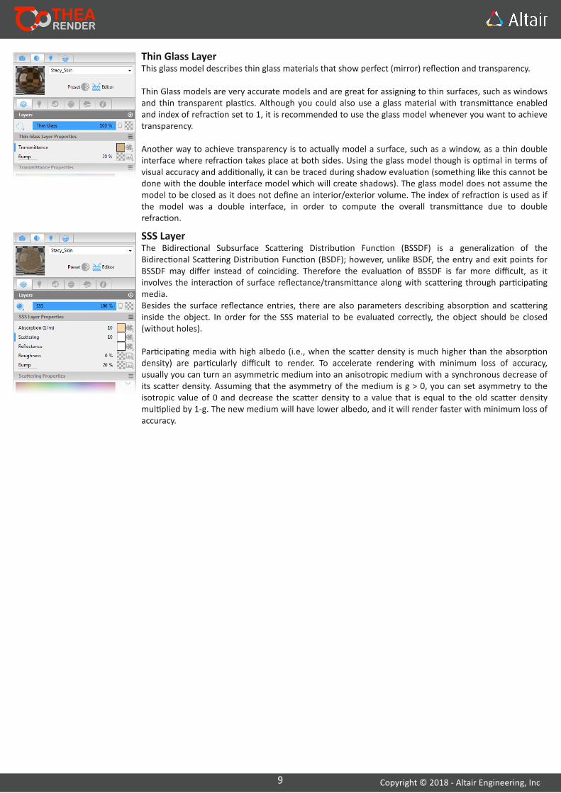
SSS LayerThe Bidirec onal Subsurface Sca ering Distribu on Func on (BSSDF) is a generaliza on of the Bidirec onal Sca ering Distribu on Func on (BSDF); however, unlike BSDF, the entry and exit points for BSSDF may differ instead of coinciding. Therefore the evalua on of BSSDF is far more difficult, as it involves the interac on of surface reflectance/transmi ance along with sca ering through par cipa ng media.Besides the surface reflectance entries, there are also parameters describing absorp on and sca ering inside the object. In order for the SSS material to be evaluated correctly, the object should be closed (without holes).
Par cipa ng media with high albedo (i.e., when the sca er density is much higher than the absorp on density) are par cularly difficult to render. To accelerate rendering with minimum loss of accuracy, usually you can turn an asymmetric medium into an anisotropic medium with a synchronous decrease of its sca er density. Assuming that the asymmetry of the medium is g > 0, you can set asymmetry to the isotropic value of 0 and decrease the sca er density to a value that is equal to the old sca er density mul plied by 1‐g. The new medium will have lower albedo, and it will render faster with minimum loss of accuracy.
Thin Glass LayerThis glass model describes thin glass materials that show perfect (mirror) reflec on and transparency.
Thin Glass models are very accurate models and are great for assigning to thin surfaces, such as windows and thin transparent plas cs. Although you could also use a glass material with transmi ance enabled and index of refrac on set to 1, it is recommended to use the glass model whenever you want to achieve transparency.
Another way to achieve transparency is to actually model a surface, such as a window, as a thin double interface where refrac on takes place at both sides. Using the glass model though is op mal in terms of visual accuracy and addi onally, it can be traced during shadow evalua on (something like this cannot be done with the double interface model which will create shadows). The glass model does not assume the model to be closed as it does not define an interior/exterior volume. The index of refrac on is used as if the model was a double interface, in order to compute the overall transmi ance due to double refrac on.

10 Copyright © 2018 ‐ Altair Engineering, Inc
LAYER PARAMETERS
Diffuse: Diffuse reflec on is when light is sca ered at several angles on a surface. You can select a texture, color, or procedural.Layers used in: Basic
Reflectance: Reflectance is the texture for the specular component when you view the surface from directly above. Reflectance at the grazing angle (90 degrees) is also implicitly defined. So, the specular reflectance is calculated as a combina on between user Reflectance and Reflectance 90 (white by default), depending on the viewing angle.Layers used in: Basic, Metal, Glass, SSS, and Coa ng
Anisotropy: Stretch and blur highlights against the grain of the material, which is par cularly useful for metals. For no anisotropy, set the value to 0%. For full anisotropy, set the value to 100% (the material is a perfect reflector/refractor in one direc on and completely rough in the other direc on).Layers used in: Basic, Metal, Glass, SSS, and Coa ng
Rota on (deg): To rotate the stretched and blurred highlights created using Anisotropy, enter a value from 0 to 360 degrees or select a texture.Layers used in: Basic, Metal, Glass, SSS, and Coa ng
Roughness: Adds texture to the material at a microscopic level, affec ng specular reflectance and transmi ance. 0% creates a perfect mirror reflec on. Lower values produce crisper and brighter reflec ons. Increasing the roughness will spread and distribute reflec ons and create a more ma e surface. Higher values produce bigger highlights and reflec ons that are more blurry and dim. At values approaching 100%, light becomes so sca ered that the reflec ons are barely visible, if at all.Layers used in: Basic, Metal, Glass, SSS, and Coa ng
Bump: Adds texture to the material at a macroscopic level. A bump map gives the illusion of texture without physically distor ng the geometry, minimizing rendering me. Each layer of material can have its own bump map. The grayscale map tells Thea Render how to change the surface normals as if the surface has been displaced; the modified normals are used in ligh ng calcula ons. A bump map looks like the inverse of what you might expect: black represents the highest extreme and white represents the fla est extreme, while shades of gray represent grades in between. Layers used in: All
Normal: This is a more detailed version of bump mapping, where you select a RGB color image instead of a grayscale image. While standard bump mapping uses grayscale values to describe the surface's hills and valleys in terms of height, normal mapping translates red, green, and blue values to x, y, and z coordinates. This creates texture in terms of normal vectors up the hill or down the valley. Specifically, the red, green, and blue values (0 to 255) are translated to x (–1 to 1), y (–1 to 1), and z (0 to 1) coordinates respec vely.Layers used in: All
Index of Refrac on (n): When you place something behind a transparent object, it becomes distorted. The level of distor on is determined by the Index of Refrac on, which defines how much light is bent and reflected when it comes into contact with a transparent surface. For example, air's value, 1.0, causes no distor on of background objects. A value of 1.5 means that the background objects become considerably distorted (e.g., a glass marble). A value just below 1.0 causes the object to reflect along its edges (e.g., a bubble seen from under water).Layers used in: All
Ex nc on Coefficient (k): This refers to light that is likely to be lost (i.e., to absorp on and sca ering). The higher the ex nc on coefficient, the more opaque the material. You can use a value of zero or above.Layers used in: Basic, Metal, Glass, and Coa ng
Translucent: Make the material semitransparent by clicking on a texture. If no texture is selected, then no translucency will be rendered.Layers used in: Basic
Micro Roughness: Adjust the sharpness of reflec ons, as the viewing distance goes from near to far. When looking at a surface that is completely rough, planes that are closer appear rougher (because you can see them more clearly) while surfaces that are further away appear smoother (because you can't seem them as clearly). You can adjust the Height and Width to define the average height and width (μm) of the bumps on the surface.Layers used in: Basic, Metal, Glass, SSS, and Coa ng
11 Copyright © 2018 ‐ Altair Engineering, Inc
Thickness (μm): This refers to the coa ng thickness. The thickness and ex nc on coefficient are used to calculate the amount of light absorbed by any layers underneath the coa ng.Layers used in: Coa ng
IOR File: You can create a physically accurate material by using an Index of Refrac on file, which provides the exact index of refrac on and ex nc on coefficient for each wavelength of a material. The file extension is .ior or .nk.Layers used in: Glass and Metal
Transmi ance: The amount of light that passes through a material.Layers used in: Glass and Thin Glass
Absorp on (1/m): Change the absorp on density and color. You can use a value of zero or higher. The higher the density, the more absorp ve the material. Note: In the Basic layer, Translucency needs to be enabled for Absorp on to take effect. For glossy materials, you need to select a color or a texture for transmi ance first.When the absorp on values is greater than zero, a value in millimeters will be displayed. This value represents the distance that the absorp on color will be visualized.Layers used in: Basic, Glass, SSS, and Coa ng
Abbe Number: Can be used to create a rainbow effect in the interior of an object, such as a gemstone. Without this rainbow effect, gemstones would look like glass. Lower values correspond to a stronger rainbow effect. Increase the value for a more subtle effect. You can look up the values for specific materials online. The Abbe number describes the varia on of the index of refrac on with respect to the wavelength.Layers used in: Glass
Interference: Makes a surface iridescent, simula ng a phenomenon called thin film interference. You may have seen this in soap bubbles, oil slicks on water, or peacock feathers. When light waves come into contact with a thin film, some waves are reflected from the top surface while others penetrate the film, hit the bo om surface, and are reflected. When these light waves interact, momentary streaks of color result. The iridescent colors change when the viewing angle is changed. Adjust the Thickness to change the iridescence level. 200‐1000 is a good general range for making a visible change.Layers used in: Thin Glass
Sca ering (1/m): Changes the sca er density and color for a subsurface sca ering material. You can use a value of zero or higher. Note that the higher the value, the longer it will take to render the material. The sca er color is used for both in‐sca ering and out‐sca ering light interac on.Layers used in: SSS
Asymmetry: Controls the asymmetric coefficient of a subsurface sca ering medium, which follows the Henyey‐Greenstein phase func on. You can use a value between –1 and +1, where –1 corresponds to a perfect back sca ering media, +1 to a perfect front sca ering media, and 0 to an isotropic media.Layers used in: SSS
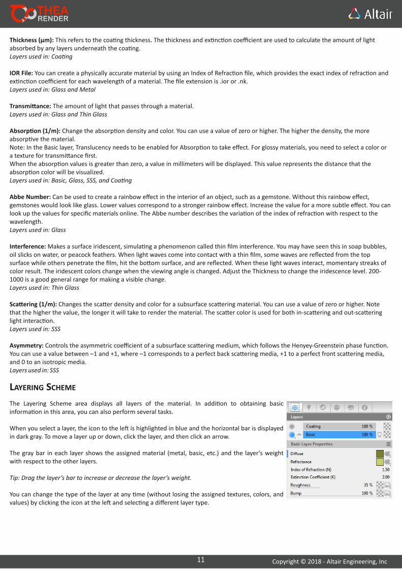
The Layering Scheme area displays all layers of the material. In addi on to obtaining basic informa on in this area, you can also perform several tasks.
When you select a layer, the icon to the le is highlighted in blue and the horizontal bar is displayed in dark gray. To move a layer up or down, click the layer, and then click an arrow.
The gray bar in each layer shows the assigned material (metal, basic, etc.) and the layer’s weight with respect to the other layers.
Tip: Drag the layer’s bar to increase or decrease the layer’s weight.
You can change the type of the layer at any me (without losing the assigned textures, colors, and values) by clicking the icon at the le and selec ng a different layer type.
LAYERING SCHEME
12 Copyright © 2018 ‐ Altair Engineering, Inc
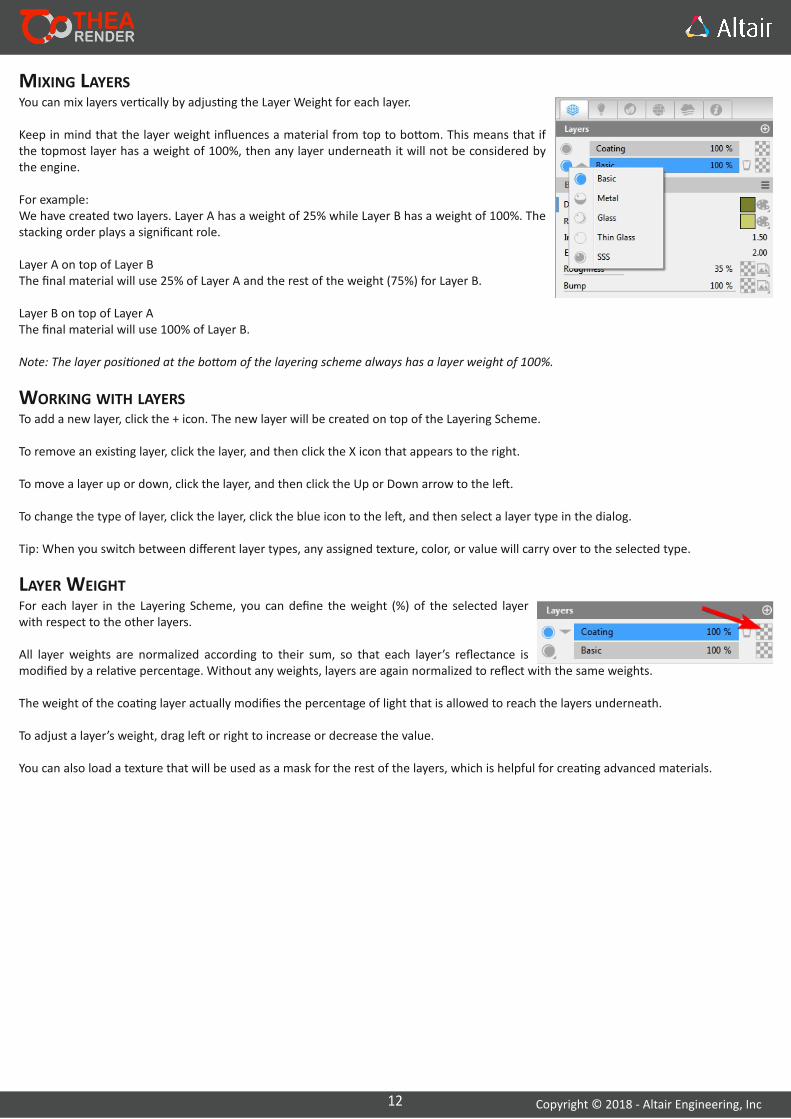
You can mix layers ver cally by adjus ng the Layer Weight for each layer.
Keep in mind that the layer weight influences a material from top to bo om. This means that if the topmost layer has a weight of 100%, then any layer underneath it will not be considered by the engine.
For example: We have created two layers. Layer A has a weight of 25% while Layer B has a weight of 100%. The stacking order plays a significant role.
Layer A on top of Layer BThe final material will use 25% of Layer A and the rest of the weight (75%) for Layer B.
Layer B on top of Layer AThe final material will use 100% of Layer B.
Note: The layer posi oned at the bo om of the layering scheme always has a layer weight of 100%.
MIXING LAYERS
WORKING WITH LAYERSTo add a new layer, click the + icon. The new layer will be created on top of the Layering Scheme.
To remove an exis ng layer, click the layer, and then click the X icon that appears to the right.
To move a layer up or down, click the layer, and then click the Up or Down arrow to the le .
To change the type of layer, click the layer, click the blue icon to the le , and then select a layer type in the dialog.
Tip: When you switch between different layer types, any assigned texture, color, or value will carry over to the selected type.
LAYER WEIGHTFor each layer in the Layering Scheme, you can define the weight (%) of the selected layer with respect to the other layers.
All layer weights are normalized according to their sum, so that each layer’s reflectance is modified by a rela ve percentage. Without any weights, layers are again normalized to reflect with the same weights.
The weight of the coa ng layer actually modifies the percentage of light that is allowed to reach the layers underneath.
To adjust a layer’s weight, drag le or right to increase or decrease the value.
You can also load a texture that will be used as a mask for the rest of the layers, which is helpful for crea ng advanced materials.
13 Copyright © 2018 ‐ Altair Engineering, Inc
EMITTERThea Render supports both area and point light emi ers. The area emi ers are applied to a surface. Typically, the area emi er has a diffusion‐like emission model and distributes light evenly in all direc ons. Nevertheless, more complex emission models can be defined using an IES file.
Color: You can define the color of the light using the following op ons: Color, Custom Color, Temperature, Bitmap, and Procedural.
Power: Define the power of the emi ance.
Passive Emi er: The emi er will not cast light into the scene, but it will glow.
IES Emi erTo convert a standard emi er to an IES emi er, click the hamburger menu icon and select IES Emi er.
Efficacy: Maximum efficacy is 683 lm/w, which corresponds to light with no energy loss (all power is converted to visible light).
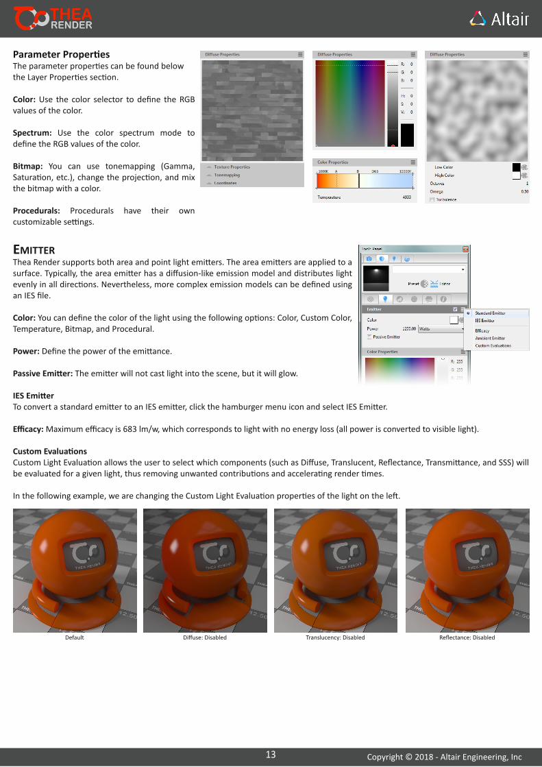
Custom Evalua onsCustom Light Evalua on allows the user to select which components (such as Diffuse, Translucent, Reflectance, Transmi ance, and SSS) will be evaluated for a given light, thus removing unwanted contribu ons and accelera ng render mes.
In the following example, we are changing the Custom Light Evalua on proper es of the light on the le .
Default Diffuse: Disabled Translucency: Disabled Reflectance: Disabled
Parameter Proper esThe parameter proper es can be found below the Layer Proper es sec on.
Color: Use the color selector to define the RGB values of the color.
Spectrum: Use the color spectrum mode to define the RGB values of the color.
Bitmap: You can use tonemapping (Gamma, Satura on, etc.), change the projec on, and mix the bitmap with a color.
Procedurals: Procedurals have their own customizable se ngs.

14 Copyright © 2018 ‐ Altair Engineering, Inc
CLIPPINGUsed to make areas of the material transparent, using a grayscale texture map where black represents complete transparency and white complete opaqueness. This is useful for quickly crea ng perforated materials like a mesh, since you can skip modeling the holes by hand.
Texture: Select an image. Colored images will be mapped as grayscale.
So Clipping (Default): So ens the contrast between complete transparency and opaqueness. The alpha channel of the image is respected, and all gray values are used to clip the material.
Hard Clipping: Increases the contrast between complete transparency and opaquness. When used in combina on with the Threshold parameter, you can select which parts of the image are used to clip the material.
Threshold: Changes how the texture map is interpreted. For example, at a value of 50, 50% gray is interpreted as 50% transparent. To make a larger area of the texture transparent; increase the threshold; to make a larger area of the texture opaque, decrease the threshold. At 100, all of the texture is transparent; at 0, all of the texture is opaque.
So Clipping
Hard Clipping with 5% Threshold
Hard Clipping with 30% Threshold
Clip Mapping Window
Transmi ance: Enabled Transmi ance: Disabled Medium: Enabled Medium: Disabled
15 Copyright © 2018 ‐ Altair Engineering, Inc
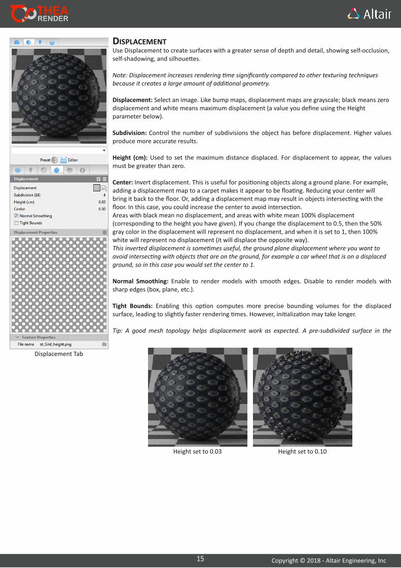
DISPLACEMENTUse Displacement to create surfaces with a greater sense of depth and detail, showing self‐occlusion, self‐shadowing, and silhoue es.
Note: Displacement increases rendering me significantly compared to other texturing techniques because it creates a large amount of addi onal geometry.
Displacement: Select an image. Like bump maps, displacement maps are grayscale; black means zero displacement and white means maximum displacement (a value you define using the Height parameter below).
Subdivision: Control the number of subdivisions the object has before displacement. Higher values produce more accurate results.
Height (cm): Used to set the maximum distance displaced. For displacement to appear, the values must be greater than zero.
Center: Invert displacement. This is useful for posi oning objects along a ground plane. For example, adding a displacement map to a carpet makes it appear to be floa ng. Reducing your center will bring it back to the floor. Or, adding a displacement map may result in objects intersec ng with the floor. In this case, you could increase the center to avoid intersec on.Areas with black mean no displacement, and areas with white mean 100% displacement (corresponding to the height you have given). If you change the displacement to 0.5, then the 50% gray color in the displacement will represent no displacement, and when it is set to 1, then 100% white will represent no displacement (it will displace the opposite way).This inverted displacement is some mes useful, the ground plane displacement where you want to avoid intersec ng with objects that are on the ground, for example a car wheel that is on a displaced ground, so in this case you would set the center to 1.
Normal Smoothing: Enable to render models with smooth edges. Disable to render models with sharp edges (box, plane, etc.).
Tight Bounds: Enabling this op on computes more precise bounding volumes for the displaced surface, leading to slightly faster rendering mes. However, ini aliza on may take longer.
Tip: A good mesh topology helps displacement work as expected. A pre‐subdivided surface in the
Height set to 0.03 Height set to 0.10
Displacement Tab
16 Copyright © 2018 ‐ Altair Engineering, Inc
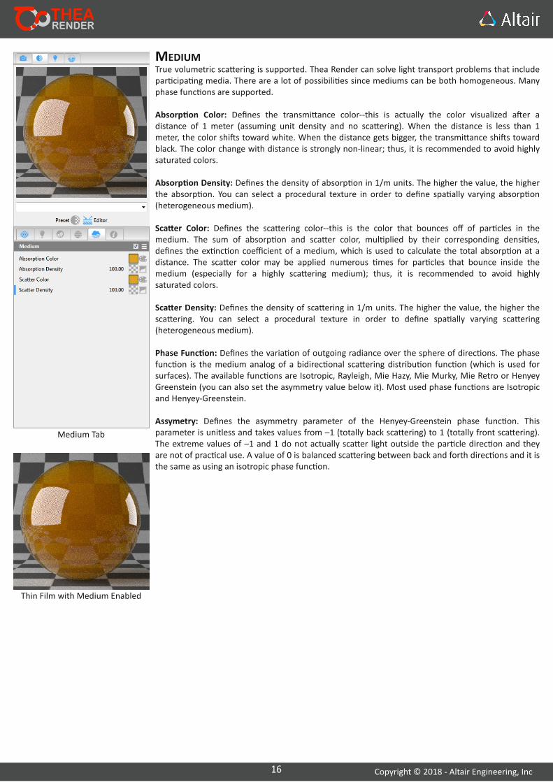
MEDIUMTrue volumetric sca ering is supported. Thea Render can solve light transport problems that include par cipa ng media. There are a lot of possibili es since mediums can be both homogeneous. Many phase func ons are supported.
Absorp on Color: Defines the transmi ance color‐‐this is actually the color visualized a er a distance of 1 meter (assuming unit density and no sca ering). When the distance is less than 1 meter, the color shi s toward white. When the distance gets bigger, the transmi ance shi s toward black. The color change with distance is strongly non‐linear; thus, it is recommended to avoid highly saturated colors.
Absorp on Density: Defines the density of absorp on in 1/m units. The higher the value, the higher the absorp on. You can select a procedural texture in order to define spa ally varying absorp on (heterogeneous medium).
Sca er Color: Defines the sca ering color‐‐this is the color that bounces off of par cles in the medium. The sum of absorp on and sca er color, mul plied by their corresponding densi es, defines the ex nc on coefficient of a medium, which is used to calculate the total absorp on at a distance. The sca er color may be applied numerous mes for par cles that bounce inside the medium (especially for a highly sca ering medium); thus, it is recommended to avoid highly saturated colors.
Sca er Density: Defines the density of sca ering in 1/m units. The higher the value, the higher the sca ering. You can select a procedural texture in order to define spa ally varying sca ering (heterogeneous medium).
Phase Func on: Defines the varia on of outgoing radiance over the sphere of direc ons. The phase func on is the medium analog of a bidirec onal sca ering distribu on func on (which is used for surfaces). The available func ons are Isotropic, Rayleigh, Mie Hazy, Mie Murky, Mie Retro or Henyey Greenstein (you can also set the asymmetry value below it). Most used phase func ons are Isotropic and Henyey‐Greenstein.
Assymetry: Defines the asymmetry parameter of the Henyey‐Greenstein phase func on. This parameter is unitless and takes values from –1 (totally back sca ering) to 1 (totally front sca ering). The extreme values of –1 and 1 do not actually sca er light outside the par cle direc on and they are not of prac cal use. A value of 0 is balanced sca ering between back and forth direc ons and it is the same as using an isotropic phase func on.
Thin Film with Medium Enabled
Medium Tab

17 Copyright © 2018 ‐ Altair Engineering, Inc
TEXTURE EDITINGEdi ng ModesThe texture edi ng tool has two modes to work with, Overview Mode and Edit Mode.
Overview: Only the modified parameters are displayed; the rest are hidden.
Edit: All available parameters for bitmap edi ng (Texture Proper es, Tonemapping, and Coordinates) are displayed.Any parameters modified here will be displayed in Overview Mode.
Edi ng a BitmapBy default, the Thea Material editor is in Overview Mode, displaying only the path to the file and any modified parameters. To start edi ng the bitmap, click the hamburger menu icon and select Edit Mode.
Texture Proper esProjec on: Press the down arrow, and then select a projec on for the selected texture: UV, Cubic, Cylindrical, Spherical, Flat, Front, Shrinkwrap, Camera Map, Cubic (Centered), and Flat (Centered).UV Channel: You can link a texture to a channel (e.g., Diffuse, Refrac on, Bump, etc.).Channel: Two main channels exist for a texture, the RGB channel and the Alpha channel.Interpola on: Select a type of interpola on for the selected image: None, Bilinear, or Trilinear.
Repeat: Force the bitmap texture to le in all direc ons.
TonemappingInvert: Invert all the colors of the texture to their complementary colors.Gamma: Use a value from ‐100% to 100%. In the next images, you can see how the gamma affects the appearance of the texture.Satura on: Use a value from ‐100% to 100%. In the next textures, you can see how two extreme values for satura on affect the tone of the texture.Brightness: Use a value from ‐100% to 100% to control the tone of the texture. A brightness of ‐100% makes the image completely black.Contrast: The contrast of the texture. Clamp Min and Max: Specify the minimum and maximum clamp of the selected texture. RGB colors normally range from 0 to 255. By se ng, for example, the minimum clamp to 20%, the colors with RGB values less than around 51 will be “cut” and get this value. By increasing minimum clamp percentage, the image turns whiter, while decreasing the maximum clamp percentage results in darker image colors. By decreasing the maximum percentage and increasing the minimum at the same me, textures tend to appear grayer, as gray colors has RGV values around the middle of the 256 colors (128, 128, 128).
CoordinatesOffset X and Y: Offsets the bitmap over the x‐ or y‐axis.Spa al Size (X and Y): Spa al size is used to correctly account for scaling when changing from UV to cubic coordinates, while UV scaling affects the scaling once UV projec on is used.UV Scale X and Y: Scales the bitmap over the x‐ or y‐axis.
18 Copyright © 2018 ‐ Altair Engineering, Inc
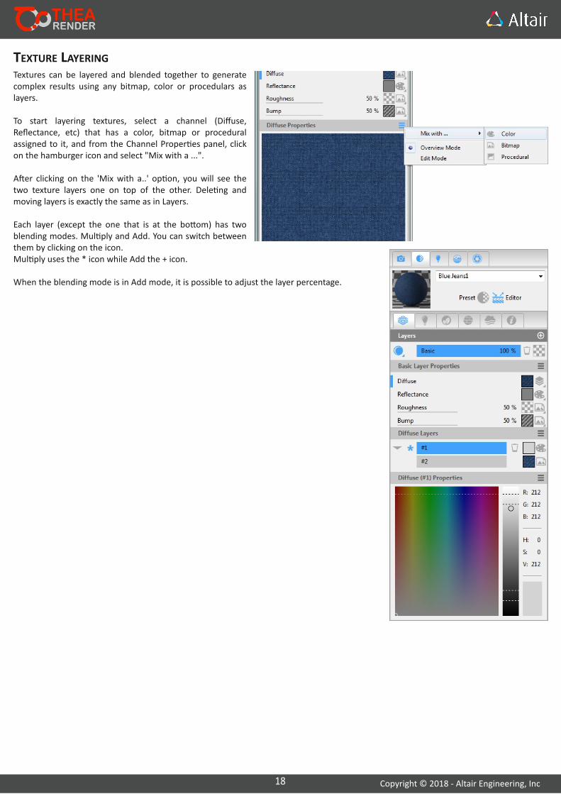
TEXTURE LAYERINGTextures can be layered and blended together to generate complex results using any bitmap, color or procedulars as layers.
To start layering textures, select a channel (Diffuse, Reflectance, etc) that has a color, bitmap or procedural assigned to it, and from the Channel Proper es panel, click on the hamburger icon and select "Mix with a ...".
A er clicking on the 'Mix with a..' op on, you will see the two texture layers one on top of the other. Dele ng and moving layers is exactly the same as in Layers.
Each layer (except the one that is at the bo om) has two blending modes. Mul ply and Add. You can switch between them by clicking on the icon.Mul ply uses the * icon while Add the + icon.
When the blending mode is in Add mode, it is possible to adjust the layer percentage.
19 Copyright © 2018 ‐ Altair Engineering, Inc
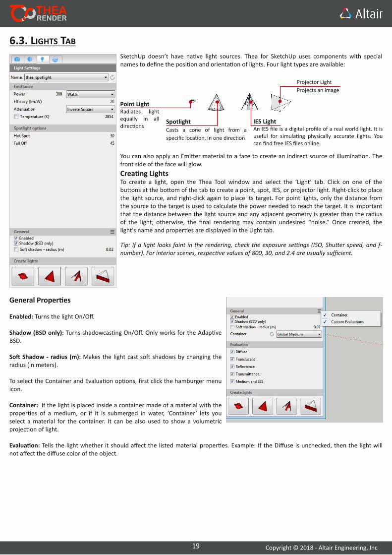
6.3. LIGHTS TAB
You can also apply an Emi er material to a face to create an indirect source of illumina on. The front side of the face will glow.
Crea ng LightsTo create a light, open the Thea Tool window and select the ‘Light’ tab. Click on one of the bu ons at the bo om of the tab to create a point, spot, IES, or projector light. Right‐click to place the light source, and right‐click again to place its target. For point lights, only the distance from the source to the target is used to calculate the power needed to reach the target. It is important that the distance between the light source and any adjacent geometry is greater than the radius of the light; otherwise, the final rendering may contain undesired “noise.” Once created, the light's name and proper es are displayed in the Light tab.
Point LightRadiates light equally in all direc ons
SpotlightCasts a cone of light from a
specific loca on, in one direc on
IES LightAn IES file is a digital profile of a real world light. It is useful for simula ng physically accurate lights. You can find free IES files online.
SketchUp doesn’t have na ve light sources. Thea for SketchUp uses components with special names to define the posi on and orienta on of lights. Four light types are available:
Tip: If a light looks faint in the rendering, check the exposure se ngs (ISO, Shu er speed, and f‐number). For interior scenes, respec ve values of 800, 30, and 2.4 are usually sufficient.
Projector Light
Projects an image
General Proper es
Enabled: Turns the light On/Off.
Shadow (BSD only): Turns shadowcas ng On/Off. Only works for the Adap ve BSD.
So Shadow ‐ radius (m): Makes the light cast so shadows by changing the radius (in meters).
To select the Container and Evalua on op ons, first click the hamburger menu icon.
Container: If the light is placed inside a container made of a material with the proper es of a medium, or if it is submerged in water, ‘Container’ lets you select a material for the container. It can be also used to show a volumetric projec on of light.
Evalua on: Tells the light whether it should affect the listed material proper es. Example: If the Diffuse is unchecked, then the light will not affect the diffuse color of the object.

20 Copyright © 2018 ‐ Altair Engineering, Inc
EDITING LIGHTSDouble‐click a light component (or single‐click when the Thea Tool is open) to access the light's proper es. On top of the Light tab, the name of the current light is displayed.
Point Light and Spotlight Proper esPoint lights and spotlights share several proper es:Emi ance: The color of the light is controlled by the color of the light's material. But if Temperature is enabled, it controls the color of the light.
All lights have the following parameters:Power (mul ple units available), Efficacy (lm/W), A enua on, and Temperature (K).
Unique Spotlight Proper esSpotlights have two addi onal values that control their cone shape.Hot Spot: The angle at the p of the cone, where light is emi ed at full intensity.Fall Off: The angle at which the light fades away.
IES Light Proper esMul plier: Use this op on to modify the intensity of the IES light.
In general, it is recommended to keep the default value of 1.0 because IES lights simulate physically accurate lights. To make the rendering brighter, adjust the display se ngs instead.
The default IES light uses the sample .ies file. A preview image is displayed below.
You can select another IES file using the drop‐down menu and clicking the ‘Load’ bu on.
To use your own IES file, select ‘Other file’ from the drop‐down menu and click ‘Load’. Select the desired IES file, which will be saved with the light component.
Tip: The IES descrip on is saved inside each IES light component. You can safely share SketchUp models with others without including .ies files.
Projector Light Proper esA projector light emits light in the shape of a square pyramid to display images on surfaces. Ifan image is not selected, the projector light will emit a color (defined by the color of the light'smaterial or the Temperature parameter).Use 'W x H' (Width and Height) to change the size of the projected image. By default, the aspect ra o is locked. Click on the chain icon to unlock it.Power, Efficacy, and A enua on are the same as they are for other light types.
Tip: It is important that the distance between the light source and any adjacent geometry is greater than the radius of the light; otherwise, the final rendering may contain undesired “noise.”

21 Copyright © 2018 ‐ Altair Engineering, Inc
6.4. ENVIRONMENT TAB
! Toggle Sky: The background is a clear sky that changes automa cally according to the posi on of the sun. If a background image is not used, it is disabled.
D Toggle Sun: Creates a sun that produces the same shadows as in a SketchUp model.
0 Toggle Ground Plane: Toggles on/off a ground plane that catches shadows and reflects objects.
9 Toggle Preview Widget: Hides/Unhides the Preview Widget. The widget gives a preview of the environment and updates automa cally. When Manual Sun is disabled and IBL ligh ng is being
SUN/GROUND/SKY TAB
Manual SunBy default, the intensity, posi on, and spectral color of the sun are handled automa cally, based on the shadow se ngs in SketchUp. The Manual Sun op on lets you override these se ngs.
When Manual Sun in enabled, you can modify the so ness of Sun shadows with the mul plier, power, and emi ance se ngs.
If you want complete control over the Sun's posi on regardless of SketchUp's Shadow se ngs, disable "Use SketchUp Sun posi on." You can adjust the sun Polar Angle and Azimuth, either by entering the desired values or by opening the Environment Preview Widget and clicking the preferred loca on in the preview.
Ground Se ngsThe Ground se ngs let you control the way the ground plane reflects light. You can specify roughness of the reflec ons as well as their intensity (%) and color.
Sky Se ngsThe Sky se ngs affect the appearance of the Thea Physical Sky. The most important parameter is Turbidity which requires a value of approximately 2.5 for a clear sky and close to 10.0 for an overcast one.
IBL TAB
Use the IBL Tab to specify the Illumina on, Background, Reflec on, and Refrac on maps.
Image‐Based Ligh ng is a convenient way to add illumina on to your scene. A photo of a real scene can be used, to create highly convincing ligh ng and enhance the realism of your renderings. In most cases, you need to use High Dynamic Range images to provide sufficientligh ng.
You can use one image for illumina ng the scene or set up different images for the background, reflec ons, and refrac ons. This makes it possible to use different sources for ligh ng and for the background/reflec ons, which in most cases need more detailed images. This is actually standard prac ce: the illumina on source is a rela vely low‐detailed texture so that the image can quickly “converge,” while the background and reflec ons use a detailed map for visually enhanced results.
To add an image, select the type, and click the ß bu on to select the desired image. When a bitmap is selected, its path is displayed next to the bu on. You can control the Intensity, Rota on, and Wrapping (the way the image is wrapped around the model).
There is also an op on to use a pure color for an IBL slot. You can access this op on by clicking on the image icon and selec ng 'Color.' From this menu, you can also remove the image currently loaded in the slot by selec ng "Remove Bitmap."
22 Copyright © 2018 ‐ Altair Engineering, Inc
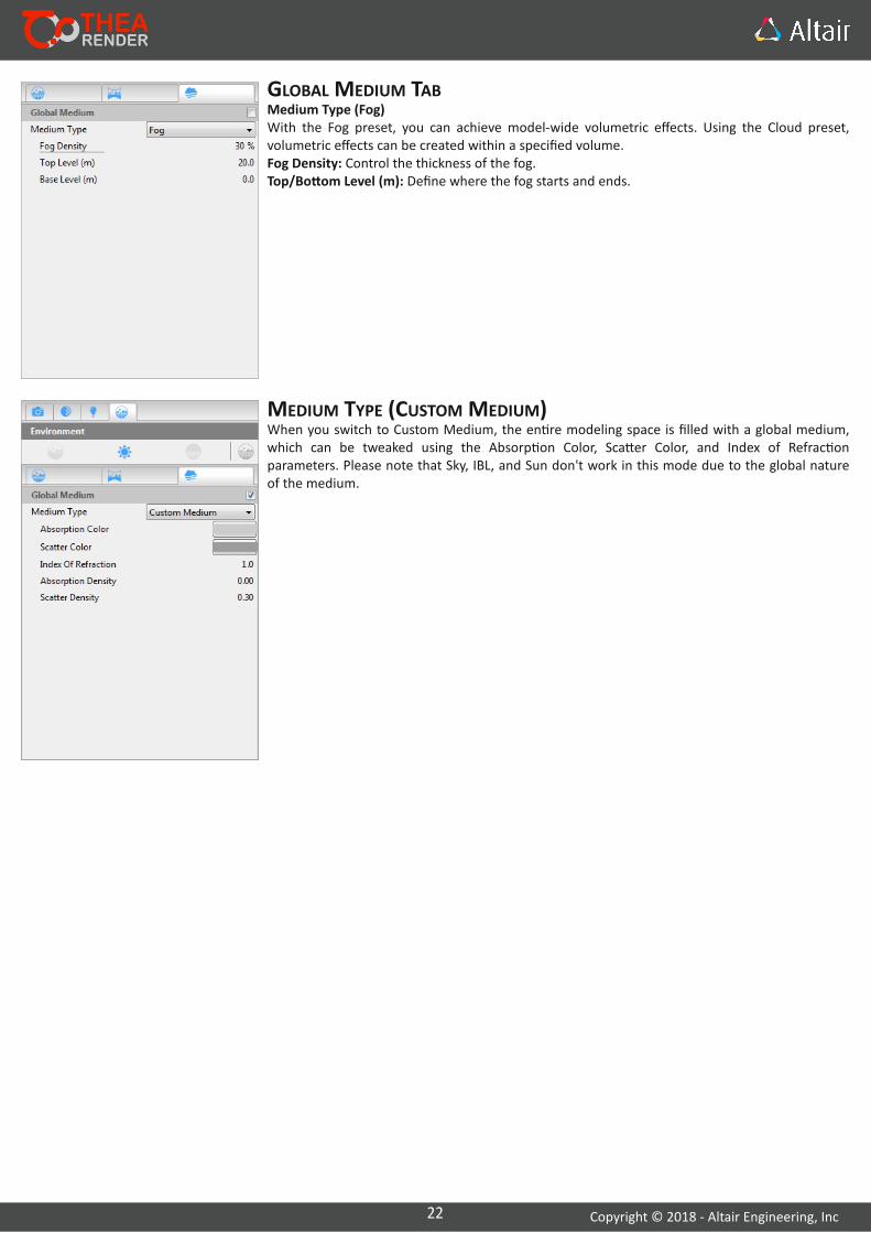
GLOBAL MEDIUM TABMedium Type (Fog)With the Fog preset, you can achieve model‐wide volumetric effects. Using the Cloud preset, volumetric effects can be created within a specified volume.Fog Density: Control the thickness of the fog.Top/Bo om Level (m): Define where the fog starts and ends.
MEDIUM TYPE (CUSTOM MEDIUM)When you switch to Custom Medium, the en re modeling space is filled with a global medium, which can be tweaked using the Absorp on Color, Sca er Color, and Index of Refrac on parameters. Please note that Sky, IBL, and Sun don't work in this mode due to the global nature of the medium.

23 Copyright © 2018 ‐ Altair Engineering, Inc
The Display tab is a very important area where you can manipulate your rendered image (especially in terms of exposure/brightness, color satura on, and contrast) and apply other post‐processing effects.
ExposureTonemapping: Select a tonemapping method: Standard, Filmic, Reinhard Global, Reinhard Local.ISO: Defines how sensi ve the image sensor is to the amount of light present. A value of 100 is mostly used for exterior shots under a clear sky and sun ligh ng. Higher values, usually between 400–1600 are used mostly for interior shots.Shu er: The shu er speed corresponds to the dura on a camera shu er stays open, measured in 1/sec. Low values result in brighter images.f‐number: The lens aperture is the ra o of the focal length to the effec ve aperture diameter. Low values make the image brighter.Gamma: The gamma factor typically ranges from 1.0 to 2.5. In order to compensate for the darkening of the image due to non‐linear output, we apply a gamma correc on scheme to the pixel values before displaying the image.Brightness: This parameter is used to compensate for a linear scaling of the image by a monitor.
Camera Response Func onCamera Response Func on files use real data provided by the camera manufacturers to create realis c (non‐linear) display results, as if the image were taken with that specific camera.
FilteringSharpness: This is the most important op on for controlling filtering during downsampling of the image. It is advised to use the default of 50%, which is a balanced value between blurring and sharpening. A value near 0% produces a more blurred image, while a value near 100% produces a more sharpened image.Burn: The burn value can be used to compress a High Dynamic Range (HDR) into a Low Dynamic
Range (LDR) image, presentable on screens and other limited range devices. Se ng burn to 100% means that there is no compression.Vigne ng: In photography and op cs, vigne ng is a reduc on of an image's brightness or satura on at the periphery compared to the image center.Chroma: Increase the value to enhance the colors of the image. Chroma acts as a satura on control.Contrast: Determines the difference in the color and brightness of the object and the objects within the same field of view. 0% equals a disabled control. 100% is the maximum value that can be set.White Balance (K): Change the overall color balance of a render, so that it matches the expected physical phenomenon. A value of 6500K is usually used to balance sunlight and make white walls appear white, even if the sunlight is yellowish.Glare: Glare is the effect of a high amount of protons arriving at a film, causing ligh ng to also flood nearby areas. The shape of the glare itself depends on the shape of the diaphragm.Glare Type: Select how many blades you want. Radial equals Bloom.Glare Weight: Controls the intensity of the glare.Glare Radius: Controls the length of the blades.
Op x DenoiserOp x offers AI‐accelerated denoising. The denoiser can be enabled before or a er the rendering has finished. If you enable Op x before star ng the engine, two addi onal channels are enabled to ensure the best denoising quality. These channels are Normals and Raw Diffuse Color. An NVIDIA GPU is required for Op x to work.Blend with original: Controls the blending between the original and the denoised image.
OtherStereoscopic: Use this op on to produce stereoscopic images (Anaglyph, Le , Right, Le /Right, Top/Bo om).
Info: The Stereoscopic op ons need to be enabled from the Camera tab before using the op ons in this dialog.
7.1. DISPLAY TAB
7. SETTINGS PANEL

24 Copyright © 2018 ‐ Altair Engineering, Inc
7.2. RENDERING TAB
The Rendering Tab displays the selected engine parameters along with every other common render se ng like the Devices List, Network Rendering, etc.
Engine Se ngsIn this sec on, only the selected engine's se ngs will be displayed. You can find detailed informa on about each engine in Sec on 8.1.
Devices (Presto MC only)Provides a list with all devices that have been detected on your system. That includes the CPU and any NVIDIA/AMD graphics card. It is possible to enable/disable devices individually and set the priority of each. It is best to disable the GPU that is being used by Windows for machines with more than one GPU.
ClayBy enabling this op on, all materials in the scene will be rendered as diffuse gray, giving the final image a clay effect. Material proper es like bump and clipping can s ll be seen in the final render.Reflectance: Increases/Decreases the diffuse material reflectance (from black to white).
Network RenderingNetwork rendering is only available when in Produc on Mode. To start using machines on the local network, enable Network Rendering by clicking on the checkbox.Server Mode: There are two op ons to choose from. "Render and Manage" makes the server machine render along with the rest of the nodes. "Manage Nodes Only" should be used when the server is not powerful; this way, the server doesn't execute the rendering itself but just exchanges data with nodes.Server Port: The default value is 6200 and is used for communica on between the SketchUp (server) and nodes.For more informa on on Network Rendering, go to sec on 9 (Network Tab).
Distribu onThreads: Refers to the worker threads used during rendering. While the default value is set to Max, you can use the drop‐down to select the preferred amount of threads.Priority: This parameter corresponds to the priority assigned to render threads by the opera ng system. Select 'Normal' to make rendering faster; however, 'Normal' is not recommended when you use the machine in parallel or run other demanding processes.
25 Copyright © 2018 ‐ Altair Engineering, Inc
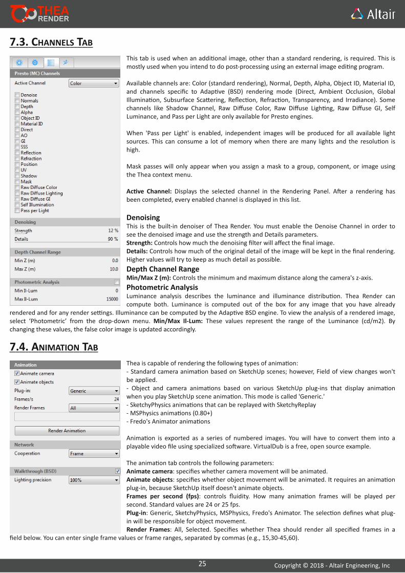
This tab is used when an addi onal image, other than a standard rendering, is required. This is mostly used when you intend to do post‐processing using an external image edi ng program.
Available channels are: Color (standard rendering), Normal, Depth, Alpha, Object ID, Material ID, and channels specific to Adap ve (BSD) rendering mode (Direct, Ambient Occlusion, Global Illumina on, Subsurface Sca ering, Reflec on, Refrac on, Transparency, and Irradiance). Some channels like Shadow Channel, Raw Diffuse Color, Raw Diffuse Ligh ng, Raw Diffuse GI, Self Luminance, and Pass per Light are only available for Presto engines.
When 'Pass per Light' is enabled, independent images will be produced for all available light sources. This can consume a lot of memory when there are many lights and the resolu on is high.
Mask passes will only appear when you assign a mask to a group, component, or image using the Thea context menu.
Ac ve Channel: Displays the selected channel in the Rendering Panel. A er a rendering has been completed, every enabled channel is displayed in this list.
DenoisingThis is the built‐in denoiser of Thea Render. You must enable the Denoise Channel in order to see the denoised image and use the strength and Details parameters.Strength: Controls how much the denoising filter will affect the final image.Details: Controls how much of the original detail of the image will be kept in the final rendering. Higher values will try to keep as much detail as possible.
Depth Channel RangeMin/Max Z (m): Controls the minimum and maximum distance along the camera's z‐axis.
Photometric AnalysisLuminance analysis describes the luminance and illuminance distribu on. Thea Render can compute both. Luminance is computed out of the box for any image that you have already
rendered and for any render se ngs. Illuminance can be computed by the Adap ve BSD engine. To view the analysis of a rendered image, select ‘Photometric’ from the drop‐down menu. Min/Max Il‐Lum: These values represent the range of the Luminance (cd/m2). By changing these values, the false color image is updated accordingly.
7.3. CHANNELS TAB
Thea is capable of rendering the following types of anima on:‐ Standard camera anima on based on SketchUp scenes; however, Field of view changes won't be applied.‐ Object and camera anima ons based on various SketchUp plug‐ins that display anima on when you play SketchUp scene anima on. This mode is called 'Generic.'‐ SketchyPhysics anima ons that can be replayed with SketchyReplay‐ MSPhysics anima ons (0.80+)‐ Fredo's Animator anima ons
Anima on is exported as a series of numbered images. You will have to convert them into a playable video file using specialized so ware. VirtualDub is a free, open source example.
The anima on tab controls the following parameters:Animate camera: specifies whether camera movement will be animated.Animate objects: specifies whether object movement will be animated. It requires an anima on plug‐in, because SketchUp itself doesn't animate objects.Frames per second (fps): controls fluidity. How many anima on frames will be played per second. Standard values are 24 or 25 fps.Plug‐in: Generic, SketchyPhysics, MSPhysics, Fredo's Animator. The selec on defines what plug‐in will be responsible for object movement.Render Frames: All, Selected. Specifies whether Thea should render all specified frames in a
field below. You can enter single frame values or frame ranges, separated by commas (e.g., 15,30‐45,60).
7.4. ANIMATION TAB
26 Copyright © 2018 ‐ Altair Engineering, Inc
Network coopera on: Frame, Bucket|Pixels. This is only used when rendering is performed through a network using nodes. It controls whether computers in the network will render whole frames independently (Frame) or contribute to each frame (Bucket|Pixels). We recommend using Bucket|Pixels, because this minimizes the network bandwidth needed to send whole frames from the nodes to the server. It is also more efficient when computers of varying performance are in the network.
When using the Adap ve (BSD) engine and pure camera mo on, you can also enable the Walk‐through op on. It will speed up walkthrough rendering because ligh ng calcula ons will be done just once and shared among all frames.When you click the "Render Anima on" bu on, you will be asked to select a folder and specify a file name. Frame numbers will be appended automa cally to the file name (Anima on000.png, Anima on001.png, etc.).
Please note that for the me being, Thea For SketchUp doesn't animate standard lights. Fredo's Animator can animate standard lights, if you start rendering the anima on from the Animator instead of Thea.
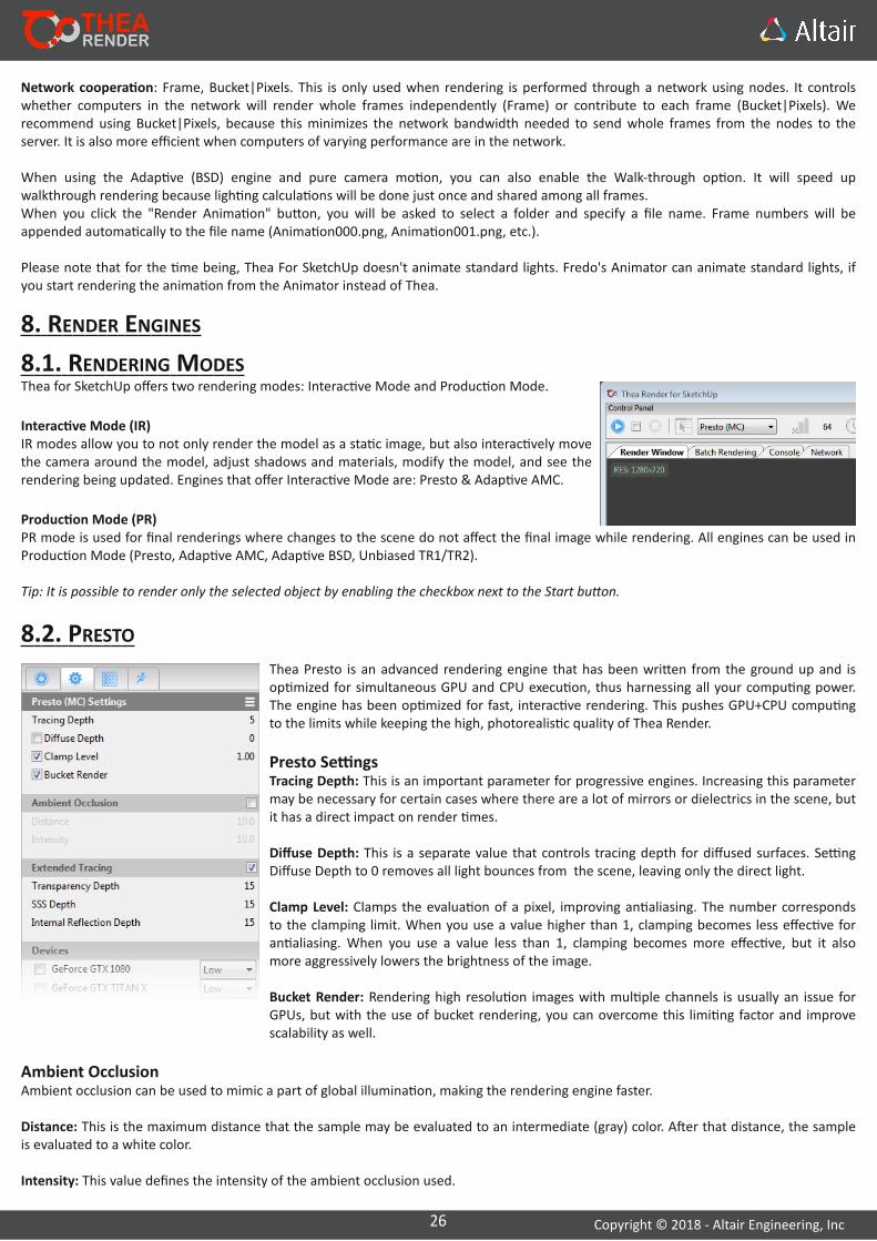
Thea for SketchUp offers two rendering modes: Interac ve Mode and Produc on Mode.
Interac ve Mode (IR)IR modes allow you to not only render the model as a sta c image, but also interac vely move the camera around the model, adjust shadows and materials, modify the model, and see the rendering being updated. Engines that offer Interac ve Mode are: Presto & Adap ve AMC.
Produc on Mode (PR)PR mode is used for final renderings where changes to the scene do not affect the final image while rendering. All engines can be used in Produc on Mode (Presto, Adap ve AMC, Adap ve BSD, Unbiased TR1/TR2).
Tip: It is possible to render only the selected object by enabling the checkbox next to the Start bu on.
8. RENDER ENGINES
8.1. RENDERING MODES
8.2. PRESTOThea Presto is an advanced rendering engine that has been wri en from the ground up and is op mized for simultaneous GPU and CPU execu on, thus harnessing all your compu ng power. The engine has been op mized for fast, interac ve rendering. This pushes GPU+CPU compu ng to the limits while keeping the high, photorealis c quality of Thea Render.
Presto Se ngsTracing Depth: This is an important parameter for progressive engines. Increasing this parameter may be necessary for certain cases where there are a lot of mirrors or dielectrics in the scene, but it has a direct impact on render mes.
Diffuse Depth: This is a separate value that controls tracing depth for diffused surfaces. Se ng Diffuse Depth to 0 removes all light bounces from the scene, leaving only the direct light.
Clamp Level: Clamps the evalua on of a pixel, improving an aliasing. The number corresponds to the clamping limit. When you use a value higher than 1, clamping becomes less effec ve for an aliasing. When you use a value less than 1, clamping becomes more effec ve, but it also more aggressively lowers the brightness of the image.
Bucket Render: Rendering high resolu on images with mul ple channels is usually an issue for GPUs, but with the use of bucket rendering, you can overcome this limi ng factor and improve scalability as well.
Ambient OcclusionAmbient occlusion can be used to mimic a part of global illumina on, making the rendering engine faster.
Distance: This is the maximum distance that the sample may be evaluated to an intermediate (gray) color. A er that distance, the sample is evaluated to a white color.
Intensity: This value defines the intensity of the ambient occlusion used.
27 Copyright © 2018 ‐ Altair Engineering, Inc
Extended TracingExtended tracing can efficiently render scenes with transparent objects or materials with subsurface sca ering while using a lower tracing depth.
Transparency Depth: Determines the extended tracing depth for all transparent materials like Thin Glass, Glass, and Clip Map.
Internal Reflec on Depth: Determines the extended tracing depth for transparent materials that have refrac on and total internal reflec on. These materials are created with the use of the Glass Layer (e.g., solid glass or water). If you no ce that you get dark areas on solid glass, this is o en the result of the Internal Reflec on Depth being too low, not because of the Transperency Depth.
SSS Depth: Determines the extended tracing depth for subsurface sca ering (SSS) materials. In some cases increasing this value is needed to increase the brightness of brightly colored, and dense SSS materials. Not available when Diffuse Depth is enabled.
Advanced Se ngsSupersampling: This corresponds to the supersampling used for the image output (i.e., internal resolu on mul plier for an aliasing enhancement).'None' corresponds to no supersampling at all, 'Normal' to 2x2, and 'High' to 3x3. 'Auto' corresponds to no supersampling for the biased engine (disabled by default).Se ng supersampling to a higher level generally improves an aliasing of the output, but increases memory demands for storing the image (by 4 mes for 'Normal' and by 9 mes for 'High'). The me needed to render the scene is also increased for a biased engine.
8.3. UNBIASED TR1/TR2Thea Render supports a superior, unbiased core, which is one of the most advanced on the market and delivers stunning images without any compromises. All possible paths of ligh ng transfer are explored, delivering the highest accuracy without any ar facts. Sun‐pool caus cs and terminator ar facts are robustly handled, offering stunning results.
Unbiased TR1/TR2 Se ngsThese two engines have no se ngs and are controlled only by the Sample and Time Limit.
Unbiased engine TR1 is op mal for exteriors and scenes with dominant direct ligh ng, while unbiased engine TR2 is op mal for extremely difficult indirect and caus c ligh ng.
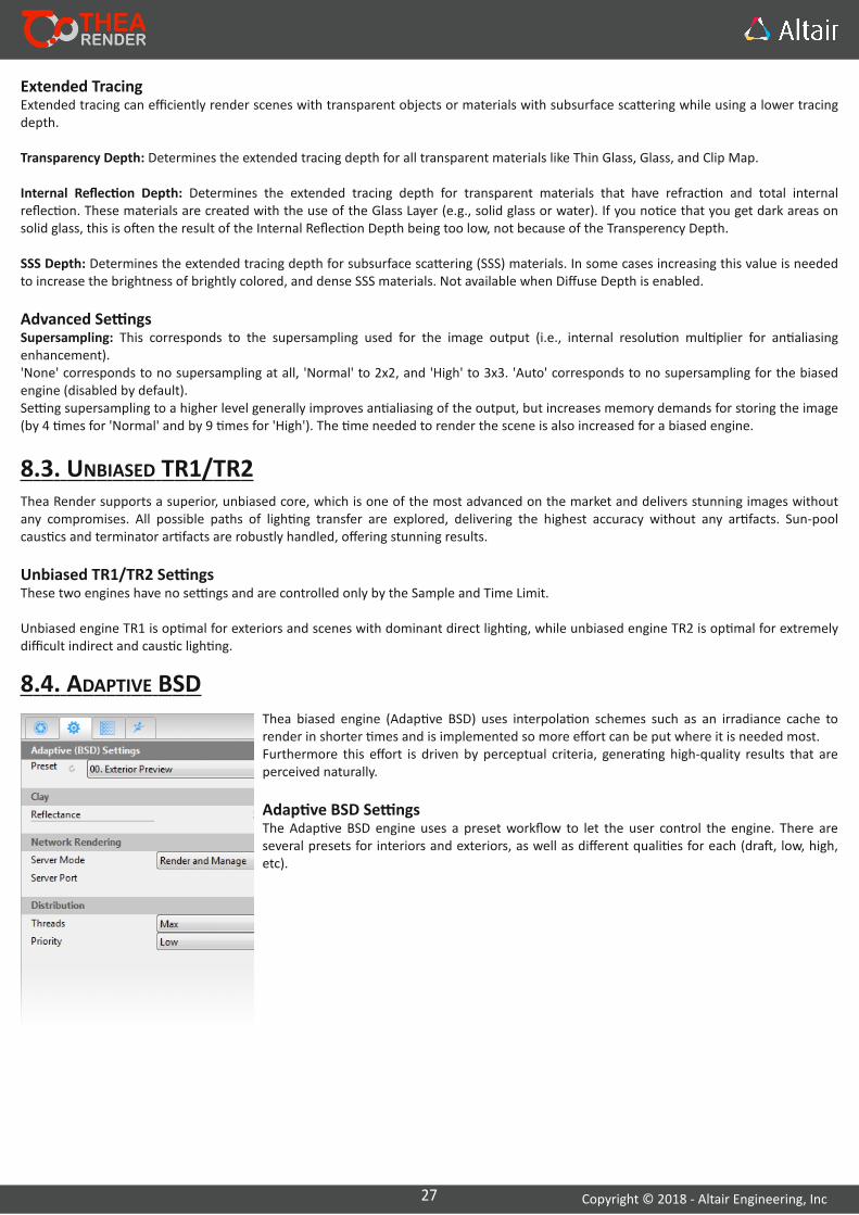
8.4. ADAPTIVE BSDThea biased engine (Adap ve BSD) uses interpola on schemes such as an irradiance cache to render in shorter mes and is implemented so more effort can be put where it is needed most.Furthermore this effort is driven by perceptual criteria, genera ng high‐quality results that are perceived naturally.
Adap ve BSD Se ngsThe Adap ve BSD engine uses a preset workflow to let the user control the engine. There are several presets for interiors and exteriors, as well as different quali es for each (dra , low, high, etc).
28 Copyright © 2018 ‐ Altair Engineering, Inc
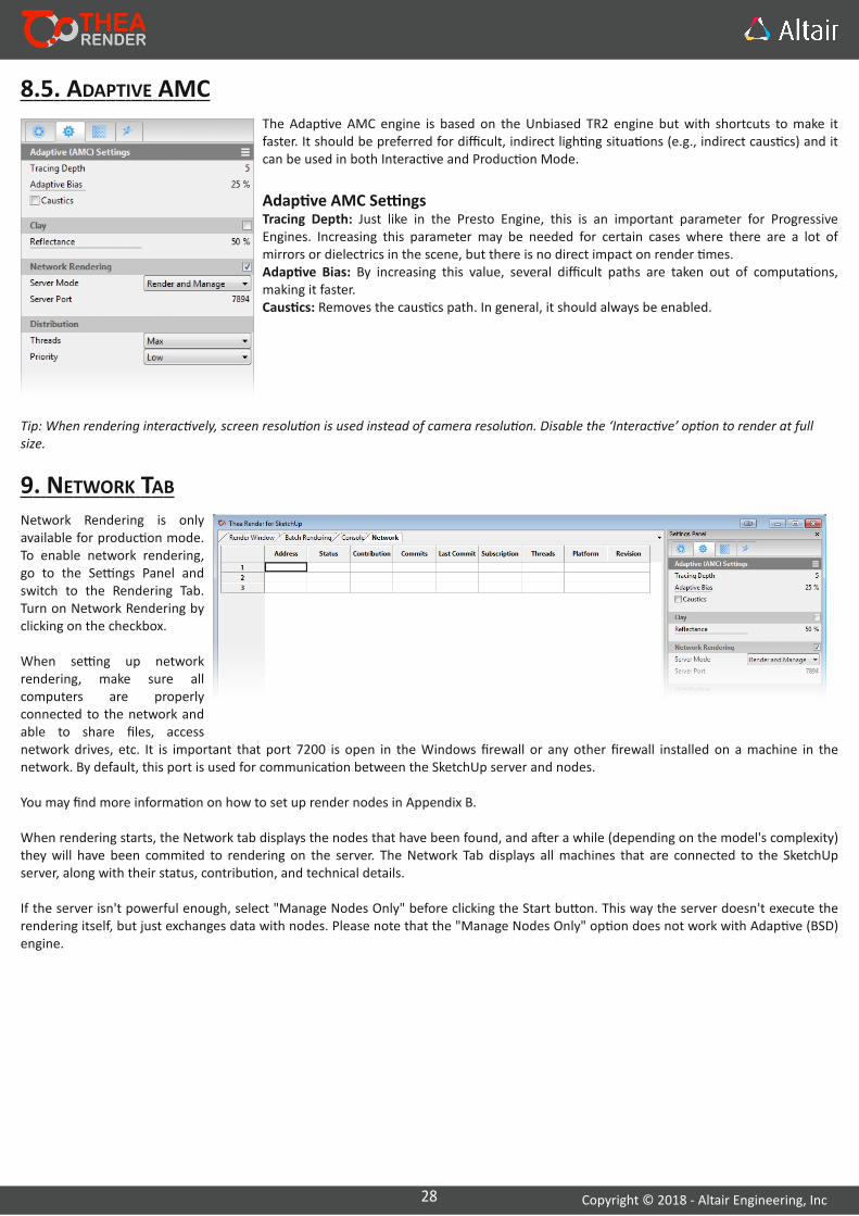
8.5. ADAPTIVE AMCThe Adap ve AMC engine is based on the Unbiased TR2 engine but with shortcuts to make it faster. It should be preferred for difficult, indirect ligh ng situa ons (e.g., indirect caus cs) and it can be used in both Interac ve and Produc on Mode.
Adap ve AMC Se ngsTracing Depth: Just like in the Presto Engine, this is an important parameter for Progressive Engines. Increasing this parameter may be needed for certain cases where there are a lot of mirrors or dielectrics in the scene, but there is no direct impact on render mes.Adap ve Bias: By increasing this value, several difficult paths are taken out of computa ons, making it faster.Caus cs: Removes the caus cs path. In general, it should always be enabled.
Tip: When rendering interac vely, screen resolu on is used instead of camera resolu on. Disable the ‘Interac ve’ op on to render at full size.
9. NETWORK TABNetwork Rendering is only available for produc on mode. To enable network rendering, go to the Se ngs Panel and switch to the Rendering Tab. Turn on Network Rendering by clicking on the checkbox.
When se ng up network rendering, make sure all computers are properly connected to the network and able to share files, access network drives, etc. It is important that port 7200 is open in the Windows firewall or any other firewall installed on a machine in the network. By default, this port is used for communica on between the SketchUp server and nodes.
You may find more informa on on how to set up render nodes in Appendix B.
When rendering starts, the Network tab displays the nodes that have been found, and a er a while (depending on the model's complexity) they will have been commited to rendering on the server. The Network Tab displays all machines that are connected to the SketchUp server, along with their status, contribu on, and technical details.
If the server isn't powerful enough, select "Manage Nodes Only" before clicking the Start bu on. This way the server doesn't execute the rendering itself, but just exchanges data with nodes. Please note that the "Manage Nodes Only" op on does not work with Adap ve (BSD) engine.
29 Copyright © 2018 ‐ Altair Engineering, Inc
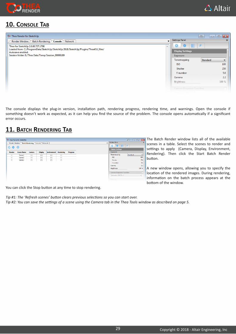
10. CONSOLE TAB
The console displays the plug‐in version, installa on path, rendering progress, rendering me, and warnings. Open the console if something doesn’t work as expected, as it can help you find the source of the problem. The console opens automa cally if a significant error occurs.
11. BATCH RENDERING TABThe Batch Render window lists all of the available scenes in a table. Select the scenes to render and se ngs to apply (Camera, Display, Environment, Rendering). Then click the Start Batch Render bu on.
A new window opens, allowing you to specify the loca on of the rendered images. During rendering, informa on on the batch process appears at the bo om of the window.
You can click the Stop bu on at any me to stop rendering.
Tip #1: The ‘Refresh scenes’ bu on clears previous selec ons so you can start over.Tip #2: You can save the se ngs of a scene using the Camera tab in the Thea Tools window as described on page 5.

30 Copyright © 2018 ‐ Altair Engineering, Inc
12. WINDOW SELECTION FOR INTERACTIVE RENDERING ‐ OVERLAY OPTIONWhen Interac ve Rendering is enabled, use the drop‐down list to choose between displaying the interac ve rendering in the Thea window (see right) or in SketchUp as an overlay (see below).
‘With edges’ mode is especially well‐suited to interac on with SketchUp models. This mode temporarily modifies the SketchUp display style to clearly show edges in exterior/interior models. You can navigate, modify materials, add models, and see the changes take effect in SketchUp while rendering.
‘Blended’ and ‘Mul plied’ give you full freedom to set up SketchUp style. ‘Blended’ works best with dark backgrounds and bright lines (like ‘With edges’). ‘Mul plied’ is the opposite and works best in hidden line mode with a white background.
The rendering can be saved as an image, both in standard and overlay modes.
In Thea Window
In SketchUp Window In SketchUp With Edges
Blended With SketchUp Mul plied With SketchUp
Tip: While using the overlay and modifying a model, the best results can be achieved with Presto engines using only GPU for rendering. CPU shouldn't be used, but should be made available to SketchUp.

31 Copyright © 2018 ‐ Altair Engineering, Inc
With the Thea Browser, you can:• quickly access Thea materials, external models and skies, and SketchUp components in the 'Thea Data' folder• access the same items in user‐defined 'Custom folders'• find currently used and missing external textures, models, and other image maps• zip a SketchUp file with all external dependences (textures, images, and models)
Please note that Thea provides a wide range of material libraries, as well as models and skies/studio ligh ng set‐ups. You can find more informa on on how to download and install Thea Libraries in Appendix C.
Double‐click the desired material or model. You can then apply the material to a surface or insert the model at a desired loca on in SketchUp.
Double‐click Thea Sky to enable it and add it directly to the IBL of the Environment tab. Please not that skies may alter the current display se ngs.
You can create a custom folder by right‐clicking and selec ng the 'Add folder' op on. You can also right‐click to refresh or remove folders.
External Thea models usually contain very complex geometry. It is not feasible to load them directly in SketchUp. By default, Thea only imports the bounding box of an external model, but in general it is be er to have a 'proxy' component that will resemble the shape of the full geometry. Right‐click to have Thea create this approxima on automa cally. See page 35 for more details on proxies.
INTERACTIVE REGION RENDERING IN SKETCHUP WINDOWInterac ve rendering in the SketchUp window allows you to render a selected area of your scene. When interac ve rendering is on, hold down the Shi key while clicking and dragging to select the desired area. Mul ple regions can be displayed at the same me. You can also save an ac ve region by clicking on the Save bu on.
RENDER A REGION IN THE RENDERING WINDOWA er rendering, you may decide to edit a specific region. Instead of re‐rendering the en re scene, you can re‐render just the region. Right‐click and drag to select the region to re‐render. The selected region will be outlined with green dashed lines, and its size will be displayed.
Please note that although the whole image will be displayed, the display se ngs will only affect the selected region. In general, it is not recommended to modify the se ngs, as the result will not match the original image.
The en re image can only be saved in non‐HDRI formats. The region can be saved as an Exr, img.thea, or HDRI.
13. THEA BROWSER WINDOW

32 Copyright © 2018 ‐ Altair Engineering, Inc
General TabLanguageClick on the Preferences bu on to open a window where you can change the Language. Then follow these steps:‐ Locate the TheaForSketchUp.po file in the folder: Thea4SU_file/languages/ ‐ If needed, translate the file using Poedit and compile to a .mo file.‐ Copy the translated TheaForSketchUp.mo file to the corresponding language folder. Typical country codes are: de (German), es (Spanish), fr (French), it (Italian), ja (Japanese), pt (Portuguese), pt_BR (Brazilian Portuguese), ru (Russian), zh_CN (Chinese Simplified), and zh_TW (Chinese Tradi onal).‐ If the desired language has already been configured, it will be used automa cally when SketchUp starts. Otherwise, open Thea Tool/Tools/Preferences and select the
language manually. For example, if you placed the TheaForSketchUp.mo file in the es (Spanish) folder, you will be able to select Spanish from the Language drop‐down list.‐The language changes will take effect a er you restart SketchUp.
Use Back Face Material: This op on applies to models where mul ple faces are painted on the back side only (the front face has no material). When this op on is enabled, SketchUp will use the back face material for rendering instead of the default white material.
Weld Ver ces: This op on is disabled by default. Enable it to weld the ver ces of objects when conver ng SketchUp models to Thea format. This is actually only required for objects with displacement or a wireframe procedural texture. The welding is performed automa cally for geometry using displacement. It is recommended to enable this op on only when using the wireframe texture.
13.1. MODEL INFOThea Browser also has a Model Info sec on which shows External Dependencies associated with a model.This window allows you to view and find/modify/update external textures, IBLs, and models used in the scene.
Saving the SketchUp Model with DependenciesRight‐click on Model Info to save the en re scene with dependencies (textures, external models, etc.) in .*zip format.
14. PREFERENCES
A SketchUp model (*.mod.skp) can be wri en in the same folder as the Thea Model (*.mod.thea). In this way, the SketchUp file will be used instead of the bounding box when inser ng the external models as a proxy. When mod.skp is present, its preview will be displayed on top of the mod. thea preview, as shown in the image.
Applying a material from the Content BrowserYou can apply a material from the Thea Browser window to the Thea Material Editor by right‐clicking a thumbnail and selec ng "Apply to Edited Thea Material."
Note: You need to open a material in the Material Editor before you can select or replace it.
33 Copyright © 2018 ‐ Altair Engineering, Inc
Interac ve Render TabIni al Appearance: Use the slider to find the best balance between rendering quality and responsiveness. The more responsive, the less precise the ini al frame.
Resolu on Reduc on for IR Overlay: You can render at the same resolu on as your monitor, but this is not prac cal when you have a high resolu on monitor. The resolu on reduc on op on lets you reduce the rendering resolu on so you can render faster (the image s ll maps correctly to SketchUp view). It is highly recommended to use resolu on reduc on if you have a 4K+ monitor.
Channels TabUse the Channels preference panel to select a format. For EXR, you can select a bit depth for each channel. Note: Not all channels require 32‐bit depth; only some (e.g., posi on, depth, and UV pass) will benefit from 32‐bit depth.
To save the render passes as one mul ‐layered EXR file, enable the op on “Create mul ‐layered EXR including all channels”; otherwise, each channel will be saved as a separate file.
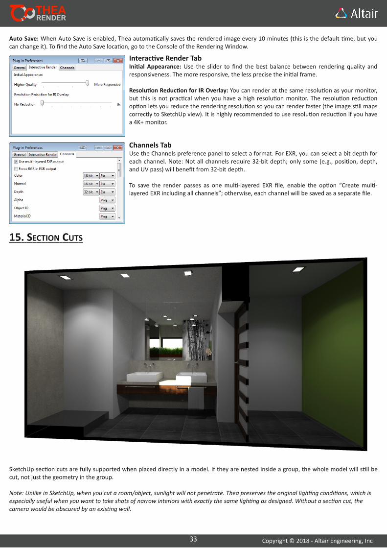
15. SECTION CUTS
SketchUp sec on cuts are fully supported when placed directly in a model. If they are nested inside a group, the whole model will s ll be cut, not just the geometry in the group.
Note: Unlike in SketchUp, when you cut a room/object, sunlight will not penetrate. Thea preserves the original ligh ng condi ons, which is especially useful when you want to take shots of narrow interiors with exactly the same ligh ng as designed. Without a sec on cut, the camera would be obscured by an exis ng wall.
Auto Save: When Auto Save is enabled, Thea automa cally saves the rendered image every 10 minutes (this is the default me, but you can change it). To find the Auto Save loca on, go to the Console of the Rendering Window.
34 Copyright © 2018 ‐ Altair Engineering, Inc
16. THEA CONTEXT MENU
Click on a component, group, or image to access the Thea context menu. This allows you to perform a func on on an object or modify object‐specific proper es.
Create External Model/ProxyThis op on lets you export a component into an external Thea model and create a reduced placeholder for it. This may help you keep the SketchUp file size small, while having high polygon models visible only in your renderings. The process in described on page 35.
Assign Mask IndexThis item allows you to assign a mask index from 0–15 to a selected object. If you enable "Mask" channel in the Channels tab in the Rendering window and start rendering, you will see that a white mask on a black background was created for this object.
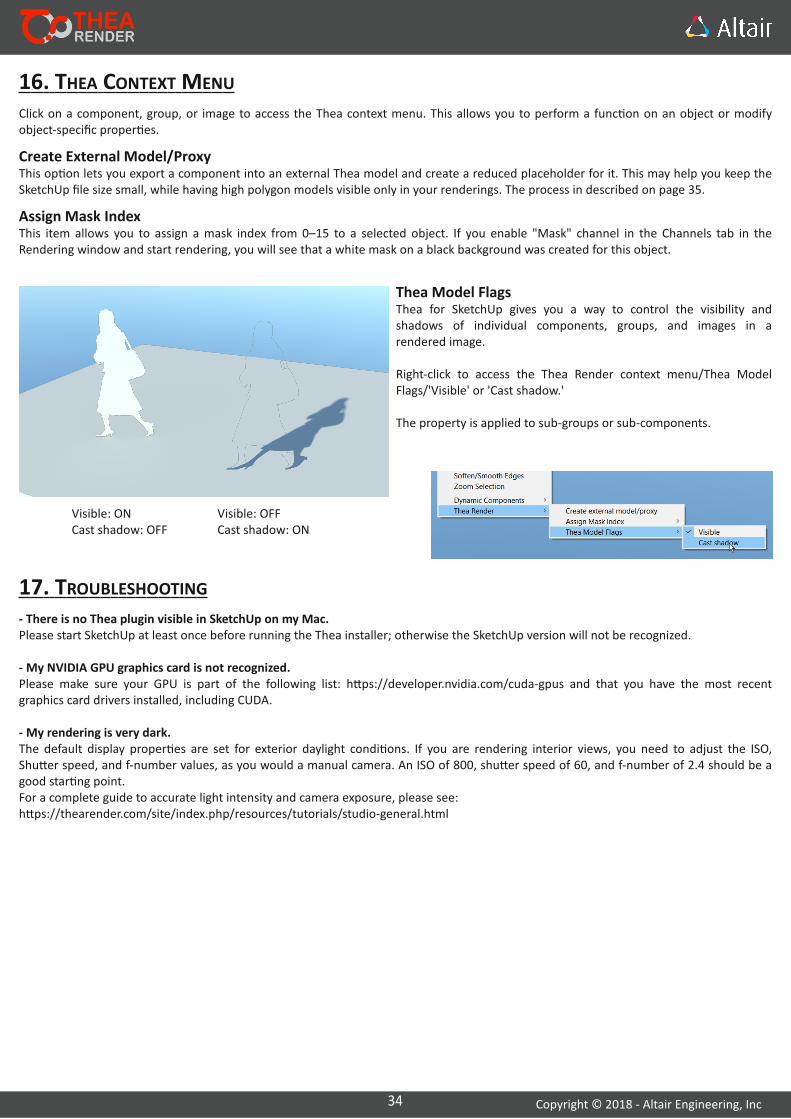
Thea Model FlagsThea for SketchUp gives you a way to control the visibility and shadows of individual components, groups, and images in a rendered image.
Right‐click to access the Thea Render context menu/Thea Model Flags/'Visible' or 'Cast shadow.'
The property is applied to sub‐groups or sub‐components.
Visible: ONCast shadow: OFF
Visible: OFFCast shadow: ON
17. TROUBLESHOOTING‐ There is no Thea plugin visible in SketchUp on my Mac.Please start SketchUp at least once before running the Thea installer; otherwise the SketchUp version will not be recognized.
‐ My NVIDIA GPU graphics card is not recognized.Please make sure your GPU is part of the following list: h ps://developer.nvidia.com/cuda‐gpus and that you have the most recent graphics card drivers installed, including CUDA.
‐ My rendering is very dark.The default display proper es are set for exterior daylight condi ons. If you are rendering interior views, you need to adjust the ISO, Shu er speed, and f‐number values, as you would a manual camera. An ISO of 800, shu er speed of 60, and f‐number of 2.4 should be a good star ng point. For a complete guide to accurate light intensity and camera exposure, please see:h ps://thearender.com/site/index.php/resources/tutorials/studio‐general.html
35 Copyright © 2018 ‐ Altair Engineering, Inc
18. CREATING EXTERNAL MODELS & THEIR PROXIESTo keep SketchUp model sizes small and s ll produce very high‐quality renderings, export the heaviest components (trees, cars, etc.) into external .mod.thea files and replace them with simplified ‘proxy’ versions in SketchUp.
Proxies can also be created for Thea models that come from other modeling applica ons. This can be done in the Thea Browser.
Every SketchUp component can be exported into an external .mod.thea file and replaced by an automa cally generated approxima on of the original.
The special external model crea on tool can be opened by right‐clicking on a selected component and choosing the ‘Thea Render/Create external model/proxy’ op on.
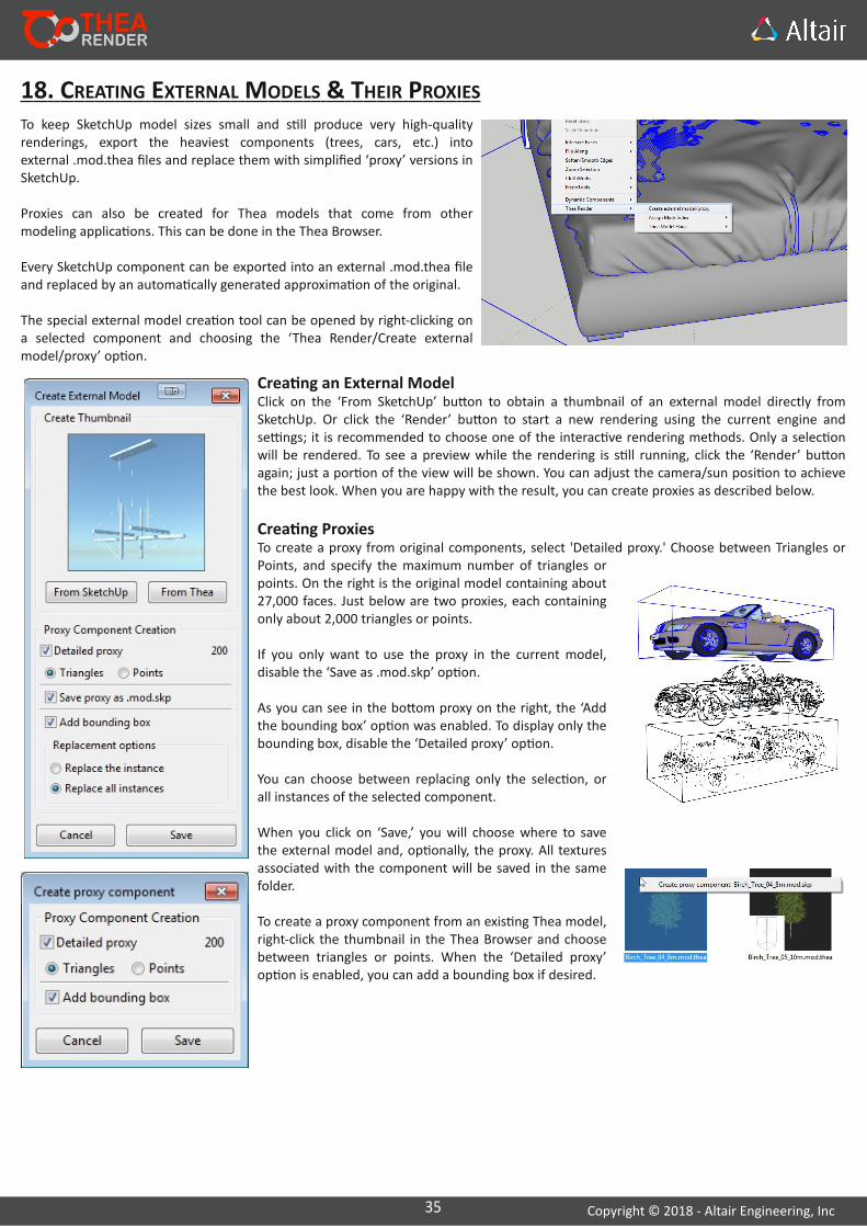
Crea ng an External ModelClick on the ‘From SketchUp’ bu on to obtain a thumbnail of an external model directly from SketchUp. Or click the ‘Render’ bu on to start a new rendering using the current engine and se ngs; it is recommended to choose one of the interac ve rendering methods. Only a selec on will be rendered. To see a preview while the rendering is s ll running, click the ‘Render’ bu on again; just a por on of the view will be shown. You can adjust the camera/sun posi on to achieve the best look. When you are happy with the result, you can create proxies as described below.
Crea ng ProxiesTo create a proxy from original components, select 'Detailed proxy.' Choose between Triangles or Points, and specify the maximum number of triangles or points. On the right is the original model containing about 27,000 faces. Just below are two proxies, each containing only about 2,000 triangles or points.
If you only want to use the proxy in the current model, disable the ‘Save as .mod.skp’ op on.
As you can see in the bo om proxy on the right, the ‘Add the bounding box’ op on was enabled. To display only the bounding box, disable the ‘Detailed proxy’ op on.
You can choose between replacing only the selec on, or all instances of the selected component.
When you click on ‘Save,’ you will choose where to save the external model and, op onally, the proxy. All textures associated with the component will be saved in the same folder.
To create a proxy component from an exis ng Thea model, right‐click the thumbnail in the Thea Browser and choose between triangles or points. When the ‘Detailed proxy’ op on is enabled, you can add a bounding box if desired.
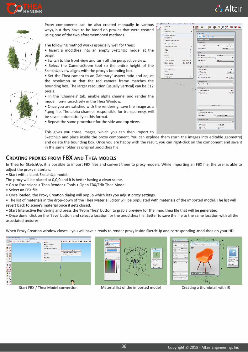
36 Copyright © 2018 ‐ Altair Engineering, Inc
Proxy components can be also created manually in various ways, but they have to be based on proxies that were created using one of the two aforemen oned methods.
The following method works especially well for trees:• Insert a mod.thea into an empty SketchUp model at the origin.• Switch to the front view and turn off the perspec ve view.• Select the Camera/Zoom tool so the en re height of the SketchUp view aligns with the proxy's bounding box.• Set the Thea camera to an ‘Arbitrary’ aspect ra o and adjust the resolu on so that the red camera frame matches the bounding box. The larger resolu on (usually ver cal) can be 512 pixels.• In the ‘Channels’ tab, enable alpha channel and render the model non‐interac vely in the Thea Window.• Once you are sa sfied with the rendering, save the image as a *.png file. The alpha channel, responsible for transparency, will be saved automa cally in this format.• Repeat the same procedure for the side and top views.
This gives you three images, which you can then import to SketchUp and place inside the proxy component. You can explode them (turn the images into editable geometry) and delete the bounding box. Once you are happy with the result, you can right‐click on the component and save it in the same folder as original .mod.thea file.
In Thea for SketchUp, it is possible to import FBX files and convert them to proxy models. While impor ng an FBX file, the user is able to adjust the proxy materials.• Start with a blank SketchUp model.The proxy will be placed at 0,0,0 and it is be er having a clean scene.• Go to Extensions > Thea Render > Tools > Open FBX/Edit Thea Model• Select an FBX file.• Once loaded, the Proxy Crea on dialog will popup which lets you adjust proxy se ngs.• The list of materials in the drop‐down of the Thea Material Editor will be populated with materials of the imported model. The list will revert back to scene's material once it gets closed.• Start Interac ve Rendering and press the 'From Thea' bu on to grab a preview for the .mod.thea file that will be generated.• Once done, click on the 'Save' bu on and select a loca on for the .mod.thea file. Be er to save the file to the same loca on with all the associated textures.
When Proxy Crea on window closes – you will have a ready to render proxy inside SketchUp and corresponding .mod.thea on your HD.
CREATING PROXIES FROM FBX AND THEA MODELS
Start FBX / Thea Model conversion Material list of the imported model Crea ng a thumbnail with IR

37 Copyright © 2018 ‐ Altair Engineering, Inc
19. COPYRIGHTCopyright of this manual belongs to Altair Engineering, Inc. 3ds max is copyright Autodesk, SketchUp is Trimble and CUDA is copyright NVIDIA.
20. DISCLAIMER“Thea for SketchUp” is provided “as‐is” and without warranty of any kind, express, implied or otherwise, including without limita on, any warranty of merchantability or fitness for a par cular purpose. In no event shall the author of this so ware be held liable for data loss, damages, loss of profits or any other kind of loss while using or misusing this so ware.
The so ware must not be modified, you may not decompile, disassemble. Any kind of reverse engineering of the so ware is prohibited.
21. APPENDIX AMATERIAL PRESET TYPES
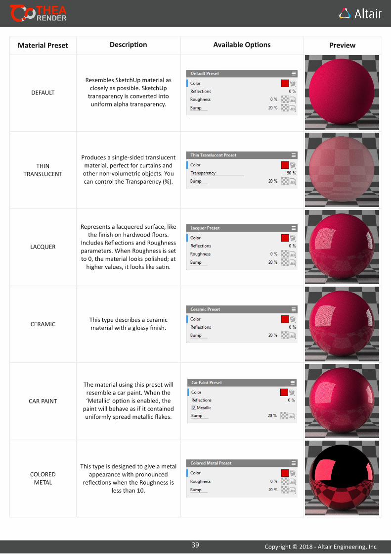
39 Copyright © 2018 ‐ Altair Engineering, Inc
Material Preset Descrip on Available Op ons Preview
DEFAULT
Resembles SketchUp material as closely as possible. SketchUp transparency is converted into uniform alpha transparency.
THINTRANSLUCENT
Produces a single‐sided translucent material, perfect for curtains and other non‐volumetric objects. You can control the Transparency (%).
LACQUER
Represents a lacquered surface, like the finish on hardwood floors.
Includes Reflec ons and Roughness parameters. When Roughness is set to 0, the material looks polished; at higher values, it looks like sa n.
CERAMICThis type describes a ceramicmaterial with a glossy finish.
CAR PAINT
The material using this preset willresemble a car paint. When the‘Metallic’ op on is enabled, thepaint will behave as if it containeduniformly spread metallic flakes.
COLOREDMETAL
This type is designed to give a metalappearance with pronounced
reflec ons when the Roughness isless than 10.
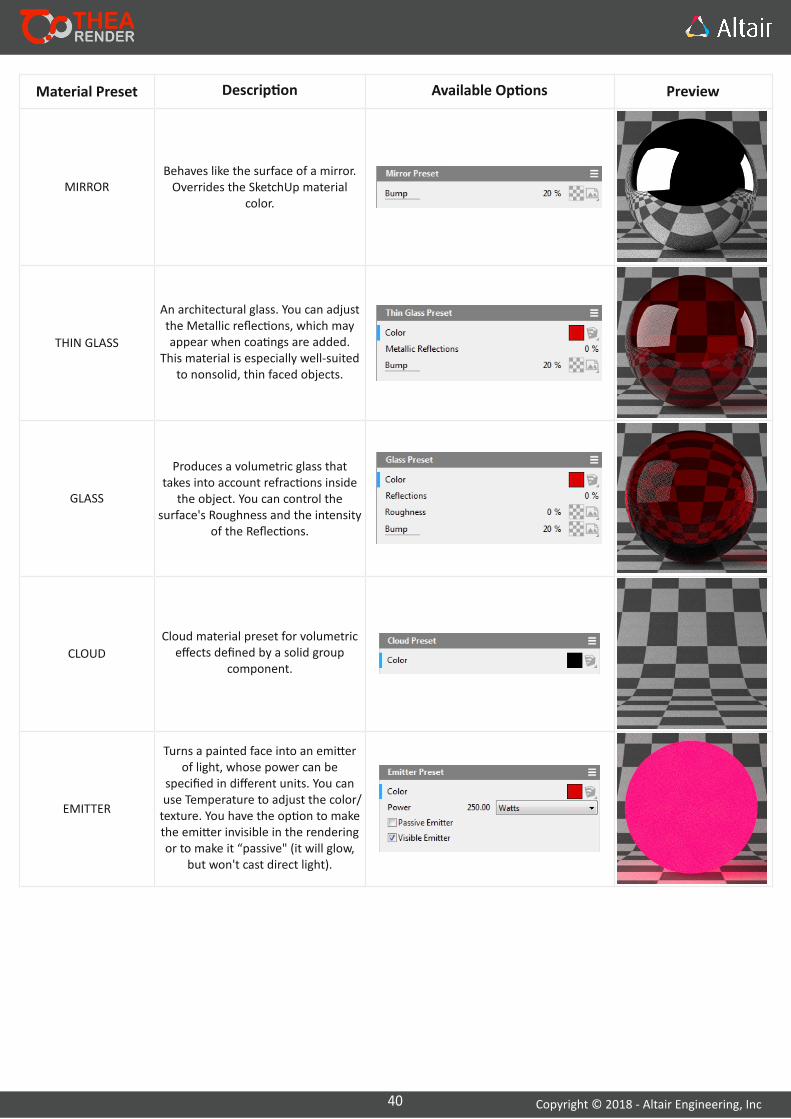
40 Copyright © 2018 ‐ Altair Engineering, Inc
Material Preset Descrip on Available Op ons Preview
MIRRORBehaves like the surface of a mirror.Overrides the SketchUp material
color.
THIN GLASS
An architectural glass. You can adjust the Metallic reflec ons, which may appear when coa ngs are added.
This material is especially well‐suited to nonsolid, thin faced objects.
GLASS
Produces a volumetric glass that takes into account refrac ons inside
the object. You can control the surface's Roughness and the intensity
of the Reflec ons.
CLOUD
Cloud material preset for volumetric effects defined by a solid group
component.
EMITTER
Turns a painted face into an emi er of light, whose power can be
specified in different units. You can use Temperature to adjust the color/texture. You have the op on to make the emi er invisible in the rendering or to make it “passive" (it will glow,
but won't cast direct light).

41 Copyright © 2018 ‐ Altair Engineering, Inc
22. APPENDIX BNETWORK RENDERING
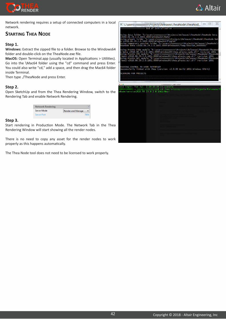
42 Copyright © 2018 ‐ Altair Engineering, Inc
Network rendering requires a setup of connected computers in a local network.
STARTING THEA NODE
Step 1.Windows: Extract the zipped file to a folder. Browse to the Windows64 folder and double‐click on the TheaNode.exe file.MacOS: Open Terminal.app (usually located in Applica ons > U li es). Go into the \Mac64 folder using the "cd" command and press Enter. You could also write "cd," add a space, and then drag the Mac64 folder inside Terminal.Then type ./TheaNode and press Enter.
Step 2.Open SketchUp and from the Thea Rendering Window, switch to the Rendering Tab and enable Network Rendering.
Step 3.Start rendering in Produc on Mode. The Network Tab in the Thea Rendering Window will start showing all the render nodes.
There is no need to copy any asset for the render nodes to work properly as this happens automa cally.
The Thea Node tool does not need to be licensed to work properly.
43 Copyright © 2018 ‐ Altair Engineering, Inc
23. APPENDIX CINSTALLING THEA LIBRARIES

44 Copyright © 2018 ‐ Altair Engineering, Inc
DOWNLOADING AND INSTALLING THEA LIBRARIESLibraries can be downloaded by visi ng the following link:h ps://www.thearender.com/libraries/
The libraries that you will download are packed in zip format. Before proceeding to the installa on, you need to first extract the .lib.thea file. Once done, go to SketchUp and from the main menu, select:
Extensions > Thea Render > Tools > Install Library
A new window will pop up asking you to select the .lib.thea file you wish to install. Select the file and then click on 'Open'. More informa on will be displayed in the next window asking you to check the 'Accept License Agreement' and click on the install icon on the le .
A er the installa on has been completed, you will get a no fica on informing you about the path where the library has been installed. The installer uses the Thea Data/Materials folder by default.
The new library can be accessed from the Thea Content Browser.
Step 1: Select the .lib.thea file.
Step 2: Accept the license and click on install.
Step 3: Confirma on dialog. Click Close.