Furniture placement using SketchUp and Ruby
64
VILNIUS UNIVERSITY FACULTY OF MATHEMATICS AND INFORMATICS MASTER THESIS Furniture placement using SketchUp and Ruby: move and collision correction tools Done by: Alberto Valverde Templado (Signature) Advisor: Rimvydas Krasauskas (Signature) Co-Advisor: José Pascual Molina Massó (Signature) Vilnius, 2011
-
Upload
khangminh22 -
Category
Documents
-
view
1 -
download
0
Transcript of Furniture placement using SketchUp and Ruby
VILNIUS UNIVERSITY
FACULTY OF MATHEMATICS AND INFORMATICS
MASTER THESIS
Furniture placement using SketchUp and Ruby: move and collision correction tools
Done by: Alberto Valverde Templado
(Signature)
Advisor: Rimvydas Krasauskas
(Signature)
Co-Advisor: José Pascual Molina Massó
(Signature)
Vilnius, 2011

ii

iii
Universidad de Castilla-La Mancha
Escuela Superior de Ingeniería Informática
Departamento de Sistemas Informáticos
Programa Oficial de Postgrado en Tecnologías Informáticas Avanzadas
Trabajo Fin de Máster ____________________
Furniture placement using SketchUp and Ruby: move
and collision correction tools
Julio de 2011
Alumno: Alberto Valverde Templado Tutor: Dr. D. Jose Pascual Molina Massó

iv

v
I. GENERAL INDEX
CHAPTER 1: INTRODUCTION, MOTIVATION AND
OBJECTIVES .......................................................................................... 1
1.1 Introduction ...................................................................................... 1
1.2 Motivation ........................................................................................ 2
1.3 Objectives ......................................................................................... 2
1.4 Organization ..................................................................................... 3
CHAPTER 2: STATE OF THE ART ..................................................... 5
2.1 SketchUp tool ................................................................................... 5
2.2 Ruby tool ........................................................................................ 10
2.2.1 Install Ruby scripts ....................................................................... 10
2.2.2 Fundaments of Ruby scripting ...................................................... 11
CHAPTER 3: APPROACH DESIGN OF A FURNITURE MOVEMENT TOOL ............................................................................. 23
3.1 Design of furniture .......................................................................... 23
3.2 Design of a move tool ..................................................................... 26
3.3 Design of a collisions correction tool .............................................. 34
3.4 Design of an object situation tool .................................................... 43
CHAPTER 4: CONCLUSIONS AND FUTURE WORKS .................. 45
4.1 Conclusions .................................................................................... 45
4.2 Future works ................................................................................... 46
ANNEX 1: MASTER SUBJECTS ................................................... 49
A1.1 Human Computer Interaction (HCI)................................................ 49
A1.2 Ubiquitous computing. Advanced topics on Mobile Services (MS) 50
A1.3 Computer-Aided Geometry ............................................................. 51
A1.4 Interactive Web 3D Graphics .......................................................... 51
A1.5 Cryptography .................................................................................. 52
A1.6 Introduction to Statistics with R ...................................................... 53
A1.7 Applied Statistics with R ................................................................. 53
ANNEX 2: CURRICULUM VITAE ................................................ 55
CHAPTER 5: BIBLIOGRAPHY .......................................................... 59

vi

vii
II. FIGURE INDEX Figure 2.1: Toolbar of SketchUp program ......................................................................... 5 Figure 2.2: SketchUp initial screen .................................................................................... 8 Figure 2.3: Objects diagram of SketchUp Ruby API ........................................................ 12 Figure 2.4: Content of a SketchUp Model objet. .............................................................. 13 Figure 2.5: Extrusion created by followme method .......................................................... 15 Figure 2.6: Application of a texture in SketchUp ............................................................. 19 Figure 3.1: Plane of the rooms to modeling ..................................................................... 24 Figure 3.2: Modeling of one room with a Ruby script ...................................................... 25 Figure 3.3: Modeling of a table with Ruby script ............................................................. 26 Figure 3.4: Modeling of a shelf with Ruby script ............................................................. 26 Figure 3.5: Common error in the coordinates change ....................................................... 28 Figure 3.6: Different positions of a shelf in a wall ........................................................... 29 Figure 3.7: Possible movements of a shelf in a wall ......................................................... 30 Figure 3.8: Example of the rotation of a shelf .................................................................. 31 Figure 3.9: Error in the rotation for a wrong measure of situation .................................... 32 Figure 3.10: Correct movement of three pieces of furniture ............................................. 33 Figure 3.11: Movement with the line which show the destiny .......................................... 34 Figure 3.12: Up collision correction ................................................................................ 36 Figure 3.13: Right correct side collision correction .......................................................... 38 Figure 3.14: Left wrong side collision correction ............................................................. 38 Figure 3.15: Correction collision between a wardrobe and a window ............................... 39 Figure 3.16: Representation of multiple collisions ........................................................... 40 Figure 3.17: Example of correction of multiples collisions .............................................. 41 Figure 3.18: Example of no possible collision correction ................................................. 42 Figure 3.19: Return of an object to its initial position....................................................... 43
III. TABLE INDEX Table 2.1: Methods of the Tool class ............................................................................... 22 Table 3.1: Collision correction between different kinds of objects ................................... 35
IV. ACRONYMS VCB Value Control Box API Application Programming Interface

viii

INTRODUCTION, MOTIVATION AND OBJECTIVES
1
CHAPTER 1: INTRODUCTION, MOTIVATION AND OBJECTIVES
1.1 Introduction
Nowadays there are a lot of 3D modeling programs in the market. Each aimed at a particular audience and with functions and concrete objectives. The most famous are Blender [1], Wings3D [2] or 3D Studio MAX [3]. Depending of the work that we want to do, we will have to choose one or another.
Another 3D modeling program is Google SketchUp, which quickly gained a great
success, mainly because its learning curve is much less steep than other 3D design software. At present, Google SketchUp is used in homes, schools, universities and offices around the world, both professionals and amateurs alike, it can be downloaded free of charge in six languages and have over 12,500 registered users.
One of the reasons why Google SketchUp has gained many adherents lately is because
it is an easy software to use and extremely powerful allowing you to easily create 3D shapes. a creative tool with many possibilities like creation of simulations, prototypes, designs or views.
You can do these entire things with SketchUp, but can also program applications for it
with the programming language Ruby. Ruby is a complete programming language but it can also be used like an application programming interface (API), to extend its functionality.
With Ruby you can manage all the little details which compose the shapes in
SketchUp. Using this feature you can increase the potential of SketchUp, using features available for scripts that are not available through the SketchUp interface.
There are many developers who contribute of the SketchUp community uploading
their scripts as we can see in [4], increasing the number of readily available features.

INTRODUCTION, MOTIVATION AND OBJECTIVES
2
1.2 Motivation
Google SketchUp is a program designed to realize 3D models with great power. But
necessary to use the API Ruby and realize these ideas with scripts. One of the ideas that emerge is the interior design/furniture arrangements of several
rooms for teachers in a faculty. This idea is a consequence of the relocation of several offices and the subsequence placement of furniture. The objective is to design these offices and the furniture inside them in SketchUp, as well as the possibility of moving this furniture inside the room, following the typical restrictions that there are in a room.
We can design a room and some pieces of furniture with SketchUp and also we can
move them, but this movement would be without any control. For example, you could move a table floating in the middle of the room or you could move it penetrating walls. So we know that we cannot control the movement of pieces of furniture in a room with the basic features that SketchUp has.
To make the movement tool that we are talking about it will be necessary to take
advantage of features that Ruby offers us and make an script that solve the problem of restrictions and collisions that there are in the movement of furniture in a room. 1.3 Objectives
The objectives of this Final Master Thesis are oriented to the investigation and
restrictions.
Study of the Google SketchUp program and how can it be used in the movement of pieces of furniture.
Study of the Ruby programming language and its application in SketchUp.
Design of a tool in Ruby and working in SketchUp which can move pieces of For this tool we have to follow this objectives:
o Investigate the different restrictions that there are in the placement of an object attached to one wall.
o Investigate when two pieces of furniture have a collision in the movement of one of them.

INTRODUCTION, MOTIVATION AND OBJECTIVES
3
o Investigate the better corrections of a piece of furniture when it has a collision with another.
o Place new pieces of furniture in the room within the above restrictions.
Evaluate the new tool seeing if the movement of furniture is correct or not.
1.4 Organization
To cover these objectives the Final Master Thesis has been structured as follows:
Chapter 1: is the present chapter where they are shown the motivation and objectives of this Final Master Thesis.
Chapter 2: in this chapter we show an analysis of the programs that we are going to use for the realization of this Final Master Thesis.
Chapter 3: this chapter presents the investigation and the development of a tool for office.
Chapter 4: conclusions and the future lines of work.
Annex 1: summary of the master subjects.
Annex 2: curriculum vitae.
Chapter 5: bibliography.

INTRODUCTION, MOTIVATION AND OBJECTIVES
4

STATE OF THE ART
5
CHAPTER 2: STATE OF THE ART
in this Final Master Thesis: SketchUp program and Ruby tool. This programs are the basis for realize this Final Master Thesis because the tool that we have designed run in SketchUp and in written in Ruby.
We are not going to focus only on explaining these programs, but will also investigate
their strengths and how can these programs help us in the realization of our tool which will consist in the creation of a movement tool and a control correction tool. 2.1 SketchUp tool
Google SketchUp [5] is a program that lets you create, share and present 3D models easily, quickly and efficiently.
SketchUp allows you to model any object in three dimensions and, once the
model is finished, can export an image, display it on Google Earth, share it through the 3D gallery, make a movie or print a view of the model.
SketchUp is equipped with a single toolset, a guided drawing system and an intuitive
user interface that makes SketchUp much easier, faster and more intuitive to learn than use other 3D modeling programs, often based on complex sets of commands.
The primary goal of this overview is to access the main features of Google SketchUp
through existing SketchUp models in order to work more efficiently with the tool. The description of the features will be a quick overview because in this project, SketchUp only is accessed through scripts the features
going to use, it would be too much theory about SketchUp. The main features of Google Sketchup are the follows and they can be seen in the
Figure 2.1:
Figure 2.1: Toolbar of SketchUp program

STATE OF THE ART
6
Edges and faces
All SketchUp models are composed entirely of these two elements: edges and faces. Edges are straight lines and faces are two-dimensional shapes created when several edges form a flat loop. For example, a rectangular face is bounded by four edges together by angles.
Push / pull tool
This tool allows us to extrude a flat surface until it becomes three-dimensional shape. Also this tool allows you to delete parts of a shape.
Accuracy
We set the units of length and angle that we want to use, both format (architecture, engineering, decimal, fractional) and accuracy (up to 6 decimal).
Follow me tool
This tool lets you create 3D shapes by extruding surfaces bidirectional default routes (for example, to design a pipeline curve, we must extrude a circle along an L-shaped line). Follow me also serves to round edges in some elements such as railings, furniture and electronics.
Paint bucket
The is used to paint the model with materials like colors and textures. SketchUp contains a library of photographic textures and allows us using textures created by others.
Move tool
for managing that tool is to select the object and move the mouse, while the object is moving in the scene. Then you select the final position of the object
Groups and components
A group is a collection of entities that are grouped into a single entity. For its part, the components are like groups but with some extra features, the main one is that copies of the components are linked yes, which means that making changes in one of them will be reflected in all other with the same name.
Shadows
SketchUp has an engine of real-time shadows which analyzes affect how accurate the sun and shadow in a model, according to the date and time.

STATE OF THE ART
7
Interactive sections
This tool allows sections in our model. It will be useful, for example, creating orthographic views (as drawings) or to export geometric figures CAD programs.
Scenes and animations
Scenes allow you to store detailed views of the model to make it possible to return to them later. To create an animation, just create a few scenes and SketchUp will automatically move from scene to scene by adding soft transitions. You can also export your animations as movies independent if you can create AVI files for Windows, and QuickTime MOV format for Macs.
Navigation in the models
SketchUp allows us to place the camera at any point in the model, rotate it to look in any direction or even activate the to explore the creation by walking up and down stairs and ramps, as in games.
Dimensions and labels
"Dimension" and "Label" tools are used to add dimension, notes and other details to the model. Once implemented, the dimensions of SketchUp are dynamic, which means they are automatically scaled to the model.
The instructor
The "Instructor" dialog box provides help based on the context in where being. Depending on which tool is active, the instructor displays step by step instructions, animations or any other relevant information.
Layers and schemes
The layers are used to control the visibility of the different elements of a model. We assign an element to a layer and when we show / hide the layer automatically it will show / hide all the elements assigned to that layer. The scheme of SketchUp is a dialog box that displays a dropdown list with all groups and components of the model. You can use the diagram to organize the hierarchy of these elements and to control their visibility without having to dig into the model to find them.
Sandbox
The sandbox tool creates, optimize and alter the terrain in 3D.
Import DXF, DWG and 3DS files You can import files in the three formats.

STATE OF THE ART
8
Import images SketchUp can import images in JPG, TIFF, PNG and PDF formats. You can use these images independently (like posters), or paste them into surfaces to create photo-textured models. Export to TIFF, JPEG and PNG formats
SketchUp can export raster images up to 10,000 pixels.
Once we have seen all the features of Google Sketchup, we will see how to start to use the program. With Google SketchUp is possible to design a model in many ways. The designer has complete freedom to choose how to develop the model and the choice will depend on several factors such as: objectives of the model, time available, knowledge of the developer, etc.
Figure 2.2: SketchUp initial screen
When you launch SketchUp for the first time, the only thing on the screen are the axes
and the figure of a person whose size can be taken as a reference or you can delete it to leave space for the model. From here you can model any object imaginable. The initial screen can be seen in the Figure 2.2.

STATE OF THE ART
9
The SketchUp user interface is designed to be easier to use. The main elements of the SketchUp user interface are the title bar, the menus, the toolbar, the drawing area, the status bar and the value control box (VCB).
Title bar
The title bar (at the top of SketchUp) contains the standard Microsoft Windows controls (close, minimize and maximize) on the right and the name of the open file. When you start SketchUp, it shows a blank drawing area. In the title bar shows "Untitled" as the name of the opened file, indicating that the document has not been saved.
Menus
Menus appear below the title bar. Most tools, SketchUp commands and settings are available in these menus. The menus that appear default are ,
Toolbars The toolbars, appearing below the menus and left side of the application, contain a set of tools and user-defined controls. The visibility of a toolbar can be enabled or disabled
View> Toolbars Drawing area
The drawing area is where you create the model. The 3D space of the drawing area is identified visually by the drawing axes.
Status bar
The status bar is the long gray rectangular area at the bottom of the drawing area. The left side of the status bar displays tips about drawing tools that are used, including special functions which can be accessed using keyboard shortcuts. The status bar displays advanced capabilities of each tool.
VCB
The VCB is located on the right side of the status bar. It displays dimensional information while you draw. It is also possible to use the VCB to enter values and manipulate the selected features, for example, to define the dimensions of a new item.
Google SketchUp elements are all edges and faces (2D surfaces bounded by edges). It
is possible to model real world objects such as buildings, vehicles, furniture, etc, or imaginary objects. But whether the model is simple or it is complex, it will consist of edges

STATE OF THE ART
10
and faces. The set of edges and faces of the model is called that.
Faces are 2D entities combine to form 3D geometry in a SketchUp model. Faces are created automatically when three or more intersecting lines or edges are in the same plane. When you delete a face, the edges which form it are maintained. In contrast, the faces automatically disappear if you remove some of the edges that form its outline. The faces are drawn with the tools Line, Arc, Freehand, Rectangle, Circle or Polygon. 2.2 Ruby tool
SketchUp includes an API to extend its functionality. This interface allows you to create tools, menu items and other macros, such as automated component generators, to be included in the SketchUp menus. Besides the API, SketchUp also includes a Ruby console: an environment to experiment with Ruby commands or methods.
Ruby is the programming language that is used in SketchUp. It can be used to
automate virtually everything that can be done manually in SketchUp, which can greatly increase efficiency. SketchUp contains some utilities and sample scripts in Ruby, but you can also create your own scripts.
Ruby is an object-oriented programming language as we can see in [6]. On one hand,
it may refer to a thing that you create as part of a SketchUp design, such as a line or circle or cube. On the other hand, "object" may also refer to a specific type of data structure. The programming language combines syntax inspired by Perl [7] with Smalltalk-like [8] features and also is similar in many aspects to Python [9] and Eiffel [10].
2.2.1 Install Ruby scripts Installing a Ruby script is easy, you only have to place the Ruby script file in the
folder inside the installation folder of SketchUp and restart SketchUp. Ruby script files have the following extension: .rb.
After restart SketchUp, the script commands have been added to the menus specified in the script
that console you can load the the path, like we can see below:
load "folder inside Plugins/nameScript.rb"

STATE OF THE ART
11
folder will be loaded directly when SketchUp
them. For this reason, we can have a hierarchy of folders where we will save our scripts, and then load them as we saw before.
Also, you can use the Ruby console in SketchUp to write simple commands, but when
2.2.2 Fundaments of Ruby scripting
Ruby is a complex programming language which gives access to the features available in the similar programming languages mentioned before. However, the most interesting thing for us is not the power together with SketchUp. For this reason, we will focus all this Final Master Thesis on that, assuming that we know the basic concepts of object-oriented programming and using these concepts to create the scripts necessary for this work.
To make a first study of Ruby, we have learned the concepts in [11]. If you want to
learn about the programming concepts there are some chapters that focus on it in there, as well as in [6].
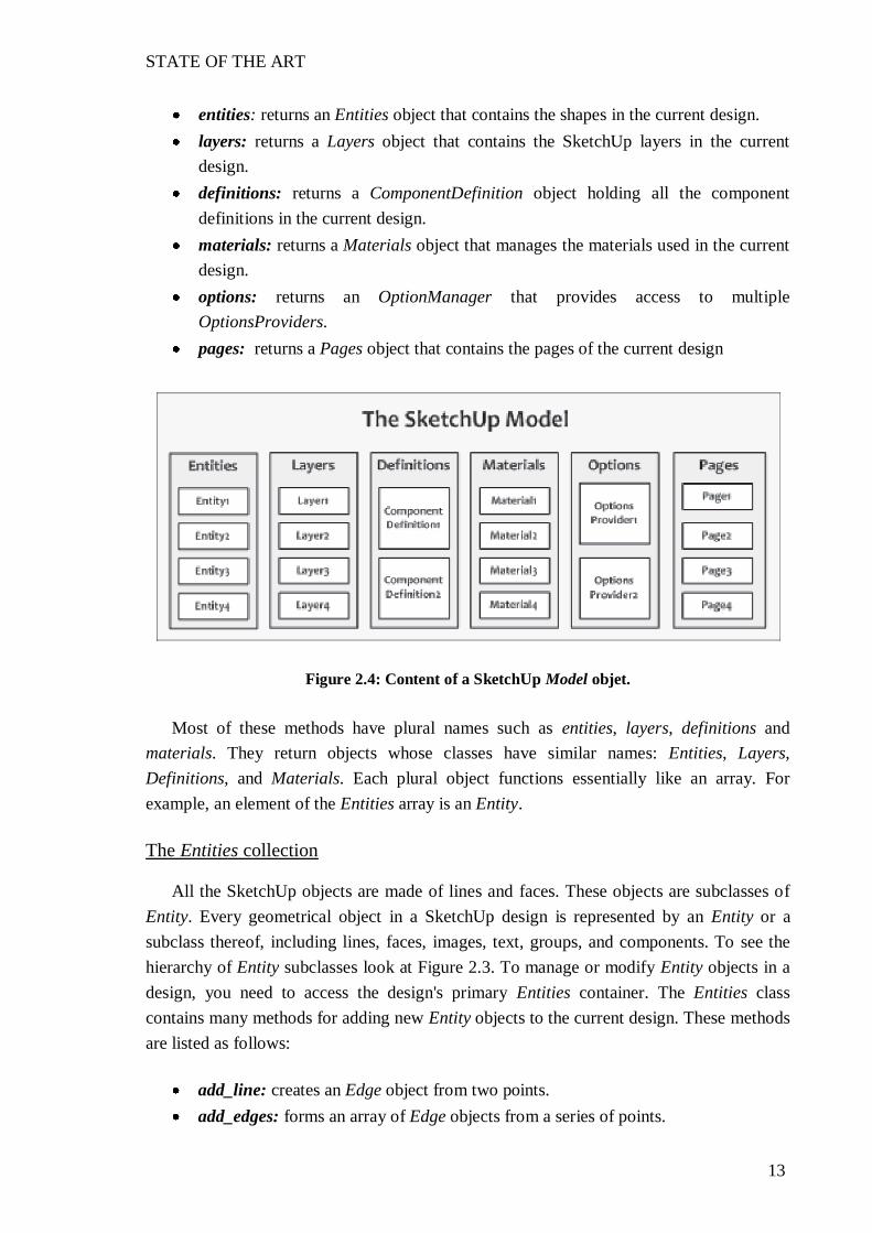
Ruby is divided in to modules and classes as we can see in [12]. Figure 2.3 shows the object diagram of these classes. The modules are divided in methods. The most important module for us is Sketchup and it most important method active_model. Just as the Sketchup module represents the entire SketchUp application, the Model object represents a single SketchUp file (*.skp). When you open a new file in SketchUp, the properties of the Sketchup module remain the same but the data in the active Model object becomes entirely different. The methods in the Model class provide information about the current design. Figure 2.4 shows six of the most important object "drawers" contained within a Model object.

STATE OF THE ART
12
Figure 2.3: Objects diagram of SketchUp Ruby API
To access these modules you need to call the appropriate Model methods that are
classes. These are:
STATE OF THE ART
13
entities: returns an Entities object that contains the shapes in the current design. layers: returns a Layers object that contains the SketchUp layers in the current
design. definitions: returns a ComponentDefinition object holding all the component
definitions in the current design. materials: returns a Materials object that manages the materials used in the current
design. options: returns an OptionManager that provides access to multiple
OptionsProviders. pages: returns a Pages object that contains the pages of the current design
Figure 2.4: Content of a SketchUp Model objet.
Most of these methods have plural names such as entities, layers, definitions and
materials. They return objects whose classes have similar names: Entities, Layers, Definitions, and Materials. Each plural object functions essentially like an array. For example, an element of the Entities array is an Entity.
The Entities collection
All the SketchUp objects are made of lines and faces. These objects are subclasses of
Entity. Every geometrical object in a SketchUp design is represented by an Entity or a subclass thereof, including lines, faces, images, text, groups, and components. To see the hierarchy of Entity subclasses look at Figure 2.3. To manage or modify Entity objects in a design, you need to access the design's primary Entities container. The Entities class contains many methods for adding new Entity objects to the current design. These methods are listed as follows:
add_line: creates an Edge object from two points. add_edges: forms an array of Edge objects from a series of points.

STATE OF THE ART
14
add_circle: forms an array of Edge objects that combine to form a circle. add_ngon: forms an array of Edge objects that combine to form a polygon. add_face: creates a Face object from edges or points. add_text: adds a label to the design at a given point.
When you add something to the Entities container, the corresponding shape appears in
the SketchUp window. Then, when you save the design, the Edges and Faces will be included in the stored Model object.
One of the descendant classes of Entity is Edge. Edge in turn extends to the class
Drawingelement. It represents a line segment between two points. Edge objects are created with the add_line method of the Entities class, like we saw before. For example, the following command creates an Edge that extends from [5, 0, 0] to [10, 0, 0]:
Sketchup.active_model.entities.add_line[5,0,0],[10,0,0]
To create a curve or a circle SketchUp does not really create arcs and circles. Instead,
each curve-like shape is a succession of tiny line segments. We can create several edges with the method add_curve, which accepts a succession of points and returns the array of Edge objects that connect the points;
To create circles we use the method add_circle, which creates a circle with a given
center, normal vector, and radius. The normal vector identifies the up direction. For example, the following command creates a circle with a center at [1, 2, 3], a normal vector equal to [4, 5, 6], and a radius of 7:
circle = Sketchup.active_model.entities.add_circle [1,2,3],[4,5,6],7
Once that you have the Edges, you can create the second important part of SketchUp
components, the faces. Face objects are created by the add_face method of the Entities class. This method accepts a series of points or a series of Edges, and either can be provided in a comma-separated list or in an array. For example, if we have five points saved in five variables previously, we can create one face as follows:
Sketchup.active_model.entities.add_face pt1, pt2, pt3, pt4, pt5
Until now we only have seen two-dimensional elements, but SketchUp is a three-
dimensional program. To create three-dimensional figures, the Face class provides two methods: pushpull and followme.

STATE OF THE ART
15
The pushpull surface along the Face -dimensional figure. If the number is negative, the method pushes the surface in the direction opposite the Facevector. For example, if we have a Face saved in the variable face, we can create the three-dimensional object at follows:
face.pushpull 5
With followme method, you can make an extrusion performed along a vector, but now you control the vector's direction. That is, you specify the path the extrusion should take. Once you've determined the path, that will be the Edges that form the extrusion, you can invoke followme with an array of Edges. This will extrude the Face along each Edge of the extrusion path. For example, if we have one Face saved in the variable circle and the path saved in the variable path, we can extrude the circle along the path with the follow command. We can see the result in the Figure 2.5:
circle.followme path
Figure 2.5: Extrusion created by followme method
Transformations
Once we have a two-dimensional or three-dimensional object, we can apply a set of
transformations with a Transformation object. A Transformation object embodies the movement of an Entity, and this movement can be placed into one or more of the following categories:
translation: moving an object a given distance in a given direction. In SketchUp, the Move tool performs translation.
rotation: moving an object through a given angle, as measured from an origin. SketchUp's Rotate tool performs rotation.

STATE OF THE ART
16
scaling: increasing or reducing the size of an object along with its distance from the origin. SketchUp's Scale tool performs scaling.
A SketchUp translation moves an Entity a specified distance in a given direction. To
define a translation in three dimensions, it is necessarily an array with three elements. Each of these array elements will be added to the coordinates of the Entity, producing a new set of coordinates for the Entity. To make a new translation (and any other transformation), is necessary to invoke the Geom object. For example, if we have an Entity saved in the variable entity, we can translate it four units in the +x direction as follows:
t = Geom::Transformation.translation [4, 0, 0] ents.transform_entities t, entity
To rotate a shape it is necessary define the origin around which the rotation is to be
performed (a point), the axis of rotation (a vector), and the rotation angle (a floating-point value). For example, the following Transformation rotates an entity 90° about the z-axis, with the origin at [100, 0, 0].
tr = Geom::Transformation.rotation [100,0,0],[0,0,1], 90.degrees
The last transformation is the scale, which changes the dimensions of a shape. For
example, we can double the size of a shape with the following command:
t = Geom::Transformation.scaling 2
We can combine Transformation objects with the * operator. For example, if tran translates an Entity and rot rotates an Entity, the following command creates a Transformation that translates an Entity with tran and then rotates it with rot:
t_prod = t_rot * t_tran
Groups and components
When the number of shapes grows large, you'll need a way to manage them. If you want to apply transformations to some Entities which form a specific object, until now you would have to apply the same Transformation to all the Entities. There are three mechanisms provided by SketchUp for managing geometry: layers, groups, and components.
Layers make possible to hide large sections of geometry at once. Groups combine
multiple objects and allow you to create copies and organize subgroups in a hierarchical

STATE OF THE ART
17
fashion. Components are similar to groups, but provide many more features. One of the primary advantages of using components is that you can save a component's data to a file.
A Group is a collection of Entity objects, such as Edges, Faces, and even other
Groups. The advantage of using Groups is that you can organize Entity objects in a hierarchical fashion. When you operate on a Group, you operate on all of its Entity objects at once, like make a transform with a Transformation object in only one time to all the Entities of the Group.
The add_group method in the Entities class creates a new Group object and inserts it
into the current model. This method accepts a list of one or more Entity objects, an array of Entity objects, or an Entities object. For example, if we have a cube, we can create a Group using the method add_group and all the Entities connected to one of the Faces of the Group as follows:
group1 = ent.add_group face.all_connected
You can configure the name, description, and locked state of each Group you create. These name and description will be useful, because we can access to them in other scripts, thereby keeping track of the objects we work with.
Like Groups, SketchUp components contain Entity objects and make it possible to operate on all the Entity objects at once. But components are more powerful and more versatile than Groups. There are two classes to define components: ComponentDefinition and ComponentInstance. The ComponentDefinition stores the component's model information. This can be saved to and read from a file. The ComponentInstance is an instantiation of a component within the current design. As an example, the following code creates a ComponentDefinition called new_def, gives it the name NewComp, and saves it to a component file called newcomp.skp:
def_list = Sketchup.active_model.definitions new_def = def_list.add "NewComp" new_def.save_as "newcomp.skp"
Once you've created your ComponentDefinition you can add instances of the
component, called ComponentInstance, to your design. The Entities class has an add_instance method that creates a ComponentInstance according to two parameters: a ComponentDefinition and a Transformation object. For example, the following code creates a ComponentInstance object from a ComponentDefinition called comp_def and translates it three units in the +x and +y directions:

STATE OF THE ART
18
ent = Sketchup.active_model.entities t = Geom::Transformation.translation [3, 3, 0] inst = ent.add_instance comp_def, t
Materials
There are three ways to define a Material's characteristics: by Color, Texture, or by Color and Texture. A Color contains red, green, and blue components. A Texture is an image repeated across a surface like a wallpaper pattern.
The Material objects in a design are stored in a Materials object (the same way the
Entity objects are stored in an Entities object). To add new materials, you need to access the design's Materials container and invoke its add method with the material's name.
All the classes descending from Drawingelement has the method material=, which
one you can apply a Material to the object. For example, the following command applies a Material, created previously with the method add, to one Face saved in the variable face:
face.material = new_mat
To use the class Color is very easy, you can create Color objects directly if you know SketchUp's name for your color or its red, green, and blue components. To know all the names that SketchUp use you can call the method names of the class Color. For example, these two commands both assign the Color dark orange to one Group previously save in the variable group:
group.material="DarkOrange" group.material=[255,140,0]
To apply a Texture to the shape you create a Texture object from an image file and use
the Texture to create a Material. Then you apply the Material to the surface. Texture objects are created with the texture method of the Material class. For example, the followings commands create a Texture from one image previously saved in the path of the variable save_path and assign it to one Face saved in face, with the method material=. This example is shown in the Figure 2.6.
new_mat = Sketchup.active_model.materials.add "Color_Texture" new_mat.texture = Sketchup.find_support_file "Project/door.jpg", "Plugins" face.material = new_mat

STATE OF THE ART
19
Figure 2.6: Application of a texture in SketchUp
There are times that you have to change the size of the Texture
the Texture repeats in the shape. In this case you can for example, assign it the same size than one Face has. To do that, there are some methods of the class Texture, as width, height or size. Observers
At this point it would be interesting to know how to respond to events. The SketchUp API makes this possible by implementing a design pattern called the observer pattern. An observer is an object that responds when an object being observed changes in some way. The SketchUp API provides three types of observers: EntityObserver, SelectionObserver and MaterialObserver.
The EntityObserver respond to changes in Entity objects. It means that you can make
an action when some Entity is changed or deleted. Coding an EntityObserver requires three main steps:
1. Define a class that extends EntityObserver. For example:
class EntObserver < Sketchup::EntityObserver
2. Add instance methods that respond to events: onChangeEntity and/or onEraseEntity. For example, the following code creates a method inside the class
def onEraseEntity (entity) puts entity.typename + " erased" end
3. Invoke the new method to create an object from your EntityObserver subclass. For
example, the following code associate a new EntityObserver with one face previously created:

STATE OF THE ART
20
obs = EntObserver.new face.add_observer obs
The Selection object contains all the Entity objects that have been selected by the user.
The common way to access it is to invoke the selection method of the Model class. This returns the Selection object containing all of the currently selected Entity objects.
The Selection object becomes particularly helpful when combined with a
SelectionObserver. This observer class provides four methods that respond to selection events:
onSelectionAdded(Selection, Entity): responds when an Entity has been selected. onSelectionRemoved(Selection, Entity): responds when an Entity has been
deselected. onSelectedCleared(Selection): responds when all Entity objects have been deleted
or deselected. onSelectionBulkChange(Selection): responds when selected Entity objects have
been changed.
The procedure to apply this SelectionObserver is similar to EntityObserver. The MaterialsObserver class provides six methods that respond when the elements of
a Materials object change:
onMaterialAdd(Materials, Material): responds when a new Material is added to the model.
onMaterialChange(Materials, Material): responds when a Material in the design is changed.
onMaterialRemove(Materials, Material): responds when a Material is removed from the model.
onMaterialRefChange(Materials, Material): responds when a Material is applied to an Entity or when an applied Material is changed.
onMaterialUndoRedo(Materials, Material): responds when a Material's property or application is changed by an undo or redo action.
onMaterialRemoveAll(Materials, Material): responds when all of the materials are removed from the model.

STATE OF THE ART
21
Menus and Toolbars
As we saw in Section 2.1, in Google SketchUp there are two ways to present the information and to interact with the program: menus and toolbars. We can access
with both, but in different ways. Programming with Ruby we can also design our user interface by these two ways.
represented in code by a Menu object. Once you have a Menu object, you can invoke its four methods, listed as follows:
add_item: creates a new menu entry and defines the procedure that should be executed when it's selected.
add_submenu: returns a Menu object to serve as a submenu of the current Menu object.
add_separator: adds a line to separate the menu item from following items and submenus.
set_validation_proc: checks the state of the current design to determine how the menu entry should be presented.
To The Tool class identifies
methods that SketchUp looks for when a tool is active and the user performs an action. At any given time, only one tool in the SketchUp toolbar can be active. By default, the active tool is the Selection tool. To make a tool active in code, you need to call the select_tool method from the Model class. For example, to make my_tool active, you need to execute a command like the following:
Sketchup.active_model.select_tool my_tool
To create a tool you have to create a class, which in Ruby will act like an interface.
This means that the methods are predefined and they have only necessary to overwrite these methods. Depending on how the tool will work you have to consider which method to choose, like mouse methods or keyboard methods. In Table 2.1 you can see some of the most important methods that you can overwrite in the Tool class.
To manage the toolbars in code we can use the Toolbar class accessible with the
module UI. The primary method in the Toolbar class that concerns us is add_item, which accepts a Command. In SketchUp, a Command identifies a procedure that can be executed through a menu item or tool selection. Once you've created a Command, you can associate it with a menu item, a toolbar item, or both. First, the Command calls its validation procedure (set_validation_proc) to determine whether it should be enabled or grayed out.

STATE OF THE ART
22
If it's enabled and the user selects it, the code block defined in the Command's constructor is executed. For example, the following lines create and configure one Toolbar, accepting the Command, called cmd, which create a new Tool.
toolbar = UI::Toolbar.new "Movement" toolbar.add_item cmd toolbar.show
Method Input Parameters Description onKeyDown
key, repeat, flags, view
Invoked when the user presses a key down.
onLButtonDoubleClick
flags, x, y, view
Invoked when the user double-clicks the left mouse button.
onLButtonDown
flags, x, y, view
Invoked when the user presses the left mouse button.
onMouseMove
flags, x, y, view
Invoked when the user moves the mouse.
onRButtonDoubleClick
flags, x, y, view
Invoked when the user double-clicks the right mouse button
onRButtonDown
flags, x, y, view
Invoked when the user presses the right mouse button.
onReturn
view
Invoked when the user presses Enter/Return.
Table 2.1: Methods of the Tool class
Once you have created the Tool and you have referenced it with the Toolbar, the
Tool specified happen.

APPROACH DESIGN OF A FURNITURE MOVEMENT TOOL
23
CHAPTER 3: APPROACH DESIGN OF A FURNITURE MOVEMENT TOOL
In the last chapter we saw the necessary programs for the realization of this Final Master Thesis: Google SketchUp and Ruby. In this chapter we will see how SketchUp is the base where we will implement our approach, using the programming language Ruby.
The main goal of this Final Master Thesis is investigate the potential of the
programming language Ruby, designing a tool for the adjustment of the furniture inside a room. The idea is to design several rooms with the furniture according to each one. The user moves the furniture where he wants, respecting the physical restrictions that there are in one room like collisions or limits of the room. The user can also add new furniture to the room.
At first glance it appears that SketchUp has the capacity to do this, because, as we seen
in Section 2.1, it has a move tool with which we could move the furniture around the room.
are in one room. For this reason we have to make a tool to move the furniture contemplating the restrictions.
Another important goal is to investigate the different possibilities that there are in the
adjustment of one object to a wall, as well as investigating what to do when a piece of furniture is moved and there is a restriction in the movement. We will make a study of these possibilities.
The design of the tool has been the work of two people making the Final Master
Thesis. That is because the problem is complex enough. So in this Final Master Thesis I will explain in detail the operation of the tool, but I will focus in the realization of the parts that I have done. These parts are the design of the move tool and the design of the adjustment of the collisions.
3.1 Design of furniture
Once we know the main features of the tool for the control of the furniture in a room, the first thing that we have to do is to know what kind of furniture and what kind of room we need.

APPROACH DESIGN OF A FURNITURE MOVEMENT TOOL
24
We will do simple furniture because the main goal of this Final Master Thesis is the
move tool, not to create the furniture. Also if is more difficult create shapes with code than in the console of SketchUp. For that reason, all the pieces of furniture will be combination of boxes and cylinders.
The idea is to control the furniture of three rooms in the faculty of mathematics and
informatics in Vilnius. So we have to design these three rooms. We have followed the plan of the rooms that we can see in the Figure 3.1. These rooms have different dimensions and different locations of the door. The length unit of the plan is meters, but Ruby works with inches, so we have followed the conversion 1m = 39.37 inches.
Figure 3.1: Plane of the rooms to modeling
The process to create one room is simple. We will explain more detail this process for
be the first, but not entering so much in implementation details for not do very boring this memory.
1. Create one Face with four Points in the z axis. 2. Extrude de Face. The result box is the back wall. 3. Create one Group with the box. For this we use the method all_connected of the
class Face. 4. Copy the Group with it method copy and move this second Group 5.9 meters along
the y axis with the method translation of the class Transformation. This is the front wall.
5. Repeat this process for the left and right walls creating the first Face in the y axis. 6. Create the floor in the x axis.

APPROACH DESIGN OF A FURNITURE MOVEMENT TOOL
25
7. Create the door that will be another Group and situate it in the corresponding position.
8. Create the one window and act the same as with the door. 9. Apply different textures to the elements of the room.
In Figure 3.2 we can see the empty room with and without textures.
Figure 3.2: Modeling of one room with a Ruby script
With the room created we need some furniture. We made two typical pieces of
furniture that there are in a faculty room: a table and a shelf. To create the table we followed this steps:
1. Create the box that will be the table in x axis and enter it in a Group. 2. Create the left leg in the z axis; enter in a Group, copy de Group and move in the x
axis. It will be the right table leg. 3. Create the drawer with one box, two Edges and three cylinders. 4. Combine all the groups with the method add_group of the class Entities. 5. Write a description to the final Group. We will explain this lat to
distinguish what kind of furniture will move in the floor and what kind in the wall. 6. Apply different textures to the elements of the table.
In Figure 3.3 we can see the finished table with and without textures.

APPROACH DESIGN OF A FURNITURE MOVEMENT TOOL
26
Figure 3.3: Modeling of a table with Ruby script
We are not going to enter in detail about how to create the self because the procedure
is similar than the table and the room. In Figure 3.4 we can see the shelf with and without textures.
Figure 3.4: Modeling of a shelf with Ruby script
3.2 Design of a move tool
Once we have designed some furniture, our object is to move them. We know that the main goal of this tool is to move objects across a room within the restrictions. We cannot do that with the move tool of SketchUp because as we saw in the previous section it
re in a room. For that reason the first step in the implementation of this tool is to make a new tool able to move objects in SketchUp, no matter whether they are inside a room or not.
APPROACH DESIGN OF A FURNITURE MOVEMENT TOOL
27
This tool will be implemented in a class, because as we saw in Section 2.2necessary to create a new tool. The name of this class will be MovementTool and inside it will be all the necessary methods for the performance of the tool.
The idea is to click in one object, select it and to click again in the destiny position. To
do that, we saw in Section 2.2 how to create a tool in a Ruby script. We have to define a class which will be our tool and inside the class overwrite the methods interesting for us, because this Tool class is like an interface.
We will have two points created with the method new of the class InputPoint.
InputPoints convert two-dimensional pixel coordinates to three-dimensional coordinates in the design, it means that with the method pick, InputPoint transform the coordinates x and y in the screen by the correspondent three-dimensional coordinates in 3D space. Therefore we know how to find 3D points, now we want to find the point that the user click. For this reason, we have to overwrite the method onLButtonDown of the Tool class and distinguish
use the first click will select the object and the second will move it. Group or Component, to know what object to , we find where the second point is and we move the object with a translation between the position of the second point and the position of the object. We can see the following pseudo code of that we have explained.
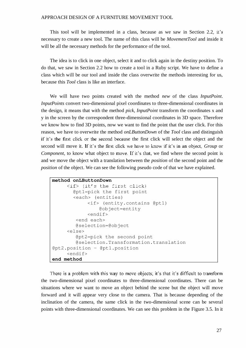
method onLButtonDown
@pt1=pick the first point <each> (entities)
<if> (entity.contains @pt1) @object=entity
<endif> <end each> @selection=@object
<else> @pt2=pick the second point @selection.Transformation.translation
@pt2.position - @pt1.position <endif>
end method
the two-dimensional pixel coordinates to three-dimensional coordinates. There can be situations where we want to move an object behind the scene but the object will move forward and it will appear very close to the camera. That is because depending of the inclination of the camera, the same click in the two-dimensional scene can be several points with three-dimensional coordinates. We can see this problem in the Figure 3.5. In it

APPROACH DESIGN OF A FURNITURE MOVEMENT TOOL
28
we have the two pieces of furniture created previously, one table and one shelf, situated both in the y axis and we want to move both of them back to that axis. For this, we click the second point behind the axis but we see that the table has moved to the back but the shelf has moved forward. If we move the camera the result can change.
Figure 3.5: Common error in the coordinates change
At this point we know that we have to guide the movement modifying the translation,
depending on where the movement will be. It will be useful when we have to move the object attached to a wall. With the move tool that we have until now we cannot move the object exactly along we save will change depending on the part of the object that we click. Another problem is
of the limits of the wall.
BoundingBox which
because the translation will be the difference between the second point and the center of the BoundingBox of the object.
The second problem is not as straightforward to solve as the first. We need to
investigate the final position of the object depending on the part of the wall where the user wants to move it. This final position will depend of the dimensions of the object, especially the height and the width, because we always have to calculate if the difference between the limit of the wall with the limit of the object is greater of less than the half of the height or the width. For example, if we want to move the object to the upper limit of the wall, it will be if it satisfies the following condition:
APPROACH DESIGN OF A FURNITURE MOVEMENT TOOL
29
z coordinate of upper limit of face wall @pt2.position.z < object.height / 2
With the same procedure we divided the wall in the following parts: upper left corner,
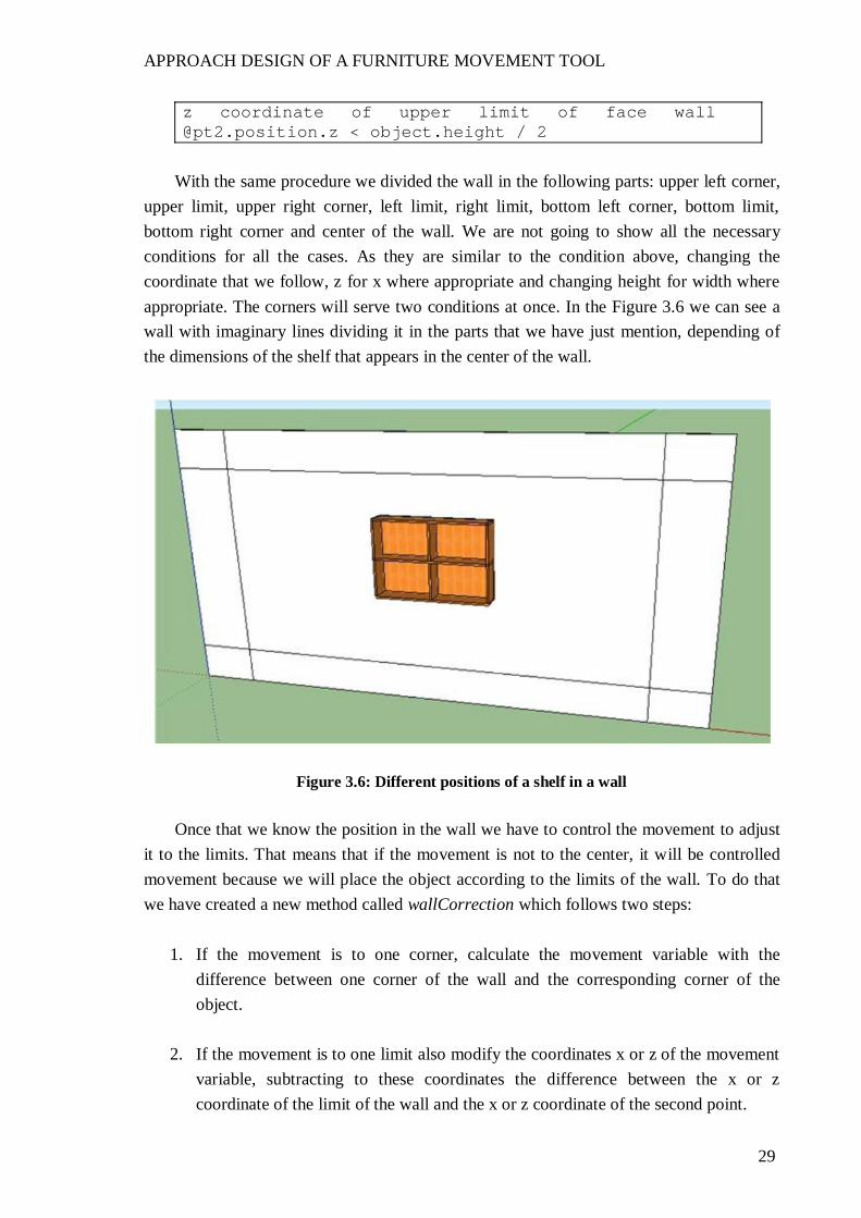
upper limit, upper right corner, left limit, right limit, bottom left corner, bottom limit, bottom right corner and center of the wall. We are not going to show all the necessary conditions for all the cases. As they are similar to the condition above, changing the coordinate that we follow, z for x where appropriate and changing height for width where appropriate. The corners will serve two conditions at once. In the Figure 3.6 we can see a wall with imaginary lines dividing it in the parts that we have just mention, depending of the dimensions of the shelf that appears in the center of the wall.
Figure 3.6: Different positions of a shelf in a wall
Once that we know the position in the wall we have to control the movement to adjust
it to the limits. That means that if the movement is not to the center, it will be controlled movement because we will place the object according to the limits of the wall. To do that we have created a new method called wallCorrection which follows two steps:
1. If the movement is to one corner, calculate the movement variable with the difference between one corner of the wall and the corresponding corner of the object.
2. If the movement is to one limit also modify the coordinates x or z of the movement variable, subtracting to these coordinates the difference between the x or z coordinate of the limit of the wall and the x or z coordinate of the second point.

APPROACH DESIGN OF A FURNITURE MOVEMENT TOOL
30
For example, this is the pseudo code for move the objet to the bottom limit of the wall: @movement = position of the bottom right corner of the wall bottom right corner of the object @movement.x = @movement.x (x coordinate of the position of the bottom right corner of the wall @pt2.position.x object.width / 2)
For the other parts of the wall the procedure is the same depending of the corner. In
the Figure 3.7 we can see the different movements of a shelf in a wall, with the procedures that we have seen.
Figure 3.7: Possible movements of a shelf in a wall
in a room there are objects that have to be attached also to the floor, like a table or a wardrobe. For the correct movement of these objects we have to modify movement correction. The movement will be the same that we have explained but now we modify the z coordinate of the movement subtracting the distance between the bottom limit of the object and the floor.
The objective is to move the objects not only on one wall but also in all the walls of
the room. We have seen the movement correction in a wall situated in the x axis. The movement correction in a wall situated in the y axis follows the same idea but with some small details to consider.
APPROACH DESIGN OF A FURNITURE MOVEMENT TOOL
31
1. The first one is that in that wall the coordinates of the corners of the wall change; therefore we cannot follow the same conditions for know the part of the wall.
2. If before we modified the coordinates x and z for correct the movement, now we modify the coordinates y and z. In our case, the side walls of the room are situated in the negative y axis, so we have to work with absolute values. An absolute value is applied with the function abs.
For these reasons we cannot use the function wallCorrection in the movement
correction of the side walls, and we created another function. This new function has as parameters the corners of the wall, because between the two side walls they change and if
opposite side. We have designed two functions that place the object in the walls of the room
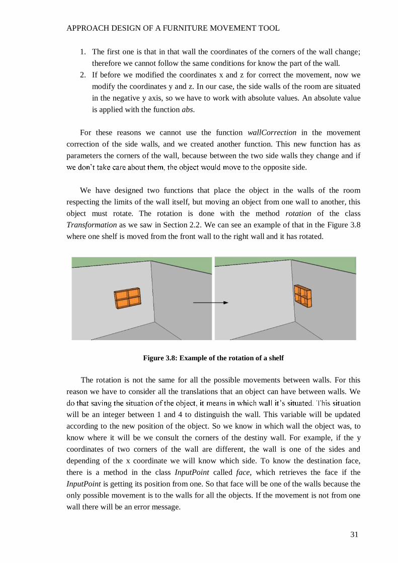
respecting the limits of the wall itself, but moving an object from one wall to another, this object must rotate. The rotation is done with the method rotation of the class Transformation as we saw in Section 2.2. We can see an example of that in the Figure 3.8 where one shelf is moved from the front wall to the right wall and it has rotated.
Figure 3.8: Example of the rotation of a shelf
The rotation is not the same for all the possible movements between walls. For this
reason we have to consider all the translations that an object can have between walls. We uation
will be an integer between 1 and 4 to distinguish the wall. This variable will be updated according to the new position of the object. So we know in which wall the object was, to know where it will be we consult the corners of the destiny wall. For example, if the y coordinates of two corners of the wall are different, the wall is one of the sides and depending of the x coordinate we will know which side. To know the destination face, there is a method in the class InputPoint called face, which retrieves the face if the InputPoint is getting its position from one. So that face will be one of the walls because the only possible movement is to the walls for all the objects. If the movement is not from one wall there will be an error message.

APPROACH DESIGN OF A FURNITURE MOVEMENT TOOL
32
We have spoken about the variable position of the object. This variable would be valid
not enough because they can be in different walls. An error could occur because SketchUp only knows where the first object to move is, but not the followings objects and the rotation would be wrong. For example, in Figure 3.9 this situation is represented. There is a table and a shelf in a room. First, the user moves the table to the right wall. This table rotates well, but now the position is in that wall, so when the user moves the shelf to the right wall also, this shewall.
Figure 3.9: Error in the rotation for a wrong measure of situation
To solve this problem it is necessary a position for every object in the room. So we
need an array as many dimensions as pieces of furniture are there in the room. First we have to initialize that array counting the pieces of furniture. Then, we have to assign the position of each object at the beginning to that array. We do that seeing where the corners of the object are in relation with the dimensions of the room. Every time that an object changes wall, the array must to be updated. For that reason we need two new methods: the first one will be called position and it will assign one wall to the object passed as parameter. The second one will be called positionw and it will return the position of the wall where one object passed as parameter is. This method, positionw, will be called every time that we need to know the wall where the object is before moving to another. We can see the pseudocode of these two methods as follows.
method position (object, num)
<for> (i to entities-1) <if> (entities[i].name == object.name) @situation[i]=num <endif> <end for>
end method

APPROACH DESIGN OF A FURNITURE MOVEMENT TOOL
33
method positionw (object) <for> (i to entities-1) <if> (entities[i].name == object.name) return i <endif> <end for>
end method
We have seen the methods for the correct movement of one object on one wall, to change the objects between walls and to rotate these objects as appropriate, but we need to join all these things. In the method onLButtonDown that we explained before, when the second point is picked, is the place for do that. First we need to know which is the destination wall, after which is the original wall and, contemplating all the possible combinations, follow these steps:
1. Rotate the object as appropriate for original and destination walls. 2. Assign the new position of the object to the array of positions with the method seen
previously. 3. Call one of the methods of movement correction seen previously, depending if the
destination wall is in the x axis or in the y axis.
In the Figure 3.10 we can see the result of this move tool with the movements of three pieces of furniture between the walls. There is a shelf moved from the back wall to the left wall, a table moved from the left wall to the right wall and a wardrobe moved from the right wall to the back wall.
Figure 3.10: Correct movement of three pieces of furniture
very well. There are times that you click in one point, but SketchUp save another depending of the view point in the scene. This can cause problems of perception if we think that the movement is to one point, but there is a small error because SketchUp has taken another closer point. To solve this little problem of perception we draw a line with

APPROACH DESIGN OF A FURNITURE MOVEMENT TOOL
34
all the possible destinations there are when you have selected an object and you have to click to second time. This line is drawn with the method draw_line of the class view, between the final and the original point and must be inside the method onMouseMove of the tool class, which we saw is executed every time that the mouse is moved, but we will use only when the object is selected to move. With this method you also know if you are moving an object following one of the axes, because the colors of the line change. In Figure 3.11 we can see the selected object with the line drawing the destination.
Figure 3.11: Movement with the line which show the destiny
3.3 Design of a collisions correction tool
As mentioned earlier this project, the improved movement tool for furniture has been developed by two persons. The work has been divided in two well differentiated parts. One of the tasks of the project is to create a collision detection tool. This tool, based on the move tool explained in Section 3.2, evaluate if there is a collision between two pieces of furniture after the movement of one of them. We are not going to explain the details of the
for the implementation of the collision correction tool. All that we have to know is that there is a boolean method which return if an object passed as parameter has a collision with another object or not.
After the implementation of the move tool which correct the movement of an object in
the wall of a room, the other main goal of this Final Master Thesis is the detection and the correction of the collisions for a complete simulation of the behavior of a room with pieces of furniture. We have the method which detect if there is a collision or not. Now, using this method, the next step is to create a tool which corrects the different collisions investigating the best option for the correction. The idea is that every time that a collision is detected, the system correct that collision placing the object which was moving in the best place near the object it collided with. From now we will call the object which is moving simply as object and the object which receive the collision as collided object .

APPROACH DESIGN OF A FURNITURE MOVEMENT TOOL
35
As we saw in Section 3.2 there are two kinds of furniture in the rooms which we work
with: the objects whose movement is attached to the wall, like pictures of shelves and object whose movement is attached to the wall and the floor at the same time, like tables or
object that could follow this movement is a chair, but in our case chairs are attached to le, so chairs will have the
same movement as tables.
The kind of furniture will be important to decide the direction of the collision correction. Depending of the combination of the object which was moving with the object that was collided, the collision correction can be two modes:
Movement up respect the collided object: The object which was moving moves up of the object collided, changing it z coordinate. This correction is typical, for example when a shelf have a collision with a table because normal is that the shelf will be up the table.
Movement to the sides respect the collided object: The object which was moving moves to the right or to the left of the object collided, changing it x or y coordinate, depending of the wall where is the collision. This correction collision is normal between object attached to wall and floor, because they cannot go up or down because they must to be attached to the floor.
In Table 3.1 we can see the direction of the collision correction depending of the kind
of object which has a collision.
Object attached to wall
Object attached to wall and floor
Door and window
Object attached to wall
Sides movement Up movement Sides movement
Object attached to wall and floor
Sides movement Sides movement Sides movement
Table 3.1: Collision correction between different kinds of objects
The collision correction is applied after moving the object to its initial destiny. For that
reason that correction will be another movement to place the object close to the collided object. This movement will be done defining the corresponding translation. To do that it will be necessary to define an array of dimension three, the three coordinates, to pass as parameter to the translation.
APPROACH DESIGN OF A FURNITURE MOVEMENT TOOL
36
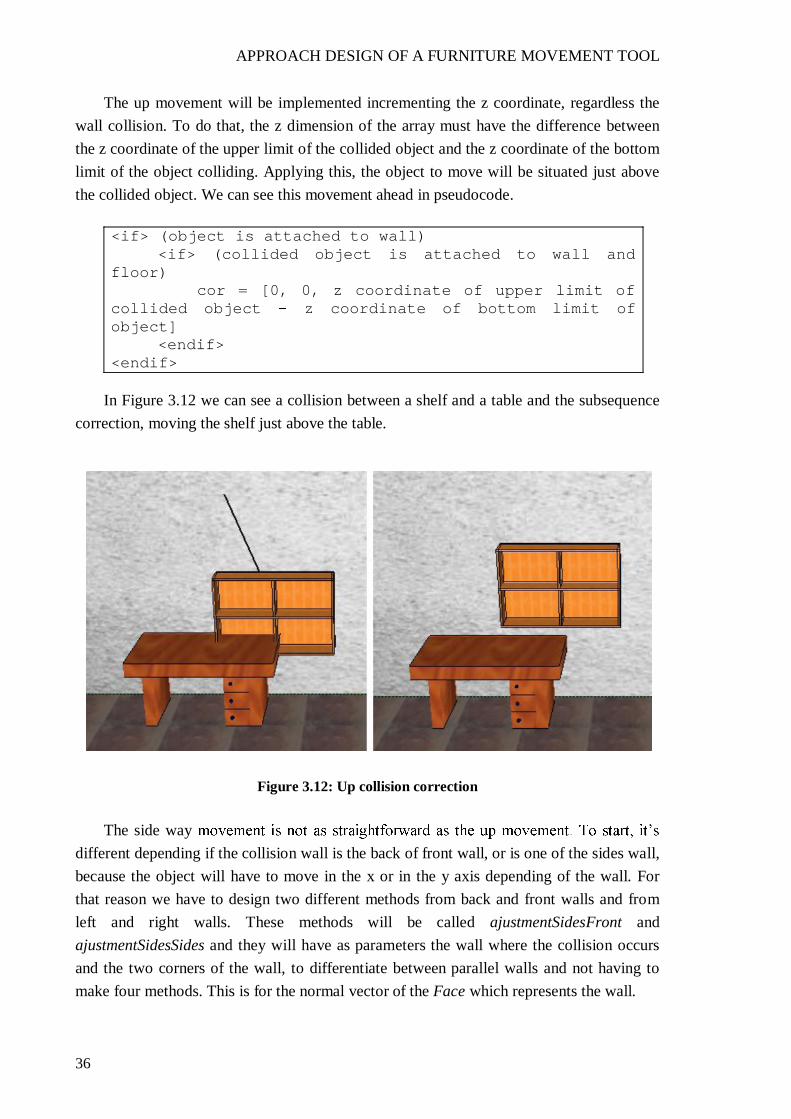
The up movement will be implemented incrementing the z coordinate, regardless the wall collision. To do that, the z dimension of the array must have the difference between the z coordinate of the upper limit of the collided object and the z coordinate of the bottom limit of the object colliding. Applying this, the object to move will be situated just above the collided object. We can see this movement ahead in pseudocode.
<if> (object is attached to wall) <if> (collided object is attached to wall and
floor) cor = [0, 0, z coordinate of upper limit of collided object z coordinate of bottom limit of object] <endif> <endif>
In Figure 3.12 we can see a collision between a shelf and a table and the subsequence
correction, moving the shelf just above the table.
Figure 3.12: Up collision correction
The side way
different depending if the collision wall is the back of front wall, or is one of the sides wall, because the object will have to move in the x or in the y axis depending of the wall. For that reason we have to design two different methods from back and front walls and from left and right walls. These methods will be called ajustmentSidesFront and ajustmentSidesSides and they will have as parameters the wall where the collision occurs and the two corners of the wall, to differentiate between parallel walls and not having to make four methods. This is for the normal vector of the Face which represents the wall.

APPROACH DESIGN OF A FURNITURE MOVEMENT TOOL
37
The idea of the side ways movement is move the object to one side or another of the colliding object, the best possible way. If the collision is for the right side, the normal correction is to move the object just to the right of the collided to the left side, to move the object to the left. The problem is that the dimensions of the room must be respected, so the object cannot move beyond the limits of the wall. For that reason, once the side of the movement is decided, if the object is going to pass a limit of the wall, the movement is to the other side.
In the ajustmentSidesFront method the first thing is to know the intention of the user
respecting the side direction of the movement. If the x coordinate of one of the lefts corners of the object is less than the x coordinate of one of the lefts corners of the collided object, is because the movement is to the left. Otherwise, the movement is to the right. Once we know the side of the movement we have to know if the movement may procede or not, depending on how close the collided object is with the limit of the wall. For that we have to know if the difference between the x coordinate of one of the left corners of the collided object and the x coordinate of one of the limits of the wall is less or not than the difference between the x coordinate of one of the right corners of the object and the x coordinate of one of the left corners of the object. It means that if the width of the object enters or not in the distance between the object collided and the wall. This is the procedure for the left side. The right side is the same but changing the limit of the wall. Once we know what the situation is, we have to make the movement. We do that modifying the array argument to the translation. That array will be returned in the method ajustmentSidesFront. If the movement is to the left, we have to modify the x coordinate of the array and now it will be the negative value of the difference between the x coordinate of the right limit of the object and the x coordinate of the left limit of the collided object. If the movement is to the right, the x coordinate of the array will be the difference between the x coordinate of the right limit of the collided object and the x coordinate of the left limit of the object.
Before showing the pseudocode of the explained procedure we are going to see with
pictures the two possible situations. In Figure 3.13 we see a wardrobe that the user wants to move to the right of a table, but there is a collision. As the wardrobe fits on the piece of wall to the right of the table, the wardrobe moves to the right side. In Figure 3.14 we see
fit in the piece of wall between the wardrobe and the left limit of the wall, so the movement correction is to the right of the wardrobe.

APPROACH DESIGN OF A FURNITURE MOVEMENT TOOL
38
Figure 3.13: Right correct side collision correction
Figure 3.14: Left wrong side collision correction
After these examples of sides movement, we will see the pseudocode of the method
ajustmentSidesFront.
method ajustmentSidesFront (wall, limit1, limit2) <if> (x coordinate of left corner of object < x coordinate of left corner of collided object) <if> (x coordinate of left corner of collided object x coordinate of left limit of wall < object.width) cor=[x coordinate of right corner of collided object x coordinate of left corner of object,0,0] <else> cor=[ (x coordinate of right corner of object x coordinate of left corner of collided
APPROACH DESIGN OF A FURNITURE MOVEMENT TOOL
39
object),0,0] <else> <if> (x coordinate of right limit of wall x coordinate of right corner of collided object < object.width) cor=[ (x coordinate of right corner of object x coordinate of left corner of collided object),0,0] <else> cor=[x coordinate of right corner of collided object x coordinate of left corner of object,0,0]
<endif> return cor
end method
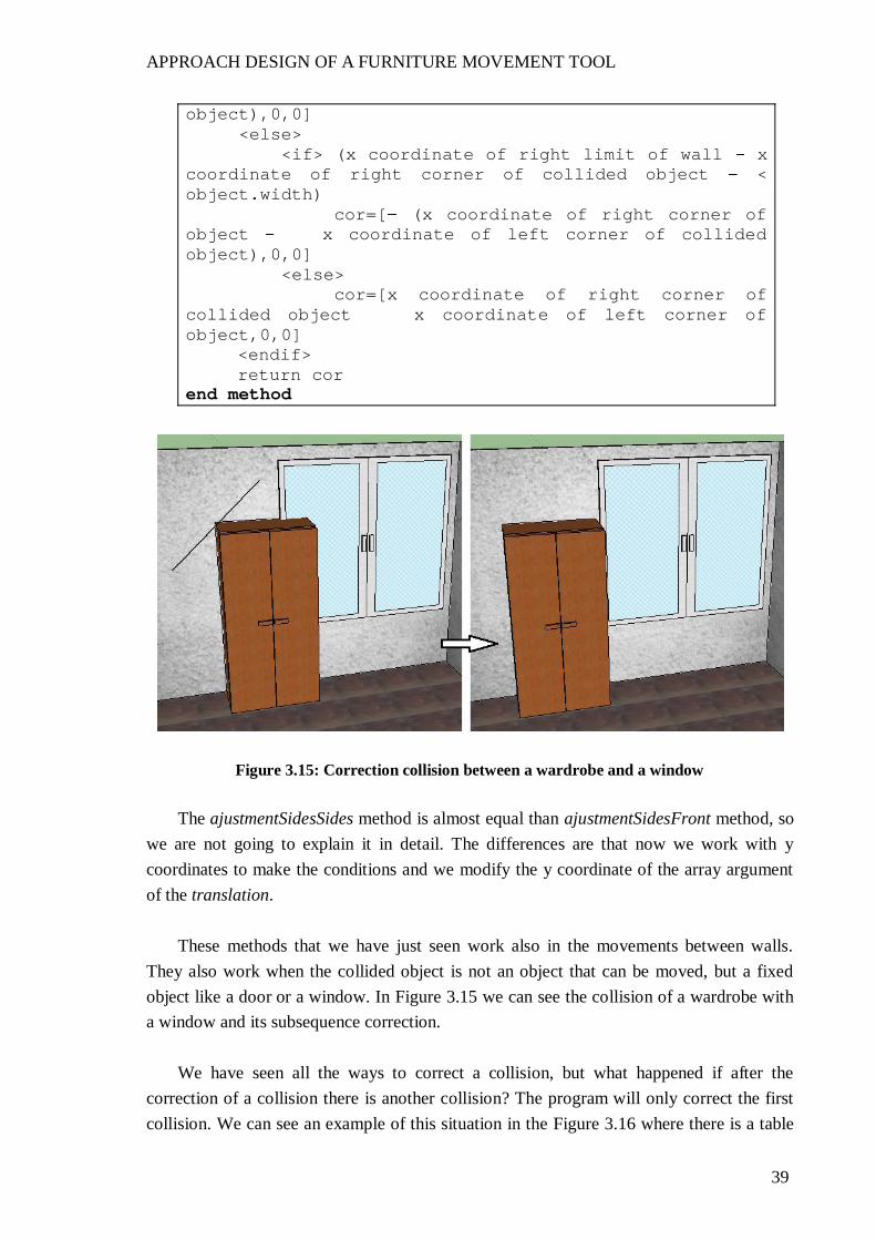
Figure 3.15: Correction collision between a wardrobe and a window
The ajustmentSidesSides method is almost equal than ajustmentSidesFront method, so
we are not going to explain it in detail. The differences are that now we work with y coordinates to make the conditions and we modify the y coordinate of the array argument of the translation.
These methods that we have just seen work also in the movements between walls.
They also work when the collided object is not an object that can be moved, but a fixed object like a door or a window. In Figure 3.15 we can see the collision of a wardrobe with a window and its subsequence correction.
We have seen all the ways to correct a collision, but what happened if after the
correction of a collision there is another collision? The program will only correct the first collision. We can see an example of this situation in the Figure 3.16 where there is a table

APPROACH DESIGN OF A FURNITURE MOVEMENT TOOL
40
with its chair and a shelf. If we try to put another shelf in the position that the line mark, it will have a collision with the table. As be an up correction. The problem is that now the shelf will have other collision with the other shelf.
Figure 3.16: Representation of multiple collisions
We said before that, for the collision correction we call the method which detects the
collisions. But we have to call it while still others collisions after solve the first one, like we explained before. So now we will have a
re until the next movement. Otherwise if there is a collision it will execute all the algorithms that we saw for correct a collision. Like with the correction the object will have another movement, the detection collision will execute again. When it
be detected any collision the loop will end. We can see this procedure with pseudocode.
exit=false <while> (exit==false)
Collision = collisionDetection (object) <if> (collision==true)
<if> (object is attached to wall) <if> (collided object is attached to
wall and floor) up movement <elsif> (collided object is attached to
wall)
APPROACH DESIGN OF A FURNITURE MOVEMENT TOOL
41
(back) ajustmentSidesFront (left) ajustmentSidesSides (right) ajustmentSidesSides (front) ajustmentSidesFront
<end case> <endif> <elsif> (object is attached to wall and floor) same case that before <endif> tr = Transformation.translation cor entities.transform_entities tr, object
<else> exit = true <endif>
<end while>
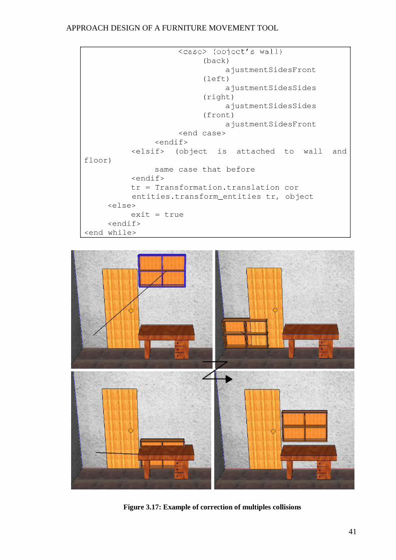
Figure 3.17: Example of correction of multiples collisions
APPROACH DESIGN OF A FURNITURE MOVEMENT TOOL
42
In Figure 3.17 there is an example of the correction of multiples collisions. We want to move the selected shelf to the bottom left corner of the wall. In this position the shelf has a collision with the door, so there is a sides correction. After that the shelf has another collision, now with a table. For that there is an up correction and the process finish because
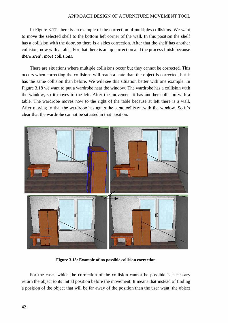
There are situations where multiple collisions occur but they cannot be corrected. This occurs when correcting the collisions will reach a state than the object is corrected, but it has the same collision than before. We will see this situation better with one example. In Figure 3.18 we want to put a wardrobe near the window. The wardrobe has a collision with the window, so it moves to the left. After the movement it has another collision with a table. The wardrobe moves now to the right of the table because at left there is a wall. After moving to that clear that the wardrobe cannot be situated in that position.
Figure 3.18: Example of no possible collision correction
For the cases which the correction of the collision cannot be possible is necessary return the object to its initial position before the movement. It means that instead of finding a position of the object that will be far away of the position than the user want, the object

APPROACH DESIGN OF A FURNITURE MOVEMENT TOOL
43
will return to the initial position. To do that, we have designed a new method called initialPosition which receive as parameters the wall where the object was before the movement (wall where the object has to return) and the center of the object before the movement. This method will follow the same idea as the movement of objects between walls explained in Section 3.2. It means that the object has to rotate as correspond and after it has to adjust its position to the wall. So, depending of its position before movement and the actual position of the object, it rotates and after the translation is calculated with the difference between the center before the movement and the actual center. We can see the application of this method reflected in the Figure 3.19. In it is continued the situation of the Figure 3.18, placing the wardrobe in its initial position after its repeated collision with the window.
Figure 3.19: Return of an object to its initial position
3.4 Design of an object situation tool
Until now, we have seen how to move objects with all the possible restrictions in a room. One of these restrictions is the collisions. So we have seen how to correct the collision investigating the possible corrections depending of the situation. All of these things can be applied when we already have objects in the room. But the tool that we
to enter new objects in the room. We can enter all the objects that we have designed in the room. Once these objects are
placed in its position we can use the move tool explained in Section 3.2, the same as if these objects were in the room before.
APPROACH DESIGN OF A FURNITURE MOVEMENT TOOL
44
In the move tool designed we needed the initial point where the object was and the final point where we want to place the object. Now we only need the second point for place
assign the first point in the origin of coordinates [0,0,0] and we hide the object with the method hidden of the class Group. After this modification the performance is the same that we have seen in the lasts sections, it means that the object to place in the room will be situated in a correct position of the wall and it will correct the possible collisions.
We are not going to explain all the methods used because are the same that we have
seen. All of these methods will be in a new class called NewFurniture. We use a new class because in Ruby although you can access the methods of other class, you cannot its environment variables.
The only thing that changes compared with the MovementTool class is the method
initialPosition meaning have initial position. So when there are collisions without possible correction, instead of moving the object to its initial position, it will be deleted with the method erase of the class Group.

CONCLUSIONS AND FUTURE WORKS
45
CHAPTER 4: CONCLUSIONS AND FUTURE WORKS
4.1 Conclusions
Once developed this Final Master Thesis it raises a number of conclusions that serve as the culmination of that. We have investigated the behavior of the Ruby tool integrated in Google SketchUp program, and have designed a tool to move pieces of furniture in a
office. The main conclusion we can reach is that Ruby allows us to develop all kind of scripts to increase the potential of SketchUp, and which makes it possible to do the things that SketchUp cannot do alone. One of these scripts which use Ruby to increase the potential of SketchUp is a tool capable of moving and placing pieces of furniture in a room according with the physical restrictions of the room.
This general conclusion is reached on the basis of the partial conclusions emerging
from the different chapters of this Final Master Thesis. These conclusions are:
With Ruby scripts you can design objects like pieces of furniture, but it is much more difficult than creating complex objects. Therefore the conclusion is that Ruby scripts are more useful in the transformations of objects than the creation of them.
There are difficulties in dealing with three dimensions working with a two-
dimension screen. These difficulties come from the problem of transforming two-dimension points in the screen to three-dimensional points in space. With this transformation in SketchUp, there are times you think that you are clicking one point but really in the scene is another point.
A translation of an object between two points is made with the difference of the coordinates of the first and second one. To place an object attached to the wall, it is not good to use the first point because it can be in all the faces of the object and the object work with the center of the object, regardless the selection point.
To avoid that an object gets out of the limit of a wall when it has been attached to it, we must investigate the possible positions of the object in the wall. Once the relative positions in the wall are known the

CONCLUSIONS AND FUTURE WORKS
46
destination point when this point is in the limits of the wall. There will be a correction to attach the object to one limit.
There are two kinds of objects in a room: the objects attached to the wall and the objects attached to the wall and the floor. The movement of the second is similar that the first but is always attached to the floor.
necessary and the rotation has to be according to the destination wall. For that
he object placed.
One of the restrictions of a room are the collisions. When a collision is detected it has to be corrected. This correction depends of the object which is moving and the collided object.
If the collision correction is to one of the sides to know if the object can be placed in the piece of wall between the collided object and the limit of the wall. If not the correction will be to the other side.
The collision detection and it subsequent correction have to be done until the object is correctly positioned.
When the collisions of an object cannot be solved because the object cannot be placed in that position, the object has to return to its initial position.
The placement of one object in the room follows the same procedure as moving an object already
4.2 Future works
As a result of the research performed in this Final Master Thesis, there are several lines of work that could be exploited in future studies and help to extend the existing knowledge about the subject. The following describe these future lines:
Management of user-created objects
In the move tool that we have created the only object that can be managed are the previis, to apply one behavior or another. This restricts the use of the tool to copied or

CONCLUSIONS AND FUTURE WORKS
47
created objects. For that reason one of the future works is expand the tool to support other objects that are not created with the same tool.
Possibility of other rotations
As we have seen, when one object is moved from one wall to another, the object rotates such a way that its back is still attached to the wall. These are the most common
wants to rotate an object in the same way, for example, rotate a table 90º. The future work will allow all kinds of possible rotations.
Possibility of moving objects on the floor and the ceiling
We have seen in this Final Master Thesis a classification of the objects used in this tool: objects attached to the wall and objects attached to the wall and the floor. This classification extends to objects like a lamp or a chair that has to move attached to the ceiling and the floor respectively. One future work is to include the movements of these kinds of objects.

48

MASTER SUBJECTS
49
ANNEX 1:
The realization of the advanced computer technologies master consists of a series of subjects totaling 30 ECTS credits and this Final Master Thesis of another 30 ECTS credits. The subjects have been coursed during the academic year 2010/2011 in Vilnius University, Vilnius, Lithuania.
This annex is a brief summary of the subjects studied, including the papers presented
for the evaluation of acquired knowledge within the area corresponding to each of them.
A1 1. Human Computer Interaction (HCI)
In this subject are studied the main fundaments of the HCI following the next points:
The scope of issues affecting human-computer interaction. The importance of the user interface to motivate the study of topics like HCI and
user interfaces. The impact of good and bad user interfaces. The diversity of users and tasks (applications) and their impact on the design of
user interfaces. Different system development lifecycles including those particularly applicable to
HCI systems (e.g., iterative design, implementation, evaluation, and prototyping). How HCI concerns can be incorporated into software systems development
lifecycles The need to evaluate system usability. The existence of design, implementation, and evaluation tools for developers with
diverse needs and technical expertise. The information sources available on HCI.
The book that we have followed in this subject is [14]. To pass the subject they were delivered several practices which constituted the phases
of the development of an interface of software for a management of a hotel. These phases and the practices delivered are the follows:
User needs and user categories Scenarios and use cases

MASTER SUBJECTS
50
Usability goals Time tasks Cognitive warthrough Usability test Heuristic evaluation report Testing with users
In addition to the practices it was realized an exam type test about the knowledge of
the subject.
A1 2. Ubiquitous computing. Advanced topics on Mobile Services (MS)
This subject enabled us to get insight of various aspects of MS implementation.
During the lectures, the theoretical part about MS types, essential components, and non-trivial problems was presented.
The subject presents Mobile Services (MS) from the perspective of context-aware
computing and database management systems. The subject covers architectural aspects, types, and standards of MS. Problem areas are distinguished. The main focuses of the subject are:
Location-based mobile services. Definition of context. Design of the database schema to store data about moving objects (MO). Modeling, indexing, and querying of MO. Presentation and implementation of location algorithms.
For pass the subject it was realized two practices. The first one was to make an
application which took latitudes and longitudes from a file and situated the represented points in a map by location based services, shown by the book [15]. The second one was to implement the location algorithms A* and IDA*.
The practices was half of the final mark. The another half was the realization of one
opinion exam about location based services in relationship to the newest devices.
MASTER SUBJECTS
51
A1 3. Computer-Aided Geometry The subject gave basics in computer-aided geometry, introducing fundamental methods
and emphasizing implementation of algorithms. The main contents that the subject covers are:
Bezier curves and their properties Smooth splines Cubic smooth splines Drawing algorithms B-splines Edge cutting Chaikin algorithms Geometric splines Bezier surfaces Smooth collocation of surfaces Design of complex surfaces
For pass the subject it was necessary to implement a program, regardless of the
programming language, which was capable of draw Bezier curves. We used java with its IDE Netbeans [16different delimiter points of the Bezier curve and drew it according to these points.
A1 4. Interactive Web 3D Graphics This subject had a goal to give an experience to build interactive 3D applications on
Web. The course introduced VRML (Virtual Reality Modeling Language) and a pure Java-based 3D technology - Shout3D. The special emphasis was given on real internet projects.
During the subject we studied three 3D modeling programs:
Wings3D [2] Google SketchUp [5]
o le o Google SketchUp Techniques: Copy and Arrays o Google SketchUp Techniques: Mirror o Google SketchUp Techniques: Intersect with Model
Blender 3D [1]
The most studied program was Google SketchUp, for that reason the final practice necessary for pass the subject was the creation of a complex building in SketchUp. The building that I made was the Cathedral of Saint Mary in Salisbury, England.

MASTER SUBJECTS
52
After finish the building the next step was to make some animations to the building with VRML. Like a SketchUp file is very big, we have to reduce it with the program Chisel [17]. For the animation we take only the entrance of the cathedral and we made a VRML script which was opening and closing the doors of the cathedral.
A1 5. Cryptography
In this subject it was studied the most important cryptography methods of ciphered and deciphered. The contents of the subject are:
History of cryptography Cryptography in the digital world Block and stream ciphers Encryption standards DES (Data Encryption Standard), AES (Advanced
Encryption Standard) Mathematical foundation of public key cryptography Public key cryptography algorithms Digital signatures Hash-functions Secret sharing schemes Zero-knowledge proofs Digital cash Electronic voting and other cryptographic protocols
The evaluation of the subject consisted in two parts. The first one was the realization of
ten assignments each of them to decipher a text previously ciphered by these cipher methods:
Cesar cipher Vigenere cipher Enigma cipher DES cipher in CBC (Cipher Block Chaining) mode DES cipher with the keystream produced by LFSR (Linear Feedback Shift
Register) Knapsack cryptosystem RSA and Rabin cryptosystem ElGamal cryptosystem ElGamal signatures The secret sharing schemes

MASTER SUBJECTS
53
These assignments consisted in 50% of the final mark. The other 50% was the realization of an exam about the contents of the subject.
A1 6. Introduction to Statistics with R
The subject aimed to familiarize the students with both the theory and practice of statistics. We learned to meet the basic real-life challenges and to apply relevant statistical techniques. The R package is one of the most comprehensive statistical tools of these days and the ability to program this language opens wide possibilities.
This was an introductory course to statistics. We started with very basic facts from the
theory of probability and then cover descriptive statistics, exploratory data analysis and classical tests in both univariate and bivariate settings. The work in a computer lab was an essential part of this course with the powerful R package.
To follow the subject we used the book [18]. In this subject the theoretical concepts
was the firsts chapters of that book. These concepts were:
Starting R with Data Univariate data Bivariate data
For pass the subject we have to do several practices which consisted in make the
necessaries scripts in R for solve some of the problems of the book.
A1 7. Applied Statistics with R
Once we knew the basic concepts of statistics with the R tool, in this subject we
deepened into the statistical concepts following the same methodology. Now the scripts were more complicated, using control structures instead of simple
lines in R. The theoretical concepts that we learnt was also chapter of the book [18]. These concepts were:
Multivariate Data Description of populations Simulation Confidence intervals Significance Test
MASTER SUBJECTS
54
Goodness of fit
The evaluation of the subject was divided into two parts. The first one was the same than in the another subject, it means, to do several practices which consisted in make the necessaries scripts in R for solve some of the problems of the book.
The second part was the realization of several practices about simulation, probing the normality of some statistical distributions.

58
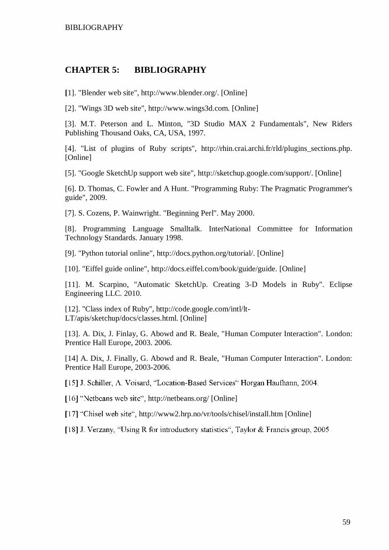
BIBLIOGRAPHY
59
CHAPTER 5: BIBLIOGRAPHY [1]. "Blender web site", http://www.blender.org/. [Online]
[2]. "Wings 3D web site", http://www.wings3d.com. [Online]
[3]. M.T. Peterson and L. Minton, "3D Studio MAX 2 Fundamentals", New Riders Publishing Thousand Oaks, CA, USA, 1997.
[4]. "List of plugins of Ruby scripts", http://rhin.crai.archi.fr/rld/plugins_sections.php. [Online]
[5]. "Google SketchUp support web site", http://sketchup.google.com/support/. [Online]
[6]. D. Thomas, C. Fowler and A Hunt. "Programming Ruby: The Pragmatic Programmer's guide", 2009.
[7]. S. Cozens, P. Wainwright. "Beginning Perl". May 2000.
[8]. Programming Language Smalltalk. InterNational Committee for Information Technology Standards. January 1998.
[9]. "Python tutorial online", http://docs.python.org/tutorial/. [Online]
[10]. "Eiffel guide online", http://docs.eiffel.com/book/guide/guide. [Online]
[11]. M. Scarpino, "Automatic SketchUp. Creating 3-D Models in Ruby". Eclipse Engineering LLC. 2010.
[12]. "Class index of Ruby", http://code.google.com/intl/lt-LT/apis/sketchup/docs/classes.html. [Online]
[13]. A. Dix, J. Finlay, G. Abowd and R. Beale, "Human Computer Interaction". London: Prentice Hall Europe, 2003. 2006.
[14] A. Dix, J. Finally, G. Abowd and R. Beale, "Human Computer Interaction". London: Prentice Hall Europe, 2003-2006.
-
http://netbeans.org/ [Online]
http://www2.hrp.no/vr/tools/chisel/install.htm [Online]