Invitation for Bids For Treasurer's Offices Renovations For the ...
387
Invitation for Bids For Treasurer’s Offices Renovations For the City of Chelsea, MA Contract # 2020-176 January 2020 IFB Contact: City of Chelsea, MA Dylan Cook Chief Procurement Officer City Hall 500 Broadway, Room 204 Chelsea, MA 02150 Telephone Number: 617-466-4224 Fax Number: 617-466-4225 E-Mail: [email protected]
-
Upload
khangminh22 -
Category
Documents
-
view
0 -
download
0
Transcript of Invitation for Bids For Treasurer's Offices Renovations For the ...
Invitation for Bids
For
Treasurer’s Offices Renovations
For the City of Chelsea, MA
Contract # 2020-176
January 2020
IFB Contact: City of Chelsea, MA Dylan Cook Chief Procurement Officer City Hall 500 Broadway, Room 204 Chelsea, MA 02150 Telephone Number: 617-466-4224 Fax Number: 617-466-4225 E-Mail: [email protected]

TABLE OF CONTENTS Section 1 Procurement Scope
1.1 Authority 1.2 Modify, Withdraw and Amend Bids 1.3 Bid Bond 1.4 Payment & Performance Bonds 1.5 Familiarity with Requirements 1.6 Independent Party 1.7 Conflict of Interest 1.8 Political Activity Prohibited 1.9 Assignment by the Contractor 1.10 Subcontracting 1.11 Choice of Law 1.12 Notices 1.13 Severable Sections Do Not Effect Entire Contract 1.14 Liquidated Damages for Failure to Enter into a Contract 1.15 Liquidated Damages for Failure to Perform Under Terms of the Contract 1.16 Contract Performance 1.17 Prevailing/Minimum Wages 1.18 Funding and Fiscal Appropriation 1.19 Procurement Calendar 1.20 Duration of Contract Section 2 General Bid Information 2.1 Required IFB Sections 2.2 Minority or Woman Business Enterprise Participation 2.3 Contract Award 2.4 ADA, Regulatory Compliance and Standards 2.5 Indemnification 2.6 Federal, State and Local Laws 2.7 Tax Exempt 2.8 Insurance 2.9 Confidentiality 2.10 Force Majeure 2.11 Equal Opportunity 2.12 Termination 2.13 Obligation in the Event of Termination 2.14 Ownership of Furnishings and Equipment 2.15 Anti-Boycott Warranty 2.16 Tied Bids 2.17 Unexpected Closures or Delays 2.18 Wage Theft 2.19 Living Wage 2.20 Change Orders

Section 3 Bid Information 3.1 Bidder Communication 3.2 Reasonable Accommodation 3.3 Public Records 3.4 Brand Name or Equal 3.5 Publicity 3.6 Costs 3.7 Required Contract Attachments 3.8 Submitted Bids 3.9 Clarification of Bids 3.10 Evaluation and Award of Contract 3.11 Rejection of Bidder’s Response 3.12 IFB Cancellation 3.13 No Guarantee of Purchase 3.14 Prime Contractors and Subcontractors 3.15 Written Inquiries 3.16 Instructions for Submission of IFB Responses 3.17 Deadline for Submission
Section 4 Plans and Specs – Treasurer’s Offices Renovations MANDATORY SUBMITTALS: RESPONDER INFORMATION FORM (To be first page of Proposal) BID PRICE FORM CERTIFICATE OF NON-COLLUSION TAX COMPLIANCE CERTIFICATION STATEMENT OF CORPORATE AUTHORITY WAGE THEFT CERTIFICATION LIVING WAGE CERTIFICATION W-9 TAXPAYER IDENTIFICATION NUMBER REFERENCE FORM OSHA COMPLIANCE CERTIFICATION IFB ATTACHMENTS:
SAMPLE CITY OF CHELSEA CONTRACT FOR SERVICES OVER $10,000
MASSACHUSETTS PREVAILING WAGE RATES PLAN DRAWINGS

(LEGAL NOTICE)
CITY OF CHELSEA INVITATION FOR BIDS
TREASURER’S OFFICES RENOVATIONS
The City of Chelsea is seeking sealed bids to provide all labor, tools, equipment, transportation and supervision necessary for office renovations to City Clerk offices in City Hall. Specifications and contract documents will be available on or after Thursday, January 2, 2020 at the Office of the Chief Procurement Officer, City Hall, Room 204, Chelsea, Massachusetts. Bid documents can be downloaded at http://www.chelseama.gov/purchasing/pages/current-bids-solicitations. Bids must be sealed and clearly marked “Treasurer’s Offices Renovations” and submitted to the Office of the Chief Procurement Officer, City Hall, Room 204, Chelsea, Massachusetts no later than 11:00AM Thursday, January 23, 2020, for general contractor bids. Bids must be sealed and clearly marked “Treasurer’s Offices Renovations-HVAC” and submitted to the Office of the Chief Procurement Officer, City Hall, Room 204, Chelsea, Massachusetts no later than 9:00AM Thursday, January 16, 2020, for filed sub- bids. Bids must be sealed and clearly marked “Treasurer’s Offices Renovations-Electrical” and submitted to the Office of the Chief Procurement Officer, City Hall, Room 204, Chelsea, Massachusetts no later than 10:00AM Thursday, January 16, 2020, for filed sub- bids. Each bid must be accompanied by a certified check, issued by a responsible bank or trust company. Or a bid bond duly executed by the bidder as principal and having as surety thereon a surety company approved by the City, all in the amount of 5% of the bid payable to the "City of Chelsea.” The City of Chelsea reserves the right to accept any bid, to reject and/or all bids and to waive minor irregularities and/or formalities as it deems to be in the best interest of the City. To be given consideration, all general bids must be accompanied by a copy of the Bidder’s Certificate of Eligibility (DCAM&M Form) and an Update Statement (DCAM&M Form).
The certification category of work is: General Contractor certification, filed sub-bids include HVAC and Electrical. In accordance with our Minority Business Enterprise Plan, we are inviting all qualified women and minority business firms to respond. The City of Chelsea is an Equal Opportunity Employer. This invitation for bid is in accordance with M.G.L. Chapter149. Dylan Cook Chief Procurement Officer

Section 1 PROCUREMENT SCOPE 1.1 Authority Invitation to Bid Procedures and award of the Contract shall be in accordance with Massachusetts General Law, Chapter 149, plus all applicable Federal, State and Local laws and regulations. 1.2 Withdraw, Modify, And Amend Bids Bidders who wish to withdraw, modify or amend their bid must do so in writing utilizing electronic mail to the City of Chelsea Chief Procurement Officer at [email protected] or via fax at 617-466-4225, no later than the time and date set forth herein for the receipt of the Bid for Treasurer’s Offices Renovations All such withdrawals, modifications or amendments must so state in the subject line of the email correspondence. Any withdrawal, modification or amendment arriving after the date and time set forth for accepting bids will not be considered. After the opening of the bids, a bidder may not change any provision of the bid in a manner prejudicial to the interests of the City of Chelsea or fair competition. Minor informalities will be waived at the discretion of the City of Chelsea. 1.3 Bid Bond Each bid must be accompanied by a certified check: of the bidder or a bid bond duly executed by the bidder as principal and having as surety thereon a surety company approved by the City, in the amount of 5% of the bid, payable to the "City of Chelsea" and must be filed with the original bid. 1.4 Payment & Performance Bonds The successful bidder is required to furnish performance bonds and payment bonds in the contract amount and with surety satisfaction to the City, in an award form this Invitation for Bids. The Bidder must pay all costs. The Performance Bond shall be in the sum of 100% of the contract price. The Payment Bond shall be in the sum of 100% of the contract price. The bonds shall be provided by the successful bidder to the City within five business days of the contract award.
1.5 Familiarity With Requirements Bidders are to thoroughly familiarize themselves with the requirements of this Invitation for Bids. Ignorance of the requirements will not relieve the bidder from any obligations or liabilities of any contract(s) issued as a result of this Invitation for Bids.

1.6 Independent Party Under this Invitation for Bids, the successful bidder declares itself to be at all times acting and performing as an independent party and nothing in this request for bid or any subsequent contract(s) is intended to constitute a partnership or joint venture between the bidder and the City of Chelsea. 1.7 Conflict of Interest No officer or employee of the City of Chelsea shall participate in any decision relating to any contract which would affect their financial or personal interest or the interest of any corporation, partnership, sole proprietorship or association in which they are directly or indirectly interested. 1.8 Political Activity Prohibited None of the services to be provided by any bidder shall be used for any partisan political activity or to further the election of any candidate for public office. 1.9 Assignment by Contractor The successful bidder or contractor shall not assign in whole or in part or otherwise transfer any interest in any contract without the written consent of the City of Chelsea, provided however, that the present and prospective claims for money due owing to the Contractor from the City of Chelsea or any other Buyer may be assigned to a bank or trust company or to a financial institution insured by the Federal Deposit Insurance Corporation (FDIC) without such consent so long as notice of such assignment is promptly furnished to the City of Chelsea. Any complete or partial assignment of the contractor’s or successful bidder’s interest in any such contract shall require the assignee, at the City of Chelsea’s discretion, to supply such further information as the City of Chelsea deems necessary to comply with the City of Chelsea rules and regulations governing contracts for services. Any such assignment, in whole or in part, shall also be expressly made subject to all defenses, set-offs or counter claims which would have been made available to the City of Chelsea against the successful bidder in the absence of such assignment. 1.10 Subcontracting None of the services to be provided by the contractor pursuant to any contract shall be subcontracted or delegated in whole or in part to any other organization, association, individual, corporation, partnership, or any other such entity without the prior written approval of the City of Chelsea. All intended subcontracts must be in writing. All intended subcontracts shall be provisions, which are functionally identical to and consistent with the language of this Invitation for Bids.

1.11 Choice of Law Any contracts awarded as a result of this Invitation for Bids shall be construed under the laws of the Commonwealth of Massachusetts. The successful bidder and agents thereof agree to bring any federal or state legal proceedings arising from any such contract in which the City of Chelsea is a party in a court of competent jurisdiction within the Commonwealth of Massachusetts. This section shall not be construed to limit any rights any party may have to intervene in any action in any court or wherever pending in which the other is a party. 1.12 Notices Unless otherwise specified, any notice hereunder shall be in writing and shall be deemed delivered when sent via electronic mail (e-mail), given in person to either party or deposited in the U.S. Mail, postage prepaid and addressed to the persons indicated in any contract or as specified by any amendment hereto. 1.13 Severable Sections Do Not Affect Entire Contract If any provision of the Invitation for Bids or any subsequent contract is declared or found to be illegal, unenforceable or void, then both parties shall be relieved of all obligations under the provision. The remainder of the Invitation for Bids and any subsequent contract shall remain in full force and effect and enforceable to the fullest extent provided by law. 1.14 Liquidated Damages for Failure to Enter Into Contract The successful Responder, upon its failure or refusal to execute and deliver the Contract, Bond and Certificates of Insurance required within ten days after receipt of notice of the acceptance of the bid, shall forfeit to the City of Chelsea, as liquidated damages for such failure or refusal, the security deposited with its bid, provided that the amount forfeited shall not exceed the difference between its bid price and the bid price of the next lowest responsive and responsible Responder. In case of death, disability, bona fide clerical or mechanical error of a substantial nature or similar unforeseen circumstances affecting the Responder, its bid deposit shall be returned. 1.15 Liquidated Damages for Failure to Perform Under Terms of the Contract Should the successful Responder fail to commence or diligently perform according to the terms of the contract, the successful Responder agrees to pay to the City of Chelsea, as liquidated damages, Two Hundred Fifty Dollars ($250.00) per calendar day that the successful Responder fails to commence or diligently perform the work in accordance with the contract documents and/or is in violation of the contract. Liquidated damages assessed under this provision shall be deducted from any payment(s) due to the successful Responder.

1.16 Contract Performance
The failure of any party to insist in any one or more situations, upon performance of any of the terms or provisions of any part of this Invitation for Bids or resulting contract shall not be considered as a waiver or relinquishment of the right of either party to future performance of any such term or provision, and the rights and obligations of the parties to such future performance shall continue in full force and effect.
1.17 Prevailing/Minimum Wages
Prevailing/Minimum Wage Rates as determined by the Commissioner of the Division of Occupational Safety of the Executive Office of Labor and Workforce Development under the provisions of Massachusetts General Laws Chapter 149, Section 26 to 27D, as amended, apply to this project. It is the responsibility of the Bidder, before the bid opening, to request, if necessary, any additional information on Prevailing/Minimum Wage Rates for those trades’ people who may be employed for the proposed work under this contract.
1.18 Funding & Fiscal Year Appropriation
Appropriations for expenditures by the City of Chelsea and authorizations to spend for a particular purpose are ordinarily made on a fiscal year basis. The fiscal year for the City of Chelsea, MA begins on July 1st and ends June 30th of the following year. The obligations of the City of Chelsea under any contract resulting from this Invitation for Bids for any subsequent fiscal year following the fiscal year in which the initial contract is awarded is subject to the appropriations to the City of Chelsea of funds sufficient to discharge its obligations, which accrue in such subsequent fiscal year, and to the authorization to spend such funds for the purposes of this Invitation for Bids. In the absence of such appropriation or authorization, any contract resulting from this Invitation for Bids shall be terminated immediately without liability for damages, penalties or other charges arising from early termination. Expenditures for contracted services, which will extend beyond a single fiscal year shall not exceed in any fiscal year the amount appropriated and authorized for the said fiscal year.
1.19 Procurement Calendar
The City of Chelsea invites bids that will result in a contract. The IFB schedule of events for this solicitation, subject to amendment by the City of Chelsea is:
EVENT IFB Released Optional On-Site Pre-Bid Deadline for Written Inquiries Response to Written Inquiries Due Date for Filed-Sub Bids Due Date for General Bids
DATE 1/02/2020 1/08/2020 at 10:00AM 1/10/2020 1/14/2020 1/16/2020 at 9:00AM (HVAC)1/16/2020 AT 10:00AM (Electrical) 1/23/2020 at 11:00AM

1.20 Duration of Contract The contract term will commence upon signature of the agreement and end no later than July 31, 2020.
End of Section

Section 2 General Bid Information 2.1 Required IFB Sections The Responder must provide, in its bid, a reply to the particular specifications included in the Invitation for Bids. 2.2 Minority or Woman Business Enterprise Participation In accordance with the Minority Business Enterprise Plan for the City of Chelsea, all qualified Minority-Owned Business Enterprises (MBE) or Woman-Owned Business Enterprises (WBE) are strongly encouraged to submit bids in response to this Invitation for Bids. For the purpose of this IFB, the term MBE or WBE shall mean a vendor who is certified as a minority business enterprise by the State Office of Minority and Women-Owned Business Assistance (SOMWBA), and who is certified at the time the vendor's bid is submitted. All minority owned businesses are encouraged to apply for SOMWBA certification. For further information on SOMWBA qualifications or access to SOMWBA vendor lists, contact the Supplier Diversity Office, Commonwealth of Massachusetts Operational Services Division at 617-720-3300. 2.3 The Contract Award
Based upon the bids received, the contract will be awarded to the lowest responsible and eligible Bidder. 2.4 ADA, Regulatory, Compliance and Standards Responders are expected to provide services and commodities that are in compliance with Section 504 of the Federal Rehabilitation Act of 1973, the Americans with Disabilities Act of 1990, the Telecommunications Act of 1996, and all successor federal and related legislation throughout the term of any contract resulting from this solicitation. 2.5 Indemnification Any successor in exchange for entering into an agreement or contract resulting from this Invitation for Bids shall indemnify and hold harmless the City of Chelsea and all persons acting for or on behalf of either of them from all suits and claims against them, or either of them, arising from or occasioned by the use of any service, material, equipment or apparatus, or any part thereof, which infringes or is alleged to infringe on any patent rights. In case such service, material, equipment or apparatus, or any part thereof in any suit is held to constitute infringement, the successful Responder, within a reasonable time, will at its expense, and as the City of Chelsea may elect, replace such material, equipment or apparatus with non-infringing material, equipment or apparatus or remove

the material, equipment or apparatus and refund the amounts paid therefore. Said indemnification includes reasonable attorney’s fees related thereto. Furthermore, any successful Responder in exchange for entering into any agreement or contract resulting from this Invitation for Bids agrees to indemnify and hold harmless, release and forever discharge the City of Chelsea as well as their officers, agents and employees as well as their successors and assigns from any and all manner of actions, suits, claims, demands, judgments, damages and liability in law and in equity which may arise or result from performance under this contract. This includes any discrimination, labor or employment claims against the successful Responder and the City of Chelsea and any and all manners of legal action brought against the successful Responder and /or the City of Chelsea. Said indemnification includes reasonable attorney’s fees related thereto. 2.6 Federal, State and Local Laws The successful Responder will comply with all applicable Federal, State and Local laws and regulations. 2.7 Tax Exempt Purchases made by municipalities and government are exempt from Federal Excise Taxes and Massachusetts Sales Taxes and bid prices must show the exclusion of such taxes. Tax exemption certificates will be furnished as required. 2.8 Insurance The successful Responder in addition to any insurance required by State or Local Law, shall maintain in force during the term of any contract(s) issued as a result of this Invitation for Bids, the following insurance issued by an insurance company licensed to do business in the Commonwealth of Massachusetts. Failure to provide or maintain such insurance shall be grounds to reject a bid or execute a contract.
a. Public Commercial Liability coverage in the amount of $1,000,000.00 per occurrence and $2,000.000.00 aggregate. Automobile Liability Insurance coverage in the amount of $500,000.00 per person, $1,000,000.00 per occurrence. Property damage Insurance in the amount of $250,000.00.
b. Worker’s Compensation Insurance in the amounts required by Massachusetts Law.
c. Evidence of such insurance must name the City of Chelsea as the named insured as well as the successful Responder.
d. An Insurance Certificate giving evidence of the insurance must be delivered to the City of Chelsea within 10 days by the successful Responder receiving the award of this Invitation for Bids.

2.9 Confidentiality The successful Responder will comply with all provisions of Executive Order No. 11246 of September 24, 1975 and the successful Responder acknowledges that in performance of any contract resulting from the Invitation for Bids it may require or have access to “personal data” and become a “holder” of personal data as defined by M.G. L. c. 66A. The successful Responder shall comply with all laws and regulations relating to confidentiality and privacy, including but not limited to any rules and regulations of the City of Chelsea. The successful Responder shall at all times recognize the City of Chelsea’s ownership of personal data and the exclusive right and jurisdiction of the City, and “data subjects” (as defined in chapter 66A) to control the use of personal data. The successful Responder shall immediately notify the City of Chelsea both orally and in writing if any personal data in its possession is subpoenaed, improperly used, copied or removed by anyone except an authorized representative of the City of Chelsea. The successful Responder shall cooperate with the City of Chelsea in taking all steps it deems advisable to enjoin, misuse, regain possession and/or otherwise protect the City of Chelsea’s rights and data subject’s privacy. The successful Responder shall allow access to any personal data held in their possession solely to those employees of the City of Chelsea who require such information in the performance of their occupational responsibilities. All personal data held by the successful Responder shall be delivered to the City of Chelsea within 14 calendar days after termination of any contract resulting from this Invitation for Bids. The successful Responder agrees to take reasonable steps to insure the physical security of such data under its control, including but not limited to fire protection, protection against smoke and water damage, alarm system, locked removal of manually held data, passwords, access logs, badges or other methods reasonably expected to prevent loss or unauthorized access to electronically or mechanically held data, limited terminal access, access to electronically or mechanically held data, limited terminal access, access to input documents and design provisions to limit use of personal data. The successful Responder agrees that it will inform each of its employees having any involvement with their personal data or confidentiality. The City of Chelsea shall have access at all times to any data maintained pursuant to any contract resulting from this Invitation for Bids, without the consent of the data subject. The successful Responder shall use personal data, and material derived from such data, only as necessary for the performance of the subject contract. Failure of the successful Responder to comply with the requirements of this section may be grounds for terminating any contract resulting from this Invitation for Bids. 2.10 Force Majeure Neither the City of Chelsea nor the successful Responder shall be liable to the other, nor deemed to be in breach of any contract resulting from this Invitation for Bids for failure or delay in rendering performance rising out of causes factually beyond its control and without its fault or negligence. Such causes may include, but are not limited to, Acts of God or the public enemy, wars, fires, flood, epidemics, quarantine restrictions, strikes, unforeseen freight embargos or unusually severe weather. Dates of times of performance shall be extended to the extent of delays excused by this section, provided that the party

whose performance is affected notifies the other party promptly of the existence and nature of such a delay. It is agreed that since the performance dates of the subject contract are of the essence and important to the implementation of essential City of Chelsea work, continued failure to perform for periods aggregating 45 or more calendar days, even for causes beyond the control of the successful Responder, shall afford the City of Chelsea the right to terminate any contract resulting from this Invitation for Bids without assessment of termination costs or penalties. 2.11 Equal Opportunity During the performance of this contract, the successful Responder agrees as follows:
a. The successful Responder will not discriminate against any employee or applicant for employment because of race, religion, color, sex or national origin, sexual orientation, which shall not include persons whose sexual orientation involves minor children as the sex object, genetic information or ancestry. The successful Responder will take affirmative action to ensure that applicants are employed and that the employees are treated during employment without regard to their race, religion, color, sex, nation origin or sexual orientation, which shall not include persons whose sexual orientation involves minor children as the sex object, genetic information or ancestry.
b. The successful Responder will comply with all provisions of Executive Order No. 11246 of September 24, 1975 and all of the rules, regulations and relevant orders of the Secretary of Labor.
2.12 Termination The Responders for this Invitation for Bids should note that the City of Chelsea reserves the right to terminate any contract resulting from this Invitation for Bids in whole or in part, by written notice:
• Without cause: Either party may terminate the subject contract by giving written notice to the other party at least 60 calendar days prior to the normal contractual effective date of termination as stated or such other period as is mutually agreed upon in advance by the parties
• For cause: If, in the opinion of the City of Chelsea, the successful Responder fails to fulfill its obligations, the City of Chelsea may terminate any contract resulting from this Invitation for Bids by giving 30 days written notice to the successful Responder at any time. The subject contract shall be terminated immediately in the event of fraud or program abuse.
• Emergency: The City of Chelsea may terminate or suspend any contract resulting from this Invitation for Bids up to 60 calendar days by providing written notice to the successful Responder, stating the grounds for the City of Chelsea’s action, in the form of U.S. Mail, hand-carried letter, or other appropriate written means, if the City of Chelsea determines that immediate action is necessary to protect City, State and/or Federal funds or property, or to protect persons from

injury. Such termination or suspension shall be effective upon receipt of notice of either suspension or termination by the successful Responder. In the case of a suspension under this paragraph, the notice of suspension shall be accompanied by instructions from the City of Chelsea specifying requisite actions by the successful Responder to remove the suspension, proposed timetable for meeting those requirements and a description by the City of Chelsea of allowable activities and costs, if any, during the suspension period. Failure by the successful Responder to remedy the stated deficiencies according to the timetable prescribed by the City of Chelsea shall be cause for immediate termination.
• Elimination or Reduction of Funding: In the event of a reduction of funding for
any reason, the City of Chelsea may terminate any contract resulting from this Invitation for Bids by providing notice of termination in a reasonable time. The City of Chelsea may provide a conditional notice of termination with a proposed amendment to the subject contract. Any such notice shall provide that the subject contract will terminate automatically 30 calendar days after the date of the conditional notice of termination unless the successful Responder submits to the City of Chelsea a properly signed copy of the amendment, or such modification form of amendment as may be agreeable to the City of Chelsea, within 20 calendar days after the date of the conditional notice of termination, or such other time as it is otherwise specified in the conditional notice.
• Office’s Remedies: Upon Termination for Cause or for Emergencies:
Notwithstanding the terms contained in this section, in the event of termination, the successful Responder shall not be relieved of liability to the City of Chelsea by virtue of any breach of any contract resulting from this Invitation for Bids by the successful Responder. In the event of termination pursuant to this section, the City of Chelsea may withhold any payments to the successful Responder for the purpose of set-off until such time as the exact amount of damages due to the City of Chelsea from the successful Responder is determined. In addition to and notwithstanding the above, the successful Responder covenants and agrees that in the event of termination of any contract resulting from this Invitation for Bids the successful Responder shall pay to the City of Chelsea as damages: (a) such sum as, at the time of termination, the City of Chelsea reasonably determines that is, shall require to compensate a subsequent contractor to complete the delivery of service, and (b) the sum, reasonably determined by the City of Chelsea, which will compensate the City of Chelsea for all the direct and indirect costs resulting from delay in the delivery of services upon the successful Responder’s default. The successful Responder further covenants and agrees with the City of Chelsea that the successful Responder shall pay all of the City of Chelsea’s costs and expenses (including attorney’s fees) incurred or paid in obtaining and enforcing any court order favorable to the City of Chelsea for any obligation of the successful Responder under any contract resulting from this Invitation for Bids.

2.13 Obligation in the Event of Termination Upon termination of any contract resulting from this Invitation for Bids, all documents finished or unfinished, data, studies and reports prepared by the successful Responder pursuant to the subject contract shall become the property of the City of Chelsea. Copies of finished and unfinished documents, data, studies and reports generated as a necessary part of performing the subject contract shall be delivered to the City of Chelsea upon reasonable request and shall be retained by the successful Responder for future use. The City of Chelsea shall promptly pay the successful Responder for all services performed and for all costs and un-cancelable commitments reasonably incurred in performance of the subject contract to the effective date of termination, provided the successful Responder is not in default of the terms of the subject contract and submits to the City of Chelsea properly completed invoices with supporting documentation covering such services no later than 45 days after the effective date of termination, and that the successful Responder make every reasonable effort to minimize or recover costs incurred. 2.14 Ownership of Furnishings & Equipment Unless otherwise provided by law or a federal grant award, title to all furnishings and equipment provided by the City of Chelsea or that the awarded Responder provides under the terms of this Invitation for Bids and paid for with public funds, shall vest in and be retained by the City of Chelsea. Upon completion of performance of the awarded Responder’s contract, the awarded Responder shall return such furnishings and equipment in its possession in the same condition as at the commencement of any contract resulting from this Invitation for Bids, normal wear and tear excepted. 2.15 Anti-Boycott Warranty During the term of any contract resulting from this Invitation for Bids, neither the successful Responder nor any “affiliated company” as hereafter described, shall participate in or cooperate with an international boycott, as defined in section 999(b) (3) and (4) of the Internal revenue Code of 1954, as amended by the Tax Reform Act of 1986, or engage on conduct declared to be unlawful by sections 2 and 4 of Chapter 151E of The Massachusetts General Laws. As used herein, an “affiliated company” shall be any business entity or which at least 51% of the ownership interests are directly or indirectly owned by the successful responder or by a person or persons or business entity or entities which directly own at least 51% of the ownership interest of the successful Responder. 2.16 Tied Bids In the event that there is a tie bid between two (2) responsive and responsible bidders, the award of the contract will be determined by a coin toss. The bidder’s whose submission was received earliest shall be assigned “Heads” in the coin toss. In the event that there is a tie bid with three (3) or more responsive and responsible bidders, the award shall be made by a draw by lot limited to those bidders. The coin toss/draw by lot shall be
scheduled within two (2) business days from when it was determined by the City to be a tie bid. The bidders involved shall be given an opportunity to attend. The coin toss/drawing shall be witnessed by at least three (3) City officials. The tie breaker event shall be held at Chelsea City Hall during regular business hours. 2.17 Unexpected Closures or Delays If, at the time of the scheduled bid submission deadline, the designated location for delivery of the bid is closed due to uncontrolled events such as fire, snow, ice, wind, building evacuation or other, the deadline will be postponed until 11:00 a.m. on the next normal business day. Bids will be accepted at the same location until that date and time. 2.18 Wage Theft
Prospective vendors must provide the following certifications or disclosures in writing to the purchasing agent with their bids or proposals. Failure to provide the following shall result in rejection of the bid or proposal;
• Prospective vendors must certify that neither they nor any of their subcontractors have been subject to a federal or state criminal or civil judgment, administrative citation, final administrative determination, order or debarment resulting from a violation of M.G.L. c. 149, M.G.L. c. 151, the Fair Labor Standards Act or any other state or federal laws regulating the payment of wages within three years prior to the date vendors submit their bids or proposals; or
o Prospective vendors must disclose any such criminal or civil judgments, administrative citation, final administrative determination, order or debarment and include copy(ies) with their bids or proposals.
• Prospective vendors are notified that they must report any such criminal or civil judgment, administrative citation, final administrative determination, order or debarment from a violation of M.G.L. c. 149, M.G.L. c. 151, the Fair Labor Standards Act or any other state or federal laws regulating the payment of wages while any of their bids or proposals to the purchasing agent official is pending and, if awarded a contract, during the term of the resulting contract, within five days of vendor's receipt.
• Prospective vendors that are subject to a state or federal debarment for violation of the above laws, either voluntarily or involuntarily, or that have been prohibited from contracting with the Commonwealth or any of its agencies or subdivisions will be deemed not responsible and their bids or proposals shall be rejected. Such vendors shall be deemed not responsible for the entire term of debarment or other stated time period. During the term of a contract, upon a finding or order of such debarment or prohibition, the city may terminate the contract.
• Vendor(s) awarded a contract that have disclosed a federal or state criminal or civil judgment, administrative citation, final administrative determination, order or debarment resulting from a violation of M.G.L. c. 149, M.G.L. c. 151, the Fair Labor Standards Act or any other state or federal laws regulating the payment of wages within three years prior to the date they submit their bids or proposals, or

vendor(s) awarded a Contract that receive a federal or state criminal or civil judgment, administrative citation, order or final administrative determination resulting from a violation of M.G.L. c. 149, M.G.L. c. 151, the Fair Labor Standards Act or any other state or federal laws regulating the payment of wages during the term of the contract and that are not otherwise prohibited from public contracting may be required by the city to obtain a wage bond or other form of suitable insurance in an amount equal to the aggregate of one year's gross wages for all employees, based on an average of its total labor costs for the past two years. Such bond must be maintained for the terms or extensions of any contract, and proof of such bond must be provided upon request by the city.
• Vendor(s) awarded a contract that have disclosed a federal or state criminal or civil judgment administrative citation, final administrative determination, order or debarment resulting from a violation of M.G.L. c. 149, M.G.L. c. 151, the Fair Labor Standards Act or any other state or federal laws regulating the payment of wages within three years prior to the date they submit their bids or proposals and through the contract term shall furnish their monthly certified payrolls to the purchasing agent for all employees working on such contract.
2.19 Living Wage
• Purpose o The purpose of this chapter is to ensure that when taxpayer-funded
benefits are extended by the city to private businesses, they are used in a way that benefits the interests of the city as a whole by creating jobs that keep workers and their families out of poverty. This section therefore requires the city, its contractors and subcontractors to pay their employees a wage that will enable a full-time worker to support a family at a level that meets basic needs and avoids economic hardship.
• Applicability o This chapter shall apply to any for-profit contractor that employs or
contracts with five or more individuals firm-wide; or a nonprofit contractor that employs or contracts with ten or more individuals firm-wide.
o This chapter shall apply to any city contract initially awarded after the effective date of this chapter.
• Covered employer o The city is a "covered employer" in all of its operations and activities. o A contractor is a "covered employer" if it enters into one or more city
contracts where the annual value of payments under all such city contracts is (or is projected to be) more than twenty-five thousand dollars. A contractor is a covered employer from the beginning of the term of the city contract that caused the combined annual value of payments to exceed twenty-five thousand dollars and continues until the termination of all city contracts.
o A subcontractor is a "covered employer" beginning on the later of the following dates: (1) the beginning of the term of the subcontract; or (2)

the date on which the subcontractor's associated contractor becomes a covered employer. A subcontractor ceases to be a covered employer on the earlier of the following dates: (1) the termination of the subcontract; or (2) the date on which the subcontractor's associated contractor ceases to be a covered employer.
• Covered employee o Employees of the city are covered employees for all hours they work
for the city. o Employees of covered employers are covered employees for all hours
they perform work relating to a city contract. o The only individuals who otherwise meet the standard of "covered
employee" who are automatically exempted from the living wage are individuals in a youth or senior program, those working part-time at the Chelsea Public Library or those in a child care or summer food program for the Chelsea School Department. See definitions under subsection (h) below.
• Living wage required o Every covered employer must pay covered employees no less than a
living wage for all hours worked as a covered employee. The living wage shall be thirteen dollars and twenty cents ($13.20) per hour upon implementation of this chapter. Each year thereafter, starting January 1, 2018, the amount of the living wage shall be upwardly adjusted to the higher of these three calculations: the increase, if any, for the period of the preceding November over the level as of November of the immediately preceding year in the "Consumer Price Index—All Urban Consumers" or its successor index as published by the U.S. Department of Labor or its successor agency; or the minimum wage required for a person working 2000 hours annually to earn enough to at least match the poverty level for a family of four as determined annually by the U.S. Dept. of Health & Human Services; or 110% of the state minimum wage.
o Beginning in 2018 and each year thereafter, the city shall publish a bulletin on or about February 1st announcing the adjusted living wage which shall take effect immediately upon publication. This bulletin shall be distributed to all city agencies and covered employers upon publication. Covered employers shall provide written notification of the rate adjustment to their covered employees, and to their affected contractors and subcontractors. In the event that the city fails to publish the adjusted living wage, it shall remain the obligation of each covered employer to calculate and begin paying the adjusted living wage effective no later than February 1st.
• Retaliation prohibited o No covered employer shall discharge or take other adverse action
against any person in retaliation for asserting any claim or right under this chapter, for assisting any other person in doing so or for informing any person about their rights.

• Exemptions o Notwithstanding any other provisions in this chapter, the following
exemptions shall apply: o The following will be granted an automatic exemption from the
requirements of this chapter: o Any city, state or federally funded program which employs youth, as
defined by city, state or federal guidelines, or as part of a school to work program or in other seasonal or related part-time program, including:
o A bona fide training program o An after school or summer or youth employment program, or o A bona fide work-study program, internship, fellowship, or other
similar program, including the ROCA program; o Any city, state or federally funded senior program which employs
individuals sixty years of age or older in a community service employment program or other subsidized employment or training program;
o The part-time employment program at the Chelsea public library which employs part-time individuals for the purpose of supporting the full-time staff and ensuring that there is adequate personnel to meet state-mandated hours of operation.
o The part-time program at the Chelsea Public Schools for child care assistants and for workers in the Summer Food Program.
• Monitoring of chapter o Every covered employer shall agree to the payment of a living wage as
a condition of entering into or renewing a city contract, shall agree to post a notice regarding the applicability of this chapter in every workplace in which covered employees are working and shall agree to provide payroll records or other documentation as deemed necessary within ten business days from the receipt of the city's request. All city contracts covered by this chapter shall provide that a violation of the living wage requirements of this chapter shall be a material breach of the city contract. The city or its designee shall monitor the compliance of each contractor under procedures developed and approved by the city administrator.
o Each covered employer shall submit to the city information regarding the number of employees and applicable wage rates of its employees covered by this chapter in such manner as requested by the city or its designee. At the request of the city or its designee, any contractor shall provide satisfactory proof of compliance with the living wage provisions of this chapter.
o Any person may submit a complaint or report of a violation of this chapter to the city. Upon receipt of such a complaint or report, the city or its designee shall investigate to determine if there has been a violation. The investigation shall be resolved within ninety days.

• Penalties and enforcement o A violation of any provision of this chapter is a civil infraction
punishable by a fine of not more than three hundred dollars plus all costs of the action. Any court of competent jurisdiction may issue and enforce any judgment, writ, or order necessary to enforce this chapter, including backpay to affected employees and other relief deemed appropriate.
o Each day upon which a violation occurs shall constitute a separate violation.
o In addition to enforcement under subsections A and B, the city shall have the right to modify, terminate, and/or seek specific performance of any city contract with a covered employer or to cancel, terminate or suspend the city contract in whole or in part.
o Nothing contained in this chapter shall be construed to limit in any way the remedies, legal or equitable, which are available to the city or any other person for the correction of violations of this chapter.
• Private actions for damages or injunctive relief o A covered employee who is denied payment of the applicable living
wage in violation of this chapter may bring a civil action in any court of competent jurisdiction for appropriate injunctive relief or damages or both against the person(s) who acted in violation of this chapter. No employee or person shall bring a civil action alleging a violation of this chapter unless the employee or person has first provided a written allegation of the violation of this chapter to the city and the covered employer no less than ninety days prior to filing said civil action. After at least ninety days have passed after the written allegation has been provided, the employee or person shall be free to proceed with a civil action. Any civil action under this section must be brought within one year of the last date of the violation. The last date of the violation shall be determined by the last paycheck received by the employee or person that did not contain the living wage, or by the last occurrence of retaliation prohibited by subsection (g).
o As used in subsection, "damages" means restitution of the difference between amounts actually paid and the living wage that should have been paid including interest, an additional equal amount as liquidated damages, and reasonable attorney fees and costs.
o Private actions and remedies under this section shall be in addition to any actions for violations which the city may take.
• Other provisions o No covered employer may fund the living wage increase required by
this chapter by reducing the compensation, fringe benefits or leave available to any covered employee.

2.20 Change Orders
All requests for changes to the contract and/or procurement scope must be made in writing and submitted to the project manager. No work contained in the request change order will be paid, unless a fully executed Contract Amendment exists. Verbal approvals/changes are not valid and no payments shall be made.
End of Section
Section 3 Responder's Bid Information 3.1 Bidder Communications Responders are prohibited from communicating directly with any employee of the Purchasing Department and any other member of the City of Chelsea except as specified in this Invitation for Bids, and no other individual City of Chelsea employee or representative is authorized to provide any information or respond to any question or inquiry concerning this Invitation for Bids. Responders may contact the person identified on the cover sheet of this Invitation for Bids in the event this Invitation for Bids is incomplete. 3.2 Reasonable Accommodation Responders with disabilities or hardships that seek reasonable accommodation, which may include the receipt of the Invitation for Bids information in an alternative format, must communicate such requests in writing, via electronic mail (e-mail) to the contact person. Requests for accommodation will be addressed on a case by case basis. A Responder requesting accommodation must submit a written statement, via e-mail which describes the responder’s disability and the requested accommodation to the contact person for the Invitation for Bids. The City of Chelsea reserves the right to reject unreasonable request. 3.3 Public Records All bids and information submitted in response to this Invitation for Bids are subject to the Massachusetts Public Record Law, M.G.L., Chapter 66, Section 10, and to Chapter 4, Section 2, and Subsection 26. Any statements in the Responder’s bid inconsistent with these statutes will be disregarded. 3.4 Brand Name or Equal Unless otherwise specified in this Invitation for Bids, any reference to a particular trademark, trade name, patent, design, type, specification, producer or supplier is not intended to restrict this Invitation for Bids to any manufacturer or proprietor or to constitute an endorsement of any good or service, and the City of Chelsea must consider clearly identified offers if substantially equivalent goods and services submitted in response to such reference. 3.5 Publicity Any Responder awarded a contract under this Invitation for Bids is prohibited from selling or distributing any information collected or derived from the contract, including lists of participating or eligible departments, employee names, telephone numbers, e-mail addresses, addresses or any other reports or information except as specifically authorized under this contract.
3.6 Costs Costs for services that are not specifically identified in the Responder’s response and identified as part of a contract, will not be compensated under any contract awarded pursuant to this Invitation for Bids. The City of Chelsea will not be responsible for any costs or expenses incurred by responders responding to this Invitation for Bids. 3.7 Required Contract Attachments All Responders are required to complete, sign and return at minimum the following documents:
1.) Bid Information- to be included as cover page of bid 2.) Bid Price Form - Signature required 3.) Certificate of Non-Collusion- Signature required 4.) Statement of Corporate Authority ( If Responder is a Corporation) - If the
Responder is a Corporation, a vote of the Corporation approving participation in this Invitation for Bids process must be signed by the corporate officers with the Corporate Seal Affixed and attached to the original Invitation for Bids.
If the Responder is a Corporation, the names and addresses of the corporate Officers and the state and date of incorporation must be included. The Responder must state if the Corporation is publicly held or privately held. If the Corporation is publicly held, the exchange on which it is traded and the symbol under which it is traded is required.
Sole Proprietorship ( If Responder is a Sole Proprietorship)- If the Responder is a Sole Proprietorship, a partnership or any other legal business entity, the names and addresses of the officers must be included, the parent state of business and the numbers of years this entity has been in business. In short, a complete business profile must be included in the bid.
5.) Tax Compliance Certification - Signature required 6.) Wage Theft Certification - Signature required 7.) Living Wage Certification - Signature required 8.) W-9-- Signature required 9.) Reference Form- To include three current contract references, at least one of
which is a government agency that can be contacted during the IFB process. Two of the references must be customers for which the Responder is or has provided services similar to those outlined in the Scope of Services of the IFB. Include customer name, contact person, his/her title, address and telephone number. Do not use the names of relatives or City Employees as references. Do not use any previous City contracts as a source of project reference information. You may use previous City contracts as a record of your experience only.
10.) OSHA Certification - Signature required

3.8 Submitted Responses The City of Chelsea shall be under no obligation to return any responses or materials submitted by the Responder in response to this Invitation for Bids. All materials submitted by Responders become the property of the City of Chelsea and will not be returned to the Responder. The City of Chelsea has the right to use any ideas, concepts or configurations that are presented in the Responder’s bid whether or not the bid is selected for contract award. 3.9 Clarification of Response The City of Chelsea is not required to seek clarification of responses; therefore, the responder should be as clear as possible in all of its responses to this Invitation for Bids. 3.10 Evaluation and Award of Contract All pricing must remain constant for the entire term of the contract, as well as any possible extension offered. Bids will be evaluated and awarded based upon the lowest, responsible and eligible bid. 3.11 Rejection of Responder’s Bid A Responder’s bid may be rejected by the City of Chelsea if the Responder’s bid:
• Fails to adhere to one or more of the requirements • Fails to submit its bid to the required address on or before the Invitation for Bid
responses due date • Fails to submit a bid in accordance to the format and instructions specified or to
supply the minimum information requested in this Invitation for Bids. • Fails to meet unconditionally or is unable to demonstrate competence to meet the
requirements of this Invitation for Bids. • Misrepresents its equipment, systems or services or provides demonstrably false
information in its response or fails to provide material information. • Violates the restrictions on contacts with the City of Chelsea employees and
representatives • Refuses, is unable to, or fails to provide clarification requested by the City of
Chelsea in a reasonable time frame.
3.12 Invitation for Bids Cancellation The City of Chelsea retains the right to cancel this Invitation for Bids, or any portion thereof, at any time prior to the execution and approval of a contract. If this Invitation for Bids is cancelled, all responses received to this Invitation for Bids will be rejected. All expenses related to the preparation of responses to this Invitation for Bids remain the responsibility of the Responder.

3.13 No Guarantee of Purchase The City of Chelsea makes no guarantee that any purchase shall take place from any contract resulting from this Invitation for Bids nor does the City of Chelsea guarantee any minimum quantity of purchases from any contract resulting from this Invitation for Bids. Any estimated or past procurement volumes referenced in this Invitation for Bids are included only for the convenience of the Responders, and not to be relied upon as any indication of future purchases. The Responder may not place, as a condition for providing the cost levels proposed, any minimum purchase requirements. 3.14 Prime Contractors and Subcontractors Prior approval of the eligible entity is required for any subcontracted service of the contract. Contractors are responsible for the satisfactory performance and adequate oversight of its subcontractors. Subcontractors are required to meet the same state and federal financial program and reporting requirements and are held to the same reimbursable cost standards as the successful Responder. The City of Chelsea requires a single point of contact for any contract resulting from this Invitation for Bids. Subcontractors may be used, but the successful Responder, as prime contractors, shall be responsible for meeting all of the terms of any contract resulting from this Invitation for Bids and must accept full responsibility for any subcontractor’s performance. Responders must provide a list of subcontractors, a description of each subcontractor’s responsibility in regards to this contract and signed letters of agreement between the Responder as the prime contractor, and its subcontractor(s) identifying their responsibilities and their relationship to the prime contractor. The prime contractor must notify each individual account (eligible entity) in writing; the name of their subcontractor both initially and when a sub-contractor is changed. If a subcontractor has filed for Chapter 11 Bankruptcy of Chapter 7 Bankruptcy, the prime contractor also must notify the City of Chelsea. The notification must be written and must be within one week of the events noted above. 3.15 Written Inquires Responders may submit written inquiries concerning any part or attachment of this Invitation for Bids. Written inquiries regarding issues outside of the scope of this Invitation for Bids will not be considered. All inquiries must be submitted by the required date and time, to the contact listed on the cover page of this Invitation for Bids.

All written inquiries must be submitted via electronic mail (email) only. No other manner of submission will be accepted. Any change to this submission date and/or time will be made by a notice sent electronically to all Responders. The Responder is responsible for confirming receipt of written inquiries with Dylan Cook, Chief Procurement Officer, and City of Chelsea at [email protected]. The City of Chelsea will provide written responses via electronic mail (e-mail) to all written inquiries received by the required due date. Responses will not identify the inquiry by Responder. 3.16 Instructions for Submission of IFB Responses Each Invitation for Bid Response must be sealed, labeled and submitted to the address listed on the cover page of this document. Paper Submission- the Responder must submit one (1) original response to the Invitation for Bids marked “ORIGINAL” The Envelope must be clearly marked “Treasurer’s Offices Renovations”. 3.17 Deadline for Submission All responses to this Invitation for Bids are due at the address listed on the cover page and no later than the date and time listed in the Procurement Calendar.
End of Section

Section 4 Plans and Specs – Treasurer’s Offices Renovations

Technical Specifications Section 4.1
Chelsea City Hall
Renovation of Rooms 213 & 215
Treasurer’s Offices
Chelsea, Massachusetts
Bid Set
Date of Issue: 18 December 2019
BY
68 Harrison Ave. 5th Floor
Boston, MA 02111
Project #1907.00

THIS PAGE IS INTENTIONALLY LEFT BLANK

CHELSEA CITY HALL - RENOVATION OF ROOMS 213 & 215 Chelsea, Massachusetts 02150
Project No. 1907.00
BID SET TABLE OF CONTENTS 12/18/2018 1
TECHNICAL SPECIFICATIONS – SECTION 4.1
TABLE OF CONTENTS
DIVISION 01 — GENERAL REQUIREMENTS (no. of pages) Section 01 10 00 Summary 2 Section 01 25 13 Product Substitution Procedures 2 Section 01 33 00 Submittal Procedure 4 Section 01 35 43 Environmental Procedures 2 Section 01 56 20 Dust Control 2 Section 01 73 29 Cutting and Patching 4 Section 01 74 19 Construction Waste Management 4 Section 01 78 00 Closeout 8 DIVISION 02 — EXISTING CONDITIONS (no. of pages) Section 02 41 19 Selective Demolition 2 DIVISION 06 — WOOD, PLASTICS AND COMPOSITES (no. of pages) Section 06 10 00 Rough Carpentry 4 Section 06 20 00 Finish Carpentry 4 Section 06 61 16 Solid Surfacing Fabrications 4 DIVISION 07 — THERMAL AND MOISTURE PROTECTION (no. of pages) Section 07 84 00 Firestopping 10 Section 07 92 00 Sealants 6 DIVISION 08 — OPENINGS (no. of pages) Section 08 14 16 Wood Doors 2 Section 08 55 00 Wood Windows 4 Section 08 71 00 Door Hardware 14 Section 08 80 00 Glass and Glazing 4 DIVISION 09 — FINISHES (no. of pages) Section 09 22 16 Non-Structural Metal Framing 4 Section 09 29 00 Gypsum Board Assemblies 10 Section 09 51 00 Acoustical Ceiling Systems 4 Section 09 65 13 Resilient Base and Accessories 4 Section 09 65 19 Rubber Tile Flooring 6 Section 09 68 10 Carpet Tile 10 Section 09 81 00 Acoustical Insulation 4 Section 09 91 00 Painting 10 DIVISION 10 — SPECIALTIES (no. of pages) Section 10 11 00 Visual Display Surfaces 2 Section 10 14 00 Signage 2

CHELSEA CITY HALL –RENOVATION OF ROOMS 213 & 215 Chelsea, Massachusetts 02150 Project No. 1907.00
TABLE OF CONTENTS BID SET 2 12/18/2019
DIVISION 22 — PLUMBING (no. of pages) Section 22 00 00 Plumbing 20 DIVISION 23 — HEATING, VENTILATING AND AIR CONDITIONING (no. of pages) * Section 23 00 00 HVAC 44 DIVISION 26 — ELECTRICAL (no. of pages) * Section 26 00 00 Electrical 52 *= Filed Sub Bid
END OF SECTION

CHELSEA CITY HALL - RENOVATION OF ROOMS 213 & 215 Chelsea, Massachusetts 02150
Project No. 1907.00
BID SET SUMMARY 12/18/2019 01 10 00 -1
Section 01 10 00
SUMMARY
PART 1 – GENERAL 1.1 SECTION INCLUDES A. Project description. B. Definitions – Owner and Architect. C. Work by Owner. D. Use of site. 1.2 PROJECT DESCRIPTION
A. Work covered by Contract Documents:
1. Renovation of existing Treasurer’s offices Rooms 213 & 215) in the Chelsea City Hall, including selective demolition of existing furnishings, equipment and finishes, and construction of new partitions, doors, ceilings, cabinetry, and installation of HVAC systems, Electrical systems, plumbing fixtures and finishes as shown or indicated in the drawings and specifications.
B. Contract time: The Contractor may begin on-site work on, or after receipt of a written Notice to Proceed, or suitable Letter of Intent. After commencement of work, the Contractor shall pursue the work continuously and with diligence, and bring the Project to Substantial Completion within 90 days as defined in the General Conditions: 1. Substantial completion is the stage in the progress of the Work when the work or
designated portion thereof is sufficiently complete in accordance with the Contract Documents so the Owner can occupy or utilize the Work for its intended use. This includes any and all permits required by governmental agencies necessary for occupancy and use.
2. The Contractor will prepare and provide a Project Schedule, within 5 days of the Notice to proceed, showing the anticipated work items and their durations to be reviewed and approved by the Architect and Owner.
C. Building Permits: Contractor is responsible to ensure all required permits are obtained, and
that the work pertaining to permits is properly inspected and certified. Subcontractors are required to obtain permits relating to their work.
1.3 DEFINITIONS - OWNER AND ARCHITECT
A. Wherever the term "Owner" is used in this specification, it refers to: Public Works Department
City of Chelsea 500 Broadway Chelsea, MA 02150
1. The terms “Owner” and “Awarding Authority” as used in the Project Manual have the
same meaning and are interchangeable in Contract Documents. Both terms refer to the

CHELSEA CITY HALL – RENOVATION OF ROOMS 213 & 215 Chelsea, Massachusetts 02150 Project No. 1907.00
SUMMARY BID SET 01 10 00 -2 12/18/2019
same entity.
B. Wherever the term "Architect", “Designer”, or “Architect/Engineer”, is used in the Contract Documents, it refers to: Context Architecture 68 Harrison Avenue Boston, Massachusetts 02111 1.5 USE OF SITE A. Use of, and access to, site may be subject to special requirements of the Owner, as
directed.
1. Prior to beginning the Work of this Contract, the Contractor shall meet with the Owner and the Architect to determine procedures regarding access and use of the site, locations and access to staging and storage areas, temporary barriers, and any special restrictions regarding the use of the site areas surrounding the construction.
2. Hours of construction and provisions for extension of working hours are defined in the
General Conditions or as directed by Owner.
3. The Contractor shall comply with the noise regulations as stipulated in the General Conditions or as directed by Owner.
4. Contractor is responsible to deliver and receive all materials and equipment.
5. The Contractor will coordinate with the owner all equipment and furnishings scheduled
for salvage and reuse.
6. The Contractor will coordinate with the owner all equipment and furnishings to be furnished by Owner – whether installed by Owner, or Installed by Contractor.
PART 2 - PRODUCTS (Not Used) PART 3 - EXECUTION (Not Used)
END OF SECTION

CHELSEA CITY HALL - RENOVATION OF ROOMS 213 & 215 Chelsea, Massachusetts 02150
Project No. 1907.00
BID SET PRODUCT SUBSTITUTION PROCEDURES 12/18/2019 01 25 13 -1
Section 01 25 13
PRODUCT SUBSTITUTION PROCEDURES
PART 1 – GENERAL 1.1 SECTION INCLUDES A. Product options. 1. Product selections. 2. Visual matching. B. Product substitution procedures. 1.2 PRODUCT OPTIONS A. Product selections: Comply with the following for selection of products: B. Products specified by reference standards or by description only: Provide any acceptable
product meeting those standards or description. C. Products specified by performance requirements only: Provide any acceptable product
which has been tested to show compliance with specified requirements, including indicated performances.
D. Products specified by naming one or more manufacturers: Provide products of
manufacturers named or submit a request for substitution for any manufacturer or product not named in accordance with Massachusetts General Laws, Chapter 30, Section 39M(b).
E. Visual matching: Where Specifications require matching a sample, the Architect's decision
on whether a proposed product matches is final. Where no product matches and complies with other requirements, comply with provisions for "substitutions" for selection of a matching product in another category.
2.1 PRODUCT SUBSTITUTION A. Products specified by reference standards or by description only: Any product meeting
those standards or description. B. Pursuant to Massachusetts General Laws, Chapter 30, Section 39M(b), where products or
materials are prescribed by manufacturer name, trade name or catalog reference, or indicated as proprietary, the word “or approved equal” shall be implied. The Architect will evaluate the proposed “equal” item on the following criteria:
1. The submitted “equal” item is at least equal in quality, durability, appearance, strength
and design. 2. The submitted “equal” item is at least equal in function for the purpose intended by the
design of the Work. 3. The submitted “equal” item conforms substantially to the detailed requirements for the
items as indicated by the specifications. C. Substitution Procedure: Where the Contractor is proposing a substitute product as allowed
in Section 1.2 above, the Contractor shall submit a written notice containing the name and full particulars pertaining to any items other than the specific or specifics named or described in the Contract Documents.

CHELSEA CITY HALL –RENOVATION OF ROOMS 213 & 215 Chelsea, Massachusetts 02150 Project No. 1907.00
PRODUCT SUBSTITUTION PROCEDURES BID SET 01 25 13 -2 12/18/2019
1. The full particulars shall be arranged in a tabular form allowing direct side-by-side comparison with the specified items.
2. Such submittal shall in no event be made later than 120 calendar days prior to the incorporation of the item into the Work, except in any case in which: a. The period of time specified in the Contract Documents for Substantial Completion
of the Work is less than 120 calendar days or b. The item in question is to be incorporated into the work prior to the expiration of 120
calendar days from the time of execution of the Contract. 3. The aforesaid notices shall be submitted within 30 calendar days of awarding each
trade subcontract and related subcontract awards shall be timed and coordinated by the Construction Manager to the best of his ability.
D. The Architect's evaluation and decision on whether a proposed product is equal to that
specified, based on the above evaluation requirements, is final. The Contractor retains the right to appeal the Architect’s determination of equality through regulated statutory provisions.
1. The Architect and Owner reserve the right to reject proposed substitutions where data
for VOCs is not provided or where emissions of individual VOCs are higher than for specified materials.
E. Where Specifications require matching existing materials, the Architect's decision on
whether a proposed product matches is final. PART 2 PRODUCTS (Not Used) PART 3 EXECUTION (Not Used)
END OF SECTION

CHELSEA CITY HALL - RENOVATION OF ROOMS 213 & 215 Chelsea, Massachusetts 02150
Project No. 1907.00
BID SET SUBMITTAL PROCEDURES 12/18/2019 01 33 00 -1
Section 01 33 00
SUBMITTAL PROCEDURES
PART 1 – GENERAL
1.1 PROVISIONS INCLUDED
A. The Conditions of the Contract and other Sections of Division 1, General Requirements, apply to the Work under this Section.
1.2 SHOP DRAWINGS, PRODUCT DATA AND SAMPLES
A. Related Documents
1. This Article supplements the General Conditions.
2. Consult the individual Sections of the Specifications for the specific submittals
required under those Sections and for further descriptions of the requirements.
B. General Procedures for Submittal
1. The Contractor shall transmit each submittal to the Architect sufficiently in advance of performing related work or other applicable activities, so that the installation will not be delayed by processing times, including disapproval and resubmittal (if required), coordination with other submittals, testing, purchasing, fabrication, delivery and similar sequenced activities. No extension of time will be authorized because of the Contractor's failure to transmit submittals to the Architect sufficiently in advance of the Work.
2. Only submittals received from and bearing the stamp of approval by the
Contractor will be considered for review by the Architect. Submittals shall be accompanied by a transmittal notice stating name of Project, date of submittal, "To", "From", (Contractor, Subcontractor, Installer, Manufacturer, Supplier), Specification Section or Drawing No. to which the submittal refers, purpose (first submittal, resubmittal), description, remarks, distribution record, signature of transmitter.
3. No later than 5 days after the start of the job, the General Contractor shall
submit to the Architect for approval a schedule for submittal of all shop drawings for the project.
C. Submission of Shop Drawings
1. Shop Drawings shall be complete, give all information necessary or requested
in the individual Sections of the Specifications, and also show adjoining work and details of connection thereto.
2. The Architect reserves the right to review and approve Shop Drawings only
after approval of related Project Data and Samples.
3. Shop Drawings shall be properly identified and contain name of Project, name of firm submitting the Shop Drawings, Shop Drawing number, date of Shop Drawing, and of revisions, Contractor's stamp of approval, and sufficient spaces near the title block for the Architect's stamp.
4. The Contractor shall submit to the Architect one legible, reproducible copy and

CHELSEA CITY HALL – RENOVATION OF ROOMS 213 & 215 Chelsea, Massachusetts 02150 Project No. 1907.00
SUBMITTAL PROCEDURES BID SET 01 33 00 -2 12/18/2019
three black line prints of each Shop Drawing when submitted in hard copy; otherwise the contractor shall submit 1 electronic copy. Each submittal, electronic or hard copy shall be accompanied by transmittal notice.
5. If submittals are approved in electronic format, contractor shall submit a final
electronic version in PDF format with the as-built Drawings.
D. Submission of Product Data
1. The Contractor shall submit to the Architect 4 copies of Product Data when submitted in hard copy; otherwise the contractor shall submit 1 electronic copy. All such data shall be specific, and identification of material or equipment submitted shall be clearly made in ink. Data of general nature will not be accepted.
2. Product Data shall be accompanied by transmittal notice. The Contractor's
stamp of approval shall appear on the printed information itself, in a location which will not mar legibility.
3. Product Data returned by the Architect with the stamp "Revise and Resubmit"
or "Rejected", shall be resubmitted in the manner specified hereinabove until the Architect's approval is obtained.
4. When the Product Data are acceptable, the Architect will stamp them
"Reviewed" or "Reviewed with Comments", retain 2 copies for his own use, and return the remaining copies to the Contractor. The Contractor shall provide and distribute such number of additional copies as required for his own and his Subcontractor's use.
E. Submission of Samples
1. Unless otherwise specified in the individual Section, the Contractor shall
submit two (2) specimens of each sample.
2. Samples shall be of adequate size to permit proper evaluation of material. Where variations in color or in other characteristics are typical, submit samples for each variation except such as may be waived by the Architect.
3. Samples of items of interior finishes shall be submitted all at once to permit a
coordinated selection of colors and finishes. 4. All Samples shall be sent to the Architect, accompanied by transmittal notice.
On the transmittal notice the Contractor shall stamp his approval of samples submitted.
5. If sample is rejected by the Architect, a new sample shall be resubmitted in the
manner specified hereinabove. This procedure shall be repeated until sample is approved in writing by the Architect.
6. Samples will not be returned unless return is requested at the time of
submission. The right is reserved to require submission of samples whether or not particular mention thereof is made in the Specifications.
1.03 SCHEDULE
A. Within five days after the contract has been awarded the Contractor shall submit to
the Architect for approval, a progress schedule in the form described in the General
CHELSEA CITY HALL - RENOVATION OF ROOMS 213 & 215 Chelsea, Massachusetts 02150
Project No. 1907.00
BID SET SUBMITTAL PROCEDURES 12/18/2019 01 33 00 -3
Conditions, showing in detail his proposed progress for the construction of the various parts of the Work. The time in which the various portions and the whole of this contract are to be performed is of the essence of the agreement.
1.04 REQUESTS FOR INFORMATION (RFIs)
A. Contractor may submit a Request For Information (RFI) to the Architect seeking
clarification or interpretation of conflicts, errors, discrepancies, or ambiguities in the Contract Documents. It must be presented in writing, on the approved form. An oral RFI or an RFI presented on an unapproved form will not be accepted. Any project delay caused by Architect’s refusal to accept an oral RFI or an RFI presented on an unapproved form will be attributed solely to the Contractor.
B. Architect’s review of or responses to RFIs shall not constitute an approval, direction,
or procedure related to the construction means, methods, techniques, sequences, or procedures of Contractor.
C. Architect’s review of or responses to RFIs shall not constitute an approval, direction or
procedure related to the construction site safety precautions, procedures, or methodology of Contractor.
D. The use of an RFI is limited to clarification of the contract documents. Contractor will
limit each RFI to a single issue. Information which is discernible from the contract documents; construction means and methods; and construction site safety will not be addressed by the Architect in responding to an RFI.
END OF SECTION

CHELSEA CITY HALL – RENOVATION OF ROOMS 213 & 215 Chelsea, Massachusetts 02150 Project No. 1907.00
SUBMITTAL PROCEDURES BID SET 01 33 00 -4 12/18/2019
THIS PAGE INTENTIONALLY BLANK

CHELSEA CITY HALL – RENOVATION OF ROOMS 213 & 215 Chelsea, Massachusetts 02150
Project No. 1907.00
BID SET DUST CONTROL 12/18/2019 01 56 20-1
SECTION 01 56 20 DUST CONTROL PART 1. GENERAL 1.1 CONDITIONS A. General provisions of Contract, including General and Supplementary Conditions and
Division l, General Requirements, apply to work specified in this Section and all other Sections.
B. Equality of material, article, assembly, or system other than those named or described in
this Section shall be determined in accordance with the provisions of the GENERAL CONDITIONS.
1.2 WORK INCLUDED A. Furnish and install dustproof partitions to isolate the work area from the public and
employees in Chelsea City Hall during construction. PART 2. PRODUCTS 2.1 MATERIALS A. Provide wood framing, plywood and polyethylene sheeting to construct dust proof barrier.
1. Install materials without damage to surrounding surfaces, walls, floors or ceiling of the corridor area outside of rooms 213 and 215. Allow adequate space and maintain clear passageway in the corridor as directed by Owner.
PART 3. EXECUTION 3.1 APPLICATION A. Maintain dust proof partition in proper order throughout the construction period as needed. B. Following the completion of the project, remove the partition and repair and clean any
surfaces that may have been affected.
END OF SECTION

CHELSEA CITY HALL – RENOVATION OF ROOMS 213 & 215 Chelsea, Massachusetts 02150 Project No. 1907.00
DUST CONTROL BID SET 01 56 20-2 12/18/2019
THIS PAGE INTENTIONALLY LEFT BLANK
CHELSEA CITY HALL - RENOVATION OF ROOMS 213 & 215 Chelsea, Massachusetts 02150
Project No. 1907.00
BID SET ENVIRONMENTAL PROCEDURES 12/18/2019 01 35 43-1
Section 01 35 43
ENVIRONMENTAL PROCEDURES
PART 1 – GENERAL 1.1 GENERAL REQUIREMENTS: A. The Supplemental Instructions to Bidders, Bid Form, Special Conditions and City of Chelsea Contract Forms are made a part of this Section and shall be binding on the Contractor who performs this work. Note also all addenda. B. Examine all Drawings and all other Sections of the Specifications for requirements therein affecting the work of this trade. 1.2 PRIOR TO THE START OF WORK OR CONSTRUCTION A. A pre-construction meeting must be held with the Contractor and the City of Chelsea and
other applicable City Departments to discuss scheduling of inspections to be conducted on the project and the construction schedule.
C. The Contractor must comply with any requirements/decisions of City Departments having
jurisdiction over this project. 1.3 DURING CONSTRUCTION A. Dust mitigation must be performed weekly, or more frequently as directed by the City of
Chelsea, throughout the construction process. See section 01 56 20 DUST CONTROL. 1.4 PRIOR TO CERTIFICATE OF OCCUPANCY A. A final as-built plan showing final plans must be submitted to the City of Chelsea and the
Architect. 1.5 GENERAL CONDITIONS A. The hours for construction shall be limited to between 7:00 AM and 5:00 PM Monday
through Friday and between 8:00 AM and 5:00 PM on Saturday, or as defined by the Owner.
PART 2 – (PRODUCTS) Not Used PART 3 – (EXCUTION) Not Used
END OF SECTION

CHELSEA CITY HALL – RENOVATION OF ROOMS 213 & 215 Chelsea, Massachusetts 02150 Project No. 1907.00
ENVIRONMENTAL PROCEDURES BID SET 01 35 43 -2 12/18/2019
THIS PAGE INTENTIONALLY BLANK

CHELSEA CITY HALL - RENOVATION OF ROOMS 213 & 215 Chelsea, Massachusetts 02150
Project No. 1907.00
BID SET CUTTING AND PATCHING 12/18/2019 01 73 29 -1
Section 01 73 29
CUTTING AND PATCHING
PART 1 – GENERAL 1.1 PROVISIONS INCLUDED
A. The conditions of the Contract and other Sections of Division 1, General Requirements, apply to the work under this Section.
1.2 SUMMARY
A. This Section establishes general requirements pertaining to cutting (including excavating,) coring, fitting, and patching of the Contracted Work in existing or new facilities (structures) required to:
1. Make the several parts fit properly;
2. Uncover work to provide for removal, installing, inspecting, or both, of ill-timed
work;
3. Remove and replace work not conforming to requirements of the Contract Documents;
4. Remove and replace defective work.
B. Related Work:
1. In addition to other specified requirements, the CONTRACTOR shall, upon the Architect or Consultant's request, uncover work to provide for inspection by the Architect or Consultant of uncovered work and remove samples of installed materials for testing.
2. Do not cut or alter Work performed under separate Contracts without the Architect’s or Consultant's written permission.
1.3 GENERAL REQUIREMENTS
A Contractor shall be responsible for all cutting, fitting and patching, including attendant excavation and backfill, required to complete the Work or to:
1 Make its several parts fit together properly.
2 Uncover portions of the Work to provide for installation of ill-timed work.
3 Remove and replace defective work.
4 Remove and replace work not conforming to requirements of Contract
Documents.

CHELSEA CITY HALL – RENOVATION OF ROOMS 213 & 215 Chelsea, Massachusetts 02150 Project No. 1907.00
CUTTING AND PATCHING BID SET 01 73 29 -2 12/18/2019
5 Remove samples of installed work as specified for testing.
6 Provide penetrations of structural surfaces for installation of piping and
electrical conduit. Structural penetrations shall only be made with the approval of the Architect.
B The Contractor shall submit a written request to the Architect well in advance of
executing any cutting or alteration which affects:
1 The work of the Owner or any separate contractor.
2 The structural value or integrity of any element of the Project.
3 The integrity or effectiveness of weather-exposed or moisture-resistant elements or systems.
4 The efficiency, operational life, maintenance or safety of operational
elements.
5 The visual qualities of sight-exposed elements.
C Prior to doing any cutting or patching, the Contractor shall carry out the following preparatory work:
1 Inspect existing conditions of the Project, including elements subject to
damage or to movement during cutting and patching.
2 After uncovering work, inspect the conditions affecting the installation of Products, or performance of the work.
3 Report unsatisfactory or questionable conditions to the Architect in writing; the
Contractor shall not proceed with the work until the Architect has provided further instructions.
4 Provide adequate temporary support as necessary to assure the structural
value or integrity of the affected portion of the Work.
5 Provide devices and methods to protect other portions of the Project from damage.
6 Provide protection from the elements for that portion of the Project which may
be exposed by cutting and patching work, and maintain excavations free from water.
D The Contractor shall carry out any cutting and patching work observing the
following requirements:
1 Execute cutting and demolition by methods which will prevent damage to other work and will provide proper surfaces to receive installation of repairs.
2 Execute excavating and backfilling by methods which will prevent settlement
or damage to other work.
3 Employ the original Installer or Fabricator to perform cutting and patching for:
a Weather-exposed or moisture-resistant elements.

CHELSEA CITY HALL - RENOVATION OF ROOMS 213 & 215 Chelsea, Massachusetts 02150
Project No. 1907.00
BID SET CUTTING AND PATCHING 12/18/2019 01 73 29 -3
b Sight-exposed finished surfaces.
4 Execute fitting and adjustment of products to provide a finished installation to comply with the Specifications with respect to specified products, functions, tolerances and finishes.
5 Restore work which has been cut or removed; install new products to provide
completed Work in accordance with requirements of Contract Documents.
6 Fit work airtight to pipes, sleeves, ducts, conduits and other penetrations through surfaces.
7 Refinish entire surfaces as necessary to provide an even finish to match
adjacent finishes; on continuous surfaces, refinish to nearest intersection.
END OF SECTION

CHELSEA CITY HALL – RENOVATION OF ROOMS 213 & 215 Chelsea, Massachusetts 02150 Project No. 1907.00
CUTTING AND PATCHING BID SET 01 73 29 -4 12/18/2019
THIS PAGE INTENTIONALLY LEFT BLANK

CHELSEA CITY HALL - RENOVATION OF ROOMS 213 & 215 Chelsea, Massachusetts 02150
Project No. 1907.00
BID SET CONSTRUCTION WASTE MANAGEMENT AND DISPOSAL 12/18/2019 01 74 19-1
Section 01 74 19
CONSTRUCTION WASTE MANAGEMENT AND DISPOSAL
PART 1 – GENERAL
1.01 SECTION INCLUDES
A. Section includes: Special administrative and procedural requirements for the General Contractor and Filed-subcontractors as required for the Project waste management and recycling activities and as described herein.
1. Recycling goals and waste management program intent. 2. List of recyclable materials. 3. Resources 4. Waste management plan. 5. Waste management plan implementation. 6. Waste management reporting.
1.02 RECYCLING GOALS AND WASTE MANAGEMENT PROGRAM INTENT
A. Program Goal: It is the Owner’s determination that this Project shall generate the least amount of construction waste possible. The Owner's goal is to salvage and recycle as much nonhazardous demolition and construction waste as possible (minimum 75% waste diversion is mandatory for this project). This program goal shall be accomplished by the following processes:
1. Efficiently use demolition waste materials to the maximum extent as economically
feasible:
a) Segregate and salvage existing materials and items for salvage and reuse on site where possible.
b) Segregate demolished materials for salvage and recycling, or to be recycled as mixed
debris.
2. Ensure the reduction of waste generated due to errors, poor planning, breakage, mishandling, contamination, or other factors shall be employed.
3. Efficiently use waste material to the fullest extent possible in the completion of this Project, including the following.
a) Reuse of materials on site where possible.
b) Recycling of waste generated during the construction processes.
4. The Contractor is encouraged to include additional resource efficient methods in the Project.

CHELSEA CITY HALL – RENOVATION OF ROOMS 213 & 215 Chelsea, Massachusetts 02150 Project No. 1907.00
CONSTRUCTION WASTE MANAGEMENT AND DISPOSAL BID SET 01 74 19-2 12/18/2019
B. Contractor Participation: The Contractor shall take a pro-active, responsible role in the management of construction and demolition waste and require all subcontractors, vendors, and suppliers to participate in the effort.
1. The Contractor is responsible for implementation of special programs involving rebates or
similar incentives related to recycling of waste.
2. Revenues or other savings obtained for salvage, or recycling shall accrue to the Contractor. Firms and facilities used for recycling, reuse, and disposal shall be appropriately permitted for the intended use to the extent required by federal, state, and local regulations.
C. Waste disposal: In no case shall material be disposed of in a landfill or incinerator where an
approved and less costly recycling or reuse alternative exists. Waste disposal in landfills and incinerators shall be minimized and shall be considered the alternative of last resort.
1.03 LIST OF RECYCLABLE MATERIALS. A. Materials to be recycled, salvaged, or reused during this project include, but are not limited to,
the following:
1. Beverage containers. 2. Carpet and carpet pad trim. 3. Fluorescent light tubes, per local regulatory requirements. 4. Furnishings. 5. Glass. 6. Gypsum wallboard. 7. Insulation. 8. Metals including, but not limited to: stud trim, ductwork, piping, other trim, steel, iron,
galvanized sheet steel, stainless steel, aluminum, copper, zinc, lead, brass, and bronze. (ferrous and non-ferrous).
9. Paint. 10. Paper, including bond, newsprint, cardboard, mixed paper, packing materials, and
packaging. 11. Plastics, plastic buckets and plastic sheeting. 12. Rigid foam insulation and packing materials. 13. Wood, including clean dimensional wood, pallet wood, plywood, oriented strand board
(OSB), particle board.
B. The Contractor should be aware that the Commonwealth of Massachusetts has banned the following waste streams from incineration or landfill disposal. These items may not be included in waste destined for incineration or landfills:
1. Lead-acid batteries 2. Leaves and Yard Waste 3. Whole Tires 4. White Goods (Appliances) 5. Cathode Ray Tubes (CRTs) including computer monitors 6. Metal, Plastic and Glass Containers 7. Recyclable Paper

CHELSEA CITY HALL - RENOVATION OF ROOMS 213 & 215 Chelsea, Massachusetts 02150
Project No. 1907.00
BID SET CONSTRUCTION WASTE MANAGEMENT AND DISPOSAL 12/18/2019 01 74 19-3
C. The Contractor should be aware that the Commonwealth of Massachusetts has enacted a law, and implemented regulations effective December 31, 2008 that prohibits disposal of mercury-added products in any manner other than recycling, disposing as hazardous waste, or a method approved by the State Department of Environmental Protection. Certain provisions of the law focus on mercury-containing lamps (which include fluorescent, HID and energy-efficient lamps).
1.04 WASTE MANAGEMENT PLAN
A. Draft Waste Management Plan: Within 5 calendar days after receipt of Notice of Award of Bid,
and prior to any waste removal, the Contractor shall submit a Draft Waste Management Plan to both Architect and Owner. Submit draft Waste Management Plan and obtain approval from Architect and Owner prior to engagement of waste or recycling subcontractors. The Draft Waste Management Plan shall include as a minimum the following:
1. Analysis of the jobsite waste expected to be generated, categorized by material types and
approximate quantities.
a) List specific waste materials that will be salvaged for resale, salvaged and reused, or recycled.
b) Estimated percentage of waste diverted by this Plan. c) Identification of materials that cannot be recycled or reused
2. Disposal options: The name of all landfills and incinerators proposed for trash disposal,
the respective tipping fees for each of these disposal options including transportation costs, and the projected cost of disposing of all Project waste in the landfills.
3. Schedule of special meetings required to address waste management implementation.
PART 2 – PRODUCTS (Not Used)
PART 3 – EXECUTION
3.01 GENERAL WASTE MANAGEMENT
A. Use detailed material estimates to reduce risk of unplanned and potentially wasteful cuts.
B. Provide clearly labeled containers for recycled waste that is to be recycled, with a list of acceptable and unacceptable materials. The list of acceptable materials must be the same as the materials recycled at the receiving material recovery facility or recycling processor.
1. Separate corrugated cardboard in accordance with the Waste Management Plan and
place in designated areas for recycling.
2. Separate and recycle waste materials in accordance with the Waste Management Plan and to the maximum extent economically feasible.
3. Place materials defined as hazardous or toxic waste in designated containers.
C. Provide labeled containers for all recycled waste that is to be disposed in a landfill.

CHELSEA CITY HALL – RENOVATION OF ROOMS 213 & 215 Chelsea, Massachusetts 02150 Project No. 1907.00
CONSTRUCTION WASTE MANAGEMENT AND DISPOSAL BID SET 01 74 19-4 12/18/2019
D. Handle and transport recyclable materials in manner to prevent contamination of materials from incompatible products and materials.
E. Conduct regular visual inspections of dumpsters and recycling bins to remove contaminants.
3.02 SOURCE SEPARATION
A. General: Separate recyclable materials from general construction waste. Separate recyclable materials by type.
1. Provide containers, clearly labeled, by type of separated materials or provide other
storage method for managing recyclable materials until they are removed from Project site.
B. Source Separation Methods:
1. Waste products and materials that are recyclable shall be separated from trash and sorted
into appropriately marked separate containers and then transported to the respective recycling facility for further processing.
2. Comingled Method: Recyclable materials shall be placed into a single container and then
transported to a recycling facility where the recyclable materials are sorted and processed.
a) Do not put recycled waste that will be disposed in a landfill into a co-mingled waste
recycling container.
3. Other Methods: Other methods proposed by the Contractor may be used when approved by the Architect and Owner.
C. Waste materials not suitable for reuse, but having value as being recyclable, shall be made
available for recycling whenever economically feasible.
3.03 REMOVAL OF CONSTRUCTION AND DEMOLITION WASTE MATERIALS
A. Remove recycled waste materials from project site on a regular basis. Do not allow recycled waste to accumulate on-site.
B. Transport recycled waste materials off Owner's property and legally dispose of them.
1. Materials with no practical use or economic benefit shall be disposed at a landfill or
incinerator.
END OF SECTION

CHELSEA CITY HALL - RENOVATION OF ROOMS 213 & 215 Chelsea, Massachusetts 02150
Project No. 1907.00
BIDSET CLOSEOUT 12/18/2019 01 78 00-1
Section 01 78 00
CLOSEOUT PART 1 – GENERAL
1.01 PROVISIONS INCLUDED
A The conditions of the Contract and other Sections of Division 1, General Requirements, apply to the work under this Section.
1.02 SUMMARY
A This Section specifies administrative and procedural requirements for project closeout,
including but not limited to:
1. Inspection procedures.
2. Project record document submittal.
3. Operating and maintenance manual submittal.
4. Submittal of warranties.
5. Final Cleaning.
B Closeout requirements for specific construction activities are included in the appropriate Sections in Divisions 2 through 16.
C A general checklist is provided to inform closeout activities. It is not meant to be exhaustive, full compliance with the Contract Documents is required.
1.03 SUBSTANTIAL COMPLETION
A Preliminary Procedures: The following conditions shall be met before requesting
inspection for certification of Substantial Completion. List exceptions in the request.
1. Advise Owner of pending insurance change-over requirements.
2. Submit specific warranties, workmanship bonds, maintenance agreements, final certifications and similar documents.
3. Obtain and submit releases enabling the Owner unrestricted use of the Work and
access to services and utilities; include operating certificates and similar releases.
4. Obtain Certificate of Occupancy and transmit to Owner & Architect
5. Deliver tools, spare parts, extra stock, and similar items.
6. Make final change-over of permanent locks and transmit keys to the Owner. Advise the Owner's personnel of change-over in security provisions.

CHELSEA CITY HALL – RENOVATION OF ROOMS 213 & 215 Chelsea, Massachusetts 02150 Project No. 1907.00
CLOSEOUT BID SET 01 78 00-2 12/18/2019
7. Complete start-up testing and balancing of systems and instruction of the Owner's operating and maintenance personnel. Discontinue or change over and remove temporary facilities from the site, along with construction tools, mock-ups, and similar elements.
8. Perform final cleaning and clean-up requirements, including touch-up painting.
Touch-up and otherwise repair and restore marred exposed finishes.
B Contractor's List of Incomplete Work: Prior to inspection for Substantial Completion the Contractor shall submit a list of incomplete work which shall be comprehensive and detailed and shall be complete for the entire project and for the work of all trades, and shall be in a form acceptable to the Architect. An incomplete list will be returned to the Contractor for completion prior to arrival on site for inspection.
1. Format: Tabular format, with work listed room by room. Include columns for the
following information: a) room number. b) room name. c) description of the item of work. d) trade responsible for each item of work.
2. Divide the list into separate sections for work related to the building interior, building exterior and roof, and the project site.
3. Prepare the list using a data base or word processing software such as Microsoft Word or Excel that is compatible with the Architect's computer software.
4. Submit 2 hard copies and 1 copy in electronic format.
C Inspection Procedures: On receipt of a request for inspection, the Architect will either proceed with inspection or advise the Contractor of unfilled requirements. The Architect will prepare the Certificate of Substantial Completion following inspection, or advise the Contractor of construction that must be completed or corrected before the certificate will be issued.
1. The Architect will repeat inspection once only when assured that the Work has
been substantially completed. Additional repeat inspections requested by the Contractor shall be at the expense of the Contractor.
2. Results of the completed inspection will form the basis of requirements for final
acceptance.
3. Items remaining to be complete after Substantial Completion will be assigned monetized values and issued as a list to the contractor.
D The Contractor shall post the Architect's list of incomplete work in a conspicuous place
in each room, shall proceed promptly to complete and correct all items on the list, and shall have each trade signify its completion of the item by signing and dating the list. The Contractor shall have the Owner's Project Representative present to witness the signing of the list by the trades.
1.04 FINAL ACCEPTANCE

CHELSEA CITY HALL - RENOVATION OF ROOMS 213 & 215 Chelsea, Massachusetts 02150
Project No. 1907.00
BIDSET CLOSEOUT 12/18/2019 01 78 00-3
A Preliminary Procedures: before requesting final inspection for certification of final acceptance and final payment, complete the following. List exceptions in the request.
1. Submit the final payment request with releases and supporting documentation not
previously submitted and accepted.
2. Submit an updated final statement, accounting for final additional changes to the Contract Sum.
3. Submit consent of surety to final payment.
B Final Inspection Procedure: The Architect will inspect the Work once only upon receipt
of notice that the Work, including inspection list items from earlier inspections, has been completed, except items whose completion has been delayed because of circumstances acceptable to the Architect. Any additional repeat inspections requested by the contractor shall be at the expense of the Contractor.
1. As evidence of completion of this work, submit to the Architect the originals of the
lists which were posted on site and which have been signed and dated item-by-item to indicate completion of all the work listed.
2. Upon completion of final inspection, the Architect will prepare a certificate of final
acceptance, or advise the Contractor of Work that is incomplete or of obligations that have not been fulfilled but are required for final acceptance.
3. If necessary, final inspection will be repeated, but at the expense of the Contractor.
1.05 RECORD DRAWINGS
A From the sets of drawings furnished by the Owner, the Contractor shall reserve one set
for record purposes. From this set, the Contractor shall detach and furnish at no charge to the Mechanical and Electrical Subcontractors, the drawings of their Work for the same purpose.
B The Contractor and the above Subcontractors shall keep their record set on the site at
all times and note on it in colored ink or pencil, neatly, legibly, and accurately at the end of each working day, the exact location of their Work as actually installed, location and dimension of underground and concealed Work, any variations from the Contract Drawings, and any information requested in their individual Sections. All changes, including those issued by Addendum, Change Order, instructions by the Architect, and those due to all other causes, shall be recorded.
C The architect may periodically inspect the record drawings at the site. The proper and
current maintenance of the information required on these drawings shall be a condition precedent to approval of requisitions for periodic payment.
D At Substantial Completion, the Contractor shall submit the complete set of record
drawings to the Architect. The Architect will review these drawings and return them to the Contractor with any necessary comments. The Contractor shall then make the following final documents from these corrected drawings for submission to the Architect for transmittal to the Owner:
1. 1 set of reproducible Mylars 2. 1 set of scanned or electronic files of the Record Drawings (PDF format)

CHELSEA CITY HALL – RENOVATION OF ROOMS 213 & 215 Chelsea, Massachusetts 02150 Project No. 1907.00
CLOSEOUT BID SET 01 78 00-4 12/18/2019
3. 1 set of CAD files of the Record Drawings (.dwg format)
E Submission of accurate record drawings and their approval by the Architect shall be a condition precedent to final payment.
F The General Contractor is responsible for Record Drawings for all work except that
described in Divisions 15 and 16. Record Drawings for work in those divisions shall be prepared by the respective sub-contractors.
G The Architect will make available to the Contractors the project CAD files for their use in providing Record Drawings. CAD files will represent the Bid Set and may or may not contain any information issued in Addenda, Sketches, RFI response or any other Construction Phase documentation. It is the contractor’s sole responsibility to integrate this information into the CAD files.
1.06 OPERATING AND MAINTENANCE MANUALS
A Subcontractors, installers, and suppliers shall furnish to the Contractor two sets of operating and maintenance manuals of all mechanical, electrical, and manually operated equipment furnished and/or installed by them under the Contract. Mechanical and Electrical Subcontractors shall furnish manuals as specified in their respective Sections.
B Maintenance Manuals: Provide 1 digital copy (PDF) of each Manual and provide 1
digital copy and 1 set of hard copy manuals after final review and acceptance. Organize hard copy of operating and maintenance data into suitable sets of manageable size. Bind properly indexed data in individual heavy-duty 2-inch, 3-ring vinyl-covered binders, with pocket folders for folded sheet information. Mark appropriate identification on front and spine of each binder. Include the following types of information:
1. Emergency instructions 2. Spare parts list 3. Copies of warranties 4. Wiring diagrams 5. Recommend "turn around" cycles 6. Inspection procedures 7. Shop Drawings and Product Data 8. Fixture lamping schedule 9. Listing of all finish products with manufacturer and model number/color 10. Listing of all paint colors and numbers and a diagram with locations 11. Training & Maintenance Instruction Videos
C Submission of operating and maintenance manuals shall be a condition precedent to
final payment.
1.07 TRAINING & MAINTENANCE INSTRUCTION
A Operating and Maintenance Instructions: Arrange for each installer of equipment that requires regular maintenance to meet with the Owner's personnel to provide instruction in proper operation and maintenance. If installers are not experienced in procedures, provide instruction by manufacturer's representatives. Include a detailed review of the following items:

CHELSEA CITY HALL - RENOVATION OF ROOMS 213 & 215 Chelsea, Massachusetts 02150
Project No. 1907.00
BIDSET CLOSEOUT 12/18/2019 01 78 00-5
1. Maintenance manuals 2. Record documents 3. Spare parts and materials 4. Tools 5. Lubricants 6. Fuels 7. Identification systems 8. Control sequences 9. Hazards 10. Cleaning 11. Warranties and bonds 12. Maintenance agreements and similar continuing commitments
B As part of instruction for operating equipment, demonstrate the following procedures:
1. Start-up 2. Shutdown 3. Emergency operations 4. Noise and vibration adjustments 5. Safety procedures 6. Economy and efficiency adjustments 7. Effective energy utilization
C Each training and maintenance instruction session shall be video recorded and provided to the owner with the Operation and Maintenance Manuals. The requirement for video recording shall not be overridden by any other lesser requirement contained within the project manual.
D Have Owner's representative sign a statement indicating what they have received and
are satisfied with the Instructions. Submit a copy of statement to the Architect.
1.08 FINAL CLEANING
A General cleaning during construction is required by the General Conditions and included in Section "Temporary Facilities".
B Employ experienced workers or professional cleaners for final cleaning. Clean each
surface or unit to the condition expected in a normal, commercial building cleaning and maintenance program. Comply with manufacturer's instructions.
1. Complete the following cleaning operations before requesting inspection for
Certification of Substantial Completion.
a) Remove labels that are not permanent labels.
b) Clean transparent materials, including mirrors and glass in doors and windows. Remove glazing compound and other substances that are noticeable vision-obscuring materials. Replace chipped or broken glass and other damaged transparent materials.

CHELSEA CITY HALL – RENOVATION OF ROOMS 213 & 215 Chelsea, Massachusetts 02150 Project No. 1907.00
CLOSEOUT BID SET 01 78 00-6 12/18/2019
c) Clean exposed exterior and interior hard-surfaced finishes to a dust-free condition, free of stains, films and similar foreign substances. Vacuum carpeted surfaces.
d) Wipe surfaces of mechanical and electrical equipment. Remove excess
lubrication and other substances. Clean plumbing fixtures to a sanitary condition. Clean light fixtures and lamps.
e) Clean the site, including landscape development areas, of rubbish, litter and
other foreign substances. Sweep paved areas broom clean; remove stains, spills and other foreign deposits. Rake grounds that are neither paved nor planted, to a smooth even textured surface.
f) Use only cleaning materials recommended by manufacturers of surface to be
cleaned. Use non-toxic, low VOC and “green” products where acceptable by the manufacturer.
g) Remove grease, dust, dirt, stains, labels, fingerprints, and other foreign
materials from sight exposed interior and exterior surfaces. This includes cleaning of the Work of all finishing trades as included in their respective specifications.
h) Repair, patch, and touch up marred surfaces to specified finish to match
adjacent surfaces.
i) Clean and polish glass on both sides. Clean plastic glazing (if any) on both sides in accordance with the manufacturer's directions.
j) Leave all architectural metals, hardware, and fixtures in undamaged, polished
conditions.
k) Leave pipe and duct spaces, plenums, furred spaces, and the like clean of debris and decayable materials.
l) In cleaning items with manufacturer's finish or items previously finished by a
Subcontractor, care shall be taken not to damage such manufacturer's or Subcontractor's finish. In cleaning glass and finish surfaces, care shall be taken not to use detergents or other cleaning agent which may stain adjoining finish surfaces.
m) Any damage to finishes caused by cleaning operations shall be repaired by the
Contractor at his own expense.
C Removal of Protection: Remove temporary protection and facilities installed for protection of the work during construction.
D Compliance: Comply with regulations of authorities having jurisdiction and safety
standards for cleaning. Do not burn waste materials. Do not bury debris or excess materials on the Owner's property. Do not discharge volatile, harmful or dangerous materials into drainage systems. Remove waste materials from the site and dispose of in a lawful manner.

CHELSEA CITY HALL - RENOVATION OF ROOMS 213 & 215 Chelsea, Massachusetts 02150
Project No. 1907.00
BIDSET CLOSEOUT 12/18/2019 01 78 00-7
1. Where extra materials of value remaining after completion of associated Work have become the Owner's property, arrange for disposition of these materials as directed.
1.09 PROJECT CLOSEOUT CHECKLIST
This list is not exhaustive, full compliance with the Contract Documents is required.
A General Requirements DATE COMPLETED
1. Certificate of Substantial Completion (AIA G704) (Executed by Designer, Contractor and Owner)
2. Inspections Certifications
a) Certificate of Occupancy (By Building Inspections Officials)
b) Copy of Building Official Inspection Card (Showing required inspection approvals)
c) Regulatory Inspection Sign-Offs (as applicable)
(i) Fire Department
(ii) Well Water Quality Test Report (if applicable)
(iii) EPA/NESHAPS
(iv) Other Certifications as Required (DOT, Local Authorities, Utilities, Board of Health)
3. Closeout Reports & Documentation
a) Owner Instruction and Training Sign Off Sheet (Memo/List of Attendees required for each session)
b) HVAC Test and Balance Report (Approval cover letter from Designer required)
c) Attic Stock Turnover (Transfer to Owner with Typed Inventory Required)
d) Keys & Permanent Hardware Changeover (Delivery of Final Keys and Cabinet to Owner & Hardware Changeover Date)
e) Insurance Coverage Change Over
f) Utility Account Change Over
B Record Document Requirements
1. As-built drawings DATE COMPLETED
a) Architectural & Structural
b) Mechanical
c) Electrical
d) Security

CHELSEA CITY HALL – RENOVATION OF ROOMS 213 & 215 Chelsea, Massachusetts 02150 Project No. 1907.00
CLOSEOUT BID SET 01 78 00-8 12/18/2019
2. Operation & Maintenance (O+M) Manuals (Approval cover letter from Designer required)
a) Product & Operations Data
b) Maintenance Information
c) Product Warranty Certificates/Maintenance Agreements
C Final Accounting Requirements – by Contractor
1. Contractor's Certification Of Completion Of Work
2. Affidavit of Release of Liens (AIA G706A)
3. Affidavit of Payment of Debts and Claims (AIA G706)
4. Consent of Surety to Final Payment (AIA G707)
5. Final Request for Payment Certified by Designer
D Final Accounting Requirements – by Designer
1. Cover Letter of Approval for O&M Manuals
2. Certification by Architect of Completed Final Punch List
3. Record Drawings (Electronic files + reproducible sets of all drawings based on Contractor As-Builts)
END OF SECTION

CHELSEA CITY HALL - RENOVATION OF ROOMS 213 & 215 Chelsea, Massachusetts 02150
Project No. 1907.00
BID SET 12/18/2019 SELECTIVE DEMOLITION
02 41 19 -1
Section 02 41 19
SELECTIVE DEMOLITION
PART 1 – GENERAL 1.1 GENERAL PROVISIONS A. Examine all other Sections of the Specifications for requirements which affect work of this Section whether or not such work is specifically mentioned in this Section. B. Coordinate work with that of all other trades affecting or affected by work of this Section. Cooperate with such trades to assure the steady progress of all work under the Contract. 1.2 DESCRIPTION OF WORK A. Work Included: Provide labor, materials and equipment necessary to complete the work of
this Section, including but not limited to the following:
1. Removal and disposal of all existing fixtures and/or furnishings located in rooms 213 & 215 and as indicated on the Construction Documents.
2. Demolition of existing built in cabinetry, windows and/or casework and trim as shown and indicated on drawings.
3. Removal and disposal of existing floor finishes (carpeting). 4. Removal, storage and re-installation of any items indicated for re-use, or as needed for
installation of new work. 5. For Mechanical, Plumbing and/or Electrical demolition see MEP Drawings and
Specifications. PART 2 – PRODUCTS (Not Used) PART 3 – EXECUTION 3.1 INSPECTION A. Inspect existing conditions of the Project, including elements subject to damage or to
movement during cutting and patching; verify all items to be salvaged are removed / stored safely.
B. Report unsatisfactory or questionable conditions to the Owner. 3.2 PREPARATION A. Provide adequate temporary support / protection as necessary to assure the structural
integrity of the affected portion(s) of the work. B. Follow all applicable safety standards and best practices for the containment, removal,
handling, and disposal of any hazardous materials. C. Schedule work as noted in Division 01 with owner for coordination of transfer and storage of
salvaged items.
END OF SECTION

CHELSEA CITY HALL – RENOVATIONS TO ROOMS 213 & 215 Chelsea, Massachusetts 02150 Project No.1907.00
BID SET SELECTIVE DEMOLITION 12/18/2019 02 41 19 -2
THIS PAGE INTENTIONALLY BLANK

CHELSEA CITY HALL - RENOVATION OF ROOMS 213 & 215 Chelsea, Massachusetts 02150
Project No. 1907.00
BID SET ROUGH CARPENTRY 12/18/2019 06 10 00 -1
Section 06 10 00
ROUGH CARPENTRY
PART 1 – GENERAL 1.1 WORK TO BE PERFORMED A. Provide labor, materials, equipment, services and transportation required to complete rough carpentry work shown on the Drawings, as specified herein, or both, including but not limited to items noted below. 1. Temporary enclosures for openings in the building, and other temporary items normally performed under rough carpentry work. 2. Wood framing members, jambs, nailers, blocking and/or shimming. 3. Plywood floor decking, to be installed over existing 2X wood sleepers. 4. Wood blocking in framed walls at door openings and window openings. 5. Rough hardware, including joist/beam hangers, bolts, screws, spikes, nails, inserts, clips and related metal components required for assembly / installation of work of this section, except those items specifically provided by other trades. 6. Other usual items of normal rough carpentry work indicated on the Drawings or necessary for the proper completion of the project, even though not specifically mentioned herein. B. Coordinate the rough carpentry work of this SECTION with the work of the various trades responsible for applying finish materials and other items to rough carpentry work. Furnish and install furring, blocking, and shims, as required to make the rough carpentry surfaces acceptable to these trades. 1.2 RELATED WORK A. The following related work will be performed under the designated SECTIONS: 1. Section 06 20 00 - FINISH CARPENTRY: All exterior and interior exposed to view
wood finish and trim, installation of hinged doors and installation of miscellaneous specialties. Wood interior and exterior trim.
5. Section 09 22 16 - NON-STRUCTURAL METAL FRAMING: Metal framing for drywall construction work.
7. Section 09 29 00 - GYPSUM WALL BOARD. 8. Section 09 91 00 - PAINTING: Applied primer and finish coatings exposed to view
rough carpentry work. 1.3 SUBMITTALS A. Information and Review Submittals: Submit the following under provisions of Section 01 33 00 - SUBMITTAL PROCEDURES: 1. Product Data: Manufacturer's product data sheets, specifications, performance data, physical properties and installation instructions for products specified herein. 1.5 STORAGE AND PROTECTION OF MATERIALS A. Immediately upon delivery to job site, place materials in area protected from weather.

CHELSEA CITY HALL – RENOVATION OF ROOMS 213 & 215 Chelsea, Massachusetts 02150 Project No. 1907.00
ROUGH CARPENTRY BID SET 06 10 00 -2 12/18/2019
PART 2 – PRODUCTS 2.1 LUMBER, PLYWOOD, AND OTHER ROUGH CARPENTRY MATERIALS B. Lumber, 2 in. to 4 in. thick, 2 in. to 14 in. wide. 1. Light framing: any commercial softwood species. a. Supports and nailers for hollow metal frames and finished carpentry: construction grade. b. Furring: minimum grade, standard. 2. Rafters and sills: shall have an allowable extreme fiber stress in bending for single
member use of 875 psi and a Modulus of Elasticity of 1,400,000 psi. 4. All lumber used for window or door jambs, heads and sills or otherwise noted on the
drawings as “PT” shall be pressure preservative treated wood. C. Plywood sheathing for concealed from view locations: APA RATED SHEATHING EXT, except where sheet membrane roofing and/or flashing is indicated to be directly applied thereto; in which cases use APA C-C PLUGGED EXT. D. Plywood to be the following, unless shown otherwise on Construction Drawings: 1. Plywood for floor decking shall be ¾ “ T&G sheathing, glued and nailed. Plywood for canopy sheathing shall be 1/2-inch plywood APA Structural 1 and II. 2. Pressure preservative treated wood. Designated as “PT” E. Bolts and fastenings, use galvanized or zinc-dipped bolts, washers, and nuts, in conjunction with preservative treated lumber. 2.2 ACCESSORIES A. Adhesives: 1. General: Provide adhesives approved which are Low-VOC or non-VOC, non-
flammable, water-proof after cured, odor free. 2. Adhesive for underlayment: High strength, waterproof and non-freezing adhesive
complying with AFG-01 “Frozen Lumber Test” and ASTM 3498, and having a VOC limit of 50 g/L.
B. Nails (interior and exterior): Galvanized common nails, of size and type to suit application
and as required by state and local building codes. C. Screws: 1. Screws for interior applications: Flat head electroplated-galvanized wood screws of
the appropriate sizes. D. Anchor bolts, expansion bolts and lag screws: Hot-dipped galvanized steel. E. Protection paper: Canadian red-rosen paper or kraft paper. F. Building paper: ASTM D 226, Non-perforated, No. 15 (73 kg/sq m) asphalt-saturated
building felt. PART 3 – EXECUTION

CHELSEA CITY HALL - RENOVATION OF ROOMS 213 & 215 Chelsea, Massachusetts 02150
Project No. 1907.00
BID SET ROUGH CARPENTRY 12/18/2019 06 10 00 -3
3.1 STORAGE OF MATERIALS A. Store all materials in an elevated dry location, protected by waterproof coverings. 3.2 TEMPORARY BRACING A. Provide and maintain, until such time as permanently built into the structure, all temporary bracing which is not specified as being provided under other SECTIONS of the Specifications. 3.3 PROTECTION A. Do such work as is necessary to cover and protect all finishes and other work from damage during construction. Provide and maintain temporary substantial wood handrails around all openings through floors, and provide temporary traffic-supporting coverings for roof openings until permanent items are installed there over. 3.4 GENERAL INSTALLATION OF ROUGH CARPENTRY WORK A. Erect all rough carpentry work plumb, level, and true with tight, close fitting joints, securely attached and braced to surrounding construction, all in a first class workmanlike manner. Counterbore for bolt heads, nuts, and washers where required to avoid interference with other materials. B. Use as long lengths as practicable for wood nailers, blockings, and curbs, to minimize number of joints, and attach the members with the types, and spacings of fasteners specified herein. C. Install wood grounds and furring, as required for proper attachment of the work of other trades in accordance with the requirements provided by the respective related trades. 3.5 TOLERANCES A. Framing members: Maximum deviation more than 1/4 inch in 10 feet from true or plumb position.
END OF SECTION

CHELSEA CITY HALL – RENOVATION OF ROOMS 213 & 215 Chelsea, Massachusetts 02150 Project No. 1907.00
ROUGH CARPENTRY BID SET 06 10 00 -4 12/18/2019
THIS PAGE INTENTIONALLY LEFT BLANK

CHELSEA CITY HALL - RENOVATION OF ROOMS 213 & 215 Chelsea, Massachusetts 02150
Project No. 1907.00
BID SET FINISH CARPENTRY 12/18/2019 06 20 00 -1
SECTION 06 20 00 FINISH CARPENTRY PART 1 – GENERAL 1.1 REFERENCES: General provisions of Contract, including General and Supplementary
Conditions and Division l, General Requirements, apply to work specified in this Section. 1.2 WORK INCLUDED IN THIS SECTION: A. Provide labor, materials and equipment necessary to complete the work of this Section,
including but not limited to the following: 1. Interior finish wood casing, trim, cabinets, casework, counters and other items as
indicated on the Drawings and/or as specified below. 2. Hardware for all casework. 3. Interior Doors and Hardware installation. 4. All finish woodwork to match existing (wood species, trim profiles and finish). 1.3 RELATED WORK SPECIFIED IN OTHER SECTIONS A. Section 05 50 00 - METAL FABRICATIONS B. Section 06 10 00 – ROUGH CARPENTRY: Blocking for wall-mounted items. C. Section 06 61 16 – SOLID SURFACE FABRICATIONS: Solid surface counters D. Section 07 92 00 – SEALANTS E. Section 08 71 00 - HARDWARE E. Section 09 22 16 – NON-STRUCTURAL INTERIOR METAL FRAMING: Interior metal stud
framing, including supplementary support for wall-mounted items. F. Section 09 29 00 – GYPSUM BOARD G. Section 09 91 00 & 09 91 13 – PAINTING: Field finishing finish carpentry items. 1.4 SUBMITTALS: Issue submittals in accordance with Section 01 33 00 Submittal Procedures.
Submittals under this Section shall include manufacturers' specifications and installation instructions on all specified products.
A. Shop drawings on shop-fabricated casework. B. Samples of exposed hardware. 1.5 QUALITY ASSURANCE A. Refer to General Conditions and Division l general requirements for general provisions
covering material delivery, storage, and installation, and product - substitutions. B. Mark each assembled unit of architectural casework with manufacturer’s identification and
grade mark, evidencing compliance with specified AWI quality grade. Locate grade mark on

CHELSEA CITY HALL – RENOVATION OF ROOMS 213 & 215 Chelsea, Massachusetts 02150 Project No. 1907.00
FINISH CARPENTRY BID SET 06 20 00 -2 12/18/2019
surfaces which will not be exposed after installation. For other items requiring field assembly, a certification of compliance may be substituted for marking of individual pieces.
PART 2 – PRODUCTS 2.1 MATERIALS A. Finish carpentry shall comply with Architectural Woodwork Institute Premium Grade
requirements. B. Interior finish wood: 1. Species where scheduled for clear or stain finish: plain sliced select red oak, per AWI
Quality Standards referenced above. 2. All woodwork to be stained with clear finish to match existing woodwork to remain. 2.2 CABINETS, MISCELLANEOUS CASEWORK: A. Per AWI Quality Standards for Casework, grades as specified in 2.1. B. Exposed and semi-exposed surfaces: 1. Transparent finish: solid wood drawer fronts, solid wood style and rail doors and
finished panels; veneered plywood carcasses, shelving and panels for style and rail components. Finished surfaces shall be of same species as specified above for clear-finished finish wood; to receive field-applied transparent finish specified in Section 09 90 10, Painting.
2. Laminate finish: plastic laminate per AWI 400B-S-l; high-pressure laminate at semi-exposed surfaces; inside kitchenette cabinetry only. Cabinetry exposed to view to be hardwood veneer and solid edge banding as noted above.
3. All other cabinetry in all office areas, including upper and lower cabinets and/or open shelving, to be hardwood veneer with solid edge banding for all exposed or semi exposed surfaces ( inside base cabinets or base file cabinets).
C. If not detailed otherwise, details shall conform to Flush Overlay design in AWI Architectural
Casework Details brochure. D. Drawer box construction shall be 7-ply void-free plywood. E. Hardware:
1. Casework manufacturer's standard, adjustable slotted pilaster end-supported metal shelf hardware: K&V 255-256 by Accuride, Waterloo, Grant HDI, or equal.
2. Wire loop pulls: 3 1/2 inch, satin stainless finish. 3. Provide US32D self-closing hinges. Provide locks at doors and drawers where noted. 4. Cabinet hardware and cabinet locks shall comply with ANSI A156.9 and ANSI A156.ll,
Grade l. Provide 3 keys per lock. F. Cabinet materials and construction shall conform to AWI Standards specified above,
including requirements on the following: 1. Lumber and panel product grades, and surface materials for plastic laminate clad
cabinets 2. Thickness and materials for cabinet components and thickness and materials of cores
for laminate-clad cabinet components 3. Size and thickness of doors 4. Edge treatment of exposed and semi-exposed components

CHELSEA CITY HALL - RENOVATION OF ROOMS 213 & 215 Chelsea, Massachusetts 02150
Project No. 1907.00
BID SET FINISH CARPENTRY 12/18/2019 06 20 00 -3
5. Joinery and fastening of case body members 7. Fitting of case doors and drawers 8. Joint tolerances 9. Flatness of doors 10. Flushness between factory-assembled joints 11. Factory-sanding requirements for surfaces to be field-finished G. Provide matching filler panels between cabinets and walls as required to eliminate gaps
around completed millwork. 2.3 SHELVING A. Shelving shall comply with AWI Quality Standards, Section 600, Premium Grade; wood
materials as specified above under paragraph 2.01, General. B. Unless noted otherwise, shelving shall be 3/4 in. thick minimum with 1 ½” front edging.
Front edge shall be pre-finished solid wood and shelf to be plastic laminate as specified above.
C. Shelving support: 1. Where adjustable shelving is surface-mounted on wall, provide Knape & Vogt 80-180,
Accuride, Grant, or equal adjustable steel standards and brackets 36 in. o.c., brushed stainless finish, shelves and brackets 10 in. deep if not noted otherwise.
2. Where adjustable shelving is end-supported in a recess or a cabinet, provide K&V 255-256, Accuride, Grant, or equal adjustable slotted pilaster support combination, finish as specified above.
3. Support fixed shelving on 1" x 2" shelf cleats. D. Edge-banding shall be ¼” thick solid wood. 2.4 CONTINUOUS WOOD STANDING AND RUNNING TRIM (CASINGS, BASE, ETC.) A. Fabricate in compliance with AWI Quality standards, Section 300, Grade and wood material
as specified above under Paragraph 2.1. Section thicknesses and profiles as shown on drawings or match existing.
PART 3 – EXECUTION 3.1 INSTALLATION A. Store and install materials in conformance with general provisions of Division 6 rough
carpentry Section; and AWI Quality Standards Section 1700, Installation of Architectural Woodwork.
B. Verify that substrates are plumb, level, and structurally adequate to support finish carpentry
installation. C. Prime, stain, or seal finish wood required to be job-finished immediately upon delivery to
job, including edges, ends, faces, undersides, and backsides. D. Install finish carpentry items straight, true, level and plumb, firmly anchored in place. Shim
items as required using concealed shims. Install to a tolerance of 1/8 in. in 8'-0" for plumb and level (including counter-tops); and with a 1/16 in. maximum offset in flush adjoining surfaces, 1/8 in. maximum offsets in revealed adjoining surfaces.
CHELSEA CITY HALL – RENOVATION OF ROOMS 213 & 215 Chelsea, Massachusetts 02150 Project No. 1907.00
FINISH CARPENTRY BID SET 06 20 00 -4 12/18/2019
F. Where possible, secure finish wood by blind nailing, or locate and drive attachments so as to be imperceptible on finished surfaces.
G. Where attachments must be visible, anchor millwork to concealed blocking with finish nails
or countersunk fasteners. Use fine finish nails, well-set, filled with matching putty. Conceal countersunk fasteners with solid plugs of species matching surrounding surfaces, finished flush with surrounding surfaces.
I. Stagger joints in adjacent and related members. Cope at returns, miter at corners. Gently
ease exposed edges. J. Lap trim over grounds and fit tightly to adjacent materials. Scribe and closely fit face plates
and filler strips to irregularities of adjacent surfaces, leaving a maximum gap of 1/32 in. Do not use additional overlay trim for this purpose.
K. Lightly sand finished wood surfaces as required to produce uniformly smooth surface,
always sanding in direction of grain. No coarse-grained sandpaper mark, hammer mark, or other imperfection will be accepted.
L. Install casework without distortion so that doors and drawers fit openings properly, in
accurate alignment. Adjust hardware to center doors and drawers in openings and to provide smooth operation.
N. Protect installed work as required from subsequent construction. At job completion, clean
exposed-to-view surfaces, touch-up shop-applied finishes, lubricate and adjust hardware.
END OF SECTION

CHELSEA CITY HALL - RENOVATION OF ROOMS 213 & 215 Chelsea, Massachusetts 02150
Project No. 1907.00
BID SET SOLID SURFACING FABRICATIONS 12/18/2019 06 61 16 -1
Section 06 61 16 SOLID SURFACING FABRICATIONS PART 1 – GENERAL 1.1 REFERENCES: General provisions of Contract, including General and Supplementary
Conditions and Division l, General Requirements, apply to work specified in this Section. 1.2 WORK INCLUDED IN THIS SECTION: furnishing all labor, materials, and accessories for solid
surface counters. 1.3 RELATED WORK SPECIFIED IN OTHER SECTIONS A. Section 06 10 00 - Rough Carpentry: B. Section 06 20 00 - Finish Carpentry: C. Section 09 29 00 - Gypsum Board: D. Section 09 90 00 - Painting: 1.4 SUBMITTALS: Issue submittals in accordance with Section 01 33 00, Submittal Procedures.
Submittals under this Section shall include manufacturers' specifications and installation instructions on all specified products.
A. Manufacturer's detailed specification of construction and fabrication. Manufacturer's
installation instructions. Manufacturer's detailed recommendations for handling, storage, installation, protection, and maintenance.
B. Shop Drawings: Installation details including location and layout of each type of fabrication
and accessory. C. Samples: full range of colors and patterns. 1.5 QUALITY ASSURANCE A. Refer to General Conditions and Division l general requirements for general provisions
covering material delivery, storage, and installation, and product - substitutions. B. Fabricator Qualifications: certified solid surface fabricator/installer. C. Installer Qualifications: firm experienced in installation or application of systems similar in
complexity to those required for this Project, including acceptable to or licensed by manufacturer.
D. Source limitations: obtain materials and products from single source. 1.6 DELIVERY, STORAGE, AND HANDLING A. Deliver fabrications appropriately wrapped in protective materials. B. Protect fabrications from damage. 1.7 PROJECT CONDITIONS

CHELSEA CITY HALL – RENOVATION OF ROOMS 213 & 215 Chelsea, Massachusetts 02150 Project No. 1801.00
SOLID SURFACING FABRICATIONS BID SET 06 61 16 -2 12/18/2019
A. Maintain relative humidity planned for building occupants and an ambient temperature
between 65 and 75_F for 48 hours prior to and during installation. After installation, maintain relative humidity and ambient temperature planned for building occupants.
1.8 WARRANTY A. Furnish manufacturer’s limited 10 year warranty. PART 2 –PRODUCTS 2.1 MANUFACTURER A. Wilsonart, Gibraltar Solid Surface, Type 051, Formica solid surfacing, Dupont Corian or
approved equal. B. GIBRALTAR SOLID SURFACE SHEET (COUNTERTOPS)
Nominal sheet thickness: 0.50 inch (13 mm) Surface burning characteristics in accordance with ASTM E 84: Class I or A, and as follows:
1. Flame spread: < 25. 2. Smoke developed: <25. 3. Liquid Absorption, ISO 4586-2, for 1/2 inch material thickness: 0.4 percent after 2 hour
period. 4. Izod Impact, ASTM D 256, Method A: 0.3 foot pounds per inch. 5. Tensile Modulus, ASTM D 638 Nominal: 1.2 million pounds/square inch 6. Thermal Expansion, ASTM D 696: 0.000018 inch per inch per degree F, max. 7. Hardness, ASTM D 2583, Barcol Impressor: 57. 8. Flexural Toughness, ASTM D 790: 3 (in.-lb,/in³). 9. Deflection Temperature under load, ASTM D 648: 90 degrees C. 10. Stain Resistance, ANSI Z-124.3 Modified; 3.4: No effect. 11. Boiling Water Resistance, NEMA LD 3-3.05: No effect. 12. High Temperature Resistance, NEMA LD 3-3.06: No effect. 13. Radiant Heat Resistance, NEMA LD 3-3.10: No effect. 14. Light Resistance, NEMA LD 3-3.03: No effect. 15. Ball Impact Resistance, NEMA LD 3-3.08, one half pound ball, unsupported: 125” 16. Specific Gravity (Density ASTM D792): 1.60 grams per cubic centimeter. 17. Approximate weight: 4.20 pounds per square foot. 18. Weatherability, ASTM D 2565: Pass. 19. Fungus Resistance, ASTM G 21: Pass. 20. Bacterial Resistance, ASTM G 22: Pass. 21. Pittsburgh Protocol Toxicity: 66.9 grams. 22. Pattern/color/finish: select from manufacture’s full range of available selections. Color/pattern to be selected by Architect. 23. All exposed edges shall double ¼’ round-over edges. 24. Panels installed against walls shall have ¼” round-over at exposed edge and square
edge at wall. C. ACCESSORY MATERIALS 1. Joint adhesive: Manufacturer’s standard adhesive to create inconspicuous, nonporous
joints, with a chemical bond (WA8215). 2. Sealant: Standard mildew resistant, FDA/UL® recognized silicone sealant in color
matched or clear formulations.

CHELSEA CITY HALL - RENOVATION OF ROOMS 213 & 215 Chelsea, Massachusetts 02150
Project No. 1907.00
BID SET SOLID SURFACING FABRICATIONS 12/18/2019 06 61 16 -3
2.03 FABRICATION A. Fabrication to be performed by a certified solid surface fabricator/installer. B. Fabricate components in shop to greatest extent practical to size and shape indicated, in
accordance with approved shop drawing and manufacturer’s requirements. C. Form joints between components using manufacturer’s standard joint adhesive. Joints shall
be inconspicuous in appearance and without voids. Attach 4" (100mm) wide manufacturer’s reinforcing strip under joints as required by manufacturer.
D. Rout and finish component edges to a smooth, uniform finish. Rout all cutouts then sand all
edges smooth. Repair or reject defective or inaccurate work. E. Finish: Surfaces shall have a uniform finish. F. Satin: Standard finish. G. Construct matching molds to form components shape. H. Form pieces to shape prior to seaming and joining. I. Cut pieces larger than finished dimensions, sand edges, remove all nicks and scratches. J. Heat entire component uniformly between 280°−325°F during forming. K. Prevent blistering, whitening or cracking of material during forming. PART 3 – EXECUTION 3.1 EXAMINATION A. Examine substrates to receive solid surfacing. Identify conditions detrimental to proper or
timely installation. Do not commence installation until conditions have been corrected. 3.02 INSTALLATION A. Install components plumb and level, in accordance with approved shop drawings, project
installation details and manufacturer’s printed instructions. B. Form joints using manufacturer’s approved adhesive, with joints inconspicuous in finished
work. C. Remove excessive adhesive and sealants. Components shall be clean on Date of
Substantial Completion. 3.3 PROTECTION A. Protect surfaces from damage until Date of Substantial Completion. Repair or replace
damaged components that cannot be repaired to architect’s satisfaction. B. Fabricator/Installer to provide Owner with manufacturer’s maintenance kit and review
maintenance procedures and the warranty with the Owner upon completion of project.

CHELSEA CITY HALL – RENOVATION OF ROOMS 213 & 215 Chelsea, Massachusetts 02150 Project No. 1801.00
SOLID SURFACING FABRICATIONS BID SET 06 61 16 -4 12/18/2019
END OF SECTION

CHELSEA CITY HALL – RENOVATION OF ROOMS 213 & 215 Chelsea, Massachusetts 02150
Project No. 1907.00
BID SET FIRE STOPPING 12/18/2019 07 84 00-1
Section 07 84 00
FIRE STOPPING PART 1 – GENERAL 1.1 SUMMARY A. Furnish and install fireproof firestopping, firesafing materials, smoke seals and related accessories required for this Project for all penetrations through fire resistance rated
construction, including, but not limited to, penetrations for heating, ventilating and air conditioning, electrical systems, and specialized equipment.
B. Furnish and install firestopping/smoke seals at construction joints occurring at tops of fire
resistance rated partitions. 1.2 RELATED REQUIREMENTS A. Section 01 73 29 - CUTTING AND PATCHING B. Section 06 10 00 – ROUGH CARPENTRY. Framed openings. C. Section 09 29 00 - GYPSUM BOARD: Gypsum wallboard fireproofing. D. Division 23 - HEATING, VENTILATING AND AIR CONDITIONING: Heating, ventilating and
air conditioning system penetrations through fire resistance rated construction. E. Division 26 - ELECTRICAL: Electrical penetrations through fire resistance rated
construction. 1.3 REFERENCES A. Comply with applicable requirements of the following standards. Where these standards
conflict with other specified requirements, the most restrictive requirements shall govern. 1. ASTM E-84 - Test Method for Surface Burning Characteristics of Building Materials. 2. ASTM E-119 - Method for Fire Tests of Building Construction and Materials. 3. ASTM E-814 - Test Method of Fire Tests of Through-Penetration Firestops. 4. NFPA 70 - National Electrical Code. 5. UL - Fire Resistance Directory. 6. UL 1479 - Fire Tests of Through Penetration Firestops. 1.4 PERFORMANCE REQUIREMENTS A. Provide materials and work to conform to Building Code Requirements in fire resistant wall and floor assemblies. B. Manufacturer’s certified product test requirements: 1. All firestop/smokeseal material shall be tested by a recognized, independent testing agency and shall conform to both Flame (F-rating) and Temperature (T-rating) requirements of ASTM E-814. 2. Conform to UL Fire Hazard Classification Requirements. 3. Tested and classified non-combustible per ASTM E-84.

CHELSEA CITY HALL – RENOVATION OF ROOMS 213 & 215 Chelsea, Massachusetts 02150 Project No. 1907.00
FIRESTOPPING BID SET 07 84 00-2 12/18/2019
C. Firestops in place shall be of sufficient thickness, width, and density to provide a fire resistance rating at least equal to the floor, wall, or partition construction into which it is installed. 1.5 SUBMITTALS A. Submit the following: 1. Literature: Manufacturer's product data sheets, specifications, performance data, and physical properties. a. Indicate requirements for manufacturer’s descriptive data for products and related materials with FM, UL or Warnock-Hersey illustrations showing systems and approval of materials in systems. 2. Certification: Manufacturer's written certification stating that firestopping materials, meet or exceed the requirements specified under this Section and that all fire-resistive
requirements for the indicated combustibility, Flame (F-rating) and Temperature (T- rating) Ratings have been met.
3. Manufacturer’s installation instructions. 4. Test reports: Submit fire test reports from recognized, independent testing agent(s) indicating the following: a. Fire test report of firestop material applied to substrate and penetration materials similar to project conditions. Tests to indicate both Flame (F-rating) and Temperature (T-rating) Ratings. b. Test reports of products to be used shall indicate conformance to ASTM E-814. 5. On-site sample installation to be included in Work: Minimum thirty days prior to application in any area, provide samples of firestop and smokeseal materials and installation in accordance with the following requirements. a. Apply one sample of appropriate firestop and smokeseal material for each different penetration and fire rating required for the work. b. Sample areas will comply with thickness, fire resistance ratings, and finished appearance of the project and applicable fire code. c. Acceptance samples will constitute standard of acceptance for method of application, thickness, and finished appearance for firestop and smokeseal application. The sample(s) shall remain visible during completion of the work and shall remain as part of the completed work. 6. Shop drawings indicating requirements for penetrations in wall/deck intersections, change of planes, control joints, expansion joints and blank openings. 1.6 QUALITY ASSURANCE A. Obtain firestop and smokeseal products from a single manufacturer, except as otherwise approved by Architect. B. Notify the Architect where conflicts apply between referenced standards and existing materials, and existing methods of construction. C. Special Inspections: 1. All firestopping shall be inspected prior to installation of suspended ceilings or concealed by other materials.

CHELSEA CITY HALL – RENOVATION OF ROOMS 213 & 215 Chelsea, Massachusetts 02150
Project No. 1907.00
BID SET FIRE STOPPING 12/18/2019 07 84 00-3
1.7 QUALIFICATIONS A. Installer, a specialized subcontractor having not less than 3 years documented experience demonstrating previously successful work of the type specified herein. 1. The manufacturer of the firestop material shall submit written certification that the firm to be used for the firestop products has been trained in the application of the products by the manufacturer. 1.8 REGULATORY REQUIREMENTS A. Conform to applicable code for fire resistance ratings and surface burning characteristics. 1.9 MOCK-UPS A. Provide firestop samples and locate as directed. Accepted samples may remain as part of
the work. 1.10 DELIVERY, STORAGE AND HANDLING A. Deliver and store firestopping materials in original, sealed, packages showing
manufacturer’s identification and date of packaging. B. Store and handle materials following manufacturer's recommended procedures, and in accordance with material safety data sheets. PART 2 – PRODUCTS 2.1 MANUFACTURERS A. Acceptable Manufacturers: Subject to compliance with the requirements specified herein,
manufacturers offering products which may be incorporated in the work include the following, or approved equal:
1. Bio Fireshield (A Division of Rectroseal), Houston TX. 2. Dow Corning Corporation, Midland MI. 3. Hilti, Inc. Tulsa OK. 4. 3M Company, Saint Paul MN. 5. Specified Technologies, Inc., Somerville NJ. 6. Metacaulk, (A Division of Rectroseal), Houston TX. 7. Tremco, Inc., Beachwood OH. 2.2 MATERIALS A. Firestop mortar: asbestos free, cementitious mortar, U.L. classified as a "fill, void, or cavity material" for through penetration firestop system when tested in accordance with ASTM/UL1479. 1. Acceptable products, or approved equal: a. Bio Fireshield, product “Novasit K-10”. b. Specified Technologies, Inc., product “Spec Seal Mortar”. c. Tremco Inc., product “Tremstop M”. B. Silicone Firestop sealant: Single component, non-combustible silicone elastomer firestop sealant, U.L. classified as a "fill, void, or cavity material" for through penetration firestop

CHELSEA CITY HALL – RENOVATION OF ROOMS 213 & 215 Chelsea, Massachusetts 02150 Project No. 1907.00
FIRESTOPPING BID SET 07 84 00-4 12/18/2019
system when tested in accordance with ASTM E-814/UL1479. 1. Acceptable products, or approved equal: a. Bio Fireshield, product product “Biotherm 100" (Gun Grade) or “Biotherm 200" (Self Leveling). b. Specified Technologies, Inc., product “Spec Seal Pensil 300 Sealant (gun grade)” or “Spec Seal Pensil 300SL" (Self Leveling). c. 3M Company, product “Fire Barrier Silicone Sealants”. d. Tremco Inc., product product “Tremsil" (Gun Grade) or “Tremsil S/L" (Self Leveling). 2. Sealants will not dissolve in water. C. Intumescent firestop sealant and caulks: Acrylic based, water resistant sealant, which will
not re-emulsify after drying. 1. Acceptable products, or approved equal: a. Bio Fireshield, product “Biostop 500". b. Specified Technologies, Inc., product “Spec Seal Triple-S Sealant". c. 3M Company, product “Fire Barrier Caulk CP25WB+". d. Tremco Inc., product “Tremstop 1A". D. Firestop putty: sticks or pads. 1. Acceptable products, or approved equal: a. Bio Fireshield, product “Moldable Putty”. b. Specified Technologies, Inc., product “Spec Seal Putty Bars and Pads”. c. 3M Company, product “Fire Barrier Moldable Putty”. d. Tremco Inc., product “Flowable Putty”. E. Firestop collars: Pre-manufactured fire protective pipe sleeve, UL classified as "fill, void, or cavity material" for through penetration firestop system when tested in accordance with ASTM E-814/UL1479. 1. Provide separated (two piece) firestop collar for application when plastic pipe system is already in place. Provide non-separated firestop collar for application prior to installation of plastic pipe system. 2. Acceptable products, or approved equal: a. 3M Company, Inc., product “Fireshield Firestop Sleeve”. b. Specified Technologies, Inc., product “Spec Seal Collars”. c. 3M Company, product “Fire Barrier PPD’s”. d. Tremco Inc., product “Fyrecan sleeve”. F. Firestop pillows: UL Classified as "fill, void, or cavity material" for through penetration
firestop system when tested in accordance with ASTM E-814/UL1479. 1. Acceptable products, or approved equal: a. Bio Fireshield, product “Fireshield Firestop Pillows”. b. Specified Technologies, Inc., product “Spec Seal Pillows”. c. Tremco Inc., product “Tremstop P.S”. G. Wrap strips:

CHELSEA CITY HALL – RENOVATION OF ROOMS 213 & 215 Chelsea, Massachusetts 02150
Project No. 1907.00
BID SET FIRE STOPPING 12/18/2019 07 84 00-5
1. Acceptable products, or approved equal: a. Bio Fireshield, product “FS-195”. b. Specified Technologies, Inc., product “Spec Seal Wrap Strip”. c. 3M Company, product “Fire Barrier FS195 Wrap Strip”. d. Tremco Inc., product “Tremco W.S”. H. Mineral wool fiber / ceramic wool non-combustible insulation (fire safing): Conforming to
ASTM C665, Type 1, ASTM C612, and ASTM C553 with a minimum density of 4 pounds per cubic foot.
1. Flame Spread Classification: Material shall be classified non-combustible per ASTM E-814. 2. Recycled content of slag:: Use maximum available percentage of material (slag). Mineral wool insulation products incorporated into the work shall contain not less than 75 percent of recycled material (slag) by weight. 3. Acceptable products include: a. Fibrex Insulations Inc. Sarnia Ontario, Canada, product: “Fibrex FBX” Industrial board. b. Rock Wool Manufacturing Company, Leeds, AL, product: “Delta Safing Mineral Wool”. c. Roxul, Inc., product “Roxul Safe”. d. Thermafiber, Inc. product “Safing 4.0 pcf”. 4. Accessories: Provide galvanized steel safing clips as required for installation of insulation. I. Elastomeric Firestopping: Non halogenated latex based elastomeric coating applied by airless spray. 1. Acceptable products, or approved equal: a. Specified Technologies, Inc., product “Spec Seal Elastomeric Firestop Spray”. b. Bio Fireshield (A Division of Rectroseal), product “Flamesafe FS900+” c. Hilti, Inc., product “CP 601S.” 2.3 ACCESSORIES A. Forming and damming materials: Mineral fiberboard or other type as recommended by firestopping manufacturer. B. Primer, sealant and solvents: As recommended by manufacturer. C. Woven wire mesh: Galvanized 20 gage woven wire mesh “chicken wire” or “poultry
fencing”, 1 inch spacing. PART 3 – EXECUTION 3.1 INSPECTION A. Examine the areas and conditions where firestops are to be installed and notify the
Architect of conditions detrimental to the proper and timely completion of the work. Do not proceed with the work until unsatisfactory conditions have been corrected.
3.2 PREPARATION

CHELSEA CITY HALL – RENOVATION OF ROOMS 213 & 215 Chelsea, Massachusetts 02150 Project No. 1907.00
FIRESTOPPING BID SET 07 84 00-6 12/18/2019
A. Surface to receive firestops shall be free of dirt, dust, grease, oil, form release agents, or
other matter that would impair the bond of the firestop material to the substrate or penetrating item(s).
B. Voids and cracks in substrate shall be filled and unnecessary projection removed prior to installation of firestops. C. All penetrating items shall be permanently installed prior to firestop installation. D. Substrate shall be frost, free and, when applicable, dry. 3.3 INSTALLATION A. General 1. Installation of firestops shall be performed by applicators/installers qualified and trained by the manufacturer. Installation shall be performed in strict accordance with manufacturer's detailed installation procedures. 2. Apply firestops in accordance with fire test reports, fire resistance requirements, acceptable sample installations, and manufacturer's recommendations. Meet building code requirements. 3. Coordinate with plumbing, mechanical, electrical, and other trades to assure that all pipe, conduit, cable, and other items which penetrate fire rated construction have been permanently installed prior to installation of firestops. Schedule and sequence the work to assure that partitions and other construction which would conceal penetrations are not erected prior to the installation of firestops. a. Ensure that all firestopping is inspected prior to installation of suspended ceilings or concealed by other finished materials. B. Dam construction 1. Install dams when required to properly contain firestopping materials within openings and as required to achieve required fire resistance rating. Combustible damming material must be removed after appropriate curing. Incombustible damming material may be left as a permanent component of the firestop system. 2. Placement of dams shall not interfere with function or adversely affect the appearance of adjacent construction. C. Installation of single component silicone firestop 1. Apply with manual or powered caulking gun. 2. Apply minimum 1/2 inch thickness for 2 hour rating. Apply 1/2 inch to both sides of wall penetrations; one side only in floor penetrations. 3. Use incombustible insulation as required to achieve fire resistance rating. 4. Surface of gun grade silicone firestop may be tooled using clean, potable water. 5. Clean excess material off of adjacent surfaces and tools within 10 minutes using either water or Xylol where the use of such would not be hazardous. D. Installation of cementitious firestop mortar. 1. Add dry powder to water and mix with mechanical mixer or hand mixing tools as recommended by firestop mortar manufacturer. Allow a average mixing time is 3 minutes and provide a average wet density of 70 pounds per cubic foot, plus or minus 5 PCF. 2. Do not apply if ambient or substrate temperature is less than 35 degrees Fahrenheit during 24 hours after application.

CHELSEA CITY HALL – RENOVATION OF ROOMS 213 & 215 Chelsea, Massachusetts 02150
Project No. 1907.00
BID SET FIRE STOPPING 12/18/2019 07 84 00-7
3. Wet all surfaces prior to application of firestop mortar. 4. Mortar may be hand applied or pumped into the opening. 5. Exposed surfaces shall be finished using conventional plastering tools prior to curing. 6. When installation around layered cables, it is recommended to increase the fluidity of the firestop mortar to provide a better fill around the cables. Vibrate or move the cables slightly to prevent voids from forming between the cables. 7. Allow 48 hours for initial cure prior to form removal. For full cure allow 27 days. 8. Wet material may be cleaned with water. Dry material may require scraping or chipping. E. Installation of firestop collars (plastic pipe only) 1. Firestop collars may be surface mounted to a slab or wall or imbedded in Firestop Mortar to a maximum depth of 2 inches. 2. For wall penetrations with ABS pipe firestop collars must be installed on both sides of the penetration to provide a 2 hour F and T Rating. All other applications required installation on one side only to provide a 2 hour F and T Rating. F. Firesafing insulation: Install firestopping safing insulation on safing clips spaced as needed between each stud and floor slab, leaving no voids. Secure safing clips to slab using fasteners recommended by insulation manufacturer. Install sealant over mineral wool in accordance with test requirements. 3.5 SCHEDULE A. General: Typical penetrations are indicated below with list of standard
firestopping/smokeseal approaches. Actual firestopping materials and combination of materials will vary with size of penetration and with individual firestopping manufacturer’s approved UL Design System Requirements. Use only UL Design System materials for each penetration that best matches the wall and floor construction.
1. Where penetrations occur for which no listed UL or WH Design System test exists, obtain from the firestop system manufacturer an engineered system acceptable to the authorities having jurisdiction for firestopping such penetrations. Engineered system from manufacturer shall include a detail drawing showing the engineered system and shall contain no disclaimers. B. Single metal pipe (non-insulated) and conduit penetrations through floors: 1. Firestop mortar. 2. Silicone Firestop sealant. 3. Intumescent firestop sealant. 4. Firestop putty, sticks or pads. 5. Mineral fiber / ceramic wool non-combustible insulation (fire safing) in conjunction with a firestop sealant. C. Single metal pipe (non-insulated) and conduit penetrations through walls: 1. (masonry and concrete walls only) Firestop mortar and putty. 2. Intumescent firestop sealant over mineral fiber / ceramic wool non-combustible insulation (fire safing). 3. Intumescent firestop sealant with wrap strips. D. Multiple metal pipe and conduit penetrations through floors: 1. Firestop mortar and wrap strips. 2. Intumescent firestop sealant over mineral fiber / ceramic wool non-combustible insulation (fire safing).

CHELSEA CITY HALL – RENOVATION OF ROOMS 213 & 215 Chelsea, Massachusetts 02150 Project No. 1907.00
FIRESTOPPING BID SET 07 84 00-8 12/18/2019
E. Multiple metal pipe and conduit penetrations through walls: 1. Firestop mortar and putty. 2. (through masonry walls only) Firestop pillows with woven wire mesh. 3. Silicone Firestop sealant over mineral fiber / ceramic wool non-combustible insulation (fire safing). F. Insulated metal pipe penetrations through floors: 1. Firestop mortar and wrap strips. 2. Silicone Firestop sealant over mineral fiber / ceramic wool non-combustible insulation (fire safing). 3. Intumescent firestop sealant over mineral fiber / ceramic wool non-combustible insulation (fire safing). 4. Silicone Firestop sealant over wrap strip. 5. Mineral fiber / ceramic wool non-combustible insulation (fire safing) in conjunction with a firestop sealant. G. Insulated metal pipe penetrations (single and multiple) through walls: 1. Firestop mortar with wrap strips. 2. Intumescent firestop sealant over mineral fiber / ceramic wool non-combustible insulation (fire safing). 3. Intumescent firestop sealant over mineral fiber / ceramic wool non-combustible insulation (fire safing) and Wrap strips. 4. (multiple penetrations through masonry walls only) Firestop pillows with woven wire mesh. H. Duct penetrations through floors or walls: 1. Rectangular and square ducts: Intumescent firestop sealant over mineral fiber / ceramic wool non-combustible insulation (fire safing), and steel flanges provided under Division15. 2. Round ducts: Intumescent firestop sealant over mineral fiber / ceramic wool
noncombustible insulation (fire safing). I. Combustible plastic pipe and conduit penetrations through floors: 1. Firestop mortar with wrap strips. 2. Firestop mortar with firestop putty and firestop collars. 3. Silicone firestop sealant over mineral fiber / ceramic wool non-combustible insulation (fire safing). 4. Silicone firestop sealant and firestop collars. 5. Intumescent firestop sealant and firestop collars. 6. Intumescent firestop sealant over mineral fiber / ceramic wool non-combustible insulation (fire safing) with firestop collars. 7. (maximum pipe size 2 inches) Intumescent firestop sealant over mineral fiber / ceramic wool non-combustible insulation (fire safing) with wrap strips. J. Combustible plastic pipe and conduit penetrations through walls: 1. Intumescent firestop sealant over mineral fiber / ceramic wool non-combustible insulation (fire safing). 2. Intumescent firestop sealant with firestop collars. K. Cable penetrations through floors:

CHELSEA CITY HALL – RENOVATION OF ROOMS 213 & 215 Chelsea, Massachusetts 02150
Project No. 1907.00
BID SET FIRE STOPPING 12/18/2019 07 84 00-9
1. Silicone Firestop sealant over mineral fiber / ceramic wool non-combustible insulation (fire safing). 2. Intumescent firestop sealant over mineral fiber / ceramic wool non-combustible insulation (fire safing). L. Cable penetrations through walls: 1. Silicone Firestop sealant over mineral fiber / ceramic wool non-combustible insulation (fire safing). 2. Intumescent firestop sealant over mineral fiber / ceramic wool non-combustible insulation (fire safing). 3. (single penetrations only) Firestop putty. 4. (electrical boxes) Firestop pads. 5. Firestop putty over mineral fiber / ceramic wool non-combustible insulation (fire safing). M. Blank openings: 1. Firestop mortar. 2. Silicone Firestop sealant over mineral fiber / ceramic wool non-combustible insulation (fire safing). N. Fire rated joints: 1. Silicone Firestop sealant over backer rod or bond breaker. O. Construction joints at head of wall/floor assemblies: 1. Silicone Firestop sealant/mastic over mineral fiber / ceramic wool non-combustible insulation (fire safing). 2. Elastomeric spray over mineral fiber / ceramic wool non-combustible insulation (fire safing).
END OF SECTION

CHELSEA CITY HALL – RENOVATION OF ROOMS 213 & 215 Chelsea, Massachusetts 02150 Project No. 1907.00
FIRESTOPPING BID SET 07 84 00-10 12/18/2019
THIS PAGE INTENTIONALLY LEFT BLANK

CHELSEA CITY HALL – RENOVATION OF ROOMS 213 & 215 Chelsea, Massachusetts 02150
Project No. 1907.00
BID SET WOOD DOORS 12/18/2019 08 14 16 -1
Section 08 14 16
WOOD DOORS
PART 1 – GENERAL 1.1 REFERENCES: General provisions of Contract, including General and Supplementary
Conditions and Division 1, General Requirements, apply to work specified in this Section. 1.2 WORK INCLUDED IN THIS SECTION: Flush wood door to match existing, including
accessories for a complete installation as specified below. It is the intent under contract, for the existing doors to be re-used with new hardware installed as specified. A new door would need to be used only in the event that the existing doors could not be re-used as intended.
1.3 RELATED WORK SPECIFIED IN OTHER SECTIONS
A. Division 01 - General Requirements.
B. Section 06 20 00 - Finish Carpentry.
C. Section 08 71 00 - Door Hardware
D. Sections 09 91 00 – Painting
1.4 SUBMITTALS: Issue submittals in accordance with Section 01 33 00, Submittals. Submittals under this Section shall include:
A. Manufacturer's specifications and installation instructions on all specified products,
including stile and rail construction for panel doors, and trim for openings.
B. Shop drawings showing size, location, and elevation of each type of door, including fire- ratings and factory-machined cut-outs where applicable.
C. Sample of specified door facing material.
1.5 QUALITY ASSURANCE
A. Refer to General Conditions and Division l general requirements for general provisions covering material delivery, delivery, storage, and installation, and product substitutions.
B. Design, materials, and construction: per Architectural Woodwork Institute Quality
standards, Section 1300, Architectural Flush Doors, Custom Grade; and ANSI/NWWDA I.S. l Series; including provisions on facing, stile, and core materials, lumber, adhesives, dimensions and tolerances, light/louver openings, moisture content, testing and inspection, and hardware locations.
C. Additional AWI and NWDDA standards for installation are specified under EXECUTION
portion of this Section.
1.6 WARRANTY A. Provide three year manufacturer’s warranty for all doors against warpage, twisting,
bowing, cracking or delamination; warranty to include door replacement, labor and finishing.

CHELSEA CITY HALL – RENOVATION OF ROOMS 213 & 215 Chelsea, Massachusetts 02150 Project No. 1907.00
WOOD DOORS BID SET 08 14 16 -2 12/18/2019
PART 2 – PRODUCTS 2.1 FLUSH DOORS A. Acceptable manufacturers: Fenestra, Graham, Mohawk, Weyerhaeuser. B. Solid-core doors: solid particleboard or wood stave cores, of 5- or 7-ply construction;
with minimum 1/16 in. thick cross-banding, hardwood edge stiles and rails; per AWI Section 1300-G-3 and NWWDA 1.5.1.2.
1. Door Grade: Custom
1) Matching of existing pieces of veneer: Book matched Red Oak. 2) Panel face assembly: Balanced. 3) Crossbanding: Hardwood veneer or composite product at least 1/16
inch thick. PART 3 – EXECUTION 3.1 INSTALLATION
A. Store and install materials in conformance with storage and installation recommendations of AWI Guide Specifications Section 1700, Installation of Architectural Woodwork; and NWWDA Guide Publication "How to Store, Handle, Finish, Install and Maintain Wood Doors".
B. Store doors in an area not subject to excessive heat or humidity. Stack doors flat on lumber blocking, laid 12 in. from door ends and under door centers, with plywood or cardboard under bottom of stack, and polyethylene or canvas tarpaulin over top. Do not drag doors across one another.
C. Seal tops, bottoms, and cut-outs of unprimed wood doors with coat of varnish or
equivalent sealer, immediately upon delivery to job.
D. If doors are not pre-machined in factory, cut doors accurately to receive hardware from templates specified in Division 8 door hardware Section. Lightly sand edges of job-cut surfaces, and immediately seal with one coat of clear varnish.
E. Verify that frames are plumb and square, and that no conditions exist which would
prevent proper installation of doors.
F. Install doors plumb and true, field-sawing or planning as required. Maximum allowable distortion (diagonal warp, vertical bow, cupping): 1/4 in. when measured with a straight- edge or taut string.
G. Installed edge clearances: 1/8 in. at jambs, and heads; 1/4 in. between bottom of door
and top of threshold; 1/8 in. between bottom of door and surface of finish floor, where no threshold is provided.
H. Lightly sand damaged surfaces with hand block and light sandpaper to remove handling
marks, raised grain, moisture residue, and other imperfections, in preparation for field- finishing specified in Division 9 painting Section.
I. Before job completion, rehang or replace damaged or improperly swinging doors. Doors
installed without closers shall remain stationary at any position in arc of swing.
END OF SECTION

CHELSEA CITY HALL –RENOVATION OF ROOMS 213 & 215 Chelsea, Massachusetts 02150
Project No. 1907.00
BID SET SEALANTS 12/18/2019 07 92 00 -1
Section 07 92 00
SEALANTS
PART 1 – GENERAL 1.1 GENERAL PROVISIONS A. All of the Contract Documents, including General and Supplementary General Conditions
and Division 1 General Requirements, apply to the work of this Section. 1.2 WORK INCLUDED IN THIS SECTION A. General: The work of this Section consists of sealants and backing materials where shown
on the Drawings, as specified herein, and as required for a complete and proper installation. B. Prepare sealant substrate surfaces including thoroughly cleaning of joints. C. Furnish and install sealant and backing materials. 1.3 RELATED REQUIREMENTS A. Section 01 73 29 - CUTTING AND PATCHING: Procedural and administrative requirements
for cutting and patching. B. Section 06 10 00 - ROUGH CARPENTRY. D. Section 09 29 00 - GYPSUM BOARD: Application of concealed acoustical sealant used in conjunction with gypsum board work at abutting surfaces (perimeter of partitions and walls). E. Section 09 91 00 - PAINTING: Caulks used in preparation of applied finish coatings. 1.7 SUBMITTALS A. Information and Review Submittals: Submit the following under provisions of Section 01 33 00 - SUBMITTAL PROCEDURES: Product Data, specifications and properties 1.4 SITE CONDITIONS A. Do not install single component solvent curing sealant in enclosed building spaces. B. Environmental Requirements: Maintain temperature and humidity recommended by the
sealant manufacturer during and 24 hours after installation. Do not proceed with installation of joint sealants under the following conditions.
1. When ambient and substrate temperature conditions are below 40 degrees F. 2. When joint substrates are wet due to rain, frost, condensation, or other causes. C. Do not proceed with installation of joint sealers until contaminates capable of interfering with
their adhesion are removed from substrates. 1.5 WARRANTY A. Provide 5 year warranty under provisions of Section 01 78 00 - CLOSEOUT SUBMITTALS.
CHELSEA CITY HALL – RENOVATION OF ROOMS 213 & 215 Chelsea, Massachusetts 02150 Project No. 1907.00
SEALANTS BID SET 07 92 00 -2 12/18/2019
Warranty shall include coverage of installed sealant and accessories which fail to achieve air tight and watertight seal, exhibit loss of adhesion or cohesion, or do not cure.
PART 2 – PRODUCTS 2.1 MANUFACTURERS A. Acceptable Manufacturers: Subject to compliance with the requirements specified herein,
manufacturers offering products which may be incorporated in the work include the following, or approved equal: BASF Construction Chemicals (Sonneborn), Chem Link Inc., Dow Corning Corporation, Pecora Corporation, Sika Corp, Tremco, Inc.
2.2 SEALANT MATERIALS A. Sealant Materials, General Requirements: 1. Only use sealant and primers that comply with the following limits for VOC content: a. Architectural Sealants: 250 g/L. b. Roofing Sealants: 450 g/L. c. Sealant primer: 250 g/L. 2. Sealants containing aromatic solvents, fibrous talc, formaldehyde, halogenated
solvents,mercury, lead, cadmium, chromium and their compounds, are not permitted. B. Joint Sealer Type AA (Acrylic acoustical): One component acrylic latex, permanently elastic,
non-staining, non-shrinking, non-migrating and paintable. 1. Tremco, product “Tremco Acoustical Sealant”. 2. USG, product “USG Acoustical Sealant”. 3. Pecora, product “ AC-20 FTR”. C. Joint Sealer Type AP (Acrylic painters caulk): One component acrylic latex caulking compound, conforming to FS 19-TP-21M and ASTM C 834 Type P, Grade NF, paintable within 24 hours after application, with a minimum movement capability of ±12.5 percent, equal to one of the following: 1. BASF (Sonneborn), product, “Sonolac”. 2. Tremco, product, “Tremflex 834”. 3. Bostik, product, “Chem-Calk 600”. 4. Pecora, product “ AC-20+”. D. Joint Sealer Type SC (Silicone, general construction): One-part medium modulus, natural cure, synthetic sealant, having a useful life expectancy of at least 20 years, conforming to ASTM C 920, Type S, NS, Class 25, use NT, G, A, M, O with a minimum movement capability of ±50 percent, equal to the following: 1. BASF (Sonneborn), product, “Sonolastic - OmniSeal”. 2. Dow Corning, product, “791”. 3. GE Silicones, product, “Silpruf”. 4. Pecora, product, “895”. 5. Sika, product, “Sika Sil-C 995”. 6. Tremco, product, “Spectrem 2”. L. Joint Sealer Type SE (Silicone, Exterior construction): One-part low modulus, moisture curing, synthetic rubber sealant, having a useful life expectancy of at least 20 years, conforming to ASTM C 920, Type S, NS, Class 25, FS TT-S-001543A, Type, Class A with a

CHELSEA CITY HALL –RENOVATION OF ROOMS 213 & 215 Chelsea, Massachusetts 02150
Project No. 1907.00
BID SET SEALANTS 12/18/2019 07 92 00 -3
minimum movement capability of +100 percent and -50 percent, equal to the following: 1. Dow Corning, product, “790”. 2. GE Silicones, product, “SCS9000 SilPruf NB”. 3. Sika, product “Sika Sil-C 990”. 4. Tremco, product “Spectrem 1”. 2.3 ACCESSORIES A. Compressible joint bead back-up: Compressible closed cell polyethylene, extruded
polyolefin or polyurethane foam rod complying with ASTM C 1330, Type C, 1/3 greater in diameter than width of joint. Shape and size of compressible back-up shall be as recommended by manufacturer for the specific condition used.
B. Primers: Furnish and install joint primers of the types, and to the extent, recommended by
the respective sealant manufacturers for the specific joint materials and joint function. C. Bond-breaker tape, and temporary masking tape: Of types as recommended by the manufacturer of the specific sealant and caulking material used at each application, and completely free from contaminants which would adversely affect the sealant and caulking materials. PART 3 – EXECUTION 3.1 EXAMINATION A. Examine joints indicated to receive joint sealants, with Installer present, for compliance with requirements for joint configuration, installation tolerances, and other conditions affecting joint-sealant performance. 3.2 PREPARATION A. General: 1. Weather conditions must be dry and of the temperature, as recommended by sealant manufacturer, during application operations. 2. Surface receiving work of this section must be absolutely dry and dust free. All joints receiving sealant/caulking materials and primers shall be subject to the approval of the sealant manufacturer for proper use of specified materials. B. Thoroughly clean all joints, removing all loose mortar, oil, grease, dust, frost, and other foreign materials that will prevent proper adhesion of primers and sealant materials. 1. Clean ferrous metals of all rust and coatings by wire brush, grinding or sandblasting. Remove oil, grease and protective coatings with cleaners recommended by sealant manufacturer. C. Prime joint substrates, as recommended in writing by joint-sealant manufacturer, as based
on preconstruction joint-sealant-substrate tests or as based upon prior experience. Apply primer to comply with joint-sealant manufacturer's written instructions. Confine primers to areas of joint-sealant bond; do not allow spillage or migration onto adjoining surfaces.
D. Verify that joint backing and release tapes are compatible with sealant. E. Perform preparation in accordance with ASTM C 804 and C 790 for solvent and latex base solvents, respectively.

CHELSEA CITY HALL – RENOVATION OF ROOMS 213 & 215 Chelsea, Massachusetts 02150 Project No. 1907.00
SEALANTS BID SET 07 92 00 -4 12/18/2019
3.3 INSTALLATION A. General: Conform to sealant manufacturer’s written requirements for installation. B. Install joint bead back-up in all joints in excess of 5/8-inch depth, and joints that have no back-up therein, placing the joint bead in the joint in a manner that will assure a constant depth 1/8 inch greater than the sealant and caulking material depth tolerances. C. Install bond breaker in joints where shown in the Drawings and wherever recommended by the sealant manufacturer to prevent bond of the sealant to surfaces where such bond might impair the Work. D. Apply masking tape or other precautions to prevent migration or spillage of materials onto adjoining surfaces. E. Apply urethane sealant and latex caulking materials into joints in accordance with
manufacturer's instructions, using mechanical or power caulking gun equipped with nozzle of appropriate size, with sufficient pressure to completely fill the joints.
F. Apply pouring self-leveling urethane sealant (Sealant designation HL) into horizontal joints
in accordance with manufacturer's instructions, to a level approximately 1/16 inch below adjacent surfaces.
3.4 CLEANING A. Clean all surfaces of adjacent surfaces which have been marked or soiled by the work of
this Section, removing all excess sealant and caulking materials with solvents which will not damage the surfaces in any way. 3.5 PROTECTION A. During the operation of sealant work, protect the work of other trades against undue soilage
and damage by the exercise of reasonable care and precautions. Repair or replace any work so damaged and soiled.
3.6 TYPE A. General: Seal joints indicated and all interior and exterior joints, seams, and intersections between dissimilar materials. B. Exterior joints (Listed by primary building material abutting sealant joints): 3. Exterior wood and plastic: Joint Condition Sealant Type a. Wood to wood (painted opaque finishes): P1 b. Wood to masonry: P1 C. Interior joints (Listed by primary building material abutting sealant joints): 1. Interior Masonry (excluding stone): * Includes interior side of exterior masonry walls.
Joint Condition Sealant Type a. Masonry* to Gypsum board: SC 2. Gypsum Board: Joint Condition Sealant Type

CHELSEA CITY HALL –RENOVATION OF ROOMS 213 & 215 Chelsea, Massachusetts 02150
Project No. 1907.00
BID SET SEALANTS 12/18/2019 07 92 00 -5
a. Gypsum board to metal or wood trim: AP
b. Gypsum board to interior door and window frames: AP
c. Gypsum board to building specialty items and visual display surfaces: AP
d. Gypsum board to all mechanical equipment penetrating wall or ceiling surfaces: AP
e. Gypsum board to any surface mounted fixtures (Plumbing and/or Electrical)
mounted on walls or ceilings: AP
f. Gypsum board to any surface mounted fixtures (Plumbing and/or Electrical) mounted on walls or ceilings: AP
END OF SECTION

CHELSEA CITY HALL – RENOVATION OF ROOMS 213 & 215 Chelsea, Massachusetts 02150 Project No. 1907.00
SEALANTS BID SET 07 92 00 -6 12/18/2019
THIS PAGE INTENTIONALLY LEFT BLANK

CHELSEA CITY HALL – RENOVATION OF ROOMS 213 & 215 Chelsea, Massachusetts 02150
Project No. 1907.00
BID SET WOOD WINDOWS 12/18/2019 08 55 00 -1
Section 08 55 00
WOOD WINDOWS
PART 1 – GENERAL 1.1 REFERENCES: General provisions of Contract, including General and Supplementary
Conditions and Division 1, General Requirements, apply to work specified in this Section. 1.2 WORK INCLUDED IN THIS SECTION: Furnish and install shop fabricated, factory finished,
operable wood windows complete with factory glazing, weatherstripping and standard required anchorages, attachments, and accessories as shown and/or specified.
1.3 RELATED WORK SPECIFIED IN OTHER SECTIONS
A. Division 01 - General Requirements.
B. Section 06 20 00 - Finish Carpentry.
C. Sections 09 91 00 – Painting
1.4 SUBMITTALS: Issue submittals in accordance with Section 01 33 00, Submittals. Submittals under this Section shall include:
A. Manufacturer's specifications and installation instructions on all specified products.
B. Shop drawings showing size, location, elevation and details of window type.
C. Sample of specified window finish.
1.5 QUALITY ASSURANCE
A. Refer to General Conditions and Division l general requirements for general provisions covering material delivery, delivery, storage, and installation, and product substitutions.
B. Comply with applicable requirements of the following standards.
1. ASTM E 283 - Rate of Air Leakage through Exterior Windows, Curtain Walls,
and Doors.
3. ASTM E 547 - Water Penetration of Exterior Windows, Curtain Walls, and Doors by Cyclic Static Air Pressure Difference.
4. ASTM E 330 - Structural Performance of Exterior Windows, Curtain Walls, and Doors by Uniform Static Air Pressure Difference.
5. ASTM E 331 - Test Method for Water Penetration of Exterior Windows, Curtain Walls, and Doors by Uniform Static Air Pressure Difference.
6. ASTM E 2112 – Installation of Doors, Windows, and Skylights.
7. NWWDA IS-2 - Industry Standard for Wood Windows.
8. NWWDA IS-4 - Industry Standard for Water Repellant Preservative (NON- PRESSURE) Treatment for Millwork.

CHELSEA CITY HALL – RENOVATION OF ROOMS 213 & 215 Chelsea, Massachusetts 02150 Project No. 1907.00
WOOD WIDOWS BID SET 08 55 00 -2 12/18/2019
1.6 PERFORMANCE A. Design, fabricate, assemble and erect windows, and their interfacing conditions with
contiguous work, to ensure continuity of building enclosure.
1. The U-factor, SHGC, and air leakage rate shall be determined by a laboratory accredited by a nationally recognized accreditation organization, such as the National Fenestration Rating Council.
2. Solar Heat Gain Coefficient (SHGC) for the overall fenestration area shall be determined in accordance with NFRC 200. SHGC shall not exceed 0.25.
3. U-factors shall be determined in accordance with NFRC 100. U-factor shall not exceed 0.36.
4. Visible Light Transmittance (VLT) shall be determined in accordance with NFRC 200. VLT shall not exceed 0.44.
PART 2 – PRODUCTS 2.1 WOOD SINGLE HUNG WINDOW: A. Basis of Design: JB Proper Bostonian Insert Single Hung Window as manufactured by
JB Sash and Door 280 2nd St. Chelsea, MA 02150 617-884-8940 or equal.
B. Provide solid pine sash and frame.
1. Window Grade: Custom a) Size as shown on drawings and as required by existing masonry openings. b) 5-3/16” Jamb Depth c) 1-3/4” Sash Depth d) 1-3/8” True Divided Light e) 5/8” Insulated Low E Argon filled Glass w/ Bronze Spacer f) White Jamb Liners g) 1-1/4” Sill Depth h) Brass Sash Locks (2) i) Brass Sash Lifts (2)
C. Provide Transom Panels:
1. Mapes Insulated Panel – 2” Primed Aluminum Exterior / Mill Finish Aluminum Interior – High Density Tempered Hardboard Substrate w/ 2 lb. Density Expended Polystyrene Insulation.
D. Finishes:
1. Interior and exterior shop pre-finished with custom color to match existing.
2. Paint Finish System: “KLIMA” Water Based Wood Coatings as manufactured
by ILVA – IVM Chemicals or equal.

CHELSEA CITY HALL – RENOVATION OF ROOMS 213 & 215 Chelsea, Massachusetts 02150
Project No. 1907.00
BID SET WOOD WINDOWS 12/18/2019 08 55 00 -3
PART 3 – EXECUTION 3.1 EXAMINATION
A. Inspect all openings and surfaces; verify that they are in proper condition to receive the work of this Section. Field measure existing openings prior to shop drawings and /or fabrication.
B. Beginning of installation means acceptance of existing conditions.
3.2 INSTALLATION
A. Install wood windows in accordance with the manufacturers' installation instructions.
B. Erect the windows plumb and level, free of warp or twist. Provide shims at bearing locations, anchors, and latch points, install in a manner so they are not dislodged by subsequent operations.
C. Maintain dimensional tolerances, aligning with adjacent work.
D. Install anchors through frame and beside shims. Anchor window frame units to wood blocking with wood screws and to metal framing with toggle bolts; countersink anchor heads. All anchors shall be concealed by closed sash, or in the case of fixed units, with plugs.
3.3 CLEANING
A. Clean excess sealant or compound from glass and framing members immediately after application using solvents or cleaners recommended by the manufacturer.
B. Clean glass surfaces promptly after installation, exercising care to avoid damage to the same.
C. Wash down exposed surfaces free of dirt, handling marks, packing tapes, and foreign matter. Take care to remove dirt from corners. Wipe surfaces clean.
3.4 GLASS PROTECTION
A. Protect glass from breakage immediately upon installation.
B. Cover glass to protect it from activities that might abrade the glass surface.
C. Prior to Date of Substantial Completion, the Contractor shall replace in kind and thickness all glass breakage, caused by the Work, weather, vandalism, accidents, negligence or any other reasons, with the costs being borne by the trade at fault, or the Contractor, as applicable.
END OF SECTION

CHELSEA CITY HALL – RENOVATION OF ROOMS 213 & 215 Chelsea, Massachusetts 02150 Project No. 1907.00
WOOD WIDOWS BID SET 08 55 00 -4 12/18/2019
THIS PAGE INTENTIONALLY LEFT BLANK

CHELSEA CITY HALL – RENOVATION OF ROOMS 213 & 215 Chelsea, Massachusetts 02150
Project No. 1907.00
12/18/2019 DOOR HARDWARE BID SET 08 71 00-1
SECTION 08 71 00
DOOR HARDWARE PART 1 - GENERAL
1.1 RELATED DOCUMENTS
A. Drawings and general provisions of the Contract, including General and Supplementary Conditions and Division 1 Specification Sections, apply to this Section.
1.2 SUMMARY
A. Section Includes
1. Furnishing and installation of all mechanical and electrical finish hardware necessary for all doors, and hardware as specified herein and as enumerated in hardware sets and as indicated and required by actual conditions at the building. The hardware shall include the furnishing of all necessary screws, bolts, expansion shields, drop plates, and all other devices necessary for the proper application of the hardware.
2. The intent is to provide new hardware for the new office door 213B and to re-use the hardware for office entrance doors 213 and 215. Should it be necessary to replace any existing hardware in order for the existing doors to be re-used as indicated, new hardware, meeting specifications shall be provided to make re-used doors fully functional.
B. Related Sections
1. Division 06 20 00 Section - Finish Carpentry 2. Division 08 14 13 Section - Metal Frames 3. Division 08 14 16 Section - Wood Doors 4. Division 26 00 00 Section – Electrical
C. Specific Omissions: Hardware for cabinets is specified elsewhere.
1.3 REFERENCES
A. Applicable state and local building codes and standards.
B. FIRE/LIFE SAFETY
1. NFPA - National Fire Protection Association
a. NFPA 70 – National Electric Code b. NFPA 80 - Standard for Fire Doors and Fire Windows c. NFPA 101 - Life Safety Code d. NFPA 105 - Smoke and Draft Control Door Assemblies
C. UL - Underwriters Laboratories

CHELSEA CITY HALL – RENOVATION OF ROOMS 213 & 215 Chelsea, Massachusetts 02150 Project No. 1907.00
DOOR HARDWARE 12/18/2019 08 71 00-2 BID SET
1. UL 10B - Fire Test of Door Assemblies 2. UL 10C - Positive Pressure Test of Fire Door Assemblies 3. UL 1784 - Air Leakage Tests of Door Assemblies 4. UL 305 - Panic Hardware
D. Accessibility
1. ADA - Americans with Disabilities Act 2. Massachusetts Architectural Access Board Regulation – 521 CMR
E. DHI - Door and Hardware Institute
1. Sequence and Format for the Hardware Schedule 2. Recommended Locations for Builders Hardware
F. ANSI - American National Standards Institute
1. ANSI/BHMA A156.1 - A156.29, and ANSI A156.31 - Standards for Hardware and Specialties
1.4 SUBMITTALS
A. General: Submit the following in accordance with Conditions of Contract and Division 1 requirements. Advise architect within the submittal package of incompatibility or issues.
B. Catalog Cuts: Product data including manufacturers' technical product data for each item of door hardware, installation instructions, maintenance of operating parts and finish, and other information necessary to show compliance with requirements.
C. Final Hardware Schedule Content: Submit schedule with hardware sets in vertical format as illustrated by the Sequence of Format for the Hardware Schedule as published by the Door and Hardware Institute. Indicate complete designations of each item required for each door or opening, Include the following information:
1. Door Index; include door number, heading number, and Architects hardware set number.
2. Opening Lock Function Spreadsheet; list locking device and function for each opening.
3. Type, style, function, size, and finish of each hardware item. 4. Name and manufacturer of each item. 5. Fastenings and other pertinent information. 6. Location of each hardware set cross-referenced to indications on
Drawings. 7. Explanation of all abbreviations, symbols, and codes contained in
schedule. 8. Mounting locations for hardware. 9. Door and frame sizes and materials.

CHELSEA CITY HALL – RENOVATION OF ROOMS 213 & 215 Chelsea, Massachusetts 02150
Project No. 1907.00
12/18/2019 DOOR HARDWARE BID SET 08 71 00-3
10. Name and phone number for the local manufacturer's representative for each product.
11. Operational Description of openings with any electrified hardware (locks, electric strikes, and/or access control components). Operational description should include how the door will operate on egress, ingress, and/or fire/smoke alarm connection.
D. Key Schedule: After a keying meeting between representatives of the Owner, Architect, hardware supplier, and, if requested, the representative for the lock manufacturer, provide a keying schedule, listing the levels of keying, as well as an explanation of the key system's function, the key symbols used, and the door numbers controlled. Utilize ANSI A156.28 “Recommended Practices for Keying Systems” as a guideline for nomenclature, definitions, and approach for selecting the optimal keying system.
E. Samples: If requested by the Architect, submit production sample or sample installations as requested of each type of exposed hardware unit in the finish indicated, and tagged with a full description for coordination with the schedule.
1. Samples will be returned to the supplier in like-new condition. Units that are acceptable to the Architect may, after final check of operations, be incorporated into the Work, within limitations of key coordination requirements.
F. Templates: After final approval of the hardware schedule, provide templates for doors, frames, and other work specified to be factory prepared for the installation of door hardware.
G. Riser and Wiring Diagrams: After final approval of the hardware schedule, submit riser and wiring diagrams as required for the proper installation of complete electrical, electromechanical, and electromagnetic products.
H. Operations and Maintenance Data: Provide in accordance with Division 1 and include the following:
1. Complete information on care, maintenance, and adjustment; data on repair and replacement parts, and information on preservation of finishes.
2. Catalog pages for each product. 3. Name, address, and phone number of local representative for each
manufacturer. 4. Parts list for each product. 5. Copy of final approved hardware schedule, edited to reflect “As installed.” 6. Copy of final keying schedule. 7. As installed “Wiring Diagrams” for each opening connected to power, both
low voltage and 110 volts. 8. One (1) complete set of special tools required for maintenance and
adjustment of hardware, including changing of cylinders. 9. Copy of warranties including appropriate reference numbers for
manufacturers to identify the project.
I. Certificates of Compliance: Upon request of Architect or Authority Having Jurisdiction certificates of compliance for fire-rated hardware and installation instructions shall be made available.

CHELSEA CITY HALL – RENOVATION OF ROOMS 213 & 215 Chelsea, Massachusetts 02150 Project No. 1907.00
DOOR HARDWARE 12/18/2019 08 71 00-4 BID SET
1.5 QUALITY ASSURANCE
A. Substitutions: Products are to be those specified to ensure a uniform basis of acceptable materials. Requests for substitutions must be made in accordance with Division 1 requirements. If proposing a substitute product, submit product data for the proposed item with product data for the specified item and indicate basis for substitution and savings to be made. Provide sample if requested. Certain products have been selected for their unique characteristics and particular project suitability.
1. Items specified as "no substitute” shall be provided exactly as listed. 2. Items listed with no substitute manufacturers listed have been requested
by the Owner or Architect to match existing for continuity and/or future performance and maintenance standards or because there is no known equal product.
3. If no other products are listed in a category, then "no substitute" is implied.
B. Supplier Qualifications: A recognized architectural hardware supplier, with warehousing facilities in the Project's vicinity, that has a record of successful in-service performance for supplying door hardware similar in quantity, type, and quality to that indicated for this Project and that provides a certified Architectural Hardware Consultant (AHC) available to the Owner, Architect, and Contractor, at reasonable times during the course of the Work for consultation.
C. Single Source Responsibility: Obtain each type of hardware (latch and locksets, hinges, exit devices, closers, etc.) from a single manufacturer.
D. Fire-Rated Openings: Provide door hardware for fire-rated openings that complies with NFPA Standard No. 80 and requirements of authorities having jurisdiction. Provide only items of door hardware that are listed and are identical to products tested by Underwrites Laboratories, Intertek Testing Services, or other testing and inspecting organizations acceptable to the authorities having jurisdiction for use on types and sizes of doors indicated in compliance with requirements of fire-rated door and door frame labels.
E. Electronic Security Hardware: When electrified hardware is included in the hardware specification, the hardware supplier must employ an individual knowledgeable in electrified components and systems, who is capable of producing wiring diagrams and consulting as needed. Coordinate installation of the electronic security hardware with the Architect and electrical engineers and provide installation and technical data to the Architect and other related subcontractors. Upon completion of electronic security hardware installation, inspect and verify that all components are working properly.
1.6 DELIVERY, STORAGE, AND HANDLING
A. Tag each item or package separately with identification related to the final hardware schedule, and include installation instructions with each item or package.

CHELSEA CITY HALL – RENOVATION OF ROOMS 213 & 215 Chelsea, Massachusetts 02150
Project No. 1907.00
12/18/2019 DOOR HARDWARE BID SET 08 71 00-5
B. Each article of hardware shall be individually packaged in manufacturer's original packaging.
C. Contractor will provide secure lock-up for door hardware delivered to the Project, but not yet installed. Control handling and installation of hardware items so that completion of Work will not be delayed by hardware losses both before and after installation.
D. Items damaged in shipment shall be replaced promptly and with proper material and paid for by whomever did the damage or caused the damage to occur.
E. Hardware shall be handled in a manner to avoid damage, marring, or scratching. Irregularities that occur to the hardware after it has been delivered to the Project shall be corrected, replaced, or repaired by the Contractor. Hardware shall be protected against malfunction due to paint, solvent, cleanser, or any chemical agent.
F. No direct shipments will be allowed unless approved by the Contractor.
1.7 WARRANTY
A. Provide manufacturer's warrantees as specified in Division 1 and as follows:
1. Closers: 10 years, except electronic closers, 2 years. 2. Exit Devices: 3 years, except electrified devices, 1 year. 3. Locksets: 3 years, except electrified locksets, 1 year. 4. Continuous Hinges: Lifetime warranty. 5. Other hardware: 1 year.
B. No liability is to be assumed where damage or faulty operation is due to improper installation, improper use, or abuse.
C. Products judged to be defective during the warranty period shall be replaced or repaired in accordance with the manufacturer's warranty, at no additional cost to the Owner.
1.8 MAINTENANCE
A. Maintenance Tools and Instructions: Furnish a complete set of specialized tools and maintenance instructions as needed for Owner's continued adjustment, maintenance, and removal and replacement of door hardware.
PART 2 - PRODUCTS
2.1 MANUFACTURERS
A. Approval of manufacturers other than those listed shall be in accordance with paragraph 1.05.A.
B. Note that even though an acceptable substitute manufacturer may be listed, the product must provide all the functions and features of the specified product or it will not be approved.

CHELSEA CITY HALL – RENOVATION OF ROOMS 213 & 215 Chelsea, Massachusetts 02150 Project No. 1907.00
DOOR HARDWARE 12/18/2019 08 71 00-6 BID SET
Item Scheduled Manufacturer Acceptable Substitute Hinges Ives (IVE) Hager, Stanley Continuous Hinges Ives (IVE) Select, Stanley Electric Power Transfer Von Duprin (VON) ABH Locksets Schlage (SCH) Best, Sargent Power Supplies Von Duprin (VON) Precision, Sargent Exit Devices Von Duprin (VON) Precision, Sargent Door Closers LCN (LCN) Sargent Electro-Hydraulic Automatic Operators
LCN (LCN) Besam, Norton
Electro-Mechanical Automatic Operators
LCN (LCN) Besam, Norton
Stops & Holders Ives (IVE) Burns, Rockwood Door Trim Ives (IVE) Burns, Rockwood Protection Plates Ives (IVE) Burns, Rockwood Overhead Stops Glynn-Johnson (GLY) Rixson, Sargent Silencers Ives (IVE) Burns, Rockwood Cylinders & Keying SFIC – Perm. Cores by
Owner
C. Hand of Door: Drawings show direction of slide, swing, or hand of each door leaf.
Furnish each item of hardware for proper installation and operation of door movement as shown.
D. Where the hardware specified is not adaptable to the finished shape or size of the members requiring hardware, furnish suitable types having the same operation and quality as the type specified, subject to the Architect's approval.
2.2 MATERIALS
A. Fasteners
1. Provide hardware manufactured to conform to published templates, generally prepared for machine screw installation.
2. Furnish screws for installation with each hardware item. Finish exposed (exposed under any condition) screws to match hardware finish, or, if exposed in surfaces of other work, to match finish of this other work as closely as possible including "prepared for paint" surfaces to receive painted finish.
3. Provide concealed fasteners for hardware units that are exposed when door is closed except to the extent that no standard units of type specified are available with concealed fasteners. Do not use thru-bolts for installation where bolt head or nut on opposite face is exposed in other work unless their use is the only means of reinforcing the work adequately to fasten the hardware securely. Review door specification and advise Architect if thru-bolts are required.
4. Hardware shall be installed with the fasteners provided by the hardware manufacturer.
B. Hinges

CHELSEA CITY HALL – RENOVATION OF ROOMS 213 & 215 Chelsea, Massachusetts 02150
Project No. 1907.00
12/18/2019 DOOR HARDWARE BID SET 08 71 00-7
1. Provide five-knuckle, ball bearing hinges of type, material, and height as outlined in the following guide for this specification:
a. 1-3/4 inch thick doors, up to and including 36 inches wide: Exterior: standard weight, bronze/stainless steel, 4-1/2 inches high Interior: standard weight, steel, 4-1/2 inches high
b. 1-3/4 inch thick doors over 36 inches wide: Exterior: heavy weight, bronze/stainless steel, 5 inches high Interior: heavy weight, steel, 5 inches high
2. Provide three hinges per door leaf for doors 90 inches or less in height,
and one additional hinge for each 30 inches of additional door height. 3. Hinge Pins: Except as otherwise indicated, provide hinge pins as follows:
a. Steel Hinges: Steel pins b. Non-Ferrous Hinges: Stainless steel pins c. Out-Swinging Exterior Doors: Non-removable pins d. Out-Swinging Interior Lockable Doors: Non-removable pins e. Interior Non-lockable Doors: Non-rising pins
4. The width of hinges shall be 4-1/2 inches at 1-3/4 inch thick doors, and 5
inches at 2 inches or thicker doors. Adjust hinge width as required for door, frame, and/or wall conditions to allow proper degree of opening.
5. Acceptable manufacturers and/or products: Ives 5BB series, Hager BB series, Stanley FBB Series.
C. Continuous Hinges
1. Provide aluminum geared continuous hinges conforming to ANSI A156.25, Grade 2.
2. Provide aluminum geared continuous hinges, where specified in the hardware sets, fabricated from 6063-T6 aluminum, with .25 inch diameter Teflon coated stainless steel hinge pin.
3. Provide split nylon bearings at each hinge knuckle for quiet, smooth, self-lubricating operation.
4. Hinges shall be capable of supporting door weights up to 450 pounds, and shall be successfully tested for 1,500,000 cycles.
5. On fire-rated doors, provide aluminum geared continuous hinges that are classified for use on rated doors by a testing agency acceptable to the authority having jurisdiction.
6. Provide aluminum geared continuous hinges with electrified option where specified. Provide with sufficient number and gage of concealed wires to accommodate electric function of specified hardware.
7. Install hinges with fasteners supplied by manufacturer. Hole pattern shall be symmetrically patterned.
8. Acceptable manufacturers and/or products: Ives, Markar, Stanley.
D. Electric Power Transfer
1. Provide power transfer sufficient for number and gage of wires to accommodate electric function of specified hardware.

CHELSEA CITY HALL – RENOVATION OF ROOMS 213 & 215 Chelsea, Massachusetts 02150 Project No. 1907.00
DOOR HARDWARE 12/18/2019 08 71 00-8 BID SET
2. Electric power transfer is to be located per manufacturer’s template and UL requirements, unless interference with operation of door or other hardware items.
3. Acceptable manufacturers and/or products: Von Duprin, ABH.
E. Mortise Locks
1. Provide mortise locks certified as ANSI A156.13, Grade 1 Operational, Grade 1 Security, and manufactured from heavy gauge steel, containing components of steel with a zinc dichromate plating for corrosion resistance. Lock case shall be multi-function and field reversible for handing without opening the case. Cylinders: Refer to 2.04 KEYING.
2. Provide locks with a standard 2-3/4 inches backset with a full 3/4 inch throw stainless steel mechanical anti-friction latchbolt. Deadbolt shall be a full 1 inch throw, constructed of stainless steel.
3. Provide standard ASA strikes unless extended lip strikes are necessary to protect trim.
4. Provide electrical options as scheduled. Provide electrified locksets with micro switch (RX) option that monitors the retractor crank, and is actuated when rotation of the inside or outside lever rotates the retractor hub. Provide normally closed contacts or normally open contacts as required by security system.
5. Lever trim shall be solid brass, bronze, or stainless steel, cast or forged in the design specified, with wrought roses and external lever spring cages. Levers shall be thru-bolted to assure proper alignment, and shall have a 2-piece spindle.
a. Lever design shall be Schlage 07A. b. Lever trim on the secure side of doors serving rooms considered by
the authority having jurisdiction to be hazardous shall have a tactile warning.
6. Acceptable manufacturers and/or products: Schlage L9000 series, Best
45H series, Sargent 8200 series.
F. Power Supplies
1. Provide power supplies, recommended and approved by the manufacturer of the electrified locking component, for the operation of electrified locks, electrified exit devices, magnetic locks, electric strikes, and other components requiring a power supply.
2. Provide the appropriate quantity of power supplies necessary for the proper operation of the electrified locking component and/or components as recommended by the manufacturer of the electrified locking components with consideration for each electrified component utilizing the power supply, the location of the power supply, and the approved wiring diagrams. Locate the power supplies as directed by the Architect.
3. Provide a power supply that is regulated and filtered 24 VDC, or as required, and UL class 2 listed.
4. Provide a power supply complete requiring only 120VAC to the fused input and shall be supplied in an enclosure.

CHELSEA CITY HALL – RENOVATION OF ROOMS 213 & 215 Chelsea, Massachusetts 02150
Project No. 1907.00
12/18/2019 DOOR HARDWARE BID SET 08 71 00-9
5. Provide a power supply with emergency release terminals, where required, that allow the release of all devices upon activation of the fire alarm system complete with fire alarm input for initiating “no delay” exiting mode.
6. Acceptable manufacturers and/or products: Von Duprin PS900 series, Precision ELR series, Sargent 3500 series.
7. Acceptable manufacturers and/or products: Ives, Burns, Rockwood.
G. Electro-Hydraulic Automatic Operators
1. Provide low energy automatic operator units with hydraulic closer complying with ANSI A156.19 where automatic operators are specified.
2. Provide hydraulic fluid of a type requiring no seasonal closer adjustment for temperatures ranging from 120 degrees F to -30 degrees F. Fluid shall be fireproof and shall pass the requirements of the UL10C “positive pressure” fire test.
3. Provide units with conventional door closer opening and closing forces unless the power operator motor is activated. Provide door closer assembly with adjustable spring size, back-check, and opening and closing speed adjustment valves to control door
4. Provide units with on/off switch for manual operation, motor start up delay, vestibule interface delay, electric lock delay, and door hold open delay.
5. Provide units with conventional door closer opening and closing forces unless the power operator motor is activated. Provide door closer assembly with adjustable spring size, back-check valve, sweep valve, latch valve to control door.
6. Provide drop plates, brackets, or adapters for arms as required for details. 7. Provide hard-wired actuator switches for operation as specified. Actuators
shall be weather-resistant type at exterior applications. 8. Where automatic operators are scheduled, provide complete assemblies
of controls, switches, power supplies, relays, and parts/material recommended and approved by the manufacturer of the automatic operator for each individual leaf. Actuators shall control both doors simultaneously at pairs. Exterior and vestibule doors with automatic operators shall be sequenced to allow ingress or egress through both sets of openings as directed by the Architect. Locate the actuators, key switches, and other controls as directed by the Architect.
9. Provide units with vestibule inputs, which allow sequencing operation of two units, and a SPDT relay for interfacing with latching or locking devices.
10. Acceptable manufacturers and/or products: LCN 4600 series, Norton 6900 series, Besam Power Swing.
H. Electro-Mechanical Automatic Operators
1. Provide low energy automatic operator units that are electro-mechanical design complying with ANSI A156.19 where automatic operators are specified.
2. The operator shall be powered with a DC motor working through reduction gears. Closing shall be spring force. No manual, hydraulic, or chain drive closer will be acceptable. The motor is to be off when the door is in closing mode. The door can be manually operated with the power on or off without damage to the operator. The operator shall include variable

CHELSEA CITY HALL – RENOVATION OF ROOMS 213 & 215 Chelsea, Massachusetts 02150 Project No. 1907.00
DOOR HARDWARE 12/18/2019 08 71 00-10 BID SET
adjustments, including opening and closing speed adjustment. Operator shall be mounted in an aluminum cover.
3. Provide units with manual off/auto/hold-open switch, push and go function to activate power operator, vestibule interface delay, electric lock delay, hold-open delay adjustable from 2 to 30 seconds, and logic terminal to interface with accessories, mats, and sensors.
4. Provide drop plates, brackets, or adapters for arms as required to suit details.
5. Provide hard-wired motion sensors and/or actuator switches for operation as specified. Actuators shall be weather-resistant type at exterior applications.
6. Where automatic operators are scheduled, provide complete assemblies of controls, switches, power supplies, relays, and parts/material recommended and approved by the manufacturer of the automatic operator for each individual leaf. Actuators shall control both doors simultaneously at pairs. Exterior and vestibule doors with automatic operators shall be sequenced to allow ingress or egress through both sets of openings as directed by the Architect. Locate the actuators, key switches, and other controls as directed by the Architect.
7. Acceptable manufacturers and/or products: LCN Senior Swing, Besam Swingmaster MP, Horton 4000LE series.
I. Door Closers
1. Provide door closers certified to ANSI/BHMA A156.4 Grade 1 requirements by a BHMA certified independent testing laboratory. Closers shall be ISO 9000 certified. Units shall be stamped with date of manufacture code.
2. Door closers shall have fully hydraulic, full rack and pinion action with a high strength cast iron cylinder, and shall utilize full complement bearings at shaft. Cylinder body shall be 1-1/2 inch diameter, and double heat-treated pinion shall be 11/16 inch diameter.
3. Provide hydraulic fluid requiring no seasonal closer adjustment for temperatures ranging from 120 degrees F to -30 degrees F. Fluid shall be fireproof and shall pass the requirements of the UL10C “positive pressure” fire test.
4. Spring power shall be continuously adjustable over the full range of closer sizes, and allow for reduced opening force as required by accessibility codes and standards. Hydraulic regulation shall be by tamper-proof, non-critical valves. Closers shall have separate adjustment for latch speed, general speed, and backcheck.
5. Provide closers with a solid forged steel main arms and factory assembled heavy-duty forged forearms for parallel arm closers.
6. Closers shall not incorporate Pressure Relief Valve (PRV) technology. 7. Closer cylinders, arms, adapter plates, and metal covers shall have a
powder coating finish which has been certified to exceed 100 hours salt spray testing as described in ANSI Standard A156.4 and ASTM B117, or shall have special rust inhibitor (SRI).
8. Provide special templates, drop plates, mounting brackets, or adapters for arms as required for details, overhead stops, and other finish hardware items interfering with closer mounting.

CHELSEA CITY HALL – RENOVATION OF ROOMS 213 & 215 Chelsea, Massachusetts 02150
Project No. 1907.00
12/18/2019 DOOR HARDWARE BID SET 08 71 00-11
9. Mount closers on room side of corridor doors, inside of exterior doors, and stair side of stairway doors from corridors. Closers shall not be visible in corridors, lobbies and other public spaces unless approved by Architect.
10. Door closers meeting this specification: LCN 4000 series, Sargent 281/281P10 series factory assembled (without PRV).
J. Overhead Stops and Overhead Stop/Holders
1. Provide heavy or medium duty and concealed or surface mounted overhead stop or overhead stop/holder for interior doors as specified. Provide medium duty surface mounted overhead stop for interior doors and at any door that swings more than 140 degrees before striking a wall, open against equipment, casework, sidelights, and/or where conditions do not allow a wall stop or a floor stop presents a tripping hazard.
2. Where overhead holders are specified provide friction type at doors without a closer and positive type at doors with a closer.
3. Acceptable manufacturers and/or products: Glynn-Johnson, Rixson, Sargent.
K. Door Stops and Holders
1. Provide door stops for all doors in accordance with the following requirements:
a. Provide wall stops wherever possible. Provide convex type where mortise type locks are used and concave type where cylindrical type locks are used.
b. Where wall stops cannot be used, provide dome type floor stops of the proper height.
c. At any opening where a wall or floor stop cannot be used, a medium duty surface mounted overhead stop shall be used.
2. Acceptable manufacturers and/or products: Ives, Burns, Rockwood.
L. Thresholds, Seals, Door Sweeps, Automatic Door Bottoms, and Gasketing
1. Provide thresholds, weatherstripping (including door sweeps, seals, astragals) and gasketing systems (including smoke, sound, and light) as specified and per architectural details. Match finish of other items as closely as possible. Size of thresholds shall be as follows:
a. Saddle Thresholds – 1/2 inch high x jamb width x door width M. Silencers
1. Provide "Push-in" type silencers for each hollow metal or wood frame. Provide three for each single frame and two for each pair frame. Omit where gasketing is specified or required by code.
2. Acceptable manufacturers and/or products: Ives, Burns, Rockwood.
2.3 FINISHES

CHELSEA CITY HALL – RENOVATION OF ROOMS 213 & 215 Chelsea, Massachusetts 02150 Project No. 1907.00
DOOR HARDWARE 12/18/2019 08 71 00-12 BID SET
A. Finish of all hardware shall be US26D (BHMA 626/652) with the exceptions as follows:
1. Hinges: US32D (BHMA 630). 2. Overhead Stops and Holders: US32D (BHMA 630). 3. Door Closers: Powder Coat to Match.
2.4 KEYING
A. Provide cylinder housings to accept permanent cores for the Owner’s Existing small format i/c core key system conforming to the following requirements:
1. Provide construction cores with construction master keying for use during construction. The Owner or Owner’s security agent shall install permanent keyed cores upon completion of the project. The temporary construction cores are to be returned to the hardware supplier.
2. Permanent cores shall be furnished and keyed by the Owner. 3. The hardware supplier, accompanied by a qualified factory representative
for the manufacturer of the cores and cylinders, shall meet with Owner and Architect to review keying requirements and lock functions prior to ordering finish hardware.
4. Provide keys as follows:
a. Three key blanks per lock and/or cylinder. b. Two construction core control keys
5. Deliver all key blanks from the factory or authorized distributor directly to
the Owner in sealed containers, return receipt requested. Failure to comply with these requirements may be cause to require replacement of all or any part of the keying system that was compromised at no additional cost to the Owner.
6. Approved products: Schlage, Best, Sargent.
PART 3 - EXECUTION
3.1 EXAMINATION
A. Prior to installation of any hardware, examine all doors, frames, walls and related items for conditions that would prevent proper installation of finish hardware. Correct all defects prior to proceeding with installation.
3.2 INSTALLATION
A. Coordination:
1. Prior to installation of hardware, schedule and hold a meeting for the purpose of instructing installers on proper installation and adjustment of finish hardware. Representatives of locks, closers and electrified hardware shall conduct training; provide at least 10 days notice to representatives. After training a letter of compliance, indicating when the

CHELSEA CITY HALL – RENOVATION OF ROOMS 213 & 215 Chelsea, Massachusetts 02150
Project No. 1907.00
12/18/2019 DOOR HARDWARE BID SET 08 71 00-13
training was held and who was in attendance, shall be sent to the Architect.
2. Prior to ordering electrified hardware, schedule and hold a meeting for the purpose of coordinating finish hardware with security, electrical, doors and frames, and other related suppliers. A representative of the supplier of finish hardware, and doors and frames, the electrical subcontractor, and the Owner’s security contractor shall meet with the Owner, Architect, and General Contractor prior to ordering finish hardware. After meeting a letter of compliance, indicating when the training was held and who was in attendance, shall be sent to the Architect.
B. Hardware will be installed by qualified tradesmen, skilled in the application of commercial grade hardware. For technical assistance if necessary, installers may contact the manufacturer’s rep for the item in question, as listed in the hardware schedule.
C. Mount hardware units at heights indicated in “Recommended Locations for Builders Hardware for Standard Steel Doors and Frames” by the Door and Hardware Institute.
D. Install each hardware item in compliance with the manufacturer’s instructions and recommendations, using only the fasteners provided by the manufacturer.
E. Do not install surface mounted items until finishes have been completed on the substrate. Protect all installed hardware during painting.
F. Set units level, plumb and true to line and location. Adjust and reinforce the attachment substrate as necessary for proper installation and operation.
G. Operating parts shall move freely and smoothly without binding, sticking, or excessive clearance.
H. Wire (including low voltage), conduit, junction boxes, and pulling of wire is by Division 26, Electrical. Electrical Contractor shall connect wire to door position switches and run wire to central room or area as directed by the Architect. Wires shall be tested and labeled with the Architects opening number. Connections to/from power supplies to electrified hardware and any connection to fire/smoke alarm system, and/or smoke evacuation system where specified is by Division 26 Electrical.
3.3 ADJUSTING, CLEANING, AND DEMONSTRATING
A. Adjust and check each operating item of hardware and each door, to insure proper operation or function of every unit. Replace units which cannot be adjusted to operate freely and smoothly.
B. Where door hardware is installed more than one month prior to acceptance or occupancy of a space or area, return to the installation during the week prior to acceptance or occupancy and make a final check and adjustment of all hardware items in such space or area. Clean operating items as necessary to restore proper function and finish of hardware and doors. Adjust door control devices to compensate for final operation of heating and ventilating equipment.

CHELSEA CITY HALL – RENOVATION OF ROOMS 213 & 215 Chelsea, Massachusetts 02150 Project No. 1907.00
DOOR HARDWARE 12/18/2019 08 71 00-14 BID SET
C. Clean adjacent surfaces soiled by hardware installation.
D. Instruct Owner’s personnel in the proper adjustment, lubrication, and maintenance of door hardware and hardware finishes.
3.4 FIELD QUALITY CONTROL
A. Prior to Substantial Completion, the installer, as instructed by the manufacturers of locks, closers, and any electrified hardware, shall perform the following work:
1. Examine and re-adjust each item of door hardware as necessary to restore function of doors and hardware to comply with specified requirements.
2. Consult with and instruct Owner’s personnel in recommended additions to the maintenance procedures.
3. Replace hardware items that have deteriorated or failed due to faulty design, materials, or installation of hardware units.
4. Prepare a written report of current and predictable problems of substantial nature in the performance of the hardware.
3.5 PROTECTION
A. Provide for the proper protection of complete items of hardware until the Owner accepts the project as complete. Damaged or disfigured hardware shall be replaced or repaired by the responsible party.
3.6 HARDWARE SCHEDULE
A. Provide hardware for each door to comply with requirements of Section “Finish Hardware,” hardware set numbers indicated in door schedule, and in the following schedule of hardware sets.
B. It is intended that the following schedule includes complete items of finish hardware necessary to complete the work. If a discrepancy is found in the schedule, such as a missing item, improper hardware for a frame, door or fire codes, the preamble will be the deciding document.
C. Hardware Sets:
HARDWARE SET: 1 – Office Door #213B, 3 EA HINGE 5BB1 4.5 X 4.5 NRP 652 IVE 1 EA CLASSROOM LOCK L9070 07A 626 SCH 1 EA OH STOP 410S 630 GLY 3 EA SILENCER SR64 GRY IVE TEMPLATE OVERHEAD STOP FOR 90 DEGREES. END OF SECTION
CHELSEA CITY HALL – RENOVATION OF ROOMS 213 & 215 Chelsea, Massachusetts 02150
Project No. 1907.00
BID SET GLASS AND GLAZING 12/18/2019 08 80 00 -1
SECTION 08 80 00
GLASS AND GLAZING
PART 1 – GENERAL 1.1 GENERAL PROVISIONS A. The BIDDING REQUIREMENTS, CONTRACT FORMS, and CONTRACT CONDITIONS as listed in the Table of Contents, and applicable parts of Division 1 - GENERAL REQUIREMENTS, shall be included in and made a part of this Section. 1.2 REFERENCES: A. General provisions of Contract, including General and Supplementary Conditions and
Division l, General Requirements, apply to work specified in this Section. 1.3 WORK INCLUDED IN THIS SECTION A. The work of this Section consists of glass and glazing where shown on the Drawings, as specified herein, and as required for a complete and proper installation. B. Furnish and install the following: 1. Tempered, safety glass for new transaction windows where shown and called for on the
Drawings. 4. All materials required to properly install glass furnished hereunder, including receiving
channels, fastening clips, sealant, tapes, setting blocks, and/or spacers. 1.3 RELATED WORK SPECIFIED IN OTHER SECTIONS A. Division 01 – GENERAL REQUIREMENTS. B. Section 06 10 00 – ROUGH CARPENTRY D. Section 06.20.00 – FINISH CARPENTRY 1.4 ADMINISTRATIVE REQUIREMENTS A. Field Measurements 1. Take field measurements before preparation of shop drawings and fabrication, where possible, to ensure proper fitting of Work. Allow for adjustments within specified tolerances wherever taking of field measurements before fabrication might delay Work. 1.5 SUBMITTALS A. Information and Review Submittals: Submit the following under provisions of Section 01 33 00 - SUBMITTAL PROCEDURES: 1. Product Data: Product data sheets on glazing products: Provide chemical, functional
characteristics, size limitations, special application requirements. 2. Sample Warranty: Provide copies of manufacturers' actual warranties for all materials to

CHELSEA CITY HALL – RENOVATION OF ROOMS 213 & 215 Chelsea, Massachusetts 02150 Project No. 1907.00
GLASS AND GLAZING BID SET 08 80 00 -2 12/18/2019
be furnished under this Section, clearly defining all terms, conditions, and time periods for the coverage thereof.
1.6 WARRANTY A. General: Submit warranties under provisions of Section 01 78 00 - CLOSEOUT
SUBMITTALS. B. Manufacturer Warranty/Guarantee: All shall include replacement of defective glass and mirrors, and delivery of replacement glass products furnished f.o.b. from point of manufacturer to project site. 1. Tempered Safety Glass: Manufacturer's 10 year written guarantee covering against
defects in materials and workmanship effective on date of original factory shipment to site.
PART 2 – PRODUCTS 2.1 GLASS – GENERAL A. General requirements for glass: Of domestic and foreign manufacture and with the
additional requirements specified herein; factory labeled on each pane stating the strength, type, thickness and quality; with all labels remaining on glass until final cleaning.
1. Glass thickness shown and heat treatment specified are minimum requirements. Provide glass thickness and heat treatment as required to meet specified performance criteria, State and local codes and ordinances. B. Tempered Glass: Comply with ASTM C 1048 FT, fully tempered, Class 1 clear, quality q3 glazing select, conforming to ANSI Z97.1. 2.2 GLASS – TYPES
A. Tempered Safety Glass, clear: 1/4 inch thick. B. Tempered Safety Glass, obscured, to match existing: 1/4 inch thick.
2.3 FABRICATION A. General: Do not fabricate materials until all specified submittals have been submitted to,
and approved by, the Owner B. Fabricate glass as required to openings with edge clearances and bite on glass as
recommended by the manufacturer with clean-cut edges where concealed, and smooth ground, polished and seamed edges where exposed to view. Do not cut, seam, nip or abrade glass after heat-tempering.
2.4 ACCESSORIES A. Glazing tape: Preformed butyl-polyisobutylene rubber with 100 percent solids contained in extruded tape roll form and complying with AAMA 804.1; coiled on release paper; of sizes required for proper glazing. B. Setting blocks: Neoprene, 80-90 shore A durometer hardness, certified to be “silicone compatible”.
CHELSEA CITY HALL – RENOVATION OF ROOMS 213 & 215 Chelsea, Massachusetts 02150
Project No. 1907.00
BID SET GLASS AND GLAZING 12/18/2019 08 80 00 -3
C. Spacers: Neoprene, 60-80 shore A durometer hardness; sized as required. D. Glazing sealant: 1. General glazing sealant: One-part medium modulus, neutral curing, synthetic rubber
sealant, having a useful life expectancy of at least 20 years, conforming to ASTM C 920, Type S, grade NS, Class 25 for uses NT, G and A, FS TT-S-001543A, Type, Class A. Color as selected by Owner.
PART 3 – EXECUTION 3.1 EXAMINATION AND PREPARATION A. Inspect receiving surfaces and ensure that they are dry and free from dust, or other foreign
materials before glazing. Clean all surfaces with cloth saturated with mineral spirits of highflash naphtha as recommended by glazing tape manufacturer, before glazing.
B. Field Measurements: Verify that field measurements are as indicated on approved Shop Drawings. C. Beginning of installation means acceptance of existing conditions. 3.2 INSTALLATION - WET GLAZING A. Utilize wet glazing methods for field installation of glass in exterior framing systems. B. Place setting blocks at quarter points on web of sill receiving member. Set glass unit in
place with equal spaces on all sides. C. As the glazing stop is being applied, install spacers between the outer face of the glass unit and the stop, locating the spacers directly opposite the previously installed interior spacers. Install the glazing stops, ensuring that all clearances around the perimeter of the glass unit conform to the requirements of the respective standards referenced herein. 3.3 PROTECTION A. Protect glass from breakage immediately upon installation. Use streamers or ribbons
suitably attached to framing and held free of the glass. Do not apply warning markings directly to the glass.
3.4 CLEANING A. Clean glass surfaces promptly after installation, exercising care to avoid damage to the same. Remove excess glazing tape, labels, dirt, and other contaminants.
END OF SECTION

CHELSEA CITY HALL – RENOVATION OF ROOMS 213 & 215 Chelsea, Massachusetts 02150 Project No. 1907.00
GLASS AND GLAZING BID SET 08 80 00 -4 12/18/2019
THIS PAGE INTENTIONALLY LEFT BLANK
CHELSEA CITY HALL – RENOVATION OF ROOMS 213 &215 Chelsea, Massachusetts 02150
Project No. 1907.00
BID SET NON-STRUCTURAL METAL FRAMING 12/18/2019 09 22 16 -1
Section 09 22 16
NON-STRUCTURAL METAL FRAMING
PART 1 – GENERAL 1.1 SUMMARY A. The work of this Section consists of non-load bearing metal framing for interior walls,
ceilings, and soffits, where shown on the Drawings, as specified herein, and as required for a complete and proper installation. Work includes but is not limited to the following.
B. Furnish and install: 1. Metal framing where indicated on the Drawings. 2. Metal soffit framing. 1.2 RELATED REQUIREMENTS A. Section 01 73 29 - CUTTING AND PATCHING: Procedural and administrative requirements
for cutting and patching. B. Section 06 10 00 - ROUGH CARPENTRY: D. Section 09 81 00 – ACOUSTICAL INSULATION. E. Section 09 29 00 - GYPSUM BOARD: I. HEATING, VENTILATING AND AIR CONDITIONING. 1.3 SUBMITTALS A. Information and Review Submittals: Submit the following under provisions of Section 01 33 00 - SUBMITTAL PROCEDURES: Product Data: Manufacturer's product data sheets, specifications, performance data, physical properties for each item furnished hereunder. PART 2 – PRODUCTS 2.1 MANUFACTURERS A. Acceptable Manufacturers: Subject to compliance with the requirements specified herein,
manufacturers offering products which may be incorporated in the work include the following, or approved equal: Clark/Dietrich Building Systems, Marino / Ware Industries Corp., Super Stud Building Products, Inc.
2.2 FRAMING MATERIALS A. “Hat shaped” Furring channels: 7/8 x 2-3/4 inch, roll-formed, hat-shaped, furring channel 25 gage hot-dip galvanized steel galvanized steel conforming to ASTM C 645. B. Resilient furring channels: Roll-formed, hat-shaped, 1/2 x 2-5/8 inch, 26 gage hot-dip galvanized steel conforming to ASTM C 645, with pre-punched holes, equal to Dietrich Industries, Inc., Pittsburgh PA, Metal Channel “RC1”.

CHELSEA CITY HALL – RENOVATION OF ROOMS 213 & 215 Chelsea, Massachusetts 02150 Project No. 1907.00
NON-STRUCTURAL METAL FRAMING BID SET 09 22 16 -2 12/18/2019
C. Furring channels: ‘Z-shaped’ 1-1/2 inch depth, roll-formed, 25 gage (0.179 inch [0.45 mm] minimum thickness), hot-dip galvanized steel. D. Studs: ‘C-shaped’ screw studs, hot-dip galvanized steel complying to ASTM C 645, 20 gage
equivalent (nominal 0.02 inches [0.75 mm] factory ribbed and/or embossed for performance equivalent to 20 gage (0.0329 inch [0.84 mm] minimum thickness studs), of widths indicated on the Drawings.
E. Runners for metal studs: ‘U-shaped’ hemmed, hot-dip galvanized steel track conforming to
ASTM C645, of gage and width to match respective stud sizes, or heavier gage per design requirements, having 1-1/4 inch leg, provided at tops and bottoms of all studs and at heads of all openings in stud partitions.
F. Internal reinforcement for various stud conditions, and bracing as required: 10 gage, minimum, galvanized steel. G. Furnish cross bracing and knee bracing, as required to assure a completely rigid assembly on metal stud partitions and furred areas. 2.3 CEILING AND SOFFIT FRAMING MATERIALS A. Carrying channels, 2 inches deep, 16 gage cold-rolled channels, galvanized. B. Support channels: 3/4 inches deep, 16 gage cold-rolled channels, galvanized. C. Furring Channels: 7/8 x 2-3/4 inch, roll-formed, hat-shaped, furring channel 25 gage hot-
dip galvanized steel galvanized steel conforming to ASTM C 645. D. Metal Studs used in soffit and ceiling framing: ‘C-shaped’ screw studs, hot-dip galvanized steel complying to ASTM C 645, 25 gage, of widths indicated on the Drawings, or other gages as required under the specified standards to meet fire resistance ratings. 2.4 ACCESSORIES A. Metal sheet plate blocking and bracing, where indicated: galvanized sheet 0.0312 inch thickness (20 gage). PART 3 – EXECUTION 3.1 INSTALLATION, QUALITY STANDARDS A. General: Perform erection procedures for the various gypsum board system conditions, except as otherwise specified, as set forth in GA 201, GA 206, the written instructions of gypsum board manufacturer, together with the additional requirements specified herein and as indicated on the Drawings. 3.2 INSTALLATION OF FURRING A. Install metal furring channel horizontally, with channels spaced not more than 16-inch on
centers , and attaching the channels to the masonry or concrete substrates with expansion type fasteners spaced not more than 8 inches on centers. Shim beneath channels as needed to ensure that a uniform receiving plane is maintained throughout.
3.3 INSTALLATION OF PARTITION FRAMING, GENERAL A. Install metal runners at floor and ceiling to structural elements with suitable fasteners

CHELSEA CITY HALL – RENOVATION OF ROOMS 213 &215 Chelsea, Massachusetts 02150
Project No. 1907.00
BID SET NON-STRUCTURAL METAL FRAMING 12/18/2019 09 22 16 -3
located 2 inches from each end and intermediate fasteners spaced no greater than 24 inches.
B. Install metal stud framing with open side facing in same direction, engaging floor and ceiling runners. 3.4 INSTALLATION OF REINFORCING PLATE BLOCKING A. Install steel reinforcing plates in partitions and furred walls for the support of wall mounted objects as follows: B. Secure gage sheet metal reinforcing plates to steel studs with 1-1/4", Type "S" bugle head screws. 3.5 INSTALLATION OF CEILING AND SOFFIT FRAMING A. Install framing to height indicated, independent of walls, columns, and above ceiling work. Erect after Work above ceiling is complete. Coordinate the location of hangers with other work. B. Securely anchor hangers to structural members or embed in structural slab. Space hangers to achieve deflection limits indicated. C. Space main carrying channels at maximum 48 inch centers; not more than 4 inches from
wall surfaces. Lap splice securely. D. Securely fix furring channels or metal studs to hangers to prevent turning or twisting and to transmitted full load to hangers. E. Reinforce openings in suspension system which interrupt main carrying channels or furring
channels with lateral channel bracing. Extend bracing minimum 24 inches past each opening.
3.6 TOLERANCES A. Install partition and ceiling framing and furring with a maximum variation from true flatness
of 1/8 inch per 10 feet, noncumulative.
END OF SECTION

CHELSEA CITY HALL – RENOVATION OF ROOMS 213 & 215 Chelsea, Massachusetts 02150 Project No. 1907.00
NON-STRUCTURAL METAL FRAMING BID SET 09 22 16 -4 12/18/2019
THIS PAGE INTENTIONALLY LEFT BLANK

CHELSEA CITY HALL – RENOVATION OF ROOMS 213 & 215 Chelsea, Massachusetts 02150
Project No. 1907.00
BID SET ACOUSTICAL CEILING SYSTEMS 12/18/2019 09 51 00 -1
SECTION 09 51 00 ACOUSTICAL CEILING SYSTEMS PART 1 - GENERAL 1.1 GENERAL PROVISIONS A. All of the Contract Documents, including General and Supplementary General Conditions and
Division 1 General Requirements, apply to the work of this Section 1.2 WORK INCLUDED IN THIS SECTION: A. Mineral-fiber and glass-fiber acoustical units, and suspension systems for a complete installation as specified below. 1.5 RELATED WORK SPECIFIED IN OTHER SECTIONS A. Section 05 50 00 - METAL FABRICATIONS B. Section 06 20 00 - FINISH CARPENTRY C. Section 07 92 00 - SEALANTS D. Section 09 29 00 - GYPSUM BOARD E. Division 09 91 00 - PAINTING F. Division 23 - MECHANICAL G. Division 26 - ELECTRICAL 1.6 SUBMITTALS: A. Issue submittals in accordance with Section 01 33 00, Submittals. Submittals under this Section
shall include manufacturers' specifications and installation instructions on all specified products. 1. Manufacturers' specifications and installation instructions on all specified products. 2. Samples of each type of acoustical unit and exposed ceiling grid specified. 3. Shop drawings showing ceiling suspension system, method of attaching hangers to building
structure, junctions of ceiling with adjacent construction, and ceiling-mounted equipment such as light fixtures, air diffusers, and sprinklers.
1.7 QUALITY ASSURANCE A. Install sample area for each type of ceiling system specified, size and location as approved by Architect. Sample area shall be an accurate illustration of suspension system and finished ceiling appearance to be expected in complete installation. Subject to Architect's approval, accepted sample areas may become part of completed work. PART 2 - PRODUCTS 2.1 MINERAL-FIBER ACOUSTICAL UNITS
CHELSEA CITY HALL – RENOVATION OF ROOMS 213 & 215 Chelsea, Massachusetts 02150 Project No. 1907.00
ACOUSTICAL CEILING SYSTEMS BID SET 09 51 00 -2 12/18/2019
A. Acceptable manufacturers: Armstrong, Celotex, USG. B. Units shall be mineral-fiber board complying with ASTM E 1264, maximum 25 flame-spread rating. Units shall be formaldehyde free. C. Millennia Climaplus high-NRC ceiling panels by USG or approved equal Size: 2’x2’x3/4” thick with SLT edge. Class A tile NRC: .70 Color: White 2.2 SUSPENSION SYSTEM A. Acceptable manufacturers: Chicago Metallic, Gordon, National Rolling Mills, USG/Donn, approved acoustical unit manufacturer. B. Suspension system: per ASTM C 635. Detailed design of system is manufacturer's responsibility, including materials, metal thickness, dimensions of necessary component section configurations, hanger and assembly devices, and provision of necessary accessory items. C. System shall support design load with a maximum deflection of 1/360 between supports. Component materials that oxidize or corrode in normal environments shall have protective treatment or coatings, such as galvanizing or anodizing. D. Structural classification (per Table l, ASTM C 635): intermediate-duty. E. Design for lay-in acoustical panels: exposed grid in which main and cross runners are flush and exposed-to-view, standard 15/16 in. exposed tee face dimension. Where indicated on the Drawings, provide design intended for use in fire-resistive assembly. Provide matching edge moldings. 1. Grid to be DX/DWL, 15/16”. White, by USG or approved equal. F. Exposed members shall be steel with low-gloss baked enamel finish, color to be selected to match acoustical units as closely as possible. G. Provide manufacturer's standard retention clips within 20 ft. of an exterior door, and where required
for fire-rating. H. Where lay-in panel system with reveal-edge detail meets vertical surface, provide stepped-edge molding in matching finish, Fry 875 Series or equal, which forms 1/4 in. reveal against wall. PART 3 - EXECUTION 3.1 INSTALLATION A. Before beginning installation, examine areas to receive ceiling system for dampness, structural weakness, and other conditions which would affect quality of finished work. Coordinate layout with work in Divisions 23 and 26, for alignment of equipment with ceiling suspension system. B. Suspension system: 1. Installation of suspension system: per ASTM C 636. Finished installation shall be level to within 1/4 in. in 10 ft.

CHELSEA CITY HALL – RENOVATION OF ROOMS 213 & 215 Chelsea, Massachusetts 02150
Project No. 1907.00
BID SET ACOUSTICAL CEILING SYSTEMS 12/18/2019 09 51 00 -3
2. Secure wire, flat, angle, channel, and rod hangers either directly to structural members or to inserts, eyes crews, or other devices that are secure and appropriate for substrate. 3. Secure hangers in such a manner that they will not deteriorate or otherwise fail due to age, corrosion, or temperature. Secure wire hangers by looping and wire-tying. 4. Install hangers plumb, and free from contact with insulation or other objects within ceiling plenum which are not part of structural or ceiling suspension system. Splay hangers where required to miss obstructions, and offset resulting horizontal forces by bracing, countersplaying, or other effective means. 5. Space hangers not more than 4'-0" o.c. along each member supported directly from hangers. Provide hangers not more than 8" from ends of each member. 6. Where ductwork and other construction within ceiling plenum make specified hanger spacing
impossible, install supplemental suspension members and hangers in form of trapezes or equivalent devices. Size supplemental suspension members and hangers to support ceiling loads within performance limits established by referenced standards. C. Install edge moldings at intersection of suspended ceiling and vertical surfaces. Miter corners where wall moldings intersect or install corner caps. Attach to vertical surfaces with mechanical fasteners, spaced 19" o.c. maximum, not more than 3" from ends. D. Install lay-in panels to bear fully on suspension system, with edges fully-concealed. Install retention clips as required, spaced 24 in. o.c. along cross tees unless otherwise specified by manufacturer. E. Scribe and cut acoustical units to fit tightly and neatly around ceiling penetrations and equipment, and at ceiling edges. 3.2 CLEAN-UP AND PROTECTION A. Clean exposed surfaces of units where required. Remove and replace units which are damaged or cannot be cleaned. B. All work shall be left clean, free from defective units and of any other defects at the time of Substantial Completion. 3.3 MAINTENANCE STOCK A. Acoustical tile contractor to provide a minimum of two percent but no less than full 1 box of each type
and color of acoustical tile and two percent of suspension grid to Owner for maintenance purposes after final acceptance of building.
END OF SECTION

CHELSEA CITY HALL – RENOVATION OF ROOMS 213 & 215 Chelsea, Massachusetts 02150 Project No. 1907.00
ACOUSTICAL CEILING SYSTEMS BID SET 09 51 00 -4 12/18/2019
THIS PAGE INTENTIONALLY LEFT BLANK

CHELSEA CITY HALL – RENOVATION OF ROOMS 213 & 215 Chelsea, Massachusetts 02150
Project No. 1907.00
BID SET GYPSUM BOARD 12/18/2019 09 29 00 -1
Section 09 29 00
GYPSUM BOARD
PART 1 – GENERAL 1.1 WORK OF THIS SECTION A. The work of this Section consists of gypsum board (drywall) and trim finishes for partitions
inside face of exterior walls, ceilings and soffits, where shown on the Drawings, as specified herein, and as required for a complete and proper installation.
B. Gypsum Board - furnish and install: 1. Taped, compounded and sanded gypsum board finishes. 2. All trim and accessory components related to gypsum board work. 4. Acoustical joint sealant and backing at perimeter of gypsum board partitions. 1.2 RELATED REQUIREMENTS A. Section 01 60 00 - PRODUCT REQUIREMENTS: B. Section 01 73 29 - CUTTING AND PATCHING: Procedural and administrative requirements for cutting and patching. C. Section 06 10 00 - ROUGH CARPENTRY: 1. Installation of metal door frames in gypsum board work. D. Section 06 20 00 - FINISH CARPENTRY: Interior wood trim. E. Section 08 11 13 - METAL FRAMES: Furnishing steel door frames. F. Section 09 22 16 - NON-STRUCTURAL METAL FRAMING: Non-load bearing partition and ceiling framing and furring. G. Section 09 51 00 - ACOUSTICAL CEILINGS: Suspended acoustical tile ceilings. H. Section 09 81 00 – ACOUSTICAL INSULATION: acoustical batt insulation. I. Section 09 91 00 - PAINTING: Applied finish coatings. 1.3 REFERENCES A. Reference Standards: comply with applicable requirements of the following standards and those others referenced in this Section. 1. ASTM C 475 - Joint Treatment Materials for Gypsum Wallboard Construction. 2. ASTM C 630 - Water Resistant Gypsum Backing Board. 3. ASTM C 645 - Non-Load Bearing Steel Studs, Runners, and Rigid Furring Channels for Screw Application of Gypsum Board. 4. ASTM C 646 - Steel Drill Screws for the Application of Gypsum Sheet Material to Light Gage Steel Studs.

CHELSEA CITY HALL – RENOVATION OF ROOMS 213 & 215 Chelsea, Massachusetts 02150 Project No. 1907.00
GYPSUM BOARD BID SET 09 29 00 -2 12/18/2019
5. ASTM C 754 - Installation of Steel Framing Members to Receive Screw-Attached Gypsum Board. 6. ASTM C 919 - Use of Sealants in Acoustical Applications. 7. ASTM C 1002 - Steel Self-Piercing Tapping Screws for the Application of Gypsum
Panel Products or Metal Plaster Bases to Wood Studs or Steel Studs. 8. ASTM C 1047 - Accessories for Gypsum wall board. 9. ASTM C 1396 - Gypsum Wallboard. 10. ASTM D 3678 - Polyvinyl chloride material for indoor exposure. 11. ASTM E 90 - Method of Laboratory Measurement of Airborne Sound Transmission Loss
of Building Partitions. 12. ASTM E 119 - Fire Tests of Building Construction and Materials. 13. GA 201 - Gypsum Board for Walls and Ceilings. 14. GA 214 - Recommended Specifications for Levels of Gypsum Board Finish. 15. GA 216 - Recommended Specifications for the Application and Finishing of Gypsum Board. 16. UL - Fire Resistance Directory. 17. UL 723 - Tests for Surface Burning Characteristics of Building Materials. 18. All applicable federal, state and municipal codes, laws and regulations for fire rated assemblies. 1.4 ADMINISTRATIVE REQUIREMENTS A. Coordination: 1. General: Coordinate the work of this Section with the respective trades responsible for installing interfacing and adjoining work for proper sequence of installation, and ensure that the work performed hereunder is acceptable to such trades for the installation of their work. 2. Work of this Section shall be closely coordinated with the work of Section 09 22 16 - NON-STRUCTURAL METAL FRAMING, to assure the steady progress of the Contract. B. Sequencing: 1. Do not install gypsum board until all pipes, ducts, conduits, and other such items which are to be enclosed thereby, have been permanently installed, inspected and approved. 1.5 SUBMITTALS A. Information and Review Submittals: Submit the following under provisions of Section 01 33 00 - SUBMITTAL PROCEDURES: 1. Product Data: Manufacturer's product data sheets, specifications, performance data, physical properties for each item furnished hereunder. 2. Shop Drawings: a. Details of any special conditions associated with fireproofing. b. Mark-up a set of blackline interior elevations indicate corrections to grid layout and provide dimensioning showing locations of all proposed control joints and expansion joints. (Gypsum Board) 1) Provide interior elevation drawings for interior elevations which are not included as part of the Contract Drawing set. B. Closeout Submittals: Submit the following under provisions of Section 01 78 00 - CLOSEOUT SUBMITTALS. 1.6 QUALITY ASSURANCE

CHELSEA CITY HALL – RENOVATION OF ROOMS 213 & 215 Chelsea, Massachusetts 02150
Project No. 1907.00
BID SET GYPSUM BOARD 12/18/2019 09 29 00 -3
A. General: Notify the Architect where conflicts apply between referenced standards and existing materials, and existing methods of construction. B. Sole Source: Obtain products required for the Work of this Section from a single manufacturer, or from manufacturers recommended by the prime manufacturer of gypsum board. 1.7 DELIVERY, STORAGE AND HANDLING A. Delivery and Acceptance Requirements: 1. Do not deliver items to the site, until all specified submittals have been submitted to,
and approved by, the Architect. 2. Deliver materials in original packages, containers or bundles bearing brand name and identification of manufacturer or supplier. B. Storage and Handling Requirements: 1. Store materials inside, under cover and in manner to keep them dry, protected from
weather, direct sunlight, surface contamination, corrosion and damage from construction traffic and other causes.
a. Neatly stack board materials flat to prevent sagging. 2. Handle board materials so to prevent damage to edges, ends and surfaces. 3. Protect trim, accessories and corner beads from being bent or damaged. 1.8 SITE CONDITIONS
A. Gypsum Board: Environmental Conditions: In accordance with GA 216, maintain minimum ambient temperature of 50 degrees Fahrenheit 48 hours before, during taping and compounding, and until completely dry thereafter.
PART 2 – PRODUCTS 2.1 GYPSUM BOARD: MANUFACTURERS A. Acceptable Manufacturers: Subject to compliance with the requirements specified herein,
manufacturers offering products which may be incorporated in the work include the following, or approved equal:
1. Shaft wall system components: a. United States Gypsum Company, Chicago IL. (USG). b. National Gypsum Company, Gold Bond Products Division, Charlotte NC. (Gold Bond). c. G-P Gypsum Corporation, Atlanta GA. 2. Gypsum board products: a. United States Gypsum Company, Chicago IL. (USG). b. National Gypsum Company, Gold Bond Products Division, Charlotte NC. (Gold Bond). c. G-P Gypsum Corporation, Atlanta GA. d. Lafarge Corporation, Hendron VA.

CHELSEA CITY HALL – RENOVATION OF ROOMS 213 & 215 Chelsea, Massachusetts 02150 Project No. 1907.00
GYPSUM BOARD BID SET 09 29 00 -4 12/18/2019
3. Polyvinyl chloride trim and accessories: a. Plastic Components, Inc., Miami FL. b. Vinyl Corporation, Miami FL. c. Alabama Metal Industries Corporation, (AMICO)Birmingham, AL. 4. Joint Sealants: a. Tremco, Beachwood OH. b. United States Gypsum Company, Chicago IL. c. Pecora Corporation, Harleysville PA. B. The design and details as shown on the Drawings and the model numbers specified herein are to establish the standards of design and quality and not to limit competition. 2.2 DESCRIPTION A. Regulatory Requirements 1. Obtain certificate of compliance from authority having jurisdiction indicating approval of specified products. 2. Fire resistance ratings: Where gypsum board systems with fire-resistance ratings are
indicated, provide materials and assemblies of the rating required, tested per ASTM E 119, which are identical to those indicated by reference to Gypsum Association file numbers in "Fire Resistance Design Manual" or to design designation in the Underwriters Laboratories "Fire Resistance Directory" or in listing of other testing
agencies acceptable to authorities having jurisdiction and to the Owners' insurance underwriters. 2.3 GYPSUM BOARD MATERIALS A. Standard gypsum base: 5/8 inch thick, except where 1/2 inch thickness is indicated on Drawings, of lengths to minimize end joints , with tapered edges. 1. Acceptable products include the following, or approved equal: a. USG sheetrock brand “gypsum panels” b. National Gypsum Company, Gold Bond brand product Gypsum Board c. Georgia Pacific Gypsum Corporation product “Toughrock” B. Fire rated gypsum base: Type “X” panels complying with ASTM
C 1398 for use in UL fire resistance rated assemblies, 5/8 inch thick and 1/2 inch thick, 48 inch width, of lengths to minimize end joints, with tapered edges.
1. Acceptable products include the following, or approved equal: a. USG sheetrock brand “Fire Code Core” b. National Gypsum Company, Gold Bond brand product Fire Shield Gypsum Board c. Georgia Pacific Gypsum Corporation product “Toughrock Fireguard” C. Sag-resistant gypsum board ceiling panels: Non-rated 1/2 inch thick, 48 inch width, of
lengths to minimize end joints, with tapered edges, conforming to ASTM C1396, ASTM C1395 and ASTM C1396.

CHELSEA CITY HALL – RENOVATION OF ROOMS 213 & 215 Chelsea, Massachusetts 02150
Project No. 1907.00
BID SET GYPSUM BOARD 12/18/2019 09 29 00 -5
1. Acceptable products include the following or approved equal: a. USG Sheetrock brand product “Interior Ceiling Panel, Sag Resistant”. b. National Gypsum Company, Gold Bond brand product “High Strength Ceiling Board: c. G-P Gypsum Corporation product, “Toughrock” 1/2 CD Ceiling Board” d. Lafarge Corporation, product “Sagcheck” 2. At fire-resistant rated ceilings, provide 5/8 inch thick fire-rated gypsum board as specified herein. 2.5 ACCESSORIES B. Reveal trim: polyvinyl chloride trim with 1/2 inch wide recess. 1. Plastic Components model number: 228/ 2. Vinyl Corp. model number: DC50-38S/ 3. AMICO. model number: NO EQUAL/ C. Gypsum board polyvinyl chloride trim accessories, conforming to ASTM D 1784 and C
1047. 1. J Bead: Edge trim with exposed 1/2 inch face cap, furnish trim model number corresponding to the board thickness where installed. a. Plastic Components model number: 200X-50 (for 1/2 inch thick board) or 200S-58 (for 5/8 inch thick board). b. Vinyl Corp. model number: JB50 (for 1/2 inch thick board) or JB58 (for 5/8 inch thick board). c. AMICO. model number: AMJB50 (for 1/2” thick board) or AMJB58 (for 5/8” thick board). 2. L Bead: casing edge trim, furnish trim model number corresponding to the board thickness where installed a. Plastic Components model number: 221-50 (for 1/2 inch thick board) or 221-58 (for 5/8 inch thick board). b. Vinyl Corp. model number: SB50 (for 1/2 inch thick board) or SB58 (for 5/8 inch thick board). c. AMICO. model number: AMSB50 (for 1/2 inch thick board) or AMSB58 (for 5/8 inch thick board). 3. L-Bead with removable leg: Casing edge trim for joints at ceilings doors and windows, with removable leg strip, furnish trim model number corresponding to the board thickness where installed a. Plastic Components model number: 224-50 (for 1/2 inch thick board) or 224-58 (for 5/8 inch thick board). b. Vinyl Corp. model number: CT-50(for 1/2 inch thick board) or CT-58 (for 5/8 inch thick board). c. AMICO product “Zip Strip” model number: AMZIP50 (for 1/2 inch thick board) or AMZIP58 (for 5/8 inch thick board). 4. Corner beads, 90 degree with 1-1/4 inch flanges: a. Plastic Components model number: 209.

CHELSEA CITY HALL – RENOVATION OF ROOMS 213 & 215 Chelsea, Massachusetts 02150 Project No. 1907.00
GYPSUM BOARD BID SET 09 29 00 -6 12/18/2019
b. Vinyl Corp. model number: CB125. c. AMICO. model number: AMCB125. 5. Control joints: “V” type joint with nominal 3/16 inch reveal and removable temporary tape: a. Gold bond model “EZ Strip Expansion Joint”. b. Plastic Components model number: 2027-16. c. Vinyl Corp. model number: CJV16. d. AMICO. model number: AMDCJV16. D. Tapes and compound: 1. Joint tape (at paper-faced gypsum): Nominal 2 inch wide, high strength, cross-fibered paper drywall tape. 2. Joint tape (at fiberglass faced gypsum): Nominal 2 inch wide, self adhering (adhesive backed), fiberglass mesh tape. 3. Joint Compound for setting fiberglass joint tape: a. Cetainteed, Valley Forge PA., product “ProRock Moisture and Mold Resistant 90”. b. Georgia Pacific Gypsum LCC., Pittsburgh PA, product “Densarmor Cote” c. CTS Cement Manufacturing Corporation, Cypress CA., product “Rapid Set OnePass”. 4. Joint Compound for setting paper joint tape: ‘Speed-setting type compound’, field
mixed. a. Acceptable products, or approved equal: 1) USG product “Durabond 20”. 2) Gold bond product “Stay Smooth 30”. 3) Georgia Pacific Gypsum LCC, product “ToughRock All-Purpose Dry Mix” 5. Joint Compound for finishing: field mixed joint compound or factory pre-mixed compound. a. Field-mixed compounds: acceptable products, or approved equal: 1) USG product “Durabond 90”. 2) Gold bond product “Stay Smooth 90”. 3) Georgia Pacific Gypsum LCC, product “ToughRock Setting Compound 90”. b. Factory pre-mixed compounds: acceptable products, or approved equal: 1) USG product “Ready-Mixed Joint Compound”. 2) Gold bond product “All Purpose Compound”. 3) Georgia Pacific Gypsum LCC, product “ToughRock Ready Mix All-Purpose Compound” 2.6 SOURCE QUALITY CONTROL A. Obtain gypsum board and shaft wall products from a single manufacturer, or from manufacturers recommended by the prime manufacturer of gypsum boards. PART 3 – EXECUTION

CHELSEA CITY HALL – RENOVATION OF ROOMS 213 & 215 Chelsea, Massachusetts 02150
Project No. 1907.00
BID SET GYPSUM BOARD 12/18/2019 09 29 00 -7
3.1 EXAMINATION
A. Verify that all items which are to be enclosed by Work of this Section, have been permanently installed, inspected and approved.
B. Inspect framing and other substrates; verify that they are in proper condition to receive the work of this Section. C. Beginning of installation means acceptance of existing substrate and site conditions. 3.2 PREPARATION A. During the operation of gypsum board, protect all wood, metal, glass, flooring, and other
finished materials against undue soilage and damage by the exercise of reasonable care and precautions. Repair or replace any work so damaged and soiled.
1. Cover concrete slabs with drop cloths or similar materials to protect them from plaster droppings and splatter; including protecting slabs which are scheduled to receive other finishes. 3.3 INSTALLATION – GENERAL A. General: Perform erection procedures for the various gypsum board system conditions, except as otherwise specified, as set forth in GA 201, GA 216,GA 220, the written instructions of gypsum board manufacturer, together with the additional requirements specified herein and as indicated on the Drawings. B. Where fire-resistive rated assemblies are indicated, erect gypsum board systems in strict
accordance with the manufacturers' UL listed test constructions for the required fire rating on each specific assembly.
C. If applicable, Install specified control joints where indicated on Drawings and where run of
partitions, or furred surfaces exceeds 30 feet. Show locations of all control joints on shop drawings.
1. Locate control joints at corners of head frames of doors. 2. Run vertical control joints continuously to top of partition, shaft wall or furred area, as applicable. 3.4 INSTALLATION - QUALITY STANDARDS A. General: Perform erection procedures for the various plaster system conditions, except as
otherwise specified, as set forth in GA 201, GA206, the written instructions of plaster manufacturer, together with the additional requirements specified herein and as indicated on the Drawings.
B. Wherever fire-resistive rated assemblies are indicated on the Drawings, erect the plaster
Gypsum Board systems in strict accordance with the manufacturers' UL listed test constructions for the required fire rating on each specific assembly.
3.5 INSTALLATION OF GYPSUM BOARD A. Screw fasten only, gypsum board to framing and furring, with ends and edges occurring
over firm bearing. At all door jambs screw fasten gypsum panels 8 inches on center to both box studs
1. Erect single layer fire-resistance rated gypsum board vertically.

CHELSEA CITY HALL – RENOVATION OF ROOMS 213 & 215 Chelsea, Massachusetts 02150 Project No. 1907.00
GYPSUM BOARD BID SET 09 29 00 -8 12/18/2019
2. Erect standard and moisture resistant layer board in most economical direction. 3. Erect ceiling and soffit gypsum boards to meet UL requirements, where applicable, stagger end joints over supports. Secure gypsum board with fasteners inserted through ceiling buttons; anchor fasteners directly to framing or suspended support system. B. Wherever items penetrate the gypsum board surfaces, use extra care in cutting the gypsum
board to ensure a uniformly-dimensioned joint between the penetrating item and the gypsum board, and fill joints with specified sealant material. Verify the expected deflection factor of the penetrating members, and cut the gypsum accordingly, to prevent damage thereto from the deflecting members.
3.7 INSTALLATION OF REVEAL TRIM A. General: Install reveal trim in accordance with trim manufacturer’s recommendations and as
follows: 1. Lay out drywall surface with chalk lines to exact heights and locations indicated. Cut out
gypsum board with router. 2. Cut extrusions to proper lengths and dry-fit to drywall. Mitre all corners for hairline joints. 3. Screw install trim through at 8 inches on center maximum with standard bugle head
drywall screws. 3.8 APPLICATION OF ACOUSTICAL SEALANT
A. General: Install sealant and backing in accordance with the recommendations of ASTM C-919 and sealant manufacturer’s recommendations.
1. Perform preparation in accordance with C-790. Thoroughly clean all joints, removing all loose mortar, oil, grease, dust, frost, and other foreign materials that will prevent proper adhesion of primers and sealant materials. 2. If so recommended and furnished by the specific sealant manufacturer, apply primer to all joint surfaces, taking care not to stain adjacent surfaces. B. Seal all partition perimeters prior to taping or compounding. Where perimeters are edged with metal trim, apply sealant and backing material between trim and dissimilar material. C. Seal all penetrations in partition types designated for “acoustical” insulation. Penetrations to receive sealant include electrical boxes, plumbing, heating and air conditioning ducts, telephone, intercom hookups and similar items. 1. Install joint bead back-up in all joints in excess of 5/8-inch depth, and joints that have no back-up therein, placing the joint bead in the joint in a manner that will assure a constant depth 1/8 inch greater than the sealant and caulking material depth tolerances. a. Set beads into joints continuously, by slightly stretching during placement, to permit compression against sides of joint, without surface wrinkles or buckles. b. Do not stretch back-up material into joints. c. Install bond breaker wherever recommended by the sealant manufacturer to prevent bond of the sealant to surfaces where such bond might impair the Work. 2. Apply sealant in continuous beads without open joints, voids or air pockets.

CHELSEA CITY HALL – RENOVATION OF ROOMS 213 & 215 Chelsea, Massachusetts 02150
Project No. 1907.00
BID SET GYPSUM BOARD 12/18/2019 09 29 00 -9
a. The depth of sealant and caulking materials shall be in accordance with manufacturer's recommendations for the specific joint function, but in no case exceed 1/2-inch in depth, nor less than 1/4-inch, regardless of the joint width. 3. Remove the temporary masking tape immediately after tooling, and before the sealant or caulking material has taken initial set. 3.9 APPLICATION OF JOINT TREATMENT A. Install joint tape at all joints where gypsum boards and veneer plaster boards abut and
where boards form internal corners, whether or not such joints will be concealed from view. B. Apply compound to all joints, edges, corners, fastener head depressions and abrasions in
the surfaces, whether or not such conditions will be concealed from view. Sand completely smooth all compound surfaces, which will be exposed to view, and leave ready to receive applied coatings or finish. C. Provide the minimum levels of board finishes as defined by the Gypsum Association recommended specifications GA-214 and GA-216, per the following: 1. At areas hidden from view, except as otherwise specified: Level 1. 2. At areas hidden from view, requiring a fire resistance rating: Level 1. 3. At areas hidden from view, requiring smoke-resistance: Level 1. 4. At concealed plenum spaces above ceilings attic spaces: Level 1. 5. At non-occupied spaces (i.e. attics): Level 1. 6. At surfaces scheduled to receive painted finishes: Level 4. 3.10 TOLERANCES A. Maximum variation for gypsum board partitions and ceilings from true flatness: 1/8 inch per
10 feet, noncumulative. 3.11 CLEANING A. Daily clean work areas by sweeping and disposing of debris, scraps, and deposits of compound and gypsum fill. B. After completion of the work of this Section, remove equipment, and clean all wall, partition, and floor areas free from deposits of gypsum fill, and other materials installed under this Section.
END OF SECTION

CHELSEA CITY HALL – RENOVATION OF ROOMS 213 & 215 Chelsea, Massachusetts 02150 Project No. 1907.00
GYPSUM BOARD BID SET 09 29 00 -10 12/18/2019
THIS PAGE INTENTIONALLY LEFT BLANK

CHELSEA CITY HALL – RENOVATION OF ROOMS 213 & 215 Chelsea, Massachusetts 02150
Project No. 1907.0
BID SET RESILIENT BASE & ACCESSORIES 12/18/2019 09 65 13 -1
Section 09 65 13
RESILIENT BASE AND ACCESSORIES PART 1 – GENERAL 1.1 REFERENCES: General provisions of Contract, including General and Supplementary Conditions and
Division l, General Requirements, apply to work specified in this Section. 1.2 SUMMARY A. Prepare substrate to receive resilient base. B. Furnish and install the following:
1. Coved resilient base at all rubber tile floor areas. 2. Install over existing or new wood base (matching existing in profile and wood species)
1.3 RELATED REQUIREMENTS A. Section 01 60 00 - PRODUCT REQUIREMENTS: B. Section 09 29 00 - GYPSUM BOARD C. Section 06 20 00 – FINISH CARPENTRY D. Section 09 65 19 – RUBBER TILE FLOORING 1.4 REFERENCES A. Comply with applicable requirements of the following standards and those others referenced
in this Section. Where these standards conflict with other specified requirements, the most restrictive requirements shall govern.
1. ASTM E 84 - Surface Burning Characteristics of Building Materials. 2. ASTM F 1861 - Standard Specification for Resilient Wall Base 3. All applicable federal, state and municipal codes, laws and regulations regarding flammability and smoke generation of interior finishes. 1.5 ADMINISTRATIVE REQUIREMENTS A. Coordination: 1. General: Coordinate the work of this Section with the respective trades responsible for installing interfacing and adjoining work for proper sequence of installation, and ensure that the work performed hereunder is acceptable to such trades for the installation of their work. B. Sequencing: 1. Sequence work to ensure resilient flooring is not installed until building is enclosed, sufficient heat is provided, dust generating activities have terminated, wet work is dry

CHELSEA CITY HALL – RENOVATION OF ROOMS 213 & 215 Chelsea, Massachusetts 02150 Project No. 1907.00
RESILIENT BASE & ACCESSORIES BID SET 09 65 13 -2 12/18/2019
and cured, and work overhead is completed. 2. Ensure that installation of flooring and accessories occurs after other finishing operations, including painting. 1.6 SUBMITTALS A. Information and Review Submittals: Submit the following under provisions of Section 01 33 00 - SUBMITTAL PROCEDURES: 1. Product Data: Manufacturer's product data sheets, specifications, performance data, physical properties and installation instructions. a. Include certification of data indicating Volatile Organic Compound (VOC) content of all adhesives. Submit MSDS highlighting VOC limits. 2. Selection Samples: Manufacturers' sample chain of colors available for selection by Architect. 3. Verification Samples: Each type resilient base and color selected, 24 inches long. B. Closeout Submittals: Submit the following under provisions of Section 01 78 00 - CLOSEOUT SUBMITTALS. 1. Bonds and Warranty Documentation: a. Manufacturer’s Warranties and guarantees as specified elsewhere herein this Section. C. Maintenance Material Submittals: Submit the following under provisions of Section 01 78 00 - CLOSEOUT SUBMITTALS. Clearly label and package extra materials securely to prevent damage. 1. Provide to the Owner, extra resilient base, 3 percent of each type installed. 1.7 QUALITY ASSURANCE A. General: Avoid color and pattern differential; provide base from one production run in any single room or contiguous areas. 1.8 DELIVERY, STORAGE AND HANDLING A. Delivery and Acceptance Requirements: 1. Do not deliver items to the site, until all specified submittals have been submitted to, and approved by, the Architect. 2. Deliver resilient base materials in original, unopened packages and store protected for three days prior to installation in area of installation to achieve temperature stability. B. Storage and Handling Requirements: 1. Store materials in a clean dry, enclosed space off the ground and protected from the weather. Protect adhesives from freezing. 1.9 SITE CONDITIONS A. Maintain uniform temperature of minimum of 65 degrees Fahrenheit and humidity of 20 to 40

CHELSEA CITY HALL – RENOVATION OF ROOMS 213 & 215 Chelsea, Massachusetts 02150
Project No. 1907.0
BID SET RESILIENT BASE & ACCESSORIES 12/18/2019 09 65 13 -3
percent 48 hours prior to, during, and 48 hours after installation. Store resilient flooring materials and accessories in the spaces where they will be installed for at least 48 hours before beginning installation. Thereafter, maintain a minimum temperature of 55 degrees Fahrenheit in the areas where the work is completed. 1.10 WARRANTY A. General: Submit warranties under provisions of Section 01 78 00 - CLOSEOUT SUBMITTALS. B. Manufacturer Warranty: 1. Resilient Base: Provide manufacturer’s standard one year limited product warranty for resilient base materials. 2. Adhesives: Provide manufacturer’s one year limited product warranty for adhesion reliability. PART 2 – PRODUCTS 2.1 MANUFACTURERS A. Acceptable Manufacturers: Subject to compliance with the requirements specified herein, manufacturers offering products which may be incorporated in the work include the following, or approved equal: 1. Johnsonite, Middlefield OH. 2. Burke-Mercer Products Company, San Jose CA. 3. Roppe Corporation, Fostoria OH. 4. Vinyl Products Inc., Floor Products Division, Sheboygan WI. 5. Tarkett, Inc., Parsippany NH. 2.2 DESCRIPTION A. Regulatory Requirements: 1. Provide materials and assemblies conforming to applicable building codes and regulatory agencies for flame/fuel/smoke rating requirements of base trim in accordance with ASTM E 84. 2.3 RESILIENT BASE A. Rubber base: 4 inches high, coved, ribbed back, 1/8 inch thick, rounded top complying with ASTM F-1861, Type TP, Thermoplastic Rubber (TBR). Colors shall be as selected. Rubber base shall be furnished in continuous lengths, approximately 100 feet long. B. Base accessories: Premolded end stops of same material, size and color as base. Job-form all external and internal corners from base material, pre-molded corner pieces will not be acceptable. 2.4 ACCESSORIES A. Adhesives 1. General: Water resistant, low VOC, acceptable to the resilient flooring manufacturer, for substrate conditions.
CHELSEA CITY HALL – RENOVATION OF ROOMS 213 & 215 Chelsea, Massachusetts 02150 Project No. 1907.00
RESILIENT BASE & ACCESSORIES BID SET 09 65 13 -4 12/18/2019
a. Cove Base Adhesives: Maximum VOC 50 [gIL less water] 2. Acceptable manufacturers: a. Advanced Adhesive Technology, Inc, Dalton GA, product: “No. 432 Modified Acrylic Cove Base Adhesive”. b. DAP Incorporated, Dayton OH, product: ”Cove Base Construction Adhesive”. c. W.W. Henry Company, Aliquippa PA., product: “Henry 440 Cove Base Adhesive”. d. Roberts Consolidated Industries, Inc., City of Industry, CA, product: ”Premium Solvent-Free Cove Base Adhesive”. B. Joint Sealer for between the top of wall base and irregular wall surfaces: Plastic filler as recommended by manufacturer. C. Cleaning material: Domestic neutral floor detergent having a pH 7 or pH 8, as recommended by the flooring manufacturer. PART 3 – EXECUTION 3.1 EXAMINATION A. Inspect all surfaces and verify that they are in proper condition to receive the work of this Section. B. Verify that wall surfaces are smooth and flat within the tolerances specified for that type of work, are dust-free, and are ready to receive resilient base. C. Beginning of installation means acceptance of existing substrate and site conditions. 3.2 INSTALLATION A. Install all products in strict accordance with each manufacturer's written installation procedures and other provisions specified herein. B. Spread only enough adhesive to permit installation of materials before initial set. C. Install Resilient base: Install base on solid backing, bond to vertical substrate with continuous contact at horizontal and vertical surfaces. Apply wall base to walls, columns, casework and other permanent fixtures in areas where base is required. 1. Install in lengths as long as practical. 2. Scribe to fit to door frames and other interruptions. 3. Form all external and internal corners in accordance with manufacturer's written instructions. Cope inside corners and fit neatly. 4. Fill voids with plastic filler along the top edge of the resilient wall base on masonry surfaces or other similar irregular substrates. 3.3 CLEANING A. Post-installation Cleaning: As installation progresses, continually remove excess adhesive from floor, base and wall surfaces without damage.
END OF SECTION

CHELSEA CITY HALL – RENOVATION OF ROOMS 213 & 215 Chelsea, Massachusetts 02150
Project No. 1907.00
BID SET RUBBER TILE FLOORING 12/18/2019 09 65 18 -1
Section 09 65 19
RUBBER TILE FLOORING (Thermoset Rubber)
PART 1 – GENERAL 1.1 REFERENCES: A. General provisions of Contract, including General and Supplementary Conditions and
Division l, General Requirements, apply to work specified in this Section. 1.2 WORK INCLUDED IN THIS SECTION C. Prepare substrates to receive rubber tile flooring as required to ensure specified tolerance
level for finish surface of flooring. Preparation work includes patching, smoothing and leveling substrate, including:
1. Grinding down high spots of substrate. 2. Providing Portland cement-based latex underlayment (filler). D. Furnish and install the following: 1. Rubber tile flooring in Mailroom # 215 only. 2. Vinyl transition strips wherever edges of flooring materials abut dissimilar flooring, where no thresholds occur. 3. Resilient wall base. 1.3 RELATED WORK SPECIFIED IN OTHER SECTIONS
A. Section 06 10 00 - ROUGH CARPENTRY: Wood blocking, nailers and plywood decking.
B. Section 06 20 00 - FINISH CARPENTRY
C. Section 09 65 13 - RUBBER BASE: Coved resilient base in conjunction with resilient
flooring.
1.4 SUBMITTALS A. Submit the following under provisions of Section 01 33 00 - SUBMITTAL PROCEDURES: 1. Literature: Manufacturer's product data sheets, specifications, performance data, physical properties and installation instructions for each specified product. a. Furnish manufacturer’s product literature on flooring adhesive, highlight adhesive properties, including VOC’s and maximum moisture pressure limits for substrates. 2. Shop drawings: 1/4 inch scale plans of each flooring area scheduled for Work of this Section. a. Identify selected colors. 3. Samples for selection: Manufacturers' sample chain of colors and patterns available for

CHELSEA CITY HALL – RENOVATION OF ROOMS 213 & 215 Chelsea, Massachusetts 02150 Project No. 1907.00
RUBBER TILE FLOORING BID SET 09 65 18 -2 12/18/2019
selection by Architect. 4. Verification Samples: a. Tile flooring: 18 by 18 inch illustrating color, and pattern for each color and type of flooring selected. 1.5 QUALITY ASSURANCE A. Refer to General Conditions and Division l general requirements for general provisions
covering material delivery, storage, and installation, and product substitutions. B. Before proceeding with complete installation of resilient flooring materials, install a 3 ft. x 3
ft. sample panel of each specified type of flooring over each type of substrate, to test for compatibility of adhesive to substrate and general appearance of finished installation. Do not proceed with complete installation until a minimum of 72 hours after completion of sample panels. Subject to Architect's approval, accepted sample areas may become part of completed work.
1.6 REFERENCES
A. Comply with applicable requirements of the following standards:
1. ASTM E 84 - Surface Burning Characteristics of Building Materials. 2. ASTM F-710 - Preparing Concrete Floors to Receive Resilient Flooring. 3. ASTM F-1869 – Measuring Moisture Vapor Emission Rate of Concrete Subfloor Using Anhydrous Calcium Chloride. 4. NFPA 253 - Critical Radiant Flux of Floor Covering Systems Using a Radiant Heat Energy Source. 5. All applicable federal, state and municipal codes, laws and regulations regarding flammability and smoke generation of interior finishes. 1.7 REGULATORY REQUIREMENTS A. Provide materials and assemblies conforming to applicable building codes and regulatory agencies for flame/fuel/smoke rating requirements of flooring and base trim in accordance with ASTM E 84. B. Provide rubber material to meet the following fire test performance criteria as tested by a recognized independent testing laboratory: 1. ASTM E 648 ( Critical Radiant Flux ) of 0.45 watts per sq. cm. or greater, Class 1. 2. ASTM E 662 ( Smoke Generation ) Maximum Specified Optical Density of 450 or less. 1.8 DELIVERY, STORAGE AND HANDLING A. Deliver rubber tiles in original, unopened packages and store protected for three days prior
to installation in area of installation to achieve temperature stability. B. Store materials in a clean dry, enclosed space off the ground and protected from the
weather. Protect adhesives from freezing. 1.9 ENVIRONMENTAL CONDITIONS A. Maintain uniform temperature of minimum of 65 degrees Fahrenheit and humidity of 20 to
40 percent 72 hours prior to, during, and after installation. Store flooring and accessories in the spaces where they will be installed for at least 72 hours before beginning installation. Thereafter, maintain a minimum temperature of 55 degrees Fahrenheit in the areas where

CHELSEA CITY HALL – RENOVATION OF ROOMS 213 & 215 Chelsea, Massachusetts 02150
Project No. 1907.00
BID SET RUBBER TILE FLOORING 12/18/2019 09 65 18 -3
the work is completed. 1.10 SEQUENCING AND SCHEDULING A. Sequence work to ensure flooring and stair materials are not installed until building is
enclosed, sufficient heat is provided, dust generating activities have terminated and work overhead is completed.
B. Install flooring and stair covering after interior wet work is dry. 1.11 EXTRA MATERIALS A. Upon completion of the Work of this Section, deliver to the Owner extra flooring and stair
covering materials for future repairs and maintenance, from the same manufacturing runs as those installed, in the following amounts:
1. All rubber flooring material: 3 percent of each material in each color, and pattern
installed. 1.12 WARRANTY A. Manufacturer shall provide a five year material warranty. Installer shall provide a two year fabrication and installation warranty. PART 2 – PRODUCTS 2.1 ACCEPTABLE MANUFACTURERS
A. Mannington Mills.
B. Nora Rubber Flooring. C. Roppe Corporation. 2.2 MATERIALS
A. Rubber Tile: ASTM F1344, Standard Specification for Rubber Floor Tile, Class I B, homogeneous rubber tile, through mottled pattern, 1/8 inch thick, 18 1/8” X 18 1/8” tile size, conforming to ADAAG requirements for non-slip materials.
a. Specification is based on Mannington Mills “Colorspec” Rubber Tile Flooring, to be selected from the full range of currently available tile colors.
b. Requests for substitutions will be considered in accordance with Section 01 25 13. B. Crack Filler and Leveling Compound: Cementitious type, Durabond's Webcrete # 95, Ardex
SD-F, Armstrong S-194 or equal, as recommended by flooring manufacturer. D. Adhesive: Water based, low odor type formulated specially for use with rubber tile, and
manufactured or recommended by manufacturer of rubber tile. F. Reducer Strips: Tapered rubber not less than one inch wide, and thickness to match tile. G. Floor Finish: Polymer type recommended by manufacturer for rubber flooring, UL rated
non-slip. PART 3 – EXECUTION

CHELSEA CITY HALL – RENOVATION OF ROOMS 213 & 215 Chelsea, Massachusetts 02150 Project No. 1907.00
RUBBER TILE FLOORING BID SET 09 65 18 -4 12/18/2019
3.1 COORDINATION A. Coordinate with related Work to assure level, smooth, and clean finish surfaces to receive rubber floor tile. 3.2 EXAMINATION A. Field verify dimensions and other conditions affecting the Work of this section. B. Before Work is commenced, examine surfaces that are to receive rubber tile. Repair and/or
replace defective Work before starting Work of this section. 3.3 PREPARATION A. Floor Decks: 1. Leveling: Check sub-floors for true to level and plane within a tolerance of 1/8 inch in
10 feet. Test floor areas both ways with a 10-foot straightedge and repair high and low areas exceeding allowable tolerance. Pop ups shall be hammered out and floor filled with a cementitious leveling compound. Remove high areas by power sanding, and filling with leveling compound, or equivalent method. Fill low areas with leveling compound. Repair and level the surfaces having abrupt changes in plane, whether or not within the allowable tolerance. Clean areas where repairs are performed.
2. Cleaning: After leveling, clean substrates of deleterious substances and foreign matter. Fill cracks or depressions with cementitious leveling compound of the type recommended by flooring manufacturer for the specific Work conditions.
3. If testing determines slab is out of compliance install water vapor emissions control systems to meet the manufacturers’ recommendations for proper adhesion.
3.4 INSTALLATION OF TILE A. Color and pattern: Install tiles in a rectangular pattern, one color in a field with a second
color border in all rooms or spaces, unless otherwise indicated.
C. Special designs: Floor with special designs shall be installed as indicated on Drawings or as required by Architect.
D. Install rubber floor tile when ambient temperature is 70 degrees F. or higher. E. Install the tile adhesive in a thin film evenly with a notched trowel. Trowel notches shall be
as recommended by flooring manufacturer. 1. Mix adhesive in accordance with manufacturer’s instructions. Provide safety
precautions during mixing. 2. Install adhesive only in the area that can be covered by flooring material within the
adhesive manufacture’s recommended working time. 3. Remove any adhesive that has dried or filmed over. 4. Adhesive application rate shall be as required to avoid telegraphing trowel lines to the
surface after maintenance coatings are applied. Adjust tile runoff during installation if necessary.
E. Provide reducer where floor covering edges are exposed, such as at center of the door or
where floor coverings terminate. F. Install rubber tile in accordance with manufacturer’s recommendations. Tiles shall fit snugly
at wall. Closely trim to pipes, jambs, outlets, and similar conditions.

CHELSEA CITY HALL – RENOVATION OF ROOMS 213 & 215 Chelsea, Massachusetts 02150
Project No. 1907.00
BID SET RUBBER TILE FLOORING 12/18/2019 09 65 18 -5
G. Install tiles symmetrically about centerlines of areas while progressing toward walls. Adjust
border tiles as required. Tiles shall be straight and joints close. Tile shall be cut to fit snugly at doorframes and walls.
H. Mechanically cut flooring material to provide square true edges. I. As floor tile is installed, the floor shall be rolled with a clean, 150-pound roller in both directions. 3.6 CLEANING, FINISHING, AND COMPLETION A. Maintain flooring surfaces clean as installation progresses. B. Clean flooring when sufficiently seated and remove foreign substances. C. Before Substantial Completion, install at least two coats of floor finish on rubber tile flooring,
in accordance with manufacturer's instructions. Do not buff polymeric floor finish unless specifically recommended by finish manufacturer.
D. Clean adjacent surfaces of adhesive or other deleterious conditions. 3.7 CLEAN UP A. Remove rubbish, debris and waste material and legally dispose of off the Project site. 3.8 PROTECTION A. Protect the Work of this section until Substantial Completion. 3.9 INSTRUCTION
A. After Work of this section is complete, flooring manufacture’s technical representative shall provide a four hour instruction period to Owner staff in maintenance of flooring.
END OF SECTION

CHELSEA CITY HALL – RENOVATION OF ROOMS 213 & 215 Chelsea, Massachusetts 02150 Project No. 1907.00
RUBBER TILE FLOORING BID SET 09 65 18 -6 12/18/2019
THIS PAGE INTENTIONALLY LEFT BLANK

CHELSEA CITY HALL – RENOVATION OF ROOMS 213 & 215 Chelsea, Massachusetts 02150
Project No. 1907.00
BID SET CARPET TILE 12/18/2019 09 68 10 -1
Section 09 68 10
CARPET TILE PART 1 – GENERAL 1.1 REFERENCES: A. General provisions of Contract, including General and Supplementary Conditions and
Division l, General Requirements, apply to work specified in this Section.
1.2 SECTION INCLUDES:
A. Prepare substrates to receive carpet as required to ensure specified tolerance level for
finish surface of carpeting. Preparation work includes patching, smoothing and leveling subfloors and underlayment, including:
1. Providing Portland cement-based latex underlayment (filler). 2. Cleaning subfloors as required for installation of carpet.
B. Furnish and install 1. Tufted carpet tile.
C. Furnish Owner with carpet installer’s written guarantee for performance of Work. 1.3 RELATED SECTIONS
A. Section 09 65 13 - RESILIENT BASE AND ACCESSORIES: Straight resilient bases, where indicated in conjunction with carpeting.
1.4 REFERENCES
A. Comply with applicable requirements of the following standards. Where these standards conflict with other specified requirements, the most restrictive requirements shall govern.
1. ASTM D 2859 - Test Method for Flammability of Finished Textile Floor Covering Materials.
2. ASTM D 418 - Methods of Testing Pile Yarn Floor Covering Construction.
3. ASTM D5116 - Guide for Small-Scale Environmental Chamber Determinations of Organic Emissions from Indoor Materials/Products.
4. ASTM D 5252 - Standard Practice for the Operation of the Hexapod Drum Tester.
5. ASTM E 84 - Surface Burning Characteristics of Building Materials.
6. ASTM E 648 - Test Method for Critical Radiant Flux of Floor-Covering Systems Using a Radiant Heat Energy Source.
7. ASTM E 662 - Test Method for Specific Optical Density of Smoke Generated by Solid
Materials.
8. CRI Test Method 101 – Assessment of Carpet Surface Appearance Change using the CRI Reference Scales.
9. NFPA: Publication 253 - Test for Critical Radiant Flux of Floor Covering Systems.

CHELSEA CITY HALL – RENOVATION OF ROOMS 213 & 215 Chelsea, Massachusetts 02150 Project No. 1907.00
CARPET TILE BID SET 09 68 10 -2 12/18/2019
10. All applicable federal, state and municipal codes, laws and regulations regarding flammability and smoke generation of interior finishes.
1.5 SUBMITTALS A. Information and Review Submittals: Submit the following under provisions of Section 01 33 00 - SUBMITTAL PROCEDURES: 1. Product Data: Manufacturer's product data sheets, specifications, performance data, physical properties for each item furnished hereunder.
B. Manufacturer's Data - Submit two (2) copies of manufacturer's specifications and installation instructions for carpet tile and related items specified. Manufacturer shall also submit a plan for recycling the specified carpet tile and related items at the end of useful life of the carpet.
C. Fiber and backing verification - Certification from the producer verifying use of the
branded fiber and backing in the submitted carpet product. Certification should include the % recycled content by weight for fiber and backing, describing the source of this recycled content. If virgin nylon or backing is used, the manufacturer shall include as part of the fiber and backing certification, the precise method that will be used to recapture the nylon and backing at the end of the useful life of the carpet tile. State how it will be returned to carpet production, fiber into fiber and backing into backing. Fiber types shall not be mixed to facilitate future recycling.
D. Shop Drawings - Submit shop drawings for areas to be carpeted showing installation of
carpeting, seam diagram, pattern direction, necessary installation accessories, and provisions for work of other trades. Show location of different patterns or styles of carpet. Also, show locations of any threshold conditions.
1. The construction manager will supply reproducible prints on request, to
facilitate shop drawing preparation.
E. Samples - Submit standard size carpet samples of each type of carpet, in each specified pattern, color and construction. 1. Any alternates to specified products) must be submitted for approval by a
representative of the end user at least ten (10) working days prior to bid or proposal.
2. Final Sample Submittal - Submit two (2) sets of samples for each carpet type. 3. No carpet shipments are permitted until acceptance of final samples by
representative of the end user or architect/design firm, certifying that samples are the approved color, pattern, and texture. No carpet shipments are permitted until the fiber and backing certifications and recycling plans are approved by the end user or architect/design firm.
4. Samples submitted will be assumed to be the manufacturer's best obtainable match to the carpet described under Materials section.
F. Maintenance Instructions - Submit to the Architect two (2) copies of the manufacturer's
carpet maintenance instructions, including information needed for the removal of common stains from each type of carpet required.
1.6 QUALITY ASSURANCE A. Manufacturer - Carpet manufacturer shall have no less than three years of production
experience with recyclable carpet tile (fiber to fiber and backing to backing) similar to

CHELSEA CITY HALL – RENOVATION OF ROOMS 213 & 215 Chelsea, Massachusetts 02150
Project No. 1907.00
BID SET CARPET TILE 12/18/2019 09 68 10 -3
type specified in this document; and whose published product literature clearly indicates compliance of products with requirements of this section.
1. Single source responsibility - provide product material by a single manufacturer for
each recyclable carpet type specified. 2. Commitment to sustainability - carpet manufacturer must practice environmental
responsibility through programs of source reduction, recycling, reuse, and conservation.
B. Contractor - firm with not less than five years of successful carpet tile experience similar
to work of this Section and recommended and approved by the carpet manufacturer. Upon request, submit letter from carpet manufacturer stating certification qualifications and acceptance of all environmental requirements.
1. Participant in environmental program including responsible carpet removal,
recycling and installation
D. Substitutes - Where a selected manufacturer or product has been specified, an equal or superior product may be accepted only upon review and written acceptance by the architect. It is mandatory that such review and approval be obtained prior to bidding, or the substitution will not be considered. All such proposed substitutions shall be submitted to the architect with appropriate manufacturer's specifications, literature, environmental compliance assurance, and independent laboratory testing data. The architect's decision as to whether a product is equal or superior to the one specified shall be final. This section applies to any "or equal" noted in the specification.
1.7 PRODUCT DELIVERY AND STORAGE
A. Deliver carpeting materials in sealed protective packaging for carpet tile and sealed containers for related materials. Carpet materials shall be bound with secure protective wrapping. Consideration should be given to bulk packaging of carpet tile when delivery is made to the jobsite for immediate installation to reduce packaging waste.
B. Storage and staging area at the site must be coordinated with the Construction
Manager.
C. Provide 3% overage of calculated yardage for each type of carpet (calculated yardage shall include carpet needed for complete installation plus waste and usable scraps).
1. Deliver specified overrun and usable scraps of packages to owner's designated
storage space, properly packaged (boxed) and identified. (Redirect small pieces of waste carpet to be appropriately recycled.)
D. Materials shall be stored in an enclosed and dry area protected from damage and
soiling.
E. Store carpet in working areas which have been enclosed and have maintained environmental conditions as those planned for occupancy. Carpet shall be allowed to reach room temperature or minimum temperature recommended by manufacturer before installation.
1.9 WARRANTY
A. Provide warranties by Carpet Manufacturer and Contractor agreeing to replace defective materials and workmanship of carpet work during one (1) year warranty

CHELSEA CITY HALL – RENOVATION OF ROOMS 213 & 215 Chelsea, Massachusetts 02150 Project No. 1907.00
CARPET TILE BID SET 09 68 10 -4 12/18/2019
period following substantial completion. Also, submit carpet manufacturer's warranties as follows:
1. Wear - Surface wear shall not be more than 10% by weight throughout the life of
the product. 2. Static - Carpet will maintain static generation at less than 3.5 KV at 70 degrees F,
and 20% R.H. throughout the life of the product. 3. No delamination throughout the life of the product. 4. No edge ravel throughout the life of the product. 5. No dimensional instability, I.e. shrinkage, curling, and doming which adversely
affect the ability of the tile to lay flat throughout the life of the product (per installation instructions). See Aachen test.
6. Colorfastness Warranties: Lifetime Colorfastness to Light, Lifetime Colorfastness to Atmospheric Contaminants for 100% solution dyed nylon products.
7. Stain Removal: Lifetime Stain Removal Limited Guarantee 8. Manufacturer must take back carpet free of charge for quantities above 500 yds.
B. Submit manufacturer's certified independent test results to show that carpet meets or
exceeds product performance specification criteria for carpet testing requirements (i.e. see section 2.3 flame, smoke, Aachen test, etc.).
C. Lifetime Commercial Limited Warranty (Owner's Option) - Owner will be completely
satisfied with the performance of the carpet product when installed in accordance with the manufacturer's current installation specifications and is maintained in accordance with the current carpet care recommendations and such maintenance continues throughout the duration of the original installation when owned and maintained by the original end user. Further, owner will be satisfied with the recycling of the product at the end of its useful life as outlined in the manufacturer's environmental program.
PART 2 - PRODUCTS
2.1 MANUFACTURER - CT-1
A. Subject to the minimum requirements listed above and below, provide carpeting as specified.
1. Colors and patterns of carpet shall match samples. 2. A preference will be given to manufacturers recycling 100% of the reclaimed
carpet tile back into carpet tile with recycled content. 3. The product must be capable of disassembly, with nylon returned to nylon carpet
yarn production and the backing returned to carpet backing production. 4. The product must meet the guidelines of Presidential Executive Order 13101and
meet the spirit of section 6002 of the Resource and Recovery Act (RCRA).
A. Manufacturer is ISO 9001 and 14001 certified or equivalent. B. Product: Mohawk, Brain Power Tile – GT 136.
2.2 CARPET TILE
A. Package Marking - Mark each carpet package according to style, color, pattern, dye lot, run number and quantity. Within each continuous carpet area, install carpet from same dye lot and run.
B. Carpet Construction Specification - All yarn and carpet shall be manufacturer's first
quality and 100% recyclable. 2.3 Carpet shall meet the following performance standards:

CHELSEA CITY HALL – RENOVATION OF ROOMS 213 & 215 Chelsea, Massachusetts 02150
Project No. 1907.00
BID SET CARPET TILE 12/18/2019 09 68 10 -5
A. Carpet flammability
1. Pill Test (ASTM D2859 or CPSC FF-1-70): Passes 2. Radiant Panel Test (ASTM E648): > .45 watts/cm2, Class I
B. Smoke Density (ASTM E662): < 300 Flaming Mode C. Dimensional Stability (Aachen Method DIN 54318): < 0.2% change
D. Static Generation at 700 F. (AATCC 134 w/neolite): < 3.5 KV at 20% R.H. E. Lightfastness (AATCC 16E): 4.0 after 60 hours F. Crocking (AATCC 165): 4.0 wet, dry G. Cold Water Bleed (AATCC 107): 4.0
H. Sublimation (AATCC 117): 4.0 I. Gas Fade (AATCC 23): 4.0 J. Ozone Fade (AATCC 109): 4.0 K. Antimicrobial (AATCC 174, part I or part II): Pass L. Fungicidal (AATCC 174, part III): No growth M. Appearance Retention Rating (ASTM D-5252 Moderate or Heavy use or ASTM D-5417): classification
N. CRI Green Label Plus Air Quality Certification Passes O. PPM Fluorine (AATCC 189) Minimum 350 ppm
2.4 PRODUCT SPECIFICATIONS
A. Captivate Tile (100% recyclable) 24” Modular Tile
B. Construction Type Multi-Level Pattern Loop
C. Face Fiber Eco Solution Q Nylon
D. Yarn Treatment SSP Soil Protection, FlorSept Antimicrobial, Antistatic E. Gauge 1/12 F. Stitches 9 G. Pile Density (UM 44D) 7,355 H. Yarn Weight 19 oz. I. Pile Thickness (ASTM D-418) .093 inch
J. Backing Structure 75 oz. wt. polyolefin recyclable

CHELSEA CITY HALL – RENOVATION OF ROOMS 213 & 215 Chelsea, Massachusetts 02150 Project No. 1907.00
CARPET TILE BID SET 09 68 10 -6 12/18/2019
composite, PVC Free contains no 4-PCH, brominated flame
retardants or phthalate plasticizers- total backing wt.
shall not exceed 80 oz.
K. Recycled Content 32.9% Pre-Consumer / 11.5% Post-Consumer
L Cradle to Cradle Certified Must be MBDC Cradle to Cradle Certified
M. Total Weight 92 oz. N. Total Thickness .236 inch O. Size 24 in. x 24 in. P. Base Color Method Solution Dyed
Q. Antimicrobial FlorSept Antimicrobial Treatment (inhibits fungi, gram positive and gram negative bacteria)
R. NSF140 Platinum Certified
2.5 MINIMUM CONSTRUCTION STANDARDS IN ADDITION TO PRODUCT SPECIFICATIONS
A. Nylon Specification - All nylon fiber shall be branded nylon containing pre-consumer recycled content.
B. Carpet average density shall be 7,355 minimum. Average pile thickness as determined
by ASTM D418. C. Appearance Retention Rating (see performance standards)
D. Antimicrobial with broad spectrum efficacy against bacteria and fungus for the life of the product (see product specification). Minimizes likelihood of Building Related Illness, Sick Building Syndrome, and assists in improving Indoor Air Quality.
E. Carpet tile backing shall contain pre consumer and post consumer recycled
content, 2.6 RELATED CARPET MATERIALS A. Leveling Compound - Latex type as recommended by carpet manufacturer and is compatible with carpet adhesive and curing/sealing compound on concrete.
B. Releasable pressure sensitive type adhesive - Use the following as recommended by the carpet manufacturer which will allow removal of carpet at any time without damage or adherence to carpet: N5000 low VOC (no solvents) carpet tile adhesive.
C. Multi-purpose Adhesive - Provide the following adhesive as recommended by carpet
manufacturer for direct glue-down of carpet on steps.
D. Carpet Edge Guard, Nonmetallic - Extruded or molded heavy duty vinyl or rubber carpet

CHELSEA CITY HALL – RENOVATION OF ROOMS 213 & 215 Chelsea, Massachusetts 02150
Project No. 1907.00
BID SET CARPET TILE 12/18/2019 09 68 10 -7
edge guard of size and profile indicated and with minimum 2 inch wide anchorage flange; colors selected by architect/designer from among standard colors available within the industry.
E. Miscellaneous Materials - As recommended by manufacturer of carpet, cushion and other
carpeting products and selected by Trade Contractor to meet project circumstance and requirements.
PART 3 - EXECUTION 3.1 PRE-INSTALLATION REQUIREMENTS AND PREPARATORY WORK
A. The Trade Contractor shall measure carefully and check all dimensions and other
conditions in the field to insure proper fit in the areas designated. Trade Contractor shall be totally responsible for the accuracy of his measurements on total yardage requirements, individual floor yardage requirements and dye lot yardage requirements. No request for carpet or installation extras from the owner will be considered due to measurement or takeoff errors by the Trade Contractor. The Trade Contractor shall confirm total yardage required, including 3% attic stock along with bid.
B. Removal of carpet to be replaced (if applicable) should be handled according to
preapproved plan for reuse and/or recycling. See carpet reclamation specification. C. Sequence carpeting with other work so as to minimize possibility of damage and soiling
of carpet during remainder of construction period. Carpet installation must not commence until painting and finishing work is complete and ceiling and other overhead work has been tested, approved and completed, unless specifically approved by owner's Project Manager, in writing.
D. Trade Contractor and manufacturer's representative must examine substrates for
conditions over which carpeting is to be installed.
4. Cracks 1/16 inch or more, holes, unevenness and roughness must be filled, leveled and made smooth with a compatible latex floor patching compound. Prior to filling, the floor must be swept clean of all loose granular debris. After filling, allow filler to dry. Then damp mop the floor with warm water and allow to dry. Vacuum after mopping, to ensure all lose granular debris is removed and provide a proper substrate to install carpet.
E. All surfaces to receive carpet shall be clean and dry, and in a condition satisfactory for the installation of the materials.
F. Contractor shall vacuum floors again immediately before installation of carpeting.
G. Confirm compatibility of adhesive with curing compounds on concrete floors. All
adhesives and curing compounds shall comply with the CRI Green Label Certification program for low VOC.
H. Environmental Conditions - Areas to be carpeted must be pre-heated at a minimum of
68º F. for 72 hours prior to installation with the relative humidity not more than 65%. A minimum temperature of 50º F. shall be maintained thereafter. Carpet and adhesive must be stored at a minimum temperature of 68º F. for 72 hours prior to installation.
3.2 INSTALLATION A. General

CHELSEA CITY HALL – RENOVATION OF ROOMS 213 & 215 Chelsea, Massachusetts 02150 Project No. 1907.00
CARPET TILE BID SET 09 68 10 -8 12/18/2019
1. Comply with manufacturer's instructions and recommendations for uniformity of
direction of carpet installation. 2. Install carpet under open-bottom obstructions and under removable flanges and
furnishings, and into alcoves and closets of each space. 3. Provide cut outs where required. Conceal cut edges with protective edge
guards or overlapping flanges. 4. Run carpet under open-bottom items such as heating convectors and install
tight against walls, columns and cabinets so that the entire floor area is covered with carpet. Cover over all floor type door closures.
5. Install edging guard at all openings and doors wherever carpet terminates, unless indicated otherwise.
6. Cutting shall be done in accordance with the manufacturer's recommendation, using the tools designed for the carpet being installed. Scraps shall be retained or disposed of per the manufacturer’s environmental program.
7. Edges shall be butted together with the proper pressure to produce the tightest joint possible without distortion.
8. All carpet shall be installed with pile-lay in the same direction except when directed to use a quarter turned method as specified in the drawings.
9. Use leveling compound where necessary. Any floor filling or leveling shall have a minimum of 4'0" of feather.
B. Installation 1. Install carpet according to carpet manufacturer's printed instructions.
2. Measuring - Divide the room into four quadrants and snap a chalk line. Make sure quadrants meet at right angles (offset the center line, if necessary, to ensure that perimeter tiles will be cut no less than half size (9 inches).
3. Apply environmentally approved adhesive as per instructions in the area to be carpeted first.
4. Note carefully if the product is designed to be installed "quarter turned" only. Arrows should point in the same direction every other tile and diagonally. Arrows on alternating tiles should be turned 90º in either direction, consistently.
5. Begin installing by laying an anchor row of tiles on one side of the center chalk line. Ensure straight lines and square corners. Repeat anchor rows in each quadrant, extending out from center. Fill in each quadrant with tiles using a stair step technique.
6. Tip individual tiles into place to avoid catching pile in the joint. Frequently check tile joints for proper alignment and firm abutment.
7. Although tiles are nominally 24 inches by 24 inches square, there will be slight gain due to joints. To check, measure 10 installed tiles from edge to edge, spanning 10 joints. This measurement should be no greater than 240 and 1/8 inches for tufted product. If more gain is measured, tiles are not butted tightly enough. Reposition and check again. Use this method to continually check for excessive gain. See manufacturer's instructions for 24" x 24" modular tiles.
8. Fixtures, architectural elements, and perimeters will require tile cutting. Cut tiles from the back. Secure cut or partial tiles with adhesive.
9. Install tile over installed access panels and mark locations with a piece of tape. 10. Compatible reducer strips, edge trim and transitions will be required as part of
the complete installation. 3.3 CLEANING AND PROTECTION
A. On completion of the installation in each area, all dirt, carpet scraps, etc., must be removed from the surface of the carpet. Any soiling spots or excessive adhesive on the carpet shall be removed with the proper spot remover.

CHELSEA CITY HALL – RENOVATION OF ROOMS 213 & 215 Chelsea, Massachusetts 02150
Project No. 1907.00
BID SET CARPET TILE 12/18/2019 09 68 10 -9
B. Construction traffic other than as may be required to fit up specific carpeted area will
not be allowed to traverse the completed work.
C. Remove debris, and sort pieces to be saved from scraps to be redirected and recycled. D. Protect carpeting against damage during construction. Cover with 6-mil thick
polyethylene covering with taped joints during the construction period, wherever protection is required, so that carpet will be without any indication of deterioration, wear, or damage at the time of acceptance. Damaged carpeting will be rejected and recycled. As the carpet is laid, remove all trimmings, excess pieces of carpet and laying materials.
E. At the completion of the work, vacuum carpet using commercial dual motor vacuum of
type recommended by carpet manufacturer. Remove spots and replace carpet where spots cannot be removed. Remove rejected carpeting and replace with new carpeting. Remove any protruding yarns with shears or sharp scissors.
3.4 INSPECTION A. Upon completion of the installation, verify that work is complete, properly installed and
acceptable. Remove and replace all work not found acceptable to the owner at the installer's expense.
END OF SECTION

CHELSEA CITY HALL – RENOVATION OF ROOMS 213 & 215 Chelsea, Massachusetts 02150 Project No. 1907.00
CARPET TILE BID SET 09 68 10 -10 12/18/2019
THIS PAGE INTENTIONALLY LEFT BLANK

CHELSEA CITY HALL – RENOVATION OF ROOMS 213 & 215 Chelsea, Massachusetts 02150
Project No. 1907.00
BID SET ACOUSTICAL INSULATION 12/18/2019 09 81 00 – page 1 of 4
Section 09 81 00
THERMAL ACOUSTICAL INSULATION
PART 1 – GENERAL 1.1 SUMMARY A. The work of this Section consists of acoustical insulation where shown on the Drawings, as specified herein, and as required for a complete and proper installation. Work includes, but is not limited to the following. B. Furnish and install: 1. Thermal acoustical insulation as scheduled and where indicated. 1.2 RELATED REQUIREMENTS A. Section 01 60 00 - PRODUCT REQUIREMENTS: Listing of VOC requirements for adhesives, cleaning/maintenance materials, paints, coatings, and sealants. B. Section 06 10 00 - ROUGH CARPENTRY: Wood blocking. C. Section 09 22 16 - NON-STRUCTURAL METAL FRAMING: Installation of wall board over acoustical insulation. D. Section 09 29 00 - GYPSUM BOARD: Installation of wall board over acoustical insulation. E. Division 23 - HEATING, VENTILATING AND AIR CONDITIONING: Ductwork and piping insulation. 1.3 REFERENCES A. Comply with applicable requirements of the following standards and those others referenced in this Section, under the provisions of Section 01 42 00 - REFERENCES. Where these standards conflict with other specified requirements, the most restrictive requirements shall govern. 1. ASTM C 518 - Thermal Transmission Properties by Means of the Heat Flow Meter. 2. ASTM C 553 - Mineral Fiber Blanket Thermal Insulation for Commercial and Industrial Applications. 3. ASTM C 665 - Mineral-Fiber Blanket Thermal Insulation for Light Frame Construction and Manufactured Housing. 4. ASTM E 84 - Surface Burning Characteristics of Building Materials.

CHELSEA CITY HALL – RENOVATION OF ROOMS 213 & 215 Chelsea, Massachusetts 02150 Project No. 1907.00
ACOUSTICAL INSULATION BID SET 09 81 00 - page 2 of 4 12/18/2019
5. ASTM E 96 - Water Vapor Transmission of Materials. 1.4 SUBMITTALS A. Information and Review Submittals: Submit the following under provisions of Section 01 33 00 - SUBMITTAL PROCEDURES: 1. Product Data: Manufacturer's product data sheets, specifications, performance data, physical properties for each item furnished hereunder. 2. Sustainable Design Submittals: a. Recycled content: Provide manufacturer’s written certification of recycled content as defined in accordance with International Standard ISO 14021–1999, Environmental Labels and Declarations—Self-Declared Environmental Claims (Type II Environmental Labeling). Indicate post-consumer and pre-consumer recycled content and provide documentation certifying products are from recycled sources. (LEED Credit MRc4). b. Local/regional materials (LEED Credit MRc5): 1) Indicate location of content of extraction, harvesting, and recovery; indicate the distance between extraction, harvesting, and recovery and the project site. Indicate percentage of product content from qualified locations. 2) Indicate location of manufacturing facility; indicate distance between manufacturing facility and the project site. 1.5 DELIVERY, STORAGE AND HANDLING A. Delivery and Acceptance Requirements: 1. Deliver materials in original packages, containers or bundles bearing brand name and identification of manufacturer or supplier. 2. Do not deliver items to the site, until all specified submittals have been submitted to, and approved by, the Architect. B. Storage and Handling Requirements: 1. Store materials under cover and in manner to keep them dry, protected from weather, direct sunlight and damage from construction traffic and other causes. PART 2 – PRODUCTS 2.1 MANUFACTURERS A. Acceptable Manufacturers: Subject to compliance with the requirements specified herein, manufacturers offering products which may be incorporated in the work include the following,

CHELSEA CITY HALL – RENOVATION OF ROOMS 213 & 215 Chelsea, Massachusetts 02150
Project No. 1907.00
BID SET ACOUSTICAL INSULATION 12/18/2019 09 81 00 – page 3 of 4
or approved equal: 1. Acoustical glass fiber insulation: a. CertainTeed Corporation, Valley Forge PA. b. Johns Manville Building Insulation, Denver, CO c. Owens Corning Fiberglas Corp., Toledo OH. d. (Goldline brand) Schuller International, Inc., Denver CO. e. USG Corp./ USG Interiors Inc., Chicago IL. 2. Acoustical mineral fiber insulation: a. Fibrex Insulations Inc., Sarnia, Ontario b. Thermafiber Inc., Wabash IN. c. Roxul, Inc., Milton, Ontario. 2.2 MATERIALS A. Acoustical batt insulation: Mineral wool fiber insulation batts, conforming to ASTM C665 Type 1, and ASTM C553 with a nominal density of 2.5 pounds per cubic foot, nominally 3-1/2 inches thick. 1. Flame Spread Classification: Class A (less than 25, per testing by NFPA 255, ASTM E- 84 or UL 723). 2. Recycled content of slag in mineral wool insulation: Use maximum available percentage of material (slag). Mineral wool insulation products incorporated into the work shall contain not less than 75 percent of recycled material (slag) by weight. 3. Acceptable products include: a. Fibrex Insulations Inc. product: “Fibrex Sound Attenuation Fire Batt (SAFB)” b. Roxul, Inc., product “Roxul AFB”. c. Thermafiber, Inc. product “Thermafiber SAFB”. B. Acoustical batt insulation: Unfaced glass fiber insulation nominal 3-1/2 inches [89mm] thick conforming to ASTM C-665 Type I, of width appropriate for spacing of framing or furring members with which used. 1. Flame Spread Classification: Class A (less than 25, per testing by NFPA 255, ASTM E- 84 or UL 723). 2. Recycled content of glass in glass-fiber insulation: Use maximum available percentage of recycled glass. Fiber glass insulation products incorporated into the work shall contain not less than 20 percent of recycled glass cullet. 2.3 ACCESSORIES A. Staples, tape, adhesives and fasteners required for the proper and complete installation for

CHELSEA CITY HALL – RENOVATION OF ROOMS 213 & 215 Chelsea, Massachusetts 02150 Project No. 1907.00
ACOUSTICAL INSULATION BID SET 09 81 00 - page 4 of 4 12/18/2019
work of this Section shall be as recommended by each respective manufacturers of each insulation type. PART 3 – EXECUTION 3.1 INSTALLATION A. Install insulation baffles between roofing framing members scheduled to receive batt/blanket insulation. Install as recommended by baffle manufacturer in manner to provide continuous free flow of air underside of roof sheathing, from bottom of roof to top of roof. B. Acoustical insulation: 1. Install insulation in accordance with insulation manufacturer's instructions. 2. Install in interior walls, and ceiling spaces where indicated. Trim insulation neatly to fit spaces. Fit insulation tight in spaces. Leave no gaps or voids. 3.2 CLEANING A. Daily clean work areas by sweeping and disposing of debris and scraps. B. Upon completion of the work of this Section in any given area, remove tools, equipment and all rubbish and debris from the work area; leave area in broom-clean condition.
END OF SECTION

CHELSEA CITY HALL – RENOVATION OF ROOMS 213 & 215 Chelsea, Massachusetts 02150
Project No. 1907.00
BID SET PAINTING 12/18/2019 09 91 00 -1
Section 09 91 00
PAINTING
PART 1 – GENERAL 1.1 REFERENCES: A. General provisions of Contract, including General and Supplementary Conditions and
Division l, General Requirements, apply to work specified in this Section. 1.2 WORK INCLUDED IN THIS SECTION A. Summary: This Section consists of painting work where shown on the Drawings, as
specified herein, and as required for a complete and proper installation. Painting work includes, but is not limited to the surface preparation and application of coated finishes, and subsequent touch-up, of interior and exterior items and surfaces as indicated on the Contract Drawings and as scheduled herein.
B. Surfaces and Materials: In general, without limiting the generality thereof, the following surfaces, fixtures and equipment require a painted finish by this section: 1. Gypsum Board walls, ceilings, partitions and soffits. 2. Existing Masonry and/or Plaster Walls of Ceilings. 3. Exterior Carpentry at Windows. 4. Exterior HVAC condensate lines. 5. Wood trim at interiors (Windows, Doors, Standing and Running Trim). 6. Millwork called to have a painted, stained or clear finish. 7. Exposed to view electrical conduit and raceways. 8. Access panels and frames. 9. Exposed to view HVAC, grilles and fin tube radiation covers in finished spaces. C. DO NOT PAINT the following surfaces and materials. 1. Concealed from view surfaces, except as indicated otherwise in the Contract Documents or as specified herein. 2. Chrome or nickel plating, stainless steel, bronze, brass. 3. Aluminum other than mill finished or factory primed. 4. Factory finished mechanical and electrical equipment, pumps, machinery and similar items which occur in mechanical, storage or equipment rooms or areas. 5. Factory finished materials, specialties, and accessories unless otherwise specified. 6. Tile and stone. 7. Ductwork and conduit in mechanical equipment spaces. 8. Galvanized metal surfaces called to remain as galvanized finish. 1.3 RELATED WORK SPECIFIED IN OTHER SECTIONS
A. Section 06 20 00 - FINISH CARPENTRY: Raw wood trim items, prefinished wood, setting
and filling of nails, sanding of wood trim. Final finish of wood items by PAINTING
B. Section 07 92 00 - SEALANTS: Requirements for sealant and backing materials. Installation of painters sealants by PAINTING
C. Section 08 11 13 - METAL DOORS AND FRAMES: Shop priming of metal frames and steel

CHELSEA CITY HALL – RENOVATION OF ROOMS 213 & 215 Chelsea, Massachusetts 02150 Project No. 1801.00
PAINTING BID SET 09 91 00 -2 12/18/2019
doors. Field finish of metal doors & Frames by PAINTING
D. Section 08 14 16 - WOOD DOORS: Wood doors, unfinished shall be field finished by PAINTING.
E. Section 08 31 00 - ACCESS DOORS AND PANELS, and by trades requiring the same:
Shop primed access panels, occurring in partitions and walls. Field finish by PAINTING
F. Section 09 29 00 - GYPSUM BOARD: Drywall partitions, ceilings and soffits, including joint treatment and sanding. Field prime & finish by PAINTING.
1.4 REFERENCES A. Comply with applicable requirements of the following standards and those others
referenced in this Section, under the provisions of Section 01 42 00 - REFERENCES. Where these standards conflict with other specified requirements, the most restrictive requirements shall govern.
1. ANSI/ASTM D 16 - Definitions of Terms Relating to Paint, Varnish, Lacquer, and Related Products. 2. ASTM D 2016 - Test Method for Moisture Content of Wood. 3. All applicable federal, state and municipal codes, laws and regulations for flammability and smoke generation of interior finishes. 1.5 DEFINITIONS A. "Paint" includes coating systems materials, primers, emulsions, enamels, stains, sealers
and fillers, and other applied materials specified herein, whether used as prime, intermediate or finish coats.
B. Sheen: Specular gloss readings in accordance with ASTM D52 1. Flat: less than 5 (measured at 85 degrees) 2. Eggshell: 5 – 20 (measured at 60 degrees) 3. Satin: 15-35 (measured at 60 degrees) 4. Low Luster: 25 – 35 (measured at 60 degrees) 5. Semi-Gloss: 30 -65 (measured at 60 degrees) 6. Gloss: 65 or more (measured at 60 degrees) 1.6 SUBMITTALS A. Submit the following under provisions of Section 01 33 00 - SUBMITTAL PROCEDURES: 1. Literature: Manufacturer's product data sheets, specifications, performance data, physical properties, material compositions, and application instructions for all finishing products to be applied hereunder. 2. Samples: a. Manufacturer's color selector for custom mixed colors for Architect's color scheduling. b. Opaque coatings: Two 9 x 12 inch finished samples on hardboard of each color scheduled in each finish for review and approval. Identify boards with finish type, color mix number and scheduled substrate surfaces or materials. c. Transparent finishes and stains: Two 9 x 12 inch finished samples on same
species of solid wood and plywood to be furnished under Section 06 20 00 – FINISH CARPENTRY, of each color scheduled in each finish for review and

CHELSEA CITY HALL – RENOVATION OF ROOMS 213 & 215 Chelsea, Massachusetts 02150
Project No. 1907.00
BID SET PAINTING 12/18/2019 09 91 00 -3
approval. Identify boards with finish type, color mix number and scheduled substrate surfaces or materials.
B. Submit the following under provisions of Section 01 78 00 - CLOSEOUT SUBMITTALS: 1. Color chips: After final approval of all colors and tints by the Architect, submit to the Owner, color chips of all coatings used, with manufacturer's name and mix designation of the coating for the purpose of future re-ordering of coatings. Color chips shall be at least six (6) square inches in size, for each color and tint. 1.7 QUALITY ASSURANCE A. Single source responsibility: Provide primers and other undercoat paint produced by same manufacturer as finish coats. Use only thinners approved by paint manufacturer, and use only within recommended limits. 1.8 FIELD SAMPLES A. Provide field samples under provisions of Section 01 45 00 - QUALITY CONTROL for
purpose of verifying selected colors. B. Paint on-site sample areas, minimum 40 square feet, illustrating selected color, and tint. C. Locate samples where directed. The Contractor shall provide in the base Contract, a total amount of samples equal to one sample per room. D. Accepted samples may not remain as part of the work. 1.9 DELIVERY, STORAGE AND HANDLING A. Deliver products to site in sealed and labeled containers; container labeling shall include manufacturer's name, type of paint, color mix designation, expected coverage, surface preparation instructions, instructions for mixing and reducing, drying time, and clean-up recommendations. B. Store materials, conforming with applicable codes and fire regulations, in designated
spaces. Keep storage area secure when direct access is not required or when not performing work under this Section. Take precautionary measures to prevent fire hazards and spontaneous combustion, maintain a dry-chemical type fire extinguisher in all areas where materials of this Section are being stored or used.
C. Store paint materials in a well-ventilated area at minimum ambient temperature of 45
degrees Fahrenheit and a maximum of 90 degrees Fahrenheit. D. Do not use the sanitary system for mixing or disposal of refuse material. Carry water to
mixing rooms and dump waste material in a suitable refuse receptacle. Remove oily rags and waste each day.
E. Attic Stock: Provide 1 new, unopened, gallon of each interior finish paint color and sheen.
Deliver specified overrun to owner's designated storage space, properly packaged (boxed) and identified.
1.10 PROJECT CONDITIONS A. Provide continuous ventilation and heating facilities to maintain surface and ambient temperatures above 45 degrees Fahrenheit for 24 hours before, during and 48 hours after application of finishes, unless required otherwise by manufacturer's instructions.

CHELSEA CITY HALL – RENOVATION OF ROOMS 213 & 215 Chelsea, Massachusetts 02150 Project No. 1801.00
PAINTING BID SET 09 91 00 -4 12/18/2019
B. Do not apply exterior coatings during rain or snow, or when relative humidity is above 50 percent unless required otherwise by manufacturer's instructions. C. Apply paints and finishes above minimum temperature conditions in strict accordance with manufacturer's instructions. D. Provide sufficient lighting to maintain 80 foot-candles measured mid-height at substrate surface. 1.11 SEQUENCING AND SCHEDULING A. The applicator of work specified herein is responsible to ensure that all paints, enamels,
and coatings, proposed to be applied hereunder, are compatible with coatings used for shop primed items and items which have been prime-coated under the work of other trades.
B. Immediately notify the Architect in writing of conditions which may require a change in the specifications of this Section before proceeding with the work. Failure to do so, in a timely fashion, so as not to interfere with the schedule of work of this Contract, shall be construed as acceptance of the coatings specified. Perform all corrective measures, at no cost to the Owner, for any defects in the work, resulting from the use of such materials. C. Painting work should be scheduled so as to minimize touch-ups. Interior painting is to be without flash marks. Should flash marks occur due to touch-ups, the Contractor shall be required to redo the entire surrounding wall surface. PART 2 – PRODUCTS 2.1 MANUFACTURERS A. Acceptable Manufacturers: Subject to compliance with the requirements specified herein,
manufacturers offering products which may be incorporated in the work include the following, or approved equal:
1. Paints and general finishes: Benjamin Moore & Company, California Paints, Glidden
Professional, Pittsburgh Paints / PPG Industries, Inc., Pratt & Lambert Inc., Sherwin Williams.
2. Interior stains and clear finishes for wood: Samuel Cabot, Inc., PPG Architectural Finishes Inc., Olympic Home Care Products Division.
3. Sealant: Pecora Corporation, Sonneborn Building Products Inc, Tremco. 2.2 MATERIALS A. Coatings: Ready mixed, except for field catalyzed coatings with good flow and brushing properties; capable of drying or curing free of streaks or sags. Color pigments shall be
processed to a soft paste consistency, capable of being readily and uniformly dispersed to a homogeneous coating.
B. Joint sealant for fill of minor cracks in plaster prior to painting: One component acrylic latex caulking compound, conforming to FS 19-TP-21M and ASTM C 834, paintable within 24 hours after application, with a minimum movement capability of ±12.5 percent. 2.3 SCAFFOLDS AND STAGING A. Furnishing portable ladders and mobile platforms of all required heights, which may be necessary to perform the work of this trade, are the responsibility of this Subcontractor.

CHELSEA CITY HALL – RENOVATION OF ROOMS 213 & 215 Chelsea, Massachusetts 02150
Project No. 1907.00
BID SET PAINTING 12/18/2019 09 91 00 -5
PART 3 – EXECUTION 3.1 PREPARATION A. Furnish and lay suitable drop cloths in all areas where coating work is being done to protect floors and all other surfaces from damage during the work. B. Mix coatings thoroughly, unless otherwise directed by the manufacturer of the specific coating used, to ensure uniformity of color and mass. Strain previously opened coatings to remove skins, lumps, and other foreign matter prior to painting. C. Shop primed steel surfaces: 1. Remove rust, blistered and defective shop prime paint, and all foreign materials, down to bright metal by wire brushing, scraping, sanding, or commercial paint remover. Feather edges to make touch-up patches inconspicuous. 2. Remove all grease or dirt with mineral spirits. D. Interior wood items scheduled to receive paint finish. 1. Smooth minor defects and remove all foreign matter by sanding. 2. Wash sap spots and knots with mineral spirits. When dry, touch up knots, pitch streaks, and sappy sections with commercial stain sealer. 3. Fill up nail holes and cracks with wood putty or plastic wood after primer of first coat of finish is dry, and sand smooth. 3.2 APPLICATION A. Apply all materials in strict accordance with the approved manufacturer's printed
instruction, and in accordance with the best trade practices. B. Number of coats is indicated under Painting Schedules. Number of coats is dicated
as a minimum number to be applied over scheduled substrates. An additional coat or coats may be required for proper color coverage of substrate as determined by the Owner.
C. Sand lightly between coats to achieve required finish. D. Where clear finishes are required, tint fillers to match wood. Work fillers into the
grain before set. Wipe excess from surface. 3.3 PAINTING SCHEDULE FOR EXTERIOR SURFACES AND MATERIALS A. Exterior METAL, FERROUS, new, shop primed and existing: 1. One coat rust inhibitive primer. (touch up bare metal at existing and shop primed surfaces). a. California: “Larcoloid Primer, Nº. 21150. b. Devoe Coatings: Devguard 4160 Multi-Purpose Tank & Structural Primer. c. Moore: “Universal Metal Primer” Nº. P07. d. Pittsburgh: “Speedhide Industrial Rust Inhibitive Primers”, 7-852 Series . e. Sherwin-Williams: "Kem Kromik Universal Metal Primer", B50Z Series. 2. Two coats acrylic gloss enamel:

CHELSEA CITY HALL – RENOVATION OF ROOMS 213 & 215 Chelsea, Massachusetts 02150 Project No. 1801.00
PAINTING BID SET 09 91 00 -6 12/18/2019
a. California: “Larcoloid Acrylic”, Nº. 511. b. Devoe Coatings: Devflex 4208QD Waterborne Gloss Enamel. c. Moore: “Acrylic Gloss Enamel”, Nº. P28 d. Pittsburgh: “Pitt-Tech DTM Exterior Waterborne High Gloss Enamel”, 90-300 Series. e. Sherwin-Williams: "DTM Acrylic Gloss", B66 Series 3.4 PAINTING SCHEDULE FOR INTERIOR SURFACES AND MATERIALS A. Interior MASONRY/ PLASTER walls: 1. Two coats acrylic semi-gloss paint: a. California: “Fres-Coat 100% Acrylic Latex Semi-Gloss”, Nº. 563. b. Glidden Professional: Ultra-Hide 250 Semi-Gloss No 1406. c. Moore: “Superspec Latex Semi Gloss”, 276 Series. d. Pittsburgh: “Speedhide”, 6-500 Series. e. Sherwin-Williams: “ProMar 200 Latex Semi-Gloss”. B. Interior GYPSUM BOARD (drywall) partitions: 1. One coat latex primer. a. California: “Elements 100% Acrylic White Primer”, Nº. 74600. b. Glidden Professional: Lifemaster No VOC Primer Nº. 9116. c. Moore: “Eco Spec Interior Latex Primer Sealer”, Nº. 231. d. Pittsburgh: “Pure Performance Interior Latex Primer”, Nº. 9-900. e. Sherwin-Williams: "Harmony Interior Latex Primer”, B11W900 Series. 2. Two coats eggshell paint: a. California: “Elements 100% Acrylic Zero VOC Eggshell”, Nº. 731. b. Glidden Professional: Lifemaster No VOC Eggshell Nº. 9300. c. Moore: “Eco Spec Interior Latex Eggshell”, Nº. 223. d. Pittsburgh: “Pure Performance Eggshell”, Nº. 9-300. e. Sherwin-Williams: "Harmony Low Odor Interior Latex Eg-Shell” B9 Series. D. Interior GYPSUM BOARD (drywall) soffits: 1. One coat latex primer. a. California: “Elements 100% Acrylic White Primer”, Nº. 74600. b. Glidden Professional: Lifemaster No VOC Primer Nº. 9116. c. Moore: “Eco Spec Interior Latex Primer Sealer”, Nº. 231. d. Pittsburgh: “Pure Performance Interior Latex Primer”, Nº. 9-900. e. Sherwin-Williams: "Harmony Interior Latex Primer”, B11W900 Series. 2. Two coats flat paint: a. California: “Elements Zero VOC Flat 100% Acrylic”, Nº. 733.

CHELSEA CITY HALL – RENOVATION OF ROOMS 213 & 215 Chelsea, Massachusetts 02150
Project No. 1907.00
BID SET PAINTING 12/18/2019 09 91 00 -7
b. Glidden Professional: Lifemaster No VOC Flat Nº. 9100. c. Moore: “Eco Spec Interior Latex, Flat”, Nº. 219. d. Pittsburgh: “Pure Performance, Flat”, 9-100 Series. e. Sherwin-Williams: “Harmony Low Odor Interior Latex Flat”, B5 Series. E. Interior METAL, FERROUS, to receive semi-gloss finish: (includes galvanized metal doors
and frames): 1. One coat of rust prohibitive primer for unfinished metal surfaces, and touch up bare metal at shop primed, existing and previously coated surfaces: a. California: “Rust-Stop DTM Primer/Finish”, Nº. 1061. b. Devoe Coatings: Devflex 4020PF DTM Primer and Flat Finish. c. Moore: “Acrylic Metal Primer”, Nº. P04. d. Pittsburgh: “Pitt-Tech DTM Primer/Finish 100% Acrylic”, 90-709/712 Series e. Sherwin-Williams: "DTM Acrylic Primer Finish", B66 W1 Series. 2. Two coats acrylic semi-gloss enamel: a. California: “Rust-Stop DTM Primer/Finish”, Nº. 1061. b. Devoe Coatings: Devflex 4216HP High Performance Waterborne Acrylic Semi- Gloss Enamel. c. Moore: “Super Spec HP DTM Semi-Gloss Enamel”, Nº. P29. d. Pittsburgh: “Pitt-Tech Plus High Performance, Semi -Gloss DTM Industrial Enamel”, 90-1210 Series. e. Sherwin-Williams: “Sher-Cryl HPA Semi-Gloss”, B66 Series. F. Interior exposed METAL, PIPING: Same as specified for ferrous metal. G. Interior METAL, GALVANIZED, (includes exposed ductwork): 1. Touch-up with metal primer. a. California: “Rust-Stop DTM Primer/Finish”, Nº. 1061. b. Devoe Coatings: Devflex 4020PF DTM Primer and Flat Finish. c. Moore: “Acrylic Metal Primer”, Nº. P04. d. Pittsburgh: “Pitt-Tech DTM Primer/Finish 100% Acrylic”, 90-709/712 Series. e. Sherwin-Williams: "DTM Acrylic Primer Finish" B66 W1 Series. 2. Two coats acrylic semi-gloss enamel: a. California: “Rust-Stop DTM Primer/Finish”, Nº. 1061. b. Devoe Coatings: Devflex 4216HP High Performance Waterborne Acrylic Semi- Gloss Enamel. c. Moore: “Super Spec HP DTM Semi-Gloss Enamel”, Nº. P29. d. Pittsburgh: “Pitt-Tech Plus High Performance, Semi -Gloss DTM Industrial Enamel”, 90-1210 Series. e. Sherwin-Williams: “Sher-Cryl HPA Semi-Gloss”, B66 Series. H. Interior WOOD TRIM, shop primed, to receive painted (opaque) finish:

CHELSEA CITY HALL – RENOVATION OF ROOMS 213 & 215 Chelsea, Massachusetts 02150 Project No. 1801.00
PAINTING BID SET 09 91 00 -8 12/18/2019
1. Touch up bare wood with acrylic primer-sealer (undercoater): a. Glidden: Wall and Woodwork Primer Sealer, Nº 1020. b. Moore: “Alkyd Enamel Underbody”, Nº. 217. c. Pittsburgh: “Speedhide Alkyd Interior Quick-Drying Enamel Undercoater”, 6-6 Series. d. Sherwin-Williams: "PrepRite Classic Latex Primer”, B28W200 Series. 2. Two coats acrylic semi-gloss enamel: a. California: “Fres-Cote Semi-Gloss”, Nº. 563. b. Glidden Professional: Ultra Hide 250 Semi-Gloss Nº. 1406. c. Moore: “Superspec Latex Semi Gloss”, 276 Series. d. Pittsburgh: “Speedhide Interior Semi-Gloss”, 6-500 Series. e. Sherwin-Williams: “ProClassic Waterborne”, B31W20 Series. I. Interior running or standing WOOD TRIM, unfinished, to receive transparent-stain
polyurethane (water-based) finish. Color to match existing wood trim. 1. One coat paste wood filler only for open-grained woods. a. California: No equivalent. b. Glidden Professional: No equivalent. c. Moore: “Benwood Paste Wood Grain Filler”, Nº. 238. d. Pittsburgh: No equivalent. e. Sherwin-Williams: “SherWood Paste Filler”, D70T1 Series. 2. One coat acrylic stain: As recommended or acceptable to water-based polyurethane
finish manufacturer, in tint to achieve finish matching Architect’s Sample. Color to match existing wood finish unless otherwise noted.
3. Two coats of satin-gloss (low luster) finish clear water-based polyurethane a. Cabot: Water-based Polyurethane Varnish - Satin” No. 2201. b. California: “Clear Acrylic Polyurethane Satin”, Nº. 58009. c. Glidden Professional: Woodpride Water-Based Varnish Satin Nº. 1802. d. Moore: “Benwood Clear Acrylic Polyurethane Finish - Low Lustre”, Nº. 423. e. Pittsburgh: Olympic Interior Water Based Polyurethane”, Nº. 42386. f. Sherwin-Williams: “Wood Classics Waterborne Polyurethane Varnish – Satin”, A68 Series. J. WOOD DOORS all surfaces, including tops and bottoms, (includes all wood doors, without
a factory applied finish): 1. One coat acrylic stain: As recommended or acceptable to water-based polyurethane
finish manufacturer, in tint to achieve finish matching Architect’s Sample. Color to match existing wood finish unless otherwise noted.
2 Two coats of high-gloss finish clear water-based polyurethane: a. Cabot: “Water-based Polyurethane Varnish - Gloss”, Nº. 2203. b. California: “Clear Acrylic Polyurethane Floor Finish Gloss”, Nº. 58107.

CHELSEA CITY HALL – RENOVATION OF ROOMS 213 & 215 Chelsea, Massachusetts 02150
Project No. 1907.00
BID SET PAINTING 12/18/2019 09 91 00 -9
c. Glidden Professional: Wood Pride Water-Based Varnish Gloss Nº. 1808. d. Moore: “Benwood Clear Acrylic Polyurethane Finish – High Gloss”, Nº. 422. e. Pittsburgh: “Olympic Interior Water Based Polyurethane Gloss”, Nº. 47284. f. Sherwin-Williams: “Wood Classics Waterborne Polyurethane Varnish - Gloss”, A68 Series. K. PAINTING SCHEDULE FOR MECHANICAL EQUIPMENT exposed to view: A. Fin Tube Radiation Covers: 1. Two coats acrylic semi-gloss enamel (spray apply only: a. California: “Rust-Stop DTM Primer/Finish”, Nº. 1061. b. Devoe Coatings: Devflex 4216HP High Performance Waterborne Acrylic Semi- Gloss Enamel.Moore: “Super Spec HP DTM Semi-Gloss Enamel”, Nº. P29. c. Pittsburgh: “Pitt-Tech Plus High Performance, Semi -Gloss DTM Industrial Enamel”, 90-12 10 Series. d. Sherwin-Williams: “Sher-Cryl HPA Semi-Gloss”, B66 Series. 3.7 PROTECTION AND TOUCH-UP A. During painting work, protect the work of other trades against undue soilage and damage
by the exercise of reasonable care and precautions. Properly clean, repair or replace any work so damaged and soiled.
B. Protect all painted and finished surfaces against damage until the date of final acceptance of the work.
END OF SECTION

CHELSEA CITY HALL – RENOVATION OF ROOMS 213 & 215 Chelsea, Massachusetts 02150 Project No. 1801.00
PAINTING BID SET 09 91 00 -10 12/18/2019
THIS PAGE INTENTIONALLY LEFT BLANK

CHELSEA CITY HALL – RENOVATION OF ROOMS 213 & 215 Chelsea, Massachusetts 02150
Project No. 1907.00
BID SET VISUAL DISPLAY SURFACES 12/18/2019 10 11 00 -1
Section 10 11 00 VISUAL DISPLAY SURFACES PART 1 – GENERAL 1.1 REFERENCES: General provisions of Contract, including General and Supplementary
Conditions and Division l, General Requirements, apply to work specified in this Section.
1.2 WORK INCLUDED IN THIS SECTION: Provide and install visual display surfaces, as
specified below. 1.3 RELATED WORK SPECIFIED IN OTHER SECTIONS
A. Section 06 10 00 ROUGH CARPENTRY
B. Section 06 20 00 FINISH CARPENTRY
C. Section 09 22 16 NOM-STRUCTURAL METAL FRAMING D. Section 09 29 00 – GYPSUM BOARD
1.4 SUBMITTALS: Issue submittals in accordance with Section 01 33 00, Submittals.
Submittals under this Section shall include manufacturers' specifications and installation instructions on all specified products.
1.5 QUALITY ASSURANCE A. Refer to General Conditions and Division l general requirements for general
provisions covering material delivery, storage, and installation, and product - substitutions.
PART 2 – PRODUCTS 2.1 GENERAL A. Products of particular manufacturers are specified to establish a standard of
quality. Similar products of other established manufacturers may be submitted for approval.
B. Refer to drawings for mounting heights and locations. 2.2 FABRIC WRAPPED PANELS WHERE INDICATED ON DRAWINGS. A. Fabric wrapped cork panels secured to walls in wood frames as shown. 1. Fabric shall be by Larsen fabric 40” wide roll goods. 2. Fabric shall be in compliance with ASTM E 84 (80a), UL rated Class A.
Flame resistant treatment shall be applied to back side of fabric only. 3. Fabric color and pattern to be selected from manufacturer’s full range of
colors.

CHELSEA CITY HALL – RENOVATION OF ROOMS 213 & 215 Chelsea, Massachusetts 02150 Project No. 1907.00
VISUAL DISPLAY SURFACES BID SET 10 11 00 -2 12/18/2019
2.3 WHITE PORCELAIN STEEL MARKER BOARDS WHERE SHOWN ON DRAWINGS. A. White marker boards secured to walls in wood frames as shown. 1. ½” thick magnetic porcelain steel surface laminated to
substrate. 2. Custom hardwood frames as indicated on drawings. PART 3 – EXECUTION 3.1 INSTALLATION
A. Examine surfaces and areas to receive specified products. Verify that they are dry, level, properly dimensioned, structurally adequate, and otherwise suitable to permit installation.
B. Install specified products in accordance with manufacturer's instructions, and
protect after installation as required with sheet plastic, kraft paper, etc. C. Before Substantial Completion, touch up damaged finishes.
END OF SECTION

CHELSEA CITY HALL – RENOVATION OF ROOMS 213 & 215 Chelsea, Massachusetts 02150
Project No. 1907.00
BID SET SIGNAGE 12/18/2019 10 14 00 -1
Section 10 14 00
SIGNAGE
PART 1 – GENERAL 1.1 REFERENCES: General provisions of Contract, including General and Supplementary
Conditions and Division l, General Requirements, apply to work specified in this Section. 1.2 WORK INCLUDED IN THIS SECTION: products listed below in this Section, plus products
shown on drawings and not listed here, including associated accessories required for complete installation. Scope includes installation unless otherwise noted. Provide the following items where shown on the drawing. A. Interior Signage
1.3 SUBMITTALS: Issue submittals in accordance with Section 01 33 00, Submittals. Submittals under this Section shall include manufacturers' specifications and installation instructions on all specified products.
1.4 SAMPLES: Submit supplier’s standard color chart for selection purposes and selected colors for verification purposes.
1.5 QUALITY ASSURANCE: Refer to General Conditions and Division l general requirements for
general provisions covering material delivery, storage, and installation, and product - substitutions.
PART 2 – PRODUCTS 2.1 GENERAL A. Products of particular manufacturers are specified to establish a standard of quality. Similar
products of other established manufacturers may be submitted for approval. B. Refer to drawings for details, mounting heights and locations.
1. Match existing Owner’s signage. 2.2 INTERIOR SIGNAGE
A. General: See door schedule on Drawings for locations where interior signage is required. Signage systems shall be ASI Sign Systems of East Berlin, CT., Telephone
(860) 828-3331, or equal.
B. Sign Type 1 (Signs mounted adjacent to doors, with room names plus Braille): ASI “Intouch” photopolymer tactile graphics. Signs shall be 4" high with 1" high raised tactile, Helvetica type face lettering, sign length to be determined by room name. Signs shall meet ADA requirements. Unframed, with .125" acrylic backplates, two colors, selected by Architect. Verify mounting location with architect.
C. Provide back plates for any signs required to be installed on glass.
PART 3 – EXECUTION

CHELSEA CITY HALL – RENOVATION OF ROOMS 213 & 215 Chelsea, Massachusetts 02150 Project No. 1907.00
SIGNAGE BID SET 10 14 00 -2 12/18/2019
A.1 INSTALLATION
A. Examine surfaces and areas to receive specified products. Verify that they are dry, level, properly dimensioned, structurally adequate, and otherwise suitable to permit installation.
B. Install signage in accordance with manufacturer's instructions, and protect after installation as required with sheet plastic, kraft paper, etc.
C. Install signs level, plumb and at heights indicated on drawings within the following tolerances:
1. Interior signs: within ¼ inch vertically and horizontally of intended location.
D. Before Substantial Completion, touch up damaged finishes.
END OF SECTION

CHELSEA CITY HALL – RENOVATION OF ROOMS 213-215 Chelsea, Massachusetts 02150
Project No. 1907.00
BID SET PLUMBING 12/18/2019 22 00 00 - i
Section 22 00 00
PLUMBING PART 1 - GENERAL .................................................................................................................................. 1
1.1 GENERAL PROVISIONS ........................................................................................................... 1 1.2 DESCRIPTION OF WORK ........................................................................................................ 1 1.3 RELATED WORK ...................................................................................................................... 2 1.4 CODES, ORDINANCES, AND PERMITS .................................................................................. 2 1.5 DISCREPANCIES IN DOCUMENTS ......................................................................................... 2 1.6 MODIFICATIONS IN LAYOUT................................................................................................... 3 1.7 SHOP DRAWING AND MATERIAL SCHEDULES .................................................................... 3 1.8 RECORD DRAWINGS ............................................................................................................... 4 1.9 OPERATING INSTRUCTIONS AND MAINTENANCE MANUALS ........................................... 4 1.10 GUARANTEE ......................................................................................................................... 5 1.11 DRAWINGS ............................................................................................................................ 5 1.12 PIPE MARKER IDENTIFICATION SYSTEM ......................................................................... 5 1.13 SANITARY, WASTE AND VENT SYSTEM ........................................................................... 5 1.14 DOMESTIC WATER SYSTEMS ............................................................................................ 6 1.15 EQUIPMENT FURNISHED BY OTHERS .............................................................................. 6 1.16 DEMOLITION ......................................................................................................................... 6 1.17 PAINTING .............................................................................................................................. 7 1.18 HOISTING EQUIPMENT AND MACHINERY ........................................................................ 7 1.19 STAGING AND SCAFFOLDING ............................................................................................ 7 1.20 BREAKDOWN ........................................................................................................................ 7 1.21 VISIT TO SITE ....................................................................................................................... 8
PART 2 - PRODUCTS ............................................................................................................................... 8
2.1 GENERAL .................................................................................................................................. 8 2.2 PIPE AND FITTINGS ................................................................................................................. 8 2.3 JOINTS ....................................................................................................................................... 9 2.4 VALVES ..................................................................................................................................... 9 2.5 INSULATION ............................................................................................................................ 10 2.6 TRAPS ..................................................................................................................................... 10 2.7 DRAIN VALVES ....................................................................................................................... 10 2.8 SHOCK ABSORBERS ............................................................................................................. 10 2.9 PIPING ACCESSORIES .......................................................................................................... 11 2.10 CLEANOUTS ....................................................................................................................... 11 2.11 ACCESS DOORS ................................................................................................................ 11 2.12 SUPPLEMENTARY STEEL, CHANNEL, AND SUPPORTS ............................................... 11 2.13 HANGERS, ANCHORS, GUIDES, AND PIERS .................................................................. 12 2.14 PLUMBING FIXTURES ........................................................................................................ 13 2.15 UNION AND NIPPLES ......................................................................................................... 14 2.16 ELECTRIC WATER HEATER .............................................................................................. 14 2.17 FIRESTOP SYSTEMS ......................................................................................................... 14 2.18 SCAFFOLDS AND STAGING .............................................................................................. 14 2.19 HOISTING MACHINERY AND EQUIPMENT ...................................................................... 15
PART 3 - EXECUTION ............................................................................................................................ 15
3.1 WORKMANSHIP AND INSTALLATION METHODS ............................................................... 15

CHELSEA CITY HALL – RENOVATION OF ROOMS 213-215 Chelsea, Massachusetts 02150 Project No. 1907.00
PLUMBING BID SET 22 00 00 - ii 12/18/2019
3.2 WORK COORDINATION AND JOB OPERATIONS ............................................................... 15 3.3 CUTTING AND CORE DRILLING ........................................................................................... 16 3.4 CLEANING AND PROTECTION ............................................................................................. 16 3.5 SLEEVES, INSERTS, AND ESCUTCHEONS ........................................................................ 16 3.6 TESTING ................................................................................................................................. 17 3.7 CHLORINATION...................................................................................................................... 17 3.8 INSTALLATION OF FIRESTOP SYSTEMS ............................................................................ 18 3.9 SYSTEM SHUTDOWNS ......................................................................................................... 18
END OF INDEX
CHELSEA CITY HALL – RENOVATION OF ROOMS 213-215 Chelsea, Massachusetts 02150
Project No. 1907.00
BID SET PLUMBING 12/18/2019 22 00 00 - 1
Section 22 00 00
PLUMBING
PART 1 - GENERAL
1.1 GENERAL PROVISIONS
A. All the Contract Documents and General Provisions of the Contract including, but not limited to, General and Supplementary Conditions, and Division 1 Specification Sections apply to this Section.
B. The work of this Section provides and contains general information which is inherently made a part of each Section and applies to all work performed under this Contract.
C. The Drawings on which this Contract is based are listed in Section 00860. Consult all Drawings, note all conditions that may affect the Work and care for same in executing the Contract.
D. Refer to Section 01030, Alternates, for alternates, which may affect the work of this Section.
1.2 DESCRIPTION OF WORK
A. Provide all labor, materials, equipment, services and accessories necessary to furnish and install the work of this Section, complete and functional, as indicated in the Contract Documents and as specified herein.
B. The work covered by this Section of the Specifications includes the furnishing of all labor and materials and in performing all operations in connection with the installation of the Plumbing Work.
C. Without limiting the generality thereof, the work to be performed under this Section includes: 1. Complete Sanitary, Waste & Vent System as shown on the drawings. 2. Domestic Hot and Cold Water System. 3. Insulation. 4. Domestic Water Heating Equipment. 5. Fixtures and Equipment 6. Connection to Equipment Furnished by Others 7. Flushing, Sterilization, and Tests 8. Furnishing of Access Panels 9. Drilling, Coring and Cutting & Patching of holes and openings where the largest
dimension thereof does not exceed 12 inches for Plumbing Piping and Equipment.
10. Demolition of existing Plumbing Equipment and Disconnecting, Capping, and otherwise making inactive, all existing Plumbing Services in the various areas where Demolition and Removal Work is required; and removing, relocating, and reinstalling existing Plumbing items to the extent specifically noted in the documents. Remove all piping hangers and equipment in accordance with the description in paragraph 1.16.
CHELSEA CITY HALL – RENOVATION OF ROOMS 213-215 Chelsea, Massachusetts 02150 Project No. 1907.00
PLUMBING BID SET 22 00 00 - 2 12/18/2019
11. Scaffolding, Rigging, and Staging required for all Plumbing Work. Comply with Division 1 requirements.
12. Smoke and Firestopping Seals and sealing of all wall and floor penetrations as detailed on the drawings. Refer to Section 078400 which defines the firestopping materials and methods.
13. When open-flame or spark producing tools such as blower torches, welding equipment, and the like are required in the process of executing the work, the General Contractor shall be notified not less than twenty four hours in advance of the time that the work is to begin and the location where work is to be performed. Provide fire protective covering and maintain constant non-working fire watch, paying all fees, where work is being performed and until it is completed. Fee for fire watch shall be included in the bid.
1.3 RELATED WORK
A. The following Related Work will be performed under the designated Sections:
1. Cutting and Patching beyond 1.2C.10 above: SECTION 010450 - CUTTING AND PATCHING
2. Electric Power Wiring: SECTION 260000 - ELECTRICAL 3. HVAC Equipment: SECTION 230000 - HVAC 4. Finish Painting: SECTION 099000 - PAINTING 5. Installation of Access Panels: SECTION describing material in which panel is
installed.
1.4 CODES, ORDINANCES, AND PERMITS
A. Perform all work in accordance with the requirements of the City of Chelsea Building Department, Massachusetts State Plumbing Code, D.E.P., A.D.A., NFPA, The Architectural Barrier Code, and applicable State and Federal Laws. Give all requisite notices, file all requisite plans, and obtain all permits required to perform all Plumbing Work. Where the Contract Documents indicate more stringent requirements than the above Codes and Ordinances, the Contract Documents shall take precedence.
B. Obtain all permits, inspections, and approvals, from the governing authorities and pay all fees and include cost in the bid, including approvals for the cross connection control device. Provide the Owner with the cross connection permit for the device in the Owner's name.
1.5 DISCREPANCIES IN DOCUMENTS
A. Where Drawings or Specifications conflict or are unclear, advise Designer in writing before Award of Contract. Otherwise, Designer's interpretation of Contract Documents shall be final, and no additional compensation shall be permitted due to discrepancies or unclarities thus resolved.
B. Where Drawings or Specifications do not coincide with manufacturers' recommendations, or with applicable codes and standards, alert Designer in writing before installation. Otherwise, make changes in installed work as Designer requires within Contract Price.

CHELSEA CITY HALL – RENOVATION OF ROOMS 213-215 Chelsea, Massachusetts 02150
Project No. 1907.00
BID SET PLUMBING 12/18/2019 22 00 00 - 3
C. If the required material, installation, or work can be interpreted differently from drawing to drawing, or between drawings and specs, this contractor shall provide that material, installation, or work which is of the higher standard.
D. It is the intent of these contract documents to have the contractor provide systems and components that are fully complete and operational and fully suitable for the intended use. There may be situations in the documents where insufficient information exists to precisely describe a certain component or subsystem, or the routing of a component. In cases such as this, where the contractor has failed to notify the Designer of the situation in accordance with the paragraph above, the contractor shall provide the specific component or subsystem with all parts necessary for the intended use, fully complete and operational, and installed in workmanlike manner either concealed or exposed per the design intent.
E. In cases covered by the paragraph above, where the contractor believes he needs engineering guidance, he shall submit a sketch identifying his proposed solution and the Designer shall review, note if necessary, and approve the sketch.
1.6 MODIFICATIONS IN LAYOUT
A. HVAC, Plumbing, Fire Protection, and Electrical Drawings are diagrammatic. They indicate general arrangements of mechanical and electrical systems and other work. They do not show all offsets required for coordination nor do they show the exact routings and locations needed to coordinate with structure and other trades and to meet architectural requirements.
B. In all spaces, prior to installation of visible material and equipment, including access panels, review Architectural Drawings for exact locations and where not definitely indicated, request information from Designer.
C. Check Contract Drawings as well as Shop Drawings of all subcontractors to verify and coordinate spaces in which work of this Section will be installed.
D. Maintain maximum headroom at all locations. All piping and associated components to be as tight to underside of structure as possible.
E. Make reasonable modifications in layout and components needed to prevent conflict with work of other trades and to coordinate according to Paragraphs A, B, C, D above. Systems shall be run in a rectilinear fashion.
F. Where conflicts or potential conflicts exist and engineering guidance is desired, submit sketch of proposed resolution to Designer for review and approval.
1.7 SHOP DRAWING AND MATERIAL SCHEDULES
A. Refer to SECTION 013000 - SUBMITTALS for submittal of Shop Drawings. If apparatus or materials are substituted for those specified, and such substitution necessitates changes in or additional connections, piping, supports or construction, same shall be provided as the responsibility, and at the expense, of the Plumbing Subcontractor.
B. Fabrication of any material or performing of any work prior to the final approval of the Submittals will be entirely at the risk of the Subcontractor. The Subcontractor is responsible for furnishing and installing materials called for in the Contract Documents, even though these materials may have been omitted from approved Submittals.

CHELSEA CITY HALL – RENOVATION OF ROOMS 213-215 Chelsea, Massachusetts 02150 Project No. 1907.00
PLUMBING BID SET 22 00 00 - 4 12/18/2019
C. Submit Shop Drawings for the following materials and equipment. 1. Valves, Piping, couplings and Fittings 2. Fixtures 3. Access Panels and Covers 4. Insulation 5. Hangers, Anchors and Guides 6. Cleanouts 7. Piping Identification System 8. Water Heating Equipment 9. Leak Detection System
1.8 RECORD DRAWINGS
A. General: Refer to DIVISION 01 - GENERAL REQUIREMENTS for general requirements for maintaining as-built drawings and submitting final reproducible record documents.
B. The General Contractor will provide two sets of Drawings to the Plumbing Subcontractor, one set of which shall be maintained at the site and which shall, at all times, be accurate, clear, and complete, showing the actual locations of all equipment and piping as it is being installed. The Record Drawings shall be available to the Architect/Engineer's field representative at all times.
C. Provide electronic AutoCAD drawings to indicate revisions to piping size and location both exterior and interior; including locations of valves and other equipment requiring periodic maintenance or repair; actual equipment locations, dimensioned from column lines; concealed equipment, dimensioned to column line; mains and branches of piping systems, with valves and control devices located and numbered, concealed unions located, and with items requiring maintenance located.
D. Include in the Record Drawings any addenda, sketches, and supplementary Drawings issued during the course of construction.
E. Non-availability of Record Drawings or inaccuracies therein will postpone the final inspection until they are available.
F. All costs related to the foregoing requirements shall be paid by the Plumbing Subcontractor.
1.9 OPERATING INSTRUCTIONS AND MAINTENANCE MANUALS
A. Provide operating instructions to the Owner's designated representative with respect to operation functions and maintenance procedures for all equipment and systems installed. At the completion of the project, turn over to the Architect four (4) complete manuals, in three-ring, loose-leaf binders, containing the following:
1. Complete Shop Drawings of all equipment. 2. Operation description for all systems. 3. Names, addresses, and telephone numbers of all suppliers of the system. 4. Preventative maintenance instructions for all systems. 5. Spare parts lists of all system components.

CHELSEA CITY HALL – RENOVATION OF ROOMS 213-215 Chelsea, Massachusetts 02150
Project No. 1907.00
BID SET PLUMBING 12/18/2019 22 00 00 - 5
B. Provide DVD recording of operation and maintenance training sessions and include as part of O & M Manual submittal. Training session video recording and DVDs shall be performed by a professional videographer. Provide indexed table of contents for DVD recording.
1.10 GUARANTEE
A. Refer to Division 1 of the Contract. Guarantee all work under this Section free from defects in workmanship and materials for a period of one (1) year from the date of final acceptance of the building, as set forth in the Contract. Replace any such defective work developing during this period, unless such defects are clearly the result of bad usage of equipment by others. Where such defective work results in damage to work of other Sections of the Specifications, restore such work to its original condition by mechanics skilled in the affected trade.
1.11 DRAWINGS
A. All work shown on the Drawings is intended to be approximately correct to scale, but shall be taken in a sense as diagrammatic. Sizes of pipes and general method of running them are shown, but it is not intended to show every offset and fitting. To carry out the true intent and purpose of the plans, furnish all necessary parts to make complete working systems ready for use. The Plumbing Drawings are intended to show the main stacks and risers and may or may not necessarily show all runout piping particularly in lavatories. Contractor shall include all runout piping to all referenced scheduled fixtures and equipment appearing on the Plumbing Drawings.
B. The Plumbing Drawings and Specifications are intended to supplement each other so that any details shown on the Drawings and not mentioned in the Specifications, or vice-versa, shall be executed the same as if mentioned in the Specifications and shown on the Drawings.
C. Refer to the Architectural, Structural, and other Mechanical and Electrical Drawings, which indicate the construction in which this Work shall be installed. Locations shown on the plans shall be checked against the general and detailed Drawings of the construction proper. All measurements shall be taken at the Building.
1.12 PIPE MARKER IDENTIFICATION SYSTEM
A. Mark all piping installed under this Section and at all Access Panels with a marking system in basic colors conforming to those specified in ANSI/ASME A-13.1. Markings shall indicate pipe content and direction of flow. Markers shall be applied at all valves and tee joints, and on straight runs of pipe at every 20 ft.-0 in. on center.
B. Markers shall be vinyl snap-around pipe type system. Adhesive markings are not acceptable.
1.13 SANITARY, WASTE AND VENT SYSTEM
A. Furnish and install complete Sanitary, Waste and Vent System (all hereinafter called Drainage Systems) to convey wastes from all Soil and Waste Stacks, Fixtures and Equipment as indicated and/or described in these Plans and Specifications. The use of double "Y's" in the horizontal shall not be permitted. All piping shall be installed straight and true and located concealed within building construction.

CHELSEA CITY HALL – RENOVATION OF ROOMS 213-215 Chelsea, Massachusetts 02150 Project No. 1907.00
PLUMBING BID SET 22 00 00 - 6 12/18/2019
B. All horizontal Drainage Systems Piping within the building, 3 in. and smaller, shall be pitched at least 1/4 in. per ft. in the direction of flow. Drainage Piping 4 in. and larger shall be pitched at least 1/8 in. per ft. Make changes in direction of drainage lines with 45 wyes, long turn wyes, or sweep bends.
C. Furnish and install all cleanouts indicated on the Drawings and/or where required in Drainage Pipes regardless of size so that the distance between cleanouts does not exceed 45 ft. o.c. Cleanouts shall be installed at the base of all risers and at each change of direction.
D. Refer to drawings for termination points, which generally are connection to existing piping.
1.14 DOMESTIC WATER SYSTEMS
A. Furnish, install, sterilize, and test in accordance with the documents and the Plumbing Code, complete Domestic Hot and Cold Water Systems including all piping, valves, low point drains, shock absorbers, hangers, insulation and water heating equipment. Clearly mark the systems as provided above. This work shall start as indicated on the Drawings.
B. In general, piping shall pitch upward in the direction of flow with each branch and riser separately valved and with 1/2 in. hose end drain on the outlet side of the valve and at all low points in the system. Install shutoff valves for each battery of fixtures and other valves as necessary to isolate any part of each system.
C. Install shock absorbers on hot and cold water piping to each fixture. Provide shock absorbers at all quick closing valves and as shown on the Drawings and/or specified.
1.15 EQUIPMENT FURNISHED BY OTHERS
A. Miscellaneous items, including but not necessarily limited to the following, shall be furnished and set by others as specified in other SECTIONS of the Documents. 1. Coffee Maker
B. Verify the extent of the connection requirements from the General, Architectural, and Mechanical Plans and Specifications and be responsible for: Setting in place, all such equipment and furnishing and installing trim and roughing including, but not limited to drains, water or other plumbing piping, traps, tailpiece, nipples, escutcheons and stop valves for all items which above are not so supplied.
C. The Plumbing Subcontractor shall be responsible in making final connections to all equipment furnished by others, to ascertain complete cross-connection prevention compliance, and to furnish and install vacuum breaker and backflow preventers which may be required to be Code compliant and are not so furnished with the equipment.
1.16 DEMOLITION
A. When and as directed by the General Contractor perform all demolition work.
B. All hangers, valves, piping, fixtures and other miscellaneous equipment and materials in the existing building not specifically designated for reuse in the documents shall remain the property of the Owner.

CHELSEA CITY HALL – RENOVATION OF ROOMS 213-215 Chelsea, Massachusetts 02150
Project No. 1907.00
BID SET PLUMBING 12/18/2019 22 00 00 - 7
C. Remove as indicated existing Plumbing piping, fixtures, and equipment including all hangers and supports and disconnect all Plumbing connections to equipment to be removed under other Sections of the Specifications. Clean, recondition, and relocate where indicated all items to be reused. 1. Carefully remove plumbing fixtures and trim and deliver in good condition to an
on-site location designated by the Architect. The Owner will review all the fixtures and trim and select the items to be kept and the items to be disposed. The disposal of all items not wanted by Owner is specified by the Demolition Section.
2. In cases where main piping is to remain, remove all existing piping to fixtures being removed and cap said piping back to riser or main. All caps or plugs to be installed shall be of like material as pipe being capped or plugged.
3. All piping, valves, hangers, and fittings shall be removed from ceiling and walls as indicated and placed on the floor by this Section. The General Contractor shall remove from the floor and dispose.
4. Any disputes between this Subcontractor and other Contractors or Subcontractors relative to the responsibility for removal of equipment shall be referred to the Architect for decision. The Architect's decision shall be firm and binding and to whomever he designates responsibility for removal of equipment shall do so without any additional cost to the Owner.
1.17 PAINTING
A. All interior exposed piping is to be painted and all painting, except as noted, will be done by the Painting Subcontractor. All uncovered piping and hangers shall be thoroughly cleaned of rust, oil, and other containments by the Plumbing Subcontractor and left ready to receive primer coat.
B. Painting for pipe markings shall be done under this Section.
1.18 HOISTING EQUIPMENT AND MACHINERY
A. Unless otherwise specified, all hoisting and rigging equipment and machinery required for the proper and expeditious prosecution and progress of the Work of this Section shall be furnished, installed, operated and maintained in safe condition by each sub-contractor, as specified under Section 015000, TEMPORARY FACILITIES AND CONTROLS
1.19 STAGING AND SCAFFOLDING
A. Unless otherwise specified, each sub-contractor shall provide all lifts and man-lifts, and furnish, erect and maintain in safe condition, all staging and scaffolding as specified under Section 015000 Temporary Facilities and Controls, as needed for proper execution of the work of this Section. Staging and scaffolding shall be of adequate design, erected and removed by experienced stage builders having all accident prevention devices required by Federal, state and local laws.
1.20 BREAKDOWN
A. Submit a breakdown of the contract price to aid the Architect in determining the value of the work installed as the job progresses.
B. No requisition will be approved until the breakdown is delivered to the Architect.

CHELSEA CITY HALL – RENOVATION OF ROOMS 213-215 Chelsea, Massachusetts 02150 Project No. 1907.00
PLUMBING BID SET 22 00 00 - 8 12/18/2019
1.21 VISIT TO SITE
A. Prior to submitting a Bid, visit the site of work and become familiar with existing conditions. Any assumptions made are at this Subcontractor's expense.
PART 2 - PRODUCTS
2.1 GENERAL
A. All materials and equipment furnished under this SECTION shall be new, unused, first quality of a manufacturer of established reputation. Each valve, fitting, section of pipe, and piece of equipment supplied to project shall have cast or indelibly stamped thereon the manufacturer's name, pressure rating where applicable, type, and any other specific information provided by manufacturer. Materials shall conform to Massachusetts Code as a minimum requirement and shall appear on the Massachusetts Approved Plumbing Products list.
2.2 PIPE AND FITTINGS
A. Pipe and fittings shall conform to the latest A.S.A., A.S.T.M., C.A., and F.S. standards.
B. All piping installed under this SECTION shall be in accordance with the following: Service Material Above ground Drainage and No Hub cast iron soil pipe and fittings Vent, piping 2 in. and larger bearing collective trademark of the CISPI Above ground drainage, and Type ‘L’ hard tempered Vent piping 2 in. and smaller copper tubing Domestic water piping Type ‘L’ hard tempered above ground copper tubing
C. Above ground waste fittings shall be no hub C.I. soil pipe fittings, Massachusetts Standard.
D. Fittings for sweat drainage piping shall be cast bronze or wrought copper of recessed drainage pattern.
E. Fittings for Type 'L' hard tempered copper tubing for domestic water piping 2-1/2 inch in size and smaller shall be copper press fittings. 1. Acceptable Manufacturers:
a. Viega North America, b. Ridge Tool Co. c. Victaulic d. Or equal
2. Material: a. ASTM B88 and ANSI/ASME B16.22. O-rings for copper press fittings
shall be EPDM.

CHELSEA CITY HALL – RENOVATION OF ROOMS 213-215 Chelsea, Massachusetts 02150
Project No. 1907.00
BID SET PLUMBING 12/18/2019 22 00 00 - 9
3. Installation of copper press fittings and installation are to be made in strict accordance with the manufacturers installation instructions. All tubing is to be reamed prior to the installation of the fitting. The tubing shall be fully inserted into the fitting and the tubing marked at the shoulder of the fitting. The fitting alignment shall be checked against the mark on the tubing to assure the tubing is fully engaged (inserted) in the fitting. The joints shall be pressed using the tool approved by the manufacturer.
2.3 JOINTS
A. Joints for above ground cast iron shall be made up of heavy duty – 4 band stainless steel clamps, and gaskets. Couplings shall be in compliance with CISPI 310 and shall bear the mark of NSF International. Couplings shall be Husky “SD 4000”, Clamp - All HI-TORQ 125, Mission “HW”, or equal.
B. Copper water tubing and fittings shall be assembled with press or grooved fittings depending on pipe size.
C. Copper waste and vent tubing with sweat fittings shall be assembled with lead free solder, Silverbrite, Oatey, Harris, or equal, and a non-corrosive flux recommended by the manufacturer.
D. Joints between copper waste/vent tubing and cast iron shall be made with cast iron threaded fittings and copper thread by sweat fittings.
E. Joints at water heaters or other tanks having threaded connections shall be made up with dielectric unions.
F. Threaded pipe joints including plastics shall be made up with teflon tape.
2.4 VALVES
A. Furnish and install valves where indicated on the Drawings or where specified and located so that they may be operated, repaired, or replaced with a minimum effort and repacked under pressure.
B. The following list of valves is intended only as a guide for type and quality. Valves shall be as manufactured by Apollo, Milwaukee, Nibco, Elkhart, Watts or approved equal.
Shutoff valves Apollo #94VLF-A lead-free ball valves Stop and waste valves Apollo #95LF-203 through 1 in. and smaller #95LF-205, lead-free Check valves Walworth #406 SJ Drain valves Apollo #77WLF-HC ball valve with cap and chain 1/2 in. x 3/4 in. hose end

CHELSEA CITY HALL – RENOVATION OF ROOMS 213-215 Chelsea, Massachusetts 02150 Project No. 1907.00
PLUMBING BID SET 22 00 00 - 10 12/18/2019
2.5 INSULATION
A. Insulation for all water piping whether concealed or exposed shall be 1 in. thick, heavy density, preformed snap-on insulation equal to Johns Manville Micro-Lok HP, 850 degrees snap-on system. Insulation for cold water piping shall have a factory applied vapor barrier with ends and butts sealed with overlapping 4 in. sealing strips.
B. Valves and fittings shall be insulated with pre-formed fiberglass fitting insulation cut from dense fiberglass blanket and covered with pre-molded P.V.C. fitting covers. P.V.C. covers shall overlap the adjoining insulation and shall be secured with pressure sensitive vinyl tape over a vapor barrier adhesive seal at the joints. (Note: Staples or tacks are not permitted on covers).
C. All insulation shall have self-sealing type, all service jacket (ASJ-SSL) factory applied. At all exposed piping, cover jacket with continuous P.V.C. jacket.
D. Sealers, solvents, tapes, and adhesives, and mastics used in conjunction with the installation of insulation under this Section shall possess the maximum possible fire safe qualities available and shall be NFPA approved.
E. Covering shall be applied over clean and dry surfaces. No covering shall be applied until after the approval of all pressure and leakage tests.
F. Insulation shall be as manufactured by Johns Manville, Inc., Owens-Corning Fiberglass Corporation SSL II-ASJ, or Knauf Insulation 1000. Insulation shall be applied by skilled insulation mechanics in a first class manner.
2.6 TRAPS
A. Furnish and install traps with cleanouts on all fixtures and equipment requiring connection to the sanitary system of the same size and material as the pipe on which they occur. Traps installed on threaded pipe shall be recessed drainage pattern.
2.7 DRAIN VALVES
A. It shall be possible to drain the water from all sections of the Potable and Non-Potable Hot and Cold Water Piping. Furnish and install 1/2 in. x 3/4 in. hose end ball valves with cap and chain. (see 2.4 for model no.)
2.8 SHOCK ABSORBERS
A. Furnish and install, where shown on Drawings and where required to prevent water hammer, Zurn Manufacturing Company model 1250-XL lead free shock absorbers, or equal, as manufactured by J.R. Smith Manufacturing Company, Josam Manufacturing Company, or equal.
B. Installation of absorbers shall be as per manufacturer's recommendations.

CHELSEA CITY HALL – RENOVATION OF ROOMS 213-215 Chelsea, Massachusetts 02150
Project No. 1907.00
BID SET PLUMBING 12/18/2019 22 00 00 - 11
2.9 PIPING ACCESSORIES
A. Pressure and Temperature Relief Valves shall be A.S.M.E. rated temperature relief 210 deg. F. double BTU rated, self-closing, as manufactured by Watts Regulator Company or equal by Wilkins, McDonnell and Miller, or equal.
B. Vacuum reliefs shall be lead free Watts Regulator Company #LFN36 or equal by Wilkins or Lawler.
C. Temperature gauges shall be 4-1/2 in. diameter dial thermometers, any angle, and range of 30 degrees F. to 240 degrees F. as manufactured by Weiss Instruments, U.S. Gauge, Trerice or equal.
D. Domestic Water system pressure gauges shall be 4-1/2 in. diameter with a range of 0 to 160 psi as manufactured by Weiss Instruments, U.S. Gauge, Trerice or equal.
2.10 CLEANOUTS
A. Cleanout plugs on the Sanitary System shall be of heavy cast brass of the screwed type. Plugs shall be full size up to and including 4 inch.
2.11 ACCESS DOORS
A. Furnish Access Doors for access to all concealed control valves, cleanouts, valves, expansion joints, and to all other concealed parts of the Plumbing System that require accessibility for the proper operation and maintenance of the system. These doors shall be installed under the appropriate SECTION of the Specifications as determined by the surface upon which the panels are mounted.
B. All Access Doors shall be located in a workmanlike manner in closets, storage rooms, and/or other non-public areas, positioned so that the valve or part can be easily reached, and the size shall be sufficient for this purpose (minimum size 12 in. x 16 in.). Furnish Access Doors for each pipe space to permit thorough inspection of same. When access doors are required in corridors, lobbies, or other habitable areas, they shall be located as directed by the Architect.
C. Refer to Section 083100 - Access Doors and Frames, for all product requirements for furnishing access panels.
D. Coordinate locations and schedule with the work of trades involved with construction in which access panels will be installed.
E. Access Door Shop Drawings shall be submitted to the Architect for approval.
F. All access panels shall be keyed alike. Coordinate keying with other trades.
2.12 SUPPLEMENTARY STEEL, CHANNEL, AND SUPPORTS
A. Furnish and install all supplementary steel, channels, and supports required for the proper installation, mounting, and support of all equipment.
B. Supplementary Steel and Channels shall be firmly connected to building construction in a manner approved by the Architect.

CHELSEA CITY HALL – RENOVATION OF ROOMS 213-215 Chelsea, Massachusetts 02150 Project No. 1907.00
PLUMBING BID SET 22 00 00 - 12 12/18/2019
C. The type and size of the Supporting Channels and Supplementary Steel shall be determined by the Plumbing Subcontractor and shall be sufficient strength and size to allow only a minimum deflection in conformance with the manufacturer's requirements for loading.
D. All Supplementary Steel and Channel shall be installed in a neat and workmanlike manner parallel to the walls, floor, and ceiling construction. All turns shall be made with 90 deg. fittings, as necessary to suit the construction and installation conditions.
2.13 HANGERS, ANCHORS, GUIDES, AND PIERS
A. All piping shall be supported from the Building Structure by means of approved hangers and supports. Piping shall be supported to maintain required grading and pitching of lines, to prevent vibration, and to secure piping in place, and shall be so arranged as to provide for expansion and contraction.
B. The spacing for hangers for horizontal piping shall be in accordance with the following: 1. Cast Iron Soil Pipe: 5 ft.-0 in. at the hubs for 5 ft. lengths. For 10 ft. lengths, use
one (1) hanger at the hub and one (1) at midpoint of the length. Install cast iron pipe in accordance with CISPI Handbook - latest edition.
2. Copper Tubing: 6 ft.-0 in. o.c. for 1-1/4 in. and smaller, and 10 ft.-0 in. o.c. for 1-1/2 in. and larger.
C. Hanger rod diameter shall be as follows:
Pipe Size
Rod Diameter
1/2 in. thru 2 in.
3/8 in.
2-1/2 in. and 3 in.
1/2 in.
4 in. and 5 in.
5/8 in.
6 in.
3/4 in.
8 in. and over
7/8 in.
D. Vertical lines shall be adequately supported at their bases by a suitable hanger placed in the horizontal line near the riser and at every 10 ft. interval.
E. All Hangers shall be adjustable Clevis Hanger. Hanger rods shall have machine threads. Malleable iron brackets of approved type shall be used along the walls. All Hangers for copper tubing shall be copper plated except where pipe is insulated, in which case, Steel Clevis Hanger and pipe shield shall be used.
F. Piping shall not be hung from the hangers of other trades.
G. Hangers shall be manufactured by Grinnell, Carpenter and Paterson, Fee and Mason, or equal.
H. Wire and strap hangers will not be permitted in this installation.

CHELSEA CITY HALL – RENOVATION OF ROOMS 213-215 Chelsea, Massachusetts 02150
Project No. 1907.00
BID SET PLUMBING 12/18/2019 22 00 00 - 13
I. Install a 14 gauge metal pipe shield between pipe insulation and all pipe hangers. Hangers shall be sized so that the pipe insulation passes through the hanger and is supported on the shield.
2.14 PLUMBING FIXTURES
A. Furnish and install all fixtures and equipment, including supports, connections, fittings, and any incidentals, to make a complete installation in accordance with the Drawings and as specified. This project includes hard wired electronic actuated fixtures. Electrical Subcontractor shall wire all the fixtures requiring power.
B. The Architect shall be final judge as to whether fixtures and trim fulfill the requirements of the Specifications and as to whether they are of suitable quality.
C. All fixtures requiring hot and cold water shall have the cold water faucet on the right hand side of the fixture and the hot water faucet on the left hand side of the fixture.
D. Escutcheons shall be furnished and installed on all supplies and traps. Escutcheons shall be one (1) piece chrome plated brass with set screws.
E. All fixtures shall have the manufacturer's guaranteed label or trademark indicating first quality. All acid resisting enameled ware shall bear the manufacturer's symbol signifying acid resisting material.
F. Unless otherwise specified, faucets and all exposed fittings shall be chromium plated.
G. All supply pipes shall run in a reasonable straight vertical line from the stops to faucets. Traps shall be installed perpendicular to walls.
H. Vitreous china and acid resisting enameled fixtures shall be of one manufacturer by Sloan, American Standard, Toto, or equal. Trim shall be Symmons, Speakman, Chicago, T & S Brass, or equal. Stainless steel sinks shall be Elkay, Just, Kindred, or equal.
I. Note: All fixtures and fittings shall be vandal proof mounted, unless specifically noted otherwise.
J. Fixture Schedule: 1. P-1 Countertop Sink:
Elkay ELUHAD281645PD, single bowl, 30-1/2 in. x 18-1/2 in., undermount, 4-1/2 in. deep, 18 ga. type 316 stainless steel sink with rear outlet. Chicago Faucet 200A-GN8A-E2805-369 concealed deck faucet with 8 in. swing gooseneck spout, 2-3/8 in. wrist blade handles, vandal resistant 0.5 GPM aerator, vegetable spray. Just J-ADA-35-316 type 316 crumb cup strainer with 1-1/2 in. offset tailpiece and stainless steel ground seat stopper. 1-1/2 in. x 2 in. chrome plated P-trap with cleanout, waste outlet with escutcheon.

CHELSEA CITY HALL – RENOVATION OF ROOMS 213-215 Chelsea, Massachusetts 02150 Project No. 1907.00
PLUMBING BID SET 22 00 00 - 14 12/18/2019
Pair of 1/2 in. x 3/8 in. supplies with stops and escutcheons.
The casework includes roughing protection knee guard. Rough tight to wall.
2.15 UNION AND NIPPLES
A. All connections between copper tubing and galvanized piping or between copper tubing and all tanks (such as water heaters, chillers, and similar equipment) shall be made with dielectric unions and nipples.
B. All connection to Water Heaters and other equipment requiring maintenance or alteration shall be made up with unions. Unions on brass piping, 2 in. and smaller, shall be brass composition "E" in strict accordance with Federal Specification WW-U-516.
C. All close and shoulder nipples shall be corresponding materials as the pipe and shall be extra heavy.
2.16 ELECTRIC WATER HEATER
A. Provide mini tank electric water heater and leak detection system, as indicated on the plumbing Drawing.
2.17 FIRESTOP SYSTEMS
A. General: Provide firestopping at all new fire-rated construction where penetrated by the Work of this Section.
B. Refer to Section 078400 - Firestopping, for all product requirements for maintaining integrity of fire-rated construction at penetrations.
2.18 SCAFFOLDS AND STAGING
A. General: Trade Contractors shall obtain required permits for, and provide scaffolds, staging, and other similar raised platforms, required to access their Work as specified in Section 01 50 00 - Temporary Facilities and Controls and herein. 1. Scaffolding and staging required for use by this Trade Contractor pursuant to
requirements of Section 01 50 00 - Temporary Facilities and Controls shall be furnished, erected, maintained in a safe condition, and dismantled when no longer required, by this Trade Contract requiring such scaffolding.
2. Each Trade Contractor is responsible to provide, maintain and remove at dismantling, all tarpaulins and similar protective measures necessary to cover scaffolding for inclement weather conditions other than those required to be provided, maintained and removed by the General Contractor pursuant to MGL (Refer to Section 01 50 00 - Temporary Facilities and Controls and as additionally required for dust control).
3. General Contractor is responsible to provide enclosures required for temporary heat; refer to Section 01 50 00 - Temporary Facilities and Controls. a. Furnishing portable ladders and mobile platforms of all required heights,
which may be necessary to perform the work of this trade, are the responsibility of this Trade Contractor.

CHELSEA CITY HALL – RENOVATION OF ROOMS 213-215 Chelsea, Massachusetts 02150
Project No. 1907.00
BID SET PLUMBING 12/18/2019 22 00 00 - 15
2.19 HOISTING MACHINERY AND EQUIPMENT
A. All hoisting equipment, rigging equipment, crane services and lift machinery required for the work by this Trade Contractor shall be furnished, installed, operated and maintained in safe conditions by this Trade Contractor, as referenced under Section 01 50 00 - Temporary Facilities and Controls.
PART 3 - EXECUTION
3.1 WORKMANSHIP AND INSTALLATION METHODS
A. All work shall be installed in a first-class manner consistent with the best current practices. All materials shall be securely installed plumb and/or level, and all flush mounted equipment shall have front edge flush with finished wall surface.
B. All piping shall be installed true to line and grade in the case of underground piping. All piping above ceilings or exposed shall be grouped together, be parallel to each other, and be either parallel or perpendicular to the structure. Utilize gang hangers wherever feasible. Group all valves together where feasible.
C. Training: 1. Train the Owner's maintenance personnel on troubleshooting procedures, and
servicing and preventative maintenance schedules and procedures. 2. Schedule training with Owner through the Architect with at least 7 days prior
notice.
3.2 WORK COORDINATION AND JOB OPERATIONS
A. The equipment shall not be installed in congested and possible problem areas without first coordinating the installation of same.
B. Particular attention shall be directed to the coordination of piping and other equipment installed in the ceiling areas. Coordinate the elevations of all piping in hung ceiling areas to insure adequate space for the installation of recessed lighting fixtures before other mechanical equipment is installed.
C. Furnish to the General Contractor, and all other Subcontractors, all information relative to the portion of the Plumbing installation that will affect them, sufficiently in advance so that they may plan their work and installation accordingly.
D. In case of failure to give proper information as indicated above sufficiently in advance, pay for all back-charges for the modification, renovation, and relocation of any portion of the work already performed.
E. Obtain from the other trades, all information relative to the Plumbing Work to be executed in conjunction with the installation of their respective equipment.

CHELSEA CITY HALL – RENOVATION OF ROOMS 213-215 Chelsea, Massachusetts 02150 Project No. 1907.00
PLUMBING BID SET 22 00 00 - 16 12/18/2019
3.3 CUTTING AND CORE DRILLING
A. Perform all cutting and core drilling operations that are outlined in Part 1 of this SECTION. Throughout the performance of the cutting and coring work, ensure that the structural integrity of the walls, floors, overhead structure, and other structural components, which are to remain, is maintained until permanent work is installed. Prior to any coring or cutting, verify all locations of same with the General Contractor. All cutting and coring is to be performed in accordance with approved Coordination Drawings
B. Cut all masonry and concrete with an approved diamond blade concrete saw in a neat straight direction, perpendicular to the plane of the wall or floor.
C. Use a core drilling process which produces clean, sharp edges and the minimum hole size which will accommodate the size of pipe sleeve specified. Submit procedures for cutting thru existing steel beams to Architect for review.
D. The patching of holes shall be performed by Plumbing Sub-contractor utilizing methods outlined for the finish trade involved. Holes shall be patched to the satisfaction of the Architect.
3.4 CLEANING AND PROTECTION
A. Protect all materials and equipment during shipment and so as to prevent damage. Water closets, lavatories, and sinks shall be boarded over and all other fixtures shall be protected with pasted on paper. Post notice prohibiting the use of the fixtures prior to completion. Assume full responsibility for protection of work until its completion and final acceptance.
B. Keep the premises reasonably clean at all times and remove rubbish caused by the Plumbing Work as directed by the Architect.
C. Upon completion of this work, clean all fixtures and equipment installed herein and replace damaged parts. Failure to fulfill this obligation will result in back-charges for correction of the defective work.
3.5 SLEEVES, INSERTS, AND ESCUTCHEONS
A. All piping passing through slabs, floors, walls, partitions, foundation walls and grade beams, shall be sleeved and all such sleeves shall be furnished and installed by the Plumbing Subcontractor as detailed on the Drawings and herein specified. Set sleeves in concrete floors and walls as soon as forms are set and before concrete is poured. Core drilling openings shall have a sleeve caulked and grouted in place.
B. All pipes passing through floor, whether slab-on grade or above grade levels, shall be sleeved with sleeve extending 1 in. above floor. This includes all piping in toilet room pipe space, stairwells, closets, partitions and pre-cast planks.
C. All sleeves shall be Schedule 40 galvanized steel and shall be reamed. There shall be a minimum of 1 in. annular space between the sleeve and pipe provide greater clearance where seismic requirements dictate. Sleeves on insulated pipe shall be large enough to allow insulation to pass through sleeve. Sleeves on drywall, masonry, or concrete walls and partitions, shall be flush with wall on both sides.

CHELSEA CITY HALL – RENOVATION OF ROOMS 213-215 Chelsea, Massachusetts 02150
Project No. 1907.00
BID SET PLUMBING 12/18/2019 22 00 00 - 17
D. The space between sleeve and pipe in all cases shall be filled with a U.L./F.M. approved caulking compound. This includes pipes concealed in chases and/or partitions.
E. Inserts where required shall be furnished and set by the Plumbing Subcontractor and where necessary may be drilled or power driven and shall be sized such that the insert will not exceed a depth of penetration of 1 in. into concrete.
F. Escutcheons: All exposed pipe, uncovered, passing through walls or floors or ceilings shall be fitted with C.P. brass spun or split type escutcheons with approved clamping device for holding in position. Floor escutcheons shall be deep enough to fit over sleeves, fastened to pipe, and extend down to floor.
3.6 TESTING
A. Test all Work in the presence of the Architect and/or Engineer and as required by Local Codes.
B. After Soil, Waste and Vent Piping is in place and before being buried or furred in, plug lower ends and fill the system with water up to the top of stacks. Piping is to be left tight under these conditions and water lever shall be maintained intact for the period of at least four (4) hours.
C. Test all water piping by applying a hydrostatic pressure of 150 PSIG using a pump for this purpose. Make sure that all lines are properly plugged or capped and that air has been vented before applying pressure which shall remain constant without pumping for two (2) hours at least.
D. Any leaks in joints or evidence of defective pipe on fittings disclosed by test shall be immediately corrected by replacing defective parts with new joints or materials. No makeshift repair effected by caulking threaded pipe with lead wool, application or Wilky or patented compounds will be permitted.
E. Provide testing report for all systems tested.
3.7 CHLORINATION
A. Upon completion of the Plumbing Work, thoroughly chlorinate the entire domestic water system before putting same in service. Chlorinate all work in the presence of the Architect and/or Engineer. The chlorinating agent shall be as a solution of sodium hypochlorite. Water shall be fed slowly into the new line with chlorine in the proper amount to produce a dosage of 50 PPM. Open and close all valves while system is being chlorinated.
B. After the sterilization agent has been applied for 24 hours, pay for an independent testing agency to test for residual chlorine and for presence of bacteria. A residual of not more than 5 PPM shall be required in all parts of the line.
C. If test show 5 PPM or greater of residual chlorine, flush out system until all traces of the chemical used are removed.
D. Provide testing report from independent testing agency.

CHELSEA CITY HALL – RENOVATION OF ROOMS 213-215 Chelsea, Massachusetts 02150 Project No. 1907.00
PLUMBING BID SET 22 00 00 - 18 12/18/2019
3.8 INSTALLATION OF FIRESTOP SYSTEMS
A. General: Install firestop systems at all fire-rated construction where penetrated by the Work of this Section.
B. Refer to Section 078400 - Firestopping, for all installation requirements for maintaining integrity of fire-rated construction at penetrations.
3.9 SYSTEM SHUTDOWNS
A. Coordinate shutdowns of existing systems with the Owner and submit a written request at least ten working days in advance. Minimize system shut downs as much as possible. Submit a list of all affected areas, the proposed work to be performed, and the expected length of the shut-down including time for retesting.
B. Provide temporary services to maintain active system during extended shut-downs as required for demolition and construction phasing.
END OF SECTION

CHELSEA CITY HALL – RENOVATION OF ROOMS 213-215 Chelsea, Massachusetts 02150
Project No. 1907.00
BID SET HVAC 12/18/2019 23 00 00 - i
Section 23 00 00 HVAC
(Filed Sub-Bid Required)
PART 1 - GENERAL .................................................................................................................................. 1 1.1 GENERAL PROVISIONS ............................................................................................................. 1 1.2 RELATED DOCUMENTS ............................................................................................................. 2 1.3 WORK TO BE PERFORMED ....................................................................................................... 2 1.4 RELATED WORK ......................................................................................................................... 2 1.5 DEFINITIONS ............................................................................................................................... 3 1.6 CODES, ORDINANCES, AND PERMITS..................................................................................... 3 1.7 QUALITY ASSURANCE ............................................................................................................... 3 1.8 DISCREPANCIES IN DOCUMENTS ............................................................................................ 4 1.9 PHASING ...................................................................................................................................... 4 1.10 CONTRACT DRAWINGS ............................................................................................................. 5 1.11 ACCESSIBILITY ........................................................................................................................... 5 1.12 ROUGH IN .................................................................................................................................... 5 1.13 NOTIFICATION OF RELATED TRADES ..................................................................................... 5 1.14 MECHANICAL INSTALLATIONS ................................................................................................. 5 1.15 CUTTING AND PATCHING .......................................................................................................... 6 1.16 SUBMITTALS ................................................................................................................................ 6 1.17 SUBSTITUTIONS ......................................................................................................................... 7 1.18 PRODUCT LISTING ..................................................................................................................... 7 1.19 NAMEPLATE DATA ...................................................................................................................... 7 1.20 DELIVERY, STORAGE AND HANDLING .................................................................................... 8 1.21 RECORD DOCUMENTS .............................................................................................................. 8 1.22 COORDINATION DRAWINGS ..................................................................................................... 8 1.23 OPERATION AND MAINTENANCE DATA .................................................................................. 9 1.24 ENERGY REBATE PROGRAM .................................................................................................... 9 1.25 WARRANTIES .............................................................................................................................. 9 1.26 WELDING QUALIFICATIONS: ................................................................................................... 10 1.27 TRADE RESPONSIBILITY FOR INTERCONNECTIONS MATRIX ........................................... 10 PART 2 - PRODUCTS ............................................................................................................................. 10 2.1 ELECTRICAL REQUIREMENTS FOR MECHANICAL EQUIPMENT ........................................ 10 2.2 HANGERS & ATTACHMENTS ................................................................................................... 12 2.3 MECHANICAL IDENTIFICATION ............................................................................................... 15 2.4 MECHANICAL INSULATION ...................................................................................................... 16 2.5 HYDRONIC PIPING AND ACCESSORIES ................................................................................ 17 2.6 REFRIGERANT PIPING ............................................................................................................. 19 2.7 DUCTLESS COOLING UNITS (VRF) ......................................................................................... 21 2.8 TERMINAL HEATING UNITS (HYDRONIC) .............................................................................. 26 2.9 METAL DUCTWORK .................................................................................................................. 27 2.10 DUCTWORK ACCESSORIES .................................................................................................... 29 2.11 ARCHITECTURAL LOUVERS AND VENTS .............................................................................. 30 PART 3 - EXECUTION ............................................................................................................................ 30 3.1 INSTALLATION OF HANGERS AND ATTACHMENTS ............................................................. 30 3.2 INSTALLATION OF MECHANICAL IDENTIFICATION .............................................................. 32 3.3 INSTALLATION OF MECHANICAL INSULATION ..................................................................... 32 3.4 INSTALLATION OF HYDRONIC PIPING AND ACCESSORIES ............................................... 33

CHELSEA CITY HALL – RENOVATION OF ROOMS 213-215 Chelsea, Massachusetts 02150 Project No. 1907.00
HVAC BID SET 23 00 00 - ii 12/18/2019
3.5 INSTALLATION OF REFRIGERANT PIPING AND ACCESSORIES ........................................ 36 3.6 INSTALLATION OF DUCTLESS COOLING UNIT SYSTEMS (VRF)........................................ 36 3.7 INSTALLATION OF TERMINAL HEATING UNITS (HYDRONIC) ............................................. 37 3.8 INSTALLATION OF METAL DUCTWORK ................................................................................. 37 3.9 INSTALLATION OF DUCTWORK ACCESSORIES................................................................... 38 3.10 INSTALLATION OF ARCHITECTURAL LOUVERS AND VENTS ............................................. 39 3.11 TESTING, ADJUSTING, AND BALANCING .............................................................................. 40
END OF INDEX

CHELSEA CITY HALL – RENOVATION OF ROOMS 213-215 Chelsea, Massachusetts 02150
Project No. 1907.00
BID SET HVAC 12/18/2019 23 00 00 -1
Section 23 00 00
HVAC (Filed Sub-Bid Required)
PART 1 - GENERAL
1.1 GENERAL PROVISIONS
The BIDDING REQUIREMENTS, CONTRACT FORMS, and CONTRACT CONDITIONS as listed in the Table of Contents, and applicable parts of Division 01 – GENERAL REQUIREMENTS, shall be included in and made a part of this Section.
Work of this Section requires Filed Sub-Bids and is governed by the provisions of the Massachusetts General Laws (MGL), Public Bidding Law - Chapter 149, Sections 44A to 44J inclusive, as amended, and applicable Sections of the MGL, Public Contract Law – Chapter 30.
The work to be completed by the Filed Subcontractor for the work of this Section is shown on the following listed Drawings, not just those pertaining particularly to this Sub-Trade, unless specifically called out otherwise, regardless of where among the Drawings it appears:
HVAC Drawings: M1.1, M2.1
Examine all Drawings and all other Sections of the Specifications for requirements therein affecting the Work of this Filed Subcontract.
This project is being Electronically Bid. Sub-Bids for work under this Section shall be for the complete work and shall be filed in strict accordance with requirements outlined in Section 00 11 13, Invitation to Bid, and Section 00 21 13, Instruction to Bidders.
Sub Sub-Bid Requirements: CLASS OF WORK PARAGRAPH NUMBER Insulation 2.4, 3.3
Sheetmetal & Accessories 2.9, 2.10, 2.11, 3.9, 3.10, 3.11 Testing, Adjusting, and Balancing 3.11
If Sub-Bidder intends to perform with persons of his own staff the classes of work listed above, he must nevertheless list his own name therefore, under Paragraph E, of the FORM FOR SUB-BID.
The Contractor, Subcontractors, and/or suppliers providing goods and services referenced in or related to this Section shall also be bound by the Related Documents identified in Division 01 Section.
All Fees associated with Gas, Plumbing, Electric, Building, Fire Alarm and HVAC permits are the responsibility of the Owner. The General Contractor and associated sub-contractors shall not carry such fees in their bid.
CHELSEA CITY HALL – RENOVATION OF ROOMS 213-215 Chelsea, Massachusetts 02150 Project No. 1907.00
HVAC BID SET 23 00 00 - 2 12/18/2019
1.2 RELATED DOCUMENTS
Drawings and general provisions of the Contract, including General and Supplementary Conditions and other Division 01 Specification Sections, apply to this Section.
1.3 WORK TO BE PERFORMED
The work described herein shall be interpreted as work to be done by the HVAC Subcontractor. Work to be performed by other trades will always be specifically referenced to that trade.
Furnish all staging, rigging, temporary support, labor, materials, and perform all operations in connection with the installation of the HVAC work.
Without limiting the generality thereof, the work to be performed under this Section includes complete new HVAC systems with the following major sub systems: 1. Ductwork with Insulation, Diffusers, Registers and Grilles 2. Ductless Cooling Units and Air Cooled Condensing Units 3. Terminal Heating Units 4. Valves 5. Meters and Gauges 6. Hangers and Attachments 7. Mechanical Identification 8. Mechanical Insulation 9. Hydronic Piping 10. Metal Ductwork 11. Ductwork Accessories 12. Air Outlets & Inlets 13. Testing, Adjusting, Balancing
1.4 RELATED WORK
Cutting beyond the requirements as stated herein, and patching of all openings regardless of size, is specified in the respective Sections of the trade responsible for furnishing and installing similar new materials.
For temporary controls, coordinate with General Contractor and/or Construction Manager.
For power wiring of mechanical equipment refer to SECTION 26 00 00 - ELECTRICAL.
For excavation and backfill of below grade mechanical and related systems refer to Division 02.
For firestopping not called for in this Section refer to Section 07 84 00.
For finished painting of mechanical systems not called for in this Section refer to SECTION 09 91 00 - PAINTING.
For interior concrete work relating to this Section refer to SECTION 03 00 00 - CAST IN PLACE CONCRETE.
For exterior concrete work relating to this Section refer to SECTION 03 00 00 - CAST IN PLACE CONCRETE.

CHELSEA CITY HALL – RENOVATION OF ROOMS 213-215 Chelsea, Massachusetts 02150
Project No. 1907.00
BID SET HVAC 12/18/2019 23 00 00 -3
1.5 DEFINITIONS
Most terms used within the documents are industry standard. Certain words or phrases shall be understood to have specific meanings as follows: 1. Provide: Furnish and install completely connected up and in operable condition. 2. Furnish: Purchase and deliver to a specific location within the building or site. 3. Install: With respect to equipment furnished by others, install means to receive,
unpack, move into position, mount and connect, including removal of packaging materials.
4. Conduit: Raceways of the metallic type which are not flexible. 5. Connect: To duct, pipe or wire up, including all branch ductwork, piping, and/or
circuitry, control and disconnection devices so item is complete and ready for operation.
6. Subject to Mechanical Damage: Equipment, ductwork, piping and raceways installed exposed and less than eight feet above finished floor in mechanical rooms or other areas where heavy equipment may be in use or moved.
7. General Contractor and Construction Manager are one in the same.
1.6 CODES, ORDINANCES, AND PERMITS
Perform all work in accordance with the requirements of the City of Chelsea Building Department, State of Massachusetts Building Code, and applicable State and Federal Laws. Give all requisite notices, file all requisite plans, and obtain all permits required to perform HVAC Work. Pay all fees and include in the Bid.
1.7 QUALITY ASSURANCE
Codes and Standards: 1. HI Compliance: Design, manufacture, and install HVAC pumps in accordance with HI
Hydraulic Institute Standards". 2. UL Compliance: Design, manufacture, and install HVAC pumps in accordance with
UL 779 "Motor Operated Water Pumps". 3. ANSI Standards: Comply with ANSI A13.1 for pipe, valve, and equipment
identification. 4. I=B=R Compliance: Provide cast iron boilers that have been tested and rated in
accordance with Institute of Boiler and Radiator Manufacturers (I=B=R) "Testing and Rating Standard for Cast Iron and Steel Heating Boiler", and bear I=B=R emblem on nameplate affixed to boiler.
5. NFPA Compliance: Install oil fire cast iron boilers in accordance with NFPA Standard 31 "Standard for the Installation of Oil Burning Equipment".
6. ASME Compliance: Construct cast iron boilers in accordance with ASME Boiler and Pressure Vessel Code, Section IV "Heating Boilers".
7. UL and NEMA Compliance: Provide cast iron boiler ancillary electrical components, which have been listed and labeled UL, and comply with NEMA Standards.
8. FM Compliance: Provide control devices and control sequences in accordance with requirements of Factory Mutual System (FM).
9. IRI Compliance: Provided control devices and control sequences in accordance with requirements of Industrial Risk Insurance (IRI).
10. AMCA Compliance: Test and rate air handling units in accordance with AMCA standards.
11. AGA Compliance: Provide gas controls and devices in accordance with American Gas Associates.
12. ARI Compliance: Test and rate air handling units in accordance with ARI 430 "Standard for Central-Station Air Handling Units", display certification symbol on units of certified models.

CHELSEA CITY HALL – RENOVATION OF ROOMS 213-215 Chelsea, Massachusetts 02150 Project No. 1907.00
HVAC BID SET 23 00 00 - 4 12/18/2019
13. ASHRAE Compliance: Construct and install refrigerant coils in accordance with ASHRAE 15 "Safety Code for Mechanical Refrigeration".
14. NFPA Compliance: Provide air handling unit internal insulation having flame spread rating not over 25 and smoke developed rating no higher than 50; and complying with NFPA 90A "Standard for the Installation of Air Conditioning and Ventilating Systems".
15. UL and NEMA Compliance: Provide electrical components required as part of air handling units, which have been listed and labeled by UL and comply with NEMA standards.
16. NEC Compliance: Comply with National Electrical Code (NFPA 70) as applicable to installation and electrical connections of ancillary electrical components of air handling units.
MSS Standard Practices: Comply with the following standards for valves: 1. MSS SP-45: Bypass and Drain Connection Standard 2. MSS SP-67: Butterfly Valves 3. MSS SP-70: Cast Iron Gate Valves, Flanged and Threaded Ends 4. MSS SP-71: Cast Iron Swing Check Valves, Flanged 5. MSS SP-72: Ball Valves with Flanged or Butt-Welding Ends for General Service 6. MSS SP-78: Cast Iron Plug Valves, Flanged and Threaded Ends 7. MSS SP-80: Bronze Gate, Glove Angle and Check Valves 8. MSS SP-84: Steel Valves - Socket Welding and Threaded Ends 9. MSS SP-85: Cast Iron Globe and Angle Valves, Flanged with Threaded Ends 10. MSS SP-92: MSS Valve User Guide
1.8 DISCREPANCIES IN DOCUMENTS
Where Drawings or Specifications conflict or are unclear, advise Architect in writing before Award of Contract. Otherwise, Architect’s interpretation of Contract Documents shall be final, and no additional compensation shall be permitted.
Where Drawings or Specifications do not coincide with manufacturer’s recommendations, or with applicable codes and standards, alert Architect in writing before installation.
If the required material, installation, or work can be interpreted differently from drawing to drawing, for between drawings and specs, this contractor shall provide that material, installation, or work which is of the more stringent.
It is the intent of these contract documents to have the contractor provide systems and components that are fully complete and operational and fully suitable for the intended use. There may be situations in the documents were insufficient information exists to precisely describe a certain component or subsystem, or the routing of a system. In cases such as this, where the contractor has failed to notify the Architect of the situation in accordance with Paragraph (A) above, the contractor shall provide the specific component or subsystem with all parts necessary for the intended use, fully complete and operational, and installed in workmanlike manner.
1.9 PHASING
The mechanical subcontractor shall construct the subject project in phases as directed by the Architect to suit the project progress schedule, as well as the completion date of the project.
For additional information related to phasing, review the General Conditions and Supplementary Conditions and the Architectural drawings.
CHELSEA CITY HALL – RENOVATION OF ROOMS 213-215 Chelsea, Massachusetts 02150
Project No. 1907.00
BID SET HVAC 12/18/2019 23 00 00 -5
1.10 CONTRACT DRAWINGS
All work shown on the Drawings is intended to be approximately correct to scale, but shall be taken in a sense as diagrammatic. Sizes of ductwork and pipes and general method of running them are shown, but it is not intended to show every offset and fitting. To carry out the true intent and purpose of the plans, furnish all necessary parts to make complete working systems ready for use.
The HVAC Drawings and Specifications are intended to supplement each other so that any details shown on the Drawings and not mentioned in the Specifications, or vice-versa, shall be executed the same as if mentioned in the Specifications and shown on the Drawings.
Refer to the Architectural, Structural, and other Mechanical and Electrical Drawings which indicate the construction in which this work shall be installed. Locations shown on the plans shall be checked against the general and detailed Drawings of the construction proper. All measurements must be taken at the building.
1.11 ACCESSIBILITY
Install equipment and materials to provide required access for servicing and maintenance. Coordinate the final location of concealed equipment and devices requiring access with final location of required access panels and doors. Allow ample space for removal of all parts that require replacement or servicing.
Extend all grease fittings to an accessible location.
1.12 ROUGH IN
Verify final locations for rough-ins with field measurements and with the requirements of the actual equipment to be connected.
1.13 NOTIFICATION OF RELATED TRADES
Notify all other trades responsible for installing chases, inserts, sleeves, anchors, louvers, etc. when ready for such installation and for final checking immediately before concrete is placed. Cooperate with such trades to obtain proper installation.
Leave openings in walls for pipes, ducts, etc. for mechanical and electrical work as shown on Drawings or required by layout of mechanical or electrical systems.
1.14 MECHANICAL INSTALLATIONS
Coordinate mechanical equipment and materials installation with other building components.
Verify all dimensions by field measurements.
Arrange for chases, slots, and openings in other building components to allow for mechanical installations.
Coordinate the installation of required supporting devices and sleeves to be set in poured in place concrete and other structural components, as they are constructed.
Sequence, coordinate, and integrate installations of mechanical materials and equipment for efficient flow of the work. Give particular attention to large equipment requiring positioning prior to closing-in the building.

CHELSEA CITY HALL – RENOVATION OF ROOMS 213-215 Chelsea, Massachusetts 02150 Project No. 1907.00
HVAC BID SET 23 00 00 - 6 12/18/2019
Coordinate the cutting and patching of building components to accommodate the installation of mechanical equipment and materials.
Where mounting heights are not detailed or dimensioned, install mechanical services and overhead equipment to provide the maximum headroom possible.
Install mechanical equipment to facilitate maintenance and repair or replacement of equipment components. As much as practical, connect equipment for ease of disconnecting, with minimum of interference with other installations.
Coordinate connection of mechanical system with overhead utilities and services. Comply with requirements of governing regulations, franchised service companies, and controlling agencies. Provide required connection for each service.
1.15 CUTTING AND PATCHING
Drilling, coring, and cutting of new and existing structures (through walls, floors, ceiling, etc.) where the largest dimension does not exceed 12" shall be by this Contractor.
Throughout the performance of the cutting and coring work, ensure that the structural integrity of the existing walls, floors, overhead structure, and other structural components, which are to remain, is maintained until permanent work is installed. Prior to any coring or cutting verify all locations of same with the General Contractor. All cutting and coring is to be performed in accordance with approved coordination drawings. All cutting or coring of structural must receive approval of the Architect prior to proceeding.
No additional compensation will be authorized for cutting and patching work that is necessitated by ill-timed, defective, or non-conforming installations.
Patching of surfaces shall be by the trade responsible for the surface penetrated.
Refer to various architectural sections for additional reference.
1.16 SUBMITTALS
Refer to Section 01 33 00 - SUBMITTAL PROCEDURES for submittal definitions, requirements, and procedures. The following paragraphs supplement the requirements of Section 01 33 00.
Submittal of Shop Drawings, product data, and samples will be accepted only when submitted by the General Contractor. Data submitted by Sub-contractors and material suppliers directly to the Architect/Engineer will not be processed.
Provide submittals for the following equipment: 1. Hangers and Attachments 2. Mechanical Identification 3. Mechanical Insulation 4. Ductless Cooling Units 5. Piping, Valves and Accessories 6. Terminal Heating Units 7. Metal Ductwork 8. Ductwork Accessories 9. Air Outlets and Inlets 10. Testing, Adjusting, Balancing

CHELSEA CITY HALL – RENOVATION OF ROOMS 213-215 Chelsea, Massachusetts 02150
Project No. 1907.00
BID SET HVAC 12/18/2019 23 00 00 -7
If a Shop Drawing is not accepted after two submissions, a third submission from the same manufacturer will not be considered.
Check Shop Drawings and other submittals to assure compliance with contract documents before submittal to A/E.
Review of Shop Drawings is final and no further changes shall be considered without written application. Shop Drawings review does not apply to quantities, nor relieve this Contractor of his responsibility for furnishing materials or performing his work in full compliance with these Contract Drawings and Specifications. Review of these shop drawings shall not be considered a guarantee of the measurements of this building or the conditions encountered.
1.17 SUBSTITUTIONS
Refer to, Section 01 33 00 – SUBMITTAL PROCEDURES for requirements in requesting substitutions. The following paragraphs supplement the requirements of Section 01 3300.
If materials or equipment are substituted for specified items that alter the systems shown or its physical characteristics, or which have different operating characteristics, clearly note the alterations or difference and call it to the attention of the a/e. Under no circumstances shall substitutions be made unless material or equipment has been successfully operated for at least three consecutive years.
Any modifications to the design, as a result of approving a substitution, shall be the responsibility of this contractor. Any additional cost to this contractor or any other contractor, directly or indirectly, as a result of such substitutions, shall be the responsibility of this contractor.
1.18 PRODUCT LISTING
Prepare listing of major mechanical equipment and materials for the project.
Provide all necessary information.
Submit to the A/E through the General Contractor, within twenty (20) days of signing contract, this listing indicating all equipment and manufacturers, as a part of the submittal requirement. If the product list is not submitted, it will be the responsibility of the sub-contractor to submit one (1) of the three (3) named equal manufacturers.
When two or more items of same material or equipment are required they shall be of the same manufacturer. Product manufacturer uniformity does not apply to raw materials, bulk materials, pipe, tube, fittings (except flanged and grooved types), sheet metal, wire, steel bar stock, welding rods, solder, fasteners, motors for dissimilar equipment units, and similar items used in work, except as otherwise indicated.
Provide products, which are compatible within systems and other connected items.
1.19 NAMEPLATE DATA
Provide permanent operational data nameplate on each item of power operated mechanical equipment, indicating manufacturer, product name, mode, number, serial number, capacity, operating, and power characteristics labels of tested compliances, and similar essential data. Locate nameplates in an accessible location.

CHELSEA CITY HALL – RENOVATION OF ROOMS 213-215 Chelsea, Massachusetts 02150 Project No. 1907.00
HVAC BID SET 23 00 00 - 8 12/18/2019
1.20 DELIVERY, STORAGE AND HANDLING
Refer to Section General Conditions for delivery, storage, and handling of equipment. The following paragraphs supplement the requirements of Section General Conditions.
Deliver products to project properly identified with names, model numbers, types, grades, compliance labels, and similar information needed for distinct identifications; adequately packaged and protected to prevent damage during shipment, storage, and handling.
Store equipment and materials at the site, unless off-site storage is authorized in writing. Protect stored equipment and materials from damage.
Coordinate deliveries of mechanical materials and equipment to minimize construction site congestion. Limit each shipment of materials and equipment to the items and quantities needed for the smooth and efficient flow of installations.
1.21 RECORD DOCUMENTS
Refer to 01 78 00, the general conditions, and the supplementary conditions for requirements for record documents. The following paragraphs supplement the above.
Mark Drawings to indicate revisions to piping and ductwork, size and location both exterior and interior; including locations of coils, dampers and other control devices, filters, boxes, and similar units requiring periodic maintenance or repair; actual equipment locations, dimensioned from column lines; concealed equipment, dimensioned to column line; mains and branches of piping systems, with valves and control devices located and numbered, concealed unions located, and with items requiring maintenance located.
1.22 COORDINATION DRAWINGS
Refer to Division 01 before materials are purchased or work is begun, prepare and submit to the Architect, Coordination Drawings showing the size and location of all equipment and piping lines relevant to the complete system. Ensure that these Drawings are compatible and correctly annotated and cross-referenced at their interfaces.
The General Contractor shall be responsible for the coordination of all mechanical and electrical work. Before materials are fabricated or work begun, he shall submit to the Architect complete Coordination Drawings in the form of reproducible (vellum) transparencies at not less than ¼ inch scale. Congested areas and sections through shafts shall be prepared at not less than 3/8 inch scale, such areas being as determined by the Architect. The General Contractor may request electronic files, from the Architect, to generate the indication of the building shell background for the Coordination Drawings.
Coordination Drawings shall indicate the necessary offsets for all ductwork, piping, conduit, and other items to clear the work of all other trades and to maintain the required ceiling height and partition layout. Each subcontractor shall indicate both top and bottom elevations of their equipment taking into account hangers, flanges, and other accessories.
Prepare Coordination Drawings as follows:
1. The General Contractor shall require the HVAC Subcontractor to prepare original
Drawings showing all his/her equipment, ducts, and piping on these transparencies. 2. The General Contractor shall have vellum transparencies made therefrom. 3. The General Contractor shall then require the PLUMBING Subcontractor to indicate
all Plumbing piping and heating lines.

CHELSEA CITY HALL – RENOVATION OF ROOMS 213-215 Chelsea, Massachusetts 02150
Project No. 1907.00
BID SET HVAC 12/18/2019 23 00 00 -9
4. The General Contractor shall then require the FIRE PROTECTION Subcontractor to indicate all his/her equipment and piping on these transparencies.
5. The General Contractor shall then require the ELECTRICAL Subcontractor to indicate all his/her equipment and conduit lines on these transparencies.
6. The General Contractor shall resolve conflicts and then submit these transparencies to the Architect for review.
Coordination Drawings shall bear the signature of all Subcontractors involved indicating that all space conditions have been satisfactorily resolved. In addition, the Drawings shall bear the Contractor’s stamp bearing the notation “Drawings Have Been Checked and Coordinated with All Trades”. Drawings without these notations will not be accepted by the Architect.
If any space conflicts cannot be resolved by the Contractor, he shall immediately notify the Architect and request disposition of the conflict.
Coordination Drawings are for the Contractor’s and Architect’s use during construction and shall not be construed as replacing any Shop, “As-Built”, or Record Drawings required elsewhere in these Contract Documents.
Architect’s review of Coordination Drawings shall not relieve the Contractor from his overall responsibility for coordination of all work performed pursuant to the Contract or from any other requirement of the Contract.
1.23 OPERATION AND MAINTENANCE DATA
Refer to Section 01 78 00 - CLOSEOUT for procedures and requirements for preparation and submittal of maintenance manuals. The following paragraphs supplement the requirements of Section 01 78 00.
In addition to the information required by Section 01 78 00 for maintenance data, include the following information: 1. Description of function, normal operating characteristics and limitations, performance
curves, engineering data and tests, and complete nomenclature and commercial numbers of all replaceable parts.
2. Manufacturer's printed operating procedures to include start-up, break-in, routine and normal operating instructions; regulation, control, stopping, shut-down, and emergency instructions; and user summer and winter operating instructions.
3. Maintenance procedures for routine preventative maintenance and trouble-shooting; disassembly, repair, and reassembly; aligning and adjusting instructions.
4. Servicing instructions and lubrication charts and schedules. 5. Videotape all demonstrations and training sessions and provide (3) DVD copies to the
Owner
1.24 ENERGY REBATE PROGRAM
This project has been designed to incorporate equipment approved for energy rebate such as boilers, high efficiency motors, chillers, etc. Meet with Utility Company prior to submitting shop drawing to ascertain that submittal meets program guidelines.
1.25 WARRANTIES
The contractor shall provide a two (2) year minimum warrantee on all product (unless otherwise stated in the product specification for a specific product) and labor for work under this section.

CHELSEA CITY HALL – RENOVATION OF ROOMS 213-215 Chelsea, Massachusetts 02150 Project No. 1907.00
HVAC BID SET 23 00 00 - 10 12/18/2019
Refer to Section General Conditions and Section 01 78 00 - CLOSEOUT for additional procedures and submittal requirements for warranties.
1.26 WELDING QUALIFICATIONS:
Piping shall be welded in accordance with qualifications procedures using performance qualified welders and welding operators. Procedures and welders shall be qualified in accordance with ASME BPV IX. Welding procedures qualified by others, and welders and welding operations qualified by another employer may be accepted as permitted by ASME B31.1. The Owner’s Representative shall be notified 24 hours in advance of tests and the tests shall be performed at the work site if practicable. The welder or welding operator shall apply his assigned symbol near each weld he makes as a permanent record. Structural members shall be welded in accordance with Division 01.
When open-flame or spark producing tools such as welding equipment, and the like are required in the process of executing the work, the General Contractor shall be notified not less than twenty four hours in advance of the time that the work is to begin and the location where work is to be performed. Provide fire protective covering and maintain constant fire watch/fire detail (by the Chelsea Fire Department) where work is being performed and until it is completed. This Contractor shall be responsible for obtaining required permit and paying all permit fees and fire watch detail expenses.
1.27 TRADE RESPONSIBILITY FOR INTERCONNECTIONS MATRIX
Device Furnished By Installed By Power Wiring
Control Wiring
Fire Alarm Wiring
Notes
Smoke Detectors (Area type)
260000 260000 260000 230000 260000
Fire Dampers
230000 230000 N/A N/A N/A
Hydronic Control Valves
230000 230000 N/A 230000 N/A 1
Hydronic Control Valve Actuator
230000 230923 230000 230000 N/A 1
Sheet Metal Damper
230000 230000 N/A N/A N/A 1
Sheet Metal Damper Actuators
230000 230923 230000 230000 N/A 1
DDC Panels 230000 230000 260000 & 230000
230000 N/A 4
Notes:
1. Division 23 00 00 and Division 230000 (ATC) Contractors shall fully coordinate all airflow damper and hydronic valves sizes and quantities.
2. Division 26 00 00 shall provide power at main DDC Panel. Division 230000 (ATC) shall provide power to all other DDC Panels.
PART 2 - PRODUCTS 2.1 ELECTRICAL REQUIREMENTS FOR MECHANICAL EQUIPMENT
Pursuant to Massachusetts General Laws Chapter 141, a Massachusetts Licensed electrician shall install all low and line voltage wiring required by this section.
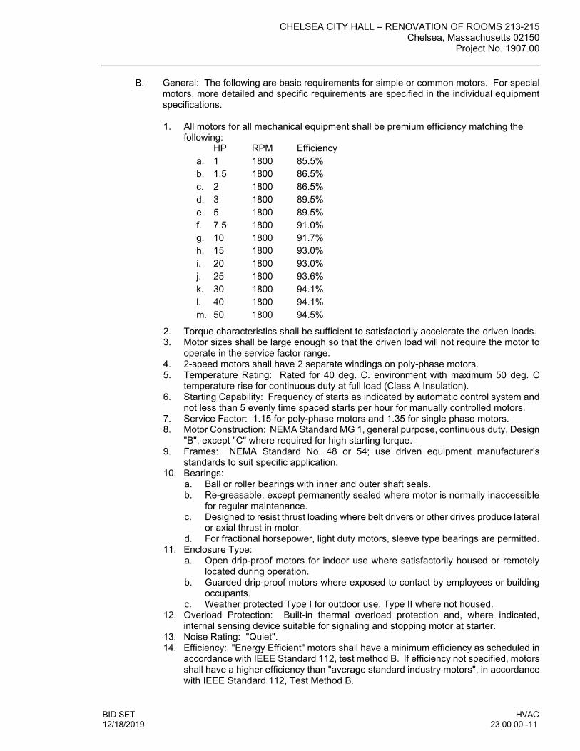
CHELSEA CITY HALL – RENOVATION OF ROOMS 213-215 Chelsea, Massachusetts 02150
Project No. 1907.00
BID SET HVAC 12/18/2019 23 00 00 -11
General: The following are basic requirements for simple or common motors. For special motors, more detailed and specific requirements are specified in the individual equipment specifications. 1. All motors for all mechanical equipment shall be premium efficiency matching the
following: HP RPM Efficiency a. 1 1800 85.5% b. 1.5 1800 86.5% c. 2 1800 86.5% d. 3 1800 89.5% e. 5 1800 89.5% f. 7.5 1800 91.0% g. 10 1800 91.7% h. 15 1800 93.0% i. 20 1800 93.0% j. 25 1800 93.6% k. 30 1800 94.1% l. 40 1800 94.1% m. 50 1800 94.5%
2. Torque characteristics shall be sufficient to satisfactorily accelerate the driven loads. 3. Motor sizes shall be large enough so that the driven load will not require the motor to
operate in the service factor range. 4. 2-speed motors shall have 2 separate windings on poly-phase motors. 5. Temperature Rating: Rated for 40 deg. C. environment with maximum 50 deg. C
temperature rise for continuous duty at full load (Class A Insulation). 6. Starting Capability: Frequency of starts as indicated by automatic control system and
not less than 5 evenly time spaced starts per hour for manually controlled motors. 7. Service Factor: 1.15 for poly-phase motors and 1.35 for single phase motors. 8. Motor Construction: NEMA Standard MG 1, general purpose, continuous duty, Design
"B", except "C" where required for high starting torque. 9. Frames: NEMA Standard No. 48 or 54; use driven equipment manufacturer's
standards to suit specific application. 10. Bearings:
a. Ball or roller bearings with inner and outer shaft seals. b. Re-greasable, except permanently sealed where motor is normally inaccessible
for regular maintenance. c. Designed to resist thrust loading where belt drivers or other drives produce lateral
or axial thrust in motor. d. For fractional horsepower, light duty motors, sleeve type bearings are permitted.
11. Enclosure Type: a. Open drip-proof motors for indoor use where satisfactorily housed or remotely
located during operation. b. Guarded drip-proof motors where exposed to contact by employees or building
occupants. c. Weather protected Type I for outdoor use, Type II where not housed.
12. Overload Protection: Built-in thermal overload protection and, where indicated, internal sensing device suitable for signaling and stopping motor at starter.
13. Noise Rating: "Quiet". 14. Efficiency: "Energy Efficient" motors shall have a minimum efficiency as scheduled in
accordance with IEEE Standard 112, test method B. If efficiency not specified, motors shall have a higher efficiency than "average standard industry motors", in accordance with IEEE Standard 112, Test Method B.

CHELSEA CITY HALL – RENOVATION OF ROOMS 213-215 Chelsea, Massachusetts 02150 Project No. 1907.00
HVAC BID SET 23 00 00 - 12 12/18/2019
15. Nameplate: Indicate the full identification of manufacturer, ratings, characteristics, construction, special features and similar information.
Starters, Electrical Devices, and Wiring: (Provided by the HVAC Contractor for Each Packaged Piece of HVAC Equipment Requiring Such): 1. Motor Starter Characteristics:
a. Enclosures: NEMA 1, general purpose enclosures with padlock ears, except in wet locations shall be NEMA 3R with conduit hubs, or units in hazardous locations which shall have NEC proper class and division.
b. Type and size of starter shall be as recommended by motor manufacturer and the driven equipment manufacturer for applicable protection and start-up condition.
2. Manual Switches shall have: a. Pilot lights and extra position for multi-speed motors. b. Overload Protection: Melting alloy type thermal overload relays.
3. Magnetic Starters: a. Maintained contact push buttons and pilot lights, properly arranged for single
speed or multi-speed operation as indicated. b. Trip-free thermal overload relays, each phase. c. Interlocks, switches and similar devices as required for co-ordination with control
requirements of Division 23 Controls Sections. d. Built-in 120 volts control circuit transformer, fused from line side, where service
exceeds 240 volts. e. Externally operated manual reset. f. Under-voltage release or protection.
4. Capacitors: a. Individual unit cells. b. All welded steel housing. c. Each capacitor internally fused. d. Non-flammable synthetic liquid impregnant. e. Craft tissue insulation. f. Aluminum foil electrodes. g. KVAR size shall be as required to correct motor power factor to 90% or better
and shall be installed on all motors 1 horsepower and larger, that have an uncorrected power factor of less than 85% at rated load.
5. Disconnect Switches (Those specified under this Section): a. Fusible Switches: Fused, each phase; general duty; horsepower rated; non-
teasible quick-make, quick-break mechanism; dead front line side shield; solderless lugs suitable for copper or aluminum conductors; spring reinforced fuse clips; electro silver plated current carrying parts; hinged doors; operating lever arranged for locking in the "OPEN" position; arc quenchers; capacity and characteristics as indicated.
b. Non-fusible Switches: For equipment 2 horsepower and smaller, shall be horsepower rated; toggle switch type; quantity of poles and voltage rating as indicated. For equipment larger than 2 horsepower, switches shall be the same as fusible type.
2.2 HANGERS & ATTACHMENTS
Horizontal-Piping Hangers and Supports: 1. General: Except as otherwise indicated, provide factory-fabricated horizontal piping
hangers and supports complying with MSS SP-58, of one of the following MSS types listed, selected by Installer to suit horizontal-piping systems, in accordance with MSS SP-69 and manufacturer's published product information. Use only one type by one manufacture for each piping service. Select size of hangers and supports to exactly

CHELSEA CITY HALL – RENOVATION OF ROOMS 213-215 Chelsea, Massachusetts 02150
Project No. 1907.00
BID SET HVAC 12/18/2019 23 00 00 -13
fit pip size for bare piping, and to insulated piping. Provide copper-plated hangers and supports for copper-piping systems. a. Adjustable Steel Clevises Hangers: MSS Type 1. b. Steel Pipe Clamps: MSS Type 4. c. Pipe Slides and Slide Plates: MSS Type 35, including one of the following plate
types: 1. Plate: Unguided type. 2. Plate: Guided type. 3. Plate: Hold-down clamp type.
d. Pipe Saddle Supports: MSS Type 36, including steel pipe base-support and cast-iron floor flange.
e. Pipe Stanchion Saddles: MSS Tube 37, including steel pip base support and cast-iron floor flange.
f. Adjustable Pipe Saddle Supports: MSS Type 38, including steel pipe base support and cast-iron floor flange.
g. Single Pipe Rolls: MSS Type 41. h. Adjustable Roller Hangers: MSS Type 43. i. Pipe Roll Stands: MSS Type 44. j. Pipe Rolls and Plates: MSS Type 45. k. Adjustable Pipe Roll Stands: MSS Type 46.
2. Manufacturer: Subject to compliance with requirements, provide hangers and supports of one of the following: a. Carpenter and Patterson, Inc. b. Corner & Lada Co., Inc. c. Elcen Metal Products Co. d. Fee & Mason Mfg. Co.; Div. Figgie International e. ITT Grinnel Corp. f. Or equal.
Vertical-Piping Clamps:
1. General: Except as otherwise indicated, provide factory-fabricated vertical-piping
clamps, complying with MSS SP-58, of one of the following types listed, selected by Installer to suit vertical piping systems, in accordance with MSS SP-69 and manufacturer's published product information. Select size of vertical piping clamps to exactly fit pipe size of bare pipe. Provide copper-plated clamps for copper-piping systems. a. Two-Bolt Riser Clamps: MSS Type 8. b. Four-Bolt Riser Clamps: MSS Type 42.
2. Manufacturer: Subject to compliance with requirements, provide hangers and supports of one of the following: a. Carpenter and Patterson, Inc. b. Corner & Lada Co., Inc. c. Elcen Metal Products Co. d. Fee & Mason Mfg. Co.; Div. Figgie International e. ITT Grinnel Corp. f. Or equal.
Hanger-Rod Attachments:
1. General: Except as otherwise indicated, provide factory-fabricated hanger-rod
attachments complying with MSS SP-58, of one of the following MSS types listed, selected by Installer to suit horizontal-pipe hangers and building attachments, in accordance with MSS SP-69 and manufacturer's published product information. Use only one type by one manufacturer for each piping service. Select size of hanger-rod attachments to suit hanger rods. Provide copper-plated hanger-rod attachments for copper-piping systems.

CHELSEA CITY HALL – RENOVATION OF ROOMS 213-215 Chelsea, Massachusetts 02150 Project No. 1907.00
HVAC BID SET 23 00 00 - 14 12/18/2019
a. Steel Turnbuckles: MSS Type 13. b. Swivel Turnbuckles: MSS Type 15. c. Malleable Iron Sockets: MSS Type 16.
2. Manufacturer: Subject to compliance with requirements, provide hangers and supports of one of the following: a. Carpenter and Patterson, Inc. b. Corner & Lada Co., Inc. c. Elcen Metal Products Co. d. Fee & Mason Mfg. Co.; Div. Figgie International e. ITT Grinnel Corp. f. Or equal.
Building Attachments:
1. General: Except as otherwise indicate, provide factory-fabricated building
attachments complying with MSS SP-58, of one of the following MSS types listed, selected by Installer to suit building substrate conditions, in accordance with MSS SP-69 and manufacturer's published product information. Select size of building attachments to suit hanger rods. Provide copper-plated building attachments for copper-piping systems. a. Concrete Inserts: MSS Type 18. b. Top Beam C-Clamp: MSS Type 19. c. Side Beam or Channel Clamps: MSS Type 20. d. Center Beam Clamps: MSS Type 21. e. Welded Beam Attachments: MSS Type 22. f. C-Clamps: MSS Type 23. g. Top Beam Clamps: MSS Type 25. h. Side Beam Clamps: MSS Type 27. i. Steel Beam Clamps W/Eye Nut: MSS Type 28. j. Linked Steel Clamps W/Eye Nut: MSS Type 29. k. Malleable Beam Clamps: MSS Type 30. l. Steel Brackets: One of the following for indicated loading:
1. Light Duty: MSS Type 31. 2. Medium Duty: MSS Type 32. 3. Heavy Duty: MSS Type 33.
m. Side Beam Brackets: MSS Type 34. n. Plate Lugs: MSS Type 57. o. Horizontal Travelers: MSS Type 58.
2. Manufacturer: Subject to compliance with requirements, provide hangers and supports of one of the following: a. Carpenter and Patterson, Inc. b. Corner & Lada Co., Inc. c. Elcen Metal Products Co. d. Fee & Mason Mfg. Co.; Div. Figgie International e. ITT Grinnel Corp. f. Or equal.
Saddles and Shields:
1. General: Except as otherwise indicated, provide saddles or shields under piping
hangers and supports, factory-fabricated, for all insulated piping. Size saddles and shields for exact fit to mate with pipe insulation.
2. Protection Saddles: MSS Type 39; fill interior voids with segments of insulation matching adjoining insulation.
3. Protection Shields: MSS Type 40; of length recommended by manufacturer to prevent crushing of insulation.

CHELSEA CITY HALL – RENOVATION OF ROOMS 213-215 Chelsea, Massachusetts 02150
Project No. 1907.00
BID SET HVAC 12/18/2019 23 00 00 -15
4. Manufacturer: Subject to compliance with requirements, provide thermal hanger shields of one of the following: a. Elcen Metal Products Co. b. Pipe Shields, Inc. c. Carpenter Patterson, Inc. d. ITT Grinnel Corp. e. Or equal.
Miscellaneous Materials:
1. Metal Framing: Provide products complying with NEMA STD ML 1. 2. Steel Plates, Shapes, and Bars: Provide products complying with ASTM A 36. 3. Cement Grout: Portland cement (ASTM C 150, Type I or Type III) and clean uniformly
graded, natural sand (ASTM C 404, Size No. 2). Mix at a ratio of 1.0 part cement to 3.0 parts sand, by volume, with minimum amount of water required for placement and hydration.
4. Heavy Duty Steel Trapezes: Fabricate from steel shapes selected for loads required; weld steel in accordance with AWS standards.
5. Pipe Guides: Provide factory-fabricated guides, of cast semi-steel or heavy fabricated steel, consisting of bolted two-section outer cylinder and base with two-section guiding spider bolted tight to pipe. Size guide and spiders to clear pipe and insulation (if any), and cylinder. Provide guides of length recommended by manufacturer to allow indicated travel.
2.3 MECHANICAL IDENTIFICATION
Plastic Pipe Markers: 1. Snap-On Type: Provide manufacturer's standard pre-printed, semi-rigid snap-on,
color-coded pipe markers, complying with ANSI A13.1 2. Pressure-Sensitive Type: Provide manufacturer's standard pre-printed, permanent
adhesive, color-coded, pressure-sensitive vinyl pipe markers, complying with ANSI A13.1
3. Insulation: Furnish 1" thick molded fiberglass insulation with jacket for each plastic pipe marker to be installed on uninsulated pipes subjected to fluid temperatures of 125 deg. F (52 deg. C) or greater. Cut length to extend 2" beyond each end of plastic pipe marker.
4. Small Pipes: For external diameters less than 6" (including insulation if any), provide full-band pipe markers, extending 360 degrees around pipe at each location, fastened by one of the following methods: a. Snap-on application of pre-tensioned semi-rigid plastic pipe marker. b. Adhesive lap joint in pipe marker overlap. c. Laminated or bonded application of pipe marker to pipe (or insulation). d. Taped to pipe (or insulation) with color-coded plastic adhesive tape, not less than
3/4" wide; full circle at both ends of pipe marker, tape lapped 1-1/2".
Plastic Equipment Markers: 1. General: Provide manufacturer's standard laminated plastic, color-coded equipment
markers. Conform to the following color code: a. Green: Cooling equipment and components. b. Yellow: Heating equipment and components. c. Yellow/Green: Combination cooling and heating equipment and components. d. Blue: Equipment and components that do not meet any of the above criteria.
2. Nomenclature: Include the following, matching terminology on schedules as closely as possible: a. Name and plan number.

CHELSEA CITY HALL – RENOVATION OF ROOMS 213-215 Chelsea, Massachusetts 02150 Project No. 1907.00
HVAC BID SET 23 00 00 - 16 12/18/2019
b. Equipment service. c. Design capacity.
1. Other design parameters such as pressure drop, entering and leaving conditions, rpm, etc.
3. Size: Provide approximate 2-1/2" x 6" markers for each piece of equipment. 4. Application: Provide equipment labels for the following equipment:
a. Ductless Cooling Units 2.4 MECHANICAL INSULATION
Piping Insulation Materials: 1. Fiberglass Piping Insulation: ASTM C 547, Class 45 required.
a. Class 1 for use to 450 degrees F; Class 2 for use to 650 degrees F; Class 3 for use to 1200 degrees F.
2. Flexible Unicellular Piping Insulation: ASTM C 534, Type as required. a. Type I - tubular; Type II - sheet. For use between -40 degrees F and 200 degrees
F. 3. Jackets for piping Insulation: ASTM C 921, with vapor barrier for piping with
temperatures below ambient. 4. Encase pipe fittings insulation with one-piece pre-molded PVC fitting covers, fastened
as per manufacturer's recommendations. 5. Encase straight pipe insulation, where exposed in occupied areas, with one piece 20-
mil thick PVC Jacketing. Fasten and seal as per manufacturer's recommendations. 6. Encase exterior piping insulation with aluminum jacket with weather-proof
construction. 7. Staples, Bands, Wires and Cement: As recommended by insulation manufacturer for
applications indicated. 8. Adhesives, Sealants and Protective Finishes: As recommended by insulation
manufacturer for applications indicated.
Piping Insulation Application and Thickness: 1. Application: Cold Piping (40 Degrees F to Ambient):
a. Insulate the following cold HVAC piping systems: 1. Air conditioner condensate drain piping. 2. Refrigerant liquid and suction piping.
b. Insulate each piping system specified above with the following type and thicknesses of insulation: 1. Fiberglass: 1" thick.
Ductwork Insulation Materials:
1. Rigid Fiberglass Ductwork Insulation: ASTM C 612, Class as required.
CLASS 2 - 400 deg. F; 4 LBS. /FT3.
CLASS 3 - 850 deg. F; 12 LBS. /FT3.
CLASS 4 - 1000 deg. F; 12 LBS. /FT3.
CLASS 5 - 1800 deg. F; 20 LBS. /FT3.
2. Flexible Fiberglass Ductwork Insulation: ASTM C 512, Class as required. CLASS 2 - 400 deg. F; .75 LBS. /FT3.
CLASS 3 - 850 deg. F; 1.5 LBS./FT3. 3. Jackets for Ductwork Insulation: ASTM C 921, with vapor barrier.

CHELSEA CITY HALL – RENOVATION OF ROOMS 213-215 Chelsea, Massachusetts 02150
Project No. 1907.00
BID SET HVAC 12/18/2019 23 00 00 -17
4. Ductwork Insulation Accessories: Provide staples, bands, wire, tape, anchors, corner angles and similar accessories as recommended by insulation manufacturer for applications indicated.
5. Ductwork Insulation Compounds: Provide cements, adhesives, coatings, sealers, protective finishes and similar compounds as recommended by insulation manufacturer for applications indicated.
Ductwork Insulation Application and Thickness:
1. Application: Ventilation and AC System Ductwork:
a. Insulate the following ductwork: 1. Outdoor air intake ductwork between air entrance and air handling unit inlet. 2. HVAC supply ductwork between HVAC unit discharge and room terminal
outlet. 3. Insulate neck and bells of supply diffusers. 4. HVAC return ductwork between room terminal inlet and HVAC unit inlet;
except omit insulation on return ductwork located in return air ceiling plenums.
5. HVAC plenums and unit housing not pre-insulated at factory or lined. 6. Exhaust ductwork between in-line exhaust fan and point of exit in building.
b. Insulate each ductwork system specified above with the following type and thicknesses of insulation: 1. Rigid Fiberglass: In machine rooms, fan rooms, and mechanical spaces
insulate all supply air, return air and outside air ductwork with 2" thick rigid. All exposed outdoor ductwork in occupied areas shall be insulated internally with same thickness and material.
2. Flexible Fiberglass: 2 in. thick, minimum R-8 application limited to concealed locations which shall include above ceilings, in chases, shafts etc.
3. All outside air ductwork shall be 2" rigid.
2.5 HYDRONIC PIPING AND ACCESSORIES
Manufacturer: Subject to compliance with requirements, provide piping system products from one of the following: 1. Grooved Mechanical Joint Pipe, Fittings and Couplings:
a. Victaulic Company of America. b. Or equal.
2. Pump Discharge Valves (Triple-Duty Valve): a. Bell & Gossett ITT; Fluid Handling Div. b. Amtrol, Inc. c. Armstrong Pumps, Inc. d. Taco, Inc. e. Or equal.
3. Safety Relief Valves: a. Bell & Gossett ITT; Fluid Handling Div. b. Amtrol, Inc. c. Spirax Sarco. d. Watts Regulator Co. e. Or equal.
4. Pressure Reducing Valves: a. Bell & Gossett ITT; Fluid Handling Div. b. Amtrol, Inc. c. Armstrong Pumps, Inc. d. Taco, Inc. e. Or equal.
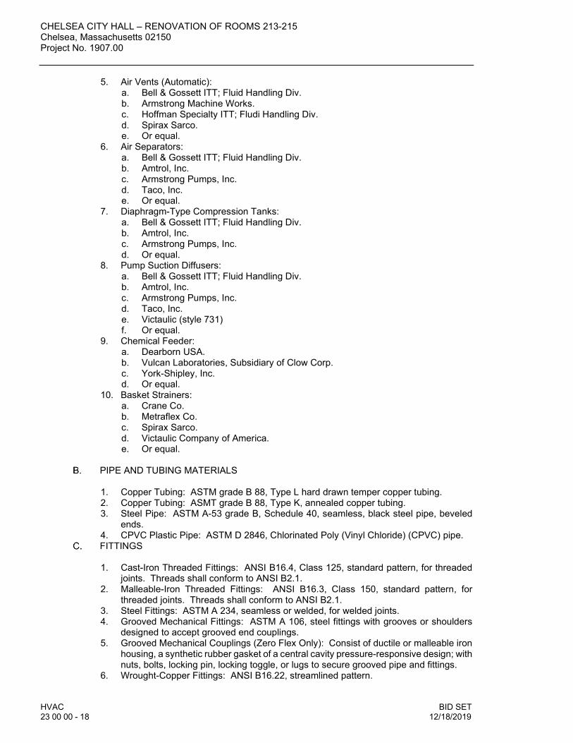
CHELSEA CITY HALL – RENOVATION OF ROOMS 213-215 Chelsea, Massachusetts 02150 Project No. 1907.00
HVAC BID SET 23 00 00 - 18 12/18/2019
5. Air Vents (Automatic): a. Bell & Gossett ITT; Fluid Handling Div. b. Armstrong Machine Works. c. Hoffman Specialty ITT; Fludi Handling Div. d. Spirax Sarco. e. Or equal.
6. Air Separators: a. Bell & Gossett ITT; Fluid Handling Div. b. Amtrol, Inc. c. Armstrong Pumps, Inc. d. Taco, Inc. e. Or equal.
7. Diaphragm-Type Compression Tanks: a. Bell & Gossett ITT; Fluid Handling Div. b. Amtrol, Inc. c. Armstrong Pumps, Inc. d. Or equal.
8. Pump Suction Diffusers: a. Bell & Gossett ITT; Fluid Handling Div. b. Amtrol, Inc. c. Armstrong Pumps, Inc. d. Taco, Inc. e. Victaulic (style 731) f. Or equal.
9. Chemical Feeder: a. Dearborn USA. b. Vulcan Laboratories, Subsidiary of Clow Corp. c. York-Shipley, Inc. d. Or equal.
10. Basket Strainers: a. Crane Co. b. Metraflex Co. c. Spirax Sarco. d. Victaulic Company of America. e. Or equal.
PIPE AND TUBING MATERIALS
1. Copper Tubing: ASTM grade B 88, Type L hard drawn temper copper tubing. 2. Copper Tubing: ASMT grade B 88, Type K, annealed copper tubing. 3. Steel Pipe: ASTM A-53 grade B, Schedule 40, seamless, black steel pipe, beveled
ends. 4. CPVC Plastic Pipe: ASTM D 2846, Chlorinated Poly (Vinyl Chloride) (CPVC) pipe.
FITTINGS 1. Cast-Iron Threaded Fittings: ANSI B16.4, Class 125, standard pattern, for threaded
joints. Threads shall conform to ANSI B2.1. 2. Malleable-Iron Threaded Fittings: ANSI B16.3, Class 150, standard pattern, for
threaded joints. Threads shall conform to ANSI B2.1. 3. Steel Fittings: ASTM A 234, seamless or welded, for welded joints. 4. Grooved Mechanical Fittings: ASTM A 106, steel fittings with grooves or shoulders
designed to accept grooved end couplings. 5. Grooved Mechanical Couplings (Zero Flex Only): Consist of ductile or malleable iron
housing, a synthetic rubber gasket of a central cavity pressure-responsive design; with nuts, bolts, locking pin, locking toggle, or lugs to secure grooved pipe and fittings.
6. Wrought-Copper Fittings: ANSI B16.22, streamlined pattern.

CHELSEA CITY HALL – RENOVATION OF ROOMS 213-215 Chelsea, Massachusetts 02150
Project No. 1907.00
BID SET HVAC 12/18/2019 23 00 00 -19
7. CPVC Plastic Fittings: ASTM D 2846, Chlorinated Poly Vinyl Chloride (CPVC) socket-type fittings and solvent for solvent cemented joints.
8. Cast-Iron Threaded Flanges: ANSI B16.1, Class 125; raised ground face, bolt holes spot faced.
9. Cast Bronze Flanges: ANSI B16.24, Class 150; raised ground face, bolt holes spot faced.
10. Steel Flanges and Flanged Fittings: ANSI B16.5, including bolts, nuts, and gaskets of the following material group, end connection and facing: a. Material Group: 1.1. b. End Connections: Butt Welding. c. Facings: Raised face.
11. Solder Filler Metals: ASTM B 32, 50-50, Tin-Lead, for condenser water, chilled water, and make-up water and drain piping.
12. Solder Filler Metals: ASTM B 32, 95-5 Tin-Antimony, for heating hot water and low pressure steam piping.
13. Brazing Filler Metals: AWS A5.8. WARNING: Some filler metal contain compounds which produce highly toxic fumes
when heated. Avoid breathing fumes. Provide adequate ventilation. 14. Gasket Material: Thickness, material, and type suitable for fluid to be handled, and
design temperatures and pressures. 15. Flexible Connectors: Stainless steel bellows with woven flexible bronze wire
reinforcing protective jacket; minimum 150 psig working pressure, maximum 250° F. operating temperature. Connectors shall have flanged or threaded end connections to match equipment connected; and shall be capable of 3/4" misalignment.
PIPE SLEEVES AND ESCUTCHEONS 1. General: Provide schedule 40 black steel or 18 gage galvanized pipe sleeve large
enough to accept pipe along with specified pipe insulation at each point where pipe penetrates a wall or floor. Sleeve shall be large enough to allow for free movement of pipe however minimized to prevent leakage of smoke and fire during a fire emergency. For all piping exposed to view provide a chrome plated escutcheon that will surround insulation where applicable on pipe for a neat finished appearance. Where piping is concealed above ceilings no escutcheons are required.
2.6 REFRIGERANT PIPING
General: Provide piping materials and factory-fabricated piping products of sizes, types, pressure ratings, temperature ratings, and capacities as indicated. Where not indicated, provide proper selection as determined by Installer to comply with installation requirements. Provide materials and products complying with ANSI B31.5 Code for refrigeration piping where applicable, base pressure rating on refrigerant piping system maximum design pressures. Provide sizes and types matching piping and equipment connections; provide fittings of materials which match pipe materials used in refrigerant piping systems. Where more than one type of materials and products are indicated, selection is Installer’s option.
Material: Provide pipes and pipe fittings in accordance with the following listing: 1. Tube Size 4-1/8” and Smaller: Copper tube; Type ACR, hard-drawn temper; wrought-
copper, solder-joint fittings; brazed joints.
Soldered Joints: Solder joints using silver-lead solder, ASTM B32, Grade 96 TS.
Brazed Joints: Braze joints using American Welding Society (AWS) classification BCUO-4 for brazing filler metal.

CHELSEA CITY HALL – RENOVATION OF ROOMS 213-215 Chelsea, Massachusetts 02150 Project No. 1907.00
HVAC BID SET 23 00 00 - 20 12/18/2019
Piping Specialties: Provide piping specialties complying with Division-23 “Hydronic Piping” in accordance with the following listing: 1. Pipe escutcheons. 2. Drip pans. 3. Sleeves. 4. Sleeve seals.
Refrigerant Valves: Special valves required for refrigerant piping include the following
types. 1. Globe Shutoff Valves: Forged brass, packed, back seating, winged seal cap, 300
degrees F (149 degrees C) temperature rating, 500 psi working pressure. 2. Check Valves: Forged brass, accessible internal parts, soft synthetic seat, fully guided
piston and stainless steel spring, 250 degrees F (121 degrees C) temperature rating, 500 psi working pressure.
3. Manufacturer: Subject to compliance with requirements, provide globe and check valves of one of the following: a. Henry Valve CO. b. Parker Hannifin Corp.; Refrigeration & Air Cond. Div. c. Sporlan Valve Co. d. Or equal.
4. 2-Way Solenoid Valves: Forged brass, designed to conform to ARI 760, normally closed, Teflon valve seat, NEMA 1 solenoid enclosure, 24 volt, 60 Hz., UL-listed, ½” conduit adapter, 250 degrees F (121 degrees C) temperature rating, 400 psi working pressure.
5. Manufacturer: Subject to compliance with requirements, provide solenoid valves of one of the following: a. Alco Controls Div.; Emerson Electric Co. b. Automatic Switch Co. c. Sporland Valve Co. d. Or equal.
6. Refrigerant Strainers: Brass shell and end connections, brazed joints, monel screen, 100 mesh, UL-listed, 350 psi working pressure.
7. Moisture-Liquid Indicators: Forged brass, single port, removable cap, polished optical glass, solder connections, UL-listed, 200 degrees F (93 degrees C) temperature rating, 500 psi working pressure.
8. Refrigerant Filter-Driers: Steel shell, ceramic fired desiccant core, solder connections, UL-listed, 500 psi working pressure.
9. Refrigerant Filter-Driers: Corrosion-resistant steel shell, steel flange ring and spring, wrought copper fittings, ductile iron coverplate with steel cap screws, replaceable filter-drier core, 500 psi working pressure.
10. Evaporator Pressure Regulators: Provide corrosion-resistant, spring loaded, stainless steel springs, pressure operated, evaporator pressure regulator, in size and working pressure indicated, with copper connections.
11. Refrigerant Discharge Line Mufflers: Provide discharge line mufflers as recommended by equipment manufacturer for use in service indicated, UL-listed.
12. Manufacturer: Subject to compliance with requirements, provide refrigeration accessories of one of the following: a. Alco Controls Div.; Emerson Electric CO. b. Henry Valve CO. c. Parker-Hannifin Corp.; Refrigeration & Air Conditioning Div. d. Sporlan Valve Co. e. Or equal.

CHELSEA CITY HALL – RENOVATION OF ROOMS 213-215 Chelsea, Massachusetts 02150
Project No. 1907.00
BID SET HVAC 12/18/2019 23 00 00 -21
Basic Vibration Control: Provide vibration control products as required in accordance with the following listing: 1. Isolation hangers. 2. Riser isolators. 3. Riser support isolators. 4. Flexible pipe connectors.
2.7 DUCTLESS COOLING UNITS (VRF)
General (Outdoor Unit):
1. The PUMY outdoor units shall be equipped with multiple circuit boards that interface to the M-NET controls system and shall perform all functions necessary for operation. The outdoor unit shall be completely factory assembled, piped and wired. Each unit shall be run tested at the factory.
a. The sum of connected capacity of all CITY MULTI indoor units shall range from
50% to 130% of outdoor rated capacity. b. Outdoor unit shall have a sound rating no higher than 59 dB(A). c. Both refrigerant lines from the outdoor unit to indoor units shall be individually
insulated. d. The outdoor unit shall have an accumulator with refrigerant level sensors and
controls. e. The outdoor unit shall have a high pressure safety switch, low pressure safety
switch and over-current protection and DC bus protection. f. The outdoor unit shall have the ability to operate with a maximum height
difference of 164 feet for the PUMY-P48NKMU. The greatest length is not to exceed 262 feet between the outdoor unit and the CITY MULTI indoor units and shall not require line size changes nor traps.
g. The outdoor unit shall have rated performance for heat operation at -4°F for the PUMY-P48NKMU (-BS) ambient temperature without additional low ambient controls.
h. The outdoor unit shall be capable of cooling operation down to 23°F outdoor ambient without additional low ambient controls.
i. The outdoor unit shall have a high efficiency oil separator plus additional logic controls to ensure adequate oil volume in the compressor is maintained.
Unit Cabinet:
1. The casing shall be fabricated of galvanized steel, bonderized and finished with a powder coated baked enamel.
Fan:
1. The unit shall be furnished with two direct drive, variable speed motors. 2. The fans will be forward curved type blades for quiet operation. 3. The fan motor shall have inherent protection, have permanently lubricated bearings,
and be completely variable speed. 4. The fan motor shall be mounted for quiet operation. 5. The fan shall be provided with a raised guard to prevent contact with moving parts. 6. The outdoor unit shall have horizontal discharge airflow.
Refrigerant
1. R410A refrigerant shall be required for all S-Series outdoor unit systems.

CHELSEA CITY HALL – RENOVATION OF ROOMS 213-215 Chelsea, Massachusetts 02150 Project No. 1907.00
HVAC BID SET 23 00 00 - 22 12/18/2019
Coil:
1. The outdoor coil shall be of nonferrous construction with lanced or corrugated fins on copper tubing.
2. The coil fins will have a factory applied corrosion resistant blue-fin finish. 3. The coil shall be protected with an integral metal guard. 4. Refrigerant flow from the outdoor unit shall be controlled by means of an inverter
driven compressor.
Compressor:
1. The compressor shall be a single high performance, inverter driven, modulating capacity scroll compressor.
2. The outdoor unit compressor shall have an inverter to modulate capacity. The capacity shall be completely variable down to 29% for the PUMY-P48NKMU (-BS).
3. The compressor shall be equipped with an internal thermal overload. 4. The compressor shall be mounted to avoid the transmission of vibration.
Electrical:
1. The outdoor unit electrical power shall be 208/230 volts, 1-phase, 60 hertz. 2. The unit shall be capable of satisfactory operation within voltage limitations of 187-
228 volts (208V/60Hz) or 207-253 volts (230V/60Hz) 3. The outdoor unit shall be controlled by integral microprocessors. 4. The control circuit between the indoor units and the outdoor unit shall be 24VDC
completed using a 2-conductor, twisted pair, non-polar shielded cable to provide total integration of the system.
5. Manufacturers: a. Subject to compliance with requirements, provide products by one of the
following: 1. Mitsubishi 2. Toshiba Carrier 3. Daikin AC 4. Or Equal.
General (Indoor Unit):
1. The PLFY-P**NCMU-ER4 shall be a four-way cassette style indoor unit that recesses into the ceiling with a ceiling grille. The indoor unit shall be factory assembled, wired and run tested. Contained within the unit shall be all factory wiring, piping, electronic modulating linear expansion device, control circuit board and fan motor. The unit shall have a self-diagnostic function, 3-minute time delay mechanism, an auto restart function, an emergency operation function and a test run switch. Indoor unit and refrigerant pipes shall be charged with dehydrated air before shipment from the factory.
Unit Cabinet:
1. The cabinet shall be a compact 22-7/16” wide x 22-7/16” deep so it will fit within a standard 24” square suspended ceiling grid.
2. The cabinet panel shall have provisions for a field installed filtered outside air intake. 3. Four-way grille shall be fixed to bottom of cabinet allowing two, three or four-way
blow.
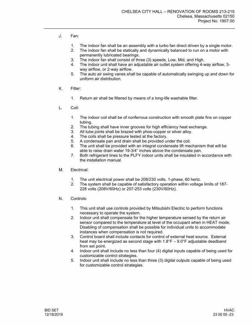
CHELSEA CITY HALL – RENOVATION OF ROOMS 213-215 Chelsea, Massachusetts 02150
Project No. 1907.00
BID SET HVAC 12/18/2019 23 00 00 -23
Fan:
1. The indoor fan shall be an assembly with a turbo fan direct driven by a single motor. 2. The indoor fan shall be statically and dynamically balanced to run on a motor with
permanently lubricated bearings. 3. The indoor fan shall consist of three (3) speeds, Low, Mid, and High. 4. The indoor unit shall have an adjustable air outlet system offering 4-way airflow, 3-
way airflow, or 2-way airflow. 5. The auto air swing vanes shall be capable of automatically swinging up and down for
uniform air distribution.
Filter:
1. Return air shall be filtered by means of a long-life washable filter.
Coil:
1. The indoor coil shall be of nonferrous construction with smooth plate fins on copper tubing.
2. The tubing shall have inner grooves for high efficiency heat exchange. 3. All tube joints shall be brazed with phos-copper or silver alloy. 4. The coils shall be pressure tested at the factory. 5. A condensate pan and drain shall be provided under the coil. 6. The unit shall be provided with an integral condensate lift mechanism that will be
able to raise drain water 19-3/4” inches above the condensate pan. 7. Both refrigerant lines to the PLFY indoor units shall be insulated in accordance with
the installation manual.
Electrical:
1. The unit electrical power shall be 208/230 volts, 1-phase, 60 hertz. 2. The system shall be capable of satisfactory operation within voltage limits of 187-
228 volts (208V/60Hz) or 207-253 volts (230V/60Hz).
Controls:
1. This unit shall use controls provided by Mitsubishi Electric to perform functions necessary to operate the system.
2. Indoor unit shall compensate for the higher temperature sensed by the return air sensor compared to the temperature at level of the occupant when in HEAT mode. Disabling of compensation shall be possible for individual units to accommodate instances when compensation is not required.
3. Control board shall include contacts for control of external heat source. External heat may be energized as second stage with 1.8°F – 9.0°F adjustable deadband from set point.
4. Indoor unit shall include no less than four (4) digital inputs capable of being used for customizable control strategies.
5. Indoor unit shall include no less than three (3) digital outputs capable of being used for customizable control strategies.

CHELSEA CITY HALL – RENOVATION OF ROOMS 213-215 Chelsea, Massachusetts 02150 Project No. 1907.00
HVAC BID SET 23 00 00 - 24 12/18/2019
Centralized Controller (Web-enabled)
1. AE-200 Centralized Controller a. The AE-200A Centralized Controller shall be capable of controlling a maximum
of two hundred (200) indoor units across multiple CITY MULTI outdoor units with the use of three (3) AE-50A expansion controllers. The AE-200A Centralized Controller shall be approximately 11-5/32” x 7-55/64” x 2-17/32” in size and shall be powered with an integrated 100-240 VAC power supply. The AE-200A Centralized Controller shall support system configuration, daily/weekly scheduling, monitoring of operation status, night setback settings, free contact interlock configuration and malfunction monitoring. When being used alone without the expansion controllers, the AE-200A Centralized Controller shall have five basic operation controls which can be applied to an individual indoor unit, a collection of indoor units (up to 50 indoor units), or all indoor units (collective batch operation). This basic set of operation controls for the AE-200 Centralized Controller shall include on/off, operation mode selection (cool, heat, auto (R2/WR2-Series only), dry, setback (R2/WR2-Series only) and fan), temperature setting, fan speed setting, and airflow direction setting. Since the AE-200A provides centralized control it shall be able to enable or disable operation of local remote controllers. In terms of scheduling, the AE-200A Centralized Controller shall allow the user to define both daily and weekly schedules (up to 24 scheduled events per day) with operations consisting of ON/OFF, mode selection, temperature setting, air flow (vane) direction, fan speed, and permit/prohibit of remote controllers.
AE-200 (Centralized Controller) Item Description Operation Display
ON/OFF Run and stop operation. Each Block, Group or Collective
Each Group or Collective
Operation Mode
Switches between Cool/Dry/Auto/Fan/Heat. (Group of Lossnay unit: automatic ventilation/vent-heat/interchange/normal ventilation) Operation modes vary depending on the air conditioner unit. Auto mode is available for the R2/WR2-Series only.
Each Block, Group or Collective Each Group
Temperature Setting
Sets the temperature from 57°F – 87°F depending on operation mode and indoor unit.
Each Block, Group or Collective Each Group
Fan Speed Setting
Available fan speed settings depending on indoor unit.
Each Block, Group or Collective Each Group
Air Flow Direction Setting
Air flow direction settings vary depending on the indoor unit model. *1. Louver cannot be set.
*1 Each Block, Group or Collective
Each Group
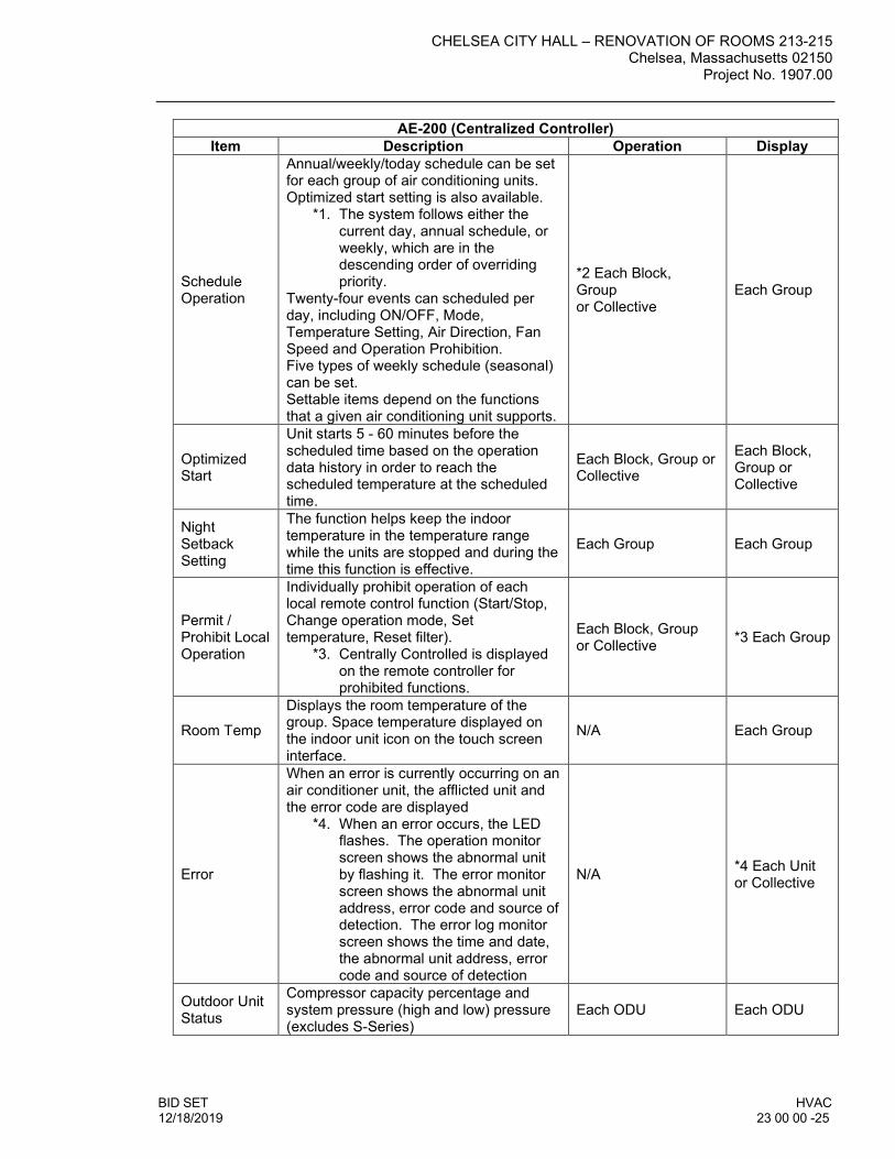
CHELSEA CITY HALL – RENOVATION OF ROOMS 213-215 Chelsea, Massachusetts 02150
Project No. 1907.00
BID SET HVAC 12/18/2019 23 00 00 -25
AE-200 (Centralized Controller) Item Description Operation Display
Schedule Operation
Annual/weekly/today schedule can be set for each group of air conditioning units. Optimized start setting is also available.
*1. The system follows either the current day, annual schedule, or weekly, which are in the descending order of overriding priority.
Twenty-four events can scheduled per day, including ON/OFF, Mode, Temperature Setting, Air Direction, Fan Speed and Operation Prohibition. Five types of weekly schedule (seasonal) can be set. Settable items depend on the functions that a given air conditioning unit supports.
*2 Each Block, Group or Collective
Each Group
Optimized Start
Unit starts 5 - 60 minutes before the scheduled time based on the operation data history in order to reach the scheduled temperature at the scheduled time.
Each Block, Group or Collective
Each Block, Group or Collective
Night Setback Setting
The function helps keep the indoor temperature in the temperature range while the units are stopped and during the time this function is effective.
Each Group Each Group
Permit / Prohibit Local Operation
Individually prohibit operation of each local remote control function (Start/Stop, Change operation mode, Set temperature, Reset filter).
*3. Centrally Controlled is displayed on the remote controller for prohibited functions.
Each Block, Group or Collective *3 Each Group
Room Temp
Displays the room temperature of the group. Space temperature displayed on the indoor unit icon on the touch screen interface.
N/A Each Group
Error
When an error is currently occurring on an air conditioner unit, the afflicted unit and the error code are displayed
*4. When an error occurs, the LED flashes. The operation monitor screen shows the abnormal unit by flashing it. The error monitor screen shows the abnormal unit address, error code and source of detection. The error log monitor screen shows the time and date, the abnormal unit address, error code and source of detection
N/A *4 Each Unit or Collective
Outdoor Unit Status
Compressor capacity percentage and system pressure (high and low) pressure (excludes S-Series)
Each ODU Each ODU

CHELSEA CITY HALL – RENOVATION OF ROOMS 213-215 Chelsea, Massachusetts 02150 Project No. 1907.00
HVAC BID SET 23 00 00 - 26 12/18/2019
AE-200 (Centralized Controller) Item Description Operation Display
Connected Unit Information
MNET addresses of all connected systems
Each IDU, ODU and BC
Each IDU, ODU and BC
Ventilation Equipment
This interlocked system settings can be performed by the master system controller. When setting the interlocked system, use the ventilation switch the free plan LOSSNAY settings between “Hi”, “Low” and “Stop”. When setting a group of only free plan LOSSNAY units, you can switch between “Normal ventilation”, “Interchange ventilation” and “Automatic ventilation”.
Each Group Each Group
Multiple Language
Other than English, the following language can be chosen. Spanish, French, Japanese, Dutch, Italian, Russian, Chinese, and Portuguese are available.
N/A Collective
External Input / Output
By using accessory cables you can set and monitor the following.
By level: “Batch start/stop”, “Batch emergency stop” By pulse: “batch start/stop”, “Enable/disable remote controller” Output: “start/stop”, “error/Normal” *5. Requires the external I/O cables
(PAC-YG10HA-E) sold separately.
*5 Collective *5 Collective
b. All AE-200A Centralized Controllers shall be equipped with two RJ-45 Ethernet
ports to support interconnection with a network PC via a closed/direct Local Area Network (LAN) or to a network switch for IP communication to up to three AE-50A expansion controllers for display of up to two hundred (200) indoor units on the main AE-200A interface.
c. The AE-200A Centralized Controller shall be capable of performing initial settings via the high-resolution, backlit, color touch panel on the controller or via a PC browser using the initial settings.
d. Standard software functions shall be available so that the building manager can securely log into each AE-200A via the PC’s web browser to support operation monitoring, scheduling, error email, interlocking and online maintenance diagnostics. Additional optional software functions of personal browser for PCs and MACs and Tenant Billing shall be available but are not included. The Tenant Billing function shall require TG-2000 Integrated System software in conjunction with the Centralized Controllers.
2.8 TERMINAL HEATING UNITS (HYDRONIC)
BASEBOARD RADIATION: 1. General: Provide baseboard radiation of lengths and in locations as indicated, and of
capacities, style, and having accessories as scheduled.

CHELSEA CITY HALL – RENOVATION OF ROOMS 213-215 Chelsea, Massachusetts 02150
Project No. 1907.00
BID SET HVAC 12/18/2019 23 00 00 -27
2. Cabinets: Minimum 20-ga cold-rolled steel, one-piece back and top panel, front panel with integral damper. Provide steel brackets, inserted in back/top panel, to support element and front panel. Provide baked enamel finish. Color as selected by the Architect.
3. Elements: Copper tube and aluminum fins, with slide mechanism between element and support brackets to eliminate expansion and contraction noises.
4. Accessories: Provide the following accessories: a. Blank end caps. b. End caps with hinged access panel. c. Trim strips.
5. Manufacturer: Subject to compliance with requirements, provide baseboard radiation of one of the following: a. Slant/Fin Corp. b. Rittling c. Sterling Radiator: Div. of Reed National Corp. d. Trane (The) Co. e. Or equal.
FINNED TUBE RADIATION:
1. General: Provide finned tube radiation of lengths and in locations as indicated, and
of capacities, style, and having accessories as scheduled. 2. Cabinets: Minimum 18-ga cold rolled steel full backplate, minimum 16-ga front. Brace
and reinforce front minimum of 4'-0" o.c. without visible fasteners. 3. Elements: Copper tube and aluminum fins, or steel tube and steel fin (as scheduled)
with tube mechanically expanded into fin collars to eliminate noise and insure durability and performance at scheduled ratings.
4. Finish: Flat black heat resisting paint for backplate; factory finished baked enamel on fronts and accessories. Standard manufacturer color as selected by Architect.
5. Accessories: a. End panels, inside and outside corners, and enclosure extension. b. Access panels in front of valves, balancing cocks, and traps. c. Factory mounted dampers. d. Ball bearing hangers.
6. Manufacturer: Subject to compliance with requirements, provide finned tube radiation of one of the following: a. Slant/Fin Corp. b. Rittling c. Sterling Radiator; Div. of Reed National Corp. d. Or equal.
2.9 METAL DUCTWORK
Ductwork Materials: 1. Exposed Ductwork Materials: Where ductwork is indicated to be exposed to view in
occupied spaces, provide materials which are free from visual imperfections including piping, seam marks, roller marks, stains and discolorations, and other imperfections, including those which would impair painting.
2. Sheet Metal: Except as otherwise indicated, fabricate ductwork from galvanized sheet steel complying with ASTM A 527, lock forming quality, with G 90 zinc coating in accordance with ASTM A 525; and mill phosphatized for exposed locations.
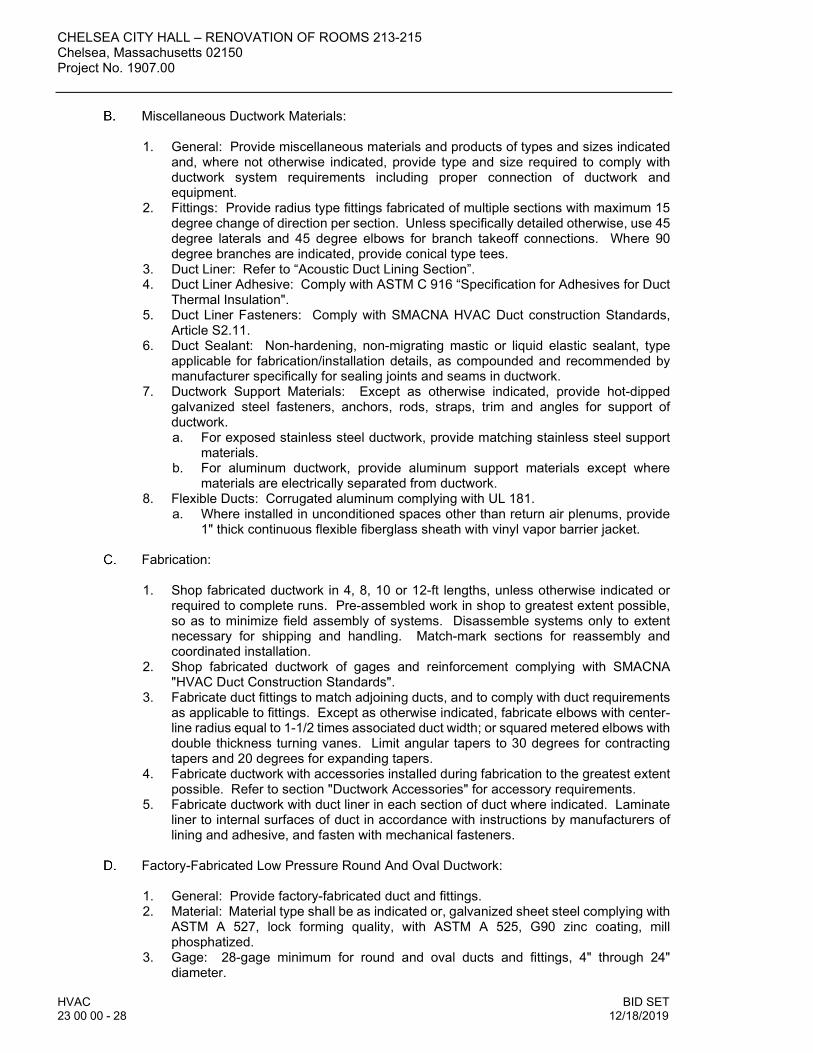
CHELSEA CITY HALL – RENOVATION OF ROOMS 213-215 Chelsea, Massachusetts 02150 Project No. 1907.00
HVAC BID SET 23 00 00 - 28 12/18/2019
Miscellaneous Ductwork Materials: 1. General: Provide miscellaneous materials and products of types and sizes indicated
and, where not otherwise indicated, provide type and size required to comply with ductwork system requirements including proper connection of ductwork and equipment.
2. Fittings: Provide radius type fittings fabricated of multiple sections with maximum 15 degree change of direction per section. Unless specifically detailed otherwise, use 45 degree laterals and 45 degree elbows for branch takeoff connections. Where 90 degree branches are indicated, provide conical type tees.
3. Duct Liner: Refer to “Acoustic Duct Lining Section”. 4. Duct Liner Adhesive: Comply with ASTM C 916 “Specification for Adhesives for Duct
Thermal Insulation". 5. Duct Liner Fasteners: Comply with SMACNA HVAC Duct construction Standards,
Article S2.11. 6. Duct Sealant: Non-hardening, non-migrating mastic or liquid elastic sealant, type
applicable for fabrication/installation details, as compounded and recommended by manufacturer specifically for sealing joints and seams in ductwork.
7. Ductwork Support Materials: Except as otherwise indicated, provide hot-dipped galvanized steel fasteners, anchors, rods, straps, trim and angles for support of ductwork. a. For exposed stainless steel ductwork, provide matching stainless steel support
materials. b. For aluminum ductwork, provide aluminum support materials except where
materials are electrically separated from ductwork. 8. Flexible Ducts: Corrugated aluminum complying with UL 181.
a. Where installed in unconditioned spaces other than return air plenums, provide 1" thick continuous flexible fiberglass sheath with vinyl vapor barrier jacket.
Fabrication: 1. Shop fabricated ductwork in 4, 8, 10 or 12-ft lengths, unless otherwise indicated or
required to complete runs. Pre-assembled work in shop to greatest extent possible, so as to minimize field assembly of systems. Disassemble systems only to extent necessary for shipping and handling. Match-mark sections for reassembly and coordinated installation.
2. Shop fabricated ductwork of gages and reinforcement complying with SMACNA "HVAC Duct Construction Standards".
3. Fabricate duct fittings to match adjoining ducts, and to comply with duct requirements as applicable to fittings. Except as otherwise indicated, fabricate elbows with center-line radius equal to 1-1/2 times associated duct width; or squared metered elbows with double thickness turning vanes. Limit angular tapers to 30 degrees for contracting tapers and 20 degrees for expanding tapers.
4. Fabricate ductwork with accessories installed during fabrication to the greatest extent possible. Refer to section "Ductwork Accessories" for accessory requirements.
5. Fabricate ductwork with duct liner in each section of duct where indicated. Laminate liner to internal surfaces of duct in accordance with instructions by manufacturers of lining and adhesive, and fasten with mechanical fasteners.
Factory-Fabricated Low Pressure Round And Oval Ductwork: 1. General: Provide factory-fabricated duct and fittings. 2. Material: Material type shall be as indicated or, galvanized sheet steel complying with
ASTM A 527, lock forming quality, with ASTM A 525, G90 zinc coating, mill phosphatized.
3. Gage: 28-gage minimum for round and oval ducts and fittings, 4" through 24" diameter.

CHELSEA CITY HALL – RENOVATION OF ROOMS 213-215 Chelsea, Massachusetts 02150
Project No. 1907.00
BID SET HVAC 12/18/2019 23 00 00 -29
4. Seams: All seams shall be spiral lock seams. 5. Elbows: One piece construction for 90 degrees and 45 degree elbows 14" and
smaller. Provide multiple gore construction for larger diameters with standing seam circumferential joint.
6. Divided flow Fittings: 90 degree tees, constructed with saddle tap spot welded and bonded to duct fitting body.
7. Manufacturers: Subject to compliance with requirements, provide factory-fabricated ductwork of one of the following: a. Semco Mfg., Inc. b. United Sheet Metal Div., United McGill Corp. c. Or equal.
2.10 DUCTWORK ACCESSORIES
Dampers: 1. Low Pressure Manual Dampers: Provide dampers of single blade type or multiblade
type, constructed in accordance with SMACNA "HVAC Duct construction Standards". 2. Automatic Control Dampers: Refer to Division-23 section "Automatic Temperature
Control" for control dampers; not work of this section. 3. Backdraft Relief Dampers: Provide dampers with parallel blades, counterbalanced
and factory-set to relieve at .05" static pressure. Construct blades of 16-ga. aluminum, provide 1/2" diameter ball bearings, 1/2" diameter steel axles spaced on 9" centers. Construct from 2" x 1/2" x 1/8" steel channel for face areas 25 sq. ft. and under: 4" x 1-1/4" x 16 ga. channel for face areas over 25 sq. ft. Provide galvanized steel finish on frame with aluminum touch-up. Provide felted or rubber trim to assure tight, leak-proof seal when closed.
4. Manufacturer: Subject to compliance with requirements, provide dampers of one of the following: a. Air Balance, Inc. b. Airguarde Corp. c. American Warming & Ventilating, Inc. d. Arrow Louver and Damper; Div. of Arrow United Industries, Inc. e. Louvers & Dampers, Inc. f. Penn Ventilator Co. g. Ruskin Mfg. Co. h. Or equal.
Turning Vanes: 1. Manufactured Turning Vanes: Provide double thickness airfoil turning vanes
constructed of 1-1/2" wide curved blades set at 3/4" o.c., supported with bars perpendicular to blades set at 2" o.c, and set into side strips suitable for mounting in ductwork.
2. Manufacturer: Subject to compliance with requirements, provide turning banes of one of the following: a. Aero Dyne Co. b. Airsan Corp. c. Anemostat Products Div.; Dynamics Corp. of America. d. Barber-Colman Co. e. Duro Dyne Corp. f. Environmental Elements Corp.; Subs, Koppers Co., Inc. g. Hart & Cooley Mfg. Co. h. Register & Grille Mfg. Co., Inc. i. Souther, Inc. j. Or equal.

CHELSEA CITY HALL – RENOVATION OF ROOMS 213-215 Chelsea, Massachusetts 02150 Project No. 1907.00
HVAC BID SET 23 00 00 - 30 12/18/2019
Duct Hardware: 1. General: Provide duct hardware, manufactured by one manufacturer for all items on
project, for the following: a. Test Holes: Provide in ductwork at fan inlet and outlet, and elsewhere as
indicated, duct test holes, consisting of slot and cover, for instrument tests. b. Quadrant Locks: Provide for each damper, quadrant lock device on one end of
shaft; and end bearing plate on other end for damper lengths over 12". Provide extended quadrant locks and end extended bearing plates for externally insulated ductwork.
2. Manufacturer: Subject to compliance with requirements, provide duct hardware of one of the following: a. Ventbabrics, Inc. b. Young Regulator Co. c. Or equal.
Flexible Connectors:
1. General: Provide flexible duct connections wherever ductwork connects to vibration
isolated equipment. Construct flexible connections of neoprene-coated flameproof fabric crimped into duct flanges for attachment to duct and equipment. Make airtight joint. Provide adequate joint flexibility to allow for thermal, axial, transverse, and torsional movement, and also capable of absorbing vibration of connected equipment.
2. Manufacturer: Subject to compliance with requirements, provide flexible connections of one of the following: a. American/Elgen Co.; Energy Div. b. Duro Dyne Corp. c. Flexaust (The) Co. d. Ventfabrics, Inc. e. Or equal.
2.11 ARCHITECTURAL LOUVERS AND VENTS
Manufacturers:
1. Louver: Acceptable Manufacturers: Subject to compliance with the requirements specified herein, manufacturers offering products which may be incorporated in the work include the following, or approved equal: a. Dayton. b. Grainger. c. Industrial Louvers, Inc. d. Equal.
Architectural Louvers:
1. Louvers: Prefinished fixed aluminum louver. 2. Vision Screen Louvers: Prefinished fixed aluminum louver.
PART 3 - EXECUTION 3.1 INSTALLATION OF HANGERS AND ATTACHMENTS
Examine areas and conditions under which supports and anchors are to be installed. Do not proceed with work until unsatisfactory conditions have been corrected in manner acceptable to Installer.

CHELSEA CITY HALL – RENOVATION OF ROOMS 213-215 Chelsea, Massachusetts 02150
Project No. 1907.00
BID SET HVAC 12/18/2019 23 00 00 -31
Proceed with installation of hangers, supports and anchors only after required building
structural work has been completed in areas where the work is to be installed. Correct inadequacies including (but not limited to) proper placement of inserts, anchors, and other building structural attachments.
Prior to installation of hangers, supports, anchors, and associated work, Installer shall meet at project site with Contractor, installer of each component of associated work, inspection and testing agency representatives (if any), installers of other work requiring coordination with work of this section and Architect/Engineer for purposes of reviewing material selections and procedures to be followed in performing the work in compliance with requirements specified.
Install building attachments at required locations within concrete or on structural steel for
proper piping support. Space attachments within maximum piping span length indicated in MSS SP-69. Install additional concentrated loads, including valves, flanges, guides, strainers, expansion joints, and at changes in direction of piping. Install concrete inserts before concrete is placed; fasten insert securely to forms. Where concrete with compressive strength less than 2500 psi is indicated, install reinforcing bars through the openings at the tops of inserts.
Install hangers, supports, clamps, and attachments to support piping properly from building structure; comply with MSS SP-69. Arrange for grouping of parallel runs of horizontal piping to be supported together on trapeze type hangers where possible. Install supports with maximum spacing complying with MSS SP-69. Where piping of various sizes is to be supported together by trapeze hangers, space hangers for smallest pipe size or install intermediate supports for smaller diameter pipe. Do not use wire or perforated metal to support piping, and do not support piping from other piping.
1. Install hangers and supports complete with necessary inserts, bolts, rods, nuts,
washers, and other accessories. Except as otherwise indicated for exposed continuous pipe runs, install hangers and supports of same type and style as installed for adjacent similar piping.
2. Prevent electrolysis in support of copper tubing by the use of hangers and supports which are copper plated, or by other recognized industry methods.
3. Install hangers and supports to allow controlled movement of piping systems and to permit freedom of movement between pipe anchors, and to facilitate action of expansion joints, expansion loops, expansion bends, and similar units.
4. Load Distribution: Install hangers and supports so that piping live and dead loading and stresses from movement will not be transmitted to connected equipment.
5. Pipe Slopes: Install hangers and supports to provide indicated pipe slopes, and so that maximum pipe deflections allowed by ANSI B31 Pressure Piping Codes are not exceeded.
6. Insulated Piping: Comply with the following installation requirements: a. Clamps: Attach clamps, including spacers (if any), to piping with clamps
projecting through insulation; do not exceed pipe stresses allowed by ANSI B31. b. Shields: For pipe sizes up to and including 4” provide heavy gage shield at each
hanger point. c. Saddles: For all pipe sizes over 4” provide saddle at each hanger point.
Completely fill void in saddle with loose insulation.
Install anchors at proper locations to prevent stresses from exceeding those permitted by ANSI B31, and to prevent transfer for loading and stresses to connected equipment.
Fabricate and install anchor by welding steel shapes, plates, and bars to piping and to structure. Comply with ANSI B31 and with AWS standards.

CHELSEA CITY HALL – RENOVATION OF ROOMS 213-215 Chelsea, Massachusetts 02150 Project No. 1907.00
HVAC BID SET 23 00 00 - 32 12/18/2019
Where expansion compensators are indicated, install anchors in accordance with expansion unit manufacturer's written instructions, to limit movement of piping and forces to maximums recommended by manufacturer for each unit.
Anchor Spacings: Where not otherwise indicated, install anchors at ends of principal pipe-runs, at intermediate points in pipe-runs between expansion loops and bends. Make provisions for preset of anchors as required to accommodate both expansion and contraction of piping.
Provide concrete housekeeping bases for all floor-mounted equipment. Size bases to
extend minimum of 4" beyond equipment base in any direction; and 4" above finished floor elevation. Construct of reinforced concrete, roughen floor slab beneath base for bond, and provide steel rod anchors between floor and base. Locate anchor bolts using equipment manufacturer's templates. Chamfer top and edge corners.
Provide structural steel stands to support equipment not floor mounted or hung from structure. Construct of structural steel members or steel pipe and fittings. Provide factory-fabricated tank saddles for tanks mounted on steel stands.
Adjusting and Cleaning:
1. Hanger Adjustment: Adjust hangers so as to distribute loads equally on attachments. 2. Support Adjustment: Provide grout under supports so as to bring piping and
equipment to proper level and elevations. 3. Cleaning: Clean factory-finished surfaces. Repair any marred or scratched surfaces
with manufacturer's touch-up paint.
3.2 INSTALLATION OF MECHANICAL IDENTIFICATION
Coordination: Where identification is to be applied to surfaces which require insulation, painting or other covering or finish, including valve tags in finished mechanical spaces, install identification after completion of covering and painting. Install identification prior to installation of acoustical ceilings and similar removable concealment.
Mechanical Equipment Identification: 1. General: Install engraved plastic laminate sign or plastic equipment marker on or near
each major item of mechanical equipment and each operational device, as specified herein if not otherwise specified for each item or device.
2. Lettering Size: Minimum 1/4" high lettering for name of unit where viewing distance is less than 2' - 0", 1\2" high for distances up to 6' - 0", and proportionately larger lettering for greater distances. Provide secondary lettering of 2/3 to 3/4 of size of the principal lettering.
Adjusting and Cleaning: 1. Adjusting: Relocate any mechanical identification device which has become visually
blocked by work of this division or other divisions. 2. Cleaning: Clean face of identification devices, and glass frames of valve charts.
3.3 INSTALLATION OF MECHANICAL INSULATION
Installation of Piping Insulation: 1. General: Install insulation products in accordance with manufacturer's written
instructions, and in accordance with recognized industry practices to ensure that insulation serves its intended purpose.

CHELSEA CITY HALL – RENOVATION OF ROOMS 213-215 Chelsea, Massachusetts 02150
Project No. 1907.00
BID SET HVAC 12/18/2019 23 00 00 -33
2. Install insulation materials with smooth and even surfaces. Insulate each continuous run of piping with full-length units of insulation, with a single cut piece to complete run. Do not use cut pieces or scraps abutting each other.
3. Clean and dry pipe surfaces prior to insulating. Butt installation joints firmly together to ensure a complete and tight fit over surfaces to be covered.
4. Maintain integrity of vapor-barrier jackets on pipe insulation, and protect to prevent puncture or other damage.
5. Cover valves, fittings and similar items in each piping system with equivalent thickness and composition of insulation as applied to adjoining pipe run. Install factory molded, precut or job fabricated units (at Installer's option) except where specific form or type is indicated.
6. Extend piping insulation without interruption through walls, floors and similar piping penetrations, except where otherwise indicated.
7. Butt pipe insulation against pipe hanger insulation inserts. For hot pipes, apply 3" wide vapor barrier tape or band over the butt joints. For cold piping apply wet coat of vapor barrier lap cement on butt joints and seal joints with 3" wide vapor barrier tape or band.
Installation of Ductwork Insulation: 1. General: Install insulation products in accordance with manufacturer's written
instructions, and in accordance with recognized industry practices to ensure that insulation serves its indented purpose.
2. Install insulation materials with smooth and even surfaces. 3. Clean and dry ductwork prior to insulating. Butt insulation joints firmly together to
ensure complete and tight fit over surfaces to be covered. 4. Maintain integrity of vapor-barrier on ductwork insulation, and protect it to prevent
puncture and other damage. 5. Extend ductwork insulation without interruption through walls, floors and similar
ductwork penetrations, except where otherwise indicated. 6. Lined Ductwork: Except as otherwise indicated, omit insulation on ductwork where
internal insulation or sound absorbing linings have been installed.
Protection and Replacement: 1. Replace damaged insulation which cannot be repaired satisfactorily, including units
with vapor barrier damage and moisture saturated units. 2. Protection: Insulation Installer shall advise Contractor of required protection for
insulation work during remainder of construction period, to avoid damage and deterioration.
3.4 INSTALLATION OF HYDRONIC PIPING AND ACCESSORIES
Piping Installations: 1. Locations and Arrangements: Drawings indicate the general location and
arrangement of piping systems. Locations and arrangements of piping take into consideration pipe sizing and friction loss, expansion, pump sizing, and other design consideration. So far as practical, install piping as indicated.
2. Install piping at a uniform grade of 1" in 40' upward in the direction of flow. 3. Make reductions in pipe sizes using eccentric reducer fitting installed with the level
side up. 4. Install branch connections to mains using Tee fittings in main with take-off out the
bottom, except for up-freed risers which shall have take-off out the top of the main line.

CHELSEA CITY HALL – RENOVATION OF ROOMS 213-215 Chelsea, Massachusetts 02150 Project No. 1907.00
HVAC BID SET 23 00 00 - 34 12/18/2019
5. Install unions in pipes 2" and smaller, adjacent to each valve, at final connections of each piece of equipment, and elsewhere as indicated. Unions are not required on flanged devices.
6. Install flanges on valves, apparatus, and equipment having 2-1/2" and larger connections.
7. Install strainers on the supply side of each control valve, pressure reducing valve, pressure regulating valve, solenoid valve, inline pump, and elsewhere as indicated. Install nipple and ball valve in blow down connection of strainers 2" and larger.
8. Anchor piping to ensure proper direction of expansion and contraction. Expansion loops and joints are indicated on the Drawings
9. Install pipe sleeves at all wall and floor penetrations. 10. Install escutcheons at all exposed pipe wall penetrations. 11. Provide Dielectric couplings at all dissimilar piping/valve connections.
Pipe Applications:
1. Copper Tubing: Use Type L, drawn copper tubing with wrought copper fittings and
solder joints for 2" and smaller, above ground, within building. Use Type K, annealed temper copper tubing for 2" and smaller without joints, below ground or within slabs. Mechanical fittings (crimp or flair) are not permitted.
2. Steel Pipe: Use steel pipe with threaded joints and fittings for 2" and smaller, and with welded joints for 2-1/2" and larger.
3. Steel Pipe: Use mechanical grooved end steel pipe and mechanical couplings and fittings.
Grooved Ends: 1. Roll Groove pipe ends in accordance with the latest published instructions from
manufacturer of grooved couplings.
Valve Applications: 1. General Duty Valve Applications: The Drawings indicate valve types to be used.
Where specific valve types are not indicated the following requirements apply: a. Shut-Off Duty: Use gate, and ball, valves. b. Throttling Duty: Use globe, ball, and plug valves.
2. Install drain valves at low points in mains, risers, branch lines, and elsewhere as required for system drainage.
3. Install pump discharge valves with stem in upward position; allow clearance above stem for check mechanism removal.
4. Install safety relief valve on hot water generators, and elsewhere as required by ASME Boiler and Pressure Vessel Code. Pipe discharge to floor without valves. Comply with ASME Boiler and Pressure Vessel Code Section VIII, Division 01 for installation requirements.
5. Install pressure reducing valves on hot water generators, and elsewhere as required to regulate system pressure.
Hydronic Specialties Installation: 1. Install automatic air vents at high points in the system, heat transfer coils, and
elsewhere as required for system air venting. Install air vents with cocks such that vents can be removed without draining system.
2. Install combination separator/strainer in pump suction lines. Run piping to compression tank with 1/4" per foot (2%) upward slope towards tank. Install blowdown piping with gate valve; extend to nearest drain.
3. Install pump suction diffusers on pump suction inlet, adjust foot support to carry weight of suction piping. Install nipple and ball valve in blowdown connection.

CHELSEA CITY HALL – RENOVATION OF ROOMS 213-215 Chelsea, Massachusetts 02150
Project No. 1907.00
BID SET HVAC 12/18/2019 23 00 00 -35
4. Install shot-type chemical feeders in each hydronic system; in upright position with top of funnel not more than 48" above floor. Install feeder in bypass line, off main using globe valves on each side of feeder and in the main between bypass connections. Pipe drain, with ball valve, to nearest equipment drain.
5. Install diaphragm-type compression tanks as indicated. Vent and purge air from hydronic system, charge tank with proper air charge to suit system design requirements. a. In the absence of details provide support from the floor or structure above
sufficient for the weight of water assuming a full tank of water. Do not overload building components and structural members.
Field Quality Control: 1. Preparation for Testing: Prepare hydronic piping in accordance with ASME B 31.9
and as follows: a. Leave joints including welds uninsulated and exposed for examination during the
test. b. Provide temporary restraints for expansion joints which cannot sustain the
reactions due to test pressure. If temporary restraints are not practical, isolate expansion joints from testing.
c. Flush system with clean water. Clean strainers. d. Isolate equipment that is not to be subjected to the test pressure from the piping.
If a valve is used to isolate the equipment, its closure shall be capable of sealing against the test pressure without damage to the valve. Flanged joints at which blinds are inserted to isolate equipment need not be tested.
e. Install relief valve set at a pressure no more than 1/3 higher than the test pressure, to protect against damage by expansion of liquid or other source of overpressure during the test.
2. Testing: Test hydronic piping as follows: a. Use ambient temperature water as the testing medium, except where there is a
risk of damage due to freezing. Another liquid may be used if it is safe for workmen and compatible with the piping system components.
b. Use vents installed at high points in the system to release trapped air while filling the system. Use drains installed at point for complete removal of the liquid.
c. Examine system to see that equipment and parts that cannot withstand test pressures are properly isolated. Examine test equipment to ensure that it is tight and that low pressure filling lines are disconnected.
d. Subject piping system to a hydrostatic test pressure which at every point in the system is not less than 1.5 times the design pressure. The test pressure shall not exceed the maximum pressure for any vessel, pump, valve, or other component in the system under test. Make a check to verify that the stress due to pressure at the bottom of vertical runs does not exceed either 90% of specified minimum yield strength, or 1.7 times the "SE" value in Appendix A of ASME B31.9, Code for Pressure Piping, Building Services Piping.
e. After the hydrostatic test pressure has been applied for at least 10 minutes, examine piping, joints, and connection for leakage. Eliminate leaks by tightening, repairing, or replacing components as appropriate, and repeat hydrostatic test until there are no leaks.
Adjusting and Cleaning: 1. Clean and flush hydronic piping systems. Remove, clean, and replace strainer
screens. After cleaning and flushing hydronic piping system, but before balancing, remove disposable fine mesh strainers in pump suction diffusers.
2. Chemical Treatment: Provide a water analysis prepared by the chemical treatment supplier to determine the type and level of chemicals required for prevention of scale and corrosion. Perform initial treatment after completion of system testing.

CHELSEA CITY HALL – RENOVATION OF ROOMS 213-215 Chelsea, Massachusetts 02150 Project No. 1907.00
HVAC BID SET 23 00 00 - 36 12/18/2019
3.5 INSTALLATION OF REFRIGERANT PIPING AND ACCESSORIES
Piping Installations: 1. Locations and Arrangements: Drawings indicate the general location and
arrangement of piping systems. Locations and arrangements of piping take into consideration pipe sizing and friction loss, and other design consideration. So far as practical, install piping as indicated.
2. Install pipe sleeves at all wall and floor penetrations. 3. Install escutcheons at all exposed pipe wall penetrations.
3.6 INSTALLATION OF DUCTLESS COOLING UNIT SYSTEMS (VRF)
General:
1. Rig and install in full accordance with manufacturer’s requirements, project drawings,
and contract documents. Refer to the manufacturer’s installation manual for full requirements.
Location:
1. Locate indoor and outdoor units as indicated on drawings. Provide service clearance per manufacturer’s installation manual. Adjust and level outdoor units on support structure.
2. For climates that experience snowfall, mount the outdoor unit a minimum of 12” above the average snowfall line. In climates where this height requirement proves unfeasible, the outdoor units may be installed at the average snowfall line provided regular snow removal in the area surrounding the units keeps the snow line below the bottom of the units.
Components / Piping:
1. Installing contractor shall provide and install all accessories and piping for a fully
operational system. Refer to manufacturer’s installation manual for full instructions. 2. Traps, filter driers, and sight glasses are NOT to be installed on the refrigerant piping
or condensate lines. 3. Standard ACR fittings rated for use with R410A are to be used for all connections.
Proprietary manufacturer-specific appurtenances are not allowed. 4. Refrigerant pipe for CITY MULTI shall be made of phosphorus deoxidized copper, and
has two types. a. ACR “Annealed”: Soft copper pipe, can be easily bent with human's hand. b. ACR “Drawn Temper”: Hard copper pipe (Straight pipe), being stronger than
Type-O pipe of the same radical thickness.
5. The maximum operation pressure of R410A air conditioner is 4.30 MPa [623psi] . The refrigerant piping should ensure the safety under the maximum operation pressure. Refer to recommend piping specifications in Mitsubishi Electric’s engineering manual. Pipes of radical thickness 0.7mm or less shall not be used.
6. Flare connection should follow dimensions provided in manufacturer’s installation manuals.
Insulation:
1. Refrigerant lines, as well as any valves, shall be insulated per Section 2.4.

CHELSEA CITY HALL – RENOVATION OF ROOMS 213-215 Chelsea, Massachusetts 02150
Project No. 1907.00
BID SET HVAC 12/18/2019 23 00 00 -37
Electrical:
1. Installing contractor shall coordinate electrical requirements and connections for all power feeds with electrical contractor. Refer to Division 26 for additional information.
Third Party Controls:
1. Installing contractor shall coordinate all BAS/BMS control requirements and
connections with controls contractor. 3.7 INSTALLATION OF TERMINAL HEATING UNITS (HYDRONIC)
Installation of Baseboard Radiation: (HYDRONIC) 1. General: Install baseboard radiation as indicated, and in accordance with
manufacturer's installation instructions. 2. Locate baseboard radiation as indicated, run cover continuous wall-to-wall unless
otherwise indicated. 3. Install end caps where units butt against walls. Install access panels centered in front
of each shutoff valve, balancing cock, or temperature control valve.
Installation of Finned Tube Radiation: (HYDRONIC) 1. General: Install finned tube radiation as indicated, and in accordance with
manufacturer's installation instructions. 2. Locate finned tube radiation as indicated, run cover wall-to-wall unless otherwise
indicated. Provide butt caps, splice joints, "Z" bends etc. for a complete installation. 3. Install access panels centered in front of each shutoff valve, balancing cock, steam
trap, or temperature control valve.
3.8 INSTALLATION OF METAL DUCTWORK
Installation of Metal Ductwork: 1. General: Assemble and install ductwork in accordance with recognized industry
practices which will achieve air-tight (5% leakage for systems rated 3" and under; 1% for systems rated over 3") and noiseless (no objectionable noise) systems, capable of performing each indicated service. Install each run with minimum number of joints. Align ductwork accurately with internal surface smooth. Support ducts rigidly with suitable ties, braces, hangers and anchors of type which will hold ducts true-to-shape and to prevent buckling. Support vertical ducts at every floor.
2. Sealing: All ductwork joints and seams shall be sealed with flexible duct sealer to assure an airtight installation.
3. Penetrations: Where ducts pass through interior partitions and exterior walls, and are exposed to view, conceal space between construction opening and duct or duct insulation with sheet metal flanges of same gage as duct. Overlap opening on 4 sides by at least 1-1/2". Fasten to duct and substrate. a. Where ducts pass through fire-rated floors, walls, or partitions, provide
firestopping between duct and substrate. 4. Coordination: Coordinate duct installation with installation of accessories, dampers,
coil frames, equipment, controls and other associated work of ductwork system. 5. Installation: Install metal ductwork in accordance with "SMACNA HVAC Duct
Construction Standards".

CHELSEA CITY HALL – RENOVATION OF ROOMS 213-215 Chelsea, Massachusetts 02150 Project No. 1907.00
HVAC BID SET 23 00 00 - 38 12/18/2019
Installation of Duct Liners: 1. General Install duct liners in accordance with SMACNA "HVAC Duct Construction
Standards".
Installation of Flexible Ducts: 1. Maximum Length: For any duct run using flexible ductwork, do not exceed 4'-0"
extended length. 2. Installation: Install in accordance with Section II of SMACNA's, "HVAC Duct
Construction Standards, Metal and Flexible".
Field Quality Control: 1. Leakage Tests: After each duct system, which is constructed for duct classes over 3"
is completed, test for duct leakage in accordance with SMACNA "HVAC Air Duct Leakage Test Manual". Repair leaks and repeat tests until total leakage is less than 1% of system design air flow.
Equipment Connections: 1. General: Connect metal ductwork to equipment as indicated, provide flexible
connection for each ductwork connection to equipment mounted on vibration isolators, and/or equipment containing rotating machinery.
Adjusting and Cleaning: 1. Clean ductwork internally, unit by unit as it is installed, of dust and debris. Clean
external surfaces of foreign substances which might cause corrosive deterioration of metal or, where ductwork is to be painted, might interfere with painting or cause paint deterioration.
2. Temporary Closure: At ends of ducts which are not connected to equipment or air distribution devices at time of ductwork installation, provide temporary closure of polyethylene film or other covering which will prevent entrance of dust and debris until final connections are to be completed.
3. Balancing: Refer to Division 23 section "Testing, Adjusting, and Balancing" for air distribution balancing of metal ductwork. Seal any leaks in ductwork that become apparent in balancing process.
3.9 INSTALLATION OF DUCTWORK ACCESSORIES
Install ductwork accessories in accordance with manufacturer's installation instructions, with applicable portions of details of construction as shown in SMACNA standards, and in accordance with recognized industry practices to ensure that products serve intended function.
Install turning vanes in square or rectangular 90 degree elbows in supply, return, and exhaust air systems, and elsewhere as indicated.
Install splitter damper with adjusting rod in each supply branch. Install according to detail on drawings.
Install access doors to open against system air pressure, with latches operable from either side, except outside only where duct is too small for person to enter.

CHELSEA CITY HALL – RENOVATION OF ROOMS 213-215 Chelsea, Massachusetts 02150
Project No. 1907.00
BID SET HVAC 12/18/2019 23 00 00 -39
Operate installed ductwork accessories to demonstrate compliance with requirements. Test for air leakage while system is operating. Repair or replace faulty accessories, as required to obtain proper operation and leak proof performance.
Adjusting: Adjust ductwork accessories for proper settings, install fusible links in fire dampers and adjust for proper action.
Cleaning: Clean factory-finished surfaces. Repair any marred or scratched surfaces with manufacturer's touch-up paint.
Furnish extra fusible links to owner, one link for every 10 installed of each temperature range; obtain receipt.
3.10 INSTALLATION OF ARCHITECTURAL LOUVERS AND VENTS
Examination: 1. Inspect all surfaces and verify that they are in proper condition to receive the work of
this Section. Verify that prepared openings and flashings are ready to receive the work of this Section and opening dimensions are as indicated on the shop drawings. Verify that all blocking and nailers are set in place and secure.
2. Beginning of installation means acceptance of existing project conditions.
Installation: 1. Install louver in accordance with manufacturer’s instructions. 2. No permanent exposed to view labels of any kind will be permitted to remain on the
louvers or frames. 3. Coordinate installation with HVAC system.
Tolerances:
1. Maximum Variation from Level or Plumb: 0.06 inches every 3 feet non-cumulative or
0.5 inches per 100 feet, whichever is less.
Cleaning and Touch Up: 1. Upon completion of the work of this Section in any given area, remove tools,
equipment and all rubbish and debris from the work area; leave area in broom-clean condition.
2. Remove excess sealant by solvent acceptable to sealant manufacturer. All exposed edges of sealant and gaskets shall be left smooth, uniform in line, and with edges neatly struck.
3. Remove protective material from prefinished aluminum surfaces. Wash down exposed surfaces free of dirt, handling marks, packing tapes, and foreign matter, using a solution of mild detergent in warm water, applied with soft, clean wiping cloths. Take care to remove dirt from corners. Wipe surfaces clean.
4. Touch-up all scratches, abrasions, and other defects in the prefinished metal surfaces with shop-coat finish material, supplied with the various items to be furnished hereunder.

CHELSEA CITY HALL – RENOVATION OF ROOMS 213-215 Chelsea, Massachusetts 02150 Project No. 1907.00
HVAC BID SET 23 00 00 - 40 12/18/2019
3.11 TESTING, ADJUSTING, AND BALANCING
Requirements: 1. Requirements include measurement and establishment of the fluid quantities of the
mechanical systems as required to meet specifications, and recording and reporting the results.
2. Test, adjust and balance the following mechanical systems: a. Supply air systems. b. Return air systems. c. Exhaust air systems. d. Outside air systems. e. Verify temperature control system operation.
3. Do not include: a. Testing boilers and pressure vessels for compliance with safety code. b. Installation of adjusting and balancing devices. If devices must be added to
achieve proper adjusting and balancing. Contact Mechanical Contractor and the Engineer for direction.
Report: 1. Format: Report forms shall be those standard forms prepared by the referenced
standard for each respective item and system to be tested, adjusted, and balanced. Bind report forms complete with schematic systems diagrams and other data in reinforced, vinyl, three-ring binders. Provide binding edge labels with the project identification and a title descriptive of the contents. Divide the contents of the binder into the below listed divisions, separated by divider tabs: a. General Information and Summary. b. Air Systems. c. Temperature Control Systems.
2. Contents: Provide the following minimum information, forms and data: a. General Information and Summary: Inside cover sheet to identify testing,
adjusting, and balancing agency, Contractor, Owner, Architect, Engineer, and Project. Include addresses, and contact names and telephone numbers. Also include a certification sheet containing the seal and name address, telephone number, and signature of the Certified Test and Balance Engineer. Include in this division a listing of the instrumentation used for the procedures along with the proof of calibration.
b. The remainder of the report shall contain the appropriate forms containing as a minimum, the information indicated on the standard report forms prepared by the AABC for each respective item and system.
c. Submit proof that all required instrumentation has been calibrated to tolerances specified in the referenced standards, within a period of six months prior to starting the project.
Quality Assurance: 1. An independent testing, adjusting, and balancing agency certified by the AABC or
NEBB as a Test and Balance Engineer in those testing and balancing disciplines required for this project.
2. Codes and Standards: a. AABC: "National Standards for Total System Balance". b. ASHRAE: ASHRAE Handbook, 1984 Systems Volume, Chapter 37, Testing,
Adjusting, and Balancing.

CHELSEA CITY HALL – RENOVATION OF ROOMS 213-215 Chelsea, Massachusetts 02150
Project No. 1907.00
BID SET HVAC 12/18/2019 23 00 00 -41
3. Pre-Balancing Conference: Prior to beginning of the testing, adjusting, and balancing procedures, schedule and conduct a conference with the Architect/Engineer and Mechanical Contractor. The objective of the conference is final coordination and verification of system operation and readiness for testing, adjusting, and balancing.
4. System Operation: Systems shall be fully operational prior to beginning procedures. All new automatic temperature controls shall be fully operational. Test, adjust and balance the air systems before refrigerant systems. Test, adjust and balance air conditioning systems during summer season, and heating systems during winter season, including at least a period of operation at outside conditions within 5 F. wet bulb temperature of maximum summer design condition, and within 10 F. dry bulb temperature of minimum winter design condition. Take final temperature reading during seasonal operation.
Preliminary Procedures:
1. Air Systems:
a. Obtain drawings and become thoroughly acquainted with the systems. b. Compare drawings to installed equipment and field installations. c. Walk the system from the system air handling equipment to terminal units to
determine variations in installation. d. Check filters for cleanliness. e. Check all dampers (volume and fire) for correct and locked position, and
temperature control for completeness of installation before starting fans. f. Prepare report test sheets for both fans and outlets. Obtain manufacturer's outlet
factors and recommended procedures for testing. Prepare a summation of required outlet volumes to permit a cross check with required fan volumes.
g. Determine best locations in main and branch ductwork for most accurate duct traverses. Traverses shall be performed in each supply and return duct main and sub-mains for each AHU and return air fan.
h. Place outlet dampers in the full open position. i. Prepare schematic diagrams of system "as-built" ductwork and piping layouts to
facilitate reporting. j. Verify lubrication of all motors and bearings. k. Check fan belt tension. l. Check fan rotation.
2. Measurements: a. Provide all required instrumentation to obtain proper measurements, calibrated
to the tolerance specified in the referenced standards. Instruments shall be properly maintained and protected against damage.
b. Provide instruments meeting the specifications of the referenced standards. c. Use only those instruments which have the maximum field measuring accuracy
and are best suited to the function being measured. d. Apply instrument as recommended by the manufacturer. e. Use instruments with minimum scale and maximum subdivisions and with scaled
ranges proper for the value being measured. f. When averaging values, take a sufficient quantity of readings which will result in
a repeatability error of less than 5%. When measuring a single point, repeat readings until 2 consecutive identical values are obtained.
g. Take all reading with the eye at the level of the indicated value to prevent parallax.
h. Use pulsation dampeners where necessary to eliminate error involved in estimating average of rapidly fluctuation readings.
i. Take measurements in the system where best suited to the task.

CHELSEA CITY HALL – RENOVATION OF ROOMS 213-215 Chelsea, Massachusetts 02150 Project No. 1907.00
HVAC BID SET 23 00 00 - 42 12/18/2019
Performing Testing, Adjusting, and Balancing: 1. Test, adjust and balance all noted systems according to SMACNA standards and as
follows: a. Perform testing and balancing procedures on each system identified, in
accordance with the detailed procedures outlined in the referenced standards. b. Cut insulation and ductwork for installation of test probes to the minimum extent
necessary to allow adequate performance of procedures. c. Patch insulation, ductwork, and housings, using materials identical to those
removed. d. Seal ducts and test for and repair leaks. e. Seal insulation to re-establish integrity of the vapor barrier. f. Mark equipment settings, including damper control positions, valve indicators,
fan speed control levers, and similar controls and devices, to show final settings. Mark with paint or other suitable, permanent identification materials.
g. Retest, adjust and balance system subsequent to significant system modifications, and resubmit test results.
2. System Deficiencies: a. The Balancing Contractor shall advise the Mechanical Contractor and the
Engineer of all system deficiencies in writing. Report all motors not running, missing dampers, inoperative valves and controls, lack of access, etc.
b. Upon completion of system deficiencies, Balancing Contractor shall balance and record data.
Subject to compliance with the above requirements and certifications, provide the services of air and water testing and balancing of one of the following: 1. Thomas Young 2. Leonhardt Co. 3. Arden Engineering 4. American Testing and Balancing 5. Or equal.
END OF SECTION

CHELSEA CITY HALL – RENOVATION OF ROOMS 213-215 Chelsea, Massachusetts 02150
Project No. 1907.00
BID SET ELECTRICAL 12/18/2019 26 00 00 - i
Section 26 00 00
ELECTRICAL (Filed Sub-Bid Required)
PART 1 - GENERAL ................................................................................................................................... 1 1.1 GENERAL PROVISIONS ................................................................................................................ 1 1.2 RELATED DOCUMENTS ............................................................................................................... 1 1.3 WORK TO BE PERFORMED ......................................................................................................... 1 1.4 DEFINITIONS ................................................................................................................................. 2 1.5 ITEMS TO BE FURNISHED ONLY ................................................................................................ 2 1.6 ITEMS TO BE INSTALLED ONLY .................................................................................................. 2 1.7 RELATED WORK ........................................................................................................................... 2 1.8 CONTRACT COST BREAKDOWN ................................................................................................ 3 1.9 INSPECTION OF SITE ................................................................................................................... 3 1.10 CONTRACTOR’S REPRESENTATIVE .......................................................................................... 3 1.11 COOPERATION .............................................................................................................................. 3 1.12 CODES, ORDINANCES, AND PERMITS ....................................................................................... 3 1.13 ELECTRICAL ROOMS OR SPACES ............................................................................................. 4 1.14 SUBMITTALS .................................................................................................................................. 4 1.15 GUARANTEE .................................................................................................................................. 4 1.16 ELECTRICAL CHARACTERISTICS ............................................................................................... 4 1.17 TEMPORARY LIGHT & POWER .................................................................................................... 4 1.18 TEMPORARY ELECTRICAL SUPPORT FACILITIES ................................................................... 4 1.19 RECORD DRAWINGS .................................................................................................................... 5 1.20 OPERATING INSTRUCTIONS AND MAINTENANCE MANUALS ................................................ 5 1.21 INSPECTIONS AND TESTS........................................................................................................... 6 1.22 RETURN AIR PLENUM .................................................................................................................. 6 1.23 PHASING, DEMOLITION AND MAINTAINING EXISTING SERVICES ......................................... 6 1.24 TRADE RESPONSIBILITY FOR INTERCONNECTIONS MATRIX ............................................... 7 PART 2 - PRODUCTS ................................................................................................................................ 7 2.1 GENERAL ....................................................................................................................................... 7 2.2 RACEWAYS AND FITTINGS.......................................................................................................... 8 2.3 CONDUCTORS ............................................................................................................................ 10 2.4 ACCESS PANELS ........................................................................................................................ 11 2.5 SLEEVES, INSERTS AND OPENINGS ....................................................................................... 12 2.6 WIRING DEVICES ........................................................................................................................ 12 2.7 LIGHTING FIXTURES .................................................................................................................. 13 2.8 ELECTRICAL POWER EQUIPMENT ........................................................................................... 14 2.9 ELECTRICAL SYSTEM CONTROLS AND INSTRUMENTS ....................................................... 14 2.10 GROUNDING SYSTEM ................................................................................................................ 15 2.11 PANELBOARD CIRCUIT BREAKERS ......................................................................................... 16 2.12 FIRE ALARM AND DETECTION SYSTEM (EXTENSION OF EXISTING) .................................. 16 2.13 SEALS ........................................................................................................................................... 20 PART 3 - EXECUTION ............................................................................................................................. 21 3.1 WORK COORDINATION AND JOB OPERATIONS..................................................................... 21 3.2 PLANS AND SPECIFICATIONS ................................................................................................... 22 3.3 IDENTIFICATION .......................................................................................................................... 22 3.4 PROTECTION AND CLEANUP .................................................................................................... 23

CHELSEA CITY HALL – RENOVATION OF ROOMS 213-215 Chelsea, Massachusetts 02150 Project No. 1907.00
ELECTRICAL BID SET 26 00 00 - ii 12/18/2019
3.5 PORTABLE OR DETACHABLE PARTS ...................................................................................... 23 3.6 SAFETY PRECAUTIONS ............................................................................................................. 23 3.7 MOUNTING HEIGHTS ................................................................................................................. 23 3.8 WORKMANSHIP AND INSTALLATION METHODS .................................................................... 24 3.9 BRANCH CIRCUITS .................................................................................................................... 29 3.10 FIREPROOFING AND WATERPROOFING ................................................................................ 29 3.11 CUTTING AND PATCHING ......................................................................................................... 29 3.12 STORAGE AND INSTALLATION OF EQUIPMENT .................................................................... 29 PART 4 - TECHNOLOGY ......................................................................................................................... 29 4.1 TELEPHONE/DATA SYSTEM ..................................................................................................... 29 4.2 DEFINITIONS ............................................................................................................................... 31 4.3 SYSTEM DESCRIPTION ............................................................................................................. 31 4.4 SCOPE OF WORK ....................................................................................................................... 32 4.5 FUNCTION AND OPERATION .................................................................................................... 32 4.6 RETURN AIR PLENUM: ............................................................................................................... 32 4.7 WARRANTY ................................................................................................................................. 33 4.8 PRODUCTS .................................................................................................................................. 34 4.9 COMMUNICATION EQUIPMENT ROOM FITTINGS .................................................................. 34 4.10 FIBER DISTRIBUTION ................................................................................................................. 36 4.11 WORK STATION CABLE ............................................................................................................. 37 4.12 WORK MAIN DISTRIBUTION FACILITY (MDF) .......................................................................... 45 4.13 INTERMEDIATE DISTRIBUTION FACILITIES ............................................................................ 45 4.14 TESTING AND DOCUMENTATION............................................................................................. 47 4.15 EXECUTION ................................................................................................................................. 49
END OF INDEX

CHELSEA CITY HALL – RENOVATION OF ROOMS 213-215 Chelsea, Massachusetts 02150
Project No. 1907.00
BID SET ELECTRICAL 12/18/2019 26 00 00 - 1
Section 26 00 00 ELECTRICAL
(Filed Sub-Bid Required)
PART 1 - GENERAL
1.1 GENERAL PROVISIONS
The BIDDING REQUIREMENTS, CONTRACT FORMS, and CONTRACT CONDITIONS as listed in the Table of Contents, and applicable parts of Division 01 – GENERAL REQUIREMENTS, shall be included in and made a part of this Section.
Work of this Section requires Filed Sub-Bids and is governed by the provisions of the Massachusetts General Laws (MGL), Public Bidding Law - Chapter 149, Sections 44A to 44J inclusive, as amended, and applicable Sections of the MGL, Public Contract Law – Chapter 30.
The work to be completed by the Filed Subcontractor for the work of this Section is shown on the following listed Drawings, not just those pertaining particularly to this Sub-Trade, unless specifically called out otherwise, regardless of where among the Drawings it appears:
Electrical Drawings: E0.1, E2.0, E3.0, E4.0, ED1.0
Examine all Drawings and all other Sections of the Specifications for requirements therein affecting the Work of this Filed Subcontract.
This project is being Electronically Bid. Sub-Bids for work under this Section shall be for the complete work and shall be filed in strict accordance with requirements outlined in Section 00 11 00, Invitation to Bid, and Section 00 21 13, Instruction to Bidders.
Sub Sub-Bid Requirements:
None
1.2 RELATED DOCUMENTS
Drawings and general provisions of the Contract, including General and Supplementary Conditions and other Division 01 Specification Sections, apply to this Section.
1.3 WORK TO BE PERFORMED
Work described herein shall be interpreted as work to be done by the Electrical Subcontractor. Work to be performed by other trades will be referenced to a particular contractor or subcontractor.
Provide all labor, materials, tools, and equipment, to complete the installation of the electrical system. Install, equip, adjust, and put into operation the respective portions of the installation specified, and so interconnect various items or sections of work in order to form a complete and operating whole. Systems may be referenced in singular or plural terms, also refer to drawings to confirm quantities. The work shall consist of, but shall not necessarily be limited to, the following:

CHELSEA CITY HALL – RENOVATION OF ROOMS 213-215 Chelsea, Massachusetts 02150 Project No. 1907.00
ELECTRICAL BID SET 26 00 00 - 2 12/18/2019
1. Fire alarm system extension. 2. Lighting systems, including fixtures, lamps, and controls. 3. All raceway systems, including boxes, couplings, and fittings. 4. All branch circuit wiring systems, including wiring devices, plates. 5. Connections for all building equipment, including HVAC and plumbing. 6. All testing of equipment installed. 7. Any other item of work hereinafter specified or indicated on electrical drawings. 8. Drilling, Coring, and Cutting of holes and openings where the largest
dimension thereof does not exceed 12 inches, for Electrical conduit, wiring, and Equipment.
9. Scaffolding, Rigging, and Staging required for all Electrical work. 10. Fire stopping shall be performed by Electrical Contractor. 11. Modifications to existing panelboards. 12. Phasing and Demolition. 13. Sealing of all penetrations that are not fire rated. 14. Telephone and data wiring by Electrical Contractor as specified in Part 4 of this
section.
1.4 DEFINITIONS
Most terms used within the documents are industry standard. Certain words or phrases shall be understood to have specific meanings as follows:
1. Provide: Furnish and install completely connected up and in operable
condition. 2. Furnish: Purchase and deliver to a specific location within the building or site. 3. Install: With respect to equipment furnished by others, install means to
receive, unpack, move into position, mount and connect, including removal of packaging materials.
4. Conduit: Raceways of the metallic type which are not flexible. Specific types as specified.
5. Connect: To wire up, including all branch circuitry, control and disconnection devices so item is complete and ready for operation.
6. Subject to Mechanical Damage: Equipment and raceways installed exposed and less than eight feet above finished floor in mechanical rooms or other areas where heavy equipment may be in use or moved.
1.5 ITEMS TO BE FURNISHED ONLY
Furnish the following items for installation under designated sections.
1. None.
1.6 ITEMS TO BE INSTALLED ONLY
Install the following items furnished under designated sections.
1. None.
1.7 RELATED WORK
The following related work is to be performed under designated sections.
1. Cutting beyond 1.3, B.8 above and patching of all openings regardless of size will be by the respective Sections of the trade responsible for surface on which opening is made.
CHELSEA CITY HALL – RENOVATION OF ROOMS 213-215 Chelsea, Massachusetts 02150
Project No. 1907.00
BID SET ELECTRICAL 12/18/2019 26 00 00 - 3
2. Temporary Lighting and Power: Section 011000 – Summary. 3. Finish painting: Section 099100 -Painting 4. Payment for energy for temporary light and power will be by owner.
1.8 CONTRACT COST BREAKDOWN
Submit a breakdown of contract price to aid Architect in determining value of work installed as job progresses.
1.9 INSPECTION OF SITE
Electrical bidders shall inspect site. Failure to inspect existing conditions or to fully understand work which is required shall not excuse Electrical Subcontractor from his obligations to supply and install work in accordance with specifications and the drawings and under all site conditions as they exist.
1.10 CONTRACTOR’S REPRESENTATIVE
Retain a competent representative on the project.
1.11 COOPERATION
Work shall be carried on under usual construction conditions, in conjunction with other contractors work. Cooperate with other contractors, coordinate work and proceed in a manner as not to delay progress.
Before proceeding, examine all construction drawings and consult other contractors to coordinate installation and avoid interference.
In case of dispute, the Architect will render a decision in accordance with General and Supplementary General Conditions.
1.12 CODES, ORDINANCES, AND PERMITS
Codes and Ordinances:
1. All material and work provided shall be in accordance with the following codes and standards as most recently amended.
State of Massachusetts Building Code Massachusetts Electric Code, 2017 Edition State Department of Public Safety NFPA 101 "Life Safety Code" NFPA Standards Standards of the Underwriters Laboratories (UL) Occupational Safety and Health Act (OSHA) Americans with Disabilities Act (ADA) Energy Conservation Code City of Chelsea
2. Where contract documents indicate more stringent requirements than codes, the contract documents shall take precedence.
Permits: Be responsible for filing documents, payment of all fees and securing of inspection and approvals. Refer to instructions to bidders.
CHELSEA CITY HALL – RENOVATION OF ROOMS 213-215 Chelsea, Massachusetts 02150 Project No. 1907.00
ELECTRICAL BID SET 26 00 00 - 4 12/18/2019
1.13 ELECTRICAL ROOMS OR SPACES
Be responsible for ensuring that the dedicated space and clearances required in the NEC, Sections 110-26 and 110-16 are maintained for all electrical equipment.
Call other contractors' attention to the requirements contained in the above mentioned code sections, prior to the installation of equipment by other contractors, in order to ensure no violations.
1.14 SUBMITTALS
Refer to Supplementary General Conditions for information relative to submission of shop drawings. Six (6) copies are required. No equipment for which review is required shall be installed prior to review, except at Contractor's own risk. Shop Drawings will be required for all electrical equipment.
Notwithstanding any restrictions upon contractor proposed substitutions, should apparatus or materials be permitted by Architect to be substituted for those specified for good cause, and such substitution necessitates changes in or additional connections, piping, supports, or construction, same shall be provided. Assume cost and entire responsibility thereof.
Submit the following samples:
1. Lighting fixtures as may be requested. 2. Other items as may be requested.
1.15 GUARANTEE
Keep work in repair without expense to Owner as far as concerns defects in workmanship or materials for a period of not less than one year from date of substantial completion.
1.16 ELECTRICAL CHARACTERISTICS
In general, and unless specifically indicated otherwise, all building service, heating, ventilating, air conditioning, and plumbing equipment shall be of the following characteristics.
1. Motors up to and including 1/3 HP shall be suitable for 120 volts, one phase operation.
2. Motors larger than 1/3 HP shall be suitable for 208 volts, three phase operation.
3. Electric heating equipment 1.5 KW and less shall be suitable for 120 volt single phase operation. Over 1.5KW shall be 208 volt three phase.
Power Factor: All equipment provided rated greater than 1,000 watts and lighting equipment greater than 15 watts with an inductive reactance load component shall have a power factor of not less than 90 percent under rated load conditions.
1.17 TEMPORARY LIGHT & POWER
Refer to SECTION 011000 – SUMMARY.
1.18 TEMPORARY ELECTRICAL SUPPORT FACILITIES

CHELSEA CITY HALL – RENOVATION OF ROOMS 213-215 Chelsea, Massachusetts 02150
Project No. 1907.00
BID SET ELECTRICAL 12/18/2019 26 00 00 - 5
Refer to and comply with SECTION 011000, General Requirements and the following:
1. Provide own field office and/or storage facilities which shall be located as directed or permitted by General Contractor and in accordance with local regulations. Provide all tools, equipment, ladders, and temporary construction required for execution of the work.
2. All scaffolding, ladders, and other temporary construction shall be rigidly built in accordance with all local and state requirements, and shall be removed upon completion.
1.19 RECORD DRAWINGS
Refer and comply with SECTION 011000, General Requirements and the following;
Provide two sets of black or blue line on white drawings to maintain and submit record drawings, one set shall be maintained at site and which shall be accurate, clear, and complete showing actual location of all equipment as installed. Record drawings shall be updated at least monthly. Record drawings shall show outlet from which homeruns are taken, and location of all junction boxes and access panels. These drawings shall be available to Architect/Engineer field representative.
Any addenda sketches and supplementary drawings issued during course of construction shall be attached to drawings.
At completion, submit an accurate checked set of drawings.
After approval of these drawings, photo reproductions of original tracings shall be revised to incorporate changes, including addenda sketches and supplementary drawings. These “as-built” photo reproductions shall be certified as correct and delivered to the Architect along with two sets of black line prints. Provide an Auto-Cad CD of the as-built drawings.
1.20 OPERATING INSTRUCTIONS AND MAINTENANCE MANUALS
Refer to and comply with SECTION 011000, General Requirements and the following:
Operating Instructions: Furnish operating instructions to Owner's designated representative with respect to operations, functions and maintenance procedures for equipment and systems installed. Cost of such instruction up to a full three (3) days of Electrical Subcontractor's time shall be included in contract. Cost of providing a manufacturer's representative at site for instructional purposes shall also be included.
Maintenance Manuals:
1. Provide four copies of complete manuals containing the following: a. Complete shop drawings of equipment. b. Operation description of systems. c. Names, addresses, and telephone numbers of suppliers of systems. d. Vendors' P.O. numbers for equipment installed. e. Preventive maintenance instructions for systems. f. Spare parts list of system components.
2. All information shall be in binders.

CHELSEA CITY HALL – RENOVATION OF ROOMS 213-215 Chelsea, Massachusetts 02150 Project No. 1907.00
ELECTRICAL BID SET 26 00 00 - 6 12/18/2019
1.21 INSPECTIONS AND TESTS
Inspection: If inspection of materials installed shows defects, such defective work, materials, and/or equipment shall be replaced and inspection and tests repeated.
Tests: Make reasonable tests and prove integrity of work and leave electrical installation in correct adjustment and ready to operate. All panels and switchboards shall have phases balanced as near as practical. A consistent phase orientation shall be adhered to at all terminations.
1.22 RETURN AIR PLENUM
All wiring above hung ceilings shall either be run in conduit or be "UL listed" plenum cable.
1.23 PHASING, DEMOLITION AND MAINTAINING EXISTING SERVICES
During the execution of the work, required relocation, rerouting, etc., of existing equipment and systems in the existing building areas where new work is to be installed or new connections are scheduled to be made, shall be performed by the Electrical Subcontractor, as required by job conditions and as determined by the Architect in the field, to facilitate the installation of the new system, while demolition, relocation work or new tie-ins will be performed. Outages required for construction purposes shall be scheduled for the shortest practical periods of time, in coordination with the Owner’s designated representative, for specified, mutually agreeable periods of time, after each of which the interruption shall cease and the service shall be restored. This procedure shall be repeated to suit the Owner’s working schedule, as many times as required until all work is complete. Any outages of service shall be approved by the Owner, prior to commencing the work. No outages or shutdowns of service shall occur without the written authorization of the Owner prior to commencing the work. Give notice of any scheduled shutdowns, a minimum of two weeks in advance. Owner shall make their best effort to meet this request without adversely affecting the electric service to the existing building.
Prior to any deactivation and relocation or demolition work, consult the drawings and arrange a conference with the Architect and the Owner’s representative in the field to inspect each of the items to be deactivated, removed or relocated. Care shall be taken to protect all equipment designated to be relocated and reused or to remain in operation and be integrated with the new systems.
Where existing outlets are to be reused and are cut off by the remodeling, they shall be reconnected to existing circuits as required by field conditions. Where existing outlets are to be abandoned, they shall be removed and blank plates installed. Each bidder shall, before submitting his bid, visit the site and make a thorough examination of the conditions in the existing buildings in order to determine the extent of the work to be done.
All deactivation, relocation and temporary tie-ins of electrical systems and equipment shall be provided by the Electrical Subcontractor. All demolition and removal of electrical systems and equipment designated to be demolished shall be by the Electrical Subcontractor. Stack all demolished electrical materials except hazardous materials (PCB lighting ballasts, fluorescent lamps, etc.) nearby for removal by the General Contractor. All hazardous electrical materials shall be stacked as directed by General Contractor and shall be legally disposed by the General Contractor. The General Contractor will be removing the lamps and ballasts from the fixtures.

CHELSEA CITY HALL – RENOVATION OF ROOMS 213-215 Chelsea, Massachusetts 02150
Project No. 1907.00
BID SET ELECTRICAL 12/18/2019 26 00 00 - 7
The Owner reserves the right to inspect the material scheduled for removal and salvage any items he deems usable as spare parts.
Phasing
1. The Electrical Subcontractor shall construct the subject in phases as directed by the Architect to suit the project progress schedule, as well as the completion date of the project.
2. For additional information related to phasing, review the General Conditions and Supplementary Conditions and the Architectural drawings.
1.24 TRADE RESPONSIBILITY FOR INTERCONNECTIONS MATRIX
Device Furnished By Installed By Power Wiring
Control Wiring
Fire Alarm Wiring
Notes
Smoke Detectors (Area type)
260000 260000 260000 230000 260000
Fire Dampers
230000 230000 N/A N/A N/A
Hydronic Control Valves
230000 230000 N/A 230000 N/A 1
Hydronic Control Valve Actuator
230000 230923 230000 230000 N/A 1
Sheet Metal Damper
230000 230000 N/A N/A N/A 1
Sheet Metal Damper Actuators
230000 230923 230000 230000 N/A 1
DDC Panels 230000 230000 260000 & 230000
230000 N/A 4
Notes:
1. Division 23 00 00 and Division 230000 (ATC) Contractors shall fully coordinate all airflow damper and hydronic valves sizes and quantities.
2. Division 26 00 00 shall provide power at main DDC Panel. Division 230000 (ATC) shall provide power to all other DDC Panels.
PART 2 - PRODUCTS
2.1 GENERAL
Product specifications are written in such a manner so as to specify what materials may be used in a particular location or application and therefore do not indicate what is not acceptable or suitable for a particular location or application. As an example: non-metallic sheathed cable is not specified; therefore, it is not acceptable.
For purpose of establishing a standard of quality and not for purpose of limiting competition, the basis of this Specification is upon specified models and types of equipment and materials, as manufactured by specified manufacturers.

CHELSEA CITY HALL – RENOVATION OF ROOMS 213-215 Chelsea, Massachusetts 02150 Project No. 1907.00
ELECTRICAL BID SET 26 00 00 - 8 12/18/2019
In all cases, standard cataloged materials and systems have been selected. Materials such as lighting fixtures specially manufactured for this particular project and not part of a manufacturers' standard product line will not be acceptable. In the case of systems, the system components shall be from a single source regularly engaged in supplying such systems. A proposed system made up of a collection of various manufacturers' products will be unacceptable.
Where Specifications list manufacturers' names and/or "as approved" or "Equal approved by Architect", other manufacturers' equipment will be considered if equipment meets Specification requirements and has all features of the specified items as are considered essential by Architect.
All material shall be new and shall be UL listed.
2.2 RACEWAYS AND FITTINGS
Raceways - General:
1. No raceway shall be used smaller than 3/4" diameter and shall have no more than four 90 deg. bends in any one run, and where necessary, pull boxes shall be provided. Only rigid metal conduit or intermediate metal conduit is allowed for slab work. Cable systems, if allowed to be used by other sections of this specification, shall not be used exposed or in slabs, whether listed by "UL" for such use or not.
2. Rigid metal conduit conforming to, and installed in accordance with, Article 344 shall be heavy wall zinc coated steel conforming to American Standard Specification C80-1 and may be used for service work, exterior work, slab work, and below grade level slab, wet locations, where raceway may be subject to mechanical damage.
3. Intermediate metal conduit conforming to, and installed in accordance with Article 342, may be used for all applications where rigid metal conduit is allowed by these specifications.
4. Electrical Metallic Tubing (EMT), conforming to, and installed in accordance with, Article 358 shall be zinc coated steel, conforming to industry standards, may be used in masonry block walls, stud partitions, above furred ceilings, where exposed but not subject to mechanical damage, and may be used for fire alarm work.
5. Surface metal raceways conforming to, and installed in accordance with, Article 386 shall be used where raceways cannot be run concealed in areas accessible to the public including classrooms, corridors, offices, etc.
6. Flexible metal conduit shall be used for final connections to recessed lighting fixtures from above ceiling junction boxes and for final flexible connections to motors and other rotating or vibrating equipment. Liquid tight flexible metal conduit shall be used for the above connections which are located in moist locations. All flexible connections shall include an insulated grounding conductor.
7. Rigid non-metallic conduit may be used for underground electric and low tension services outside the foundation wall and shall be polyvinyl chloride (PVC) schedule 40, 90 deg. C. PVC schedule 40 may also be used below slab. PVC Schedule 40 shall not be used in slabs, or where it penetrates slab or foundation wall. PVC Schedule 40 may be used for outside feeders and branch circuits. Below slab conduits do not require concrete encasement.
8. Acceptable manufacturers: a. Pittsburgh Standard Conduit Company b. Republic Steel and Tube c. Youngstown Sheet and Tube Company

CHELSEA CITY HALL – RENOVATION OF ROOMS 213-215 Chelsea, Massachusetts 02150
Project No. 1907.00
BID SET ELECTRICAL 12/18/2019 26 00 00 - 9
d. Carlon e. Or equal.
9. Fittings: a. Provide insulated bushings on all raceways 1 inch diameter or larger. b. Manufacturer's standard fittings shall be used for raceway supports. c. Expansion Fittings: Expansion fittings shall be used where structural
and concrete expansion joints occur and shall include a ground strap. d. Couplings for rigid metal and intermediate metal conduit shall be
threaded type. e. Threadless fittings for EMT shall be watertight compression type or
set-screw type (dry-locations). All fittings shall be concrete tight. No diecast fittings allowed except for raceways larger than 1 inch diameter.
f. Cable supports in vertical raceways shall be of the split wedge type. Armored cable supports for vertical runs to be of wire mesh basket design.
g. Wall entrance seals shall be equal to O.Z. Gedney type "WSK". h. Couplings, elbows and other fittings used with rigid nonmetallic conduit
shall be of the solvent cemented type to secure a waterproof installation.
i. Acceptable manufacturers: 1) O.Z. 2) Crouse Hinds 3) Appleton 4) EFCOR 5) Steel City 6) Or equal
Outlets, Pull and Junction Boxes:
1. Outlets: a. Each outlet in wiring or raceway systems shall be provided with an
outlet box to suit conditions encountered. Boxes installed in normally wet locations or surface mounted shall be of the cast-metal type having hubs. Concealed boxes shall be cadmium plated or zinc coated sheet metal type. Old work boxes with Madison clamps not allowed in new construction. Thru the wall boxes are not permitted.
b. Each box shall have sufficient volume to accommodate number of conductors in accordance with requirements of Code. Boxes shall not be less than 1-1/2 in. deep unless shallower boxes are required by structural conditions and are specifically approved by Architect. Ceiling and bracket outlet boxes shall not be less than 4 in. octagonal except that smaller boxes may be used where required by particular fixture to be installed. Flush or recessed fixtures shall be provided with separate junction boxes when required by fixture terminal temperature requirements. Switch and receptacle boxes shall be 4 in. square or of comparable volume.
c. Far side box supports shall be Caddy J-1A. d. Acceptable manufacturers:
1) Appleton 2) Crouse Hinds 3) Steel City 4) RACO 5) Or equal

CHELSEA CITY HALL – RENOVATION OF ROOMS 213-215 Chelsea, Massachusetts 02150 Project No. 1907.00
ELECTRICAL BID SET 26 00 00 - 10 12/18/2019
2. Pull and Junction Boxes: Where indicated on plans, and where necessary to terminate, tap off, or redirect multiple raceway runs or to facilitate conductor installation, furnish, and install appropriately designed boxes. Boxes shall be fabricated from code gauge steel assembled with corrosion resistant machine screws. Box size shall be as required by Code.
Boxes in moist or wet areas shall be galvanized type. Boxes larger than 4-11/16 inches square shall have hinged covers. Boxes larger than 12 inches in one dimension will be allowed to have screw fastened covers, if a hinged cover would not be capable of being opened a full 90 degrees due to installation location. a. Acceptable Manufacturers:
1) Brasch 2) Hoffman 3) Keystone 4) Lee Products Co. 5) McKinstry Inc. 6) Eldon Inc. 7) Or equal
2.3 CONDUCTORS
All conductors shall be a minimum size of #12 AWG except for control wiring and fire alarm wiring where #14 AWG may be used. For all exit sign circuits, normal/emergency and/or emergency only circuits, exterior lighting circuits, and also where distance from panelboard to first outlet exceeds 80 ft. at 120 volts and 150 ft. at 277 volts, #10 AWG shall be minimum size wire allowed. All feeder and branch circuit conductor shall be color coded as follows:
1. 208Y/120V Phase A Black 2. 208Y/120V Phase B Red 3. 208Y/120V Phase C Blue 4. Grounded Conductor
120/208 White 5. Equipment Ground
120/208 Green
All conductors not installed in accordance with color scheme shall be replaced. All conductors larger than #6 AWG must be identified with colored tape.
Connections throughout the entire job shall be made with solderless type devices.
1. For #10 AWG and smaller: spring type. 2. For #8 AWG and larger: circumferential compression type. 3. Acceptable manufacturers:
a. 3M "Scotchlock" b. IDEAL "Wingnut" c. BURNDY d. MAC e. Or equal.
4. Any splices made up in ground mounted pull boxes shall be resin cast waterproof type or waterproof pressure type.

CHELSEA CITY HALL – RENOVATION OF ROOMS 213-215 Chelsea, Massachusetts 02150
Project No. 1907.00
BID SET ELECTRICAL 12/18/2019 26 00 00 - 11
Conductors shall be copper, soft drawn, and annealed of 98 percent conductivity. Conductors larger than #10 AWG shall be stranded; #10 AWG and smaller shall be solid. Conductors shall be insulated for 600 volts and be of following types:
1. All conductors shall have heat/moisture resistant thermoplastic insulation type THHN/THWN (75 deg. C) except as follows: a. In sizes #1 AWG and larger: Crosslinked polyethylene insulation type
XHHW (75 deg. C – 90 deg. C) may be used. b. Fire alarm system conductors shall be #14 AWG, type THHN, solid.
Color coding of fire alarm conductors shall be in accordance with fire codes.
c. Fixture whips #16AWG type "SF".
Stranded conductors for all wiring systems except fire alarm will be allowed if installed and terminated as specified under Execution Section.
Type MC Cable may be used for concealed branch circuits in hollow spaces where allowed by code if installed and terminated as specified under Execution Section. Armor shall be galvanized steel and shall be UL listed for 2 hour fire wall penetration. Light steel armor is acceptable.
Type MC Cable may be used for fire alarm where concealed and allowed by Code, armor shall be red.
Acceptable manufacturers:
1. AFC Cable Systems 2. American Wire & Cable 3. Cerro 4. Cornish 5. Cresent 6. General Cable 7. Okonite 8. Or equal.
2.4 ACCESS PANELS
Provide access panels for access to concealed junction boxes and to other concealed parts of system that require accessibility for operation and maintenance. In general, electrical work shall be laid out so access panels are not required.
Access panels shall be located in a workmanlike manner in closets, storage rooms, and/or other non-public areas, positioned so that junction can be easily reached and size shall be sufficient for purpose (minimum size 12 in. x 12 in.). When access panels are required in corridors, lobbies, or other habitable areas, they shall be located as directed.
Access panels shall be prime painted and equipped with screwdriver operated cam locks.
1. Acceptable manufacturers: 2. Inland Steel Products Company - Milcor 3. Miami Carey 4. Walsh-Hannon-Gladwin, Inc. - Way Locator 5. Or equal

CHELSEA CITY HALL – RENOVATION OF ROOMS 213-215 Chelsea, Massachusetts 02150 Project No. 1907.00
ELECTRICAL BID SET 26 00 00 - 12 12/18/2019
6. Specific types: a. Acoustical Tile Ceiling "Milcor Type AT" b. Plastered Surfaces "Milcor Type K" c. Masonry Construction "Milcor Type M" d. Drywall Construction "Milcor Type DW"
Furnish access panel shop drawings.
2.5 SLEEVES, INSERTS AND OPENINGS
Sleeves: Provide sleeves of proper sizes for all openings required in concrete floors and walls. Sleeves passing through floors shall be set with top of sleeve 1in. above finished floor. Core drilling will also be acceptable if in accordance with any structural standards. Any unsleeved openings shall be waterproofed.
Inserts: Provide inserts or other anchoring devices in concrete and masonry construction as required to support raceways and equipment.
Openings: Where an opening is required in concrete slabs to allow passage of a multitude of raceways, give adequate notice to General Contractor so he may box out opening in form work.
Sleeves or openings through slabs for passage of future cables shall be located within 6 inches of walls and shall be in a single row and shall be proofed whether used or not.
Any openings through fire rated surfaces shall be closed off with fireproofing materials providing the same rating as the surface penetrated.
Acceptable Manufacturers:
1. Specified Technologies Inc. 2. Thomas & Betts 3. International Protective Coatings Corp. 4. 3M Fire Protection Products 5. Dow Corning 6. Or equal
2.6 WIRING DEVICES
Receptacles: Receptacles shall be flush mounted. All standard 20 ampere devices to be of same manufacturer.
1. Acceptable Manufacturers:
Twenty (20) ampere duplex grounding type NEMA 5-20R, provide tamper resistant receptacles where shown on drawings. Cooper 5362-V Hubbell 5362I Pass and Seymour 5362I Leviton 5362I Or equal

CHELSEA CITY HALL – RENOVATION OF ROOMS 213-215 Chelsea, Massachusetts 02150
Project No. 1907.00
BID SET ELECTRICAL 12/18/2019 26 00 00 - 13
Switches: 20 ampere, Cooper CWD 2221, General Electric 5951, Hubbell 1221, Pass and Seymour 20AC-2, Leviton 1221. Or equal Prewired devices with pigtails acceptable
Composition material of wiring devices to be nylon with ivory finish.
Coverplates: Finish shall be 302 stainless steel.
Provide gaskets on all wiring device plates where devices are on walls separating conditioned and non-conditioned spaces.
2.7 LIGHTING FIXTURES
Provide lighting fixtures complete with lamps, ballasts, and other devices as required for a first class installation. Furnish Ceiling Subcontractor with instructions concerning openings necessary, and provide frames for NEMA standard ceiling types or special mounting frames, as may be required. Fixtures shall be supported independently of hung ceiling construction.
LED Assemblies
1. LED luminaires shall conform to UL 1598 and to UL 8250 – Safety Standard for Light-Emitting Diode (LED) Light Sources for Use in Lighting Products.
2. Products shall be lead and mercury free. 3. Photometric characteristics shall be established using IESNA LM-79-08,
IESNA Approved Method for the Electrical and Photometric Measurement of Solid-State Lighting Products.
4. Color characteristics of LED luminaires shall be as follows in accordance with ANSI C78.377 – Specifications for the Chromaticity of Solid State Lighting Products.
5. LED and driver cooling system shall be passive and shall resist the buildup of debris.
6. LED luminaire output after 50,000 hours of operation shall be not less than 70 percent of the initial lumen output when determined in accordance with IESNA LM-80-08 – IESNA approved Method for Measuring Lumen Maintenance of LED Lighting Sources.
7. LED source package electrical characteristics: a. Supply voltage: 120 V, 208 V, 240 V, 277 V, or 480 V as indicated on
the Drawings. Provide step-down transformers if required to match driver input voltage rating.
b. Total harmonic distortion (current): Not more than 10 percent c. Power factor: Not less than 90 precent d. RF interference: Meet FCC 47 CFR Part 15/18 e. Transient protection: IEEE C62.41 Class A.
8. All LED Assemblies shall be provided by Osram, Phillips, GE, or equal.
Fixture types shall be as scheduled. The note on fixture schedule "Possibly Acceptable Alternate Manufacturers" means that the manufacturers listed have products which could be equal. The determination of "equal" will be determined based upon features of the product specified by catalog number. Fixtures specially manufactured for this particular project and not part of a manufacturers standard line will not be acceptable.

CHELSEA CITY HALL – RENOVATION OF ROOMS 213-215 Chelsea, Massachusetts 02150 Project No. 1907.00
ELECTRICAL BID SET 26 00 00 - 14 12/18/2019
2.8 ELECTRICAL POWER EQUIPMENT
Disconnect Switches:
1. Disconnect (safety) switches shall conform to industrial standards of NEMA, be UL listed and shall be heavy duty type, quick-make, quick-break type with interlocking cover mechanism and provisions for padlocking switch handle in "OFF" position. Three pole toggle switches are not acceptable as substitute for disconnect switches.
2. Disconnect switches shall be of fused or unfused type as indicated with number of disconnecting poles indicated. The grounded conductor shall not be switched. Switches for use with current limiting fuses shall be rejection type and those used in conjunction with motors shall be horsepower rated. Provide oversize termination lugs if required by conductor size.
3. Enclosures shall be of proper NEMA type for intended location and shall be phosphate coated or equivalent code gauge galvanized sheet steel with ANSI #24 dark gray baked enamel finish.
4. Acceptable Manufacturers: a. Westinghouse b. Square D/Groupe Schneider c. Siemens d. General Electric e. Or equal
Fuses:
1. Provide a complete set of fuses for each item of fusible type equipment. Fusible equipment furnished by other contractors will be complete with fuses, unless noted otherwise on electrical drawings. Each fuse initially installed shall be provided with Bussmann SAMI-indicating fuse covers.
2. Turn over to authorized representative of Owner upon completion a spare set of fuses of each different type and ampere rating installed. These spares shall be bound with twine and tagged.
3. Secondary system fuses, rated at 600 volts or less, shall be UL listed and constructed in conformance with the applicable standards set forth by NEMA and ANSI. All fuses of a particular class shall be of same manufacturer.
4. All fuses in distribution panelboards and switchboards shall be class “L” above 600 amperes and class “RK1” for 600 amperes and below.
5. Main, Feeder, and Branch Circuits: 6. Circuits 601 amperes and above shall be protected by (Bussmann type KRP-C
LOW-PEAK) current limiting time delay fuses. 7. Circuits 0-600 amperes shall be protected by (Bussmann “LOW-PEAK” dual
element), KPS-RK (600 volts), UL class RK-1. 8. Acceptable Manufacturers:
a. Bussmann, Division of McGraw b. Gould/Shawmut c. GEC-ALSTHOM d. Or equal
2.9 ELECTRICAL SYSTEM CONTROLS AND INSTRUMENTS
Provide a complete power system consisting of branch circuits, motor disconnect switches, pushbutton stations, motor starters, and other devices to connect up and leave in operating condition each piece of electrically operated equipment provided either under this section or other Divisions.

CHELSEA CITY HALL – RENOVATION OF ROOMS 213-215 Chelsea, Massachusetts 02150
Project No. 1907.00
BID SET ELECTRICAL 12/18/2019 26 00 00 - 15
The Electrical Subcontractor is to provide a 120 volt source with a disconnect switch at one location next to the main automatic temperature control panel.
All control wiring not indicated in the electrical specifications or not shown on electrical drawings will be provided by Temperature Control Subcontractor.
2.10 GROUNDING SYSTEM
All equipment and systems shall be grounded. Refer especially to NEC Section 250 Requiring Connections to Building Steel, Foundation, Water Service, and Interior Piping. Provide transformer pad grounding to be in accordance with local utility company standards.
The grounded conductor shall be supplemented by an equipment grounding system.
The equipment grounding system shall be installed so all conductive items in close proximity to electrical circuits operate continuously at ground potential and provide a low impedance path for ground fault currents.
Grounding conductors shall be so installed as to permit shortest and most direct path to ground.
Maximum measured resistance to ground of 5.0 ohms shall not be exceeded. Ground separately derived systems (dry type transformers) in accordance with Article 250 by grounding neutral to transformer ground lug and providing insulated grounding electrode conductor to nearest effectively grounded building steel or, if unavailable, to nearest available effectively grounded metal water pipe.
Equipment grounding conductors and straps shall be sized in compliance with Code Table 250-122.
Grounding conductors shall be insulated with green color. Grounding conductors for use on isolated ground receptacles shall be green with trace color to differentiate between normal ground conductors.
Branch circuits shall consist of phase and grounded conductor installed in common metallic raceway. The raceway system may not serve as the grounding conductor. All circuits shall have a separate insulated grounding conductor installed. Any flexible cable system or non-metallic raceway system shall have an insulated grounding conductor. Any cable system for use on isolated ground circuits shall have both an isolated ground conductor as well as an equipment ground conductor, both of which shall be insulated.
Each electrical expansion fitting shall be furnished with a bonding jumper.
Provide grounding bushings and ground connections for all raceways terminating below equipment where there is no metal-to-metal continuity.
Continuity between all metallic and non-metallic raceway systems and equipment shall be maintained.
Outdoor lighting fixtures shall be grounded and bonded in common with building system via a separate grounding conductor.

CHELSEA CITY HALL – RENOVATION OF ROOMS 213-215 Chelsea, Massachusetts 02150 Project No. 1907.00
ELECTRICAL BID SET 26 00 00 - 16 12/18/2019
2.11 PANELBOARD CIRCUIT BREAKERS
Panelboards shall be of the following types with minimum circuit breaker frame sizes listed below. Refer to schedules for larger circuit breaker frame sizes due to fault current availability.
1. 120/208 volt, three phase, four wire.
Style
Square D match existing
General Electric match existing
2.12 FIRE ALARM AND DETECTION SYSTEM (EXTENSION OF EXISTING)
Scope:
1. Provide extension of existing Fire-Lite Model MS-9200UD addressable -fire alarm system as required and indicated on drawings. Provide all necessary power supplies, relays and addressable cards for work indicated on drawings.
2. Basic System Functional Operation: 3. When a fire alarm condition is detected and reported by one of the system
initiating devices or appliances, the following functions shall immediately occur: a. The FACP alarm LED on the FACP shall flash. b. A local piezo-electric signal in the FACP control panel shall sound. c. The 80-character LCD display on the local FACP node and on the
intelligent network display shall indicate all information associated with the fire alarm condition, including the type of alarm point, and its location within the protected premises.
d. Printing and history storage equipment shall log the information associated with the fire alarm control panel condition, along with the time and date of occurrence.
e. All system output programs assigned via control-by-event interlock programming to be activated by the particular point in alarm shall be executed, and the associated system outputs (alarm notification appliances and/or relays) shall be activated on either local outputs or points located on other network nodes.
f. Program system to reflect new devices. g. Test system so that alarm transmits to campus police and fire
department simultaneously. 4. Software Modifications:
a. Provide the services of a factory trained and authorized technician to perform all system software modifications, upgrades or changes.
b. Provide all hardware, software, programming tools and documentation necessary to modify the fire alarm network on site. Modification includes addition and deletion of devices, circuits, zones and changes to system operation and custom label changes for devices or zones. The system structure and software shall place no limit on the type or extent of software modifications on-site. Modification of software shall not require power-down of the system or loss of system fire protection while modifications are being made.

CHELSEA CITY HALL – RENOVATION OF ROOMS 213-215 Chelsea, Massachusetts 02150
Project No. 1907.00
BID SET ELECTRICAL 12/18/2019 26 00 00 - 17
c. Certifications: 1) Together with the shop drawing submittal, submit a
certification from the major equipment manufacturer indicating that the proposed supervisor of installation and the proposed performer of contract maintenance is an authorized representative of the major equipment manufacturer and trained on network applications. Include names and addresses in the certification.
Applicable Publications:
The publications listed below form a part of this specification. The publications are referenced in text by the basic designation only.
1. National Fire Protection Association (NFPA) - USA: No. 72 National Fire Alarm Code No. 70 National Electric Code No. 101 Life Safety Code
2. Underwriters Laboratories Inc. (UL) - USA: No. 50 Cabinets and Boxes No. 268 Smoke Detectors for Fire Protective Signaling Systems No. 864 Control Units for Fire Protective Signaling Systems No. 268A Smoke Detectors for Duct Applications No. 521 Heat Detectors for Fire Protective Signaling Systems No. 228 Door Closers-Holders for Fire Protective Signaling Systems No. 464 Audible Signaling Appliances No. 38 Manually Actuated Signaling Boxes No. 346 Waterflow Indicators for Fire Protective Signaling Systems No. 1481 Power supplies for Fire Protective Signaling Systems No. 1076 Control Units for Burglar Alarm Proprietary Protective Signaling Systems No. 1971 Visual Notification Appliances
3. Local and State Building Codes: 4. All requirements of the Authority Having Jurisdiction (AHJ).
Approvals:
1. The system must have proper listing and/or approval from the following nationally recognized agencies:
UL Underwriters Laboratories Inc. FM Factory Mutual MEA Material Equipment Acceptance (NYC) CSFM California State Fire Marshal

CHELSEA CITY HALL – RENOVATION OF ROOMS 213-215 Chelsea, Massachusetts 02150 Project No. 1907.00
ELECTRICAL BID SET 26 00 00 - 18 12/18/2019
Conduit and Wire:
1. Conduit: a. Conduit shall be in accordance with the National Electrical Code
(NEC), local and state requirements. b. Where exposed, all wiring shall be installed in conduit or raceway.
Conduit fill shall not exceed 40 percent of interior cross sectional area where three or more cables are contained within a single conduit.
c. Cable must be separated from any open conductors of power, or Class 1 circuits, and shall not be placed in any conduit, junction box or raceway containing these conductors, per NEC Article 760-29.
d. Wiring for 24 volt control, alarm notification, emergency communication and similar power-limited auxiliary functions may be run in the same conduit as initiating and signaling line circuits. All circuits shall be provided with transient suppression devices and the system shall be designed to permit simultaneous operation of all circuits without interference or loss of signals.
e. Conduit shall not enter any FACP, or any other remotely mounted control panel equipment or backboxes, except where conduit entry is specified by the FACP manufacturer.
f. Conduit shall be 3/4 inch (19.1 mm) minimum. g. MC Fire Alarm Control Cable with red armor may be used for fire alarm
where concealed and allowed by code. 2. Wire:
a. All fire alarm system wiring must be new, unless specified herein. b. Wiring shall be in accordance with local, state and national codes (e.g.,
NEC Article 760) and as recommended by the manufacturer of the fire alarm system. Number and size of conductors shall be as recommended by the fire alarm system manufacturer, but not less than 16 AWG (1.02 mm) for initiating device circuits and signaling line circuits, and 14 AWG (1.32 mm) for notification appliance circuits.
c. All wire and cable shall be listed and/or approved by a recognized testing agency for use with a protective signaling system.
d. Wiring used for the SLC multiplex communication loop shall be twisted and shielded unless specifically accepted by the fire alarm equipment manufacturer.
e. All field wiring shall be completely supervised. 3. Initiating circuits shall be arranged to serve like categories (manual, smoke,
waterflow). Mixed category circuitry shall not be permitted except on signaling line circuits connected to intelligent reporting devices.
Intelligent Photoelectric Smoke Detector:
1. The detectors shall use the photoelectric (light-scattering) principal to measure smoke density and shall, on command from the control panel, send data to the panel representing the analog level of smoke density. Smoke detector shall be compatible with existing FACP model #4098-9714 with #4098-9792 base.
Two Wire Detector Monitor Module:
1. Addressable monitor modules shall be provided to connect one supervised IDC zone of conventional 2-wire smoke detectors or alarm initiating devices (any N.O. dry contact device).
2. The two-wire monitor module shall mount in a 4-inch square, 2-1/8 inch deep electrical box or with an optional surface backbox.

CHELSEA CITY HALL – RENOVATION OF ROOMS 213-215 Chelsea, Massachusetts 02150
Project No. 1907.00
BID SET ELECTRICAL 12/18/2019 26 00 00 - 19
3. The IDC zone may be wired for Class A or B (Style D or Style B) operation. An LED shall be provided that shall flash under normal conditions, indicating that the monitor module is operational and in regular communication with the control panel.
Addressable Control Module:
1. Addressable control modules shall be provided to supervise and control the operation of one conventional NACs of compatible, 24 VDC powered, polarized audio/visual notification appliances. For fan shutdown and other auxiliary control functions, the control module may be set to operate as a dry contract relay.
2. The control module shall mount in a standard 4-inch square, 2-1/8 inch deep electrical box, or to a surface mounted backbox.
3. The control module NAC may be wired for Style Z or Style Y (Class A/B) with up to 1 amp of inductive A/V signal, or 2 amps of resistive A/V signal operation, or as a dry contact (Form-C) relay. The relay coil shall be magnetically latched to reduce wiring connection requirements, and to insure that 100% of all auxiliary relay or NACs may be energized at the same time on the same pair of wires.
4. Audio/visual power shall be provided by a separate supervised power loop from the main fire alarm control panel or from a supervised, UL listed remote power supply.
5. The control module shall be suitable for pilot duty applications and rated for a minimum of .6 amps at 30 VDC.
Isolator Module:
1. Isolator modules shall be provided to automatically isolate wire-to-wire short circuits on an SLC loop. The isolator module shall limit the number of modules or detectors that may be rendered inoperative by a short circuit fault on the SLC Loop. At least one isolator module shall be provided for each floor or protected zone of the building.
2. If a wire-to-wire short occurs, the isolator module shall automatically open-circuit (disconnect) the SLC loop. When the short circuit condition is corrected, the isolator module shall automatically reconnect the isolated section.
3. The isolator module shall not require any address-setting, and its operations shall be totally automatic. It shall not be necessary to replace or reset an isolator module after its normal operation.
4. The isolator module shall mount in a standard 4-inch deep electrical box or in a surface mounted backbox. It shall provide a single LED that shall flash to indicate that the isolator is operational and shall illuminate steadily to indicate that a short circuit condition has been detected and isolated.
Batteries and External Charger:
1. Battery: a. Batteries shall be 12 volt, Gell-Cell type. b. The battery shall have sufficient capacity to power the fire alarm
system for not less than 60 hours plus 10 minutes of alarm upon a normal AC power failure.
c. The batteries are to be completely maintenance free. No liquids are required. Fluid level checks for refilling, spills and leakage shall not be required.

CHELSEA CITY HALL – RENOVATION OF ROOMS 213-215 Chelsea, Massachusetts 02150 Project No. 1907.00
ELECTRICAL BID SET 26 00 00 - 20 12/18/2019
Field Quality Control
1. Manufacturer's Field Services: Provide services of a factory-authorized service representative to supervise the field assembly and connection of components and the pretesting, testing, and adjustment of the system.
2. Service personnel shall be qualified and experienced in the inspection, testing, and maintenance of fire alarm systems. Examples of qualified personnel shall be permitted to include, but shall not be limited to, individuals with the following qualifications: a. Factory trained and certified. b. National Institute for Certification in Engineering Technologies (NICET)
fire alarm certified. c. International Municipal Signal Association (IMSA) fire alarm certified. d. Certified by a state or local authority. e. Trained and qualified personnel employed by an organization listed by
a national testing laboratory for the servicing of fire alarm systems. 3. Pretesting: Determine, through pretesting, the conformance of the system to
the requirements of the Drawings and Specifications. Correct deficiencies observed in pretesting. Replace malfunctioning or damaged items with new and retest until satisfactory performance and conditions are achieved.
4. Final Test Notice: Provide a 10-day minimum notice in writing when the system is ready for final acceptance testing.
5. Minimum System Tests: Test the system according to the procedures outlined in NFPA 72.
6. Retesting: Correct deficiencies indicated by tests and completely retest work affected by such deficiencies. Verify by the system test that the total system meets the Specifications and complies with applicable standards.
7. Report of Tests and Inspections: Provide a written record of inspections, tests, and detailed test results in the form of a test log.
8. Final Test, Certificate of Completion, and Certificate of Occupancy: a. Test the entire system as required by the Authority Having Jurisdiction
in order to obtain a certificate of occupancy. 9. Provide 2 hours of Owner training.
2.13 SEALS
Water Tight Seals
1. Conduits entering from the exterior or below grade shall have water tight fittings on the outside and on the inside of the conduit. a. Fittings on the outside of the conduit shall be O-Z Gedney type FSK or
approved equal. Provide type WSK if penetration is within two feet of the high water table. Provide grounding attachment.
b. Fittings on the inside of the conduit shall be O-Z Gedney type CSBI or approved equal. Provide type CSBG if penetration is within two feet of the high water table. Provide a blank fitting to seal spare or empty conduits.
c. O-Z Gedney type CSM fitting may be used when sealing within a sleeve or cored hole.
2. Submit on seals to be used.

CHELSEA CITY HALL – RENOVATION OF ROOMS 213-215 Chelsea, Massachusetts 02150
Project No. 1907.00
BID SET ELECTRICAL 12/18/2019 26 00 00 - 21
Environmental Seals
1. Provide seals on raceways exposed to widely different temperatures, as in refrigerating or cold storage areas. Install seal to prevent circulation of air from warmer to colder sections through the raceway.
Hazardous Area Seals
1. Provide explosion proof seals as required by the Electric Code. a. NONE.
Smoke and Fire Stopping Seals
1. Provide a seal around raceways or cables penetrating full height walls (slab to slab), floors or ventilation or air handling ducts so that the spread of fire or products of combustion shall not be substantially increased.
2. Penetrations through fire-resistant-rated walls, partitions, floors or ceilings shall be firestopped using approved methods and NRTL listed products to maintain the fire resistance rating.
3. Fire stopping in sleeves or in areas that may require the addition or modification of installed cables or raceways shall be a soft, pliable, non-hardening fire stop putty. Putty shall be water resistant and intumescent. Provide for all sleeves and raceways.
4. Firestopping in locations not likely to require frequent modification shall be NRTL listed putty, caulk or mortar to meet the required fire resistant rating.
5. Box penetrations into a fire rated wall or shaft shall have a fire stopping pad installed on the back of the box.
6. Firestopping of cable trays or busways through walls shall be within a non-hardening putty or with seal bags.
7. Firestopping materials shall be NRTL listed to UL 1479 (ASTM E814). Installation methods shall conform to a UL firestopping system. Submit specifications and installation drawings for the type of material to be used. Firestopping materials shall be as manufactured by 3M, International Protective Coatings Corp., RayChem or approved equal.
PART 3 - EXECUTION
3.1 WORK COORDINATION AND JOB OPERATIONS
Equipment shall not be installed in congested and possible problem areas without first coordinating installation of same with other trades. Relocate electrical equipment installed in congested or problem areas should it interfere with the proper installation of equipment to be installed by other trades.
Particular attention shall be directed to coordination of lighting fixtures and other electrically operated equipment requiring access which is to be installed in ceiling areas. Coordinate with other trades, the elevations of equipment in hung ceiling areas to insure adequate space for installation of recessed fixtures before said equipment is installed. Conflicts in mounting heights and clearances above hung ceilings for installation of recessed lighting fixtures or other electrically operated equipment requiring access shall be brought to the attention of Architect for a decision prior to equipment installation.

CHELSEA CITY HALL – RENOVATION OF ROOMS 213-215 Chelsea, Massachusetts 02150 Project No. 1907.00
ELECTRICAL BID SET 26 00 00 - 22 12/18/2019
Furnish to General Contractor and other subcontractors information relative to portions of electrical installation that will affect other trades sufficiently in advance so that they may plan their work and installation.
Obtain from other trades information relative to electrical work which he, the Electrical Subcontractor, is to execute in conjunction with installation of other trades' equipment.
Lighting fixtures in mechanical spaces or utility/ storage rooms shall only be installed after all mechanical equipment is in place.
3.2 PLANS AND SPECIFICATIONS
Plans
1. Drawings showing layout of electrical systems indicate approximate location of raceways, outlets and apparatus. Runs of feeders and branch circuits are schematic and are not intended to show exact routing. Final determination as to routing shall be governed by structural conditions and other obstructions.
Specifications
1. Specifications supplement drawings and provide specifics pertaining to methods and material to be used.
3.3 IDENTIFICATION
Equipment shall be marked for ease of identification as follows.
1. Provide screw-on nameplates on switchboards, panelboards, F.A. terminal cabinets, starters, and disconnect switches. Nameplates to be of black phenolic with white engraving. For starters and disconnect switches lettering shall be minimum of 1/4 in. high. Nameplates on panelboards shall have the following information. a. Line 1 - Panel designation in 1/2 in. high letters. b. Line 2 - Utilization voltage in 3/8 in. high letters. c. Line 3 - Distribution source "Fed from " in 1/4 in. high letters.
2. Neatly typed directory cards listing circuit designations shall be fastened inside the cover of panelboards. Spare circuits shall be penciled.
3. Color coding schedules. If there is more than a single system voltage, different voltages shall have secondary switchboard and distribution panel and shall be of the phenolic nameplate type as previously specified. A typewritten color code schedule shall also be affixed, under plastic, inside each panelboard door.
4. Outlet boxes both concealed and exposed shall be identified as to panel origination and circuit number by means of fibre pen on the inside of coverplate.
5. Special system outlet boxes concealed above hung ceilings shall be identified as to system by spray painting during roughing. The following systems shall be identified. a. Fire Alarm - red. b. Emergency - yellow. c. Sound – green
6. Wiring device plates on devices connected to normal-emergency circuits shall be red in color.

CHELSEA CITY HALL – RENOVATION OF ROOMS 213-215 Chelsea, Massachusetts 02150
Project No. 1907.00
BID SET ELECTRICAL 12/18/2019 26 00 00 - 23
7. All conductors in boxes larger than standard outlet boxes, in all wireways, trench headers, etc. shall be grouped logically and be identified.
8. Grounding conductors and neutrals shall be labeled in panels, wireways, etc. as to circuits associated with.
3.4 PROTECTION AND CLEANUP
Protection:
1. Materials and equipment shall be suitably stored and protected from weather. 2. During progress of work, pipe and equipment openings shall be temporarily
closed so as to prevent obstruction and damage. 3. Be responsible for maintenance and protection of material and equipment until
final acceptance.
Cleanup:
1. Keep job site free from accumulation of waste material and rubbish. Remove all rubbish, construction equipment, and surplus materials from site and leave premises in a clean condition.
2. At completion, equipment with factory finished surfaces shall be cleaned and damaged spots touched up with the same type paint applied at factory.
3. Particular attention is called to Section 110-12(c) of the NEC, which requires that internal parts of electrical equipment not be contaminated by construction operations.
3.5 PORTABLE OR DETACHABLE PARTS
Retain possession of and be responsible for spare parts, portable and detachable parts, and other removable portions of installation including fuses, keys, locks, blocking clips, inserts, lamps, instructions, drawings, and other devices or materials that are relative to and necessary for proper operation and maintenance of the system until final acceptance, at which time such parts shall be installed or turned over to the Owner, as the case may be.
3.6 SAFETY PRECAUTIONS
Provide proper guards, signage, and other necessary construction required for prevention of accidents and to insure safety of life and property. Remove any temporary safety precautions at completion.
3.7 MOUNTING HEIGHTS
All electrical equipment shall be mounted at the following heights unless noted or detailed otherwise on drawings. Notes on architectural drawings shall supersede those noted below or detailed on the electrical drawings. If mounting height of an electrical component is questionable, obtain clarification from Architect before installation.
1. Duplex convenience outlets, microphone outlets, and telephone outlets - 18 inches.
2. Light switches, pushbutton stations, HOA switches, and all other toggle or control switches for the operation of heating, ventilating, and air conditioning, plumbing, and general service - 48 inches.
3. Fire alarm pull stations - 48 inches. 4. Fire alarm audio visual signals - 80 inches or 6 inches below ceiling, whichever
is lower.

CHELSEA CITY HALL – RENOVATION OF ROOMS 213-215 Chelsea, Massachusetts 02150 Project No. 1907.00
ELECTRICAL BID SET 26 00 00 - 24 12/18/2019
5. Panelboards for lighting, power, telephone, and other auxiliary systems - 78" to top.
6. Equipment located in lobbies shall be located as detailed on architectural drawings or as directed by Architect.
7. All receptacles, light switches, and fire alarm signals sharing a common location shall be symmetrically arranged.
8. Exterior and interior wall brackets shall be as detailed on architectural drawings or as directed by Architect.
Mounting heights given are from finished floor to centerline. In the case of a raised floor, surface of raised floor is the finished floor.
3.8 WORKMANSHIP AND INSTALLATION METHODS
Work shall be installed in first-class manner consistent with best current trade practices. Equipment shall be securely installed plumb and/or level. Flush-mounted outlet boxes shall have front edge flush with finished wall surface. No electrical equipment shall be supported by work of other trades. Cable systems shall be supported and not draped over ducts and piping or laid on ceiling suspension members. Lighting fixtures shall be installed to agree with Architects reflected ceiling plans.
Supports
1. Support work in accordance with best industry practice and by use of standard fittings.
2. In general, walls and partitions will not be suitable for supporting weight of panelboards, and the like. Provide supporting frames or racks extending from floor slab to structure above.
3. Provide supporting frames or racks for equipment, intended for vertical surface mounting in free standing position where no walls exist.
4. Supporting frames or racks shall be of standard angle, standard channel or specialty support system steel members, rigidly bolted or welded together and adequately braced to form a substantial structure. Racks shall be of ample size to assure a workmanlike arrangement of equipment.
5. General Contractor to provide 3/4 in. thick painted plywood mounting surfaces in all electric and telephone areas and for all equipment on freestanding racks. All plywood shall be fire retardant and painted both sides and edges with 2 coats of white paint.
6. No work for exposed installations in damp locations shall be mounted directly on any building surface. In such locations, flat bar members or spacers shall be used to create a minimum of 1/4 in. air space between building surfaces and work.
7. Nothing (including outlet, pull and junction boxes and fittings) shall depend on electric raceways or cables for support. All outlet, pull, and junction boxes shall be independently supported.
8. Nothing shall rest on, or depend for support on, suspended ceiling or its mounting members.
9. Support surface or pendant mounted lighting fixtures: a. From outlet box by means of an interposed metal strap, where weight
is less than five pounds. b. From outlet box by means of a hickey or other direct threaded
connection, where weight is from five to fifty pounds. c. Directly from structural slab, deck or framing member, where weight
exceeds fifty pounds.

CHELSEA CITY HALL – RENOVATION OF ROOMS 213-215 Chelsea, Massachusetts 02150
Project No. 1907.00
BID SET ELECTRICAL 12/18/2019 26 00 00 - 25
d. Pendant lighting fixtures shall be supported by threaded rods in non-public areas and by manufacturer’s standard tube hangers with swivel aligner and canopy in public areas. Provide non-standard pendant lengths where required to mount fixtures at elevations either called for on drawings or as shown in architectural elevations.
10. Support recessed lighting fixtures directly from structural slabs, decks or framing members, by means of jack chain or air craft cable, one at each end of fixture at opposite corners.
11. Where support members must of necessity penetrate air ducts, provide airtight sealing provisions which allow for a relative movement between the support members and the duct walls.
12. Provide channel sills or skids for leveling and support of all floor mounted electrical equipment.
13. Where permitted loading is exceeded by direct application of electrical equipment to a slab or deck, provide proper dunnage as required to distribute the weight in a safe manner.
14. Support metallic raceways by either running within steel frame or hung from the building frame. Anything hung from building frame shall be attached with metallic fasteners.
Fastenings
1. Fasten electric work to building structure in accordance with the best industry practice.
2. Where weight applied to attachment points is 100 pounds or less, fasten to building elements of: a. Wood -- with wood screws. b. Concrete and solid masonry -- with bolts and expansion shields. c. Hollow construction -- with toggle bolts. d. Solid metal -- with machine screws in tapped holes or with welded
studs. 3. Where weight applied to attachment points exceeds 100 pounds, fasten as
follows: a. At field poured concrete slabs, provide inserts with 18 in. minimum
length slip-through steel rods, set transverse to reinforcing steel. b. Where building is steel framed, utilize suitable auxiliary channel or
angle iron bridging between structural steel elements to establish fastening points. Bridging members shall be suitably welded or clamped to building steel. Provide threaded rods or bolts to attach to bridging members.
4. Floor mounted equipment shall not be held in place solely by its own dead weight. Provide floor anchor fastenings. Floor mounted equipment over 72 inches in height shall also be braced to nearest wall or overhead structural elements.
5. For items which are shown as being mounted at locations where fastenings to the building construction element above is not possible, provide suitable auxiliary channel or angle iron bridging to building structural elements.
6. Fastenings for metallic raceways using the fastening as support shall be of the metallic type. Fastenings to hold raceways or cables in place may be via tyraps.
General Raceway Installation:
1. Install the various types of raceways in permitted locations as previously specified. All raceways shall be run concealed. Consult Architect for instruction for raceways which must be exposed in public spaces.

CHELSEA CITY HALL – RENOVATION OF ROOMS 213-215 Chelsea, Massachusetts 02150 Project No. 1907.00
ELECTRICAL BID SET 26 00 00 - 26 12/18/2019
2. Raceways for normal-emergency or emergency only wiring cannot contain other conductors.
3. Raceways shall be properly aligned, grouped, and supported in accordance with code. Exposed raceways shall be installed at right angles to or parallel with structural members. Concealed raceways may take most direct route between outlets.
4. Raceways run on trapese hangers shall be secured to the trapese. 5. Raceways shall be continuous and shall enter and be secured to all boxes in
such a manner that each system shall be electrically continuous from service to all outlets. Provide grounding bushings and bonding jumpers where raceways attach to painted enclosures or terminate below equipment.
6. Where raceways enter boxes, cabinets, tap boxes, other than those having threaded hubs, a standard locknut shall be used on the outside and locknut and bushing on the inside.
7. Where raceways terminate below equipment and there is no direct metal to metal continuity, provide grounding bushings on raceways and interconnect with equipment grounding conductor.
8. All empty raceways shall be provided with a pull wire. 9. All raceway sleeves, stub-ups, or stub-outs, where not connected to a box or
cabinet, shall be terminated with a bushing. 10. All raceway joints shall be made up tight and no running threads will be
permitted. 11. Where raceways are cut, the inside edge shall be reamed smooth to prevent
injury to conductors. 12. All vertical raceways passing through floor slabs shall be supported. 13. Raceways shall not be installed in concrete slabs above grade or below
waterproofed slabs. 14. Electric raceways and/or sleeves passing through floors or walls shall be of
such size and in such location as not to impair strength of construction. Where raceways alter structural strength or the installation is questionable, the structural engineer shall be contacted for approval.
15. Raceways shall not run directly above or below heat producing apparatus such as boilers, nor shall raceways run parallel within 6 inches of heated pipes. Raceways crossing heated pipes shall maintain at least a 1-inch space from them.
16. Raceways shall be installed in such a manner as to prevent collection of trapped condensates, and all runs shall be arranged to drain.
17. Where two alternate wiring methods interconnect such as EMT to flexible metal conduit, an outlet box shall be provided.
18. All empty raceways entering building and all sleeves or core drilled openings through floors shall be sealed.
19. Each exterior raceway or assembly in a ductbank shall be provided with continuous warning tape installed 12 inches above raceway or ductbank.
20. Underground rigid non-metallic raceways where allowed and run as a ductbank encased in concrete shall be installed with plastic spacers to ensure a separation of 3 inches between raceways. Top of ductbanks shall be 30 inches below grade, unless otherwise detailed.
21. Elbows and extensions of rigid non-metallic raceway systems which penetrate slabs shall be rigid or intermediate metal conduit.
22. Raceways used for transformer connections shall be flexible type and shall contain a grounding conductor.
23. Raceways entering building through foundation wall into a basement area shall be provided with wall entrance seals or with other acceptable waterproofing method.

CHELSEA CITY HALL – RENOVATION OF ROOMS 213-215 Chelsea, Massachusetts 02150
Project No. 1907.00
BID SET ELECTRICAL 12/18/2019 26 00 00 - 27
General Outlet Box Installation:
1. Boxes shall be set flush with finish surface and provided with proper type extension rings or plaster covers. Thru the wall boxes are not permitted. Check device or fixture to be mounted to box to ensure box orientation is proper.
2. In addition to boxes shown, install additional boxes where needed to prevent damage to cables and wires during pulling-in operation.
3. Remove knockouts only as required and plug unused openings. 4. Where required for horizontal and vertical alignment of boxes in stud partitions,
bar hangers spanning two studs shall be used. Device boxes for insertion type receptacles shall be provided with far side box supports where there are less than two entering nonflexible raceways, and where bar rangers are not provided.
5. Boxes flush mounted in fire rated partitions and on opposite sides of the partition shall be separated by a distance of 24 inches in accordance with UL listing for the box.
6. Locations of outlets indicated on drawings are approximate. For items exposed to view, refer to architectural drawings and coordinate locations with masonry joints, panel joints, ceiling grids, structural members, etc.
7. In case of conflict with standard mounting heights and device alignment, consult Architect prior to roughing.
8. Check all door swings on architectural drawings to ensure lighting switches are installed on strike side of door.
9. The right to make any reasonable change in location of outlets prior to roughing is reserved by Architect. "Reasonable change" shall be interpreted as movement within 10 feet of location shown.
10. Obtain dimensioned plan from Architect for floor outlets. 11. Outlet boxes for use where surface metal raceways are allowed shall be of a
type specifically designed to be used with such surface metal raceway systems.
Conductor Installation:
1. No conductors shall be pulled into individual raceways until such raceway system is complete and free of debris. No harmful lubricants shall be used to ease pulling.
2. All conductors shall be wired so that grounded conductor is unbroken; switches in all cases being connected in ungrounded conductor.
3. Connections throughout the entire job shall be made with solderless type devices of approved design satisfactory to Inspector of Wires.
4. All taps and splices shall be insulated equal to that of conductor insulation. 5. All conductors of each feeder in pull boxes etc. shall be grouped, tied together,
supported, and identified. 6. All conductors in panelboards and other wiring enclosures shall be neatly
formed and grouped. 7. All conductors of emergency only shall be run in separate raceway systems to
final outlet box. 8. Provide support for conductors in vertical raceways in accordance with Article
300-19. 9. Strip insulation from conductors with approved tools and only of sufficient
length for proper termination. Cutting of conductor stranding is unacceptable. 10. Taps from paralleled conductors shall be of a type which tap each conductor,
such as ILSCO "PTA" series. 11. Grounding conductors are to be identified as to associated power circuits.

CHELSEA CITY HALL – RENOVATION OF ROOMS 213-215 Chelsea, Massachusetts 02150 Project No. 1907.00
ELECTRICAL BID SET 26 00 00 - 28 12/18/2019
Type MC Cable Installation:
1. Where cable is permitted under the products section, the installation of same shall be done in accordance with code and the following: a. Cable shall be supported in accordance with code. Tie wire is not an
acceptable means of support. Horizontally run cable supports such as Caddy WMX-6, and clamps on vertical runs such as Caddy CJ6 shall be used. Where cables are supported by the structure and only need securing in place, then ty-raps will also be acceptable. Ty-raps are not acceptable as a means of support. All fittings, hangers, and clamps for support and termination of cables shall be of types specifically designed for use with cable, i.e., romex connectors not acceptable.
b. Armor of cable shall be removed with rotary cutter device equal to roto-split by Seatek Co., not with hacksaw.
c. Use split "insuliner" sleeves at terminations. d. Any cable system used in conjunction with isolated ground circuits
shall have both an isolated ground conductor and an equipment ground conductor.
Stranded Conductor Installation:
1. If Contractor selects stranded conductors for # 10 AWG and smaller, terminate such conductors as follows: a. No stranded conductor may be terminated under a screwhead.
Provide insulated terminal lugs for all screw connections equal to Thomas & Betts "STA-KON" type RC with forked tongue and turned up toes. Installation of lugs shall be done with compression tool such as T&B WT-145C which prevents opening of tool until full compression action is completed.
b. Backwired wiring devices shall be of clamp type; screw tightened. Force fit connections not allowed.
2. Stranded conductors will not be allowed for fire alarm work.
Accessibility:
1. Electrical equipment requiring service or manual operation shall be accessible. 2. Work switches for equipment within accessible hung ceiling spaces, such as
fan powered terminal boxes, shall be located at terminal box, and so located so as to be accessible.
Vibration Elimination:
1. All equipment connections to rotating equipment or equipment capable of vibration shall be made up by flexible raceways.
Wiring Device Gaskets: 1. Provide wiring device gaskets at coverplates where device is mounted in wall
separating conditioned and non-conditioned spaces.

CHELSEA CITY HALL – RENOVATION OF ROOMS 213-215 Chelsea, Massachusetts 02150
Project No. 1907.00
BID SET ELECTRICAL 12/18/2019 26 00 00 - 29
3.9 BRANCH CIRCUITS
Provide all branch circuit wiring and outlets for a complete and operating system. The system shall consist of insulated conductors connected to the panelboards and run in raceways or as cable systems if permitted under products section, as required to the final outlet and shall include outlet boxes, supports, fittings, receptacles, plates, fuses, etc.
Physical arrangement of branch circuit wiring shall correspond to circuit numbering on drawings. Combining of circuits and raceways will be allowed up to a 3 phase, 4 wire circuit in a single raceway, unless shared neutrals are not allowed by other sections of this Division, or are indicated as separate neutrals on the drawings. All receptacle circuits shall have dedicated neutrals. Any combination of homeruns such as this, however, shall be indicated on record drawings. Combining of conductors and raceways for tenant fitup work is allowed only for fitup boxes in accordance with details on drawings. When a common grounded conductor is used for more than one circuit, the arrangement shall be such that a receptacle, fixture, or other device may be removed or disconnected without disconnecting the grounded conductor for other circuits. Ground fault circuit breakers and isolated ground outlets shall be wired with separate neutrals and separate grounding conductors per circuit. A consistent phase orientation shall be adhered to throughout project at terminations.
Circuits feeding three phase equipment shall not be combined into common raceways, unless specifically indicated.
All wiring in panelboards and cabinets shall be neatly formed and grouped.
3.10 FIREPROOFING AND WATERPROOFING
Fireproof and waterproof all openings in slabs and walls.
3.11 CUTTING AND PATCHING
All cutting of surfaces, including core drilling of walls and slabs as called for on 1.02.B.11 shall be done by Electrical Subcontractor. Openings through new wall surfaces will be provided by General Contractor if Electrical Subcontractor gives suitable noticeas erection of surface proceeds. If suitable notice is not given, Electrical Subcontractor shall then be responsible for cost of corrective work required.
Patching will be provided by the trade responsible for the surface to be patched.
3.12 STORAGE AND INSTALLATION OF EQUIPMENT
The electrical subcontractor shall store and install electrical equipment and wiring listed for dry locations only after the building is watertight.
PART 4 - TECHNOLOGY
4.1 TELEPHONE/DATA SYSTEM
General:
1. All telecommunication and data system interconnecting wiring, terminal blocks, connections, terminations, shall be furnished and installed by a licensed and certified installer.

CHELSEA CITY HALL – RENOVATION OF ROOMS 213-215 Chelsea, Massachusetts 02150 Project No. 1907.00
ELECTRICAL BID SET 26 00 00 - 30 12/18/2019
2. The Electrical Subcontractor (E.C.) shall furnish and install all raceways, and outlet boxes as indicated on the drawings, including pull wires for all empty raceways and all access panels. General contractor will furnish and install all backboards (3/4" thick by 78" high) which shall be mounted at the MDF room and each IDF room.
3. General Requirements: a. Applicable Standards:
Materials and equipment shall be installed in accordance with the most current versions of the National Electrical Code, local codes, safety codes, ANSI, ASTM, EIA, TIA, BISCI, IEEE, UL, NFPA. The following industry standards are the basis for the structured cabling system described in this document. 1) ANSI/TIA/EIA
a) TIA/EIA-568-B Commercial Building Telecommunications Cabling Standard
b) TIA/EIA-568-B.1 General Requirements c) TIA/EIA-568-B.2 Balanced Twisted Pair Cabling
Components Standard d) TIA/EIA-568-B.3 Optical Fiber Cabling
Components Standard e) TIA/EIA - 942 Telecommunications Infrastructure for
Data Centers f) TIA/EIA-569-A Commercial Building Standard for
Telecommunications Pathway and Spaces g) TIA/EIA-606-A Administration Standard for the
Telecommunications Infrastructure of Commercial Buildings
h) J-STD-607-A Commercial Building Grounding/Bonding Requirements NFPA
i) NFPA 70 National Electric Code (NEC) ISO/IEC j) ISO 11801 Generic Cabling for Customer Premises k) EIA/TIA-TSB 67. Telecommunications Systems
Bulletin, Additional Transmission Specifications for Unshielded Twisted-Pair Cabling Systems"
l) EIA/TIA-455-61. "FOTP-61, Measurement of Fiber or Cable Attenuation Using An OTDR".
m) IEEE 802.3 "Carrier Sense Multiple Access With Collision Detection".
n) ATM Forum Standard for 155 Mb/s ATM over Category 6 (AF-PHY-0015.000, 9/94)
o) BISCI: Telecommunications Distribution Methods and LAN Design Manual
p) IEEE-802: Standards for Local Area Networking q) UL Performance Levels Certification Program r) ANSI-IEEE-C2: National Electrical Safety Code
(NESC) s) ANSI/NFPA-101: Life Safety Code t) Massachusetts Electric Code CMR527
b. Exposed wiring is not acceptable in any occupied space. c. Contractor is responsible for strict adherence to Massachusetts
electrical codes, and all other applicable codes. d. The contractor is responsible for obtaining municipal permits and
inspections as mandated by law. e. All exposed cabling shall be run in raceway or conduit. f. All penetrations in station raceway shall have rubber or equivalent
grommets to prevent cable cuts on trough edges.

CHELSEA CITY HALL – RENOVATION OF ROOMS 213-215 Chelsea, Massachusetts 02150
Project No. 1907.00
BID SET ELECTRICAL 12/18/2019 26 00 00 - 31
g. Raceway shall be of sufficient size to accommodate all wiring. Fill density not to exceed 40%, unless otherwise noted. It is the responsibility of the bidder to determine the size needed based upon the floor plans provided. A minimum size of ¾ in. conduit shall be adhered to.
h. All raceways shall be attached to the building structure using screws and anchors.
i. The I.T. sub contractor is responsible for all aspects of MDF & IDF construction. Refer to drawings for configuration of each IDF and MDF.
j. All cabling at the MDF and IDFs shall be neatly bundled and dressed to the termination blocks. All appropriate cable management materials (slotted duct, D rings, etc.) should be utilized for this purpose. All wiring at IDF cabinets shall be installed concealed.
k. All labeling of cables shall be 6 in. back from the termination with machine generated labels, hand written labels are not permitted.
l. All cable pulls in conduit, raceway, innerduct, etc. shall have pull string left in place for future use.
m. Color code identification of cables must be maintained throughout all splices.
n. All station cabling shall be clearly and legibly labeled at both the faceplate end and the IDF/MDF termination blocks. In addition to labeling both the inside of the faceplates and IDF/MDF termination blocks, the cable jacket shall be labeled six inches back from the terminations on both ends. Labeling shall be machine generated.
o. Labeling of the outside of the jack with identification numbers shall be made using a Panduit LS8 handheld label machine or equal. Samples shall be provided to Engineer for approval prior to installation.
p. In order to qualify for installation of the data communications system, Contractor must possess the required license classification, a performance history, experience in the installation and termination of optical fiber cable systems, and proof of time in business. Contractor must be trained and certified for the communications cable and hardware which it installs, and must furnish proof of certification.
q. License Classification: Contractor must possess a valid state Contractor's License.
4.2 DEFINITIONS
Main Cross Connect (MC): The MC is the location, within a building or complex of buildings, where the entire telecommunications system originates. It may include: the physical location, enclosure, wire and cable management hardware, termination hardware, distribution hardware, and patching and equipment racks.
Horizontal Cross Connect (HC): The HC is the location in a building where a transition between the backbone or vertical riser system and the horizontal distribution system occurs.
4.3 SYSTEM DESCRIPTION
The data communications system shall consist of four components, active switch equipment, an optical fiber backbone, a copper twisted-pair backbone, and twisted pair copper work station cabling.
CHELSEA CITY HALL – RENOVATION OF ROOMS 213-215 Chelsea, Massachusetts 02150 Project No. 1907.00
ELECTRICAL BID SET 26 00 00 - 32 12/18/2019
4.4 SCOPE OF WORK
Electrical Contractor shall provide materials for and install a complete, functional voice data communication in accordance with this specification and all drawings. Contractor shall be responsible for providing a complete, functional system including all necessary components, whether included in this specification or not.
The installation shall include cable (optical fiber and twisted-pair copper), innerduct, interconnect/patching equipment (fiber and copper), connectors (fiber and copper), jumpers (optical fiber and twisted-pair copper), wiring blocks, and telecommunications outlets, and any other equipment. In addition to material and equipment, Contractor shall provide labor and any incidental material required for installation. All fiber strands shall be terminated with connectors and landed on the fiber interconnect equipment. All copper station cables shall be terminated on patch panels and data communications outlets. Upon completion of installation, Contractor shall test all fiber and copper pathways and record the test results, as specified in the following.
The work performed under this specification shall be of good quality and performed in a workmanlike manner. In this context "good quality" means the work shall meet industry technical standards and quality of appearance. The owner reserves the right to reject all or a portion of the work performed, either on technical or aesthetic grounds.
4.5 FUNCTION AND OPERATION
The intended function of the data communications cable system is to transmit data signals from a central location to several individual data outlet locations. Upon completion of the work outlined in this specification, the system shall be capable of transmitting data signals at a rate of 1000 Mbps.
The multimode optical fiber cable system shall be capable of transmitting signals with a minimum bandwidth of 160 MHz at both 850 or 1300 nm. The cumulative signal loss, through connectors, jumpers, couplers, and fiber cable, shall be less than 10 dB. The single mode optical fiber cable system shall be capable of transmitting signals with a bandwidth of up to 500 MHz at both 1310 and 1550 nm. The cumulative signal loss, through connectors, jumpers, couplers, and fiber cable, shall be less than 10 dB.
Work station cable, from the HC to the work area, shall be installed in accordance with EIA/TIA-568-A specified installation practices, EIA/TIA TSB 67 recommended installation practices, manufacturer specified installation practices, and shall be capable of transmitting a signal at 155 Mbps with acceptable attenuation and cross-talk measurements. The entire work station cable system, including wiring blocks, cable, and telecommunications outlets shall be tested for Category 6 compliance.
4.6 RETURN AIR PLENUM:
All wiring systems including telephone and/ or data, must either be run in conduit or shall be "UL listed" plenum cable.

CHELSEA CITY HALL – RENOVATION OF ROOMS 213-215 Chelsea, Massachusetts 02150
Project No. 1907.00
BID SET ELECTRICAL 12/18/2019 26 00 00 - 33
4.7 WARRANTY
Voice and Data Cabling Warranty: The products that shall best support the needs of the project, and provide the highest level of system performance over the life of the facility, shall be a voice and data cabling system that is made up of system components designed, manufactured and installed as a total system solution. This requirement also applies to data patch cords specified in this Section; e.g. Ortronics patch cords shall be used with Ortronics jacks and patch panels.
Provide a Manufacturer's Extended Product Warranty that covers product defects for all passive components of the Voice and Data Cabling System. Passive components are defined as those exhibiting no gain or contributing no energy to the Data Cabling System and include but are not limited to cabling, connectors, outlets, patch panels, patch cords, racks as outlined in PART 2 of this Specification.
The following shall be covered by the Manufacturer's Extended Product Warranty:
All passive components that comprise the Voice and Data Cabling System will be free from manufacturing defects in material of workmanship under normal and proper use.
All passive components that comprise the Voice and Data Cabling System shall exceed the specifications of ANSI/TIA/EIA 568B series, and exceed ISO/IEC 11801 standards, including all subsequent changes to these standards that are in effect at the time of bidding, and shall meet or exceed the performance specifications as outlined in PART 4 of this Specification.
The installation shall exceed the insertion and return loss, attenuation and near end crosstalk (NEXT) requirements of ANSI/TIA/EIA 568B series and the ISO/IEC 11801 standards for cabling links/channel configurations specified in these standards including all subsequent changes to these standards that are in effect at the time of bidding.
Each Voice and Data Channel shall be capable of delivering data at 1.2 Gbps between active network electronics. A Data Channel is comprised of all passive components including cabling, connectors, patch panel port, and patch cords, with up to a total of 4 connections between Owner's network electronics (not in the contract).
Upon successful completion of the Voice and Data Cabling System installation by the Communication Systems Installer, and subsequent inspection by an authorized representative of the Manufacturer of the passive components, the Owner shall be provided with Registration Certificate, from the Manufacturer, registering the Installation.
Duration of Warranty: The warranty shall run for 20 years from the Date of Substantial Completion of the Project, unless the Registration Certificate is issued by the Manufacturer at a later date, in which case the warranty shall run for 20 years from the date that the Registration Certificate is issued.
The Extended Product Warranty is applicable to the Voice and Data Cabling System passive components at the original site of installation. Under the Extended Product Warranty, the Manufacturer of the passive components shall either repair or replace the defective product(s) at the Manufacturers cost. This includes the replacement or repair cost of defective materials and the cost of labor to repair or replace any and all defective products.

CHELSEA CITY HALL – RENOVATION OF ROOMS 213-215 Chelsea, Massachusetts 02150 Project No. 1907.00
ELECTRICAL BID SET 26 00 00 - 34 12/18/2019
The Communication Systems Installer shall be able to provide a Manufacturer's warranty that the Voice and Data Cabling System shall be free from failures which prevent operation of the specific applications for which the original Voice and Data Cabling System was designed to support, including but not limited to: 10Base-T; 100Base-T; 52/155 Mbps ATM; 622Mbps 64-CAP ATM; 1000Base-T Gigabit Ethernet.
4.8 PRODUCTS
General
1. Throughout Part 4, material quantities are given. These quantities are given for reference purposes only. It is the responsibility of the Contractor to provide appropriate quantities of materials to provide a complete, functional system.
2. Equipment shall be installed in accordance with Technology drawings. General installation provisions are as follows: a. Equipment Racks: Equipment racks shall be assembled and mounted
in locations shown in the Drawings and as described herein. Each rack shall be assembled in accordance with the manufacturer's instructions and recommendations. Each rack shall be mounted such that the side rails are plumb. Each rack shall be affixed to the building structure at each of the mounting holes provided. Attachment shall be by ½ in. X 1-1/4 in. lag bolts. A 3/8 in. pilot hole shall be drilled for each lag bolt. Each bolt shall be tightened to the extent that it holds the mounting hardware firmly, but not so tight as to distort the hardware or strip the threads. Equipment racks are to be co-located with the quadplex power outlets to allow for easy connection of racked equipment to the power system.
b. Wiring Blocks and Wire Management Components: Where required, wiring blocks and wire management components shall be mounted to the plywood backboard. Wiring blocks and wire management shall be mounted in accordance with the attached drawings. Each device shall be mounted such that its horizontal dimension is level. In cases where more than one device is mounted, they shall be aligned vertically. Each device shall be affixed to the plywood backboard by means of screws suitable for fastening to plywood. A minimum of four (4) of the mounting holes provided shall be utilized for fastening. Screws shall be tightened to the extent that they hold the device snug to the backboard, but not so tight as to distort or damage the device. Wiring blocks shall be terminated in accordance with the manufacturer's instructions and recommendations. Installation of accessories shall also be conducted in accordance with the manufacturer's instructions and recommendations.
4.9 COMMUNICATION EQUIPMENT ROOM FITTINGS
Summary: Section Includes:
1. Telecommunications mounting elements. 2. Pathways 3. Telecommunications equipment racks and cabinets 4. Grounding.

CHELSEA CITY HALL – RENOVATION OF ROOMS 213-215 Chelsea, Massachusetts 02150
Project No. 1907.00
BID SET ELECTRICAL 12/18/2019 26 00 00 - 35
Coordination: Coordinate layout and installation of communications equipment with Owner's telecommunications and LAN equipment and service suppliers. Coordinate service entrance arrangement with local exchange carrier. 1. Meet jointly with telecommunications and LAN equipment suppliers, local
exchange carrier representatives, and Owner to exchange information and agree on details of equipment arrangements and installation interfaces.
2. Record agreements reached in meetings and distribute them to other participants.
3. Adjust arrangements and locations of distribution frames, cross-connects, and patch panels in equipment rooms to accommodate and optimize arrangement and space requirements of telephone switch and LAN equipment.
4. Adjust arrangements and locations of equipment with distribution frames, cross-connects, and patch panels of cabling systems of other communications, electronic safety and security, and related systems that share space in the equipment room.
5. Coordinate location of power raceways and receptacles with locations of communications equipment requiring electrical power to operate.
Pathways:
1. General Requirements: Comply with TIA/EIA-569-A. 2. Cable Support: NRTL labeled. Cable support brackets shall be designed to
prevent degradation of cable performance and pinch points that could damage cable. Cable tie slots fasten cable ties to brackets. a. Comply with NFPA 70 and UL 2043 for fire-resistant and low-smoke-
producing characteristics. b. Support brackets with cable tie slots for fastening cable ties to
brackets. c. Lacing bars, spools, J-hooks, and D-rings. d. Straps and other devices.
Equipment Frames (Racks):
1. Manufacturers: Subject to compliance with requirements, manufacturers offering products that may be incorporated into the Work include, but are not limited to, the following: a. Hoffman b. Panduit c. Middle atlantic. d. Chatsworth
2. Equipment Cabinets: a. Steel construction. b. Treated to resist corrosion. c. Perforated front and rear doors. d. Grounding lug. e. Power strip (1). f. Regulatory approvals: EIA-310-E g. Warranty: 5-years h. Standards: UL 60950
3. Cable Management for Equipment Frames: a. Metal, with integral wire retaining fingers. b. Baked-polyester powder coat finish. c. Vertical cable management panels shall have front and rear channels,
with covers. 4. Power Strips: Comply with UL 1363.
a. Rack mounting.

CHELSEA CITY HALL – RENOVATION OF ROOMS 213-215 Chelsea, Massachusetts 02150 Project No. 1907.00
ELECTRICAL BID SET 26 00 00 - 36 12/18/2019
b. Receptacles: Six 20-A, 120-V ac, NEMA WD 6, Configuration 5-20R receptacles for each power strip. Provide two in each rack.
c. LED indicator lights for power and protection status. d. LED indicator lights for reverse polarity and open outlet ground. e. Circuit Breaker and Thermal Fusing: When protection is lost, circuit
opens and cannot be reset. f. Cord connected with 15-foot line cord. g. Rocker-type on-off switch, illuminated when in on position. h. Peak Single-Impulse Surge Current Rating: 33 kA per phase. i. Protection modes shall be line to neutral, line to ground, and neutral to
ground. UL 1449 clamping voltage for all 3 modes shall be not more than 330 V.
Grounding:
1. Comply with requirements in 260000 Section "Grounding and Bonding for Electrical Systems." for grounding conductors and connectors.
2. Telecommunications Main Bus Bar: a. Connectors: Mechanical type, cast silicon bronze, solderless
exothermic-type wire terminals, and long-barrel, two-bolt connection to ground bus bar.
b. Ground Bus Bar: Copper, minimum 1/4 inch thick by 4 inches wide with 9/32-inch holes spaced 1-1/8 inches apart.
c. Stand-Off Insulators: Comply with UL 891 for use in switchboards, 600 V. Lexan or PVC, impulse tested at 5000 V.
3. Comply with ANSI-J-STD-607-A.
Labeling:
1. Comply with TIA/EIA-606-A and UL 969 for a system of labeling materials, including label stocks, laminating adhesives, and inks used by label printers.
4.10 FIBER DISTRIBUTION
Description: From the MDF to each IDF a continuous segment of fiber cable shall be provided.
1. Product: 12 strands single-mode 8.3/125 UM. 2. Quantities Required: The contractor is responsible for determination of actual
segment lengths. Actual quantities will be determined by the routing established by the electrical engineer.
3. Required Accessories and Quantities: a. Kit of Parts: Sufficient quantities to block and buffer both ends of each
cable segment. b. Sealant: Sealant sufficient quantities to block each end of each cable
segment.

CHELSEA CITY HALL – RENOVATION OF ROOMS 213-215 Chelsea, Massachusetts 02150
Project No. 1907.00
BID SET ELECTRICAL 12/18/2019 26 00 00 - 37
Installation: Installation shall be conducted following guidelines established by the product manufacturer and industry standards.
1. Fiber Optic Cable: During installation of the optical fiber cable segments into the conduit system, special care shall be taken to avoid damage to the cable. While under pulling tension, the cable shall not be bent into a curve with a radius of less than twenty (20) times the cable diameter. Pulling tension shall not exceed manufacturer's recommended maximum tensile load. Contractor shall utilize a winch with tension control or a "break-away" link designed to break away at or below the recommended maximum tension.
2. The optical fiber cable shall be routed through the existing conduit and onto the appropriate HC backboard. Routing on the backboard shall be straight and plumb. A minimum ten (10) foot service loop shall be provided at each terminal location. Refer to Drawings for cable configuration.
4.11 WORK STATION CABLE
Description: From each MDF or IDF, 4-pair enhanced Category 6 cables shall be routed to each work station (data outlets).
1. Product: a. Copper 4-pair UTP:
UTP cables shall be manufactured by one of the following: Hitatchi Cable Manchester Belden Berk-Tek Commscope General Cable Mohawk Helix Panduit Or equal Be 100 Ω 4-pair, category 6 cable. Shall be plenum rated.
2. Required Accessories and Quantities (Hard Wall Locations): a. Work Station: Panduit CFPLS** stainless steel Single Gang, Single
Port Face plate. Using Panduit CMB**-X blank modules to fill unused ports. Refer to drawings for two, three, and four gang configurations. Modules shall be CJ688TP** – color to be selected by engineer.
3. Work Area Equipment Cords: The Work Area Equipment Cords shall meet or exceed the following criteria: Modular Equipment Cords: Category 6
4. Category 6, modular equipment cords shall: Be round, and consist of eight insulated 24 AWG, stranded copper conductors, arranged in four color-coded twisted-pairs within a flame-retardant jacket. Be equipped with modular 8-position (RJ45 style) plugs on both ends, wired straight-through with standards compliant wiring.
5. Use modular plugs which exceed FCC CFR 47 part 68 subpart F and IEC 60603-7 specifications, and have 50 microinches minimum of gold plating over nickel contacts.
6. Be resistant to corrosion from humidity, extreme temperatures, and airborne contaminants.

CHELSEA CITY HALL – RENOVATION OF ROOMS 213-215 Chelsea, Massachusetts 02150 Project No. 1907.00
ELECTRICAL BID SET 26 00 00 - 38 12/18/2019
7. Utilize cable that exhibit power sum NEXT performance. Be available in several colors with or without color strain relief boots featuring a snagless design. Provide (1) 10 foot cord per data jack shown on drawings. Be made by an ISO 9001 and 14001 Certified Manufacturer. Electrical Specifications: DC resistance per lead: 9.38 Ω / 100 m maximum. Input impedance without averaging: 100 Ω + 15% from 1 to 100 MHz. 100% transmission tested with laboratory grade network analyzers for proper performance up to 1000 MHz. Vendor shall guarantee cords are compatible with category 6 links.
8. UL VERIFIED (or equivalent) for TIA/EIA proposed category 6 electrical performance.
9. UL LISTED 1863. 10. All information outlets for 100 Ω 22-26 AWG copper cable shall:
Be available in black, white, gray, ivory and light ivory. Accommodate a minimum of two 8-position / 8-conductor modular jacks. Utilize compliant pin technology 110 style insulation displacement connectors which allows the use of a 4-pair impact tool. Allow for a minimum of 200 re-terminations without signal degradation below standards compliance limit. Be constructed of high impact, flame-retardant thermoplastic. Be available in a screened version for 100 Ω ScTP cable. Be made by an ISO 9001 and 14001 Certified Manufacturer. Electrical Specifications: ANSI/TIA/EIA-568-B1, B2, B3 and ISO/IEC 11801 proposed category 6 compliant. The following requirements shall also be met (NEXT Loss and FEXT tested in both Differential and Common Mode):
Parameters Performance Performance @ 100 MHz *
NEXT Loss + 3.0 dB 43.0 dB
FEXT + 3.0 dB 43.0 dB **
Insertion Loss (Attenuation) + 40% .24 dB
Return Loss + 6 dB 20 dB
LCL 40 dB (1-100 MHz) **
Installation: Installation shall be conducted in accordance with guidelines established the manufacturer and industry standards. Wall Plates shall be mounted such that their vertical dimension is plumb. Each wall plate shall be labeled with its respective work station number. Each modular mounting frame shall be labeled with its respective work station number.

CHELSEA CITY HALL – RENOVATION OF ROOMS 213-215 Chelsea, Massachusetts 02150
Project No. 1907.00
BID SET ELECTRICAL 12/18/2019 26 00 00 - 39
Technical Requirements: Horizontal cabling: the horizontal subsystem is the portion of the telecommunications cabling system that extends from the work area telecommunications outlet/connector to the horizontal cross-connect in the Telecommunications room/closet. It consists of the telecommunications outlet/connector, the horizontal cables, optional consolidation point, and that portion of the cross-connect in the telecommunications room/closet serving the horizontal cable.
1. Cable Types: All UTP and fiber optic cables shall conform to the following standards:
ANSI/TIA-568C.0 Generic Telecommunications Cabling for Customer Premises ANSI/TIA-568C.1 Commercial Building Telecommunications Cabling ANSI/TIA-568C.2 Balance Twisted Pair Telecommunications Cabling ANSI/TIA-568C.3 Optical Fiber Cabling and Components Standard Including all applicable addenda) and ISO/IEC 11801 (International) Generic Cabling for Customer Premises standard (latest amendment and including all applicable addenda).
Input Bonded-Pair Non-bonded Pair Impedance 100 + 12 1-20 MHz ---- 100 + 15 20-250 MHz 1-100 MHz 100 + 20 250-350 MHz ----- 100 + 22 350-625 MHz 100-200 MHz 100 + 32 ----- 200-625 MHz
Copper: The following cable specifications shall also be met by the cable manufacturer for 4-pair UTP, premium category 6 cables:
Attenuation: Qualified Cables shall exhibit worst case attenuation less than the values derived using the equations shown in the chart below from 1 MHz to the highest referenced frequency value. Worst case qualified cable attenuation performance for selected frequency points of interest is also provided.
Attenuation Limits Table
System 6SM
Frequency Range 1-350 MHz
Worst Case f
ff 0.20 + .017 + 82.1 ⋅≤
Frequency Points of Interest
MHz
19.8 dB
29 dB
35.3 dB
100
200
300

CHELSEA CITY HALL – RENOVATION OF ROOMS 213-215 Chelsea, Massachusetts 02150 Project No. 1907.00
ELECTRICAL BID SET 26 00 00 - 40 12/18/2019
Near End Crosstalk (NEXT) Loss:
Qualified Cables shall exhibit worst case NEXT Loss greater than the values derived using the equations shown in the chart below from 1 MHz to the highest referenced frequency value.
Worst case qualified cable NEXT Loss performance for selected frequency points of interest is also provided.
Power Sum Near-En
Crosstalk (PSNEXT) Loss:
Qualified Cables shall exhibit worst case PSNEXT Loss greater than the values derived using the equations shown in the chart below from 1 MHz to the highest referenced frequency value. Worst case qualified cable PSNEXT Loss performance for selected frequency points of interest is also provided.
PSNEXT Loss Limits Table
System 6SM
Frequency Range 1-350 MHz
Worst Case PSNEXT Loss )0.772
15log(-74 f≥
Frequency Points of Interest
MHz
42.3 dB
37.8 dB
35.1 dB
100
200
300
NEXT Loss Limits Table
System 6SM
Frequency Range 1-350 MHz
Worst Case Cable NEXT Loss
)0.772
15log(-76 f≥
Frequency Points of Interest
MHz
44.3 dB
39.8 dB
37.1 dB
100
200
300

CHELSEA CITY HALL – RENOVATION OF ROOMS 213-215 Chelsea, Massachusetts 02150
Project No. 1907.00
BID SET ELECTRICAL 12/18/2019 26 00 00 - 41
Equal Level Far-End Crosstalk (ELFEXT):
Qualified Cables shall exhibit worst case ELFEXT greater than the values derived using the equations shown in the chart below from 1 MHz to the highest referenced frequency value. Worst case qualified cable ELFEXT performance for selected frequency points of interest is also provided.
ELFEXT Limits Table
System 6SM
Frequency Range 1-350 MHz
Worst Case ELFEXT )0.772
20log(-70 f≥
Frequency Points of Interest
MHz
27.8 dB
22.7 dB
18.2 dB
100
200
300
Power Sum Equal Level Far-End Crosstalk (PSELFEXT):
Qualified Cables shall exhibit worst case PSELFEXT Loss greater than the values derived using the equations shown in the chart below from 1 MHz to the highest referenced frequency value. Worst case qualified cable PSELFEXT performance for selected frequency points of interest is also provided.
PSELFEXT Loss Limits Table
System 6SM
Frequency Range 1-350 MHz
Worst Case PSELFEXT )0.772
20log(-67 f≥
Frequency Points of Interest
MHz
24.8 dB
18.7 dB
15.2 dB
100
200
300

CHELSEA CITY HALL – RENOVATION OF ROOMS 213-215 Chelsea, Massachusetts 02150 Project No. 1907.00
ELECTRICAL BID SET 26 00 00 - 42 12/18/2019
Return Loss:
Qualified Cables shall exhibit worst case Return Loss greater than the values derived using the equations shown in the chart below from 1 MHz to the highest referenced frequency value. Worst case qualified cable Return Loss performance for selected frequency points of interest is also provided.
Propagation Delay (ANSI/TIA/EIA-568-A-1):
Qualified Cables shall exhibit worst case Propagation Delay less than the values derived using the equations shown in the chart below from 1 MHz to the highest referenced frequency value. Worst case qualified cable Propagation Delay performance for selected frequency points of interest is also provided.
Propagation Delay Limits Table
System 6SM
Frequency Range 1-350 MHz
Worst Case Propagation Delay
MHzf
36476 +<
Frequency Points of Interest
MHz
480 ns
479 ns
478 ns
100
200
300
Return Loss Limits Table
System 6SM
Frequency Range 1-350 MHz
Worst Case Return Loss
Frequency (MHz)
Return Loss (dB)
≤ f <10
10 ≤ f < 20
20 ≤ f ≤ 300
21 +4⋅log(f)dB
25 dB
25 –7⋅log(f/20)
Frequency Points of Interest
MHz
20.1 dB
18 dB
16.8 dB
100
200
300

CHELSEA CITY HALL – RENOVATION OF ROOMS 213-215 Chelsea, Massachusetts 02150
Project No. 1907.00
BID SET ELECTRICAL 12/18/2019 26 00 00 - 43
Delay Skew (ANSI/TIA/EIA-568-A-1):
Qualified Cables shall exhibit worst case Delay Skew less than the values specified in the chart below per 100 m from 1 MHz to the highest referenced frequency value.
Delay Skew Limits Table
System 6SM
Frequency Range 1-350 MHz
Worst Case Delay Skew
MHz
25 ns
25 ns
25 ns
100
200
300
Longitudinal Conversion Loss (LCL):
For all categories of 100 Ω unshielded and screened cables, the worst case calculated LCL for any pair in a 100 m cable shall not be less than 35 dB, from 1 MHz to the highest referenced frequency for each performance category. LCL measurements shall be performed in accordance with ITU-T Recommendation O.9 (November, 1988) or equivalent. Calculated LCL performance shall be determined by subtracting the test balun loss correction factor (as specified by the balun manufacturer) from the measured value at all frequencies.
LCL Limits Table
System 6SM
Frequency Range 1-350 MHz
Worst Case Delay Skew
MHz
35 dB
35 dB*
35 dB
100
200
300

CHELSEA CITY HALL – RENOVATION OF ROOMS 213-215 Chelsea, Massachusetts 02150 Project No. 1907.00
ELECTRICAL BID SET 26 00 00 - 44 12/18/2019
Longitudinal Transfer Conversion Loss (LCTL):
For all categories of 100 Ω unshielded and screened cables, the worst case calculated LCTL for any pair in a 100 m cable shall not be less than 35 dB, from 1 MHz to the highest referenced frequency for each performance category. LCTL measurements shall be performed in accordance with ITU-T Recommendation O.9 (November, 1988) or equivalent. Calculated LCL performance shall be determined by subtracting the test balun loss correction factor (as specified by the balun manufacturer) from the measured value at all frequencies.
LCTL Limits Table
System 6SM
Frequency Range 1-350 MHz
Worst Case Delay Skew
MHz
35 dB
35 dB*
35 dB*
100
200
300
Attenuation to Crosstalk Ratio (ACR):
Using “pair-to-pair NEXT Loss”, all Qualified Cables shall exhibit worst case ACR performance for the specified frequency range shown in the following table.
ACR Limits Table
System 6SM
Frequency Range 1-350 MHz
Worst Case ACR
MHz
24.1 dB
24.1 dB
24.1 dB
.5 dB
1-80
80-100
1-100
100-300
PSACR Limits Table
System 6SM

CHELSEA CITY HALL – RENOVATION OF ROOMS 213-215 Chelsea, Massachusetts 02150
Project No. 1907.00
BID SET ELECTRICAL 12/18/2019 26 00 00 - 45
Frequency Range 1-350 MHz
Worst Case PSACR
MHz
22.1 dB
22.1 dB
22.1 dB
-1.5 dB
1-80
80-100
1-100
100-300
Transfer Impedance:
Surface Transfer Impedance is specified for ScTP cables and is determined by the formula below in mΩ/m where f = frequency. All qualified ScTP cables shall have a margin greater than or equal to the values specified in the following table.
354437 fffTcable +++=
Transfer Impedance Limits Table
Margin 1-100 MHz System 6SM
Transfer Impedance 10 %
4.12 WORK MAIN DISTRIBUTION FACILITY (MDF)
DESCRIPTION: The equipment shall be installed in accordance with Drawings.
1. Products and Quantities: a. Fiber Interconnect: Panduit FRME24 rack mount fiber optic enclosure
or equal. Supply and install as many as necessary to service all fiber strands entering the MDF.
2. Required Accessories and Quantities: a. Adapter Panels: Panduit FAP6WBUDLCZ – 6 Port Duplex Single LC
Adapter Panels. b. Fiber Jumpers: Panduit F9E10-10M3Y, 3 meter, Duplex, 9/125 micron,
OS1/OS2, LC to LC Fiber or equal.
INSTALLATION: Installation shall be conducted in accordance with manufacturer's recommendations, industry standards, and this specification. Installation includes complete assembly and mounting of the fiber interconnect equipment, dressing the fiber and copper cables, complete assembly and mounting of the equipment rack, and mounting of the wiring blocks. Equipment shall be mounted in accordance with attached Drawings.
4.13 INTERMEDIATE DISTRIBUTION FACILITIES
DESCRIPTION: The equipment shall be installed in accordance with Drawings.
1. Products and Quantities: a. Equipment Rack: - As specified.

CHELSEA CITY HALL – RENOVATION OF ROOMS 213-215 Chelsea, Massachusetts 02150 Project No. 1907.00
ELECTRICAL BID SET 26 00 00 - 46 12/18/2019

CHELSEA CITY HALL – RENOVATION OF ROOMS 213-215 Chelsea, Massachusetts 02150
Project No. 1907.00
BID SET ELECTRICAL 12/18/2019 26 00 00 - 47
b. Fiber Interconnect: Panduit FRME24 rack mount fiber optic enclosure or equal. Supply and install as many as necessary to service all fiber strands entering the IDF.
c. Modular Patch Panels: Panduit CPPLA48WBLY or equal: 48-port patch panel wired Category 6 Patch Panel. One port for each workstation served from the IDF with a minimum of 12 spare ports are required. If the number of workstation cables, plus required spare count 12 is greater than 48, then a second 48-port patch panel is required. Supply and install as many patch panels in the IDF as necessary to service all workstation cables plus the required spare count.
d. Patch Cables: Panduit UTPSPXX-** or equal where XX is the length in feet and ** is the color. The length shall vary between 3 ft. and 15 ft. and shall be determined by the owner. Colors shall also be determined by the owner. A minimum of five different color patch cables shall be carried for different systems.
2. Required Accessories and Quantities: a. Adapter Panels: Panduit FAP6WBUDLCZ – 6 Port Duplex Single LC
Adapter Panels. b. Fiber Jumpers: Panduit F9E10-10M3Y, 3 meter, Duplex, 9/125 micron
OS1/OS2, LC to LC Fiber Jumper or equal. c. Cable Management: Panduit WMPH2E Front/Rear cable manager or
Panduit WMPLS Low Profile Cable Manager or equal. d. Cable Management Rings and Strain Relief: Panduit WMBV1 21 in. x5
in. Vertical Manager Ring, Panduit WMBV2 2 in. x5 in. Vertical Manager Ring and/or Panduit WMSRC1 or WMSRC2 strain relief clips. Provide and install sufficient quantities to conform to the attached Drawings.
INSTALLATION: Installation shall be conducted in accordance with manufacturer's recommendations, industry standards, and this specification. Installation includes complete assembly and mounting of the fiber interconnect equipment, dressing the fiber and copper cables, complete assembly and mounting of the equipment rack, and mounting of the wiring blocks. Equipment shall be mounted in accordance with Drawings.
4.14 TESTING AND DOCUMENTATION
Testing Agency: Engage a qualified testing agency to perform tests and inspections.
Perform tests and inspections.
Tests and Inspections:
1. Visually inspect UTP jacket materials for NRTL certification markings. Inspect cabling terminations in communications equipment rooms for compliance with color-coding for pin assignments, and inspect cabling connections for compliance with TIA/EIA-568-B.1.
2. Visually confirm Category 5e marking of outlets, cover plates, outlet/connectors, and patch panels.
3. Visually inspect cable placement, cable termination, grounding and bonding, equipment and patch cords, and labeling of all components.

CHELSEA CITY HALL – RENOVATION OF ROOMS 213-215 Chelsea, Massachusetts 02150 Project No. 1907.00
ELECTRICAL BID SET 26 00 00 - 48 12/18/2019
4. Test UTP copper cabling for DC loop resistance, shorts, opens, intermittent faults, and polarity between conductors. Test operation of shorting bars in connection blocks. Test cables after termination but not cross-connection. a. Provide test instruments that meet or exceed applicable requirements
in TIA/EIA-568-B.2. Perform tests with a tester that complies with performance requirements in "Test Instruments (Normative)" Annex, complying with measurement accuracy specified in "Measurement Accuracy (Informative)" Annex. Use only test cords and adapters that are qualified by test equipment manufacturer for channel or link test configuration.
5. Multi-pair Voice Riser Tests: a. Test each pair of multi-pair voice riser cables for proper polarity; no
reversals; no transpositions; continuity; no shorts; no AC voltages; no DC voltages; no opens; and proper numbering at each termination.
b. Bring cables and/or pairs not meeting the requirements of the standard into full compliance, at no additional cost to the Owner.
c. Document cable testing in accordance with Submittals Article. Provide a table of test results in a 3-ring binder submitted with the as-built Drawings.
6. Category 6 Data, and Voice UTP Cable Testing: a. Test voice and data jack in each Outlet for Category 6 ANSI/TIA/EIA
568B series compliance, using a Certified Level III testing instrument. Tests shall verify both the integrity of all conductors and correctness of the termination sequence. Tests shall also include length, mutual capacitance, characteristic impedance, attenuation and near-end and far-end crosstalk. Testing shall be performed between modular jacks at the Outlets and the modular jacks at the patch panel field.
b. The Communication Systems Installer shall bring cables and/or pairs not meeting the requirements of the standard into full compliance, at no additional cost to the Owner.
c. Document cable testing in accordance with Submittals Article. Provide a table of test results in a 3-ring binder submitted with the as-built Drawings.
7. Fiber Optic Cable Testing: a. Test all fibers in the completed end-to-end system. Testing shall
consist of a bi-directional end to end OTDR trace, or a bi-directional end to end power meter test performed per ANSI/TIA/EIA 455 53A. The system loss measurement shall be provided at 850 and 1310 nanometers.
b. Pre-installation cable testing: Test all fiber optic cable prior to the installation of the cable. Assume all liability for the replacement of the cable should it be found defective after the installation.
c. Loss Budget: Fiber links shall have a Maximum Loss of: Maximum Loss = (allowable loss per km) (km of fiber in link) + (.4dB)(number of connectors) Note: A mated connector-to-connector interface is defined as a Single connector.
d. Loss numbers for the installed link shall be calculated by taking the sum of the bi-directional measurements and dividing that sum by two. Any link not meeting the requirements of the Maximum Loss shall be brought into compliance at no additional charge to the Owner.
e. Prepare a certification report listing the test results and both the calculated and measure loss for each fiber. Submit this report with the test results as called for in the Submittals Article.

CHELSEA CITY HALL – RENOVATION OF ROOMS 213-215 Chelsea, Massachusetts 02150
Project No. 1907.00
BID SET ELECTRICAL 12/18/2019 26 00 00 - 49
f. Bring cables and/or strands not meeting the requirements of the standard into full compliance.
Final Verification Tests: Perform verification tests for UTP systems after the complete communications cabling and workstation outlet/connectors are installed. 1. Voice Tests: These tests assume that dial tone service has been installed.
Connect to the network interface device at the demarcation point. Go off-hook and listen and receive a dial tone. If a test number is available, make and receive a local, long distance, and digital subscription line telephone call.
Document data for each measurement. Print data for submittals in a summary report that is formatted similar to Table 10.1 in BICSI TDMM, or transferred from the instrument to the computer, saved as text files, and printed and submitted.
Remove and replace cabling where test results indicate that they do not comply with specified requirements.
End-to-end cabling will be considered defective if it does not pass tests and inspections.
Prepare test and inspection reports.
4.15 EXECUTION
Submittals:
1. Data sheets shall be provided on all equipment being provided. 2. Internal control cabinet Drawings showing internal block diagram connection
shall be provided. 3. Wiring diagrams showing complete field wiring requirements shall be provided. 4. FCC registration numbers shall be provided.
Maintenance Service:
1. The Contractor shall provide a one-year guarantee of the installed system against defects in material and workmanship. All labor and materials shall be provided at no expense to the Owner. Guarantee period shall begin on the date of acceptance by the Owner.
2. A maintenance contract offering continued factory authorized service of this system shall be made available to the Owner after the first year warranty period.
Quality Assurance
1. The vendor shall be an authorized distributor of the supplied equipment with full warranty privileges.
2. The vendor shall maintain at his facility the necessary spare parts in the proper proportion as recommended by the equipment manufacturer to maintain and service the equipment being supplied.
3. The vendor shall have attended the manufacturer's installation and service school.
4. The vendor shall furnish manufacturer's manuals of the complete system including individual Specification sheets, schematics, inter-panel and intra-panel wiring diagrams. In addition, all information necessary for the proper maintenance and operation of the system must be included.
5. As-Built Drawings that include any changes to wiring, wiring designations,
CHELSEA CITY HALL – RENOVATION OF ROOMS 213-215 Chelsea, Massachusetts 02150 Project No. 1907.00
ELECTRICAL BID SET 26 00 00 - 50 12/18/2019
junction box labeling and any other pertinent information shall be supplied upon completion of project.
Check out and final connection to the system shall be made by a factory trained technician in the employ of a manufacturer of the products installed. In addition, factory trained technicians shall demonstrate operation of the complete system and each major component to the Owner.
END OF SECTION

Bidder Information Form
Bid for Treasurer’s Offices Renovations (To be first page of Bid)
Name of Company: Address: Telephone #: Fax #: Email Contact: Is the Company a: Corporation ____ Partnership ____ Sole Proprietorship____ Publicly Held ____ Privately Held ____ Names and address of the Principals, Owners, Directors, Officers: ______________________________________________________________ ______________________________________________________________ ______________________________________________________________
____________________________ Signature of authorizing party

CITY OF CHELSEA
REQUIRED BID SUBMITTAL FORM
BID PRICING FORM A. The undersigned proposes to furnish all labor and materials required for the City of
Chelsea in Chelsea, Massachusetts in accordance with the Contract Documents for Treasurer’s Offices Renovations, for the contract price specified below.
B. This bid includes addenda number(s) __________. C. The subdivision of the proposed Contract Price is as follows: (Bidder: insert words and numbers. In cases of conflict between words and numbers, the
words shall control). D. The contract term will commence upon signature of the agreement and end no
later than July 31, 2020. The subdivision of the proposed contract price is as follows: Base Bid: Item 1. The work of the general contractor, being all work other than that
covered by Items 2 & 3. $_______________________ (figures)
$_______________________
(words) Item 2. Sub-bids as follows: HVAC: – Sub-trade
Name of Sub-bidder
Amount
Bonds required, indicated by “Yes” or “No”
____________ _____________ $____________ _______________ Total of Item 2
$ _____________________________ (figures)
$ _______________________________ (words)

This sub may be used by any general bidder except: ___________________________________________________________________ ___________________________________________________________________ may only be used by the following general bidders: ___________________________________________________________________ ___________________________________________________________________ Item 3. Sub-bids as follows: Electrical – Sub-trade
Name of Sub-bidder
Amount
Bonds required, indicated by “Yes” or “No”
____________ _____________ $____________ _______________ Total of Item 3
$ _____________________________ (figures)
$ _______________________________ (words)
This sub may be used by any general bidder except: ___________________________________________________________________ ___________________________________________________________________ may only be used by the following general bidders: ___________________________________________________________________ ___________________________________________________________________ TOTAL BASE BID PRICING - (General Contractor + Filed HVAC Sub-Bid + Electrical Sub-Bid): $___________________________________ $_____________________________ (Words) (Figures)
Name of Firm:
Address:

Phone Number: (___________) - ____________________________________ Signature: _________________________________________________________ Print Name: __________________________________ Date: ________________ Email Address: __________________________________________________________ The above named firm agrees with the terms and conditions set forth in these Bid Specifications and submits the following rates. The rate shall be inclusive of all charges associated with the provisions of the services. In conjunction with the words, and figures submitted above for the requisite bid items, and an integral part of said bid submission, the undersigned certifies that: The undersigned declares that the only persons or parties interested in his/her bid as principals area as stated; that the bid is made without any collusion with other persons, firms, or corporations; that he/she has carefully examined all the Contract Documents and has informed him/herself fully in regard to all conditions pertaining to the work and based on this information, the undersigned makes this bid. These prices shall cover all expenses incurred in performing the work required under the Contract Documents of which this Bid Form is a part. All bids shall remain open for sixty (60) days, not including Saturdays, Sundays, and legal holidays, after the date of the bid opening. If a notice of award and three (3) unsigned copies of the Contract (and all other applicable Contract Documents) is delivered to the undersigned within thirty (30) calendar days, not including Saturdays, Sundays, and legal holidays, after the date of receipt of such notification, he/she shall within five (5) days execute and return all copies of the Contract (and all other applicable Contract Documents) to the City. The premiums for all bonds required shall be paid by the Contractor and shall be included in the contract price. The undersigned further agrees that the bid security accompanying this bid shall become the City’s property if the bidder fails to execute the Contract as stated above. Amounts shall be shown in both words and figures, where indicated. In case of discrepancy, the amount shown in words will govern. The above prices shall include all labor, materials, equipment, supervision, transportation, overhead, profit, insurance, and incidentals required to complete the Work. The undersigned hereby certifies that s/he is able to furnish labor that can work in harmony with all other elements of labor employed or to be employed on the Work.
Furthermore, pursuant to M.G.L., Chapter 62C, Section 49A, I certify under the penalties of perjury that I, to my best knowledge and belief, have filed all state tax returns and paid all state taxes required under the law. The undersigned under penalties of perjury certifies that this bid is in all respects true, accurate, bonafide, fair, and made without collusion or fraud with any other person. As used in this section, the word "person" shall mean any natural person, joint venture partnership, corporation, or other business or legal entity. Signed this ____ day________, 2020. ____________________________ ____________________________ Social Security Number or Signature of Individual or Federal Identification Number Corporate Name By: _________________________ Partner of Corporate

CITY OF CHELSEA
REQUIRED BID SUBMITTAL FORM
Certificate of Non-Collusion
The undersigned certifies under the penalties of perjury that this proposal has been made and submitted in good faith and without collusion or fraud with any other person. As used in this Certification the word “person” shall mean any natural person, business, partnership, corporation, union, committee, club or other organization, entity or group of individuals. Signature Date ____________________________ ____________________ _____________________________________________________ Name (Please Print) Title ________________________________________________________________ Company ________________________________________________________________ Address _______________________________________________________________ Contact Number
CITY OF CHELSEA
REQUIRED RESPONSE SUBMITTAL FORM
TAX COMPLIANCE CERTIFICATION Pursuant to M.G.L. c. 62C, Section 49A, I certify under penalties of perjury that I, to my best knowledge and belief, have filed all Massachusetts tax returns and paid all Massachusetts taxes required under law, as well as paid all contributions and payments in lieu of contributions pursuant to M.G.L., c. 151A, Section 19A(b). I further certify that I have complied with all federal, state and local laws relating to taxes, including but not limited to the withholding and reporting of any income taxes for employees and contractors, and the withholding and remittance of child support. _____________________________________________ Signature _____________________________________________ Social Security or Federal ID No. _______________________________
Date
BIDDERS/RESPONDENTS MUST SUBMIT THIS FORM FULLY COMPLETED.

CITY OF CHELSEA
REQUIRED BID SUBMITTAL FORM
STATEMENT OF CORPORATE AUTHORITY
REQUIRED (IF CORPORATION) IF A CORPORATION, COMPLTE BELOW OR ATTACH TO EACH SIGNED COPYOF THE BID A NOTORIZED COPY OF VOTE OF CORPORATION AUTHORIZING THE SIGNATORY TO SIGN THIS CONTRACT. IF ATTESTING CLERK IS THE SAME PERSON AS THE INDIVIDUAL EXECUTING THIS CONTRACT, HAVE SIGNATURE NOTORIZED ABOVE. At a duly authorized meeting of the Board of Directors of _____________________________held on_________________________ Name of Corporation Date at which time all voted that__________________________________ Name Officer of this Company, be and hereby is authorized to execute contracts and bonds in the name and behalf of said Company, and affix its Corporate Seal thereto, and such execution of any contract of obligation in this Company's name on its behalf by such person _______________________________under seal of the Company, shall be valid and binding upon this company. A TRUE COPY, ATTEST: ____________________________ Clerk PLACE OF BUSINESS: _________________________________________________________________ DATE OF THIS BID: ____________________________________________________________________ I hereby certify that I am the Clerk of the ____________________________________________________ _____________________________________and that_________________________________________ is duly elected ________________________of said Company, and that the above vote has not been amended or rescinded and remains in full force and effect as of the date of this contract. ___________________________________ (Clerk's Signature) (CORPORATE SEAL) On this __________ day of __________, 2020, before me, the undersigned notary public, personally appeared ___________________________, proved to me through satisfactory evidence of identification, which were______________________________________to be the person whose name is signed on the preceding or attached document in my presence. __________________________ Notary Public - My Commission Expires:

CITY OF CHELSEA
REQUIRED BID SUBMITTAL FORM
WAGE THEFT CERTIFICATION Pursuant to M.G.L. c. 149, M.G.L. c. 151, I certify under penalties of perjury that, neither this Company nor any of its subcontractors have been subject to a federal or state criminal or civil judgment, administrative citation, final administrative determination, order or debarment resulting from a violation of M.G.L. c. 149, M.G.L. c. 151, the Fair Labor Standards Act or any other state or federal laws regulating the payment of wages within three (3) years prior to the date of the Contract. Or I certify that this Company has provided copies of any and all of the above to the City prior to the date of the Contract and any required wage bond or insurance; and certifies that while the Contract is in effect, it will report any instance of the above to the City within five (5) days of the Contractor’s receipt.
Signature
Social Security or Federal ID No.
Date BIDDERS/RESPONDENTS MUST SUBMIT THIS FORM FULY COMPLETED

CITY OF CHELSEA
REQUIRED BID SUBMITTAL FORM LIVING WAGE CERTIFICATION
I hereby certify, on behalf of _________________ (Company Name), that we pay each employee at least the Living Wage required by the City of Chelsea pursuant to Section 2.284B of the Code of Ordinances of the City of Chelsea, Massachusetts, which Living Wage is currently $13.20 per hour. We further certify and acknowledge that this Living Wage shall increase each February 1st, and we shall pay the required new Living Wage to all employees as of its effective date. We further certify and acknowledge that the payment of the Living Wage is a condition of this contract, and any failure to pay such Living Wage shall constitute a material breach of the contract. We agree to post a notice of this required Living Wage in our workplace.
Signature
Social Security or Federal ID No.
Date
BIDDERS/RESPONDENTS MUST SUBMIT THIS FORM FULY COMPLETED

CITY OF CHELSEA REQUIRED BID SUBMITTAL FORM
W-9 FORM

Form W-9(Rev. December 2011)Department of the Treasury Internal Revenue Service
Request for Taxpayer Identification Number and Certification
Give Form to the requester. Do not send to the IRS.
Pri
nt o
r ty
pe
See
Sp
ecifi
c In
stru
ctio
ns o
n p
age
2.
Name (as shown on your income tax return)
Business name/disregarded entity name, if different from above
Check appropriate box for federal tax classification:
Individual/sole proprietor C Corporation S Corporation Partnership Trust/estate
Limited liability company. Enter the tax classification (C=C corporation, S=S corporation, P=partnership)
Other (see instructions)
Exempt payee
Address (number, street, and apt. or suite no.)
City, state, and ZIP code
Requester’s name and address (optional)
List account number(s) here (optional)
Part I Taxpayer Identification Number (TIN)Enter your TIN in the appropriate box. The TIN provided must match the name given on the “Name” line to avoid backup withholding. For individuals, this is your social security number (SSN). However, for a resident alien, sole proprietor, or disregarded entity, see the Part I instructions on page 3. For other entities, it is your employer identification number (EIN). If you do not have a number, see How to get a TIN on page 3.
Note. If the account is in more than one name, see the chart on page 4 for guidelines on whose number to enter.
Social security number
– –
Employer identification number
–
Part II CertificationUnder penalties of perjury, I certify that:
1. The number shown on this form is my correct taxpayer identification number (or I am waiting for a number to be issued to me), and
2. I am not subject to backup withholding because: (a) I am exempt from backup withholding, or (b) I have not been notified by the Internal Revenue Service (IRS) that I am subject to backup withholding as a result of a failure to report all interest or dividends, or (c) the IRS has notified me that I am no longer subject to backup withholding, and
3. I am a U.S. citizen or other U.S. person (defined below).
Certification instructions. You must cross out item 2 above if you have been notified by the IRS that you are currently subject to backup withholding because you have failed to report all interest and dividends on your tax return. For real estate transactions, item 2 does not apply. For mortgage interest paid, acquisition or abandonment of secured property, cancellation of debt, contributions to an individual retirement arrangement (IRA), and generally, payments other than interest and dividends, you are not required to sign the certification, but you must provide your correct TIN. See the instructions on page 4.
Sign Here
Signature of U.S. person Date
General InstructionsSection references are to the Internal Revenue Code unless otherwise noted.
Purpose of FormA person who is required to file an information return with the IRS must obtain your correct taxpayer identification number (TIN) to report, for example, income paid to you, real estate transactions, mortgage interest you paid, acquisition or abandonment of secured property, cancellation of debt, or contributions you made to an IRA.
Use Form W-9 only if you are a U.S. person (including a resident alien), to provide your correct TIN to the person requesting it (the requester) and, when applicable, to:
1. Certify that the TIN you are giving is correct (or you are waiting for a number to be issued),
2. Certify that you are not subject to backup withholding, or
3. Claim exemption from backup withholding if you are a U.S. exempt payee. If applicable, you are also certifying that as a U.S. person, your allocable share of any partnership income from a U.S. trade or business is not subject to the withholding tax on foreign partners’ share of effectively connected income.
Note. If a requester gives you a form other than Form W-9 to request your TIN, you must use the requester’s form if it is substantially similar to this Form W-9.
Definition of a U.S. person. For federal tax purposes, you are considered a U.S. person if you are:
• An individual who is a U.S. citizen or U.S. resident alien,
• A partnership, corporation, company, or association created or organized in the United States or under the laws of the United States,
• An estate (other than a foreign estate), or
• A domestic trust (as defined in Regulations section 301.7701-7).
Special rules for partnerships. Partnerships that conduct a trade or business in the United States are generally required to pay a withholding tax on any foreign partners’ share of income from such business. Further, in certain cases where a Form W-9 has not been received, a partnership is required to presume that a partner is a foreign person, and pay the withholding tax. Therefore, if you are a U.S. person that is a partner in a partnership conducting a trade or business in the United States, provide Form W-9 to the partnership to establish your U.S. status and avoid withholding on your share of partnership income.
Cat. No. 10231X Form W-9 (Rev. 12-2011)

Form W-9 (Rev. 12-2011) Page 2
The person who gives Form W-9 to the partnership for purposes of establishing its U.S. status and avoiding withholding on its allocable share of net income from the partnership conducting a trade or business in the United States is in the following cases:
• The U.S. owner of a disregarded entity and not the entity,
• The U.S. grantor or other owner of a grantor trust and not the trust, and
• The U.S. trust (other than a grantor trust) and not the beneficiaries of the trust.
Foreign person. If you are a foreign person, do not use Form W-9. Instead, use the appropriate Form W-8 (see Publication 515, Withholding of Tax on Nonresident Aliens and Foreign Entities).
Nonresident alien who becomes a resident alien. Generally, only a nonresident alien individual may use the terms of a tax treaty to reduce or eliminate U.S. tax on certain types of income. However, most tax treaties contain a provision known as a “saving clause.” Exceptions specified in the saving clause may permit an exemption from tax to continue for certain types of income even after the payee has otherwise become a U.S. resident alien for tax purposes.
If you are a U.S. resident alien who is relying on an exception contained in the saving clause of a tax treaty to claim an exemption from U.S. tax on certain types of income, you must attach a statement to Form W-9 that specifies the following five items:
1. The treaty country. Generally, this must be the same treaty under which you claimed exemption from tax as a nonresident alien.
2. The treaty article addressing the income.
3. The article number (or location) in the tax treaty that contains the saving clause and its exceptions.
4. The type and amount of income that qualifies for the exemption from tax.
5. Sufficient facts to justify the exemption from tax under the terms of the treaty article.
Example. Article 20 of the U.S.-China income tax treaty allows an exemption from tax for scholarship income received by a Chinese student temporarily present in the United States. Under U.S. law, this student will become a resident alien for tax purposes if his or her stay in the United States exceeds 5 calendar years. However, paragraph 2 of the first Protocol to the U.S.-China treaty (dated April 30, 1984) allows the provisions of Article 20 to continue to apply even after the Chinese student becomes a resident alien of the United States. A Chinese student who qualifies for this exception (under paragraph 2 of the first protocol) and is relying on this exception to claim an exemption from tax on his or her scholarship or fellowship income would attach to Form W-9 a statement that includes the information described above to support that exemption.
If you are a nonresident alien or a foreign entity not subject to backup withholding, give the requester the appropriate completed Form W-8.
What is backup withholding? Persons making certain payments to you must under certain conditions withhold and pay to the IRS a percentage of such payments. This is called “backup withholding.” Payments that may be subject to backup withholding include interest, tax-exempt interest, dividends, broker and barter exchange transactions, rents, royalties, nonemployee pay, and certain payments from fishing boat operators. Real estate transactions are not subject to backup withholding.
You will not be subject to backup withholding on payments you receive if you give the requester your correct TIN, make the proper certifications, and report all your taxable interest and dividends on your tax return.
Payments you receive will be subject to backup withholding if:
1. You do not furnish your TIN to the requester,
2. You do not certify your TIN when required (see the Part II instructions on page 3 for details),
3. The IRS tells the requester that you furnished an incorrect TIN,
4. The IRS tells you that you are subject to backup withholding because you did not report all your interest and dividends on your tax return (for reportable interest and dividends only), or
5. You do not certify to the requester that you are not subject to backup withholding under 4 above (for reportable interest and dividend accounts opened after 1983 only).
Certain payees and payments are exempt from backup withholding. See the instructions below and the separate Instructions for the Requester of Form W-9.
Also see Special rules for partnerships on page 1.
Updating Your InformationYou must provide updated information to any person to whom you claimed to be an exempt payee if you are no longer an exempt payee and anticipate receiving reportable payments in the future from this person. For example, you may need to provide updated information if you are a C corporation that elects to be an S corporation, or if you no longer are tax exempt. In addition, you must furnish a new Form W-9 if the name or TIN changes for the account, for example, if the grantor of a grantor trust dies.
PenaltiesFailure to furnish TIN. If you fail to furnish your correct TIN to a requester, you are subject to a penalty of $50 for each such failure unless your failure is due to reasonable cause and not to willful neglect.
Civil penalty for false information with respect to withholding. If you make a false statement with no reasonable basis that results in no backup withholding, you are subject to a $500 penalty.
Criminal penalty for falsifying information. Willfully falsifying certifications or affirmations may subject you to criminal penalties including fines and/or imprisonment.
Misuse of TINs. If the requester discloses or uses TINs in violation of federal law, the requester may be subject to civil and criminal penalties.
Specific InstructionsNameIf you are an individual, you must generally enter the name shown on your income tax return. However, if you have changed your last name, for instance, due to marriage without informing the Social Security Administration of the name change, enter your first name, the last name shown on your social security card, and your new last name.
If the account is in joint names, list first, and then circle, the name of the person or entity whose number you entered in Part I of the form.
Sole proprietor. Enter your individual name as shown on your income tax return on the “Name” line. You may enter your business, trade, or “doing business as (DBA)” name on the “Business name/disregarded entity name” line.
Partnership, C Corporation, or S Corporation. Enter the entity's name on the “Name” line and any business, trade, or “doing business as (DBA) name” on the “Business name/disregarded entity name” line.
Disregarded entity. Enter the owner's name on the “Name” line. The name of the entity entered on the “Name” line should never be a disregarded entity. The name on the “Name” line must be the name shown on the income tax return on which the income will be reported. For example, if a foreign LLC that is treated as a disregarded entity for U.S. federal tax purposes has a domestic owner, the domestic owner's name is required to be provided on the “Name” line. If the direct owner of the entity is also a disregarded entity, enter the first owner that is not disregarded for federal tax purposes. Enter the disregarded entity's name on the “Business name/disregarded entity name” line. If the owner of the disregarded entity is a foreign person, you must complete an appropriate Form W-8.
Note. Check the appropriate box for the federal tax classification of the person whose name is entered on the “Name” line (Individual/sole proprietor, Partnership, C Corporation, S Corporation, Trust/estate).
Limited Liability Company (LLC). If the person identified on the “Name” line is an LLC, check the “Limited liability company” box only and enter the appropriate code for the tax classification in the space provided. If you are an LLC that is treated as a partnership for federal tax purposes, enter “P” for partnership. If you are an LLC that has filed a Form 8832 or a Form 2553 to be taxed as a corporation, enter “C” for C corporation or “S” for S corporation. If you are an LLC that is disregarded as an entity separate from its owner under Regulation section 301.7701-3 (except for employment and excise tax), do not check the LLC box unless the owner of the LLC (required to be identified on the “Name” line) is another LLC that is not disregarded for federal tax purposes. If the LLC is disregarded as an entity separate from its owner, enter the appropriate tax classification of the owner identified on the “Name” line.

Form W-9 (Rev. 12-2011) Page 3
Other entities. Enter your business name as shown on required federal tax documents on the “Name” line. This name should match the name shown on the charter or other legal document creating the entity. You may enter any business, trade, or DBA name on the “Business name/disregarded entity name” line.
Exempt Payee If you are exempt from backup withholding, enter your name as described above and check the appropriate box for your status, then check the “Exempt payee” box in the line following the “Business name/disregarded entity name,” sign and date the form.
Generally, individuals (including sole proprietors) are not exempt from backup withholding. Corporations are exempt from backup withholding for certain payments, such as interest and dividends.
Note. If you are exempt from backup withholding, you should still complete this form to avoid possible erroneous backup withholding.
The following payees are exempt from backup withholding:
1. An organization exempt from tax under section 501(a), any IRA, or a custodial account under section 403(b)(7) if the account satisfies the requirements of section 401(f)(2),
2. The United States or any of its agencies or instrumentalities,
3. A state, the District of Columbia, a possession of the United States, or any of their political subdivisions or instrumentalities,
4. A foreign government or any of its political subdivisions, agencies, or instrumentalities, or
5. An international organization or any of its agencies or instrumentalities.
Other payees that may be exempt from backup withholding include:
6. A corporation,
7. A foreign central bank of issue,
8. A dealer in securities or commodities required to register in the United States, the District of Columbia, or a possession of the United States,
9. A futures commission merchant registered with the Commodity Futures Trading Commission,
10. A real estate investment trust,
11. An entity registered at all times during the tax year under the Investment Company Act of 1940,
12. A common trust fund operated by a bank under section 584(a),
13. A financial institution,
14. A middleman known in the investment community as a nominee or custodian, or
15. A trust exempt from tax under section 664 or described in section 4947.
The following chart shows types of payments that may be exempt from backup withholding. The chart applies to the exempt payees listed above, 1 through 15.
IF the payment is for . . . THEN the payment is exempt for . . .
Interest and dividend payments All exempt payees except for 9
Broker transactions Exempt payees 1 through 5 and 7 through 13. Also, C corporations.
Barter exchange transactions and patronage dividends
Exempt payees 1 through 5
Payments over $600 required to be reported and direct sales over $5,000 1
Generally, exempt payees 1 through 7 2
1 See Form 1099-MISC, Miscellaneous Income, and its instructions.2 However, the following payments made to a corporation and reportable on Form
1099-MISC are not exempt from backup withholding: medical and health care payments, attorneys' fees, gross proceeds paid to an attorney, and payments for services paid by a federal executive agency.
Part I. Taxpayer Identification Number (TIN)Enter your TIN in the appropriate box. If you are a resident alien and you do not have and are not eligible to get an SSN, your TIN is your IRS individual taxpayer identification number (ITIN). Enter it in the social security number box. If you do not have an ITIN, see How to get a TIN below.
If you are a sole proprietor and you have an EIN, you may enter either your SSN or EIN. However, the IRS prefers that you use your SSN.
If you are a single-member LLC that is disregarded as an entity separate from its owner (see Limited Liability Company (LLC) on page 2), enter the owner’s SSN (or EIN, if the owner has one). Do not enter the disregarded entity’s EIN. If the LLC is classified as a corporation or partnership, enter the entity’s EIN.
Note. See the chart on page 4 for further clarification of name and TIN combinations.
How to get a TIN. If you do not have a TIN, apply for one immediately. To apply for an SSN, get Form SS-5, Application for a Social Security Card, from your local Social Security Administration office or get this form online at www.ssa.gov. You may also get this form by calling 1-800-772-1213. Use Form W-7, Application for IRS Individual Taxpayer Identification Number, to apply for an ITIN, or Form SS-4, Application for Employer Identification Number, to apply for an EIN. You can apply for an EIN online by accessing the IRS website at www.irs.gov/businesses and clicking on Employer Identification Number (EIN) under Starting a Business. You can get Forms W-7 and SS-4 from the IRS by visiting IRS.gov or by calling 1-800-TAX-FORM (1-800-829-3676).
If you are asked to complete Form W-9 but do not have a TIN, write “Applied For” in the space for the TIN, sign and date the form, and give it to the requester. For interest and dividend payments, and certain payments made with respect to readily tradable instruments, generally you will have 60 days to get a TIN and give it to the requester before you are subject to backup withholding on payments. The 60-day rule does not apply to other types of payments. You will be subject to backup withholding on all such payments until you provide your TIN to the requester.
Note. Entering “Applied For” means that you have already applied for a TIN or that you intend to apply for one soon.
Caution: A disregarded domestic entity that has a foreign owner must use the appropriate Form W-8.
Part II. CertificationTo establish to the withholding agent that you are a U.S. person, or resident alien, sign Form W-9. You may be requested to sign by the withholding agent even if item 1, below, and items 4 and 5 on page 4 indicate otherwise.
For a joint account, only the person whose TIN is shown in Part I should sign (when required). In the case of a disregarded entity, the person identified on the “Name” line must sign. Exempt payees, see Exempt Payee on page 3.
Signature requirements. Complete the certification as indicated in items 1 through 3, below, and items 4 and 5 on page 4.
1. Interest, dividend, and barter exchange accounts opened before 1984 and broker accounts considered active during 1983. You must give your correct TIN, but you do not have to sign the certification.
2. Interest, dividend, broker, and barter exchange accounts opened after 1983 and broker accounts considered inactive during 1983. You must sign the certification or backup withholding will apply. If you are subject to backup withholding and you are merely providing your correct TIN to the requester, you must cross out item 2 in the certification before signing the form.
3. Real estate transactions. You must sign the certification. You may cross out item 2 of the certification.
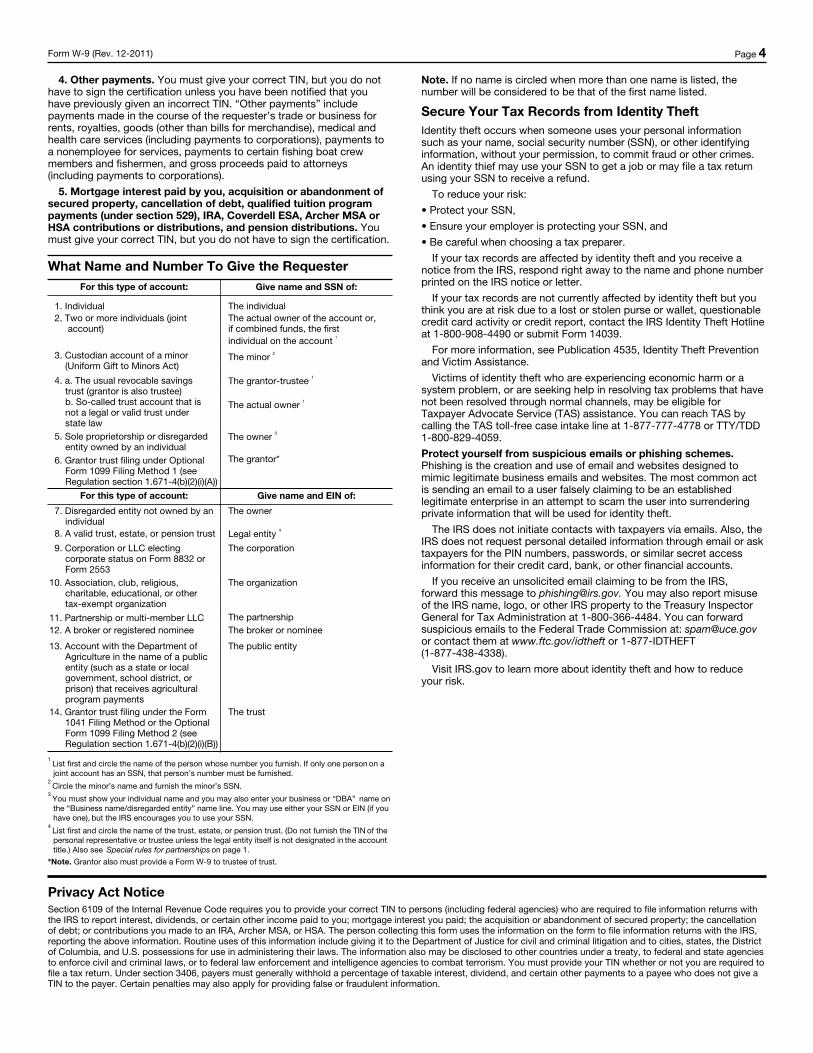
Form W-9 (Rev. 12-2011) Page 4
4. Other payments. You must give your correct TIN, but you do not have to sign the certification unless you have been notified that you have previously given an incorrect TIN. “Other payments” include payments made in the course of the requester’s trade or business for rents, royalties, goods (other than bills for merchandise), medical and health care services (including payments to corporations), payments to a nonemployee for services, payments to certain fishing boat crew members and fishermen, and gross proceeds paid to attorneys (including payments to corporations).
5. Mortgage interest paid by you, acquisition or abandonment of secured property, cancellation of debt, qualified tuition program payments (under section 529), IRA, Coverdell ESA, Archer MSA or HSA contributions or distributions, and pension distributions. You must give your correct TIN, but you do not have to sign the certification.
What Name and Number To Give the RequesterFor this type of account: Give name and SSN of:
1. Individual The individual2. Two or more individuals (joint
account)The actual owner of the account or, if combined funds, the first individual on the account 1
3. Custodian account of a minor (Uniform Gift to Minors Act)
The minor 2
4. a. The usual revocable savings trust (grantor is also trustee) b. So-called trust account that is not a legal or valid trust under state law
The grantor-trustee 1
The actual owner 1
5. Sole proprietorship or disregarded entity owned by an individual
The owner 3
6. Grantor trust filing under Optional Form 1099 Filing Method 1 (see Regulation section 1.671-4(b)(2)(i)(A))
The grantor*
For this type of account: Give name and EIN of:
7. Disregarded entity not owned by an individual
The owner
8. A valid trust, estate, or pension trust Legal entity 4
9. Corporation or LLC electing corporate status on Form 8832 or Form 2553
The corporation
10. Association, club, religious, charitable, educational, or other tax-exempt organization
The organization
11. Partnership or multi-member LLC The partnership12. A broker or registered nominee The broker or nominee
13. Account with the Department of Agriculture in the name of a public entity (such as a state or local government, school district, or prison) that receives agricultural program payments
The public entity
14. Grantor trust filing under the Form 1041 Filing Method or the Optional Form 1099 Filing Method 2 (see Regulation section 1.671-4(b)(2)(i)(B))
The trust
1 List first and circle the name of the person whose number you furnish. If only one person on a joint account has an SSN, that person’s number must be furnished.
2 Circle the minor’s name and furnish the minor’s SSN.
3 You must show your individual name and you may also enter your business or “DBA” name on the “Business name/disregarded entity” name line. You may use either your SSN or EIN (if you have one), but the IRS encourages you to use your SSN.
4 List first and circle the name of the trust, estate, or pension trust. (Do not furnish the TIN of the personal representative or trustee unless the legal entity itself is not designated in the account title.) Also see Special rules for partnerships on page 1.
*Note. Grantor also must provide a Form W-9 to trustee of trust.
Note. If no name is circled when more than one name is listed, the number will be considered to be that of the first name listed.
Secure Your Tax Records from Identity TheftIdentity theft occurs when someone uses your personal information such as your name, social security number (SSN), or other identifying information, without your permission, to commit fraud or other crimes. An identity thief may use your SSN to get a job or may file a tax return using your SSN to receive a refund.
To reduce your risk:
• Protect your SSN,
• Ensure your employer is protecting your SSN, and
• Be careful when choosing a tax preparer.
If your tax records are affected by identity theft and you receive a notice from the IRS, respond right away to the name and phone number printed on the IRS notice or letter.
If your tax records are not currently affected by identity theft but you think you are at risk due to a lost or stolen purse or wallet, questionable credit card activity or credit report, contact the IRS Identity Theft Hotline at 1-800-908-4490 or submit Form 14039.
For more information, see Publication 4535, Identity Theft Prevention and Victim Assistance.
Victims of identity theft who are experiencing economic harm or a system problem, or are seeking help in resolving tax problems that have not been resolved through normal channels, may be eligible for Taxpayer Advocate Service (TAS) assistance. You can reach TAS by calling the TAS toll-free case intake line at 1-877-777-4778 or TTY/TDD 1-800-829-4059.
Protect yourself from suspicious emails or phishing schemes. Phishing is the creation and use of email and websites designed to mimic legitimate business emails and websites. The most common act is sending an email to a user falsely claiming to be an established legitimate enterprise in an attempt to scam the user into surrendering private information that will be used for identity theft.
The IRS does not initiate contacts with taxpayers via emails. Also, the IRS does not request personal detailed information through email or ask taxpayers for the PIN numbers, passwords, or similar secret access information for their credit card, bank, or other financial accounts.
If you receive an unsolicited email claiming to be from the IRS, forward this message to [email protected]. You may also report misuse of the IRS name, logo, or other IRS property to the Treasury Inspector General for Tax Administration at 1-800-366-4484. You can forward suspicious emails to the Federal Trade Commission at: [email protected] or contact them at www.ftc.gov/idtheft or 1-877-IDTHEFT (1-877-438-4338).
Visit IRS.gov to learn more about identity theft and how to reduce your risk.
Privacy Act NoticeSection 6109 of the Internal Revenue Code requires you to provide your correct TIN to persons (including federal agencies) who are required to file information returns with the IRS to report interest, dividends, or certain other income paid to you; mortgage interest you paid; the acquisition or abandonment of secured property; the cancellation of debt; or contributions you made to an IRA, Archer MSA, or HSA. The person collecting this form uses the information on the form to file information returns with the IRS, reporting the above information. Routine uses of this information include giving it to the Department of Justice for civil and criminal litigation and to cities, states, the District of Columbia, and U.S. possessions for use in administering their laws. The information also may be disclosed to other countries under a treaty, to federal and state agencies to enforce civil and criminal laws, or to federal law enforcement and intelligence agencies to combat terrorism. You must provide your TIN whether or not you are required to file a tax return. Under section 3406, payers must generally withhold a percentage of taxable interest, dividend, and certain other payments to a payee who does not give a TIN to the payer. Certain penalties may also apply for providing false or fraudulent information.

CITY OF CHELSEA
REQUIRED BID SUBMITTAL FORM
REFERENCE FORM
Bidder: _____________________________________________ Title of Bid: Treasurer’s Offices Renovations Bidder must provide references for: All contracts performed within the past five years of similar size and scope to this contract • Reference: _____________________________________ • Address: ______________________________________ • Contact: _______________________________________ • Phone: ________________________________________ • Fax: __________________________________________ • Description and date(s) of services provided:
• Reference: _____________________________________ • Address: ______________________________________ • Contact: _______________________________________ • Phone: ________________________________________ • Fax: __________________________________________ • Description and date(s) of services provided:
• Reference: _____________________________________ • Address: ______________________________________ • Contact: _______________________________________ • Phone: ________________________________________ • Fax: __________________________________________ • Description and date(s) of services provided:

CITY OF CHELSEA
REQUIRED BID SUBMITTAL FORM
OSHA COMPLIANCE CERTIFICATION Any person submitting a bid for, signing a contract to work on, the construction, reconstruction, alteration, remodeling or repair of any building or public works project undertaken by a public awarding authority in Massachusetts and estimated to cost more than $10,000 must certify on the bid or contract, under penalties of perjury, as follows:
1. That he is able to furnish labor than can work in harmony with all other elements of labor employed or to be employed at the work
2. All employees to be employed at the worksite will have successfully completed a
course in construction safety and health approved by the United States Occupational Safety and Health Administration that is at least 10 hours in duration at the time the employee begins work and who shall furnish documentation of successful completion of said course with the first certified payroll report for each employee; and
3. That all employees to be employed in the work subject to this bid have
successfully completed a course in construction safety and health approved by the United States Occupational Safety and Health Administration that is at least 10 hours in duration. (MGL. c. 30, Section 39S (a))
________________________________________________________________________ Pursuant to M.G.L. c. 30, Section 39M and M.G.L. c. 149, I certify under penalties of perjury that, to the best of my Knowledge and belief, I am in compliance with the OSHA requirements as stated above. Dated_________________________ ____________________________________ Name of Company or Corporation ____________________________________ Authorized Official’s Signature BIDDERS/RESPONDENTS MUST SUBMIT THIS FORM FULY COMPLETED

CONTRACT NO.__________
CITY OF CHELSEA
CONTRACT FOR SERVICES over $10,000
_____________________________________________________________
This agreement (the "Agreement") is made and entered into by and between the City of Chelsea (hereinafter the CITY), a municipal corporation organized and existing under the laws of the Commonwealth of Massachusetts, and
[NAME] [ADDRESS]
(hereinafter the CONTRACTOR) For mutual consideration the Parties hereby agree as follows: ARTICLE 1. DEFINITION. This CONTRACT as used herein shall consist of this Agreement, and the "contract documents" which include but are not limited to the following identified items and all documents, and forms submitted therewith, or attached hereby. Attachment A: Scope of Services, and/or other bid package materials Attachment B: Additional Contract Terms and Conditions Attachment C: Certificate of Non-Collusion, Tax Compliance
Certification, Statement of Corporate Authority Attachment D: Summaries of Laws Regarding State Ethics - Acknowledgment of
Receipt Addenda through # ARTICLE II. AMOUNT AND TERM. Pursuant to the terms and conditions stated in the Contract, this CITY agrees to pay an amount not to exceed $___________________, and the Contractor agrees to perform the services detailed in the Contract. The Contract shall commence on or about ____________________________ (the "Commencing Date") unless earlier terminated pursuant to Article IV, Termination and shall terminate no later than _____________________, unless a written amendment to renew or extend this contract is executed in accordance with the provisions of this CONTRACT. ARTICLE III. PERFORMANCE. The Contractor agrees to provide all goods and/or services set forth in the Invitation for Bid/Request for Proposal Documents, Scope of Service, the Contractor's proposal for "_______________________________", and/or as outlined in ATTACHMENT A - SCOPE OF SERVICES. ARTICLE IV. TERMINATION. i) Without Cause. The CITY may terminate this CONTRACT on sixty (60) calendar day’s notice, or may suspend this CONTRACT for up to sixty (60) calendar days upon receipt of notice, when in the best interests of the CITY, by providing notice to the CONTRACTOR, which shall be in writing and shall be deemed delivered and received when given in person to the CONTRACTOR, or when received by fax, express mail, certified mail return receipt requested,

regular mail postage prepaid or delivered by any other appropriate method evidencing actual receipt by the CONTRACTOR. ii) For Cause. If the CONTRACTOR is determined by the CITY to be in default of any term or condition of CONTRACT, the CITY may terminate this contract on thirty (30) day’s notice by providing notice to the CONTRACTOR, which shall be in writing and shall be deemed delivered and received when given in person to the CONTRACTOR, or when received by fax, express mail, certified mail return receipt requested, regular mail postage prepaid or delivered by any other appropriate method evidencing actual receipt by the CONTRACTOR. If the CITY is determined by the CONTRACTOR to be in default of any term or condition of this CONTRACT the CONTRACTOR may terminate this contract on thirty (30) day’s notice by providing notice to the CITY, which shall be in writing and shall be deemed delivered and received when given in person to the CITY, or when received by fax, express mail, certified mail return receipt requested, regular mail postage prepaid or delivered by any other appropriate method evidencing actual receipt by the CITY. iii) Default. Events of default under this CONTRACT shall include, but are not limited to the following: a) any material misrepresentation made by the CONTRACTOR to the CITY, b) any failure to perform any of its obligations under this CONTRACT including, but not limited to the following: (i) failure to commence performance of this CONTRACT at the time specified in this CONTRACT due to a reason or circumstance within the CONTRACTOR'S reasonable control, (ii) failure to perform this CONTRACT with sufficient personnel and equipment or with sufficient material to ensure the completion of this CONTRACT within the specified time due to a reason or circumstance within the CONTRACTOR'S reasonable control, (iii) failure to perform this CONTRACT in a manner reasonably satisfactory to the CITY, (iv) failure to promptly re-perform with reasonable time the services that were rejected by the CITY as unsatisfactory, or erroneous, (v) discontinuance of the services for reasons not beyond the CONTRACTOR'S reasonable control, (vi) failure to comply with a material term of this CONTRACT, including, but not limited to, the provision of insurance or failure to comply with nondiscrimination provisions, and (vii) any other acts specifically and expressly stated in this CONTRACT as constituting a basis for termination of this CONTRACT, and (viii) failure to comply with any and all requirements of state law, and/or regulations, and City ordinances, and/or regulations. ARTICLE V. REMEDIES OF THE CITY. The City hereby retains all remedies in law and equity, including but not limited to, the right to deduct the cost of any substitute contract or performance for expenses, losses, and all damages and the right to withhold from payment, any amounts for expenses, losses, and damages from sums due, or which become due. ARTICLE VI. REMEDIES OF THE CONTRACTOR. If the Contractor, due to any act or omission for which the City is legally responsible, sustains damages, other than loss, non-conformance, or non-performance, the Contractor may request, within 30 days of the alleged act or omission from the City, a sum equal to the amount of such damages sustained by the Contractor, which amount may be determined by the City in writing, at the City 's sole discretion, provided that the Contractor has provided to all signatories of this Agreement, a detailed, written statement of such damages and cause thereof within said 30 day period. ARTICLE VII. ASSIGNABILITY. The CONTRACTOR shall not assign, subcontract or in any way transfer any interest, rights or obligations in this CONTRACT without the prior written consent of the City Manager. In the

event of such assignment the CITY reserves the right to deal with any assignee subcontractor or transferee directly and the CONTRACTOR agrees to remain bound by all terms and conditions of this CONTRACT in accordance with its original tenor and in no way shall the CONTRACTOR be relieved of its responsibilities and obligations under this CONTRACT. The provisions of this CONTRACT shall be binding upon, and shall inure to the benefit of, the successors and assigns of the CONTRACTOR and any public body or bodies succeeding the interests of the CITY. ARTICLE VIII. INDEMNIFICATION. The CONTRACTOR shall assume the defense, indemnify and hold harmless the CITY, the CITY'S agents and employees, from and against all losses and all claims, demands, payments, suits, actions, recoveries and judgments of every nature and description brought or recovered against them by reason of acts, in actions, omissions, negligence, reckless or intentional misconduct of the said CONTRACTOR, its agent(s), officers, employees, or subcontractors; in the execution of the work or in guarding the same. Unless otherwise provided by law, the CITY may elect, at its sole discretion, to indemnify the CONTRACTOR for claims arising in tort if it is determined that the CONTRACTOR performed its obligations under this CONTRACT pursuant to the direct supervision and control of the CITY or its designated agent(s). ARTICLE IX. WORKER'S COMPENSATION AND OTHER INSURANCE. The CONTRACTOR shall provide insurance for the payment of compensation and the furnishing of other benefits under Chapter 152 of the General Laws of Massachusetts (The Worker's Compensation Act) to all employees of the CONTRACTOR who are subject to the provisions of Chapter 152 of the General Laws of Massachusetts. Failure to provide and continue in force such insurance during the period of this contract shall be deemed a material breach of this contract, shall operate as an immediate termination thereof, and CONTRACTOR shall indemnify the CITY for all losses, claims, and actions resulting from the failure to provide the insurance required by this Article. The Contractor shall furnish to the CITY evidence of such insurance prior to the execution of this contract and before the same shall be binding on the parties thereto, except if specifically waived in Attachment B. Prior to commencement of any work and until completion of its work under this CONTRACT, the CONTRACTOR shall maintain the following insurance coverage, at its cost, from insurance acceptable to the CITY, giving evidence of such coverage to the CITY prior to execution of this CONTRACT, a copy of such insurance coverage to be attached herewith: 1. Comprehensive Automobile Liability Insurance covering the use of all owned, non-owned and hired automobiles in connection with its operations with a combined single limit of $1,000,000. The comprehensive Automobile Liability insurance may be provided through primary and excess or umbrella insurance policies. 2. CONTRACTOR'S Equipment Coverage (or a certification of self-insurance satisfactory to the CITY) must be provided on an “All Risks" basis, covering physical damage to all tools and equipment, including automotive equipment owned, rented, or used by the CONTRACTOR. 3. Commercial General Liability Insurance coverage which may be provided through primary and excess or umbrella liability policies for limits of $1,000,000 general aggregate, and $500,000 per occurrence.

All required insurance must be endorsed to name the CITY as Additional Insured. All required insurance shall be endorsed to waive the insurer's rights of subrogation against the City. All policies and certificates of insurance must contain language that the insurance shall not be canceled, materially changed or non-renewed without at least thirty (30) days advance written notice to the CITY. The CONTRACTOR under this CONTRACT shall not allow its subcontractors to begin work until similar insurance has been so obtained and certificates of insurance approved by the CONTRACTOR. ARTICLE X. CORPORATE CONTRACTOR. If CONTRACTOR is a corporation, CONTRACTOR shall endorse the Certificate of Corporate Authority for the CONTRACTORS' signatory (Exhibit C), or shall otherwise provide a form similar in nature and substance acceptable to the CITY at the City's sole discretion. If CONTRACTOR is a non-profit corporation, CONTRACTOR shall provide satisfactory proof of present status as a non-profit corporation. Such proof shall be in the form of a certification from the Massachusetts Secretary of State's office and/or from the Internal Revenue Service and shall provide the Federal Tax Identification Number of the non-profit corporation. This CONTRACT shall not be enforceable against the CITY unless and until the CONTRACTOR complies with this Article. Failure to inform the CITY in writing of revocation, or other loss of non-profit status shall be deemed a material breach of this contract and operate as an immediate termination thereof. ARTICLE XI. SUBJECT TO APPROPRIATION. The obligations of the CITY under this CONTRACT shall be subject to appropriation. In the absence of appropriation this CONTRACT shall be immediately terminated without liability for damages, penalties, or other charges. In the event any portion of this Agreement is to be funded with alternate funding including but not limited to state, local, federal or private grant funding. In the requisite circumstances, the obligations of the CITY under this CONTRACT shall be subject to the formal award of such state, local, federal or private grant. ARTICLE XII. DOCUMENTS, MATERIALS, ETC. Any materials, reports, information, data, etc. given to or prepared or assembled by the CONTRACTOR under this CONTRACT are to be kept confidential and shall not be made available to any individual or organization by the CONTRACTOR (except agents, servants, or employees of the CONTRACTOR) without the prior written approval of the CITY. The CONTRATOR understands that he/she/it may acquire or have access to "personal data" otherwise kept by the CITY. The CONTRACTOR shall comply with the provisions Chapter 66A of the General Laws of Massachusetts as it relates to public documents, and all other state and federal laws and regulations relating to confidentiality, security, privacy and use of confidential data. Any materials produced in whole or in part under this CONTRACT shall not be subject to copyright, except by the CITY, in the United States or any other country. The CITY shall have unrestricted authority to, without payment of any royalty, commission, or additional fee of any type or nature, publicly disclose, reproduce, distribute and otherwise use, and authorize other to use, in whole or in part, any reports, data or other materials prepared under this CONTRACT. All data, reports, programs, software, equipment, furnishings, and any other documentation or product paid for by the CITY shall vest in the CITY at the termination of this CONTRACT. The CONTRACTOR shall at all times, during or after termination of this CONTRACT, obtain the
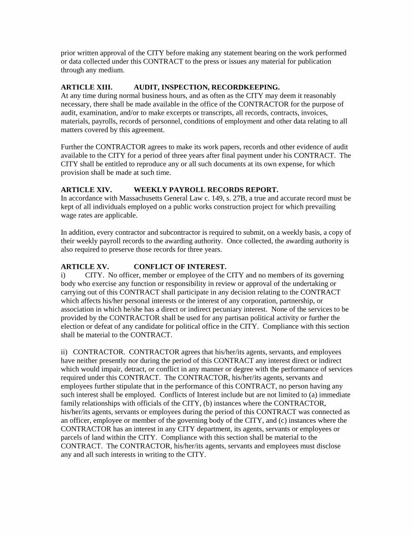
prior written approval of the CITY before making any statement bearing on the work performed or data collected under this CONTRACT to the press or issues any material for publication through any medium. ARTICLE XIII. AUDIT, INSPECTION, RECORDKEEPING. At any time during normal business hours, and as often as the CITY may deem it reasonably necessary, there shall be made available in the office of the CONTRACTOR for the purpose of audit, examination, and/or to make excerpts or transcripts, all records, contracts, invoices, materials, payrolls, records of personnel, conditions of employment and other data relating to all matters covered by this agreement. Further the CONTRACTOR agrees to make its work papers, records and other evidence of audit available to the CITY for a period of three years after final payment under his CONTRACT. The CITY shall be entitled to reproduce any or all such documents at its own expense, for which provision shall be made at such time. ARTICLE XIV. WEEKLY PAYROLL RECORDS REPORT. In accordance with Massachusetts General Law c. 149, s. 27B, a true and accurate record must be kept of all individuals employed on a public works construction project for which prevailing wage rates are applicable. In addition, every contractor and subcontractor is required to submit, on a weekly basis, a copy of their weekly payroll records to the awarding authority. Once collected, the awarding authority is also required to preserve those records for three years. ARTICLE XV. CONFLICT OF INTEREST. i) CITY. No officer, member or employee of the CITY and no members of its governing body who exercise any function or responsibility in review or approval of the undertaking or carrying out of this CONTRACT shall participate in any decision relating to the CONTRACT which affects his/her personal interests or the interest of any corporation, partnership, or association in which he/she has a direct or indirect pecuniary interest. None of the services to be provided by the CONTRACTOR shall be used for any partisan political activity or further the election or defeat of any candidate for political office in the CITY. Compliance with this section shall be material to the CONTRACT. ii) CONTRACTOR. CONTRACTOR agrees that his/her/its agents, servants, and employees have neither presently nor during the period of this CONTRACT any interest direct or indirect which would impair, detract, or conflict in any manner or degree with the performance of services required under this CONTRACT. The CONTRACTOR, his/her/its agents, servants and employees further stipulate that in the performance of this CONTRACT, no person having any such interest shall be employed. Conflicts of Interest include but are not limited to (a) immediate family relationships with officials of the CITY, (b) instances where the CONTRACTOR, his/her/its agents, servants or employees during the period of this CONTRACT was connected as an officer, employee or member of the governing body of the CITY, and (c) instances where the CONTRACTOR has an interest in any CITY department, its agents, servants or employees or parcels of land within the CITY. Compliance with this section shall be material to the CONTRACT. The CONTRACTOR, his/her/its agents, servants and employees must disclose any and all such interests in writing to the CITY.

ARTICLE XVI. PAYMENT. The City agrees to make all reasonable efforts to pay to the CONTRACTOR the sum set forth any invoice which has been approved by the City Manager or his authorized designee within thirty (30) days of receipt of such invoice at the Office of the City Auditor. Each invoice shall detail the work completed. Subject to pending statutory appeal rights, the City hereby reserves the right and the CONTRACTOR hereby agrees that the City may deduct from the sum(s) otherwise payable under this CONTRACT any outstanding taxes, fines, fees and/or other municipal charges prior to disbursement to the CONTRACTOR. ARTICLE XVII. CONFLICT. In the event there is a conflict between these Articles and any Attachment, these Articles shall supersede any Attachment. ARTICLE XVIII. WAIVER AND AMENDMENT. The provisions contained in this CONTRACT may be modified only by the express written consent of the Parties. Any amendments, must be made only by written amendment executed by all signatories to the original agreement, prior to the effective date of the amendment. The failure of any party to insist on the strict performance of any term, covenant or condition to this CONTRACT, at anytime, or in any one or more instances, or its failure to take advantage of any of its rights, or any course of conduct or dealing, shall not be construed as a waiver or a relinquishment of any such rights or conditions at any future time and shall, in no way act, as a wavier by any party of a breach of another party or have any affect on the continuance of or the full force and affect of any or all of the provisions of this Contract. The waiver of any provisions must be in writing and executed by all signatories to this Agreement prior to the force and effect of any such waiver. Forbearance or indulgence in any form or manner by a party shall not be construed as a waiver, nor in any manner limit the legal or equitable remedies available to that party. No waiver by either party of any default or breach shall constitute a waiver of any subsequent default or breach of a similar or different matter. ARTICLE XIX. CERTIFICATION. IN WITNESS WHEREOF, THE CONTRACTOR CERTIFIES, UNDER THE PAINS AND PENALTIES OF PERJURY, THAT THE CONTRACTOR IS IN COMPLIANCE WITH EACH OF THE FOLLOWING: a. TAXES. PURSUANT to M.G.L. c. 62C, s. 49A, the CONTRACTOR has filed all state tax returns and complied with all laws of the Commonwealth relating to taxes. b. DEBARMENT. The CONTRACTOR is not currently debarred or suspended by the Commonwealth of Massachusetts, or any of its entities or subdivisions. c. AMERICANS WITH DISABILITIES ACT. The CONTRACTOR is aware of the Americans with Disabilities Act which prohibits discrimination based upon disability and shall meet any relevant standards, and/or conditions set out in the bid/proposal documents, bid/proposal specifications, and/or ATTACHMENT A - SCOPE OF SERVICES.

ARTICLE XX. FORUM AND CHOICE OF LAW This CONTRACT and any performance herein shall be governed by and be construed in accordance with the laws of Commonwealth of Massachusetts, exclusive of its conflicts of law provisions. Any and all proceedings or actions relating to subject matter herein shall be brought and maintained in the courts of the Commonwealth of Massachusetts or the federal district court sitting in the Commonwealth of Massachusetts, which shall have exclusive jurisdiction thereof. Each of the Parties hereto irrevocably consents to and waives any objection to the exercise of personal jurisdiction by the state and federal courts of the Commonwealth of Massachusetts. This paragraph shall not be construed to limit any other legal rights of the parties. ARTICLE XXI. TAXES CONTRACTOR shall be solely responsible for the payment of any taxes, levies, betterments or assessments, fees or charges, whether in existence on the date hereof or becoming applicable pursuant to this Contract, which may be assessed against the CONTRACTOR or the CITY which are directly attributable to CONTRACTOR'S activities under this CONTRACT (the “Taxes”). CONTRACTOR shall pay all Taxes directly to the taxing authority before delinquency and before any fine, interest or penalty shall become due or be imposed by operation of law for their nonpayment. ARTICLE XXII. NOTICES All notices, demands, requests, consents, approvals and other instruments required or permitted to be given pursuant to the terms hereof (hereinafter “Notice”), shall be in writing and shall be deemed to have been properly given when delivered in hand or deposited in registered or certified United States mail, postage prepaid, return receipt requested, addressed, as described herein or when delivered by messenger or overnight mail service to the correct addressee. Unless otherwise specified, Notice shall be deemed received when actually received or when the proffered Notice has been refused by the Addressee. The signature of an employee, servant or agent of the Addressee shall be determinative on the issue of actual receipt. All notices shall be sent to the persons and addresses listed below. CONTRACTOR and the CITY shall, at any time and from time to time, have the right to specify as their proper addresses for purposes of this CONTRACT any other address or addresses giving fifteen (15) days' written notice thereof to the other party. All Notices shall be forwarded to: FOR THE CITY Thomas G. Ambrosino, City Manager 500 Broadway City Hall Chelsea, MA 02150 With a Copy to: Cheryl Watson Fisher City Solicitor Law Department, Room 307 500 Broadway Chelsea, MA 02150 FOR THE CONTRACTOR: [NAME] [ADDRESS]

ARTICLE XXIII. CONSIDERATION The Parties mutually agree to enter into this CONTRACT for good and valuable consideration. ARTICLE XXIV. REPRESENTATIONS AND WARRANTIES OF THE CONTRACTOR The CONTRACTOR represents and warrants (i) the CONTRACTOR has all requisite corporate power and authority to enter into this CONTRACT and to perform the obligations of the CONTRACTOR; (ii) that this CONTRACT has been duly and validly authorized, executed and delivered by the CONTRACTOR; (iii) the execution and delivery of this CONTRACT does not violate or conflict with any other agreement, license or obligation; (iv) the CONTRACTOR is duly organized, legal and validly existing and in good standing in the Commonwealth of Massachusetts; (v) that the CONTRACTOR is duly qualified and authorized to do business in the Commonwealth of Massachusetts; (vi) the CONTRACTOR is in compliance and is current with any payments under all federal, state and local tax laws; (vii) the CONTRACTOR will obtain any and all permits which may be necessary to perform the obligations of this CONTRACT; (viii) the CONTRACTOR will timely perform its obligations required by this CONTRACT. ARTICLE XXV. THIRD PARTY BENEFICIARIES This CONTRACT shall not be construed to create any third party beneficiary rights in favor of any other parties or any right or privilege for the benefit of any other parties. ARTICLE XXVI. ENTIRE CONTRACT This CONTRACT constitutes the entire Agreement of the parties hereto with respect to the subject matter hereof, and no representations, inducements, promises, or agreements, oral or otherwise, between the parties hereto with respect to the subject matter hereof not embodied herein shall be of any force or effect. ARTICLE XXVII. LIABILITY OF MUNICIPALITY The CITY shall not be liable to CONTRACTOR for any loss of business or any indirect, incidental, special, consequential or exemplary damages or lost profits unless expressly specified herein. ARTICLE XXVIII. HEADINGS Heading used in this Agreement are for convenience of reference only and shall not be construed as altering the meaning of this CONTRACT or any of its provisions. ARTICLE XXIX. DAYS Any reference to "days" in this CONTRACT, shall be deemed to mean business days (Monday through Friday, excluding generally recognized holidays) except where specific reference is made to calendar days. ARTICLE XXX. SURVIVAL The parties agree that the provisions of ARTICLE II – AMOUNT AND TERM; ARTICLE III – PERFORMANCE; ARTICLE V- REMEDIES OF THE CITY; ARTICLE VI- REMEDIES OF THE CONTRACTOR. ARTICLE VII – ASSIGNABILITY; ARTICLE VIII – INDEMNIFICATION; ARTICLE IX- WORKER’S COMPENSATION AND OTHER INSURANCE; ARTICLE XI-SUBJECT TO APPROPRIATION; ARTICLE XII – DOCUMENTS, MATERIALS, ETC; ARTICLE XIII – AUDIT, INSPECTION, RECORDKEEPING; ARTICLE XIV- WEEKLY PAYROLL RECORDS REPORT; ARTICLE XVI – PAYMENT; ARTICLE XVIII – WAIVER AND AMENDMENT; ARTICLE XIX – CERTIFICATION; ARTICLE XX- FORUM AND CHOICE OF LAW; ARTICLE XXI –

TAXES; ARTICLE XXIV- REPRESENTATIONS AND WARRANTIES OF THE CONTRACTOR; ARTICLE XXVII- LIABILITY OF THE MUNICIPALITY; ARTICLE XXX – SURVIVAL; and ARTICLE XXXI - SEVERABILITY shall survive the expiration or any earlier termination of this CONTRACT. ARTICLE XXXI. SEVERABILITY If any provision of this CONTRACT is held to be illegal, invalid or unenforceable, the remaining terms shall not be affected and shall remain in full force and effect. The Agreement shall be interpreted as if the illegal, invalid or unenforceable provision had not been included in it and the invalid or unenforceable provision shall be stricken and shall be replaced by a mutually acceptable provision which being valid and enforceable comes closest to the intention of the parties with respect to the invalid or unenforceable provision. ARTICLE XXXII. ADVICE AND COUNSEL The CONTRACTOR hereby acknowledges and agrees that CONTRACTOR has read this Agreement in its entirety and that CONTRACTOR has had the opportunity to consult legal and financial advisors of their choosing regarding the execution, delivery and performance of their obligations, hereunder. ARTICLE XXXIII. COUNTERPARTS This CONTRACT may be executed in counterpart.
THE REMAINDER OF THIS PAGE LEFT INTENTIONALLY BLANK

IN WITNESS WHEREOF the parties have hereto and to three other identical instruments set forth their hands the day and year first above written. THE CONTRACTOR CITY MANAGER ___________________ __________________ Company Name Thomas G. Ambrosino, City Manager ______________________ Status (Corporation/Non-corporate) ______________________ Signature & Title _______________________ ___________________ Please Print Name & Title Dylan Cook Chief Procurement Officer _______________________ Date _______________________ APPROVED AS TO FORM: Taxpayer Identification Number ____________________ Cheryl Watson Fisher
City Solicitor
I CERTIFY THAT FUNDS HAVE BEEN ENCUMBERED IN THE AMOUNT OF $____________ FOR THIS CONTRACT
Approved as to Contract Manager: Appropriation Number: _________________________ ____________________________ _____________________ Mary M. Bourque, Superintendent Edward M. Dunn Chelsea Public Schools City Auditor City of Chelsea

ATTACHMENT A
SCOPE OF SERVICES
INSTRUCTIONS FOR DEPARTMENT AND CONTRACTOR: Please attach for reference purposes a copy of all bid/proposal documents, including but not limited to (i)
invitations/instructions for bidders (ii) invitation/instructions for proposers, (iii) general and specific conditions, and please provide a detailed description of all types of goods and/or services that will be provided pursuant to this CONTRACT, not otherwise provided in any bid/proposal
instructions, specifications, conditions or other documents.

ATTACHMENT B
ADDITIONAL CONTRACT TERMS AND CONDITIONS
INSTRUCTIONS FOR DEPARTMENTS: Please specify any additions or modifications to the terms and conditions (not to conflict with the public procurement laws or City ordinances or
regulations:

ATTACHMENT C
CERTIFICATE OF NON-COLLUSION
-----------------
TAX COMPLIANCE CERTIFICATION
----------------
STATEMENT OF CORPORATE AUTHORITY
----------------
WAGE THEFT CERTIFICATION

CERTIFICATE OF NON-COLLUSION MANDATORY
The undersigned certifies under penalties of perjury that this bid or proposal has been made and submitted in good faith and without collusion or fraud with any other person. As used in this certification, the word "person" shall mean any natural person, business, partnership, corporation, union, committee, club, or other organization, entity, or group of individuals. Dated:__________________________ _____________________________________ Name of Company or Corporation _____________________________________ Authorized Official's Signature
BIDDERS/RESPONDENTS MUST SUBMIT THIS FORM FULLY COMPLETED.
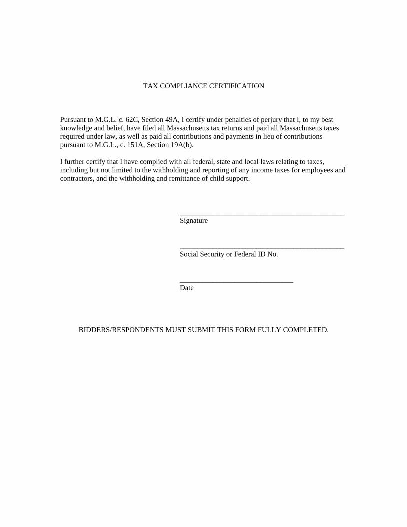
TAX COMPLIANCE CERTIFICATION
Pursuant to M.G.L. c. 62C, Section 49A, I certify under penalties of perjury that I, to my best knowledge and belief, have filed all Massachusetts tax returns and paid all Massachusetts taxes required under law, as well as paid all contributions and payments in lieu of contributions pursuant to M.G.L., c. 151A, Section 19A(b). I further certify that I have complied with all federal, state and local laws relating to taxes, including but not limited to the withholding and reporting of any income taxes for employees and contractors, and the withholding and remittance of child support. _____________________________________________ Signature _____________________________________________ Social Security or Federal ID No. _______________________________
Date
BIDDERS/RESPONDENTS MUST SUBMIT THIS FORM FULLY COMPLETED.

STATEMENT OF CORPORATE AUTHORITY At a duly authorized meeting of the Board of Directors of ______________________ held on _______________________at which time all voted that____________________ of this Company, be and hereby is authorized to execute contracts and bonds in the name and on behalf of said Company, and affix its Corporate seal thereto, and such execution of any contract of obligation in this Company's name on its behalf by such person___________________________ under seal of the Company, shall be valid and binding upon this Company. A TRUE COPY, ATTEST: ___________________________ PLACE OF BUSINESS: __________________________________ __________________________________ DATE OF THIS CONTRACT: __________________________________ I hereby certify that I am Clerk of ___________________________________ and that ______________________________________is duly elected __________________________ of said Company, and that the above vote has not been amended or rescinded and remains in full force and effect as of the date of this contract. ____________________________________ (Clerk's Signature)

(CORPORATE SEAL)
WAGE THEFT CERTIFICATION
Pursuant to M.G.L. c. 149, M.G.L. c. 151, I certify under penalties of perjury that, neither this Company nor any of its subcontractors have been subject to a federal or state criminal or civil judgment, administrative citation, final administrative determination, order or debarment resulting from a violation of M.G.L. c. 149, M.G.L. c. 151, the Fair Labor Standards Act or any other state or federal laws regulating the payment of wages within three (3) years prior to the date of the Contract. Or I certify that this Company has provided copies of any and all of the above to the City prior to the date of the Contract and any required wage bond or insurance; and certifies that while the Contract is in effect, it will report any instance of the above to the City within five (5) days of the Contractor’s receipt.
Signature
Social Security or Federal ID No.
Date
BIDDERS/RESPONDENTS MUST SUBMIT THIS FORM FULY COMPLETED

ATTACHMENT D
City of Chelsea Conflict of Interest Law
Compliance Statement and Requirements for Vendors
On July 1, 2009, the Legislature enacted Chapter 28 of the Acts of 2009 which made changes to Mass. General Laws c. 268A and c. 268B, the Massachusetts’ Conflict of Interest Law. On November 9, 2009, the Chelsea City Council designated the Chelsea City Solicitor as the Municipal Liaison to the State Ethics Commission and responsible for the facilitation of Chelsea’s obligation to comply with the changes in the law. The City has a requirement for compliance, which is to make sure that all municipal elected officials, board and commission members, and employees including vendors are provided copies of the Summaries of the Ethics Laws. Enclosed is a packet that should be copied and provide to UeachU one of your employees who are Uassigned U to work in UChelseaU; including yourself. At the end of the summary is an acknowledgement of receipt of the summary. UThe acknowledgments must be submitted along with any purchase order or contract with the City of ChelseaU. All documents pursuant to this new law will be kept on file in the City Clerk’s Office The Procurement Officer will contact you directly, if there is a determination that you or your staff should undergo the Conflict of Interest Online Training Program. If you have any questions, feel free to contact the Chelsea City Solicitor at 617-466-4150 as soon as possible.

Summary of the Conflict of Interest Law for Municipal Employees
________________________________________________________________________
This summary of the conflict of interest law, General Laws chapter 268A, is intended to help municipal employees understand how that law applies to them. This summary is not a substitute for legal advice, nor does it mention every aspect of the law that may apply in a particular situation. Municipal employees can obtain free confidential advice about the conflict of interest law from the Commission's Legal Division at our website, phone number, and address above. Municipal counsel may also provide advice.
The conflict of interest law seeks to prevent conflicts between private interests and public duties, foster integrity in public service, and promote the public's trust and confidence in that service by placing restrictions on what municipal employees may do on the job, after hours, and after leaving public service, as described below. The sections referenced below are sections of G.L. c. 268A.
When the Commission determines that the conflict of interest law has been violated, it can impose a civil penalty of up to $10,000 ($25,000 for bribery cases) for each violation. In addition, the Commission can order the violator to repay any economic advantage he gained by the violation, and to make restitution to injured third parties. Violations of the conflict of interest law can also be prosecuted criminally.
I. Are you a municipal employee for conflict of interest law purposes?
You do not have to be a full-time, paid municipal employee to be considered a municipal employee for conflict of interest purposes. Anyone performing services for a city or town or holding a municipal position, whether paid or unpaid, including full- and part-time municipal employees, elected officials, volunteers, and consultants, is a municipal employee under the conflict of interest law. An employee of a private firm can also be a municipal employee, if the private firm has a contract with the city or town and the employee is a "key employee" under the contract, meaning the town has specifically contracted for her services. The law also covers private parties who engage in impermissible dealings with municipal employees, such as offering bribes or illegal gifts.
II. On-the-job restrictions. (a) Bribes. Asking for and taking bribes is prohibited. (See Section 2)
A bribe is anything of value corruptly received by a municipal employee in exchange for the employee being influenced in his official actions. Giving, offering, receiving, or asking for a bribe is illegal.
Bribes are more serious than illegal gifts because they involve corrupt intent. In other words, the municipal employee intends to sell his office by agreeing to do or not do some official act, and the giver intends to influence him to do so. Bribes of any value are illegal.
(b) Gifts and gratuities. Asking for or accepting a gift because of your official position, or because of something you can do or have done in your official position, is prohibited. (See Sections 3, 23(b)(2), and 26)
Municipal employees may not accept gifts and gratuities valued at $50 or more given to influence their official actions or because of their official position. Accepting a gift intended to reward past official action or to bring about future official action is illegal, as is giving such gifts. Accepting a gift given to you because of the municipal position you hold is also illegal. Meals, entertainment event tickets, golf, gift baskets, and payment of travel expenses can all be illegal gifts if given in connection with official action or position, as can anything worth $50 or more. A number of smaller gifts together worth $50 or more may also violate these sections.
TExample of violationT : A town administrator accepts reduced rental payments from developers.
TExample of violationT : A developer offers a ski trip to a school district employee who oversees the developer's work for the school district.
TURegulatory exemptionsUT . There are situations in which a municipal employee's receipt of a gift does not present a genuine risk of a conflict of interest, and may in fact advance the public interest. The Commission has created exemptions permitting giving and receiving gifts in these situations. One commonly used exemption permits municipal employees to accept payment of travel-related expenses when doing so advances a public purpose. Another commonly used exemption permits municipal employees to accept payment of costs involved in attendance at educational and training programs. Other exemptions are listed on the Commission's website.
TExample where there is no violationT : A fire truck manufacturer offers to pay the travel expenses of a fire chief to a trade show where the chief can examine various kinds of fire-fighting equipment that the town may purchase. The chief fills out a disclosure form and obtains prior approval from his appointing authority.
TExample where there is no violationT : A town treasurer attends a two-day annual school featuring multiple substantive seminars on issues relevant to treasurers. The annual school is paid for in part by banks that do business with town treasurers. The treasurer is only required to make a disclosure if one of the sponsoring banks has official business before her in the six months before or after the annual school.
(c) Misuse of position. Using your official position to get something you are not entitled to, or to get someone else something they are not entitled to, is prohibited. Causing someone else to do these things is also prohibited. (See Sections 23(b)(2) and 26)
A municipal employee may not use her official position to get something worth $50 or more that would not be properly available to other similarly situated individuals. Similarly, a municipal employee may not use her official position to get something worth $50 or more for someone else
that would not be properly available to other similarly situated individuals. Causing someone else to do these things is also prohibited.
TExample of violationT : A full-time town employee writes a novel on work time, using her office computer, and directing her secretary to proofread the draft.
TExample of violationT : A city councilor directs subordinates to drive the councilor's wife to and from the grocery store.
TExample of violationT : A mayor avoids a speeding ticket by asking the police officer who stops him, "Do you know who I am?" and showing his municipal I.D.
(d) Self-dealing and nepotism. Participating as a municipal employee in a matter in which you, your immediate family, your business organization, or your future employer has a financial interest is prohibited. (See Section 19)
A municipal employee may not participate in any particular matter in which he or a member of his immediate family (parents, children, siblings, spouse, and spouse's parents, children, and siblings) has a financial interest. He also may not participate in any particular matter in which a prospective employer, or a business organization of which he is a director, officer, trustee, or employee has a financial interest. Participation includes discussing as well as voting on a matter, and delegating a matter to someone else.
A financial interest may create a conflict of interest whether it is large or small, and positive or negative. In other words, it does not matter if a lot of money is involved or only a little. It also does not matter if you are putting money into your pocket or taking it out. If you, your immediate family, your business, or your employer have or has a financial interest in a matter, you may not participate. The financial interest must be direct and immediate or reasonably foreseeable to create a conflict. Financial interests which are remote, speculative or not sufficiently identifiable do not create conflicts.
TExample of violationT : A school committee member's wife is a teacher in the town's public schools. The school committee member votes on the budget line item for teachers' salaries.
TExample of violationT : A member of a town affordable housing committee is also the director of a non-profit housing development corporation. The non-profit makes an application to the committee, and the member/director participates in the discussion.
TExampleT T: T A planning board member lives next door to property where a developer plans to construct a new building. Because the planning board member owns abutting property, he is presumed to have a financial interest in the matter. He cannot participate unless he provides the

State Ethics Commission with an opinion from a qualified independent appraiser that the new construction will not affect his financial interest.
In many cases, where not otherwise required to participate, a municipal employee may comply with the law by simply not participating in the particular matter in which she has a financial interest. She need not give a reason for not participating.
There are several exemptions to this section of the law. An appointed municipal employee may file a written disclosure about the financial interest with his appointing authority, and seek permission to participate notwithstanding the conflict. The appointing authority may grant written permission if she determines that the financial interest in question is not so substantial that it is likely to affect the integrity of his services to the municipality. Participating without disclosing the financial interest is a violation. Elected employees cannot use the disclosure procedure because they have no appointing authority.
TExample where there is no violationT : An appointed member of the town zoning advisory committee, which will review and recommend changes to the town's by-laws with regard to a commercial district, is a partner at a company that owns commercial property in the district. Prior to participating in any committee discussions, the member files a disclosure with the zoning board of appeals that appointed him to his position, and that board gives him a written determination authorizing his participation, despite his company's financial interest. There is no violation.
There is also an exemption for both appointed and elected employees where the employee's task is to address a matter of general policy and the employee's financial interest is shared with a substantial portion (generally 10% or more) of the town's population, such as, for instance, a financial interest in real estate tax rates or municipal utility rates.
(e) False claims. Presenting a false claim to your employer for a payment or benefit is prohibited, and causing someone else to do so is also prohibited. (See Sections 23(b)(4) and 26)
A municipal employee may not present a false or fraudulent claim to his employer for any payment or benefit worth $50 or more, or cause another person to do so.
TExample of violationT : A public works director directs his secretary to fill out time sheets to show him as present at work on days when he was skiing.

(f) Appearance of conflict. Acting in a manner that would make a reasonable person think you can be improperly influenced is prohibited. (See Section 23(b)(3))
A municipal employee may not act in a manner that would cause a reasonable person to think that she would show favor toward someone or that she can be improperly influenced. Section 23(b)(3) requires a municipal employee to consider whether her relationships and affiliations could prevent her from acting fairly and objectively when she performs her duties for a city or town. If she cannot be fair and objective because of a relationship or affiliation, she should not perform her duties. However, a municipal employee, whether elected or appointed, can avoid violating this provision by making a public disclosure of the facts. An appointed employee must make the disclosure in writing to his appointing official.
TExample where there is no violationT : A developer who is the cousin of the chair of the conservation commission has filed an application with the commission. A reasonable person could conclude that the chair might favor her cousin. The chair files a written disclosure with her appointing authority explaining her relationship with her cousin prior to the meeting at which the application will be considered. There is no violation of Sec. 23(b)(3).
(g) Confidential information. Improperly disclosing or personally using confidential information obtained through your job is prohibited. (See Section 23(c))
Municipal employees may not improperly disclose confidential information, or make personal use of non-public information they acquired in the course of their official duties to further their personal interests.
III. After-hours restrictions.
(a) Taking a second paid job that conflicts with the duties of your municipal job is prohibited. (See Section 23(b)(1))
A municipal employee may not accept other paid employment if the responsibilities of the second job are incompatible with his or her municipal job.
TExampleT : A police officer may not work as a paid private security guard in the town where he serves because the demands of his private employment would conflict with his duties as a police officer.
(b) Divided loyalties. Receiving pay from anyone other than the city or town to work on a matter involving the city or town is prohibited. Acting as agent or attorney for anyone other

than the city or town in a matter involving the city or town is also prohibited whether or not you are paid. (See Sec. 17)
Because cities and towns are entitled to the undivided loyalty of their employees, a municipal employee may not be paid by other people and organizations in relation to a matter if the city or town has an interest in the matter. In addition, a municipal employee may not act on behalf of other people and organizations or act as an attorney for other people and organizations in which the town has an interest. Acting as agent includes contacting the municipality in person, by phone, or in writing; acting as a liaison; providing documents to the city or town; and serving as spokesman.
A municipal employee may always represent his own personal interests, even before his own municipal agency or board, on the same terms and conditions that other similarly situated members of the public would be allowed to do so. A municipal employee may also apply for building and related permits on behalf of someone else and be paid for doing so, unless he works for the permitting agency, or an agency which regulates the permitting agency.
TExample of violationT : A full-time health agent submits a septic system plan that she has prepared for a private client to the town's board of health.
TExample of violationT : A planning board member represents a private client before the board of selectmen on a request that town meeting consider rezoning the client's property.
While many municipal employees earn their livelihood in municipal jobs, some municipal employees volunteer their time to provide services to the town or receive small stipends. Others, such as a private attorney who provides legal services to a town as needed, may serve in a position in which they may have other personal or private employment during normal working hours. In recognition of the need not to unduly restrict the ability of town volunteers and part-time employees to earn a living, the law is less restrictive for "special" municipal employees than for other municipal employees.
The status of "special" municipal employee has to be assigned to a municipal position by vote of the board of selectmen, city council, or similar body. A position is eligible to be designated as "special" if it is unpaid, or if it is part-time and the employee is allowed to have another job during normal working hours, or if the employee was not paid for working more than 800 hours during the preceding 365 days. It is the position that is designated as "special" and not the person or persons holding the position. Selectmen in towns of 10,000 or fewer are automatically "special"; selectman in larger towns cannot be "specials."
If a municipal position has been designated as "special," an employee holding that position may be paid by others, act on behalf of others, and act as attorney for others with respect to matters before municipal boards other than his own, provided that he has not officially participated in the

matter, and the matter is not now, and has not within the past year been, under his official responsibility.
TExampleT : A school committee member who has been designated as a special municipal employee appears before the board of health on behalf of a client of his private law practice, on a matter that he has not participated in or had responsibility for as a school committee member. There is no conflict. However, he may not appear before the school committee, or the school department, on behalf of a client because he has official responsibility for any matter that comes before the school committee. This is still the case even if he has recused himself from participating in the matter in his official capacity.
TExampleT : A member who sits as an alternate on the conservation commission is a special municipal employee. Under town by-laws, he only has official responsibility for matters assigned to him. He may represent a resident who wants to file an application with the conservation commission as long as the matter is not assigned to him and he will not participate in it.
(c) Inside track. Being paid by your city or town, directly or indirectly, under some second arrangement in addition to your job is prohibited, unless an exemption applies. (See Section 20)
A municipal employee generally may not have a financial interest in a municipal contract, including a second municipal job. A municipal employee is also generally prohibited from having an indirect financial interest in a contract that the city or town has with someone else. This provision is intended to prevent municipal employees from having an "inside track" to further financial opportunities.
TExample of violationT : Legal counsel to the town housing authority becomes the acting executive director of the authority, and is paid in both positions.
TExample of violationT : A selectman buys a surplus truck from the town DPW.
TExample of violationT : A full-time secretary for the board of health wants to have a second paid job working part-time for the town library. She will violate Section 20 unless she can meet the requirements of an exemption.
TExample of violationT : A city councilor wants to work for a non-profit that receives funding under a contract with her city. Unless she can satisfy the requirements of an exemption under Section 20, she cannot take the job.

There are numerous exemptions. A municipal employee may hold multiple unpaid or elected positions. Some exemptions apply only to special municipal employees. Specific exemptions may cover serving as an unpaid volunteer in a second town position, housing-related benefits, public safety positions, certain elected positions, small towns, and other specific situations. Please call the Ethics Commission's Legal Division for advice about a specific situation.
IV. After you leave municipal employment. (See Section 18)
(a) Forever ban. After you leave your municipal job, you may never work for anyone other than the municipality on a matter that you worked on as a municipal employee.
If you participated in a matter as a municipal employee, you cannot ever be paid to work on that same matter for anyone other than the municipality, nor may you act for someone else, whether paid or not. The purpose of this restriction is to bar former employees from selling to private interests their familiarity with the facts of particular matters that are of continuing concern to their former municipal employer. The restriction does not prohibit former municipal employees from using the expertise acquired in government service in their subsequent private activities.
TExample of violationT : A former school department employee works for a contractor under a contract that she helped to draft and oversee for the school department.
(b) One year cooling-off period. For one year after you leave your municipal job you may not participate in any matter over which you had official responsibility during your last two years of public service.
Former municipal employees are barred for one year after they leave municipal employment from personally appearing before any agency of the municipality in connection with matters that were under their authority in their prior municipal positions during the two years before they left.
TExampleT : An assistant town manager negotiates a three-year contract with a company. The town manager who supervised the assistant, and had official responsibility for the contract but did not participate in negotiating it, leaves her job to work for the company to which the contract was awarded. The former manager may not call or write the town in connection with the company's work on the contract for one year after leaving the town.
A former municipal employee who participated as such in general legislation on expanded gaming and related matters may not become an officer or employee of, or acquire a financial interest in, an applicant for a gaming license, or a gaming licensee, for one year after his public employment ceases.

(c) Partners. Your partners will be subject to restrictions while you serve as a municipal employee and after your municipal service ends.
Partners of municipal employees and former municipal employees are also subject to restrictions under the conflict of interest law. If a municipal employee participated in a matter, or if he has official responsibility for a matter, then his partner may not act on behalf of anyone other than the municipality or provide services as an attorney to anyone but the city or town in relation to the matter.
TExampleT T: T While serving on a city's historic district commission, an architect reviewed an application to get landmark status for a building. His partners at his architecture firm may not prepare and sign plans for the owner of the building or otherwise act on the owner's behalf in relation to the application for landmark status. In addition, because the architect has official responsibility as a commissioner for every matter that comes before the commission, his partners may not communicate with the commission or otherwise act on behalf of any client on any matter that comes before the commission during the time that the architect serves on the commission.
TExampleT : A former town counsel joins a law firm as a partner. Because she litigated a lawsuit for the town, her new partners cannot represent any private clients in the lawsuit for one year after her job with the town ended.
* * * * *
This summary is not intended to be legal advice and, because it is a summary, it does not mention every provision of the conflict law that may apply in a particular situation. Our website, TUhttp://www.mass.gov/ethicsUT contains further information about how the law applies in many situations. You can also contact the Commission's Legal Division via our website, by telephone, or by letter. Our contact information is at the top of this document.
Version 5: Revised December 23, 2011

City of Chelsea Conflict of Interest Law
Compliance Statement and Requirements for Vendors
T_____________________
ACKNOWLEDGMENT OF RECEIPT
I, __________________________________________________________, T(first and last name)T
an employee at ______________________________________________, T(name of vendor)T
hereby acknowledge that I received a copy of the summary of the conflict of interest law for municipal employees, revised December 23, 2011, on
_____________. _______________________________________________ T(date) (signature)
-------------------------------------------------------------------------------------
The City has a requirement for compliance, which is to make sure that all vendors are provided copies of the Summary of the Conflict of Interest Law for Municipal Employees (including Vendors).
VENDORS should copy the Summary of the Conflict of Interest Law and provide it to UeachU one of the employees who are Uassigned U to work in UChelsea U.
Each employee shall complete the “Acknowledgment of Receipt” and the Vendor shall return the
acknowledgments-only (Vendor keeping the Summary for their records ) to the Chelsea the Chelsea Procurement Office.
The “Acknowledgment of Receipt” must be submitted along with any purchase order or contract with the City of Chelsea

THE COMMONWEALTH OF MASSACHUSETTS
DEPARTMENT OF LABOR STANDARDS
As determined by the Director under the provisions of the
Massachusetts General Laws, Chapter 149, Sections 26 to 27H
EXECUTIVE OFFICE OF LABOR AND WORKFORCE DEVELOPMENT
Prevailing Wage RatesCHARLES D. BAKER ROSALIN ACOSTA
SecretaryGovernor
WILLIAM D MCKINNEY
Treasurer's Offices Renovations of Rooms 213 & 215
Director
Awarding Authority: City of Chelsea
City/Town:Contract Number: 2020-176 CHELSEA
Description of Work:
Job Location: City of Chelsea
Wage Request Number: 20191226-012Issue Date: 12/26/2019
Information about Prevailing Wage Schedules for Awarding Authorities and Contractors
• This wage schedule applies only to the specific project referenced at the top of this page and uniquely identified by the
“Wage Request Number” on all pages of this schedule.
• An Awarding Authority must request an updated wage schedule from the Department of Labor Standards (“DLS”) if it has
not opened bids or selected a contractor within 90 days of the date of issuance of the wage schedule. For CM AT RISK
projects (bid pursuant to G.L. c.149A), the earlier of: (a) the execution date of the GMP Amendment, or (b) the bid for the first
construction scope of work must be within 90-days of the wage schedule issuance date.
• The wage schedule shall be incorporated in any advertisement or call for bids for the project as required by M.G.L. c. 149,
§ 27. The wage schedule shall be made a part of the contract awarded for the project. The wage schedule must be posted in a
conspicuous place at the work site for the life of the project in accordance with M.G.L. c. 149 § 27. The wages listed on the
wage schedule must be paid to employees performing construction work on the project whether they are employed by the prime
contractor, a filed sub-bidder, or any sub-contractor.
• All apprentices working on the project are required to be registered with the Massachusetts Department of Labor
Standards, Division of Apprentice Standards (DLS/DAS). Apprentice must keep his/her apprentice identification card on
his/her person during all work hours on the project. An apprentice registered with DAS may be paid the lower apprentice
wage rate at the applicable step as provided on the prevailing wage schedule. Any apprentice not registered with DLS/DAS
regardless of whether or not they are registered with any other federal, state, local, or private agency must be paid the
journeyworker's rate for the trade.
• The wage rates will remain in effect for the duration of the project, except in the case of multi-year public construction
projects. For construction projects lasting longer than one year, awarding authorities must request an updated wage schedule.
Awarding authorities are required to request these updates no later than two weeks before the anniversary of the date the
contract was executed by the awarding authority and the general contractor. For multi-year CM AT RISK projects, awarding
authority must request an annual update no later than two weeks before the anniversary date, determined as the earlier of: (a)
the execution date of the GMP Amendment, or (b) the execution date of the first amendment to permit procurement of
construction services. Contractors are required to obtain the wage schedules from awarding authorities, and to pay no less than
these rates to covered workers. The annual update requirement is not applicable to 27F “rental of equipment” contracts.
• Every contractor or subcontractor which performs construction work on the project is required to submit weekly payroll
reports and a Statement of Compliance directly to the awarding authority by mail or email and keep them on file for three years.
Each weekly payroll report must contain: the employee’s name, address, occupational classification, hours worked, and wages
paid. Do not submit weekly payroll reports to DLS. A sample of a payroll reporting form may be obtained at
http://www.mass.gov/dols/pw.
• Contractors with questions about the wage rates or classifications included on the wage schedule have an affirmative
obligation to inquire with DLS at (617) 626-6953.
• Employees not receiving the prevailing wage rate set forth on the wage schedule may report the violation to the Fair Labor
Division of the office of the Attorney General at (617) 727-3465.
• Failure of a contractor or subcontractor to pay the prevailing wage rates listed on the wage schedule to all employees who
perform construction work on the project is a violation of the law and subjects the contractor or subcontractor to civil and
KARYN E. POLITO
Lt. Governor

Classification Total RateBase Wage Health PensionSupplemental
UnemploymentEffective Date
Construction
(2 AXLE) DRIVER - EQUIPMENTTEAMSTERS JOINT COUNCIL NO. 10 ZONE A
$61.48 12/01/2019 $12.41 $0.00 $35.35 $13.72
$62.38 06/01/2020 $12.41 $0.00 $36.25 $13.72
$62.88 08/01/2020 $12.91 $0.00 $36.25 $13.72
$63.98 12/01/2020 $12.91 $0.00 $36.25 $14.82
$64.78 06/01/2021 $12.91 $0.00 $37.05 $14.82
$65.28 08/01/2021 $13.41 $0.00 $37.05 $14.82
$66.47 12/01/2021 $13.41 $0.00 $37.05 $16.01
(3 AXLE) DRIVER - EQUIPMENTTEAMSTERS JOINT COUNCIL NO. 10 ZONE A
$61.55 12/01/2019 $12.41 $0.00 $35.42 $13.72
$62.45 06/01/2020 $12.41 $0.00 $36.32 $13.72
$62.95 08/01/2020 $12.91 $0.00 $36.32 $13.72
$64.05 12/01/2020 $12.91 $0.00 $36.32 $14.82
$64.85 06/01/2021 $12.91 $0.00 $37.12 $14.82
$65.35 08/01/2021 $13.41 $0.00 $37.12 $14.82
$66.54 12/01/2021 $13.41 $0.00 $37.12 $16.01
(4 & 5 AXLE) DRIVER - EQUIPMENTTEAMSTERS JOINT COUNCIL NO. 10 ZONE A
$61.67 12/01/2019 $12.41 $0.00 $35.54 $13.72
$62.57 06/01/2020 $12.41 $0.00 $36.44 $13.72
$63.07 08/01/2020 $12.91 $0.00 $36.44 $13.72
$64.17 12/01/2020 $12.91 $0.00 $36.44 $14.82
$64.97 06/01/2021 $12.91 $0.00 $37.24 $14.82
$65.47 08/01/2021 $13.41 $0.00 $37.24 $14.82
$66.66 12/01/2021 $13.41 $0.00 $37.24 $16.01
ADS/SUBMERSIBLE PILOTPILE DRIVER LOCAL 56 (ZONE 1)
$133.83 08/01/2019 $9.90 $0.00 $102.78 $21.15
For apprentice rates see "Apprentice- PILE DRIVER"
AIR TRACK OPERATORLABORERS - ZONE 1
$64.60 12/01/2019 $8.10 $0.00 $39.90 $16.60
$65.59 06/01/2020 $8.10 $0.00 $40.89 $16.60
$66.57 12/01/2020 $8.10 $0.00 $41.87 $16.60
$67.59 06/01/2021 $8.10 $0.00 $42.89 $16.60
$68.60 12/01/2021 $8.10 $0.00 $43.90 $16.60For apprentice rates see "Apprentice- LABORER"
ASBESTOS REMOVER - PIPE / MECH. EQUIPT.HEAT & FROST INSULATORS LOCAL 6 (BOSTON)
$58.35 12/01/2019 $12.50 $0.00 $37.00 $8.85
$59.35 06/01/2020 $12.50 $0.00 $38.00 $8.85
$60.35 12/01/2020 $12.50 $0.00 $39.00 $8.85
ASPHALT RAKERLABORERS - ZONE 1
$64.10 12/01/2019 $8.10 $0.00 $39.40 $16.60
$65.09 06/01/2020 $8.10 $0.00 $40.39 $16.60
$66.07 12/01/2020 $8.10 $0.00 $41.37 $16.60
$67.09 06/01/2021 $8.10 $0.00 $42.39 $16.60
$68.10 12/01/2021 $8.10 $0.00 $43.40 $16.60For apprentice rates see "Apprentice- LABORER"
ASPHALT/CONCRETE/CRUSHER PLANT-ON SITEOPERATING ENGINEERS LOCAL 4
$76.93 12/01/2019 $12.50 $0.00 $48.73 $15.70
$78.03 06/01/2020 $12.50 $0.00 $49.83 $15.70
$79.18 12/01/2020 $12.50 $0.00 $50.98 $15.70
$80.28 06/01/2021 $12.50 $0.00 $52.08 $15.70
$81.43 12/01/2021 $12.50 $0.00 $53.23 $15.70For apprentice rates see "Apprentice- OPERATING ENGINEERS"
Issue Date: Wage Request Number:12/26/2019 Page 2 of 3920191226-012

Classification Total RateBase Wage Health PensionSupplemental
UnemploymentEffective Date
BACKHOE/FRONT-END LOADEROPERATING ENGINEERS LOCAL 4
$76.93 12/01/2019 $12.50 $0.00 $48.73 $15.70
$78.03 06/01/2020 $12.50 $0.00 $49.83 $15.70
$79.18 12/01/2020 $12.50 $0.00 $50.98 $15.70
$80.28 06/01/2021 $12.50 $0.00 $52.08 $15.70
$81.43 12/01/2021 $12.50 $0.00 $53.23 $15.70For apprentice rates see "Apprentice- OPERATING ENGINEERS"
BARCO-TYPE JUMPING TAMPERLABORERS - ZONE 1
$64.10 12/01/2019 $8.10 $0.00 $39.40 $16.60
$65.09 06/01/2020 $8.10 $0.00 $40.39 $16.60
$66.07 12/01/2020 $8.10 $0.00 $41.37 $16.60
$67.09 06/01/2021 $8.10 $0.00 $42.39 $16.60
$68.10 12/01/2021 $8.10 $0.00 $43.40 $16.60For apprentice rates see "Apprentice- LABORER"
BLOCK PAVER, RAMMER / CURB SETTERLABORERS - ZONE 1
$64.60 12/01/2019 $8.10 $0.00 $39.90 $16.60
$65.59 06/01/2020 $8.10 $0.00 $40.89 $16.60
$66.57 12/01/2020 $8.10 $0.00 $41.87 $16.60
$67.59 06/01/2021 $8.10 $0.00 $42.89 $16.60
$68.60 12/01/2021 $8.10 $0.00 $43.90 $16.60For apprentice rates see "Apprentice- LABORER"
BOILER MAKERBOILERMAKERS LOCAL 29
$69.50 01/01/2019 $7.07 $0.00 $44.71 $17.72
$71.15 01/01/2020 $7.07 $0.00 $46.10 $17.98
Issue Date: Wage Request Number:12/26/2019 Page 3 of 3920191226-012

Classification Total RateBase Wage Health PensionSupplemental
UnemploymentEffective Date
BOILERMAKER - Local 29Apprentice -
01/01/2019
Health PensionSupplemental
UnemploymentStep Apprentice Base Wage Total Ratepercent
Effective Date -
1 $29.06 $7.07 $11.52 $0.00 $47.65 65
2 $29.06 $7.07 $11.52 $0.00 $47.65 65
3 $31.30 $7.07 $12.40 $0.00 $50.77 70
4 $33.53 $7.07 $13.30 $0.00 $53.90 75
5 $35.77 $7.07 $14.18 $0.00 $57.02 80
6 $38.00 $7.07 $15.07 $0.00 $60.14 85
7 $40.24 $7.07 $15.95 $0.00 $63.26 90
8 $42.47 $7.07 $16.84 $0.00 $66.38 95
01/01/2020
Health PensionSupplemental
UnemploymentStep Apprentice Base Wage Total Ratepercent
Effective Date -
1 $29.97 $7.07 $11.69 $0.00 $48.73 65
2 $29.97 $7.07 $11.69 $0.00 $48.73 65
3 $32.27 $7.07 $12.59 $0.00 $51.93 70
4 $34.58 $7.07 $13.49 $0.00 $55.14 75
5 $36.88 $7.07 $14.38 $0.00 $58.33 80
6 $39.19 $7.07 $15.29 $0.00 $61.55 85
7 $41.49 $7.07 $16.18 $0.00 $64.74 90
8 $43.80 $7.07 $17.09 $0.00 $67.96 95
Notes:
Apprentice to Journeyworker Ratio:1:4
BRICK/STONE/ARTIFICIAL MASONRY (INCL. MASONRY
WATERPROOFING)BRICKLAYERS LOCAL 3 (BOSTON)
$86.45 08/01/2019 $10.75 $0.00 $54.40 $21.30
$87.09 02/01/2020 $10.75 $0.00 $55.04 $21.30
$88.59 08/01/2020 $10.75 $0.00 $56.39 $21.45
$89.23 02/01/2021 $10.75 $0.00 $57.03 $21.45
$90.79 08/01/2021 $10.75 $0.00 $58.43 $21.61
$91.38 02/01/2022 $10.75 $0.00 $59.02 $21.61
Issue Date: Wage Request Number:12/26/2019 Page 4 of 3920191226-012
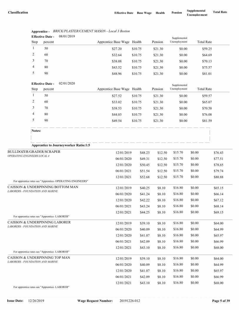
Classification Total RateBase Wage Health PensionSupplemental
UnemploymentEffective Date
BRICK/PLASTER/CEMENT MASON - Local 3 BostonApprentice -
08/01/2019
Health PensionSupplemental
UnemploymentStep Apprentice Base Wage Total Ratepercent
Effective Date -
1 $27.20 $10.75 $21.30 $0.00 $59.25 50
2 $32.64 $10.75 $21.30 $0.00 $64.69 60
3 $38.08 $10.75 $21.30 $0.00 $70.13 70
4 $43.52 $10.75 $21.30 $0.00 $75.57 80
5 $48.96 $10.75 $21.30 $0.00 $81.01 90
02/01/2020
Health PensionSupplemental
UnemploymentStep Apprentice Base Wage Total Ratepercent
Effective Date -
1 $27.52 $10.75 $21.30 $0.00 $59.57 50
2 $33.02 $10.75 $21.30 $0.00 $65.07 60
3 $38.53 $10.75 $21.30 $0.00 $70.58 70
4 $44.03 $10.75 $21.30 $0.00 $76.08 80
5 $49.54 $10.75 $21.30 $0.00 $81.59 90
Notes:
Apprentice to Journeyworker Ratio:1:5
BULLDOZER/GRADER/SCRAPEROPERATING ENGINEERS LOCAL 4
$76.43 12/01/2019 $12.50 $0.00 $48.23 $15.70
$77.51 06/01/2020 $12.50 $0.00 $49.31 $15.70
$78.65 12/01/2020 $12.50 $0.00 $50.45 $15.70
$79.74 06/01/2021 $12.50 $0.00 $51.54 $15.70
$80.88 12/01/2021 $12.50 $0.00 $52.68 $15.70For apprentice rates see "Apprentice- OPERATING ENGINEERS"
CAISSON & UNDERPINNING BOTTOM MANLABORERS - FOUNDATION AND MARINE
$65.15 12/01/2019 $8.10 $0.00 $40.25 $16.80
$66.14 06/01/2020 $8.10 $0.00 $41.24 $16.80
$67.12 12/01/2020 $8.10 $0.00 $42.22 $16.80
$68.14 06/01/2021 $8.10 $0.00 $43.24 $16.80
$69.15 12/01/2021 $8.10 $0.00 $44.25 $16.80For apprentice rates see "Apprentice- LABORER"
CAISSON & UNDERPINNING LABORERLABORERS - FOUNDATION AND MARINE
$64.00 12/01/2019 $8.10 $0.00 $39.10 $16.80
$64.99 06/01/2020 $8.10 $0.00 $40.09 $16.80
$65.97 12/01/2020 $8.10 $0.00 $41.07 $16.80
$66.99 06/01/2021 $8.10 $0.00 $42.09 $16.80
$68.00 12/01/2021 $8.10 $0.00 $43.10 $16.80For apprentice rates see "Apprentice- LABORER"
CAISSON & UNDERPINNING TOP MANLABORERS - FOUNDATION AND MARINE
$64.00 12/01/2019 $8.10 $0.00 $39.10 $16.80
$64.99 06/01/2020 $8.10 $0.00 $40.09 $16.80
$65.97 12/01/2020 $8.10 $0.00 $41.07 $16.80
$66.99 06/01/2021 $8.10 $0.00 $42.09 $16.80
$68.00 12/01/2021 $8.10 $0.00 $43.10 $16.80For apprentice rates see "Apprentice- LABORER"
Issue Date: Wage Request Number:12/26/2019 Page 5 of 3920191226-012

Classification Total RateBase Wage Health PensionSupplemental
UnemploymentEffective Date
CARBIDE CORE DRILL OPERATORLABORERS - ZONE 1
$64.10 12/01/2019 $8.10 $0.00 $39.40 $16.60
$65.09 06/01/2020 $8.10 $0.00 $40.39 $16.60
$66.07 12/01/2020 $8.10 $0.00 $41.37 $16.60
$67.09 06/01/2021 $8.10 $0.00 $42.39 $16.60
$68.10 12/01/2021 $8.10 $0.00 $43.40 $16.60For apprentice rates see "Apprentice- LABORER"
CARPENTERCARPENTERS -ZONE 1 (Metro Boston)
$78.14 09/01/2019 $9.40 $0.00 $49.79 $18.95
$78.99 03/01/2020 $9.40 $0.00 $50.64 $18.95
$79.89 09/01/2020 $9.40 $0.00 $51.54 $18.95
$80.74 03/01/2021 $9.40 $0.00 $52.39 $18.95
$81.64 09/01/2021 $9.40 $0.00 $53.29 $18.95
$82.49 03/01/2022 $9.40 $0.00 $54.14 $18.95
$83.39 09/01/2022 $9.40 $0.00 $55.04 $18.95
$84.24 03/01/2023 $9.40 $0.00 $55.89 $18.95
CARPENTER - Zone 1 Metro BostonApprentice -
09/01/2019
Health PensionSupplemental
UnemploymentStep Apprentice Base Wage Total Ratepercent
Effective Date -
1 $24.90 $9.40 $1.73 $0.00 $36.03 50
2 $29.87 $9.40 $1.73 $0.00 $41.00 60
3 $34.85 $9.40 $13.76 $0.00 $58.01 70
4 $37.34 $9.40 $13.76 $0.00 $60.50 75
5 $39.83 $9.40 $15.49 $0.00 $64.72 80
6 $39.83 $9.40 $15.49 $0.00 $64.72 80
7 $44.81 $9.40 $17.22 $0.00 $71.43 90
8 $44.81 $9.40 $17.22 $0.00 $71.43 90
03/01/2020
Health PensionSupplemental
UnemploymentStep Apprentice Base Wage Total Ratepercent
Effective Date -
1 $25.32 $9.40 $1.73 $0.00 $36.45 50
2 $30.38 $9.40 $1.73 $0.00 $41.51 60
3 $35.45 $9.40 $13.76 $0.00 $58.61 70
4 $37.98 $9.40 $13.76 $0.00 $61.14 75
5 $40.51 $9.40 $15.49 $0.00 $65.40 80
6 $40.51 $9.40 $15.49 $0.00 $65.40 80
7 $45.58 $9.40 $17.22 $0.00 $72.20 90
8 $45.58 $9.40 $17.22 $0.00 $72.20 90
Notes:
% Indentured After 10/1/17; 45/45/55/55/70/70/80/80
Step 1&2 $33.54/ 3&4 $40.18/ 5&6 $59.74/ 7&8 $66.45
Apprentice to Journeyworker Ratio:1:5
CARPENTER WOOD FRAMECARPENTERS -ZONE 2 (Wood Frame)
$42.88 10/01/2019 $7.07 $0.00 $27.95 $7.86
All Aspects of New Wood Frame Work
Issue Date: Wage Request Number:12/26/2019 Page 6 of 3920191226-012

Classification Total RateBase Wage Health PensionSupplemental
UnemploymentEffective Date
CARPENTER (Wood Frame) - Zone 2Apprentice -
10/01/2019
Health PensionSupplemental
UnemploymentStep Apprentice Base Wage Total Ratepercent
Effective Date -
1 $16.77 $7.07 $0.00 $0.00 $23.84 60
2 $16.77 $7.07 $0.00 $0.00 $23.84 60
3 $18.17 $7.07 $7.86 $0.00 $33.10 65
4 $19.57 $7.07 $7.86 $0.00 $34.50 70
5 $20.96 $7.07 $7.86 $0.00 $35.89 75
6 $22.36 $7.07 $7.86 $0.00 $37.29 80
7 $23.76 $7.07 $7.86 $0.00 $38.69 85
8 $25.16 $7.07 $7.86 $0.00 $40.09 90
Notes:
% Indentured After 10/1/17; 45/45/55/55/70/70/80/80
Step 1&2 $19.65/ 3&4 $27.19/ 5&6 $34.50/ 7&8 $37.29
Apprentice to Journeyworker Ratio:1:5
CEMENT MASONRY/PLASTERINGBRICKLAYERS LOCAL 3 (BOSTON)
$83.45 07/01/2019 $12.75 $0.62 $47.67 $22.41
$84.85 01/01/2020 $12.75 $0.62 $49.07 $22.41
CEMENT MASONRY/PLASTERING - Eastern Mass (Boston)Apprentice -
07/01/2019
Health PensionSupplemental
UnemploymentStep Apprentice Base Wage Total Ratepercent
Effective Date -
1 $23.84 $12.75 $15.41 $0.00 $52.00 50
2 $28.60 $12.75 $17.41 $0.62 $59.38 60
3 $30.99 $12.75 $18.41 $0.62 $62.77 65
4 $33.37 $12.75 $19.41 $0.62 $66.15 70
5 $35.75 $12.75 $20.41 $0.62 $69.53 75
6 $38.14 $12.75 $21.41 $0.62 $72.92 80
7 $42.90 $12.75 $22.41 $0.62 $78.68 90
01/01/2020
Health PensionSupplemental
UnemploymentStep Apprentice Base Wage Total Ratepercent
Effective Date -
1 $24.54 $12.75 $15.41 $0.00 $52.70 50
2 $29.44 $12.75 $17.41 $0.62 $60.22 60
3 $31.90 $12.75 $18.41 $0.62 $63.68 65
4 $34.35 $12.75 $19.41 $0.62 $67.13 70
5 $36.80 $12.75 $20.41 $0.62 $70.58 75
6 $39.26 $12.75 $21.41 $0.62 $74.04 80
7 $44.16 $12.75 $22.41 $0.62 $79.94 90
Notes:
Steps 3,4 are 500 hrs. All other steps are 1,000 hrs.
Apprentice to Journeyworker Ratio:1:3
Issue Date: Wage Request Number:12/26/2019 Page 7 of 3920191226-012

Classification Total RateBase Wage Health PensionSupplemental
UnemploymentEffective Date
CHAIN SAW OPERATORLABORERS - ZONE 1
$64.10 12/01/2019 $8.10 $0.00 $39.40 $16.60
$65.09 06/01/2020 $8.10 $0.00 $40.39 $16.60
$66.07 12/01/2020 $8.10 $0.00 $41.37 $16.60
$67.09 06/01/2021 $8.10 $0.00 $42.39 $16.60
$68.10 12/01/2021 $8.10 $0.00 $43.40 $16.60For apprentice rates see "Apprentice- LABORER"
CLAM SHELLS/SLURRY BUCKETS/HEADING MACHINESOPERATING ENGINEERS LOCAL 4
$77.93 12/01/2019 $12.50 $0.00 $49.73 $15.70
$79.03 06/01/2020 $12.50 $0.00 $50.83 $15.70
$80.18 12/01/2020 $12.50 $0.00 $51.98 $15.70
$81.28 06/01/2021 $12.50 $0.00 $53.08 $15.70
$82.43 12/01/2021 $12.50 $0.00 $54.23 $15.70For apprentice rates see "Apprentice- OPERATING ENGINEERS"
COMPRESSOR OPERATOROPERATING ENGINEERS LOCAL 4
$60.67 12/01/2019 $12.50 $0.00 $32.47 $15.70
$61.42 06/01/2020 $12.50 $0.00 $33.22 $15.70
$62.20 12/01/2020 $12.50 $0.00 $34.00 $15.70
$62.95 06/01/2021 $12.50 $0.00 $34.75 $15.70
$63.74 12/01/2021 $12.50 $0.00 $35.54 $15.70For apprentice rates see "Apprentice- OPERATING ENGINEERS"
DELEADER (BRIDGE)PAINTERS LOCAL 35 - ZONE 1
$80.31 07/01/2019 $8.20 $0.00 $50.66 $21.45
$81.26 01/01/2020 $8.20 $0.00 $50.96 $22.10
$82.36 07/01/2020 $8.20 $0.00 $52.06 $22.10
$83.46 01/01/2021 $8.20 $0.00 $53.16 $22.10
Issue Date: Wage Request Number:12/26/2019 Page 8 of 3920191226-012

Classification Total RateBase Wage Health PensionSupplemental
UnemploymentEffective Date
PAINTER Local 35 - BRIDGES/TANKSApprentice -
07/01/2019
Health PensionSupplemental
UnemploymentStep Apprentice Base Wage Total Ratepercent
Effective Date -
1 $25.33 $8.20 $0.00 $0.00 $33.53 50
2 $27.86 $8.20 $5.78 $0.00 $41.84 55
3 $30.40 $8.20 $6.30 $0.00 $44.90 60
4 $32.93 $8.20 $6.83 $0.00 $47.96 65
5 $35.46 $8.20 $18.30 $0.00 $61.96 70
6 $38.00 $8.20 $18.83 $0.00 $65.03 75
7 $40.53 $8.20 $19.35 $0.00 $68.08 80
8 $45.59 $8.20 $20.40 $0.00 $74.19 90
01/01/2020
Health PensionSupplemental
UnemploymentStep Apprentice Base Wage Total Ratepercent
Effective Date -
1 $25.48 $8.20 $0.00 $0.00 $33.68 50
2 $28.03 $8.20 $5.94 $0.00 $42.17 55
3 $30.58 $8.20 $6.48 $0.00 $45.26 60
4 $33.12 $8.20 $7.02 $0.00 $48.34 65
5 $35.67 $8.20 $18.51 $0.00 $62.38 70
6 $38.22 $8.20 $19.05 $0.00 $65.47 75
7 $40.77 $8.20 $19.59 $0.00 $68.56 80
8 $45.86 $8.20 $20.67 $0.00 $74.73 90
Notes:
Steps are 750 hrs.
Apprentice to Journeyworker Ratio:1:1
DEMO: ADZEMANLABORERS - ZONE 1
$64.00 12/01/2019 $8.10 $0.00 $39.30 $16.60
For apprentice rates see "Apprentice- LABORER"
DEMO: BACKHOE/LOADER/HAMMER OPERATORLABORERS - ZONE 1
$65.00 12/01/2019 $8.10 $0.00 $40.30 $16.60
For apprentice rates see "Apprentice- LABORER"
DEMO: BURNERSLABORERS - ZONE 1
$64.75 12/01/2019 $8.10 $0.00 $40.05 $16.60
For apprentice rates see "Apprentice- LABORER"
DEMO: CONCRETE CUTTER/SAWYERLABORERS - ZONE 1
$65.00 12/01/2019 $8.10 $0.00 $40.30 $16.60
For apprentice rates see "Apprentice- LABORER"
DEMO: JACKHAMMER OPERATORLABORERS - ZONE 1
$64.75 12/01/2019 $8.10 $0.00 $40.05 $16.60
For apprentice rates see "Apprentice- LABORER"
DEMO: WRECKING LABORERLABORERS - ZONE 1
$64.00 12/01/2019 $8.10 $0.00 $39.30 $16.60
For apprentice rates see "Apprentice- LABORER"
Issue Date: Wage Request Number:12/26/2019 Page 9 of 3920191226-012

Classification Total RateBase Wage Health PensionSupplemental
UnemploymentEffective Date
DIRECTIONAL DRILL MACHINE OPERATOROPERATING ENGINEERS LOCAL 4
$76.43 12/01/2019 $12.50 $0.00 $48.23 $15.70
$77.51 06/01/2020 $12.50 $0.00 $49.31 $15.70
$78.65 12/01/2020 $12.50 $0.00 $50.45 $15.70
$79.74 06/01/2021 $12.50 $0.00 $51.54 $15.70
$80.88 12/01/2021 $12.50 $0.00 $52.68 $15.70For apprentice rates see "Apprentice- OPERATING ENGINEERS"
DIVERPILE DRIVER LOCAL 56 (ZONE 1)
$99.57 08/01/2019 $9.90 $0.00 $68.52 $21.15
For apprentice rates see "Apprentice- PILE DRIVER"
DIVER TENDERPILE DRIVER LOCAL 56 (ZONE 1)
$79.99 08/01/2019 $9.90 $0.00 $48.94 $21.15
For apprentice rates see "Apprentice- PILE DRIVER"
DIVER TENDER (EFFLUENT)PILE DRIVER LOCAL 56 (ZONE 1)
$104.46 08/01/2019 $9.90 $0.00 $73.41 $21.15
For apprentice rates see "Apprentice- PILE DRIVER"
DIVER/SLURRY (EFFLUENT)PILE DRIVER LOCAL 56 (ZONE 1)
$133.83 08/01/2019 $9.90 $0.00 $102.78 $21.15
For apprentice rates see "Apprentice- PILE DRIVER"
DRAWBRIDGE OPERATOR (Construction)ELECTRICIANS LOCAL 103
$82.98 03/01/2019 $13.00 $0.00 $51.10 $18.88
For apprentice rates see "Apprentice- ELECTRICIAN"
ELECTRICIANELECTRICIANS LOCAL 103
$82.98 03/01/2019 $13.00 $0.00 $51.10 $18.88
ELECTRICIAN - Local 103Apprentice -
03/01/2019
Health PensionSupplemental
UnemploymentStep Apprentice Base Wage Total Ratepercent
Effective Date -
1 $20.44 $13.00 $0.61 $0.00 $34.05 40
2 $20.44 $13.00 $0.61 $0.00 $34.05 40
3 $23.00 $13.00 $14.34 $0.00 $50.34 45
4 $23.00 $13.00 $14.34 $0.00 $50.34 45
5 $25.55 $13.00 $14.76 $0.00 $53.31 50
6 $28.11 $13.00 $15.17 $0.00 $56.28 55
7 $30.66 $13.00 $15.58 $0.00 $59.24 60
8 $33.22 $13.00 $16.00 $0.00 $62.22 65
9 $35.77 $13.00 $16.40 $0.00 $65.17 70
10 $38.33 $13.00 $16.82 $0.00 $68.15 75
Notes: :
App Prior 1/1/03; 30/35/40/45/50/55/65/70/75/80
Apprentice to Journeyworker Ratio:2:3***
ELEVATOR CONSTRUCTORELEVATOR CONSTRUCTORS LOCAL 4
$92.56 01/01/2019 $15.58 $0.00 $59.47 $17.51
$95.56 01/01/2020 $15.73 $0.00 $61.42 $18.41
$98.66 01/01/2021 $15.88 $0.00 $63.47 $19.31
$101.86 01/01/2022 $16.03 $0.00 $65.62 $20.21
Issue Date: Wage Request Number:12/26/2019 Page 10 of 3920191226-012

Classification Total RateBase Wage Health PensionSupplemental
UnemploymentEffective Date
ELEVATOR CONSTRUCTOR - Local 4Apprentice -
01/01/2019
Health PensionSupplemental
UnemploymentStep Apprentice Base Wage Total Ratepercent
Effective Date -
1 $29.74 $15.58 $0.00 $0.00 $45.32 50
2 $32.71 $15.58 $17.51 $0.00 $65.80 55
3 $38.66 $15.58 $17.51 $0.00 $71.75 65
4 $41.63 $15.58 $17.51 $0.00 $74.72 70
5 $47.58 $15.58 $17.51 $0.00 $80.67 80
01/01/2020
Health PensionSupplemental
UnemploymentStep Apprentice Base Wage Total Ratepercent
Effective Date -
1 $30.71 $15.73 $0.00 $0.00 $46.44 50
2 $33.78 $15.73 $18.41 $0.00 $67.92 55
3 $39.92 $15.73 $18.41 $0.00 $74.06 65
4 $42.99 $15.73 $18.41 $0.00 $77.13 70
5 $49.14 $15.73 $18.41 $0.00 $83.28 80
Notes:
Steps 1-2 are 6 mos.; Steps 3-5 are 1 year
Apprentice to Journeyworker Ratio:1:1
ELEVATOR CONSTRUCTOR HELPERELEVATOR CONSTRUCTORS LOCAL 4
$74.72 01/01/2019 $15.58 $0.00 $41.63 $17.51
$77.13 01/01/2020 $15.73 $0.00 $42.99 $18.41
$79.62 01/01/2021 $15.88 $0.00 $44.43 $19.31
$82.17 01/01/2022 $16.03 $0.00 $45.93 $20.21For apprentice rates see "Apprentice - ELEVATOR CONSTRUCTOR"
FENCE & GUARD RAIL ERECTORLABORERS - ZONE 1
$64.10 12/01/2019 $8.10 $0.00 $39.40 $16.60
$65.09 06/01/2020 $8.10 $0.00 $40.39 $16.60
$66.07 12/01/2020 $8.10 $0.00 $41.37 $16.60
$67.09 06/01/2021 $8.10 $0.00 $42.39 $16.60
$68.10 12/01/2021 $8.10 $0.00 $43.40 $16.60For apprentice rates see "Apprentice- LABORER"
FIELD ENG.INST.PERSON-BLDG,SITE,HVY/HWYOPERATING ENGINEERS LOCAL 4
$71.78 11/01/2019 $12.00 $0.00 $44.18 $15.60
$72.93 05/01/2020 $12.00 $0.00 $45.33 $15.60
$73.93 11/01/2020 $12.00 $0.00 $46.33 $15.60
$75.08 05/01/2021 $12.00 $0.00 $47.48 $15.60
$76.08 11/01/2021 $12.00 $0.00 $48.48 $15.60
$77.23 05/01/2022 $12.00 $0.00 $49.63 $15.60For apprentice rates see "Apprentice- OPERATING ENGINEERS"
FIELD ENG.PARTY CHIEF-BLDG,SITE,HVY/HWYOPERATING ENGINEERS LOCAL 4
$73.28 11/01/2019 $12.00 $0.00 $45.68 $15.60
$74.43 05/01/2020 $12.00 $0.00 $46.83 $15.60
$75.44 11/01/2020 $12.00 $0.00 $47.84 $15.60
$76.60 05/01/2021 $12.00 $0.00 $49.00 $15.60
$77.61 11/01/2021 $12.00 $0.00 $50.01 $15.60
$78.77 05/01/2022 $12.00 $0.00 $51.17 $15.60For apprentice rates see "Apprentice- OPERATING ENGINEERS"
Issue Date: Wage Request Number:12/26/2019 Page 11 of 3920191226-012
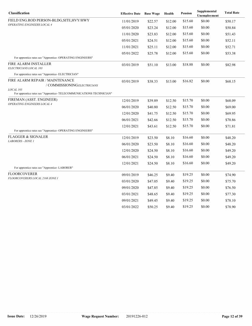
Classification Total RateBase Wage Health PensionSupplemental
UnemploymentEffective Date
FIELD ENG.ROD PERSON-BLDG,SITE,HVY/HWYOPERATING ENGINEERS LOCAL 4
$50.17 11/01/2019 $12.00 $0.00 $22.57 $15.60
$50.84 05/01/2020 $12.00 $0.00 $23.24 $15.60
$51.43 11/01/2020 $12.00 $0.00 $23.83 $15.60
$52.11 05/01/2021 $12.00 $0.00 $24.51 $15.60
$52.71 11/01/2021 $12.00 $0.00 $25.11 $15.60
$53.38 05/01/2022 $12.00 $0.00 $25.78 $15.60For apprentice rates see "Apprentice- OPERATING ENGINEERS"
FIRE ALARM INSTALLERELECTRICIANS LOCAL 103
$82.98 03/01/2019 $13.00 $0.00 $51.10 $18.88
For apprentice rates see "Apprentice- ELECTRICIAN"
FIRE ALARM REPAIR / MAINTENANCE
/ COMMISSIONINGELECTRICIANS
LOCAL 103
$68.15 03/01/2019 $13.00 $0.00 $38.33 $16.82
For apprentice rates see "Apprentice- TELECOMMUNICATIONS TECHNICIAN"
FIREMAN (ASST. ENGINEER)OPERATING ENGINEERS LOCAL 4
$68.09 12/01/2019 $12.50 $0.00 $39.89 $15.70
$69.00 06/01/2020 $12.50 $0.00 $40.80 $15.70
$69.95 12/01/2020 $12.50 $0.00 $41.75 $15.70
$70.86 06/01/2021 $12.50 $0.00 $42.66 $15.70
$71.81 12/01/2021 $12.50 $0.00 $43.61 $15.70For apprentice rates see "Apprentice- OPERATING ENGINEERS"
FLAGGER & SIGNALERLABORERS - ZONE 1
$48.20 12/01/2019 $8.10 $0.00 $23.50 $16.60
$48.20 06/01/2020 $8.10 $0.00 $23.50 $16.60
$49.20 12/01/2020 $8.10 $0.00 $24.50 $16.60
$49.20 06/01/2021 $8.10 $0.00 $24.50 $16.60
$49.20 12/01/2021 $8.10 $0.00 $24.50 $16.60For apprentice rates see "Apprentice- LABORER"
FLOORCOVERERFLOORCOVERERS LOCAL 2168 ZONE I
$74.90 09/01/2019 $9.40 $0.00 $46.25 $19.25
$75.70 03/01/2020 $9.40 $0.00 $47.05 $19.25
$76.50 09/01/2020 $9.40 $0.00 $47.85 $19.25
$77.30 03/01/2021 $9.40 $0.00 $48.65 $19.25
$78.10 09/01/2021 $9.40 $0.00 $49.45 $19.25
$78.90 03/01/2022 $9.40 $0.00 $50.25 $19.25
Issue Date: Wage Request Number:12/26/2019 Page 12 of 3920191226-012

Classification Total RateBase Wage Health PensionSupplemental
UnemploymentEffective Date
FLOORCOVERER - Local 2168 Zone IApprentice -
09/01/2019
Health PensionSupplemental
UnemploymentStep Apprentice Base Wage Total Ratepercent
Effective Date -
1 $23.13 $9.40 $1.79 $0.00 $34.32 50
2 $25.44 $9.40 $1.79 $0.00 $36.63 55
3 $27.75 $9.40 $13.88 $0.00 $51.03 60
4 $30.06 $9.40 $13.88 $0.00 $53.34 65
5 $32.38 $9.40 $15.67 $0.00 $57.45 70
6 $34.69 $9.40 $15.67 $0.00 $59.76 75
7 $37.00 $9.40 $17.46 $0.00 $63.86 80
8 $39.31 $9.40 $17.46 $0.00 $66.17 85
03/01/2020
Health PensionSupplemental
UnemploymentStep Apprentice Base Wage Total Ratepercent
Effective Date -
1 $23.53 $9.40 $1.79 $0.00 $34.72 50
2 $25.88 $9.40 $1.79 $0.00 $37.07 55
3 $28.23 $9.40 $13.88 $0.00 $51.51 60
4 $30.58 $9.40 $13.88 $0.00 $53.86 65
5 $32.94 $9.40 $15.67 $0.00 $58.01 70
6 $35.29 $9.40 $15.67 $0.00 $60.36 75
7 $37.64 $9.40 $17.46 $0.00 $64.50 80
8 $39.99 $9.40 $17.46 $0.00 $66.85 85
Notes: Steps are 750 hrs.
% After 09/1/17; 45/45/55/55/70/70/80/80 (1500hr Steps)
Step 1&2 $32.00/ 3&4 $38.36/ 5&6 $57.45/ 7&8 $63.86
Apprentice to Journeyworker Ratio:1:1
FORK LIFT/CHERRY PICKEROPERATING ENGINEERS LOCAL 4
$76.93 12/01/2019 $12.50 $0.00 $48.73 $15.70
$78.03 06/01/2020 $12.50 $0.00 $49.83 $15.70
$79.18 12/01/2020 $12.50 $0.00 $50.98 $15.70
$80.28 06/01/2021 $12.50 $0.00 $52.08 $15.70
$81.43 12/01/2021 $12.50 $0.00 $53.23 $15.70For apprentice rates see "Apprentice- OPERATING ENGINEERS"
GENERATOR/LIGHTING PLANT/HEATERSOPERATING ENGINEERS LOCAL 4
$60.67 12/01/2019 $12.50 $0.00 $32.47 $15.70
$61.42 06/01/2020 $12.50 $0.00 $33.22 $15.70
$62.20 12/01/2020 $12.50 $0.00 $34.00 $15.70
$62.95 06/01/2021 $12.50 $0.00 $34.75 $15.70
$63.74 12/01/2021 $12.50 $0.00 $35.54 $15.70For apprentice rates see "Apprentice- OPERATING ENGINEERS"
GLAZIER (GLASS PLANK/AIR BARRIER/INTERIOR
SYSTEMS)GLAZIERS LOCAL 35 (ZONE 1)
$75.60 07/01/2019 $8.20 $0.00 $45.95 $21.45
$76.55 01/01/2020 $8.20 $0.00 $46.25 $22.10
$77.65 07/01/2020 $8.20 $0.00 $47.35 $22.10
$78.75 01/01/2021 $8.20 $0.00 $48.45 $22.10
Issue Date: Wage Request Number:12/26/2019 Page 13 of 3920191226-012

Classification Total RateBase Wage Health PensionSupplemental
UnemploymentEffective Date
GLAZIER - Local 35 Zone 1Apprentice -
07/01/2019
Health PensionSupplemental
UnemploymentStep Apprentice Base Wage Total Ratepercent
Effective Date -
1 $22.98 $8.20 $0.00 $0.00 $31.18 50
2 $25.27 $8.20 $5.78 $0.00 $39.25 55
3 $27.57 $8.20 $6.30 $0.00 $42.07 60
4 $29.87 $8.20 $6.83 $0.00 $44.90 65
5 $32.17 $8.20 $18.30 $0.00 $58.67 70
6 $34.46 $8.20 $18.83 $0.00 $61.49 75
7 $36.76 $8.20 $19.35 $0.00 $64.31 80
8 $41.36 $8.20 $20.40 $0.00 $69.96 90
01/01/2020
Health PensionSupplemental
UnemploymentStep Apprentice Base Wage Total Ratepercent
Effective Date -
1 $23.13 $8.20 $0.00 $0.00 $31.33 50
2 $25.44 $8.20 $5.94 $0.00 $39.58 55
3 $27.75 $8.20 $6.48 $0.00 $42.43 60
4 $30.06 $8.20 $7.02 $0.00 $45.28 65
5 $32.38 $8.20 $18.51 $0.00 $59.09 70
6 $34.69 $8.20 $19.05 $0.00 $61.94 75
7 $37.00 $8.20 $19.59 $0.00 $64.79 80
8 $41.63 $8.20 $20.67 $0.00 $70.50 90
Notes:
Steps are 750 hrs.
Apprentice to Journeyworker Ratio:1:1
HOISTING ENGINEER/CRANES/GRADALLSOPERATING ENGINEERS LOCAL 4
$76.93 12/01/2019 $12.50 $0.00 $48.73 $15.70
$78.03 06/01/2020 $12.50 $0.00 $49.83 $15.70
$79.18 12/01/2020 $12.50 $0.00 $50.98 $15.70
$80.28 06/01/2021 $12.50 $0.00 $52.08 $15.70
$81.43 12/01/2021 $12.50 $0.00 $53.23 $15.70
Issue Date: Wage Request Number:12/26/2019 Page 14 of 3920191226-012

Classification Total RateBase Wage Health PensionSupplemental
UnemploymentEffective Date
OPERATING ENGINEERS - Local 4Apprentice -
12/01/2019
Health PensionSupplemental
UnemploymentStep Apprentice Base Wage Total Ratepercent
Effective Date -
1 $26.80 $12.50 $0.00 $0.00 $39.30 55
2 $29.24 $12.50 $15.70 $0.00 $57.44 60
3 $31.67 $12.50 $15.70 $0.00 $59.87 65
4 $34.11 $12.50 $15.70 $0.00 $62.31 70
5 $36.55 $12.50 $15.70 $0.00 $64.75 75
6 $38.98 $12.50 $15.70 $0.00 $67.18 80
7 $41.42 $12.50 $15.70 $0.00 $69.62 85
8 $43.86 $12.50 $15.70 $0.00 $72.06 90
06/01/2020
Health PensionSupplemental
UnemploymentStep Apprentice Base Wage Total Ratepercent
Effective Date -
1 $27.41 $12.50 $0.00 $0.00 $39.91 55
2 $29.90 $12.50 $15.70 $0.00 $58.10 60
3 $32.39 $12.50 $15.70 $0.00 $60.59 65
4 $34.88 $12.50 $15.70 $0.00 $63.08 70
5 $37.37 $12.50 $15.70 $0.00 $65.57 75
6 $39.86 $12.50 $15.70 $0.00 $68.06 80
7 $42.36 $12.50 $15.70 $0.00 $70.56 85
8 $44.85 $12.50 $15.70 $0.00 $73.05 90
Notes:
Apprentice to Journeyworker Ratio:1:6
HVAC (DUCTWORK)SHEETMETAL WORKERS LOCAL 17 - A
$87.98 08/01/2019 $13.20 $2.56 $48.10 $24.12
$89.68 02/01/2020 $13.20 $2.61 $49.75 $24.12
$91.33 08/01/2020 $13.20 $2.66 $51.35 $24.12
$93.03 02/01/2021 $13.20 $2.71 $53.00 $24.12
$94.83 08/01/2021 $13.20 $2.76 $54.75 $24.12
$96.63 02/01/2022 $13.20 $2.81 $56.50 $24.12For apprentice rates see "Apprentice- SHEET METAL WORKER"
HVAC (ELECTRICAL CONTROLS)ELECTRICIANS LOCAL 103
$82.98 03/01/2019 $13.00 $0.00 $51.10 $18.88
For apprentice rates see "Apprentice- ELECTRICIAN"
HVAC (TESTING AND BALANCING - AIR)SHEETMETAL WORKERS LOCAL 17 - A
$87.98 08/01/2019 $13.20 $2.56 $48.10 $24.12
$89.68 02/01/2020 $13.20 $2.61 $49.75 $24.12
$91.33 08/01/2020 $13.20 $2.66 $51.35 $24.12
$93.03 02/01/2021 $13.20 $2.71 $53.00 $24.12
$94.83 08/01/2021 $13.20 $2.76 $54.75 $24.12
$96.63 02/01/2022 $13.20 $2.81 $56.50 $24.12For apprentice rates see "Apprentice- SHEET METAL WORKER"
Issue Date: Wage Request Number:12/26/2019 Page 15 of 3920191226-012

Classification Total RateBase Wage Health PensionSupplemental
UnemploymentEffective Date
HVAC (TESTING AND BALANCING -WATER)PIPEFITTERS LOCAL 537
$85.38 09/01/2019 $10.95 $0.00 $54.69 $19.74
$86.88 03/01/2020 $10.95 $0.00 $56.19 $19.74
$88.38 09/01/2020 $10.95 $0.00 $57.69 $19.74
$89.88 03/01/2021 $10.95 $0.00 $59.19 $19.74For apprentice rates see "Apprentice- PIPEFITTER" or "PLUMBER/PIPEFITTER"
HVAC MECHANICPIPEFITTERS LOCAL 537
$85.38 09/01/2019 $10.95 $0.00 $54.69 $19.74
$86.88 03/01/2020 $10.95 $0.00 $56.19 $19.74
$88.38 09/01/2020 $10.95 $0.00 $57.69 $19.74
$89.88 03/01/2021 $10.95 $0.00 $59.19 $19.74For apprentice rates see "Apprentice- PIPEFITTER" or "PLUMBER/PIPEFITTER"
HYDRAULIC DRILLSLABORERS - ZONE 1
$64.60 12/01/2019 $8.10 $0.00 $39.90 $16.60
$65.59 06/01/2020 $8.10 $0.00 $40.89 $16.60
$66.57 12/01/2020 $8.10 $0.00 $41.87 $16.60
$67.59 06/01/2021 $8.10 $0.00 $42.89 $16.60
$68.60 12/01/2021 $8.10 $0.00 $43.90 $16.60For apprentice rates see "Apprentice- LABORER"
INSULATOR (PIPES & TANKS)HEAT & FROST INSULATORS LOCAL 6 (BOSTON)
$77.64 09/01/2019 $12.80 $0.00 $48.44 $16.40
ASBESTOS INSULATOR (Pipes & Tanks) - Local 6 BostonApprentice -
09/01/2019
Health PensionSupplemental
UnemploymentStep Apprentice Base Wage Total Ratepercent
Effective Date -
1 $24.22 $12.80 $11.90 $0.00 $48.92 50
2 $29.06 $12.80 $12.80 $0.00 $54.66 60
3 $33.91 $12.80 $13.70 $0.00 $60.41 70
4 $38.75 $12.80 $14.60 $0.00 $66.15 80
Notes:
Steps are 1 year
Apprentice to Journeyworker Ratio:1:4
IRONWORKER/WELDERIRONWORKERS LOCAL 7 (BOSTON AREA)
$78.16 03/16/2019 $8.00 $0.00 $46.66 $23.50
Issue Date: Wage Request Number:12/26/2019 Page 16 of 3920191226-012

Classification Total RateBase Wage Health PensionSupplemental
UnemploymentEffective Date
IRONWORKER - Local 7 BostonApprentice -
03/16/2019
Health PensionSupplemental
UnemploymentStep Apprentice Base Wage Total Ratepercent
Effective Date -
1 $28.00 $8.00 $23.50 $0.00 $59.50 60
2 $32.66 $8.00 $23.50 $0.00 $64.16 70
3 $35.00 $8.00 $23.50 $0.00 $66.50 75
4 $37.33 $8.00 $23.50 $0.00 $68.83 80
5 $39.66 $8.00 $23.50 $0.00 $71.16 85
6 $41.99 $8.00 $23.50 $0.00 $73.49 90
Notes:
** Structural 1:6; Ornamental 1:4
Apprentice to Journeyworker Ratio:**
JACKHAMMER & PAVING BREAKER OPERATORLABORERS - ZONE 1
$64.10 12/01/2019 $8.10 $0.00 $39.40 $16.60
$65.09 06/01/2020 $8.10 $0.00 $40.39 $16.60
$66.07 12/01/2020 $8.10 $0.00 $41.37 $16.60
$67.09 06/01/2021 $8.10 $0.00 $42.39 $16.60
$68.10 12/01/2021 $8.10 $0.00 $43.40 $16.60For apprentice rates see "Apprentice- LABORER"
LABORERLABORERS - ZONE 1
$63.85 12/01/2019 $8.10 $0.00 $39.15 $16.60
$64.84 06/01/2020 $8.10 $0.00 $40.14 $16.60
$65.82 12/01/2020 $8.10 $0.00 $41.12 $16.60
$66.84 06/01/2021 $8.10 $0.00 $42.14 $16.60
$67.85 12/01/2021 $8.10 $0.00 $43.15 $16.60
LABORER - Zone 1Apprentice -
12/01/2019
Health PensionSupplemental
UnemploymentStep Apprentice Base Wage Total Ratepercent
Effective Date -
1 $23.49 $8.10 $16.60 $0.00 $48.19 60
2 $27.41 $8.10 $16.60 $0.00 $52.11 70
3 $31.32 $8.10 $16.60 $0.00 $56.02 80
4 $35.24 $8.10 $16.60 $0.00 $59.94 90
06/01/2020
Health PensionSupplemental
UnemploymentStep Apprentice Base Wage Total Ratepercent
Effective Date -
1 $24.08 $8.10 $16.60 $0.00 $48.78 60
2 $28.10 $8.10 $16.60 $0.00 $52.80 70
3 $32.11 $8.10 $16.60 $0.00 $56.81 80
4 $36.13 $8.10 $16.60 $0.00 $60.83 90
Notes:
Apprentice to Journeyworker Ratio:1:5
Issue Date: Wage Request Number:12/26/2019 Page 17 of 3920191226-012

Classification Total RateBase Wage Health PensionSupplemental
UnemploymentEffective Date
LABORER: CARPENTER TENDERLABORERS - ZONE 1
$63.85 12/01/2019 $8.10 $0.00 $39.15 $16.60
$64.84 06/01/2020 $8.10 $0.00 $40.14 $16.60
$65.82 12/01/2020 $8.10 $0.00 $41.12 $16.60
$66.84 06/01/2021 $8.10 $0.00 $42.14 $16.60
$67.85 12/01/2021 $8.10 $0.00 $43.15 $16.60For apprentice rates see "Apprentice- LABORER"
LABORER: CEMENT FINISHER TENDERLABORERS - ZONE 1
$63.85 12/01/2019 $8.10 $0.00 $39.15 $16.60
$64.84 06/01/2020 $8.10 $0.00 $40.14 $16.60
$65.82 12/01/2020 $8.10 $0.00 $41.12 $16.60
$66.84 06/01/2021 $8.10 $0.00 $42.14 $16.60
$67.85 12/01/2021 $8.10 $0.00 $43.15 $16.60For apprentice rates see "Apprentice- LABORER"
LABORER: HAZARDOUS WASTE/ASBESTOS REMOVERLABORERS - ZONE 1
$64.00 12/01/2019 $8.10 $0.00 $39.30 $16.60
For apprentice rates see "Apprentice- LABORER"
LABORER: MASON TENDERLABORERS - ZONE 1
$64.10 12/01/2019 $8.10 $0.00 $39.40 $16.60
$65.09 06/01/2020 $8.10 $0.00 $40.39 $16.60
$66.07 12/01/2020 $8.10 $0.00 $41.37 $16.60
$67.09 06/01/2021 $8.10 $0.00 $42.39 $16.60
$68.10 12/01/2021 $8.10 $0.00 $43.40 $16.60For apprentice rates see "Apprentice- LABORER"
LABORER: MULTI-TRADE TENDERLABORERS - ZONE 1
$63.85 12/01/2019 $8.10 $0.00 $39.15 $16.60
$64.84 06/01/2020 $8.10 $0.00 $40.14 $16.60
$65.82 12/01/2020 $8.10 $0.00 $41.12 $16.60
$66.84 06/01/2021 $8.10 $0.00 $42.14 $16.60
$67.85 12/01/2021 $8.10 $0.00 $43.15 $16.60For apprentice rates see "Apprentice- LABORER"
LABORER: TREE REMOVERLABORERS - ZONE 1
$63.85 12/01/2019 $8.10 $0.00 $39.15 $16.60
$64.84 06/01/2020 $8.10 $0.00 $40.14 $16.60
$65.82 12/01/2020 $8.10 $0.00 $41.12 $16.60
$66.84 06/01/2021 $8.10 $0.00 $42.14 $16.60
$67.85 12/01/2021 $8.10 $0.00 $43.15 $16.60This classification applies to all tree work associated with the removal of standing trees, and trimming and removal of branches and limbs when the work is not done for
a utility company for the purpose of operation, maintenance or repair of utility company equipment. For apprentice rates see "Apprentice- LABORER"
LASER BEAM OPERATORLABORERS - ZONE 1
$64.10 12/01/2019 $8.10 $0.00 $39.40 $16.60
$65.09 06/01/2020 $8.10 $0.00 $40.39 $16.60
$66.07 12/01/2020 $8.10 $0.00 $41.37 $16.60
$67.09 06/01/2021 $8.10 $0.00 $42.39 $16.60
$68.10 12/01/2021 $8.10 $0.00 $43.40 $16.60For apprentice rates see "Apprentice- LABORER"
MARBLE & TILE FINISHERSBRICKLAYERS LOCAL 3 - MARBLE & TILE
$71.85 08/01/2019 $10.75 $0.00 $41.49 $19.61
$72.36 02/01/2020 $10.75 $0.00 $42.00 $19.61
$73.59 08/01/2020 $10.75 $0.00 $43.08 $19.76
$74.10 02/01/2021 $10.75 $0.00 $43.59 $19.76
$75.38 08/01/2021 $10.75 $0.00 $44.71 $19.92
$75.85 02/01/2022 $10.75 $0.00 $45.18 $19.92
Issue Date: Wage Request Number:12/26/2019 Page 18 of 3920191226-012

Classification Total RateBase Wage Health PensionSupplemental
UnemploymentEffective Date
MARBLE & TILE FINISHER - Local 3 Marble & TileApprentice -
08/01/2019
Health PensionSupplemental
UnemploymentStep Apprentice Base Wage Total Ratepercent
Effective Date -
1 $20.75 $10.75 $19.61 $0.00 $51.11 50
2 $24.89 $10.75 $19.61 $0.00 $55.25 60
3 $29.04 $10.75 $19.61 $0.00 $59.40 70
4 $33.19 $10.75 $19.61 $0.00 $63.55 80
5 $37.34 $10.75 $19.61 $0.00 $67.70 90
02/01/2020
Health PensionSupplemental
UnemploymentStep Apprentice Base Wage Total Ratepercent
Effective Date -
1 $21.00 $10.75 $19.61 $0.00 $51.36 50
2 $25.20 $10.75 $19.61 $0.00 $55.56 60
3 $29.40 $10.75 $19.61 $0.00 $59.76 70
4 $33.60 $10.75 $19.61 $0.00 $63.96 80
5 $37.80 $10.75 $19.61 $0.00 $68.16 90
Notes:
Apprentice to Journeyworker Ratio:1:3
MARBLE MASONS,TILELAYERS & TERRAZZO MECHBRICKLAYERS LOCAL 3 - MARBLE & TILE
$86.47 08/01/2019 $10.75 $0.00 $54.42 $21.30
$87.10 02/01/2020 $10.75 $0.00 $55.05 $21.30
$88.60 08/01/2020 $10.75 $0.00 $56.40 $21.45
$89.24 02/01/2021 $10.75 $0.00 $57.04 $21.45
$90.80 08/01/2021 $10.75 $0.00 $58.44 $21.61
$91.37 02/01/2022 $10.75 $0.00 $59.01 $21.61
Issue Date: Wage Request Number:12/26/2019 Page 19 of 3920191226-012

Classification Total RateBase Wage Health PensionSupplemental
UnemploymentEffective Date
MARBLE-TILE-TERRAZZO MECHANIC - Local 3 Marble & TileApprentice -
08/01/2019
Health PensionSupplemental
UnemploymentStep Apprentice Base Wage Total Ratepercent
Effective Date -
1 $27.21 $10.75 $21.30 $0.00 $59.26 50
2 $32.65 $10.75 $21.30 $0.00 $64.70 60
3 $38.09 $10.75 $21.30 $0.00 $70.14 70
4 $43.54 $10.75 $21.30 $0.00 $75.59 80
5 $48.98 $10.75 $21.30 $0.00 $81.03 90
02/01/2020
Health PensionSupplemental
UnemploymentStep Apprentice Base Wage Total Ratepercent
Effective Date -
1 $27.53 $10.75 $21.30 $0.00 $59.58 50
2 $33.03 $10.75 $21.30 $0.00 $65.08 60
3 $38.54 $10.75 $21.30 $0.00 $70.59 70
4 $44.04 $10.75 $21.30 $0.00 $76.09 80
5 $49.55 $10.75 $21.30 $0.00 $81.60 90
Notes:
Apprentice to Journeyworker Ratio:1:5
MECH. SWEEPER OPERATOR (ON CONST. SITES)OPERATING ENGINEERS LOCAL 4
$76.43 12/01/2019 $12.50 $0.00 $48.23 $15.70
$77.51 06/01/2020 $12.50 $0.00 $49.31 $15.70
$78.65 12/01/2020 $12.50 $0.00 $50.45 $15.70
$79.74 06/01/2021 $12.50 $0.00 $51.54 $15.70
$80.88 12/01/2021 $12.50 $0.00 $52.68 $15.70For apprentice rates see "Apprentice- OPERATING ENGINEERS"
MECHANICS MAINTENANCEOPERATING ENGINEERS LOCAL 4
$76.43 12/01/2019 $12.50 $0.00 $48.23 $15.70
$77.51 06/01/2020 $12.50 $0.00 $49.31 $15.70
$78.65 12/01/2020 $12.50 $0.00 $50.45 $15.70
$79.74 06/01/2021 $12.50 $0.00 $51.54 $15.70
$80.88 12/01/2021 $12.50 $0.00 $52.68 $15.70For apprentice rates see "Apprentice- OPERATING ENGINEERS"
MILLWRIGHT (Zone 1)MILLWRIGHTS LOCAL 1121 - Zone 1
$70.62 04/01/2019 $9.90 $0.00 $42.22 $18.50
Issue Date: Wage Request Number:12/26/2019 Page 20 of 3920191226-012

Classification Total RateBase Wage Health PensionSupplemental
UnemploymentEffective Date
MILLWRIGHT - Local 1121 Zone 1Apprentice -
04/01/2019
Health PensionSupplemental
UnemploymentStep Apprentice Base Wage Total Ratepercent
Effective Date -
1 $23.22 $9.90 $5.31 $0.00 $38.43 55
2 $27.44 $9.90 $15.13 $0.00 $52.47 65
3 $31.67 $9.90 $16.10 $0.00 $57.67 75
4 $35.89 $9.90 $17.06 $0.00 $62.85 85
Notes:
Steps are 2,000 hours
Apprentice to Journeyworker Ratio:1:5
MORTAR MIXERLABORERS - ZONE 1
$64.10 12/01/2019 $8.10 $0.00 $39.40 $16.60
$65.09 06/01/2020 $8.10 $0.00 $40.39 $16.60
$66.07 12/01/2020 $8.10 $0.00 $41.37 $16.60
$67.09 06/01/2021 $8.10 $0.00 $42.39 $16.60
$68.10 12/01/2021 $8.10 $0.00 $43.40 $16.60For apprentice rates see "Apprentice- LABORER"
OILER (OTHER THAN TRUCK CRANES,GRADALLS)OPERATING ENGINEERS LOCAL 4
$51.28 12/01/2019 $12.50 $0.00 $23.08 $15.70
$51.83 06/01/2020 $12.50 $0.00 $23.63 $15.70
$52.40 12/01/2020 $12.50 $0.00 $24.20 $15.70
$52.95 06/01/2021 $12.50 $0.00 $24.75 $15.70
$53.53 12/01/2021 $12.50 $0.00 $25.33 $15.70For apprentice rates see "Apprentice- OPERATING ENGINEERS"
OILER (TRUCK CRANES, GRADALLS)OPERATING ENGINEERS LOCAL 4
$55.84 12/01/2019 $12.50 $0.00 $27.64 $15.70
$56.49 06/01/2020 $12.50 $0.00 $28.29 $15.70
$57.17 12/01/2020 $12.50 $0.00 $28.97 $15.70
$57.81 06/01/2021 $12.50 $0.00 $29.61 $15.70
$58.49 12/01/2021 $12.50 $0.00 $30.29 $15.70For apprentice rates see "Apprentice- OPERATING ENGINEERS"
OTHER POWER DRIVEN EQUIPMENT - CLASS IIOPERATING ENGINEERS LOCAL 4
$76.43 12/01/2019 $12.50 $0.00 $48.23 $15.70
$77.51 06/01/2020 $12.50 $0.00 $49.31 $15.70
$78.65 12/01/2020 $12.50 $0.00 $50.45 $15.70
$79.74 06/01/2021 $12.50 $0.00 $51.54 $15.70
$80.88 12/01/2021 $12.50 $0.00 $52.68 $15.70For apprentice rates see "Apprentice- OPERATING ENGINEERS"
PAINTER (BRIDGES/TANKS)PAINTERS LOCAL 35 - ZONE 1
$80.31 07/01/2019 $8.20 $0.00 $50.66 $21.45
$81.26 01/01/2020 $8.20 $0.00 $50.96 $22.10
$82.36 07/01/2020 $8.20 $0.00 $52.06 $22.10
$83.46 01/01/2021 $8.20 $0.00 $53.16 $22.10
Issue Date: Wage Request Number:12/26/2019 Page 21 of 3920191226-012

Classification Total RateBase Wage Health PensionSupplemental
UnemploymentEffective Date
PAINTER Local 35 - BRIDGES/TANKSApprentice -
07/01/2019
Health PensionSupplemental
UnemploymentStep Apprentice Base Wage Total Ratepercent
Effective Date -
1 $25.33 $8.20 $0.00 $0.00 $33.53 50
2 $27.86 $8.20 $5.78 $0.00 $41.84 55
3 $30.40 $8.20 $6.30 $0.00 $44.90 60
4 $32.93 $8.20 $6.83 $0.00 $47.96 65
5 $35.46 $8.20 $18.30 $0.00 $61.96 70
6 $38.00 $8.20 $18.83 $0.00 $65.03 75
7 $40.53 $8.20 $19.35 $0.00 $68.08 80
8 $45.59 $8.20 $20.40 $0.00 $74.19 90
01/01/2020
Health PensionSupplemental
UnemploymentStep Apprentice Base Wage Total Ratepercent
Effective Date -
1 $25.48 $8.20 $0.00 $0.00 $33.68 50
2 $28.03 $8.20 $5.94 $0.00 $42.17 55
3 $30.58 $8.20 $6.48 $0.00 $45.26 60
4 $33.12 $8.20 $7.02 $0.00 $48.34 65
5 $35.67 $8.20 $18.51 $0.00 $62.38 70
6 $38.22 $8.20 $19.05 $0.00 $65.47 75
7 $40.77 $8.20 $19.59 $0.00 $68.56 80
8 $45.86 $8.20 $20.67 $0.00 $74.73 90
Notes:
Steps are 750 hrs.
Apprentice to Journeyworker Ratio:1:1
PAINTER (SIGN, PICTORIAL & DISPLAY)PAINTERS LOCAL 35 - ZONE 1
$39.93 06/01/2013 $7.07 $0.00 $25.81 $7.05
Issue Date: Wage Request Number:12/26/2019 Page 22 of 3920191226-012

Classification Total RateBase Wage Health PensionSupplemental
UnemploymentEffective Date
PAINTER SIGN - Local 35 Zone 1Apprentice -
06/01/2013
Health PensionSupplemental
UnemploymentStep Apprentice Base Wage Total Ratepercent
Effective Date -
1 $12.91 $7.07 $0.00 $0.00 $19.98 50
2 $14.20 $7.07 $2.45 $0.00 $23.72 55
3 $15.49 $7.07 $2.45 $0.00 $25.01 60
4 $16.78 $7.07 $2.45 $0.00 $26.30 65
5 $18.07 $7.07 $7.05 $0.00 $32.19 70
6 $19.36 $7.07 $7.05 $0.00 $33.48 75
7 $20.65 $7.07 $7.05 $0.00 $34.77 80
8 $21.94 $7.07 $7.05 $0.00 $36.06 85
9 $23.23 $7.07 $7.05 $0.00 $37.35 90
Notes:
Steps are 4 mos.
Apprentice to Journeyworker Ratio:1:1
PAINTER (SPRAY OR SANDBLAST, NEW) *
* If 30% or more of surfaces to be painted are new construction,
NEW paint rate shall be used.PAINTERS LOCAL 35 - ZONE 1
$77.00 07/01/2019 $8.20 $0.00 $47.35 $21.45
$77.95 01/01/2020 $8.20 $0.00 $47.65 $22.10
$79.05 07/01/2020 $8.20 $0.00 $48.75 $22.10
$80.15 01/01/2021 $8.20 $0.00 $49.85 $22.10
Issue Date: Wage Request Number:12/26/2019 Page 23 of 3920191226-012

Classification Total RateBase Wage Health PensionSupplemental
UnemploymentEffective Date
PAINTER Local 35 Zone 1 - Spray/Sandblast - NewApprentice -
07/01/2019
Health PensionSupplemental
UnemploymentStep Apprentice Base Wage Total Ratepercent
Effective Date -
1 $23.68 $8.20 $0.00 $0.00 $31.88 50
2 $26.04 $8.20 $5.78 $0.00 $40.02 55
3 $28.41 $8.20 $6.30 $0.00 $42.91 60
4 $30.78 $8.20 $6.83 $0.00 $45.81 65
5 $33.15 $8.20 $18.30 $0.00 $59.65 70
6 $35.51 $8.20 $19.18 $0.00 $62.89 75
7 $37.88 $8.20 $19.70 $0.00 $65.78 80
8 $42.62 $8.20 $20.75 $0.00 $71.57 90
01/01/2020
Health PensionSupplemental
UnemploymentStep Apprentice Base Wage Total Ratepercent
Effective Date -
1 $23.83 $8.20 $0.00 $0.00 $32.03 50
2 $26.21 $8.20 $5.94 $0.00 $40.35 55
3 $28.59 $8.20 $6.48 $0.00 $43.27 60
4 $30.97 $8.20 $7.02 $0.00 $46.19 65
5 $33.36 $8.20 $18.51 $0.00 $60.07 70
6 $35.74 $8.20 $19.40 $0.00 $63.34 75
7 $38.12 $8.20 $19.94 $0.00 $66.26 80
8 $42.89 $8.20 $21.02 $0.00 $72.11 90
Notes:
Steps are 750 hrs.
Apprentice to Journeyworker Ratio:1:1
PAINTER (SPRAY OR SANDBLAST, REPAINT)PAINTERS LOCAL 35 - ZONE 1
$75.06 07/01/2019 $8.20 $0.00 $45.41 $21.45
$76.01 01/01/2020 $8.20 $0.00 $45.71 $22.10
$77.11 07/01/2020 $8.20 $0.00 $46.81 $22.10
$78.21 01/01/2021 $8.20 $0.00 $47.91 $22.10
Issue Date: Wage Request Number:12/26/2019 Page 24 of 3920191226-012

Classification Total RateBase Wage Health PensionSupplemental
UnemploymentEffective Date
PAINTER Local 35 Zone 1 - Spray/Sandblast - RepaintApprentice -
07/01/2019
Health PensionSupplemental
UnemploymentStep Apprentice Base Wage Total Ratepercent
Effective Date -
1 $22.71 $8.20 $0.00 $0.00 $30.91 50
2 $24.98 $8.20 $5.78 $0.00 $38.96 55
3 $27.25 $8.20 $6.30 $0.00 $41.75 60
4 $29.52 $8.20 $6.83 $0.00 $44.55 65
5 $31.79 $8.20 $18.30 $0.00 $58.29 70
6 $34.06 $8.20 $18.83 $0.00 $61.09 75
7 $36.33 $8.20 $19.35 $0.00 $63.88 80
8 $40.87 $8.20 $20.40 $0.00 $69.47 90
01/01/2020
Health PensionSupplemental
UnemploymentStep Apprentice Base Wage Total Ratepercent
Effective Date -
1 $22.86 $8.20 $0.00 $0.00 $31.06 50
2 $25.14 $8.20 $5.94 $0.00 $39.28 55
3 $27.43 $8.20 $6.48 $0.00 $42.11 60
4 $29.71 $8.20 $7.02 $0.00 $44.93 65
5 $32.00 $8.20 $18.51 $0.00 $58.71 70
6 $34.28 $8.20 $19.05 $0.00 $61.53 75
7 $36.57 $8.20 $19.59 $0.00 $64.36 80
8 $41.14 $8.20 $20.67 $0.00 $70.01 90
Notes:
Steps are 750 hrs.
Apprentice to Journeyworker Ratio:1:1
PAINTER (TRAFFIC MARKINGS)LABORERS - ZONE 1
$63.85 12/01/2019 $8.10 $0.00 $39.15 $16.60
$64.84 06/01/2020 $8.10 $0.00 $40.14 $16.60
$65.82 12/01/2020 $8.10 $0.00 $41.12 $16.60
$66.84 06/01/2021 $8.10 $0.00 $42.14 $16.60
$67.85 12/01/2021 $8.10 $0.00 $43.15 $16.60For Apprentice rates see "Apprentice- LABORER"
PAINTER / TAPER (BRUSH, NEW) *
* If 30% or more of surfaces to be painted are new construction,
NEW paint rate shall be used.PAINTERS LOCAL 35 - ZONE 1
$75.60 07/01/2019 $8.20 $0.00 $45.95 $21.45
$76.55 01/01/2020 $8.20 $0.00 $46.25 $22.10
$77.65 07/01/2020 $8.20 $0.00 $47.35 $22.10
$78.75 01/01/2021 $8.20 $0.00 $48.45 $22.10
Issue Date: Wage Request Number:12/26/2019 Page 25 of 3920191226-012

Classification Total RateBase Wage Health PensionSupplemental
UnemploymentEffective Date
PAINTER - Local 35 Zone 1 - BRUSH NEWApprentice -
07/01/2019
Health PensionSupplemental
UnemploymentStep Apprentice Base Wage Total Ratepercent
Effective Date -
1 $22.98 $8.20 $0.00 $0.00 $31.18 50
2 $25.27 $8.20 $5.78 $0.00 $39.25 55
3 $27.57 $8.20 $6.30 $0.00 $42.07 60
4 $29.87 $8.20 $6.83 $0.00 $44.90 65
5 $32.17 $8.20 $18.30 $0.00 $58.67 70
6 $34.46 $8.20 $18.83 $0.00 $61.49 75
7 $36.76 $8.20 $19.35 $0.00 $64.31 80
8 $41.36 $8.20 $20.40 $0.00 $69.96 90
01/01/2020
Health PensionSupplemental
UnemploymentStep Apprentice Base Wage Total Ratepercent
Effective Date -
1 $23.13 $8.20 $0.00 $0.00 $31.33 50
2 $25.44 $8.20 $5.94 $0.00 $39.58 55
3 $27.75 $8.20 $6.48 $0.00 $42.43 60
4 $30.06 $8.20 $7.02 $0.00 $45.28 65
5 $32.38 $8.20 $18.51 $0.00 $59.09 70
6 $34.69 $8.20 $19.05 $0.00 $61.94 75
7 $37.00 $8.20 $19.59 $0.00 $64.79 80
8 $41.63 $8.20 $20.67 $0.00 $70.50 90
Notes:
Steps are 750 hrs.
Apprentice to Journeyworker Ratio:1:1
PAINTER / TAPER (BRUSH, REPAINT)PAINTERS LOCAL 35 - ZONE 1
$73.66 07/01/2019 $8.20 $0.00 $44.01 $21.45
$74.61 01/01/2020 $8.20 $0.00 $44.31 $22.10
$75.71 07/01/2020 $8.20 $0.00 $45.41 $22.10
$76.81 01/01/2021 $8.20 $0.00 $46.51 $22.10
Issue Date: Wage Request Number:12/26/2019 Page 26 of 3920191226-012
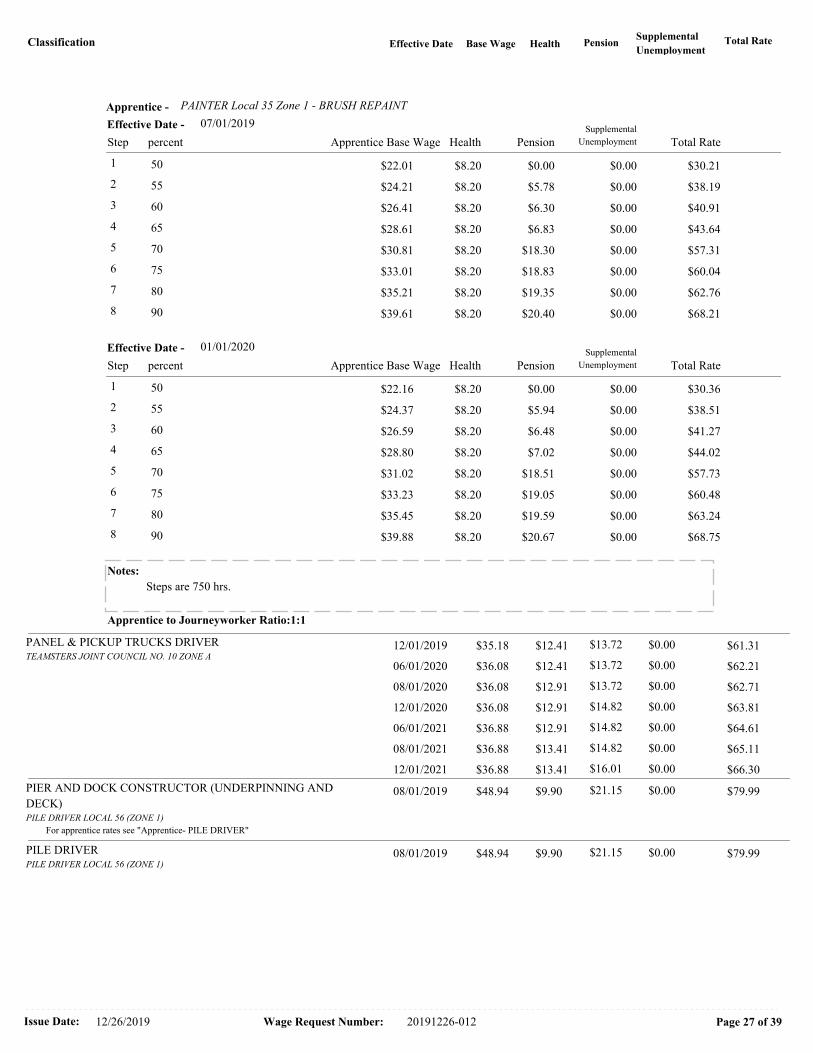
Classification Total RateBase Wage Health PensionSupplemental
UnemploymentEffective Date
PAINTER Local 35 Zone 1 - BRUSH REPAINTApprentice -
07/01/2019
Health PensionSupplemental
UnemploymentStep Apprentice Base Wage Total Ratepercent
Effective Date -
1 $22.01 $8.20 $0.00 $0.00 $30.21 50
2 $24.21 $8.20 $5.78 $0.00 $38.19 55
3 $26.41 $8.20 $6.30 $0.00 $40.91 60
4 $28.61 $8.20 $6.83 $0.00 $43.64 65
5 $30.81 $8.20 $18.30 $0.00 $57.31 70
6 $33.01 $8.20 $18.83 $0.00 $60.04 75
7 $35.21 $8.20 $19.35 $0.00 $62.76 80
8 $39.61 $8.20 $20.40 $0.00 $68.21 90
01/01/2020
Health PensionSupplemental
UnemploymentStep Apprentice Base Wage Total Ratepercent
Effective Date -
1 $22.16 $8.20 $0.00 $0.00 $30.36 50
2 $24.37 $8.20 $5.94 $0.00 $38.51 55
3 $26.59 $8.20 $6.48 $0.00 $41.27 60
4 $28.80 $8.20 $7.02 $0.00 $44.02 65
5 $31.02 $8.20 $18.51 $0.00 $57.73 70
6 $33.23 $8.20 $19.05 $0.00 $60.48 75
7 $35.45 $8.20 $19.59 $0.00 $63.24 80
8 $39.88 $8.20 $20.67 $0.00 $68.75 90
Notes:
Steps are 750 hrs.
Apprentice to Journeyworker Ratio:1:1
PANEL & PICKUP TRUCKS DRIVERTEAMSTERS JOINT COUNCIL NO. 10 ZONE A
$61.31 12/01/2019 $12.41 $0.00 $35.18 $13.72
$62.21 06/01/2020 $12.41 $0.00 $36.08 $13.72
$62.71 08/01/2020 $12.91 $0.00 $36.08 $13.72
$63.81 12/01/2020 $12.91 $0.00 $36.08 $14.82
$64.61 06/01/2021 $12.91 $0.00 $36.88 $14.82
$65.11 08/01/2021 $13.41 $0.00 $36.88 $14.82
$66.30 12/01/2021 $13.41 $0.00 $36.88 $16.01
PIER AND DOCK CONSTRUCTOR (UNDERPINNING AND
DECK)PILE DRIVER LOCAL 56 (ZONE 1)
$79.99 08/01/2019 $9.90 $0.00 $48.94 $21.15
For apprentice rates see "Apprentice- PILE DRIVER"
PILE DRIVERPILE DRIVER LOCAL 56 (ZONE 1)
$79.99 08/01/2019 $9.90 $0.00 $48.94 $21.15
Issue Date: Wage Request Number:12/26/2019 Page 27 of 3920191226-012

Classification Total RateBase Wage Health PensionSupplemental
UnemploymentEffective Date
PILE DRIVER - Local 56 Zone 1Apprentice -
08/01/2019
Health PensionSupplemental
UnemploymentStep Apprentice Base Wage Total Ratepercent
Effective Date -
1 $24.47 $9.90 $21.15 $0.00 $55.52 50
2 $29.36 $9.90 $21.15 $0.00 $60.41 60
3 $34.26 $9.90 $21.15 $0.00 $65.31 70
4 $36.71 $9.90 $21.15 $0.00 $67.76 75
5 $39.15 $9.90 $21.15 $0.00 $70.20 80
6 $39.15 $9.90 $21.15 $0.00 $70.20 80
7 $44.05 $9.90 $21.15 $0.00 $75.10 90
8 $44.05 $9.90 $21.15 $0.00 $75.10 90
Notes:
Apprentice to Journeyworker Ratio:1:5
PIPEFITTER & STEAMFITTERPIPEFITTERS LOCAL 537
$85.38 09/01/2019 $10.95 $0.00 $54.69 $19.74
$86.88 03/01/2020 $10.95 $0.00 $56.19 $19.74
$88.38 09/01/2020 $10.95 $0.00 $57.69 $19.74
$89.88 03/01/2021 $10.95 $0.00 $59.19 $19.74
PIPEFITTER - Local 537Apprentice -
09/01/2019
Health PensionSupplemental
UnemploymentStep Apprentice Base Wage Total Ratepercent
Effective Date -
1 $21.88 $10.95 $8.00 $0.00 $40.83 40
2 $24.61 $10.95 $19.74 $0.00 $55.30 45
3 $32.81 $10.95 $19.74 $0.00 $63.50 60
4 $38.28 $10.95 $19.74 $0.00 $68.97 70
5 $43.75 $10.95 $19.74 $0.00 $74.44 80
03/01/2020
Health PensionSupplemental
UnemploymentStep Apprentice Base Wage Total Ratepercent
Effective Date -
1 $22.48 $10.95 $8.00 $0.00 $41.43 40
2 $25.29 $10.95 $19.74 $0.00 $55.98 45
3 $33.71 $10.95 $19.74 $0.00 $64.40 60
4 $39.33 $10.95 $19.74 $0.00 $70.02 70
5 $44.95 $10.95 $19.74 $0.00 $75.64 80
Notes:
** 1:3; 3:15; 1:10 thereafter / Steps are 1 yr.
Refrig/AC Mechanic **1:1;1:2;2:4;3:6;4:8;5:10;6:12;7:14;8:17;9:20;10:23(Max)
Apprentice to Journeyworker Ratio:**
Issue Date: Wage Request Number:12/26/2019 Page 28 of 3920191226-012

Classification Total RateBase Wage Health PensionSupplemental
UnemploymentEffective Date
PIPELAYERLABORERS - ZONE 1
$64.10 12/01/2019 $8.10 $0.00 $39.40 $16.60
$65.09 06/01/2020 $8.10 $0.00 $40.39 $16.60
$66.07 12/01/2020 $8.10 $0.00 $41.37 $16.60
$67.09 06/01/2021 $8.10 $0.00 $42.39 $16.60
$68.10 12/01/2021 $8.10 $0.00 $43.40 $16.60For apprentice rates see "Apprentice- LABORER"
PLUMBERS & GASFITTERSPLUMBERS & GASFITTERS LOCAL 12
$86.52 09/01/2019 $11.82 $0.00 $57.69 $17.01
$88.02 03/01/2020 $11.82 $0.00 $59.19 $17.01
$89.52 09/01/2020 $11.82 $0.00 $60.69 $17.01
$91.02 03/01/2021 $11.82 $0.00 $62.19 $17.01
PLUMBER/GASFITTER - Local 12Apprentice -
09/01/2019
Health PensionSupplemental
UnemploymentStep Apprentice Base Wage Total Ratepercent
Effective Date -
1 $20.19 $11.82 $6.16 $0.00 $38.17 35
2 $23.08 $11.82 $6.99 $0.00 $41.89 40
3 $31.73 $11.82 $9.53 $0.00 $53.08 55
4 $37.50 $11.82 $11.18 $0.00 $60.50 65
5 $43.27 $11.82 $12.88 $0.00 $67.97 75
03/01/2020
Health PensionSupplemental
UnemploymentStep Apprentice Base Wage Total Ratepercent
Effective Date -
1 $20.72 $11.82 $6.16 $0.00 $38.70 35
2 $23.68 $11.82 $6.99 $0.00 $42.49 40
3 $32.55 $11.82 $9.53 $0.00 $53.90 55
4 $38.47 $11.82 $11.18 $0.00 $61.47 65
5 $44.39 $11.82 $12.88 $0.00 $69.09 75
Notes:
** 1:2; 2:6; 3:10; 4:14; 5:19/Steps are 1 yr
Step4 with lic$64.20, Step5 with lic$71.67
Apprentice to Journeyworker Ratio:**
PNEUMATIC CONTROLS (TEMP.)PIPEFITTERS LOCAL 537
$85.38 09/01/2019 $10.95 $0.00 $54.69 $19.74
$86.88 03/01/2020 $10.95 $0.00 $56.19 $19.74
$88.38 09/01/2020 $10.95 $0.00 $57.69 $19.74
$89.86 03/01/2021 $10.95 $0.00 $59.17 $19.74For apprentice rates see "Apprentice- PIPEFITTER" or "PLUMBER/PIPEFITTER"
PNEUMATIC DRILL/TOOL OPERATORLABORERS - ZONE 1
$64.10 12/01/2019 $8.10 $0.00 $39.40 $16.60
$65.09 06/01/2020 $8.10 $0.00 $40.39 $16.60
$66.07 12/01/2020 $8.10 $0.00 $41.37 $16.60
$67.09 06/01/2021 $8.10 $0.00 $42.39 $16.60
$68.10 12/01/2021 $8.10 $0.00 $43.40 $16.60For apprentice rates see "Apprentice- LABORER"
Issue Date: Wage Request Number:12/26/2019 Page 29 of 3920191226-012

Classification Total RateBase Wage Health PensionSupplemental
UnemploymentEffective Date
POWDERMAN & BLASTERLABORERS - ZONE 1
$64.85 12/01/2019 $8.10 $0.00 $40.15 $16.60
$65.84 06/01/2020 $8.10 $0.00 $41.14 $16.60
$66.82 12/01/2020 $8.10 $0.00 $42.12 $16.60
$67.84 06/01/2021 $8.10 $0.00 $43.14 $16.60
$68.85 12/01/2021 $8.10 $0.00 $44.15 $16.60For apprentice rates see "Apprentice- LABORER"
POWER SHOVEL/DERRICK/TRENCHING MACHINEOPERATING ENGINEERS LOCAL 4
$76.93 12/01/2019 $12.50 $0.00 $48.73 $15.70
$78.03 06/01/2020 $12.50 $0.00 $49.83 $15.70
$79.18 12/01/2020 $12.50 $0.00 $50.98 $15.70
$80.28 06/01/2021 $12.50 $0.00 $52.08 $15.70
$81.43 12/01/2021 $12.50 $0.00 $53.23 $15.70For apprentice rates see "Apprentice- OPERATING ENGINEERS"
PUMP OPERATOR (CONCRETE)OPERATING ENGINEERS LOCAL 4
$76.93 12/01/2019 $12.50 $0.00 $48.73 $15.70
$78.03 06/01/2020 $12.50 $0.00 $49.83 $15.70
$79.18 12/01/2020 $12.50 $0.00 $50.98 $15.70
$80.28 06/01/2021 $12.50 $0.00 $52.08 $15.70
$81.43 12/01/2021 $12.50 $0.00 $53.23 $15.70For apprentice rates see "Apprentice- OPERATING ENGINEERS"
PUMP OPERATOR (DEWATERING, OTHER)OPERATING ENGINEERS LOCAL 4
$60.67 12/01/2019 $12.50 $0.00 $32.47 $15.70
$61.42 06/01/2020 $12.50 $0.00 $33.22 $15.70
$62.20 12/01/2020 $12.50 $0.00 $34.00 $15.70
$62.95 06/01/2021 $12.50 $0.00 $34.75 $15.70
$63.74 12/01/2021 $12.50 $0.00 $35.54 $15.70For apprentice rates see "Apprentice- OPERATING ENGINEERS"
READY MIX CONCRETE DRIVERS after 4/30/12
(Drivers Hired After 4/30/2012)TEAMSTERS 25 (Metro) - Aggregate
$50.13 08/01/2019 $10.41 $0.00 $26.65 $13.07
$52.43 05/01/2020 $10.41 $0.00 $27.90 $14.12
$52.93 08/01/2020 $10.91 $0.00 $27.90 $14.12
$55.31 05/01/2021 $10.91 $0.00 $29.15 $15.25
$55.81 08/01/2021 $11.41 $0.00 $29.15 $15.25
$57.06 05/01/2022 $11.41 $0.00 $30.40 $15.25
$57.56 08/01/2022 $11.91 $0.00 $30.40 $15.25
READY-MIX CONCRETE DRIVERTEAMSTERS 25 (Metro) - Aggregate
$55.64 08/01/2019 $10.41 $0.00 $32.16 $13.07
$57.44 05/01/2020 $10.41 $0.00 $32.91 $14.12
$57.94 08/01/2020 $10.91 $0.00 $32.91 $14.12
$59.82 05/01/2021 $10.91 $0.00 $33.66 $15.25
$60.32 08/01/2021 $11.41 $0.00 $33.66 $15.25
$61.07 05/01/2022 $11.41 $0.00 $34.41 $15.25
$61.57 08/01/2022 $11.91 $0.00 $34.41 $15.25
RECLAIMERSOPERATING ENGINEERS LOCAL 4
$76.43 12/01/2019 $12.50 $0.00 $48.23 $15.70
$77.51 06/01/2020 $12.50 $0.00 $49.31 $15.70
$78.65 12/01/2020 $12.50 $0.00 $50.45 $15.70
$79.74 06/01/2021 $12.50 $0.00 $51.54 $15.70
$80.88 12/01/2021 $12.50 $0.00 $52.68 $15.70For apprentice rates see "Apprentice- OPERATING ENGINEERS"
Issue Date: Wage Request Number:12/26/2019 Page 30 of 3920191226-012

Classification Total RateBase Wage Health PensionSupplemental
UnemploymentEffective Date
RIDE-ON MOTORIZED BUGGY OPERATORLABORERS - ZONE 1
$64.10 12/01/2019 $8.10 $0.00 $39.40 $16.60
$65.09 06/01/2020 $8.10 $0.00 $40.39 $16.60
$66.07 12/01/2020 $8.10 $0.00 $41.37 $16.60
$67.09 06/01/2021 $8.10 $0.00 $42.39 $16.60
$68.10 12/01/2021 $8.10 $0.00 $43.40 $16.60For apprentice rates see "Apprentice- LABORER"
ROLLER/SPREADER/MULCHING MACHINEOPERATING ENGINEERS LOCAL 4
$76.43 12/01/2019 $12.50 $0.00 $48.23 $15.70
$77.51 06/01/2020 $12.50 $0.00 $49.31 $15.70
$78.65 12/01/2020 $12.50 $0.00 $50.45 $15.70
$79.74 06/01/2021 $12.50 $0.00 $51.54 $15.70
$80.88 12/01/2021 $12.50 $0.00 $52.68 $15.70For apprentice rates see "Apprentice- OPERATING ENGINEERS"
ROOFER (Inc.Roofer Waterproofng &Roofer Damproofg)ROOFERS LOCAL 33
$72.04 08/01/2019 $11.50 $0.00 $44.64 $15.90
$73.32 02/01/2020 $11.50 $0.00 $45.92 $15.90
$74.75 08/01/2020 $11.50 $0.00 $47.35 $15.90
$76.18 02/01/2021 $11.50 $0.00 $48.78 $15.90
$77.61 08/01/2021 $11.50 $0.00 $50.21 $15.90
$79.04 02/01/2022 $11.50 $0.00 $51.64 $15.90
ROOFER - Local 33Apprentice -
08/01/2019
Health PensionSupplemental
UnemploymentStep Apprentice Base Wage Total Ratepercent
Effective Date -
1 $22.32 $11.50 $3.69 $0.00 $37.51 50
2 $26.78 $11.50 $15.90 $0.00 $54.18 60
3 $29.02 $11.50 $15.90 $0.00 $56.42 65
4 $33.48 $11.50 $15.90 $0.00 $60.88 75
5 $37.94 $11.50 $15.90 $0.00 $65.34 85
02/01/2020
Health PensionSupplemental
UnemploymentStep Apprentice Base Wage Total Ratepercent
Effective Date -
1 $22.96 $11.50 $3.69 $0.00 $38.15 50
2 $27.55 $11.50 $15.90 $0.00 $54.95 60
3 $29.85 $11.50 $15.90 $0.00 $57.25 65
4 $34.44 $11.50 $15.90 $0.00 $61.84 75
5 $39.03 $11.50 $15.90 $0.00 $66.43 85
Notes: ** 1:5, 2:6-10, the 1:10; Reroofing: 1:4, then 1:1
Step 1 is 2000 hrs.; Steps 2-5 are 1000 hrs.
(Hot Pitch Mechanics' receive $1.00 hr. above ROOFER)
Apprentice to Journeyworker Ratio:**
ROOFER SLATE / TILE / PRECAST CONCRETEROOFERS LOCAL 33
$72.29 08/01/2019 $11.50 $0.00 $44.89 $15.90
$73.57 02/01/2020 $11.50 $0.00 $46.17 $15.90
$75.00 08/01/2020 $11.50 $0.00 $47.60 $15.90
$76.43 02/01/2021 $11.50 $0.00 $49.03 $15.90
$77.86 08/01/2021 $11.50 $0.00 $50.46 $15.90
$79.29 02/01/2022 $11.50 $0.00 $51.89 $15.90
Issue Date: Wage Request Number:12/26/2019 Page 31 of 3920191226-012

Classification Total RateBase Wage Health PensionSupplemental
UnemploymentEffective Date
For apprentice rates see "Apprentice- ROOFER"
SHEETMETAL WORKERSHEETMETAL WORKERS LOCAL 17 - A
$87.98 08/01/2019 $13.20 $2.56 $48.10 $24.12
$89.68 02/01/2020 $13.20 $2.61 $49.75 $24.12
$91.33 08/01/2020 $13.20 $2.66 $51.35 $24.12
$93.03 02/01/2021 $13.20 $2.71 $53.00 $24.12
$94.83 08/01/2021 $13.20 $2.76 $54.75 $24.12
$96.63 02/01/2022 $13.20 $2.81 $56.50 $24.12
SHEET METAL WORKER - Local 17-AApprentice -
08/01/2019
Health PensionSupplemental
UnemploymentStep Apprentice Base Wage Total Ratepercent
Effective Date -
1 $20.20 $13.20 $5.89 $0.00 $39.29 42
2 $20.20 $13.20 $5.89 $0.00 $39.29 42
3 $22.61 $13.20 $11.13 $1.41 $48.35 47
4 $22.61 $13.20 $11.13 $1.41 $48.35 47
5 $25.01 $13.20 $12.08 $1.51 $51.80 52
6 $25.01 $13.20 $12.33 $1.52 $52.06 52
7 $28.86 $13.20 $13.70 $1.67 $57.43 60
8 $31.27 $13.20 $14.65 $1.77 $60.89 65
9 $36.08 $13.20 $16.56 $1.98 $67.82 75
10 $40.89 $13.20 $17.96 $2.16 $74.21 85
02/01/2020
Health PensionSupplemental
UnemploymentStep Apprentice Base Wage Total Ratepercent
Effective Date -
1 $20.90 $13.20 $5.89 $0.00 $39.99 42
2 $20.90 $13.20 $5.89 $0.00 $39.99 42
3 $23.38 $13.20 $11.13 $1.43 $49.14 47
4 $23.38 $13.20 $11.13 $1.43 $49.14 47
5 $25.87 $13.20 $12.08 $1.53 $52.68 52
6 $25.87 $13.20 $12.33 $1.54 $52.94 52
7 $29.85 $13.20 $13.70 $1.70 $58.45 60
8 $32.34 $13.20 $14.65 $1.82 $62.01 65
9 $37.31 $13.20 $16.56 $2.01 $69.08 75
10 $42.29 $13.20 $17.96 $2.20 $75.65 85
Notes:
Steps are 6 mos.
Apprentice to Journeyworker Ratio:1:4
SPECIALIZED EARTH MOVING EQUIP < 35 TONSTEAMSTERS JOINT COUNCIL NO. 10 ZONE A
$61.77 12/01/2019 $12.41 $0.00 $35.64 $13.72
$62.67 06/01/2020 $12.41 $0.00 $36.54 $13.72
$63.17 08/01/2020 $12.91 $0.00 $36.54 $13.72
$64.27 12/01/2020 $12.91 $0.00 $36.54 $14.82
$65.07 06/01/2021 $12.91 $0.00 $37.34 $14.82
$65.57 08/01/2021 $13.41 $0.00 $37.34 $14.82
$66.76 12/01/2021 $13.41 $0.00 $37.34 $16.01
Issue Date: Wage Request Number:12/26/2019 Page 32 of 3920191226-012

Classification Total RateBase Wage Health PensionSupplemental
UnemploymentEffective Date
SPECIALIZED EARTH MOVING EQUIP > 35 TONSTEAMSTERS JOINT COUNCIL NO. 10 ZONE A
$62.06 12/01/2019 $12.41 $0.00 $35.93 $13.72
$62.96 06/01/2020 $12.41 $0.00 $36.83 $13.72
$63.46 08/01/2020 $12.91 $0.00 $36.83 $13.72
$64.56 12/01/2020 $12.91 $0.00 $36.83 $14.82
$65.36 06/01/2021 $12.91 $0.00 $37.63 $14.82
$65.86 08/01/2021 $13.41 $0.00 $37.63 $14.82
$67.05 12/01/2021 $13.41 $0.00 $37.63 $16.01
SPRINKLER FITTERSPRINKLER FITTERS LOCAL 550 - (Section A) Zone 1
$89.55 10/01/2019 $9.47 $0.00 $60.48 $19.60
$89.55 01/01/2020 $9.68 $0.00 $60.07 $19.80
$91.05 03/01/2020 $9.47 $0.00 $61.98 $19.60
$92.55 10/01/2020 $9.47 $0.00 $63.48 $19.60
$94.05 03/01/2021 $9.47 $0.00 $64.98 $19.60
SPRINKLER FITTER - Local 550 (Section A) Zone 1Apprentice -
10/01/2019
Health PensionSupplemental
UnemploymentStep Apprentice Base Wage Total Ratepercent
Effective Date -
1 $21.17 $9.47 $11.15 $0.00 $41.79 35
2 $24.19 $9.47 $11.80 $0.00 $45.46 40
3 $27.22 $9.47 $12.45 $0.00 $49.14 45
4 $30.24 $9.47 $13.10 $0.00 $52.81 50
5 $33.26 $9.47 $13.75 $0.00 $56.48 55
6 $36.29 $9.47 $14.40 $0.00 $60.16 60
7 $39.31 $9.47 $15.05 $0.00 $63.83 65
8 $42.34 $9.47 $15.70 $0.00 $67.51 70
9 $45.36 $9.47 $16.35 $0.00 $71.18 75
10 $48.38 $9.47 $17.00 $0.00 $74.85 80
01/01/2020
Health PensionSupplemental
UnemploymentStep Apprentice Base Wage Total Ratepercent
Effective Date -
1 $21.02 $9.68 $11.35 $0.00 $42.05 35
2 $24.03 $9.68 $12.00 $0.00 $45.71 40
3 $27.03 $9.68 $12.65 $0.00 $49.36 45
4 $30.04 $9.68 $13.30 $0.00 $53.02 50
5 $33.04 $9.68 $13.95 $0.00 $56.67 55
6 $36.04 $9.68 $14.60 $0.00 $60.32 60
7 $39.05 $9.68 $15.25 $0.00 $63.98 65
8 $42.05 $9.68 $15.90 $0.00 $67.63 70
9 $45.05 $9.68 $16.55 $0.00 $71.28 75
10 $48.06 $9.68 $17.20 $0.00 $74.94 80
Notes: Apprentice entered prior 9/30/10:
40/45/50/55/60/65/70/75/80/85
Steps are 850 hours
Apprentice to Journeyworker Ratio:1:3
Issue Date: Wage Request Number:12/26/2019 Page 33 of 3920191226-012

Classification Total RateBase Wage Health PensionSupplemental
UnemploymentEffective Date
STEAM BOILER OPERATOROPERATING ENGINEERS LOCAL 4
$76.43 12/01/2019 $12.50 $0.00 $48.23 $15.70
$77.51 06/01/2020 $12.50 $0.00 $49.31 $15.70
$78.65 12/01/2020 $12.50 $0.00 $50.45 $15.70
$79.74 06/01/2021 $12.50 $0.00 $51.54 $15.70
$80.88 12/01/2021 $12.50 $0.00 $52.68 $15.70For apprentice rates see "Apprentice- OPERATING ENGINEERS"
TAMPERS, SELF-PROPELLED OR TRACTOR DRAWNOPERATING ENGINEERS LOCAL 4
$76.43 12/01/2019 $12.50 $0.00 $48.23 $15.70
$77.51 06/01/2020 $12.50 $0.00 $49.31 $15.70
$78.65 12/01/2020 $12.50 $0.00 $50.45 $15.70
$79.74 06/01/2021 $12.50 $0.00 $51.54 $15.70
$80.88 12/01/2021 $12.50 $0.00 $52.68 $15.70For apprentice rates see "Apprentice- OPERATING ENGINEERS"
TELECOMMUNICATION TECHNICIANELECTRICIANS LOCAL 103
$68.15 03/01/2019 $13.00 $0.00 $38.33 $16.82
TELECOMMUNICATION TECHNICIAN - Local 103Apprentice -
03/01/2019
Health PensionSupplemental
UnemploymentStep Apprentice Base Wage Total Ratepercent
Effective Date -
1 $15.33 $13.00 $0.46 $0.00 $28.79 40
2 $15.33 $13.00 $0.46 $0.00 $28.79 40
3 $17.25 $13.00 $13.42 $0.00 $43.67 45
4 $17.25 $13.00 $13.42 $0.00 $43.67 45
5 $19.17 $13.00 $13.73 $0.00 $45.90 50
6 $21.08 $13.00 $14.03 $0.00 $48.11 55
7 $23.00 $13.00 $14.34 $0.00 $50.34 60
8 $24.91 $13.00 $14.66 $0.00 $52.57 65
9 $26.83 $13.00 $14.96 $0.00 $54.79 70
10 $28.75 $13.00 $15.27 $0.00 $57.02 75
Notes:
Apprentice to Journeyworker Ratio:1:1
TERRAZZO FINISHERSBRICKLAYERS LOCAL 3 - MARBLE & TILE
$85.39 08/01/2019 $10.75 $0.00 $53.34 $21.30
$86.03 02/01/2020 $10.75 $0.00 $53.98 $21.30
$87.53 08/01/2020 $10.75 $0.00 $55.33 $21.45
$88.17 02/01/2021 $10.75 $0.00 $55.97 $21.45
$89.73 08/01/2021 $10.75 $0.00 $57.37 $21.61
$90.32 02/01/2022 $10.75 $0.00 $57.96 $21.61
Issue Date: Wage Request Number:12/26/2019 Page 34 of 3920191226-012

Classification Total RateBase Wage Health PensionSupplemental
UnemploymentEffective Date
TERRAZZO FINISHER - Local 3 Marble & TileApprentice -
08/01/2019
Health PensionSupplemental
UnemploymentStep Apprentice Base Wage Total Ratepercent
Effective Date -
1 $26.67 $10.75 $21.30 $0.00 $58.72 50
2 $32.00 $10.75 $21.30 $0.00 $64.05 60
3 $37.34 $10.75 $21.30 $0.00 $69.39 70
4 $42.67 $10.75 $21.30 $0.00 $74.72 80
5 $48.01 $10.75 $21.30 $0.00 $80.06 90
02/01/2020
Health PensionSupplemental
UnemploymentStep Apprentice Base Wage Total Ratepercent
Effective Date -
1 $26.99 $10.75 $21.30 $0.00 $59.04 50
2 $32.39 $10.75 $21.30 $0.00 $64.44 60
3 $37.79 $10.75 $21.30 $0.00 $69.84 70
4 $43.18 $10.75 $21.30 $0.00 $75.23 80
5 $48.58 $10.75 $21.30 $0.00 $80.63 90
Notes:
Apprentice to Journeyworker Ratio:1:3
TEST BORING DRILLERLABORERS - FOUNDATION AND MARINE
$65.40 12/01/2019 $8.10 $0.00 $40.50 $16.80
$66.39 06/01/2020 $8.10 $0.00 $41.49 $16.80
$67.37 12/01/2020 $8.10 $0.00 $42.47 $16.80
$68.39 06/01/2021 $8.10 $0.00 $43.49 $16.80
$69.40 12/01/2021 $8.10 $0.00 $44.50 $16.80For apprentice rates see "Apprentice- LABORER"
TEST BORING DRILLER HELPERLABORERS - FOUNDATION AND MARINE
$64.12 12/01/2019 $8.10 $0.00 $39.22 $16.80
$65.11 06/01/2020 $8.10 $0.00 $40.21 $16.80
$66.09 12/01/2020 $8.10 $0.00 $41.19 $16.80
$67.11 06/01/2021 $8.10 $0.00 $42.21 $16.80
$68.12 12/01/2021 $8.10 $0.00 $43.22 $16.80For apprentice rates see "Apprentice- LABORER"
TEST BORING LABORERLABORERS - FOUNDATION AND MARINE
$64.00 12/01/2019 $8.10 $0.00 $39.10 $16.80
$64.99 06/01/2020 $8.10 $0.00 $40.09 $16.80
$65.97 12/01/2020 $8.10 $0.00 $41.07 $16.80
$66.99 06/01/2021 $8.10 $0.00 $42.09 $16.80
$68.00 12/01/2021 $8.10 $0.00 $43.10 $16.80For apprentice rates see "Apprentice- LABORER"
TRACTORS/PORTABLE STEAM GENERATORSOPERATING ENGINEERS LOCAL 4
$76.43 12/01/2019 $12.50 $0.00 $48.23 $15.70
$77.51 06/01/2020 $12.50 $0.00 $49.31 $15.70
$78.65 12/01/2020 $12.50 $0.00 $50.45 $15.70
$79.74 06/01/2021 $12.50 $0.00 $51.54 $15.70
$80.88 12/01/2021 $12.50 $0.00 $52.68 $15.70For apprentice rates see "Apprentice- OPERATING ENGINEERS"
Issue Date: Wage Request Number:12/26/2019 Page 35 of 3920191226-012

Classification Total RateBase Wage Health PensionSupplemental
UnemploymentEffective Date
TRAILERS FOR EARTH MOVING EQUIPMENTTEAMSTERS JOINT COUNCIL NO. 10 ZONE A
$62.35 12/01/2019 $12.41 $0.00 $36.22 $13.72
$63.25 06/01/2020 $12.41 $0.00 $37.12 $13.72
$63.75 08/01/2020 $12.91 $0.00 $37.12 $13.72
$64.85 12/01/2020 $12.91 $0.00 $37.12 $14.82
$65.65 06/01/2021 $12.91 $0.00 $37.92 $14.82
$66.15 08/01/2021 $13.41 $0.00 $37.92 $14.82
$67.34 12/01/2021 $13.41 $0.00 $37.92 $16.01
TUNNEL WORK - COMPRESSED AIRLABORERS (COMPRESSED AIR)
$76.68 12/01/2019 $8.10 $0.00 $51.38 $17.20
$77.67 06/01/2020 $8.10 $0.00 $52.37 $17.20
$78.65 12/01/2020 $8.10 $0.00 $53.35 $17.20
$79.67 06/01/2021 $8.10 $0.00 $54.37 $17.20
$80.68 12/01/2021 $8.10 $0.00 $55.38 $17.20For apprentice rates see "Apprentice- LABORER"
TUNNEL WORK - COMPRESSED AIR (HAZ. WASTE)LABORERS (COMPRESSED AIR)
$78.68 12/01/2019 $8.10 $0.00 $53.38 $17.20
$79.67 06/01/2020 $8.10 $0.00 $54.37 $17.20
$80.65 12/01/2020 $8.10 $0.00 $55.35 $17.20
$81.67 06/01/2021 $8.10 $0.00 $56.37 $17.20
$82.68 12/01/2021 $8.10 $0.00 $57.38 $17.20For apprentice rates see "Apprentice- LABORER"
TUNNEL WORK - FREE AIRLABORERS (FREE AIR TUNNEL)
$68.75 12/01/2019 $8.10 $0.00 $43.45 $17.20
$69.74 06/01/2020 $8.10 $0.00 $44.44 $17.20
$70.72 12/01/2020 $8.10 $0.00 $45.42 $17.20
$71.74 06/01/2021 $8.10 $0.00 $46.44 $17.20
$72.75 12/01/2021 $8.10 $0.00 $47.45 $17.20For apprentice rates see "Apprentice- LABORER"
TUNNEL WORK - FREE AIR (HAZ. WASTE)LABORERS (FREE AIR TUNNEL)
$70.75 12/01/2019 $8.10 $0.00 $45.45 $17.20
$71.74 06/01/2020 $8.10 $0.00 $46.44 $17.20
$72.72 12/01/2020 $8.10 $0.00 $47.42 $17.20
$73.74 06/01/2021 $8.10 $0.00 $48.44 $17.20
$74.75 12/01/2021 $8.10 $0.00 $49.45 $17.20For apprentice rates see "Apprentice- LABORER"
VAC-HAULTEAMSTERS JOINT COUNCIL NO. 10 ZONE A
$61.77 12/01/2019 $12.41 $0.00 $35.64 $13.72
$62.67 06/01/2020 $12.41 $0.00 $36.54 $13.72
$63.17 08/01/2020 $12.91 $0.00 $36.54 $13.72
$64.27 12/01/2020 $12.91 $0.00 $36.54 $14.82
$65.07 06/01/2021 $12.91 $0.00 $37.34 $14.82
$65.57 08/01/2021 $13.41 $0.00 $37.34 $14.82
$66.76 12/01/2021 $13.41 $0.00 $37.34 $16.01
WAGON DRILL OPERATORLABORERS - ZONE 1
$64.10 12/01/2019 $8.10 $0.00 $39.40 $16.60
$65.09 06/01/2020 $8.10 $0.00 $40.39 $16.60
$66.07 12/01/2020 $8.10 $0.00 $41.37 $16.60
$67.09 06/01/2021 $8.10 $0.00 $42.39 $16.60
$68.10 12/01/2021 $8.10 $0.00 $43.40 $16.60For apprentice rates see "Apprentice- LABORER"
Issue Date: Wage Request Number:12/26/2019 Page 36 of 3920191226-012
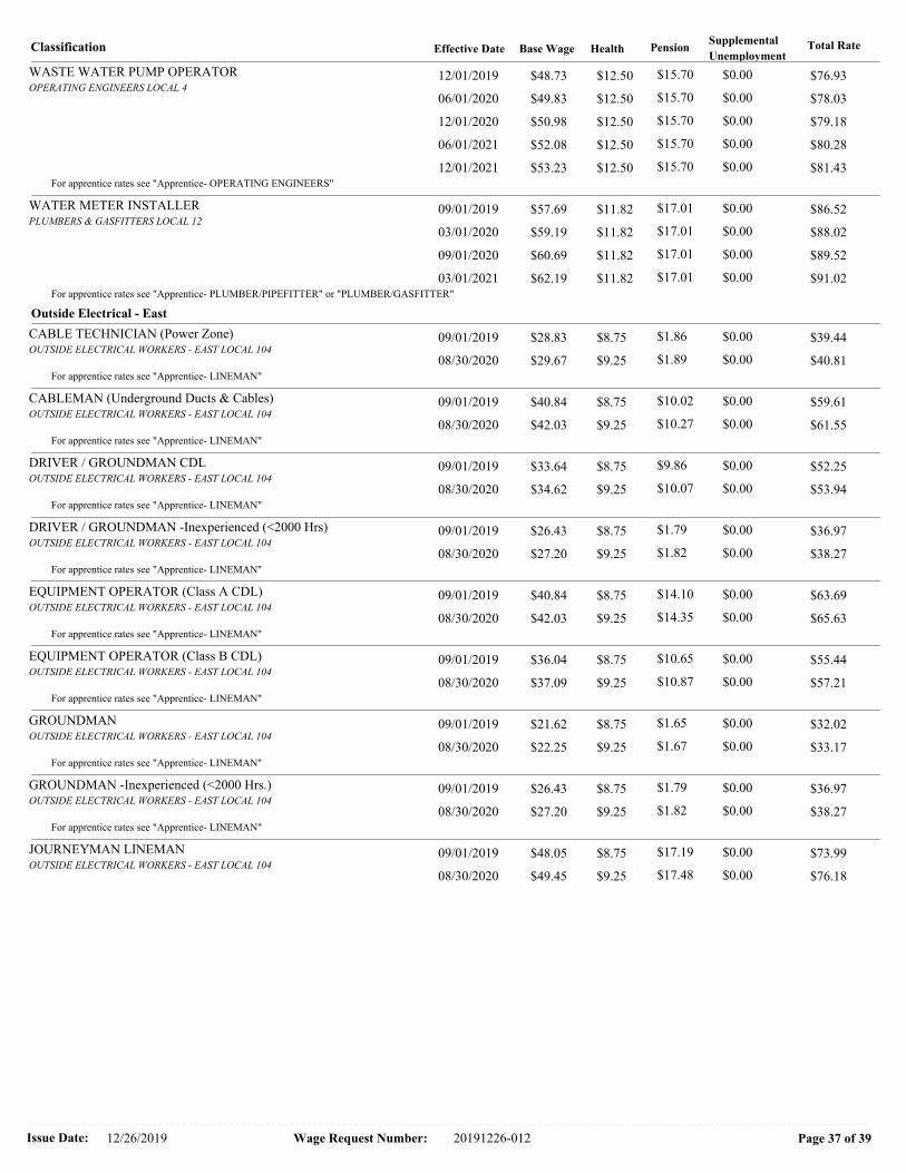
Classification Total RateBase Wage Health PensionSupplemental
UnemploymentEffective Date
WASTE WATER PUMP OPERATOROPERATING ENGINEERS LOCAL 4
$76.93 12/01/2019 $12.50 $0.00 $48.73 $15.70
$78.03 06/01/2020 $12.50 $0.00 $49.83 $15.70
$79.18 12/01/2020 $12.50 $0.00 $50.98 $15.70
$80.28 06/01/2021 $12.50 $0.00 $52.08 $15.70
$81.43 12/01/2021 $12.50 $0.00 $53.23 $15.70For apprentice rates see "Apprentice- OPERATING ENGINEERS"
WATER METER INSTALLERPLUMBERS & GASFITTERS LOCAL 12
$86.52 09/01/2019 $11.82 $0.00 $57.69 $17.01
$88.02 03/01/2020 $11.82 $0.00 $59.19 $17.01
$89.52 09/01/2020 $11.82 $0.00 $60.69 $17.01
$91.02 03/01/2021 $11.82 $0.00 $62.19 $17.01For apprentice rates see "Apprentice- PLUMBER/PIPEFITTER" or "PLUMBER/GASFITTER"
Outside Electrical - East
CABLE TECHNICIAN (Power Zone)OUTSIDE ELECTRICAL WORKERS - EAST LOCAL 104
$39.44 09/01/2019 $8.75 $0.00 $28.83 $1.86
$40.81 08/30/2020 $9.25 $0.00 $29.67 $1.89For apprentice rates see "Apprentice- LINEMAN"
CABLEMAN (Underground Ducts & Cables)OUTSIDE ELECTRICAL WORKERS - EAST LOCAL 104
$59.61 09/01/2019 $8.75 $0.00 $40.84 $10.02
$61.55 08/30/2020 $9.25 $0.00 $42.03 $10.27For apprentice rates see "Apprentice- LINEMAN"
DRIVER / GROUNDMAN CDLOUTSIDE ELECTRICAL WORKERS - EAST LOCAL 104
$52.25 09/01/2019 $8.75 $0.00 $33.64 $9.86
$53.94 08/30/2020 $9.25 $0.00 $34.62 $10.07For apprentice rates see "Apprentice- LINEMAN"
DRIVER / GROUNDMAN -Inexperienced (<2000 Hrs)OUTSIDE ELECTRICAL WORKERS - EAST LOCAL 104
$36.97 09/01/2019 $8.75 $0.00 $26.43 $1.79
$38.27 08/30/2020 $9.25 $0.00 $27.20 $1.82For apprentice rates see "Apprentice- LINEMAN"
EQUIPMENT OPERATOR (Class A CDL)OUTSIDE ELECTRICAL WORKERS - EAST LOCAL 104
$63.69 09/01/2019 $8.75 $0.00 $40.84 $14.10
$65.63 08/30/2020 $9.25 $0.00 $42.03 $14.35For apprentice rates see "Apprentice- LINEMAN"
EQUIPMENT OPERATOR (Class B CDL)OUTSIDE ELECTRICAL WORKERS - EAST LOCAL 104
$55.44 09/01/2019 $8.75 $0.00 $36.04 $10.65
$57.21 08/30/2020 $9.25 $0.00 $37.09 $10.87For apprentice rates see "Apprentice- LINEMAN"
GROUNDMANOUTSIDE ELECTRICAL WORKERS - EAST LOCAL 104
$32.02 09/01/2019 $8.75 $0.00 $21.62 $1.65
$33.17 08/30/2020 $9.25 $0.00 $22.25 $1.67For apprentice rates see "Apprentice- LINEMAN"
GROUNDMAN -Inexperienced (<2000 Hrs.)OUTSIDE ELECTRICAL WORKERS - EAST LOCAL 104
$36.97 09/01/2019 $8.75 $0.00 $26.43 $1.79
$38.27 08/30/2020 $9.25 $0.00 $27.20 $1.82For apprentice rates see "Apprentice- LINEMAN"
JOURNEYMAN LINEMANOUTSIDE ELECTRICAL WORKERS - EAST LOCAL 104
$73.99 09/01/2019 $8.75 $0.00 $48.05 $17.19
$76.18 08/30/2020 $9.25 $0.00 $49.45 $17.48
Issue Date: Wage Request Number:12/26/2019 Page 37 of 3920191226-012

Classification Total RateBase Wage Health PensionSupplemental
UnemploymentEffective Date
LINEMAN (Outside Electrical) - East Local 104Apprentice -
09/01/2019
Health PensionSupplemental
UnemploymentStep Apprentice Base Wage Total Ratepercent
Effective Date -
1 $28.83 $8.75 $3.36 $0.00 $40.94 60
2 $31.23 $8.75 $3.44 $0.00 $43.42 65
3 $33.64 $8.75 $3.51 $0.00 $45.90 70
4 $36.04 $8.75 $5.08 $0.00 $49.87 75
5 $38.44 $8.75 $5.15 $0.00 $52.34 80
6 $40.84 $8.75 $5.23 $0.00 $54.82 85
7 $43.25 $8.75 $7.30 $0.00 $59.30 90
08/30/2020
Health PensionSupplemental
UnemploymentStep Apprentice Base Wage Total Ratepercent
Effective Date -
1 $29.67 $9.25 $3.39 $0.00 $42.31 60
2 $32.14 $9.25 $3.46 $0.00 $44.85 65
3 $34.62 $9.25 $3.54 $0.00 $47.41 70
4 $37.09 $9.25 $5.11 $0.00 $51.45 75
5 $39.56 $9.25 $5.19 $0.00 $54.00 80
6 $42.03 $9.25 $5.26 $0.00 $56.54 85
7 $44.51 $9.25 $7.34 $0.00 $61.10 90
Notes:
Apprentice to Journeyworker Ratio:1:2
TELEDATA CABLE SPLICEROUTSIDE ELECTRICAL WORKERS - EAST LOCAL 104
$38.60 02/04/2019 $4.70 $0.00 $30.73 $3.17
TELEDATA LINEMAN/EQUIPMENT OPERATOROUTSIDE ELECTRICAL WORKERS - EAST LOCAL 104
$36.77 02/04/2019 $4.70 $0.00 $28.93 $3.14
TELEDATA WIREMAN/INSTALLER/TECHNICIANOUTSIDE ELECTRICAL WORKERS - EAST LOCAL 104
$36.77 02/04/2019 $4.70 $0.00 $28.93 $3.14
TREE TRIMMEROUTSIDE ELECTRICAL WORKERS - EAST LOCAL 104
$22.06 01/31/2016 $3.55 $0.00 $18.51 $0.00
This classification applies only to tree work done: (a) for a utility company, R.E.A. cooperative, or railroad or coal mining company, and (b) for the purpose of
operating, maintaining, or repairing the utility company’s equipment, and (c) by a person who is using hand or mechanical cutting methods and is not on the ground.
This classification does not apply to wholesale tree removal.
TREE TRIMMER GROUNDMANOUTSIDE ELECTRICAL WORKERS - EAST LOCAL 104
$19.87 01/31/2016 $3.55 $0.00 $16.32 $0.00
This classification applies only to tree work done: (a) for a utility company, R.E.A. cooperative, or railroad or coal mining company, and (b) for the purpose of
operating, maintaining, or repairing the utility company’s equipment, and (c) by a person who is using hand or mechanical cutting methods and is on the ground. This
classification does not apply to wholesale tree removal.
Issue Date: Wage Request Number:12/26/2019 Page 38 of 3920191226-012

Classification Total RateBase Wage Health PensionSupplemental
UnemploymentEffective Date
Additional Apprentice Information:
Minimum wage rates for apprentices employed on public works projects are listed above as a percentage of the pre-determined hourly wage rate established by the
Commissioner under the provisions of the M.G.L. c. 149, ss. 26-27D. Apprentice ratios are established by the Division of Apprenticeship Training pursuant to M.G.L.
c. 23, ss. 11E-11L.
All apprentices must be registered with the Division of Apprenticeship Training in accordance with M.G.L. c. 23, ss. 11E-11L.
All steps are six months (1000 hours.)
Ratios are expressed in allowable number of apprentices to journeymen or fraction thereof, unless otherwise specified.
** Multiple ratios are listed in the comment field.
*** APP to JM; 1:1, 2:2, 2:3, 3:4, 4:4, 4:5, 4:6, 5:7, 6:7, 6:8, 6:9, 7:10, 8:10, 8:11, 8:12, 9:13, 10:13, 10:14, etc.
**** APP to JM; 1:1, 1:2, 2:3, 2:4, 3:5, 4:6, 4:7, 5:8, 6:9, 6:10, 7:11, 8:12, 8:13, 9:14, 10:15, 10:16, etc.
Issue Date: Wage Request Number:12/26/2019 Page 39 of 3920191226-012


T-2
CE
NT
RA
L F
ILE
S
T-1 T-3
WS 5'-6" x 6'-0"
COPY
WS 5'-6" x 6'-0"
46" x 26"
WS 7'-0" x 7'-0"
WS 7'-0" x 7'-0"
T.B.D.
T.B.D.
WS 5'-6" x 6'-0"
NEW OFFICE
213B
VAULT
N.I.C.
TREASURES OFFICE
213
MAIL ROOM
215
EXISTING OFFICE
213A
213215
213A
213B
Drawn by:
proj
ect n
umbe
r:
Scale:
68 H
ARRI
SON
AVE
NU
E
BOST
ON
, MA
0211
1
TEL
617
.423
.140
0
WEB
CO
NTE
XTAR
C.CO
M
CHEL
SEA
CITY
HAL
L - R
OO
M 2
13 -
215
500
BRO
ADW
AY, C
HELS
EA M
A 02
150
1907
.00
No.
Issue:
Date:
1
12/18/2019
GA
RC
IA
G
ALU
SK
A D
ES
OU
SA
P1.1
PLU
MBI
NG
- NEW
WO
RK A
ND
DEM
OLI
TIO
N P
LAN
MM1/4"=1'-0"
PLUMBING DEMOLITION PLAN
PLUMBING NEW WORK PLAN
PIPE SIZE TO FIXTURE SCHEDULE
SINK
FIXTURE
P-1
P. NO. S/W
2"
VENT
2"
HWCW
1/2"
REMARKS
1/2"
PLUMBING ELECTRICAL EQUIPMENT
WATER HEATER
UNIT FUNCTION
EWH-1
NO.
UNIT LOCATION
TREASURES 213
V
MOTOR
1
REMARKS
120
UNIT
LD-1LEAK DETECTION
AT WATER HEATER
HPPH
-
1120-
2.5 GALLON
ABBREV
LEGEND
HWR
HW
CW
EX
V
V
S/W
S/W
SYMBOL
NEW
HOT WATER
HOT WATER RETURN
COLD WATER
EXISTING WORK (LIGHT)
VENT UNDERGROUND
SOIL/WASTE ABV. GRADE
SOIL/WASTE UNDERGROUND
VENT ABV. GRADE
DESCRIPTION
NEW WORK (DARK)
EXP
STK
FPC
UC
FIRE PROTECTION CONTRACTOR
EXPOSED
UNDER COUNTER
STACK
BUTTERFLY VALVE
S&W
FG
AFG
AFF
VTR
FFE
TYP.
EX
PT
VOV
EXISTING
ABOVE FINISHED FLOOR
FINISHED GRADE
ABOVE FINISHED GRADE
VENT THRU ROOF
FINISHED FLOOR ELEVATION
CONNECT TO EXISTING
TYPICAL
FLOW IN DIRECTION OF ARROW
VALVE ON VERTICAL
STOP & WASTE VALVE
PIPE ANCHOR
PIPE GUIDE
GAS COCK LUBRICATED
GLOBE VALVE
P-TRAP
DP,DN
RD
GV
PRV
BV
CV
CO
DCO
FCO
FD
UP
TEE LOOKING DOWN
FLOOR DRAIN, ROOF DRAIN, AREA DRAIN
BALANCING VALVE
PRESSURE REDUCING VALVE
CHECK VALVE
GATE VALVE
BALL VALVE
FLOOR CLEANOUT
DANDY CLEANOUT
CAP ON END OF PIPE
UNION
CLEANOUT
STRAINER
AD
PIPE DROP OR DOWN
PIPE RISE OR UP
NOTE: NOT ALL SYMBOLS LISTED ARE APPLICABLE TO THIS PROJECT
CTE
ETR EXISTING TO REMAIN
ETBR EXISTING TO BE REMOVED
FINISHED FLOOR
UNDERCOUNTER ELECTRIC STORAGE WATER HEATER DETAIL
VB
EWH-1
120V
NOTE:
1. INSULATE ALL PIPING LOCATED
UNDER SINK W/ ARMARFLEX WHITE
2000 AND FITTING W/ PVC JACKETS.
2. EWH-2 5 GALLON ELECTRIC WATER
HEATER - "HTP PRODUCTS" MODEL
EVR02.5A014C, 1500 kW, 120 V., 1
PHASE, 60 HZ.
LEAK DETECTION
FIRSTSMART SENSOR MODEL
FSS-1ZMC WITH
TRANSFORMER
ASCO SOLENOID VALVE
#8210G34, 24VAC/60HZ
VACUUM RELIEF
1/2" HW OUTLET
T & P RELIEF VALVE
HARDWARE SENSOR
FSS-HWSR
METALIC NON-CORROSIVE
DRIP PAN
NOT TO SCALE
CONNECT 1/2"H&CW TO
EXISTING SUPPLIES
AT WALL
P-1 SINK
1/2" CW
2"V
2" W
2" W
P-TRAP
W/ C.O.
2" W TO EX.
2" W ABOVE FLOOR
EX 2" W STACK
1/2"VALVE &
CAP FOR
APPLIANCE(S)
AutoCAD SHX Text
EX 2" W & T (AT CEILING)
AutoCAD SHX Text
EX 2" W UP & DN
AutoCAD SHX Text
DISCONNECT AND REMOVE EX. SINK, FAUCET, TRAP, SUPPLIES, & DROP CUT BACK EX. 2" W 1/2" H & CW TO CEILING AND BELOW AND CAP AT MAINS. CUT BACK EX 2" V TO CEILING AND CAP FOR RECONNECTION
AutoCAD SHX Text
ETBR 1/2" HW DN ETBR 2" W DN & 2" V UP ETBR 1/2" CW DN
AutoCAD SHX Text
CAP TYP. FOR 3
AutoCAD SHX Text
EX 2" W (ACB)
AutoCAD SHX Text
EX H & CW MAINS (ACB)
AutoCAD SHX Text
P-1
AutoCAD SHX Text
EX 2" W & T (AT CEILING)
AutoCAD SHX Text
EX 2" W UP & DN
AutoCAD SHX Text
LD-1 LEAK DETECTION
AutoCAD SHX Text
EWH-1 ELECTRIC WATER HEATER UNDER COUNTER
AutoCAD SHX Text
1/2" CW DROP 2" W & 2" V
AutoCAD SHX Text
2" W TO EX.
AutoCAD SHX Text
2" W ABOVE FLOOR
AutoCAD SHX Text
2" V.(RUN AS HIGH
AutoCAD SHX Text
AS POSSABLE)
AutoCAD SHX Text
1/2" CW
AutoCAD SHX Text
CONNECT 1/2" CW
AutoCAD SHX Text
(AT CEILING BELOW)
AutoCAD SHX Text
TO EX. 1/2"CW
AutoCAD SHX Text
CONNECT 2" V
AutoCAD SHX Text
(AT CEILING)
AutoCAD SHX Text
TO EX. 2"V
AutoCAD SHX Text
1/2" CW DN
AutoCAD SHX Text
EX 2" V UP
AutoCAD SHX Text
1 1/2" W ALONG WALL UNDER COUNTER
AutoCAD SHX Text
375 Faunce Corner Road Suite D, Dartmouth,MA
AutoCAD SHX Text
CONSULTING ENGINEERS
AutoCAD SHX Text
INC.
AutoCAD SHX Text
508
AutoCAD SHX Text
0883
AutoCAD SHX Text
998
AutoCAD SHX Text
FAX 508
AutoCAD SHX Text
d.com
AutoCAD SHX Text
g
AutoCAD SHX Text
MAIL info@g
AutoCAD SHX Text
E
AutoCAD SHX Text
998
AutoCAD SHX Text
5700
AutoCAD SHX Text
1271
AutoCAD SHX Text
02747
AutoCAD SHX Text
SCALE: 1/4" = 1'-0"
AutoCAD SHX Text
SCALE: 1/4" = 1'-0"
AutoCAD SHX Text
S

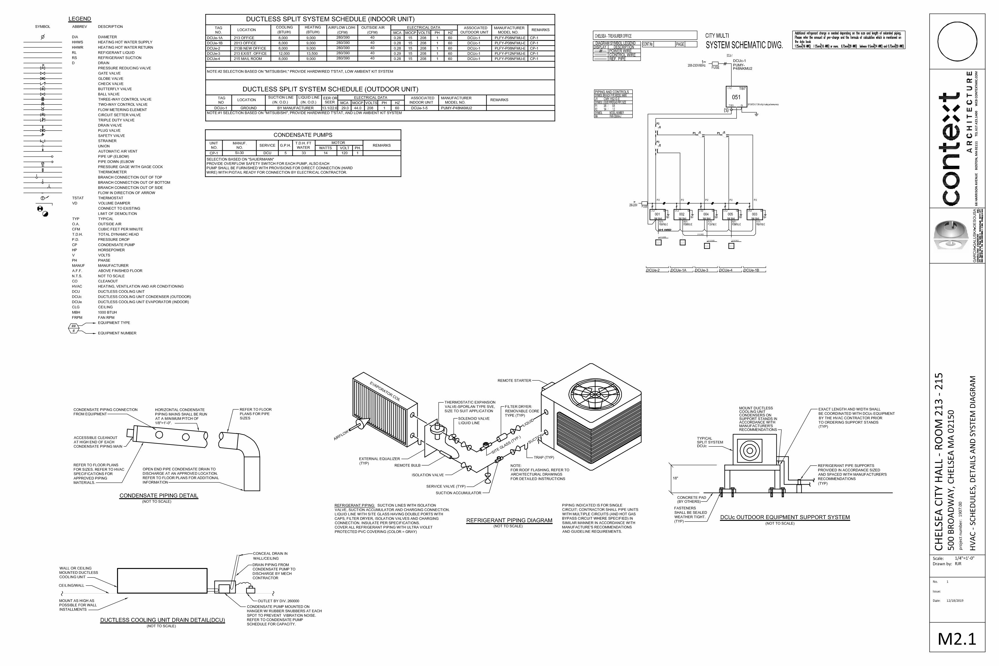

XN
XR
XL
XM
X
EXISTING EQUIPMENT
XS
MOTOR - NUMERAL INDICATES HORSEPOWER
EXHAUST FAN - F & I BY HVAC, WIRED BY E.C.
MECHANICAL EQUIPMENT
(REFER TO MECHANICAL EQUIPMENT SCHEDULE)
EF
2
HORN/VISUAL "ADA" COMPLIANT SIGNAL - MTD 80" AFF TO .
VISUAL "ADA" COMPLIANT SIGNAL - MTD 80" AFF TO .
THERMAL DETECTOR - 135 F FIXED TEMPERATURE AND
THERMAL DETECTOR - 200 F FIXED TEMPERATURE.
RATE OF RISE. "F" INDICATES FIXED TEMPERATURE ONLY.
FIRE ALARM CONTROL PANEL.FACP
FIRE ALARM SYSTEM
MANUAL PULL STATION - MTD 48" AFF TO .
F
F
F
L
C
L
C
C
L
H
135°
F
H
200°
LIGHTING FIXTURES
S
OS
S
P
S
a
S
3
LED LIGHT FIXTURE, CEILING MOUNTED
SURFACE OR RECESSED.
LED CHANNEL STRIP OR INSTRIAL STRIP.
CEILING MOUNTED FIXTURE-RECESSED,
SURFACE OR PENDANT.
A1
32b
FIXTURE KEYING SYSTEM
A1 = FIXTURE TYPE 3
2= CIRCUIT #, b= SWITCH CONTROL
SINGLE FACE INTERNALLY LIT EXIT SIGN,
DIRECTIONAL INDICATORS OF THE 'CHEVRON'
TYPE AS INDICATED ON DRAWINGS.
(typically mtd 48" AFF u.n.o)
SWITCHESL
C
(see lighting fixture schedule)
SINGLE POLE SWITCH-"a" DESIGNATES
SWITCH CONTROL (LOWER CASE).
SINGLE POLE SWITCH WITH PILOT LIGHT-GLOWS
IN "OFF" POSITION WHEN IN VIEW OF LIGHTS.
GLOWS IN "ON" POSITION WHEN REMOTE FROM
LIGHTS.
THREE-WAY SWITCH.
WALL MOUNTED SINGLE POLE DUAL-RELAY SWITCH/
OCCUPANCY SENSOR EQUAL TO PASS & SEYMOUR
CAT # 05R300SI.
3R
J J
DW J
POWER
TYPICAL OUTLET NOTATIONS
"a" SWITCHED OUTLET, "a" - INDICATES SWITCH CONTROL.
"C" MOUNTED 8" ABOVE COUNTER OR 44" AFF. COORDINATE EXACT
MOUNTING HEIGHT WITH ARCHITECTURAL DRAWINGS.
"F" FURNITURE MTD, COORDINATE EXACT LOCATION WITH FURNITURE PLANS.
"USB" OUTLET WITH INTEGRAL USB CHARGING PORTS.
20 AMP, 120 VOLT DUPLEX RECEPTACLE; "2" INDICATES CIRCUIT NUMBER.
2
RECEPTACLES
=
=
LEGEND NOTES:
A.
(typically mtd. at 18" a.f.f., uno)
SYMBOL LIST
TECHNOLOGY
VOICE/DATA OUTLET - AT 18" A.F.F., UNO - SINGLE GANG OPENING
WITH SINGLE GANG PLASTER RING AND PULL LINE TO NEAREST
ACCESSIBLE CEILING SPACE. MOUNTING DESIGNATIONS: "C"=ABOVE
COUNTER. WIRING (CAT 6), TERMINATIONS AND JACKS BY E.C.
# INDICATES NUMBER OF DROPS.
VOICE OUTLET - AT 18" A.F.F., UNO - SINGLE GANG OPENING
WITH SINGLE GANG PLASTER RING AND PULL LINE TO NEAREST
ACCESSIBLE CEILING SPACE. MOUNTING DESIGNATIONS:
"C"=ABOVE COUNTER, "W" WALL PHONE AT 48" A.F.F. WIRING
(CAT 6), TERMINATIONS AND JACKS BY E.C.
W
DATA OUTLET - AT 18" A.F.F. UNO-SINGLE GANG OPENING WITH
SINGLE GANG PLASTER RING AND PULL LINE TO NEAREST
ACCESSIBLE CEILING SPACE. MOUNTING DESIGNATIONS:
"C"=ABOVE COUNTER, "AN"=WIRELESS ACCESS POINT MTD. AT
84"A.F.F. JACKS, TERMINATIONS AND WIRING (CAT 6) BY E.C.
WIRE AND RACEWAYS
HOMERUN TO PANEL - NO. OF ARROWS INDICATES NO. OF
20 AMP/1 POLE CIRCUITS TO PANEL - UNLESS NOTED OTHERWISE.
WIRING AND RACEWAY - NO. OF DIAGONAL LINES INDICATES NO. #12 AWG
CONDUCTORS. ABSENCE OF DIAGONAL LINES INDICATES 2 #12
AWG+#12AWG GROUND UNLESS NOTED OTHERWISE. NOT SHOWN IN COUNT BUT SHALL BE PROVIDE
(MATCH EXISTING DEVICES)
EXISTING EQUIPMENT TO BE DISCONNECTED AND
RECONNECTED AT SAME LOCATION. PROVIDE ALL
NEW WIRING.
EXISTING EQUIPMENT TO BE REMOVED AND NEW
EQUIPMENT INSTALLED IN SAME LOCATION.
NEW LOCATION OF RELOCATED EXISTING EQUIPMENT.
EXISTING EQUIPMENT TO BE REMOVED AND
RELOCATED.
EXISTING EQUIPMENT TO REMAIN.
EXISTING EQUIPMENT TO BE REMOVED AND
CIRCUIT PULLED BACK TO NEXT ACTIVE
OUTLET/BACK TO PANEL.
DOTTED DENOTES EXISTING EQUIPMENT.
JUNCTION BOX - WITH FLEXIBLE CONNECTION TO EQUIPMENT-"DW" DENOTES
DISHWASHER, "H" HOOD, "WO" WALL OVEN, "D" DISPOSER, "HD" HAND DRYER.
UNFUSED DISCONNECT SWITCH HEAVY DUTY TYPE-"3R" INDICATES NEMA 3R
JUNCTION BOX - SIZE AS REQUIRED.
120/208 VOLT, 3 PHASE, 4 WIRE PANELBOARD.
THIS SHEET IS A GENERAL LIST OF SYMBOLS AND ABBREVIATIONS AND
SHALL BE USED AS A DICTIONARY TO DEFINE ITEMS INDICATED ON DRAWINGS. NOT
ALL SYMBOLS OR ABBREVIATIONS ARE NECESSARILY USED ON THIS PROJECT. ALL
EQUIPMENT IS TO BE PROVIDED UNDER THIS SECTION UNLESS SPECIFICALLY
INDICATED OTHERWISE.
20AMP, 120 VOLT DOUBLE DUPLEX RECEPTACLE.
17.
16.
15.
14.
13.
12.
11.
10.
9.
GENERAL NOTES:
6.
7.
8.
5.
4.
3.
2.
1.
ALL BRANCH CIRCUIT CONDUCTORS SHALL BE COPPER MINIMUM #12 AWG. SIZE
UNLESS OTHERWISE INDICATED.
PROVIDE NRTL LISTED SMOKE AND FIRE SEALS AT ALL PENETRATIONS THROUGH
FLOORS OR FULL HEIGHT (SLAB TO SLAB) WALLS.
INSTALL A GREEN GROUNDING CONDUCTOR WITHIN EACH RACEWAY SIZED IN
ACCORDANCE WITH THE ELECTRIC CODE.
FURNISH AND INSTALL CODE REQUIRED DISCONNECTS WHICH ARE NOT FURNISHED
BY THE HVAC OR PLUMBING CONTRACTORS.
WIRE AND CONDUIT SIZES INDICATED ON HOMERUNS SHALL BE CONTINUOUS
THROUGHOUT CIRCUIT.
PROVIDE ELECTRICAL OUTLET PLATE GASKET SEALS AT RECEPTACLES, SWITCHES
AND OTHER ELECTRICAL BOXES ON EXTERIOR WALLS AND INTERIOR WALLS BETWEEN
CONDITIONED AND NON-CONDITIONED SPACES.
DO NOT INSTALL OUTLETS BACK TO BACK. PROVIDE 24 INCH SPACING IN FIRE
RATED WALLS.
ELECTRICAL WORK SHALL BE RECESSED INTO WALLS OR INSTALLED ABOVE HUNG
CEILINGS UNLESS OTHERWISE INDICATED.
IF EXACT MOUNTING OR RACEWAY ROUTINGS ARE NOT INDICATED (LOCATION
OR HEIGHT) REQUEST CLARIFICATION PRIOR TO ROUGHING, OR INSTALLATION.
ALL MOUNTING HEIGHTS ARE TO CENTERLINE UNLESS OTHERWISE INDICATED.
SUPPORT ALL WORK FROM THE BUILDING STRUCTURE.
FURNISH AND INSTALL ALL INCIDENTAL ACCESSORIES NECESSARY TO MAKE THE
ELECTRICAL WORK COMPLETE AND READY FOR OPERATION.
DRAWINGS ARE DIAGRAMMATIC ONLY. EXACT LOCATION, MOUNTING HEIGHTS OF
EQUIPMENT AND ROUTING OF RACEWAYS SHALL BE COORDINATED WITH THE EQUIPMENT
REQUIREMENTS AND FIELD CONDITIONS.
TEST ALL EQUIPMENT AND SYSTEMS INSTALLED TO CERTIFY COMPLIANCE WITH
DRAWINGS, SPECIFICATIONS, CODES, LOCAL AUTHORITIES AND REGULATIONS. INCLUDE
LABOR AND COSTS FOR TESTING, REVIEWS, APPROVALS AND CERTIFICATIONS.
ELECTRICAL WORK SHALL BE IN ACCORDANCE WITH OSHA, NFPA STANDARDS, THE
ELECTRICAL CODE AND THE LOCAL GOVERNING AUTHORITIES. THE DRAWINGS AND
SPECIFICATIONS DO NOT ATTEMPT TO INDICATE ALL WORK REQUIRED BY CODES
AND AUTHORITIES.
COORDINATE WITH THE GENERAL CONTRACTOR, OTHER TRADES AND OF MANUFACTURERS
EQUIPMENT AND MAKE ALL FINAL CONNECTIONS AS REQUIRED, I.E., POWER, CONTROL,
INTERLOCK, ETC.
THE SCOPE OF WORK SHALL INCLUDE PROVIDING ALL WORK INDICATED, AND
COORDINATION WITH ALL TRADES. SCOPE OF WORK IS INDICATED ON THE
CONTRACT DOCUMENTS INCLUDING THE DRAWINGS AND THE SPECIFICATIONS,
WHICH ARE COMPLIMENTARY. WORK INDICATED IN ANY CONTRACT DOCUMENT
SHALL BE CONSIDERED PART OF THE SCOPE OF WORK. IN GENERAL, WORK
REQUIREMENTS ARE NOT INDICATED IN BOTH DOCUMENTS . WHERE
DOCUMENTS CONFLICT WITHIN THEMSELVES OR WITH CODES AND
REGULATIONS, PROVIDE THE HIGHER QUANTITY AND QUALITY AND FOLLOW THE
STRICTER REQUIREMENTS.
MOUNTING DESIGNATIONS LIGHTING GENERAL NOTES
TRACK / RAIL / CABLE
SURFACE
RECESSED
PENDANT
COVE
POLE
BOLLARD
AIRCRAFT CABLE
WALL
UNIVERSALU
W
AC
BOL
POLE
T
S
R
P
C
4. VERIFY ALL FIXTURE MOUNTING HEIGHTS AND LOCATIONS WITH LATEST
ARCHITECTURAL DRAWINGS. EXACT LOCATION OF FIXTURES SHALL BE
CONFIRMED WITH THE ARCHITECT PRIOR TO START OF ROUGHING.
5. FIXTURES SHALL BE SUPPORTED FROM THE BUILDING STRUCTURE,
INDEPENDENT OF HUNG CEILINGS. DO NOT TAP METAL ROOF DECK FOR
SUPPORT OF ANY ELECTRICAL EQUIPMENT. PROVIDE UNISTRUT AS REQUIRED
FOR SUPPORT OF ALL ELECTRICAL EQUIPMENT.
3. FURNISH ALL LIGHTING FIXTURES COMPLETE WITH MOUNTING ACCESSORIES TO
MEET THE JOB REQUIREMENTS. VERIFY ROOM SURFACE CONSTRUCTION AND
FINISHES PRIOR TO ORDERING FIXTURES TO ENSURE PROPER MOUNTING
PROVISIONS AND FIXTURE FITTINGS. REFER TO LATEST ARCHITECTURAL
DRAWINGS.
2. "LIGHTING FIXTURE SCHEDULE" REMARKS, "LIGHTING FIXTURE SCHEDULE
NOTES", "LIGHTING GENERAL NOTES", AND NOTATIONS ELSEWHERE MAY
INDICATE FEATURES AND ACCESSORIES THAT ARE NOT INDICATED IN THE
CATALOG NUMBER BUT ARE REQUIRED FOR THE PROJECT. PRODUCTS OTHER
THAN THOSE SPECIFIED SUBMITTED SHALL BE DOCUMENTED FOR
CONFORMANCE IN PERFORMANCE, CONSTRUCTION, AND APPEARANCE WITH
THE CRITERIA ESTABLISHED BY THE SPECIFIED PRODUCT.
1. MANUFACTURERS AND CATALOG NUMBERS IDENTIFIED IN THE "LIGHTING
FIXTURE SCHEDULE" SHALL SERVE TO ESTABLISH THE BASIS OF DESIGN FOR
EACH LIGHTING FIXTURE TYPE. PRODUCTS OF EQUAL APPEARANCE,
CONSTRUCTION, PERFORMANCE, AND WARRANTY COVERAGE FROM
MANUFACTURERS OTHER THAN THOSE IDENTIFIED MAY BE PROPOSED
FOR USE ON THIS PROJECT, SUBJECT TO REVIEW AND APPROVAL BY
THE ARCHITECT AND ENGINEER. THE
"FIXTURE MANUFACTURER OPTIONS (OR EQUAL)" LISTING IS PROVIDED FOR
GUIDANCE IDENTIFYING MANUFACTURERS CAPABLE OF PROVIDING EQUAL
PRODUCTS, BUT IN NOW WAY LIMITS MANUFACTURERS OR PRODUCTS THAT MAY
BE PROPOSED AS EQUALS FOR THE PROJECT.
THOUSAND CIRCULAR MILS
AIR CONDITIONING SUBCONTRACTOR
ISOLATED GROUND
INFORMATION TECHNOLOGY SUBCONTRACTOR
JUNCTION BOX
HORSEPOWER
HEATING, VENTILATING, AND
FIRE PROTECTION SYSTEM SUBCONTRACTOR
GROUND FAULT INTERRUPTER
FURNISHED AND INSTALLED
GROUND
GENERAL CONTRACTOR
FIRE ALARM
DRAWING
ELECTRICAL SUBCONTRACTOR
ELECTRIC WATER COOLER
ELECTRIC METALLIC TUBING
CENTERLINE
COPPER
RACEWAY. PROVIDE AS SPECIFIED)
CIRCUIT BREAKER
CABLE TELEVISION
CONDUIT (GENERIC TERM FOR
CIRCUIT
CEILING
KCMIL
JB
IT
G,GND
IG
HP
GFI
GC
HVAC
EMT
F&I
FPC
FA
EC
EWC
DWG
CLG
CKT
L
C
CU
C
CATV
CB
WP
WG
UNO
TYP
SWBD
TEL/DATA
SN
PH,Ø
PWR
PVC
P
NTS
PB
PC
NIC
MTG
NO,#
INTERRUPTING CAPACITY
AMERICAN WIRE GAUGE
ALUMINUM
ABOVE FINISHED GRADE
ABOVE FINISHED FLOOR
AUTOMATIC TRANSFER SWITCH
AMPERE
ARCHITECT
AMP, FRAME
AMP TRIP
AUTO-TEMP CONTROL SUBCONTRACTOR
ATS
AT
ATC
AWG
AFF
AIC
AFG
ARCH
AF
AL
A
ABBREVIATIONS
LTG
MLO
MDP
MH
MTD
MCM
MCB
KVA
KW
UNLESS NOTED OTHERWISE
WEATHERPROOF
WIRE GUARD
TYPICAL
POLY-VINYL CHLORIDE CONDUIT
SOLID NEUTRAL
TELEPHONE/DATA
SWITCHBOARD
PHASE
POWER
NOT IN CONTRACT
NOT TO SCALE
PLUMBING SUBCONTRACTOR
POLE(S)
PULL BOX
NUMBER
MOUNTING
LIGHTING
MAIN LUGS ONLY
MOUNTING HEIGHT
MAIN CIRCUIT BREAKER
THOUSAND CIRCULAR MILS
MAIN DISTRIBUTION PANEL
MOUNTED
KILO-VOLT AMPERE
KILO-WATT
INTEGRATED ELECTRONIC SECURITY SYSTEM SUBCONTRACTORIESS
EB EMERGENCY BATTERY UNIT WITH INTEGRAL HEADS.
CEILING MOUNTED PHOTOELECTRIC SMOKE DETECTOR
S
SDWALL MOUNTED SINGLE POLE 0-10V DIMMER WITH
ON/OFF SWITCH
"WP" WEATHERPROOF RECEPTACLE WITH "NRTL" LISTED COVERPLATE
FOR WET LOCATION WITH GFI TYPE RECEPTACLE INSTALLED IN
NEMA 4 ENCLOSURE W/KEY LOCK.
LIGHT SOURCE
DESCRIPTIONMTG.MANUFACTURER MODEL / SERIESTYPE
LIGHTING FIXTURE SCHEDULE
VOLTAGE
NO. WATTS TYPE
1
PHILIPS120R
2AVEG38L835-2-ACR-UNV-DIMLR22
40 LED/835 2'x2' RECESSED LED FIXTURE
BARN LIGHT120AC
BLE-C-CBYC-805-SBK-805-
LED11-3000K-FL
LP1
11 LED/830 PENDANT
MISCELLANEOUS-DEVICES
CEILING MOUNTED OCCUPANCY SENSOR-DUAL TECHNOLOGY,
PASSIVE INFRARED/ ULTRASONIC EQUAL TO UNENCO
#CUI-500-2000-EMS. (REQUIRES REMOTE POWER SUPPLY).
CEILING MOUNTED OCCUPANCY SENSOR WITH SELF-CONTAINED
POWER SUPPLY-DUAL TECHNOLOGY PASSIVE INFRARED/
ULTRASONIC EQUAL TO UNENCO # CUI-500-2000-P277.
EXTERIOR DOOR INTERCOM STATION BY E.C. AIPHONE # DA-1DS AND INTERFACE
TO MASTER INTERCOM SYSTEM. COORDINATE AS REQUIRED WITH SUPPLIER.
SINGLE GANG BOX, 3/4" CONDUIT & PULL STRING TO NEAREST ACCESSIBLE CEILING
SPACE BY E.C.
ICS
IMS
DOOR INTERCOM MASTER STATION. AIPHONE #DB-1MD WITH DESK STAND/WALL
MOUNT ACCESSORIES. SINGLE GANG BOX, 3/4" CONDUIT & PULL STRING TO
NEAREST ACCESSIBLE CEILING SPACE BY E.C FURNISHED, INSTALLED & WIRED BY
E.C.
OS P
OS
#V/#D
REX
DC
PT
SECURITY SYSTEM
EL
DJ
HID READER. CUSTOM BACK BOX FURNISHED AND INSTALL BY E.C. 3/4" CONDUIT
W/PULL STRING TO NEAREST ACCESSIBLE CEILING SPACE BY E.C..
POWER SUPPLY FOR ELECTRIFIED HARDWARE FURNISHED BY DOOR HARDWARE
CONTRACTOR. INSTALLED & WIRED BY E.C. 120VAC EMERGENCY BY E.C.
INTERFACE WIRING BY E.C.
DOOR POSITION SWITCH - GE/SENTROL 1078DB DOUBLE POLE DEVICE ONE POLE TO ACESS
CONTROL, SECOND POLE TO INTRUSION, COORDINATE HOLE WITH DOOR HARDWARE.
PROVIDE 3/4" CONDUIT w/ PULL STRING TO NEAREST ACCESSIBLE CEILING SPACE BY E.C.
REQUEST TO EXIT MOTION SENSOR, PROVIDE 3/4" CONDUIT w/ PULL STRING TO
NEAREST ACCESSIBLE CEILING SPACE BY E.C.
ELECTRIC LOCK FURNISHED AND INSTALLED BY HARDWARE CONTRACTOR, WIRED
BY E.C. 4"SQ.X2 1/2"DP. J.B. WITH 3/4" CONDUIT W/ PULL STRING TO NEAREST
ACCESSIBLE CEILING SPACE BY E.C. 4" SQ.
DOOR JUNCTION BOX BY EC.
CR
Drawn by:
proj
ect n
umbe
r:
Scale:
68 H
ARRI
SON
AVE
NU
E
BOST
ON
, MA
0211
1
TEL
617
.423
.140
0
WEB
CO
NTE
XTAR
C.CO
M
CHEL
SEA
CITY
HAL
L - R
OO
M 2
13 -
215
500
BRO
ADW
AY, C
HELS
EA M
A 02
150
1907
.00
No.
Issue:
Date:
1
12/18/2019
GA
RC
IA
G
AL
US
KA
D
ES
OU
SA
E0.1
ELEC
TRIC
AL S
YMBO
L LI
ST
GGDAs Indicated
AutoCAD SHX Text
375 Faunce Corner Road Suite D, Dartmouth,MA
AutoCAD SHX Text
CONSULTING ENGINEERS
AutoCAD SHX Text
INC.
AutoCAD SHX Text
508
AutoCAD SHX Text
0883
AutoCAD SHX Text
998
AutoCAD SHX Text
FAX 508
AutoCAD SHX Text
d.com
AutoCAD SHX Text
g
AutoCAD SHX Text
MAIL info@g
AutoCAD SHX Text
E
AutoCAD SHX Text
998
AutoCAD SHX Text
5700
AutoCAD SHX Text
1271
AutoCAD SHX Text
02747

X
X
X
X
X
2
X
X
S
X
X
X
X
X
X
X
X X X
X
X
X X X X X X
XXXXXX
X X X X X X
X
X
X
X
X
X
X
X, WIREMOLD
X
X, WIREMOLD
X
X
S
S
X
S
S S S
X
S
X
X X X X
PB
BUZZ AND LIGHT CONTROL,
TYPICAL AT TELLER WINDOW
(THREE TO REMAIN AND ONE
TO BE REMOVED)
XM
X X X X
PB
XM
4
X X X X
PB
X
4
X X X X
PB
XM
1
X
X
X, WHIP
1
X
J
X
XM XXM
XM
LIGHT WITH BUZZ, TYPICAL
ABOVE TELLER WINDOW (THREE
TO REMAIN AND ONE TO BE
REMOVED). MAINTAIN EXISTING
CIRCUIT AND WIRING.
Drawn by:
proj
ect n
umbe
r:
Scale:
68 H
ARRI
SON
AVE
NU
E
BOST
ON
, MA
0211
1
TEL
617
.423
.140
0
WEB
CO
NTE
XTAR
C.CO
M
CHEL
SEA
CITY
HAL
L - R
OO
M 2
13 -
215
500
BRO
ADW
AY, C
HELS
EA M
A 02
150
1907
.00
No.
Issue:
Date:
1
12/18/2019
GA
RC
IA
G
AL
US
KA
D
ES
OU
SA
ED1.0
ELEC
TRIC
AL D
EMO
LITI
ON
PLA
N
GGDAs Indicated
SCALE: 1/4" = 1'-0"
ELECTRICAL DEMOLITION PLAN
1
ED1.0
GENERAL DEMOLITION NOTES
1. REFER TO DEMOLITION SECTION OF SPECIFICATION FOR ADDITIONAL REQUIREMENTS.
2. WHERE DOWNSTREAM DEVICES ARE AFFECTED BY THE DEMOLITION WORK THIS
CONTRACTOR SHALL PROVIDE NEW SERVICES AS REQUIRED TO MAINTAIN SUCH
DOWNSTREAM DEVICES.
3. ALL DEVICES AND/OR EQUIPMENT REMOVED BY THIS CONTRACTOR SHALL BE
INSPECTED BY THE OWNER FOR DETERMINATION OF DISPOSAL OR STORAGE AS
DIRECTED BY THE OWNER. FOR PURPOSES OF PRICING THIS CONTRACTOR SHALL
ASSUME THAT NO DEVICE OR EQUIPMENT WILL BE RE-USED UNLESS SPECIFICALLY
NOTED AS SUCH. TURN OVER ALL LIGHT FIXTURES TO OWNER IN GOOD CONDITION.
4. IT IS NOT THE INTENT OF THESE DRAWINGS TO SHOW ALL EQUIPMENT TO BE
DISCONNECTED AND/OR REMOVED. IT SHALL BE THE RESPONSIBILITY OF THIS
CONTRACTOR TO VISIT THE SITE PRIOR TO SUBMITTING HIS/HER BID TO DETERMINE
THE EXACT QUANTITY AND TYPES OF EQUIPMENT TO BE REMOVED.
5. PARTICULAR CARE SHALL BE TAKEN TO AVOID CREATING HAZARDS ON THE PROJECT
OR CAUSING DISRUPTION OF SERVICES REMAINING.
6. ALL EXISTING EQUIPMENT INDICATED TO BE REMOVED SHALL BE DONE IN A NEAT AND
WORKMANLIKE MANNER. ALL EXISTING EQUIPMENT INDICATED TO BE TURNED OVER TO
THE OWNER SHALL BE PRESENTED TO THE OWNER IN GOOD CONDITION AT A
LOCATION DESIGNATED BY THE OWNER. ALL OTHER EQUIPMENT SHALL BE REMOVED
FROM THE SITE.
7. REMOVE ALL ABANDONED CONDUCTORS AND EQUIPMENT NOT BUILT INTO THE
BUILDING CONSTRUCTION. WHERE CEILING AND WALLS ARE REMOVED, ABANDONED
WIRING SHALL BE REMOVED, AND ENDS OF LIVE SERVICES TO BE DISCONNECTED AND
CUT-OFF.
8. ABANDONED ELEMENTS BUILT INTO WALLS SHALL BE MARKED "ABANDONED".
9. REPLACE SMOKE DETECTORS WITH 135 DEGREE RATE OF RISE COMBINATION
DETECTORS PRIOR TO CEILING DEMOLITION IN AREAS TO BE RENOVATED.
10. DISCONNECT AND DROP EQUIPMENT TO FLOOR FOR REMOVAL BY GENERAL
CONTRACTOR.
AutoCAD SHX Text
375 Faunce Corner Road Suite D, Dartmouth,MA
AutoCAD SHX Text
CONSULTING ENGINEERS
AutoCAD SHX Text
INC.
AutoCAD SHX Text
508
AutoCAD SHX Text
0883
AutoCAD SHX Text
998
AutoCAD SHX Text
FAX 508
AutoCAD SHX Text
d.com
AutoCAD SHX Text
g
AutoCAD SHX Text
MAIL info@g
AutoCAD SHX Text
E
AutoCAD SHX Text
998
AutoCAD SHX Text
5700
AutoCAD SHX Text
1271
AutoCAD SHX Text
02747

VAULT
N.I.C.
LR22 LR22 LR22 LR22
LR22 LR22
LR22 LR22
LR22LR22
LR22LR22
LR22
LR22LR22
LR22LR22
OS
OS
OS
OS
OS
S
P
P
P
P
P
1a 1a
1b
1b1b
1b 1b 1b 1b
3a 3a
PPB-3
b
D
S
a
D
PPB-1
3a 3a
3a 3a
3a3a
LP1 LP1
LP1 LP1 LP1
PPB-5
5c 5c
5c 5c 5d
XM
S
a
D
S
a
D
S
a
D
EB
EB
EB
1
1
3
XMXM
BUZZ AND LIGHT CONTROL,
TYPICAL AT TELLER WINDOW
TO REMAIN.
LIGHT WITH BUZZ, TYPICAL
ABOVE TELLER WINDOW TO
REMAIN.
PB
XM
PB
XM
PB
XM
S
c
D
S
d
D
LR22
1b
T-2
CE
NT
RA
L F
IL
ES
T-1 T-3
WS 5'-6" x 6'-0"
COPY
WS 5'-6" x 6'-0"
46" x 26"
WS 7'-0" x 7'-0"
WS 7'-0" x 7'-0"
T.B.D.
T.B.D.
WS 5'-6" x 6'-0"
NEW OFFICE
213B
VAULT
N.I.C.
TREASURES OFFICE
213
MAIL ROOM
215
EXISTING OFFICE
213A
2
2
C
C
2
2
C
C
C
2
C
C
C
2
C
C
C
2
2
GFC
GFC
2
PPB-2
PPB-4
GFC
PPB-6
PPB-8
2
4
6
8
8
PPB-9,11
9
11
9
11
PPB-13,15
13
13
15
15
PPB-16
16
16
PPB-18
18
18
20
20
20
PPB-24
24
PPB-26
26
24
26
26
PPB-20
20
PPB-10
10 10
PPB-12
12 12
PPB-14
14 14
PPB-25
25
25
PPB-27
27
27
PPB-22
PT TS
DC
DJ
EL
EH
REX
22
CR
NEW INTERCOM EXTERIOR
DOOR STATION TO BE FIELD
LOCATED.
IMSNEW INTERCOM MASTER STATION
TO BE FIELD LOCATED.
J
J
DATA JUNCTION BOX FOR
FURNITURE CONNECTION
WHIP FOR FURNITURE
CONNECTION
1
DCUc
1B
DCUe
1
CP
4
DCUe
1
CP
DCUe
1A
DCUe
CP
DCUe
1
CP
2
3
1
CP
8
5 WIRE FURNITURE WHIP
(2 CIRCUIT, 2 NEUTRAL,
1 GROUND)
1
1V
/3D
1V
/3D
1V
/3D
PPB-22
PT TS
DC
DJ
EL
EH
REX
22
CR
1V
/3D
1V
/3D
ICS
PROVIDE WALL MOUNT
HOFFMAN DATA CABINET
MODEL# EWMW242425 W/ RACK
MOUNTED CHATSWORTH PDU
MODEL# 12816-707 OR EQUAL.
COORDINATE MOUNTING
HEIGHT W/ CITY HALL IT
DEPARTMENT & ARCHITECT.
HID CARD READER SHALL
BE COORDINATE WITH
OWNER TO MATCH
EXISTING AND WORK W/
EXISTING SECURITY
SYSTEM. (TYP.)
PPB-29
29
FOR
DATA
CABINET.
LD-1 LEAK DETECTION
EWH-1 ELECTRIC
WATER HEATER
UNDER COUNTER
Drawn by:
proj
ect n
umbe
r:
Scale:
68 H
ARRI
SON
AVE
NU
E
BOST
ON
, MA
0211
1
TEL
617
.423
.140
0
WEB
CO
NTE
XTAR
C.CO
M
CHEL
SEA
CITY
HAL
L - R
OO
M 2
13 -
215
500
BRO
ADW
AY, C
HELS
EA M
A 02
150
1907
.00
No.
Issue:
Date:
1
12/18/2019
GA
RC
IA
G
ALU
SK
A D
ES
OU
SA
E1.0
ELEC
TRIC
AL L
IGHT
ING
AND
POW
ER P
LAN
S
GGDAs Indicated
SCALE: 1/4" = 1'-0"
ELECTRICAL LIGHTING PLAN
1
E1.0
SCALE: 1/4" = 1'-0"
ELECTRICAL POWER PLAN
2
E1.0
GENERAL LIGHTING NOTES
1. EXACT LOCATIONS OF ALL FIXTURES AND DEVICES SHALL BE FULLY COORDINATED WITH ARCHITECTURAL PLANS,
ELEVATIONS, SECTIONS AND THE WORK OF OTHER TRADES PRIOR TO ROUGH-IN.
2. WIRING AND CONDUIT OR MC CABLE SHALL BE REQUIRED BETWEEN ALL LIGHTING FIXTURES, SWITCHES, DIMMERS,
SENSORS,POWER PACKS, RELAYS, AND OTHER AUXILIARY DEVICES. WIRING AND CONDUIT OR MC CABLE IS SHOWN
ON DRAWINGS ONLY FOR SPECIFIC ROUTES OR SPECIAL CONDITIONS. IT IS THE INTENT OF THESE DOCUMENTS THAT A
COMPLETE BRANCH CIRCUIT AND CONTROL WIRING SYSTEM BE INSTALLED.
3. ALL BRANCH CIRCUIT CONDUCTORS SHALL BE 98% CONDUCTIVITY, COPPER MINIMUM # 12 AWG SIZE, THWN/THHN
INSULATION, 600 VOLTS RATED UNLESS OTHERWISE NOTED.
4. UTILITIES SHALL NOT PENETRATE STAIR ENCLOSURES, ELEVATOR SHAFTS, AND MACHINE ROOMS EXCEPT WHERE
SPECIFICALLY SERVING THAT STAIR OR ELEVATOR.
5. METAL ROOF DECKS SHALL NOT BE TAPPED FOR SUPPORT OF ANY LIGHTING FIXTURES OR ELECTRICAL EQUIPMENT.
PROVIDE UNISTRUT OR OTHER SUPPLEMENTAL SUPPORT FITTINGS TO BE ATTACHED TO BUILDING STRUCTURAL
FRAMING AS REQUIRED FOR SUPPORT OF ALL LIGHTING FIXTURES AND ELECTRICAL EQUIPMENT.
6. ALL EXPOSED CONDUITS, RACEWAYS, WIREWAYS, BOXES, FITTINGS AND SIMILAR COMPONENTS SHALL BE PAINTED TO
MATCH SURROUNDING FINISH WITH EQUAL TYPE PRODUCT(S).
7. ALL OCCUPANCY AND DAYLIGHT HARVESTING PHOTOSENSORS SHALL BE LOCATED IN COMPLIANCE WITH THE
MANUFACTURER'S RECOMMENDATIONS FOR EACH INDIVIDUAL SPACE. E.C. SHALL PROVIDE A CEILING PLAN LOCATING
ALL SENSORS WHICH HAS BEEN FULLY COORDINATED WITH THE WORK OF OTHER TRADES FOR FINAL REVIEW AND
APPROVAL. E.C. SHALL PROVIDE THE SENSOR VENDOR(S) WITH ALL INFORMATION REQUIRED TO FULLY UNDERSTAND
THE CONDITIONS OF EACH SPACE.
8. INDIRECT AND DIRECT/INDIRECT FIXTURES SHALL BE SUSPENDED WITH AIRCRAFT CABLE TO PROVIDE A MINIMUM
CLEARANCE 18" FROM THE CEILING TO TOP OF EACH FIXTURE. FIELD CONDITIONS REQUIRING A SHORTER
SUSPENSION SHALL BE BROUGHT TO THE ATTENTION OF THE ARCHITECT AND ENGINEER PRIOR TO COMMENCING
WITH FIXTURE INSTALLATIONS
9. FIXTURES ON PLANS SHALL BE PROVIDED WITH 0-10V DIMMING DRIVER(S) OR LIGHT ENGINE(S) AS REQUIRED FOR LED
SOURCES SPECIFIED TO BE CONTROLLED VIA A 0-10V SIGNAL FROM THE ALCS, DAYLIGHT HARVESTING
PHOTOSENSORS, THEATRICAL DIMMING SYSTEM OR OTHER CONTROLS
10. REFER TO "AUTOMATED LIGHTING CONTROL SYSTEM (ALCS) - TYPICAL ONE LINE DIAGRAM" AND SPECIFICATIONS FOR
DETAILED LIGHTING CONTROL REQUIREMENTS.
11. ALL EXTERIOR EQUIPMENT, FIXTURES, AND DEVICES SHALL BE RATED IP65 (MINIMUM) AND BE CONSTRUCTED OF
STAINLESS STEEL AND/OR MARINE GRADE ALUMINUM SUITABLE FOR COASTAL ENVIRONMENT APPLICATION. PAINTED
FINISHES SHALL HAVE PASSED A MINIMUM 5,000 HOUR SALT SPRAY TEST.
12. ALL EXIT SIGNS SHALL BE ALIGNED AND CENTERED ON CORRIDORS AND ABOVE DOORS AND SHALL BE CIRCUITED
AHEAD OF ANY LOCAL LINE VOLTAGE SWITCH CONTROL OR CONSTANTLY ON OPERATION CIRCUIT.
13. ALL EXIT SIGN SHOWN ON THIS SHEET SHALL BE CIRCUITED TO PANEL "ELP" CIRCUIT NUMBER "21"
1. COORDINATE EXACT LOCATION OF ALL DEVICES AND EQUIPMENT WITH ARCHITECT PRIOR TO
INSTALLATION.
2. REFER TO MECHANICAL AND PLUMBING PLANS FOR ANY CHANGES AND FOR EXACT LOCATION OF ALL
HVAC EQUIPMENT.
3. WIRING IS SHOWN ON DRAWINGS ONLY FOR SPECIFIC ROUTES OR SPECIAL CONDITIONS.
4. WIRING AND CONDUIT SHALL BE REQUIRED BETWEEN ALL OUTLETS INDICATED WITH CIRCUIT NUMBERS
AND PANEL DESIGNATIONS.
5. ALTHOUGH ALL BRANCH CIRCUIT WIRE AND CONDUIT IS NOT SHOWN, IT IS THE INTENT OF THESE
DOCUMENTS THAT A COMPLETE BRANCH CIRCUIT WIRING SYSTEM BE INSTALLED.
6. ALL BRANCH CIRCUIT CONDUCTORS SHALL BE TYPE MC 98%%% CONDUCTIVITY, COPPER MINIMUM #12
AWG SIZE, THWN/THHN INSULATION, 600 VOLTS RATED UNLESS OTHERWISE NOTED.
7. REFER TO FIRE PROTECTION PLANS FOR ANY CHANGES AND FOR EXACT LOCATION OF ALL FLOW
SWITCH. TAMPER SWITCH, ETC.
8. DO NOT PENETRATE STAIRS WITH ANY UTILITIES EXCEPT FOR UTILITIES SPECIFICALLY SERVING THAT
STAIR.
9. WHERE CONDUITS AND/OR BOXES CANNOT BE FLUSH MOUNTED IN BUILDING PROVIDE A SYSTEM OF
SURFACE METAL RACEWAYS AND BOXES IN ACCORDANCE WITH ARTICLE 386, EQUAL TO WIREMOLD FOR
ALL FINISH SPACES WHERE PUBLIC HAS ACCESS, INCLUDING CORRIDORS, CLASSROOMS, OFFICES, ETC.
10. CONFIRM RATINGS & FINAL LOCATIONS OF EQUIPMENT WITH OWNER PRIOR TO ROUGHING.
11. ALL OUTLETS ON EXTERIOR WALLS WITH CASEWORK SHALL BE MOUNTED 6" ABOVE CASEWORK.
CONFIRM HEIGHT OF CASEWORK WITH HVAC AND ARCHITECT PRIOR TO ROUGHING.
12. TYPICALLY PROVIDE GROUND FAULT INTERRUPTER TYPE RECEPTACLES WITHIN 6 FEET OF WATER
SOURCES.
13. PROVIDE ALL EMPTY CONDUITS WITH PULL-STRINGS.
14. TYPICALLY PROVIDE (2) 4" SLEEVES OVER EACH CORRIDOR DOOR.
15. PROVIDE (2) 2" THROUGH-WALL SLEEVE ABOVE CEILING OVER THE DOORS INTO EACH ROOM LEADING
FROM THE CORRIDOR FOR COMMUNICATIONS/DATA WIRING.
16. LOCATE ALL WALL TELEPHONE OUTLETS 12 INCHES AWAY FROM ALL OTHER OUTLETS/DEVICES.
17. PROVIDE (2) 1" SLEEVES OVER EACH DOOR FOR TEL./DATA SECURITY AND SOUND SYSTEM WIRING.
TEL./DATA SHALL BE DEDICATED TO (1) OF THE CONDUITS.
18. TYPICALLY MOUNT LCD PROJECTOR "TVE" DATA OUTLET ABOVE CEILING. MOUNT DUPLEX RECEPTACLE
ON CEILING TILE, FACE DOWN CENTERED 10'-12' FROM SCREEN.
GENERAL POWER NOTES
AutoCAD SHX Text
375 Faunce Corner Road Suite D, Dartmouth,MA
AutoCAD SHX Text
CONSULTING ENGINEERS
AutoCAD SHX Text
INC.
AutoCAD SHX Text
508
AutoCAD SHX Text
0883
AutoCAD SHX Text
998
AutoCAD SHX Text
FAX 508
AutoCAD SHX Text
d.com
AutoCAD SHX Text
g
AutoCAD SHX Text
MAIL info@g
AutoCAD SHX Text
E
AutoCAD SHX Text
998
AutoCAD SHX Text
5700
AutoCAD SHX Text
1271
AutoCAD SHX Text
02747

DN
DN
DN
UP UP
UP
EXISTING GE PANEL
"PPB" LOCATED IN
BOILER ROOM
XM
XM
EXISTING DATA RACK
WITH PATCH PANEL.
CORRIDOR
BOILER ROOM
OFFICE
CORRIDOR
CORRIDOR
CORRIDOR
OFFICE OFFICE
EXISTING FIRE-LITE FIRE
ALARM CONTROL PANEL
AREA OF RENOVATION
ON SECOND FLOOR
FACP
XM
(BELOW)
EXISTING MDF RACK
UNIT
NO.
SCHEDULE OF MECHANICAL EQUIPMENT
CHARACTERISTICS
LOAD
DESCRIPTION VOLT PH
PANEL
CIRCUIT
CIRCUIT
BREAKER FEEDER REMARKS
EQUIPMENT AND CONNCECTIONS
WP
S
D
TS
J
SWP
J
EXTERIOR AC UNIT
VFD
LOCATION
X208 1 PPB-17,19 50A/2P
NEMA
3R
X44 MOCP
INTERIOR AC UNIT
X
X
X
X
X3-#12G IN 3/4"C208 1
1.
MECHANICAL SCHEDULE NOTES:
2.
3.
PROVIDE FLEXIBLE CONNECTION TO EQUIPMENT REFER TO SPECIFICATIONS.
CONTROLLERS AND DISCONNECT DEVICES SHALL BE NRTL RATED FOR USE WITH
A DESIGN E MOTOR WITH A HORSE POWER RATING NOT LESS THAN 1.4 TIMES
THE MOTOR HORSE POWER. (REFER TO ELECTRICAL CODE ARTICLE 430).
ALL EXTERIOR MOUNTED DISCONNECT SWITCHES SHALL BE NEMA "3R."
E.C. SHALL F&I UNI-STRUT, FOR MOUNTING OF DISCONNECT SWITCH,
ATTACHED TO ROOF STRUCTURE INDEPENDENT OF HVAC ROOF-TOP
EQUIPMENT TO PREVENT EXCESSIVE WEAR DUE TO VIBRATIONS.
4.
1
CONNECT "WP" RECEPTACLE TO PPB-29
MECHANICAL SCHEDULE KEY NOTES:
2 PROVIDE HARD CONNECTION FOR CONDENSATE PUMP (CP-1). CONNECT TO
NEAREST 120V, 1Ø BRANCH CIRCUIT UNLESS OTHERWISE INDICATED. PROVIDE
THERMAL SWITCH AT UNIT. FIELD COORDINATE EXACT LOCATION WITH HVAC.
1 PROVIDE 3/4"CONDUIT W/PULL WIRE BETWEEN INDOOR UNIT & OUTDOOR UNIT
FOR EACH SPLIT SYSTEM.
REFER TO MECHANICAL DRAWINGS FOR EXACT LOCATION OF CONDENSATE
PUMPS CP-1.
3
5. WHERE INDICATED PROVIDE WEATHERPROOF DUPLEX RECEPTACLES AT
MECHANICAL EQUIPMENT. PROVIDE 3/4"C. WITH 2#12+#12G AWG TO NEAREST
PANEL AND CONNECT TO 20A/1P CIRCUIT BREAKER UNLESS OTHERWISE
INDICATED.
X
PROVIDE 3#12G - 3/4"C TO DCUc-1 FOR CONTROLS.
120/208V, 3Ø, 4W
PANEL
PANEL SCHEDULE
AMPS
BUS
MAIN
NO.
LOCATION
MTG1 POLE
BRANCH CKT BREAKER (AMPS)
15
MAIN
CB
30 2015 2015
OTHERS
60
POLES
TOTAL
30
S
PPB100
--
BOILER ROOM10 - 1 - - - - --
20 30
2 POLE 3 POLE
-(1) 50A/2P
3-#6
G IN 1"C
1
1
EXISTING PANEL TO REMAIN. PROVIDE CIRCUIT BREAKERS AS NOTED TO MATCH EXISTING PANEL MANUFACTURER.
1
SCALE: 1/16" = 1'-0"
OVERALL LOWER FLOOR PLAN - ELECTRICAL POWER PLAN
1
E2.0
Drawn by:
proj
ect n
umbe
r:
Scale:
68 H
ARRI
SON
AVE
NU
E
BOST
ON
, MA
0211
1
TEL
617
.423
.140
0
WEB
CO
NTE
XTAR
C.CO
M
CHEL
SEA
CITY
HAL
L - R
OO
M 2
13 -
215
500
BRO
ADW
AY, C
HELS
EA M
A 02
150
1907
.00
No.
Issue:
Date:
1
12/18/2019
GA
RC
IA
G
AL
US
KA
D
ES
OU
SA
E2.0
ELEC
TRIC
AL O
VERA
LL P
LAN
AN
D SC
HEDU
LES
CJAs Indicated
GROUND LEVEL
OFFICE
DCUc-1
DCUe-1A
INTERIOR AC UNIT
XX X3-#12G IN 3/4"C208 1 -
PROVIDE 3#12G - 3/4"C TO DCUc-1 FOR CONTROLS.OFFICEDCUe-1B
INTERIOR AC UNIT
XX X3-#12G IN 3/4"C208 1 -
PROVIDE 3#12G - 3/4"C TO DCUc-1 FOR CONTROLS.OFFICEDCUe-2
INTERIOR AC UNIT
XX X3-#12G IN 3/4"C208 1 -
PROVIDE 3#12G - 3/4"C TO DCUc-1 FOR CONTROLS.OFFICEDCUe-3
INTERIOR AC UNIT
XX X3-#12G IN 3/4"C208 1 -
PROVIDE 3#12G - 3/4"C TO DCUc-1 FOR CONTROLS.OFFICEDCUe-4
CONDENSATE PUMP
X X3-#12G IN 3/4"C120 1
PROVIDE 3#12G - 3/4"C TO DCUc-1 FOR CONTROLS.AT EACH DCU-e UNITCP-1
PPB-21,23
PPB-21,23
PPB-21,23
PPB-21,23
PPB-21,23
PPB-28 20A/1P
20A/2P
LD-1
GFI
J
S
D
TS
EQUIPMENT AND CONNCECTIONS
LEAK DETECTION SYSTEM
SCHEDULE OF PLUMBING EQUIPMENT
120 1 20A-1P 2#12&1#12G-3/4"CMP1-23
BREAKER
CIRCUITLOCATIONDESCRIPTION VOLT PH
CIRCUIT
PANEL FEEDER REMARKS
-
X X
1
PLUMBING SCHEDULE NOTES
-
LOAD
CHARACTERISTICS
REFER TO FLOOR PLANS FOR EXACT LOCATION AND QUANTITIES.
UNIT
NO.
EWH-1
ELECTRIC WATER HEATER 120 1 20A-1P 2#12&1#12G-3/4"C
-
1500W X XMP1-21
2 PROVIDE GFI OUTLET FOR EQUIPMENT. CONFIRM LOCATION.
1
1
UNDER CABINET
2
X
XUNDER CABINET
2
AutoCAD SHX Text
375 Faunce Corner Road Suite D, Dartmouth,MA
AutoCAD SHX Text
CONSULTING ENGINEERS
AutoCAD SHX Text
INC.
AutoCAD SHX Text
508
AutoCAD SHX Text
0883
AutoCAD SHX Text
998
AutoCAD SHX Text
FAX 508
AutoCAD SHX Text
d.com
AutoCAD SHX Text
g
AutoCAD SHX Text
MAIL info@g
AutoCAD SHX Text
E
AutoCAD SHX Text
998
AutoCAD SHX Text
5700
AutoCAD SHX Text
1271
AutoCAD SHX Text
02747

Drawn by:
proj
ect n
umbe
r:
Scale:
68 H
ARRI
SON
AVE
NU
E
BOST
ON
, MA
0211
1
TEL
617
.423
.140
0
WEB
CO
NTE
XTAR
C.CO
M
CHEL
SEA
CITY
HAL
L - R
OO
M 2
13 -
215
500
BRO
ADW
AY, C
HELS
EA M
A 02
150
1907
.00
No.
Issue:
Date:
1
12/18/2019
GA
RC
IA
G
ALU
SK
A D
ES
OU
SA
E3.0
DETA
ILS
AND
TECH
NO
LOGY
RIS
ER D
IAGR
AM
GGDAs Indicated
FIRST FLOOR
PATCH PANEL PORTS. AT BOTH MDF/IDF
AND WORK STATION.
TO ACCOMODATE
OF DATA PATCH PANELS
PRIOR TO ROUGHING-IN.
ALL RESPECTIVE DATA CIRCUITS.
TO MATCH TOTAL QUANTITY OF
3. PROVIDE APPROPRIATE QUANTITIES
4. PROVIDE CAT 6 PATCH CORDS
FIBER ARMORED CABLE TO
MDF.
12 STRAND MULTI-MODE
B
A
COORDINATE ALL WIRING REQUIREMENTS
WITH EQUIPMENT SUPPLIER.
2. ALL WIRING SHALL BE IN ACCORDANCE
FURNISH ALL EQUIP. LABOR, WIRING
COMPLETELY OPERATIONAL SYSTEM.
THIS CONTRACTOR SHALL PROVIDE
AND OUTLETS REQUIRED FOR A
FOR A COMPLETE INSTALLATION.
1.
NOTE:
SECOND FLOOR
ROOF
VOICE/DATA/FIBER RACK
EXISTING
MDF
PLENUM RATED TO IDF/MDF DATA
3
IN BLOCKED AREA (TYPICAL)
TO IDF/MDF VOICE RACK
CAT 6 UTP CABLE PLENUM RATED
RACK IN BLOCKED AREA & (1)
BLOCKED AREA
IDF/MDF VOICE RACK IN
CABLES PLENUM RATED TO
AREA & (1) CAT 6 UTP
2
1
NOTES:
- (1) CAT 6 UTP CABLE
DATA RACK IN BLOCKED
PLENUM RATED TO IDF/MDF
- (3) CAT 6 UTP CABLES
AREA (TYPICAL)
DATA RACK IN BLOCKED
PLENUM RATED TO IDF/MDF
- (2) CAT 6 UTP CABLES
SEE
E2.0
1
FOR EXISTING MDF LOCATION
EXISTING MDF
B
FRAME)
DISTR.
(INTER
NEW IDF
WALL MTD
RACK
VOICE/DATA/FIBER RACK
213
TREASURES OFFICE
1V/3D 2
213A
EXISTING OFFICE
1V/3D 1V/3D 2 2 21V/3D
213B
NEW OFFICE
21V/3D
2
2
215
MAIL ROOM
2 2
INTERFACE RJ 45 T-1.
CAT 6 VOICE
T-1
2
D-1
INTERFACE RJ 45
D-1 & D-2
SPEED DATA LAN
CAT 6 HIGH
D-1
D-2
MDF-A-D1,T1
TYPE AND PORT # (TYPICAL)
PATCH PANEL (TYPICAL)
MDF-A-D1,T1
ROOM ORIGIN (TYPICAL)
TYPICAL WALL MTD
VOICE/DATA OUTLET
( ) DETAIL
SCALE: NTS
TYPICAL DATA OUTLET
( ) DETAIL
SCALE: NTS SCALE: NTS
CAT 6 HIGH
SPEED DATA LAN
INTERFACE RJ 45
D-1
1
E3.0
2
E3.0
3
E3.0
D-1 D-2, D-3
INTERFACE RJ 45
SPEED DATA LAN
CAT 6 HIGH
T-1
D-1 D-2
INTERFACE RJ 45 T-1
CAT 6 VOICE
MDF-A-D1,T1
TYPICAL DATA OUTLET
( ) DETAIL
1V/3D
NOT TO SCALE
EXISTING MDF DETAIL
EXISTING DATA/FIBER RACK
6
E3.0
2
PATCH PANEL (RJ45 PORTS)
(1) 48 PORT CAT 6
PROVIDE WALL MOUNT HOFFMAN
DATA CABINET MODEL#
EWMW242425 W/ RACK MOUNTED
CHATSWORTH PDU MODEL#
12816-707 OR EQUAL.
NOT TO SCALE
NEW IDF DETAIL5
E3.0
48 PORT CAT 6 PATCH PANEL
AND FULLY COMPLY WITH FCC PART 68 AND TIA-568-A
CODE REQUIREMENTS AND SPECIFICATIONS FOR UL 1863;
PANELS SHALL BE UL LISTED; MEET NATIONAL ELECTRICAL
NOTE
CATEGORY 6.
NOT TO SCALE
SPRING
CONTACTS
WIRE
PORT ID
3.5"W X 19.0"H
PC-MOUNTED D-4 110 IDC
FRONT VIEW
CONNECTORS
SIDE VIEW
CABLE MANAGEMENT
CLIP
4
E3.0
SEE DETAIL
4
E3.0
(TYP.)
FIBER OPTIC SINGLEMODE LIU (LIGHTGUIDE INTERFACE UNIT)
UNIT) PATCH PANEL (12 PORT - SC CONNECTORS) - PREMISES
CABLE/FIBER SCHEDULE
PATCH PANEL (12 PORT - LC CONNECTORS) - PREMISES
DISTRIBUTION
2
3
FIBER OPTIC MULTIMODE LIU (LIGHTGUIDE INTERFACE
DISTRIBUTION
1
FIBER OPTIC SINGLEMODE LIU (LIGHTGUIDE INTERFACE UNIT)
PATCH PANEL (12 PORT - ST CONNECTORS) - PREMISES
DISTRIBUTION
CONFIRM FIBER
OPTIC CONNECT
TYPE W/ OWNER
1 1/4"C TO EXISTING MDF
SEE
E2.0
1
FOR EXISTING MDF LOCATION
12 STRAND SINGLE MODE
ARMORED 8/9 MICRON
FIBER CABLE TO MDF.
EXISTING
TECHNOLOGY
EQUIPMENT TO
REMAIN
2
CONFIRM FIBER
OPTIC CONNECT
TYPE W/ OWNER
COORDINATE
LOCATION OF FIBER
OPTIC ENCLOSURE
WITH OWNER PRIOR
INSTALLATION.
1
TYP.
2
TYP.
3
TYP.
W/ ACCESS CONTROL
SCALE: N.T.S.
TYPICAL DOOR
7
E3.0
4"
ELECTRICAL HINGE
ELECTRICAL LOCK
48" A.F.F.
(TYP)
ABOVE CEILING
4" SQUARE BOX
W/BLANK COVER
STUB CONDUIT TO
ELECTRIC STRIKE
STUB INTO DOOR
FRAME FOR DOOR
CONTACT.
STUB CONDUIT TO
ELECTRIC HINGE
1" CONDUIT STUB TO
NEAREST ACCESSIBLE
CEILING
3/4" CONDUIT
(TYP OF 4)
DOOR
CONTACT
2' MAX
CONDUIT
LENGTH
TO "DJ"
FLUSH MOUNT BOX
FOR CARD READER
W/ KEYPAD.
DJ
TOTAL
2
1V/3D
QUANTITY OF DEVICES
=
=
NEW IDF (EXISTING OFFICE 213A)
DATA (CAT 6) VOICE (CAT 6)
-
3
36
3
18
8
9
3
=
5155
MAIN DISTRIBUTION FRAME MDF
LOCATION: MDF (HEAD END 146B)
CAT 6 (RJ45)
VOICE/DATA PORT
USED SPARE PATCH PANEL
SIZE
(1) 48 PORT444
D-3
EXISTING
FIBER/DATA RACK
AutoCAD SHX Text
375 Faunce Corner Road Suite D, Dartmouth,MA
AutoCAD SHX Text
CONSULTING ENGINEERS
AutoCAD SHX Text
INC.
AutoCAD SHX Text
508
AutoCAD SHX Text
0883
AutoCAD SHX Text
998
AutoCAD SHX Text
FAX 508
AutoCAD SHX Text
d.com
AutoCAD SHX Text
g
AutoCAD SHX Text
MAIL info@g
AutoCAD SHX Text
E
AutoCAD SHX Text
998
AutoCAD SHX Text
5700
AutoCAD SHX Text
1271
AutoCAD SHX Text
02747

T-2
CE
NT
RA
L F
IL
ES
T-1 T-3
WS 5'-6" x 6'-0"
COPY
WS 5'-6" x 6'-0"
46" x 26"
WS 7'-0" x 7'-0"
WS 7'-0" x 7'-0"
T.B.D.
T.B.D.
WS 5'-6" x 6'-0"
NEW OFFICE
213B
VAULT
N.I.C.
TREASURES OFFICE
213
MAIL ROOM
215
EXISTING OFFICE
213A
75cd
SS
S
S
S
F
15cd
F
75cd
F
S
S
Drawn by:
proj
ect n
umbe
r:
Scale:
68 H
ARRI
SON
AVE
NU
E
BOST
ON
, MA
0211
1
TEL
617
.423
.140
0
WEB
CO
NTE
XTAR
C.CO
M
CHEL
SEA
CITY
HAL
L - R
OO
M 2
13 -
215
500
BRO
ADW
AY, C
HELS
EA M
A 02
150
1907
.00
No.
Issue:
Date:
1
12/18/2019
GA
RC
IA
G
AL
US
KA
D
ES
OU
SA
E4.0
ELEC
TRIC
AL F
IRE
ALAR
M P
LAN
AN
D DE
TAIL
S
GGDAs Indicated
SCALE: 1/4" = 1'-0"
ELECTRICAL FIRE ALARM PLAN
1
E4.0
LOCATE AT 'FATC'
(TYPICAL)
FFF
ISOLATION MODULE,
IM
F SH
NEW AUDIO/VISUAL
SIGNAL CIRCUIT.
FIRST FLOOR
EXISTING FIRE-LITE
ADDRESSABLE FIRE
ALARM CONTROL
PANEL TO REMAIN.
EXISTING TYPICAL DETECTION
LOOP TO REMAIN
EXISTING TYPICAL
DETECTION ZONE
TO REMAIN
S
PROVIDE NEW
POWER SUPPLY
AS REQUIRED.
XM
ADA
BASEMENT
COORDINATE FINAL LOCATIONS OF MAGNETIC DOOR HOLDERS AND
OTHER HARDWARE DEVICES WITH HARDWARE SUPPLIER PRIOR TO
ROUGHING.
TYPICALLY REFER TO DOOR HARDWARE SCHEDULES & DRAWINGS FOR
LOCATIONS & QUANTITIES OF HARDWARE EQUIPMENT AFFECTING THIS
SECTION. PROVIDE ALL WORK AS REQUIRED.
6.
7.
E.C. SHALL REFER TO SPECIFICATIONS AND DRAWINGS FOR QUANTITY
OF DEVICES, SPARE CAPACITY, PARTS, ETC.
TYPICALLY ALL AUDIO/VISUAL UNITS SHALL BE WIRED IN A FASHION THAT
THE SPEAKER AND STROBES ARE SILENCED SIMULTANEOUSLY.
TYPICALLY FIRE ALARM SYSTEM SIGNAL CONDUCTORS SHALL BE #14
AWG, TYPE THHN SOLID.
PROVIDE EACH FIRE ALARM TERMINAL CABINET AND FIRE ALARM
CONTROL PANEL WITH AN ADA POWER SUPPLY TO SERVE ALL
SPEAKER/STROBE UNITS ON RESPECTIVE FLOORS/AREAS.
E.C. SHALL REFER TO HVAC DRAWINGS FOR EXACT LOCATION OF HVAC
UNITS AND FOR LOCATIONS OF DUCT MOUNTED SMOKE DETECTORS.
DUCT DETECTORS FURNISHED AND WIRED BY E.C.; INSTALLED BY HVAC.
5.
3.
4.
FIRE ALARM NOTES:
2.
1.
MECHANICAL EQUIPMENT, MOTORIZED FIRE/SMOKE DAMPER -
FURNISHED & INSTALLED BY HVAC, WIRED BY E.C. FIRE ALARM
INTERLOCK WIRING BY E. C. PROVIDE A CONTROL MODULE, FOR EACH
UNIT AND INTERLOCK EACH DAMPER SO THAT DAMPER IS POWERED
OPEN AND IS SPRING CLOSED. LOCATE CONTROL MODULES ADJACENT
TO DAMPERS. REFER TO HVAC DRAWINGS FOR DAMPER LOCATIONS.
CONNECT TO THE NEAREST 120V, 1Ø BRANCH CIRCUIT.
9.
10. ALL WIRING SHALL BE IN SURFACE METAL RACEWAY IN ACCORDANCE
WITH NEC ARTICLE 386, WHERE EXPOSED IN ALL OCCUPIED SPACES
WHERE PUBLIC HAS ACCESS.
WITH ALL DEVICES SHOWN AND WITH DEVICE ADDRESSES.
PROVIDE ISOLATION MODULE FOR EVERY 25 DEVICES (TYPICAL).
SUBMIT AS PART OF SHOP DRAWINGS COMPLETE FLOOR PLANS & RISERS
ALL DETECTION & SIGNAL WIRING SHALL BE CLASS "A".
13.
12.
11.
14. PROVIDE ADDITIONAL POWER AND BATTERY BACKUP TO ACCOMMODATE
NEW ADDED DEVICES.
ALL AUDIO/VISUAL SHALL BE MOUNTED IN ACCORDANCE WITH ADA ROOM SPACING
ALLOCATION TABLES FOR VISUAL SIGNALING DEVICES.
8.
15. ALL STROBE DEVICES WITHIN SAME ROOM SHALL BE SYNCHRONIZED.
SCALE: NONE
FIRE ALARM RISER DIAGRAM
2
E4.0
AutoCAD SHX Text
375 Faunce Corner Road Suite D, Dartmouth,MA
AutoCAD SHX Text
CONSULTING ENGINEERS
AutoCAD SHX Text
INC.
AutoCAD SHX Text
508
AutoCAD SHX Text
0883
AutoCAD SHX Text
998
AutoCAD SHX Text
FAX 508
AutoCAD SHX Text
d.com
AutoCAD SHX Text
g
AutoCAD SHX Text
MAIL info@g
AutoCAD SHX Text
E
AutoCAD SHX Text
998
AutoCAD SHX Text
5700
AutoCAD SHX Text
1271
AutoCAD SHX Text
02747