CAMPUS POLICE RENOVATIONS - Joliet Junior College
605
Project Manual Volume 2 of 2 ARCHITECT’S PROJECT NUMBER: 220120.00 CAMPUS POLICE RENOVATIONS FOR THE Board of Trustees Joliet Junior College 1215 Houbolt Road Joliet, Illinois 60431 June 28, 2021
-
Upload
khangminh22 -
Category
Documents
-
view
1 -
download
0
Transcript of CAMPUS POLICE RENOVATIONS - Joliet Junior College

Project Manual Volume 2 of 2 ARCHITECT’S PROJECT NUMBER: 220120.00
CAMPUS POLICE RENOVATIONS
FOR THE
Board of Trustees
Joliet Junior College 1215 Houbolt Road Joliet, Illinois 60431
June 28, 2021
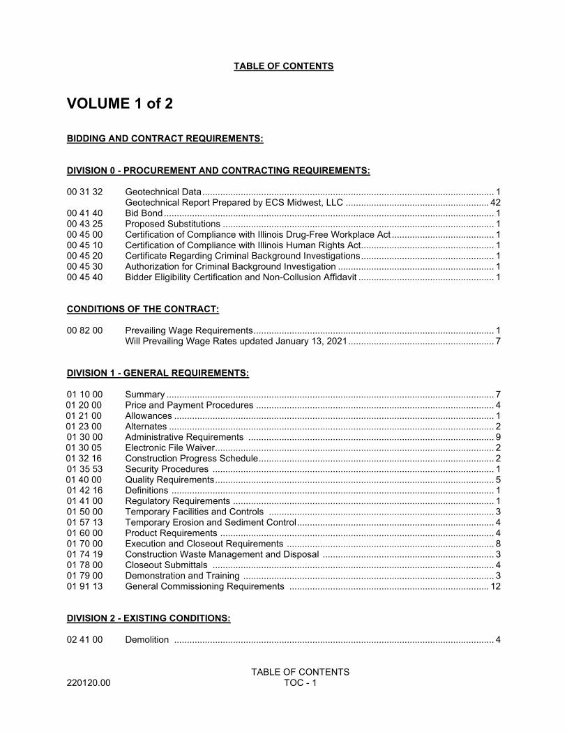
TABLE OF CONTENTS
TABLE OF CONTENTS 220120.00 TOC - 1
VOLUME 1 of 2 BIDDING AND CONTRACT REQUIREMENTS: DIVISION 0 - PROCUREMENT AND CONTRACTING REQUIREMENTS: 00 31 32 Geotechnical Data .................................................................................................................. 1 Geotechnical Report Prepared by ECS Midwest, LLC ........................................................ 42 00 41 40 Bid Bond ................................................................................................................................. 1 00 43 25 Proposed Substitutions .......................................................................................................... 1 00 45 00 Certification of Compliance with Illinois Drug-Free Workplace Act ........................................ 1 00 45 10 Certification of Compliance with Illinois Human Rights Act .................................................... 1 00 45 20 Certificate Regarding Criminal Background Investigations .................................................... 1 00 45 30 Authorization for Criminal Background Investigation ............................................................. 1 00 45 40 Bidder Eligibility Certification and Non-Collusion Affidavit ..................................................... 1 CONDITIONS OF THE CONTRACT: 00 82 00 Prevailing Wage Requirements .............................................................................................. 1 Will Prevailing Wage Rates updated January 13, 2021 ......................................................... 7 DIVISION 1 - GENERAL REQUIREMENTS: 01 10 00 Summary ................................................................................................................................ 7 01 20 00 Price and Payment Procedures ............................................................................................. 4 01 21 00 Allowances ............................................................................................................................. 1
01 23 00 Alternates ............................................................................................................................... 2 01 30 00 Administrative Requirements ................................................................................................ 9 01 30 05 Electronic File Waiver ............................................................................................................. 2 01 32 16 Construction Progress Schedule ............................................................................................ 2 01 35 53 Security Procedures .............................................................................................................. 1 01 40 00 Quality Requirements ............................................................................................................. 5 01 42 16 Definitions .............................................................................................................................. 1 01 41 00 Regulatory Requirements ...................................................................................................... 1 01 50 00 Temporary Facilities and Controls ........................................................................................ 3 01 57 13 Temporary Erosion and Sediment Control ............................................................................. 4 01 60 00 Product Requirements ........................................................................................................... 4 01 70 00 Execution and Closeout Requirements ................................................................................. 8 01 74 19 Construction Waste Management and Disposal ................................................................... 3 01 78 00 Closeout Submittals .............................................................................................................. 4 01 79 00 Demonstration and Training .................................................................................................. 3 01 91 13 General Commissioning Requirements .............................................................................. 12 DIVISION 2 - EXISTING CONDITIONS: 02 41 00 Demolition ............................................................................................................................. 4
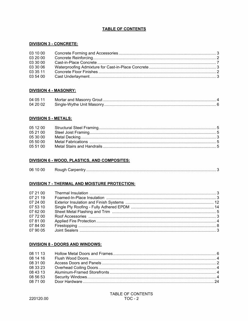
TABLE OF CONTENTS
TABLE OF CONTENTS 220120.00 TOC - 2
DIVISION 3 - CONCRETE: 03 10 00 Concrete Forming and Accessories ....................................................................................... 3 03 20 00 Concrete Reinforcing .............................................................................................................. 2 03 30 00 Cast-in-Place Concrete .......................................................................................................... 7 03 30 06 Waterproofing Admixture for Cast-in-Place Concrete ............................................................ 3 03 35 11 Concrete Floor Finishes ......................................................................................................... 2 03 54 00 Cast Underlayment ................................................................................................................. 3 DIVISION 4 - MASONRY: 04 05 11 Mortar and Masonry Grout ..................................................................................................... 4 04 20 02 Single-Wythe Unit Masonry .................................................................................................... 6 DIVISION 5 - METALS: 05 12 00 Structural Steel Framing......................................................................................................... 5 05 21 00 Steel Joist Framing ................................................................................................................. 5 05 30 00 Metal Decking ......................................................................................................................... 3 05 50 00 Metal Fabrications ................................................................................................................. 5 05 51 00 Metal Stairs and Handrails ..................................................................................................... 5 DIVISION 6 - WOOD, PLASTICS, AND COMPOSITES: 06 10 00 Rough Carpentry .................................................................................................................... 3 DIVISION 7 - THERMAL AND MOISTURE PROTECTION: 07 21 00 Thermal Insulation ................................................................................................................. 3 07 21 19 Foamed-In-Place Insulation .................................................................................................. 3 07 24 00 Exterior Insulation and Finish Systems ............................................................................... 12 07 53 10 Single Ply Roofing - Fully Adhered EPDM .......................................................................... 14 07 62 00 Sheet Metal Flashing and Trim ............................................................................................. 5 07 72 00 Roof Accessories .................................................................................................................. 3 07 81 00 Applied Fire Protection ........................................................................................................... 4 07 84 00 Firestopping ........................................................................................................................... 8 07 90 05 Joint Sealers .......................................................................................................................... 3 DIVISION 8 - DOORS AND WINDOWS: 08 11 13 Hollow Metal Doors and Frames ............................................................................................ 6 08 14 16 Flush Wood Doors .................................................................................................................. 4 08 31 00 Access Doors and Panels ...................................................................................................... 2 08 33 23 Overhead Coiling Doors ......................................................................................................... 4 08 43 13 Aluminum-Framed Storefronts ............................................................................................... 4 08 56 53 Security Windows ................................................................................................................... 4 08 71 00 Door Hardware ..................................................................................................................... 24
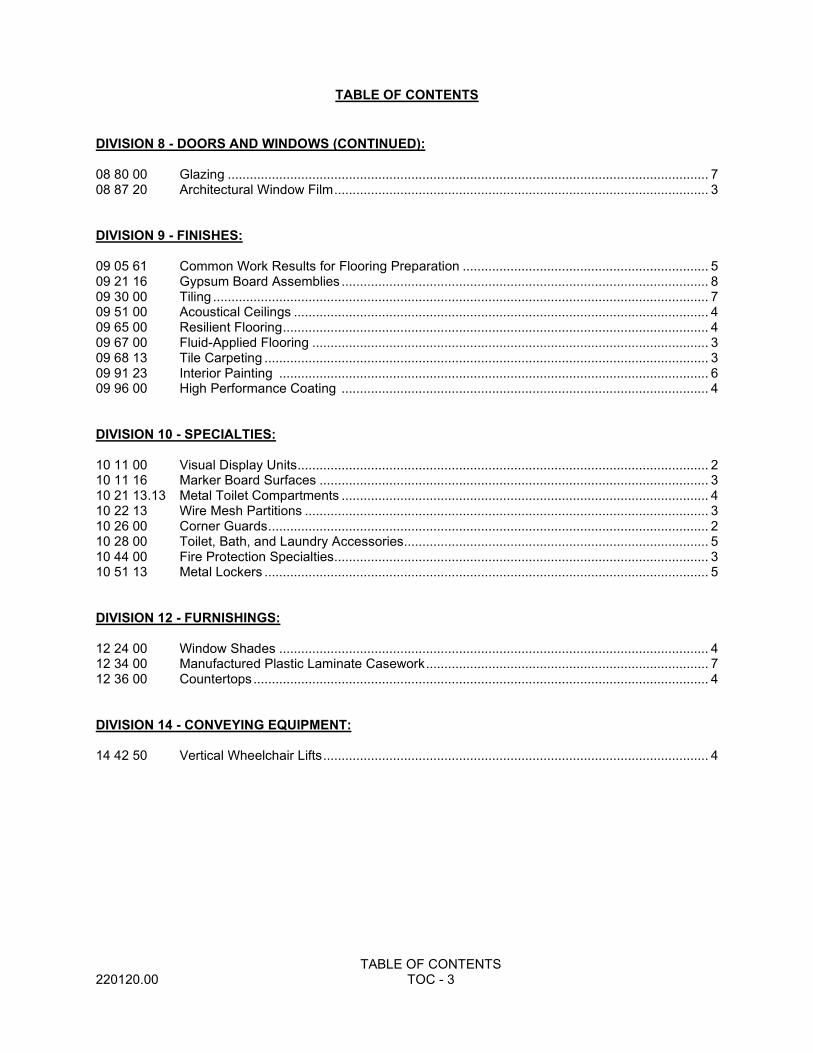
TABLE OF CONTENTS
TABLE OF CONTENTS 220120.00 TOC - 3
DIVISION 8 - DOORS AND WINDOWS (CONTINUED): 08 80 00 Glazing ................................................................................................................................... 7 08 87 20 Architectural Window Film ...................................................................................................... 3 DIVISION 9 - FINISHES: 09 05 61 Common Work Results for Flooring Preparation ................................................................... 5 09 21 16 Gypsum Board Assemblies .................................................................................................... 8 09 30 00 Tiling ....................................................................................................................................... 7 09 51 00 Acoustical Ceilings ................................................................................................................. 4 09 65 00 Resilient Flooring .................................................................................................................... 4 09 67 00 Fluid-Applied Flooring ............................................................................................................ 3 09 68 13 Tile Carpeting ......................................................................................................................... 3 09 91 23 Interior Painting ..................................................................................................................... 6 09 96 00 High Performance Coating .................................................................................................... 4 DIVISION 10 - SPECIALTIES: 10 11 00 Visual Display Units ................................................................................................................ 2 10 11 16 Marker Board Surfaces .......................................................................................................... 3 10 21 13.13 Metal Toilet Compartments .................................................................................................... 4 10 22 13 Wire Mesh Partitions .............................................................................................................. 3 10 26 00 Corner Guards ........................................................................................................................ 2 10 28 00 Toilet, Bath, and Laundry Accessories ................................................................................... 5 10 44 00 Fire Protection Specialties...................................................................................................... 3 10 51 13 Metal Lockers ......................................................................................................................... 5 DIVISION 12 - FURNISHINGS: 12 24 00 Window Shades ..................................................................................................................... 4 12 34 00 Manufactured Plastic Laminate Casework ............................................................................. 7 12 36 00 Countertops ............................................................................................................................ 4 DIVISION 14 - CONVEYING EQUIPMENT: 14 42 50 Vertical Wheelchair Lifts ......................................................................................................... 4
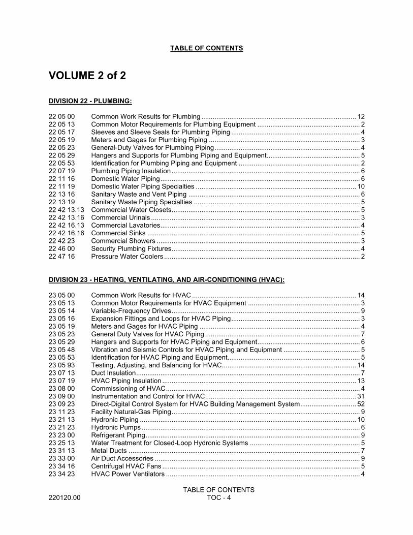
TABLE OF CONTENTS
TABLE OF CONTENTS 220120.00 TOC - 4
VOLUME 2 of 2 DIVISION 22 - PLUMBING: 22 05 00 Common Work Results for Plumbing ................................................................................... 12 22 05 13 Common Motor Requirements for Plumbing Equipment ....................................................... 2 22 05 17 Sleeves and Sleeve Seals for Plumbing Piping ..................................................................... 4 22 05 19 Meters and Gages for Plumbing Piping ................................................................................. 3 22 05 23 General-Duty Valves for Plumbing Piping .............................................................................. 4 22 05 29 Hangers and Supports for Plumbing Piping and Equipment .................................................. 5 22 05 53 Identification for Plumbing Piping and Equipment ................................................................. 2 22 07 19 Plumbing Piping Insulation ..................................................................................................... 6 22 11 16 Domestic Water Piping ........................................................................................................... 6 22 11 19 Domestic Water Piping Specialties ...................................................................................... 10 22 13 16 Sanitary Waste and Vent Piping ............................................................................................ 6 22 13 19 Sanitary Waste Piping Specialties ......................................................................................... 5 22 42 13.13 Commercial Water Closets..................................................................................................... 5 22 42 13.16 Commercial Urinals ................................................................................................................ 3 22 42 16.13 Commercial Lavatories ........................................................................................................... 4 22 42 16.16 Commercial Sinks .................................................................................................................. 5 22 42 23 Commercial Showers ............................................................................................................. 3 22 46 00 Security Plumbing Fixtures..................................................................................................... 4 22 47 16 Pressure Water Coolers ......................................................................................................... 2 DIVISION 23 - HEATING, VENTILATING, AND AIR-CONDITIONING (HVAC): 23 05 00 Common Work Results for HVAC ........................................................................................ 14 23 05 13 Common Motor Requirements for HVAC Equipment ............................................................ 3 23 05 14 Variable-Frequency Drives ..................................................................................................... 9 23 05 16 Expansion Fittings and Loops for HVAC Piping ..................................................................... 3 23 05 19 Meters and Gages for HVAC Piping ...................................................................................... 4 23 05 23 General Duty Valves for HVAC Piping ................................................................................... 7 23 05 29 Hangers and Supports for HVAC Piping and Equipment ....................................................... 6 23 05 48 Vibration and Seismic Controls for HVAC Piping and Equipment ......................................... 5 23 05 53 Identification for HVAC Piping and Equipment....................................................................... 5 23 05 93 Testing, Adjusting, and Balancing for HVAC........................................................................ 14 23 07 13 Duct Insulation ........................................................................................................................ 7 23 07 19 HVAC Piping Insulation ........................................................................................................ 13 23 08 00 Commissioning of HVAC ........................................................................................................ 4 23 09 00 Instrumentation and Control for HVAC ................................................................................. 31 23 09 23 Direct-Digital Control System for HVAC Building Management System .............................. 52 23 11 23 Facility Natural-Gas Piping ..................................................................................................... 9 23 21 13 Hydronic Piping .................................................................................................................... 10 23 21 23 Hydronic Pumps ..................................................................................................................... 6 23 23 00 Refrigerant Piping ................................................................................................................... 9 23 25 13 Water Treatment for Closed-Loop Hydronic Systems ........................................................... 5 23 31 13 Metal Ducts ............................................................................................................................ 7 23 33 00 Air Duct Accessories .............................................................................................................. 9 23 34 16 Centrifugal HVAC Fans .......................................................................................................... 5 23 34 23 HVAC Power Ventilators ........................................................................................................ 4
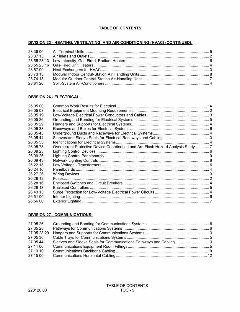
TABLE OF CONTENTS
TABLE OF CONTENTS 220120.00 TOC - 5
DIVISION 23 - HEATING, VENTILATING, AND AIR-CONDITIONING (HVAC) (CONTINUED): 23 36 00 Air Terminal Units ................................................................................................................... 5 23 37 13 Air Inlets and Outlets .............................................................................................................. 2 23 55 23.13 Low-Intensity, Gas-Fired, Radiant Heaters ............................................................................ 6 23 55 23.16 Gas-Fired Unit Heaters .......................................................................................................... 4 23 57 00 Heat Exchangers for HVAC.................................................................................................... 3 23 73 13 Modular Indoor Central-Station Air Handling Units ................................................................ 8 23 74 13 Modular Outdoor Central-Station Air-Handling Units ............................................................. 7 23 81 26 Split-System Air-Conditioners ................................................................................................ 4 DIVISION 26 - ELECTRICAL: 26 05 00 Common Work Results for Electrical ................................................................................... 14 26 05 03 Electrical Equipment Mounting Requirements ....................................................................... 2 26 05 19 Low-Voltage Electrical Power Conductors and Cables .......................................................... 3 26 05 26 Grounding and Bonding for Electrical Systems ..................................................................... 5 26 05 29 Hangers and Supports for Electrical Systems........................................................................ 4 26 05 33 Raceways and Boxes for Electrical Systems ......................................................................... 6 26 05 43 Underground Ducts and Raceways for Electrical Systems .................................................... 4 26 05 44 Sleeves and Sleeve Seals for Electrical Raceways and Cabling .......................................... 3 26 05 53 Identifications for Electrical Systems ...................................................................................... 4 26 05 73 Overcurrent Protective Device Coordination and Arc-Flash Hazard Analysis Study ............. 7 26 09 23 Lighting Control Devices ........................................................................................................ 6 26 09 26 Lighting Control Panelboards ............................................................................................... 10 26 09 43 Network Lighting Controls ...................................................................................................... 8 26 22 13 Low Voltage - Transformers ................................................................................................... 6 26 24 16 Panelboards ........................................................................................................................... 4 26 27 26 Wiring Devices ....................................................................................................................... 3 26 28 13 Fuses ...................................................................................................................................... 2 26 28 16 Enclosed Switches and Circuit Breakers ............................................................................... 4 26 29 13 Enclosed Controllers .............................................................................................................. 5 26 43 13 Surge Protection for Low-Voltage Electrical Power Circuits .................................................. 4 26 51 00 Interior Lighting ....................................................................................................................... 6 26 56 00 Exterior Lighting ..................................................................................................................... 7 DIVISION 27 - COMMUNICATIONS: 27 05 26 Grounding and Bonding for Communications Systems ......................................................... 6 27 05 28 Pathways for Communications Systems ................................................................................ 6 27 05 28.29 Hangers and Supports for Communications Systems ........................................................... 3 27 05 36 Cable Trays for Communications Systems ............................................................................ 5 27 05 44 Sleeves and Sleeve Seals for Communications Pathways and Cabling ............................... 3 27 11 00 Communications Equipment Room Fittings ........................................................................... 5 27 13 10 Communications Backbone Cabling .................................................................................... 10 27 15 00 Communications Horizontal Cabling .................................................................................... 12
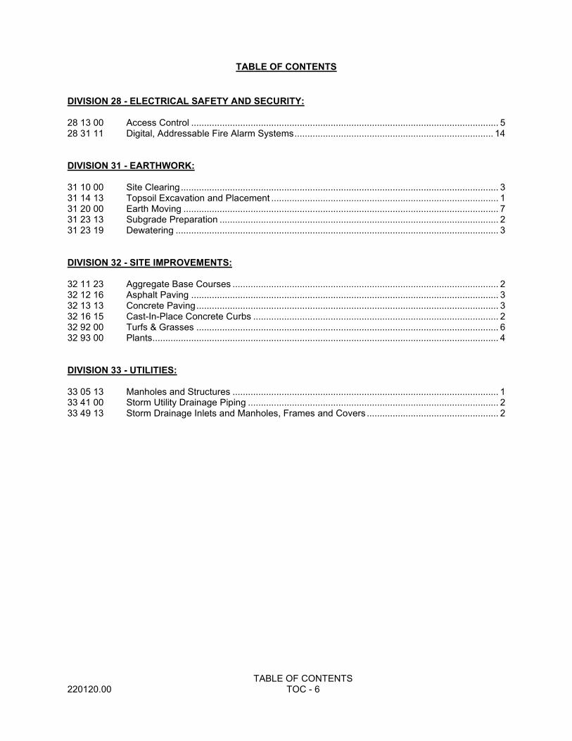
TABLE OF CONTENTS
TABLE OF CONTENTS 220120.00 TOC - 6
DIVISION 28 - ELECTRICAL SAFETY AND SECURITY: 28 13 00 Access Control ....................................................................................................................... 5 28 31 11 Digital, Addressable Fire Alarm Systems ............................................................................. 14 DIVISION 31 - EARTHWORK: 31 10 00 Site Clearing ........................................................................................................................... 3 31 14 13 Topsoil Excavation and Placement ........................................................................................ 1 31 20 00 Earth Moving .......................................................................................................................... 7 31 23 13 Subgrade Preparation ............................................................................................................ 2 31 23 19 Dewatering ............................................................................................................................. 3 DIVISION 32 - SITE IMPROVEMENTS: 32 11 23 Aggregate Base Courses ....................................................................................................... 2 32 12 16 Asphalt Paving ....................................................................................................................... 3 32 13 13 Concrete Paving ..................................................................................................................... 3 32 16 15 Cast-In-Place Concrete Curbs ............................................................................................... 2 32 92 00 Turfs & Grasses ..................................................................................................................... 6 32 93 00 Plants...................................................................................................................................... 4 DIVISION 33 - UTILITIES: 33 05 13 Manholes and Structures ....................................................................................................... 1 33 41 00 Storm Utility Drainage Piping ................................................................................................. 2 33 49 13 Storm Drainage Inlets and Manholes, Frames and Covers ................................................... 2
COMMON WORK RESULTS FOR PLUMBING 220120.00 22 05 00 - 1
SECTION 22 05 00 COMMON WORK RESULTS FOR PLUMBING
PART 1 GENERAL
1.01 SUMMARY
A. This Section includes the following:
1. Piping materials and installation instructions common to most piping systems.
2. Transition fittings.
3. Dielectric fittings.
4. Mechanical sleeve seals.
5. Sleeves.
6. Escutcheons.
7. Grout.
8. Mechanical demolition.
9. Equipment installation requirements common to equipment sections.
10. Painting and finishing.
11. Supports and anchorages.
1.02 DEFINITIONS
A. Finished Spaces: Spaces other than mechanical and electrical equipment rooms, furred spaces, pipe and duct shafts, unheated spaces immediately below roof, spaces above ceilings, unexcavated spaces, crawlspaces, and tunnels.
B. Exposed, Interior Installations: Exposed to view indoors. Examples include finished occupied spaces and mechanical equipment rooms.
C. Concealed, Interior Installations: Concealed from view and protected from physical contact by building occupants. Examples include above ceilings and in duct shafts.
D. The following are industry abbreviations for plastic materials:
1. ABS: Acrylonitrile-butadiene-styrene plastic.
2. CPVC: Chlorinated polyvinyl chloride plastic.
3. PE: Polyethylene plastic.
4. PVC: Polyvinyl chloride plastic.
E. The following are industry abbreviations for rubber materials:
1. EPDM: Ethylene-propylene-diene terpolymer rubber.
2. NBR: Acrylonitrile-butadiene rubber.
1.03 SUBMITTALS
A. Product Data: For the following:
1. Piping materials.
2. Mechanical sleeve seals.
1.04 QUALITY ASSURANCE
A. Steel Support Welding: Qualify processes and operators according to AWS D1.1, "Structural Welding Code--Steel."
B. Electrical Characteristics for Plumbing Equipment: Equipment of higher electrical characteristics may be furnished provided such proposed equipment is approved in writing and connecting electrical services, circuit breakers, and conduit sizes are
COMMON WORK RESULTS FOR PLUMBING 220120.00 22 05 00 - 2
appropriately modified. If minimum energy ratings or efficiencies are specified, equipment shall comply with requirements.
1.05 DELIVERY, STORAGE, AND HANDLING
A. Deliver pipes and tubes with factory-applied end caps. Maintain end caps through shipping, storage, and handling to prevent pipe end damage and to prevent entrance of dirt, debris, and moisture.
B. Store plastic pipes protected from direct sunlight. Support to prevent sagging and bending.
1.06 COORDINATION
A. Arrange for pipe spaces, chases, slots, and openings in building structure during progress of construction, to allow for plumbing installations.
B. Coordinate installation of required supporting devices and set sleeves in poured-in-place concrete and other structural components as they are constructed.
C. Coordinate requirements for access panels and doors for mechanical items requiring access that are concealed behind finished surfaces. Access panels and doors are specified in Division 8 Section "Access Doors and Panels."
D. Coordination Meetings: Attend coordination meetings with the construction manager and all other trades for the purpose of coordinating the locations of all fire protection, plumbing, HVAC and electrical work for the entire project. The goal of these meetings is to avoid conflicts between trades in the field.
E. Coordination Drawings: Each fire protection, plumbing, HVAC and electrical contractor shall develop ¼” coordination floor plan drawings for all of their respective working areas that necessitate additional coordination to allow for efficient systems installation. Each coordination drawing, for all trades, shall be signed and dated by each trade indicating that each trade has fully coordinated their work
F. Conflicts Between Trades: Resolve all conflicts with other trades at no additional cost to the Owner or Architect.
G. Ceiling Heights: Maintain all ceiling heights indicated on the architectural drawings. Ceiling heights will not be lowered to accommodate installation of fire protection, plumbing, HVAC or electrical work. Install all work so that there is at least eight (8) inches clearance above the ceiling grid, in all areas, to facilitate installation of light fixtures. If installed work does not comply with the ceiling height requirements stated above, then the contractor shall remove and re-install work to comply with the stated requirements above at no additional cost to the Owner or Architect.
1.07 INTENT OF DRAWINGS AND SPECIFICATIONS
A. These specifications and attendant drawings are intended to cover a complete installation of systems. The omission of expressed reference to any item of labor or material necessary for the proper execution of the work in accordance with present practices of the trade shall not relieve the Contractor from providing such additional labor and materials.
B. The drawings depicting plumbing work are diagrammatic and show, in their approximate location, symbols representing plumbing equipment and devices. The exact location of such equipment and devices shall be established in the field in accordance with instructions from the Architect and/or established by manufacturer’s installation drawings and details.
1. The Contractor shall refer to shop drawings and submittal drawings for all equipment requiring plumbing connections to verify rough-in and connection locations.
COMMON WORK RESULTS FOR PLUMBING 220120.00 22 05 00 - 3
2. Unless specifically stated to the contrary, no measurement of an plumbing drawing derived by scaling shall be used as a dimension to work by. Dimensions noted on the plumbing drawings are subject to measurements of adjacent and previously completed work. All measurements shall be performed prior to the actual installation of equipment.
1.08 DRAWINGS
A. The plumbing drawings do not attempt to show the complete details of building construction which affect the plumbing installation. The Contractor shall refer to the architectural, civil, structural and mechanical, and electrical drawings for additional details which affect the proper installation of this work. Bring any discrepancies to the attention of the A/E for resolution. The Contractor is cautioned that diagrams showing plumbing connections and/or piping are diagrammatic only and must not be used for obtaining lineal runs of piping. Piping diagrams do not necessarily show the exact physical arrangement of the equipment.
B. The Engineer will make available to the contractor a complete set of plan sheets in AutoCAD version 2008 format. Each copy of electronic plan sheet requested will be put on disk for the cost of $200 to cover technician time and mailing costs. Any requests shall be made in writing to the Engineer with a certified check or money order payable to the Engineer. The disk(s) will be sent out within 7 days of receipt of the request and payment in full.
C. The Contractor shall be responsible for all existing field conditions, review existing field conditions prior to bid and shall take into account in bid proposal. No additional compensation will be allowed due to Contractor’s failure to include all necessary work in the bid proposal.
1.09 MATERIAL AND EQUIPMENT
A. All material and equipment shall be new and of the quality used for the purpose in good commercial practice, and shall be standard product of reputable manufacturers. Each major component of equipment shall have the manufacturer's name, catalog number, and capacity or rating on a nameplate, securely affixed on the equipment in a conspicuous place.
1.10 DAMAGE TO OTHER WORK
A. The Plumbing Contractor will be held rigidly responsible for all damages to the work of his own or any other trade resulting from the execution of his work. It shall be the Contractor's responsibility to adequately protect his work at all times. All damages resulting from his operations shall be repaired or the damaged portions replaced by the party originally performing the work, (to the entire satisfaction of the Engineer), and all cost thereof shall be borne by the Contractor responsible for the damage.
1.11 COOPERATION WITH OTHER TRADES
A. This Contractor shall completely cooperate with all other trades in the matter of planning and executing of the work. Every reasonable effort shall be made to prevent conflict and interferences as to space requirements, dimensions, locations, openings, sleeving or other matters which tend to delay or obstruct the work of any trade.
1.12 NEGLIGENCE
A. Should the Contractor fail to provide materials, templates, etc., or other necessary information causing delay or expense to another party, he shall pay the actual amount of the damages to the party who sustained the loss.

COMMON WORK RESULTS FOR PLUMBING 220120.00 22 05 00 - 4
1.13 FIELD CHANGES
A. Should any change in drawings or specifications be required to comply with local regulations and/or field conditions, the Contractor shall refer same to Architect for approval before any work which deviates from the original requirements of the drawings and specifications is started. In the event of disagreements as to the necessity of such changes, the decision of the Architect shall be final.
1.14 CUTTING AND PATCHING
A. As necessary and with approval to permit the installation of piping or any part of the work under this branch. Any cost caused by defective or ill-timed work shall be by the party responsible there for. Patching of holes, openings, etc. resulting from the work of this branch shall be furnished by this Contractor.
1.15 STANDARDS, CODES AND PERMITS
A. All work shall be installed in accordance with National, State and Local plumbing codes, laws, ordinances and regulations. Comply with all applicable OSHA regulations.
B. All materials shall have a U.L. label where a U.L. standard and/or test exists.
C. Prepare and submit to all authorities having jurisdiction, for their approval, all applications and working drawings required by them. Secure and pay for all permits and licenses required.
1.16 CLEAN-UP
A. This Contractor shall at all times keep the premises free from excessive accumulation of waste material or rubbish resulting from his work, including tools, scaffolding and surplus materials, and he shall leave his work broom-clean or its equivalent. In case of disputes, the Architect may order the removal of such rubbish and charge the cost to the responsible contractor as determined by the Architect. At the time of final clean-up all fixtures and equipment shall be thoroughly cleaned and left in proper condition for their intended use.
1.17 GUARANTEE
A. The Contractor shall unconditionally guarantee his work and all components thereof for a period of one year from the date of his final payment. He shall remedy any defects in workmanship and repair or replace any faulty equipment which shall appear within the guarantee period to the entire satisfaction of the Architect at no additional charge.
1.18 TEMPORARY PLUMBING
A. Temporary water includes all required up to the time of substantial completion.
1.19 DEMOLITION, RENOVATION AND DISPOSITION OF EXISTING EQUIPMENT.
A. This Contractor shall note that the existing building will remain in service during portions of the construction period. Areas of the building will be vacated as required to facilitate construction. This Contractor shall proceed with the completion of his work in such a manner as to cause the least possible interference with the Owner's operation. All work required in the existing building shall be done in a manner and time acceptable to the Owner.
B. Plumbing equipment in conflict with construction shall be removed and/or relocated as indicated on the drawings, as directed or required. This Contractor shall remove all plumbing equipment released from service as a result of construction, and no equipment removed shall be reused, except as specifically directed on the drawings or elsewhere herein. Except for piping and miscellaneous hardware, all plumbing equipment that the owner desires to retain shall remain the property of the Owner and shall be stored on the site for removal by the Owner. All other piping and

COMMON WORK RESULTS FOR PLUMBING 220120.00 22 05 00 - 5
equipment removed and not retained by the Owner shall become the property of this Contractor and shall be removed from the site.
C. This Contractor shall be responsible for the work of other trades as may be necessary to facilitate the installation of plumbing work in the existing building. Such work necessary that is normally done by other trades and is not covered as a part of other Divisions of the work shall be done under the direction and at the expense of the Plumbing Contractor. This work shall include but is not limited to, cutting, patching, and refinishing and all necessary and required to leave existing building in condition acceptable to the Architect.
D. Any existing fixtures or equipment not shown on the drawings and which are logically expected to be continued in service and which may be interrupted or disturbed during construction shall be reconnected in an approved manner. In addition, any existing fixture or equipment which may require relocation or rerouting, as a result of construction, shall be considered a part of the work of this branch and shall be done by this Contractor with no additional compensation.
E. All coring that is required for plumbing work shall be by this Contractor.
F. All equipment containing hazardous materials removed during the project become the Contractor's property and he shall dispose of them in accordance with applicable DNR and EPA regulations.
G. Piping which is to remain in service, but which is presently routed through areas being demolished shall be rerouted around demolition area.
1.20 SUBSTITUTION AND APPROVAL OF MATERIAL, EQUIPMENT OR DESIGN
A. Such requests shall be accompanied by three copies of all necessary illustrations, cuts, drawings and descriptions of material proposed for substitution and shall fully describe all points in which it differs from the articles specified. The Engineer will retain two copies and one copy returned to the Contractor with acceptance, rejection or revisions indicated thereon.
B. The proposed substitution does not affect dimensions shown on Drawings or as specified.
C. The proposed substitution will have no adverse affect on other trades, the construction schedule, or specified warranty requirements.
D. All proposed substitutions will be subject to satisfactory performance to the specification and considered as a deduct alternate rather than as an equivalent.
E. Where equipment or accessories are used which differ in arrangement, configuration, dimensions, ratings, or engineering parameters from those indicated on the contract documents, the Contractor is responsible for all costs, including architectural/engineering design and construction costs, involved in integrating the equipment or accessories into the system and the assigned space and for obtaining the performance from the system into which these items are placed.
F. All substitution review costs shall be reimbursed to the Engineer by the contractor or their suppliers on a Time/Material bases. This cost shall be paid on approval or disproval of the substitution material, equipment or design.
1.21 SHOP DRAWINGS
A. Submit to Engineer for review, copies of manufacturer's shop drawings and/or equipment brochure depicting items in this specification.
B. Other materials at the request of the Engineer.
C. Shop drawings shall bear the Contractor's stamp indicating approval.
D. Any equipment fabrication prior to shop drawing review shall be at the Contractor's risk.

COMMON WORK RESULTS FOR PLUMBING 220120.00 22 05 00 - 6
E. Any shop drawing not meeting the requirements as outlined in this or any other part of this specification or drawing, requiring more than two reviews or in excess of 4 hours of total review time shall have a fee of reimbursement to the Engineer by the contractor or their suppliers. This shall be done on a Time/Material bases. This cost shall be paid on approval on disproval of the material, equipment or design.
1.22 WORKMANSHIP
A. The installation of all work shall be made so that its several component parts will function as a workable system complete with all accessories necessary for its operation, and shall be left with all equipment properly adjusted and in working order. The work shall be executed in conformity with the best-accepted standard practice of the trade so as to contribute to efficiency and appearance. It shall also be executed so that the installation will conform and adjust itself to the building structure, its equipment and its usage.
1.23 DRAWINGS OF OTHER TRADES
A. The Contractor shall consult the drawings of the work for the various other trades; field layouts of the parties performing the work of the other trades; their shop drawings, and he shall be governed accordingly in laying out his work.
1.24 FIELD MEASUREMENTS
A. The Contractor shall take all field measurements necessary for his work and shall assume the full responsibility for their accuracy.
1.25 STRUCTURAL INTERFERENCES
A. Should any structural interference prevent the installation of the fixtures, running of piping, etc., at points shown on drawings, the necessary minor deviation there from, as determined by the Architect, may be permitted. Minor changes in the position of the fixtures, equipment or piping if decided upon before any work has been done by the Contractor shall be made without additional charge.
1.26 EXAMINATION OF PLANS, SPECIFICATIONS AND SITE
A. Before submitting a bid, the Contractor shall visit the site and familiarize himself with all features of the building and site, which may affect the execution of his work. No extra payment will be allowed for the failure to obtain this information. If in the opinion of the Contractor there are omissions or errors in the plans or specifications, the Contractor shall clarify these points with the Engineer before submitting his bid. In lieu of written clarification by addendum, the contractor shall resolve all conflicts in favor of the greater quantity or better quality.
PART 2 PRODUCTS
2.01 MANUFACTURERS
A. In other Part 2 articles where subparagraph titles below introduce lists, the following requirements apply for product selection:
1. Manufacturers: Subject to compliance with requirements, provide products by the manufacturers specified.
2.02 PIPE, TUBE, AND FITTINGS
A. Pipe Threads: ASME B1.20.1 for factory-threaded pipe and pipe fittings.
2.03 JOINING MATERIALS
A. Refer to individual Division 22 piping Sections for special joining materials not listed below.
B. Pipe-Flange Gasket Materials: Suitable for chemical and thermal conditions of piping system contents.
COMMON WORK RESULTS FOR PLUMBING 220120.00 22 05 00 - 7
1. ASME B16.21, nonmetallic, flat, asbestos-free, 1/8-inch (3.2-mm) maximum thickness unless thickness or specific material is indicated.
a. Full-Face Type: For flat-face, Class 125, cast-iron and cast-bronze flanges.
b. Narrow-Face Type: For raised-face, Class 250, cast-iron and steel flanges.
2. AWWA C110, rubber, flat face, 1/8 inch (3.2 mm) thick, unless otherwise indicated; and full-face or ring type, unless otherwise indicated.
C. Flange Bolts and Nuts: ASME B18.2.1, carbon steel, unless otherwise indicated.
D. Plastic, Pipe-Flange Gasket, Bolts, and Nuts: Type and material recommended by piping system manufacturer, unless otherwise indicated.
E. Solder Filler Metals: ASTM B 32, lead-free alloys. Include water-flushable flux according to ASTM B 813.
F. Brazing Filler Metals: AWS A5.8, BCuP Series, copper-phosphorus alloys for general-duty brazing, unless otherwise indicated; and AWS A5.8, BAg1, silver alloy for refrigerant piping, unless otherwise indicated.
G. Welding Filler Metals: Comply with AWS D10.12 for welding materials appropriate for wall thickness and chemical analysis of steel pipe being welded.
H. Solvent Cements for Joining Plastic Piping:
1. ABS Piping: ASTM D 2235.
2. CPVC Piping: ASTM F 493.
3. PVC Piping: ASTM D 2564. Include primer according to ASTM F 656.
4. PVC to ABS Piping Transition: ASTM D 3138.
2.04 TRANSITION FITTINGS
A. AWWA Transition Couplings: Same size as, and with pressure rating at least equal to and with ends compatible with, piping to be joined.
1. Manufacturers:
a. Cascade Waterworks Mfg. Co.
b. Dresser Industries, Inc.; DMD Div.
c. Ford Meter Box Company, Incorporated (The); Pipe Products Div.
d. Viking Johnson.
2. Underground Piping NPS 1-1/2 (DN 40) and Smaller: Manufactured fitting or coupling.
3. Underground Piping NPS 2 (DN 50) and Larger: AWWA C219, metal sleeve-type coupling.
4. Aboveground Pressure Piping: Pipe fitting.
B. Plastic-to-Metal Transition Fittings: CPVC and PVC one-piece fitting with manufacturer's Schedule 80 equivalent dimensions; one end with threaded brass insert, and one solvent-cement-joint end.
C. Plastic-to-Metal Transition Unions: MSS SP-107, CPVC and PVC four-part union. Include brass end, solvent-cement-joint end, rubber O-ring, and union nut.
D. Flexible Transition Couplings for Underground Nonpressure Drainage Piping: ASTM C 1173 with elastomeric sleeve, ends same size as piping to be joined, and corrosion-resistant metal band on each end.
COMMON WORK RESULTS FOR PLUMBING 220120.00 22 05 00 - 8
2.05 DIELECTRIC FITTINGS
A. Description: Combination fitting of copper alloy and ferrous materials with threaded, solder-joint, plain, or weld-neck end connections that match piping system materials.
B. Insulating Material: Suitable for system fluid, pressure, and temperature.
C. Dielectric Unions: Factory-fabricated, union assembly, for 250-psig (1725-kPa) minimum working pressure at 180 deg F (82 deg C).
1. Manufacturers:
a. Eclipse, Inc.
b. Epco Sales, Inc.
c. Hart Industries, International, Inc.
d. Watts Industries, Inc.; Water Products Div.
e. Zurn Industries, Inc.; Wilkins Div.
D. Dielectric Couplings: Galvanized-steel coupling with inert and noncorrosive, thermoplastic lining; threaded ends; and 300-psig (2070-kPa) minimum working pressure at 225 deg F (107 deg C).
1. Manufacturers:
a. Calpico, Inc.
b. Lochinvar Corp.
E. Dielectric Nipples: Electroplated steel nipple with inert and noncorrosive, thermoplastic lining; plain, threaded, or grooved ends; and 300-psig (2070-kPa) minimum working pressure at 225 deg F (107 deg C).
1. Manufacturers:
a. Precision Plumbing Products, Inc.
b. Sioux Chief Manufacturing Co., Inc.
c. Victaulic Co. of America.
2.06 SLEEVES
A. Galvanized-Steel Sheet: 0.0239-inch (0.6-mm) minimum thickness; round tube closed with welded longitudinal joint.
B. Steel Pipe: ASTM A 53, Type E, Grade B, Schedule 40, galvanized, plain ends.
C. Cast Iron: Cast or fabricated "wall pipe" equivalent to ductile-iron pressure pipe, with plain ends and integral waterstop, unless otherwise indicated.
D. Stack Sleeve Fittings: Manufactured, cast-iron sleeve with integral clamping flange. Include clamping ring and bolts and nuts for membrane flashing.
1. Underdeck Clamp: Clamping ring with set screws.
E. PVC Pipe: ASTM D 1785, Schedule 40.
2.07 ESCUTCHEONS
A. Description: Manufactured wall and ceiling escutcheons and floor plates, with an ID to closely fit around pipe, tube, and insulation of insulated piping and an OD that completely covers opening.
B. One-Piece, Deep-Pattern Type: Deep-drawn, box-shaped brass with polished chrome-plated finish.
C. One-Piece, Cast-Brass Type: With set screw.
1. Finish: Polished chrome-plated and rough brass.
D. Split-Casting, Cast-Brass Type: With concealed hinge and set screw.
COMMON WORK RESULTS FOR PLUMBING 220120.00 22 05 00 - 9
1. Finish: Polished chrome-plated and rough brass.
E. One-Piece, Stamped-Steel Type: With set screw or spring clips and chrome-plated finish.
F. Split-Plate, Stamped-Steel Type: With hinge, set screw or spring clips, and chrome-plated finish.
G. One-Piece, Floor-Plate Type: Cast-iron floor plate.
H. Split-Casting, Floor-Plate Type: Cast brass with concealed hinge and set screw.
2.08 GROUT
A. Description: ASTM C 1107, Grade B, nonshrink and nonmetallic, dry hydraulic-cement grout.
1. Characteristics: Post-hardening, volume-adjusting, nonstaining, noncorrosive, nongaseous, and recommended for interior and exterior applications.
2. Design Mix: 5000-psi (34.5-MPa), 28-day compressive strength.
3. Packaging: Premixed and factory packaged.
PART 3 EXECUTION
3.01 PIPING SYSTEMS - COMMON REQUIREMENTS
A. Drawing plans, schematics, and diagrams indicate general location and arrangement of piping systems. Indicated locations and arrangements were used to size pipe and calculate friction loss, expansion, pump sizing, and other design considerations. Install piping as indicated unless deviations to layout are approved on Coordination Drawings.
B. Install piping in concealed locations, unless otherwise indicated and except in equipment rooms and service areas.
C. Install piping indicated to be exposed and piping in equipment rooms and service areas at right angles or parallel to building walls. Diagonal runs are prohibited unless specifically indicated otherwise.
D. Install piping above accessible ceilings to allow sufficient space for ceiling panel removal.
E. Install piping to permit valve servicing.
F. Install piping at indicated slopes.
G. Install piping free of sags and bends.
H. Install fittings for changes in direction and branch connections.
I. Install piping to allow application of insulation.
J. Select system components with pressure rating equal to or greater than system operating pressure.
K. Install escutcheons for penetrations of walls, ceilings, and floors according to the following:
1. New Piping:
a. Piping with Fitting or Sleeve Protruding from Wall: One-piece, deep-pattern type.
b. Chrome-Plated Piping: One-piece, cast-brass type with polished chrome-plated finish.
c. Insulated Piping: One-piece, stamped-steel type with spring clips.
d. Bare Piping at Wall and Floor Penetrations in Finished Spaces: One-piece, cast-brass type with polished chrome-plated finish.
COMMON WORK RESULTS FOR PLUMBING 220120.00 22 05 00 - 10
e. Bare Piping at Ceiling Penetrations in Finished Spaces: One-piece or split-casting, cast-brass type with polished chrome-plated finish. Bare Piping at Ceiling Penetrations in Finished Spaces: One-piece, stamped-steel type or split-plate, stamped-steel type with concealed hinge and set screw.
f. Bare Piping in Unfinished Service Spaces: One-piece, cast-brass type with rough-brass finish.
g. Bare Piping in Equipment Rooms: One-piece, cast-brass type.
h. Bare Piping at Floor Penetrations in Equipment Rooms: One-piece, floor-plate type.
2. Existing Piping: Use the following:
a. Chrome-Plated Piping: Split-casting, cast-brass type with chrome-plated finish.
b. Insulated Piping: Split-plate, stamped-steel type with concealed or exposed-rivet hinge and spring clips.
c. Bare Piping at Wall and Floor Penetrations in Finished Spaces: Split-casting, cast-brass type with chrome-plated finish.
d. Bare Piping at Ceiling Penetrations in Finished Spaces: Split-casting, cast-brass type with chrome-plated finish.
e. Bare Piping in Unfinished Service Spaces: Split-casting, cast-brass type with rough-brass finish.
f. Bare Piping at Floor Penetrations in Equipment Rooms: Split-casting, floor-plate type.
L. Sleeves are not required for core-drilled holes.
M. Permanent sleeves are not required for holes formed by removable PE sleeves.
N. Install sleeves for pipes passing through concrete and masonry walls and concrete floor and roof slabs.
O. Install sleeves for pipes passing through concrete and masonry walls, gypsum-board partitions, and concrete floor and roof slabs.
1. Cut sleeves to length for mounting flush with both surfaces.
a. Exception: Extend sleeves installed in floors of mechanical equipment areas or other wet areas 2 inches (50 mm) above finished floor level. Extend cast-iron sleeve fittings below floor slab as required to secure clamping ring if ring is specified.
2. Install sleeves in new walls and slabs as new walls and slabs are constructed.
3. Install sleeves that are large enough to provide 1/4-inch (6.4-mm) annular clear space between sleeve and pipe or pipe insulation. Use the following sleeve materials:
a. Steel Pipe Sleeves: For pipes smaller than NPS 6 (DN 150).
b. Steel Sheet Sleeves: For pipes NPS 6 (DN 150) and larger, penetrating gypsum-board partitions.
c. Stack Sleeve Fittings: For pipes penetrating floors with membrane waterproofing. Secure flashing between clamping flanges. Install section of cast-iron soil pipe to extend sleeve to 2 inches (50 mm) above finished floor level. Refer to Division 7 Section "Sheet Metal Flashing and Trim" for flashing.
1) Seal space outside of sleeve fittings with grout.
COMMON WORK RESULTS FOR PLUMBING 220120.00 22 05 00 - 11
4. Except for underground wall penetrations, seal annular space between sleeve and pipe or pipe insulation, using joint sealants appropriate for size, depth, and location of joint. Refer to Division 7 Section "Joint Sealants" for materials and installation.
P. Fire-Barrier Penetrations: Maintain indicated fire rating of walls, partitions, ceilings, and floors at pipe penetrations. Seal pipe penetrations with firestop materials. Refer to Division 7 Section "Through-Penetration Firestop Systems" for materials.
Q. Verify final equipment locations for roughing-in.
R. Refer to equipment specifications in other Sections of these Specifications for roughing-in requirements.
S. All piping installed in plenums shall be plenum rated. No PVC piping is permitted in plenums.
3.02 PIPING JOINT CONSTRUCTION
A. Join pipe and fittings according to the following requirements and Division 15 Sections specifying piping systems.
B. Ream ends of pipes and tubes and remove burrs. Bevel plain ends of steel pipe.
C. Remove scale, slag, dirt, and debris from inside and outside of pipe and fittings before assembly.
D. Soldered Joints: Apply ASTM B 813, water-flushable flux, unless otherwise indicated, to tube end. Construct joints according to ASTM B 828 or CDA's "Copper Tube Handbook," using lead-free solder alloy complying with ASTM B 32.
E. Brazed Joints: Construct joints according to AWS's "Brazing Handbook," "Pipe and Tube" Chapter, using copper-phosphorus brazing filler metal complying with AWS A5.8.
F. Threaded Joints: Thread pipe with tapered pipe threads according to ASME B1.20.1. Cut threads full and clean using sharp dies. Ream threaded pipe ends to remove burrs and restore full ID. Join pipe fittings and valves as follows:
1. Apply appropriate tape or thread compound to external pipe threads unless dry seal threading is specified.
2. Damaged Threads: Do not use pipe or pipe fittings with threads that are corroded or damaged. Do not use pipe sections that have cracked or open welds.
G. Welded Joints: Construct joints according to AWS D10.12, using qualified processes and welding operators according to Part 1 "Quality Assurance" Article.
H. Plastic Piping Solvent-Cement Joints: Clean and dry joining surfaces. Join pipe and fittings according to the following:
1. Comply with ASTM F 402 for safe-handling practice of cleaners, primers, and solvent cements.
2. ABS Piping: Join according to ASTM D 2235 and ASTM D 2661 Appendixes.
3. CPVC Piping: Join according to ASTM D 2846/D 2846M Appendix.
4. PVC Pressure Piping: Join schedule number ASTM D 1785, PVC pipe and PVC socket fittings according to ASTM D 2672. Join other-than-schedule-number PVC pipe and socket fittings according to ASTM D 2855.
5. PVC Nonpressure Piping: Join according to ASTM D 2855.
6. PVC to ABS Nonpressure Transition Fittings: Join according to ASTM D 3138 Appendix.
I. Plastic Pressure Piping Gasketed Joints: Join according to ASTM D 3139.
COMMON WORK RESULTS FOR PLUMBING 220120.00 22 05 00 - 12
J. Plastic Nonpressure Piping Gasketed Joints: Join according to ASTM D 3212.
3.03 PIPING CONNECTIONS
A. Make connections according to the following, unless otherwise indicated:
1. Install unions, in piping NPS 2 (DN 50) and smaller, adjacent to each valve and at final connection to each piece of equipment.
2. Install flanges, in piping NPS 2-1/2 (DN 65) and larger, adjacent to flanged valves and at final connection to each piece of equipment.
3. Dry Piping Systems: Install dielectric unions and flanges to connect piping materials of dissimilar metals.
4. Wet Piping Systems: Install dielectric coupling and nipple fittings to connect piping materials of dissimilar metals.
3.04 EQUIPMENT INSTALLATION - COMMON REQUIREMENTS
A. Install equipment to allow maximum possible headroom unless specific mounting heights are indicated.
B. Install equipment level and plumb, parallel and perpendicular to other building systems and components in exposed interior spaces, unless otherwise indicated.
C. Install plumbing equipment to facilitate service, maintenance, and repair or replacement of components. Connect equipment for ease of disconnecting, with minimum interference to other installations. Extend grease fittings to accessible locations.
D. Install equipment to allow right of way for piping installed at required slope.
3.05 ERECTION OF METAL SUPPORTS AND ANCHORAGES
A. Refer to Division 5 Section "Metal Fabrications" for structural steel.
B. Cut, fit, and place miscellaneous metal supports accurately in location, alignment, and elevation to support and anchor mechanical materials and equipment.
C. Field Welding: Comply with AWS D1.1.
3.06 ERECTION OF WOOD SUPPORTS AND ANCHORAGES
A. Cut, fit, and place wood grounds, nailers, blocking, and anchorages to support, and anchor mechanical materials and equipment.
B. Select fastener sizes that will not penetrate members if opposite side will be exposed to view or will receive finish materials. Tighten connections between members. Install fasteners without splitting wood members.
C. Attach to substrates as required to support applied loads.
3.07 GROUTING
A. Mix and install grout for mechanical equipment base bearing surfaces, pump and other equipment base plates, and anchors.
B. Clean surfaces that will come into contact with grout.
C. Provide forms as required for placement of grout.
D. Avoid air entrapment during placement of grout.
E. Place grout, completely filling equipment bases.
F. Place grout on concrete bases and provide smooth bearing surface for equipment.
G. Place grout around anchors.
H. Cure placed grout.
END OF SECTION
COMMON MOTOR REQUIREMENTS FOR PLUMBING EQUIPMENT220120.00 22 05 13 - 1
SECTION 22 05 13COMMON MOTOR REQUIREMENTS FOR PLUMBING EQUIPMENT
PART 1 GENERAL1.01 SUMMARY
A. Section includes general requirements for single-phase and polyphase, general-purpose, horizontal, small and medium, squirrel-cage induction motors for use on ac power systems up to 600 V and installed at equipment manufacturer's factory or shipped separately by equipment manufacturer for field installation.
1.02 COORDINATIONA. Coordinate features of motors, installed units, and accessory devices to be compatible with the
following:1. Motor controllers.2. Torque, speed, and horsepower requirements of the load.3. Ratings and characteristics of supply circuit and required control sequence.4. Ambient and environmental conditions of installation location.
PART 2 PRODUCTS2.01 GENERAL MOTOR REQUIREMENTS
A. Comply with NEMA MG 1 unless otherwise indicated.B. Comply with IEEE 841 for severe-duty motors.
2.02 MOTOR CHARACTERISTICSA. Duty: Continuous duty at ambient temperature of 40 deg C and at altitude of 3300 feet above
sea level.B. Capacity and Torque Characteristics: Sufficient to start, accelerate, and operate connected
loads at designated speeds, at installed altitude and environment, with indicated operating sequence, and without exceeding nameplate ratings or considering service factor.
2.03 POLYPHASE MOTORSA. Description: NEMA MG 1, Design B, medium induction motor.B. Efficiency: Energy efficient, as defined in NEMA MG 1.C. Service Factor: 1.15.D. Multispeed Motors: Variable torque.
1. For motors with 2:1 speed ratio, consequent pole, single winding.2. For motors with other than 2:1 speed ratio, separate winding for each speed.
E. Multispeed Motors: Separate winding for each speed.F. Rotor: Random-wound, squirrel cage.G. Bearings: Regreasable, shielded, antifriction ball bearings suitable for radial and thrust loading.H. Temperature Rise: Match insulation rating.I. Insulation: Class F.J. Code Letter Designation:
1. Motors 15 HP and Larger: NEMA starting Code F or Code G.2. Motors Smaller than 15 HP: Manufacturer's standard starting characteristic.
K. Enclosure Material: Cast iron for motor frame sizes 324T and larger; rolled steel for motor frame sizes smaller than 324T.

COMMON MOTOR REQUIREMENTS FOR PLUMBING EQUIPMENT220120.00 22 05 13 - 2
2.04 SINGLE-PHASE MOTORSA. Motors larger than 1/20 hp shall be one of the following, to suit starting torque and requirements
of specific motor application:1. Permanent-split capacitor.2. Split phase.3. Capacitor start, inductor run.4. Capacitor start, capacitor run.
B. Multispeed Motors: Variable-torque, permanent-split-capacitor type.C. Bearings: Prelubricated, antifriction ball bearings or sleeve bearings suitable for radial and
thrust loading.D. Motors 1/20 HP and Smaller: Shaded-pole type.E. Thermal Protection: Internal protection to automatically open power supply circuit to motor
when winding temperature exceeds a safe value calibrated to temperature rating of motor insulation. Thermal-protection device shall automatically reset when motor temperature returns to normal range.
PART 3 EXECUTION (NOT APPLICABLE)END OF SECTION
SLEEVES AND SLEEVE SEALS FOR PLUMBING PIPING 220120.00 22 05 17 - 1
SECTION 22 05 17 SLEEVES AND SLEEVE SEALS FOR PLUMBING PIPING
PART 1 GENERAL
1.01 SUMMARY
A. Section Includes:
1. Sleeves.
2. Stack-sleeve fittings.
3. Sleeve-seal systems.
4. Sleeve-seal fittings.
5. Grout.
1.02 ACTION SUBMITTALS
A. Product Data: For each type of product indicated.
PART 2 PRODUCTS
2.01 SLEEVES
A. Cast-Iron Wall Pipes: Cast or fabricated of cast or ductile iron and equivalent to ductile-iron pressure pipe, with plain ends and integral waterstop unless otherwise indicated.
B. Galvanized-Steel Wall Pipes: ASTM A 53/A 53M, Schedule 40, with plain ends and welded steel collar; zinc coated.
C. Galvanized-Steel-Pipe Sleeves: ASTM A 53/A 53M, Type E, Grade B, Schedule 40, zinc coated, with plain ends.
D. PVC-Pipe Sleeves: ASTM D 1785, Schedule 40.
E. Galvanized-Steel-Sheet Sleeves: 0.0239-inch minimum thickness; round tube closed with welded longitudinal joint.
F. Molded-PE or -PP Sleeves: Removable, tapered-cup shaped, and smooth outer surface with nailing flange for attaching to wooden forms.
G. Molded-PVC Sleeves: With nailing flange for attaching to wooden forms.
2.02 STACK-SLEEVE FITTINGS
A. Manufacturers: Subject to compliance with requirements, provide products by one of the following:
1. Smith, Jay R. Mfg. Co.
2. Zurn Specification Drainage Operation; Zurn Plumbing Products Group.
B. Description: Manufactured, cast-iron sleeve with integral clamping flange. Include clamping ring, bolts, and nuts for membrane flashing.
1. Underdeck Clamp: Clamping ring with setscrews.
2.03 SLEEVE-SEAL SYSTEMS
A. Manufacturers: Subject to compliance with requirements, provide products by one of the following:
1. Advance Products & Systems, Inc.
2. CALPICO, Inc.
3. Metraflex Company (The).
4. Pipeline Seal and Insulator, Inc.
5. Proco Products, Inc.
SLEEVES AND SLEEVE SEALS FOR PLUMBING PIPING 220120.00 22 05 17 - 2
B. Description: Modular sealing-element unit, designed for field assembly, for filling annular space between piping and sleeve.
1. Sealing Elements: EPDM-rubber interlocking links shaped to fit surface of pipe. Include type and number required for pipe material and size of pipe.
2. Pressure Plates: Stainless steel.
3. Connecting Bolts and Nuts: Stainless steel of length required to secure pressure plates to sealing elements.
2.04 SLEEVE-SEAL FITTINGS
A. Manufacturers: Subject to compliance with requirements, provide products by one of the following:
1. Presealed Systems.
B. Description: Manufactured plastic, sleeve-type, waterstop assembly made for imbedding in concrete slab or wall. Unit has plastic or rubber waterstop collar with center opening to match piping OD.
2.05 GROUT
A. Standard: ASTM C 1107/C 1107M, Grade B, post-hardening and volume-adjusting, dry, hydraulic-cement grout.
B. Characteristics: Nonshrink; recommended for interior and exterior applications.
C. Design Mix: 5000-psi, 28-day compressive strength.
D. Packaging: Premixed and factory packaged.
PART 3 EXECUTION
3.01 SLEEVE INSTALLATION
A. Install sleeves for piping passing through penetrations in floors, partitions, roofs, and walls.
B. For sleeves that will have sleeve-seal system installed, select sleeves of size large enough to provide 1-inch annular clear space between piping and concrete slabs and walls.
1. Sleeves are not required for core-drilled holes.
C. Install sleeves in concrete floors, concrete roof slabs, and concrete walls as new slabs and walls are constructed.
1. Permanent sleeves are not required for holes in slabs formed by molded-PE or -PP sleeves.
2. Cut sleeves to length for mounting flush with both surfaces.
a. Exception: Extend sleeves installed in floors of mechanical equipment areas or other wet areas 2 inches above finished floor level.
3. Using grout, seal the space outside of sleeves in slabs and walls without sleeve-seal system.
D. Install sleeves for pipes passing through interior partitions.
1. Cut sleeves to length for mounting flush with both surfaces.
2. Install sleeves that are large enough to provide 1/4-inch annular clear space between sleeve and pipe or pipe insulation.
3. Seal annular space between sleeve and piping or piping insulation; use joint sealants appropriate for size, depth, and location of joint. Comply with requirements for sealants specified in Section 079200 "Joint Sealants."
E. Fire-Barrier Penetrations: Maintain indicated fire rating of walls, partitions, ceilings, and floors at pipe penetrations. Seal pipe penetrations with firestop materials. Comply with requirements for firestopping specified in Section 078413 "Penetration Firestopping."
SLEEVES AND SLEEVE SEALS FOR PLUMBING PIPING 220120.00 22 05 17 - 3
3.02 STACK-SLEEVE-FITTING INSTALLATION
A. Install stack-sleeve fittings in new slabs as slabs are constructed.
1. Install fittings that are large enough to provide 1/4-inch annular clear space between sleeve and pipe or pipe insulation.
2. Secure flashing between clamping flanges for pipes penetrating floors with membrane waterproofing. Comply with requirements for flashing specified in Section 076200 "Sheet Metal Flashing and Trim."
3. Install section of cast-iron soil pipe to extend sleeve to 2 inches above finished floor level.
4. Extend cast-iron sleeve fittings below floor slab as required to secure clamping ring if ring is specified.
5. Using grout, seal the space around outside of stack-sleeve fittings.
B. Fire-Barrier Penetrations: Maintain indicated fire rating of floors at pipe penetrations. Seal pipe penetrations with firestop materials. Comply with requirements for firestopping specified in Section 078413 "Penetration Firestopping."
3.03 SLEEVE-SEAL-SYSTEM INSTALLATION
A. Install sleeve-seal systems in sleeves in exterior concrete walls and slabs-on-grade at service piping entries into building.
B. Select type, size, and number of sealing elements required for piping material and size and for sleeve ID or hole size. Position piping in center of sleeve. Center piping in penetration, assemble sleeve-seal system components, and install in annular space between piping and sleeve. Tighten bolts against pressure plates that cause sealing elements to expand and make a watertight seal.
3.04 SLEEVE-SEAL-FITTING INSTALLATION
A. Install sleeve-seal fittings in new walls and slabs as they are constructed.
B. Assemble fitting components of length to be flush with both surfaces of concrete slabs and walls. Position waterstop flange to be centered in concrete slab or wall.
C. Secure nailing flanges to concrete forms.
D. Using grout, seal the space around outside of sleeve-seal fittings.
3.05 SLEEVE AND SLEEVE-SEAL SCHEDULE
A. Use sleeves and sleeve seals for the following piping-penetration applications:
1. Exterior Concrete Walls above Grade:
a. Piping Smaller Than NPS 6: Cast-iron wall sleeves.
b. Piping NPS 6 and Larger: Cast-iron wall sleeves.
2. Exterior Concrete Walls below Grade:
a. Piping Smaller Than NPS 6: Galvanized-steel wall sleeves with sleeve-seal system.
1) Select sleeve size to allow for 1-inch annular clear space between piping and sleeve for installing sleeve-seal system.
b. Piping NPS 6 and Larger: Galvanized-steel wall sleeves with sleeve-seal system.
1) Select sleeve size to allow for 1-inch annular clear space between piping and sleeve for installing sleeve-seal system.
3. Concrete Slabs-on-Grade:
a. Piping Smaller Than NPS 6: Galvanized-steel wall sleeves with sleeve-seal system.
1) Select sleeve size to allow for 1-inch annular clear space between piping and sleeve for installing sleeve-seal system.
b. Piping NPS 6 and Larger: Galvanized-steel wall sleeves with sleeve-seal system.
SLEEVES AND SLEEVE SEALS FOR PLUMBING PIPING 220120.00 22 05 17 - 4
1) Select sleeve size to allow for 1-inch annular clear space between piping and sleeve for installing sleeve-seal system.
4. Concrete Slabs above Grade:
a. Piping Smaller Than NPS 6: Galvanized-steel-pipe sleeves.
b. Piping NPS 6 and Larger: Galvanized-steel-pipe sleeves.
5. Interior Partitions:
a. Piping Smaller Than NPS 6: Galvanized-steel-pipe sleeves.
b. Piping NPS 6 and Larger: Galvanized-steel-sheet sleeves.
END OF SECTION
METERS AND GAGES FOR PLUMBING PIPING 220120.00 22 05 19 - 1
SECTION 22 05 19 METERS AND GAGES FOR PLUMBING PIPING
PART 1 GENERAL
1.01 SUMMARY
A. Section Includes:
1. Liquid-in-glass thermometers.
2. Thermowells.
3. Dial-type pressure gages.
4. Gage attachments.
5. Test plugs.
1.02 ACTION SUBMITTALS
A. Product Data: For each type of product indicated.
1.03 INFORMATIONAL SUBMITTALS
A. Product Certificates: For each type of meter and gage, from manufacturer.
1.04 CLOSEOUT SUBMITTALS
A. Operation and Maintenance Data: For meters and gages to include in operation and maintenance manuals.
PART 2 PRODUCTS
2.01 LIQUID-IN-GLASS THERMOMETERS
A. Metal-Case, Industrial-Style, Liquid-in-Glass Thermometers:
1. Manufacturers: Subject to compliance with requirements, provide products by one of the following:
a. Miljoco Corporation. b. Trerice, H. O. Co. c. Weiss Instruments, Inc.
2. Standard: ASME B40.200.
3. Case: Cast aluminum; 9-inch nominal size unless otherwise indicated.
4. Case Form: Adjustable angle unless otherwise indicated.
5. Tube: Glass with magnifying lens and organic liquid.
6. Tube Background: Nonreflective aluminum with permanently etched scale markings graduated in deg F.
7. Window: Glass.
8. Stem: Aluminum and of length to suit installation. a. Design for Thermowell Installation: Bare stem.
9. Connector: 1-1/4 inches, with ASME B1.1 screw threads.
10. Accuracy: Plus or minus 1 percent of scale range or one scale division, to a maximum of 1.5 percent of scale range.
2.02 THERMOWELLS
A. Manufacturer: Same as manufacturer of thermometer being used.
B. Description: Pressure-tight, socket-type metal fitting made for insertion into piping and of type, diameter, and length required to hold thermometer.

METERS AND GAGES FOR PLUMBING PIPING 220120.00 22 05 19 - 2
2.03 PRESSURE GAGES
A. Direct- and Remote-Mounted, Metal-Case, Dial-Type Pressure Gages:
1. Manufacturers: Subject to compliance with requirements, provide products by one of the following:
a. Miljoco Corporation. b. Trerice, H. O. Co. c. Watts Regulator Co.; a div. of Watts Water Technologies, Inc. d. Weiss Instruments, Inc.
2. Standard: ASME B40.100.
3. Case: Liquid-filled type(s); cast aluminum or drawn steel; 4-1/2-inch nominal diameter.
4. Pressure-Element Assembly: Bourdon tube unless otherwise indicated.
5. Pressure Connection: Brass, with NPS 1/4 or NPS 1/2, ASME B1.20.1 pipe threads and bottom-outlet type unless back-outlet type is indicated.
6. Movement: Mechanical, with link to pressure element and connection to pointer.
7. Dial: Nonreflective aluminum with permanently etched scale markings graduated in psi.
8. Pointer: Dark-colored metal.
9. Window: Glass.
10. Ring: Metal.
11. Accuracy: Grade A, plus or minus 1 percent of middle half of scale range.
2.04 GAGE ATTACHMENTS
A. Snubbers: ASME B40.100, brass; with NPS 1/4 or NPS 1/2, ASME B1.20.1 pipe threads and porous-metal-type surge-dampening device. Include extension for use on insulated piping.
B. Valves: Brass ball, with NPS 1/4 or NPS 1/2, ASME B1.20.1 pipe threads.
2.05 TEST PLUGS
A. Description: Test-station fitting made for insertion into piping tee fitting.
B. Body: Brass or stainless steel with core inserts and gasketed and threaded cap. Include extended stem on units to be installed in insulated piping.
C. Thread Size: NPS 1/4 or NPS 1/2, ASME B1.20.1 pipe thread.
D. Minimum Pressure and Temperature Rating: 500 psig at 200 deg F.
E. Core Inserts: EPDM self-sealing rubber.
PART 3 EXECUTION
3.01 INSTALLATION
A. Install thermowells with socket extending one-third of pipe diameter and in vertical position in piping tees.
B. Install thermowells of sizes required to match thermometer connectors. Include bushings if required to match sizes.
C. Install thermowells with extension on insulated piping.
D. Fill thermowells with heat-transfer medium.
E. Install direct-mounted thermometers in thermowells and adjust vertical and tilted positions.
F. Install direct-mounted pressure gages in piping tees with pressure gage located on pipe at the most readable position.
METERS AND GAGES FOR PLUMBING PIPING 220120.00 22 05 19 - 3
G. Install remote-mounted pressure gages on panel.
H. Install valve and snubber in piping for each pressure gage for fluids.
I. Install test plugs in piping tees.
J. Install thermometers in the following locations:
1. Inlet and outlet of each water heater.
2. Inlets and outlets of each domestic water heat exchanger.
3. Inlet and outlet of each domestic hot-water storage tank.
4. Inlet and outlet of each remote domestic water chiller.
K. Install pressure gages in the following locations:
1. Building water service entrance into building.
2. Inlet and outlet of each pressure-reducing valve.
3. Suction and discharge of each domestic water pump.
3.02 CONNECTIONS
A. Install meters and gages adjacent to machines and equipment to allow service and maintenance of meters, gages, machines, and equipment.
3.03 ADJUSTING
A. Adjust faces of meters and gages to proper angle for best visibility.
3.04 THERMOMETER SCALE-RANGE SCHEDULE
A. Scale Range for Domestic Cold-Water Piping: 0 to 100 deg F.
B. Scale Range for Domestic Hot-Water Piping: 30 to 240 deg F.
3.05 PRESSURE-GAGE SCALE-RANGE SCHEDULE
A. Scale Range for Water Service Piping: 0 to 160 psi.
END OF SECTION
GENERAL-DUTY VALVES FOR PLUMBING PIPING 220120.00 22 05 23 - 1
SECTION 22 05 23 GENERAL-DUTY VALVES FOR PLUMBING PIPING
PART 1 GENERAL
1.01 SUMMARY
A. This Section includes the following general-duty valves:
1. Copper-alloy ball valves.
2. Bronze gate valves.
3. Bronze globe valves.
B. Related Sections include the following:
1. Division 22 Section "Identification for Plumbing Piping and Equipment" for valve tags and charts.
2. Division 22 piping Sections for specialty valves applicable to those Sections only.
1.02 DEFINITIONS
A. The following are standard abbreviations for valves:
1. CWP: Cold working pressure.
2. EPDM: Ethylene-propylene-diene terpolymer rubber.
3. NBR: Acrylonitrile-butadiene rubber.
4. PTFE: Polytetrafluoroethylene plastic.
5. TFE: Tetrafluoroethylene plastic.
1.03 SUBMITTALS
A. Product Data: For each type of valve indicated. Include body, seating, and trim materials; valve design; pressure and temperature classifications; end connections; arrangement; dimensions; and required clearances. Include list indicating valve and its application. Include rated capacities; shipping, installed, and operating weights; furnished specialties; and accessories.
1.04 QUALITY ASSURANCE
A. NSF Compliance: NSF 61 for valve materials for potable-water service.
1.05 DELIVERY, STORAGE, AND HANDLING
A. Prepare valves for shipping and storage as follows:
1. Protect internal parts against rust and corrosion.
2. Protect threads, flange faces, grooves, and weld ends.
3. Set gate and globe valves closed to prevent rattling.
4. Set ball valves open to minimize exposure of functional surfaces.
5. Block check valves in either closed or open position.
B. Use sling to handle large valves; rig sling to avoid damage to exposed parts. Do not use handwheels or stems as lifting or rigging points.
PART 2 PRODUCTS
2.01 MANUFACTURERS
A. Subject to compliance with requirements, provide products by the manufacturers specified.
2.02 VALVES, GENERAL
A. Refer to Part 3 "Valve Applications" Article for applications of valves.
GENERAL-DUTY VALVES FOR PLUMBING PIPING 220120.00 22 05 23 - 2
B. Bronze Valves: NPS 2 and smaller with threaded ends, unless otherwise indicated.
C. Valve Pressure and Temperature Ratings: Not less than indicated and as required for system pressures and temperatures.
D. Valve Sizes: Same as upstream pipe, unless otherwise indicated.
E. Valve Actuators:
1. Handwheel: For valves other than quarter-turn types.
2. Lever Handle: For quarter-turn valves NPS 6 and smaller.
F. Extended Valve Stems: On insulated valves.
G. Valve Flanges: ASME B16.1 for cast-iron valves, ASME B16.5 for steel valves, and ASME B16.24 for bronze valves.
H. Valve Grooved Ends: AWWA C606.
1. Solder Joint: With sockets according to ASME B16.18.
a. Caution: Use solder with melting point below 840 deg F for, check, gate, and globe valves; below 421 deg F for ball valves.
2. Threaded: With threads according to ASME B1.20.1.
I. Valve Bypass and Drain Connections: MSS SP-45.
2.03 COPPER-ALLOY BALL VALVES
A. Manufacturers:
1. Copper-Alloy Ball Valves:
a. Grinnell Corporation.
b. Milwaukee Valve Company
c. NIBCO INC.
d. Watts Industries, Inc.; Water Products Div.
B. Copper-Alloy Ball Valves, General: MSS SP-110.
C. Two- or Three-Piece, Copper-Alloy Ball Valves: Bronze body with full -port, chrome-plated bronze ball; PTFE or TFE seats; and 600-psig minimum CWP rating and blowout-proof stem.
2.04 BRONZE GATE VALVES
A. Manufacturers:
1. Type 2, Bronze, Rising-Stem, Solid-Wedge Gate Valves:
a. Grinnell Corporation.
b. Milwaukee Valve Company.
c. NIBCO INC.
d. Red-White Valve Corp.
B. Bronze Gate Valves, General: MSS SP-80, with ferrous-alloy handwheel.
C. Type 2, Class 150, Bronze Gate Valves: Bronze body with rising stem and bronze solid wedge and union-ring bonnet.
PART 3 EXECUTION
3.01 EXAMINATION
A. Examine piping system for compliance with requirements for installation tolerances and other conditions affecting performance.
1. Proceed with installation only after unsatisfactory conditions have been corrected.

GENERAL-DUTY VALVES FOR PLUMBING PIPING 220120.00 22 05 23 - 3
B. Examine valve interior for cleanliness, freedom from foreign matter, and corrosion. Remove special packing materials, such as blocks, used to prevent disc movement during shipping and handling.
C. Operate valves in positions from fully open to fully closed. Examine guides and seats made accessible by such operations.
D. Examine threads on valve and mating pipe for form and cleanliness.
E. Examine mating flange faces for conditions that might cause leakage. Check bolting for proper size, length, and material. Verify that gasket is of proper size, that its material composition is suitable for service, and that it is free from defects and damage.
F. Do not attempt to repair defective valves; replace with new valves.
3.02 VALVE APPLICATIONS
A. Refer to piping Sections for specific valve applications. If valve applications are not indicated, use the following:
1. Shutoff Service: Ball or gate valves.
2. Throttling Service: Ball valves.
3. Pump Discharge: Spring-loaded, lift-disc check valves.
B. If valves with specified SWP classes or CWP ratings are not available, the same types of valves with higher SWP class or CWP ratings may be substituted.
C. Domestic Water Piping: Use the following types of valves:
1. Ball Valves, NPS 2 and Smaller: Two-piece, 600-psig CWP rating, copper alloy.
2. Swing Check Valves, NPS 2 and Smaller: Type 4, Class 125, bronze.
3. Spring-Loaded, Lift-Disc Check Valves, NPS 2 and Smaller: Type IV, Class 125 minimum.
4. Gate Valves, NPS 2 and Smaller: Type 2, Class 150, bronze.
D. Select valves, except wafer and flangeless types, with the following end connections:
1. For Copper Tubing, NPS 2 and Smaller: Solder-joint or threaded ends.
3.03 VALVE INSTALLATION
A. Piping installation requirements are specified in other Division 22 Sections. Drawings indicate general arrangement of piping, fittings, and specialties.
B. Install valves with unions or flanges at each piece of equipment arranged to allow service, maintenance, and equipment removal without system shutdown.
C. Locate valves for easy access and provide separate support where necessary.
D. Install valves in horizontal piping with stem at or above center of pipe.
E. Install valves in position to allow full stem movement.
F. Install check valves for proper direction of flow and as follows:
1. Swing Check Valves: In horizontal position with hinge pin level.
2. Lift Check Valves: With stem upright and plumb.
3.04 JOINT CONSTRUCTION
A. Refer to Division 22 Section "Common Work Results for Plumbing" for basic piping joint construction.
B. Grooved Joints: Assemble joints with keyed coupling housing, gasket, lubricant, and bolts according to coupling and fitting manufacturer's written instructions.
GENERAL-DUTY VALVES FOR PLUMBING PIPING 220120.00 22 05 23 - 4
C. Soldered Joints: Use ASTM B 813, water-flushable, lead-free flux; ASTM B 32, lead-free-alloy solder; and ASTM B 828 procedure, unless otherwise indicated.
END OF SECTION
HANGERS AND SUPPORTS FOR PLUMBING PIPING AND EQUIPMENT 220120.00 22 05 29 - 1
SECTION 22 05 29 HANGERS AND SUPPORTS FOR PLUMBING PIPING AND EQUIPMENT
PART 1 GENERAL
1.01 SUMMARY
A. This Section includes hangers and supports for plumbing system piping and equipment.
B. Related Sections include the following:
1. Division 5 Section "Metal Fabrications" for materials for attaching hangers and supports to building structure.
1.02 DEFINITIONS
A. MSS: Manufacturers Standardization Society for the Valve and Fittings Industry.
B. Terminology: As defined in MSS SP-90, "Guidelines on Terminology for Pipe Hangers and Supports."
1.03 PERFORMANCE REQUIREMENTS
A. Design channel support systems for piping to support multiple pipes capable of supporting combined weight of supported systems, system contents, and test water.
B. Design heavy-duty steel trapezes for piping to support multiple pipes capable of supporting combined weight of supported systems, system contents, and test water.
1.04 QUALITY ASSURANCE
A. Welding: Qualify processes and operators according to ASME Boiler and Pressure Vessel Code: Section IX, "Welding and Brazing Qualifications."
PART 2 PRODUCTS
2.01 MANUFACTURERS
A. Manufacturers: Subject to compliance with requirements, provide products by one of the following:
1. B-Line Systems, Inc.
2. Carpenter & Patterson, Inc.
3. Grinnell Corp.
4. Michigan Hanger Co., Inc.
5. National Pipe Hanger Corp.
6. Unistrut Corp.
2.02 MANUFACTURED UNITS
A. Pipe Hangers, Supports, and Components: MSS SP-58, factory-fabricated components. Refer to "Hanger and Support Applications" Article in Part 3 for where to use specific hanger and support types.
1. Galvanized, Metallic Coatings: For piping and equipment that will not have field-applied finish.
2. Nonmetallic Coatings: On attachments for electrolytic protection where attachments are in direct contact with copper tubing.
B. Channel Support Systems: MFMA-2, factory-fabricated components for field assembly.
1. Coatings: Manufacturer's standard finish, unless bare metal surfaces are indicated.
2. Nonmetallic Coatings: On attachments for electrolytic protection where attachments are in direct contact with copper tubing.
HANGERS AND SUPPORTS FOR PLUMBING PIPING AND EQUIPMENT 220120.00 22 05 29 - 2
C. Thermal-Hanger Shield Inserts: 100-psi minimum compressive-strength insulation, encased in sheet metal shield.
1. Material for Cold Piping: ASTM C 552, Type I cellular glass or water-repellent-treated, ASTM C 533, Type I calcium silicate with vapor barrier.
2. Material for Hot Piping: ASTM C 552, Type I cellular glass or water-repellent-treated, ASTM C 533, Type I calcium silicate.
3. For Trapeze or Clamped System: Insert and shield cover entire circumference of pipe.
4. For Clevis or Band Hanger: Insert and shield cover lower 180 degrees of pipe.
5. Insert Length: Extend 2 inches beyond sheet metal shield for piping operating below ambient air temperature.
2.03 MISCELLANEOUS MATERIALS
A. Mechanical-Anchor Fasteners: Insert-type attachments with pull-out and shear capacities appropriate for supported loads and building materials where used.
B. Structural Steel: ASTM A 36/A 36M, steel plates, shapes, and bars, black and galvanized.
C. Grout: ASTM C 1107, Grade B, factory-mixed and -packaged, nonshrink and nonmetallic, dry, hydraulic-cement grout.
1. Characteristics: Post hardening and volume adjusting; recommended for both interior and exterior applications.
2. Properties: Nonstaining, noncorrosive, and nongaseous.
3. Design Mix: 5000-psi, 28-day compressive strength.
PART 3 EXECUTION
3.01 HANGER AND SUPPORT APPLICATIONS
A. Specific hanger requirements are specified in Sections specifying equipment and systems.
B. Comply with MSS SP-69 for pipe hanger selections and applications that are not specified in piping system Specification Sections.
C. Horizontal-Piping Hangers and Supports: Unless otherwise indicated and except as specified in piping system Specification Sections, install the following types:
1. Adjustable Swivel-Ring Band Hangers (MSS Type 10): For suspension of noninsulated stationary pipes, NPS 1/2 to NPS 2.
2. Adjustable Steel Clevis Hangers (MSS Type 1): For suspension of noninsulated or insulated stationary pipes, NPS 1/2 to NPS 30.
3. Adjustable Steel Band Hangers (MSS Type 7): For suspension of noninsulated stationary pipes, NPS 1/2 to NPS 8.
D. Vertical-Piping Clamps: Unless otherwise indicated and except as specified in piping system Specification Sections, install the following types:
1. Extension Pipe or Riser Clamps (MSS Type 8): For support of pipe risers, NPS 3/4 to NPS 20.
E. Hanger-Rod Attachments: Unless otherwise indicated and except as specified in piping system Specification Sections, install the following types:
1. Steel Turnbuckles (MSS Type 13): For adjustment up to 6 inches for heavy loads.
2. Steel Clevises (MSS Type 14): For 120 to 450 deg F piping installations.
3. Swivel Turnbuckles (MSS Type 15): For use with MSS Type 11, split pipe rings.
4. Malleable-Iron Sockets (MSS Type 16): For attaching hanger rods to various types of building attachments.
5. Steel Weldless Eye Nuts (MSS Type 17): For 120 to 450 deg F piping installations.

HANGERS AND SUPPORTS FOR PLUMBING PIPING AND EQUIPMENT 220120.00 22 05 29 - 3
F. Building Attachments: Unless otherwise indicated and except as specified in piping system Specification Sections, install the following types:
1. Steel or Malleable Concrete Inserts (MSS Type 18): For upper attachment to suspend pipe hangers from concrete ceiling.
2. Top-Beam C-Clamps (MSS Type 19): For use under roof installations with bar-joist construction to attach to top flange of structural shape.
3. C-Clamps (MSS Type 23): For structural shapes.
4. Steel-Beam Clamps with Eye Nuts (MSS Type 28): For attaching to bottom of steel I-beams for heavy loads.
5. Linked-Steel Clamps with Eye Nuts (MSS Type 29): For attaching to bottom of steel I-beams for heavy loads, with link extensions.
6. Welded-Steel Brackets: For support of pipes from below or for suspending from above by using clip and rod. Use one of the following for indicated loads:
a. Light (MSS Type 31): 750 lb.
b. Medium (MSS Type 32): 1500 lb.
c. Heavy (MSS Type 33): 3000 lb.
7. Side-Beam Brackets (MSS Type 34): For sides of steel or wooden beams.
8. Plate Lugs (MSS Type 57): For attaching to steel beams if flexibility at beam is required.
9. Horizontal Travelers (MSS Type 58): For supporting piping systems subject to linear horizontal movement where head room is limited.
G. Saddles and Shields: Unless otherwise indicated and except as specified in piping system Specification Sections, install the following types:
1. Steel Pipe-Covering Protection Saddles (MSS Type 39): To fill interior voids with insulation that matches adjoining insulation.
2. Protection Shields (MSS Type 40): Of length recommended by manufacturer to prevent crushing insulation.
3. Thermal-Hanger Shield Inserts: For supporting insulated pipe, 360-degree insert of high-density, 100-psi minimum compressive-strength, water-repellent-treated calcium silicate or cellular-glass pipe insulation, same thickness as adjoining insulation with vapor barrier and encased in 360-degree sheet metal shield.
3.02 HANGER AND SUPPORT INSTALLATION
A. Pipe Hanger and Support Installation: Comply with MSS SP-69 and MSS SP-89. Install hangers, supports, clamps, and attachments as required to properly support piping from building structure.
B. Channel Support System Installation: Arrange for grouping of parallel runs of piping and support together on field-assembled channel systems.
1. Field assemble and install according to manufacturer's written instructions.
C. Heavy-Duty Steel Trapeze Installation: Arrange for grouping of parallel runs of horizontal piping and support together on field-fabricated, heavy-duty trapezes.
1. Pipes of Various Sizes: Support together and space trapezes for smallest pipe size or install intermediate supports for smaller diameter pipes as specified above for individual pipe hangers.
2. Field fabricate from ASTM A 36/A 36M, steel shapes selected for loads being supported. Weld steel according to AWS D-1.1.
D. Install building attachments within concrete slabs or attach to structural steel. Space attachments within maximum piping span length indicated in MSS SP-69. Install additional attachments at concentrated loads, including valves, flanges, guides, strainers, and expansion
HANGERS AND SUPPORTS FOR PLUMBING PIPING AND EQUIPMENT 220120.00 22 05 29 - 4
joints, and at changes in direction of piping. Install concrete inserts before concrete is placed; fasten inserts to forms and install reinforcing bars through openings at top of inserts.
E. Install mechanical-anchor fasteners in concrete after concrete is placed and completely cured. Install fasteners according to manufacturer's written instructions.
F. Install hangers and supports complete with necessary inserts, bolts, rods, nuts, washers, and other accessories.
G. Install hangers and supports to allow controlled thermal and seismic movement of piping systems, to permit freedom of movement between pipe anchors, and to facilitate action of expansion joints, expansion loops, expansion bends, and similar units.
H. Load Distribution: Install hangers and supports so that piping live and dead loads and stresses from movement will not be transmitted to connected equipment.
I. Pipe Slopes: Install hangers and supports to provide indicated pipe slopes and so maximum pipe deflections allowed by ASME B31.9, "Building Services Piping," is not exceeded.
J. Insulated Piping: Comply with the following:
1. Attach clamps and spacers to piping.
a. Piping Operating above Ambient Air Temperature: Clamp may project through insulation.
b. Piping Operating below Ambient Air Temperature: Use thermal-hanger shield insert with clamp sized to match OD of insert.
c. Do not exceed pipe stress limits according to ASME B31.9.
2. Install MSS SP-58, Type 39 protection saddles, if insulation without vapor barrier is indicated. Fill interior voids with insulation that matches adjoining insulation.
a. Option: Thermal-hanger shield inserts may be used
3. Install MSS SP-58, Type 40 protective shields on cold piping with vapor barrier. Shields shall span arc of 180 degrees.
a. Option: Thermal-hanger shield inserts may be used
4. Shield Dimensions for Pipe: Not less than the following:
a. NPS 1/4 to NPS 3-1/2: 12 inches long and 0.048 inch thick.
b. NPS 4: 12 inches long and 0.06 inch thick.
5. Insert Material: Length at least as long as protective shield.
6. Thermal-Hanger Shields: Install with insulation same thickness as piping insulation.
3.03 EQUIPMENT SUPPORTS
A. Fabricate structural-steel stands to suspend equipment from structure above or to support equipment above floor.
B. Grouting: Place grout under supports for equipment and make smooth bearing surface.
3.04 METAL FABRICATION
A. Cut, drill, and fit miscellaneous metal fabrications for heavy-duty steel trapezes and equipment supports.
B. Fit exposed connections together to form hairline joints. Field-weld connections that cannot be shop-welded because of shipping size limitations.
C. Field Welding: Comply with AWS D1.1 procedures for shielded metal arc welding, appearance and quality of welds, and methods used in correcting welding work, and with the following:
1. Use materials and methods that minimize distortion and develop strength and corrosion resistance of base metals.
2. Obtain fusion without undercut or overlap.
HANGERS AND SUPPORTS FOR PLUMBING PIPING AND EQUIPMENT 220120.00 22 05 29 - 5
3. Remove welding flux immediately.
4. Finish welds at exposed connections so no roughness shows after finishing and contours of welded surfaces match adjacent contours.
3.05 ADJUSTING
A. Hanger Adjustment: Adjust hangers to distribute loads equally on attachments and to achieve indicated slope of pipe.
3.06 PAINTING
A. Touching Up: Clean field welds and abraded areas of shop paint. Paint exposed areas immediately after erecting hangers and supports. Use same materials as used for shop painting. Comply with SSPC-PA 1 requirements for touching up field-painted surfaces.
1. Apply paint by brush or spray to provide a minimum dry film thickness of 2.0 mils.
B. Galvanized Surfaces: Clean welds, bolted connections, and abraded areas and apply galvanizing-repair paint to comply with ASTM A 780.
END OF SECTION
IDENTIFICATION FOR PLUMBING PIPING AND EQUIPMENT 220120.00 22 05 53 - 1
SECTION 22 05 53 IDENTIFICATION FOR PLUMBING PIPING AND EQUIPMENT
PART 1 GENERAL
1.01 SUMMARY
A. This Section includes the following plumbing identification materials and their installation:
1. Pipe markers.
1.02 COORDINATION
A. Coordinate installation of identifying devices with completion of covering and painting of surfaces where devices are to be applied.
B. Coordinate installation of identifying devices with location of access panels and doors.
C. Install identifying devices before installing acoustical ceilings and similar concealment.
PART 2 PRODUCTS
2.01 PIPING IDENTIFICATION DEVICES
A. Manufactured Pipe Markers, General: Preprinted, color-coded, with lettering indicating service, and showing direction of flow.
1. Colors: Comply with ASME A13.1, unless otherwise indicated.
2. Pipes with OD, Including Insulation, Less Than 6 Inches: Full-band pipe markers extending 360 degrees around pipe at each location.
3. Arrows: Integral with piping system service lettering to accommodate both directions; or as separate unit on each pipe marker to indicate direction of flow.
B. Pretensioned Pipe Markers: Precoiled semirigid plastic formed to cover full circumference of pipe and to attach to pipe without adhesive.
C. Shaped Pipe Markers: Preformed semirigid plastic formed to partially cover circumference of pipe and to attach to pipe with mechanical fasteners that do not penetrate insulation vapor barrier.
D. Self-Adhesive Pipe Markers: Plastic with pressure-sensitive, permanent-type, self-adhesive back.
E. Plastic Tape: Continuously printed, vinyl tape at least 3 mils thick with pressure-sensitive, permanent-type, self-adhesive back.
1. Width for Markers on Pipes with OD, Including Insulation, Less Than 6 Inches: 3/4 inch minimum.
PART 3 EXECUTION
3.01 PIPING IDENTIFICATION
A. Install manufactured pipe markers indicating service on each piping system. Install with flow indication arrows showing direction of flow.
1. Pipes with OD, Including Insulation, Less Than 6 Inches: Pretensioned pipe markers. Use size to ensure a tight fit.
B. Locate pipe markers and color bands where piping is exposed in finished spaces; machine rooms; accessible maintenance spaces such as shafts, tunnels, and plenums; and exterior nonconcealed locations as follows:
1. Near each valve.
2. Near each branch connection, excluding short takeoffs for fixtures. Where flow pattern is not obvious, mark each pipe at branch.
3. Near penetrations through walls, floors, ceilings, and nonaccessible enclosures.
IDENTIFICATION FOR PLUMBING PIPING AND EQUIPMENT 220120.00 22 05 53 - 2
4. At access doors, manholes, and similar access points that permit view of concealed piping.
5. Near major equipment items and other points of origination and termination.
6. Spaced at maximum intervals of 50 feet along each run. Reduce intervals to 25 feet in areas of congested piping and equipment.
7. On piping above removable acoustical ceilings. Omit intermediately spaced markers.
3.02 CLEANING
A. Clean faces of mechanical identification devices.
END OF SECTION
PLUMBING PIPING INSULATION 220120.00 22 07 19 - 1
SECTION 22 07 19 PLUMBING PIPING INSULATION
PART 1 GENERAL
1.01 SUMMARY
A. This Section includes preformed, rigid and flexible pipe insulation; insulating cements; field-applied jackets; accessories and attachments; and sealing compounds.
B. Related Sections include the following:
1. Division 7 Section "Firestopping" for firestopping materials and requirements for penetrations through fire and smoke barriers.
2. Division 22 Section "Hangers and Supports for Plumbing Piping and Equipment" for pipe insulation shields and protection saddles.
1.02 ACTION SUBMITTALS
A. Product Data: For each type of product indicated. Include thermal conductivity, water-vapor permeance thickness, and jackets (both factory- and field-applied, if any).
B. LEED Submittals:
1. Product Data for Credit IEQ 4.1: For adhesives and sealants, documentation including printed statement of VOC content and chemical components.
2. Laboratory Test Reports for Credit IEQ 4: For adhesives and sealants, documentation indicating that product complies with the testing and product requirements of the California Department of Health Services' "Standard Practice for the Testing of Volatile Organic Emissions from Various Sources Using Small-Scale Environmental Chambers."
1.03 QUALITY ASSURANCE
A. Installer Qualifications: Skilled mechanics who have successfully completed an apprenticeship program or another craft training program certified by the U.S. Department of Labor, Bureau of Apprenticeship and Training.
B. Fire-Test-Response Characteristics: As determined by testing materials identical to those specified in this Section according to ASTM E 84, by a testing and inspecting agency acceptable to authorities having jurisdiction. Factory label insulation and jacket materials and sealer and cement material containers with appropriate markings of applicable testing and inspecting agency.
1. Insulation Installed Indoors: Flame-spread rating of 25 or less, and smoke-developed rating of 50 or less.
2. Insulation Installed Outdoors: Flame-spread rating of 75 or less, and smoke-developed rating of 150 or less.
1.04 DELIVERY, STORAGE, AND HANDLING
A. Packaging: Ship insulation materials in containers marked by manufacturer with appropriate ASTM specification designation, type and grade, and maximum use temperature.
1.05 COORDINATION
A. Coordinate size and location of supports, hangers, and insulation shields specified in Division 22 Section "Hangers and Supports for Plumbing Piping and Equipment."
B. Coordinate clearance requirements with piping Installer for insulation application.
C. Coordinate installation and testing of electric heat tracing.
1.06 SCHEDULING
A. Schedule insulation application after testing piping systems and, where required, after installing and testing heat-trace tape. Insulation application may begin on segments of piping that have satisfactory test results.
PLUMBING PIPING INSULATION 220120.00 22 07 19 - 2
PART 2 PRODUCTS
2.01 MANUFACTURERS
A. Manufacturers: Subject to compliance with requirements, provide products by one of the following:
1. Mineral-Fiber Insulation:
a. CertainTeed Manson.
b. Knauf FiberGlass GmbH.
c. Owens-Corning Fiberglas Corp.
2.02 INSULATION MATERIALS
A. Mineral-Fiber Insulation: Glass fibers bonded with a thermosetting resin complying with the following:
1. Preformed Pipe Insulation: Comply with ASTM C 547, Type 1, with factory-applied, all-purpose, vapor-retarder jacket.
2. Fire-Resistant Adhesive: Comply with MIL-A-3316C in the following classes and grades:
a. Class 1, Grade A for bonding glass cloth and tape to unfaced glass-fiber insulation, for sealing edges of glass-fiber insulation, and for bonding lagging cloth to unfaced glass-fiber insulation.
b. Class 2, Grade A for bonding glass-fiber insulation to metal surfaces.
3. Vapor-Retarder Mastics: Fire- and water-resistant, vapor-retarder mastic for indoor applications. Comply with MIL-C-19565C, Type II.
4. Mineral-Fiber Insulating Cements: Comply with ASTM C 195.
5. Expanded or Exfoliated Vermiculite Insulating Cements: Comply with ASTM C 196.
6. Mineral-Fiber, Hydraulic-Setting Insulating and Finishing Cement: Comply with ASTM C 449/C 449M.
B. Prefabricated Thermal Insulating Fitting Covers: Comply with ASTM C 450 for dimensions used in performing insulation to cover valves, elbows, tees, and flanges.
2.03 FIELD-APPLIED JACKETS
A. General: ASTM C 921, Type 1, unless otherwise indicated.
B. Foil and Paper Jacket: Laminated, glass-fiber-reinforced, flame-retardant kraft paper and aluminum foil.
C. PVC Jacket: High-impact, ultraviolet-resistant PVC; 20 mils thick; roll stock ready for shop or field cutting and forming.
1. Adhesive: As recommended by insulation material manufacturer.
2. PVC Jacket Color: White or gray.
D. Standard PVC Fitting Covers: Factory-fabricated fitting covers manufactured from 20-mil- thick, high-impact, ultraviolet-resistant PVC.
1. Shapes: 45- and 90-degree, short- and long-radius elbows, tees, valves, flanges, reducers, end caps, soil-pipe hubs, traps, mechanical joints, and P-trap and supply covers for lavatories for the disabled.
2. Adhesive: As recommended by insulation material manufacturer.
2.04 ACCESSORIES AND ATTACHMENTS
A. Glass Cloth and Tape: Comply with MIL-C-20079H, Type I for cloth and Type II for tape. Woven glass-fiber fabrics, plain weave, presized a minimum of 8 oz./sq. yd..
1. Tape Width: 4 inches.
B. Bands: 3/4 inch wide, in one of the following materials compatible with jacket:
PLUMBING PIPING INSULATION 220120.00 22 07 19 - 3
1. Stainless Steel: ASTM A 666, Type 304; 0.020 inch thick.
2. Galvanized Steel: 0.005 inch thick.
3. Aluminum: 0.007 inch thick.
4. Brass: 0.010 inch thick.
5. Nickel-Copper Alloy: 0.005 inch thick.
C. Wire: 0.080-inch, nickel-copper alloy; 0.062-inch, soft-annealed, stainless steel; or 0.062-inch, soft-annealed, galvanized steel.
2.05 VAPOR RETARDERS
A. Mastics: Materials recommended by insulation material manufacturer that are compatible with insulation materials, jackets, and substrates.
PART 3 EXECUTION
3.01 EXAMINATION
A. Examine substrates and conditions for compliance with requirements for installation and other conditions affecting performance of insulation application.
B. Proceed with installation only after unsatisfactory conditions have been corrected.
3.02 PREPARATION
A. Surface Preparation: Clean and dry pipe and fitting surfaces. Remove materials that will adversely affect insulation application.
3.03 GENERAL APPLICATION REQUIREMENTS
A. Apply insulation materials, accessories, and finishes according to the manufacturer's written instructions; with smooth, straight, and even surfaces; free of voids throughout the length of piping, including fittings, valves, and specialties.
B. Refer to schedules at the end of this Section for materials, forms, jackets, and thicknesses required for each piping system.
C. Use accessories compatible with insulation materials and suitable for the service. Use accessories that do not corrode, soften, or otherwise attack insulation or jacket in either wet or dry state.
D. Apply insulation with longitudinal seams at top and bottom of horizontal pipe runs.
E. Apply multiple layers of insulation with longitudinal and end seams staggered.
F. Do not weld brackets, clips, or other attachment devices to piping, fittings, and specialties.
G. Seal joints and seams with vapor-retarder mastic on insulation indicated to receive a vapor retarder.
H. Keep insulation materials dry during application and finishing.
I. Apply insulation with tight longitudinal seams and end joints. Bond seams and joints with adhesive recommended by the insulation material manufacturer.
J. Apply insulation with the least number of joints practical.
K. Apply insulation over fittings, valves, and specialties, with continuous thermal and vapor-retarder integrity, unless otherwise indicated. Refer to special instructions for applying insulation over fittings, valves, and specialties.
L. Hangers and Anchors: Where vapor retarder is indicated, seal penetrations in insulation at hangers, supports, anchors, and other projections with vapor-retarder mastic.
1. Apply insulation continuously through hangers and around anchor attachments.
2. For insulation application where vapor retarders are indicated, extend insulation on anchor legs at least 12 inches from point of attachment to pipe and taper insulation ends. Seal
PLUMBING PIPING INSULATION 220120.00 22 07 19 - 4
tapered ends with a compound recommended by the insulation material manufacturer to maintain vapor retarder.
3. Install insert materials and apply insulation to tightly join the insert. Seal insulation to insulation inserts with adhesive or sealing compound recommended by the insulation material manufacturer.
4. Cover inserts with jacket material matching adjacent pipe insulation. Install shields over jacket, arranged to protect the jacket from tear or puncture by the hanger, support, and shield.
M. Insulation Terminations: For insulation application where vapor retarders are indicated, taper insulation ends. Seal tapered ends with a compound recommended by the insulation material manufacturer to maintain vapor retarder.
N. Apply adhesives and mastics at the manufacturer's recommended coverage rate.
O. Apply insulation with integral jackets as follows:
1. Pull jacket tight and smooth.
2. Circumferential Joints: Cover with 3-inch- wide strips, of same material as insulation jacket. Secure strips with adhesive and outward clinching staples along both edges of strip and spaced 4 inches o.c.
3. Longitudinal Seams: Overlap jacket seams at least 1-1/2 inches. Apply insulation with longitudinal seams at bottom of pipe. Clean and dry surface to receive self-sealing lap. Staple laps with outward clinching staples along edge at 4 inches o.c.
a. Exception: Do not staple longitudinal laps on insulation having a vapor retarder.
4. Vapor-Retarder Mastics: Where vapor retarders are indicated, apply mastic on seams and joints and at ends adjacent to flanges, unions, valves, and fittings.
5. At penetrations in jackets for thermometers and pressure gages, fill and seal voids with vapor-retarder mastic.
P. Interior Wall and Partition Penetrations: Apply insulation continuously through walls and floors.
Q. Fire-Rated Wall and Partition Penetrations: Apply insulation continuously through penetrations of fire-rated walls and partitions.
1. Firestopping and fire-resistive joint sealers are specified in Division 7 Section "Firestopping."
R. Floor Penetrations: Apply insulation continuously through floor assembly.
1. For insulation with vapor retarders, seal insulation with vapor-retarder mastic where floor supports penetrate vapor retarder.
3.04 MINERAL-FIBER INSULATION APPLICATION
A. Apply insulation to straight pipes and tubes as follows:
1. Secure each layer of preformed pipe insulation to pipe with wire, tape, or bands without deforming insulation materials.
2. Where vapor retarders are indicated, seal longitudinal seams and end joints with vapor-retarder mastic. Apply vapor retarder to ends of insulation at intervals of 15 to 20 feet to form a vapor retarder between pipe insulation segments.
3. For insulation with factory-applied jackets, secure laps with outward clinched staples at 6 inches o.c.
4. For insulation with factory-applied jackets with vapor retarders, do not staple longitudinal tabs but secure tabs with additional adhesive as recommended by the insulation material manufacturer and seal with vapor-retarder mastic.
B. Apply insulation to flanges as follows:
1. Apply preformed pipe insulation to outer diameter of pipe flange.
PLUMBING PIPING INSULATION 220120.00 22 07 19 - 5
2. Make width of insulation segment the same as overall width of the flange and bolts, plus twice the thickness of the pipe insulation.
3. Fill voids between inner circumference of flange insulation and outer circumference of adjacent straight pipe segments with mineral-fiber blanket insulation.
4. Apply canvas jacket material with manufacturer's recommended adhesive, overlapping seams at least 1 inch, and seal joints with vapor-retarder mastic.
C. Apply insulation to fittings and elbows as follows:
1. Apply premolded insulation sections of the same material as straight segments of pipe insulation when available. Secure according to manufacturer's written instructions.
2. When premolded insulation elbows and fittings are not available, apply mitered sections of pipe insulation, or glass-fiber blanket insulation, to a thickness equal to adjoining pipe insulation. Secure insulation materials with wire, tape, or bands.
3. Cover fittings with standard PVC fitting covers.
D. Apply insulation to valves and specialties as follows:
1. Apply premolded insulation sections of the same material as straight segments of pipe insulation when available. Secure according to manufacturer's written instructions.
2. When premolded insulation sections are not available, apply glass-fiber blanket insulation to valve body. Arrange insulation to permit access to packing and to allow valve operation without disturbing insulation. For check valves, arrange insulation for access to stainer basket without disturbing insulation.
3. Apply insulation to flanges as specified for flange insulation application.
4. Use preformed standard PVC fitting covers for valve sizes where available. Secure fitting covers with manufacturer's attachments and accessories. Seal seams with tape and vapor-retarder mastic.
5. For larger sizes where PVC fitting covers are not available, seal insulation with canvas jacket and sealing compound recommended by the insulation material manufacturer.
3.05 FIELD-APPLIED JACKET APPLICATION
A. Apply PVC jacket where indicated, with 1-inch overlap at longitudinal seams and end joints. Seal with manufacturer's recommended adhesive.
3.06 PIPING SYSTEM APPLICATIONS
A. Insulation materials and thicknesses are specified in schedules at the end of this Section.
B. Items Not Insulated: Unless otherwise indicated, do not apply insulation to the following systems, materials, and equipment:
1. Flexible connectors.
2. Vibration-control devices.
3. Fire-suppression piping.
4. Drainage piping located in crawl spaces, unless otherwise indicated.
5. Below-grade piping, unless otherwise indicated.
6. Chrome-plated pipes and fittings, unless potential for personnel injury.
7. Air chambers, unions, strainers, check valves, plug valves, and flow regulators.
3.07 FIELD QUALITY CONTROL
A. Inspection: Perform the following field quality-control inspections, after installing insulation materials, jackets, and finishes, to determine compliance with requirements:
1. Inspect fittings and valves randomly selected by Architect.
PLUMBING PIPING INSULATION 220120.00 22 07 19 - 6
B. Insulation applications will be considered defective if sample inspection reveals noncompliance with requirements. Remove defective Work and replace with new materials according to these Specifications.
C. Reinstall insulation and covers on fittings and valves uncovered for inspection according to these Specifications.
3.08 INSULATION APPLICATION SCHEDULE, GENERAL
A. Refer to insulation application schedules for required insulation materials, vapor retarders, and field-applied jackets.
B. Application schedules identify piping system and indicate pipe size ranges and material, thickness, and jacket requirements.
3.09 INTERIOR INSULATION APPLICATION SCHEDULE
A. Service: Domestic hot water.
1. Operating Temperature: 60 to 140 deg F.
2. Insulation Material: Mineral fiber with ASJ Jacket
3. Insulation Thickness for piping up to and including 2”: 1 (one) inch minimum.
4. Insulation Thickness for piping over 2”: 1-1/2 (one and one-half) inch minimum.
5. Field-Applied Fitting covers: PVC
6. Vapor Retarder Required: No.
B. Service: Domestic cold water.
1. Operating Temperature: 35 to 60 deg F.
2. Insulation Material: Mineral fiber with ASJ Jacket
3. Insulation Thickness: 1 (one) inch minimum.
4. Field-Applied Fitting covers: PVC.
5. Vapor Retarder Required: Yes.
C. Service: Exposed sanitary drains and domestic water supplies and stops for fixtures for the disabled.
1. Operating Temperature: 35 to 120 deg F.
2. Insulation Material: Mineral fiber with ASJ
3. Insulation Thickness: 1 (one) inch
4. Field-Applied Jacket: PVC P-trap and supply covers.
D. Service: Storm Piping.
1. Operating Temperature: 35 to 60 deg F.
2. Insulation Material: Mineral fiber with ASJ Jacket
3. Insulation Thickness: 1 (one) inch minimum.
4. Field-Applied Fitting covers: PVC.
5. Vapor Retarder Required: Yes.
E. Service: Condensate and Equipment Drain Water.
1. Operating Temperature: 35 to 60 deg F.
2. Insulation Material: Mineral fiber with ASJ Jacket
3. Insulation Thickness: 1 (one) inch minimum.
4. Field-Applied Fitting covers: PVC.
5. Vapor Retarder Required: Yes.
END OF SECTION
DOMESTIC WATER PIPING 220120.00 22 11 16 - 1
SECTION 22 11 16 DOMESTIC WATER PIPING
PART 1 GENERAL
1.01 SUMMARY
A. Section Includes:
1. Aboveground and under-building-slab domestic water pipes, tubes, and fittings inside buildings.
2. Encasement for piping.
1.02 INFORMATIONAL SUBMITTALS
A. System purging and disinfecting activities report.
1.03 FIELD CONDITIONS
A. Interruption of Existing Water Service: Do not interrupt water service to facilities occupied by Owner or others unless permitted under the following conditions and then only after arranging to provide temporary water service according to requirements indicated:
1. Notify Owner no fewer than two days in advance of proposed interruption of water service.
2. Do not interrupt water service without Owner's written permission.
PART 2 PRODUCTS
2.01 PIPING MATERIALS
A. Comply with requirements in "Piping Schedule" Article for applications of pipe, tube, fitting materials, and joining methods for specific services, service locations, and pipe sizes.
B. Potable-water piping and components shall comply with NSF 14 and NSF 61.
2.02 COPPER TUBE AND FITTINGS
A. Hard Copper Tube: ASTM B 88, Type L water tube, drawn temper.
B. Soft Copper Tube: ASTM B 88, Type K water tube, annealed temper.
C. Cast-Copper, Solder-Joint Fittings: ASME B16.18, pressure fittings.
D. Wrought-Copper, Solder-Joint Fittings: ASME B16.22, wrought-copper pressure fittings.
E. Bronze Flanges: ASME B16.24, Class 150, with solder-joint ends.
F. Copper Unions: MSS SP-123, cast-copper-alloy, hexagonal-stock body with ball-and-socket, metal-to-metal seating surfaces and solder-joint or threaded ends.
2.03 PIPING JOINING MATERIALS
A. Solder Filler Metals: ASTM B 32, lead-free alloys.
B. Flux: ASTM B 813, water flushable.
C. Brazing Filler Metals: AWS A5.8/A5.8M, BCuP Series, copper-phosphorus alloys for general-duty brazing unless otherwise indicated.
2.04 ENCASEMENT FOR PIPING
A. Standard: ASTM A 674 or AWWA C105/A21.5.
PART 3 EXECUTION
3.01 PIPING INSTALLATION
A. Drawing plans, schematics, and diagrams indicate general location and arrangement of domestic water piping. Indicated locations and arrangements are used to size pipe and calculate friction loss, expansion, and other design considerations. Install piping as indicated unless deviations to layout are approved on coordination drawings.
DOMESTIC WATER PIPING 220120.00 22 11 16 - 2
B. Install copper tubing under building slab according to CDA's "Copper Tube Handbook."
C. Install underground copper tube and ductile-iron pipe in PE encasement according to ASTM A 674 or AWWA C105/A21.5.
D. Install shutoff valve, hose-end drain valve, strainer, pressure gage, and test tee with valve inside the building at each domestic water-service entrance. Comply with requirements for drain valves and strainers in Division 22 Section "Domestic Water Piping Specialties."
E. Install shutoff valve immediately upstream of each dielectric fitting.
F. Install water-pressure-reducing valves downstream from shutoff valves. Comply with requirements for pressure-reducing valves in Division 22 Section "Domestic Water Piping Specialties."
G. Install domestic water piping level without pitch and plumb.
H. Rough-in domestic water piping for water-meter installation according to utility company's requirements.
I. Install piping concealed from view and protected from physical contact by building occupants unless otherwise indicated and except in equipment rooms and service areas.
J. Install piping indicated to be exposed and piping in equipment rooms and service areas at right angles or parallel to building walls. Diagonal runs are prohibited unless specifically indicated otherwise.
K. Install piping above accessible ceilings to allow sufficient space for ceiling panel removal, and coordinate with other services occupying that space.
L. Install piping to permit valve servicing.
M. Install nipples, unions, special fittings, and valves with pressure ratings the same as or higher than the system pressure rating used in applications below unless otherwise indicated.
N. Install piping free of sags and bends.
O. Install fittings for changes in direction and branch connections.
P. Install unions in copper tubing at final connection to each piece of equipment, machine, and specialty.
Q. Install pressure gages on suction and discharge piping for each plumbing pump and packaged booster pump.
R. Install sleeves for piping penetrations of walls, ceilings, and floors. Comply with requirements for sleeves specified in Division 22 Section "Common Work Results for Plumbing."
S. Install sleeve seals for piping penetrations of concrete walls and slabs. Comply with requirements for sleeve seals specified in Division 22 Section "Common Work Results for Plumbing ."
T. Install escutcheons for piping penetrations of walls, ceilings, and floors. Comply with requirements for escutcheons specified in Division 22 Section "Common Work Results for Plumbing ."
3.02 JOINT CONSTRUCTION
A. Ream ends of pipes and tubes and remove burrs. Bevel plain ends of steel pipe.
B. Remove scale, slag, dirt, and debris from inside and outside of pipes, tubes, and fittings before assembly.
C. Threaded Joints: Thread pipe with tapered pipe threads according to ASME B1.20.1. Cut threads full and clean using sharp dies. Ream threaded pipe ends to remove burrs and restore full ID. Join pipe fittings and valves as follows:
1. Apply appropriate tape or thread compound to external pipe threads.
DOMESTIC WATER PIPING 220120.00 22 11 16 - 3
2. Damaged Threads: Do not use pipe or pipe fittings with threads that are corroded or damaged.
D. Brazed Joints for Copper Tubing: Comply with CDA's "Copper Tube Handbook," "Brazed Joints" chapter.
E. Soldered Joints for Copper Tubing: Apply ASTM B 813, water-flushable flux to end of tube. Join copper tube and fittings according to ASTM B 828 or CDA's "Copper Tube Handbook."
F. Joints for Dissimilar-Material Piping: Make joints using adapters compatible with materials of both piping systems.
3.03 DIELECTRIC FITTING INSTALLATION
A. Install dielectric fittings in piping at connections of dissimilar metal piping and tubing.
B. Dielectric Fittings for NPS 2 and Smaller: Use dielectric couplings.
C. Dielectric Fittings for NPS 2-1/2 to NPS 4: Use dielectric flange kits.
3.04 HANGER AND SUPPORT INSTALLATION
A. Comply with requirements for pipe hanger, support products, and installation in Division 22 Section "Hangers and Supports for Plumbing Piping and Equipment."
1. Vertical Piping: MSS Type 8 or 42, clamps.
2. Individual, Straight, Horizontal Piping Runs:
a. 100 Feet and Less: MSS Type 1, adjustable, steel clevis hangers.
b. Longer Than 100 Feet: MSS Type 43, adjustable roller hangers.
c. Longer Than 100 Feet if Indicated: MSS Type 49, spring cushion rolls.
3. Multiple, Straight, Horizontal Piping Runs 100 Feet or Longer: MSS Type 44, pipe rolls. Support pipe rolls on trapeze.
4. Base of Vertical Piping: MSS Type 52, spring hangers.
B. Support vertical piping and tubing at base and at each floor.
C. Rod diameter may be reduced one size for double-rod hangers, to a minimum of 3/8 inch.
D. Install hangers for copper tubing with the following maximum horizontal spacing and minimum rod diameters:
1. NPS 3/4 and Smaller: 60 inches with 3/8-inch rod.
2. NPS 1 and NPS 1-1/4: 72 inches with 3/8-inch rod.
3. NPS 1-1/2 and NPS 2: 96 inches with 3/8-inch rod.
4. NPS 2-1/2: 108 inches with 1/2-inch rod.
5. NPS 3 to NPS 5: 10 feet with 1/2-inch rod.
6. NPS 6: 10 feet with 5/8-inch rod.
7. NPS 8: 10 feet with 3/4-inch rod.
E. Install supports for vertical copper tubing every 10 feet.
F. Install hangers for steel piping with the following maximum horizontal spacing and minimum rod diameters:
1. NPS 1-1/4 and Smaller: 84 inches with 3/8-inch rod.
2. NPS 1-1/2: 108 inches with 3/8-inch rod.
3. NPS 2: 10 feet with 3/8-inch rod.
4. NPS 2-1/2: 11 feet with 1/2-inch rod.
5. NPS 3 and NPS 3-1/2: 12 feet with 1/2-inch rod.
6. NPS 4 and NPS 5: 12 feet with 5/8-inch rod.

DOMESTIC WATER PIPING 220120.00 22 11 16 - 4
7. NPS 6: 12 feet with 3/4-inch rod.
8. NPS 8 to NPS 12: 12 feet with 7/8-inch rod.
G. Install supports for vertical steel piping every 15 feet.
H. Install hangers for stainless-steel piping with the following maximum horizontal spacing and minimum rod diameters:
1. NPS 1-1/4 and Smaller: 84 inches with 3/8-inch rod.
2. NPS 1-1/2: 108 inches with 3/8-inch rod.
3. NPS 2: 10 feet with 3/8-inch rod.
4. NPS 2-1/2: 11 feet with 1/2-inch rod.
5. NPS 3 and NPS 3-1/2: 12 feet with 1/2-inch rod.
6. NPS 4 and NPS 5: 12 feet with 5/8-inch rod.
7. NPS 6: 12 feet with 3/4-inch rod.
8. NPS 8 to NPS 12: 12 feet with 7/8-inch rod.
I. Install supports for vertical stainless-steel piping every 15 feet.
3.05 CONNECTIONS
A. Drawings indicate general arrangement of piping, fittings, and specialties.
B. When installing piping adjacent to equipment and machines, allow space for service and maintenance.
C. Connect domestic water piping to exterior water-service piping. Use transition fitting to join dissimilar piping materials.
D. Connect domestic water piping to water-service piping with shutoff valve; extend and connect to the following:
1. Plumbing Fixtures: Cold- and hot-water-supply piping in sizes indicated, but not smaller than that required by plumbing code. Comply with requirements for connection sizes in Division 22 plumbing fixture Sections.
2. Equipment: Cold- and hot-water-supply piping as indicated, but not smaller than equipment connections. Provide shutoff valve and union for each connection. Use flanges instead of unions for NPS 2-1/2 and larger.
3.06 IDENTIFICATION
A. Identify system components. Comply with requirements for identification materials and installation in Division 22 Section "Identification for Plumbing Piping and Equipment."
B. Label pressure piping with system operating pressure.
3.07 FIELD QUALITY CONTROL
A. Perform the following tests and inspections:
1. Piping Inspections:
a. Do not enclose, cover, or put piping into operation until it has been inspected and approved by authorities having jurisdiction.
b. During installation, notify authorities having jurisdiction at least one day before inspection must be made. Perform tests specified below in presence of authorities having jurisdiction:
1) Roughing-in Inspection: Arrange for inspection of piping before concealing or closing in after roughing in and before setting fixtures.
2) Final Inspection: Arrange for authorities having jurisdiction to observe tests specified in "Piping Tests" Subparagraph below and to ensure compliance with requirements.
DOMESTIC WATER PIPING 220120.00 22 11 16 - 5
c. Reinspection: If authorities having jurisdiction find that piping will not pass tests or inspections, make required corrections and arrange for reinspection.
d. Reports: Prepare inspection reports and have them signed by authorities having jurisdiction.
2. Piping Tests:
a. Fill domestic water piping. Check components to determine that they are not air bound and that piping is full of water.
b. Test for leaks and defects in new piping and parts of existing piping that have been altered, extended, or repaired. If testing is performed in segments, submit a separate report for each test, complete with diagram of portion of piping tested.
c. Leave new, altered, extended, or replaced domestic water piping uncovered and unconcealed until it has been tested and approved. Expose work that was covered or concealed before it was tested.
d. Cap and subject piping to static water pressure of 50 psig above operating pressure, without exceeding pressure rating of piping system materials. Isolate test source and allow it to stand for four hours. Leaks and loss in test pressure constitute defects that must be repaired.
e. Repair leaks and defects with new materials, and retest piping or portion thereof until satisfactory results are obtained.
f. Prepare reports for tests and for corrective action required.
B. Domestic water piping will be considered defective if it does not pass tests and inspections.
C. Prepare test and inspection reports.
3.08 ADJUSTING
A. Perform the following adjustments before operation:
1. Close drain valves, hydrants, and hose bibbs.
2. Open shutoff valves to fully open position.
3. Open throttling valves to proper setting.
4. Adjust balancing valves in hot-water-circulation return piping to provide adequate flow.
a. Manually adjust ball-type balancing valves in hot-water-circulation return piping to provide hot-water flow in each branch.
b. Adjust calibrated balancing valves to flows indicated.
5. Remove plugs used during testing of piping and for temporary sealing of piping during installation.
6. Remove and clean strainer screens. Close drain valves and replace drain plugs.
7. Remove filter cartridges from housings and verify that cartridges are as specified for application where used and are clean and ready for use.
8. Check plumbing specialties and verify proper settings, adjustments, and operation.
3.09 CLEANING
A. Clean and disinfect potable domestic water piping as follows:
1. Purge new piping and parts of existing piping that have been altered, extended, or repaired before using.
2. Use purging and disinfecting procedures prescribed by authorities having jurisdiction; if methods are not prescribed, use procedures described in either AWWA C651 or AWWA C652 or follow procedures described below:
a. Flush piping system with clean, potable water until dirty water does not appear at outlets.

DOMESTIC WATER PIPING 220120.00 22 11 16 - 6
b. Fill and isolate system according to either of the following:
1) Fill system or part thereof with water/chlorine solution with at least 50 ppm of chlorine. Isolate with valves and allow to stand for 24 hours.
2) Fill system or part thereof with water/chlorine solution with at least 200 ppm of chlorine. Isolate and allow to stand for three hours.
c. Flush system with clean, potable water until no chlorine is in water coming from system after the standing time.
d. Repeat procedures if biological examination shows contamination.
e. Submit water samples in sterile bottles to authorities having jurisdiction.
B. Clean non-potable domestic water piping as follows:
1. Purge new piping and parts of existing piping that have been altered, extended, or repaired before using.
2. Use purging procedures prescribed by authorities having jurisdiction or; if methods are not prescribed, follow procedures described below:
a. Flush piping system with clean, potable water until dirty water does not appear at outlets.
b. Submit water samples in sterile bottles to authorities having jurisdiction. Repeat procedures if biological examination shows contamination.
C. Prepare and submit reports of purging and disinfecting activities. Include copies of water-sample approvals from authorities having jurisdiction.
D. Clean interior of domestic water piping system. Remove dirt and debris as work progresses.
3.10 PIPING SCHEDULE
A. Transition and special fittings with pressure ratings at least equal to piping rating may be used in applications below unless otherwise indicated.
B. Flanges and unions may be used for aboveground piping joints unless otherwise indicated.
C. Fitting Option: Extruded-tee connections and brazed joints may be used on aboveground copper tubing.
D. Under-Building Slab:
1. Soft copper tube, ASTM B 88, Type L; wrought-copper, solder-joint fittings; and brazed joints.
E. Aboveground domestic water piping:
1. Hard copper tube, ASTM B 88, Type L; wrought-copper, solder-joint fittings; and brazed or soldered joints.
3.11 VALVE SCHEDULE
A. Drawings indicate valve types to be used. Where specific valve types are not indicated, the following requirements apply:
1. Shutoff Duty: Use ball or gate valves for piping NPS 2 and smaller. Use butterfly, ball, or gate valves with flanged ends for piping NPS 2-1/2 and larger.
2. Throttling Duty: Use ball or globe valves for piping NPS 2 and smaller. Use butterfly or ball valves with flanged ends for piping NPS 2-1/2 and larger.
3. Hot-Water Circulation Piping, Balancing Duty: Memory-stop balancing valves.
4. Drain Duty: Hose-end drain valves.
B. Use check valves to maintain correct direction of domestic water flow to and from equipment.
END OF SECTION
DOMESTIC WATER PIPING SPECIALTIES 220120.00 2 11 19 - 1
SECTION 22 11 19 DOMESTIC WATER PIPING SPECIALTIES
PART 1 GENERAL
1.01 SUMMARY
A. Section Includes:
1. Vacuum breakers.
2. Backflow preventers.
3. Water pressure-reducing valves.
4. Balancing valves.
5. Temperature-actuated, water mixing valves.
6. Strainers.
7. Outlet boxes.
8. Hose bibbs.
9. Wall hydrants.
10. Drain valves.
11. Water-hammer arresters.
12. Air vents.
13. Flexible connectors.
14. Water meters.
B. Related Requirements:
1. Division 22 Section "Meters and Gages for Plumbing Piping" for thermometers, pressure gages, and flow meters in domestic water piping.
1.02 ACTION SUBMITTALS
A. Product Data: For each type of product.
B. Shop Drawings: For domestic water piping specialties.
1. Include diagrams for power, signal, and control wiring.
1.03 INFORMATIONAL SUBMITTALS
A. Field quality-control reports.
1.04 CLOSEOUT SUBMITTALS
A. Operation and Maintenance Data: For domestic water piping specialties to include in emergency, operation, and maintenance manuals.
PART 2 PRODUCTS
2.01 GENERAL REQUIREMENTS FOR PIPING SPECIALTIES
A. Potable-water piping and components shall comply with NSF 61.
2.02 PERFORMANCE REQUIREMENTS
A. Minimum Working Pressure for Domestic Water Piping Specialties: 125 psig unless otherwise indicated.
2.03 VACUUM BREAKERS
A. Pipe-Applied, Atmospheric-Type Vacuum Breakers:
1. Manufacturers: Subject to compliance with requirements, provide products by one of the following:
a. Conbraco Industries, Inc.
DOMESTIC WATER PIPING SPECIALTIES 220120.00 2 11 19 - 2
b. Watts; a division of Watts Water Technologies, Inc.; Watts Regulator Company.
c. Zurn Industries, LLC; Plumbing Products Group; Wilkins Water Control Products.
2. Standard: ASSE 1001.
3. Size: NPS 1/4 to NPS 3, as required to match connected piping.
4. Body: Bronze.
5. Inlet and Outlet Connections: Threaded.
6. Finish: Chrome plated.
B. Hose-Connection Vacuum Breakers:
1. Manufacturers: Subject to compliance with requirements, provide products by one of the following:
a. Conbraco Industries, Inc.
b. Watts; a division of Watts Water Technologies, Inc.; Watts Regulator Company.
c. Woodford Manufacturing Company; a division of WCM Industries, Inc.
d. Zurn Industries, LLC; Plumbing Products Group; Light Commercial Products.
2. Standard: ASSE 1011.
3. Body: Bronze, nonremovable, with manual drain.
4. Outlet Connection: Garden-hose threaded complying with ASME B1.20.7.
5. Finish: Chrome or nickel plated.
2.04 BACKFLOW PREVENTERS
A. Intermediate Atmospheric-Vent Backflow Preventers:
1. Basis-of-Design Product: Subject to compliance with requirements, provide Watts model 9D or comparable product by one of the following:
a. Conbraco Industries, Inc.
b. Zurn Industries, LLC; Plumbing Products Group; Wilkins Water Control Products.
2. Standard: ASSE 1012.
3. Operation: Continuous-pressure applications.
4. Size: NPS 3/4.
5. Body: Bronze.
6. End Connections: Union, solder joint.
7. Finish: Rough bronze.
B. Reduced-Pressure-Principle Backflow Preventers:
1. Basis-of-Design Product: Subject to compliance with requirements, provide Watts model 909 or comparable product by one of the following:
a. Ames Fire & Waterworks; a division of Watts Water Technologies, Inc.
b. Conbraco Industries, Inc.
c. Zurn Industries, LLC; Plumbing Products Group; Wilkins Water Control Products.
2. Standard: ASSE 1013.
3. Operation: Continuous-pressure applications.
4. Pressure Loss: 12 psig maximum, through middle third of flow range.
5. Size: Same size as piping.
6. Body: Bronze for NPS 2 and smaller; cast iron with interior lining that complies with AWWA C550 or that is FDA approved for NPS 2-1/2 and larger.
DOMESTIC WATER PIPING SPECIALTIES 220120.00 2 11 19 - 3
7. End Connections: Threaded for NPS 2 and smaller; flanged for NPS 2-1/2 and larger.
8. Configuration: Designed for horizontal, straight-through flow.
9. Accessories:
a. Valves NPS 2 and Smaller: Ball type with threaded ends on inlet and outlet.
b. Valves NPS 2-1/2 and Larger: Outside-screw and yoke-gate type with flanged ends on inlet and outlet.
c. Air-Gap Fitting: ASME A112.1.2, matching backflow-preventer connection.
C. Reduced-Pressure-Detector, Fire-Protection, Backflow-Preventer Assemblies:
1. Manufacturers: Subject to compliance with requirements, provide products by one of the following:
a. Ames Fire & Waterworks; a division of Watts Water Technologies, Inc.
b. Conbraco Industries, Inc.
c. Watts; a division of Watts Water Technologies, Inc.; Watts Regulator Company.
d. Zurn Industries, LLC; Plumbing Products Group; Wilkins Water Control Products.
2. Standard: ASSE 1047 and is FM Global approved or UL listed.
3. Operation: Continuous-pressure applications.
4. Pressure Loss: 12 psig maximum, through middle third of flow range.
5. Size: Same size as piping .
6. Body: Stainless steel.
7. End Connections: Flanged or grooved.
8. Configuration: Designed for horizontal or vertical, straight-through flow.
9. Accessories:
a. Valves: Outside-screw and yoke-gate type with flanged ends or gear operated butterfly valves with grooved connections and tamper switches on inlet and outlet.
b. Air-Gap Fitting: ASME A112.1.2, matching backflow-preventer connection.
c. Bypass: With displacement-type water meter, shutoff valves, and reduced-pressure backflow preventer.
D. Double-Check, Detector-Assembly Backflow Preventers:
1. Basis-of-Design Product: Subject to compliance with requirements, provide Watts 757DCDA or comparable product by one of the following:
a. Ames Fire & Waterworks; a division of Watts Water Technologies, Inc.
b. Conbraco Industries, Inc.
c. Zurn Industries, LLC; Plumbing Products Group; Wilkins Water Control Products.
2. Standard: ASSE 1048 and is FM Global approved or UL listed.
3. Operation: Continuous-pressure applications.
4. Pressure Loss: 5 psig maximum, through middle third of flow range.
5. Size: Same size as piping.
6. Body: Stainless steel.
7. End Connections: Flanged or grooved.
8. Configuration: Designed for horizontal or vertical, straight-through flow.
9. Accessories:
DOMESTIC WATER PIPING SPECIALTIES 220120.00 2 11 19 - 4
a. Valves: Outside-screw and yoke-gate type with flanged ends or gear operated butterfly valves with grooved connections and tamper switches on inlet and outlet.
b. Bypass: With displacement-type water meter, shutoff valves, and reduced-pressure backflow preventer.
E. Hose-Connection Backflow Preventers:
1. Manufacturers: Subject to compliance with requirements, provide products by one of the following:
a. Conbraco Industries, Inc.
b. Watts; a division of Watts Water Technologies, Inc.; Watts Regulator Company.
c. Woodford Manufacturing Company; a division of WCM Industries, Inc.
2. Standard: ASSE 1052.
3. Operation: Up to 10-foot head of water back pressure.
4. Inlet Size: NPS 1/2 or NPS 3/4.
5. Outlet Size: Garden-hose thread complying with ASME B1.20.7.
6. Capacity: At least 3-gpm flow.
2.05 WATER PRESSURE-REDUCING VALVES
A. Water Regulators:
1. Manufacturers: Subject to compliance with requirements, provide products by one of the following:
a. Cash Acme; a division of Reliance Worldwide Corporation.
b. Conbraco Industries, Inc.
c. Watts; a division of Watts Water Technologies, Inc.; Watts Regulator Company.
d. Zurn Industries, LLC; Plumbing Products Group; Wilkins Water Control Products.
2. Standard: ASSE 1003.
3. Pressure Rating: Initial working pressure of 150 psig.
4. Size: 3/4”.
5. Body: Bronze for NPS 2 and smaller.
6. Valves for Booster Heater Water Supply: Include integral bypass.
7. End Connections: Threaded for NPS 2 and smaller.
2.06 BALANCING VALVES
A. Copper-Alloy Calibrated Balancing Valves:
1. Manufacturers: Subject to compliance with requirements, provide products by one of the following:
a. Armstrong International, Inc.
b. ITT Corporation; Bell & Gossett Div.
c. NIBCO Inc.
d. TACO Incorporated.
e. Watts; a division of Watts Water Technologies, Inc.; Watts Regulator Company.
2. Type: Ball or Y-pattern globe valve with two readout ports and memory-setting indicator.
3. Body: Brass or bronze.
4. Size: Same as connected piping, but not larger than NPS 2.
5. Accessories: Meter hoses, fittings, valves, differential pressure meter, and carrying case.

DOMESTIC WATER PIPING SPECIALTIES 220120.00 2 11 19 - 5
B. Accessories: Meter hoses, fittings, valves, differential pressure meter, and carrying case.
2.07 TEMPERATURE-ACTUATED, WATER MIXING VALVES
A. Primary, Thermostatic, Water Mixing Valves:
1. Manufacturers: Subject to compliance with requirements, provide products by one of the following:
a. Lawler Manufacturing Company, Inc.
b. Leonard Valve Company.
c. Powers; a division of Watts Water Technologies, Inc.
d. Symmons Industries, Inc.
2. Standard: ASSE 1017.
3. Pressure Rating: 125 psig minimum unless otherwise indicated.
4. Type: Exposed-mounted, thermostatically controlled, water mixing valve.
5. Material: Bronze body with corrosion-resistant interior components.
6. Connections: Threaded union inlets and outlet.
7. Accessories: Manual temperature control, check stops on hot- and cold-water supplies, and adjustable, temperature-control handle.
8. Tempered-Water Setting: 115 deg F.
9. Valve Finish: Rough bronze.
10. Piping Finish: Copper.
B. Individual-Fixture, Water Tempering Valves:
1. Manufacturers: Subject to compliance with requirements, provide products by one of the following:
a. Lawler Manufacturing Company, Inc.
b. Leonard Valve Company.
c. Powers; a division of Watts Water Technologies, Inc.
2. Standard: ASSE 1016, thermostatically controlled, water tempering valve.
3. Pressure Rating: 125 psig minimum unless otherwise indicated.
4. Body: Bronze body with corrosion-resistant interior components.
5. Temperature Control: Adjustable.
6. Inlets and Outlet: Threaded.
7. Finish: Rough or chrome-plated bronze.
8. Tempered-Water Setting: 115.
2.08 STRAINERS FOR DOMESTIC WATER PIPING
A. Y-Pattern Strainers:
1. Pressure Rating: 125 psig minimum unless otherwise indicated.
2. Body: Bronze for NPS 2 and smaller.
3. End Connections: Threaded for NPS 2 and smaller.
4. Screen: Stainless steel with round perforations unless otherwise indicated.
5. Perforation Size:
a. Strainers NPS 2 and Smaller: 0.020 inch.
6. Drain: Factory-installed, hose-end drain valve.
DOMESTIC WATER PIPING SPECIALTIES 220120.00 2 11 19 - 6
2.09 OUTLET BOXES
A. Icemaker Outlet Boxes:
1. Manufacturers: Subject to compliance with requirements, provide products by one of the following:
a. Acorn Engineering Company.
b. IPS Corporation.
c. Oatey.
d. Plastic Oddities.
2. Mounting: Recessed.
3. Material and Finish: Enameled-steel or epoxy-painted-steel box and faceplate.
4. Faucet: Valved fitting complying with ASME A112.18.1. Include NPS 1/2 or smaller copper tube outlet.
5. Supply Shutoff Fitting: NPS 1/2 gate, globe, or ball valve and NPS 1/2 copper, water tubing.
2.10 HOSE BIBBS
A. Hose Bibbs:
1. Standard: ASME A112.18.1 for sediment faucets.
2. Body Material: Bronze.
3. Seat: Bronze, replaceable.
4. Supply Connections: NPS 1/2 or NPS 3/4 threaded or solder-joint inlet.
5. Outlet Connection: Garden-hose thread complying with ASME B1.20.7.
6. Pressure Rating: 125 psig.
7. Vacuum Breaker: Integral or field-installation, nonremovable, drainable, hose-connection vacuum breaker complying with ASSE 1011.
8. Finish for Equipment Rooms: Rough bronze, or chrome or nickel plated.
9. Operation for Equipment Rooms: Wheel handle or operating key.
10. Include operating key with each operating-key hose bibb.
11. Include integral wall flange with each chrome- or nickel-plated hose bibb.
2.11 WALL HYDRANTS
A. Nonfreeze Wall Hydrants:
1. Manufacturers: Subject to compliance with requirements, provide products by one of the following:
a. Josam Company.
b. Smith, Jay R. Mfg. Co.; Division of Smith Industries, Inc.
c. Watts Drainage Products.
d. Woodford Manufacturing Company; a division of WCM Industries, Inc.
e. Zurn Industries, LLC; Plumbing Products Group; Specification Drainage Products.
2. Standard: ASME A112.21.3M for exposed-outlet, self-draining wall hydrants.
3. Pressure Rating: 125 psig.
4. Operation: Loose key.
5. Casing and Operating Rod: Of length required to match wall thickness. Include wall clamp.
DOMESTIC WATER PIPING SPECIALTIES 220120.00 2 11 19 - 7
6. Inlet: NPS 3/4 or NPS 1.
7. Outlet: Exposed, with integral vacuum breaker and garden-hose thread complying with ASME B1.20.7.
8. Nozzle and Wall-Plate Finish: Polished nickel bronze.
9. Operating Keys(s): Onewith each wall hydrant.
2.12 DRAIN VALVES
A. Ball-Valve-Type, Hose-End Drain Valves:
1. Standard: MSS SP-110 for standard-port, two-piece ball valves.
2. Pressure Rating: 400-psig minimum CWP.
3. Size: NPS 3/4.
4. Body: Copper alloy.
5. Ball: Chrome-plated brass.
6. Seats and Seals: Replaceable.
7. Handle: Vinyl-covered steel.
8. Inlet: Threaded or solder joint.
9. Outlet: Threaded, short nipple with garden-hose thread complying with ASME B1.20.7 and cap with brass chain.
B. Stop-and-Waste Drain Valves:
1. Standard: MSS SP-110 for ball valves or MSS SP-80 for gate valves.
2. Pressure Rating: 200-psig minimum CWP or Class 125.
3. Size: NPS 3/4.
4. Body: Copper alloy or ASTM B 62 bronze.
5. Drain: NPS 1/8 side outlet with cap.
2.13 WATER-HAMMER ARRESTERS
A. Water-Hammer Arresters:
1. Manufacturers: Subject to compliance with requirements, provide products by one of the following:
a. AMTROL, Inc.
b. Josam Company.
c. Precision Plumbing Products, Inc.
d. Sioux Chief Manufacturing Company, Inc.
e. Smith, Jay R. Mfg. Co.; Division of Smith Industries, Inc.
f. Tyler Pipe; Wade Div.
g. Watts Drainage Products.
h. Zurn Industries, LLC; Plumbing Products Group; Specification Drainage Products.
2. Standard: ASSE 1010 or PDI-WH 201.
3. Type: Copper tube with piston.
4. Size: ASSE 1010, Sizes AA and A through F, or PDI-WH 201, Sizes A through F.
2.14 AIR VENTS
A. Bolted-Construction Automatic Air Vents:
1. Body: Bronze.
2. Pressure Rating and Temperature: 125-psig minimum pressure rating at 140 deg F.
DOMESTIC WATER PIPING SPECIALTIES 220120.00 2 11 19 - 8
3. Float: Replaceable, corrosion-resistant metal.
4. Mechanism and Seat: Stainless steel.
5. Size: NPS 3/8 minimum inlet.
6. Inlet and Vent Outlet End Connections: Threaded.
B. Welded-Construction Automatic Air Vents:
1. Body: Stainless steel.
2. Pressure Rating: 150-psig minimum pressure rating.
3. Float: Replaceable, corrosion-resistant metal.
4. Mechanism and Seat: Stainless steel.
5. Size: NPS 3/8 minimum inlet.
6. Inlet and Vent Outlet End Connections: Threaded.
2.15 FLEXIBLE CONNECTORS
A. Manufacturers: Subject to compliance with requirements, provide products by one of the following:
1. Hyspan Precision Products, Inc.
2. Metraflex, Inc.
B. Stainless-Steel-Hose Flexible Connectors: Corrugated-stainless-steel tubing with stainless-steel wire-braid covering and ends welded to inner tubing.
1. Working-Pressure Rating: Minimum 200 psig.
2. End Connections NPS 2 and Smaller: Threaded steel-pipe nipple.
2.16 WATER METERS
A. Turbine-Type Water Meters:
1. Description:
a. Standard: AWWA C701.
b. Pressure Rating: 150-psig working pressure.
c. Body Design: Turbine; totalization meter.
d. Registration: In gallons or cubic feet as required by utility company.
e. Case: Bronze.
f. End Connections for Meters NPS 2 and Smaller: Threaded.
g. End Connections for Meters NPS 2-1/2 and Larger: Flanged.
B. Remote Registration System: Encoder type complying with AWWA C707; modified with signal-transmitting assembly, low-voltage connecting wiring, and remote register assembly as required by utility company.
PART 3 EXECUTION
3.01 INSTALLATION
A. Install backflow preventers in each water supply to mechanical equipment and systems and to other equipment and water systems that may be sources of contamination. Comply with authorities having jurisdiction.
1. Locate backflow preventers in same room as connected equipment or system.
2. Install drain for backflow preventers with atmospheric-vent drain connection with air-gap fitting, fixed air-gap fitting, or equivalent positive pipe separation of at least two pipe diameters in drain piping and pipe-to-floor drain. Locate air-gap device attached to or under backflow preventer. Simple air breaks are unacceptable for this application.
DOMESTIC WATER PIPING SPECIALTIES 220120.00 2 11 19 - 9
3. Do not install bypass piping around backflow preventers.
B. Install water regulators with inlet and outlet shutoff valves and bypass with memory-stop balancing valve. Install pressure gages on inlet and outlet.
C. Install water-control valves with inlet and outlet shutoff valves and bypass with globe valve. Install pressure gages on inlet and outlet.
D. Install balancing valves in locations where they can easily be adjusted.
E. Install temperature-actuated, water mixing valves with check stops or shutoff valves on inlets and with shutoff valve on outlet.
1. Install cabinet-type units recessed in or surface mounted on wall as specified.
F. Install Y-pattern strainers for water on supply side of each water pressure-reducing valve, solenoid valve and pump.
G. Install outlet boxes recessed in wall or surface mounted on wall. Install 2-by-4-inch fire-retardant-treated-wood blocking, wall reinforcement between studs. Comply with requirements for fire-retardant-treated-wood blocking in Division 06 Section "Rough Carpentry."
H. Install water-hammer arresters in water piping according to PDI-WH 201.
I. Install air vents at high points of water piping.
3.02 CONNECTIONS
A. Comply with requirements for piping specified in other Division 22 Sections. Drawings indicate general arrangement of piping, fittings, and specialties.
B. Comply with requirements for ground equipment in Division 26 Section "Grounding and Bonding for Electrical Systems."
C. Fire-retardant-treated-wood blocking is specified in Division 26 Section "Low-Voltage Electrical Power Conductors and Cables" for electrical connections.
3.03 LABELING AND IDENTIFYING
A. Equipment Nameplates and Signs: Install engraved plastic-laminate equipment nameplate or sign on or near each of the following:
1. Reduced-pressure-detector, fire-protection, backflow-preventer assemblies.
2. Double-check, detector-assembly backflow preventers.
3. Water pressure-reducing valves.
4. Primary, thermostatic, water mixing valves.
B. Distinguish among multiple units, inform operator of operational requirements, indicate safety and emergency precautions, and warn of hazards and improper operations, in addition to identifying unit. Nameplates and signs are specified in Division 22 Section "Identification for Plumbing Piping and Equipment."
3.04 FIELD QUALITY CONTROL
A. Perform the following tests and inspections:
1. Test each double-check, backflow-prevention assembly and double-check, detector-assembly backflow preventer according to authorities having jurisdiction and the device's reference standard.
B. Domestic water piping specialties will be considered defective if they do not pass tests and inspections.
C. Prepare test and inspection reports.
3.05 ADJUSTING
A. Set field-adjustable pressure set points of water pressure-reducing valves.
B. Set field-adjustable flow set points of balancing valves.

DOMESTIC WATER PIPING SPECIALTIES 220120.00 2 11 19 - 10
C. Set field-adjustable temperature set points of temperature-actuated, water mixing valves.
END OF SECTION
SANITARY WASTE AND VENT PIPING 220120.00 22 13 16 - 1
SECTION 22 13 16 SANITARY WASTE AND VENT PIPING
PART 1 GENERAL
1.01 SUMMARY
A. This Section includes soil and waste, sanitary drainage and vent piping inside the building and to locations indicated.
B. Related Sections include the following:
1. Division 22 Section "Sanitary Waste Piping Specialties" for soil, waste, and vent piping systems specialties.
1.02 DEFINITIONS
A. The following are industry abbreviations for plastic and rubber piping materials:
1. ABS: Acrylonitrile-butadiene-styrene plastic.
2. EPDM: Ethylene-propylene-diene terpolymer.
3. NBR: Acrylonitrile-butadiene rubber.
4. PE: Polyethylene plastic.
5. PVC: Polyvinyl chloride plastic.
1.03 PERFORMANCE REQUIREMENTS
A. Provide components and installation capable of producing piping systems with the following minimum working-pressure ratings, unless otherwise indicated:
1. Soil, Waste, and Vent Piping: 10-foot head of water.
2. Sanitary Sewer, Force-Main Piping: 50 psig .
1.04 ACTION SUBMITTALS
A. LEED Submittals:
1. Product Data for Credit IEQ 4.1: For solvent cements and adhesive primers, documentation including printed statement of VOC content.
2. Laboratory Test Reports for Credit IEQ 4: For solvent cements and adhesive primers, documentation indicating that products comply with the testing and product requirements of the California Department of Health Services' "Standard Practice for the Testing of Volatile Organic Emissions from Various Sources Using Small-Scale Environmental Chambers."
1.05 QUALITY ASSURANCE
A. Piping materials shall bear label, stamp, or other markings of specified testing agency.
B. Comply with NSF 14, "Plastics Piping Systems Components and Related Materials," for plastic piping components. Include marking with "NSF-dwv" for plastic drain, waste, and vent piping; "NSF-drain" for plastic drain piping; "NSF-tubular" for plastic continuous waste piping; and "NSF-sewer" for plastic sewer piping.
PART 2 PRODUCTS
2.01 PIPING MATERIALS
A. Refer to Part 3 "Piping Applications" Article for applications of pipe, tube, fitting, and joining materials.
B. Flexible Transition Couplings for Underground Nonpressure Piping: ASTM C 1173 with elastomeric sleeve. Include ends of same sizes as piping to be joined and include corrosion-resistant metal band on each end.
C. Transition Couplings for Underground Pressure Piping: AWWA C219 metal, sleeve-type coupling or other manufactured fitting same size as, with pressure rating at least equal to and ends compatible with, piping to be joined.
SANITARY WASTE AND VENT PIPING 220120.00 22 13 16 - 2
2.02 CAST-IRON SOIL PIPING
A. Hub-and-Spigot Pipe and Fittings: ASTM A 74, class.
1. Gaskets: ASTM C 564, rubber.
B. Hubless Pipe and Fittings: ASTM A 74, A888, CISPI 301.
1. Couplings: ASTM C 1277 assembly of metal housing, corrosion-resistant fasteners, and ASTM C 564 rubber sleeve with integral, center pipe stop.
a. Heavy-Duty, Type 304, Stainless-Steel Couplings: ASTM A 666, Type 304, stainless-steel shield; stainless-steel bands; and sleeve.
1) NPS 1-1/2 to NPS 4: 3-inch- wide shield with 4 bands.
b. Compact, Stainless-Steel Couplings: CISPI 310 with ASTM A 167, Type 301, or ASTM A 666, Type 301, stainless-steel corrugated shield; stainless-steel bands; and sleeve.
1) NPS 1-1/2 to NPS 4: 2-1/8-inch- wide shield with 2 bands.
2) NPS 5 and NPS 6: 3-inch- wide shield with 4 bands.
2.03 STEEL PIPING
A. Steel Pipe: ASTM A 53, Type E or S, Grade A or B, Schedule 40, galvanized. Include ends matching joining method.
1. Steel Pipe Nipples: ASTM A 733, made of ASTM A 53 or ASTM A 106, Schedule 40, galvanized, seamless steel pipe. Include ends matching joining method.
2. Malleable-Iron Unions: ASME B16.39; Class 150; hexagonal-stock body with ball-and-socket, metal-to-metal, bronze seating surface; and female threaded ends.
3. Cast-Iron, Threaded, Drainage Fittings: ASME B16.12, galvanized.
2.04 COPPER TUBING – FOR VENT PIPING IN PLENUM CEILING AREAS
A. Copper DWV Tube: ASTM B 306, drainage tube, drawn temper.
1. Copper Drainage Fittings: ASME B16.23, cast copper or ASME B16.29, wrought copper, solder-joint fittings.
B. Hard Copper Tube: ASTM B 88, Types K and L, water tube, drawn temper.
1. Copper Pressure Fittings: ASME B16.18, cast-copper-alloy or ASME B16.22, wrought- copper, solder-joint fittings. Furnish wrought-copper fittings if indicated.
2. Bronze Flanges: ASME B16.24, Class 150, with solder-joint end.
3. Copper Unions: MSS SP-123, cast-copper-alloy, hexagonal-stock body with ball-and-socket, metal-to-metal seating surfaces, and solder-joint or threaded ends.
2.05 PVC PIPING
A. PVC Pipe: Schedule 40 ASTM D1785, D2665, D3034, F891 solid-wall drain, waste, and vent.
1. PVC Socket Fittings: ASTM D 2665, socket type, made to ASTM D 3311, drain, waste, and vent patterns.
B. PVC Special Fittings: ASTM F 409, drainage-pattern tube and tubular fittings with ends as required for application.
2.06 PE ENCASEMENT
A. PE Encasement for Underground Metal Piping: ASTM A 674 or AWWA C105, PE film, 0.008-inch minimum thickness, tube or sheet.
PART 3 EXECUTION
3.01 EXCAVATION
A. Refer to Division 31 Section "Earthwork" for excavating, trenching, and backfilling.
SANITARY WASTE AND VENT PIPING 220120.00 22 13 16 - 3
3.02 PIPING APPLICATIONS
A. Transition and special fittings with pressure ratings at least equal to piping pressure ratings may be used in applications below, unless otherwise indicated.
B. All piping installed in plenums shall be plenum rated. No PVC piping is permitted in plenums.
C. Aboveground, Soil, Waste, and Vent Piping: Use any of the following piping materials for each size range:
1. NPS 1-1/4 and NPS 1-1/2: Use NPS 1-1/2 hubless, cast-iron soil piping with heavy-duty, Type 301, stainless steel couplings.
2. NPS 1-1/4 and NPS 1-1/2: Steel pipe; cast-iron, threaded drainage fittings; and threaded joints.
3. NPS 1-1/4 to NPS 2: Copper DWV tube, copper drainage fittings, and soldered joints.
4. NPS 1-1/4 to NPS 8: PVC pipe, PVC socket fittings, and solvent-cemented joints.
5. NPS 2 to NPS 8: Service class, cast-iron soil piping; gaskets; and gasketed joints.
6. NPS 2 to NPS 8: Hubless, cast-iron soil piping and one of the following:
a. Couplings: Heavy-duty, Type 301, stainless steel.
b. Couplings: Compact, stainless steel.
D. Underground, Soil, Waste, and Vent Piping: Use any of the following piping materials for each size range:
1. NPS 2 to NPS 8: Service class, cast-iron soil piping; gaskets; and gasketed joints.
2. NPS 2 to NPS 8: Extra-Heavy class, cast-iron soil piping; gaskets; and gasketed joints.
3. NPS 2 to NPS 4: PVC pipe, PVC socket fittings, and solvent-cemented joints.
3.03 PIPING INSTALLATION
A. Refer to Division 22 Section "Common Work Results for Plumbing" for basic piping installation.
B. Make changes in direction for soil and waste drainage and vent piping using appropriate branches, bends, and long-sweep bends. Sanitary tees and short-sweep 1/4 bends may be used on vertical stacks if change in direction of flow is from horizontal to vertical. Use long-turn, double Y-branch and 1/8-bend fittings if 2 fixtures are installed back to back or side by side with common drain pipe. Straight tees, elbows, and crosses may be used on vent lines. Do not change direction of flow more than 90 degrees. Use proper size of standard increasers and reducers if pipes of different sizes are connected. Reducing size of drainage piping in direction of flow is prohibited.
C. Lay buried building drainage piping beginning at low point of each system. Install true to grades and alignment indicated, with unbroken continuity of invert. Place hub ends of piping upstream. Install required gaskets according to manufacturer's written instructions for use of lubricants, cements, and other installation requirements. Maintain swab in piping and pull past each joint as completed.
D. Install soil and waste drainage and vent piping at the following minimum slopes, unless otherwise indicated:
1. Building Sanitary Drain: 2 percent downward in direction of flow for piping NPS 3 and smaller; 1 percent downward in direction of flow for piping NPS 4 and larger.
2. Horizontal Sanitary Drainage Piping: 2 percent downward in direction of flow.
3. Vent Piping: 1 percent down toward vertical fixture vent or toward vent stack.
E. Install PVC soil and waste drainage and vent piping according to ASTM D 2665.
1. Install underground PVC soil and waste drainage piping according to ASTM D 2321.
F. Do not enclose, cover, or put piping into operation until it is inspected and approved by authorities having jurisdiction.
SANITARY WASTE AND VENT PIPING 220120.00 22 13 16 - 4
3.04 JOINT CONSTRUCTION
A. Refer to Division 22 Section "Common Work Results for Plumbing" for basic piping joint construction.
B. Cast-Iron, Soil-Piping Joints: Make joints according to CISPI's "Cast Iron Soil Pipe and Fittings Handbook," Chapter IV, "Installation of Cast Iron Soil Pipe and Fittings."
1. Gasketed Joints: Make with rubber gasket matching class of pipe and fittings.
2. Hubless Joints: Make with rubber gasket and sleeve or clamp.
C. Soldered Joints: Use ASTM B 813, water-flushable, lead-free flux; ASTM B 32, lead-free-alloy solder; and ASTM B 828 procedure, unless otherwise indicated.
D. Grooved Joints: Assemble joint with keyed coupling, gasket, lubricant, and bolts according to coupling and fitting manufacturer's written instructions.
E. PVC Nonpressure Piping Joints: Join piping according to ASTM D 2665.
3.05 HANGER AND SUPPORT INSTALLATION
A. Refer to Division 22 Section "Hangers and Supports for Plumbing Piping and Equipment" for pipe hanger and support devices. Install the following:
1. Vertical Piping: MSS Type 8 or Type 42, clamps.
2. Individual, Straight, Horizontal Piping Runs: According to the following:
a. 100 Feet and Less: MSS Type 1, adjustable, steel clevis hangers.
b. Longer Than 100 Feet: MSS Type 43, adjustable roller hangers.
3. Multiple, Straight, Horizontal Piping Runs 100 Feet or Longer: MSS Type 44, pipe rolls. Support pipe rolls on trapeze.
4. Base of Vertical Piping: MSS Type 52, spring hangers.
B. Install supports according to Division 22 Section "Hangers and Supports for Plumbing Piping and Equipment."
C. Support vertical piping and tubing at base and at each floor.
D. Rod diameter may be reduced 1 size for double-rod hangers, with 3/8-inch minimum rods.
E. Install hangers for cast-iron soil piping with the following maximum horizontal spacing and minimum rod diameters:
1. NPS 1-1/2 and NPS 2: 60 inches with 3/8-inch rod.
2. NPS 3: 60 inches with 1/2-inch rod.
F. Install supports for vertical cast-iron soil piping every 15 feet.
G. Install hangers for steel piping with the following maximum horizontal spacing and minimum rod diameters:
1. NPS 1-1/4: 84 inches with 3/8-inch rod.
2. NPS 1-1/2: 108 inches with 3/8-inch rod.
3. NPS 2: 10 feet with 3/8-inch rod.
4. NPS 2-1/2: 11 feet with 1/2-inch rod.
5. NPS 3: 12 feet with 1/2-inch rod.
H. Install supports for vertical steel piping every 15 feet.
I. Install hangers for copper tubing with the following maximum horizontal spacing and minimum rod diameters:
1. NPS 1-1/4: 72 inches with 3/8-inch rod.
2. NPS 1-1/2 and NPS 2: 96 inches with 3/8-inch rod.
3. NPS 2-1/2: 108 inches with 1/2-inch rod.
SANITARY WASTE AND VENT PIPING 220120.00 22 13 16 - 5
J. Install supports for vertical copper tubing every 10 feet.
K. Install hangers for PVC piping with the following maximum horizontal spacing and minimum rod diameters:
1. NPS 1-1/2 and NPS 2: 48 inches with 3/8-inch rod.
2. NPS 3 and 4: 48 inches with 1/2-inch rod.
L. Install supports for vertical PVC piping every 48 inches.
M. Support piping and tubing not listed above according to MSS SP-69 and manufacturer's written instructions.
3.06 CONNECTIONS
A. Drawings indicate general arrangement of piping, fittings, and specialties.
B. Connect soil and waste piping to exterior sanitary sewerage piping. Use transition fitting to join dissimilar piping materials.
C. Connect drainage and vent piping to the following:
1. Plumbing Fixtures: Connect drainage piping in sizes indicated, but not smaller than required by plumbing code. Refer to Division 22 Sections for plumbing fixtures.
2. Plumbing Fixtures and Equipment: Connect atmospheric vent piping in sizes indicated, but not smaller than required by authorities having jurisdiction.
3. Plumbing Specialties: Connect drainage and vent piping in sizes indicated, but not smaller than required by plumbing code. Refer to Division 22 Section "Sanitary Waste Piping Specialties."
4. Equipment: Connect drainage piping as indicated. Provide shutoff valve, if indicated, and union for each connection. Use flanges instead of unions for connections NPS 2-1/2 and larger.
3.07 FIELD QUALITY CONTROL
A. During installation, notify authorities having jurisdiction at least 24 hours before inspection must be made. Perform tests specified below in presence of authorities having jurisdiction.
1. Roughing-in Inspection: Arrange for inspection of piping before concealing or closing-in after roughing-in and before setting fixtures.
2. Final Inspection: Arrange for final inspection by authorities having jurisdiction to observe tests specified below and to ensure compliance with requirements.
B. Reinspection: If authorities having jurisdiction find that piping will not pass test or inspection, make required corrections and arrange for reinspection.
C. Reports: Prepare inspection reports and have them signed by authorities having jurisdiction.
D. Test sanitary drainage and vent piping according to procedures of authorities having jurisdiction or, in absence of published procedures, as follows:
1. Test for leaks and defects in new piping and parts of existing piping that have been altered, extended, or repaired. If testing is performed in segments, submit separate report for each test, complete with diagram of portion of piping tested.
2. Leave uncovered and unconcealed new, altered, extended, or replaced drainage and vent piping until it has been tested and approved. Expose work that was covered or concealed before it was tested.
3. Roughing-in Plumbing Test Procedure: Test drainage and vent piping, except outside leaders, on completion of roughing-in. Close openings in piping system and fill with water to point of overflow, but not less than 10-foot head of water. From 15 minutes before inspection starts to completion of inspection, water level must not drop. Inspect joints for leaks.
4. Finished Plumbing Test Procedure: After plumbing fixtures have been set and traps filled with water, test connections and prove they are gastight and watertight. Plug vent-stack
SANITARY WASTE AND VENT PIPING 220120.00 22 13 16 - 6
openings on roof and building drains where they leave building. Introduce air into piping system equal to pressure of 1-inch wg. Use U-tube or manometer inserted in trap of water closet to measure this pressure. Air pressure must remain constant without introducing additional air throughout period of inspection. Inspect plumbing fixture connections for gas and water leaks.
5. Repair leaks and defects with new materials and retest piping, or portion thereof, until satisfactory results are obtained.
6. Prepare reports for tests and required corrective action.
3.08 CLEANING
A. Clean interior of piping. Remove dirt and debris as work progresses.
B. Protect drains during remainder of construction period to avoid clogging with dirt and debris and to prevent damage from traffic and construction work.
C. Place plugs in ends of uncompleted piping at end of day and when work stops.
3.09 PROTECTION
A. Exposed PVC Piping: Protect plumbing vents exposed to sunlight with two coats of water-based latex paint.
END OF SECTION
SANITARY WASTE PIPING SPECIALTIES 220120.00 22 13 19 - 1
SECTION 22 13 19 SANITARY WASTE PIPING SPECIALTIES
PART 1 GENERAL
1.01 SUMMARY
A. Section Includes:
1. Cleanouts.
2. Floor drains.
3. Roof flashing assemblies.
4. Through-penetration firestop assemblies.
5. Miscellaneous sanitary drainage piping specialties.
6. Flashing materials.
1.02 DEFINITIONS
A. ABS: Acrylonitrile-butadiene-styrene plastic.
B. FOG: Fats, oils, and greases.
C. FRP: Fiberglass-reinforced plastic.
D. HDPE: High-density polyethylene plastic.
E. PE: Polyethylene plastic.
F. PP: Polypropylene plastic.
G. PVC: Polyvinyl chloride plastic.
1.03 ACTION SUBMITTALS
A. Product Data: For each type of product indicated. Include rated capacities, operating characteristics, and accessories for the following:
1. Cleanouts
2. Floor drains.
1.04 CLOSEOUT SUBMITTALS
A. Operation and Maintenance Data: For drainage piping specialties to include in emergency, operation, and maintenance manuals.
1.05 QUALITY ASSURANCE
A. Comply with NSF 14, "Plastics Piping Components and Related Materials," for plastic sanitary piping specialty components.
1.06 COORDINATION
A. Coordinate size and location of roof penetrations.
PART 2 PRODUCTS
2.01 CLEANOUTS
A. Manufacturers: Subject to compliance with requirements, provide products by one of the following:
1. Zurn Plumbing Products Group; Specification Drainage Operation.
2. MIFAB, Inc.
3. Josam Company; Blucher-Josam Div.
4. Smith, Jay R. Mfg. Co.; d of Smith Industries, Inc.
5. Watts Drainage Products Inc.
Zurn Plumbing Products Group; Specification Drainage Operation.MIFAB, Inc.Josam Company; Blucher-Josam Div.Smith, Jay R. Mfg. Co.; Division of Smith Industries, Inc.Watts Drainage Products Inc.
SANITARY WASTE PIPING SPECIALTIES 220120.00 22 13 19 - 2
B. Exposed Metal Cleanouts:
1. Standard: ASME A112.36.2M for cast iron for cleanout test tee.
2. Size: Same as connected drainage piping
3. Body Material: Hub-and-spigot, cast-iron soil pipe T-branch as required to match connected piping.
4. Closure: Countersunk, brass plug.
5. Closure Plug Size: Same as or not more than one size smaller than cleanout size.
6. Closure: Stainless-steel plug with seal.
C. Metal Floor Cleanouts FCO:
1. Standard: ASME A112.36.2M for adjustable housing cleanout.
2. Size: Same as connected branch.
3. Type: Adjustable housing.
4. Body or Ferrule: Cast iron.
5. Clamping Device: Required.
6. Outlet Connection: Spigot.
7. Closure: Stainless steel plug with straight threads and gasket.
8. Adjustable Housing Material: Stainless steel with threads.
9. Frame and Cover Material and Finish: Stainless steel.
10. Frame and Cover Shape: Round.
11. Top Loading Classification: Heavy Duty.
12. Riser: ASTM A 74, Service class, cast-iron drainage pipe fitting and riser to cleanout.
13. Standard: ASME A112.3.1.
D. Cast-Iron Wall Cleanouts WCO:
1. Standard: ASME A112.36.2M. Include wall access.
2. Size: Same as connected drainage piping.
3. Body: Hubless, cast-iron soil pipe test tee as required to match connected piping.
4. Closure: Countersunk brass plug.
5. Closure Plug Size: Same as or not more than one size smaller than cleanout size.
6. Wall Access: Round, flat, chrome-plated brass or stainless-steel cover plate with screw.
2.02 FLOOR DRAINS
A. Manufacturers: Subject to compliance with requirements, provide products by one of the following:
1. Zurn Plumbing Products Group; Specification Drainage Operation.
2. MIFAB, Inc.
3. Josam Company; Blucher-Josam Div.
4. Smith, Jay R. Mfg. Co.; d of Smith Industries, Inc.
5. Watts Drainage Products Inc.
Zurn Plumbing Products Group; Specification Drainage Operation.MIFAB, Inc.Josam Company; Blucher-Josam Div.Smith, Jay R. Mfg. Co.; Division of Smith Industries, Inc.Watts Drainage Products Inc.
SANITARY WASTE PIPING SPECIALTIES 220120.00 22 13 19 - 3
B. Stainless-Steel Floor Drains FD:
1. Standard: ASME A112.3.1.
2. Outlet: Bottom.
3. Top or Strainer Material: Stainless steel.
4. Top Shape: Round.
5. Trap Material: Cast iron.
6. Trap Pattern: Standard P-trap.
7. Trap Features: Trap Guard
2.03 ROOF FLASHING ASSEMBLIES
A. Roof Flashing Assemblies:
B. Description: Manufactured assembly made of 4.0-lb/sq. ft., 0.0625-inch-thick, lead flashing collar and skirt extending at least 6 inches from pipe, with galvanized-steel boot reinforcement and counterflashing fitting.
1. Open-Top Vent Cap: Without cap.
2. Low-Silhouette Vent Cap: With vandal-proof vent cap.
3. Extended Vent Cap: With field-installed, vandal-proof vent cap.
2.04 THROUGH-PENETRATION FIRESTOP ASSEMBLIES
A. Through-Penetration Firestop Assemblies:
1. Standard: UL 1479 assembly of sleeve and stack fitting with firestopping plug.
2. Size: Same as connected soil, waste, or vent stack.
3. Sleeve: Molded PVC plastic, of length to match slab thickness and with integral nailing flange on one end for installation in cast-in-place concrete slabs.
4. Stack Fitting: ASTM A 48/A 48M, gray-iron, hubless-pattern, wye branch with neoprene O-ring at base and gray-iron plug in thermal-release harness. Include PVC protective cap for plug.
5. Special Coating: Corrosion resistant on interior of fittings.
2.05 MISCELLANEOUS SANITARY DRAINAGE PIPING SPECIALTIES
A. Open Drains:
1. Description: Shop or field fabricate from ASTM A 74, Service class, hub-and-spigot, cast-iron, soil-pipe fittings. Include P-trap, hub-and-spigot riser section; and where required, increaser fitting joined with ASTM C 564, rubber gaskets.
2. Size: Same as connected waste piping with increaser fitting of size indicated.
3. Drain Features: Trap Guard
2.06 FLASHING MATERIALS
A. Lead Sheet: ASTM B 749, Type L51121, copper bearing, with the following minimum weights and thicknesses, unless otherwise indicated:
1. General Use: 4.0-lb/sq. ft., 0.0625-inch thickness.
2. Vent Pipe Flashing: 3.0-lb/sq. ft., 0.0469-inch thickness.
3. Burning: 6-lb/sq. ft., 0.0938-inch thickness.
B. Zinc-Coated Steel Sheet: ASTM A 653/A 653M, with 0.20 percent copper content and 0.04-inch minimum thickness, unless otherwise indicated. Include G90 hot-dip galvanized, mill-phosphatized finish for painting if indicated.
SANITARY WASTE PIPING SPECIALTIES 220120.00 22 13 19 - 4
C. Elastic Membrane Sheet: ASTM D 4068, flexible, chlorinated polyethylene, 40-mil minimum thickness.
D. Fasteners: Metal compatible with material and substrate being fastened.
E. Metal Accessories: Sheet metal strips, clamps, anchoring devices, and similar accessory units required for installation; matching or compatible with material being installed.
F. Solder: ASTM B 32, lead-free alloy.
G. Bituminous Coating: SSPC-Paint 12, solvent-type, bituminous mastic.
PART 3 EXECUTION
3.01 INSTALLATION
A. Install cleanouts in aboveground piping and building drain piping according to the following, unless otherwise indicated:
1. Size same as drainage piping up to NPS 4. Use NPS 4 for larger drainage piping unless larger cleanout is indicated.
2. Locate at each change in direction of piping greater than 45 degrees.
3. Locate at minimum intervals of 50 feet for piping NPS 4 and smaller and 100 feet for larger piping.
4. Locate at base of each vertical soil and waste stack.
B. For floor cleanouts for piping below floors, install cleanout deck plates with top flush with finished floor.
C. For cleanouts located in concealed piping, install cleanout wall access covers, of types indicated, with frame and cover flush with finished wall.
D. Install floor drains at low points of surface areas to be drained. Set grates of drains flush with finished floor, unless otherwise indicated.
1. Position floor drains for easy access and maintenance.
2. Set floor drains below elevation of surrounding finished floor to allow floor drainage. Set with grates depressed according to the following drainage area radii:
a. Radius, 30 Inches or Less: Equivalent to 1 percent slope, but not less than 1/4-inch total depression.
b. Radius, 30 to 60 Inches: Equivalent to 1 percent slope.
c. Radius, 60 Inches or Larger: Equivalent to 1 percent slope, but not greater than 1-inch total depression.
3. Install floor-drain flashing collar or flange so no leakage occurs between drain and adjoining flooring. Maintain integrity of waterproof membranes where penetrated.
4. Install individual traps for floor drains connected to sanitary building drain, unless otherwise indicated.
E. Install roof flashing assemblies on sanitary stack vents and vent stacks that extend through roof.
F. Install flashing fittings on sanitary stack vents and vent stacks that extend through roof.
G. Install through-penetration firestop assemblies in plastic conductors and stacks at floor penetrations.
H. Assemble open drain fittings and install with top of hub 2 inches above floor.
SANITARY WASTE PIPING SPECIALTIES 220120.00 22 13 19 - 5
I. Install vent caps on each vent pipe passing through roof.
J. Install grease interceptors, including trapping, venting, and flow-control fitting, according to authorities having jurisdiction and with clear space for servicing.
1. Above-Floor Installation: Set unit with bottom resting on floor, unless otherwise indicated.
2. Flush with Floor Installation: Set unit and extension, if required, with cover flush with finished floor.
3. Recessed Floor Installation: Set unit in receiver housing having bottom or cradle supports, with receiver housing cover flush with finished floor.
4. Install cleanout immediately downstream from interceptors not having integral cleanout on outlet.
K. Install traps on plumbing specialty drain outlets. Omit traps on indirect wastes unless trap is indicated.
3.02 CONNECTIONS
A. Comply with requirements in Division 22 "Sanitary Waste and Vent Piping" for piping installation requirements. Drawings indicate general arrangement of piping, fittings, and specialties.
B. Install piping adjacent to equipment to allow service and maintenance.
3.03 FIELD QUALITY CONTROL
A. Tests and Inspections:
1. Leak Test: After installation, charge system and test for leaks. Repair leaks and retest until no leaks exist.
2. Test and adjust controls and safeties. Replace damaged and malfunctioning controls and equipment.
3.04 PROTECTION
A. Protect drains during remainder of construction period to avoid clogging with dirt or debris and to prevent damage from traffic or construction work.
B. Place plugs in ends of uncompleted piping at end of each day or when work stops.
END OF SECTION
COMMERCIAL WATER CLOSETS
220120.00 22 42 13.13 - 1
SECTION 22 42 13.13 COMMERCIAL WATER CLOSETS
PART 1 GENERAL
1.01 SUMMARY
A. Section Includes:
1. Water closets.
2. Flushometer valves.
3. Toilet seats.
1.02 ACTION SUBMITTALS
A. Product Data: For each type of product.
1. Include construction details, material descriptions, dimensions of individual components and profiles, and finishes for water closets.
2. Include rated capacities, operating characteristics, electrical characteristics, and furnished specialties and accessories.
B. LEED Submittals:
1. Product Data for Prerequisite WE 1 and Credit WE 3: Documentation indicating flow and water consumption requirements.
C. Shop Drawings: Include diagrams for power, signal, and control wiring.
1.03 CLOSEOUT SUBMITTALS
A. Operation and Maintenance Data: For flushometer valves and electronic sensors to include in operation and maintenance manuals.
1.04 QUALITY ASSURANCE
A. Source Limitations: Obtain plumbing fixtures and other components of each category through one source from a single manufacturer.
1. Exception: If fixtures or other components are not available from a single manufacturer, obtain similar products from other manufacturers specified for that category.
B. Electrical Components, Devices, and Accessories: Listed and labeled as defined in NFPA 70, by a testing agency acceptable to authorities having jurisdiction, and marked for intended use.
C. Regulatory Requirements: Comply with requirements in ICC/ANSI A117.1, "Accessible and Usable Buildings and Facilities" about plumbing fixtures for people with disabilities.
D. Regulatory Requirements: Comply with requirements in Public Law 109-58, "Energy Policy Act of 2005," about water flow and consumption rates for plumbing fixtures.
E. NSF Standard: Comply with NSF 61, "Drinking Water System Components--Health Effects," for fixture materials that will be in contact with potable water.
F. Select combinations of fixtures and trim, fittings, and other components that are compatible.
G. Comply with the following applicable standards:
1. Vitreous-China Fixtures: ASME A112.19.2/CSA B45.1. 2. Water-Closet, Flushometer Tank Trim: ASME A112.19.5. 3. Brass and Copper Supplies: ASME A112.18.1/CSA B125.1. 4. Manual-Operation Flushometers: ASSE 1037. 5. Sensor-Operation Flushometers: ASSE 1037 and UL 1951.
COMMERCIAL WATER CLOSETS
220120.00 22 42 13.13 - 2
6. Off-Floor Fixture Supports: ASME A112.6.1M. 7. Pipe Threads: ASME B1.20.1. 8. Plastic Toilet Seats: ANSI Z124.5.
1.05 COORDINATION
A. Coordinate roughing-in and final plumbing fixture locations, and verify that fixtures can be installed to comply with original design and referenced standards.
PART 2 PRODUCTS
2.01 WALL-MOUNTED WATER CLOSETS
A. Water Closet WC-1: Wall-mounted, top spud.
1. Manufacturer: Subject to compliance with requirements, Provide products by one of the following:
a. American Standard.
b. Crane Plumbing, LLC.
c. Kohler Co.
d. Mansfield Plumbing Products LLC.
e. TOTO USA, Inc.
f. Zurn Industries, LLC.
2. Bowl:
a. Standards: ASME A112.19.2/CSA B45.1 and ASME A112.19.5, ADA, ICC/ANSI A117.1, CSA B651.
b. Material: Vitreous china.
c. Type: Siphon jet.
d. Style: Flushometer valve.
e. Height: Standard.
f. Rim Contour: Elongated.
g. Water Consumption: 1.1 to 1.6 gal. per flush.
h. Spud Size and Location: NPS 1-1/2; top.
3. Flushometer Valve: WC-1.
4. Toilet Seat: WC-1.
5. Support:
a. Standard: ASME A112.6.1M.
b. Description: Waste-fitting assembly as required to match drainage piping material and arrangement with faceplates, couplings gaskets, and feet; bolts and hardware matching fixture. Include additional extension coupling, faceplate, and feet for installation in wide pipe space.
c. Water-Closet Mounting Height: Standard.
B. Water Closet WC-2: Wall-mounted, top spud, Accessible/ADA.
1. Manufacturer: Subject to compliance with requirements, Provide products by one of the following:
a. American Standard.
b. Crane Plumbing, LLC.
c. Kohler Co.
COMMERCIAL WATER CLOSETS
220120.00 22 42 13.13 - 3
d. Mansfield Plumbing Products LLC.
e. TOTO USA, Inc.
f. Zurn Industries, LLC.
2. Bowl:
a. Standards: ASME A112.19.2/CSA B45.1, ASME A112.19.5.
b. Material: Vitreous china.
c. Type: Siphon jet.
d. Style: Flushometer valve.
e. Height: Accessible/ADA.
f. Rim Contour: Elongated.
g. Water Consumption: 1.6 gal. per flush.
h. Spud Size and Location: NPS 1-1/2; top.
3. Flushometer Valve: WC-2.
4. Toilet Seat: WC-2.
5. Support:
a. Standard: ASME A112.6.1M.
b. Description: Waste-fitting assembly as required to match drainage piping material and arrangement with faceplates, couplings gaskets, and feet; bolts and hardware matching fixture. Include additional extension coupling, faceplate, and feet for installation in wide pipe space.
c. Water-Closet Mounting Height: Handicapped/elderly according to ICC/ANSI A117.1.
2.02 FLUSHOMETER VALVE
A. Flushometer Valves WC-1 and WC-2:
1. Manufacturers: Subject to compliance with requirements, provide products by one of the following:
a. TOTO USA, Inc.
b. Sloan.
c. Zurn.
2. Standard: ASSE 1037.
3. Minimum Pressure Rating: 125 psig.
4. Features: Include integral check stop and backflow-prevention device.
5. Material: Brass body with corrosion-resistant components.
6. Exposed Flushometer-Valve Finish: Chrome plated.
7. Panel Finish: Chrome plated or stainless steel.
8. Style: Exposed.
9. Eco-power, automatic infrared sensor activated with manual override button.
10. Consumption: 1.28 gal. per flush.
11. Minimum Inlet: NPS 1.
12. Minimum Outlet: NPS 1-1/2.

COMMERCIAL WATER CLOSETS
220120.00 22 42 13.13 - 4
2.03 TOILET SEATS
A. Toilet Seats WC-1 and WC-2:
1. Manufacturers: Subject to compliance with requirements, provide products by one of the following:
a. American Standard.
b. Crane Plumbing, LLC.
c. Kohler Co.
d. Mansfield Plumbing Products LLC.
e. TOTO USA, Inc.
f. Zurn Industries, LLC.
2. Standard: IAPMO/ANSI Z124.5.
3. Material: Plastic.
4. Type: Commercial (Standard).
5. Shape: Elongated rim, open front.
6. Hinge: Check.
7. Hinge Material: Noncorroding metal.
8. Seat Cover: Not required.
9. Color: White.
PART 3 EXECUTION
3.01 EXAMINATION
A. Examine roughing-in of water supply and sanitary drainage and vent piping systems to verify actual locations of piping connections before water-closet installation.
B. Examine walls and floors for suitable conditions where water closets will be installed.
C. Proceed with installation only after unsatisfactory conditions have been corrected.
3.02 INSTALLATION
A. Water-Closet Installation:
1. Install level and plumb according to roughing-in drawings.
2. Install accessible, floor-mounted water closets at mounting height for handicapped/elderly, according to ICC/ANSI A117.1.
B. Flushometer-Valve Installation:
1. Install flushometer-valve, water-supply fitting on each supply to each water closet.
2. Attach supply piping to supports or substrate within pipe spaces behind fixtures.
C. Install toilet seats on water closets.
D. Wall Flange and Escutcheon Installation:
1. Install wall flanges or escutcheons at piping wall penetrations in exposed, finished locations and within cabinets and millwork.
2. Install deep-pattern escutcheons if required to conceal protruding fittings.
E. Joint Sealing:
1. Seal joints between water closets and walls and floors using sanitary-type, one-part, mildew-resistant silicone sealant.
2. Match sealant color to water-closet color.
COMMERCIAL WATER CLOSETS
220120.00 22 42 13.13 - 5
3. Comply with sealant requirements specified in Section 079200 "Joint Sealants."
3.03 CONNECTIONS
A. Connect water closets with water supplies and soil, waste, and vent piping. Use size fittings required to match water closets.
B. Comply with water piping requirements specified in Section 221116 "Domestic Water Piping."
C. Comply with soil and waste piping requirements specified in Section 221316 "Sanitary Waste and Vent Piping."
D. Where installing piping adjacent to water closets, allow space for service and maintenance.
3.04 ADJUSTING
A. Operate and adjust water closets and controls. Replace damaged and malfunctioning water closets, fittings, and controls.
B. Adjust water pressure at flushometer valves to produce proper flow.
3.05 CLEANING AND PROTECTION
A. Clean water closets and fittings with manufacturers' recommended cleaning methods and materials.
B. Install protective covering for installed water closets and fittings.
C. Do not allow use of water closets for temporary facilities unless approved in writing by Owner.
END OF SECTION
COMMERCIAL URINALS 220120.00 22 42 13.16 - 1
SECTION 22 42 13.16 COMMERCIAL URINALS
PART 1 GENERAL
1.01 SUMMARY
A. Section Includes:
1. Urinals.
2. Flushometer valves.
1.02 ACTION SUBMITTALS
A. Product Data: For each type of product.
1. Include construction details, material descriptions, dimensions of individual components and profiles, and finishes for urinals.
2. Include rated capacities, operating characteristics, electrical characteristics, and furnished specialties and accessories.
B. LEED Submittals:
1. Product Data for Prerequisite WE 1 and Credit WE 3: Documentation indicating flow and water consumption requirements.
C. Shop Drawings: Include diagrams for power, signal, and control wiring.
1.03 CLOSEOUT SUBMITTALS
A. Operation and Maintenance Data: For flushometer valves and electronic sensors to include in operation and maintenance manuals.
PART 2 PRODUCTS
2.01 WALL-HUNG URINALS
A. Urinals UR-1: Wall hung, Accessible/ADA.
1. Manufacturers: Subject to compliance with requirements, provide products by one of the following:
a. American Standard.
b. Crane Plumbing, LLC.
c. Kohler Co.
d. Mansfield Plumbing Products LLC.
e. TOTO USA, Inc.
f. Zurn Industries, LLC.
2. Fixture:
a. Standards: ASME A112.19.2/CSA B45.1, ADA, ICC/ANSI A117.1
b. Material: Vitreous china.
c. Type: Washout with extended shields.
d. Strainer or Trapway: Manufacturer's standard strainer with integral trap.
e. Water Consumption: 0.5 gal. per flush.
f. Spud Size and Location: NPS 3/4, top.
g. Outlet Size and Location: NPS 2, back.
h. Color: White.
3. Flushometer Valve: UR-1.
4. Waste Fitting:
COMMERCIAL URINALS 220120.00 22 42 13.16 - 2
a. Standard: ASME A112.18.2/CSA B125.2 for coupling.
b. Size: NPS 2.
5. Support: ASME A112.6.1M, Type I, urinal carrier with fixture support plates and coupling with seal and fixture bolts and hardware matching fixture. Include rectangular, steel uprights.
2.02 URINAL FLUSHOMETER VALVES
A. Flushometer Valves UR-1:
1. Manufacturers: Subject to compliance with requirements, provide products by one of the following:
a. TOTO USA, Inc.
b. Sloan.
c. Zurn.
2. Standard: ASSE 1037.
3. Minimum Pressure Rating: 125 psig.
4. Features: Include integral check stop and backflow-prevention device.
5. Material: Brass body with corrosion-resistant components.
6. Exposed Flushometer-Valve Finish: Chrome plated.
7. Panel Finish: Chrome plated or stainless steel.
8. Style: Exposed.
9. Eco-power, automatic infrared sensor activated with manual override button.
10. Consumption: 0.5 gal. per flush.
11. Minimum Inlet: NPS 3/4.
12. Minimum Outlet: NPS 3/4.
PART 3 EXECUTION
3.01 EXAMINATION
A. Examine roughing-in of sanitary drainage and vent piping systems to verify actual locations of piping connections before urinal installation.
B. Examine walls and floors for suitable conditions where urinals will be installed.
C. Proceed with installation only after unsatisfactory conditions have been corrected.
3.02 INSTALLATION
A. Urinal Installation:
1. Install urinals level and plumb according to roughing-in drawings.
2. Install wall-hung, back-outlet urinals onto waste fitting seals and attached to supports.
3. Install accessible, wall-mounted urinals at mounting height for the handicapped/elderly, according to ICC/ANSI A117.1.
B. Support Installation:
1. Install supports, affixed to building substrate, for wall-hung urinals.
2. Use off-floor carriers with waste fitting and seal for back-outlet urinals.
3. Use chair-type carrier supports with rectangular steel uprights for accessible urinals.
C. Flushometer-Valve Installation:
1. Install flushometer-valve water-supply fitting on each supply to each urinal.

COMMERCIAL URINALS 220120.00 22 42 13.16 - 3
2. Attach supply piping to supports or substrate within pipe spaces behind fixtures.
3. Install fresh batteries in battery-powered, electronic-sensor mechanisms.
D. Wall Flange and Escutcheon Installation:
1. Install wall flanges or escutcheons at piping wall penetrations in exposed, finished locations.
2. Install deep-pattern escutcheons if required to conceal protruding fittings.
E. Joint Sealing:
1. Seal joints between urinals and walls and floors using sanitary-type, one-part, mildew-resistant silicone sealant.
2. Match sealant color to urinal color.
3.03 CONNECTIONS
A. Connect urinals with water supplies and soil, waste, and vent piping. Use size fittings required to match urinals.
B. Connect urinals with soil, waste, and vent piping. Use size fittings required to match urinals.
C. Comply with soil and waste piping requirements specified in Division 22 "Sanitary Waste and Vent Piping."
D. Where installing piping adjacent to urinals, allow space for service and maintenance.
3.04 ADJUSTING
A. Operate and adjust urinals and controls. Replace damaged and malfunctioning urinals, fittings, and controls.
B. Adjust water pressure at flushometer valves to produce proper flow.
3.05 CLEANING AND PROTECTION
A. Clean urinals and fittings with manufacturers' recommended cleaning methods and materials.
B. Install protective covering for installed urinals and fittings.
C. Do not allow use of urinals for temporary facilities unless approved in writing by Owner.
END OF SECTION

COMMERCIAL LAVATORIES
220120.00 22 42 16.13 - 1
SECTION 22 42 16.13 COMMERCIAL LAVATORIES
PART 1 GENERAL
1.01 SUMMARY
A. Section Includes:
1. Lavatories.
2. Faucets.
1.02 ACTION SUBMITTALS
A. Product Data: For each type of product.
1. Include construction details, material descriptions, dimensions of individual components and profiles, and finishes for lavatories.
2. Include rated capacities, operating characteristics, and furnished specialties and accessories.
B. LEED Submittals:
1. Product Data for Prerequisite WE 1 and Credit WE 3: Documentation indicating flow and water consumption requirements.
C. Shop Drawings: Include diagrams for power, signal, and control wiring of automatic faucets.
1.03 INFORMATIONAL SUBMITTALS
A. Coordination Drawings: Counter cutout templates for mounting of counter-mounted lavatories.
1.04 CLOSEOUT SUBMITTALS
A. Operation and Maintenance Data: For lavatories and faucets to include in operation and maintenance manuals.
PART 2 PRODUCTS
2.01 INTEGRAL WITH COUNTER TOP LAVATORIES
A. Lavatory LAV-1: Round, integral with countertop.
1. Fixture:
a. Standard: ASME A112.19.3/CSA B45.4.
b. Nominal Size: Round, 14-15/16” diameter x 6-9/16” deep, ADA compliant.
c. Faucet-Hole Punching: No holes.
d. Faucet-Hole Location: On countertop.
2. Faucet: LAV-1.
2.02 VITREOUS-CHINA, WALL-MOUNTED LAVATORIES
A. Lavatory LAV-2: Vitreous china, wall mounted, with back.
1. Manufacturers: Subject to compliance with requirements, provide products by one of the following:
a. American Standard America.
b. Crane Plumbing, L.L.C.
c. Kohler Co.
d. Zurn Industries, LLC.
2. Fixture:
a. Standard: ASME A112.19.2/CSA B45.1.
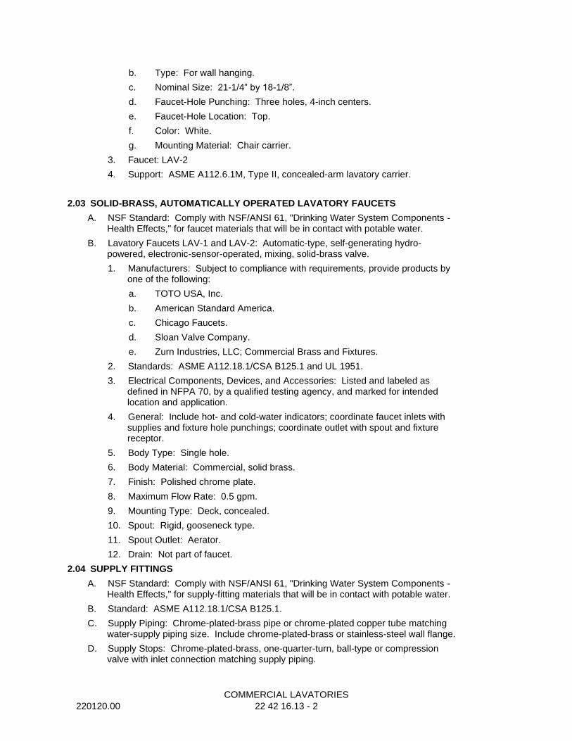
COMMERCIAL LAVATORIES
220120.00 22 42 16.13 - 2
b. Type: For wall hanging.
c. Nominal Size: 21-1/4” by 18-1/8”.
d. Faucet-Hole Punching: Three holes, 4-inch centers.
e. Faucet-Hole Location: Top.
f. Color: White.
g. Mounting Material: Chair carrier.
3. Faucet: LAV-2
4. Support: ASME A112.6.1M, Type II, concealed-arm lavatory carrier.
2.03 SOLID-BRASS, AUTOMATICALLY OPERATED LAVATORY FAUCETS
A. NSF Standard: Comply with NSF/ANSI 61, "Drinking Water System Components - Health Effects," for faucet materials that will be in contact with potable water.
B. Lavatory Faucets LAV-1 and LAV-2: Automatic-type, self-generating hydro-powered, electronic-sensor-operated, mixing, solid-brass valve.
1. Manufacturers: Subject to compliance with requirements, provide products by one of the following:
a. TOTO USA, Inc.
b. American Standard America.
c. Chicago Faucets.
d. Sloan Valve Company.
e. Zurn Industries, LLC; Commercial Brass and Fixtures.
2. Standards: ASME A112.18.1/CSA B125.1 and UL 1951.
3. Electrical Components, Devices, and Accessories: Listed and labeled as defined in NFPA 70, by a qualified testing agency, and marked for intended location and application.
4. General: Include hot- and cold-water indicators; coordinate faucet inlets with supplies and fixture hole punchings; coordinate outlet with spout and fixture receptor.
5. Body Type: Single hole.
6. Body Material: Commercial, solid brass.
7. Finish: Polished chrome plate.
8. Maximum Flow Rate: 0.5 gpm.
9. Mounting Type: Deck, concealed.
10. Spout: Rigid, gooseneck type.
11. Spout Outlet: Aerator.
12. Drain: Not part of faucet.
2.04 SUPPLY FITTINGS
A. NSF Standard: Comply with NSF/ANSI 61, "Drinking Water System Components - Health Effects," for supply-fitting materials that will be in contact with potable water.
B. Standard: ASME A112.18.1/CSA B125.1.
C. Supply Piping: Chrome-plated-brass pipe or chrome-plated copper tube matching water-supply piping size. Include chrome-plated-brass or stainless-steel wall flange.
D. Supply Stops: Chrome-plated-brass, one-quarter-turn, ball-type or compression valve with inlet connection matching supply piping.
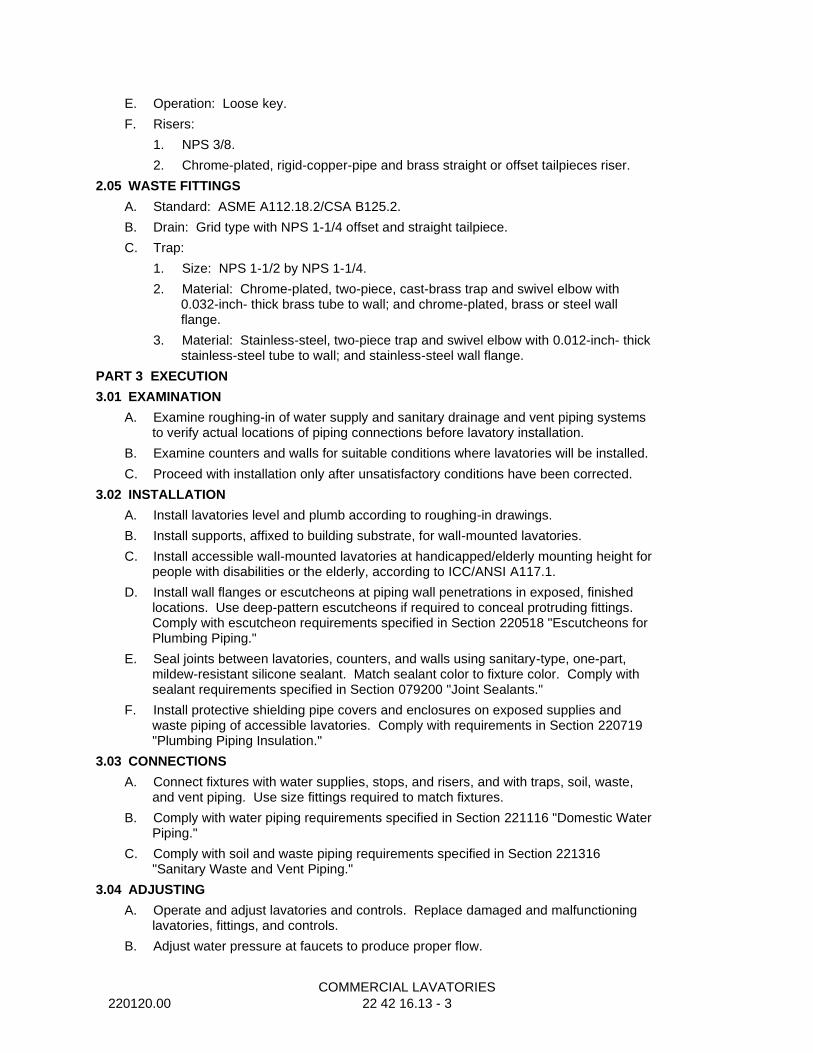
COMMERCIAL LAVATORIES
220120.00 22 42 16.13 - 3
E. Operation: Loose key.
F. Risers:
1. NPS 3/8.
2. Chrome-plated, rigid-copper-pipe and brass straight or offset tailpieces riser.
2.05 WASTE FITTINGS
A. Standard: ASME A112.18.2/CSA B125.2.
B. Drain: Grid type with NPS 1-1/4 offset and straight tailpiece.
C. Trap:
1. Size: NPS 1-1/2 by NPS 1-1/4.
2. Material: Chrome-plated, two-piece, cast-brass trap and swivel elbow with 0.032-inch- thick brass tube to wall; and chrome-plated, brass or steel wall flange.
3. Material: Stainless-steel, two-piece trap and swivel elbow with 0.012-inch- thick stainless-steel tube to wall; and stainless-steel wall flange.
PART 3 EXECUTION
3.01 EXAMINATION
A. Examine roughing-in of water supply and sanitary drainage and vent piping systems to verify actual locations of piping connections before lavatory installation.
B. Examine counters and walls for suitable conditions where lavatories will be installed.
C. Proceed with installation only after unsatisfactory conditions have been corrected.
3.02 INSTALLATION
A. Install lavatories level and plumb according to roughing-in drawings.
B. Install supports, affixed to building substrate, for wall-mounted lavatories.
C. Install accessible wall-mounted lavatories at handicapped/elderly mounting height for people with disabilities or the elderly, according to ICC/ANSI A117.1.
D. Install wall flanges or escutcheons at piping wall penetrations in exposed, finished locations. Use deep-pattern escutcheons if required to conceal protruding fittings. Comply with escutcheon requirements specified in Section 220518 "Escutcheons for Plumbing Piping."
E. Seal joints between lavatories, counters, and walls using sanitary-type, one-part, mildew-resistant silicone sealant. Match sealant color to fixture color. Comply with sealant requirements specified in Section 079200 "Joint Sealants."
F. Install protective shielding pipe covers and enclosures on exposed supplies and waste piping of accessible lavatories. Comply with requirements in Section 220719 "Plumbing Piping Insulation."
3.03 CONNECTIONS
A. Connect fixtures with water supplies, stops, and risers, and with traps, soil, waste, and vent piping. Use size fittings required to match fixtures.
B. Comply with water piping requirements specified in Section 221116 "Domestic Water Piping."
C. Comply with soil and waste piping requirements specified in Section 221316 "Sanitary Waste and Vent Piping."
3.04 ADJUSTING
A. Operate and adjust lavatories and controls. Replace damaged and malfunctioning lavatories, fittings, and controls.
B. Adjust water pressure at faucets to produce proper flow.
COMMERCIAL LAVATORIES
220120.00 22 42 16.13 - 4
3.05 CLEANING AND PROTECTION
A. After completing installation of lavatories, inspect and repair damaged finishes.
B. Clean lavatories, faucets, and other fittings with manufacturers' recommended cleaning methods and materials.
C. Provide protective covering for installed lavatories and fittings.
D. Do not allow use of lavatories for temporary facilities unless approved in writing by Owner.
END OF SECTION
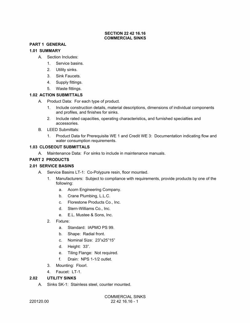
COMMERCIAL SINKS220120.00 22 42 16.16 - 1
SECTION 22 42 16.16COMMERCIAL SINKS
PART 1 GENERAL1.01 SUMMARY
A. Section Includes:1. Service basins.2. Utility sinks.3. Sink Faucets.4. Supply fittings.5. Waste fittings.
1.02 ACTION SUBMITTALSA. Product Data: For each type of product.
1. Include construction details, material descriptions, dimensions of individual components and profiles, and finishes for sinks.
2. Include rated capacities, operating characteristics, and furnished specialties and accessories.
B. LEED Submittals:1. Product Data for Prerequisite WE 1 and Credit WE 3: Documentation indicating flow and
water consumption requirements.1.03 CLOSEOUT SUBMITTALS
A. Maintenance Data: For sinks to include in maintenance manuals.PART 2 PRODUCTS2.01 SERVICE BASINS
A. Service Basins LT-1: Co-Polypure resin, floor mounted.1. Manufacturers: Subject to compliance with requirements, provide products by one of the
following:a. Acorn Engineering Company.b. Crane Plumbing, L.L.C.c. Florestone Products Co., Inc.d. Stern-Williams Co., Inc.e. E.L. Mustee & Sons, Inc.
2. Fixture:a. Standard: IAPMO PS 99.b. Shape: Radial front.c. Nominal Size: 23”x25”15”d. Height: 33”.e. Tiling Flange: Not required.f. Drain: NPS 1-1/2 outlet.
3. Mounting: Floorl.4. Faucet: LT-1.
2.02 UTILITY SINKSA. Sinks SK-1: Stainless steel, counter mounted.
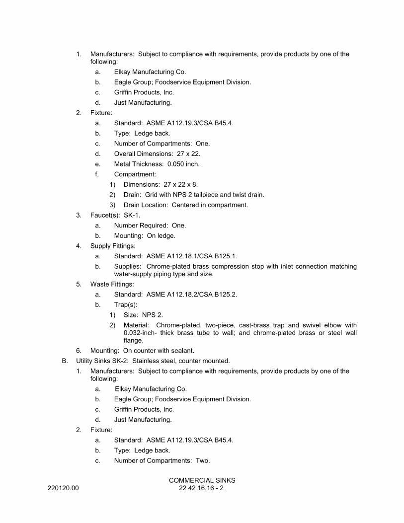
COMMERCIAL SINKS220120.00 22 42 16.16 - 2
1. Manufacturers: Subject to compliance with requirements, provide products by one of the following:
a. Elkay Manufacturing Co.b. Eagle Group; Foodservice Equipment Division.c. Griffin Products, Inc.d. Just Manufacturing.
2. Fixture:a. Standard: ASME A112.19.3/CSA B45.4.b. Type: Ledge back.c. Number of Compartments: One.d. Overall Dimensions: 27 x 22.e. Metal Thickness: 0.050 inch.f. Compartment:
1) Dimensions: 27 x 22 x 8.2) Drain: Grid with NPS 2 tailpiece and twist drain.3) Drain Location: Centered in compartment.
3. Faucet(s): SK-1.a. Number Required: One.b. Mounting: On ledge.
4. Supply Fittings:a. Standard: ASME A112.18.1/CSA B125.1.b. Supplies: Chrome-plated brass compression stop with inlet connection matching
water-supply piping type and size.5. Waste Fittings:
a. Standard: ASME A112.18.2/CSA B125.2.b. Trap(s):
1) Size: NPS 2.2) Material: Chrome-plated, two-piece, cast-brass trap and swivel elbow with
0.032-inch- thick brass tube to wall; and chrome-plated brass or steel wall flange.
6. Mounting: On counter with sealant.B. Utility Sinks SK-2: Stainless steel, counter mounted.
1. Manufacturers: Subject to compliance with requirements, provide products by one of the following:
a. Elkay Manufacturing Co.b. Eagle Group; Foodservice Equipment Division.c. Griffin Products, Inc.d. Just Manufacturing.
2. Fixture:a. Standard: ASME A112.19.3/CSA B45.4.b. Type: Ledge back.c. Number of Compartments: Two.
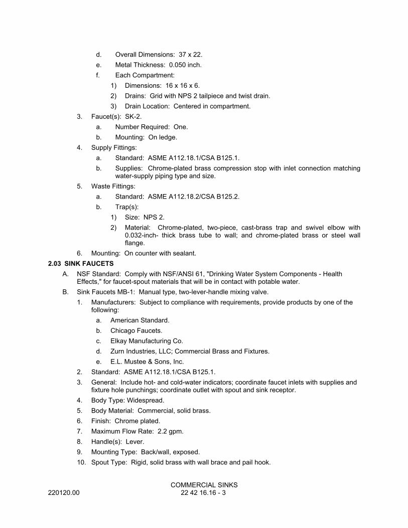
COMMERCIAL SINKS220120.00 22 42 16.16 - 3
d. Overall Dimensions: 37 x 22.e. Metal Thickness: 0.050 inch.f. Each Compartment:
1) Dimensions: 16 x 16 x 6.2) Drains: Grid with NPS 2 tailpiece and twist drain.3) Drain Location: Centered in compartment.
3. Faucet(s): SK-2.a. Number Required: One.b. Mounting: On ledge.
4. Supply Fittings:a. Standard: ASME A112.18.1/CSA B125.1.b. Supplies: Chrome-plated brass compression stop with inlet connection matching
water-supply piping type and size.5. Waste Fittings:
a. Standard: ASME A112.18.2/CSA B125.2.b. Trap(s):
1) Size: NPS 2.2) Material: Chrome-plated, two-piece, cast-brass trap and swivel elbow with
0.032-inch- thick brass tube to wall; and chrome-plated brass or steel wall flange.
6. Mounting: On counter with sealant.2.03 SINK FAUCETS
A. NSF Standard: Comply with NSF/ANSI 61, "Drinking Water System Components - Health Effects," for faucet-spout materials that will be in contact with potable water.
B. Sink Faucets MB-1: Manual type, two-lever-handle mixing valve.1. Manufacturers: Subject to compliance with requirements, provide products by one of the
following:a. American Standard.b. Chicago Faucets.c. Elkay Manufacturing Co.d. Zurn Industries, LLC; Commercial Brass and Fixtures.e. E.L. Mustee & Sons, Inc.
2. Standard: ASME A112.18.1/CSA B125.1.3. General: Include hot- and cold-water indicators; coordinate faucet inlets with supplies and
fixture hole punchings; coordinate outlet with spout and sink receptor.4. Body Type: Widespread.5. Body Material: Commercial, solid brass.6. Finish: Chrome plated.7. Maximum Flow Rate: 2.2 gpm.8. Handle(s): Lever.9. Mounting Type: Back/wall, exposed.10. Spout Type: Rigid, solid brass with wall brace and pail hook.

COMMERCIAL SINKS220120.00 22 42 16.16 - 4
11. Vacuum Breaker: Required for hose outlet.12. Spout Outlet: Hose thread according to ASME B1.20.7.
C. Sink Faucets SK-1 and SK-2: Manual type, two-lever-handle mixing valve.1. Manufacturers: Subject to compliance with requirements, provide products by the
following:a. American Standard.b. Chicago Faucets.c. Elkay Manufacturing Co.d. Zurn Industries, LLC; Commercial Brass and Fixtures.e. Moen Commercial.
2. Standard: ASME A112.18.1/CSA B125.1.3. General: Include hot- and cold-water indicators; coordinate faucet inlets with supplies and
fixture hole punchings; coordinate outlet with spout and sink receptor.4. Body Type: Three hole.5. Body Material: Commercial, solid brass.6. Finish: Chrome plated.7. Maximum Flow Rate: 1.5 gpm.8. Handle(s): Lever.9. Mounting Type: Deck, concealed10. Spout Type: Swing, shaped tube, solid brass11. Spout Outlet: Aerator
2.04 SUPPLY FITTINGSA. NSF Standard: Comply with NSF/ANSI 61, "Drinking Water System Components - Health
Effects," for supply-fitting materials that will be in contact with potable water.B. Standard: ASME A112.18.1/CSA B125.1.C. Supply Piping: Chrome-plated brass pipe or chrome-plated copper tube matching water-supply
piping size. Include chrome-plated brass or stainless-steel wall flange.D. Supply Stops: Chrome-plated brass, one-quarter-turn, ball-type or compression valve with inlet
connection matching supply piping.E. Operation: Loose key.
2.05 GROUTA. Standard: ASTM C 1107/C 1107M, Grade B, post-hardening and volume-adjusting, dry,
hydraulic-cement grout.B. Characteristics: Nonshrink; recommended for interior and exterior applications.C. Design Mix: 5000-psi, 28-day compressive strength.D. Packaging: Premixed and factory packaged.
PART 3 EXECUTION3.01 EXAMINATION
A. Examine roughing-in of water supply and sanitary drainage and vent piping systems to verify actual locations of piping connections before sink installation.
B. Examine walls, floors, and counters for suitable conditions where sinks will be installed.C. Proceed with installation only after unsatisfactory conditions have been corrected.
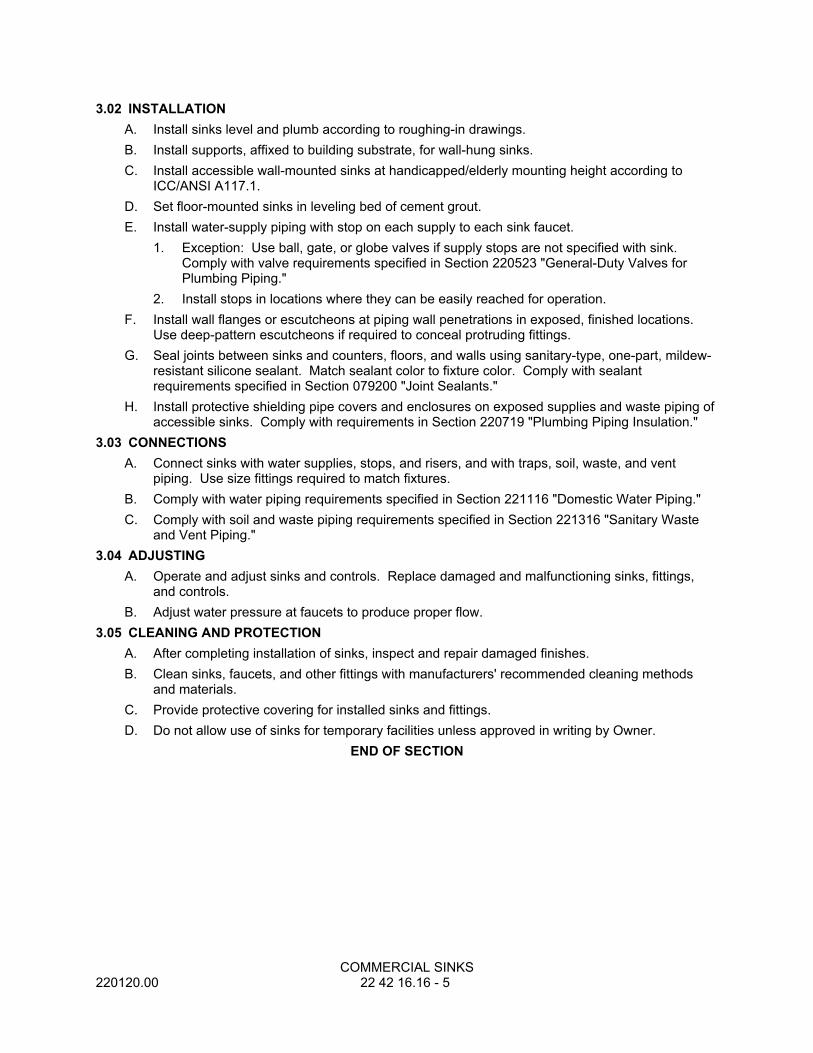
COMMERCIAL SINKS220120.00 22 42 16.16 - 5
3.02 INSTALLATIONA. Install sinks level and plumb according to roughing-in drawings.B. Install supports, affixed to building substrate, for wall-hung sinks.C. Install accessible wall-mounted sinks at handicapped/elderly mounting height according to
ICC/ANSI A117.1.D. Set floor-mounted sinks in leveling bed of cement grout.E. Install water-supply piping with stop on each supply to each sink faucet.
1. Exception: Use ball, gate, or globe valves if supply stops are not specified with sink. Comply with valve requirements specified in Section 220523 "General-Duty Valves for Plumbing Piping."
2. Install stops in locations where they can be easily reached for operation.F. Install wall flanges or escutcheons at piping wall penetrations in exposed, finished locations.
Use deep-pattern escutcheons if required to conceal protruding fittings. G. Seal joints between sinks and counters, floors, and walls using sanitary-type, one-part, mildew-
resistant silicone sealant. Match sealant color to fixture color. Comply with sealant requirements specified in Section 079200 "Joint Sealants."
H. Install protective shielding pipe covers and enclosures on exposed supplies and waste piping of accessible sinks. Comply with requirements in Section 220719 "Plumbing Piping Insulation."
3.03 CONNECTIONSA. Connect sinks with water supplies, stops, and risers, and with traps, soil, waste, and vent
piping. Use size fittings required to match fixtures.B. Comply with water piping requirements specified in Section 221116 "Domestic Water Piping."C. Comply with soil and waste piping requirements specified in Section 221316 "Sanitary Waste
and Vent Piping."3.04 ADJUSTING
A. Operate and adjust sinks and controls. Replace damaged and malfunctioning sinks, fittings, and controls.
B. Adjust water pressure at faucets to produce proper flow.3.05 CLEANING AND PROTECTION
A. After completing installation of sinks, inspect and repair damaged finishes.B. Clean sinks, faucets, and other fittings with manufacturers' recommended cleaning methods
and materials.C. Provide protective covering for installed sinks and fittings.D. Do not allow use of sinks for temporary facilities unless approved in writing by Owner.
END OF SECTION
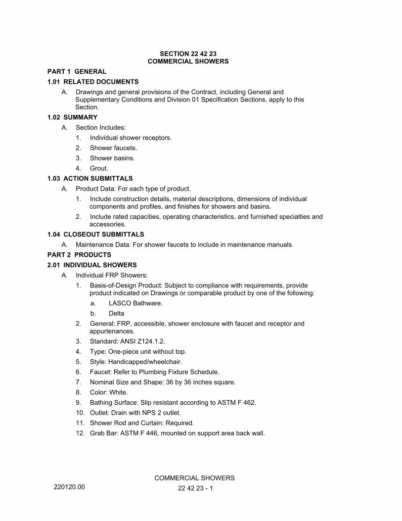
220120.00COMMERCIAL SHOWERS
22 42 23 - 1
SECTION 22 42 23COMMERCIAL SHOWERS
PART 1 GENERAL1.01 RELATED DOCUMENTS
A. Drawings and general provisions of the Contract, including General and Supplementary Conditions and Division 01 Specification Sections, apply to this Section.
1.02 SUMMARYA. Section Includes:
1. Individual shower receptors.2. Shower faucets.3. Shower basins.4. Grout.
1.03 ACTION SUBMITTALSA. Product Data: For each type of product.
1. Include construction details, material descriptions, dimensions of individual components and profiles, and finishes for showers and basins.
2. Include rated capacities, operating characteristics, and furnished specialties and accessories.
1.04 CLOSEOUT SUBMITTALSA. Maintenance Data: For shower faucets to include in maintenance manuals.
PART 2 PRODUCTS2.01 INDIVIDUAL SHOWERS
A. Individual FRP Showers:1. Basis-of-Design Product: Subject to compliance with requirements, provide
product indicated on Drawings or comparable product by one of the following:a. LASCO Bathware.b. Delta
2. General: FRP, accessible, shower enclosure with faucet and receptor and appurtenances.
3. Standard: ANSI Z124.1.2.4. Type: One-piece unit without top.5. Style: Handicapped/wheelchair.6. Faucet: Refer to Plumbing Fixture Schedule.7. Nominal Size and Shape: 36 by 36 inches square.8. Color: White.9. Bathing Surface: Slip resistant according to ASTM F 462.10. Outlet: Drain with NPS 2 outlet.11. Shower Rod and Curtain: Required.12. Grab Bar: ASTM F 446, mounted on support area back wall.
220120.00COMMERCIAL SHOWERS
22 42 23 - 2
2.02 SHOWER FAUCETSA. NSF Standard: Comply with NSF 61, "Drinking Water System Components - Health
Effects," for shower materials that will be in contact with potable water.B. Shower Faucets:
1. Description: Single-handle, thermostatic mixing valve with hot- and cold-water indicators; check stops; and shower head.
2. Faucet:a. Standards: ASME A112.18.1/CSA B125.1 and ASSE 1016.b. Body Material: Solid brass.c. Finish: Polished chrome plate.d. Maximum Flow Rate: 2.5 gpm unless otherwise indicated.e. Mounting: Concealed.f. Operation: Single-handle, twist or rotate control.g. Antiscald Device: [Integral with mixing valve] [Separate unit] [Not
required].h. Check Stops: Check-valve type, integral with or attached to body; on hot-
and cold-water supply connections.3. Supply Connections: NPS 1/2.4. Shower Head:
a. Standard: ASME A112.18.1/CSA B125.1.b. Type: Sprayer with hose and adjustable mounting rod.c. Shower Head Material: Metallic with chrome-plated finish.d. Spray Pattern: Adjustable.e. Temperature Indicator: Integral with faucet.
2.03 GROUTA. Standard: ASTM C 1107/C 1107M, Grade B, post-hardening and volume-adjusting,
dry, hydraulic-cement grout.B. Characteristics: Nonshrink; recommended for interior and exterior applications.C. Design Mix: 5000-psi, 28-day compressive strength.D. Packaging: Premixed and factory packaged.
PART 3 EXECUTION3.01 EXAMINATION
A. Examine roughing-in of water-supply and sanitary drainage and vent piping systems to verify actual locations of piping connections before shower installation.
B. Examine walls and floors for suitable conditions where showers will be installed.C. Proceed with installation only after unsatisfactory conditions have been corrected.
3.02 INSTALLATIONA. Assemble shower components according to manufacturers' written instructions.B. Install showers level and plumb according to roughing-in drawings.C. Install water-supply piping with stop on each supply to each shower faucet.
1. Exception: Use ball or gate valves if supply stops are not specified with shower. 2. Install stops in locations where they can be easily reached for operation.
220120.00COMMERCIAL SHOWERS
22 42 23 - 3
D. Install shower flow-control fittings with specified maximum flow rates in shower arms.E. Set shower receptors in leveling bed of cement grout.F. Install wall flanges or escutcheons at piping wall penetrations in exposed, finished
locations. Use deep-pattern escutcheons if required to conceal protruding fittings.G. Seal joints between showers and floors and walls using sanitary-type, one-part,
mildew-resistant silicone sealant. Match sealant color to fixture color. 3.03 CONNECTIONS
A. Connect fixtures with water supplies, stops, and risers, and with traps, soil, waste, and vent piping. Use size fittings required to match fixtures.
B. Comply with water piping requirements specified in Section 221116 "Domestic Water Piping."
C. Comply with traps and soil and waste piping requirements specified in Section 221316 "Sanitary Waste and Vent Piping."
3.04 ADJUSTINGA. Operate and adjust showers and controls. Replace damaged and malfunctioning
showers, fittings, and controls.B. Adjust water pressure at faucets to produce proper flow.
3.05 CLEANING AND PROTECTIONA. After completing installation of showers and basins, inspect and repair damaged
finishes.B. Clean showers and basins, faucets, and other fittings with manufacturers'
recommended cleaning methods and materials.C. Provide protective covering for installed fixtures and fittings.D. Do not allow use of showers and basins for temporary facilities unless approved in
writing by Owner.END OF SECTION
SECURITY PLUMBING FIXTURES22 46 00 - 1
SECTION 22 46 00SECURITY PLUMBING FIXTURES
PART 1 - GENERAL1.01 RELATED DOCUMENTS
A. Drawings and general provisions of the Contract, including General and Supplementary Conditions and Division 01 Specification Sections, apply to this Section.
1.02 SUMMARYA. Section Includes:
1. Water closets.2. Lavatories.
B. Related Requirements:1. Section 22 42 13.13 "Commercial Water Closets."2. Section 22 42 16.13 "Commercial Lavatories."
1.03 DEFINITIONSA. Accessible Service Space: Service area in secure space behind wall-mounted fixtures.B. Back-Access Fixture: Security plumbing fixture designed to mount on wall sleeve built into wall
or on wall, so installation and removal of fixture, piping, and other components are accessible only from service space behind wall.
C. Front-Access Fixture: Security plumbing fixture designed to mount on wall with installation and removal from fixture side of wall, and with piping and other components accessible only from access panel in fixture.
1.04 ACTION SUBMITTALSA. Product Data: For each type of product.
1. Include construction details, material descriptions, dimensions of individual components and profiles, and finishes for security plumbing fixtures.
2. Include rated capacities, operating characteristics, and furnished specialties and accessories.
1.05 CLOSEOUT SUBMITTALSA. Maintenance Data: For security plumbing fixtures and components to include in maintenance
manuals.1.06 MAINTENANCE MATERIAL SUBMITTALS
A. Furnish extra materials that match products installed and that are packaged with protective covering for storage and identified with labels describing contents.1. Flushometer-Valve Repair Kits: Equal to [10] <Insert number> percent of quantity of
each type installed, but no fewer than [one] [six] <Insert number> of each type.2. Toilet Seats: Equal to [five] <Insert number> percent of quantity of each type installed.
PART 2 - PRODUCTS2.01 STAINLESS-STEEL WATER CLOSETS
A. Water Closets WC-3: Back access, off floor, back outlet, cabinet.1. Manufacturers: Subject to compliance with requirements, provide products by one of the
following:a. Acorn Engineering Company.b. Metcraft Industries Inc.c. Willoughby Industries, Inc.
220120.00
SECURITY PLUMBING FIXTURES22 46 00 - 2
2. Material: 0.078-inch minimum-thick stainless steel; corrosion-resistant metal for internal piping and bracing.
3. Finish: ASTM A 480/A 480M, No. 4 polished finish on exposed surfaces.4. Mounting: Bolts through wall sleeve into accessible service space.5. Water Closet:
a. Standard: IAPMO PS 61.b. Bowl:
1) Type: Elongated, with back inlet, integral trap, and blowout design with back outlet and contoured seat.
2) Back-Outlet Connection: NPS 4, horizontal with cleanout and slip joint.3) Seat Surface: ASTM A 480/A 480M, No. 7 polished finish.
6. Flushometer Valve: WC-3.7. Wall Sleeve: Galvanized-steel frame of dimensions required to match fixture. Include
steel bars or other design to prevent escape if fixture is removed.a. Configuration: Modify wall sleeve for water-closet mounting height according to
ICC A117.1.2.02 FLUSHOMETER VALVES
A. Flushometer Valves WC-3: Lever handle, diaphragm.1. Manufacturers: Subject to compliance with requirements, provide products by one of the
following:a. Acorn Engineering Company.b. Metcraft Industries Inc.c. Willoughby Industries, Inc.
2. Standard: ASSE 1037.3. Minimum Pressure Rating: 125 psig.4. Features: Integral check stops and backflow-prevention device.5. Material: Brass body with corrosion-resistant components.6. Exposed Flushometer-Valve Finish: Chrome plated.7. Panel Finish: Chrome plated or stainless steel.8. Style: Exposed.9. Consumption: 1.6 gal per flush.10. Minimum Inlet: NPS 1-1/2.11. Minimum Outlet: NPS 4.
2.03 STAINLESS-STEEL LAVATORIESA. Lavatories LAV-3: Back access.
1. Manufacturers: Subject to compliance with requirements, provide products by one of the following:a. Acorn Engineering Company.b. Bradley Corporation.c. Metcraft Industries Inc.d. Willoughby Industries, Inc.
2. Fixture:a. Standard: ASME A112.19.3/CSA B45.4.
220120.00
SECURITY PLUMBING FIXTURES22 46 00 - 3
b. Material: 0.078-inch- minimum-thick stainless steel; corrosion-resistant metal for internal piping and bracing.
c. Finish: ASTM A 480/A 480M, No. 4 polished finish on exposed surfaces.d. Receptor: Oval bowl with backsplash.e. Hot- and Cold-Water Supply Valves: Mechanical-metering type with push-button
actuation, individual check stops, and backsplash- mounted filler spouts complying with ASME A112.18.1/CSA B125.1.
f. Drain: Integral punched grid with NPS 1-1/2 minimum horizontal waste and trap complying with ASME A112.18.2/CSA B125.2.
3. Mounting: Bolts through wall into accessible service space.PART 3 - EXECUTION3.01 EXAMINATION
A. Examine roughing-in for water supply and sanitary drainage and vent piping systems to verify actual locations of piping connections before fixture installation.
B. Examine walls and floors for suitable conditions where fixtures will be installed.C. Proceed with installation only after unsatisfactory conditions have been corrected.
3.02 INSTALLATIONA. Install security plumbing fixtures level and plumb according to roughing-in drawings.B. Install back-access, stainless-steel fixtures as follows:
1. Install wall sleeve in wall if indicated.2. Install fixture on wall sleeve or wall, as indicated, with access from accessible service
space.3. Extend supply piping from service space to fixture.4. Install soil and waste piping from fixture and extend into service space.5. Install fixture trap in service space instead of below fixture drain.
C. Install front-access, stainless-steel fixtures as follows:1. Install fixture support or mounting bracket.2. Install fixture on support; mount components inside of or attached to fixture.3. Extend supply piping from pipe space to fixture.4. Install trap below fixture and extend soil and waste piping into pipe space.
D. Install fixture outlets with gasket seals.E. Install fixtures designated "accessible" according to ICC A117.1 for heights, dimensions, and
clearances.F. Install protective shielding pipe covers and enclosures on exposed supplies and waste piping of
accessible fixtures. Comply with requirements in Section 220719 "Plumbing Piping Insulation."G. Seal joints between fixtures, floors, and walls using sanitary-type, one-part, mildew-resistant
silicone sealant. Match sealant color to fixture color. Comply with sealant requirements specified in Section 079200 "Joint Sealants."
H. Install wall flanges or escutcheons at piping wall penetrations in exposed, finished locations. Use deep-pattern escutcheons if required to conceal protruding fittings. Comply with escutcheon requirements specified in Section 220518 "Escutcheons for Plumbing Piping."
3.03 CONNECTIONSA. Connect fixtures with water supplies, stops, and risers, and with traps, soil, waste, and vent
piping. Use size fittings required to match fixtures.
220120.00
SECURITY PLUMBING FIXTURES22 46 00 - 4
B. Comply with requirements for water piping specified in Section 221116 "Domestic Water Piping."
C. Comply with requirements for soil and waste drainage piping specified in Section 221316 "Sanitary Waste and Vent Piping."
3.04 ADJUSTINGA. Operate and adjust flushometer valves and flow-control valves on fixtures.
3.05 CLEANING AND PROTECTIONA. After installing fixtures, inspect and repair damaged finishes.B. Clean fixtures, faucets, and other fittings with manufacturers' recommended cleaning methods
and materials.C. Provide protective covering for installed fixtures and fittings.D. Do not allow use of fixtures for temporary facilities unless approved in writing by Owner.
END OF SECTION
220120.00
PRESSURE WATER COOLERS220120.00 22 47 16 - 1
SECTION 22 47 16PRESSURE WATER COOLERS
PART 1 GENERAL1.01 SUMMARY
A. Section includes pressure water coolers and related components.1.02 ACTION SUBMITTALS
A. Product Data: For each type of pressure water cooler.1. Include construction details, material descriptions, dimensions of individual components
and profiles, and finishes.2. Include rated capacities, operating characteristics, electrical characteristics, and furnished
specialties and accessories.B. LEED Submittals:
1. Product Data for Prerequisite WE 1 and Credit WE 3: Documentation indicating flow and water consumption requirements.
C. Shop Drawings: Include diagrams for power, signal, and control wiring.1.03 CLOSEOUT SUBMITTALS
A. Maintenance Data: For pressure water coolers to include in maintenance manuals.PART 2 PRODUCTS
A. Pressure Water Coolers EWC: Bi-Level, wall mounted.1. Manufacturers: Subject to compliance with requirements, provide products by one of the
following:a. Elkay Manufacturing Co.b. Halsey Taylor.c. Haws Corporation.d. Tri Palm International, LLC; Oasis Brand.
2. Cabinet: Bi-level with two attached cabinets and with a bi-level skirt kit, vinyl-covered steel with stainless-steel top.
3. Bubbler: One, with adjustable stream regulator, located on each cabinet deck.4. Bottle Filler Station: 1.1 GPM, laminar flow. Electronic sensor for touchless activation.5. Control: Push button.6. Drain: Grid with NPS 1-1/4 tailpiece.7. Supply: NPS 3/8 with shutoff valve.8. Waste Fitting: ASME A112.18.2/CSA B125.2, NPS 1-1/4 brass P-trap.9. Cooling System: Electric, with hermetically sealed compressor, cooling coil, air-cooled
condensing unit, corrosion-resistant tubing, refrigerant, corrosion-resistant-metal storage tank, and adjustable thermostat.a. Electrical Components, Devices, and Accessories: Listed and labeled as defined in
NFPA 70, by a qualified testing agency, and marked for intended location and application.
10. Support: ASME A112.6.1M, Type I water-cooler carrier.PART 3 EXECUTION3.01 EXAMINATION
A. Examine roughing-in for water-supply and sanitary drainage and vent piping systems to verify actual locations of piping connections before fixture installation.
PRESSURE WATER COOLERS220120.00 22 47 16 - 2
B. Examine walls and floors for suitable conditions where fixtures will be installed.C. Proceed with installation only after unsatisfactory conditions have been corrected.
3.02 INSTALLATIONA. Install fixtures level and plumb according to roughing-in drawings. For fixtures indicated for
children, install at height required by authorities having jurisdiction.B. Set freestanding pressure water coolers on floor.C. Install off-the-floor carrier supports, affixed to building substrate, for wall-mounted fixtures.D. Install mounting frames, affixed to building construction, and attach recessed, pressure water
coolers to mounting frames.E. Install water-supply piping with shutoff valve on supply to each fixture to be connected to
domestic-water distribution piping. Use ball, gate, or globe valve. Install valves in locations where they can be easily reached for operation. Valves are specified in Section 220523 "General-Duty Valves for Plumbing Piping."
F. Install trap and waste piping on drain outlet of each fixture to be connected to sanitary drainage system.
G. Install wall flanges or escutcheons at piping wall penetrations in exposed, finished locations. Use deep-pattern escutcheons where required to conceal protruding fittings. Comply with escutcheon requirements specified in Section 220518 "Escutcheons for Plumbing Piping."
H. Seal joints between fixtures and walls using sanitary-type, one-part, mildew-resistant, silicone sealant. Match sealant color to fixture color. Comply with sealant requirements specified in Section 079200 "Joint Sealants."
3.03 CONNECTIONSA. Connect fixtures with water supplies, stops, and risers, and with traps, soil, waste, and vent
piping. Use size fittings required to match fixtures.B. Comply with water piping requirements specified in Section 221116 "Domestic Water Piping."C. Install ball, gate, or globe shutoff valve on water supply to each fixture. Install valve upstream
from filter for water cooler. Comply with valve requirements specified in Section 220523 "General-Duty Valves for Plumbing Piping."
D. Comply with soil and waste piping requirements specified in Section 221316 "Sanitary Waste and Vent Piping."
3.04 ADJUSTINGA. Adjust fixture flow regulators for proper flow and stream height.B. Adjust pressure water-cooler temperature settings.
3.05 CLEANINGA. After installing fixture, inspect unit. Remove paint splatters and other spots, dirt, and debris.
Repair damaged finish to match original finish.B. Clean fixtures, on completion of installation, according to manufacturer's written instructions.C. Provide protective covering for installed fixtures.D. Do not allow use of fixtures for temporary facilities unless approved in writing by Owner.
END OF SECTION
COMMON WORK RESULTS FOR HVAC220120.00 23 05 00 - 1
SECTION 23 05 00COMMON WORK RESULTS FOR HVAC
PART 1 GENERAL1.01 SUMMARY
A. This Section includes the following:1. Piping materials and installation instructions common to most piping systems.2. Transition fittings.3. Dielectric fittings.4. Mechanical sleeve seals.5. Sleeves.6. Escutcheons.7. Grout.8. Mechanical demolition.9. Equipment installation requirements common to equipment sections.10. Painting and finishing.11. Concrete bases.12. Supports and anchorages.
1.02 DEFINITIONSA. Finished Spaces: Spaces other than mechanical and electrical equipment rooms,
furred spaces, pipe and duct shafts, unheated spaces immediately below roof, spaces above ceilings, unexcavated spaces, crawlspaces, and tunnels.
B. Exposed, Interior Installations: Exposed to view indoors. Examples include finished occupied spaces and mechanical equipment rooms.
C. Concealed, Interior Installations: Concealed from view and protected from physical contact by building occupants. Examples include above ceilings and in duct shafts.
D. The following are industry abbreviations for plastic materials:1. ABS: Acrylonitrile-butadiene-styrene plastic.2. CPVC: Chlorinated polyvinyl chloride plastic.3. PE: Polyethylene plastic.4. PVC: Polyvinyl chloride plastic.
E. The following are industry abbreviations for rubber materials:1. EPDM: Ethylene-propylene-diene terpolymer rubber.2. NBR: Acrylonitrile-butadiene rubber.
1.03 SUBMITTALSA. Product Data: For the following:
1. Transition fittings.2. Dielectric fittings.3. Mechanical sleeve seals.4. Escutcheons.
B. Welding certificates.

COMMON WORK RESULTS FOR HVAC220120.00 23 05 00 - 2
1.04 QUALITY ASSURANCEA. Steel Support Welding: Qualify processes and operators according to AWS D1.1,
"Structural Welding Code--Steel."B. Steel Pipe Welding: Qualify processes and operators according to ASME Boiler and
Pressure Vessel Code: Section IX, "Welding and Brazing Qualifications."1. Comply with provisions in ASME B31 Series, "Code for Pressure Piping."2. Certify that each welder has passed AWS qualification tests for welding processes
involved and that certification is current.C. Electrical Characteristics for HVAC Equipment: Equipment of higher electrical
characteristics may be furnished provided such proposed equipment is approved in writing and connecting electrical services, circuit breakers, and conduit sizes are appropriately modified. If minimum energy ratings or efficiencies are specified, equipment shall comply with requirements.
1.05 DELIVERY, STORAGE, AND HANDLINGA. Deliver pipes and tubes with factory-applied end caps. Maintain end caps through
shipping, storage, and handling to prevent pipe end damage and to prevent entrance of dirt, debris, and moisture.
1.06 COORDINATIONA. Arrange for pipe spaces, chases, slots, and openings in building structure during
progress of construction, to allow for HVAC installations.B. Coordinate installation of required supporting devices and set sleeves in poured-in-
place concrete and other structural components as they are constructed.C. Coordinate requirements for access panels and doors for mechanical items requiring
access that are concealed behind finished surfaces. Access panels and doors are specified in Division 8 Section "Access Doors and Panels."
D. Coordination Meetings: Attend coordination meetings with the construction manager and all other trades for the purpose of coordinating the locations of all fire protection, plumbing, HVAC and electrical work for the entire project. The goal of these meetings is to avoid conflicts between trades in the field.
E. Coordination Drawings: Each fire protection, plumbing, HVAC and electrical contractor shall develop ¼” coordination floor plan drawings for all of their respective working areas that necessitate additional coordination to allow for efficient systems installation. Each coordination drawing, for all trades, shall be signed and dated by each trade indicating that each trade has fully coordinated their work
F. Conflicts Between Trades: Resolve all conflicts with other trades at no additional cost to the Owner or Architect.
G. Ceiling Heights: Maintain all ceiling heights indicated on the architectural drawings. Ceiling heights will not be lowered to accommodate installation of fire protection, plumbing, HVAC or electrical work. Install all work so that there is at least eight (8) inches clearance above the ceiling grid, in all areas, to facilitate installation of light fixtures. If installed work does not comply with the ceiling height requirements stated above, then the contractor shall remove and re-install work to comply with the stated requirements above at no additional cost to the Owner or Architect.
1.07 INTENT OF DRAWINGS AND SPECIFICATIONSA. These specifications and attendant drawings are intended to cover a complete
installation of systems. The omission of expressed reference to any item of labor or material necessary for the proper execution of the work in accordance with present practices of the trade shall not relieve the Contractor from providing such additional labor and materials.
COMMON WORK RESULTS FOR HVAC220120.00 23 05 00 - 3
B. The drawings depicting HVAC work are diagrammatic and show, in their approximate location, symbols representing HVAC equipment and devices. The exact location of such equipment and devices shall be established in the field in accordance with instructions from the Architect and/or established by manufacturer’s installation drawings and details.1. The Contractor shall refer to shop drawings and submittal drawings for all
equipment requiring HVAC connections to verify rough-in and connection locations.
2. Unless specifically stated to the contrary, no measurement of any HVAC drawing derived by scaling shall be used as a dimension to work by. Dimensions noted on the HVAC drawings are subject to measurements of adjacent and previously completed work. All measurements shall be performed prior to the actual installation of equipment.
1.08 DRAWINGSA. The HVAC drawings do not attempt to show the complete details of building
construction which affect the HVAC installation. The Contractor shall refer to the architectural, civil, structural and plumbing, and electrical drawings for additional details which affect the proper installation of this work. Bring any discrepancies to the attention of the A/E for resolution. The Contractor is cautioned that diagrams showing HVAC connections and/or piping are diagrammatic only and must not be used for obtaining lineal runs of piping. Piping diagrams do not necessarily show the exact physical arrangement of the equipment.
B. The Engineer will make available to the contractor a complete set of plan sheets in AutoCAD version 2010 format. Each copy of electronic plan sheet requested will be put on disk for the cost of $200 to cover technician time and mailing costs. Any requests shall be made in writing to the Engineer with a certified check or money order payable to the Engineer. The disk(s) will be sent out within 7 days of receipt of the request and payment in full.
C. The Contractor shall be responsible for all existing field conditions, review existing field conditions prior to bid and shall take into account in bid proposal. No additional compensation will be allowed due to Contractor’s failure to include all necessary work in the bid proposal.
1.09 MATERIAL AND EQUIPMENTA. All material and equipment shall be new and of the quality used for the purpose in good
commercial practice, and shall be standard product of reputable manufacturers. Each major component of equipment shall have the manufacturer's name, catalog number, and capacity or rating on a nameplate, securely affixed on the equipment in a conspicuous place.
1.10 DAMAGE TO OTHER WORKA. The HVAC Contractor will be held rigidly responsible for all damages to the work of his
own or any other trade resulting from the execution of his work. It shall be the Contractor's responsibility to adequately protect his work at all times. All damages resulting from his operations shall be repaired or the damaged portions replaced by the party originally performing the work, (to the entire satisfaction of the Engineer), and all cost thereof shall be borne by the Contractor responsible for the damage.
1.11 COOPERATION WITH OTHER TRADESA. This Contractor shall completely cooperate with all other trades in the matter of
planning and executing of the work. Every reasonable effort shall be made to prevent conflict and interferences as to space requirements, dimensions, locations,
COMMON WORK RESULTS FOR HVAC220120.00 23 05 00 - 4
openings, sleeving or other matters which tend to delay or obstruct the work of any trade.
1.12 NEGLIGENCEA. Should the Contractor fail to provide materials, templates, etc., or other necessary
information causing delay or expense to another party, he shall pay the actual amount of the damages to the party who sustained the loss.
1.13 FIELD CHANGESA. Should any change in drawings or specifications be required to comply with local
regulations and/or field conditions, the Contractor shall refer same to Architect for approval before any work which deviates from the original requirements of the drawings and specifications is started. In the event of disagreements as to the necessity of such changes, the decision of the Architect shall be final.
1.14 CUTTING AND PATCHINGA. As necessary and with approval to permit the installation of piping or any part of the
work under this branch. Any cost caused by defective or ill-timed work shall be by the party responsible there for. Patching of holes, openings, etc. resulting from the work of this branch shall be furnished by this Contractor.
1.15 STANDARDS, CODES AND PERMITSA. All work shall be installed in accordance with National, State and Local Mechanical
codes, laws, ordinances and regulations. Comply with all applicable OSHA regulations.B. All materials shall have a U.L. label where a U.L. standard and/or test exists.C. Prepare and submit to all authorities having jurisdiction, for their approval, all
applications and working drawings required by them. Secure and pay for all permits and licenses required.
1.16 CLEAN-UPA. This Contractor shall at all times keep the premises free from excessive accumulation
of waste material or rubbish resulting from his work, including tools, scaffolding and surplus materials, and he shall leave his work broom-clean or its equivalent. In case of disputes, the Architect may order the removal of such rubbish and charge the cost to the responsible contractor as determined by the Architect. At the time of final clean-up all fixtures and equipment shall be thoroughly cleaned and left in proper condition for their intended use.
1.17 GUARANTEEA. The Contractor shall unconditionally guarantee his work and all components thereof for
a period of one year from the date of his final payment. He shall remedy any defects in workmanship and repair or replace any faulty equipment which shall appear within the guarantee period to the entire satisfaction of the Architect at no additional charge.
1.18 TEMPORARY HVACA. Temporary heat includes all required up to the time of substantial completion.
1.19 DEMOLITION, RENOVATION AND DISPOSITION OF EXISTING EQUIPMENT.A. This Contractor shall note that the existing building will remain in service during
portions of the construction period. Areas of the building will be vacated as required to facilitate construction. This Contractor shall proceed with the completion of his work in such a manner as to cause the least possible interference with the Owner's operation. All work required in the existing building shall be done in a manner and time acceptable to the Owner.
COMMON WORK RESULTS FOR HVAC220120.00 23 05 00 - 5
B. HVAC equipment in conflict with construction shall be removed and/or relocated as indicated on the drawings, as directed or required. This Contractor shall remove all HVAC equipment released from service as a result of construction, and no equipment removed shall be reused, except as specifically directed on the drawings or elsewhere herein. Except for piping and miscellaneous hardware, all HVAC equipment that the owner desires to retain shall remain the property of the Owner and shall be stored on the site for removal by the Owner. All other piping and equipment removed and not retained by the Owner shall become the property of this Contractor and shall be removed from the site.
C. This Contractor shall be responsible for the work of other trades as may be necessary to facilitate the installation of HVAC work in the existing building. Such work necessary that is normally done by other trades and is not covered as a part of other Divisions of the work shall be done under the direction and at the expense of the HVAC Contractor. This work shall include but is not limited to, cutting, patching, and refinishing and all necessary and required to leave existing building in condition acceptable to the Architect.
D. Any existing fixtures or equipment not shown on the drawings and which are logically expected to be continued in service and which may be interrupted or disturbed during construction shall be reconnected in an approved manner. In addition, any existing fixture or equipment which may require relocation or rerouting, as a result of construction, shall be considered a part of the work of this branch and shall be done by this Contractor with no additional compensation.
E. All coring that is required for HVAC work shall be by this Contractor.F. All equipment containing hazardous materials removed during the project become the
Contractor's property and he shall dispose of them in accordance with applicable DNR and EPA regulations.
G. Piping which is to remain in service, but which is presently routed through areas being demolished shall be rerouted around demolition area.
1.20 SUBSTITUTION AND APPROVAL OF MATERIAL, EQUIPMENT OR DESIGNA. Such requests shall be accompanied by three copies of all necessary illustrations, cuts,
drawings and descriptions of material proposed for substitution and shall fully describe all points in which it differs from the articles specified. The Engineer will retain two copies and one copy returned to the Contractor with acceptance, rejection or revisions indicated thereon.
B. The proposed substitution does not affect dimensions shown on Drawings or as specified.
C. The proposed substitution will have no adverse affect on other trades, the construction schedule, or specified warranty requirements.
D. All proposed substitutions will be subject to satisfactory performance to the specification and considered as a deduct alternate rather than as an equivalent.
E. Where equipment or accessories are used which differ in arrangement, configuration, dimensions, ratings, or engineering parameters from those indicated on the contract documents, the Contractor is responsible for all costs, including architectural/engineering design and construction costs, involved in integrating the equipment or accessories into the system and the assigned space and for obtaining the performance from the system into which these items are placed.
F. All substitution review costs shall be reimbursed to the Engineer by the contractor or their suppliers on a Time/Material bases. This cost shall be paid on approval or disproval of the substitution material, equipment or design.
COMMON WORK RESULTS FOR HVAC220120.00 23 05 00 - 6
1.21 SHOP DRAWINGSA. Submit to Engineer for review, copies of manufacturer's shop drawings and/or
equipment brochure depicting items in this specification.B. Other materials at the request of the Engineer.C. Shop drawings shall bear the Contractor's stamp indicating approval.D. Any equipment fabrication prior to shop drawing review shall be at the Contractor's risk.E. Any shop drawing not meeting the requirements as outlined in this or any other part of
this specification or drawing, requiring more than two reviews or in excess of 4 hours of total review time shall have a fee of reimbursement to the Engineer by the contractor or their suppliers. This shall be done on a Time/Material bases. This cost shall be paid on approval on disproval of the material, equipment or design.
1.22 WORKMANSHIPA. The installation of all work shall be made so that its several component parts will
function as a workable system complete with all accessories necessary for its operation, and shall be left with all equipment properly adjusted and in working order. The work shall be executed in conformity with the best-accepted standard practice of the trade so as to contribute to efficiency and appearance. It shall also be executed so that the installation will conform and adjust itself to the building structure, its equipment and its usage.
1.23 DRAWINGS OF OTHER TRADESA. The Contractor shall consult the drawings of the work for the various other trades; field
layouts of the parties performing the work of the other trades; their shop drawings, and he shall be governed accordingly in laying out his work.
1.24 FIELD MEASUREMENTSA. The Contractor shall take all field measurements necessary for his work and shall
assume the full responsibility for their accuracy.1.25 STRUCTURAL INTERFERENCES
A. Should any structural interference prevent the installation of the fixtures, running of piping, etc., at points shown on drawings, the necessary minor deviation there from, as determined by the Architect, may be permitted. Minor changes in the position of the fixtures, equipment or piping if decided upon before any work has been done by the Contractor shall be made without additional charge.
1.26 EXAMINATION OF PLANS, SPECIFICATIONS AND SITEA. Before submitting a bid, the Contractor shall visit the site and familiarize himself with all
features of the building and site, which may affect the execution of his work. No extra payment will be allowed for the failure to obtain this information. If in the opinion of the Contractor there are omissions or errors in the plans or specifications, the Contractor shall clarify these points with the Engineer before submitting his bid. In lieu of written clarification by addendum, the contractor shall resolve all conflicts in favor of the greater quantity or better quality.
PART 2 PRODUCTS2.01 MANUFACTURERS
A. In other Part 2 articles where subparagraph titles below introduce lists, the following requirements apply for product selection:1. Manufacturers: Subject to compliance with requirements, provide products by the
manufacturers specified.
COMMON WORK RESULTS FOR HVAC220120.00 23 05 00 - 7
2.02 PIPE, TUBE, AND FITTINGSA. Refer to individual Division 23 piping Sections for pipe, tube, and fitting materials and
joining methods.B. Pipe Threads: ASME B1.20.1 for factory-threaded pipe and pipe fittings.
2.03 JOINING MATERIALSA. Refer to individual Division 23 piping Sections for special joining materials not listed
below.B. Pipe-Flange Gasket Materials: Suitable for chemical and thermal conditions of piping
system contents.1. ASME B16.21, nonmetallic, flat, asbestos-free, 1/8-inch (3.2-mm) maximum
thickness unless thickness or specific material is indicated.a. Full-Face Type: For flat-face, Class 125, cast-iron and cast-bronze flanges.b. Narrow-Face Type: For raised-face, Class 250, cast-iron and steel flanges.
2. AWWA C110, rubber, flat face, 1/8 inch (3.2 mm) thick, unless otherwise indicated; and full-face or ring type, unless otherwise indicated.
C. Flange Bolts and Nuts: ASME B18.2.1, carbon steel, unless otherwise indicated.D. Plastic, Pipe-Flange Gasket, Bolts, and Nuts: Type and material recommended by
piping system manufacturer, unless otherwise indicated.E. Solder Filler Metals: ASTM B 32, lead-free alloys. Include water-flushable flux
according to ASTM B 813.F. Brazing Filler Metals: AWS A5.8, BCuP Series, copper-phosphorus alloys for general-
duty brazing, unless otherwise indicated; and AWS A5.8, BAg1, silver alloy for refrigerant piping, unless otherwise indicated.
G. Welding Filler Metals: Comply with AWS D10.12 for welding materials appropriate for wall thickness and chemical analysis of steel pipe being welded.
H. Solvent Cements for Joining Plastic Piping:1. ABS Piping: ASTM D 2235.2. CPVC Piping: ASTM F 493.3. PVC Piping: ASTM D 2564. Include primer according to ASTM F 656.4. PVC to ABS Piping Transition: ASTM D 3138.
2.04 TRANSITION FITTINGSA. AWWA Transition Couplings: Same size as, and with pressure rating at least equal to
and with ends compatible with, piping to be joined.1. Manufacturers:
a. Cascade Waterworks Mfg. Co.b. Dresser Industries, Inc.; DMD Div.c. Ford Meter Box Company, Incorporated (The); Pipe Products Div.d. Viking Johnson.
2. Underground Piping NPS 1-1/2 (DN 40) and Smaller: Manufactured fitting or coupling.
3. Underground Piping NPS 2 (DN 50) and Larger: AWWA C219, metal sleeve-type coupling.
4. Aboveground Pressure Piping: Pipe fitting.
COMMON WORK RESULTS FOR HVAC220120.00 23 05 00 - 8
B. Plastic-to-Metal Transition Fittings: CPVC and PVC one-piece fitting with manufacturer's Schedule 80 equivalent dimensions; one end with threaded brass insert, and one solvent-cement-joint end.
C. Plastic-to-Metal Transition Unions: MSS SP-107, CPVC and PVC four-part union. Include brass end, solvent-cement-joint end, rubber O-ring, and union nut.
D. Flexible Transition Couplings for Underground Nonpressure Drainage Piping: ASTM C 1173 with elastomeric sleeve, ends same size as piping to be joined, and corrosion-resistant metal band on each end.
2.05 DIELECTRIC FITTINGSA. Description: Combination fitting of copper alloy and ferrous materials with threaded,
solder-joint, plain, or weld-neck end connections that match piping system materials.B. Insulating Material: Suitable for system fluid, pressure, and temperature.C. Dielectric Unions: Factory-fabricated, union assembly, for 250-psig (1725-kPa)
minimum working pressure at 180 deg F (82 deg C).1. Manufacturers:
a. Eclipse, Inc.b. Epco Sales, Inc.c. Hart Industries, International, Inc.d. Watts Industries, Inc.; Water Products Div.e. Zurn Industries, Inc.; Wilkins Div.
D. Dielectric Couplings: Galvanized-steel coupling with inert and noncorrosive, thermoplastic lining; threaded ends; and 300-psig (2070-kPa) minimum working pressure at 225 deg F (107 deg C).1. Manufacturers:
a. Calpico, Inc.b. Lochinvar Corp.
E. Dielectric Nipples: Electroplated steel nipple with inert and noncorrosive, thermoplastic lining; plain, threaded, or grooved ends; and 300-psig (2070-kPa) minimum working pressure at 225 deg F (107 deg C).1. Manufacturers:
a. Precision Plumbing Products, Inc.b. Sioux Chief Manufacturing Co., Inc.c. Victaulic Co. of America.
2.06 MECHANICAL SLEEVE SEALSA. Description: Modular sealing element unit, designed for field assembly, to fill annular
space between pipe and sleeve.1. Manufacturers:
a. Advance Products & Systems, Inc.b. Calpico, Inc.c. Metraflex Co.d. Pipeline Seal and Insulator, Inc.
2. Sealing Elements: EPDM interlocking links shaped to fit surface of pipe. Include type and number required for pipe material and size of pipe.
3. Pressure Plates: Stainless steel. Include two for each sealing element.
COMMON WORK RESULTS FOR HVAC220120.00 23 05 00 - 9
4. Connecting Bolts and Nuts: Stainless steel of length required to secure pressure plates to sealing elements. Include one for each sealing element.
2.07 SLEEVESA. Galvanized-Steel Sheet: 0.0239-inch (0.6-mm) minimum thickness; round tube closed
with welded longitudinal joint.B. Steel Pipe: ASTM A 53, Type E, Grade B, Schedule 40, galvanized, plain ends.C. Cast Iron: Cast or fabricated "wall pipe" equivalent to ductile-iron pressure pipe, with
plain ends and integral waterstop, unless otherwise indicated.D. Stack Sleeve Fittings: Manufactured, cast-iron sleeve with integral clamping flange.
Include clamping ring and bolts and nuts for membrane flashing.1. Underdeck Clamp: Clamping ring with set screws.
E. PVC Pipe: ASTM D 1785, Schedule 40.2.08 ESCUTCHEONS
A. Description: Manufactured wall and ceiling escutcheons and floor plates, with an ID to closely fit around pipe, tube, and insulation of insulated piping and an OD that completely covers opening.
B. One-Piece, Deep-Pattern Type: Deep-drawn, box-shaped brass with polished chrome-plated finish.
C. One-Piece, Cast-Brass Type: With set screw.1. Finish: Polished chrome-plated and rough brass.
D. Split-Casting, Cast-Brass Type: With concealed hinge and set screw.1. Finish: Polished chrome-plated and rough brass.
E. One-Piece, Stamped-Steel Type: With set screw or spring clips and chrome-plated finish.
F. Split-Plate, Stamped-Steel Type: With hinge, set screw or spring clips, and chrome-plated finish.
G. One-Piece, Floor-Plate Type: Cast-iron floor plate.H. Split-Casting, Floor-Plate Type: Cast brass with concealed hinge and set screw.
2.09 GROUTA. Description: ASTM C 1107, Grade B, nonshrink and nonmetallic, dry hydraulic-cement
grout.1. Characteristics: Post-hardening, volume-adjusting, nonstaining, noncorrosive,
nongaseous, and recommended for interior and exterior applications.2. Design Mix: 5000-psi (34.5-MPa), 28-day compressive strength.3. Packaging: Premixed and factory packaged.
PART 3 EXECUTION3.01 MECHANICAL DEMOLITION
A. Refer to Division 1 Sections "Cutting and Patching" and "Selective Demolition" for general demolition requirements and procedures.
B. Disconnect, demolish, and remove HVAC systems, equipment, and components indicated to be removed.1. Piping to Be Removed: Remove portion of piping indicated to be removed and
cap or plug remaining piping with same or compatible piping material.2. Piping to Be Abandoned in Place: Drain piping and cap or plug piping with same
or compatible piping material.
COMMON WORK RESULTS FOR HVAC220120.00 23 05 00 - 10
3. Ducts to Be Removed: Remove portion of ducts indicated to be removed and plug remaining ducts with same or compatible ductwork material.
4. Ducts to Be Abandoned in Place: Cap or plug ducts with same or compatible ductwork material.
5. Equipment to Be Removed: Disconnect and cap services and remove equipment.6. Equipment to Be Removed and Reinstalled: Disconnect and cap services and
remove, clean, and store equipment; when appropriate, reinstall, reconnect, and make equipment operational.
7. Equipment to Be Removed and Salvaged: Disconnect and cap services and remove equipment and deliver to Owner. Verify with owner all equipment and fixtures prior to removal.
C. Remove demolished material from Project site.D. Remove, store, clean, reinstall, reconnect, and make operational components indicated
for relocation.E. If pipe, duct, insulation, or equipment to remain is damaged in appearance or is
unserviceable, remove damaged or unserviceable portions and replace with new products of equal capacity and quality.
3.02 PIPING SYSTEMS - COMMON REQUIREMENTSA. Install piping according to the following requirements and Division 23 Sections
specifying piping systems.B. Drawing plans, schematics, and diagrams indicate general location and arrangement of
piping systems. Indicated locations and arrangements were used to size pipe and calculate friction loss, expansion, pump sizing, and other design considerations. Install piping as indicated unless deviations to layout are approved on Coordination Drawings.
C. Install piping in concealed locations, unless otherwise indicated and except in equipment rooms and service areas.
D. Install piping indicated to be exposed and piping in equipment rooms and service areas at right angles or parallel to building walls. Diagonal runs are prohibited unless specifically indicated otherwise.
E. Install piping above accessible ceilings to allow sufficient space for ceiling panel removal.
F. Install piping to permit valve servicing.G. Install piping at indicated slopes.H. Install piping free of sags and bends.I. Install fittings for changes in direction and branch connections.J. Install piping to allow application of insulation.K. Select system components with pressure rating equal to or greater than system
operating pressure.L. Install escutcheons for penetrations of walls, ceilings, and floors according to the
following:1. New Piping:
a. Piping with Fitting or Sleeve Protruding from Wall: One-piece, deep-pattern type.
b. Chrome-Plated Piping: One-piece, cast-brass type with polished chrome-plated finish.
c. Insulated Piping: One-piece, stamped-steel type with spring clips.
COMMON WORK RESULTS FOR HVAC220120.00 23 05 00 - 11
d. Bare Piping at Wall and Floor Penetrations in Finished Spaces: One-piece, cast-brass type with polished chrome-plated finish.
e. Bare Piping at Ceiling Penetrations in Finished Spaces: One-piece or split-casting, cast-brass type with polished chrome-plated finish.
f. Bare Piping at Ceiling Penetrations in Finished Spaces: One-piece, stamped-steel type or split-plate, stamped-steel type with concealed hinge and set screw.
g. Bare Piping in Unfinished Service Spaces: One-piece, cast-brass type with rough-brass finish.
h. Bare Piping in Equipment Rooms: One-piece, cast-brass typei. Bare Piping at Floor Penetrations in Equipment Rooms: One-piece, floor-
plate type.2. Existing Piping: Use the following:
a. Chrome-Plated Piping: Split-casting, cast-brass type with chrome-plated finish.
b. Insulated Piping: Split-plate, stamped-steel type with concealed or exposed-rivet hinge and spring clips.
c. Bare Piping at Wall and Floor Penetrations in Finished Spaces: Split-casting, cast-brass type with chrome-plated finish.
d. Bare Piping at Ceiling Penetrations in Finished Spaces: Split-casting, cast-brass type with chrome-plated finish.
e. Bare Piping in Unfinished Service Spaces: Split-casting, cast-brass type with rough-brass finish.
f. Bare Piping at Floor Penetrations in Equipment Rooms: Split-casting, floor-plate type.
M. Sleeves are not required for core-drilled holes.N. Permanent sleeves are not required for holes formed by removable PE sleeves.O. Install sleeves for pipes passing through concrete and masonry walls and concrete floor
and roof slabs.P. Install sleeves for pipes passing through concrete and masonry walls, gypsum-board
partitions, and concrete floor and roof slabs.1. Cut sleeves to length for mounting flush with both surfaces.
a. Exception: Extend sleeves installed in floors of mechanical equipment areas or other wet areas 2 inches (50 mm) above finished floor level. Extend cast-iron sleeve fittings below floor slab as required to secure clamping ring if ring is specified.
2. Install sleeves in new walls and slabs as new walls and slabs are constructed.3. Install sleeves that are large enough to provide 1/4-inch (6.4-mm) annular clear
space between sleeve and pipe or pipe insulation. Use the following sleeve materials:a. Steel Pipe Sleeves: For pipes smaller than NPS 6 (DN 150).b. Steel Sheet Sleeves: For pipes NPS 6 (DN 150) and larger, penetrating
gypsum-board partitions.c. Stack Sleeve Fittings: For pipes penetrating floors with membrane
waterproofing. Secure flashing between clamping flanges. Install section of cast-iron soil pipe to extend sleeve to 2 inches (50 mm) above finished floor level. Refer to Division 7 Section "Sheet Metal Flashing and Trim" for flashing.
COMMON WORK RESULTS FOR HVAC220120.00 23 05 00 - 12
1) Seal space outside of sleeve fittings with grout.4. Except for underground wall penetrations, seal annular space between sleeve and
pipe or pipe insulation, using joint sealants appropriate for size, depth, and location of joint. Refer to Division 7 Section "Joint Sealants" for materials and installation.
Q. Aboveground, Exterior-Wall Pipe Penetrations: Seal penetrations using sleeves and mechanical sleeve seals. Select sleeve size to allow for 1-inch (25-mm) annular clear space between pipe and sleeve for installing mechanical sleeve seals.1. Install steel pipe for sleeves smaller than 6 inches (150 mm) in diameter.2. Install cast-iron "wall pipes" for sleeves 6 inches (150 mm) and larger in diameter.3. Mechanical Sleeve Seal Installation: Select type and number of sealing elements
required for pipe material and size. Position pipe in center of sleeve. Assemble mechanical sleeve seals and install in annular space between pipe and sleeve. Tighten bolts against pressure plates that cause sealing elements to expand and make watertight seal.
R. Underground, Exterior-Wall Pipe Penetrations: Install cast-iron "wall pipes" for sleeves. Seal pipe penetrations using mechanical sleeve seals. Select sleeve size to allow for 1-inch (25-mm) annular clear space between pipe and sleeve for installing mechanical sleeve seals.1. Mechanical Sleeve Seal Installation: Select type and number of sealing elements
required for pipe material and size. Position pipe in center of sleeve. Assemble mechanical sleeve seals and install in annular space between pipe and sleeve. Tighten bolts against pressure plates that cause sealing elements to expand and make watertight seal.
S. Fire-Barrier Penetrations: Maintain indicated fire rating of walls, partitions, ceilings, and floors at pipe penetrations. Seal pipe penetrations with firestop materials. Refer to Division 7 Section "Through-Penetration Firestop Systems" for materials.
T. Verify final equipment locations for roughing-in.U. Refer to equipment specifications in other Sections of these Specifications for roughing-
in requirements.3.03 PIPING JOINT CONSTRUCTION
A. Join pipe and fittings according to the following requirements and Division 23 Sections specifying piping systems.
B. Ream ends of pipes and tubes and remove burrs. Bevel plain ends of steel pipe.C. Remove scale, slag, dirt, and debris from inside and outside of pipe and fittings before
assembly.D. Soldered Joints: Apply ASTM B 813, water-flushable flux, unless otherwise indicated,
to tube end. Construct joints according to ASTM B 828 or CDA's "Copper Tube Handbook," using lead-free solder alloy complying with ASTM B 32.
E. Brazed Joints: Construct joints according to AWS's "Brazing Handbook," "Pipe and Tube" Chapter, using copper-phosphorus brazing filler metal complying with AWS A5.8.
F. Threaded Joints: Thread pipe with tapered pipe threads according to ASME B1.20.1. Cut threads full and clean using sharp dies. Ream threaded pipe ends to remove burrs and restore full ID. Join pipe fittings and valves as follows:1. Apply appropriate tape or thread compound to external pipe threads unless dry
seal threading is specified.
COMMON WORK RESULTS FOR HVAC220120.00 23 05 00 - 13
2. Damaged Threads: Do not use pipe or pipe fittings with threads that are corroded or damaged. Do not use pipe sections that have cracked or open welds.
G. Welded Joints: Construct joints according to AWS D10.12, using qualified processes and welding operators according to Part 1 "Quality Assurance" Article.
H. Flanged Joints: Select appropriate gasket material, size, type, and thickness for service application. Install gasket concentrically positioned. Use suitable lubricants on bolt threads.
I. Plastic Piping Solvent-Cement Joints: Clean and dry joining surfaces. Join pipe and fittings according to the following:1. Comply with ASTM F 402 for safe-handling practice of cleaners, primers, and
solvent cements.2. ABS Piping: Join according to ASTM D 2235 and ASTM D 2661 Appendixes.3. CPVC Piping: Join according to ASTM D 2846/D 2846M Appendix.4. PVC Pressure Piping: Join schedule number ASTM D 1785, PVC pipe and PVC
socket fittings according to ASTM D 2672. Join other-than-schedule-number PVC pipe and socket fittings according to ASTM D 2855.
5. PVC Nonpressure Piping: Join according to ASTM D 2855.6. PVC to ABS Nonpressure Transition Fittings: Join according to ASTM D 3138
Appendix.J. Plastic Pressure Piping Gasketed Joints: Join according to ASTM D 3139.K. Plastic Nonpressure Piping Gasketed Joints: Join according to ASTM D 3212.L. PE Piping Heat-Fusion Joints: Clean and dry joining surfaces by wiping with clean
cloth or paper towels. Join according to ASTM D 2657.1. Plain-End Pipe and Fittings: Use butt fusion.2. Plain-End Pipe and Socket Fittings: Use socket fusion.
3.04 PIPING CONNECTIONSA. Make connections according to the following, unless otherwise indicated:
1. Install unions, in piping NPS 2 (DN 50) and smaller, adjacent to each valve and at final connection to each piece of equipment.
2. Install flanges, in piping NPS 2-1/2 (DN 65) and larger, adjacent to flanged valves and at final connection to each piece of equipment.
3. Dry Piping Systems: Install dielectric unions and flanges to connect piping materials of dissimilar metals.
4. Wet Piping Systems: Install dielectric coupling and nipple fittings to connect piping materials of dissimilar metals.
3.05 EQUIPMENT INSTALLATION - COMMON REQUIREMENTSA. Install equipment to allow maximum possible headroom unless specific mounting
heights are indicated.B. Install equipment level and plumb, parallel and perpendicular to other building systems
and components in exposed interior spaces, unless otherwise indicated.C. Install mechanical equipment to facilitate service, maintenance, and repair or
replacement of components. Connect equipment for ease of disconnecting, with minimum interference to other installations. Extend grease fittings to accessible locations.
D. Install equipment to allow right of way for piping installed at required slope.
COMMON WORK RESULTS FOR HVAC220120.00 23 05 00 - 14
3.06 PAINTINGA. Painting of HVAC systems, equipment, and components is specified in Division 9 B. Damage and Touchup: Repair marred and damaged factory-painted finishes with
materials and procedures to match original factory finish.3.07 CONCRETE BASES
A. Concrete Bases: Anchor equipment to concrete base according to equipment manufacturer's written instructions and according to seismic codes at Project.1. Construct concrete bases of dimensions indicated, but not less than 4 inches
larger in both directions than supported unit.2. Install dowel rods to connect concrete base to concrete floor. Unless otherwise
indicated, install dowel rods on 18-inch centers around the full perimeter of the base.
3. Install epoxy-coated anchor bolts for supported equipment that extend through concrete base, and anchor into structural concrete floor.
4. Place and secure anchorage devices. Use supported equipment manufacturer's setting drawings, templates, diagrams, instructions, and directions furnished with items to be embedded.
5. Install anchor bolts to elevations required for proper attachment to supported equipment.
6. Install anchor bolts according to anchor-bolt manufacturer's written instructions.7. Use 3000-psi, 28-day compressive-strength concrete and reinforcement as
specified in Division 3 Section.3.08 ERECTION OF METAL SUPPORTS AND ANCHORAGES
A. Refer to Division 5 Section "Metal Fabrications" for structural steel.B. Cut, fit, and place miscellaneous metal supports accurately in location, alignment, and
elevation to support and anchor mechanical materials and equipment.C. Field Welding: Comply with AWS D1.1.
3.09 ERECTION OF WOOD SUPPORTS AND ANCHORAGESA. Cut, fit, and place wood grounds, nailers, blocking, and anchorages to support, and
anchor mechanical materials and equipment.B. Select fastener sizes that will not penetrate members if opposite side will be exposed to
view or will receive finish materials. Tighten connections between members. Install fasteners without splitting wood members.
C. Attach to substrates as required to support applied loads.3.10 GROUTING
A. Mix and install grout for mechanical equipment base bearing surfaces, pump and other equipment base plates, and anchors.
B. Clean surfaces that will come into contact with grout.C. Provide forms as required for placement of grout.D. Avoid air entrapment during placement of grout.E. Place grout, completely filling equipment bases.F. Place grout on concrete bases and provide smooth bearing surface for equipment.G. Place grout around anchors.H. Cure placed grout.
END OF SECTION

COMMON MOTOR REQUIREMENTS FOR HVAC220120.00 23 05 13 - 1
SECTION 23 05 13COMMON MOTOR REQUIREMENTS FOR HVAC EQUIPMENT
PART 1 GENERAL1.01 SUMMARY
A. This Section includes basic requirements for factory and field installed motors.1.02 COORDINATION
A. Coordinate features of motors, installed units, and accessory devices to be compatible with the following:1. Motor controllers.2. Torque, speed, and horsepower requirements of the load.3. Ratings and characteristics of supply circuit and required control sequence.4. Ambient and environmental conditions of installation location.
1.03 DEFINITIONSA. Factory-Installed Motor: A motor installed by motorized-equipment manufacturer as
a component of equipment.B. Field-Installed Motor: A motor installed at Project site and not factory installed as an
integral component of motorized equipment.1.04 SUBMITTALS
A. Product Data for Field-Installed Motors: For each type and size of motor, provide nameplate data and ratings; shipping, installed, and operating weights; enclosure type and mounting arrangements; size, type, and location of winding terminations; conduit entry and ground lug locations; and information on coatings or finishes.
1.05 QUALITY ASSURANCEA. Source Limitations: Obtain field-installed motors through one source from a single
manufacturer.B. Electrical Components, Devices, and Accessories: Listed and labeled as defined in
NFPA 70, Article 100, by a testing agency acceptable to authorities having jurisdiction, and marked for intended use.
C. Comply with NFPA 70.PART 2 PRODUCTS2.01 MOTOR REQUIREMENTS
A. Motor requirements apply to factory or field installed motors except as follows:1. Different ratings, performance, or characteristics for motor are specified in
another Section.2. Motorized-equipment manufacturer requires ratings, performance, or
characteristics, other than those specified in this Section, to meet performance specified.
2.02 MOTOR CHARACTERISTICSA. Motors 3/4 HP and Larger: Three phase.B. Motors Smaller Than 1/2 HP: Single phase.C. Frequency Rating: 60 Hz.D. Voltage Rating: NEMA standard voltage selected to operate on nominal circuit
voltage to which motor is connected.E. Service Factor: 1.15 for open drip proof motors; 1.0 for totally enclosed motors.
COMMON MOTOR REQUIREMENTS FOR HVAC220120.00 23 05 13 - 2
F. Duty: Continuous duty at ambient temperature of 105 deg F and at altitude of 3300 feet above sea level.
G. Capacity and Torque Characteristics: Sufficient to start, accelerate, and operate connected loads at designated speeds, at installed altitude and environment, with indicated operating sequence, and without exceeding nameplate ratings or considering service factor.
H. Enclosure: Open drip proof.2.03 POLYPHASE MOTORS
A. Description: NEMA MG 1, Design B, medium induction motor.B. Efficiency: Energy efficient, as defined in NEMA MG 1.C. Service Factor: 1.15.D. Multispeed Motors: Variable torque.
1. For motors with 2:1 speed ratio, consequent pole, single winding.2. For motors with other than 2:1 speed ratio, separate winding for each speed.
E. Rotor: Random-wound, squirrel cage.F. Bearings: Regreasable, shielded, antifriction ball bearings suitable for radial and
thrust loading.G. Temperature Rise: Match insulation rating.H. Insulation: Class F.I. Code Letter Designation:
1. Motors 15 HP and Larger: NEMA starting Code F or Code G.2. Motors Smaller than 15 HP: Manufacturer's standard starting characteristic.
J. Enclosure Material: Cast iron for motor frame sizes 324T and larger; rolled steel for motor frame sizes smaller than 324T.
2.04 POLYPHASE MOTORS WITH ADDITIONAL REQUIREMENTSA. Motors Used with Reduced-Voltage and Multispeed Controllers: Match wiring
connection requirements for controller with required motor leads. Provide terminals in motor terminal box, suited to control method.
B. Motors Used with Variable Frequency Controllers: Ratings, characteristics, and features coordinated with and approved by controller manufacturer.
1. Windings: Copper magnet wire with moisture-resistant insulation varnish, designed and tested to resist transient spikes, high frequencies, and short time rise pulses produced by pulse-width modulated inverters.
2. Energy- and Premium-Efficient Motors: Class B temperature rise; Class F insulation.
3. Inverter-Duty Motors: Class F temperature rise; Class H insulation.4. Thermal Protection: Comply with NEMA MG 1 requirements for thermally
protected motors.5. Provide with grounding rings.
C. Severe-Duty Motors: Comply with IEEE 841, with 1.15 minimum service factor.2.05 SINGLE-PHASE MOTORS
A. Type: One of the following, to suit starting torque and requirements of specific motor application:1. Permanent-split capacitor.2. Split-phase start, capacitor run.3. Capacitor start, capacitor run.
COMMON MOTOR REQUIREMENTS FOR HVAC220120.00 23 05 13 - 3
B. Shaded-Pole Motors: For motors 1/20 hp and smaller only.C. Thermal Protection: Internal protection to automatically open power supply circuit to
motor when winding temperature exceeds a safe value calibrated to temperature rating of motor insulation. Thermal-protection device shall automatically reset when motor temperature returns to normal range.
D. Bearings: Ball type for belt-connected motors and other motors with high radial forces on motor shaft; sealed, prelubricated-sleeve type for other single-phase motors.
E. Source Quality Control for Field-Installed Motors: Perform the following tests on each motor according to NEMA MG 1:1. Measure winding resistance.2. Read no-load current and speed at rated voltage and frequency.3. Measure locked rotor current at rated frequency.4. Perform high-potential test.
PART 3 EXECUTION3.01 EXAMINATION
A. Examine areas to receive field-installed motors for compliance with requirements, installation tolerances, and other conditions affecting performance.
B. Examine roughing-in for conduit systems to verify actual locations of conduit connections before motor installation.
C. Proceed with installation only after unsatisfactory conditions have been corrected.3.02 FIELD-INSTALLED MOTOR INSTALLATION
A. Anchor each motor assembly to base, adjustable rails, or other support, arranged and sized according to manufacturer's written instructions. Attach by bolting. Level and align with load transfer link.
3.03 FIELD QUALITY CONTROL FOR FIELD-INSTALLED MOTORSA. Prepare for acceptance tests.
1. Align motors, bases, shafts, pulleys, and belts. Tension belts according to manufacturer's written instructions.
2. Verify bearing lubrication.3. Run each motor with its controller. Demonstrate correct rotation, alignment,
and speed at motor design load.4. Test interlocks and control and safety features for proper operation.5. Verify that current and voltage for each phase comply with nameplate rating and
NEMA MG 1 tolerances.END OF SECTION

VARIABLE FREQUENCY DRIVES220120.00 23 05 14 - 1
SECTION 23 05 14VARIABLE-FREQUENCY DRIVES
PART 1 GENERAL1.01 SUMMARY
A. Section includes separately enclosed, pre-assembled, combination VFCs, rated 600 V and less, for speed control of three-phase, squirrel-cage induction motors.
1.02 DEFINITIONSA. BAS: Building automation system.B. CPT: Control power transformer.C. EMI: Electromagnetic interference.D. IGBT: Insulated-gate bipolar transistor.E. LAN: Local area network.F. LED: Light-emitting diode.G. MCP: Motor-circuit protector.H. NC: Normally closed.I. NO: Normally open.J. OCPD: Overcurrent protective device.K. PCC: Point of common coupling.L. PID: Control action, proportional plus integral plus derivative.M. PWM: Pulse-width modulated.N. RFI: Radio-frequency interference.O. TDD: Total demand (harmonic current) distortion.P. THD(V): Total harmonic voltage demand.Q. VFD: Variable-frequency drive.
1.03 ACTION SUBMITTALSA. Product Data: For each type and rating of VFD indicated. Include features, performance,
electrical ratings, operating characteristics, shipping and operating weights, and furnished specialties and accessories.1. Schematic and Connection Wiring Diagrams: For power, signal, and control wiring.
1.04 CLOSEOUT SUBMITTALSA. Operation and Maintenance Data: For VFDs to include in emergency, operation, and
maintenance manuals. In addition to items specified in Section 017823 "Operation and Maintenance Data," include the following:1. Manufacturer's written instructions for testing and adjusting thermal-magnetic circuit
breaker and MCP trip settings.2. Manufacturer's written instructions for setting field-adjustable overload relays.3. Manufacturer's written instructions for testing, adjusting, and reprogramming
microprocessor control modules.4. Manufacturer's written instructions for setting field-adjustable timers, controls, and status
and alarm points.1.05 QUALITY ASSURANCE
A. Testing Agency Qualifications: Member company of NETA or an NRTL.

VARIABLE FREQUENCY DRIVES220120.00 23 05 14 - 2
1. Testing Agency's Field Supervisor: Currently certified by NETA to supervise on-site testing.
B. Electrical Components, Devices, and Accessories: Listed and labeled as defined in NFPA 70, by a qualified testing agency, and marked for intended location and application.
C. Comply with NFPA 70.1.06 DELIVERY, STORAGE, AND HANDLING
A. If stored in space that is not permanently enclosed and air conditioned, remove loose packing and flammable materials from inside controllers..
1.07 PROJECT CONDITIONSA. Environmental Limitations: Rate equipment for continuous operation, capable of driving full load
without derating, under the following conditions unless otherwise indicated:1. Ambient Temperature: Not less than 14 deg F and not exceeding 104 deg F.2. Ambient Storage Temperature: Not less than minus 4 deg F and not exceeding 140 deg F3. Humidity: Less than 95 percent (noncondensing).4. Altitude: Not exceeding 3300 feet.
1.08 COORDINATIONA. Coordinate features of motors, load characteristics, installed units, and accessory devices to be
compatible with the following:1. Torque, speed, and horsepower requirements of the load.2. Ratings and characteristics of supply circuit and required control sequence.3. Ambient and environmental conditions of installation location.
1.09 WARRANTYA. Special Warranty: Manufacturer's standard form in which manufacturer agrees to repair or
replace VFDs that fail in materials or workmanship within specified warranty period.1. Warranty Period: Five years from date of Substantial Completion.
PART 2 PRODUCTS2.01 MANUFACTURED UNITS
A. Manufacturers: Subject to compliance with requirements, provide products by the following:1. ABB.
B. General Requirements for VFDs: Comply with NEMA ICS 7, NEMA ICS 61800-2, and UL 508C.
C. VFD Description: Variable-frequency power converter (rectifier, dc bus, and IGBT, PWM inverter) factory packaged in an enclosure, with integral disconnecting means and overcurrent and overload protection; listed and labeled by an NRTL as a complete unit; arranged to provide self-protection, protection, and variable-speed control of one or more three-phase induction motors by adjusting output voltage and frequency.1. Units suitable for operation of NEMA MG 1, Design A and Design B motors as defined by
NEMA MG 1, Section IV, Part 30, "Application Considerations for Constant Speed Motors Used on a Sinusoidal Bus with Harmonic Content and General Purpose Motors Used with Adjustable-Voltage or Adjustable-Frequency Controls or Both."
2. Units suitable for operation of inverter-duty motors as defined by NEMA MG 1, Section IV, Part 31, "Definite-Purpose Inverter-Fed Polyphase Motors."
3. Listed and labeled for integrated short-circuit current (withstand) rating by an NRTL acceptable to authorities having jurisdiction.
VARIABLE FREQUENCY DRIVES220120.00 23 05 14 - 3
D. Design and Rating: Match load type, such as fans, blowers, and pumps; and type of connection used between motor and load such as direct or through a power-transmission connection.
E. Output Rating: Three-phase; 10 to 60 Hz, with voltage proportional to frequency throughout voltage range; maximum voltage equals input voltage.
F. Unit Operating Requirements:1. Input AC Voltage Tolerance: Plus 10 and minus 10 percent of VFC input voltage rating.2. Input AC Voltage Unbalance: Not exceeding 3 percent.3. Input Frequency Tolerance: Plus or minus 3 percent of VFC frequency rating.4. Minimum Efficiency: 96 percent at 60 Hz, full load.5. Minimum Displacement Primary-Side Power Factor: 96 percent under any load or speed
condition.6. Minimum Short-Circuit Current (Withstand) Rating: 10 kA.7. Ambient Temperature Rating: Not less than 14 deg F and not exceeding 104 deg F.8. Ambient Storage Temperature Rating: Not less than minus 4 deg F and not exceeding 140
deg F9. Humidity Rating: Less than 95 percent (noncondensing).10. Altitude Rating: Not exceeding 3300 feet.11. Vibration Withstand: Comply with IEC 60068-2-6.12. Overload Capability: 1.1 times the base load current for 60 seconds; minimum of 1.8 times
the base load current for three seconds.13. Starting Torque: Minimum 100 percent of rated torque from 3 to 60 Hz.14. Speed Regulation: Plus or minus 5 percent.15. Output Carrier Frequency: Selectable; 0.5 to 15 kHz.16. Stop Modes: Programmable; includes fast, free-wheel, and dc injection braking.
G. Inverter Logic: Microprocessor based, 32 bit, isolated from all power circuits.H. Isolated Control Interface: Allows VFDs to follow remote-control signal over a minimum 40:1
speed range.1. Signal: Electrical.2. Signal: Pneumatic.
I. Internal Adjustability Capabilities:1. Minimum Speed: 5 to 25 percent of maximum rpm.2. Maximum Speed: 80 to 100 percent of maximum rpm.3. Current Limit: 30 to minimum of 150 percent of maximum rating.
J. Self-Protection and Reliability Features:1. Input transient protection by means of surge suppressors to provide three-phase protection
against damage from supply voltage surges 10 percent or more above nominal line voltage.
2. Loss of Input Signal Protection: Selectable response strategy, including speed default to a percent of the most recent speed, a preset speed, or stop; with alarm.
3. Under- and overvoltage trips.4. Inverter overcurrent trips.5. VFD and Motor Overload/Overtemperature Protection: Microprocessor-based thermal
protection system for monitoring VFDs and motor thermal characteristics, and for providing
VARIABLE FREQUENCY DRIVES220120.00 23 05 14 - 4
VFD overtemperature and motor overload alarm and trip; settings selectable via the keypad; NRTL approved.
6. Critical frequency rejection, with three selectable, adjustable deadbands.7. Instantaneous line-to-line and line-to-ground overcurrent trips.8. Loss-of-phase protection.9. Reverse-phase protection.10. Short-circuit protection.11. Motor overtemperature fault.
K. Automatic Reset/Restart: Attempt three restarts after drive fault or on return of power after an interruption and before shutting down for manual reset or fault correction; adjustable delay time between restart attempts.
L. Power-Interruption Protection: To prevent motor from re-energizing after a power interruption until motor has stopped, unless "Bidirectional Autospeed Search" feature is available and engaged.
M. Bidirectional Autospeed Search: Capable of starting VFD into rotating loads spinning in either direction and returning motor to set speed in proper direction, without causing damage to drive, motor, or load.
N. Torque Boost: Automatically varies starting and continuous torque to at least 1.5 times the minimum torque to ensure high-starting torque and increased torque at slow speeds.
O. Motor Temperature Compensation at Slow Speeds: Adjustable current fall-back based on output frequency for temperature protection of self-cooled, fan-ventilated motors at slow speeds.
P. Integral Input Disconnecting Means and OCPD: NEMA AB 1, instantaneous-trip circuit breaker with pad-lockable, door-mounted handle mechanism.1. Disconnect Rating: Not less than 115 percent of NFPA 70 motor full-load current rating or
VFD input current rating, whichever is larger.2. Auxiliary Contacts: NO/NC, arranged to activate before switch blades open.3. NC alarm contact that operates only when circuit breaker has tripped.
2.02 CONTROLS AND INDICATIONA. Status Lights: Door-mounted LED indicators displaying the following conditions:
1. Power on.2. Run.3. Overvoltage.4. Line fault.5. Overcurrent.6. External fault.
B. Panel-Mounted Operator Station: Manufacturer's standard front-accessible, sealed keypad and plain-English language digital display; allows complete programming, program copying, operating, monitoring, and diagnostic capability.1. Keypad: In addition to required programming and control keys, include keys for HAND,
OFF, and AUTO modes.2. Security Access: Provide electronic security access to controls through identification and
password with at least three levels of access: View only; view and operate; and view, operate, and service.a. Control Authority: Supports at least four conditions: Off, local manual control at
VFD, local automatic control at VFD, and automatic control through a remote source.
VARIABLE FREQUENCY DRIVES220120.00 23 05 14 - 5
C. Historical Logging Information and Displays:1. Real-time clock with current time and date.2. Running log of total power versus time.3. Total run time.4. Fault log, maintaining last four faults with time and date stamp for each.
D. Indicating Devices: Digital display mounted flush in VFD door and connected to display VFD parameters including, but not limited to:1. Output frequency (Hz).2. Motor speed (rpm).3. Motor status (running, stop, fault).4. Motor current (amperes).5. Motor torque (percent).6. Fault or alarming status (code).7. PID feedback signal (percent).8. DC-link voltage (V dc).9. Set point frequency (Hz).10. Motor output voltage (V ac).
E. Control Signal Interfaces:1. Electric Input Signal Interface:
a. A minimum of two programmable analog inputs: 0- to 10-V dc .b. A minimum of six multifunction programmable digital inputs.
2. Remote Signal Inputs: Capability to accept any of the following speed-setting input signals from the BAS or other control systems:a. 0- to 10-V dc.b. Potentiometer using up/down digital inputs.c. Fixed frequencies using digital inputs.
3. Output Signal Interface: A minimum of one programmable analog output signal(s) (0- to 10-V dc), which can be configured for any of the following:a. Output frequency (Hz).b. Output current (load).c. DC-link voltage (V dc).d. Motor torque (percent).e. Motor speed (rpm).f. Set point frequency (Hz).
4. Remote Indication Interface: A minimum of two programmable dry-circuit relay outputs (120-V ac, 1 A) for remote indication of the following:a. Motor running.b. Set point speed reached.c. Fault and warning indication (overtemperature or overcurrent).d. PID high- or low-speed limits reached.
VARIABLE FREQUENCY DRIVES220120.00 23 05 14 - 6
F. BAS Interface: Factory-installed hardware and software to enable the BAS to monitor, control, and display VFD status and alarms and energy usage. Allows VFD to be used with an external system within a multidrop LAN configuration; settings retained within VFD's nonvolatile memory.1. Network Communications Ports: Ethernet and RS-422/485.2. Embedded BAS Protocols for Network Communications: ASHRAE 135 BACnet; protocols
accessible via the communications ports.2.03 BYPASS SYSTEMS
A. Bypass Operation: Safely transfers motor between power converter output and bypass circuit, manually, automatically, or both. Selector switches set modes and indicator lights indicate mode selected. Unit is capable of stable operation (starting, stopping, and running) with motor completely disconnected from power converter.
B. Bypass Mode: Manual operation only; requires local operator selection at VFD. Transfer between power converter and bypass contactor and retransfer shall only be allowed with the motor at zero speed.
C. Bypass Mode: Field-selectable automatic or manual, allows local and remote transfer between power converter and bypass contactor and retransfer, either via manual operator interface or automatic control system feedback.
D. Bypass Controller: Two-contactor-style bypass allows motor operation via the power converter or the bypass controller; with input isolating switch and barrier arranged to isolate the power converter and permit safe troubleshooting and testing, both energized and de-energized, while motor is operating in bypass mode.1. Bypass Contactor: Load-break, NEMA-rated contactor.2. Output Isolating Contactor: Non-load-break, NEMA-rated contactor.3. Isolating Switch: Non-load-break switch arranged to isolate power converter and permit
safe troubleshooting and testing of the power converter, both energized and de-energized, while motor is operating in bypass mode; pad-lockable, door-mounted handle mechanism.
E. Bypass Contactor Configuration: Full-voltage (across-the-line) type.1. NORMAL/BYPASS selector switch.2. HAND/OFF/AUTO selector switch.3. NORMAL/TEST Selector Switch: Allows testing and adjusting of VFD while the motor is
running in the bypass mode.4. Contactor Coils: Pressure-encapsulated type.
a. Operating Voltage: Depending on contactor NEMA size and line-voltage rating, manufacturer's standard matching control power or line voltage.
b. Power Contacts: Totally enclosed, double break, and silver-cadmium oxide; assembled to allow inspection and replacement without disturbing line or load wiring.
PART 3 EXECUTION3.01 EXAMINATION
A. Examine areas, surfaces, and substrates to receive VFCs, with Installer present, for compliance with requirements for installation tolerances, and other conditions affecting performance.
B. Examine VFC before installation. Reject VFCs that are wet, moisture damaged, or mold damaged.
C. Examine roughing-in for conduit systems to verify actual locations of conduit connections before VFC installation.
D. Proceed with installation only after unsatisfactory conditions have been corrected.
VARIABLE FREQUENCY DRIVES220120.00 23 05 14 - 7
3.02 INSTALLATIONA. Coordinate layout and installation of VFCs with other construction including conduit, piping,
equipment, and adjacent surfaces. Maintain required workspace clearances and required clearances for equipment access doors and panels.
B. Wall-Mounting Controllers: Install VFCs on walls with tops at uniform height and with disconnect operating handles not higher than 79 inches above finished floor unless otherwise indicated, and by bolting units to wall or mounting on lightweight structural-steel channels bolted to wall. For controllers not on walls, provide freestanding racks complying with Section 260529 "Hangers and Supports for Electrical Systems."
C. Install fuses in each fusible-switch VFC.D. Install fuses in control circuits if not factory installed. Comply with requirements in
Section 262813 "Fuses."E. Install heaters in thermal-overload relays. Select heaters based on actual nameplate full-load
amperes after motors have been installed.F. Install, connect, and fuse thermal-protector monitoring relays furnished with motor-driven
equipment.G. Comply with NECA 1.
3.03 IDENTIFICATIONA. Identify VFCs, components, and control wiring. Comply with requirements for identification
specified in Section 260553 "Identification for Electrical Systems."1. Identify field-installed conductors, interconnecting wiring, and components; provide warning
signs.2. Label each VFC with engraved nameplate.3. Label each enclosure-mounted control and pilot device.
B. Operating Instructions: Frame printed operating instructions for VFCs, including control sequences and emergency procedures. Fabricate frame of finished metal, and cover instructions with clear acrylic plastic. Mount on front of VFC units.
3.04 CONTROL WIRING INSTALLATIONA. Install wiring between VFCs and remote devices and facility's central-control system. B. Bundle, train, and support wiring in enclosures.C. Connect selector switches and other automatic control devices where applicable.
1. Connect selector switches to bypass only those manual- and automatic control devices that have no safety functions when switches are in manual-control position.
2. Connect selector switches with control circuit in both manual and automatic positions for safety-type control devices such as low- and high-pressure cutouts, high-temperature cutouts, and motor overload protectors.
3.05 FIELD QUALITY CONTROLA. Testing Agency: Engage a qualified testing agency to perform tests and inspections.B. Manufacturer's Field Service: Engage a factory-authorized service representative to inspect,
test, and adjust components, assemblies, and equipment installations, including connections.C. Perform tests and inspections.
1. Manufacturer's Field Service: Engage a factory-authorized service representative to inspect components, assemblies, and equipment installations, including connections, and to assist in testing.
D. Acceptance Testing Preparation:
VARIABLE FREQUENCY DRIVES220120.00 23 05 14 - 8
1. Test insulation resistance for each VFC element, bus, component, connecting supply, feeder, and control circuit.
2. Test continuity of each circuit.E. Tests and Inspections:
1. Inspect VFC, wiring, components, connections, and equipment installation. Test and adjust controllers, components, and equipment.
2. Test insulation resistance for each VFC element, component, connecting motor supply, feeder, and control circuits.
3. Test continuity of each circuit.4. Verify that voltages at VFC locations are within 10 percent of motor nameplate rated
voltages. If outside this range for any motor, notify Architect before starting the motor(s).5. Test each motor for proper phase rotation.6. Perform each electrical test and visual and mechanical inspection stated in
NETA Acceptance Testing Specification. Certify compliance with test parameters.7. Correct malfunctioning units on-site, where possible, and retest to demonstrate
compliance; otherwise, replace with new units and retest.8. Test and adjust controls, remote monitoring, and safeties. Replace damaged and
malfunctioning controls and equipment.F. VFCs will be considered defective if they do not pass tests and inspections.G. Prepare test and inspection reports, including a certified report that identifies the VFC and
describes scanning results. Include notation of deficiencies detected, remedial action taken, and observations made after remedial action.
3.06 STARTUP SERVICEA. Engage a factory-authorized service representative to perform startup service.
1. Complete installation and startup checks according to manufacturer's written instructions.3.07 ADJUSTING
A. Program microprocessors for required operational sequences, status indications, alarms, event recording, and display features. Clear events memory after final acceptance testing and prior to Substantial Completion.
B. Set field-adjustable switches, auxiliary relays, time-delay relays, timers, and overload-relay pickup and trip ranges.
C. Adjust the trip settings of MCPs and thermal-magnetic circuit breakers with adjustable, instantaneous trip elements. Initially adjust to six times the motor nameplate full-load amperes and attempt to start motors several times, allowing for motor cool-down between starts. If tripping occurs on motor inrush, adjust settings in increments until motors start without tripping. Do not exceed eight times the motor full-load amperes (or 11 times for NEMA Premium Efficient motors if required). Where these maximum settings do not allow starting of a motor, notify Architect before increasing settings.
D. Set the taps on reduced-voltage autotransformer controllers.E. Set field-adjustable circuit-breaker trip ranges.F. Set field-adjustable pressure switches.
3.08 PROTECTIONA. Temporary Heating: Apply temporary heat to maintain temperature according to manufacturer's
written instructions until controllers are ready to be energized and placed into service.B. Replace VFCs whose interiors have been exposed to water or other liquids prior to Substantial
Completion.

VARIABLE FREQUENCY DRIVES220120.00 23 05 14 - 9
3.09 DEMONSTRATIONA. Engage a factory-authorized service representative to train Owner's maintenance personnel to
adjust, operate, reprogram, and maintain VFCs.END OF SECTION
EXPANSION FITTINGS AND LOOPS FOR HVAC PIPING220120.00 23 05 16 - 1
SECTION 23 05 16EXPANSION FITTINGS AND LOOPS FOR HVAC PIPING
PART 1 GENERAL1.01 SUMMARY
A. Section Includes:1. Metal-bellows packless expansion joints.2. Rubber packless expansion joints.3. Alignment guides and anchors.
1.02 PERFORMANCE REQUIREMENTSA. Compatibility: Products shall be suitable for piping service fluids, materials, working
pressures, and temperatures.B. Capability: Products to absorb 200 percent of maximum axial movement between anchors.
1.03 ACTION SUBMITTALSA. Product Data: For each type of product indicated.
PART 2 PRODUCTS2.01 PACKLESS EXPANSION JOINTS
A. Metal-Bellows Packless Expansion Joints:1. Manufacturers: Subject to compliance with requirements, provide products by one of
the following:a. Badger Industries, Inc.b. Flex-Hose Co., Inc.c. Metraflex, Inc.
2. Standards: ASTM F 1120 and EJMA's "Standards of the Expansion Joint Manufacturers Association, Inc."
3. Type: Circular, corrugated bellows with external tie rods.4. Minimum Pressure Rating: 150 psig unless otherwise indicated.5. Configuration: Single joint with base class(es) unless otherwise indicated.6. Expansion Joints for Copper Tubing: Single- or multi-ply phosphor-bronze bellows,
copper pipe ends, and brass shrouds.a. End Connections for Copper Tubing NPS 2 and Smaller: Solder joint.b. End Connections for Copper Tubing NPS 2-1/2 to NPS 4: Solder joint.c. End Connections for Copper Tubing NPS 5 and Larger: Flanged.
7. Expansion Joints for Steel Piping: Single- or multi-ply stainless-steel bellows, steel pipe ends, and carbon-steel shroud.a. End Connections for Steel Pipe NPS 2 and Smaller: Threaded.b. End Connections for Steel Pipe NPS 2-1/2 and Larger: Flanged.
B. Rubber Packless Expansion Joints:1. Manufacturers: Subject to compliance with requirements, provide products by one of
the following:a. Flex-Hose Co., Inc.b. Mason Industries, Inc.; Mercer Rubber Co.
EXPANSION FITTINGS AND LOOPS FOR HVAC PIPING220120.00 23 05 16 - 2
c. Metraflex, Inc.2. Standards: ASTM F 1123 and FSA's "Technical Handbook: Non-Metallic Expansion
Joints and Flexible Pipe Connectors."3. Material: Fabric-reinforced rubber complying with FSA-NMEJ-703.4. Arch Type: Single or multiple arches.5. Spherical Type: Single or multiple spheres.6. Minimum Pressure Rating for NPS 1-1/2 to NPS 4: 150 psig at 220 deg F.7. Minimum Pressure Rating for NPS 5 and NPS 6: 140 psig at 200 deg F.8. Material for Water: BR.9. End Connections: Full-faced, integral steel flanges with steel retaining rings.
2.02 ALIGNMENT GUIDES AND ANCHORSA. Alignment Guides:
1. Manufacturers: Subject to compliance with requirements, provide products by one of the following:
2. Basis-of-Design Product: Subject to compliance with requirements, provide product indicated on Drawings or comparable product by one of the following:a. Adsco Manufacturing LLC.b. Flex-Weld, Inc.c. Metraflex, Inc.
3. Description: Steel, factory-fabricated alignment guide, with bolted two-section outer cylinder and base for attaching to structure; with two-section guiding spider for bolting to pipe.
B. Anchor Materials:1. Steel Shapes and Plates: ASTM A 36/A 36M.2. Bolts and Nuts: ASME B18.10 or ASTM A 183, steel hex head.3. Washers: ASTM F 844, steel, plain, flat washers.4. Mechanical Fasteners: Insert-wedge-type stud with expansion plug anchor for use in
hardened portland cement concrete, with tension and shear capacities appropriate for application.a. Stud: Threaded, zinc-coated carbon steel.b. Expansion Plug: Zinc-coated steel.c. Washer and Nut: Zinc-coated steel.
5. Chemical Fasteners: Insert-type-stud, bonding-system anchor for use with hardened portland cement concrete, with tension and shear capacities appropriate for application.a. Bonding Material: ASTM C 881/C 881M, Type IV, Grade 3, two-component
epoxy resin suitable for surface temperature of hardened concrete where fastener is to be installed.
b. Stud: ASTM A 307, zinc-coated carbon steel with continuous thread on stud unless otherwise indicated.
c. Washer and Nut: Zinc-coated steel.PART 3 EXECUTION3.01 EXPANSION-JOINT INSTALLATION
A. Install expansion joints of sizes matching sizes of piping in which they are installed.
EXPANSION FITTINGS AND LOOPS FOR HVAC PIPING220120.00 23 05 16 - 3
B. Install metal-bellows expansion joints according to EJMA's "Standards of the Expansion Joint Manufacturers Association, Inc."
C. Install rubber packless expansion joints according to FSA-NMEJ-702.3.02 ALIGNMENT-GUIDE AND ANCHOR INSTALLATION
A. Install alignment guides to guide expansion and to avoid end-loading and torsional stress.B. Install one guide on each side of pipe expansion fittings and loops. Install guides nearest to
expansion joint not more than four pipe diameters from expansion joint.C. Attach guides to pipe and secure guides to building structure.D. Install anchors at locations to prevent stresses from exceeding those permitted by
ASME B31.9 and to prevent transfer of loading and stresses to connected equipment.E. Anchor Attachments:
1. Anchor Attachment to Steel Pipe: Attach by welding. Comply with ASME B31.9 and ASME Boiler and Pressure Vessel Code: Section IX, "Welding and Brazing Qualifications."
2. Anchor Attachment to Copper Tubing: Attach with pipe hangers. Use MSS SP-69, Type 24, U-bolts bolted to anchor.
F. Fabricate and install steel anchors by welding steel shapes, plates, and bars. Comply with ASME B31.9 and AWS D1.1/D1.1M.1. Anchor Attachment to Steel Structural Members: Attach by welding.2. Anchor Attachment to Concrete Structural Members: Attach by fasteners. Follow
fastener manufacturer's written instructions.G. Use grout to form flat bearing surfaces for guides and anchors attached to concrete.
END OF SECTION
METERS AND GAGES
FOR HVAC PIPING 220120.00 23 0519-1
SECTION 23 05 19 METERS AND GAGES FOR HVAC PIPING
PART 1 GENERAL
1.01 SUMMARY
A. Section Includes:
1. Liquid-in-glass thermometers.
2. Thermowells.
3. Dial-type pressure gages.
4. Gage attachments.
5. Test plugs.
PART 2 PRODUCTS
2.01 LIQUID-IN-GLASS THERMOMETERS
A. Metal-Case, Industrial-Style, Liquid-in-Glass Thermometers:
1. Manufacturers: Subject to compliance with requirements, available manufacturers offering products that may be incorporated into the Work include, but are not limited to, the following:
a. Flo Fab Inc.
b. Miljoco Corporation.
c. Palmer Wahl Instrumentation Group.
d. Tel-Tru Manufacturing Company.
e. Trerice, H. O. Co.
f. Weiss Instruments, Inc.
g. Winters Instruments - U.S.
2. Standard: ASME B40.200.
3. Case: Cast aluminum; 7-inch nominal size unless otherwise indicated.
4. Case Form: Adjustable angle unless otherwise indicated.
5. Tube: Glass with magnifying lens and blue organic liquid.
6. Tube Background: Nonreflective aluminum with permanently etched scale markings graduated in deg F.
7. Window: Glass.
8. Stem: Aluminum and of length to suit installation.
a. Design for Air-Duct Installation: With ventilated shroud.
b. Design for Thermowell Installation: Bare stem.
9. Connector: 1-1/4 inches, with ASME B1.1 screw threads.
10. Accuracy: Plus or minus 1 percent of scale range or one scale division, to a maximum of 1.5 percent of scale range.
2.02 THERMOWELLS
A. Thermowells:
1. Standard: ASME B40.200.
2. Description: Pressure-tight, socket-type fitting made for insertion into piping tee fitting.
3. Material for Use with Copper Tubing: CNR.
METERS AND GAGES
FOR HVAC PIPING 220120.00 23 0519-2
4. Material for Use with Steel Piping: CRES.
5. Type: Stepped shank unless straight or tapered shank is indicated.
6. External Threads: NPS 1/2, NPS 3/4, or NPS 1, ASME B1.20.1 pipe threads.
7. Internal Threads: 1/2, 3/4, and 1 inch, with ASME B1.1 screw threads.
8. Bore: Diameter required to match thermometer bulb or stem.
9. Insertion Length: Length required to match thermometer bulb or stem.
10. Lagging Extension: Include on thermowells for insulated piping and tubing.
11. Bushings: For converting size of thermowell's internal screw thread to size of thermometer connection.
B. Heat-Transfer Medium: Mixture of graphite and glycerin.
2.03 PRESSURE GAGES
A. Direct-Mounted, Metal-Case, Dial-Type Pressure Gages:
1. Manufacturers: Subject to compliance with requirements, available manufacturers offering products that may be incorporated into the Work include, but are not limited to, the following:
a. AMETEK, Inc.; U.S. Gauge.
b. Ashcroft Inc.
c. Ernst Flow Industries.
d. Flo Fab Inc.
e. Marsh Bellofram.
f. Miljoco Corporation.
g. Noshok.
h. Palmer Wahl Instrumentation Group.
i. REOTEMP Instrument Corporation.
j. Tel-Tru Manufacturing Company.
k. Trerice, H. O. Co.
l. Watts Regulator Co.; a div. of Watts Water Technologies, Inc.
m. Weiss Instruments, Inc.
n. WIKA Instrument Corporation - USA.
o. Winters Instruments - U.S.
2. Standard: ASME B40.100.
3. Case: Liquid-filled type; cast aluminum or drawn steel; 4-1/2-inch nominal diameter.
4. Pressure-Element Assembly: Bourdon tube unless otherwise indicated.
5. Pressure Connection: Brass, with NPS 1/4, ASME B1.20.1 pipe threads and bottom-outlet type unless back-outlet type is indicated.
6. Movement: Mechanical, with link to pressure element and connection to pointer.
7. Dial: Nonreflective aluminum with permanently etched scale markings graduated in psi.
8. Pointer: Dark-colored metal.
9. Window: Glass.
10. Ring: Metal.
METERS AND GAGES
FOR HVAC PIPING 220120.00 23 0519-3
11. Accuracy: Grade A, plus or minus 1 percent of middle half of scale range.
2.04 GAGE ATTACHMENTS
A. Snubbers: ASME B40.100, brass; with NPS 1/4, ASME B1.20.1 pipe threads and piston-type surge-dampening device. Include extension for use on insulated piping.
B. Siphons: Loop-shaped section of brass pipe with NPS 1/4 pipe threads.
C. Valves: Brass ball with NPS 1/4 ASME B1.20.1 pipe threads.
2.05 TEST PLUGS
A. Manufacturers: Subject to compliance with requirements, available manufacturers offering products that may be incorporated into the Work include, but are not limited to, the following:
1. Flow Design, Inc.
2. Miljoco Corporation.
3. National Meter, Inc.
4. Peterson Equipment Co., Inc.
5. Sisco Manufacturing Company, Inc.
6. Trerice, H. O. Co.
7. Watts Regulator Co.; a div. of Watts Water Technologies, Inc.
8. Weiss Instruments, Inc.
B. Description: Test-station fitting made for insertion into piping tee fitting.
C. Body: Brass or stainless steel with core inserts and gasketed and threaded cap. Include extended stem on units to be installed in insulated piping.
D. Thread Size: NPS 1/4, ASME B1.20.1 pipe thread.
E. Minimum Pressure and Temperature Rating: 500 psig at 200 deg F.
F. Core Inserts: Chlorosulfonated polyethylene synthetic self-sealing rubber.
PART 3 EXECUTION
3.01 INSTALLATION
A. Install thermowells with socket extending one-third of pipe diameter and in vertical position in piping tees.
B. Install thermowells of sizes required to match thermometer connectors. Include bushings if required to match sizes.
C. Install thermowells with extension on insulated piping.
D. Fill thermowells with heat-transfer medium.
E. Install direct-mounted thermometers in thermowells and adjust vertical and tilted positions.
F. Install direct-mounted pressure gages in piping tees with pressure gage located on pipe at the most readable position.
G. Install test plugs in piping tees.
H. Install thermometers in the following locations:
1. Inlet and outlet of each hydronic zone.
2. Inlet and outlet of each hydronic boiler.
I. Install pressure gages in the following locations:
1. Suction and discharge of each pump.
METERS AND GAGES
FOR HVAC PIPING 220120.00 23 0519-4
3.02 CONNECTIONS
A. Install meters and gages adjacent to machines and equipment to allow service and maintenance of meters, gages, machines, and equipment.
3.03 ADJUSTING
A. After installation, calibrate meters according to manufacturer's written instructions.
B. Adjust faces of meters and gages to proper angle for best visibility.
3.04 THERMOMETER SCHEDULE
A. Thermometers at inlet and outlet of each hydronic zone shall be the following:
1. Industrial-style, liquid-in-glass type.
B. Thermometers at inlet and outlet of each hydronic boiler shall be the following:
1. Industrial-style, liquid-in-glass type.
C. Thermometer stems shall be of length to match thermowell insertion length.
3.05 PRESSURE-GAGE SCHEDULE
A. Pressure gages at suction and discharge of each pump shall be the following:
1. Liquid-filled, direct-mounted, metal case.
END OF SECTION
GENERAL DUTY VALVES FOR HVAC PIPING220120.00 23 05 23 - 1
SECTION 23 05 23GENERAL-DUTY VALVES FOR HVAC PIPING
PART 1 GENERAL
1.01 SUMMARY
A. This Section includes the following general-duty valves:1. Copper-alloy ball valves.2. Ferrous-alloy ball valves.3. Ferrous-alloy butterfly valves.4. Bronze check valves.5. Gray-iron swing check valves.6. Ferrous-alloy wafer check valves.7. Spring-loaded, lift-disc check valves.8. Bronze gate valves.9. Cast-iron gate valves.10. Bronze globe valves.11. Cast-iron globe valves.12. Cast-iron plug valves.13. Resilient-seated, cast-iron, eccentric plug valves.14. Chainwheel actuators.
B. Related Sections include the following:1. Division 23 Section "Identification for HVAC Piping and Equipment" for valve tags and
charts.2. Division 23 Section "Instrumentation and Control Devices for HVAC" for control valves and
actuators.3. Division 23 piping Sections for specialty valves applicable to those Sections only.
1.02 DEFINITIONS
A. The following are standard abbreviations for valves:1. CWP: Cold working pressure.2. EPDM: Ethylene-propylene-diene terpolymer rubber.3. NBR: Acrylonitrile-butadiene rubber.4. PTFE: Polytetrafluoroethylene plastic.5. SWP: Steam working pressure.6. TFE: Tetrafluoroethylene plastic.
1.03 SUBMITTALS
A. Product Data: For each type of valve indicated. Include body, seating, and trim materials; valve design; pressure and temperature classifications; end connections; arrangement; dimensions; and required clearances. Include list indicating valve and its application. Include rated capacities; shipping, installed, and operating weights; furnished specialties; and accessories.
1.04 QUALITY ASSURANCE
A. Source Limitations for Valves: Obtain each type of valve from single source from single manufacturer.
B. ASME Compliance: 1. ASME B31.9 for building services piping valves.2. ASME B16.10 and ASME B16.34 for ferrous valve dimension and design criteria.
1.05 DELIVERY, STORAGE, AND HANDLING
A. Prepare valves for shipping and storage as follows:
GENERAL DUTY VALVES FOR HVAC PIPING220120.00 23 05 23 - 2
1. Protect internal parts against rust and corrosion.2. Protect threads, flange faces, grooves, and weld ends.3. Set gate, and globe valves closed to prevent rattling.4. Set ball and plug valves open to minimize exposure of functional surfaces.5. Set butterfly valves closed or slightly open.6. Block check valves in either closed or open position.
B. Use the following precautions during storage:1. Maintain valve end protection.2. Store valves indoors and maintain at higher than ambient dew point temperature. If
outdoor storage is necessary, store valves off the ground in watertight enclosures.
C. Use sling to handle large valves; rig sling to avoid damage to exposed parts. Do not use handwheels or stems as lifting or rigging points.
PART 2 PRODUCTS
2.01 MANUFACTURERS
A. Subject to compliance with requirements, provide products by the manufacturers specified.
2.02 VALVES, GENERAL
A. Refer to Part 3 "Valve Applications" Article for applications of valves.
B. Bronze Valves: NPS 2 and smaller with threaded ends, unless otherwise indicated.
C. Ferrous Valves: NPS 2-1/2 and larger with flanged ends, unless otherwise indicated.
D. Valve Pressure and Temperature Ratings: Not less than indicated and as required for system pressures and temperatures.
E. Valve Sizes: Same as upstream pipe, unless otherwise indicated.
F. Extended Valve Stems: On insulated valves.
G. Valve Flanges: ASME B16.1 for cast-iron valves, ASME B16.5 for steel valves, and ASME B16.24 for bronze valves.
H. Threaded: With threads according to ASME B1.20.1.
I. Valve Bypass and Drain Connections: MSS SP-45.
2.03 COPPER-ALLOY BALL VALVES
A. Manufacturers:1. Milwaukee Valve Company.2. NIBCO INC.3. Watts Regulator Company.
B. Copper-Alloy Ball Valves, General: MSS SP-110, 600-psig minimum CWP rating bronze body with chrome-plated brass ball; reinforced PTFE or TFE seats; lever handle and blowout-proof stem.
C. Two-Piece, Copper-Alloy Ball Valves: Regular-port.
D. Three-Piece, Copper-Alloy Ball Valves: Full-port.
2.04 FERROUS-ALLOY BUTTERFLY VALVES
A. Manufacturers:1. Milwaukee Valve Company.2. NIBCO INC.
GENERAL DUTY VALVES FOR HVAC PIPING220120.00 23 05 23 - 3
3. Watts Regulator Company.
B. Ferrous-Alloy Butterfly Valves: MSS SP-67, 200-psig CWP Rating, rated for dead end service to 150-psig, bubble-tight shutoff.
1. Disc: Aluminum bronze ASTM B148 2. Lining: EPDM lining3. Stem: Stainless steel stem with upper and lower alignment bearings4. Handle: 10-position lever handle with spring-loaded lock for valves NPS 2-1/2 to NPS 6,
wheel with gear operator for valves larger than NPS 6.
2.05 BRONZE SWING CHECK VALVES
A. Manufacturers:1. Milwaukee Valve Company.2. NIBCO INC.3. Watts Regulator Company.
B. Bronze Swing Check Valves: MSS SP-80 Type 3, Class 150, Y-pattern bronze body with renewable bronze disc and seat.
2.06 GRAY-IRON SWING CHECK VALVES
A. Manufacturers:1. Type I, Gray-Iron Swing Check Valves with Metal Seats:
a. Milwaukee Valve Company.b. NIBCO INC.
B. Gray-Iron Swing Check Valves: MSS SP-71 Type 1, Class 125, iron body with non-asbestos gasket, renewable bronze seat and bronze disc or cast iron disc with bronze face rings.
2.07 SPRING-LOADED, LIFT-DISC CHECK VALVES
A. Manufacturers:1. Type II, Compact-Wafer, Lift-Disc Check Valves:
a. APCO/Valve and Primer Corporationb. Milwaukee Valve Company.c. NIBCO INC.
2. Type III, Globe Lift-Disc Check Valves:a. APCO/Valve and Primer Corporationb. Milwaukee Valve Company.c. NIBCO INC.
B. Lift-Disc Check Valves, General: FCI 74-1, with spring-loaded bronze or alloy disc and bronze or alloy seat.
C. Type II, Class 125, Compact-Wafer, Lift-Disc Check Valves: Compact-wafer style with cast-iron shell with diameter made to fit within bolt circle.
1. Plug: Bronze.2. Seat: Bronze with Buna-N.3. Spring: Stainless steel.4. Set Screw: Stainless steel.
D. Type III, Class 125, Globe Lift-Disc Check Valves: Globe style with cast-iron shell and flanged ends.
1. Plug: Bronze.2. Seat: Bronze with Buna-N.3. Spring: Stainless steel.4. Set Screw: Stainless steel.
GENERAL DUTY VALVES FOR HVAC PIPING220120.00 23 05 23 - 4
2.08 BRONZE GATE VALVES
A. Manufacturers:1. Milwaukee Valve Company.2. NIBCO INC.3. Red-White Valve Corp.
B. Bronze Gate Valves: MSS SP-80, Class 150, bronze body with rising stem and union-ring bonnet.
1. Disc: Solid wedge, bronze ASTM B62.2. Packing: Graphite3. Stem: Silicon bronze4. Handle: Malleable iron handwheel
2.09 CAST-IRON GATE VALVES
A. Manufacturers:1. Milwaukee Valve Company.2. NIBCO INC.3. Watts Regulator Company.
B. Cast-Iron Gate Valves: MSS SP-70, Class 125, cast-iron body with outside screw and yoke and bolted bonnet.
1. Disc: Solid wedge, bronze for valves NPS 2-1/2 to NPS 6, cast iron with bronze facings for valves larger than NPS 6.
2. Seat Ring: Bronze ASTM B5843. Wedge Seat Facing: Bronze ASTM B5844. Packing: Graphite5. Stem: Brass ASTM B16.6. Handle: Cast iron handwheel
2.10 BRONZE GLOBE VALVES
A. Manufacturers:1. Milwaukee Valve Company.2. NIBCO INC.
B. General: MSS SP-80, with ferrous-alloy handwheel.
C. Bronze Globe Valves: MSS SP-80, Class 150, bronze body with rising stem, union ring bonnet and integral seat.
1. Disc: PTFE or TFE.2. Packing: Graphite.3. Stem: Bronze.4. Handle: Malleable iron handwheel
2.11 CAST-IRON GLOBE VALVES
A. Manufacturers:1. Milwaukee Valve Company.2. NIBCO INC.
B. Cast-Iron Globe Valves, General: MSS SP-85.
C. Cast-Iron Globe Valves: MSS SP-85, Class 125 cast-iron body with outside screw and yoke and bolted bonnet.
1. Disc: Cast bronze or cast iron with bronze rings.2. Seat Ring: Bronze ASTM B5843. Packing: Non-asbestos.
GENERAL DUTY VALVES FOR HVAC PIPING220120.00 23 05 23 - 5
4. Stem: Brass ASTM B16.5. Handle: Cast iron handwheel
2.12 CAST-IRON PLUG VALVES
A. Manufacturers:1. Lubricated-Type, Cast-Iron Plug Valves:
a. Milliken Valve Co., Inc.b. Nordstrom Valves, Inc.c. Olson Technologies; Homestead Div.d. R & M Energy Systems (Tomball, TX).e. Walworth Co.
2. Nonlubricated-Type, Cast-Iron Plug Valves:a. General Signal; DeZurik Unit.b. Grinnell Corporation.c. Mueller Flow Technologies.d. Tyco International, Ltd.; Tyco Valves & Controls.e. Wheatley Gaso, Inc.f. Xomox Corporation.
B. Cast-Iron Plug Valves, General: MSS SP-78.
C. Class 125 or 150, lubricated-type, cast-iron plug valves.
D. Class 250 or 300, lubricated-type, cast-iron plug valves.
E. Class 125 or 150, nonlubricated-type, cast-iron plug valves.
F. Class 250, nonlubricated-type, cast-iron plug valves.
2.13 RESILIENT-SEATED, CAST-IRON, ECCENTRIC PLUG VALVES
A. Manufacturers:1. Milliken Valve Company.
B. Resilient-Seated, Cast-Iron, Eccentric Plug Valves, NPS 2-1/2 and Smaller: Design similar to MSS SP-108, and rated for 175-psig minimum CWP.1. Resilient Seating Material: Suitable for potable-water service, unless otherwise indicated.
C. Resilient-Seated, Cast-Iron, Eccentric Plug Valves, NPS 3 and Larger: MSS SP-108, and rated for 175-psig minimum CWP.1. Resilient Seating Material: Suitable for potable-water service, unless otherwise indicated.
2.14 CHAINWHEEL ACTUATORS
A. Available Manufacturers:
B. Manufacturers:1. Babbitt Steam Specialty Co.2. Roto Hammer Industries, Inc.
C. Description: Valve actuation assembly with sprocket rim, brackets, and chain.1. Sprocket Rim with Chain Guides: Ductile iron, Cast iron of type and size required for
valve.2. Brackets: Type, number, size, and fasteners required to mount actuator on valve.3. Chain: Hot-dip, galvanized steel, of size required to fit sprocket rim.
PART 3 EXECUTION
GENERAL DUTY VALVES FOR HVAC PIPING220120.00 23 05 23 - 6
3.01 EXAMINATION
A. Examine piping system for compliance with requirements for installation tolerances and other conditions affecting performance.1. Proceed with installation only after unsatisfactory conditions have been corrected.
B. Examine valve interior for cleanliness, freedom from foreign matter, and corrosion. Remove special packing materials, such as blocks, used to prevent disc movement during shipping and handling.
C. Operate valves in positions from fully open to fully closed. Examine guides and seats made accessible by such operations.
D. Examine threads on valve and mating pipe for form and cleanliness.
E. Examine mating flange faces for conditions that might cause leakage. Check bolting for proper size, length, and material. Verify that gasket is of proper size, that its material composition is suitable for service, and that it is free from defects and damage.
F. Do not attempt to repair defective valves; replace with new valves.
3.02 VALVE APPLICATIONS
A. Heating Water Piping: 1. Shutoff Service:
a. NPS 2 and Smaller: Ball valves.b. NPS 2-1/2 and Larger: Butterfly valves.
2. Throttling Service:a. NPS 2 and Smaller: Ball or globe valves.b. NPS 2-1/2 and Larger: Butterfly or globe valves.
3. Pump Discharge:a. NPS 2 and Smaller: Swing check valves or spring-loaded, lift-disc check valves.b. NPS 2-1/2 and Larger: Spring-loaded, lift-disc check valves.
B. Select valves, except wafer and flangeless types, with the following end connections:1. For Copper Tubing, NPS 2 and Smaller: Solder-joint or threaded ends, except provide
valves with threaded ends for condenser water, heating hot water, steam, and steam condensate services.
2. For Copper Tubing, NPS 2-1/2 to NPS 4: Flanged or threaded ends.3. For Copper Tubing, NPS 5 and Larger: Flanged ends.4. For Steel Piping, NPS 2 and Smaller: Threaded ends.5. For Steel Piping, NPS 2-1/2 to NPS 4: Flanged or threaded ends.6. For Steel Piping, NPS 5 and Larger: Flanged ends.
3.03 VALVE INSTALLATION
A. Piping installation requirements are specified in other Division 23 Sections. Drawings indicate general arrangement of piping, fittings, and specialties.
B. Install valves with unions or flanges at each piece of equipment arranged to allow service, maintenance, and equipment removal without system shutdown.
C. Locate valves for easy access and provide separate support where necessary.
D. Install valves in horizontal piping with stem at or above center of pipe.
E. Install valves in position to allow full stem movement.
F. Install chainwheel operators on valves NPS 4 and larger and more than 96 inches above floor. Extend chains to 60 inches above finished floor elevation.
GENERAL DUTY VALVES FOR HVAC PIPING220120.00 23 05 23 - 7
G. Install check valves for proper direction of flow and as follows:1. Swing Check Valves: In horizontal position with hinge pin level.2. Dual-Plate Check Valves: In horizontal or vertical position, between flanges.3. Lift Check Valves: With stem upright and plumb.
3.04 JOINT CONSTRUCTION
A. Refer to Division 23 Section "Common Work Results for HVAC" for basic piping joint construction.
3.05 ADJUSTING
A. Adjust or replace valve packing after piping systems have been tested and put into service but before final adjusting and balancing. Replace valves if persistent leaking occurs.
END OF SECTION
HANGERS AND SUPPORTS FOR HVAC PIPING AND EQUIPMENT220120.00 23 05 29 - 1
SECTION 23 05 29HANGERS AND SUPPORTS FOR HVAC PIPING AND EQUIPMENT
PART 1 GENERAL1.01 SUMMARY
A. This Section includes hangers and supports for mechanical system piping and equipment.
1.02 DEFINITIONSA. MSS: Manufacturers Standardization Society for the Valve and Fittings Industry.B. Terminology: As defined in MSS SP-90, "Guidelines on Terminology for Pipe
Hangers and Supports."1.03 PERFORMANCE REQUIREMENTS
A. Design channel support systems for piping to support multiple pipes capable of supporting combined weight of supported systems, system contents, and test water.
B. Design heavy-duty steel trapezes for piping to support multiple pipes capable of supporting combined weight of supported systems, system contents, and test water.
1.04 QUALITY ASSURANCEA. Welding: Qualify procedures and personnel according to the following:
1. AWS D1.1, "Structural Welding Code--Steel."2. AWS D1.2, "Structural Welding Code--Aluminum."3. AWS D1.3, "Structural Welding Code--Sheet Steel."4. AWS D1.4, "Structural Welding Code--Reinforcing Steel."5. ASME Boiler and Pressure Vessel Code: Section IX.
PART 2 PRODUCTS2.01 MANUFACTURERS
A. Manufacturers: Subject to compliance with requirements, provide products by one of the following:1. Pipe Hangers:
a. B-Line Systems, Inc.b. Grinnell Corp.c. National Pipe Hanger Corp.d. Or approved equal.
2. Channel Support Systems:a. B-Line Systems, Inc.b. Grinnell Corp.; Power-Strut Unit.c. National Pipe Hanger Corp.d. Unistrut Corp.e. Or approved Equal
2.02 MANUFACTURED UNITSA. Pipe Hangers, Supports, and Components: MSS SP-58, factory-fabricated
components. Refer to "Hanger and Support Applications" Article in Part 3 for where to use specific hanger and support types.1. Galvanized, Metallic Coatings: For piping and equipment that will not have
field-applied finish.
HANGERS AND SUPPORTS FOR HVAC PIPING AND EQUIPMENT220120.00 23 05 29 - 2
2. Nonmetallic Coatings: On attachments for electrolytic protection where attachments are in direct contact with copper tubing.
B. Channel Support Systems: MFMA-2, factory-fabricated components for field assembly.1. Coatings: Manufacturer's standard finish, unless bare metal surfaces are
indicated.2. Nonmetallic Coatings: On attachments for electrolytic protection where
attachments are in direct contact with copper tubing.2.03 MISCELLANEOUS MATERIALS
A. Mechanical-Anchor Fasteners: Insert-type attachments with pull-out and shear capacities appropriate for supported loads and building materials where used.
B. Structural Steel: ASTM A 36/A 36M, steel plates, shapes, and bars, black and galvanized.
C. Grout: ASTM C 1107, Grade B, factory-mixed and -packaged, nonshrink and nonmetallic, dry, hydraulic-cement grout.1. Characteristics: Post hardening and volume adjusting; recommended for both
interior and exterior applications.2. Properties: Nonstaining, noncorrosive, and nongaseous.3. Design Mix: 5000-psi, 28-day compressive strength.
PART 3 EXECUTION3.01 HANGER AND SUPPORT APPLICATIONS
A. Specific hanger requirements are specified in Sections specifying equipment and systems.
B. Comply with MSS SP-69 for pipe hanger selections and applications that are not specified in piping system Specification Sections.
C. Horizontal-Piping Hangers and Supports: Unless otherwise indicated and except as specified in piping system Specification Sections, install the following types:1. Adjustable Steel Clevis Hangers (MSS Type 1): For suspension of
noninsulated or insulated stationary pipes, NPS 1/2 to NPS 30.2. Yoke-Type Pipe Clamps (MSS Type 2): For suspension of 120 to 450 deg F
pipes, NPS 4 to NPS 16, requiring up to 4 inches of insulation.3. Carbon- or Alloy-Steel, Double-Bolt Pipe Clamps (MSS Type 3): For
suspension of pipes, NPS 3/4 to NPS 24, requiring clamp flexibility and up to 4 inches of insulation.
4. Steel Pipe Clamps (MSS Type 4): For suspension of cold and hot pipes, NPS 1/2 to NPS 24, if little or no insulation is required.
5. Pipe Hangers (MSS Type 5): For suspension of pipes, NPS 1/2 to NPS 4, to allow off-center closure for hanger installation before pipe erection.
6. Adjustable Swivel Split- or Solid-Ring Hangers (MSS Type 6): For suspension of noninsulated stationary pipes, NPS 3/4 to NPS 8.
7. Adjustable Steel Band Hangers (MSS Type 7): For suspension of noninsulated stationary pipes, NPS 1/2 to NPS 8.
8. Adjustable Band Hangers (MSS Type 9): For suspension of noninsulated stationary pipes, NPS 1/2 to NPS 8.
9. Adjustable Swivel-Ring Band Hangers (MSS Type 10): For suspension of noninsulated stationary pipes, NPS 1/2 to NPS 2.

HANGERS AND SUPPORTS FOR HVAC PIPING AND EQUIPMENT220120.00 23 05 29 - 3
10. Split Pipe-Ring with or without Turnbuckle-Adjustment Hangers (MSS Type 11): For suspension of noninsulated stationary pipes, NPS 3/8 to NPS 8.
11. Extension Hinged or Two-Bolt Split Pipe Clamps (MSS Type 12): For suspension of noninsulated stationary pipes, NPS 3/8 to NPS 3.
12. U-Bolts (MSS Type 24): For support of heavy pipe, NPS 1/2 to NPS 30.13. Clips (MSS Type 26): For support of insulated pipes not subject to expansion
or contraction.D. Vertical-Piping Clamps: Unless otherwise indicated and except as specified in piping
system Specification Sections, install the following types:1. Extension Pipe or Riser Clamps (MSS Type 8): For support of pipe risers,
NPS 3/4 to NPS 20.2. Carbon- or Alloy-Steel Riser Clamps (MSS Type 42): For support of pipe risers,
NPS 3/4 to NPS 20, if longer ends are required for riser clamps.E. Hanger-Rod Attachments: Unless otherwise indicated and except as specified in
piping system Specification Sections, install the following types:1. Steel Turnbuckles (MSS Type 13): For adjustment up to 6 inches for heavy
loads.2. Steel Clevises (MSS Type 14): For 120 to 450 deg F piping installations.3. Swivel Turnbuckles (MSS Type 15): For use with MSS Type 11, split pipe
rings.4. Malleable-Iron Sockets (MSS Type 16): For attaching hanger rods to various
types of building attachments.5. Steel Weldless Eye Nuts (MSS Type 17): For 120 to 450 deg F piping
installations.F. Building Attachments: Unless otherwise indicated and except as specified in piping
system Specification Sections, install the following types:1. Steel or Malleable Concrete Inserts (MSS Type 18): For upper attachment to
suspend pipe hangers from concrete ceiling.2. Top-Beam C-Clamps (MSS Type 19): For use under roof installations with bar-
joist construction to attach to top flange of structural shape.3. Side-Beam or Channel Clamps (MSS Type 20): For attaching to bottom flange
of beams, channels, or angles.4. Center-Beam Clamps (MSS Type 21): For attaching to center of bottom flange
of beams.5. Welded Beam Attachments (MSS Type 22): For attaching to bottom of beams if
loads are considerable and rod sizes are large.6. C-Clamps (MSS Type 23): For structural shapes.7. Top-Beam Clamps (MSS Type 25): For top of beams if hanger rod is required
tangent to flange edge.8. Side-Beam Clamps (MSS Type 27): For bottom of steel I-beams.9. Steel-Beam Clamps with Eye Nuts (MSS Type 28): For attaching to bottom of
steel I-beams for heavy loads.10. Linked-Steel Clamps with Eye Nuts (MSS Type 29): For attaching to bottom of
steel I-beams for heavy loads, with link extensions.11. Malleable Beam Clamps with Extension Pieces (MSS Type 30): For attaching
to structural steel.
HANGERS AND SUPPORTS FOR HVAC PIPING AND EQUIPMENT220120.00 23 05 29 - 4
12. Welded-Steel Brackets: For support of pipes from below or for suspending from above by using clip and rod. Use one of the following for indicated loads:a. Light (MSS Type 31): 750 lb.b. Medium (MSS Type 32): 1500 lb.c. Heavy (MSS Type 33): 3000 lb.
13. Side-Beam Brackets (MSS Type 34): For sides of steel or wooden beams.14. Plate Lugs (MSS Type 57): For attaching to steel beams if flexibility at beam is
required.15. Horizontal Travelers (MSS Type 58): For supporting piping systems subject to
linear horizontal movement where head room is limited.G. Saddles and Shields: Unless otherwise indicated and except as specified in piping
system Specification Sections, install the following types:1. Steel Pipe-Covering Protection Saddles (MSS Type 39): To fill interior voids
with insulation that matches adjoining insulation.2. Protection Shields (MSS Type 40): Of length recommended by manufacturer to
prevent crushing insulation.3. Thermal-Hanger Shield Inserts: For supporting insulated pipe, 360-degree
insert of high-density, 100-psi minimum compressive-strength, water-repellent-treated calcium silicate or cellular-glass pipe insulation, same thickness as adjoining insulation with vapor barrier and encased in 360-degree sheet metal shield.
3.02 HANGER AND SUPPORT INSTALLATIONA. Pipe Hanger and Support Installation: Comply with MSS SP-69 and MSS SP-89.
Install hangers, supports, clamps, and attachments as required to properly support piping from building structure.
B. Channel Support System Installation: Arrange for grouping of parallel runs of piping and support together on field-assembled channel systems.1. Field assemble and install according to manufacturer's written instructions.
C. Install building attachments within concrete slabs or attach to structural steel. Space attachments within maximum piping span length indicated in MSS SP-69. Install additional attachments at concentrated loads, including valves, flanges, guides, strainers, and expansion joints, and at changes in direction of piping. Install concrete inserts before concrete is placed; fasten inserts to forms and install reinforcing bars through openings at top of inserts.
D. Install powder-actuated drive-pin fasteners in concrete after concrete is placed and completely cured. Use operators that are licensed by powder-actuated tool manufacturer. Install fasteners according to powder-actuated tool manufacturer's operating manual.
E. Install mechanical-anchor fasteners in concrete after concrete is placed and completely cured. Install fasteners according to manufacturer's written instructions.
F. Install hangers and supports complete with necessary inserts, bolts, rods, nuts, washers, and other accessories.
G. Install hangers and supports to allow controlled thermal and seismic movement of piping systems, to permit freedom of movement between pipe anchors, and to facilitate action of expansion joints, expansion loops, expansion bends, and similar units.
H. Load Distribution: Install hangers and supports so that piping live and dead loads and stresses from movement will not be transmitted to connected equipment.
HANGERS AND SUPPORTS FOR HVAC PIPING AND EQUIPMENT220120.00 23 05 29 - 5
I. Pipe Slopes: Install hangers and supports to provide indicated pipe slopes and so maximum pipe deflections allowed by ASME B31.9, "Building Services Piping," is not exceeded.
J. Insulated Piping: Comply with the following:1. Attach clamps and spacers to piping.
a. Piping Operating above Ambient Air Temperature: Clamp may project through insulation.
b. Piping Operating below Ambient Air Temperature: Use thermal-hanger shield insert with clamp sized to match OD of insert.
c. Do not exceed pipe stress limits according to ASME B31.9.2. Install MSS SP-58, Type 39 protection saddles, if insulation without vapor
barrier is indicated. Fill interior voids with insulation that matches adjoining insulation.a. Option: Thermal-hanger shield inserts may be used. Include steel
weight-distribution plate for pipe NPS 4 and larger if pipe is installed on rollers.
3. Install MSS SP-58, Type 40 protective shields on cold piping with vapor barrier. Shields shall span arc of 180 degrees.a. Option: Thermal-hanger shield inserts may be used. Include steel
weight-distribution plate for pipe NPS 4 and larger if pipe is installed on rollers.
4. Shield Dimensions for Pipe: Not less than the following:a. NPS 1/4 to NPS 3-1/2: 12 inches long and 0.048 inch thick.b. NPS 4: 12 inches long and 0.06 inch thick.c. NPS 5 and NPS 6: 18 inches long and 0.06 inch thick.
5. Insert Material: Length at least as long as protective shield.3.03 EQUIPMENT SUPPORTS
A. Fabricate structural-steel stands to suspend equipment from structure above or to support equipment above floor.
B. Grouting: Place grout under supports for equipment and make smooth bearing surface.
3.04 METAL FABRICATIONA. Cut, drill, and fit miscellaneous metal fabrications for heavy-duty steel trapezes and
equipment supports.B. Fit exposed connections together to form hairline joints. Field-weld connections that
cannot be shop-welded because of shipping size limitations.C. Field Welding: Comply with AWS D1.1 procedures for shielded metal arc welding,
appearance and quality of welds, and methods used in correcting welding work, and with the following:1. Use materials and methods that minimize distortion and develop strength and
corrosion resistance of base metals.2. Obtain fusion without undercut or overlap.3. Remove welding flux immediately.4. Finish welds at exposed connections so no roughness shows after finishing and
contours of welded surfaces match adjacent contours.
HANGERS AND SUPPORTS FOR HVAC PIPING AND EQUIPMENT220120.00 23 05 29 - 6
3.05 ADJUSTINGA. Hanger Adjustment: Adjust hangers to distribute loads equally on attachments.
3.06 PAINTINGA. Touching Up: Cleaning and touchup painting of field welds, bolted connections, and
abraded areas of shop paint on miscellaneous metal. All pipe hangers and supports are to be painted.
B. Galvanized Surfaces: Clean welds, bolted connections, and abraded areas and apply galvanizing-repair paint to comply with ASTM A 780.
END OF SECTION
VIBRATION AND SEISMIC CONTROLS FOR HVAC PIPING AND EQUIPMENT220120.00 23 05 48 - 1
SECTION 23 05 48VIBRATION AND SEISMIC CONTROLS FOR HVAC PIPING AND EQUIPMENT
PART 1 GENERAL1.01 SUMMARY
A. This Section includes the following:1. Isolation pads.2. Isolation mounts.3. Freestanding and restrained spring isolators.4. Housed spring mounts.5. Elastomeric hangers.6. Spring hangers.7. Resilient pipe guides.8. Restrained vibration isolation roof-curb rails.
1.02 DEFINITIONSA. IBC: International Building Code.B. ICC-ES: ICC-Evaluation Service.
1.03 QUALITY ASSURANCEA. Welding: Qualify procedures and personnel according to AWS D1.1/D1.1M, "Structural Welding
Code - Steel."PART 2 PRODUCTS2.01 VIBRATION ISOLATORS
A. Manufacturers: Subject to compliance with requirements, provide products by one of the following:1. Ace Mountings Co., Inc.2. Amber/Booth Company, Inc.3. California Dynamics Corporation.4. Isolation Technology, Inc.5. Kinetics Noise Control.6. Mason Industries.7. Vibration Eliminator Co., Inc.8. Vibration Isolation.9. Vibration Mountings & Controls, Inc.
B. Pads: Arranged in single or multiple layers of sufficient stiffness for uniform loading over pad area, molded with a nonslip pattern and galvanized-steel baseplates, and factory cut to sizes that match requirements of supported equipment.1. Resilient Material: Oil- and water-resistant neoprene.
C. Mounts: Double-deflection type, with molded, oil-resistant rubber, hermetically sealed compressed fiberglass, or neoprene isolator elements with factory-drilled, encapsulated top plate for bolting to equipment and with baseplate for bolting to structure. Color-code or otherwise identify to indicate capacity range.
VIBRATION AND SEISMIC CONTROLS FOR HVAC PIPING AND EQUIPMENT220120.00 23 05 48 - 2
1. Materials: Cast-ductile-iron or welded steel housing containing two separate and opposing, oil-resistant rubber or neoprene elements that prevent central threaded element and attachment hardware from contacting the housing during normal operation.
2. Neoprene: Shock-absorbing materials compounded according to the standard for bridge-bearing neoprene as defined by AASHTO.
D. Spring Isolators: Freestanding, laterally stable, open-spring isolators.1. Outside Spring Diameter: Not less than 80 percent of the compressed height of the spring
at rated load.2. Minimum Additional Travel: 50 percent of the required deflection at rated load.3. Lateral Stiffness: More than 80 percent of rated vertical stiffness.4. Overload Capacity: Support 200 percent of rated load, fully compressed, without
deformation or failure.5. Baseplates: Factory drilled for bolting to structure and bonded to 1/4-inch- thick, rubber
isolator pad attached to baseplate underside. Baseplates shall limit floor load to 500 psig.6. Top Plate and Adjustment Bolt: Threaded top plate with adjustment bolt and cap screw to
fasten and level equipment.E. Restrained Spring Isolators: Freestanding, steel, open-spring isolators with seismic or limit-stop
restraint.1. Housing: Steel with resilient vertical-limit stops to prevent spring extension due to weight
being removed; factory-drilled baseplate bonded to 1/4-inch- thick, neoprene or rubber isolator pad attached to baseplate underside; and adjustable equipment mounting and leveling bolt that acts as blocking during installation.
2. Restraint: Seismic or limit stop as required for equipment and authorities having jurisdiction.
3. Outside Spring Diameter: Not less than 80 percent of the compressed height of the spring at rated load.
4. Minimum Additional Travel: 50 percent of the required deflection at rated load.5. Lateral Stiffness: More than 80 percent of rated vertical stiffness.6. Overload Capacity: Support 200 percent of rated load, fully compressed, without
deformation or failure.F. Housed Spring Mounts: Housed spring isolator with integral seismic snubbers.
1. Housing: Ductile-iron or steel housing to provide all-directional seismic restraint.2. Base: Factory drilled for bolting to structure.3. Snubbers: Vertically adjustable to allow a maximum of 1/4-inch travel up or down before
contacting a resilient collar.G. Elastomeric Hangers: Single or double-deflection type, fitted with molded, oil-resistant
elastomeric isolator elements bonded to steel housings with threaded connections for hanger rods. Color-code or otherwise identify to indicate capacity range.
H. Spring Hangers: Combination coil-spring and elastomeric-insert hanger with spring and insert in compression.1. Frame: Steel, fabricated for connection to threaded hanger rods and to allow for a
maximum of 30 degrees of angular hanger-rod misalignment without binding or reducing isolation efficiency.
2. Outside Spring Diameter: Not less than 80 percent of the compressed height of the spring at rated load.
3. Minimum Additional Travel: 50 percent of the required deflection at rated load.
VIBRATION AND SEISMIC CONTROLS FOR HVAC PIPING AND EQUIPMENT220120.00 23 05 48 - 3
4. Lateral Stiffness: More than 80 percent of rated vertical stiffness.5. Overload Capacity: Support 200 percent of rated load, fully compressed, without
deformation or failure.6. Elastomeric Element: Molded, oil-resistant rubber or neoprene. Steel-washer-reinforced
cup to support spring and bushing projecting through bottom of frame.7. Self-centering hanger rod cap to ensure concentricity between hanger rod and support
spring coil.I. Resilient Pipe Guides: Telescopic arrangement of 2 steel tubes or post and sleeve
arrangement separated by a minimum of 1/2-inch- thick neoprene. Where clearances are not readily visible, a factory-set guide height with a shear pin to allow vertical motion due to pipe expansion and contraction shall be fitted. Shear pin shall be removable and reinsertable to allow for selection of pipe movement. Guides shall be capable of motion to meet location requirements.
2.02 RESTRAINED VIBRATION ISOLATION ROOF-CURB RAILSA. Manufacturers: Subject to compliance with requirements, provide products by one of the
following:1. Amber/Booth Company, Inc.2. California Dynamics Corporation.3. Isolation Technology, Inc.4. Kinetics Noise Control.5. Mason Industries.6. Thybar Corporation.7. Vibration Eliminator Co., Inc.8. Vibration Isolation.9. Vibration Mountings & Controls, Inc.
B. General Requirements for Restrained Vibration Isolation Roof-Curb Rails: Factory-assembled, fully enclosed, insulated, air- and watertight curb rail designed to resiliently support equipment and to withstand seismic and wind forces.
C. Lower Support Assembly: Formed sheet-metal section containing adjustable and removable steel springs that support upper frame. Upper frame shall provide continuous support for equipment and shall be captive to resiliently resist seismic and wind forces. Lower support assembly shall have a means for attaching to building structure and a wood nailer for attaching roof materials, and shall be insulated with a minimum of 2 inches of rigid, glass-fiber insulation on inside of assembly.
D. Spring Isolators: Adjustable, restrained spring isolators shall be mounted on 1/4-inch- thick, elastomeric vibration isolation pads and shall have access ports, for level adjustment, with removable waterproof covers at all isolator locations. Isolators shall be located so they are accessible for adjustment at any time during the life of the installation without interfering with the integrity of the roof.1. Restrained Spring Isolators: Freestanding, steel, open-spring isolators with seismic or
wind restraint.a. Housing: Steel with resilient vertical-limit stops and adjustable equipment mounting
and leveling bolt.b. Outside Spring Diameter: Not less than 80 percent of the compressed height of the
spring at rated load.c. Minimum Additional Travel: 50 percent of the required deflection at rated load.d. Lateral Stiffness: More than 80 percent of rated vertical stiffness.
VIBRATION AND SEISMIC CONTROLS FOR HVAC PIPING AND EQUIPMENT220120.00 23 05 48 - 4
e. Overload Capacity: Support 200 percent of rated load, fully compressed, without deformation or failure.
2. Pads: Arranged in single or multiple layers of sufficient stiffness for uniform loading over pad area, molded with a nonslip pattern and galvanized-steel baseplates, and factory cut to sizes that match requirements of supported equipment.a. Resilient Material: Oil- and water-resistant standard neoprene.
E. Snubber Bushings: All-directional, elastomeric snubber bushings at least 1/4 inch thick.F. Water Seal: Galvanized sheet metal with EPDM seals at corners, attached to upper support
frame, extending down past wood nailer of lower support assembly, and counterflashed over roof materials.
2.03 FACTORY FINISHESA. Finish: Manufacturer's standard paint applied to factory-assembled and -tested equipment
before shipping.1. Powder coating on springs and housings.2. All hardware shall be galvanized. Hot-dip galvanize metal components for exterior use.3. Baked enamel or powder coat for metal components on isolators for interior use.4. Color-code or otherwise mark vibration isolation and seismic- and wind-control devices to
indicate capacity range.PART 3 EXECUTION3.01 EXAMINATION
A. Examine areas and equipment to receive vibration isolation and seismic- and wind-control devices for compliance with requirements for installation tolerances and other conditions affecting performance.
B. Examine roughing-in of reinforcement and cast-in-place anchors to verify actual locations before installation.
C. Proceed with installation only after unsatisfactory conditions have been corrected.3.02 APPLICATIONS
A. Multiple Pipe Supports: Secure pipes to trapeze member with clamps approved for application by an agency acceptable to authorities having jurisdiction.
B. Hanger Rod Stiffeners: Install hanger rod stiffeners where indicated or scheduled on Drawings to receive them and where required to prevent buckling of hanger rods due to seismic forces.
C. Strength of Support and Seismic-Restraint Assemblies: Where not indicated, select sizes of components so strength will be adequate to carry present and future static and seismic loads within specified loading limits.
3.03 VIBRATION-CONTROL AND SEISMIC-RESTRAINT DEVICE INSTALLATIONA. Comply with requirements in Section 077200 "Roof Accessories" for installation of roof curbs,
equipment supports, and roof penetrations.B. Install bushing assemblies for anchor bolts for floor-mounted equipment, arranged to provide
resilient media between anchor bolt and mounting hole in concrete base.C. Install bushing assemblies for mounting bolts for wall-mounted equipment, arranged to provide
resilient media where equipment or equipment-mounting channels are attached to wall.D. Attachment to Structure: If specific attachment is not indicated, anchor bracing to structure at
flanges of beams, at upper truss chords of bar joists, or at concrete members.E. Drilled-in Anchors:
1. Identify position of reinforcing steel and other embedded items prior to drilling holes for anchors. Do not damage existing reinforcing or embedded items during coring or drilling.

VIBRATION AND SEISMIC CONTROLS FOR HVAC PIPING AND EQUIPMENT220120.00 23 05 48 - 5
Notify the structural engineer if reinforcing steel or other embedded items are encountered during drilling. Locate and avoid prestressed tendons, electrical and telecommunications conduit, and gas lines.
2. Do not drill holes in concrete or masonry until concrete, mortar, or grout has achieved full design strength.
3. Wedge Anchors: Protect threads from damage during anchor installation. Heavy-duty sleeve anchors shall be installed with sleeve fully engaged in the structural element to which anchor is to be fastened.
4. Adhesive Anchors: Clean holes to remove loose material and drilling dust prior to installation of adhesive. Place adhesive in holes proceeding from the bottom of the hole and progressing toward the surface in such a manner as to avoid introduction of air pockets in the adhesive.
5. Set anchors to manufacturer's recommended torque, using a torque wrench.6. Install zinc-coated steel anchors for interior and stainless-steel anchors for exterior
applications.3.04 FIELD QUALITY CONTROL
A. Perform tests and inspections.B. Tests and Inspections:
1. Provide evidence of recent calibration of test equipment by a testing agency acceptable to authorities having jurisdiction.
2. Schedule test with Owner, through Architect, before connecting anchorage device to restrained component (unless postconnection testing has been approved), and with at least seven days' advance notice.
3. Obtain Architect's approval before transmitting test loads to structure. Provide temporary load-spreading members.
4. Test at least four of each type and size of installed anchors and fasteners selected by Architect.
5. Test to 90 percent of rated proof load of device.6. Measure isolator restraint clearance.7. Measure isolator deflection.8. Verify snubber minimum clearances.9. If a device fails test, modify all installations of same type and retest until satisfactory results
are achieved.C. Remove and replace malfunctioning units and retest as specified above.D. Prepare test and inspection reports.
3.05 ADJUSTINGA. Adjust isolators after piping system is at operating weight.B. Adjust limit stops on restrained spring isolators to mount equipment at normal operating height.
After equipment installation is complete, adjust limit stops so they are out of contact during normal operation.
C. Adjust active height of spring isolators.D. Adjust restraints to permit free movement of equipment within normal mode of operation.
END OF SECTION
IDENTIFICATION FOR HVAC PIPING AND EQUIPMENT220120.00 23 05 53 - 1
SECTION 23 05 53IDENTIFICATION FOR HVAC PIPING AND EQUIPMENT
PART 1 GENERAL1.01 SUMMARY
A. This Section includes the following mechanical identification materials and their installation:1. Equipment nameplates.2. Equipment markers.3. Pipe markers.4. Stencils.5. Valve tags.6. Valve schedules.7. Warning tags.
1.02 QUALITY ASSURANCEA. ASME Compliance: Comply with ASME A13.1, "Scheme for the Identification of Piping
Systems," for letter size, length of color field, colors, and viewing angles of identification devices for piping.
1.03 COORDINATIONA. Coordinate installation of identifying devices with completion of covering and painting of
surfaces where devices are to be applied.B. Coordinate installation of identifying devices with location of access panels and doors.C. Install identifying devices before installing acoustical ceilings and similar concealment.
PART 2 PRODUCTS2.01 EQUIPMENT IDENTIFICATION DEVICES
A. Equipment Nameplates: Metal, with data engraved or stamped, for permanent attachment on equipment.1. Data:
a. Manufacturer, product name, model number, and serial number.b. Capacity, operating and power characteristics, and essential data.c. Labels of tested compliances.
2. Location: Accessible and visible.3. Fasteners: As required to mount on equipment.
B. Equipment Markers: Engraved, color-coded laminated plastic. Include contact-type, permanent adhesive.1. Terminology: Match schedules as closely as possible.2. Data:
a. Name and plan number.b. Equipment service.c. Design capacity.
3. Size: 2-1/2 by 4 inches for control devices, dampers, and valves; 4-1/2 by 6 inches for equipment.
IDENTIFICATION FOR HVAC PIPING AND EQUIPMENT220120.00 23 05 53 - 2
2.02 PIPING IDENTIFICATION DEVICESA. Manufactured Pipe Markers, General: Preprinted, color-coded, with lettering indicating
service, and showing direction of flow.1. Colors: Comply with ASME A13.1, unless otherwise indicated.2. Lettering: Use piping system terms indicated and abbreviate only as necessary
for each application length.3. Pipes with OD, Including Insulation, Less Than 6 Inches: Full-band pipe markers
extending 360 degrees around pipe at each location.4. Pipes with OD, Including Insulation, 6 Inches and Larger: Either full-band or strip-
type pipe markers at least three times letter height and of length required for label.5. Arrows: Integral with piping system service lettering to accommodate both
directions; or as separate unit on each pipe marker to indicate direction of flow.B. Pretensioned Pipe Markers: Precoiled semirigid plastic formed to cover full
circumference of pipe and to attach to pipe without adhesive.C. Self-Adhesive Pipe Markers: Plastic with pressure-sensitive, permanent-type, self-
adhesive back.D. Plastic Tape: Continuously printed, vinyl tape at least 3 mils thick with pressure-
sensitive, permanent-type, self-adhesive back.1. Width for Markers on Pipes with OD, Including Insulation, Less Than 6 Inches: 3/4
inch minimum.2. Width for Markers on Pipes with OD, Including Insulation, 6 Inches or Larger: 1-
1/2 inches minimum.2.03 STENCILS
A. Stencils: Prepared with letter sizes according to ASME A13.1 for piping; minimum letter height of 1-1/4 inches for ducts; and minimum letter height of 3/4 inch for access panel and door markers, equipment markers, equipment signs, and similar operational instructions.1. Stencil Material: Metal or fiberboard.2. Stencil Paint: Exterior, gloss, black, unless otherwise indicated. Paint may be in
pressurized spray-can form.3. Identification Paint: Exterior, in colors according to ASME A13.1, unless otherwise
indicated.2.04 VALVE TAGS
A. Valve Tags: Stamped or engraved with 1/4-inch letters for piping system abbreviation and 1/2-inch numbers, with numbering scheme. Provide 5/32-inch hole for fastener.1. Material: 0.032-inch- thick brass.2. Material: 0.0375-inch- thick stainless steel.3. Material: 3/32-inch- thick laminated plastic with 2 black surfaces and white inner
layer.4. Valve-Tag Fasteners: Brass wire-link or beaded chain; or S-hook.
2.05 VALVE SCHEDULESA. Valve Schedules: For each piping system, on standard-size bond paper. Tabulate
valve number, piping system, system abbreviation (as shown on valve tag), location of valve (room or space), normal-operating position (open, closed, or modulating), and variations for identification. Mark valves for emergency shutoff and similar special uses.
IDENTIFICATION FOR HVAC PIPING AND EQUIPMENT220120.00 23 05 53 - 3
1. Valve-Schedule Frames: Glazed display frame for removable mounting on masonry walls for each page of valve schedule. Include mounting screws.
2. Frame: Finished hardwood or Extruded aluminum.3. Glazing: ASTM C 1036, Type I, Class 1, Glazing Quality B, 2.5-mm, single-
thickness glass.2.06 WARNING TAGS
A. Warning Tags: Preprinted or partially preprinted, accident-prevention tags; of plasticized card stock with matte finish suitable for writing.1. Size: Approximately 4 by 7 inches2. Fasteners: Brass grommet and wire3. Nomenclature: Large-size primary caption such as DANGER, CAUTION, or DO
NOT OPERATE.4. Color: Yellow background with black lettering.
PART 3 EXECUTION3.01 APPLICATIONS, GENERAL
A. Products specified are for applications referenced in other Division 23 Sections. If more than single-type material, device, or label is specified for listed applications, selection is Installer's option.
3.02 EQUIPMENT IDENTIFICATIONA. Install and permanently fasten equipment nameplates on each major item of
mechanical equipment that does not have nameplate or has nameplate that is damaged or located where not easily visible. Locate nameplates where accessible and visible. Include nameplates for the following general categories of equipment:1. Fuel-burning units, including boilers, furnaces, heaters, stills, and absorption units.2. Pumps, compressors, chillers, condensers, and similar motor-driven units.3. Heat exchangers, coils, evaporators, cooling towers, heat recovery units, and
similar equipment.4. Fans, blowers, primary balancing dampers, and mixing boxes.5. Packaged HVAC central-station and zone-type units.6. Variable frequency Drives
B. Install access panel markers with screws on equipment access panels.C. Install equipment markers with permanent adhesive on or near each major item of
mechanical equipment. Data required for markers may be included on signs, and markers may be omitted if both are indicated.1. Letter Size: Minimum 1/4 inch for name of units if viewing distance is less than 24
inches, 1/2 inch for viewing distances up to 72 inches, and proportionately larger lettering for greater viewing distances. Include secondary lettering two-thirds to three-fourths the size of principal lettering.
2. Data: Distinguish among multiple units, indicate operational requirements, indicate safety and emergency precautions, warn of hazards and improper operations, and identify units.
3. Locate markers where accessible and visible. Include markers for the following general categories of equipment:a. Main control and operating valves, including safety devices and hazardous
units such as gas outlets.b. Fire department hose valves and hose stations.

IDENTIFICATION FOR HVAC PIPING AND EQUIPMENT220120.00 23 05 53 - 4
c. Meters, gages, thermometers, and similar units.d. Fuel-burning units, including boilers, furnaces, heaters, stills, and
absorption units.e. Pumps, compressors, chillers, condensers, and similar motor-driven units.f. Heat exchangers, coils, evaporators, cooling towers, heat recovery units,
and similar equipment.g. Fans, blowers, primary balancing dampers, and mixing boxes.h. Packaged HVAC central-station and zone-type units.i. Tanks and pressure vessels.j. Strainers, filters, humidifiers, water-treatment systems, and similar
equipment.D. Stenciled Equipment Marker Option: Stenciled markers may be provided instead of
laminated-plastic equipment markers, at Installer's option, if lettering larger than 1 inch high is needed for proper identification because of distance from normal location of required identification.
E.3.03 PIPING IDENTIFICATION
A. Install manufactured pipe markers indicating service on each piping system. Install with flow indication arrows showing direction of flow.1. Pipes with OD, Including Insulation, Less Than 6 Inches: Pretensioned pipe
markers. Use size to ensure a tight fit.2. Pipes with OD, Including Insulation, 6 Inches and Larger: Self-adhesive pipe
markers. Use color-coded, self-adhesive plastic tape, at least 1-1/2 inches wide, lapped at least 3 inches at both ends of pipe marker, and covering full circumference of pipe.
3. Pipes with OD, Including Insulation, 6 Inches and Larger: Shaped pipe markers. Use size to match pipe and secure with fasteners.
4. Pipes with OD, Including Insulation, 6 Inches and Larger: Self-adhesive pipe markers. Use color-coded, self-adhesive plastic tape, at least 1-1/2 inches wide, lapped at least 3 inches at both ends of pipe marker, and covering full circumference of pipe.
B. Stenciled Pipe Marker Option: Stenciled markers may be provided instead of manufactured pipe markers, at Installer's option. Install stenciled pipe markers with painted, color-coded bands or rectangles complying with ASME A13.1 on each piping system.1. Identification Paint: Use for contrasting background.2. Stencil Paint: Use for pipe marking.
C. Locate pipe markers and color bands where piping is exposed in finished spaces; machine rooms; accessible maintenance spaces such as shafts, tunnels, and plenums; and exterior nonconcealed locations as follows:1. Near each valve and control device.2. Near each branch connection, excluding short takeoffs for fixtures and terminal
units. Where flow pattern is not obvious, mark each pipe at branch.3. Near penetrations through walls, floors, ceilings, and nonaccessible enclosures.4. At access doors, manholes, and similar access points that permit view of
concealed piping.5. Near major equipment items and other points of origination and termination.
IDENTIFICATION FOR HVAC PIPING AND EQUIPMENT220120.00 23 05 53 - 5
6. Spaced at maximum intervals of 25 feet along each run. Reduce intervals to 15 feet in areas of congested piping and equipment.
7. On piping above removable acoustical ceilings. Omit intermediately spaced markers.
3.04 VALVE-TAG INSTALLATIONA. Install tags on valves and control devices in piping systems, except check valves;
valves within factory-fabricated equipment units; plumbing fixture supply stops; shutoff valves; faucets; convenience and lawn-watering hose connections; and HVAC terminal devices and similar roughing-in connections of end-use fixtures and units. List tagged valves in a valve schedule.
B. Valve-Tag Application Schedule: Tag valves according to size, shape, and color scheme and with captions similar to those indicated in the following:1. Valve-Tag Size and Shape:
a. All Systems: 1-1/2 inches round.2. Valve-Tag and letter Color:
a. Conform to existing building standards. If no existing standards exist, comply with ASME A13.1.
3.05 VALVE-SCHEDULE INSTALLATIONA. Mount valve schedule on wall in accessible location in each major equipment room.
3.06 WARNING-TAG INSTALLATIONA. Write required message on, and attach warning tags to, equipment and other items
where required.3.07 ADJUSTING
A. Relocate mechanical identification materials and devices that have become visually blocked by other work.
3.08 CLEANINGA. Clean faces of mechanical identification devices.
END OF SECTION
TESTING, ADJUSTING, AND BALANCING FOR HVAC220120.00 23 05 93 - 1
SECTION 23 05 93TESTING, ADJUSTING, AND BALANCING FOR HVAC
PART 1 GENERAL
1.01 SUMMARY
A. Section Includes:1. Balancing Air Systems:
a. Constant-volume air systems.b. Variable-air-volume systems.
2. Balancing Hydronic Piping Systems:a. Variable-flow hydronic systems.b. Primary-secondary hydronic systems.
1.02 DEFINITIONS
A. AABC: Associated Air Balance Council.
B. NEBB: National Environmental Balancing Bureau.
C. TAB: Testing, adjusting, and balancing.
D. TABB: Testing, Adjusting, and Balancing Bureau.
E. TAB Specialist: An entity engaged to perform TAB Work.
1.03 INFORMATIONAL SUBMITTALS
A. Qualification Data: Within 15 days of Contractor's Notice to Proceed, submit documentation that the TAB contractor and this Project's TAB team members meet the qualifications specified in "Quality Assurance" Article.
B. Contract Documents Examination Report: Within 15 days of Contractor's Notice to Proceed, submit the Contract Documents review report as specified in Part 3.
C. Strategies and Procedures Plan: Within 30 days of Contractor's Notice to Proceed, submit TAB strategies and step-by-step procedures as specified in "Preparation" Article.
D. Certified TAB reports.
E. Sample report forms.
F. Instrument calibration reports, to include the following:1. Instrument type and make.2. Serial number.3. Application.4. Dates of use.5. Dates of calibration.
1.04 QUALITY ASSURANCE
A. TAB Contractor Qualifications: Engage a TAB entity certified by AABC.1. TAB Field Supervisor: Employee of the TAB contractor and certified by AABC.2. TAB Technician: Employee of the TAB contractor and who is certified by AABC as a TAB
technician.
B. TAB Conference: Meet with Architect, Engineer, and Construction Manager on approval of the TAB strategies and procedures plan to develop a mutual understanding of the details. Require the participation of the TAB field supervisor and technicians. Provide seven days' advance notice of scheduled meeting time and location.
TESTING, ADJUSTING, AND BALANCING FOR HVAC220120.00 23 05 93 - 2
1. Agenda Items:a. The Contract Documents examination report.b. The TAB plan.c. Coordination and cooperation of trades and subcontractors.d. Coordination of documentation and communication flow.
C. Certify TAB field data reports and perform the following:1. Review field data reports to validate accuracy of data and to prepare certified TAB reports.2. Certify that the TAB team complied with the approved TAB plan and the procedures
specified and referenced in this Specification.
D. TAB Report Forms: Use standard TAB contractor's forms approved by the Engineer.
E. Instrumentation Type, Quantity, Accuracy, and Calibration: As described in ASHRAE 111, Section 5, "Instrumentation."
F. ASHRAE Compliance: Applicable requirements in ASHRAE 62.1, Section 7.2.2 - "Air Balancing."
G. ASHRAE/IESNA Compliance: Applicable requirements in ASHRAE/IESNA 90.1, Section 6.7.2.3 - "System Balancing."
1.05 PROJECT CONDITIONS
A. Full Owner Occupancy: Owner will occupy the site and existing building during entire TAB period. Cooperate with Owner during TAB operations to minimize conflicts with Owner's operations.
B. Partial Owner Occupancy: Owner may occupy completed areas of building before Substantial Completion. Cooperate with Owner during TAB operations to minimize conflicts with Owner's operations.
1.06 COORDINATION
A. Notice: Provide seven days' advance notice for each test. Include scheduled test dates and times.
B. Perform TAB after leakage and pressure tests on air and water distribution systems have been satisfactorily completed.
PART 2 PRODUCTS (NOT APPLICABLE)
PART 3 EXECUTION
3.01 EXAMINATION
A. Examine the Contract Documents to become familiar with Project requirements and to discover conditions in systems' designs that may preclude proper TAB of systems and equipment.
B. Examine systems for installed balancing devices, such as test ports, gage cocks, thermometer wells, flow-control devices, balancing valves and fittings, and manual volume dampers. Verify that locations of these balancing devices are accessible.
C. Examine the approved submittals for HVAC systems and equipment.
D. Examine design data including HVAC system descriptions, statements of design assumptions for environmental conditions and systems' output, and statements of philosophies and assumptions about HVAC system and equipment controls.
E. Examine ceiling plenums air plenums used for supply, return, or relief air to verify that they meet the leakage class of connected ducts as specified in Section 233113 "Metal Ducts" and are properly separated from adjacent areas. Verify that penetrations in plenum walls are sealed and fire-stopped if required.
TESTING, ADJUSTING, AND BALANCING FOR HVAC220120.00 23 05 93 - 3
F. Examine equipment performance data including fan and pump curves.1. Relate performance data to Project conditions and requirements, including system effects
that can create undesired or unpredicted conditions that cause reduced capacities in all or part of a system.
2. Calculate system-effect factors to reduce performance ratings of HVAC equipment when installed under conditions different from the conditions used to rate equipment performance. To calculate system effects for air systems, use tables and charts found in AMCA 201, "Fans and Systems," or in SMACNA's "HVAC Systems - Duct Design." Compare results with the design data and installed conditions.
G. Examine system and equipment installations and verify that field quality-control testing, cleaning, and adjusting specified in individual Sections have been performed.
H. Examine test reports specified in individual system and equipment Sections.
I. Examine HVAC equipment and filters and verify that bearings are greased, belts are aligned and tight, and equipment with functioning controls is ready for operation.
J. Examine terminal units, such as variable-air-volume boxes, and verify that they are accessible and their controls are connected and functioning.
K. Examine strainers. Verify that startup screens are replaced by permanent screens with indicated perforations.
L. Examine three-way valves for proper installation for their intended function of diverting or mixing fluid flows.
M. Examine heat-transfer coils for correct piping connections and for clean and straight fins.
N. Examine system pumps to ensure absence of entrained air in the suction piping.
O. Examine operating safety interlocks and controls on HVAC equipment.
P. Report deficiencies discovered before and during performance of TAB procedures. Observe and record system reactions to changes in conditions. Record default set points if different from indicated values.
3.02 PREPARATION
A. Prepare a TAB plan that includes strategies and step-by-step procedures.
B. Complete system-readiness checks and prepare reports. Verify the following:1. Permanent electrical-power wiring is complete.2. Hydronic systems are filled, clean, and free of air.3. Automatic temperature-control systems are operational.4. Equipment and duct access doors are securely closed.5. Balance, smoke, and fire dampers are open.6. Isolating and balancing valves are open and control valves are operational.7. Ceilings are installed in critical areas where air-pattern adjustments are required and access
to balancing devices is provided.8. Windows and doors can be closed so indicated conditions for system operations can be met.
3.03 GENERAL PROCEDURES FOR TESTING AND BALANCING
A. Perform testing and balancing procedures on each system according to the procedures contained in AABC's "National Standards for Total System Balance" and in this Section.1. Comply with requirements in ASHRAE 62.1, Section 7.2.2 - "Air Balancing."
B. Cut insulation, ducts, pipes, and equipment cabinets for installation of test probes to the minimum extent necessary for TAB procedures.
TESTING, ADJUSTING, AND BALANCING FOR HVAC220120.00 23 05 93 - 4
1. After testing and balancing, patch probe holes in ducts with same material and thickness as used to construct ducts.
2. After testing and balancing, install test ports and duct access doors that comply with requirements in Section 233300 "Air Duct Accessories."
3. Install and join new insulation that matches removed materials. Restore insulation, coverings, vapor barrier, and finish according to Section 230713 "Duct Insulation," and Section 230719 "HVAC Piping Insulation."
C. Mark equipment and balancing devices, including damper-control positions, valve position indicators, fan-speed-control levers, and similar controls and devices, with paint or other suitable, permanent identification material to show final settings.
D. Take and report testing and balancing measurements in inch-pound (IP) units.
3.04 GENERAL PROCEDURES FOR BALANCING AIR SYSTEMS
A. Prepare test reports for both fans and outlets. Obtain manufacturer's outlet factors and recommended testing procedures. Crosscheck the summation of required outlet volumes with required fan volumes.
B. Prepare schematic diagrams of systems' "as-built" duct layouts.
C. For variable-air-volume systems, develop a plan to simulate diversity.
D. Determine the best locations in main and branch ducts for accurate duct-airflow measurements.
E. Check airflow patterns from the outdoor-air louvers and dampers and the return- and exhaust-air dampers through the supply-fan discharge and mixing dampers.
F. Locate start-stop and disconnect switches, electrical interlocks, and motor starters.
G. Verify that motor starters are equipped with properly sized thermal protection.
H. Check dampers for proper position to achieve desired airflow path.
I. Check for airflow blockages.
J. Check condensate drains for proper connections and functioning.
K. Check for proper sealing of air-handling-unit components.
L. Verify that air duct system is sealed as specified in Section 233113 "Metal Ducts."
3.05 PROCEDURES FOR CONSTANT-VOLUME AIR SYSTEMS
A. Adjust fans to deliver total indicated airflows within the maximum allowable fan speed listed by fan manufacturer.1. Measure total airflow.
a. Where sufficient space in ducts is unavailable for Pitot-tube traverse measurements, measure airflow at terminal outlets and inlets and calculate the total airflow.
2. Measure fan static pressures as follows to determine actual static pressure:a. Measure outlet static pressure as far downstream from the fan as practical and
upstream from restrictions in ducts such as elbows and transitions.b. Measure static pressure directly at the fan outlet or through the flexible connection.c. Measure inlet static pressure of single-inlet fans in the inlet duct as near the fan as
possible, upstream from the flexible connection, and downstream from duct restrictions.d. Measure inlet static pressure of double-inlet fans through the wall of the plenum that
houses the fan.3. Measure static pressure across each component that makes up an air-handling unit, rooftop
unit, and other air-handling and -treating equipment.a. Report the cleanliness status of filters and the time static pressures are measured.

TESTING, ADJUSTING, AND BALANCING FOR HVAC220120.00 23 05 93 - 5
4. Measure static pressures entering and leaving other devices, such as sound traps, heat-recovery equipment, and air washers, under final balanced conditions.
5. Review Record Documents to determine variations in design static pressures versus actual static pressures. Calculate actual system-effect factors. Recommend adjustments to accommodate actual conditions.
6. Obtain approval from Engineer for adjustment of fan speed higher or lower than indicated speed. Comply with requirements in HVAC Sections for air-handling units for adjustment of fans, belts, and pulley sizes to achieve indicated air-handling-unit performance.
7. Do not make fan-speed adjustments that result in motor overload. Consult equipment manufacturers about fan-speed safety factors. Modulate dampers and measure fan-motor amperage to ensure that no overload will occur. Measure amperage in full-cooling, full-heating, economizer, and any other operating mode to determine the maximum required brake horsepower.
B. Adjust volume dampers for main duct, submain ducts, and major branch ducts to indicated airflows within specified tolerances.1. Measure airflow of submain and branch ducts.
a. Where sufficient space in submain and branch ducts is unavailable for Pitot-tube traverse measurements, measure airflow at terminal outlets and inlets and calculate the total airflow for that zone.
2. Measure static pressure at a point downstream from the balancing damper, and adjust volume dampers until the proper static pressure is achieved.
3. Remeasure each submain and branch duct after all have been adjusted. Continue to adjust submain and branch ducts to indicated airflows within specified tolerances.
C. Measure air outlets and inlets without making adjustments.1. Measure terminal outlets using a direct-reading hood or outlet manufacturer's written
instructions and calculating factors.
D. Adjust air outlets and inlets for each space to indicated airflows within specified tolerances of indicated values. Make adjustments using branch volume dampers rather than extractors and the dampers at air terminals.1. Adjust each outlet in same room or space to within specified tolerances of indicated
quantities without generating noise levels above the limitations prescribed by the Contract Documents.
2. Adjust patterns of adjustable outlets for proper distribution without drafts.
3.06 PROCEDURES FOR VARIABLE-AIR-VOLUME SYSTEMS
A. Compensating for Diversity: When the total airflow of all terminal units is more than the indicated airflow of the fan, place a selected number of terminal units at a minimum set-point airflow with the remainder at maximum-airflow condition until the total airflow of the terminal units equals the indicated airflow of the fan. Select the reduced-airflow terminal units so they are distributed evenly among the branch ducts.
B. Pressure-Independent, Variable-Air-Volume Systems: After the fan systems have been adjusted, adjust the variable-air-volume systems as follows:1. Set outdoor-air dampers at minimum, and set return- and exhaust-air dampers at a position
that simulates full-cooling load.2. Select the terminal unit that is most critical to the supply-fan airflow and static pressure.
Measure static pressure. Adjust system static pressure so the entering static pressure for the critical terminal unit is not less than the sum of the terminal-unit manufacturer's recommended minimum inlet static pressure plus the static pressure needed to overcome terminal-unit discharge system losses.
3. Measure total system airflow. Adjust to within indicated airflow.
TESTING, ADJUSTING, AND BALANCING FOR HVAC220120.00 23 05 93 - 6
4. Set terminal units at maximum airflow and adjust controller or regulator to deliver the designed maximum airflow. Use terminal-unit manufacturer's written instructions to make this adjustment. When total airflow is correct, balance the air outlets downstream from terminal units the same as described for constant-volume air systems.
5. Set terminal units at minimum airflow and adjust controller or regulator to deliver the designed minimum airflow. Check air outlets for a proportional reduction in airflow the same as described for constant-volume air systems.a. If air outlets are out of balance at minimum airflow, report the condition but leave
outlets balanced for maximum airflow.6. Remeasure the return airflow to the fan while operating at maximum return airflow and
minimum outdoor airflow.a. Adjust the fan and balance the return-air ducts and inlets the same as described for
constant-volume air systems.7. Measure static pressure at the most critical terminal unit and adjust the static-pressure
controller at the main supply-air sensing station to ensure that adequate static pressure is maintained at the most critical unit.
8. Record final fan-performance data.
C. Pressure-Dependent, Variable-Air-Volume Systems without Diversity: After the fan systems have been adjusted, adjust the variable-air-volume systems as follows:1. Balance variable-air-volume systems the same as described for constant-volume air
systems.2. Set terminal units and supply fan at full-airflow condition.3. Adjust inlet dampers of each terminal unit to indicated airflow and verify operation of the
static-pressure controller. When total airflow is correct, balance the air outlets downstream from terminal units the same as described for constant-volume air systems.
4. Readjust fan airflow for final maximum readings.5. Measure operating static pressure at the sensor that controls the supply fan if one is
installed, and verify operation of the static-pressure controller.6. Set supply fan at minimum airflow if minimum airflow is indicated. Measure static pressure to
verify that it is being maintained by the controller.7. Set terminal units at minimum airflow and adjust controller or regulator to deliver the
designed minimum airflow. Check air outlets for a proportional reduction in airflow the same as described for constant-volume air systems.a. If air outlets are out of balance at minimum airflow, report the condition but leave the
outlets balanced for maximum airflow.8. Measure the return airflow to the fan while operating at maximum return airflow and minimum
outdoor airflow.a. Adjust the fan and balance the return-air ducts and inlets the same as described for
constant-volume air systems.
D. Pressure-Dependent, Variable-Air-Volume Systems with Diversity: After the fan systems have been adjusted, adjust the variable-air-volume systems as follows:1. Set system at maximum indicated airflow by setting the required number of terminal units at
minimum airflow. Select the reduced-airflow terminal units so they are distributed evenly among the branch ducts.
2. Adjust supply fan to maximum indicated airflow with the variable-airflow controller set at maximum airflow.
3. Set terminal units at full-airflow condition.4. Adjust terminal units starting at the supply-fan end of the system and continuing
progressively to the end of the system. Adjust inlet dampers of each terminal unit to indicated airflow. When total airflow is correct, balance the air outlets downstream from terminal units the same as described for constant-volume air systems.
5. Adjust terminal units for minimum airflow.
TESTING, ADJUSTING, AND BALANCING FOR HVAC220120.00 23 05 93 - 7
6. Measure static pressure at the sensor.7. Measure the return airflow to the fan while operating at maximum return airflow and minimum
outdoor airflow. Adjust the fan and balance the return-air ducts and inlets the same as described for constant-volume air systems.
3.07 GENERAL PROCEDURES FOR HYDRONIC SYSTEMS
A. Prepare test reports with pertinent design data, and number in sequence starting at pump to end of system. Check the sum of branch-circuit flows against the approved pump flow rate. Correct variations that exceed plus or minus 5 percent.
B. Prepare schematic diagrams of systems' "as-built" piping layouts.
C. Prepare hydronic systems for testing and balancing according to the following, in addition to the general preparation procedures specified above:1. Open all manual valves for maximum flow.2. Check liquid level in expansion tank.3. Check makeup water-station pressure gage for adequate pressure for highest vent.4. Check flow-control valves for specified sequence of operation, and set at indicated flow.5. Set differential-pressure control valves at the specified differential pressure. Do not set at
fully closed position when pump is positive-displacement type unless several terminal valves are kept open.
6. Set system controls so automatic valves are wide open to heat exchangers.7. Check pump-motor load. If motor is overloaded, throttle main flow-balancing device so
motor nameplate rating is not exceeded.8. Check air vents for a forceful liquid flow exiting from vents when manually operated.
3.08 PROCEDURES FOR VARIABLE-FLOW HYDRONIC SYSTEMS
A. Balance systems with automatic two- and three-way control valves by setting systems at maximum flow through heat-exchange terminals and proceed as specified above for hydronic systems.
3.09 PROCEDURES FOR PRIMARY-SECONDARY HYDRONIC SYSTEMS
A. Balance the primary circuit flow first and then balance the secondary circuits.
3.10 PROCEDURES FOR STEAM SYSTEMS
A. Measure and record upstream and downstream pressure of each piece of equipment.
B. Measure and record upstream and downstream steam pressure of pressure-reducing valves.
C. Check settings and operation of automatic temperature-control valves, self-contained control valves, and pressure-reducing valves. Record final settings.
D. Check settings and operation of each safety valve. Record settings.
E. Verify the operation of each steam trap.
3.11 PROCEDURES FOR HEAT EXCHANGERS
A. Measure water flow through all circuits.
B. Adjust water flow to within specified tolerances.
C. Measure inlet and outlet water temperatures.
D. Check settings and operation of safety and relief valves. Record settings.
3.12 PROCEDURES FOR MOTORS
A. Motors, 1/2 HP and Larger: Test at final balanced conditions and record the following data:
TESTING, ADJUSTING, AND BALANCING FOR HVAC220120.00 23 05 93 - 8
1. Manufacturer's name, model number, and serial number.2. Motor horsepower rating.3. Motor rpm.4. Efficiency rating.5. Nameplate and measured voltage, each phase.6. Nameplate and measured amperage, each phase.7. Starter thermal-protection-element rating.
B. Motors Driven by Variable-Frequency Controllers: Test for proper operation at speeds varying from minimum to maximum. Test the manual bypass of the controller to prove proper operation. Record observations including name of controller manufacturer, model number, serial number, and nameplate data.
3.13 PROCEDURES FOR CONDENSING UNITS
A. Verify proper rotation of fans.
B. Measure entering- and leaving-air temperatures.
C. Record compressor data.
3.14 PROCEDURES FOR HEAT-TRANSFER COILS
A. Measure, adjust, and record the following data for each water coil:1. Entering- and leaving-water temperature.2. Water flow rate.3. Water pressure drop.4. Dry-bulb temperature of entering and leaving air.5. Wet-bulb temperature of entering and leaving air for cooling coils.6. Airflow.7. Air pressure drop.
B. Measure, adjust, and record the following data for each refrigerant coil:1. Dry-bulb temperature of entering and leaving air.2. Wet-bulb temperature of entering and leaving air.3. Airflow.4. Air pressure drop.5. Refrigerant suction pressure and temperature.
3.15 TOLERANCES
A. Set HVAC system's air flow rates and water flow rates within the following tolerances:1. Supply, Return, and Exhaust Fans and Equipment with Fans: Plus or minus 10 percent..2. Air Outlets and Inlets: Plus or minus 10 percent..3. Heating-Water Flow Rate: Plus or minus 10 percent..4. Cooling-Water Flow Rate: Plus or minus 10 percent..
3.16 REPORTING
A. Initial Construction-Phase Report: Based on examination of the Contract Documents as specified in "Examination" Article, prepare a report on the adequacy of design for systems' balancing devices. Recommend changes and additions to systems' balancing devices to facilitate proper performance measuring and balancing. Recommend changes and additions to HVAC systems and general construction to allow access for performance measuring and balancing devices.
B. Status Reports: Prepare weekly progress reports to describe completed procedures, procedures in progress, and scheduled procedures. Include a list of deficiencies and problems
TESTING, ADJUSTING, AND BALANCING FOR HVAC220120.00 23 05 93 - 9
found in systems being tested and balanced. Prepare a separate report for each system and each building floor for systems serving multiple floors.
3.17 FINAL REPORT
A. General: Prepare a certified written report; tabulate and divide the report into separate sections for tested systems and balanced systems.1. Include a certification sheet at the front of the report's binder, signed and sealed by the
certified testing and balancing engineer.2. Include a list of instruments used for procedures, along with proof of calibration.
B. Final Report Contents: In addition to certified field-report data, include the following:1. Pump curves.2. Fan curves.3. Manufacturers' test data.4. Field test reports prepared by system and equipment installers.5. Other information relative to equipment performance; do not include Shop Drawings and
product data.
C. General Report Data: In addition to form titles and entries, include the following data:1. Title page.2. Name and address of the TAB contractor.3. Project name.4. Project location.5. Architect's name and address.6. Engineer's name and address.7. Contractor's name and address.8. Report date.9. Signature of TAB supervisor who certifies the report.10. Table of Contents with the total number of pages defined for each section of the report.
Number each page in the report.11. Summary of contents including the following:
a. Indicated versus final performance.b. Notable characteristics of systems.c. Description of system operation sequence if it varies from the Contract Documents.
12. Nomenclature sheets for each item of equipment.13. Data for terminal units, including manufacturer's name, type, size, and fittings.14. Notes to explain why certain final data in the body of reports vary from indicated values.15. Test conditions for fans and pump performance forms including the following:
a. Settings for outdoor-, return-, and exhaust-air dampers.b. Conditions of filters.c. Cooling coil, wet- and dry-bulb conditions.d. Face and bypass damper settings at coils.e. Fan drive settings including settings and percentage of maximum pitch diameter.f. Settings for supply-air, static-pressure controller.g. Other system operating conditions that affect performance.
D. Air-Handling-Unit Test Reports: For air-handling units with coils, include the following:1. Unit Data:
a. Unit identification.b. Location.c. Make and type.d. Model number and unit size.e. Manufacturer's serial number.f. Unit arrangement and class.g. Discharge arrangement.

TESTING, ADJUSTING, AND BALANCING FOR HVAC220120.00 23 05 93 - 10
h. Sheave make, size in inches, and bore.i. Center-to-center dimensions of sheave, and amount of adjustments in inches.j. Number, make, and size of belts.k. Number, type, and size of filters.
2. Motor Data:a. Motor make, and frame type and size.b. Horsepower and rpm.c. Volts, phase, and hertz.d. Full-load amperage and service factor.e. Sheave make, size in inches, and bore.f. Center-to-center dimensions of sheave, and amount of adjustments in inches.
3. Test Data (Indicated and Actual Values):a. Total air flow rate in cfm.b. Total system static pressure in inches wg.c. Fan rpm.d. Discharge static pressure in inches wg.e. Filter static-pressure differential in inches wg.f. Preheat-coil static-pressure differential in inches wg.g. Cooling-coil static-pressure differential in inches wg.h. Heating-coil static-pressure differential in inches wg.i. Outdoor airflow in cfm.j. Return airflow in cfm.k. Outdoor-air damper position.l. Return-air damper position.m. Vortex damper position.
E. Apparatus-Coil Test Reports:1. Coil Data:
a. System identification.b. Location.c. Coil type.d. Number of rows.e. Fin spacing in fins per inch o.c.f. Make and model number.g. Face area in sq. ft..h. Tube size in NPS.i. Tube and fin materials.j. Circuiting arrangement.
2. Test Data (Indicated and Actual Values):a. Air flow rate in cfm.b. Average face velocity in fpm.c. Air pressure drop in inches wg.d. Outdoor-air, wet- and dry-bulb temperatures in deg F.e. Return-air, wet- and dry-bulb temperatures in deg F.f. Entering-air, wet- and dry-bulb temperatures in deg F.g. Leaving-air, wet- and dry-bulb temperatures in deg F.h. Water flow rate in gpm.i. Water pressure differential in feet of head or psig.j. Entering-water temperature in deg F.k. Leaving-water temperature in deg F.l. Refrigerant expansion valve and refrigerant types.m. Refrigerant suction pressure in psig.n. Refrigerant suction temperature in deg F.o. Inlet steam pressure in psig.

TESTING, ADJUSTING, AND BALANCING FOR HVAC220120.00 23 05 93 - 11
F. Gas- and Oil-Fired Heat Apparatus Test Reports: In addition to manufacturer's factory startup equipment reports, include the following:1. Unit Data:
a. System identification.b. Location.c. Make and type.d. Model number and unit size.e. Manufacturer's serial number.f. Fuel type in input data.g. Output capacity in Btu/h.h. Ignition type.i. Burner-control types.j. Motor horsepower and rpm.k. Motor volts, phase, and hertz.l. Motor full-load amperage and service factor.m. Sheave make, size in inches, and bore.n. Center-to-center dimensions of sheave, and amount of adjustments in inches.
2. Test Data (Indicated and Actual Values):a. Total air flow rate in cfm.b. Entering-air temperature in deg F.c. Leaving-air temperature in deg F.d. Air temperature differential in deg F.e. Entering-air static pressure in inches wg.f. Leaving-air static pressure in inches wg.g. Air static-pressure differential in inches wg.h. Low-fire fuel input in Btu/h.i. High-fire fuel input in Btu/h.j. Manifold pressure in psig.k. High-temperature-limit setting in deg F.l. Operating set point in Btu/h.m. Motor voltage at each connection.n. Motor amperage for each phase.o. Heating value of fuel in Btu/h.
G. Fan Test Reports: For supply, return, and exhaust fans, include the following:1. Fan Data:
a. System identification.b. Location.c. Make and type.d. Model number and size.e. Manufacturer's serial number.f. Arrangement and class.g. Sheave make, size in inches, and bore.h. Center-to-center dimensions of sheave, and amount of adjustments in inches.
2. Motor Data:a. Motor make, and frame type and size.b. Horsepower and rpm.c. Volts, phase, and hertz.d. Full-load amperage and service factor.e. Sheave make, size in inches, and bore.f. Center-to-center dimensions of sheave, and amount of adjustments in inches.g. Number, make, and size of belts.
3. Test Data (Indicated and Actual Values):a. Total airflow rate in cfm.b. Total system static pressure in inches wg.
TESTING, ADJUSTING, AND BALANCING FOR HVAC220120.00 23 05 93 - 12
c. Fan rpm.d. Discharge static pressure in inches wg.e. Suction static pressure in inches wg.
H. Round, Flat-Oval, and Rectangular Duct Traverse Reports: Include a diagram with a grid representing the duct cross-section and record the following:1. Report Data:
a. System and air-handling-unit number.b. Location and zone.c. Traverse air temperature in deg F.d. Duct static pressure in inches wg.e. Duct size in inches.f. Duct area in sq. ft..g. Indicated air flow rate in cfm.h. Indicated velocity in fpm.i. Actual air flow rate in cfm.j. Actual average velocity in fpm.k. Barometric pressure in psig.
I. Air-Terminal-Device Reports:1. Unit Data:
a. System and air-handling unit identification.b. Location and zone.c. Apparatus used for test.d. Area served.e. Make.f. Number from system diagram.g. Type and model number.h. Size.i. Effective area in sq. ft..
2. Test Data (Indicated and Actual Values):a. Air flow rate in cfm.b. Air velocity in fpm.c. Preliminary air flow rate as needed in cfm.d. Preliminary velocity as needed in fpm.e. Final air flow rate in cfm.f. Final velocity in fpm.g. Space temperature in deg F.
J. System-Coil Reports: For reheat coils and water coils of terminal units, include the following:1. Unit Data:
a. System and air-handling-unit identification.b. Location and zone.c. Room or riser served.d. Coil make and size.e. Flowmeter type.
2. Test Data (Indicated and Actual Values):a. Air flow rate in cfm.b. Entering-water temperature in deg F.c. Leaving-water temperature in deg F.d. Water pressure drop in feet of head or psig.e. Entering-air temperature in deg F.f. Leaving-air temperature in deg F.
K. Pump Test Reports: Calculate impeller size by plotting the shutoff head on pump curves and include the following:
TESTING, ADJUSTING, AND BALANCING FOR HVAC220120.00 23 05 93 - 13
1. Unit Data:a. Unit identification.b. Location.c. Service.d. Make and size.e. Model number and serial number.f. Water flow rate in gpm.g. Water pressure differential in feet of head or psig.h. Required net positive suction head in feet of head or psig.i. Pump rpm.j. Impeller diameter in inches.k. Motor make and frame size.l. Motor horsepower and rpm.m. Voltage at each connection.n. Amperage for each phase.o. Full-load amperage and service factor.p. Seal type.
2. Test Data (Indicated and Actual Values):a. Static head in feet of head or psig.b. Pump shutoff pressure in feet of head or psig.c. Actual impeller size in inches.d. Full-open flow rate in gpm.e. Full-open pressure in feet of head or psig.f. Final discharge pressure in feet of head or psig.g. Final suction pressure in feet of head or psig.h. Final total pressure in feet of head or psig.i. Final water flow rate in gpm.j. Voltage at each connection.k. Amperage for each phase.
L. Instrument Calibration Reports:1. Report Data:
a. Instrument type and make.b. Serial number.c. Application.d. Dates of use.e. Dates of calibration.
3.18 INSPECTIONS
A. Initial Inspection:1. After testing and balancing are complete, operate each system and randomly check
measurements to verify that the system is operating according to the final test and balance readings documented in the final report.
2. Check the following for each system:a. Measure airflow of at least 10 percent of air outlets.b. Measure water flow of at least 5 percent of terminals.c. Measure room temperature at each thermostat/temperature sensor. Compare the
reading to the set point.d. Verify that balancing devices are marked with final balance position.e. Note deviations from the Contract Documents in the final report.
B. Final Inspection:1. The TAB contractor's test and balance engineer shall conduct the inspection in the presence
of Construction Manager.
TESTING, ADJUSTING, AND BALANCING FOR HVAC220120.00 23 05 93 - 14
2. Engineer shall randomly select measurements, documented in the final report, to be rechecked. Rechecking shall be limited to either 10 percent of the total measurements recorded or the extent of measurements that can be accomplished in a normal 8-hour business day.
3. If rechecks yield measurements that differ from the measurements documented in the final report by more than the tolerances allowed, the measurements shall be noted as "FAILED."
4. If the number of "FAILED" measurements is greater than 10 percent of the total measurements checked during the final inspection, the testing and balancing shall be considered incomplete and shall be rejected.
C. TAB Work will be considered defective if it does not pass final inspections. If TAB Work fails, proceed as follows:1. Recheck all measurements and make adjustments. Revise the final report and balancing
device settings to include all changes; resubmit the final report and request a second final inspection.
2. If the second final inspection also fails, Owner may contract the services of another TAB contractor to complete TAB Work according to the Contract Documents and deduct the cost of the services from the original TAB contractor's final payment.
D. Prepare test and inspection reports.
3.19 ADDITIONAL TESTS
A. Within 90 days of completing TAB, perform additional TAB to verify that balanced conditions are being maintained throughout and to correct unusual conditions.
B. Seasonal Periods: If initial TAB procedures were not performed during near-peak summer and winter conditions, perform additional TAB during near-peak summer and winter conditions.
END OF SECTION
DUCT INSULAITON 220120.00 23 07 13 - 1
SECTION 23 07 13DUCT INSULATION
PART 1 - GENERAL1.01 SUMMARY
A. This Section includes semi rigid and flexible duct, and plenum insulation; insulating cements; field-applied jackets; accessories and attachments; and sealing compounds.
B. Related Sections include the following:1. Division 7 Section "Firestopping" for firestopping materials and requirements for
penetrations through fire and smoke barriers.2. Division 23 Section "HVAC Piping Insulation" for insulation for piping systems.3. Division 23 Section "Metal Ducts" for duct liner.
1.02 ACTION SUBMITTALSA. Product Data: For each type of product indicated. Include thermal conductivity,
water-vapor permeance thickness, and jackets (both factory- and field-applied if any).
B. LEED Submittals:1. Product Data for Credit IEQ 4.1: For adhesives and sealants, documentation
including printed statement of VOC content.2. Laboratory Test Reports for Credit IEQ 4: For adhesives and sealants,
documentation indicating that products comply with the testing and product requirements of the California Department of Health Services' "Standard Practice for the Testing of Volatile Organic Emissions from Various Sources Using Small-Scale Environmental Chambers."
1.03 QUALITY ASSURANCEA. Fire-Test-Response Characteristics: As determined by testing materials identical to
those specified in this Section according to ASTM E 84, by a testing and inspecting agency acceptable to authorities having jurisdiction. Factory label insulation and jacket materials and sealer and cement material containers with appropriate markings of applicable testing and inspecting agency.1. Insulation Installed Indoors: Flame-spread rating of 25 or less, and smoke-
developed rating of 50 or less.2. Insulation Installed Outdoors: Flame-spread rating of 75 or less and smoke-
developed rating of 150 or less.1.04 DELIVERY, STORAGE, AND HANDLING
A. Packaging: Ship insulation materials in containers marked by manufacturer with appropriate ASTM specification and designation, type and grade, and maximum use temperature.
1.05 COORDINATIONA. Coordinate clearance requirements with duct Installer for insulation application.
1.06 SCHEDULINGA. Schedule insulation application after testing duct systems. Insulation application
may begin on segments of ducts that have satisfactory test results.PART 2 - PRODUCTS2.01 MANUFACTURERS
A. Manufacturers: Subject to compliance with requirements, provide products by one of the following:
DUCT INSULAITON 220120.00 23 07 13 - 2
1. Mineral-Fiber Insulation:a. CertainTeed Manson.b. Johns Manvillec. Knauf FiberGlass GmbH.d. Owens-Corning Fiberglas Corp.
2.02 INSULATION MATERIALSA. Mineral-Fiber Board Thermal Insulation: Glass fibers bonded with a thermosetting
resin. Comply with ASTM C 612, Type IB, without facing and with all-service jacket manufactured from kraft paper, reinforcing scrim, aluminum foil, and vinyl film.
B. Mineral-Fiber Blanket Thermal Insulation: Glass fibers bonded with a thermosetting resin. Comply with ASTM C 553, Type II, without facing and with all-service jacket manufactured from kraft paper, reinforcing scrim, aluminum foil, and vinyl film.
2.03 FIELD-APPLIED JACKETSA. PVC Jacket: High-impact, ultraviolet-resistant PVC; 20 mils thick; roll stock ready for
shop or field cutting and forming.1. Adhesive: As recommended by insulation material manufacturer.2. PVC Jacket Color: White or gray.
B. Aluminum Jacket: Deep corrugated sheets manufactured from aluminum alloy complying with ASTM B 209, and having an integrally bonded moisture barrier over entire surface in contact with insulation. Metal thickness and corrugation dimensions are scheduled at the end of this Section.1. Finish: Smooth finish.2. Moisture Barrier: 1-mil- thick, heat-bonded polyethylene and kraft paper.
2.04 ACCESSORIES AND ATTACHMENTSA. Glass Cloth and Tape: Comply with MIL-C-20079H, Type I for cloth and Type II for
tape. Woven glass-fiber fabrics, plain weave, presized a minimum of 8 oz./sq. yd.1. Tape Width: 4 inches.
B. Bands: 3/4 inch wide, in one of the following materials compatible with jacket:1. Stainless Steel: ASTM A 666, Type 304; 0.020 inch thick.2. Aluminum: 0.007 inch thick.3. Galvanized Steel: 0.005 inch thick.4. Brass: 0.010 inch thick.5. Nickle-Copper Alloy: 0.005 inch thick.
C. Wire: 0.080-inch nickel-copper alloy; 0.062-inch soft-annealed, stainless steel; or 0.062-inch, soft-annealed, galvanized steel.
D. Weld-Attached Anchor Pins and Washers: Copper-coated steel pin for capacitor-discharge welding and galvanized speed washer. Pin length sufficient for insulation thickness indicated.1. Welded Pin Holding Capacity: 100 lb for direct pull perpendicular to the
attached surface.2.05 VAPOR RETARDERS
A. Mastics: Materials recommended by insulation material manufacturer that are compatible with insulation materials, jackets, and substrates.
PART 3 EXECUTION
DUCT INSULAITON 220120.00 23 07 13 - 3
3.01 EXAMINATIONA. Examine substrates and conditions for compliance with requirements for installation
and other conditions affecting performance of insulation application.B. Proceed with installation only after unsatisfactory conditions have been corrected.
3.02 PREPARATIONA. Surface Preparation: Clean and dry surfaces to receive insulation. Remove
materials that will adversely affect insulation application.3.03 GENERAL APPLICATION REQUIREMENTS
A. Apply insulation materials, accessories, and finishes according to the manufacturer's written instructions; with smooth, straight, and even surfaces; and free of voids throughout the length of ducts and fittings.
B. Refer to schedules at the end of this Section for materials, forms, jackets, and thicknesses required for each duct system.
C. Use accessories compatible with insulation materials and suitable for the service. Use accessories that do not corrode, soften, or otherwise attack insulation or jacket in either wet or dry state.
D. Apply multiple layers of insulation with longitudinal and end seams staggered.E. Seal joints and seams with vapor-retarder mastic on insulation indicated to receive a
vapor retarder.F. Keep insulation materials dry during application and finishing.G. Apply insulation with tight longitudinal seams and end joints. Bond seams and joints
with adhesive recommended by the insulation material manufacturer.H. Apply insulation with the least number of joints practical.I. Apply insulation over fittings and specialties, with continuous thermal and vapor-
retarder integrity, unless otherwise indicated.J. Hangers and Anchors: Where vapor retarder is indicated, seal penetrations in
insulation at hangers, supports, anchors, and other projections with vapor-retarder mastic. Apply insulation continuously through hangers and around anchor attachments.
K. Insulation Terminations: For insulation application where vapor retarders are indicated, seal ends with a compound recommended by the insulation material manufacturer to maintain vapor retarder.
L. Apply insulation with integral jackets as follows:1. Pull jacket tight and smooth.2. Joints and Seams: Cover with tape and vapor retarder as recommended by
insulation material manufacturer to maintain vapor seal.3. Vapor-Retarder Mastics: Where vapor retarders are indicated, apply mastic on
seams and joints and at ends adjacent to duct flanges and fittings.M. Cut insulation according to manufacturer's written instructions to prevent
compressing insulation to less than 75 percent of its nominal thickness.N. Install vapor-retarder mastic on ducts and plenums scheduled to receive vapor
retarders.1. Ducts with Vapor Retarders: Overlap insulation facing at seams and seal with
vapor-retarder mastic and pressure-sensitive tape having same facing as insulation. Repair punctures, tears, and penetrations with tape or mastic to maintain vapor-retarder seal.

DUCT INSULAITON 220120.00 23 07 13 - 4
2. Ducts without Vapor Retarders: Overlap insulation facing at seams and secure with outward clinching staples and pressure-sensitive tape having same facing as insulation.
O. Roof Penetrations: Apply insulation for interior applications to a point even with top of roof flashing.1. Seal penetrations with vapor-retarder mastic.2. Apply insulation for exterior applications tightly joined to interior insulation ends.3. Seal insulation to roof flashing with vapor-retarder mastic.
P. Interior Wall and Partition Penetrations: Apply insulation continuously through walls and partitions, except fire-rated walls and partitions.
Q. Fire-Rated Wall and Partition Penetrations: Terminate insulation at fire/smoke damper sleeves for fire-rated wall and partition penetrations.
R. Floor Penetrations: Terminate insulation at underside of floor assembly and at floor support at top of floor.1. For insulation indicated to have vapor retarders, taper termination and seal
insulation ends with vapor-retarder mastic.3.04 MINERAL-FIBER INSULATION APPLICATION
A. Blanket Applications for Ducts and Plenums: Secure blanket insulation with adhesive and anchor pins and speed washers.1. Apply adhesives according to manufacturer's recommended coverage rates per
square foot, for 100 percent coverage of duct and plenum surfaces.2. Apply adhesive to entire circumference of ducts and to all surfaces of fittings
and transitions.3. Install anchor pins and speed washers on sides and bottom of horizontal ducts
and sides of vertical ducts as follows:a. On duct sides with dimensions 18 inches and smaller, along longitudinal
centerline of duct. Space 3 inches maximum from insulation end joints, and 16 inches o.c.
b. On duct sides with dimensions larger than 18 inches Space 16 inches o.c. each way, and 3 inches maximum from insulation joints. Apply additional pins and clips to hold insulation tightly against surface at cross bracing.
c. Anchor pins may be omitted from top surface of horizontal, rectangular ducts and plenums.
d. Do not over compress insulation during installation.4. Impale insulation over anchors and attach speed washers.5. Cut excess portion of pins extending beyond speed washers or bend parallel
with insulation surface. Cover exposed pins and washers with tape matching insulation facing.
6. Create a facing lap for longitudinal seams and end joints with insulation by removing 2 inches from one edge and one end of insulation segment. Secure laps to adjacent insulation segment with 1/2-inch staples, 1 inch o.c., and cover with pressure-sensitive tape having same facing as insulation.
7. Overlap unfaced blankets a minimum of 2 inches on longitudinal seams and end joints. Secure with steel band at end joints and spaced a maximum of 18 inches o.c.
DUCT INSULAITON 220120.00 23 07 13 - 5
8. Apply insulation on rectangular duct elbows and transitions with a full insulation segment for each surface. Apply insulation on round and flat-oval duct elbows with individually mitered gores cut to fit the elbow.
9. Insulate duct stiffeners, hangers, and flanges that protrude beyond the insulation surface with 6 inch wide strips of the same material used to insulate duct. Secure on alternating sides of stiffener, hanger, and flange with anchor pins spaced 6 inches o.c.
10. Apply vapor-retarder mastic to open joints, breaks, and punctures for insulation indicated to receive vapor retarder.
B. Board Applications for Ducts and Plenums: Secure board insulation with adhesive and anchor pins and speed washers.1. Apply adhesives according to manufacturer's recommended coverage rates per
square foot, for 100 percent coverage of duct and plenum surfaces.2. Apply adhesive to entire circumference of ducts and to all surfaces of fittings
and transitions.3. Space anchor pins as follows:
a. On duct sides with dimensions 18 inches and smaller, along longitudinal centerline of duct. Space 3 inches maximum from insulation end joints, and 16 inches o.c.
b. On duct sides with dimensions larger than 18 inches. Space 16 inches o.c. each way, and 3 inches maximum from insulation joints. Apply additional pins and clips to hold insulation tightly against surface at cross bracing.
c. Anchor pins may be omitted from top surface of horizontal, rectangular ducts and plenums.
d. Do not over compress insulation during installation.4. Cut excess portion of pins extending beyond speed washers or bend parallel
with insulation surface. Cover exposed pins and washers with tape matching insulation facing.
5. Create a facing lap for longitudinal seams and end joints with insulation by removing 2 inches from one edge and one end of insulation segment. Secure laps to adjacent insulation segment with 1/2-inchstaples, 1 inch o.c., and cover with pressure-sensitive tape having same facing as insulation.
6. Apply insulation on rectangular duct elbows and transitions with a full insulation segment for each surface. Groove and score insulation to fit as closely as possible to outside and inside radius of elbows. Apply insulation on round and flat-oval duct elbows with individually mitered gores cut to fit the elbow.
7. Insulate duct stiffeners, hangers, and flanges that protrude beyond the insulation surface with 6 inch wide strips of the same material used to insulate duct. Secure on alternating sides of stiffener, hanger, and flange with anchor pins spaced 6 inches o.c.
8. Apply vapor-retarder mastic to open joints, breaks, and punctures for insulation indicated to receive vapor retarder.
3.05 FIELD-APPLIED JACKET APPLICATIONA. Apply glass-cloth jacket, where indicated, directly over bare insulation or insulation
with factory-applied jackets.1. Apply jacket smooth and tight to surface with 2-inch overlap at seams and
joints.
DUCT INSULAITON 220120.00 23 07 13 - 6
2. Embed glass cloth between two 0.062-inch- thick coats of jacket manufacturer's recommended adhesive.
3. Completely encapsulate insulation with jacket, leaving no exposed raw insulation.
3.06 FINISHESA. Glass-Cloth Jacketed Insulation: Paint insulation finished with glass-cloth jacket.B. Color: Final Color as selected by Architect. Vary fist and second coats to allow visual
inspection of the completed work.3.07 DUCT SYSTEM APPLICATIONS
A. Insulation materials and thicknesses are specified in schedules at the end of this Section.
B. Materials and thicknesses for systems listed below are specified in schedules at the end of this Section.
C. Insulate the following plenums and duct systems:1. Indoor concealed supply- , return-, exhaust- and outside-air ductwork.2. Indoor exposed supply- , return-, exhaust- and outside-air ductwork.3. Outdoor exposed supply and return ductwork.
D. Items Not Insulated: Unless otherwise indicated, do not apply insulation to the following systems, materials, and equipment:1. Metal ducts with duct liner providing equivalent insulation values.2. Fibrous-glass ducts3. Factory-insulated plenums, casings, terminal boxes, and filter boxes and
sections.4. Factory-insulated flexible ducts.5. Vibration-control devices.6. Testing agency labels and stamps.7. Nameplates and data plates.8. Access panels and doors in air-distribution systems.9. Flexible Connectors.
3.08 INDOOR DUCT AND PLENUM APPLICATION SCHEDULEA. Service: Supply-air ducts & Return-air ducts, concealed.
1. Material: Mineral-fiber blanket with FSK jacket2. Thickness: 1-1/2 inches.3. Number of Layers: One.4. Vapor Retarder Required: Yes.5. Installed insulation value minimum: R-6
B. Service: Outside-air ducts, concealed & exposed.1. Material: Mineral-fiber board with FSK jacket2. Thickness: 1-1/2 inches each.3. Number of Layers: Two.4. Vapor Retarder Required: Yes.5. Installed insulation value minimum: R-8
C. Service: Round, Supply-air & Return-air ducts exposed in un-occupied spaces.
DUCT INSULAITON 220120.00 23 07 13 - 7
1. Material: Mineral-fiber blanket with FSK jacket2. Thickness: 1-1/2 inches.3. Number of Layers: One.4. Vapor Retarder Required: Yes.5. Installed insulation value minimum: R-6
D. Service: Round, supply-air & Return-air ducts, exposed in occupied spaces.1. Ducts to be uninsulated – Clean and prep for Painting.
3.09 OUTDOOR DUCT AND PLENUM APPLICATION SCHEDULEA. Service: Supply-air ducts.
1. Material: Mineral-fiber board.2. Thickness: 2 inches.3. Number of Layers: One.4. Field-Applied Jacket: Aluminum.
a. Aluminum Thickness: 0.032 inch.b. Corrugation Dimension: 2-1/2 by 5/8 inch.
5. Vapor Retarder Required: Yes.6. Installed insulation value minimum: R-8
B. Service: Return-air ducts.1. Material: Mineral-fiber board.2. Thickness: 2 inches.3. Number of Layers: One.4. Field-Applied Jacket: Aluminum.
a. Aluminum Thickness: 0.032 inch.b. Corrugation Dimension: 2-1/2 by 5/8 inch.
5. Vapor Retarder Required: Yes.6. Installed insulation value minimum: R-8
END OF SECTION
HVAC PIPING INSULATION220120.00 23 07 19 - 1
SECTION 23 07 19HVAC PIPING INSULATION
PART 1 GENERAL1.01 SUMMARY
A. Section includes insulating the following HVAC piping systems:1. Condensate drain piping.2. Chilled-water piping.3. Heating hot-water piping.4. Steam and steam condensate piping.5. Refrigerant suction and hot-gas piping.
B. Related Sections:1. Section 23 "Duct Insulation."
1.02 ACTION SUBMITTALSA. Product Data: For each type of product indicated. Include thermal conductivity, water-
vapor permeance thickness, and jackets (both factory and field applied if any).B. LEED Submittals:
1. Product Data for Credit IEQ 4.1: For adhesives and sealants, documentation including printed statement of VOC content.
2. Laboratory Test Reports for Credit IEQ 4: For adhesives and sealants, documentation indicating that products comply with the testing and product requirements of the California Department of Health Services' "Standard Practice for the Testing of Volatile Organic Emissions from Various Sources Using Small-Scale Environmental Chambers."
1.03 QUALITY ASSURANCEA. Installer Qualifications: Skilled mechanics who have successfully completed an
apprenticeship program or another craft training program certified by the Department of Labor, Bureau of Apprenticeship and Training.
B. Surface-Burning Characteristics: For insulation and related materials, as determined by testing identical products according to ASTM E 84, by a testing and inspecting agency acceptable to authorities having jurisdiction. Factory label insulation and jacket materials and adhesive, mastic, tapes, and cement material containers, with appropriate markings of applicable testing agency.1. Insulation Installed Indoors: Flame-spread index of 25 or less, and smoke-
developed index of 50 or less.2. Insulation Installed Outdoors: Flame-spread index of 75 or less, and smoke-
developed index of 150 or less.1.04 DELIVERY, STORAGE, AND HANDLING
A. Packaging: Insulation material containers shall be marked by manufacturer with appropriate ASTM standard designation, type and grade, and maximum use temperature.
B. Protect insulation against dirt, water, chemical and mechanical damage before, during and after installation. Do not install damaged insulation; remove it from the project site.
1.05 COORDINATIONA. Coordinate sizes and locations of supports, hangers, and insulation shields specified in
Section 230529 "Hangers and Supports for HVAC Piping and Equipment."
HVAC PIPING INSULATION220120.00 23 07 19 - 2
B. Coordinate clearance requirements with piping Installer for piping insulation application. Before preparing piping Shop Drawings, establish and maintain clearance requirements for installation of insulation and field-applied jackets and finishes and for space required for maintenance.
1.06 SCHEDULINGA. Schedule insulation application after pressure testing systems and, where required, after
installing and testing heat tracing. Insulation application may begin on segments that have satisfactory test results.
B. Complete installation and concealment of plastic materials as rapidly as possible in each area of construction.
PART 2 PRODUCTS2.01 INSULATION MATERIALS
A. Comply with requirements in "Piping Insulation Schedule, General" article for where insulating materials shall be applied.
B. Products shall not contain asbestos, lead, mercury, or mercury compounds.C. Products that come in contact with stainless steel shall have a leachable chloride
content of less than 50 ppm when tested according to ASTM C 871.D. Insulation materials for use on austenitic stainless steel shall be qualified as acceptable
according to ASTM C 795.E. Foam insulation materials shall not use CFC or HCFC blowing agents in the
manufacturing process.F. Mineral-Fiber, Preformed Pipe Insulation:
1. Products: Subject to compliance with requirements, provide one of the following:a. Johns Manville; Micro-Lok.b. Knauf Insulation; 1000-Degree Pipe Insulation.c. Owens Corning; Fiberglas Pipe Insulation.
2. Type I, 850 deg F Materials: Mineral or glass fibers bonded with a thermosetting resin. Comply with ASTM C 547, Type I, Grade A, with factory-applied ASJ Factory-applied jacket requirements are specified in "Factory-Applied Jackets" Article.
G. Mineral-Fiber, Pipe and Tank Insulation: Mineral or glass fibers bonded with a thermosetting resin. Semirigid board material with factory-applied ASJ jacket complying with ASTM C 1393, Type II or Type IIIA Category 2, or with properties similar to ASTM C 612, Type IB. Nominal density is 2.5 lb/cu. ft. or more. Thermal conductivity (k-value) at 100 deg F is 0.29 Btu x in./h x sq. ft. x deg F or less. Factory-applied jacket requirements are specified in "Factory-Applied Jackets" Article.1. Products: Subject to compliance with requirements, provide one of the following:
a. CertainTeed Corp.; CrimpWrap.b. Johns Manville; MicroFlex.c. Knauf Insulation; Pipe and Tank Insulation.d. Owens Corning; Fiberglas Pipe and Tank Insulation.
H. Flexible Elastomeric Insulation: Closed-cell, sponge- or expanded-rubber materials. Comply with ASTM C 534, Type I for tubular materials.
HVAC PIPING INSULATION220120.00 23 07 19 - 3
1. Products: Subject to compliance with requirements, provide one of the following:a. Aeroflex USA, Inc.; Aerocel.b. Armacell LLC; AP Armaflex.c. K-Flex USA; Insul-Lock, Insul-Tube, and K-FLEX LS.
2.02 INSULATING CEMENTSA. Mineral-Fiber Insulating Cement: Comply with ASTM C 195.B. Mineral-Fiber, Hydraulic-Setting Insulating and Finishing Cement: Comply with
ASTM C 449.2.03 ADHESIVES
A. Materials shall be compatible with insulation materials, jackets, and substrates and for bonding insulation to itself and to surfaces to be insulated unless otherwise indicated.
B. Flexible Elastomeric and Polyolefin Adhesive: Comply with MIL-A-24179A, Type II, Class I.1. For indoor applications, adhesive shall have a VOC content of 50 g/L or less when
calculated according to 40 CFR 59, Subpart D (EPA Method 24).2. Adhesive shall comply with the testing and product requirements of the California
Department of Health Services' "Standard Practice for the Testing of Volatile Organic Emissions from Various Sources Using Small-Scale Environmental Chambers."
C. Mineral-Fiber Adhesive: Comply with MIL-A-3316C, Class 2, Grade A.1. For indoor applications, adhesive shall have a VOC content of 80 g/L or less when
calculated according to 40 CFR 59, Subpart D (EPA Method 24).2. Adhesive shall comply with the testing and product requirements of the California
Department of Health Services' "Standard Practice for the Testing of Volatile Organic Emissions from Various Sources Using Small-Scale Environmental Chambers."
D. PVC Jacket Adhesive: Compatible with PVC jacket.1. For indoor applications, adhesive shall have a VOC content of 50 g/L or less when
calculated according to 40 CFR 59, Subpart D (EPA Method 24).2. Adhesive shall comply with the testing and product requirements of the California
Department of Health Services' "Standard Practice for the Testing of Volatile Organic Emissions from Various Sources Using Small-Scale Environmental Chambers."
2.04 MASTICSA. Materials shall be compatible with insulation materials, jackets, and substrates; comply
with MIL-PRF-19565C, Type II.1. For indoor applications, use mastics that have a VOC content of 50 g/L or less
when calculated according to 40 CFR 59, Subpart D (EPA Method 24).B. Vapor-Barrier Mastic: Water based; suitable for indoor use on below-ambient services.
1. Water-Vapor Permeance: ASTM E 96/E 96M, Procedure B, 0.013 perm at 43-mil dry film thickness.
2. Service Temperature Range: Minus 20 to plus 180 deg F.3. Solids Content: ASTM D 1644, 58 percent by volume and 70 percent by weight.
HVAC PIPING INSULATION220120.00 23 07 19 - 4
4. Color: White.C. Vapor-Barrier Mastic: Solvent based; suitable for indoor use on below-ambient services.
1. Water-Vapor Permeance: ASTM F 1249, 0.05 perm at 35-mil dry film thickness.2. Service Temperature Range: 0 to 180 deg F.3. Solids Content: ASTM D 1644, 44 percent by volume and 62 percent by weight.4. Color: White.
D. Breather Mastic: Water based; suitable for indoor and outdoor use on above-ambient services.1. Water-Vapor Permeance: ASTM F 1249, 1.8 perms at 0.0625-inch dry film
thickness.2. Service Temperature Range: Minus 20 to plus 180 deg F.3. Solids Content: 60 percent by volume and 66 percent by weight.4. Color: White.
2.05 LAGGING ADHESIVESA. Description: Comply with MIL-A-3316C, Class I, Grade A and shall be compatible with
insulation materials, jackets, and substrates.1. For indoor applications, use lagging adhesives that have a VOC content of 50 g/L
or less when calculated according to 40 CFR 59, Subpart D (EPA Method 24).2. Fire-resistant, water-based lagging adhesive and coating for use indoors to adhere
fire-resistant lagging cloths over pipe insulation.3. Service Temperature Range: 0 to plus 180 deg F.4. Color: White.
2.06 SEALANTSA. Sealants shall comply with the testing and product requirements of the California
Department of Health Services' "Standard Practice for the Testing of Volatile Organic Emissions from Various Sources Using Small-Scale Environmental Chambers."
B. Joint Sealants:1. Materials shall be compatible with insulation materials, jackets, and substrates.2. Permanently flexible, elastomeric sealant.3. Service Temperature Range: Minus 100 to plus 300 deg F.4. Color: White or gray.5. VOC limit for indoor applications:420 g/L.
C. FSK and Metal Jacket Flashing Sealants:1. Materials shall be compatible with insulation materials, jackets, and substrates.2. Fire- and water-resistant, flexible, elastomeric sealant.3. Service Temperature Range: Minus 40 to plus 250 deg F.4. Color: Aluminum.5. VOC limit for indoor applications:420 g/L.
D. ASJ Flashing Sealants, and Vinyl, PVDC, and PVC Jacket Flashing Sealants:1. Materials shall be compatible with insulation materials, jackets, and substrates.

HVAC PIPING INSULATION220120.00 23 07 19 - 5
2. Fire- and water-resistant, flexible, elastomeric sealant.3. Service Temperature Range: Minus 40 to plus 250 deg F.4. Color: White.5. VOC limit for indoor applications: 420 g/L.
2.07 FACTORY-APPLIED JACKETSA. Insulation system schedules indicate factory-applied jackets on various applications.
When factory-applied jackets are indicated, comply with the following:1. ASJ-SSL: ASJ with self-sealing, pressure-sensitive, acrylic-based adhesive
covered by a removable protective strip; complying with ASTM C 1136, Type I.2.08 FIELD-APPLIED JACKETS
A. Field-applied jackets shall comply with ASTM C 921, Type I, unless otherwise indicated.B. PVC Jacket: High-impact-resistant, UV-resistant PVC complying with ASTM D 1784,
Class 16354-C; thickness as scheduled; roll stock ready for shop or field cutting and forming. Thickness is indicated in field-applied jacket schedules.1. Adhesive: As recommended by jacket material manufacturer.2. Color: White. 3. Factory-fabricated fitting covers to match jacket if available; otherwise, field
fabricate.a. Shapes: 45- and 90-degree, short- and long-radius elbows, tees, valves,
flanges, unions, reducers, end caps, soil-pipe hubs, traps, mechanical joints, and P-trap and supply covers for lavatories.
C. Underground Direct-Buried Jacket: 125-mil- thick vapor barrier and waterproofing membrane consisting of a rubberized bituminous resin reinforced with a woven-glass fiber or polyester scrim and laminated aluminum foil.
2.09 TAPESA. ASJ Tape: White vapor-retarder tape matching factory-applied jacket with acrylic
adhesive, complying with ASTM C 1136.1. Width: 3 inches.2. Thickness: 11.5 mils.3. Adhesion: 90 ounces force/inch in width.4. Elongation: 2 percent.5. Tensile Strength: 40 lbf/inch in width.6. ASJ Tape Disks and Squares: Precut disks or squares of ASJ tape.
B. PVC Tape: White vapor-retarder tape matching field-applied PVC jacket with acrylic adhesive; suitable for indoor and outdoor applications.1. Width: 2 inches.2. Thickness: 6 mils.3. Adhesion: 64 ounces force/inch in width.4. Elongation: 500 percent.5. Tensile Strength: 18 lbf/inch in width.
C. Aluminum-Foil Tape: Vapor-retarder tape with acrylic adhesive.1. Width: 2 inches.2. Thickness: 3.7 mils.3. Adhesion: 100 ounces force/inch in width.
HVAC PIPING INSULATION220120.00 23 07 19 - 6
4. Elongation: 5 percent.5. Tensile Strength: 34 lbf/inch in width.6.
2.10 SECUREMENTSA. Bands:
1. Stainless Steel: ASTM A 167 or ASTM A 240/A 240M, Type 304; 0.015 inch thick, 3/4 inch wide with wing seal or closed seal.
2. Aluminum: ASTM B 209, Alloy 3003, 3005, 3105, or 5005; Temper H-14, 0.020 inch thick, 13/4 inch wide with wing seal or closed seal.
3. Springs: Twin spring set constructed of stainless steel with ends flat and slotted to accept metal bands. Spring size determined by manufacturer for application.
B. Staples: Outward-clinching insulation staples, nominal 3/4-inch- wide, stainless steel or Monel.
C. Wire: 0.080-inch nickel-copper alloy.PART 3 EXECUTION3.01 EXAMINATION
A. Examine substrates and conditions for compliance with requirements for installation tolerances and other conditions affecting performance of insulation application.1. Verify that systems to be insulated have been tested and are free of defects.2. Verify that surfaces to be insulated are clean and dry.3. Proceed with installation only after unsatisfactory conditions have been corrected.
3.02 PREPARATIONA. Surface Preparation: Clean and dry surfaces to receive insulation. Remove materials
that will adversely affect insulation application.B. Mix insulating cements with clean potable water; if insulating cements are to be in
contact with stainless-steel surfaces, use demineralized water.3.03 GENERAL INSTALLATION REQUIREMENTS
A. Install insulation materials, accessories, and finishes with smooth, straight, and even surfaces; free of voids throughout the length of piping including fittings, valves, and specialties.
B. Install insulation materials, forms, vapor barriers or retarders, jackets, and thicknesses required for each item of pipe system as specified in insulation system schedules.
C. Install accessories compatible with insulation materials and suitable for the service. Install accessories that do not corrode, soften, or otherwise attack insulation or jacket in either wet or dry state.
D. Install insulation with longitudinal seams at top and bottom of horizontal runs.E. Install multiple layers of insulation with longitudinal and end seams staggered.F. Do not weld brackets, clips, or other attachment devices to piping, fittings, and
specialties.G. Keep insulation materials dry during application and finishing.H. Install insulation with tight longitudinal seams and end joints. Bond seams and joints
with adhesive recommended by insulation material manufacturer.I. Install insulation with least number of joints practical.
HVAC PIPING INSULATION220120.00 23 07 19 - 7
J. Where vapor barrier is indicated, seal joints, seams, and penetrations in insulation at hangers, supports, anchors, and other projections with vapor-barrier mastic.1. Install insulation continuously through hangers and around anchor attachments.2. For insulation application where vapor barriers are indicated, extend insulation on
anchor legs from point of attachment to supported item to point of attachment to structure. Taper and seal ends at attachment to structure with vapor-barrier mastic.
3. Install insert materials and install insulation to tightly join the insert. Seal insulation to insulation inserts with adhesive or sealing compound recommended by insulation material manufacturer.
4. Cover inserts with jacket material matching adjacent pipe insulation. Install shields over jacket, arranged to protect jacket from tear or puncture by hanger, support, and shield.
K. Apply adhesives, mastics, and sealants at manufacturer's recommended coverage rate and wet and dry film thicknesses.
L. Install insulation with factory-applied jackets as follows:1. Draw jacket tight and smooth.2. Cover circumferential joints with 3-inch- wide strips, of same material as insulation
jacket. Secure strips with adhesive and outward clinching staples along both edges of strip, spaced 4 inches o.c.
3. Overlap jacket longitudinal seams at least 1-1/2 inches. Install insulation with longitudinal seams at bottom of pipe. Clean and dry surface to receive self-sealing lap. Staple laps with outward clinching staples along edge at 2 inches o.c.a. For below-ambient services, apply vapor-barrier mastic over staples.
4. Cover joints and seams with tape, according to insulation material manufacturer's written instructions, to maintain vapor seal.
5. Where vapor barriers are indicated, apply vapor-barrier mastic on seams and joints and at ends adjacent to pipe flanges and fittings.
M. Cut insulation in a manner to avoid compressing insulation more than 75 percent of its nominal thickness.
N. Finish installation with systems at operating conditions. Repair joint separations and cracking due to thermal movement.
O. Repair damaged insulation facings by applying same facing material over damaged areas. Extend patches at least 4 inches beyond damaged areas. Adhere, staple, and seal patches similar to butt joints.
P. For above-ambient services, do not install insulation to the following:1. Vibration-control devices.2. Testing agency labels and stamps.3. Nameplates and data plates.4. Manholes.5. Handholes.6. Cleanouts.
3.04 PENETRATIONSA. Insulation Installation at Roof Penetrations: Install insulation continuously through roof
penetrations.1. Seal penetrations with flashing sealant.
HVAC PIPING INSULATION220120.00 23 07 19 - 8
2. For applications requiring only indoor insulation, terminate insulation above roof surface and seal with joint sealant. For applications requiring indoor and outdoor insulation, install insulation for outdoor applications tightly joined to indoor insulation ends. Seal joint with joint sealant.
3. Extend jacket of outdoor insulation outside roof flashing at least 2 inches below top of roof flashing.
4. Seal jacket to roof flashing with flashing sealant.B. Insulation Installation at Underground Exterior Wall Penetrations: Terminate insulation
flush with sleeve seal. Seal terminations with flashing sealant.C. Insulation Installation at Aboveground Exterior Wall Penetrations: Install insulation
continuously through wall penetrations.1. Seal penetrations with flashing sealant.2. For applications requiring only indoor insulation, terminate insulation inside wall
surface and seal with joint sealant. For applications requiring indoor and outdoor insulation, install insulation for outdoor applications tightly joined to indoor insulation ends. Seal joint with joint sealant.
3. Extend jacket of outdoor insulation outside wall flashing and overlap wall flashing at least 2 inches.
4. Seal jacket to wall flashing with flashing sealant.D. Insulation Installation at Interior Wall and Partition Penetrations (That Are Not Fire
Rated): Install insulation continuously through walls and partitions.E. Insulation Installation at Fire-Rated Wall and Partition Penetrations: Install insulation
continuously through penetrations of fire-rated walls and partitions.1. Comply with requirements in Section 07 84 13 "Penetration Firestopping" for
firestopping and fire-resistive joint sealers.F. Insulation Installation at Floor Penetrations:
1. Pipe: Install insulation continuously through floor penetrations.2. Seal penetrations through fire-rated assemblies. Comply with requirements in
Section 07 84 13 "Penetration Firestopping."3.05 GENERAL PIPE INSULATION INSTALLATION
A. Requirements in this article generally apply to all insulation materials except where more specific requirements are specified in various pipe insulation material installation articles.
B. Insulation Installation on Fittings, Valves, Strainers, Flanges, and Unions:1. Install insulation over fittings, valves, strainers, flanges, unions, and other
specialties with continuous thermal and vapor-retarder integrity unless otherwise indicated.
2. Insulate pipe elbows using preformed fitting insulation or mitered fittings made from same material and density as adjacent pipe insulation. Each piece shall be butted tightly against adjoining piece and bonded with adhesive. Fill joints, seams, voids, and irregular surfaces with insulating cement finished to a smooth, hard, and uniform contour that is uniform with adjoining pipe insulation.
3. Insulate tee fittings with preformed fitting insulation or sectional pipe insulation of same material and thickness as used for adjacent pipe. Cut sectional pipe insulation to fit. Butt each section closely to the next and hold in place with tie wire. Bond pieces with adhesive.
4. Insulate valves using preformed fitting insulation or sectional pipe insulation of same material, density, and thickness as used for adjacent pipe. Overlap

HVAC PIPING INSULATION220120.00 23 07 19 - 9
adjoining pipe insulation by not less than two times the thickness of pipe insulation, or one pipe diameter, whichever is thicker. For valves, insulate up to and including the bonnets, valve stuffing-box studs, bolts, and nuts. Fill joints, seams, and irregular surfaces with insulating cement.
5. Insulate strainers using preformed fitting insulation or sectional pipe insulation of same material, density, and thickness as used for adjacent pipe. Overlap adjoining pipe insulation by not less than two times the thickness of pipe insulation, or one pipe diameter, whichever is thicker. Fill joints, seams, and irregular surfaces with insulating cement. Insulate strainers so strainer basket flange or plug can be easily removed and replaced without damaging the insulation and jacket. Provide a removable reusable insulation cover. For below-ambient services, provide a design that maintains vapor barrier.
6. Insulate flanges and unions using a section of oversized preformed pipe insulation. Overlap adjoining pipe insulation by not less than two times the thickness of pipe insulation, or one pipe diameter, whichever is thicker.
7. Cover segmented insulated surfaces with a layer of finishing cement and coat with a mastic. Install vapor-barrier mastic for below-ambient services and a breather mastic for above-ambient services. Reinforce the mastic with fabric-reinforcing mesh. Trowel the mastic to a smooth and well-shaped contour.
8. For services not specified to receive a field-applied jacket except for flexible elastomeric and polyolefin, install fitted PVC cover over elbows, tees, strainers, valves, flanges, and unions. Terminate ends with PVC end caps. Tape PVC covers to adjoining insulation facing using PVC tape.
9. Stencil or label the outside insulation jacket of each union with the word "union." Match size and color of pipe labels.
C. Insulate instrument connections for thermometers, pressure gages, pressure temperature taps, test connections, flow meters, sensors, switches, and transmitters on insulated pipes. Shape insulation at these connections by tapering it to and around the connection with insulating cement and finish with finishing cement, mastic, and flashing sealant.
D. Install removable insulation covers at locations indicated. Installation shall conform to the following:1. Make removable flange and union insulation from sectional pipe insulation of same
thickness as that on adjoining pipe. Install same insulation jacket as adjoining pipe insulation.
2. When flange and union covers are made from sectional pipe insulation, extend insulation from flanges or union long at least two times the insulation thickness over adjacent pipe insulation on each side of flange or union. Secure flange cover in place with stainless-steel or aluminum bands. Select band material compatible with insulation and jacket.
3. Construct removable valve insulation covers in same manner as for flanges, except divide the two-part section on the vertical center line of valve body.
4. When covers are made from block insulation, make two halves, each consisting of mitered blocks wired to stainless-steel fabric. Secure this wire frame, with its attached insulation, to flanges with tie wire. Extend insulation at least 2 inches over adjacent pipe insulation on each side of valve. Fill space between flange or union cover and pipe insulation with insulating cement. Finish cover assembly with insulating cement applied in two coats. After first coat is dry, apply and trowel second coat to a smooth finish.
5. Unless a PVC jacket is indicated in field-applied jacket schedules, finish exposed surfaces with a metal jacket.
HVAC PIPING INSULATION220120.00 23 07 19 - 10
3.06 INSTALLATION OF MINERAL-FIBER INSULATIONA. Insulation Installation on Straight Pipes and Tubes:
1. Secure each layer of preformed pipe insulation to pipe with wire or bands and tighten bands without deforming insulation materials.
2. Where vapor barriers are indicated, seal longitudinal seams, end joints, and protrusions with vapor-barrier mastic and joint sealant.
3. For insulation with factory-applied jackets on above-ambient surfaces, secure laps with outward-clinched staples at 6 inches o.c.
4. For insulation with factory-applied jackets on below-ambient surfaces, do not staple longitudinal tabs. Instead, secure tabs with additional adhesive as recommended by insulation material manufacturer and seal with vapor-barrier mastic and flashing sealant.
B. Insulation Installation on Pipe Flanges:1. Install preformed pipe insulation to outer diameter of pipe flange.2. Make width of insulation section same as overall width of flange and bolts, plus
twice the thickness of pipe insulation.3. Fill voids between inner circumference of flange insulation and outer circumference
of adjacent straight pipe segments with mineral-fiber blanket insulation.4. Install jacket material with manufacturer's recommended adhesive, overlap seams
at least 1 inch, and seal joints with flashing sealant.C. Insulation Installation on Pipe Fittings and Elbows:
1. Install preformed sections of same material as straight segments of pipe insulation when available.
2. When preformed insulation elbows and fittings are not available, install mitered sections of pipe insulation, to a thickness equal to adjoining pipe insulation. Secure insulation materials with wire or bands.
D. Insulation Installation on Valves and Pipe Specialties:1. Install preformed sections of same material as straight segments of pipe insulation
when available.2. When preformed sections are not available, install mitered sections of pipe
insulation to valve body.3. Arrange insulation to permit access to packing and to allow valve operation without
disturbing insulation.4. Install insulation to flanges as specified for flange insulation application.
3.07 INSTALLATION OF FLEXIBLE ELASTOMERIC INSULATIONA. Seal longitudinal seams and end joints with manufacturer's recommended adhesive to
eliminate openings in insulation that allow passage of air to surface being insulated.B. Insulation Installation on Pipe Flanges:
1. Install pipe insulation to outer diameter of pipe flange.2. Make width of insulation section same as overall width of flange and bolts, plus
twice the thickness of pipe insulation.3. Fill voids between inner circumference of flange insulation and outer circumference
of adjacent straight pipe segments with cut sections of sheet insulation of same thickness as pipe insulation.
HVAC PIPING INSULATION220120.00 23 07 19 - 11
4. Secure insulation to flanges and seal seams with manufacturer's recommended adhesive to eliminate openings in insulation that allow passage of air to surface being insulated.
C. Insulation Installation on Pipe Fittings and Elbows:1. Install mitered sections of pipe insulation.2. Secure insulation materials and seal seams with manufacturer's recommended
adhesive to eliminate openings in insulation that allow passage of air to surface being insulated.
D. Insulation Installation on Valves and Pipe Specialties:1. Install preformed valve covers manufactured of same material as pipe insulation
when available.2. When preformed valve covers are not available, install cut sections of pipe and
sheet insulation to valve body. Arrange insulation to permit access to packing and to allow valve operation without disturbing insulation.
3. Install insulation to flanges as specified for flange insulation application.4. Secure insulation to valves and specialties and seal seams with manufacturer's
recommended adhesive to eliminate openings in insulation that allow passage of air to surface being insulated.
3.08 FIELD-APPLIED JACKET INSTALLATIONA. Where glass-cloth jackets are indicated, install directly over bare insulation or insulation
with factory-applied jackets.1. Draw jacket smooth and tight to surface with 2-inch overlap at seams and joints.2. Embed glass cloth between two 0.062-inch- thick coats of lagging adhesive.3. Completely encapsulate insulation with coating, leaving no exposed insulation.
B. Where PVC jackets are indicated, install with 1-inch overlap at longitudinal seams and end joints; for horizontal applications. Seal with manufacturer's recommended adhesive.1. Apply two continuous beads of adhesive to seams and joints, one bead under lap
and the finish bead along seam and joint edge.3.09 FINISHES
A. Pipe Insulation with ASJ, Glass-Cloth, or Other Paintable Jacket Material: Paint jacket with paint system identified below and as specified in Section 09 91 13 "Exterior Painting" and Section 09 91 23 "Interior Painting."
1. Flat Acrylic Finish: Two finish coats over a primer that is compatible with jacket material and finish coat paint. Add fungicidal agent to render fabric mildew proof.
a. Finish Coat Material: Interior, flat, latex-emulsion size.B. Flexible Elastomeric Thermal Insulation: After adhesive has fully cured, apply two coats
of insulation manufacturer's recommended protective coating.C. Color: Final color as selected by Architect. Vary first and second coats to allow visual
inspection of the completed Work.D. Do not field paint aluminum or stainless-steel jackets.
3.10 FIELD QUALITY CONTROLA. Perform tests and inspections.B. All insulation applications will be considered defective Work if sample inspection reveals
noncompliance with requirements.
HVAC PIPING INSULATION220120.00 23 07 19 - 12
3.11 PIPING INSULATION SCHEDULE, GENERALA. Acceptable preformed pipe and tubular insulation materials and thicknesses are
identified for each piping system and pipe size range. If more than one material is listed for a piping system, selection from materials listed is Contractor's option.
3.12 INDOOR PIPING INSULATION SCHEDULE A. Condensate and Equipment Drain Water below 60 Deg F:
1. Insulation Material: Mineral fiber.2. Insulation Thickness: 1 inch minimum.3. Factory Applied Jacket: ASJ-SSL.4. Field-Applied Jacket: PVC on exposed piping in mechanical rooms or within 10 ft
of floor in occupied spaces5. Vapor Barrier Required: Yes
B. Chilled Water above 40 Deg F:1. Insulation Material: Mineral fiber.2. Insulation Thickness:
a. NPS 1-1/4 and smaller: 1/2 inch minimum.b. NPS 1-1/2 and larger: 1 inch minimum.
3. Factory Applied Jacket: ASJ-SSL.4. Field-Applied Jacket: PVC on exposed piping in mechanical rooms or within 10 ft
of floor in occupied spaces.5. Vapor Barrier Required: Yes
C. Hot Water above 140 Deg F:1. Insulation Material: Mineral fiber.2. Insulation Thickness:
a. NPS 1-1/4 and smaller: 1-1/2 inch minimum.b. NPS 1-1/2 and larger: 2 inch minimum.
3. Factory Applied Jacket: ASJ-SSL.4. Field-Applied Jacket: PVC on exposed piping in mechanical rooms or within 10 ft
of floor in occupied spaces.5. Vapor Barrier Required: No
D. Hot Water, 140 Deg F and below:1. Insulation Material: Mineral fiber.2. Insulation Thickness:
a. NPS 1-1/4 and smaller: 1 inch minimum.b. NPS 1-1/2 and larger: 1-1/2 inch minimum.
3. Factory Applied Jacket: ASJ-SSL.4. Field-Applied Jacket: PVC on exposed piping in mechanical rooms or within 10 ft
of floor in occupied spaces.5. Vapor Barrier Required: No
E. Steam and Steam Condensate, 350 Deg F and Below:1. NPS 3/4 and Smaller: Insulation shall be the following:
a. Mineral-Fiber, Preformed Pipe, Type I or II: 2 inches thick.2. NPS 1 and Larger: Insulation shall be one of the following:

HVAC PIPING INSULATION220120.00 23 07 19 - 13
a. Mineral-Fiber, Preformed Pipe, Type I or II or Pipe and Tank Insulation: 3 inches thick.
F. Steam and Steam Condensate, above 350 Deg F:1. NPS 3/4 and Smaller: Insulation shall be the following:
a. Mineral-Fiber, Preformed Pipe, Type I or II: 2 inches thick.2. NPS 1 and Larger: Insulation shall be one of the following:
a. Mineral-Fiber, Preformed Pipe, Type I or II or Pipe and Tank Insulation: 3 inches thick.
G. Refrigerant Suction and Hot-Gas Piping:1. All Pipe Sizes: Insulation shall be the following:
a. Flexible Elastomeric: 1 inch thick.END OF SECTION

COMMISSIONING OF HVAC220120.00 23 08 00 - 1
SECTION 23 08 00COMMISSIONING OF HVAC
PART 1 GENERAL
1.01 SUMMARY
A. Section includes commissioning process requirements for HVAC&R systems, assemblies, and equipment.
1.02 DEFINITIONS
A. Commissioning Plan: A document that outlines the organization, schedule, allocation of resources, and documentation requirements of the commissioning process.
B. CxA: Commissioning Authority.
C. HVAC&R: Heating, Ventilating, Air Conditioning, and Refrigeration.
D. Systems, Subsystems, Equipment, and Components: Where these terms are used together or separately, they shall mean "as-built" systems, subsystems, equipment, and components.
1.03 INFORMATIONAL SUBMITTALS
A. Certificates of readiness.
B. Certificates of completion of installation, prestart, and startup activities.
1.04 ALLOWANCES
A. Labor, instrumentation, tools, and equipment costs for technicians for the performance of commissioning testing are covered by the "Schedule of Allowances" Article in Section 012100 "Allowances."
1.05 UNIT PRICES
A. Commissioning testing allowance may be adjusted up or down by the "List of Unit Prices" Article in Section 012200 "Unit Prices" when actual man-hours are computed at the end of commissioning testing.
1.06 CONTRACTOR'S RESPONSIBILITIES
A. Perform commissioning tests at the direction of the CxA.
B. Attend construction phase controls coordination meeting.
C. Attend testing, adjusting, and balancing review and coordination meeting.
D. Participate in HVAC&R systems, assemblies, equipment, and component maintenance orientation and inspection as directed by the CxA.
E. Provide information requested by the CxA for final commissioning documentation.
F. Provide measuring instruments and logging devices to record test data, and provide data acquisition equipment to record data for the complete range of testing for the required test period.
1.07 CXA'S RESPONSIBILITIES
A. Provide Project-specific construction checklists and commissioning process test procedures for actual HVAC&R systems, assemblies, equipment, and components to be furnished and installed as part of the construction contract.
B. Direct commissioning testing.
COMMISSIONING OF HVAC220120.00 23 08 00 - 2
C. Verify testing, adjusting, and balancing of Work are complete.
D. Provide test data, inspection reports, and certificates in Systems Manual.
1.08 COMMISSIONING DOCUMENTATION
A. Provide the following information to the CxA for inclusion in the commissioning plan:
1. Plan for delivery and review of submittals, systems manuals, and other documents and reports.
2. Identification of installed systems, assemblies, equipment, and components including design changes that occurred during the construction phase.
3. Process and schedule for completing construction checklists and manufacturer's prestart and startup checklists for HVAC&R systems, assemblies, equipment, and components to be verified and tested.
4. Certificate of completion certifying that installation, prestart checks, and startup procedures have been completed.
5. Certificate of readiness certifying that HVAC&R systems, subsystems, equipment, and associated controls are ready for testing.
6. Test and inspection reports and certificates.7. Corrective action documents.8. Verification of testing, adjusting, and balancing reports.
PART 2 PRODUCTS (NOT USED)
PART 3 EXECUTION
3.01 TESTING PREPARATION
A. Certify that HVAC&R systems, subsystems, and equipment have been installed, calibrated, and started and are operating according to the Contract Documents.
B. Certify that HVAC&R instrumentation and control systems have been completed and calibrated, that they are operating according to the Contract Documents, and that pretest set points have been recorded.
C. Certify that testing, adjusting, and balancing procedures have been completed and that testing, adjusting, and balancing reports have been submitted, discrepancies corrected, and corrective work approved.
D. Set systems, subsystems, and equipment into operating mode to be tested (e.g., normal shutdown, normal auto position, normal manual position, unoccupied cycle, emergency power, and alarm conditions).
E. Inspect and verify the position of each device and interlock identified on checklists.
F. Check safety cutouts, alarms, and interlocks with smoke control and life-safety systems during each mode of operation.
G. Testing Instrumentation: Install measuring instruments and logging devices to record test data as directed by the CxA.
3.02 TESTING AND BALANCING VERIFICATION
A. Prior to performance of testing and balancing Work, provide copies of reports, sample forms, checklists, and certificates to the CxA.
B. Notify the CxA at least 10 days in advance of testing and balancing Work, and provide access for the CxA to witness testing and balancing Work.
C. Provide technicians, instrumentation, and tools to verify testing and balancing of HVAC&R systems at the direction of the CxA.

COMMISSIONING OF HVAC220120.00 23 08 00 - 3
1. The CxA will notify testing and balancing Contractor 10 days in advance of the date of field verification. Notice will not include data points to be verified.
2. The testing and balancing Contractor shall use the same instruments (by model and serial number) that were used when original data were collected.
3. Failure of an item includes, other than sound, a deviation of more than 10 percent. Failure of more than 10 percent of selected items shall result in rejection of final testing, adjusting, and balancing report. For sound pressure readings, a deviation of 3 dB shall result in rejection of final testing. Variations in background noise must be considered.
4. Remedy the deficiency and notify the CxA so verification of failed portions can be performed.
3.03 GENERAL TESTING REQUIREMENTS
A. Provide technicians, instrumentation, and tools to perform commissioning test at the direction of the CxA.
B. Scope of HVAC&R testing shall include entire HVAC&R installation, from central equipment for heat generation and refrigeration through distribution systems to each conditioned space. Testing shall include measuring capacities and effectiveness of operational and control functions.
C. Test all operating modes, interlocks, control responses, and responses to abnormal or emergency conditions, and verify proper response of building automation system controllers and sensors.
D. The CxA along with the HVAC&R Contractor, testing and balancing Contractor, and HVAC&R Instrumentation and Control Contractor shall prepare detailed testing plans, procedures, and checklists for HVAC&R systems, subsystems, and equipment.
E. Tests will be performed using design conditions whenever possible.
F. Simulated conditions may need to be imposed using an artificial load when it is not practical to test under design conditions. Before simulating conditions, calibrate testing instruments. Provide equipment to simulate loads. Set simulated conditions as directed by the CxA and document simulated conditions and methods of simulation. After tests, return settings to normal operating conditions.
G. The CxA may direct that set points be altered when simulating conditions is not practical.
H. The CxA may direct that sensor values be altered with a signal generator when design or simulating conditions and altering set points are not practical.
I. If tests cannot be completed because of a deficiency outside the scope of the HVAC&R system, document the deficiency and report it to the Owner. After deficiencies are resolved, reschedule tests.
J. If the testing plan indicates specific seasonal testing, complete appropriate initial performance tests and documentation and schedule seasonal tests.
3.04 HVAC&R SYSTEMS, SUBSYSTEMS, AND EQUIPMENT TESTING PROCEDURES
A. Boiler Testing and Acceptance Procedures: Testing requirements are specified in HVAC boiler Sections. Provide submittals, test data, inspector record, and boiler certification to the CxA.
B. HVAC&R Instrumentation and Control System Testing: Field testing plans and testing requirements are specified in Section 230900 "Instrumentation and Control for HVAC" and Section 230993 "Sequence and Operations for HVAC Controls." Assist the CxA with preparation of testing plans.
C. Pipe system cleaning, flushing, hydrostatic tests, and chemical treatment requirements are specified in HVAC piping Sections. HVAC&R Contractor shall prepare a pipe system cleaning,
COMMISSIONING OF HVAC220120.00 23 08 00 - 4
flushing, and hydrostatic testing plan. Provide cleaning, flushing, testing, and treating plan and final reports to the CxA. Plan shall include the following:
1. Sequence of testing and testing procedures for each section of pipe to be tested, identified by pipe zone or sector identification marker. Markers shall be keyed to Drawings for each pipe sector, showing the physical location of each designated pipe test section. Drawings keyed to pipe zones or sectors shall be formatted to allow each section of piping to be physically located and identified when referred to in pipe system cleaning, flushing, hydrostatic testing, and chemical treatment plan.
2. Description of equipment for flushing operations.3. Minimum flushing water velocity.4. Tracking checklist for managing and ensuring that all pipe sections have been cleaned,
flushed, hydrostatically tested, and chemically treated.
D. Energy Supply System Testing: Provide technicians, instrumentation, tools, and equipment to test performance of oil, gas, coal, steam, hot-water, or solar systems and equipment at the direction of the CxA. The CxA shall determine the sequence of testing and testing procedures for each equipment item and pipe section to be tested.
E. Refrigeration System Testing: Provide technicians, instrumentation, tools, and equipment to test performance of chillers, cooling towers, refrigerant compressors and condensers, heat pumps, and other refrigeration systems. The CxA shall determine the sequence of testing and testing procedures for each equipment item and pipe section to be tested.
F. HVAC&R Distribution System Testing: Provide technicians, instrumentation, tools, and equipment to test performance of air, steam, and hydronic distribution systems; special exhaust; and other distribution systems, including HVAC&R terminal equipment and unitary equipment.
G. Vibration and Sound Tests: Provide technicians, instrumentation, tools, and equipment to test performance of vibration isolation and seismic controls.
END OF SECTION
INSTRUMENTATION AND CONTROL HVAC
220120.00 23 09 00 - 1
SECTION 23 09 00INSTRUMENTATION AND CONTROL FOR HVAC
PART 1 GENERAL1.01 SUBMITTALS
A. Shop Drawings: Electronic copies of shop drawings in Acrobat PDF format of the entire BAS shall be submitted.
B. Product Data: Include manufacturer's technical literature for each control device. Indicate dimensions, capacities, performance characteristics, electrical characteristics, finishes for materials, and installation and startup instructions for each type of product indicated. Provide a concordance schedule for controllers indicating method of compliance with each item of this specification.
C. Detail equipment assemblies and indicate dimensions, weights, loads, required clearances, method of field assembly, components, and location and size of each field connection.
1. DDC System Hardware: Bill of materials of equipment indicating quantity, manufacturer, and model number. Include technical data for controllers, control units, interface equipment, transducers/transmitters, meters, sensors, actuators, valves, relays/switches, and control panels,a. Wiring diagrams for control units with termination numbers.b. Schematic diagrams and floor plans for field sensors and control hardware.c. Schematic diagrams for control, communication, and power wiring, showing
trunk data conductors and wiring between operator workstation and control unit locations.
2. Schematic flow diagrams showing pumps, valves, and control devices.
3. Details of control panel faces, including controls, instruments, and labeling.
4. Written description of sequence of operation.
5. Schedule of dampers including size, leakage, and flow characteristics.
6. Schedule of valves including size and flow characteristics.
7. In all cases, control identification shall match equipment tags nomenclature as indicated on the Contract Documents.
8. Controlled Systems:a. Schematic diagrams of each controlled system with control points labeled
and control elements graphically shown, with wiring.b. Written description of sequence of operation including schematic diagram.c. Points list.
D. Data Communications Protocol Certificates: Certify that each proposed DDC system component complies with ASHRAE 135.
INSTRUMENTATION AND CONTROL HVAC220120.00
INSTRUMENTATION AND CONTROL HVAC
220120.00 23 09 00 - 2
E. Samples for Initial Selection: For each color required, of each type of thermostat or sensor cover with factory-applied color finishes.
F. Samples for Verification: For each color required, of each type of thermostat or sensor cover.
G. Software and Firmware Operational Documentation: Include the following:
1. Device address list.
2. Printout of software application.
H. Field quality-control test reports.
I. Operation and Maintenance Data: For HVAC instrumentation and control system to include in emergency, operation, and maintenance manuals. In addition to items specified in Division 01 Section "Operation and Maintenance Data," include the following:
1. Maintenance instructions and lists of spare parts for each type of control device.
2. Interconnection wiring diagrams with identified and numbered system components and devices.
3. Inspection period, cleaning methods, cleaning materials recommended, and calibration tolerances.
4. Calibration records and list of set points.
J. Upon completion of the work, provide a complete set of ‘as-built’ drawings and application software on compact disk. Drawings shall be provided as AutoCAD™ or Visio™ compatible files. Eight copies of the ‘as-built’ drawings shall be provided in addition to the documents on compact disk.
1.02 QUALITY ASSURANCE
A. Installer Qualifications: Automatic control system manufacturer's authorized representative who is trained and approved for installation of system components required for this Project. Upon request, Installer shall present certification of completed training including hours of instruction and course outlines.
B. Installing Office: The installing office shall have a minimum of five years of experience and shall provide documentation in the submittal package verifying the company's experience.
C. Electrical Components, Devices, and Accessories: Listed and labeled as defined in NFPA 70, Article 100, by a testing agency acceptable to authorities having jurisdiction, and marked for intended use.
1.03 DELIVERY, STORAGE, AND HANDLING
A. Factory-Mounted Components: Where control devices specified in this Section are indicated to be factory mounted on equipment, arrange for shipping of control devices to equipment manufacturer.
INSTRUMENTATION AND CONTROL HVAC220120.00
INSTRUMENTATION AND CONTROL HVAC
220120.00 23 09 00 - 3
B. Provide factory-shipping cartons for each piece of equipment and control device. Maintain cartons through shipping, storage, and handling as required to prevent equipment damage. Store equipment and materials inside and protected from weather.
1.04 JOB CONDITIONS
A. Cooperation with Other Trades: Coordinate the Work of this section with that of other sections to ensure that the Work will be carried out in an orderly fashion. It shall be this Contractor's responsibility to check the Contract Documents for possible conflicts between his Work and that of other crafts in equipment location, pipe, duct and conduit runs, electrical outlets and fixtures, air diffusers, and structural and architectural features.
1.05 COORDINATION
A. Coordinate location of thermostats, humidistats, and other exposed control sensors with plans and room details before installation.
B. Coordinate supply of electrical branch circuits for control units and operator workstation.
1.06 EXTRA MATERIALS
A. Furnish extra materials described below that match products installed and that are packaged with protective covering for storage and identified with labels describing contents.
1. Replacement Materials: One replacement diaphragm or relay mechanism for each unique valve actuator, controller, thermostat, positioning relay.
1.07 WARRANTY
A. Warrant labor and materials for specified control system free from defects for a period of 12 months after final acceptance. Control system failures during warranty period shall be adjusted, repaired, or replaced at no additional cost or reduction in service to Owner. Respond during normal business hours within 24 hours of Owner’s warranty service request.
B. Work shall have a single warranty date, even if Owner receives beneficial use due to early system start-up. If specified work is split into multiple contracts or a multi-phase contract, each contract or phase shall have a separate warranty start date and period.
C. If Engineer determines that equipment and systems operate satisfactorily at the end of final start-up, testing, and commissioning phase, Engineer will certify in writing that control system operation has been tested and accepted in accordance with the terms of this specification. Date of acceptance shall begin warranty period.
D. Upon notice by the Owner, any defects in the work provided under this section within the warranty period due to faulty materials, methods of installation or workmanship shall be promptly (within 48 hours after receipt of notice) repaired or replaced at no expense to the Owner
INSTRUMENTATION AND CONTROL HVAC220120.00
INSTRUMENTATION AND CONTROL HVAC
220120.00 23 09 00 - 4
E. The Owner shall grant reasonable access to the contractor during the warranty period. The owner shall allow the contractor to access the BAS from a remote location via the Internet, for the purpose of diagnostics and troubleshooting during the warranty period.
F. Provide updates to operator workstation software, project-specific software, graphic software, database software, and firmware that resolve Contractor-identified software deficiencies at no charge during warranty period. If available, Owner can purchase in-warranty service agreement to receive upgrades for functional enhancements associated with above-mentioned items. Do not install updates or upgrades without Owner’s written authorization.
1. Exception: Contractor shall not be required to warrant reused devices except those that have been rebuilt or repaired. Installation labor and materials shall be warranted. Demonstrate operable condition of reused devices at time of Engineer’s acceptance.
G. Special warranty on instrumentation:
1. All instrumentation shall be covered by manufacturer’s transferable one-year “No Fault” warranty. If manufacturer warranty is not available, the BAS installer shall provide the same.
PART 2 PRODUCTSActuators and Operators
A. General Requirements
1. Actuators shall be electronic or pneumatic, or both, as detailed in the following sections.
2. The manufacturer shall be ISO 9001 certified.
B. Electronic Damper Actuators
1. Spring Return Actuators:
2. Spring Return Actuators shall be manufactured, brand labelled and distributed by Johnson Controls or an approved equivalent.
3. Spring Return Actuators shall comply with the following regulatory agency listings: cULus, CSA C22.2 No24-93, and CE marked. Asia Pacific (APAC) actuators shall be excluded from this regulatory information.
4. Spring Return Actuators shall be of direct-coupled design and require no crank arm or linkage for mounting to a shaft.
5. Spring Return Actuators shall offer a coupling method which requires a toothed V-bolt clamp and nuts with toothed cradle.
6. Spring Return Actuators shall be configured for reversible mounting which provides either clockwise or counter clockwise operation.
INSTRUMENTATION AND CONTROL HVAC220120.00
INSTRUMENTATION AND CONTROL HVAC
220120.00 23 09 00 - 5
7. Spring Return Actuators power failure operation shall configure upon a loss of electric power to the actuator, a mechanical spring return system shall drive the actuator to the failsafe home position. Other forms of internal energy storage for power failure operation shall not be acceptable.
8. Spring Return Actuators shall utilize the following motor technology:
i. Modulating types: Microprocessor-controlled brushless DC motors
ii. On/Off types: DC brush motor
9. Spring Return Actuators shall be furnished with Electronic Stall Detection which protects the actuator from overload at all angles of rotation without the need for end switches.
10. Spring Return Actuators shall comply with enclosure ratings of NEMA type 2 or IP54 mounted in any orientation.
11. Spring Return Actuators shall eliminate the need for electrical ground wires for double-insulated construction.
12. Spring Return Actuators shall be furnished with integral cables with colored and numbered conductors for simplified wiring.
13. Spring Return Actuators shall be sized for the torque required to seal the damper at load conditions.
14. Spring Return Actuators shall be available in parallel operation that are capable of being mechanically or electrically paralleled.
15. Proportional actuators shall be user configurable without the use of external computer software or programming tools. Calibration, input signal range selection, and control logic reversal shall be selectable with an external mode selection switch.
16. Spring Return Actuators shall operate in the following temperature ranges:
i. For a 70 lb·in. torque actuator range must be -40°F to 140°F (-40°C to 60°C)
ii. For a 177 lb·in. torque actuator range must be -40°F to 131°F (-40°C to 55°C)
17. Spring Return Actuators shall be provided with the following power requirements:
i. Modulating types:
INSTRUMENTATION AND CONTROL HVAC220120.00
INSTRUMENTATION AND CONTROL HVAC
220120.00 23 09 00 - 6
A torque of 27 lb·in. has a 6VA maximum
A torque of 70 lb·in. has an 8VA maximum
A torque of 177 lb·in. has a 16VA maximum
ii. Two-position types:
A torque of 27 lb·in. has a 6VA maximum
A torque of 70 lb·in. has an 8VA maximum
A torque of 177 lb·in. has a 16VA maximum
18. Non-Spring Return Actuators
a. Non-Spring Return (NSR) actuators shall be manufactured, brand labelled or distributed by Johnson Controls or an approved equivalent. The NSR actuators are manufactured under International Standards Organization (ISO) 9001 Quality Control Standards to ensure quality.
b. NSR actuators shall comply with the following regulatory agency listings: cULus, CSA C22.2 No 24-93, and CE marked. APAC actuators are excluded from this regulatory information.
c. NSR actuators shall be provided with a 5 year warranty from the date of sale.
19. Actuators sold in the APAC region shall comply with an 18 month warranty policy.
d. NSR actuators shall be of direct-coupled design and require no crank arm or linkage for mounting to a shaft.
e. NSR actuators shall be of a design that converts the damper version to the valve version without the use of special tools.
f. NSR actuators shall be configured for direct mounting and will not require any damper linkage. Actuators can be mounted directly with a universal clamp to the following:
i. Round damper shaft from 3/8 in. (10mm) up to 1 in. to 1/16 in. (27mm)
ii. Square damper shaft from 3/8 in. (10mm) up to 3/4 in. (19mm)
INSTRUMENTATION AND CONTROL HVAC220120.00
INSTRUMENTATION AND CONTROL HVAC
220120.00 23 09 00 - 7
g. NSR actuators shall feature an optional NEMA 4X/IP66 weather shield for applications in harsh environments.
h. NSR actuators shall be furnished such that the actuator complies with the following control signals:
i. The NSR actuators shall be available in models that accept input signal controls for on/off, floating, and proportional control.
ii. The NSR actuators shall operate with an automatic signal input detection which allows automatic recognition of input signals for on/off, floating and proportional control. They shall be equipped with adjustable span automatic controls that require no special tools.
iii. In proportional mode, the actuator shall respond to control signals DC 0 V to 10 V or DC 2 to 10 V.
iv. When a 500 ohm resistor is added in proportional mode, the actuator shall respond to a 0 mA to 20 mA or 4 to 20mA signal. A feedback signal of DC 0 V to 10 V or DC to 10 V indicates position.
i. NSR actuators shall be available in line voltage On/Off and floating models to offer reduced total installation cost by avoiding installation of external power supply adapters.
j. NSR actuators shall be available in high speed On/Off and floating models for applications in loop that require a quick response time.
k. NSR actuators shall offer optional auxiliary switches to provide the following:
i. Two line-voltage-capable single-pole, double-throw (SPDT) switches with continuously adjustable switch points
ii. An auxiliary potentiometer kit provides and potentiometer feedback options for improving the safety, interface and signal.
l. NSR actuators shall be furnished with the option of backward compatible to produce a seamless retrofit without the need to replace the controller.
m. NSR actuators shall have the option to be furnished with a plenum-rated ca
INSTRUMENTATION AND CONTROL HVAC220120.00
INSTRUMENTATION AND CONTROL HVAC
220120.00 23 09 00 - 8
ble which are specially configured for installation in spaces used for environmental air-handling purposes, other than ducts and plenums, as specified in National Fire Protection Association (NFPA) 70: National Electrical Code section 300.22(C), Other Space Used for Environmental Air.
n. NSR actuators shall have a constant runtime which is independent of supply voltage frequency and load.
o. NSR actuators for Floating and On/Off models for line voltage (AC 85 to 264 V) for standard speed applications shall operate with AC 85 to 264 V and provide the rated torque. The actuators shall be designed to provide constant runtime, independent of supply voltage frequency and load.
p. NSR actuators for Floating and On/Off models for AC/DC 24 V for high speed applications shall have an 8-second constant runtime, independent of supply voltage frequency and load.
q. NSR actuators shall be furnished with electronic stall detection which protects the actuator from overload at all angles of rotation. The actuator may be stalled anywhere in its rotation range without the need for mechanical end switches.
r. NSR actuators shall be equipped with microprocessor-controlled brushless DC motors which provides constant runtime independent of torque and increases the actuators lifecycle by reducing water.
s. NSR Actuators shall have the option of a bottom-mounted coupler which simplifies short shaft damper applications.
t. NSR actuators shall offer multiple shaft coupling methods:
i. For units above 80 lb·in a toothed V-bolt clamp and nuts with a toothed cradled shall be used
ii. For units 80 lb·in. and below use a single-cup-point set screw and toothed cradle shall be used
u. NSR actuators shall be furnished with a Minimum IP (ingress protection) enclosure ratings as follows:
i. Actuator for types with covered wiring terminals shall be furnished as NEMA type 2/IP42 mounted in any orientation.
INSTRUMENTATION AND CONTROL HVAC220120.00
INSTRUMENTATION AND CONTROL HVAC
220120.00 23 09 00 - 9
ii. Actuators for types without a covered wiring terminal shall be furnished with a NEMA type 1/IP30 or IP40.
iii. Actuators for types with integrated cables shall be furnished as NEMA type 2/IP42 mounted in any orientation.
iv. NSR actuators shall be furnished with a minimum IP (ingress protection) rating of no lower than IP42, but also be available in NEMA5/IP54.
v. NSR actuators shall be able to operable in a temperature range of -4°F to 122°F (-20°C to 50°C) except for VAV and similar indoor applications in which 32°F to 122°F (0°C to 50°C) is acceptable.
w. NSR actuators shall be provided with the following power requirements:
i. 24 V with models available for both 24 VAC and 24 VDC operation (maximum)
ii. For NSR actuators above 80 lb·in. a maximum of 7.5 VA at 24 VAC
iii. For NSR actuators 80 lb·in. or below a maximum of 3.5 VA at 24 VAC
x. NSR actuators shall be sized for the torque required to seal the damper at load conditions. For NSR actuators in parallel operation, actuators shall be available that are capable of being mechanically or electrically paralleled automatically.
y. NSR proportional actuators shall be user configurable without requiring the use of external computer software or programming tools.
z. NSR actuators shall also be furnished with the option of backward compatible auxiliary switch kits and auxiliary potentiometers which allow for a seamless retrofit without the needs to replace the controller.
Sensors and TransmittersA. General Requirements
1. Installation, testing, and calibration of all sensors, transmitters, and other input devices shall be provided to meet the system requirements. Exact OEM equivalents of specified sensors and transmitters shall be acceptable if clearly identified in submittals.
INSTRUMENTATION AND CONTROL HVAC220120.00
INSTRUMENTATION AND CONTROL HVAC
220120.00 23 09 00 - 10
B. Temperature Sensors
1. General Requirements
a. Sensors and transmitters shall be provided, as outlined in the input/output summary and sequence of operations.
b. The temperature sensor shall be of the resistance type, and shall be either two-wire 1000 ohm nickel RTD, or two-wire 1000 ohm platinum RTD. Thermistor sensors of 10,000 or 2,250 ohms resistance may be substituted based on the application.
c. The following point types (and the accuracy of each) are required, and their associated accuracy values include errors associated with the sensor, lead wire, and A to D conversion.
Point Type Accuracy
Chilled Water + .5°F
Room Temp + .5°F
Duct Temperature + .5°F
All Others + .75°F
2. Room Temperature Sensors
a. Room sensors shall be constructed for either surface or wall box mounting.
Room sensors shall have the following options when specified:
i. Setpoint warmer/cooler
ii. Individual heating/cooling setpoint
iii. Momentary override request for activation of after-hours operation
iv. Analog thermometer
3. Room Temperature Sensors with Integral Display
a. Room sensors shall be constructed for either surface or wall box mounting.
Room sensors shall have an integral LCD display and the following capabilities when specified:
i. Display room air temperatures
INSTRUMENTATION AND CONTROL HVAC220120.00
INSTRUMENTATION AND CONTROL HVAC
220120.00 23 09 00 - 11
ii. Display and adjust room comfort setpoint
iii. Display and adjust fan operation status
iv. Setpoint override request via setpoint adjust dial or buttons
v. Timed override request via occupancy override with status indication for activation of after-hours setpoint operation
vi. Occupancy sensor status
vii. Toggle between Degrees F and Degrees C
viii. Toggle between temperature and humidity where specified
4. Thermowells
a. Thermowell manufacturer shall have models available in stainless steel, brass body, and copper bulb.
b. When thermowells are required, the sensor and well shall be supplied as a complete assembly, including wellhead and sensor.
c. Thermowells shall be pressure rated and constructed in accordance with the system working pressure.
d. Thermowells and sensors shall be mounted in a direct mount (no adapter) offering faster installation or 1/2” NFT saddle and allow easy access to the sensor for repair or replacement.
e. Thermowells constructed of 316 stainless steel shall comply with Canadian Registration Number (CRN) pressure vessel rating.
5. Outside Air Sensors
a. Outside air sensors shall be designed to withstand the environmental conditions to which they will be exposed. They shall be provided with a solar shield.
b. Sensors exposed to wind velocity pressures shall be shielded by a perforated plate that surrounds the sensor element.
c. Temperature transmitters shall be of NEMA 3R (IP54) or NEMA 4 (IP65) construction and rated for ambient temperatures.
d. The outdoor sensor shall be capable of being mounted on a roof, pole or side of a building utilizing its preassembled mounting bracket.
INSTRUMENTATION AND CONTROL HVAC220120.00
INSTRUMENTATION AND CONTROL HVAC
220120.00 23 09 00 - 12
e. Outside air relative humidity sensors 0-100% full range of accurate measurement. Operating temperature -4 to 140°F (-20 to 60°C).
f. Outside air temperature sensors operating temperature range -40 to 140°F, +/- .55°F (+/- .3°C).
6. Duct Mount Sensors
a. Duct mount sensors shall mount in an electrical box through a hole in the duct, positioned to provide ease of accessibility for repair or replacement.
b. Duct sensors shall be insertion type and constructed as a complete assembly, including lock nut and mounting plate.
c. For outdoor air duct applications, a weatherproof mounting box with weatherproof cover and gasket shall be provided.
7. Averaging Sensors
a. For ductwork greater in any dimension that 48 inches and/or where air temperature stratification exists, an averaging sensor with multiple sensing points shall be used.
b. For plenum applications, such as mixed air temperature measurements, a continuous averaging sensor or a string of sensors mounted across the plenum shall be used to account for stratification and/or air turbulence. The averaging string shall have a minimum of 4 sensing points per 12-foot long segment.
c. Capillary supports at the sides of the duct shall be provided to support the sensing string.
8. Acceptable Manufacturers: Johnson Controls.
Humidity Sensors
1. The sensor shall be a solid-state type, relative humidity sensor of the Thin Film Capacitance or Bulk Polymer Design. The sensor element shall resist service contamination.
2. The humidity transmitter shall be equipped with non-interactive span and zero adjustments, a 2-wire isolated loop powered, 4-20 mA, 0-100% linear proportional output.
3. The humidity transmitter shall meet the following overall accuracy, including lead loss and Analog to Digital conversion. 3% between 20% and 80% RH at 77°F unless specified elsewhere.
INSTRUMENTATION AND CONTROL HVAC220120.00
INSTRUMENTATION AND CONTROL HVAC
220120.00 23 09 00 - 13
4. Outside air relative humidity sensors shall be installed with a rain proof, perforated cover. The transmitter shall be installed in a NEMA 3R (IP54) or NEMA 4 (IP65) enclosure with sealtite fittings.
5. A single point humidity calibrator shall be provided, if required, for field calibration. Transmitters shall be shipped factory pre-calibrated.
6. Duct type sensing probes shall be constructed of 304 stainless steel, and shall be equipped with a neoprene grommet, bushings, and a mounting bracket.
7. Acceptable Manufacturers: Johnson Controls and Vaisala.
CO2 Sensors
1. Where shown on the drawings, CO2 sensors shall have the following features:
a. Jumper selectable: 0-20mA, 4-20mA & 0-10 VDC output
b. Liquid Crystal Display (LCD)
2. The CO2 sensors shall have the ability to monitor and output the following variables as required by the systems sequence of operations:
a. Zone CO2
3. The CO2 shall transmit the information back to the controller via jumper selectable 0-20mA, 4-20mA & 0-10 VDC output signals:
a. The CO2 sensors shall provide a maximum output current of 25mA; Maximum output voltage of 12.5V.
b. The CO2 sensors shall be FCC compliant to CFR47 Part 15 subpart B Class A.
4. The CO2 sensors shall be available with:
a. CO2 response time (0-63%) of 1 minute
b. Less than 0.083% of full scale/°F temperature dependence of CO2 output
c. Long term CO2 stability ±5% of full scale for 5 years
d. CO2 measurement accuracy of ±(40ppm + 2.0% of reading)
e. CO2 non-linearity of less than 1.0% of full scale
INSTRUMENTATION AND CONTROL HVAC220120.00

INSTRUMENTATION AND CONTROL HVAC
220120.00 23 09 00 - 14
5. The CO2 sensors may include the following items:
a. Relay output module
b. LCD module
c. Analog temperature module with linear 0-10 VDC output for 32-122F
Differential Pressure Transmitters
1. General Air and Water Pressure Transmitter Requirements:
a. Pressure transmitters shall be constructed to withstand 100% pressure over-range without damage, and to hold calibrated accuracy when subject to a momentary 40% over-range input.
b. Pressure transmitters shall transmit a 0 to 5 VDC, 0 to 10 VDC, or 4 to 20 mA output signal.
c. Differential pressure transmitters used for flow measurement shall be sized to the flow sensing device, and shall be supplied with Tee fittings and shut-off valves in the high and low sensing pick-up lines to allow the balancing Contractor and Owner permanent, easy-to-use connection.
d. A minimum of a NEMA 1 housing shall be provided for the transmitter. Transmitters shall be located in accessible local control panels wherever possible.
2. Low Differential Water Pressure Applications (0” - 20” WC):
a. The differential pressure transmitter shall be of industrial quality and transmit a linear, 4 to 20 mA output in response to variation of flow meter differential pressure or water pressure sensing points.
b. The differential pressure transmitter shall have non-interactive zero and span adjustments that are adjustable from the outside cover and meet the following performance specifications:
i. .01-20” WC input differential pressure range
ii. 4-20 mA output
iii. Maintain accuracy up to 20 to 1 ratio turndown
iv. Reference Accuracy: +0.2% of full span
v. Acceptable Manufacturers: Setra and Mamac.
3. Medium to High Differential Water Pressure Applications (Over 21” WC):
INSTRUMENTATION AND CONTROL HVAC220120.00
INSTRUMENTATION AND CONTROL HVAC
220120.00 23 09 00 - 15
a. The differential pressure transmitter shall meet the low-pressure transmitter specifications with the following exceptions:
i. Differential pressure range 10” WC to 300 PSI
ii. Reference Accuracy: +1% of full span (includes non-linearity, hysteresis, and repeatability)
b. Standalone pressure transmitters shall be mounted in a bypass valve assembly panel. The panel shall be constructed to NEMA 1 standards. The transmitter shall be installed in the panel with high and low connections piped and valved. Air bleed units, bypass valves, and compression fittings shall be provided.
c. Acceptable Manufacturers: Setra and Mamac.
4. Building Differential Air Pressure Applications (-1” to +1” WC):
a. The differential pressure transmitter shall be of industrial quality and transmit a linear, 4 to 20 mA output in response to variation of differential pressure or air pressure sensing points.
b. The differential pressure transmitter shall have non-interactive zero and span adjustments that are adjustable from the outside cover and meet the following performance specifications:
i. -1.00 to +1.00 WC input differential pressure ranges. (Select range appropriate for system application)
ii. 4-20 mA output
iii. Maintain accuracy up to 20 to 1 ratio turndown
iv. Reference Accuracy: +0.2% of full span
v. Acceptable Manufacturers: Johnson Controls or approved equal
5. Low Differential Air Pressure Applications (0” to 2.5” WC):
a. The differential pressure transmitter shall be of industrial quality and transmit a linear, 4 to 20 mA output in response to variation of differential pressure or air pressure sensing points.
b. The differential pressure transmitter shall have non-interactive zero and span adjustments that are adjustable from the outside cover and meet the following performance specifications.
i. (0.00 - 1.00” to 5.00”) WC input differential pressure ranges (select range appropriate for system application)
INSTRUMENTATION AND CONTROL HVAC220120.00
INSTRUMENTATION AND CONTROL HVAC
220120.00 23 09 00 - 16
ii. 4-20 mA, 0-5 VDC, 0-10 VDC output
iii. Maintain accuracy up to 20/1 ratio turndown
iv. Reference Accuracy: +0.25%, or 0.5% of full span
v. Acceptable Manufacturers: Johnson Controls and Ruskin
6. Medium Differential Air Pressure Applications (5” to 21” WC):
a. The pressure transmitter shall be similar to the Low Air Pressure Transmitter, except that the performance specifications are not as severe. Differential pressure transmitters shall be provided that meet the following performance requirements.
i. Zero & span: (c/o F.S./Deg. F): .04% including linearity, hysteresis and repeatability
ii. Accuracy: 1% F.S. (best straight line) Static Pressure Effect: 0.5% F.S. (to 100 psig.)
iii. Thermal Effects: <+.033 F.S./Deg. F. over 40°F to 100°F (calibrated at 70°F.)
b. Standalone pressure transmitters shall be mounted in a bypass valve assembly panel. The panel shall be constructed to NEMA 1 standards. The transmitter shall be installed in the panel with high and low connections piped and valved. Air bleed units, bypass valves, and compression fittings shall be provided.
c. Acceptable manufacturers: Johnson Controls and Ruskin
Flow Monitoring
1. Air Flow Monitoring
a. Fan Inlet Air Flow Measuring Stations
i. At the inlet of each fan and near the exit of the inlet sound trap, airflow sensors shall be provided that shall continuously monitor the fan air volumes or velocity pressure.
ii. Each sensor shall be surface mount type. Unit shall be capable of monitoring and reporting the airflow and temperature at each fan inlet location through two or four sensing circuits. If a static pressure manifold is used, it shall incorporate dual offset static tips on the opposing sides of the averaging manifold so as to be insensitive to flow-angle variations of as much as + 20° in the approaching air stream.
INSTRUMENTATION AND CONTROL HVAC220120.00
INSTRUMENTATION AND CONTROL HVAC
220120.00 23 09 00 - 17
iii. Devices creating fan performance degradation, resulting in additional energy consumption, caused from pressure drop associated with probes or mounting apparatus in the center of the fan inlet are not allowed. The device shall not induce a significant pressure drop, nor shall the sound level within the duct be amplified by its singular or multiple presence in the air stream. Sensor circuit casings shall be constructed of U.L. 94 flame rated high impact ABS and include a stainless steel thermistor cap that maintains the precise calibrated flow over the heated and ambient measurement points.
iv. Acceptable manufacturers: Johnson Controls, Air Monitor Corp., Tek-Air Systems, Inc., or Dietrich Standard
b. Single Probe Air Flow Measuring Sensor
i. The single probe airflow-measuring sensor shall be duct mounted with an adjustable sensor insertion length of up to eight inches. The transmitter shall produce a 4-20 mA or 0-10 VDC signal linear to air velocity. The sensor shall be a thermal dispersion and utilize one temperature sensor and a heated thermistor. The sensor pair shall measure the air temperature and airflow velocity.
Duct Air Flow Measuring Stations
i. Furnish and install, at locations shown on plans or as in accordance with schedules, an equalized air measuring probe system piped to a high performance pressure transducer or an electronic type airflow temperature measuring station.
ii. Each device shall be designed and built in order to comply with, and provide results in accordance with, accepted practice as defined for system testing in the ASHRAE Handbook of fundamentals, as well as in the Industrial Ventilation Handbook.
iii. Assembly shall be AMCA tested and capable of measuring a range from 70 to 5,000 FPM (22 to 1524 MPM).
vi. Equalized air measuring assembly shall measure to ±3% average and consist of 6063T5 extruded aluminum step sensing blade(s) with anodized finish, plenum-rated polyethylene pressure tubing, brass barbed fittings, mounting hardware and a glass-on-silicone capacitance sensor pressure transducer capable of measuring up to five field-selectable pressure ranges up to 2.5 in. WC.
vii. The transducer shall be accurate to ±0.5%, or 0.25% of full scale and be contained in a National Electrical Manufacturer’s Association (NEMA) 4 (IP-65) enclosure. Transducer shall be factory mounted
INSTRUMENTATION AND CONTROL HVAC220120.00

INSTRUMENTATION AND CONTROL HVAC
220120.00 23 09 00 - 18
and piped to high and low pressure ports through fittings made of brass.
viii. All sensor tubing shall terminate in solid brass barbed fittings.
ix. Total and static pressure manifolds shall terminate with external ports for connection to control tubing. An identification label shall be present on each unit casing, listing model number, size, area, and airflow capacity.
x. Air straightener shall be provided for sizes over 17 square feet (1.6 sq meter).
xi. Airflow measuring station assemblies shall be fabricated of galvanized steel or aluminum casing of appropriate thickness for slip fits or with 90 Deg. connecting flanges in configuration and size equal to that of the duct into which it is mounted. Each station shall be complete with an air directionalizer and parallel cell profile suppressor (3/4” maximum cell) across the entering air stream and mechanically fastened to the casing in such a way to withstand velocities up to 5000 feet per minute.
xii. Electronic air measuring station shall be capable of monitoring and reporting the airflow and temperature at each measuring location through one or more measuring probes containing multiple sensor points and a control transmitter that outputs a 4-20 mA linear signal.
xiii. Probe(s) shall be constructed of an airfoil shaped aluminum extrusion containing the sensor circuit(s).
xiv. Each sensor circuit shall consist of coated thermistors, for temperature and velocity, mounted to a Printed Circuit Board (PCB). Multiplexer board shall be encased to prevent moisture damage.
xv. Control transmitter shall be capable of processing independent sensing points and shall operate on a fused 24 VAC supply.
xvi. Control transmitter shall feature a 16 x 2 character alphanumeric LCD screen, digital offset/gain adjustment, continuous performing sensor/transmitter diagnostics, and a visual alarm to detect malfunctions.
xvii. Installation Considerations
xviii. The maximum allowable pressure loss through the Flow and Static Pressure elements shall not exceed .04” WC at 1000 feet per minute, or .11” WC at 2000 feet per minute. Each unit shall measure the airflow rate within an accuracy of plus 3-5% as determined by AMCA.
INSTRUMENTATION AND CONTROL HVAC220120.00
INSTRUMENTATION AND CONTROL HVAC
220120.00 23 09 00 - 19
xix. Where the stations are installed in insulated ducts, the airflow passage of the station shall be the same size as the inside airflow dimension of the duct. Station flanges shall be 1.5 inches to facilitate matching connecting ductwork.
xx. Where control dampers are provided as part of the airflow measuring station, parallel blade precision controlled volume dampers integral to the station and complete with actuator, and linkage shall be provided.
xxi. Stations shall be installed in strict accordance with the manufacturer’s published requirements, and in accordance with ASME Guidelines affecting non-standard approach conditions.
xxii. All air measuring devices shall be tested according to AMCA Standard 610.
xxiii. Acceptable manufacturers: Johnson Controls, Air Monitor Corp., Tek-Air, Ruskin, and Dietrich Standard.
Static Pressure Traverse Probe
i. Duct static traverse probes shall be provided where required to monitor duct static pressure. The probe shall contain multiple static pressure sensors located along exterior surface of the cylindrical probe.
ii. Acceptable manufacturers: Cleveland Controls
Shielded Static Air Probe
i. Where indicated on plans or in schedules a shielded static pressure probe shall be provided at each end of the building. The probe shall have multiple sensing ports, an impulse suppression chamber, and airflow shielding.
Water Flow Monitoring
i. Water flow meters shall be electromagnetic type with integral microprocessor-Based electronics. The meter shall have an accuracy of 0.25%.
ii. Acceptable manufacturers: Onicon
Power Monitoring Devices
1. Current Measurement (amps)
a. Current measurement shall be by a combination current transformer and a current transducer. The current transformer shall be sized to reduce the full amperage of the monitored circuit to a maximum 5 Amp
INSTRUMENTATION AND CONTROL HVAC220120.00
INSTRUMENTATION AND CONTROL HVAC
220120.00 23 09 00 - 20
signal, which will be converted to a 4-20 mA DDC compatible signal for use by the Facility Management System.
Current Transformer – A split core current transformer shall be provided to monitor motor amps.
i. Operating frequency – 50 - 400 Hz
Insulation – 0.6 Kv class 10Kv BIL
UL recognized
Five amp secondary
Select current range as appropriate for application
Acceptable manufacturers: Setra
Current Transducer – A current to voltage or current to mA transducer shall be provided. The current transducer shall include:
i. 6X input over amp rating for AC inrushes of up to 120 amps
Manufactured to UL 1244
Accuracy: +.5%, Ripple +1%
Minimum load resistance 30kOhm
Input 0-20 amps
Output 4-20 mA
Transducer shall be powered by a 24 VDC regulated power supply (24 VDC +5%)
Acceptable manufacturers: Setra
Refrigerant Leak Detectors
1. The refrigerant leak detector shall be a standalone device and shall provide SPDT switch contacts to directly energize the refrigeration room exhaust ventilation fans. The detector shall include a sensor or sensors connected to a control panel. Two relay contacts at the control panel shall provide trouble and alarm indication to the Facility Management System. The alarm relay contact shall also directly energize the exhaust fans.
2. The refrigerant leak detector shall sense the type of refrigerant used in the specified chillers. Multiple sensors shall be required to detect different re
INSTRUMENTATION AND CONTROL HVAC220120.00
INSTRUMENTATION AND CONTROL HVAC
220120.00 23 09 00 - 21
frigerants and/or provide proper sensing coverage for the area of the refrigeration room.
3. Acceptable manufacturers: Johnson Controls, MSA Instruments
Smoke Detectors
1. Ionization type air duct detectors shall be furnished as specified elsewhere in Division 26 for installation under Division 23. All wiring for air duct detectors shall be provided under Division 26, Fire Alarm System.
Status and Safety Switches
1. General Requirements
a. Switches shall be provided to monitor equipment status, safety conditions, and generate alarms at the Building Management System (BMS) when a failure or abnormal condition occurs. Safety switches shall be provided with two sets of contacts and shall be interlock wired to shut down respective equipment.
2. Current Sensing Switches
a. The current sensing switch shall be self-powered with solid-state circuitry and a dry contact output. It shall consist of a current transformer, a solid state current sensing circuit, adjustable trip point, solid state switch, SPDT relay, and an LED indicating the on or off status. A conductor of the load shall be passed through the window of the device. It shall accept over-current up to twice its trip point range.
b. Current sensing switches shall be used for run status for fans, pumps, and other miscellaneous motor loads.
c. Current sensing switches shall be calibrated to show a positive run status only when the motor is operating under load. A motor running with a broken belt or coupling shall indicate a negative run status.
d. Acceptable manufacturers: Johnson Controls or approved equal
3. Air Filter Status Switches
a. Differential pressure switches used to monitor air filter status shall be of the automatic reset type with SPDT contacts rated for 2 amps at 120VAC.
b. A complete installation kit shall be provided, including: static pressure tops, tubing, fittings, and air filters.
INSTRUMENTATION AND CONTROL HVAC220120.00
INSTRUMENTATION AND CONTROL HVAC
220120.00 23 09 00 - 22
c. Provide appropriate scale range and differential adjustment for intended service.
d. Acceptable manufacturers: Johnson Controls, Cleveland Controls
4. Air Flow Switches
a. Differential pressure flow switches shall be bellows actuated mercury switches or snap acting micro-switches with appropriate scale range and differential adjustment for intended service.
b. Acceptable manufacturers: Johnson Controls, Cleveland Controls
5. Air Pressure Safety Switches
a. Air pressure safety switches shall be of the manual reset type with SPDT contacts rated for 2 amps at 120VAC.
b. Pressure range shall be adjustable with appropriate scale range and differential adjustment for intended service.
c. Acceptable manufacturers: Johnson Controls, Cleveland Controls
6. Water Flow Switches
a. Water flow switches shall be equal to the Johnson Controls P74.
7. Low Temperature Limit Switches
a. The low temperature limit switch shall be of the manual reset type with Double Pole/Single Throw snap acting contacts rated for 16 amps at 120VAC.
b. The sensing element shall be a minimum of 15 feet in length and shall react to the coldest 18-inch section. Element shall be mounted horizontally across duct in accordance with manufacturers recommended installation procedures.
c. For large duct areas where the sensing element does not provide full coverage of the air stream, additional switches shall be provided as required to provide full protection of the air stream.
d. The low temperature limit switch shall be equal to Johnson Controls A70.
Control Relays
1. Control Pilot Relays
INSTRUMENTATION AND CONTROL HVAC220120.00
INSTRUMENTATION AND CONTROL HVAC
220120.00 23 09 00 - 23
a. Control pilot relays shall be of a modular plug-in design with retaining springs or clips.
b. Mounting Bases shall be snap-mount.
c. DPDT, 3PDT, or 4PDT relays shall be provided, as appropriate for application.
d. Contacts shall be rated for 10 amps at 120VAC.
e. Relays shall have an integral indicator light and check button.
f. Acceptable manufacturers: Johnson Controls, Lectro
2. Lighting Control Relays
a. Lighting control relays shall be latching with integral status contacts.
b. Contacts shall be rated for 20 amps at 277 VAC.
c. The coil shall be a split low-voltage coil that moves the line voltage contact armature to the On or Off latched position.
d. Lighting control relays shall be controlled by:
i. Pulsed Tristate Output – Preferred method
ii. Pulsed Paired Binary Outputs
iii. A Binary Input to the Facility Management System shall monitor integral status contacts on the lighting control relay. Relay status contacts shall be of the “dry-contact” type.
iv. The relay shall be designed so that power outages do not result in a change-of-state, and so that multiple same state commands will simply maintain the commanded state. Example: Multiple Off command pulses shall simply keep the contacts in the Off position.
Electronic Signal Isolation Transducers
1. A signal isolation transducer shall be provided whenever an analog output signal from the BMS is to be connected to an external control system as an input (such as a chiller control panel), or is to receive as an input signal from a remote system.
2. The signal isolation transducer shall provide ground plane isolation between systems.
INSTRUMENTATION AND CONTROL HVAC220120.00
INSTRUMENTATION AND CONTROL HVAC
220120.00 23 09 00 - 24
3. Signals shall provide optical isolation between systems.
4. Acceptable manufacturers: Advanced Control Technologies
Electronic/Pneumatic Transducers
1. Electronic to Pneumatic transducers shall provide:
a. Output: 3-15 psig
b. Input: 4-20 mA or 0-10 VDC
c. Manual output adjustment
d. Pressure gauge
e. External replaceable supply air filter
2. Acceptable manufacturers: Johnson Controls, Mamac
Thermostats – Electric
1. Electric room thermostats of the heavy-duty type shall be provided for unit heaters, cabinet unit heaters, and ventilation fans, where required. All these items shall be provided with concealed adjustment. Finish of covers for all room-type instruments shall match and, unless otherwise indicated or specified, covers shall be manufacturer’s standard finish.
2. Acceptable Manufacturers: Penn, Emerson, Honeywell
Control ValvesA. Ball Valves, 1/2 through 2 in.
1. Ball Valves shall have forged brass bodies.
2. Valves shall have available either Chrome Plated Brass Balls or 300 Series Stainless Steel Balls in all sizes.
3. Valves shall have available either Nickel Plated Brass Stems or 300 Series Stainless Steel Stems with a blow-out proof stem design in all sizes.
4. Valves shall have Graphite reinforced Polytetrafluoroethylene (PTFE) seats with Ethylene Propylene Diene Monomer (EPDM) O-ring backing.
5. Stem seals shall be double EPDM O-rings.
6. Flow Characterization Disk shall be manufactured from Amodel AS-1145HS Polyphthalamide Resin and rated for 50 psi maximum differential pressure and shall be inserted against the casting of the valve.
INSTRUMENTATION AND CONTROL HVAC220120.00

INSTRUMENTATION AND CONTROL HVAC
220120.00 23 09 00 - 25
7. All ball valves with internal pipe thread end connections shall be rated to 580 psi maximum static pressure at 203°F (95°C) fluid temperature.
8. All ball valves with sweat end connections or press end connection shall be rated to 300 psig maximum static pressure at 203°F (95°C) fluid temperature.
9. All valves shall be rated for service with hot water, chilled water and 50% glycol solutions.
10. Ball Valves with stainless steel balls and stems shall be rated for use with 15 psig saturated steam.
11. Flow Characteristics shall be equal percentage on the control port. Bypass port on three-way valves shall have linear flow characteristics.
12. Valves shall have a maximum leakage specification of 0.01% of maximum flow for the control port, ANSI/FCI 70-2, Class 4 and 1% of maximum flow, bypass port.
13. Valves shall be maintenance free.
14. Valves shall be provided with a 5 year equipment warranty.
15. Valves shall be rated for 200 psi differential closeoff pressure.
16. Valve actuators shall be UL-recognized or CSA-certified.
17. Valves shall be Johnson Controls VG1000 Series ball valves or approved equal.
B. Ball Valves, ½ in. to 1 in. with integrated controller
1. Ball valves shall have forged brass bodies.
2. Valves shall be available in either chrome plated brass balls or 300 series stainless steel balls in all sizes.
3. Valves shall be available in all sizes with either a nickel plated brass stems or 300 series steel stems with a blow-out proof stem design.
4. Valves shall have graphite reinforced PTFE seats with EPDM O-ring backing.
5. Stem seals shall be double EPDM O-rings.
6. Flow characterization disks shall be manufactured from Amodel AS-1145HS Polypthalamide Resin and rated for 50 psid maximum differential pressure and shall be inserted against the casting of the valve. The valves
INSTRUMENTATION AND CONTROL HVAC220120.00
INSTRUMENTATION AND CONTROL HVAC
220120.00 23 09 00 - 26
shall be installed in any flow direction because of the non-directional disk design.
7. Flow characteristics shall be of equal percentage on the control port. Bypass port on three-way valves shall have linear flow characteristics.
8. Valves with internal pipe thread end connections shall be rated to 580 psi maximum static pressure at 203°F (95°C) fluid temperature.
9. Valves with sweat end connections or press end connection shall be rated to 300 psig (kPa) maximum static pressure at 203°F (95°C) fluid temperature.
10. Valves shall be rated for service with hot water, chilled water and 50% glycol solutions.
11. Ball valves with stainless steel balls and stems shall be rated for use with 15 psig (103 kPa) saturated steam.
12. Ball valves shall have a maximum leakage specification of 0.01% of maximum flow for the control port, ANSI/FCI 70–2, Class 4 and 1% maximum flow, bypass port.
13. Ball valves shall be maintenance free.
14. Ball valves shall be provided with a 5 year warranty from the date of sale. Valves sold in the APAC region shall comply with an 18 month warranty policy.
15. Ball valves shall be rated for 200 psid (1,378 kPa) close off pressure.
16. Ball valves shall be UL–recognized or CSA-certified. APAC valves shall be excluded from this regulatory information.
17. Ball valves shall be Johnson Controls VG1000 Series Ball Valves or approved equal.
C. Ball valves ½ in. through 1 in with integrated controllers and actuators
D. The specifications apply to Ball valves ½ in. through 1 in. with integrated controller or actuators.
1. The actuator or controller shall provide both standalone and networked direct digital control of terminal units.
2. The actuator or controller shall be BACnet Testing Labs (BTL) listed/certified and carry the BTL Label.
INSTRUMENTATION AND CONTROL HVAC220120.00
INSTRUMENTATION AND CONTROL HVAC
220120.00 23 09 00 - 27
3. The actuator or controller shall tested and certified as a BACnet Application Specific Controller (B-ASC).
4. A BACnet Protocol Implementation Conformance Statement shall be provided for the actuator or controller.
5. The actuator or controller shall communicates over the Field Controller Bus (FC Bus) using BACnet Standard protocol SSPC-135, Clause 9.
6. The actuator or controllers shall have internal electrical isolation for AC power, DC inputs, and MS/TP communications. An externally mounted isolation transformer shall not be acceptable.
7. The actuator/controller shall be a configurable digital controller. All components shall be connected and mounted as a single assembly that can be removed as one piece. With ball valve linkage for use on the Johnson Controls VG-1000 1/2 inch to 1 inch valves.
8. The actuator or controller shall be assembled in a plenum-rated plastic housing with flammability rated to UL95-5VB or the controller is designed and suitable for use in other environmental air spaced (plenums) in accordance with Section 300.252© of the National Electrical Code.
9. Each controller shall continuously and adaptively tune the control algorithms to improve control and controller reliability through reduced actuator duty cycle. This shall reduce commissioning costs and eliminated the maintenance costs of manually re-tuning loops to compensate for load changes.
10. The controller shall provide the ability to download and upload configuration files, both locally and through the communications network. Controllers shall be able to be loaded individually or as a group using a zone schedule generated spreadsheet of controller parameters.
11. Control set point changes initiated over the network shall be written to the actuator or the controller’s non-volatile memory to prevent the loss of set point changes and to prove consistent operation in the event of a communication failure.
12. The controller firmware shall be flash-upgradeable remotely through the communications bus to minimize the cost of feature enhancements.
13. Inputs:
a. Analog inputs with user defined ranges shall monitor the following analog signals, with only the equipment in the terminal controller cabinet:
i. 0 VDC to10 VDC Sensors
INSTRUMENTATION AND CONTROL HVAC220120.00
INSTRUMENTATION AND CONTROL HVAC
220120.00 23 09 00 - 28
ii. 1000 ohm RTDs
iii. NTC Thermistors
c. Binary inputs shall monitor dry contact closures. Filtering shall eliminate false signals resulting from input ‘bouncing’.
d. The inputs shall be isolated from power, communications, and output circuits for noise immunity.
e. Provide side loop application for humidity control.
14. Outputs:
a. Analog output shall provide a 0 VDC to 10 VDC control output.
b. Binary outputs shall provide a SPST Triac output rated for 500 mA at 24 VAC.
c. For noise immunity, the outputs shall be internally isolated from power, communications, and other output circuits.
15. The actuator or controller shall be configured with a software tool that provides a question and answer format for developing and downloading applications.
16. Sensor support:
a. The actuator or controller shall communicate over the Sensor-Actuator Bus (SA Bus) with a Network Sensor.
b. The actuator or controller shall support an LCD display room sensor.
c. The actuator or controllers shall support standard room sensors as defined by analog input requirements.
d. The actuator or controllers shall support humidity sensors defined by the AI side loop.
E. Ball Valves, 2 in. to ½ .in through 4 in. Flanged
1. Ball valves shall have forged brass bodies with ASME Class 150 ductile iron flanges.
2. Valves shall be manufactured from 300 series stainless steel balls and the flanges shall rotate independently until tightened down which is an advantage during installation.
3. Valves shall have 300 series steel stems with a blow-out proof stem design.
INSTRUMENTATION AND CONTROL HVAC220120.00
INSTRUMENTATION AND CONTROL HVAC
220120.00 23 09 00 - 29
4. Stem seals shall have double EPDM O-rings.
5. Valves have graphite reinforced PTFE seats with EPDM O-ring backing.
6. Flow characterization disk shall be manufactured from Amodel AS-1145HS Polypthalamide Resin and rated for 50 psid maximum differential pressure.
7. Flow characteristics shall be of equal percentage on the control port. Bypass port on three-way valves shall have linear flow characteristics.
8. Valves shall be rated for service with hot water, chilled water and 50% glycol solutions and are rated for use with 25 psig (kPa) saturated steam.
9. Two-way valves shall be rated for 100 psid close off pressure and three-way valves shall be rated for maximum of 50 psid close off pressure.
10. Valves shall have a maximum leakage specification of 0.01% of maximum flow for the control port, ANSI/FCI 70-2, Class 4 and 1% of maximum flow, bypass port.
11. Valves shall be maintenance free.
12. Valves shall be provided with a 5 year warranty. Valves sold in the APAC region shall comply with an 18 month warranty policy.
13. Valves shall be CE marked as Johnson Controls declares these valves are in compliance with essential requirements and other relevant provisions of the Pressure Equipment Directive (PED). APAC actuators shall be excluded from this regulatory information.
14. Valves shall be Johnson Controls VG1000 Series ball valves or approved equal.
F. Butterfly Valves, 2 through 20 in. resilient seat ASME Class 125/150 Flanged
1. Butterfly valves shall have cast iron bodies meetings ASTM A126 Class B requirements, meet ASME class 125/150 flange requirements and shall be fully lugged.
2. Valves seats shall be EPDM.
3. Valves disks shall be ductile iron with Nylon 11 coating.
4. Valves stems shall be stainless steel.
5. Flow characteristics shall be of equal percentage up to 70 degrees of disk rotation.
INSTRUMENTATION AND CONTROL HVAC220120.00
INSTRUMENTATION AND CONTROL HVAC
220120.00 23 09 00 - 30
6. Valves shall be rated for service with hot water, chilled water and 50% glycol solutions.
7. Valves shall be maintenance free.
8. Valves shall be provided with a 3 year warranty. Valves sold in the APAC region shall comply with an 18 month warranty policy.
9. Valves shall be UL-recognized and CSA-certified. Valves sold in the APAC region shall be excluded from this regulatory information.
10. Valves shall be Johnson Controls VF series butterfly valves or approved equal.
G. Butterfly Valves, High Performance 2-1/2 through 16 in.
1. Butterfly valve shall have bodies manufactured from carbon steel, ASTM A216 GR WCB/A516 GR 70 and shall be fully lugged per ASME Class 150 or ASME Class 300.
2. Valve seat assemblies shall be RPTFE (reinforced polytetrafluorethylene) and the seat retainer shall be carbon steel, ASTM A516 GR 70.
3. Valve disks shall be stainless steel, ASTM A 351 GR CF8M.
4. Valve stems shall be 17-4 PH stainless steel, ASTM A564-Type 630.
5. Stem seals shall be one carbon fiber ring and three TFE rings.
6. Flow characteristics shall be equal percentage up to 70° of disk rotation.
7. Valves shall be rated for service with hot water, chilled water, 50% glycol solutions and 50 psig (kPa) saturated steam in modulating service or 150 psig (kPa) saturated steam in two position service.
8. Valves shall meet the performance requirements of the ASMA Class 150 and Class 300.
9. Valves shall be maintenance free.
10. Valves shall be provided with a 3 year warranty. Valves sold in the APAC region shall comply with an 18 month warranty policy.
11. Valves shall be UL–recognized or CSA-certified. APAC valves shall be excluded from this regulatory information.
12. Valves shall be Johnson Controls VF Series Butterfly Valves or approved equal.
INSTRUMENTATION AND CONTROL HVAC220120.00

INSTRUMENTATION AND CONTROL HVAC
220120.00 23 09 00 - 31
Control DampersA. The BMS Contractor shall furnish all automatic dampers. All automatic dampers
shall be sized for the application by the BMS Contractor or as specifically indicated on the drawings.
B. All dampers used for throttling airflow shall be of the opposed blade type arranged for normally open or normally closed operation, as required. The damper is to be sized so that, when wide open, the pressure drop is a sufficient amount of its close-off pressure drop to shift the characteristic curve to near linear.
C. All dampers used for two-position, open/close control shall be parallel blade type arranged for normally open or closed operation, as required.
D. Damper frames and blades shall be constructed of either galvanized steel or aluminum. Maximum blade length in any section shall be 60”. Damper blades shall be 16-gauge minimum and shall not exceed eight (8) inches in width. Damper frames shall be 16-gauge minimum hat channel type with corner bracing. All damper bearings shall be made of reinforced nylon, stainless steel or oil-impregnated bronze. Dampers shall be tight closing, low leakage type, with synthetic elastomer seals on the blade edges and flexible stainless steel side seals. Dampers of 48”x48” size shall not leak in excess of 8.0 cfm per square foot when closed against 4” WC static pressure when tested in accordance with AMCA Std. 500.
E. Airfoil blade dampers of double skin construction with linkage out of the air stream shall be used whenever the damper face velocity exceeds 1500 FPM or system pressure exceeds 2.5” WC, but no more than 4000 FPM or 6” WC.
1. Acceptable manufacturers are Johnson Controls VD-1250, VD1630, or VD-1330, Ruskin CD50 or CD60, and Vent Products 5650.
F. One piece rolled blade dampers with exposed or concealed linkage may be used with face velocities of 1500 FPM or below.
1. Acceptable manufacturers: Johnson Controls VD-1620, VD-1320, Ruskin CD36, and Vent Products 5800.
G. Multiple section dampers may be jack-shafted to allow mounting of piston pneumatic actuators and direct connect electronic actuators. Each end of the jackshaft shall receive at least one actuator to reduce jackshaft twist.
END OF SECTION
INSTRUMENTATION AND CONTROL HVAC220120.00
DIRECT-DIGITAL CONTROL SYSTEM FOR HVAC
BUILDING MANAGEMENT SYSTEM
220120.00 23 09 23 - 1
SECTION 23 09 23 DIRECT-DIGITAL CONTROL SYSTEM FOR HVAC BUILDING MANAGEMENT SYSTEM
PART 1 – GENERAL
Related Documents
1. All work of this Division shall be coordinated and provided by the single BMS Contractor.
2. The work of this Division shall be scheduled, coordinated, and interfaced with the associated work of other trades. Reference the applicable sections for details.
3. The work of this Division shall be as required by the Specifications, Point Sched-ules and Drawings.
4. If the BMS Contractor believes there are conflicts or missing information in the project documents, the Contractor shall promptly request clarification and instruc-tion from the design team.
BMS System Description
1. The BMS shall be a complete system designed for use with the enterprise IT sys-tems. This functionality shall extend into the equipment rooms. Devices residing on the automation network located in equipment rooms and similar shall be fully IT compatible devices that mount and communicate directly on the IT infrastruc-ture in the facility. Contractor shall be responsible for coordination with the own-er’s IT staff to ensure that the BMS will perform in the owner’s environment with-out disruption to any of the other activities taking place on that LAN.
2. Any and all components of the BMS that are connected via field bus or IP net-work, including the network controllers, field controllers, application specific con-trollers, server and user interface software, system and controller programming tools and software applications shall be designed, engineered, and tested to work together as a complete building management system, and shall be manu-factured by the same BMS manufacturer. Systems that use or require network controllers, field controllers, application specific controllers, server and user inter-face software, programming tools and software from more than one BMS manu-facturer shall not be accepted.
3. All points of user interface shall be on standard computing devices that do not require the purchase of any special software from the BMS manufacturer for use as a building operations terminal. The primary point of interface on these devices will be a standard Web Browser.
4. The work of the single BMS Contractor shall be as defined individually and col-lectively in all Sections of this Division specification together with the associated Point Sheets and Drawings and the associated interfacing work as referenced in the related documents.
5. The BMS work shall consist of the provision of all labor, materials, tools, equip-ment, software, software licenses, software configurations and database entries, interfaces, wiring, tubing, installation, labeling, engineering, calibration, documen-
DIRECT-DIGITAL CONTROL SYSTEM FOR HVAC
BUILDING MANAGEMENT SYSTEM
220120.00 23 09 23 - 2
tation, samples, submittals, testing, commissioning, training services, permits and licenses, transportation, shipping, handling, administration, supervision, management, insurance, temporary protection, cleaning, cutting and patching, warranties, services, and items, even though these may not be specifically men-tioned in these Division documents which are required for the complete, fully functional and commissioned BMS.
6. Provide a complete, neat and workmanlike installation. Use only manufacturer employees or subcontractors who are skilled, experienced, trained, and familiar with the specific equipment, software, standards and configurations to be provid-ed for this Project.
7. Manage and coordinate the BMS work in a timely manner in consideration of the Project schedules. Coordinate with the associated work of other trades so as not to impede or delay the work of associated trades.
8. The BMS as provided shall incorporate, at minimum, the following integrated fea-tures, functions and services:
a. Operator information, alarm management and control functions
b. Information management including monitoring, transmission, archiving, re-trieval, and reporting functions
c. Diagnostic monitoring and reporting of BMS functions
d. Energy management
e. Standard applications for terminal HVAC systems
f. Enterprise-wide information and control access
g. Offsite monitoring and management access
Quality Assurance
1. General
a. The BMS Contractor shall be the primary manufacturer-owned branch office that is regularly engaged in the engineering, programming, installation and service of total integrated BMS.
b. The BMS Contractor shall be a recognized national manufacturer, installer and service provider of BMS.
c. The BMS installer shall be a BMS manufacturer-owned branch office, or an independent controls contractor who is factory trained and authorized by the BMS manufacturer to sell, service and support the BMS specified herein.
d. Independent controls contractors who are authorized by the BMS manufac-turer must provide a letter written and signed by a company officer of the specific BMS manufacturer. This document must be dated within the 30 days prior to bid submittal and must state that they are currently a “direct author-ized representative” in good standing for the BMS manufacturer for the build-
DIRECT-DIGITAL CONTROL SYSTEM FOR HVAC
BUILDING MANAGEMENT SYSTEM
220120.00 23 09 23 - 3
ing management system products described and listed in this specification, that they have “direct purchasing access” to all of the BMS manufacturer’s controllers, servers, software and components and technical support, and that they will continue to be an Authorized representative with this access for the duration of the installation and warranty phases of project.
e. If an independent controls contractor is to be considered via addendum, the contractor must provide a letter written by a company officer of the specific BMS manufacturer with the following verbiage; “should this contractor fail to provide a complete and operational system (as judged by the own-er/engineer), the Manufacturer will complete the project to the Engineer’s sat-isfaction at no additional cost to the Owner”. This letter must be dated within 30 days prior to bid submittal and provided to the engineer along with the other supporting documentation at the time of request for equivalence.
f. The BMS Contractor shall have a branch facility within a 100-mile radius of the job site supplying complete maintenance and support services on a 24 hour, 7-day-a-week basis. The BMS Contractor shall have, at this facility, a trained, directly employed and full time technical staff, spare parts inventory, and all necessary test and diagnostic equipment.
g. As evidence and assurance of the contractor’s ability to support the Owner's system with service and parts, the contractor must have been in the BMS business for at least the last ten (10) years and have successfully completed total projects of at least 10 times the value of this contract in each of the pre-ceding five years.
h. The BMS architecture shall consist of the products of a manufacturer regular-ly engaged in the production of BMS, and shall be the manufacturer’s latest standard of design at the time of bid.
2. Workplace Safety and Hazardous Materials
a. Provide a safety program in compliance with the Contract Documents.
b. The BMS Contractor shall have a corporately certified comprehensive Safety Certification Manual and a designated Safety Supervisor for the Project.
c. The Contractor and its employees and subtrades shall comply with federal, state and local safety regulations.
d. The Contractor shall ensure that all subcontractors and employees have writ-ten safety programs in place that covers their scope of work, and that their employees receive the training required by the OSHA rules that have jurisdic-tion for at least each topic listed in the Safety Certification Manual.
3. Quality Management Program
a. Designate a competent and experienced employee to provide BMS Project Management. The designated Project Owner shall be empowered to make technical, scheduling and related decisions on behalf of the BMS Contractor. At minimum, the Project Owner shall:

DIRECT-DIGITAL CONTROL SYSTEM FOR HVAC
BUILDING MANAGEMENT SYSTEM
220120.00 23 09 23 - 4
b. Manage the scheduling of the work to ensure that adequate materials, labor and other resources are available as needed.
c. Manage the financial aspects of the BMS Contract.
d. Coordinate as necessary with other trades.
e. Be responsible for the work and actions of the BMS workforce on site.
References
1. All work shall conform to the following Codes and Standards, as applicable:
a. National Fire Protection Association (NFPA) Standards
b. National Electric Code (NEC) and applicable local Electric Code
c. UL listing and labels
d. UL 864 10th Edition UUKL Smoke Control (for USA and Canada)
e. UL 268 Smoke Detectors
f. UL 916 Energy Management
g. NFPA 70 – National Electrical Code
h. NFPA 90A – Standard For The Installation Of Air Conditioning And Ventilat-ing Systems
i. NFPA 92A and 92B Smoke Purge/Control Equipment
j. Factory Mutual (FM)
k. American National Standards Institute (ANSI)
l. National Electric Manufacturer’s Association (NEMA)
m. American Society of Mechanical Engineers (ASME)
n. American Society of Heating, Refrigerating and Air Conditioning Engineers (ASHRAE)
o. Air Movement and Control Association (AMCA)
p. Institute of Electrical and Electronic Engineers (IEEE)
q. American Standard Code for Information Interchange (ASCII)
Electronics Industries Association (EIA)
2. Occupational Safety and Health Administration (OSHA)
3. American Society for Testing and Materials (ASTM)
4. Federal Communications Commission (FCC) including Part 15, RF Devices
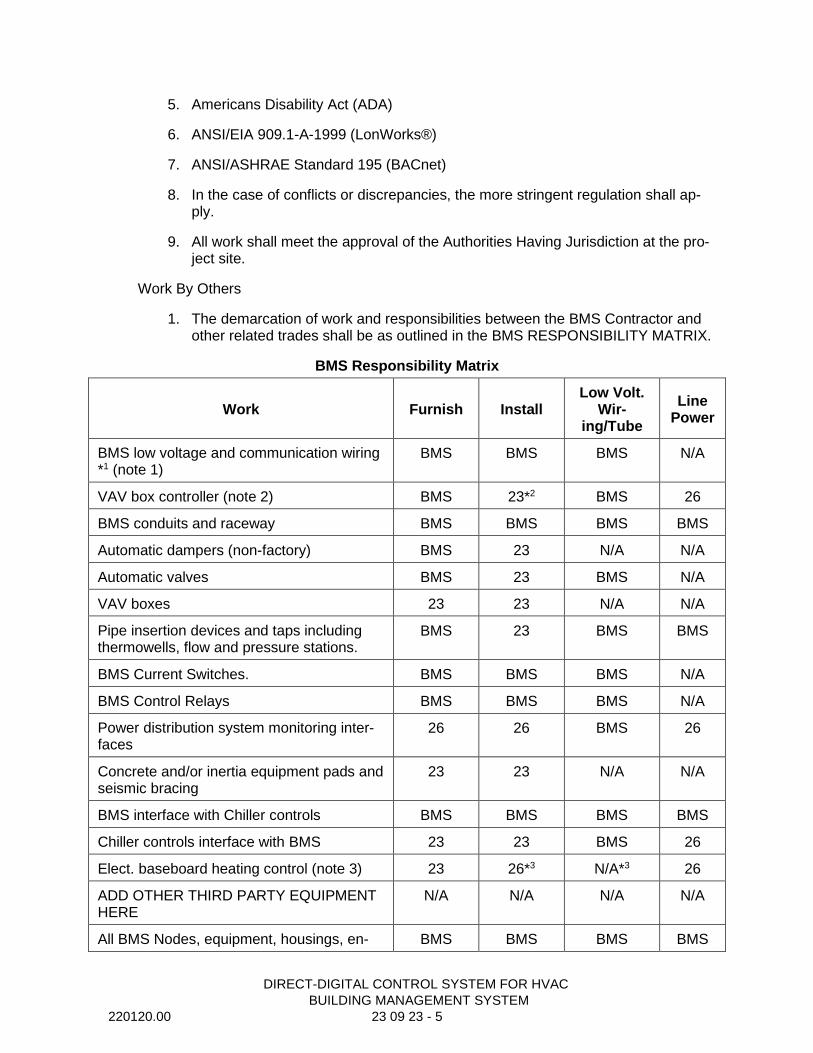
DIRECT-DIGITAL CONTROL SYSTEM FOR HVAC
BUILDING MANAGEMENT SYSTEM
220120.00 23 09 23 - 5
5. Americans Disability Act (ADA)
6. ANSI/EIA 909.1-A-1999 (LonWorks®)
7. ANSI/ASHRAE Standard 195 (BACnet)
8. In the case of conflicts or discrepancies, the more stringent regulation shall ap-ply.
9. All work shall meet the approval of the Authorities Having Jurisdiction at the pro-ject site.
Work By Others
1. The demarcation of work and responsibilities between the BMS Contractor and other related trades shall be as outlined in the BMS RESPONSIBILITY MATRIX.
BMS Responsibility Matrix
Work Furnish Install Low Volt.
Wir-ing/Tube
Line Power
BMS low voltage and communication wiring *1 (note 1)
BMS BMS BMS N/A
VAV box controller (note 2) BMS 23*2 BMS 26
BMS conduits and raceway BMS BMS BMS BMS
Automatic dampers (non-factory) BMS 23 N/A N/A
Automatic valves BMS 23 BMS N/A
VAV boxes 23 23 N/A N/A
Pipe insertion devices and taps including thermowells, flow and pressure stations.
BMS 23 BMS BMS
BMS Current Switches. BMS BMS BMS N/A
BMS Control Relays BMS BMS BMS N/A
Power distribution system monitoring inter-faces
26 26 BMS 26
Concrete and/or inertia equipment pads and seismic bracing
23 23 N/A N/A
BMS interface with Chiller controls BMS BMS BMS BMS
Chiller controls interface with BMS 23 23 BMS 26
Elect. baseboard heating control (note 3) 23 26*3 N/A*3 26
ADD OTHER THIRD PARTY EQUIPMENT HERE
N/A N/A N/A N/A
All BMS Nodes, equipment, housings, en- BMS BMS BMS BMS
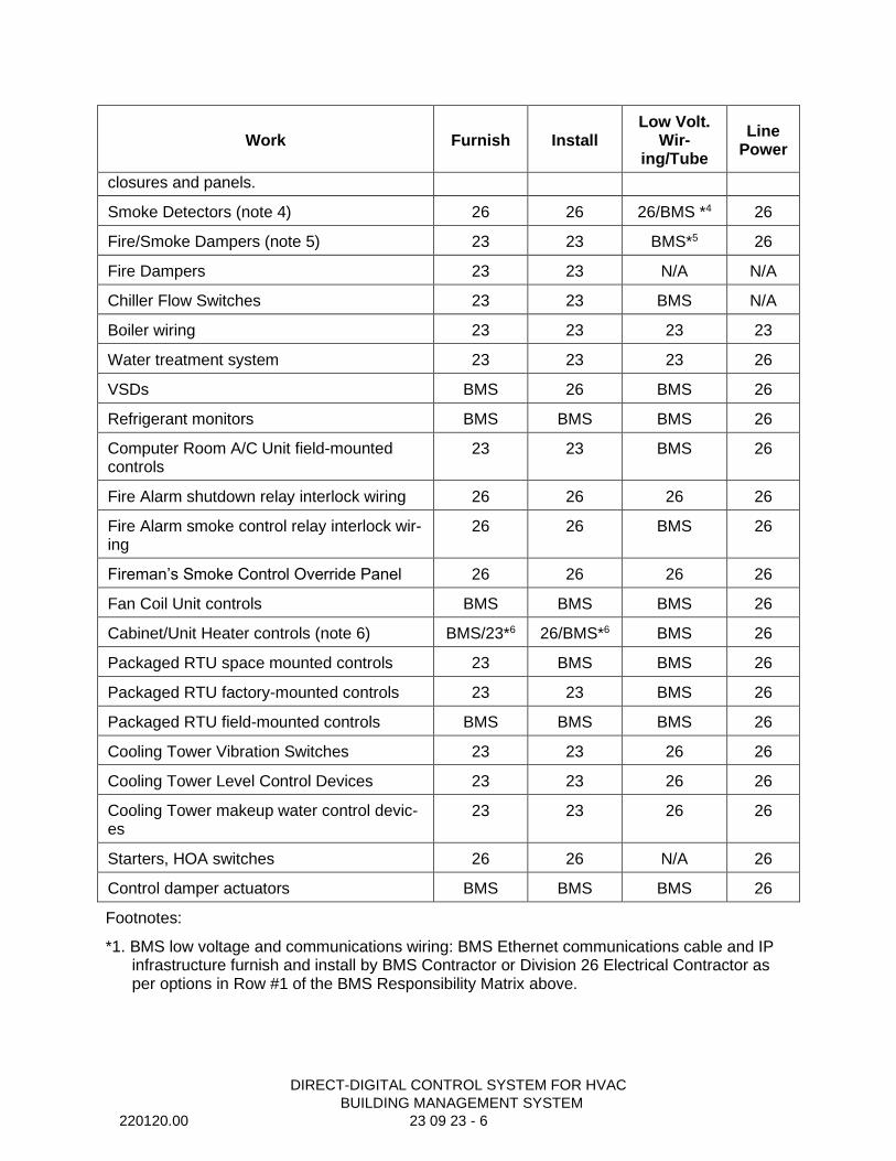
DIRECT-DIGITAL CONTROL SYSTEM FOR HVAC
BUILDING MANAGEMENT SYSTEM
220120.00 23 09 23 - 6
Work Furnish Install Low Volt.
Wir-ing/Tube
Line Power
closures and panels.
Smoke Detectors (note 4) 26 26 26/BMS *4 26
Fire/Smoke Dampers (note 5) 23 23 BMS*5 26
Fire Dampers 23 23 N/A N/A
Chiller Flow Switches 23 23 BMS N/A
Boiler wiring 23 23 23 23
Water treatment system 23 23 23 26
VSDs BMS 26 BMS 26
Refrigerant monitors BMS BMS BMS 26
Computer Room A/C Unit field-mounted controls
23 23 BMS 26
Fire Alarm shutdown relay interlock wiring 26 26 26 26
Fire Alarm smoke control relay interlock wir-ing
26 26 BMS 26
Fireman’s Smoke Control Override Panel 26 26 26 26
Fan Coil Unit controls BMS BMS BMS 26
Cabinet/Unit Heater controls (note 6) BMS/23*6 26/BMS*6 BMS 26
Packaged RTU space mounted controls 23 BMS BMS 26
Packaged RTU factory-mounted controls 23 23 BMS 26
Packaged RTU field-mounted controls BMS BMS BMS 26
Cooling Tower Vibration Switches 23 23 26 26
Cooling Tower Level Control Devices 23 23 26 26
Cooling Tower makeup water control devic-es
23 23 26 26
Starters, HOA switches 26 26 N/A 26
Control damper actuators BMS BMS BMS 26
Footnotes:
*1. BMS low voltage and communications wiring: BMS Ethernet communications cable and IP infrastructure furnish and install by BMS Contractor or Division 26 Electrical Contractor as per options in Row #1 of the BMS Responsibility Matrix above.
DIRECT-DIGITAL CONTROL SYSTEM FOR HVAC
BUILDING MANAGEMENT SYSTEM
220120.00 23 09 23 - 7
*2. VAV box controller factory installation would normally be by Division 23 Mechanical who fur-nishes the VAV boxes; could be by BMS for field installation of special controllers, see Row #2 of the BMS Responsibility Matrix above.
*3. Electric Baseboard Heating Controls – for line voltage stand-alone controls: furnished by Di-vision 23 Mechanical Contractor who furnishes the baseboard units; line voltage controls in-stalled and connected by Division 26 Electrical Contractor. Alternately, controls may be fur-nished and installed by BMS Contractors for projects requiring Baseboard Heating controls to be integrated into the BMS.
*4. Smoke Detector also wired to shut down AHU/HVAC by BMS Contractor; Division 26 for pro-jects NYC. Duct smoke detectors and fire alarm control modules shall be provided by others. Provide wiring, conduit, and necessary interface with fire alarm system to perform specified sequence of operation.
*5. Fire/Smoke Dampers: BMS Contractor to provide and ensure OPEN/CLOSE control of Fire/Smoke dampers as coordinated between BMS HVAC systems sequences, controls and overrides, and the Fire Alarm system control status priorities and overrides. Coordinate with Division 26 to provide duct detectors or fire alarm control modules for air handling unit and exhaust system shutdown and smoke control inputs to the DDC system. In most cases fire alarm control modules will be the most effective and flexible way of achieving this interface. Ensure that the logic matrix for the fire alarm devices to trigger a HVAC response is clearly specified.
*6. Cabinet/Unit Heater Controls – for line voltage stand-alone controls: furnished by Division 23 Mechanical Contractor who furnishes the Cabinet/Unit Heaters; line voltage stand-alone controls installed and connected by Division 26 Electrical Contractor. Even for stand-alone controls, it is common for the line voltage TStat and associated interlock wiring to be in-stalled by the BAS. The power to the UH/CUH is performed by the Division 26 contractor. Al-ternately, controls may be furnished and installed by BMS Contractors for projects requiring Cabinet/Unit Heater controls to be integrated into BMS.
DIRECT-DIGITAL CONTROL SYSTEM FOR HVAC
BUILDING MANAGEMENT SYSTEM
220120.00 23 09 23 - 8
Submittals
1. Shop Drawings, Product Data, and Samples
a. The BMS contractor shall submit a list of all shop drawings with submittals dates within 30 days of contract award.
b. Submittals shall be in defined packages. Each package shall be complete, shall only reference itself, and previously submitted packages. The packages shall be as approved by the Architect and Engineer for Contract compliance.
c. Allow 15 working days for the review of each package by the Architect and Engineer in the scheduling of the total BMS work.
d. Equipment and systems requiring approval of local authorities must comply with such regulations and be approved. Filing shall be at the expense of the BMS Contractor where filing is necessary. Provide a copy of all related corre-spondence and permits to the Owner.
e. Prepare an index of all submittals and shop drawings for the installation. In-dex shall include a shop drawing identification number, Contract Documents reference and item description.
f. The BMS Contractor shall correct any errors or omissions noted in the first review.
g. At a minimum, submit the following:
h. BMS network architecture diagrams including all nodes and interconnections.
i. Systems schematics, sequences, and flow diagrams
j. Points schedule for each point in the BMS, including: Point Type, Object Name, Expanded ID, Display Units, Controller type, and Address
k. Samples of Graphic Display screen types and associated menus
l. Detailed Bill of Material list for each system or application, identifying quanti-ties, part numbers, descriptions, and optional features
m. Control Damper Schedule including a separate line for each damper provided under this section and a column for each of the damper attributes, including Code Number, Fail Position, Damper Type, Damper Operator, Duct Size, Damper Size, Mounting, and Actuator Type
n. Room Schedule including a separate line for each VAV box and/or terminal unit indicating location and address
o. Control Valve Schedules including a separate line for each valve provided under this section and a column for each of the valve attributes: Code Num-ber, Configuration, Fail Position, Pipe Size, Valve Size, Body Configuration, Close off Pressure, Capacity, Valve CV, Design Pressure, and Actuator Type
p. Details of all BMS interfaces and connections to the work of other trades

DIRECT-DIGITAL CONTROL SYSTEM FOR HVAC
BUILDING MANAGEMENT SYSTEM
220120.00 23 09 23 - 9
q. Product data sheets or marked catalog pages including part number, photo and description for all products including software
2. Existing Systems Inventory
a. Where applicable, provide a complete and current BMS site inventory for all existing field and supervisory controllers to be integrated into the new BMS including manufacturer, model number, firmware version, available updates, battery condition, integrations, controlled equipment, and point counts.
b. Site inventory shall be provided on a separate, new USB compatible flash drive.
Record Documentation
1. Operation and Maintenance Manuals.
c. Three (3) copies of the Operation and Maintenance Manuals shall be provid-ed to the Owner's Representative upon completion of the project. The entire Operation and Maintenance Manual shall be furnished on Compact Disc me-dia or USB Flash Drive, and include the following for the BMS provided:
d. Table of contents
e. As-built system record drawings. Computer Aided Drawings (CAD) record drawings shall represent the as-built condition of the system and incorporate all information supplied with the approved submittal.
f. Manufacturer’s product data sheets or catalog pages for all products includ-ing software
g. System Operator’s manuals
h. Archive copy of all site-specific databases and sequences
i. BMS network diagrams
j. Interfaces to all third party products and work by other trades
k. The Operation and Maintenance Manual shall be self-contained, and include all necessary software required to access the product data sheets. Include a logically organized table of contents. Viewer software shall provide the ability to display, zoom, print, and search all documents.
2. On-Line documentation: After completion of all tests and adjustments the con-tractor shall provide a copy of all as-built information and product data to be in-stalled on a customer designated computer workstation or server.
Warranty
1. Standard Material and Labor Warranty:
a. Provide a one-year labor and material warranty on the BMS.

DIRECT-DIGITAL CONTROL SYSTEM FOR HVAC
BUILDING MANAGEMENT SYSTEM
220120.00 23 09 23 - 10
b. If within twelve (12) months from the date of acceptance of product, upon written notice from the owner, it is found to be defective in operation, work-manship or materials, it shall be replaced, repaired or adjusted at the option of the BMS Contractor at the cost of the BMS Contractor.
c. Maintain an adequate supply of materials within 100 miles of the Project site such that replacement of key parts and labor support, including programming. Warranty work shall be done during BMS Contractor’s normal business hours.
PART 2 – PRODUCTS
General Description
1. The BMS shall use an open architecture and fully support a multi-vendor envi-ronment. To accomplish this effectively, the BMS shall support open communica-tion protocol standards and integrate a wide variety of third party devices and applications. The system shall be designed for use on the Internet, or intranets using off the shelf, industry standard technology compatible with other owner provided networks.
2. The BMS shall consist of the following:
a. Application and Data Server
b. Network Engine(s)
c. Equipment Controller(s)
d. Input/Output Module(s)
e. Local Display Device(s)
f. Portable Operator's Terminal(s)
g. Distributed User Interface(s)
h. Network processing, data storage and communications equipment
i. Other components required for a complete and working BMS
3. The system shall be modular in nature, and shall permit expansion of both ca-pacity and functionality through the addition of sensors, actuators, controllers and operator devices, while re-using existing controls equipment.
4. System architectural design shall eliminate dependence upon any single device for alarm reporting and control execution.
a. The failure of any single component or network connection shall not interrupt the execution of control strategies at other operational devices.
b. The System shall maintain all settings and overrides through a system re-boot.

DIRECT-DIGITAL CONTROL SYSTEM FOR HVAC
BUILDING MANAGEMENT SYSTEM
220120.00 23 09 23 - 11
5. System architectural design shall eliminate dependence upon any single device for alarm reporting and control execution.
6. The System shall comply with the following International Code Council (ICC) Codes:
a. Building Officials and code Administrators International (BOMA) model code
International Conference of Building Officials (ICBO) model code
7. Acceptable Manufacturers
a. Johnson Controls, Metasys – Installed by the local JCI branch. Contact Jim Perisin 708-418-2268
BMS System Architecture
8. Automation Network
a. The automation network shall be based on a PC industry standard of Ether-net TCP/IP. Where used, LAN controller cards shall be standard “off the shelf” products available through normal PC vendor channels.
b. The BMS shall network multiple user interface clients, application and data servers, network engines, system controllers and application-specific control-lers including but not limited to:
c. Application and Data Server
d. Network Engines
e. Network Control Engines
f. Equipment Controllers
g. VAV Box Controllers
h. Third Party BACnet controllers and peripheral devices with compatibility listed by BACnet International
i. Application and Data Server
j. All BMS devices on the automation network shall be capable of operating at a minimum communication speed of 100 Mbps, with full peer-to-peer network communication.
k. Network Security – To protect the BMS from unauthorized users and com-puter hackers the Automation Network shall support HTTPS with TLS 1.2 be-tween components, including the Application and Data Server(s), Network Engines, Mobile User Interface and Site Management Portal. Self-signed cer-tificates are installed on supported products, with the option of configuring trusted certificates. Computing devices supplied by the BMS vendor will au-tomatically shut down unused ports to deter unauthorized access.
DIRECT-DIGITAL CONTROL SYSTEM FOR HVAC
BUILDING MANAGEMENT SYSTEM
220120.00 23 09 23 - 12
l. The automation network will be compatible with other enterprise-wide net-works. Automation network components of the BMS shall be connected to the Owner’s enterprise network and share resources with it by way of standard networking devices and practices.
i. Owner shall provide and maintain all infrastructure components for the Automation network, including switches, routers, firewalls, etc.
ii. All data drops and IP addresses to and for BACnet IP components of the BMS shall be provided by the Owner.
9. Control Network
m. Network Engines shall provide supervisory control over the control network and shall selectively support the following communication protocols:
i. BACnet Standard Master-Slave/Token-Passing (MS/TP) Bus Protocol ASHRAE SSPC-135:
a) The Network Engines shall be BTL listed/certified.
b) The Network Engines shall be tested and certified as a BACnet Building Controller (B-BC) profile.
i. LonWorks enabled devices using the Free Topology Trans-ceiver (FTT-10a)
ii. The Johnson Controls N2 Field Bus
iii. Modbus® TCP and RTU
iv. Control networks shall provide either “Peer-to-Peer”, Master-Slave, or Supervised Token Passing communications, and shall operate at a minimum communication speed of 9600 baud.
v. Control network shall support digital controllers as indicated in plans and specifications.
vi. Default control network communication protocol for this project shall be BACnet Standard MS/TP Bus Protocol ASHRAE SSPC-135.
vii. A BACnet Protocol Implementation Conformance Statement (PICS) shall be provided for each controller device (master or slave) that will communicate on the BACnet MS/TP Bus.
viii. The PICS shall be submitted 10 days prior to bidding.
10. Integration
11. BACnet Protocol Integration – BACnet

DIRECT-DIGITAL CONTROL SYSTEM FOR HVAC
BUILDING MANAGEMENT SYSTEM
220120.00 23 09 23 - 13
ii. The neutral protocol used between systems will be BACnet IP and comply with the ASHRAE BACnet standard 135.
iii. A complete Protocol Implementation Conformance Statement (PICS) shall be provided for all BACnet system devices.
iv. The ability to command, share point object data, change of state (COS) data and schedules between the host and BACnet systems shall be provided.
User Interface
1. Dedicated Web Based User Interface
a. Where indicated on plans the BMS Contractor shall provide and install a per-sonal computer for command entry, information management, network alarm management, and database management functions. Real-time control func-tions, including scheduling, history collection and alarming, shall be resident in the BMS Network, Engines and Data Server(s) to facilitate greater fault tol-erance and reliability.
b. Dedicated User Interface Architecture – The architecture of the computer shall be implemented to conform to industry standards, so that it can accom-modate applications provided by the BMS Contractor and by other third party applications suppliers, including but not limited to Microsoft Office Applica-tions. Specifically, it must be implemented to conform to the following inter-face standards.
c. Edge or Google Chrome or Safari for user interface functions.
d. Microsoft Office Professional for creation, modification and maintenance of reports, sequences other necessary building management functions.
e. Microsoft Outlook or other e-mail program for supplemental alarm functionali-ty and communication of system events, and reports.
f. Required network operating system for exchange of data and network func-tions such as printing of reports, trends and specific system summaries.
g. PC Hardware/Software – The personal computer(s) shall be configured as specified in the Computing Hardware and Software section.
h. Provide one operational device as herein specified and located on plans.
2. Associated Application Components
Security/Passwords
i. Multiple-level passwords access protection shall be provided via roles and permissions. The feature will allow the system to base access on a user’s job title or role and allow the user/manager access interface control, display, and database manipulation capabilities based on an assigned password.
DIRECT-DIGITAL CONTROL SYSTEM FOR HVAC
BUILDING MANAGEMENT SYSTEM
220120.00 23 09 23 - 14
ii. Roles may be copied and altered to meet specific roles and permis-sions based on the particular policies.
iii. Each user shall have the following: a user account name (with a max-imum of 30 characters), a complex password or passphrase (with a min of 8 characters and a max of 50 characters), other user account policies (such as session timeout), timesheet access based on day of the week and time of day, and specific user view.
iv. The system shall allow each user to change his or her password at will.
v. When entering or editing passwords, the system shall not echo the actual characters for display on the monitor.
vi. A maximum of 150 categories may be used to determine or assign areas of responsibilities to each user account. A maximum of 13 (of the 150) named categories which are specifics such as “No Access, View, Advanced Review, Operate, Intervene, Diagnostic, Manage Item Events, Manage Energy, and Configure Items”.
vii. A minimum of 100 unique passwords shall be supported.
viii. Operators shall be able to perform only those commands available for their respective passwords. Display of menu selections shall be lim-ited to only those items defined for the access level of the password used to log-on.
ix. Operators shall be further limited to only access, command, and modi-fy those buildings, systems, and subsystems for which they have re-sponsibility. Provide a minimum of 100 categories of systems to which individual operators may be assigned.
x. The system shall automatically generate a report of log-on/log-off and system activity for each user. Any action that results in a change in the operation or configuration of the control system shall be recorded, including: modification of point values, schedules or history collection parameters, and all changes to the alarm management system, in-cluding the acknowledgment and deletion of alarms.
xi. The system shall have the ability to provide a Department of Defense (DoD) specific warning banner for applicable sites that warns the user they are accessing a restricted site.
xii. After successful login to the Site Management Portal (SMP) the last time and date that user name was previously logged in is shown on the screen.
xiii. Each login attempt is recorded in the system Audit Log with the option to record the IP address of the PC that made the login.
Screen Manager
DIRECT-DIGITAL CONTROL SYSTEM FOR HVAC
BUILDING MANAGEMENT SYSTEM
220120.00 23 09 23 - 15
i. The system will allow a customized image on the login screen (e.g. organization name, logo).
ii. User View navigations can be displayed as either a set of tabs or a drop down list.
iii. Allows user preference for assigning of a background color for when an object is Out of Service which will enable the operator to quickly distinguish points that have been commanded to this state.
iv. The User Interface shall be provided with screen management capa-bilities that allow the user to activate, close, and simultaneously ma-nipulate a minimum of 4 active display windows plus a network or us-er defined navigation tree.
Historical trending and data collection
i. Each Network Engine shall store trend and point history data for all analog and digital inputs and outputs, as follows:
ii. Any point, physical or calculated, may be designated for trending. Two methods of collection shall be allowed:
a. Defined time interval
b. Upon a change of value
iii. Each Network Engine shall have the capability to store multiple sam-ples for each physical point and software variable based upon availa-ble memory, including an individual sample time/date stamp. Points may be assigned to multiple history trends with different collection pa-rameters.
iv. Trend and change of value data shall be stored within the engine and uploaded to a dedicated trend database or exported in a selectable data format via a provided data export utility. Uploads to a dedicated database shall occur based upon one of the following: user-defined interval, manual command, or when the trend buffers are full. Exports shall be as requested by the user or on a time-scheduled basis.
v. The system shall provide a configurable data storage subsystem for the collection of historical data. Data can be stored in SQL database format.
vi. The system shall provide data to enable optimization capabilities in-cluding fault detection and diagnostics, advanced analytics and cen-tral plant optimization without the need of a gateway or additional hardware.
Database Management
i. Where a separate SQL database is utilized for information storage the System shall provide a Database Manager that separates the data-
DIRECT-DIGITAL CONTROL SYSTEM FOR HVAC
BUILDING MANAGEMENT SYSTEM
220120.00 23 09 23 - 16
base monitoring and managing functions by supporting two separate windows.
ii. Database secure access shall be accomplished using standard SQL authentication including the ability to access data for use outside of the Building Automation application.
iii. The database managing function shall include summarized infor-mation on trend, alarm, event, and audit for the following database management actions:
a. Backup
b. Purge
c. Restore
iv. The Database Manager shall support four tabs:
a. Statistics – shall display Database Server information and Trend, Alarm (Event), and Audit information on the Databases.
b. Maintenance – shall provide an easy method of purging rec-ords from the Server trend, alarm (event), and audit databases by supporting separate screens for creating a backup prior to purging, selecting the database, and allowing for the retention of a selected number of day’s data.
c. Backup – Shall provide the means to create a database back-up file and select a storage location.
d. Restore – shall provide a restricted means of restoring a data-base by requiring the user to log into an Expert Mode in order to view the Restore screen.
v. The Status Bar shall appear at the bottom of all Database Manager Tabs and shall provide information on the current database activity. The following icons shall be provided:
a. Ready
b. Purging Record from a database
c. Action Failed
d. Refreshing Statistics
e. Restoring database
f. Shrinking a database
g. Backing up a database
h. Resetting internet information Services
DIRECT-DIGITAL CONTROL SYSTEM FOR HVAC
BUILDING MANAGEMENT SYSTEM
220120.00 23 09 23 - 17
i. Starting the Device Manager
j. Shutting down the Device Manager
k. Action successful
vi. The Database Manager monitoring functions shall be accessed through the Monitoring Settings window and shall continuously read database information once the user has logged in.
vii. The System shall provide user notification via taskbar icons and e-mail messages when a database value has exceeded a warning or alarm limit.
viii. The Monitoring Settings window shall have the following sections:
a. General – Shall allow the user to set and review scan intervals and start times.
b. Email – Shall allow the user to create and review e-mail and phone text messages to be delivered when a Warning or Alarm is generated.
c. Warning – shall allow the user to define the Warning limit pa-rameters, set the Reminder Frequency, and link the e-mail message.
d. Alarm – shall allow the user to define the Alarm limit parame-ters, set the Reminder Frequency, and link the e-mail mes-sage.
e. Database login – Shall protect the system from unauthorized database manipulation by creating a Read Access and a Write Access for each of the Trend, Alarm (Event) and Audit data-bases as well as an Expert Mode required to restore a data-base.
ix. The Monitoring Settings Taskbar shall provide the following informa-tional icons:
a. Normal – Indicates by color and size that all databases are within their limits.
b. Warning – Indicates by color and size that one or more data-bases have exceeded their Warning limit.
c. Alarm – Indicates by color and size that one or more data-bases have exceeded their Alarm limit.
x. The System shall provide user notification via Taskbar icons and e-mail messages when a database value has exceeded a warning or alarm limit.
xi. Demand Limiting and Load Rolling
DIRECT-DIGITAL CONTROL SYSTEM FOR HVAC
BUILDING MANAGEMENT SYSTEM
220120.00 23 09 23 - 18
xii. The System shall provide a Demand Limiting and Load Rolling pro-gram for the purpose of limiting peak energy usage and reducing overall energy consumption and shall be implemented as outlined within the sequences of operations.
xiii. The System shall support both Sliding Window and Fixed Window methods of predicting demand.
xiv. The System shall support three levels of sensitivity in the Sliding Win-dow demand calculations for fine tuning the system.
xv. Low Setting – Sheds loads later and over the shortest amount of time. Maximizes the time the equipment is on.
xvi. Medium Setting – Sheds loads earlier over a longer amount of time than the Low Setting. Increases the time the equipment is on and de-creases the probability of exceeding the Tariff Target over the Low Setting.
xvii. High Setting – Sheds loads earlier over a longer amount of time than the Medium Setting. Minimizes the probability of exceeding the Tariff Target.
xviii. The System shall have both a Shed Mode and a Monitor Only Mode of operation.
xix. When the Shed Mode is engaged, the System shall actively control the Demand.
xx. When the Monitor Mode is engaged, the System will simulate the shedding action but will not take any action.
xxi. The Demand Limiting program shall monitor the energy consumption rate and compare it to a user defined Tariff Target. The system shall maintain consumption below the target by selectively shedding loads based upon a user defined strategy.
xxii. The Demand Limiting program shall be capable of supporting a minimum of 10 separate Load Priorities. Each load shall be user as-signed to a Load Priority.
xxiii. The Demand Limiting program shall be capable of supporting a minimum of 12 separate Tariff Targets defining the maximum allowed average power during the current interval.
xxiv. The System shall support a Maximum Shed Time for each load as determined by the user. The system shall restore the load before the Maximum Shed time has expired.
xxv. The System shall support a Minimum Shed Time for each load as determined by the user. The system shall not restore the load sooner than the Minimum Shed Time has expired.
DIRECT-DIGITAL CONTROL SYSTEM FOR HVAC
BUILDING MANAGEMENT SYSTEM
220120.00 23 09 23 - 19
xxvi. The System shall support a Minimum Release Time for each load as determined by the user. The System shall not shed the load until it has been off for the Minimum Release time.
xxvii. The System shall support three user defined options if the meter goes unreliable.
a. Shedding – The currently shed loads will be released as their Maximum shed Times expire.
b. Maintain the Current Shed Rate – The System will use the Demand Limiting shed rate that was present when the meter went unreliable.
c. Use Unreliable Meter Shed Rate – the system will control to a user defined Unreliable Shed Rate target.
xxviii. The Load Rolling program shall sum the loads currently shed and compare it to a user defined Load Rolling Target. The system shall maintain consumption below the target by selectively shedding loads based upon a user defined Load Priority.
xxix. The Load Rolling program shall be capable of supporting a mini-mum of 10 separate Load Priorities. Each load shall be user assigned to a Load Priority.
xxx. The Load Rolling program shall be capable of supporting a mini-mum of 12 separate Tariff Targets defining the amount of power by which the demand must be reduced.
xxxi. The System shall provide the user with a Load Tab that displays all of the Demand Limiting and Load Rolling parameters for any se-lected load.
xxxii. The System shall provide the user with a Load Summary that dis-plays all of the loads associated with the Demand Limiting and Load Rolling programs. Status Icons for each load shall indicate:
Load is Offline
Load is Disabled
Load is Shed
Load is Locked
Load is in Comfort Override
The Load Summary shall include a Load Summary Runtime view listing the following load conditions:
Load Priority
Shed Strategy
Load Rating

DIRECT-DIGITAL CONTROL SYSTEM FOR HVAC
BUILDING MANAGEMENT SYSTEM
220120.00 23 09 23 - 20
Present Value
Ineligibility Status
Active Timer
Time Remaining
Last Shed Time
Provide Site Management Portal with associated user interface at each Network Engine as well as all Application and Data Servers.
Network Engines
1. General
a. The Network Engine shall be a fully user-programmable, supervisory control-ler. The Network Engine(s) shall monitor the network of distributed equipment controllers, provide global strategy and direction, and communicate on a peer-to-peer basis with other Network Engine(s).
Automation network – The Network Engine(s) shall reside on the automation network and shall support a subnet of system controllers.
User Interface – Each Network Engine shall have the ability to deliver a web-based User Interface. All computers connected physically or virtually to the automation network shall have access to the web-based user interface.
Processor – The Network Engine(s) shall be microprocessor-based with a mini-mum word size of 32 bits. The Network Engine(s) shall be a multi-tasking, multi-user, and real-time digital control processor. Standard operating sys-tems shall be employed. Network Engine(s) size and capability shall be suffi-cient to fully meet the requirements of this Specification.
Memory – Each Network Engine shall have sufficient memory to support its own operating system, databases, and control programs, and to provide supervi-sory control for all control level devices.
Secure Boot – The Network Engine(s) shall prevent malicious or unauthorized software applications from loading during the system startup process.
User Authentication – The Network Engine(s) shall support local user authentica-tion.
Password Security – Access to the Network Engines’ embedded user interface shall require a password of 8 to 50 characters including a minimum of one lower case letter, one upper case letter, one number, and one special charac-ter. An alarm shall be generated after three unsuccessful attempts within 15 minutes, and the user shall be denied access until permission is renewed by a system administrator.
Network Security – Communication between the Network Engine and other sys-tem networked devices including additional Network Engines, Application and Data Servers, Open Data Servers (BACnet listed OWS), and user interface
DIRECT-DIGITAL CONTROL SYSTEM FOR HVAC
BUILDING MANAGEMENT SYSTEM
220120.00 23 09 23 - 21
clients shall be encrypted and support HTTPS with Transport Level Security (TLS) Version 1.2. Self-signed certificates are to be provided with the option of configuring trusted certificates.
Hardware Real Time Clock – The Network Engine(s) shall include an integrated, hardware-based, real-time clock, with a supercapacitor to maintain time for a minimum of 72 hours during a power loss. Controllers using a battery to maintain time during a power loss shall not be acceptable.
Diagnostics – The Network Engine(s) shall continuously perform self-diagnostics, communication diagnosis, and diagnosis of all panel components. The Net-work Engine(s) shall provide both local and remote annunciation of any de-tected component failures or repeated failures to establish communication.
Power Failure – In the event of the loss of normal power, the Network Engine(s) shall continue to operate for a user adjustable period of up to 10 minutes after which there shall be an orderly shutdown of all programs to prevent the loss of database or operating system software.
i. During a loss of normal power, the control sequences shall go to the normal system shutdown conditions. All critical configuration data shall be saved into Flash memory.
Upon restoration of normal power and after a minimum off-time delay, the controller shall automatically resume full operation without manual in-tervention through a normal soft-start sequence.
Certification – The Network Engine(s) shall meet and be listed to the UL 916 Standard for Energy Management Equipment and be FCC Compliant to CFR47, Part 15, Subpart B, Class A.
Device Integration – The Network Engine(s) shall support integrating networked devices using the following communication protocols on the device/controller network:
i. Primary protocol support: The Network Engine(s) shall support BAC-net Standard MS/TP Bus Protocol ASHRAE SSPC-135 on the control-ler network.
The Network Engine(s) shall support Remote Field Bus integration via a BACnet IP to MS/TP router.
The Network Engine(s) shall be tested and BTL listed/certified as a BACnet Building Controller (B-BC).
A BACnet Protocol Implementation Conformance Statement shall be provided for the Network Engine(s).
The Protocol Implementation Conformance Statement shall be submitted 10 days prior to bidding.
Optional protocol support:
DIRECT-DIGITAL CONTROL SYSTEM FOR HVAC
BUILDING MANAGEMENT SYSTEM
220120.00 23 09 23 - 22
• The Network Engine shall support LonWorks enabled devices using a whitelisted USB-to-LonWorks FTT10 Free Topology Transceiver adapter.
• Johnson Controls N2 or third party N2 Open devices.
The Network Engine(s) shall optionally support integration of networked devices using the following networking protocols:
MODBUS RTU
MODBUS TCP
KNX - KNX is an open communication standard (EN 50090, ISO/IEC 14543) that many European manufacturers have ap-plied to lighting controls, blinds and shutters, HVAC controls, security systems, energy management, audio, video, displays, and remote controls.
M-Bus - M-Bus (Meter Bus) is a European standard (EN 1434-3) that applies primarily to energy and heat meters.
C-CURE 9000 Access Control System
victor Video Management System
OPC UA
The Network Engine(s) shall include the following multi-color, flashing LEDs to indicate important operating conditions and status:
i. Heartbeat – to indicate each of the following states: operational (nor-mal), powered but not operational, starting up, shutting down, or no power applied
ii. Fault – to indicate if fault conditions have been detected
iii. Ethernet Activity – to indicate if Ethernet Traffic is occurring or not oc-curring.
iv. Ethernet Link Speed – to indicate the speed of Ethernet Link (10, 100, or 1000 Mbps)
v. Site Director – to indicate if the Network Engine has been designated as the Site Director
vi. BACnet/IP – to indicate if the Network Engine is transmitting BACnet messages over BACnet/IP to other devices, including other Network Engines
vii. USB -1 – to indicate if a supported device is connected, no device is connected, or an unsupported device is connected on USB port 1
viii. USB-1 – to indicate if a supported device is connected, no device is connected, or an unsupported device is connected on USB port 2
DIRECT-DIGITAL CONTROL SYSTEM FOR HVAC
BUILDING MANAGEMENT SYSTEM
220120.00 23 09 23 - 23
ix. FC BUS-# – to indicate if communication is occurring on FC Bus port # (1 or 2)
x. FC EOL-# – to indicate if the end-of-line termination switch # (1 or 2) is on or off
2. Network Engine – Flexible Sizing Options
a. The Network Engine shall support up to 50, 100 or 200 supervised devices across all supported integrations.
b. Communications Ports – The Network Engine(s) shall provide the following ports for connecting networkable devices
i. Two (2) USB ports
One (1) or Two (2) RS-485 ports
One (1) Ethernet port
c. Provide Johnson Controls SNE10501, SNE11001 or SNE22001 or approved equal as indicated on plans.
Network Control Engines
1. General
d. The Network Control Engine shall be a fully user-programmable, supervisory controller. The Network Control Engine shall monitor the network of equip-ment controllers, provide global strategy and direction, and communicate on a peer-to-peer basis with other Network Engines.
e. The Network Control Engine shall also be a fully user-programmable, equip-ment controller that includes a minimum of 28 I/O points.
f. Automation Network – The Network Control Engine(s) shall reside on the au-tomation network and shall support a subnet system controllers.
g. User Interface – Each Network Control Engine shall have the ability to deliver a web-based User Interface previously described. All computers connected physically or virtually to the automation network shall have access to the web-based user interface.
h. Processor – The Network Control Engine(s) shall be microprocessor-based with a minimum word size of 32 bits. The Network Control Engine shall be a multi-tasking, multi-user, and real-time digital control process. Standard op-erating systems shall be employed. Network Control Engine(s) size and ca-pability shall be sufficient to fully meet the requirements of this Specification.
i. Memory – Each Network Control Engine shall have sufficient memory to sup-port its own operating system, databases, and control programs, and to pro-vide supervisory control for all control level devices.

DIRECT-DIGITAL CONTROL SYSTEM FOR HVAC
BUILDING MANAGEMENT SYSTEM
220120.00 23 09 23 - 24
j. Secure Boot – The Network Control Engine shall prevent malicious or unau-thorized software applications from loading during the system startup pro-cess.
k. User Authentication – The Network Control Engine shall support local user authentication.
l. Password Security – Access to the Network Control Engines’ embedded user interface shall require a password of 8 to 50 characters including a minimum of one lower case letter, one upper case letter, one number, and one special character. An alarm shall be generated after three unsuccessful attempts within 15 minutes and the user shall be denied access until permission is re-newed by a system administrator.
m. Network Security – Communication between the Network Control Engine and other system networked devices including additional Network Engines, Appli-cation and Data Servers, Open Data Servers (BACnet listed OWS), and user interface clients shall be encrypted and support HTTPS with Transport Level Security (TLS) Version 1.2. Self-signed certificates are to be provided with the option of configuring trusted certificates.
n. Hardware Real Time Clock – The Network Control Engine shall include an in-tegrated, hardware-based, real-time clock, with a supercapacitor to maintain time for a minimum of 72 hours during a power loss. Controllers using a bat-tery to maintain time during a power loss shall not be acceptable.
o. Diagnostics – The Network Control Engine(s) shall continuously perform self-diagnostics, communication diagnosis, and diagnosis of all panel compo-nents. The Network Control Engine(s) shall provide both local and remote annunciation of any detected component failures or repeated failures to es-tablish communication.
p. Power Failure – In the event of the loss of normal power, the Network Control Engine(s) shall continue to operate for a user adjustable period of up to 10 minutes after which there shall be an orderly shutdown of all programs to prevent the loss of database or operating system software.
i. During a loss of normal power, the control sequences shall go to the normal system shutdown conditions. All critical configuration data shall be saved into Flash memory.
ii. Upon restoration of normal power and after a minimum off-time de-lay, the controller shall automatically resume full operation without manual intervention through a normal soft-start sequence.
q. Certification – The Network Control Engine(s) shall meet and be listed to the UL 916 Standard for Energy Management Equipment and be FCC Compliant to CFR47, Part 15, Subpart B, Class A.
r. Device Integration – The Network Control Engine(s) shall support integrating and supervising networked devices using the following communication proto-cols on the device/controller network:

DIRECT-DIGITAL CONTROL SYSTEM FOR HVAC
BUILDING MANAGEMENT SYSTEM
220120.00 23 09 23 - 25
ii. The Network Control Engine(s) shall support BACnet Standard MS/TP Bus Protocol ASHRAE SSPC-135 on the controller network.
iii. The Network Control Engine(s) shall support Remote Field Bus inte-gration via a BACnet IP to MS/TP router.
iv. The Network Control Engine(s) shall be tested and BTL listed/certified as a BACnet Building Controller (B-BC).
v. A BACnet Protocol Implementation Conformance Statement shall be provided for the Network Engine(s).
vi. The Protocol Implementation Conformance Statement shall be sub-mitted 10 days prior to bidding.
s. The Network Control Engine(s) shall support LonWorks enabled devices us-ing a whitelisted USB-to-LonWorks FTT10 Free Topology Transceiver adapter.
i. All LonWorks controls devices shall be LonMark® certified.
t. The Network Control Engine(s) shall support Johnson Controls N2 or third party N2 Open devices.
u. The Network Engine(s) shall optionally support integration of networked de-vices using the following networking protocols:
i. MODBUS RTU
ii. MODBUS TCP
iii. KNX – KNC is an open communication standard (EN 50090, ISO/IEC 14543) that many European manufacturers have applied to lighting controls, blinds and shutters, HVAC controls, security systems, ener-gy management, audio, video, displays, and remote controls.
iv. M-Bus – M-Bus (Meter Bus) is a European standard (EN 1434-3) that applies primarily to energy and heat meters.
v. C-CURE 9000 Access Control System
vi. victor Video Management System
vii. OPC UA
v. The Network Control Engine shall employ a finite state programming to elimi-nate unnecessary conflicts between control functions at crossover points in their operational sequences. Suppliers using non-state based DDC shall pro-vide separate control strategy diagrams for all controlled functions in their submittals.
w. The Network Control Engine shall be factory programmed with a continuous adaptive tuning algorithm that senses changes in the physical environment and continually adjusts loop tuning parameters appropriately. Controllers that

DIRECT-DIGITAL CONTROL SYSTEM FOR HVAC
BUILDING MANAGEMENT SYSTEM
220120.00 23 09 23 - 26
require manual tuning of loops or perform automatic tuning on command on-ly, shall not be acceptable.
x. The Network Control Engine shall support the following types of inputs and outputs:
y. Universal Inputs – shall be configured to monitor any of the following:
i. Analog Input, Voltage Mode
ii. Analog Input, Current Mode
iii. Analog Input, Resistive Mode
iv. Binary Input, Dry Contact Maintained Mode
v. Binary Input, Pulse Counter Mode
z. Binary Inputs – shall be configured to monitor either of the following:
i. Dry Contact Maintained Mode
ii. Pulse Counter Mode
aa. Analog Outputs – shall be configured to output either of the following:
i. Analog Output, Voltage Mode
ii. Analog Output, Current Mode
bb. Binary Outputs – shall output the following:
i. 24 VAC Triac
ii. Configurable Outputs – shall be configured to output either of the following:
• Analog Output, Voltage Mode
• Binary Output, 24 VAC Triac Mode
cc. The Network Control Engine shall have the ability to monitor and control a network of sensors and actuators over a Sensor Actuator (SA) Bus.
i. The SA Bus shall be a MS/TP Bus supporting BACnet Standard protocol SSPC-135.
ii. The SA Bus shall support a minimum of 9 devices.
iii. The SA Bus shall operate at a maximum distance of 1,200 Ft. be-tween the Network Control Engine and the furthest connected de-vice.
dd. The Network Control Engine shall have the capability to execute complex control sequences involving direct wired I/O points as well as input and output devices communicating over the Field Bus or the SA Bus.
DIRECT-DIGITAL CONTROL SYSTEM FOR HVAC
BUILDING MANAGEMENT SYSTEM
220120.00 23 09 23 - 27
ee. The Network Control Engine shall provide removable, labeled, screw terminal blocks for 24 VAC power, communication bus and I/O point field wiring.
ff. The Network Control Engine shall include the following multi-color, flashing LEDs to indicate important operating conditions and status:
i. Heartbeat – to indicate each of the following states: operational (normal), powered but not operational, starting up, shutting down, or no power applied
ii. Fault – to indicate if fault conditions have been detected
iii. SA Bus – to indicate if communication is occurring on the SA Bus
iv. FC BUS-1 – to indicate if communication is occurring on FC Bus port 1
v. Ethernet Activity - to indicate if Ethernet Traffic is occurring or not occurring
vi. USB-1|2 – to indicate if a supported device is connected, no de-vice is connected, or an unsupported device is connected on USB port 1 or 2
vii. FC EOL - to indicate if the end-of-line termination switch is on or off
gg. Communications Ports – The Network Control Engine(s) shall provide the fol-lowing ports for connecting networkable devices:
i. Two (2) USB ports
ii. One (1) RS-485 port
iii. Two (2) Ethernet ports
hh. The Network Control Engine shall support an integrated user interface featur-ing a display and keypad.
i. The integrated user interface shall allow viewing and monitoring points, alarms, and trends.
ii. The integrated user interface shall allow viewing and changing set-points, modes of operation, and parameters.
iii. The integrated user interface shall provide password protection with user-adjustable password timeout.
iv. The information presented by the integrated user interface shall be organized into folders for easy navigation.
v. The integrated user interface shall support textual descriptions in Eng-lish for each point.

DIRECT-DIGITAL CONTROL SYSTEM FOR HVAC
BUILDING MANAGEMENT SYSTEM
220120.00 23 09 23 - 28
vi. The display shall be, at minimum, a 2.4-inch, color display with 320x240 resolution.
vii. The display shall support adjustable contrast and brightness.
viii. The keypad shall include no more than seven (7) keys.
2. Network Control Engine – Flexible Sizing Options
a. The Network Control Engine shall support up to 4 or 50 supervised devices across all supported integrations.
b. Provide Johnson Controls SNCxxxxx-04x, -0x or approved equal as indicated on plans.
1. Application and Data Server (ADS)
a. The existing JCI Application and Data Server shall be utilized for this project
b. The Application and Data Server shall be a software solution designed to manage the collection and presentation of large amounts of trend data, event messages, operator transactions, and system configuration data on the BMS.
c. The Application and Data Server shall act as site director for consolidating BMS information from Network Engines for integrated storage and presenta-tion. The ADS shall not restrict access to the individual Network Engines en-suring optimal BMS accessibility in the event of individual component failure or a loss of communication.
d. The Application and Data Server shall act as a server for the following func-tionality as described in these specifications:
i. Mobile user interface providing user friendly access to system infor-mation via site navigation by place or device.
ii. Site Management Portal functions and applications.
iii. System Configuration Tool controller configuration and programming.
e. Network Security – Communication between the Network Engines, Applica-tion and Data Server, and user interface clients shall be encrypted and sup-port HTTPS with Transport Level Security (TLS) Version 1.2. Self-signed cer-tificates are to be provided with the option of configuring trusted certificates.
f. The Application and Data Server shall be capable of supporting up to 5 simul-taneous users via Web client access.
g. Supported Web Client operating systems:
i. Microsoft Windows 7, 8.1, 10 (Professional, Enterprise, Ultimate, An-niversary.)
ii. Apple OS X 10.8, 10.9, 10.10, 10.11.
h. Supported Web Browsers:
DIRECT-DIGITAL CONTROL SYSTEM FOR HVAC
BUILDING MANAGEMENT SYSTEM
220120.00 23 09 23 - 29
i. Google Chrome
ii. Microsoft Internet Explorer 11
iii. Microsoft Edge
iv. Apple Safari 11 or later
i. User Authentication – The Application and Data Server shall support local, Active Directory, and Microsoft 365 authentication.
j. Computer shall be configured as specified in the Computing Hardware and Software section of this specification.
k. Provide Johnson Controls M4-OAS, MS-ADS, MS-ADX or approved equal.
DDC Equipment Controllers
2. General Purpose Equipment Controller
a. The General Purpose Equipment Controller (CGM) shall be a fully program-mable, digital controller that communicates via the BACnet MS/TP protocol.
i. The CGM shall support BACnet Standard ANSI/ASHRAE 135.
ii. The CGM shall be BTL listed/certified.
iii. The CGM shall be tested and certified as a BACnet Advanced Appli-cation Controller (B-AAC).
iv. A BACnet Protocol Implementation Conformance Statement shall be provided for the CGM.
v. The Conformance Statement shall be submitted 10 days prior to bid-ding.
b. The CGM shall employ finite state programming to eliminate unnecessary conflicts between control functions at crossover points in their operational se-quences. Suppliers using non-state based DDC shall provide separate con-trol strategy diagrams for all controlled functions in their submittals.
c. CGM controllers shall be factory programmed with a continuous adaptive tun-ing algorithm that senses changes in the physical environment and continual-ly adjusts loop tuning parameters appropriately. Controllers that require man-ual tuning of loops or perform automatic tuning on command only shall not be acceptable.
d. The CGM shall be assembled in a plastic housing with protection class IP20 (IEC529) and flammability rated to UL94-5VB.
e. The CGM shall include an integral real-time clock and support time-based tasks which enables these field controllers to monitor and control:
i. Schedules
DIRECT-DIGITAL CONTROL SYSTEM FOR HVAC
BUILDING MANAGEMENT SYSTEM
220120.00 23 09 23 - 30
ii. Calendars
iii. Alarms
iv. Trends
3. The CGM can continue time-based monitoring when offline for extended periods of time from a network.
4. The CGM can operate as a stand-alone controller in applications that do not re-quire a networked supervisory device or for network applications where it is pre-ferred to have the scheduling, alarming, and/or trending performed locally in the equipment controllers.
5. The CGM shall include troubleshooting LEDs to indicate the following conditions:
i. Power—to indicate if the controller is powered or not powered
ii. Fault – to indicate if the controller is in its default state, has no faults, has a device fault, is in startup or download mode, or has an SA Bus communication issue
iii. SA Bus – to indicate if SA Bus communication is occurring and nor-mal, is not occurring, or was occurring but has been lost and is waiting to rejoin
iv. FC Bus – to indicate if FC Bus communication is occurring and nor-mal, is not occurring, or was occurring but has been lost and is waiting to rejoin
v. EOL – to indicate if the end-of-line termination switch is on or off
6. The CGM shall have the ability to transfer and apply firmware files to all SA Bus devices (XPM, IOM, and NS8000) connected to it.
7. The CGM shall include pluggable and labeled screw terminal blocks for all I/O, FC and SA Bus communication, and power wiring connections.
8. The CGM shall accommodate the direct wiring of analog and binary I/O field points with the following resolution.
i. Inputs – 24-bit analog-to-digital converter
ii. Outputs – +/- 200 mV accuracy in 0-10 VDC applications
9. The CGM shall support the following types of inputs and outputs supplied in the amounts required for the specified applications:
i. Universal Inputs – shall be configurable to monitor any of the follow-ing:
0-10 VDC analog input
4-20 mA analog input
DIRECT-DIGITAL CONTROL SYSTEM FOR HVAC
BUILDING MANAGEMENT SYSTEM
220120.00 23 09 23 - 31
0-600k ohms analog input
Dry contact binary input
i. Binary Inputs – shall be configurable to monitor either of the following:
Dry Contact Maintained Mode
Pulse Counter Mode
ii. Analog Outputs – shall be configurable to output either of the follow-ing:
0-10 VDC analog output
4-20 mA analog output
iii. Binary Outputs – shall output the following:
24 VAC Triac
iv. Configurable Outputs – shall be capable of the following:
0-10 VDC analog output
24 VAC Triac binary output
The CGM shall have the ability to reside on a Field Controller Bus (FC Bus).
10. The FC Bus shall be a MS/TP Bus supporting BACnet Standard protocol SSPC-135.
11. The FC Bus shall support communications between the CGMs and the Network Engine.
12. The FC Bus shall also support peer-to-peer communications between non-supervisory devices, allowing these devices to communicate system data with each other directly, bypassing the supervisory network engine on the bus.
13. The FC Bus shall support a minimum of 100 equipment controllers and/or expan-sion modules in any combination.
14. The FC Bus shall operate at a maximum distance of 15,000 Ft. between the CGM and the furthest connected device.
15. The CGM shall include three (3) decimal rotary dial switches for setting the BAC-net MS/TP device address.
16. The CGM shall have the ability to monitor and control a network of sensors and actuators over a SA Bus.
i. The SA Bus shall be a MS/TP Bus supporting BACnet Standard Pro-tocol SSPC-135.
17. The CGM shall have the capability to execute complex control sequences involv-ing direct wired I/O points as well as input and output devices communicating over a MS/TP Bus.
DIRECT-DIGITAL CONTROL SYSTEM FOR HVAC
BUILDING MANAGEMENT SYSTEM
220120.00 23 09 23 - 32
18. The CGM shall support a Local Controller Display as a remote device communi-cating over the SA Bus.
ii. The Display shall use a BACnet Standard SSPC-135 MS/TP protocol.
iii. The Display shall allow the user to view monitored points without log-ging into the system.
iv. The Display shall allow the user to view and change setpoints, modes of operation, and parameters.
v. The Display shall provide password protection with user adjustable password timeout.
vi. The Display shall be menu driven with separate paths for:
vii. Input/Output
viii. Parameter/Setpoint
ix. Overrides
x. The Display shall use easy-to-read English text messages.
xi. The Display shall allow the user to select the points to be shown and in what order.
xii. The Display shall support a back lit LCD with adjustable contrast and brightens and automatic backlight brightening during user interaction.
xiii. The display shall be a minimum of 4 lines and a minimum of 20 char-acters per line.
xiv. The Display shall have a keypad with no more than 7 keys.
xv. The Display shall be panel mountable.
19. Provide Johnson Controls CGM or approved equal as shown on plans.
20. VAV Box Controller
a. The VAV Box Controller (hereafter referred to as CVM) shall provide both standalone and networked DDC of pressure-independent, VAV terminal units.
a. The CVM controller shall be a fully programmable, digital controller that communicates via BACnet MS/TP protocol.
i. The CVM shall support BACnet Standard ANSI/ASHRAE 135.
The CVM shall be BTL listed/certified.
The CVM shall be tested and certified as a BACnet Advanced Ap-plication Controller (B-AAC).
A BACnet Protocol Implementation Conformance Statement shall be provided for the CVM.
DIRECT-DIGITAL CONTROL SYSTEM FOR HVAC
BUILDING MANAGEMENT SYSTEM
220120.00 23 09 23 - 33
The Conformance Statement shall be submitted 10 days prior to bidding.
21. The CVM shall include 14 preloaded single duct VAV box control applications to allow the CVM to be made fully operational without the need to create a custom program.
22. The CVM shall employ finite state programming to eliminate unnecessary con-flicts between control functions at crossover points in their operational sequenc-es. Suppliers using non-state based DDC shall provide separate control strategy diagrams for all controlled functions in their submittals.
23. CVM controllers shall be factory programmed with a continuous adaptive tuning algorithm that senses changes in the physical environment and continually ad-justs loop tuning parameters appropriately. Controllers that require manual tuning of loops or perform automatic tuning on command only shall not be acceptable.
24. The CVM shall be assembled in a plenum-rated plastic housing with protection class IP20 (IEC529) and flammability rated to UL94-5VB.
25. The CVM shall include an integral real-time clock and support time-based tasks which enables these equipment controllers to monitor and control:
i. Schedules
ii. Calendars
iii. Alarms
iv. Trends
26. The CVM can continue time-based monitoring when offline for extended periods of time from a network.
27. The CVM shall include an integral differential pressure transducer and damper actuator. An additional configuration option shall be available that also includes an integral potentiometer for actual damper position feedback. All components shall be connected and mounted as a single assembly, removable as one piece.
28. The integral damper actuator shall be a fast response stepper motor capable of stroking 90 degrees in 60 seconds for quick damper positioning to speed com-missioning and troubleshooting tasks.
i. Integral damper actuator shall have an integral potentiometer for mon-itoring actual position of damper actuator and reporting the position to the BMS
29. The CVM shall determine airflow by a state-of-the-art, digital, non-flow pressure sensor that supports automatic correction for polarity on high- and low-pressure DP tube connections to eliminate high- and low-pressure connection mistakes.
30. The CVM shall have the ability to automatically calibrate the flow sensor to elimi-nate pressure transducer offset error due to ambient temperature / humidity ef-fects.
DIRECT-DIGITAL CONTROL SYSTEM FOR HVAC
BUILDING MANAGEMENT SYSTEM
220120.00 23 09 23 - 34
31. The CVM can operate as a stand-alone controller in applications that do not re-quire a networked supervisory device or for network applications where it is pre-ferred to have the scheduling, alarming, and/or trending performed locally in the equipment controllers.
32. The CVM shall include troubleshooting LEDs to indicate the following conditions:
ii. Power—to indicate if the controller is powered or not powered
iii. Fault – to indicate if the controller is in its default state, has no faults, has a device fault, is in startup or download mode, or has an SA Bus communication issue
iv. SA Bus – to indicate if SA Bus communication is occurring and nor-mal, is not occurring, or was occurring but has been lost and is waiting to rejoin
v. FC Bus – to indicate if FC Bus communication is occurring and nor-mal, is not occurring, or was occurring but has been lost and is waiting to rejoin
vi. EOL – to indicate if the end-of-line termination switch is on or off
33. The CVM shall have the ability to transfer and apply firmware files to all SA Bus devices (XPM, IOM, and NS8000) connected to it.
34. The CVM shall include pluggable screw terminal blocks for all I/O, FC and SA Bus communication, and power wiring connections.
35. The CVM shall accommodate the direct wiring of analog and binary I/O field points with the following resolution.
i. Inputs – 24-bit analog-to-digital converter
ii. Outputs – +/- 200 mV accuracy in 0-10 VDC applications
36. The CVM shall support the following types of inputs and outputs supplied in the amounts required for the specified applications:
i. Universal Inputs – shall be configurable to monitor any of the follow-ing:
ii. 0-10 VDC analog input
iii. 4-20 mA analog input
iv. 0-600k ohms analog input
v. Dry contact binary input
37. Binary Outputs – shall output the following:
• 24 VAC Triac binary outputs
38. Configurable Outputs – shall be configurable of outputting the following:
DIRECT-DIGITAL CONTROL SYSTEM FOR HVAC
BUILDING MANAGEMENT SYSTEM
220120.00 23 09 23 - 35
i. 0-10 VDC analog output
ii. 24 VAC Triac binary output
39. The CVM shall have the ability to reside on a Field Controller Bus (FC Bus).
40. The FC Bus shall be a MS/TP Bus supporting BACnet Standard protocol SSPC-135.
41. The CVM shall include three (3) decimal rotary dial switches for setting the BAC-net MS/TP device address.
42. The CVM shall have the ability to monitor and control a network of sensors and actuators over a SA Bus.
43. The SA Bus shall be a MS/TP Bus supporting BACnet Standard Protocol SSPC-135.
44. The CVM shall have the capability to execute VAV box control sequences involv-ing direct wired I/O points as well as input and output devices communicating over a MS/TP Bus.
45. The controller shall utilize a proportional plus integration (PI) algorithm for the space temperature control loops.
46. Each controller shall continuously, adaptively tune the control algorithms to im-prove control and controller reliability through reduced actuator duty cycle. In ad-dition, this tuning reduces commissioning costs, and eliminates the maintenance costs of manually re-tuning loops to compensate for seasonal or other load changes.
47. The controller shall provide the ability to download and upload VAV box control application configuration files, both locally and via the communications network. Controllers shall be able to be loaded individually or as a group.
48. Control setpoint changes initiated over the network shall be written to CVM non-volatile memory to prevent loss of setpoint changes and to provide consistent operation in the event of communication failure.
49. The CVM controller firmware shall be flash-upgradeable remotely via the com-munications bus to minimize costs of feature enhancements.
50. The CVM controller shall provide fail-soft operation if the airflow signal becomes unreliable, by automatically reverting to a pressure-dependent control mode.
51. The CVM controller shall interface with balancer tools that allow automatic recal-culation of box flow pickup gain ("K" factor), and the ability to directly command the airflow control loop to the box minimum and maximum airflow setpoints.
52. The CVM controller shall have on-board diagnostics. These diagnostics shall consist of control loop performance measurements executing at each control loop's sample interval, which may be used to continuously monitor and document system performance. The CVM shall calculate Exponentially Weighted Moving
DIRECT-DIGITAL CONTROL SYSTEM FOR HVAC
BUILDING MANAGEMENT SYSTEM
220120.00 23 09 23 - 36
Averages (EWMA) for each of the following metrics, which shall be available to the end user for efficient management of the VAV terminals.
53. The controller shall detect system error conditions to assist in managing the VAV zones.
54. The controller shall provide a flow test function to view damper position vs. flow in a graphical format. The information would alert the user to check damper posi-tion. The CVM would also provide a method to calculate actuator duty cycle as an indicator of damper actuator runtime.
55. The CVM controller shall provide a compliant interface for ASHRAE Standard 62-1989 (indoor air quality), and shall be capable of resetting the box minimum air-flow based on the percent of outdoor air in the primary air stream.
56. The CVM controller shall comply with ASHRAE Standard 90.1 (energy efficiency) by preventing simultaneous heating and cooling, and where the control strategy requires reset of airflow while in reheat, by modulating the box reheat device fully open prior to increasing the airflow in the heating sequence.
57. Provide Johnson Controls CVM or approved equal as shown on plans.
58. XPM expansion I/O module (XPM)
a. The XPM provides additional input and output interfaces for use in digital con-trollers.
b. The XPM shall communicate with controllers over the FC Bus or the SA Bus.
c. The XPM shall support BACnet Standard ANSI/ASHRAE 135.
i. The XPM shall be BTL listed/certified and carry the BTL Label.
ii. The XPM shall be tested and certified as a BACnet Smart Actuator (B-SA).
iii. A BACnet Protocol Implementation Conformance Statement shall be provided for the XPM.
iv. The Conformance Statement shall be submitted 10 days prior to bid-ding.
d. The XPM shall include pluggable screw terminal blocks for all I/O, SA/FC bus communication, and power wiring connections.
e. The XPM shall include three (3) decimal rotary dial switches for setting the BACnet MS/TP device address.
f. The XPM shall accommodate the direct wiring of analog and binary I/O field points with the following resolution:
i. Inputs – 24-bit analog-to-digital converter
ii. Outputs – +/- 200 mV accuracy in 0-10 VDC applications

DIRECT-DIGITAL CONTROL SYSTEM FOR HVAC
BUILDING MANAGEMENT SYSTEM
220120.00 23 09 23 - 37
g. The XPM shall support the following types of inputs and outputs:
i. Universal Inputs – shall be configured to monitor any of the following:
• 0-10 VDC analog input
• 4-20 mA analog input
• 0-600k ohms analog input
• Dry contact binary input
ii. Binary Inputs – shall be configured to monitor either of the following:
• Dry Contact Maintained Mode
• Pulse Counter Mode
iii. Analog Outputs – shall be configured to output either of the following:
• 0-10 VDC analog output
• 4-20 mA analog output
iv. Binary Outputs – shall output the following:
• 24 VAC Triac
v. Configurable Outputs – shall be capable of the following:
• 0-10 VDC analog output
• 24 VAC Triac binary output
h. The XPM shall include troubleshooting LEDs to indicate the following condi-tions:
i. Power – to indicate if the device is powered or not powered
ii. Fault – to indicate if the device is in its default state, has no faults, has a device fault, is in startup or download mode, or has an SA Bus communication issue
iii. SA/FC Bus – to indicate if bus communication is occurring and nor-mal, is not occurring, or was occurring but has been lost and is wait-ing to rejoin
iv. EOL – to indicate if the end of line termination is on or off.
i. Provide Johnson Controls XPM or approved equal as shown on plans.
59. Network Thermostat – Fan Coil and Zoning
a. The network thermostat shall be capable of controlling two- or four-pipe fan coils, cabinet unit heaters, a pressure dependent VAV System, zoning type systems employing reheat including local hydronic reheat valves, RTU/heat pump with economizer or other similar equipment.
DIRECT-DIGITAL CONTROL SYSTEM FOR HVAC
BUILDING MANAGEMENT SYSTEM
220120.00 23 09 23 - 38
b. The Networked Thermostat shall communicate over the FC Bus using BAC-net Standard protocol SSPC-135 or Johnson Controls N2 protocol.
i. Communications shall be selectable locally at thermostat through the display.
c. The TEC shall be BTL listed/certified and carry the BTL Label.
i. The TEC shall be tested and certified as a BACnet Application Specif-ic Controller (B-ASC).
d. The network thermostat shall include a 4.2 inch LED backlit touch screen
e. The network thermostat shall provide the flexibility to support any one of the following inputs:
i. Integral indoor air temperature sensor.
ii. Analog input for remote air temperature sensing
iii. Universal input
iv. Remote indoor air temperature sensor.
v. Two configurable binary inputs
f. The network thermostat shall provide 4 digit passcode security.
g. The network thermostat shall employ nonvolatile EEPROM for all adjustable parameters.
h. The network thermostat shall have a temperature accuracy of ±0.9°F/±0.5°C at 70.0°F/21.0°C typical calibrated.
i. The network thermostat shall have a humidity accuracy of ±5% RH from 20 to 80% RH at 50 to 90°F (10 to 32°C.)
j. The network thermostat shall provide user equipment visibility from a mobile device
k. Provide Johnson Controls TEC or approved equal as indicated on plans.
60. Network Sensors
a. The Network Sensors (NS) shall have the ability to monitor the following vari-ables all within a single wall-mounted enclosure (no exceptions) as required by the systems sequence of operations:
i. Zone Temperature
ii. Zone Humidity
iii. Zone Occupancy
iv. Zone CO2
DIRECT-DIGITAL CONTROL SYSTEM FOR HVAC
BUILDING MANAGEMENT SYSTEM
220120.00 23 09 23 - 39
b. The NS shall transmit the information back to the controller on the SA Bus us-ing BACnet Standard protocol SSPC-135.
c. The NS shall be BTL listed/certified and carry the BTL Label.
i. The NS shall be tested and certified as a BACnet Smart Sensors (B-SS).
d. The Network Zone Temperature Sensors shall include the following items:
i. A backlit LCD to indicate the temperature, humidity and setpoint
ii. An LED to indicate the status of the Override feature
iii. A button to toggle the temperature display between Fahrenheit and Celsius
iv. A button to program the display for temperature or humidity
v. A button to initiate a timed override command
vi. Available in either surface mount, wall mount, or flush mount
vii. Available with either screw terminals or phone jack
e. Provide Johnson Controls NS series or approved equal where indicated on plans.
System Tools
1. One software copy of each system tool shall be provided with the BMS
2. System Configuration Tool
a. The Configuration Tool shall be a software package enabling a computer platform to be used as a stand-alone engineering configuration tool for a Network Engine.
b. The configuration tool shall provide an archive database for the configura-tion and application data.
c. The configuration tool shall include the following features:
i. Basic system navigation tree for connected networks
i. Integration of Johnson Controls N1, LonWorks, and BACnet enabled devices
ii. Customized user navigation trees
iii. Point naming operating parameter setting
iv. Graphic diagram configuration
v. Alarm and event message routing

DIRECT-DIGITAL CONTROL SYSTEM FOR HVAC
BUILDING MANAGEMENT SYSTEM
220120.00 23 09 23 - 40
vi. Graphical logic connector tool for custom programming
vii. Downloading, uploading, and archiving databases
d. The configuration tool shall provide a site discovery feature to automati-cally discover field devices on connected buses and networks. Automatic discovery shall be available for the following field devices:
i. BACnet Devices
ii. LonWorks devices
iii. Johnson Controls N2 Bus devices
e. A wireless access point shall allow a wireless enabled portable PC to make a temporary Ethernet connection to the automation network.
i. The wireless connection shall allow the PC to access configuration tool through the web browser using the user interface.
ii. The wireless use of configuration tool shall be the same as a wired connection in every respect.
iii. The wireless connection shall use the Bluetooth Wireless Technology.
f. Provide Johnson Controls SCT or approved equal.
3. Controller Configuration Tool
a. As part of the single software tool environment including system and con-troller elements, the Controller Configuration Tool (CCT) shall be used to configure, simulate and commission equipment controllers (e.g. CGM, CVM, XPM, FAC, FEC, VMA, and IOM) and Network Control Engine con-trollers.
b. The CCT shall operate in distinct modes to facilitate efficiency at various steps in the steps leading to project completion as well as future up-grades and maintenance:
i. The configuration mode allows users to select various mechanical and control logic options through selection trees for typical air handling, terminal unit, central plant, and VAV applications.
ii. The simulation mode allows the user to review all application logic as if the device were operating in a connected systems environment.
iii. The commissioning mode allows users to validate all sensor and con-trol point interfaces and to adjust key setpoints and setup parameters once the device is mounted and connected in an operational environ-ment.
c. The configuration tool shall be capable of programming the Equipment Controllers.
DIRECT-DIGITAL CONTROL SYSTEM FOR HVAC
BUILDING MANAGEMENT SYSTEM
220120.00 23 09 23 - 41
i. The configuration tool shall provide the capability to configure, simu-late, and commission the Equipment Controllers.
ii. The configuration tool shall allow the equipment controllers to be run in Simulation Mode to verify the applications.
iii. The configuration tool shall contain a library of standard applications to be used for configuration.
d. The CCT shall provide multiple options for downloading files to the con-trollers including direct wired, wireless and Ethernet pass thru as dictated by controller type and location.
e. Provide Johnson Controls CCT or approve equal.
4. Performance Verification Tool (PVT) Report or “AS-IS” Digital Time Capsule Report
a. The IAS Contractor shall provide a “time capsule” report of all “as is” ex-isting software and hardware configurations, as well as hardware operat-ing status, for comparison with the final “as built” system, and/or to return the system to the “As Is” status and conditions in the event of a cata-strophic failure.
b. The AS-IS Digital Time Capsule Report shall include:
i. A complete and current Integrated Automation System site inventory including the following information at a minimum: a listing of all field and supervisory controllers with the following key attribute data; cor-responding model numbers, firmware versions, available security up-dates, CPU and memory performance data, battery conditions, inte-grations, controlled equipment, and device and point counts.
ii. A complete, documented evaluation of system configuration and per-formance in the following categories: Security, Energy Performance and Savings, Reliability, Comfort and Health, and Standards.
• The Security evaluation shall include information about controllers that require security updates and conformance of user accounts to latest security rules and best practices.
• The Energy Performance and Savings evaluation shall identify opportunities through schedule and nightly setbacks, economiz-ers, eliminating simultaneous heating and cooling, and adding var-iable speed drives to equipment.
• The Comfort and Health evaluation shall identify temperature, pressure, and carbon dioxide values that deviate from desired set points that could lead to occupant discomfort.
• The Reliability evaluation shall identify overridden control points, control points creating excessive alarms, and opportunities to add-ing control points and trends to further enable system functionality.
DIRECT-DIGITAL CONTROL SYSTEM FOR HVAC
BUILDING MANAGEMENT SYSTEM
220120.00 23 09 23 - 42
• The Standards evaluation shall identify conformance to published IAS manufacturer controller limits for point count, network perfor-mance and protocol standards.
c. The AS-IS Digital Time Capsule Report shall be submitted in writing, with a PDF copy on a portable thumb drive device.
2.I Computing Hardware and Software
1. General
a. Computing hardware, software and operating systems shall be provided at the revision level or model number as specified or at the latest release of the vendor if not specified.
b. In order to provide a consistent level of performance, all PCs shall be provided with Operating Systems and Processors by the manufacturer specified.
2. Dedicated Web Based User Interface
a. PC Hardware – The personal computer(s) shall be configured as follows:
i. Memory – 16 GB (8 GB Minimum)
ii. CPU– Intel Quad Core processor. 3.2 GHz Clock Speed (minimum)
iii. Hard Drive – 500 GB hard drive capacity
iv. Hard drive backup system – CD/RW, DVD/RW or network backup software provided by owners IT department.
v. Ports – (2) USB 3.0, Ethernet, VGA, microphone/headset
vi. Keyboard – 101 Keyboard and 2 Button Mouse
vii. Display configuration – 1-2 displays as follows:
• Each Display – 24” LED Flat Panel Monitor 1920 x 1080 reso-lution minimum
• 16 bit or higher color resolution
• Display card with multiple monitor support
b. Operating System Software
i. Windows 10 Professional or Enterprise Edition with Anniversary Up-date (64 bit)
ii. Provide complete operator workstation software package, including any hardware or software keys. Include the original installation disks and licenses for all included software, device drivers, and peripherals.

DIRECT-DIGITAL CONTROL SYSTEM FOR HVAC
BUILDING MANAGEMENT SYSTEM
220120.00 23 09 23 - 43
iii. Provide software registration cards to the Owner for all included soft-ware.
c. Peripheral Hardware
i. Reports printer (Dedicated):
ii. Printer Make – Hewlett Packard DeskJet
iii. Print Speed – 600 DPI Black, 300 DPI Color
iv. Buffer – 64 K Input Print Buffer (minimum)
3. Application and Data Server
a. PC Hardware – The personal computer shall be configured as follows:
i. Memory – 8 GB
ii. CPU – Intel Dual Core processor. 2.8 GHz Clock Speed (minimum)
iii. Hard Drive – 240 GB free hard drive space after program installation
iv. Hard Drive Backup – DVD/RW or 500 GB portable back-up drive
v. Ports: (2) USB 3.0, VGA, HDMI 1920x1080 resolution, Ethernet – 10/100/1000
vi. User Interface:
• 101 key full size QWERTY Keyboard with number pad
• Two (2) Button LED mouse
• LED flat panel 24 in. monitor with wide screen full HD resolution
b. Software/Operating System Requirements
i. Windows 10 Pro or Windows 10 Enterprise Editions with Anniversary Update (version 1607) (64-bit)
ii. SQL 2014 Express SP3 (64-bit)
iii. Microsoft Office Professional
iv. BMS supplier-specific programs and files required for described func-tionality.
4. Extended Application and Data Server
a. PC Hardware – The personal computer(s) shall be configured as follows:
i. Memory – 16 GB (8 GB Minimum)
ii. CPU – Intel Quad Core processor. 3.2 GHz Clock Speed (minimum)
DIRECT-DIGITAL CONTROL SYSTEM FOR HVAC
BUILDING MANAGEMENT SYSTEM
220120.00 23 09 23 - 44
iii. Optical Media Drive – DVD-RW 16x
iv. Hard Drives – 2x 500GB configured as Raid 1 (mirroring) with write caching turned on
v. Hard Drive Backup – 1TB portable back-up drive or secure network backup provided by owner’s IT department
vi. Ports: (2) USB 3.0, HDMI capable of Wide screen 1920x1080 resolu-tion, Ethernet 10/100/1000
vii. User Interface:
• 101 key full size QWERTY Keyboard with number pad
• Two (2) Button LED mouse
• LED flat panel 24 in. monitor with wide screen full HD resolution
b. Software/Operating System Requirements
i. Windows Server 2012 (64-bit)
ii. SQL 2014 SP2 (64-bit)
iii. Microsoft Office Professional
iv. BMS supplier-specific programs and files required for described func-tionality
2.B Miscellaneous Devices
1. Local Control Panels
a. All control panels shall be factory constructed, incorporating the BMS manufacturer’s standard designs and layouts. All control panels shall be UL inspected and listed as an assembly and carry a UL 508A label listing compliance. Control panels shall be fully enclosed, with sub-panel, hinged door, and flush latch.
b. In general, the control panels shall consist of the DDC controller(s), dis-play module as specified and indicated on the plans, and I/O devices—such as relays, transducers, and so forth—that are not required to be lo-cated external to the control panel due to function. Where specified the display module shall be flush mounted in the panel face unless otherwise noted.
c. All I/O connections on the DDC controller shall be provide via removable or fixed screw terminals.
d. Low and line voltage wiring shall be segregated. All provided terminal strips and wiring shall be UL listed, 300-volt service and provide adequate clearance for field wiring.
e. All wiring shall be neatly installed in plastic trays or tie-wrapped.
DIRECT-DIGITAL CONTROL SYSTEM FOR HVAC
BUILDING MANAGEMENT SYSTEM
220120.00 23 09 23 - 45
f. Control panels for use in seismic areas shall be built in an approved facili-ty and carry the appropriate label.
g. Except where otherwise noted, all standard and custom control panels shall be built in an ISO9002 certified facility.
2. Power Supplies
a. DC power supplies shall be sized for the connected device load. Total rated load shall not exceed 75% of the rated capacity of the power sup-ply.
b. Input: 120 VAC +10%, 60Hz
c. Output: 24 VDC
d. Line Regulation: +0.05% for 10% line change
e. Load Regulation: +0.05% for 50% load change
f. Ripple and Noise: 1 mV rms, 5 mV peak to peak
g. An appropriately sized fuse and fuse block shall be provided and located next to the power supply.
h. A power disconnect switch shall be provided next to the power supply.
PART 3 – PERFORMANCE/EXECUTION
BMS Specific Requirements
1. Graphic Displays
a. Provide a color graphic system flow diagram display for each system with all points as indicated on the point list. All terminal unit graphic displays shall be from a standard design library.
b. User shall access the various system schematics via a graphical penetra-tion scheme and/or menu selection.
2. Custom Reports:
a. Provide custom reports as required for this project.
3. Actuation / Control Type
a. Primary Equipment
i. Controls shall be provided by equipment manufacturer as specified herein.
ii. All damper and valve actuation shall be electric.
b. Air Handling Equipment
i. All air handlers shall be controlled with a HVAC-DDC Controller.
DIRECT-DIGITAL CONTROL SYSTEM FOR HVAC
BUILDING MANAGEMENT SYSTEM
220120.00 23 09 23 - 46
ii. All damper and valve actuation shall be electric.
c. Terminal Equipment:
i. Terminal Units (VAV, UV, etc.) shall have electric damper and valve actuation.
ii. All Terminal Units shall be controlled with HVAC-DDC Controller.
Installation Practices
1. BMS Wiring
a. All conduit, wiring, accessories and wiring connections required for the in-stallation of the BMS, as herein specified, shall be provided by the BMS Contractor unless specifically shown on the Electrical Drawings under Di-vision 24 Electrical. All wiring shall comply with the requirements of appli-cable portions of Division 24 and all local and national electric codes, un-less specified otherwise in this section.
b. All BMS wiring materials and installation methods shall comply with BMS manufacturer recommendations.
c. The sizing, type and provision of cable, conduit, cable trays, and race-ways shall be the design responsibility of the BMS Contractor. If compli-cations arise, however, due to the incorrect selection of cable, cable trays, raceways and/or conduit by the BMS Contractor, the Contractor shall be responsible for all costs incurred in replacing the selected com-ponents.
d. Class 2 Wiring
i. All Class 2 (24 VAC or less) wiring shall be installed in conduit unless otherwise specified.
ii. Conduit is not required for Class 2 wiring in concealed accessible lo-cations. Class 2 wiring not installed in conduit shall be supported eve-ry 5’ from the building structure utilizing metal hangers designed for this application. Wiring shall be installed parallel to the building struc-tural lines. All wiring shall be installed in accordance with local code requirements.
e. Class 2 signal wiring and 24 VAC power can be run in the same conduit. Power wiring 120VAC and greater cannot share the same conduit with Class 2 signal wiring.
f. Provide for complete grounding of all applicable signal and communica-tions cables, panels and equipment so as to ensure system integrity of operation. Ground cabling and conduit at the panel terminations. Avoid grounding loops.
2. BMS Line Voltage Power Source
DIRECT-DIGITAL CONTROL SYSTEM FOR HVAC
BUILDING MANAGEMENT SYSTEM
220120.00 23 09 23 - 47
a. 120-volt AC circuits used for the BMS shall be taken from panel boards and circuit breakers provided by Division 26.
b. Circuits used for the BMS shall be dedicated to the BMS and shall not be used for any other purposes.
c. DDC terminal unit controllers may use AC power from motor power cir-cuits.
3. BMS Raceway
a. All wiring shall be installed in conduit or raceway except as noted else-where in this specification. Minimum control wiring conduit size 1/2”.
b. Where it is not possible to conceal raceways in finished locations, surface raceway (Wiremold) may be used as approved by the Architect.
c. All conduits and raceways shall be installed level, plumb, at right angles to the building lines and shall follow the contours of the surface to which they are attached.
d. Flexible Metal Conduit shall be used for vibration isolation and shall be limited to 3 feet in length when terminating to vibrating equipment. Flexi-ble Metal Conduit may be used within partition walls. Flexible Metal Con-duit shall be UL listed.
4. Penetrations
a. Provide fire stopping for all penetrations used by dedicated BMS conduits and raceways.
b. All openings in fire proofed or fire stopped components shall be closed by using approved fire resistive sealant.
c. All wiring passing through penetrations, including walls shall be in conduit or enclosed raceway.
d. Penetrations of floor slabs shall be by core drilling. All penetrations shall be plumb, true, and square.
5. BMS Identification Standards
a. Node Identification. All nodes shall be identified by a permanent label fas-tened to the enclosure. Labels shall be suitable for the node location.
b. Cable types specified in Item A shall be color coded for easy identification and troubleshooting.
6. BMS Panel Installation
a. The BMS panels and cabinets shall be located as indicated at an eleva-tion of not less than 2 feet from the bottom edge of the panel to the fin-ished floor. Each cabinet shall be anchored per the manufacturer’s rec-ommendations.
DIRECT-DIGITAL CONTROL SYSTEM FOR HVAC
BUILDING MANAGEMENT SYSTEM
220120.00 23 09 23 - 48
b. The BMS contractor shall be responsible for coordinating panel locations with other trades and electrical and mechanical contractors.
7. Input Devices
a. All Input devices shall be installed per the manufacturer recommendation.
b. Locate components of the BMS in accessible local control panels wher-ever possible.
8. HVAC Input Devices – General
a. All Input devices shall be installed per the manufacturer recommendation.
b. Locate components of the BMS in accessible local control panels wher-ever possible.
c. The mechanical contractor shall install all in-line devices such as temper-ature wells, pressure taps, airflow stations, etc.
d. Input Flow Measuring Devices shall be installed in strict compliance with ASME guidelines affecting non-standard approach conditions.
e. Outside Air Sensors
i. Sensors shall be mounted on the North wall to minimize solar radiant heat impact or located in a continuous intake flow adequate to monitor outdoor air conditions accurately.
ii. Sensors shall be installed with a rain proof, perforated cover.
f. Water Differential Pressure Sensors
i. Differential pressure transmitters used for flow measurement shall be sized to the flow-sensing device.
ii. Differential pressure transmitters shall be supplied with tee fittings and shut-off valves in the high and low sensing pick-up lines.
iii. The transmitters shall be installed in an accessible location wherever possible.
g. Medium to High Differential Water Pressure Applications (Over 21” WC)
i. Air bleed units, bypass valves and compression fittings shall be pro-vided.
h. Building Differential Air Pressure Applications (-0.5” to +0.5” WC)
i. Transmitters exterior sensing tip shall be installed with a shielded stat-ic air probe to reduce pressure fluctuations caused by wind.
ii. The interior tip shall be inconspicuous and located as shown on the drawings.
DIRECT-DIGITAL CONTROL SYSTEM FOR HVAC
BUILDING MANAGEMENT SYSTEM
220120.00 23 09 23 - 49
i. Air Flow Measuring Stations
i. Where the stations are installed in insulated ducts, the airflow pas-sage of the station shall be the same size as the inside airflow dimen-sion of the duct.
ii. Station flanges shall be two inch to three inch to facilitate matching connecting ductwork.
j. Duct Temperature Sensors
i. Duct mount sensors shall mount in an electrical box through a hole in the duct and be positioned so as to be easily accessible for repair or replacement.
ii. The sensors shall be insertion type and constructed as a complete assembly including lock nut and mounting plate.
iii. For ductwork greater in any dimension than 48 inches or where air temperature stratification exists such as a mixed air plenum, utilize an averaging sensor.
iv. The sensor shall be mounted to suitable supports using factory ap-proved element holders.
k. Space Sensors
i. Shall be mounted per ADA requirements.
ii. Provide lockable tamper-proof covers in public areas and/or where in-dicated on the plans.
l. Low Temperature Limit Switches
i. Install on the discharge side of the first water or steam coil in the air stream.
ii. Mount element horizontally across duct in a serpentine pattern ensur-ing each square foot of coil is protected by 1 foot of sensor.
iii. For large duct areas where the sensing element does not provide full coverage of the air stream, provide additional switches as required to provide full protection of the air stream.
m. Air Differential Pressure Status Switches
i. Install with static pressure tips, tubing, fittings, and air filter.
n. Water Differential Pressure Status Switches
i. Install with shut off valves for isolation.
o. HVAC Output Devices
DIRECT-DIGITAL CONTROL SYSTEM FOR HVAC
BUILDING MANAGEMENT SYSTEM
220120.00 23 09 23 - 50
i. All output devices shall be installed per the manufacturers’ recom-mendation. The mechanical contractor shall install all in-line devices such as control valves, dampers, airflow stations, pressure wells, etc.
ii. Actuators: All control actuators shall be sized capable of closing against the maximum system shut-off pressure. The actuator shall modulate in a smooth fashion through the entire stroke. When any pneumatic actuator is sequenced with another device, pilot positioners shall be installed to allow for proper sequencing.
iii. Control Dampers: Shall be opposed blade for modulating control of airflow. Parallel blade dampers shall be installed for two position ap-plications.
iv. Control Valves: Shall be sized for proper flow control with equal per-centage valve plugs. The maximum pressure drop for water applica-tions shall be 5 PSI. The maximum pressure drop for steam applica-tions shall be 7 PSI.
v. Electronic Signal Isolation Transducers: Whenever an analog output signal from the BMS is to be connected to an external control system as an input (such as a chiller control panel), or is to receive as an in-put a signal from a remote system, provide a signal isolation trans-ducer. Signal isolation transducer shall provide ground plane isolation between systems. Signals shall provide optical isolation between sys-tems.
Training
1. The BMS contractor shall provide the following training services:
a. Three days of on-site orientation by a system technician who is fully knowl-edgeable of the specific installation details of the project. This orientation shall, at a minimum, consist of a review of the project as-built drawings, the BMS software layout and naming conventions, and a walk through of the fa-cility to identify panel and device locations.
Commissioning Requirements
2. Fully commission all aspects of the BMS work.
3. Acceptance Check Sheet
a. Prepare a check sheet that includes all points for all functions of the BMS as indicated on the point list included in this specification.
b. Submit the check sheet to the Engineer for approval.
c. The Engineer will use the check sheet as the basis for acceptance with the BMS Contractor.
4. VAV box performance verification and documentation:
DIRECT-DIGITAL CONTROL SYSTEM FOR HVAC
BUILDING MANAGEMENT SYSTEM
220120.00 23 09 23 - 51
a. The BMS Contractor shall test each VAV box for operation and correct flow. At each step, after a settling time, box air flows and damper positions will be sampled. Following the tests, a pass/fail report indicating results shall be pro-duced. Possible results are Pass, No change in flow between full open and full close, Reverse operation or Maximum flow not achieved. The report shall be submitted as documentation of the installation.
b. The BMS Contractor shall issue a report based on a sampling of the VAV calculated loop performance metrics. The report shall indicate performance criteria, include the count of conforming and non-conforming boxes, list the non-conforming boxes along with their performance data, and shall also in-clude graphical representations of performance.
c. Promptly rectify all listed deficiencies and submit a document summarizing completion to the Engineer.
Performance Verification
5. The installing contractor shall perform a complete Performance Verification (PV) of the Building management system three times throughout the project:
a. At project turnover to customer.
b. At six (6) months of project operation.
c. At twelve (12) months of project operation or end of warranty.
6. Performance Verification shall include a complete and current Building Automa-tion System site inventory including the following information at a minimum: a listing of all field and supervisory controllers with the following key attribute data; corresponding model numbers, firmware versions, available security updates, CPU and memory performance data, battery conditions, integrations, controlled equipment, and device and point counts.
7. Performance Verification shall include a complete written evaluation of system configuration and performance in the following categories:
a. Security – The Security evaluation shall include information about controllers that require security updates and conformance of user accounts to latest se-curity rules and best practices.
b. Energy Performance – The Energy Performance and Savings evaluation shall identify opportunities through schedule and nightly setbacks, economiz-ers, eliminating simultaneous heating and cooling and adding VSD to equip-ment.
c. Comfort and Health – The Comfort and Health evaluation shall identify tem-perature, pressure, and carbon dioxide values that deviate from desired set points that could lead to occupant discomfort.
d. Reliability – The Reliability evaluation shall identify overridden control points, control points creating excessive alarms, and opportunities to adding control points and trends to further enable system functionality.

DIRECT-DIGITAL CONTROL SYSTEM FOR HVAC
BUILDING MANAGEMENT SYSTEM
220120.00 23 09 23 - 52
e. Standards – The Standards evaluation shall identify conformance to pub-lished standards for point count, network performance and protocol stand-ards.
8. Provide all reports as specified on a new, USB compatible flash drive.
END OF SECTION

220120.00FACILITY NATURAL-GAS PIPING
23 11 23 - 1
SECTION 23 11 23FACILITY NATURAL-GAS PIPING
PART 1 - GENERAL1.01 SUMMARY
A. Section Includes:1. Pipes, tubes, and fittings.2. Piping specialties.3. Piping and tubing joining materials.4. Valves.5. Pressure regulators.
1.02 DEFINITIONSA. Finished Spaces: Spaces other than mechanical and electrical equipment rooms,
furred spaces, pipe and duct shafts, unheated spaces immediately below roof, spaces above ceilings, unexcavated spaces, crawlspaces, and tunnels.
B. Exposed, Interior Installations: Exposed to view indoors. Examples include finished occupied spaces and mechanical equipment rooms.
C. Exposed, Exterior Installations: Exposed to view outdoors or subject to outdoor ambient temperatures and weather conditions. Examples include rooftop locations.
1.03 PERFORMANCE REQUIREMENTSA. Minimum Operating-Pressure Ratings:
1. Piping and Valves: 100 psig minimum unless otherwise indicated.B. Natural-Gas System Pressures within Buildings: Pressures of less than 0.5 psig.
1.04 ACTION SUBMITTALSA. Product Data: For each type of the following:
1. Piping specialties.2. Corrugated, stainless-steel tubing with associated components.3. Valves. Include pressure rating, capacity, settings, and electrical connection data of
selected models.4. Pressure regulators. Indicate pressure ratings and capacities.5. Dielectric fittings.
1.05 INFORMATIONAL SUBMITTALSA. Qualification Data: For qualified professional engineer.B. Welding certificates.C. Field quality-control reports.
1.06 CLOSEOUT SUBMITTALSA. Operation and Maintenance Data: For motorized gas valves to include in emergency,
operation, and maintenance manuals.1.07 QUALITY ASSURANCE
A. Steel Support Welding Qualifications: Qualify procedures and personnel according to AWS D1.1/D1.1M, "Structural Welding Code - Steel."
B. Pipe Welding Qualifications: Qualify procedures and operators according to ASME Boiler and Pressure Vessel Code.
C. Electrical Components, Devices, and Accessories: Listed and labeled as defined in NFPA 70, by a qualified testing agency, and marked for intended location and application.
220120.00FACILITY NATURAL-GAS PIPING
23 11 23 - 2
1.08 DELIVERY, STORAGE, AND HANDLINGA. Handling Flammable Liquids: Remove and dispose of liquids from existing natural-gas
piping according to requirements of authorities having jurisdiction.B. Deliver pipes and tubes with factory-applied end caps. Maintain end caps through
shipping, storage, and handling to prevent pipe end damage and to prevent entrance of dirt, debris, and moisture.
C. Store and handle pipes and tubes having factory-applied protective coatings to avoid damaging coating, and protect from direct sunlight.
1.09 PROJECT CONDITIONSA. Interruption of Existing Natural-Gas Service: Do not interrupt natural-gas service to
facilities occupied by Owner or others unless permitted under the following conditions and then only after arranging to provide purging and startup of natural-gas supply according to requirements indicated:1. Notify Architect no fewer than two days in advance of proposed interruption of natural-
gas service.2. Do not proceed with interruption of natural-gas service without Architect's written
permission.1.10 COORDINATION
A. Coordinate sizes and locations of concrete bases with actual equipment provided.B. Coordinate requirements for access panels and doors for valves installed concealed
behind finished surfaces. PART 2 - PRODUCTS2.01 PIPES, TUBES, AND FITTINGS
A. Steel Pipe: ASTM A 53/A 53M, black steel, Schedule 40, Type E or S, Grade B.1. Malleable-Iron Threaded Fittings: ASME B16.3, Class 150, standard pattern.2. Wrought-Steel Welding Fittings: ASTM A 234/A 234M for butt welding and socket
welding.3. Unions: ASME B16.39, Class 150, malleable iron with brass-to-iron seat, ground joint,
and threaded ends.4. Forged-Steel Flanges and Flanged Fittings: ASME B16.5, minimum Class 150, including
bolts, nuts, and gaskets of the following material group, end connections, and facings:a. Material Group: 1.1.b. End Connections: Threaded or butt welding to match pipe.c. Lapped Face: Not permitted underground.d. Gasket Materials: ASME B16.20, metallic, flat, asbestos free, aluminum o-
rings, and spiral-wound metal gaskets.e. Bolts and Nuts: ASME B18.2.1, carbon steel aboveground and stainless
steel underground.5. Mechanical Couplings:
a. Steel flanges and tube with epoxy finish.b. Buna-nitrile seals.c. Steel bolts, washers, and nuts.d. Coupling shall be capable of joining steel pipe to steel pipe.
B. Corrugated, Stainless-Steel Tubing: Comply with ANSI/IAS LC 1.1. Manufacturers: Subject to compliance with requirements, provide products by one of the
following:a. OmegaFlex, Inc.
220120.00FACILITY NATURAL-GAS PIPING
23 11 23 - 3
b. Parker Hannifin Corporation; Parflex Division.c. Titeflex.d. Tru-Flex Metal Hose Corp.
2. Tubing: ASTM A 240/A 240M, corrugated, Series 300 stainless steel.3. Coating: PE with flame retardant.
a. Surface-Burning Characteristics: As determined by testing identical products according to ASTM E 84 by a qualified testing agency. Identify products with appropriate markings of applicable testing agency.1) Flame-Spread Index: 25 or less.2) Smoke-Developed Index: 50 or less.
4. Fittings: Copper-alloy mechanical fittings with ends made to fit and listed for use with corrugated stainless-steel tubing and capable of metal-to-metal seal without gaskets. Include brazing socket or threaded ends complying with ASME B1.20.1.
5. Striker Plates: Steel, designed to protect tubing from penetrations.6. Manifolds: Malleable iron or steel with factory-applied protective coating. Threaded
connections shall comply with ASME B1.20.1 for pipe inlet and corrugated tubing outlets.7. Operating-Pressure Rating: 5 psig.
2.02 PIPING SPECIALTIESA. Appliance Flexible Connectors:
1. Indoor, Fixed-Appliance Flexible Connectors: Comply with ANSI Z21.24.2. Indoor, Movable-Appliance Flexible Connectors: Comply with ANSI Z21.69.3. Corrugated stainless-steel tubing with polymer coating.4. Operating-Pressure Rating: 0.5 psig.5. End Fittings: Zinc-coated steel.6. Threaded Ends: Comply with ASME B1.20.1.7. Maximum Length: 72 inches
B. Y-Pattern Strainers:1. Body: ASTM A 126, Class B, cast iron with bolted cover and bottom drain connection.2. End Connections: Threaded ends for NPS 2 and smaller; flanged ends for NPS 2-1/2
and larger.3. Strainer Screen: 40-mesh startup strainer, and perforated stainless-steel basket with 50
percent free area.4. CWP Rating: 125 psig.
C. T-Pattern Strainers:1. Body: Ductile or malleable iron with removable access coupling and end cap for strainer
maintenance.2. End Connections: Grooved ends.3. Strainer Screen: 40-mesh startup strainer, and perforated stainless-steel basket with 57
percent free area.4. CWP Rating: 750 psig.
D. Weatherproof Vent Cap: Cast- or malleable-iron increaser fitting with corrosion-resistant wire screen, with free area at least equal to cross-sectional area of connecting pipe and threaded-end connection.
2.03 JOINING MATERIALSA. Joint Compound and Tape: Suitable for natural gas.B. Welding Filler Metals: Comply with AWS D10.12/D10.12M for welding materials
appropriate for wall thickness and chemical analysis of steel pipe being welded.C. Brazing Filler Metals: Alloy with melting point greater than 1000 deg F complying with
AWS A5.8/A5.8M. Brazing alloys containing more than 0.05 percent phosphorus are
220120.00FACILITY NATURAL-GAS PIPING
23 11 23 - 4
prohibited.2.04 MANUAL GAS SHUTOFF VALVES
A. General Requirements for Metallic Valves, NPS 2 and Smaller: Comply with ASME B16.33.1. CWP Rating: 125 psig.2. Threaded Ends: Comply with ASME B1.20.1.3. Dryseal Threads on Flare Ends: Comply with ASME B1.20.3.4. Listing: Listed and labeled by an NRTL acceptable to authorities having jurisdiction for
valves 1 inch and smaller.5. Service Mark: Valves 1-1/4 inches to NPS 2 shall have initials "WOG" permanently
marked on valve body.B. General Requirements for Metallic Valves, NPS 2-1/2 and Larger: Comply with
ASME B16.38.1. CWP Rating: 125 psig.2. Flanged Ends: Comply with ASME B16.5 for steel flanges.3. Service Mark: Initials "WOG" shall be permanently marked on valve body.
C. One-Piece, Bronze Ball Valve with Bronze Trim: MSS SP-110.1. Body: Bronze, complying with ASTM B 584.2. Ball: Chrome-plated brass.3. Stem: Bronze; blowout proof.4. Seats: Reinforced TFE; blowout proof.5. Packing: Separate packnut with adjustable-stem packing threaded ends.6. Ends: Threaded, flared, or socket.7. CWP Rating: 600 psig.8. Listing: Valves NPS 1 and smaller shall be listed and labeled by an NRTL acceptable to
authorities having jurisdiction.9. Service: Suitable for natural-gas service with "WOG" indicated on valve body.
D. Bronze Plug Valves: MSS SP-78.1. Body: Bronze, complying with ASTM B 584.2. Plug: Bronze.3. Ends: Threaded, socket, or flanged.4. Operator: Square head or lug type with tamperproof feature where indicated.5. Pressure Class: 125 psig.6. Listing: Valves NPS 1 and smaller shall be listed and labeled by an NRTL acceptable to
authorities having jurisdiction.7. Service: Suitable for natural-gas service with "WOG" indicated on valve body.
E. Cast-Iron, Nonlubricated Plug Valves: MSS SP-78.1. Body: Cast iron, complying with ASTM A 126, Class B.2. Plug: Bronze or nickel-plated cast iron.3. Seat: Coated with thermoplastic.4. Stem Seal: Compatible with natural gas.5. Ends: Threaded or flanged.6. Operator: Square head or lug type with tamperproof feature where indicated.7. Pressure Class: 125 psig.8. Listing: Valves NPS 1 and smaller shall be listed and labeled by an NRTL acceptable to
authorities having jurisdiction.9. Service: Suitable for natural-gas service with "WOG" indicated on valve body.
F. Cast-Iron, Lubricated Plug Valves: MSS SP-78.1. Body: Cast iron, complying with ASTM A 126, Class B.2. Plug: Bronze or nickel-plated cast iron.
220120.00FACILITY NATURAL-GAS PIPING
23 11 23 - 5
3. Seat: Coated with thermoplastic.4. Stem Seal: Compatible with natural gas.5. Ends: Threaded or flanged.6. Operator: Square head or lug type with tamperproof feature where indicated.7. Pressure Class: 125 psig.8. Listing: Valves NPS 1 and smaller shall be listed and labeled by an NRTL acceptable to
authorities having jurisdiction.9. Service: Suitable for natural-gas service with "WOG" indicated on valve body.
2.05 PRESSURE REGULATORSA. General Requirements:
1. Single stage and suitable for natural gas.2. Steel jacket and corrosion-resistant components.3. Elevation compensator.4. End Connections: Threaded for regulators NPS 2 and smaller; flanged for regulators
NPS 2-1/2 and larger.B. Line Pressure Regulators: Comply with ANSI Z21.80.
1. Manufacturers: Subject to compliance with requirements, provide products by one of the following:a. Actaris.b. American Meter Company.c. Eclipse Combustion, Inc.d. Fisher Control Valves and Regulators; Division of Emerson Process Management.e. Invensys.f. Maxitrol Company.g. Richards Industries; Jordan Valve Div.
2. Body and Diaphragm Case: Cast iron or die-cast aluminum.3. Springs: Zinc-plated steel; interchangeable.4. Diaphragm Plate: Zinc-plated steel.5. Seat Disc: Nitrile rubber resistant to gas impurities, abrasion, and deformation at the
valve port.6. Orifice: Aluminum; interchangeable.7. Seal Plug: Ultraviolet-stabilized, mineral-filled nylon.8. Single-port, self-contained regulator with orifice no larger than required at maximum
pressure inlet, and no pressure sensing piping external to the regulator.9. Pressure regulator shall maintain discharge pressure setting downstream, and not
exceed 150 percent of design discharge pressure at shutoff.10. Overpressure Protection Device: Factory mounted on pressure regulator.11. Atmospheric Vent: Factory- or field-installed, stainless-steel screen in opening if not
connected to vent piping.12. Maximum Inlet Pressure: 2 psig.
C. Appliance Pressure Regulators: Comply with ANSI Z21.18.1. Manufacturers: Subject to compliance with requirements, provide products by one of the
following:a. Canadian Meter Company Inc.b. Eaton Corporation; Controls Div.c. Harper Wyman Co.d. Maxitrol Company.e. SCP, Inc.
2. Body and Diaphragm Case: Die-cast aluminum.3. Springs: Zinc-plated steel; interchangeable.
220120.00FACILITY NATURAL-GAS PIPING
23 11 23 - 6
4. Diaphragm Plate: Zinc-plated steel.5. Seat Disc: Nitrile rubber.6. Seal Plug: Ultraviolet-stabilized, mineral-filled nylon.7. Factory-Applied Finish: Minimum three-layer polyester and polyurethane paint finish.8. Regulator may include vent limiting device, instead of vent connection, if approved by
authorities having jurisdiction.9. Maximum Inlet Pressure: 1 psig.
2.06 DIELECTRIC FITTINGSA. General Requirements: Assembly of copper alloy and ferrous materials with
separating nonconductive insulating material. Include end connections compatible with pipes to be joined.
B. Dielectric Unions:1. Manufacturers: Subject to compliance with requirements, provide products by one of the
following:a. Capitol Manufacturing Company.b. Central Plastics Company.c. Hart Industries International, Inc.d. Jomar International Ltd.e. Matco-Norca, Inc.f. McDonald, A. Y. Mfg. Co.g. Watts Regulator Co.; a division of Watts Water Technologies, Inc.h. Wilkins; a Zurn company.
2. Description:a. Standard: ASSE 1079.b. Pressure Rating: 125 psig minimum at 180 deg F.c. End Connections: Solder-joint copper alloy and threaded ferrous.
PART 3 - EXECUTION3.01 EXAMINATION
A. Examine roughing-in for natural-gas piping system to verify actual locations of piping connections before equipment installation.
B. Proceed with installation only after unsatisfactory conditions have been corrected.3.02 PREPARATION
A. Close equipment shutoff valves before turning off natural gas to premises or piping section.
B. Inspect natural-gas piping according to NFPA 54 to determine that natural-gas utilization devices are turned off in piping section affected.
C. Comply with NFPA 54 requirements for prevention of accidental ignition.3.03 INDOOR PIPING INSTALLATION
A. Comply with NFPA 54 for installation and purging of natural-gas piping.B. Drawing plans, schematics, and diagrams indicate general location and arrangement of
piping systems. Indicated locations and arrangements are used to size pipe and calculate friction loss, expansion, and other design considerations. Install piping as indicated unless deviations to layout are approved on Coordination Drawings.
C. Arrange for pipe spaces, chases, slots, sleeves, and openings in building structure during progress of construction, to allow for mechanical installations.
D. Install piping in concealed locations unless otherwise indicated and except in equipment rooms and service areas.
220120.00FACILITY NATURAL-GAS PIPING
23 11 23 - 7
E. Install piping indicated to be exposed and piping in equipment rooms and service areas at right angles or parallel to building walls. Diagonal runs are prohibited unless specifically indicated otherwise.
F. Install piping above accessible ceilings to allow sufficient space for ceiling panel removal.
G. Locate valves for easy access.H. Install natural-gas piping at uniform grade of 2 percent down toward drip and sediment
traps.I. Install piping free of sags and bends.J. Install fittings for changes in direction and branch connections.K. Verify final equipment locations for roughing-in.L. Comply with requirements in Sections specifying gas-fired appliances and equipment
for roughing-in requirements.M. Drips and Sediment Traps: Install drips at points where condensate may collect,
including service-meter outlets. Locate where accessible to permit cleaning and emptying. Do not install where condensate is subject to freezing.1. Construct drips and sediment traps using tee fitting with bottom outlet plugged or capped.
Use nipple a minimum length of 3 pipe diameters, but not less than 3 inches long and same size as connected pipe. Install with space below bottom of drip to remove plug or cap.
N. Extend relief vent connections for service regulators, line regulators, and overpressure protection devices to outdoors and terminate with weatherproof vent cap.
O. Conceal pipe installations in walls, pipe spaces, utility spaces, above ceilings, below grade or floors, and in floor channels unless indicated to be exposed to view.
P. Concealed Location Installations: Except as specified below, install concealed natural-gas piping and piping installed under the building in containment conduit constructed of steel pipe with welded joints as described in Part 2. Install a vent pipe from containment conduit to outdoors and terminate with weatherproof vent cap.1. Above Accessible Ceilings: Natural-gas piping, fittings, valves, and regulators may be
installed in accessible spaces without containment conduit.2. In Floors: Install natural-gas piping with welded or brazed joints and protective coating in
cast-in-place concrete floors. Cover piping to be cast in concrete slabs with minimum of 1-1/2 inches of concrete. Piping may not be in physical contact with other metallic structures such as reinforcing rods or electrically neutral conductors. Do not embed piping in concrete slabs containing quick-set additives or cinder aggregate.
3. In Floor Channels: Install natural-gas piping in floor channels. Channels must have cover and be open to space above cover for ventilation.
4. In Walls or Partitions: Protect tubing installed inside partitions or hollow walls from physical damage using steel striker barriers at rigid supports.a. Exception: Tubing passing through partitions or walls does not require
striker barriers.5. Prohibited Locations:
a. Do not install natural-gas piping in or through circulating air ducts, clothes or trash chutes, chimneys or gas vents (flues), ventilating ducts, or dumbwaiter or elevator shafts.
b. Do not install natural-gas piping in solid walls or partitions.Q. Use eccentric reducer fittings to make reductions in pipe sizes. Install fittings with level
side down.R. Connect branch piping from top or side of horizontal piping.
220120.00FACILITY NATURAL-GAS PIPING
23 11 23 - 8
S. Install unions in pipes NPS 2 and smaller, adjacent to each valve, at final connection to each piece of equipment. Unions are not required at flanged connections.
T. Do not use natural-gas piping as grounding electrode.U. Install strainer on inlet of each line-pressure regulator and automatic or electrically
operated valve.V. Install sleeves for piping penetrations of walls, ceilings, and floors.W. Install sleeve seals for piping penetrations of concrete walls and slabs.X. Install escutcheons for piping penetrations of walls, ceilings, and floors.
3.04 VALVE INSTALLATIONA. Install manual gas shutoff valve for each gas appliance ahead of corrugated stainless-
steel tubing, aluminum, or copper connector.B. Install regulators and overpressure protection devices with maintenance access space
adequate for servicing and testing.3.05 PIPING JOINT CONSTRUCTION
A. Ream ends of pipes and tubes and remove burrs.B. Remove scale, slag, dirt, and debris from inside and outside of pipe and fittings before
assembly.C. Threaded Joints:
1. Thread pipe with tapered pipe threads complying with ASME B1.20.1.2. Cut threads full and clean using sharp dies.3. Ream threaded pipe ends to remove burrs and restore full inside diameter of pipe.4. Apply appropriate tape or thread compound to external pipe threads unless dryseal
threading is specified.5. Damaged Threads: Do not use pipe or pipe fittings with threads that are corroded or
damaged. Do not use pipe sections that have cracked or open welds.D. Welded Joints:
1. Construct joints according to AWS D10.12/D10.12M, using qualified processes and welding operators.
2. Bevel plain ends of steel pipe.3. Patch factory-applied protective coating as recommended by manufacturer at field welds
and where damage to coating occurs during construction.3.06 HANGER AND SUPPORT INSTALLATION
A. Comply with requirements for pipe hangers and supports specified in Section 230529 "Hangers and Supports for HVAC Piping and Equipment."
B. Install hangers for horizontal steel piping with the following maximum spacing and minimum rod sizes:1. NPS 1 and Smaller: Maximum span, 96 inches; minimum rod size, 3/8 inch.2. NPS 1-1/4: Maximum span, 108 inches; minimum rod size, 3/8 inch.3. NPS 1-1/2 and NPS 2: Maximum span, 108 inches; minimum rod size, 3/8 inch.4. NPS 2-1/2 to NPS 3-1/2: Maximum span, 10 feet; minimum rod size, 1/2 inch.5. NPS 4 and Larger: Maximum span, 10 feet; minimum rod size, 5/8 inch.
3.07 CONNECTIONSA. Connect to utility's gas main according to utility's procedures and requirements.B. Install natural-gas piping electrically continuous, and bonded to gas appliance
equipment grounding conductor of the circuit powering the appliance according to NFPA 70.
C. Install piping adjacent to appliances to allow service and maintenance of appliances.D. Connect piping to appliances using manual gas shutoff valves and unions. Install valve
220120.00FACILITY NATURAL-GAS PIPING
23 11 23 - 9
within 72 inches of each gas-fired appliance and equipment. Install union between valve and appliances or equipment.
E. Sediment Traps: Install tee fitting with capped nipple in bottom to form drip, as close as practical to inlet of each appliance.
3.08 LABELING AND IDENTIFYINGA. Comply with requirements in Section 230553 "Identification for HVAC Piping and
Equipment" for piping and valve identification.3.09 FIELD QUALITY CONTROL
A. Perform tests and inspections.B. Tests and Inspections:
1. Test, inspect, and purge natural gas according to NFPA 54 and authorities having jurisdiction.
C. Natural-gas piping will be considered defective if it does not pass tests and inspections.D. Prepare test and inspection reports.
3.10 INDOOR PIPING SCHEDULE FOR SYSTEM PRESSURES LESS THAN 0.5 PSIGA. Aboveground, branch piping NPS 2-1/2 and smaller shall be the following:
1. Steel pipe with malleable-iron fittings and threaded joints.B. Aboveground, branch piping NPS 3 and above shall be the following:
1. Steel pipe with wrought-steel fittings and welded joints.3.11 ABOVEGROUND MANUAL GAS SHUTOFF VALVE SCHEDULE
A. Valves for pipe sizes NPS 2 and smaller at service meter shall be one of the following:1. One-piece, bronze ball valve with bronze trim.2. Bronze plug valve.
B. Valves for pipe sizes NPS 2-1/2 and larger at service meter shall be one of the following:1. Bronze plug valve.2. Cast-iron, nonlubricated plug valve.
C. Distribution piping valves for pipe sizes NPS 2 and smaller shall be one of the following:1. One-piece, bronze ball valve with bronze trim.2. Bronze plug valve.
D. Distribution piping valves for pipe sizes NPS 2-1/2 and larger shall be one of the following:1. Bronze plug valve.2. Cast-iron, nonlubricated plug valve.
E. Valves in branch piping for single appliance shall be one of the following:1. One-piece, bronze ball valve with bronze trim.2. Bronze plug valve.
END OF SECTION
HYDRONIC PIPING220120.00 23 21 13 - 1
SECTION 23 21 13HYDRONIC PIPING
PART 1 GENERAL1.01 SUMMARY
A. This Section includes pipe and fitting materials, joining methods, special-duty valves, and specialties for the following:1. Hot-water heating piping.2. Chilled water piping.3. Makeup-water piping.
B. Related Sections include the following:1. Division 23 Section "Hydronic Pumps" for pumps, motors, and accessories for
hydronic piping.1.02 ACTION SUBMITTALS
A. Product Data: For each type of the following:1. Air control devices.2. Hydronic specialties.
1.03 CLOSEOUT SUBMITTALSA. Operation and Maintenance Data: For air control devices, hydronic specialties, and
special-duty valves to include in emergency, operation, and maintenance manuals.1.04 QUALITY ASSURANCE
A. Installer Qualifications:1. Installers of Pressure-Sealed Joints: Installers shall be certified by the pressure-
seal joint manufacturer as having been trained and qualified to join piping with pressure-seal pipe couplings and fittings.
B. Steel Support Welding: Qualify processes and operators according to AWS D1.1/D1.1M, "Structural Welding Code - Steel."
C. Welding: Qualify processes and operators according to ASME Boiler and Pressure Vessel Code: Section IX.1. Comply with provisions in ASME B31 Series, "Code for Pressure Piping."2. Certify that each welder has passed AWS qualification tests for welding processes
involved and that certification is current.D. ASME Compliance: Comply with ASME B31.9, "Building Services Piping," for materials,
products, and installation. Safety valves and pressure vessels shall bear the appropriate ASME label. Fabricate and stamp air separators and expansion tanks to comply with ASME Boiler and Pressure Vessel Code: Section VIII, Division 01.
PART 2 PRODUCTS2.01 COPPER TUBE AND FITTINGS
A. Drawn-Temper Copper Tubing: ASTM B 88, Type L.B. Annealed-Temper Copper Tubing: ASTM B 88, Type K.C. Wrought-Copper Unions: ASME B16.22.
2.02 STEEL PIPE AND FITTINGSA. Steel Pipe: ASTM A 53/A 53M, black steel with plain ends; type, grade, and wall
thickness as indicated in Part 3 "Piping Applications" Article.
HYDRONIC PIPING220120.00 23 21 13 - 2
B. Cast-Iron Threaded Fittings: ASME B16.4; Classes 125 and 250 as indicated in Part 3 "Piping Applications" Article.
C. Malleable-Iron Threaded Fittings: ASME B16.3, Classes 150 and 300 as indicated in Part 3 "Piping Applications" Article.
D. Malleable-Iron Unions: ASME B16.39; Classes 150, 250, and 300 as indicated in Part 3 "Piping Applications" Article.
E. Cast-Iron Pipe Flanges and Flanged Fittings: ASME B16.1, Classes 25, 125, and 250; raised ground face, and bolt holes spot faced as indicated in Part 3 "Piping Applications" Article.
F. Wrought-Steel Fittings: ASTM A 234/A 234M, wall thickness to match adjoining pipe.G. Wrought Cast- and Forged-Steel Flanges and Flanged Fittings: ASME B16.5, including
bolts, nuts, and gaskets of the following material group, end connections, and facings:1. Material Group: 1.1.2. End Connections: Butt welding.3. Facings: Raised face.
H. Steel Pipe Nipples: ASTM A 733, made of same materials and wall thicknesses as pipe in which they are installed.
2.03 JOINING MATERIALSA. Pipe-Flange Gasket Materials: Suitable for chemical and thermal conditions of piping
system contents.1. ASME B16.21, nonmetallic, flat, asbestos free, 1/8-inch maximum thickness unless
thickness or specific material is indicated.a. Full-Face Type: For flat-face, Class 125, cast-iron and cast-bronze flanges.b. Narrow-Face Type: For raised-face, Class 250, cast-iron and steel flanges.
B. Flange Bolts and Nuts: ASME B18.2.1, carbon steel, unless otherwise indicated.C. Solder Filler Metals: ASTM B 32, lead-free alloys. Include water-flushable flux
according to ASTM B 813.D. Brazing Filler Metals: AWS A5.8, BCuP Series, copper-phosphorus alloys for joining
copper with copper; or BAg-1, silver alloy for joining copper with bronze or steel.E. Welding Filler Metals: Comply with AWS D10.12/D10.12M for welding materials
appropriate for wall thickness and chemical analysis of steel pipe being welded.F. Gasket Material: Thickness, material, and type suitable for fluid to be handled and
working temperatures and pressures.2.04 DIELECTRIC FITTINGS
A. General Requirements: Assembly of copper alloy and ferrous materials with separating nonconductive insulating material. Include end connections compatible with pipes to be joined.
A. Insulating Material: Suitable for system fluid, pressure, and temperature.B. Dielectric Unions: ASSE 1079; factory-fabricated, union assembly, for 250-psig
minimum working pressure at 180 deg F.C. Dielectric Flanges: ASSE 1079; factory-fabricated, bolted, companion-flange assembly,
for 150- or 300-psig minimum working pressure as required to suit system pressures.
HYDRONIC PIPING220120.00 23 21 13 - 3
D. Dielectric-Flange Kits: Companion-flange assembly for field assembly. Include flanges, full-face- neoprene or phenolic gasket, phenolic or polyethylene bolt sleeves, phenolic washers, and steel backing washers.1. Separate companion flanges and steel bolts and nuts shall have 150- or 300-psig
minimum working pressure where required to suit system pressures.E. Dielectric Nipples: IAPMO PS 66; electroplated steel nipple complying with ASTM F
1545 with inert and noncorrosive, propylene lining; plain, threaded, or grooved ends; and 300-psig minimum working pressure at 225 deg F.
2.05 VALVESA. Gate, Globe, Check, Ball, and Butterfly Valves: Comply with requirements specified in
Division 23 Section "General-Duty Valves for HVAC Piping."B. Automatic Temperature-Control Valves, Actuators, and Sensors: Comply with
requirements specified in Division 23 Section "Instrumentation and Control for HVAC."C. Bronze, Calibrated-Orifice, Balancing Valves:
1. Manufacturers: Subject to compliance with requirements, provide products by one of the following:a. Armstrong Pumps, Inc.b. Bell & Gossett Domestic Pump; a division of ITT Industries.c. Flow Design Inc.d. Gerand Engineering Co.e. Griswold Controls.f. Taco.
2. Body: Bronze, ball or plug type with calibrated orifice or venturi.3. Ball: Brass or stainless steel.4. Plug: Resin.5. Seat: PTFE.6. End Connections: Threaded or socket.7. Pressure Gage Connections: Integral seals for portable differential pressure meter.8. Handle Style: Lever, with memory stop to retain set position.9. CWP Rating: Minimum 125 psig.10. Maximum Operating Temperature: 250 deg F.
D. Cast-Iron or Steel, Calibrated-Orifice, Balancing Valves:1. Manufacturers: Subject to compliance with requirements, provide products by one
of the following:a. Armstrong Pumps, Inc.b. Bell & Gossett Domestic Pump; a division of ITT Industries.c. Flow Design Inc.d. Gerand Engineering Co.e. Griswold Controls.f. Taco.g. Tour & Andersson; available through Victaulic Company.
2. Body: Cast-iron or steel body, ball, plug, or globe pattern with calibrated orifice or venturi.
HYDRONIC PIPING220120.00 23 21 13 - 4
3. Ball: Brass or stainless steel.4. Stem Seals: EPDM O-rings.5. Disc: Glass and carbon-filled PTFE.6. Seat: PTFE.7. End Connections: Flanged or grooved.8. Pressure Gage Connections: Integral seals for portable differential pressure meter.9. Handle Style: Lever, with memory stop to retain set position.10. CWP Rating: Minimum 125 psig.11. Maximum Operating Temperature: 250 deg F.
2.06 AIR CONTROL DEVICESA. Manual Air Vents:
1. Body: Bronze.2. Internal Parts: Nonferrous.3. Operator: Screwdriver or thumbscrew.4. Inlet Connection: NPS 1/2.5. Discharge Connection: NPS 1/8.6. CWP Rating: 150 psig.7. Maximum Operating Temperature: 225 deg F.
B. Automatic Air Vents:1. Body: Bronze or cast iron.2. Internal Parts: Nonferrous.3. Operator: Noncorrosive metal float.4. Inlet Connection: NPS 1/2.5. Discharge Connection: NPS 1/4.6. CWP Rating: 150 psig.7. Maximum Operating Temperature: 240 deg F.
C. Bladder-Type Expansion Tanks:1. Tank: Welded steel, rated for 125-psig working pressure and 375 deg F maximum
operating temperature. Factory test with taps fabricated and supports installed and labeled according to ASME Boiler and Pressure Vessel Code: Section VIII, Division 1.
2. Bladder: Securely sealed into tank to separate air charge from system water to maintain required expansion capacity.
3. Air-Charge Fittings: Schrader valve, stainless steel with EPDM seats.D. Tangential-Type Air Separators:
1. Tank: Welded steel; ASME constructed and labeled for 125-psig minimum working pressure and 375 deg F maximum operating temperature.
2. Air Collector Tube: Perforated stainless steel, constructed to direct released air into expansion tank.
3. Tangential Inlet and Outlet Connections: Threaded for NPS 2 and smaller; flanged connections for NPS 2-1/2 and larger.
4. Blowdown Connection: Threaded.5. Size: Match system flow capacity.

HYDRONIC PIPING220120.00 23 21 13 - 5
2.07 CHEMICAL TREATMENTA. Bypass Chemical Feeder: Welded steel construction; 125-psig working pressure; 5-gal.
capacity; with fill funnel and inlet, outlet, and drain valves.1. Chemicals: Specially formulated, based on analysis of makeup water, to prevent
accumulation of scale and corrosion in piping and connected equipment.2.08 HYDRONIC PIPING SPECIALTIES
A. Y-Pattern Strainers:1. Body: ASTM A 126, Class B, cast iron with bolted cover and bottom drain
connection.2. End Connections: Threaded ends for NPS 2 and smaller; flanged ends for NPS 2-
1/2 and larger.3. Strainer Screen: 40-mesh startup strainer, and perforated stainless-steel basket
with 50 percent free area.4. CWP Rating: 125 psig.
B. Basket Strainers:1. Body: ASTM A 126, Class B, high-tensile cast iron with bolted cover and bottom
drain connection.2. End Connections: Threaded ends for NPS 2 and smaller; flanged ends for NPS 2-
1/2 and larger.3. Strainer Screen: 40-mesh startup strainer, and perforated stainless-steel basket
with 50 percent free area.4. CWP Rating: 125 psig.
C. Stainless-Steel Bellow, Flexible Connectors:1. Body: Stainless-steel bellows with woven, flexible, bronze, wire-reinforcing
protective jacket.2. End Connections: Threaded or flanged to match equipment connected.3. Performance: Capable of 3/4-inch misalignment.4. CWP Rating: 150 psig.5. Maximum Operating Temperature: 250 deg F.
D. Spherical, Rubber, Flexible Connectors:1. Body: Fiber-reinforced rubber body.2. End Connections: Steel flanges drilled to align with Classes 150 and 300 steel
flanges.3. Performance: Capable of misalignment.4. CWP Rating: 150 psig.5. Maximum Operating Temperature: 250 deg F.
E. Expansion fittings are specified in Division 23 Section "Expansion Fittings and Loops for HVAC Piping."
PART 3 EXECUTION3.01 PIPING APPLICATIONS
A. Hot-water heating piping, aboveground, shall be either of the following:1. Type L, drawn-temper copper tubing, wrought-copper fittings, and soldered joints.

HYDRONIC PIPING220120.00 23 21 13 - 6
2. Schedule 40 steel pipe; Class 125, cast-iron or Class 150, malleable-iron fittings; cast-iron flanges and flange fittings; and threaded joints.
B. Chilled-water heating piping, aboveground, shall be either of the following:1. Type L, drawn-temper copper tubing, wrought-copper fittings, and soldered joints.2. Schedule 40 steel pipe; Class 125, cast-iron or Class 150, malleable-iron fittings;
cast-iron flanges and flange fittings; and threaded joints.C. Makeup-water piping installed aboveground shall be the following:
1. Type L, drawn-temper copper tubing, wrought-copper fittings, and soldered joints.D. Condensate-Drain Piping: Type M, drawn-temper copper tubing, wrought-copper
fittings, and soldered joints or Schedule 40 PVC plastic pipe and fittings and solvent-welded joints.
E. Blowdown-Drain Piping: Same materials and joining methods as for piping specified for the service in which blowdown drain is installed.
F. Air-Vent Piping:1. Inlet: Same as service where installed with metal-to-plastic transition fittings for
plastic piping systems according to the piping manufacturer's written instructions.2. Outlet: Type K, annealed-temper copper tubing with soldered or flared joints.
3.02 VALVE APPLICATIONSA. Install shutoff-duty valves at each branch connection to supply mains, and at supply
connection to each piece of equipment.B. Install throttling-duty valves at each branch connection to return main.C. Install calibrated-orifice, balancing valves in the return pipe of each heating or cooling
terminal.D. Install check valves at each pump discharge and elsewhere as required to control flow
direction.E. Install safety valves at hot-water generators and elsewhere as required by ASME Boiler
and Pressure Vessel Code. Install drip-pan elbow on safety-valve outlet and pipe without valves to the outdoors; and pipe drain to nearest floor drain or as indicated on Drawings. Comply with ASME Boiler and Pressure Vessel Code: Section VIII, Division 1, for installation requirements.
F. Install pressure-reducing valves at makeup-water connection to regulate system fill pressure.
3.03 PIPING INSTALLATIONSA. Drawing plans, schematics, and diagrams indicate general location and arrangement of
piping systems. Indicate piping locations and arrangements if such were used to size pipe and calculate friction loss, expansion, pump sizing, and other design considerations. Install piping as indicated unless deviations to layout are approved on Coordination Drawings.
B. Install piping in concealed locations, unless otherwise indicated and except in equipment rooms and service areas.
C. Install piping indicated to be exposed and piping in equipment rooms and service areas at right angles or parallel to building walls. Diagonal runs are prohibited unless specifically indicated otherwise.
D. Install piping above accessible ceilings to allow sufficient space for ceiling panel removal.
HYDRONIC PIPING220120.00 23 21 13 - 7
E. Install piping to permit valve servicing.F. Install piping at indicated slopes.G. Install piping free of sags and bends.H. Install fittings for changes in direction and branch connections.I. Install piping to allow application of insulation.J. Select system components with pressure rating equal to or greater than system
operating pressure.K. Install groups of pipes parallel to each other, spaced to permit applying insulation and
servicing of valves.L. Install drains, consisting of a tee fitting, NPS 3/4 ball valve, and short NPS 3/4 threaded
nipple with cap, at low points in piping system mains and elsewhere as required for system drainage.
M. Install piping at a uniform grade of 0.2 percent upward in direction of flow.N. Reduce pipe sizes using eccentric reducer fitting installed with level side up.O. Install branch connections to mains using tee fittings in main pipe, with the branch
connected to the bottom of the main pipe. For up-feed risers, connect the branch to the top of the main pipe.
P. Install valves according to Division 23 Section "General-Duty Valves for HVAC Piping."Q. Install unions in piping, NPS 2 and smaller, adjacent to valves, at final connections of
equipment, and elsewhere as indicated.R. Install flanges in piping, NPS 2-1/2 and larger, at final connections of equipment and
elsewhere as indicated.S. Install strainers on inlet side of each control valve, pressure-reducing valve, solenoid
valve, in-line pump, and elsewhere as indicated. Install NPS 3/4 nipple and ball valve in blowdown connection of strainers NPS 2 and larger. Match size of strainer blowoff connection for strainers smaller than NPS 2.
T. Install expansion loops, expansion joints, anchors, and pipe alignment guides as specified in Division 23 Section "Expansion Fittings and Loops for HVAC Piping."
U. Identify piping as specified in Division 23 Section "Identification for HVAC Piping and Equipment."
V. Install sleeves for piping penetrations of walls, ceilings, and floors. Comply with requirements for sleeves specified in Division 23 Section "Sleeves and Sleeve Seals for HVAC Piping."
W. Install sleeve seals for piping penetrations of concrete walls and slabs. Comply with requirements for sleeve seals specified in Division 23 Section "Sleeves and Sleeve Seals for HVAC Piping."
X. Install escutcheons for piping penetrations of walls, ceilings, and floors. Comply with requirements for escutcheons specified in Division 23 Section "Escutcheons for HVAC Piping."
3.04 PIPE JOINT CONSTRUCTIONA. Join pipe and fittings according to the following requirements and Division 23 Sections
specifying piping systems.B. Ream ends of pipes and tubes and remove burrs. Bevel plain ends of steel pipe.C. Remove scale, slag, dirt, and debris from inside and outside of pipe and fittings before
assembly.
HYDRONIC PIPING220120.00 23 21 13 - 8
D. Soldered Joints: Apply ASTM B 813, water-flushable flux, unless otherwise indicated, to tube end. Construct joints according to ASTM B 828 or CDA's "Copper Tube Handbook," using lead-free solder alloy complying with ASTM B 32.
E. Threaded Joints: Thread pipe with tapered pipe threads according to ASME B1.20.1. Cut threads full and clean using sharp dies. Ream threaded pipe ends to remove burrs and restore full ID. Join pipe fittings and valves as follows:1. Apply appropriate tape or thread compound to external pipe threads unless dry
seal threading is specified.2. Damaged Threads: Do not use pipe or pipe fittings with threads that are corroded
or damaged. Do not use pipe sections that have cracked or open welds.F. Welded Joints: Construct joints according to AWS D10.12/D10.12M, using qualified
processes and welding operators according to Part 1 "Quality Assurance" Article.G. Flanged Joints: Select appropriate gasket material, size, type, and thickness for service
application. Install gasket concentrically positioned. Use suitable lubricants on bolt threads.
3.05 HYDRONIC SPECIALTIES INSTALLATIONA. Install manual air vents at high points in piping, at heat-transfer coils, and elsewhere as
required for system air venting.B. Install automatic air vents at high points of system piping in mechanical equipment
rooms only. Manual vents at heat-transfer coils and elsewhere as required for air venting.
C. Install piping from boiler air outlet, air separator, or air purger to expansion tank with a 2 percent upward slope toward tank.
D. Install in-line air separators in pump suction. Install drain valve on air separators NPS 2 and larger.
E. Install tangential air separator in pump suction. Install blowdown piping with gate or full-port ball valve; extend full size to nearest floor drain.
F. Install bypass chemical feeders in each hydronic system where indicated, in upright position with top of funnel not more than 48 inches above the floor. Install feeder in minimum NPS 3/4 bypass line, from main with full-size, full-port, ball valve in the main between bypass connections. Install NPS 3/4 pipe from chemical feeder drain, to nearest equipment drain and include a full-size, full-port, ball valve.
G. Install expansion tanks on the floor. Vent and purge air from hydronic system, and ensure tank is properly charged with air to suit system Project requirements.
3.06 TERMINAL EQUIPMENT CONNECTIONSA. Sizes for supply and return piping connections shall be the same as or larger than
equipment connections.B. Install control valves in accessible locations close to connected equipment.C. Install bypass piping with ball valve around control valve. If parallel control valves are
installed, only one bypass is required.D. Install ports for pressure gages and thermometers at coil inlet and outlet connections
according to Division 23 Section "Meters and Gages for HVAC Piping."3.07 CHEMICAL TREATMENT
A. Perform an analysis of makeup water to determine type and quantities of chemical treatment needed to keep system free of scale, corrosion, and fouling, and to sustain the following water characteristics. Water chemistry shall comply with boiler manufacturer’s requirements.
HYDRONIC PIPING220120.00 23 21 13 - 9
B. Fill system with fresh water and add liquid alkaline compound with emulsifying agents and detergents to remove grease and petroleum products from piping. Circulate solution for a minimum of 24 hours, drain, clean strainer screens, and refill with fresh water.
C. Add initial chemical treatment and maintain water quality in ranges noted above for the first year of operation.
3.08 FIELD QUALITY CONTROLA. Prepare hydronic piping according to ASME B31.9 and as follows:
1. Leave joints, including welds, uninsulated and exposed for examination during test.2. Provide temporary restraints for expansion joints that cannot sustain reactions due
to test pressure. If temporary restraints are impractical, isolate expansion joints from testing.
3. Flush hydronic piping systems with clean water; then remove and clean or replace strainer screens.
4. Isolate equipment from piping. If a valve is used to isolate equipment, its closure shall be capable of sealing against test pressure without damage to valve. Install blinds in flanged joints to isolate equipment.
5. Install safety valve, set at a pressure no more than one-third higher than test pressure, to protect against damage by expanding liquid or other source of overpressure during test.
B. Perform the following tests on hydronic piping:1. Use ambient temperature water as a testing medium unless there is risk of damage
due to freezing. Another liquid that is safe for workers and compatible with piping may be used.
2. While filling system, use vents installed at high points of system to release air. Use drains installed at low points for complete draining of test liquid.
3. Isolate expansion tanks and determine that hydronic system is full of water.4. Subject piping system to hydrostatic test pressure that is not less than 1.5 times
the system's working pressure. Test pressure shall not exceed maximum pressure for any vessel, pump, valve, or other component in system under test. Verify that stress due to pressure at bottom of vertical runs does not exceed 90 percent of specified minimum yield strength or 1.7 times "SE" value in Appendix A in ASME B31.9, "Building Services Piping."
5. After hydrostatic test pressure has been applied for at least 10 minutes, examine piping, joints, and connections for leakage. Eliminate leaks by tightening, repairing, or replacing components, and repeat hydrostatic test until there are no leaks.
6. Prepare written report of testing.C. Perform the following before operating the system:
1. Open manual valves fully.2. Inspect pumps for proper rotation.3. Set makeup pressure-reducing valves for required system pressure.4. Inspect air vents at high points of system and determine if all are installed and
operating freely (automatic type), or bleed air completely (manual type).5. Set temperature controls so all coils are calling for full flow.6. Inspect and set operating temperatures of hydronic equipment, such as boilers,
chillers, cooling towers, to specified values.

HYDRONIC PIPING220120.00 23 21 13 - 10
7. Verify lubrication of motors and bearings.END OF SECTION
HYDRONIC PUMPS220120.00 23 21 23 - 1
SECTION 23 21 23HYDRONIC PUMPS
PART 1 GENERAL1.01 SUMMARY
A. Section Includes:1. Separately coupled, horizontally mounted, in-line centrifugal pumps.2. Separately coupled, vertically mounted, in-line centrifugal pumps.3. Separately coupled, base-mounted, end-suction centrifugal pumps.4. Automatic condensate pump units.
1.02 DEFINITIONSA. Buna-N: Nitrile rubber.B. EPT: Ethylene propylene terpolymer.
1.03 ACTION SUBMITTALSA. Product Data: For each type of pump. Include certified performance curves and rated
capacities, operating characteristics, furnished specialties, final impeller dimensions, and accessories for each type of product indicated. Indicate pump's operating point on curves.
B. Shop Drawings: For each pump.1. Show pump layout and connections.2. Include setting drawings with templates for installing foundation and anchor bolts and other
anchorages.3. Include diagrams for power, signal, and control wiring.
1.04 CLOSEOUT SUBMITTALSA. Operation and Maintenance Data: For pumps to include in emergency, operation, and
maintenance manuals.1.05 MAINTENANCE MATERIAL SUBMITTALS
A. Furnish extra materials described below that match products installed and that are packaged with protective covering for storage and identified with labels describing contents.1. Mechanical Seals: One mechanical seal for each pump.
PART 2 PRODUCTS2.01 SEPARATELY COUPLED, HORIZONTALLY MOUNTED, IN-LINE CENTRIFUGAL PUMPS
A. Manufacturers: Subject to compliance with requirements, provide products by one of the following:1. Armstrong Pumps Inc.2. ITT Corporation; Bell & Gossett.3. TACO Incorporated.
B. Description: Factory-assembled and -tested, centrifugal, overhung-impeller, separately coupled, in-line pump as defined in HI 1.1-1.2 and HI 1.3; designed for installation with pump and motor shafts mounted horizontally.
C. Pump Construction:1. Casing: Radially split, cast iron, with threaded gage tappings at inlet and outlet, and
threaded companion-flange connections.2. Impeller: ASTM B 584, cast bronze; statically and dynamically balanced, and keyed to
shaft. For pumps not frequency-drive controlled, trim impeller to match specified performance.

HYDRONIC PUMPS220120.00 23 21 23 - 2
3. Pump Shaft: Steel, with copper-alloy shaft sleeve.4. Mechanical Seal: Carbon rotating ring against a ceramic seat held by a stainless-steel
spring, and EPT bellows and gasket. Include water slinger on shaft between motor and seal.
5. Pump Bearings: Permanently lubricated ball bearings.D. Shaft Coupling: Molded-rubber insert with interlocking spider capable of absorbing vibration.E. Motor: Single speed and resiliently mounted to pump casing.
1. Electrical Components, Devices, and Accessories: Listed and labeled as defined in NFPA 70, by a qualified testing agency, and marked for intended location and application.
2. Comply with NEMA designation, temperature rating, service factor, and efficiency requirements for motors specified in Section 230513 "Common Motor Requirements for HVAC Equipment."a. Enclosure: Open, dripproof.
2.02 SEPARATELY COUPLED, VERTICALLY MOUNTED, IN-LINE CENTRIFUGAL PUMPSA. Manufacturers: Subject to compliance with requirements, provide products by one of the
following:1. Armstrong Pumps Inc.2. ITT Corporation; Bell & Gossett.3. TACO Incorporated.
B. Description: Factory-assembled and -tested, centrifugal, overhung-impeller, separately coupled, in-line pump as defined in HI 1.1-1.2 and HI 1.3; designed for installation with pump and motor shafts mounted vertically.
C. Pump Construction:1. Casing: Radially split, cast iron, with threaded gage tappings at inlet and
outlet, replaceable bronze wear rings, and threaded companion-flange connections.2. Impeller: ASTM B 584, cast bronze; statically and dynamically balanced, keyed to shaft,
and secured with a locking cap screw. For pumps not frequency-drive controlled, trim impeller to match specified performance.
3. Pump Shaft: Steel, with copper-alloy shaft sleeve.4. Seal: Mechanical seal consisting of carbon rotating ring against a ceramic seat held by a
stainless-steel spring, and EPT bellows and gasket. Include water slinger on shaft between motor and seal.
5. Seal: Packing seal consisting of stuffing box with a minimum of four rings of graphite-impregnated braided yarn with bronze lantern ring between center two graphite rings, and bronze packing gland.
6. Pump Bearings: Permanently lubricated ball bearings.D. Shaft Coupling: Axially split spacer coupling.E. Motor: Single speed and rigidly mounted to pump casing with lifting eyebolt and supporting lugs
in motor enclosure.1. Electrical Components, Devices, and Accessories: Listed and labeled as defined in
NFPA 70, by a qualified testing agency, and marked for intended location and application.2. Comply with NEMA designation, temperature rating, service factor, and efficiency
requirements for motors specified in Section 230513 "Common Motor Requirements for HVAC Equipment."a. Enclosure: Open, dripproof.

HYDRONIC PUMPS220120.00 23 21 23 - 3
2.03 SEPARATELY COUPLED, BASE-MOUNTED, END-SUCTION CENTRIFUGAL PUMPSA. Manufacturers: Subject to compliance with requirements, provide products by one of the
following:1. Armstrong Pumps Inc.2. ITT Corporation; Bell & Gossett.3. TACO Incorporated.
B. Description: Factory-assembled and -tested, centrifugal, overhung-impeller, separately coupled, end-suction pump as defined in HI 1.1-1.2 and HI 1.3; designed for base mounting, with pump and motor shafts horizontal.
C. Pump Construction:1. Casing: Radially split, cast iron, with replaceable bronze wear rings, threaded gage
tappings at inlet and outlet, drain plug at bottom and air vent at top of volute, and threaded companion-flange connections. Provide integral mount on volute to support the casing, and provide attached piping to allow removal and replacement of impeller without disconnecting piping or requiring the realignment of pump and motor shaft.
2. Impeller: ASTM B 584, cast bronze; statically and dynamically balanced, keyed to shaft, and secured with a locking cap screw. For pumps not frequency-drive controlled, trim impeller to match specified performance.
3. Pump Shaft: Steel, with copper-alloy shaft sleeve.4. Seal: Mechanical seal consisting of carbon rotating ring against a ceramic seat held by a
stainless-steel spring, and EPT bellows and gasket.5. Seal: Packing seal consisting of stuffing box with a minimum of four rings of graphite-
impregnated braided yarn with bronze lantern ring between center two graphite rings, and bronze packing gland.
6. Pump Bearings: Grease-lubricated ball bearings in cast-iron housing with grease fittings.D. Shaft Coupling: Molded-rubber insert and interlocking spider capable of absorbing vibration.
EPDM coupling sleeve for variable-speed applications.E. Coupling Guard: Dual rated; ANSI B15.1, Section 8; OSHA 1910.219 approved; steel;
removable; attached to mounting frame.F. Mounting Frame: Welded-steel frame and cross members, factory fabricated from
ASTM A 36/A 36M channels and angles. Fabricate to mount pump casing, coupling guard, and motor.
G. Motor: Single speed, secured to mounting frame, with adjustable alignment.1. Electrical Components, Devices, and Accessories: Listed and labeled as defined in
NFPA 70, by a qualified testing agency, and marked for intended location and application.2. Comply with NEMA designation, temperature rating, service factor, and efficiency
requirements for motors specified in Section 230513 "Common Motor Requirements for HVAC Equipment."a. Enclosure: Open, dripproof.
2.04 AUTOMATIC CONDENSATE PUMP UNITSA. Manufacturers: Subject to compliance with requirements, provide products by one of the
following:1. Beckett Corporation.2. Hartell Pumps Div.; Milton Roy Co.3. Little Giant Pump Co.4. Mepco, LLC.

HYDRONIC PUMPS220120.00 23 21 23 - 4
B. Description: Packaged units with corrosion-resistant pump, plastic tank with cover, and automatic controls. Include factory- or field-installed check valve and a 72-inch- minimum, electrical power cord with plug.
2.05 PUMP SPECIALTY FITTINGSA. Suction Diffuser:
1. Angle pattern.2. 300-psig pressure rating, cast-iron body and end cap, pump-inlet fitting.3. Bronze startup and bronze or stainless-steel permanent strainers.4. Bronze or stainless-steel straightening vanes.5. Drain plug.6. Factory-fabricated support.
B. Triple-Duty Valve:1. Angle or straight pattern.2. 300-psig pressure rating, cast-iron body, pump-discharge fitting.3. Drain plug and bronze-fitted shutoff, balancing, and check valve features.4. Brass gage ports with integral check valve and orifice for flow measurement.
PART 3 EXECUTION3.01 EXAMINATION
A. Examine equipment foundations and anchor-bolt locations for compliance with requirements for installation tolerances and other conditions affecting performance of the Work.
B. Examine roughing-in for piping systems to verify actual locations of piping connections before pump installation.
C. Examine foundations and inertia bases for suitable conditions where pumps are to be installed.D. Proceed with installation only after unsatisfactory conditions have been corrected.
3.02 PUMP INSTALLATIONA. Comply with HI 1.4.B. Install pumps to provide access for periodic maintenance including removing motors, impellers,
couplings, and accessories.C. Independently support pumps and piping so weight of piping is not supported by pumps and
weight of pumps is not supported by piping.D. Automatic Condensate Pump Units: Install units for collecting condensate and extend to open
drain.E. Equipment Mounting: Install base-mounted pumps on cast-in-place concrete equipment bases.
Comply with requirements for equipment bases specified in Section 033000 "Cast-in-Place Concrete." or Section 033053 "Miscellaneous Cast-in-Place Concrete."1. Coordinate sizes and locations of concrete bases with actual equipment provided.2. Construct concrete bases 4 inches high and extend base not less than 6 inches in all
directions beyond the maximum dimensions of base-mounted pumps unless otherwise indicated or unless required for seismic-anchor support.
3. Minimum Compressive Strength: 3000 psi at 28 days.F. Equipment Mounting: Install in-line pumps with continuous-thread hanger rods and spring
hangers with vertical-limit stop of size required to support weight of in-line pumps.1. Comply with requirements for seismic-restraint devices specified in Section 230548
"Vibration and Seismic Controls for HVAC Piping and Equipment."
HYDRONIC PUMPS220120.00 23 21 23 - 5
2. Comply with requirements for hangers and supports specified in Section 230529 "Hangers and Supports for HVAC Piping and Equipment."
3.03 ALIGNMENTA. Engage a factory-authorized service representative to perform alignment service.B. Comply with requirements in Hydronics Institute standards for alignment of pump and motor
shaft. Add shims to the motor feet and bolt motor to base frame. Do not use grout between motor feet and base frame.
C. Comply with pump and coupling manufacturers' written instructions.D. After alignment is correct, tighten foundation bolts evenly but not too firmly. Completely fill
baseplate with nonshrink, nonmetallic grout while metal blocks and shims or wedges are in place. After grout has cured, fully tighten foundation bolts.
3.04 CONNECTIONSA. Comply with requirements for piping specified in Section 232213 "Steam and Condensate
Heating Piping." Drawings indicate general arrangement of piping, fittings, and specialties.B. Where installing piping adjacent to pump, allow space for service and maintenance.C. Connect piping to pumps. Install valves that are same size as piping connected to pumps.D. Install suction and discharge pipe sizes equal to or greater than diameter of pump nozzles.E. Install triple-duty valve on discharge side of pumps.F. Install suction diffuser and shutoff valve on suction side of pumps.G. Install flexible connectors on suction and discharge sides of base-mounted pumps between
pump casing and valves.H. Install pressure gages on pump suction and discharge or at integral pressure-gage tapping, or
install single gage with multiple-input selector valve.I. Install check valve and gate or ball valve on each condensate pump unit discharge.J. Ground equipment according to Section 260526 "Grounding and Bonding for Electrical
Systems."K. Connect wiring according to Section 260519 "Low-Voltage Electrical Power Conductors and
Cables."3.05 STARTUP SERVICE
A. Engage a factory-authorized service representative to perform startup service.1. Complete installation and startup checks according to manufacturer's written instructions.2. Check piping connections for tightness.3. Clean strainers on suction piping.4. Perform the following startup checks for each pump before starting:
a. Verify bearing lubrication.b. Verify that pump is free to rotate by hand and that pump for handling hot liquid is
free to rotate with pump hot and cold. If pump is bound or drags, do not operate until cause of trouble is determined and corrected.
c. Verify that pump is rotating in the correct direction.5. Prime pump by opening suction valves and closing drains, and prepare pump for
operation.6. Start motor.7. Open discharge valve slowly.

HYDRONIC PUMPS220120.00 23 21 23 - 6
3.06 DEMONSTRATIONA. Engage a factory-authorized service representative to train Owner's maintenance personnel to
adjust, operate, and maintain hydronic pumps.END OF SECTION
REFRIGERANT PIPING220120.00 23 23 00 - 1
SECTION 23 23 00REFRIGERANT PIPING
PART 1 GENERAL1.01 SUMMARY
A. This Section includes refrigerant piping used for air-conditioning applications.1.02 PERFORMANCE REQUIREMENTS
A. Line Test Pressure for Refrigerant R-134a:1. Suction Lines for Air-Conditioning Applications: 115 psig.2. Suction Lines for Heat-Pump Applications: 225 psig.3. Hot-Gas and Liquid Lines: 225 psig.
B. Line Test Pressure for Refrigerant R-407C:1. Suction Lines for Air-Conditioning Applications: 230 psig.2. Suction Lines for Heat-Pump Applications: 380 psig.3. Hot-Gas and Liquid Lines: 380 psig.
C. Line Test Pressure for Refrigerant R-410A:1. Suction Lines for Air-Conditioning Applications: 300 psig.2. Suction Lines for Heat-Pump Applications: 535 psig.3. Hot-Gas and Liquid Lines: 535 psig.
1.03 ACTION SUBMITTALSA. Product Data: For each type of valve and refrigerant piping specialty indicated. Include pressure drop, based
on manufacturer's test data, for the following:1. Thermostatic expansion valves.2. Solenoid valves.3. Hot-gas bypass valves.4. Filter dryers.5. Strainers.6. Pressure-regulating valves.
B. Shop Drawings: Show layout of refrigerant piping and specialties, including pipe, tube, and fitting sizes, flow capacities, valve arrangements and locations, slopes of horizontal runs, oil traps, double risers, wall and floor penetrations, and equipment connection details. Show interface and spatial relationships between piping and equipment.1. Shop Drawing Scale: 1/4 inch equals 1 foot.2. Refrigerant piping indicated on Drawings is schematic only. Size piping and design actual piping layout,
including oil traps, double risers, specialties, and pipe and tube sizes to accommodate, as a minimum, equipment provided, elevation difference between compressor and evaporator, and length of piping to ensure proper operation and compliance with warranties of connected equipment.
1.04 INFORMATIONAL SUBMITTALSA. Welding certificates.B. Field quality-control test reports.
1.05 CLOSEOUT SUBMITTALSA. Operation and Maintenance Data: For refrigerant valves and piping specialties to include in maintenance
manuals.
REFRIGERANT PIPING220120.00 23 23 00 - 2
1.06 QUALITY ASSURANCEA. Welding: Qualify procedures and personnel according to ASME Boiler and Pressure Vessel Code:
Section IX, "Welding and Brazing Qualifications."B. Comply with ASHRAE 15, "Safety Code for Refrigeration Systems."C. Comply with ASME B31.5, "Refrigeration Piping and Heat Transfer Components."
1.07 PRODUCT STORAGE AND HANDLINGA. Store piping in a clean and protected area with end caps in place to ensure that piping interior and exterior are
clean when installed.1.08 COORDINATION
A. Coordinate size and location of roof curbs, equipment supports, and roof penetrations. These items are specified in Section 077200 "Roof Accessories."
PART 2 PRODUCTS2.01 COPPER TUBE AND FITTINGS
A. Copper Tube: ASTM B 88, Type K and ASTM B 280, Type ACR.B. Wrought-Copper Fittings: ASME B16.22.C. Wrought-Copper Unions: ASME B16.22.D. Solder Filler Metals: ASTM B 32. Use 95-5 tin antimony or alloy HB solder to join copper socket fittings on
copper pipe.E. Brazing Filler Metals: AWS A5.8.F. Flexible Connectors:
1. Body: Tin-bronze bellows with woven, flexible, tinned-bronze-wire-reinforced protective jacket.2. End Connections: Socket ends.3. Offset Performance: Capable of minimum 3/4-inch misalignment in minimum 7-inch- long assembly.4. Pressure Rating: Factory test at minimum 500 psig.5. Maximum Operating Temperature: 250 deg F.
2.02 VALVES AND SPECIALTIESA. Diaphragm Packless Valves:
1. Body and Bonnet: Forged brass or cast bronze; globe design with straight-through or angle pattern.2. Diaphragm: Phosphor bronze and stainless steel with stainless-steel spring.3. Operator: Rising stem and hand wheel.4. Seat: Nylon.5. End Connections: Socket, union, or flanged.6. Working Pressure Rating: 500 psig.7. Maximum Operating Temperature: 275 deg F.
B. Packed-Angle Valves:1. Body and Bonnet: Forged brass or cast bronze.2. Packing: Molded stem, back seating, and replaceable under pressure.3. Operator: Rising stem.4. Seat: Nonrotating, self-aligning polytetrafluoroethylene.5. Seal Cap: Forged-brass or valox hex cap.
REFRIGERANT PIPING220120.00 23 23 00 - 3
6. End Connections: Socket, union, threaded, or flanged.7. Working Pressure Rating: 500 psig.8. Maximum Operating Temperature: 275 deg F.
C. Check Valves:1. Body: Ductile iron, forged brass, or cast bronze; globe pattern.2. Bonnet: Bolted ductile iron, forged brass, or cast bronze; or brass hex plug.3. Piston: Removable polytetrafluoroethylene seat.4. Closing Spring: Stainless steel.5. Manual Opening Stem: Seal cap, plated-steel stem, and graphite seal.6. End Connections: Socket, union, threaded, or flanged.7. Maximum Opening Pressure: 0.50 psig.8. Working Pressure Rating: 500 psig.9. Maximum Operating Temperature: 275 deg F.
D. Service Valves:1. Body: Forged brass with brass cap including key end to remove core.2. Core: Removable ball-type check valve with stainless-steel spring.3. Seat: Polytetrafluoroethylene.4. End Connections: Copper spring.5. Working Pressure Rating: 500 psig.
E. Solenoid Valves: Comply with ARI 760 and UL 429; listed and labeled by an NRTL.1. Body and Bonnet: Plated steel.2. Solenoid Tube, Plunger, Closing Spring, and Seat Orifice: Stainless steel.3. Seat: Polytetrafluoroethylene.4. End Connections: Threaded.5. Electrical: Molded, watertight coil in NEMA 250 enclosure of type required by location with 1/2-inch
conduit adapter, and 24-V ac coil.6. Working Pressure Rating: 400 psig.7. Maximum Operating Temperature: 240 deg F.8. Manual operator.
F. Safety Relief Valves: Comply with ASME Boiler and Pressure Vessel Code; listed and labeled by an NRTL.1. Body and Bonnet: Ductile iron and steel, with neoprene O-ring seal.2. Piston, Closing Spring, and Seat Insert: Stainless steel.3. Seat Disc: Polytetrafluoroethylene.4. End Connections: Threaded.5. Working Pressure Rating: 400 psig.6. Maximum Operating Temperature: 240 deg F.
G. Thermostatic Expansion Valves: Comply with ARI 750.1. Body, Bonnet, and Seal Cap: Forged brass or steel.2. Diaphragm, Piston, Closing Spring, and Seat Insert: Stainless steel.3. Packing and Gaskets: Non-asbestos.
REFRIGERANT PIPING220120.00 23 23 00 - 4
4. Capillary and Bulb: Copper tubing filled with refrigerant charge.5. Suction Temperature: 40 deg F.6. Superheat: Adjustable.7. Reverse-flow option (for heat-pump applications).8. End Connections: Socket, flare, or threaded union.9. Working Pressure Rating: 450 psig.
H. Hot-Gas Bypass Valves: Comply with UL 429; listed and labeled by an NRTL.1. Body, Bonnet, and Seal Cap: Ductile iron or steel.2. Diaphragm, Piston, Closing Spring, and Seat Insert: Stainless steel.3. Packing and Gaskets: Non-asbestos.4. Solenoid Tube, Plunger, Closing Spring, and Seat Orifice: Stainless steel.5. Seat: Polytetrafluoroethylene.6. Equalizer: Internal.7. Electrical: Molded, watertight coil in NEMA 250 enclosure of type required by location with 1/2-inch
conduit adapter, and 24-V ac coil.8. End Connections: Socket.9. Throttling Range: Maximum 5 psig.10. Working Pressure Rating: 500 psig.11. Maximum Operating Temperature: 240 deg F.
I. Straight-Type Strainers:1. Body: Welded steel with corrosion-resistant coating.2. Screen: 100-mesh stainless steel.3. End Connections: Socket or flare.4. Working Pressure Rating: 500 psig.5. Maximum Operating Temperature: 275 deg F.
J. Angle-Type Strainers:1. Body: Forged brass or cast bronze.2. Drain Plug: Brass hex plug.3. Screen: 100-mesh monel.4. End Connections: Socket or flare.5. Working Pressure Rating: 500 psig.6. Maximum Operating Temperature: 275 deg F.
K. Moisture/Liquid Indicators:1. Body: Forged brass.2. Window: Replaceable, clear, fused glass window with indicating element protected by filter screen.3. Indicator: Color coded to show moisture content in ppm.4. Minimum Moisture Indicator Sensitivity: Indicate moisture above 60 ppm.5. End Connections: Socket or flare.6. Working Pressure Rating: 500 psig.7. Maximum Operating Temperature: 240 deg F.
REFRIGERANT PIPING220120.00 23 23 00 - 5
L. Permanent Filter Dryers: Comply with ARI 730.1. Body and Cover: Painted-steel shell.2. Filter Media: 10 micron, pleated with integral end rings; stainless-steel support.3. Desiccant Media: Activated alumina.4. End Connections: Socket.5. Access Ports: NPS 1/4 connections at entering and leaving sides for pressure differential measurement.6. Maximum Pressure Loss: 2 psig.7. Working Pressure Rating: 500 psig.8. Maximum Operating Temperature: 240 deg F.
M. Mufflers:1. Body: Welded steel with corrosion-resistant coating.2. End Connections: Socket or flare.3. Working Pressure Rating: 500 psig.4. Maximum Operating Temperature: 275 deg F.
N. Receivers: Comply with ARI 495.1. Comply with ASME Boiler and Pressure Vessel Code; listed and labeled by an NRTL.2. Comply with UL 207; listed and labeled by an NRTL.3. Body: Welded steel with corrosion-resistant coating.4. Tappings: Inlet, outlet, liquid level indicator, and safety relief valve.5. End Connections: Socket or threaded.6. Working Pressure Rating: 500 psig.7. Maximum Operating Temperature: 275 deg F.
O. Liquid Accumulators: Comply with ARI 495.1. Body: Welded steel with corrosion-resistant coating.2. End Connections: Socket or threaded.3. Working Pressure Rating: 500 psig.4. Maximum Operating Temperature: 275 deg F.
2.03 REFRIGERANTSA. Manufacturers: Subject to compliance with requirements, provide products by one of the following:
1. Atofina Chemicals, Inc.2. DuPont Company; Fluorochemicals Div.3. Honeywell, Inc.; Genetron Refrigerants.4. INEOS Fluor Americas LLC.
B. ASHRAE 34, R-134a: Tetrafluoroethane.C. ASHRAE 34, R-407C: Difluoromethane/Pentafluoroethane/1,1,1,2-Tetrafluoroethane.D. ASHRAE 34, R-410A: Pentafluoroethane/Difluoromethane.
PART 3 EXECUTION3.01 PIPING APPLICATIONS FOR REFRIGERANT R-134A
A. Suction Lines NPS 1-1/2 and Smaller for Conventional Air-Conditioning Applications: Copper, Type ACR, annealed-temper tubing and wrought-copper fittings with soldered joints.
REFRIGERANT PIPING220120.00 23 23 00 - 6
B. Suction Lines NPS 2 to NPS 4 for Conventional Air-Conditioning Applications: Copper, Type L, drawn-temper tubing and wrought-copper fittings with soldered joints.
C. Hot-Gas and Liquid Lines:1. NPS 1-1/2 and Smaller: Copper, Type ACR, annealed-temper tubing and wrought-copper fittings with
soldered joints.2. NPS 2 to NPS 4: Copper, Type L, drawn-temper tubing and wrought-copper fittings with soldered joints.
D. Safety-Relief-Valve Discharge Piping:1. NPS 1-1/2 and Smaller: Copper, Type ACR, annealed-temper tubing and wrought-copper fittings with
soldered joints.2. NPS 2 to NPS 4: Copper, Type L, drawn-temper tubing and wrought-copper fittings with soldered joints.
3.02 PIPING APPLICATIONS FOR REFRIGERANT R-407CA. Suction Lines NPS 1-1/2 and Smaller for Conventional Air-Conditioning Applications: Copper, Type ACR,
annealed-temper tubing and wrought-copper fittings with soldered joints.B. Suction Lines NPS 2 to NPS 4 for Conventional Air-Conditioning Applications: Copper, Type L, drawn-temper
tubing and wrought-copper fittings with soldered joints.C. Hot-Gas and Liquid Lines:
1. NPS 1-1/2 and Smaller: Copper, Type ACR, annealed-temper tubing and wrought-copper fittings with soldered joints.
2. NPS 2 to NPS 4: Copper, Type L, drawn-temper tubing and wrought-copper fittings with soldered joints.D. Safety-Relief-Valve Discharge Piping:
1. NPS 1-1/2 and Smaller: Copper, Type ACR, annealed-temper tubing and wrought-copper fittings with soldered joints.
2. NPS 2 to NPS 4: Copper, Type L, drawn-temper tubing and wrought-copper fittings with soldered joints.3.03 PIPING APPLICATIONS FOR REFRIGERANT R-410A
A. Suction Lines NPS 1-1/2 and Smaller for Conventional Air-Conditioning Applications: Copper, Type ACR, annealed-temper tubing and wrought-copper fittings with soldered joints.
B. Suction Lines NPS 2 to NPS 4 for Conventional Air-Conditioning Applications: Copper, Type L, drawn-temper tubing and wrought-copper fittings with soldered joints.
C. Hot-Gas and Liquid Lines:1. NPS 1-1/2 and Smaller: Copper, Type ACR, annealed-temper tubing and wrought-copper fittings with
soldered joints.2. NPS 2 to NPS 4: Copper, Type L, drawn-temper tubing and wrought-copper fittings with soldered joints.
D. Safety-Relief-Valve Discharge Piping:1. NPS 1-1/2 and Smaller: Copper, Type ACR, annealed-temper tubing and wrought-copper fittings with
soldered joints.2. NPS 2 to NPS 4: Copper, Type L, drawn-temper tubing and wrought-copper fittings with soldered joints.
3.04 VALVE AND SPECIALTY APPLICATIONSA. Install diaphragm packless valves in suction and discharge lines of compressor.B. Install service valves for gage taps at inlet and outlet of hot-gas bypass valves and strainers if they are not an
integral part of valves and strainers.
REFRIGERANT PIPING220120.00 23 23 00 - 7
C. Install a check valve at the compressor discharge and a liquid accumulator at the compressor suction connection.
D. Except as otherwise indicated, install diaphragm packless valves on inlet and outlet side of filter dryers.E. Install thermostatic expansion valves as close as possible to distributors on evaporators.
1. Install valve so diaphragm case is warmer than bulb.2. Secure bulb to clean, straight, horizontal section of suction line using two bulb straps. Do not mount
bulb in a trap or at bottom of the line.3. If external equalizer lines are required, make connection where it will reflect suction-line pressure at bulb
location.F. Install safety relief valves where required by ASME Boiler and Pressure Vessel Code. Pipe safety-relief-valve
discharge line to outside according to ASHRAE 15.G. Install moisture/liquid indicators in liquid line at the inlet of the thermostatic expansion valve or at the inlet of
the evaporator coil capillary tube.H. Install strainers upstream from and adjacent to the following unless they are furnished as an integral assembly
for device being protected:1. Solenoid valves.2. Thermostatic expansion valves.3. Hot-gas bypass valves.4. Compressor.
I. Install filter dryers in liquid line between compressor and thermostatic expansion valve, and in the suction line at the compressor.
J. Install receivers sized to accommodate pump-down charge.K. Install flexible connectors at compressors.
3.05 PIPING INSTALLATIONA. Drawing plans, schematics, and diagrams indicate general location and arrangement of piping systems;
indicated locations and arrangements were used to size pipe and calculate friction loss, expansion, pump sizing, and other design considerations. Install piping as indicated unless deviations to layout are approved on Shop Drawings.
B. Install refrigerant piping according to ASHRAE 15.C. Install piping in concealed locations unless otherwise indicated and except in equipment rooms and service
areas.D. Install piping indicated to be exposed and piping in equipment rooms and service areas at right angles or
parallel to building walls. Diagonal runs are prohibited unless specifically indicated otherwise.E. Install piping above accessible ceilings to allow sufficient space for ceiling panel removal.F. Install piping adjacent to machines to allow service and maintenance.G. Install piping free of sags and bends.H. Install fittings for changes in direction and branch connections.I. Select system components with pressure rating equal to or greater than system operating pressure.J. Install piping as short and direct as possible, with a minimum number of joints, elbows, and fittings.K. Arrange piping to allow inspection and service of refrigeration equipment. Install valves and specialties in
accessible locations to allow for service and inspection. Install access doors or
REFRIGERANT PIPING220120.00 23 23 00 - 8
panels as specified in Section 083113 "Access Doors and Frames" if valves or equipment requiring maintenance is concealed behind finished surfaces.
L. Install refrigerant piping in protective conduit where installed belowground.M. Install refrigerant piping in rigid or flexible conduit in locations where exposed to mechanical injury.N. Slope refrigerant piping as follows:
1. Install horizontal hot-gas discharge piping with a uniform slope downward away from compressor.2. Install horizontal suction lines with a uniform slope downward to compressor.3. Install traps and double risers to entrain oil in vertical runs.4. Liquid lines may be installed level.
O. When brazing or soldering, remove solenoid-valve coils and sight glasses; also remove valve stems, seats, and packing, and accessible internal parts of refrigerant specialties. Do not apply heat near expansion-valve bulb.
P. Install piping with adequate clearance between pipe and adjacent walls and hangers or between pipes for insulation installation.
Q. Identify refrigerant piping and valves according to Section 230553 "Identification for HVAC Piping and Equipment."
3.06 PIPE JOINT CONSTRUCTIONA. Ream ends of pipes and tubes and remove burrs. Bevel plain ends of steel pipe.B. Remove scale, slag, dirt, and debris from inside and outside of pipe and fittings before assembly.C. Fill pipe and fittings with an inert gas (nitrogen or carbon dioxide), during brazing or welding, to prevent scale
formation.D. Soldered Joints: Construct joints according to ASTM B 828 or CDA's "Copper Tube Handbook."E. Brazed Joints: Construct joints according to AWS's "Brazing Handbook," Chapter "Pipe and Tube."
1. Use Type BcuP, copper-phosphorus alloy for joining copper socket fittings with copper pipe.2. Use Type BAg, cadmium-free silver alloy for joining copper with bronze or steel.
3.07 HANGERS AND SUPPORTSA. Hanger, support, and anchor products are specified in Section 230529 "Hangers and Supports for HVAC
Piping and Equipment."B. Install the following pipe attachments:
1. Adjustable steel clevis hangers for individual horizontal runs less than 20 feet long.2. Roller hangers and spring hangers for individual horizontal runs 20 feet or longer.3. Pipe Roller: MSS SP-58, Type 44 for multiple horizontal piping 20 feet or longer, supported on a
trapeze.4. Spring hangers to support vertical runs.5. Copper-clad hangers and supports for hangers and supports in direct contact with copper pipe.
C. Install hangers for copper tubing with the following maximum spacing and minimum rod sizes:1. NPS 1/2: Maximum span, 60 inches; minimum rod size, 1/4 inch.2. NPS 5/8: Maximum span, 60 inches; minimum rod size, 1/4 inch.3. NPS 1: Maximum span, 72 inches; minimum rod size, 1/4 inch.
REFRIGERANT PIPING220120.00 23 23 00 - 9
4. NPS 1-1/4: Maximum span, 96 inches; minimum rod size, 3/8 inch.5. NPS 1-1/2: Maximum span, 96 inches; minimum rod size, 3/8 inch.6. NPS 2: Maximum span, 96 inches; minimum rod size, 3/8 inch.7. NPS 2-1/2: Maximum span, 108 inches; minimum rod size, 3/8 inch.8. NPS 3: Maximum span, 10 feet; minimum rod size, 3/8 inch.9. NPS 4: Maximum span, 12 feet; minimum rod size, 1/2 inch.
D. Support multifloor vertical runs at least at each floor.3.08 FIELD QUALITY CONTROL
A. Perform tests and inspections and prepare test reports.B. Tests and Inspections:
1. Comply with ASME B31.5, Chapter VI.2. Test refrigerant piping, specialties, and receivers. Isolate compressor, condenser, evaporator, and
safety devices from test pressure if they are not rated above the test pressure.3. Test high- and low-pressure side piping of each system separately at not less than the pressures
indicated in Part 1 "Performance Requirements" Article.a. Fill system with nitrogen to the required test pressure.b. System shall maintain test pressure at the manifold gage throughout duration of test.c. Test joints and fittings with electronic leak detector or by brushing a small amount of soap and
glycerin solution over joints.d. Remake leaking joints using new materials, and retest until satisfactory results are achieved.
3.09 SYSTEM CHARGINGA. Charge system using the following procedures:
1. Install core in filter dryers after leak test but before evacuation.2. Evacuate entire refrigerant system with a vacuum pump to 500 micrometers. If vacuum holds for 12
hours, system is ready for charging.3. Break vacuum with refrigerant gas, allowing pressure to build up to 2 psig.4. Charge system with a new filter-dryer core in charging line.
3.10 ADJUSTINGA. Adjust thermostatic expansion valve to obtain proper evaporator superheat.B. Adjust high- and low-pressure switch settings to avoid short cycling in response to fluctuating suction
pressure.C. Adjust set-point temperature of air-conditioning or chilled-water controllers to the system design temperature.D. Perform the following adjustments before operating the refrigeration system, according to manufacturer's
written instructions:1. Open shutoff valves in condenser water circuit.2. Verify that compressor oil level is correct.3. Open compressor suction and discharge valves.4. Open refrigerant valves except bypass valves that are used for other purposes.5. Check open compressor-motor alignment and verify lubrication for motors and bearings.
E. Replace core of replaceable filter dryer after system has been adjusted and after design flow rates and pressures are established.
END OF SECTION
220120.00
WATER TREATMENT FOR CLOSED-LOOP HYDRONIC SYSTEMS
232513 - 1
SECTION 232513WATER TREATMENT FOR CLOSED-LOOP HYDRONIC SYSTEMS
PART 1 - GENERAL1.01 RELATED DOCUMENTS
A. Drawings and general provisions of the Contract, including General and Supplementary Conditions and Division 01 Specification Sections, apply to this Section.
1.02 SUMMARYA. Section includes the following water treatment for closed-loop hydronic systems:
1. Chemical-feed equipment.2. Chemicals.
1.03 DEFINITIONSA. Low Voltage: As defined in NFPA 70 for circuits and equipment operating at less
than 50 V or for remote-control, signaling power-limited circuits.B. RO: Reverse osmosis.C. TSS: Total suspended solids are solid materials, including organic and inorganic,
that are suspended in the water. These solids may include silt, plankton, and industrial wastes.
1.04 ACTION SUBMITTALSA. Product Data: Include rated capacities, operating characteristics, and furnished
specialties and accessories for the following products:1. Bypass feeders.2. Water meters.3. Inhibitor injection timers.4. pH controllers.5. TSS controllers.6. Chemical solution tanks.7. Injection pumps.8. Chemical material safety data sheets.
1.05 INFORMATIONAL SUBMITTALSA. Seismic Qualification Certificates: For components, from manufacturer.
1. Basis for Certification: Indicate whether withstand certification is based on actual test of assembled components or on calculation.
B. Water Analysis Provider Qualifications: Verification of experience and capability of HVAC water-treatment service provider.
C. Field quality-control reports.D. Other Informational Submittals:
1. Water-Treatment Program: Written sequence of operation on an annual basis for the application equipment required to achieve water quality defined in "Performance Requirements" Article.
2. Water Analysis: Illustrate water quality available at Project site.1.06 CLOSEOUT SUBMITTALS
A. Operation and Maintenance Data: For sensors, injection pumps, and controllers to include in emergency, operation, and maintenance manuals.
220120.00
WATER TREATMENT FOR CLOSED-LOOP HYDRONIC SYSTEMS
232513 - 2
1.07 QUALITY ASSURANCEA. HVAC Water-Treatment Service Provider Qualifications: An experienced HVAC
water-treatment service provider capable of analyzing water qualities, installing water-treatment equipment, and applying water treatment as specified in this Section.
PART 2 - PRODUCTS2.01 MANUFACTURERS
A. Manufacturers: Subject to compliance with requirements, available manufacturers offering products that may be incorporated into the Work include, but are not limited to, the following. Coordinate with Owner to incorporate equipment and chemicals provided by the chemical treatment vendor under contract with the Owner as applicable:1. Ampion Corp.2. Anderson Chemical Company.3. Aqua-Chem, Inc.4. Barclay Water Management, Inc.5. Boland.6. Cascade Water Services, Inc.7. Earthwise Environmental Inc.8. General Electric Company; GE Water & Process Technologies.9. H-O-H Water Technology, Inc.10. Metro Group, Inc. (The); Metropolitan Refining Div.11. Nalco; an Ecolab company.12. Watcon, Inc.13. Water Services Inc.
2.02 PERFORMANCE REQUIREMENTSA. Water quality for hydronic systems shall minimize corrosion, scale buildup, and
biological growth for optimum efficiency of hydronic equipment without creating a hazard to operating personnel or the environment.
B. Base HVAC water treatment on quality of water available at Project site, hydronic system equipment material characteristics and functional performance characteristics, operating personnel capabilities, and requirements and guidelines of authorities having jurisdiction.
C. Closed hydronic systems, including hot-water heating and chilled water, shall have the following water qualities:1. pH: Maintain a value within 9.0 to 10.5.2. "P" Alkalinity: Maintain a value within 100 to 500 ppm.3. Boron: Maintain a value within 100 to 200 ppm.4. Chemical Oxygen Demand: Maintain a maximum value of 100 ppm.5. Soluble Copper: Maintain a maximum value of 0.20 ppm.6. TSS: Maintain a maximum value of 10 ppm.7. Ammonia: Maintain a maximum value of 20 ppm.8. Free Caustic Alkalinity: Maintain a maximum value of 20 ppm.9. Microbiological Limits:
220120.00
WATER TREATMENT FOR CLOSED-LOOP HYDRONIC SYSTEMS
232513 - 3
a. Total Aerobic Plate Count: Maintain a maximum value of 1000 organisms/mL.
b. Total Anaerobic Plate Count: Maintain a maximum value of 100 organisms/mL.
c. Nitrate Reducers: Maintain a maximum value of 100 organisms/mL.d. Sulfate Reducers: Maintain a maximum value of zero organisms/mL.e. Iron Bacteria: Maintain a maximum value of zero organisms/mL.
2.03 MANUAL CHEMICAL-FEED EQUIPMENTA. Bypass Feeders: Steel, with corrosion-resistant exterior coating, minimum 3-1/2-inch
(89-mm) fill opening in the top, and NPS 3/4 (DN 20) bottom inlet and top side outlet. Quarter turn or threaded fill cap with gasket seal and diaphragm to lock the top on the feeder when exposed to system pressure in the vessel.1. Capacity: 2 gal. (7.6 L).2. Minimum Working Pressure: 125 psig (860 kPa).
2.04 AUTOMATIC CHEMICAL-FEED EQUIPMENTA. Chemical Solution Tanks:
1. Chemical-resistant reservoirs fabricated from high-density opaque polyethylene with minimum 110 percent containment vessel.
2. Molded cover with recess for mounting pump.B. Chemical Solution Injection Pumps:
1. Self-priming, positive displacement; rated for intended chemical with minimum 25 percent safety factor for design pressure and temperature.
2. Adjustable flow rate.3. Metal and thermoplastic construction.4. Built-in relief valve.5. Fully enclosed, continuous-duty, single-phase motor. Comply with
requirements in Section 230513 "Common Motor Requirements for HVAC Equipment."
6. Electrical Components, Devices, and Accessories: Listed and labeled as defined in NFPA 70, by a qualified testing agency, and marked for intended location and application.
C. Chemical Solution Tubing: Polyethylene tubing with compression fittings and joints except ASTM A 269, Type 304, stainless steel for steam boiler injection assemblies.
D. Injection Assembly:1. Quill: Minimum NPS 1/2 (DN 15) with insertion length sufficient to discharge
into at least 25 percent of pipe diameter.2. Ball Valve: Three-piece, stainless steel; selected to fit quill.3. Packing Gland: Mechanical seal on quill of sufficient length to allow quill
removal during system operation.4. Assembly Pressure/Temperature Rating: Minimum 600 psig (4137 kPa) at 200
deg F (93 deg C).2.05 CHEMICALS
A. Chemicals shall be as recommended by water-treatment system manufacturer that are compatible with piping system components and connected equipment and that can attain water quality specified in "Performance Requirements" Article.
220120.00
WATER TREATMENT FOR CLOSED-LOOP HYDRONIC SYSTEMS
232513 - 4
PART 3 - EXECUTION3.01 WATER ANALYSIS
A. Perform an analysis of supply water to determine quality of water available at Project site.
3.02 INSTALLATIONA. Install chemical application equipment on concrete bases, level and plumb. Maintain
manufacturer's recommended clearances. Arrange units so controls and devices that require servicing are accessible. Anchor chemical tanks and floor-mounting accessories to substrate.
B. Install interconnecting control wiring for chemical treatment controls and sensors.C. Mount sensors and injectors in piping circuits.D. Bypass Feeders: Install in closed hydronic systems, including hot-water heating, and
equipped with the following:1. Install bypass feeder in a bypass circuit around circulating pumps unless
otherwise indicated on Drawings.2. Install water meter in makeup-water supply.3. Install test-coupon assembly in bypass circuit around circulating pumps unless
otherwise indicated on Drawings.4. Install a gate or full-port ball isolation valves on inlet, outlet, and drain below
the feeder inlet.5. Install a swing check on the inlet after the isolation valve.
3.03 CONNECTIONSA. Where installing piping adjacent to equipment, allow space for service and
maintenance.B. Make piping connections between HVAC water-treatment equipment and dissimilar-
metal piping with dielectric fittings. C. Install shutoff valves on HVAC water-treatment equipment inlet and outlet.D. Comply with requirements in Section 221119 "Domestic Water Piping Specialties" for
backflow preventers required in makeup-water connections to potable-water systems.
E. Confirm applicable electrical requirements in electrical Sections for connecting electrical equipment.
3.04 FIELD QUALITY CONTROLA. Manufacturer's Field Service: Engage a factory-authorized service representative to
test and inspect components, assemblies, and equipment installations, including connections.
B. Perform the following tests and inspections with the assistance of a factory-authorized service representative:1. Inspect field-assembled components and equipment installation, including
piping and electrical connections.2. Inspect piping and equipment to determine that systems and equipment have
been cleaned, flushed, and filled with water, and are fully operational before introducing chemicals for water-treatment system.
3. Place HVAC water-treatment system into operation and calibrate controls during the preliminary phase of hydronic systems' startup procedures.
4. Do not enclose, cover, or put piping into operation until it is tested and satisfactory test results are achieved.
220120.00
WATER TREATMENT FOR CLOSED-LOOP HYDRONIC SYSTEMS
232513 - 5
5. Test for leaks and defects. If testing is performed in segments, submit separate report for each test, complete with diagram of portion of piping tested.
6. Leave uncovered and unconcealed new, altered, extended, and replaced water piping until it has been tested and approved. Expose work that has been covered or concealed before it has been tested and approved.
7. Cap and subject piping to static water pressure of 50 psig (345 kPa) above operating pressure, without exceeding pressure rating of piping system materials. Isolate test source and allow test pressure to stand for four hours. Leaks and loss in test pressure constitute defects.
8. Repair leaks and defects with new materials and retest piping until no leaks exist.
C. Equipment will be considered defective if it does not pass tests and inspections.D. Prepare test and inspection reports.E. Comply with ASTM D 3370 and with the following standards:
1. Silica: ASTM D 859.2. Acidity and Alkalinity: ASTM D 1067.3. Iron: ASTM D 1068.4. Water Hardness: ASTM D 1126.
3.05 DEMONSTRATIONA. Engage a factory-authorized service representative to train Owner's maintenance
personnel to adjust, operate, and maintain HVAC water-treatment systems and equipment.
B. Training: Provide a "how-to-use" self-contained breathing apparatus video that details exact operating procedures of equipment.
END OF SECTION
METAL DUCTS220120.00 23 31 13 - 1
SECTION 23 31 13METAL DUCTS
PART 1 GENERAL1.01 SUMMARY
A. This Section includes metal ducts for supply, return, outside, and exhaust air-distribution systems in pressure classes from minus 2- to plus 10-inch wg. Metal ducts include the following:1. Rectangular ducts and fittings.2. Single-wall, round and flat-oval spiral-seam ducts and formed fittings.3. Duct liner.
B. Related Sections include the following:1. Division 23 Section "Duct Accessories" for dampers, sound-control devices,
duct-mounting access doors and panels, turning vanes, and flexible ducts.1.02 SYSTEM DESCRIPTION
A. Duct system design, as indicated, has been used to select size and type of air-moving and -distribution equipment and other air system components. Changes to layout or configuration of duct system must be specifically approved in writing by Engineer. Accompany requests for layout modifications with calculations showing that proposed layout will provide original design results without increasing system total pressure.
1.03 QUALITY ASSURANCEA. NFPA Compliance:
1. NFPA 90A, "Installation of Air Conditioning and Ventilating Systems."2. NFPA 90B, "Installation of Warm Air Heating and Air Conditioning Systems."
PART 2 PRODUCTS2.01 SHEET METAL MATERIALS
A. Comply with SMACNA's "HVAC Duct Construction Standards--Metal and Flexible" for acceptable materials, material thicknesses, and duct construction methods, unless otherwise indicated. Sheet metal materials shall be free of pitting, seam marks, roller marks, stains, discolorations, and other imperfections.
B. Galvanized Sheet Steel: Lock-forming quality; complying with ASTM A 653/A 653M and having G60 coating designation; ducts shall have mill-phosphatized finish for surfaces exposed to view.
C. Reinforcement Shapes and Plates: Galvanized-steel reinforcement where installed on galvanized sheet metal ducts.
D. Tie Rods: Galvanized steel, 1/4-inch minimum diameter for lengths 36 inches or less; 3/8-inch minimum diameter for lengths longer than 36 inches.
2.02 DUCT LINER (ACOUSTICAL) A. Fibrous-Glass Liner: Comply with NFPA 90A or NFPA 90B and with NAIMA AH124.
1. Available Manufacturers:a. CertainTeed Corp.; Insulation Group.b. Johns Manville International, Inc.c. Knauf Fiber Glass GmbH.d. Owens Corning.
2. Materials: ASTM C 1071; surfaces exposed to airstream shall be coated to prevent erosion of glass fibers.
METAL DUCTS220120.00 23 31 13 - 2
a. Thickness: 1 inchb. Density: 1.6 pcf (Type 150)c. NRC: 0.65 mind. Thermal Conductivity (k-Value): 0.26 at 75 deg F mean temperature.e. Fire-Hazard Classification: Maximum flame-spread index of 25 and smoke-
developed index of 50 when tested according to ASTM E 84.f. Liner Adhesive: Comply with NFPA 90A or NFPA 90B and with
ASTM C 916.g. Mechanical Fasteners: Galvanized steel suitable for adhesive attachment,
mechanical attachment, or welding attachment to duct without damaging liner when applied as recommended by manufacturer and without causing leakage in duct.1) Tensile Strength: Indefinitely sustain a 50-lb- tensile, dead-load test
perpendicular to duct wall.2) Fastener Pin Length: As required for thickness of insulation and
without projecting more than 1/8 inch into airstream.3) Adhesive for Attaching Mechanical Fasteners: Comply with fire-hazard
classification of duct liner system.2.03 SEALANT MATERIALS
A. Joint and Seam Sealants, General: The term "sealant" is not limited to materials of adhesive or mastic nature but includes tapes and combinations of open-weave fabric strips and mastics.
B. Joint and Seam Tape: 2 inches wide; glass-fiber-reinforced fabric.C. Tape Sealing System: Woven-fiber tape impregnated with gypsum mineral
compound and modified acrylic/silicone activator to react exothermically with tape to form hard, durable, airtight seal.
D. Water-Based Joint and Seam Sealant: Flexible, adhesive sealant, resistant to UV light when cured, UL 723 listed, and complying with NFPA requirements for Class 1 ducts.
E. Solvent-Based Joint and Seam Sealant: One-part, nonsag, solvent-release-curing, polymerized butyl sealant formulated with a minimum of 75 percent solids.
F. Flanged Joint Mastic: One-part, acid-curing, silicone, elastomeric joint sealant complying with ASTM C 920, Type S, Grade NS, Class 25, Use O.
G. Flange Gaskets: Butyl rubber or EPDM polymer with polyisobutylene plasticizer.2.04 HANGERS AND SUPPORTS
A. Building Attachments: Concrete inserts, powder-actuated fasteners, or structural-steel fasteners appropriate for construction materials to which hangers are being attached.1. Use powder-actuated concrete fasteners for standard-weight aggregate
concretes or for slabs more than 4 inches thick.2. Exception: Do not use powder-actuated concrete fasteners for lightweight-
aggregate concretes or for slabs less than 4 inches thick.B. Hanger Materials: Galvanized sheet steel or threaded steel rod.
1. Hangers Installed in Corrosive Atmospheres: Electrogalvanized, all-thread rods or galvanized rods with threads painted with zinc-chromate primer after installation.
2. Strap and Rod Sizes: Comply with SMACNA's "HVAC Duct Construction Standards--Metal and Flexible" for steel sheet width and thickness and for steel rod diameters.
METAL DUCTS220120.00 23 31 13 - 3
3. Galvanized-steel straps attached to aluminum ducts shall have contact surfaces painted with zinc-chromate primer.
C. Duct Attachments: Sheet metal screws, blind rivets, or self-tapping metal screws; compatible with duct materials.
D. Trapeze and Riser Supports: Steel shapes complying with ASTM A 36/A 36M.1. Supports for Galvanized-Steel Ducts: Galvanized-steel shapes and plates.
2.05 RECTANGULAR DUCT FABRICATIONA. Fabricate ducts, elbows, transitions, offsets, branch connections, and other
construction according to SMACNA's "HVAC Duct Construction Standards--Metal and Flexible" and complying with requirements for metal thickness, reinforcing types and intervals, tie-rod applications, and joint types and intervals.1. Lengths: Fabricate rectangular ducts in lengths appropriate to reinforcement
and rigidity class required for pressure class.2. Deflection: Duct systems shall not exceed deflection limits according to
SMACNA's "HVAC Duct Construction Standards--Metal and Flexible."B. Transverse Joints: Prefabricated slide-on joints and components constructed using
manufacturer's guidelines for material thickness, reinforcement size and spacing, and joint reinforcement.1. Manufacturers:
a. Ductmate Industries, Inc.b. Nexus Inc.c. Ward Industries, Inc.
C. Formed-On Flanges: Construct according to SMACNA's "HVAC Duct Construction Standards--Metal and Flexible," Figure 1-4, using corner, bolt, cleat, and gasket details.1. Manufacturers:
a. Ductmate Industries, Inc.b. Lockformer.
2. Duct Size: Maximum 30 inches wide and up to 2-inch wg pressure class.3. Longitudinal Seams: Pittsburgh lock sealed with noncuring polymer sealant.
D. Cross Breaking or Cross Beading: Cross break or cross bead duct sides 19 inches and larger and 0.0359 inch thick or less, with more than 10 sq. ft. of nonbraced panel area unless ducts are lined.
2.06 APPLICATION OF LINER IN RECTANGULAR DUCTSA. Adhere a single layer of indicated thickness of duct liner with at least 90 percent
adhesive coverage at liner contact surface area. Attaining indicated thickness with multiple layers of duct liner is prohibited.
B. Apply adhesive to transverse edges of liner facing upstream that do not receive metal nosing.
C. Butt transverse joints without gaps and coat joint with adhesive.D. Fold and compress liner in corners of rectangular ducts or cut and fit to ensure butted-
edge overlapping.E. Do not apply liner in rectangular ducts with longitudinal joints, except at corners of
ducts, unless duct size and standard liner product dimensions make longitudinal joints necessary.
F. Apply adhesive coating on longitudinal seams in ducts with air velocity of 2500 fpm.
METAL DUCTS220120.00 23 31 13 - 4
G. Secure liner with mechanical fasteners 4 inches from corners and at intervals not exceeding 12 inches transversely; at 3 inches from transverse joints and at intervals not exceeding 18 inches longitudinally. Refer to SMACNA requirements for ducts with velocities that exceed 2500 FPM.
H. Secure transversely oriented liner edges facing the airstream with metal nosings that have either channel or "Z" profiles or are integrally formed from duct wall. Fabricate edge facings at the following locations:
1. Fan discharges.2. Intervals of lined duct preceding unlined duct.3. Upstream edges of transverse joints in ducts where air velocities are greater
than 2500 fpm (12.7 m/s) or where indicated.I. Secure insulation between perforated sheet metal inner duct of same thickness as
specified for outer shell. Use mechanical fasteners that maintain inner duct at uniform distance from outer shell without compressing insulation.
1. Sheet Metal Inner Duct Perforations: 3/32-inch diameter, with an overall open area of 23 percent.
J. Terminate inner ducts with buildouts attached to fire-damper sleeves, dampers, turning vane assemblies, or other devices. Fabricated buildouts (metal hat sections) or other buildout means are optional; when used, secure buildouts to duct walls with bolts, screws, rivets, or welds.
2.07 ROUND DUCT AND FITTING FABRICATIONA. Diameter as applied to flat-oval ducts in this Article is the diameter of a round duct
with a circumference equal to the perimeter of a given size of flat-oval duct.B. Round, Longitudinal and Spiral Lock-Seam Ducts: Fabricate supply ducts of
galvanized steel according to SMACNA's "HVAC Duct Construction Standards--Metal and Flexible."
C. C.Flat-Oval, Longitudinal and Spiral Lock-Seam Ducts: Fabricate supply ducts according to SMACNA's "HVAC Duct Construction Standards--Metal and Flexible."
D. Duct Joints:1. Ducts up to 20 Inches in Diameter: Interior, center-beaded slip coupling, sealed
before and after fastening, attached with sheet metal screws.2. Ducts 21 to 72 Inches in Diameter: Three-piece, gasketed, flanged joint
consisting of two internal flanges with sealant and one external closure band with gasket.
3. Round Ducts: Prefabricated connection system consisting of double-lipped, EPDM rubber gasket. Manufacture ducts according to connection system manufacturer's tolerances.
4. Flat-Oval Ducts: Prefabricated connection system consisting of two flanges and one synthetic rubber gasket.
E. 90-Degree Tees and Laterals and Conical Tees: Fabricate to comply with SMACNA's "HVAC Duct Construction Standards--Metal and Flexible," with metal thicknesses specified for longitudinal-seam straight ducts.
F. Diverging-Flow Fittings: Fabricate with reduced entrance to branch taps and with no excess material projecting from fitting onto branch tap entrance.
G. Fabricate elbows using die-formed, gored, pleated, or mitered construction. Bend radius of die-formed, gored, and pleated elbows shall be 1-1/2 times duct diameter
METAL DUCTS220120.00 23 31 13 - 5
2.08 OUTDOOR DUCT REQUIREMENTS
A. Outdoor duct shall be a manufactured system similar to the Thermaduct Outdoor Rectangular duct system. Provide the following:
1. R-20 minimum insulation.
2. Internal reinforcement capable of withstanding 10”wc of positive or negative pressure.
3. Coordinate finish with architect.
4. Provide all required supports for roof mounting. PART 3 EXECUTION3.01 DUCT APPLICATIONS
A. Static-Pressure Classes: Unless otherwise indicated, construct ducts according to the following:1. Supply Ducts (before Air Terminal Units): 3-inch wg.2. Supply Ducts (after Air Terminal Units): 1-inch wg.3. Return Ducts (Negative Pressure): 1-inch wg.4. Exhaust Ducts (Negative Pressure): 1-inch wg
3.02 DUCT INSTALLATIONA. Construct and install ducts according to SMACNA's "HVAC Duct Construction
Standards--Metal and Flexible," unless otherwise indicated.B. Install round and flat-oval ducts in lengths not less than 12 feet unless interrupted by
fittings.C. Install ducts with fewest possible joints.D. Install fabricated fittings for changes in directions, size, and shape and for
connections.E. Install couplings tight to duct wall surface with a minimum of projections into duct.
Secure couplings with sheet metal screws. Install screws at intervals of 12 inches, with a minimum of 3 screws in each coupling.
F. Install ducts, unless otherwise indicated, vertically and horizontally and parallel and perpendicular to building lines; avoid diagonal runs.
G. Install ducts close to walls, overhead construction, columns, and other structural and permanent enclosure elements of building.
H. Install ducts with a clearance of 1 inch, plus allowance for insulation thickness.I. Conceal ducts from view in finished spaces. Do not encase horizontal runs in solid
partitions unless specifically indicated.J. Seal all joints and seams. Apply sealant to male end connectors before insertion,
and afterward to cover entire joint and sheet metal screws.K. Electrical Equipment Spaces: Route ducts to provide necessary clearances around
electrical panelsL. Non-Fire-Rated Partition Penetrations: Where ducts pass through interior partitions
and exterior walls and are exposed to view, conceal spaces between construction openings and ducts or duct insulation with sheet metal flanges of same metal thickness as ducts. Overlap openings on 4 sides by at least 1-1/2 inches.
METAL DUCTS220120.00 23 31 13 - 6
M. Fire-Rated Partition Penetrations: Where ducts pass through interior partitions and exterior walls, install appropriately rated fire dampers, sleeves, and firestopping sealant. Retain first paragraph below for projects in seismic areas.
3.03 SEAM AND JOINT SEALINGA. Seal duct seams and joints according to SMACNA's "HVAC Duct Construction
Standards--Metal and Flexible" for duct pressure class indicated.1. For pressure classes lower than 2-inch wg, seal transverse joints.
B. Seal ducts before external insulation is applied.3.04 HANGING AND SUPPORTING
A. Support horizontal ducts within 24 inches of each elbow and within 48 inches of each branch intersection.
B. Support vertical ducts at maximum intervals of 16 feet and at each floor.C. Install upper attachments to structures with an allowable load not exceeding one-
fourth of failure (proof-test) load.D. Install concrete inserts before placing concrete.E. Install powder-actuated concrete fasteners after concrete is placed and completely
cured.1. Do not use powder-actuated concrete fasteners for lightweight-aggregate
concretes or for slabs less than 4 inches thick.3.05 CONNECTIONS
A. Make connections to equipment with flexible connectors.B. Comply with SMACNA's "HVAC Duct Construction Standards--Metal and Flexible"
for branch, outlet and inlet, and terminal unit connections.3.06 FIELD QUALITY CONTROL
A. Perform tests and inspections.B. Leakage Tests:
1. Comply with SMACNA's "HVAC Air Duct Leakage Test Manual." Submit a test report for each test. Testing shall be in compliance with IECC 2015 402.5.
2. Test the following systems:a. Supply Ducts: Test representative duct sections totaling no less than 50
percent of total installed duct area for each designated pressure class.b. Return Ducts: Test representative duct sections totaling no less than 50
percent of total installed duct area for each designated pressure class.c. Exhaust Ducts: Test representative duct sections totaling no less than 50
percent of total installed duct area for each designated pressure class.d. Outdoor Air Ducts: Test representative duct sections totaling no less than
50 percent of total installed duct area for each designated pressure class.3. Disassemble, reassemble, and seal segments of systems to accommodate
leakage testing and for compliance with test requirements.4. Test for leaks before applying external insulation.5. Conduct tests at static pressures equal to maximum design pressure of system
or section being tested. If static-pressure classes are not indicated, test system at maximum system design pressure. Do not pressurize systems above maximum design operating pressure.
C. Duct System Cleanliness Tests:1. Visually inspect duct system to ensure that no visible contaminants are present.
METAL DUCTS220120.00 23 31 13 - 7
2. Test sections of metal duct system, chosen randomly by Owner, for cleanliness according to "Vacuum Test" in NADCA ACR, "Assessment, Cleaning and Restoration of HVAC Systems."a. Acceptable Cleanliness Level: Net weight of debris collected on the filter
media shall not exceed 0.75 mg/100 sq. cm.D. Duct system will be considered defective if it does not pass tests and inspections.E. Prepare test and inspection reports.
3.07 CLEANING NEW SYSTEMSA. Mark position of dampers and air-directional mechanical devices before cleaning,
and perform cleaning before air balancing.END OF SECTION
AIR DUCT ACCESSORIES220120.00 23 33 00 - 1
SECTION 23 33 00AIR DUCT ACCESSORIES
PART 1 GENERAL1.01 SUMMARY
A. This Section includes the following:1. Backdraft and pressure relief dampers.2. Barometric relief dampers.3. Volume dampers.4. Motorized control dampers.5. Fire dampers.6. Smoke dampers.7. Combination fire and smoke dampers.8. Duct silencers.9. Turning vanes.10. Duct-mounting access doors.11. Flexible connectors.12. Flexible ducts.13. Duct accessory hardware.
1.02 ACTION SUBMITTALSA. Product Data: For the following:
1. Motorized control dampers.2. Fire dampers.3. Smoke dampers.4. Combination fire and smoke dampers.5. Duct silencers.
1.03 CLOSEOUT SUBMITTALSA. Operation and Maintenance Data: For air duct accessories to include in operation and
maintenance manuals.1.04 QUALITY ASSURANCE
A. Comply with NFPA 90A, "Installation of Air Conditioning and Ventilating Systems," and NFPA 90B, "Installation of Warm Air Heating and Air Conditioning Systems."
1.05 EXTRA MATERIALSA. Furnish extra materials described below that match products installed and that are
packaged with protective covering for storage and identified with labels describing contents.1. Fusible Links: Furnish quantity equal to 10 percent of amount installed.
PART 2 PRODUCTS2.01 ASSEMBLY DESCRIPTION
A. Comply with NFPA 90A, "Installation of Air Conditioning and Ventilating Systems," and with NFPA 90B, "Installation of Warm Air Heating and Air Conditioning Systems."
B. Comply with SMACNA's "HVAC Duct Construction Standards - Metal and Flexible" for acceptable materials, material thicknesses, and duct construction methods unless

AIR DUCT ACCESSORIES220120.00 23 33 00 - 2
otherwise indicated. Sheet metal materials shall be free of pitting, seam marks, roller marks, stains, discolorations, and other imperfections.
2.02 MANUFACTURERSA. In other Part 2 articles where titles below introduce lists, the following requirements
apply to product selection:1. Manufacturers: Subject to compliance with requirements, provide products by
one of the manufacturers specified.2.03 SHEET METAL MATERIALS
A. Galvanized Sheet Steel: Lock-forming quality; complying with ASTM A 653/A 653M and having G60 coating designation; ducts shall have mill-phosphatized finish for surfaces exposed to view.
B. Stainless Steel: ASTM A 480/A 480M.C. Aluminum Sheets: ASTM B 209, alloy 3003, temper H14; with mill finish for concealed
ducts and standard, 1-side bright finish for exposed ducts.D. Extruded Aluminum: ASTM B 221, alloy 6063, temper T6.E. Reinforcement Shapes and Plates: Galvanized-steel reinforcement where installed on
galvanized sheet metal ducts; compatible materials for aluminum and stainless-steel ducts.
F. Tie Rods: Galvanized steel, 1/4-inch minimum diameter for lengths 36 inches or less; 3/8-inch minimum diameter for lengths longer than 36 inches.
2.04 BACKDRAFT DAMPERS PRESSURE RELIEF DAMPERSA. Description: Multiple-blade, parallel action gravity balanced, with blades of maximum
6-inch width, with sealed edges, assembled in rattle-free manner with 90-degree stop, steel ball bearings, and axles; adjustment device to permit setting for varying differential static pressure.
B. Frame: 0.052-inch- thick, galvanized sheet steel, with welded corners and mounting flange.
C. Blades: 0.050-inch- thick aluminum sheet.D. Blade Seals: Vinyl.E. Blade Axles: Nonferrous.F. Tie Bars and Brackets: Aluminum.G. Return Spring: Adjustable tension.H. Accessories:
1. Adjustment device to permit setting for varying differential static pressure.2. Counterweights and spring-assist kits for vertical airflow installations.3. Electric actuators.4. 90-degree stops.
2.05 BAROMETRIC RELIEF DAMPERSA. Suitable for horizontal or vertical mounting.B. Maximum Air Velocity: 1250 fpmC. Maximum System Pressure: 3-inch wgD. Frame: Hat-shaped, 0.094-inch- thick, galvanized sheet steel or A0.063-inch- thick
extruded aluminum with welded corners or mechanically attachedE. Blades:
1. Multiple, 0.025-inch- thick, roll-formed aluminum.
AIR DUCT ACCESSORIES220120.00 23 33 00 - 3
2. Maximum Width: 6 inches.3. Action: Parallel.4. Balance: Gravity.
F. Blade Seals: VinylG. Blade Axles: Nonferrous metalH. Tie Bars and Brackets:
1. Material: Aluminum2. Rattle free with 90-degree stop.
I. Return Spring: Adjustable tension.J. Accessories:
1. Flange on intake.2. Adjustment device to permit setting for varying differential static pressures.
2.06 VOLUME DAMPERSA. General Description: Factory fabricated, with required hardware and accessories.
Stiffen damper blades for stability. Include locking device to hold single-blade dampers in a fixed position without vibration. Close duct penetrations for damper components to seal duct consistent with pressure class.1. Pressure Classes of 3-Inch wg or Higher: End bearings or other seals for ducts
with axles full length of damper blades and bearings at both ends of operating shaft.
B. Standard Volume Dampers: Multiple- or single-blade, parallel- or opposed-blade design as indicated, standard leakage rating, with linkage outside airstream, and suitable for horizontal or vertical applications.1. Aluminum Frames: Hat-shaped, 0.10-inch- thick, aluminum sheet channels;
frames with flanges where indicated for attaching to walls; and flangeless frames where indicated for installing in ducts.
2. Roll-Formed Aluminum Blades: 0.10-inch- thick aluminum sheet.3. Extruded-Aluminum Blades: 0.050-inch- thick extruded aluminum.4. Blade Axles: Stainless steel.5. Bearings: Oil-impregnated bronze.6. Tie Bars and Brackets: Galvanized steel.
C. Jackshaft: 1-inch- diameter, galvanized-steel pipe rotating within pipe-bearing assembly mounted on supports at each mullion and at each end of multiple-damper assemblies.1. Length and Number of Mountings: Appropriate to connect linkage of each
damper in multiple-damper assembly.D. Damper Hardware: Zinc-plated, die-cast core with dial and handle made of 3/32-inch-
thick zinc-plated steel, and a 3/4-inch hexagon locking nut. Include center hole to suit damper operating-rod size. Include elevated platform for insulated duct mounting.
2.07 MOTORIZED CONTROL DAMPERSA. General Description: AMCA-rated, parallel-blade design; minimum of 0.1084-inch-
thick, galvanized-steel frames with holes for duct mounting; minimum of 0.0635-inch- thick, galvanized-steel damper blades with maximum blade width of 8 inches.1. Secure blades to 1/2-inch- diameter, zinc-plated axles using zinc-plated
hardware, with nylon blade bearings, blade-linkage hardware of zinc-plated
AIR DUCT ACCESSORIES220120.00 23 33 00 - 4
steel and brass, ends sealed against spring-stainless-steel blade bearings, and thrust bearings at each end of every blade.
2. Operating Temperature Range: From minus 40 to plus 200 deg F.3. Provide parallel- or opposed-blade design with inflatable seal blade edging, or
replaceable rubber seals, rated for leakage at less than 10 cfm per sq. ft. of damper area, at differential pressure of 4-inch wg when damper is being held by torque of 50 in. x lbf; when tested according to AMCA 500D.
2.08 FIRE DAMPERSA. Manufacturers:
1. Greenheck.2. Prefco Products, Inc.3. Ruskin Company.4. Pottorff.
B. Type: Static; rated and labeled according to UL 555 by an NRTL.C. Closing rating in ducts up to 4-inch wg static pressure class and minimum 4000-fpm
velocity.D. Fire Rating: 1-1/2 hours unless otherwise specifiedE. Frame: Curtain type with blades outside airstream; fabricated with roll-formed, 0.034-
inch- thick galvanized steel; with mitered and interlocking corners.F. Mounting Sleeve: Factory- or field-installed, galvanized sheet steel.
1. Minimum Thickness: 0.052 or 0.138 inch thick as indicated and of length to suit application.
2. Exceptions: Omit sleeve where damper frame width permits direct attachment of perimeter mounting angles on each side of wall or floor, and thickness of damper frame complies with sleeve requirements.
G. Mounting Orientation: Vertical or horizontal as indicated.H. Blades: Roll-formed, interlocking, 0.034-inch- thick, galvanized sheet steel. In place
of interlocking blades, use full-length, 0.034-inch- thick, galvanized-steel blade connectors.
I. Horizontal Dampers: Include blade lock and stainless-steel closure spring.J. Fusible Links: Replaceable, 165 deg F rated.
2.09 SMOKE DAMPERSA. Manufacturers:
1. Greenheck.2. Prefco Products, Inc.3. Ruskin Company.4. Pottorff.
B. General Requirements: Label according to UL 555S by an NRTL.C. Smoke Detector: Integral, factory wired for single-point connection.D. Frame: Hat-shaped, 0.094-inch- thick, galvanized sheet steel, with welded
interlocking, gusseted or mechanically attached corners and mounting flange.E. Blades: Roll-formed, horizontal, interlocking, 0.063-inch- thick, galvanized sheet steel.F. Leakage: Class I.G. Rated pressure and velocity to exceed design airflow conditions.
AIR DUCT ACCESSORIES220120.00 23 33 00 - 5
H. Mounting Sleeve: Factory-installed, 0.05-inch- thick, galvanized sheet steel; length to suit wall or floor application with factory-furnished silicone calking.
I. Damper Motors: Two-position action.J. Comply with NEMA designation, temperature rating, service factor, enclosure type,
and efficiency requirements for motors specified in Section 230513 "Common Motor Requirements for HVAC Equipment."1. Motor Sizes: Minimum size as indicated. If not indicated, large enough so driven
load will not require motor to operate in service factor range above 1.0.2. Controllers, Electrical Devices, and Wiring: Comply with requirements for
electrical devices and connections.3. Permanent-Split-Capacitor or Shaded-Pole Motors: With oil-immersed and
sealed gear trains.4. Spring-Return Motors: Equip with an integral spiral-spring mechanism where
indicated. Enclose entire spring mechanism in a removable housing designed for service or adjustments. Size for running torque rating of 150 in. x lbf and breakaway torque rating of 150 in. x lbf.
5. Outdoor Motors and Motors in Outdoor-Air Intakes: Equip with O-ring gaskets designed to make motors weatherproof. Equip motors with internal heaters to permit normal operation at minus 40 deg F.
6. Nonspring-Return Motors: For dampers larger than 25 sq. ft., size motor for running torque rating of 150 in. x lbf and breakaway torque rating of 300 in. x lbf.
K. Accessories:1. Auxiliary switches for signaling fan control or position indication.2. Test and reset switches, remote mounted.
2.10 COMBINATION FIRE AND SMOKE DAMPERSA. Manufacturers:
1. Greenheck.2. Prefco Products, Inc.3. Ruskin Company.4. Pottorff.
B. Type: Dynamic; rated and labeled according to UL 555 and UL 555S by an NRTL.C. Closing rating in ducts up to 4-inch wg static pressure class and minimum 2000-fpm
velocity.D. Fire Rating: 1-1/2 and 3 hours.E. Frame: Hat-shaped, 0.094-inch- thick, galvanized sheet steel, with welded
interlocking, gusseted or mechanically attached corners and mounting flange.F. Heat-Responsive Device: Replaceable, 165 deg F rated, fusible links.G. Smoke Detector: Integral, factory wired for single-point connection.H. Blades: Roll-formed, horizontal, interlocking, 0.034-inch- thick, galvanized sheet steel.I. Leakage: Class I.J. Rated pressure and velocity to exceed design airflow conditions.K. Mounting Sleeve: Factory-installed, 0.05-inch- thick, galvanized sheet steel; length to
suit wall or floor application with factory-furnished silicone calking.L. Master control panel for use in dynamic smoke-management systems.M. Damper Motors: Two-position action.
AIR DUCT ACCESSORIES220120.00 23 33 00 - 6
N. Comply with NEMA designation, temperature rating, service factor, enclosure type, and efficiency requirements for motors specified in Section 230513 "Common Motor Requirements for HVAC Equipment."1. Motor Sizes: Minimum size as indicated. If not indicated, large enough so driven
load will not require motor to operate in service factor range above 1.0.2. Controllers, Electrical Devices, and Wiring: Comply with requirements for
electrical devices and connections.3. Permanent-Split-Capacitor or Shaded-Pole Motors: With oil-immersed and
sealed gear trains.4. Spring-Return Motors: Equip with an integral spiral-spring mechanism where
indicated. Enclose entire spring mechanism in a removable housing designed for service or adjustments. Size for running torque rating of 150 in. x lbf and breakaway torque rating of 150 in. x lbf.
5. Outdoor Motors and Motors in Outdoor-Air Intakes: Equip with O-ring gaskets designed to make motors weatherproof. Equip motors with internal heaters to permit normal operation at minus 40 deg F.
6. Nonspring-Return Motors: For dampers larger than 25 sq. ft., size motor for running torque rating of 150 in. x lbf and breakaway torque rating of 300 in. x lbf.
7. Electrical Connection: 115 V, single phase, 60 Hz.O. Accessories:
1. Auxiliary switches for signaling fan control or position indication.2. Test and reset switches, remote mounted.
2.11 FLANGE CONNECTORSA. Description: Add-on or roll-formed, factory-fabricated, slide-on transverse flange
connectors, gaskets, and components.B. Material: Galvanized steel.C. Gage and Shape: Match connecting ductwork.
2.12 DUCT SILENCERSA. Manufacturers:
1. Industrial Noise Control, Inc.2. McGill AirFlow Corporation.3. Ruskin Company.4. Vibro-Acoustics.5. Pottorff.6. VAW Systems.
B. General Description: Factory-fabricated and -tested, round or rectangular silencers with performance characteristics and physical requirements as indicated.
C. Fire Performance: Adhesives, sealants, packing materials, and accessory materials shall have fire ratings not exceeding 25 for flame-spread index and 50 for smoke-developed index when tested according to ASTM E 84.
D. Rectangular Units: Fabricate casings with a minimum of 0.034-inch- thick, solid galvanized sheet metal for outer casing and 0.022-inch- thick, ASTM A 653/A 653M, G60, perforated galvanized sheet metal for inner casing.
E. Sheet Metal Perforations: 1/8-inch diameter for inner casing and baffle sheet metal.F. Fill Material: Inert and vermin-proof fibrous material, packed under not less than 5
percent compression
AIR DUCT ACCESSORIES220120.00 23 33 00 - 7
1. Erosion Barrier: Polymer bag enclosing fill and heat-sealed before assembly.G. Fabricate silencers to form rigid units that will not pulsate, vibrate, rattle, or otherwise
react to system pressure variations.1. Do not use nuts, bolts, or sheet metal screws for unit assemblies.2. Lock form and seal or continuously weld joints.3. Suspended Units: Factory-installed suspension hooks or lugs attached to frame
in quantities and spaced to prevent deflection or distortion.4. Reinforcement: Cross or trapeze angles for rigid suspension.
H. Source Quality Control:1. Acoustic Performance: Test according to ASTM E 477.2. Record acoustic ratings, including dynamic insertion loss and self-noise power
levels with an airflow of at least 2000-fpm face velocity.3. Leak Test: Test units for airtightness at 200 percent of associated fan static
pressure or 6-inch wg static pressure, whichever is greater.2.13 TURNING VANES
A. Fabricate to comply with SMACNA's "HVAC Duct Construction Standards--Metal and Flexible" for vanes and vane runners. Vane runners shall automatically align vanes.
B. Manufactured Turning Vanes: Fabricate 1-1/2-inch- wide, double-vane, curved blades of galvanized sheet steel set 3/4 inch o.c.; support with bars perpendicular to blades set 2 inches o.c.; and set into vane runners suitable for duct mounting.
C. Acoustic Turning Vanes: Fabricate airfoil-shaped aluminum extrusions with perforated faces and fibrous-glass fill.
2.14 DUCT-MOUNTING ACCESS DOORSA. General Description: Fabricate doors airtight and suitable for duct pressure class.B. Door: Double wall, duct mounting, and rectangular; fabricated of galvanized sheet
metal with insulation fill and thickness as indicated for duct pressure class. Include vision panel where indicated. Include 1-by-1-inch butt or piano hinge and cam latches.1. Frame: Galvanized sheet steel, with bend-over tabs and foam gaskets.2. Provide number of hinges and locks as follows:
a. Less Than 12 Inches Square: Secure with two sash locks.b. Up to 18 Inches Square: Two hinges and two sash locks.
C. Door: Double wall, duct mounting, and round; fabricated of galvanized sheet metal with insulation fill and 1-inch thickness. Include cam latches.1. Frame: Galvanized sheet steel, with spin-in notched frame.
D. Seal around frame attachment to duct and door to frame with neoprene or foam rubber.
E. Insulation: 1-inch- thick, fibrous-glass or polystyrene-foam board.2.15 FLEXIBLE CONNECTORS
A. General Description: Flame-retardant or noncombustible fabrics, coatings, and adhesives complying with UL 181, Class 1.
B. Metal-Edged Connectors: Factory fabricated with a fabric strip 3-1/2 inches wide attached to two strips of 2-3/4-inch- wide, 0.028-inch- thick, galvanized sheet steel or 0.032-inch- thick aluminum sheets. Select metal compatible with ducts.
C. Indoor System, Flexible Connector Fabric: Glass fabric double coated with neoprene.
AIR DUCT ACCESSORIES220120.00 23 33 00 - 8
1. Minimum Weight: 26 oz./sq. yd..2. Tensile Strength: 480 lbf/inch in the warp and 360 lbf/inch in the filling.3. Service Temperature: Minus 40 to plus 200 deg F.
D. Outdoor System, Flexible Connector Fabric: Glass fabric double coated with weatherproof, synthetic rubber resistant to UV rays and ozone.1. Minimum Weight: 24 oz./sq. yd..2. Tensile Strength: 530 lbf/inch in the warp and 440 lbf/inch in the filling.3. Service Temperature: Minus 50 to plus 250 deg F.
2.16 FLEXIBLE DUCTSA. Insulated-Duct Connectors: UL 181, Class 1, multiple layers of aluminum laminate
supported by helically wound, spring-steel wire; fibrous-glass insulation; aluminized vapor barrier film.1. Pressure Rating: 10-inch wg positive and 1.0-inch wg negative.2. Maximum Air Velocity: 4000 fpm.3. Temperature Range: Minus 20 to plus 210 deg F.
B. Flexible Duct Clamps: Stainless-steel band with cadmium-plated hex screw to tighten band with a worm-gear action, in sizes 3 through 18 inches to suit duct size.
2.17 DUCT ACCESSORY HARDWAREA. Instrument Test Holes: Cast iron or cast aluminum to suit duct material, including
screw cap and gasket. Size to allow insertion of pitot tube and other testing instruments and of length to suit duct insulation thickness.
B. Adhesives: High strength, quick setting, neoprene based, waterproof, and resistant to gasoline and grease.
PART 3 EXECUTION3.01 CONTROL DAMPER APPLICATIONS
A. If damper applications are not otherwise indicated, use the following:1. Dampers Used in Mixing Airstreams: Parallel-blade.2. Modulating or Throttling: Opposed-blade.3. Two-position Shutoff: Parallel- or opposed-blade.4. Outside Air: Thermally broken dampers.
3.02 APPLICATION AND INSTALLATIONA. Install duct accessories according to applicable details in SMACNA's "HVAC Duct
Construction Standards--Metal and Flexible" for metal ducts.B. Provide duct accessories of materials suited to duct materials; use galvanized-steel
accessories in galvanized-steel ducts, stainless-steel accessories in stainless-steel ducts, and aluminum accessories in aluminum ducts.
C. Install backdraft dampers on exhaust fans or exhaust ducts nearest to outside and where indicated.
D. Install volume dampers in ducts with liner; avoid damage to and erosion of duct liner.E. Provide balancing dampers for all diffuser and equipment connections unless noted
otherwise.F. Provide additional balancing dampers that are required to achieve a balanced system
but not shown on the drawings. Install balancing dampers a minimum of two duct widths from branch takeoff.
G. Provide test holes at fan inlets and outlets and elsewhere as indicated.
AIR DUCT ACCESSORIES220120.00 23 33 00 - 9
H. Install fire and smoke dampers, with fusible links, according to manufacturer's UL-approved written instructions.
I. Install duct silencers rigidly to ducts.J. Install duct access doors to allow for inspecting, adjusting, and maintaining
accessories and terminal units as follows:1. On both sides of duct coils.2. Downstream from volume dampers, turning vanes, and equipment.3. Adjacent to fire or smoke dampers, providing access to reset or reinstall fusible
links.4. To interior of ducts for cleaning; before and after each change in direction, at
maximum 50-foot spacing.5. On sides of ducts where adequate clearance is available.
K. Install the following sizes for duct-mounting, rectangular access doors:1. One-Hand or Inspection Access: 8 by 5 inches.2. Two-Hand Access: 12 by 6 inches.3. Head and Hand Access: 18 by 10 inches.4. Head and Shoulders Access: 21 by 14 inches.
L. Label access doors according to Division 23 Section "Identification for HVAC Piping and Equipment."
M. Install flexible connectors immediately adjacent to equipment in ducts associated with fans and motorized equipment supported by vibration isolators.
N. For fans developing static pressures of 5-inch wg and higher, cover flexible connectors with loaded vinyl sheet held in place with metal straps.
O. Connect flexible ducts to metal ducts with draw bands.P. Install duct test holes where indicated and required for testing and balancing
purposes.3.03 ADJUSTING
A. Adjust duct accessories for proper settings.B. Adjust fire and smoke dampers for proper action.C. Final positioning of manual-volume dampers is specified in Division 23 Section
"Testing, Adjusting, and Balancing for HVAC."END OF SECTION
CENTRIFUGAL HVAC FANS220120.00 23 34 16 - 1
SECTION 23 34 16CENTRIFUGAL HVAC FANS
PART 1 GENERAL1.01 SUMMARY
A. Section Includes: For each product.1. Backward-inclined centrifugal fans.2. Forward-curved centrifugal fans.
1.02 ACTION SUBMITTALSA. Product Data:
1. Include rated capacities, furnished specialties, and accessories for each fan.2. Certified fan performance curves with system operating conditions indicated.3. Certified fan sound-power ratings.4. Motor ratings and electrical characteristics, plus motor and electrical accessories.5. Material thickness and finishes, including color charts.6. Dampers, including housings, linkages, and operators.
B. Shop Drawings:1. Include plans, elevations, sections, and attachment details.2. Include details of equipment assemblies. Indicate dimensions, weights, loads, required
clearances, method of field assembly, components, and location and size of each field connection.
3. Include diagrams for power, signal, and control wiring.4. Design Calculations: Calculate requirements for selecting vibration isolators and seismic
restraints and for designing vibration isolation bases.5. Vibration Isolation Base Details: Detail fabrication, including anchorages and attachments
to structure and to supported equipment. Include auxiliary motor slides and rails, and base weights.
1.03 INFORMATIONAL SUBMITTALSA. Coordination Drawings: Show fan room layout and relationships between components and
adjacent structural and mechanical elements. Show support locations, type of support, and weight on each support. Indicate and certify field measurements.
B. Field quality-control reports.1.04 CLOSEOUT SUBMITTALS
A. Operation and Maintenance Data: For centrifugal fans to include in emergency, operation, and maintenance manuals.
1.05 MAINTENANCE MATERIAL SUBMITTALSA. Belts: One set for each belt-driven unit.
PART 2 PRODUCTS2.01 PERFORMANCE REQUIREMENTS
A. AMCA Compliance:1. Comply with AMCA performance requirements and bear the AMCA-Certified Ratings Seal.2. Operating Limits: Classify according to AMCA 99.
CENTRIFUGAL HVAC FANS220120.00 23 34 16 - 2
B. Electrical Components, Devices, and Accessories: Listed and labeled as defined in NFPA 70, by a qualified testing agency, and marked for intended location and application.
2.02 BACKWARD-INCLINED CENTRIFUGAL FANSA. Manufacturers: Subject to compliance with requirements, provide products by one of the
following:1. Chicago Blower Corporation.2. Greenheck Fan Corporation.3. Loren Cook Company.4. New York Blower Company (The).5. Twin City Fan and Blower.6. ACME.
B. Description:1. Factory-fabricated, -assembled, -tested, and -finished, belt-driven centrifugal fans consisting
of housing, wheel, fan shaft, bearings, motor, drive assembly, and support structure.2. Deliver fans as factory-assembled units, to the extent allowable by shipping limitations.3. Factory-installed and -wired disconnect switch.
C. Housings:1. Formed panels to make curved-scroll housings with shaped cutoff.2. Panel Bracing: Steel angle- or channel-iron member supports for mounting and supporting
fan scroll, wheel, motor, and accessories.3. Horizontally split, bolted-flange housing.4. Spun inlet cone with flange.5. Outlet flange.
D. Backward-Inclined Wheels:1. Single-width-single-inlet and double-width-double-inlet construction with curved inlet flange,
backplate, backward-inclined blades, and fastened to shaft with set screws.2. Welded or riveted to flange and backplate; cast-iron or cast-steel hub riveted to backplate.
E. Shafts:1. Statically and dynamically balanced and selected for continuous operation at maximum
rated fan speed and motor horsepower, with adjustable alignment and belt tensioning.2. Turned, ground, and polished hot-rolled steel with keyway. Ship with protective coating of
lubricating oil.3. Designed to operate at no more than 70 percent of first critical speed at top of fan's speed
range.F. Prelubricated and Sealed Shaft Bearings:
1. Self-aligning, pillow-block-type ball bearings.2. Ball-Bearing Rating Life: ABMA 9, Ll0 at 50,000 hours.3. Roller-Bearing Rating Life: ABMA 11, Ll0 at 50,000 hours.
G. Belt Drives:1. Factory mounted, with adjustable alignment and belt tensioning.2. Service Factor Based on Fan Motor Size: 1.5.3. Fan Pulleys: Cast iron or cast steel with split, tapered bushing; dynamically balanced at
factory.
CENTRIFUGAL HVAC FANS220120.00 23 34 16 - 3
4. Motor Pulleys: Adjustable pitch for use with motors through 5 hp; fixed pitch for use with larger motors. Select pulley so pitch adjustment is at the middle of adjustment range at fan design conditions.
5. Belts: Oil resistant, nonsparking, and nonstatic; matched sets for multiple belt drives.6. Belt Guards: Fabricate to comply with OSHA and SMACNA requirements of diamond-mesh
wire screen welded to steel angle frame or equivalent, prime coated. Secure to fan or fan supports without short circuiting vibration isolation. Include provisions for adjustment of belt tension, lubrication, and use of tachometer with guard in place.
7. Motor Mount: Adjustable for belt tensioning.H. Accessories:
1. Access for Inspection, Cleaning, and Maintenance: Comply with requirements in ASHRAE 62.1.
2. Companion Flanges: Rolled flanges for duct connections of same material as housing.2.03 FORWARD-CURVED CENTRIFUGAL FANS
A. Manufacturers: Subject to compliance with requirements, provide products by one of the following:1. Chicago Blower Corporation.2. Greenheck Fan Corporation.3. Loren Cook Company.4. New York Blower Company (The).5. Twin City Fan and Blower.6. ACME.
B. Description:1. Factory-fabricated, -assembled, -tested, and -finished, belt-driven centrifugal fans consisting
of housing, wheel, fan shaft, bearings, motor, drive assembly, and support structure.2. Deliver fans as factory-assembled units, to the extent allowable by shipping limitations.3. Factory-installed and -wired disconnect switch.
C. Housings:1. Formed panels to make curved-scroll housings with shaped cutoff.2. Panel Bracing: Steel angle- or channel-iron member supports for mounting and supporting
fan scroll, wheel, motor, and accessories.3. Horizontally split, bolted-flange housing.4. Spun inlet cone with flange.5. Outlet flange.
D. Forward-Curved Wheels:1. Black-enameled or galvanized-steel construction with inlet flange, backplate, shallow blades
with inlet and tip curved forward in direction of airflow.2. Mechanically secured to flange and backplate; cast-steel hub swaged to backplate and
fastened to shaft with set screws.E. Shafts:
1. Statically and dynamically balanced and selected for continuous operation at maximum rated fan speed and motor horsepower, with adjustable alignment and belt tensioning.
2. Turned, ground, and polished hot-rolled steel with keyway. Ship with protective coating of lubricating oil.
CENTRIFUGAL HVAC FANS220120.00 23 34 16 - 4
3. Designed to operate at no more than 70 percent of first critical speed at top of fan's speed range.
F. Prelubricated and Sealed Shaft Bearings:1. Self-aligning, pillow-block-type ball bearings.2. Ball-Bearing Rating Life: ABMA 9, Ll0 at 50,000 hours.3. Roller-Bearing Rating Life: ABMA 11, Ll0 at 50,000 hours.
G. Belt Drives:1. Factory mounted, with adjustable alignment and belt tensioning.2. Service Factor Based on Fan Motor Size: 1.5.3. Fan Pulleys: Cast iron or cast steel with split, tapered bushing; dynamically balanced at
factory.4. Motor Pulleys: Adjustable pitch for use with motors through 5 hp; fixed pitch for use with
larger motors. Select pulley so pitch adjustment is at the middle of adjustment range at fan design conditions.
5. Belts: Oil resistant, nonsparking, and nonstatic; matched sets for multiple belt drives.6. Belt Guards: Fabricate to comply with OSHA and SMACNA requirements of diamond-mesh
wire screen welded to steel angle frame or equivalent, prime coated. Secure to fan or fan supports without short circuiting vibration isolation. Include provisions for adjustment of belt tension, lubrication, and use of tachometer with guard in place.
7. Motor Mount: Adjustable for belt tensioning.H. Accessories:
1. Access for Inspection, Cleaning, and Maintenance: Comply with requirements in ASHRAE 62.1.
2. Companion Flanges: Rolled flanges for duct connections of same material as housing.2.04 MOTORS
A. Comply with NEMA designation, temperature rating, service factor, and efficiency requirements for motors specified in Section 230513 "Common Motor Requirements for HVAC Equipment."
2.05 SOURCE QUALITY CONTROLA. Sound-Power Level Ratings: Comply with AMCA 301, "Methods for Calculating Fan Sound
Ratings from Laboratory Test Data." Factory test fans according to AMCA 300, "Reverberant Room Method for Sound Testing of Fans." Label fans with the AMCA-Certified Ratings Seal.
B. Fan Performance Ratings: Establish flow rate, pressure, power, air density, speed of rotation, and efficiency by factory tests and ratings according to AMCA 210/ASHRAE 51, "Laboratory Methods of Testing Fans for Certified Aerodynamic Performance Rating."
PART 3 EXECUTION3.01 INSTALLATION
A. Install centrifugal fans level and plumb.B. Disassemble and reassemble units, as required for moving to the final location, according to
manufacturer's written instructions.C. Lift and support units with manufacturer's designated lifting or supporting points.D. Equipment Mounting: Install continuous-thread hanger rods and spring hangers with vertical-
limit stop of size required to support weight of dehumidification unit.1. Comply with requirements for seismic-restraint devices specified in Section 230548
"Vibration and Seismic Controls for HVAC Piping and Equipment."
CENTRIFUGAL HVAC FANS220120.00 23 34 16 - 5
2. Comply with requirements for hangers and supports specified in Section 230529 "Hangers and Supports for HVAC Piping and Equipment."
E. Install units with clearances for service and maintenance.F. Label fans according to requirements specified in Section 230553 "Identification for HVAC Piping
and Equipment."3.02 CONNECTIONS
A. Drawings indicate general arrangement of ducts and duct accessories. Make final duct connections with flexible connectors. Flexible connectors are specified in Section 233300 "Air Duct Accessories."
B. Install ducts adjacent to fans to allow service and maintenance.3.03 FIELD QUALITY CONTROL
A. Testing Agency: Engage a qualified testing agency to perform tests and inspections.B. Manufacturer's Field Service: Engage a factory-authorized service representative to test and
inspect components, assemblies, and equipment installations, including connections.C. Perform the following tests and inspections with the assistance of a factory-authorized service
representative]:1. Verify that shipping, blocking, and bracing are removed.2. Verify that unit is secure on mountings and supporting devices and that connections to
ducts and electrical components are complete. Verify that proper thermal-overload protection is installed in motors, starters, and disconnect switches.
3. Verify that cleaning and adjusting are complete.4. Disconnect fan drive from motor, verify proper motor rotation direction, and verify fan wheel
free rotation and smooth bearing operation. Reconnect fan drive system, align and adjust belts, and install belt guards.
5. Adjust belt tension.6. Adjust damper linkages for proper damper operation.7. Verify lubrication for bearings and other moving parts.8. Verify that manual and automatic volume control and fire and smoke dampers in connected
ductwork systems are in fully open position.9. See Section 230593 "Testing, Adjusting, and Balancing For HVAC" for testing, adjusting,
and balancing procedures.10. Remove and replace malfunctioning units and retest as specified above.
D. Test and adjust controls and safeties. Controls and equipment will be considered defective if they do not pass tests and inspections.
E. Prepare test and inspection reports.3.04 DEMONSTRATION
A. Engage a factory-authorized service representative to train Owner's maintenance personnel to adjust, operate, and maintain centrifugal fans.
END OF SECTION
HVAC POWER VENTILATORS220120.00 23 34 23 - 1
SECTION 23 34 23HVAC POWER VENTILATORS
PART 1 GENERAL1.01 SUMMARY
A. Section Includes:1. Centrifugal roof ventilators.2. In-line mixed flow fans.
1.02 PERFORMANCE REQUIREMENTSA. Project Altitude: Base fan-performance ratings on sea level.B. Operating Limits: Classify according to AMCA 99.
1.03 ACTION SUBMITTALSA. Product Data: For each type of product indicated. Include rated capacities,
operating characteristics, and furnished specialties and accessories. Also include the following:1. Certified fan performance curves with system operating conditions indicated.2. Certified fan sound-power ratings.3. Motor ratings and electrical characteristics, plus motor and electrical
accessories.4. Material thickness and finishes, including color charts.5. Dampers, including housings, linkages, and operators.6. Roof curbs.7. Fan speed controllers.
1.04 CLOSEOUT SUBMITTALSA. Operation and Maintenance Data: For power ventilators to include in emergency,
operation, and maintenance manuals.1.05 MAINTENANCE MATERIAL SUBMITTALS
A. Furnish extra materials that match products installed and that are packaged with protective covering for storage and identified with labels describing contents.1. Belts: One set for each belt-driven unit.
1.06 QUALITY ASSURANCEA. Electrical Components, Devices, and Accessories: Listed and labeled as defined in
NFPA 70, by a qualified testing agency, and marked for intended location and application.
B. AMCA Compliance: Fans shall have AMCA-Certified performance ratings and shall bear the AMCA-Certified Ratings Seal.
C. NEMA Compliance: Motors and electrical accessories shall comply with NEMA standards.
D. UL Standards: Power ventilators shall comply with UL 705. Power ventilators for use for restaurant kitchen exhaust shall also comply with UL 762.
1.07 EXTRA MATERIALSA. Furnish extra materials described below that match products installed and that are
packaged with protective covering for storage and identified with labels describing contents.1. Belts: One set for each belt-driven unit.
HVAC POWER VENTILATORS220120.00 23 34 23 - 2
1.08 COORDINATIONA. Coordinate size and location of structural-steel support members.B. Coordinate sizes and locations of roof curbs, equipment supports, and roof
penetrations with actual equipment provided.PART 2 PRODUCTS2.01 MANUFACTURERS
A. Manufacturers: Subject to compliance with requirements, provide product indicated on Drawings or comparable product by one of the following:1. Twin City.2. Carnes Company.3. Greenheck Fan Corporation.4. Loren Cook Company5. ACME.
2.02 CENTRIFUGAL ROOF VENTILATORSA. Description: Belt-driven or direct-driven centrifugal fans consisting of housing,
wheel, fan shaft, bearings, motor and disconnect switch, drive assembly, curb base, and accessories.
B. Housing: Removable, spun-aluminum, dome top and outlet baffle; square, one-piece, aluminum base with venturi inlet cone.1. Upblast Units: Provide spun-aluminum discharge baffle to direct discharge air
upward, with rain and snow drains and grease collector.2. Hinged Subbase: Galvanized-steel hinged arrangement permitting service and
maintenance.C. Fan Wheels: Aluminum hub and wheel with backward-inclined blades.D. Belt Drives:
1. Resiliently mounted to housing.2. Fan Shaft: Turned, ground, and polished steel; keyed to wheel hub.3. Shaft Bearings: Permanently lubricated, permanently sealed, self-aligning ball
bearings.4. Pulleys: Cast-iron, adjustable-pitch motor pulley.5. Fan and motor isolated from exhaust airstream.
E. Accessories:1. Disconnect Switch: Nonfusible type, with thermal-overload protection mounted
outside fan housing, factory wired through an internal aluminum conduit.2. Bird Screens: Removable, 1/2-inch mesh, aluminum or brass wire.3. Dampers: Counterbalanced, parallel-blade, backdraft dampers mounted in curb
base; factory set to close when fan stops.4. Motorized Dampers: Parallel-blade dampers mounted in curb base with electric
actuator; wired to close when fan stops.F. Roof Curbs: Galvanized steel; mitered and welded corners; 1-1/2-inch- thick, rigid,
fiberglass insulation adhered to inside walls; and 1-1/2-inch wood nailer. Size as required to suit roof opening and fan base.1. Configuration: Built-in raised cant and mounting flange.2. Overall Height: 12 inches.3. Pitch Mounting: Manufacture curb for roof slope.
HVAC POWER VENTILATORS220120.00 23 34 23 - 3
4. Metal Liner: Galvanized steel.5. Hinged Subbase: Galvanized steel hinged arrangement permitting service and
maintenance.6. Mounting Pedestal: Galvanized steel with removable access panel.7. Vented Curb: Unlined with louvered vents in vertical sides.
2.03 IN-LINE MIXED FLOW FANSA. Description: In-line, belt-driven mixed flow fans consisting of housing, wheel, outlet
guide vanes, fan shaft, bearings, motor and disconnect switch, drive assembly, mounting brackets, and accessories.
B. Housing: Split, spun aluminum with aluminum straightening vanes, inlet and outlet flanges, and support bracket adaptable to floor, side wall, or ceiling mounting.
C. Direct-Driven Units: Motor encased in housing outside of airstream, factory wired to disconnect switch located on outside of fan housing.
D. Belt-Driven Units: Motor mounted on adjustable base, with adjustable sheaves, enclosure around belts within fan housing, and lubricating tubes from fan bearings extended to outside of fan housing.
E. Fan Wheels: Aluminum, airfoil blades welded to aluminum hub.F. Accessories:
1. Volume-Control Damper: Manually operated with quadrant lock, located in fan outlet.
2. Companion Flanges: For inlet and outlet duct connections.3. Fan Guards: 1/2- by 1-inch mesh of galvanized steel in removable frame.
Provide guard for inlet or outlet for units not connected to ductwork.4. Motor and Drive Cover (Belt Guard): Epoxy-coated steel.
2.04 MOTORSA. Comply with NEMA designation, temperature rating, service factor, enclosure type,
and efficiency requirements for motors specified in Section 230513 "Common Motor Requirements for HVAC Equipment."1. Motor Sizes: Minimum size as indicated. If not indicated, large enough so
driven load will not require motor to operate in service factor range above 1.0.B. Enclosure Type: Totally enclosed, fan cooled.
2.05 SOURCE QUALITY CONTROLA. Certify sound-power level ratings according to AMCA 301, "Methods for Calculating
Fan Sound Ratings from Laboratory Test Data." Factory test fans according to AMCA 300, "Reverberant Room Method for Sound Testing of Fans." Label fans with the AMCA-Certified Ratings Seal.
B. Certify fan performance ratings, including flow rate, pressure, power, air density, speed of rotation, and efficiency by factory tests according to AMCA 210, "Laboratory Methods of Testing Fans for Aerodynamic Performance Rating." Label fans with the AMCA-Certified Ratings Seal.
PART 3 EXECUTION3.01 INSTALLATION
A. Install power ventilators level and plumb.B. Support units using elastomeric mounts. C. Secure roof-mounted fans to roof curbs with cadmium-plated hardware. See
Section 077200 "Roof Accessories" for installation of roof curbs.
HVAC POWER VENTILATORS220120.00 23 34 23 - 4
D. Install units with clearances for service and maintenance.E. Label units according to requirements specified in Division 23 "Identification for
HVAC Piping and Equipment."3.02 CONNECTIONS
A. Drawings indicate general arrangement of ducts and duct accessories. Make final duct connections with flexible connectors. Flexible connectors are specified in Division 23 "Air Duct Accessories."
B. Install ducts adjacent to power ventilators to allow service and maintenance.C. Ground equipment according to Division 26D. Connect wiring according to Division 26.
3.03 FIELD QUALITY CONTROLA. Tests and Inspections:
1. Verify that shipping, blocking, and bracing are removed.2. Verify that unit is secure on mountings and supporting devices and that
connections to ducts and electrical components are complete. Verify that proper thermal-overload protection is installed in motors, starters, and disconnect switches.
3. Verify that cleaning and adjusting are complete.4. Disconnect fan drive from motor, verify proper motor rotation direction, and
verify fan wheel free rotation and smooth bearing operation. Reconnect fan drive system, align and adjust belts, and install belt guards.
5. Adjust belt tension.6. Adjust damper linkages for proper damper operation.7. Verify lubrication for bearings and other moving parts.8. Verify that manual and automatic volume control and fire and smoke dampers in
connected ductwork systems are in fully open position.9. Disable automatic temperature-control operators, energize motor and adjust fan
to indicated rpm, and measure and record motor voltage and amperage.10. Shut unit down and reconnect automatic temperature-control operators.11. Remove and replace malfunctioning units and retest as specified above.
B. Test and adjust controls and safeties. Replace damaged and malfunctioning controls and equipment.
C. Prepare test and inspection reports.3.04 ADJUSTING
A. Adjust damper linkages for proper damper operation.B. Adjust belt tension.C. Comply with requirements in Section 230593 "Testing, Adjusting, and Balancing for
HVAC" for testing, adjusting, and balancing procedures.D. Replace fan and motor pulleys as required to achieve design airflow.E. Lubricate bearings.
END OF SECTION
AIR TERMINAL UNITS220120.00 23 36 00 - 1
SECTION 23 36 00AIR TERMINAL UNITS
PART 1 GENERAL1.01 SUMMARY
A. Section Includes:1. Fan-powered air terminal units.2. Shutoff, single-duct air terminal units.
1.02 PERFORMANCE REQUIREMENTSA. Structural Performance: Hangers and supports shall withstand the effects of gravity
loads and stresses within limits and under conditions described in SMACNA's "HVAC Duct Construction Standards - Metal and Flexible".
1.03 SUBMITTALSA. Product Data: For each type of the following products, including rated capacities,
furnished specialties, sound-power ratings, and accessories.1. Air terminal units.
B. Operation and Maintenance Data: For air terminal units to include in emergency, operation, and maintenance manuals. In addition to items specified in Section 017823 "Operation and Maintenance Data," include the following:1. Instructions for resetting minimum and maximum air volumes.2. Instructions for adjusting software set points.
1.04 QUALITY ASSURANCEA. Electrical Components, Devices, and Accessories: Listed and labeled as defined in
NFPA 70, by a qualified testing agency, and marked for intended location and application.
B. ASHRAE Compliance: Applicable requirements in ASHRAE 62.1, Section 5 - "Systems and Equipment" and Section 7 - "Construction and System Start-Up."
1.05 EXTRA MATERIALSA. Furnish extra materials that match products installed and that are packaged with
protective covering for storage and identified with labels describing contents.1. Fan-Powered-Unit Filters: Furnish one spare filter for each filter installed.
PART 2 PRODUCTS2.01 PARALLEL FAN-POWERED AIR TERMINAL UNITS
A. Manufacturers: Subject to compliance with requirements, provide products by one of the following:1. Titus2. Carrier3. Johnson Controls
B. Configuration: Volume-damper assembly and fan in parallel arrangement inside unit casing with control components inside a protective metal shroud.
C. Casing: 0.034-inch steel, single wall.1. Casing Lining: Adhesive attached, 3/4-inch- thick, coated, fibrous-glass duct
liner complying with ASTM C 1071, and having a maximum flame-spread index of 25 and a maximum smoke-developed index of 50, for both insulation and adhesive, when tested according to ASTM E 84.a. Cover liner with nonporous foil.
AIR TERMINAL UNITS220120.00 23 36 00 - 2
b. Cover liner with nonporous foil and perforated metal.2. Air Inlets: Round stub connections or S-slip and drive connections for duct
attachment.3. Air Outlet: S-slip and drive connections.4. Access: Removable panels for access to parts requiring service, adjustment, or
maintenance; with airtight gasket and quarter-turn latches.5. Fan: Forward-curved centrifugal, located at plenum air inlet.6. Airstream Surfaces: Surfaces in contact with the airstream shall comply with
requirements in ASHRAE 62.1.D. Volume Damper: Galvanized steel with flow-sensing ring and peripheral gasket and
self-lubricating bearings.1. Maximum Damper Leakage: ARI 880 rated, 2 percent of nominal airflow at 3-
inch wg inlet static pressure.2. Damper Position: Normally open.
E. Velocity Sensors: Multipoint array with velocity sensors in cold- and hot-deck air inlets and air outlets.
F. Motor:1. Comply with NEMA designation, temperature rating, service factor, enclosure
type, and efficiency requirements for motors specified in Section 230513 "Common Motor Requirements for HVAC Equipment."
2. Type: Electronically commutated motor.3. Fan-Motor Assembly Isolation: Rubber isolators.4. Enclosure: Open dripproof.5. Enclosure Materials: Rolled steel.6. Efficiency: Premium efficient.7. Motor Speed: Single speed.
G. Filters: Minimum arrestance according to ASHRAE 52.1 and a minimum efficiency reporting value (MERV) according to ASHRAE 52.2.1. Material: Polyurethane foam having 70 percent arrestance and 3 MERV.2. Material: Glass fiber treated with adhesive; having 80 percent arrestance and
5 MERV.3. Material: Pleated cotton-polyester media having 90 percent arrestance and
7 MERV.4. Thickness: 1 inch.
H. Attenuator Section: 0.034-inch steel sheet.1. Lining: Adhesive attached, 3/4-inch- thick, coated, fibrous-glass duct liner
complying with ASTM C 1071, and having a maximum flame-spread index of 25 and a maximum smoke-developed index of 50, for both insulation and adhesive, when tested according to ASTM E 84.a. Cover liner with nonporous foil.b. Cover liner with nonporous foil and perforated metal.
2. Airstream Surfaces: Surfaces in contact with the airstream shall comply with requirements in ASHRAE 62.1.
I. Hydronic Coils: Copper tube, with mechanically bonded aluminum fins spaced no closer than 0.1 inch, and rated for a minimum working pressure of 200 psig and a
AIR TERMINAL UNITS220120.00 23 36 00 - 3
maximum entering-water temperature of 220 deg F. Include manual air vent and drain valve.1. Location: Plenum air inlet.
J. Factory-Mounted and –Wired Controls: Control devices are specified in Section 23 09 00 "Instrumentation and Control for HVAC" and Section 25 00 00 “Building Automation System." Control devices furnished by the control system manufacturer shall be factory installed and tested.
K. Control Panel Enclosure: NEMA 250, Type 1, with access panel sealed from airflow and mounted on side of unit.
2.02 SHUTOFF, SINGLE-DUCT AIR TERMINAL UNITSA. Manufacturers: Subject to compliance with requirements, provide products by the
following:1. Titus2. Carrier3. Johnson Controls
B. Configuration: Volume-damper assembly inside unit casing with control components inside a protective metal shroud.
C. Casing: 0.034-inch steel, single wall.1. Casing Lining: Adhesive attached, 1/2-inch-thick, coated, fibrous-glass duct
liner complying with ASTM C 1071, and having a maximum flame-spread index of 25 and a maximum smoke-developed index of 50, for both insulation and adhesive, when tested according to ASTM E 84.a. Cover liner with high density matte facing.
2. Air Inlet: Round stub connection or S-slip and drive connections for duct attachment.
3. Air Outlet: S-slip and drive connections.4. Access: Removable panels for access to parts requiring service, adjustment, or
maintenance; with airtight gasket.5. Airstream Surfaces: Surfaces in contact with the airstream shall comply with
requirements in ASHRAE 62.1.D. Volume Damper: Galvanized steel with peripheral gasket and self-lubricating
bearings.1. Maximum Damper Leakage: ARI 880 rated, 1 percent of nominal airflow at 4-
inch wg inlet static pressure.2. Damper Position: Normally open.
E. Hydronic Coils: Copper tube, with mechanically bonded aluminum fins spaced no closer than 0.08 inch, and rated for a minimum working pressure of 200 psig and a maximum entering-water temperature of 220 deg F. Include manual air vent and drain valve.
2.03 HANGERS AND SUPPORTSA. Hanger Rods for Noncorrosive Environments: Cadmium-plated steel rods and nuts.B. Air Terminal Unit Attachments: Sheet metal screws, blind rivets, or self-tapping
metal screws; compatible with duct materials.C. Trapeze and Riser Supports: Steel shapes and plates for units with steel casings;
aluminum for units with aluminum casings.2.04 SOURCE QUALITY CONTROL
A. Factory Tests: Test assembled air terminal units according to ARI 880.
AIR TERMINAL UNITS220120.00 23 36 00 - 4
1. Label each air terminal unit with plan number, nominal airflow, maximum and minimum factory-set airflows, coil type, and ARI certification seal.
PART 3 EXECUTION3.01 INSTALLATION
A. Install air terminal units according to NFPA 90A, "Standard for the Installation of Air Conditioning and Ventilating Systems."
B. Install air terminal units level and plumb. Maintain sufficient clearance for normal service and maintenance.
C. Install wall-mounted thermostats.3.02 HANGER AND SUPPORT INSTALLATION
A. Comply with SMACNA's "HVAC Duct Construction Standards - Metal and Flexible," Chapter 5, "Hangers and Supports."
B. Hangers Exposed to View: Threaded rod and angle or channel supports.3.03 CONNECTIONS
A. Install piping adjacent to air terminal unit to allow service and maintenance.B. Hot-Water Piping: In addition to requirements in Section 232113 "Hydronic Piping,"
connect heating coils to supply with shutoff valve, strainer, control valve, and union or flange; and to return with balancing valve and union or flange.
C. Connect ducts to air terminal units according to Division 23 Section "Metal Ducts."D. Make connections to air terminal units with flexible connectors complying with
requirements in Division 23 Section "Air Duct Accessories."3.04 IDENTIFICATION
A. Label each air terminal unit with plan number, nominal airflow, and maximum and minimum factory-set airflows. Comply with requirements in Division 23 Section "Identification for HVAC Piping and Equipment" for equipment labels and warning signs and labels.
3.05 FIELD QUALITY CONTROLA. Manufacturer's Field Service: Engage a factory-authorized service representative to
inspect, test, and adjust components, assemblies, and equipment installations, including connections.
B. Perform tests and inspections.1. Manufacturer's Field Service: Engage a factory-authorized service
representative to inspect components, assemblies, and equipment installations, including connections, and to assist in testing.
C. Tests and Inspections:1. After installing air terminal units and after electrical circuitry has been energized,
test for compliance with requirements.2. Leak Test: After installation, fill water coils and test for leaks. Repair leaks and
retest until no leaks exist.3. Operational Test: After electrical circuitry has been energized, start units to
confirm proper motor rotation and unit operation.4. Test and adjust controls and safeties. Replace damaged and malfunctioning
controls and equipment.D. Air terminal unit will be considered defective if it does not pass tests and inspections.E. Prepare test and inspection reports.
AIR TERMINAL UNITS220120.00 23 36 00 - 5
3.06 STARTUP SERVICEA. Perform startup service.
1. Complete installation and startup checks according to manufacturer's written instructions.
2. Verify that inlet duct connections are as recommended by air terminal unit manufacturer to achieve proper performance.
3. Verify that controls and control enclosure are accessible.4. Verify that control connections are complete.5. Verify that nameplate and identification tag are visible.6. Verify that controls respond to inputs as specified.
3.07 DEMONSTRATIONA. Engage a factory-authorized service representative to train Owner's maintenance
personnel to adjust, operate, and maintain air terminal units.END OF SECTION
AIR INLETS AND OUTLETS220120.00 23 37 13 - 1
SECTION 23 37 13AIR INLETS AND OUTLETS
PART 1 GENERAL1.01 SUMMARY
A. Section includes:1. Ceiling and wall mounted diffusers, registers, and grilles.2. Linear slot diffusers.
B. Related Sections:1. Division 23 Section "Air Duct Accessories" for fire and smoke dampers and
volume-control dampers not integral to diffusers, registers, and grilles.1.02 SUBMITTALS
A. Product Data: For each product indicated, including the following:1. Data Sheet: Indicate materials of construction, finish, and mounting details; and
performance data including throw and drop, static-pressure drop, and noise ratings.
PART 2 PRODUCTS2.01 GRILLES, REGISTERS AND DIFFUSERS
A. Grilles, registers, and diffusers shall be as manufactured by one of the following:1. Titus2. Carnes3. MetalAire4. Krueger 5. Tuttle & Bailey
B. Types, sizes, patterns, deflections, finishes, and all accessories are scheduled on the drawings.
C. Color shall be coordinated with Architect.D. All grilles registers and diffusers shall be compatible with adjacent wall and ceiling
systems. Confirm ceiling type with existing conditions and architectural plans and provide appropriate frame.
E. Provide 3 operating keys for each type of volume damper.F. Provide galvanized sheet metal transitions, collars, or plenums for attaching grilles to
ductwork.G. All grilles, registers, and diffusers located in suspended lay-in ceilings shall be with
compatible with the ceiling grid system as specified the architectural documents.
2.02 LINEAR SLOT DIFFUSERS WITH INSULATED PLENUMSA. Air slot diffusers with insulated plenums shall be as manufactured by one of the
following:1. Titus2. Carnes3. MetalAire4. Krueger 5. Tuttle & Bailey
AIR INLETS AND OUTLETS220120.00 23 37 13 - 2
B. Types, sizes, patterns, deflections, finishes, and all accessories are scheduled on the drawings.
C. Diffuser plenums shall be constructed of 24 gauge galvanized steel and air slots with steel mounting channel and tees. Plenum shall be furnished with round or oval duct inlet collar. Match duct collar sizes with inlet duct sizes shown on the drawings.
D. Slot width shall be nominal 1” with quantity and throw pattern indicated. Where shown on drawings slot diffusers shall have pattern controller for adjustment of supply air from horizontal to vertical discharge.
E. Internal insulation of slot diffuser plenums shall be ½” thick FRK faced fiberglass insulation attached to interior of plenums with adhesive and fasteners. Insulation shall conform to U.L. 181 and NFPA 90A requirements.
F. All slot diffusers shall be compatible with adjacent ceiling systems. Confirm ceiling type with existing conditions and architectural plans.
G. All grilles, registers, and diffusers located in suspended lay-in ceilings shall be with compatible with the ceiling grid system as specified the architectural documents.
PART 3 EXECUTION3.01 GENERAL
A. Install items in accordance with manufacturer’s instructions.3.02 GRILLES, REGISTERS AND DIFFUSERS
A. Install ceiling grilles, diffusers and registers where shown on drawings.B. Coordinate exact location of ceiling grilles, diffusers and registers with new electrical
lighting and architectural reflected ceiling plans.C. Confirm proper orientation of all units with unit manufacturer.
3.03 AIR SLOT DIFFUSERSA. Install slot diffusers where shown on the plans. B. Coordinate exact location of diffusers with new electrical lighting and architectural
reflected ceiling drawings.C. Confirm proper orientation of all units with unit manufacturer.D. Connections from duct to plenum shall be with flexible air duct.
END OF SECTION
220120.00LOW-INTENSITY, GAS-FIRED, RADIANT HEATERS
235523.13 - 1
SECTION 23 55 23.13LOW-INTENSITY, GAS-FIRED, RADIANT HEATERS
PART 1 - GENERAL1.01 RELATED DOCUMENTS
A. Drawings and general provisions of the Contract, including General and Supplementary Conditions and Division 01 Specification Sections, apply to this Section.
1.02 SUMMARYA. Section includes low-intensity, gas-fired, forced-draft radiant heaters.
1.03 ACTION SUBMITTALSA. Product Data: For each type of product.
1. Include rated capacities, operating characteristics, electrical characteristics, and furnished specialties and accessories.
B. Shop Drawings:1. Include plans, elevations, sections, and mounting attachment details.2. Include details of equipment assemblies. Indicate dimensions, weights, loads, required
clearances, method of field assembly, components, and location and size of each field connection.
3. Detail fabrication and assembly of high-intensity, gas-fired, radiant heaters, as well as procedures and diagrams.
4. Include diagrams for power, signal, and control wiring.1.04 INFORMATIONAL SUBMITTALS
A. Field quality-control reports.B. Sample Warranty: For manufacturer's special warranties.
1.05 CLOSEOUT SUBMITTALSA. Operation and Maintenance Data: For gas-fired, radiant heaters to include in emergency,
operation, and maintenance manuals.1.06 WARRANTY
A. Manufacturer's Special Warranty: Manufacturer agrees to repair or replace components of radiant heaters that fail in materials or workmanship within specified warranty period.1. Warranty Period: All warranty periods listed below are from date of Substantial
Completion.a. Burner Assembly: Three years.b. Combustion and Emitter Tubes: Two years.c. Heater Controls: One year.
PART 2 - PRODUCTS2.01 PERFORMANCE REQUIREMENTS
A. CSA certified, with CSA Seal and certification number clearly visible on units indicating compliance with ANSI Z83.20/CSA 2.34.
B. UL listed and labeled, with UL label clearly visible on units indicating compliance with ANSI Z83.20/CSA 2.34.
C. Electrical Components, Devices, and Accessories: Listed and labeled as defined in NFPA 70, by a qualified testing agency, and marked for intended location and application.

220120.00LOW-INTENSITY, GAS-FIRED, RADIANT HEATERS
235523.13 - 2
2.02 FORCED-DRAFT HEATERSA. Manufacturers: Subject to compliance with requirements, provide products by one of the
following:1. Roberts-Gordon, LLC.2. Schwank Group.3. Space-Ray; Division of Gas Fired Products, Inc.4. Sterling Heating, Ventilation & Air-Conditioning Products; a Mestek company.5. Thomas & Betts Corporation.
B. Description: Factory-assembled, indoor, overhead-mounted, electrically controlled, low-intensity, infrared radiant heating units using gas combustion. Heater to have all necessary factory-installed wiring and piping required prior to field installation and startup.
C. Fuel Type: Design burner for natural gas having characteristics same as those of gas available at Project site.
D. Burner Assembly:1. Combustion-Air Inlet: Non-ducted, unvented.2. Combustion-Air Inlet: Ducted horizontal to outdoors through sidewall with vent caps.3. Combustion-Air Inlet: Ducted vertical to outdoors through roof with vent caps.4. Burner Control Housing: Corrosion-resistant, aluminized steel.
a. Totally enclosed with steel access cover.b. Sight glass for visual inspection of burner.c. Finish: Enameled finish or powder-coated finish.
5. Burner: One-piece cast iron.6. Ignition System: Silicon carbide hot-surface igniter with flame rod sensing capabilities and
self-diagnostic control module.7. Combustion Blower Fan: Dynamically balanced, direct-driven, forward-curved fan with
cast-aluminum-alloy impeller and aluminized-steel housing, with a minimum temperature rating of 450 deg F (232 deg C).
8. Motors: General requirements for motors are specified in Section 230513 "Common Motor Requirements for HVAC Equipment."a. Motor: Resilient-mounted, capacitor-start-capacitor-run type with sealed ball
bearings; totally enclosed, nonventilated type with internal thermal protection.b. Motor Sizes: Minimum size as indicated. If not indicated, large enough so driven
load will not require motor to operate in service factor range above 1.0.E. Combustion Chamber: 4-inch- (100-mm-) diameter, 12-gage, aluminized-steel tubing with high-
emissivity, high-temperature, corrosion-resistant external finish. Chambers shall be equipped with sight glass for burner and pilot flame observation.
F. Emitter Tube: 4-inch- (100-mm-) diameter, 12-gage, aluminized-steel tubing with high-emissivity, high-temperature, corrosion-resistant external finish. Emitter tubing shall be equipped with baffles to maximize heating efficiency.1. Tubing Connections: Compression couplings made from aluminized or stainless steel.2. 90-degree-bend emitter steel tubing with high-emissivity, high-temperature, corrosion-
resistant external finish.3. Exhaust Vent Termination: Vertical through roof or Horizontal though side wall with vent
caps.G. Reflector: Polished aluminum, with end caps. Shape to control radiation from tubing for uniform
intensity at floor level with 100 percent cutoff above centerline of tubing. Reflectors or entire
220120.00LOW-INTENSITY, GAS-FIRED, RADIANT HEATERS
235523.13 - 3
heater shall accommodate rotational adjustment from horizontal to a minimum 30-degree tilt from vertical.
H. Accessories:1. Reflector Extension Shields: Same material as reflectors, arranged for fixed connection to
lower reflector lip and rigid support to provide 100 percent cutoff of direct radiation from tubing at angles greater than 30 degrees from vertical.
2. Protective grilles mounted to reflectors to protect emitter tubing.3. Stainless-steel flexible connector with manual valve for gas supply.4. Hanger chain with "S" hooks.5. 3/16-inch- (5-mm-) diameter, galvanized-steel wire tubing hangers and reflector supports.6. Rigid mounting kits.7. Outdoor use conversion kit.8. Clearance warning plaque.
2.03 DRAFT-INDUCED HEATERSA. Manufacturers: Subject to compliance with requirements, provide products by one of the
following:1. Detroit Radiant Products Company.2. Roberts-Gordon, LLC.3. Schwank Group.4. Solaronics, Inc.5. Space-Ray; Division of Gas Fired Products, Inc.
B. Description: Factory-assembled, indoor, overhead-mounted, electrically controlled, low-intensity, infrared radiant heating units using gas combustion. Heater to have all necessary factory-installed wiring and piping required prior to field installation and startup.
C. Fuel Type: Design burner for natural gas having characteristics same as those of gas available at Project site.
D. Burner Assembly:1. Combustion-Air Inlet: Non-ducted, unvented.2. Combustion-Air Inlet: Ducted horizontal to outdoors through sidewall with vent caps.3. Combustion-Air Inlet: Ducted vertical to outdoors through roof with vent caps.4. Burner Control Housing: Corrosion-resistant, aluminized steel.
a. Totally enclosed with stainless-steel access cover.b. Sight glass for visual inspection of burner.c. Finish: Enameled finish or powder-coated finish.
5. Burner: One-piece cast iron.6. Ignition System: Silicon carbide hot-surface igniter with flame rod sensing capabilities and
self-diagnostic control module.7. Combustion Blower Fan: Dynamically balanced, direct-driven, forward-curved fan with
cast-aluminum-alloy impeller and aluminized-steel housing, with a minimum temperature rating of 450 deg F (232 deg C).
8. Motors: General requirements for motors are specified in Section 230513 "Common Motor Requirements for HVAC Equipment."a. Motor: Resilient-mounted, capacitor-start-capacitor-run type with sealed ball
bearings; totally enclosed, nonventilated type with internal thermal protection.
220120.00LOW-INTENSITY, GAS-FIRED, RADIANT HEATERS
235523.13 - 4
b. Motor Sizes: Minimum size as indicated. If not indicated, large enough so driven load will not require motor to operate in service factor range above 1.0.
E. Combustion Chamber: 4-inch- (100-mm-) diameter, 12-gage, aluminized-steel tubing with high-emissivity, high-temperature, corrosion-resistant external finish. Chambers shall be equipped with sight glass for burner and pilot flame observation.
F. Emitter Tube: 4-inch- (100-mm-) diameter, 12-gage, aluminized-steel tubing with high-emissivity, high-temperature, corrosion-resistant external finish. Emitter tubing shall be equipped with baffles to maximize heating efficiency.1. Tubing Connections: Compression couplings made from aluminized or stainless steel.2. 90-degree-bend emitter steel tubing with high-emissivity, high-temperature, corrosion-
resistant external finish.G. Vacuum Exhaust Fan: Dynamically balanced, direct-driven, cast-aluminum-alloy impeller in
aluminized-steel housing, isolated from emitter tubing exhaust system by high-temperature flexible vibration isolation connector. Fan and connector to have a minimum temperature rating of 450 deg F (232 deg C).1. Motors: General requirements for motors are specified in Section 230513 "Common
Motor Requirements for HVAC Equipment."a. Motor: Resilient-mounted, capacitor-start-capacitor-run type with sealed ball
bearings; totally enclosed, nonventilated type with internal thermal protection.b. Motor Sizes: Minimum size as indicated. If not indicated, large enough so driven
load will not require motor to operate in service factor range above 1.0.2. Balancing Dampers: Plate type, mounted in cast, double-flange fitting with vacuum test
plug.3. Filter: Cartridge type for mounting on burner housing.4. Exhaust Vent Termination: Vertical through roof or Horizontal though side-wall with vent
caps.H. Reflector: Polished aluminum, with end caps. Shape to control radiation from tubing for uniform
intensity at floor level with 100 percent cutoff above centerline of tubing. Reflectors or entire heater shall accommodate rotational adjustment from horizontal to a minimum 30-degree tilt from vertical.
I. Accessories:1. Reflector Extension Shields: Same material as reflectors, arranged for fixed connection to
lower reflector lip and rigid support to provide 100 percent cutoff of direct radiation from tubing at angles greater than 30 degrees from vertical.
2. Protective grilles mounted to reflectors to protect emitter tubing.3. Stainless-steel flexible connector with manual valve for gas supply.4. Hanger chain with "S" hooks.5. 3/16-inch- (5-mm-) diameter, galvanized-steel wire tubing hangers and reflector supports.6. Rigid mounting kits.7. Outdoor use conversion kit.8. Clearance warning plaque.
2.04 CONTROLS AND SAFETIESA. Gas Control Valve: Two-stage, regulated redundant 24-V ac gas valve that contains pilot
solenoid valve, electric gas valve, pilot filter, pressure regulator, pilot shutoff, and manual shutoff all in one body.
B. Failure Safeguards: 100 percent shutoff of gas flow in the event of flame or power failure.C. Prepurge of 30 seconds of air control system prior to burner ignition.
220120.00LOW-INTENSITY, GAS-FIRED, RADIANT HEATERS
235523.13 - 5
D. Safety lockout of burner after flame is not reestablished within trial ignition period.E. Blocked Vent Safety: Differential pressure switch in burner safety circuit to stop burner
operation with high discharge or suction pressure.F. Control Panel Interlock: Stops burner if panel is open.G. Indicator Lights: "Airflow-on" and "burner-on" indicator lights.H. Thermostat: Two-stage, wall-mounted type with 50 to 90 deg F (10 to 32 deg C) operating
range and fan on switch.1. Control Transformer: Integrally mounted.
PART 3 - EXECUTION3.01 EXAMINATION
A. Examine structures, substrates, areas and conditions, with Installer present, for compliance with requirements for installation tolerances, required clearances, and other conditions affecting performance of the Work.
B. Examine roughing-in for fuel-gas piping to verify actual locations of piping connections before equipment installation.
C. Prepare written report, endorsed by Installer, listing conditions detrimental to performance of the Work.
D. Proceed with installation only after unsatisfactory conditions have been corrected.3.02 INSTALLATION
A. Equipment Installation: Install gas-fired, radiant heaters and associated gas features and systems according to NFPA 54.
B. Suspended Units: Suspend from substrate using chain hanger kits and building attachments.1. Comply with requirements for hangers and supports specified in Section 230529
"Hangers and Supports for HVAC Piping and Equipment."C. Maintain manufacturers' recommended clearances for combustibles.
3.03 CONNECTIONSA. Gas Piping: Comply with Section 231123 "Facility Natural-Gas Piping." Connect gas piping to
gas train inlet; provide union with enough clearance for burner removal and service.1. Gas Connections: Connect gas piping to radiant heaters according to NFPA 54.
B. Where installing piping adjacent to gas-fired, radiant heaters, allow space for service and maintenance.
C. Electrical Connections: Comply with applicable requirements in Section 260519 "Low-Voltage Electrical Power Conductors and Cables."1. Install electrical devices furnished with heaters but not specified to be factory mounted.
3.04 FIELD QUALITY CONTROLA. Manufacturer's Field Service: Engage a factory-authorized service representative to test and
inspect components, assemblies, and equipment installations, including connections.B. Perform the following tests and inspections with the assistance of a factory-authorized service
representative:1. Test and adjust controls and safeties. Replace damaged and malfunctioning controls and
equipment.2. Verify bearing lubrication.3. Verify proper motor rotation.4. Test Reports: Prepare a written report to record the following:
a. Test procedures used.
220120.00LOW-INTENSITY, GAS-FIRED, RADIANT HEATERS
235523.13 - 6
b. Test results that comply with requirements.c. Test results that do not comply with requirements and corrective action taken to
achieve compliance with requirements.C. Gas-fired, radiant heaters will be considered defective if they do not pass tests and inspections.D. Prepare test and inspection reports.
3.05 ADJUSTINGA. Adjust initial-temperature set points.B. Adjust burner and other unit components for optimum heating performance and efficiency.
3.06 DEMONSTRATIONA. Engage a factory-authorized service representative to train Owner's maintenance personnel to
adjust, operate, and maintain gas-fired, radiant heaters.END OF SECTION
220120.00GAS-FIRED UNIT HEATERS
23 55 33.16 - 1
SECTION 23 55 33.16GAS-FIRED UNIT HEATERS
PART 1 - GENERAL1.01 RELATED DOCUMENTS
A. Drawings and general provisions of the Contract, including General and Supplementary Conditions and Division 01 Specification Sections, apply to this Section.
1.02 SUMMARYA. Section includes gas-fired unit heaters.
1.03 ACTION SUBMITTALSA. Product Data: For each type of gas-fired unit heater.
1. Include rated capacities, operating characteristics, and accessories.2. Include details of equipment assemblies. Indicate dimensions, weights, loads, required
clearances, method of field assembly, components, and location and size of each field connection.
3. Include diagrams for power, signal, and control wiring.1.04 INFORMATIONAL SUBMITTALS
A. Coordination Drawings: Plans, elevations, and other details, drawn to scale, on which the following items are shown and coordinated with each other, using input from installers of the items involved:1. Structural members to which equipment will be attached.2. Items penetrating roof and the following:
a. Vent and gas piping rough-ins and connections.B. Field quality-control reports.C. Sample Warranty: For special warranty.
1.05 CLOSEOUT SUBMITTALSA. Operation and Maintenance Data: For gas-fired unit heaters to include in emergency, operation,
and maintenance manuals.1.06 QUALITY ASSURANCE
A. ASHRAE/IES 90.1 Compliance: Applicable requirements in ASHRAE/IES 90.1, Section 6 - "Heating, Ventilating, and Air-Conditioning."
1.07 WARRANTYA. Special Warranty: Manufacturer agrees to repair or replace heat exchanger of gas-fired unit
heater that fails in materials or workmanship within specified warranty period.1. Warranty Period: [Two] [Five] <Insert number> years from date of Substantial
Completion.PART 2 - PRODUCTS2.01 MANUFACTURERS
A. Manufacturers: Subject to compliance with requirements, provide products by one of the following:1. Modine Manufacturing Company.2. Reznor/Thomas & Betts Corporation.3. Sterling HVAC Products; Div. of Mestek Technology Inc.4. Trane; a brand of Ingersoll Rand.
220120.00GAS-FIRED UNIT HEATERS
23 55 33.16 - 2
2.02 PERFORMANCE REQUIREMENTSA. Electrical Components, Devices, and Accessories: Listed and labeled as defined in NFPA 70, by
a qualified testing agency, and marked for intended location and application.2.03 MANUFACTURED UNITS
A. Description: Factory assembled, piped, and wired, and complying with ANSI Z83.8/CSA 2.6.B. Gas Type: Design burner for natural gas having characteristics same as those of gas available at
Project site.C. Housing: Steel, with integral draft hood and inserts for suspension mounting rods.
1. External Casings and Cabinets: Baked enamel or Powder coating over corrosion-resistant-treated surface.
2. Discharge Louvers: Independently adjustable, [horizontal] [vertical] blades.3. Discharge Nozzle: Discharge at 25 to 65 degrees (0.44 to 1.13 radians) from horizontal.
D. Accessories:1. Four-point suspension kit.2. Power Venter: Centrifugal aluminized-steel fan, with stainless-steel shaft; 120-V ac motor.3. Concentric, Terminal Vent Assembly: Combined combustion-air inlet and power-vent
outlet with wall or roof caps. Include adapter assembly for connection to inlet and outlet pipes, and flashing for wall or roof penetration.
E. Heat Exchanger: Aluminized steel.F. Burner Material: Aluminized steel with stainless-steel inserts.G. Propeller Unit Fan:
1. Aluminum propeller blades riveted to heavy-gage steel spider bolted to cast-iron hub, dynamically balanced, and resiliently mounted.
2. Fan-Blade Guard: Galvanized steel, complying with OSHA specifications, removable for maintenance.
H. Centrifugal Unit Fan:1. Steel, centrifugal fan dynamically balanced and resiliently mounted.2. Belt-Driven Drive Assembly:
a. Resiliently mounted to housing, with the following features:1) Fan Shaft: Turned, ground, and polished steel; keyed to wheel hub.2) Shaft Bearings: Permanently lubricated, permanently sealed, self-aligning
ball bearings.3) Pulleys: Cast-iron, adjustable-pitch motor pulley.
I. Motors:1. Comply with NEMA designation, temperature rating, service factor, and efficiency
requirements for motors specified in Section 230513 "Common Motor Requirements for HVAC Equipment."
2. Enclosure Materials: Rolled steel.J. Controls: Regulated redundant gas valve containing pilot solenoid valve, electric gas valve, pilot
filter, pressure regulator, pilot shutoff, and manual shutoff all in one body.1. Gas Control Valve: Two stage.2. Ignition: Electronically controlled electric spark with flame sensor.3. Fan Thermal Switch: Operates fan on heat-exchanger temperature.4. Vent Flow Verification: Flame rollout switch.
220120.00GAS-FIRED UNIT HEATERS
23 55 33.16 - 3
5. Control transformer.6. High Limit: Thermal switch or fuse to stop burner.7. Wall-Mounted Thermostat:
a. Single stage.b. Fan on-off-automatic switch.c. 24-V ac.d. 50 to 90 deg F (10 to 32 deg C) operating range.
K. Electrical Connection: Factory wire motors and controls for a single electrical connection.PART 3 - EXECUTION3.01 INSTALLATION
A. Install and connect gas-fired unit heaters and associated gas and vent features and systems according to NFPA 54, applicable local codes and regulations, and manufacturer's written instructions.
3.02 EQUIPMENT MOUNTINGA. Suspended Units: Suspend from substrate using threaded rods, spring hangers, and building
attachments. Secure rods to unit hanger attachments. Adjust hangers so unit is level and plumb.B. Substrate-Mounted Units: Provide supports connected to substrate. Secure units to supports.
1. Spring hangers are specified in Section 230529 "Hangers and Supports for HVAC Piping and Equipment."
3.03 CONNECTIONSA. Piping installation requirements are specified in other Sections. Drawings indicate general
arrangement of piping, fittings, and specialties.B. Where installing piping adjacent to gas-fired unit heater, allow space for service and
maintenance.C. Gas Piping: Comply with Section 231123 "Facility Natural-Gas Piping." Connect gas piping to
gas train inlet; provide union with enough clearance for burner removal and service.D. Ground equipment according to Section 260526 "Grounding and Bonding for Electrical
Systems."E. Connect wiring according to Section 260519 "Low-Voltage Electrical Power Conductors and
Cables."3.04 FIELD QUALITY CONTROL
A. Manufacturer's Field Service: Engage a factory-authorized service representative to test and inspect components, assemblies, and equipment installations, including connections.
B. Perform the following tests and inspections with the assistance of a factory-authorized service representative:1. Test and adjust controls and safeties. Replace damaged and malfunctioning controls and
equipment.2. Verify bearing lubrication.3. Verify proper motor rotation.4. Test Reports: Prepare a written report to record the following:
a. Test procedures used.b. Test results that comply with requirements.c. Test results that do not comply with requirements and corrective action taken to
achieve compliance with requirements.
220120.00GAS-FIRED UNIT HEATERS
23 55 33.16 - 4
C. Gas-fired unit heater will be considered defective if it does not pass tests and inspections.D. Prepare test and inspection reports.
3.05 ADJUSTINGA. Adjust initial temperature and humidity set points.B. Adjust burner and other unit components for optimum heating performance and efficiency.
3.06 DEMONSTRATIONA. Engage a factory-authorized service representative to train Owner's maintenance personnel to
adjust, operate, and maintain gas-fired unit heaters.END OF SECTION
220120.00 HEAT EXCHANGERS FOR HVAC
235700 - 1
SECTION 235700 HEAT EXCHANGERS FOR HVAC
PART 1 - GENERAL1.01 RELATED DOCUMENTS
A. Drawings and general provisions of the Contract, including General and Supplementary Conditions and Division 01 Specification Sections, apply to this Section.
1.02 SUMMARYA. Section includes plate heat exchangers.
1.03 ACTION SUBMITTALSA. Product Data: For each type of product.
1. Include rated capacities, operating characteristics, and furnished specialties and accessories.
1.04 INFORMATIONAL SUBMITTALSA. Source quality-control reports.B. Field quality-control reports.C. Sample Warranty: For manufacturer's warranty.
1.05 CLOSEOUT SUBMITTALSA. Operation and Maintenance Data: For heat exchangers to include in emergency, operation, and
maintenance manuals.1.06 WARRANTY
A. Special Warranty: Manufacturer's standard form in which manufacturer agrees to repair or replace components of domestic-water heat exchangers that fail in materials or workmanship within specified warranty period.1. Failures include, but are not limited to, the following:
a. Structural failures including heat exchanger, storage tank, and supports.b. Faulty operation of controls.c. Deterioration of metals, metal finishes, and other materials beyond normal use.
2. Warranty Periods: From date of Substantial Completion.a. Plate, Domestic-Water Heat Exchangers:
1) Brazed-Plate Type: One year.2) Plate-and-Frame Type: One year.
PART 2 - PRODUCTS2.01 GASKETED-PLATE HEAT EXCHANGERS
A. Manufacturers: Subject to compliance with requirements, provide products by one of the following:1. Armstrong Pumps, Inc.2. ITT Corporation; Bell & Gossett.3. TACO Incorporated.
B. Configuration: Freestanding assembly consisting of frame support, top and bottom carrying and guide bars, fixed and movable end plates, tie rods, individually removable plates, and one-piece gaskets.
C. Construction: Fabricate and label heat exchangers to comply with ASME Boiler and Pressure Vessel Code, Section VIII, "Pressure Vessels," Division 1.

220120.00 HEAT EXCHANGERS FOR HVAC
235700 - 2
D. Frame:1. Capacity to accommodate 20 percent additional plates.2. Painted carbon steel with provisions for anchoring to support.
E. Top and Bottom Carrying and Guide Bars: Painted carbon steel, aluminum, or stainless steel.1. Fabricate attachment of heat-exchanger carrying and guide bars with reinforcement strong
enough to resist heat-exchanger movement during seismic event when heat-exchanger carrying and guide bars are anchored to building structure.
F. End-Plate Material: Painted carbon steel.G. Tie Rods and Nuts: Steel or stainless steel.H. Plate Material: 0.024 inch (0.6 mm) thick before stamping; Type 304 stainless steel.I. Gasket Materials: EPDM rubber.
1. Glue: Chlorine free.J. Piping Connections: Factory fabricated of materials compatible with heat-exchanger shell. Attach
tappings to shell before testing and labeling.1. NPS 2 (DN 50) and Smaller: Threaded ends according to ASME B1.20.1.2. NPS 2-1/2 (DN 65) and Larger: Flanged ends according to ASME B16.5 for steel and
stainless-steel flanges and according to ASME B16.24 for copper and copper-alloy flanges.K. Enclose plates in solid aluminum removable shroud.
2.02 ACCESSORIESA. Hangers and Supports:
1. Custom, steel supports for mounting on floor.B. Shroud: Aluminum sheet.C. Miscellaneous Components for High-Temperature Hot-Water Unit: Control valve, valves, and
piping.D. Pressure Relief Valves: ASME rated and stamped.
2.03 SOURCE QUALITY CONTROLA. Factory Tests: Test and inspect heat exchangers according to ASME Boiler and Pressure Vessel
Code, Section VIII, "Pressure Vessels," Division 1. Affix ASME label.B. Hydrostatically test heat exchangers to minimum of one and one-half times pressure rating before
shipment.C. Heat exchangers will be considered defective if they do not pass tests and inspections.D. Prepare test and inspection reports.
PART 3 - EXECUTION3.01 EXAMINATION
A. Examine areas for compliance with requirements for installation tolerances and for structural rigidity, strength, anchors, and other conditions affecting performance of heat exchangers.
B. Examine roughing-in for heat-exchanger piping to verify actual locations of piping connections before equipment installation.
C. Proceed with installation only after unsatisfactory conditions have been corrected.3.02 GASKETED-PLATE HEAT-EXCHANGER INSTALLATION
A. Install gasketed-plate heat exchanger on custom-designed wall supports anchored to structure as indicated on Drawings.
B. Install metal shroud over installed gasketed-plate heat exchanger according to manufacturer's written instructions.
220120.00 HEAT EXCHANGERS FOR HVAC
235700 - 3
3.03 BRAZED-PLATE HEAT-EXCHANGER INSTALLATIONA. Install brazed-plate heat exchanger on custom-designed wall supports anchored to structure as
indicated on Drawings.3.04 CONNECTIONS
A. Comply with requirements for piping specified in other Section 232113 "Hydronic Piping" and Section 232116 Hydronic Piping Specialties." Drawings indicate general arrangement of piping, fittings, and specialties.
B. Install piping adjacent to heat exchangers to allow space for service and maintenance of heat exchangers. Arrange piping for easy removal of heat exchangers.
C. Install shutoff valves at heat-exchanger inlet and outlet connections.D. Install relief valves on heat-exchanger heated-fluid connection and install pipe relief valves, full
size of valve connection, to floor drain.E. Install vacuum breaker at heat-exchanger steam inlet connection.F. Install hose end valve to drain shell.G. Install thermometer on heat-exchanger and inlet and outlet piping, and install thermometer on
heating-fluid inlet and outlet piping. Comply with requirements for thermometers specified in Section 230519 "Meters and Gages for HVAC Piping."
H. Install pressure gages on heat-exchanger and heating-fluid piping. Comply with requirements for pressure gages specified in Section 230519 "Meters and Gages for HVAC Piping."
3.05 FIELD QUALITY CONTROLA. Perform the following tests and inspections with the assistance of a factory-authorized service
representative:1. Leak Test: After installation, charge system and test for leaks. Repair leaks and retest until
no leaks exist.2. Test and adjust controls and safeties. Replace damaged and malfunctioning controls and
equipment.B. Heat exchanger will be considered defective if it does not pass tests and inspections.C. Prepare test and inspection reports.
3.06 CLEANINGA. After completing system installation, including outlet fitting and devices, inspect exposed finish.
Remove burrs, dirt, and construction debris and repair damaged finishes.3.07 DEMONSTRATION
A. Engage a factory-authorized service representative to train Owner's maintenance personnel to adjust, operate, and maintain heat exchangers.
END OF SECTION
MODULAR INDOOR CENTRAL-STATION AIR HANDLING UNITS220120.00 23 73 13 - 1
SECTION 23 73 13MODULAR INDOOR CENTRAL-STATION AIR-HANDLING UNITS
PART 1 GENERAL1.01 SUMMARY
A. Section Includes:1. Variable-air-volume and constant-air-volume air-handling units.
1.02 ACTION SUBMITTALSA. Product Data: For each air-handling unit indicated.
1. Unit dimensions and weight.2. Cabinet material, metal thickness, finishes, insulation, and accessories.3. Fans:
a. Certified fan-performance curves with system operating conditions indicated.b. Certified fan-sound power ratings.c. Fan construction and accessories.d. Motor ratings, electrical characteristics, and motor accessories.
4. Certified coil-performance ratings with system operating conditions indicated.5. Dampers, including housings, linkages, and operators.6. Filters with performance characteristics.
1.03 INFORMATIONAL SUBMITTALSA. Coordination Drawings: Floor plans and other details, drawn to scale, on which the following items are
shown and coordinated with each other, using input from installers of the items involved:1. Mechanical-room layout and relationships between components and adjacent structural and
mechanical elements.2. Support location, type, and weight.3. Field measurements.
B. Source quality-control reports.C. Field quality-control reports.
1.04 CLOSEOUT SUBMITTALSA. Operation and Maintenance Data: For air-handling units to include in emergency, operation, and
maintenance manuals.1.05 MAINTENANCE MATERIAL SUBMITTALS
A. Furnish extra materials that match products installed and that are packaged with protective covering for storage and identified with labels describing contents.1. Filters: One set for each air-handling unit.2. Gaskets: One set for each access door.3. Fan Belts: One set for each air-handling unit fan.
1.06 QUALITY ASSURANCEA. Electrical Components, Devices, and Accessories: Listed and labeled as defined in NFPA 70, by a
qualified testing agency, and marked for intended location and application.B. NFPA Compliance: Comply with NFPA 90A for design, fabrication, and installation of air-handling units
and components.
MODULAR INDOOR CENTRAL-STATION AIR HANDLING UNITS220120.00 23 73 13 - 2
C. ARI Certification: Air-handling units and their components shall be factory tested according to ARI 430, "Central-Station Air-Handling Units," and shall be listed and labeled by ARI.
D. ASHRAE Compliance: Applicable requirements in ASHRAE 62.1, Section 5 - "Systems and Equipment" and Section 7 - "Construction and Startup."
E. ASHRAE/IESNA 90.1 Compliance: Applicable requirements in ASHRAE/IESNA 90.1, Section 6 - "Heating, Ventilating, and Air-Conditioning."
F. Comply with NFPA 70.1.07 COORDINATION
A. Coordinate sizes and locations of concrete bases with actual equipment provided.B. Coordinate sizes and locations of structural-steel support members, if any, with actual equipment provided.
PART 2 PRODUCTS2.01 MANUFACTURERS
A. Manufacturers: Subject to compliance with requirements, provide products by one of the following:1. Carrier Corporation; a member of the United Technologies Corporation Family.2. Trane; American Standard Inc.3. YORK International Corporation.
2.02 UNIT CASINGSA. General Fabrication Requirements for Casings:
1. Forming: Form walls, roofs, and floors with at least two breaks at each joint.2. Casing Joints: Sheet metal screws or pop rivets.3. Sealing: Seal all joints with water-resistant sealant.4. Factory Finish for Steel and Galvanized-Steel Casings: Immediately after cleaning and pretreating,
apply manufacturer's standard two-coat, baked-on enamel finish, consisting of prime coat and thermosetting topcoat.
5. Casing Coating: Powder-baked enamel.6. Airstream Surfaces: Surfaces in contact with the airstream shall comply with requirements in
ASHRAE 62.1.B. Casing Insulation and Adhesive:
1. Materials: ASTM C 1071, Type I.2. Location and Application: Factory applied with adhesive and mechanical fasteners to the internal
surface of section panels downstream from, and including, the cooling-coil section.a. Liner Adhesive: Comply with ASTM C 916, Type I.b. Mechanical Fasteners: Galvanized steel, suitable for adhesive attachment, mechanical
attachment, or welding attachment to duct without damaging liner when applied as recommended by manufacturer and without causing leakage in cabinet.
c. Liner materials applied in this location shall have air-stream surface coated with a temperature-resistant coating or faced with a plain or coated fibrous mat or fabric depending on service-air velocity.
3. Location and Application: Encased between outside and inside casing.C. Inspection and Access Panels and Access Doors:
1. Panel and Door Fabrication: Formed and reinforced, single- or double-wall and insulated panels of same materials and thicknesses as casing.
2. Inspection and Access Panels:
MODULAR INDOOR CENTRAL-STATION AIR HANDLING UNITS220120.00 23 73 13 - 3
a. Fasteners: Two or more camlock type for panel lift-out operation. Arrangement shall allow panels to be opened against air-pressure differential.
b. Gasket: Neoprene, applied around entire perimeters of panel frames.c. Size: Large enough to allow inspection and maintenance of air-handling unit's internal
components.3. Access Doors:
a. Hinges: A minimum of two ball-bearing hinges or stainless-steel piano hinge and two wedge-lever-type latches, operable from inside and outside. Arrange doors to be opened against air-pressure differential.
b. Gasket: Neoprene, applied around entire perimeters of panel frames.c. Fabricate windows in fan section doors of double-glazed, wire-reinforced safety glass with an
air space between panes and sealed with interior and exterior rubber seals.d. Size: At least 18 inches wide by full height of unit casing up to a maximum height of 60
inches.4. Locations and Applications:
a. Fan Section: Doors and inspection and access panels.b. Access Section: Doors.c. Coil Section: Inspection and access panel.d. Damper Section: Inspection and access panels.e. Filter Section: Inspection and access panels large enough to allow periodic removal and
installation of filters.f. Mixing Section: Doors.
D. Condensate Drain Pans:1. Fabricated with one percent slope in at least two planes to collect condensate from cooling coils
(including coil piping connections, coil headers, and return bends) and from humidifiers and to direct water toward drain connection.a. Length: Extend drain pan downstream from leaving face to comply with ASHRAE 62.1.b. Depth: A minimum of 2 inches deep.
2. Integral part of floor plating.3. Single-wall, stainless-steel sheet.4. Drain Connection: Located at lowest point of pan and sized to prevent overflow. Terminate with
threaded nipple on both ends of pan.a. Minimum Connection Size: NPS 1.
5. Pan-Top Surface Coating: Asphaltic waterproofing compound.6. Units with stacked coils shall have an intermediate drain pan to collect condensate from top coil.
E. Air-Handling-Unit Mounting Frame: Formed galvanized-steel channel or structural channel supports, designed for low deflection, welded with integral lifting lugs.
2.03 FAN, DRIVE, AND MOTOR SECTIONA. Fan and Drive Assemblies: Statically and dynamically balanced and designed for continuous operation at
maximum-rated fan speed and motor horsepower.1. Shafts: Designed for continuous operation at maximum-rated fan speed and motor horsepower, and
with field-adjustable alignment.
MODULAR INDOOR CENTRAL-STATION AIR HANDLING UNITS220120.00 23 73 13 - 4
a. Turned, ground, and polished hot-rolled steel with keyway. Ship with a protective coating of lubricating oil.
b. Designed to operate at no more than 70 percent of first critical speed at top of fan's speed range.
B. Centrifugal Fan Housings: Formed- and reinforced-steel panels to form curved scroll housings with shaped cutoff and spun-metal inlet bell.1. Bracing: Steel angle or channel supports for mounting and supporting fan scroll, wheel, motor, and
accessories.2. Horizontal-Flanged, Split Housing: Bolted construction.3. Housing for Supply Fan: Attach housing to fan-section casing with metal-edged flexible duct
connector.4. Flexible Connector: Factory fabricated with a fabric strip 3-1/2 inches wide attached to 2 strips of 2-
3/4-inch- wide, 0.028-inch- thick, galvanized-steel sheet or 0.032-inch- thick aluminum sheets; select metal compatible with casing.a. Flexible Connector Fabric: Glass fabric, double coated with neoprene. Fabrics, coatings, and
adhesives shall comply with UL 181, Class 1.1) Fabric Minimum Weight: 26 oz./sq. yd..2) Fabric Tensile Strength: 480 lbf/inch in the warp and 360 lbf/inch in the filling.3) Fabric Service Temperature: Minus 40 to plus 200 deg F.
C. Plenum Fan Housings: Steel frame and panel; fabricated without fan scroll and volute housing.D. Backward-Inclined, Centrifugal Fan Wheels: Single-width-single-inlet and double-width-double-inlet
construction with curved inlet flange, backplate, backward-inclined blades welded or riveted to flange and backplate; cast-iron or cast-steel hub riveted to backplate and fastened to shaft with set screws.
E. Forward-Curved, Centrifugal Fan Wheels: Inlet flange, backplate, and shallow blades with inlet and tip curved forward in direction of airflow and mechanically fastened to flange and backplate; cast-steel hub swaged to backplate and fastened to shaft with set screws.
F. Airfoil, Centrifugal Fan Wheels: Smooth-curved inlet flange, backplate, and hollow die-formed airfoil-shaped blades continuously welded at tip flange and backplate; cast-iron or cast-steel hub riveted to backplate and fastened to shaft with set screws.
G. Axial Fans: Fan wheel and housing, straightening-vane section, factory-mounted motor with belt drive or direct drive, an inlet cone section, and accessories.
H. Fan Shaft Bearings:1. Prelubricated and Sealed, Ball Bearings: Self-aligning, pillow-block type with a rated life of 50,000
hours according to ABMA 9.I. Belt Drives: Factory mounted, with adjustable alignment and belt tensioning, and with 1.5 service factor
based on fan motor.1. Pulleys: Cast iron or cast steel with split, tapered bushing; dynamically balanced at factory.2. Motor Pulleys: Adjustable pitch for use with 5-hp motors and smaller; fixed pitch for use with motors
larger than 5 hp. Select pulley size so pitch adjustment is at the middle of adjustment range at fan design conditions.
3. Belts: Oil resistant, nonsparking, and nonstatic; in matched sets for multiple-belt drives.4. Belt Guards: Comply with requirements specified by OSHA and fabricate according to SMACNA's
"HVAC Duct Construction Standards"; 0.1046-inch- thick, 3/4-inch diamond-mesh wire screen, welded to steel angle frame; prime coated.
MODULAR INDOOR CENTRAL-STATION AIR HANDLING UNITS220120.00 23 73 13 - 5
J. Internal Vibration Isolation: Fans shall be factory mounted with manufacturer's standard vibration isolation mounting devices having a minimum static deflection of 1 inch.
K. Motor: Comply with NEMA designation, temperature rating, service factor, enclosure type, and efficiency requirements for motors specified in Section 230513 "Common Motor Requirements for HVAC Equipment."1. Enclosure Type: Totally enclosed, fan cooled.2. NEMA Premium (TM) efficient motors as defined in NEMA MG 1.3. Motor Sizes: Minimum size as indicated. If not indicated, large enough so driven load will not require
motor to operate in service factor range above 1.0.4. Controllers, Electrical Devices, and Wiring: Comply with requirements for electrical devices and
connections specified in electrical Sections.5. Mount unit-mounted disconnect switches on exterior of unit.
L. Variable Frequency Controllers:1. Description: NEMA ICS 2, IGBT, PWM, VFC; listed and labeled as a complete unit and arranged to
provide variable speed of an NEMA MG 1, Design B, 3-phase induction motor by adjusting output voltage and frequency.
2. See Section 23 05 14 “Variable Frequency Drives” for requirements.2.04 COIL SECTION
A. General Requirements for Coil Section:1. Comply with ARI 410.2. Fabricate coil section to allow removal and replacement of coil for maintenance and to allow in-place
access for service and maintenance of coil(s).3. Coils shall not act as structural component of unit.
2.05 AIR FILTRATION SECTIONA. General Requirements for Air Filtration Section:
1. Comply with NFPA 90A.2. Provide minimum arrestance according to ASHRAE 52.1, and a minimum efficiency reporting value
(MERV) according to ASHRAE 52.2.3. Provide filter holding frames arranged for flat or angular orientation, with access doors on both sides
of unit. Filters shall be removable from one side or lifted out from access plenum.B. Disposable Panel Filters:
1. Factory-fabricated, viscous-coated, flat-panel type.2. Thickness: 2 inches.3. Arrestance (ASHRAE 52.1): 80.4. Merv (ASHRAE 52.2): 6.5. Media: Interlaced glass fibers sprayed with nonflammable adhesive.6. Frame: Galvanized steel, with metal grid on outlet side, steel rod grid on inlet side, hinged, and with
pull and retaining handles.2.06 DAMPERS
A. General Requirements for Dampers: Leakage rate, according to AMCA 500, "Laboratory Methods for Testing Dampers for Rating," shall not exceed 2 percent of air quantity at 2000-fpm face velocity through damper and 4-inch wg pressure differential.
B. Damper Operators: Comply with requirements in Section 230900 "Instrumentation and Control for HVAC."
MODULAR INDOOR CENTRAL-STATION AIR HANDLING UNITS220120.00 23 73 13 - 6
C. Face-and-Bypass Dampers: Opposed-blade, galvanized-steel dampers with cadmium-plated steel operating rods rotating in sintered bronze or nylon bearings mounted in a single galvanized-steel frame and with operating rods connected with a common linkage. Provide blade gaskets and edge seals, and mechanically fasten blades to operating rod.
D. Outdoor- and Return-Air Dampers: Low-leakage, double-skin, airfoil-blade, galvanized-steel dampers with compressible jamb seals and extruded-vinyl blade edge seals in opposed-blade arrangement with cadmium-plated steel operating rods rotating in stainless-steel sleeve bearings mounted in a single galvanized-steel frame, and with operating rods connected with a common linkage. Leakage rate shall not exceed 5 cfm/sq. ft. at 1-inch wg and 9 cfm/sq. ft. at 4-inch wg.
E. Mixing Section: Multiple-blade, air-mixer assembly located immediately downstream of mixing section.F. Combination Filter and Mixing Section:
1. Cabinet support members shall hold 2-inch- thick, pleated, flat, permanent or throwaway filters.2. Multiple-blade, air-mixer assembly shall mix air to prevent stratification, located immediately
downstream of mixing box.2.07 SOURCE QUALITY CONTROL
A. Fan Sound-Power Level Ratings: Comply with AMCA 301, "Methods for Calculating Fan Sound Ratings from Laboratory Test Data." Test fans according to AMCA 300, "Reverberant Room Method for Sound Testing of Fans." Fans shall bear AMCA-certified sound ratings seal.
B. Fan Performance Rating: Factory test fan performance for airflow, pressure, power, air density, rotation speed, and efficiency. Rate performance according to AMCA 210, "Laboratory Methods of Testing Fans for Aerodynamic Performance Rating."
C. Water Coils: Factory tested to 300 psig according to ARI 410 and ASHRAE 33.PART 3 EXECUTION3.01 EXAMINATION
A. Examine areas and conditions, with Installer present, for compliance with requirements for installation tolerances and other conditions affecting performance of the Work.
B. Examine casing insulation materials and filter media before air-handling unit installation. Reject insulation materials and filter media that are wet, moisture damaged, or mold damaged.
C. Examine roughing-in for steam, hydronic, and condensate drainage piping systems and electrical services to verify actual locations of connections before installation.
D. Proceed with installation only after unsatisfactory conditions have been corrected.3.02 INSTALLATION
A. Equipment Mounting: Install air-handling units on concrete bases. Secure units to anchor bolts installed in concrete bases. Comply with requirements for concrete bases specified in Section 033000 "Cast-in-Place Concrete." or Section 033053 "Miscellaneous Cast-in-Place Concrete." Comply with requirements for vibration isolation devices specified in Section 230548 "Vibration and Seismic Controls for HVAC Piping and Equipment."
B. Arrange installation of units to provide access space around air-handling units for service and maintenance.
C. Do not operate fan system until filters (temporary or permanent) are in place. Replace temporary filters used during construction and testing, with new, clean filters.
D. Install filter-gage, static-pressure taps upstream and downstream of filters. Mount filter gages on outside of filter housing or filter plenum in accessible position. Provide filter gages on filter banks, installed with separate static-pressure taps upstream and downstream of filters.

MODULAR INDOOR CENTRAL-STATION AIR HANDLING UNITS220120.00 23 73 13 - 7
3.03 CONNECTIONSA. Comply with requirements for piping specified in other Sections. Drawings indicate general arrangement
of piping, fittings, and specialties.B. Install piping adjacent to air-handling unit to allow service and maintenance.C. Connect piping to air-handling units mounted on vibration isolators with flexible connectors.D. Connect condensate drain pans using NPS 1-1/4, ASTM B 88, Type M copper tubing. Extend to nearest
equipment or floor drain. Construct deep trap at connection to drain pan and install cleanouts at changes in direction.
E. Hot- and Chilled-Water Piping: Comply with applicable requirements in Section 232113 "Hydronic Piping." Install shutoff valve and union or flange at each coil supply connection. Install balancing valve and union or flange at each coil return connection.
F. Connect duct to air-handling units with flexible connections. Comply with requirements in Section 233300 "Air Duct Accessories."
3.04 FIELD QUALITY CONTROLA. Manufacturer's Field Service: Engage a factory-authorized service representative to inspect, test, and
adjust components, assemblies, and equipment installations, including connections.B. Perform tests and inspections.
1. Manufacturer's Field Service: Engage a factory-authorized service representative to inspect components, assemblies, and equipment installations, including connections, and to assist in testing.
C. Tests and Inspections:1. Leak Test: After installation, fill water and steam coils with water, and test coils and connections for
leaks.2. Charge refrigerant coils with refrigerant and test for leaks.3. Fan Operational Test: After electrical circuitry has been energized, start units to confirm proper
motor rotation and unit operation.4. Test and adjust controls and safeties. Replace damaged and malfunctioning controls and
equipment.D. Air-handling unit or components will be considered defective if unit or components do not pass tests and
inspections.E. Prepare test and inspection reports.
3.05 STARTUP SERVICEA. Engage a factory-authorized service representative to perform startup service.
1. Complete installation and startup checks according to manufacturer's written instructions.2. Verify that shipping, blocking, and bracing are removed.3. Verify that unit is secure on mountings and supporting devices and that connections to piping, ducts,
and electrical systems are complete. Verify that proper thermal-overload protection is installed in motors, controllers, and switches.
4. Verify proper motor rotation direction, free fan wheel rotation, and smooth bearing operations. Reconnect fan drive system, align belts, and install belt guards.
5. Verify that bearings, pulleys, belts, and other moving parts are lubricated with factory-recommended lubricants.
6. Verify that face-and-bypass dampers provide full face flow.7. Verify that outdoor- and return-air mixing dampers open and close, and maintain minimum outdoor-
air setting.8. Comb coil fins for parallel orientation.
MODULAR INDOOR CENTRAL-STATION AIR HANDLING UNITS220120.00 23 73 13 - 8
9. Install new, clean filters.10. Verify that manual and automatic volume control and fire and smoke dampers in connected duct
systems are in fully open position.B. Starting procedures for air-handling units include the following:
1. Energize motor; verify proper operation of motor, drive system, and fan wheel. Adjust fan to indicated rpm. Replace fan and motor pulleys as required to achieve design conditions.
2. Measure and record motor electrical values for voltage and amperage.3. Manually operate dampers from fully closed to fully open position and record fan performance.
3.06 ADJUSTINGA. Adjust damper linkages for proper damper operation.B. Comply with requirements in Section 230593 "Testing, Adjusting, and Balancing for HVAC" for air-handling
system testing, adjusting, and balancing.3.07 CLEANING
A. After completing system installation and testing, adjusting, and balancing air-handling unit and air-distribution systems and after completing startup service, clean air-handling units internally to remove foreign material and construction dirt and dust. Clean fan wheels, cabinets, dampers, coils, and filter housings, and install new, clean filters.
3.08 DEMONSTRATIONA. Engage a factory-authorized service representative to train Owner's maintenance personnel to adjust,
operate, and maintain air-handling units.END OF SECTION

MODULAR OUTDOOR CENTRAL-STATION AIR HANDLING UNITS
220120.00 23 74 13 - 1
SECTION 23 74 13
MODULAR OUTDOOR CENTRAL-STATION AIR-HANDLING UNITS
PART 1 - GENERAL
1.01 WORK INCLUDED
A. Applied Air Handling Units.
1.02 REFERENCES
A. AMCA Publication 99 - Standards Handbook.
B. AMCA Standard 500-D - Laboratory Methods of Testing Dampers for Rating.
C. ANSI/ABMA Standard 9 - Load Ratings and Fatigue Life for Ball Bearings.
D. ANSI/AMCA Standard 204 - Balance Quality and Vibration Levels for Fans.
E. ANSI/AHRI Standard 410 - Forced Circulation Air-Cooling and Air-Heating Coils.
F. ANSI/AHRI Standard 430 - Central Station Air Handling Units.
G. ANSI/ASHRAE Standard 52.2 - Method of Testing General Ventilation Air-Cleaning Devices for Removal Efficiency by Particle Size.
H. ANSI/ASHARE Standard 62.1 - Ventilation for Acceptable Indoor Air Quality.
I. ANSI/ASHARE Standard 90.1 - Energy Standard for Buildings Except Low-Rise Residential Buildings.
J. ANSI/NEMA MG 1 - Motors and Generators.
K. ANSI/UL 900 - Standard for Safety Air Filter Units.
L. ASHRAE Standard 111 - Measurement, Testing, Adjusting, and Balancing of Building HVAC Systems.
M. ASTM B117 - Standard Practice for Operation Salt Spray Apparatus.
N. NFPA 70 - National Electrical Code
O. NFPA 90A - Standard for the Installation of Air Conditioning and Ventilation Systems.
P. UL 1995 - Standard for Safety Heating and Cooling Equipment
1.03 QUALITY ASSURANCE
A. Air Coils: Certify capacities, pressure drops and selection procedures in accordance with current AHRI Standard 410.
B. Air handling units shall be rated and/or rated and certified in accordance with AHRI Standard.
1.04 SUBMITTALS
A. No equipment shall be fabricated or delivered until the receipt of approved shop drawings from the Owner or Owner's approved representative.
B. AHU manufacturer shall provide the following information with each shop drawing/product data submission:
1. Dimensioned arrangement drawings for each AHU including a plan and elevation view of the assembled unit with overall dimensions, lift points, unit shipping split locations and dimensions, installation and operating weights, and installation, operation and service clearances.
2. All electrical, piping, and ductwork requirements, including sizes, connection locations, and connection method recommendations.
3. Each component of the unit shall be identified and mechanical specifications shall be provided for unit and accessories describing construction, components, and options.
4. All performance data, including capacities and airside and waterside pressure drops, for components.
MODULAR OUTDOOR CENTRAL-STATION AIR HANDLING UNITS
220120.00 23 74 13 - 2
5. Fan curves shall be provided for fans with the design operating points indicated. Data shall be corrected to actual operating conditions, temperatures, and altitudes.
C. The AHU manufacturer shall provide appropriate sets of submittals as referenced in the General Conditions and shall submit to the Owner electronic copies of the IOM.
D. The AHU manufacturer shall list any exceptions to the specification.
1.05 REGULATORY REQUIREMENTS
A. Agency Listings/Certifications
1. Unit shall be manufactured to conform to UL 1995 and shall be listed by either UL/CUL or ETL. Units shall be provided with listing agency label affixed to the unit. In the event the unit is not UL/CUL or ETL approved, the contractor shall, at his/her expense, provide for a field inspection by a UL/CUL or ETL representative to verify conformance. If necessary, contractor shall perform modifications to the unit to comply with UL/CUL or ETL as directed by the representative, at no additional expense to the owner.
2. Air handling units shall be certified in accordance with AHRI Standard 430. Units meeting AHRI Standard 430 certification shall have a label affixed to the unit. If the unit is not AHRI 430 certified, or tested in accordance with AHRI 430 then the contractor shall be responsible for expenses associated with testing of units after installation to verify performance of fan(s). Any costs incurred to adjust fans to meet scheduled capacities shall be the sole responsibility of the contractor.
3. Certify air handling coils in accordance with AHRI Standard 410. Units shall be provided with certification label affixed to the unit. If air handling coils are not certified in accordance with AHRI Standard 410, contractor shall be responsible for expenses associated with testing of coils after installation to verify performance of coil(s). Any costs incurred to adjust coils to meet scheduled capacities shall be the sole responsibility of the contractor.
1.06 DELIVERY, STORAGE, AND HANDLING
A. Comply with manufacturer's installation instructions for rigging, unloading, and transporting units.
B. Units shall ship fully assembled up to practical shipping and rigging limitations. Shipping splits shall be clearly defined on submittal drawings. Cost associated with non-conformance to shop drawings shall be the responsibility of the manufacturer. AHU's less than 100-inches wide shall allow for forklift transport and maneuverability on the jobsite.
C. Deliver units to jobsite with fan motor(s), sheave(s), and belt(s) completely assembled and mounted in units.
D. Outdoor unit openings not covered by an inlet hood shall be covered and protected from the elements to prevent moisture entrainment into the unit during transit.
E. Installing contractor shall be responsible for storing AHU in a clean, dry place and protect from weather and construction traffic. Handle carefully to avoid damage to components, enclosures, and finish.
1.07 START-UP AND OPERATING REQUIREMENTS
A. Do not operate units for any purpose, temporary or permanent, until ductwork is clean, filters in place, bearings lubricated (if applicable), condensate properly trapped, piping connections verified and leak-tested, belts aligned and tensioned, all shipping braces removed, bearing set screws torqued, and fan has been test run under observation.
1.08 WARRANTY
A. AHU manufacturer shall provide, at no additional cost, a standard parts AND LABOR warranty that covers a period of one year from unit start-up or 18 months from shipment, whichever occurs first. This warrants that all products are free from defects in material and workmanship and shall meet the capacities and ratings set forth in the equipment manufacturer's catalog and bulletins.
PART 2 - PRODUCTS
2.01 MANUFACTURERS
A. Manufacturers: Subject to compliance with requirements, provide products by one of the following:
MODULAR OUTDOOR CENTRAL-STATION AIR HANDLING UNITS
220120.00 23 74 13 - 3
1. Carrier Corporation; a member of the United Technologies Corporation Family.
2. Trane; American Standard Inc.
3. YORK International Corporation.
2.02 GENERAL
A. Unit layout and configuration shall be as defined in project plans and schedule.
2.03 UNIT CASING
A. The entire air handler shall be constructed of galvanized steel. Casing finished to meet ASTM B117 250-hour salt-spray test. The removal of access panels or access doors shall not affect the structural integrity of the unit. All removable panels shall be gasketed. All doors shall have gasketing around full perimeter to prevent air leakage. Contractor shall be responsible to provide connection flanges and all other framework that is needed to properly support the unit.
B. All panels shall be 2-inch double wall construction to facilitate cleaning of unit interior. Casing deflection shall not exceed .005-inch deflection per linear inch under negative or positive pressure, up to unit 6" of pressure.
C. Unit floor shall be of sufficient strength to support 300-lb load during maintenance activities, and shall deflect no more than .005-inches when sitting on a support structure.
D. Panel insulation shall provide a minimum thermal resistance (R) value of 13 ft^2*h*F/Btu throughout the entire unit. Insulation shall completely fill the panel cavities in all directions so that no voids exist and settling of insulation is prevented. Panel assembly shall comply with NFPA 90A.
E. Access panels and/or access doors shall be provided in all sections to allow easy access to drain pan, coil(s), motor, drive components and bearings for cleaning, inspection, and maintenance.
F. Access panels and doors shall be fully removable without the use of specialized tools to allow complete access of interior surfaces.
2.04 ACCESS DOORS
A. Access doors shall be 2-inch double-wall construction. Interior and exterior shall be of the same construction as the interior and exterior wall panels.
B. Gasketing shall be provided around the full perimeter of the doors to prevent air leakage.
C. Door hardware shall be surface-mounted to prevent through-cabinet penetrations that could likely weaken the casing leakage and thermal performance.
D. Handle hardware shall be designed to prevent unintended closure.
E. Access doors shall be hinged and removable without the use of specialized tools to allow.
F. All doors shall be a 60-inch high when sufficient unit height is available, or the maximum height allowed by the unit height.
2.05 PRIMARY DRAIN PANS
A. The drain pan shall be designed in accordance with ASHRAE 62.1 being of sufficient size to collect all condensation produced from the coil and sloped in two planes, pitched toward drain connections, promoting positive drainage to eliminate stagnant water conditions when unit is installed level and trapped per manufacturer's requirements. The outlet shall be located at the lowest point of the pan and shall be sufficient diameter to preclude drain pan overflow under any normally expected operating condition. Drainpan shall be polymer
B. All drain pan threaded connections shall be visible external to the unit. Threaded connections under the unit floor shall not be accepted.
C. Drain connections shall be of the same material as the primary drain pan and shall extend a minimum 2-1/2-inch beyond the base to ensure adequate room for field piping of condensate traps.
D. The installing contractor is responsible to ensure the unit is installed level, trapped in accordance with the manufacturer's requirements, and visually inspected to ensure proper drainage of condensate
2.06 SUPPLY FAN

MODULAR OUTDOOR CENTRAL-STATION AIR HANDLING UNITS
220120.00 23 74 13 - 4
A. Fan sections shall have a minimum of one hinged and latched access door located on the drive side of the unit to allow inspection and maintenance of the fan, motor, and drive components. Construct door(s) per Section 2.04.
B. Direct drive plenum fans with integral frame motors shall be internally isolated to inhibit noise and vibration through the ductwork and building structure. A flexible connection shall be installed between the fan and unit casing to ensure complete isolation. If fans and motors are not internally isolated, then the entire unit shall be externally isolated from the building, including supply and return duct work, piping, and electrical connections. External isolation shall be furnished by the installing contractor in order to avoid transmission of noise and vibration through the ductwork and building structure.
2.07 MOTORS AND DRIVES
A. Integral horsepower motors shall meet or exceed all NEMA Standards Publication MG 1 - 2006 requirements and comply with NEMA Premium efficiency levels when applicable. Motors shall comply with applicable requirements of NEC and shall be UL Listed.
B. Integral horsepower fan motors shall be heavy duty, open drip-proof operable at 460/60/3 volts, 60Hz, 3-phase. If applicable, motor efficiency shall meet or exceed NEMA Premium efficiencies.
C. All fan types utilizing integral horsepower motors, shall use 4-pole, 1800 rpm, motors, NEMA B design, with Class B insulation, capable to operate continuously at 104 deg F (40 deg C) without tripping overloads.
D. Motors shall have a +/- 10 percent voltage utilization range to protect against voltage variation.
E. All housed fans with motors 15 hp and larger shall be equipped with multiple belt drives.
2.08 COILS
A. Coils section header end panel shall be removable to allow for removal and replacement of coils without impacting the structural integrity of the unit.
B. Install coils such that headers and return bends are enclosed by unit casing to ensure that if condensate forms on the header or return bends, it is captured by the drain pan under the coil.
C. Coils shall be manufactured with plate fins to minimize water carryover and maximize airside thermal efficiency. Fin tube holes shall have drawn and belled collars to maintain consistent fin spacing to ensure performance and air pressure drop across the coil as scheduled. Tubes shall be mechanically expanded and bonded to fin collars for maximum thermal conductivity. Use of soldering or tinning during the fin-to-tube bonding process is not acceptable due to the inherent thermal stress and possible loss of bonding at that joint.
D. Construct coil casings of stainless steel. End supports and tube sheets shall have belled tube holes to minimize wear of the tube wall during thermal expansion and contraction of the tube.
E. All coils shall be completely cleaned prior to installation into the air handling unit. Complete fin bundle in direction of airflow shall be degreased and steam cleaned to remove any lubricants used in the manufacturing of the fins, or dirt that may have accumulated, in order to minimize the chance for water carryover.
F. On units with two (or more) coils in the airstream, no space between the coils shall be supplied.
G. Hydronic Coils
1. Supply and return header connections shall be such that direction of coil water-flow is counter to direction of unit air-flow.
2. Coils shall be proof-tested to 300 psig and leak-tested to 200 psig air pressure under water.
3. Headers shall be constructed of round copper pipe.
4. Tubes shall be 1/2-inch .016 copper, with aluminum fins.
5. Hydronic coils shall be supplied with factory installed drain and vent piping to unit casing exterior. Piping is to facilitate field installation of automatic venting or drain valves on coils, which are not supplied with unit. Refer to the Product Data section of the submittal for the units and/or coils supplied with drain and vent piping. If not ordered from the factory, any drain or vent connection shall be the responsibility of the piping contractor to locate the connections, drill holes in unit casing and extended connections beyond unit casing.
MODULAR OUTDOOR CENTRAL-STATION AIR HANDLING UNITS
220120.00 23 74 13 - 5
2.09 FILTERS
A. Provide factory-fabricated filter section of the same construction and finish as unit casings. Filter section shall have side access filter guides and access door(s) extending the full height of the casing to facilitate filter removal. Construct doors in accordance with Section 2.04. Provide fixed filter blockoffs as required to prevent air bypass around filters. Blockoffs shall not need to be removed during filter replacement. Filters to be of size, and quantity needed to maximize filter face area of each particular unit size.
B. Filter type, MERV rating, and arrangement shall be provided as defined in project plans and schedule
2.10 DAMPERS
A. All dampers shall be internally mounted. Dampers shall be premium ultra low leak and located as indicated on the schedule and plans. Parallel blade arrangement shall be provided as indicated on the schedule and drawings. Dampers shall be Ruskin CD60 double-skin airfoil design or equivalent for minimal air leakage and pressure drop. Leakage rate shall not exceed 3 CFM/square foot at one inch water gauge complying with ASHRAE 90.1 maximum damper leakage and shall be AMCA licensed for Class 1A. All leakage testing and pressure ratings shall be based on AMCA Standard 500-D. Manufacturer shall submit brand and model of damper(s) being furnished, if not Ruskin CD60.
2.11 OUTDOOR CASING
A. Units mounted outdoors shall include a unit roof consisting of a 2-inch R13 foam injected inner roof, with a standing seam exterior roof. Roof shall be standing seam to ensure panel rigidity and prevent water infiltration. Exterior roof shall overhang side wall panels of unit by 2.5-inches, minimum.
B. Exterior surface of unit casing, hood(s) and pipe cabinet (if ordered) shall be factory coated with a minimum of 1.5 mill enamel finish, or equal. Factory coating shall be able to meet or exceed ASTM B117 500 salt spray test. Casing exterior coating shall be manufacturers standard color.
C. Outside air and exhaust air (if ordered) dampers shall be covered with a factory supplied hood to protect these air paths from moisture. Outside air inlet hoods shall include a high performance moisture eliminator to prevent moisture entrainment of water through the outside air path. All hoods shall be sized for 100 percent of nominal damper airflow. Hood(s) shall be painted with the same paint requirements as outlined in section 2.11.B. Inlet hoods mounted parallel to airflow of the unit shall ship mounted by the unit manufacturer. Inlet/exhaust hoods mounted perpendicular to airflow shall ship separate to facilitate jobsite rigging, and shall be mounted in the field by the installing contractor.
D. Units shall be curb mounted. On units with factory supplied piping cabinets, that will be curb mounted, either the factory or field supplied curb shall include a full perimeter curb section to support the piping cabinet.
E. A factory supplied/factory assembled piping cabinet shall be supplied by the unit manufacturer, as defined by the specifications. Piping cabinet shall ship separate from the main unit in order to facilitate piping of the coils in the field. Construction of the cabinet shall be the same as the main unit casing. Cabinet shall be painted as outlined in section 2.11.B.
2.12 VARIABLE FREQUENCY DRIVE
A. Service Conditions
1. VFDs shall provide full output in an ambient temperature from -10 to 50⁰C (14 to 104⁰F).
2. VFDs shall provide full output in a relative humidity from 0 to 95%, non-condensing.
3. VFDs shall provide full output up to 3,300 feet elevation without derating.
4. VFDs shall provide full output with an AC line voltage variation from -10 to +10% of nominal voltage.
5. No side clearance shall be required for cooling of any units. All power and control wiring shall be done from the bottom.
B. Warranty
MODULAR OUTDOOR CENTRAL-STATION AIR HANDLING UNITS
220120.00 23 74 13 - 6
1. The VFD shall be warranted by the manufacturer for a period of 42 months from date of shipment, or 36 months from start-up, which ever occurs first. The warranty shall include parts, labor, travel costs and living expenses incurred by the manufacturer to provide factory-authorized on-site service.
2.13 FACTORY-INSTALLED MOTOR WIRE TERMINATION, VFD, AND STARTER ENCLOSURES
A. VFDs or starter shall be factory mounted on the drive side of the fan section.
B. Any welds shall be properly finished with no rough edges. Enclosures shall house, Drive-OFF switches, manual speed controls, and control transformers.
2.14 FACTORY WIRING OF VFD'S AND STARTERS
A. VFDs shall be wired per NEC, UL, and NFPA 90A requirements. Units with factory-mounted controls shall also include power wiring from the VFD or starter control transformer to the control system transformers. After mounting and wiring of VFDs, on the AHUs, trained factory personnel shall ensure proper operation of each VFD, through a thorough factory test. Testing shall include a Hypot test of unit wiring to ensure that no weaknesses exist in wiring or motor. Each VFD shall be energized and the fan run to ensure the VFD will operate throughout the usable range of the drive and that the fan rotation is correct.
B. On units provided with factory mounted and wired supply fan starter or VFD and DDC controls, the manufacturer shall provide a single point of power. Line-to-24v transformers shall be provided with sufficient vA to power the factory installed control points.
PART 3 - EXECUTION
3.01 SHIPPING
A. Paper copies of the IOM shall also be shipped with each AHU.
B. The AHU manufacturer shall identify all shipments with the order number. Enough information shall be provided with each shipment to enable the Mechanical Contractor to confirm the receipt of units when they are received. For parts too small to mark individually, the AHU manufacturer shall place them in containers.
C. After loading the equipment for shipment, the AHU manufacturer shall contact the shipping contact on the order and provide the name of the carrier, description of equipment, order number, shipping point, and date of shipment.
3.02 ON-SITE STORAGE
A. If equipment is to be stored for a period of time prior to installation, the Mechanical Contractor shall remove all stretch or shrink wrap from units upon receipt to prevent unit corrosion and shall either place the units in a controlled indoor environment or shall cover the units with canvas tarps and place them in a well-drained area. Covering units with plastic tarps shall not be acceptable.
3.03 FIELD EXAMINATION
A. The Mechanical Contractor shall verify that the mechanical room is ready to receive work and the opening dimensions are as indicated on the shop drawings and contract documents.
B. The Mechanical Contractor shall verify that the proper power supply is available prior to starting of the fans.
3.04 INSTALLATION
A. The Mechanical Contractor shall be responsible to coordinate ALL of his installation requirements with the Owner and the Owner's selected Mechanical Contractor to ensure that a complete installation for each unit is being provided. Coordination efforts shall include such items as unloading and hoisting requirements, field wiring requirements, field piping requirements, field ductwork requirements, requirements for assembly of field-bolted or welded joints, and all other installation and assembly requirements.
B. The Mechanical Contractor shall verify that the following items have been completed prior to scheduling the AHU manufacturer's final inspection and start up:
1. All isolated components have had their shipping restraints removed and the components have been leveled.
MODULAR OUTDOOR CENTRAL-STATION AIR HANDLING UNITS
220120.00 23 74 13 - 7
2. On all field-joined units, that all interconnections have been completed, i.e., electrical and control wiring, piping, casing joints, bolting, welding, etc.
3. All water and steam piping connections have been completed and hydrostatically tested and all water flow rates have been set in accordance with the capacities
4. All ductwork connections have been completed and all ductwork has been pressure tested for its intended service.
5. All power wiring, including motor starters and disconnects, serving the unit has been completed.
6. All automatic temperature and safety controls have been completed.
7. All dampers are fully operational.
8. All shipping materials have been removed.
9. Clean filter media has been installed in the units.
3.05 LEVELING
A. The Mechanical Contractor shall level all unit sections in accordance with the unit manufacturer's instructions. The Mechanical Contractor shall provide and install all necessary permanent shim material to ensure individual sections and entire assembled units are level.
3.06 FINAL INSPECTION AND START UP SERVICE
A. After the Mechanical Contractor has provided all water and steam piping connections, ductwork connections, and field control wiring, and Electrical Contractor has provided all the field power wiring, the Mechanical Contractor shall inspect the installation. The Mechanical Contractor shall then perform startup of the equipment.
B. The Automatic Temperature Control (Building Direct Digital Control) Contractor shall be scheduled to be at the job site at the time of the equipment start up.
C. The Mechanical Contractor, shall perform the following tests and services and submit a report outlining the results:
1. Record date, time, and person(s) performing service.
2. Check all motor and starter power lugs and tighten as required.
3. Verify all electrical power connections.
4. Conduct a start up inspection per the AHU manufacturer's recommendations.
5. Record fan motor voltage and amperage readings.
6. Check fan rotation and spin wheel to verify that rotation is free and does not rub or bind.
7. Check fan for excessive vibration.
8. If so equipped, check V belt drive for proper tension and alignment. Tighten the belts in accordance with the AHU manufacturer's directions. Check belt tension during the second and seventh day's operation and re-adjust belts, as may be required, to maintain proper tension as directed by the AHU manufacturer.
9. Remove all foreign loose material in ductwork leading to and from the fan and in the fan itself.
10. Disengage all shipping fasteners on vibration isolation equipment.
11. Secure all access doors to the fan, the unit and the ductwork.
12. Switch electrical supply "on" and allow fan to reach full speed.
13. Physically check each fan at start up and shut down to insure no abnormal or problem conditions exist.
14. Check entering and leaving air temperatures (dry bulb and wet bulb) and simultaneously record entering and leaving chilled water temperatures and flow, steam pressures and flow, and outside air temperature.
15. Check all control sequences.
END OF SECTION
SPLIT-SYSTEM AIR-CONDITIONERS220120.00 23 81 26 - 1
SECTION 23 81 26SPLIT-SYSTEM AIR-CONDITIONERS
PART 1 GENERAL1.01 SUMMARY
A. Section includes split-system air-conditioning and heat-pump units consisting of separate evaporator-fan and compressor-condenser components.
1.02 ACTION SUBMITTALSA. Product Data: For each type of product indicated. Include rated capacities, operating
characteristics, and furnished specialties and accessories. Include performance data in terms of capacities, outlet velocities, static pressures, sound power characteristics, motor requirements, and electrical characteristics.
1.03 INFORMATIONAL SUBMITTALSA. Field quality-control reports.B. Warranty: Sample of special warranty.
1.04 CLOSEOUT SUBMITTALSA. Operation and Maintenance Data: For split-system air-conditioning units to include in
emergency, operation, and maintenance manuals.1.05 MAINTENANCE MATERIAL SUBMITTALS
A. Furnish extra materials that match products installed and that are packaged with protective covering for storage and identified with labels describing contents.1. Filters: One set(s) for each air-handling unit.
1.06 QUALITY ASSURANCEA. Electrical Components, Devices, and Accessories: Listed and labeled as defined in NFPA 70,
by a qualified testing agency, and marked for intended location and application.B. ASHRAE Compliance:
1. Fabricate and label refrigeration system to comply with ASHRAE 15, "Safety Standard for Refrigeration Systems."
2. ASHRAE Compliance: Applicable requirements in ASHRAE 62.1, Section 4 - "Outdoor Air Quality," Section 5 - "Systems and Equipment," Section 6 - " Procedures," and Section 7 - "Construction and System Start-up."
C. ASHRAE/IESNA Compliance: Applicable requirements in ASHRAE/IESNA 90.1.1.07 COORDINATION
A. Coordinate sizes and locations of roof curbs, equipment supports, and roof penetrations with actual equipment provided.
1.08 WARRANTYA. Special Warranty: Manufacturer's standard form in which manufacturer agrees to repair or
replace components of split-system air-conditioning units that fail in materials or workmanship within specified warranty period.1. Warranty Period:
a. For Compressor: Five year(s) from date of Substantial Completion.b. For Parts: One year(s) from date of Substantial Completion.c. For Labor: One year(s) from date of Substantial Completion.
PART 2 PRODUCTS
SPLIT-SYSTEM AIR-CONDITIONERS220120.00 23 81 26 - 2
2.01 MANUFACTURERSA. Manufacturers: Subject to compliance with requirements, provide products by one of the
following:1. Mitsubishi.2. Sanyo.3. LG.
2.02 INDOOR UNITS A. Concealed Evaporator-Fan Components:
1. Chassis: Galvanized steel with flanged edges, removable panels for servicing, and insulation on back of panel.
2. Insulation: Faced, glass-fiber duct liner.3. Refrigerant Coil: Copper tube, with mechanically bonded aluminum fins and thermal-
expansion valve. Comply with ARI 210/240.4. Fan: Forward-curved, double-width wheel of galvanized steel; directly connected to motor.5. Fan Motors:
a. Comply with NEMA designation, temperature rating, service factor, enclosure type, and efficiency requirements specified in Section 230513 "Common Motor Requirements for HVAC Equipment."
b. Multitapped, multispeed with internal thermal protection and permanent lubrication.c. Wiring Terminations: Connect motor to chassis wiring with plug connection.
6. Airstream Surfaces: Surfaces in contact with the airstream shall comply with requirements in ASHRAE 62.1.
7. Filters: Permanent, cleanable.8. Condensate Drain Pans:
a. Fabricated with one percent slope in at least two planes to collect condensate from cooling coils (including coil piping connections, coil headers, and return bends) and humidifiers, and to direct water toward drain connection.1) Length: Extend drain pan downstream from leaving face.2) Depth: A minimum of 2 inches deep.
b. Single-wall, galvanized-steel sheet.c. Drain Connection: Located at lowest point of pan and sized to prevent overflow.
Terminate with threaded nipple on one end of pan.1) Minimum Connection Size: NPS 1.
d. Pan-Top Surface Coating: Asphaltic waterproofing compound.e. Units with stacked coils shall have an intermediate drain pan to collect condensate
from top coil.B. Wall-Mounted, Evaporator-Fan Components:
1. Cabinet: Enameled steel with removable panels on front and ends in color selected by Architect, and discharge drain pans with drain connection.
2. Refrigerant Coil: Copper tube, with mechanically bonded aluminum fins and thermal-expansion valve. Comply with ARI 206/110.
3. Fan: Direct drive, centrifugal.4. Fan Motors:
SPLIT-SYSTEM AIR-CONDITIONERS220120.00 23 81 26 - 3
a. Comply with NEMA designation, temperature rating, service factor, enclosure type, and efficiency requirements specified in Section 230513 "Common Motor Requirements for HVAC Equipment."
b. Multitapped, multispeed with internal thermal protection and permanent lubrication.c. Enclosure Type: Totally enclosed, fan cooled.d. NEMA Premium (TM) efficient motors as defined in NEMA MG 1.e. Controllers, Electrical Devices, and Wiring: Comply with requirements for electrical
devices and connections specified in electrical Sections.5. Airstream Surfaces: Surfaces in contact with the airstream shall comply with requirements
in ASHRAE 62.1.6. Condensate Drain Pans:
a. Fabricated with one percent slope in at least two planes to collect condensate from cooling coils (including coil piping connections, coil headers, and return bends) and humidifiers, and to direct water toward drain connection.1) Length: Extend drain pan downstream from leaving face to comply with
ASHRAE 62.1.2) Depth: A minimum of 1 inch deep.
b. Single-wall, galvanized-steel sheet.c. Drain Connection: Located at lowest point of pan and sized to prevent overflow.
Terminate with threaded nipple on one end of pan.1) Minimum Connection Size: NPS 1.
d. Pan-Top Surface Coating: Asphaltic waterproofing compound.7. Air Filtration Section:
a. General Requirements for Air Filtration Section:1) Comply with NFPA 90A.2) Minimum Arrestance: According to ASHRAE 52.1 and MERV according to
ASHRAE 52.2.3) Filter-Holding Frames: Arranged for flat or angular orientation, with access
doors on both sides of unit. Filters shall be removable from one side or lifted out from access plenum.
2.03 OUTDOOR UNITS A. Air-Cooled, Compressor-Condenser Components:
1. Casing: Steel, finished with baked enamel in color selected by Architect, with removable panels for access to controls, weep holes for water drainage, and mounting holes in base. Provide brass service valves, fittings, and gage ports on exterior of casing.
2. Compressor: Hermetically sealed with crankcase heater and mounted on vibration isolation device. Compressor motor shall have thermal- and current-sensitive overload devices, start capacitor, relay, and contactor.a. Compressor Type: Scroll.b. Two-speed compressor motor with manual-reset high-pressure switch and
automatic-reset low-pressure switch.c. Refrigerant Charge: R-410A.d. Refrigerant Coil: Copper tube, with mechanically bonded aluminum fins and liquid
subcooler. Comply with ARI 210/240.3. Heat-Pump Components: Reversing valve and low-temperature-air cutoff thermostat.4. Fan: Aluminum-propeller type, directly connected to motor.
SPLIT-SYSTEM AIR-CONDITIONERS220120.00 23 81 26 - 4
5. Motor: Permanently lubricated, with integral thermal-overload protection.6. Low Ambient Kit: Permits operation down to 45 deg F.7. Mounting Base: Polyethylene.
2.04 ACCESSORIESA. Thermostat: Low voltage with subbase to control compressor and evaporator fan.
1. Compressor time delay.2. 24-hour time control of system stop and start.3. Liquid-crystal display indicating temperature, set-point temperature, time setting, operating
mode, and fan speed.4. Fan-speed selection including auto setting.
B. Automatic-reset timer to prevent rapid cycling of compressor.C. Refrigerant Line Kits: Soft-annealed copper suction and liquid lines factory cleaned, dried,
pressurized, and sealed; factory-insulated suction line with flared fittings at both ends.D. Drain Hose: For condensate.E. Additional Monitoring:
1. Monitor constant and variable motor loads.2. Monitor variable-frequency-drive operation.3. Monitor economizer cycle.4. Monitor cooling load.5. Monitor air distribution static pressure and ventilation air volumes.
PART 3 EXECUTION3.01 INSTALLATION
A. Install units level and plumb.B. Install evaporator-fan components using manufacturer's standard mounting devices securely
fastened to building structure.C. Install and connect precharged refrigerant tubing to component's quick-connect fittings. Install
tubing to allow access to unit.3.02 CONNECTIONS
A. Piping installation requirements are specified in other Sections. Drawings indicate general arrangement of piping, fittings, and specialties.
B. Where piping is installed adjacent to unit, allow space for service and maintenance of unit.3.03 FIELD QUALITY CONTROL
A. Tests and Inspections:1. Leak Test: After installation, charge system and test for leaks. Repair leaks and retest
until no leaks exist.2. Operational Test: After electrical circuitry has been energized, start units to confirm proper
motor rotation and unit operation.3. Test and adjust controls and safeties. Replace damaged and malfunctioning controls and
equipment.B. Remove and replace malfunctioning units and retest as specified above.C. Prepare test and inspection reports.
END OF SECTION
COMMON WORK RESULTS FOR ELECTRICAL220120.00 26 05 00 - 1
SECTION 26 05 00COMMON WORK RESULTS FOR ELECTRICAL
PART 1 GENERAL1.01 SUMMARY
A. The Electrical drawings do not attempt to show complete details of building construction which affects the electrical installation. The Contractor shall refer to the complete set of project drawings and specifications for additional details, which affect the proper installation of this work.
B. The mention of any article, operation, or method requires that the Contractor shall provide same and perform each operation, in complete accordance with the conditions stated. The Contractor shall provide all material, labor, equipment and transportation as necessary to complete the project in compliance with the Contract Documents. In general, this work includes everything essential for a complete electrical system in operating order as shown on the drawings and as specified.
C. All work shall be installed in accordance with all State and Local Inspection Authorities having jurisdiction together with the recommendations of the manufacturer whose equipment is to be supplied and installed under this Contract. The omission of expressed reference to any item of labor or material necessary for the proper execution of the work in accordance with the present practices of the trade shall not relieve the Contractor from providing such additional labor and materials.
D. Before submitting his bid, each bidder shall examine the drawings relating to his work and shall become fully informed as to the extent and character of the work required and its relation to other work in the building.
E. The Contractor, in conjunction with the Architect, shall establish exact locations of all materials and equipment to be installed. Consideration shall be given to construction features, equipment of other trades and requirements of the equipment proper.
F. All materials shall be suitably stored and protected prior to installation and all work shall be protected after installation, during construction and prior to acceptance.
G. The Contractor shall furnish all scaffolding, rigging, hoisting and services necessary for delivery, erection and installation of all equipment and apparatus required to be installed by the Contractor. All such equipment shall be removed by the Contractor upon completion of the project.
1.02 PERMITS AND LICENSESA. The Contractor shall prepare and submit all applications and working drawings, as
required, to authorities having jurisdiction over the project. All licenses and permits required shall be secured and paid for by the Contractor. The Contractor shall submit a copy of all permits secured to the Owner.
B. Provide the Owner with a written certificate that all parts of the electrical system have been inspected and final approval has been obtained from the appropriate authority having jurisdiction.
C. Provide a copy of the electrical permit to the Owner representative prior to proceeding with any work.
1.03 DEFINITIONSA. EMT: Electrical metallic tubing.B. FMC: Flexible metal conduit.C. IMC: Intermediate metal conduit.D. LFMC: Liquidtight flexible metal conduit.
COMMON WORK RESULTS FOR ELECTRICAL220120.00 26 05 00 - 2
E. RNC: Rigid nonmetallic conduit.F. Provide: Furnish, install and wire complete and ready for service.G. Exposed: Exposed to view in any room, corridor or stairway.H. This Contractor: The Electrical Contractor, also referred to as "The Contractor".I. The Architect: Legat Architects.J. The Engineer: RTM Engineering Consultants, LLCK. Code: National, State and Local Electrical codes including OSHA requirements.L. The Owner: The individual who the Owner selects as his project representative.M. Equivalent: Manufacturers or methods listed by name in the specifications, on the
drawings or in an addendum are considered to be equivalent subject to Engineer review.
N. Substitution: Any manufacturer or method other than those listed by name in these specifications, on the drawings, or in an addendum.
O. Demo (Demolish): Detach item(s) from existing construction and legally dispose of them off-site unless indicated to be removed and salvaged or removed and reinstalled.
P. Remove and Salvage: Carefully detach from existing construction, in a manner to prevent damage to surrounding surfaces, and deliver to Owner.
Q. Remove and Reinstall: Detach item(s) from existing construction, prepare for reuse, and reinstall where indicated.
R. Existing to Remain: Existing item(s) of construction that are not to be permanently removed and that are not otherwise indicated to be demolished, removed and salvaged, or removed and reinstalled.
1.04 SUBMITTALSA. Submit to Engineer for review, the manufacturer's shop drawings and/or equipment
brochures in quantities determined by the Architect for the following:1. Panelboards.2. Transformers.3. Wiring.4. Conduit.5. Wiring Devices.6. Enclosed Switches and Circuit Breakers.7. Enclosed Controllers.8. Lighting Fixtures.9. Lighting Control Devices.10. Network Lighting Controls.11. Overcurrent Protective Device Coordination and Arc-Flash Hazard Analysis
Study.12. Communications Backbone and Horizontal Cabling.13. Communications Equipment Room Fittings.14. Cable Trays.15. Access Control.16. Fire Alarm System.
B. Shop drawings shall be submitted in advance of construction and installation so as to not cause delay in other Contractor's work and to allow for Engineer’s review.
COMMON WORK RESULTS FOR ELECTRICAL220120.00 26 05 00 - 3
C. All data submitted for Engineer's review shall be numbered consecutively, shall be noted to correlate with the electrical drawings, and shall bear:1. The name and location of the project.2. The name of the Contractor.3. The date of submittal.4. The date of the drawings and the date of each correction and revision5. If more than one type of lighting fixture (or other material) is on a submitted
sheet, the proposed equipment shall be conspicuously checked with red pen by the Electrical Contractor.
6. Failure to do this, may result in the submittal(s) being returned to the Contractor for correction and re-submission.
7. Failing to follow these instructions does not relieve the Contractor from the requirement of meeting the project schedule.
D. The Contractor shall examine, stamp and sign shop drawings and equipment brochures prior to submission. The Contractor shall verify that the materials and equipment depicted will properly fit into the construction. The Contractor shall also review all previously completed work related to the installation of the equipment depicted to insure that it has been properly installed.
E. No materials or equipment subject to prior review by the Engineer shall be fabricated or installed by the Contractor. The Engineer's review of shop drawings shall not relieve the Contractor of responsibility for deviations from the requirements of the drawings and specifications, unless prior approval for such deviations has been granted.
F. Submit additional materials at the request of the Engineer.G. Shop drawings shall bear the Contractor's stamp indicating approval or approved as
noted.H. Any equipment fabrication prior to shop drawing review shall be at the Contractor's
risk.1.05 MAINTENANCE MANUALS
A. The Contractor shall assemble and submit to the Architect for subsequent submission to the Owner, three complete sets of a Manual of Operation and Maintenance for each of the electrical and communications systems.
B. Each manual shall consist of a loose leaf bound volume instructing the Owner's personnel in the use, operation and maintenance of the system in question. The manual shall cover all phases of operation and maintenance of the equipment. Manuals shall accurately describe the operation, construction and adjustable features of the complete system and it's component parts.
C. Assemble material in three-ring or post binders, using an index at the front of each volume and tabs for each system or type of equipment. In addition to the data indicated in the General Requirements, include the following information: 1. Copies of all reviewed submittals bearing Contractor’s stamp indicating approval
or approved as noted.2. Manufacturer’s wiring diagrams for electrically powered equipment.3. Records of tests performed to certify compliance with system requirements.4. Certificates of inspection by regulatory agencies.5. Parts lists for manufactured equipment.6. Preventive maintenance recommendations.7. Warranties.

COMMON WORK RESULTS FOR ELECTRICAL220120.00 26 05 00 - 4
8. Overcurrent Protective Device Coordination and Arc-Flash Hazard Analysis Study.
9. Additional information as indicated in the technical specification sections.1.06 QUALITY ASSURANCE
A. Substitution of Materials: Refer to Division 01, General Conditions.B. Where equipment or accessories are used which differ in arrangement, configuration,
dimensions, ratings, or engineering parameters from those indicated on the contract documents, the Contractor is responsible for all costs involved in integrating the equipment or accessories into the system and the assigned space and for obtaining the performance from the system into which these items are placed.
C. Manufacturer references used herein are intended to establish a level of quality and performance requirements unless more explicit restrictions are stated to apply
D. All work and material shall conform with the National Electrical Code (ANSI/NFPA 70).
E. All materials shall be listed by and shall bear the label of an approved electrical testing laboratory. If none of the approved electrical testing laboratories has published standards for a particular item, then other national independent testing standards, if available, applicable, and approved by the Architect/Engineer, shall apply and such items shall bear those labels. Where one of the approved electrical testing laboratories has an applicable system listing and label, the entire system, shall be so labeled.
1.07 COORDINATIONA. Coordinate chases, slots, inserts, sleeves, and openings with general construction
work and arrange in building structure during progress of construction to facilitate the electrical installations that follow.1. Set inserts and sleeves in poured-in-place concrete, masonry work, and other
structural components as they are constructed.B. Sequence, coordinate, and integrate installing electrical materials and equipment for
efficient flow of the Work. Coordinate installing large equipment requiring positioning before closing in the building.
C. The Contractor shall verify that all devices are compatible for the surfaces on which they will be used. This includes, but is not limited to, light fixtures, panelboards, devices, etc. and recessed or semi-recessed heating units installed in/on architectural surfaces.
D. Coordinate all work with other contractors/subcontractors prior to installation. Any installed work that is not coordinated and that interferes with other contractor's work shall be removed or relocated at the installing contractor's expense.
E. Coordinate electrical service connections to components furnished by utility companies.1. Coordinate installation and connection of exterior underground utilities and
services, including provision for electricity-metering components.2. Comply with requirements of authorities having jurisdiction and of utility company
providing electrical power and other services.3. Coordinate location of access panels and doors for electrical items that are
concealed by finished surfaces.4. Where electrical identification devices are applied to field-finished surfaces,
coordinate installation of identification devices with completion of finished surface.
COMMON WORK RESULTS FOR ELECTRICAL220120.00 26 05 00 - 5
F. Coordination Meetings: Attend coordination meetings with the construction manager and all other trades for the purpose of coordinating the locations of all fire protection, plumbing, HVAC and electrical work for the entire project. The goal of these meetings is to avoid conflicts between trades in the field.
G. Conflicts Between Trades: Resolve all conflicts with trades at no additional cost to the Owner or Architect/Engineer.
H. Ceiling Heights: Maintain all ceiling heights indicated on the architectural drawings. Ceiling heights will not be lowered to accommodate installation of fire protection, HVAC or electrical work. Install all work so that there is at least eight (8) inches clearance above the ceiling grid, in all areas, to facilitate installation of light fixtures. If installed work does not comply with the ceiling height requirements stated above, then the contractor shall remove and re-install work to comply with the stated requirements above at no additional cost to the Owner or Architect.
I. Ceiling Grid Priority: Lighting fixture locations take priority over diffuser and sprinkler head locations.
1.08 INTENT OF DRAWINGS AND SPECIFICATIONSA. These specifications and attendant drawings are intended to cover a complete
installation of systems. The omission of expressed reference to any item of labor or material necessary for the proper execution of the work in accordance with present practices of the trade shall not relieve the Contractor from providing such additional labor and materials. No later than ten (10) days before bid opening, the Contractor shall call the attention of the Architect/Engineer in writing to any materials or apparatus the Contractor believes to be inadequate and to any necessary items of work omitted. If in the opinion of the Contractor there are omissions or errors in the plans or specifications, the Contractor shall clarify these points in writing with the Architect/Engineer before submitting his bid. In lieu of written clarification by addendum, resolve all conflicts in favor of the greater quantity or better quality.
B. The Contractor shall furnish and install all the necessary materials, apparatus, and devices to complete the electrical equipment and systems installation herein specified, except such parts as are specifically exempted herein.
C. If an item is either called for in the specifications or shown on the plans, it shall be considered sufficient for the inclusion of said item in this contract. If a conflict exists within the Specifications or exists within the Drawings, the Contractor shall furnish the item, system, or workmanship, which is the highest quality, largest, or most closely fits the Architect/Engineer’s intent (as determined by the Engineer). Refer to the General Conditions of the Contract for further clarification.
D. It must be understood that the details and drawings are diagrammatic. The Contractor shall verify all dimensions at the site with the Owner’s representative and be responsible for their accuracy. Where appropriate the location shall be established in accordance with the manufacturer’s installation drawings and details subject to the Architect’s review.
E. All sizes as given are minimum except as noted.F. Materials and labor shall be new (unless noted or stated otherwise), first class, and
workmanlike, and shall be subject at all times to the Authority Having Jurisdiction inspections and A/E's reviews, tests and approval from the commencement until the acceptance of the completed work.
G. Whenever a particular manufacturer's product is named, it is intended to establish a level of quality and performance requirements unless more explicit restrictions are stated to apply. Refer to Division 01, General Conditions of the Contract.
H. The Contractor shall refer to shop drawings and submittal drawings for all equipment requiring electrical connections to verify rough-in and connection locations.
COMMON WORK RESULTS FOR ELECTRICAL220120.00 26 05 00 - 6
I. Unless specifically stated to the contrary, no measurement of an electric drawing derived by scaling shall be used as a dimension to work by. Dimensions noted on the electric drawings are subject to measurements of adjacent and previously completed work. All measurements shall be performed prior to the actual installation of equipment.
1.09 DRAWINGSA. The Electrical drawings do not attempt to show the complete details of building
construction which affect the electrical installation. The Contractor shall refer to the architectural, civil, structural and mechanical drawings for additional details which affect the proper installation of this work. Bring any discrepancies to the attention of the A/E for resolution. The Contractor is cautioned that diagrams showing electrical connections and/or circuiting are diagrammatic only and must not be used for obtaining lineal runs of wire to conduit. Wiring diagrams do not necessarily show the exact physical arrangement of the equipment.
B. The Contractor shall be responsible for all existing field conditions, review existing field conditions prior to bid and shall take into account in bid proposal. No additional compensation will be allowed due to Contractor’s failure to include all necessary work in the bid proposal.
1.10 MATERIAL AND EQUIPMENTA. All material and equipment shall be new and of the quality used for the purpose in
good commercial practice, and shall be standard product of reputable manufacturers. Each major component of equipment shall have the manufacturer's name, catalog number, and capacity or rating on a nameplate, securely affixed on the equipment in a conspicuous place.
1.11 DAMAGE TO OTHER WORKA. The Electrical Contractor will be held rigidly responsible for all damages to the work
of his own or any other trade resulting from the execution of his work. It shall be the Contractor's responsibility to adequately protect his work at all times. All damages resulting from his operations shall be repaired or the damaged portions replaced by the party originally performing the work, (to the entire satisfaction of the Architect), and all cost thereof shall be borne by the Contractor responsible for the damage.
1.12 COOPERATION WITH OTHER TRADESA. This Contractor shall completely cooperate with all other trades in the matter of
planning and executing of the work. Every reasonable effort shall be made to prevent conflict and interferences as to space requirements, dimensions, locations, openings, sleeving or other matters which tend to delay or obstruct the work of any trade.
1.13 NEGLIGENCEA. Should the Contractor fail to provide materials, templates, etc., or other necessary
information causing delay or expense to another party, he shall pay the actual amount of the damages to the party who sustained the loss.
1.14 FIELD CHANGESA. Should any change in drawings or specifications be required to comply with local
regulations and/or field conditions, the Contractor shall refer same to Architect/Engineer for approval before any work which deviates from the original requirements of the drawings and specifications is started. In the event of disagreements as to the necessity of such changes, the decision of the Architect/Engineer shall be final.
1.15 CUTTING AND PATCHINGA. Provide all necessary cutting and patching, and with approval, to permit the
installation of conduit or any part of the work under this branch. The Contractor shall be responsible for any cost caused by defective or ill-timed work. Patching of holes,
COMMON WORK RESULTS FOR ELECTRICAL220120.00 26 05 00 - 7
openings, etc. resulting from the work of this branch shall be provided by this Contractor.
1.16 STANDARDS, CODES AND PERMITSA. All work and materials are to conform in every detail to applicable rules and
requirements of National, State and Local electrical codes, laws, ordinances, and regulations. Comply with all applicable OSHA regulations.
B. Conform with other applicable National Fire Protection Association codes, the National Electrical Safety Code, and present manufacturing standards (including NEMA).
C. All Division 26 work shall be done under the direction of a currently State Certified Master Electrician.
D. All materials shall have a U.L. label where a U.L. standard and/or test exists.E. Prepare and submit to all authorities having jurisdiction, for their approval, all
applications and working drawings required by them. Secure and pay for all permits and licenses required.
F. Abbreviations of standards organizations referenced in this and other sections are as follows:1. ANSI American National Standards Institute2. ASTM American Society for Testing and Materials3. EPA Environmental Protection Agency4. ETL Electrical Testing Laboratories, Inc.5. IEEE Institute of Electrical and Electronics Engineers6. IES Illuminating Engineering Society7. ISA Instrument Society of America8. NBS National Bureau of Standards9. NEC National Electric Code10. NEMA National Electrical Manufacturers Association11. NESC National Electrical Safety Code12. NFPA National Fire Protection Association13. UL Underwriters Laboratories Inc.
1.17 CLEAN-UPA. Refer to Division 01, General Requirements, for additional requirements.B. This Contractor shall at all times keep the premises free from excessive accumulation
of waste material or rubbish resulting from his work, including tools, scaffolding and surplus materials, and he shall leave his work broom-clean or its equivalent. In case of disputes, the Architect may order the removal of such rubbish and charge the cost to the responsible contractor as determined by the Architect/Engineer. At the time of final clean-up all fixtures and equipment shall be thoroughly cleaned and left in proper condition for their intended use.
C. The Contractor shall repair all damage to new and existing equipment resulting from his work. When job is complete, this Contractor shall remove all tools, excess material and equipment, etc., from the site.
1.18 TESTSA. General: The Contractor shall provide all instrumentation, labor and conduct all tests
required by the Architect. All tests shall be made before any circuit or item of equipment is permanently energized. Circuits shall be phased out and loads shall be distributed as evenly as possible on all phases. All phase conductors shall be entirely free from grounds and short circuits. All instrumentation and personnel
COMMON WORK RESULTS FOR ELECTRICAL220120.00 26 05 00 - 8
required for testing shall be provided by the Contractor and all tests shall be conducted in the presence of the Architect or his authorized representative.
B. System Tests:1. Service and building ground tests.2. Secondary feeders shall have an insulation resistance test utilizing a megger
applying a test potential of 500 volts DC minimum.3. Establish secondary phase to ground voltages.4. Set transformer taps to deliver nominal rated voltage.5. Establish proper phase relationship and motor rotation.
The following tests are required under normal load condition:
6. Record secondary phase to phase and phase to ground voltages and phase currents at all major equipment, apparatus, and on all secondary feeders. Voltage readings shall be taken at line side terminals of distribution centers and panelboards.
7. Confirm proper phase relationship and motor rotation.8. Confirm load balance at distribution centers and panels. Rebalance load if
necessary such that the minimum unbalance between phases shall not exceed 7-1/2%.
9. Reset transformer taps if necessary to deliver nominal rated voltage. Identify final tap settings on transformers nameplates.
10. Confirm operation of all electrically operated apparatus, such as circuit breakers, transfer switches, etc., by exercising same under load.
11. Record all settings and calibrations of circuit breakers, transfer switches, transformers, meters, timing devices, etc.
C. Records: All test data obtained by the Contractor or manufacturer/supplier shall be recorded and filed with the maintenance manual as part of permanent job records. Test data shall include identification of instruments employed, (field test only) condition of test (time, date, weather, etc.), parameters of test, personnel conducting test, and any pertinent information or conditions noted during the test.
1.19 DRAWINGS OF OTHER TRADESA. The Contractor shall consult the drawings of the work for the various other trades;
field layouts of the parties performing the work of the other trades; their shop drawings, and he shall be governed accordingly in laying out his work.
B. Specifically examine shop drawings of other trades to confirm voltage, current characteristics, and other wiring requirements for utilization equipment. Bring any discrepancies to the attention of the A/E.
1.20 FIELD MEASUREMENTSA. The Contractor shall take all field measurements necessary for his work and shall
assume the full responsibility for their accuracy.B. Should any structural interferences prevent the installation of the outlets, running of
conduits, etc., at points shown on drawings, the necessary minor deviations therefrom, as determined by the Architect, may be permitted. Minor changes in the position of the outlets or equipment if decided upon before any work has been done by the Contractor shall be made without additional charge.
COMMON WORK RESULTS FOR ELECTRICAL220120.00 26 05 00 - 9
1.21 EXAMINATION OF PLANS, SPECIFICATIONS AND SITEA. Before submitting a bid, the Contractor shall familiarize himself with all features of the
building and site which may affect the execution of his work. No extra payment will be allowed for the failure to obtain this information. As soon as possible but no later than ten (10) days before bid opening, the Contractor shall call the attention of the Architect/Engineer in writing of any materials or apparatus the Contractor believes to be inadequate and/or any necessary items of work omitted. If the Contractor believes there are inadequacies in the specifications or drawings, where clarifications are necessary to complete the project in accordance with the Contract Documents, the Contractor shall clarify these points with the Architect/Engineer before submitting his bid. In lieu of written clarification by addendum, resolve all conflicts in favor of the greater quantity or better quality.
1.22 GUARANTEEA. The Contractor shall unconditionally guarantee his work and all components thereof,
excluding lamps, for a period of one year from the date of his final payment. He shall remedy any defects in workmanship and repair or replace any faulty equipment which shall appear within the guarantee period to the entire satisfaction of the Owner/Architect at no additional charge.
1.23 TEMPORARY ELECTRICA. Temporary electrical services include all electric service required up to the time of
substantial completion. B. As soon as contract is awarded, Electrical Contractor will make all arrangements for
temporary service. A 120/208 volt, 400 ampere, three phase, 4 wire service shall be extended into the building as work progresses and panels provided as necessary to provide a minimum of two weatherproof sockets per 1000 sq. ft. of floor space. Sockets shall be utilized for interior lighting and small fractional HP motors only. Cost of temporary service shall be by the Electrical Contractor. In addition, install and maintain lamps as required to provide illumination of 1/4 watt per sq. ft. throughout, or as required by any codes or ordinances. Maintain and replace all defective sockets, fuses and wiring. Remove temporary installation upon completion of permanent service. All temporary wiring shall conform all applicable codes including NEC and OSHA.
C. Install permanent service as soon as practical.D. All contractors shall provide and maintain their own extension cords and additional
lamps as required to perform their work properly. E. Contractors requiring temporary connections to 3 phase power service and single
phase feeders for other than lighting and small fractional horsepower motorized tools shall make arrangement with the Electrical Contractor. Contractors requiring lighting outside of the building shall make their own arrangements with the Electrical Contractor and pay all costs for installation, maintenance and removal. Contractors requiring electrical equipment over one HP, including welders, hoists, heaters and coolers shall make their own arrangements for such service beyond the main switch and shall pay all costs thereof.
F. No permanent electrical equipment or wiring shall be used for temporary connections, unless authorized by this Section, upon signed order and with approval by the Architect on behalf of the Owner. Such approvals shall not shorten guarantee period.
1.24 DEMOLITION, RENOVATION AND DISPOSITION OF EXISTING EQUIPMENT.A. The building will be vacated as required to facilitate construction. Contractor shall
proceed with the completion of his work in such a manner as to cause the least possible interference with the Owner's operation. All work required in the existing building shall be done in a manner and time acceptable to the Owner. Outages and other work rendering existing equipment inoperative shall be held to a minimum -
COMMON WORK RESULTS FOR ELECTRICAL220120.00 26 05 00 - 10
prior arrangements for each shall be made with the Owner and shall be acceptable as to time and duration
B. Electrical equipment in conflict with construction shall be removed and/or relocated as indicated on the drawings, as directed or required. This Contractor shall remove all electrical equipment released from service as a result of construction, and no equipment removed shall be reused, except as specifically directed on the drawings or elsewhere herein. The Owner shall have the privilege to retain ownership of any electrical equipment that has been removed, and all such equipment shall be relocated to a designated temporary location for storage until removed by the Owner. All other equipment, conduit, conductors, and miscellaneous hardware removed shall become the property of this Contractor and shall be removed from the site and properly desposed.
C. This Contractor shall be responsible for the work of other trades as may be necessary to facilitate the installation of electrical work in the existing building. Such work necessary that is normally done by other trades and is not covered as a part of other Divisions of the work shall be done under the direction and at the expense of the Electrical Contractor.
D. This work shall include but is not limited to, cutting, patching, and refinishing and all necessary and required to leave existing building in condition acceptable to the Architect.
E. Any existing circuits or equipment not shown on the drawings and which are logically expected to be continued in service and which may be interrupted or disturbed during construction shall be reconnected in an approved manner. In addition, any existing circuit or equipment which may require relocation or rerouting, as a result of construction, shall be considered a part of the work of this branch and shall be done by this Contractor with no additional compensation.
F. All coring that is required for electrical work shall be by this Contractor.G. All ballasts, lamps, transformers, or other equipment containing hazardous materials
removed during the project become the Contractor's property and he shall dispose of them in accordance with applicable DNR and EPA regulations.
H. Feeders, branch circuits, and other system wiring which are to remain in service, but which are presently routed through areas being demolished shall be rerouted around demolition area.
1.25 SUBSTITUTION AND APPROVAL OF MATERIAL, EQUIPMENT OR DESIGNA. Such requests shall be accompanied by three copies of all necessary illustrations,
cuts, drawings and descriptions of material proposed for substitution and shall fully describe all points in which it differs from the articles specified. The Engineer will retain two copies and one copy returned to the Contractor with acceptance, rejection or revisions indicated thereon.
B. The proposed substitution does not affect dimensions shown on Drawings or as specified.
C. The proposed substitution will have no adverse affect on other trades, the construction schedule, or specified warranty requirements.
D. All proposed substitutions will be subject to satisfactory performance to the specification and considered as a deduct alternate rather than as an equivalent.
E. Where equipment or accessories are used which differ in arrangement, configuration, dimensions, ratings, or engineering parameters from those indicated on the contract documents, the Contractor is responsible for all costs, including architectural/engineering design and construction costs, involved in integrating the equipment or accessories into the system and the assigned space and for obtaining the performance from the system into which these items are placed.
COMMON WORK RESULTS FOR ELECTRICAL220120.00 26 05 00 - 11
F. All substitution review costs shall be reimburse to the Engineer by the contractor or their suppliers on a Time/Material bases. This cost shall be paid on approval on disproval of the substitution material, equipment or design.
1.26 WORKMANSHIPA. The installation of all work shall be made so that its several component parts will
function as a workable system complete with all accessories necessary for its operation, and shall be left with all equipment properly adjusted and in working order. The work shall be executed in conformity with the best-accepted standard practice of the trade so as to contribute to efficiency and appearance. It shall also be executed so that the installation will conform and adjust itself to the building structure, its equipment and its usage.
1.27 COMMISSIONINGA. Section 01 91 13 “General Commissioning Requirements” requires the engagement
of a Commissioning Agent to document the completion of the Plumbing, HVAC, and Electrical systems for the project. Comply with the requirements of Section 01 91 13 as a Commissioning Team member for commissioning of the various building systems.
PART 2 PRODUCTS2.01 SUPPORTING DEVICES
A. Material: Cold-formed steel, with corrosion-resistant coating acceptable to authorities having jurisdiction.
B. Metal Items for Use Outdoors or in Damp Locations: Hot-dip galvanized steel.C. Slotted-Steel Channel Supports: Flange edges turned toward web, and 9/16-inch-
diameter slotted holes at a maximum of 2 inches o.c., in webs.D. Slotted-Steel Channel Supports:
1. Channel Thickness: Selected to suit structural loading.2. Fittings and Accessories: Products of the same manufacturer as channel
supports.E. Raceway and Cable Supports: Manufactured clevis hangers, riser clamps, straps,
threaded C-clamps with retainers, ceiling trapeze hangers, wall brackets, and spring-steel clamps or click-type hangers.
F. Pipe Sleeves: ASTM A 53, Type E, Grade A, Schedule 40, galvanized steel, plain ends.
G. Expansion Anchors: Carbon-steel wedge or sleeve type.H. Toggle Bolts: All-steel springhead type.I. Powder-Driven Threaded Studs: Heat-treated steel.
2.02 CONCRETE BASESA. Concrete: 3000-psi, 28-day compressive strength.B. Provide a 4” housekeeping pad under any floor mounted electrical equipment as
directed by the Engineer.2.03 TOUCHUP PAINT
A. For Equipment: Equipment manufacturer's paint selected to match installed equipment finish.
B. Galvanized Surfaces: Zinc-rich paint recommended by item manufacturer.PART 3 EXECUTION
COMMON WORK RESULTS FOR ELECTRICAL220120.00 26 05 00 - 12
3.01 ELECTRICAL EQUIPMENT INSTALLATIONA. Headroom Maintenance: If mounting heights or other location criteria are not
indicated, arrange and install components and equipment to provide the maximum possible headroom.
B. Materials and Components: Install level, plumb, and parallel and perpendicular to other building systems and components, unless otherwise indicated.
C. Equipment: Install to facilitate service, maintenance, and repair or replacement of components. Connect for ease of disconnecting, with minimum interference with other installations.
D. Right of Way: Give to raceways and piping systems installed at a required slope.3.02 ELECTRICAL SUPPORTING DEVICE APPLICATION
A. Damp Locations and Outdoors: Hot-dip galvanized materials or nonmetallic, U-channel system components.
B. Install equipment grounding conductors in all feeders and circuits.C. Support Clamps for PVC Raceways: Click-type clamp system.D. Selection of Supports: Comply with manufacturer's written instructions.E. Strength of Supports: Adequate to carry present and future loads, times a safety
factor of at least four; minimum of 200-lb design load.3.03 SUPPORT INSTALLATION
A. Install support devices to securely and permanently fasten and support electrical components.
B. Install individual and multiple raceway hangers and riser clamps to support raceways. Provide U-bolts, clamps, attachments, and other hardware necessary for hanger assemblies and for securing hanger rods and conduits.
C. Support parallel runs of horizontal raceways together on trapeze- or bracket-type hangers.
D. Size supports for multiple raceway installations so capacity can be increased by a 25 percent minimum in the future.
E. Support individual horizontal raceways with separate, malleable-iron pipe hangers or clamps.
F. Install 1/4-inch- diameter or larger threaded steel hanger rods, unless otherwise indicated.
G. Spring-steel fasteners specifically designed for supporting single conduits or tubing may be used instead of malleable-iron hangers for 1-1/2-inch and smaller raceways serving lighting and receptacle branch circuits above suspended ceilings and for fastening raceways to slotted channel and angle supports.
H. Arrange supports in vertical runs so the weight of raceways and enclosed conductors is carried entirely by raceway supports, with no weight load on raceway terminals.
I. Simultaneously install vertical conductor supports with conductors.J. Separately support cast boxes that are threaded to raceways and used for fixture
support. Support sheet-metal boxes directly from the building structure or by bar hangers. If bar hangers are used, attach bar to raceways on opposite sides of the box and support the raceway with an approved fastener not more than 24 inches from the box.
K. Install metal channel racks for mounting cabinets, panelboards, disconnect switches, control enclosures, pull and junction boxes, transformers, and other devices unless components are mounted directly to structural elements of adequate strength.
COMMON WORK RESULTS FOR ELECTRICAL220120.00 26 05 00 - 13
L. Install sleeves for cable and raceway penetrations of concrete slabs and walls unless core-drilled holes are used. Install sleeves for cable and raceway penetrations of masonry and fire-rated gypsum walls and of all other fire-rated floor and wall assemblies. Install sleeves during erection of concrete and masonry walls.
M. Securely fasten electrical items and their supports to the building structure, unless otherwise indicated. Perform fastening according to the following unless other fastening methods are indicated:1. Wood: Fasten with wood screws or screw-type nails.2. Masonry: Toggle bolts on hollow masonry units and expansion bolts on solid
masonry units.3. New Concrete: Concrete inserts with machine screws and bolts.4. Existing Concrete: Expansion bolts.5. Instead of expansion bolts, threaded studs driven by a powder charge and
provided with lock washers may be used in existing concrete.6. Steel: Welded threaded studs or spring-tension clamps on steel.
a. Field Welding: Comply with AWS D1.1.7. Welding to steel structure may be used only for threaded studs, not for conduits,
pipe straps, or other items.8. Light Steel: Sheet-metal screws.9. Fasteners: Select so the load applied to each fastener does not exceed 25
percent of its proof-test load.3.04 UTILITY COMPANY ELECTRICITY-METERING EQUIPMENT
A. Install equipment according to utility company's written requirements. Provide grounding and empty conduits as required by utility company.
3.05 FIRESTOPPINGA. Apply firestopping to cable and raceway penetrations of fire-rated floor and wall
assemblies to achieve fire-resistance rating of the assembly. Firestopping materials and installation requirements are specified in Division 07.
3.06 CONCRETE BASESA. Construct concrete bases of dimensions indicated, but not less than 4 inches larger,
in both directions, than supported unit. Follow supported equipment manufacturer's anchorage recommendations and setting templates for anchor-bolt and tie locations, unless otherwise indicated. Use 3000-psi, 28-day compressive-strength concrete and reinforcement as specified in Division 03.
3.07 DEMOLITIONA. Protect existing electrical equipment and installations indicated to remain. If
damaged or disturbed in the course of the Work, remove damaged portions and install new products of equal capacity, quality, and functionality.
B. Accessible Work: Remove exposed electrical equipment and installations, indicated to be demolished, in their entirety.
C. Abandoned Work: Cut and remove buried raceway and wiring, indicated to be abandoned in place, 2 inches below the surface of adjacent construction. Cap raceways and patch surface to match existing finish.
D. Remove demolished material from Project site.E. Remove, store, clean, reinstall, reconnect, and make operational components
indicated for relocation.
COMMON WORK RESULTS FOR ELECTRICAL220120.00 26 05 00 - 14
3.08 CUTTING AND PATCHINGA. Cut, channel, chase, and drill floors, walls, partitions, ceilings, and other surfaces
required to permit electrical installations. Perform cutting by skilled mechanics of trades involved.
B. Repair and refinish disturbed finish materials and other surfaces to match adjacent undisturbed surfaces. Install new fireproofing where existing firestopping has been disturbed. Repair and refinish materials and other surfaces by skilled mechanics of trades involved.
3.09 FIELD QUALITY CONTROLA. Inspect installed components for damage and faulty work, including the following:
1. Raceways.2. Building wire and connectors.3. Supporting devices for electrical components.4. Electrical identification.5. Electricity-metering components.6. Concrete bases.7. Electrical demolition.8. Cutting and patching for electrical construction.9. Touchup painting.
3.10 REFINISHING AND TOUCHUP PAINTINGA. Refinish and touch up paint.
1. Clean damaged and disturbed areas and apply primer, intermediate, and finish coats to suit the degree of damage at each location.
2. Follow paint manufacturer's written instructions for surface preparation and for timing and application of successive coats.
3. Repair damage to galvanized finishes with zinc-rich paint recommended by manufacturer.
4. Repair damage to paint finishes with matching touchup coating recommended by manufacturer.
3.11 CLEANING AND PROTECTIONA. On completion of installation, including outlets, fittings, and devices, inspect exposed
finish. Remove burrs, dirt, paint spots, and construction debris.B. Protect equipment and installations and maintain conditions to ensure that coatings,
finishes, and cabinets are without damage or deterioration at time of Substantial Completion.
END OF SECTION
ELECTRICAL EQUIPMENT MOUNTING REQUIREMENTS220120.00 26 05 03 - 1
SECTION 26 05 03 ELECTRICAL EQUIPMENT MOUNTING REQUIREMENTS
PART 1 GENERAL1.01 SECTION INCLUDES
A. Electrical equipment mounting height requirements applicable to all Division 26 sections.
1.02 REFERENCES A. NECA - Standard of Installation.B. NFPA - National Fire Protection Association.C. ADA- American with Disabilities Act.
PART 2 PRODUCTS – NOT USEDPART 3 EXECUTION3.01 GENERAL
A. The mounting heights described below are the standard mounting heights. All mounting heights indicated on the drawings shall supersede the mounting heights described herein for that item only.
B. All mounting heights are to the centerline of the item unless otherwise noted.C. All equipment installed in his project shall be mounted per the Americans with
Disabilities Act.3.02 MOUNTING HEIGHTS
A. Wiring Devices1. Switches and Switch/Receptacle Combinations: 44 inches above finished floor.2. Receptacles:
a. Standard: 18 inches above finished floor.b. Above countertops: 6 inches above backsplash.
B. Telecommunications Outlets:1. Standard: 18 inches above finished floor. 2. Above countertops: 6 inches above backsplash3. Wall mount: 54 inches above finished floor.
C. Low Voltage Switching Equipment:1. Switches: 44 inches above finished floor. 2. Relay panels: 74 inches above finished floor to top of enclosure.
D. Disconnect Switches: 1. Disconnect Switches: 46 inches above finished floor to top of enclosure.
E. Panel Boards:1. Panel boards: 74 inches above finished floor to top of enclosure; install panel
boards taller than 74 inches with bottom of the enclosure 4 inches above finished floor.
F. Motor Controllers:1. Motor controllers: 60 inches above finished floor to top of enclosure.
ELECTRICAL EQUIPMENT MOUNTING REQUIREMENTS220120.00 26 05 03 - 2
G. Contactors:1. Contactors: 60 inches above finished floor to top of enclosure.
H. Time Clocks:1. Time clocks: 60 inches above finished floor to top of enclosure
I. Transfer Switches:1. Transfer Switches: 74 inches above finished floor to top of enclosure; transfer
switches taller than 74 inches shall be floor mounted on 4 inch high concrete housekeeping pad.
J. Interior Luminaries: 1. Fixtures to be mounted at 80" minimum above finished floor to bottom of fixture:
a. Wall mounted luminaries protruding greater than 4 inches form wall.b. Pendant mounted fixtures located above walkways.
2. See electrical and architectural drawings for additional information further defining mounting height requirements.
K. Fire Alarm System: 1. Pull stations: 44 inches above finished floor.2. Alarm indicating device: 80 inches above finished floor or 6 inches below
finished ceiling whichever is lower.3. Control panel: 74 inches above finished floor to top of enclosure.4. Remote Annunciator: 60 inches above finished floor to top of enclosure.
L. Security Systems:1. Card Readers and key pads: 44 inches above finished floor.2. Request-To-Exit pushbutton stations: 44 inches above finished floor.3. Control Panels: 74 inches above finished floor to top of enclosure.
END OF SECTION
LOW VOLTAGE ELECTRICAL POWER CONDUCTORS AND CABLES220120.00 26 05 19 - 1
SECTION 26 05 19LOW-VOLTAGE ELECTRICAL POWER CONDUCTORS AND CABLES
PART 1 GENERAL1.01 SUMMARY
A. This Section includes building wires and cables and associated connectors, splices, and terminations for wiring systems rated 600 V and less.
1.02 QUALITY ASSURANCEA. Electrical Components, Devices, and Accessories: Listed and labeled as defined in
NFPA 70, Article 100, by a testing agency acceptable to authorities having jurisdiction, and marked for intended use.
B. Comply with NFPA 70.PART 2 PRODUCTS2.01 MANUFACTURERS
A. Manufacturers: Subject to compliance with requirements, provide products by the manufacturers specified.
2.02 CONDUCTORS AND CABLESA. Manufacturers:
1. American Insulated Wire Corp.; a Leviton Company.2. General Cable Corporation.3. Senator Wire & Cable Company.4. Southwire Company.
B. Refer to Part 3 "Conductor and Insulation Applications" Article for insulation type, cable construction, and ratings.
C. Conductor Material: Copper complying with NEMA WC 70/ICEA S-95-658. Conductor size #10 AWG and smaller to be solid, #8 AWG and larger to be stranded.
D. Conductor Insulation: Comply with NEMA WC 70/ICEA S-95-658 for Type THHN-THWN, Type XHHW-2, and Type SO.
2.03 CONNECTORS AND SPLICESA. Manufacturers: Subject to compliance with requirements, available manufacturers
offering products that may be incorporated into the Work include, but are not limited to, the following:1. AFC Cable Systems, Inc.2. AMP Incorporated/Tyco International.3. Gardner Bender.4. Hubbell Power Systems, Inc.5. Ideal Industries, Inc.6. O-Z/Gedney; EGS Electrical Group LLC.7. 3M Company; Electrical Products Division.
B. Description: Factory-fabricated connectors and splices of size, ampacity rating, material, type, and class for application and service indicated.
PART 3 EXECUTION3.01 CONDUCTOR MATERIAL APPLICATIONS
A. Feeders: Copper. Solid for No. 10 AWG and smaller; stranded for No. 8 AWG and larger.

LOW VOLTAGE ELECTRICAL POWER CONDUCTORS AND CABLES220120.00 26 05 19 - 2
B. Branch Circuits: Copper. Solid for No. 10 AWG and smaller; stranded for No. 8 AWG and larger.
3.02 CONDUCTOR AND INSULATION APPLICATIONSA. Service Entrance: Type THHN-THWN, single conductors in raceway.B. Exposed Feeders: Type THHN-THWN, single conductors in raceway.C. Feeders Concealed in Ceilings, Walls, and Partitions: Type THHN-THWN, single
conductors in raceway.D. Feeders Concealed in Concrete, below Slabs-on-Grade, and in Crawlspaces:
Type THHN-THWN, single conductors in raceway.E. Exposed Branch Circuits, including in Crawlspaces: Type THHN-THWN, single
conductors in raceway.F. Branch Circuits Concealed in Ceilings, Walls, and Partitions: Type THHN-THWN,
single conductors in raceway.G. Branch Circuits Concealed in Concrete and below Slabs-on-Grade: Type THHN-
THWN, single conductors in raceway. H. Underground Feeders and Branch Circuits: Type XHHW-2, single conductors in
raceway. No. 10 AWG minimum size.I. Branch circuit conductors installed inside light poles: Type XLP/RHW, single
conductors. J. Cord Drops and Portable Appliance Connections: Type SO, hard service cord with
stainless-steel, wire-mesh, strain relief device at terminations to suit application.K. Fire Alarm Circuits: Power-limited, fire-protective, signaling circuit cable.L. Class 1 Control Circuits: Type THHN-THWN, in raceway.M. Class 2 Control Circuits: Type THHN-THWN, in raceway.
3.03 INSTALLATIONA. Do not use conductor smaller than No. 12 AWG for power and lighting branch
circuits.B. All conductors and cables shall be installed in conduit, unless otherwise indicated.C. Conceal raceways for conductors and cables in finished walls, ceilings, and floors
unless otherwise indicated.D. Complete raceway installation between conductor and cable termination points prior
to pulling conductors and cables.E. Use manufacturer-approved pulling compound or lubricant where necessary;
compound used must not deteriorate conductor or insulation. Do not exceed manufacturer's recommended maximum pulling tensions and sidewall pressure values.
F. Use pulling means, including fish tape, cable, rope, and basket-weave wire/cable grips, that will not damage cables or raceway.
G. Install exposed cables parallel and perpendicular to surfaces of exposed structural members, and follow surface contours where possible.
H. Support cables according to Division 26 Section "Hangers and Supports for Electrical Systems."
I. Seal around cables penetrating fire-rated elements according to Division 07.J. Identify and color-code conductors and cables according to Division 26 Section "
Identification for Electrical Systems."K. Conductor sizes indicated on the drawings are minimum sizes. Ampacities of
conductors do not take voltage drop into consideration. All conductors shall be sized to prevent excessive voltage drop at rated circuit ampacity. Where circuit wiring
LOW VOLTAGE ELECTRICAL POWER CONDUCTORS AND CABLES220120.00 26 05 19 - 3
length exceeds 100 feet, increase conductor size as needed to maintain a maximum voltage drop of three percent.1. As a minimum use 10 AWG conductor for 20 ampere, 120 volt branch circuit
home runs longer than 100 feet (30 m), and for 20 ampere, 277 volt branch circuit home runs longer than 200 feet (61 m).
3.04 CONNECTIONSA. Tighten electrical connectors and terminals according to manufacturer's published
torque-tightening values. If manufacturer's torque values are not indicated, use those specified in UL 486A and UL 486B.
B. Make splices, terminations, and taps that are compatible with conductor material and that possess equivalent or better mechanical strength and insulation ratings than unspliced conductors.
C. Wiring at Outlets: Install conductor at each outlet, with at least 12 inches of slack.3.05 IDENTIFICATION
A. Identify and color-code conductors and cables according to Section 26 05 53 "Identification for Electrical Systems."
B. Identify each spare conductor at each end with identity number and location of other end of conductor, and identify as spare conductor.
3.06 FIRESTOPPINGA. Apply firestopping to electrical penetrations of fire-rated floor and wall assemblies to
restore original fire-resistance rating of assembly according to Section 07.3.07 FIELD QUALITY CONTROL
A. Testing: Perform the following field quality-control testing:1. After installing conductors and cables and before electrical circuitry has been
energized, test for compliance with requirements.2. Perform each electrical test and visual and mechanical inspection stated in
NETA Acceptance Testing Specification. Certify compliance with test parameters.
3. Infrared Scanning: After Substantial Completion, but not more than 60 days after Final Acceptance, perform an infrared scan of each splice in conductors No. 3 AWG and larger. Remove box and equipment covers so splices are accessible to portable scanner. Correct deficiencies determined during the scan.a. Follow-up Infrared Scanning: Perform an additional follow-up infrared
scan of each splice 11 months after date of Substantial Completion.b. Instrument: Use an infrared scanning device designed to measure
temperature or to detect significant deviations from normal values. Provide calibration record for device.
c. Record of Infrared Scanning: Prepare a certified report that identifies splices checked and that describes scanning results. Include notation of deficiencies detected, remedial action taken, and observations after remedial action.]
B. Test Reports: Prepare a written report to record the following:1. Test procedures used.2. Test results that comply with requirements.3. Test results that do not comply with requirements and corrective action taken to
achieve compliance with requirements.C. Cables will be considered defective if they do not pass tests and inspections.
END OF SECTION
GROUNDING AND BONDING FOR ELECTRICAL SYSTEMS220120.00 26 05 26 - 1
SECTION 26 05 26GROUNDING AND BONDING FOR ELECTRICAL SYSTEMS
PART 1 GENERAL1.01 SUMMARY
A. This Section includes grounding of electrical systems and equipment. Grounding requirements specified in this Section may be supplemented by special requirements of systems described in other Sections.
1.02 QUALITY ASSURANCEA. Electrical Components, Devices, and Accessories: Listed and labeled as defined in
NFPA 70, Article 100, by a testing agency acceptable to authorities having jurisdiction, and marked for intended use.1. Comply with UL 467.
B. Comply with NFPA 70.C. Field Test Reports: Submit written test reports to include the following:
1. Test procedures used.2. Test results that comply with requirements. 3. Results of failed tests and corrective action taken to achieve test results that
comply with requirements.1.03 COORDINATION
A. Show location of all service grounding equipment and describe method of grounding installation. Show the following:1. Service ground conductor.2. Grounding at water meter.3. Grounding at BUS locations.4. Telephone/Data grounding equipment and conductor.
PART 2 PRODUCTS2.01 MANUFACTURERS
A. Manufacturers: Subject to compliance with requirements, provide products by one of the following:1. Grounding Conductors, Cables, Connectors, and Rods:
a. Chance/Hubbell.b. Copperweld Corp.c. Erico Inc.; Electrical Products Group.d. Ideal Industries, Inc.e. ILSCO.f. O-Z/Gedney Co.; a business of the EGS Electrical Group.g. Raco, Inc.; Division of Hubbell.h. Superior Grounding Systems, Inc.i. Thomas & Betts, Electrical, a Member of the ABB Group.
2.02 GROUNDING CONDUCTORSA. For insulated conductors, comply with Division 26 Section "Low-Voltage Electrical
Power Conductors and Cables."B. Material: Copper.C. Equipment Grounding Conductors: Insulated with green-colored insulation.
GROUNDING AND BONDING FOR ELECTRICAL SYSTEMS220120.00 26 05 26 - 2
D. Isolated Ground Conductors: Insulated with green-colored insulation with yellow stripe. On feeders with isolated ground, use colored tape, alternating bands of green and yellow tape to provide a minimum of three bands of green and two bands of yellow.
E. Grounding Electrode Conductors: Stranded cable.F. Underground Conductors: Bare, tinned, stranded, unless otherwise indicated.G. Bare Copper Conductors: Comply with the following:
1. Solid Conductors: ASTM B 3.2. Assembly of Stranded Conductors: ASTM B 8.3. Tinned Conductors: ASTM B 33.
H. Copper Bonding Conductors: As follows:1. Bonding Conductor: No. 4 or No. 6 AWG, stranded copper conductor.2. Bonding Jumper: Bare copper tape, braided bare copper conductors,
terminated with copper ferrules; 1-5/8 inches wide and 1/16 inch thick.3. Tinned Bonding Jumper: Tinned-copper tape, braided copper conductors,
terminated with copper ferrules; 1-5/8 inches wide and 1/16 inch thick.I. Grounding Bus: Bare, annealed copper bars of rectangular cross section, with
insulators.2.03 CONNECTOR PRODUCTS
A. Irreversible Compression Connectors: Comply with IEEE 837 and UL 467; listed for use for specific types, sizes, and combinations of conductors and connected items.
B. Bolted Connectors: Bolted-pressure-type connectors, or compression type (at bus bars, equipment, and test wells only).
C. Welded Connectors: Exothermic-welded type, in kit form, and selected per manufacturer's written instructions.
PART 3 EXECUTION3.01 APPLICATION
A. Use only copper conductors for both insulated and bare grounding conductors in direct contact with earth, concrete, masonry, crushed stone, and similar materials.
B. In raceways, use insulated equipment grounding conductors.C. Exothermic-Welded Connections and irreversible Compression Connections: Use
for connections to structural steel and for underground connections, except those at test wells.
D. Equipment Grounding Conductor Terminations: Use bolted pressure clamps.E. Grounding Bus: Install in electrical and telephone equipment rooms, whole service
equipment, and elsewhere as indicated.1. Use insulated spacer; space 1 inch from wall and support from wall 6 inches
above finished floor, unless otherwise indicated.3.02 EQUIPMENT GROUNDING CONDUCTORS
A. Comply with NFPA 70, Article 250, for types, sizes, and quantities of equipment grounding conductors, unless specific types, larger sizes, or more conductors than required by NFPA 70 are indicated.
B. Install insulated equipment grounding conductor with circuit conductors for the following items, in addition to those required by NEC:1. Feeders and branch circuits.2. Lighting circuits.3. Receptacle circuits.
GROUNDING AND BONDING FOR ELECTRICAL SYSTEMS220120.00 26 05 26 - 3
4. Single-phase motor and appliance branch circuits.5. Three-phase motor and appliance branch circuits.6. Flexible raceway runs.
C. Computer Outlet Circuits: Install insulated equipment grounding conductor in branch-circuit runs from computer-area power panels or power-distribution units.
D. Isolated Grounding Receptacle Circuits: Install an insulated equipment grounding conductor connected to the receptacle grounding terminal. Isolate grounding conductor from raceway and from panelboard grounding terminals. Terminate at equipment grounding conductor terminal of the applicable derived system or service, unless otherwise indicated.
E. Isolated Equipment Enclosure Circuits: For designated equipment supplied by a branch circuit or feeder, isolate equipment enclosure from supply raceway with a nonmetallic raceway fitting listed for the purpose. Install fitting where raceway enters enclosure, and install a separate equipment grounding conductor. Isolate equipment grounding conductor from raceway and from panelboard grounding terminals. Terminate at equipment grounding conductor terminal of the applicable derived system or service, unless otherwise indicated.
F. Nonmetallic Raceways: Install an equipment grounding conductor in nonmetallic raceways unless they are designated for telephone or data cables.
G. Air-Duct Equipment Circuits: Install an equipment grounding conductor to duct-mounted electrical devices operating at 120 V and more, including air cleaners and heaters. Bond conductor to each unit and to air duct.
H. Water Heater, Heat-Tracing, and Antifrost Heating Cables: Install a separate equipment grounding conductor to each electric water heater, heat-tracing, and antifrost heating cable. Bond conductor to heater units, piping, connected equipment, and components.
I. Signal and Communication Systems: For telephone, alarm, voice and data, and other communication systems, provide No. 4 AWG minimum insulated grounding conductor in raceway from grounding electrode system to each service location, terminal cabinet, wiring closet, and central equipment location.1. Service and Central Equipment Locations and Wiring Closets: Terminate
grounding conductor on grounding bus.2. Terminal Cabinets: Terminate grounding conductor on cabinet grounding
terminal.J. Metal Poles Supporting Outdoor Lighting Fixtures: Provide a grounding electrode in
addition to installing a separate equipment grounding conductor with supply branch-circuit conductors.
3.03 INSTALLATIONA. Grounding Conductors: Route along shortest and straightest paths possible, unless
otherwise indicated. Avoid obstructing access or placing conductors where they may be subjected to strain, impact, or damage.
B. Bonding Straps and Jumpers: Install so vibration by equipment mounted on vibration isolation hangers and supports is not transmitted to rigidly mounted equipment. Use exothermic-welded connectors for outdoor locations, unless a disconnect-type connection is required; then, use a bolted clamp. Bond straps directly to the basic structure taking care not to penetrate any adjacent parts. Install straps only in locations accessible for maintenance.
C. Metal Water Service Pipe: Provide insulated copper grounding conductors, in conduit, from building's main service equipment, or grounding bus, to main metal water service entrance to building. Connect grounding conductors to main metal water service pipes by grounding clamp connectors. Where a dielectric main water
GROUNDING AND BONDING FOR ELECTRICAL SYSTEMS220120.00 26 05 26 - 4
fitting is installed, connect grounding conductor to street side of fitting. Bond metal grounding conductor conduit or sleeve to conductor at each end.
D. Water Meter Piping: Use braided-type bonding jumpers to electrically bypass water meters. Connect to pipe with grounding clamp connectors.
E. Bond interior metal piping systems and metal air ducts to equipment grounding conductors of associated pumps, fans, blowers, electric heaters, and air cleaners. Use braided-type bonding straps.
F. Bond each aboveground portion of gas piping system upstream from equipment shutoff valve.
G. Install one test well for each service at the ground rod electrically closest to the service entrance. Set top of well flush with finished grade or floor.
3.04 CONNECTIONSA. General: Make connections so galvanic action or electrolysis possibility is
minimized. Select connectors, connection hardware, conductors, and connection methods so metals in direct contact will be galvanically compatible.1. Use electroplated or hot-tin-coated materials to ensure high conductivity and to
make contact points closer to order of galvanic series.2. Make connections with clean, bare metal at points of contact.3. Make aluminum-to-steel connections with stainless-steel separators and
mechanical clamps.4. Make aluminum-to-galvanized steel connections with tin-plated copper jumpers
and mechanical clamps.5. Coat and seal connections having dissimilar metals with inert material to
prevent future penetration of moisture to contact surfaces.B. Exothermic-Welded Connections: Comply with manufacturer's written instructions.
Welds that are puffed up or that show convex surfaces indicating improper cleaning are not acceptable.
C. Equipment Grounding Conductor Terminations: For No. 8 AWG and larger, use pressure-type grounding lugs. No. 10 AWG and smaller grounding conductors may be terminated with winged pressure-type connectors.
D. Noncontact Metal Raceway Terminations: If metallic raceways terminate at metal housings without mechanical and electrical connection to housing, terminate each conduit with a grounding bushing. Connect grounding bushings with a bare grounding conductor to grounding bus or terminal in housing. Bond electrically noncontinuous conduits at entrances and exits with grounding bushings and bare grounding conductors, unless otherwise indicated.
E. Connections at Test Wells: Use compression-type connectors on conductors and make bolted- and clamped-type connections between conductors and ground rods.
F. Tighten screws and bolts for grounding and bonding connectors and terminals according to manufacturer's published torque-tightening values. If manufacturer's torque values are not indicated, use those specified in UL 486A and UL 486B.
G. Compression-Type Connections: Use hydraulic compression tools to provide correct circumferential pressure for compression connectors. Use tools and dies recommended by connector manufacturer. Provide embossing die code or other standard method to make a visible indication that a connector has been adequately compressed on grounding conductor. Connectors must be factory filled with an oxide inhibitor. Connectors must comply with IEEE 837, UL 467 and CSA 22.2.
H. Moisture Protection: If insulated grounding conductors are connected to ground rods or grounding buses, insulate entire area of connection and seal against moisture penetration of insulation and cable.
GROUNDING AND BONDING FOR ELECTRICAL SYSTEMS220120.00 26 05 26 - 5
3.05 FIELD QUALITY CONTROLA. Testing: Perform the following field quality-control testing:
1. After installing grounding system but before permanent electrical circuitry has been energized, test for compliance with requirements.
2. Test completed grounding system at each location where a maximum ground-resistance level is specified, at service disconnect enclosure grounding terminal, and at ground test wells. Measure ground resistance not less than two full days after the last trace of precipitation, and without the soil being moistened by any means other than natural drainage or seepage and without chemical treatment or other artificial means of reducing natural ground resistance. Perform tests, by the fall-of-potential method according to IEEE 81.
3. Provide drawings locating each ground rod and ground rod assembly and other grounding electrodes, identify each by letter in alphabetical order, and key to the record of tests and observations. Include the number of rods driven and their depth at each location and include observations of weather and other phenomena that may affect test results. Describe measures taken to improve test results.a. Equipment Rated 500 kVA and Less: 10 ohms.b. Equipment Rated 500 to 1000 kVA: 5 ohms.c. Equipment Rated More Than 1000 kVA: 3 ohms.
4. Excessive Ground Resistance: If resistance to ground exceeds specified values, notify Architect promptly and include recommendations to reduce ground resistance.
END OF SECTION
HANGERS AND SUPPORTS FOR ELECTRICAL SYSTEMS220120.00 26 05 29 - 1
SECTION 26 05 29HANGERS AND SUPPORTS FOR ELECTRICAL SYSTEMS
PART 1 GENERAL1.01 SUMMARY
A. This Section includes the following:1. Hangers and supports for electrical equipment and systems.2. Construction requirements for concrete bases.
1.02 DEFINITIONSA. EMT: Electrical metallic tubing.B. IMC: Intermediate metal conduit.C. RMC: Rigid metal conduit.
1.03 PERFORMANCE REQUIREMENTSA. Delegated Design: Design supports for multiple raceways, including comprehensive
engineering analysis by a qualified professional engineer, using performance requirements and design criteria indicated.
B. Design supports for multiple raceways capable of supporting combined weight of supported systems and its contents.
C. Design equipment supports capable of supporting combined operating weight of supported equipment and connected systems and components.
1.04 QUALITY ASSURANCEA. Comply with NFPA 70.
1.05 COORDINATIONA. Coordinate size and location of concrete bases. Cast anchor-bolt inserts into bases.
Concrete, reinforcement, and formwork requirements are specified together with concrete Specifications.
B. Coordinate installation of roof curbs, equipment supports, and roof penetrations. PART 2 PRODUCTS2.01 SUPPORT, ANCHORAGE, AND ATTACHMENT COMPONENTS
A. Steel Slotted Support Systems: Comply with MFMA-4, factory-fabricated components for field assembly.1. Available Manufacturers: Subject to compliance with requirements,
manufacturers offering products that may be incorporated into the Work include, but are not limited to, the following:a. Allied Tube & Conduit.b. Cooper B-Line, Inc.; a division of Cooper Industries.c. ERICO International Corporation.d. Thomas & Betts Corporation.e. Unistrut; Tyco International, Ltd.
2. Metallic Coatings: Hot-dip galvanized after fabrication and applied according to MFMA-4.
3. Painted Coatings: Manufacturer's standard painted coating applied according to MFMA-4.
4. Channel Dimensions: Selected for applicable load criteria.B. Raceway and Cable Supports: As described in NECA 1 and NECA 101.
HANGERS AND SUPPORTS FOR ELECTRICAL SYSTEMS220120.00 26 05 29 - 2
C. Conduit and Cable Support Devices: Steel hangers, clamps, and associated fittings, designed for types and sizes of raceway or cable to be supported.
D. Support for Conductors in Vertical Conduit: Factory-fabricated assembly consisting of threaded body and insulating wedging plug or plugs for non-armored electrical conductors or cables in riser conduits. Plugs shall have number, size, and shape of conductor gripping pieces as required to suit individual conductors or cables supported. Body shall be malleable iron.
E. Structural Steel for Fabricated Supports and Restraints: ASTM A 36/A 36M, steel plates, shapes, and bars; black and galvanized.
F. Mounting, Anchoring, and Attachment Components: Items for fastening electrical items or their supports to building surfaces include the following:1. Powder-Actuated Fasteners: Threaded-steel stud, for use in hardened portland
cement concrete, steel, or wood, with tension, shear, and pullout capacities appropriate for supported loads and building materials where used.a. Available Manufacturers: Subject to compliance with requirements,
manufacturers offering products that may be incorporated into the Work include, but are not limited to, the following:1) Hilti Inc.2) ITW Ramset/Red Head; a division of Illinois Tool Works, Inc.3) MKT Fastening, LLC.4) Simpson Strong-Tie Co., Inc.; Masterset Fastening Systems Unit.
2. Mechanical-Expansion Anchors: Insert-wedge-type, zinc-coated steel, for use in hardened portland cement concrete with tension, shear, and pullout capacities appropriate for supported loads and building materials in which used.a. Available Manufacturers: Subject to compliance with requirements,
manufacturers offering products that may be incorporated into the Work include, but are not limited to, the following:1) Cooper B-Line, Inc.; a division of Cooper Industries.2) Empire Tool and Manufacturing Co., Inc.3) Hilti Inc.4) ITW Ramset/Red Head; a division of Illinois Tool Works, Inc.5) MKT Fastening, LLC.
3. Concrete Inserts: Steel or malleable-iron, slotted support system units similar to MSS Type 18; complying with MFMA-4 or MSS SP-58.
4. Clamps for Attachment to Steel Structural Elements: MSS SP-58, type suitable for attached structural element.
5. Through Bolts: Structural type, hex head, and high strength. Comply with ASTM A 325.
6. Toggle Bolts: All-steel springhead type.7. Hanger Rods: Threaded steel.
2.02 FABRICATED METAL EQUIPMENT SUPPORT ASSEMBLIESA. Description: Welded or bolted, structural-steel shapes, shop or field fabricated to fit
dimensions of supported equipment.B. Materials: Comply with requirements in Section 05 for steel shapes and plates.
PART 3 EXECUTION3.01 APPLICATION
A. Comply with NECA 1 and NECA 101 for application of hangers and supports for electrical equipment and systems except if requirements in this Section are stricter.
HANGERS AND SUPPORTS FOR ELECTRICAL SYSTEMS220120.00 26 05 29 - 3
B. Maximum Support Spacing and Minimum Hanger Rod Size for Raceway: Space supports for EMT, IMC, and RMC as required by NFPA 70. Minimum rod size shall be 1/4 inch in diameter.
C. Multiple Raceways or Cables: Install trapeze-type supports fabricated with steel slotted support system, sized so capacity can be increased by at least 25 percent in future without exceeding specified design load limits.1. Secure raceways and cables to these supports with single-bolt conduit clamps
using spring friction action for retention in support channel.D. Spring-steel clamps designed for supporting single conduits without bolts may be
used for 1-1/2-inch and smaller raceways serving branch circuits and communication systems above suspended ceilings and for fastening raceways to trapeze supports.
3.02 SUPPORT INSTALLATIONA. Comply with NECA 1 and NECA 101 for installation requirements except as
specified in this Article.B. Raceway Support Methods: In addition to methods described in NECA 1, EMT, IMC,
and RMC may be supported by openings through structure members, as permitted in NFPA 70.
C. Strength of Support Assemblies: Where not indicated, select sizes of components so strength will be adequate to carry present and future static loads within specified loading limits. Minimum static design load used for strength determination shall be weight of supported components plus 200 lb.
D. Mounting and Anchorage of Surface-Mounted Equipment and Components: Anchor and fasten electrical items and their supports to building structural elements by the following methods unless otherwise indicated by code:1. To Wood: Fasten with lag screws or through bolts.2. To New Concrete: Bolt to concrete inserts.3. To Masonry: Approved toggle-type bolts on hollow masonry units and
expansion anchor fasteners on solid masonry units.4. To Existing Concrete: Expansion anchor fasteners.5. Instead of expansion anchors, powder-actuated driven threaded studs provided
with lock washers and nuts may be used in existing standard-weight concrete 4 inches thick or greater. Do not use for anchorage to lightweight-aggregate concrete or for slabs less than 4 inches thick.
6. To Steel: Beam clamps (MSS Type 19, 21, 23, 25, or 27) complying with MSS SP-69, or Spring-tension clamps.
7. To Light Steel: Sheet metal screws.8. Items Mounted on Hollow Walls and Nonstructural Building Surfaces: Mount
cabinets, panelboards, disconnect switches, control enclosures, pull and junction boxes, transformers, and other devices on slotted-channel racks attached to substrate.
E. Drill holes for expansion anchors in concrete at locations and to depths that avoid reinforcing bars.
3.03 INSTALLATION OF FABRICATED METAL SUPPORTSA. Comply with installation requirements in Section 05 for site-fabricated metal
supports.B. Cut, fit, and place miscellaneous metal supports accurately in location, alignment,
and elevation to support and anchor electrical materials and equipment.C. Field Welding: Comply with AWS D1.1/D1.1M.
HANGERS AND SUPPORTS FOR ELECTRICAL SYSTEMS220120.00 26 05 29 - 4
3.04 CONCRETE BASESA. Construct concrete bases of dimensions indicated but not less than 4 inches larger in
both directions than supported unit, and so anchors will be a minimum of 10 bolt diameters from edge of the base.
B. Use 3000-psi, 28-day compressive-strength concrete. Concrete materials, reinforcement, and placement requirements are specified in Section 03 30 00 "Cast-in-Place Concrete."
C. Anchor equipment to concrete base.1. Place and secure anchorage devices. Use supported equipment
manufacturer's setting drawings, templates, diagrams, instructions, and directions furnished with items to be embedded.
2. Install anchor bolts to elevations required for proper attachment to supported equipment.
3. Install anchor bolts according to anchor-bolt manufacturer's written instructions.3.05 PAINTING
A. Touchup: Clean field welds and abraded areas of shop paint. Paint exposed areas immediately after erecting hangers and supports. Use same materials as used for shop painting. Comply with SSPC-PA 1 requirements for touching up field-painted surfaces.1. Apply paint by brush or spray to provide minimum dry film thickness of 2.0 mils.
B. Touchup: Comply with requirements in Division 09 for cleaning and touchup painting of field welds, bolted connections, and abraded areas of shop paint on miscellaneous metal.
C. Galvanized Surfaces: Clean welds, bolted connections, and abraded areas and apply galvanizing-repair paint to comply with ASTM A 780.
END OF SECTION
RACEWAYS AND BOXES FOR ELECTRICAL SYSTEMS220120.00 26 05 33 - 1
SECTION 26 05 33RACEWAYS AND BOXES FOR ELECTRICAL SYSTEMS
PART 1 GENERAL1.01 SUMMARY
A. Section Includes:1. Metal conduits, tubing, and fittings.2. Metal wireways and auxiliary gutters.3. Surface raceways.4. Boxes, enclosures, and cabinets.
B. Related Requirements:1. Section 26 05 29 “Hangers and Supports for Electrical Systems” for supports,
anchors, and attachment components for raceways, boxes, enclosures, and cabinets.
2. Section 26 27 26 “Wiring Devices” for devices installed in boxes.1.02 DEFINITIONS
A. EMT: Electrical metallic tubing.B. FMC: Flexible metal conduit.C. GRC: Galvanized rigid steel conduit.D. LFMC: Liquidtight flexible metal conduit.
1.03 INFORMATIONAL SUBMITTALSA. Coordination Drawings: Conduit routing plans, drawn to scale, on which the following
items are shown and coordinated with each other, using input from installers of items involved:1. Structural members in paths of conduit groups with common supports.2. HVAC and plumbing items and architectural features in paths of conduit groups
with common supports.B. Source quality-control reports.
PART 2 PRODUCTS2.01 METAL CONDUITS, TUBING, AND FITTINGS
A. Manufacturers: Subject to compliance with requirements, provide products by the following:1. AFC Cable Systems, Inc.2. Allied Tube & Conduit; a Tyco International Ltd. Co.3. Electri-Flex Company.4. O-Z/Gedney; a brand of EGS Electrical Group.5. Republic Conduit.6. Thomas & Betts Corporation.7. Western Tube and Conduit Corporation.8. Wheatland Tube Company; a division of John Maneely Company.
B. Listing and Labeling: Metal conduits, tubing, and fittings shall be listed and labeled as defined in NFPA 70, by a qualified testing agency, and marked for intended location and application.
C. GRC: Comply with ANSI C80.1 and UL 6.D. EMT: Comply with ANSI C80.3 and UL 797.
RACEWAYS AND BOXES FOR ELECTRICAL SYSTEMS220120.00 26 05 33 - 2
E. FMC: Comply with UL 1; zinc-coated steel.F. LFMC: Flexible steel conduit with PVC jacket and complying with UL 360.G. Fittings for Metal Conduit: Comply with NEMA FB 1 and UL 514B.
1. Fittings for EMT:a. Material: Steel.b. Type: Compression or set-screw.
2. Expansion Fittings: Steel to match conduit type, complying with UL 651, rated for environmental conditions where installed, and including flexible external bonding jumper.
H. Joint Compound for GRC: Approved, as defined in NFPA 70, by authorities having jurisdiction for use in conduit assemblies, and compounded for use to lubricate and protect threaded conduit joints from corrosion and to enhance their conductivity.
2.02 METAL WIREWAYS AND AUXILIARY GUTTERSA. Manufacturers: Subject to compliance with requirements, provide products by the
following:1. Cooper B-Line, Inc.2. Hoffman; a Pentair company.3. Square D; a brand of Schneider Electric.4. Wiegmann; Hubbell Inc.
B. Description: Sheet metal, complying with UL 870 and NEMA 250, Type 1, unless otherwise indicated, and sized according to NFPA 70.
C. Fittings and Accessories: Include covers, couplings, offsets, elbows, expansion joints, adapters, hold-down straps, end caps, and other fittings to match and mate with wireways as required for complete system.
D. Wireway Covers: Screw-cover type unless otherwise indicated.E. Finish: Manufacturer's standard enamel finish.
2.03 BOXES, ENCLOSURES, AND CABINETSA. Manufacturers: Subject to compliance with requirements, provide products by the
following:1. Cooper Technologies Company; Cooper Crouse-Hinds.2. EGS/Appleton Electric.3. Hoffman; a Pentair company.4. RACO; a Hubbell Company.5. Spring City Electrical Manufacturing Company.6. Thomas & Betts Corporation.7. Wiremold / Legrand.
B. General Requirements for Boxes, Enclosures, and Cabinets: Boxes, enclosures, and cabinets installed in wet locations shall be listed for use in wet locations.
C. Sheet Metal Outlet and Device Boxes: Comply with NEMA OS 1 and UL 514A.D. Cast-Metal Outlet and Device Boxes: Comply with NEMA FB 1, ferrous alloy,
Type FD, with gasketed cover.E. Luminaire Outlet Boxes: Nonadjustable, designed for attachment of luminaire
weighing 50 lb. Outlet boxes designed for attachment of luminaires weighing more than 50 lb shall be listed and marked for the maximum allowable weight.
F. Small Sheet Metal Pull and Junction Boxes: NEMA OS 1.G. Cast-Metal Access, Pull, and Junction Boxes: Comply with NEMA FB 1 and UL 1773,
cast aluminum with gasketed cover.
RACEWAYS AND BOXES FOR ELECTRICAL SYSTEMS220120.00 26 05 33 - 3
H. Box extensions used to accommodate new building finishes shall be of same material as recessed box.
I. Device Box Dimensions: 1. Single-gang box: 4 inches by 2-1/8 inches by 2-1/8 inches deep. 2. Double-gang box: 4 inches square by 2-1/8 inches deep.3. Three-gang box: 4-1/2 inches by 8-5/8 inches by 2-1/2 inches deep.
J. Gangable boxes are prohibited.K. Hinged-Cover Enclosures: Comply with UL 50 and NEMA 250, Type 1 with
continuous-hinge cover with flush latch unless otherwise indicated.1. Metal Enclosures: Steel, finished inside and out with manufacturer's standard
enamel.2. Metal Enclosures, Type 4: Stainless steel.3. Interior Panels: Steel; all sides finished with manufacturer's standard enamel.
L. Cabinets:1. NEMA 250, Type 1 galvanized-steel box with removable interior panel and
removable front, finished inside and out with manufacturer's standard enamel.2. Hinged door in front cover with flush latch and concealed hinge.3. Key latch to match panelboards.4. Metal barriers to separate wiring of different systems and voltage.5. Accessory feet where required for freestanding equipment.
PART 3 EXECUTION3.01 RACEWAY APPLICATION
A. Indoors: Apply raceway products as specified below unless otherwise indicated:1. Exposed, Not Subject to Physical Damage: EMT.2. Exposed, Not Subject to Severe Physical Damage: EMT.3. Exposed and Subject to Severe Physical Damage: GRC.4. Concealed in Ceilings and Interior Walls and Partitions: EMT.5. Connection to Vibrating Equipment (Including Transformers and Hydraulic,
Pneumatic, Electric Solenoid, or Motor-Driven Equipment): FMC, except use LFMC in damp or wet locations.
6. Damp or Wet Locations: GRC.7. Boxes and Enclosures: NEMA 250, Type 1, except use NEMA 250, Type 4
stainless steel in damp or wet locations.B. Minimum Raceway Size: 1/2-inch trade size.C. Raceway Fittings: Compatible with raceways and suitable for use and location.
1. Rigid Conduit: Use threaded rigid steel conduit fittings with bushings unless otherwise indicated. Comply with NEMA FB 2.10.
2. EMT: Use setscrew or compression, steel fittings with insulated throat. Comply with NEMA FB 2.10.
3. Flexible Conduit: Use only fittings listed for use with flexible conduit. Comply with NEMA FB 2.20.
D. Install surface raceways only where indicated on Drawings.3.02 INSTALLATION
A. Comply with NECA 1 and NECA 101 for installation requirements except where requirements on Drawings or in this article are stricter. Comply with NFPA 70 limitations for types of raceways allowed in specific occupancies and number of floors.

RACEWAYS AND BOXES FOR ELECTRICAL SYSTEMS220120.00 26 05 33 - 4
B. Keep raceways at least 6 inches away from parallel runs of flues and steam or hot-water pipes. Install horizontal raceway runs above water and steam piping.
C. Complete raceway installation before starting conductor installation. Install temporary closures to prevent foreign matter from entering raceways.
D. Comply with requirements in Section 26 05 29 "Hangers and Supports for Electrical Systems" for hangers and supports.
E. Protect stub-ups from damage where conduits rise through floor slabs. Arrange stub-ups so curved portions of bends are not visible above finished slab.
F. Install no more than the equivalent of three 90-degree bends in any conduit run except for control wiring conduits, for which fewer bends are allowed. Support within 12 inches of changes in direction.
G. Make bends and offsets so ID is not reduced. Keep legs of bends in the same plane and keep straight legs of offsets parallel, unless otherwise noted.
H. Conceal conduit and EMT within finished walls, ceilings, and floors unless otherwise indicated.
I. Install exposed conduits parallel or perpendicular to building lines.J. Support conduit within 12 inches of enclosures to which attached.K. Stub-ups to Above Recessed Ceilings:
1. Use EMT or GRC for raceways.2. Use a conduit bushing or insulated fitting to terminate stub-ups not terminated in
hubs or in an enclosure.L. Threaded Conduit Joints, Exposed to Wet, Damp, Corrosive, or Outdoor Conditions:
Apply listed compound to threads of raceway and fittings before making up joints. Follow compound manufacturer's written instructions.
M. Raceway Terminations at Locations Subject to Moisture or Vibration: Use insulating bushings to protect conductors including conductors smaller than No. 4 AWG.
N. Terminate threaded conduits into threaded hubs or with locknuts on inside and outside of boxes or cabinets. Install bushings on conduits up to 1-1/4-inch trade size and insulated throat metal bushings on 1-1/2-inch trade size and larger conduits terminated with locknuts. Install insulated throat metal grounding bushings on service conduits.
O. Install raceways square to the enclosure and terminate at enclosures with locknuts. Install locknuts hand tight plus 1/4 turn more.
P. Do not rely on locknuts to penetrate nonconductive coatings on enclosures. Remove coatings in the locknut area prior to assembling conduit to enclosure to assure a continuous ground path.
Q. Cut conduit perpendicular to the length. For conduits 2-inch trade size and larger, use roll cutter or a guide to make cut straight and perpendicular to the length.
R. Install pull wires in empty raceways. Use polypropylene or monofilament plastic line with not less than 200-lb tensile strength. Leave at least 12 inches of slack at each end of pull wire. Cap underground raceways designated as spare above grade alongside raceways in use.
S. Surface Raceways:1. Install surface raceway only at locations that are approved by the Architect.2. Install surface raceway with a minimum 2-inch radius control at bend points.3. Secure surface raceway with screws or other anchor-type devices at intervals not
exceeding 48 inches and with no less than two supports per straight raceway section. Support surface raceway according to manufacturer's written instructions. Tape and glue are not acceptable support methods.
RACEWAYS AND BOXES FOR ELECTRICAL SYSTEMS220120.00 26 05 33 - 5
T. Install raceway sealing fittings at accessible locations according to NFPA 70 and fill them with listed sealing compound. For concealed raceways, install each fitting in a flush steel box with a blank cover plate having a finish similar to that of adjacent plates or surfaces. Install raceway sealing fittings according to NFPA 70.
U. Install devices to seal raceway interiors at accessible locations. Locate seals so no fittings or boxes are between the seal and the following changes of environments. Seal the interior of all raceways at the following points:1. Where conduits pass from warm to cold locations, such as boundaries of
refrigerated spaces.2. Where an underground service raceway enters a building or structure.3. Where otherwise required by NFPA 70.
V. Expansion-Joint Fittings:1. Install in each run of aboveground GRC, IMC, and EMT conduit that is located
where environmental temperature change may exceed 100 deg F and that has straight-run length that exceeds 100 feet.
2. Install type and quantity of fittings that accommodate temperature change listed for each of the following locations:a. Indoor Spaces Connected with Outdoors without Physical Separation: 125
deg F temperature change.3. Install expansion fittings at all locations where conduits cross building or structure
expansion joints.4. Install each expansion-joint fitting with position, mounting, and piston setting
selected according to manufacturer's written instructions for conditions at specific location at time of installation. Install conduit supports to allow for expansion movement.
W. Flexible Conduit Connections: Comply with NEMA RV 3. Use a maximum of 72 inches of flexible conduit for recessed and semi-recessed luminaires; use a maximum of 24 inches of flexible conduit for equipment subject to vibration, noise transmission, or movement, and for all transformers and motors.1. Use LFMC in damp or wet locations.2. Install a separate ground conductor within all flexible conduit connections.
X. Mount boxes at heights indicated on Drawings. If mounting heights of boxes are not individually indicated, give priority to ADA requirements. Install boxes with height measured to center of box unless otherwise indicated.
Y. Recessed Boxes in Masonry Walls: Saw-cut opening for box in center of cell of masonry block, and install box flush with surface of wall. Prepare block surfaces to provide a flat surface for a raintight connection between box and cover plate or supported equipment and box.
Z. Horizontally separate boxes mounted on opposite sides of walls so they are not in the same vertical channel. Horizontal distance shall not be less than 24 inches.
AA. Locate boxes so that cover or plate will not span different building finishes.BB. Support boxes of three gangs or more from more than one side by spanning two
framing members or mounting on brackets specifically designed for the purpose.CC. Fasten junction and pull boxes to or support from building structure. Do not support
boxes by conduits.DD. Set metal floor boxes level and flush with finished floor surface.
3.03 INSTALLATION OF UNDERGROUND CONDUITA. Direct-Buried Conduit:
RACEWAYS AND BOXES FOR ELECTRICAL SYSTEMS220120.00 26 05 33 - 6
1. Excavate trench bottom to provide firm and uniform support for conduit. Prepare trench bottom as specified in Division 31 for pipe less than 6 inches in nominal diameter.
2. Install backfill as specified in Division 31.3. After installing conduit, backfill and compact. Start at tie-in point, and work
toward end of conduit run, leaving conduit at end of run free to move with expansion and contraction as temperature changes during this process. Firmly hand tamp backfill around conduit to provide maximum supporting strength. After placing controlled backfill to within 12 inches of finished grade, make final conduit connection at end of run and complete backfilling with normal compaction as specified in Division 31.
4. Install manufactured rigid steel conduit elbows for stub-ups at equipment and at building entrances through floor.a. Couple steel conduits to ducts with adapters designed for this purpose,
and encase coupling with 3 inches of concrete for a minimum of 12 inches on each side of the coupling.
b. For stub-ups at equipment mounted on outdoor concrete bases and where conduits penetrate building foundations, extend steel conduit horizontally a minimum of 60 inches from edge of foundation or equipment base. Install insulated grounding bushings on terminations at equipment.
5. Underground Warning Tape: Comply with requirements in Section 26 05 53 "Identification for Electrical Systems."
3.04 FIRESTOPPINGA. Install firestopping at penetrations of fire-rated floor and wall assemblies. Comply with
requirements in Division 07.3.05 PROTECTION
A. Protect coatings, finishes, and cabinets from damage and deterioration.1. Repair damage to galvanized finishes with zinc-rich paint recommended by
manufacturer.2. Repair damage to paint finishes with matching touchup coating recommended by
manufacturer.END OF SECTION
UNDERGROUND DUCTS AND RACEWAYS FOR ELECTRICAL SYSTEMS220120.00 26 05 43 - 1
SECTION 26 05 43UNDERGROUND DUCTS AND RACEWAYS FOR ELECTRICAL SYSTEMS
PART 1 GENERAL1.01 SUMMARY
A. This Section includes the following:1. Ducts in direct-buried duct banks.2. Handholes and handhole accessories.
B. Related Sections include the following:1. Division 26 Section "Grounding and Bonding for Electrical Systems.”
1.02 SUBMITTALSA. Product Data: For the following:
1. Handholes and handhole hardware.1.03 QUALITY ASSURANCE
A. Electrical Components, Devices, and Accessories: Listed and labeled as defined in NFPA 70, Article 100, by a testing agency acceptable to authorities having jurisdiction, and marked for intended use.
B. Comply with ANSI C2.C. Comply with NFPA 70.
1.04 DELIVERY, STORAGE, AND HANDLINGA. Deliver ducts to Project site with ends capped. Store nonmetallic ducts with supports
to prevent bending, warping, and deforming.B. Store precast concrete units at Project site as recommended by manufacturer to
prevent physical damage. Arrange so identification markings are visible.C. Lift and support precast concrete units only at designated lifting or supporting points.
1.05 PROJECT CONDITIONSA. Existing Utilities: Do not interrupt utilities serving facilities occupied by Owner or
others unless permitted under the following conditions and then only after arranging to provide temporary utility services according to requirements indicated.1. Notify Architect at least two days in advance of proposed utility interruptions.2. Do not proceed with utility interruptions without Architect's written permission.
1.06 COORDINATIONA. Coordinate layout and installation of ducts and handholes with final arrangement of
other utilities and site grading, as determined in the field.B. Coordinate elevations of ducts and duct-bank entrances into handholes with final
profiles of conduits as determined by coordination with other utilities and underground obstructions. Revise locations and elevations as required to suit field conditions and to ensure duct runs drain to handholes, and as approved by Architect.
PART 2 PRODUCTS2.01 PRODUCTS AND MANUFACTURERS
A. Available Manufacturers: Subject to compliance with requirements, manufacturers offering products that may be incorporated into the Work include, but are not limited to, the following:
B. Manufacturers: Subject to compliance with requirements, provide products by one of the following:1. Precast Polymer Concrete Handholes:

UNDERGROUND DUCTS AND RACEWAYS FOR ELECTRICAL SYSTEMS220120.00 26 05 43 - 2
a. Quazite.2. Nonmetallic Ducts and Accessories:
a. Cantex, Inc.b. Certainteed Corp.; Pipe & Plastics Group.c. Lamson & Sessions; Carlon Electrical Products.
2.02 CONDUITA. Conduit and fittings are specified in Division 26 Section "Raceways and Boxes for
Electrical Systems."2.03 DUCTS
A. Rigid Nonmetallic Conduit: NEMA TC 2, Type EPC-40-PVC, UL 651, with matching fittings by the same manufacturer as the conduit, complying with NEMA TC 3 and UL 514B.
B. Rigid Nonmetallic Conduit: NEMA TC 2, Type EPC-80-PVC, UL 651, with matching fittings by the same manufacturer as the conduit, complying with NEMA TC 3 and UL 514B.
2.04 HANDHOLESA. Polymer Concrete Handholes and Boxes with Polymer Concrete Cover: Molded of
sand and aggregate, bound together with a polymer resin, and reinforced with steel or fiberglass or a combination of the two.
B. Cover Legend: "ELECTRIC."2.05 ACCESSORIES
A. Duct Spacers: Rigid PVC interlocking spacers, selected to provide minimum duct spacings and cover depths indicated while supporting ducts during concreting and backfilling; produced by the same manufacturer as the ducts.
B. Duct-Sealing Compound: Nonhardening, safe for contact with human skin, not deleterious to cable insulation, and workable at temperatures as low as 35 deg F. Capable of withstanding temperature of 300 deg F without slump and of adhering to clean surfaces of plastic ducts, metallic conduits, conduit coatings, concrete, masonry, lead, cable sheaths, cable jackets, insulation materials, and common metals.
C. Warning Tape: Underground-line warning tape specified in Division 26 Section " Identification for Electrical Systems."
PART 3 EXECUTION3.01 APPLICATION
A. Underground Ducts for Electrical Branch Circuits: Type EPC-40-PVC, direct-buried duct bank.
B. Underground Ducts for Communication Circuits: Type EPC-40-PVC, direct-buried duct bank.
3.02 EARTHWORKA. Excavation and Backfill: Comply with Division 31, but do not use heavy-duty,
hydraulic-operated, compaction equipment.B. Restore surface features at areas disturbed by excavation and reestablish original
grades, unless otherwise indicated. Replace removed sod immediately after backfilling is completed.
C. Restore all areas disturbed by trenching, storing of dirt, cable laying, and other work. Restore vegetation and include necessary topsoiling, fertilizing, liming, seeding, sodding, sprigging, and mulching. Comply with Division 32.
D. Restore disturbed pavement. Refer to Division 1 Section "Cutting and Patching."
UNDERGROUND DUCTS AND RACEWAYS FOR ELECTRICAL SYSTEMS220120.00 26 05 43 - 3
3.03 CONDUIT AND DUCT INSTALLATIONA. Slope: Pitch ducts a minimum slope of 1:300 down toward handholes and away
from buildings and equipment. Slope ducts from a high point in runs between two handholes to drain in both directions.
B. Curves and Bends: Use manufactured elbows for stub-ups at equipment and at building entrances. Use manufactured long sweep bends with a minimum radius of 25 feet, both horizontally and vertically, at other locations.
C. Use solvent-cement joints in ducts and fittings and make watertight according to manufacturer's written instructions. Stagger couplings so those of adjacent ducts do not lie in the same plane.
D. Duct Entrances to Handholes: Space end bells approximately 10 inches o.c. for 5-inch ducts and vary proportionately for other duct sizes. Change from regular spacing to end-bell spacing 10 feet from the end bell without reducing duct line slope and without forming a trap in the line. Grout end bells into manhole walls from both sides to provide watertight entrances.
E. Building Entrances: Make a transition from underground duct to conduit at least 10 feet outside the building wall. Use fittings manufactured for this purpose. Follow the appropriate installation instructions below:1. Direct-Buried, Nonencased Ducts at Nonwaterproofed Wall Penetrations:
Install a Schedule 40, galvanized steel pipe sleeve for each duct. Calk space between conduit and sleeve with duct-sealing compound on both sides for moisture-tight seal
2. Waterproofed Wall and Floor Penetrations: Install a watertight entrance-sealing device with sealing gland assembly on the inside. Anchor device into masonry construction with one or more integral flanges. Secure membrane waterproofing to the device to make permanently watertight.
F. Direct-Buried Ducts: Support ducts on duct spacers, spaced as recommended by manufacturer and coordinated with duct size, duct spacing, and outdoor temperature. Install as follows:1. Separator Installation: Space separators close enough to prevent sagging and
deforming of ducts.2. Install expansion fittings as shown on Shop Drawings.3. Trench Bottom: Continuous, firm, and uniform support for duct bank. Prepare
trench bottoms as specified in Division 31 for pipes less than 6 inches in nominal diameter.
4. Backfill: Install backfill as specified in Division 31. After installing first tier of ducts, backfill and compact. Repeat backfilling after placing each tier. After placing last tier, hand-place backfill to 4 inches over ducts and hand tamp. Firmly tamp backfill around ducts to provide maximum supporting strength. Use hand tamper only. After placing controlled backfill over final tier, complete backfilling normally.
5. Minimum Clearances between Ducts: 3 inches between ducts for like services and 6 inches between power and signal ducts.
6. Depth: Install top of duct bank at least 36 inches below finished grade, unless otherwise indicated.
G. Warning Tape: Bury warning tape approximately 18 inches above all duct banks. Align tape parallel to and within 3 inches of the centerline of duct bank.
H. Stub-ups: Use rigid steel conduit for stub-ups to equipment. For equipment mounted on outdoor concrete bases, extend steel conduit a minimum of 5 feet from edge of base. Install insulated grounding bushings on terminations. Couple steel conduits to ducts with adapters designed for this purpose and encase coupling with 3 inches of concrete.
UNDERGROUND DUCTS AND RACEWAYS FOR ELECTRICAL SYSTEMS220120.00 26 05 43 - 4
I. Sealing: Provide temporary closure at terminations of ducts that have cables pulled. Seal spare ducts at terminations. Use sealing compound and plugs to withstand at least 15-psig hydrostatic pressure.
J. Pulling Cord: Install 100-lbf- test nylon cord in ducts, including spares.3.04 HANDHOLE INSTALLATION
A. Unless otherwise indicated, comply with ASTM C 891.1. Install units level and plumb and with orientation and depth coordinated with
connecting ducts to minimize bends and deflections required for proper entrances.
2. Unless otherwise indicated, support units on a level bed of crushed stone or gravel, graded from 1-inch sieve to No. 4 sieve and compacted to same density as adjacent undisturbed earth.
3.05 FIELD QUALITY CONTROLA. Testing: Demonstrate capability and compliance with requirements on completion of
installation of underground ducts and utility structures.B. Duct Integrity: Pull aluminum or wood test mandrel through duct to prove joint
integrity and test for out-of-round duct. Provide mandrel equal to 80 percent fill of the duct. If obstructions are indicated, remove obstructions and retest.
C. Correct installations if possible and retest to demonstrate compliance. Remove and replace defective products and retest.
3.06 CLEANINGA. Pull leather-washer-type duct cleaner, with graduated washer sizes, through full
length of ducts. Follow with rubber duct swab for final cleaning and to assist in spreading lubricant throughout ducts.
B. Clean internal surfaces of handholes. Remove foreign material.END OF SECTION
220120.00
SLEEVES AND SLEEVE SEALS FOR ELECTRICAL RACEWAYS AND CABLING
260544 - 1
SECTION 260544SLEEVES AND SLEEVE SEALS FOR ELECTRICAL RACEWAYS AND CABLING
PART 1 - GENERAL1.01 RELATED DOCUMENTS
A. Drawings and general provisions of the Contract, including General and Supplementary Conditions and Division 01 Specification Sections, apply to this Section.
1.02 SUMMARYA. Section Includes:
1. Sleeves for raceway and cable penetration of non-fire-rated construction walls and floors.2. Sleeve-seal systems.3. Sleeve-seal fittings.4. Grout.5. Silicone sealants.
B. Related Requirements:1. Section 078413 "Penetration Firestopping" for penetration firestopping installed in fire-
resistance-rated walls, horizontal assemblies, and smoke barriers, with and without penetrating items.
1.03 ACTION SUBMITTALSA. Product Data: For each type of product.
PART 2 - PRODUCTS2.01 SLEEVES
A. Wall Sleeves:1. Steel Pipe Sleeves: ASTM A 53/A 53M, Type E, Grade B, Schedule 40, zinc coated,
plain ends.2. Cast-Iron Pipe Sleeves: Cast or fabricated "wall pipe," equivalent to ductile-iron pressure
pipe, with plain ends and integral waterstop unless otherwise indicated.B. Sleeves for Conduits Penetrating Non-Fire-Rated Gypsum Board Assemblies: Galvanized-steel
sheet; 0.0239-inch minimum thickness; round tube closed with welded longitudinal joint, with tabs for screw-fastening the sleeve to the board.
C. PVC-Pipe Sleeves: ASTM D 1785, Schedule 40.D. Molded-PVC Sleeves: With nailing flange for attaching to wooden forms.E. Molded-PE or -PP Sleeves: Removable, tapered-cup shaped, and smooth outer surface with
nailing flange for attaching to wooden forms.F. Sleeves for Rectangular Openings:
1. Material: Galvanized sheet steel.2. Minimum Metal Thickness:
a. For sleeve cross-section rectangle perimeter less than 50 inches and with no side larger than 16 inches, thickness shall be 0.052 inch.
b. For sleeve cross-section rectangle perimeter 50 inches or more and one or more sides larger than 16 inches, thickness shall be 0.138 inch.
2.02 SLEEVE-SEAL SYSTEMSA. Description: Modular sealing device, designed for field assembly, to fill annular space between
sleeve and raceway or cable.
220120.00
SLEEVES AND SLEEVE SEALS FOR ELECTRICAL RACEWAYS AND CABLING
260544 - 2
1. Sealing Elements: EPDM rubber interlocking links shaped to fit surface of pipe. Include type and number required for pipe material and size of pipe.
2. Pressure Plates: Carbon steel.3. Connecting Bolts and Nuts: Carbon steel, with corrosion-resistant coating of length
required to secure pressure plates to sealing elements.2.03 SLEEVE-SEAL FITTINGS
A. Description: Manufactured plastic, sleeve-type, waterstop assembly made for embedding in concrete slab or wall. Unit shall have plastic or rubber waterstop collar with center opening to match piping OD.
2.04 GROUTA. Description: Nonshrink; recommended for interior and exterior sealing openings in non-fire-rated
walls or floors.B. Standard: ASTM C 1107/C 1107M, Grade B, post-hardening and volume-adjusting, dry,
hydraulic-cement grout.C. Design Mix: 5000-psi, 28-day compressive strength.D. Packaging: Premixed and factory packaged.
2.05 SILICONE SEALANTSA. Silicone Sealants: Single-component, silicone-based, neutral-curing elastomeric sealants of
grade indicated below.1. Grade: Pourable (self-leveling) formulation for openings in floors and other horizontal
surfaces that are not fire rated.B. Silicone Foams: Multicomponent, silicone-based liquid elastomers that, when mixed, expand
and cure in place to produce a flexible, nonshrinking foam.PART 3 - EXECUTION3.01 SLEEVE INSTALLATION FOR NON-FIRE-RATED ELECTRICAL PENETRATIONS
A. Comply with NECA 1.B. Comply with NEMA VE 2 for cable tray and cable penetrations.C. Sleeves for Conduits Penetrating Above-Grade Non-Fire-Rated Concrete and Masonry-Unit
Floors and Walls:1. Interior Penetrations of Non-Fire-Rated Walls and Floors:
a. Seal annular space between sleeve and raceway or cable, using joint sealant appropriate for size, depth, and location of joint. Comply with requirements in Section 079200 "Joint Sealants."
b. Seal space outside of sleeves with mortar or grout. Pack sealing material solidly between sleeve and wall so no voids remain. Tool exposed surfaces smooth; protect material while curing.
2. Use pipe sleeves unless penetration arrangement requires rectangular sleeved opening.3. Size pipe sleeves to provide 1/4-inch annular clear space between sleeve and raceway
or cable unless sleeve seal is to be installed.4. Install sleeves for wall penetrations unless core-drilled holes or formed openings are
used. Install sleeves during erection of walls. Cut sleeves to length for mounting flush with both surfaces of walls. Deburr after cutting.
5. Install sleeves for floor penetrations. Extend sleeves installed in floors 2 inches above finished floor level. Install sleeves during erection of floors.
D. Sleeves for Conduits Penetrating Non-Fire-Rated Gypsum Board Assemblies:
220120.00
SLEEVES AND SLEEVE SEALS FOR ELECTRICAL RACEWAYS AND CABLING
260544 - 3
1. Use circular metal sleeves unless penetration arrangement requires rectangular sleeved opening.
2. Seal space outside of sleeves with approved joint compound for gypsum board assemblies.
E. Roof-Penetration Sleeves: Seal penetration of individual raceways and cables with flexible boot-type flashing units applied in coordination with roofing work.
F. Aboveground, Exterior-Wall Penetrations: Seal penetrations using steel pipe sleeves and mechanical sleeve seals. Select sleeve size to allow for 1-inch annular clear space between pipe and sleeve for installing mechanical sleeve seals.
G. Underground, Exterior-Wall and Floor Penetrations: Install cast-iron pipe sleeves. Size sleeves to allow for 1-inch annular clear space between raceway or cable and sleeve for installing sleeve-seal system.
3.02 SLEEVE-SEAL-SYSTEM INSTALLATIONA. Install sleeve-seal systems in sleeves in exterior concrete walls and slabs-on-grade at raceway
entries into building.B. Install type and number of sealing elements recommended by manufacturer for raceway or
cable material and size. Position raceway or cable in center of sleeve. Assemble mechanical sleeve seals and install in annular space between raceway or cable and sleeve. Tighten bolts against pressure plates that cause sealing elements to expand and make watertight seal.
3.03 SLEEVE-SEAL-FITTING INSTALLATIONA. Install sleeve-seal fittings in new walls and slabs as they are constructed.B. Assemble fitting components of length to be flush with both surfaces of concrete slabs and
walls. Position waterstop flange to be centered in concrete slab or wall.C. Secure nailing flanges to concrete forms.D. Using grout, seal the space around outside of sleeve-seal fittings.
END OF SECTION
IDENTIFICATION FOR ELECTRICAL SYSTEMS220120.00 26 05 29 - 1
SECTION 26 05 53IDENTIFICATION FOR ELECTRICAL SYSTEMS
PART 1 GENERAL1.01 SUMMARY
A. This Section includes electrical identification materials and devices required to comply with ANSI C2, NFPA 70, OSHA standards, and authorities having jurisdiction.
1.02 QUALITY ASSURANCEA. Comply with ANSI C2.B. Comply with NFPA 70.C. Comply with ANSI A13.1 and NFPA 70 for color-coding.
PART 2 PRODUCTS2.01 RACEWAY AND CABLE LABELS
A. Comply with ANSI A13.1, Table 3, for minimum size of letters for legend and for minimum length of color field for each raceway and cable size.1. Color: Black letters on white field.2. Legend: Indicates voltage and service.
B. Adhesive Labels: Preprinted, flexible, self-adhesive vinyl with legend overlaminated with a clear, weather- and chemical-resistant coating.
C. Pretensioned, Wraparound Plastic Sleeves: Flexible, preprinted, color-coded, acrylic band sized to suit the diameter of the line it identifies and arranged to stay in place by pretensioned gripping action when placed in position.
D. Underground-Line Warning Tape: Permanent, bright-colored, continuous-printed, vinyl tape.1. Not less than 6 inches wide by 4 mils thick.2. Compounded for permanent direct-burial service.3. Embedded continuous metallic strip or core.4. Printed legend indicating type of underground line.
E. Tape Markers: Vinyl or vinyl-cloth, self-adhesive, wraparound type with preprinted numbers and letters.
2.02 NAMEPLATES AND SIGNSA. Safety Signs: Comply with 29 CFR, Chapter XVII, Part 1910.145.B. Engraved Plastic Nameplates and Signs: Engraving stock, melamine plastic
laminate, minimum 1/16 inch thick for signs up to 20 sq. in. and 1/8 inch thick for larger sizes.1. Engraved legend with black letters on white face.2. Punched or drilled for mechanical fasteners.
C. Fasteners for Nameplates and Signs: Self-tapping, stainless-steel screws or No. 10/32, stainless-steel machine screws with nuts and flat and lock washers.
2.03 MISCELLANEOUS IDENTIFICATION PRODUCTSA. Cable Ties: Fungus-inert, self-extinguishing, one-piece, self-locking, Type 6/6 nylon
cable ties.1. Minimum Width: 3/16 inch.2. Tensile Strength: 50 lb minimum.3. Temperature Range: Minus 40 to plus 185 deg F.
HANGERS AND SUPPORTS FOR ELECTRICAL SYSTEMS220120.00 26 05 29 - 2
4. Color: According to color-coding.B. Paint: Formulated for the type of surface and intended use.
1. Primer for Galvanized Metal: Single-component acrylic vehicle formulated for galvanized surfaces.
2. Primer for Concrete Masonry Units: Heavy-duty-resin block filler.3. Primer for Concrete: Clear, alkali-resistant, binder-type sealer.4. Enamel: Silicone-alkyd or alkyd urethane as recommended by primer
manufacturer.PART 3 EXECUTION3.01 INSTALLATION
A. Identification Materials and Devices: Install at locations for most convenient viewing without interference with operation and maintenance of equipment.
B. Lettering, Colors, and Graphics: Coordinate names, abbreviations, colors, and other designations with corresponding designations in the Contract Documents or with those required by codes and standards. Use consistent designations throughout Project.
C. Sequence of Work: If identification is applied to surfaces that require finish, install identification after completing finish work.
D. Self-Adhesive Identification Products: Clean surfaces before applying.E. Install painted identification according to manufacturer's written instructions and as
follows:1. Clean surfaces of dust, loose material, and oily films before painting.2. Prime surfaces using type of primer specified for surface.3. Apply one intermediate and one finish coat of enamel.
F. Color Banding Raceways and Exposed Cables: Band exposed and accessible raceways of the systems listed below:1. Bands: Pretensioned, wraparound plastic sleeves; colored adhesive tape; or a
combination of both. Make each color band 2 inches wide, completely encircling conduit, and place adjacent bands of two-color markings in contact, side by side.
2. Band Locations: At changes in direction, at penetrations of walls and floors, at 50-foot maximum intervals in straight runs, and at 25-foot maximum intervals in congested areas.
3. Apply the following colors to the systems listed below:a. Fire Alarm System: Red.b. Security System: Yellow.c. Telecommunication System: Blue.
G. Caution Labels for Indoor Boxes and Enclosures for Power and Lighting: Install pressure-sensitive, self-adhesive labels identifying system voltage with black letters on orange background. Install on exterior of door or cover.
H. Circuit Identification Labels on Wiring Devices: All outlets shall be labeled on the device cover with the panel designation and circuit number.
I. Circuit Identification Labels on Boxes: Install labels externally.1. Exposed Boxes: Pressure-sensitive, self-adhesive plastic label on cover.2. Concealed Boxes: Plasticized card-stock tags.3. Labeling Legend: Permanent, waterproof listing of panel and circuit number or
equivalent.
IDENTIFICATION FOR ELECTRICAL SYSTEMS
HANGERS AND SUPPORTS FOR ELECTRICAL SYSTEMS220120.00 26 05 29 - 3
J. Paths of Underground Electrical Lines: During trench backfilling, for exterior underground power, control, signal, and communication lines, install continuous underground plastic line marker located directly above line at 6 to 8 inches below finished grade. Where width of multiple lines installed in a common trench or concrete envelope does not exceed 16 inches overall, use a single line marker. Install line marker for underground wiring, both direct-buried cables and cables in raceway.
K. Color-Coding of Secondary Phase Conductors: Use the following colors for service feeder phase conductors:1. 208/120-V Conductors:
a. Phase A: Black.b. Phase B: Red.c. Phase C: Blue.
2. 480/277-V Conductors:a. Phase A: Brown.b. Phase B: Orange.c. Phase C: Yellow.
3. Factory apply color the entire length of conductors, except the following field-applied, color-coding methods may be used instead of factory-coded wire for sizes larger than No. 10 AWG:a. Colored, pressure-sensitive plastic tape in half-lapped turns for a
distance of 6 inches from terminal points and in boxes where splices or taps are made. Apply last two turns of tape with no tension to prevent possible unwinding. Use 1-inch- wide tape in colors specified. Adjust tape bands to avoid obscuring cable identification markings.
b. Colored cable ties applied in groups of three ties of specified color to each wire at each terminal or splice point starting 3 inches from the terminal and spaced 3 inches apart. Apply with a special tool or pliers, tighten to a snug fit, and cut off excess length.
L. Power-Circuit Identification: Metal tags or aluminum, wraparound marker bands for cables, feeders, and power circuits in vaults, pull and junction boxes, manholes, and switchboard rooms.1. Legend: 1/4-inch- steel letter and number stamping or embossing with legend
corresponding to indicated circuit designations.2. Tag Fasteners: Nylon cable ties.3. Band Fasteners: Integral ears.
M. Apply identification to conductors as follows:1. Conductors to Be Extended in the Future: Indicate source and circuit numbers.2. Multiple Power or Lighting Circuits in the Same Enclosure: Identify each
conductor with source, voltage, circuit number, and phase. Use color-coding to identify circuits' voltage and phase.
3. Multiple Control and Communication Circuits in the Same Enclosure: Identify each conductor by its system and circuit designation. Use a consistent system of tags, color-coding, or cable marking tape.
N. Apply warning, caution, and instruction signs as follows:1. Warnings, Cautions, and Instructions: Install to ensure safe operation and
maintenance of electrical systems and of items to which they connect. Install engraved plastic-laminated instruction signs with approved legend where instructions are needed for system or equipment operation. Install metal-backed butyrate signs for outdoor items.
IDENTIFICATION FOR ELECTRICAL SYSTEMS
HANGERS AND SUPPORTS FOR ELECTRICAL SYSTEMS220120.00 26 05 29 - 4
2. Emergency Operation: Install engraved laminated signs with white legend on red background with minimum 3/8-inch- high lettering for emergency instructions on power transfer, load shedding, and other emergency operations.
O. Equipment Identification Labels: Engraved plastic laminate. Install on each unit of equipment, including central or master unit of each system. This includes power, lighting, communication, signal, and alarm systems, unless units are specified with their own self-explanatory identification. Unless otherwise indicated, provide a single line of text with 1/2-inch- high lettering on 1-1/2-inch- high label; where two lines of text are required, use labels 2 inches high. Use black lettering on white field. Apply labels for each unit of the following categories of equipment using mechanical fasteners:1. Panelboards, electrical cabinets, and enclosures.2. Access doors and panels for concealed electrical items.3. Electrical switchboards.4. Disconnect switches.5. Enclosed circuit breakers.6. Motor starters.7. Push-button stations.8. Contactors.9. Dimmers.10. Control devices.11. Transformers.12. Telephone switching equipment.13. Fire alarm master station or control panel.14. Security-monitoring master station or control panel.
END OF SECTION
IDENTIFICATION FOR ELECTRICAL SYSTEMS
OVER CURRENT AND PROTECTIVE DEVICE COORDINATION220120.00 26 05 73 - 1
SECTION 26 05 73OVERCURRENT PROTECTIVE DEVICE COORDINATION
AND ARC FLASH HAZARD ANALYSIS
PART 1 GENERAL1.01 SUMMARY
A. This Section includes computer-based, fault-current and overcurrent protective device coordination studies. Protective devices shall be set based on results of the protective device coordination study.1. Coordination of series-rated devices is permitted where indicated on Drawings.
B. This Section includes an Arc Flash Hazard Analysis Study per the requirements set forth in the current version of NFPA 70E -Standard for Electrical Safety in the Workplace. The arc flash hazard analysis shall be performed according to the IEEE Standard 1584 – 2002, the IEEE Guide for Performing Arc-Flash Calculations.
1.02 ACTION SUBMITTALSA. Product Data: For computer software program to be used for studies.B. Other Action Submittals: The following submittals shall be made after the approval
process for system protective devices has been completed. Submittals shall be in digital form.1. Coordination-study input data, including completed computer program input
data sheets.2. Study and Equipment Evaluation Reports.3. Coordination-Study Report.
1.03 INFORMATIONAL SUBMITTALSA. Qualification Data: For coordination-study specialist.B. Product Certificates: For coordination-study and fault-current-study computer
software programs, certifying compliance with IEEE 399.1.04 QUALITY ASSURANCE
A. Studies shall use computer programs that are distributed nationally and are in wide use. Software algorithms shall comply with requirements of standards and guides specified in this Section. Manual calculations are not acceptable.
B. Coordination-Study Specialist Qualifications: An entity experienced in the application of computer software used for studies, having performed successful studies of similar magnitude on electrical distribution systems using similar devices.1. Professional engineer, licensed in the state where Project is located, shall be
responsible for the study. All elements of the study shall be performed under the direct supervision and control of engineer.
C. Comply with IEEE 242 for short-circuit currents and coordination time intervals.D. Comply with IEEE 399 for general study procedures.
PART 2 PRODUCTS2.01 COMPUTER SOFTWARE DEVELOPERS
A. Computer Software Developers: Subject to compliance with requirements, provide products by one of the following:1. CGI CYME.2. EDSA Micro Corporation.3. ESA Inc.4. Operation Technology, Inc.
OVER CURRENT AND PROTECTIVE DEVICE COORDINATION220120.00 26 05 73 - 2
5. SKM Systems Analysis, Inc.2.02 COMPUTER SOFTWARE PROGRAM REQUIREMENTS
A. Comply with IEEE 399.B. Analytical features of fault-current-study computer software program shall include
"mandatory," "very desirable," and "desirable" features as listed in IEEE 399.C. Computer software program shall be capable of plotting and diagramming time-
current-characteristic curves as part of its output. Computer software program shall report device settings and ratings of all overcurrent protective devices and shall demonstrate selective coordination by computer-generated, time-current coordination plots.1. Optional Features:
a. Arcing faults.b. Simultaneous faults.c. Explicit negative sequence.d. Mutual coupling in zero sequence.
PART 3 EXECUTION3.01 EXAMINATION
A. Examine Project overcurrent protective device submittals for compliance with electrical distribution system coordination requirements and other conditions affecting performance. Devices to be coordinated are indicated on Drawings.1. Proceed with coordination study only after relevant equipment submittals have
been assembled. Overcurrent protective devices that have not been submitted and approved prior to coordination study may not be used in study.
3.02 POWER SYSTEM DATAA. Gather and tabulate the following input data to support coordination study:
1. Product Data for overcurrent protective devices specified in other electrical Sections and involved in overcurrent protective device coordination studies. Use equipment designation tags that are consistent with electrical distribution system diagrams, overcurrent protective device submittals, input and output data, and recommended device settings.
2. Impedance of utility service entrance.3. Electrical Distribution System Diagram: In hard-copy and electronic-copy
formats, showing the following:a. Circuit-breaker and fuse-current ratings and types.b. Relays and associated power and current transformer ratings and ratios.c. Transformer kilovolt amperes, primary and secondary voltages,
connection type, impedance, and X/R ratios.d. Generator kilovolt amperes, size, voltage, and source impedance.e. Cables: Indicate conduit material, sizes of conductors, conductor
material, insulation, and length.f. Busway ampacity and impedance.g. Motor horsepower and code letter designation according to NEMA MG 1.
4. Data sheets to supplement electrical distribution system diagram, cross-referenced with tag numbers on diagram, showing the following:a. Special load considerations, including starting inrush currents and
frequent starting and stopping.b. Transformer characteristics, including primary protective device,
magnetic inrush current, and overload capability.
OVER CURRENT AND PROTECTIVE DEVICE COORDINATION220120.00 26 05 73 - 3
c. Motor full-load current, locked rotor current, service factor, starting time, type of start, and thermal-damage curve.
d. Generator thermal-damage curve.e. Ratings, types, and settings of utility company's overcurrent protective
devices.f. Special overcurrent protective device settings or types stipulated by utility
company.g. Time-current-characteristic curves of devices indicated to be coordinated.h. Manufacturer, frame size, interrupting rating in amperes rms symmetrical,
ampere or current sensor rating, long-time adjustment range, short-time adjustment range, and instantaneous adjustment range for circuit breakers.
i. Manufacturer and type, ampere-tap adjustment range, time-delay adjustment range, instantaneous attachment adjustment range, and current transformer ratio for overcurrent relays.
j. Panelboards, switchboards, motor-control center ampacity, and interrupting rating in amperes rms symmetrical.
3.03 FAULT-CURRENT STUDYA. Calculate the maximum available short-circuit current in amperes rms symmetrical at
circuit-breaker positions of the electrical power distribution system. The calculation shall be for a current immediately after initiation and for a three-phase bolted short circuit at each of the following:1. Switchgear and switchboard bus.2. Medium-voltage controller.3. Motor-control center.4. Distribution panelboard.5. Branch circuit panelboard.
B. Study electrical distribution system from normal and alternate power sources throughout electrical distribution system for Project. Include studies of system-switching configurations and alternate operations that could result in maximum fault conditions.
C. Calculate momentary and interrupting duties on the basis of maximum available fault current.
D. Calculations to verify interrupting ratings of overcurrent protective devices shall comply with IEEE 141 and IEEE 242.1. Transformers:
a. ANSI C57.12.10.b. ANSI C57.12.22.c. ANSI C57.12.40.d. IEEE C57.12.00.e. IEEE C57.96.
2. Medium-Voltage Circuit Breakers: IEEE C37.010.3. Low-Voltage Circuit Breakers: IEEE 1015 and IEEE C37.20.1.4. Low-Voltage Fuses: IEEE C37.46.
E. Study Report:1. Show calculated X/R ratios and equipment interrupting rating (1/2-cycle) fault
currents on electrical distribution system diagram.
OVER CURRENT AND PROTECTIVE DEVICE COORDINATION220120.00 26 05 73 - 4
2. Show interrupting (5-cycle) and time-delayed currents (6 cycles and above) on medium- voltage breakers as needed to set relays and assess the sensitivity of overcurrent relays.
F. Equipment Evaluation Report:1. For 600-V overcurrent protective devices, ensure that interrupting ratings are
equal to or higher than calculated 1/2-cycle symmetrical fault current.2. For devices and equipment rated for asymmetrical fault current, apply
multiplication factors listed in the standards to 1/2-cycle symmetrical fault current.
3. Verify adequacy of phase conductors at maximum three-phase bolted fault currents; verify adequacy of equipment grounding conductors and grounding electrode conductors at maximum ground-fault currents. Ensure that short-circuit withstand ratings are equal to or higher than calculated 1/2-cycle symmetrical fault current.
3.04 COORDINATION STUDYA. Perform coordination study using approved computer software program. Prepare a
written report using results of fault-current study. Comply with IEEE 399.1. Calculate the maximum and minimum 1/2-cycle short-circuit currents.2. Calculate the maximum and minimum interrupting duty (5 cycles to 2 seconds)
short-circuit currents.3. Calculate the maximum and minimum ground-fault currents.
B. Comply with IEEE 242 recommendations for fault currents and time intervals.C. Transformer Primary Overcurrent Protective Devices:
1. Device shall not operate in response to the following:a. Inrush current when first energized.b. Self-cooled, full-load current or forced-air-cooled, full-load current,
whichever is specified for that transformer.c. Permissible transformer overloads according to IEEE C57.96 if required
by unusual loading or emergency conditions.2. Device settings shall protect transformers according to IEEE C57.12.00, for fault
currents.D. Motors served by voltages more than 600 V shall be protected according to
IEEE 620.E. Conductor Protection: Protect cables against damage from fault currents according
to ICEA P-32-382, ICEA P-45-482, and conductor melting curves in IEEE 242. Demonstrate that equipment withstands the maximum short-circuit current for a time equivalent to the tripping time of the primary relay protection or total clearing time of the fuse. To determine temperatures that damage insulation, use curves from cable manufacturers or from listed standards indicating conductor size and short-circuit current.
F. Coordination-Study Report: Prepare a written report indicating the following results of coordination study:1. Tabular Format of Settings Selected for Overcurrent Protective Devices:
a. Device tag.b. Relay-current transformer ratios; and tap, time-dial, and instantaneous-
pickup values.c. Circuit-breaker sensor rating; and long-time, short-time, and
instantaneous settings.d. Fuse-current rating and type.
OVER CURRENT AND PROTECTIVE DEVICE COORDINATION220120.00 26 05 73 - 5
e. Ground-fault relay-pickup and time-delay settings.2. Coordination Curves: Prepared to determine settings of overcurrent protective
devices to achieve selective coordination. Graphically illustrate that adequate time separation exists between devices installed in series, including power utility company's upstream devices. Prepare separate sets of curves for the switching schemes and for emergency periods where the power source is local generation. Show the following information:a. Device tag.b. Voltage and current ratio for curves.c. Three-phase and single-phase damage points for each transformer.d. No damage, melting, and clearing curves for fuses.e. Cable damage curves.f. Transformer inrush points.g. Maximum fault-current cutoff point.
G. Completed data sheets for setting of overcurrent protective devices.3.05 OVERCURRENT PROTECTIVE DEVICE SETTING
A. Manufacturer's Field Service: Engage a factory-authorized service representative, of electrical distribution equipment being set and adjusted, overcurrent protective devices within equipment.
B. Testing: Owner will engage a qualified testing agency to perform device setting.C. Testing: Engage a qualified testing agency to perform the following device setting
and to prepare test reports.D. Testing: Perform the following device setting and prepare reports:
1. After installing overcurrent protective devices and during energizing process of electrical distribution system, perform the following:a. Verify that overcurrent protective devices meet parameters used in
studies.b. Adjust devices to values listed in study results.
2. Adjust devices according to recommendations in Chapter 7, "Inspection and Test Procedures," and Tables 10.7 and 10.8 in NETA ATS.
3.06 ARC FLASH HAZARD ANALYSISA. The arc flash hazard analysis shall be performed according to the IEEE 1584
equations that are presented in NFPA70E-2009, Annex D. The arc flash hazard analysis shall be performed in conjunction with the short-circuit analysis (Section 2.03) and the protective device time-current coordination analysis (Section 2.04).
B. The flash protection boundary and the incident energy shall be calculated at significant locations in the electrical distribution system (switchboards, switchgear, motor-control centers, panelboards, busway and splitters) where work could be performed on energized parts.
C. Circuits 240V or less fed by single transformer rated less than 125 kVA may be omitted from the computer model and will be assumed to have a hazard risk category 0 per NFPA 70E.
D. Working distances shall be based on IEEE 1584. The calculated arc flash protection boundary shall be determined using those working distances.
E. When appropriate, the short circuit calculations and the clearing times of the phase overcurrent devices will be retrieved from the short-circuit and coordination study model. Ground overcurrent relays should not be taken into consideration when determining the clearing time when performing incident energy calculations.
OVER CURRENT AND PROTECTIVE DEVICE COORDINATION220120.00 26 05 73 - 6
F. The short-circuit calculations and the corresponding incident energy calculations for multiple system scenarios must be compared and the greatest incident energy must be uniquely reported for each equipment location in a single table. Calculations must be performed to represent the maximum and minimum contributions of fault current magnitude for normal and emergency operating conditions. The minimum calculation will assume that the utility contribution is at a minimum. Conversely, the maximum calculation will assume a maximum contribution from the utility. Calculations shall take into consideration the parallel operation of synchronous generators with the electric utility, where applicable as well as any stand-by generator applications.
G. The Arc-Flash Hazard Analysis shall be performed utilizing mutually agreed upon facility operational conditions, and the final report shall describe, when applicable, how these conditions differ from worst-case bolted fault conditions.
H. The incident energy calculations must consider the accumulation of energy over time when performing arc flash calculations on buses with multiple sources. Iterative calculations must take into account the changing current contributions, as the sources are interrupted or decremented with time. Fault contribution from motors should be decremented as follows:1. Fault contribution from induction motors should not be considered beyond 5
cycles.I. For each piece of ANSI rated equipment with an enclosed main device, two
calculations shall be made. A calculation shall be made for the main cubicle, sides, or rear; and shall be based on a device located upstream of the equipment to clear the arcing fault. A second calculation shall be made for the front cubicles and shall be based on the equipment’s main device to clear the arcing fault. For all other non-ANSI rated equipment, only one calculation shall be required and it shall be based on a device located upstream of the equipment to clear the arcing fault.
J. When performing incident energy calculations on the line side of a main breaker (as required per above), the line side and load side contributions must be included in the fault calculation.
K. Mis-coordination should be checked amongst all devices within the branch containing the immediate protective device upstream of the calculation location and the calculation should utilize the fastest device to compute the incident energy for the corresponding location.
L. Arc Flash calculations shall be based on actual overcurrent protective device clearing time. A maximum clearing time of 2 seconds will be used based on IEEE 1584-2002 section B.1.2. Where it is not physically possible to move outside of the flash protection boundary in less than 2 seconds during an arc flash event, a maximum clearing time based on the specific location shall be utilized.
M. Provide the following:1. Results of the Arc-Flash Hazard Analysis shall be submitted in tabular form, and
shall include device or bus name, bolted fault and arcing fault current levels, flash protection boundary distances, working distances, personal-protective equipment classes and AFIE (Arc Flash Incident Energy) levels.
2. The Arc-Flash Hazard Analysis shall report incident energy values based on recommended device settings for equipment within the scope of the study.
3. The Arc-Flash Hazard Analysis may include recommendations to reduce AFIE levels and enhance worker safety.
3.07 ARC FLASH LABELSA. Provide a 4.0 in. x 4.0 in. Brady thermal transfer type label of high adhesion
polyester for each work location analyzed.B. The labels shall be designed according to the following standards:
1. UL969 – Standard for Marking and Labeling Systems.
OVER CURRENT AND PROTECTIVE DEVICE COORDINATION220120.00 26 05 73 - 7
2. ANSI Z535.4 – Product Safety Signs and Labels.3. NFPA 70 (National Electric Code) – Article 110.16.
C. The label shall include the following information:1. System Voltage.2. Flash protection boundary.3. Personal Protection Equipment (PPE) category.4. Arc Flash Incident energy value (cal/cm²).5. Limited, restricted, and prohibited Approach Boundaries.6. Study report number and issue date.
D. Labels shall be printed by a thermal transfer type printer, with no field markings.E. Arc flash labels shall be provided for equipment as identified in the study and the
respective equipment access areas per the following:1. Floor Standing Equipment - Labels shall be provided on the front of each
individual section. Equipment requiring rear and/or side access shall have labels provided on each individual section access area. Equipment line-ups containing sections with multiple incident energy and flash protection boundaries shall be labeled as identified in the Arc Flash Analysis table.
2. Wall Mounted Equipment – Labels shall be provided on the front cover or a nearby adjacent surface, depending upon equipment configuration.
3. General Use Safety labels shall be installed on equipment in coordination with the Arc Flash labels. The General Use Safety labels shall warn of general electrical hazards associated with shock, arc flash, and explosions, and instruct workers to turn off power prior to work.
F. Labels shall be field installed. The technician providing the installation shall have completed an 8-Hour instructor led Electrical Safety Training Course with includes NFPA 70E material including the selection of personal protective equipment.
3.08 ARC FLASH TRAININGA. The vendor supplying the Arc Flash Hazard Analysis shall train the owner’s qualified
electrical personnel of the potential arc flash hazards associated with working on energized equipment (minimum of 4 hours). The training shall be certified for continuing education units (CEUs) by the International Association for Continuing Education Training (IACET) or equivalent. The trainer shall be an authorized OSHA Outreach instructor.
B. The vendor supplying the Arc Flash Hazard Analysis shall offer instructor led and online NFPA 70E training classes.
END OF SECTION
LIGHTING CONTROL DEVICES 220120.00 26 09 23 - 1
SECTION 26 09 23
LIGHTING CONTROL DEVICES
PART 1 GENERAL
1.01 SUMMARY
A. This Section includes the following lighting control devices:
1. Outdoor photoelectric switches.
2. Daylight harvesting dimming controls.
3. Switch-box occupancy sensors.
4. Indoor occupancy and vacancy sensors.
5. Multipole contactors.
6. Emergency Lighting Bypass Relay
B. Related Sections include the following:
1. Division 26 Section "Network Lighting Controls" for low-voltage, manual and programmable lighting control systems.
2. Division 26 Section "Wiring Devices" for wall-box dimmers and manual light switches.
1.02 DEFINITIONS
A. LED: Light-emitting diode.
B. PIR: Passive infrared.
1.03 SUBMITTALS
A. Product Data: For each type of product indicated.
B. Shop Drawings: Show installation details for occupancy and light-level sensors.
1. Lighting plan showing location, orientation, and coverage area of each sensor.
2. Interconnection diagrams showing field-installed wiring.
C. Field quality-control test reports.
D. Operation and Maintenance Data: For each type of product to include in emergency, operation, and maintenance manuals.
1.04 QUALITY ASSURANCE
A. Electrical Components, Devices, and Accessories: Listed and labeled as defined in NFPA 70, Article 100, by a testing agency acceptable to authorities having jurisdiction, and marked for intended use.
1.05 COORDINATION
A. Coordinate layout and installation of ceiling-mounted devices with other construction that penetrates ceilings or is supported by them, including light fixtures, HVAC equipment, fire-suppression system, and partition assemblies.
PART 2 PRODUCTS
2.01 MANUFACTURERS
A. In other Part 2 articles where titles below introduce lists, the following requirements apply to product selection:
1. Manufacturers: Subject to compliance with requirements, provide products by one of the manufacturers specified.
LIGHTING CONTROL DEVICES 220120.00 26 09 23 - 2
2.02 GENERAL LIGHTING CONTROL DEVICE REQUIREMENTS
A. Line-Voltage Surge Protection: An integral part of the devices for 120- and 277-V solid-state equipment. For devices without integral line-voltage surge protection, field-mounting surge protection shall comply with IEEE C62.41 and with UL 1449.
2.03 OUTDOOR PHOTOELECTRIC SWITCHES
A. Manufacturers:
1. Intermatic, Inc.
2. Paragon Electric Co.
3. TORK.
4. Autani
B. Description: Solid state, with DPST dry contacts rated for 1800 VA to operate connected load, relay, or contactor coils; and complying with UL 773.
1. Light-Level Monitoring Range: 1.5 to 10 fc, with an adjustment for turn-on and turn-off levels within that range.
2. Time Delay: 15-second minimum, to prevent false operation.
3. Lightning Arrester: Air-gap type.
4. Mounting: Provide with stem mounting or stem-and-swivel mounting accessories as required to direct sensor to the North sky exposure.
2.04 DAYLIGHT HARVESTING DIMMING CONTROLS
A. Manufacturers:
1. Intermatic, Inc.
2. Acuity Brands
3. Leviton Mfg. Company, Inc.
4. Paragon Electric Co.
5. Square D.
6. TORK.
7. Touchplate Technologies, Inc.
8. Watt Stopper (The).
9. Autani
B. System Description: Sensing daylight and electrical levels, the system adjusts the indoor electrical lighting levels. As daylight increases, the lights are dimmed.
C. Ceiling-Mounted Dimming Controls: Solid-state, light-level sensor unit, with separate relay unit, to detect changed in lighting levels that area perceived by the eye.
1. Listed and labeled as defined in NFPA 70, by a qualified testing agency, and marked for intended location and application.
2. Sensor Output: 0- to 10-V dc to operation electronic dimming driver. Sensor is powered by relay unit.
3. Relay unit: Sensor has 24-V dc, Class 2 power source, as defined by NFPA 70.
4. Light-Level Sensor has Set-Point Adjustment Range: 20 to 60 fc.
2.05 SWITCH-BOX OCCUPANCY SENSORS
A. Manufacturers:
1. Acuity Brands.
2. Hubbell Building Automation, Inc.
3. TORK.
LIGHTING CONTROL DEVICES 220120.00 26 09 23 - 3
4. Hubbell Wiring Devices.
5. Watt Stopper.
B. General Requirements for Sensors: Automatic-wall-switch occupancy sensor with manual on-off switch, suitable for mounting in a single gang switchbox using hardwired connection.
1. Listed and labeled as defined in NFPA 70, by a qualified testing agency, and marked for intended location and application.
2. Occupancy Sensor Operation: Unless otherwise indicated, turn lights on when coverage area is occupied, and turn lights off when unoccupied; with a time delay for turning lights off, adjustable over a minimum range of 1 to 30 minutes.
3. Operating Ambient Conditions: Dry interior conditions, 32 to 120 deg F.
4. Switch Rating: Not less than 800-VA LED load at 120 V, 1200-VA LED load at 277 V.
C. Wall-Switch Sensor.
1. Standard Range: 180-degree field of view, field adjustable from 180 to 40 degrees; with a minimum coverage area of 900 sq. ft.
2. Sensing Technology: Dual technology.
3. Capable of controlling load in three-way application.
4. Voltage: Match the circuit voltage.
5. Ambient-Light Override: Concealed, field-adjustable, light-level sensor from 10 to 150 fc. The switch prevents the lights from turning on when the light level is higher than the set point of the sensor.
6. Concealed, field-adjustable, "off" time-delay selector at up to 30 minutes.
7. Adaptive Technology: Self-adjusting circuitry detects and memorizes usage patterns of the space and helps eliminate false "off" switching.
8. Color matched to switch (white), unless otherwise required by the Architect.
2.06 INDOOR OCCUPANCY AND VACANCY SENSORS
A. Manufacturers:
1. Acuity Brands.
2. Hubbell Building Automation, Inc.
3. Hubbell Wiring Devices.
4. Leviton Mfg. Company, Inc.
5. Watt Stopper.
6. Autani
B. General Requirements for Sensors:
1. Wall- or ceiling-mounted, solid-state indoor occupancy and vacancy sensors.
2. Separate power pack.
3. Hardwired connection to switch.
4. Listed and labeled as defined in NFPA 70, by a qualified testing agency, and marked for intended location and application.
5. Operation:
a. Combination Sensor: Unless otherwise indicated, sensor shall be programmed to turn lights on when coverage area is occupied and turn them off when unoccupied, or to turn off lights that have been manually turned on; with a time delay for turning lights off, adjustable over a minimum range of 1 to 30 minutes.
LIGHTING CONTROL DEVICES 220120.00 26 09 23 - 4
6. Sensor Output: Sensor is powered from the power pack.
7. Power: Power pack
a. Power Pack: Dry contacts rated for 20-A LED load at 120- and 277-V ac, for 13-A tungsten at 120-V ac, and for 1 hp at 120-V ac. Sensor has 24-V dc, 150-mA, Class 2 power source, as defined by NFPA 70.
8. Mounting:
a. Sensor: Suitable for mounting in any position on a standard outlet box.
b. Relay: Externally mounted through a 1/2-inch knockout in a standard electrical enclosure.
c. Time-Delay and Sensitivity Adjustments: Recessed and concealed behind hinged door.
9. Indicator: LED, to show when motion is detected during testing and normal operation of sensor.
10. Bypass Switch: Override the "on" function in case of sensor failure.
11. Automatic Light-Level Sensor: Adjustable from 2 to 200 fc; turn lights off when selected lighting level is present.
C. Dual-technology Type: Wall or ceiling mounted, detect occupants in coverage area using PIR and ultrasonic detection methods. The particular technology or combination of technologies that control on-off functions is selectable in the field by operating controls on unit.
1. Sensitivity Adjustment: Separate for each sensing technology.
2. Detector Sensitivity: Detect occurrences of 6-inch- minimum movement of any portion of a human body that presents a target of not less than 36 sq. in., and detect a person of average size and weight moving not less than 12 inches in either a horizontal or a vertical manner at an approximate speed of 12 inches/s.
3. Detection Coverage (Standard Room): Detect occupancy anywhere within a circular area of 1000 sq. ft. when mounted on a 96-inch- high ceiling.
4. Detection Coverage (Room, Wall Mounted): Detect occupancy anywhere within a 180-degree pattern centered on the sensor over an area of 1000 square feet when mounted 48 inches above finished floor.
D. PIR Type: Ceiling mounting; detect occupancy by sensing a combination of heat and movement in area of coverage.
1. Detector Sensitivity: Detect occurrences of 6-inch minimum movement of any portion of a human body that presents a target of at least 36 sq. in..
2. Detection Coverage (Room): Detect occupancy anywhere in a circular area of 1000 sq. ft. when mounted on a 96-inch- high ceiling.
3. Detection Coverage (Corridor): Detect occupancy within 90 feet when mounted on a 10-foot- high ceiling.
2.07 MULTIPOLE CONTACTORS
A. Manufacturers:
1. Allen-Bradley/Rockwell Automation.
2. ASCO Power Technologies, LP; a division of Emerson Electric Co.
3. Cutler-Hammer; Eaton Corporation.
4. GE Industrial Systems; Total Lighting Control.
5. Square D.
B. Description: Electrically operated and electrically held, complying with NEMA ICS 2 and UL 508.
LIGHTING CONTROL DEVICES 220120.00 26 09 23 - 5
1. Current Rating for Switching: Listing or rating consistent with type of load served, including tungsten filament, inductive, and high-inrush ballast (ballast with 15 percent or less total harmonic distortion of normal load current).
2. Fault Current Withstand Rating; Equal to exceeding the available fault current at the point of installation.
3. Enclosure: Comply with NEMA 250 rated compatible with intended location.
4. Control-Coil Voltage: Match control power source.
2.08 EMERGENCY LIGHTING BYPASS RELAY
A. Manufacturers:
1. LVS
2. Leviton
3. Wattstopper
B. General Description: Ceiling mounted emergency power control device that can convert and control up to 20 regular light fixtures to approved emergency lights. Device shall be UL 924 listed emergency power control device.
1. Operation: Device is equipped with an automatic diagnostic feature that is initiated when the room switch is turned off. This test procedure will turn the emergency luminaires on for at least 2 seconds, indicating that an emergency power source is available and that the luminaire is functioning correctly. At all other times the room switch operates normally by turning both regular and emergency luminaires on at the same time. During a local or general power failure, the emergency luminaire will illuminate automatically, regardless of room switch on or off position, conforming to all life safety codes.
2. Device is a manufactured control equipped with an integral manual test switch, high voltage surge protection and LED indicators that denote the presence of emergency power (red LED) and utility power (green LED).
3. Load Rating: 20A at 120V or 277V Tungsten: 1800W at 120V, 1500W at 277V, HP rating: 1HP; Ambient Temperature Rating: 32 degrees F to 140 degrees F. General use 20 Amp.
4. Mounting: Device is mounted in the ceiling in the controlled space, in a manner that readily exposes LED’s and test switch to inspection, without requiring removal of ceiling tile, covers, or other obstructions.
5. Warranty: 5 years.
2.09 CONDUCTORS AND CABLES
A. Power Wiring to Supply Side of Remote-Control Power Sources: Not smaller than No. 12 AWG, complying with Division 26 Section "Low-Voltage Electrical Power Conductors and Cables."
B. Classes 2 and 3 Control Cable: Multiconductor cable with stranded copper conductors not smaller than No. 18 AWG, complying with Division 26 Section "Low-Voltage Electrical Power Conductors and Cables."
C. Class 1 Control Cable: Multiconductor cable with stranded copper conductors not smaller than No. 14 AWG, complying with Division 26 Section "Low-Voltage Electrical Power Conductors and Cables."
PART 3 EXECUTION
3.01 SENSOR INSTALLATION
A. Install and aim sensors in locations to achieve at least 90 percent coverage of areas indicated. Do not exceed coverage limits specified in manufacturer's written instructions.
LIGHTING CONTROL DEVICES 220120.00 26 09 23 - 6
3.02 WIRING INSTALLATION
A. Wiring Method: Comply with Division 26 Section "Low-Voltage Electrical Power Conductors and Cables." Minimum conduit size shall be 1/2 inch.
B. Wiring within Enclosures: Bundle, lace, and train conductors to terminal points. Separate power-limited and nonpower-limited conductors according to conductor manufacturer's written instructions.
C. Install field-mounting transient voltage suppressors for lighting control devices in Category A locations that do not have integral line-voltage surge protection.
D. Size conductors according to lighting control device manufacturer's written instructions, unless otherwise indicated.
E. Splices, Taps, and Terminations: Make connections only on numbered terminal strips in junction, pull, and outlet boxes; terminal cabinets; and equipment enclosures.
F. Tighten electrical connectors and terminals according to manufacturer's published torque-tightening values. If manufacturer's torque values are not indicated, use those specified in UL 486A and UL 486B.
3.03 IDENTIFICATION
A. Identify components and power and control wiring according to Division 26 Section "Identification for Electrical Systems."
B. Label time contactors with a unique designation.
3.04 FIELD QUALITY CONTROL
A. Perform the following field tests and inspections and prepare test reports:
1. After installing time switches and sensors, and after electrical circuitry has been energized, adjust and test for compliance with requirements.
2. Operational Test: Verify actuation of each sensor and adjust time delays.
B. Remove and replace lighting control devices where test results indicate that they do not comply with specified requirements.
C. Additional testing and inspecting, at Contractor's expense, will be performed to determine compliance of replaced or additional work with specified requirements.
3.05 ADJUSTING
A. Sensor Adjustments: When requested within 12 months of date from Substantial Completion, provide on-site assistance in adjusting sensors to suit actual occupied conditions. Provide up to two visits to site outside normal occupancy hours for this purpose.
1. Autani LLC shall perform post-installation commissioning of applicable control devices as required by Owner to assist in ensuring the lighting control system is operating in conformance with design requirements.
END OF SECTION
220120.00LIGHTING CONTROL PANELBOARDS
260926 - 1
SECTION 260926 LIGHTING CONTROL PANELBOARDS
PART 1 - GENERAL1.01 RELATED DOCUMENTS
A. Drawings and general provisions of the Contract, including General and Supplementary Conditions and Division 01 Specification Sections, apply to this Section.
1.02 SUMMARYA. Section Includes: Lighting controls using electrically operated circuit breakers.B. Related Requirements:
1. Section 260923 "Lighting Control Devices" for time switches, photoelectric switches, occupancy sensors and vacancy sensors connected to building automation or lighting control systems, multipole contactors, and emergency shunt relays.
1.03 DEFINITIONSA. DDC: Direct digital control.B. IP: Internet protocol.C. Low Voltage: As defined in NFPA 70 for circuits and equipment operating at less than 50 V or
for remote-control, signaling power-limited circuits.D. Monitoring: Acquisition, processing, communication, and display of equipment status data,
metered electrical parameter values, power quality evaluation data, event and alarm signals, tabulated reports, and event logs.
E. PC: Personal computer; sometimes plural as "PCs."F. RS-485: A serial network protocol, similar to RS-232, complying with TIA-485-A.
1.04 ACTION SUBMITTALSA. Product Data: For each type of product.
1. Include construction details, material descriptions, dimensions of individual components and profiles, and finishes for control modules, power distribution components, manual switches and plates, and conductors and cables.
2. Include rated capacities, operating characteristics, electrical characteristics, and furnished specialties and accessories.
B. Shop Drawings: For each lighting control panelboard and related equipment.1. Include dimensioned plans, elevations, sections, and details. Show tabulations of
installed devices, equipment features, and ratings.2. Detail enclosure types and details for types other than NEMA 250, Type 1.3. Detail bus configuration and current and voltage ratings.4. Short-circuit current rating of panelboards and overcurrent protective devices.5. Detail features, characteristics, ratings, and factory settings of individual overcurrent
protective devices and auxiliary components.6. Include time-current coordination curves for each type and rating of overcurrent
protective device included in panelboards. Submit on translucent log-log graph paper; include selectable ranges for each type of overcurrent protective device.
7. Include diagrams for power, signal, and control wiring.8. Block Diagram: Show interconnections between components specified in this Section and
devices furnished with power distribution system components. Indicate data communication paths and identify networks, data buses, data gateways, concentrators, and other devices to be used. Describe characteristics of network and other data communication lines.
220120.00LIGHTING CONTROL PANELBOARDS
260926 - 2
1.05 INFORMATIONAL SUBMITTALSA. Coordination Drawings: Submit evidence that lighting controls are compatible with connected
monitoring and control devices and systems specified in other Sections.1. Show interconnecting signal and control wiring and interfacing devices that prove
compatibility of inputs and outputs.2. For networked controls, list network protocols and provide statements from
manufacturers that input and output devices comply with interoperability requirements of the network protocol.
B. Qualification Data: For testing agency.C. Field quality-control reports.D. Software licenses and upgrades required by and installed for operation and programming of
digital and analog devices.E. Sample Warranty: For manufacturer's special warranty.
1.06 CLOSEOUT SUBMITTALSA. Operation and Maintenance Data: For lighting controls to include in emergency, operation, and
maintenance manuals.B. Software and Firmware Operational Documentation:
1. Software operating and upgrade manuals.2. Program Software Backup: On USB media.3. Printout of software application and graphic screens.4. Device address list.
1.07 MAINTENANCE MATERIAL SUBMITTALSA. Furnish extra materials that match products installed and that are packaged with protective
covering for storage and identified with labels describing contents.1. Electrically Operated, Molded-Case Circuit Breakers: Equal to 10 percent of amount
installed, but no fewer than 3.1.08 QUALITY ASSURANCE
A. Testing Agency Qualifications:1. Member company of NETA.
a. Testing Agency's Field Supervisor: Certified by NETA to supervise on-site testing.1.09 DELIVERY, STORAGE, AND HANDLING
A. Handle and prepare panelboards for installation according to NEMA PB 1.1.1.10 WARRANTY
A. Special Warranty: Manufacturer agrees to repair or replace components of lighting control panelboards that fail in materials or workmanship within specified warranty period.1. Warranty Period: Five years from date of Substantial Completion.
PART 2 - PRODUCTS2.01 MANUFACTURERS
A. Source Limitations: Obtain lighting controls and power distribution components from single manufacturer.
2.02 SYSTEM DESCRIPTIONA. Input signal from field-mounted or onboard signal source shall open or close one or more
electrically operated circuit breakers in the lighting control panelboards. Any combination of inputs shall be programmable to any combination outputs.

220120.00LIGHTING CONTROL PANELBOARDS
260926 - 3
B. Electrical Components, Devices, and Accessories: Listed and labeled as defined in NFPA 70, by a qualified testing agency, and marked for intended location and application.
C. Comply with 47 CFR, Subpart A and Subpart B, for Class A digital devices.2.03 PERFORMANCE REQUIREMENTS
A. Expansion Requirements: Capacity for future expansion of number of control functions by 25 percent of current capacity; to include equipment ratings, housing capacities, spare spaces for circuit breakers, terminals, number of conductors in control cables, and control software.
B. Interface with DDC System for HVAC: Provide hardware and software to enable the DDC system for HVAC to monitor, control, display, and record data for use in processing reports.1. Hardwired Points:
a. Monitoring: On-off status>.b. Control: On-off operation.
2. Communication Interface: Comply with ASHRAE 135. The communication interface shall enable the DDC system for HVAC operator to remotely control and monitor lighting from a DDC system for HVAC operator workstation. Control features and monitoring points displayed locally at lighting panel shall be available through the DDC system for HVAC.
C. Source Limitations: Obtain the following from a single manufacturer:1. Panelboards.2. Circuit breakers.3. Main Controllers.4. Slave panel controllers.
2.04 PANELBOARDSA. The lighting panelboards may contain both remotely operated circuit breakers specified in this
Section and standard branch molded-case circuit breakers specified in Section 262416 "Panelboards."
B. Assemblies: Comply with UL 67 and NEMA PB 1.C. Surge Protective Device: Field mounted, complying with Section 264313 "Surge Protection for
Low-Voltage Electrical Power Circuits."D. Surge Protective Device: Integrally mounted, complying with UL 1449, Type 1.
1. Comply with IEEE C62.41, Category C, 200-kA short-circuit current rating.2. Nonmodular type with the following features and accessories:
a. Digital-display indicator lights for power and protection status.E. Enclosures: General purpose, NEMA 250, Type 1, complying with UL 50 unless otherwise
indicated.F. Future Devices: Mounting brackets, bus connections, filler plates, and necessary
appurtenances required for future installation of devices.G. Panelboard Short-Circuit Current Rating: Rated for series-connected system with integral or
remote upstream overcurrent protective devices and labeled by an NRTL. Include size and type of allowable upstream and branch devices, listed and labeled for series-connected, short-circuit rating by an NRTL.
H. Panelboard Short-Circuit Current Rating: Fully rated to interrupt 10-kA symmetrical short-circuit current available at terminals.
I. Panelboards shall have a UL-listed interrupting rating of 10 kA, sufficient for the application, or a UL-listed, series-connected rating for the maximum available fault current at that point in the system.
220120.00LIGHTING CONTROL PANELBOARDS
260926 - 4
2.05 CIRCUIT BREAKERSA. Remotely operated branch circuit breakers used for lighting control shall provide branch-circuit
overcurrent protection.B. Labeled with SWD and HID Ratings: Comply with UL 489 for 15- and 20-A, single-pole branch
devices. 15- and 20-A circuit breakers, if scheduled, shall be a product of the same manufacturer and be of the same class as the rated circuit breakers.
C. Switching Endurance Rating: Not less than 50,000 full-load open/close/open remote operations.D. Remotely Operated Circuit Breakers: Manual override switch or handle position shall enable or
disable the remote operation of the device and allow breaker handle to manually control the breaker's on-off status.
E. MCCB: Comply with UL 489, with interrupting capacity to meet available fault currents.1. Thermal-Magnetic Circuit Breakers:
a. Inverse time-current element for low-level overloads.b. Instantaneous magnetic trip element for short circuits.c. Adjustable magnetic trip setting for circuit-breaker frame sizes 250 A and larger.
2. Adjustable Instantaneous-Trip Circuit Breakers: Magnetic trip element with front-mounted, field-adjustable trip setting.
3. Electronic Trip Circuit Breakers:a. RMS sensing.b. Field-replaceable rating plug or electronic trip.c. Digital display of settings, trip targets, and indicated metering displays.d. Multi-button keypad to access programmable functions and monitored data.e. Ten-event, trip-history log. Each trip event shall be recorded with type, phase, and
magnitude of fault that caused the trip.f. Integral test jack for connection to portable test set or laptop computer.g. Field-Adjustable Settings:
1) Instantaneous trip.2) Long- and short-time pickup levels.3) Long- and short-time adjustments.4) Ground-fault pickup level, time delay, and I squared T response.
4. Current-Limiting Circuit Breakers: Frame sizes 400 A and smaller; let-through ratings less than NEMA FU 1, RK-5.
5. GFCI Circuit Breakers: Single- and double-pole configurations with Class A ground-fault protection (6-mA trip).
6. GFEP Circuit Breakers: Class B ground-fault protection (30-mA trip).7. Arc-Fault Circuit Interrupter Circuit Breakers: Comply with UL 1699; 120/240-V, single-
pole configuration.8. Subfeed Circuit Breakers: Vertically mounted.9. MCCB Features and Accessories:
a. Standard frame sizes, trip ratings, and number of poles.b. Breaker handle indicates tripped status.c. UL listed for reverse connection without restrictive line or load ratings.d. Lugs: Compression style, suitable for number, size, trip ratings, and conductor
materials.

220120.00LIGHTING CONTROL PANELBOARDS
260926 - 5
e. Application Listing: Appropriate for application; Type SWD for switching fluorescent lighting loads; Type HID for feeding fluorescent and HID lighting circuits.
f. Ground-Fault Protection: Integrally mounted relay and trip unit with adjustable pickup and time-delay settings, push-to-test feature, and ground-fault indicator.
g. Communication Capability: Circuit-breaker-mounted communication module with functions and features compatible with power monitoring and control system specified in Section 260913 "Electrical Power Monitoring and Control."
h. Shunt Trip: 120-V trip coil energized from separate circuit, set to trip at 75 percent of rated voltage.
i. Undervoltage Trip: Set to operate at 35 to 75 percent of rated voltage without intentional time delay.
j. Rating Plugs: Three-pole breakers with ampere ratings greater than 150 amperes shall have interchangeable rating plugs or electronic adjustable trip units.
k. Auxiliary Contacts: One, SPDT switch with "a" and "b" contacts; "a" contacts mimic circuit-breaker contacts and "b" contacts operate in reverse of circuit-breaker contacts.
l. Alarm Switch: Single-pole, normally open contact that actuates only when circuit breaker trips.
m. Key Interlock Kit: Externally mounted to prohibit circuit-breaker operation; key shall be removable only when circuit breaker is in off position.
n. Zone-Selective Interlocking: Integral with electronic trip unit; for interlocking ground-fault protection function with other upstream or downstream devices.
o. Handle Padlocking Device: Fixed attachment, for locking circuit-breaker handle in on or off position.
p. Handle Clamp: Loose attachment, for holding circuit-breaker handle in on position.2.06 MAIN CONTROLLERS
A. Description: Controllers shall contain the power supply and electronic control for operating and monitoring remotely operated branch circuit breakers.1. Comply with UL 916; with a microprocessor-based, solid-state, 365-day timing and
control unit.2. Power Supply: Powered from the panelboard, sized to provide control power for the
operation of the remotely operated circuit breakers, controller, bus system, low-voltage inputs, field-installed occupancy sensors, and low-voltage photo sensors.
3. Integral keypad and digital-display front panel for local setup, including the following:a. Blink notice, time adjustable from software.b. Ability to log and display remotely operated breaker-on-time.c. Upgradeable firmware, so that the latest production features may be added in the
future without replacing the module.4. Nonvolatile memory shall retain all setup configurations. After a power failure, the
controller shall automatically reboot and return to normal system operation.5. Ethernet Communications: Comply with ASHRAE 135 protocols.
a. Each input connected to the controller shall control any remotely operated breaker in any other networked lighting control panel.
b. A schedule programmed at one controller shall be able to control any remotely operated breaker in any other networked lighting control panel.
6. Web Server: Display information listed below over a standard Web-enabled server for displaying information over a standard Web browser.

220120.00LIGHTING CONTROL PANELBOARDS
260926 - 6
a. A secure, password-protected login screen for modifying operational parameters, accessible to authorized users via webpage interface.
b. Separate webpage, showing status of each main and slave lighting control panel, with the arrangement of breakers on the page matching the physical appearance of the panel. Status shall include breaker nametags, pole configuration, location in panel, actual contact state (on-off/tripped/manual), and breaker-on-time and blink information in real time.
c. Panel summary showing the master and slave panels connected to the controller.d. Controller diagnostic information.e. Show front panel mimic screens for setting up controller parameters, input types,
zones, and operating schedules. These mimic screens shall also allow direct breaker control and zone overrides.
7. Alarm and E-mail Notification: Automatically initiate alarms based on preconfigured conditions listed below and routing alarm alerts as set at the control panel.a. General Alarms: Power loss, nonresponding breakers, loss and restoration of sub-
net communications, loss and restoration of serial port communications, and loss and restoration of DDC system for HVAC commands.
b. Specific Alarms: Input status, zone status, breaker-on-time status (0 to 99999 hours).
c. E-mail Notification: Automatically route e-mail messages to five individual e-mail addresses. Within the body text of the e-mail, include a link that automatically redirects the user to the associated panels' status webpage.
B. Timing Unit:1. 365-day calendar, astronomical clock, and automatic adjustments for daylight savings
and leap year.2. Clock configurable for 12-hour (a.m./p.m.) or 24-hour format.3. 16 independent schedules, each having 24 time periods.4. Schedule periods settable to the minute.5. Day of week, day of month, day of year with one-time or repeating capability.6. 32 special date periods.
C. With eight inputs, each configurable to the following parameters:1. NO, NC, two-wire maintained toggle, two-wire momentary toggle, two-wire momentary
on, two-wire momentary off, or three-wire momentary operation.2. On- and off-delay timers for local override operation, adjustable from five minutes to 12
hours. Local override shall be by field-installed, two-wire momentary toggle switch.2.07 SLAVE PANEL CONTROLLERS
A. Slave panels shall contain the necessary busses and network hardware to allow connection of the sub-net wiring between panels, with programming at the main panel controller. Programmable timing unit, Web server, alarm and e-mail notification, and Ethernet connection to the control network is not required, provided all of these functions are available for the slave panel from the main lighting panel controller.
B. Sub-net wiring connections shall allow connection of wiring to a terminal that can be removed from the panel without interrupting communications to other panels.
C. Slave panels shall contain a nameplate label attached to the deadfront trim indicating the panel designation, panel network address, and panel designation of the associated master panel.
220120.00LIGHTING CONTROL PANELBOARDS
260926 - 7
2.08 MANUAL SWITCHES AND PLATESA. Keypads: Programmable and designed to control lighting applications and functions associated
with the equipment of this Section. The units shall be able to control any system output device, including remotely operated circuit breakers, relays, dimmers, and analog outputs.
B. Push-Button Switches: Modular, momentary-contact, low-voltage type.1. Match color specified in Section 262726 "Wiring Devices."2. Integral green LED pilot light to indicate when circuit is on.3. Internal white LED locator light to illuminate when circuit is off.
C. Manual, Maintained Contact, Full- or Low-Voltage Switch: Comply with Section 262726 "Wiring Devices."
D. Wall Plates: Single- and multigang plates as specified in Section 262726 "Wiring Devices."E. Legend: Engraved or permanently silk-screened on wall plate where indicated. Use
designations indicated on Drawings.2.09 CONDUCTORS AND CABLES
A. Power Wiring to Supply Side of Class 2 Power Source: Not smaller than No. 12 AWG. Comply with requirements in Section 260519 "Low-Voltage Electrical Power Conductors and Cables."
B. Class 2 and Class 3 Control Cables: Multiconductor cable with copper conductors not smaller than No. 18 AWG. Comply with requirements in Section 260519 "Low-Voltage Electrical Power Conductors and Cables."
C. Class 1 Control Cables: Multiconductor cable with copper conductors not smaller than No. 14 AWG. Comply with requirements in Section 260519 "Low-Voltage Electrical Power Conductors and Cables."
D. Digital and Multiplexed Signal Cables: Unshielded, twisted-pair cable with copper conductors, complying with TIA/EIA-568-B.2, Category 6, for horizontal copper cable. Comply with requirements in Section 271500 "Communications Horizontal Cabling."
PART 3 - EXECUTION3.01 EXAMINATION
A. Receive, inspect, handle, and store panelboards according to NEMA PB 1.1.B. Examine panelboards before installation. Reject panelboards that are, damaged, rusted, or
water saturated.C. Examine elements and surfaces to receive panelboards for compliance with installation
tolerances and other conditions affecting performance of the Work.D. Proceed with installation only after unsatisfactory conditions have been corrected.
3.02 WIRING INSTALLATIONA. Comply with NECA 1.B. Wiring Method: Install cables in raceways and cable trays, except within consoles, cabinets,
desks, and counters and except in accessible ceiling spaces and in gypsum board partitions where unenclosed wiring method may be used. Conceal raceways and cables, except in unfinished spaces.1. Install plenum cable in environmental air spaces, including plenum ceilings.2. Comply with requirements for cable trays specified in Section 260536 "Cable Trays for
Electrical Systems."3. Comply with requirements for raceways and boxes specified in Section 260533
"Raceways and Boxes for Electrical Systems."C. Wiring Method: Conceal conductors and cables in accessible ceilings, walls, and floors where
possible.
220120.00LIGHTING CONTROL PANELBOARDS
260926 - 8
D. Wiring within Enclosures: Bundle, lace, and train conductors to terminal points with no excess and without exceeding manufacturer's limitations on bending radii. Install lacing bars and distribution spools.
3.03 PANELBOARD INSTALLATIONA. Comply with NECA 1.B. Install panelboards and accessories according to NEMA PB 1.1.C. Comply with mounting and anchoring requirements specified in Section 260548.16 "Seismic
Controls for Electrical Systems."D. Mounting Height: 90 inches to top of trim above finished floor unless otherwise indicated.E. Mount panelboard cabinet plumb and rigid without distortion of box. Mount recessed
panelboards with fronts uniformly flush with wall finish and mating with back box.F. Install filler plates in unused spaces.
3.04 IDENTIFICATIONA. Identify system components, wiring, cabling, and terminals. Comply with requirements for
identification specified in Section 260553 "Identification for Electrical Systems."B. Identify field-installed conductors, interconnecting wiring, and components; provide warning
signs complying with Section 260553 "Identification for Electrical Systems."C. Create a directory to indicate loads served by each circuit; incorporate Owner's final room
designations. Obtain approval before installing. Use a computer or typewriter to create directory; handwritten directories are unacceptable.
D. Panelboard Nameplates: Label each panelboard with a nameplate complying with requirements for identification specified in Section 260553 "Identification for Electrical Systems."
3.05 FIELD QUALITY CONTROLA. Testing Agency: Engage a qualified testing agency to perform tests and inspections.B. Manufacturer's Field Service: Engage a factory-authorized service representative to test and
inspect components, assemblies, and equipment installations, including connections.C. Perform the following tests and inspections with the assistance of a factory-authorized service
representative:1. Visual and Mechanical Inspection:
a. Verify equipment nameplate.b. Inspect physical and mechanical conditions.c. Inspect anchorage, alignment, and grounding.d. Verify that unit is clean.e. Operate circuit breaker to ensure smooth operation.f. Inspect bolted electrical connections for high resistance, using one or more of the
following methods:1) Using a low-resistance ohmmeter.2) Verify bolted connections, using a calibrated torque wrench method
according to manufacturer's published data.g. Inspect operating mechanism, contacts, and arc chutes in unsealed units.h. Perform adjustments for final protective device settings according to coordination
study.2. Electrical Tests:
a. Measure resistance through bolted connections with low-resistance ohmmeter.
220120.00LIGHTING CONTROL PANELBOARDS
260926 - 9
b. Insulation resistance test for one minute on each pole, phase-to-phase, and phase-to-ground with the circuit breaker closed, and across each open pole.
c. Contact/pole resistance test.d. Insulation resistance tests on all control wiring with respect to ground. Applied
potential shall be 500 V dc for 300-V rated cable and 1000 V dc for 600-V rated cable. Test duration shall be one minute. Follow manufacturer's recommendations for solid-state units.
e. Determine long-time pickup and delay by primary current injection.f. Determine short-time pickup and delay by primary current injection.g. Determine ground-fault pickup and time delay by primary current injection.h. Determine instantaneous pickup by means of secondary injection.i. Test trip unit by means of secondary injection.j. Verify correct operation of auxiliary features.
D. Correct malfunctioning units on-site, where possible, and retest to demonstrate compliance; otherwise, replace with new units and retest.
E. Perform the following infrared scan tests and inspections, and prepare reports:1. Initial Infrared Scanning: After Substantial Completion, but not more than 60 days after
Final Acceptance, perform an infrared scan of each panelboard. Remove front panels so joints and connections are accessible to portable scanner.
2. Follow-up Infrared Scanning: Perform an additional follow-up infrared scan of each panelboard 11 months after date of Substantial Completion.
3. Instruments and Equipment:a. Use an infrared scanning device designed to measure temperature or to detect
significant deviations from normal values. Provide calibration record for device.F. Acceptance Testing Preparation:
1. Test insulation resistance for each panelboard bus, component, connecting supply, feeder, and control circuit.
2. Test continuity of each circuit.G. Panelboard will be considered defective if it does not pass tests and inspections.H. Prepare test and inspection reports, including a certified report that identifies panelboards
included and describes scanning results. Include notation of deficiencies detected, remedial action taken, and observations made after remedial action.
3.06 STARTUP SERVICEA. Engage a factory-authorized service representative to perform startup service.
1. Complete installation and startup checks according to manufacturer's written instructions.2. Confirm correct communication wiring, initiate communications between panels, and
program the lighting control system according to approved zone configuration schedules, time-of-day schedules, and input override assignments.
3.07 ADJUSTINGA. Occupancy Adjustments: When requested within 12 months from date of Substantial
Completion, provide on-site assistance in adjusting system to suit actual occupied conditions. Provide up to two visits to Project during other-than-normal occupancy hours for this purpose.
3.08 SOFTWARE SERVICE AGREEMENTA. Technical Support: Beginning at Substantial Completion, service agreement shall include
software support for two years.
220120.00LIGHTING CONTROL PANELBOARDS
260926 - 10
B. Upgrade Service: At Substantial Completion, update software to latest version. Install and program software upgrades that become available within two years from date of Substantial Completion. Upgrading software shall include operating system and new or revised licenses for using software.1. Upgrade Notice: At least 30 days to allow Owner to schedule and access the system and
to upgrade computer equipment if necessary.3.09 DEMONSTRATION
A. Engage a factory-authorized service representative to train Owner's maintenance personnel to adjust, operate, and maintain control modules.
END OF SECTION
220120.00NETWORK LIGHTING CONTROLS
260943 - 1
SECTION 260943NETWORK LIGHTING CONTROLS
PART 1 GENERAL1.01 SUMMARY
A. This Section includes the following lighting controls:1. Hardwired, low-voltage control.2. Digital control.3. Digital control, for integration with building automation systems.
1.02 DEFINITIONSA. BACnet: A networking communication protocol that complies with ASHRAE 135.B. BAS: Building automation system.C. HVACIC: Heating, ventilating, and air-conditioning instrumentation and controls.D. LonWorks: A control network technology platform for designing and implementing
interoperable control devices and networks.E. Monitoring: Acquisition, processing, communication, and display of equipment
status data, metered electrical parameter values, power quality evaluation data, event and alarm signals, tabulated reports, and event logs.
F. PC: Personal computer; sometimes plural as "PCs."G. RS-485: A serial network protocol, similar to RS-232, complying with TIA/EIA-485-A.
1.03 SUBMITTALSA. Product Data: For each type of product indicated.B. Shop Drawings: Detail assemblies of standard components, custom assembled for
specific application on this Project.1. Outline Drawings: Indicate dimensions, weights, arrangement of components,
and clearance and access requirements.2. Block Diagram: Show interconnections between components specified in this
Section and devices furnished with power distribution system components. Indicate data communication paths and identify networks, data buses, data gateways, concentrators, and other devices to be used. Describe characteristics of network and other data communication lines.
3. Wiring Diagrams: Power, signal, and control wiring. Coordinate nomenclature and presentation with a block diagram.
4. Contractor shall provide unit pricing for each component and 100' of appropriate wiring.
C. Coordination Drawings: Submit evidence that lighting controls are compatible with connected monitoring and control devices and systems specified in other Sections.1. Show interconnecting signal and control wiring and interfacing devices that
prove compatibility of inputs and outputs.2. For networked controls, list network protocols and provide statements from
manufacturers that input and output devices meet interoperability requirements of the network protocol.
D. Software and Firmware Operational Documentation:1. Software operating and upgrade manuals.
220120.00NETWORK LIGHTING CONTROLS
260943 - 2
2. Program Software Backup: On a magnetic media or compact disc, complete with data files.
3. Device address list.4. Printout of software application and graphic screens.
E. Software Upgrade Kit: For Owner to use in modifying software to upgrade and to allow system expansion.
F. Field quality-control test reports.G. Operation and Maintenance Data: For lighting controls to include in emergency,
operation, and maintenance manuals.1.04 QUALITY ASSURANCE
A. Source Limitations: Obtain lighting control module and power distribution components through one source from a single manufacturer.
B. Electrical Components, Devices, and Accessories: Listed and labeled as defined in NFPA 70, Article 100, by a testing agency acceptable to authorities having jurisdiction, and marked for intended use.
C. Comply with 47 CFR, Subparts A and B, for Class A digital devices.D. Comply with NFPA 70.
1.05 COORDINATIONA. Coordinate lighting control components to form an integrated interconnection of
compatible components.1. Match components and interconnections for optimum performance of lighting
control functions.2. Coordinate lighting controls with BAS. Design display graphics showing
building areas controlled by this system; include the status of lighting controls in each area.
3. Coordinate lighting controls with that in Sections specifying distribution components that are monitored or controlled by power monitoring and control equipment.
B. Coordinate compatibility with all ballasts and drivers provided with lighting fixtures.C. Coordinate lighting control components specified in this Section with components
specified in other Sections, including the following:1. Division 26 Section "Lighting Control Devices."2. Division 26 Section "Panelboards."
1.06 WARRANTYA. Special Warranty: Manufacturer's standard form in which manufacturer agrees to
repair or replace components of lighting controls that fail in materials or workmanship within specified warranty period.1. Failures include, but are not limited to, the following:
a. Software: Failure of input/output to execute switching or dimming commands.
b. Failure of modular relays to operate under manual or software commands.
c. Damage of electronic components due to transient voltage surges.d.
220120.00NETWORK LIGHTING CONTROLS
260943 - 3
2. Warranty Period: Cost to repair or replace malfunctioning parts for two years from date of Substantial Completion.
3. Extended Warranty Period: Cost of replacement parts that failed in service due to transient voltage surges (materials only, f.o.b. the nearest shipping point to Project site) for eight years.
4. Extended Warranty Period: Cost to repair or replace electrically held relays for 10 years from date of Substantial Completion.
PART 2 PRODUCTS2.01 MANUFACTURERS
A. Available Manufacturers: Subject to compliance with requirements, manufacturers offering products that may be incorporated into the Work include, but are not limited to, the following:
B. Manufacturers: Subject to compliance with requirements, provide products by one of the following:1. Lithonia Lighting.2. MicroLite Corporation.3. Touchplate Technologies, Inc.4. Nextlight5. Lutron Electronics, Inc.6. Electronic Theatre Controls, Inc.7. Douglas Lighting Controls8. Cooper Industries
2.02 SYSTEM REQUIREMENTSA. Expansion Capability: Adequate to increase the number of control functions in the
future by 25 percent more than those indicated. This expansion capability applies to equipment ratings, housing volumes, spare relays, terminals, number of conductors in control cables, and control software.
B. Line-Voltage Surge Suppression: Factory installed as an integral part of 120- and 277-V ac, solid-state control panels.1. Alternative Line-Voltage Surge Suppression: Field-mounting surge suppressors
that comply with UL 1449 and with IEEE C62.41 for Category A locations.2.03 FUNCTIONAL SYSTEM DESCRIPTION
A. Manual switch operation energizes and de-energizes one or more groups of lighting fixtures or other loads by closing and opening one or more relays in the power-supply circuits to the fixture groups. Switches are hard-wired to the relays they operate.
B. Manual switch operation sends a signal to programmable-system control module that processes the signal according to its programming and routes an open or close command to one or more relays in the power-supply circuits to groups of lighting fixtures or other loads.
C. Manual switch, an internal timing and control unit, or an external sensor or other control signal source sends a signal to programmable-system control module that processes the signal according to its programming and routes an open or close command to one or more relays in the power-supply circuits for groups of lighting fixtures or other loads.
220120.00NETWORK LIGHTING CONTROLS
260943 - 4
2.04 CONTROL MODULEA. Control Module Description: Complying with UL 916; microprocessor-based, solid-
state, 365-day timing unit. Output circuits shall be switched on or off by internally programmed time signals or by program-controlled analog or digital signals from external sources. Output circuits shall be pilot-duty relay type capable of operating the types of power switching devices specified. An integral keypad shall provide local programming and control capability. Keypad use shall be protected by a key-locked cover and a programmed security access code. An integral alphanumeric LCD or LED display shall provide menu-assisted programming and control capability.
B. Control Module Description: Complying with UL 916; microprocessor-based, solid-state, 365-day timing and control unit. Unit shall be programmable for control of indicated number of output circuits. Output circuits shall be switched on or off by internally programmed time signals or by program-controlled analog or digital signals from external sources. Output circuits shall be pilot-duty relay type capable of operating latching-type, single-pole lighting circuit relays; multipole lighting contactors; and other devices, all located in other enclosures. An integral keypad shall provide local programming and control capability. Keypad use shall be protected by a key-locked cover and a programmed security access code. Manual control and programming steps shall be displayed on an alphameric LCD display. Modules and their associated control panels.
C. Control Module Description: Complying with UL 916; microprocessor-based control unit receives programming from hand-held programmer. Control units shall include a solid-state, programmable, 365-day timing unit and can receive inputs from indicated sensors and other sources. Output circuits shall be pilot-duty relay type capable of operating latching-type, single-pole lighting circuit relays; multipole lighting contactors; and other devices. Output circuits shall include digital circuits arranged to transmit control commands to remote preset dimmers.
D. Control Module Description: Panelboard mounted; complying with UL 916; microprocessor based. Panelboard shall use low-voltage-controlled, electrically operated, molded-case branch circuit breakers as prime power-circuit switching devices. Circuit breakers and a limited number of digital or analog, low-voltage control-circuit outputs shall be individually controlled by control module. Control units shall include a solid-state, programmable, 365-day timing unit and can receive inputs from indicated sensors and other sources. Line-voltage components and wiring shall be separated from low-voltage components and wiring by barriers. Control module shall be locally programmable. Panelboard shall also comply with Division 26 Section "Panelboards."
E. Control Module Description: Programmable; complying with UL 508; microprocessor-based control unit mounted in preassembled modular relay panel. Low-voltage-controlled, latching-type, single-pole lighting circuit relays shall be prime output circuit devices. Where indicated, a limited number of digital or analog, low-voltage control-circuit outputs shall be supported by control unit and circuit boards associated with relays. Control units can receive inputs from indicated sensors and other sources. Line-voltage components and wiring shall be separated from low-voltage components and wiring by barriers. Control module shall be locally programmable.
F. Control Module Description: Programmable, PC-based unit with 17-inch color video monitor and keyboard for system programming and graphic display of system status, override breaker status, and diagnostic information.1. Display: Single graphic display for programming lighting control panelboards.
220120.00NETWORK LIGHTING CONTROLS
260943 - 5
2. Display: Separate graphic displays for programming each lighting control panelboard.
3. Interoperability: Control module shall be configured to connect with other control systems using RS-485 network to enable remote workstations to use control module functions.
4. Interoperability: Control module shall be configured to connect to BACnet -compliant network, resulting in extending control to any network-compliant devices such as occupancy switches.
5. Interoperability: Lighting control shall be configured to allow individual users to turn lighting on and off with their PCs. Software shall be written for Windows operating system, with Web page as the display and ActiveX controls that can be accessed through an Internet browser. Include at least three levels of password protection. Include an egress lighting option that will provide each user with a lighted path for exiting the building after normal working hours.
6. System Memory: Nonvolatile. System shall reboot program and reset time automatically without errors after power outages up to 90 days' duration.
7. Software: Lighting control software shall be capable of linking switch inputs to relay outputs, retrieving links, viewing relay output status, controlling relay outputs, simulating switch inputs, setting device addresses, and assigning switch input and relay output modes.
8. Automatic Time Adjustment: System shall automatically adjust for leap year and daylight saving time and shall provide weekly routine and annual holiday scheduling.
9. Astronomic Control: Automatic adjustment of dawn and dusk switching.10. Demand Control: Demand shall be monitored through pulses from a remote
meter and shall be controlled by programmed switching of loads. System capability shall include sliding window averaging and programming of load priorities and characteristics. Minimum of two different time-of-day demand schedules shall execute load-management control actions by switching output circuits or by transmitting other types of load-control signals.
11. Confirmation: Each relay or contactor device operated by system shall have auxiliary contacts that provide a confirmation signal to the system of on or off status of device. On or off status confirmation for each electrically operated circuit breaker shall be provided by an auxiliary contact or by a sensing device at load terminal.a. Software shall interpret status signals, provide for their display, and
initiate failure signals.b. Lamp or LED at control module or display panel shall identify status of
each controlled circuit.12. Remote Communication Capability: Allow programming, data-gathering
interrogation, status display, and controlled command override from a PC at a remote location over telephone lines . System shall include modem, communications and control software, and remote computer compatibility verification for this purpose.
13. Telephone Override Capability: Override programmed lighting shutdown commands by telephoning computer and shall enter a voice-menu-guided, override touch-tone code specific to zone being controlled.
220120.00NETWORK LIGHTING CONTROLS
260943 - 6
14. Local Override Capability: Manual, low-voltage control devices shall override programmed shutdown of lighting and shall override other programmed control for intervals that may be duration programmed.
15. Automatic battery backup shall provide power to maintain program and system clock operation for 90 days' minimum duration when power is off.
16. Compatibility with dimmer controls shall permit commands that change preset scenes and dimmer settings according to programmed time signals.
17. Daylight Balancing Dimming Control: Control module shall interpret variable analog signal from photoelectric sensor and shall route dimming signals to dimming fluorescent ballast control circuits. Signal shall control dimming of fixture so illumination level remains constant as daylight contribution varies.
18. Daylight Compensating Switch Control: Control module shall interpret a preset threshold illumination-level signal from a photoelectric relay and shall activate relays controlling power to selected groups of lighting fixtures to turn them on and off to maintain adjustable minimum illumination level as daylight contribution varies.
19. Flick Warning: Programmable momentary turnoff of lights shall warn that programmed shutoff will occur after a preset interval. Warning shall be repeated after a second preset interval before end of programmed override period.
20. Diagnostics: When system operates improperly, software shall initiate factory-programmed diagnosis of failure and display messages identifying problem and possible causes.
2.05 POWER DISTRIBUTION COMPONENTSA. Modular Relay Panel: Complying with UL 508 and UL 916; factory assembled with
modular single-pole relays, power supplies, and accessory components required for specified performance.1. Cabinet: Steel with hinged, locking door.
a. Barriers separate low-voltage and line-voltage components.b. Directory: Mounted on back of door. Identifies each relay as to load
groups controlled and each programmed pilot device if any.c. Control Power Supply: Transformer and full-wave rectifier with filtered dc
output.2. Single-Pole Relays: Mechanically held unless otherwise indicated; split-coil,
momentary-pulsed type.a. Low-Voltage Leads: Plug connector to connector strip in cabinet and
pilot light power where indicated.b. Rated Capacity (Mounted in Relay Panel): 20 A, 125-V ac for tungsten
filaments; 20 A, 277-V ac for ballasts.c. Endurance: 50,000 cycles at rated capacity.d. Mounting: Provision for easy removal and installation in relay cabinet.
B. Electrically Operated, Molded-Case Circuit-Breaker Panel: Complying with NEMA PB 1 and UL 50, UL 67, UL 489, and UL 916.1. Cabinets: Comply with Division 26 Section "Panelboards."2. Electrically Operated, Molded-Case Circuit Breakers: Bolt-on type.
220120.00NETWORK LIGHTING CONTROLS
260943 - 7
a. Switching Endurance Ratings: Certified by manufacturer or by a nationally recognized testing laboratory (NRTL) for at least 20,000 open and close operations under rated load at 0.8 power factor.
b. Minimum 30,000 open and close operations with load equal to circuit-breaker trip rating and consisting of 100 percent tungsten filament load.
c. Minimum 30,000 open and close operations with load equal to circuit-breaker trip rating and consisting of 100 percent fluorescent ballasts rated for 10 percent total harmonic distortion.
d. NRTL listed and labeled with UL SWD, HCAR, and HID ratings.2.06 MANUAL SWITCHES AND PLATES
A. Switches: Modular, momentary push-button, low-voltage type.1. Color: White, unless otherwise indicated.2. Integral Pilot Light: Indicate when circuit is on. Use where indicated.3. Locator Light: Internal illumination.4. Wall Plates: Match those specified in Division 26 Section "Wiring Devices" for
materials, finish, and color. Use multigang plates if more than one switch is indicated at a location.
5. Legend: Engraved or permanently silk-screened on wall plate where indicated. Use designations indicated on Drawings.
2.07 CONDUCTORS AND CABLESA. Power Wiring to Supply Side of Class 2 Power Source: Not smaller than No. 12
AWG. B. Classes 2 and 3 Control Cable: Multiconductor cable with copper conductors not
smaller than No. 18 AWG.C. Class 1 Control Cable: Multiconductor cable with copper conductors not smaller
than No. 14 AWG.D. Digital and Multiplexed Signal Wire: Shielded, twisted-pair cable.
PART 3 EXECUTION3.01 WIRING INSTALLATION
A. Wiring Method: Install wiring in raceways except where installed in accessible ceilings. Minimum conduit size shall be 1/2 inch.
B. Wiring within Enclosures: Bundle, lace, and train conductors to terminal points. Separate power-limited and non-power-limited conductors according to conductor manufacturer's written instructions.
C. Install field-mounting transient voltage suppressors for lighting control devices in Category A locations that do not have integral line-voltage surge protection.
D. Size conductors according to lighting control device manufacturer's written instructions, unless otherwise indicated.
E. Splices, Taps, and Terminations: Make connections only on numbered terminal strips in terminal cabinets, equipment enclosures, and in junction, pull, and outlet boxes.
F. Tighten electrical connectors and terminals according to manufacturer's published torque-tightening values. If manufacturer's torque values are not indicated, use those specified in UL 486A and UL 486B.
220120.00NETWORK LIGHTING CONTROLS
260943 - 8
3.02 IDENTIFICATIONA. Identify components and power and control wiring according to Division 26 Section
"Identification for Electrical Systems."3.03 FIELD QUALITY CONTROL
A. Manufacturer's Field Service: Engage a factory-authorized service representative to inspect, test, and adjust field-assembled components and equipment installation, including connections, and assist in field testing. Report results in writing.
B. Perform the following field tests and inspections and prepare test reports:1. Test for circuit continuity.2. Verify that the control module features are operational.3. Check operation of local override controls.4. Test system diagnostics by simulating improper operation of several
components selected by Architect.3.04 ADJUSTING
A. Occupancy Adjustments: When requested within 12 months of date of Substantial Completion, provide on-site assistance in adjusting sensors to suit actual occupied conditions. Provide up to two visits to site outside normal occupancy hours for this purpose.
3.05 DEMONSTRATIONA. Engage a factory-authorized service representative to train Owner's maintenance
personnel to adjust, operate, and maintain lighting controls. Refer to Division 1 Section "Closeout Procedures."
END OF SECTION
220120.00LOW VOLTAGE TRANSFORMERS
262213 - 1
SECTION 262213 LOW-VOLTAGE TRANSFORMERS
PART 1 - GENERAL1.01 RELATED DOCUMENTS
A. Drawings and general provisions of the Contract, including General and Supplementary Conditions and Division 01 Specification Sections, apply to this Section.
1.02 SUMMARYA. Section Includes: Distribution and buck-boost, dry-type transformers with a nominal primary and
secondary rating of 600 V and less, with capacities up to 1500 kVA.1.03 ACTION SUBMITTALS
A. Product Data: For each type of product.1. Include construction details, material descriptions, dimensions of individual components and
profiles, and finishes for each type and size of transformer.2. Include rated nameplate data, capacities, weights, dimensions, minimum clearances, installed
devices and features, and performance for each type and size of transformer.B. Shop Drawings:
1. Detail equipment assemblies and indicate dimensions, weights, loads, required clearances, method of field assembly, components, and location and size of each field connection.
2. Vibration Isolation Base Details: Detail fabrication including anchorages and attachments to structure and to supported equipment.
3. Include diagrams for power, signal, and control wiring.1.04 INFORMATIONAL SUBMITTALS
A. Seismic Qualification Certificates: For transformers, accessories, and components, from manufacturer.1. Basis for Certification: Indicate whether withstand certification is based on actual test of
assembled components or on calculation.2. Dimensioned Outline Drawings of Equipment Unit: Identify center of gravity and locate and
describe mounting and anchorage provisions.3. Detailed description of equipment anchorage devices on which the certification is based and their
installation requirements.B. Qualification Data: For testing agency.C. Source quality-control reports.D. Field quality-control reports.
1.05 CLOSEOUT SUBMITTALSA. Operation and Maintenance Data: For transformers to include in emergency, operation, and maintenance
manuals.1.06 QUALITY ASSURANCE
A. Testing Agency Qualifications: Member company of NETA or an NRTL.1. Testing Agency's Field Supervisor: Certified by NETA to supervise on-site testing.
1.07 DELIVERY, STORAGE, AND HANDLINGA. Inspection: On receipt, inspect for and note any shipping damage to packaging and transformer.
1. If manufacturer packaging is removed for inspection, and transformer will be stored after inspection, re-package transformer using original or new packaging materials that provide protection equivalent to manufacturer's packaging.
220120.00LOW VOLTAGE TRANSFORMERS
262213 - 2
B. Storage: Store in a warm, dry, and temperature-stable location in original shipping packaging.C. Temporary Heating: Apply temporary heat according to manufacturer's written instructions within the
enclosure of each ventilated-type unit, throughout periods during which equipment is not energized and when transformer is not in a space that is continuously under normal control of temperature and humidity.
D. Handling: Follow manufacturer's instructions for lifting and transporting transformers.PART 2 - PRODUCTS2.01 MANUFACTURERS
A. Source Limitations: Obtain each transformer type from single source from single manufacturer.2.02 GENERAL TRANSFORMER REQUIREMENTS
A. Description: Factory-assembled and -tested, air-cooled units for 60-Hz service.B. Electrical Components, Devices, and Accessories: Listed and labeled as defined in NFPA 70, by a
qualified testing agency, and marked for intended location and application.C. Transformers Rated 15 kVA and Larger: Marked as compliant with DOE 2016 efficiency levels by an
NRTL.D. Cores: Electrical grade, non-aging silicon steel with high permeability and low hysteresis losses.
1. One leg per phase.2. Core volume shall allow efficient transformer operation at 10 percent above the nominal tap
voltage.3. Grounded to enclosure.
E. Coils: Continuous windings without splices except for taps.1. Internal Coil Connections: Brazed or pressure type.2. Coil Material: Aluminum or Copper.
F. Encapsulation: Transformers smaller than 30 kVA shall have core and coils completely resin encapsulated.
G. Shipping Restraints: Paint or otherwise color code bolts, wedges, blocks, and other restraints that are to be removed after installation and before energizing. Use fluorescent colors that are easily identifiable inside the transformer enclosure.
2.03 DISTRIBUTION TRANSFORMERSA. Comply with NFPA 70, and list and label as complying with UL 1561.B. Provide transformers that are constructed to withstand seismic forces specified in Section 260548.16
"Seismic Controls for Electrical Systems."C. Cores: One leg per phase.D. Enclosure: Ventilated.
1. NEMA 250, Type 2: Core and coil shall be encapsulated within resin compound utilizing a vacuum pressure impregnation process to seal out moisture and air.
2. KVA Ratings: Based on convection cooling only and not relying on auxiliary fans.E. Enclosure: Ventilated.
1. NEMA 250, Type 3R and Type 4X: Core and coil shall be encapsulated within resin compound, sealing out moisture and air.
2. Wiring Compartment: Sized for conduit entry and wiring installation.3. Finish: Comply with NEMA 250.
a. Finish Color: Gray weather-resistant enamel.F. Transformer Enclosure Finish: Comply with NEMA 250.
1. Finish Color: Gray.
220120.00LOW VOLTAGE TRANSFORMERS
262213 - 3
G. Taps for Transformers 3 kVA and Smaller: None.H. Taps for Transformers 7.5 to 24 kVA: One 5 percent tap above and one 5 percent tap below normal full
capacity.I. Taps for Transformers 25 kVA and Larger: Two 2.5 percent taps above and two 2.5 percent taps below
normal full capacity.J. Insulation Class, Smaller than 30 kVA: 185 deg C, UL-component-recognized insulation system with a
maximum of 115-deg C rise above 40-deg C ambient temperature.K. Insulation Class, 30 kVA and Larger: 220 deg C, UL-component-recognized insulation system with a
maximum of 150-deg C rise above 40-deg C ambient temperature.L. K-Factor Rating: Transformers indicated to be K-factor rated shall comply with UL 1561 requirements for
nonsinusoidal load current-handling capability to the degree defined by designated K-factor.1. Unit shall not overheat when carrying full-load current with harmonic distortion corresponding to
designated K-factor.2. Indicate value of K-factor on transformer nameplate.3. Unit shall meet requirements of NEMA TP 1 when tested according to NEMA TP 2 with a K-factor
equal to one.M. Electrostatic Shielding: Each winding shall have an independent, single, full-width copper electrostatic
shield arranged to minimize interwinding capacitance.1. Arrange coil leads and terminal strips to minimize capacitive coupling between input and output
terminals.2. Include special terminal for grounding the shield.
N. Neutral: Rated 200 percent of full load current for K-factor rated transformers.O. Wall Brackets: Manufacturer's standard brackets.P. Fungus Proofing: Permanent fungicidal treatment for coil and core.Q. Low-Sound-Level Requirements: Maximum sound levels when factory tested according to
IEEE C57.12.91.1. 9.00 kVA and Less: 40 dBA.2. 9.01 to 30.00 kVA: 45 dBA.3. 30.01 to 50.00 kVA: 45 dBA for K-factors of 1, 4, and 9, and 48 dBA for K-factors of 13 and 20.4. 50.01 to 150.00 kVA: 50 dBA for K-factors of 1, 4, and 9, and 53 dBA for K-factors of 13 and 20.5. 150.01 to 300.00 kVA: 55 dBA for K-factors of 1, 4, and 9 and 58 dBA for K-factors of 13 and 20.6. 300.01 to 500.00 kVA: 60 dBA for K-factors of 1, 4, and 9 and 63 dBA for K-factors of 13 and 20.7. 500.01 to 700.00: 62 dBA for K-factors of 1, 4, and 9 and 65 dBA for K-factors of 13 and 20.
2.04 BUCK-BOOST TRANSFORMERSA. Description: Self-cooled, two-winding dry type, rated for continuous duty and with wiring terminals
suitable for connection as autotransformer. Transformers shall be listed and labeled as complying with UL 506 or UL 1561.1. Standard impedance at 60Hz: 2 percent to 5 percent (up to 10 kVA), 4 percent to 6.5 percent
(above 10 kVA).2. Nameplate Rating: Linear load, 60Hz.
220120.00LOW VOLTAGE TRANSFORMERS
262213 - 4
3. Insulation Class: 220 deg C system.4. Temperature Rise: 150 deg C.5. Core Construction: Electrical grade, non-aging silicon steel with high permeability and low
hysteresis losses.6. Coil Conductors: Continuous copper windings, with terminations brazed, welded, or bolted.7. Coil Impregnation: Vacuum impregnated with polyester resin.8. Sound Level: Not exceeding values listed above for distribution transformers.9. Enclosure: Ventilated, NEMA 250, Type 3R.10. Terminations: Transformer coils shall terminate in mounting pads. Mounting lugs shall be provided
on all units up to and including 270 A ratings.11. Antivibration pads or isolators shall be used between the transformer core and coil and the
enclosure.12. Ground core and coil assembly to enclosure with a flexible copper grounding strap or equivalent.13. Mounting:
a. Ventilated Units up to 750 lb: Suitable for wall, floor, or ceiling mounting (drip plate required).
b. Ventilated Units over 750 lb: Suitable for floor mounting only.c. Encapsulated Units up to 285 lb: Suitable for wall or floor mounting.d. Encapsulated Units over 285 lb: Suitable for floor mounting only.
B. Enclosure: Ventilated or Encapsulated, NEMA 250, Type 2 or NEMA 250, Type 3R.1. Finish Color: Gray.
2.05 IDENTIFICATIONA. Nameplates: Engraved, laminated-plastic or metal nameplate for each distribution and buck-boost
transformer, mounted with corrosion-resistant screws. Nameplates and label products are specified in Section 260553 "Identification for Electrical Systems."
2.06 SOURCE QUALITY CONTROLA. Test and inspect transformers according to IEEE C57.12.01 and IEEE C57.12.91.
1. Resistance measurements of all windings at the rated voltage connections and at all tap connections.
2. Ratio tests at the rated voltage connections and at all tap connections.3. Phase relation and polarity tests at the rated voltage connections.4. No load losses, and excitation current and rated voltage at the rated voltage connections.5. Impedance and load losses at rated current and rated frequency at the rated voltage connections.6. Applied and induced tensile tests.7. Regulation and efficiency at rated load and voltage.8. Insulation Resistance Tests:
a. High-voltage to ground.b. Low-voltage to ground.c. High-voltage to low-voltage.
9. Temperature tests.B. Factory Sound-Level Tests: Conduct sound-level tests on equipment for this Project.
220120.00LOW VOLTAGE TRANSFORMERS
262213 - 5
PART 3 - EXECUTION3.01 EXAMINATION
A. Examine conditions for compliance with enclosure- and ambient-temperature requirements for each transformer.
B. Verify that field measurements are as needed to maintain working clearances required by NFPA 70 and manufacturer's written instructions.
C. Examine walls, floors, roofs, and concrete bases for suitable mounting conditions where transformers will be installed.
D. Verify that ground connections are in place and requirements in Section 260526 "Grounding and Bonding for Electrical Systems" have been met. Maximum ground resistance shall be 5 ohms at location of transformer.
E. Environment: Enclosures shall be rated for the environment in which they are located. Covers for NEMA 250, Type 4X enclosures shall not cause accessibility problems.
F. Proceed with installation only after unsatisfactory conditions have been corrected.3.02 INSTALLATION
A. Install wall-mounted transformers level and plumb with wall brackets fabricated by transformer manufacturer.1. Coordinate installation of wall-mounted and structure-hanging supports with actual transformer
provided.B. Install transformers level and plumb on a concrete base with vibration-dampening supports. Locate
transformers away from corners and not parallel to adjacent wall surface.C. Construct concrete bases according to Section 033000 "Cast-in-Place Concrete" or Section 033053
"Miscellaneous Cast-in-Place Concrete" and anchor floor-mounted transformers according to manufacturer's written instructions and requirements in Section 260529 "Hangers and Supports for Electrical Systems."1. Coordinate size and location of concrete bases with actual transformer provided. Cast anchor-bolt
inserts into bases. Concrete, reinforcement, and formwork requirements are specified with concrete.
D. Secure transformer to concrete base according to manufacturer's written instructions.E. Secure covers to enclosure and tighten all bolts to manufacturer-recommended torques to reduce noise
generation.F. Remove shipping bolts, blocking, and wedges.
3.03 CONNECTIONSA. Ground equipment according to Section 260526 "Grounding and Bonding for Electrical Systems."B. Connect wiring according to Section 260519 "Low-Voltage Electrical Power Conductors and Cables."C. Tighten electrical connectors and terminals according to manufacturer's published torque-tightening
values. If manufacturer's torque values are not indicated, use those specified in UL 486A-486B.D. Provide flexible connections at all conduit and conductor terminations and supports to eliminate sound
and vibration transmission to the building structure.3.04 FIELD QUALITY CONTROL
A. Testing Agency: Engage a qualified testing agency to perform tests and inspections and prepare test reports.
B. Manufacturer's Field Service: Engage a factory-authorized service representative to inspect, test, and adjust components, assemblies, and equipment installations, including connections. Report results in writing.

220120.00LOW VOLTAGE TRANSFORMERS
262213 - 6
C. Perform tests and inspections and prepare test reports.1. Manufacturer's Field Service: Engage a factory-authorized service representative to inspect
components, assemblies, and equipment installations, including connections, and to assist in testing.
D. Tests and Inspections:1. Perform each visual and mechanical inspection and electrical test stated in NETA ATS for dry-
type, air-cooled, low-voltage transformers. Certify compliance with test parameters.E. Remove and replace units that do not pass tests or inspections and retest as specified above.F. Infrared Scanning: Two months after Substantial Completion, perform an infrared scan of transformer
connections.1. Use an infrared-scanning device designed to measure temperature or detect significant deviations
from normal values. Provide documentation of device calibration.2. Perform two follow-up infrared scans of transformers, one at four months and the other at 11
months after Substantial Completion.3. Prepare a certified report identifying transformer checked and describing results of scanning.
Include notation of deficiencies detected, remedial action taken, and scanning observations after remedial action.
G. Test Labeling: On completion of satisfactory testing of each unit, attach a dated and signed "Satisfactory Test" label to tested component.
3.05 ADJUSTINGA. Record transformer secondary voltage at each unit for at least 48 hours of typical occupancy period.
Adjust transformer taps to provide optimum voltage conditions at secondary terminals. Optimum is defined as not exceeding nameplate voltage plus 5 percent and not being lower than nameplate voltage minus 3 percent at maximum load conditions. Submit recording and tap settings as test results.
B. Connect buck-boost transformers to provide nameplate voltage of equipment being served, plus or minus 5 percent, at secondary terminals.
C. Output Settings Report: Prepare a written report recording output voltages and tap settings.3.06 CLEANING
A. Vacuum dirt and debris; do not use compressed air to assist in cleaning.END OF SECTION
PANELBOARDS220120.00 26 24 16 - 1
SECTION 26 24 16PANELBOARDS
PART 1 GENERAL1.01 SUMMARY
A. This Section includes the following:1. Distribution panelboards.2. Lighting and appliance branch-circuit panelboards.
1.02 DEFINITIONSA. GFCI: Ground-fault circuit interrupter.
1.03 SUBMITTALSA. Product Data: For each type of panelboard, overcurrent protective devices, transient
voltage suppression devices, accessories, and components indicated. Include dimensions and manufacturers' technical data on features, performance, electrical characteristics, ratings, and finishes.
B. Shop Drawings: For each panelboard and related equipment.1. Dimensioned plans, elevations, sections, and details. Show tabulations of
installed devices, equipment features, and ratings. Include the following:a. Enclosure types and details for types other than NEMA 250, Type 1.b. Bus configuration, current, and voltage ratings.c. Short-circuit current rating of panelboards and overcurrent protective
devices.d. UL listing for series rating of installed devices.e. Features, characteristics, ratings, and factory settings of individual
overcurrent protective devices and auxiliary components.f. Coordination drawing of location and layout.
2. Wiring Diagrams: Power, signal, and control wiring.C. Field quality-control test reports including the following:
1. Test procedures used.2. Test results that comply with requirements.3. Results of failed tests and corrective action taken to achieve test results that
comply with requirements.D. Panelboard Schedules: For installation in panelboards. Submit final versions after
load balancing.E. Operation and Maintenance Data: For panelboards and components to include in
emergency, operation, and maintenance manuals. In addition to items specified in Division 01 Section "Closeout Procedures," include the following:1. Manufacturer's written instructions for testing and adjusting overcurrent
protective devices.1.04 QUALITY ASSURANCE
A. Source Limitations: Obtain panelboards, overcurrent protective devices, components, and accessories through one source from a single manufacturer.
B. Product Options: Drawings indicate size, profiles, and dimensional requirements of panelboards and are based on the specific system indicated. Refer to Division 01 Section "Product Requirements."
PANELBOARDS220120.00 26 24 16 - 2
C. Electrical Components, Devices, and Accessories: Listed and labeled as defined in NFPA 70, Article 100, by a testing agency acceptable to authorities having jurisdiction, and marked for intended use.
D. Comply with NEMA PB 1.E. Comply with NFPA 70.
1.05 COORDINATIONA. Coordinate layout and installation of panelboards and components with other
construction that penetrates walls or is supported by them, including electrical and other types of equipment, raceways, piping, and encumbrances to workspace clearance requirements.
B. Coordinate size and location of concrete bases. Cast anchor-bolt inserts into bases. Concrete, reinforcement, and formwork requirements are specified in Division 03.
PART 2 PRODUCTS2.01 MANUFACTURERS
A. Manufacturers: Subject to compliance with requirements, provide products by the following:1. Panelboards, Overcurrent Protective Devices, Controllers, Contactors, and
Accessories:a. Square D.
2.02 MANUFACTURED UNITSA. Enclosures: Flush- and surface-mounted cabinets. NEMA PB 1, Type 1.
1. Hinged Front Cover: Entire front trim hinged to box and with standard door within hinged trim cover.
2. Finish: Manufacturer's standard enamel finish over corrosion-resistant treatment or primer coat.
3. Directory Card: With transparent protective cover, mounted in metal frame, inside panelboard door.
B. Phase and Ground Buses:1. Material: Hard-drawn copper, 98 percent conductivity.2. Equipment Ground Bus: Adequate for feeder and branch-circuit equipment
ground conductors; bonded to box.3. Isolated Equipment Ground Bus: Adequate for branch-circuit equipment ground
conductors; insulated from box.C. Conductor Connectors: Suitable for use with conductor material.
1. Main and Neutral Lugs: Mechanical type.2. Ground Lugs and Bus-Configured Terminators: Mechanical type.3. Feed-Through Lugs: Mechanical type suitable for use with conductor material.
Locate at opposite end of bus from incoming lugs or main device.D. Service Entrance Label: UL labeled for use as service equipment for panelboards
with main service disconnect devices.E. Future Devices: Mounting brackets, bus connections, and necessary appurtenances
required for future installation of devices.2.03 PANELBOARD SHORT-CIRCUIT RATING
A. UL label indicating series-connected rating with integral or remote upstream overcurrent protective devices. Include size and type of upstream device allowable, branch devices allowable, and UL series-connected short-circuit rating.
PANELBOARDS220120.00 26 24 16 - 3
2.04 DISTRIBUTION PANELBOARDSA. Doors: Secured with vault-type latch with tumbler lock; keyed alike. B. Main Overcurrent Protective Devices: Circuit Breaker.C. Branch Overcurrent Protective Devices:
1. For Circuit Breaker Frame Sizes 125A and Smaller: Bolt-on circuit breakers.2. For Circuit Breaker Frame Sizes Larger Than 125A: Bolt-on circuit breakers;
plug-in circuit breakers where individual positive-locking device requires mechanical release for removal.
2.05 LIGHTING AND APPLIANCE BRANCH-CIRCUIT PANELBOARDSA. Branch Overcurrent Protective Devices: Bolt-on circuit breakers, replaceable without
disturbing adjacent units.B. Doors: Concealed hinges; secured with flush latch with tumbler lock; keyed alike.
2.06 OVERCURRENT PROTECTIVE DEVICESA. Molded-Case Circuit Breaker: UL 489, with interrupting capacity to meet available
fault currents.1. Thermal-Magnetic Circuit Breakers: Inverse time-current element for low-level
overloads, and instantaneous magnetic trip element for short circuits. Adjustable magnetic trip setting for circuit-breaker frame sizes 250 A and larger.
2. GFCI Circuit Breakers: Single- and two-pole configurations with 5-30mA trip sensitivity.
B. Molded-Case Circuit-Breaker Features and Accessories:1. Standard frame sizes, trip ratings, and number of poles.2. Lugs: Mechanical style, suitable for number, size, trip ratings, and conductor
materials.3. Application Listing: Appropriate for application; Type SWD for switching
fluorescent lighting loads; Type HACR for heating, air-conditioning, and refrigerating equipment.
4. Multipole units enclosed in a single housing or factory assembled to operate as a single unit.
5. Handle Clamp: Loose attachment, for holding circuit-breaker handle in on position.
PART 3 EXECUTION3.01 INSTALLATION
A. Install panelboards and accessories according to NEMA PB 1.1.B. Mount top of trim 74 inches above finished floor, unless otherwise indicated.C. Mount plumb and rigid without distortion of box. Mount recessed panelboards with
fronts uniformly flush with wall finish.D. Install overcurrent protective devices and controllers.
1. Set field-adjustable switches and circuit-breaker trip ranges.E. Install filler plates in unused spaces.F. Stub four 1-inch empty conduits from panelboard into accessible ceiling space or
space designated to be ceiling space in the future. Stub four 1-inch empty conduits into raised floor space or below slab not on grade.
G. Arrange conductors in gutters into groups and bundle and wrap with wire ties after completing load balancing.
PANELBOARDS220120.00 26 24 16 - 4
3.02 IDENTIFICATIONA. Identify field-installed conductors, interconnecting wiring, and components; provide
warning signs as specified in Division 26 Section " Identification for Electrical Systems."
B. Create a directory to indicate installed circuit loads after balancing panelboard loads. Obtain approval before installing. Use a computer or typewriter to create directory; handwritten directories are not acceptable.
C. Panelboard Nameplates: Label each panelboard with engraved metal or laminated-plastic nameplate mounted with corrosion-resistant screws.
D. Device Nameplates: Label each branch circuit device in distribution panelboards with a nameplate complying with requirements for identification specified in Division 26 Section "Identification for Electrical Systems.”
3.03 CONNECTIONSA. Ground equipment according to Division 26 Section "Grounding and Bonding for
Electrical Systems."B. Connect wiring according to Division 26 Section "Low-Voltage Electrical Power
Conductors and Cables."3.04 FIELD QUALITY CONTROL
A. Prepare for acceptance tests as follows:1. Test insulation resistance for each panelboard bus, component, connecting
supply, feeder, and control circuit.2. Test continuity of each circuit.
B. Perform the following field tests and inspections and prepare test reports:1. Perform each electrical test and visual and mechanical inspection stated in
NETA ATS, Section 7.5 for switches and Section 7.6 for molded-case circuit breakers. Certify compliance with test parameters.
2. Correct malfunctioning units on-site, where possible, and retest to demonstrate compliance; otherwise, replace with new units and retest.
C. Load Balancing: After Substantial Completion, but not more than 60 days after Final Acceptance, measure load balancing and make circuit changes.1. Measure as directed during period of normal system loading.2. Perform load-balancing circuit changes outside normal occupancy/working
schedule of the facility and at time directed. Avoid disrupting critical 24-hour services such as fax machines and on-line data processing, computing, transmitting, and receiving equipment.
3. After circuit changes, recheck loads during normal load period. Record all load readings before and after changes and submit test records.
4. Tolerance: Difference exceeding 7-1/2 percent between phase loads, within a panelboard, is not acceptable. Rebalance and recheck as necessary to meet this minimum requirement.
3.05 CLEANINGA. On completion of installation, inspect interior and exterior of panelboards. Remove
paint splatters and other spots. Vacuum dirt and debris; do not use compressed air to assist in cleaning. Repair exposed surfaces to match original finish.
END OF SECTION
WIRING DEVICES220120.00 26 27 26 - 1
SECTION 26 27 26WIRING DEVICES
PART 1 GENERAL1.01 SUMMARY
A. This Section includes the following:1. Single and duplex receptacles, ground-fault circuit interrupters, weather resistant
receptacles, and isolated-ground receptacles.2. Single-, 3-way and 4-way toggle switches and dimmer switches.3. Device wall plates.4. Floor poke-through assemblies, and multi-outlet assemblies.
1.02 DEFINITIONSA. EMI: Electromagnetic interference.B. GFCI: Ground-fault circuit interrupter.C. IG: Isolated ground.D. RFI: Radio-frequency interference.E. UTP: Unshielded twisted pair.
1.03 QUALITY ASSURANCEA. Source Limitations: Obtain each type of wiring device through one source from a single
manufacturer.B. Electrical Components, Devices, and Accessories: Listed and labeled as defined in
NFPA 70, Article 100, by a testing agency acceptable to authorities having jurisdiction, and marked for intended use.
C. Comply with NFPA 70.1.04 COORDINATION
A. Receptacles for Owner-Furnished Equipment: Match plug configurations.1. Cord and Plug Sets: Match equipment requirements.
PART 2 PRODUCTS2.01 MANUFACTURERS
A. Manufacturers: Subject to compliance with requirements, provide products by one of the following:1. Wiring Devices:
a. Cooper Wiring Devices.b. Hubbell Incorporated; Wiring Device-Kellems.c. Leviton Mfg. Company Inc.d. Pass & Seymour/Legrand
2. Multi-outlet Assemblies:a. Hubbell Incorporated; Wiring Device-Kellems.b. Wiremold Company (The).
2.02 RECEPTACLESA. Straight-Blade-Type Receptacles: Heavy-Duty Specification Grade, Comply with
NEMA WD 1, NEMA WD 6, Fed. Spec. W-C-596G, and UL 498.B. GFCI Receptacles: Straight blade, Heavy-Duty Specification Grade, with integral
NEMA WD 6, Configuration 5-20R duplex receptacle; complying with UL 498 and
WIRING DEVICES220120.00 26 27 26 - 2
UL 943. Design units for installation in a 2-3/4-inch- deep outlet box without an adapter.
C. USB Charger Duplex Receptacles: Straight blade, Heavy-Duty Specification Grade, with integral NEMA WD 6, Fed. Spec. W-C-596, Configuration 5-20R duplex receptacle; complying with UL 498 and UL 1310; with overall 3.1A USB charging capability with two 5-volt DC USB ports that are compatible with USB 2.0 and 3.0 devices.
D. Weather Resistant Receptacles: Straight blade, Extra Heavy-Duty Specification Grade, weather resistant, comply with NEMA WD 1, NEMA WD 6, Fed. Spec. W-C-596G, NEC 406.8(A) and 406.8(B), and UL 498. Configuration NEMA 5-15R and 5-20R, 125V duplex receptacle listed as weather resistant type.
E. Isolated-Ground Receptacles: Straight blade, Hospital grade, duplex receptacle, with equipment grounding contacts connected only to the green grounding screw terminal of the device and with inherent electrical isolation from mounting strap.1. Devices: Listed and labeled as isolated-ground receptacles.2. Isolation Method: Integral to receptacle construction and not dependent on
removable parts.2.03 CORD AND PLUG SETS
A. Description: Match voltage and current ratings and number of conductors to requirements of equipment being connected.1. Cord: Rubber-insulated, stranded-copper conductors, with Type SOW-A jacket;
with green-insulated grounding conductor and equipment-rating ampacity plus a minimum of 30 percent.
2. Plug: Nylon body and integral cable-clamping jaws. Match cord and receptacle type for connection.
2.04 SWITCHESA. Single- and Double-Pole Switches: Comply with Fed. Spec. W-C-896F and UL 20.B. Toggle Switches: Heavy -Duty grade, quiet type.C. Dimmer Switches: Modular, full-wave, solid-state units with integral, quiet on/off
switches and audible frequency and EMI/RFI filters. Switch type shall meet ADA requirements.1. Control: Continuously adjustable slider toggle switch; with single-pole or three-
way switching to suit connections.
2. LED Dimmer Switches: Modular, compatible with submitted dimming LED luminaire & driver; dimmer-driver combination capable of consistent dimming with low end not greater than 20 percent of full brightness.
2.05 WALL PLATESA. Single and combination types to match corresponding wiring devices.
1. Plate-Securing Screws: Metal with head color to match plate finish.2. Material for Finished Spaces: 0.035-inch- thick, satin-finished stainless steel.3. Material for Unfinished Spaces: Galvanized steel.4. Material for Wet Locations: Cast aluminum or polycarbonate, and listed and
labeled for use in wet locations while “In Use.”2.06 MULTIOUTLET ASSEMBLIES
A. Components of Assemblies: Products from a single manufacturer designed for use as a complete, matching assembly of raceways and receptacles.
B. Raceway Material: Two-piece surface metal raceway, with factory-wired multi-outlet harness. Manufacturer's standard finish.
WIRING DEVICES220120.00 26 27 26 - 3
C. Multi-outlet harness: Receptacles, 15A, 125V, NEMA WD 6 Configuration 5-15R receptacles complying with NEMA WD 1, UL 498, and FS W-C 596. Receptacle spacing 18 inches.
D. Wire: No. 12 AWG solid, Type THHN copper, single circuit.2.07 FINISHES
A. Color:1. Wiring Devices Connected to Normal Power System: White, unless another color
is selected by Architect, or required by NFPA 70.2. Wiring Devices Connected to Emergency and Optional Standby Power Systems:
Red.3. Isolated-Ground Receptacles: Orange.
PART 3 EXECUTION3.01 INSTALLATION
A. Install devices and assemblies level, plumb, and square with building lines.B. Wrap wiring devices with insulating tape before installing and placing plates.C. Arrangement of Devices: Unless otherwise indicated, mount flush, with long dimension
vertical, and with grounding terminal of receptacles on top. Group adjacent switches under single, multi-gang wall plates.
D. Remove wall plates and protect devices and assemblies during painting.E. All 15- and 20-ampere, 125- and 250-volt non-locking receptacles installed in damp and
wet locations shall be a listed weather-resistant type.F. Adjust locations of floor service outlets to suit arrangement of partitions and furnishings.G. Install wall dimmers to achieve indicated rating after derating for ganging according to
manufacturer's written instructions.H. Install unshared neutral conductors on line and load side of dimmers according to
manufacturers' written instructions.3.02 IDENTIFICATION
A. Comply with Division 26 Section " Identification for Electrical Systems."1. Receptacles: Identify panelboard and circuit number from which served. Use
white engraved nameplates with black-filled lettering adhered to face of wall plates, and durable wire markers or tags inside outlet boxes.
3.03 CONNECTIONSA. Ground equipment according to Division 26 Section "Grounding and Bonding for
Electrical Systems."B. Connect wiring according to Division 26 Section "Low-Voltage Electrical Power
Conductors and Cables."C. Tighten electrical connectors and terminals according to manufacturer's published
torque-tightening values. If manufacturer's torque values are not indicated, use those specified in UL 486A and UL 486B.
3.04 FIELD QUALITY CONTROLA. Perform the following field tests and inspections and prepare test reports:
1. After installing wiring devices and after electrical circuitry has been energized, test for proper polarity, ground continuity, and compliance with requirements.
2. Test GFCI operation with both local and remote fault simulations according to manufacturer's written instructions.
B. Remove malfunctioning units, replace with new units, and retest as specified above.END OF SECTION
FUSES220120.00 26 28 13 - 1
SECTION 26 28 13FUSES
PART 1 GENERAL1.01 SUMMARY
A. This Section includes cartridge fuses, rated 600 V and less, for use in enclosed switches, and controllers.
1.02 QUALITY ASSURANCEA. Source Limitations: Provide fuses from a single manufacturer.B. Electrical Components, Devices, and Accessories: Listed and labeled as defined in
NFPA 70, Article 100, by a testing agency acceptable to authorities having jurisdiction, and marked for intended use.
C. Comply with NEMA FU 1.D. Comply with NFPA 70.
1.03 PROJECT CONDITIONSA. Where ambient temperature to which fuses are directly exposed is less than 40
deg F or more than 100 deg F, apply manufacturer's ambient temperature adjustment factors to fuse ratings.
1.04 COORDINATIONA. Coordinate fuse ratings with HVAC and refrigeration equipment nameplate
limitations of maximum fuse size.PART 2 PRODUCTS2.01 MANUFACTURERS
A. Manufacturers: Subject to compliance with requirements, provide products by one of the following:1. Cooper Industries, Inc.; Bussmann Div.2. Eagle Electric Mfg. Co., Inc.3. Ferraz Shawmut, inc.4. Littelfuse, Inc.
2.02 CARTRIDGE FUSESA. Characteristics: NEMA FU 1, nonrenewable cartridge fuse; class and current rating
indicated; voltage rating consistent with circuit voltage.PART 3 EXECUTION3.01 EXAMINATION
A. Examine fuses before installation. Reject fuses that are moisture damaged or physically damaged.
B. Examine holders to receive fuses for compliance with installation tolerances and other conditions affecting performance, such as rejection features.
C. Examine utilization equipment nameplates and installation instructions. Install fuses of sizes and with characteristics appropriate for each piece of equipment.
D. Evaluate ambient temperatures to determine if fuse rating adjustment factors must be applied to fuse ratings.
E. Proceed with installation only after unsatisfactory conditions have been corrected.3.02 FUSE APPLICATIONS
A. Main Service: Class L, fast acting Class L, time delay Class RK1, fast acting.B. Main Feeders: Class L, fast acting Class L, time delay Class RK1, fast acting.
FUSES220120.00 26 28 13 - 2
C. Motor Branch Circuits: Class RK5, time delay.D. Other Branch Circuits: Class RK5, time delay.E. Control Circuits: Class CC, fast acting.
3.03 INSTALLATIONA. Install fuses in fusible devices. Arrange fuses so rating information is readable
without removing fuse.3.04 IDENTIFICATION
A. Install labels indicating fuse replacement information on inside door of each fused switch.
END OF SECTION
ENCLOSED SWITCHES AND CIRCUIT BREAKERS220120.00 26 28 16 - 1
SECTION 26 28 16ENCLOSED SWITCHES AND CIRCUIT BREAKERS
PART 1 GENERAL1.01 SUMMARY
A. This Section includes individually mounted enclosed switches and circuit breakers used for the following:1. Feeder and branch-circuit protection.2. Motor and equipment disconnecting means.
B. Related Sections include the following:1. Division 26 Section "Wiring Devices" for attachment plugs, receptacles, and
toggle switches used for disconnecting means.2. Division 26 Section "Fuses" for fusible devices.
1.02 DEFINITIONSA. GFCI: Ground-fault circuit interrupter.B. RMS: Root mean square.
1.03 SUBMITTALSA. Product Data: For each type of switch, circuit breaker, accessory, and component
indicated. Include dimensions and manufacturers' technical data on features, performance, electrical characteristics, ratings, and finishes.
B. Shop Drawings: For each switch and circuit breaker.1. Dimensioned plans, elevations, sections, and details, including required
clearances and service space around equipment. Show tabulations of installed devices, equipment features, and ratings. Include the following:a. Enclosure types and details for types other than NEMA 250, Type 1.b. Current and voltage ratings.c. Short-circuit current rating.d. UL listing for series rating of installed devices.e. Features, characteristics, ratings, and factory settings of individual
overcurrent protective devices and auxiliary components.2. Wiring Diagrams: Power, signal, and control wiring. Differentiate between
manufacturer-installed and field-installed wiring.C. Field Test Reports: Submit written test reports and include the following:
1. Test procedures used.2. Test results that comply with requirements.3. Results of failed tests and corrective action taken to achieve test results that
comply with requirements.D. Manufacturer's field service report.E. Maintenance Data: For enclosed switches and circuit breakers and for components
to include in maintenance manuals specified in Division 01. In addition to requirements specified in Division 01, include the following:1. Routine maintenance requirements for components.2. Manufacturer's written instructions for testing and adjusting switches and circuit
breakers.3. Time-current curves, including selectable ranges for each type of circuit breaker.
ENCLOSED SWITCHES AND CIRCUIT BREAKERS220120.00 26 28 16 - 2
1.04 QUALITY ASSURANCEA. Electrical Components, Devices, and Accessories: Listed and labeled as defined in
NFPA 70, Article 100, by a testing agency acceptable to authorities having jurisdiction, and marked for intended use.
B. Comply with NEMA AB 1 and NEMA KS 1.C. Comply with NFPA 70.
1.05 PROJECT CONDITIONSA. Environmental Limitations: Rate equipment for continuous operation under the
following conditions, unless otherwise indicated:1. Ambient Temperature: Not less than minus 22 deg F and not exceeding 104
deg F.2. Altitude: Not exceeding 6600 feet.
1.06 COORDINATIONA. Coordinate layout and installation of switches, circuit breakers, and components with
other construction, including conduit, piping, equipment, and adjacent surfaces. Maintain required workspace clearances and required clearances for equipment access doors and panels.
PART 2 PRODUCTS2.01 MANUFACTURERS
A. Manufacturers: Subject to compliance with requirements, provide products by the following:1. Fusible and Non-Fusible Switches:
a. Square D Co.2. Molded-Case Circuit Breakers:
a. Square D Co.2.02 ENCLOSED SWITCHES
A. Enclosed, Non-fusible Switch, 800 A and Smaller: NEMA KS 1, Type HD, lockable handle for up to two padlocks, and interlocked with cover in the closed position.
B. Enclosed, Fusible Switch, 800 A and Smaller: NEMA KS 1, Type HD, with clips to accommodate specified fuses, lockable handle for up to two padlocks, and interlocked with cover in the closed position.
C. Accessories:1. Equipment Ground Kit: Internally mounted and labeled for copper and aluminum
ground conductors.2. Neutral Kit (where applicable, refer to plans): Internally mounted; insulated,
capable of being grounded, and bonded; and labeled for copper and aluminum neutral conductors.
3. Auxiliary Contact Kit (where specified, refer to plans): Auxiliary set of contacts arranged to open before switch blades open.
2.03 ENCLOSED CIRCUIT BREAKERSA. Molded-Case Circuit Breaker: NEMA AB 1, with interrupting capacity to meet
available fault currents.1. Thermal-Magnetic Circuit Breakers: Inverse time-current element for low-level
overloads, and instantaneous magnetic trip element for short circuits. Adjustable magnetic trip setting for circuit-breaker frame sizes 250 A and larger.
B. Molded-Case Circuit-Breaker Features and Accessories: Standard frame sizes, trip ratings, and number of poles.

ENCLOSED SWITCHES AND CIRCUIT BREAKERS220120.00 26 28 16 - 3
1. Lugs: Mechanical style suitable for number, size, trip ratings, and material of conductors.
2. Application Listing: Appropriate for application; Type SWD for switching fluorescent lighting loads; Type HACR for heating, air-conditioning, and refrigerating equipment.
2.04 ENCLOSURESA. NEMA AB 1 and NEMA KS 1 to meet environmental conditions of installed location.
1. Indoor Locations: NEMA 250, Type 1.2. Outdoor Locations: NEMA 250, Type 3R.3. Other Wet or Damp Indoor Locations: NEMA 250, Type 4X, stainless steel.
2.05 FACTORY FINISHESA. Finish: Manufacturer's standard paint applied to factory-assembled and -tested
enclosures before shipping.PART 3 EXECUTION3.01 EXAMINATION
A. Examine elements and surfaces to receive enclosed switches and circuit breakers for compliance with installation tolerances and other conditions affecting performance.1. Proceed with installation only after unsatisfactory conditions have been
corrected.3.02 INSTALLATION
A. Comply with applicable portions of NECA 1, NEMA PB 1.1, and NEMA PB 2.1 for installation of enclosed switches and circuit breakers.
B. Mount individual wall-mounting switches and circuit breakers with tops at uniform height, unless otherwise indicated.
C. Temporary Lifting Provisions: Remove temporary lifting eyes, channels, and brackets and temporary blocking of moving parts from enclosures and components.
3.03 IDENTIFICATIONA. Identify field-installed conductors, interconnecting wiring, and components; provide
warning signs as specified in Division 26 Section "Identification for Electrical Systems."
B. Enclosure Nameplates: Label each enclosure with engraved metal or laminated-plastic nameplate mounted with corrosion-resistant screws, as specified in Division 26 Section “Identification for Electrical Systems.”
3.04 CONNECTIONSA. Install equipment grounding connections for switches and circuit breakers with ground
continuity to main electrical ground bus.B. Install power wiring. Install wiring between switches and circuit breakers, and control
and indication devices.C. Tighten electrical connectors and terminals according to manufacturer's published
torque-tightening values. If manufacturer's torque values are not indicated, use those specified in UL 486A and UL 486B.
3.05 FIELD QUALITY CONTROLA. Prepare for acceptance tests as follows:
1. Test insulation resistance for each enclosed switch, circuit breaker, component, and control circuit.
2. Test continuity of each line- and load-side circuit.3. Inspect mechanical and electrical connections.
ENCLOSED SWITCHES AND CIRCUIT BREAKERS220120.00 26 28 16 - 4
4. Verify rating of installed fuses.B. Testing: After installing enclosed switches and circuit breakers and after electrical
circuitry has been energized, perform the following field tests and inspections and prepare test reports:1. Procedures: Perform each visual and mechanical inspection and electrical test
indicated in NETA ATS, Section 7.5 for switches and Section 7.6 for molded-case circuit breakers. Certify compliance with test parameters.
2. Correct malfunctioning units on-site, where possible, and retest to demonstrate compliance; otherwise, replace with new units and retest.
3.06 ADJUSTINGA. Set field-adjustable switches and circuit-breaker trip ranges.
3.07 CLEANINGA. On completion of installation, inspect interior and exterior of enclosures. Remove
paint splatters and other spots. Vacuum dirt and debris; do not use compressed air to assist in cleaning. Repair exposed surfaces to match original finish.
END OF SECTION
ENCLOSED CONTROLLERS220120.00 26 29 13 - 1
SECTION 26 29 13ENCLOSED CONTROLLERS
PART 1 GENERAL1.01 SUMMARY
A. This Section includes ac general-purpose controllers rated 600 V and less that are supplied as enclosed units.
B. Related Sections include the following:1. Division 26 Section "Fuses" for fuses to be used in combination controllers with
fusible disconnect switch.1.02 SUBMITTALS
A. Product Data: For each type of enclosed controller. Include dimensions and manufacturer's technical data on features, performance, electrical characteristics, ratings, and finishes.
B. Shop Drawings: For each enclosed controller.1. Dimensioned plans, elevations, sections, and details, including required
clearances and service space around equipment. Show tabulations of installed devices, equipment features, and ratings. Include the following:a. Enclosure types and details.b. Nameplate legends.c. Short-circuit current rating of integrated unit.d. UL listing for series rating of overcurrent protective devices in
combination controllers.e. Features, characteristics, ratings, and factory settings of individual
overcurrent protective devices in combination controllers.2. Wiring Diagrams: Power, signal, and control wiring. Differentiate between
manufacturer-installed and field-installed wiring.C. Field Test Reports: Written reports specified in Part 3.D. Operation and Maintenance Data: For enclosed controllers and components to
include in maintenance manuals specified in Division 01. In addition to requirements specified in Division 01, include the following:1. Routine maintenance requirements for enclosed controllers and all installed
components.2. Manufacturer's written instructions for testing and adjusting overcurrent
protective devices.E. Load-Current and Overload-Relay Heater List: Compile after motors have been
installed and arrange to demonstrate that selection of heaters suits actual motor nameplate full-load currents.
1.03 QUALITY ASSURANCEA. Manufacturer Qualifications: Maintain, within 100 miles of Project site, a service
center capable of providing training, parts, and emergency maintenance and repairs.B. Source Limitations: Obtain enclosed controllers of a single type through one source
from a single manufacturer.C. Electrical Components, Devices, and Accessories: Listed and labeled as defined in
NFPA 70, Article 100, by a testing agency acceptable to authorities having jurisdiction, and marked for intended use.
ENCLOSED CONTROLLERS220120.00 26 29 13 - 2
D. Comply with NFPA 70.1.04 DELIVERY, STORAGE, AND HANDLING
A. Store enclosed controllers indoors in clean, dry space with uniform temperature to prevent condensation. Protect enclosed controllers from exposure to dirt, fumes, water, corrosive substances, and physical damage.
1.05 COORDINATIONA. Coordinate layout and installation of enclosed controllers with other construction
including conduit, piping, equipment, and adjacent surfaces. Maintain required workspace clearances and required clearances for equipment access doors and panels.
B. Coordinate installation of roof curbs, equipment supports, and roof penetrations. These items are specified in Division 07.
C. Coordinate features of enclosed controllers and accessory devices with pilot devices and control circuits to which they connect.
D. Coordinate features, accessories, and functions of each enclosed controller with ratings and characteristics of supply circuit, motor, required control sequence, and duty cycle of motor and load.
PART 2 PRODUCTS2.01 MANUFACTURERS
A. Manufacturers: Subject to compliance with requirements, provide products by the following:1. Manual and Magnetic Enclosed Controllers:
a. Square D Co.2.02 MANUAL ENCLOSED CONTROLLERS
A. Description: NEMA ICS 2, general purpose, Class A, with toggle action and overload element.
2.03 MAGNETIC ENCLOSED CONTROLLERSA. Description: NEMA ICS 2, Class A, full voltage, non-reversing, across the line,
unless otherwise indicated.B. Control Circuit: 120 V; obtained from integral control power transformer with a
control power transformer of sufficient capacity to operate connected pilot, indicating and control devices, plus 100 percent spare capacity. Control transformer to be provided with (2) primary and (1) secondary fuses.
C. Combination Controller: Factory-assembled combination controller and disconnect switch.1. Fusible Disconnecting Means: NEMA KS 1, heavy-duty, fusible switch with
rejection-type fuse clips rated for fuses. Select and size fuses to provide Type 2 protection according to IEC 947-4-1, as certified by a nationally recognized testing laboratory.
D. Overload Relay: Ambient-compensated type with inverse-time-current characteristic and NEMA ICS 2, Class 10 tripping characteristic. Provide with heaters or sensors in each phase matched to nameplate full-load current of specific motor to which they connect and with appropriate adjustment for duty cycle.
2.04 ENCLOSURESA. Description: Flush- or surface-mounted cabinets as indicated. NEMA 250, Type 1,
unless otherwise indicated to comply with environmental conditions at installed location.1. Outdoor Locations: NEMA 250, Type 3R.
ENCLOSED CONTROLLERS220120.00 26 29 13 - 3
2. Wet or Damp Indoor Locations: NEMA 250, Type 4X, stainless steel.2.05 ACCESSORIES
A. Devices shall be factory installed in controller enclosure, unless otherwise indicated.B. Push-Button Stations, Pilot Lights, and Selector Switches: NEMA ICS 2, heavy-duty
type.C. Stop and Lockout Push-Button Station: Momentary-break, push-button station with a
factory-applied hasp arranged so padlock can be used to lock push button in depressed position with control circuit open.
D. Control Relays: Auxiliary and adjustable time-delay relays.E. Elapsed Time Meters: Heavy duty with digital readout in hours.
2.06 FACTORY FINISHESA. Finish: Manufacturer's standard paint applied to factory-assembled and -tested
enclosed controllers before shipping.PART 3 EXECUTION3.01 EXAMINATION
A. Examine areas and surfaces to receive enclosed controllers for compliance with requirements, installation tolerances, and other conditions affecting performance.
B. Proceed with installation only after unsatisfactory conditions have been corrected.3.02 APPLICATIONS
A. Select features of each enclosed controller to coordinate with ratings and characteristics of supply circuit and motor; required control sequence; duty cycle of motor, drive, and load; and configuration of pilot device and control circuit affecting controller functions.
B. Select horsepower rating of controllers to suit motor controlled.3.03 INSTALLATION
A. See Division 26 Section "Common Work Results for Electrical" for general installation requirements.
B. For control equipment at walls, bolt units to wall or mount on lightweight structural-steel channels bolted to wall. For controllers not at walls, provide freestanding racks complying with Division 26 Section "Common Work Results for Electrical."
C. Enclosed Controller Fuses: Install fuses in each fusible switch. Comply with requirements in Division 26 Section "Fuses."
3.04 IDENTIFICATIONA. Identify enclosed controller components and control wiring according to Division 26
Section "Identification for Electrical Systems."3.05 CONTROL WIRING INSTALLATION
A. Install wiring between enclosed controllers according to Division 26 Section "Low-Voltage Electric Power Conductors and Cables."
B. Bundle, train, and support wiring in enclosures.C. Connect hand-off-automatic switch and other automatic-control devices where
applicable.1. Connect selector switches to bypass only manual- and automatic-control
devices that have no safety functions when switch is in hand position.2. Connect selector switches with enclosed controller circuit in both hand and
automatic positions for safety-type control devices such as low- and high-pressure cutouts, high-temperature cutouts, and motor overload protectors.
ENCLOSED CONTROLLERS220120.00 26 29 13 - 4
3.06 CONNECTIONSA. Conduit installation requirements are specified in Division 26 Section “Raceways and
Boxes for Electrical Systems.”B. Ground equipment.C. Tighten electrical connectors and terminals according to manufacturer's published
torque-tightening values. If manufacturer's torque values are not indicated, use those specified in UL 486A and UL 486B.
3.07 FIELD QUALITY CONTROLA. Prepare for acceptance tests as follows:
1. Test insulation resistance for each enclosed controller bus, component, connecting supply, feeder, and control circuit.
2. Test continuity of each circuit.B. Testing: Perform the following field tests and inspections, and prepare test reports:
1. Perform each electrical test and visual and mechanical inspection indicated in NETA ATS, Sections 7.5, 7.6, and 7.16.
2. Certify compliance with test parameters.3. Correct malfunctioning units on-site, where possible, and retest to demonstrate
compliance; otherwise, replace with new units and retest.C. Manufacturer's Field Service: Engage a factory-authorized service representative to
inspect field-assembled components and equipment installation, including pretesting and adjusting solid-state controllers.
D. Test Reports: Prepare a written report to record the following:1. Test procedures used.2. Test results that comply with requirements.3. Test results that do not comply with requirements and corrective action taken to
achieve compliance with requirements.3.08 ADJUSTING
A. Set field-adjustable switches and circuit-breaker trip ranges.3.09 CLEANING
A. Clean enclosed controllers internally, on completion of installation, according to manufacturer's written instructions. Vacuum dirt and debris; do not use compressed air to assist in cleaning.
3.10 STARTUP SERVICEA. Engage a factory-authorized service representative to perform startup service.B. Verify that enclosed controllers are installed and connected according to the
Contract Documents.C. Verify that electrical wiring installation complies with manufacturer's submittal and
installation requirements in Division 26 Sections.D. Complete installation and startup checks according to manufacturer's written
instructions.3.11 DEMONSTRATION
A. Engage a factory-authorized service representative to train Owner's maintenance personnel to adjust, operate, and maintain enclosed controllers.1. Train Owner's maintenance personnel on procedures and schedules for starting
and stopping, troubleshooting, servicing, and maintaining equipment and schedules.

ENCLOSED CONTROLLERS220120.00 26 29 13 - 5
2. Review data in maintenance manuals. Refer to Division 01.3. Schedule training with Owner, through Architect, with at least seven days'
advance notice.END OF SECTION
220120.00
SURGE PROTECTION FOR LOW-VOLTAGE ELECTRICAL POWER CIRCUITS
264313 - 1
SECTION 26 43 13SURGE PROTECTION FOR LOW-VOLTAGE ELECTRICAL POWER CIRCUITS
PART 1 GENERAL1.01 RELATED DOCUMENTS
A. Drawings and general provisions of the Contract, including General and Supplementary Conditions and Division 01 Specification Sections, apply to this Section.
1.02 SUMMARYA. Section includes field-mounted SPDs for low-voltage (120 to 600 V) power distribution and
control equipment.1.03 DEFINITIONS
A. Inominal: Nominal discharge current.B. MCOV: Maximum continuous operating voltage.C. Mode(s), also Modes of Protection: The pair of electrical connections where the VPR applies.D. MOV: Metal-oxide varistor; an electronic component with a significant non-ohmic current-
voltage characteristic.E. OCPD: Overcurrent protective device.F. SCCR: Short-circuit current rating.G. SPD: Surge protective device.H. VPR: Voltage protection rating.
1.04 ACTION SUBMITTALSA. Product Data: For each type of product.
1. Include rated capacities, operating characteristics, electrical characteristics, and furnished specialties and accessories.
2. Copy of UL Category Code VZCA certification, as a minimum, listing the tested values for VPRs, Inominal ratings, MCOVs, type designations, OCPD requirements, model numbers, system voltages, and modes of protection.
1.05 INFORMATIONAL SUBMITTALSA. Field quality-control reports.B. Sample Warranty: For manufacturer's special warranty.
1.06 CLOSEOUT SUBMITTALSA. Maintenance Data: For SPDs to include in maintenance manuals.
1.07 WARRANTYA. Manufacturer's Warranty: Manufacturer agrees to replace or replace SPDs that fail in materials
or workmanship within specified warranty period.1. Warranty Period: Five years from date of Substantial Completion.
PART 2 PRODUCTS2.01 GENERAL SPD REQUIREMENTS
A. SPD with Accessories: Listed and labeled as defined in NFPA 70, by a qualified testing agency, and marked for intended location and application.
B. Comply with NFPA 70.C. Comply with UL 1449.
220120.00
SURGE PROTECTION FOR LOW-VOLTAGE ELECTRICAL POWER CIRCUITS
264313 - 2
D. MCOV of the SPD shall be the nominal system voltage.2.02 SERVICE ENTRANCE SUPPRESSOR
A. SPDs: Comply with UL 1449, Type 1.B. SPDs: Listed and labeled by an NRTL acceptable to authorities having jurisdiction as complying
with UL 1449, Type 11. SPDs with the following features and accessories:
a. Integral disconnect switch.b. Internal thermal protection that disconnects the SPD before damaging internal
suppressor components.c. Indicator light display for protection status.d. Form-C contacts rated at 5 A and 250-V ac, one normally open and one normally
closed, for remote monitoring of protection status. Contacts shall reverse on failure of any surge diversion module or on opening of any current-limiting device. Coordinate with building power monitoring and control system.
e. Surge counter.C. Comply with UL 1283.D. Peak Surge Current Rating: The minimum single-pulse surge current withstand rating per phase
shall not be less than 200 kA. The peak surge current rating shall be the arithmetic sum of the ratings of the individual MOVs in a given mode.
E. Protection modes and UL 1449 VPR for grounded wye circuits with 208Y/120 V, three-phase, four-wire circuits shall not exceed the following:1. Line to Neutral: 700 V for 208Y/120 V.2. Line to Ground: 700 V for 208Y/120 V.3. Line to Line: 1200 V for 208Y/120 V.
F. Protection modes and UL 1449 VPR for 240/120 V, single-phase, three-wire circuits shall not exceed the following:1. Line to Neutral: 700 V.2. Line to Ground: 700 V.3. Line to Line: 1000 V.
G. SCCR: Equal or exceed 200 kA.H. Inominal Rating: 20 kA.
2.03 PANEL SUPPRESSORSA. SPDs: Comply with UL 1449, Type 1.
1. Include LED indicator lights for power and protection status.2. Internal thermal protection that disconnects the SPD before damaging internal suppressor
components.3. Include Form-C contacts rated at 5 A and 250-V ac, one normally open and one normally
closed, for remote monitoring of protection status. Contacts shall reverse on failure of any surge diversion module or on opening of any current-limiting device. Coordinate with building power monitoring and control system.
B. Peak Surge Current Rating: The minimum single-pulse surge current withstand rating per phase shall not be less than 100 kA. The peak surge current rating shall be the arithmetic sum of the ratings of the individual MOVs in a given mode.
C. Comply with UL 1283.
220120.00
SURGE PROTECTION FOR LOW-VOLTAGE ELECTRICAL POWER CIRCUITS
264313 - 3
D. Protection modes and UL 1449 VPR for grounded wye circuits with 208Y/120 V, three-phase, four-wire circuits shall not exceed the following:1. Line to Neutral: 700 V for 208Y/120 V.2. Line to Ground: 700 V for 208Y/120 V.3. Neutral to Ground: 700 V for 208Y/120 V.4. Line to Line: 1200 V for 208Y/120 V.
E. Protection modes and UL 1449 VPR for 240/120-V, single-phase, three-wire circuits shall not exceed the following:1. Line to Neutral: 700 V.2. Line to Ground: 700 V.3. Neutral to Ground: 700 V.4. Line to Line: 1200 V.
F. SCCR: Equal or exceed 100 kA.G. Inominal Rating: 20 kA.
2.04 ENCLOSURESA. Indoor Enclosures: NEMA 250, Type 1.B. Outdoor Enclosures: NEMA 250, Type 3R.
2.05 CONDUCTORS AND CABLESA. Power Wiring: Same size as SPD leads, complying with Section 260519 "Low-Voltage Electrical
Power Conductors and Cables."B. Class 2 Control Cables: Multiconductor cable with copper conductors not smaller than No. 18
AWG, complying with Section 260519 "Low-Voltage Electrical Power Conductors and Cables."C. Class 1 Control Cables: Multiconductor cable with copper conductors not smaller than No. 14
AWG, complying with Section 260519 "Low-Voltage Electrical Power Conductors and Cables."PART 3 EXECUTION3.01 INSTALLATION
A. Comply with NECA 1.B. Install an OCPD or disconnect as required to comply with the UL listing of the SPD.C. Install SPDs with conductors between suppressor and points of attachment as short and
straight as possible, and adjust circuit-breaker positions to achieve shortest and straightest leads. Do not splice and extend SPD leads unless specifically permitted by manufacturer. Do not exceed manufacturer's recommended lead length. Do not bond neutral and ground.
D. Use crimped connectors and splices only. Wire nuts are unacceptable.E. Wiring:
1. Power Wiring: Comply with wiring methods in Section 260519 "Low-Voltage Electrical Power Conductors and Cables."
2. Controls: Comply with wiring methods in Section 260519 "Low-Voltage Electrical Power Conductors and Cables."
3.02 FIELD QUALITY CONTROLA. Perform the following tests and inspections with the assistance of a factory-authorized service
representative.1. Compare equipment nameplate data for compliance with Drawings and Specifications.2. Inspect anchorage, alignment, grounding, and clearances.
220120.00
SURGE PROTECTION FOR LOW-VOLTAGE ELECTRICAL POWER CIRCUITS
264313 - 4
3. Verify that electrical wiring installation complies with manufacturer's written installation requirements.
B. An SPD will be considered defective if it does not pass tests and inspections.C. Prepare test and inspection reports.
3.03 STARTUP SERVICEA. Complete startup checks according to manufacturer's written instructions.B. Do not perform insulation-resistance tests of the distribution wiring equipment with SPDs
installed. Disconnect SPDs before conducting insulation-resistance tests, and reconnect them immediately after the testing is over.
C. Energize SPDs after power system has been energized, stabilized, and tested.3.04 DEMONSTRATION
A. Train Owner's maintenance personnel to operate and maintain SPDs.END OF SECTION
INTERIOR LIGHTING 220120.00 26 51 00 - 1
SECTION 26 51 00
INTERIOR LIGHTING
PART 1 GENERAL
1.01 SUMMARY
A. This Section includes the following:
1. Interior lighting fixtures with lamps and LED drivers.
2. Lighting fixtures mounted on exterior building surfaces.
3. Emergency lighting units.
4. Exit signs.
5. Accessories, including fixture dimmers and occupancy sensors.
B. Related Sections include the following:
1. Division 26 Section "Network Lighting Controls" for manual or programmable control systems employing low-voltage control wiring or data communication circuits.
2. Division 26 Section "Wiring Devices" for manual light switches and manual wall-box dimmers.
3. Division 26 Section "Lighting Control Devices" for automatic control of lighting, including time switches, photoelectric relays, occupancy sensors, and multipole lighting relays and contactors.
1.02 DEFINITIONS
A. CRI: Color rendering index.
B. CCT: Correlated color temperature.
C. CU: Coefficient of utilization.
D. LER: Luminaire efficiency rating, which is calculated according to NEMA LE 5. This value can be estimated from photometric data using the following formula:
1. LER is equal to the product of total rated lamp lumens times BF times luminaire efficiency, divided by input watts.
E. LPW: Lumens per watt, system efficacy.
F. RCR: Room cavity ratio.
G. LED: Light emitting diode.
H. L70: Lumen depreciation to 70% of initial lumen output.
1.03 SUBMITTALS
A. Product Data: For each type of lighting fixture scheduled, arranged in order of fixture designation. Include data on features, accessories, finishes, and the following:
1. Physical description of fixture, including dimensions and verification of indicated parameters.
2. Emergency lighting unit battery and charger.
3. Complete fixture catalog number designation.
4. LED:
a. CCT, CRI
b. Delivered lumen output
c. Driver
1) Drive current
INTERIOR LIGHTING 220120.00 26 51 00 - 2
2) Provide documentation illustrating compatibility to the submitted control system.
d. LPW
e. Photometric data
B. Shop Drawings: Show details of nonstandard or custom fixtures. Indicate dimensions, weights, methods of field assembly, components, features, and accessories.
C. Wiring Diagrams: Power, signal, and control wiring.
D. Samples for Verification: For interior lighting fixtures designated for sample submission in the Lighting Fixture Schedule or as directed by the Architect.
1. Lamps: Specified units installed.
2. Drivers: 120-V models of specified driver types.
3. Accessories: Cords and plugs.
E. Product Certificates: For each type of driver for dimmer-controlled fixtures, signed by product manufacturer.
F. Source quality-control test reports.
G. Field quality-control test reports.
H. Operation and Maintenance Data: For lighting equipment and fixtures to include in emergency, operation, and maintenance manuals. In addition to items specified in Division 01, include the following:
1. Catalog data for each fixture. Include the diffuser, driver, and lamps installed in that fixture.
I. Warranties: Special warranties specified in this Section.
1.04 QUALITY ASSURANCE
A. Electrical Components, Devices, and Accessories: Listed and labeled as defined in NFPA 70, Article 100, by a testing agency acceptable to authorities having jurisdiction, and marked for intended use.
B. Comply with NFPA 70.
C. NFPA 101 Compliance: Comply with visibility and luminance requirements for exit signs.
D. Mockups: Provide lighting fixtures for room or module mockups. Install fixtures for mockups with power and control connections.
1. Obtain Architect's approval of fixtures for mockups before starting installations.
2. Maintain mockups during construction in an undisturbed condition as a standard for judging the completed Work.
3. Approved fixtures in mockups may become part of the completed Work if undisturbed at time of Substantial Completion.
1.05 COORDINATION
A. Coordinate layout and installation of lighting fixtures and suspension system with other construction that penetrates ceilings or is supported by them, including HVAC equipment, fire-suppression system, and partition assemblies.
B. Coordinate luminaire with submitted ceiling system for appropriate mounting accessory(s).
1.06 WARRANTY
A. Special Warranty for Emergency Lighting Unit Batteries: Manufacturer's standard form in which manufacturer of battery-powered emergency lighting unit agrees to
INTERIOR LIGHTING 220120.00 26 51 00 - 3
repair or replace components of rechargeable batteries that fail in materials or workmanship within specified warranty period.
1. Warranty Period: 10 years from date of Substantial Completion. Full warranty shall apply for first year, and prorated warranty for the remaining nine years.
B. Special Warranty for LED drivers: Manufacturer’s standard form in which driver manufacturer agrees to repair or replace drivers that fail in materials or workmanship within specified warranty period.
1. Warranty Period for Driver: Five years from date of Substantial Completion.
PART 2 PRODUCTS
2.01 FIXTURES AND COMPONENTS, GENERAL
A. Recessed Fixtures: Comply with NEMA LE 4 for ceiling compatibility for recessed fixtures.
B. Metal Parts: Free of burrs and sharp corners and edges.
C. Sheet Metal Components: Steel, unless otherwise indicated. Form and support to prevent warping and sagging.
D. Doors, Frames, and Other Internal Access: Smooth operating, free of light leakage under operating conditions, and designed to permit replacement of LED lamp modules without use of tools. Designed to prevent doors, frames, lenses, diffusers, and other components from falling accidentally during relamping and when secured in operating position.
E. Reflecting surfaces shall have minimum reflectance as follows, unless otherwise indicated:
1. White Surfaces: 85 percent.
2. Specular Surfaces: 83 percent.
3. Diffusing Specular Surfaces: 75 percent.
F. Plastic Diffusers, Covers, and Globes:
1. Acrylic Lighting Diffusers: 100 percent virgin acrylic plastic. High resistance to yellowing and other changes due to aging, exposure to heat, and UV radiation.
a. Lens Thickness: At least 0.125 inch minimum unless different thickness is scheduled.
b. UV stabilized.
2. Glass: Annealed crystal glass, unless otherwise indicated.
G. For all luminaires provide the product specified in the lighting schedule or an equal product that meets the performance requirements listed within the specifications. Equals are subject to design team’s acceptance.
1. Equal shall have the same aesthetic qualities and appearance as the specified luminaire including, but not limited to, shape, dimensions, mounting, and finish.
2. Lumen data for all LED luminaires
a. Lumen data must be per IES LM-79 & 80.
b. Lumen data must be based on equal drive current to specified fixture.
c. Lumen data must be calculated at the same CCT as specified luminaire.
3. Provide photometric calculations for equals for typical areas upon request.
a. Include in provided calculations LLF utilized.
b. LLF for LED: .72 LLF.
4. Equals shall have the same electrical components as the specified luminaire including but not limited to the following:
INTERIOR LIGHTING 220120.00 26 51 00 - 4
a. Lamping including number, type and layout within the fixture (staggered or not).
b. Distribution.
c. Voltage.
d. Driver shall be of the same type as listed in the schedule including the drive current. If a different control system is selected, the driver must have the same drive current and be able to work with the selected system while having the same functionality as the specified luminaires’ driver.
2.02 EXIT SIGNS
A. General: Comply with UL 924; for sign colors and lettering size, comply with authorities having jurisdiction.
1. Contractor shall provide an additional ten percent of the total exit signs to be installed at the direction of the A/E, or the authority having jurisdiction.
B. Internally Lighted Signs:
1. Lamps for AC Operation: Light-emitting diodes (LED), 70,000 hours minimum of rated lamp life
2. No greater that 5 input watts per face.
C. Self-Powered Exit Signs (Battery Type): Integral automatic charger in a self-contained power pack.
1. Battery: Sealed, maintenance-free, nickel-cadmium type with special warranty.
2. Charger: Fully automatic, solid-state type with sealed transfer relay.
3. Operation: Relay automatically energizes lamp from battery when circuit voltage drops to 80 percent of nominal voltage or below. When normal voltage is restored, relay disconnects lamps from battery, and battery is automatically recharged and floated on charger.
2.03 EMERGENCY LIGHTING UNITS
A. General: Self-contained units complying with UL 924.
1. Battery: Sealed, maintenance-free, nickel-cadmium type with minimum 10-year nominal life and special warranty.
2. Charger: Fully automatic, solid-state type with sealed transfer relay.
3. Operation: Relay automatically turns lamp on when power supply circuit voltage drops to 80 percent of nominal voltage or below. Lamp automatically disconnects from battery when voltage approaches deep-discharge level. When normal voltage is restored, relay disconnects lamps from battery, and battery is automatically recharged and floated on charger.
4. Wire Guard: Where indicated, heavy-chrome-plated wire guard protects lamp heads or fixtures.
5. Integral Time-Delay Relay: Holds unit on for fixed interval when power is restored after an outage; time delay permits high-intensity-discharge lamps to restrike and develop adequate output.
6. Contractor shall provide ten percent of total emergency lighting units to be installed at the direction of the A/E or authority having jurisdiction.
2.04 LED LUMINAIRES
A. Maintain color consistency and light intensity across multiple fixtures of the same designation and those with the same family.
B. Design luminaires with heat sinking adequate such that the junction temperature of the LED’s is maintained to meet the rated life as published by the LED manufacturer.
INTERIOR LIGHTING 220120.00 26 51 00 - 5
2.05 LED LIGHT SOURCES (LED PACKAGES, ARRAYS, OR MODULES)
A. Minimum Color Rendering Index of 80.
B. Bin LED’s so that all luminaires of the same type have closely-matched color and lumen output characteristics so that they shall be within 3 Mc Adams ellipse steps.
C. Efficacy: 75 Lumens per watt unless otherwise indicated.
D. L70: 50,000 hours minimum.
E. CCT: 4000-4100K unless otherwise indicated.
2.06 LED POWER SUPPLY
A. Performance Requirements:
1. Operate LED’s within the current limit specifications for the LED manufacturer.
2. Operate at 60Hz input source and have input power factor above 90% and a minimum efficiency or 70% at full rated load of the driver.
3. Provide short circuit and overload protection.
B. Regulatory Requirements:
1. Contain no PCB’s (polychlorinated biphenyl)
2. Comply with IEEE C.62.41-1991, Class A operation.
3. Be UL1310/8750 recognized when used in conjunction with a UL listed luminaire.
2.07 FIXTURE SUPPORT COMPONENTS
A. Comply with Division 26 Section "Common Work Results for Electrical" for channel- and angle-iron supports.
B. Single-Stem Hangers: 1/2-inch steel tubing with swivel ball fittings and ceiling canopy. Finish same as fixture.
C. Wires: ASTM A 641/A 641M, Class 3, soft temper, zinc-coated, 12 gage.
D. Rod Hangers: 3/16-inch- minimum diameter, cadmium-plated, threaded steel rod.
E. Aircraft Cable Support: Use cable, anchorages, and intermediate supports recommended by fixture manufacturer.
2.08 FINISHES
A. Fixtures: Manufacturers' standard, unless otherwise indicated.
1. Paint Finish: Applied over corrosion-resistant treatment or primer, free of defects.
2. Metallic Finish: Corrosion resistant.
2.09 LIGHTING CONTROL DEVICES
A. Dimming LED Driver Controls: Sliding-handle type with on/off control; compatible with LED driver and having light output and energy input over the full dimming range.
B. Light Level Sensor: Detect changes in ambient lighting level and provide dimming range of 20 to 100 percent in response to change.
1. Sensor Capacity: At least 40 electronic dimming drivers.
2. Adjustable Ambient Detection Range: 10 to 100 fc minimum.
C. Occupancy Sensors: Adjustable sensitivity and off delay time range of 5 to 15 minutes.
1. Device Color:
a. Wall Mounted: Ivory, unless another color is selected by the Architect.
b. Ceiling Mounted: White.
2. Occupancy detection indicator.
INTERIOR LIGHTING 220120.00 26 51 00 - 6
3. Ultrasonic Sensors: Crystal controlled with circuitry that causes no detection interference between adjacent sensors.
4. Infrared Sensors: With daylight filter and lens to afford coverage applicable to space to be controlled.
5. Combination Sensors: Ultrasonic and infrared sensors combined.
2.10 SOURCE QUALITY CONTROL
A. Provide services of a qualified, independent testing and inspecting agency to factory test fixtures with drivers and lamps; certify results for electrical ratings and photometric data.
B. Factory test fixtures with drivers and lamps; certify results for electrical ratings and photometric data.
PART 3 EXECUTION
3.01 INSTALLATION
A. Fixtures: Set level, plumb, and square with ceilings and walls.
B. Support for Fixtures in or on Grid-Type Suspended Ceilings: Use grid for support.
1. Install a minimum of four ceiling support system rods or wires for each fixture. Locate not more than 6 inches from fixture corners.
2. Support Clips: Fasten to fixtures and to ceiling grid members at or near each fixture corner with clips that are UL listed for the application.
3. Fixtures of Sizes Less Than Ceiling Grid: Install as indicated on reflected ceiling plans or center in acoustical panel, and support fixtures independently with at least two 3/4-inch metal channels spanning and secured to ceiling tees.
C. Suspended Fixture Support: As follows:
1. Pendants and Rods: Where longer than 48 inches, brace to limit swinging.
2. Stem-Mounted, Single-Unit Fixtures: Suspend with twin-stem hangers.
3. Continuous Rows: Suspend from cable.
D. Adjust aimable fixtures to provide required light intensities.
3.02 CONNECTIONS
A. Tighten electrical connectors and terminals according to manufacturer's published torque-tightening values. If manufacturer's torque values are not indicated, use those specified in UL 486A and UL 486B.
3.03 FIELD QUALITY CONTROL
A. Inspect each installed fixture for damage. Replace damaged fixtures and components.
B. Verify normal operation of each fixture after installation.
C. Burn in all lamps that require specific aging period to operate properly, prior to occupancy by Owner. Burn-in lamps intended to be dimmed, for at least 100 hours at full voltage.
D. Test for Emergency Lighting: Interrupt power supply to demonstrate proper operation. Verify normal transfer to battery power source and retransfer to normal.
E. Prepare a written report of tests, inspections, observations, and verifications indicating and interpreting results. If adjustments are made to lighting system, retest to demonstrate compliance with standards.
F. Corroded Fixtures: During warranty period, replace fixtures that show any signs of corrosion.
G. Provide field adjustments to sensors after occupancy.
END OF SECTION
EXTERIOR LIGHTING 220120.0026 26 56 19 - 1
SECTION 26 56 19 - EXTERIOR LIGHTING
PART 1 GENERAL
1.01 RELATED DOCUMENTS
A. Drawings and general provisions of the Contract, including General and Supplementary Conditions and Division 01 Specification Sections, apply to this Section.
1.02 SUMMARY
A. Section Includes:
1. Exterior solid-state luminaires that are designed for and exclusively use LED lamp
technology.
2. Luminaire supports.
3. Luminaire-mounted photoelectric relays.
B. Related Requirements:
1. Section 26 09 23 "Lighting Control Devices" for automatic control of lighting, including time
switches, photoelectric relays, occupancy sensors, and multipole lighting relays and
contactors.
2. Section 26 09 26 "Lighting Control Panelboards" for panelboard-based lighting control.
1.03 DEFINITIONS
A. CCT: Correlated color temperature.
B. CRI: Color rendering index.
C. Fixture: See "Luminaire."
D. IP: International Protection or Ingress Protection Rating.
E. Lumen: Measured output of lamp and luminaire, or both.
F. Luminaire: Complete lighting unit, including lamp, reflector, and housing.
1.04 ACTION SUBMITTALS
A. Product Data: For each type of luminaire.
1. Arrange in order of luminaire designation.
2. Include data on features, accessories, and finishes.
3. Include physical description and dimensions of luminaire.
4. Lamps, include life, output (lumens, CCT, and CRI), and energy-efficiency data.
5. Photometric data and adjustment factors based on laboratory tests, complying with IES
Lighting Measurements Testing and Calculation Guides, of each luminaire type. The
adjustment factors shall be for lamps and accessories identical to those indicated for the
luminaire as applied in this Project IES LM-79.
a. Manufacturer's Certified Data: Photometric data certified by manufacturer's laboratory with a current accreditation under the NVLAP for Energy Efficient Lighting Products.
b. Testing Agency Certified Data: For indicated luminaires, photometric data certified by a qualified independent testing agency. Photometric data for remaining luminaires shall be certified by manufacturer.
6. Wiring diagrams for power, control, and signal wiring.
7. Photoelectric relays.
8. Means of attaching luminaires to supports and indication that the attachment is suitable for
components involved.
EXTERIOR LIGHTING
SECTION 26 56 19
EXTERIOR LIGHTING 220120.0026 26 56 19 - 2
B. Shop Drawings: For nonstandard or custom luminaires.
1. Include plans, elevations, sections, and mounting and attachment details.
2. Include details of luminaire assemblies. Indicate dimensions, weights, loads, required
clearances, method of field assembly, components, and location and size of each field
connection.
3. Include diagrams for power, signal, and control wiring.
C. Samples: For each luminaire and for each color and texture indicated with factory-applied finish.
D. Product Schedule: For luminaires and lamps. Use same designations indicated on Drawings.
E. Delegated-Design Submittal: For luminaire supports.
1. Include design calculations for luminaire supports.
1.05 INFORMATIONAL SUBMITTALS
A. Coordination Drawings: Plans, drawn to scale, on which the following items are shown and coordinated with each other, using input from installers of the items involved:
1. Luminaires.
2. Structural members to which equipment and luminaires will be attached.
3. Underground utilities and structures.
4. Existing underground utilities and structures.
5. Above-grade utilities and structures.
6. Existing above-grade utilities and structures.
7. Building features.
8. Vertical and horizontal information.
B. Qualification Data: For testing laboratory providing photometric data for luminaires.
C. Seismic Qualification Certificates: For luminaires, accessories, and components, from manufacturer.
1. Basis for Certification: Indicate whether withstand certification is based on actual test of
assembled components or on calculation.
2. Dimensioned Outline Drawings of Equipment Unit: Identify center of gravity and locate and
describe mounting and anchorage provisions.
3. Detailed description of equipment anchorage devices on which the certification is based
and their installation requirements.
D. Product Certificates: For each type of the following:
1. Luminaire.
2. Photoelectric relay.
E. Product Test Reports: For each luminaire, for tests performed by a qualified testing agency.
F. Source quality-control reports.
G. Sample warranty.
1.06 CLOSEOUT SUBMITTALS
A. Operation and Maintenance Data: For luminaires and photoelectric relays to include in operation and maintenance manuals.
1. Provide a list of all lamp types used on Project. Use ANSI and manufacturers' codes.
2. Provide a list of all photoelectric relay types used on Project; use manufacturers' codes.

EXTERIOR LIGHTING 220120.0026 26 56 19 - 3
1.07 MAINTENANCE MATERIAL SUBMITTALS
A. Furnish extra materials that match products installed and that are packaged with protective covering for storage and identified with labels describing contents.
1. Lamps: Ten for every 100 of each type and rating installed. Furnish at least one of each
type.
2. Glass, Acrylic, and Plastic Lenses, Covers, and Other Optical Parts: One for every 100 of
each type and rating installed. Furnish at least one of each type.
3. Diffusers and Lenses: One for every 100 of each type and rating installed. Furnish at least
one of each type.
4. Globes and Guards: One for every 20 of each type and rating installed. Furnish at least
one of each type.
1.08 QUALITY ASSURANCE
A. Luminaire Photometric Data Testing Laboratory Qualifications: Luminaire manufacturers' laboratory that is accredited under the NVLAP for Energy Efficient Lighting Products.
B. Luminaire Photometric Data Testing Laboratory Qualifications: Provided by an independent agency, with the experience and capability to conduct the testing indicated, that is an NRTL as defined by OSHA in 29 CFR 1910.7, accredited under the NVLAP for Energy Efficient Lighting Products and complying with applicable IES testing standards.
C. Provide luminaires from a single manufacturer for each luminaire type.
D. Each luminaire type shall be binned within a three-step MacAdam Ellipse to ensure color consistency among luminaires.
E. Installer Qualifications: An authorized representative who is trained and approved by manufacturer.
F. Mockups: For exterior luminaires, complete with power and control connections.
1. Obtain Architect's approval of luminaires in mockups before starting installations.
2. Maintain mockups during construction in an undisturbed condition as a standard for judging
the completed work.
3. Approval of mockups does not constitute approval of deviations from the Contract
Documents contained in mockups unless Architect specifically approves such deviations in
writing.
4. Subject to compliance with requirements, approved mockups may become part of the
completed Work if undisturbed at time of Substantial Completion.
1.09 DELIVERY, STORAGE, AND HANDLING
A. Protect finishes of exposed surfaces by applying a strippable, temporary protective covering prior to shipping.
1.10 FIELD CONDITIONS
A. Verify existing and proposed utility structures prior to the start of work associated with luminaire installation.
B. Mark locations of exterior luminaires for approval by Architect prior to the start of luminaire installation.
1.11 WARRANTY
A. Warranty: Manufacturer and Installer agree to repair or replace components of luminaires that fail in materials or workmanship within specified warranty period.
1. Failures include, but are not limited to, the following:
a. Structural failures, including luminaire support components.
b. Faulty operation of luminaires and accessories.
EXTERIOR LIGHTING 220120.0026 26 56 19 - 4
c. Deterioration of metals, metal finishes, and other materials beyond normal weathering.
2. Warranty Period: 2 year(s) from date of Substantial Completion.
PART 2 PRODUCTS
2.01 LUMINAIRE REQUIREMENTS
A. Electrical Components, Devices, and Accessories: Listed and labeled as defined in NFPA 70, by a qualified testing agency, and marked for intended location and application.
B. NRTL Compliance: Luminaires shall be listed and labeled for indicated class and division of hazard by an NRTL.
C. FM Global Compliance: Luminaires for hazardous locations shall be listed and labeled for indicated class and division of hazard by FM Global.
D. UL Compliance: Comply with UL 1598 and listed for wet location.
E. Lamp base complying with ANSI C81.61.
F. Bulb shape complying with ANSI C79.1.
G. CRI of minimum 70. CCT of 4100 K.
H. L70 lamp life of 35,000 hours.
I. Lamps dimmable from 100 percent to 0 percent of maximum light output.
J. Internal driver.
K. Nominal Operating Voltage: 277 V ac.
L. In-line Fusing: On the primary for each luminaire.
M. Lamp Rating: Lamp marked for outdoor use and in enclosed locations.
N. Source Limitations: Obtain luminaires from single source from a single manufacturer.
O. Source Limitations: For luminaires, obtain each color, grade, finish, type, and variety of luminaire from single source with resources to provide products of consistent quality in appearance and physical properties.
2.02 LUMINAIRE-MOUNTED PHOTOELECTRIC RELAYS
A. Comply with UL 773 or UL 773A.
B. Contact Relays: Factory mounted, single throw, designed to fail in the on position, and factory set to turn light unit on at 1.5 to 3 fc and off at 4.5 to 10 fc with 15-second minimum time delay. Relay shall have directional lens in front of photocell to prevent artificial light sources from causing false turnoff.
1. Relay with locking-type receptacle shall comply with ANSI C136.10.
2. Adjustable window slide for adjusting on-off set points.
2.03 MATERIALS
A. Metal Parts: Free of burrs and sharp corners and edges.
B. Sheet Metal Components: Corrosion-resistant aluminum. Form and support to prevent warping and sagging.
C. Doors, Frames, and Other Internal Access: Smooth operating, free of light leakage under operating conditions, and designed to permit relamping without use of tools. Designed to prevent doors, frames, lenses, diffusers, and other components from falling accidentally during relamping and when secured in operating position. Doors shall be removable for cleaning or replacing lenses.
D. Diffusers and Globes:
1. Acrylic Diffusers: 100 percent virgin acrylic plastic, with high resistance to yellowing and
other changes due to aging, exposure to heat, and UV radiation.
EXTERIOR LIGHTING 220120.0026 26 56 19 - 5
2. Glass: Annealed crystal glass unless otherwise indicated.
3. Lens Thickness: At least 0.125 inch minimum unless otherwise indicated.
E. Lens and Refractor Gaskets: Use heat- and aging-resistant resilient gaskets to seal and cushion lenses and refractors in luminaire doors.
F. Reflecting surfaces shall have minimum reflectance as follows unless otherwise indicated:
1. White Surfaces: 85 percent.
2. Specular Surfaces: 83 percent.
3. Diffusing Specular Surfaces: 75 percent.
G. Housings:
1. Rigidly formed, weather- and light-tight enclosure that will not warp, sag, or deform in use.
2. Provide filter/breather for enclosed luminaires.
H. Factory-Applied Labels: Comply with UL 1598. Include recommended lamps. Labels shall be located where they will be readily visible to service personnel, but not seen from normal viewing angles when lamps are in place.
1. Label shall include the following lamp characteristics:
a. "USE ONLY" and include specific lamp type.
b. Lamp diameter, shape, size, wattage and coating.
c. CCT and CRI for all luminaires.
2.04 FINISHES
A. Variations in Finishes: Noticeable variations in same piece are unacceptable. Variations in appearance of adjoining components are acceptable if they are within the range of approved Samples and are assembled or installed to minimize contrast.
B. Luminaire Finish: Manufacturer's standard paint applied to factory-assembled and -tested luminaire before shipping. Where indicated, match finish process and color of pole or support materials.
C. Factory-Applied Finish for Aluminum Luminaires: Comply with NAAMM's "Metal Finishes Manual for Architectural and Metal Products" for recommendations for applying and designating finishes.
1. Finish designations prefixed by AA comply with the system established by the Aluminum
Association for designating aluminum finishes.
2. Natural Satin Finish: Provide fine, directional, medium satin polish (AA-M32); buff
complying with AA-M20 requirements; and seal aluminum surfaces with clear, hard-coat
wax.
3. Class I, Clear-Anodic Finish: AA-M32C22A41 (Mechanical Finish: Medium satin; Chemical
Finish: Etched, medium matte; Anodic Coating: Architectural Class I, clear coating 0.018
mm or thicker) complying with AAMA 611.
4. Class I, Color-Anodic Finish: AA-M32C22A42/A44 (Mechanical Finish: Medium satin;
Chemical Finish: Etched, medium matte; Anodic Coating: Architectural Class I, integrally
colored or electrolytically deposited color coating 0.018 mm or thicker), complying with
AAMA 611.
a. Color: Medium bronze.
D. Factory-Applied Finish for Steel Luminaires: Comply with NAAMM's "Metal Finishes Manual for Architectural and Metal Products" for recommendations for applying and designating finishes.
1. Surface Preparation: Clean surfaces to comply with SSPC-SP 1, to remove dirt, oil,
grease, and other contaminants that could impair paint bond. Grind welds and polish
EXTERIOR LIGHTING 220120.0026 26 56 19 - 6
surfaces to a smooth, even finish. Remove mill scale and rust, if present, from uncoated
steel, complying with SSPC-SP 5/NACE No. 1 or SSPC-SP 8.
2. Exterior Surfaces: Manufacturer's standard finish consisting of one or more coats of primer
and two finish coats of high-gloss, high-build polyurethane enamel.
a. Color: As selected from manufacturer's standard catalog of colors.
b. Color: Match Architect's sample of manufacturer's standard color.
c. Color: As selected by Architect from manufacturer's full range.
2.05 LUMINAIRE SUPPORT COMPONENTS
A. Comply with requirements in Section 260529 "Hangers and Supports for Electrical Systems" for channel and angle iron supports and nonmetallic channel and angle supports.
PART 3 EXECUTION
3.01 EXAMINATION
A. Examine substrates, areas, and conditions, with Installer present, for compliance with requirements for installation tolerances and other conditions affecting performance of the Work.
B. Examine roughing-in for luminaire electrical conduit to verify actual locations of conduit connections before luminaire installation.
C. Examine walls, roofs, and canopy ceilings for suitable conditions where luminaires will be installed.
D. Proceed with installation only after unsatisfactory conditions have been corrected.
3.02 TEMPORARY LIGHTING
A. If approved by the Architect, use selected permanent luminaires for temporary lighting. When construction is substantially complete, clean luminaires used for temporary lighting and install new lamps.
3.03 GENERAL INSTALLATION REQUIREMENTS
A. Comply with NECA 1.
B. Use fastening methods and materials selected to resist seismic forces defined for the application and approved by manufacturer.
C. Install lamps in each luminaire.
D. Fasten luminaire to structural support.
E. Supports:
1. Sized and rated for luminaire weight.
2. Able to maintain luminaire position after cleaning and relamping.
3. Support luminaires without causing deflection of finished surface.
4. Luminaire-mounting devices shall be capable of supporting a horizontal force of 100
percent of luminaire weight and a vertical force of 400 percent of luminaire weight.
F. Wall-Mounted Luminaire Support:
1. Attached to structural members in walls.
G. Wiring Method: Install cables in raceways. Conceal raceways and cables.
H. Install luminaires level, plumb, and square with finished grade unless otherwise indicated.
I. Coordinate layout and installation of luminaires with other construction.
J. Adjust luminaires that require field adjustment or aiming. Include adjustment of photoelectric device to prevent false operation of relay by artificial light sources, favoring a north orientation.
K. Comply with requirements in Section 260519 "Low-Voltage Electrical Power Conductors and Cables" and 260533 "Raceways and Boxes for Electrical Systems" for wiring connections and wiring methods.
EXTERIOR LIGHTING 220120.0026 26 56 19 - 7
3.04 CORROSION PREVENTION
A. Aluminum: Do not use in contact with earth or concrete. When in direct contact with a dissimilar metal, protect aluminum by insulating fittings or treatment.
B. Steel Conduits: Comply with Section 260533 "Raceways and Boxes for Electrical Systems." In concrete foundations, wrap conduit with 0.010-inch- thick, pipe-wrapping plastic tape applied with a 50 percent overlap.
3.05 IDENTIFICATION
A. Identify system components, wiring, cabling, and terminals. Comply with requirements for identification specified in Section 260553 "Identification for Electrical Systems."
3.06 FIELD QUALITY CONTROL
A. Inspect each installed luminaire for damage. Replace damaged luminaires and components.
B. Perform the following tests and inspections:
1. Operational Test: After installing luminaires, switches, and accessories, and after electrical
circuitry has been energized, test units to confirm proper operation.
2. Verify operation of photoelectric controls.
C. Illumination Tests:
1. Measure light intensities at night. Use photometers with calibration referenced to NIST
standards. Comply with the following IES testing guide(s):
a. IES LM-5.
b. IES LM-50.
c. IES LM-52.
d. IES LM-64.
e. IES LM-72.
2. Operational Test: After installing luminaires, switches, and accessories, and after electrical
circuitry has been energized, test units to confirm proper operation.
D. Luminaire will be considered defective if it does not pass tests and inspections.
E. Prepare a written report of tests, inspections, observations, and verifications indicating and interpreting results. If adjustments are made to lighting system, retest to demonstrate compliance with standards.
3.07 DEMONSTRATION
A. Train Owner's maintenance personnel to adjust, operate, and maintain luminaires and photocell relays.
3.08 ADJUSTING
A. Occupancy Adjustments: When requested within 12 months of date of Substantial Completion, provide on-site assistance in adjusting the direction of aim of luminaires to suit occupied conditions. Make up to two visits to Project during other-than-normal hours for this purpose. Some of this work may be required during hours of darkness.
1. During adjustment visits, inspect all luminaires. Replace lamps or luminaires that are
defective.
2. Parts and supplies shall be manufacturer's authorized replacement parts and supplies.
3. Adjust the aim of luminaires in the presence of the Architect.
END OF SECTION

220120.00
GROUNDING AND BONDING FOR COMMUNICATIONS SYSTEMS
27 05 26 - 1
SECTION 27 05 26GROUNDING AND BONDING FOR COMMUNICATIONS SYSTEMS
PART 1 - GENERAL1.01 RELATED DOCUMENTS
A. Drawings and general provisions of the Contract, including General and Supplementary Conditions and Division 01 Specification Sections, apply to this Section.
1.02 SUMMARYA. Section Includes:
1. Grounding conductors.2. Grounding connectors.3. Grounding busbars.4. Grounding labeling.
1.03 DEFINITIONSA. BCT: Bonding conductor for telecommunications.B. EMT: Electrical metallic tubing.C. PBB: Primary bonding busbar.D. SBB: Secondary bonding busbar.E. TGB: Telecommunications grounding busbar.F. TMGB: Telecommunications main grounding busbar.
1.04 ACTION SUBMITTALSA. Product Data: For each type of product.B. Shop Drawings: For communications equipment room signal reference grid. Include plans,
elevations, sections, details, and attachments to other work.1.05 INFORMATIONAL SUBMITTALS
A. As-Built Data: Plans showing as-built locations of grounding and bonding infrastructure, including the following:1. BCT, TMGB, TGBs, and routing of their bonding conductors.
B. Qualification Data: For Installer, installation supervisor, and field inspector.C. Qualification Data: For testing agency and testing agency's field supervisor.D. Field quality-control reports.
1.06 QUALITY ASSURANCEA. Installer Qualifications: Cabling Installer must have personnel certified by BICSI on staff.
1. Installation Supervision: Installation shall be under the direct supervision of ITS Technician, who shall be present at all times when Work of this Section is performed at Project site.
2. Field Inspector: Currently registered by BICSI as a registered communications distribution designer to perform the on-site inspection.
PART 2 - PRODUCTS2.01 SYSTEM COMPONENTS
A. Comply with J-STD-607-A.2.02 CONDUCTORS
A. Manufacturers: Subject to compliance with requirements, available manufacturers offering products that may be incorporated into the Work include, but are not limited to the following:
220120.00
GROUNDING AND BONDING FOR COMMUNICATIONS SYSTEMS
27 05 26 - 2
1. Panduit 2. Or Owner Approved Equal
B. Comply with UL 486A-486B.C. Insulated Conductors: Stranded copper wire, green or green with yellow stripe insulation, insulated
for 600 V, and complying with UL 83.1. Ground wire for custom-length equipment ground jumpers shall be No. 6 AWG, 19-strand,
UL-listed, Type THHN wire.D. Cable Tray Grounding Jumper:
1. Not smaller than No. 6 AWG and not longer than 12 inches. If jumper is a wire, it shall have a crimped grounding lug with two holes and long barrel for two crimps. If jumper is a flexible braid, it shall have a one-hole ferrule. Attach with grounding screw or connector provided by cable tray manufacturer.
E. Bare Copper Conductors:1. Solid Conductors: ASTM B 3.2. Stranded Conductors: ASTM B 8.3. Tinned Conductors: ASTM B 33.4. Bonding Conductor: No. 4 or No. 6 AWG, stranded conductor.5. Bonding Jumper: Tinned-copper tape, braided conductors terminated with two-hole copper
ferrules; 1-5/8 inches wide and 1/16 inch thick.2.03 CONNECTORS
A. Manufacturers: Subject to compliance with requirements, provide products by one of the following:1. Panduit Corp.2. Or Owner Approved Equal
B. Irreversible connectors listed for the purpose. Listed by an NRTL as complying with NFPA 70 for specific types, sizes, and combinations of conductors and other items connected. Comply with UL 486A-486B.
C. Compression Wire Connectors: Crimp-and-compress connectors that bond to the conductor when the connector is compressed around the conductor. Comply with UL 467.1. Electroplated tinned copper, C and H shaped.
D. Signal Reference Grid Connectors: Combination of compression wire connectors, access floor grounding clamps, bronze U-bolt grounding clamps, and copper split-bolt connectors, designed for the purpose.
E. Busbar Connectors: Cast silicon bronze, solderless compression or exothermic-type, mechanical connector; with a long barrel and two holes spaced on 5/8- or 1-inch centers for a two-bolt connection to the busbar.
F. Welded Connectors: Exothermic-welding kits of types recommended by kit manufacturer for materials being joined and installation conditions.
2.04 GROUNDING BUSBARSA. Manufacturers: Subject to compliance with requirements, provide products by one of the following:
1. Panduit Corp.2. Or Owner Approved Equal
B. TMGB: Predrilled, wall-mounted, rectangular bars of hard-drawn solid copper, 1/4 by 4 inches in cross section, length as indicated on Drawings. The busbar shall be NRTL listed for use as TMGB and shall comply with J-STD-607-A.
220120.00
GROUNDING AND BONDING FOR COMMUNICATIONS SYSTEMS
27 05 26 - 3
1. Predrilling shall be with holes for use with lugs specified in this Section.2. Mounting Hardware: Stand-off brackets that provide a 4-inch clearance to access the rear of
the busbar. Brackets and bolts shall be stainless steel.3. Stand-off insulators for mounting shall be Lexan or PVC. Comply with UL 891 for use in 600-
V switchboards, impulse tested at 5000 V.C. TGB: Predrilled rectangular bars of hard-drawn solid copper, 1/4 by 2 inches in cross section, length
as indicated on Drawings. The busbar shall be for wall mounting, shall be NRTL listed as complying with UL 467, and shall comply with J-STD-607-A.1. Predrilling shall be with holes for use with lugs specified in this Section.2. Mounting Hardware: Stand-off brackets that provide at least a 2-inch (50-mm) clearance to
access the rear of the busbar. Brackets and bolts shall be stainless steel.3. Stand-off insulators for mounting shall be Lexan or PVC. Comply with UL 891 for use in 600-
V switchboards, impulse tested at 5000 V.D. Rack and Cabinet Grounding Busbars: Rectangular bars of hard-drawn solid copper, accepting
conductors ranging from No. 14 to No. 2/0 AWG, NRTL listed as complying with UL 467, and complying with J-STD-607-A. Predrilling shall be with holes for use with lugs specified in this Section.1. Cabinet-Mounted Busbar: Terminal block, with stainless-steel or copper-plated hardware for
attachment to the cabinet.2. Rack-Mounted Horizontal Busbar: Designed for mounting in 19- or 23-inch (483- or 584-mm)
equipment racks. Include a copper splice bar for transitioning to an adjoining rack, and stainless-steel or copper-plated hardware for attachment to the rack.
3. Rack-Mounted Vertical Busbar: 72 or 36 inches (1827 or 914 mm) long, with stainless-steel or copper-plated hardware for attachment to the rack.
2.05 LABELINGA. Manufacturers: Subject to compliance with requirements, provide products by one of the following:
1. Panduit Corp.2. Or Owner Approved
B. Comply with TIA/EIA-606-A and UL 969 for a system of labeling materials, including label stocks, laminating adhesives, and inks used by label printers.
C. Adhesive Film Label with Clear Protective Overlay: Machine printed, in black, by thermal transfer or equivalent process. Minimum letter height shall be 3/8 inch (10 mm). Overlay shall provide a weatherproof and UV-resistant seal for label.
PART 3 - EXECUTION3.01 EXAMINATION
A. Examine the ac grounding electrode system and equipment grounding for compliance with requirements for maximum ground-resistance level and other conditions affecting performance of grounding and bonding of the electrical system.
B. Inspect the test results of the ac grounding system measured at the point of BCT connection.C. Prepare written report, endorsed by Installer, listing conditions detrimental to performance of the
Work.D. Proceed with connection of the BCT only after unsatisfactory conditions have been corrected.
3.02 INSTALLATIONA. Bonding shall include the ac utility power service entrance, the communications cable entrance, and
the grounding electrode system. The bonding of these elements shall form a loop so that each element is connected to at least two others.
220120.00
GROUNDING AND BONDING FOR COMMUNICATIONS SYSTEMS
27 05 26 - 4
B. Comply with NECA 1.C. Comply with J-STD-607-A.
3.03 APPLICATIONA. Conductors: Install solid conductor for No. 8 AWG and smaller and stranded conductors for
No. 6 AWG and larger unless otherwise indicated.1. The bonding conductors between the TGB and structural steel of steel-frame buildings shall
not be smaller than No. 6 AWG.2. The bonding conductors between the TMGB and structural steel of steel-frame buildings
shall not be smaller than No. 6 AWG.B. Conductor Terminations and Connections:
1. Pipe and Equipment Grounding Conductor Terminations: Bolted connectors.2. Underground Connections: Welded connectors except at test wells and as otherwise
indicated.3. Connections to Ground Rods at Test Wells: Bolted connectors.4. Connections to Structural Steel: Welded connectors.
C. Conductor Support:1. Secure grounding and bonding conductors at intervals of not less than 36 inches.
D. Grounding and Bonding Conductors:1. Install in the straightest and shortest route between the origination and termination point, and
no longer than required. The bend radius shall not be smaller than eight times the diameter of the conductor. No one bend may exceed 90 degrees.
2. Install without splices.3. Support at not more than 36-inch intervals.4. Install grounding and bonding conductors in 3/4-inch PVC conduit until conduit enters a
telecommunications room. The grounding and bonding conductor pathway through a plenum shall be in EMT. Conductors shall not be installed in EMT unless otherwise indicated.a. If a grounding and bonding conductor is installed in ferrous metallic conduit, bond the
conductor to the conduit using a grounding bushing that complies with requirements in Section 270528 "Pathways for Communications Systems," and bond both ends of the conduit to a TGB.
3.04 GROUNDING BUSBARSA. Indicate locations of grounding busbars on Drawings. Install busbars horizontally, on insulated
spacers 2 inches minimum from wall, 12 inches above finished floor unless otherwise indicated.B. Where indicated on both sides of doorways, route bus up to top of door frame, across top of
doorway, and down; connect to horizontal bus.3.05 CONNECTIONS
A. Bond metallic equipment in a telecommunications equipment room to the grounding busbar in that room, using equipment grounding conductors not smaller than No. 6 AWG.
B. Stacking of conductors under a single bolt is not permitted when connecting to busbars.C. Assemble the wire connector to the conductor, complying with manufacturer's written instructions
and as follows:1. Use crimping tool and the die specific to the connector.2. Pretwist the conductor.3. Apply an antioxidant compound to all bolted and compression connections.
D. Primary Protector: Bond to the TMGB with insulated bonding conductor.
220120.00
GROUNDING AND BONDING FOR COMMUNICATIONS SYSTEMS
27 05 26 - 5
E. Interconnections: Interconnect all TGBs with the TMGB with the telecommunications backbone conductor. If more than one TMGB is installed, interconnect TMGBs using the grounding equalizer conductor. The telecommunications backbone conductor and grounding equalizer conductor size shall not be less than 2 kcmils/linear foot of conductor length, up to a maximum size of No. 3/0 AWG unless otherwise indicated.
F. Telecommunications Enclosures and Equipment Racks: Bond metallic components of enclosures to the telecommunications bonding and grounding system. Install vertically mounted rack grounding busbar unless the enclosure and rack are manufactured with the busbar. Bond the equipment grounding busbar to the TGB No. 2 AWG bonding conductors.
G. Structural Steel: Where the structural steel of a steel frame building is readily accessible within the room or space, bond each TGB and TMGB to the vertical steel of the building frame.
H. Electrical Power Panelboards: Where an electrical panelboard for telecommunications equipment is located in the same room or space, bond each TGB to the ground bar of the panelboard.
I. Rack- and Cabinet-Mounted Equipment: Bond powered equipment chassis to the cabinet or rack grounding bar. Power connection shall comply with NFPA 70; the equipment grounding conductor in the power cord of cord- and plug-connected equipment shall be considered as a supplement to bonding requirements in this Section.
3.06 IDENTIFICATIONA. Labels shall be preprinted or computer-printed type.
1. Label TMGB(s) with "fs-TMGB," where "fs" is the telecommunications space identifier for the space containing the TMGB.
2. Label TGB(s) with "fs-TGB," where "fs" is the telecommunications space identifier for the space containing the TGB.
3. Label the BCT and each telecommunications backbone conductor at its attachment point: "WARNING! TELECOMMUNICATIONS BONDING CONDUCTOR. DO NOT REMOVE OR DISCONNECT!"
3.07 FIELD QUALITY CONTROLA. Perform tests and inspections.B. Tests and Inspections:
1. Inspect physical and mechanical condition. Verify tightness of accessible, bolted, electrical connections with a calibrated torque wrench according to manufacturer's written instructions.
2. Test the bonding connections of the system using an ac earth ground-resistance tester, taking two-point bonding measurements in each telecommunications equipment room containing a TMGB and a TGB and using the process recommended by BICSI TDMM. Conduct tests with the facility in operation.a. Measure the resistance between the busbar and the nearest available grounding
electrode. The maximum acceptable value of this bonding resistance is 100 milliohms.3. Test for ground loop currents using a digital clamp-on ammeter, with a full-scale of not more
than 10 A, displaying current in increments of 0.01 A at an accuracy of plus/minus 2.0 percent.a. With the grounding infrastructure completed and the communications system
electronics operating, measure the current in every conductor connected to the TMGB and in each TGB. Maximum acceptable ac current level is 1 A.
C. Excessive Ground Resistance: If resistance to ground at the BCT exceeds 5 ohms, notify Architect promptly and include recommendations to reduce ground resistance.
D. Grounding system will be considered defective if it does not pass tests and inspections.

220120.00
GROUNDING AND BONDING FOR COMMUNICATIONS SYSTEMS
27 05 26 - 6
E. Prepare test and inspection reports.END OF SECTION
220120.00PATHWAYS FOR COMMUNICATIONS SYSTEMS
27 05 28 - 1
SECTION 27 05 28PATHWAYS FOR COMMUNICATIONS SYSTEMS
PART 1 - GENERAL1.01 RELATED DOCUMENTS
A. Drawings and general provisions of the Contract, including General and Supplementary Conditions and Division 01 Specification Sections, apply to this Section.
1.02 SUMMARYA. Section Includes:
1. Metal conduits and fittings.2. Nonmetallic conduits and fittings.3. Optical-fiber-cable pathways and fittings.4. Hooks.5. Boxes.
1.03 DEFINITIONSA. ARC: Aluminum rigid conduit.B. GRC: Galvanized rigid conduit.C. IMC: Intermediate metal conduit.
1.04 ACTION SUBMITTALSA. Product data for the following:
1. Surface pathways2. Wireways and fittings.3. Boxes, enclosures, and cabinets.
PART 2 - PRODUCTS2.01 METAL CONDUITS AND FITTINGS
A. Description: Metal raceway of circular cross section with manufacturer-fabricated fittings.B. General Requirements for Metal Conduits and Fittings:
1. Listed and labeled as defined in NFPA 70, by a nationally recognized testing laboratory, and marked for intended location and application.
2. Comply with TIA-569-D.C. GRC: Comply with ANSI C80.1 and UL 6.D. IMC: Comply with ANSI C80.6 and UL 1242.E. PVC-Coated Steel Conduit: PVC-coated IMC.
1. Comply with NEMA RN 1.2. Coating Thickness: 0.040 inch, minimum.
F. EMT: Comply with ANSI C80.3 and UL 797.G. Fittings for Metal Conduit: Comply with NEMA FB 1 and UL 514B.
1. Fittings for EMT:a. Material: Steel or die cast.b. Type: set screw or compression.
2. Expansion Fittings: PVC or steel to match conduit type, complying with UL-467, rated for environmental conditions where installed, and including flexible external bonding jumper.
220120.00PATHWAYS FOR COMMUNICATIONS SYSTEMS
27 05 28 - 2
3. Coating for Fittings for PVC-Coated Conduit: Minimum thickness of 0.040 inch, with overlapping sleeves protecting threaded joints.
H. Joint Compound for IMC, or GRC,: Approved, as defined in NFPA 70, by authorities having jurisdiction for use in conduit assemblies, and compounded for use to lubricate and protect threaded conduit joints from corrosion and to enhance their conductivity.
2.02 NONMETALLIC CONDUITS AND FITTINGSA. Description: Nonmetallic raceway of circular section with manufacturer-fabricated fittings.B. General Requirements for Nonmetallic Conduits and Fittings:
1. Listed and labeled as defined in NFPA 70, by an NRTL, and marked for intended location and application.
2. Comply with TIA-569-D.C. RNC: Type EPC-40-PVC, complying with NEMA TC 2 and UL 651 unless otherwise indicated.D. Rigid HDPE: Comply with UL 651A.E. Continuous HDPE: Comply with UL 651A.F. RTRC: Comply with UL 2515A and NEMA TC 14.G. Fittings: Comply with NEMA TC 3; match to conduit or tubing type and material.H. Solvents and Adhesives: As recommended by conduit manufacturer.
2.03 OPTICAL-FIBER-CABLE PATHWAYS AND FITTINGSA. Description: Comply with UL 2024; flexible-type pathway with a circular cross section, approved for plenum
installation unless otherwise indicated.B. Listed and labeled as defined in NFPA 70, by an NRTL, and marked for intended location and application.C. Comply with TIA-569-D.
2.04 HOOKSA. Description: Prefabricated sheet metal cable supports for telecommunications cable.B. Manufacturers: Subject to compliance with requirements, provide products by one of the following:
1. Erico.2. Panduit Corp.3. Wiremold / Legrand.
C. Listed and labeled as defined in NFPA 70, by an NRTL, and marked for intended location and application.D. Comply with TIA-569-D.E. Galvanized steel.F. J shape.
2.05 BOXES, ENCLOSURES, AND CABINETSA. Description: Enclosures for communications.B. General Requirements for Boxes, Enclosures, and Cabinets:
1. Comply with TIA-569-D.2. Boxes, enclosures, and cabinets installed in wet locations shall be listed and labeled as defined in
NFPA 70, by an NRTL, and marked for use in wet locations.3. Box extensions used to accommodate new building finishes shall be of same material as recessed
box.4. Device Box Dimensions: 4 inches square by 2-1/8 inches deep.

220120.00PATHWAYS FOR COMMUNICATIONS SYSTEMS
27 05 28 - 3
5. Gangable boxes are prohibited.C. Sheet Metal Outlet and Device Boxes: Comply with NEMA OS 1 and UL 514A.D. Cast-Metal Outlet and Device Boxes: Comply with NEMA FB 1, aluminum, Type FD, with gasketed cover.E. Metal Floor Boxes:
1. Material: Cast metal or sheet metal.2. Type: Fully adjustable.3. Shape: Rectangular.4. Metal floor boxes shall be listed and labeled as defined in NFPA 70, by a qualified testing agency,
and marked for intended location and application.PART 3 - EXECUTION3.01 PATHWAY APPLICATION
A. Outdoors: Apply pathway products as specified below unless otherwise indicated:1. Exposed Conduit: GRC IMC RNC, Type EPC-40-PVC RNC, Type EPC-80-PVC.2. Concealed Conduit, Aboveground: EMT, RNC, Type EPC-40-PVC.3. Underground Conduit: RNC, Type EPC-40-PVC Type EPC-80-PVC.4. Boxes and Enclosures, Aboveground: NEMA 250, Type 4.
B. Indoors: Apply pathway products as specified below unless otherwise indicated:1. Exposed, Not Subject to Physical Damage: EMT.2. Exposed, Not Subject to Severe Physical Damage: EMT.3. Exposed and Subject to Severe Physical Damage: IMC. Pathway locations include the following:
a. Sally Portb. Mechanical rooms.
4. Concealed in Ceilings and Interior Walls and Partitions: EMT.5. Damp or Wet Locations: IMC.6. Pathways for Optical-Fiber or Communications Cable in Spaces Used for Environmental Air:
Plenum-type, optical-fiber-cable pathway or EMT.7. Pathways for Optical-Fiber or Communications-Cable Risers in Vertical Shafts: EMT.8. Pathways for Concealed General-Purpose Distribution of Optical-Fiber or Communications Cable:
EMT.9. Boxes and Enclosures: NEMA 250, Type 1, except use NEMA 250, Type 4 stainless steel units in
institutional and commercial kitchens and damp or wet locations.C. Minimum Pathway Size: 1-inch trade size for copper and aluminum cables, and 1 inch for optical-fiber
cables.D. Pathway Fittings: Compatible with pathways and suitable for use and location.
1. Rigid and Intermediate Steel Conduit: Use threaded rigid steel conduit fittings unless otherwise indicated. Comply with NEMA FB 2.10.
2. PVC Externally Coated, Rigid Steel Conduits: Use only fittings listed for use with this type of conduit. Patch and seal all joints, nicks, and scrapes in PVC coating after installing conduits and fittings. Use sealant recommended by fitting manufacturer and apply in thickness and number of coats recommended by manufacturer.
3. EMT: Use set-screw or compression, steel fittings. Comply with NEMA FB 2.10.E. Do not install aluminum conduits, boxes, or fittings in contact with concrete or earth.
220120.00PATHWAYS FOR COMMUNICATIONS SYSTEMS
27 05 28 - 4
F. Install surface pathways only where indicated on Drawings.G. Do not install nonmetallic conduit where ambient temperature exceeds 120 deg F.
3.02 INSTALLATIONA. Comply with the following standards for installation requirements except where requirements on Drawings or
in this Section are stricter:1. NECA 1.2. NECA/BICSI 568.3. TIA-569-D.4. NECA 1015. NECA 102.6. NECA 105.
B. Comply with NFPA 70 limitations for types of pathways allowed in specific occupancies and number of floors.C. Comply with requirements in Section 078413 "Penetration Firestopping" for firestopping materials and
installation for penetrations through fire-rated walls, ceilings, and assemblies.D. Comply with requirements in Section 270528.29 "Hangers and Supports for Communications Systems" for
hangers and supports.E. Comply with requirements in Section 270544 "Sleeves and Sleeve Seals for Communications Pathways and
Cabling" for sleeves and sleeve seals for communications.F. Keep pathways at least 6 inches away from parallel runs of flues and steam or hot-water pipes. Install
horizontal pathway runs above water and steam piping.G. Complete pathway installation before starting conductor installation.H. Arrange stub-ups so curved portions of bends are not visible above finished slab.I. Install no more than the equivalent of two 90-degree bends in any pathway run. Support within 12 inches of
changes in direction. Utilize long radius ells for all optical-fiber cables.J. Conceal rigid conduit within finished walls, ceilings, and floors unless otherwise indicated. Install conduits
parallel or perpendicular to building lines.K. Support conduit within 12 inches of enclosures to which attached.L. Pathways Embedded in Slabs:
1. Run conduit larger than 1-inch trade size, parallel or at right angles to main reinforcement. Where at right angles to reinforcement, place conduit close to slab support. Secure pathways to reinforcement at maximum 10-foot intervals.
2. Arrange pathways to cross building expansion joints at right angles with expansion fittings. Comply with requirements for expansion joints specified in this article.
3. Arrange pathways to keep a minimum of 1 inch of concrete cover in all directions.4. Do not embed threadless fittings in concrete unless specifically approved by Architect for each
specific location.M. Stub-ups to Above Recessed Ceilings:
1. Use EMT, IMC, or RMC for pathways.2. Use a conduit bushing or insulated fitting to terminate stub-ups not terminated in hubs or in an
enclosure.N. Threaded Conduit Joints, Exposed to Wet, Damp, Corrosive, or Outdoor Conditions: Apply listed compound
to threads of pathway and fittings before making up joints. Follow compound manufacturer's written instructions.
O. Coat field-cut threads on PVC-coated pathway with a corrosion-preventing conductive compound prior to assembly.

220120.00PATHWAYS FOR COMMUNICATIONS SYSTEMS
27 05 28 - 5
P. Terminate threaded conduits into threaded hubs or with locknuts on inside and outside of boxes or cabinets. Install insulated bushings on conduits terminated with locknuts.
Q. Do not rely on locknuts to penetrate nonconductive coatings on enclosures. Remove coatings in the locknut area prior to assembling conduit to enclosure, to assure a continuous ground path.
R. Cut conduit perpendicular to the length. For conduits of 2-inch trade size and larger, use roll cutter or a guide to ensure cut is straight and perpendicular to the length.
S. Install pull wires in empty pathways. Use polypropylene or monofilament plastic line with not less than 200-lb tensile strength. Leave at least 12 inches of slack at each end of pull wire. Secure pull wire, so it cannot fall into conduit. Cap pathways designated as spare alongside pathways in use.
T. Surface Pathways:1. Install surface pathway for surface telecommunications outlet boxes only where indicated on
Drawings.2. Install surface pathway with a minimum 2-inch radius control at bend points.3. Secure surface pathway with screws or other anchor-type devices at intervals not exceeding 48
inches and with no less than two supports per straight pathway section. Support surface pathway according to manufacturer's written instructions. Tape and glue are not acceptable support methods.
U. Pathways for Optical-Fiber and Communications Cable: Install pathways, metal and nonmetallic, rigid and flexible, as follows:1. 1-Inch Trade Size and Larger: Install pathways in maximum lengths of 75 feet.2. Install with a maximum of two 90-degree bends or equivalent for each length of pathway unless
Drawings show stricter requirements. Separate lengths with pull or junction boxes or terminations at distribution frames or cabinets where necessary to comply with these requirements.
V. Install pathway-sealing fittings at accessible locations according to NFPA 70 and fill them with listed sealing compound. For concealed pathways, install each fitting in a flush steel box with a blank cover plate having a finish similar to that of adjacent plates or surfaces. Install pathway-sealing fittings according to NFPA 70.
W. Install devices to seal pathway interiors at accessible locations. Locate seals, so no fittings or boxes are between the seal and the following changes of environments. Seal the interior of all pathways at the following points:1. Where conduits pass from warm to cold locations, such as boundaries of refrigerated spaces.2. Where an underground service pathway enters a building or structure.3. Where otherwise required by NFPA 70.
X. Comply with manufacturer's written instructions for solvent welding PVC conduit and fittings.Y. Expansion-Joint Fittings:
1. Install in each run of aboveground RNC that is located where environmental temperature change may exceed 30 deg F, and that has straight-run length that exceeds 25 feet. Install in each run of aboveground RMC and EMT that is located where environmental temperature change may exceed 100 deg F, and that has straight-run length that exceeds 100 feet.
2. Install type and quantity of fittings that accommodate temperature change listed for each of the following locations:a. Outdoor Locations Not Exposed to Direct Sunlight: 125 deg F temperature change.b. Outdoor Locations Exposed to Direct Sunlight: 155 deg F temperature change.

220120.00PATHWAYS FOR COMMUNICATIONS SYSTEMS
27 05 28 - 6
c. Indoor Spaces Connected with Outdoors without Physical Separation: 125 deg F temperature change.
3. Install expansion fittings at all locations where conduits cross building or structure expansion joints.4. Install each expansion-joint fitting with position, mounting, and piston setting selected according to
manufacturer's written instructions for conditions at specific location at time of installation. Install conduit supports to allow for expansion movement.
Z. Hooks:1. Size to allow a minimum of 25 percent future capacity without exceeding design capacity limits.2. Shall be supported by dedicated support wires. Do not use ceiling grid support wire or support rods.3. Hook spacing shall allow no more than 6 inches of slack. The lowest point of the cables shall be no
less than 6 inches adjacent to ceilings, mechanical ductwork and fittings, luminaires, power conduits, power and telecommunications outlets, and other electrical and communications equipment.
4. Space hooks no more than 4 feet o.c.5. Provide a hook at each change in direction.
AA. Mount boxes at heights indicated on Drawings. If mounting heights of boxes are not individually indicated, give priority to ADA requirements. Install boxes with height measured to center of box unless otherwise indicated.
BB. Recessed Boxes in Masonry Walls: Saw-cut opening for box in center of cell of masonry block, and install box flush with surface of wall. Prepare block surface to provide a flat surface for a raintight connection between box and cover plate or supported equipment and box.
CC. Horizontally separate boxes mounted on opposite sides of walls, so they are not in the same vertical channel.
DD. Support boxes of three gangs or more from more than one side by spanning two framing members or mounting on brackets specifically designed for the purpose.
EE. Fasten junction and pull boxes to or support from building structure. Do not support boxes by conduits.FF. Set metal floor boxes level and flush with finished floor surface.GG. Set nonmetallic floor boxes level. Trim after installation to fit flush with finished floor surface.
3.03 SLEEVE AND SLEEVE-SEAL INSTALLATION FOR COMMUNICATIONS PENETRATIONSA. Install sleeves and sleeve seals at penetrations of exterior floor and wall assemblies. Comply with
requirements in Section 270544 "Sleeves and Sleeve Seals for Communications Pathways and Cabling."3.04 FIRESTOPPING
A. Install firestopping at penetrations of fire-rated floor and wall assemblies. Comply with requirements in Section 078413 "Penetration Firestopping."
3.05 PROTECTIONA. Protect coatings, finishes, and cabinets from damage or deterioration.
1. Repair damage to galvanized finishes with zinc-rich paint recommended by manufacturer.2. Repair damage to PVC coatings or paint finishes with matching touchup coating recommended by
manufacturer.END OF SECTION
220120.00HANGERS AND SUPPORTS FOR COMMUNICATIONS SYSTEMS
27 05 28.29 - 1
SECTION 27 05 28.29HANGERS AND SUPPORTS FOR COMMUNICATIONS SYSTEMS
PART 1 - GENERAL1.01 RELATED DOCUMENTS
A. Drawings and general provisions of the Contract, including General and Supplementary Conditions and Division 01 Specification Sections, apply to this Section.
1.02 SUMMARYA. Section Includes:
1. Steel slotted support systems for communication raceways.2. Aluminum slotted support systems for communication raceways.3. Nonmetallic slotted support systems for communication raceways.4. Conduit and cable support devices.5. Support for conductors in vertical conduit.6. Structural steel for fabricated supports and restraints.7. Mounting, anchoring, and attachment components, including powder-actuated fasteners,
mechanical expansion anchors, concrete inserts, clamps, through bolts, toggle bolts, and hanger rods.
8. Fabricated metal equipment support assemblies.1.03 ACTION SUBMITTALS
A. Product Data: For each type of product.1. Include construction details, material descriptions, dimensions of individual components
and profiles, and finishes for the following:a. Slotted support systems, hardware, and accessories.b. Clamps.c. Hangers.d. Sockets.e. Eye nuts.f. Fasteners.g. Anchors.h. Saddles.i. Brackets..
2. Include rated capacities and furnished specialties and accessories.PART 2 - PRODUCTS2.01 SUPPORT, ANCHORAGE, AND ATTACHMENT COMPONENTS
A. Steel Slotted Support Systems: Preformed steel channels and angles with minimum 13/32-inch- diameter holes at a maximum of 8 inches o.c. in at least one surface.1. Standard: Comply with MFMA-4 factory-fabricated components for field assembly.2. Material for Channel, Fittings, and Accessories: Galvanized steel or Plain steel3. Channel Width: Selected for applicable load criteria.
B. Aluminum Slotted Support Systems: Extruded aluminum channels and angles with minimum 13/32-inch- diameter holes at a maximum of 8 inches o.c. in at least one surface.1. Standard: Comply with MFMA-4 factory-fabricated components for field assembly.2. Channel Material: 6063-T6 aluminum alloy.
220120.00HANGERS AND SUPPORTS FOR COMMUNICATIONS SYSTEMS
27 05 28.29 - 2
3. Fittings and Accessories Material: 5052-H32 aluminum alloy.4. Channel Width: Selected for applicable load criteria.
C. Conduit and Cable Support Devices: Steel and malleable-iron clamps, hangers, and associated fittings, designed for types and sizes of raceway or cable to be supported.
D. Support for Conductors in Vertical Conduit: Factory-fabricated assembly consisting of threaded body and insulating wedging plug or plugs for nonarmored communications conductors or cables in riser conduits. Plugs shall have number, size, and shape of conductor gripping pieces as required to suit individual conductors or cables supported. Body shall be made of malleable iron.
E. Structural Steel for Fabricated Supports and Restraints: ASTM A 36/A 36M steel plates, shapes, and bars; black and galvanized.
F. Mounting, Anchoring, and Attachment Components: Items for fastening electrical items or their supports to building surfaces include the following:1. Mechanical-Expansion Anchors: Insert-wedge-type zinc-coated steel or stainless steel for
use in hardened portland cement concrete, with tension, shear, and pullout capacities appropriate for supported loads and building materials where used.
2. Concrete Inserts: Steel or malleable-iron, slotted support system units are similar to MSS Type 18 units and comply with MFMA-4 or MSS SP-58.
3. Clamps for Attachment to Steel Structural Elements: MSS SP-58 units are suitable for attached structural element.
4. Through Bolts: Structural type, hex head, and high strength. Comply with ASTM A 325.5. Toggle Bolts: All-steel springhead type.6. Hanger Rods: Threaded steel.
PART 3 - EXECUTION3.01 APPLICATION
A. Comply with the following standards for application and installation requirements of hangers and supports, except where requirements on Drawings or in this Section are stricter:1. NECA 1.2. NECA/BICSI 568.3. TIA-569-D.4. NECA 1015. NECA 102.6. NECA 105.
B. Comply with requirements in Section 078413 "Penetration Firestopping" for firestopping materials and installation for penetrations through fire-rated walls, ceilings, and assemblies.
C. Comply with requirements for pathways specified in Section 270528 "Pathways for Communications Systems."
D. Maximum Support Spacing and Minimum Hanger Rod Size for Raceway: Space supports for EMTs, IMCs, and RMCs as required by NFPA 70. Minimum rod size shall be 1/4 inch in diameter.
E. Multiple Raceways or Cables: Install trapeze-type supports fabricated with steel slotted [or other ]support system, sized so capacity can be increased by at least 25 percent in future without exceeding specified design load limits.1. Secure raceways and cables to these supports with two-bolt conduit clamps.
220120.00HANGERS AND SUPPORTS FOR COMMUNICATIONS SYSTEMS
27 05 28.29 - 3
3.02 SUPPORT INSTALLATIONA. Strength of Support Assemblies: Where not indicated, select sizes of components, so strength
will be adequate to carry present and future static loads within specified loading limits. Minimum static design load used for strength determination shall be weight of supported components plus 200 lb.
B. Mounting and Anchorage of Surface-Mounted Equipment and Components: Anchor and fasten communications items and their supports to building structural elements by the following methods unless otherwise indicated by code:1. To Wood: Fasten with lag screws or through bolts.2. To New Concrete: Bolt to concrete inserts.3. To Masonry: Use approved toggle-type bolts on hollow masonry units and expansion
anchor fasteners on solid masonry units.4. To Existing Concrete: Use expansion anchor fasteners.5. To Steel: Beam clamps (MSS SP-58, Type 19, 21, 23, 25, or 27), complying with
MSS SP-69.6. To Light Steel: Sheet metal screws.7. Items Mounted on Hollow Walls and Nonstructural Building Surfaces: Mount cabinets,
panelboards, disconnect switches, control enclosures, pull and junction boxes, transformers, and other devices on slotted-channel racks attached to substrate.
C. Drill holes for expansion anchors in concrete at locations and to depths that avoid the need for reinforcing bars.
END OF SECTION
220120.00CABLE TRAYS FOR COMMUNICATIONS SYSTEMS
27 05 36 - 1
SECTION 27 05 36CABLE TRAYS FOR COMMUNICATIONS SYSTEMS
PART 1 - GENERAL1.01 RELATED DOCUMENTS
A. Drawings and general provisions of the Contract, including General and Supplementary Conditions and Division 01 Specification Sections, apply to this Section.
1.02 SUMMARYA. Section Includes:
1. Wire-mesh cable tray.2. Cable tray accessories.3. Warning signs.
1.03 ACTION SUBMITTALSA. Product Data: For each type of cable tray.
1. Include data indicating dimensions and finishes for each type of cable tray indicated.PART 2 - PRODUCTS
A. Cable Trays and Accessories: Identified as defined in NFPA 70 and marked for intended location, application, and grounding.1. Source Limitations: Obtain cable trays and components from single manufacturer.
B. Sizes and Configurations: See the Drawings for specific requirements for types, sizes, and configurations.
C. Structural Performance: See articles for individual cable tray types for specific values for the following parameters:1. Uniform Load Distribution: Capable of supporting a uniformly distributed load on the
indicated support span when supported as a simple span and tested according to NEMA VE 1.
2. Load and Safety Factors: Applicable to both side rails and rung capacities.2.02 LADDER CABLE TRAY
A. Manufacturers: Subject to compliance with requirements, provide products by one of the following:1. Panduit 2. Or Owner Approved Equal
B. Description:1. Configuration: Two longitudinal side rails with transverse rungs swaged or welded to side
rails, complying with NEMA VE 1.2. Width: 24 inches unless otherwise indicated on Drawings.3. Minimum Usable Load Depth: 43 inches.4. Straight Section Lengths: 10 feet, except where shorter lengths are required to facilitate
tray assembly.5. Rung Spacing: 9 inches o.c.6. Radius-Fitting Rung Spacing: 9 inches at center of tray's width.7. Minimum Cable-Bearing Surface for Rungs: 7/8-inch width with radius edges.8. No portion of the rungs shall protrude below the bottom plane of side rails.

220120.00CABLE TRAYS FOR COMMUNICATIONS SYSTEMS
27 05 36 - 2
9. Structural Performance of Each Rung: Capable of supporting a maximum cable load, with a safety factor of 1.5, plus a 200-lb concentrated load, when tested according to NEMA VE 1.
10. Fitting Minimum Radius: 12 inches.11. Splicing Assemblies: Bolted type using serrated flange locknuts.12. Splice-Plate Capacity: Splices located within support span shall not diminish rated
loading capacity of cable tray.C. Materials and Finishes:
1. Steel:a. Straight Section and Fitting Side Rails and Rungs: Steel complies with the
minimum mechanical properties of ASTM A 1011/A 1011M, SS, Grade 33 .b. Steel Tray Splice Plates: ASTM A 1011/A 1011M, HSLAS, Grade 50, Class 1.c. Fasteners: Steel complies with the minimum mechanical properties of
ASTM A 510/A 510M, Grade 1008.d. Finish: Hot-dipped galvanized after fabrication, complying with
ASTM A123/A123 M, Class B2.1) Hardware: Galvanized, ASTM B 633 [Stainless steel, Type 316].
2. Aluminum:a. Materials: Alloy 6063-T6 according to ANSI H35.1/H 35.1M for extruded
components, and Alloy 5052-H32 or Alloy 6061-T6 according to ANSI H35.1/H 35.1M for fabricated parts.
b. Hardware: Chromium-zinc-plated steel, ASTM F 1136.c. Hardware for Aluminum Cable Tray Used Outdoors: Stainless steel, Type 316,
ASTM F 593 and ASTM F 594.2.03 WIRE-MESH CABLE TRAY
A. Manufacturers: Subject to compliance with requirements, provide products by one of the following:1. Panduit 2. Or Owner Approved Equal
B. Description:1. Configuration: steel wire mesh, complying with NEMA VE 1.2. Width: 12 inches unless otherwise indicated on Drawings.3. Minimum Usable Load Depth: 4 inches unless otherwise indicated on Drawings.4. Straight Section Lengths: 12 feet, except where shorter lengths are required to facilitate
tray assembly.5. Structural Performance: Capable of supporting a maximum cable load, with a safety
factor of 1.5, plus a 200-lb concentrated load, when tested according to NEMA VE 1.6. Splicing Assemblies: Bolted type using serrated flange locknuts.7. Splice-Plate Capacity: Splices located within support span shall not diminish rated
loading capacity of cable tray.C. Materials and Finishes:
1. Steel:a. Straight Sections and Fittings: Steel complies with the minimum mechanical
properties of ASTM A 1011/A 1011M, SS, Grade 33.b. Steel Tray Splice Plates: ASTM A 1011/A 1011M, HSLAS, Grade 50, Class 1.

220120.00CABLE TRAYS FOR COMMUNICATIONS SYSTEMS
27 05 36 - 3
c. Fasteners: Steel complies with the minimum mechanical properties of ASTM A 510/A 510M, Grade 1008.
d. Finish: Hot-dipped galvanized after fabrication, complying with ASTM A123/A123 M, Class B2.1) Hardware: Galvanized, ASTM B 633.
2.04 CABLE TRAY ACCESSORIESA. Fittings: Tees, crosses, risers, elbows, and other fittings as indicated, of same materials and
finishes as cable tray.B. Cable tray supports and connectors, including bonding jumpers, as recommended by cable tray
manufacturer.C. Conduit-to-Cable Tray Adaptors: U clamp type, of same materials and finishes as cable trays.D. Cable Drop-outs (Waterfalls):
1. Sized to cable tray width for cable bundle distribution.2. Category 6 and 6a compliant (meeting minimum bend radius).3. Same material and finish as cable tray.
2.05 SOURCE QUALITY CONTROLA. Testing: Test and inspect cable trays according to NEMA VE 1.
PART 3 - EXECUTION3.01 CABLE TRAY INSTALLATION
A. Install cable trays according to NEMA VE 2.B. Install cable trays as a complete system, including fasteners, hold-down clips, support systems,
barrier strips, adjustable horizontal and vertical splice plates, elbows, reducers, tees, crosses, cable dropouts, adapters, covers, and bonding.
C. Install cable trays so that the tray is accessible for cable installation and all splices are accessible for inspection and adjustment.
D. Remove burrs and sharp edges from cable trays.E. Join aluminum cable tray with splice plates; use four square neck-carriage bolts and locknuts.F. Fasten cable tray supports to building structure.G. Place supports so that spans do not exceed maximum spans on schedules and provide
clearances shown on Drawings. Install intermediate supports when cable weight exceeds the load-carrying capacity of the tray rungs.
H. Construct supports from channel members, threaded rods, and other appurtenances furnished by cable tray manufacturer. Arrange supports in trapeze or wall-bracket form as required by application.
I. Support bus assembly to prevent twisting from eccentric loading.J. Install center-hung supports for single-rail trays designed for 60 versus 40 percent eccentric
loading condition, with a safety factor of 3.K. Locate and install supports according to NEMA VE 2. Do not install more than one cable tray
splice between supports.L. Support wire-basket cable trays with trapeze hangers or wall brackets. Center support hangers
are not allowed.M. Make connections to equipment with flanged fittings fastened to cable trays and to equipment.
Support cable trays independent of fittings. Do not carry weight of cable trays on equipment enclosure.
220120.00CABLE TRAYS FOR COMMUNICATIONS SYSTEMS
27 05 36 - 4
N. Install expansion connectors where cable trays cross building expansion joints and in cable tray runs that exceed dimensions recommended in NEMA VE 2. Space connectors and set gaps according to applicable standard.
O. Make changes in direction and elevation using manufacturer's recommended fittings.P. Make cable tray connections using manufacturer's recommended fittings.Q. Seal penetrations through fire and smoke barriers. Comply with requirements in Section 078413
"Penetration Firestopping."R. Install cable trays with enough workspace to permit access for installing cables.S. Provide cable dropouts at each rack / cabinet to allow proper cable bending radius.
3.02 CABLE TRAY GROUNDINGA. Ground cable trays according to NFPA 70 unless additional grounding is specified. Comply with
requirements in Section 270526 "Grounding and Bonding for Communications Systems."B. Cable trays shall be bonded together with splice plates listed for grounding purposes or with
listed bonding jumpers.C. When using epoxy- or powder-coat painted cable trays as a grounding conductor, completely
remove coating at all splice contact points or ground connector attachment. After completing splice-to-grounding bolt attachment, repair the coated surfaces with coating materials recommended by cable tray manufacturer.
3.03 CABLE INSTALLATIONA. Install cables only when each cable tray run has been completed and inspected.B. Fasten cables on horizontal runs with cable clamps or cable ties according to NEMA VE 2.
Tighten clamps only enough to secure the cable, without indenting the cable jacket. Install cable ties with a tool that includes an automatic pressure-limiting device.
C. Fasten cables on vertical runs to cable trays every 18 inches.D. Fasten and support cables that pass from one cable tray to another or drop from cable trays to
equipment enclosures. Fasten cables to the cable tray at the point of exit and support cables independent of the enclosure. The cable length between cable trays or between cable tray and enclosure shall be no more than 72 inches.
3.04 CONNECTIONSA. Remove paint from all connection points before making connections. Repair paint after the
connections are completed.B. Connect pathways to cable trays according to requirements in NEMA VE 2 and NEMA FG 1.
3.05 FIELD QUALITY CONTROLA. Perform the following tests and inspections:
1. After installing cable trays and after electrical circuitry has been energized, survey for compliance with requirements.
2. Visually inspect cable insulation for damage. Correct sharp corners, protuberances in cable trays, vibrations, and thermal expansion and contraction conditions, which may cause or have caused damage.
3. Verify that the number, size, and voltage of cables in cable trays do not exceed that permitted by NFPA 70. Verify that communications or data-processing circuits are separated from power circuits by barriers or are installed in separate cable trays.
4. Verify that there are no intruding items such as pipes, hangers, or other equipment in the cable tray.
5. Remove dust deposits, industrial process materials, trash of any description, and any blockage of tray ventilation.
220120.00CABLE TRAYS FOR COMMUNICATIONS SYSTEMS
27 05 36 - 5
6. Visually inspect each cable tray joint and each ground connection for mechanical continuity. Check bolted connections between sections for corrosion. Clean and retorque in suspect areas.
7. Check for improperly sized or installed bonding jumpers.8. Check for missing, incorrect, or damaged bolts, bolt heads, or nuts. When found, replace
with specified hardware.9. Perform visual and mechanical checks for adequacy of cable tray grounding; verify that
all takeoff raceways are bonded to cable trays. Test entire cable tray system for continuity. Maximum allowable resistance is 1 ohm.
B. Prepare test and inspection reports.3.06 PROTECTION
A. Protect installed cable trays and cables.1. Install temporary protection for cables in open trays to safeguard exposed cables against
falling objects or debris during construction. Temporary protection for cables and cable tray can be constructed of wood or metal materials and shall remain in place until the risk of damage is over.
2. Repair damage to galvanized finishes with zinc-rich paint recommended by cable tray manufacturer.
3. Repair damage to paint finishes with matching touchup coating recommended by cable tray manufacturer.
END OF SECTION
220120.00
SLEEVES AND SLEEVE SEALS FOR COMMUNICATIONS PATHWAYS AND CABLING
270544 - 1
SECTION 27 05 44SLEEVES AND SLEEVE SEALS FOR COMMUNICATIONS PATHWAYS AND CABLING
PART 1 - GENERAL1.01 RELATED DOCUMENTS
A. Drawings and general provisions of the Contract, including General and Supplementary Conditions and Division 01 Specification Sections, apply to this Section.
1.02 SUMMARYA. Section Includes:
1. Sleeves for pathways and cable penetration of fire-rated construction walls and floors.2. Sleeves for pathway and cable penetration of non-fire-rated construction walls and floors.3. Sleeve-seal systems.4. Sleeve-seal fittings.5. Grout.6. Silicone sealants.
B. Related Requirements:1. Section 078413 "Penetration Firestopping" for penetration firestopping installed in fire-
resistance-rated walls, horizontal assemblies, and smoke barriers, with and without penetrating items.
1.03 ACTION SUBMITTALSA. Product Data: For each type of product.
PART 2 - PRODUCTS2.01 SLEEVES
A. Wall Sleeves:
1. Steel Pipe Sleeves: ASTM A 53/A 53M, Type E, Grade B, Schedule 40, zinc coated, plain ends.
2. Cast-Iron Pipe Sleeves: Cast or fabricated "wall pipe," equivalent to ductile-iron pressure pipe, with plain ends and integral waterstop unless otherwise indicated.
B. Sleeves for Conduits Penetrating Non-Fire-Rated Gypsum Board Assemblies: Galvanized-steel sheet; 0.0239-inch (0.6-mm) minimum thickness; round tube closed with welded longitudinal joint, with tabs for screw-fastening the sleeve to the board.
C. Sleeves for Rectangular Openings:
1. Material: Galvanized-steel sheet.2. Minimum Metal Thickness:
a. For sleeve cross-section rectangle perimeter less than 50 inches (1270 mm) and with no side larger than 16 inches (400 mm), thickness shall be 0.052 inch (1.3 mm).
b. For sleeve cross-section rectangle perimeter 50 inches (1270 mm) or more and one or more sides larger than 16 inches (400 mm), thickness shall be 0.138 inch (3.5 mm).
2.02 SLEEVE-SEAL FITTINGSA. Description: Manufactured plastic, sleeve-type, waterstop assembly made for embedding in
concrete slab or wall. Unit shall have plastic or rubber waterstop collar with center opening to match piping OD.

220120.00
SLEEVES AND SLEEVE SEALS FOR COMMUNICATIONS PATHWAYS AND CABLING
27 05 44 - 2
2.03 GROUTA. Description: Nonshrink; recommended for interior and exterior sealing openings in non-fire-rated
walls or floors.B. Standard: ASTM C 1107/C 1107M, Grade B, post-hardening and volume-adjusting, dry,
hydraulic-cement grout.C. Design Mix: 5000-psi (34.5-MPa), 28-day compressive strength.D. Packaging: Premixed and factory packaged.
2.04 SILICONE SEALANTSA. Silicone Sealants: Single-component, silicone-based, neutral-curing elastomeric sealants of
grade indicated below.1. Grade: Pourable (self-leveling) formulation for openings in floors and other horizontal
surfaces that are not fire rated.B. Silicone Foams: Multicomponent, silicone-based liquid elastomers that, when mixed, expand
and cure in place to produce a flexible, nonshrinking foam.PART 3 - EXECUTION3.01 SLEEVE INSTALLATION FOR NON-FIRE-RATED ELECTRICAL PENETRATIONS
A. Comply with NECA 1.B. Comply with NEMA VE 2 for cable tray and cable penetrations.C. Sleeves for Conduits Penetrating Above-Grade Non-Fire-Rated Concrete and Masonry-Unit
Floors and Walls:1. Interior Penetrations of Non-Fire-Rated Walls and Floors:
a. Seal annular space between sleeve and pathway or cable, using joint sealant appropriate for size, depth, and location of joint. Comply with requirements in Section 079200 "Joint Sealants."
b. Seal space outside of sleeves with mortar or grout. Pack sealing material solidly between sleeve and wall so no voids remain. Tool exposed surfaces smooth; protect material while curing.
2. Use pipe sleeves unless penetration arrangement requires rectangular sleeved opening.3. Size pipe sleeves to provide 1/4-inch annular clear space between sleeve and pathway
or cable unless sleeve seal is to be installed.4. Install sleeves for wall penetrations unless core-drilled holes or formed openings are
used. Install sleeves during erection of walls. Cut sleeves to length for mounting flush with both surfaces of walls. Deburr after cutting.
5. Install sleeves for floor penetrations. Extend sleeves installed in floors 2 inches above finished floor level. Install sleeves during erection of floors.
D. Sleeves for Conduits Penetrating Non-Fire-Rated Gypsum Board Assemblies:1. Use circular metal sleeves unless penetration arrangement requires rectangular sleeved
opening.2. Seal space outside of sleeves with approved joint compound for gypsum board
assemblies.E. Roof-Penetration Sleeves: Seal penetration of individual pathways and cables with flexible boot-
type flashing units applied in coordination with roofing work.F. Aboveground, Exterior-Wall Penetrations: Seal penetrations using [steel] [cast-iron] pipe
sleeves and mechanical sleeve seals. Select sleeve size to allow for 1-inch (25-mm) annular clear space between pipe and sleeve for installing mechanical sleeve seals.
220120.00
SLEEVES AND SLEEVE SEALS FOR COMMUNICATIONS PATHWAYS AND CABLING
27 05 44 - 3
G. Underground, Exterior-Wall and Floor Penetrations: Install cast-iron pipe sleeves. Size sleeves to allow for 1-inch (25-mm) annular clear space between pathway or cable and sleeve for installing sleeve-seal system.
3.02 SLEEVE-SEAL-SYSTEM INSTALLATIONA. Install sleeve-seal systems in sleeves in exterior concrete walls and slabs-on-grade at pathway
entries into building.B. Install type and number of sealing elements recommended by manufacturer for pathway or
cable material and size. Position pathway or cable in center of sleeve. Assemble mechanical sleeve seals and install in annular space between pathway or cable and sleeve. Tighten bolts against pressure plates that cause sealing elements to expand and make watertight seal.
3.03 SLEEVE-SEAL-FITTING INSTALLATIONA. Install sleeve-seal fittings in new walls and slabs as they are constructed.B. Assemble fitting components of length to be flush with both surfaces of concrete slabs and
walls. Position waterstop flange to be centered in concrete slab or wall.C. Secure nailing flanges to concrete forms.D. Using grout, seal the space around outside of sleeve-seal fittings.
END OF SECTION
220120.00COMMUNICATIONS EQUIPMENT ROOM FITTINGS
27 11 00 - 1
SECTION 27 11 00COMMUNICATIONS EQUIPMENT ROOM FITTINGS
PART 1 - GENERAL1.01 RELATED DOCUMENTS
A. Drawings and general provisions of the Contract, including General and Supplementary Conditions and Division 01 Specification Sections, apply to this Section.
1.02 SUMMARYA. Section Includes:
1. Telecommunications mounting elements.2. Backboards.3. Telecommunications equipment racks and cabinets.4. Power distribution units (PDUs).5. Grounding.
B. Related Requirements:1. Section 270536 "Cable Trays for Communications Systems" for cable trays and
accessories.2. Section 271300 "Communications Backbone Cabling" for backbone data cabling
associated with system panels and devices.3. Section 271500 "Communications Horizontal Cabling" for horizontal data cabling
associated with system panels and devices.4. Section 280513 "Conductors and Cables for Electronic Safety and Security" for voice and
data cabling associated with system panels and devices.1.03 DEFINITIONS
A. BICSI: Building Industry Consulting Service International.B. LAN: Local area network.C. RCDD: Registered Communications Distribution Designer.
1.04 ACTION SUBMITTALSA. Product Data: For each type of product.
1. Include construction details, material descriptions, dimensions of individual components and profiles, and finishes for equipment racks and cabinets.
2. Include rated capacities, operating characteristics, electrical characteristics, and furnished specialties and accessories.
1.05 QUALITY ASSURANCEA. Installer Qualifications: Cabling Installer must have personnel certified by BICSI on staff.
1. Layout Responsibility: Preparation of Shop Drawings shall be under the direct supervision of RCDD.
2. Installation Supervision: Installation shall be under the direct supervision of Registered Technician, who shall be present at all times when Work of this Section is performed at Project site.
3. Field Inspector: Currently registered by BICSI as RCDD to perform the on-site inspection.PART 2 - PRODUCTS2.01 BACKBOARDS
A. Backboards: Plywood, fire-retardant treated, 3/4 by 48 by 96 inches. Comply with requirements for plywood backing panels specified in Section 061000 "Rough Carpentry."
220120.00COMMUNICATIONS EQUIPMENT ROOM FITTINGS
27 11 00 - 2
2.02 FREE STANDING TWO POST RACKSA. Provide racks as shown on Drawings to meet the requirements of the surrounding environment.
1. Racks shall be aluminum construction.2. The rack shall be rated for 1,500 lb. of equipment.3. Equipment mounting channels shall be punched on the front and rear flange with EIA-310-
D Universal hole pattern, 1-3/4” Rack-mount spaces (U), to provide 45U, for equipment. 4. Mounting space (U) shall be marked and numbered on the mounting channel.5. Baked-polyester powder coat finish. Color shall be White.6. Manufacturers: Subject to compliance with requirements, provide products by one of the
following:a. Panduit Corp.b. Or Owner Approved Equal
2.03 CABLE MANAGEMENT FOR EQUIPMENT FRAMES:A. Vertical Cable Manager
1. The vertical cable manager shall be manufactured to work as a system with the proposed data rack. No mixing of manufacturer solutions.
2. The vertical cable manager shall be double sided.3. Covers shall be removable, and shall be hinged to open to the right or left side. 4. The cable manager shall come with all necessary hardware (screws, nuts, washers) to be
mechanically connected to each side of the data rack provided.5. The vertical manager shall match height of data rack it is providing cable management for.6. Refer to Drawings for vertical cable quantities and widths. 7. The vertical cable manager shall bolt to the side of racks/frames with included hardware.
When placed between two racks, the cable manager shall bolt to the sides of both racks/frames with included hardware.
8. The vertical cable manager and the hardware must not utilize nor interfere with the front and rear EIA rack mount surfaces of the rack(s).
9. The vertical cable manager shall have cable openings along both sides of the trough. The openings shall be formed by evenly space cable guides. Each cable opening shall align with a rack-mount space (U) on the rack/frame. Each opening shall pass a minimum of 24 cables.
10. The vertical cable manager shall be manufactured from steel and plastic.11. Color shall match rack color.12. Products: Subject to compliance with requirements, provide one of the following products:
a. Panduitb. Or Owner Approved Equal
B. Horizontal Cable Manager:1. The horizontal cable manager shall be manufactured to work as a system with the
proposed data rack. No mixing of manufacturer solutions.2. The horizontal cable manager shall be a single-sided C-shaped trough with a cover. Each
manager will have two edge-protected openings at the rear to facilitate front-to-rear cabling.
3. The horizontal cable managers shall be sized to fit in standard 19” wide EIA-310-D rack-mount spacing.
220120.00COMMUNICATIONS EQUIPMENT ROOM FITTINGS
27 11 00 - 3
4. Refer to Drawings for horizontal cable manager quantities and sizes (U).5. The front of the cable manager shall have cable guides along the top and bottom surfaces
of the cable manager. Evenly spaced cable openings in between the T-shaped cable guides shall allow cables to enter/exit the cable manager from/into the rack-mount space.
6. The cover shall be removable, hinged to open up or down and shall snap on to secure the cover in the closed position.
7. The horizontal cable manager shall be manufactured from plastic and will include installation hardware.
8. Color shall match rack color.9. Products: Subject to compliance with requirements, provide one of the following products:
a. Panduitb. Or Owner Approved Equal
2.04 POWER DISTRIBUTION UNITS (PDUs)A. The Rack-Mounted PDU shall be vertical, single-input and able to be mounted within a
freestanding equipment rack or cabinet.B. The PDU shall include universal tool-less mounting hardware C. Listed and labeled as defined in NFPA 70, by a qualified testing agency, and marked for
intended location and application. Power Input (Plug) D. The PDU shall include one (1) single input cord permanently attached to the PDU and minimum
5’ in length. The PDU shall have a nominal input voltage range of: 120/208V Three Phase Input.1. The PDU input plug shall be: L21-20P
E. Breakers 1. The PDU shall have 3 UL489 hydraulic magnetic breakers fully rated to 16A each,
Double-Pole. The chassis design shall be minimized to reduce the breaker box height and include flush mounted breakers to prevent accidental discharge.
F. The PDU shall have one these standard outlet combinations: a. (24) C13 (6) C19 (6) 5-20Rb. (30) C13 (6) C19 (2) 5-20Rc. (36) C13 (6) C19 (2) 5-20R
G. Manufacturers: Subject to compliance with requirements, provide products by one of the following:1. Panduit 2. Or Owner App
2.05 LABELINGA. Comply with TIA-606-B and UL 969 for a system of labeling materials, including label stocks,
laminating adhesives, and inks used by label printers.PART 3 - EXECUTION3.01 INSTALLATION
A. Comply with NECA 1.B. Comply with BICSI TDMM for layout and installation of communications equipment rooms.C. Bundle, lace, and train conductors and cables to terminal points without exceeding
manufacturer's limitations on bending radii. Install lacing bars and distribution spools.D. Coordinate location of power raceways and receptacles with locations of communications
equipment requiring electrical power to operate.
220120.00COMMUNICATIONS EQUIPMENT ROOM FITTINGS
27 11 00 - 4
3.02 INSTALLATIONA. FREE STANDING DATA RACK, VERTICAL & HORIZONTAL CABLE MANAGERS
1. Field verify room layout and rack placement prior to securing racks to the floor. 2. All data racks will be mounted to the floor utilizing the appropriate mounting hardware
based on the floor composition.3. All data racks will be secured together, utilizing hardware provided with the vertical cable
wire managers, between each rack. Vertical cable wire managers will also be installed on the outside ends of the row of racks. Refer to drawing for number of racks and vertical cable managers and placement within the room.
4. Each data rack will be grounded individually using a #6 AWG ground wire and an approved two hole ground clamp secured to the rack and the Telecommunications Ground Bus (TGB) bar within the Communications Equipment Room.
5. Vertical cable managers and overhead basket tray within the equipment rooms are not intended for the storage of cable slack as prescribed in Section 27 15 00. Each is intended to provide a gradual transition for the horizontal or backbone cabling from the horizontal pathway in the ceiling to the point of termination. An excess amount of cable slack within the vertical managers will eventually create issues properly closing he doors installed on each manager. Cable slack shall be dressed within the equipment room within the ceiling utilizing J-hook hardware without creating large loops of cable slack that would be difficult to add additional cables to in the future. Slack shall be dressed in a neat orderly fashion using hook and loop closures that can be easily opened and closed for the purpose of adding additional cables.
6. Install horizontal cable management panels in each data rack as shown on the drawings.B. FREE STANDING DATA CABINETS
1. Field verify room layout and cabinet placement prior to baying cabinets as detailed on all drawings.
2. All cabinets in the data center shall be bayed together using hardware supplied by the manufacturer of the cabinets for the purpose of baying the cabinets.
3. All cabinets shall be leveled utilizing adjustable leveling feet side to side as well as front to back.
4. Cabinet doors shall be installed and shall wing freely without excessive pressure applied to open or close the door.
5. All locking hardware shall be installed on both front and rear doors. Both front and rear locks shall be keyed the same and two keys per cabinet shall be supplied to the owner.
6. Side panels shall be installed on each cabinet.7. Each cabinet shall be grounded using a #6 AWG jacketed ground wire and an approved
two hole ground clamp secured to the cabinet and the Telecommunications Ground Busbar (TGB) within the Data Center. The paint will be removed beneath the connection point within the cabinet.
8. Inspect each cabinet and all cabinet hardware upon arrival to site. Dents, scratches, mares in the finish, or missing parts shall not be acceptable. The bayed rows of cabinets shall be installed as a completed system free of imperfections.
9. Install all grommets for cable entry as well as any cable management hardware provided with each cabinet. Leave bags of additional cage nuts and screws as called out under this specification within each cabinet for use by owner for mounting equipment.
10. Install any air dam kits, filler/blanking panels, as well as any thermal management accessories provided with each cabinet.
C. POWER DISTRIBUTION UNITS
220120.00COMMUNICATIONS EQUIPMENT ROOM FITTINGS
27 11 00 - 5
1. Provide two vertical cabinet mounted PDUs in each cabinet installed. Mount one on ethe left side and one on the right side in the rear of the cabinet. Mount per manufacturer’s specifications and with manufacturer specified mounting hardware.
2. Provide one vertical mounted PDU in each data rack installed. Neatly route line cord to power outlet provided at each data rack. Provide proper two post rack mounting bracket. Mount per manufacturer’s specifications and with manufacturer specified mounting hardware.
3.03 GROUNDINGA. Install grounding according to BICSI TDMM, "Grounding, Bonding, and Electrical Protection"
Chapter.B. Comply with TIA-607-B.C. Bond metallic equipment to the grounding bus bar, using not smaller than No. 6 AWG equipment
grounding conductor.3.04 IDENTIFICATION
A. Identify system components, wiring, and cabling complying with TIA-606-B. Comply with requirements in Section 260553 "Identification for Electrical Systems."
B. Comply with requirements in Section 099123 "Interior Painting" for painting backboards. For fire-resistant plywood, do not paint over manufacturer's label.
C. Paint and label colors for equipment identification shall comply with TIA-606-B for Class 2 level of administration.
D. Labels shall be preprinted or computer-printed type.END OF SECTION
220120.00COMMUNICATIONS BACKBONE CABLING
27 13 00 - 1
SECTION 27 13 00COMMUNICATIONS BACKBONE CABLING
PART 1 - GENERAL
1.01 RELATED DOCUMENTSA. Drawings and general provisions of the Contract, including General and Supplementary
Conditions and Division 01 Specification Sections, apply to this Section.1.02 SUMMARY
A. Section Includes:1. High-count Category 3 twisted pair cable.2. Category 6 twisted pair cable.3. 850 nanometer laser-optimized 50/125 micrometer multimode optical fiber cable (OM4).4. Twisted pair and fiber cable hardware, including plugs, jacks, and patch panels.5. Grounding provisions.6. Cabling identification products.7. Source quality control requirements.
1.03 DEFINITIONSA. Cross-Connect: A facility enabling the termination of cable elements and their interconnection or
cross-connection.B. EMI: Electromagnetic interference.C. IDC: Insulation displacement connector.D. LAN: Local area network.E. RCDD: Registered Communications Distribution Designer.
1.04 BACKBONE CABLING DESCRIPTIONA. Communications backbone cabling system shall provide interconnections between
communications equipment rooms, main terminal space, and entrance facilities in the telecommunications cabling system structure. Cabling system consists of backbone cables, intermediate and main cross-connects, mechanical terminations, and patch cords or jumpers used for backbone-to-backbone cross-connection.
B. Backbone cabling cross-connects may be located in communications equipment rooms or at entrance facilities. Bridged taps and splitters shall not be used as part of backbone cabling.
1.05 ACTION SUBMITTALSA. Product Data: For each type of product.B. Shop Drawings: Reviewed and stamped by RCDD.
1. System Labeling Schedules: Electronic copy of labeling schedules that are part of the cabling and asset identification system of the software.
2. Cabling administration Drawings and printouts.C. Twisted pair cable testing plan.D. Fiber optic cable testing plan.
1.06 INFORMATIONAL SUBMITTALSA. Qualification Data: For RCDD, Installer, installation supervisor, and field inspector.B. Source quality-control reports.C. Product Certificates: For each type of product.
220120.00COMMUNICATIONS BACKBONE CABLING
27 13 00 - 2
D. Field quality-control reports.1.07 CLOSEOUT SUBMITTALS
A. Maintenance Data: For splices and connectors to include in maintenance manuals.1.08 QUALITY ASSURANCE
A. Installer Qualifications: Cabling Installer must have personnel certified by BICSI on staff.1. Layout Responsibility: Preparation of Shop Drawings, cabling administration Drawings, and
field testing program development by an RCDD.2. Installation Supervision: Installation shall be under the direct supervision of Registered
Technician, who shall be present at all times when Work of this Section is performed at Project site.
3. Testing Supervisor: Currently certified by BICSI as an RCDD to supervise on-site testing.B. Testing Agency Qualifications: Certified by BICSI.
1. Testing Agency's Field Supervisor: Currently certified by BICSI as an RCDD to supervise on-site testing.
1.09 DELIVERY, STORAGE, AND HANDLINGA. Test cables upon receipt at Project site.
1. Test each pair for open and short circuits.2. Test optical fiber cable while on reels. Use an optical time domain reflectometer to verify
the cable length and locate cable defects, splices, and connector, including the loss value of each. Retain test data and include the record in maintenance data.
1.10 PROJECT CONDITIONSA. Environmental Limitations: Do not deliver or install cables and connecting materials until wet work
in spaces is complete and dry, and temporary HVAC system is operating and maintaining ambient temperature and humidity conditions at occupancy levels during the remainder of the construction period.
1.11 COORDINATIONA. Coordinate layout and installation of telecommunications pathways and cabling with Owner's
telecommunications and LAN equipment and service suppliers.1.12 WARRANTY COVERAGE
A. The cabling system warranty shall cover all products (components and cable), and labor to repair/replace systems for a minimum of 15 years from the date of substantial completion.
B. The cabling system warranty shall include both permanent link and channel system performance guarantees which insure that the cabling will operate all existing and future applications as approved by ANSI, IEEE or ISO that specify compatibility with the cabling system.
C. The warranty shall include responsibility for replacing/removing other work as necessary to accomplish repairs or replacement of materials covered by the warranty.
PART 2 - PRODUCTS2.01 PERFORMANCE REQUIREMENTS
A. General Performance: Backbone cabling system shall comply with transmission standards in TIA-568-C.1, when tested according to test procedures of this standard.
B. Telecommunications Pathways and Spaces: Comply with TIA-569-D.C. Grounding: Comply with TIA-607-B.
2.02 GENERAL CABLE CHARACTERISTICSA. Listed and labeled by an NRTL acceptable to authorities having jurisdiction as complying with the
applicable standard and NFPA 70 for the following types:
220120.00COMMUNICATIONS BACKBONE CABLING
27 13 00 - 3
1. Communications, Plenum Rated: Type CMP complying with UL 1685 B. RoHS compliant.
2.03 HIGH-COUNT CATEGORY 3 TWISTED PAIR CABLEA. Description: 25-pair, balanced-twisted pair cable, certified to meet transmission characteristics of
Category 3 cable at frequencies up to 16MHz.B. Manufacturers: Subject to compliance with requirements, provide products by one of the
following:1. Belden CDT Networking Division/NORDX.2. CommScope, Inc.3. Panduit Corp.4. SYSTIMAX Solutions; a CommScope Inc. brand.
C. Standard: Comply with ICEA S-90-661, NEMA WC 63.1, and TIA-568-C.2 for Category 3 cables.D. Conductors: 100-ohm, 24 AWG solid copper.E. Shielding/Screening: Unshielded twisted pairs (UTP).F. Cable Rating: Plenum.G. Jacket: Gray thermoplastic.
2.04 CATEGORY 6 TWISTED PAIR CABLEA. Description: Four-pair, balanced-twisted pair cable, with internal spline, certified to meet
transmission characteristics of Category 6 cable at frequencies up to 500MHz.B. Manufacturers: Subject to compliance with requirements, provide products by one of the
following:1. Belden CDT Networking Division/NORDX.2. CommScope, Inc.3. Panduit Corp.4. SYSTIMAX Solutions; a CommScope Inc. brand.
C. Standard: Comply with TIA-568-C.2 for Category 6 cables.D. Conductors: 100-ohm, 23 AWG solid copper.E. Shielding/Screening: Unshielded twisted pairs (UTP).F. Cable Rating: Plenum.G. Cable Jacket shall be Green thermoplastic.
2.05 850 NANOMETER LASER-OPTIMIZED, 50/125 MICROMETER, MULTIMODE OPTICAL FIBER CABLE (OM4)
A. Description: Multimode, 50/125-micrometer, tight buffer, optical fiber cable. Fiber quantity as indicated on drawings.
B. Manufacturers: Subject to compliance with requirements, provide products by one of the following:1. Belden CDT Networking Division/NORDX.2. CommScope, Inc.3. Corning4. Panduit Corp.5. SYSTIMAX Solutions; a CommScope Inc. brand.
C. Conductive cable shall be aluminum armored type.D. Maximum Attenuation: 3.50 dB/km at 850 nm; 1.5 dB/km at 1300 nm.
220120.00COMMUNICATIONS BACKBONE CABLING
27 13 00 - 4
E. Minimum Overfilled Modal Bandwidth-length Product: 3500 MHz-km at 850 nm; 500 MHz-km at 1300 nm.
F. Minimum Effective Modal Bandwidth-length Product: 4700 MHz-km at 850 nm.G. Jacket:
1. Jacket Color: Aqua.2. Cable cordage jacket, fiber, unit, and group color shall be according to TIA-598-D.3. Imprinted with fiber count, fiber type, and aggregate length at regular intervals not to
exceed 40 inches (1000 mm).H. Comply with ICEA S-83-596 for mechanical properties.I. Comply with TIA-568-C.3 for performance specifications.J. Comply with TIA-492AAAD for detailed specifications.K. Listed and labeled by an NRTL acceptable to authorities having jurisdiction as complying with
UL 444, UL 1651, and NFPA 70 for the following types:1. Plenum Rated, Conductive: Type OFCP, complying with NFPA 262.
2.06 GENERAL FIBER CABLE HARDWARE REQUIREMENTSA. Manufacturers: Subject to compliance with requirements, provide products by one of the
following:1. Belden CDT Networking Division/NORDX.2. CommScope, Inc.3. Corning4. Panduit Corp.5. SYSTIMAX Solutions; a CommScope Inc. brand.
B. Standards:1. Comply with Fiber Optic Connector Intermateability Standard (FOCIS) specifications of the
TIA-604 series.2. Comply with TIA-568-C.3.
C. Connector Type: Type LC complying with TIA-604-10-B, connectors.2.07 PATCH PANELS
A. Bulk Cat 3 Patch Panels: 1. Provide Category 3 patch panels for the termination of all Category 6 data outlets at
horizontal cross-connects in telecommunications rooms throughout the facility.a. Standard 19” width.b. All patch panels shall be straight.c. 110 Style IDC termination blocks shall be capable of terminating 22 AWG – 24 AWG
solid copper conductors.d. Universal T568A and T568B wiring labels.e. Labeling areas adjacent to conductors.f. Construction: cold rolled steel and mountable on 19-inch equipment racks.g. Standard density; 24-ports per 1 RMU.h. Cable support and/or strain relief mechanisms to secure the horizontal cables at the
termination block and to insure that all manufacturers minimum bend radius specifications are adhered to.
B. Category 6 Patch Panels:

220120.00COMMUNICATIONS BACKBONE CABLING
27 13 00 - 5
1. Provide Category 6 patch panels for the termination of all Category 6 data outlets at horizontal cross-connects in telecommunications rooms throughout the facility.a. Standard 19” width.b. All patch panels shall be angled.c. 110 Style IDC termination blocks shall be capable of terminating 22 AWG – 24 AWG
solid copper conductors. d. Modular style with replaceable connectors.e. Universal T568A and T568B wiring labels.f. Labeling areas adjacent to conductors.g. Construction: cold rolled steel and mountable on 19-inch equipment racks.h. Standard density; 24-ports per 1 RMU.i. Cable support and/or strain relief mechanisms to secure the horizontal cables at the
termination block and to insure that all manufacturers minimum bend radius specifications are adhered to.
2. Supply 24-port or 48-port patch panels as indicated on drawings.3. Coordinate "Number of Jacks per Field" Subparagraph below with Drawings for quantity of
fields.4. Number of Jacks per Field: One for each four-pair cable indicated.
C. Fiber Optic Patch Panels:1. Provide fiber optic patch panels for the termination of all fiber optic cabling at
telecommunications rooms throughout the facility.a. Standard 19” width. b. Capable of terminating a minimum of 48-ports utilizing 4, 12-port, adapter plates.c. Labeling areas adjacent to conductors. d. Fully enclosed tray for coiling fiber and clear plastic front panel to protect coupled
connectors inside front panel. e. Cable support, strain relief mechanisms for support. f. Provide an engraved, laminated plastic plate on the fiber patch panel cover to read
“Warning, Fiber Optic Cables Enclosed.”g. Dust covers shall be provided and installed at all terminations upon completion of
terminations. h. Patch panel color shall be black.i. Optional splice housing adapter where required.
D. Adapter platesa. Provide 12-port, adapter plates as required to mount all fiber terminations.b. LC Adapters:
1) Multimode adapter plate for termination of six (6) 2-strand connectors, to match fiber termination unit.
2) Single-mode adapter plate for termination of six (6) 2-strand connectors, to match fiber termination unit.
2.08 PATCH CORDSA. Description: Patch cords for use in patch panels. B. General Requirements for Patch Cords:
1. The same manufacturer shall provide the patch cords as the backbone cabling.
220120.00COMMUNICATIONS BACKBONE CABLING
27 13 00 - 6
C. Copper Patch Cords:1. Patch cords will be chosen to match the backbone cabling medium and rating.2. Patch Cords: Factory-made, four-pair cables terminated with an eight-position modular plug
at each end.3. Bend-relief-compliant boots and color-coded icons to ensure performance. Patch cords
shall have latch guards to protect against snagging.D. Fiber Patch Cords:
1. Factory-made and tested.2. 50/125 micrometer multimode patch cords laser-optimized:
a. LC type, duplex, aqua.2.09 MODULAR INFORMATION OUTLETS (JACKS)
A. Description:B. General Requirements for Modular Information Outlets:
1. Designed to snap-in to a patch panel or faceplate.2. Standard: Comply with TIA-568-C.2.3. Marked to indicate transmission performance.4. Jacks shall be chosen to match the backbone cabling medium and rating.
C. Cat 6 Information Outlets1. Female; eight position; modular; fixed telecommunications connector designed for
termination of a single four-pair, 100-ohm, unshielded or shielded twisted pair cable.2. Non-keyed, 8-Position, 8-Conductor, RJ-453. 110 Style IDC termination block4. Jack contacts shall have a minimum of 50 micro-inches of gold plating.5. Transmission characteristics of the jack shall be as required to meet the ANSI/TIA
Category 6 performance criteria. Refer to the Execution Section which details the required performance criteria of the completed Link of which the Jacks are a part of.
2.10 IDENTIFICATION PRODUCTSA. Comply with TIA-606-B and UL 969 for a system of labeling materials, including label stocks,
laminating adhesives, and inks used by label printers.2.11 GROUNDING
A. Comply with requirements in Section 270526 "Grounding and Bonding for Communications Systems" for grounding conductors and connectors.
B. Comply with TIA-607-B.2.12 SOURCE QUALITY CONTROL
A. Factory test cables on reels according to TIA-568-C.1.B. Factory test cables according to TIA-568-C.2.C. Cable will be considered defective if it does not pass tests and inspections.D. Prepare test and inspection reports.
PART 3 - EXECUTION3.01 ENTRANCE FACILITIES
A. Coordinate backbone cabling with the protectors and demarcation point provided by communications service provider.
220120.00COMMUNICATIONS BACKBONE CABLING
27 13 00 - 7
3.02 WIRING METHODSA. Wiring Method: Install cables in raceways and cable trays, except within consoles, cabinets,
desks, and counters. Conceal raceway and cables, except in unfinished spaces.1. Comply with requirements for raceways and boxes specified in Section 270528 "Pathways
for Communications Systems."B. Wiring within Enclosures: Bundle, lace, and train cables within enclosures. Connect to terminal
points with no excess and without exceeding manufacturer's limitations on bending radii. Provide and use lacing bars and distribution spools. Install cables parallel with or at right angles to sides and back of enclosure.
3.03 INSTALLATION OF PATHWAYSA. Comply with requirements for demarcation point, cabinets, and racks specified in Section 271100
"Communications Equipment Room Fittings."B. Comply with Section 270528 "Pathways for Communications Systems" for communications
raceways. Drawings indicate general arrangement of pathways and fittings.3.04 INSTALLATION OF COMMUNICATIONS BACKBONE CABLES
A. Comply with NECA 1 and NECA/BICSI 568.B. General Requirements for Cabling:
1. Comply with TIA-568-C.1 and TIA-568-C.3.2. Comply with BICSI's "Information Transport Systems Installation Methods Manual
(ITSIMM)," Ch. 5, "Copper Structured Cabling Systems," "Cable Termination Practices" Section.
3. Comply with BICSI ITSIMM, Ch. 6, "Cable Termination Practices."4. Install 110-style IDC termination hardware for copper cabling unless otherwise indicated.5. Terminate all conductors; no cable shall contain unterminated elements. Make terminations
only at indicated outlets, terminals, cross-connects, and patch panels.6. Cables may not be spliced. Secure and support cables at intervals not exceeding 30 inches
and not more than 6 inches from cabinets, boxes, fittings, outlets, racks, frames, and terminals.
7. Install lacing bars to restrain cables, prevent straining connections, and prevent bending cables to smaller radii than minimums recommended by manufacturer.
8. Bundle, lace, and train conductors to terminal points without exceeding manufacturer's limitations on bending radii, but not less than radii specified in BICSI ITSIMM, Ch. 5, "Copper Structured Cabling Systems," "Cable Termination Practices" Section Use lacing bars and distribution spools.
9. Do not install bruised, kinked, scored, deformed, or abraded cable. Do not splice cable between termination, tap, or junction points. Remove and discard cable if damaged during installation, and replace it with new cable.
10. Cold-Weather Installation: Bring cable to room temperature before dereeling. Heat lamps shall not be used for heating.
11. In the communications equipment room, install a 10-foot long service loop on each end of cable.
12. Pulling Copper Cable: Comply with BICSI ITSIMM, Ch. 5, "Copper Structured Cabling Systems," "Pulling and Installing Cable" Section. Monitor cable pull tensions.
13. Pulling Fiber Cable: Comply with BICSI ITSIMM, Ch. 4, "Pulling Cable." Monitor cable pull tensions.
C. Copper Cable Installation:1. Comply with TIA-568-C.0 and TIA-568-C.2.
220120.00COMMUNICATIONS BACKBONE CABLING
27 13 00 - 8
2. Do not untwist twisted pair cables more than 1/2 inch from the point of termination to maintain cable geometry.
D. Open-Cable Installation:1. Install cabling with horizontal and vertical cable guides in telecommunications spaces with
terminating hardware and interconnection equipment.2. Suspend cable, not in a wireway or pathway, a minimum of 8 inches above ceilings by
cable supports not more than 60 inches apart.3. Cable shall not be run through structural members or in contact with pipes, ducts, or other
potentially damaging itemsE. Group connecting hardware for cables into separate logical fields.F. Separation from EMI Sources:
1. Comply with recommendations from BICSI's "Telecommunications Distribution Methods Manual" and TIA-569-D for separating unshielded copper communication cable from potential EMI sources, including electrical power lines and equipment.
2. Separation between open communications cables or cables in nonmetallic raceways and unshielded power conductors and electrical equipment shall be as follows:a. Electrical Equipment Rating Less Than 2 kVA: A minimum of 5 inches.b. Electrical Equipment Rating between 2 and 5 kVA: A minimum of 12 inches.c. Electrical Equipment Rating More Than 5 kVA: A minimum of 24 inches.
3. Separation between communications cables in grounded metallic raceways and unshielded power lines or electrical equipment shall be as follows:a. Electrical Equipment Rating Less Than 2 kVA: A minimum of 2-1/2 inches.b. Electrical Equipment Rating between 2 and 5 kVA: A minimum of 6 inches.c. Electrical Equipment Rating More Than 5 kVA: A minimum of 12 inches.
4. Separation between communications cables in grounded metallic raceways, power lines, and electrical equipment located in grounded metallic conduits or enclosures shall be as follows:a. Electrical Equipment Rating Less Than 2 kVA: No requirement.b. Electrical Equipment Rating between 2 and 5 kVA: A minimum of 3 inches.c. Electrical Equipment Rating More Than 5 kVA: A minimum of 6 inches.
5. Separation between Communications Cables and Electrical Motors and Transformers, 5 kVA or HP and Larger: A minimum of 48 inches.
6. Separation between Communications Cables and Fluorescent Fixtures: A minimum of 5 inches.
3.05 FIRESTOPPINGA. Comply with requirements in Section 078413 "Penetration Firestopping."B. Comply with TIA-569-D, Annex A, "Firestopping."C. Comply with "Firestopping Systems" Article in BISCI's "Telecommunications Distribution Methods
Manual."3.06 GROUNDING
A. Install grounding according to the "Grounding, Bonding, and Electrical Protection" chapter in BICSI's "Telecommunications Distribution Methods Manual."
B. Comply with TIA-607-B and NECA/BICSI-607.C. Bond metallic equipment to the grounding bus bar, using not smaller than a No. 6 AWG
equipment grounding conductor.

220120.00COMMUNICATIONS BACKBONE CABLING
27 13 00 - 9
3.07 IDENTIFICATIONA. Identify system components, wiring, and cabling complying with TIA-606-B. Comply with
requirements for identification specified in Section 260553 "Identification for Electrical Systems."1. Administration Class: 2.2. Color-code cross-connect fields and apply colors to voice and data service backboards,
connections, covers, and labels.B. Paint and label colors for equipment identification shall comply with TIA-606-B for Class 2 level of
administration.C. Comply with requirements in Section 271500 "Communications Horizontal Cabling" for cable and
asset management software.D. Cable Schedule: Install in a prominent location in each equipment room and wiring closet. List
incoming and outgoing cables and their designations, origins, and destinations. Protect with rigid frame and clear plastic cover. Furnish an electronic copy of final comprehensive schedules for Project.
E. Cabling Administration Drawings: Show building floor plans with cabling administration-point labeling. Identify labeling convention and show labels for telecommunications closets, backbone pathways and cables, terminal hardware and positions, horizontal cables, work areas and workstation terminal positions, grounding buses and pathways, and equipment grounding conductors.
F. Cable and Wire Identification:1. Label each cable within 4 inches of each termination and tap, where it is accessible in a
cabinet or junction or outlet box, and elsewhere as indicated.2. Each wire connected to building-mounted devices is not required to be numbered at the
device if wire color is consistent with associated wire connected and numbered within panel or cabinet.
3. Exposed Cables and Cables in Cable Trays and Wire Troughs: Label each cable at intervals not exceeding 15 feet.
4. Label each terminal strip, and screw terminal in each cabinet, rack, or panel.a. Individually number wiring conductors connected to terminal strips, and identify each
cable or wiring group, extended from a panel or cabinet to a building-mounted device, with the name and number of a particular device.
b. Label each unit and field within distribution racks and frames.5. Identification within Connector Fields in Equipment Rooms and Wiring Closets: Label each
connector and each discrete unit of cable-terminating and -connecting hardware. Where similar jacks and plugs are used for both voice and data communication cabling, use a different color for jacks and plugs of each service.
G. Labels shall be preprinted or computer-printed type, with a printing area and font color that contrast with cable jacket color but still comply with TIA-606-B requirements for the following:1. Cables use flexible vinyl or polyester that flexes as cables are bent.
3.08 FIELD QUALITY CONTROLA. Perform tests and inspectionsB. Tests and Inspections:
1. Visually inspect jacket materials for NRTL certification markings. Inspect cabling terminations in communications equipment rooms for compliance with color-coding for pin assignments, and inspect cabling connections for compliance with TIA-568-C.1.
2. Visually inspect cable placement, cable termination, grounding and bonding, equipment and patch cords, and labeling of all components.
220120.00COMMUNICATIONS BACKBONE CABLING
27 13 00 - 10
3. Test cabling for DC loop resistance, shorts, opens, intermittent faults, and polarity between conductors. Test operation of shorting bars in connection blocks. Test cables after termination but not cross-connection.a. Test instruments shall meet or exceed applicable requirements in TIA-568-C.2.
Perform tests with a tester that complies with performance requirements in "Test Instruments (Normative)" Annex, complying with measurement accuracy specified in "Measurement Accuracy (Informative)" Annex. Use only test cords and adapters that are qualified by test equipment manufacturer for channel or link test configuration.
4. Optical Fiber Cable Tests:a. Test instruments shall meet or exceed applicable requirements in TIA-568-C.1. Use
only test cords and adapters that are qualified by test equipment manufacturer for channel or link test configuration.
b. Link End-to-End Attenuation Tests:1) Horizontal and multimode backbone link measurements: Test at 850 or 1300
nm in one direction according to TIA-526-14-B, Method B, One Reference Jumper.
2) Attenuation test results for backbone links shall be less than 2.0 dB. Attenuation test results shall be less than those calculated according to equation in TIA-568-C.1.
C. Data for each measurement shall be documented. Data for submittals shall be printed in a summary report that is formatted similarly to Table 10.1 in BICSI's "Telecommunications Distribution Methods Manual," or shall be transferred from the instrument to the computer, saved as text files, printed, and submitted.
D. Remove and replace cabling where test results indicate that they do not comply with specified requirements.
E. End-to-end cabling will be considered defective if it does not pass tests and inspections.F. Prepare test and inspection reports.
3.09 PATCH CORDSA. General:
1. Install patch cords in wire management parallel and perpendicular to equipment rails.B. Copper Patch Cords:
1. Quantitiesa. Provide two (2) patch cords for each Cat6 backbone cable. Patch cords shall be the
following length: 15 foot.b. Provide (2) patch cords for each Cat3 pair. Patch cords shall be the following length:
15 foot.C. Fiber Optic Patch Cords
1. Quantities:a. Provide the following quantities of fiber optic patch cords:
1) Thirty (30) – 15 Foot patch cords2) Thirty (30) – 7 Foot patch cords
b. Color to match respective backbone cable color. 2. Installation:
a. Install fiber optic patch cords to complete backbone connection to network electronics
END OF SECTION
220120.00COMMUNICATIONS HORIZONTAL CABLING
27 15 13 - 1
SECTION 27 15 00COMMUNICATIONS HORIZONTAL CABLING
PART 1 - GENERAL1.01 RELATED DOCUMENTS
A. Drawings and general provisions of the Contract, including General and Supplementary Conditions and Division 01 Specification Sections, apply to this Section.
1.02 SUMMARYA. Section Includes:
1. Category 6A twisted pair cable.2. 850 nanometer laser-optimized 50/125 micrometer multimode optical fiber cable (OM4).3. Twisted pair cable hardware, including connecting hardware, patch panels, plugs and
jacks.4. Optical fiber cable connecting hardware, patch panels, and cross-connects.5. Cable management system.6. Cabling identification products.7. Grounding provisions for twisted pair and optical fiber cable.8. Source quality control requirements for twisted pair and optical fiber cable.
B. Related Requirements:1. Section 280513 "Conductors and Cables for Electronic Safety and Security" for data
cabling associated with system panels and devices.1.03 DEFINITIONS
A. Cross-Connect: A facility enabling the termination of cable elements and their interconnection or cross-connection.
B. EMI: Electromagnetic interference.C. IDC: Insulation displacement connector.D. LAN: Local area network.E. Jack: Also commonly called an "outlet," it is the fixed, female connector.F. Plug: Also commonly called a "connector," it is the removable, male telecommunications
connector.G. RCDD: Registered Communications Distribution Designer.H. Screen: A metallic layer, either a foil or braid, placed around a pair or group of conductors.I. UTP: Unscreened (unshielded) twisted pair.
1.04 HORIZONTAL CABLING DESCRIPTIONA. Horizontal cabling system shall provide interconnections between Distributor A, Distributor B, or
Distributor C, and the equipment outlet, otherwise known as "Cabling Subsystem 1," in the telecommunications cabling system structure. Cabling system consists of horizontal cables, intermediate and main cross-connects, mechanical terminations, and patch cords or jumpers used for horizontal-to-horizontal cross-connection.1. TIA-568-C.1 requires that a minimum of two equipment outlets be installed for each work
area.2. Horizontal cabling shall contain no more than one transition point or consolidation point
between the horizontal cross-connect and the telecommunications equipment outlet.3. Bridged taps and splices shall not be installed in the horizontal cabling.
220120.00COMMUNICATIONS HORIZONTAL CABLING
27 15 13 - 2
B. A work area is approximately 100 sq. ft., and includes the components that extend from the equipment outlets to the station equipment.
C. The maximum allowable horizontal cable length is 295 feet. This maximum allowable length does not include an allowance for the length of 16 feet to the workstation equipment or in the horizontal cross-connect.
1.05 ACTION SUBMITTALSA. Product Data: For each type of product.B. Shop Drawings: Reviewed and stamped by RCDD.
1. System Labeling Schedules: Electronic copy of labeling schedules that are part of the cabling and asset identification system of the software.
2. Cabling administration Drawings and printouts.C. Twisted pair cable testing plan.D. Fiber optic cable testing plan.
1.06 INFORMATIONAL SUBMITTALSA. Qualification Data: For RCDD, Installer, installation supervisor, and field inspector.B. Product Certificates: For each type of product.C. Source quality-control reports.D. Field quality-control reports.
1.07 CLOSEOUT SUBMITTALSA. Maintenance Data: For cable, splices and connectors to include in maintenance manuals.
1.08 MAINTENANCE MATERIAL SUBMITTALSA. Furnish extra materials that match products installed and that are packaged with protective
covering for storage and identified with labels describing contents.1. Faceplates: Two of each type.2. Jacks: Ten of each type.3. Patch-Panel Units: One of each type.4. Plugs: Ten of each type.
1.09 QUALITY ASSURANCEA. Installer Qualifications: Cabling Installer must have personnel certified by BICSI on staff.
1. Layout Responsibility: Preparation of Shop Drawings, cabling administration Drawings, and field testing program development by an RCDD.
2. Installation Supervision: Installation shall be under the direct supervision of Registered Technician, who shall be present at all times when Work of this Section is performed at Project site.
1.10 DELIVERY, STORAGE, AND HANDLINGA. Test cables upon receipt at Project site.
1. Test each cables upon receipt at Project site.2. Test optical fiber cable while on reels. Use an optical time domain reflectometer to verify
the cable length and locate cable defects, splices, and connector, including the loss value of each. Retain test data and include the record in maintenance data.
1.11 PROJECT CONDITIONSA. Environmental Limitations: Do not deliver or install cables and connecting materials until wet work
in spaces is complete and dry, and temporary HVAC system is operating and maintaining ambient temperature and humidity conditions at occupancy levels during the remainder of the construction period.
220120.00COMMUNICATIONS HORIZONTAL CABLING
27 15 13 - 3
1.12 COORDINATIONA. Coordinate layout and installation of telecommunications pathways and cabling with Owner's
telecommunications and LAN equipment and service suppliers.1.13 WARRANTY COVERAGE
A. The cabling system warranty shall cover all products (components and cable), and labor to repair/replace systems for a minimum of 15 years from the date of substantial completion.
B. The cabling system warranty shall include both permanent link and channel system performance guarantees which insure that the cabling will operate all existing and future applications as approved by ANSI, IEEE or ISO that specify compatibility with the cabling system.
C. The warranty shall include responsibility for replacing/removing other work as necessary to accomplish repairs or replacement of materials covered by the warranty.
PART 2 - PRODUCTS2.01 PERFORMANCE REQUIREMENTS
A. General Performance: Horizontal cabling system shall comply with transmission standards in TIA-568-C.1, when tested according to test procedures of this standard.
B. Telecommunications Pathways and Spaces: Comply with TIA-569-D.C. Grounding: Comply with TIA-607-B.
2.02 GENERAL COPPER CABLE CHARACTERISTICS AND REQUIREMENTSListed and labeled by an NRTL acceptable to authorities having jurisdiction as complying with the applicable standard and NFPA 70 for the following types:1. Communications, Plenum Rated: Type CMP complying with UL 1685
B. RoHS compliant.2.03 CATEGORY 6A TWISTED PAIR CABLE
A. Description: Four-pair, balanced-twisted pair cable, with internal spline, certified to meet transmission characteristics of Category 6A cable at frequencies up to 250MHz.
B. Manufacturers: Subject to compliance with requirements, provide products by one of the following:1. Belden CDT Networking Division/NORDX. –Datatwist 36002. CommScope, Inc. – Ultramedia 3. Panduit Corp. – Mini-com Cabling System4. SYSTIMAX Solutions; a CommScope Inc. brand.
C. Standard: Comply with NEMA WC 66/ICEA S-116-732 and TIA-568-C.2 for Category 6A cables.D. Conductors: 100-ohm, 23 AWG solid copper.E. Shielding/Screening: Unshielded twisted pairs (UTP).F. Cable Rating: Plenum.G. Cable Jacket color shall be color-coded based on its intended use as follow:
1. Blue – General Network Devices (PCs, Printers, Conference Connections)2. Orange – Television and Digital Signage Locations
2.04 ARMORED 850 NANOMETER LASER-OPTIMIZED, 50/125 MICROMETER, MULTIMODE OPTICAL FIBER CABLE (OM4)
A. Description: Multimode, 50/125-micrometer, 24-fiber, conductive, tight buffer, optical fiber cable.B. Manufacturers: Subject to compliance with requirements, provide products by one of the
following:
220120.00COMMUNICATIONS HORIZONTAL CABLING
27 15 13 - 4
1. Belden CDT Networking Division/NORDX.2. CommScope, Inc.3. Corning4. Panduit Corp.5. SYSTIMAX Solutions; a CommScope Inc. brand.
C. Conductive cable shall be aluminum armored type.D. Maximum Attenuation: 3.50 dB/km at 850 nm; 1.5 dB/km at 1300 nm.E. Minimum Overfilled Modal Bandwidth-length Product: 3500 MHz-km at 850 nm; 500 MHz-km at
1300 nm.F. Minimum Effective Modal Bandwidth-length Product: 4700 MHz-km at 850 nm.G. Jacket:
1. Jacket Color: Aqua.2. Cable cordage jacket, fiber, unit, and group color shall be according to TIA-598-D.3. Imprinted with fiber count, fiber type, and aggregate length at regular intervals not to
exceed 40 inches (1000 mm).H. Standards:
1. Comply with ICEA S-83-596 for mechanical properties.2. Comply with TIA-568-C.3 for performance specifications.3. Comply with TIA-492AAAD for detailed specifications.
I. Listed and labeled by an NRTL acceptable to authorities having jurisdiction as complying with UL 444, UL 1651, and NFPA 70 for the following types:1. Plenum Rated, Conductive: Type OFCP, complying with NFPA 262.
2.05 NON-ARMORED 850 NANOMETER LASER-OPTIMIZED, 50/125 MICROMETER, MULTIMODE OPTICAL FIBER CABLE (OM4)
A. Description: Multimode, 50/125-micrometer, 4-fiber, tight buffer, optical fiber cable.B. Manufacturers: Subject to compliance with requirements, provide products by one of the
following:1. Belden CDT Networking Division/NORDX.2. CommScope, Inc.3. Corning4. Panduit Corp.5. SYSTIMAX Solutions; a CommScope Inc. brand.
C. Maximum Attenuation: 3.50 dB/km at 850 nm; 1.5 dB/km at 1300 nm.D. Minimum Overfilled Modal Bandwidth-length Product: 3500 MHz-km at 850 nm; 500 MHz-km at
1300 nm.E. Minimum Effective Modal Bandwidth-length Product: 4700 MHz-km at 850 nm.F. Jacket:
1. Jacket Color: Aqua.2. Cable cordage jacket, fiber, unit, and group color shall be according to TIA-598-D.3. Imprinted with fiber count, fiber type, and aggregate length at regular intervals not to
exceed 40 inches (1000 mm).G. Standards:
1. Comply with ICEA S-83-596 for mechanical properties.
220120.00COMMUNICATIONS HORIZONTAL CABLING
27 15 13 - 5
2. Comply with TIA-568-C.3 for performance specifications.3. Comply with TIA-492AAAD for detailed specifications.
H. Listed and labeled by an NRTL acceptable to authorities having jurisdiction as complying with UL 444, UL 1651, and NFPA 70 for the following types:1. Plenum Rated, Nonconductive: Type OFNP, complying with NFPA 262.
2.06 GENERAL TWISTED PAIR CABLE HARDWARE REQUIREMENTSA. Description: Hardware designed to connect, splice, and terminate twisted pair copper
communications cable; including patch panels, patch cords, jacks, faceplates, and surface mount boxes.
B. Manufacturers: Subject to compliance with requirements, provide products by one of the following:1. Panduit Corp.2. Or Owner Approved Equal
C. Source Limitations: Obtain twisted pair cable hardware from same manufacturer as twisted pair cable, from single source.
2.07 GENERAL FIBER CABLE HARDWARE REQUIREMENTSA. Manufacturers: Subject to compliance with requirements, provide products by one of the
following:1. Panduit Corp.2. Or Owner Approved Equal
B. Standards:1. Comply with Fiber Optic Connector Intermateability Standard (FOCIS) specifications of the
TIA-604 series.2. Comply with TIA-568-C.3.
C. Connector Type: Type LC complying with TIA-604-10-B, connectors.2.08 PATCH PANELS
A. Category 6A Patch Panels: 1. Provide Category 6A patch panels for the termination of all Category 6A data outlets at
horizontal cross-connects in telecommunications rooms throughout the facility.a. Standard 19” width.b. All patch panels shall be angled. Provide straight patch panel where indicated on
drawings.c. 110 Style IDC termination blocks shall be capable of terminating 22 AWG – 24 AWG
solid copper conductors. d. Modular style with replaceable connectors.e. Universal T568A and T568B wiring labels.f. Labeling areas adjacent to conductors.g. Construction: cold rolled steel and mountable on 19-inch equipment racks.h. All patch panels shall be Standard density; 24-ports per 1 RMU. Provide High
density; 48-ports per 1 RMU where indicated on drawings. i. Cable support and/or strain relief mechanisms to secure the horizontal cables at the
termination block and to insure that all manufacturers minimum bend radius specifications are adhered to.
2. Supply multiple 48-port patch panels as required for all terminations. 24, 72, 96-port, etc. patch panels will not be accepted. Does not apply to high density patch panels.
220120.00COMMUNICATIONS HORIZONTAL CABLING
27 15 13 - 6
3. Number of Jacks per Field: One for each four-pair conductor group of indicated cables, plus spares and blank positions adequate to suit specified expansion criteria.
B. Fiber Optic Patch Panels:1. Provide fiber optic patch panels for the termination of all fiber optic cabling at
telecommunications rooms throughout the facility.a. Standard 19” width. b. Shall be sliding style.c. Capable of terminating a minimum of 48-ports utilizing 4, 12-port, adapter plates.d. Labeling areas adjacent to conductors. e. Fully enclosed tray for coiling fiber and clear plastic front panel to protect coupled
connectors inside front panel. f. Cable support, strain relief mechanisms for support. g. Provide an engraved, laminated plastic plate on the fiber patch panel cover to read
“Warning, Fiber Optic Cables Enclosed.”h. Dust covers shall be provided and installed at all terminations upon completion of
terminations. i. Patch panel color shall be black.j. Optional splice housing adapter where required.
C. Wall mounted Fiber Optic Shelves1. Provide wall mounted fiber optic shelf for use as a consolidation point in video editing suite.
a. Shall be capable of terminating a minimum of 48-ports utilizing 4, 12-port, adapter plates.
b. Labeling areas adjacent to conductors. c. Fully enclosed tray for coiling fiber and clear plastic front panel to protect coupled
connectors inside front panel. d. Cable support, strain relief mechanisms for support. e. Provide an engraved, laminated plastic plate on the fiber patch panel cover to read
“Warning, Fiber Optic Cables Enclosed.”f. Dust covers shall be provided and installed at all terminations upon completion of
terminations. g. Patch panel color shall be black.h. Optional splice housing adapter where required.
D. Adapter platesa. Provide 12-port, standard density adapter plates as required to mount all fiber
terminations.b. LC Adapters:
1) Multimode adapter plate for termination of six (6) 2-strand connectors, to match fiber termination unit.
2.09 PATCH CORDSA. Description: Patch cords for use in patch panels and work area outlets. B. General Requirements for Patch Cords:
1. The same manufacturer shall provide the patch cords as the horizontal cabling. C. Copper Patch Cords:
220120.00COMMUNICATIONS HORIZONTAL CABLING
27 15 13 - 7
1. Patch cords will be chosen to match the horizontal cabling medium and rating.2. Patch Cords: Factory-made, four-pair cables terminated with an eight-position modular plug
at each end.3. Bend-relief-compliant boots and color-coded icons to ensure performance. Patch cords
shall have latch guards to protect against snagging.D. Fiber Patch Cords:
1. Factory-made and tested.2. 50/125 micrometer multimode patch cords laser-optimized:
a. LC type, duplex, aqua.2.10 MODULAR INFORMATION OUTLETS (JACKS)
A. Description:B. General Requirements for Modular Information Outlets:
1. Designed to snap-in to a patch panel or faceplate.2. Standard: Comply with TIA-568-C.2.3. Marked to indicate transmission performance.4. Jacks shall be chosen to match the horizontal cabling medium and rating.
C. Cat 6A Information Outlets1. Female; eight position; modular; fixed telecommunications connector designed for
termination of a single four-pair, 100-ohm, unshielded or shielded twisted pair cable.2. Non-keyed, 8-Position, 8-Conductor, RJ-453. 110 Style IDC termination block4. Jack contacts shall have a minimum of 50 micro-inches of gold plating.5. Transmission characteristics of the jack shall be as required to meet the ANSI/TIA
Category 6A performance criteria. Refer to the Execution Section which details the required performance criteria of the completed Link of which the Jacks are a part of.
6. Jack color shall match color of cable being terminated. D. Fiber Information Outlets
1. Female; quick-connect, duplex; fixed telecommunications connector designed for termination of a single fiber optic cable.
2. Insertion loss not more than 0.25 dB.3. Shall have a fiber spool.
2.11 FACEPLATES & SURFACE MOUNT OUTLET BOXESA. General:
1. The telecommunications Faceplate shall accommodate:a. A minimum of two (2) modular Jacks, when installed on a wall-mounted assembly.b. A minimum of two (2) modular Jacks, when installed on a furniture-mounted
assembly.B. Faceplate:
1. Two, Four, or Six port, vertical single gang faceplates designed to mount to single gang wall boxes. Locations where one cable is indicated, utilize a two port faceplate, two to four cables, utilize a four port faceplate, five to six cables utilize a six port faceplate.
2. Twelve port, vertical double gang faceplates designed to mount to double gang wall boxes.
220120.00COMMUNICATIONS HORIZONTAL CABLING
27 15 13 - 8
3. Wall phones locations shall be provided with a One port, vertical single gang faceplate designed to mount to single gang wall boxes.
4. Plastic Faceplate: High-impact plastic. Coordinate color with Section 262726 "Wiring Devices."
5. For use with snap-in jacks accommodating any combination of twisted pair, optical fiber, and coaxial work area cords.
C. Legend:1. Machine printed, in the field, using adhesive-tape label.2. Snap-in, clear-label covers and machine-printed paper inserts.
2.12 IDENTIFICATION PRODUCTSA. Comply with TIA-606-B and UL 969 for a system of labeling materials, including label stocks,
laminating adhesives, and inks used by label printers.2.13 GROUNDING
A. Comply with requirements in Section 270526 "Grounding and Bonding for Communications Systems" for grounding conductors and connectors.
B. Comply with TIA-607-B.2.14 SOURCE QUALITY CONTROL
A. Factory test cables on reels according to TIA-568-C.1.B. Factory test multimode optical fiber cables according to TIA-526-14-B and TIA-568-C.3.C. Cable will be considered defective if it does not pass tests and inspections.D. Prepare test and inspection reports.
PART 3 - EXECUTION3.01 WIRING METHODS
A. Wiring Method: Install cables in raceways and cable trays, except within consoles, cabinets, desks, and counters and except in accessible ceiling spaces, and attics, where unenclosed wiring method may be used. Conceal raceway and cables, except in unfinished spaces.1. Install plenum cable in environmental air spaces, including plenum ceilings.2. Comply with requirements for raceways and boxes specified in Section 270528 "Pathways
for Communications Systems."B. Wiring within Enclosures: Bundle, lace, and train cables within enclosures. Connect to terminal
points with no excess and without exceeding manufacturer's limitations on bending radii. Provide and use lacing bars and distribution spools. Install conductors parallel with or at right angles to sides and back of enclosure.
3.02 INSTALLATION OF PATHWAYSA. Comply with requirements for demarcation point, cabinets, and racks specified in Section 271100
"Communications Equipment Room Fittings."B. Comply with Section 270528 "Pathways for Communications Systems."C. Comply with Section 270528.29 "Hangers and Supports for Communications Systems."D. Comply with Section 270536 "Cable Trays for Communications Systems."E. Drawings indicate general arrangement of pathways and fittings.
3.03 INSTALLATION OF HORIZONTAL CABLESA. Comply with NECA 1, NECA 301, and NECA/BICSI 568.B. General Requirements for Cabling:
1. Comply with TIA-568-C.0, TIA-568-C.1, TIA-568-C.2. and TIA-568-C.3
220120.00COMMUNICATIONS HORIZONTAL CABLING
27 15 13 - 9
2. Comply with BICSI ITSIMM, Ch. 5, "Copper Structured Cabling Systems," "Cable Termination Practices" Section.
3. Comply with BICSI ITSIMM, Ch. 6, "Cable Termination Practices."4. Install 110-style IDC termination hardware unless otherwise indicated.5. Do not untwist twisted pair cables more than 1/2 inch from the point of termination to
maintain cable geometry.6. Terminate all conductors; no cable shall contain unterminated elements. Make terminations
only at indicated outlets, terminals, cross-connects, and patch panels.7. Consolidation points may be used only for making a direct connection to equipment outlets:
a. Do not use consolidation point as a cross-connect point, as a patch connection, or for direct connection to workstation equipment.
b. Locate consolidation points for twisted-pair cables at least 49 feet from communications equipment room.
8. Cables may not be spliced. Secure and support cables at intervals not exceeding 30 inches and not more than 6 inches from cabinets, boxes, fittings, outlets, racks, frames, and terminals.
9. Install lacing bars to restrain cables, prevent straining connections, and prevent bending cables to smaller radii than minimums recommended by manufacturer.
10. Bundle, lace, and train conductors to terminal points without exceeding manufacturer's limitations on bending radii, but not less than radii specified in BICSI ITSIMM, "Cable Termination Practices" Section. Use lacing bars and distribution spools.
11. Do not install bruised, kinked, scored, deformed, or abraded cable. Do not splice cable between termination, tap, or junction points. Remove and discard cable if damaged during installation, and replace it with new cable.
12. Cold-Weather Installation: Bring cable to room temperature before dereeling. Heat lamps shall not be used for heating.
13. In the communications equipment room, install a 10-foot long service loop on each end of cable.
14. Pulling Cable: Comply with BICSI ITSIMM, Ch. 5, "Copper Structured Cabling Systems," "Pulling and Installing Cable" Section. Monitor cable pull tensions.
15. Pulling Cable: Comply with BICSI ITSIMM, Ch. 4, "Pulling Cable." Monitor cable pull tensions.
C. Open-Cable Installation:1. Install cabling with horizontal and vertical cable guides in telecommunications spaces with
terminating hardware and interconnection equipment.2. Suspend twisted pair cabling, not in a wireway or pathway, a minimum of 8 inches (200
mm) above ceilings by cable supports not more than 48 inches apart.3. Cable shall not be run through structural members or in contact with pipes, ducts, or other
potentially damaging items.D. Group connecting hardware for cables into separate logical fields.E. Separation from EMI Sources:
1. Comply with recommendations from BICSI's "Telecommunications Distribution Methods Manual" and TIA-569-D for separating unshielded copper communication cable from potential EMI sources, including electrical power lines and equipment.
2. Separation between open communications cables or cables in nonmetallic raceways and unshielded power conductors and electrical equipment shall be as follows:a. Electrical Equipment Rating Less Than 2 kVA: A minimum of 5 inches.
220120.00COMMUNICATIONS HORIZONTAL CABLING
27 15 13 - 10
b. Electrical Equipment Rating between 2 and 5 kVA: A minimum of 12 inches.c. Electrical Equipment Rating More Than 5 kVA: A minimum of 24 inches.
3. Separation between communications cables in grounded metallic raceways and unshielded power lines or electrical equipment shall be as follows:a. Electrical Equipment Rating Less Than 2 kVA: A minimum of 2-1/2 inches.b. Electrical Equipment Rating between 2 and 5 kVA: A minimum of 6 inches.c. Electrical Equipment Rating More Than 5 kVA: A minimum of 12 inches.
4. Separation between communications cables in grounded metallic raceways, power lines, and electrical equipment located in grounded metallic conduits or enclosures shall be as follows:a. Electrical Equipment Rating Less Than 2 kVA: No requirement.b. Electrical Equipment Rating between 2 and 5 kVA: A minimum of 3 inches.c. Electrical Equipment Rating More Than 5 kVA: A minimum of 6 inches.
5. Separation between Communications Cables and Electrical Motors and Transformers, 5 kVA or HP and Larger: A minimum of 48 inches.
6. Separation between Communications Cables and Fluorescent Fixtures: A minimum of 5 inches.
3.04 FIRESTOPPINGA. Comply with requirements in Section 078413 "Penetration Firestopping."B. Comply with TIA-569-D, Annex A, "Firestopping."C. Comply with "Firestopping Systems" Article in BISCI's "Telecommunications Distribution Methods
Manual."3.05 GROUNDING
A. Install grounding according to the "Grounding, Bonding, and Electrical Protection" chapter in BICSI's "Telecommunications Distribution Methods Manual."
B. Comply with TIA-607-B and NECA/BICSI-607.3.06 IDENTIFICATION
A. Identify system components, wiring, and cabling complying with TIA-606-B. Comply with requirements for identification specified in Section 260553 "Identification for Electrical Systems."1. Administration Class: Class 2.2. Color-code cross-connect fields and apply colors to voice and data service backboards,
connections, covers, and labels.B. Paint and label colors for equipment identification shall comply with TIA-606-B for Class 2 level of
administration.C. Cable Schedule: Install in a prominent location in each equipment room and wiring closet. List
incoming and outgoing cables and their designations, origins, and destinations. Protect with rigid frame and clear plastic cover. Furnish an electronic copy of final comprehensive schedules for Project.
D. Cabling Administration Drawings: Show building floor plans with cabling administration-point labeling. Identify labeling convention and show labels for telecommunications closets, terminal hardware and positions, horizontal cables, work areas and workstation terminal positions, grounding buses and pathways, and equipment grounding conductors.
E. Cable and Wire Identification:1. Label each cable within 4 inches of each termination and tap, where it is accessible in a
cabinet or junction or outlet box, and elsewhere as indicated.
220120.00COMMUNICATIONS HORIZONTAL CABLING
27 15 13 - 11
2. Each wire connected to building-mounted devices is not required to be numbered at the device if wire color is consistent with associated wire connected and numbered within panel or cabinet.
3. Exposed Cables and Cables in Cable Trays and Wire Troughs: Label each cable at intervals not exceeding 15 feet.
4. Label each terminal strip, and screw terminal in each cabinet, rack, or panel.a. Individually number wiring conductors connected to terminal strips, and identify each
cable or wiring group, extended from a panel or cabinet to a building-mounted device, with the name and number of a particular device.
b. Label each unit and field within distribution racks and frames.5. Identification within Connector Fields in Equipment Rooms and Wiring Closets: Label each
connector and each discrete unit of cable-terminating and -connecting hardware. Where similar jacks and plugs are used for both voice and data communication cabling, use a different color for jacks and plugs of each service.
F. Labels shall be preprinted or computer-printed type, with a printing area and font color that contrast with cable jacket color but still comply with TIA-606-B requirements for the following:1. Cables use flexible vinyl or polyester that flexes as cables are bent.
3.07 FIELD QUALITY CONTROLA. Perform tests and inspections.B. Tests and Inspections:
1. Visually inspect twisted pair cabling and optical fiber jacket materials for NRTL certification markings. Inspect cabling terminations in communications equipment rooms for compliance with color-coding for pin assignments, and inspect cabling connections for compliance with TIA-568-C.1.
2. Visually inspect cable placement, cable termination, grounding and bonding, equipment and patch cords, and labeling of all components.
3. Test twisted pair cabling for DC loop resistance, shorts, opens, intermittent faults, and polarity between conductors. Test operation of shorting bars in connection blocks. Test cables after termination but not cross-connection.a. Test instruments shall meet or exceed applicable requirements in TIA-568-C.2.
Perform tests with a tester that complies with performance requirements in "Test Instruments (Normative)" Annex, complying with measurement accuracy specified in "Measurement Accuracy (Informative)" Annex. Use only test cords and adapters that are qualified by test equipment manufacturer for channel or link test configuration.
4. Optical Fiber Cable Tests:a. Test instruments shall meet or exceed applicable requirements in TIA-568-C.1. Use
only test cords and adapters that are qualified by test equipment manufacturer for channel or link test configuration.
b. Link End-to-End Attenuation Tests:1) Horizontal and Multimode Horizontal Link Measurements: Test at 850 or 1300
nm in one direction according to TIA-526-14-B, Method B, One Reference Jumper.
2) Attenuation test results for horizontal links shall be less than 2.0 dB. Attenuation test results shall be less than those calculated according to equation in TIA-568-C.1.
C. Data for each measurement shall be documented. Data for submittals shall be printed in a summary report that is formatted similarly to Table 10.1 in BICSI's "Telecommunications
220120.00COMMUNICATIONS HORIZONTAL CABLING
27 15 13 - 12
Distribution Methods Manual," or shall be transferred from the instrument to the computer, saved as text files, printed, and submitted.
D. Remove and replace cabling where test results indicate that they do not comply with specified requirements.
E. End-to-end cabling will be considered defective if it does not pass tests and inspections.F. Prepare test and inspection reports.
3.08 PATCH CORDSA. General:
1. Install patch cords in wire management parallel and perpendicular to equipment rails.B. Copper Patch Cords:
1. Cat 6A Quantitiesa. Provide two (2) patch cords for each data outlet jack shown on the drawings: one
cable for connection to workstation outlet, one cable for cross connect at patch panel.
b. Color shall be blue.c. Work Station Patch cords shall be the following lengths:
1) 50% - 6 Foot patch cords2) 50% - 10 Foot patch cords
d. Patch Panel Cross Connect Patch Cords shall be the following lengths:1) 50% - 5 Foot patch cords2) 40% - 7 Foot patch cords3) 5% - 10 Foot patch cords4) 10% - 15 Foot patch cords
e. Provide an additional:1) Forty Eight (48) – 25 Foot patch cords2) Forty Eight (48) – 15 Foot patch cords3) Ten (10) – 6 Foot patch cords4) Ten (10) – 7 Foot patch cords
2. Installation:a. Install patch cords at all data locations as shown on Drawings.
C. Fiber Optic Patch Cords1. Quantities:
a. Provide the following quantities of fiber optic patch cords:1) Twenty Eight (28) – 15 Foot patch cords2) Twelve (12) – 1 Foot Patch Cords
2. Installation:a. Install 15 foot patch cords at all data locations as shown on Drawings.b. Install 15 foot patch cords in server switching cabinet in Server Room 325 for cross
connect to SAN.c. Install 1 foot patch cords in fiber shelf located in video editing suite for cross
connect.END OF SECTION
220120.00 ACCESS CONTROL28 13 00 - 1
SECTION 28 13 00ACCESS CONTROL
PART 1 - GENERAL1.01 RELATED DOCUMENTS
A. Drawings and general provisions of the Contract, including General and Supplementary Conditions and Division 01 Specification Sections, apply to this Section.
1.02 SUMMARYA. Provide a fully functional card access system as indicated on the drawings and specified herein.
Owner to provide all equipment. EC to provide all cabling and make final terminations. 1.03 ACTION SUBMITTALS
A. Shop Drawings:1. Architectural floor plans indicating all system device locations.2. Full schematic wiring information for all devices. Wiring information shall include cable type,
cable length, conductor routings, quantities, and point-to-point termination schedules.3. Complete access control system one-line block diagram.4. Riser diagrams showing interconnections.5. Test and Commission site report. 6. All Drawings shall be fully dimensioned and prepared in DWG format using AutoCAD
1.04 CLOSEOUT SUBMITTALSA. As-Built Drawings
1. At the conclusion of the project, the Contractor shall provide “as built” drawings. The “as built” drawings shall be a continuation of the Contractors shop drawings as modified, augmented, and reviewed during the installation, check out and acceptance phases of the project. All drawings shall be fully dimensioned and prepared in DWG format using AutoCAD.
1.05 QUALITY ASSURANCE1.06 WARRANTY
1. All wiring shall be guaranteed against defects in materials and workmanship for a one year period from the start up and beneficial use of the system. Warranty service for the wiring shall be provided by the system supplier’s factory trained representative during normal working hours, Monday through Friday, excluding holidays. Emergency service provided at times other than as stipulated above shall be available from the same source at additional cost to the owner.
PART 2 - PRODUCTS2.01 MANUFACTURERS
1. Owner to provide electric strikes, card readers and panic hardware. PART 3 - EXECUTION3.01 EXAMINATION
A. Examine pathway elements intended for cables. Check raceways, cable trays, and other elements for compliance with space allocations, installation tolerances, hazards to cable installation, and other conditions affecting installation.
B. Examine roughing-in for LAN and control cable conduit systems to PCs, controllers, card readers, and other cable-connected devices to verify actual locations of conduit and back boxes before device installation.
C. Proceed with installation only after unsatisfactory conditions have been corrected.
220120.00 ACCESS CONTROL28 13 00 - 2
3.02 PREPARATIONA. Comply with recommendations in SIA CP-01.B. Comply with TIA/EIA 606-A, "Administration Standard for Commercial Telecommunications
Infrastructure."C. Product Schedules: Obtain detailed product schedules from manufacturer of access-control
system or develop product schedules to suit Project. Fill in all data available from Project plans and specifications and publish as Product Schedules for review and approval.1. Record setup data for control station and workstations.2. For each Location, record setup of controller features and access requirements.3. Propose start and stop times for time zones and holidays, and match up access levels for
doors.4. Set up groups, facility codes, linking, and list inputs and outputs for each controller.5. Assign action message names and compose messages.6. Set up alarms. Establish interlocks between alarms, intruder detection, and video
surveillance features.7. Prepare and install alarm graphic maps.8. Develop user-defined fields.9. Develop screen layout formats.10. Propose setups for guard tours and key control.11. Discuss badge layout options; design badges.12. Complete system diagnostics and operation verification.13. Prepare a specific plan for system testing, startup, and demonstration.14. Develop acceptance test concept and, on approval, develop specifics of the test.
D. In meetings with Architect and Owner, present Product Schedules and review, adjust, and prepare final setup documents. Use approved, final Product Schedules to set up system software.
3.03 CABLINGA. Comply with NECA 1, "Good Workmanship in Electrical Construction."B. Install cables and wiring according to requirements in Section 280513 "Conductors and Cables
for Electronic Safety and Security."C. Wiring Method: Install wiring in raceway and cable tray except within consoles, cabinets, desks,
and counters. Conceal raceway and wiring except in unfinished spaces.D. Install LAN cables using techniques, practices, and methods that are consistent with Category 5E
rating of components and fiber-optic rating of components, and that ensure Category 6 and fiber-optic performance of completed and linked signal paths, end to end.
E. Boxes and enclosures containing security-system components or cabling, and which are easily accessible to employees or to the public, shall be provided with a lock. Boxes above ceiling level in occupied areas of the building shall not be considered accessible. Junction boxes and small device enclosures below ceiling level and easily accessible to employees or the public shall be covered with a suitable cover plate and secured with tamperproof screws.
F. Install end-of-line resistors at the field device location and not at the controller or panel location.3.04 CABLE APPLICATION
A. Comply with TIA 569-B, "Commercial Building Standard for Telecommunications Pathways and Spaces."
B. Cable application requirements are minimum requirements and shall be exceeded if recommended or required by manufacturer of system hardware.
220120.00 ACCESS CONTROL28 13 00 - 3
C. TIA 232-F Cabling: Install at a maximum distance of 50 ft..D. TIA 485-A Cabling: Install at a maximum distance of 4000 ft..E. Card Readers and Keypads:
1. Install number of conductor pairs recommended by manufacturer for the functions specified.
2. Unless manufacturer recommends larger conductors, install No. 22 AWG wire if maximum distance from controller to the reader is 250 ft., and install No. 20 AWG wire if maximum distance is 500 ft..
3. For greater distances, install "extender" or "repeater" modules recommended by manufacturer of the controller.
4. Install minimum No. 18 AWG shielded cable to readers and keypads that draw 50 mA or more.
F. Install minimum No. 18 AWG ac power wire from transformer to controller, with a maximum distance of 25 ft..
3.05 GROUNDINGA. Comply with Section 280526 "Grounding and Bonding for Electronic Safety and Security."B. Comply with IEEE 1100, "Recommended Practice for Power and Grounding Electronic
Equipment."C. Ground cable shields, drain conductors, and equipment to eliminate shock hazard and to
minimize ground loops, common-mode returns, noise pickup, cross talk, and other impairments.D. Bond shields and drain conductors to ground at only one point in each circuit.E. Signal Ground:
1. Terminal: Locate in each equipment room and wiring closet; isolate from power system and equipment grounding.
2. Bus: Mount on wall of main equipment room with standoff insulators.3. Backbone Cable: Extend from signal ground bus to signal ground terminal in each
equipment room and wiring closet.3.06 INSTALLATION
A. Card Readers:1. Install card readers at walls, door mullions as indicated on the floor plans. Readers shall
be wired back to the hardwired control panel serving the area, terminated, and configured for operation.
B. Door Position Switch:1. The door position sensor will be furnished and installed in the door by Division 8.2. Division 28 shall wire these devices to the serving control panel and configure.
C. Request to Exit Sensor (REX)1. The REX will be furnished and installed in the door by Division 8, or will be integral to the
Lockset. 2. Division 28 shall wire these devices to the serving control panel and configure.
3.07 IDENTIFICATIONA. In addition to requirements in this article, comply with applicable requirements in Section 260553
"Identification for Electrical Systems" and with TIA/EIA 606-A.B. Label each terminal strip and screw terminal in each cabinet, rack, or panel.
220120.00 ACCESS CONTROL28 13 00 - 4
1. All wiring conductors connected to terminal strips shall be individually numbered, and each cable or wiring group being extended from a panel or cabinet to a building-mounted device shall be identified with the name and number of the particular device as shown.
2. Each wire connected to building-mounted devices is not required to be numbered at the device if the color of the wire is consistent with the associated wire connected and numbered within the panel or cabinet.
3.08 SYSTEM SOFTWARE AND HARDWAREA. Develop, install, and test software and hardware, and perform database tests for the complete
and proper operation of systems involved. Assign software license to Owner.3.09 FIELD QUALITY CONTROL
A. Perform tests and inspections.B. Tests and Inspections:
1. LAN Cable Procedures: Inspect for physical damage and test each conductor signal path for continuity and shorts. Use Class 2, bidirectional, Category 5 tester. Test for faulty connectors, splices, and terminations. Test according to TIA/EIA 568-B.1, "Commercial Building Telecommunications Cabling Standards - Part 1: General Requirements." Link performance for UTP cables must comply with minimum criteria in TIA/EIA 568-B.1.
2. Test each circuit and component of each system. Tests shall include, but are not limited to, measurements of power-supply output under maximum load, signal loop resistance, and leakage to ground where applicable. System components with battery backup shall be operated on battery power for a period of not less than 10 percent of the calculated battery operating time. Provide special equipment and software if testing requires special or dedicated equipment.
3. Operational Test: After installation of cables and connectors, demonstrate product capability and compliance with requirements. Test each signal path for end-to-end performance from each end of all pairs installed. Remove temporary connections when tests have been satisfactorily completed.
C. Devices and circuits will be considered defective if they do not pass tests and inspections.D. Prepare test and inspection reports.
3.10 STARTUP SERVICEA. Engage a factory-authorized service representative to supervise and assist with startup service.
1. Complete installation and startup checks according to approved procedures that were developed in "Preparation" Article and with manufacturer's written instructions.
2. Enroll and prepare badges and access cards for Owner's operators, management, and security personnel.
3.11 PROTECTIONA. Maintain strict security during the installation of equipment and software. Rooms housing the
control station, and workstations that have been powered up shall be locked and secured with an activated burglar alarm and access-control system reporting to a central station complying with UL 1610, "Central-Station Burglar-Alarm Units," during periods when a qualified operator in the employ of Contractor is not present.
3.12 DEMONSTRATIONA. Train Owner's maintenance personnel to adjust, operate, and maintain security access system.
See Section 017900 "Demonstration and Training."B. Develop separate training modules for the following:
1. Computer system administration personnel to manage and repair the LAN and databases and to update and maintain software.

220120.00 ACCESS CONTROL28 13 00 - 5
2. Operators who prepare and input credentials to man the control station and workstations and to enroll personnel.
3. Security personnel.4. Hardware maintenance personnel.5. Corporate management.
END OF SECTION
DIGITAL, ADDRESSABLE FIRE ALARM SYSTEM220120.00 28 31 11 - 1
SECTION 28 31 11DIGITAL, ADDRESSABLE FIRE-ALARM SYSTEM
PART 1 GENERAL1.01 SUMMARY
A. Section Includes:1. Fire-alarm control unit.2. Manual fire-alarm boxes.3. System smoke detectors.4. Heat detectors.5. Notification appliances.6. Firefighters' two-way telephone communication service.7. Magnetic door holders.8. Remote annunciator.9. Addressable interface device.10. Digital alarm communicator transmitter.11. System printer.
1.02 DEFINITIONSA. LED: Light-emitting diode.B. NICET: National Institute for Certification in Engineering Technologies.
1.03 SYSTEM DESCRIPTIONA. Noncoded addressable system, with automatic sensitivity control of certain smoke
detectors and multiplexed signal transmission, dedicated to fire-alarm service only.1.04 ACTION SUBMITTALS
A. Product Data: For each type of product indicated.B. Shop Drawings: For fire-alarm system. Include plans, elevations, sections, details,
and attachments to other work.1. Comply with recommendations in the "Documentation" Section of the
"Fundamentals of Fire Alarm Systems" Chapter in NFPA 72.2. Include voltage drop calculations for notification appliance circuits.3. Include battery-size calculations.4. Include performance parameters and installation details for each detector,
verifying that each detector is listed for complete range of air velocity, temperature, and humidity possible when air-handling system is operating.
5. Include plans, sections, and elevations of heating, ventilating, and air-conditioning ducts, drawn to scale and coordinating installation of duct smoke detectors and access to them. Show critical dimensions that relate to placement and support of sampling tubes, detector housing, and remote status and alarm indicators. Locate detectors according to manufacturer's written recommendations.
6. Include voice/alarm signaling-service equipment rack or console layout, grounding schematic, amplifier power calculation, and single-line connection diagram.
7. Include floor plans to indicate final outlet locations showing address of each addressable device. Show size and route of cable and conduits.

DIGITAL, ADDRESSABLE FIRE ALARM SYSTEM220120.00 28 31 11 - 2
C. General Submittal Requirements:1. Submittals shall be approved by authorities having jurisdiction.2. Shop Drawings shall be prepared by persons with the following qualifications:
a. Trained and certified by manufacturer in fire-alarm system design.b. NICET-certified fire-alarm technician, Level III minimum.
D. Delegated-Design Submittal: For smoke and heat detectors indicated to comply with performance requirements and design criteria, including analysis data signed and sealed by the qualified professional engineer responsible for their preparation.1. Drawings showing the location of each smoke and heat detector, ratings of
each, and installation details as needed to comply with listing conditions of the detector.
2. Design Calculations: Calculate requirements for selecting the spacing and sensitivity of detection, complying with NFPA 72.
1.05 INFORMATIONAL SUBMITTALSA. Qualification Data: For qualified Installer.B. Field quality-control reports.
1.06 CLOSEOUT SUBMITTALSA. Operation and Maintenance Data: For fire-alarm systems and components to
include in emergency, operation, and maintenance manuals. In addition to items specified in Section 017823 "Operation and Maintenance Data," include the following:1. Comply with the "Records" Section of the "Inspection, Testing and
Maintenance" Chapter in NFPA 72.2. Provide "Record of Completion Documents" according to NFPA 72 article
"Permanent Records" in the "Records" Section of the "Inspection, Testing and Maintenance" Chapter.
3. Record copy of site-specific software.4. Provide "Maintenance, Inspection and Testing Records" according to NFPA 72
article of the same name and include the following:a. Frequency of testing of installed components.b. Frequency of inspection of installed components.c. Requirements and recommendations related to results of maintenance.d. Manufacturer's user training manuals.
5. Manufacturer's required maintenance related to system warranty requirements.6. Abbreviated operating instructions for mounting at fire-alarm control unit.
B. Software and Firmware Operational Documentation:1. Software operating and upgrade manuals.2. Program Software Backup: On magnetic media or compact disk, complete with
data files.3. Device address list.4. Printout of software application and graphic screens.
1.07 MAINTENANCE MATERIAL SUBMITTALSA. Furnish extra materials that match products installed and that are packaged with
protective covering for storage and identified with labels describing contents.

DIGITAL, ADDRESSABLE FIRE ALARM SYSTEM220120.00 28 31 11 - 3
1. Lamps for Remote Indicating Lamp Units: Quantity equal to 10 percent of amount installed, but no fewer than 1 unit.
2. Lamps for Strobe Units: Quantity equal to 10 percent of amount installed, but no fewer than 10 units.
3. Smoke Detectors and Heat Detectors: Quantity equal to 10 percent of amount of each type installed, but no fewer than 10 units of each type.
4. Detector Bases: Quantity equal to 2 percent of amount of each type installed, but no fewer than 5 units of each type.
5. Keys and Tools: One extra set for access to locked and tamperproofed components.
6. Audible and Visual Notification Appliances: Ten of each type installed.7. Fuses: Two of each type installed in the system.
1.08 QUALITY ASSURANCEA. Installer Qualifications: Personnel shall be trained and certified by manufacturer for
installation of units required for this Project.B. Installer Qualifications: Installation shall be by personnel certified by NICET as fire-
alarm Level III technician.C. Source Limitations for Fire-Alarm System and Components: Obtain fire-alarm
system from single source from single manufacturer. Components shall be compatible with, and operate as, an extension of existing system.
D. Electrical Components, Devices, and Accessories: Listed and labeled as defined in NFPA 70, by a qualified testing agency, and marked for intended location and application.
E. NFPA Certification: Obtain certification according to NFPA 72 by a UL-listed alarm company.
1.09 PROJECT CONDITIONSA. Interruption of Existing Fire-Alarm Service: Do not interrupt fire-alarm service to
facilities occupied by Owner or others unless permitted under the following conditions and then only after arranging to provide temporary guard service according to requirements indicated:1. Notify Construction Manager no fewer than two days in advance of proposed
interruption of fire-alarm service.2. Do not proceed with interruption of fire-alarm service without Construction
Manager's written permission.1.10 SEQUENCING AND SCHEDULING
A. Existing Fire-Alarm Equipment: Maintain existing equipment fully operational during construction until new equipment has been tested and accepted. As new equipment is installed, label it "NOT IN SERVICE" until it is accepted. Remove labels from new equipment when put into service and label existing fire-alarm equipment "NOT IN SERVICE" until removed from the building.
B. Equipment Removal: After acceptance of new fire-alarm system, remove existing disconnected fire-alarm equipment and wiring.
1.11 SOFTWARE SERVICE AGREEMENTA. Comply with UL 864.B. Technical Support: Beginning with Substantial Completion, provide software support
for two years.C. Upgrade Service: Update software to latest version at Project completion. Install
and program software upgrades that become available within two years from date of
DIGITAL, ADDRESSABLE FIRE ALARM SYSTEM220120.00 28 31 11 - 4
Substantial Completion. Upgrading software shall include operating system. Upgrade shall include new or revised licenses for use of software.1. Provide 30 days' notice to Owner to allow scheduling and access to system and
to allow Owner to upgrade computer equipment if necessary.PART 2 PRODUCTS2.01 MANUFACTURERS
A. Manufacturers: Subject to compliance with requirements, provide products compatible with the existing campus fire alarm system.
2.02 SYSTEMS OPERATIONAL DESCRIPTIONA. Fire-alarm signal initiation shall be by one or more of the following devices and
systems:1. Manual stations.2. Heat detectors.3. Smoke detectors.4. Duct smoke detectors.5. Beam Detectors.6. Verified automatic alarm operation of smoke detectors.7. Automatic sprinkler system water flow.8. Heat detectors in elevator shaft and pit.9. Fire-extinguishing system operation.
B. Fire-alarm signal shall initiate the following actions:1. Continuously operate alarm notification appliances.2. Identify alarm at fire-alarm control unit and remote annunciators.3. Transmit an alarm signal to the remote alarm receiving station.4. Unlock electric door locks in designated egress paths.5. Release fire and smoke doors held open by magnetic door holders.6. Activate voice/alarm communication system.7. Switch heating, ventilating, and air-conditioning equipment controls to fire-alarm
mode.8. Activate smoke-control system (smoke management) at firefighter smoke-
control system panel.9. Activate atrium smoke evacuation system.10. Close smoke dampers in air ducts of designated air-conditioning duct systems.11. Recall elevators to primary or alternate recall floors.12. Activate emergency shutoffs for gas and fuel supplies.13. Record events in the system memory.14. Record events by the system printer.
C. Supervisory signal initiation shall be by one or more of the following devices and actions:1. Valve supervisory switch.2. Elevator shunt-trip supervision.
D. System trouble signal initiation shall be by one or more of the following devices and actions:
DIGITAL, ADDRESSABLE FIRE ALARM SYSTEM220120.00 28 31 11 - 5
1. Open circuits, shorts, and grounds in designated circuits.2. Opening, tampering with, or removing alarm-initiating and supervisory signal-
initiating devices.3. Loss of primary power at fire-alarm control unit.4. Ground or a single break in fire-alarm control unit internal circuits.5. Abnormal ac voltage at fire-alarm control unit.6. Break in standby battery circuitry.7. Failure of battery charging.8. Abnormal position of any switch at fire-alarm control unit or annunciator.9. Fire-pump power failure, including a dead-phase or phase-reversal condition.10. Low-air-pressure switch operation on a preaction sprinkler system.
E. System Trouble and Supervisory Signal Actions: Initiate notification appliance and annunciate at fire-alarm control unit and remote annunciators. Record the event on system printer.
2.03 FIRE-ALARM CONTROL UNITA. General Requirements for Fire-Alarm Control Unit:
1. Field-programmable, microprocessor-based, modular, power-limited design with electronic modules, complying with UL 864 and listed and labeled by an NRTL.a. System software and programs shall be held in flash electrically erasable
programmable read-only memory (EEPROM), retaining the information through failure of primary and secondary power supplies.
b. Include a real-time clock for time annotation of events on the event recorder and printer.
2. Addressable initiation devices that communicate device identity and status.a. Smoke sensors shall additionally communicate sensitivity setting and
allow for adjustment of sensitivity at fire-alarm control unit.b. Temperature sensors shall additionally test for and communicate the
sensitivity range of the device.3. Addressable control circuits for operation of mechanical equipment.
B. Alphanumeric Display and System Controls: Arranged for interface between human operator at fire-alarm control unit and addressable system components including annunciation and supervision. Display alarm, supervisory, and component status messages and the programming and control menu.1. Annunciator and Display: Liquid-crystal type, 2 line(s) of 80 characters,
minimum.2. Keypad: Arranged to permit entry and execution of programming, display, and
control commands and to indicate control commands to be entered into the system for control of smoke-detector sensitivity and other parameters.
C. Circuits:1. Initiating Device, Notification Appliance, and Signaling Line Circuits: NFPA 72,
Class B.a. Initiating Device Circuits: Style B.b. Notification Appliance Circuits: Style Y.c. Signaling Line Circuits: Style 4.d. Install no more than 50 addressable devices on each signaling line
circuit.
DIGITAL, ADDRESSABLE FIRE ALARM SYSTEM220120.00 28 31 11 - 6
2. Serial Interfaces: Two RS-232 ports for printers.D. Atrium Smoke Evacuation System: Provide an output signal using an addressable
relay to start the atrium smoke evacuation system. Signal shall remain on until alarm conditions are cleared and fire-alarm system is reset. Signal shall not stop in response to alarm acknowledge or signal silence commands.1. Smoke evauation starts when any alarm within the atrium smoke evacuation
system zone is received at fire-alarm control unit.E. Smoke-Alarm Verification:
1. Initiate audible and visible indication of an "alarm-verification" signal at fire-alarm control unit.
2. Activate an NRTL-listed and -approved "alarm-verification" sequence at fire-alarm control unit and detector.
3. Record events by the system printer.4. Sound general alarm if the alarm is verified.5. Cancel fire-alarm control unit indication and system reset if the alarm is not
verified.F. Elevator Recall:
1. Smoke detectors at the following locations shall initiate automatic elevator recall. Alarm-initiating devices, except those listed, shall not start elevator recall.a. Elevator lobby detectors except the lobby detector on the designated
floor.b. Smoke detector in elevator machine room.c. Smoke detectors in elevator hoistway.
2. Elevator lobby detectors located on the designated recall floors shall be programmed to move the cars to the alternate recall floor.
3. Water-flow alarm connected to sprinkler in an elevator shaft and elevator machine room shall shut down elevators associated with the location without time delay.a. Water-flow switch associated with the sprinkler in the elevator pit may
have a delay to allow elevators to move to the designated floor.G. Door Controls: Door hold-open devices that are controlled by smoke detectors at
doors in smoke barrier walls shall be connected to fire-alarm system.H. Remote Smoke-Detector Sensitivity Adjustment: Controls shall select specific
addressable smoke detectors for adjustment, display their current status and sensitivity settings, and change those settings. Allow controls to be used to program repetitive, time-scheduled, and automated changes in sensitivity of specific detector groups. Record sensitivity adjustments and sensitivity-adjustment schedule changes in system memory, and print out the final adjusted values on system printer.
I. Transmission to Remote Alarm Receiving Station: Automatically transmit alarm, supervisory, and trouble signals to a remote alarm station.
J. Voice/Alarm Signaling Service: Central emergency communication system with redundant microphones, preamplifiers, amplifiers, and tone generators provided as a special module that is part of fire-alarm control unit.1. Indicated number of alarm channels for automatic, simultaneous transmission of
different announcements to different zones or for manual transmission of announcements by use of the central-control microphone. Amplifiers shall comply with UL 1711 and be listed by an NRTL.

DIGITAL, ADDRESSABLE FIRE ALARM SYSTEM220120.00 28 31 11 - 7
a. Allow the application of and evacuation signal to indicated number of zones and, at same time, allow voice paging to the other zones selectively or in any combination.
b. Programmable tone and message sequence selection.c. Standard digitally recorded messages for "Evacuation" and "All Clear."d. Generate tones to be sequenced with audio messages of type
recommended by NFPA 72 and that are compatible with tone patterns of notification appliance circuits of fire-alarm control unit.
2. Status Annunciator: Indicate the status of various voice/alarm speaker zones and the status of firefighters' two-way telephone communication zones.
3. Preamplifiers, amplifiers, and tone generators shall automatically transfer to backup units, on primary equipment failure.
K. Printout of Events: On receipt of signal, print alarm, supervisory, and trouble events. Identify zone, device, and function. Include type of signal (alarm, supervisory, or trouble) and date and time of occurrence. Differentiate alarm signals from all other printed indications. Also print system reset event, including same information for device, location, date, and time. Commands initiate the printing of a list of existing alarm, supervisory, and trouble conditions in the system and a historical log of events.
L. Primary Power: 24-V dc obtained from 120-V ac service and a power-supply module. Initiating devices, notification appliances, signaling lines, trouble signals, supervisory and digital alarm communicator transmitters shall be powered by 24-V dc source.1. Alarm current draw of entire fire-alarm system shall not exceed 80 percent of
the power-supply module rating.M. Secondary Power: 24-V dc supply system with batteries, automatic battery charger,
and automatic transfer switch.1. Batteries: Sealed lead calcium.
N. Instructions: Computer printout or typewritten instruction card mounted behind a plastic or glass cover in a stainless-steel or aluminum frame. Include interpretation and describe appropriate response for displays and signals. Briefly describe the functional operation of the system under normal, alarm, and trouble conditions.
2.04 MANUAL FIRE-ALARM BOXESA. General Requirements for Manual Fire-Alarm Boxes: Comply with UL 38. Boxes
shall be finished in red with molded, raised-letter operating instructions in contrasting color; shall show visible indication of operation; and shall be mounted on recessed outlet box. If indicated as surface mounted, provide manufacturer's surface back box.1. Single-action mechanism, pull-lever type; with integral addressable module
arranged to communicate manual-station status (normal, alarm, or trouble) to fire-alarm control unit.
2. Station Reset: Key-operated switch.2.05 SYSTEM SMOKE DETECTORS
A. General Requirements for System Smoke Detectors:1. Comply with UL 268; operating at 24-V dc, nominal.2. Detectors shall be two-wire type.3. Base Mounting: Detector and associated electronic components shall be
mounted in a twist-lock module that connects to a fixed base. Provide terminals in the fixed base for connection to building wiring.
DIGITAL, ADDRESSABLE FIRE ALARM SYSTEM220120.00 28 31 11 - 8
4. Self-Restoring: Detectors do not require resetting or readjustment after actuation to restore them to normal operation.
5. Integral Visual-Indicating Light: LED type indicating detector has operated and power-on status.
6. Remote Control: Unless otherwise indicated, detectors shall be analog-addressable type, individually monitored at fire-alarm control unit for calibration, sensitivity, and alarm condition and individually adjustable for sensitivity by fire-alarm control unit.a. Provide multiple levels of detection sensitivity for each sensor.
B. Photoelectric Smoke Detectors:1. Detector address shall be accessible from fire-alarm control unit and shall be
able to identify the detector's location within the system and its sensitivity setting.
2. An operator at fire-alarm control unit, having the designated access level, shall be able to manually access the following for each detector:a. Primary status.b. Device type.c. Present average value.d. Present sensitivity selected.e. Sensor range (normal, dirty, etc.).
C. Beam-Type Smoke Detector: Each detector shall consist of a separate transmitter and receiver, and shall have the following features:1. UL 268 listed, operating at 24-V dc, nominal.2. Adjustable Sensitivity: At least six sensitivity levels, settable at the receiver,
measured as percent of obscuration.3. Two selectable alarm delay settings, allowing each to be associated with a
corresponding sensitivity.4. Trouble signal delay, fixed at 20 seconds.5. Separate Color-Coded LEDs: Indicate normal, alarm, and trouble status with
remote indicator panels.D. Duct Smoke Detectors: Photoelectric type complying with UL 268A.
1. Detector address shall be accessible from fire-alarm control unit and shall be able to identify the detector's location within the system and its sensitivity setting.
2. An operator at fire-alarm control unit, having the designated access level, shall be able to manually access the following for each detector:a. Primary status.b. Device type.c. Present average value.d. Present sensitivity selected.e. Sensor range (normal, dirty, etc.).
3. Weatherproof Duct Housing Enclosure: NEMA 250, Type 4X; NRTL listed for use with the supplied detector.
4. Each sensor shall have multiple levels of detection sensitivity.5. Sampling Tubes: Design and dimensions as recommended by manufacturer for
specific duct size, air velocity, and installation conditions where applied.
DIGITAL, ADDRESSABLE FIRE ALARM SYSTEM220120.00 28 31 11 - 9
2.06 HEAT DETECTORSA. General Requirements for Heat Detectors: Comply with UL 521.B. Heat Detector, Combination Type: Actuated by either a fixed temperature of 135
deg F or a rate of rise that exceeds 15 deg F per minute unless otherwise indicated.1. Mounting: Twist-lock base interchangeable with smoke-detector bases.2. Integral Addressable Module: Arranged to communicate detector status
(normal, alarm, or trouble) to fire-alarm control unit.2.07 NOTIFICATION APPLIANCES
A. General Requirements for Notification Appliances: Individually addressed, connected to a signaling line circuit, equipped for mounting as indicated and with screw terminals for system connections.
B. General Requirements for Notification Appliances: Connected to notification appliance signal circuits, zoned as indicated, equipped for mounting as indicated and with screw terminals for system connections.1. Combination Devices: Factory-integrated audible and visible devices in a
single-mounting assembly, equipped for mounting as indicated and with screw terminals for system connections.
C. Visible Notification Appliances: Xenon strobe lights comply with UL 1971, with clear or nominal white polycarbonate lens mounted on an aluminum faceplate. The word "FIRE" is engraved in minimum 1-inch- high letters on the face plate.1. Rated Light Output:
a. 15/30/75/110 cd, selectable in the field.2. Mounting: Wall mounted unless otherwise indicated.3. Flashing shall be in a temporal pattern, synchronized with other units.4. Strobe Leads: Factory connected to screw terminals.5. Mounting Faceplate: Factory finished, red.
D. Voice/Tone Notification Appliances:1. Appliances shall comply with UL 1480 and shall be listed and labeled by an
NRTL.2. High-Range Units: Rated 2 to 15 W.3. Low-Range Units: Rated 1 to 2 W.4. Mounting: Flush.5. Matching Transformers: Tap range matched to acoustical environment of
speaker location.2.08 FIREFIGHTERS' TWO-WAY TELEPHONE COMMUNICATION SERVICE
A. Dedicated, two-way, supervised, telephone voice communication links between fire-alarm control unit and remote firefighters' telephone stations. Supervised telephone lines shall be connected to talk circuits by controls in a control module. Provide the following:1. Common-talk type for firefighter use only.2. Selective-talk type for use by firefighters and fire wardens.3. Controls to disconnect phones from talk circuits if too many phones are in use
simultaneously.4. Audible Pulse and Tone Generator, and High-Intensity Lamp: When a remote
telephone is activated, it causes audible signal to sound and high-intensity lamp to flash.

DIGITAL, ADDRESSABLE FIRE ALARM SYSTEM220120.00 28 31 11 - 10
5. Selector panel controls shall provide for simultaneous operation of up to six telephones in selected zones. Indicate ground faults and open or shorted telephone lines on the panel front by individual LEDs.
6. Display: Liquid-crystal digital to indicate location of caller.7. Remote Telephone Cabinet: Flush- or surface-mounted cabinet as indicated,
factory-standard red finish, with handset.a. Install one-piece handset to cabinet with vandal-resistant armored cord.
Silk-screened or engraved label on cabinet door, designating "Fire Emergency Phone."
b. With "break-glass" type door access lock.8. Remote Telephone Jack Stations: Single-gang, stainless-steel-plate mounted
plug, engraved "Fire Emergency Phone."9. Handsets: push-to-talk-type sets with noise-canceling microphone stored in a
cabinet adjacent to fire-alarm control unit.2.09 MAGNETIC DOOR HOLDERS
A. Description: Units are equipped for wall or floor mounting as indicated and are complete with matching doorplate.1. Electromagnet: Requires no more than 3 W to develop 25-lbf holding force.2. Wall-Mounted Units: Flush mounted unless otherwise indicated.3. Rating: 24-V ac or dc.4. Rating: 120-V ac.
B. Material and Finish: Match door hardware.2.10 REMOTE ANNUNCIATOR
A. Description: Annunciator functions shall match those of fire-alarm control unit for alarm, supervisory, and trouble indications. Manual switching functions shall match those of fire-alarm control unit, including acknowledging, silencing, resetting, and testing.1. Mounting: Flush cabinet, NEMA 250, Type 1.
B. Display Type and Functional Performance: Alphanumeric display and LED indicating lights shall match those of fire-alarm control unit. Provide controls to acknowledge, silence, reset, and test functions for alarm, supervisory, and trouble signals.
2.11 ADDRESSABLE INTERFACE DEVICEA. Description: Microelectronic monitor module, NRTL listed for use in providing a
system address for alarm-initiating devices for wired applications with normally open contacts.
B. Integral Relay: Integral Relay as follows:
1. Elevator Recalla. After any elevator lobby, machine room, or shaft smoke detector alarm is
verified, it shall, in addition to the operations listed for the fire alarm system(s), case Phase 1 Emergency Recall Operation according to the following sequence:1) If the alarmed detector is located on any floor other than the designated
level of egress, an Addressable Control Module or supervised remote relay shall be actuated. This Control Module/Relay shall be located
DIGITAL, ADDRESSABLE FIRE ALARM SYSTEM220120.00 28 31 11 - 11
within three feet of the elevator controls, and shall cause the associated cabs to be recalled to the designated recall floor.
2) If the alarmed detector is located on the designated level of egress, an Addressable Control Module or supervised remote relay shall be actuated. This Control Module/Relay shall be located within three feet of the elevator controls, and shall cause the associated cabs to be recalled to the alternate recall floor.
3) If the alarmed detector is located within the shaft, or within the machine room, an Addressable Control Module or supervised remote relay shall be actuated. This Control Module/Relay shall be located within three feet of the elevator controls, and shall cause the “Fire Hate Lamp” at the associated Fire Service Control Station provided by the Elevator Contractor/Owner to Flash. This lamp illuminates steadily, in response to elevator lobby recall conditions.
2. Elevator Shunt Trip as follows:a. The intended function of elevator shunt trip operation is to disable power to
the elevator prior to Elevator Shaft or Machine Room sprinkler activation.b. Elevator Shaft and Machine Room Heat Detectors shall be configured as
follows:1) Detectors shall be configured for fixed temperature only operation.2) Detectors shall have a lower actuation temperature than the sprinkler
heads within the shaft and machine room. The Electrical Contractor shall coordinate this information with the Fire Protection Contractor. Detector shall be installed within two feet from the sprinkler head.
3) Detectors shall have a lower response time index than the sprinkler heads within the shaft and machine room. The Electrical Contractor shall coordinate this information with the Fire Protection Contractor.
c. If the alarmed heat detector is located within the elevator shaft, or within the machine room, an Addressable Control Module or a supervised remote relay shall be actuated. This Control Module/Relay shall be located within three feet of the shunt trip circuit breaker, and shall interrupt power to the elevator. If the elevator is hydraulic, a second Control Modula Contact shall allow elevator auxiliary power to lower the elevator to the proper level. Auxiliary power, if needed, shall be furnished by the Elevator Contractor.
d. The power source, which is used to actuate each elevator shunt trip breaker, shall be individually supervised by the fire alarm control panel.
2.12 DIGITAL ALARM COMMUNICATOR TRANSMITTERA. Digital alarm communicator transmitter shall be acceptable to the remote central
station and shall comply with UL 632 and be listed and labeled by an NRTL.B. Functional Performance: Unit shall receive an alarm, supervisory, or trouble signal
from fire-alarm control unit and automatically capture two telephone line(s) and dial a preset number for a remote central station. When contact is made with central station(s), signals shall be transmitted. If service on either line is interrupted for longer than 45 seconds, transmitter shall initiate a local trouble signal and transmit the signal indicating loss of telephone line to the remote alarm receiving station over the remaining line. Transmitter shall automatically report telephone service restoration to the central station. If service is lost on both telephone lines, transmitter shall initiate the local trouble signal.
C. Local functions and display at the digital alarm communicator transmitter shall include the following:
DIGITAL, ADDRESSABLE FIRE ALARM SYSTEM220120.00 28 31 11 - 12
1. Verification that both telephone lines are available.2. Programming device.3. LED display.4. Manual test report function and manual transmission clear indication.5. Communications failure with the central station or fire-alarm control unit.
D. Digital data transmission shall include the following:1. Address of the alarm-initiating device.2. Address of the supervisory signal.3. Address of the trouble-initiating device.4. Loss of ac supply or loss of power.5. Low battery.6. Abnormal test signal.7. Communication bus failure.
E. Secondary Power: Integral rechargeable battery and automatic charger.F. Self-Test: Conducted automatically every 24 hours with report transmitted to central
station.2.13 SYSTEM PRINTER
A. Printer shall be listed and labeled by an NRTL as an integral part of fire-alarm system.
PART 3 EXECUTION3.01 EQUIPMENT INSTALLATION
A. Comply with NFPA 72 for installation of fire-alarm equipment.B. Install wall-mounted equipment, with tops of cabinets not more than 72 inches above
the finished floor.C. Smoke- or Heat-Detector Spacing:
1. Comply with NFPA 72, "Smoke-Sensing Fire Detectors" Section in the "Initiating Devices" Chapter, for smoke-detector spacing.
2. Comply with NFPA 72, "Heat-Sensing Fire Detectors" Section in the "Initiating Devices" Chapter, for heat-detector spacing.
3. Smooth ceiling spacing shall not exceed 30 feet.4. Spacing of detectors for irregular areas, for irregular ceiling construction, and for
high ceiling areas shall be determined according to Appendix A in NFPA 72.5. HVAC: Locate detectors not closer than 3 feet from air-supply diffuser or
return-air opening.6. Lighting Fixtures: Locate detectors not closer than 12 inches from any part of a
lighting fixture.D. Duct Smoke Detectors: Comply with NFPA 72 and NFPA 90A. Install sampling
tubes so they extend the full width of duct.E. Heat Detectors in Elevator Shafts: Coordinate temperature rating and location with
sprinkler rating and location.F. Remote Status and Alarm Indicators: Install near each smoke detector and each
sprinkler water-flow switch and valve-tamper switch that is not readily visible from normal viewing position.
DIGITAL, ADDRESSABLE FIRE ALARM SYSTEM220120.00 28 31 11 - 13
G. Audible Alarm-Indicating Devices: Install not less than 6 inches below the ceiling. Install bells and horns on flush-mounted back boxes with the device-operating mechanism concealed behind a grille.
H. Visible Alarm-Indicating Devices: Install adjacent to each alarm horn and at least 6 inches below the ceiling.
I. Device Location-Indicating Lights: Locate in public space near the device they monitor.
J. Fire-Alarm Control Unit: Surface mounted, with tops of cabinets not more than 72 inches above the finished floor.
K. Annunciator: Install with top of panel not more than 72 inches above the finished floor.
3.02 CONNECTIONSA. For fire-protection systems related to doors in fire-rated walls and partitions and to
doors in smoke partitions, comply with requirements in Section 087100 "Door Hardware." Connect hardware and devices to fire-alarm system.1. Verify that hardware and devices are NRTL listed for use with fire-alarm system
in this Section before making connections.B. Make addressable connections with a supervised interface device to the following
devices and systems. Install the interface device less than 3 feet from the device controlled. Make an addressable confirmation connection when such feedback is available at the device or system being controlled.1. Alarm-initiating connection to smoke-control system (smoke management) at
firefighter smoke-control system panel.
2. Smoke dampers in air ducts of designated air-conditioning duct systems.3. Alarm-initiating connection to elevator recall system and components.
4. Alarm-initiating connection to activate emergency shutoffs for gas and fuel supplies.
5. Supervisory connections at valve supervisory switches.6. Supervisory connections at elevator shunt trip breaker.
3.03 IDENTIFICATIONA. Identify system components, wiring, cabling, and terminals. Comply with
requirements for identification specified in Section 260553 "Identification for Electrical Systems."
B. Install framed instructions in a location visible from fire-alarm control unit.3.04 GROUNDING
A. Ground fire-alarm control unit and associated circuits; comply with IEEE 1100. Install a ground wire from main service ground to fire-alarm control unit.
3.05 FIELD QUALITY CONTROLA. Field tests shall be witnessed by authorities having jurisdiction.B. Manufacturer's Field Service: Engage a factory-authorized service representative to
inspect, test, and adjust components, assemblies, and equipment installations, including connections.
C. Perform tests and inspections.
DIGITAL, ADDRESSABLE FIRE ALARM SYSTEM220120.00 28 31 11 - 14
1. Manufacturer's Field Service: Engage a factory-authorized service representative to inspect components, assemblies, and equipment installations, including connections, and to assist in testing.
D. Tests and Inspections:1. Visual Inspection: Conduct visual inspection prior to testing.
a. Inspection shall be based on completed Record Drawings and system documentation that is required by NFPA 72 in its "Completion Documents, Preparation" Table in the "Documentation" Section of the "Fundamentals of Fire Alarm Systems" Chapter.
b. Comply with "Visual Inspection Frequencies" Table in the "Inspection" Section of the "Inspection, Testing and Maintenance" Chapter in NFPA 72; retain the "Initial/Reacceptance" column and list only the installed components.
2. System Testing: Comply with "Test Methods" Table in the "Testing" Section of the "Inspection, Testing and Maintenance" Chapter in NFPA 72.
3. Test audible appliances for the public operating mode according to manufacturer's written instructions. Perform the test using a portable sound-level meter complying with Type 2 requirements in ANSI S1.4.
4. Test audible appliances for the private operating mode according to manufacturer's written instructions.
5. Test visible appliances for the public operating mode according to manufacturer's written instructions.
6. Factory-authorized service representative shall prepare the "Fire Alarm System Record of Completion" in the "Documentation" Section of the "Fundamentals of Fire Alarm Systems" Chapter in NFPA 72 and the "Inspection and Testing Form" in the "Records" Section of the "Inspection, Testing and Maintenance" Chapter in NFPA 72.
E. Reacceptance Testing: Perform reacceptance testing to verify the proper operation of added or replaced devices and appliances.
F. Fire-alarm system will be considered defective if it does not pass tests and inspections.
G. Prepare test and inspection reports.H. Maintenance Test and Inspection: Perform tests and inspections listed for weekly,
monthly, quarterly, and semiannual periods. Use forms developed for initial tests and inspections.
I. Annual Test and Inspection: One year after date of Substantial Completion, test fire-alarm system complying with visual and testing inspection requirements in NFPA 72. Use forms developed for initial tests and inspections.
3.06 DEMONSTRATIONA. Engage a factory-authorized service representative to train Owner's maintenance
personnel to adjust, operate, and maintain fire-alarm system.END OF SECTION
220120.00SITE CLEARING
31 11 00 - 1
SECTION 31 11 00
SITE CLEARING
PART 1 GENERAL
1.01 RELATED DOCUMENTS
A. Drawings of the Contract, including General and supplementary Conditions and Division 01Specification Sections, apply to this Section.
1.02 SUMMARY
A. This Section includes:
1. Removal of existing trees.
2. Removal of above- and below-grade site improvements.
3. Removal of storm sewers and storm structures.
4. Temporary erosion and sedimentation control measures.
5. Removal of signage and deliver for reuse.
6. Removal of electrical & communication lines, light poles, light bases and related electricaland communication appurtenances.
7. LEED documentation for certification.
1.03 RELATED REQUIREMENTS
A. Section 01 57 13 - Temporary Erosion and Sediment Control: Control of storm water runoff.
B. Section 02 41 00 - Demolition: Demolition of site improvements.
C. Section 31 14 12 - Topsoil Excavation and Placement: Handling of topsoil.
D. Section 31 20 00 - Earth Moving: Soil materials, excavating, backfilling, and site grading.
E. Section 31 23 13 - Subgrade Preparation: Preparation of soil for pavements.
F. Section 32 92 00 - Turf and Grasses: Finish grading including preparing and placing plantingsoil mixes and testing of topsoil material.
1.04 REFERENCE STANDARDS
A. IDOT Standard Specifications for Road and Bridge Construction, including all supplements,latest edition, except where otherwise specified herein.
B. Storm Water Pollution Prevention Plan (SWPPP)
1.05 ABBREVIATIONS
A. IEPA Illinois Environmental Protection Agency
B. IDOT Illinois Department of Transportation
C. NPDES National Pollution Discharge Elimination System
D. SWPPP Storm Water Pollution Prevention Plan
E. NOI Notice of Intent
F. ION Incidence of Non-Compliance
G. NOT Notice of Termination
1.06 MATERIAL OWNERSHIP
A. Except for stripped topsoil or other materials indicated to remain using Agency’s property,cleared materials shall become Contractor's property and shall be removed from Project site.
1.07 SUBMITTALS
A. Photographs or videotape, sufficiently detailed, of existing conditions of trees and plantings,adjoining construction, and site improvements that might be misconstrued as damage causedby site clearing.
220120.00SITE CLEARING
31 11 00 - 2
B. Record drawings, according to Section 01 78 39 "Project Record Documents”, identifying andaccurately locating capped utilities and other subsurface structural, electrical, and mechanicalconditions.
C. Contractor/Subcontractor Certification Statements certifying under penalty of law understandingthe terms National Pollution Discharge Elimination System (NPDES) permit that authorizes thestorm water discharges associated with activity from the construction site.
D. Erosion and Sediment Control Inspection Reports.
E. Copies of NOT form sent to IEPA.
1.08 PROJECT CONDITIONS
A. Traffic: Minimize interference with adjoining roads, streets, walks, and other adjacent occupiedor used facilities during site-clearing operations.
1. Do not close or obstruct streets, walks, or other adjacent occupied or used facilities withoutpermission from using agency and authorities having jurisdiction.
2. Provide alternate routes around closed or obstructed traffic ways if required by authoritieshaving jurisdiction.
B. Salvable Improvements: Carefully remove items indicated to be salvaged and store onpremises as directed by the Owner.
C. Utility Locator Service: Notify utility locator service for area where Project is located before siteclearing.
D. Do not commence site clearing operations until temporary erosion and sedimentation controlmeasures are in place.
PART 2 PRODUCTS
2.01 SOIL MATERIALS
A. Satisfactory Soil Materials: Requirements for satisfactory soil materials are specified in Section31 20 00 - Earth Moving.
1. Obtain approved borrow soil materials off-site when satisfactory soil materials are notavailable on-site.
PART 3 EXECUTION
3.01 PREPARATION
A. Protect and maintain benchmarks and survey control points from disturbance duringconstruction.
B. Locate and clearly flag trees and vegetation to remain or to be relocated.
C. Protect existing site improvements to remain from damage during construction.
1. Restore damaged improvements to their original condition, as acceptable to using agency.
D. Preserve in operating condition active utilities traversing the project site including mains, tilelines, manholes, catch basins, poles, guys and other appurtenances.
E. Prior to starting work, establish locations and extent of underground utilities occurring in workarea.
F. Contact Joint Utility Locating Information for Excavators (J.U.L.I.E.). Note: underground utilitieswithin the Joliet Junior College campus are not part of J.U.L.I.E.. The Contractor shallcoordinate and pay for all utility locates.
G. Contractor is responsible for locating and verifying types of materials and sizes of undergroundutilities as necessary to complete construction activities.
3.02 INSTALLATION
A. Provide adequate protection to persons and protect all property at all times
B. Execute the work in such a manner as to avoid interference with the use of or passage to andfrom adjacent buildings or facilities.
220120.00SITE CLEARING
31 11 00 - 3
C. Do not use blasting on the Project site.
D. Do not burn materials or debris on the premises.
E. Remove existing paving and other site improvements from the site, as required for the newconstruction and site improvements.
3.03 EROSION AND SEDIMENT CONTROL
A. Follow the SWPPP for the Project.
B. General Contractor shall sign a copy of the certification statement contained in the SWPPP andmaintain a copy of the SWPPP on site at all times.
C. Submit NOT upon the completion of construction activities.
3.04 REMOVAL OF EXISTING PAVEMENT AND APPURTENANCES
A. In accordance with Articles 440.01 and 440.03 of the IDOT Standard Specifications for Roadand Bridge Construction, including all supplements, latest edition.
3.05 PROTECTION
A. Protect benchmarks, control points and existing facilities from damage or displacement.
B. Protect existing trees and other vegetation indicated to remain in place, against unnecessarycutting, breaking or skinning of roots, skinning or bruising of bark, smothering of trees bystockpiling construction materials or excavated materials within the drip line, excess foot orvehicular traffic, or parking of vehicles with the drip line. Provide temporary guards to protecttrees and vegetation to be left standing.
3.06 CLEARING AND GRUBBING
A. Remove obstructions, trees, shrubs, grass, and other vegetation to permit installation of newconstruction.
1. Do not remove trees, shrubs, and other vegetation indicated to remain or to be relocated.
2. Cut minor roots and branches of trees indicated to remain in a clean and careful mannerwhere such roots and branches obstruct installation of new construction.
3. Grind stumps and remove roots, obstructions, and debris extending to a depth of 18inches (450 mm) below exposed subgrade.
4. Use only hand methods for grubbing within tree protection zone.
B. Fill depressions caused by clearing and grubbing operations with satisfactory soil materialunless further excavation or earthwork is indicated.
1. Place fill material in horizontal layers not exceeding a loose depth of 8 inches and compacteach layer to a density equal to adjacent original ground.
3.07 TOPSOIL STRIPPING
A. Perform in accordance with Section 31 14 12 - Topsoil Excavation and Placement.
3.08 CLEAN AND ADJUST
A. Remove from the site rubbish and debris found thereon or resulting from the work of demolition.At the completion leave the site in a safe and clean condition, free from materials or equipment.
B. Repair any active utility damaged due to work under this contract to the satisfaction of the utilitycompany and the Owner.
C. Repair all inlets, catch basins, storm sewers or sanitary sewers damaged due to work under thiscontract to the satisfaction of the Owner.
D. Clean all inlets, catch basins and storm sewers to eliminate any debris.
END OF SECTION
220120.00TOPSOIL EXCAVATION AND PLACEMENT
31 14 13 - 1
SECTION 31 14 13
TOPSOIL EXCAVATION AND PLACEMENT
PART 1 GENERAL
1.01 RELATED DOCUMENTS
A. Drawings of the Contract, including General and supplementary Conditions and Division 01Specifications, apply to this Section.
1. Removal of topsoil from areas of paving within the construction limits. Remove from site.
2. Placing and finishing topsoil.
1.02 SUMMARY
A. This Section includes:
1.03 RELATED REQUIREMENTS
A. Section 01 57 13 - Temporary Erosion & Sediment Control: For control of storm water runoff.
B. Section 31 10 00 - Site Clearing: Removal of existing materials on the Project site.
C. Section 31 23 13 - Subgrade Preparation: Preparation in paving areas.
D. Section 31 20 00 - Earth Moving: Excavation and embankment related work.
E. Section 32 92 00 - Turf and Grasses: Seeding, mulching and preparation for both.
1.04 REFERENCE STANDARDS
A. Conform to IDOT Standard Specifications for Road and Bridge Construction, including allsupplements, latest edition, Section 211, Articles 211.03 to 211.06.
PART 2 PRODUCTS (NOT USED)
PART 3 EXECUTION
3.01 TOPSOIL STRIPPING AND STOCKPILING:
A. In accordance with Article 211.03 of IDOT Standard Specifications for Road and BridgeConstruction, including all supplements, latest edition.
3.02 PLACING
A. In accordance with Article 211.04 of IDOT Standard Specifications for Road and BridgeConstruction, including all supplements, latest edition.
B. Topsoil thickness in landscape areas near building shall be a minimum of 18”
3.03 FINISHING
A. In accordance with Article 211.05 of IDOT Standard Specifications for Road and BridgeConstruction, including all supplements, latest edition.
3.04 CLEARING AND DISPOSAL OF SURPLUS MATERIAL
A. In accordance with Article 211.06 of IDOT Standard Specifications for Road and BridgeConstruction, including all supplements, latest edition.
3.05 PROTECTION
A. Protect benchmarks, control points and existing facilities from damage or displacement.
B. Protect existing trees and other vegetation indicated to remain in place, against unnecessarycutting, breaking or skinning of roots, skinning or bruising of bark, smothering of trees bystockpiling construction materials or excavated materials within the drip line, excess foot orvehicular traffic, or parking of vehicles within the drip line. Provide temporary guards to protecttrees and vegetation to be left standing.
END OF SECTION

220120.00EARTH MOVING
31 20 00 - 1
SECTION 31 20 00
EARTH MOVING
PART 1 GENERAL
1.01 RELATED DOCUMENTS
A. Drawings of the Contract, including General and supplementary Conditions and Division 01Specification Sections, apply to this Section.
1.02 SUMMARY
A. Section Includes:
1. Preparing subgrades for, walks and pavements.
2. Base course for concrete walks & pavements.
3. Subsurface drainage backfill for trenches.
4. Excavating and backfilling for utility trenches.
5. Excavating and backfilling trenches for storm sewer and storm structures.
6. Excavating and backfilling trenches for electrical and communication lines andappurtenances.
1.03 RELATED REQUIREMENTS
A. Section 31 10 00 - Site Clearing: site stripping, grubbing, stripping and stockpiling topsoil, andremoval of above- and below-grade improvements
B. Section 31 23 13 - Subgrade Preparation: preparation of subgrades beneath pavements.
C. Section 31 23 19 - Dewatering: Lowering and disposing of ground water during construction.
D. Section 32 92 00 - Turf and Grasses: Finish grading, including preparing and placing topsoiland planting soil for lawns.
1.04 REFERENCE STANDARDS
A. IDOT Standard Specifications for Road and Bridge Construction, latest edition – Section 202,Earth Rock Excavation. Articles 202.02, 202.03 and 202.05.
B. IDOT Standard Specification for Road and Bridge Construction, latest edition – Section 205,Embankment. Articles 205.02 to 205.04, 205.06 and 205.07.
C. IDOT Standard Specification for Road and Bridge Construction, latest edition – Section 208,Trench Backfill. Article 208.02.
1.05 DEFINITIONS
A. Backfill: Soil material or controlled low-strength material used to fill an excavation.
1. Initial Backfill: Backfill placed beside and over pipe in a trench, including haunches tosupport sides of pipe.
2. Final Backfill: Backfill placed over initial backfill to fill a trench.
B. Base Course: Course placed between the subbase course and hot-mix asphalt paving.
C. Bedding Course: Course placed over the excavated subgrade in a trench before laying pipe.
D. Borrow Soil: Satisfactory soil imported from off-site for use as fill or backfill.
E. Drainage Course: Course supporting the slab-on-grade that also minimizes upward capillaryflow of pore water.
F. Excavation: Removal of material encountered above subgrade elevations and to lines anddimensions indicated.
G. Fill: Soil materials used to raise existing grades.
H. Rock: Rock material in beds, ledges, unstratified masses, conglomerate deposits, and bouldersof rock material 3/4 cu. yd. or more in volume that exceed a standard penetration resistance of100 blows/2 inches when tested by an independent geotechnical testing agency, according toASTM D 1586.
220120.00EARTH MOVING
31 20 00 - 2
I. Structures: Buildings, footings, foundations, retaining walls, slabs, tanks, curbs, mechanicaland electrical appurtenances, or other man-made stationary features constructed above orbelow the ground surface.
J. Subbase Course: Course placed between the subgrade and base course for hot-mix asphaltpavement, or course placed between the subgrade and a cement concrete pavement or acement concrete or hot-mix asphalt walk.
K. Subgrade: Surface or elevation remaining after completing excavation, or top surface of a fill orbackfill immediately below subbase, drainage fill, or topsoil materials.
L. Utilities: On-site underground pipes, conduits, ducts, and cables, as well as undergroundservices within buildings.
1.06 SUBMITTALS
A. Preexcavation Photographs or Videotape: Show existing conditions of adjoining constructionand site improvements, including finish surfaces that might be misconstrued as damage causedby earthwork operations. Submit before earthwork begins.
1.07 PROJECT CONDITIONS
A. Existing Utilities: Do not interrupt utilities serving facilities occupied by the using agency orothers unless permitted in writing by Owner and then only after arranging to provide temporaryutility services according to requirements indicated.
1. Notify Owner not less than two days in advance of proposed utility interruptions.
2. Do not proceed with utility interruptions without Owner's written permission.
3. Contact utility-locator service for area where Project is located before excavating.
B. Demolish and completely remove from site existing underground utilities indicated to beremoved. Coordinate with utility companies to shut off services if lines are active.
PART 2 PRODUCTS
2.01 SOIL MATERIALS
A. General: Provide borrow soil materials when sufficient satisfactory soil materials are notavailable from excavations.
B. Satisfactory Soils: ASTM D 2487 Soil Classification Groups GW, GP, GM, SW, SP, and SM, ora combination of these groups; free of rock or gravel larger than 3 inches in any dimension,debris, waste, frozen materials, vegetation, and other deleterious matter.
C. Unsatisfactory Soils: Soil Classification Groups GC, SC, CL, ML, OL, CH, MH, OH, and PTaccording to ASTM D 2487, or a combination of these groups.
1. Unsatisfactory soils also include satisfactory soils not maintained within 2 percent ofoptimum moisture content at time of compaction.
D. Subbase Material: Naturally or artificially graded mixture of natural or crushed gravel, crushedstone, and natural or crushed sand; ASTM D 2940; with at least 90 percent passing a 1-1/2-inchsieve and not more than 12 percent passing a No. 200 sieve.
E. Base Course: Naturally or artificially graded mixture of natural or crushed gravel, crushedstone, and natural or crushed sand; ASTM D 2940; with at least 95 percent passing a 1-1/2-inchsieve and not more than 8 percent passing a No. 200 sieve.
F. Engineered Fill: Naturally or artificially graded mixture of natural or crushed gravel, crushedstone, and natural or crushed sand; ASTM D 2940; with at least 90 percent passing a 1-1/2-inchsieve and not more than 12 percent passing a No. 200 sieve.
G. Bedding Course: Naturally or artificially graded mixture of natural or crushed gravel, crushedstone, and natural or crushed sand; ASTM D 2940; except with 100 percent passing a 1-inchsieve and not more than 8 percent passing a No. 200 sieve.
H. Drainage Course: Narrowly graded mixture of [washed ]crushed stone, or crushed oruncrushed gravel; ASTM D 448; coarse-aggregate grading Size 57; with 100 percent passing a1-1/2-inch sieve and 0 to 5 percent passing a No. 8 sieve.
220120.00EARTH MOVING
31 20 00 - 3
I. Filter Material: Narrowly graded mixture of natural or crushed gravel, or crushed stone andnatural sand; ASTM D 448; coarse-aggregate grading Size 67; with 100 percent passing a1-inch sieve and 0 to 5 percent passing a No. 4 sieve.
J. Sand: ASTM C 33; fine aggregate, natural, or manufactured sand.
K. Impervious Fill: Clayey gravel and sand mixture capable of compacting to a dense state.
2.02 ACCESSORIES
A. Warning Tape: Acid- and alkali-resistant polyethylene film warning tape manufactured formarking and identifying underground utilities, 6 inches wide and 4 mils thick, continuouslyinscribed with a description of the utility; colored as follows:
B. Detectable Warning Tape: Acid- and alkali-resistant polyethylene film warning tapemanufactured for marking and identifying underground utilities, a minimum of 6 inches wide and4 mils thick, continuously inscribed with a description of the utility, with metallic core encased ina protective jacket for corrosion protection, detectable by metal detector when tape is buried upto 30 inches deep; colored as follows:
1. Red: Electric.
2. Yellow: Gas, oil, steam, and dangerous materials.
3. Orange: Telephone and other communications.
4. Blue: Water systems.
5. Green: Sewer systems.
PART 3 EXECUTION
3.01 PREPARATION
A. Protect structures, utilities, sidewalks, pavements, and other facilities from damage caused bysettlement, lateral movement, undermining, washout, and other hazards created by earthworkoperations.
B. Preparation of subgrade for earthwork operations including removal of vegetation, topsoil,debris, obstructions, and deleterious materials from ground surface is specified in Section 3110 00 - Site Clearing.
C. Protect and maintain erosion and sedimentation controls, which are specified in Section 31 1000 - Site Clearing during earthwork operations.
D. Provide protective insulating materials to protect subgrades and foundation soils againstfreezing temperatures or frost.
3.02 DEWATERING
A. Prevent surface water and ground water from entering excavations, from ponding on preparedsubgrades, and from flooding Project site and surrounding area.
B. Protect subgrades from softening, undermining, washout, and damage by rain or wateraccumulation.
1. Reroute surface water runoff away from excavated areas. Do not allow water toaccumulate in excavations. Do not use excavated trenches as temporary drainageditches.
2. Install a dewatering system, specified in Section 31 23 19 - Dewatering to keep subgradesdry and convey ground water away from excavations. Maintain until dewatering is nolonger required.
3.03 EXPLOSIVES
A. Explosives: Do not use explosives.
3.04 EXCAVATION, GENERAL
A. Excavation shall conform to Articles 202.02, 202.03 and 202.05 of IDOT StandardSpecifications for Road and Bridge Construction, including all supplements, Latest edition.
B. Unclassified Excavation: Excavate to subgrade elevations regardless of the character ofsurface and subsurface conditions encountered. Unclassified excavated materials may include
220120.00EARTH MOVING
31 20 00 - 4
rock, soil materials, and obstructions. No changes in the Contract Sum or the Contract Timewill be authorized for rock excavation or removal of obstructions.
1. If excavated materials intended for fill and backfill include unsatisfactory soil materials androck, replace with satisfactory soil materials.
2. Remove rock to lines and grades indicated to permit installation of permanent constructionwithout exceeding the following dimensions:
a. 24 inches outside of concrete forms other than at footings.
b. 12 inches outside of concrete forms at footings.
c. 6 inches outside of minimum required dimensions of concrete cast against grade.
d. Outside dimensions of concrete walls indicated to be cast against rock without formsor exterior waterproofing treatments.
e. 6 inches beneath bottom of concrete slabs on grade.
3.05 EXCAVATION FOR WALKS AND PAVEMENTS
A. Excavate surfaces under walks and pavements to indicated lines, cross sections, elevations,and subgrades.
3.06 EXCAVATION FOR UTILITY TRENCHES
A. Excavate trenches to indicated gradients, lines, depths, and elevations.
1. Beyond building perimeter, excavate trenches to allow installation of top of pipe below frostline.
B. Excavate trenches to uniform widths to provide the following clearance on each side of pipe orconduit. Excavate trench walls vertically from trench bottom to 12 inches higher than top of pipeor conduit, unless otherwise indicated.
1. Clearance: 9 inches each side of pipe or conduit.
C. Trench Bottoms: Excavate and shape trench bottoms to provide uniform bearing and support ofpipes and conduit. Shape subgrade to provide continuous support for bells, joints, and barrelsof pipes and for joints, fittings, and bodies of conduits. Remove projecting stones and sharpobjects along trench subgrade.
1. For pipes and conduit less than 6 inches in nominal diameter and flat-bottomed,multiple-duct conduit units, hand-excavate trench bottoms and support pipe and conduit onan undisturbed subgrade.
2. For pipes and conduit 6 inches or larger in nominal diameter, shape bottom of trench tosupport bottom 90 degrees of pipe circumference. Fill depressions with tamped sandbackfill.
3. Excavate trenches 6 inches deeper than elevation required in rock or other unyieldingbearing material to allow for bedding course.
D. Trench Bottoms: Excavate trenches 4 inches deeper than bottom of pipe elevation to allow forbedding course. Hand excavate for bell of pipe.
1. Excavate trenches 6 inches deeper than elevation required in rock or other unyieldingbearing material to allow for bedding course.
3.07 SUBGRADE INSPECTION
A. Notify Architect or Engineer when excavations have reached required subgrade.
B. If Testing Agency determines that unsatisfactory soil is present, continue excavation andreplace with compacted backfill or fill material as directed.
C. Proof-roll subgrade below pavements with heavy pneumatic-tired equipment to identify softpockets and areas of excess yielding. Do not proof-roll wet or saturated subgrades.
1. Completely proof-roll subgrade in one direction, repeating proof-rolling in directionperpendicular to first direction. Limit vehicle speed to 3 mph.
2. Proof-roll with a loaded 10-wheel, tandem-axle dump truck weighing not less than 15 tons.
3. Excavate soft spots, unsatisfactory soils, and areas of excessive pumping or rutting, asdetermined by Testing Agency, and replace with compacted backfill or fill as directed.
220120.00EARTH MOVING
31 20 00 - 5
D. Reconstruct subgrades damaged by freezing temperatures, frost, rain, accumulated water, orconstruction activities, as directed by Testing Agency, without additional compensation.
3.08 STORAGE OF SOIL MATERIALS
A. Stockpile borrow soil materials and excavated satisfactory soil materials without intermixing. Place, grade, and shape stockpiles to drain surface water. Cover to prevent windblown dust.
1. Stockpile soil materials away from edge of excavations. Do not store within drip line ofremaining trees.
3.09 BACKFILL
A. Place and compact backfill in excavations promptly, but not before completing the following:
1. Construction below finish grade including, where applicable, subdrainage, dampproofing,waterproofing, and perimeter insulation.
2. Surveying locations of underground utilities for Record Documents.
3. Testing and inspecting underground utilities.
4. Removing concrete formwork.
5. Removing trash and debris.
6. Removing temporary shoring and bracing, and sheeting.
7. Installing permanent or temporary horizontal bracing on horizontally supported walls.
B. Place backfill on subgrades free of mud, frost, snow, or ice.
3.10 UTILITY TRENCH BACKFILL
A. When utility trenches are in or within 2 feet of pavement, trench backfill will conform to Article208.02 of the IDOT Standard Specifications for Road and Bridge Construction, including allsupplements, latest edition.
B. Place backfill on subgrades free of mud, frost, snow, or ice.
C. Place and compact bedding course on trench bottoms and where indicated. Shape beddingcourse to provide continuous support for bells, joints, and barrels of pipes and for joints, fittings,and bodies of conduits.
D. Provide 4-inch thick, concrete-base slab support for piping or conduit less than 30 inches belowsurface of roadways. After installing and testing, completely encase piping or conduit in aminimum of 4 inches of concrete before backfilling or placing roadway subbase.
E. Place and compact initial backfill of subbase material, free of particles larger than 1 inch in anydimension, to a height of 12 inches over the utility pipe or conduit.
1. Carefully compact initial backfill under pipe haunches and compact evenly up on bothsides and along the full length of utility piping or conduit to avoid damage or displacementof piping or conduit. Coordinate backfilling with utilities testing.
F. Backfill voids with satisfactory soil while installing and removing shoring and bracing.
G. Place and compact final backfill of satisfactory soil to final subgrade elevation.
H. Install warning tape directly above utilities, 12 inches below finished grade, except 6 inchesbelow subgrade under pavements and slabs.
3.11 SOIL FILL / EMBANKMENTS
A. Preparation shall confirm with Article 205.03 of the IDOT Standard Specifications for Road andBridge Construction, including all supplements, latest edition.
B. Placing shall be in accordance with Article 205.04 of the IDOT Standard Specifications for Roadand Bridge Construction, including all supplements, latest edition.
C. Place and compact fill material in layers to required elevations as follows:
1. Under grass and planted areas, use satisfactory soil material.
2. Under walks and pavements, use satisfactory soil material.
3. Under steps and ramps, use engineered fill.
220120.00EARTH MOVING
31 20 00 - 6
3.12 SOIL MOISTURE CONTROL
A. Uniformly moisten or aerate subgrade and each subsequent fill or backfill soil layer beforecompaction to within 2 percent of optimum moisture content.
1. Do not place backfill or fill soil material on surfaces that are muddy, frozen, or contain frostor ice.
2. Remove and replace, or scarify and air dry otherwise satisfactory soil material thatexceeds optimum moisture content by 2 percent and is too wet to compact to specified dryunit weight.
3.13 COMPACTION OF SOIL BACKFILLS AND FILLS
A. Compaction shall conform to Article 205.06 of the IDOT Standard Specifications for Road andBridge Construction, including all supplements, latest edition unless otherwise specified below.
B. Place backfill and fill soil materials in layers not more than 8 inches (200 mm) in loose depth formaterial compacted by heavy compaction equipment, and not more than 4 inches (100 mm) inloose depth for material compacted by hand-operated tampers.
C. Place backfill and fill soil materials evenly on all sides of structures to required elevations, anduniformly along the full length of each structure.
D. Compact soil materials to not less than the following percentages of maximum dry unit weightaccording to ASTM D 698:
1. Under structures, building slabs, steps, and pavements, scarify and recompact top 12inches of existing subgrade and each layer of backfill or fill soil material at 95 percent.
3.14 GRADING
A. General: Uniformly grade areas to a smooth surface, free of irregular surface changes. Comply with compaction requirements and grade to cross sections, lines, and elevationsindicated.
1. Provide a smooth transition between adjacent existing grades and new grades.
2. Cut out soft spots, fill low spots, and trim high spots to comply with required surfacetolerances.
B. Site Grading: Slope grades to direct water away from buildings and to prevent ponding. Finishsubgrades to required elevations within the following tolerances:
1. Lawn or Unpaved Areas: Plus or minus 1 inch.
2. Walks: Plus or minus 1 inch.
3. Pavements: Plus or minus 1/2 inch.
3.15 FIELD QUALITY CONTROL
A. Testing Agency: Owner will engage a qualified independent geotechnical engineering testingagency to perform field quality-control testing.
3.16 PROTECTION
A. Protecting Graded Areas: Protect newly graded areas from traffic, freezing, and erosion. Keepfree of trash and debris.
B. Repair and reestablish grades to specified tolerances where completed or partially completedsurfaces become eroded, rutted, settled, or where they lose compaction due to subsequentconstruction operations or weather conditions.
1. Scarify or remove and replace soil material to depth as directed by General TradesContractor; reshape and recompact.
C. Where settling occurs before Project correction period elapses, remove finished surfacing,backfill with additional soil material, compact, and reconstruct surfacing.
1. Restore appearance, quality, and condition of finished surfacing to match adjacent work,and eliminate evidence of restoration to greatest extent possible.
D. Protect benchmarks, control points and existing facilities from damage or displacement.
E. Protect above and below ground utilities which will remain.
220120.00EARTH MOVING
31 20 00 - 7
F. Repair damage at own cost.
G. Protect trees, shrubs, lawns and other features remaining as portion of final landscape.
3.17 DISPOSAL OF SURPLUS AND WASTE MATERIALS
A. Disposal shall conform to Article 202.03 of the IDOT Standard Specifications for Road andBridge Construction, including all supplements, latest edition.
END OF SECTION
220120.00SUBGRADE PREPARATION
31 23 13 - 1
SECTION 31 23 13
SUBGRADE PREPARATION
PART 1 GENERAL
1.01 RELATED DOCUMENTS
A. Drawing of the Contract, including General and supplementary Conditions and Division 01Specification Sections, apply to this Section.
1. Preparation of the completed earthwork as an unimproved subgrade prior to constructingthe pavement structure or appurtenances.
2. Dewatering
1.02 SUMMARY
A. Section includes:
1. Preparation of areas under pavement
2. Preparation of areas turf
1.03 RELATED REQUIREMENTS
A. Section 01 40 00 - Quality Requirements: Compaction testing of the subgrade.
B. Section 01 57 13 - Temporary Erosion & Sediment Control: Control of storm water runoff.
C. Section 31 10 00 - Site Clearing: Removal of existing materials on site.
D. Section 31 14 12 - Topsoil Excavation and Placement: Treatment of topsoil.
E. Section 31 20 00 - Earth Moving: Excavation and embankment.
F. Section 32 11 23 - Aggregate Base Courses: Placement of stone.
G. Section 32 13 13 - Concrete Paving: Construction of sidewalks.
H. Section 32 16 15 - Cast-In-Place Concrete Curbs: Construction of curbs.
1.04 REFERENCE STANDARDS
A. Conform to IDOT Standard Specifications for Road and Bridge Construction, including allsupplements, latest edition, Section 301, Articles 301.02 to 301.04 and 301.08 to 301.10.
PART 2 PRODUCTS (NOT USED)
PART 3 EXECUTION
3.01 EQUIPMENT
A. In accordance with Article 301.02 of IDOT Standard Specifications for Road and BridgeConstruction, including all supplements, latest edition.
3.02 PREPARATION
A. In accordance with Article 301.03 of IDOT Standard Specifications for Road and BridgeConstruction, including all supplements, latest edition.
3.03 SUBGRADE COMPACTION AND STABILITY
A. In accordance with Article 301.04 of IDOT Standard Specifications for Road and BridgeConstruction, including all supplements, latest edition.
3.04 AGGREGATE BASE COURSE
A. The subgrade shall be compacted by rolling with a steel wheel or pneumatictired roller. Therolling shall extend at least 12 inches beyond the edge of the base course.
3.05 CURBS AND SIDEWALK
A. In accordance with Article 301.08 of IDOT Standard Specifications for Road and BridgeConstruction, including all supplements, latest edition.
3.06 DRAINAGE
A. In accordance with Article 301.09 of IDOT Standard Specifications for Road and BridgeConstruction, including all supplements, latest edition.
220120.00SUBGRADE PREPARATION
31 23 13 - 2
3.07 FIELD QUALITY CONTROL
A. Testing Agency: The Owner will employ a qualified geotechnical engineering testing agency toperform field quality-control testing.
B. Allow testing agency to inspect and test subgrades. Proceed with subsequent earthwork onlyafter test results for previously completed work comply with requirements.
C. Testing agency will test densities according to Article 301.04 of IDOT Standard Specificationsfor Road and Bridge Construction, including all supplements, Latest edition. Tests will beperformed at the following locations and frequencies:
1. Paved Areas: At least 1 test for every 2000 sq ft. or less of paved area but in no casefewer than 3 tests.
D. When the testing agency reports that subgrades, have not achieved the required density andstability have not been attained, the Architect or Engineer will make a determination as towhether additional drying and recompaction will be needed or whether the ground and soilconditions warrant more extensive treatments. Soft and unstable material that will not compactwhen rolled or tamped, shall be removed and disposed of according to Article 202.03 of IDOTStandard Specifications for Road and Bridge Construction, including all supplements, Latestedition, and replaced with materials specified above.
E. Subgrade replacement:
1. The Architect or Engineer shall observe the subgrade performance under haul trucks andconstruction equipment. Areas which exhibit significant surface deflections and thedevelopment of rutting shall be identified.
2. The Testing Agency shall test those areas exhibiting surface deflections and rutting withthe Dynamic Cone Penetrometer (DCP) to determine the thickness and extents ofsubgrade treatment.
3.08 MAINTENANCE
A. In accordance with Article 301.10 of IDOT Standard Specifications for Road and BridgeConstruction, including all supplements, latest edition.
3.09 PROTECTION
A. Protect benchmarks, control points and existing facilities form damage or displacement.
B. Protect above and below ground utilities which will remain.
C. Repair damage at own cost.
D. Protect trees, shrubs, lawns and other features remaining as portion of final landscape.
END OF SECTION
220120.00DEWATERING
31 23 19 - 1
SECTION 31 23 19
DEWATERING
PART 1 GENERAL
1.01 WORK INCLUDES
A. Removal of water from trenches and excavations.
1.02 RELATED REQUIREMENTS
A. Section 01 57 13 - Temporary Erosion and Sediment Control: Measures to control runoff.
B. Section 31 20 00 - Earth Moving: Soil materials, excavating, backfilling, and site grading.
1.03 REFERENCE STANDARDS
A. Conform to IDOT Standard Specifications for Road and Bridge Construction, including allsupplements, Jan. 1, 2012, Section 202, Articles 202.02.
B. Standard Specifications for Water and Sewer Main Construction in Illinois, Seventh Edition,2014, Article 20-4.04.
1.04 PERFORMANCE REQUIREMENTS
A. Dewatering Performance: Design, furnish, install, test, operate, monitor, and maintaindewatering system of sufficient scope, size, and capacity to control hydrostatic pressures and tolower, control, remove and dispose of ground water and permit excavation and construction toproceed on dry, stable subgrades.
1. Delegated Design: Design dewatering system, including comprehensive engineeringanalysis by a qualified professional engineer, using performance requirements and designcriteria indicated.
2. Continuously monitor and maintain dewatering operations to ensure erosion control,stability of excavations and constructed slopes, that excavation does not flood, and thatdamage to subgrades and permanent structures is prevented.
3. Prevent surface water from entering excavations by grading, dikes, or other means.
4. Accomplish dewatering without damaging existing buildings, structures and siteimprovements adjacent to excavation.
5. Remove dewatering system when no longer required for construction.
1.05 SUBMITTALS
A. Shop Drawings: For dewatering system. Show arrangement, locations, and details of wells andwell points; locations of risers, headers, filters, pumps, power units, and discharge lines; andmeans of discharge, control of sediment, and disposal of water.
1. Include layouts of piezometers and flow-measuring devices for monitoring performance ofdewatering system.
2. Include a written plan for dewatering operations including control procedures to be adoptedif dewatering problems arise.
3. Delegated-Design Submittal: For dewatering system indicated to comply with performancerequirements and design criteria, including analysis data signed and sealed by thequalified professional engineer responsible for their preparation.
4. Field quality-control reports.
5. Other Informational Submittals:
a. Show existing conditions of adjoining construction and site improvements that mightbe misconstrued as damage caused by dewatering operations.
1.06 QUALITY ASSURANCE
A. Installer Qualifications: An experienced installed that has specialized in dewatering work.
B. Regulatory Requirements: Comply with governing EPA notification regulations before beginningdewatering. Comply with hauling and disposal regulations of authorities having jurisdiction.
C. Preinstallation Conference: Conduct conference at project site.
220120.00DEWATERING
31 23 19 - 2
1. Review methods and procedures related to dewatering including, but not limited to, thefollowing:
a. Inspection and discussion of condition of site to be dewatered including coordinationwith temporary erosion control measures and temporary controls and protections.
b. Geotechnical report.
c. Proposed site clearing and excavations.
d. Existing utilities and subsurface conditions.
e. Coordination for interruption, shutoff, capping, and continuation of utility services.
f. Construction schedule. Verify availability of Installer’s personnel, equipment, andfacilities needed to make progress and avoid delays.
g. Testing and monitoring of dewatering system.
1.07 PROJECT CONDITIONS
A. Interruption of Existing Utilities: Do not interrupt any utility serving facilities occupied by the usingagency or others unless permitted under the following conditions and then only after arrangingto provide temporary utility according to requirements indicated:
1. Notify Owner no fewer than two days in advance of proposed interruption of utility.
2. Do not proceed with interruption of utility without Owner’s written permission.
B. Project-Site Information: A geotechnical report has been prepared for this Project and isavailable for information only. The opinions expressed in this report are those of geotechnicalengineer and represent interpretations of subsoil conditions, tests, and results of analysesconducted by geotechnical engineer. Owner will not be responsible for interpretations orconclusions drawn from this data.
1. Make additional test borings and conduct other exploratory operations necessary fordewatering.
2. The geotechnical report is in Section 00 31 32 - Geotechnical Data.
C. Survey Work: Engage a qualified land surveyor or professional engineer to survey adjacentexisting buildings, structures, and site improvements, establishing exact elevations at fixedpoints to act as benchmarks. Clearly identify benchmarks and record existing elevations.
1. During dewatering, regularly resurvey benchmarks, maintaining an accurate log ofsurveyed elevations for comparison with original elevations. Promptly notify Architect orEngineer if changes in elevations occur or if cracks, sags, or other damage is evident inadjacent construction.
PART 2 PRODUCTS (NOT USED)
PART 3 EXECUTION
3.01 PREPARATION
A. Protect structures, utilities, sidewalks, pavements, and other facilities from damage caused bysettlement, lateral movement, undermining, washout, and other hazards created by dewateringoperations.
1. Prevent surface water and subsurface or ground water from entering excavations, fromponding on prepared subgrades, and from flooding site and surrounding area.
2. Protect subgrades and foundation soils from softening and damage by rain or wateraccumulation.
B. Install dewatering system to ensure minimum interference with roads, streets, walks, and otheradjacent occupied and used facilities.
C. Do not close or obstruct streets, walks or other adjacent occupied or used facilities withoutpermission from using agency and authorities having jurisdiction. Provide alternate routesaround closed or obstructed traffic ways if required by authorities having jurisdiction.
D. Provide temporary grading to facilitate dewatering and control of surface water.
E. Monitor dewatering systems continuously.
F. Promptly repair damages to adjacent facilities caused by dewatering.
220120.00DEWATERING
31 23 19 - 3
G. Protect and maintain temporary erosion and sedimentation controls, which are specified inSection 01 57 13 - Temporary Erosion and Sediment Control during dewatering operations.
3.02 INSTALLATION
A. Install dewatering system utilizing wells, well points, or similar methods complete with pumpequipment, standby power and pumps, filter material gradation, valves, appurtenances, waterdisposal, and surface-water controls.
1. Space well points or wells at intervals required to provide sufficient dewatering.
2. Use filters or other means to prevent pumping of fine sands or silts from the subsurface.
B. Before excavating below ground-water level, place system into operation to lower water tospecified levels. Operate system continuously until drains, sewers, and structures have beenconstructed and fill materials have been placed or until dewatering is no longer required.
C. Provide an adequate system to lower and control ground water to permit excavation,construction of structures, and placement of fill materials on dry subgrades. Install sufficientdewatering equipment to drain water-bearing strata above and below bottom of foundations,drains, sewers, and other excavations.
1. Do not permit open-sump pumping that leads to loss of fines, soil piping, subgradesoftening, and slope instability.
D. Reduce hydrostatic head in water-bearing strata below subgrade elevations of foundations,drains, sewers, and other excavations.
1. Maintain piezometers water level a minimum of 24 inches below surface of excavation.
E. Dispose of water removed by dewatering in a manner that avoids endangering public health,property, and portions of work under construction or completed. Dispose of water and sedimentin a manner that avoids inconvenience to others. Provide sumps, sedimentation tanks, andother flow-control devices as required by authorities having jurisdiction.
F. Provide standby equipment on site, installed and available for immediate operations, to maintaindewatering on continuous basis if any part of system becomes inadequate or fails. Ifdewatering requirements are not satisfied due to inadequacy or failure of dewatering system,restore damaged structures and foundation soils at no additional expense to using agency.
1. Remove dewatering system from Project site on completion of dewatering. Plug or fill wellholes with sand or cut off and cap wells a minimum of 36 inches below overlyingconstruction.
G. Damages: Promptly repair damages to adjacent facilities caused by dewatering operations.
3.03 FIELD QUALITY CONTROL
A. Observation Wells: Provide, take measurements, and maintain at least the minimum number ofobservation wells or piezometers indicated; additional observation wells may be required byauthorities having jurisdiction.
1. Observe and record daily elevation of ground water and piezometric water levels inobservation wells.
2. Repair or replace, within 24 hours, observation wells that become inactive, damaged, ordestroyed. In areas where observation wells are not functioning properly, suspendconstruction activities until reliable observation can be made. Add or remove water fromobservation-well risers to demonstrate that observation wells are functioning properly.
3. Fill observation wells, remove piezometers, and fill holes when dewatering is completed.
B. Provide continual observation to ensure that subsurface soils are not being removed by thedewatering operation.
END OF SECTION
220120.00AGGREGATE BASE COURSE
32 11 23 - 1
SECTION 32 11 23
AGGREGATE BASE COURSE
PART 1 GENERAL
1.01 RELATED DOCUMENTS
A. Drawings of the Contract, including General and supplementary Conditions and Division 01Specifications, apply to this Section.
1. Furnishing and placing granular material as a base course on a prepared subgrade forpavements either asphalt or concrete.
1.02 SUMMARY
A. Section includes:
1. Aggregate Bases Courses Under Paved Surfaces
1.03 RELATED REQUIREMENTS
A. Section 01 40 00 - Quality Requirements: Testing of aggregate materials.
B. Section 01 57 13 - Temporary Erosion and Sediment Control: Control of storm water runofffrom the site.
C. Section 31 10 00 - Site Clearing: Removal of existing materials on site.
D. Section 31 23 13 - Subgrade Preparation: Preparation of the subgrade prior to placingaggregates and paving.
E. Section 31 20 00 - Earth Moving: Exaction and embankment.
F. Section 32 13 13 - Concrete Paving: Preparation of base materials for concrete pavements.
G. Section 32 16 15 - Cast-In-Place Concrete Curbs: Preparation of base materials for curbs.
1.04 REFERENCE STANDARDS
A. IDOT Standard Specifications for Road and Bridge Construction, including all supplements,Latest edition, Section 351, Articles 351.02 to 351.06 and 351.09 to 351.10.
1.05 SUBMITTALS
A. Aggregate weight tickets from an IDOT approved source indicating material or aggregategradation, job designation, purchaser and weight.
1.06 QUALITY ASSURANCE
A. All aggregate shall be from an IDOT approved source.
PART 2 PRODUCTS
2.01 MATERIALS
A. Granular Material
1. In accordance with Article 351.02 of the IDOT Standard Specifications for Road and BridgeConstruction, including all supplements, Latest edition.
2. Aggregate Base Course, Type B shall be used.
3. Gradation of Aggregate Base Course shall be CA-6.
PART 3 EXECUTION
3.01 EQUIPMENT
A. In accordance with Article 351.03 of IDOT Standard Specifications for Road and BridgeConstruction, including all supplements, Latest edition.
3.02 SUBGRADE PREPARATION
A. In accordance with Article 351.04 of IDOT Standard Specifications for Road and BridgeConstruction, including all supplements, Latest edition.

220120.00AGGREGATE BASE COURSE
32 11 23 - 2
3.03 PLACING AND COMPACTING OF GRANULAR MATERIAL
A. In accordance with Article 351.05 of IDOT Standard Specifications for Road and BridgeConstruction, including all supplements, Latest edition.
B. Granular material shall be placed a minimum of 18 inches outside of the proposed pavements.
3.04 TOLERANCE IN THICKNESS
A. In accordance with Article 351.06 of IDOT Standard Specifications for Road and BridgeConstruction, including all supplements, Latest edition.
3.05 SHAPING, TRIMMING, AND FINISHING OF AGGREGATE BASE COURSE
A. In accordance with Article 351.09 of IDOT Standard Specifications for Road and BridgeConstruction, including all supplements, Latest edition.
3.06 MAINTAINING
A. In accordance with Article 351.10 of IDOT Standard Specifications for Road and BridgeConstruction, including all supplements, Latest edition.
END OF SECTION
220120.00ASPHALT PAVING
32 12 16 - 1
SECTION 32 12 16
ASPHALT PAVING
PART 1 GENERAL
1.01 WORK INCLUDES
A. Furnish, place and compact hot mix asphalt (HMA) binder and surface course on a preparedbase according to the details and as shown on the drawings.
1.02 RELATED REQUIREMENTS
A. Section 01 40 00 - Quality Requirements: Testing of asphalt surfaces.
B. Section 02 41 00 - Demolition: Demolition of existing asphalt pavements.
C. Section 31 10 00 - Site Clearing: Removal of existing materials on site.
D. Section 31 20 00 - Earth Moving: Excavating, backfilling, site grading, and for site utilities.
E. Section 31 23 13 - Subgrade Preparation: Preparation of subgrade prior to placing asphalt.
F. Section 32 11 23 - Aggregate Base Courses: Placement of aggregate base before paving.
1.03 REFERENCE STANDARDS
A. IDOT Standard Specifications for Road and Bridge Construction, including all supplements,Latest edition, Section 406, Articles 406.2, 406.3, 406.5, 406.6, 406.7, 406.8 & 406.12.
1.04 SUBMITTALS
A. Bill(s) of Lading for Bituminous Material (Prime Coat)
B. Hot Mix Asphalt weight tickets from an IDOT approved plant indicating material job designation,purchaser and weight.
C. Daily Plant Reports
D. IDOT approved mix designs for each required mixture.
E. Results of Density Testing.
1.05 QUALITY ASSURANCE
A. All Hot Mix Asphalt used on this project shall be produced at an IDOT approved plant.
PART 2 PRODUCTS
2.01 MATERIALS
A. In accordance with Article 406.02 of the IDOT Standard Specifications for Road and BridgeConstruction, including all supplements, Latest edition.
PART 3 EXECUTION
3.01 EQUIPMENT
A. In accordance with Article 406.03 of IDOT Standard Specifications for Road and BridgeConstruction, including all supplements, Latest edition.
3.02 PREPARATION OF BASE
A. In accordance with Article 406.05 of IDOT Standard Specifications for Road and BridgeConstruction, including all supplements, Latest edition.
B. Prime coat shall be applied to aggregate bases at a uniform rate of 0.40 gal/sq yd prior toplacing Hot Mix Asphalt.
C. A tack coat shall be applied on top of the binder course prior to placement of the surface courseat a uniform rate of 0.08 gal/sq yd.
D. Allow tack coat to cure undisturbed before applying hot-mix asphalt paving.
E. Avoid smearing or staining adjoining surfaces, appurtenances and surroundings.
F. Remove spillages and clean affected surfaces.
220120.00ASPHALT PAVING
32 12 16 - 2
3.03 PLACING
A. In accordance with Article 406.06 (b) through (g) of IDOT Standard Specifications for Road andBridge Construction, including all supplements, Latest edition.
3.04 COMPACTION
A. In accordance with Article 406.07 of IDOT Standard Specifications for Road and BridgeConstruction, including all supplements, Latest edition except as follows:
B. An intermediate roller will not be required.
3.05 INSTALLATION TOLERANCES
A. Pavement Thickness: Compact each course to produce the thickness indicated within thefollowing tolerances:
1. Binder Course: Plus or minus ¼ inch.
2. Surface Course: Plus 1/8 inch, no minus.
B. Pavement Surface Smoothness: Compact each course to produce a surface smoothness withinthe following tolerances determined by using a 10-foot straight edge (to be supplied by thecontractor) transversely or longitudinally to paved areas:
1. Binder Course: 1/4 inch.
2. Surface Course: Plus 3/16 inch, no minus.
3.06 FIELD QUALITY CONTROL
A. Correct asphalt paving work which does not conform to the specified requirements, includingdensity, tolerances and finishes. Correct deficient asphalt pavement as directed by theArchitect or Engineer.
B. Hot Mix Asphalt testing service: The Owner will employ an approved independent testinglaboratory to perform quality assurance tests.
C. In-Place Density: The Contractor, in the presence of the testing agency will take samples ofuncompacted paving mixture and compacted pavement in accordance with IDOT StandardSpecifications for Road and Bridge Construction, including all supplements, Latest edition.
D. Tolerances In Thickness: Cores 2 in. in diameter shall be taken from the pavement by theContractor, at locations selected by the Architect or Engineer. The Exact location for each corewill be selected at random. Core locations will be specified prior to beginning the coringoperations.
E. The Contractor and the Architect or Engineer shall witness the coring operations, as well as themeasuring and recording of the cores. Core measurements will be determined immediatelyupon removal from the core bit and prior to moving to the next core location. Upon concurrenceof the length, the core samples shall be disposed of according to Article 202.03.
F. Upon completion of coring, all core holes shall be filled with a rapid hardening mortar orconcrete. Only enough water to permit placement and consolidation by rodding shall be used,and the material shall be struck-off flush with the adjacent pavement.
G. Surface Smoothness: Finished surface of each hot-mix asphalt course will be tested forcompliance with smoothness tolerances.
H. Remove and replace or install additional HMA where test results or measurements indicate itdoes not comply with specified requirements.
3.07 BUTT JOINTS
A. In accordance with Article 406.08 of IDOT Standard Specifications for Road and BridgeConstruction, including all supplements, Latest edition.
3.08 PROTECTION OF PAVEMENT
A. In accordance with Article 406.12 of IDOT Standard Specifications for Road and BridgeConstruction, including all supplements, Latest edition.

220120.00ASPHALT PAVING
32 12 16 - 3
3.09 DISPOSAL
A. Remove excavated and excess asphalt materials from Project site and legally dispose of themin the EPA-approved landfill.
B. Do not allow materials to accumulate on-site.
END OF SECTION
220120.00CONCRETE PAVING
32 13 13 - 1
SECTION 32 13 13
CONCRETE PAVING
PART 1 GENERAL
1.01 RELATED DOCUMENTS
A. Drawings of the Contract, including General and supplementary Conditions and Division 01Specifications, apply to this Section.
1. All pavements composed of Portland cement concrete with or without reinforcement,constructed on a prepared subgrade, or subbase with or without forms, according to thedetails at the locations shown on the plans.
1.02 SUMMARY
A. Section includes:
1. Sidewalks
2. Thickened Edge Sidewalks
3. Utility Pads
4. Drives
1.03 RELATED REQUIREMENTS
A. Section 01 40 00 - Quality Requirements: Concrete testing.
B. Section 03 30 00 - Cast-In-Place Concrete: General building applications of concrete.
C. Section 31 23 13 - Subgrade Preparation: Preparation before placing concrete.
D. Section 31 20 00 - Earth Moving: Grading before placing concrete.
E. Section 32 11 23 - Aggregate Base Course: Placing stone prior to concrete paving.
1.04 REFERENCE STANDARDS
A. IDOT Standard Specifications for Road and Bridge Construction, latest edition – Section 420,Articles 420.02 to 420.07, 420.09, 420.11 to 420.13 and 420.18.
1.05 SUBMITTALS
A. Delivery tickets from an IDOT approved plant indicating material, job designation, purchaserand weight.
B. IDOT approved mix designs for each required mixture.
PART 2 PRODUCTS
2.01 MATERIALS
A. In accordance with Article 420.02 of IDOT Standard Specifications for Road and BridgeConstruction, including all supplements, latest edition.
PART 3 EXECUTION
3.01 EQUIPMENT
A. In accordance with Article 420.03 of IDOT Standard Specifications for Road and BridgeConstruction, including all supplements, latest edition.
3.02 SUBGRADE PREPARATION
A. In accordance with Article 420.04 of IDOT Standard Specifications for Road and BridgeConstruction, including all supplements, latest edition.
3.03 JOINTS
A. In accordance with Article 420.05 of IDOT Standard Specifications for Road and BridgeConstruction, including all supplements, latest edition.
3.04 FORMS
A. In accordance with Article 420.06 of IDOT Standard Specifications for Road and BridgeConstruction, including all supplements, latest edition except as follows:
220120.00CONCRETE PAVING
32 13 13 - 2
1. Slipforming will not be allowed.
3.05 PLACING
A. In accordance with Article 420.07 of IDOT Standard Specifications for Road and BridgeConstruction, including all supplements, latest edition.
B. Notify Architect or Engineer at least 24 hours prior to scheduled placement of all concrete.
C. Prior to placement, the General Trades Contractor will review all lines, grades, elevations,formwork, reinforcement and accessories.
3.06 FINISHING
A. In accordance with Article 420.09 of IDOT Standard Specifications for Road and BridgeConstruction, including all supplements, latest edition.
3.07 REMOVING FORMS
A. In accordance with Article 420.11 of IDOT Standard Specifications for Road and BridgeConstruction, including all supplements, latest edition.
3.08 SEALING JOINTS
A. In accordance with Article 420.12 of IDOT Standard Specifications for Road and BridgeConstruction, including all supplements, latest edition.
3.09 OPENING TO TRAFFIC
A. In accordance with Article 420.13 of IDOT Standard Specifications for Road and BridgeConstruction, including all supplements, latest edition.
3.10 PROTECTIVE COAT
A. In accordance with Article 420.18 of IDOT Standard Specifications for Road and BridgeConstruction, including all supplements, latest edition.
3.11 FIELD QUALITY CONTROL
A. Correct concrete work which does not conform to the specified requirements, including strength,tolerances and finishes. Correct deficient concrete as directed by the Architect or Engineer.
B. Concrete mix proportions may be determined by laboratory tests or by field test methods,complying with ACI 2 11.1-8 1. Submit written reports to the Architect of each concrete mix.Information submitted to the Architect shall be current.
C. Concrete testing service: The Owner will employ an approved independent testing laboratory toperform concrete quality evaluation tests.
D. Quality Control Testing During Construction: Concrete shall be sampled and tested for qualitycontrol during the placement of concrete, as follows:
1. Testing Services: Testing of composite samples of fresh concrete obtained according toASTM C 172 shall be performed according to the following requirements.
a. Testing Frequency: Obtain at least 1 composite sample for each 100 cu. Yd. (76 cu.m) or fraction thereof of each concrete mix placed each day.
1) When frequency of testing will provide fewer than five compressive-strengthtests for each concrete mixture, testing shall be conducted from at least fiverandomly selected batches or from each batch if fewer than five are used.
2) Slump shall be determined according to Article 1020.07 of IDOT StandardSpecifications for Road and Bridge Construction, including all supplements,latest edition.
3) Air content shall be determined according to Article 1020.08 of IDOT StandardSpecifications for Road and Bridge Construction, including all supplements,latest edition.
4) Compression strength tests shall be performed according to Article 1020.09 ofIDOT Standard Specifications for Road and Bridge Construction, including allsupplements, Jan 1, latest edition. Take one set of test samples on each daythat concrete is placed for the walks.
220120.00CONCRETE PAVING
32 13 13 - 3
5) Compression Test Specimens: ASTM C 31/C31M; cast and laboratory cure oneset of three standard cylinder specimens for each composite sample.
E. Testing laboratory will report test results in writing to the Architect and the General TradesContractor within 48 hours of testing. Reports of compressive strength tests will contain theproject identification name and number, date of concrete placement, name of Contractor, nameof concrete supplier and truck number, name of concrete testing service, concrete type andclass, location of concrete batch in the structure, design compressive strength at 28 days,concrete mix identification number, compressive breaking strength and type of break for both 7day tests and 28 day tests.
F. Pavement Tolerances shall comply with tolerances of ACI 117 and as follows:
1. Elevation: 1/4 inch.
2. Thickness: Plus 3/8 inch, minus 1/4 inch.
3. Surface: Gap below 10-foot-long, unleveled straightedge not to exceed 1/4 inch.
4. Joint Spacing: 3 inches.
5. Contraction Joint Depth: Plus 1/4 inch, no minus.
6. Joint Width: Plus 1/8 inch, no minus.
G. Nondestructive Testing: Impact hammer, sonoscope, or other nondestructive device may bepermitted by Architect or Engineer but will not be used as sole basis for approval or rejection ofconcrete.
H. Additional Tests: Testing and inspecting agency shall make additional tests of concrete whentest results indicate that slump, air entrainment, compressive strengths, or other requirementshave not been met, as directed by Architect or Engineer.
I. Remove and replace concrete pavement where test results indicate that it does not comply withspecified requirements.
J. Additional testing and inspecting, at Contractor's expense, will be performed to determinecompliance of replaced or additional work with specified requirements.
3.12 REPAIRS AND PROTECTION
A. Remove and replace concrete pavement that is broken, damaged, or defective or that does notcomply with requirements in this Section.
B. Drill test cores, where directed by Architect or Engineer, when necessary to determinemagnitude of cracks or defective areas. Fill drilled core holes in satisfactory pavement areaswith portland cement concrete bonded to pavement with epoxy adhesive.
C. Protect concrete from damage. Exclude traffic from pavement for at least 14 days afterplacement. When construction traffic is permitted, maintain pavement as clean as possible byremoving surface stains and spillage of materials as they occur.
D. Maintain concrete pavement free of stains, discoloration, dirt, and other foreign material. Sweep concrete pavement not more than two days before date scheduled for SubstantialCompletion inspections.
END OF SECTION

220120.00CAST-IN-PLACE CONCRETE CURBS
32 16 15 - 1
SECTION 32 16 15
CAST-IN-PLACE CONCRETE CURBS
PART 1 GENERAL
1.01 WORK INCLUDES
A. Construction of cast-in-place concrete curb and curb and gutter at locations shown on theDrawings.
1.02 RELATED REQUIREMENTS
A. Section 01 40 00 - Quality Requirements: Testing of concrete.
B. Section 31 23 13 - Subgrade Preparation: Preparation of the subgrade prior to placing concretecurbs.
C. Section 32 11 23 - Aggregate Base Courses: Placement and preparation of stone beforeplacing concrete curbs.
D. Section 32 13 13 - Concrete Paving: Related standards of concrete curb construction.
1.03 REFERENCE STANDARDS
A. IDOT Standard Specifications for Road and Bridge Construction, including all supplements,Latest edition, Articles 606.02 to 606.08, 606.11, 606.12 and 606.13.
B. IDOT Highway Standard 606001, Concrete Curb Type B and Combination Concrete Curb andGutter.
1.04 SUBMITTALS
A. Delivery tickets from an IDOT approved plant indicating material, job designation, purchaserand weight.
B. IDOT approved mix designs for each required mixture.
PART 2 PRODUCTS
2.01 MATERIALS
A. Provide all materials in accordance with Article 606.02 of IDOT Standard Specifications forRoad and Bridge Construction, including all supplements, Latest edition.
PART 3 EXECUTION
3.01 EXCAVATION
A. In accordance with Article 606.04 of IDOT Standard Specifications for Road and BridgeConstruction, including all supplements, Latest edition.
3.02 FORMS
A. Provide all materials in accordance with Article 606.03 (a) of IDOT Standard Specifications forRoad and Bridge Construction, including all supplements, Latest edition.
B. In accordance with Article 606.05 of IDOT Standard Specifications for Road and BridgeConstruction, including all supplements, Latest edition.
3.03 CONCRETE PLACEMENT
A. In accordance with Article 606.06 of IDOT Standard Specifications for Road and BridgeConstruction, including all supplements, Latest edition.
B. Notify Architect at least 24 hours prior to scheduled placement of all concrete.
C. Prior to placement, the General Trades Contractor will review all lines, grades, elevations,formwork, reinforcement and accessories.
3.04 JOINTS
A. In accordance with Article 606.07 of IDOT Standard Specifications for Road and BridgeConstruction, including all supplements, Latest edition.
220120.00CAST-IN-PLACE CONCRETE CURBS
32 16 15 - 2
3.05 FINISHING
A. In accordance with Article 606.11 of IDOT Standard Specifications for Road and BridgeConstruction, including all supplements, Latest edition.
3.06 PROTECTIVE COAT
A. Protective coat will be required if when the curb is constructed after November 15 and theadjacent pavement will be opened to traffic prior to the following April 15 or when directed by theArchitect or Engineer. When required, protective coat shall be in accordance with Article 606.12of IDOT Standard Specifications for Road and Bridge Construction, including all supplements,Latest edition.
3.07 FIELD QUALITY CONTROL
A. Correct concrete work which does not conform to the specified requirements, including strength,tolerances and finishes. Correct deficient concrete as directed by the Architect or Engineer.
B. Concrete mix proportions may be determined by laboratory tests or by field test methods,complying with ACI 2 11.1-8 1. Submit written reports to the Architect of each concrete mix.Information submitted to the Architect shall be current.
C. Concrete testing service: The Construction Manager will employ an approved independenttesting laboratory to perform concrete quality evaluation tests.
D. Quality Control Testing During Construction: Concrete shall be sampled and tested for qualitycontrol during the placement of concrete, as follows:
1. Testing Services: Testing of composite samples of fresh concrete obtained according toASTM C 172 shall be performed according to the following requirements.
a. Testing Frequency: Obtain at least 1 composite sample for each 100 cu. Yd. (76 cu.m) or fraction thereof of each concrete mix placed each day.
1) When frequency of testing will provide fewer than five compressive-strengthtests for each concrete mixture, testing shall be conducted from at least fiverandomly selected batches or from each batch if fewer than five are used.
2) Slump shall be determined according to Article 1020.07 of IDOT StandardSpecifications for Road and Bridge Construction, including all supplements,Latest edition.
3) Air content shall be determined according to Article 1020.08 of IDOT StandardSpecifications for Road and Bridge Construction, including all supplements,Latest edition.
4) Compression strength tests shall be performed according to Article 1020.09 ofIDOT Standard Specifications for Road and Bridge Construction, including allsupplements, Latest edition. Take one set of test samples on each day thatconcrete is placed for the walks.
5) Compression Test Specimens: ASTM C 31/C31M; cast and laboratory cure oneset of three standard cylinder specimens for each composite sample.
E. Testing laboratory will report test results in writing to the Construction Manager and the GeneralTrades Contractor within 48 hours of testing. Reports of compressive strength tests will containthe project identification name and number, date of concrete placement, name of Contractor,name of concrete supplier and truck number, name of concrete testing service, concrete typeand class, location of concrete batch in the structure, design compressive strength at 28 days,concrete mix identification number, compressive breaking strength and type of break for both 7day tests and 28 day tests.
3.08 BACKFILL
A. In accordance with Article 606.13 of IDOT Standard Specifications for Road and BridgeConstruction, including all supplements, Latest edition.
END OF SECTION

220120.00TURFS AND GRASSES
32 92 00 - 1
SECTION 32 92 00
TURFS AND GRASSES
PART 1 - GENERAL
1.01 RELATED DOCUMENTS
A. Drawings and general provisions of the Contract, including General and SupplementaryConditions and Division 1 Specification Sections, apply to this Section.
1. Items of this Section shall comply with the specifications below, the Illinois Urban Manual(latest edition), and the Illinois Department of Transportation Standard Specifications forRoad and Bridge Construction (latest edition). Where discrepancies exist betweenspecification references, the most stringent shall apply.
1.02 SUMMARY
A. Section Includes:
1. Seeding.
2. Erosion-control material(s).
3. Topsoil.
1.03 RELATED REQUIREMENTS
A. 31 10 00 - Site Clearing: Topsoil stripping and stockpiling.
B. 31 20 00 - Earth Moving: Excavation, filling and backfilling, and rough grading.
1.04 DEFINITIONS
A. Finish Grade: Elevation of finished surface of planting soil.
B. Manufactured Soil: Soil produced off-site by homogeneously blending mineral soils or sand withstabilized organic soil amendments to produce topsoil or planting soil.
C. Planting Soil: Native or imported topsoil, manufactured topsoil, or surface soil modified tobecome topsoil; mixed with soil amendments.
D. Subgrade: Surface or elevation of subsoil remaining after completing excavation, or top surfaceof a fill or backfill immediately beneath planting soil.
E. Subsoil: All soil beneath the topsoil layer of the soil profile, and typified by the lack of organicmatter and soil organisms.
1.05 SUBMITTALS
A. Product Data: For each type of product indicated.
B. Certification of Grass Seed: From seed vendor for each grass-seed monostand or mixturestating the botanical and common name and percentage by weight of each species and variety,and percentage of purity, germination, and weed seed. Include the year of production and dateof packaging.
1. Certification of each seed mixture for turfgrass and sod, identifying source, including nameand telephone number of supplier.
C. Qualification Data: For qualified landscape Installer.
D. Product Certificates: For soil amendments and fertilizers, from manufacturer.
E. Material Test Reports: For existing surface soil and imported topsoil.
F. Planting Schedule: Indicating anticipated planting dates for each type of planting.
G. Maintenance Instructions: Recommended procedures to be established by Owner formaintenance of lawns during a calendar year. Submit before expiration of required initialmaintenance periods.
1.06 QUALITY ASSURANCE
A. Installer Qualifications: A qualified landscape installer whose work has resulted in successfullawn establishment.
220120.00TURFS AND GRASSES
32 92 00 - 2
1. Installer's Field Supervision: Require Installer to maintain an experienced full-timesupervisor on Project site when planting is in progress.
2. Maintenance Proximity: Not more than two hours' normal travel time from Installer's placeof business to Project site.
B. Soil-Testing Laboratory Qualifications: An independent laboratory, recognized by the StateDepartment of Agriculture, with the experience and capability to conduct the testing indicatedand that specializes in types of tests to be performed.
C. Topsoil Analysis: Furnish soil analysis by a qualified soil-testing laboratory stating percentagesof organic matter; gradation of sand, silt, and clay content; cation exchange capacity;deleterious material; pH; and mineral and plant-nutrient content of topsoil.
1. Report suitability of topsoil for lawn growth. State-recommended quantities of nitrogen,phosphorus, and potash nutrients and soil amendments to be added to producesatisfactory topsoil.
D. Preinstallation Conference: Conduct conference at Project site.
1.07 DELIVERY, STORAGE, AND HANDLING
A. Seed: Deliver seed in original sealed, labeled, and undamaged containers.
B. Sod: Harvest, deliver, store, and handle sod according to requirements in TPI's "Specificationsfor Turfgrass Sod Materials" and "Specifications for Turfgrass Sod Transplanting andInstallation" in its "Guideline Specifications to Turfgrass Sodding." Deliver sod in time forplanting within 24 hours of harvesting. Protect sod from breakage and drying.
1.08 PROJECT CONDITIONS
A. Planting Restrictions: Plant during one of the following periods. Coordinate planting periodswith initial maintenance periods to provide required maintenance from date of SubstantialCompletion.
1. Spring Planting: Mid April through the end of the year.
2. Fall Planting: Mid August through the end of September.
B. Weather Limitations: Proceed with planting only when existing and forecasted weatherconditions permit.
1.09 MAINTENANCE SERVICE
A. Initial Lawn Maintenance Service: Provide full maintenance including mowing, water, fertilizersand weeding by skilled employees of landscape Installer. Maintain as required in Part 3. Beginmaintenance immediately after each area is planted and continue until acceptable lawn isestablished, but for not less than the following periods:
1. Seeded Lawns: 60 days from date of Substantial Completion.
a. When initial maintenance period has not elapsed before end of planting season, or iflawn is not fully established, continue maintenance during next planting season.
PART 2 PRODUCTS
2.01 SEED
A. Grass Seed: Fresh, clean, dry, new-crop seed complying with AOSA's "Journal of SeedTechnology; Rules for Testing Seeds" for purity and germination tolerances.
B. Seed Species: State-certified seed of grass species, as follows:
C. Seed Species: Seed of grass species as follows, with not less than 95 percent germination, notless than 85 percent pure seed, and not more than 0.5 percent weed seed:
1. Full Sun: Kentucky bluegrass (Poa pratensis), a minimum of three cultivars.
2. Sun and Partial Shade: Proportioned by weight as follows:
a. 50 percent Kentucky bluegrass (Poa pratensis).
b. 30 percent chewings red fescue (Festuca rubra variety).
c. 10 percent perennial ryegrass (Lolium perenne).
d. 10 percent redtop (Agrostis alba).
3. Shade: Proportioned by weight as follows:

220120.00TURFS AND GRASSES
32 92 00 - 3
a. 50 percent chewings red fescue (Festuca rubra variety).
b. 35 percent rough bluegrass (Poa trivialis).
c. 15 percent redtop (Agrostis alba).
2.02 TOPSOIL
A. Topsoil: ASTM D 5268, pH range of 5.5 to 7, a minimum of 4 percent organic material content;free of stones 1 inch or larger in any dimension and other extraneous materials harmful to plantgrowth. All to be pulverized. 195% of shall pass ¼ sieve.
1. Topsoil Source: Import topsoil or manufactured topsoil from off-site sources. Obtaintopsoil displaced from naturally well-drained construction or mining sites where topsoiloccurs at least 4 inches deep; do not obtain from recent agricultural land, bogs ormarshes.
a. Qualities - Fertile, friable, loamy, any surface soil, free of stones, stumps, root, trash,debris and other deleterious matter.
b. PH range 6.5 to 8.4. Topsoil not meeting this range will be amended.
c. Organic content 3-10% degradation (per above).
2.03 INORGANIC SOIL AMENDMENTS
A. Lime: ASTM C 602, agricultural limestone containing a minimum of 80 percent calciumcarbonate equivalent and as follows:
1. Class: T, with a minimum of 99 percent passing through No. 8 sieve and a minimum of 75percent passing through No. 60 sieve.
2. Class: O, with a minimum of 95 percent passing through No. 8 sieve and a minimum of 55percent passing through No. 60 sieve.
3. Provide lime in form of dolomitic limestone.
B. Sulfur: Granular, biodegradable, containing a minimum of 90 percent sulfur, with a minimum of99 percent passing through No. 6 sieve and a maximum of 10 percent passing through No. 40sieve.
C. Iron Sulfate: Granulated ferrous sulfate containing a minimum of 20 percent iron and 10percent sulfur.
D. Aluminum Sulfate: Commercial grade, unadulterated.
E. Perlite: Horticultural perlite, soil amendment grade.
F. Agricultural Gypsum: Finely ground, containing a minimum of 90 percent calcium sulfate.
G. Sand: Clean, washed, natural or manufactured, free of toxic materials.
H. Diatomaceous Earth: Calcined, diatomaceous earth, 90 percent silica, with approximately 140percent water absorption capacity by weight.
I. Zeolites: Mineral clinoptilolite with at least 60 percent water absorption by weight.
2.04 ORGANIC SOIL AMENDMENTS
A. Compost: Well-composted, stable, and weed-free organic matter, pH range of 5.5 to 8;moisture content 35 to 55 percent by weight; 100 percent passing through ½-inch sieve; solublesalt content of 5 to 10 decisiemens/m; not exceeding 0.5 percent inert contaminants and free ofsubstances toxic to plantings; and as follows:
1. Organic Matter Content: 50 to 60 percent of dry weight.
B. Peat: Sphagnum peat moss, partially decomposed, finely divided or granular texture, with a pHrange of 3.4 to 4.8.
C. Peat: Finely divided or granular texture, with a pH range of 6 to 7.5, containing partiallydecomposed moss peat, native peat, or reed-sedge peat and having a water-absorbing capacityof 1100 to 2000 percent.
D. Wood Derivatives: Decomposed, nitrogen-treated sawdust, ground bark, or wood waste; ofuniform texture, free of chips, stones, sticks, soil, or toxic materials.
1. In lieu of decomposed wood derivatives, mix partially decomposed wood derivatives withammonium nitrate at a minimum rate of 0.15 lb/cu.ft. of loose sawdust or ground bark, or
220120.00TURFS AND GRASSES
32 92 00 - 4
with ammonium sulfate at a minimum rate of 0.25 lb/cu. ft of loose sawdust or groundbark.
E. Manure: Well-rotted, unbleached, stable or cattle manure containing not more than 25 percentby volume of straw, sawdust, or other bedding materials; free of toxic substances, stones,sticks, soil, weed seed, and material harmful to plant growth.
2.05 PLANTING ACCESSORIES
A. Selective Herbicides: EPA registered and approved, of type recommended by manufacturer forapplication.
2.06 FERTILIZER
A. Bonemeal: Commercial, raw or steamed, finely ground; a minimum of 4 percent nitrogen and20 percent phosphoric acid.
B. Superphosphate: Commercial, phosphate mixture, soluble; a minimum of 20 percent availablephosphoric acid.
C. Commercial Fertilizer: Commercial-grade complete fertilizer of neutral character, consisting offast- and slow-release nitrogen, 50 percent derived from natural organic sources of ureaformaldehyde, phosphorous, and potassium in the following composition:
1. Composition: 1 lb/1000 sq. ft. of actual nitrogen, 4 percent phosphorous, and 2 percentpotassium, by weight, or in amounts recommended in soil reports form a qualifiedsoil-testing agency.
D. Slow-Release Fertilizer: Granular or pelleted fertilizer consisting of 50 percent water-insolublenitrogen, phosphorus, and potassium in the following composition:
1. Composition: 20 percent nitrogen, 10 percent phosphorous, and 10 percent potassium, byweight or in amounts recommended in soil reports from a qualified soil-testing agency.
2.07 MULCHES
A. Straw Mulch: Provide air-dry, clean, mildew- and seed-free, salt hay or threshed straw of wheat,rye, oats, or barley.
B. Peat Mulch: Sphagnum peat moss, partially decomposed, finely divided or granular texture,with a pH range of 3.4 to 4.8.
C. Peat Mulch: Finely divided or granular texture, with a pH range of 6 to 7.5, containing partiallydecomposed moss peat, native peat, or reed-sedge peat and having a water-absorbing capacityof 1100 to 2000 percent.
D. Compost Mulch: Well-composted, stable, and weed-free organic matter, pH range of 5.5 to 8;moisture content 35 to 55 percent by weight; 100 percent passing through 1-inch sieve; solublesalt content of 2 to 5 decisiemens/m; not exceeding 0.5 percent inert contaminants and free ofsubstances toxic to plantings; and as follows:
1. Organic Matter Content: 50 to 60 percent of dry weight.
E. Fiber Mulch: Biodegradable, dyed-wood, cellulose-fiber mulch; nontoxic; free of plant-growth orgermination inhibitors; with a maximum moisture content of 15 percent and a pH range of 4.5 to6.5.
F. Nonasphaltic Tackifier: Colloidal tackifier recommended by fiber-mulch manufacturer for slurryapplication; nontoxic and free of plant-growth or germination inhibitors.
G. Asphalt Emulsion: ASTM D 977, Grade SS-1; nontoxic and free of plant-growth or germinationinhibitors.
2.08 EROSION-CONTROL MATERIALS
A. Erosion-Control Blankets: Excelsior Green Blanket. Include manufacturer's recommended steelwire staples, 6 inches long.
B. Erosion-Control Fiber Mesh: Biodegradable burlap or spun-coir mesh, a minimum of 0.92 lb/sq.yd., with 50 to 65 percent open area. Include manufacturer's recommended steel wire staples,6 inches long.
220120.00TURFS AND GRASSES
32 92 00 - 5
C. Erosion-Control Rip-Rap: IDOT Specification Section 281.
PART 3 EXECUTION
3.01 EXAMINATION
A. Examine areas to receive lawns and grass for compliance with requirements and otherconditions affecting performance.
B. Proceed with installation only after unsatisfactory conditions have been corrected.
3.02 PREPARATION
A. Protect structures, utilities, sidewalks, pavements, and other facilities, trees, shrubs, andplantings from damage caused by planting operations.
1. Protect adjacent and adjoining areas from hydroseeding and hydromulching overspray.
2. Protect grade stakes set by others until directed to remove them.
B. Provide erosion-control measures to prevent erosion or displacement of soils and discharge ofsoil-bearing water runoff or airborne dust to adjacent properties and walkways.
3.03 LAWN PREPARATION
A. Limit lawn subgrade preparation to areas to be planted.
B. Newly Graded Subgrades: Loosen subgrade to a minimum depth of 4 inches. Remove stoneslarger than 1½ inches in any dimension and sticks, roots, rubbish, and other extraneous matterand legally dispose of them off Owner's property.
1. Apply recommended fertilizer directly to subgrade before loosening.
2. Thoroughly blend planting soil mix off-site before spreading or spread topsoil, apply soilamendments and fertilizer on surface, and thoroughly blend planting soil mix.
a. Delay mixing fertilizer with planting soil if planting will not proceed within a few days.
b. Mix lime if necessary, with dry soil before mixing fertilizer.
3. Spread planting soil mix to a minimum depth of 6 inches but not less than required to meetfinish grades after light rolling and natural settlement. Do not spread if planting soil orsubgrade is frozen, muddy, or excessively wet.
a. Spread approximately 1/2 the thickness of planting soil mix over loosened subgrade. Mix thoroughly into top 4 inches of subgrade. Spread remainder of planting soil mix.
b. Reduce elevation of planting soil to allow for soil thickness of sod, if sodding.
C. Finish Grading: Grade planting areas to a smooth, uniform surface plane with loose, uniformlyfine texture. Grade to within plus or minus 1/2 inch of finish elevation. Roll and rake, removeridges, and fill depressions to meet finish grades. Limit finish grading to areas that can beplanted in the immediate future.
D. Moisten prepared lawn areas before planting if soil is dry. Water thoroughly and allow surfaceto dry before planting. Do not create muddy soil.
E. Before planting, restore areas if eroded or otherwise disturbed after finish grading.
3.04 PREPARATION FOR EROSION-CONTROL MATERIALS
A. Prepare area as specified in "Lawn Preparation" Article.
B. For erosion-control blanket or mesh, install from top of slope, working downward, and asrecommended by material manufacturer for site conditions. Fasten as recommended bymaterial manufacturer.
C. Moisten prepared area before planting if surface is dry. Water thoroughly and allow surface todry before planting. Do not create muddy soil.
3.05 SEEDING
A. Sow seed with spreader or seeding machine. Do not broadcast or drop seed when windvelocity exceeds 5 mph. Evenly distribute seed by sowing equal quantities in two directions atright angles to each other.
1. Do not use wet seed or seed that is moldy or otherwise damaged.
2. Do not seed against existing trees. Limit extent of seed to outside edge of planting saucer.
220120.00TURFS AND GRASSES
32 92 00 - 6
B. Sow seed at a total rate of 4-5 lb/1,000 sq. ft.
C. Rake seed lightly into top 1/8 inch of soil, roll lightly, and water with fine spray.
D. Protect all seeded areas with excelsior – green blanket installed and anchored according tomanufacturer's written instructions.
E. Protect seeded areas from hot, dry weather or drying winds by applying mulch within 24 hoursafter completing seeding operations. Soak areas, scatter mulch uniformly to a depth of 3/16inch, and roll surface smooth.
3.06 LAWN MAINTENANCE
A. Maintain and establish lawn by watering, fertilizing, weeding, mowing, trimming, replanting, andother operations. Roll, regrade, and replant bare or eroded areas and remulch to produce auniformly smooth lawn. Provide materials and installation the same as those used in theoriginal installation.
1. In areas where mulch has been disturbed by wind or maintenance operations, add newmulch and anchor as required to prevent displacement.
B. Watering: Provide and maintain temporary piping, hoses, and lawn-watering equipment toconvey water from sources and to keep lawn uniformly moist to a depth of 4 inches.
1. Schedule watering to prevent wilting, puddling, erosion, and displacement of seed ormulch. Lay out temporary watering system to avoid walking over muddy or newly plantedareas.
2. Water lawn with fine spray at a minimum rate of 1 inch per week unless rainfallprecipitation is adequate.
C. Mow lawn as soon as top growth is tall enough to cut. Repeat mowing to maintain specifiedheight without cutting more than 1/3 of grass height. Remove no more than 1/3 of grass-leafgrowth in initial or subsequent mowings. Do not delay mowing until grass blades bend over andbecome matted. Do not mow when grass is wet. Schedule initial and subsequent mowings tomaintain the following grass height:
1. Mow grass to a height of 1-1/2 to 2 inches.
D. Lawn Postfertilization: Apply fertilizer after initial mowing and when grass is dry.
1. Use fertilizer that will provide actual nitrogen of at least 1 lb/1,000 sq. ft. to lawn area.
3.07 SATISFACTORY LAWNS
A. Lawn installations shall meet the following criteria as determined by Architect, Engineer, andOwner:
1. Satisfactory Seeded Lawn: At end of maintenance period, a healthy, uniform, close standof grass has been established, free of weeds and surface irregularities, with coverageexceeding 90 percent over any 10 sq. ft. and bare spots not exceeding 5 by 5 inches.
B. Use specified materials to reestablish lawns that do not comply with requirements and continuemaintenance until lawns are satisfactory.
3.08 CLEANUP AND PROTECTION
A. Promptly remove soil and debris, created by lawn work, from paved areas. Clean wheels ofvehicles before leaving site to avoid tracking soil onto roads, walks, or other paved areas.
B. Erect temporary fencing or barricades and warning signs as required to protect newly plantedareas from traffic. Maintain fencing and barricades throughout initial maintenance period andremove after lawn is established.
C. Remove nondegradable erosion-control measures after grass establishment period.
END OF SECTION
220120.00PLANTS
32 93 00 - 1
SECTION 32 93 00
PLANTS
PART 1 GENERAL
1.01 SECTION INCLUDES
A. Preparation of subsoil.
B. Topsoil bedding.
C. New trees, plants, and ground cover.
D. Mulch and Fertilizer.
E. Maintenance.
F. Tree Pruning.
1.02 RELATED REQUIREMENTS
A. Section 31 14 13 - Topsoil Excavation and Placement.
B. Section 31 20 00 - Earth Moving.
C. Section 32 92 00 - Turfs & Grasses.
1.03 DEFINITIONS
A. Weeds: Include Dandelion, Jimsonweed, Quackgrass, Horsetail, Morning Glory, Rush Grass,Mustard, Lambsquarter, Chickweed, Cress, Crabgrass, Canadian Thistle, Nutgrass, PoisonOak, Blackberry, Tansy Ragwort, Bermuda Grass, Johnson Grass, Poison Ivy, Nut Sedge,Nimble Will, Bindweed, Bent Grass, Wild Garlic, Perennial Sorrel, and Brome Grass.
B. Plants: Living trees, plants, and ground cover specified in this Section, and described in ANSIZ60.1.
1.04 REFERENCE STANDARDS
A. ANSI/AHIA Z60.1 - American National Standard for Nursery Stock; 2014.
B. ANSI A300 Part 1 - American National Standard for Tree Care Operations -- Tree, Shrub andOther Woody Plant Maintenance -- Standard Practices; 2017.
1.05 SUBMITTALS
A. See Section 01 30 00 - Administrative Requirements, for submittal procedures.
B. Certificate: Certify fertilizer and herbicide mixture approval by authority having jurisdiction.
C. Certificate: Submit certificate for plants free of disease or hazardous insects; certified by federaldepartment of agriculture; free of disease or hazardous insects.
D. Maintenance Data: Include cutting and trimming method; types, application frequency, andrecommended coverage of fertilizer.
E. Submit list of plant life sources.
1.06 QUALITY ASSURANCE
A. Nursery Qualifications: Company specializing in growing and cultivating the plants with fiveyears documented experience.
B. Installer Qualifications: Company specializing in installing and planting the plants with five yearsexperience.
C. Tree Pruning: Comply with ANSI A300 Part 1.
D. Maintenance Services: Performed by installer.
E. Non-native, Invasive Plant Species: Do not introduce, grow, or cultivate plant species that arenon-native to the ecosystem of the project site, and whose introduction causes or is likely tocause economic or environmental harm or harm to human health.
1. Comply with laws regulating non-native and invasive plant species in the State in which theProject is located.
220120.00PLANTS
32 93 00 - 2
1.07 DELIVERY, STORAGE, AND HANDLING
A. Deliver fertilizer in waterproof bags showing weight, chemical analysis, and name ofmanufacturer.
B. Protect and maintain plant life until planted.
C. Deliver plant life materials immediately prior to placement. Keep plants moist.
1.08 FIELD CONDITIONS
A. Do not install plant life when ambient temperatures may drop below 35 degrees F or rise above90 degrees F.
B. Do not install plant life when wind velocity exceeds 30 mph.
1.09 WARRANTY
A. See Section 01 78 00 - Closeout Submittals, for additional warranty requirements.
B. Provide two year warranty.
C. Warranty: Include coverage for one continuous growing season; replace dead or unhealthyplants.
D. Replacements: Plants of same size and species as specified, planted in the next growingseason, with a new warranty commencing on date of replacement.
1.10 MAINTENANCE
A. See Section 01 70 00 - Execution and Closeout Requirements, for additional requirementsrelating to maintenance service.
PART 2 PRODUCTS
2.01 REGULATORY REQUIREMENTS
A. Comply with regulatory agencies for fertilizer and herbicide composition.
B. Provide certificate of compliance from authority having jurisdiction indicating approval of plants,fertilizer and herbicide mixture.
C. Plant Materials: Certified by federal department of agriculture; free of disease or hazardousinsects.
2.02 PLANTS
A. Plants: Species and size identified in plant schedule, grown in climatic conditions similar tothose in locality of the work.
2.03 SOIL MATERIALS
A. Topsoil: See Section 31 14 13 - Topsoil Excavation and Placement.
2.04 SOIL AMENDMENT MATERIALS
A. Fertilizer: Containing fifty percent of the elements derived from organic sources; of proportionnecessary to eliminate any deficiencies of topsoil, as indicated in analysis.
B. Peat Moss: Shredded, loose, sphagnum moss; free of lumps, roots, inorganic material or acidicmaterials; minimum of 85 percent organic material measured by oven dry weight, pH range of 4to 5; moisture content of 30 percent.
C. Bone Meal: Raw, finely ground, commercial grade, minimum of 3 percent nitrogen and 20percent phosphorous.
D. Lime: Ground limestone, dolomite type, minimum 95 percent carbonates.
E. Water: Clean, fresh, and free of substances or matter that could inhibit vigorous growth ofplants.
2.05 MULCH MATERIALS
A. Mulching Material: Hardwood species wood shavings, free of growth or germination inhibitingingredients.
220120.00PLANTS
32 93 00 - 3
2.06 ACCESSORIES
A. Wrapping Materials: Burlap.
B. Stakes: Softwood lumber, pointed end.
C. Cable, Wire, Eye Bolts and Turnbuckles: Non-corrosive, of sufficient strength to withstand windpressure and resulting movement of plant life.
D. Plant Protectors: Rubber sleeves over cable to protect plant stems, trunks, and branches.
E. Wrapping: Waterproof fabric.
2.07 TOP SOIL MIX
A. A uniform mixture of 1 part peat and 3 parts topsoil by volume.
2.08 SOURCE QUALITY CONTROL
A. Provide analysis of topsoil; comply with requirements of Section 01 40 00.
B. Provide testing of existing topsoil.
C. Submit minimum 10 oz sample of topsoil proposed. Forward sample to testing laboratory insealed containers to prevent contamination.
PART 3 EXECUTION
3.01 EXAMINATION
A. Verify that prepared subsoil are ready to receive work.
B. Saturate soil with water to test drainage.
C. Verify that required underground utilities are available, in proper location, and ready for use.
3.02 PREPARATION OF SUBSOIL
A. Prepare subsoil to eliminate uneven areas. Maintain profiles and contours. Make changes ingrade gradual. Blend slopes into level areas.
B. Remove foreign materials, weeds and undesirable plants and their roots. Removecontaminated subsoil.
C. Scarify subsoil to a depth of 3 inches where plants are to be placed. Repeat cultivation in areaswhere equipment, used for hauling and spreading topsoil, has compacted subsoil.
D. Dig pits and beds 6 inches larger than plant root system.
3.03 PLACING TOPSOIL
A. Spread topsoil to a minimum depth of 4 inches over area to be planted. Rake smooth.
B. Place topsoil during dry weather and on dry unfrozen subgrade.
C. Remove vegetable matter and foreign non-organic material from topsoil while spreading.
D. Grade topsoil to eliminate rough, low or soft areas, and to ensure positive drainage.
E. Install topsoil into pits and beds intended for plant root balls, to a minimum thickness of 6inches.
3.04 FERTILIZING
A. Apply fertilizer in accordance with manufacturer's instructions.
B. Apply after initial raking of topsoil.
C. Mix thoroughly into upper 2 inches of topsoil.
D. Lightly water to aid the dissipation of fertilizer.
3.05 PLANTING
A. Place plants for best appearance for review and final orientation by Owner and Architect.
B. Set plants vertical.
C. Remove non-biodegradable root containers.
220120.00PLANTS
32 93 00 - 4
D. Set plants in pits or beds, partly filled with prepared plant mix, at a minimum depth of 6 inchesunder each plant. Remove burlap, ropes, and wires, from the root ball.
E. Place bare root plant materials so roots lie in a natural position. Backfill soil mixture in 6 inchlayers. Maintain plant life in vertical position.
F. Saturate soil with water when the pit or bed is half full of topsoil and again when full.
3.06 INSTALLATION OF ACCESSORIES
A. Place decorative cover and membrane, where indicated on drawings.
B. Wrap deciduous shade and flowering tree trunks and place tree protectors.
3.07 PLANT SUPPORT
A. Brace plants vertically with plant protector wrapped guy wires and stakes to the following:
1. Tree Caliper: 1 inch; Tree Support Method: 1 stake with one tie
2. Tree Caliper: 1 to 2 inches; Tree Support Method: 2 stakes with two ties
3. Tree Caliper: 2 to 4 inches; Tree Support Method: 3 guy wires with eye bolts and turnbuckles
4. Tree Caliper: Over 4 inches; Tree Support Method: 4 guy wires with eye bolts and turnbuckles
3.08 TREE PRUNING
A. Prune trees as recommended in ANSI A300 Part 1.
B. Prune newly planted trees as required to remove dead, broken, and split branches.
3.09 FIELD QUALITY CONTROL
A. Perform field inspection and testing in accordance with Section 01 40 00.
B. Plants will be rejected if a ball of earth surrounding roots has been disturbed or damaged priorto or during planting.
3.10 MAINTENANCE
A. Provide maintenance at no extra cost to Owner; Owner will pay for water.
B. Maintain plant life for six months after Date of Substantial Completion.
C. Irrigate sufficiently to saturate root system and prevent soil from drying out.
D. Cultivate and weed plant beds and tree pits.
E. Remove dead or broken branches and treat pruned areas or other wounds.
F. Neatly trim plants where necessary.
G. Immediately remove clippings after trimming.
H. Control growth of weeds. Apply herbicides in accordance with manufacturer's instructions.
I. Control insect damage and disease. Apply pesticides in accordance with manufacturersinstructions.
J. Remedy damage from use of herbicides and pesticides.
K. Replace mulch when deteriorated.
L. Maintain wrappings, guys, turnbuckles, and stakes. Adjust turnbuckles to keep guy wires tight. Repair or replace accessories when required.
END OF SECTION
220120.00MANHOLES AND STRUCTURES
33 05 13 - 1
SECTION 33 05 13
MANHOLES AND STRUCTURES
PART 1 GENERAL
1.01 RELATED DOCUMENTS
A. Drawings of the Contract, including General and supplementary Conditions and Division 01Specification Sections, apply to this Section.
B. Shown on the Drawings.
1.02 SUMMARY
A. Section includes:
1. Manholes
2. Inlets
3. Catch Basins
1.03 RELATED REQUIREMENTS
A. Section 01 74 19 – Construction Waste Management and Disposal: Keeping the constructionsite clear of dirt and debris during construction.
B. Section 33 49 13 – Storm Drainage Inlets and Manholes, Frames and Covers: Related stormsewer appurtenances.
1.04 REFERENCE STANDARDS
A. Conform to IDOT Standard Specifications for Road and Bridge Construction, including allsupplements, Latest edition, Section 602, Articles 602.02 to 603.15.
1.05 SUBMITTALS
A. Manufacturer's written certification indicating compliance with applicable codes andspecifications. Data shall indicate joint materials for joining of precast sections. Submit data on:adjusting rings and other associated structures.
PART 2 PRODUCTS
2.01 MATERIALS
A. In accordance with Article 602.02 IDOT Standard Specifications for Road and BridgeConstruction, including all supplements, Latest edition.
PART 3 EXECUTION
3.01 ADJUSTMENT
A. In accordance with Article 602.03(a) of IDOT Standard Specifications for Road and BridgeConstruction, including all supplements, Latest edition.
B. Method of adjustment shall be accordance with applicable portions of Section 602 of IDOTStandard Specifications for Road and Bridge Construction, including all supplements, Latestedition.
3.02 EXCAVATION AND BACKFILLING
A. In accordance with Article 602.12 of IDOT Standard Specifications for Road and BridgeConstruction, including all supplements, Latest edition.
3.03 CLEANING
A. In accordance with Article 602.15 of IDOT Standard Specifications for Road and BridgeConstruction, including all supplements, Latest edition.
END OF SECTION
220120.00STORM UTILITY DRAINAGE PIPING
33 41 00 - 1
SECTION 33 41 00
STORM UTILITY DRAINAGE PIPING
PART 1 GENERAL
1.01 RELATED DOCUMENTS
A. Drawings of the Contract, including General and supplementary Conditions and Division 01Specification Sections, apply to this Section.
1. General Contractor to perform:
2. Furnish and install storm sewer as shown on the drawings.
1.02 SUMMARY
A. Section includes:
1. Concrete Storm Sewer
2. PVC Storm Service Collection Stubs
1.03 RELATED REQUIREMENTS:
A. Section 31 20 00 – Earth Moving: Trenching and backfilling requirements.
B. Section 33 49 13 – Storm Drainage Inlets and Manholes, Frames and Covers: Relatedappurtenances.
1.04 REFERENCE STANDARDS
A. Conform to IDOT Standard Specifications for Road and Bridge Construction, including allsupplements, Latest edition, Section 550, Articles 550.02 to 550.04 and 550.06 to 550.07.
1.05 SUBMITTALS
A. Manufacturer/Supplier’s written certification indicating compliance with Section 1.03.
B. Trench backfill weight tickets from an approved source indicating material or aggregategradation, job designation, purchaser and weight.
PART 2 PRODUCTS
2.01 MATERIALS
A. Trench Backfill
1. In accordance with Article 208.02 of IDOT Standard Specifications for Road and BridgeConstruction, including all supplements, Latest edition.
B. Storm Sewer
1. In accordance with Article 550.02 and 550.03 of IDOT Standard Specifications for Roadand Bridge Construction, including all supplements, Latest edition.
C. Storm Sewer, Rubber Gasket
1. Precast Reinforced Concrete Pipe of the diameter with rubber gasket joints which conformto ASTM Specification C-361.
2. The joint shall be approved by the Illinois Environmental Protection Agency for stormsewer lines crossing above water mains.
PART 3 EXECUTION
3.01 SEQUENCE
A. All storm sewers shall be installed prior to the construction of the HMA pavement.
3.02 EXCAVATION AND FOUNDATION
A. In accordance with Article 550.04 of IDOT Standard Specifications for Road and BridgeConstruction, including all supplements, Latest edition.
3.03 LAYING OF STORM SEWER PIPE
A. In accordance with Article 550.06 of IDOT Standard Specifications for Road and BridgeConstruction, including all supplements, Latest edition.
B. In accordance with IDOT Highway Standard 280001, Temporary Erosion Control Systems.

220120.00STORM UTILITY DRAINAGE PIPING
33 41 00 - 2
3.04 BACKFILLING
A. In accordance with Article 550.07 of IDOT Standard Specifications for Road and BridgeConstruction, including all supplements, Latest edition.
B. Method 1 backfilling shall be required.
C. This work also includes the disposal of the surplus excavated material which is replaced bytrench backfill. Such disposal shall be made according to Article 202.03 of IDOT StandardSpecifications for Road and Bridge Construction, including all supplements, Latest edition.
END OF SECTION
220120.00STORM DRAINAGE INLETS & MANHOLES,
FRAMES & COVERS33 49 13 - 1
SECTION 33 49 13
STORM DRAINAGE INLETS & MANHOLES, FRAMES & COVERS
PART 1 GENERAL
1.01 RELATED DOCUMENTS
A. Drawings of the Contract, including General and supplementary Conditions and Division 01Specification Sections, apply to this Section.
1. Furnish and install storm drainage structures, frames and covers as shown on thedrawings.
1.02 SUMMARY
A. Section includes:
1. Frame, Grates, and Lids
2. Grates
1.03 RELATED REQUIREMENTS
A. Section 31 23 13 – Subgrade Preparation: Preparation of soils prior to paving.
B. Section 31 20 00 – Earth Moving: Excavation and embankment.
C. Section 33 41 00 – Storm Utility Drainage Piping: Construction requirements related to stormsewers.
1.04 REGULATORY REQUIREMENTS
A. Conform to IDOT Standard Specifications for Road and Bridge Construction, including allsupplements, Latest edition, Section 602, Articles 602.02, 602.07, 602.10. 602.11 to 602.13 and602.15 and Article 604.03.
B. IDOT Highway Standards:
1. Standard 602601 – Precast Reinforced Concrete Flat Slab Top.
1.05 SUBMITTALS
A. Manufacturer's written certification indicating compliance with applicable codes andspecifications. Data shall indicate joint materials for joining of precast sections. Submit data on:storm sewer inlets, Precast reinforced concrete flat slab tops, frames, grates, lids and otherassociated structures.
PART 2 PRODUCTS
2.01 MATERIALS
A. Storm Drainage Inlets and Manholes
1. In accordance with Article 602.02, 604.02 IDOT Standard Specifications for Road andBridge Construction, including all supplements, Latest edition.
2. Inlets shall be precast reinforced concrete.
B. Frames, Grates and Lids
1. In accordance with Article 602.02, 604.03 IDOT Standard Specifications for Road andBridge Construction, including all supplements, Latest edition.
PART 3 EXECUTION
3.01 PRECAST REINFORCED CONCRETE SECTIONS
A. In accordance with Article 602.07 of IDOT Standard Specifications for Road and BridgeConstruction, including all supplements, Latest edition.
3.02 FURNISHING AND PLACING CASTINGS
A. In accordance with Article 602.121 and 604.04 of IDOT Standard Specifications for Road andBridge Construction, including all supplements, Latest edition.

220120.00STORM DRAINAGE INLETS & MANHOLES,
FRAMES & COVERS33 49 13 - 2
3.03 EXCAVATION AND BACKFILLING
A. In accordance with Article 602.12 of IDOT Standard Specifications for Road and BridgeConstruction, including all supplements, Latest edition.
3.04 INLET AND OUTLET PIPES
A. In accordance with Article 602.13 of IDOT Standard Specifications for Road and BridgeConstruction, including all supplements, Latest edition.
3.05 CLEANING
A. In accordance with Article 602.15 of IDOT Standard Specifications for Road and BridgeConstruction, including all supplements, Latest edition.
END OF SECTION