
Series TGS/TGX Edition 2018 V2.0 - MANTED
370
MAN GUIDELINES TO FITTING BODIES Series TGS/TGX Edition 2018 V2.0
-
Upload
khangminh22 -
Category
Documents
-
view
4 -
download
0
Transcript of Series TGS/TGX Edition 2018 V2.0 - MANTED

MAN GUIDELINES TO FITTING BODIES
Series TGS/TGX Edition 2018 V2.0
Edition 2018 V2.0 MAN Guide to fitting bodies TGS/TGX
P U B L I S H E R
MAN Truck & Bus AG
(hereinafter referred to as MAN)
Engineering Vehicle TruckApplication Engineering
Dachauer Str. 667D-80995 München
E-Mail: [email protected]
Fax: + 49 (0) 89 1580 4264
www.manted.de
This English version is a translation. In case of doubt or conflict the valid German language original will govern.
We reserve the right to make technical modifications in the course of further development.
© 2018 MAN Truck & Bus AG
Not to be reprinted, duplicated by any means whatsoever or translated – in whole or in part – without the prior written consent of MAN Truck & Bus AG. All rights, especially those deriving from copyright law, are expressly reserved by MAN.
Trucknology® and MANTED® are registered trademarks of MAN Truck & Bus AG.
If names constitute trademarks, they are also recognised as protected by the relevant owner without use of the appropriate symbols (® ™).
MAN Guide to fitting bodies TGS/TGX Edition 2018 V2.0 I
Content
I. Applicability and legal agreements ............................................... 1
1.0 General .............................................................................................. 2
2.0 Legal agreements .............................................................................. 22.1 Requirements .................................................................................... 22.2 Responsibility .................................................................................... 32.3 Registration of the vehicle ................................................................. 4
3.0 Liability .............................................................................................. 73.1 Liability for material defects .............................................................. 73.2 Product liability .................................................................................. 73.3 Limitation of liability for accessories/spare parts .............................. 83.4 Operational and road safety .............................................................. 83.5 Instructions from body-building and conversion companies ............ 9
4.0 Quality assurance ............................................................................ 10
5.0 Approvals ........................................................................................ 115.1 Body approval ................................................................................. 115.2 Manufacturer Confirmation ............................................................. 135.3 Trademarks...................................................................................... 14

II Edition 2018 V2.0 MAN Guide to fitting bodies TGS/TGX
Contents
II. Product identification ................................................................... 17
1.0 General ............................................................................................ 18
2.0 Terms ............................................................................................... 182.1 Model range .................................................................................... 182.2 Model number ................................................................................. 182.3 Tonnage class ................................................................................. 222.4 Power rating .................................................................................... 222.5 Type of suspension ......................................................................... 222.6 Wheel configuration ........................................................................ 232.7 Suffix ............................................................................................... 252.8 Cabs ................................................................................................ 26
3.0 Door designation ............................................................................. 28
4.0 Variant descriptor ............................................................................ 28
5.0 Base vehicle number ....................................................................... 29
6.0 Vehicle identification number and vehicle production number ....... 29
MAN Guide to fitting bodies TGS/TGX Edition 2018 V2.0 III
Contents
III. Chassis ........................................................................................... 33
1.0 General ............................................................................................ 341.1 Obtaining technical vehicle data ..................................................... 341.2 Standards, guidelines, regulations, tolerances ............................... 341.3 Quality of execution ........................................................................ 351.3.1 Corrosion protection ....................................................................... 351.3.2 Welding work on the vehicle ........................................................... 351.3.3 Drill holes, riveted and bolted connections ..................................... 391.4 Fire-protection measures for vehicle bodies and modifications ..... 421.4.1 General ............................................................................................ 421.4.2 Statutory requirements .................................................................... 421.4.3 Measures in the vicinity of the engine and exhaust system ........... 431.4.4 Measures on the air intake system ................................................. 431.4.5 Electric wiring/fittings ...................................................................... 44
2.0 Overall vehicle ................................................................................. 452.1 General ............................................................................................ 452.2 Terms, dimensions and weights ...................................................... 452.2.1 Theoretical wheelbase .................................................................... 452.2.2 Theoretical and permitted overhang lengths .................................. 472.2.3 Permissible axle load ...................................................................... 482.2.4 Permissible gross weight ................................................................ 482.2.5 Permissible gross train weight ........................................................ 492.2.6 Axle overload .................................................................................. 502.2.7 Wheel-load difference ..................................................................... 512.2.8 Minimum front-axle load ................................................................. 532.2.9 Calculating the axle load and weighing procedure ......................... 552.2.10 Rolling circumference and difference in rolling circumference ....... 552.3 Modifications to the overall vehicle ................................................. 562.3.1 Modifications to the wheelbase ...................................................... 562.3.2 Modifying the frame overhang ........................................................ 622.3.3 Modifying the wheel configuration .................................................. 662.3.4 Changing the tyre type .................................................................... 662.3.5 Changing the vehicle type and interchangeable operation as semitrailer tractor/truck ................................................................... 662.3.6 Retrofitting additional units, attachments and accessories ............ 672.4 Homologated vehicle components / vehicle components relevant to safety ............................................................................. 68

IV Edition 2018 V2.0 MAN Guide to fitting bodies TGS/TGX
Contents
3.0 Cab .................................................................................................. 693.1 General ............................................................................................ 693.2 Cabs ................................................................................................ 703.3 Spoilers, roof extensions, roofwalk ................................................. 713.4 Roof sleeper cabs ........................................................................... 743.5 Fastening of warning plates to the front flap .................................. 75
4.0 Chassis frame ................................................................................. 764.1 General ............................................................................................ 764.2 Frame materials............................................................................... 764.3 Frame profiles ................................................................................. 77
5.0 Frame attachments ......................................................................... 785.1 General ............................................................................................ 785.2 Front underride protection .............................................................. 795.3 Side underride protection ............................................................... 805.4 Rear underride protection ............................................................... 845.5 Fuel tanks ........................................................................................ 865.5.1 Mounting fuel tanks ......................................................................... 885.5.2 Modifications to fuel lines ............................................................... 895.6 Coupling devices............................................................................. 925.7 Front-mounted attachments ........................................................... 935.7.1 Mounting plates for winter and road maintenance service ............. 935.7.2 Front plate for crane support .......................................................... 95
6.0 Engine and driveline ........................................................................ 976.1 General ............................................................................................ 976.2 Engine versions ............................................................................... 986.2.1 Type codes for MAN engines .......................................................... 996.3 Engine environment ...................................................................... 1006.3.1 Modifications to the engine ........................................................... 1006.3.2 Modifications to the air-intake system .......................................... 1006.3.3 Modifications to the engine cooling system ................................. 1026.3.4 Modifications to engine encapsulation, noise insulation .............. 1046.3.5 Compressed-air supply ................................................................. 1046.3.5.1 Basic principles ............................................................................. 1046.3.5.2 Routing lines ................................................................................. 1046.3.5.3 Connecting auxiliary consumers ................................................... 1076.3.5.4 Loss of compressed-air pressure ................................................. 1086.3.5.5 External air supply ......................................................................... 1096.4 Exhaust system ............................................................................. 1126.4.1 Modifications to the exhaust routing ............................................ 112
MAN Guide to fitting bodies TGS/TGX Edition 2018 V2.0 V
Contents
6.4.2 AdBlue system .............................................................................. 1226.4.2.1 Basic principles and structure of the AdBlue system ................... 1226.4.2.2 AdBlue line set .............................................................................. 1266.4.2.3 AdBlue tank ................................................................................... 1426.4.2.4 AdBlue supply module .................................................................. 1456.4.2.5 AdBlue cable harness ................................................................... 1536.4.2.6 Parts list ........................................................................................ 1626.5 Gearbox and propshafts ............................................................... 1656.5.1 Basic principles ............................................................................. 1656.5.2 Propshaft configurations ............................................................... 1666.5.3 Forces in the propshaft system ..................................................... 1706.5.4 Modifying the propshaft configuration .......................................... 1706.5.5 Fitting other manual or automatic gearboxes and transfer cases ............................................................................................. 1716.6 PTOs ............................................................................................. 1716.7 Brake system ................................................................................ 1726.7.1 Basic principles ............................................................................. 1726.7.2 Installing and fastening brake lines ............................................... 1726.7.3 ALB, EBS brake system ................................................................ 1726.7.4 Retrofitting continuous brakes ...................................................... 1726.8 MAN HydroDrive ........................................................................... 1736.8.1 General .......................................................................................... 1736.8.2 Relocating HydroDrive components ............................................. 1766.8.3 Protective covers for the HydroDrive ............................................ 183
7.0 Running gear ................................................................................. 1847.1 General .......................................................................................... 1847.2 Modifications to the running gear ................................................. 1857.3 Equipment-related notes ............................................................... 185
8.0 Electrical/electronic system (on-board network) ........................... 1878.1 General .......................................................................................... 1878.1.1 Electromagnetic compatibility ....................................................... 1888.1.2 Static discharge ............................................................................ 1888.1.3 Radio equipment and aerials ........................................................ 1888.1.4 Diagnostics concept and parameterisation using MAN-cats ....... 1918.2 Cables ........................................................................................... 1928.2.1 Routing cables .............................................................................. 1928.2.2 Ground cable................................................................................. 1938.2.3 Wiring harnesses for wheelbase extensions ................................. 193

VI Edition 2018 V2.0 MAN Guide to fitting bodies TGS/TGX
Contents
8.2.4 Cable harnesses for rear position lamps, additional rear position lamps, trailer sockets, side marker lamps and supplementary ABS sockets ......................................................... 1978.2.5 Supplementary wiring diagrams and cable-harness drawings ..... 2028.2.6 Battery cable ................................................................................. 2028.3 Interfaces on the vehicle, preparations for the body .................... 2038.3.1 Tapping into the engine-on (D+) signal ......................................... 2048.3.2 Electrical interface for liftgate........................................................ 2048.3.3 Engine-Start-stop system ............................................................. 2078.3.4 Tapping into the speed signal ....................................................... 2088.3.5 Tapping into the reverse gear signal ............................................. 2098.3.6 Interfaces for intermediate speed control with VMC/PTM and CSM (ISC interfaces) ..................................................................... 2098.3.7 Interface for reversing-camera preparation .................................. 2128.4 Additional consumers ................................................................... 2188.4.1 Notes on charging balance ........................................................... 2228.5 Batteries ........................................................................................ 2248.5.1 Handling and maintaining batteries .............................................. 2248.5.2 Handling and care of maintenance-free batteries ......................... 2258.6 Lighting installations ..................................................................... 2268.7 Display and instrumentation concept ........................................... 2278.8 Safety and assistance systems ..................................................... 2288.8.1 Yaw-rate sensor ............................................................................ 2298.8.2 Radar sensor ................................................................................. 2308.8.3 Multi-functional camera ................................................................ 233
MAN Guide to fitting bodies TGS/TGX Edition 2018 V2.0 VII
Contents
IV. Body.............................................................................................. 237
1.0 General requirements .................................................................... 2381.1 Requirements ................................................................................ 2381.2 Accessibility and clearance ........................................................... 2381.3 Handling characteristics and driving resistances ......................... 2401.4 Vibration ........................................................................................ 2411.5 Special feature of vehicles with lifting axles.................................. 2411.6 Vehicles with outriggers ................................................................ 2421.6.1 Outrigger operation with the wheels in contact with the ground ........................................................................................... 2421.6.2 Outrigger operation with the wheels not in contact with the ground ........................................................................................... 2431.7 Tolerances ..................................................................................... 2431.8 Assembly ....................................................................................... 2431.9 Corrosion protection of bodywork ................................................ 2441.10 Standards, directives and regulations ........................................... 2451.10.1 Machinery Directive (2006/42/EC)................................................. 2451.10.2 Securing of cargo .......................................................................... 2471.10.3 Contour markings ......................................................................... 247
2.0 Body and auxiliary-frame design .................................................. 2512.1 General requirements .................................................................... 2512.2 Body with auxiliary frame .............................................................. 2532.2.1 Permissible materials .................................................................... 2532.2.2 Auxiliary-frame design .................................................................. 2532.2.3 Connection to chassis frame ........................................................ 2562.2.4 Notes and restrictions due to equipment ...................................... 2572.3 Body without auxiliary frame ......................................................... 2582.4 Attaching auxiliary frames and bodies .......................................... 2602.5 Bolt connections and riveted joints ............................................... 2612.6 Flexible connection ....................................................................... 2632.6.1 General requirements for flexible body fasteners ......................... 2632.6.2 Implementations of flexible body fasteners .................................. 2652.7 Rigid connection ........................................................................... 270
3.0 Bodies ........................................................................................... 2733.1 Semitrailer tractors ........................................................................ 2733.1.1 Chassis and equipment ................................................................ 2733.1.2 Requirements for bodies ............................................................... 2733.2 Platform and box bodies ............................................................... 2763.3 Swap body fittings ........................................................................ 277
VIII Edition 2018 V2.0 MAN Guide to fitting bodies TGS/TGX
3.3.1 Chassis and equipment ................................................................ 2773.3.2 Requirements to be met by the body ........................................... 2773.4 Liftgates ........................................................................................ 2793.5 Tank and container bodies ............................................................ 2873.5.1 Chassis and equipment ................................................................ 2873.5.2 Requirements to be met by the body ........................................... 2873.6 Refuse-collector body ................................................................... 2913.6.1 Chassis and equipment ................................................................ 2913.6.2 Requirements to be met by the body ........................................... 2913.7 Tippers .......................................................................................... 2923.7.1 Chassis and equipment ................................................................ 2923.7.2 Requirements to be met by the body .......................................... 2933.8 Set-down and roll-off skip loaders ................................................ 2953.9 Loading crane ............................................................................... 2963.9.1 Chassis and equipment ................................................................ 2963.9.2 Requirements to be met by the body ........................................... 2983.9.3 Requirements to be met by auxiliary frames for loading cranes ... 3003.10 Transport mixers ........................................................................... 3063.10.1 Chassis and equipment ................................................................ 3063.10.2 Requirements to be met by the body ........................................... 3073.11 Cable winch .................................................................................. 3083.12 Single-pivot body .......................................................................... 3093.13 Vehicle transporter ........................................................................ 3093.13.1 Chassis and equipment ................................................................ 3093.13.2 Requirements to be met by the body ........................................... 311
Contents

MAN Guide to fitting bodies TGS/TGX Edition 2018 V2.0 IX
If not otherwise specified: all dimensions are in mm, all weights and loads are in kg.
V. Calculations ................................................................................. 313
1.0 General .......................................................................................... 3141.1 Speed ............................................................................................ 3141.2 Efficiency ....................................................................................... 3161.3 Tractive force ................................................................................. 3181.4 Gradeability ................................................................................... 3191.4.1 Distance travelled on uphill or downhill gradients ........................ 3191.4.2 Angle of uphill or downhill gradient ............................................... 3201.4.3 Calculating the gradeability ........................................................... 3211.5 Torque ........................................................................................... 3251.6 Power output ................................................................................. 3271.7 Rotational speeds for power take-offs on the transfer case ......... 3291.8 Driving resistances ........................................................................ 3301.9 Turning circle ................................................................................. 3331.10 Axle-load calculation ..................................................................... 3361.10.1 Performing an axle-load calculation ............................................. 3361.10.2 Calculation of weight with trailing axle lifted ................................. 3431.11 Support length for body without auxiliary frame ........................... 3451.12 Coupling devices........................................................................... 3461.12.1 Trailer coupling for steerable drawbar trailer (D value) .................. 3461.12.2 Trailer coupling for rigid drawbar trailer/ center-axle trailer (DC value, V value) ............................................................................... 3471.12.3 Trailer coupling for semi-trailer (D value) ....................................... 3491.13 Theoretical wheelbase and permissible overhang length ............. 351
Contents

X Edition 2018 V2.0 MAN Guide to fitting bodies TGS/TGX
NOTICE

MAN Guide to fitting bodies TGS/TGX Edition 2018 V2.0 XI
These Guidelines to fitting bodies aimed at professional bodybuilder.
Therefore, in this guideline, background knowledge is assumed.
It should be noted that some work may only be carried out by suitably qualified personnel in order to avoid the risk of injury and to achieve the necessary quality for construction work.
Notational conventionsIn this guideline the following notational conventions are used:
InformationThis notice points out further information to you.
Important notice This notice draws your attention to possible damage to the vehicle.
Environmental noticeAn environmental notice provides you with tips for environmental protection.
Warning noticeA hazard warning notice points out possible risks of accident or injury to you and others.

XII Edition 2018 V2.0 MAN Guide to fitting bodies TGS/TGX
NOTICE

MAN Guide to fitting bodies TGS/TGX Edition 2018 V2.0 1
I. Applicability and legal agreements

2 Edition 2018 V2.0 MAN Guide to fitting bodies TGS/TGX
I. Applicability and legal agreements
1.0 GeneralThe statements in these MAN guidelines to fitting bodies are binding. Exceptions may only be approved by MAN following a written request and provided such exceptions are technically feasible (for address see “Publisher”).
2.0 Legal agreements
2.1 Requirements
In addition to these guidelines to fitting bodies the executing company must observe all of the following that apply to the operation and bodywork of the vehicle:
• Legislation, rules and regulations• Accident-prevention regulations• Operating instructions
observed.
Standards are technical standards and thus contain minimum requirements. Failure to observe such minimum requirements is a negligent act. Standards are binding if they are part of rules and regulations.
Information received from MAN in answer to telephone enquiries is non-binding unless confirmed in writing. Enquiries must be directed to the MAN department responsible.
Information is based on conditions of use such as are typical in Europe. Dimensions, weights and other basic values deviating therefrom must consequently be taken into account for the engineering design and attachment of bod-ywork and the design of the auxiliary frame. The executing company must ensure that the entire vehicle is able to sustain the conditions of use to be expected.
Various manufacturers have worked out specifications for certain units, e.g. loading cranes, liftgates, cable winches and so on. These are also to be observed if they contain requirements extra to the MAN guidelines to fitting bodies.
Mentions of:
• Legal regulations• Accident-prevention regulations• Regulations issued by professional associations• Standard operating procedures• Other guidelines and sources
are by no means complete and are only for purposes of information. They are no replacement for due diligence on the part of the particular company.
MAN Guide to fitting bodies TGS/TGX Edition 2018 V2.0 3
I. Applicability and legal agreements
2.2 Responsibility
Responsibility for professional
• Engineering Design• Production• fitting of bodywork,• modifications to chassis
is always, and in full, that of the company producing or assembling the bodywork or carrying out the modification (manufacturer’s liability). This also applies when MAN has expressly granted approval of the bodywork or modification. Written approval of bodywork or modifications by MAN does not release the bodywork manufacturer from their responsibility for the product.
Should the executing company detect an error in the planning stage or in the intentions of the
• customers• user• its own personnel• vehicle manufacturer
they will draw the attention of the particular party to it.
The company is responsible for ensuring that the
• Operational safety• Road safety• serviceability,• Driving characteristics
of the vehicle are not negatively affected in any way.
In terms of road safety the company must construe and base:
• Engineering Design• production of bodywork,• fitting of bodywork,• modifications to chassis• instructions,• Operating instructions
by the latest state of the art and recognized rules of the discipline. More difficult operating conditions are in addition to be taken into consideration.
4 Edition 2018 V2.0 MAN Guide to fitting bodies TGS/TGX
I. Applicability and legal agreements
2.3 Registration of the vehicle
National laws and technical regulations with respect to the registration of modified vehicles are to be complied with. Modification work carried out in on the chassis must be submitted to a Technical Service for assessment. The executing company remains responsible even subsequent to the registration of the vehicle in the event of the competent authorities having issued the vehicle registration in ignorance of the operational safety of the product.
EU multi-stage type-approval procedure as per Annex XVII 2007/46/EC
ProcessWithin the framework of the multi-stage process pursuant to Annex XVII of Directive 2007/46/EC, each manufacturer shall bear independent responsibility for approval and conformity of production of all systems, components or independent technical units that it manufactures or adds in an earlier stage of manufacturing.
The body manufacturer is the manufacturer of the second or additional production stage pursuant to 2007/46/EC.
ResponsibilitiesAs a basic principle, the body builder is responsible for:
• modifications it carried out on the base vehicle.• objects granted approval at an earlier stage if, due to modifications to the base vehicle, the approvals granted are no longer applicable to this vehicle.• ensuring that the modification carried out complies with the respective national/international statutory regulations, in particular those of the destination country.• submitting the modifications it carried out to a technical service for assessment.• documenting compliance with statutory regulations in appropriate form (test report and/or permit or documents meeting the legal requirements of the destination country).
As a basic principle, MAN as manufacturer of the base vehicle is responsible for:
• providing the body builder with the homologation documentation (EU/EEC approvals) available for the scope of delivery of the base vehicles in electronic form on request.
Identification of the vehiclesThe respective vehicle shall receive a vehicle identification number (“VIN”), which identifies MAN as manufacturer of the incomplete base vehicle.
As a basic principle, the requirements laid down in Annex XVII to 2007/46/EU and the published associated procedural instructions apply.
Conformity of production (COP)As a basic principle, the requirements laid down in individual EU Directives and Annex X to 2007/46/EU as well as the requirements laid down in Annex 2 to the EEC Agreement of 1958 apply.
Provision of documentation for registration/following stageIn accordance with Annex XVII to 2007/46/EU, MAN as manufacturer of the base vehicle provides the body builder or builders the available EU/EEC system approvals and the Certificate of Conformity (CoC)1) for the base vehicle in electronic form.
1) Only in cases where the vehicle is EU-compliant and a Certificate of Conformity (CoC) has been printed by the plant.
MAN Guide to fitting bodies TGS/TGX Edition 2018 V2.0 5
I. Applicability and legal agreements
Case I: Registration in Germany
In the case of MAN acting as general contractor (“single-invoice transaction”) the body builder/s as later-stage man-ufacturer/s undertake/s to provide the following documentation in electronic form:
a) The individual supplier conditions provide for an acceptance/approval and registration process by the vehicle manufacturer (MAN).
1. In the case of an existing and valid whole vehicle type-approval in accordance with 2007/46/EC for the manufacturing stages, a CoC. On request, existing EC/EEC system approvals or technical reports must be submitted.
2. Alternatively to 1, the test reports and approval documentation required for national individual approval procedures in accordance with Section 13 of the EC vehicle approval Directive.
The latest time for submitting the above stated documentation in printable form is the day the completed vehicle is returned to the contractually agreed place of delivery.
The documentation shall be sent to the following e-mail address [email protected].
In cases where MAN receives a CoC from the bodybuilder, then original certificates may only be generated by MAN on behalf of the bodybuilder.
b) The acceptance/approval and registration process is to be carried out by the contract partner or by the manufacturer of the final completion stage of the vehicle.
1. None.The registration process is the responsibility of the contract partner or the manufacturer of the final completion stage of the vehicle.
In all other cases the acceptance/approval and registration process is to be carried out by the manufacturer of the final completion stage of the vehicle or by the corresponding contract partner.
Case II: Registration outside Germany but inside the area of application of Directive 2007/46/EC
If MAN serves as general contractor then the bodybuilder is under an obligation, as the final stage manufacturer, to provide in electronic form, all the necessary approval/registration documentation for all modifications made during the subsequent manufacturing stages of the respective responsible sales organisation or importer which exceed the scope of the basic vehicle.
Irrespective of any general contractor status of the importers, the acceptance/approval and registration process is to be carried out by the manufacturer of the final completion stage of the vehicle or by the corresponding contract partner.
The importer in the respective country or the corresponding contract partner has the authority and responsibility for the registration process.
MAN does not supply any national data for registration purposes exceeding that for incomplete vehicles set forth in Annex IX to Directive 2007/46/EG in its current form and as amended from time to time. This also applies in particular to national model codes and encrypted basic technical data.
MAN as a manufacturer reserves the right – following corresponding feasibility studies and economic implementation – and after reaching corresponding specifically applicable agreements with national sales organisations and importers, to provide data for national registration which exceeds the scope of that set forth above (e.g. vehicle’s manufacturing plates etc.). Enquiries in this regard shall be sent to the following e-mail address [email protected].

6 Edition 2018 V2.0 MAN Guide to fitting bodies TGS/TGX
I. Applicability and legal agreements
Non-disclosure agreementThe bodybuilder may not forward the approval documentation provided by MAN to any third parties without obtaining prior, express permission from MAN.
The forwarding of documentation that is directly associated with the registration of the vehicle in question to persons of the institutions listed below is excepted:
• MAN Sales partners• Technical vehicle inspection centers or testing organisations• Approval authorities• Registration authorities or licensing centers acting for the government
Note on type approval / homologation for TiB, CiB, BiB, CKD, SKD and PKD vehicles
Where:
• TiB stands for “truck in the box”• CiB stands for “chassis in the box”• BiB stands for “bus in the box”• CKD stands for “completely knocked down”• SKD stands for “semi knocked down”• PKD stands for “partly knocked down”
For these versions MAN is not considered to be the manufacturer within the meaning of Directive 2007/46/EC – therefore, the responsibility for the homologation and registration process lies with the manufacturer of these vehicles.
In principle, the substance of the contracts respectively concluded with MAN shall apply.
In principle, MAN does not provide registration-related data for completed vehicles. Exceptions include homologation documentation for components subject to approval such as the engine, which MAN provides in electronic form.
However, this does not exclude MAN as a manufacturer reserving the right – following corresponding feasibility studies and economic implementation – and after reaching corresponding specifically applicable agreements with national sales organisations and importers, to provide data for national registration which exceeds the scope of that set forth above (e.g. vehicle’s manufacturing plates etc.). Enquiries in this regard shall be sent to MAN’s Homologation Department.
MAN Guide to fitting bodies TGS/TGX Edition 2018 V2.0 7
I. Applicability and legal agreements
3.0 Liability
3.1 Liability for material defects
Claims on liability for defects only exist within the contract of sale between the purchaser and the seller. The liability for defects consequently rests with the seller of the article of sale. Claims may not be made of MAN if the reported defect results from the following:
• Non-adherence to these body guidelines• Selection of a chassis unsuitable for the intended purpose of the vehicle• Damage to the chassis caused by: - the body, - the nature/execution of body installation, - modification to the chassis, - incorrect operation.
3.2 Product liability
Defects in workmanship detected by MAN are to be corrected. In as much as this is legally admissible, MAN will bear no liability, in particular for consequential damages.
Product liability regulates:
• The liability of the manufacturer for their product or component of a product.• The claim to compensation from the manufacturer of an integrated component of a product made by the manufacturer claimed upon if the occurring damage results from a defect of this component of a product.
The company that executes the bodywork or modification to the chassis shall indemnify MAN from any claims for liability made by its customers or other third parties, in as much as any damage results from the following:
• The company having failed to comply with the guidelines to fitting bodies valid at the time.• The bodywork or chassis modification has caused damage through faulty - Engineering Design - Manufacture - Assembly - instructions. • The set principles were not complied with in any other way.

8 Edition 2018 V2.0 MAN Guide to fitting bodies TGS/TGX
I. Applicability and legal agreements
3.3 Limitation of liability for accessories/spare parts
Warning noticeAccessories and spare parts not manufactured by MAN or approved for use in its products can impair the operational and road safety of the vehicle and lead to dangerous situations.
MAN Truck & Bus AG (or the seller) accepts no liability for claims of any kind resulting from a combination of the vehicle together with an accessory that was made by another manufacturer. Excepted from the aforementioned are cases in which MAN Truck & Bus AG (or the seller) itself offers the accessory for sale or fits it to the vehicle (or the subject of the contract).
3.4 Operational and road safety
In order to ensure operational and road safety or to maintain the validity of any claims under the guarantee, the bodybuilder must observe the instructions given in these guidelines to fitting bodies exactly. MAN shall not be liable for non-compliance.
Warning noticeBefore commencing work on the body, making modifications or starting installation work, the bodybuilder must also have knowledge of the sections of the operator‘s manual that relate to the work he is completing. It will otherwise be impossible to recognise risks and other persons may be endangered.
MAN cannot be liable for reliability, safety and suitability under the following circumstances.
• Bodies are not constructed and fitted in accordance with these guidelines to fitting bodies• MAN Genuine Parts or approved parts and modifications are replaced with other parts• Unauthorised modifications are made to the vehicle
Approvals by third parties, for example Technical Inspection Agencies or approvals from public authorities, shall not be considered sufficient for precluding safety risks.
Companies handling and working on the vehicle are liable for any damages that result from deficient functional and operational safety or inadequate operating manuals. MAN consequently requires of the bodybuilder or modifier:
• maximum state-of-the-art safety standards,• comprehensible and adequately detailed operating instructions,• easily visible, permanently affixed plates at points posing a risk to operators and/or third persons,• adherence to necessary protective measures (e.g. against fire and explosion risks),• full details relating to toxicology,• full details relating to ecology.
Safety has priority! Make use of all technical possibilities to avoid and eliminate insecure operation.
This applies equally to:
• Active safety = prevention of accidents. This includes: - driving safety as a result of the overall concept of the vehicle with its bodywork - conditional safety produced by minimal physical stress on occupants through vibration, noise, climate, etc. - assured perception, especially correct design of lighting fittings, warning devices, sufficient direct and indirect visibility - operational safety, including optimum operability of all devices and fittings, and those of the bodywork
MAN Guide to fitting bodies TGS/TGX Edition 2018 V2.0 9
I. Applicability and legal agreements
• Passive safety = avoidance and containment of accident consequences. This includes: - outer safety, e.g. design of the exterior of the vehicle/bodywork in terms of deformation, fitting of protective devices - inner safety, including protection of the occupants of vehicles, but also cabs installed by bodywork producers
Climatic and environmental conditions affect:
• Operational safety• readiness for use,• in-service performance,• Service life• cost-effectiveness,
Climatic and environmental influences are, for example:
• effects of temperature• Humidity• aggressive substances,• sand and dust,• radiation.
Ensure sufficient clearance of all parts involved in movement, including all cables and leads. The operating manuals for MAN vehicles provide information on the maintenance points on the vehicle. Regardless of the kind of bodywork, ensure good access to these maintenance points in all cases. Maintenance must be possible unhindered by having to remove any parts. Ensure adequate ventilation and/or cooling of sub-assemblies.
3.5 Instructions from body-building and conversion companies
In the event of a body atng added or modifications to the vehicle atng carried out by a conversion company, the operator of the vehicle is also entitled to receive the operating instructions. All the benefits of a product are of no use if the customer is unable to:
• handle it safely and true to its purpose,• use it rationally and effortlessly,• correctly service and maintain it,• work with it expertly in all its functions.
Every bodybuilder and modifier shall consequently ensure that their technical manuals exhibit:
• Comprehensibility• Complete• Accuracy• Traceability• Product-specific notes on safety

10 Edition 2018 V2.0 MAN Guide to fitting bodies TGS/TGX
I. Applicability and legal agreements
A poor or incomplete operating manual means considerable risk factors for the user. Possible consequences are:
• reduced value because product advantages go unrecognized;• complaints, irritation and annoyance;• failures and damage that are usually attributed to the chassis,• unexpected and unnecessary extra costs through repairs and loss of time;• a negative image and thus less inclination to purchase from the same source again.
Operating personnel is to be instructed in operation and maintenance for the particular vehicle body or modification. Instruction must also include possible effects on the static and dynamic performance of the vehicle.
4.0 Quality assuranceTo satisfy the high quality demands of our customers and comply with international product/producer liability, continuous quality inspection is also needed to conduct retrofits and in the production/fitting of bodywork. This calls for a properly functioning quality-assurance system.
The bodybuilder is advised to set up and provide evidence of a quality management system complying with general requirements and accepted rules (e.g. EN ISO 9000 ff or VDA Vol. 8).If MAN is the contracting body for the bodywork or modification, it will demand evidence of qualification. MAN Truck & Bus AG reserves the right to conduct its own VDA Vol. 8 system audit of a supplier or appropriate examinations of processes. VDA Vol. 8 is harmonised with the bodywork manufacturer associations ZKF (federal association of bodywork and vehicle engineering), BVM (federal association of the metalworking trade) as well as with the ZDH (federal association of skilled crafts).
Publications:VDA Vol. 8: Aids to quality assurance for trailer, body and container manufacturers can be obtained from the German Association of the Automotive Industry (VDA).

MAN Guide to fitting bodies TGS/TGX Edition 2018 V2.0 11
I. Applicability and legal agreements
5.0 ApprovalsThe “Approvals” section contains information on the approval of bodies and manufacturer’s confirmation. The prerequisites, basic principles to be complied with when submitting applications and the options for obtaining applications are described.
5.1 Body approval
General informationBody approval from MAN is not required if the bodies or modifications are carried out in accordance with these guidelines to fitting bodies.
If MAN approves a body, this approval applies, in the case of bodies,
• to their basic compatibility with the respective chassis,• to interfaces with the body (e.g. dimensioning and fastening the auxiliary frame).
The endorsement of approval entered by MAN in the submitted technical documents does not cover inspection of the:
• Function• Engineering Design• equipment of the body or the modification.
The endorsement of approval only concerns measures or parts to be seen or taken from the submitted technical documents.
MAN reserves the right to refuse issue of an approval of bodywork, even if comparable approval was issued at an earlier date. Technical advances rule out the possibility of cases atng fully identical. MAN furthermore reserves the right to alter these guidelines at any time, or to issue instructions differing from those contained herein in the case of single chassis.
12 Edition 2018 V2.0 MAN Guide to fitting bodies TGS/TGX
I. Applicability and legal agreements
Should a number of identical chassis have identical bodywork, MAN may issue a collective approval for the sake of simplicity.
For an approval process to proceed swiftly, the following are required:
Template for inspection documentationDocuments should only be sent to MAN if bodies deviate from these guidelines to fitting bodies. If this is the case, technical documents enabling inspection must be sent to MAN (for address see “Publisher” above) before work on the vehicle begins.
A rapid processing procedure requires:
• documents preferably submitted in the usual digital formats (e.g. PDF, DWG, DXF, STEP),• complete technical data and documents,• as few documents as possible.
The following details will be contained:
• Vehicle model (for model numbers see Chapter II, Section 2.2 “Model numbers”) with - Cab version - Wheelbase - Frame overhang• Vehicle identification number or vehicle production number (if already existing, see Chapter II, Section 6.0, “Vehicle identification numbers and vehicle production numbers) • Appropriate marking of departures from these guidelines in all documents!• Loads and their points of application - Forces from bodywork• Axle load calculation• Special conditions of use:• Subframe - Material and cross-section figures - Dimensions - Type of profile - Cross member arrangement in auxiliary frame - Particularities of auxiliary frame design - Changes to cross-sections - Supplementary reinforcements - Kick-up, etc.• Joining means: - Positioning (with reference to chassis) - Type - Size - Quantity
The following are not sufficient for inspection and approval:
• Parts lists• Literature• Photos• Other non-binding information
Drawings are only of value under the number assigned them.

MAN Guide to fitting bodies TGS/TGX Edition 2018 V2.0 13
I. Applicability and legal agreements
5.2 Manufacturer Confirmation
General informationIn the case of modifications to vehicles, a manufacturer confirmation may become necessary. Upon special request, MAN can issue an exception to existing technical stipulations. Manufacturer confirmations may only be issued if this can be arranged with the functional, traffic and operational safety guidelines.
If MAN approves a chassis modification, this approval shall only relate to the basic constructive permissibility for the relevant chassis.
Manufacturer confirmations can generally be issued in the following categories:
• Vehicle confirmations, e.g. - Wheelbase modifications - Changing tyre types - Optional deployment or conversion of truck/semi-trailer tractor - Axle loads and gross weight - Trailer load and gross trailer weight• Factory automatic load-dependent brake force distribution and engine plates• Documents supplied with the vehicle, e.g. - COP document - “Low noise vehicle” certification• Approval documents, e.g. - Data confirmation
A detailed overview of the available manufacturer confirmations is available at www.manted.de.
Application for manufacturer confirmationsManufacturer confirmations may only be applied for outside Germany via the respective central import company. The applicant is both the invoice recipient and the confirmation recipient, and must be one and the same person.
Manufacturer approvals can be applied for using the following options:
• Application via fax or email - Obtaining the forms (templates) via www.manted.de → Guidelines and Forms - Sending the completed application via fax or email to the contact address specified in the application.• Application via MANTED-online application- can be found at www.manted.de →Services → MANTED-online application (additional registration required). → Create MANTED-online application → Select the corresponding application.- Please complete all the required fields in the online application.- Please see the help document in the online applications area for further information.

14 Edition 2018 V2.0 MAN Guide to fitting bodies TGS/TGX
I. Applicability and legal agreements
Note
It is a requirement that the conversion measure(s) are only carried out after the receipt of the corresponding manufacturer confirmation(s) - as far as is necessary.
Such special approval issued by MAN is not binding on the competent authority.
MAN has no influence on the issuance of exemptions by the competent authority.
Generally, every exemption must be checked and inspected by the officially recognised expert, as well as entered in the official vehicle documents by the responsible accreditation body. If the measure concerned is outside the national legal provisions and regulations, an exemption must be obtained beforehand from the competent authority.
Compliance with these guidelines to fitting bodies does not release the user from his responsibility for technically exemplary implementation of the modification works.
MAN reserves the right to decline to grant approvals for modifications, even if a comparable approval has been granted before. Technical progress does not automatically allow for equal treatment. Furthermore, MAN reserves the right to modify these guidelines to fitting bodies at any time or, for individual chassis, to issue instructions which deviate from these guidelines to fitting bodies.
5.3 Trademarks
The MAN logo and MAN emblem are trademarks of MAN Truck & Bus AG and may not be removed or repositioned without permission (for the contact address see “publisher” above).
MAN Truck & Bus AG reserves the right to prohibit the body manufacturer or vehicle modifier from using the MAN trademarks if they breach the Guideline To Fitting Bodies as amended. The body manufacturer or vehicle modifier will then be required to remove all visible trademarks.
If changes are made that render approvals for the basic vehicle (e.g. type or system approval) invalid; these approvals or evidence thereof must be reobtained by the body manufacturer or vehicle modifier. The body manufacturer or vehicle modifier must affix the legally required markings to the vehicle, e.g. the additional plate in accordance with Article 59 of the German Road Traffic Licensing Regulation (StVZO).

MAN Guide to fitting bodies TGS/TGX Edition 2018 V2.0 15
NOTICE

16 Edition 2018 V2.0 MAN Guide to fitting bodies TGS/TGX
NOTICE

MAN Guide to fitting bodies TGS/TGX Edition 2018 V2.0 17
II. Product identification

18 Edition 2018 V2.0 MAN Guide to fitting bodies TGS/TGX
II. Product identification
1.0 GeneralFor purposes of internal and external communication, various vehicle designations have been introduced according to certain classification criteria and adapted to suit requirements.
The most important designations are:
• Variant designation• Door identification• Base vehicle and model number• Vehicle identification and vehicle production number
In addition, general information on MAN’s cab variants can also be found in this chapter.
2.0 TermsDefinitions of the terms used to describe MAN vehicles.
2.1 Model range
MAN’s “Trucknology Generation” is divided into four model ranges. An overview can be found in the following table.
Table 01-II: The “Trucknology Generation” model ranges
Series Explanation Tonnage [t]**TGL Trucknology Generation L - Light range 7 - 12TGM Trucknology Generation M - Medium range 12 - 26TGS Trucknology Generation S - Heavy range with narrow cabs* 18 - 41TGX Trucknology Generation X - Heavy range with wide cabs* 18 - 41
* For further information on the MAN range of cabs, see Chapter II, Section 2.8 “Cabs” and Chapter III, Section 3.2 “Cab variants”** Standard tonnage / permissible gross weight
2.2 Model number
A vehicle can only be uniquely identified on the basis of its model number, also known as model code number. The model number comprises three characters and unambiguously classifies different vehicle families and variants. It identifies the assignment to a model range, the tonnage and the type of suspension.
As a rule, it consists of a letter and two digits and together with the base vehicle number, it is also an element of the vehicle identification number and the vehicle production number.
The tables below list the existing model code numbers for the TGL, TGM, TGS und TGX model ranges.The designation shown in the table contains the standard wheel configuration. The given suspension type is the basic suspension of the vehicle’s front- and rear-axle assemblies.
MAN Guide to fitting bodies TGS/TGX Edition 2018 V2.0 19
II. Product identification
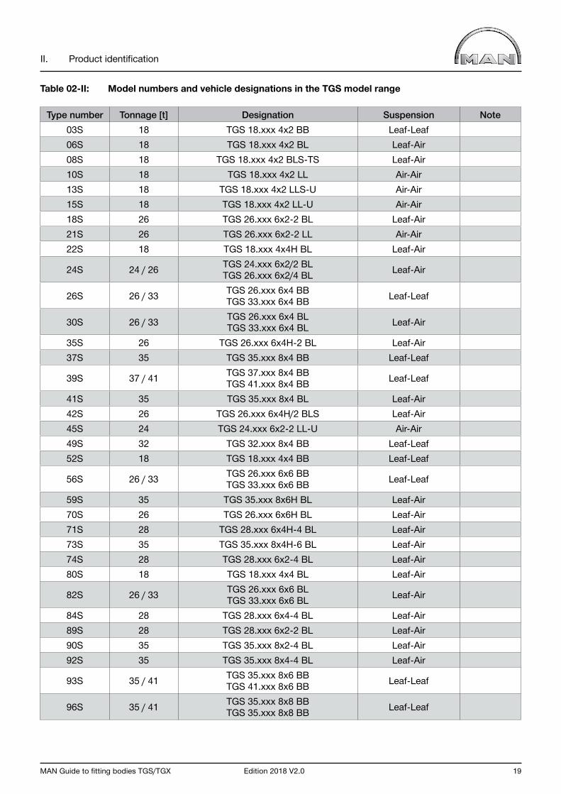
Table 02-II: Model numbers and vehicle designations in the TGS model range
Type number Tonnage [t] Designation Suspension Note03S 18 TGS 18.xxx 4x2 BB Leaf-Leaf06S 18 TGS 18.xxx 4x2 BL Leaf-Air08S 18 TGS 18.xxx 4x2 BLS-TS Leaf-Air10S 18 TGS 18.xxx 4x2 LL Air-Air13S 18 TGS 18.xxx 4x2 LLS-U Air-Air15S 18 TGS 18.xxx 4x2 LL-U Air-Air18S 26 TGS 26.xxx 6x2-2 BL Leaf-Air21S 26 TGS 26.xxx 6x2-2 LL Air-Air22S 18 TGS 18.xxx 4x4H BL Leaf-Air
24S 24 / 26 TGS 24.xxx 6x2/2 BLTGS 26.xxx 6x2/4 BL Leaf-Air
26S 26 / 33 TGS 26.xxx 6x4 BBTGS 33.xxx 6x4 BB Leaf-Leaf
30S 26 / 33 TGS 26.xxx 6x4 BLTGS 33.xxx 6x4 BL Leaf-Air
35S 26 TGS 26.xxx 6x4H-2 BL Leaf-Air37S 35 TGS 35.xxx 8x4 BB Leaf-Leaf
39S 37 / 41 TGS 37.xxx 8x4 BBTGS 41.xxx 8x4 BB Leaf-Leaf
41S 35 TGS 35.xxx 8x4 BL Leaf-Air42S 26 TGS 26.xxx 6x4H/2 BLS Leaf-Air45S 24 TGS 24.xxx 6x2-2 LL-U Air-Air49S 32 TGS 32.xxx 8x4 BB Leaf-Leaf52S 18 TGS 18.xxx 4x4 BB Leaf-Leaf
56S 26 / 33 TGS 26.xxx 6x6 BBTGS 33.xxx 6x6 BB Leaf-Leaf
59S 35 TGS 35.xxx 8x6H BL Leaf-Air70S 26 TGS 26.xxx 6x6H BL Leaf-Air71S 28 TGS 28.xxx 6x4H-4 BL Leaf-Air73S 35 TGS 35.xxx 8x4H-6 BL Leaf-Air74S 28 TGS 28.xxx 6x2-4 BL Leaf-Air80S 18 TGS 18.xxx 4x4 BL Leaf-Air
82S 26 / 33 TGS 26.xxx 6x6 BLTGS 33.xxx 6x6 BL Leaf-Air
84S 28 TGS 28.xxx 6x4-4 BL Leaf-Air89S 28 TGS 28.xxx 6x2-2 BL Leaf-Air90S 35 TGS 35.xxx 8x2-4 BL Leaf-Air92S 35 TGS 35.xxx 8x4-4 BL Leaf-Air
93S 35 / 41 TGS 35.xxx 8x6 BBTGS 41.xxx 8x6 BB Leaf-Leaf
96S 35 / 41 TGS 35.xxx 8x8 BBTGS 35.xxx 8x8 BB Leaf-Leaf
20 Edition 2018 V2.0 MAN Guide to fitting bodies TGS/TGX
II. Product identification
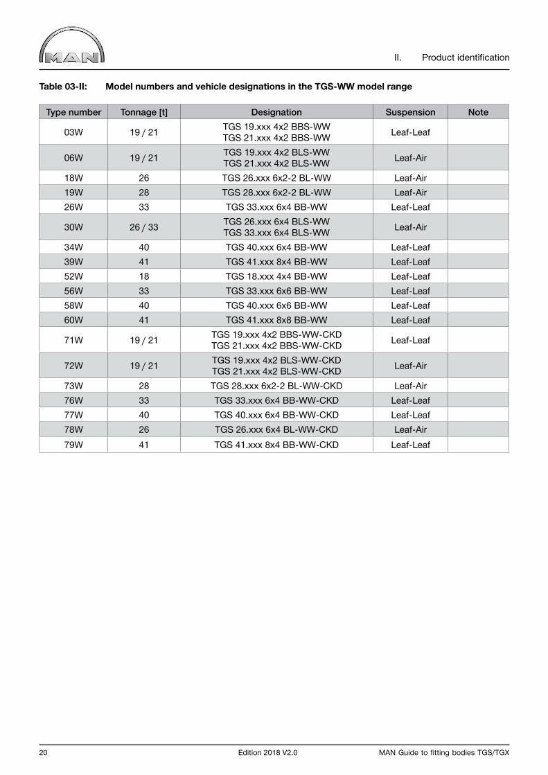
Table 03-II: Model numbers and vehicle designations in the TGS-WW model range
Type number Tonnage [t] Designation Suspension Note
03W 19 / 21 TGS 19.xxx 4x2 BBS-WWTGS 21.xxx 4x2 BBS-WW Leaf-Leaf
06W 19 / 21 TGS 19.xxx 4x2 BLS-WWTGS 21.xxx 4x2 BLS-WW Leaf-Air
18W 26 TGS 26.xxx 6x2-2 BL-WW Leaf-Air19W 28 TGS 28.xxx 6x2-2 BL-WW Leaf-Air26W 33 TGS 33.xxx 6x4 BB-WW Leaf-Leaf
30W 26 / 33 TGS 26.xxx 6x4 BLS-WWTGS 33.xxx 6x4 BLS-WW Leaf-Air
34W 40 TGS 40.xxx 6x4 BB-WW Leaf-Leaf39W 41 TGS 41.xxx 8x4 BB-WW Leaf-Leaf52W 18 TGS 18.xxx 4x4 BB-WW Leaf-Leaf56W 33 TGS 33.xxx 6x6 BB-WW Leaf-Leaf58W 40 TGS 40.xxx 6x6 BB-WW Leaf-Leaf60W 41 TGS 41.xxx 8x8 BB-WW Leaf-Leaf
71W 19 / 21 TGS 19.xxx 4x2 BBS-WW-CKDTGS 21.xxx 4x2 BBS-WW-CKD Leaf-Leaf
72W 19 / 21 TGS 19.xxx 4x2 BLS-WW-CKDTGS 21.xxx 4x2 BLS-WW-CKD Leaf-Air
73W 28 TGS 28.xxx 6x2-2 BL-WW-CKD Leaf-Air76W 33 TGS 33.xxx 6x4 BB-WW-CKD Leaf-Leaf77W 40 TGS 40.xxx 6x4 BB-WW-CKD Leaf-Leaf78W 26 TGS 26.xxx 6x4 BL-WW-CKD Leaf-Air79W 41 TGS 41.xxx 8x4 BB-WW-CKD Leaf-Leaf

MAN Guide to fitting bodies TGS/TGX Edition 2018 V2.0 21
II. Product identification
Table 04-II: Model numbers and vehicle designations in the TGX model range
Type number Tonnage [t] Designation Suspension Note05X 18 TGX 18.xxx 4x2 BLS-EL Leaf-Air06X 18 TGX 18.xxx 4x2 BL Leaf-Air10X 18 TGX 18.xxx 4x2 LL Air-Air13X 18 TGX 18.xxx 4x2 LLS-U Air-Air15X 18 TGX 18.xxx 4x2 LL-U Air-Air18X 26 TGX 26.xxx 6x2-2 BLS Leaf-Air21X 26 TGX 26.xxx 6x2-2 LL Air-Air22X 18 TGX 18.xxx 4x4H BLS Leaf-Air
24X 24 / 26TGX 24.xxx 6x2/2 BLSTGX 26.xxx 6x2/2 BLSTGX 26.xxx 6x2/4 BLS
Leaf-Air
26X 26 / 33 TGX 26.xxx 6x4 BBTGX 33.xxx 6x4 BB Leaf-Leaf
27X 28 TGX 28.xxx 6X4 BB Leaf-Leaf
28X 28 / 33 TGX 28.xxx 6x4 BBS-CKDTGX 32.xxx 6x4 BBS-CKD Leaf-Leaf
30X 26 / 33 TGX 26.xxx 6x4 BLTGX 33.xxx 6x4 BL Leaf-Air
42X 26 TGX 26.xxx 6x4H/4 BLS Leaf-Air45X 24 TGX 24.xxx 6x2-2 LL-U Air-Air78X 18 TGX 18.xxx 4x2 BLS Leaf-Air79X 33 TGX 33.xxx 6x4 BL Leaf-Air
86X 41 TGX 41.xxx 8x4/4 BBS Leaf-Leaf Leading axle is air-sprung
87X 41 TGX 41.xxx 8x4/4 BLS Leaf-Air88X 27 TGX 27.xxx 6x2-2 BBS-CKD Leaf-Leaf89X 28 TGX 28.xxx 6x2-2 BL Leaf-Air92X 35 TGX 35.xxx 8x4-4 BL Leaf-Air
94X 41 TGX 41.xxx 8x4/4 BBS Leaf-Leaf Leading axle is air-sprung
95X 41 TGX 41.xxx 8x4/4 BLS Leaf-Air
22 Edition 2018 V2.0 MAN Guide to fitting bodies TGS/TGX
II. Product identification
2.3 Tonnage class
The tonnage class corresponds to the design specification as per model-number list (see Chapter II, Section 2.2 “Model number”). It is the permissible gross weight for this vehicle model and may not be exceeded. More information on permissible gross weight can be found in Chapter III, Section 2.2.4 “Permissible gross weight”.
2.4 Power rating
The stated power ratings generally round off the engine output power to the next ten hp. Engine technical data sheets are an exception. More detailed information, for example on the exhaust-gas status (Euro standard) is not contained.
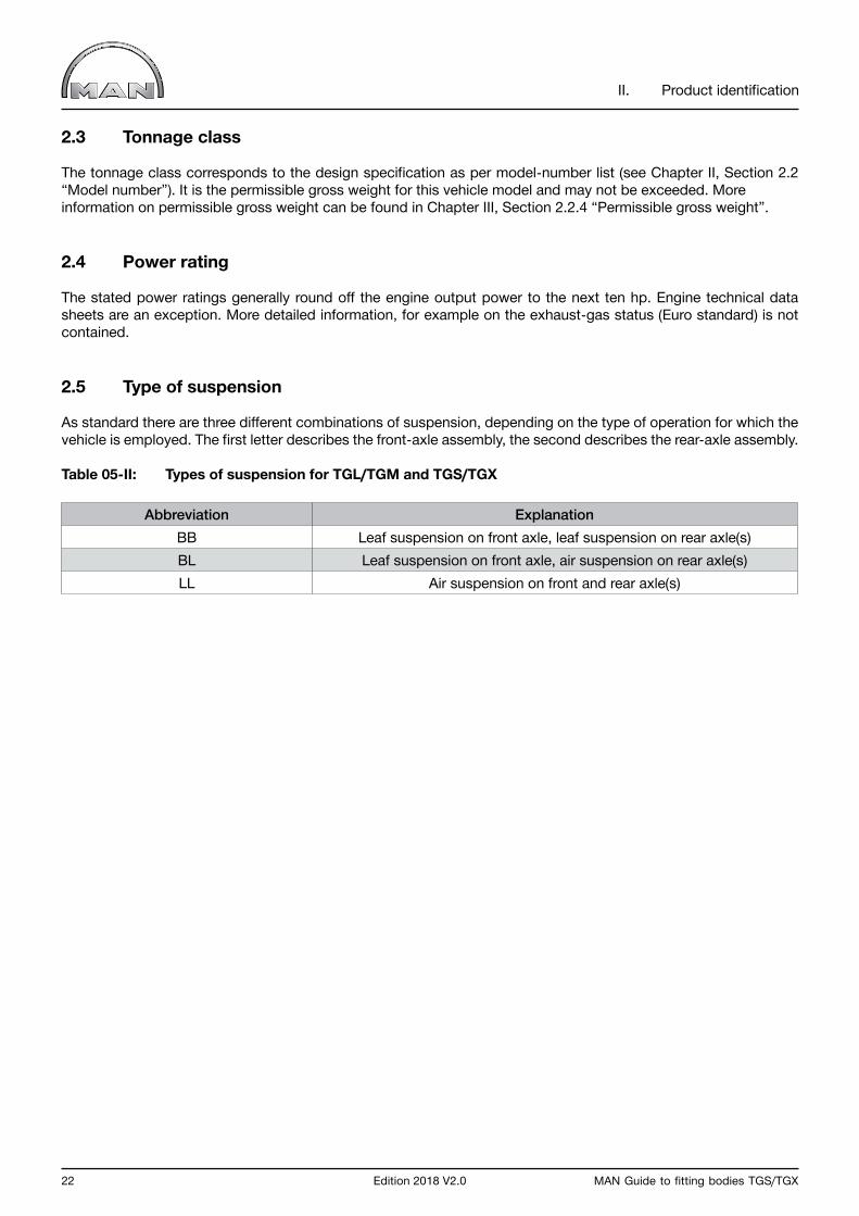
2.5 Type of suspension
As standard there are three different combinations of suspension, depending on the type of operation for which the vehicle is employed. The first letter describes the front-axle assembly, the second describes the rear-axle assembly.
Table 05-II: Types of suspension for TGL/TGM and TGS/TGX
Abbreviation ExplanationBB Leaf suspension on front axle, leaf suspension on rear axle(s)BL Leaf suspension on front axle, air suspension on rear axle(s)LL Air suspension on front and rear axle(s)
MAN Guide to fitting bodies TGS/TGX Edition 2018 V2.0 23
II. Product identification
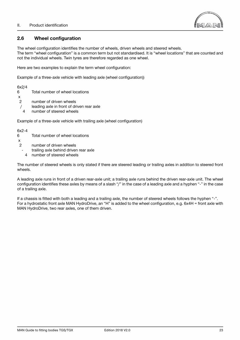
2.6 Wheel configuration
The wheel configuration identifies the number of wheels, driven wheels and steered wheels. The term “wheel configuration” is a common term but not standardised. It is “wheel locations” that are counted and not the individual wheels. Twin tyres are therefore regarded as one wheel.
Here are two examples to explain the term wheel configuration:
Example of a three-axle vehicle with leading axle (wheel configuration))
6x2/46 Total number of wheel locations x 2 number of driven wheels / leading axle in front of driven rear axle 4 number of steered wheels
Example of a three-axle vehicle with trailing axle (wheel configuration)
6x2-46 Total number of wheel locations x 2 number of driven wheels - trailing axle behind driven rear axle 4 number of steered wheels
The number of steered wheels is only stated if there are steered leading or trailing axles in addition to steered front wheels.
A leading axle runs in front of a driven rear-axle unit; a trailing axle runs behind the driven rear-axle unit. The wheel configuration identifies these axles by means of a slash “/” in the case of a leading axle and a hyphen “-” in the case of a trailing axle.
If a chassis is fitted with both a leading and a trailing axle, the number of steered wheels follows the hyphen “-”. For a hydrostatic front axle MAN HydroDrive, an “H” is added to the wheel configuration, e.g. 6x4H = front axle with MAN HydroDrive, two rear axles, one of them driven.
24 Edition 2018 V2.0 MAN Guide to fitting bodies TGS/TGX
II. Product identification
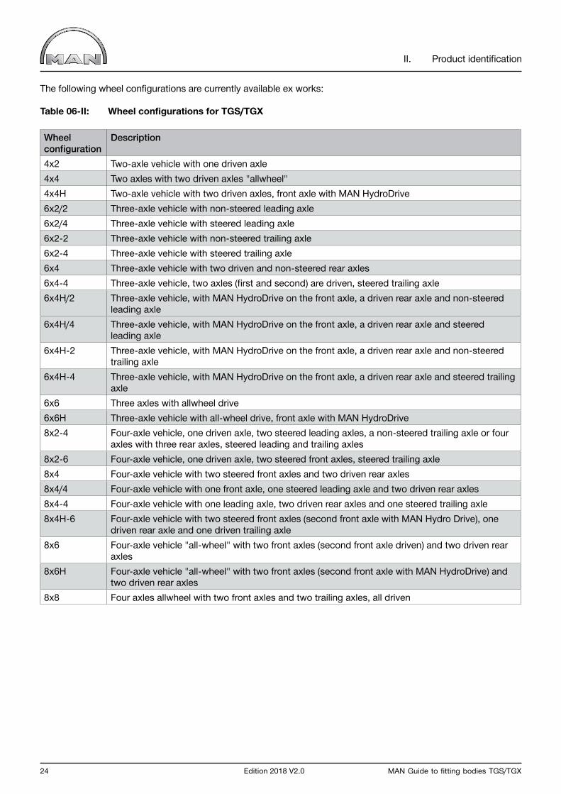
The following wheel configurations are currently available ex works:
Table 06-II: Wheel configurations for TGS/TGX
Wheel configuration
Description
4x2 Two-axle vehicle with one driven axle4x4 Two axles with two driven axles "allwheel"4x4H Two-axle vehicle with two driven axles, front axle with MAN HydroDrive6x2/2 Three-axle vehicle with non-steered leading axle6x2/4 Three-axle vehicle with steered leading axle6x2-2 Three-axle vehicle with non-steered trailing axle6x2-4 Three-axle vehicle with steered trailing axle6x4 Three-axle vehicle with two driven and non-steered rear axles6x4-4 Three-axle vehicle, two axles (first and second) are driven, steered trailing axle6x4H/2 Three-axle vehicle, with MAN HydroDrive on the front axle, a driven rear axle and non-steered
leading axle6x4H/4 Three-axle vehicle, with MAN HydroDrive on the front axle, a driven rear axle and steered
leading axle6x4H-2 Three-axle vehicle, with MAN HydroDrive on the front axle, a driven rear axle and non-steered
trailing axle6x4H-4 Three-axle vehicle, with MAN HydroDrive on the front axle, a driven rear axle and steered trailing
axle6x6 Three axles with allwheel drive6x6H Three-axle vehicle with all-wheel drive, front axle with MAN HydroDrive8x2-4 Four-axle vehicle, one driven axle, two steered leading axles, a non-steered trailing axle or four
axles with three rear axles, steered leading and trailing axles8x2-6 Four-axle vehicle, one driven axle, two steered front axles, steered trailing axle8x4 Four-axle vehicle with two steered front axles and two driven rear axles8x4/4 Four-axle vehicle with one front axle, one steered leading axle and two driven rear axles8x4-4 Four-axle vehicle with one leading axle, two driven rear axles and one steered trailing axle8x4H-6 Four-axle vehicle with two steered front axles (second front axle with MAN Hydro Drive), one
driven rear axle and one driven trailing axle8x6 Four-axle vehicle "all-wheel" with two front axles (second front axle driven) and two driven rear
axles8x6H Four-axle vehicle "all-wheel" with two front axles (second front axle with MAN HydroDrive) and
two driven rear axles8x8 Four axles allwheel with two front axles and two trailing axles, all driven
MAN Guide to fitting bodies TGS/TGX Edition 2018 V2.0 25
II. Product identification
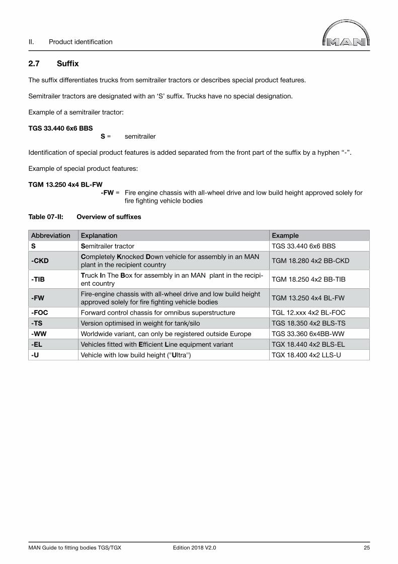
2.7 Suffix
The suffix differentiates trucks from semitrailer tractors or describes special product features.
Semitrailer tractors are designated with an ‘S’ suffix. Trucks have no special designation.
Example of a semitrailer tractor:
TGS 33.440 6x6 BBS S = semitrailer
Identification of special product features is added separated from the front part of the suffix by a hyphen “-”.
Example of special product features:
TGM 13.250 4x4 BL-FW -FW = Fire engine chassis with all-wheel drive and low build height approved solely for fire fighting vehicle bodies
Table 07-II: Overview of suffixes
Abbreviation Explanation ExampleS Semitrailer tractor TGS 33.440 6x6 BBS
-CKD Completely Knocked Down vehicle for assembly in an MAN plant in the recipient country TGM 18.280 4x2 BB-CKD
-TIB Truck In The Box for assembly in an MAN plant in the recipi-ent country TGM 18.250 4x2 BB-TIB
-FW Fire-engine chassis with all-wheel drive and low build height approved solely for fire fighting vehicle bodies TGM 13.250 4x4 BL-FW
-FOC Forward control chassis for omnibus superstructure TGL 12.xxx 4x2 BL-FOC-TS Version optimised in weight for tank/silo TGS 18.350 4x2 BLS-TS-WW Worldwide variant, can only be registered outside Europe TGS 33.360 6x4BB-WW-EL Vehicles fitted with Efficient Line equipment variant TGX 18.440 4x2 BLS-EL-U Vehicle with low build height ("Ultra") TGX 18.400 4x2 LLS-U

26 Edition 2018 V2.0 MAN Guide to fitting bodies TGS/TGX
II. Product identification
2.8 Cabs
Due to the wide range of transport tasks and uses of MAN vehicles, different cab versions are available. At MAN, there are cabs assigned to each series. The following list provides an overview.
In general, MAN offers the following cabs (not assigned here to series):
• C, M, L, DK cab - narrow cabs - e.g. for short-haul and distribution transport
• LX cab - narrow cab with high roof - e.g. for special applications and national long-haul transport
• XLX, XXL cab - wide cab - e.g. for international long-haul transport
• XL cab - wide cab - e.g. for special applications in short-haul transport - TGS/TGX cabs differ in their width

MAN Guide to fitting bodies TGS/TGX Edition 2018 V2.0 27
II. Product identification
Fig. 01-II: Cab variants
Further technical information can be found in Chapter III, Section 3.2 “Cab variants”
1620 mm 1620 mm 1620 mm
XXL
XLX
XL
LX
M
L
C
Doka / Double cab
1880 mm
2280 mm 2280 mm 2280 mm 2280 mm
2280 mm
2785 mm 2785 mm 2785 mm
2 280 mm
2 280 mm
2 280 mm2 440 mm
2280 mm 2280 mm 2280 mm
2240 mm2440 mm
2 240 mm
TGL(7,5–12 t)
TGM(12–15 t)
TGM(15–26 t)
TGS(18–41 t)
TGX(18–41 t)
TGL(17.5")
TGM(19.5")
TGM(22.5")
TGS(22.5")
TGX(22.5")
FahrerhausCab
BaureiheRange
FahrerhausCab Baureihe
Range

28 Edition 2018 V2.0 MAN Guide to fitting bodies TGS/TGX
II. Product identification
3.0 Door designationMAN’S door designation provides readily accessible information on the vehicle model with its tonnage and power output.
The door designation consists of:
• Series• Permissible gross weight• Power rating (separated from the permissible gross weight by a full stop “.”)
Table 08-II: Examples of door designations
Series Permissible gross weight [t] Power rating [hp]TGL 12 .220TGM 18 .340TGM 26 .290TGS 24 .480TGS 18 .360TGX 26 .540
4.0 Variant descriptor
The variant descriptor consists of:
• Series• Permissible gross weight• Power rating (separated from the permissible gross weight by a full stop “.”)• Wheel configuration• Suspension type• Suffix
The terms used are explained in Chapter II, Section 2.0 “Terms”.
Table 09-II: Examples of variant descriptors
Series Permissible gross weight [t] Power rating [hp] Wheel configuration
Suspension type Suffix
TGL 12 .220 4x2 BLTGM 18 .340 4x2 BB -FWTGM 26 .290 6x4 BBTGS 24 .480 6x2-2 LL -UTGS 18 .360 4x2 BL S-TSTGX 26 .540 6x2-2 LL

MAN Guide to fitting bodies TGS/TGX Edition 2018 V2.0 29
II. Product identification
5.0 Base vehicle number
The eight-character base vehicle (“GFZ”) number was introduced in order to identify and better differentiate between MAN vehicles.
The MAN base vehicle number describes an MAN vehicle (base vehicle) with certain technical features and defined standard equipment.
Table 10-II: Examples of base vehicle numbers
Digit 1 2 3 4 5 6 7 8Example L 0 6 X K G 3 1Example L 2 1 S G F 3 8Example L N 1 8 C E 0 8
L=Truck Typ number Sequential designation
The model number is an important element of the base vehicle number and occupies places 2- 4 in the base vehicle number.
More information on model numbers can be found in Chapter II, Section 2.2 “Model number”.
6.0 Vehicle identification number and vehicle production numberThe vehicle identification number and vehicle production number describe customer-specific vehicles with corresponding scopes of equipment and technical characteristics.
Vehicle identification numberThe vehicle identification number (VIN) is a 17-character internationally standardised alphanumeric string that uniquely identifies a vehicle.
Table 11-II: Example of a vehicle identification number
Digit 1 2 3 4 5 6 7 8 9 10 11 12 13 14 15 16 17Example W M A 0 6 X Z Z 9 7 K 0 0 1 4 6 4
ISO 3779
World manufacturer’s code (MAN, for
example, is WMA)
Descriptive designation (places 4-6 are the model number) Sequential designation
30 Edition 2018 V2.0 MAN Guide to fitting bodies TGS/TGX
II. Product identification
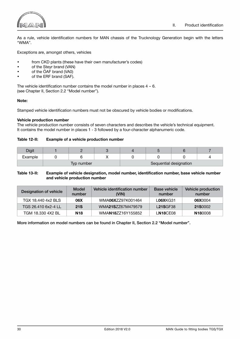
As a rule, vehicle identification numbers for MAN chassis of the Trucknology Generation begin with the letters “WMA”.
Exceptions are, amongst others, vehicles
• from CKD plants (these have their own manufacturer’s codes)• of the Steyr brand (VAN)• of the ÖAF brand (VA0)• of the ERF brand (SAF).
The vehicle identification number contains the model number in places 4 – 6. (see Chapter II, Section 2.2 “Model number”).
Note:
Stamped vehicle identification numbers must not be obscured by vehicle bodies or modifications.
Vehicle production numberThe vehicle production number consists of seven characters and describes the vehicle’s technical equipment. It contains the model number in places 1 - 3 followed by a four-character alphanumeric code.
Table 12-II: Example of a vehicle production number
Digit 1 2 3 4 5 6 7Example 0 6 X 0 0 0 4
Typ number Sequential designation
Table 13-II: Example of vehicle designation, model number, identification number, base vehicle number and vehicle production number
Designation of vehicle Model number
Vehicle identification number (VIN)
Base vehicle number
Vehicle production number
TGX 18.440 4x2 BLS 06X WMA06XZZ97K001464 L06XKG31 06X0004TGS 26.410 6x2-4 LL 21S WMA21SZZ67M479579 L21SGF38 21S0002TGM 18.330 4X2 BL N18 WMAN18ZZ16Y155852 LN18CE08 N180008
More information on model numbers can be found in Chapter II, Section 2.2 “Model number”.

MAN Guide to fitting bodies TGS/TGX Edition 2018 V2.0 31
NOTICE

32 Edition 2018 V2.0 MAN Guide to fitting bodies TGS/TGX
NOTICE

MAN Guide to fitting bodies TGS/TGX Edition 2018 V2.0 33
III. Chassis
34 Edition 2018 V2.0 MAN Guide to fitting bodies TGS/TGX
III. Chassis
1.0 GeneralTo create the product a customer expects, under certain circumstances additional components may need to be integrated, attached or modified. We recommend using MAN Genuine parts to the extent to which they are compatible with the engineering design.
1.1 Obtaining technical vehicle data
Technical vehicle data enables selection of the optimal base vehicle for the intended purpose of the vehicle.
Information on MAN vehicles and vehicle components such as
• Cabs / bumpers• Exhaust• Frame side member• Final cross member• Gearboxes / power take-off systems
can be found at www.manted.de. Registration is required.
The following can be found at MANTED:
• Dimensions• Weights• Position of center of gravity for payload and body (minimum and maximum body lengths)• Standard equipment • Drawings
InformationThe data published in MANTED refer to the series-production status of a vehicle. This may vary, depending on the technical scope of delivery. What is decisive is the actual status of the built and delivered vehicle.
National and international specifications take priority over technically admissible dimensions and weights if they restrict the technically admissible dimensions and weights.
1.2 Standards, guidelines, regulations, tolerances
Applicable standards and guidelines / directives are technical standards and must therefore be complied with. Standards are binding if they are part of rules and regulations. It cannot be assumed that all standards, regulations and guidelines/directives mentioned in the context of the chapter are complete.
Please observe notes on:
• Legal regulations• Other guidelines/directives.
All components installed in MAN vehicles comply with the respectively applicable national and European standards and directives.
MAN‘s own standards are often considerably more stringent than national and international standards. In some cases, MAN presupposes the application of its own standards for reasons of quality or safety. These are explicitly stated in the corresponding sections. MAN works standard can be obtained at www.ptd.man.eu. Registration is required.
Unless expressly stated otherwise, the general tolerances apply.

MAN Guide to fitting bodies TGS/TGX Edition 2018 V2.0 35
III. Chassis
1.3 Quality of execution
1.3.1 Corrosion protection
Surface and corrosion protection influence the service life and appearance of the chassis. The coating quality of add-on and modification parts should consequently be that of a series-production chassis. In order to ensure this requirement, MAN works standards M3297 “Corrosion-protection and coating systems for non-MAN bodies” and M3018 “Corrosion-protection and coating systems for purchased parts” are binding.
Mechanical connecting elements (e.g. screws, nuts, washers, bolts) are to be optimally protected against corrosion.
In the event of non-compliance, MAN excludes liability for the consequences.
Series production MAN chassis are coated with environmentally friendly, water-based two-component chassis top-coat paints at approx. 80°C. To guarantee uniform coating, the following coating structure is required for all metal component assemblies:
• Bare metal or blasted component surface (SA 2.5)• Priming: two-component epoxy primer, approved in accordance with MAN works standard M3162-C or, if possible, cathodic dip painting to MAN works standard M3078-2, with zinc phosphate pre-treatment.• Top coat: two-component top-coat paint to MAN works standard M3094, preferably water-based; if there are no facilities for this, then solvent-based paint is also permitted.• Refer to the data sheets of the paint manufacturer for details of curing and drying times and temperatures.
In the selection and combination of different metals (e.g. aluminium and steel), the effect of standard electrode potential for corrosion must be considered. The possible effects of the electrochemical series with regard to corrosion on the boundary surfaces (contact corrosion) must be combated by means of appropriate measures (insulation).
To prevent corrosion through salt while a vehicle is stationary during the bodybuilding phase, wash all chassis with fresh water upon arrival at the bodybuilder’s premises to remove salt residue.Further information on corrosion protection with regard to the body can be found in Chapter IV, Section 1.9.
1.3.2 Welding work on the vehicle
In general, welding work on the vehicle other than contained in these guidelines to fitting bodies or MAN repair instructions is not permissible.
Welding on components subject to design approval (e.g. connecting devices, underride guard) may only be performed by the holder of the design approval. Welding work on these components leads to the withdrawal of the design approval and may pose road safety risks!
Welding work on the chassis requires specialist knowledge. The workshop must therefore employ suitably trained and qualified personnel to carry out the required welding work (e.g. in Germany, according to the DVS leaflets 2510 – 2512 “Carrying out repair welding work on commercial vehicles”, and DVS leaflet 2518 “Weld criteria for use of fine-grain steels in commercial vehicle manufacture/repair”, available from the DVS publishing house).
Important notice Welding of a frame is only permissible using material identical to that used for the original frame (see Chapter III, Section 4.3).
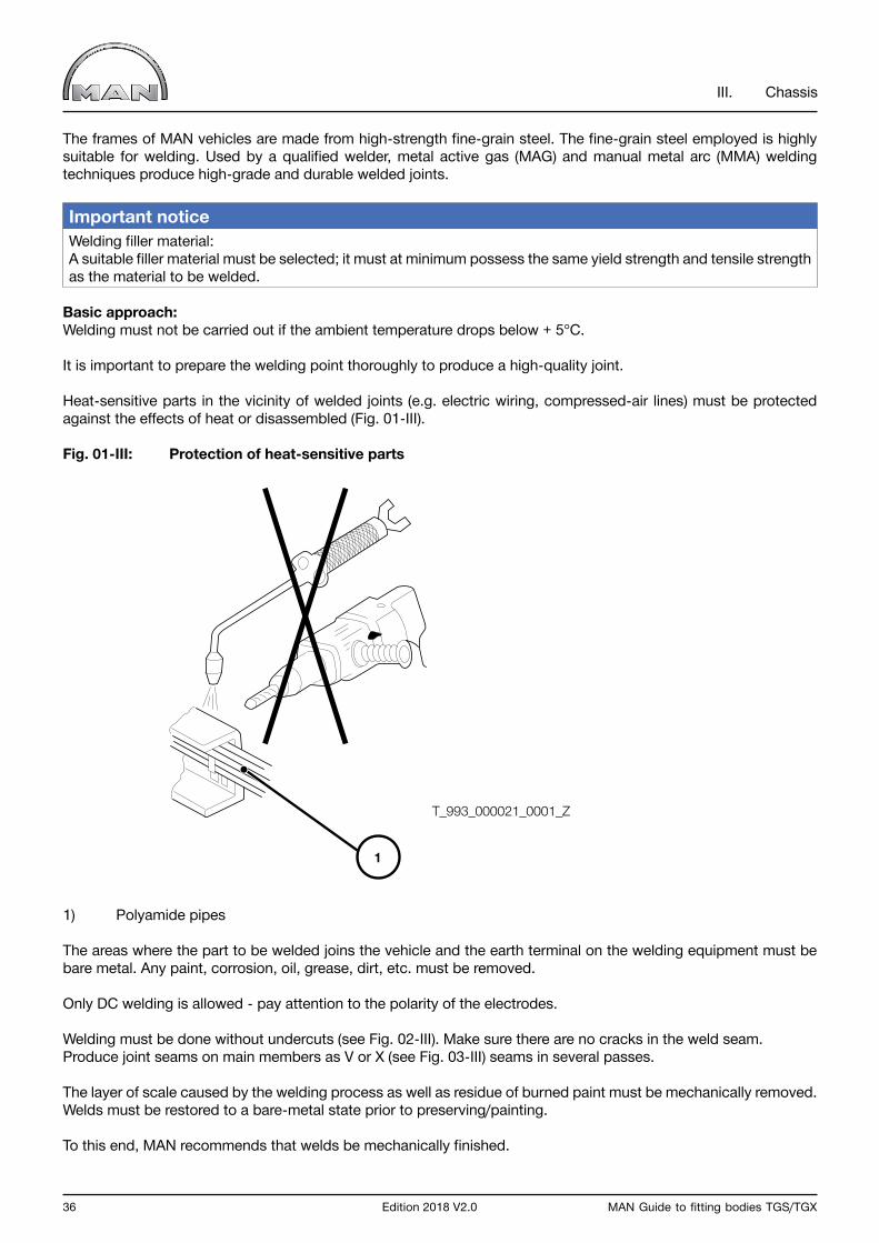
36 Edition 2018 V2.0 MAN Guide to fitting bodies TGS/TGX
III. Chassis
The frames of MAN vehicles are made from high-strength fine-grain steel. The fine-grain steel employed is highly suitable for welding. Used by a qualified welder, metal active gas (MAG) and manual metal arc (MMA) welding techniques produce high-grade and durable welded joints.
Important notice Welding filler material:A suitable filler material must be selected; it must at minimum possess the same yield strength and tensile strength as the material to be welded.
Basic approach:Welding must not be carried out if the ambient temperature drops below + 5°C.
It is important to prepare the welding point thoroughly to produce a high-quality joint.
Heat-sensitive parts in the vicinity of welded joints (e.g. electric wiring, compressed-air lines) must be protected against the effects of heat or disassembled (Fig. 01-III).
Fig. 01-III: Protection of heat-sensitive parts
1) Polyamide pipes
The areas where the part to be welded joins the vehicle and the earth terminal on the welding equipment must be bare metal. Any paint, corrosion, oil, grease, dirt, etc. must be removed.
Only DC welding is allowed - pay attention to the polarity of the electrodes.
Welding must be done without undercuts (see Fig. 02-III). Make sure there are no cracks in the weld seam. Produce joint seams on main members as V or X (see Fig. 03-III) seams in several passes.
The layer of scale caused by the welding process as well as residue of burned paint must be mechanically removed. Welds must be restored to a bare-metal state prior to preserving/painting.
To this end, MAN recommends that welds be mechanically finished.
1
T_993_000021_0001_Z

MAN Guide to fitting bodies TGS/TGX Edition 2018 V2.0 37
III. Chassis
Fig. 02-III: Undercuts
1) Weld seam2) Avoid undercuts at the locations shown
Fig. 03-III: Welding an X and Y seam
1) Weld seam with two passes2) Root pass3) Welding electrode
1
2
3
2
3
1
T_993_000023_0001_Z
T_993_000022_0001_Z
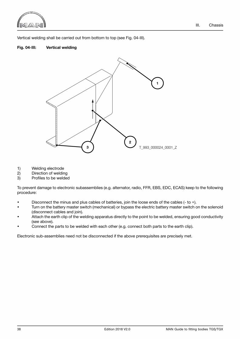
38 Edition 2018 V2.0 MAN Guide to fitting bodies TGS/TGX
III. Chassis
Vertical welding shall be carried out from bottom to top (see Fig. 04-III).
Fig. 04-III: Vertical welding
1) Welding electrode2) Direction of welding3) Profiles to be welded
To prevent damage to electronic subassemblies (e.g. alternator, radio, FFR, EBS, EDC, ECAS) keep to the following procedure:
• Disconnect the minus and plus cables of batteries, join the loose ends of the cables (- to +).• Turn on the battery master switch (mechanical) or bypass the electric battery master switch on the solenoid (disconnect cables and join).• Attach the earth clip of the welding apparatus directly to the point to be welded, ensuring good conductivity (see above).• Connect the parts to be welded with each other (e.g. connect both parts to the earth clip).
Electronic sub-assemblies need not be disconnected if the above prerequisites are precisely met.
3
1
2T_993_000024_0001_Z

MAN Guide to fitting bodies TGS/TGX Edition 2018 V2.0 39
III. Chassis
1.3.3 Drill holes, riveted and bolted connections
Connections between frame parts and frame add-ons (e.g. corner plates with cross member, thrust plates, platform corner pieces, tank brackets and so on) are realised by means of rivets or bolts during series production.
Drill holes in frame side memberThe drill holes in the frame web are to be used for connections to the frame.The hole pattern extends in parts along the entire length of the frame side member. If required, the exact hole pattern can be accessed at www.manted.de under “Frame side member”. Drill-hole and edge distances are shown in Fig. 05-III. If the existing drill holes do not enable the connection to be realised, it is possible to drill holes in the web of the side member in accordance with Fig. 05-III. Drill holes can be made (in the fame web) along the entire useful length of the frame. Drilling must not damage any of the parts located on the inner side (e.g. electric wiring, compressed-air lines). All drill holes must be deburred after drilling and the drilling swarf removed. In addition, it must be ensured that subsequently drilled holes are adequately protected against corrosion (see Chapter III, Section 1.3.1).
Fig. 05-III: Distances between drill holes
a ≥ 40 mm b ≥ 50 mm c ≥ 25 mm d ≤ 14 mm on the TGL d ≤ 16 mm on the TGM d ≤ 16 mm on the TGS/TGX
Ød
b b
b b
bb
aa
c T_993_000025_0001_Z
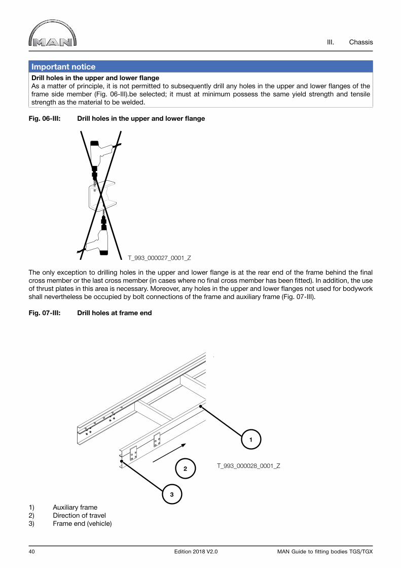
40 Edition 2018 V2.0 MAN Guide to fitting bodies TGS/TGX
III. Chassis
Important notice Drill holes in the upper and lower flangeAs a matter of principle, it is not permitted to subsequently drill any holes in the upper and lower flanges of the frame side member (Fig. 06-III).be selected; it must at minimum possess the same yield strength and tensile strength as the material to be welded.
Fig. 06-III: Drill holes in the upper and lower flange
The only exception to drilling holes in the upper and lower flange is at the rear end of the frame behind the final cross member or the last cross member (in cases where no final cross member has been fitted). In addition, the use of thrust plates in this area is necessary. Moreover, any holes in the upper and lower flanges not used for bodywork shall nevertheless be occupied by bolt connections of the frame and auxiliary frame (Fig. 07-III).
Fig. 07-III: Drill holes at frame end
1) Auxiliary frame2) Direction of travel3) Frame end (vehicle)
T_993_000027_0001_Z
1
3
2 T_993_000028_0001_Z
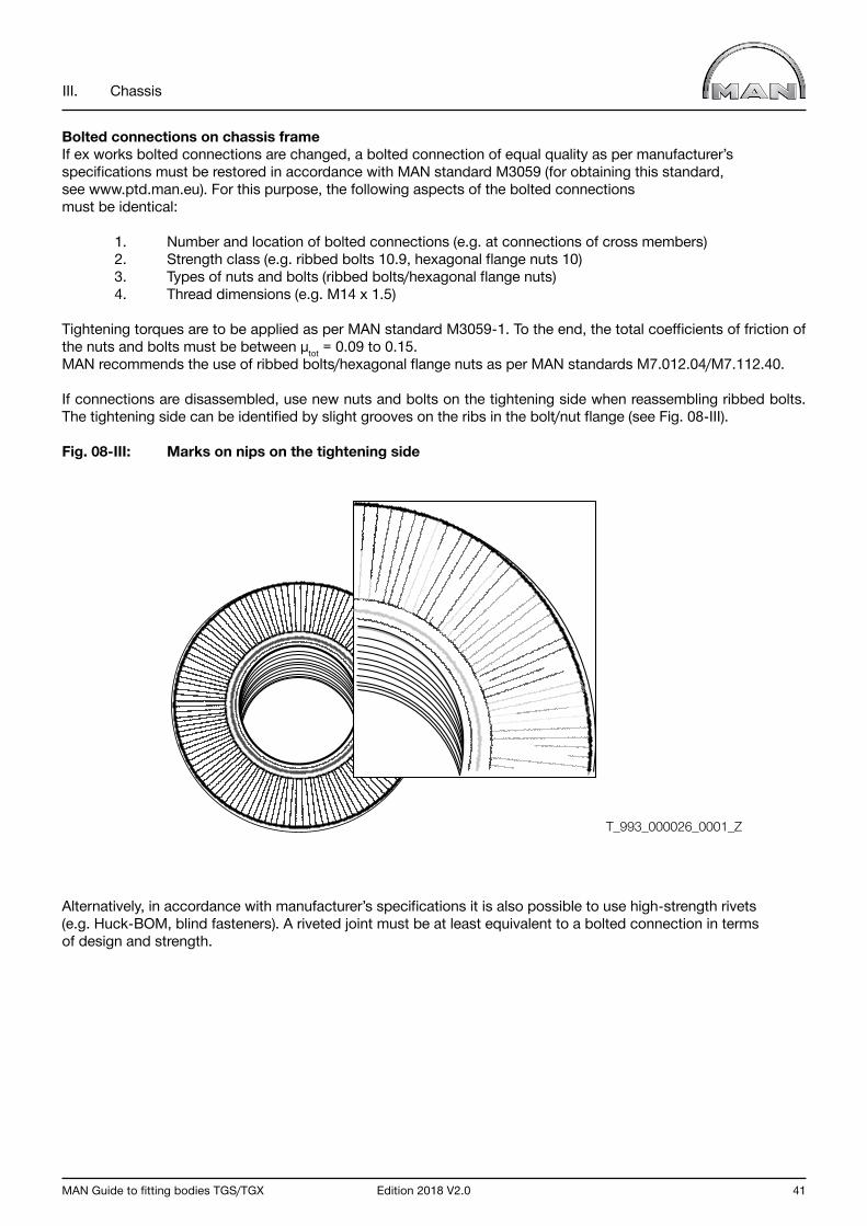
MAN Guide to fitting bodies TGS/TGX Edition 2018 V2.0 41
III. Chassis
Bolted connections on chassis frameIf ex works bolted connections are changed, a bolted connection of equal quality as per manufacturer’s specifications must be restored in accordance with MAN standard M3059 (for obtaining this standard, see www.ptd.man.eu). For this purpose, the following aspects of the bolted connections must be identical:
1. Number and location of bolted connections (e.g. at connections of cross members) 2. Strength class (e.g. ribbed bolts 10.9, hexagonal flange nuts 10) 3. Types of nuts and bolts (ribbed bolts/hexagonal flange nuts) 4. Thread dimensions (e.g. M14 x 1.5)
Tightening torques are to be applied as per MAN standard M3059-1. To the end, the total coefficients of friction of the nuts and bolts must be between µtot = 0.09 to 0.15.MAN recommends the use of ribbed bolts/hexagonal flange nuts as per MAN standards M7.012.04/M7.112.40.
If connections are disassembled, use new nuts and bolts on the tightening side when reassembling ribbed bolts. The tightening side can be identified by slight grooves on the ribs in the bolt/nut flange (see Fig. 08-III).
Fig. 08-III: Marks on nips on the tightening side
Alternatively, in accordance with manufacturer’s specifications it is also possible to use high-strength rivets (e.g. Huck-BOM, blind fasteners). A riveted joint must be at least equivalent to a bolted connection in terms of design and strength.
T_993_000026_0001_Z
42 Edition 2018 V2.0 MAN Guide to fitting bodies TGS/TGX
III. Chassis
1.4 Fire-protection measures for vehicle bodies and modifications
This chapter contains basic information as well as specific notes concerning fire-protection measures for bodies and modifications on MAN chassis.
Fires can originate from:
• vehicle bodies or modifications • falling cargo (e.g. wood chips)• the operational environment of the vehicle• the surface temperature of exhaust silencers and exhaust pipes.
1.4.1 General
An increasing variety of transport tasks and vehicle applications results in a large number of causes of fires in vehicles and cargo. It is mandatory for the body manufacturer or converter to comply with the specifications set down in MAN‘s Guideline to fitting bodies, Section I-Applicability and legal agreements -3.4 Operational and road safety.
It is mandatory for the body manufacturer or converter to initiate the fire-protection measures appropriate for the type of application/operation during conversion of the vehicle. In particular, information relevant to registration, country-specific regulations and laws must be observed.
The body manufacturer or converter must point out the corresponding fire-protection measures in the operating instructions for its body and refer the end user to the particularities thereof.
The following applies to all fire-protection measures taken by body manufacturers and converters: MAN can provide no information on the effectiveness of the measure used, responsibility lies with the company performing the modification.
1.4.2 Statutory requirements
MAN delivers chassis that are already equipped ex works in accordance with national ADR regulations. No component or system on the chassis with relevance to ADR/GGVS may be modified during work onthe body/conversion unless necessitated by the respective national regulations to be complied with.
It is mandatory for body manufacturers and converters to comply with ADR/GGVS regulations and country-specific laws and regulations.
Please see www.manted.de for further information. Registration is required.
MAN Guide to fitting bodies TGS/TGX Edition 2018 V2.0 43
III. Chassis
1.4.3 Measures in the vicinity of the engine and exhaust system
In general, modifications to the exhaust system are to be avoided. Various factory options are available for MAN chassis and body builders must check to see if these can be used on a case-by-case basis.
Temperatures of 250 – 300°C occur on the surface of the exhaust system.MAN recommends the installation of heat shields or heat-protection mats as required on parts of the vehicle/body that exhibit high temperatures.
With regard to vehicles fulfilling the EURO 6 exhaust standard, it must be noted that the diesel particulate filter (DPF) is subject to automatic regeneration cycles. The soot particles are collected and converted into CO2 in the diesel particulate filter (DPF). This process is known as regeneration. A high exhaust gas temperature is required upstream of the DPF for this purpose. Regeneration usually takes place automatically during driving operation and is not noticed.
In this regard, please note the detailed information in the vehicle‘s operating instructions.
Warning noticeFIRE RISK!
Exhaust system becomes extremely hot and requires a long time to cool down.
Combustible materials, dust and vapours can be ignited especially easily, e.g.:
• If they are lying on or adhering to the exhaust system • When refuelling, near fuel, coal, wood or grain storage facilities or similar• On grass surfaces, hay, straw, foliage or other vegetated areas.• When loading and unloading dangerous goods vehicles
Please see the further information in the vehicle operator‘s manual regarding this.
1.4.4 Measures on the air intake system
In order to avoid drawing in burning cigarette ends or similar, a so-called cigarette mesh must be fitted directly over the air intake in the same fashion as the mesh installed on production vehicles (non-flammable material, mesh size SW6, area of the open cross-section at least that of the intake air scoop on the air filter).
Warning noticeThere is a risk of vehicle fire if this requirement is not observed!
MAN can provide no information on the effectiveness of the measure used, responsibility lies with the company performing the modification.
44 Edition 2018 V2.0 MAN Guide to fitting bodies TGS/TGX
III. Chassis
1.4.5 Electric wiring/fittings
Overloading, external thermal influences, sparks produced by improper connections or loose plug connectors in the electric wiring can result in a vehicle fire.Electric wiring in the body, in particular wiring carrying heavy loads, must be adequately dimensioned and equipped with fuses appropriate for the maximum current draw.
When connecting additional electrical consumers, the electrical interfaces of the vehicle described in the Guideline to fitting bodies are to be employed.Electric wiring is to be routed in such a manner that it is protected by adequate distance from the thermal effects of heat sources such as the engine, the exhaust system and son on (see Chapter III, Section 1.4.3 „Measures in the vicinity of the engine and exhaust system“).If this is not possible, the wiring must be protected by means of suitable insulation measures such as covers, corrugated tubes/protective hoses, ducts and so on.There must be no chafing points on sharp edges, protruding threaded bolts, nuts, heads of screws and so on.
Connections between individual cables must be implemented professionally and correctly, using plug connectors. The requisite spare parts can be obtained from the MAN Spare-parts Service.
Important notice Subsequent connection to existing electric wiring by means of insulation displacement connectors or simply twisting or soldering is forbidden. Soldered connections are not permitted in movable wiring.
Any electric wiring/cable harnesses on the chassis damaged during assembly of the body must be replaced.
More detailed information can be found in Chapter III- Chassis – 8.0 Electrical/electronic system (vehicle electrical system).
MAN Guide to fitting bodies TGS/TGX Edition 2018 V2.0 45
III. Chassis
2.0 Overall vehicle
2.1 General
This chapter contains basic terms as well as specific notes concerning the modification of MAN vehicles.In particular, information relevant to registration must be observed.
2.2 Terms, dimensions and weights
The terms, dimensions and weights below are to be observed when modifying vehicles and bodywork.
InformationNational regulations take priority over technically permissible dimensions and weights if they restrict the technically permissible dimensions and weights.
2.2.1 Theoretical wheelbase
The theoretical wheelbase is a variable that assists in determining the position of the centre of gravity and the axle loads. It depends on the:
• Number of axles• Arrangement of axles• Distance between axles• Permissible loads on individual axles
The theoretical wheelbase is the distance between the theoretical front-axle centerline and the theoretical rear-axle centerline.
Theoretical axle centerlines are used as reference points in order to simplify calculations. The reference point is needed in order to group several axles at one point. The permissible axle loads of the axles to be grouped may be the same or different.
An example can be seen in Fig. 09-III, where both front axles are combined to a theoretical front-axle centerline and both rear axles to a theoretical rear-axle centerline.

46 Edition 2018 V2.0 MAN Guide to fitting bodies TGS/TGX
III. Chassis
Fig. 09-III: Theoretical wheelbase and overhang on a four-axle vehicle with two front and two rear axles (random axle-load distribution)
1) theoretical rear-axle centerline2) theoretical front-axle centerline
l12, l23, l34 distance between the respective axlesGzul1, Gzul2, Gzul3, Gzul4 permissible axle load of the respective axleslt theoretical wheelbaseUt theoretical overhang
Formulae for calculating the theoretical wheelbase in different axle configurations are described in Chapter V Section 1.13.
12
Gzul1 Gzul2 Gzul3
l23
lt Ut
l34l12
Gzul4
T_996_000012_0001_Z
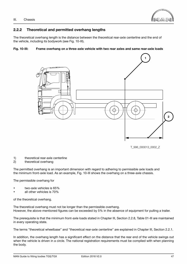
MAN Guide to fitting bodies TGS/TGX Edition 2018 V2.0 47
III. Chassis
2.2.2 Theoretical and permitted overhang lengths
The theoretical overhang length is the distance between the theoretical rear-axle centerline and the end of the vehicle, including its bodywork (see Fig. 10-III).
Fig. 10-III: Frame overhang on a three-axle vehicle with two rear axles and same rear-axle loads
1) theoretical rear-axle centerline2) theoretical overhang
The permitted overhang is an important dimension with regard to adhering to permissible axle loads and the minimum front-axle load. As an example, Fig. 10-III shows the overhang on a three-axle chassis.
The permissible overhang for
• two-axle vehicles is 65%• all other vehicles is 70%
of the theoretical overhang.
The theoretical overhang must not be longer than the permissible overhang.However, the above-mentioned figures can be exceeded by 5% in the absence of equipment for pulling a trailer.
The prerequisite is that the minimum front-axle loads stated in Chapter III, Section 2.2.8, Table 01-III are maintained in every operating state.
The terms “theoretical wheelbase” and “theoretical rear-axle centerline” are explained in Chapter III, Section 2.2.1.
In addition, the overhang length has a significant effect on the distance that the rear end of the vehicle swings out when the vehicle is driven in a circle. The national registration requirements must be complied with when planning the body.
T_996_000013_0002_Z
1
2
48 Edition 2018 V2.0 MAN Guide to fitting bodies TGS/TGX
III. Chassis
2.2.3 Permissible axle load
The permissible axle load is the total load on an axle or group of axles that may not be exceeded.
A distinction is made between
• technically permissible axle load• nationally permissible axle load.
The technically permissible load on an axle or group of axles is restricted by the characteristics, condition and design of the components of the axle(s), for example the axle itself, suspension, rims and tyres.
The nationally permissible load on an axle or group of axles depends on the laws and the criteria governing the registration of vehicles in that specific country.
Important notice Exceeding technically permissible axle loads is forbidden!
Under certain circumstances, nationally permissible axle loads may be exceeded. In this regard, the following must be observed.
• A certificate of exemption must be obtained from the national authority responsible.• A certificate of exemption can only be obtained in case where the nationally permissible axle loads are lower than the technically permissible axle loads.
2.2.4 Permissible gross weight
The permissible gross weight is the total weight of a vehicle including its load that may not be exceeded.
A distinction is made between
• technically permissible gross weight• nationally permissible gross weight.
The technically permissible gross weight is the weight that may not be exceeded, taking into account the engineering design of the vehicle‘s components (e.g. axle concept, brake system, material stress).
The nationally permissible gross weight of a vehicle depends on the laws and the criteria governing the registration of vehicles in that specific country.
Important notice Exceeding the technically permissible gross weight is forbidden!
Under certain circumstances, the nationally permissible gross weight may be exceeded. In this regard, the following must be observed.
• A certificate of exemption must be obtained from the national authority responsible.• A certificate of exemption can only be obtained in case where the nationally permissible gross weight is lower than the technically permissible gross weight.
MAN Guide to fitting bodies TGS/TGX Edition 2018 V2.0 49
III. Chassis
2.2.5 Permissible gross train weight
The permissible gross train weight is the weight of a train combination, i.e. tractor and trailer or semitrailer tractor and semitrailer (including its load) that may not be exceeded.
A distinction is made between
• technically permissible gross train weight• nationally permissible gross train weight.
The technically permissible gross train weight is the weight that may not be exceeded, taking into account the engineering design of the vehicle’s components (e.g. axle concept, brake system, material stress).
The nationally permissible gross train weight depends on the laws and the criteria governing the registration of vehicles in that specific country.
Important notice Exceeding the technically permissible gross train weight is forbidden! Under certain circumstances, the nationally permissible gross train weight may be exceeded.
In this regard, the following must be observed.
• A certificate of exemption must be obtained from the national authority responsible.• A certificate of exemption can only be obtained in case where the nationally permissible gross train weight is lower than the technically permissible gross train weight.

50 Edition 2018 V2.0 MAN Guide to fitting bodies TGS/TGX
III. Chassis
2.2.6 Axle overload
Axle overload is to be understood as the exceeding of both nationally permissible and technically permissible axle loads.
Axle overloads can result from:
• loading the vehicle in front- or back-heavy manner• overloading• incorrect design of vehicle or body.
Important notice Axle overloads must be avoided because otherwise, serious damage can occur to the vehicle and its components.
Fig. 11-III: Overload on front axle due to front-heavy loading
T_996_000019_0001_G

MAN Guide to fitting bodies TGS/TGX Edition 2018 V2.0 51
III. Chassis
2.2.7 Wheel-load difference
The wheel-load difference describes the difference in load on the left and right wheel or set of wheels of an axle or group of axles. The difference in load can cause a tilted position in relation to the road. In conjunction with a laterally shifted center of gravity, this can lead to adverse driving characteristics. Furthermore, it can also result in one-sided wear on the tyres.
Bodybuilders and operators must ensure that the wheel-load difference in all operating states (laden and unladen) is as low as possible. An uneven load distribution as a result of the body can, for example, be countered by relocating parts such as the tank, battery box and spare wheel.
If there are increased wheel-load differences, ESP (Electronic Stability Program) should be selected as alternative equipment in order to improve driving stability.
The maximum wheel-load difference must not exceed 10% of the actual (1) axle load, but 5% of the permissible (2) axle load. The smaller value is the decisive factor (see red line in Fig. 12-III).
In addition, the permissible load of the tyre and rim combination should be checked. Information concerning this can be found in the technical manuals of the tyre and rim manufacturers.
Proceed as follows to determine the maximum permissible wheel-load difference per axle or group of axles.
Step 1: calculate the limit value of the axle load = ∙ permissible axle load
Step 2: determine the applicable range: Range A ≤ limit value Range B > limit value
Step 3: calculate the permissible wheel-load difference If the actual axle load is in Range A, the formula - permissible wheel-load difference = 0.1 x actual axle load applies.
If the actual axle load is in Range B, the formula - permissible wheel-load difference = 0.05 x permissible axle load applies.
Step 4: check the permissible wheel loads
Fig. 12-III: Representation of the permissible wheel-load difference (the numerical values apply to this example; they are not universally applicable)
1) 10% of the actual axle load 2) 5% of the permissible axle load3) Limit value between Ranges A and B 4) Permissible axle load
0,05 0,1
T_354_000001_0001_D
Wheel-load difference [kg]
A B
(1)
(3) (4)
(2)
4000
200
400
8000 Actual axle load [kg]

52 Edition 2018 V2.0 MAN Guide to fitting bodies TGS/TGX
III. Chassis
Example:
Axle data: Actual weights:
• Unladen: 3000 kg; (with equal distribution 1500 kg per wheel)• Laden: 7800 kg; (with equal distribution 3900 kg per wheel)
Permissible axle load: 8000 kgTyres: 315/80R22,5 with load index 156
Step 1: calculate the limit value of the axle load
Limit value = 5 (%)⁄(10 (%) x 8000 kg = 4000 kg
Step 2: determine the applicable range
• Unladen: < limit value (3000 kg < 4000 kg) -> Range A• Laden: > limit value (7800 kg > 4000 kg) -> Range B
Step 3: calculate the permissible wheel-load difference
• Unladen: 0,1 x 3000 kg = 300 kg (± 150 kg per wheel) A load of 1350 kg is thus permitted on one side and 1650 kg on the other.• Laden: 0,05 x 8 000 kg = 400 kg (± 200 kg per wheel) A load of 4100 kg is thus permitted on one side and 3700 kg on the other.
Step 4: check the permissible wheel loads
Load index 156 means that the permissible tyre-load capacity is 4000 kg. In this example, the tyre-load capacity thus limits the possible wheel-load difference to 200 kg when laden. (± 100 kg per wheel)

MAN Guide to fitting bodies TGS/TGX Edition 2018 V2.0 53
III. Chassis
2.2.8 Minimum front-axle load
To ensure proper steering, the front axle of the vehicle, depending on model range and number of axles, must exhibit a given minimum load as per Table 01-III in all load conditions of the vehicle.
Fig. 13-III: Minimum load on front axle
T_996_000020_0001_G
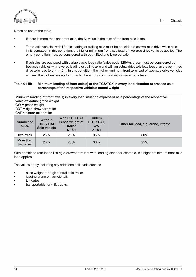
54 Edition 2018 V2.0 MAN Guide to fitting bodies TGS/TGX
III. Chassis
Notes on use of the table
• If there is more than one front axle, the %-value is the sum of the front axle loads.
• Three-axle vehicles with liftable leading or trailing axle must be considered as two-axle drive when axle lift is actuated. In this condition, the higher minimum front axle load of two-axle drive vehicles applies. The empty condition must be considered with both lifted and lowered axle.
• If vehicles are equipped with variable axle load ratio (sales code 128VA), these must be considered as two-axle vehicles with lowered leading or trailing axle and with an actual drive axle load less than the permitted drive axle load (e.g. <11.5 t). In this condition, the higher minimum front axle load of two-axle drive vehicles applies. It is not necessary to consider the empty condition with lowered axle here.
Table 01-III: Minimum loading of front axle(s) of the TGS/TGX in every load situation expressed as a percentage of the respective vehicle’s actual weight
Minimum loading of front axle(s) in every load situation expressed as a percentage of the respective vehicle’s actual gross weight GW = gross weightRDT = rigid-drawbar trailer CAT = center-axle trailer
Number of axles
Without RDT / CAT
Solo vehicle
With RDT / CATGross weight of
trailer≤ 18 t
Tridem RDT / CAT,
GW > 18 t
Other tail load, e.g. crane, liftgate
Two axles 25% 25% 35% 30%More than two axles 20% 25% 30% 25%
With combined rear loads like rigid drawbar trailers with loading crane for example, the higher minimum front-axle load applies.
The values apply including any additional tail loads such as
• nose weight through central axle trailer,• loading crane on vehicle tail,• Lift gates• transportable fork-lift trucks.
MAN Guide to fitting bodies TGS/TGX Edition 2018 V2.0 55
III. Chassis
2.2.9 Calculating the axle load and weighing procedure
It is essential that an axle load calculation be completed in order to ensure correct design of the body.The weights given in the sales documents only apply to production standard vehicles. Weight differences can be caused by optional equipment or manufacturing tolerances. Manufacturing inaccuracies (within tolerances) may occur.
Achieving optimum compatibility between bodywork and truck is only possible if the vehicle is weighed before any work on the body is commenced. The weights thus obtained are then taken as a basis for an axle load calculation.
The vehicle must be weighed subject to following conditions:
• Without the driver• With a fully filled AdBlue® tank and fully filled fuel tank• With the handbrake released and the vehicle secured with chocks• If fitted with air suspension, raise the vehicle to normal driving position• Liftable axle(s) must be raised to the normal driving position (as in loaded condition)• Do not actuate any moving-off aid.
Observe the following sequence when weighing a vehicle (leading or trailing axle relates to the rear axle):
Two-axle vehicles:
• 1st axle• 2nd axle• whole vehicle as a check
Three-axle vehicles with two rear axles:
• 1st axle• 2nd together with 3rd axle• whole vehicle as a check
Four axle vehicle with two front and two rear axles:
• 1st together with 2nd axle• 3rd together with 4th axle• whole vehicle as a check
Four-axle vehicle with one front and three rear axles:
• 1st axle• 2nd together with 3rd and 4th axles• whole vehicle as a check.
2.2.10 Rolling circumference and difference in rolling circumference
The rolling circumference is the distance a tyre covers in the course of a single revolution without slip.
Different tyre sizes on the front and rear axle(s) can only be fitted to all-wheel-drive vehicles (including HydroDrive) if the difference in rolling circumference of the tyres used does not exceed 2%.In the case of non-all-wheel-drive vehicles, the difference in rolling circumference may not exceed 10%.
The basis for calculation is always the circumference of the smaller tyre.
56 Edition 2018 V2.0 MAN Guide to fitting bodies TGS/TGX
III. Chassis
2.3 Modifications to the overall vehicle
In general, modifications to the complete vehicle should only be made in exceptional cases. It is essential to comply with all manufacturer’s specifications and to agree any modifications with MAN (for the address, see “Publisher” above). In this context, individual components cannot be regarded individually, because they are usually part of systems and functions of the complete vehicle. The cross members of the chassis frame are an example of this. Together with the frame side members, they form the support structure of the truck and affect many other functions. This means they are subject to heavy loads and may not be modified.
2.3.1 Modifications to the wheelbase
Every change of wheelbase requires manufacturer’s confirmation. It is assumed that any change to the wheelbase will only be carried out subsequent to receipt of the manufacturer’s approval.
Notes on applying for manufacturer’s confirmation can be found in Chapter I, Section 5.2.1. The conversion data file associated with changes to the wheelbase and/or frame overhang will be provided together with the confirmation.
Technical design regulations applicable to steering (in particular 70/311 EEC, ECE-R79) mean that, depending upon the number and type of steered axles, wheelbase, tyres axle loads and gross weight, chassis of MAN model ranges are fitted with different steering wheels (diameter), steering gear (range of ratios) and steering oil piping (cooling coils).
As a basic principle, it must be ensured that the new wheelbase is within the model limit. “Within the model limit” means that the new wheelbase is neither
- shorter than the shortest nor - longer than the longest standard wheelbase for the same model of vehicle.
“The same model of vehicle” means vehicles with - the same model number - the same type of vehicle and - the same wheel configuration
Important notice Any shortening or extending of wheelbases exceeding this may only be carried out by MAN or its qualified conversion suppliers (“qUL”) subsequent to consultation with MAN.
In addition, the following applies to TGS/TGX vehicles
• fitted with hydraulic forced steering of the “ZF-Servocom® RAS” (rear-axle steering) trailing axle (e.g. 6x2-4, 6x4-4 or 8x2-4): extending and shortening the wheelbase is possible. Depending on the extent to which the wheelbase from the first - Second axle has been modified, steering arms with different steering angles must be installed on the trailing axle. The steering arms to be used can be found in the confirmation.• fitted with electronic-hydraulic steering of the “ZF-Servocom RAS-EC (rear-axle steering – electronically controlled)” leading axle (e.g. all 6x2/4 and 8x4/4): shortening the wheelbase is possible, but not extending it. Modifications to the steering system, however, are not permitted.• fitted with electronic-hydraulic steering of the leading or trailing axle “EHLA®”: it is possible to extend and shorten the wheelbase. Modifications to the steering system, however, are not permitted.• fitted with two mechanically steered front axles (e.g. 8x4): steered axles may only be relocated by MAN or its qualified conversion suppliers.
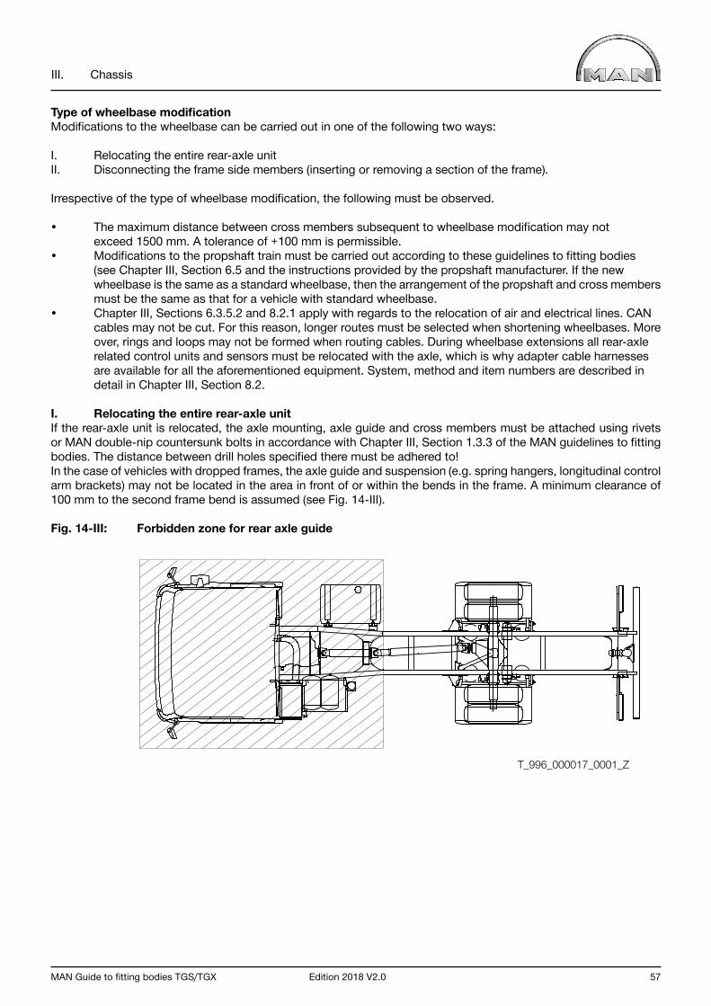
MAN Guide to fitting bodies TGS/TGX Edition 2018 V2.0 57
III. Chassis
Type of wheelbase modificationModifications to the wheelbase can be carried out in one of the following two ways:
I. Relocating the entire rear-axle unit II. Disconnecting the frame side members (inserting or removing a section of the frame).
Irrespective of the type of wheelbase modification, the following must be observed.
• The maximum distance between cross members subsequent to wheelbase modification may not exceed 1500 mm. A tolerance of +100 mm is permissible.• Modifications to the propshaft train must be carried out according to these guidelines to fitting bodies (see Chapter III, Section 6.5 and the instructions provided by the propshaft manufacturer. If the new wheelbase is the same as a standard wheelbase, then the arrangement of the propshaft and cross members must be the same as that for a vehicle with standard wheelbase.• Chapter III, Sections 6.3.5.2 and 8.2.1 apply with regards to the relocation of air and electrical lines. CAN cables may not be cut. For this reason, longer routes must be selected when shortening wheelbases. More over, rings and loops may not be formed when routing cables. During wheelbase extensions all rear-axle related control units and sensors must be relocated with the axle, which is why adapter cable harnesses are available for all the aforementioned equipment. System, method and item numbers are described in detail in Chapter III, Section 8.2.
I. Relocating the entire rear-axle unitIf the rear-axle unit is relocated, the axle mounting, axle guide and cross members must be attached using rivets or MAN double-nip countersunk bolts in accordance with Chapter III, Section 1.3.3 of the MAN guidelines to fitting bodies. The distance between drill holes specified there must be adhered to!In the case of vehicles with dropped frames, the axle guide and suspension (e.g. spring hangers, longitudinal control arm brackets) may not be located in the area in front of or within the bends in the frame. A minimum clearance of 100 mm to the second frame bend is assumed (see Fig. 14-III).
Fig. 14-III: Forbidden zone for rear axle guide
T_996_000017_0001_Z
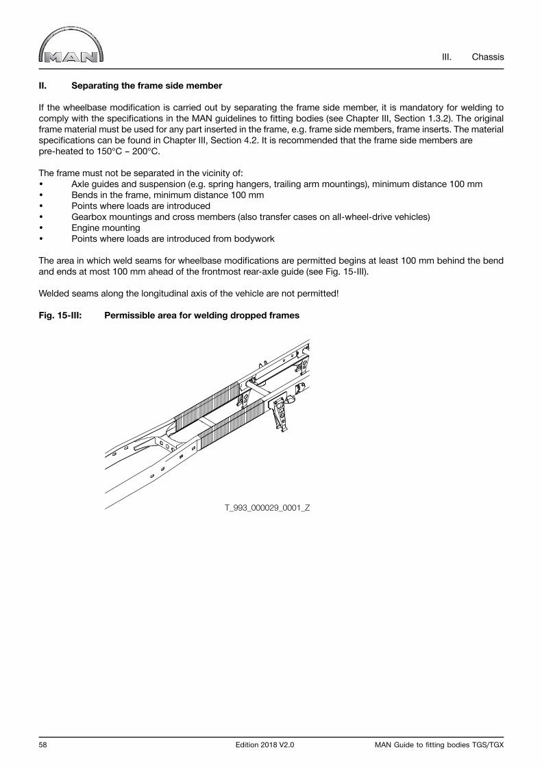
58 Edition 2018 V2.0 MAN Guide to fitting bodies TGS/TGX
III. Chassis
II. Separating the frame side member
If the wheelbase modification is carried out by separating the frame side member, it is mandatory for welding to comply with the specifications in the MAN guidelines to fitting bodies (see Chapter III, Section 1.3.2). The original frame material must be used for any part inserted in the frame, e.g. frame side members, frame inserts. The material specifications can be found in Chapter III, Section 4.2. It is recommended that the frame side members are pre-heated to 150°C – 200°C.
The frame must not be separated in the vicinity of:• Axle guides and suspension (e.g. spring hangers, trailing arm mountings), minimum distance 100 mm• Bends in the frame, minimum distance 100 mm• Points where loads are introduced• Gearbox mountings and cross members (also transfer cases on all-wheel-drive vehicles) • Engine mounting• Points where loads are introduced from bodywork
The area in which weld seams for wheelbase modifications are permitted begins at least 100 mm behind the bend and ends at most 100 mm ahead of the frontmost rear-axle guide (see Fig. 15-III).
Welded seams along the longitudinal axis of the vehicle are not permitted!
Fig. 15-III: Permissible area for welding dropped frames
T_993_000029_0001_Z
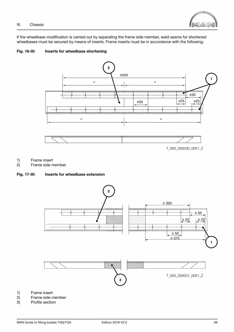
MAN Guide to fitting bodies TGS/TGX Edition 2018 V2.0 59
III. Chassis
If the wheelbase modification is carried out by separating the frame side member, weld seams for shortened wheelbases must be secured by means of inserts. Frame inserts must be in accordance with the following:
Fig. 16-III: Inserts for wheelbase shortening
1) Frame insert2) Frame side member
Fig. 17-III: Inserts for wheelbase extension
1) Frame insert2) Frame side member3) Profile section
≥ 300
≥ 50
≥ 50
≥ 25 ≥ 25
≥ 375
T_993_000031_0001_Z
1
3
2
≥550
= =
≥50
≥50≥25 ≥25
= =
T_993_000030_0001_Z
2
1

60 Edition 2018 V2.0 MAN Guide to fitting bodies TGS/TGX
III. Chassis
Location no. 1, Fig. 16-III and Fig. 17-III:
• Existing drill holes in the frame in the vicinity of the angle inserts are to be used. The following applies to the arrangement of drill holes on the frame side member: distance between holes ≥ 50 mm, edge distances ≥ 25 mm. The hole pattern can be found in the corresponding frame side member drawing.
Location number 2, Fig. 16-III and Fig. 17-III:
• Where parts are in contact, the weld seam must be levelled (no. 2 in Fig. 16-III and Fig. 17-III).
Location no. 3, Fig. 16-III and Fig. 17-III:
• Where wheelbases are extended by means of inserting a frame side member profile, the material specifications as set down in the frame-section table and the maximum permissible wheelbases as per the MAN guidelines to fitting bodies must be observed. The frame track may not be changed. If the maximum distances between frame cross members is exceeded, supplementary cross members must be inserted.
Moreover, the following notes on the dimensions of inserts must be observed.
Fig. 18-III: Inserts for wheelbase extension
Key
• Height (h) ≥ Width (a)• Width (a) is the same as the inner width of the frame (b), tolerance -5 mm.• Thickness is the same as frame thickness, tolerance -1 mm. Material min. S355J2G3 (St.52-3)• Rolled sections are not permitted.
On some long-wheelbase chassis, frame inserts are already fitted between the front and rear axles at the factory. Frame inserts may not be welded together with the frame side members. This can be avoided for example, by inserting a copper-based separating foil which is removed once the welding work is completed. Inserts used in changing the wheelbase may be simply butted-up to one another and may either be welded together or joined with an overlapping plate (see Fig. 19-III, Fig. 20-III).
A
A
h
a
b
T_993_000032_0001_Z
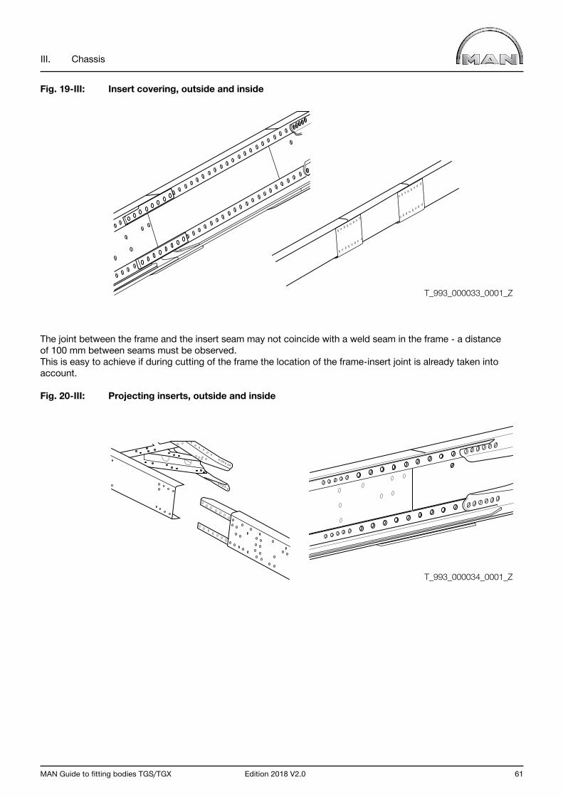
MAN Guide to fitting bodies TGS/TGX Edition 2018 V2.0 61
III. Chassis
Fig. 19-III: Insert covering, outside and inside
The joint between the frame and the insert seam may not coincide with a weld seam in the frame - a distance of 100 mm between seams must be observed.This is easy to achieve if during cutting of the frame the location of the frame-insert joint is already taken into account.
Fig. 20-III: Projecting inserts, outside and inside
T_993_000033_0001_Z
T_993_000034_0001_Z

62 Edition 2018 V2.0 MAN Guide to fitting bodies TGS/TGX
III. Chassis
2.3.2 Modifying the frame overhang
“Frame overhang modification” refers to any changes in length from the middle of the last rear axle to the frame end. As a basic principle it is possible to extend or shorten the overhang, provided the generally applicable national conditions for registration are met.
Modifications to the overhang can change the location of the center of gravity for payload and body as well as the resulting axle loads. Prior to commencing work, an axle-load calculation must be carried in order to determine whether the respective permissible axle load can be complied with (see Chapter V, Section 1.10 for an example of an axle-load calculation).
Frame overhang extensionFrame extensions are only permissible using material identical to that used for the original frame (see Chapter III, Section 4.2). Extensions must always be carried out on the frame end. Extensions consisting of several profile sections are not permitted (cf. Fig. 21-III).
Fig. 21-III: Extension of frame overhang
1) Frame extension
The specifications concerning welding on the frame (see MAN guidelines to fitting bodies, Chapter III, Section 1.3.2) must always be observed.
T_995_000023_0001_G
1

MAN Guide to fitting bodies TGS/TGX Edition 2018 V2.0 63
III. Chassis
Frame overhang extensions may not be carried out the area of the rear-axle mounting and guide or the axle suspension (e.g. the air-spring-disc, leaf-spring-bearing and stabiliser mountings). The necessary minimum distance of 100 mm must be maintained here. Cross members located in this area may not be relocated but must be left where they are.
If the distance between any two cross members to the rear of the frame overhang extension is greater than 1500 mm ± 100 mm, a supplementary cross member must be provided.
Fig. 22-III: Example of a leaf-sprung rear-axle unit with associated fastenings
1) Center of rear axle2) Axle mounting3) Fastening of axle-suspension elements (leaf spring)4) Frame side member
1 2 3 4
T_994_000001_0001_Z
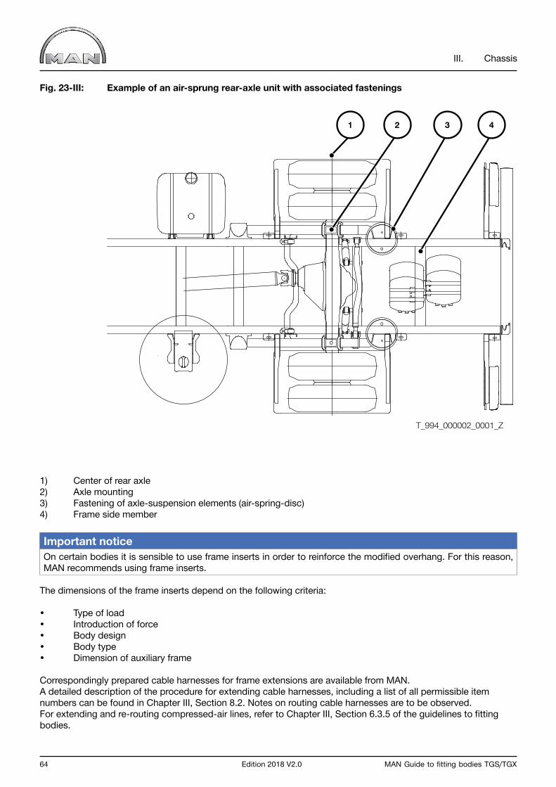
64 Edition 2018 V2.0 MAN Guide to fitting bodies TGS/TGX
III. Chassis
Fig. 23-III: Example of an air-sprung rear-axle unit with associated fastenings
1) Center of rear axle2) Axle mounting3) Fastening of axle-suspension elements (air-spring-disc)4) Frame side member
Important notice On certain bodies it is sensible to use frame inserts in order to reinforce the modified overhang. For this reason, MAN recommends using frame inserts.
The dimensions of the frame inserts depend on the following criteria:
• Type of load• Introduction of force• Body design• Body type• Dimension of auxiliary frame
Correspondingly prepared cable harnesses for frame extensions are available from MAN.A detailed description of the procedure for extending cable harnesses, including a list of all permissible item numbers can be found in Chapter III, Section 8.2. Notes on routing cable harnesses are to be observed.For extending and re-routing compressed-air lines, refer to Chapter III, Section 6.3.5 of the guidelines to fitting bodies.
1 2 3 4
T_994_000002_0001_Z
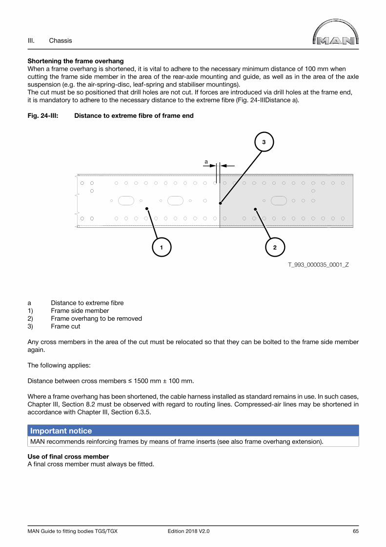
MAN Guide to fitting bodies TGS/TGX Edition 2018 V2.0 65
III. Chassis
Shortening the frame overhangWhen a frame overhang is shortened, it is vital to adhere to the necessary minimum distance of 100 mm when cutting the frame side member in the area of the rear-axle mounting and guide, as well as in the area of the axle suspension (e.g. the air-spring-disc, leaf-spring and stabiliser mountings).The cut must be so positioned that drill holes are not cut. If forces are introduced via drill holes at the frame end, it is mandatory to adhere to the necessary distance to the extreme fibre (Fig. 24-IIIDistance a).
Fig. 24-III: Distance to extreme fibre of frame end
a Distance to extreme fibre1) Frame side member2) Frame overhang to be removed3) Frame cut
Any cross members in the area of the cut must be relocated so that they can be bolted to the frame side member again.
The following applies:
Distance between cross members ≤ 1500 mm ± 100 mm.
Where a frame overhang has been shortened, the cable harness installed as standard remains in use. In such cases, Chapter III, Section 8.2 must be observed with regard to routing lines. Compressed-air lines may be shortened in accordance with Chapter III, Section 6.3.5.
Important notice MAN recommends reinforcing frames by means of frame inserts (see also frame overhang extension).
Use of final cross memberA final cross member must always be fitted.
T_993_000035_0001_Z
a
3
21
66 Edition 2018 V2.0 MAN Guide to fitting bodies TGS/TGX
III. Chassis
2.3.3 Modifying the wheel configuration
Modifying the wheel configuration means:
• fitting of additional axles,• removal of axles,• Converting non-steered axles to steered axles• Converting steered axles to non-steered axles
Important notice Modifying the wheel configuration is forbidden. These conversions are carried out exclusively by MAN and its qualified conversion suppliers (“qUL”). Manufacturer’s confirmation is necessary in every case.
2.3.4 Changing the tyre type
Every change of tyre type requires manufacturer’s confirmation. Notes on applying for manufacturer’s confirmation can be found in Chapter I, Section 5.2.
The conversion data file associated with changes to the tyre type will, if required, be provided together with the confirmation.
Technical limit values with regard to changing the tyre type can be found in Chapter I, Section 2.2.10.
The notes in Chapter IV “Body” relating to anti-skid chains, clearance and the load ratings of tyres and rims must be observed.
2.3.5 Changing the vehicle type and interchangeable operation as semitrailer tractor/truck
Conversion of a truck into a semitrailer tractor or of a semitrailer tractor into a truck or using the same vehicle alternatively as a semitrailer tractor or truck requires manufacturer’s confirmation from MAN.
Notes on applying for manufacturer’s confirmation can be found in Chapter I, Section 5.2 “Manufacturer’s confirmation”.
Conversion of a semitrailer tractor to a truck or vice versa requires modification of the vehicle’s parameterisation. The conversion data file associated with the chassis modification will be provided together with the confirmation.
Depending on the selected vehicle (vehicle model), the change of vehicle type as well as interchangeable operation may possibly require conversion measures to be taken in the area of the axle guide (e.g. springs, shock absorbers, stabilisers) and the brakes.
The scope of such conversion measure depends on the selected vehicle model and the desired utilisation.
Therefore, in the case of new-build vehicles to be used as both semitrailer tractors and trucks, it must be determined beforehand whether a truck chassis or a semitrailer tractor is to be used.
One exception in the TGS and TGX model ranges is the vehicle transporter: please refer to Chapter IV, Section 3.13 “Vehicle transporters”.
Operation of the following vehicle models (model numbers) as combined semitrailer tractors/trucks or conversions to trucks are not permitted. 05X, 08S, 13S, 13X.

MAN Guide to fitting bodies TGS/TGX Edition 2018 V2.0 67
III. Chassis
2.3.6 Retrofitting additional units, attachments and accessories
If units, attachments or accessories are to be retrofitted to the vehicle, they must be harmonised with MAN when the measures are in the planning phase (for address see “Publisher” above).Full and verifiable documentation enabling a decision to be taken on the feasibility of the planned measures must be submitted.
The background to this is that retrofitting usually involves intervention in the control unit’s CAN. This also involves additions to the programming of a vehicle’s software. Retrofitted systems may under certain circumstances not be assimilated into the vehicle’s own Trucknology® “Time maintenance system” or “Flexible maintenance system”. For this reason, in the case of retrofitted original parts, the same maintenance convenience will not necessarily result as in a first-time configuration.
Subsequent modification or expansion of the vehicle parameterisation can only be carried out with the help of the MAN Service outlet responsible and MAN approval of the programs.
Warning noticeUnder no circumstances does MAN accept design responsibility or responsibility for the consequences of retrofits that it has not approved. The stipulations stated in these guidelines and in approvals must be adhered to. Approvals, reports and certification produced by third parties (e.g. test institutes) do not automatically mean the issue of approval by MAN.
MAN may refuse approval even though third parties have issued appropriate clearance. Unless otherwise agreed, approval only refers to the actual installation of the equipment. Approval does not mean that MAN has checked the entire system with regard to strength, vehicle handling etc., and has accepted responsibility for warranty of products. This responsibility is borne by the executing company. The retrofitting of subassemblies and the like can alter the technical data of a vehicle. The respective equipment manufacturer and/or the dealer/importer is responsible for determining and issuing this new data.

68 Edition 2018 V2.0 MAN Guide to fitting bodies TGS/TGX
III. Chassis
2.4 Homologated vehicle components / vehicle components relevant to safety
This section provides an overview of the most important homologated components of the vehicle and/or components of the vehicle relevant to safety. They may not be changed without permission from MAN (for address see “Publisher” above).
If any changes are made, the affected parts must be accepted again by a technical inspectorate. The MAN warranty, however, is invalidated.
To be admissible for registration, vehicles must be configured in such a manner that they comply with the respective country-specific laws. In order to ensure this in series production, parts relevant to registration are homologated. Because of this, individual acceptances are no longer necessary.
Some of these components are listed below.
• Exhaust silencer• Axles and running gear• ADR components• Trailer bracket and coupling• Driveline and wheels• Brake system• Electrical components• Cab• Front cross member• Camera system• Fuel tank with mounting, hose and pump• Steering system• Lighting equipment• Air intake• Engine with engine attachments• Register coupling• Fifth-wheel coupling• Final cross member for trailer coupling• Underride protection, rear and side• Adjuster mechanism
Further information concerning the homologation or relevance to safety of parts not listed above can be requested from MAN (for address see “Publisher” above).
MAN Guide to fitting bodies TGS/TGX Edition 2018 V2.0 69
III. Chassis
3.0 Cab
3.1 General
Modifications to the cab’s structure (e.g. incisions/cut-outs, changes to the support structure including the seats and seat fastenings, cab extensions, lowering of the roof) as well as modifications to the cab mountings and tilting mechanism are to be avoided wherever possible.
Warning noticeIf modifications to the cab are nevertheless necessary for technical reasons relevant to the body, they must be harmonised with MAN during the planning phase (for address see “Publisher” above).
Modifications to the cab may only be carried out by MAN or its qualified conversion suppliers (“qUL”).
The generally applicable national conditions for registration must be met in every case.
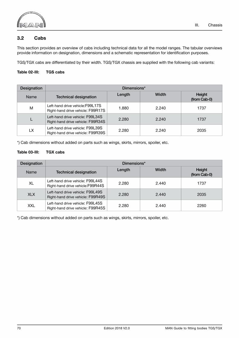
70 Edition 2018 V2.0 MAN Guide to fitting bodies TGS/TGX
III. Chassis
3.2 Cabs
This section provides an overview of cabs including technical data for all the model ranges. The tabular overviews provide information on designation, dimensions and a schematic representation for identification purposes.
TGS/TGX cabs are differentiated by their width. TGS/TGX chassis are supplied with the following cab variants:
Table 02-III: TGS cabs
Designation Dimensions*
Name Technical designation Length Width Height(from Cab-0)
M Left-hand drive vehicle:F99L17SRight-hand drive vehicle: F99R17S 1.880 2.240 1737
L Left-hand drive vehicle: F99L34SRight-hand drive vehicle: F99R34S 2.280 2.240 1737
LX Left-hand drive vehicle: F99L39SRight-hand drive vehicle: F99R39S 2.280 2.240 2035
*) Cab dimensions without added on parts such as wings, skirts, mirrors, spoiler, etc.
Table 03-III: TGX cabs
Designation Dimensions*
Name Technical designation Length Width Height(from Cab-0)
XL Left-hand drive vehicle: F99L44SRight-hand drive vehicle:F99R44S 2.280 2.440 1737
XLX Left-hand drive vehicle: F99L49SRight-hand drive vehicle: F99R49S 2.280 2.440 2035
XXL Left-hand drive vehicle: F99L45SRight-hand drive vehicle: F99R45S 2.280 2.440 2260
*) Cab dimensions without added on parts such as wings, skirts, mirrors, spoiler, etc.
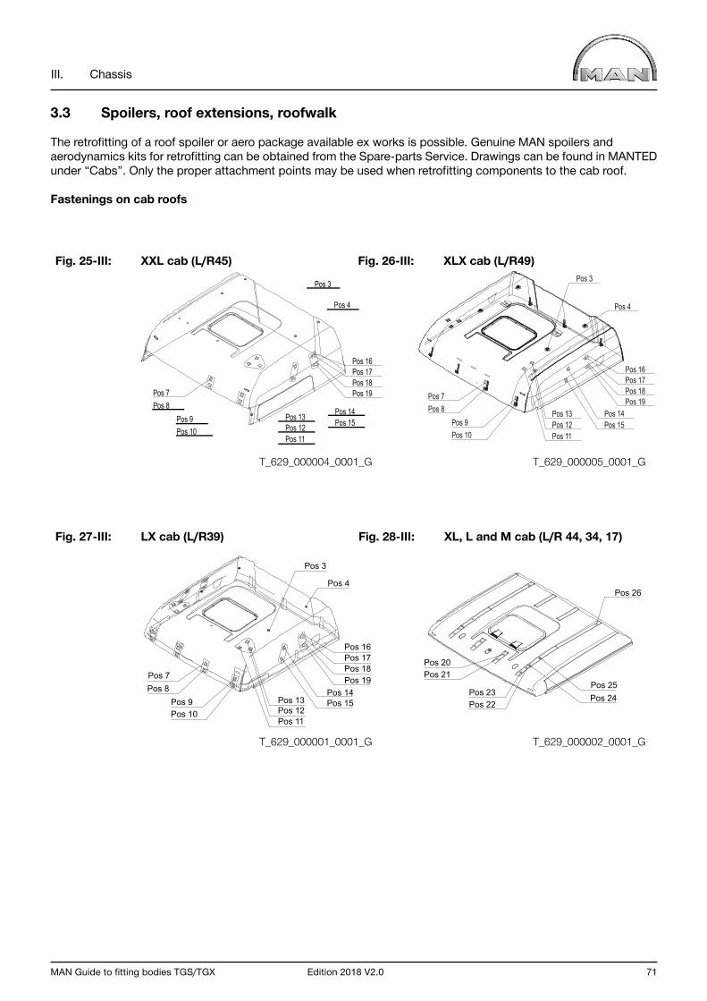
MAN Guide to fitting bodies TGS/TGX Edition 2018 V2.0 71
III. Chassis
3.3 Spoilers, roof extensions, roofwalk
The retrofitting of a roof spoiler or aero package available ex works is possible. Genuine MAN spoilers and aerodynamics kits for retrofitting can be obtained from the Spare-parts Service. Drawings can be found in MANTED under “Cabs”. Only the proper attachment points may be used when retrofitting components to the cab roof.
Fastenings on cab roofs
Fig. 25-III: XXL cab (L/R45) Fig. 26-III: XLX cab (L/R49)
Fig. 27-III: LX cab (L/R39) Fig. 28-III: XL, L and M cab (L/R 44, 34, 17)
Pos 3
Pos 7Pos 8
Pos 9Pos 10
Pos 13
Pos 16
Pos 14Pos 15
Pos 17Pos 18Pos 19
Pos 12Pos 11
Pos 4Pos 26
Pos 25Pos 24Pos 23
Pos 22
Pos 20Pos 21
Pos 11
Pos 13Pos 12 Pos 15
Pos 14
Pos 3
Pos 4
Pos 16Pos 17Pos 18Pos 19Pos 7
Pos 8Pos 9Pos 10
Pos 7Pos 8
Pos 9Pos 10 Pos 11
Pos 12Pos 13 Pos 14
Pos 15
Pos 16Pos 17Pos 18Pos 19
Pos 4
Pos 3
T_629_000004_0001_G
T_629_000001_0001_G
T_629_000005_0001_G
T_629_000002_0001_G
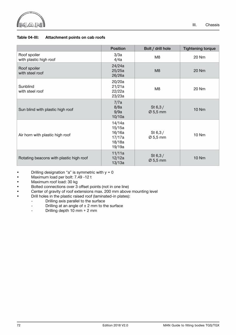
72 Edition 2018 V2.0 MAN Guide to fitting bodies TGS/TGX
III. Chassis
Table 04-III: Attachment points on cab roofs
Position Bolt / drill hole Tightening torqueRoof spoilerwith plastic high roof
3/3a4/4a M8 20 Nm
Roof spoilerwith steel roof
24/24a25/25a26/26a
M8 20 Nm
Sunblindwith steel roof
20/20a21/21a22/22a23/23a
M8 20 Nm
Sun blind with plastic high roof
7/7a8/8a9/9a
10/10a
St 6,3 /Ø 5,5 mm 10 Nm
Air horn with plastic high roof
14/14a15/15a16/16a17/17a18/18a19/19a
St 6,3 /Ø 5,5 mm 10 Nm
Rotating beacons with plastic high roof11/11a12/12a13/13a
St 6,3 /Ø 5,5 mm 10 Nm
• Drilling designation “a” is symmetric with y = 0• Maximum load per bolt: 7.49 -12 t• Maximum roof load: 30 kg• Bolted connections over 3 offset points (not in one line)• Center of gravity of roof extensions max. 200 mm above mounting level• Drill holes in the plastic raised roof (laminated-in plates): - Drilling axis parallel to the surface - Drilling at an angle of ± 2 mm to the surface - Drilling depth 10 mm + 2 mm
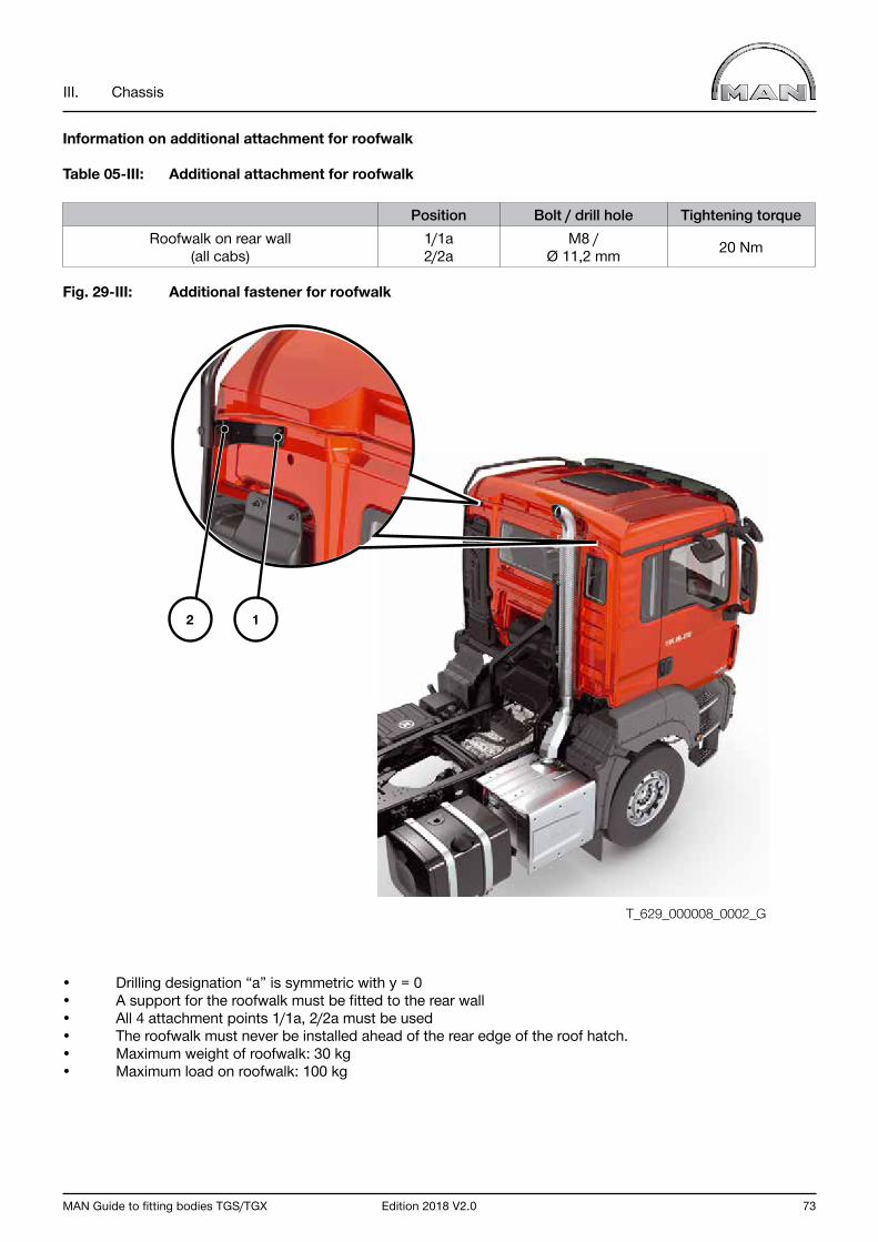
MAN Guide to fitting bodies TGS/TGX Edition 2018 V2.0 73
III. Chassis
Information on additional attachment for roofwalk
Table 05-III: Additional attachment for roofwalk
Position Bolt / drill hole Tightening torqueRoofwalk on rear wall
(all cabs)1/1a2/2a
M8 /Ø 11,2 mm 20 Nm
Fig. 29-III: Additional fastener for roofwalk
• Drilling designation “a” is symmetric with y = 0• A support for the roofwalk must be fitted to the rear wall• All 4 attachment points 1/1a, 2/2a must be used• The roofwalk must never be installed ahead of the rear edge of the roof hatch.• Maximum weight of roofwalk: 30 kg• Maximum load on roofwalk: 100 kg
T_629_000008_0002_G
2 1
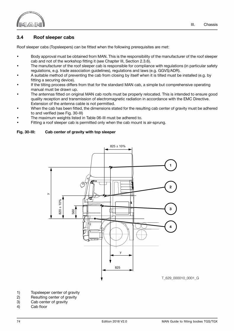
74 Edition 2018 V2.0 MAN Guide to fitting bodies TGS/TGX
III. Chassis
3.4 Roof sleeper cabs
Roof sleeper cabs (Topsleepers) can be fitted when the following prerequisites are met:
• Body approval must be obtained from MAN. This is the responsibility of the manufacturer of the roof sleeper cab and not of the workshop fitting it (see Chapter III, Section 2.3.6).• The manufacturer of the roof sleeper cab is responsible for compliance with regulations (in particular safety regulations, e.g. trade association guidelines), regulations and laws (e.g. GGVS/ADR).• A suitable method of preventing the cab from closing by itself when it is tilted must be installed (e.g. by fitting a securing device).• If the tilting process differs from that for the standard MAN cab, a simple but comprehensive operating manual must be drawn up.• The antennas fitted on original MAN cab roofs must be properly relocated. This is intended to ensure good quality reception and transmission of electromagnetic radiation in accordance with the EMC Directive. Extension of the antenna cable is not permitted.• When the cab has been fitted, the dimensions stated for the resulting cab center of gravity must be adhered to and verified (see Fig. 30-III)• The maximum weights listed in Table 06-III must be adhered to.• Fitting a roof sleeper cab is permitted only when the cab mount is air-sprung.
Fig. 30-III: Cab center of gravity with top sleeper
1) Topsleeper center of gravity2) Resulting center of gravity3) Cab center of gravity4) Cab floor
y
825
825 ± 10%
820
± 10
%
560
y
1
2
3
4
T_629_000010_0001_G
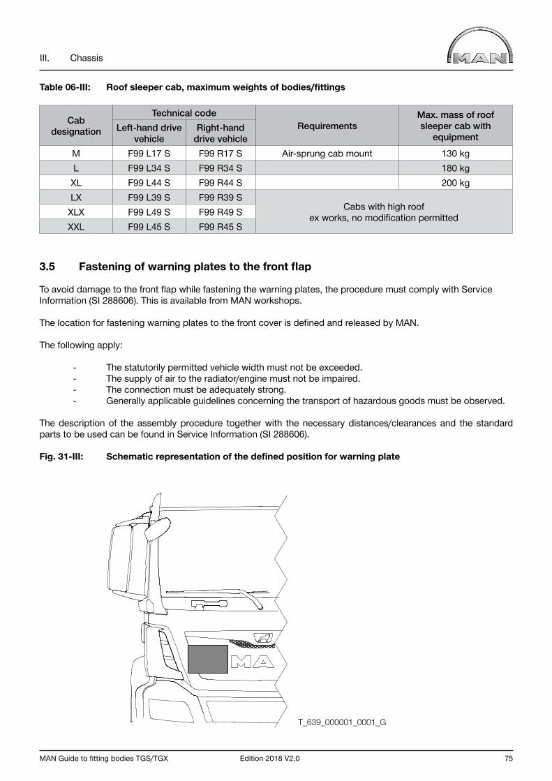
MAN Guide to fitting bodies TGS/TGX Edition 2018 V2.0 75
III. Chassis
Table 06-III: Roof sleeper cab, maximum weights of bodies/fittings
Cab designation
Technical codeRequirements
Max. mass of roof sleeper cab with
equipmentLeft-hand drive
vehicleRight-hand
drive vehicleM F99 L17 S F99 R17 S Air-sprung cab mount 130 kgL F99 L34 S F99 R34 S 180 kg
XL F99 L44 S F99 R44 S 200 kgLX F99 L39 S F99 R39 S
Cabs with high roof ex works, no modification permittedXLX F99 L49 S F99 R49 S
XXL F99 L45 S F99 R45 S
3.5 Fastening of warning plates to the front flap
To avoid damage to the front flap while fastening the warning plates, the procedure must comply with Service Information (SI 288606). This is available from MAN workshops.
The location for fastening warning plates to the front cover is defined and released by MAN.
The following apply:
- The statutorily permitted vehicle width must not be exceeded. - The supply of air to the radiator/engine must not be impaired. - The connection must be adequately strong. - Generally applicable guidelines concerning the transport of hazardous goods must be observed.
The description of the assembly procedure together with the necessary distances/clearances and the standard parts to be used can be found in Service Information (SI 288606).
Fig. 31-III: Schematic representation of the defined position for warning plate
T_639_000001_0001_G

76 Edition 2018 V2.0 MAN Guide to fitting bodies TGS/TGX
III. Chassis
4.0 Chassis frame
4.1 General
The frame forms the basis of the chassis. It accommodates the axles, the driveline with engine, gearbox and transfer case and carries the cab and bodywork. Modifications to the chassis frame must be carried out in accordance with the specifications set down in Chapter III, Section 2.3.
4.2 Frame materials
Modifications to the frame side members and cross members of the chassis are permitted only when the original frame material is used.
Table 07-III: Steel materials for MAN chassis frames
Material no. Old material designation
Old standard
σ0,2 N/mm2
σB N/mm2
New material designation New standard Profile
nos.
1.0980 QStE420TM SEW 092 ≥ 420 480-620 S420MC DIN EN 10149-25, 33, 35, 36, 37, 38, 39, 41, 42
1.0984 QStE500TM SEW 092 ≥ 500 550-700 S500MC DIN EN 10149-2 31, 32, 34, 40, 46
500 560-700 LNE500 NBR 6656:2008 43, 45
The assignment of model-range-specific frame profiles (profile numbers), their material parameters and the model-related allocation of frame profiles can be found in Chapter III, Section 4.3.
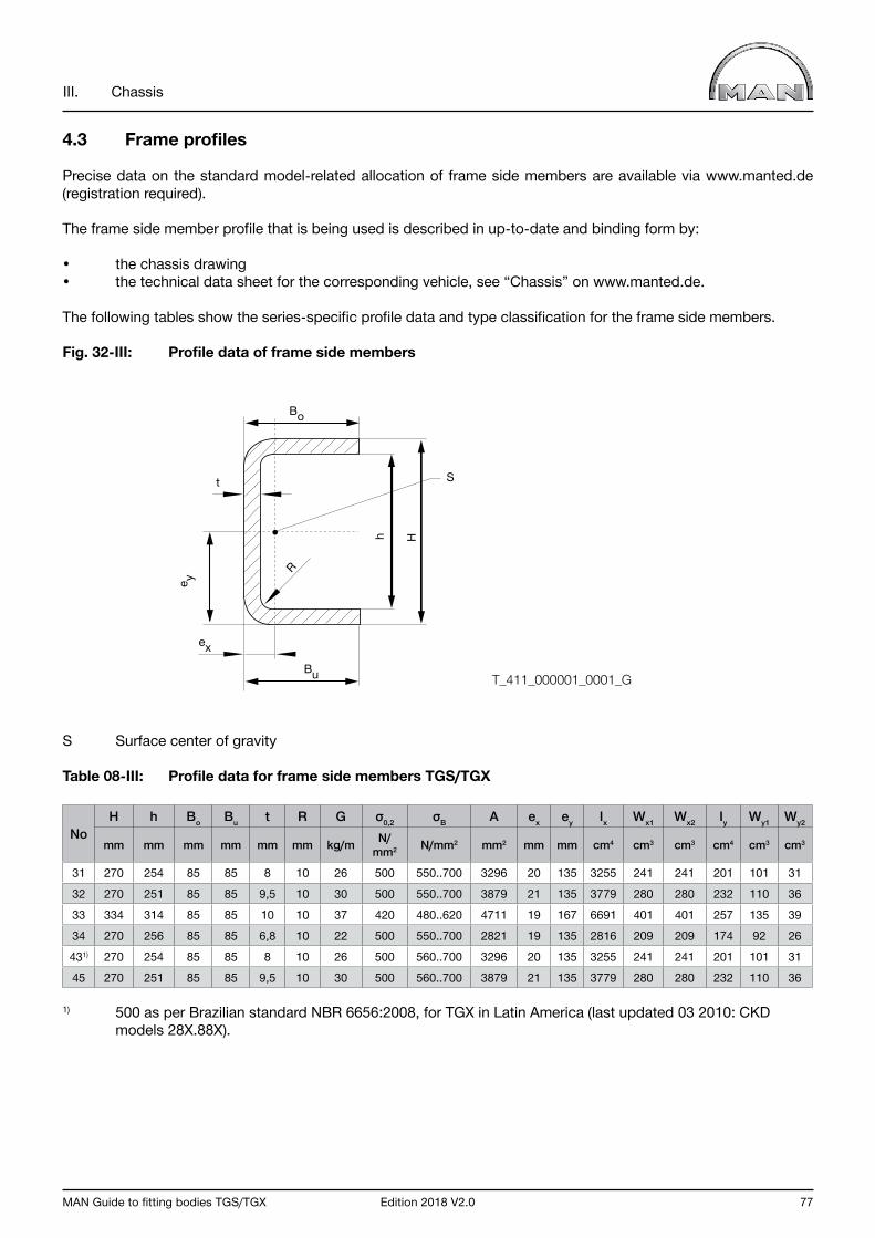
MAN Guide to fitting bodies TGS/TGX Edition 2018 V2.0 77
III. Chassis
4.3 Frame profiles
Precise data on the standard model-related allocation of frame side members are available via www.manted.de (registration required).
The frame side member profile that is being used is described in up-to-date and binding form by:
• the chassis drawing• the technical data sheet for the corresponding vehicle, see “Chassis” on www.manted.de.
The following tables show the series-specific profile data and type classification for the frame side members.
Fig. 32-III: Profile data of frame side members
S Surface center of gravity
Table 08-III: Profile data for frame side members TGS/TGX
NoH h Bo Bu t R G σ0,2 σB A ex ey Ix Wx1 Wx2 Iy Wy1 Wy2
mm mm mm mm mm mm kg/m N/mm2 N/mm2 mm2 mm mm cm4 cm3 cm3 cm4 cm3 cm3
31 270 254 85 85 8 10 26 500 550..700 3296 20 135 3255 241 241 201 101 3132 270 251 85 85 9,5 10 30 500 550..700 3879 21 135 3779 280 280 232 110 3633 334 314 85 85 10 10 37 420 480..620 4711 19 167 6691 401 401 257 135 3934 270 256 85 85 6,8 10 22 500 550..700 2821 19 135 2816 209 209 174 92 26431) 270 254 85 85 8 10 26 500 560..700 3296 20 135 3255 241 241 201 101 3145 270 251 85 85 9,5 10 30 500 560..700 3879 21 135 3779 280 280 232 110 36
1) 500 as per Brazilian standard NBR 6656:2008, for TGX in Latin America (last updated 03 2010: CKD models 28X.88X).
Bo
Bu
ex
h H
R
t
e y
S
T_411_000001_0001_G
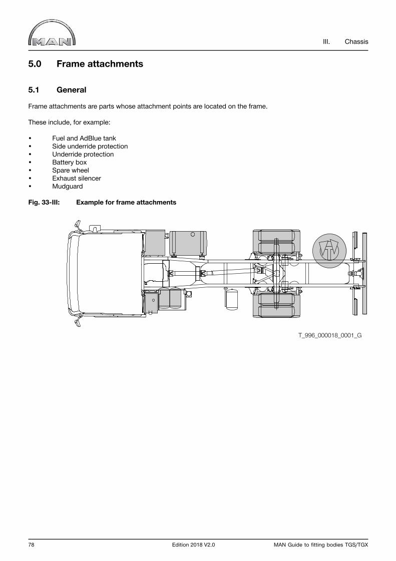
78 Edition 2018 V2.0 MAN Guide to fitting bodies TGS/TGX
III. Chassis
5.0 Frame attachments
5.1 General
Frame attachments are parts whose attachment points are located on the frame.
These include, for example:
• Fuel and AdBlue tank• Side underride protection• Underride protection• Battery box• Spare wheel• Exhaust silencer• Mudguard
Fig. 33-III: Example for frame attachments
T_996_000018_0001_G
MAN Guide to fitting bodies TGS/TGX Edition 2018 V2.0 79
III. Chassis
5.2 Front underride protection
Motor vehicles used for the transport of goods that have at least four wheels and a maximum permissible mass of over 3.5 t must be fitted with front underride protection that is approved in accordance with Directive 2000/40/EC.
This shall not apply to:
• Offroad vehicles• vehicles whose application is not compatible with the regulations for front underride protection.
The following criteria must be met in order to obtain registration as an off-road vehicle:
• At least 50% of the wheels are driven.• A differential lock or ASR is fitted.• Gradeability of the individual vehicle ≥ 25%• Plus at least four of the following requirements: - Approach angle ≥ 25° - Departure angle ≥ 25° - Ramp angle ≥ 25° - Ground clearance beneath the front axles is at least 250 mm. - Ground clearance beneath the rear axles is at least 250 mm. - Ground clearance between the axles is at least 300 mm.
Vehicles that do not meet the criteria for an off-road vehicle are fitted with FUP that complies with the requirements of Directive 2000/40/EC.
All-wheel-drive vehicles (wheel configurations e.g. 4x4, 6x4-4, 6x6, 8x6 and 8x8) and vehicles that meet the off-road criteria can be registered as off-road vehicles and are therefore not fitted with front underride protection at the factory.
If it is not possible to locate bodies or attachments (e.g. outriggers, tool boxes) such that the above stated criteria are not violated then the vehicle must be retrofitted with front underride protection, which is available from the MAN spare parts organisation.
Responsibility for this lies with the body builder. MAN is not liable for any costs arising from the retrofitting of front underride protection to vehicles that were delivered as off-road vehicles.
Important notice Underride protection equipment may not be modified (e.g. by welding, drilling or modification of brackets). Non-compliance voids type approval.

80 Edition 2018 V2.0 MAN Guide to fitting bodies TGS/TGX
III. Chassis
5.3 Side underride protection
“Lateral protection device(s) (are) designed to offer effective protection to unprotected road users against the risk of falling under the sides of the vehicle and atng caught under the wheels” (excerpt from ECE-R73). Trucks, tractor units and their trailers with a permissible gross weight of > 3.5 t must be fitted with side underride protection.
Exceptions applicable to the truck sector are as follows:
• Semitrailer tractor units (not semitrailers)• Vehicles built for special purposes that are incompatible with the fitting of side underride protection.
The following apply in Germany:
• The respective national approval authority can be applied to for certificates of exemption to cover transfer trips of chassis.• In this connection, “special vehicles” mainly means vehicles with side tipper. This only applies to vehicles with side tippers and a body inside length of less than 7,500 mm. Neither vehicles for combined transport nor off-road vehicles are exempt from the mandatory requirement for fitting side underride protection.
The corresponding national regulations must be observed when determining whether or not side underride protection has to be fitted.
Side underride protection for chassis can be delivered ex-works. Body builders who retrofit side underride protection can procure MAN profiles, profile supports and components for assembly from the Spare-parts Service.
Important notice The company installing or modifying side underride protection is responsible for compliance with national regulations (regulated by Directive ECE-R73 01, in Germany by §32c StVZO (Road Traffic Licensing Regulations)).
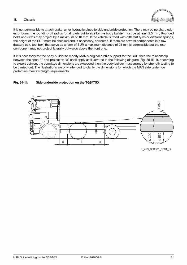
MAN Guide to fitting bodies TGS/TGX Edition 2018 V2.0 81
III. Chassis
It is not permissible to attach brake, air or hydraulic pipes to side underride protection. There may be no sharp edg-es or burrs; the rounding-off radius for all parts cut to size by the body builder must be at least 2.5 mm; Rounded bolts and rivets may project by a maximum of 10 mm. If the vehicle is fitted with different tyres or different springs, the height of the SUP must be checked and, if necessary, corrected. If there are several components in a row (battery box, tool box) that serve as a form of SUP, a maximum distance of 25 mm is permissible but the rear component may not project laterally outwards above the front one.
If it is necessary for the body builder to modify MAN’s original profile support for the SUP, then the relationship between the span “I” and projection “a” shall apply as illustrated in the following diagram (Fig. 35-III). If, according to expert opinion, the permitted dimensions are exceeded then the body builder must arrange for strength testing to be carried out. The illustrations are only intended to clarify the dimensions for which the MAN side underride protection meets strength requirements.
Fig. 34-III: Side underride protection on the TGS/TGX
a al ≤ 3
00
≤ 3
50 ≤
550
T_429_000001_0001_G
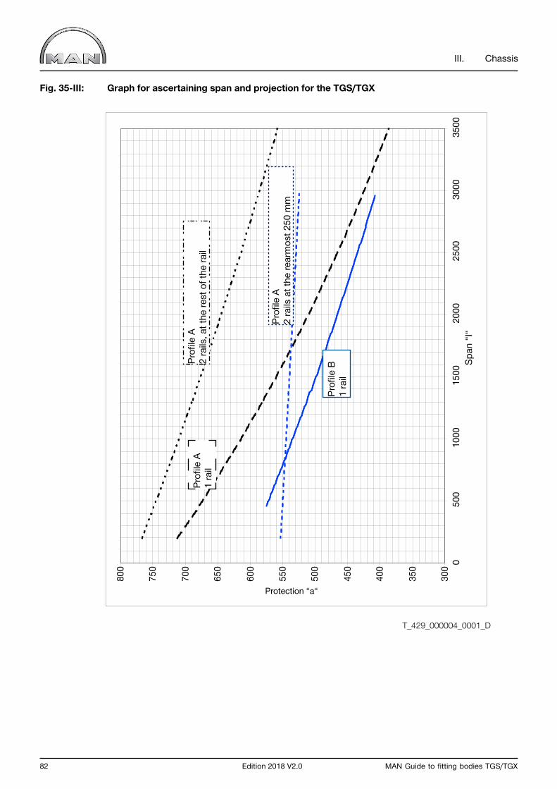
82 Edition 2018 V2.0 MAN Guide to fitting bodies TGS/TGX
III. Chassis
Fig. 35-III: Graph for ascertaining span and projection for the TGS/TGX
300
350
400
450
500
550
600
650
700
750
800 0
500
1000
1500
2000
2500
3000
3500
T_429_000004_0001_D
Profi
le A
2 ra
ils a
t the
rear
mos
t 250
mm
Profi
le B
1 ra
il
Profi
le A
2 ra
ils, a
t the
rest
of t
he ra
ilPr
ofile
A1
rail
Span
“I“
Protection “a“

MAN Guide to fitting bodies TGS/TGX Edition 2018 V2.0 83
III. Chassis
Both profiles (A and B) are used ex works for TGS/TGX vehicles in the exhaust-emission class Euro 6 and lower.
The profiles are shown in Fig. 36-III and Fig. 37-III below.
Fig. 36-III: Version A Fig. 37-III: Version B
25
100
200
20
30
100
9
T_429_000005_0001_G

84 Edition 2018 V2.0 MAN Guide to fitting bodies TGS/TGX
III. Chassis
5.4 Rear underride protection
Chassis of the TGS and TGX model ranges are delivered ex works with different variants of MAN’s rear underride protection. The respective variant is controlled by MAN in dependence on the parameters wheel configuration, build height, suspension type and wheelbase in combination with the factory-fitted body (swap body fitting), see Table 09-III. MAN underride protection devices are approved in accordance with Directive 70/221/EEC as last amended by 2006/20/EU.
Table 09-III: Underride protection variants (for an explanation of the values see Fig. 38-III)
Item no. fitting Version w X Y Z* α81.41660-8176 C2WB 191 mm max. 348 mm 340 mm max. 550 mm 56,3°81.41660-8177 C1 199 mm max. 332 mm 432 mm max. 550 mm 33,8°81.41660-8178 C2 291 mm max. 348 mm 340 mm max. 550 mm 56,3°81.41660-8180 B1 249 mm max. 318 mm 507 mm max. 550 mm 33,8°81.41660-8181 B2 366 mm max. 339 mm 391 mm max. 550 mm 56,3°81.41660-8183 A1 276 mm max. 305 mm 549 mm max. 550 mm 33,8°81.41660-8184 A2 407 mm max. 330 mm 418 mm max. 550 mm 56,3°81.41660-8213 A1 276 mm max. 305 mm 549 mm max. 550 mm 33,8°81.41660-8214 B1 249 mm max. 318 mm 507 mm max. 550 mm 33,8°81.41660-8215 D 442 mm max. 321 mm 481 mm max. 550 mm 52,8°
* maximum permissible distance as per Directive 70/221/EEC
Important notice The bodybuilder/converter must ensure and verify that the regulations have been adhered to because the dimensions are dependent upon the superstructure and can only be determined once the vehicle including the superstructure has been fully completed.
Fig. 38-III: Dimensional specifications for underride protection
The following dimensions must be observed.
w = horizontal distance from frame end to rear edge of underride protection y = vertical distance from frame lower edge to lower edge of underride protection x = horizontal distance from lower edge of underride protection to read edge of body z = vertical distance from lower edge of underride protection to the road surface for an unladen vehicle α = angle α depends upon the requirements for dimensions w and y.
x
y
z
α
w
T_429_000007_0001_G

MAN Guide to fitting bodies TGS/TGX Edition 2018 V2.0 85
III. Chassis
Depending upon the chassis variant, a folding underride guard from Ringfeder VBG is available as optional equipment for vehicles fitted with an MAN low coupling system. Alternatively, folding underride protection for construction site vehicles is available from Meiller.
Important notice Underride-protection systems may never be modified (e.g. by welding or modifying the tube or angle α) because this will invalidate certification/type approval. This also applies to vehicles with a factory-fitted body!
If rear underride protection is retrofitted or refitted, e.g. after shortening the frame, the bodybuilder/modifier is responsible for fitting it in accordance with the regulations.
The following points must be observed:
• For the bolted connections between the bracket and frame it is imperative that MAN Verbus-Ripp bolts with shaft are used (MAN 06.02813-4915, M14 x 1.5 10.9), tightening torque 200 Nm on the nut side (see Fig. 39-III).• The bolts of the lower connection of the underride protection must be tightened with a torque of 330 Nm. (See Fig. 40-III.)• Angle α of the underride protection may not be modified at a later time, otherwise registration becomes void.• Any modifications to underride protection must be certified by an officially approved inspector (e.g. an officially accredited expert in Germany).
Fig. 39-III: Bolted connection of underride protection Fig. 40-III: Lower bolted connection, underride protection bracket
T_429_000008_0001_G
a b
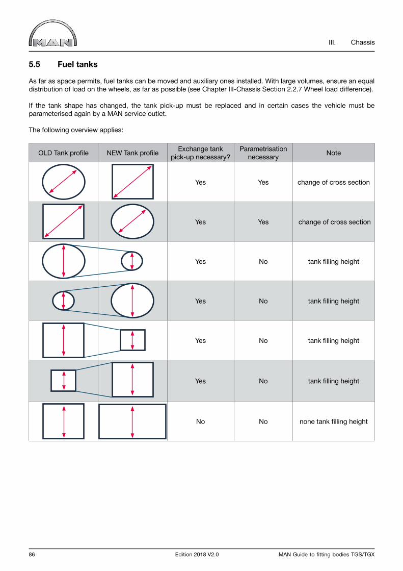
86 Edition 2018 V2.0 MAN Guide to fitting bodies TGS/TGX
III. Chassis
5.5 Fuel tanks
As far as space permits, fuel tanks can be moved and auxiliary ones installed. With large volumes, ensure an equal distribution of load on the wheels, as far as possible (see Chapter III-Chassis Section 2.2.7 Wheel load difference).
If the tank shape has changed, the tank pick-up must be replaced and in certain cases the vehicle must be parameterised again by a MAN service outlet.
The following overview applies:
OLD Tank profile NEW Tank profile Exchange tankpick-up necessary?
Parametrisationnecessary Note
Yes Yes change of cross section
Yes Yes change of cross section
Yes No tank filling height
Yes No tank filling height
Yes No tank filling height
Yes No tank filling height
No No none tank filling height
MAN Guide to fitting bodies TGS/TGX Edition 2018 V2.0 87
III. Chassis
For special fuel tank shapes, contact the manufacturer of the fuel tank.
If larger or auxiliary fuel tanks are fitted after delivery from the factory, then the additional tank volume will be subject to a mineral oil/fuel/energy tax by the territory into which it is being imported.
This regulation applies to modifications carried out before the vehicle was registered in the customer’s name (e.g. at the body builder) and to retrofits carried out once the vehicle has already been registered in the end customer’s name. Customers must be informed of this issue.
Fuel can only be carried tax-free in “main tanks” (and in reserve tanks up to a total volume of 20 litres). Main tanks are the fuel tanks with which the vehicle was delivered, not those which were fitted afterwards by a body builder or workshop, for example.
According to the ADR directive, the maximum permissible total volume may not exceed 1500 l. Country-specific ADR directives must be observed.
Country-specific guidelines must be observed in the event of modifications.
The description of the procedure for the first fuelling of twin or multi-tank systems can be found in the applicable vehicle operating instructions or service information (SI 545200).
Information on use in mining:
Corrosion damage can occur on vehicles with aluminium fuel tanks which are used in coal mining or for coal transport.
Here, contact corrosion occurs between the elements aluminium and carbon.
MAN recommends selecting steel tanks when configuring vehicles for coal mining applications. If no steel tanks are available in the desired size, then the tank system must be checked regularly. Another option is to have the fuel tank professionally painted; regular checks are still recommended, however.
88 Edition 2018 V2.0 MAN Guide to fitting bodies TGS/TGX
III. Chassis
5.5.1 Mounting fuel tanks
Various fuel tank versions are offered ex works for the different series.
The following points must be observed when fuel tanks are mounted on the frame:
• MAN recommends using original MAN fuel tanks, tank supports and fixing elements. These can be obtained from the MAN Spare Parts Service.• The weight of the tank should be borne equally by the tank supports.• If possible, tank supports are to be mounted on the chassis frame close to cross members.• Ensure that the attachment points for the tank support in the chassis frame have the greatest possible vertical spacing. • For strength and stability reasons, clamping straps must be placed over the baffles of the fuel tank.• The distance from the centre of the tank support to the centre of the baffle must not exceed 200 mm for tank volumes of up to 400 l. The distance from the centre of the tank support to the centre of the baffle for greater volumes (> 400 l) must not exceed 150 mm.• Individual fuel tanks of up to 600 l are fixed to the vehicle frame by two tank supports and clamping straps. Depending on the application, however, three tank supports may already be required.• For 600 l and larger, fuel tanks are fixed to the vehicle frame by three tank supports and clamping straps.• The fuel tanks are fixed to the vehicle frame by tank support brackets. Between the tank supports and tank shell and between the clamping straps and tank shell, underlays must be added in accordance with MAN standards M3306-2 and M3306-1 respectively in order to ensure even, slip-free transmission of force from the clamping straps and tank supports to the tank shell. Absolutely no deformation of the fuel tank may be allowed to occur.
Body builders can obtain the mentioned MAN works standards via www.ptd.man.eu(registration required).
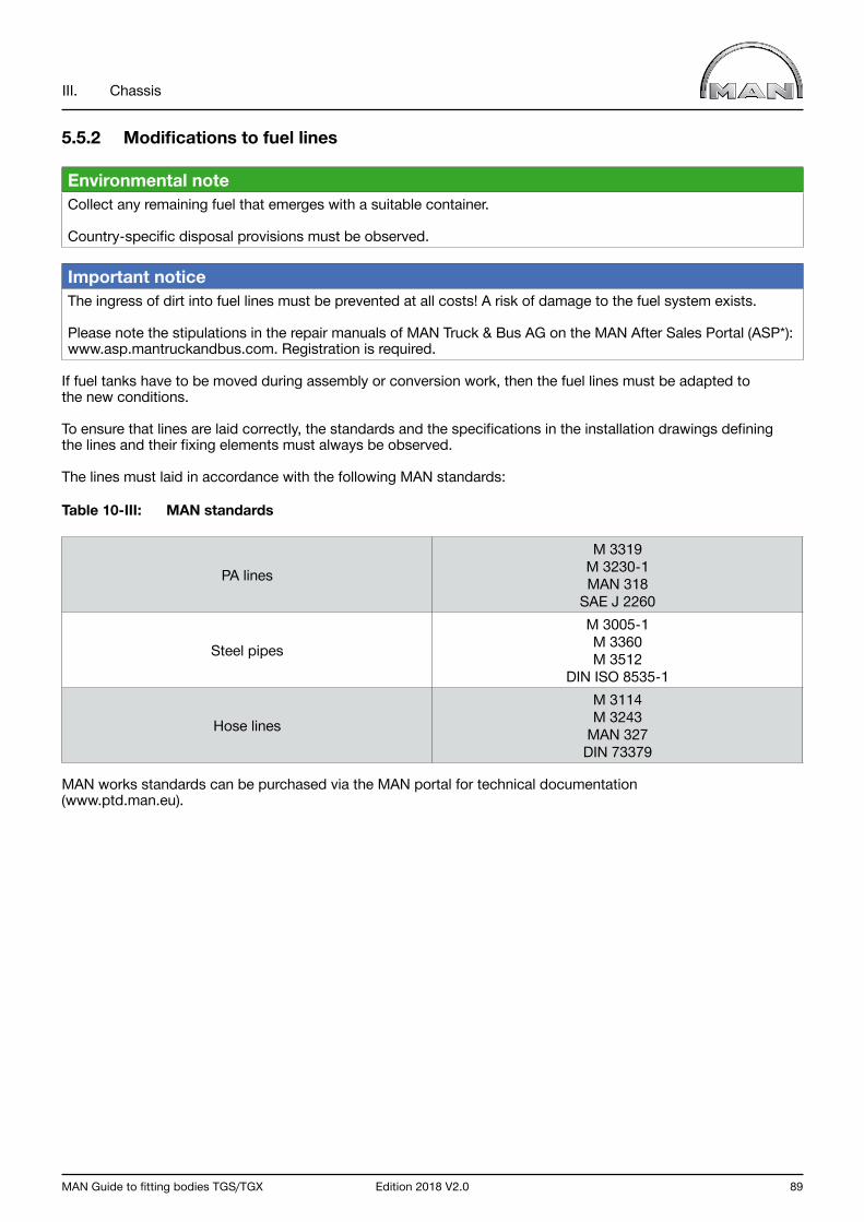
MAN Guide to fitting bodies TGS/TGX Edition 2018 V2.0 89
III. Chassis
5.5.2 Modifications to fuel lines
Environmental note Collect any remaining fuel that emerges with a suitable container.
Country-specific disposal provisions must be observed.
Important notice The ingress of dirt into fuel lines must be prevented at all costs! A risk of damage to the fuel system exists.
Please note the stipulations in the repair manuals of MAN Truck & Bus AG on the MAN After Sales Portal (ASP*): www.asp.mantruckandbus.com. Registration is required.
If fuel tanks have to be moved during assembly or conversion work, then the fuel lines must be adapted tothe new conditions.
To ensure that lines are laid correctly, the standards and the specifications in the installation drawings defining the lines and their fixing elements must always be observed.
The lines must laid in accordance with the following MAN standards:
Table 10-III: MAN standards
PA lines
M 3319M 3230-1MAN 318
SAE J 2260
Steel pipes
M 3005-1M 3360M 3512
DIN ISO 8535-1
Hose lines
M 3114M 3243
MAN 327DIN 73379
MAN works standards can be purchased via the MAN portal for technical documentation(www.ptd.man.eu).
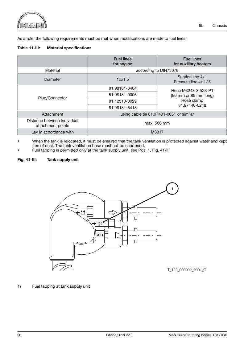
90 Edition 2018 V2.0 MAN Guide to fitting bodies TGS/TGX
III. Chassis
As a rule, the following requirements must be met when modifications are made to fuel lines:
Table 11-III: Material specifications
Fuel lines for engine
Fuel lines for auxiliary heaters
Material according to DIN73378
Diameter 12x1,5 Suction line 4x1Pressure line 4x1.25
Plug/Connector
81.98181-6404 Hose M3243-3.5X3-P1 (50 mm or 85 mm long)
Hose clamp81.97440-0248
51.98181-000681.12510-002981.98181-6418
Attachment using cable tie 81.97401-0631 or similarDistance between individual
attachment points max. 500 mm
Lay in accordance with M3317
• When the tank is relocated, it must be ensured that the tank ventilation is protected against water and kept free of dust. The tank ventilation hose must not be shortened.• Fuel tapping is permitted only at the tank supply unit, see Pos. 1, Fig. 41-III.
Fig. 41-III: Tank supply unit
1) Fuel tapping at tank supply unit
AIR
1
T_122_000002_0001_G
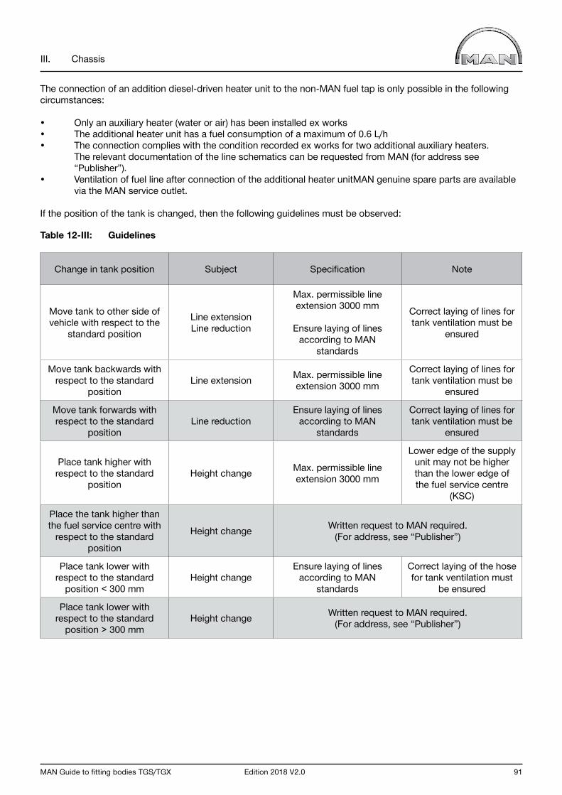
MAN Guide to fitting bodies TGS/TGX Edition 2018 V2.0 91
III. Chassis
The connection of an addition diesel-driven heater unit to the non-MAN fuel tap is only possible in the following circumstances:
• Only an auxiliary heater (water or air) has been installed ex works• The additional heater unit has a fuel consumption of a maximum of 0.6 L/h• The connection complies with the condition recorded ex works for two additional auxiliary heaters. The relevant documentation of the line schematics can be requested from MAN (for address see “Publisher”).• Ventilation of fuel line after connection of the additional heater unitMAN genuine spare parts are available via the MAN service outlet.
If the position of the tank is changed, then the following guidelines must be observed:
Table 12-III: Guidelines
Change in tank position Subject Specification Note
Move tank to other side of vehicle with respect to the
standard position
Line extensionLine reduction
Max. permissible line extension 3000 mm
Ensure laying of lines according to MAN
standards
Correct laying of lines for tank ventilation must be
ensured
Move tank backwards with respect to the standard
positionLine extension Max. permissible line
extension 3000 mm
Correct laying of lines for tank ventilation must be
ensured
Move tank forwards with respect to the standard
positionLine reduction
Ensure laying of lines according to MAN
standards
Correct laying of lines for tank ventilation must be
ensured
Place tank higher with respect to the standard
positionHeight change Max. permissible line
extension 3000 mm
Lower edge of the supply unit may not be higher than the lower edge of the fuel service centre
(KSC)
Place the tank higher than the fuel service centre with
respect to the standard position
Height change Written request to MAN required.(For address, see “Publisher”)
Place tank lower with respect to the standard
position < 300 mmHeight change
Ensure laying of lines according to MAN
standards
Correct laying of the hose for tank ventilation must
be ensured
Place tank lower with respect to the standard
position > 300 mmHeight change Written request to MAN required.
(For address, see “Publisher”)
92 Edition 2018 V2.0 MAN Guide to fitting bodies TGS/TGX
III. Chassis
5.6 Coupling devices
In order to operate turntable trailers, rigid drawbar trailers or semitrailer tractors, a correspondingly designed coupling device (i.e. trailer coupling and final cross member / fifth-wheel pick-up plate and fifth-wheel coupling) is necessary.
Important notice Standardisation and legislation for the implementation of coupling devices are based on national conditions for registration, for example:
• Article 43 of the German Road Traffic Licensing Regulations (StVZO) (safety standard),• Article 22a of the German Road Traffic Licensing Regulations (StVZO) (type approval),• BGV D29 (accident-prevention regulations of the Trade Association for Vehicle Operators)
and the calculation of the D value.
A comprehensive description of the final cross members available from MAN, the calculation of the D value and more detailed information can be found in the separate booklet entitled “Coupling devices TG”.
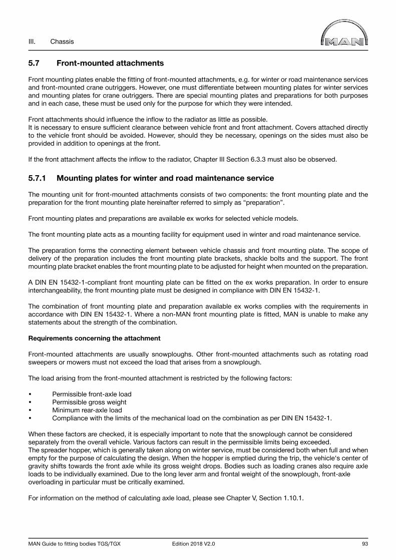
MAN Guide to fitting bodies TGS/TGX Edition 2018 V2.0 93
III. Chassis
5.7 Front-mounted attachments
Front mounting plates enable the fitting of front-mounted attachments, e.g. for winter or road maintenance services and front-mounted crane outriggers. However, one must differentiate between mounting plates for winter services and mounting plates for crane outriggers. There are special mounting plates and preparations for both purposes and in each case, these must be used only for the purpose for which they were intended.
Front attachments should influence the inflow to the radiator as little as possible.It is necessary to ensure sufficient clearance between vehicle front and front attachment. Covers attached directly to the vehicle front should be avoided. However, should they be necessary, openings on the sides must also be provided in addition to openings at the front.
If the front attachment affects the inflow to the radiator, Chapter III Section 6.3.3 must also be observed.
5.7.1 Mounting plates for winter and road maintenance service
The mounting unit for front-mounted attachments consists of two components: the front mounting plate and the preparation for the front mounting plate hereinafter referred to simply as “preparation”.
Front mounting plates and preparations are available ex works for selected vehicle models.
The front mounting plate acts as a mounting facility for equipment used in winter and road maintenance service.
The preparation forms the connecting element between vehicle chassis and front mounting plate. The scope of delivery of the preparation includes the front mounting plate brackets, shackle bolts and the support. The front mounting plate bracket enables the front mounting plate to be adjusted for height when mounted on the preparation.
A DIN EN 15432-1-compliant front mounting plate can be fitted on the ex works preparation. In order to ensure interchangeability, the front mounting plate must be designed in compliance with DIN EN 15432-1.
The combination of front mounting plate and preparation available ex works complies with the requirements in accordance with DIN EN 15432-1. Where a non-MAN front mounting plate is fitted, MAN is unable to make any statements about the strength of the combination.
Requirements concerning the attachment
Front-mounted attachments are usually snowploughs. Other front-mounted attachments such as rotating road sweepers or mowers must not exceed the load that arises from a snowplough.
The load arising from the front-mounted attachment is restricted by the following factors:
• Permissible front-axle load• Permissible gross weight• Minimum rear-axle load • Compliance with the limits of the mechanical load on the combination as per DIN EN 15432-1.
When these factors are checked, it is especially important to note that the snowplough cannot be considered separately from the overall vehicle. Various factors can result in the permissible limits being exceeded. The spreader hopper, which is generally taken along on winter service, must be considered both when full and when empty for the purpose of calculating the design. When the hopper is emptied during the trip, the vehicle‘s center of gravity shifts towards the front axle while its gross weight drops. Bodies such as loading cranes also require axle loads to be individually examined. Due to the long lever arm and frontal weight of the snowplough, front-axle overloading in particular must be critically examined.
For information on the method of calculating axle load, please see Chapter V, Section 1.10.1.
94 Edition 2018 V2.0 MAN Guide to fitting bodies TGS/TGX
III. Chassis
Fig. 42-III: Example of forces and force application points
1) Vehicle‘s center of gravity2) Weight of vehicle3) Weight of plough4) Attachment‘s Center of gravity5) Lever from the frontaxle to the attachment‘s center of gravity
Compatibility between front mounting plate and the MAN preparation as well as compliance with the above-mentioned points must be checked prior to attaching.
Retrofitting
Where the preparation is retrofitted, MAN Genuine Parts must be used. Non-MAN parts are not permitted for retrofitting this attachment.
The preparation can only be retrofitted with the aid of the appropriate MAN Service outlet and MAN Customer Service.
Important notice The clearance of the cab must not be impinged upon by front-mounted attachments.
For the protection of other road users, the front mounting plate must be fitted with a protective cover when not in use. This cover is included when the MAN front mounting plate is ordered.
T_675_000001_0001_G
3
4
5
2 1
MAN Guide to fitting bodies TGS/TGX Edition 2018 V2.0 95
III. Chassis
5.7.2 Front plate for crane support
Some types of crane require a front support. The crane support front plate available ex works allows feet to be attached in order to divert force into the vehicle frame.
To increase the frame rigidity, the frame side members with profile number 32 (see Chapter III Section 4.3 Frame profiles) and additional frame inserts must be installed in the front section.Retrofitting the reinforcements is very complicated and is only possible on vehicles equipped with frame profile 32. Therefore, the necessary equipment should be ordered ex works.
InformationAlways ask a MAN salesperson and the customer special request department (CSR) in advance whether implementation is possible for the vehicle type. To do so, a truck request must be sent via www.manted.de.
Also, the following equipment limitations must be noted:
• not available for 2-axle and 3-axle vehicles with HydroDrive (Euro 5)• not available for vehicles with air suspension on the front axle• not available for right-hand drive vehicles with hydraulically steered trailing axle without electric actuation (RAS steering system)
The following equipment must be included as a customer special request.
• 233EM steel bumper• 240EQ front plate for crane support• 240CJ 9.5 mm main frame side member and additional frame inserts at front
The following are mandatory requirements for using the front plate for crane support:
• laterally to the vehicle, the support load must be introduced symmetrically to the chassis zero point (symmetrical load on both frame side members) • the centre of the support(s) may not be more than 100 mm in front of the front plate• the support load may not occur in jolts• the auxiliary frame of the body must begin directly behind the cab mount - with M cab approx. 330 mm from the centre of the front axle - with L, LX, XLX, XL, XXL cab approx. 550 mm behind the centre of the front axle• the auxiliary frame must be firmly connected to the chassis frame
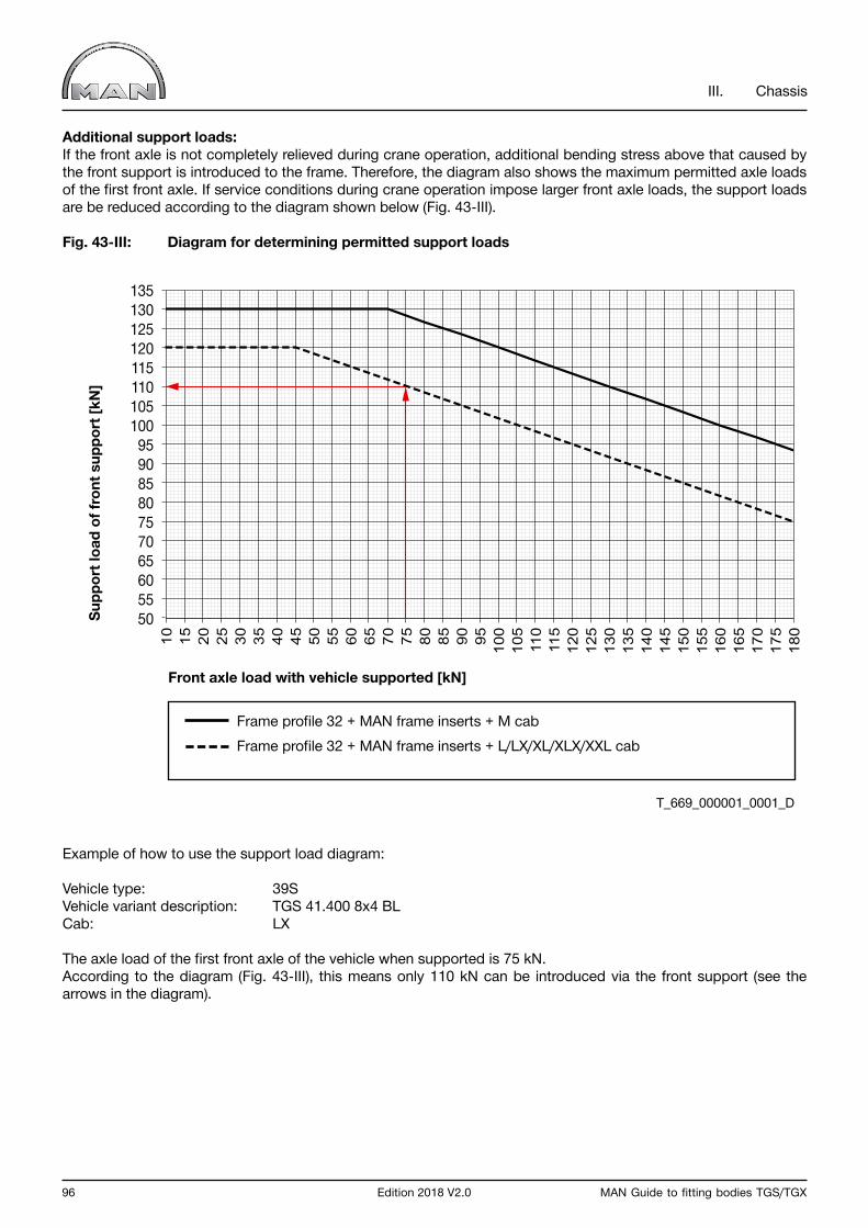
96 Edition 2018 V2.0 MAN Guide to fitting bodies TGS/TGX
III. Chassis
Additional support loads:If the front axle is not completely relieved during crane operation, additional bending stress above that caused by the front support is introduced to the frame. Therefore, the diagram also shows the maximum permitted axle loads of the first front axle. If service conditions during crane operation impose larger front axle loads, the support loads are be reduced according to the diagram shown below (Fig. 43-III).
Fig. 43-III: Diagram for determining permitted support loads
Example of how to use the support load diagram:
Vehicle type: 39SVehicle variant description: TGS 41.400 8x4 BLCab: LX
The axle load of the first front axle of the vehicle when supported is 75 kN.According to the diagram (Fig. 43-III), this means only 110 kN can be introduced via the front support (see the arrows in the diagram).
Front axle load with vehicle supported [kN]
Frame profile 32 + MAN frame inserts + M cabFrame profile 32 + MAN frame inserts + L/LX/XL/XLX/XXL cab
Supp
ort l
oad
of fr
ont s
uppo
rt [k
N]
50 55 60 65 70 75 80 85 90 95
100 105 110 115 120 125 130 135
10
15
20
25
30
35
40
45
50
55
60
65
70
75
80
85
90
95
100
105
110
115
120
125
130
135
140
145
150
155
160
165
170
175
180
T_669_000001_0001_D
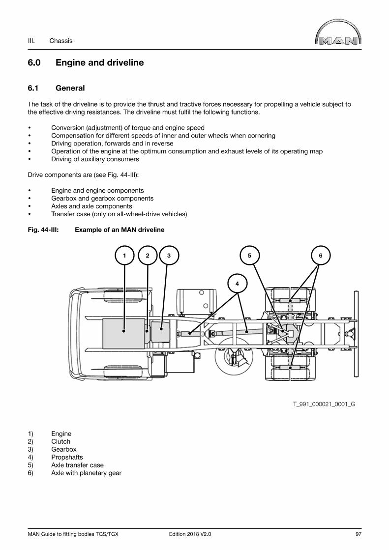
MAN Guide to fitting bodies TGS/TGX Edition 2018 V2.0 97
III. Chassis
6.0 Engine and driveline
6.1 General
The task of the driveline is to provide the thrust and tractive forces necessary for propelling a vehicle subject to the effective driving resistances. The driveline must fulfil the following functions.
• Conversion (adjustment) of torque and engine speed• Compensation for different speeds of inner and outer wheels when cornering• Driving operation, forwards and in reverse • Operation of the engine at the optimum consumption and exhaust levels of its operating map• Driving of auxiliary consumers
Drive components are (see Fig. 44-III):
• Engine and engine components• Gearbox and gearbox components• Axles and axle components• Transfer case (only on all-wheel-drive vehicles)
Fig. 44-III: Example of an MAN driveline
1) Engine2) Clutch3) Gearbox4) Propshafts5) Axle transfer case6) Axle with planetary gear
T_991_000021_0001_G
1 2 3
4
5 6

98 Edition 2018 V2.0 MAN Guide to fitting bodies TGS/TGX
III. Chassis
6.2 Engine versions
MAN offers various engine versions according to series and emissions class.
In the TGS and TGX six-cylinder in-line diesel engines (R6) with
• D20 common rail• D26 common rail• D38 common rail
are installed.
The engines are available in emissions classes Euro II, Euro III, Euro IV, Euro V, EEV and Euro VI.
Depending on emissions class, the engines are equipped with exhaust-gas recirculation, on-board diagnosis (Euro IV and higher) including NOx control (torque reduction in case of NOx control failure) and exhaust gas aftertreatment.
The Brazilian emissions class Conama P6 is similar to Euro IV without OBD. Conama P7 is similar to Euro V with an OBD similar to the European OBD2.
The following abbreviations are used:
EEV: Enhanced Environmentally friendly VehicleOBD: On Board DiagnosisEGR: Exhaust Gas RecirculationPM-Cat: Particulate filter (open particulate filter; PM = Particulate Matter)CRT: Particulate filter (closed particulate filter; CRT = Continuously Regenerating Trap SCR: Selective Catalytic Reduction with “AdBlue” as the reducing agent; without exhaust gas recirculation (Euro IV, Euro V, EEV)

MAN Guide to fitting bodies TGS/TGX Edition 2018 V2.0 99
III. Chassis
6.2.1 Type codes for MAN engines
Information on the engine number and the additional data on the type plate can be found via the MAN After Sales Portal or in the vehicle operating manual.
The type code for MAN engines is based on a precisely defined system. As a general principle, this classification key consists of 6 elements that serve to identify the following features:
1) Fuel type2) Bore3) Stroke4) Number of cylinders5) Turbocharging6) Engine installation
Using the example D2066LF80, the type code is explained as follows:
Table 13-III: Type code for MAN engines
Model designation Explanation Example
D Fuel type Diesel
20 Figure +100 120 mm bore
6 (Figure x10) +100 155 mm stroke (rounded)
6 Number of cylinders 6 cylinders
L Supercharging with turbocharging and intercooler
F Engine installation Engine/vertical/forward-control
80 Model identifier Rating/speed/approval

100 Edition 2018 V2.0 MAN Guide to fitting bodies TGS/TGX
III. Chassis
6.3 Engine environment
6.3.1 Modifications to the engine
Important notice MAN does not permit any modifications to the engine or its components. Non-compliance voids type approval and warranty.
6.3.2 Modifications to the air-intake system
In general, modifications to the air-intake system are to be avoided. Various factory options are available for the TGS/TGX and body builders should check to see if these can be used. Information on availability for the corresponding vehicle can be obtained from your closest MAN sales branch.
If it is still not possible to avoid making modifications the following requirements must be met:
• The intake of air must not be inhibited in any way.• The negative pressure in the intake branch must not be allowed to vary.• When modifying the intake system it must be ensured that all statutory regulations relevant to noise and emissions are fulfilled.• All regulations pertaining to the components in question issued by professional associations or similar facilities must also be fulfilled (e.g. surface temperature in the vicinity of handles/grips).• In the case of modified intake systems, MAN cannot - guarantee compliance with these and other regulations. Responsibility for this remains with the company performing the modification. This also applies to regulations pertaining to on-board diagnosis (OBD). - provide any information about changes in fuel consumption or noise characteristics; in some circumstances, a new noise emission approval will be required. Components that have an effect on the vehicles acoustics (e.g. nozzles in the air filter) not be modified. Non-compliance with noise limits voids type approval!
For vehicles up to and including the Euro 5 exhaust standard, the following apply in addition to the general specifications:
• Never change the shape or area of pipework cross-sections.• Avoid sharp bends in the pipe; mitre cuts are not permitted. • Do not modify air filters.• The service life of the air filter may be shortened when modifications are made to the air-intake system.• Only use approved air filters.• Changes to the installation location of the humidity sensor in the air-filter housing are not allowed.• The design of mountings and supports and the basic installation position of components must not be changed.• The air-intake must be protected against drawing in warmed air (e.g. heat dissipated by the engine in the vicinity of the wheel housings or the exhaust silencer). A suitable location for the air intake must be chosen such that the intake air is not warmed by more than 5°C (difference between the ambient air temperature and the temperature at the turbocharger inlet). If the intake air temperature is too high there is a risk that the exhaust emission limits will be exceeded. Non-compliance with emission limits voids type approval!• In order to avoid drawing in burning cigarette ends or similar, a so-called cigarette mesh must be fitted directly over the air intake in the same fashion as the mesh installed on production vehicles (non-flammable material, mesh size SW6, area of the open cross-section at least that of the intake air scoop on the air filter). There is a risk of vehicle fire if this requirement is not observed! MAN can provide no information on the effectiveness of the measure used, responsibility lies with the company performing the modification.
MAN Guide to fitting bodies TGS/TGX Edition 2018 V2.0 101
III. Chassis
• The air intake must be positioned such that there is a low level of dust and spray ingestion.• Sufficient dewatering using water separation systems and unobstructed dust discharge from the filter housing and the unfiltered side must be ensured to prevent damage to the engine.• Pipework on the filtered-air side must be selected to ensure that it is absolutely sealed from the unfiltered side. The inside of the air intake pipes must be smooth – no particles or similar may come loose from the sides. It is imperative that the air intake pipe cannot slip out at the sealed joints. Suitable brackets must therefore be fitted.• The partial-vacuum sensor shall be positioned in a straight section of the pipe at the shortest possible distance from the turbocharger. It is the responsibility of the company carrying out the modification to ensure the sensor reads correctly. Important: Risk of engine damage if the sensor underreads!• All air-intake pipes must be capable of resisting vacuum pressures of 100 mbar and temperatures of at least 80°C (peaks of 100°C). Flexible tubing (e.g. hoses) is not permitted.
For vehicles up to and including Euro 6, the following apply in addition to the requirements of the lower exhaust-gas standards:
• Modifications to the air-intake system may only be undertaken following written request and approval by MAN (for address see “Publisher” above). • Changes to the installation location, position and alignment of sensors in the air-intake system are not allowed.• If the air-compressor intake line is re-routed, it must be ensured that the cross-sections are adequately dimensioned. The line must have a vacuum stability of at least 250 mbar and a temperature stability range of between - 40°C and +120°C.• Independent retrofitting or removing of the safety elements (for difficult operating conditions) leads to non-compliance with the emission limit values. Retrofitting may only be carried out by MAN workshops. Under certain circumstances the vehicle will require parameterisation.
102 Edition 2018 V2.0 MAN Guide to fitting bodies TGS/TGX
III. Chassis
6.3.3 Modifications to the engine cooling system
Engine cooling systems are harmonised with the respective engines and the following must therefore be observed.
• Components of the factory-fitted cooling system (radiator, grille, air ducts, coolant circuit) may not be modified.• Exceptions only with permission from MAN (for address, see “Publisher” above). • The cooling system may only be filled with the coolants released by MAN as specified in the fuel database.• Materials that contain copper may not be used in the cooling circuit.
If the area of the inflow surface is reduced (by front attachments, for example), thus reducing the performance of the radiator, the following must be taken into account:
• Increased operation of the fan and thus increased fuel consumption• Negative influence on the capacity of the continuous brake• Reduction of engine power when close to its limits
Under the following conditions, a radiator with modified performance may be required:
• Operation primarily under stationary conditions• Operation in climatically unfavourable zones (countries with hot climates)• Operation in areas where it can be expected that the cooling performance can be reduced e.g. due to high dust level
When fitting a third-party radiator, it is mandatory to follow the mechanical installation requirements set down in the installation guidelines for built-in engines. These guidelines can be requested from MAN (for address see “Publisher” above).
With some bodies, it may be necessary to heat boxes or storage spaces. The vehicle engine cooling circuit must not be used for this purpose. Heating can be provided via an external diesel-driven air heater. If the vehicle has only had an auxiliary air heater installed ex works, then fuel can be supplied via the vehicle fuel tank. Chapter III, Section 5.5.2 “Changes to fuel lines” applies in this case. Otherwise an additional fuel tank may be installed on the vehicle for the operation of the auxiliary heater. Chapter III, Section 5.5 “Fuel tanks” and the tank manufacturer specification apply in this case.
Coolant tapping for heating body components
For some bodies, it can be necessary for body components through which flow medium flows to be heated at low ambient temperatures in order to prevent the flow medium from freezing or to reduce the viscosity of the transported medium. This can be achieved by tapping coolant from the cooling circuit. Coolant must be picked up via a circuit parallel to the cab heating circuit in accordance with Fig. 45-III. The tapping can take place using a T-piece in front of the H-valve (pressure-limiting valve, installed at the front right of the chassis frame) of the cab heating system. The return line of the body heating system is also connected to the heating return line using a T-piece.If the tapping of coolant is not a permanent requirement, it must be manually shut off using shut-off valves.
InformationThe software package with MAN item number 81.25890-7953 (ordered via www.manted.de) is to be installed on vehicles with engines of exhaust gas level Euro 6c or Euro 6d, which are not fitted with an Intarder or MAN PriTarder, if coolant tapping is to be achieved. If the above-named software package is not available, coolant tapping for heating body components is not permitted.

MAN Guide to fitting bodies TGS/TGX Edition 2018 V2.0 103
III. Chassis
Fig. 45-III: Coolant tapping in front of the H-valve of the cab heating system
1 – H-valve 6 – Pressure-limiting valve2 – Heating supply line 7 – Heat exchanger (optional)3 – Heating return line 8 – Temperature-controlled valve / Thermostat (>70°C)4 – T-pieces 9 – Throttle valve or flow regulator valve (max. 8l/min)5 – Shut-off valves
The following aspects must be observed for coolant tapping:
• Coolant tapping must take place in front of the H-valve (pressure-limiting valve) of the cab heating system using a T-piece • The return line of the body circuit using a T-piece in the heating return line.• Inner diameter of the lines for body heating 16 mm, the same as cab heating lines• Do not use materials containing copper• Hoses in accordance with MAN company standard 334 -1, material version 8• Coolant tapping via the body circuit max. 8l/min • Pressure limited to max. 2bar (pressure-limiting valve) • Coolant tapping only at coolant temperature of >70°C (establish using thermostat or temperature- controlled valve)• In the case of maintenance works on the cooling circuit, shut-off valves must be provided for the body circuit • Without external evidence of filling capacity, the heat exchanger must not be positioned higher than the coolant expansion tank.• The whole circuit must be ventilated prior to use.
T_779_000001_0002_G1
2
7 6
3
5
8 9
4
104 Edition 2018 V2.0 MAN Guide to fitting bodies TGS/TGX
III. Chassis
6.3.4 Modifications to engine encapsulation, noise insulation
Interference with and changes to engine capsulation in place ex works are not permitted. If a vehicle comes ready defined as “low-noise” it will lose its status as a result of subsequent changes or retrofits. The company that has carried out the modification will then be responsible for re-obtaining the previous status.
6.3.5 Compressed-air supply
The compressed-air system includes components such as:
• Air compressor• Compressed-air dryer• Compressed-air tank• External compressed-air connections
The compressed air system supplies, among other things:
• The compressed-air brake system• The cab suspension• The chassis suspension • Consumers requiring compressed air for operation.
6.3.5.1 Basic principles
Warning noticeImproperly executed work on the compressed-air system can impair the function of the brake system. This can lead to the failure of components or parts relevant to safety.
6.3.5.2 Routing lines
Principles of laying lines:
• Do not lay lines loose, use existing means of attachment and/or conduits.• Do not heat plastic pipes to install them, even if they are to be laid in a curve.• When attaching PA pipes make sure they cannot become twisted.• Fit a tube clip or, in the case of a cluster of pipes, a cable tie at the beginning and end in each case.• Attach corrugated wiring harness pipes to plastic consoles in the frame and in the engine area to prepared cable routes using cable ties or clips.• Never attach more than one line to the same hose clip.• Only polyamide pipes as per DIN74324 Part 1 or MAN standard M3230 Part 1 (extension of DIN74324 Part 1) may be employed (MAN portal for technical documentation: www.ptd.man.eu, registration required).• The cross-section of lines may not be changed.• Add 1% to the length of the polyamide pipe (corresponding to 10 mm for each metre), because plastic pipes contract in the cold and the vehicles must be capable of working at temperatures down to -40°C.• Do not heat pipes to lay them.• When cutting plastic pipes to length, use plastic pipe cutters because sawing them creates ridges on the cut faces and chippings can get into the pipe.• PA pipes may rest on the edges of a frame or in frame openings. A minimal amount of flattening on the PA pipe at the points of contact is tolerated (maximum depth 0.3 mm). However, notched abrasions are not permitted.
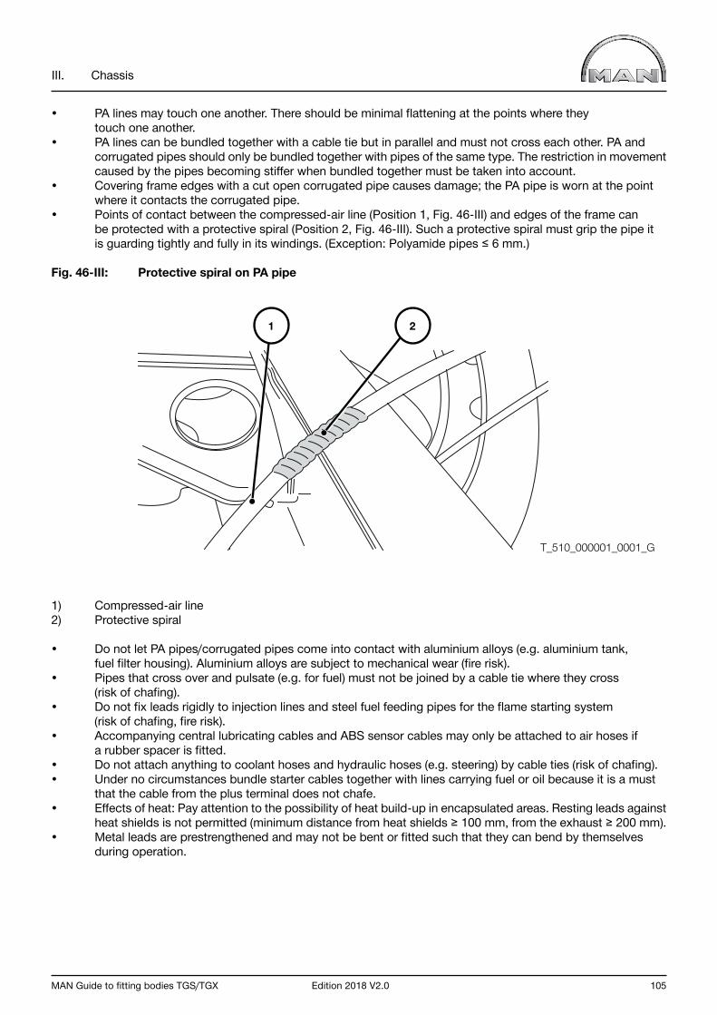
MAN Guide to fitting bodies TGS/TGX Edition 2018 V2.0 105
III. Chassis
• PA lines may touch one another. There should be minimal flattening at the points where they touch one another.• PA lines can be bundled together with a cable tie but in parallel and must not cross each other. PA and corrugated pipes should only be bundled together with pipes of the same type. The restriction in movement caused by the pipes becoming stiffer when bundled together must be taken into account.• Covering frame edges with a cut open corrugated pipe causes damage; the PA pipe is worn at the point where it contacts the corrugated pipe.• Points of contact between the compressed-air line (Position 1, Fig. 46-III) and edges of the frame can be protected with a protective spiral (Position 2, Fig. 46-III). Such a protective spiral must grip the pipe it is guarding tightly and fully in its windings. (Exception: Polyamide pipes ≤ 6 mm.)
Fig. 46-III: Protective spiral on PA pipe
1) Compressed-air line2) Protective spiral
• Do not let PA pipes/corrugated pipes come into contact with aluminium alloys (e.g. aluminium tank, fuel filter housing). Aluminium alloys are subject to mechanical wear (fire risk).• Pipes that cross over and pulsate (e.g. for fuel) must not be joined by a cable tie where they cross (risk of chafing).• Do not fix leads rigidly to injection lines and steel fuel feeding pipes for the flame starting system (risk of chafing, fire risk).• Accompanying central lubricating cables and ABS sensor cables may only be attached to air hoses if a rubber spacer is fitted.• Do not attach anything to coolant hoses and hydraulic hoses (e.g. steering) by cable ties (risk of chafing).• Under no circumstances bundle starter cables together with lines carrying fuel or oil because it is a must that the cable from the plus terminal does not chafe.• Effects of heat: Pay attention to the possibility of heat build-up in encapsulated areas. Resting leads against heat shields is not permitted (minimum distance from heat shields ≥ 100 mm, from the exhaust ≥ 200 mm).• Metal leads are prestrengthened and may not be bent or fitted such that they can bend by themselves during operation.
21
T_510_000001_0001_G

106 Edition 2018 V2.0 MAN Guide to fitting bodies TGS/TGX
III. Chassis
If subassemblies/components are seated to move in relation to one another, the following basic rules must be followed when routing leads:
• A lead must be able to follow the movement of a subassembly without hindrance; ensure that there is sufficient spacing between moving parts (rebound/compression, steering angle, tilting of cab). Lines must not be stretched.• Precisely define the respective beginning and end of the movement as a fixed clamping point. The polyamide pipe or corrugated tube is gripped tightly at the clamping point using the widest cable tie possible or a clip suitable for the diameter of the pipe.• If polyamide pipes and corrugated tubes are laid at the same junction, the stiffer polyamide pipe is laid first. The softer corrugated tube is then attached to the polyamide pipe.• A line tolerates movement at right angles to the direction in which it is laid, so ensure sufficient spacing between the clamping points (rule of thumb: spacing of clamping points ≥ 5 x amplitude of movement to be sustained).• Large amplitude of movement is best withstood by laying a pipe U-shaped and allowing movement along the arms of the U.
Rule of thumb for minimum length of slack loop:Minimum length of slack loop = ½ ● amplitude of movement ● minimum radius ● π
• Observe the following minimum radii for PA pipes (define the respective start and end of the movement precisely as the fixed clamping point).
Table 14-III: Minimum radius for PA pipes
Nominal diameter - Ø [ mm ] 4 6 9 12 14 16
Radius [ mm ] 20 30 40 60 80 95
• Use plastic clips to secure the lines and comply with the maximum clip spacing stated in Table 15-III.
Table 15-III: Maximum space between clips used to secure pipes in relation to pipe size
Pipe size 4x1 6x1 8x1 9x1,5 11x1,5 12x1,5 14x2 14x2,5 16x2Clamp spacing [mm] 500 500 600 600 700 700 800 800 800

MAN Guide to fitting bodies TGS/TGX Edition 2018 V2.0 107
III. Chassis
6.3.5.3 Connecting auxiliary consumers
The compressed-air system pipework for connecting auxiliary consumers uses Voss Systems 203 (for small pipes of nominal size [NG] 6), 230,232 and special connectors such as double mandrel.With regard to the assembly of the various systems, the MAN standards M3061-2, M3061-3 and M3298 must be observed. The mandatory standards referred to, contain detailed binding instructions for assembling pneumatic lines and units.
MAN recommends using the Voss System 232.
Additional loads may not be connected:
• to the service and parking brake circuits or trailer control,• to the test connections, • directly to the four-circuit protection valve.
Designation example: 9 x 1.5 (NG 6) polyamide pipe:
The designation of a polyamide pipe with an external diameter d1 = 9 mm and section thickness of pipe wall s = 1.5 mm is explained below.
Fig. 47-III: Apportionment of MAN works standard M3230
1) MAN works standard2) External diameter of pipe3) Section thickness of wall4) Type of material
Fig. 48-III: Dimensioning Air pipe
d1 External diameter of piped2 Internal diameter of pipeS Section thickness of wallr Radius of curvature
The radii of curvature set down in MAN standard M 3230-1 must be complied with. Can be found in Chapter III - 1.2 Standards, guidelines, regulations, tolerances.
Rohr M 3230 - 9 x 1,5 - A
31
2 4
T_511_000002_0001_G
d1 d2
s
r
T_511_000001_0001_G
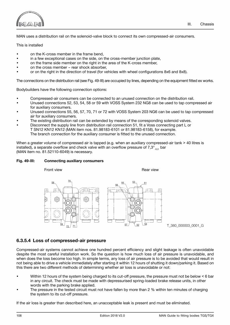
108 Edition 2018 V2.0 MAN Guide to fitting bodies TGS/TGX
III. Chassis
MAN uses a distribution rail on the solenoid-valve block to connect its own compressed-air consumers.
This is installed
• on the K-cross member in the frame bend, • in a few exceptional cases on the side, on the cross-member junction plate,• on the frame side member on the right in the area of the K-cross member,• on the cross member – rear shock absorber,• or on the right in the direction of travel (for vehicles with wheel configurations 8x6 and 8x8).
The connections on the distribution rail (see Fig. 49-III) are occupied by lines, depending on the equipment fitted ex works.
Bodybuilders have the following connection options:
• Compressed-air consumers can be connected to an unused connection on the distribution rail.• Unused connections 52, 53, 54, 58 or 59 with VOSS System 232 NG8 can be used to tap compressed air for auxiliary consumers.• Unused connections 55, 56, 57, 70, 71 or 72 with VOSS System 203 NG6 can be used to tap compressed air for auxiliary consumers.• The existing distribution rail can be extended by means of the corresponding solenoid valves. • Disconnect the supply line from distribution rail connection 51, fit a Voss connecting part L or T SN12 KN12 KN12 (MAN item nos. 81.98183-6101 or 81.98183-6158), for example. The branch connection for the auxiliary consumer is fitted to the unused connection.
When a greater volume of compressed air is tapped (e.g. when an auxiliary compressed-air tank > 40 litres is installed), a separate overflow and check valve with an overflow pressure of 7,3°-0,3 bar (MAN item no. 81.52110-6049) is necessary.
Fig. 49-III: Connecting auxiliary consumers
Front view Rear view
6.3.5.4 Loss of compressed-air pressure
Compressed-air systems cannot achieve one hundred percent efficiency and slight leakage is often unavoidable despite the most careful installation work. So the question is how much loss of air pressure is unavoidable, and when does the loss become too high. In simple terms, any loss of air pressure is to be avoided that would result in not being able to drive a vehicle immediately after starting it within 12 hours of shutting it down/parking it. Based on this there are two different methods of determining whether air loss is unavoidable or not:
• Within 12 hours of the system being charged to its cut-off pressure, the pressure must not be below < 6 bar in any circuit. The check must be made with depressurised spring-loaded brake release units, in other words with the parking brake applied.• The pressure in the tested circuit must not have fallen by more than 2 % within ten minutes of charging the system to its cut-off pressure.
If the air loss is greater than described here, an unacceptable leak is present and must be eliminated.
51
52
70
7259
58
71
53
57
55
54
56
T_380_000003_0001_G
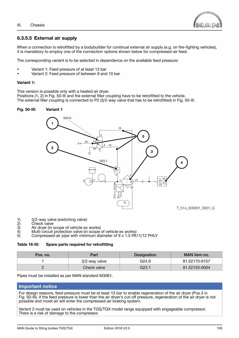
MAN Guide to fitting bodies TGS/TGX Edition 2018 V2.0 109
III. Chassis
6.3.5.5 External air supply
When a connection is retrofitted by a bodybuilder for continual external air supply (e.g. on fire-fighting vehicles), it is mandatory to employ one of the connection options shown below for compressed-air feed.
The corresponding variant is to be selected in dependence on the available feed pressure:
• Variant 1: Feed pressure of at least 13 bar• Variant 2: Feed pressure of between 9 and 10 bar
Variant 1:
This version is possible only with a heated air dryer.Positions (1, 2) in Fig. 50-III and the external filler coupling have to be retrofitted to the vehicle. The external filler coupling is connected to P2 (3/2-way valve that has to be retrofitted) in Fig. 50-III.
Fig. 50-III: Variant 1
1) 3/2-way valve (switching valve)2) Check valve3) Air dryer (in scope of vehicle ex works)4) Multi-circuit protection valve (in scope of vehicle ex works)5) Compressed-air pipe with minimum diameter of 9 x 1.5 PA11/12 PHLY
Table 16-III: Spare parts required for retrofitting
Pos. no. Part Designation MAN item no.1 3/2-way valve G24.9 81.52170-61572 Check valve G23.1 81.52120-6004
Pipes must be installed as per MAN standard M3061.
Important notice For design reasons, feed pressure must be at least 13 bar to enable regeneration of the air dryer (Pos.3 in Fig. 50-III). If the feed pressure is lower than the air dryer‘s cut-off pressure, regeneration of the air dryer is not possible and moist air will enter the compressed-air braking system.
Variant 2 must be used on vehicles in the TGS/TGX model range equipped with engageable compressor. There is a risk of damage to the compressor.
T_514_000001_0001_G
0
22
212124
2322
12
A
Z
(3)
(3)(3)
1
3
4
4L
R2
G23.1
G24.9
P2
212
,5 +
/- 0
,2 b
ar1
3
4
1
2
5
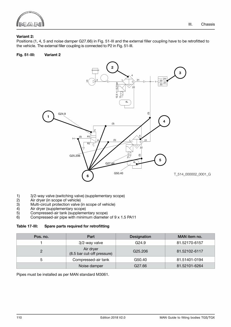
110 Edition 2018 V2.0 MAN Guide to fitting bodies TGS/TGX
III. Chassis
Variant 2:Positions (1, 4, 5 and noise damper G27.66) in Fig. 51-III and the external filler coupling have to be retrofitted to the vehicle. The external filler coupling is connected to P2 in Fig. 51-III.
Fig. 51-III: Variant 2
1) 3/2-way valve (switching valve) (supplementary scope)2) Air dryer (in scope of vehicle)3) Multi-circuit protection valve (in scope of vehicle)4) Air dryer (supplementary scope)5) Compressed-air tank (supplementary scope)6) Compressed-air pipe with minimum diameter of 9 x 1.5 PA11
Table 17-III: Spare parts required for retrofitting
Pos. no. Part Designation MAN item no.1 3/2-way valve G24.9 81.52170-6157
2 Air dryer (8.5 bar cut-off pressure) G25.206 81.52102-6117
5 Compressed-air tank G50.40 81.51401-0194Noise damper G27.66 81.52101-6264
Pipes must be installed as per MAN standard M3061.
6 T_514_000002_0001_G
0
22
212124
2322
12
A
Z
(3)
(3)
(3)
(3)(3)
1
3
4
4L
R2
G24.9
G25.206
G27.66
G50.40
P2
12,5
+/-
0,2
bar
22
211
3
4
4L
1
2
4
3
5
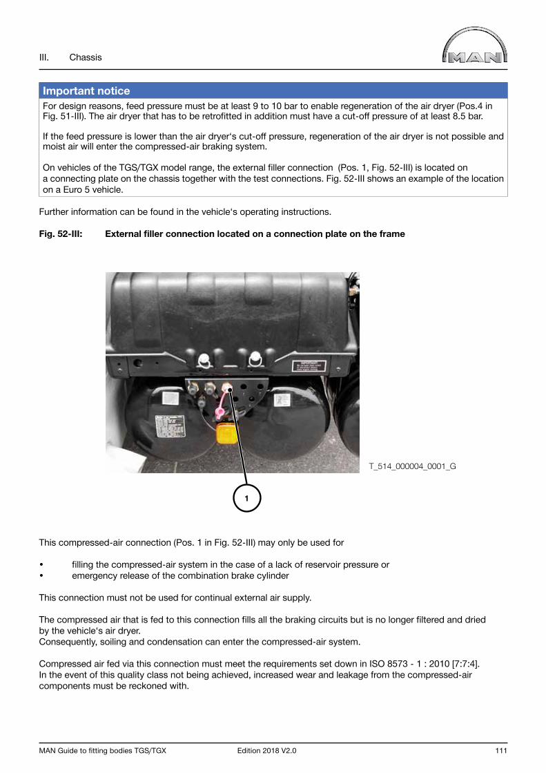
MAN Guide to fitting bodies TGS/TGX Edition 2018 V2.0 111
III. Chassis
Important notice For design reasons, feed pressure must be at least 9 to 10 bar to enable regeneration of the air dryer (Pos.4 in Fig. 51-III). The air dryer that has to be retrofitted in addition must have a cut-off pressure of at least 8.5 bar.
If the feed pressure is lower than the air dryer‘s cut-off pressure, regeneration of the air dryer is not possible and moist air will enter the compressed-air braking system.
On vehicles of the TGS/TGX model range, the external filler connection (Pos. 1, Fig. 52-III) is located on a connecting plate on the chassis together with the test connections. Fig. 52-III shows an example of the location on a Euro 5 vehicle.
Further information can be found in the vehicle‘s operating instructions.
Fig. 52-III: External filler connection located on a connection plate on the frame
This compressed-air connection (Pos. 1 in Fig. 52-III) may only be used for
• filling the compressed-air system in the case of a lack of reservoir pressure or• emergency release of the combination brake cylinder
This connection must not be used for continual external air supply.
The compressed air that is fed to this connection fills all the braking circuits but is no longer filtered and dried by the vehicle‘s air dryer. Consequently, soiling and condensation can enter the compressed-air system.
Compressed air fed via this connection must meet the requirements set down in ISO 8573 - 1 : 2010 [7:7:4]. In the event of this quality class not being achieved, increased wear and leakage from the compressed-air components must be reckoned with.
T_514_000004_0001_G
1
112 Edition 2018 V2.0 MAN Guide to fitting bodies TGS/TGX
III. Chassis
6.4 Exhaust system
6.4.1 Modifications to the exhaust routing
InformationIn general, modifications to the exhaust system are to be avoided. Various factory options are available for the TGS/TGS and body builders must check to see if these can be used. Information on availability for the corresponding vehicle can be obtained from your closest MAN sales branch.
If it is still not possible to avoid making modifications the following requirements must be met:
• The outflow of exhaust gases must not be inhibited in any way.• The backpressure in the exhaust must not be allowed to vary.• All statutory regulations relevant to noise and emissions must be fulfilled.• When modifications are made to the exhaust system and routing, care must be taken to ensure that the exhaust-gas stream is not directed at any part of the vehicle. The direction of the exhaust outlet must point away from the vehicle (observe regulations in the respective country - in Germany, these are the Road Traffic Licensing Regulations (StVZO)).• All regulations pertaining to the components in question issued by professional associations or similar bodies must also be fulfilled (e.g. surface temperature in the vicinity of handles/grips)• In the case of modified exhaust systems, MAN cannot - guarantee compliance with the above-mentioned and other regulations. Responsibility for this remains with the company performing the modification. This also applies to regulations pertaining to on-board diagnosis systems (OBD). - provide any information about changes in fuel consumption or noise characteristics. In some circumstances, new noise-emission approval will be required. Components that have an effect on acoustics may not be modified. Non-compliance with noise limits voids type approval! - make any statement of compliance about prescribed exhaust-gas limits. An expertise on emissions may be necessary. Non-compliance with emission limits voids type approval!
Depending on the emission class, modifications to the exhaust system are possible. In this regard, the following instructions must be observed.
For vehicles up to and including the Euro 4 exhaust standard, the following apply in addition to the general specifications:
• When relocating the exhaust silencer it must be ensured that the original MAN bracket is re-used and that the basic installation position of components is unchanged. (See Fig. 53-III: Exhaust-silencer bracket)• The location of the temperature and the NOx sensors (with OBD) on the exhaust silencer may not be changed. • Modifications to the factory-fitted MAN cable harness to the sensors are not permitted. If other cable harness lengths are required, order Genuine MAN cable harnesses from the MAN Spare-parts Service.• For EMC reasons, CAN cables may not be untwisted.• Conversion work or modifications to the exhaust-gas routing from the exhaust manifold to the metal hose (the flexible metal pipe between parts attached to the body and those attached to the frame) are not permitted.• No blowing-out of cargo (e.g. bitumen) using exhaust gas - danger of damage to the exhaust system and engine.• Never change the shape or area of pipework cross-sections. The original type of material must be used for pipes.• Do not modify silencers (including the silencer housing): this voids type approval.• Bending radii must be at least twice the pipe diameter; creases are not allowed.• Only continuous bends are permitted, i.e. no mitre cuts.• The function of components relevant to OBD may not be impaired. Manipulation of components relevant to OBD voids type approval!

MAN Guide to fitting bodies TGS/TGX Edition 2018 V2.0 113
III. Chassis
• The connection of the pressure-sensor line on the silencer must always face the top, the following steel pipe must be installed so that it rises continuously to connect with the sensor and it must have a minimum length of 300 mm and a maximum length of 400 mm (including the flexible section). The measurement line must be made from M01-942-X6CrNiTi1810-K3-8x1 D4-T3. In general, the installation position of the pressure sensor must be retained (connection at bottom).• The notes and requirements set down in Chapter 1.4 “Fire protection” must be observed.
Fig. 53-III: Exhaust-silencer bracket
1) Temperature sensor2) Bracket3) Metal hose
1 2 3
T_151_000004_0002_G

114 Edition 2018 V2.0 MAN Guide to fitting bodies TGS/TGX
III. Chassis
For vehicles up to and including Euro 5, the following apply in addition to the requirements of the lower exhaust standards:
• Extension of the exhaust routing by 1000 mm is permissible from the metal pipe to the exhaust silencer without fitting high temperature insulation.• Extension of the exhaust routing by > 1000 mm to max. 2000 mm is permissible from the metal pipe to the exhaust silencer if suitable high temperature insulation is fitted.
Fig. 54-III: Exhaust-gas tract from mixer to metal hose
1) Metal hose2) Mixer3) Injection nozzle4) Dosing modul
• Only austenitic stainless steels may be used for manufacturing exhaust system piping. Reason: if the otherwise commonly-used ferritic steels are used, the ammonia in the exhaust tract (reaction product from AdBlue) will cause corrosion.• Stainless steel pipes must be welded using inert gas shielded arc welding (observe the steel manufacturer’s instructions) with the work carried out by qualified and authorised personnel.
1 2 3 4
T_152_000002_0002_G
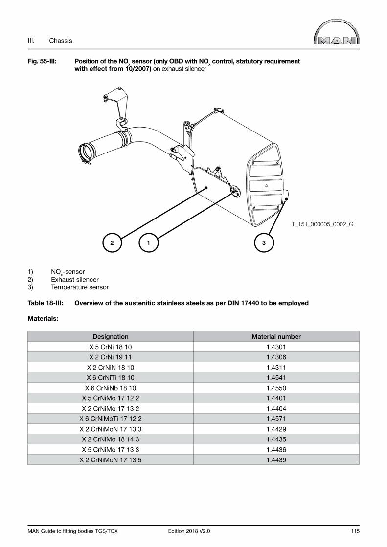
MAN Guide to fitting bodies TGS/TGX Edition 2018 V2.0 115
III. Chassis
Fig. 55-III: Position of the NOx sensor (only OBD with NOx control, statutory requirement with effect from 10/2007) on exhaust silencer
1) NOx-sensor2) Exhaust silencer3) Temperature sensor
Table 18-III: Overview of the austenitic stainless steels as per DIN 17440 to be employed
Materials:
Designation Material numberX 5 CrNi 18 10 1.4301X 2 CrNi 19 11 1.4306
X 2 CrNiN 18 10 1.4311X 6 CrNiTi 18 10 1.4541X 6 CrNiNb 18 10 1.4550
X 5 CrNiMo 17 12 2 1.4401X 2 CrNiMo 17 13 2 1.4404
X 6 CrNiMoTi 17 12 2 1.4571X 2 CrNiMoN 17 13 3 1.4429X 2 CrNiMo 18 14 3 1.4435X 5 CrNiMo 17 13 3 1.4436
X 2 CrNiMoN 17 13 5 1.4439
1 32
T_151_000005_0002_G
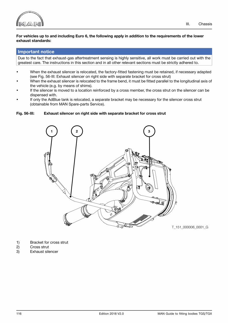
116 Edition 2018 V2.0 MAN Guide to fitting bodies TGS/TGX
III. Chassis
For vehicles up to and including Euro 6, the following apply in addition to the requirements of the lower exhaust standards:
Important notice Due to the fact that exhaust-gas aftertreatment sensing is highly sensitive, all work must be carried out with the greatest care. The instructions in this section and in all other relevant sections must be strictly adhered to.
• When the exhaust silencer is relocated, the factory-fitted fastening must be retained, if necessary adapted (see Fig. 56-III: Exhaust silencer on right side with separate bracket for cross strut)• When the exhaust silencer is relocated to the frame bend, it must be fitted parallel to the longitudinal axis of the vehicle (e.g. by means of shims).• If the silencer is moved to a location reinforced by a cross member, the cross strut on the silencer can be dispensed with.• If only the AdBlue tank is relocated, a separate bracket may be necessary for the silencer cross strut (obtainable from MAN Spare-parts Service).
Fig. 56-III: Exhaust silencer on right side with separate bracket for cross strut
1) Bracket for cross strut2) Cross strut3) Exhaust silencer
1 2 3
T_151_000006_0001_G
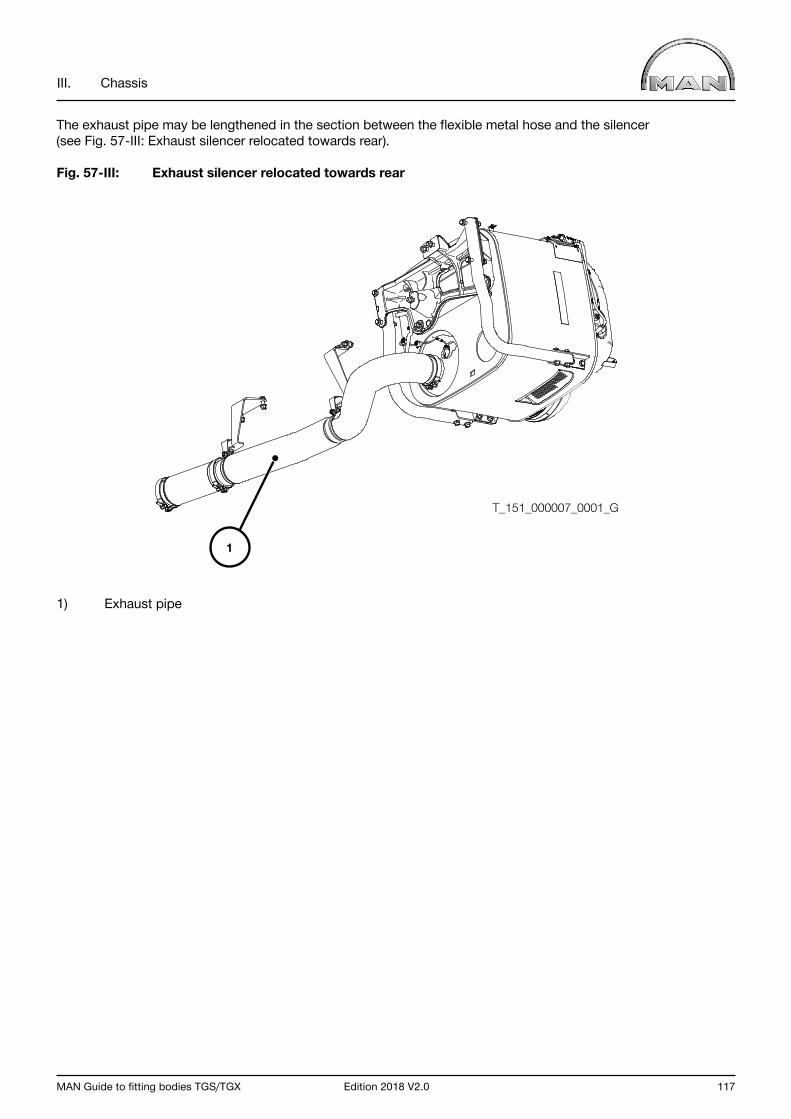
MAN Guide to fitting bodies TGS/TGX Edition 2018 V2.0 117
III. Chassis
The exhaust pipe may be lengthened in the section between the flexible metal hose and the silencer (see Fig. 57-III: Exhaust silencer relocated towards rear).
Fig. 57-III: Exhaust silencer relocated towards rear
1) Exhaust pipe
T_151_000007_0001_G
1
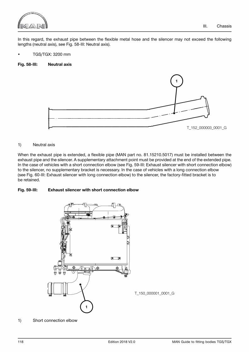
118 Edition 2018 V2.0 MAN Guide to fitting bodies TGS/TGX
III. Chassis
In this regard, the exhaust pipe between the flexible metal hose and the silencer may not exceed the following lengths (neutral axis), see Fig. 58-III: Neutral axis).
• TGS/TGX: 3200 mm
Fig. 58-III: Neutral axis
1) Neutral axis
When the exhaust pipe is extended, a flexible pipe (MAN part no. 81.15210.5017) must be installed between the exhaust pipe and the silencer. A supplementary attachment point must be provided at the end of the extended pipe. In the case of vehicles with a short connection elbow (see Fig. 59-III: Exhaust silencer with short connection elbow) to the silencer, no supplementary bracket is necessary. In the case of vehicles with a long connection elbow (see Fig. 60-III: Exhaust silencer with long connection elbow) to the silencer, the factory-fitted bracket is to be retained.
Fig. 59-III: Exhaust silencer with short connection elbow
1) Short connection elbow
1
1
T_152_000003_0001_G
T_150_000001_0001_G
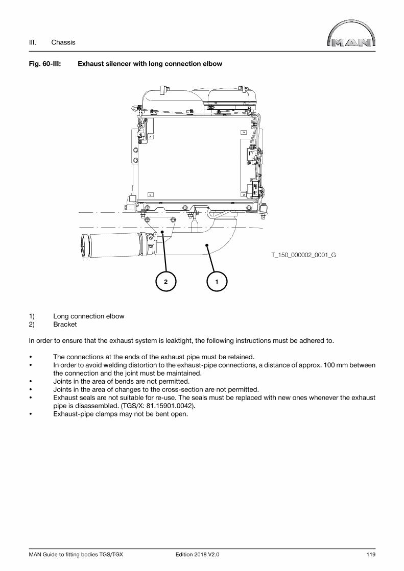
MAN Guide to fitting bodies TGS/TGX Edition 2018 V2.0 119
III. Chassis
Fig. 60-III: Exhaust silencer with long connection elbow
1) Long connection elbow2) Bracket
In order to ensure that the exhaust system is leaktight, the following instructions must be adhered to.
• The connections at the ends of the exhaust pipe must be retained.• In order to avoid welding distortion to the exhaust-pipe connections, a distance of approx. 100 mm between the connection and the joint must be maintained.• Joints in the area of bends are not permitted.• Joints in the area of changes to the cross-section are not permitted.• Exhaust seals are not suitable for re-use. The seals must be replaced with new ones whenever the exhaust pipe is disassembled. (TGS/X: 81.15901.0042).• Exhaust-pipe clamps may not be bent open.
T_150_000002_0001_G
12
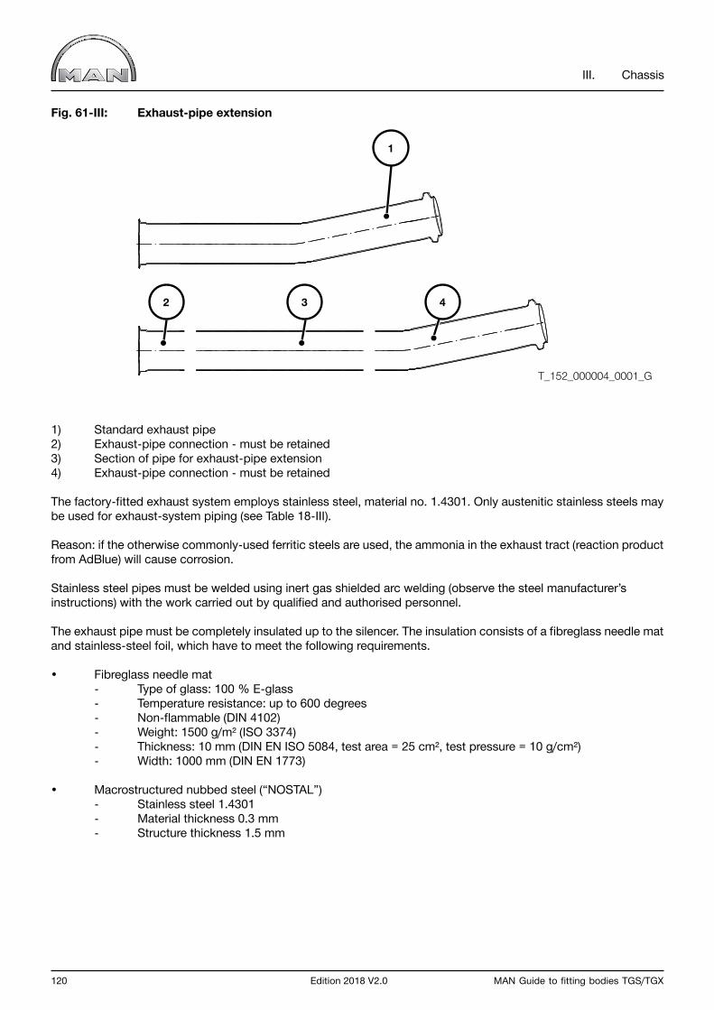
120 Edition 2018 V2.0 MAN Guide to fitting bodies TGS/TGX
III. Chassis
Fig. 61-III: Exhaust-pipe extension
1) Standard exhaust pipe2) Exhaust-pipe connection - must be retained3) Section of pipe for exhaust-pipe extension4) Exhaust-pipe connection - must be retained
The factory-fitted exhaust system employs stainless steel, material no. 1.4301. Only austenitic stainless steels may be used for exhaust-system piping (see Table 18-III).
Reason: if the otherwise commonly-used ferritic steels are used, the ammonia in the exhaust tract (reaction product from AdBlue) will cause corrosion.
Stainless steel pipes must be welded using inert gas shielded arc welding (observe the steel manufacturer’s instructions) with the work carried out by qualified and authorised personnel.
The exhaust pipe must be completely insulated up to the silencer. The insulation consists of a fibreglass needle mat and stainless-steel foil, which have to meet the following requirements.
• Fibreglass needle mat - Type of glass: 100 % E-glass - Temperature resistance: up to 600 degrees - Non-flammable (DIN 4102) - Weight: 1500 g/m² (ISO 3374) - Thickness: 10 mm (DIN EN ISO 5084, test area = 25 cm², test pressure = 10 g/cm²) - Width: 1000 mm (DIN EN 1773)
• Macrostructured nubbed steel (“NOSTAL”) - Stainless steel 1.4301 - Material thickness 0.3 mm - Structure thickness 1.5 mm
1
2 3 4
T_152_000004_0001_G
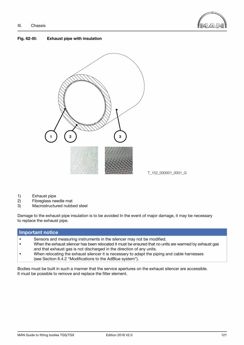
MAN Guide to fitting bodies TGS/TGX Edition 2018 V2.0 121
III. Chassis
Fig. 62-III: Exhaust pipe with insulation
1) Exhaust pipe2) Fibreglass needle mat3) Macrostructured nubbed steel
Damage to the exhaust-pipe insulation is to be avoided In the event of major damage, it may be necessary to replace the exhaust pipe.
Important notice • Sensors and measuring instruments in the silencer may not be modified.• When the exhaust silencer has been relocated it must be ensured that no units are warmed by exhaust gas and that exhaust gas is not discharged in the direction of any units.• When relocating the exhaust silencer it is necessary to adapt the piping and cable harnesses (see Section 6.4.2 “Modifications to the AdBlue system”).
Bodies must be built in such a manner that the service apertures on the exhaust silencer are accessible. It must be possible to remove and replace the filter element.
T_152_000001_0001_G
1 2 3
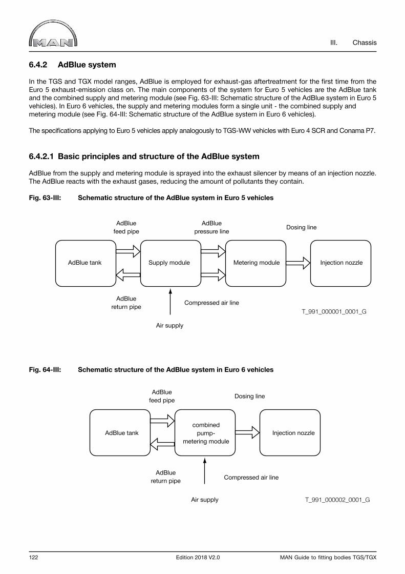
122 Edition 2018 V2.0 MAN Guide to fitting bodies TGS/TGX
III. Chassis
6.4.2 AdBlue system
In the TGS and TGX model ranges, AdBlue is employed for exhaust-gas aftertreatment for the first time from the Euro 5 exhaust-emission class on. The main components of the system for Euro 5 vehicles are the AdBlue tank and the combined supply and metering module (see Fig. 63-III: Schematic structure of the AdBlue system in Euro 5 vehicles). In Euro 6 vehicles, the supply and metering modules form a single unit - the combined supply and metering module (see Fig. 64-III: Schematic structure of the AdBlue system in Euro 6 vehicles).
The specifications applying to Euro 5 vehicles apply analogously to TGS-WW vehicles with Euro 4 SCR and Conama P7.
6.4.2.1 Basic principles and structure of the AdBlue system
AdBlue from the supply and metering module is sprayed into the exhaust silencer by means of an injection nozzle. The AdBlue reacts with the exhaust gases, reducing the amount of pollutants they contain.
Fig. 63-III: Schematic structure of the AdBlue system in Euro 5 vehicles
Fig. 64-III: Schematic structure of the AdBlue system in Euro 6 vehicles
AdBluefeed pipe Dosing line
AdBluereturn pipe Compressed air line
Air supply
AdBlue tankcombined
pump-metering module
Injection nozzle
AdBluefeed pipe
AdBluepressure line Dosing line
AdBluereturn pipe Compressed air line
Air supply
AdBlue tank Supply module Metering module Injection nozzle
T_991_000001_0001_G
T_991_000002_0001_G
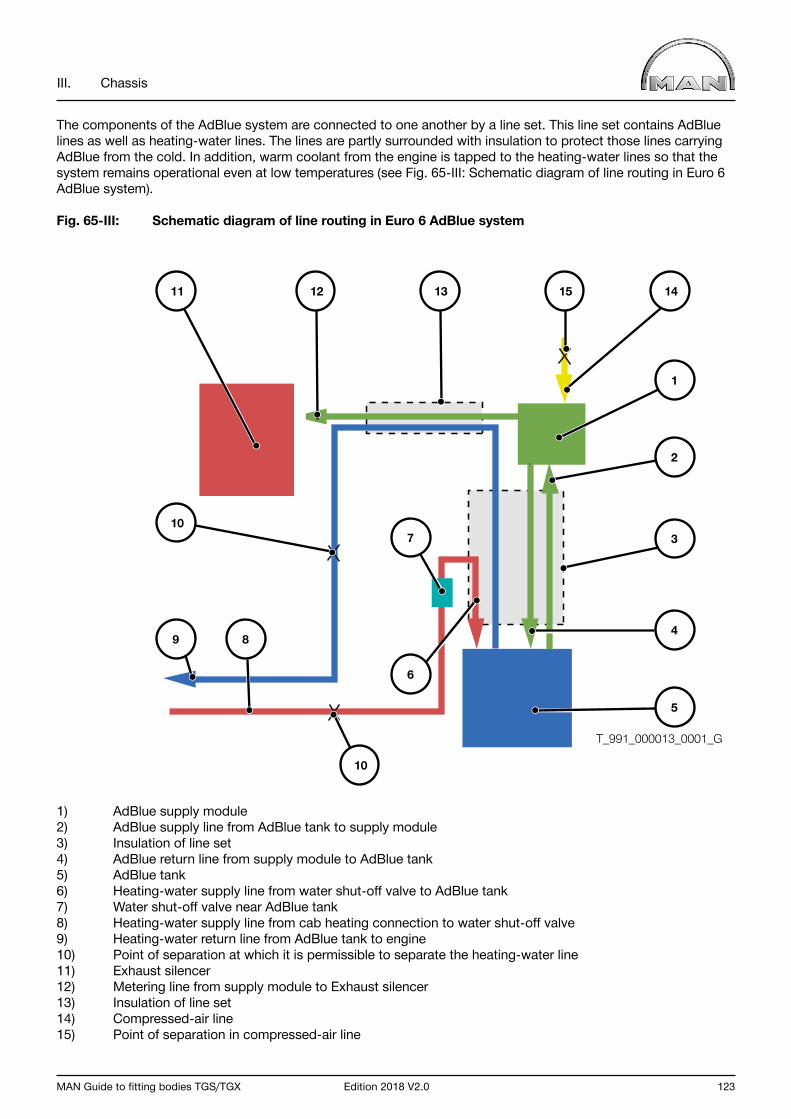
MAN Guide to fitting bodies TGS/TGX Edition 2018 V2.0 123
III. Chassis
The components of the AdBlue system are connected to one another by a line set. This line set contains AdBlue lines as well as heating-water lines. The lines are partly surrounded with insulation to protect those lines carrying AdBlue from the cold. In addition, warm coolant from the engine is tapped to the heating-water lines so that the system remains operational even at low temperatures (see Fig. 65-III: Schematic diagram of line routing in Euro 6 AdBlue system).
Fig. 65-III: Schematic diagram of line routing in Euro 6 AdBlue system
1) AdBlue supply module2) AdBlue supply line from AdBlue tank to supply module3) Insulation of line set4) AdBlue return line from supply module to AdBlue tank5) AdBlue tank6) Heating-water supply line from water shut-off valve to AdBlue tank7) Water shut-off valve near AdBlue tank8) Heating-water supply line from cab heating connection to water shut-off valve9) Heating-water return line from AdBlue tank to engine10) Point of separation at which it is permissible to separate the heating-water line11) Exhaust silencer12) Metering line from supply module to Exhaust silencer13) Insulation of line set14) Compressed-air line15) Point of separation in compressed-air line
11 12 13 15 14
2
3
4
5
1
10
10
9 8
7
6
T_991_000013_0001_G
124 Edition 2018 V2.0 MAN Guide to fitting bodies TGS/TGX
III. Chassis
Notes on the AdBlue system
AdBlue (DIN 70070) is the trade name for an aqueous, synthetically manufactured 32.5% urea solution that is used for exhaust gas after treatment in an SCR (selective catalytic reduction) catalytic converter.
AdBlue is non-poisonous but has a highly corrosive effect on non-stainless steels and non-ferrous metals (e.g. copper seals or electrical contacts). Similarly, plastics not resistant to AdBlue are negatively affected (e.g. electric leads or tubing). Any AdBlue that escapes must therefore be soaked up immediately and the affected area cleaned with warm tap water.
Important notice Risk of component damage from ingress of dirt.If contaminants find their way into the AdBlue tank, components of the exhaust gas cleaning system and injection system could fail (e.g. injector nozzles could become blocked).When working on the AdBlue tank, observe strict rules of cleanliness. Cover or seal all the openings on the AdBlue system. MAN recommends using plugs for the AdBlue system (MAN item no.: 80.99607-6092)
The stipulations in the repair manuals of MAN Truck & Bus AG on the MAN After Sales Portal (ASP*): www.asp.mantruckandbus.com must be considered. Registration is required.
Important notice Under all circumstances, AdBlue must be prevented from entering the coolant circuit - for example through transposing the lines - as engine damage results.
Modifications to the AdBlue system
Due to the very sensitive sensing of the exhaust gas aftertreatment, all work must be completed with great care and strict adherence to the points that follow in this and all other relevant chapters is required.
A check must be made in advance to establish whether existing MAN variants of the AdBlue system can be used.

MAN Guide to fitting bodies TGS/TGX Edition 2018 V2.0 125
III. Chassis
The following points must be observed when working on AdBlue systems:
• All conversion measures must be performed by personnel with appropriate training.• Subsequent to all work on the supply module, the necessity of starting up the module in accordance with the repair manual must be determined, particularly in cases where the module has been relocated or replaced.• The supply module on Euro 5 vehicles may only be relocated within the limits set down in the supply module installation overview (see Fig. 68-III: Euro 5 supply module installation overview).• The supply module on Euro 6 vehicles may not be relocated. When relocating the AdBlue tank and exhaust silencer, the limits set down in the supply module installation overview (see Fig. 69-III Euro 6 supply module installation overview) must be adhered to.• It is imperative to ensure that the lines are correctly connected. If AdBlue enters the cooling system there is a risk of damage to the engine.• The heating-water supply line to the AdBlue tank may not be bundled together with the other lines.• Lines may not be kinked and must be routed with adequately sized radii. Routing may not lead to the formation of syphons.• Plugs on the lines may not be re-used. As a basic principle, new MAN-approved plugs must be used and tightened with the approved clamps.• The fir-tree may not be greased when pressed into the line.• AdBlue freezes at -11°C. If the insulation is removed - even only partially - from the line set, insulation against the cold as effective as the standard insulation must be fitted.• Existing heating lines may not be removed. • As a basic principle, the routing of the heating lines, in particular the heating of the metering line up to the metering module (in Euro 5 vehicles) or up to the steel pipe on the exhaust silencer (in Euro 6 vehicles), must be retained.• The ends of the insulation must be closed off by means of suitable adhesive tape.• The AdBlue system, in particular any plugs that have just been pressed in, must be checked to ensure that it is leaktight.
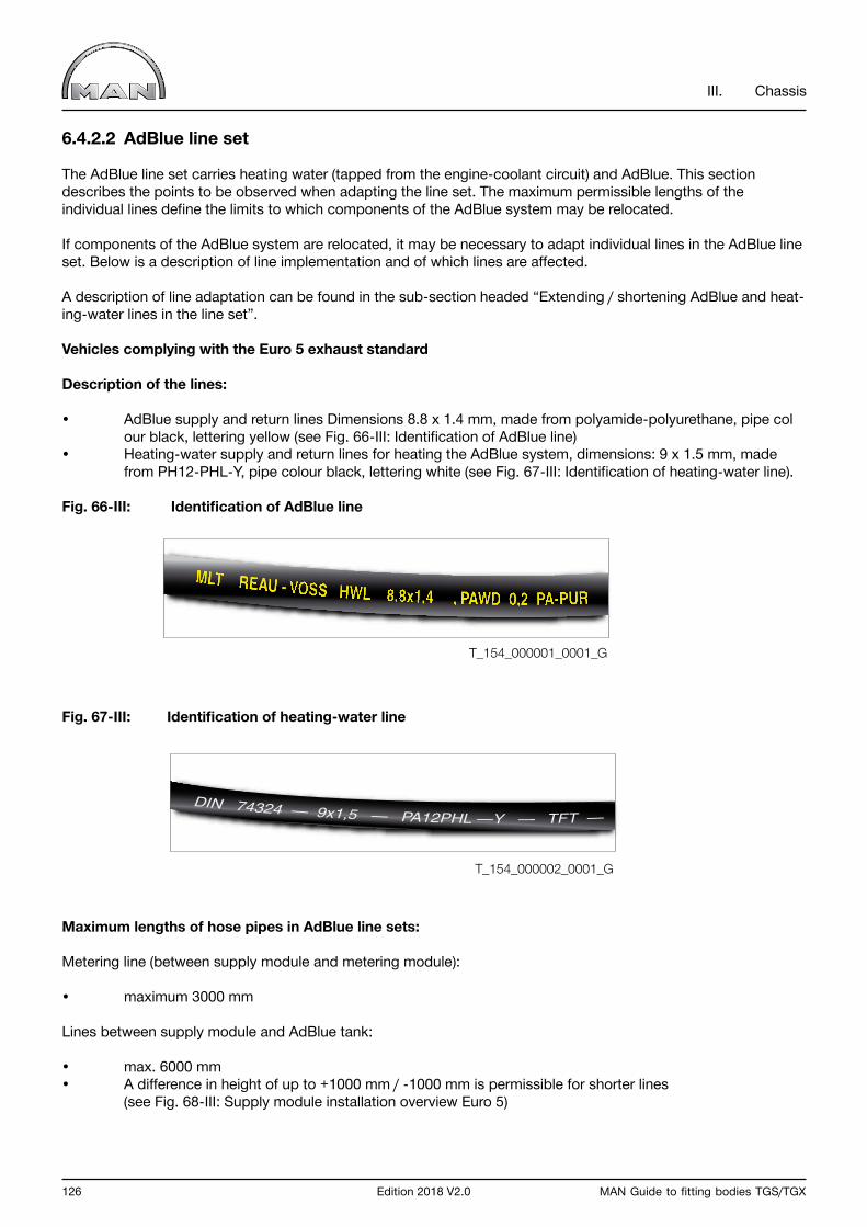
126 Edition 2018 V2.0 MAN Guide to fitting bodies TGS/TGX
III. Chassis
6.4.2.2 AdBlue line set
The AdBlue line set carries heating water (tapped from the engine-coolant circuit) and AdBlue. This section describes the points to be observed when adapting the line set. The maximum permissible lengths of the individual lines define the limits to which components of the AdBlue system may be relocated.
If components of the AdBlue system are relocated, it may be necessary to adapt individual lines in the AdBlue line set. Below is a description of line implementation and of which lines are affected.
A description of line adaptation can be found in the sub-section headed “Extending / shortening AdBlue and heat-ing-water lines in the line set”.
Vehicles complying with the Euro 5 exhaust standard
Description of the lines:
• AdBlue supply and return lines Dimensions 8.8 x 1.4 mm, made from polyamide-polyurethane, pipe col our black, lettering yellow (see Fig. 66-III: Identification of AdBlue line)• Heating-water supply and return lines for heating the AdBlue system, dimensions: 9 x 1.5 mm, made from PH12-PHL-Y, pipe colour black, lettering white (see Fig. 67-III: Identification of heating-water line).
Fig. 66-III: Identification of AdBlue line
Fig. 67-III: Identification of heating-water line
Maximum lengths of hose pipes in AdBlue line sets:
Metering line (between supply module and metering module):
• maximum 3000 mm
Lines between supply module and AdBlue tank:
• max. 6000 mm• A difference in height of up to +1000 mm / -1000 mm is permissible for shorter lines (see Fig. 68-III: Supply module installation overview Euro 5)
T_154_000001_0001_G
T_154_000002_0001_G
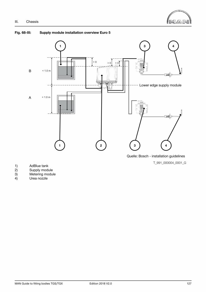
MAN Guide to fitting bodies TGS/TGX Edition 2018 V2.0 127
III. Chassis
Fig. 68-III: Supply module installation overview Euro 5
1) AdBlue tank2) Supply module3) Metering module4) Urea nozzle
< 1.0 m
< 1.0 m
> 0 > 0 > 0
2 41
1 3 4
3
Lower edge supply module
Quelle: Bosch - installation guidelines
B
A
T_991_000004_0001_G
128 Edition 2018 V2.0 MAN Guide to fitting bodies TGS/TGX
III. Chassis
Vehicles complying with the Euro 6 exhaust standard
Description of the lines:
• AdBlue supply and return lines, metering line• Dimensions 3.2 x 2.65 mm, made from EPDM, hose colour black, lettering white• Heating-water return line from water shut-off valve to AdBlue tank and heating water return line• Dimensions 6 x 3 mm, made from EPDM, hose colour black, lettering white• Heating-water supply line to water shut-off valve• Dimensions 9 x 1.5 mm, made from polyamide, pipe colour black, lettering white
Minimum bending radii
• Heating-water line made from polyamide: minimum 40 mm• Heating-water line made from EPDM: minimum 35 mm• AdBlue line made from EPDM: minimum 17 mm• Bundled line sets: minimum 35 mm
Maximum lengths of hose pipes in AdBlue line sets:
Metering line (between supply module and exhaust silencer):
• Maximum 3000 mm.• It is recommended that the line descends towards the exhaust silencer along its entire length.• Deposits may form in the line if it rises.
Lines between supply module and AdBlue tank:
• Maximum 4550 mm (currently the longest variant installed ex works)• A difference of + 500 mm / - 1500 mm in height is permissible (see Fig. 69-III: Euro 6 supply module, overview of installation)
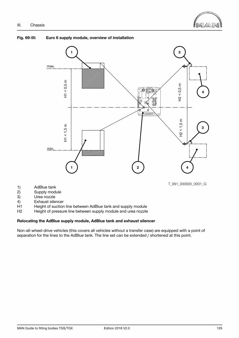
MAN Guide to fitting bodies TGS/TGX Edition 2018 V2.0 129
III. Chassis
Fig. 69-III: Euro 6 supply module, overview of installation
1) AdBlue tank2) Supply module3) Urea nozzle4) Exhaust silencerH1 Height of suction line between AdBlue tank and supply module H2 Height of pressure line between supply module and urea nozzle
Relocating the AdBlue supply module, AdBlue tank and exhaust silencer
Non-all-wheel-drive vehicles (this covers all vehicles without a transfer case) are equipped with a point of separation for the lines to the AdBlue tank. The line set can be extended / shortened at this point.
max.
min.
H1
< 1,
5 m
H2
< 1,
5 m
H1
< 0,
5 m
H2
< 0,
5 m
T_991_000005_0001_G
1
1 3
3
2 4
4
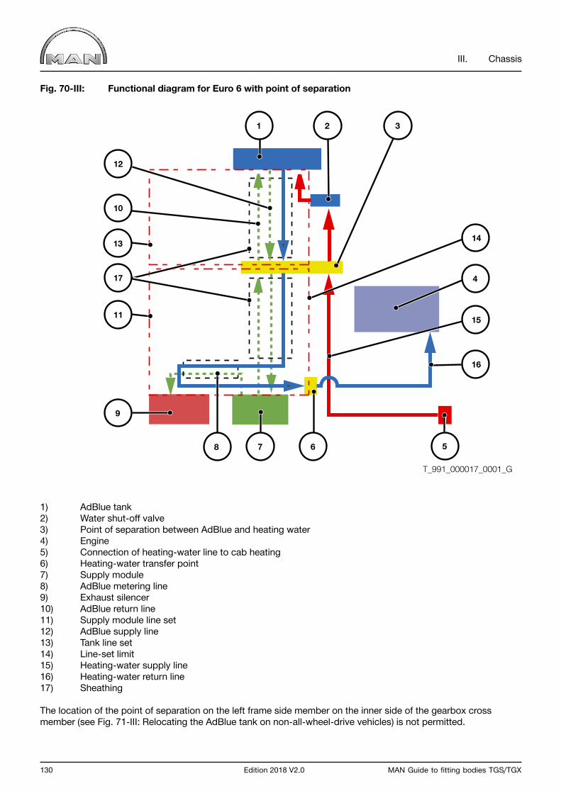
130 Edition 2018 V2.0 MAN Guide to fitting bodies TGS/TGX
III. Chassis
Fig. 70-III: Functional diagram for Euro 6 with point of separation
1) AdBlue tank2) Water shut-off valve3) Point of separation between AdBlue and heating water4) Engine5) Connection of heating-water line to cab heating6) Heating-water transfer point7) Supply module8) AdBlue metering line9) Exhaust silencer10) AdBlue return line11) Supply module line set12) AdBlue supply line13) Tank line set14) Line-set limit15) Heating-water supply line16) Heating-water return line17) Sheathing
The location of the point of separation on the left frame side member on the inner side of the gearbox cross member (see Fig. 71-III: Relocating the AdBlue tank on non-all-wheel-drive vehicles) is not permitted.
1
12
10
17
8
13
11
2 3
14
4
15
5
16
67
9
T_991_000017_0001_G
MAN Guide to fitting bodies TGS/TGX Edition 2018 V2.0 131
III. Chassis
Notes on adapting the line set when relocating the AdBlue tank
1.) In non-all-wheel drive vehicles (vehicles without a transfer case, AdBlue tank installed on the left side), the AdBlue tank is relocated as follows:
• Relocating the AdBlue tank as described in Section 6.4.2.3 “AdBlue tank”• Necessary adaptations to the line set
- When relocating the AdBlue tank towards the rear of the vehicle, - the factory fitted line set must be replaced with the longest MAN line set available, which must then be shortened. - (Obtainable from the MAN Spare-parts Service; MAN item no: 81.15400.6116) - The heating-water supply line to the water shut-off valve must be replaced with the longest MAN line available, which must then be shortened if necessary. - (Obtainable from the MAN Spare-parts Service; MAN item no: 81.15407.6027)
- When relocating the AdBlue tank towards the cab, - the factory fitted line set may be shortened, - the factory fitted heating-water supply line may be shortened.
- Lines here may only be shortened at the point of separation. - When relocating the AdBlue tank to the right side, the description in Point 2 of this sub-section must be observed.
• A description of line extension can be found in the sub-section headed “Extending / shortening AdBlue and heating-water lines in the line set”.• Information on adapting the electrical wiring can be found in Section 6.4.2.5, “AdBlue cable harness”.

132 Edition 2018 V2.0 MAN Guide to fitting bodies TGS/TGX
III. Chassis
Fig. 71-III: Relocating the AdBlue tank on non-all-wheel-drive vehicles
1) AdBlue tank in standard location1a) Relocated AdBlue tank2) Point of separation3) Supply module4) Exhaust silencerX Distance by which unit is moved; maximum lengths must be observed
1a 21
3
4
T_991_000009_0001_G
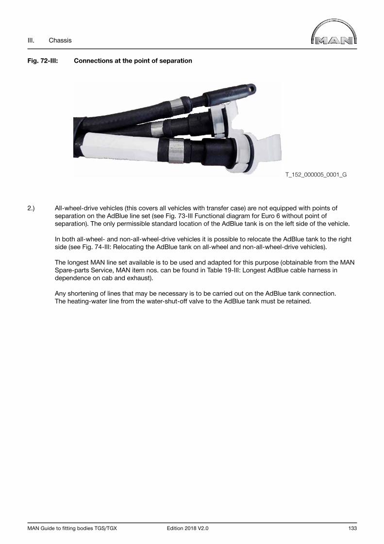
MAN Guide to fitting bodies TGS/TGX Edition 2018 V2.0 133
III. Chassis
Fig. 72-III: Connections at the point of separation
2.) All-wheel-drive vehicles (this covers all vehicles with transfer case) are not equipped with points of separation on the AdBlue line set (see Fig. 73-III Functional diagram for Euro 6 without point of separation). The only permissible standard location of the AdBlue tank is on the left side of the vehicle.
In both all-wheel- and non-all-wheel-drive vehicles it is possible to relocate the AdBlue tank to the right side (see Fig. 74-III: Relocating the AdBlue tank on all-wheel and non-all-wheel-drive vehicles).
The longest MAN line set available is to be used and adapted for this purpose (obtainable from the MAN Spare-parts Service, MAN item nos. can be found in Table 19-III: Longest AdBlue cable harness in dependence on cab and exhaust).
Any shortening of lines that may be necessary is to be carried out on the AdBlue tank connection. The heating-water line from the water-shut-off valve to the AdBlue tank must be retained.
T_152_000005_0001_G
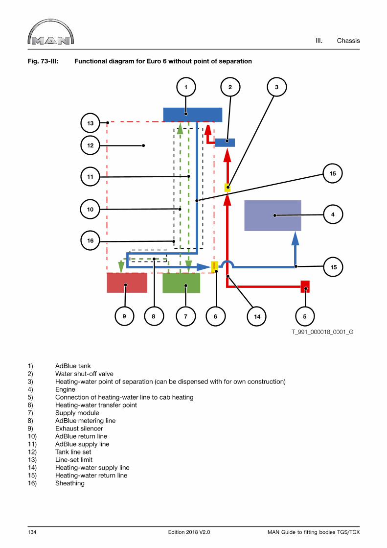
134 Edition 2018 V2.0 MAN Guide to fitting bodies TGS/TGX
III. Chassis
Fig. 73-III: Functional diagram for Euro 6 without point of separation
1) AdBlue tank2) Water shut-off valve3) Heating-water point of separation (can be dispensed with for own construction)4) Engine5) Connection of heating-water line to cab heating6) Heating-water transfer point7) Supply module8) AdBlue metering line9) Exhaust silencer10) AdBlue return line11) AdBlue supply line12) Tank line set13) Line-set limit14) Heating-water supply line15) Heating-water return line16) Sheathing
1
11
10
16
8
12
13
2 3
15
4
14 5
15
679
T_991_000018_0001_G

MAN Guide to fitting bodies TGS/TGX Edition 2018 V2.0 135
III. Chassis
Table 19-III: Longest AdBlue cable harness in dependence on cab and exhaust
MAN part no. Cab variant Exhaust variant Distance between supply module and tank
81.15400.6121 M cab Ground-directed discharge Approx. 2500 mm
81.15400.6123 M cab Directed upwards Approx. 2500 mm
81.15400.6120
L cabLX cabXL cab
XLX cabXXL cab
Ground-directed discharge Approx. 2300 mm
81.15400.6142
L cabLX cabXL cab
XLX cabXXL cab
Directed upwards Approx. 2300 mm

136 Edition 2018 V2.0 MAN Guide to fitting bodies TGS/TGX
III. Chassis
Fig. 74-III: Relocating the AdBlue tank on all-wheel and non-all-wheel-drive vehicles
1) AdBlue tank in standard location1a) Relocated AdBlue tank2) Supply module3) Exhaust silencerX Distance by which unit is moved; maximum lengths must be observed
Notes on adapting the line set when relocating the exhaust silencer
- Relocating the exhaust silencer as described in Section 6.4.2 - Necessary adaptations to the line set: · Shorten or construct a new metering line from supply module to exhaust silencer. · Shorten or construct a new heating-water line to heat the metering line. · Bundle and sheathe the above-mentioned lines up to the steel pipe on the exhaust silencer with Co-flex double-walled corrugated tubing system. · Shorten or construct a new heating-water return line to the engine. - A description of line extension can be found in the sub-section headed “Extending / shortening AdBlue and heating-water lines in the line set”. - Information on adapting the electrical cable harness can be found in Section 6.4.2.5, “AdBlue cable harness”.
1a
3
1
2
T_991_000010_0001_G
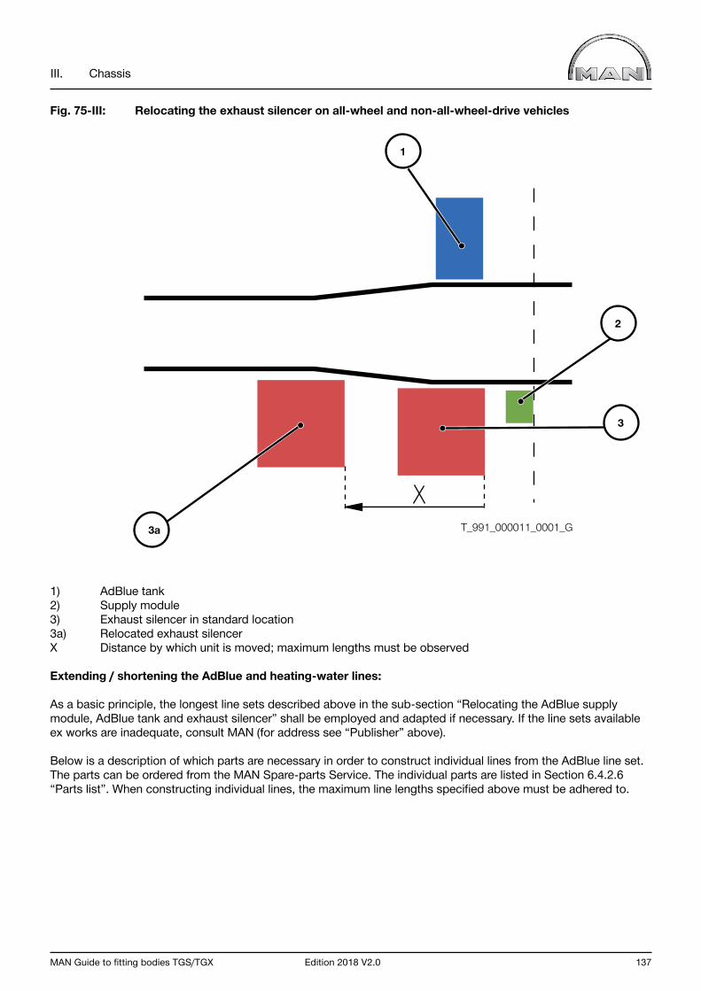
MAN Guide to fitting bodies TGS/TGX Edition 2018 V2.0 137
III. Chassis
Fig. 75-III: Relocating the exhaust silencer on all-wheel and non-all-wheel-drive vehicles
1) AdBlue tank2) Supply module3) Exhaust silencer in standard location3a) Relocated exhaust silencerX Distance by which unit is moved; maximum lengths must be observed
Extending / shortening the AdBlue and heating-water lines:
As a basic principle, the longest line sets described above in the sub-section “Relocating the AdBlue supply module, AdBlue tank and exhaust silencer” shall be employed and adapted if necessary. If the line sets available ex works are inadequate, consult MAN (for address see “Publisher” above).
Below is a description of which parts are necessary in order to construct individual lines from the AdBlue line set. The parts can be ordered from the MAN Spare-parts Service. The individual parts are listed in Section 6.4.2.6 “Parts list”. When constructing individual lines, the maximum line lengths specified above must be adhered to.
3a
3
1
2
T_991_000011_0001_G
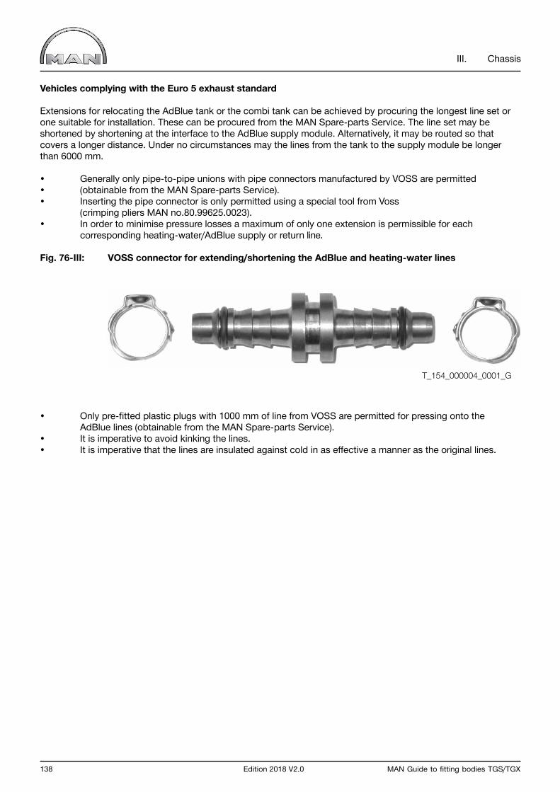
138 Edition 2018 V2.0 MAN Guide to fitting bodies TGS/TGX
III. Chassis
Vehicles complying with the Euro 5 exhaust standard
Extensions for relocating the AdBlue tank or the combi tank can be achieved by procuring the longest line set or one suitable for installation. These can be procured from the MAN Spare-parts Service. The line set may be shortened by shortening at the interface to the AdBlue supply module. Alternatively, it may be routed so that covers a longer distance. Under no circumstances may the lines from the tank to the supply module be longer than 6000 mm.
• Generally only pipe-to-pipe unions with pipe connectors manufactured by VOSS are permitted• (obtainable from the MAN Spare-parts Service).• Inserting the pipe connector is only permitted using a special tool from Voss (crimping pliers MAN no.80.99625.0023).• In order to minimise pressure losses a maximum of only one extension is permissible for each corresponding heating-water/AdBlue supply or return line.
Fig. 76-III: VOSS connector for extending/shortening the AdBlue and heating-water lines
• Only pre-fitted plastic plugs with 1000 mm of line from VOSS are permitted for pressing onto the AdBlue lines (obtainable from the MAN Spare-parts Service).• It is imperative to avoid kinking the lines.• It is imperative that the lines are insulated against cold in as effective a manner as the original lines.
T_154_000004_0001_G
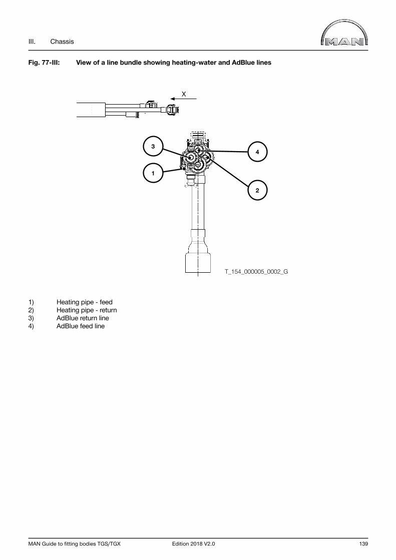
MAN Guide to fitting bodies TGS/TGX Edition 2018 V2.0 139
III. Chassis
Fig. 77-III: View of a line bundle showing heating-water and AdBlue lines
1) Heating pipe - feed2) Heating pipe - return3) AdBlue return line4) AdBlue feed line
X
T_154_000005_0002_G
2
43
1

140 Edition 2018 V2.0 MAN Guide to fitting bodies TGS/TGX
III. Chassis
Vehicles complying with the Euro 6 exhaust standard
Additional notes on adapting line sets.
• Additional points of separation in the lines of the AdBlue line set are not permitted.• Only non-all-wheel-drive vehicles (vehicles without transfer case) are equipped with points of separation in the lines.• AdBlue lines must be constructed in a single piece from plug to plug.• Lines can be obtained by the metre from the MAN Spare-parts Service.• Do not disassemble the heating-water supply-line plug to the water shut-off valve (Fig. 78-III: Connection of heating-water supply line to water shut-off valve). Extension of heating-water supply line only in the area of the polyamide pipe from engine to water shut-off valve.
Fig. 78-III: Connection of heating-water supply line to water shut-off valve
• Parts kit for constructing an AdBlue metering line - Metering line (by the metre) – (MAN item no.: 04.27405.0092) - VOSS straight plug (on supply module) – (MAN item no.: 81.98180.6036) - VOSS elbow plug (on exhaust silencer) – (MAN item no.: 81.98180.6037) - Oetiker clamps – (Oetiker no.: 16700004)
• Parts kit for constructing an AdBlue supply line - VOSS elbow plug (on AdBlue tank) – (MAN item no.: 81.98180.6042) - VOSS connector pin (at the point of separation) – (MAN item no.: 81.98180.6039) - Oetiker clamps – (Oetiker no.: 16700004)
• Parts kit for constructing an AdBlue return line - VOSS elbow plug (on AdBlue tank) – (MAN item no.: 81.98180.6041) - VOSS straight plug (at the point of separation) – (MAN item no.: 81.98180.6036) - Oetiker clamps – (Oetiker no.: 16700004)
T_154_000023_0001_G
MAN Guide to fitting bodies TGS/TGX Edition 2018 V2.0 141
III. Chassis
• Parts kit for constructing a heating-water supply line - Heating-water line (by the metre) – (MAN item no.: 04.27405.0090) - VOSS elbow plug (on AdBlue tank) – (MAN item no.: 81.98180.6027) - VOSS elbow plug (on water shut-off valve) – (MAN item no.: 81.98180.6015) or - VOSS straight plug (on water shut-off valve) – (MAN item no.: 81.98180.6004) - Oetiker clamps – (Oetiker no.: 167000014)
• Parts kit for constructing a heating-water return line - Heating-water line (by the metre) – (MAN item no.: 04.27405.0090) - VOSS elbow plug (on AdBlue tank) – (MAN item no.: 81.98180.6035) - VOSS straight plug (at the point of separation) – (MAN item no.: 81.98180.6044) - VOSS connector pin (at the point of separation) – (MAN item no.: 81.98180.6038) - VOSS straight plug – (MAN item no.: 81.98180.6044) - Oetiker clamps – (Oetiker no.: 16700014)
• Parts kit for constructing heating lines from the water shut-off valve - Heating line – polyamide pipe, dimensions 9 x 1.5 - (MAN item no.: 04.35160.9709) - Straight connector – (MAN item no.: 81.98181.0201)
• Parts kit for constructing a compressed-air line to the water shut-off valve - Compressed-air line – polyamide pipe as per DIN 74324 Part 1 or MAN standard M 3230 Part 1 - Straight connector – (MAN item no.: 81.98181.6043)
• Parts kit for constructing sheathing / insulation - Double-walled Co-flex corrugated tubing - or zip material (special pliers must be used for this)

142 Edition 2018 V2.0 MAN Guide to fitting bodies TGS/TGX
III. Chassis
6.4.2.3 AdBlue tank
This section describes the points to be observed when modifying the AdBlue tank. When relocating AdBlue tanks, the line lengths specified in Section 6.4.2.2 “AdBlue line set” must be adhered to.
Installing a larger AdBlue tank
MAN offers variously sized AdBlue tanks for every model range as equipment variants ex works. Retrofitting a larger AdBlue tank is possible if MAN has approved it for the respective model range. In such cases, professional and correct modification by trained personnel is assumed.
It there is a change in volume to the AdBlue tank, then parameterisation via a MAN service outlet is necessary.
Comply with the MAN repair guidelines.
Relocating the AdBlue tank
Depending on the body concept it may be necessary to relocate the AdBlue tank. The section below describes the points to be observed in this regard.
When the AdBlue tank is relocated the original bracket must be employed. If the AdBlue tank is relocated to the frame bend, any possible tilt must be compensated for by spacer sleeves, for example.
AdBlue tanks are equipped with four connections for lines: two (supply and return) for heating water and two (supply and return) for AdBlue. The lines are individually identified as described in the sub-sections below.
Before the vehicle is commissioned it is imperative to make sure that all the lines are correctly connected. If AdBlue enters the coolant it will cause damage to the engine (Fig. 79-III: Line connections on the AdBlue tank).

MAN Guide to fitting bodies TGS/TGX Edition 2018 V2.0 143
III. Chassis
Fig. 79-III: Line connections on the AdBlue tank
1) Heating-water supply2) Heating-water return3) AdBlue return4) AdBlue supply
A description of line adaptation can be found in the sub-section headed “Extending / shortening AdBlue and heat-ing-water lines in the line set”.
Vehicles complying with the Euro 5 exhaust standard
In addition, the following must be observed:
• Relocation of combination/single tanks may only be carried out using the original MAN tanks.• Routing of electrical and CAN wiring (e.g. for fill-level sensor, supply module, OBD sensors) is permitted only with Genuine MAN cable harnesses (obtainable from the MAN Spare-parts Service).
WATER
WATER
TO PUMP U
NIT
BACK FLOW
1
2
4
3
T_991_000014_0001_G
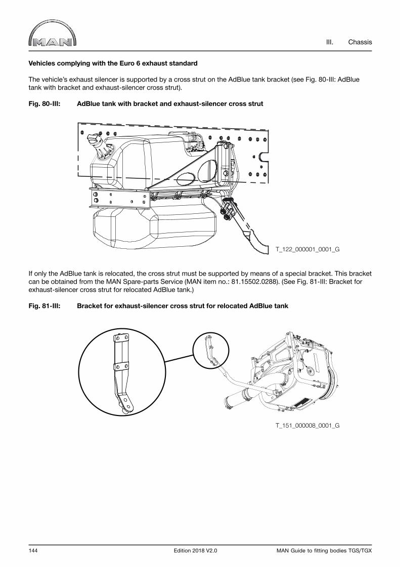
144 Edition 2018 V2.0 MAN Guide to fitting bodies TGS/TGX
III. Chassis
Vehicles complying with the Euro 6 exhaust standard
The vehicle’s exhaust silencer is supported by a cross strut on the AdBlue tank bracket (see Fig. 80-III: AdBlue tank with bracket and exhaust-silencer cross strut).
Fig. 80-III: AdBlue tank with bracket and exhaust-silencer cross strut
If only the AdBlue tank is relocated, the cross strut must be supported by means of a special bracket. This bracket can be obtained from the MAN Spare-parts Service (MAN item no.: 81.15502.0288). (See Fig. 81-III: Bracket for exhaust-silencer cross strut for relocated AdBlue tank.)
Fig. 81-III: Bracket for exhaust-silencer cross strut for relocated AdBlue tank
T_122_000001_0001_G
T_151_000008_0001_G
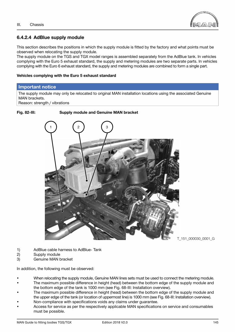
MAN Guide to fitting bodies TGS/TGX Edition 2018 V2.0 145
III. Chassis
6.4.2.4 AdBlue supply module
This section describes the positions in which the supply module is fitted by the factory and what points must be observed when relocating the supply module.The supply module on the TGS and TGX model ranges is assembled separately from the AdBlue tank. In vehicles complying with the Euro 5 exhaust standard, the supply and metering modules are two separate parts. In vehicles complying with the Euro 6 exhaust standard, the supply and metering modules are combined to form a single part.
Vehicles complying with the Euro 5 exhaust standard
Important notice The supply module may only be relocated to original MAN installation locations using the associated Genuine MAN brackets.Reason: strength / vibrations
Fig. 82-III: Supply module and Genuine MAN bracket
1) AdBlue cable harness to AdBlue- Tank2) Supply module3) Genuine MAN bracket
In addition, the following must be observed:
• When relocating the supply module, Genuine MAN lines sets must be used to connect the metering module.• The maximum possible difference in height (head) between the bottom edge of the supply module and the bottom edge of the tank is 1000 mm (see Fig. 68-III: Installation overview).• The maximum possible difference in height (head) between the bottom edge of the supply module and the upper edge of the tank (or location of uppermost line) is 1000 mm (see Fig. 68-III: Installation overview).• Non-compliance with specifications voids any claims under guarantee.• Access for service as per the respectively applicable MAN specifications on service and consumables must be possible.
1 2 3
T_151_000030_0001_G
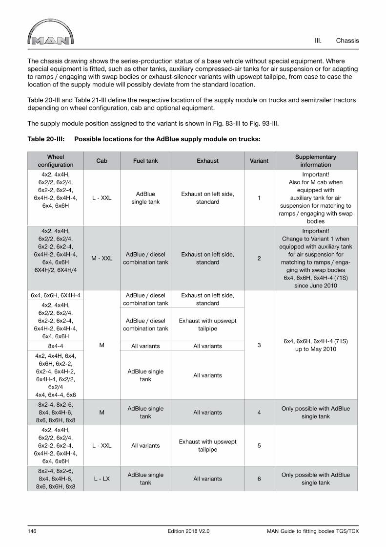
146 Edition 2018 V2.0 MAN Guide to fitting bodies TGS/TGX
III. Chassis
The chassis drawing shows the series-production status of a base vehicle without special equipment. Where special equipment is fitted, such as other tanks, auxiliary compressed-air tanks for air suspension or for adapting to ramps / engaging with swap bodies or exhaust-silencer variants with upswept tailpipe, from case to case the location of the supply module will possibly deviate from the standard location.
Table 20-III and Table 21-III define the respective location of the supply module on trucks and semitrailer tractors depending on wheel configuration, cab and optional equipment.
The supply module position assigned to the variant is shown in Fig. 83-III to Fig. 93-III.
Table 20-III: Possible locations for the AdBlue supply module on trucks:
Wheel configuration Cab Fuel tank Exhaust Variant Supplementary
information4x2, 4x4H,
6x2/2, 6x2/4, 6x2-2, 6x2-4,
6x4H-2, 6x4H-4, 6x4, 6x6H
L - XXL AdBlue single tank
Exhaust on left side, standard 1
Important! Also for M cab when
equipped with auxiliary tank for air
suspension for matching to ramps / engaging with swap
bodies4x2, 4x4H,
6x2/2, 6x2/4, 6x2-2, 6x2-4,
6x4H-2, 6x4H-4, 6x4, 6x6H
6X4H/2, 6X4H/4
M - XXL AdBlue / diesel combination tank
Exhaust on left side, standard 2
Important! Change to Variant 1 when
equipped with auxiliary tank for air suspension for
matching to ramps / enga-ging with swap bodies
6x4, 6x6H, 6x4H-4 (71S) since June 2010
6x4, 6x6H, 6X4H-4
M
AdBlue / diesel combination tank
Exhaust on left side, standard
3 6x4, 6x6H, 6x4H-4 (71S) up to May 2010
4x2, 4x4H, 6x2/2, 6x2/4, 6x2-2, 6x2-4,
6x4H-2, 6x4H-4, 6x4, 6x6H
AdBlue / diesel combination tank
Exhaust with upswept tailpipe
8x4-4 All variants All variants4x2, 4x4H, 6x4,
6x6H, 6x2-2,6x2-4, 6x4H-2,6x4H-4, 6x2/2,
6x2/44x4, 6x4-4, 6x6
AdBlue single tank All variants
8x2-4, 8x2-6, 8x4, 8x4H-6,
8x6, 8x6H, 8x8M AdBlue single
tank All variants 4 Only possible with AdBlue single tank
4x2, 4x4H, 6x2/2, 6x2/4, 6x2-2, 6x2-4,
6x4H-2, 6x4H-4, 6x4, 6x6H
L - XXL All variants Exhaust with upswept tailpipe 5
8x2-4, 8x2-6, 8x4, 8x4H-6,
8x6, 8x6H, 8x8L - LX AdBlue single
tank All variants 6 Only possible with AdBlue single tank

MAN Guide to fitting bodies TGS/TGX Edition 2018 V2.0 147
III. Chassis
Table 21-III: Possible locations for the AdBlue supply module on semitrailer tractors
Wheel configuration Cab Fuel tank Exhaust Variant
Supplementary information
4x2, 4x4H, 6x2-2, 6x2-4,
6x4, 6x6HM - XXL
All variantsExhaust on left side,
standard 1
Body restriction possible with M cab, e.g.: Crane
behind cab or swap-body semitrailer
tractor/truck6x2/2, 6x2/4,
6x2-4, 6x4H-2, 6x4H-4
Single tank
4x2, 4x4H, 6x2/2, 6x2/4, 6x2-2, 6x2-4,
6x4H-2, 6x4H-4, 6x4, 6x6H
M
Combination tank
Exhaust with upswept tailpipe
3
Body restriction possible For example: crane behind
cab or swap-body semitrailer tractor/truck
4x2, 4x4H, 6x4, 6x6H, 4x4, 6x6
Single tank
4x4, 6x4-4, 6x6 Exhaust on left side, standard
4x2, 4x4H, 6x2-2, 6x4,
6x6H
L - LX All variants Exhaust with upswept tailpipe 5
Body restriction possible For example: crane behind
cab or swap-body semitrailer tractor/truck6x2/2,
6x2/4, 6x2-44x4,
6x4-4, 6x6
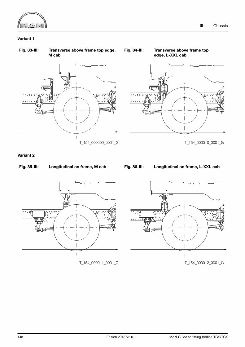
148 Edition 2018 V2.0 MAN Guide to fitting bodies TGS/TGX
III. Chassis
Variant 1
Fig. 83-III: Transverse above frame top edge, M cab
Fig. 84-III: Transverse above frame top edge, L-XXL cab
Variant 2
Fig. 85-III: Longitudinal on frame, M cab Fig. 86-III: Longitudinal on frame, L-XXL cab
T_154_000009_0001_G
T_154_000011_0001_G
T_154_000010_0001_G
T_154_000012_0001_G
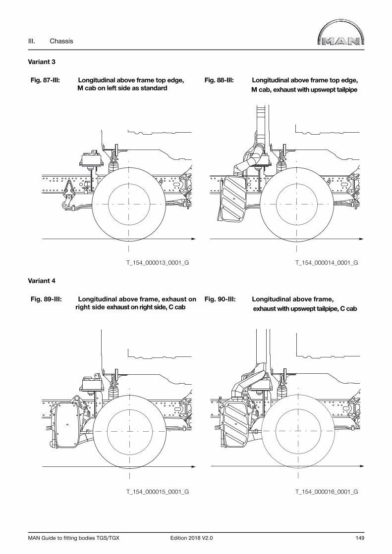
MAN Guide to fitting bodies TGS/TGX Edition 2018 V2.0 149
III. Chassis
Variant 3
Fig. 87-III: Longitudinal above frame top edge, M cab on left side as standard
Fig. 88-III: Longitudinal above frame top edge, M cab, exhaust with upswept tailpipe
Variant 4
Fig. 89-III: Longitudinal above frame, exhaust on right side exhaust on right side, C cab
Fig. 90-III: Longitudinal above frame, exhaust with upswept tailpipe, C cab
T_154_000013_0001_G
T_154_000015_0001_G
T_154_000014_0001_G
T_154_000016_0001_G

150 Edition 2018 V2.0 MAN Guide to fitting bodies TGS/TGX
III. Chassis
Variant 5
Fig. 91-III: L-XXL cab, exhaust with upswept tailpipe
Variant 6
Fig. 92-III: L-LX cab, transverse above frame top edge, rotated 180°, exhaust on right side
Fig. 93-III: L-LX cab, transverse above frametop edge, rotated 180°, exhaust with upswept tailpipe
T_154_000017_0001_G
T_154_000018_0001_G T_154_000019_0001_G

MAN Guide to fitting bodies TGS/TGX Edition 2018 V2.0 151
III. Chassis
Metering module
• The location of the metering module may not be changed • (see Fig. 94-III: Temperature sensor, injection nozzle, metering module).• Extending the pipe between the metering module and the supply module is possible up to an overall length of 3000 mm.
Fig. 94-III: Temperature sensor, injection nozzle, metering module
1) Injection nozzle2) Metering module
1 2 T_154_000020_0001_G

152 Edition 2018 V2.0 MAN Guide to fitting bodies TGS/TGX
III. Chassis
Vehicles complying with the Euro 6 exhaust standard
There are currently two - cab-dependent - installation locations, which may not be changed.
The supply and metering modules are combines to form a single unit. The supply module is located in an easy to build manner behind the cab.
Fig. 95-III: : Location on vehicles with M cab
Fig. 96-III: Location on vehicles with L, LX, XL, XLX and XXL cab
T_154_000021_0001_G
T_154_000022_0001_G

MAN Guide to fitting bodies TGS/TGX Edition 2018 V2.0 153
III. Chassis
6.4.2.5 AdBlue cable harness
When modifications are made to the AdBlue system it may be necessary to adapt the cable harness.
This section describes the cable harness, possible points of separation and the plug connectors to be used.
The following must be observed for all cable routing:
• Overlengths must not be laid in coil-like rings but only in loops to the side of the cable harness (see Fig. 97-III: Cable routings).
Fig. 97-III: Cable routings
• The cable harness must be secured in such a manner that no movement relative to the frame can occur (danger of chafing), see Fig. 98-III: Routing examples.
Fig. 98-III: Routing examples
T_992_000001_0001_G
T_998_000003_0001_G

154 Edition 2018 V2.0 MAN Guide to fitting bodies TGS/TGX
III. Chassis
Vehicles complying with the Euro 6 exhaust standard
Below is a schematic diagram of the original MAN cable harness (Fig. 99-III: Schematic diagram of cable harness).
Fig. 99-III: Schematic diagram of cable harness
1) Supply module2) EDC control unit3) AdBlue tank4) Exhaust silencer
The cable harness can separated for extension purposes at the points shown below. Suitable plugs are available from the MAN Spare-parts Service for adapting the lengths of the cable harnesses.
1
2
4
3
T_991_000020_0001_G
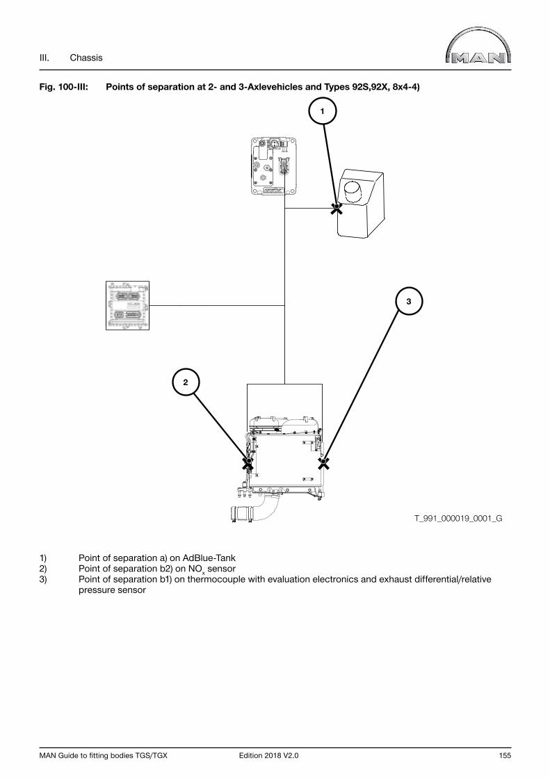
MAN Guide to fitting bodies TGS/TGX Edition 2018 V2.0 155
III. Chassis
Fig. 100-III: Points of separation at 2- and 3-Axlevehicles and Types 92S,92X, 8x4-4)
1) Point of separation a) on AdBlue-Tank2) Point of separation b2) on NOx sensor3) Point of separation b1) on thermocouple with evaluation electronics and exhaust differential/relative pressure sensor
2
3
1
T_991_000019_0001_G
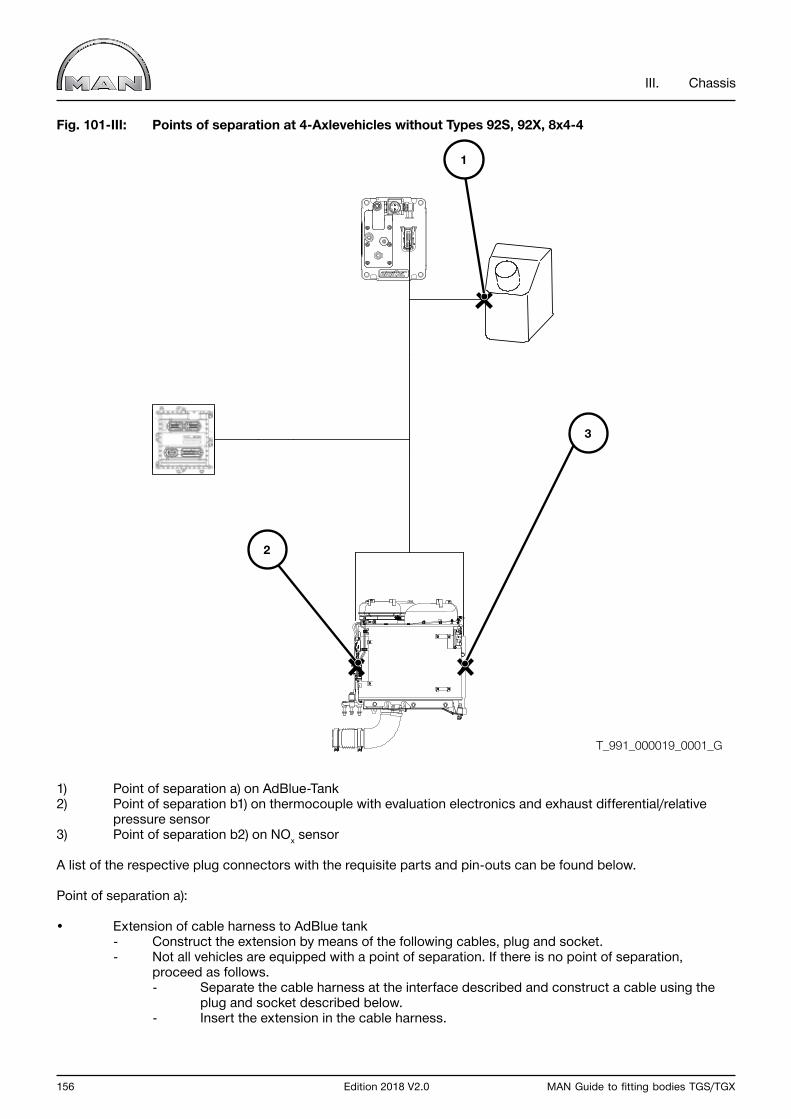
156 Edition 2018 V2.0 MAN Guide to fitting bodies TGS/TGX
III. Chassis
Fig. 101-III: Points of separation at 4-Axlevehicles without Types 92S, 92X, 8x4-4
1) Point of separation a) on AdBlue-Tank2) Point of separation b1) on thermocouple with evaluation electronics and exhaust differential/relative pressure sensor3) Point of separation b2) on NOx sensor
A list of the respective plug connectors with the requisite parts and pin-outs can be found below.
Point of separation a):
• Extension of cable harness to AdBlue tank - Construct the extension by means of the following cables, plug and socket. - Not all vehicles are equipped with a point of separation. If there is no point of separation, proceed as follows. - Separate the cable harness at the interface described and construct a cable using the plug and socket described below. - Insert the extension in the cable harness.
2
3
1
T_991_000019_0001_G

MAN Guide to fitting bodies TGS/TGX Edition 2018 V2.0 157
III. Chassis
Table 22-III: Plug connector for cable harness to AdBlue tank
Point of separation between exhaust cable harness X5508 (point of separation ahead of AdBlue tank) and bodybuilder‘s solution 6-pole BF13 - SF13 with pinning.
Socket housing BF13 MAN item no.: 81.25475-0280
Material for BF13 socket housingQty. MAN code MAN part no. Part designation
1 BF13 81.25475-0280 Socket housing1 AW95 81.25433-0289 Adapter HDSCS D-180° - NW8.56 XU60-1<0 07.91201-6020 Contact (individual goods)6 DL11 07.91163-0069 Sealing element
BF13 socket housing pin-outPIN Manager Cross-section mm2 Contact Sealing element1 90008 0,75 XU60-1<0 DL112 191 0,75 XU60-1<0 DL113 192 0,75 XU60-1<0 DL114 31000 0,75 XU60-1<0 DL115 90311 0,75 XU60-1<0 DL116 90321 0,75 XU60-1<0 DL11
Material for cable setQty. MAN part no. Material / line
1 07.08302-0191 CAN lines 2x0.75-A-RS-191-192 5 07.08131-0302 Lines FLRY-0,75-A-RS1 07.08131-0354 Lines FLRY-0,75-A-BRWS1 04.37135-9938 Corrugated tube 8.5 dia.
Pin housing SF13 MAN item no.: 81.25475-0281
Material for SF13 pin housingQty. MAN code MAN part no. Part designation
1 SF13 81.25475-0281 Pin housing1 AW95 81.25433-0289 Adapter HDSCS D-180° - NW8.56 XG60-1<0 07.91201-0216 Contact (volume goods)6 DL11 07.91163-0069 Sealing element1 GV53 81.25475-0287 Locking slide size: "B" yellow
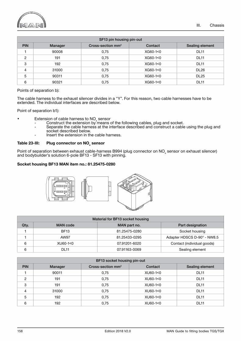
158 Edition 2018 V2.0 MAN Guide to fitting bodies TGS/TGX
III. Chassis
SF13 pin housing pin-outPIN Manager Cross-section mm2 Contact Sealing element
1 90008 0,75 XG60-1<0 DL112 191 0,75 XG60-1<0 DL113 192 0,75 XG60-1<0 DL114 31000 0,75 XG60-1<0 DL265 90311 0,75 XG60-1<0 DL256 90321 0,75 XG60-1<0 DL11
Points of separation b):
The cable harness to the exhaust silencer divides in a “Y”. For this reason, two cable harnesses have to be extended. The individual interfaces are described below.
Point of separation b1):
• Extension of cable harness to NOx sensor - Construct the extension by means of the following cables, plug and socket. - Separate the cable harness at the interface described and construct a cable using the plug and socket described below. - Insert the extension in the cable harness.
Table 23-III: Plug connector on NOx sensor
Point of separation between exhaust cable-harness B994 (plug connector on NOx sensor on exhaust silencer) and bodybuilder’s solution 6-pole BF13 - SF13 with pinning.
Socket housing BF13 MAN item no.: 81.25475-0280
Material for BF13 socket housingQty. MAN code MAN part no. Part designation
1 BF13 81.25475-0280 Socket housing1 AW97 81.25433-0295 Adapter HDSCS D-90° - NW8.56 XU60-1<0 07.91201-6020 Contact (individual goods)6 DL11 07.91163-0069 Sealing element
BF13 socket housing pin-outPIN Manager Cross-section mm2 Contact Sealing element
1 90011 0,75 XU60-1<0 DL112 191 0,75 XU60-1<0 DL113 191 0,75 XU60-1<0 DL114 31000 0,75 XU60-1<0 DL115 192 0,75 XU60-1<0 DL116 192 0,75 XU60-1<0 DL11
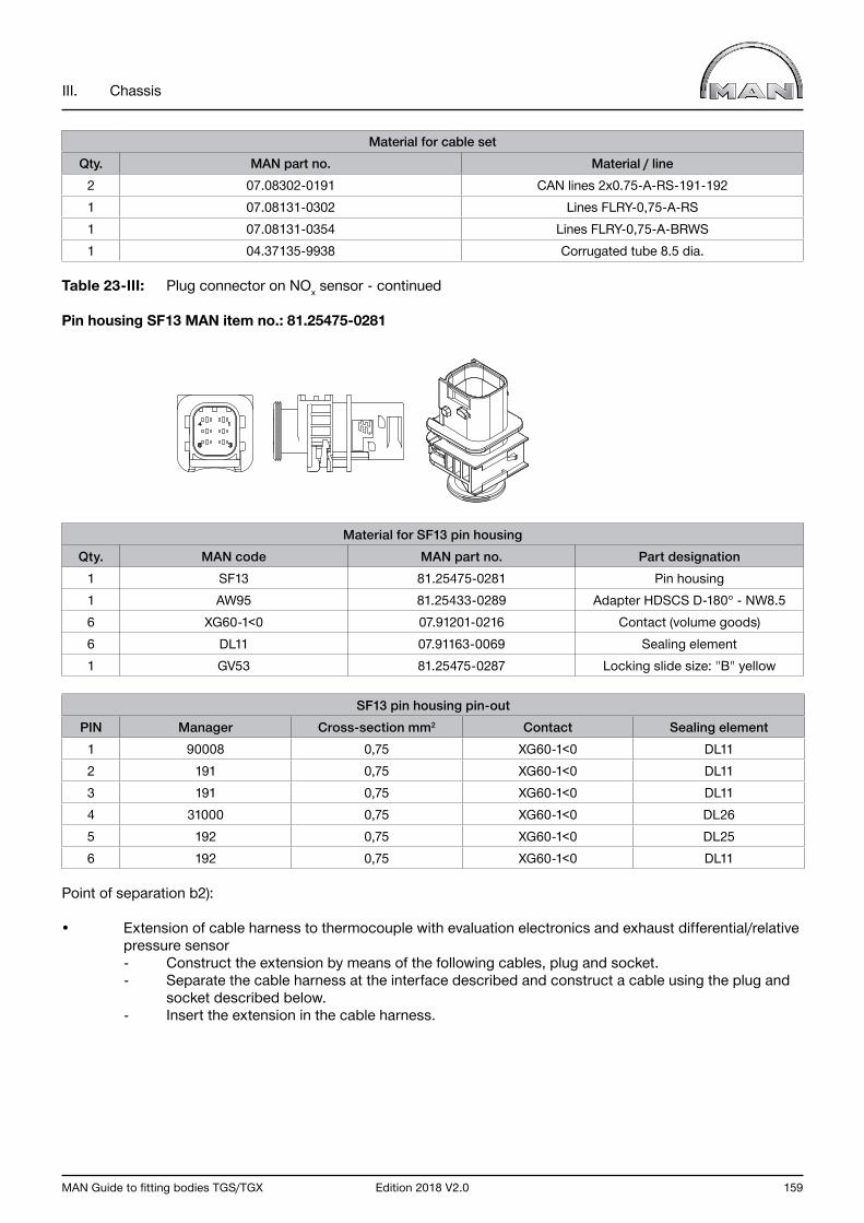
MAN Guide to fitting bodies TGS/TGX Edition 2018 V2.0 159
III. Chassis
Material for cable setQty. MAN part no. Material / line
2 07.08302-0191 CAN lines 2x0.75-A-RS-191-192 1 07.08131-0302 Lines FLRY-0,75-A-RS1 07.08131-0354 Lines FLRY-0,75-A-BRWS1 04.37135-9938 Corrugated tube 8.5 dia.
Table 23-III: Plug connector on NOx sensor - continued
Pin housing SF13 MAN item no.: 81.25475-0281
Material for SF13 pin housingQty. MAN code MAN part no. Part designation
1 SF13 81.25475-0281 Pin housing1 AW95 81.25433-0289 Adapter HDSCS D-180° - NW8.56 XG60-1<0 07.91201-0216 Contact (volume goods)6 DL11 07.91163-0069 Sealing element1 GV53 81.25475-0287 Locking slide size: "B" yellow
SF13 pin housing pin-outPIN Manager Cross-section mm2 Contact Sealing element
1 90008 0,75 XG60-1<0 DL112 191 0,75 XG60-1<0 DL113 191 0,75 XG60-1<0 DL114 31000 0,75 XG60-1<0 DL265 192 0,75 XG60-1<0 DL256 192 0,75 XG60-1<0 DL11
Point of separation b2):
• Extension of cable harness to thermocouple with evaluation electronics and exhaust differential/relative pressure sensor - Construct the extension by means of the following cables, plug and socket. - Separate the cable harness at the interface described and construct a cable using the plug and socket described below. - Insert the extension in the cable harness.
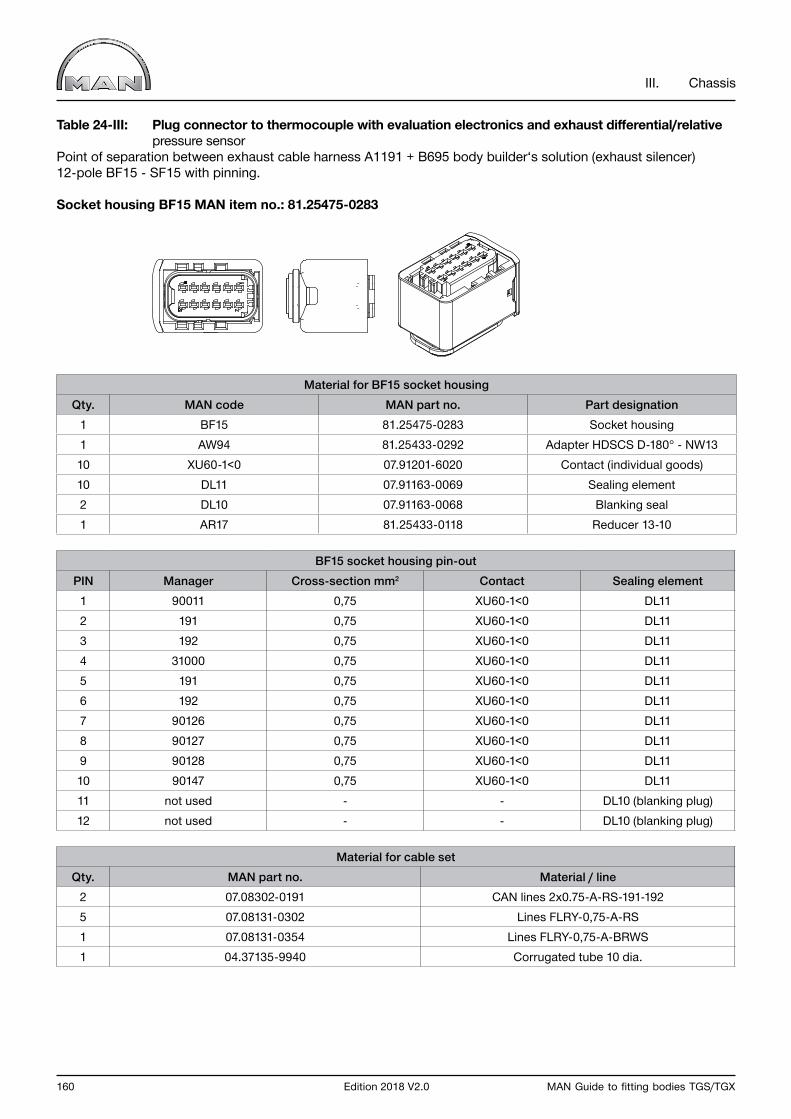
160 Edition 2018 V2.0 MAN Guide to fitting bodies TGS/TGX
III. Chassis
Table 24-III: Plug connector to thermocouple with evaluation electronics and exhaust differential/relative pressure sensorPoint of separation between exhaust cable harness A1191 + B695 body builder‘s solution (exhaust silencer)12-pole BF15 - SF15 with pinning.
Socket housing BF15 MAN item no.: 81.25475-0283
Material for BF15 socket housingQty. MAN code MAN part no. Part designation
1 BF15 81.25475-0283 Socket housing1 AW94 81.25433-0292 Adapter HDSCS D-180° - NW1310 XU60-1<0 07.91201-6020 Contact (individual goods)10 DL11 07.91163-0069 Sealing element2 DL10 07.91163-0068 Blanking seal1 AR17 81.25433-0118 Reducer 13-10
BF15 socket housing pin-outPIN Manager Cross-section mm2 Contact Sealing element
1 90011 0,75 XU60-1<0 DL112 191 0,75 XU60-1<0 DL113 192 0,75 XU60-1<0 DL114 31000 0,75 XU60-1<0 DL115 191 0,75 XU60-1<0 DL116 192 0,75 XU60-1<0 DL117 90126 0,75 XU60-1<0 DL118 90127 0,75 XU60-1<0 DL119 90128 0,75 XU60-1<0 DL1110 90147 0,75 XU60-1<0 DL1111 not used - - DL10 (blanking plug)12 not used - - DL10 (blanking plug)
Material for cable setQty. MAN part no. Material / line
2 07.08302-0191 CAN lines 2x0.75-A-RS-191-192 5 07.08131-0302 Lines FLRY-0,75-A-RS1 07.08131-0354 Lines FLRY-0,75-A-BRWS1 04.37135-9940 Corrugated tube 10 dia.
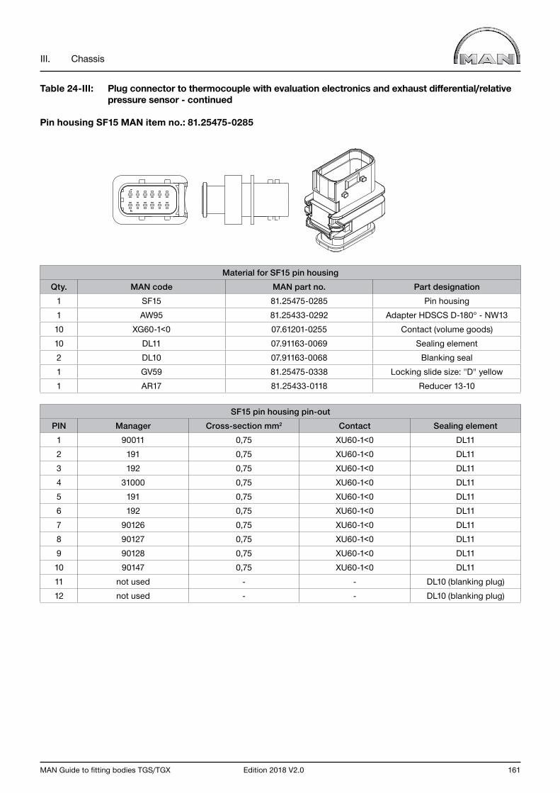
MAN Guide to fitting bodies TGS/TGX Edition 2018 V2.0 161
III. Chassis
Table 24-III: Plug connector to thermocouple with evaluation electronics and exhaust differential/relative pressure sensor - continued
Pin housing SF15 MAN item no.: 81.25475-0285
Material for SF15 pin housingQty. MAN code MAN part no. Part designation
1 SF15 81.25475-0285 Pin housing1 AW95 81.25433-0292 Adapter HDSCS D-180° - NW1310 XG60-1<0 07.61201-0255 Contact (volume goods)10 DL11 07.91163-0069 Sealing element2 DL10 07.91163-0068 Blanking seal1 GV59 81.25475-0338 Locking slide size: "D" yellow1 AR17 81.25433-0118 Reducer 13-10
SF15 pin housing pin-outPIN Manager Cross-section mm2 Contact Sealing element
1 90011 0,75 XU60-1<0 DL112 191 0,75 XU60-1<0 DL113 192 0,75 XU60-1<0 DL114 31000 0,75 XU60-1<0 DL115 191 0,75 XU60-1<0 DL116 192 0,75 XU60-1<0 DL117 90126 0,75 XU60-1<0 DL118 90127 0,75 XU60-1<0 DL119 90128 0,75 XU60-1<0 DL1110 90147 0,75 XU60-1<0 DL1111 not used - - DL10 (blanking plug)12 not used - - DL10 (blanking plug)

162 Edition 2018 V2.0 MAN Guide to fitting bodies TGS/TGX
III. Chassis
6.4.2.6 Parts list
Table 25-III: Overview of individual parts for extending lines
Illustration MAN part no. Series Designation Use
81.98180.6036 TGSTGX
Voss straight plug SAE 1/4“ NW3 AdBlue lines
81.98180.6037 TGSTGX
Voss elbow plugSAE 1/4“ NW3 AdBlue lines
81.98180.6042 TGSTGX
Voss elbow plugSAE J 2044 5/16“
NW3AdBlue lines
81.98180.6039 TGSTGX
Voss connector pinSAE J 2044 1/4“
NW3AdBlue lines

MAN Guide to fitting bodies TGS/TGX Edition 2018 V2.0 163
III. Chassis
Table 25-III: Overview of individual parts for extending lines - continued
Illustration MAN part no. Series Designation Use
81.98180.6041 TGSTGX
Voss elbow plug SAE J 2044 3/8“
NW3AdBlue lines
81.98180.6027 TGSTGX Elbow plug Heating-water lines
81.98180.6015 TGSTGX
Elbow plugPS3 NW 12 Heating-water lines
81.98180.6004 TGSTGX
Straight connector PS3 NW 12 Heating-water lines
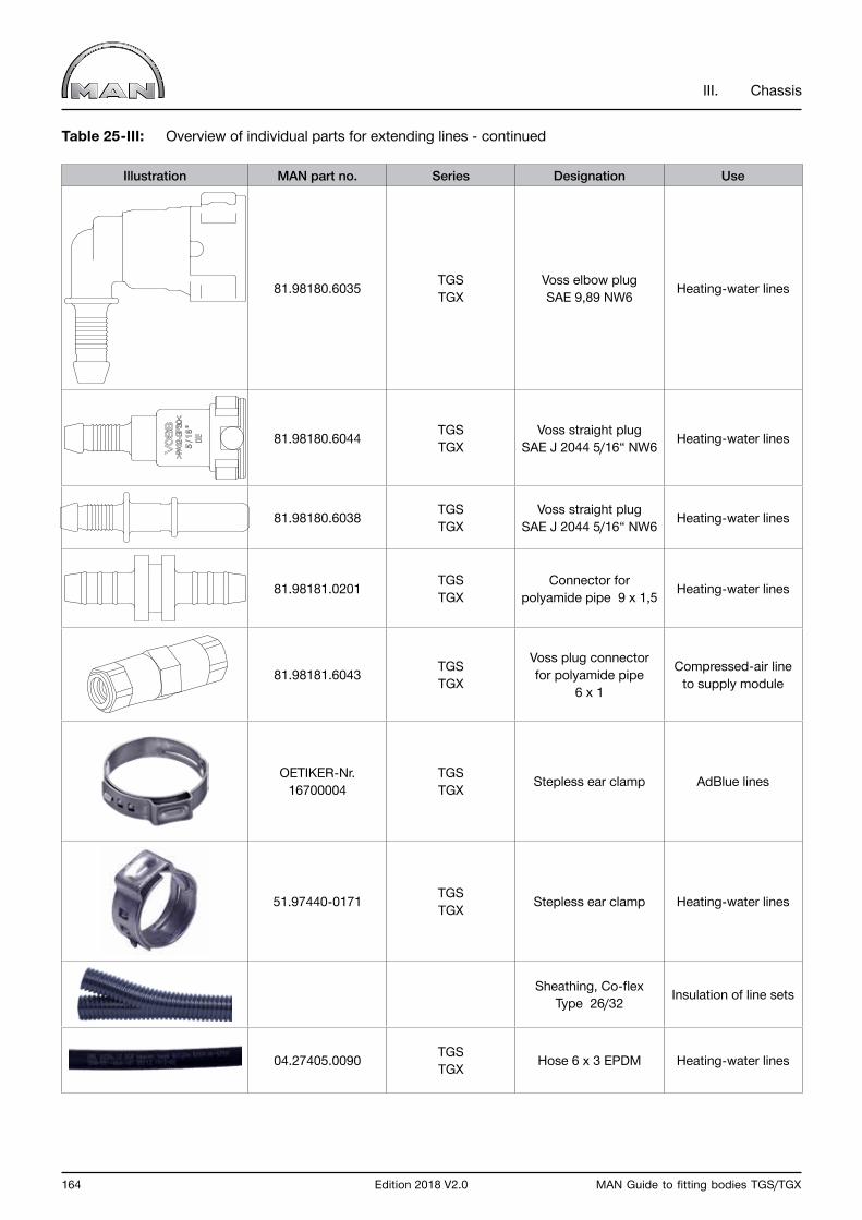
164 Edition 2018 V2.0 MAN Guide to fitting bodies TGS/TGX
III. Chassis
Table 25-III: Overview of individual parts for extending lines - continued
Illustration MAN part no. Series Designation Use
81.98180.6035 TGSTGX
Voss elbow plug SAE 9,89 NW6 Heating-water lines
81.98180.6044 TGSTGX
Voss straight plug SAE J 2044 5/16“ NW6 Heating-water lines
81.98180.6038 TGSTGX
Voss straight plug SAE J 2044 5/16“ NW6 Heating-water lines
81.98181.0201 TGSTGX
Connector for polyamide pipe 9 x 1,5 Heating-water lines
81.98181.6043 TGSTGX
Voss plug connector for polyamide pipe
6 x 1
Compressed-air line to supply module
OETIKER-Nr. 16700004
TGSTGX Stepless ear clamp AdBlue lines
51.97440-0171 TGSTGX Stepless ear clamp Heating-water lines
Sheathing, Co-flex Type 26/32 Insulation of line sets
04.27405.0090 TGSTGX Hose 6 x 3 EPDM Heating-water lines

MAN Guide to fitting bodies TGS/TGX Edition 2018 V2.0 165
III. Chassis
6.5 Gearbox and propshafts
6.5.1 Basic principles
The gearbox converts the engine torque and speed to meet the momentary demand for tractive force. Propshafts are installed to transmit the engine output from the gearbox to the transfer case and/or the final drives. Their movable splines compensate for vertical movements of the axles.
Warning noticePropeller shafts close to where persons move or work must be encased or covered.Depending on the local legislation in the country of assignment the assembly of a safety attachment or arrester bracket can be necessary for the shaft.
Propshafts are implemented in various ways.
Single jointWhen a single cardan joint, universal joint or ball joint (see Fig. 102-III) is rotated uniformly whilst bent it results in a non-uniform movement on the output side. This non-uniformity is often referred to as cardan error. Cardan error causes sinusoidal-like fluctuations in rotational speed on the output side. The output shaft leads and lags the input shaft. Despite constant input torque and input power, the output torque of the propshaft fluctuates according to the lead or lag.
Fig. 102-III: Single joint
The acceleration and delay occurring twice for each rotation mean that this kind of propeller shaft cannot be used for attachment to a power take-off.
A single joint is feasible only if it can be proven without doubt that because of the:
• mass moment of inertia,• Speed• angle of deflection,
the oscillations and loads are of minor significance.
Propeller shaft with two jointsThe non-uniformity of a single joint can be compensated by joining two single joints to produce a propeller shaft. However, full compensation of the movement can be achieved only if the following conditions are met.
• Both joints must have the same angle of deflection, i.e. ß1 = ß2• The two inner joint forks must be on the same plane.• The input and output shafts must also be in the same plane, see Fig. 103-III und Fig. 104-III.
T_364_000001_0001_G

166 Edition 2018 V2.0 MAN Guide to fitting bodies TGS/TGX
III. Chassis
All three conditions must always be met simultaneously to compensate cardan error.These conditions are met in dependence on the propshaft configuration. Possible propshaft configurations are described in Chapter III, Section 6.5.2.
6.5.2 Propshaft configurations
Well-known propshaft configurations are the so-called Z and W configurations (see Fig. 103-III and Fig. 104-III) as well as the three-dimensional configuration (see Fig. 105-III).
Fig. 103-III: W configuration of propeller shaft
Fig. 104-III: Z configuration of propeller shaft
ß1
ß2
T_364_000002_0001_G
T_364_000003_0001_G
ß1
ß2

MAN Guide to fitting bodies TGS/TGX Edition 2018 V2.0 167
III. Chassis
The conditions (cf. Chapter III, Section 6.5.1) for full compensation of movement are met by the so-called Z and W configurations.The common deflection plane that exists here may be freely rotated about the longitudinal axis. The use of the W-arrangement should be avoided in practice.
The exception is the three-dimensional propshaft configuration, see Fig. 105-III.
A three-dimensional configuration is given if the input and output shafts are not on the same plane. The input and output shafts cross offset from one another in space.
There is no common plane, so an offset of the inner joint forks by an angle “γ” is necessary to compensate speed fluctuations (see Fig. 105-III).
Fig. 105-III: Three-dimensional propeller shaft
1) Shaft 12) Plane 1 (formed by Shaft 1 and Shaft 2)3) Shaft 24) Plane 2 (formed by Shaft 2 and Shaft 3)5) Shaft 36) Fork in Plane 27) Fork in Plane 1γ Offset angle
A further condition is that the resulting three-dimensional angle ßR1 on the input shaft must be exactly the same as the three-dimensional angle ßR2 on the output shaft.
T_364_000004_0001_G
ßR1
ßR2
1
7 6
2 3 4 5
γ

168 Edition 2018 V2.0 MAN Guide to fitting bodies TGS/TGX
III. Chassis
Therefore:ßR1 = ßR2
Where: ßR1 = Resulting three-dimensional angle of Shaft 1 ßR2 = Resulting three-dimensional angle of Shaft 2
The resulting three-dimensional deflection angle ßR is a function of the vertical and horizontal deflection of the propshafts and is calculated as:
Formula 02-III: Resulting three-dimensional deflection angle
tan2 ßR = tan2 ßv + tan2 ßh
The necessary offset angle “γ” is a product of the horizontal and vertical deflection angles of the two joints:
Formula 03-III: Offset angle γ
tan ßh1 tan ßh2 tan γ1 = ; tan γ2 ; γ = γ1 + γ2 tan ßγ1 tan ßγ2
Where: ßR = Resulting three-dimensional deflection angle ßγ = Vertical deflection angle ßh = Horizontal deflection angle γ = Offset angle
Please note that:In three-dimensional deflection of the propeller shaft with two joints there is only a requirement for the same resulting three-dimensional deflection angles, so theoretically any number of configurations can be formed by combining the vertical and horizontal deflection angle.
We recommend that the manufacturers’ advice be sought for determining the offset angle for a three-dimensional propshaft configuration.

MAN Guide to fitting bodies TGS/TGX Edition 2018 V2.0 169
III. Chassis
Propeller shaft trainIf a design dictates the need for more length, it is possible to implement a propeller shaft train comprising two or more shafts. Fig. 106-III illustrates basic forms of a propeller shaft train in which the position of the joints and drivers relative to one another was randomly chosen.Drivers and joints have to be harmonized for kinematic reasons. In matters concerning propshaft train design, the propshaft manufacturers should be consulted.
Fig. 106-III: Propshaft train
T_364_000005_0001_G
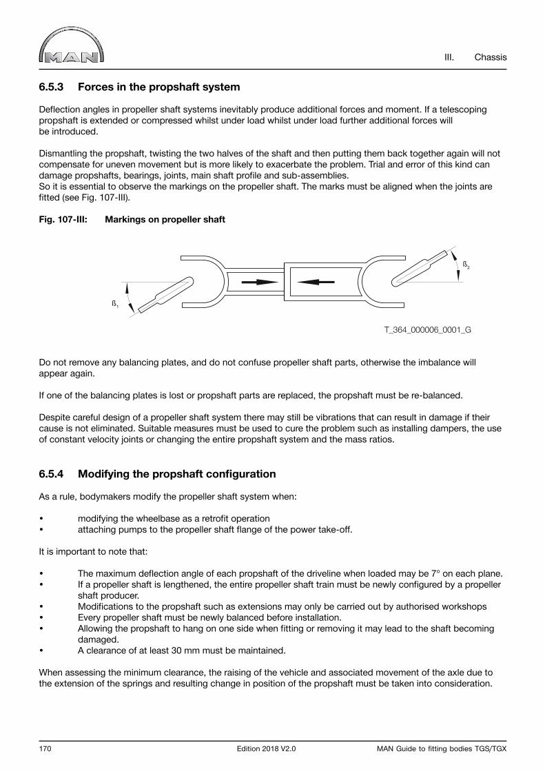
170 Edition 2018 V2.0 MAN Guide to fitting bodies TGS/TGX
III. Chassis
6.5.3 Forces in the propshaft system
Deflection angles in propeller shaft systems inevitably produce additional forces and moment. If a telescoping propshaft is extended or compressed whilst under load whilst under load further additional forces willbe introduced.
Dismantling the propshaft, twisting the two halves of the shaft and then putting them back together again will not compensate for uneven movement but is more likely to exacerbate the problem. Trial and error of this kind can damage propshafts, bearings, joints, main shaft profile and sub-assemblies. So it is essential to observe the markings on the propeller shaft. The marks must be aligned when the joints are fitted (see Fig. 107-III).
Fig. 107-III: Markings on propeller shaft
Do not remove any balancing plates, and do not confuse propeller shaft parts, otherwise the imbalance will appear again.
If one of the balancing plates is lost or propshaft parts are replaced, the propshaft must be re-balanced.
Despite careful design of a propeller shaft system there may still be vibrations that can result in damage if their cause is not eliminated. Suitable measures must be used to cure the problem such as installing dampers, the use of constant velocity joints or changing the entire propshaft system and the mass ratios.
6.5.4 Modifying the propshaft configuration
As a rule, bodymakers modify the propeller shaft system when:
• modifying the wheelbase as a retrofit operation• attaching pumps to the propeller shaft flange of the power take-off.
It is important to note that:
• The maximum deflection angle of each propshaft of the driveline when loaded may be 7° on each plane.• If a propeller shaft is lengthened, the entire propeller shaft train must be newly configured by a propeller shaft producer.• Modifications to the propshaft such as extensions may only be carried out by authorised workshops• Every propeller shaft must be newly balanced before installation.• Allowing the propshaft to hang on one side when fitting or removing it may lead to the shaft becoming damaged.• A clearance of at least 30 mm must be maintained.
When assessing the minimum clearance, the raising of the vehicle and associated movement of the axle due to the extension of the springs and resulting change in position of the propshaft must be taken into consideration.
ß2
ß1
T_364_000006_0001_G
MAN Guide to fitting bodies TGS/TGX Edition 2018 V2.0 171
III. Chassis
6.5.5 Fitting other manual or automatic gearboxes and transfer cases
Fitting manual or automatic gearboxes not documented by MAN is not possible because of the absence of an interface with the driveline CAN. If non-documented manual or automatic gearboxes are fitted malfunctions may occur in safety-relevant electronic systems. Fitting a third-party transfer box (e.g. for use as a power take-off) influences the electronic circuitry of the power train.
On vehicles fitted with mechanical gearboxes it may, under certain circumstances, be possible to adapt the system by parameterisation. Consult MAN (for address see “Publisher” above) before any work is commenced. As a basic principle, installation in vehicles fitted with MAN TipMatic/ZF ASTRONIC (e.g. ZF12AS gearbox) is not permitted.
6.6 PTOs
Power take-offs connect the vehicle’s engine with the units to be driven, for example compressors or hydraulic pumps. The power take-offs that may be used on MAN vehicles are described in the supplementary booklet entitled “Power take-offs”.
Further assistance for the selection and design of power take-offs can be found under “Gearbox/power take-offs” in MANTED (www.manted.de, registration required).
The operation of units by means of the vehicle’s engine can have a considerable effect on fuel consumption. It is therefore expected that the company carrying out the work implements a design that facilitates the lowest possible fuel consumption.
172 Edition 2018 V2.0 MAN Guide to fitting bodies TGS/TGX
III. Chassis
6.7 Brake system
6.7.1 Basic principles
Warning noticeThe brake system is among the most important safety components on a truck. No changes may be made to any part of a braking system including the lines except by appropriately trained persons. After any change a complete visual, auditory, functional and efficiency test of the complete brake system is to be performed.
6.7.2 Installing and fastening brake lines
The relevant notes in Chapter III, Section 6.3.5.2 “Routing lines” are to be observed when routing and fastening lines.
6.7.3 ALB, EBS brake system
EBS makes it unnecessary for the bodymaker to inspect the ALB (automatic load-dependent brake system), and no adjustment is possible.. Inspection may possibly be required as part of a routine check of the brake system. Should such an inspection of the brake system become necessary then a voltage measurement using the MAN-cats® diagnosis system or a visual check of the angle of the linkage at the axle-load sensor must be carried out.
The EBS of vehicles fitted with air suspension uses the axle-load signal transmitted by the ECAS via the CAN data bus. If conversions are carried out it must be ensured that this axle-load information is not affected.Never pull out the plug on the axle-load sensor. Before exchanging leaf springs, e.g. replacing them with springs for a different load, it should be checked with the MAN Service workshop whether reparameterisation of the vehicle is necessary in order to be able to set the ALB correctly.
6.7.4 Retrofitting continuous brakes
Fitting continuous brake systems (retarders, eddy current brakes) that have not been documented by MAN is fundamentally not possible.
Interventions in the electronically controlled brake system (EBS) and the vehicle’s on-board brake and driveline management system, which would be required in order to fit non-MAN continuous brakes, are not permitted.
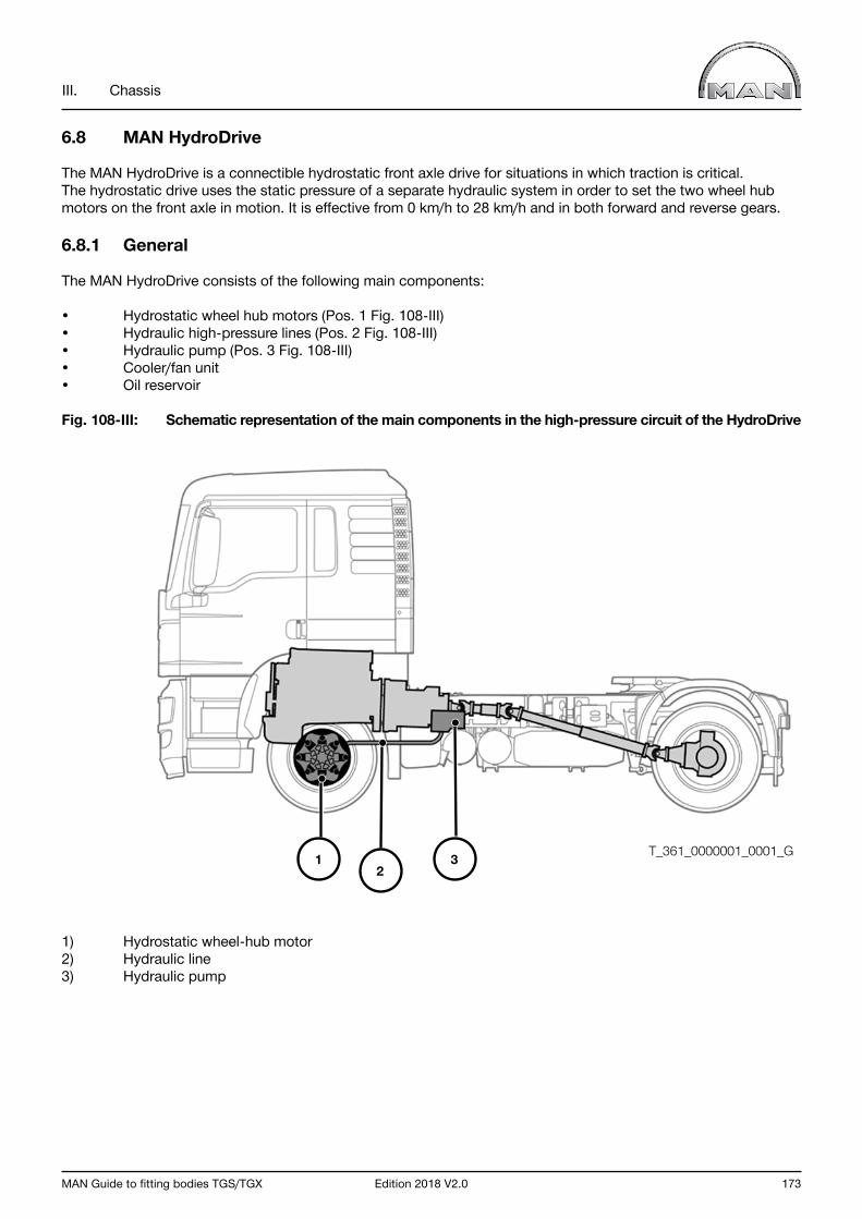
MAN Guide to fitting bodies TGS/TGX Edition 2018 V2.0 173
III. Chassis
6.8 MAN HydroDrive
The MAN HydroDrive is a connectible hydrostatic front axle drive for situations in which traction is critical. The hydrostatic drive uses the static pressure of a separate hydraulic system in order to set the two wheel hub motors on the front axle in motion. It is effective from 0 km/h to 28 km/h and in both forward and reverse gears.
6.8.1 General
The MAN HydroDrive consists of the following main components:
• Hydrostatic wheel hub motors (Pos. 1 Fig. 108-III)• Hydraulic high-pressure lines (Pos. 2 Fig. 108-III)• Hydraulic pump (Pos. 3 Fig. 108-III)• Cooler/fan unit• Oil reservoir
Fig. 108-III: Schematic representation of the main components in the high-pressure circuit of the HydroDrive
1) Hydrostatic wheel-hub motor2) Hydraulic line3) Hydraulic pump
T_361_0000001_0001_G12
3

174 Edition 2018 V2.0 MAN Guide to fitting bodies TGS/TGX
III. Chassis
Hydraulic circuit
In the following sketch, Fig. 109-III the operating principle of the self-contained hydraulic system is shown. The components of the high-pressure hydraulic system are shown connected by red lines (up to a maximum pressure of 420 bar). All components connected by a green line are part of the feed circuit (low pressure).
Fig. 109-III: Sketch showing the HydroDrive hydraulic circuit
1) Hydraulic wheel hub motors2) Feed pump3) Filter4) Engine5) Drive clutch6) Gearbox7) Gearbox/high-pressure pump clutch8) High-pressure pump9) Control block10) Cooler/fan unit11) Oil reservoir12) Low-pressure lines13) High-pressure lines
T_361_000002_0001_G
1 2 3 4 5 6 7 8 9 10
11 1213
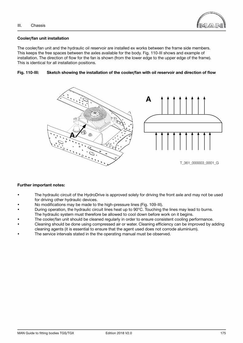
MAN Guide to fitting bodies TGS/TGX Edition 2018 V2.0 175
III. Chassis
Cooler/fan unit installation
The cooler/fan unit and the hydraulic oil reservoir are installed ex works between the frame side members. This keeps the free spaces between the axles available for the body. Fig. 110-III shows and example of installation. The direction of flow for the fan is shown (from the lower edge to the upper edge of the frame). This is identical for all installation positions.
Fig. 110-III: Sketch showing the installation of the cooler/fan with oil reservoir and direction of flow
Further important notes:
• The hydraulic circuit of the HydroDrive is approved solely for driving the front axle and may not be used for driving other hydraulic devices. • No modifications may be made to the high-pressure lines (Fig. 109-III). • During operation, the hydraulic circuit lines heat up to 90°C. Touching the lines may lead to burns. The hydraulic system must therefore be allowed to cool down before work on it begins.• The cooler/fan unit should be cleaned regularly in order to ensure consistent cooling performance.• Cleaning should be done using compressed air or water. Cleaning efficiency can be improved by adding cleaning agents (it is essential to ensure that the agent used does not corrode aluminium).• The service intervals stated in the the operating manual must be observed.
T_361_000003_0001_G
A
A
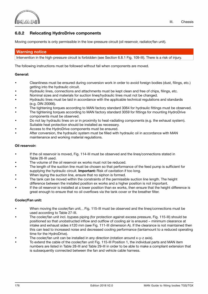
176 Edition 2018 V2.0 MAN Guide to fitting bodies TGS/TGX
III. Chassis
6.8.2 Relocating HydroDrive components
Moving components is only permissible in the low-pressure circuit (oil reservoir, radiator/fan unit).
Warning noticeIntervention in the high-pressure circuit is forbidden (see Section 6.8.1 Fig. 109-III). There is a risk of injury.
The following instructions must be followed without fail when components are moved.
General:
• Cleanliness must be ensured during conversion work in order to avoid foreign bodies (dust, filings, etc.) getting into the hydraulic circuit.• Hydraulic lines, connections and attachments must be kept clean and free of chips, filings, etc.• Nominal sizes and materials for suction lines/hydraulic lines must not be changed.• Hydraulic lines must be laid in accordance with the applicable technical regulations and standards (e.g. DIN 20066).• The tightening torques according to MAN factory standard 3064 for hydraulic fittings must be observed.• The tightening torques according to MAN factory standard 3059 for fittings for mounting HydroDrive components must be observed.• Do not lay hydraulic lines on or in proximity to heat-radiating components (e.g. the exhaust system). Suitable heat protection should be installed as necessary.• Access to the HydroDrive components must be ensured.• After conversion, the hydraulic system must be filled with hydraulic oil in accordance with MAN maintenance and working material regulations.
Oil reservoir:
• If the oil reservoir is moved, Fig. 114-III must be observed and the lines/connections stated in Table 26-III used.• The volume of the oil reservoir ex works must not be reduced.• The length of the suction line must be chosen so that performance of the feed pump is sufficient for supplying the hydraulic circuit. Important: Risk of cavitation if too long.• When laying the suction line, ensure that no siphon is formed.• The tank can be moved within the constraints of the permissible suction line length. The height difference between the installed position ex works and a higher position is not important. • If the oil reservoir is installed at a lower position than ex works, then ensure that the height difference is great enough to ensure that no oil overflows via the tank cover or the breather filter.
Cooler/Fan unit:
• When moving the cooler/fan unit, , Fig. 115-III must be observed and the lines/connections must be used according to Table 27-III.• The cooler/fan unit incl. bypass piping (for protection against excess pressure, Fig. 115-III) should be positioned so that unobstructed inflow and outflow of cooling air is ensured – minimum clearance at intake and exhaust sides ≥120 mm (see Fig. 111-III dimension A). If the clearance is not maintained then this can lead to increased noise and decreased cooling performance (tantamount to a reduced operating time for the HydroDrive).• The cooler/fan unit can be installed in any direction (rotation around x-y-z axis).• To extend the cable of the cooler/fan unit Fig. 115-III Position 1, the individual parts and MAN item numbers are listed in Table 28-III and Table 29-III in order to be able to make a compliant extension that is subsequently connected between the fan and vehicle cable harness.
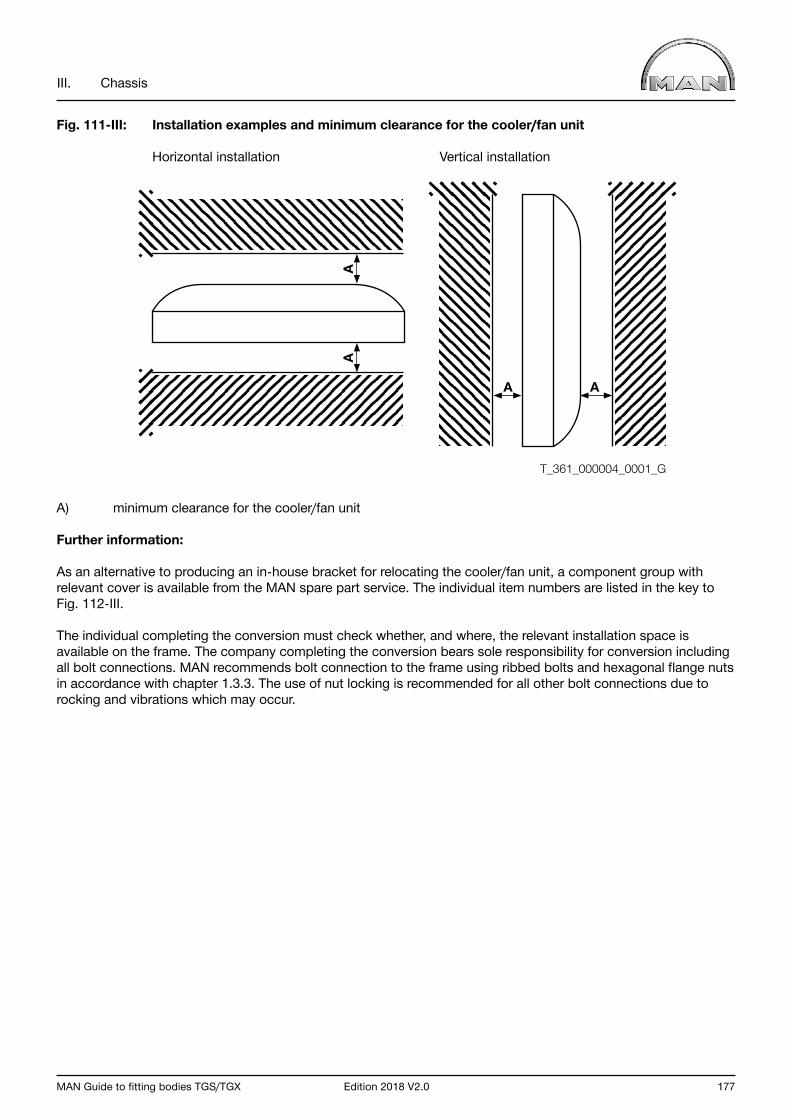
MAN Guide to fitting bodies TGS/TGX Edition 2018 V2.0 177
III. Chassis
Fig. 111-III: Installation examples and minimum clearance for the cooler/fan unit
Horizontal installation Vertical installation
A) minimum clearance for the cooler/fan unit
Further information:
As an alternative to producing an in-house bracket for relocating the cooler/fan unit, a component group with relevant cover is available from the MAN spare part service. The individual item numbers are listed in the key to Fig. 112-III.
The individual completing the conversion must check whether, and where, the relevant installation space is available on the frame. The company completing the conversion bears sole responsibility for conversion including all bolt connections. MAN recommends bolt connection to the frame using ribbed bolts and hexagonal flange nuts in accordance with chapter 1.3.3. The use of nut locking is recommended for all other bolt connections due to rocking and vibrations which may occur.
T_361_000004_0001_G
A
AA
A

178 Edition 2018 V2.0 MAN Guide to fitting bodies TGS/TGX
III. Chassis
Fig. 112-III: Overview parts
1) Item number 81.41820-0218 2) Item number 81.96002-0237 (2x) 6) Item number 82.32561-15053) Item number 81.66910-0162 (2x) 7) Item number 81.96210-0230 (4x)4) Item number 82.32560-1502 8) Item number 82.36045-15015) Item number 82.32560-1503 9) Item number 81.32560-1064
When mounting the cooler/fan unit in the frame chamfer, the spacer 81.41820-0186 and shim 81.90685-5007 (4x) Fig. 113-III) must be used instead of 81.41820.0218 (item 1 Fig. 112-III).
Fig. 113-III: Sketch of frame mounting with the relevant spacers
1) Frame side member2) Cooler/fan unit3) Angled spacer (item number 81.41820-0186)4) Straight spacer (item number 81.41820.0218)
11 34
2
9
1
2
3
4
5
6
7
8
T_361_000010_0001_G
T_361_000011_0001_G
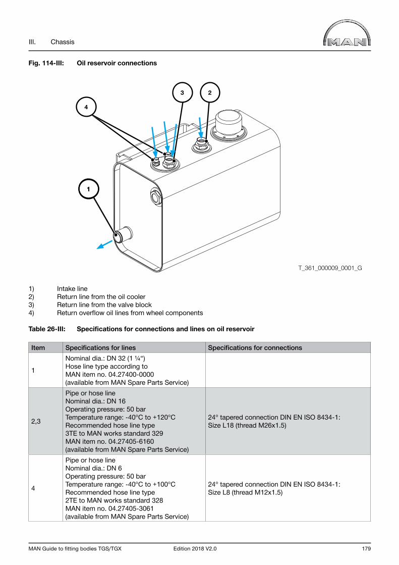
MAN Guide to fitting bodies TGS/TGX Edition 2018 V2.0 179
III. Chassis
Fig. 114-III: Oil reservoir connections
1) Intake line2) Return line from the oil cooler3) Return line from the valve block4) Return overflow oil lines from wheel components
Table 26-III: Specifications for connections and lines on oil reservoir
Item Specifications for lines Specifications for connections
1
Nominal dia.: DN 32 (1 ¼“)Hose line type according to MAN item no. 04.27400-0000(available from MAN Spare Parts Service)
2,3
Pipe or hose lineNominal dia.: DN 16Operating pressure: 50 barTemperature range: -40°C to +120°CRecommended hose line type 3TE to MAN works standard 329MAN item no. 04.27405-6160(available from MAN Spare Parts Service)
24° tapered connection DIN EN ISO 8434-1: Size L18 (thread M26x1.5)
4
Pipe or hose lineNominal dia.: DN 6Operating pressure: 50 barTemperature range: -40°C to +100°CRecommended hose line type 2TE to MAN works standard 328MAN item no. 04.27405-3061(available from MAN Spare Parts Service)
24° tapered connection DIN EN ISO 8434-1: Size L8 (thread M12x1.5)
T_361_000009_0001_G
11
23
4

180 Edition 2018 V2.0 MAN Guide to fitting bodies TGS/TGX
III. Chassis
Fig. 115-III: Cooler/Fan unit connections
1) For extended cable harness (according to Table 28-III and Table 29-III)2) Inflow from valve block3) Return line to tank4) Bypass piping with check valve (must be installed to protect the cooler from overpressure)
Table 27-III: Specifications for connections and lines to cooler/fan units (cable harness see Table 28-III and Table 29-III)
Item Specifications for lines Specifications for connections
2
Pipe or hose lineNominal dia.: DN 16Operating pressure: 50 barTemperature range: -40°C to +120°CHose line type FC 350
24° tapered connection DIN EN ISO 8434-1: Size L18 (thread M26x1.5)
3
Pipe or hose lineNominal dia.: DN 16Operating pressure: 50 barTemperature range: -40°C to +120°CRecommended hose line type 3TE to MAN works standard 329MAN item no. 04.27405-6160(available from MAN Spare Parts Service)
24° tapered connection DIN EN ISO 8434-1: Size L18 (thread M26x1.5)
T_361_000005_0001_G
1
324
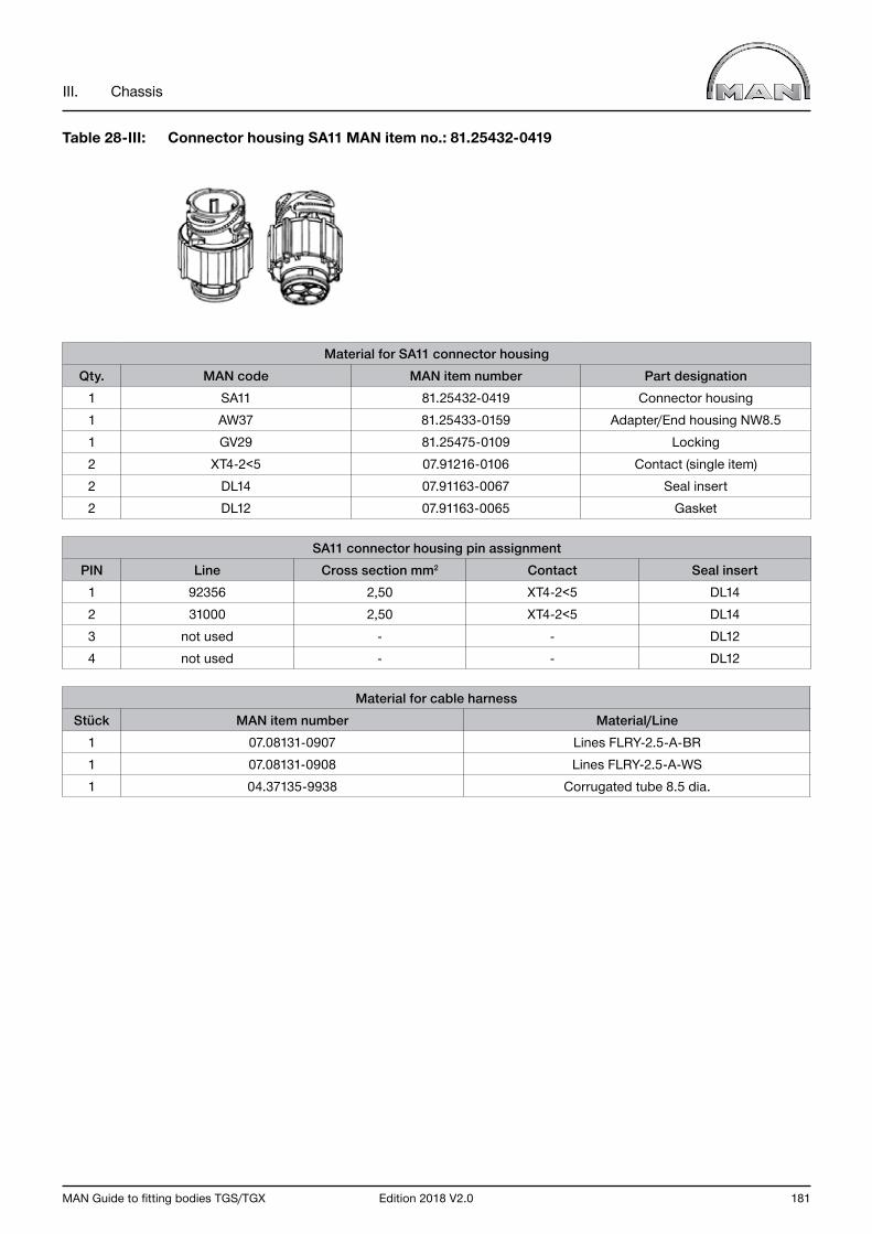
MAN Guide to fitting bodies TGS/TGX Edition 2018 V2.0 181
III. Chassis
Table 28-III: Connector housing SA11 MAN item no.: 81.25432-0419
Material for SA11 connector housingQty. MAN code MAN item number Part designation
1 SA11 81.25432-0419 Connector housing1 AW37 81.25433-0159 Adapter/End housing NW8.51 GV29 81.25475-0109 Locking2 XT4-2<5 07.91216-0106 Contact (single item)2 DL14 07.91163-0067 Seal insert2 DL12 07.91163-0065 Gasket
SA11 connector housing pin assignmentPIN Line Cross section mm2 Contact Seal insert
1 92356 2,50 XT4-2<5 DL142 31000 2,50 XT4-2<5 DL143 not used - - DL124 not used - - DL12
Material for cable harnessStück MAN item number Material/Line
1 07.08131-0907 Lines FLRY-2.5-A-BR1 07.08131-0908 Lines FLRY-2.5-A-WS1 04.37135-9938 Corrugated tube 8.5 dia.

182 Edition 2018 V2.0 MAN Guide to fitting bodies TGS/TGX
III. Chassis
Table 29-III: Socket housing BA9 MAN item no.: 81.25475-0189
Material for BA9 socket housingQty. MAN code MAN item number Part designation
1 SA11 81.25475-0189 Socket housing1 GV1 81.25435-0951 Locking2 XU4-2<5 07.91216-0156 Contact (single item)2 DL9 07.91163-0059 Seal insert2 DL7 07.91163-0057 Gasket
Pin assignment BA9 socket housingPIN Line Cross section mm2 Contact Seal insert
1 92356 2,50 XU4-2<5 DL92 31000 2,50 XU4-2<5 DL93 not used - - DL74 not used - - DL7

MAN Guide to fitting bodies TGS/TGX Edition 2018 V2.0 183
III. Chassis
6.8.3 Protective covers for the HydroDrive
For tipper vehicles and other chassis with superstructures for which there is a risk that the load will fall into the area of the cooler/fan unit, an oil cooler cover should be mounted for protection.
It is also recommendable to attach a protective cover to avoid damage to the fan if, after conversion work, the cooler/fan unit is mounted in a position subject to stone chip impacts or soiling (e.g. in front of the rear axle).
For HydroDrive-equipped semitrailer tractors, a protective cover for the cooler/fan is available ex works as special equipment and can also be retrofitted (installation item number 81.36000-8134).
You can also make and fit a protective cover on your own responsibility (see Fig. 116-III).
In this case, the following apply:
• 50% of the ace above the fan wheel must be designed so that the exhaust air can be evacuated without obstruction (e.g. using ventilation grilles), as otherwise the possible operating time for the HydroDrive will be reduced.• Minimum distance from fan ≥ 120 mm • Access to the cooler/fan unit must be ensured.• It must be ensured that the protective cover or support frame possesses sufficient rigidity, as it may be subjected to loads (e.g. when the cover is walked on)
Fig. 116-III: Example of a protective cover
1) Vertical load2) Protective cover3) Vents
T_361_000008_0001_G
1
2
3
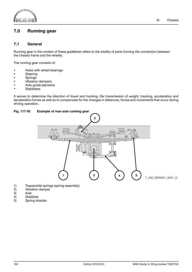
184 Edition 2018 V2.0 MAN Guide to fitting bodies TGS/TGX
III. Chassis
7.0 Running gear
7.1 General
Running gear in the context of these guidelines refers to the totality of parts forming the connection between the chassis frame and the wheels.
The running gear consists of:
• Axles with wheel bearings• Steering • Springs • Vibration dampers • Axle-guide elements • Stabilisers
It serves to determine the direction of travel and tracking, the transmission of weight, tracking, acceleration and deceleration forces as well as to compensate for the changes in distances, forces and movements that occur during driving operation.
Fig. 117-III: Example of rear-axle running gear
1) Trapezoidal springs (spring assembly)2) Vibration damper3) Axle4) Stabiliser5) Spring shackle
T_430_0000001_0001_G3 4
2
51
MAN Guide to fitting bodies TGS/TGX Edition 2018 V2.0 185
III. Chassis
7.2 Modifications to the running gear
Interventions in the axle assemblies and individual parts thereof (e.g. steering components, arms, springs, absorbers) as well as their mountings and fixations to the frame are not permissible.
Additionally, it is forbidden to create new assembly groups out of the above-mentioned individual parts.
No parts of the suspension or spring leaves may be modified or removed. It is not permitted for suspension types or systems to be fitted on one and the same axle.
If the suspension system on one axle is changed (from leaf spring to air, for example), then approval must be obtained from MAN (for address, see “Publisher” above).
Before conversion, verifiable documents must be sent to MAN. The company carrying out the conversion is responsible for the design, demonstrating sufficient strength and reviewing changes to handling characteristics.
7.3 Equipment-related notes
A range of chassis options providing beneficial characteristics for different bodies is available for MAN vehicles. Check availability in advance with the nearest sales branch.
Variable axle load ratio to improve traction (sales code 128VA)The drive axle is optimally loaded by the variable axle load ratio. With increasing load, the drive axle is increased to the value of the permitted axle load. The additional load is carried by the leading or trailing axle. This equipment option can influence the axle load capacity utilisation of the overall vehicle both positively and negatively, depend-ing on body type. Selection of this equipment option requires precise vehicle configuration for all load conditions. The minimum front axle load in particular (see Chapter III Section 2.2.8) must be checked exactly.
The equipment described below is recommended in particular for bodies with high centres of gravity.
StabilisersStabilisers reduces rolling exhibited by the fitted vehicle, thereby improving handling. For example, a rolling mo-tion of the body causes the stabiliser to be subjected to torsion. The reaction torques that occur counteract the rolling torque.The stabilisers on the front and rear axles are available under sales codes 362AA and 363AA.
For vehicles with a tandem-axle assembly, it is possible to order an additional stabiliser under sales code 362AH. In this case, a stabiliser is installed on both rear axles, thereby increasing the roll stabilisation.Special equipment (sales code 362AG) is available for installation space-critical bodies such as the roll-off skip loader; this equipment reduces the extent to which wishbone or spring brake protrude beyond the top edge of the frame when compressed.
High-load stabilisation packagesThe high-load roll stabilisation includes, in addition to the standard stabiliser, an X control arm (four-point con-trol arm with stabiliser function) and specially tailored shock absorbers. The high-load package is also available with Continuous Damping Control (CDC). It can only be selected in combination with the air suspension for high centres of gravity. Active driving safety is improved by stabilisation of the chassis. In addition, the rolling motion is reduced when cornering. The installed X control arm does not protrude beyond the top edge of the frame when the air suspension is lowered. The high-load stabilisation packages are available under sales codes 362CN and 362CP.
Air rear springs for high centre of gravityThe spring rate of the air-suspension bellows is tailored specifically for the needs of high-load deployment. As a result, the roll motion is reduced and the driving characteristics improved. The air suspension is available under sales codes 028MW and 028MZ.

186 Edition 2018 V2.0 MAN Guide to fitting bodies TGS/TGX
III. Chassis
Continuous Damping Control (CDC)The active roll stabilisation CDC (continuous damping control; sales code 283FW) uses various input parameters to ascertain the current driving and loading condition and automatically controls damping of the vehicle. The optimal damping is therefore always achieved, regardless of the payload. Rolling and pitching motion is minimised and handling is improved.
Chassis components for installation space-critical bodies
The equipment described below is recommended in particular for installation space-critical bodies.
Driving height raised by 30 mm for roll-off skip loader (sales code 281SC)The driving height is raised by 30 mm to ensure that no chassis components (such as the wishbone) protrude be-yond the top edge of the frame when the air suspension is lowered, causing installation space conflicts with the hydraulic cylinder or other parts on the roll-off device. Where required, this equipment can also be used for other bodies if there are problems with the installation space.
Rear axle shock absorber set lower and driving height raised by 30 mm for roll-off skip loader (sales code 240RK)The driving height is raised by 30 mm to ensure that no chassis components (such as the wishbone, shock ab-sorbers) protrude beyond the top edge of the frame when the air suspension is lowered, causing installation space conflicts with the hydraulic cylinder or other parts on the roll-off device. In addition, the shock absorber mounts are set lower, so that these are situated below the top edge of the frame. Where required, this equipment can also be used for other bodies if there are problems with the installation space.
Rear axle shock absorbers set lower for high-volume vehicle body (sales code 240RL)Installation of shortened shock absorbers, whereby the shock absorber mounts are situated below the top edge of the frame. Raising the air suspension beyond that of the driving position is limited to 145 mm. The wishbone pro-trudes beyond the top edge of the frame when the air suspension is lowered. Where required, this equipment can also be used for other bodies if there are problems with the installation space.

MAN Guide to fitting bodies TGS/TGX Edition 2018 V2.0 187
III. Chassis
8.0 Electrical/electronic system (on-board network)
8.1 General
MAN vehicles employ many electronic systems for controlling, regulating and monitoring vehicle functions. Full networking of the equipment fully guarantees that sensor readings can be processed to the same extent by all control units. This reduces the number of sensors, leads and connectors, and consequently means fewer error sources.
Network leads in a vehicle are recognizable because they are twisted. Several CAN bus systems are used in parallel and this enables them to be optimally adapted to perform their respective tasks. All data bus systems are reserved for exclusive use by the MAN vehicle electronics system; access to these bus systems is prohibited, with the exception of the bodybuilder CAN bus.
The “Electrical/electronic systems” chapter cannot present exhaustive information on all questions arising in connection with the on-board network of a modern commercial vehicle. Further information on individual systems can be found in the respective repair manuals. Repair manuals are supplied by the Spare-parts Service. Technical information can also be obtained from the MAN After Sales Portal (www.asp.mantruckandbus.com, registration required). The portal provides access to service and repair manuals, the MAN diagnostic system, circuit diagrams, standard times and Service Bulletins.
Electrical and electronic systems and wiring incorporated in a commercial vehicle comply with the respective national plus European standards and directives, regarded as a minimum requirement. MAN standards are often considerably more stringent than national and international standards. As a result, many electronic systems have been adapted and expanded.
In some cases, for reasons of quality or safety, MAN stipulates the condition that MAN standards are used. This is then stated in the corresponding sections. Bodybuilders can obtain the MAN standards from the MAN Portal for Technical Documentation (www.ptd.man.eu, registration required). There is no automatic exchange service.
188 Edition 2018 V2.0 MAN Guide to fitting bodies TGS/TGX
III. Chassis
8.1.1 Electromagnetic compatibility
Due to the interaction between the different electrical components, electronic systems, the vehicle itself and the environment, the electromagnetic compatibility (EMC) must be tested. All systems in MAN vehicles must meet the requirements set down in MAN standard M3285, obtainable from the MAN Portal for Technical Documentation (www.ptd.man.eu).
On delivery ex works, MAN vehicles meet the requirements set down in ECE R10 in the valid version at the time of delivery. All equipment (definition of equipment as in 89/336/EEC) that is installed in the vehicle by the bodybuilder must meet the corresponding statutory regulations iand be labelled accordingly (E label as per ECE R10, as applicable). The bodybuilder is responsible for the EMC of its components and/or systems.After installing such components and/or systems, the bodybuilder remains responsible for ensuring that the vehicle still meets the current statutory requirements. Freedom from feedback between the body-side electrics/electronics and those of the vehicle must be ensured, especially where body-side interference could affect the operation of on-board units for road toll logging, telematics equipment, telecommunications systems or other equipment fitted to the vehicle.
8.1.2 Static discharge
The body manufacturer must ensure that electrostatic discharge is avoided by means of retrofitting appropriate devices or with the use of appropriate measures.
8.1.3 Radio equipment and aerials
All equipment installed on the vehicle must comply with current statutory requirements. All radio equipment (e.g. radio units, mobile telephones, navigation systems, on-board units for road toll logging etc.) must be properly equipped with external aerials.
In other words:
• Devices such as a radio remote control for body functions must not interfere with functions of the vehicle.• Existing wiring must not be moved or used for additional purposes.• Use as a power supply is not permitted (exception: approved MAN active antennas and their leads).• Access must not be hindered to other vehicle components for maintenance and repair.• If holes are drilled in the roof, these must be at the locations provided for in the MAN design, using approved installation materials (e.g. self-tapping screws, seals).
Antennas, leads, cables, sockets and plugs approved by MAN are obtainable through the spare parts service.
Annex I of EU Council directive 72/245/EEC in its version 2004/104/EC stipulates that possible locations of transmitting antennas, permissible frequency bands and transmitting power are to be published.
For the following frequency bands the proper fitting at the attachment points stipulated by MAN (see Fig. 118-III) on the cab roof is permitted.
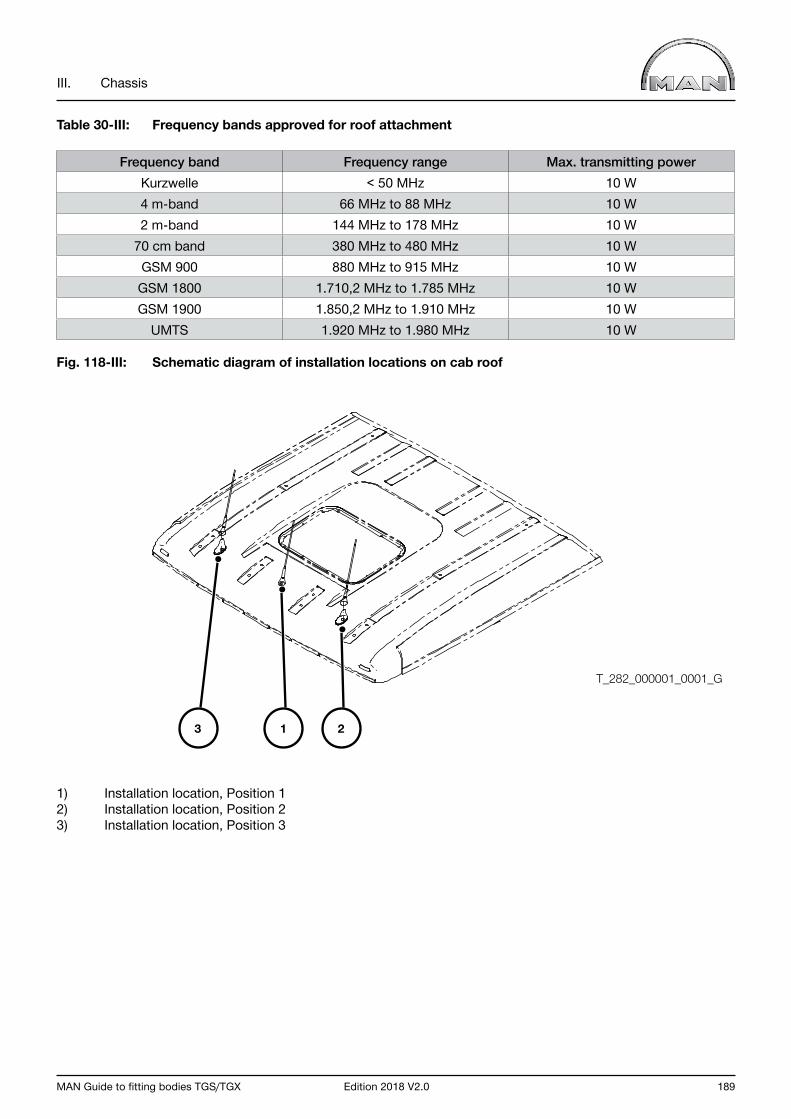
MAN Guide to fitting bodies TGS/TGX Edition 2018 V2.0 189
III. Chassis
Table 30-III: Frequency bands approved for roof attachment
Frequency band Frequency range Max. transmitting powerKurzwelle < 50 MHz 10 W4 m-band 66 MHz to 88 MHz 10 W2 m-band 144 MHz to 178 MHz 10 W
70 cm band 380 MHz to 480 MHz 10 WGSM 900 880 MHz to 915 MHz 10 WGSM 1800 1.710,2 MHz to 1.785 MHz 10 WGSM 1900 1.850,2 MHz to 1.910 MHz 10 W
UMTS 1.920 MHz to 1.980 MHz 10 W
Fig. 118-III: Schematic diagram of installation locations on cab roof
1) Installation location, Position 12) Installation location, Position 23) Installation location, Position 3
1 23
T_282_000001_0001_G
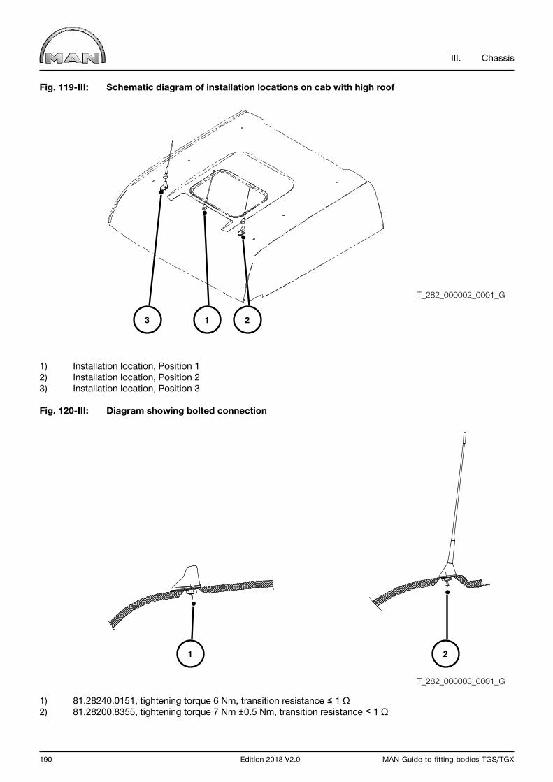
190 Edition 2018 V2.0 MAN Guide to fitting bodies TGS/TGX
III. Chassis
Fig. 119-III: Schematic diagram of installation locations on cab with high roof
1) Installation location, Position 12) Installation location, Position 23) Installation location, Position 3
Fig. 120-III: Diagram showing bolted connection
1) 81.28240.0151, tightening torque 6 Nm, transition resistance ≤ 1 Ω2) 81.28200.8355, tightening torque 7 Nm ±0.5 Nm, transition resistance ≤ 1 Ω
1
1 23
2
T_282_000003_0001_G
T_282_000002_0001_G
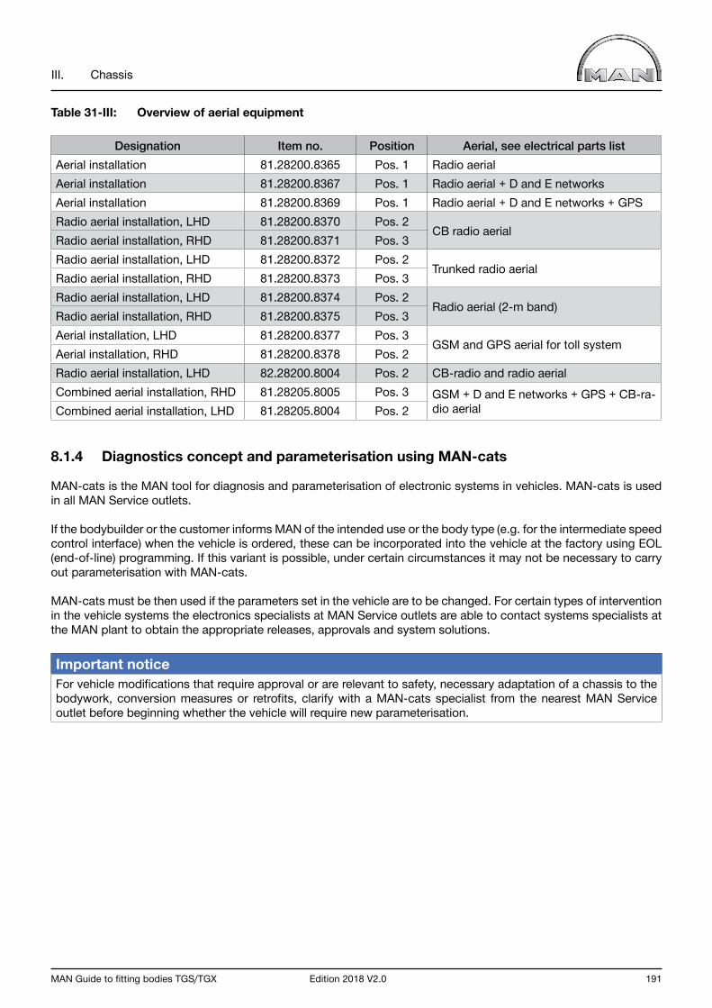
MAN Guide to fitting bodies TGS/TGX Edition 2018 V2.0 191
III. Chassis
Table 31-III: Overview of aerial equipment
Designation Item no. Position Aerial, see electrical parts listAerial installation 81.28200.8365 Pos. 1 Radio aerialAerial installation 81.28200.8367 Pos. 1 Radio aerial + D and E networksAerial installation 81.28200.8369 Pos. 1 Radio aerial + D and E networks + GPSRadio aerial installation, LHD 81.28200.8370 Pos. 2
CB radio aerialRadio aerial installation, RHD 81.28200.8371 Pos. 3Radio aerial installation, LHD 81.28200.8372 Pos. 2
Trunked radio aerialRadio aerial installation, RHD 81.28200.8373 Pos. 3Radio aerial installation, LHD 81.28200.8374 Pos. 2
Radio aerial (2-m band)Radio aerial installation, RHD 81.28200.8375 Pos. 3Aerial installation, LHD 81.28200.8377 Pos. 3
GSM and GPS aerial for toll systemAerial installation, RHD 81.28200.8378 Pos. 2Radio aerial installation, LHD 82.28200.8004 Pos. 2 CB-radio and radio aerialCombined aerial installation, RHD 81.28205.8005 Pos. 3 GSM + D and E networks + GPS + CB-ra-
dio aerialCombined aerial installation, LHD 81.28205.8004 Pos. 2
8.1.4 Diagnostics concept and parameterisation using MAN-cats
MAN-cats is the MAN tool for diagnosis and parameterisation of electronic systems in vehicles. MAN-cats is used in all MAN Service outlets.
If the bodybuilder or the customer informs MAN of the intended use or the body type (e.g. for the intermediate speed control interface) when the vehicle is ordered, these can be incorporated into the vehicle at the factory using EOL (end-of-line) programming. If this variant is possible, under certain circumstances it may not be necessary to carry out parameterisation with MAN-cats.
MAN-cats must be then used if the parameters set in the vehicle are to be changed. For certain types of intervention in the vehicle systems the electronics specialists at MAN Service outlets are able to contact systems specialists at the MAN plant to obtain the appropriate releases, approvals and system solutions.
Important notice For vehicle modifications that require approval or are relevant to safety, necessary adaptation of a chassis to the bodywork, conversion measures or retrofits, clarify with a MAN-cats specialist from the nearest MAN Service outlet before beginning whether the vehicle will require new parameterisation.

192 Edition 2018 V2.0 MAN Guide to fitting bodies TGS/TGX
III. Chassis
8.2 Cables
8.2.1 Routing cables
The following must be observed for all cable routing:
- Overlengths must not be laid in coil-like rings but only in loops to the side of the cable harness (see Fig. 121-III: Cable routings).
Fig. 121-III: Cable routings
- The cable harness must be secured in such a manner that no movement relative to the frame can occur, see Fig. 122-III: Routing examples).
Fig. 122-III: Routing examples
The relevant notes in Chapter III, Section 6.3.5.2 “Routing lines” are to be observed when routing and fastening lines.
T_998_000003_0001_G
T_992_000001_0001_G

MAN Guide to fitting bodies TGS/TGX Edition 2018 V2.0 193
III. Chassis
8.2.2 Ground cable
MAN frames are voltage-free in that neither the positive nor the ground cable is connected to it. Together with the positive cable, consumers must always have their own ground cables routed to them.
Ground points to which the bodybuilder can connect ground cables are located as follows:
• In the central electrics box• Behind the combined instrument• On the rear right-hand engine mount.
No more than a total of 10 A (actual current demand) may be tapped at the ground points behind the central electrics box and behind the combined instrument. Cigarette lighters and any extra sockets have their own power limitations, which can be found in the operating manual.
The bodybuilder’s ground cable may as a general rule be connected to the common ground point at the engine and under the following conditions may be connected to the negative terminal of the batteries.
• The vehicle is equipped with an ground cable between engine and frame (standard from January 2010 production on).• The battery terminal has sufficient room for connection of the ground cable.
Further information and instructions on connecting additional consumers can be found in Chapter III, Section 8.4 “Additional consumers”.
8.2.3 Wiring harnesses for wheelbase extensions
When wheelbases are extended, control units and sensors associated with the rear axle also have to be relocated along with the axle.As a basic principle, CAN wiring harnesses may never be cut and lengthened and for this reason, MAN offerscable-harness extensions each with a 1500 mm length of corrugated tubing. If these extensions are not sufficient, two of the cable harnesses described here can be connected in series. Only when the method described here is used can the movement of control units and sensors be considered as approved.
Control units and sensors associated with the rear axle
Basic equipment on all TG vehicles:
• EBS axle modulator (one module for all rear axles)• Switch, check for parking brake
In the case of air suspension on the rear axle(s), the following are added:
• Displacement sensor (left and right)• Valve block, ECAS
Depending on version and equipment, the following cabling is fitted.
• Differential-lock plug connector
Cable extensions from the EBS axle-modulator to the sensors on the respective wheel (speed sensors, brake-lining wear sensors) are not necessary if the EBS axle-modulator module is relocated together with the rear axle.
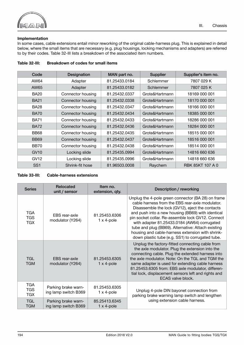
194 Edition 2018 V2.0 MAN Guide to fitting bodies TGS/TGX
III. Chassis
ImplementationIn some cases, cable extensions entail minor reworking of the original cable-harness plug. This is explained in detail below, where the small items that are necessary (e.g. plug housings, locking mechanisms and adapters) are referred to by their codes. Table 32-III lists a breakdown of the associated item numbers.
Table 32-III: Breakdown of codes for small items
Code Designation MAN part no. Supplier Supplier's item no.AW64 Adapter 81.25433.0184 Schlemmer 7807 029 KAW65 Adapter 81.25433.0182 Schlemmer 7807 025 KBA20 Connector housing 81.25432.0337 Grote&Hartmann 18169 000 001BA21 Connector housing 81.25432.0338 Grote&Hartmann 18170 000 001BA28 Connector housing 81.25432.0347 Grote&Hartmann 18166 000 001BA70 Connector housing 81.25432.0434 Grote&Hartmann 18385 000 001BA71 Connector housing 81.25432.0433 Grote&Hartmann 18286 000 001BA72 Connector housing 81.25432.0436 Grote&Hartmann 18284 000 001BB68 Connector housing 81.25432.0435 Grote&Hartmann 18515 000 001BB69 Connector housing 81.25432.0437 Grote&Hartmann 18516 000 001BB70 Connector housing 81.25432.0438 Grote&Hartmann 18514 000 001GV10 Locking slide 81.25435.0994 Grote&Hartmann 14816 660 636GV12 Locking slide 81.25435.0996 Grote&Hartmann 14818 660 636SS1 Shrink-fit hose 81.96503.0008 Raychem RBK 85KT 107 A 0
Table 33-III: Cable-harness extensions
Series Relocated unit / sensor
Item no. extension, qty. Description / reworking
TGATGSTGX
EBS rear-axle modulator (Y264)
81.25453.6306 1 x 4-pole
Unplug the 4-pole green connector (BA 28) on frame cable harness from the EBS rear-axle modulator. Disassemble the lock (GV12), eject the contacts
and push into a new housing (BB69) with identical pin socket collar. Re-assemble lock GV12. Connect
with adapter 81.25433.0184 (AW64) corrugated tube and plug (BB69). Alternative: Attach existing housing and cable-harness extension with shrink-down plastic tube (e.g. SS1) to corrugated tube.
TGLTGM
EBS rear-axle modulator (Y264)
81.25453.6305 1 x 4-pole
Unplug the factory-fitted connecting cable from the axle modulator. Plug the extension into the
connecting cable. Plug the extended harness into the axle modulator. Note: On the TGL and TGM the same adapter is used for extending cable harness 81.25453.6305 from: EBS axle modulator, differen-tial lock, displacement sensors left and rights and
ECAS valve block. TGATGSTGX
Parking brake warn-ing lamp switch B369
81.25453.6305 1 x 4-pole Unplug 4-pole DIN bayonet connection from
parking brake warning lamp switch and lengthen using extension cable harness. TGL
TGMParking brake warn-
ing lamp switch B36985.25413.6345
1 x 4-pole
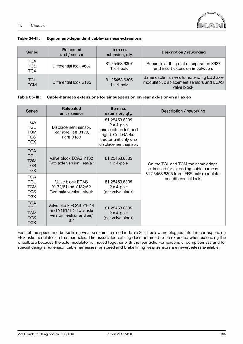
MAN Guide to fitting bodies TGS/TGX Edition 2018 V2.0 195
III. Chassis
Table 34-III: Equipment-dependent cable-harness extensions
Series Relocated unit / sensor
Item no. extension, qty. Description / reworking
TGATGSTGX
Differential lock X637 81.25453.6307 1 x 4-pole
Separate at the point of separation X637 and insert extension in between.
TGLTGM Differential lock S185 81.25453.6305
1 x 4-pole
Same cable harness for extending EBS axle modulator, displacement sensors and ECAS
valve block.
Table 35-III: Cable-harness extensions for air suspension on rear axles or on all axles
Series Relocated unit / sensor
Item no. extension, qty. Description / reworking
TGATGLTGMTGSTGX
Displacement sensor, rear axle, left B129,
right B130
81.25453.6305 2 x 4-pole
(one each on left and right). On TGA 4x2
tractor unit only one displacement sensor.
On the TGL and TGM the same adapt-er is used for extending cable harness
81.25453.6305 from: EBS axle modulator and differential lock.
TGATGLTGMTGSTGX
Valve block ECAS Y132 Two-axle version, leaf/air
81.25453.6305 1 x 4-pole
TGATGLTGMTGSTGX
Valve block ECAS Y132/61and Y132/62
Two-axle version, air/air
81.25453.6305 2 x 4-pole
(per valve block)
TGATGLTGMTGSTGX
Valve block ECAS Y161/I and Y161/II > Two-axle version, leaf/air and air/
air
81.25453.6305 2 x 4-pole
(per valve block)
Each of the speed and brake lining wear sensors itemised in Table 36-III below are plugged into the corresponding EBS axle modulator on the rear axles. The associated cabling does not need to be extended when extending the wheelbase because the axle modulator is moved together with the rear axle. For reasons of completeness and for special designs, extension cable harnesses for speed and brake lining wear sensors are nevertheless available.
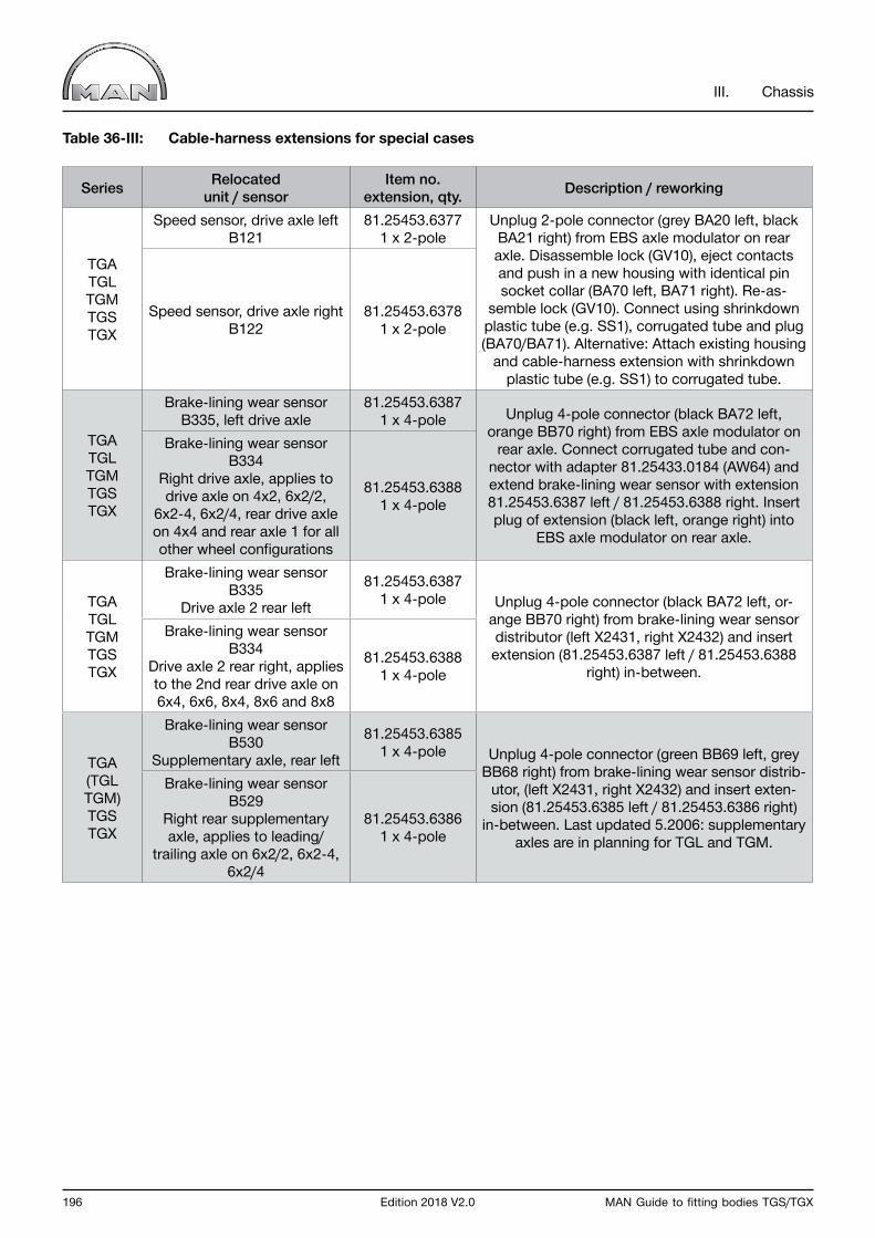
196 Edition 2018 V2.0 MAN Guide to fitting bodies TGS/TGX
III. Chassis
Table 36-III: Cable-harness extensions for special cases
Series Relocated unit / sensor
Item no. extension, qty. Description / reworking
TGA TGL TGMTGSTGX
Speed sensor, drive axle left B121
81.25453.6377 1 x 2-pole
Unplug 2-pole connector (grey BA20 left, black BA21 right) from EBS axle modulator on rear axle. Disassemble lock (GV10), eject contacts and push in a new housing with identical pin socket collar (BA70 left, BA71 right). Re-as-
semble lock (GV10). Connect using shrinkdown plastic tube (e.g. SS1), corrugated tube and plug (BA70/BA71). Alternative: Attach existing housing
and cable-harness extension with shrinkdown plastic tube (e.g. SS1) to corrugated tube.
Speed sensor, drive axle right B122
81.25453.6378 1 x 2-pole
TGA TGL TGM TGSTGX
Brake-lining wear sensor B335, left drive axle
81.25453.6387 1 x 4-pole Unplug 4-pole connector (black BA72 left,
orange BB70 right) from EBS axle modulator on rear axle. Connect corrugated tube and con-
nector with adapter 81.25433.0184 (AW64) and extend brake-lining wear sensor with extension 81.25453.6387 left / 81.25453.6388 right. Insert plug of extension (black left, orange right) into
EBS axle modulator on rear axle.
Brake-lining wear sensor B334
Right drive axle, applies to drive axle on 4x2, 6x2/2,
6x2-4, 6x2/4, rear drive axle on 4x4 and rear axle 1 for all other wheel configurations
81.25453.6388 1 x 4-pole
TGA TGL TGMTGSTGX
Brake-lining wear sensor B335
Drive axle 2 rear left
81.25453.6387 1 x 4-pole Unplug 4-pole connector (black BA72 left, or-
ange BB70 right) from brake-lining wear sensor distributor (left X2431, right X2432) and insert extension (81.25453.6387 left / 81.25453.6388
right) in-between.
Brake-lining wear sensor B334
Drive axle 2 rear right, applies to the 2nd rear drive axle on 6x4, 6x6, 8x4, 8x6 and 8x8
81.25453.6388 1 x 4-pole
TGA (TGL TGM)TGSTGX
Brake-lining wear sensor B530
Supplementary axle, rear left
81.25453.6385 1 x 4-pole Unplug 4-pole connector (green BB69 left, grey
BB68 right) from brake-lining wear sensor distrib-utor, (left X2431, right X2432) and insert exten-sion (81.25453.6385 left / 81.25453.6386 right)
in-between. Last updated 5.2006: supplementary axles are in planning for TGL and TGM.
Brake-lining wear sensor B529
Right rear supplementary axle, applies to leading/
trailing axle on 6x2/2, 6x2-4, 6x2/4
81.25453.6386 1 x 4-pole

MAN Guide to fitting bodies TGS/TGX Edition 2018 V2.0 197
III. Chassis
8.2.4 Cable harnesses for rear position lamps, additional rear position lamps, trailer sockets, side marker lamps and supplementary ABS sockets
The possible applications for these cable extensions are:
• cable-harness extension for rear position lamps and trailer sockets as a result of overhang extensions• Connection of supplementary rear position lamps via T-distributor• Connection of supplementary sockets via T-distributor – potential applications: - Installation of 15-pole and Type 24N/24S 7-pole sockets - Installation of sockets behind cab for semitrailer - Installation of trailer sockets on frame end• Cable-harness extensions for side marker lights
To extend cable harnesses or fit supplementary lights/sockets, only the cable harnesses described here may be used so as to ensure the correct functioning of the CAN data network.
Table 37-III: Extension cable harnesses, rear position lamps
Series Designation Length in metres MAN part no.TGATGLTGMTGSTGX
Extension cable harness for rear position lamps (per lamp) 1 81.25428.6975
Extension cable harness for rear position lamps (per lamp) 1,5 81.25428.6982
Table 38-III: Extension cable harnesses for trailer sockets
Series Designation Plug colour Length in metres MAN part no.
TGATGLTGMTGSTGX
Extension cable harness for trailer socket Black 1 81.25428.6971
Extension cable harness for trailer socket Black 1,5 81.25428.6972
Extension cable harness for trailer socket Brown 1 81.25428.6973
Extension cable harness for trailer socket Brown 1,5 81.25428.6974
Pin-out depends on the plug colour of the cable harnesses:
Table 39-III: Assignment of socket to plug colour of the cable
Socket Use Standard plugType 24 N 24 V 7-pole N=normal DIN ISO 1185 1 x blackType 24 S 24 V 7-pole S=supplementary DIN ISO 3731 1 x brown15 pole 24 V 15-pin DIN ISO 12098 1 x black + 1 x brown
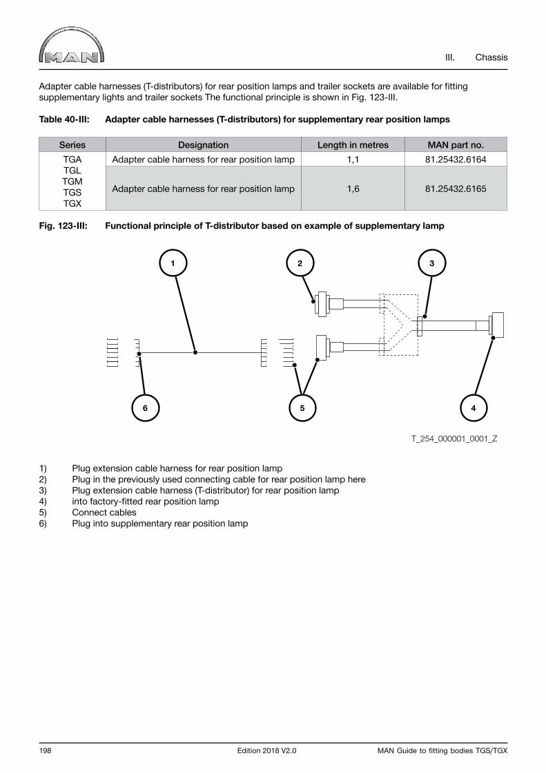
198 Edition 2018 V2.0 MAN Guide to fitting bodies TGS/TGX
III. Chassis
Adapter cable harnesses (T-distributors) for rear position lamps and trailer sockets are available for fitting supplementary lights and trailer sockets The functional principle is shown in Fig. 123-III.
Table 40-III: Adapter cable harnesses (T-distributors) for supplementary rear position lamps
Series Designation Length in metres MAN part no.TGATGLTGMTGSTGX
Adapter cable harness for rear position lamp 1,1 81.25432.6164
Adapter cable harness for rear position lamp 1,6 81.25432.6165
Fig. 123-III: Functional principle of T-distributor based on example of supplementary lamp
1) Plug extension cable harness for rear position lamp2) Plug in the previously used connecting cable for rear position lamp here3) Plug extension cable harness (T-distributor) for rear position lamp4) into factory-fitted rear position lamp5) Connect cables6) Plug into supplementary rear position lamp
T_254_000001_0001_Z
5 46
1 2 3

MAN Guide to fitting bodies TGS/TGX Edition 2018 V2.0 199
III. Chassis
Table 41-III: Adapter cable harness (T-distributor) for additional trailer sockets
Adapter cable harness (T-distributor) for additional trailer sockets Plug colour Length in metres MAN part no.
Adapter cable harness, symmetrical T-piece Black approx. 0.25 81.25432.6157Adapter cable harness, symmetrical T-piece Brown approx. 0.25 81.25432.6160Adapter cable harness, asymmetrical T-piece Black approx. 0.7 81.25432.6173Adapter cable harness, asymmetrical T-piece Brown approx. 0.7 81.25432.6174
Depending on the body, it may also be necessary to relocate the side marker lamps (the statutory regulations applicable to lighting system are to be observed). If the connection cables are too short, cable-harness extensions in various lengths are available. Only original MAN side marker lamps using LED technology are permitted. Use of any other lamps will result in the partial operating permit for the lighting system to become invalid. Side marker lamps with incandescent bulbs will damage the central on-board computer.
Table 42-III: Extensions for side marker lamps
Series Designation Length in metres MAN part no.TGATGLTGMTGSTGX
Cable-harness extension 0,5 81.25417.6685Cable-harness extension 1,0 81.25417.6686Cable-harness extension 2,0 81.25429.6294Cable-harness extension 3,0 81.25429.6295
An adapter cable harness also enables individual cables to be tapped (e.g. to connect a supplementary number-plate light). Individual connectors with individual cables are to be made up using seal connectors, Fig. 124-III shows how to make up an individual connector.
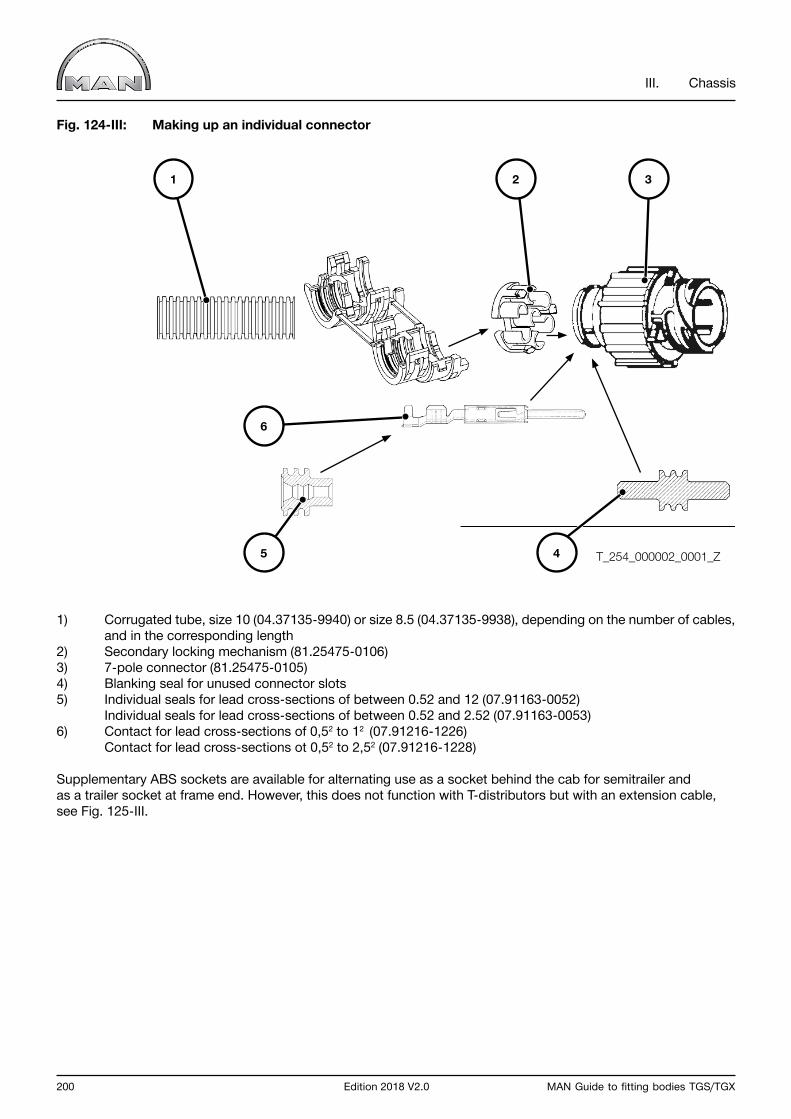
200 Edition 2018 V2.0 MAN Guide to fitting bodies TGS/TGX
III. Chassis
Fig. 124-III: Making up an individual connector
1) Corrugated tube, size 10 (04.37135-9940) or size 8.5 (04.37135-9938), depending on the number of cables, and in the corresponding length2) Secondary locking mechanism (81.25475-0106)3) 7-pole connector (81.25475-0105)4) Blanking seal for unused connector slots5) Individual seals for lead cross-sections of between 0.52 and 12 (07.91163-0052) Individual seals for lead cross-sections of between 0.52 and 2.52 (07.91163-0053)6) Contact for lead cross-sections of 0,52 to 12 (07.91216-1226) Contact for lead cross-sections ot 0,52 to 2,52 (07.91216-1228)
Supplementary ABS sockets are available for alternating use as a socket behind the cab for semitrailer and as a trailer socket at frame end. However, this does not function with T-distributors but with an extension cable, see Fig. 125-III.
T_254_000002_0001_Z
1 2 3
5 4
6

MAN Guide to fitting bodies TGS/TGX Edition 2018 V2.0 201
III. Chassis
Fig. 125-III: Use of ABS extension cable
Important:Connect the ABS socket in accordance with use.
In this way the ABS socket may be mounted either behind the cab (tractor unit) or at the frame end (truck).The cable lengths available conform with the wheelbases of the respective MAN tractor units (see Table 43-III).
Table 43-III: ABS extension cables
Item no. 81.25453.6288 81.25453.6290 81.25453.6291 81.25453.6292Cable length (total) 4.700mm 5.400 mm 6.100 mm 6.800 mm
Use Wheelbase R
Semitrailer tractor 4x2, 4x4
R <= 3.900
Semitrailer tractor 6x2
R <= 3.200+1.350
Semitrailer tractor 6x4, 6x6
R <= 3.600+1.350
Semitrailer tractor 6x4, 6x6
R <= 3.600+1.350
T_524_000001_0001_G
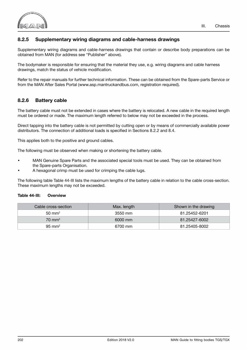
202 Edition 2018 V2.0 MAN Guide to fitting bodies TGS/TGX
III. Chassis
8.2.5 Supplementary wiring diagrams and cable-harness drawings
Supplementary wiring diagrams and cable-harness drawings that contain or describe body preparations can be obtained from MAN (for address see “Publisher” above).
The bodymaker is responsible for ensuring that the material they use, e.g. wiring diagrams and cable harness drawings, match the status of vehicle modification.
Refer to the repair manuals for further technical information. These can be obtained from the Spare-parts Service or from the MAN After Sales Portal (www.asp.mantruckandbus.com, registration required).
8.2.6 Battery cable
The battery cable must not be extended in cases where the battery is relocated. A new cable in the required length must be ordered or made. The maximum length referred to below may not be exceeded in the process.
Direct tapping into the battery cable is not permitted by cutting open or by means of commercially available power distributors. The connection of additional loads is specified in Sections 8.2.2 and 8.4.
This applies both to the positive and ground cables.
The following must be observed when making or shortening the battery cable.
• MAN Genuine Spare Parts and the associated special tools must be used. They can be obtained from the Spare-parts Organisation.• A hexagonal crimp must be used for crimping the cable lugs.
The following table Table 44-III lists the maximum lengths of the battery cable in relation to the cable cross-section. These maximum lengths may not be exceeded.
Table 44-III: Overview
Cable cross-section Max. length Shown in the drawing50 mm2 3550 mm 81.25452-620170 mm2 6000 mm 81.25427-600295 mm2 6700 mm 81.25405-8002

MAN Guide to fitting bodies TGS/TGX Edition 2018 V2.0 203
III. Chassis
8.3 Interfaces on the vehicle, preparations for the body
No intervention in the on-board network is permitted except via the interfaces provided by MAN.
Signals must not be tapped from the CAN bus, the only exception being the bodybuilder’s CAN bus (see TG interface of the control unit for external data exchange (custom module).
The interfaces provided by MAN are fully documented in the sections below. Interfaces are, for example:
• Liftgate• For start / stop device• Intermediate speed control• FMS interface• Tapping into the engine-on signal• Tapping into the speed signal• Tapping into the reverse-gear signal
If a vehicle is ordered with ready body fittings (e.g. start/stop device at end of frame) these will be installed ex works and partly connected. The instrumentation is prepared as ordered. Before commissioning the body fittings, the bodybuilder must ensure that it has used the applicable versions of wiring diagrams and cable-harness drawings in each case (see also Chapter III, Section 8.2.5).
MAN affixes transport securing devices (on the interfaces behind the front flap on the co-driver’s side) for delivery of a vehicle to the bodymaker. These devices must be properly removed before using an interface.
Retrofitting interfaces and/or bodywork preparations can be complicated and costly, requiring the support of an electronics specialist from the MAN Service Organisation.
Remote transmission from the mass storage of digital tachographs and information contained on the driver card.MAN supports the manufacturer-independent remote transmission of data from the mass storage of digital tachographs and information contained on the driver card (RDL = remote download). The corresponding interface is published on the Internet at www.fms-standard.com.

204 Edition 2018 V2.0 MAN Guide to fitting bodies TGS/TGX
III. Chassis
8.3.1 Tapping into the engine-on (D+) signal
The vehicle offers several options for tapping into the reverse-gear signal.
The engine-on signal can be tapped from the central on-board computer because this supplies an “Engine running” signal (+24 V). This signal can be tapped into directly at the central on-board computer (connector F2, plug contact 17).The maximum load on this connection must not exceed 1 A. It should be noted that other internal consumers may also be connected here. It must be ensured that this connection is free from feedback.
In addition, the engine-on signal can be tapped into amongst the signals and information supplied by the custom-er-specific control module (“KSM”) interface.
Important notice D+ may not be tapped from the alternator.
Remote transmission from the mass storage of digital tachographs and information contained on the driver card.MAN supports the manufacturer-independent remote transmission of data from the mass storage of digital tachographs and information contained on the driver card (RDL = remote download). The corresponding interface is published on the Internet at www.fms-standard.com.
8.3.2 Electrical interface for liftgate
Electrohydraulic liftgates require very careful design of the electrical supply.
Ideally the electrical interface for a liftgate is provided ex works. Retrofitting the interface is a complex procedure and requires intervention in the vehicle‘s electrical system, which must only be carried out by correspondingly qualified personnel at MAN Service outlets.
It includes the following parts:
• switch,• check lamp,• starter inhibitor • and power supply for the liftgate).
The factory-fitted transport securing device must be removed when work on the body commences.
Retrofitting is a complex procedure and requires intervention in the vehicle‘s power supply, which may only be carried out by correspondingly qualified personnel at MAN Service outlets.The bodybuilder must check the circuitry of the liftgate to ensure it is suitable for MAN vehicles. Under normal circumstances triggering of interface A358 may only be effected with 24-V continuous signals – not with flash puls-es. In the event of malfunction, a clocked signal may be applied briefly to relay K467.
For connection to the electric interface of the hydraulic liftgate, see the supplementary wiring diagrams below.

MAN Guide to fitting bodies TGS/TGX Edition 2018 V2.0 205
III. Chassis
Fig. 126-III: Supplementary wiring diagram, liftgate for TG with vehicle management computer (VMC), MAN item no. 81.99192-1920
1) Interrupt standard plug connection X669 and switch harness liftgate between.
A100 255 Central electrical systemA302 352 Central computer 2A358 Liftgate control unitA403 339 Vehicle management computerA407 342 InstrumentationF219 118 Liftgate fuse (Terminal 15)
H254 Liftgate check lamp (high active)
K175 281 Start-lock relayK467 281 Liftgate relay
S286 547 Liftgate switch
X669 Plug connector, starter interlockX744 Plug connector, liftgateX2541 246 Potential distributor 21-pole lead 31000X2542 246 Potential distributor 21-pole lead 58000X3186 Plug connector, liftgate
Leads 91003, 91336, 91555, 91556, 91557, 91572 and 91573 routed to 7-pole socket housing on frame end (rolled up)
T_678_000004_0001_G1

206 Edition 2018 V2.0 MAN Guide to fitting bodies TGS/TGX
III. Chassis
Fig. 127-III: Supplementary wiring diagram, liftgate for TG with Power Train Manager (PTM) MAN item no. 81.99192-3645
1) Interrupt standard plug connection X669 and switch harness liftgate between.
A100 255 Central electrical systemA302 352 Central computer 2A358 Liftgate control unitA403 339 Vehicle management computerA407 342 InstrumentationF219 118 Liftgate fuse (Terminal 15)
H254 Liftgate check lamp (high active)
K175 281 Start-lock relayK467 281 Liftgate relay
S286 547 Liftgate switch
X669 Plug connector, starter interlockX744 Plug connector, liftgateX2541 246 Potential distributor 21-pole lead 31000X2542 246 Potential distributor 21-pole lead 58000X3186 Plug connector, liftgate
Leads 91003, 91336, 91555, 91556, 91557, 91572 and 91573 routed to 7-pole socket housing on frame end(rolled up)
T_678_000005_0001_G1

MAN Guide to fitting bodies TGS/TGX Edition 2018 V2.0 207
III. Chassis
8.3.3 Engine-Start-stop system
The engine start-stop system enables the vehicle’s engine to be started or stopped via a remote control or switch outside the cab.
The engine start-stop system is a system that works independently of the intermediate speed control interface and must be ordered separately.
The following variants of the engine start-stop system are available ex-works.
• Engine start/stop device under the front panel (preparation), plug X679, front wall inside right after removal of cover.• Engine start/stop device on engine (plug X1551, interior panelling in steering column area).• Engine start/stop device at end of frame (preparation). Cable extension from plug X679, rolled up at end of frame.
The connection options and pin assignments are shown in the table below.
Table 45-III:
Cable number FunctionPlug assignment
Plug X679 / Pin Plug X1551 / Pin60028 + potential 1 650303 Engine start 2 1043315 Engine stop 3 11
If a variant is not included in the equipment scope of a vehicle, the “engine start/stop device” can be retrofitted by a MAN service outlet.It must then be ensured that both the original MAN cable harnesses and the documented connection options and locations are used.
It is also possible to realise the engine start-stop system by means of the CAN data bus. The requirement for this is that a customer-specific control module (“KSM”) was fitted at the factory. Further references and descriptions of connections and signals can be found in the separate guideline entitled “TG Interfaces”.
Specific parameterisation is not necessary for the engine start-stop system.
Circuit diagrams can be obtained from MAN Service or the MAN After Sales Portal.
Important notice If the bodybuilder has installed the circuitry, the designation “Engine start-stop” must be used. This must not be confused with the term “Emergency stop”.

208 Edition 2018 V2.0 MAN Guide to fitting bodies TGS/TGX
III. Chassis
8.3.4 Tapping into the speed signal
It is possible to tap into the speed signal from the tachograph. It must be ensured that the load on the corresponding plug contact does not exceed 1 mA!
This generally equates to two connected peripheral units. Should this option for tapping the signal be inadequate then the following output multipliers bearing the MAN codes can be connected:
• 81.25311-0022 (3 • v-pulse output, max. load 1 mA for each output) or • 88.27120-0003 (5 • v-pulse output, max. load 1 mA for each output).
Option for tapping the ‘B7 signal’ = speed signal:
• At connector B / plug contact 7 or plug contact 6 on the back of the tachograph• At the 3-pole plug connector X4366/contact 1. The plug connector is located behind a cover on the driver side A-pillar in the area around the driver’s footwell.• At the plug X5929 (line 16500) fitted as standard in the area of the central electrical system. The plug X5929 is not available if the interface for displacement signal and speed signal was installed ex-works, orderable via the sales code 307CS - Electrical preparation for gritter (displacement/speed signal)). In this case, the speed signal can be accessed at plug X1428 / Pin 6, also in the area of the central electrical system.• At the 2-pole plug connector X4659 / contact 1 or 2. The plug connector is located behind the central electrics box.• At the factory-fitted interface with customer-specific control module from STEP1 on (see Chapter III, Section 8.3.6).
Important notice In order to avoid diagnostic memory entries, always switch off the ignition prior to carrying out any work on the tachograph!
MAN Guide to fitting bodies TGS/TGX Edition 2018 V2.0 209
III. Chassis
8.3.5 Tapping into the reverse gear signal
It is possible to access the reversing signal on all vehicles of the TG series. You will find information on how the signal can be accessed below.
• Accessible via plug X1428 at plug contact 5 of line 71300. The plug X1428 is located in the area of the central electrical system. A prerequisite for this is that the body manufacturer preparation for displacement/ speed signal is installed in the vehicle. It must be noted that the interface load for the reversing signal must not exceed a permitted value of 100 mA.
• The reversing signal can also be accessed via the customer-specific control module (KSM). A prerequisite for this is that the customer-specific control module is installed in the vehicle ex-works. Further information and connection and signal descriptions can be found in Chapter III under Section 8.3.6.
Important notice All work must be carried out with the ignition turned off or with the battery disconnected. In addition to accident-prevention regulations, country-specific guidelines and laws must also be observed.
8.3.6 Interfaces for intermediate speed control with VMC/PTM and CSM (ISC interfaces)
MAN‘s intermediate speed control can be realised via the following interfaces.
• Interface on the vehicle management computer (VMC)/Power Train Manager (PTM)• Interface on customer-specific control module (KSM)
Detailed descriptions of these interface variants are documented separately. This chapter contains general explanations and an overview of the available interface descriptions.
AbbreviationsThe following text and the detailed interface descriptions use certain abbreviations and MAN-specific terms. These are explained in Table 46-III in alphabetical order.

210 Edition 2018 V2.0 MAN Guide to fitting bodies TGS/TGX
III. Chassis
Table 46-III: Abbreviations and MAN-specific terms used
Term/abbreviation ExplanationA-CAN Set-up-CAN (CAN = Controller Area Network)OFF Switch-off of cruise control/speed limiter/intermediate speed control functionsCAN Controller Area Network (= data bus, digital network)ESL Engine speed limitDI Digital inputEMC Electromagnetic compatibility VIN Vehicle identification number VMC vehicle management computer CC/RSL/ISC Vehicle speed control/vehicle speed limiter/intermediate speed control FMS Fleet Management System GEARBOX-N Neutral position of gearboxGMT Greenwich Mean TimeHGB Maximum speed limitationHigh-side switch Switching output downstream of Terminal 30 (+UBAT)HP ZF automatic gearbox HP...SC Short circuitCSM Customer-specific control moduleLED Light emitting diodeLow-side switch Switching output downstream of Terminal 31 (-UBAT)M3135 MAN works standard (M + 3 or 4 digits)
MAN-CATS Computer diagnostic system used in MAN workshops (CATS = computer-aided testing system)
TL Torque limitTSL Torque/speed limiterMEMORY Stored function/valuePTO Power take-off (PTO)NMV Power take-off pre-fitted, depending on enginePIN Plug contactPTO Power take off PWM Pulse width modulation R-gear Reverse gear SET+ Increase and set speed and/or accelerate SET- Reduce and set speed and/or decelerateCU Control unitT-CAN Driveline CAN (CAN = Controller Area Network)+UBAT Positive voltage of batteries-UBAT Negative voltage of batteriesUTC Universal Time CodeVIN Vehicle identification numberCOC Central on-board computerISC Intermediate speed control/regulator
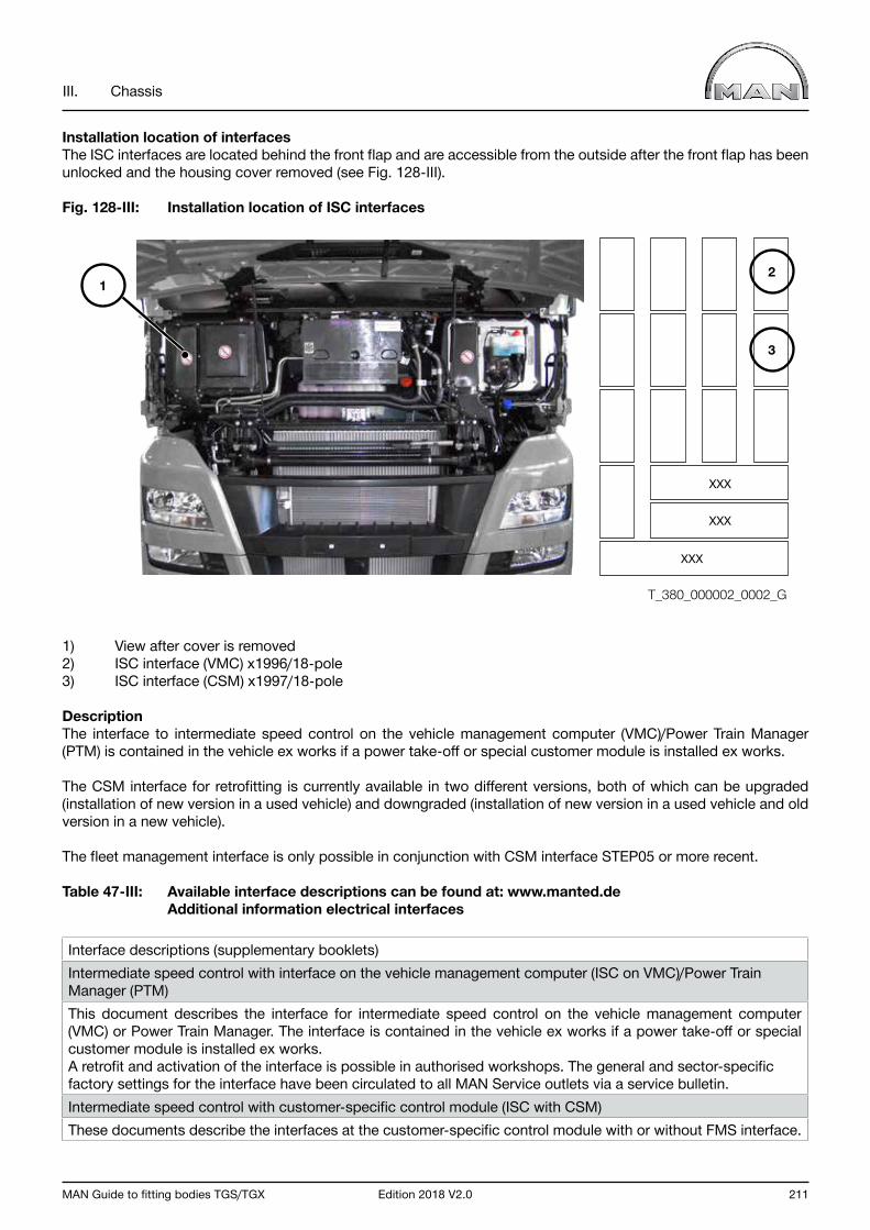
MAN Guide to fitting bodies TGS/TGX Edition 2018 V2.0 211
III. Chassis
Installation location of interfacesThe ISC interfaces are located behind the front flap and are accessible from the outside after the front flap has been unlocked and the housing cover removed (see Fig. 128-III).
Fig. 128-III: Installation location of ISC interfaces
1) View after cover is removed2) ISC interface (VMC) x1996/18-pole3) ISC interface (CSM) x1997/18-pole
DescriptionThe interface to intermediate speed control on the vehicle management computer (VMC)/Power Train Manager (PTM) is contained in the vehicle ex works if a power take-off or special customer module is installed ex works.
The CSM interface for retrofitting is currently available in two different versions, both of which can be upgraded (installation of new version in a used vehicle) and downgraded (installation of new version in a used vehicle and old version in a new vehicle).
The fleet management interface is only possible in conjunction with CSM interface STEP05 or more recent.
Table 47-III: Available interface descriptions can be found at: www.manted.de Additional information electrical interfaces
Interface descriptions (supplementary booklets)Intermediate speed control with interface on the vehicle management computer (ISC on VMC)/Power Train Manager (PTM)This document describes the interface for intermediate speed control on the vehicle management computer (VMC) or Power Train Manager. The interface is contained in the vehicle ex works if a power take-off or special customer module is installed ex works.A retrofit and activation of the interface is possible in authorised workshops. The general and sector-specific factory settings for the interface have been circulated to all MAN Service outlets via a service bulletin.Intermediate speed control with customer-specific control module (ISC with CSM)These documents describe the interfaces at the customer-specific control module with or without FMS interface.
12
3
XXX
XXX
XXX
T_380_000002_0002_G

212 Edition 2018 V2.0 MAN Guide to fitting bodies TGS/TGX
III. Chassis
8.3.7 Interface for reversing-camera preparation
The electrical interface for the rear-view camera preparation makes it possible to connect either one or two rear-view cameras and show the image on the screen of the MAN Radio MMT advanced. The system automatically switches to the camera image when reverse gear is engaged, or the rear view can be manually selected using a separate button.
The rear-view camera preparation interface is a system independent of the MAN radio MMT advanced, and must be ordered separately using the sales code for the rear-view camera preparation.
If the interface is not available ex works, it is possible to retrofit it. Because a retrofit is costly and requires access to the vehicle electrical circuit, we recommend having it done at a MAN Service centre.
Some camera manufacturers offer an adapter lead suitable for our interface (rear-view camera preparation), which can also be sourced from a MAN specialist workshop.
From September 2016 there will be a new generation of radios, which two cameras can be connected to. Switching between the two images takes place using the CAM button on the radio.
This section also describes the distinctive features of the different radios and the different interfaces.
MAN Radio MMT advanced (from 2012)
This radio has a 5-inch display and a CD slot. The system automatically switches to the camera image when reverse gear is engaged, or the rear view can be manually selected using a separate button in the switch block of the instrument panel.
MAN Radio MMT advanced (from 2016)
This radio has a 7-inch display and the system automatically switches to the camera image when reverse gear is engaged, or it can be manually selected using a button on the radio (CAM button). As a further variant, it is possible to activate the camera image using a contact to the radio; you can find the description for doing so under “MAN Radio MMT advanced (2016)” – Activating the camera image via a contact.

MAN Guide to fitting bodies TGS/TGX Edition 2018 V2.0 213
III. Chassis
MAN Radio MMT advanced (from 2012)
The plug A of the interface is below the front panel on the right of the vehicle in the direction of travel, after removing the two housing covers (Pos. A, Fig. 129-III).
Fig. 129-III: Position Plug A
T_254_000003_0002_G
A
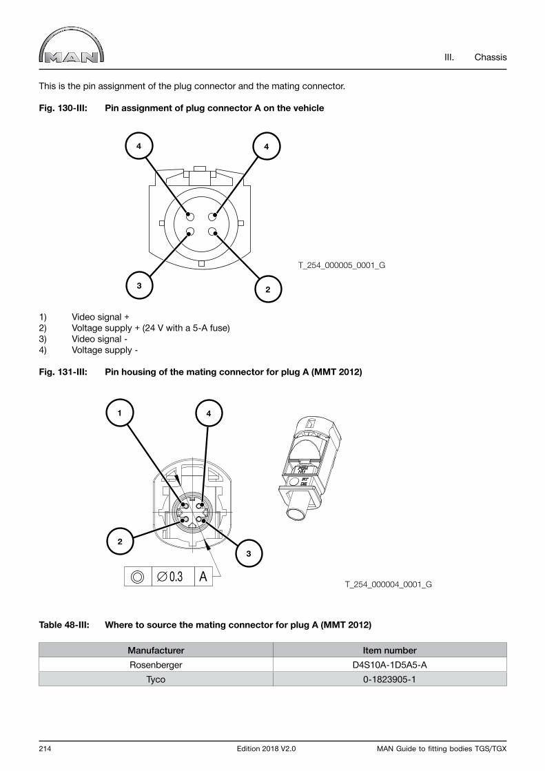
214 Edition 2018 V2.0 MAN Guide to fitting bodies TGS/TGX
III. Chassis
This is the pin assignment of the plug connector and the mating connector.
Fig. 130-III: Pin assignment of plug connector A on the vehicle
1) Video signal +2) Voltage supply + (24 V with a 5-A fuse)3) Video signal -4) Voltage supply -
Fig. 131-III: Pin housing of the mating connector for plug A (MMT 2012)
Table 48-III: Where to source the mating connector for plug A (MMT 2012)
Manufacturer Item numberRosenberger D4S10A-1D5A5-A
Tyco 0-1823905-1
T_254_000004_0001_G
T_254_000005_0001_G
∅ 0.3 A
1 4
23
4 4
3 2
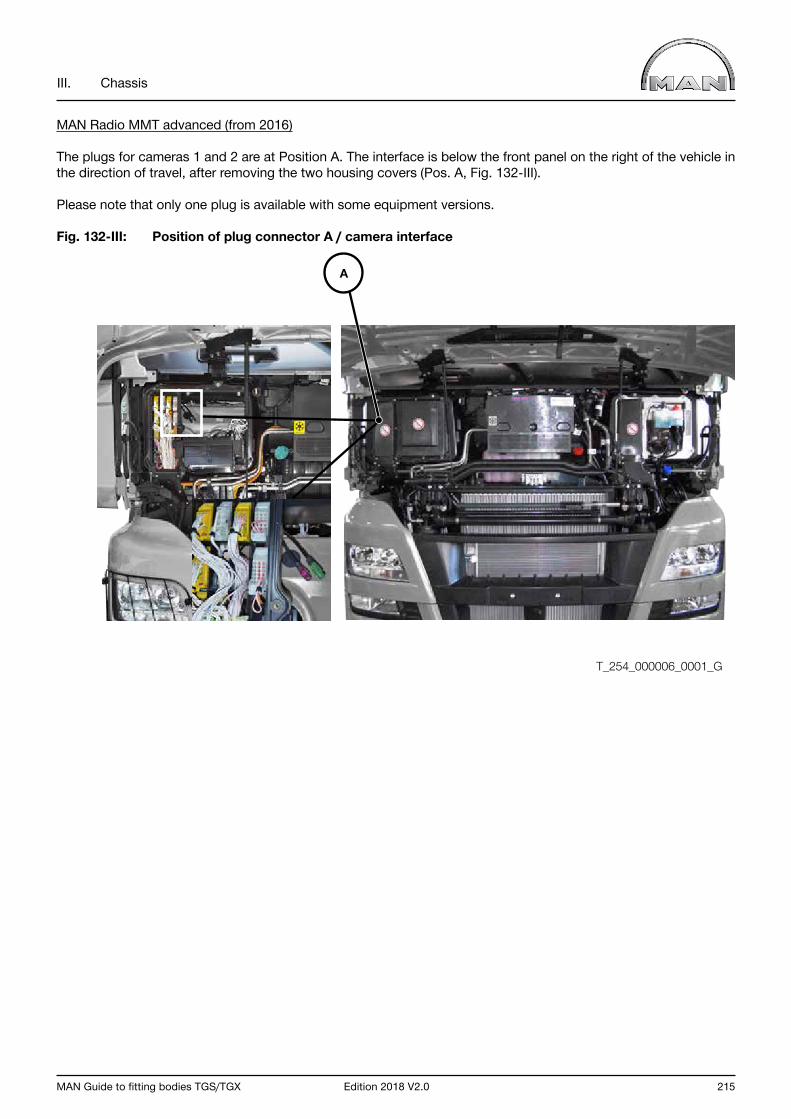
MAN Guide to fitting bodies TGS/TGX Edition 2018 V2.0 215
III. Chassis
MAN Radio MMT advanced (from 2016)
The plugs for cameras 1 and 2 are at Position A. The interface is below the front panel on the right of the vehicle in the direction of travel, after removing the two housing covers (Pos. A, Fig. 132-III).
Please note that only one plug is available with some equipment versions.
Fig. 132-III: Position of plug connector A / camera interface
A
T_254_000006_0001_G
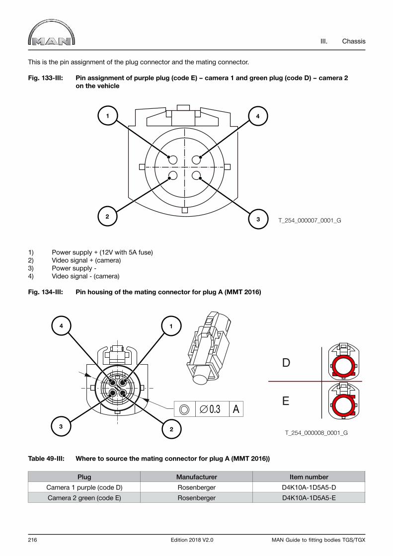
216 Edition 2018 V2.0 MAN Guide to fitting bodies TGS/TGX
III. Chassis
This is the pin assignment of the plug connector and the mating connector.
Fig. 133-III: Pin assignment of purple plug (code E) – camera 1 and green plug (code D) – camera 2 on the vehicle
1) Power supply + (12V with 5A fuse)2) Video signal + (camera)3) Power supply -4) Video signal - (camera)
Fig. 134-III: Pin housing of the mating connector for plug A (MMT 2016)
Table 49-III: Where to source the mating connector for plug A (MMT 2016))
Plug Manufacturer Item numberCamera 1 purple (code D) Rosenberger D4K10A-1D5A5-DCamera 2 green (code E) Rosenberger D4K10A-1D5A5-E
T_254_000007_0001_G
T_254_000008_0001_G
1 4
2 3
∅ 0.3 A
D
E
4 1
3 2
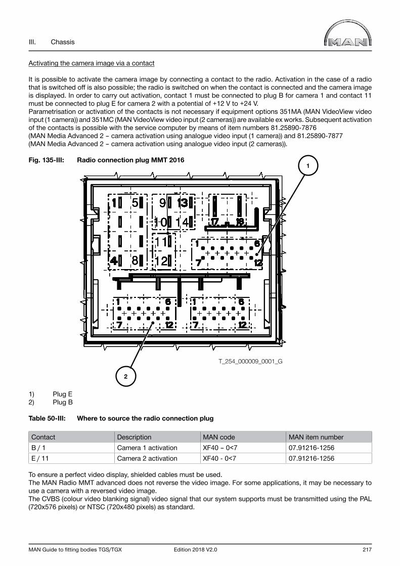
MAN Guide to fitting bodies TGS/TGX Edition 2018 V2.0 217
III. Chassis
Activating the camera image via a contact
It is possible to activate the camera image by connecting a contact to the radio. Activation in the case of a radio that is switched off is also possible; the radio is switched on when the contact is connected and the camera image is displayed. In order to carry out activation, contact 1 must be connected to plug B for camera 1 and contact 11 must be connected to plug E for camera 2 with a potential of +12 V to +24 V. Parametrisation or activation of the contacts is not necessary if equipment options 351MA (MAN VideoView video input (1 camera)) and 351MC (MAN VideoView video input (2 cameras)) are available ex works. Subsequent activation of the contacts is possible with the service computer by means of item numbers 81.25890-7876 (MAN Media Advanced 2 – camera activation using analogue video input (1 camera)) and 81.25890-7877 (MAN Media Advanced 2 – camera activation using analogue video input (2 cameras)).
Fig. 135-III: Radio connection plug MMT 2016
1) Plug E2) Plug B
Table 50-III: Where to source the radio connection plug
Contact Description MAN code MAN item numberB / 1 Camera 1 activation XF40 – 0<7 07.91216-1256E / 11 Camera 2 activation XF40 - 0<7 07.91216-1256
To ensure a perfect video display, shielded cables must be used.The MAN Radio MMT advanced does not reverse the video image. For some applications, it may be necessary to use a camera with a reversed video image.The CVBS (colour video blanking signal) video signal that our system supports must be transmitted using the PAL (720x576 pixels) or NTSC (720x480 pixels) as standard.
1
T_254_000009_0001_G
2
218 Edition 2018 V2.0 MAN Guide to fitting bodies TGS/TGX
III. Chassis
8.4 Additional consumers
As a basic principle, the connection of additional consumers is possible. If additional electrical loads are retrofitted, observe the following:
• There are no spare fuses in the central electrical system for use by the bodymaker. Extra fuses can be attached in a readied plastic container in front of the central electrical system. • Do not tap into existing vehicle power circuits.• Do not connect additional electric consumers to fuses that are already occupied.• Every added circuit must be adequately scaled and protected by its own fuses. The rating of the fuse should ensure the protection of the wiring and not that of the system connected to it.• Installation of additional open fuse carriers in the battery box is prohibited. These must be used only in areas that are protected against moisture or other environmental influences, e.g. in the cab. The body manufacturer bears sole responsibility if this is not observed and damage occurs as a result.• Electrical systems must offer sufficient protection against all possible electrical faults and environmental influences without affecting the vehicle electrics.• Freedom from feedback must be ensured in all cases. When selecting the size of the wire cross-section, the voltage drop and the heating of the conductor must be taken into account. Cross-sections below 0.75 mm2 are to be avoided because their mechanical strength is not sufficient. The bodybuilder is responsible for the dimensioning.• Minus and plus leads must have the same minimum cross-section.• Current draw for 12-V equipment must be effected only via a voltage converter.• Drawing from only one battery is impermissible because unequal charges lead to overloading and damage in the other battery. Under certain circumstances, e.g. for body-mounted equipment with a high power requirement (e.g. electrohydraulic liftgates) or in extreme climatic conditions, higher capacity batteries will be required.
Important notice If the bodybuilder installs larger batteries, the cross-section of the battery cable must be adapted to suit the new power draw.
If consumers are directly connected to Terminal 15 (Pin 94 in the central electrics box, see Fig. 136-III) it is possible that entries will be logged in the error memories of control units as a result of a reverse flow of current into thevehicle‘s electrical system. Consumers must therefore be connected in accordance with the following instructions.
• Power supply, terminal 15 Always fit a relay that is triggered via Terminal 15 (Pin 94). The load must be connected via a fuse on Terminal 30 (Pins 90-1, 90-2 and 91, rear of central electrics box), see Fig. 136-III. The maximum load must not exceed 10 A.
The tightening torque (Ma) von 5,5 Nm + / - 10% must be observed.
• Power supply, terminal 30 For maximum loads of up to 10 A the load must be connected through a circuit breaker at terminal 30 (Pins 90-1, 90-2 and 91, see Fig. 136-III, Central electrics box). For loads > 10 A connect directly to the batteries via a fuse.
The tightening torque (Ma) of 5,5 Nm + / - 10% must be observed.
• Power supply, terminal 31 Do not connect to the batteries but instead to the ground points inside (see Fig. 137-III Ground point X1644 behind central elektric unit) and outside (rear right engine mounting) the cab.
The tightening torque (Ma) of 9 Nm + / - 0,9 Nm must be observed.
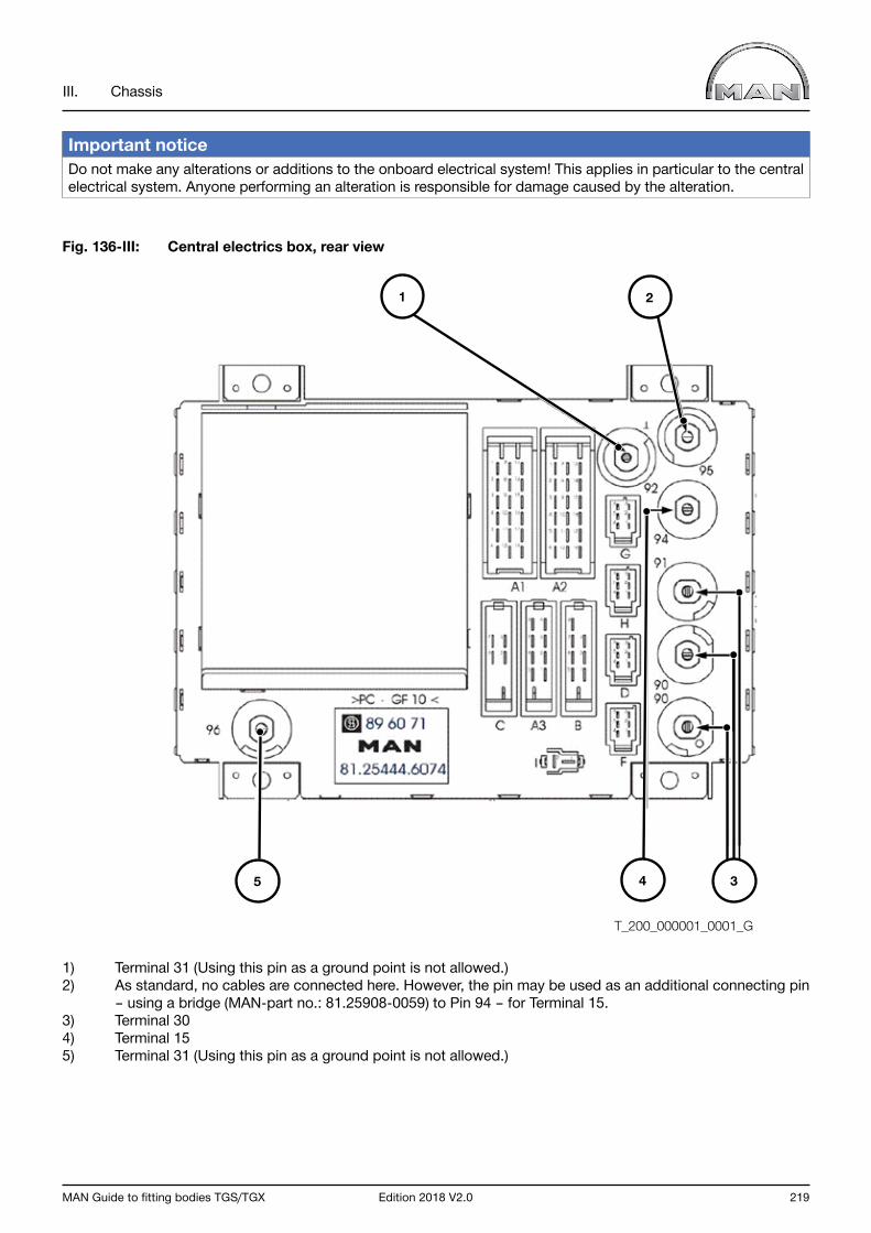
MAN Guide to fitting bodies TGS/TGX Edition 2018 V2.0 219
III. Chassis
Important notice Do not make any alterations or additions to the onboard electrical system! This applies in particular to the central electrical system. Anyone performing an alteration is responsible for damage caused by the alteration.
Fig. 136-III: Central electrics box, rear view
1) Terminal 31 (Using this pin as a ground point is not allowed.)2) As standard, no cables are connected here. However, the pin may be used as an additional connecting pin – using a bridge (MAN-part no.: 81.25908-0059) to Pin 94 – for Terminal 15.3) Terminal 304) Terminal 155) Terminal 31 (Using this pin as a ground point is not allowed.)
T_200_000001_0001_G
1 2
4 35
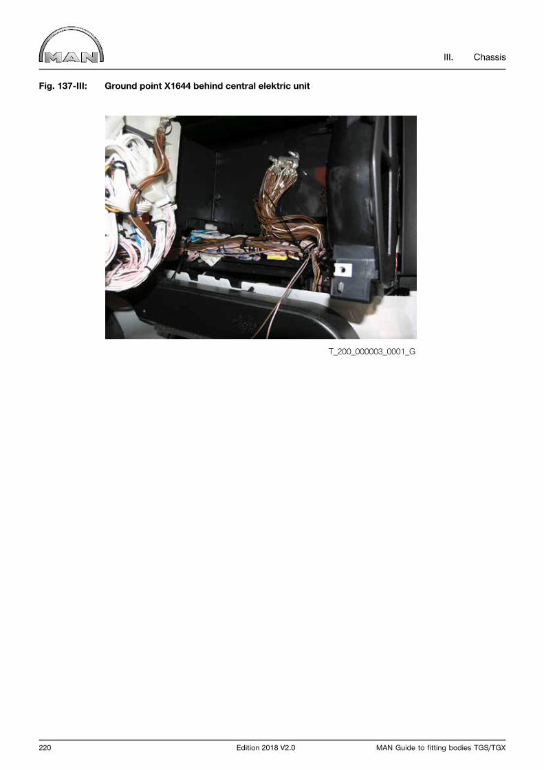
220 Edition 2018 V2.0 MAN Guide to fitting bodies TGS/TGX
III. Chassis
Fig. 137-III: Ground point X1644 behind central elektric unit
T_200_000003_0001_G
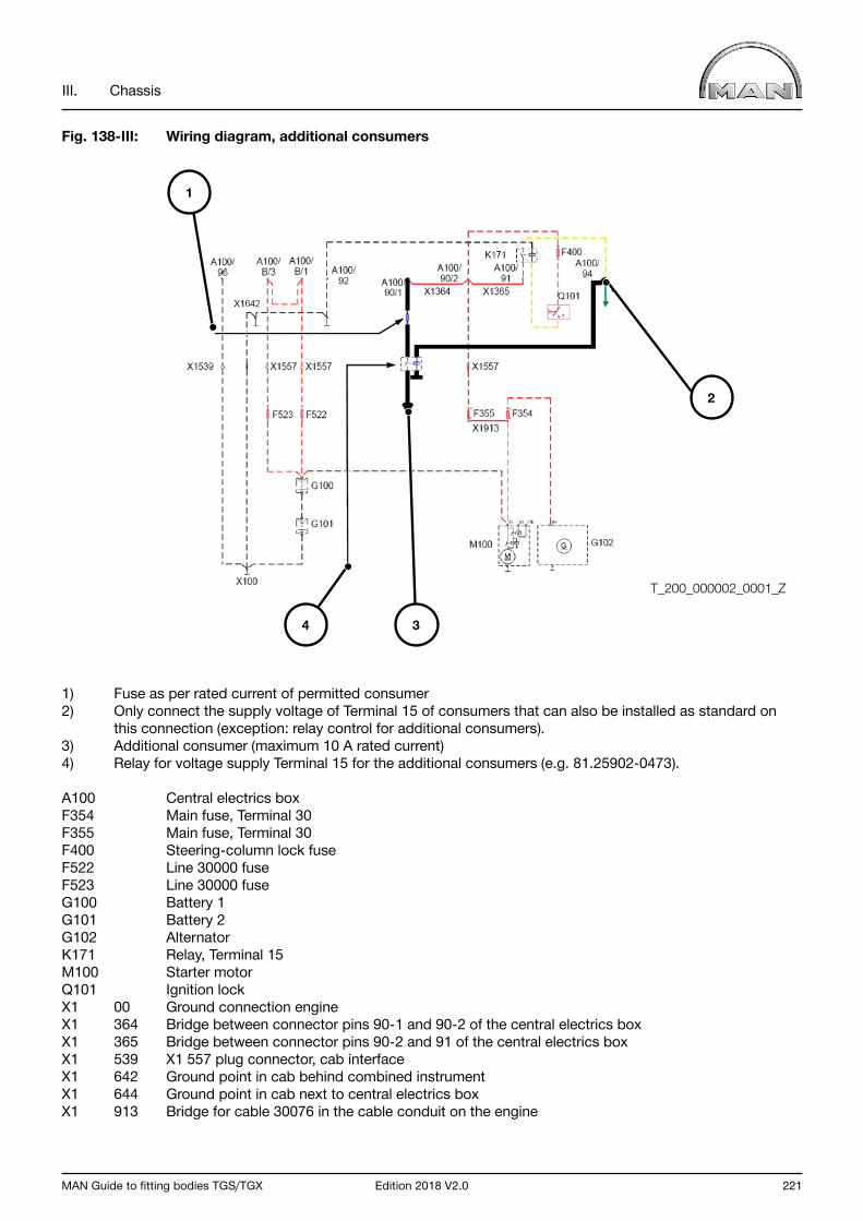
MAN Guide to fitting bodies TGS/TGX Edition 2018 V2.0 221
III. Chassis
Fig. 138-III: Wiring diagram, additional consumers
1) Fuse as per rated current of permitted consumer2) Only connect the supply voltage of Terminal 15 of consumers that can also be installed as standard on this connection (exception: relay control for additional consumers).3) Additional consumer (maximum 10 A rated current)4) Relay for voltage supply Terminal 15 for the additional consumers (e.g. 81.25902-0473).
A100 Central electrics box F354 Main fuse, Terminal 30 F355 Main fuse, Terminal 30 F400 Steering-column lock fuse F522 Line 30000 fuse F523 Line 30000 fuse G100 Battery 1 G101 Battery 2 G102 Alternator K171 Relay, Terminal 15 M100 Starter motor Q101 Ignition lock X1 00 Ground connection engine X1 364 Bridge between connector pins 90-1 and 90-2 of the central electrics box X1 365 Bridge between connector pins 90-2 and 91 of the central electrics box X1 539 X1 557 plug connector, cab interface X1 642 Ground point in cab behind combined instrumentX1 644 Ground point in cab next to central electrics boxX1 913 Bridge for cable 30076 in the cable conduit on the engine
1
4 3
2
T_200_000002_0001_Z
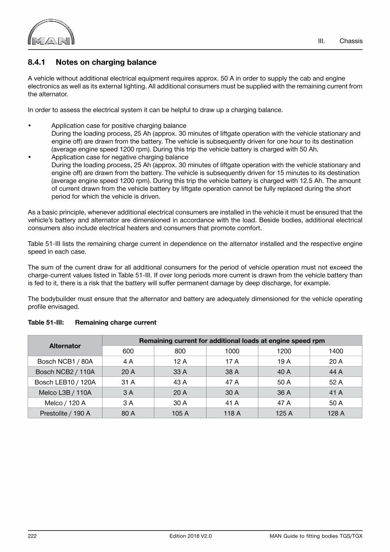
222 Edition 2018 V2.0 MAN Guide to fitting bodies TGS/TGX
III. Chassis
8.4.1 Notes on charging balance
A vehicle without additional electrical equipment requires approx. 50 A in order to supply the cab and engine electronics as well as its external lighting. All additional consumers must be supplied with the remaining current from the alternator.
In order to assess the electrical system it can be helpful to draw up a charging balance.
• Application case for positive charging balance During the loading process, 25 Ah (approx. 30 minutes of liftgate operation with the vehicle stationary and engine off) are drawn from the battery. The vehicle is subsequently driven for one hour to its destination (average engine speed 1200 rpm). During this trip the vehicle battery is charged with 50 Ah. • Application case for negative charging balance During the loading process, 25 Ah (approx. 30 minutes of liftgate operation with the vehicle stationary and engine off) are drawn from the battery. The vehicle is subsequently driven for 15 minutes to its destination (average engine speed 1200 rpm). During this trip the vehicle battery is charged with 12.5 Ah. The amount of current drawn from the vehicle battery by liftgate operation cannot be fully replaced during the short period for which the vehicle is driven.
As a basic principle, whenever additional electrical consumers are installed in the vehicle it must be ensured that the vehicle’s battery and alternator are dimensioned in accordance with the load. Beside bodies, additional electrical consumers also include electrical heaters and consumers that promote comfort.
Table 51-III lists the remaining charge current in dependence on the alternator installed and the respective engine speed in each case.
The sum of the current draw for all additional consumers for the period of vehicle operation must not exceed the charge-current values listed in Table 51-III. If over long periods more current is drawn from the vehicle battery than is fed to it, there is a risk that the battery will suffer permanent damage by deep discharge, for example.
The bodybuilder must ensure that the alternator and battery are adequately dimensioned for the vehicle operating profile envisaged.
Table 51-III: Remaining charge current
AlternatorRemaining current for additional loads at engine speed rpm
600 800 1000 1200 1400Bosch NCB1 / 80A 4 A 12 A 17 A 19 A 20 ABosch NCB2 / 110A 20 A 33 A 38 A 40 A 44 ABosch LEB10 / 120A 31 A 43 A 47 A 50 A 52 A
Melco L3B / 110A 3 A 20 A 30 A 36 A 41 AMelco / 120 A 3 A 30 A 41 A 47 A 50 A
Prestolite / 190 A 80 A 105 A 118 A 125 A 128 A
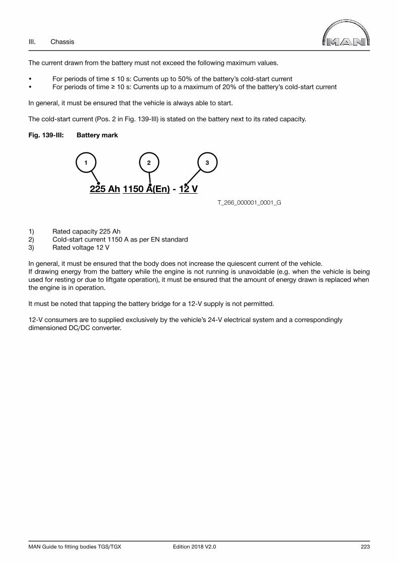
MAN Guide to fitting bodies TGS/TGX Edition 2018 V2.0 223
III. Chassis
The current drawn from the battery must not exceed the following maximum values.
• For periods of time ≤ 10 s: Currents up to 50% of the battery’s cold-start current • For periods of time ≥ 10 s: Currents up to a maximum of 20% of the battery’s cold-start current
In general, it must be ensured that the vehicle is always able to start.
The cold-start current (Pos. 2 in Fig. 139-III) is stated on the battery next to its rated capacity.
Fig. 139-III: Battery mark
1) Rated capacity 225 Ah2) Cold-start current 1150 A as per EN standard3) Rated voltage 12 V
In general, it must be ensured that the body does not increase the quiescent current of the vehicle. If drawing energy from the battery while the engine is not running is unavoidable (e.g. when the vehicle is being used for resting or due to liftgate operation), it must be ensured that the amount of energy drawn is replaced when the engine is in operation.
It must be noted that tapping the battery bridge for a 12-V supply is not permitted.
12-V consumers are to supplied exclusively by the vehicle’s 24-V electrical system and a correspondingly dimensioned DC/DC converter.
225 Ah 1150 A(En) - 12 V
321
T_266_000001_0001_G
224 Edition 2018 V2.0 MAN Guide to fitting bodies TGS/TGX
III. Chassis
8.5 Batteries
The battery is connected to the vehicle electrical system via two battery poles. To protect against injury or damage during maintenance work, the main battery switch must be switched off.
When removing the terminals from batteries and operating the master battery switch, be sure to proceed in the following order:
• Switch off all loads (e.g. lights, warning flashing indicator).• Switch off the ignition• Close the doors.• Wait for an after-run time of 60 seconds before disconnecting the batteries (negative terminal first). • The electrical battery master switch requires an extra 15 seconds.
Reason:Many vehicle functions are controlled by the central on-board computer (ZBR) which must first save its latest sta-tus before it can be de-energised. If, for example, the doors remain open, the time constant up to the controlled shutdown of the central on-board computer (ZBR) is 5 minutes, because the ZBR also monitors the door-closing functions. If the doors are open, it is therefore necessary to wait for more than 5 minutes before disconnecting the batteries: Closing the doors shortens the waiting time to 60 s. If the sequence described here is not observed, this will inevitably lead to diagnostic memory entries in some control units (e.g. in the central on-board computer ZBR) or to data/configuration loss.Excepted from this is of course operation of the EMERGENCY-OFF switch in case of emergency.
Important notice When the engine is running:
• Do not turn off the master battery switch• Do not loosen or disconnect the battery terminals.
From the end of 2016, the battery monitor will be introduced in series for vehicles whose cabs are equipped with a bunk and have 175Ah or 225Ah batteries.It is necessary when relocating the battery box or extending the measurement line to ensure that the module is recalibrated.Further information on the battery monitor is available on the MAN After Sales Portal.(www.asp.mantruckandbus.com, registration required).
8.5.1 Handling and maintaining batteries
Check batteries at regular intervals.
The battery tester DSS-7814 HD MAN, item number 08.78024-0005, must be used for testing batteries. Rapid-charge and jump-start devices must not be used for trickle charging as this could destroy control units. Jump-starting from one vehicle to another is permissible, provided that the instructions in the Operator’s Manual are followed.
MAN Guide to fitting bodies TGS/TGX Edition 2018 V2.0 225
III. Chassis
Observe the following when handling batteries:
Table 52-III:
Standstill time
For a standstill time of more than 30 days:
➔ Switch off the main battery switch. ➔ Disconnect batteries.
Open-circuit voltage never below 12.3 V before delivery
The open-circuit voltage must not fall below 12.3 V at any time prior to delivery to the customer.
Charge batteries at less than 12.5 V open circuit voltage. To ensure that the open-cir-cuit voltage does not fall below 12.3 V by the next check, batteries that do not have an open-circuit voltage of at least 12.5 V when checked must be charged.
Always recharge batteries after they have been subjected to high load.
Regardless of the standstill time, always charge batteries if they have been subjected to heavy loads, for example after fitting or repairing a liftgate with subsequent functional test, or if the vehicle has been started/manoeuvred several times without being driven afterwards.
Vehicles must not be started or moved without batteries.
Batteries age very quickly if the battery voltage drops below 12.5 V for an extended period. If batteries should prove to be damaged or faulty at the vehicle handover to the customer, they will be charged back to the body manufacturer.
Further information on handling and maintenance of batteries can be found in TI 1140TA, which is available from MAN Service and the MAN After Sales Portal.
8.5.2 Handling and care of maintenance-free batteries
When the batteries installed ex-works have been consumed, only maintenance-free batteries will be installed by MAN workshops. These differ from conventional batteries in their enhanced deep discharge durability, longer shelf-life and improved power consumption during charging. However, maintenance-free batteries still have to be recharged from time to time. The battery tester DSS-7814 HD MAN, item number 08.78024-0005, must be used for testing batteries. Also see Section 8.5.1 Handling and maintaining batteries.
Important!
The covers on the maintenance-free batteries must not be opened. Air exchange can lead to premature corrosion inside the battery.
A detailed Service Information bulletin “SI number: 1140TAd” is available form MAN Service and the MAN After Sales Portal.
226 Edition 2018 V2.0 MAN Guide to fitting bodies TGS/TGX
III. Chassis
8.6 Lighting installations
Alteration of the lighting means that the partial operating permit according to EC directive 76/756/EEC including amendment 97/28/EC becomes void. This is the case especially if the arrangement of the lights is altered, or a light is replaced by one not approved by MAN. The bodymaker is responsible for adherence to legal requirements. In particular the side marker lamps in LED technology must not be modified with other lights because it will destroy the central on-board computer!
Observe the maximum load on the lighting circuits.Fitting higher rated fuses than the corresponding ratings in the central electrics box is not permitted.
The following guideline figures are intended as maximums:
Table 53-III: Lighting current paths
Parking light 5 A each sideBrake light 4x21 W Incandescent bulbs only, LED not permitted
Turn indicator 4x21 W Incandescent bulbs only, LED not permittedRear fog lamps 4x21 W Incandescent bulbs only, LED not permittedReversing light 5 A
The term “incandescent bulbs only” indicates that these circuits are monitored by the central on-board computer for faults, which are then displayed.
The installation of LED lighting elements that are not approved by MAN is prohibited. It must be noted that MAN vehicles employ a ground cable: use of the vehicle frame as a return line is not permitted (see also Chapter III, Section 8.2.2 “Ground cable”).
Following installation of bodywork the basic beam alignment of headlamps must be newly adjusted. On vehicles with headlamp levelling this must be performed direct on the headlamps because adjustment by the regulator does not replace basic alignment on the vehicle. Extensions or modifications to the lighting system must be carried out in consultation with the nearest MAN Service outlet because it may become necessary to reparameterise the vehicle’s electronics using MAN-cats (see also Chapter III, Section 8.1.3).

MAN Guide to fitting bodies TGS/TGX Edition 2018 V2.0 227
III. Chassis
8.7 Display and instrumentation concept
The combined instrument is incorporated into the control unit network by means of a CAN bus system. A fault is displayed in plain text directly in the central display or through a diagnostic memory entry. The combined instrument receives all the information that is displayed in the form of a CAN message. Only long-life LEDs are used instead of incandescent bulbs.
The annunciator panel with its symbols is vehicle-specific, i.e. with only the ordered functions and fittings. If additional functions are to be displayed (e.g. a retrofitted liftgate), reparameterisation is necessary. A lens that matches the new parameters can be ordered from the MAN Spare-parts Service.
Bodybuilders cannot have functions of the body, e.g. liftgate or tipper operation, parameterised on the vehicle nor can they have the combined instrument fitted with the required symbols during assembly. It is neither possible to incorporate functions of the body on an “in reserve” basis nor is it permitted for the bodybuilder to incorporate its own functions into the central display or tap signals from the back of the combination instrument.

228 Edition 2018 V2.0 MAN Guide to fitting bodies TGS/TGX
III. Chassis
8.8 Safety and assistance systems
Safety and assistance systems are additional systems that assist the driver or reduce his workload.
MAN designates the following safety-related systems, among others, as assistance systems:
• Electronic Stability Program (ESP)• Lane Guard System (LGS)• Adaptive Cruise Control (ACC)• Emergency Brake Assist (EBA)
As of 01.11.2015, in all EU countries it will become a requirement for the registration of new vehicles that they be fitted with emergency braking and lane guard systems. It must therefore be noted that vehicles without the necessary equipment can no longer be registered. In the case of retrofitted deactivations, their legality must be confirmed by an officially recognised expert and an entry in the registration documents cleared with the appropriate national authorities.
Important information on the lane guard system (LGS)
The lane guard system (LGS) is a camera-based driver assistance system. An acoustic signal (also referred to as “rumble strip noise”) warns the driver if the vehicle is about to leave the traffic lane.
The lane guard system warns the driver with an acoustic signal as soon as it detects that the vehicle is leaving the traffic lane without signalling. In order to ensure the acoustic warning, the original MAN loudspeakers (Dual Coil Speakers) must remain installed.
Important information on the emergency brake assist (EBA)
The emergency brake assist system (EBA) is a driver/brake assistance system. It warns the driver of a potential rear-end collision accident and initiates action when it detects an emergency situation. If necessary, the EBA will automatically apply the vehicle’s brakes in order to minimise the effects of a collision or avoid an accident entirely.
The EBA warns the driver with (among others) an acoustic signal, as soon as it detects a risk of collision. In order to ensure the acoustic warning, the original MAN loudspeakers (Dual Coil Speakers) must remain installed.
The brake lights must be activated in the event of braking intervention by the emergency brake assist system. Changing the brake lights fitted at the factory or replacing them with rear light units that are not approved by MAN is therefore not permitted. Further information about the lighting installation can be found in Section 6.6 “Lighting installations”.
For further information on the function and operation of safety and assistance systems, please refer to the vehicle operating manual or the currently applicable MAN sales documents.
The components described in the chapters that follow are to some extent individual components but must be viewed together for the function of the safety and assistance systems.
For assembly or conversion work, the following chapters must be observed.

MAN Guide to fitting bodies TGS/TGX Edition 2018 V2.0 229
III. Chassis
8.8.1 Yaw-rate sensor
The yaw rate sensor is used for the following systems:
• Electronic Stability Program (ESP)• Adaptive Cruise Control (ACC)• Emergency Brake Assist (EBA)• Lane Guard System (LGS)
The position and attachment of the yaw rate sensor should only be modified in exceptional cases. If relocation is absolutely necessary, the following points must be complied with:
• The yaw rate sensor must be mounted either to a cross member or side member of the chassis frame.• Only original brackets available ex works may be used. These can be obtained from the MAN Spare Parts Service.• The yaw rate sensor is fixed in place by M10 bolts (tightening torque 46 Nm +/- 9 Nm).• The alignment of the yaw sensor ex works must be maintained. If turning it is unavoidable, then the viability of this must be agreed in writing with MAN (for address, see “Publisher” above) before relocation.• The yaw rate sensor may be displaced at maximum by the following values relative to the position installed ex works: - Along the X-axis +-300 mm – but it must be attached in the area between the last steered front axle and the first rear axle - Along the Y-axis within the track width of the chassis frame - Along the Z-axis +-300 mm – depending on installation position• The yaw rate sensor may not come into contact with other components once installed.• The yaw rate sensor may not be installed in an area subject to high temperatures (permissible temperatures range from -40°C to 80°C).• If the yaw rate sensor is mounted in an area subject to thrown-up dirt and stones, a suitable protective cover must be provided.
Fig. 140-III: Example of yaw-rate sensor installation
1) Sensor directly connected to a cross member2) Bracket 81.25940.0318
T_524_000002_0002_G
1
2

230 Edition 2018 V2.0 MAN Guide to fitting bodies TGS/TGX
III. Chassis
8.8.2 Radar sensor
The radar sensor is used for the following systems:
• Lane guidance system (LGS)• Adaptive Cruise Control (ACC)• Emergency Brake Assist (EBA)
InformationOn vehicles where the field scanned by the radar sensor is either temporarily or permanently obscured by attachments or other components (e.g. snowplough blade, cable-winch attachment, other covers or any type of plate etc.), the EBA and ACC functions must be permanently deactivated using a conversion data file.
The vehicle’s admissibility for registration must be checked before the conversion.
The radar sensor provides information to the safety and assistance systems installed about what lies ahead of the vehicle. The radar sensor is installed at the front of the vehicle in the bumper area (see Fig. 141-III Detail A).
Fig. 141-III: Cab front showing installation location of radar sensor
A
T_520_000002_0001_G

MAN Guide to fitting bodies TGS/TGX Edition 2018 V2.0 231
III. Chassis
Fig. 142-III: Cab front Detail A (radar sensor with cover)
The radar sensor is a component relevant to safety and is located behind a cover (see Fig. 142-III, Position 1) in the vicinity of the step surface on the front of the vehicle. To ensure trouble-free operation of the EBA it is essential that the following points are observed.
During operation, it must be ensured that the radar sensor cannot be either temporarily or permanently obscured. The sensor detection zone will be limited if the area scanned by the radar is partially or fully masked by any (front-end) attachments.
1
A
T_520_000003_0001_G
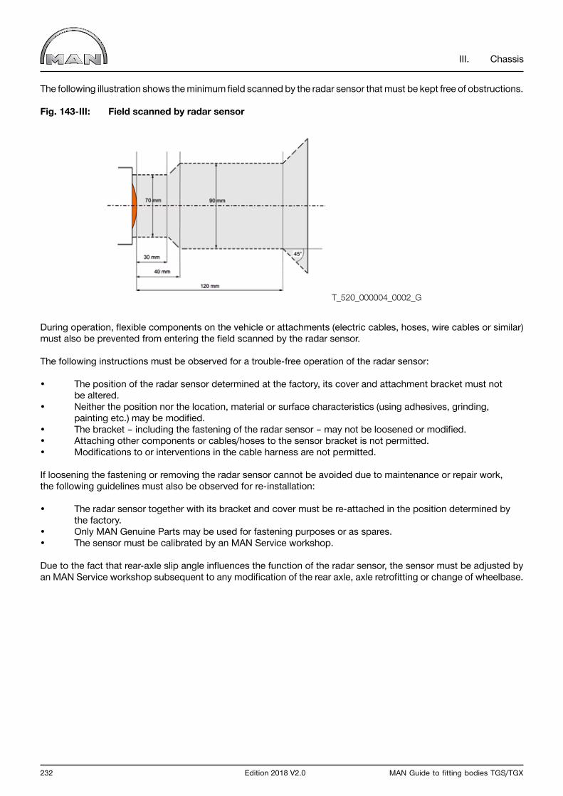
232 Edition 2018 V2.0 MAN Guide to fitting bodies TGS/TGX
III. Chassis
The following illustration shows the minimum field scanned by the radar sensor that must be kept free of obstructions.
Fig. 143-III: Field scanned by radar sensor
During operation, flexible components on the vehicle or attachments (electric cables, hoses, wire cables or similar) must also be prevented from entering the field scanned by the radar sensor.
The following instructions must be observed for a trouble-free operation of the radar sensor:
• The position of the radar sensor determined at the factory, its cover and attachment bracket must not be altered.• Neither the position nor the location, material or surface characteristics (using adhesives, grinding, painting etc.) may be modified. • The bracket – including the fastening of the radar sensor – may not be loosened or modified.• Attaching other components or cables/hoses to the sensor bracket is not permitted.• Modifications to or interventions in the cable harness are not permitted.
If loosening the fastening or removing the radar sensor cannot be avoided due to maintenance or repair work, the following guidelines must also be observed for re-installation:
• The radar sensor together with its bracket and cover must be re-attached in the position determined by the factory.• Only MAN Genuine Parts may be used for fastening purposes or as spares.• The sensor must be calibrated by an MAN Service workshop.
Due to the fact that rear-axle slip angle influences the function of the radar sensor, the sensor must be adjusted by an MAN Service workshop subsequent to any modification of the rear axle, axle retrofitting or change of wheelbase.
T_520_000004_0002_G
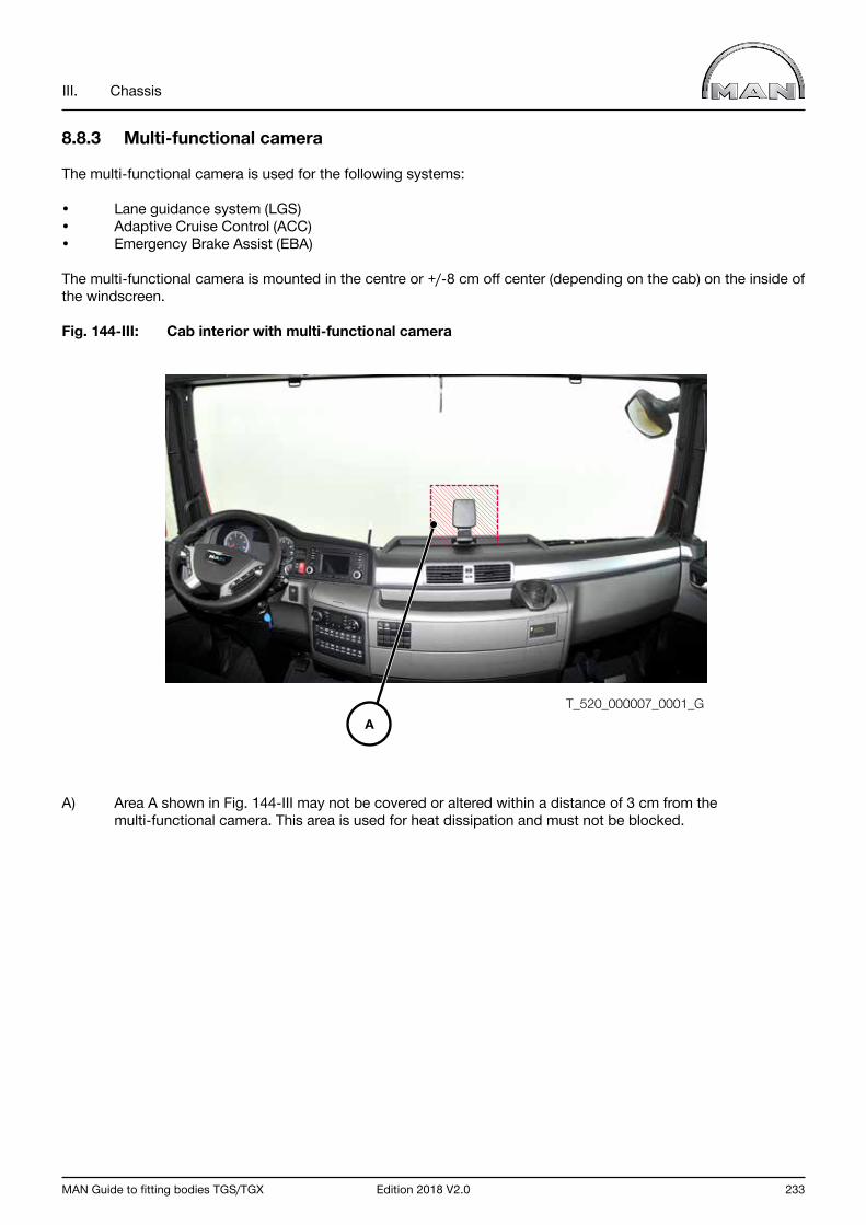
MAN Guide to fitting bodies TGS/TGX Edition 2018 V2.0 233
III. Chassis
8.8.3 Multi-functional camera
The multi-functional camera is used for the following systems:
• Lane guidance system (LGS)• Adaptive Cruise Control (ACC)• Emergency Brake Assist (EBA)
The multi-functional camera is mounted in the centre or +/-8 cm off center (depending on the cab) on the inside of the windscreen.
Fig. 144-III: Cab interior with multi-functional camera
A) Area A shown in Fig. 144-III may not be covered or altered within a distance of 3 cm from the multi-functional camera. This area is used for heat dissipation and must not be blocked.
T_520_000007_0001_GA
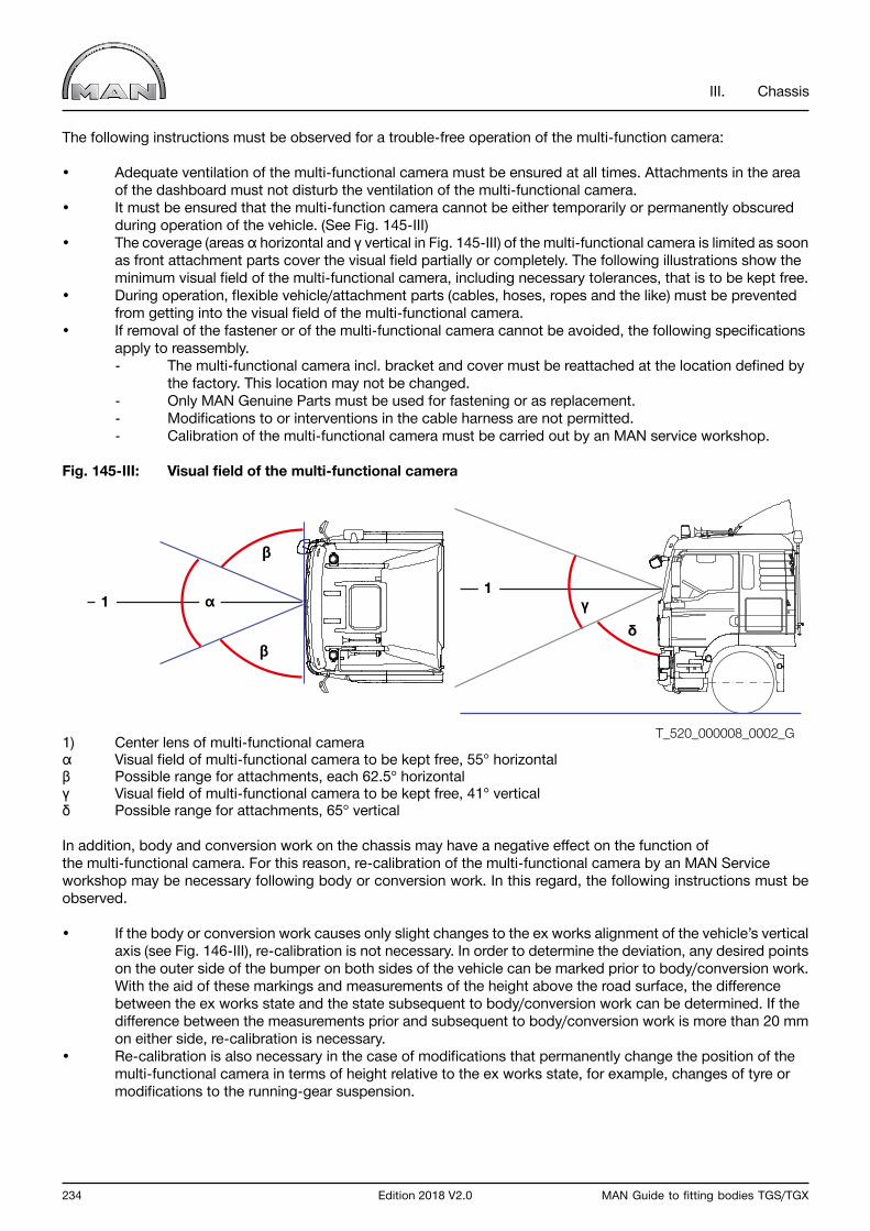
234 Edition 2018 V2.0 MAN Guide to fitting bodies TGS/TGX
III. Chassis
The following instructions must be observed for a trouble-free operation of the multi-function camera:
• Adequate ventilation of the multi-functional camera must be ensured at all times. Attachments in the area of the dashboard must not disturb the ventilation of the multi-functional camera.• It must be ensured that the multi-function camera cannot be either temporarily or permanently obscured during operation of the vehicle. (See Fig. 145-III)• The coverage (areas α horizontal and γ vertical in Fig. 145-III) of the multi-functional camera is limited as soon as front attachment parts cover the visual field partially or completely. The following illustrations show the minimum visual field of the multi-functional camera, including necessary tolerances, that is to be kept free.• During operation, flexible vehicle/attachment parts (cables, hoses, ropes and the like) must be prevented from getting into the visual field of the multi-functional camera.• If removal of the fastener or of the multi-functional camera cannot be avoided, the following specifications apply to reassembly. - The multi-functional camera incl. bracket and cover must be reattached at the location defined by the factory. This location may not be changed. - Only MAN Genuine Parts must be used for fastening or as replacement. - Modifications to or interventions in the cable harness are not permitted. - Calibration of the multi-functional camera must be carried out by an MAN service workshop.
Fig. 145-III: Visual field of the multi-functional camera
1) Center lens of multi-functional cameraα Visual field of multi-functional camera to be kept free, 55° horizontalβ Possible range for attachments, each 62.5° horizontalγ Visual field of multi-functional camera to be kept free, 41° verticalδ Possible range for attachments, 65° vertical
In addition, body and conversion work on the chassis may have a negative effect on the function of the multi-functional camera. For this reason, re-calibration of the multi-functional camera by an MAN Service workshop may be necessary following body or conversion work. In this regard, the following instructions must be observed.
• If the body or conversion work causes only slight changes to the ex works alignment of the vehicle’s vertical axis (see Fig. 146-III), re-calibration is not necessary. In order to determine the deviation, any desired points on the outer side of the bumper on both sides of the vehicle can be marked prior to body/conversion work. With the aid of these markings and measurements of the height above the road surface, the difference between the ex works state and the state subsequent to body/conversion work can be determined. If the difference between the measurements prior and subsequent to body/conversion work is more than 20 mm on either side, re-calibration is necessary.• Re-calibration is also necessary in the case of modifications that permanently change the position of the multi-functional camera in terms of height relative to the ex works state, for example, changes of tyre or modifications to the running-gear suspension.
α11
γδ
β
β
T_520_000008_0002_G
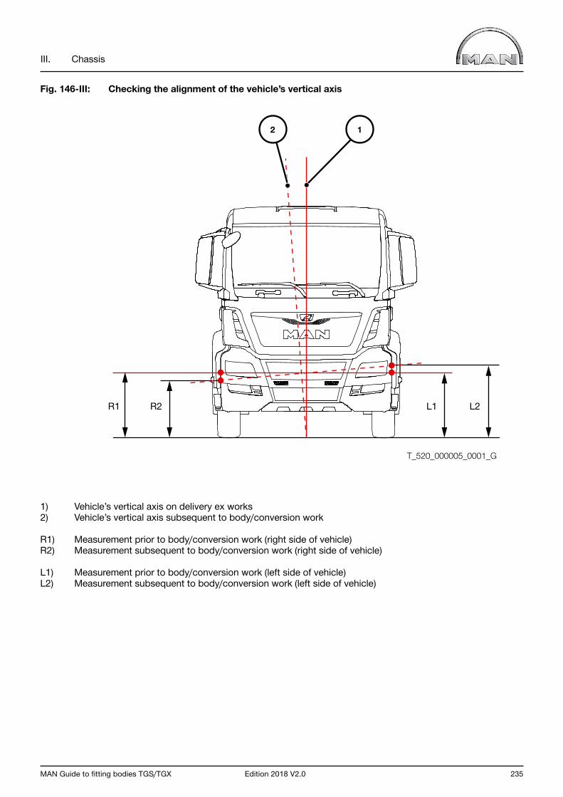
MAN Guide to fitting bodies TGS/TGX Edition 2018 V2.0 235
III. Chassis
Fig. 146-III: Checking the alignment of the vehicle’s vertical axis
1) Vehicle’s vertical axis on delivery ex works2) Vehicle’s vertical axis subsequent to body/conversion work
R1) Measurement prior to body/conversion work (right side of vehicle)R2) Measurement subsequent to body/conversion work (right side of vehicle)
L1) Measurement prior to body/conversion work (left side of vehicle)L2) Measurement subsequent to body/conversion work (left side of vehicle)
T_520_000005_0001_G
R1 L1R2 L2
12

236 Edition 2018 V2.0 MAN Guide to fitting bodies TGS/TGX
NOTICE
MAN Guide to fitting bodies TGS/TGX Edition 2018 V2.0 237
IV. Body

238 Edition 2018 V2.0 MAN Guide to fitting bodies TGS/TGX
IV. Body
1.0 General requirements
1.1 Requirements
The respective operating conditions pertaining where commercial vehicles are deployed are decisive for design. We assume that bodybuilders observe this and take it into account when working out the body concept. It is also expected that bodies are carefully designed to prevent vehicle overloading.
To this end, the following points, amongst others, must be checked.
• Weight distribution (e.g. permissible axle load, minimum axle load)• Dimensions (e.g. overall length, overall width)• Material loads (e.g. on chassis frame and auxiliary frame)• Compatibility between electrical systems (e.g. battery, alternator, wiring)
To achieve optimum payload carrying capability the chassis must be weighed before work starts on the body. Calculations can then be made to determine the best position of the center of gravity for payload and body as well as the optimum body length.
Important notice The design of the auxiliary frame, the connection between chassis and body and the ensuring of stability are all the responsibility of the bodybuilder.
1.2 Accessibility and clearance
Accessibility
Access to the filler necks of fuel and AdBlue tanks and other operating fluids (e.g. cut-out for pump nozzle) must be ensured. In addition, accessibility to chassis components (e.g. spare-wheel lift, battery box, air filter, exhaust silencer, brakes) for purpose of service or repair may not be restricted by the body.
Controls must exhibit the necessary minimum clearance and be able to be moved without restriction (e.g. the latching system of the cab tilting mechanism).
Stamped vehicle identification numbers, model plates or other features serving the purpose of identification and applied or attached ex works must not be obscured by vehicle bodies or modifications.
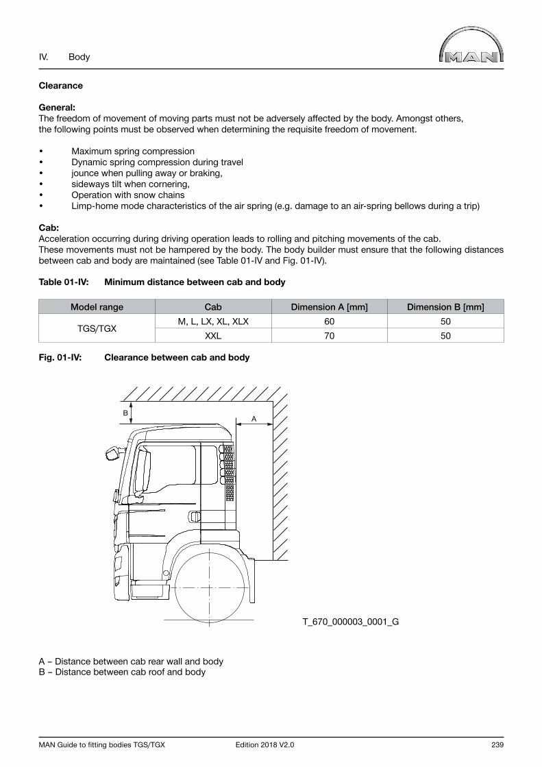
MAN Guide to fitting bodies TGS/TGX Edition 2018 V2.0 239
IV. Body
Clearance
General:The freedom of movement of moving parts must not be adversely affected by the body. Amongst others, the following points must be observed when determining the requisite freedom of movement.
• Maximum spring compression• Dynamic spring compression during travel• jounce when pulling away or braking,• sideways tilt when cornering,• Operation with snow chains• Limp-home mode characteristics of the air spring (e.g. damage to an air-spring bellows during a trip)
Cab:Acceleration occurring during driving operation leads to rolling and pitching movements of the cab. These movements must not be hampered by the body. The body builder must ensure that the following distances between cab and body are maintained (see Table 01-IV and Fig. 01-IV).
Table 01-IV: Minimum distance between cab and body
Model range Cab Dimension A [mm] Dimension B [mm]
TGS/TGXM, L, LX, XL, XLX 60 50
XXL 70 50
Fig. 01-IV: Clearance between cab and body
A – Distance between cab rear wall and bodyB – Distance between cab roof and body
T_670_000003_0001_G
AB
240 Edition 2018 V2.0 MAN Guide to fitting bodies TGS/TGX
IV. Body
Cabs are equipped with a tilting mechanism. It must be ensured that tilting can take place without hindrance. No parts that could pose a hindrance may protrude into the tilt radius. The tilt radii of the cabs are stated in the chassis drawings (obtainable from MANTED www.manted.de, registration required).
NotesIt is possible that parts will protrude above the frame top edge on some equipment variants in the operating states described above. For example:
• Brake cylinders• gear control (gearshift linkage, control cable),• parts of the running gear (wishbone, shock absorber bracket).
If components of the chassis project over the auxiliary frame top edge, an additional reinforcing frame onthe auxiliary frame will create space. The reinforcing frame can be designed to further reinforce the auxiliary frame.
1.3 Handling characteristics and driving resistances
Bodies have a significant influence on the vehicle’s handling characteristics and driving resistances. These should not be subjected to unnecessary negative influence by the body.
The following, for example, have a negative influence on handling characteristics.
• Uneven load distribution (e.g. heavy crane behind cab or at rear end)• High centers of gravity of body and payload
An uneven load distribution as a result of the body can, for example, be countered by relocating parts such as the tank, battery box and spare wheel.
The vehicle equipment, for instance, may influence the effects of bodies and payloads with high centres of gravity. To this end, MAN offers equipment options for bodies/loads with high centres of gravity.
Increasing the driving resistances leads, for example, to increased fuel consumption and thus to increased CO2 emission.
MAN Guide to fitting bodies TGS/TGX Edition 2018 V2.0 241
IV. Body
1.4 Vibration
When the body is designed, care must be taken that no impermissible vibration loads occur during operation. They can impair handling and ride comfort, for example. Bodies optimised for payload are especially sensitive in this regard.
These include, for example:
• Bodies without an auxiliary frame or with a multi-part auxiliary frame• Bodies with auxiliary frames made from lightweight metals (e.g. aluminium)
In addition, as little vibration as possible is to be transmitted from the body to the chassis (e.g. bodies with separate motors).
If impermissible vibration occurs after completion or during the operation of a vehicle its cause must be eliminated.
1.5 Special feature of vehicles with lifting axles
Lifting axles can only be fully functional when the body design is matched to them.
The function can be restricted by the following.
• Cramped installation spaces (e.g. extremely low bodies)• Unfavourable weight distribution (e.g. big loading cranes at rear end of frame)
When a lifting trailing axle is lifted, the front axle of the vehicle experiences a considerable lightening of the load. In conjunction with back-heavy body concepts (e.g. rear loading cranes), handling characteristics may be seriously impaired. The lifting facility must be disabled if more than 80% of the permissible drive axle load is reached when travelling unladen with the crane and with the axle lifted or if the minimum front-axle load (see Chapter III, Section 2.2.8) is not reached.
For manoeuvring purposes the trailing axle can be relieved if the auxiliary frame and body are of adequate size (moving-off aid). The higher bending and torsional forces acting on the body and the frame structure must then be taken into account.
242 Edition 2018 V2.0 MAN Guide to fitting bodies TGS/TGX
IV. Body
1.6 Vehicles with outriggers
Truck chassis are sometimes fitted with bodies that necessitate outriggers to ensure stability. Example of such bodies are loading cranes, skylifters and concrete pumps.
As a basic principle, a distinction can be drawn between two outrigger variants:
• outrigger operation with the wheels in contact with the ground• outrigger operation with the wheels not in contact with the ground
Depending on the variant selected, the chassis and its equipment may have to meet different requirements. The following sections describe the basic requirements for the most common cases. Exceptions are possible in the case of special-purpose vehicles / body designs in consultation with the customer and MAN, under the sole responsibility of the bodybuilder. In such cases, approval must be obtained from MAN (for address see “Publisher” above).
Warning noticeThe bodybuilder is responsible for the stability of the overall system when in working operation.
1.6.1 Outrigger operation with the wheels in contact with the ground
Vehicles with air suspensionThis section applies to vehicles fitted with at least one air-sprung axle. To improve stability on these vehicles it must be ensured that the air suspension is lowered to the buffer before commencing outrigger operation.
Lowering can be carried out manually or by means of the air-suspension control or automatically, using special equipment 311PE (input of parameter ECAS for crane operation or parameter ECAS for lowering the air suspension to the buffer). If an automatic lowering system is not fitted then the user/driver must be informed of the requirement to manually lower the air suspension.
Special equipment 311PE automatically lowers the vehicle onto the buffers if the power take-off is engaged when the vehicle is at a standstill. Once the lowering operation has finished, the system maintains a defined residual pres-sure in order to protect the air-suspension bellows.To ensure that the function is properly activated, it is imperative that the correct order of operations is observed when engaging the power take-off (see operating instructions). A check must also be carried out to ensure that the message “No ride height” appears on the display and that the vehicle has actually lowered.
If special equipment 311PE is selected in this case, it must be combined with special equipment 311PK (input of parameter ECAS with auxiliary circuit for suppressing the automatic levelling suspension system). Activating the 311PK function suppresses all the air-suspension system’s control functions. For this reason, the function may only be activated once the lowering procedure has been completed.It can be activated by means of the switch installed ex works (see operating instructions). Moreover, it is also possible to activate this function via the body. If this is the case, the switch installed ex works must be removed or disabled.If special equipment 311PK is not already fitted to the vehicle, it can be retrofitted by an MAN Service outlet (for further details see MAN Service Information 239704).
Warning noticeWe explicitly point out that this measure does not contribute to stability and is therefore not a means of extending the technical limits of body-mounted equipment (e.g. cranes). The ECAS controlling function may only be suppressed during working operation.
The functions provided by special equipment 311PE are deactivated when the engine / power take-off or similar is turned on or off and the standard control of the ECAS system activated (setting the air suspension to ride height).
MAN Guide to fitting bodies TGS/TGX Edition 2018 V2.0 243
IV. Body
1.6.2 Outrigger operation with the wheels not in contact with the ground
Although the complete raising of the axles has advantages in terms of ensuring stability within physical limits, the load that results puts a greater strain on frames and auxiliary frames.
Vehicles with air suspensionThis section applies to vehicles fitted with at least one air-sprung axle.Completely raising the axles can lead to damage due to the resulting drop in pressure in the air-suspension bellows. In order to avoid such damage, MAN recommends special equipment 311PE (input of parameter ECAS for crane operation or parameter ECAS for lowering the air suspension to the buffer) in this case. Amongst other things, this regulates the residual pressure to approx. 0.5 bar in outrigger operation.
The functions provided by special equipment 311PE are deactivated when the engine / power take-off or similar is turned on or off and the standard control of the ECAS system activated (setting the air suspension to ride height).
1.7 Tolerances
The usual tolerances and hystereses must also be taken into consideration in designing the body. These include, for example:
• Tyres• Springs (including hysteresis in air-suspension systems)• Frame
The tolerances in technical data published by MAN are in accordance with MAN standard M3264. This can be obtained from the MAN Portal for Technical Documentation (www.ptd.man.eu).
Deviations in dimensions are unavoidable. Further dimensional changes can be expected during the use of a vehicle. These include, for example:
• Settling of springs,• Deformation of tyres,• Deformation of bodywork.
1.8 Assembly
The chassis frame must not be deformed or detached before or during assembly.
Before the body is assembled, the vehicle should be driven backwards and forwards a few times to release any trapped stresses. This applies in particular to vehicles with driven tandem-axle units because of the secondary bending of the axles when cornering.
Place a vehicle on a level surface to install bodywork.
Different frame heights left/right of ≤ 1.5% of the distance from the ground to the frame top edge are within the range of the hysteresis and settling effects described in Chapter IV; Section 1.7. They may not be compensated by aligning the frame, shims in the springs or adjustment of the air suspension because they inevitably change during operation. Differences in height of > 1.5% must be reported to the MAN Customer Services department before any repairs are carried out. This department decides what measures are to be taken by the bodybuilder and/or the MAN Service workshop.
The body must sit torsionally flexible on the frame main members.
Renewed checks or adjustments will be necessary on a vehicle after installing the body.This applies in particular to the headlights, sensors fitted to the front of the vehicle (e.g. radar sensor for the emergency-braking assistant) as well as rear and side underride protection.
244 Edition 2018 V2.0 MAN Guide to fitting bodies TGS/TGX
IV. Body
1.9 Corrosion protection of bodywork
Surface and corrosion protection influence the service life and appearance of a product.The coating quality of bodywork should consequently be that of a chassis.In order to fulfil this requirement, MAN works standard M3297 “Corrosion protection and coating systems for non-MAN bodies” is binding for bodies that are ordered by MAN. If the customer commissions the body, this standard becomes a recommendation only. Should the standard not be observed, MAN provides no warranty for any consequences. MAN works standards can be obtained from the MAN Portal for Technical Documentation (www.ptd.man.eu).Series-production MAN chassis are coated with environmentally friendly, water-based two-component chassis top-coat paints at approx. 80°C. To ensure uniform coating, the following coating structure is required for all metal component assemblies on the body and auxiliary frame and subsequent to frame modifications on the chassis.
• Bare metal or blasted component surface (SA 2.5)• Priming: two-component epoxy primer, approved in accordance with MAN works standard M3162-C or, if possible, cathodic dip painting to MAN works standard M3078-2, with zinc phosphate pre-treatment.• Top coat: two-component top-coat paint to MAN works standard M3094, preferably water-based; if there are no facilities for this, then solvent-based paint is also permitted.
Instead of priming and painting the vehicle with a top coat, the substructure of the body (e.g. longitudinal and cross-members, corner plates) may also be galvanised with a layer thickness ≥ 80 µm. Refer to the data sheets of the paint manufacturer for details of curing and drying times and temperatures. When selecting and combining ma-terials the compatibility of the different metals (e.g. aluminium and steel) must be taken into consideration as must the effects of the ‘electrochemical series’ (cause of contact corrosion).
After completing all work on a chassis:
• remove any drilling swarf,• deburr edges,• preserve cavities with wax.
Mechanical connecting elements (e.g. screws, nuts, washers, bolts) are to be optimally protected against corrosion. To prevent corrosion through salt while a vehicle is stationary during the bodybuilding phase, wash all chassis with fresh water upon arrival at the bodybuilder’s premises to remove salt residue.

MAN Guide to fitting bodies TGS/TGX Edition 2018 V2.0 245
IV. Body
1.10 Standards, directives and regulations
The following section lists examples of standards, directives / guidelines and regulations applying to truck bodies. This overview is, however, not intended to be exhaustive. We wish to point out that the overall system consisting of chassis and body must comply with the conditions for registration in the respective country.
1.10.1 Machinery Directive (2006/42/EC)
The Machinery Directive is available from EUR-Lex under the following link http://eur-lex.europa.eu.
GeneralThe Machinery Directive serves to ensure the health and safety of persons, in particular of employees, consumers and objects, in particular in relation to the risks inherent whilst using machinery.
It sets forth generally applicable, fundamental health and safety protection requirements in accordance with the state of the art at the time of design, together with technical and commercial requirements that are supplemented by a range of specific requirements for certain classes of machine.
There is an appropriate procedure for every type of machine with which compliance with the fundamental health and safety protection requirements can be checked. These include the conformity assessment procedures, the CE conformity markings and a risk assessment. Furthermore, the manufacturer of the machine must prepare technical documentation for each machine.
Scope and purposeIn addition to these guidelines to fitting bodies, bodybuilders must also observe the Machinery Directive. The Machinery Directive is fundamentally not applicable to the truck’s chassis because the applicable statutory requirements are defined in the Directive on type-approval of motor vehicles and their trailers (70/156/EEC).The Machinery Directive does, however, apply to various bodies. The products (truck bodies) that fall under this scope of application are defined in Article 1 of the Directive (“Scope”).
The Machinery Directive applies fundamentally to:
• Machines• Interchangeable equipment• Safety components• Lifting accessories• Chains, ropes and webbing• Removable mechanical transmission devices• Partly completed machinery
Examples include:
• Loading cranes• Liftgates (tail-lifts)• Tipper bodies• Flushing and suction bodies• Recovery platform bodies• Compressors fitted to the body• Garbage compactors• Concrete / cement drums• Troughs• Mechanically driven cable winches• Roll-off and set-down skip loader bodies• Aerial work platforms / skylifters• Tank bodies
246 Edition 2018 V2.0 MAN Guide to fitting bodies TGS/TGX
IV. Body
Among others, exceptions include:
• Agricultural and forestry tractor units • Motor vehicles and their trailers (70/156/EEC)
If such a product (body/fitting) is installed on the truck chassis, the Machinery Directive does not apply to the truck chassis but to the body. The Machinery Directive also applies to the interfaces between the truck chassis and the body that are responsible for the safe movement and operation of the machine. A distinction should, therefore, be made between self-propelled working machines, which fall fully under the Machinery Directive and truck chassis with machinery fitted or mounted on them.
Examples of self-propelled machines include:
• Self-propelled construction machines• Concrete pumps• Truck-mounted crane• Gully emptiers• Drilling rig carrier vehicles
Definition of machinery in accordance with 2006/42/EC
“ — an assembly, fitted with or intended to be fitted with a drive system other than directly applied human or animal effort, consisting of linked parts or components, at least one of which moves, and which are joined together for a specific application;
— an assembly referred to in the first indent, missing only the components to connect it on site or to sources of energy and motion;
— an assembly referred to in the first and second indents, ready to be installed and able to function as it stands only if mounted on a means of transport, or installed in a building or a structure;
— assemblies of machinery referred to in the first, second and third indents or partly completed machinery referred to in point (g) which, in order to achieve the same end, are arranged and controlled so that they function as an integral whole;
— an assembly of linked parts or components, at least one of which moves and which are joined together, intended for lifting loads and whose only power source is directly applied human effort;”
Source: Excerpt from 2006/42/EC
CE marking (CE conformity marking in accordance with 2006/42/EC)The bodybuilder must ensure that the body, along with its attachments and accessories, complies with the statutory requirements. The Machinery Directive (2006/42/EC) lays down the types of machinery requiring a CE marking.
As a basic principle, the following apply to the body:
• All machinery must carry the CE mark. In other words, this includes all components relevant to safety, removable mechanical transmission devices, chains, ropes and webbing.• Partly completed machinery may not carry a CE mark.
For the CE marking on machinery, the following apply:
• The CE marking shall be affixed to the machinery visibly, legibly and indelibly.• The affixing on machinery of markings, signs and inscriptions that are likely to mislead third parties as to the meaning or form of the CE marking, or both, shall be prohibited. • Any other marking may be affixed to the machinery provided that the visibility, legibility and meaning of the CE marking is not thereby impaired.
MAN Guide to fitting bodies TGS/TGX Edition 2018 V2.0 247
IV. Body
• In order to ensure the same quality for the CE marking and the manufacturer’s mark, it is important that they be affixed according to the same techniques. In order to avoid confusion between any CE markings which might appear on certain components and the CE marking corresponding to the machinery, it is important that the latter marking be affixed alongside the name of the person who has taken responsibility for it, namely the manufacturer or his authorised representative.• It is prohibited to pre-date or post-date the date of manufacture of the machinery when affixing the CE marking.• If the CE marking is reduced or enlarged the proportions shown in the drawing reproduced here must be maintained.• The various components of the CE marking must have approximately the same vertical dimensions, which may not be less than 5 mm. The minimum dimension may be waived for small-scale machinery.
The CE conformity marking shall consist of the initials “CE” taking the following form:
Where machinery is also the subject of other Directives relating to other aspects and providing for the affixing of the CE marking, the marking shall indicate that the machinery also conforms to the provisions of those other Directives. However, where one or more of those Directives allow the manufacturer or his authorised representative to choose, during a transitional period, the system to be applied, the CE marking shall indicate conformity only to the provisions of those Directives applied by the manufacturer or his authorised representative.
Particulars of the Directives applied, as published in the Official Journal of the European Union, shall be given on the EC declaration of conformity. Where the full quality assurance procedure referred to in 2006/42/EC, 12(3)(c) and 12(4)(b) has been applied, the CE marking must be followed by the identification number of the notified body.
Model plate on body For identification purposes, each body must be fitted with a model plate that must contain the following data as a minimum:
• Full name of body manufacturer• Full type-approval number
The characters must be at least 4 mm high. The details on the model plate must be durable.
1.10.2 Securing of cargo
The standards applicable to the securing of cargo on commercial vehicles must be observed. In Europe, these are in particular EN12640 (lashing points), EN12641 (tarpaulins) and EN12642 (bodies).
1.10.3 Contour markings
If required under the national conditions for registration, contour markings as per ECE-R48 or 76/756 EEC are to be affixed.
T_998_000002_0001_G
248 Edition 2018 V2.0 MAN Guide to fitting bodies TGS/TGX
IV. Body
1.10.4 Radio Equipment Directive 2014/53/EU
The directive is available to read on the EUR-Lex website at the following link http://eur-lex.europa.eu
General
The Radio Equipment Directive aims to ensure radio equipment uses the radio spectrum efficiently and does not cause harmful interference. Furthermore, the Directive is intended to ensure the protection of health and safety of persons, pets and livestock and the protection of property. To achieve this objective, all devices should fall within the scope of this Directive.
Although receivers do not themselves cause harmful interference, reception capabilities are an increasingly important factor in ensuring the efficient use of radio spectrum by way of an increased resilience of receivers against harmful interference and unwanted signals on the basis of the relevant essential requirements of Union harmonisa-tion legislation.
The compliance of some categories of radio equipment with the essential requirements set out in this Directive may be affected by the inclusion of software or modification of its existing software. The user, the radio equipment or a third party should only be able to load software into the radio equipment where this does not compromise the subsequent compliance of that radio equipment with the applicable essential requirements.
The manufacturer should provide sufficient information on the intended use of the radio equipment so as to allow its use in compliance with the essential requirements. Such information may need to include a description of accessories such as antennas and of components such as software, and specifications of the installation process of the radio equipment.
Distributors and importers, being close to the market place, should be involved in market surveillance tasks carried out by the competent national authorities, and should be prepared to participate actively, providing those authorities with all necessary information relating to the radio equipment concerned. Distributors and importers have a special obligation to verify equipment labelling and the accompanying documents.
Ensuring traceability of radio equipment throughout the whole supply chain helps to make market surveillance simpler and more efficient. An efficient traceability system facilitates market surveillance authorities’ task of tracing economic operators who have made non-compliant radio equipment available on the market. When storing the information required by the RED for the purposes of identifying other industry players, the latter are not obliged to update the information they hold on other industry players from whom they have purchased radio equipment or to whom they have sold it.
Manufacturers must draw up and have available an EU declaration of conformity to provide information required under this Directive on the conformity of radio equipment with the requirements of this Directive and of the other relevant Union harmonisation legislation. Manufacturers are responsible for device labelling in accordance with the Radio Equipment Directive.
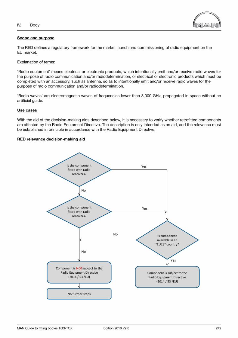
MAN Guide to fitting bodies TGS/TGX Edition 2018 V2.0 249
IV. Body
Scope and purpose
The RED defines a regulatory framework for the market launch and commissioning of radio equipment on theEU market.
Explanation of terms:
‘Radio equipment’ means electrical or electronic products, which intentionally emit and/or receive radio waves for the purpose of radio communication and/or radiodetermination, or electrical or electronic products which must be completed with an accessory, such as antenna, so as to intentionally emit and/or receive radio waves for the purpose of radio communication and/or radiodetermination.
‘Radio waves’ are electromagnetic waves of frequencies lower than 3,000 GHz, propagated in space without an artificial guide.
Use cases
With the aid of the decision-making aids described below, it is necessary to verify whether retrofitted components are affected by the Radio Equipment Directive. The description is only intended as an aid, and the relevance must be established in principle in accordance with the Radio Equipment Directive.
RED relevance decision-making aid
No
Yes
Component is subject to the Radio Equipment Directive
(2014 / 53 /EU)
Is component available in an
"EU28" country?
Yes
Component is NOTsubject to the Radio Equipment Directive
(2014 / 53 /EU)
No further steps
Is the component fitted with radio
receivers?
Is the component fitted with radio
receivers?
Yes
No
No
250 Edition 2018 V2.0 MAN Guide to fitting bodies TGS/TGX
IV. Body
Examples of components that could fall under the Radio Equipment Directive:
• Radio equipment• Radio remote controls• Radar sensors• SAT receivers• DVB-T/DVB-T2 receivers• Aerials• Radios• Navigation units• Alarm systems• Tyre pressure monitoring systems• Fleet management systems/components
Procedure:
If a component is subject to the RED and is installed in or mounted onto a vehicle, the workshop carrying out the work is obliged to enclose the manufacturer‘s EU declaration of conformity for these components with the vehicle documents/the operator‘s manual in the vehicle.
InformationIt is recommended to document the handover of the manufacturer’s EU declaration of conformity for this component for traceability purposes.
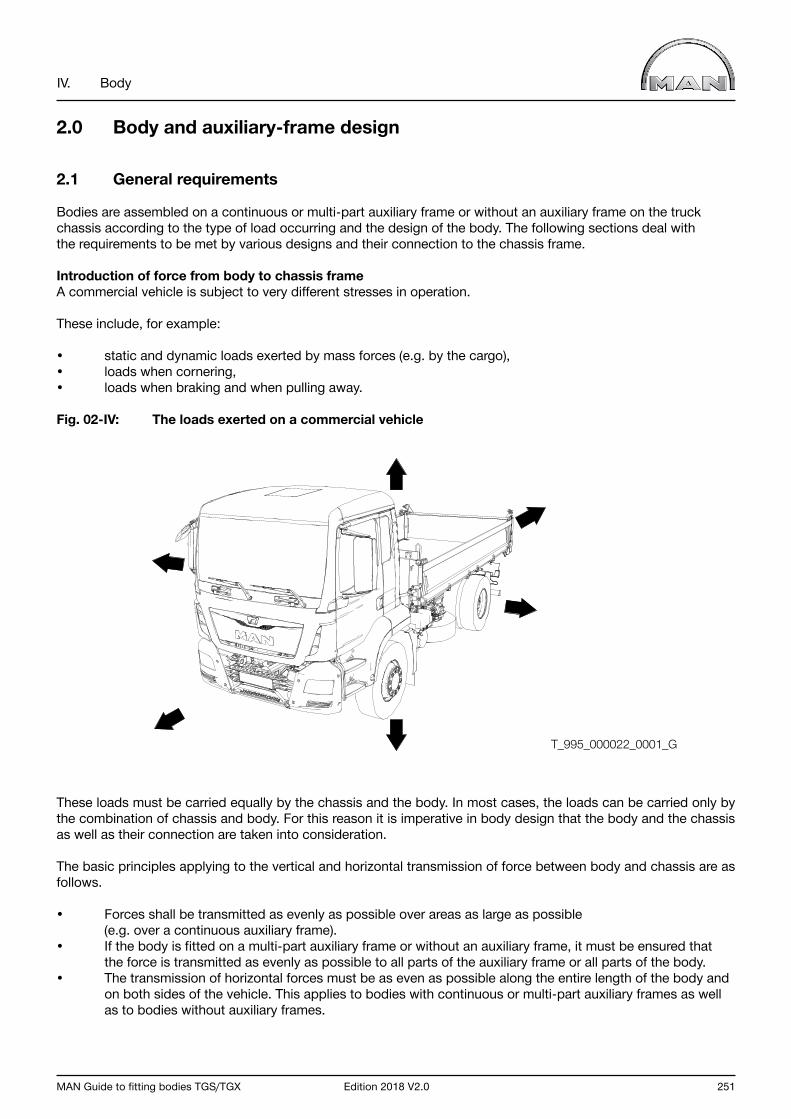
MAN Guide to fitting bodies TGS/TGX Edition 2018 V2.0 251
IV. Body
2.0 Body and auxiliary-frame design
2.1 General requirements
Bodies are assembled on a continuous or multi-part auxiliary frame or without an auxiliary frame on the truck chassis according to the type of load occurring and the design of the body. The following sections deal with the requirements to be met by various designs and their connection to the chassis frame.
Introduction of force from body to chassis frameA commercial vehicle is subject to very different stresses in operation.
These include, for example:
• static and dynamic loads exerted by mass forces (e.g. by the cargo),• loads when cornering,• loads when braking and when pulling away.
Fig. 02-IV: The loads exerted on a commercial vehicle
These loads must be carried equally by the chassis and the body. In most cases, the loads can be carried only by the combination of chassis and body. For this reason it is imperative in body design that the body and the chassis as well as their connection are taken into consideration.
The basic principles applying to the vertical and horizontal transmission of force between body and chassis are as follows.
• Forces shall be transmitted as evenly as possible over areas as large as possible (e.g. over a continuous auxiliary frame).• If the body is fitted on a multi-part auxiliary frame or without an auxiliary frame, it must be ensured that the force is transmitted as evenly as possible to all parts of the auxiliary frame or all parts of the body.• The transmission of horizontal forces must be as even as possible along the entire length of the body and on both sides of the vehicle. This applies to bodies with continuous or multi-part auxiliary frames as well as to bodies without auxiliary frames.
T_995_000022_0001_G

252 Edition 2018 V2.0 MAN Guide to fitting bodies TGS/TGX
IV. Body
Force transmission: Hertzian contact stressIrrespective of whether an auxiliary frame is used or not, the minimum lengths of the supports on the frame must be calculated according to the rules of Hertzian contact stresses. The assumption is linear contact between two cylinders. Fig. 03-IV is an exaggerated presentation of the deformation of two U-profiles on top of one another, which can occur in a combination of auxiliary frame and chassis frame. Position no. 1 in Fig. 03-IV shows the linear contact. A calculation example can be found in Chapter V, Section 1.11.0 “Support length for body without auxiliary frame”.
Fig. 03-IV: Deformation of two U-profiles
Frame deflection and torsion
Frame deflection and torsion may not cause any undesirable characteristics in either the body or the vehicle. The body and chassis must be able to absorb such forces safely.
Formula 01-IV gives a rough estimate of permissible deflection.
Formula 01-IV: Permissible deflection
lt f = 250
Where:
f = Maximum deflection [mm] lt = Theoretical wheelbase [mm] (see Chapter III, Section 2.2.1)
1
T_690_000005_0001_G

MAN Guide to fitting bodies TGS/TGX Edition 2018 V2.0 253
IV. Body
2.2 Body with auxiliary frame
The section applies both to continuous and multi-part auxiliary frames.
2.2.1 Permissible materials
Taking into account safety coefficients, the yield point, also known as the elongation limit or σ0.2 limit, must not be exceeded in any driving or load state. The materials most commonly used for auxiliary frames are listed in Table 02-IV Higher-quality materials or materials with comparable characteristics not listed here can also be used.
Should point loads arise or if units are to be fitted that exert localised forces, e.g. liftgates, cranes and cable winches, then steels with a yield point of σ0.2 > 350 N/mm² must always be used. Rolled sections are not permitted.
Table 02-IV: Subframe materials (examples), standard designations and yield points
Material numberMaterial
designation,old
Material designation, new
Yield pointN/mm2
Tensile strengthN/mm2
Suitability for auxiliary frames
1.0570 St52-3 S355J2G3 ≥ 355 Approx.490-630
Highly suitable
1.0974 QStE340TM ≥ 340 Approx.420-540
Not for point loads
1.0976 S355MC ≥ 355 Approx. 430-550
Highly suitable
1.0978 QStE380TM ≥ 380 Approx.450-590
Highly suitable
1.0980 QStE420TM S420MC ≥ 420 Approx.480-620
Highly suitable
1.0984 QStE500TM S500MC ≥ 500 Approx. 550-700
Highly suitable
2.2.2 Auxiliary-frame design
No moving parts may be restricted in their freedom of movement by the auxiliary-frame structure.
The auxiliary frame must have the same outer width as the chassis frame and follow its outer contour.
As far as possible the auxiliary frame should be designed to be flexible. The chamfered U-profiles commonly used in vehicle construction comply with this requirement.
In order to reduce variations in rigidity, the auxiliary frame must be chamfered or recessed at the front (for examples, see Fig. 04-IV and Fig. 05-IV). Fig. 04-IV: Auxiliary-frame chamfer at the front Fig. 05-IV: Auxiliary-frame recess at the front
T_690_000002_0002_G
0,2.
..0.3
h
≤ 30
° t
h
t
r=2t
h
0,6.
.0,7
h
30°
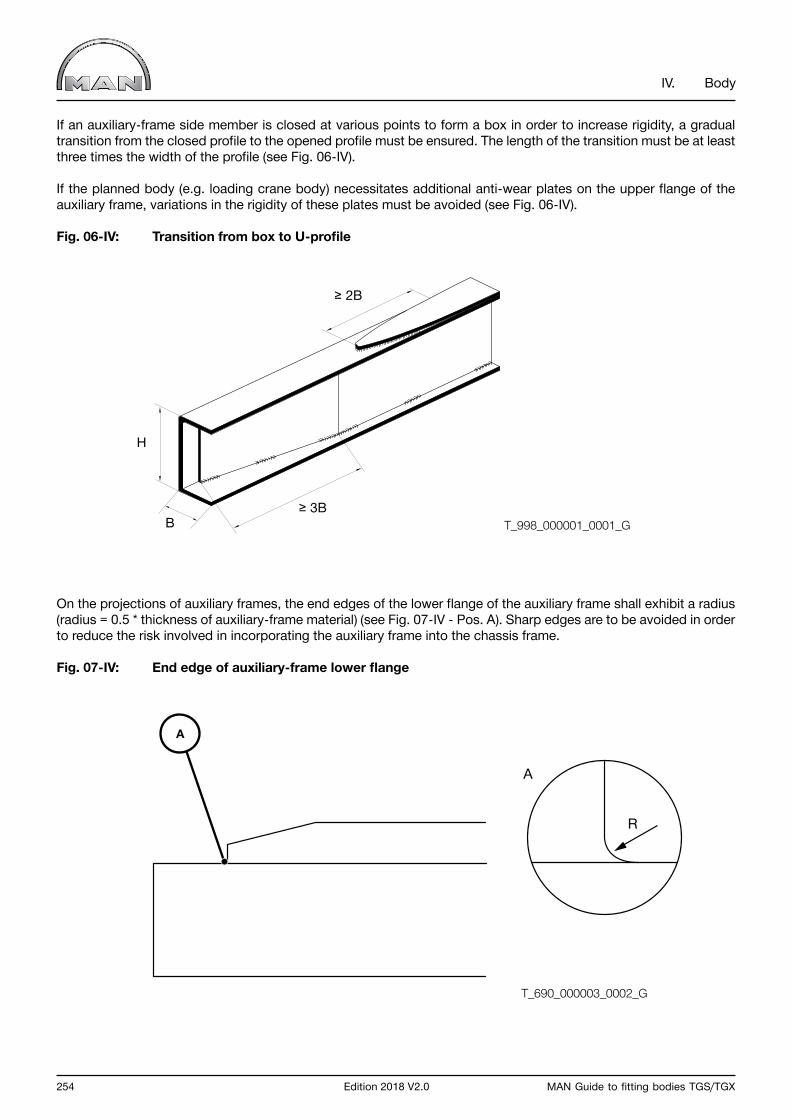
254 Edition 2018 V2.0 MAN Guide to fitting bodies TGS/TGX
IV. Body
If an auxiliary-frame side member is closed at various points to form a box in order to increase rigidity, a gradual transition from the closed profile to the opened profile must be ensured. The length of the transition must be at least three times the width of the profile (see Fig. 06-IV).
If the planned body (e.g. loading crane body) necessitates additional anti-wear plates on the upper flange of the auxiliary frame, variations in the rigidity of these plates must be avoided (see Fig. 06-IV).
Fig. 06-IV: Transition from box to U-profile
On the projections of auxiliary frames, the end edges of the lower flange of the auxiliary frame shall exhibit a radius (radius = 0.5 * thickness of auxiliary-frame material) (see Fig. 07-IV - Pos. A). Sharp edges are to be avoided in order to reduce the risk involved in incorporating the auxiliary frame into the chassis frame.
Fig. 07-IV: End edge of auxiliary-frame lower flange
T_998_000001_0001_G
H
B≥ 3B
≥ 2B
T_690_000003_0002_G
R
A
A
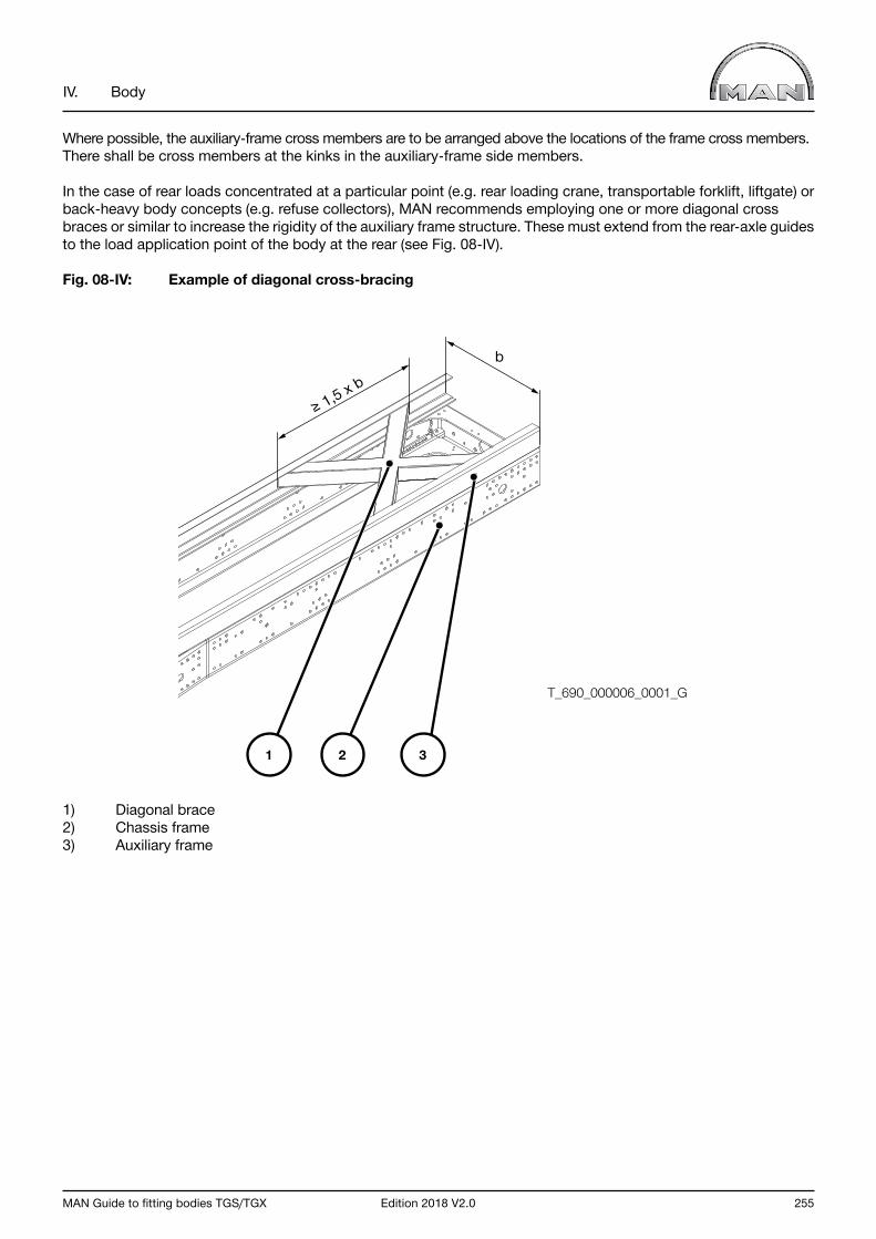
MAN Guide to fitting bodies TGS/TGX Edition 2018 V2.0 255
IV. Body
Where possible, the auxiliary-frame cross members are to be arranged above the locations of the frame cross members. There shall be cross members at the kinks in the auxiliary-frame side members.
In the case of rear loads concentrated at a particular point (e.g. rear loading crane, transportable forklift, liftgate) or back-heavy body concepts (e.g. refuse collectors), MAN recommends employing one or more diagonal cross braces or similar to increase the rigidity of the auxiliary frame structure. These must extend from the rear-axle guides to the load application point of the body at the rear (see Fig. 08-IV).
Fig. 08-IV: Example of diagonal cross-bracing
1) Diagonal brace2) Chassis frame3) Auxiliary frame
b
≥ 1,5 x b
T_690_000006_0001_G
1 2 3

256 Edition 2018 V2.0 MAN Guide to fitting bodies TGS/TGX
IV. Body
2.2.3 Connection to chassis frame
The auxiliary frame side members must be positioned level and flat on the upper flange of the frame side member.
Transverse weld seams at the kinks are to be avoided. If thrust plates are necessary in these areas, they shall be located in front of and behind the kinks.
The auxiliary frame must extend as far forward as possible, at least beyond the rearmost front spring hanger (see Fig. 09-IV – Pos. 1 and Dimension a).
In the case of an air-sprung front axle, we recommend a clearance of ≤ 600 mm between the centerline of the first axle and the auxiliary frame.
Examples of how this is done can be found in Chapter IV Section 2.6 and Section 2.7.
Fig. 09-IV: Auxiliary frame distance from center of first axle
1) Rear front spring hanger
T_690_000001_0001_G
< a
a
1
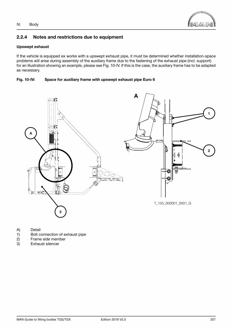
MAN Guide to fitting bodies TGS/TGX Edition 2018 V2.0 257
IV. Body
2.2.4 Notes and restrictions due to equipment
Upswept exhaust
If the vehicle is equipped ex works with a upswept exhaust pipe, it must be determined whether installation-space problems will arise during assembly of the auxiliary frame due to the fastening of the exhaust pipe (incl. support) for an illustration showing an example, please see Fig. 10-IV. If this is the case, the auxiliary frame has to be adapted as necessary.
Fig. 10-IV: Space for auxiliary frame with upswept exhaust pipe Euro 6
A) Detail1) Bolt connection of exhaust pipe2) Frame side member 3) Exhaust silencer
A
1
2
3
A
T_155_000001_0001_G
258 Edition 2018 V2.0 MAN Guide to fitting bodies TGS/TGX
IV. Body
2.3 Body without auxiliary frame
InformationAssembly without an auxiliary frame must be authorised by MAN (for address, see “Issuer” above) for all body types where an auxiliary frame is strictly necessary according to these guidelines.
An auxiliary frame may not be necessary if:
• The force transmission between the body and chassis occurs on a large area• The combination of the chassis and body provides sufficient horizontal and vertical bending stiffness • The combination of the chassis and body provides sufficient shear stiffness • The torsional stiffness of the body does not impair the required frame torsion of the chassis in an impermissible manner
Due to a body connection without auxiliary frame, the force transmission between the body and chassis takes place in few areas. This leads to increased local loads on the chassis frame. This must be carefully checked during design. The following influencing factors must be strictly observed in order to avoid overstraining the chassis components.
The actual load is dependent on:
• The number of body mounts • Position of the body mounts • Size of the body weight and the load • Position of the body and payload centre of gravity (in all coordinate directions) • Body operation (e.g. loading and unloading processes)• Driving manoeuvres (e.g. cornering)
Important noticeThe actual loads of the body mounts fluctuate greatly during operation. For example, loads occur due to driving dynamics that are greater than in the case of static loads.

MAN Guide to fitting bodies TGS/TGX Edition 2018 V2.0 259
IV. Body
Fig. 11-IV: A: Reaction forces in the case of a static load B: Reaction forces in the case of a dynamic load (left-hand bends))
1) Body and payload centre of gravity2) Reaction forces on the body mounts
The body connection must ensure firm support between the body and chassis frame in both the longitudinal and transverse direction. It must be ensured that there is a large, transversely rigid body connection in the area of the rear axle in particular.
InformationChassis are subjected to higher loads by a body without an auxiliary frame than with bodies with auxiliary frames. Driving characteristics may be negatively influenced by bodies without an auxiliary frame. They must be checked and secured by the body manufacturer after completion of the body work.We recommend equipping deployed chassis with the available stabilisation packages (refer to Chapter III Section 7.3).
Increased shear stiffness between the body mounts on the chassis frame can have a positive influence on driving characteristics, alongside the increased effect on the chassis frame. The shear stiffness can, for example, be increased by additional built-in diagonal crosses (see Chapter IV, Section 2.2.2). Appropriate positions for them are usually in the area of the rear axles and in areas with a fixed body connection.
A large level of flexibility of the body bearings in the longitudinal and transverse direction generally has a negative influence on the driving characteristics.
11
22
T_658_000001_0001_G

260 Edition 2018 V2.0 MAN Guide to fitting bodies TGS/TGX
IV. Body
2.4 Attaching auxiliary frames and bodies
Auxiliary frames and chassis frames must be connected to one another with rigid or flexible connections.Both connection types are to be combined depending on body situation.
Elastic shims (e.g. wooden shims) between frame and auxiliary frame or frame and body are prohibited (see Fig. 12-IV - Pos. 1).
Fig. 12-IV: Elastic shims
Justified exceptions are possible provided MAN is able to issue written approval (for address see “Publisher” above)..
1
T_691_000001_0001_G
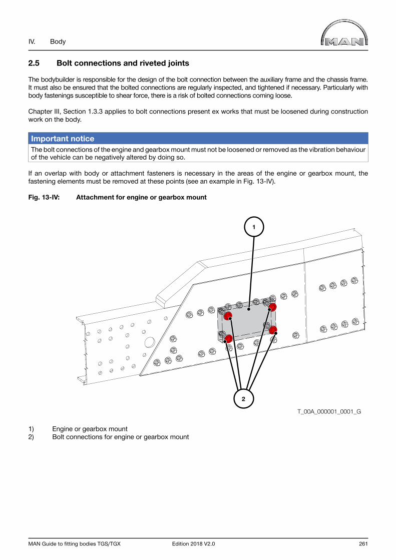
MAN Guide to fitting bodies TGS/TGX Edition 2018 V2.0 261
IV. Body
2.5 Bolt connections and riveted joints
The bodybuilder is responsible for the design of the bolt connection between the auxiliary frame and the chassis frame. It must also be ensured that the bolted connections are regularly inspected, and tightened if necessary. Particularly with body fastenings susceptible to shear force, there is a risk of bolted connections coming loose.
Chapter III, Section 1.3.3 applies to bolt connections present ex works that must be loosened during construction work on the body.
Important noticeThe bolt connections of the engine and gearbox mount must not be loosened or removed as the vibration behaviour of the vehicle can be negatively altered by doing so.
If an overlap with body or attachment fasteners is necessary in the areas of the engine or gearbox mount, the fastening elements must be removed at these points (see an example in Fig. 13-IV).
Fig. 13-IV: Attachment for engine or gearbox mount
1) Engine or gearbox mount2) Bolt connections for engine or gearbox mount
T_00A_000001_0001_G
2
1

262 Edition 2018 V2.0 MAN Guide to fitting bodies TGS/TGX
IV. Body
MAN recommends bolts of Strength Class 10.9 and a mechanical locking device for bolt connections between the auxiliary frame and the chassis frame.
It is also possible to use high-strength rivets (e.g. Huck-BOM, blind fasteners) – manufacturers’ installation instructions must be followed.
A riveted joint must be at least equivalent to a bolt connection in terms of design and strength.
Note
If a larger clamping length is required due to the bolt design, spacer sleeves (as in Fig. 14-IV) may be applied.
Fig. 14-IV: Bolt connection with spacer sleeve
T_993_000007_0002_G

MAN Guide to fitting bodies TGS/TGX Edition 2018 V2.0 263
IV. Body
2.6 Flexible connection
A flexible joint is friction-locked. Relative movement between the frame and subframe is possible to a certain degree.
In practice there are various options for creating a flexible connection between the chassis frame and the auxiliary or mounting frame. The most important aspects to be considered are dealt with below.
2.6.1 General requirements for flexible body fasteners
The flexible body fastener must ensure the transmission of force between the body and the chassis frame in both the vertical and horizontal directions despite its flexibility.
As a basic principle, the number of fasteners must be selected that the distance between the centers ofthe attachment points does not exceed 1,200 mm (see Fig. 15-IV).
Fig. 15-IV: Distance between auxiliary-frame fasteners
Retaining brackets supplied by MAN are intended for the flexible fitting of loading platforms and box bodies.Suitability for other additions and bodies is not expressly ruled out. It is, however, necessary to examine whether they are strong enough for the installation of equipment and machines, hoists, tanker bodies, etc.
Important notice If MAN retaining brackets are supplied loose or fitted to the vehicle, the bodybuilder is still responsible for ensuring that the number and arrangement (existing frame drill holes) are correct or adequate for its particular body.
T_993_000042_0001_G≤1200

264 Edition 2018 V2.0 MAN Guide to fitting bodies TGS/TGX
IV. Body
The retaining brackets on MAN vehicles have oblong holes running in the longitudinal direction of the vehicle (see Fig. 16-IV– Pos. 1). They compensate for any tolerances and in the case of flexible connections permit the inevitable longitudinal movement between the frame and the auxiliary frame or the frame and body. To compensate for the width clearances, the retaining brackets of the auxiliary frame can also be provided with oblong holes, which must then be arranged crosswise to the longitudinal direction of the vehicle(see Fig. 16-IV – Pos. 2).
Fig. 16-IV: Retaining bracket with oblong holes
1) Retaining bracket on chassis frame2) Retaining bracket on auxiliary frame
For a flexible joint the attachment points provided on the chassis are used first. If these are inadequate or unsuitable for design reasons, additional means of attachment must be provided at suitable points. If additional drill holes in the frame are required, the requirements set out in Chapter III, Section 1.3.3 must be observed.
T_993_000002_0001_G
1 2
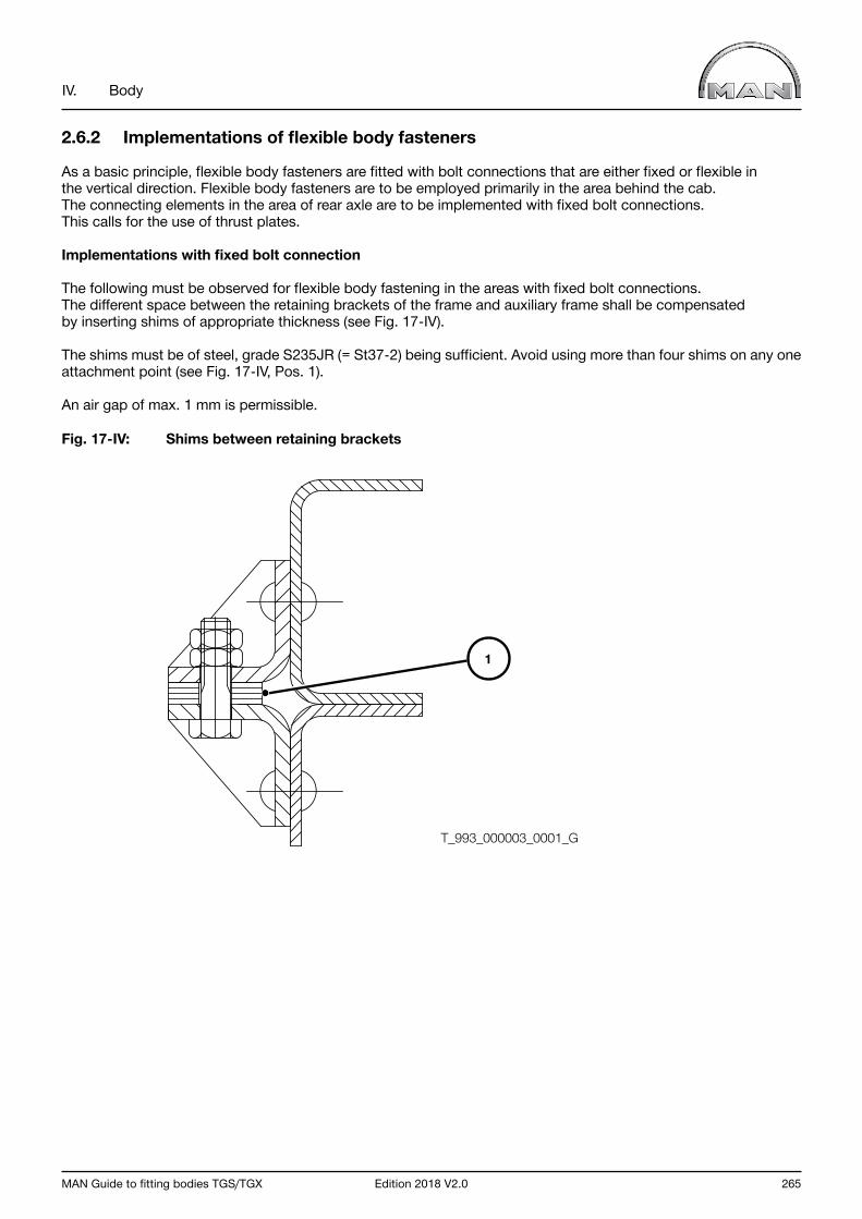
MAN Guide to fitting bodies TGS/TGX Edition 2018 V2.0 265
IV. Body
2.6.2 Implementations of flexible body fasteners
As a basic principle, flexible body fasteners are fitted with bolt connections that are either fixed or flexible in the vertical direction. Flexible body fasteners are to be employed primarily in the area behind the cab. The connecting elements in the area of rear axle are to be implemented with fixed bolt connections. This calls for the use of thrust plates.
Implementations with fixed bolt connection
The following must be observed for flexible body fastening in the areas with fixed bolt connections.The different space between the retaining brackets of the frame and auxiliary frame shall be compensated by inserting shims of appropriate thickness (see Fig. 17-IV).
The shims must be of steel, grade S235JR (= St37-2) being sufficient. Avoid using more than four shims on any one attachment point (see Fig. 17-IV, Pos. 1).
An air gap of max. 1 mm is permissible.
Fig. 17-IV: Shims between retaining brackets
T_993_000003_0001_G
1

266 Edition 2018 V2.0 MAN Guide to fitting bodies TGS/TGX
IV. Body
For another example of a flexible connection, see Fig. 18-IV.
Fig. 18-IV: Shackle fastening
1) Shackle, strength 8.82) Spacer non-elastic3) Attached on frame web only4) Angular bracket or U-shaped bridging piece5) Angle plate, approx. 5 mm thick, fitted
Vertically flexible implementations
The implementation of vertically flexible body fasteners depends in the first instance on the respective body. The torsional stiffness of the body plays a decisive role here. The following context applies.
A) Torsionally flexible body --> the requisite flexibility of the connection in the vertical direction is low (e.g. open platform body) B) Torsionally stiff body --> the requisite flexibility of the connection in the vertical direction is high (e.g. closed box body)
The flexibility of the connection in the vertical direction can be increased by using long bolts, springs or elastomers. This applies especially to the bolt connections of the first retaining brackets behind the cab because these are subject to high vertical loads.
T_993_000006_0001_G
1
2
3
4
5
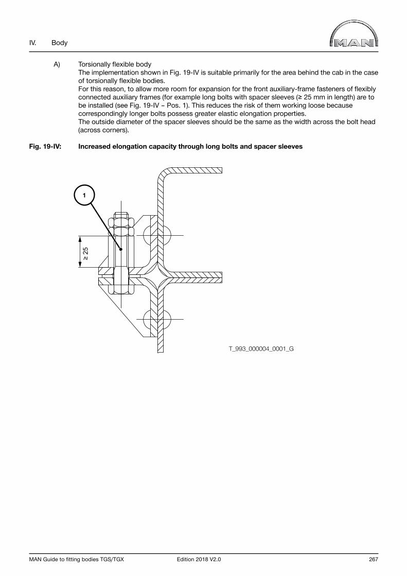
MAN Guide to fitting bodies TGS/TGX Edition 2018 V2.0 267
IV. Body
A) Torsionally flexible body The implementation shown in Fig. 19-IV is suitable primarily for the area behind the cab in the case of torsionally flexible bodies. For this reason, to allow more room for expansion for the front auxiliary-frame fasteners of flexibly connected auxiliary frames (for example long bolts with spacer sleeves (≥ 25 mm in length) are to be installed (see Fig. 19-IV – Pos. 1). This reduces the risk of them working loose because correspondingly longer bolts possess greater elastic elongation properties. The outside diameter of the spacer sleeves should be the same as the width across the bolt head (across corners).
Fig. 19-IV: Increased elongation capacity through long bolts and spacer sleeves
≥ 25
T_993_000004_0001_G
1
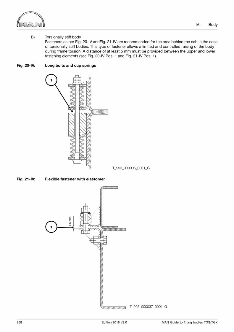
268 Edition 2018 V2.0 MAN Guide to fitting bodies TGS/TGX
IV. Body
B) Torsionally stiff body Fasteners as per Fig. 20-IV andFig. 21-IV are recommended for the area behind the cab in the case of torsionally stiff bodies. This type of fastener allows a limited and controlled raising of the body during frame torsion. A distance of at least 5 mm must be provided between the upper and lower fastening elements (see Fig. 20-IV Pos. 1 and Fig. 21-IV Pos. 1).
Fig. 20-IV: Long bolts and cup springs
Fig. 21-IV: Flexible fastener with elastomer
T_993_000005_0001_G
T_993_000037_0001_G
1
1 ≥ 5
mm
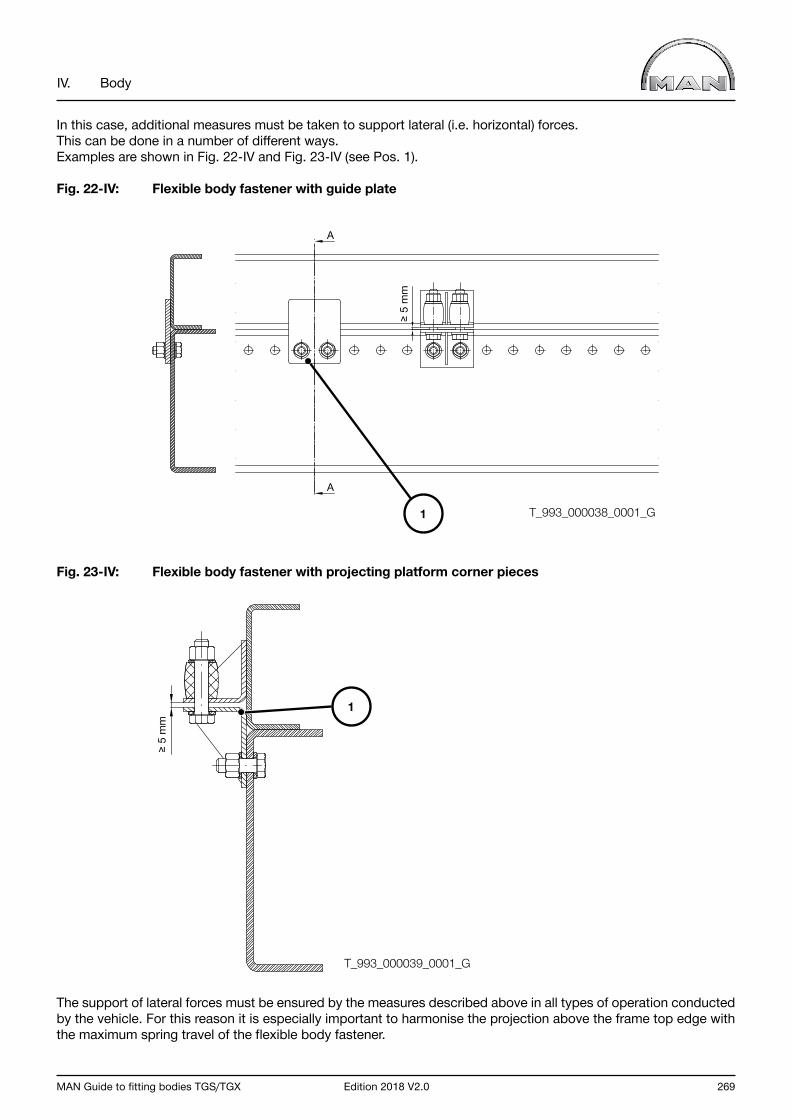
MAN Guide to fitting bodies TGS/TGX Edition 2018 V2.0 269
IV. Body
In this case, additional measures must be taken to support lateral (i.e. horizontal) forces. This can be done in a number of different ways. Examples are shown in Fig. 22-IV and Fig. 23-IV (see Pos. 1).
Fig. 22-IV: Flexible body fastener with guide plate
Fig. 23-IV: Flexible body fastener with projecting platform corner pieces
The support of lateral forces must be ensured by the measures described above in all types of operation conducted by the vehicle. For this reason it is especially important to harmonise the projection above the frame top edge with the maximum spring travel of the flexible body fastener.
1 T_993_000038_0001_G
T_993_000039_0001_G
A
A
≥ 5
mm
≥ 5
mm
1
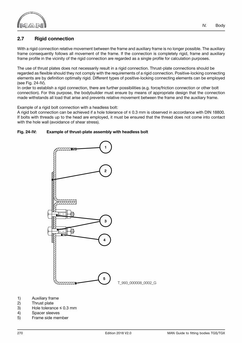
270 Edition 2018 V2.0 MAN Guide to fitting bodies TGS/TGX
IV. Body
2.7 Rigid connection
With a rigid connection relative movement between the frame and auxiliary frame is no longer possible. The auxiliary frame consequently follows all movement of the frame. If the connection is completely rigid, frame and auxiliary frame profile in the vicinity of the rigid connection are regarded as a single profile for calculation purposes.
The use of thrust plates does not necessarily result in a rigid connection. Thrust-plate connections should be regarded as flexible should they not comply with the requirements of a rigid connection. Positive-locking connecting elements are by definition optimally rigid. Different types of positive-locking connecting elements can be employed (see Fig. 24-IV). In order to establish a rigid connection, there are further possibilities (e.g. force/friction connection or other bolt connection). For this purpose, the bodybuilder must ensure by means of appropriate design that the connection made withstands all load that arise and prevents relative movement between the frame and the auxiliary frame.
Example of a rigid bolt connection with a headless bolt:A rigid bolt connection can be achieved if a hole tolerance of ≤ 0.3 mm is observed in accordance with DIN 18800. If bolts with threads up to the head are employed, it must be ensured that the thread does not come into contact with the hole wall (avoidance of shear stress).
Fig. 24-IV: Example of thrust-plate assembly with headless bolt
1) Auxiliary frame2) Thrust plate3) Hole tolerance ≤ 0.3 mm 4) Spacer sleeves5) Frame side member
T_993_000008_0002_G
1
2
3
5
4
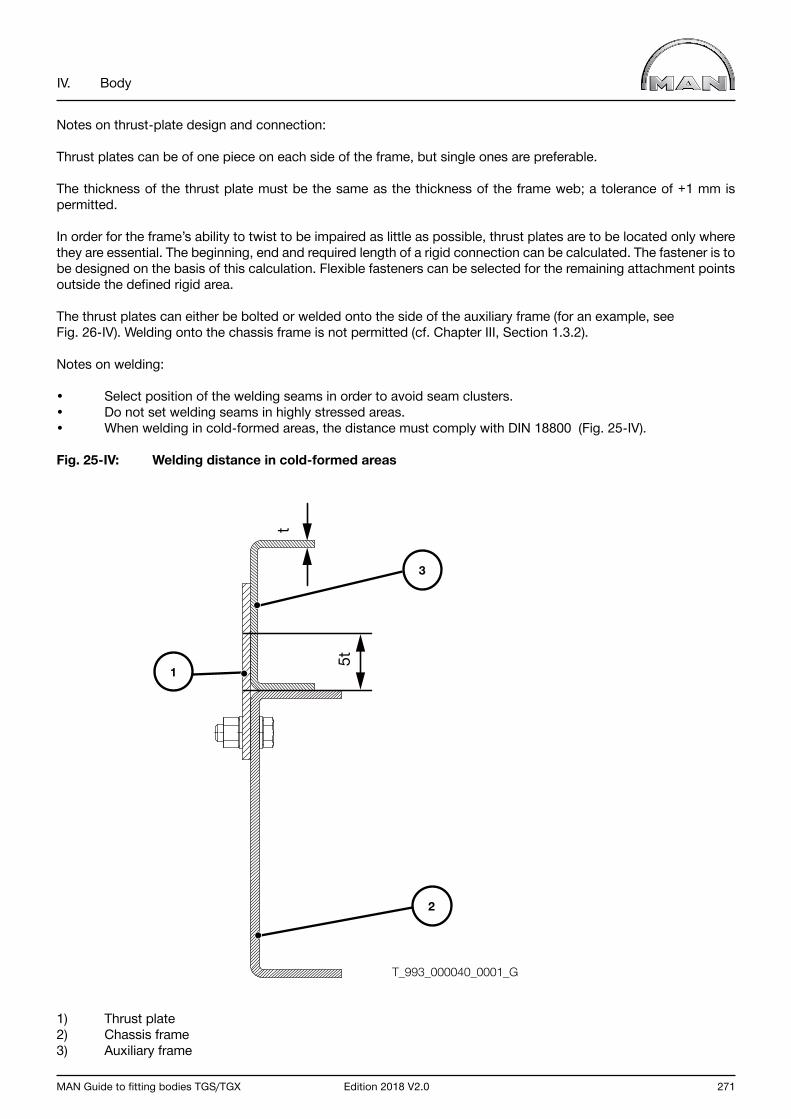
MAN Guide to fitting bodies TGS/TGX Edition 2018 V2.0 271
IV. Body
Notes on thrust-plate design and connection:
Thrust plates can be of one piece on each side of the frame, but single ones are preferable.
The thickness of the thrust plate must be the same as the thickness of the frame web; a tolerance of +1 mm is permitted.
In order for the frame’s ability to twist to be impaired as little as possible, thrust plates are to be located only where they are essential. The beginning, end and required length of a rigid connection can be calculated. The fastener is to be designed on the basis of this calculation. Flexible fasteners can be selected for the remaining attachment points outside the defined rigid area.
The thrust plates can either be bolted or welded onto the side of the auxiliary frame (for an example, see Fig. 26-IV). Welding onto the chassis frame is not permitted (cf. Chapter III, Section 1.3.2).
Notes on welding:
• Select position of the welding seams in order to avoid seam clusters.• Do not set welding seams in highly stressed areas.• When welding in cold-formed areas, the distance must comply with DIN 18800 (Fig. 25-IV).
Fig. 25-IV: Welding distance in cold-formed areas
1) Thrust plate2) Chassis frame3) Auxiliary frame
T_993_000040_0001_G
5t
t
3
2
1
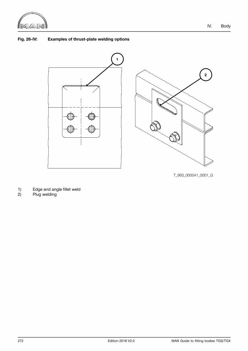
272 Edition 2018 V2.0 MAN Guide to fitting bodies TGS/TGX
IV. Body
Fig. 26-IV: Examples of thrust-plate welding options
1) Edge and angle fillet weld2) Plug welding
T_993_000041_0001_G
1
2
MAN Guide to fitting bodies TGS/TGX Edition 2018 V2.0 273
IV. Body
3.0 Bodies
3.1 Semitrailer tractors
MAN offers different semitrailer tractor variants. These range from the standard semitrailer tractor to chassis especially developed for heavy-duty transport. Various fifth-wheel couplings and pick-up plates are also available.
3.1.1 Chassis and equipment
The fifth-wheel lead stated in the sales documents or chassis drawings is valid only for the standard vehicle. Items of equipment that affect the vehicle’s dead weight or dimensions may necessitate a change in the fifth-wheel lead. This may in turn entail a change in the fifth-wheel load and the overall train length.
If a truck chassis is to be used as a semitrailer tractor or deployed optionally as a semitrailer tractor or a truck, please refer to Chapter III, Section 2.3.5.
3.1.2 Requirements for bodies
The general requirements for the design of bodies as stated in Chapter IV, Section 2.0 are to be heeded.
Important notice The semitrailer and the semitrailer tractor together form a unit. Careful matching of weights and dimensions is therefore necessary so that overloading or damage can be ruled out.
The following points must therefore be checked:
• Slew radii• Fifth-wheel height• Fifth-wheel load• Freedom of movement of all parts• Statutory requirements.
The angles of inclination required by ISO 1726 are 6° towards the front, 7° towards the rear and 3° to the side. Different tyre sizes, spring rates or fifth-wheel heights between tractor and semitrailer may reduce these angles so much that they no longer meet the standard. Apart from the inclination of the semitrailer towards the rear its inclination to the side during cornering, the spring compression (axle location, brake cylinders, wheel caps), snow chains, swinging movement of a tandem axle unit (if present) and slew radii must also be taken into account (see Fig. 27-IV). The values for high-cube bodies with low semitrailer tractors may differ from those stated.

274 Edition 2018 V2.0 MAN Guide to fitting bodies TGS/TGX
IV. Body
Fig. 27-IV: Dimensions on semitrailer tractors
If a fifth-wheel coupling is to be fitted, we recommend the following procedure before the vehicle is put into operation. This will ensure that the maximum possible fifth-wheel load is adhered to while the permissible and minimum axle loads are complied with. It will also guarantee the necessary clearance between semitrailer tractor and semitrailer and ensure that the statutory requirements are met:
• Weigh the vehicle• Draw up an axle load calculation• Determine the optimum fifth-wheel lead• Check the front slew radius• Check the rear slew radius• Check the angle of inclination towards the front• Check the angle of inclination towards the rear• Check the overall length of the tractor-semitrailer combination• Fit the fifth-wheel coupling accordingly.
InformationOnly type-tested fifth-wheel couplings and mounting plates that meet EC directive 94/20/EC may be used.
The fifth-wheel coupling to be fitted depends on a number of factors. As with trailer couplings, the decisive factor is the D value. For the tractor-semitrailer combination the smaller D values of the kingpin, fifth-wheel coupling and mounting plate apply. The D value can be found on the respective type plates. The formulae for calculating the D value for semitrailer trains can be found in the booklet “Coupling devices TG”.
At permissible fifth-wheel load the plane of the pickup plate on the semitrailer should be parallel to the road. The height of the fifth-wheel coupling and/or mounting plate must be designed accordingly.
A fifth-wheel coupling must not be fitted without a subframe. Under certain circumstances so-called direct fitting of a fifth-wheel coupling is possible: here a fifth-wheel coupling is fitted to the subframe with special bearing mounts together with a reinforcement plate (not subject to type-testing), and no mounting plate is necessary. The subframe dimensions and the material quality used must be as stated in Chapter IV, Section 2.2.
The fifth-wheel coupling mounting plate must not rest on the frame main members but solely on the fifth-wheel subframe. Only bolts approved by MAN or by the manufacturer of the mounting plate may be used to fasten the mounting plate.
T_995_000002_0001_G
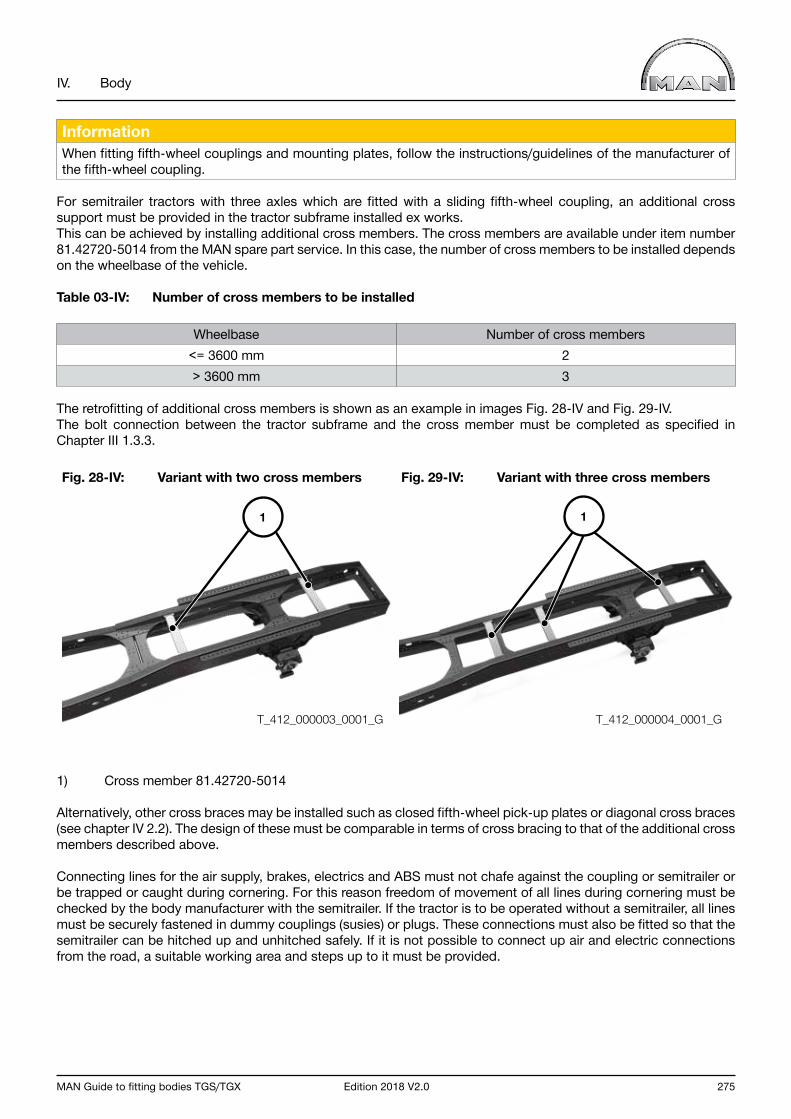
MAN Guide to fitting bodies TGS/TGX Edition 2018 V2.0 275
IV. Body
InformationWhen fitting fifth-wheel couplings and mounting plates, follow the instructions/guidelines of the manufacturer of the fifth-wheel coupling.
For semitrailer tractors with three axles which are fitted with a sliding fifth-wheel coupling, an additional cross support must be provided in the tractor subframe installed ex works. This can be achieved by installing additional cross members. The cross members are available under item number 81.42720-5014 from the MAN spare part service. In this case, the number of cross members to be installed depends on the wheelbase of the vehicle.
Table 03-IV: Number of cross members to be installed
Wheelbase Number of cross members<= 3600 mm 2> 3600 mm 3
The retrofitting of additional cross members is shown as an example in images Fig. 28-IV and Fig. 29-IV. The bolt connection between the tractor subframe and the cross member must be completed as specified in Chapter III 1.3.3.
Fig. 28-IV: Variant with two cross members Fig. 29-IV: Variant with three cross members
1) Cross member 81.42720-5014
Alternatively, other cross braces may be installed such as closed fifth-wheel pick-up plates or diagonal cross braces (see chapter IV 2.2). The design of these must be comparable in terms of cross bracing to that of the additional cross members described above.
Connecting lines for the air supply, brakes, electrics and ABS must not chafe against the coupling or semitrailer or be trapped or caught during cornering. For this reason freedom of movement of all lines during cornering must be checked by the body manufacturer with the semitrailer. If the tractor is to be operated without a semitrailer, all lines must be securely fastened in dummy couplings (susies) or plugs. These connections must also be fitted so that the semitrailer can be hitched up and unhitched safely. If it is not possible to connect up air and electric connections from the road, a suitable working area and steps up to it must be provided.
T_412_000003_0001_G T_412_000004_0001_G
11
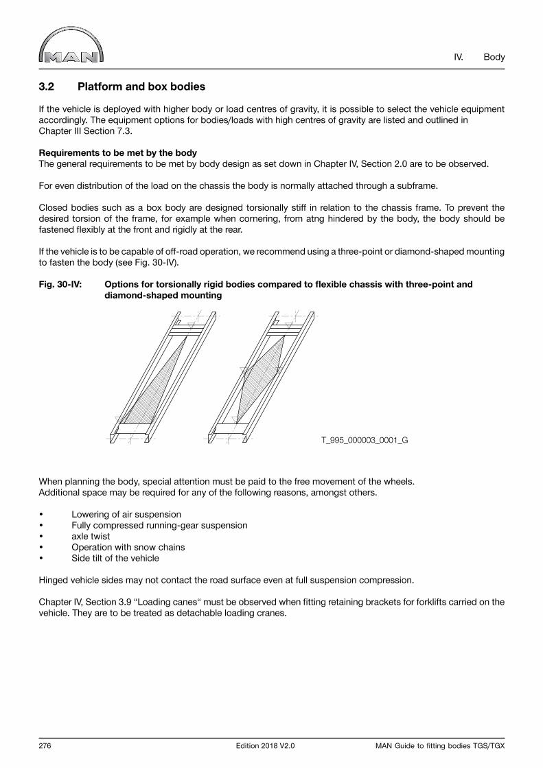
276 Edition 2018 V2.0 MAN Guide to fitting bodies TGS/TGX
IV. Body
3.2 Platform and box bodies
If the vehicle is deployed with higher body or load centres of gravity, it is possible to select the vehicle equipment accordingly. The equipment options for bodies/loads with high centres of gravity are listed and outlined inChapter III Section 7.3.
Requirements to be met by the bodyThe general requirements to be met by body design as set down in Chapter IV, Section 2.0 are to be observed.
For even distribution of the load on the chassis the body is normally attached through a subframe.
Closed bodies such as a box body are designed torsionally stiff in relation to the chassis frame. To prevent the desired torsion of the frame, for example when cornering, from atng hindered by the body, the body should be fastened flexibly at the front and rigidly at the rear.
If the vehicle is to be capable of off-road operation, we recommend using a three-point or diamond-shaped mounting to fasten the body (see Fig. 30-IV).
Fig. 30-IV: Options for torsionally rigid bodies compared to flexible chassis with three-point and diamond-shaped mounting
When planning the body, special attention must be paid to the free movement of the wheels. Additional space may be required for any of the following reasons, amongst others.
• Lowering of air suspension• Fully compressed running-gear suspension• axle twist• Operation with snow chains• Side tilt of the vehicle
Hinged vehicle sides may not contact the road surface even at full suspension compression.
Chapter IV, Section 3.9 “Loading canes“ must be observed when fitting retaining brackets for forklifts carried on the vehicle. They are to be treated as detachable loading cranes.
T_995_000003_0001_G
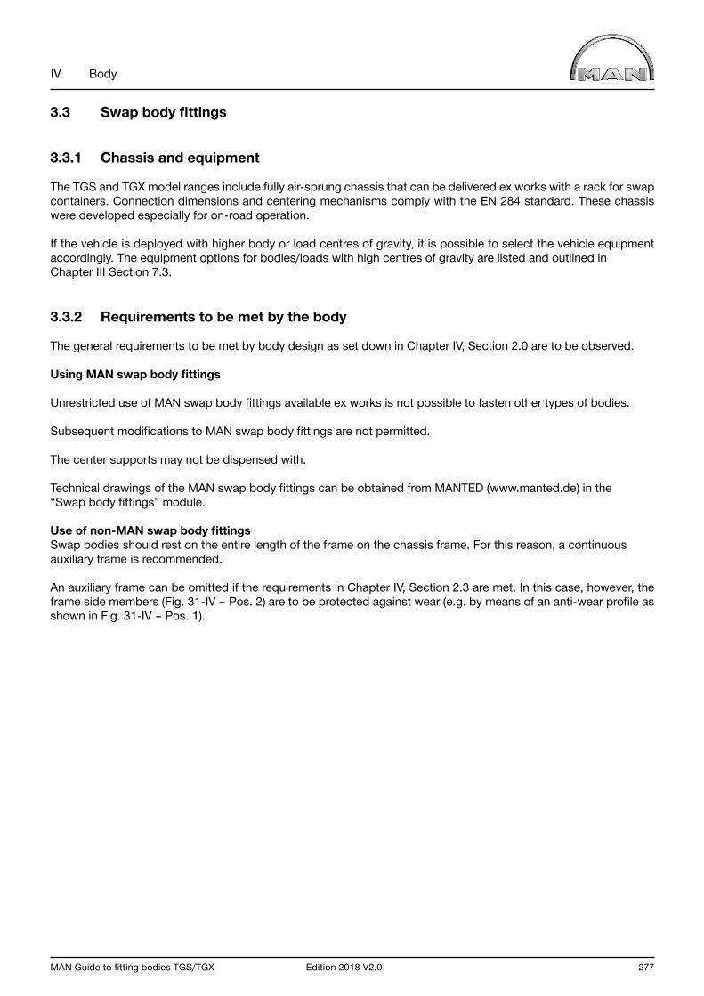
MAN Guide to fitting bodies TGS/TGX Edition 2018 V2.0 277
IV. Body
3.3 Swap body fittings
3.3.1 Chassis and equipment
The TGS and TGX model ranges include fully air-sprung chassis that can be delivered ex works with a rack for swap containers. Connection dimensions and centering mechanisms comply with the EN 284 standard. These chassis were developed especially for on-road operation.
If the vehicle is deployed with higher body or load centres of gravity, it is possible to select the vehicle equipment accordingly. The equipment options for bodies/loads with high centres of gravity are listed and outlined in Chapter III Section 7.3.
3.3.2 Requirements to be met by the body
The general requirements to be met by body design as set down in Chapter IV, Section 2.0 are to be observed.
Using MAN swap body fittings
Unrestricted use of MAN swap body fittings available ex works is not possible to fasten other types of bodies.
Subsequent modifications to MAN swap body fittings are not permitted.
The center supports may not be dispensed with.
Technical drawings of the MAN swap body fittings can be obtained from MANTED (www.manted.de) in the “Swap body fittings” module.
Use of non-MAN swap body fittingsSwap bodies should rest on the entire length of the frame on the chassis frame. For this reason, a continuous auxiliary frame is recommended.
An auxiliary frame can be omitted if the requirements in Chapter IV, Section 2.3 are met. In this case, however, the frame side members (Fig. 31-IV – Pos. 2) are to be protected against wear (e.g. by means of an anti-wear profile as shown in Fig. 31-IV – Pos. 1).
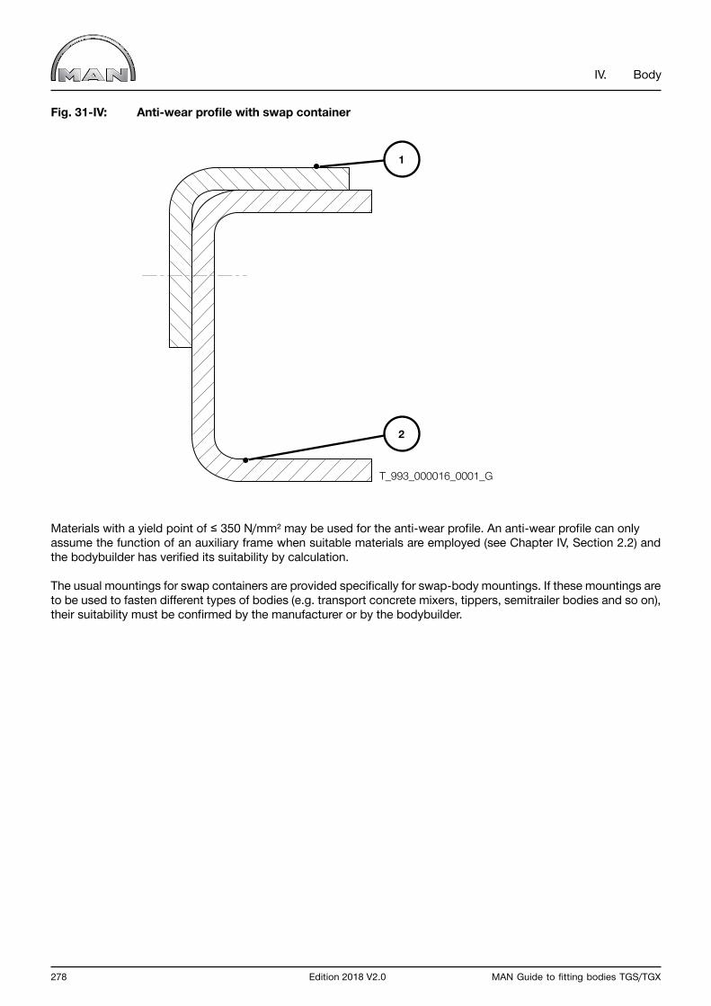
278 Edition 2018 V2.0 MAN Guide to fitting bodies TGS/TGX
IV. Body
Fig. 31-IV: Anti-wear profile with swap container
Materials with a yield point of ≤ 350 N/mm² may be used for the anti-wear profile. An anti-wear profile can only assume the function of an auxiliary frame when suitable materials are employed (see Chapter IV, Section 2.2) and the bodybuilder has verified its suitability by calculation.
The usual mountings for swap containers are provided specifically for swap-body mountings. If these mountings are to be used to fasten different types of bodies (e.g. transport concrete mixers, tippers, semitrailer bodies and so on), their suitability must be confirmed by the manufacturer or by the bodybuilder.
1
2
T_993_000016_0001_G

MAN Guide to fitting bodies TGS/TGX Edition 2018 V2.0 279
IV. Body
3.4 Liftgates
Before fitting a liftgate (or hydraulic loading platform, lifting loading tailgate, loading platform), compatibility with, the design of the vehicle, the chassis and the body must be checked.
The general requirements to be met by body design as set down in Chapter IV, Sections 1.0 and 2.0 apply.
The fitting of a liftgate influences:
• Axle-load distribution• Body and overall length • Frame flexing • Subframe flexing • Type of connection between frame and auxiliary frame • Vehicle electrical system (battery, alternator, cabling)
Prior to the assembly of a liftgate, the body builder must:
• Calculate the axle loads. • Check compliance with the stipulated minimum front-axle load (see Chapter III, Section 2.2.6 “Minimum front-axle load”). • Ensure that exceeding the permissible axle loads is precluded.• Include nose weights in addition to the liftgate in vehicle design.• If necessary, shorten the body length and rear overhang, or lengthen the wheelbase. • Provide outriggers should they prove necessary for reasons of strength, rigidity or stability.• Provide batteries of adequate capacity ≥ 175 Ah, preferably 225 Ah and sufficiently powerful alternator (at least 28 V/80 A, preferably 28 V/110 A); available as special equipment ex works.• Install an electrical interface for the liftgate (available as special equipment ex works;
circuit diagrams/pin-out Chapter III Section 8.3.2).• Observe the country-specific regulations and laws.
Auxiliary-frame design and connection between frame and auxiliary frame
The auxiliary frame is to be designed and constructed in accordance with Chapter IV Section 2.0. It is the responsibility of the bodybuilder.
The final cross member on the chassis frame must be retained. If no final cross member is installed as standard, one must be retrofitted (obtainable from MAN Spare-parts Service). A liftgate may not be fitted without a final cross member.
The table below lists some auxiliary frame profiles This list (Table 04-IV) does not claim to be exhaustive, however. All information necessary for design must also be checked.Other steel profiles are acceptable if they have at least equivalent values in respect of the moment of inertia Ix, moment of resistance Wx and yield point σ0.2. MAN does not accept profiles made from non-ferrous metals for the construction of auxiliary frames.
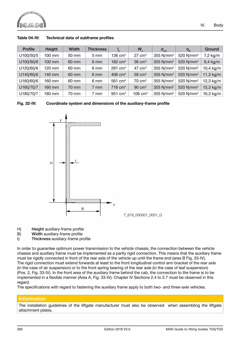
280 Edition 2018 V2.0 MAN Guide to fitting bodies TGS/TGX
IV. Body
Table 04-IV: Technical data of subframe profiles
Profile Height Width Thickness Ix Wx σ0,2 σB GroundU100/50/5 100 mm 50 mm 5 mm 136 cm4 27 cm3 355 N/mm2 520 N/mm2 7,2 kg/mU100/60/6 100 mm 60 mm 6 mm 182 cm4 36 cm3 355 N/mm2 520 N/mm2 9,4 kg/mU120/60/6 120 mm 60 mm 6 mm 281 cm4 47 cm3 355 N/mm2 520 N/mm2 10,4 kg/mU140/60/6 140 mm 60 mm 6 mm 406 cm4 58 cm3 355 N/mm2 520 N/mm2 11,3 kg/mU160/60/6 160 mm 60 mm 6 mm 561 cm4 70 cm3 355 N/mm2 520 N/mm2 12,3 kg/mU160/70/7 160 mm 70 mm 7 mm 716 cm4 90 cm3 355 N/mm2 520 N/mm2 15,3 kg/mU180/70/7 180 mm 70 mm 7 mm 951 cm4 106 cm3 355 N/mm2 520 N/mm2 16,3 kg/m
Fig. 32-IV: Coordinate system and dimensions of the auxiliary-frame profile
H) Height auxiliary-frame profileB) Width auxiliary-frame profilet) Thickness auxiliary-frame profile
In order to guarantee optimum power transmission to the vehicle chassis, the connection between the vehicle chassis and auxiliary frame must be implemented as a partly rigid connection. This means that the auxiliary frame must be rigidly connected in front of the rear axle of the vehicle up until the frame end (area B Fig. 33-IV). The rigid connection must extend forwards at least to the front longitudinal control arm bracket of the rear axle (in the case of air suspension) or to the front spring bearing of the rear axle (in the case of leaf suspension) (Pos. 2, Fig. 33-IV). In the front area of the auxiliary frame behind the cab, the connection to the frame is to be implemented in a flexible manner (Area A, Fig. 33-IV). Chapter IV Sections 2.4 to 2.7 must be observed in this regard. The specifications with regard to fastening the auxiliary frame apply to both two- and three-axle vehicles.
InformationThe installation guidelines of the liftgate manufacturer must also be observed when assembling the liftgate attachment plates.
x
y
tH
B
T_678_000001_0001_G

MAN Guide to fitting bodies TGS/TGX Edition 2018 V2.0 281
IV. Body
Fig. 33-IV: Example of liftgate installation on two- and three-axle vehicles
A) Flexible areaB) Rigid area due to thrust-plate arrangementC) Frame overhang (distance from end of frame to center of rearmost axle)
1) Body attachment bracket2) Thrust plate3) Liftgate facility
A B
C
T_678_000002_0001_G
T_678_000003_0001_G
A B
C
1
1
2
2
3
3
282 Edition 2018 V2.0 MAN Guide to fitting bodies TGS/TGX
IV. Body
Basic information on the use of the liftgate tables
The values in the tables are the benchmark values for which, due to strength/rigidity reasons, no outriggers are required. They are regarded as guideline values. MAN recommends compliance with the limit values in order to prevent damage to the frame and to ensure optimal utilisation of the vehicle. The tables list some of the usual liftgate sizes in conjunction with usual vehicle models. If liftgates with bigger payloads are to be fitted they must be considered separately.The liftgate tables are based on the optimal utilisation of a vehicle with regard to its permissible axle loads. Axle-load distribution is decisively affected by frame overhang and body length. The tables reference the series-production status (unladen weight, axle-load distribution) of the vehicles. The stated frame overhangs are calculated so that under the given boundary conditions, utilisation with regard to minimum front-axle load and permissible rear-axle load is nearly optimal.
The stated auxiliary frames to be used as a minimum have been tested with regard to the maximum permissible tension and permissible deflection.Wheels protruding above the edge of the frame on some series-production vehicles when the rear axle is fully compressed have not been taken into consideration. To bridge the frame overhang and ensure smooth assembly of the body, in these cases an auxiliary frame profile of an adequate height must be selected (as opposed to what is stated in the liftgate tables).
If the values listed are not complied with, the bodybuilder bears responsibility for ensuring the permissible deflections and tension are complied with by an adequately dimensioned auxiliary frame.
Under certain circumstances, it may be necessary to modify the wheelbase or the rear frame overhang in order to comply with the permissible axle loads. The frame overhangs listed in the tables are not the frame overhangs available ex works as standard.The values listed in the tables are not to be used in cases where the permissible frame overhang is exceeded by the planned body concept. The chassis frame and the auxiliary frame are to be separately dimensioned by the bodybuilder.
Operation of the liftgate on vehicles with leading or trailing axles is permitted only when the respective axle is lowered.

MAN Guide to fitting bodies TGS/TGX Edition 2018 V2.0 283
IV. Body
Table 05-IV: Liftgate table for two-axle TGS/TGX (dimensions are in mm, loads in kg) Applies to: 03S, 06S, 10S, 22S, 06X, 10X, 22X
Wheel base1. and 2. axle Liftgate payload Cabin Permissible frame
overhangMin. auxiliary frame profile
W x H x t
3600
≤ 1000M 1750 100x50x5
L / LX / XL / XLX / XXL 1550 100x50x5
≤ 1500M 1700 100x50x5
L / LX / XL / XLX / XXL 1500 100x50x5
≤ 2000M 1700 100x50x5
L / LX / XL / XLX / XXL 1500 100x50x5
3900
≤ 1000M 1950 100x50x5
L / LX / XL / XLX / XXL 1750 100x50x5
≤ 1500M 1900 100x50x5
L / LX / XL / XLX / XXL 1700 100x50x5
≤ 2000M 1850 100x50x5
L / LX / XL / XLX / XXL 1650 100x50x5
4200
≤ 1000M 2150 100x50x5
L / LX / XL / XLX / XXL 1950 100x50x5
≤ 1500M 2100 100x50x5
L / LX / XL / XLX / XXL 1900 100x50x5
≤ 2000M 2050 100x50x5
L / LX / XL / XLX / XXL 1850 100x50x5
4500
≤ 1000M 2350 100x50x5
L / LX / XL / XLX / XXL 2150 100x50x5
≤ 1500M 2300 100x50x5
L / LX / XL / XLX / XXL 2100 100x50x5
≤ 2000M 2250 100x60x6
L / LX / XL / XLX / XXL 2050 100x50x5
4800
≤ 1000M 2550 100x50x5
L / LX / XL / XLX / XXL 2350 100x50x5
≤ 1500M 2500 100x50x5
L / LX / XL / XLX / XXL 2300 100x50x5
≤ 2000M 2450 120x60x6
L / LX / XL / XLX / XXL 2250 100x50x5
5100
≤ 1000M 2700 100x50x5
L / LX / XL / XLX / XXL 2550 100x50x5
≤ 1500M 2650 100x60x6
L / LX / XL / XLX / XXL 2500 100x50x5
≤ 2000M 2600 140x60x6
L / LX / XL / XLX / XXL 2450 100x60x6
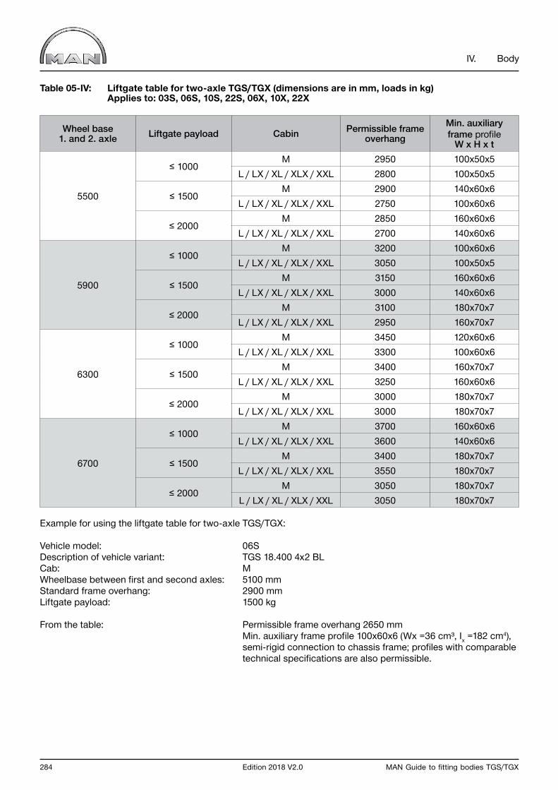
284 Edition 2018 V2.0 MAN Guide to fitting bodies TGS/TGX
IV. Body
Table 05-IV: Liftgate table for two-axle TGS/TGX (dimensions are in mm, loads in kg) Applies to: 03S, 06S, 10S, 22S, 06X, 10X, 22X
Wheel base1. and 2. axle Liftgate payload Cabin Permissible frame
overhangMin. auxiliary frame profile
W x H x t
5500
≤ 1000M 2950 100x50x5
L / LX / XL / XLX / XXL 2800 100x50x5
≤ 1500M 2900 140x60x6
L / LX / XL / XLX / XXL 2750 100x60x6
≤ 2000M 2850 160x60x6
L / LX / XL / XLX / XXL 2700 140x60x6
5900
≤ 1000M 3200 100x60x6
L / LX / XL / XLX / XXL 3050 100x50x5
≤ 1500M 3150 160x60x6
L / LX / XL / XLX / XXL 3000 140x60x6
≤ 2000M 3100 180x70x7
L / LX / XL / XLX / XXL 2950 160x70x7
6300
≤ 1000M 3450 120x60x6
L / LX / XL / XLX / XXL 3300 100x60x6
≤ 1500M 3400 160x70x7
L / LX / XL / XLX / XXL 3250 160x60x6
≤ 2000M 3000 180x70x7
L / LX / XL / XLX / XXL 3000 180x70x7
6700
≤ 1000M 3700 160x60x6
L / LX / XL / XLX / XXL 3600 140x60x6
≤ 1500M 3400 180x70x7
L / LX / XL / XLX / XXL 3550 180x70x7
≤ 2000M 3050 180x70x7
L / LX / XL / XLX / XXL 3050 180x70x7
Example for using the liftgate table for two-axle TGS/TGX:
Vehicle model: 06SDescription of vehicle variant: TGS 18.400 4x2 BLCab: MWheelbase between first and second axles: 5100 mmStandard frame overhang: 2900 mmLiftgate payload: 1500 kg
From the table: Permissible frame overhang 2650 mm Min. auxiliary frame profile 100x60x6 (Wx =36 cm³, Ix =182 cm4), semi-rigid connection to chassis frame; profiles with comparable technical specifications are also permissible.

MAN Guide to fitting bodies TGS/TGX Edition 2018 V2.0 285
IV. Body
Table 06-IV: Liftgate table for three-axle TGS/TGX (dimensions are in mm, loads in kg) Applies to: 18S, 21S, 35S, 71S, 74S, 89S, 18X, 21X, 89X
Wheel base
1. and 2. axle
Wheel base
2. and 3. axle
Liftgate payload Cabin Permissible frame
overhangMin. auxiliary frame
profileW x H x t
3600 1350
≤ 1000 M 1800 100x50x5≤ 1000 L / LX / XL / XLX / XXL 1550 100x50x5≤ 1500 M 1800 100x50x5≤ 1500 L / LX / XL / XLX / XXL 1550 100x50x5≤ 2000 M 1750 100x50x5≤ 2000 L / LX / XL / XLX / XXL 1500 100x50x5
3900 1350
≤ 1000 M 1850 100x50x5≤ 1000 L / LX / XL / XLX / XXL 1550 100x50x5≤ 1500 M 1800 100x50x5≤ 1500 L / LX / XL / XLX / XXL 1550 100x50x5≤ 2000 M 1800 100x50x5≤ 2000 L / LX / XL / XLX / XXL 1550 100x50x5
4200 1350
≤ 1000 M 2050 100x50x5≤ 1000 L / LX / XL / XLX / XXL 1800 100x50x5≤ 1500 M 2050 100x50x5≤ 1500 L / LX / XL / XLX / XXL 1800 100x50x5≤ 2000 M 2000 100x50x5≤ 2000 L / LX / XL / XLX / XXL 1750 100x50x5
4500 1350
≤ 1000 M 2300 100x50x5≤ 1000 L / LX / XL / XLX / XXL 2000 100x50x5≤ 1500 M 2250 100x50x5≤ 1500 L / LX / XL / XLX / XXL 1950 100x50x5≤ 2000 M 2200 100x50x5≤ 2000 L / LX / XL / XLX / XXL 1950 100x50x5
4800 1350
≤ 1000 M 2450 100x50x5≤ 1000 L / LX / XL / XLX / XXL 2200 100x50x5≤ 1500 M 2450 100x50x5≤ 1500 L / LX / XL / XLX / XXL 2150 100x50x5≤ 2000 M 2400 100x50x5≤ 2000 L / LX / XL / XLX / XXL 2150 100x50x5
5100 1350
≤ 1000 M 2700 100x50x5≤ 1000 L / LX / XL / XLX / XXL 2400 100x50x5≤ 1500 M 2650 100x50x5≤ 1500 L / LX / XL / XLX / XXL 2400 100x50x5≤ 2000 M 2600 120x60x6≤ 2000 L / LX / XL / XLX / XXL 2350 100x50x5
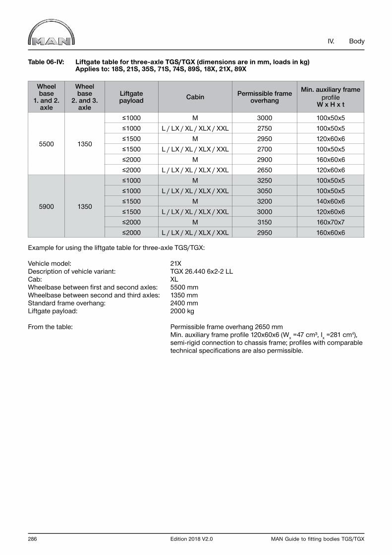
286 Edition 2018 V2.0 MAN Guide to fitting bodies TGS/TGX
IV. Body
Table 06-IV: Liftgate table for three-axle TGS/TGX (dimensions are in mm, loads in kg) Applies to: 18S, 21S, 35S, 71S, 74S, 89S, 18X, 21X, 89X
Wheel base
1. and 2. axle
Wheel base
2. and 3. axle
Liftgate payload Cabin Permissible frame
overhangMin. auxiliary frame
profileW x H x t
5500 1350
≤1000 M 3000 100x50x5≤1000 L / LX / XL / XLX / XXL 2750 100x50x5≤1500 M 2950 120x60x6≤1500 L / LX / XL / XLX / XXL 2700 100x50x5≤2000 M 2900 160x60x6≤2000 L / LX / XL / XLX / XXL 2650 120x60x6
5900 1350
≤1000 M 3250 100x50x5≤1000 L / LX / XL / XLX / XXL 3050 100x50x5≤1500 M 3200 140x60x6≤1500 L / LX / XL / XLX / XXL 3000 120x60x6≤2000 M 3150 160x70x7≤2000 L / LX / XL / XLX / XXL 2950 160x60x6
Example for using the liftgate table for three-axle TGS/TGX:
Vehicle model: 21XDescription of vehicle variant: TGX 26.440 6x2-2 LLCab: XLWheelbase between first and second axles: 5500 mmWheelbase between second and third axles: 1350 mmStandard frame overhang: 2400 mmLiftgate payload: 2000 kg
From the table: Permissible frame overhang 2650 mm Min. auxiliary frame profile 120x60x6 (Wx =47 cm³, Ix =281 cm4), semi-rigid connection to chassis frame; profiles with comparable technical specifications are also permissible.
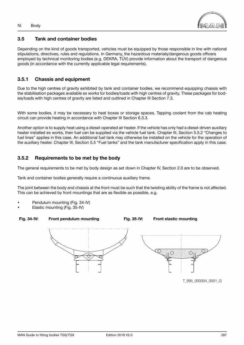
MAN Guide to fitting bodies TGS/TGX Edition 2018 V2.0 287
IV. Body
3.5 Tank and container bodies
Depending on the kind of goods transported, vehicles must be equipped by those responsible in line with national stipulations, directives, rules and regulations. In Germany, the hazardous materials/dangerous goods officers employed by technical monitoring bodies (e.g. DEKRA, TÜV) provide information about the transport of dangerous goods (in accordance with the currently applicable legal requirements).
3.5.1 Chassis and equipment
Due to the high centres of gravity exhibited by tank and container bodies, we recommend equipping chassis with the stabilisation packages available ex works for bodies/loads with high centres of gravity. These packages for bod-ies/loads with high centres of gravity are listed and outlined in Chapter III Section 7.3.
With some bodies, it may be necessary to heat boxes or storage spaces. Tapping coolant from the cab heating circuit can provide heating in accordance with Chapter III Section 6.3.3.
Another option is to supply heat using a diesel-operated air heater. If the vehicle has only had a diesel-driven auxiliary heater installed ex works, then fuel can be supplied via the vehicle fuel tank. Chapter III, Section 5.5.2 “Changes to fuel lines” applies in this case. An additional fuel tank may otherwise be installed on the vehicle for the operation of the auxiliary heater. Chapter III, Section 5.5 “Fuel tanks” and the tank manufacturer specification apply in this case.
3.5.2 Requirements to be met by the body
The general requirements to be met by body design as set down in Chapter IV, Section 2.0 are to be observed.
Tank and container bodies generally require a continuous auxiliary frame.
The joint between the body and chassis at the front must be such that the twisting ability of the frame is not affected. This can be achieved by front mountings that are as flexible as possible, e.g.
• Pendulum mounting (Fig. 34-IV)• Elastic mounting (Fig. 35-IV)
Fig. 34-IV: Front pendulum mounting Fig. 35-IV: Front elastic mounting
T_995_000004_0001_G
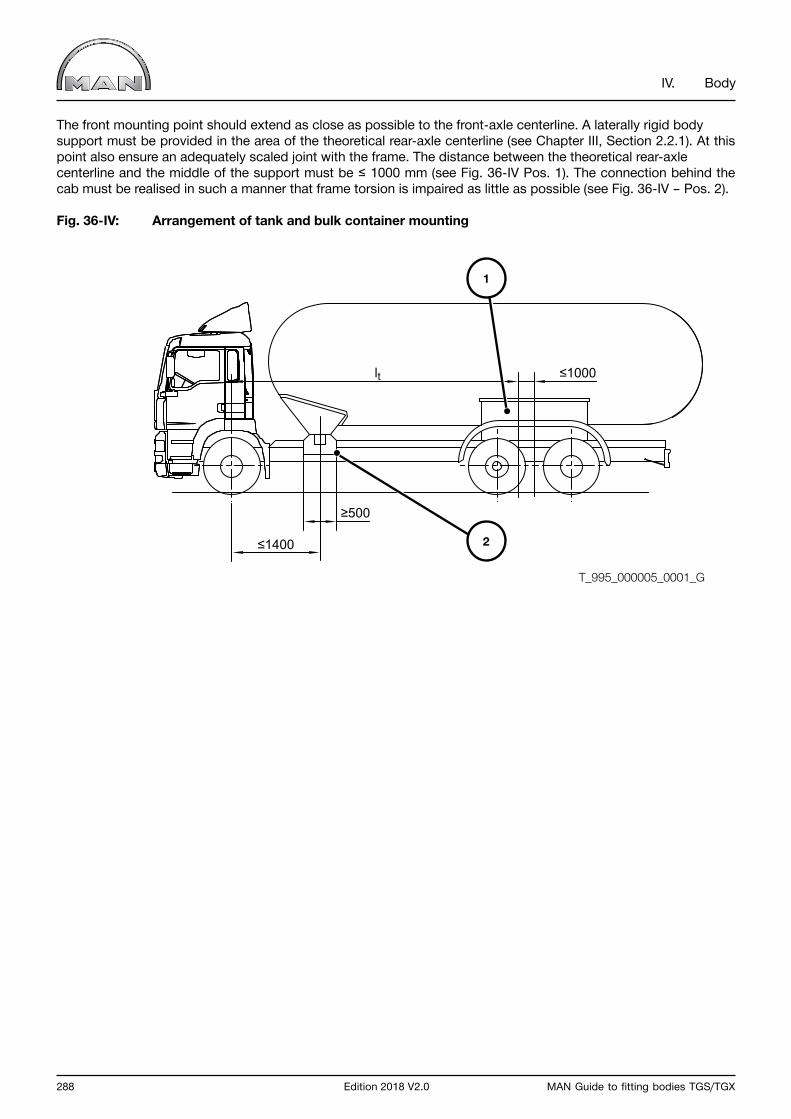
288 Edition 2018 V2.0 MAN Guide to fitting bodies TGS/TGX
IV. Body
The front mounting point should extend as close as possible to the front-axle centerline. A laterally rigid body support must be provided in the area of the theoretical rear-axle centerline (see Chapter III, Section 2.2.1). At this point also ensure an adequately scaled joint with the frame. The distance between the theoretical rear-axle centerline and the middle of the support must be ≤ 1000 mm (see Fig. 36-IV Pos. 1). The connection behind the cab must be realised in such a manner that frame torsion is impaired as little as possible (see Fig. 36-IV – Pos. 2).
Fig. 36-IV: Arrangement of tank and bulk container mounting
≤1400
lt ≤1000
≥500
2
1
T_995_000005_0001_G
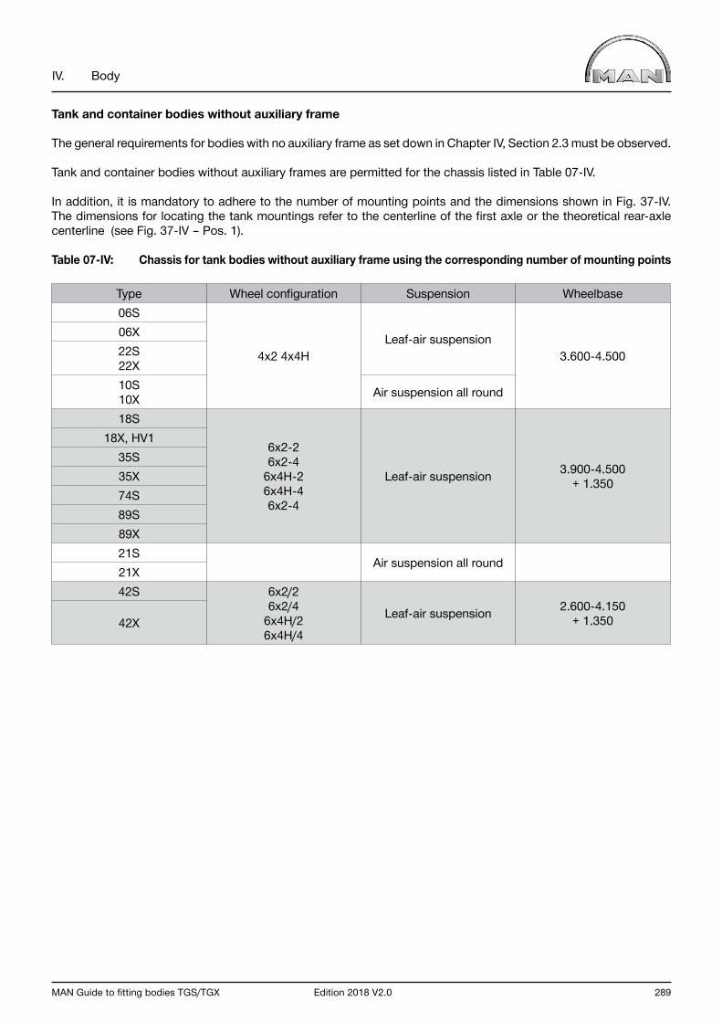
MAN Guide to fitting bodies TGS/TGX Edition 2018 V2.0 289
IV. Body
Tank and container bodies without auxiliary frame
The general requirements for bodies with no auxiliary frame as set down in Chapter IV, Section 2.3 must be observed.
Tank and container bodies without auxiliary frames are permitted for the chassis listed in Table 07-IV.
In addition, it is mandatory to adhere to the number of mounting points and the dimensions shown in Fig. 37-IV. The dimensions for locating the tank mountings refer to the centerline of the first axle or the theoretical rear-axle centerline (see Fig. 37-IV – Pos. 1).
Table 07-IV: Chassis for tank bodies without auxiliary frame using the corresponding number of mounting points
Type Wheel configuration Suspension Wheelbase06S
4x2 4x4HLeaf-air suspension
3.600-4.500
06X22S 22X10S 10X Air suspension all round
18S
6x2-2 6x2-4
6x4H-26x4H-46x2-4
Leaf-air suspension 3.900-4.500 + 1.350
18X, HV135S35X74S89S89X21S
Air suspension all round21X42S 6x2/2
6x2/46x4H/26x4H/4
Leaf-air suspension 2.600-4.150 + 1.35042X
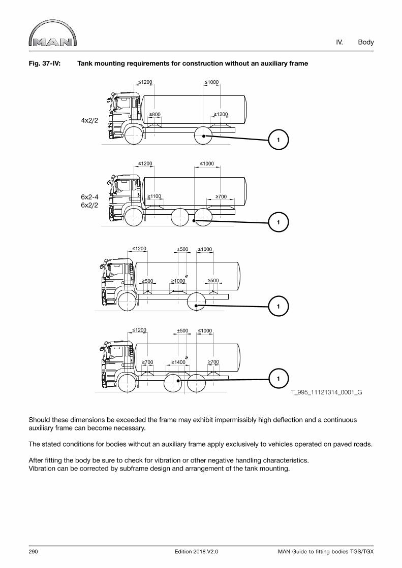
290 Edition 2018 V2.0 MAN Guide to fitting bodies TGS/TGX
IV. Body
Fig. 37-IV: Tank mounting requirements for construction without an auxiliary frame
Should these dimensions be exceeded the frame may exhibit impermissibly high deflection and a continuous auxiliary frame can become necessary.
The stated conditions for bodies without an auxiliary frame apply exclusively to vehicles operated on paved roads.
After fitting the body be sure to check for vibration or other negative handling characteristics. Vibration can be corrected by subframe design and arrangement of the tank mounting.
4x2/2
6x2-46x2/2
≥700≥1100 ≥700 ≥1400 ≥700
≥800
≤1000≤1200
≥1200
≤1200 ≤1000±500
≤1000≤1200 ≤1200 ≤1000±500
≥1000 ≥500≥500
4x2/2
6x2-46x2/2
≥700≥1100 ≥700 ≥1400 ≥700
≥800
≤1000≤1200
≥1200
≤1200 ≤1000±500
≤1000≤1200 ≤1200 ≤1000±500
≥1000 ≥500≥500
T_995_11121314_0001_G
1
1
1
1
MAN Guide to fitting bodies TGS/TGX Edition 2018 V2.0 291
IV. Body
3.6 Refuse-collector body
Refuse-collector bodies can be realised as rear-loaders, side-loaders or front-loaders. In every case, the require-ments to be met by chassis and body as well as the applicable standards and Directives (e.g. EN 1501) must be adhered to right from the concept phase.
3.6.1 Chassis and equipment
An MAN final cross member at the rear of the frame is mandatory for this type of body. If the frame overhang subsequently has to be shortened, Chapter III, Section 2.3.2 must be observed. The use of any other cross member at the end of the frame is not permitted.If the vehicle is deployed with higher body or load centres of gravity, it is possible to select the vehicle equipment accordingly. The equipment options for bodies/loads with high centres of gravity are listed and outlined in Chapter III Section 7.3.
3.6.2 Requirements to be met by the body
The general requirements to be met by body design as set down in Chapter IV, Section 2.0 are to be observed.
For refuse-collector bodies, continuous auxiliary frames are recommended. Bodies on multi-part auxiliary frames are possible.
Refuse-collector bodies with emptying systems (e.g. rear-loaders) require auxiliary frames with sufficient torsional and shear rigidity. This can be achieved by equipping the auxiliary frame with appropriate cross members, for example. In addition, the connection to the chassis frame at the rear is to be implemented over a large area, for example by means of thrust plates.
If further bodies such as loading cranes, for example, are added to the refuse-collector body, the relevant chapters in the guidelines must also be observed.
Refuse-collector vehicles are usually designed for operation on paved roads. This must be taken into account when selecting a chassis for applications on unpaved roads and reinforcement measures must be carried out.
292 Edition 2018 V2.0 MAN Guide to fitting bodies TGS/TGX
IV. Body
3.7 Tippers
3.7.1 Chassis and equipment
If the vehicle is deployed with higher body or load centres of gravity, it is possible to select the vehicle equipment accordingly. The equipment options for bodies/loads with high centres of gravity are listed and outlined in Chapter III Section 7.3.
To improve stability on vehicles with air suspension it must be ensured that the air suspension is lowered before commencing the tipping operation. Lowering can either be done manually via the ECAS control unit or it can be automatic using special equipment Sales Code 311PH (input of the ECAS parameters for air suspension lowering to 20 mm above the buffers).Special equipment 311PH automatically lowers the vehicle to the defined level above the buffers if the power take-off is engaged when the vehicle is at a standstill. To ensure that the function provided by Sales Code 311PH is properly activated it is imperative that the correct order of operations is observed when engaging the power take-off (see operating instructions). A check must also be carried out to ensure that the message “No ride height” appears on the display and that the vehicle has actually lowered.If an automatic lowering system is not fitted then the user/driver must be informed of the requirement to manually lower the air suspension.
If tipper bodies are fitted to chassis not intended for tipper bodies ex works, these chassis must be equipped for operation as tippers. This may result in the replacement of leaf springs or stabilisers, for example. In such cases, approval must be obtained from MAN (for address see “Publisher” above).
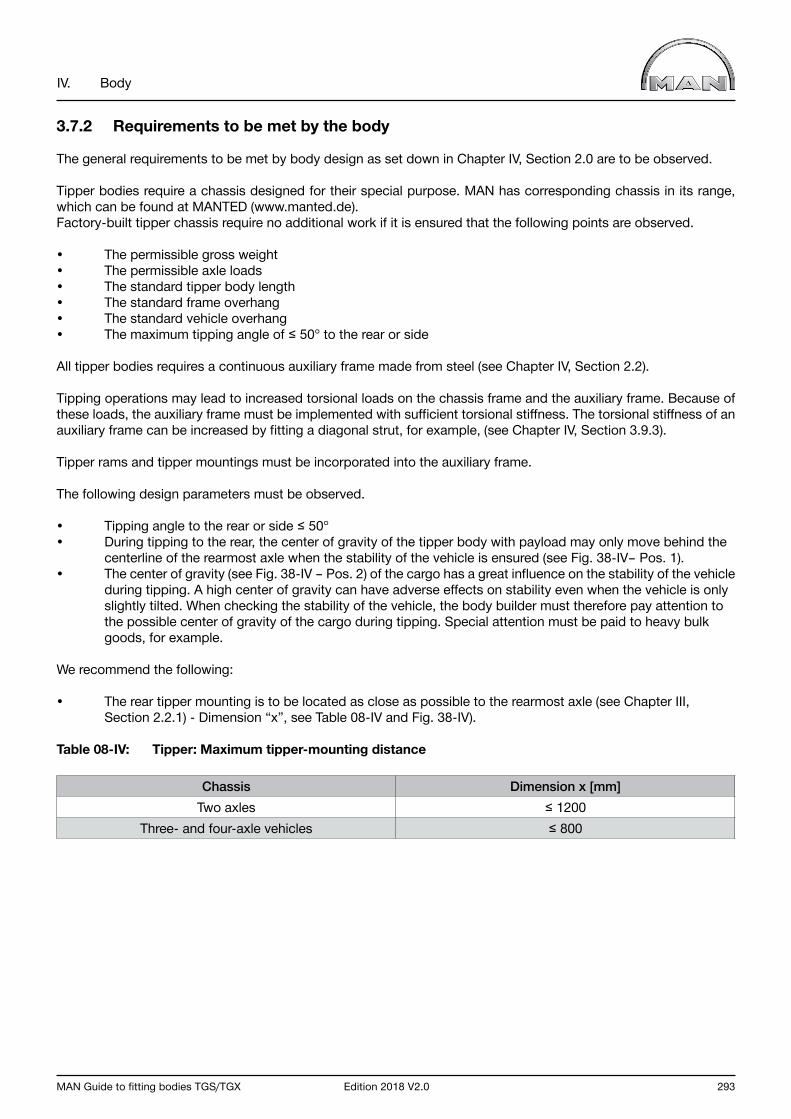
MAN Guide to fitting bodies TGS/TGX Edition 2018 V2.0 293
IV. Body
3.7.2 Requirements to be met by the body
The general requirements to be met by body design as set down in Chapter IV, Section 2.0 are to be observed.
Tipper bodies require a chassis designed for their special purpose. MAN has corresponding chassis in its range, which can be found at MANTED (www.manted.de).Factory-built tipper chassis require no additional work if it is ensured that the following points are observed.
• The permissible gross weight• The permissible axle loads• The standard tipper body length• The standard frame overhang• The standard vehicle overhang• The maximum tipping angle of ≤ 50° to the rear or side
All tipper bodies requires a continuous auxiliary frame made from steel (see Chapter IV, Section 2.2).
Tipping operations may lead to increased torsional loads on the chassis frame and the auxiliary frame. Because of these loads, the auxiliary frame must be implemented with sufficient torsional stiffness. The torsional stiffness of an auxiliary frame can be increased by fitting a diagonal strut, for example, (see Chapter IV, Section 3.9.3).
Tipper rams and tipper mountings must be incorporated into the auxiliary frame.
The following design parameters must be observed.
• Tipping angle to the rear or side ≤ 50°• During tipping to the rear, the center of gravity of the tipper body with payload may only move behind the centerline of the rearmost axle when the stability of the vehicle is ensured (see Fig. 38-IV– Pos. 1).• The center of gravity (see Fig. 38-IV – Pos. 2) of the cargo has a great influence on the stability of the vehicle during tipping. A high center of gravity can have adverse effects on stability even when the vehicle is only slightly tilted. When checking the stability of the vehicle, the body builder must therefore pay attention to the possible center of gravity of the cargo during tipping. Special attention must be paid to heavy bulk goods, for example.
We recommend the following:
• The rear tipper mounting is to be located as close as possible to the rearmost axle (see Chapter III, Section 2.2.1) - Dimension “x”, see Table 08-IV and Fig. 38-IV).
Table 08-IV: Tipper: Maximum tipper-mounting distance
Chassis Dimension x [mm]Two axles ≤ 1200
Three- and four-axle vehicles ≤ 800
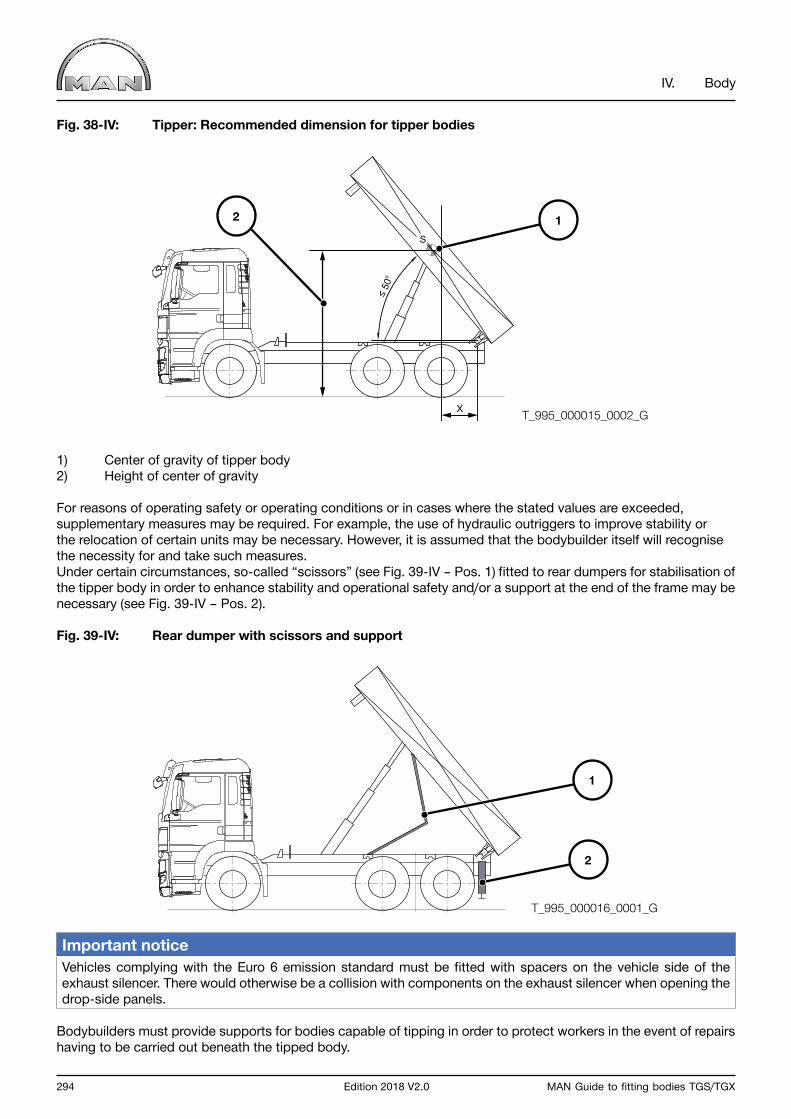
294 Edition 2018 V2.0 MAN Guide to fitting bodies TGS/TGX
IV. Body
Fig. 38-IV: Tipper: Recommended dimension for tipper bodies
1) Center of gravity of tipper body2) Height of center of gravity
For reasons of operating safety or operating conditions or in cases where the stated values are exceeded, supplementary measures may be required. For example, the use of hydraulic outriggers to improve stability or the relocation of certain units may be necessary. However, it is assumed that the bodybuilder itself will recognise the necessity for and take such measures.Under certain circumstances, so-called “scissors” (see Fig. 39-IV – Pos. 1) fitted to rear dumpers for stabilisation of the tipper body in order to enhance stability and operational safety and/or a support at the end of the frame may be necessary (see Fig. 39-IV – Pos. 2).
Fig. 39-IV: Rear dumper with scissors and support
Important notice Vehicles complying with the Euro 6 emission standard must be fitted with spacers on the vehicle side of the exhaust silencer. There would otherwise be a collision with components on the exhaust silencer when opening the drop-side panels.
Bodybuilders must provide supports for bodies capable of tipping in order to protect workers in the event of repairs having to be carried out beneath the tipped body.
T_995_000016_0001_G
2
1
S
≤ 5
0o
X T_995_000015_0002_G
12

MAN Guide to fitting bodies TGS/TGX Edition 2018 V2.0 295
IV. Body
3.8 Set-down and roll-off skip loaders
Chassis and equipment
Due to the high position of centre of gravity exhibited by transported containers, we recommend equipping chassis with the stabilisation packages available ex works for bodies/loads with high centres of gravity. These packages for bodies/loads with high centres of gravity are listed and outlined in Chapter III Section 7.3.
MAN retaining brackets are designed for fastening loading platforms and box bodies. For this reason, they are not suitable for fastening set-down and roll-off skip loaders.
To improve stability on vehicles with air suspension it must be ensured that the air suspension is lowered before commencing the tipping operation. Lowering can either be done manually via the ECAS control unit or it can be automatic using special equipment Sales Code 311PH (input of the ECAS parameters for air suspension lowering to 20 mm above the buffers). Special equipment 311PH automatically lowers the vehicle to the defined level above the buffers if the power take-off is engaged when the vehicle is at a standstill. To ensure that the function provided by Sales Code 311PH is properly activated it is imperative that the correct order of operations is observed when engaging the power take-off (see operating instructions). A check must also be carried out to ensure that the message “No ride height” appears on the display and that the vehicle has actually lowered. If an automatic lowering system is not fitted then the user/driver must be informed of the requirement to manually lower the air suspension.
Requirements to be met by the body The general requirements to be met by body design as set down in Chapter IV, Section 2.0 are to be observed.
For these types of body, the design often means that the auxiliary frames cannot follow the contour of the main frame and special connections to the main frame must therefore be provided. Information regarding proven fasteners together with their design and fitting is available in the manufacturers’ installation instructions on bodies.
Due to the low substructure heights, the clearance of all moving parts attached to the chassis (such as brake cylinders, gearbox shift components, axle-guide components and so on) and the body (such as hydraulic cylinders, pipes, tipper frame and so on) must be checked and ensured. A reinforcing frame may need to be fitted. Modifications to the driving height or restrictions to the spring travel are not permitted. MAN offers special equipment that can reduce the axle-guide components protruding beyond the top edge of the frame. Please refer to Chapter III Section 7.3 for further information.
When loading and unloading, outriggers are required at the end of the vehicle if:
• The rear-axle load is more than twice the technically permissible rear-axle load. Here, the tyre and rim load capacity must also be taken into account.• The front axle loses contact with the ground. For safety reasons, lifting of this kind is strictly forbidden!• The stability of the vehicle is not ensured. This can result from a high center of gravity, an impermissible side tilt when suspension compression occurs on one side, if the vehicle sinks into soft ground on one side, etc.
296 Edition 2018 V2.0 MAN Guide to fitting bodies TGS/TGX
IV. Body
3.9 Loading crane
Loading cranes on truck chassis are usually fitted behind the cab or at the rear end of the vehicle. In addition, truck chassis are also employed as carrier vehicles for jib cranes. Crane bodies place great demands on truck chassis and thus necessitate meticulous coordination of body and chassis.
InformationApproval of bodyApproval for a crane body will be required if the framework set by these body guidelines is exceeded.
This applies to:
• Body specifications do not permit compliance with the requirements of body and auxiliary-frame design (see Chapter IV, Sections 2.0 and 3.9.3).• The given maximum total crane moment as per Fig. 42-IV is exceeded (see Chapter IV, Sections 3.9.3).• Four outriggers• Special outriggers are fitted.
Acceptance of cranesA crane body and its working are to be examined before the crane first goes into use in line with national specifications by a crane specialist or another person authorized to examine crane structures.
Warning noticeResponsibility for ensuring stability lies with the bodybuilder.
3.9.1 Chassis and equipment
If the vehicle is deployed with higher body or load centres of gravity, it is possible to select the vehicle equipment accordingly. The equipment options for bodies/loads with high centres of gravity are listed and outlined in Chapter III Section 7.3.
Crane bodies on chassis/semitrailer tractors with frame-profile no. 34 (see Chapter III, Section 4.3) are not permitted (model code nos.: 08S, 49S, 49W).
Reinforced axle equipmentDepending on the size of the crane (weight and centre of gravity) and its position (behind the cab or at the rear), vehicles must be fitted with reinforced springs where available. These measures will prevent the chassis from adopting a lopsided position (such as due to reduced compression of the reinforced springs).
Nevertheless, it is not always possible to avoid some lopsidedness on a crane body because of the shift in a vehicle’s centre of gravity.
Important notice The body retaining brackets delivered ex works are not suitable for crane bodies.
Supporting vehiclesChapter IV, Section 1.6 must in addition be observed with regard to vehicles with outriggers.
MAN Guide to fitting bodies TGS/TGX Edition 2018 V2.0 297
IV. Body
Prepared loading crane tippers
At MAN, it is possible to order tippers with a preparation for subsequent loading crane installation ex-works.
The preparation includes:
• Vehicle equipment for tippers• Relocation of exhaust silencer to rear (space for support legs)• Continuous auxiliary frame for crane and tipper• Clearance for loading crane behind cab
The dimensions for the crane installation space and the maximum permitted gross crane torque (see Chapter IV. 3.9.3 Requirements for the auxiliary frame for loading crane bodies) are therefore already predefined. The body manufacturer must check whether the crane meets the specified conditions.If the maximum permitted gross crane torque is exceeded, the body manufacturer must take suitable measures to reinforce the auxiliary frame.The body manufacturer must also ensure that the permitted axle loads are observed with crane and uniform loading.
Table 09-IV:
Type Vehicle Code Tipper body Available clearance*
Maximum permitted gross crane torque
03S / 06S / 22S / 52S /
80S
18.XXX 4x2 / 4x4 / 4x4H BB / BL3900 M-Fhs
485DE 4000 x 2420 x 600 1040 mm 175 kNm
03S / 06S / 22S / 52S /
80S
18.XXX 4x2 / 4x4 / 4x4H BB / BL3900 M-Fhs
485DC 4200 x 2420 x 600 990 mm 175 kNm
*Area kept free for loading crane between cab and tipper body. Dimension applies only above the auxiliary frame.
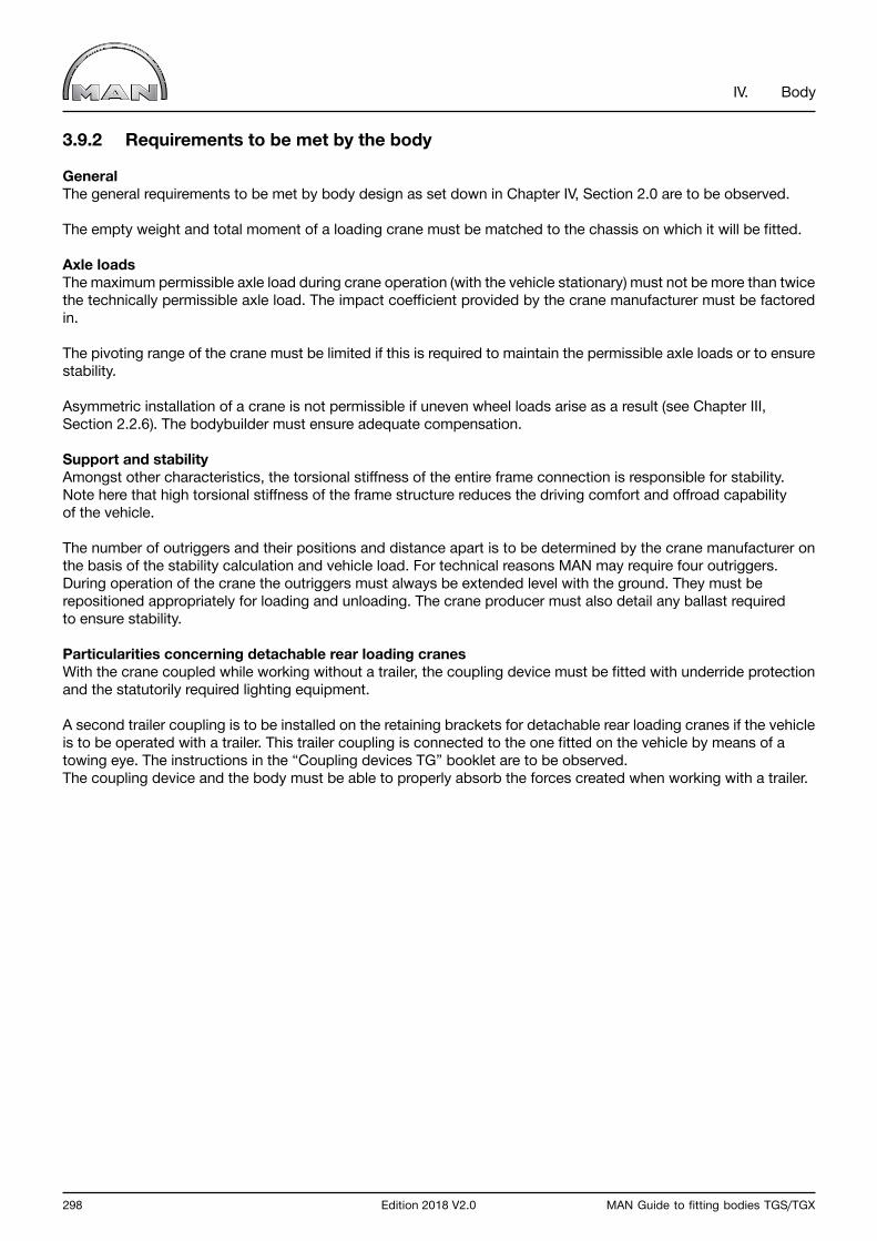
298 Edition 2018 V2.0 MAN Guide to fitting bodies TGS/TGX
IV. Body
3.9.2 Requirements to be met by the body
GeneralThe general requirements to be met by body design as set down in Chapter IV, Section 2.0 are to be observed.
The empty weight and total moment of a loading crane must be matched to the chassis on which it will be fitted.
Axle loadsThe maximum permissible axle load during crane operation (with the vehicle stationary) must not be more than twice the technically permissible axle load. The impact coefficient provided by the crane manufacturer must be factored in.
The pivoting range of the crane must be limited if this is required to maintain the permissible axle loads or to ensure stability.
Asymmetric installation of a crane is not permissible if uneven wheel loads arise as a result (see Chapter III, Section 2.2.6). The bodybuilder must ensure adequate compensation.
Support and stabilityAmongst other characteristics, the torsional stiffness of the entire frame connection is responsible for stability. Note here that high torsional stiffness of the frame structure reduces the driving comfort and offroad capability of the vehicle.
The number of outriggers and their positions and distance apart is to be determined by the crane manufacturer on the basis of the stability calculation and vehicle load. For technical reasons MAN may require four outriggers. During operation of the crane the outriggers must always be extended level with the ground. They must be repositioned appropriately for loading and unloading. The crane producer must also detail any ballast required to ensure stability.
Particularities concerning detachable rear loading cranesWith the crane coupled while working without a trailer, the coupling device must be fitted with underride protection and the statutorily required lighting equipment.
A second trailer coupling is to be installed on the retaining brackets for detachable rear loading cranes if the vehicle is to be operated with a trailer. This trailer coupling is connected to the one fitted on the vehicle by means of a towing eye. The instructions in the “Coupling devices TG” booklet are to be observed. The coupling device and the body must be able to properly absorb the forces created when working with a trailer.
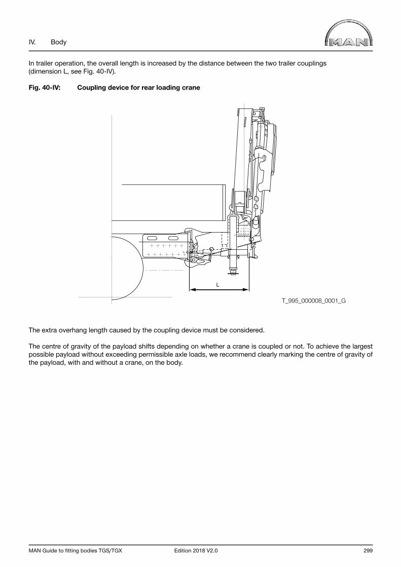
MAN Guide to fitting bodies TGS/TGX Edition 2018 V2.0 299
IV. Body
In trailer operation, the overall length is increased by the distance between the two trailer couplings (dimension L, see Fig. 40-IV).
Fig. 40-IV: Coupling device for rear loading crane
The extra overhang length caused by the coupling device must be considered.
The centre of gravity of the payload shifts depending on whether a crane is coupled or not. To achieve the largest possible payload without exceeding permissible axle loads, we recommend clearly marking the centre of gravity of the payload, with and without a crane, on the body.
L
T_995_000008_0001_G
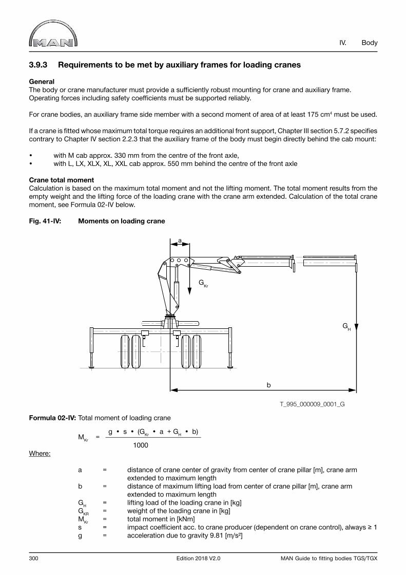
300 Edition 2018 V2.0 MAN Guide to fitting bodies TGS/TGX
IV. Body
3.9.3 Requirements to be met by auxiliary frames for loading cranes
GeneralThe body or crane manufacturer must provide a sufficiently robust mounting for crane and auxiliary frame.Operating forces including safety coefficients must be supported reliably.
For crane bodies, an auxiliary frame side member with a second moment of area of at least 175 cm4 must be used.
If a crane is fitted whose maximum total torque requires an additional front support, Chapter III section 5.7.2 specifies contrary to Chapter IV section 2.2.3 that the auxiliary frame of the body must begin directly behind the cab mount:
• with M cab approx. 330 mm from the centre of the front axle, • with L, LX, XLX, XL, XXL cab approx. 550 mm behind the centre of the front axle
Crane total momentCalculation is based on the maximum total moment and not the lifting moment. The total moment results from the empty weight and the lifting force of the loading crane with the crane arm extended. Calculation of the total crane moment, see Formula 02-IV below.
Fig. 41-IV: Moments on loading crane
Formula 02-IV: Total moment of loading crane
g • s • (GKr • a + GH • b) MKr = 1000 Where:
a = distance of crane center of gravity from center of crane pillar [m], crane arm extended to maximum length b = distance of maximum lifting load from center of crane pillar [m], crane arm extended to maximum length GH = lifting load of the loading crane in [kg] GKR = weight of the loading crane in [kg] MKr = total moment in [kNm] s = impact coefficient acc. to crane producer (dependent on crane control), always ≥ 1 g = acceleration due to gravity 9.81 [m/s²]
a
GKr
GH
b
T_995_000009_0001_G
MAN Guide to fitting bodies TGS/TGX Edition 2018 V2.0 301
IV. Body
Auxiliary frame installationLoading crane bodies are only permitted with a continuous auxiliary frame.When installing the loading crane behind the cab, the auxiliary frame must be closed at least in the crane area to the box.
If the loading crane is installed at the rear, a closed profile must be used from the end of the frame to at least a point forward of the front-most rear axle guide member. In addition, to increase the torsional stiffness of the auxiliary frame, a cross strut or an equivalent structure must be fitted (see also Chapter IV Section 2.2).
Loading cranes are frequently installed with various types of body, for which an auxiliary frame is also required (e.g. on tippers). In such cases, the auxiliary frame is usually divided into several auxiliary-frame regions. Variations in rigidity in the transitions from one region to another are to be avoided. If a continuous auxiliary-frame profile is to be used, the auxiliary frame with the greater strength and rigidity must be used for the entire body structure.
To ensure stability while a crane is operating the subframe in the region between the two outrigger members must exhibit adequate torsional stiffness. For strength reasons, lifting the vehicle on the outriggers is permissible only if the auxiliary-frame structure absorbs all the forces resulting from the operation of the crane and provided its connection to the chassis frame is not rigid (e.g. truck cranes).
To protect the auxiliary frame we recommend fitting an additional upper flange (anti-wear plate) to prevent the base of the crane from wearing into the auxiliary frame. This additional top flange should be 8-10 mm thick depending on the size of the crane.
Simplified auxiliary-frame designThe method and correlation between crane total moment and geometrical moment of inertia - dependent on the chassis frame - applies to crane structures behind the cab and to crane structures on the frame end with two outriggers. Safety coefficients have already been taken into account. The crane total moment MKr must be factored in along with the impact coefficient supplied by the crane manufacturer (see Formula 02-IV).
The necessary planar moments of inertia relate only to a subframe longitudinal member.
The freedom of movement of all moving parts is not taken into consideration here; it must therefore be re-checked when the dimensions have been selected
A diagram of total crane moment and geometrical moment of inertia for the frame profiles of TGS/TGX models is shown below (Fig. 42-IV).
Example of how to use the graphs in Fig. 42-IV:an auxiliary frame is to be specified for a TGS 18.xxx 4x2 BB, model 03S vehicle, frame-profile no. 31(see Chapter III; Section 4.3). The vehicle is to be fitted with a crane with a total moment of 160 kNm.
Solution: A minimum geometrical moment of inertia of approx. 1.250 cm4 is derived from Fig. 42-IV If one U-profile with a width of 80 mm and a thickness of 8 mm is closed to form a box with an 8-mm thick profile, a profile height of at least 170 mm is required, see diagram in Fig. 44-IV.If two U-profiles of width/thickness = 80/8 are nested to form a box, the minimum height is reduced to approx. 140 mm, see Fig. 45-IV.
If, when the values are read off, the profile size in question is not available, round up to the next available size. Rounding down is not permitted.
An open U-profile as in Fig. 43-IV must not be used in the vicinity of the crane.It is only shown here because the diagram can also be used for other bodies.
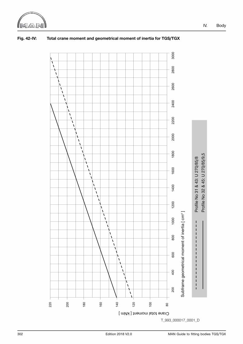
302 Edition 2018 V2.0 MAN Guide to fitting bodies TGS/TGX
IV. Body
Fig. 42-IV: Total crane moment and geometrical moment of inertia for TGS/TGX
2600
2800
3000
400
200
80100
120
140
160
180
200
220
600
1000
800
1200
1600
1400
1800
2000
2400
2200
Crane total moment [ kNm ]
Subf
ram
e ge
omet
rical
mom
ent o
f ine
rtia
[ cm
4 ] Profi
le N
o 31
& 4
3: U
270
/85/
8Pr
ofile
No
32 &
45:
U 2
70/8
5/9,
5
T_993_000017_0001_D

MAN Guide to fitting bodies TGS/TGX Edition 2018 V2.0 303
IV. Body
Fig. 43-IV: Planar moment of inertia of U-profiles
280
260
240
220
200
180
160
140
120
100 80 0
200
400
600
800
1000
1200
1400
2000
1800
1600
2200
2400
2600
2800
3200
3000
3400
1U
80...
220/
60/6
2U
80...
280/
60/7
3U
80...
220/
70/6
4U
80...
280/
70/7
5U
80...
280/
70/8
6U
80...
220/
80/6
7U
80...
280/
80/7
8U
80...
280/
80/8
24
75
8
13
H
t
BS
6
Section height in [ mm ]
Geo
met
rical
mom
ent o
f ine
rtia
[ cm
4 ]
Ope
n U
-sec
tion
T_993_000018_0001_D
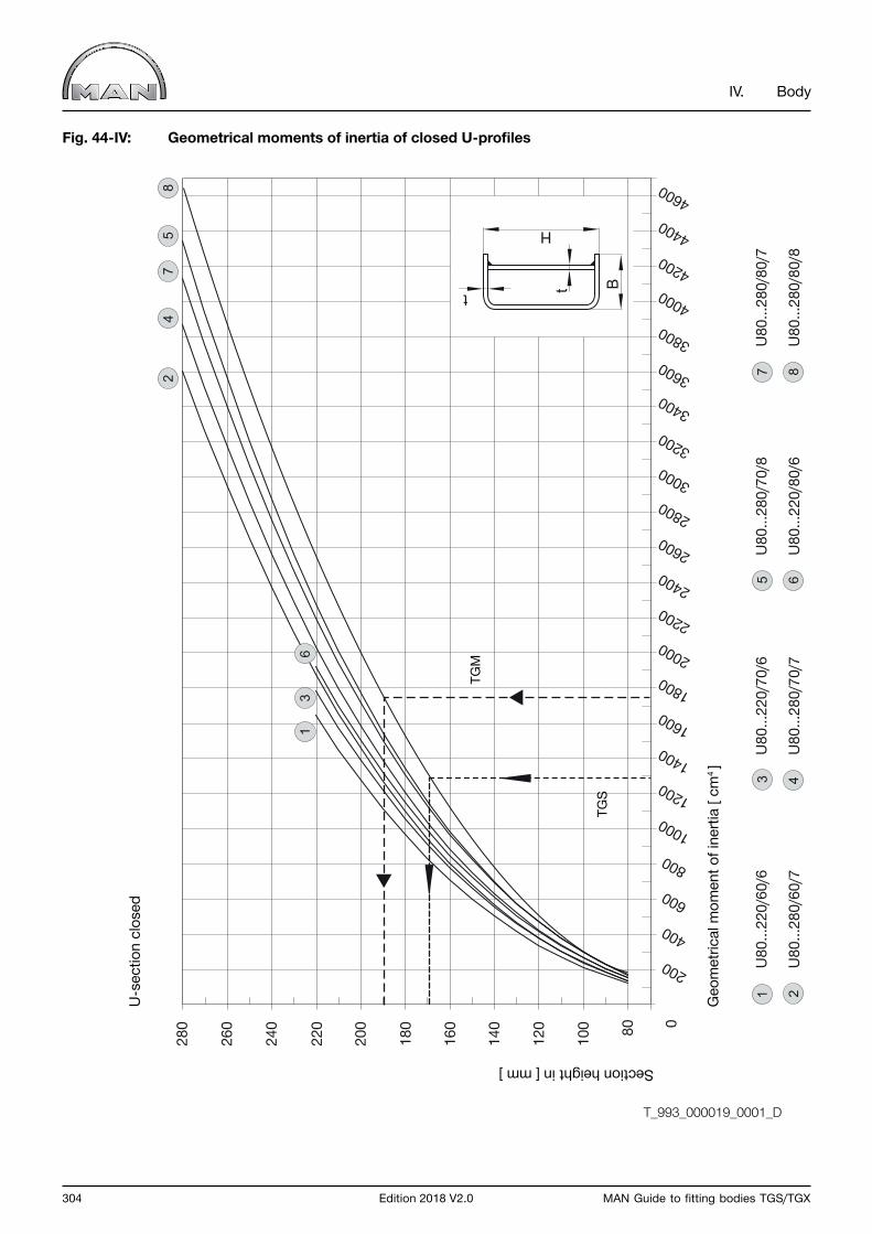
304 Edition 2018 V2.0 MAN Guide to fitting bodies TGS/TGX
IV. Body
Fig. 44-IV: Geometrical moments of inertia of closed U-profiles
280
260
240
220
200
180
160
140
120
100 80 0
200
400
600
800100012001400
2000
1800
1600
2200240026002800
3200
3000
3400360038004000420044004600
1U
80...
220/
60/6
2U
80...
280/
60/7
3U
80...
220/
70/6
4U
80...
280/
70/7
5U
80...
280/
70/8
6U
80...
220/
80/6
7U
80...
280/
80/7
8U
80...
280/
80/8
H
t Bt
24
75
8
16
3
Geo
met
rical
mom
ent o
f ine
rtia
[ cm
4 ]
T_993_000019_0001_D
Section height in [ mm ]U
-sec
tion
clos
ed
TGM
TGS
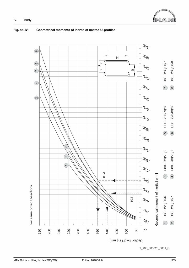
MAN Guide to fitting bodies TGS/TGX Edition 2018 V2.0 305
IV. Body
Fig. 45-IV: Geometrical moments of inertia of nested U-profiles
280
260
240
220
200
180
160
140
120
100 80 0
200
600
1000
1400
1800
2200
2600
3000
3400
3800
4200
4600
5000
5400
5800
6200
6600
7000
1U
80...
220/
60/6
2U
80...
280/
60/7
3U
80...
220/
70/6
4U
80...
280/
70/7
5U
80...
280/
70/8
6U
80...
220/
80/6
7U
80...
280/
80/7
8U
80...
280/
80/8
B
H
24
75
8
B
16
3
T_993_000020_0001_D
Geo
met
rical
mom
ent o
f ine
rtia
[ cm
4 ]
Section height in [ mm ]Tw
o sa
me
boxe
d U
-sec
tions
TGM
TGS
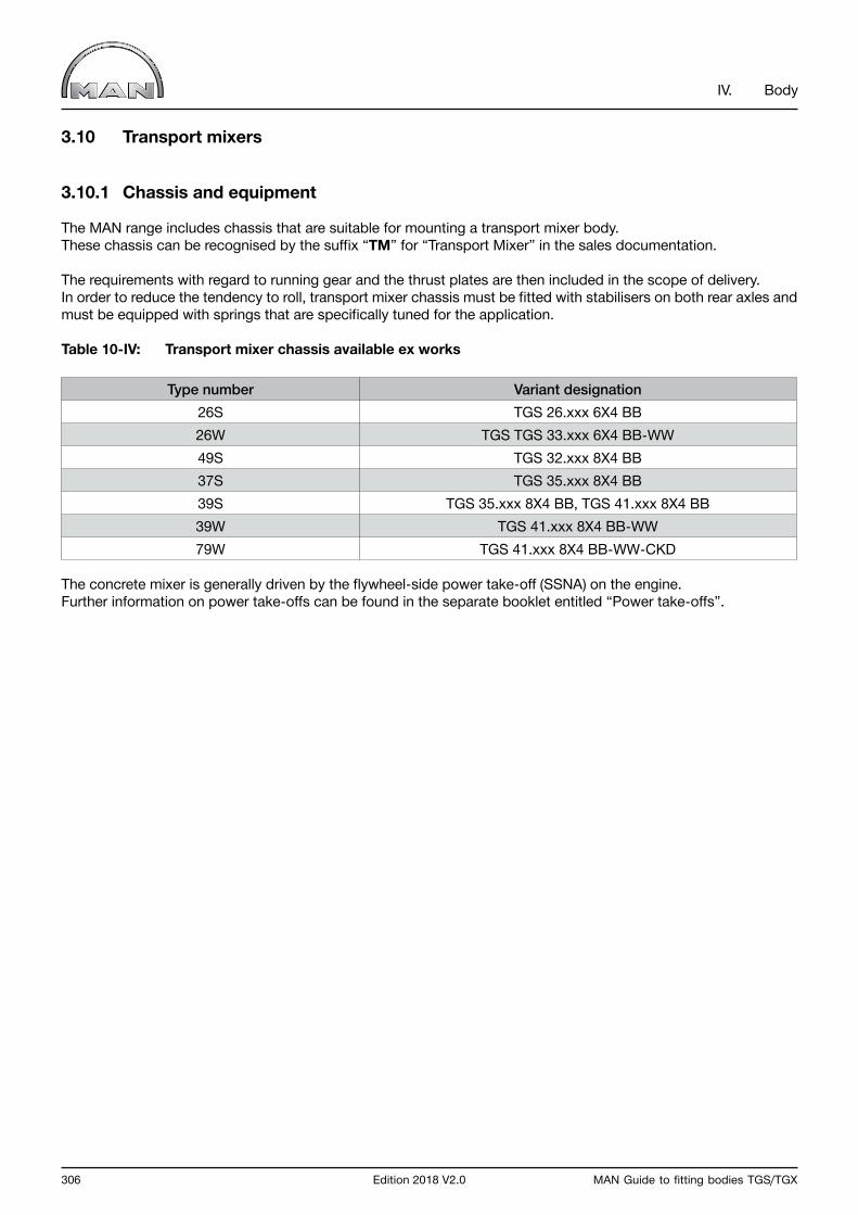
306 Edition 2018 V2.0 MAN Guide to fitting bodies TGS/TGX
IV. Body
3.10 Transport mixers
3.10.1 Chassis and equipment
The MAN range includes chassis that are suitable for mounting a transport mixer body. These chassis can be recognised by the suffix “TM” for “Transport Mixer” in the sales documentation.
The requirements with regard to running gear and the thrust plates are then included in the scope of delivery. In order to reduce the tendency to roll, transport mixer chassis must be fitted with stabilisers on both rear axles and must be equipped with springs that are specifically tuned for the application.
Table 10-IV: Transport mixer chassis available ex works
Type number Variant designation26S TGS 26.xxx 6X4 BB26W TGS TGS 33.xxx 6X4 BB-WW49S TGS 32.xxx 8X4 BB37S TGS 35.xxx 8X4 BB39S TGS 35.xxx 8X4 BB, TGS 41.xxx 8X4 BB39W TGS 41.xxx 8X4 BB-WW79W TGS 41.xxx 8X4 BB-WW-CKD
The concrete mixer is generally driven by the flywheel-side power take-off (SSNA) on the engine. Further information on power take-offs can be found in the separate booklet entitled “Power take-offs”.
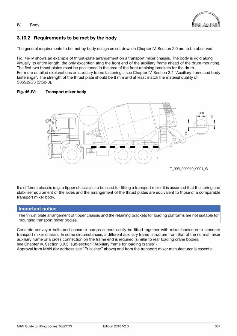
MAN Guide to fitting bodies TGS/TGX Edition 2018 V2.0 307
IV. Body
3.10.2 Requirements to be met by the body
The general requirements to be met by body design as set down in Chapter IV, Section 2.0 are to be observed.
Fig. 46-IV shows an example of thrust-plate arrangement on a transport mixer chassis. The body is rigid along virtually its entire length, the only exception atng the front end of the auxiliary frame ahead of the drum mounting. The first two thrust plates must be positioned in the area of the front retaining brackets for the drum.For more detailed explanations on auxiliary frame fastenings, see Chapter IV, Section 2.4 “Auxiliary frame and body fastenings”. The strength of the thrust plate should be 8 mm and at least match the material quality of S355J2G3 (St52-3).
Fig. 46-IV: Transport mixer body
If a different chassis (e.g. a tipper chassis) is to be used for fitting a transport mixer it is assumed that the spring and stabiliser equipment of the axles and the arrangement of the thrust plates are equivalent to those of a comparable transport mixer body.
Important notice The thrust plate arrangement of tipper chassis and the retaining brackets for loading platforms are not suitable for mounting transport mixer bodies.
Concrete conveyor belts and concrete pumps cannot easily be fitted together with mixer bodies onto standard transport mixer chassis. In some circumstances, a different auxiliary frame structure from that of the normal mixer auxiliary frame or a cross connection on the frame end is required (similar to rear loading crane bodies, see Chapter IV, Section 3.9.3, sub-section “Auxiliary frame for loading cranes”). Approval from MAN (for address see “Publisher” above) and from the transport mixer manufacturer is essential.
300
130
45
T_995_000010_0001_G
308 Edition 2018 V2.0 MAN Guide to fitting bodies TGS/TGX
IV. Body
3.11 Cable winch
Requirements to be met by the bodyThe general requirements to be met by body design as set down in Chapter IV, Section 2.0 are to be observed.
The following must be considered when installing a cable winch:
• Tractive force• Installation position: - Front installation - Central installation - Rear installation - Side installation• Type drive: - Mechanical - Hydraulic - Electrical - Electromechanical - Electrohydraulic.
Vehicle components such as axles, springs, frames, etc. must under no circumstances be overloaded by the operation of the cable winch. This is particularly important if the direction of the winch pulling force differs from the longitudinal axis of the vehicle. Automatic limiting of the pulling force may be necessary as a function of the direction of the pulling force.
In every case it is important to ensure clear and proper guidance and running of the cable. The cable should feed through as few guide pulleys as possible. At the same time no part of the vehicle may be degraded in its working.
When a winch is installed at the front, its maximum tractive force is limited by the technically permissible front-axle load. The technically permissible front-axle load is found on the factory plate of the vehicle and in the vehicle documentation. A winch design that has tractive forces above the technically permissible front-axle load is permissible only after prior consultation with MAN (for address see “Publisher” above).
A hydraulic winch drive is preferable because of the better possibilities for control and installation. The efficiency of the hydraulic pump and motor is to be taken into account (see also Chapter V “Calculations”).
Examine whether existing hydraulic pumps, e.g. of a loading crane or tipper, can be shared. This can sometimes avoid the need for installing several power take-offs.
Important notice The hydraulic circuit of HydroDrive vehicles is a closed circuit. It may not be used to drive a cable winch.
For the worm gears of mechanical winches it is necessary to observe the permissible input speed (usually < 2,000 rpm). Select the ratio of the power take-off accordingly. Take the low efficiency of the worm gear into consideration when calculating the minimum torque at the power take-off.
Refer to Chapter III, Section 8.0 “Electrical and electronic systems” with regard to electrically, electromechanically or electrohydraulically driven winches. The capacities of the alternator and battery must be taken into consideration.
InformationEvery time a winch is installed, the installation instructions of the winch manufacturer together with any applicable official safety regulations must be observed.

MAN Guide to fitting bodies TGS/TGX Edition 2018 V2.0 309
IV. Body
3.12 Single-pivot body
Requirements to be met by the bodyThe general requirements to be met by body design as set down in Chapter IV, Section 2.0 are to be observed.
The single-pivot body, comparable to a fifth-wheel coupling, always requires a subframe.
Positioning of the pivot point for the single-pivot body behind the theoretical rear-axle centerline must be approved with regard to axle load distribution and handling. In this case approval must be granted by MAN (for address see “Publisher” above).
3.13 Vehicle transporter
3.13.1 Chassis and equipment
Vehicle-transporter bodies are usually fitted to semitrailer-tractor or truck chassis.
Base vehicle: truck chassisThis body variant is characterised by the following criteria.
• Base vehicle is a truck chassis.• The body section is fitted onto the chassis and is not removable or detachable.
The trailer is usually fastened to the truck chassis by means of a low coupling system (see Fig. 47-IV).
Truck-type chassis always require a stabiliser and two level-adjustment systems.
Fig. 47-IV: Vehicle transporter on truck chassis
T_995_000019_0001_G

310 Edition 2018 V2.0 MAN Guide to fitting bodies TGS/TGX
IV. Body
Base vehicle: semitrailer tractorThis is a classic train in which the semitrailer rests on the tractor’s fifth-wheel coupling (see Fig. 48-IV). Chapter 5.3.1 must be observed with regard to this body variant.
Fig. 48-IV: Vehicle transporter on semitrailer tractor
Base vehicle: semitrailer tractor or truck chassisA semitrailer tractor as well as a truck chassis can be used as the base vehicle for this variant. The body is divided into two sections. The section that rests on the chassis is usually attached to the chassis at two or three mounting points (see Fig. 49-IV – Pos. 1). The second section of the body is attached to the first by means of a coupling system. When the vehicle is cornering, this coupling point enables rotation between the two sections of the body. Both sections of the body can be detached from the chassis (seeFig. 49-IV).
Fig. 49-IV: Vehicle transporter on truck chassis
T_995_000017_0001_G
T_995_000020_0001_G
1

MAN Guide to fitting bodies TGS/TGX Edition 2018 V2.0 311
IV. Body
If a semitrailer tractor is used as the base vehicle, the following conditions must be fulfilled.
• Wheel configuration 4x2• Maximum wheelbase 3900 mm• It is imperative that a stabiliser is fitted to the front axle.• The vehicle type entered in the official papers must be “Vehicle for interchangeable operation” or “ Optional use as tractor unit and truck for car transport”, otherwise supplementary modifications to the chassis are necessary.• The tractor final cross member with hole pattern for trailer coupling must be fitted (no. 81.41250.0141). Because of its greater material thickness (9.5 mm) only this final cross member is suitable for supporting the forces exerted by the rear body connection. The tractor final cross member with a material thickness of 5 mm must not be used.• Use of the rear-axle guide with four-point control arm (second generation cast version - only for TGS/TGX) without supplementary stabiliser is possible.• The use of semitrailer tractors with only a single level-adjustment system on the rear axle is possible.• We strongly recommend fitting ESP for vehicle transporters. This equipment can be obtained under Sales Code 307DT.
Semitrailer tractors available ex works for operation as tanker/silo vehicles (model number: 08S (TGS 18.xxx BLS-TS)) or as low semitrailer tractors (model number: 13S/13X (TGS/TGX 18.xxx LLS-U)) are not suitable and therefore not approved for this type of operation.
If the chassis is to be converted to a truck in its so-called “second life” (after use as a vehicle transporter) supplementary conversion measures are necessary.
If subsequent modifications to the chassis are necessary, for example changes to the cab or the wheel configuration, Chapter III must be observed.
3.13.2 Requirements to be met by the body
The general requirements to be met by body design as set down in Chapter IV, Section 2.0 are to be observed.

312 Edition 2018 V2.0 MAN Guide to fitting bodies TGS/TGX
NOTICE

MAN Guide to fitting bodies TGS/TGX Edition 2018 V2.0 313
V. Calculations
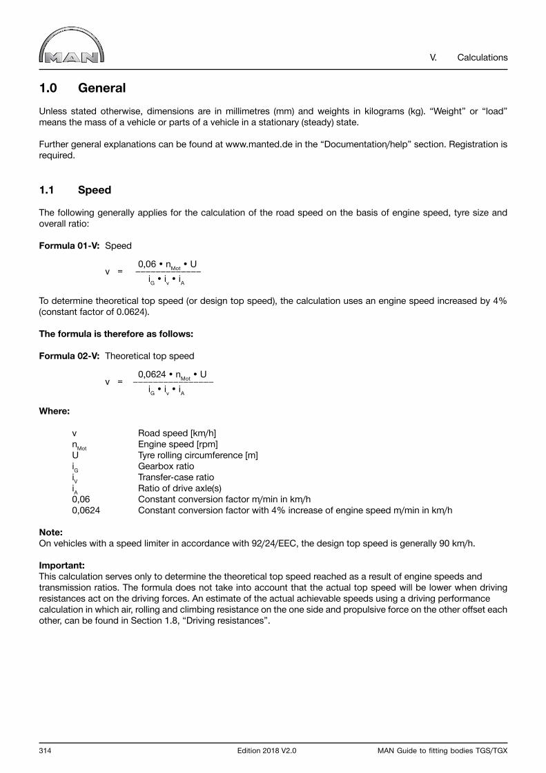
314 Edition 2018 V2.0 MAN Guide to fitting bodies TGS/TGX
V. Calculations
1.0 GeneralUnless stated otherwise, dimensions are in millimetres (mm) and weights in kilograms (kg). “Weight” or “load” means the mass of a vehicle or parts of a vehicle in a stationary (steady) state.
Further general explanations can be found at www.manted.de in the “Documentation/help” section. Registration is required.
1.1 Speed
The following generally applies for the calculation of the road speed on the basis of engine speed, tyre size and overall ratio:
Formula 01-V: Speed
0,06 • nMot • U v = iG • iv • iA
To determine theoretical top speed (or design top speed), the calculation uses an engine speed increased by 4% (constant factor of 0.0624).
The formula is therefore as follows:
Formula 02-V: Theoretical top speed
0,0624 • nMot • U v = iG • iv • iA
Where:
v Road speed [km/h] nMot Engine speed [rpm] U Tyre rolling circumference [m] iG Gearbox ratio iV Transfer-case ratio iA Ratio of drive axle(s) 0,06 Constant conversion factor m/min in km/h 0,0624 Constant conversion factor with 4% increase of engine speed m/min in km/h
Note:On vehicles with a speed limiter in accordance with 92/24/EEC, the design top speed is generally 90 km/h.
Important:This calculation serves only to determine the theoretical top speed reached as a result of engine speeds and transmission ratios. The formula does not take into account that the actual top speed will be lower when driving resistances act on the driving forces. An estimate of the actual achievable speeds using a driving performance calculation in which air, rolling and climbing resistance on the one side and propulsive force on the other offset each other, can be found in Section 1.8, “Driving resistances”.
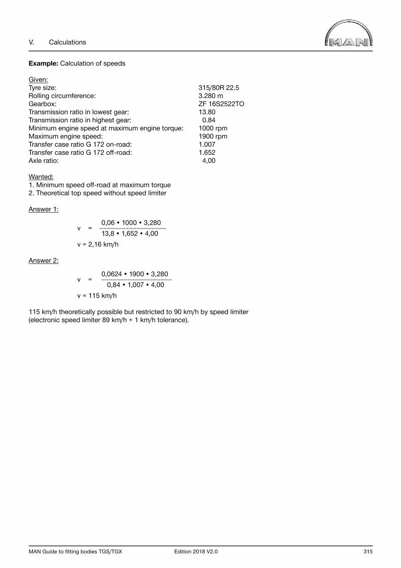
MAN Guide to fitting bodies TGS/TGX Edition 2018 V2.0 315
V. Calculations
Example: Calculation of speeds
Given:Tyre size: 315/80R 22.5Rolling circumference: 3.280 mGearbox: ZF 16S2522TOTransmission ratio in lowest gear: 13.80Transmission ratio in highest gear: 0.84Minimum engine speed at maximum engine torque: 1000 rpmMaximum engine speed: 1900 rpmTransfer case ratio G 172 on-road: 1.007Transfer case ratio G 172 off-road: 1.652Axle ratio: 4,00
Wanted:1. Minimum speed off-road at maximum torque2. Theoretical top speed without speed limiter
Answer 1:
0,06 • 1000 • 3,280 v = 13,8 • 1,652 • 4,00 v = 2,16 km/h
Answer 2: 0,0624 • 1900 • 3,280 v = 0,84 • 1,007 • 4,00 v = 115 km/h
115 km/h theoretically possible but restricted to 90 km/h by speed limiter(electronic speed limiter 89 km/h + 1 km/h tolerance).

316 Edition 2018 V2.0 MAN Guide to fitting bodies TGS/TGX
V. Calculations
1.2 Efficiency
Efficiency is the ratio of the power output to the power input.
The power output is always smaller than the power input, so the efficiency η is always < 1 or < 100 %.
Formula 03-V: Degree of efficiency
Pab η = Pzu
Where:
Pzu Power input [kW] Pab Power output [kW] η Efficiency
Note:The individual efficiencies multiply when several subassemblies are connected in series.
Example: Single efficiency
Given:Efficiency of a hydraulic pump η = 0,7 Required power Pab = 20 kW
Wanted:How high is the input power Pzu?
Solution: Pab Pzu = η 20 Pzu = 0,7
Pzu = 28,6 kW

MAN Guide to fitting bodies TGS/TGX Edition 2018 V2.0 317
V. Calculations
Example: Several efficiencies
Given:A pump drives a hydraulic motor via a jointed shaft system with two joints.Output power Pab is 20 kW.
Single efficiencies
Hydraulic pump: η1 = 0,7 Jointed shaft joint a: η2 = 0,95 Jointed shaft joint b: η3 = 0,95 Hydraulic motor: η4 = 0,8
Wanted:How high is the input power Pzu?
Solution:
Total efficiency:
ηges = η1 • η2 • η3 • η4
ηges = 0,7 • 0,95 • 0,95 • 0,8 ηges = 0,51
Input power:
20 Pzu = 0,51 Pzu = 39,2 kW
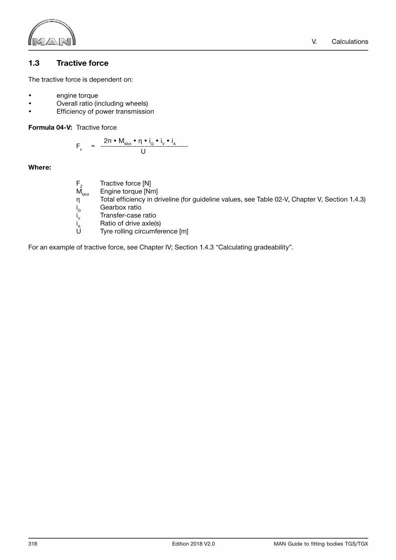
318 Edition 2018 V2.0 MAN Guide to fitting bodies TGS/TGX
V. Calculations
1.3 Tractive force
The tractive force is dependent on:
• engine torque• Overall ratio (including wheels)• Efficiency of power transmission
Formula 04-V: Tractive force
2π • MMot • η • iG • iV • iA Fz = U
Where:
FZ Tractive force [N] MMot Engine torque [Nm] η Total efficiency in driveline (for guideline values, see Table 02-V, Chapter V, Section 1.4.3) iG Gearbox ratio iV Transfer-case ratio iA Ratio of drive axle(s) U Tyre rolling circumference [m]
For an example of tractive force, see Chapter IV; Section 1.4.3 “Calculating gradeability”.
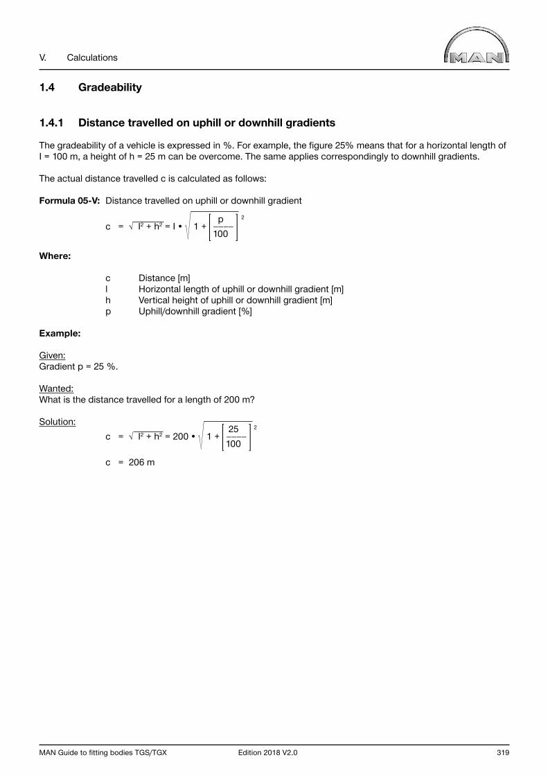
MAN Guide to fitting bodies TGS/TGX Edition 2018 V2.0 319
V. Calculations
1.4 Gradeability
1.4.1 Distance travelled on uphill or downhill gradients
The gradeability of a vehicle is expressed in %. For example, the figure 25% means that for a horizontal length of I = 100 m, a height of h = 25 m can be overcome. The same applies correspondingly to downhill gradients.
The actual distance travelled c is calculated as follows:
Formula 05-V: Distance travelled on uphill or downhill gradient p 2
c = I2 + h2 = I • 1 + 100
Where:
c Distance [m] l Horizontal length of uphill or downhill gradient [m] h Vertical height of uphill or downhill gradient [m] p Uphill/downhill gradient [%]
Example:
Given:Gradient p = 25 %.
Wanted:What is the distance travelled for a length of 200 m?
Solution: 25 2 c = I2 + h2 = 200 • 1 + 100
c = 206 m
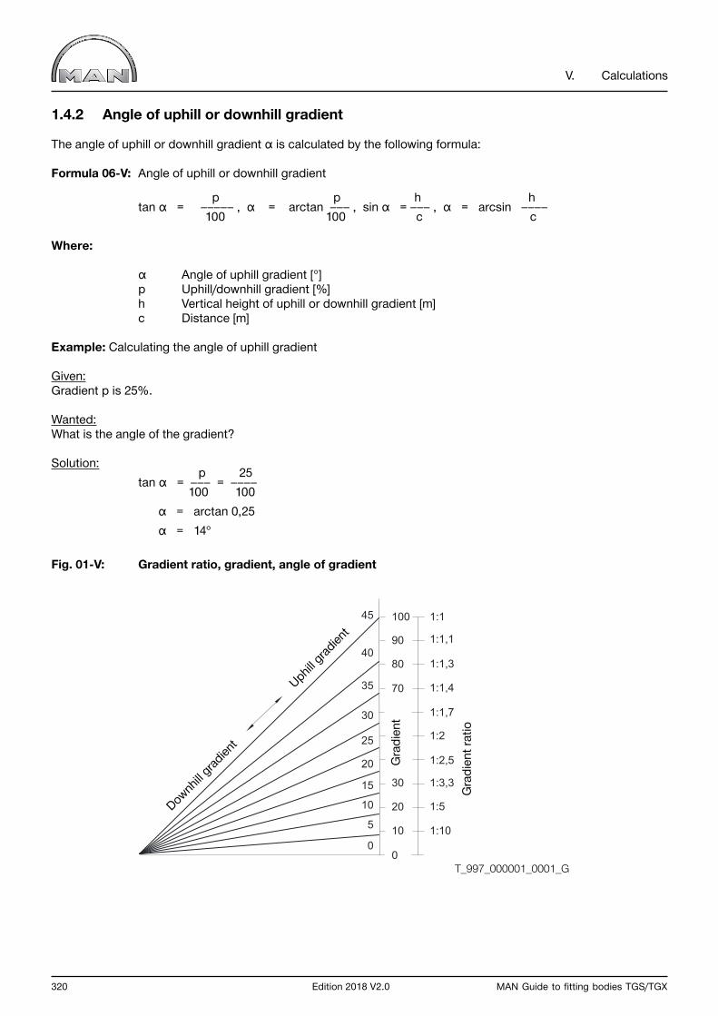
320 Edition 2018 V2.0 MAN Guide to fitting bodies TGS/TGX
V. Calculations
1.4.2 Angle of uphill or downhill gradient
The angle of uphill or downhill gradient α is calculated by the following formula:
Formula 06-V: Angle of uphill or downhill gradient
p p h h tan α = , α = arctan , sin α = , α = arcsin 100 100 c c
Where:
α Angle of uphill gradient [°] p Uphill/downhill gradient [%] h Vertical height of uphill or downhill gradient [m] c Distance [m]
Example: Calculating the angle of uphill gradient
Given:Gradient p is 25%.
Wanted:What is the angle of the gradient?
Solution: p 25 tan α = = 100 100 α = arctan 0,25 α = 14°
Fig. 01-V: Gradient ratio, gradient, angle of gradient
0
5
10
20
40
0
10
20
30
70
80
90
100 1:1
1:1,1
1:1,3
1:1,4
1:1,7
1:2
1:2,5
1:3,3
1:5
1:10
45
30
35
25
15
Downh
ill grad
ient
Uphill gr
adien
t
Gra
dien
t
Gra
dien
t rat
io
T_997_000001_0001_G
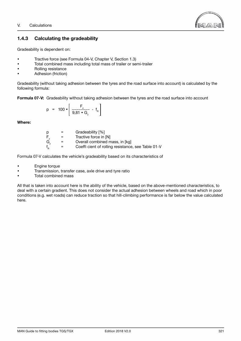
MAN Guide to fitting bodies TGS/TGX Edition 2018 V2.0 321
V. Calculations
1.4.3 Calculating the gradeability
Gradeability is dependent on:
• Tractive force (see Formula 04-V, Chapter V, Section 1.3)• Total combined mass including total mass of trailer or semi-trailer• Rolling resistance• Adhesion (friction)
Gradeability (without taking adhesion between the tyres and the road surface into account) is calculated by the following formula:
Formula 07-V: Gradeability without taking adhesion between the tyres and the road surface into account
Fz p = 100 • - fR 9,81 • Gz
Where:
p = Gradeability [%] Fz = Tractive force in [N] Gz = Overall combined mass, in [kg] fR = Coeffi cient of rolling resistance, see Table 01-V
Formula 07-V calculates the vehicle’s gradeability based on its characteristics of
• Engine torque• Transmission, transfer case, axle drive and tyre ratio• Total combined mass
All that is taken into account here is the ability of the vehicle, based on the above-mentioned characteristics, to deal with a certain gradient. This does not consider the actual adhesion between wheels and road which in poor conditions (e.g. wet roads) can reduce traction so that hill-climbing performance is far below the value calculated here.
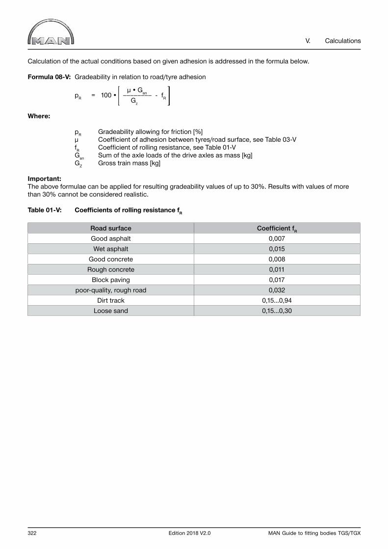
322 Edition 2018 V2.0 MAN Guide to fitting bodies TGS/TGX
V. Calculations
Calculation of the actual conditions based on given adhesion is addressed in the formula below.
Formula 08-V: Gradeability in relation to road/tyre adhesion
µ • Gan pR = 100 • - fR Gz
Where:
pR Gradeability allowing for friction [%] µ Coefficient of adhesion between tyres/road surface, see Table 03-V fR Coefficient of rolling resistance, see Table 01-V Gan Sum of the axle loads of the drive axles as mass [kg] GZ Gross train mass [kg]
Important:The above formulae can be applied for resulting gradeability values of up to 30%. Results with values of more than 30% cannot be considered realistic.
Table 01-V: Coefficients of rolling resistance fR
Road surface Coefficient fR
Good asphalt 0,007Wet asphalt 0,015
Good concrete 0,008Rough concrete 0,011
Block paving 0,017poor-quality, rough road 0,032
Dirt track 0,15...0,94Loose sand 0,15...0,30
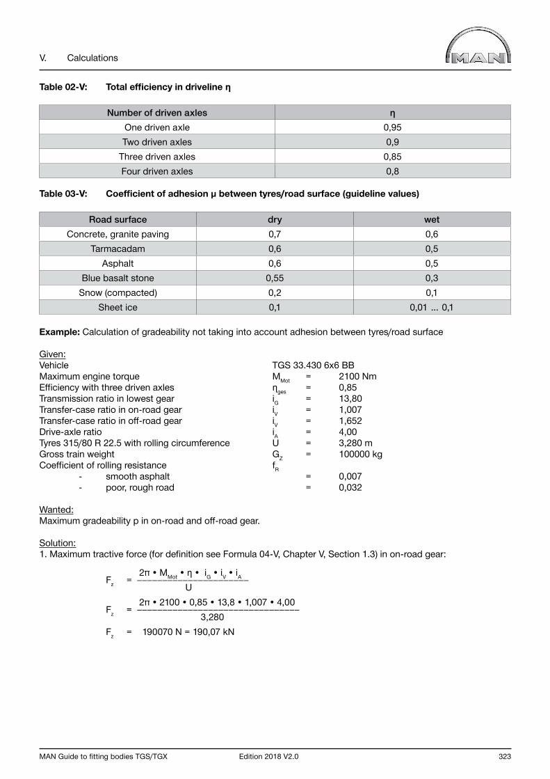
MAN Guide to fitting bodies TGS/TGX Edition 2018 V2.0 323
V. Calculations
Table 02-V: Total efficiency in driveline η
Number of driven axles ηOne driven axle 0,95Two driven axles 0,9
Three driven axles 0,85Four driven axles 0,8
Table 03-V: Coefficient of adhesion µ between tyres/road surface (guideline values)
Road surface dry wetConcrete, granite paving 0,7 0,6
Tarmacadam 0,6 0,5Asphalt 0,6 0,5
Blue basalt stone 0,55 0,3Snow (compacted) 0,2 0,1
Sheet ice 0,1 0,01 … 0,1
Example: Calculation of gradeability not taking into account adhesion between tyres/road surface
Given:Vehicle TGS 33.430 6x6 BBMaximum engine torque MMot = 2100 NmEfficiency with three driven axles ηges = 0,85Transmission ratio in lowest gear iG = 13,80Transfer-case ratio in on-road gear iV = 1,007Transfer-case ratio in off-road gear iV = 1,652Drive-axle ratio iA = 4,00Tyres 315/80 R 22.5 with rolling circumference U = 3,280 mGross train weight GZ = 100000 kgCoefficient of rolling resistance fR - smooth asphalt = 0,007 - poor, rough road = 0,032
Wanted:Maximum gradeability p in on-road and off-road gear.
Solution:1. Maximum tractive force (for definition see Formula 04-V, Chapter V, Section 1.3) in on-road gear:
2π • MMot • η • iG • iV • iA Fz = U 2π • 2100 • 0,85 • 13,8 • 1,007 • 4,00 Fz = 3,280 Fz = 190070 N = 190,07 kN
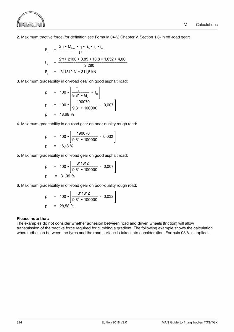
324 Edition 2018 V2.0 MAN Guide to fitting bodies TGS/TGX
V. Calculations
2. Maximum tractive force (for definition see Formula 04-V, Chapter V, Section 1.3) in off-road gear:
2π • MMot • η • iG • iV • iA Fz = U 2π • 2100 • 0,85 • 13,8 • 1,652 • 4,00 Fz = 3,280 Fz = 311812 N = 311,8 kN
3. Maximum gradeability in on-road gear on good asphalt road:
Fz p = 100 • - fR 9,81 • Gz
190070 p = 100 • - 0,007 9,81 • 100000 p = 18,68 %
4. Maximum gradeability in on-road gear on poor-quality rough road:
190070 p = 100 • - 0,032 9,81 • 100000 p = 16,18 %
5. Maximum gradeability in off-road gear on good asphalt road:
311812 p = 100 • - 0,007 9,81 • 100000 p = 31,09 %
6. Maximum gradeability in off-road gear on poor-quality rough road:
311812 p = 100 • - 0,032 9,81 • 100000 p = 28,58 %
Please note that:The examples do not consider whether adhesion between road and driven wheels (friction) will allow transmission of the tractive force required for climbing a gradient. The following example shows the calculation where adhesion between the tyres and the road surface is taken into consideration. Formula 08-V is applied.

MAN Guide to fitting bodies TGS/TGX Edition 2018 V2.0 325
V. Calculations
Example: Calculation of gradeability taking into account grip between road and tyres (front axle not activated)
Given:Coefficient of friction on wet asphalt road µ = 0,5Coefficient of rolling resistance on wet asphalt road fR = 0,015Total combined mass GZ = 100000 kgSum of axle loads of all driven axles Gan = 26000 kg
Wanted:Gradeability allowing for friction [%]
0,5 • 26000 pR = 100 • - 0,015 100000
Solution: pR = 11,5%
1.5 Torque
Torque can be calculated using various different formulae, depending on the givens.
If force and effective distance are known:
Formula 09-V: Torque with force and effective distance
M = F • I
If power and rotational speed are known:
Formula 10-V: Torque with power and rotational speed
9550 • P M = n • η
If in hydraulics delivery rate (volumetric flow), pressure and rotational speed are known:
Formula 11-V: Torque with delivery rate, pressure and rotational speed
15,9 • Q • p M = n • η
Where:
M Torque [Nm] F Force [N] I Effective distance of force from center of rotation [m] P Power [kW] n Rotational speed [rpm] η Efficiency Q Volumetric flow rate [l/minute] p Pressure [bar]

326 Edition 2018 V2.0 MAN Guide to fitting bodies TGS/TGX
V. Calculations
Example: Force and effective distance are known
Given:A cable winch with a pulling force F = 50000 N has a drum diameter d = 0.3 m.
Wanted:Without taking efficiency into account, what is the torque?
Solution: M = F • l = F • 0,5d (the radius of the drum is the lever arm) M = 50000 N • 0,5 • 0,3 m M = 7500 Nm
Example: Power and rotational speed are known
Given:A power take-off is to transmit a power P of 100 kW at n = 1,500 rpm.
Wanted:What torque must the power take-off be able to transmit without considering efficiency?
Solution:
9550 • 100 M = 1500 M = 637 Nm
Example: Delivery rate (volumetric flow rate), pressure and rotational speed are known for a hydraulic pump
Given:A hydraulic pump delivers a volumetric flow rate of Q = 80 l/minute at a pressure p = 170 bar and a pump rotational speed n = 1,000 rpm.
Wanted:Without taking efficiency into account, what torque is necessary?
Solution: 15,9 • 80 • 170 M = 1000 M = 216 Nm
If efficiency is to be taken into account, the torques calculated in each case must be divided by the overall efficiency (see also Section 1.2, “Efficiency”).
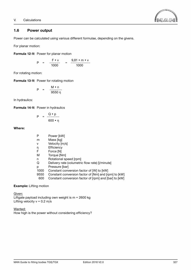
MAN Guide to fitting bodies TGS/TGX Edition 2018 V2.0 327
V. Calculations
1.6 Power output
Power can be calculated using various different formulae, depending on the givens.
For planar motion:
Formula 12-V: Power for planar motion
F • v 9,81 • m • v P = = 1000 1000
For rotating motion:
Formula 13-V: Power for rotating motion
M • n P = 9550 η
In hydraulics:
Formula 14-V: Power in hydraulics
Q • p P = 600 • η
Where:
P Power [kW] m Mass [kg] v Velocity [m/s] η Efficiency F Force [N] M Torque [Nm] n Rotational speed [rpm] Q Delivery rate (volumetric flow rate) [l/minute] p Pressure [bar] 1000 Constant conversion factor of [W] to [kW] 9550 Constant conversion factor of [Nm] and [rpm] to [kW] 600 Constant conversion factor of [rpm] and [bar] to [kW]
Example: Lifting motion
Given:Liftgate payload including own weight is m = 2600 kgLifting velocity v = 0.2 m/s
Wanted:How high is the power without considering efficiency?
328 Edition 2018 V2.0 MAN Guide to fitting bodies TGS/TGX
V. Calculations
Solution: 9,81 • 2600 • 0,2 P = 1000
P = 5,1 kW
Example: Planar motion
Given:Cable winch F = 100000 NCable velocity v = 0,15 m/s
Wanted:How much power is needed without considering efficiency?
Solution: 100000 • 0,15 P = 1000
P = 15 kW
Example: Rotational movement
Given:PTO rotational speed n = 1800 rpmPermissible torque M = 600 Nm
Wanted:How high is the power without considering efficiency?
Solution: 600 • 1800 P = 9550
P = 113 kW
Example: Hydraulic system
Given:Volumetric flow rate of pump Q = 60 l/minPressure p = 170 bar
Wanted:How high is the power without considering efficiency?
Solution: 60 • 170 P = 600
P = 17 kW

MAN Guide to fitting bodies TGS/TGX Edition 2018 V2.0 329
V. Calculations
1.7 Rotational speeds for power take-offs on the transfer case
If the PTO on the transfer case is operating and its operation is distance-dependent, its rotational speed nN is given in revolutions per metre of distance covered.
It is calculated from the following:
Formula 15-V: Revolutions per meter, power take-off on transfer case
iA • iV nN = U
The distance s in metres covered per revolution of the PTO (reciprocal value of nN) is calculated by:
Formula 16-V: Distance per revolution, power take-off on transfer case
U s = iA • iV
Where:
nN Rotational speed of PTO [1/m] iA Drive-axle ratio iV Transfer-case ratio U Rolling circumference of tyres [m] s Distance covered [m]
Example:
Given:315/80R22.5 tyres with rolling circumference U = 3,280 mDrive axle ratio iA = 5,33Transfer-case G 172 ratio in on-road gear iV = 1,007Off-road iV = 1,652
Wanted:The rotational speeds of the PTO in on-road and off-road gear and the associated distance per revolution.
Solution:PTO rotational speed in on-road gear
5,33 • 1,007 nN = 3,280
nN = 1,636 /m
330 Edition 2018 V2.0 MAN Guide to fitting bodies TGS/TGX
V. Calculations
This corresponds to a distance of
3,280 s = 5,33 • 1,007
s = 0,611 m
PTO rotational speed in off-road gear
5,33 • 1,652 nN = 3,280 nN = 2,684 /m
This corresponds to a distance of
3,280 s = 5,33 • 1,652 s = 0,372 m
1.8 Driving resistances
The major driving resistances are:
• Rolling resistance• Climbing resistance• Air resistance (drag)
A vehicle can only move if the sum of all resistances is overcome. Resistances are forces that either balance out the driving force (uniform movement) or are smaller than the driving force (accelerated movement).
Formula 17-V: Rolling resistance force
FR = 9,81 • fR • Gz • cos α
Formula 18-V: Climbing resistance force
FS = 9,81 • Gz • sin α
Angle of uphill gradient (for the formula, see Chapter V, Section 1.4.2)
p p tan α = , α = arctan 100 100
Formula 19-V: Air resistance force
FL = 0,6 • cW • A • v2
MAN Guide to fitting bodies TGS/TGX Edition 2018 V2.0 331
V. Calculations
Where:
FR Rolling resistance force [N] fR Coefficient of rolling resistance, see Table 01-V GZ Gross train mass [kg] α Angle of uphill gradient [°] FS Climbing resistance force [N] p Uphill gradient [%] FL Air resistance force [N] cW Drag coefficient A Vehicle frontal area [m²] v Velocity [m/s]
Example:
Given:Semi-trailer tractor GZ 40000 kgSpeed v 80 km/hUphill gradient p 3 %Vehicle front A 7 m²Coefficient of rolling resistance for good asphalt road fR 0,007
The difference is to be determined:
• with spoiler, cW1 = 0,6• without spoiler, cW2 = 1,0
Wanted:The values: rolling resistance, climbing resistance, air resistance with/without spoiler and the power requirement in each case.
Solution:Auxiliary calculation 1Conversion of driving speed from km/h to m/s:
80 v = 3,6 v = 22,22 m/s
Auxiliary calculation 2Conversion of gradeability from percent to degrees:
3 α = arctan = arctan 0,03 100
α = 1,72°

332 Edition 2018 V2.0 MAN Guide to fitting bodies TGS/TGX
V. Calculations
1. Calculation of rolling resistance:
FR = 9,81 • 0,007 • 40000 • cos 1,72° FR = 2746 N
2. Calculation of climbing resistance:
FS = 9,81 • 40000 • sin 1,72°
FS = 11778 N
3. Calculation of air resistance FL1 with spoiler:
FL1 = 0,6 • 0,6 • 7 • 22,222
FL1 = 1244 N
4. Calculation of air resistance FL2 without spoiler:
FL2 = 0,6 • 1 • 7 • 22,222
FL2 = 2074 N
5. Total resistance Fges1 with spoiler:
Fges1 = FR + Fs + FL1 Fges1 = 2746 + 11778 + 1244 Fges1 = 15768 N 6. Total resistance Fges2 without spoiler:
Fges2 = FR + Fs + FL2 Fges2 = 2746 + 11778 + 2074 Fges2 = 16598 N
7. Power requirement P1 with spoiler without considering efficiency:
(power after Formula 12-V: power for planar motion)
Fges1 • v P1 = 1000 15768 • 22,22 P1 = 1000 P1 = 350 kW (476 PS)

MAN Guide to fitting bodies TGS/TGX Edition 2018 V2.0 333
V. Calculations
8. Power requirement P2 without spoiler without considering efficiency:
Fges2 • v P2 = 1000 16598 • 22,22 P2 = 1000 P2 = 369 kW (502 PS)
9. Power requirement P1 with spoiler with total driveline efficiency η = 0,95: P1‘ 350 P1 = = η 0,95 P1 = 368 kW (501 PS)
10. Power requirement P2 without spoiler with total driveline efficiency η = 0,95:
P2‘ 369 P2 = = η 0,95 P2 = 388 kW (528 PS)
1.9 Turning circle
When a vehicle circles each wheel describes a turning circle. The outer turning circle, or its radius, is the main subject of interest.The calculation is only an approximation because when a vehicle is cornering the perpendiculars through the centers of all wheels do not intersect at the curve center point (Ackermann condition). Moreover, when a vehicle is in motion dynamic forces influencing cornering arise but are not taken into account in the formulae.
Nevertheless, the following formulae can be used for estimating purposes:
Formula 20-V: Distance between steering axes
j = s - 2r0
Formula 21-V: Theoretical outer steering angle
j cotßao = cot ßi + lkt
Formula 22-V: Steering deviation
ßF = ßa - ßao
Formula 23-V: Turning circle radius
lkt rs = + r0 - 50 • ßF sin ßao
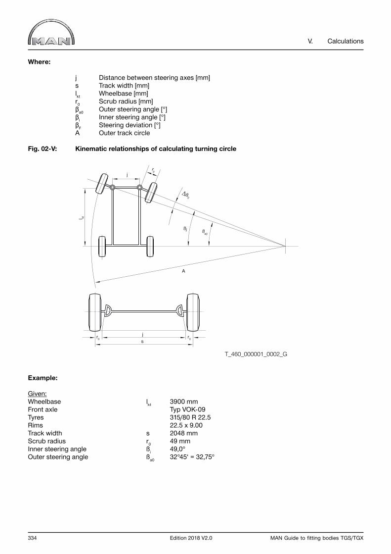
334 Edition 2018 V2.0 MAN Guide to fitting bodies TGS/TGX
V. Calculations
Where:
j Distance between steering axes [mm] s Track width [mm] lkt Wheelbase [mm] r0 Scrub radius [mm] βa0 Outer steering angle [°] βi Inner steering angle [°] βF Steering deviation [°] A Outer track circle
Fig. 02-V: Kinematic relationships of calculating turning circle
Example:
Given:Wheelbase lkt 3900 mmFront axle Typ VOK-09Tyres 315/80 R 22.5Rims 22.5 x 9.00Track width s 2048 mmScrub radius r0 49 mmInner steering angle ßi 49,0°Outer steering angle ßa0 32°45‘ = 32,75°
l kt
j
js
ßa0
ßi
r0
r0r0
Ƨ0
A
T_460_000001_0002_G
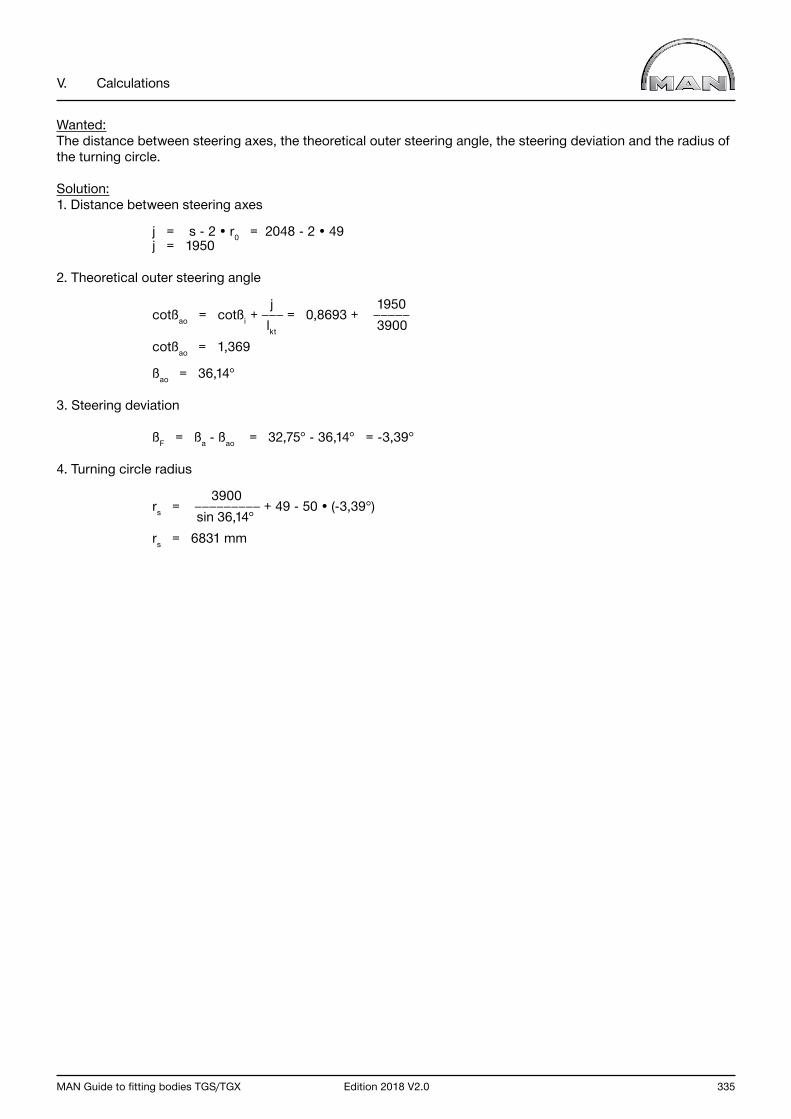
MAN Guide to fitting bodies TGS/TGX Edition 2018 V2.0 335
V. Calculations
Wanted:The distance between steering axes, the theoretical outer steering angle, the steering deviation and the radius of the turning circle.
Solution:1. Distance between steering axes
j = s - 2 • r0 = 2048 - 2 • 49 j = 1950
2. Theoretical outer steering angle
j 1950 cotßao = cotßi + = 0,8693 + lkt 3900 cotßao = 1,369
ßao = 36,14°
3. Steering deviation
ßF = ßa - ßao = 32,75° - 36,14° = -3,39°
4. Turning circle radius
3900 rs = + 49 - 50 • (-3,39°) sin 36,14° rs = 6831 mm
336 Edition 2018 V2.0 MAN Guide to fitting bodies TGS/TGX
V. Calculations
1.10 Axle-load calculation
An axle load calculation is essential for optimizing a vehicle and correctly designing a body.A body can be matched properly to a vehicle only if the vehicle is weighed before any bodymaking commences. The weights obtained in the weighing process are to be included in the axle-load calculation.
The following sub-sections explain axle-load calculation.
1.10.1 Performing an axle-load calculation
The moment theorem is used to distribute the weight of the equipment to the front and rear axles. All distances are referred to the theoretical front axle centre. For ease of understanding, „weight“ is not used in the sense of weight force (in N) in the following formulae but in the sense of mass (in kg).
The following formulae are required in order to calculate axle load:
Formula 24-V: Rear-axle weight difference
∆G ٠ a ∆GH = lt
Formula 25-V: Front-axle weight difference
∆G V = ∆G - ∆GH
Where:
ΔGH Rear-axle weight difference [kg] ΔGV Front-axle weight difference [kg] ΔG Component weight difference [kg] a Distance between theoretical front-axle centerline and component‘s center of gravity [mm] lt Theoretical wheelbase [mm]
Note:Rounding up or down to whole kilograms is quite sufficient in practice. Ensure the correct mathematical symbol.
For this reason, the following rule applies:
• Dimensions: - all distances/clearances that are IN FRONT OF the theoretical front-axle centerline have a MINUS sign (-) - all distances that are BEHIND the theoretical front-axle centerline have a PLUS sign (+)• Weights: - all weights that are ADDED TO the vehicle have a PLUS sign (+) - all equipment weights that are REMOVED FROM the vehicle have a MINUS sign (-)
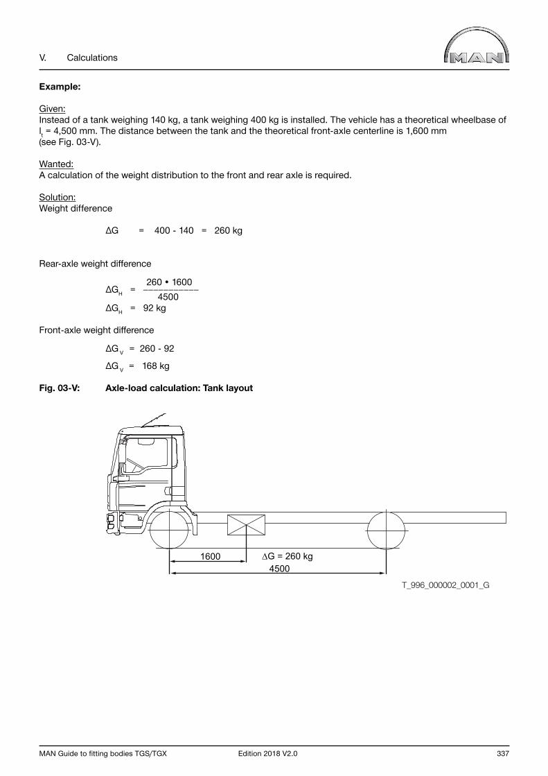
MAN Guide to fitting bodies TGS/TGX Edition 2018 V2.0 337
V. Calculations
Example:
Given:Instead of a tank weighing 140 kg, a tank weighing 400 kg is installed. The vehicle has a theoretical wheelbase of lt = 4,500 mm. The distance between the tank and the theoretical front-axle centerline is 1,600 mm(see Fig. 03-V).
Wanted:A calculation of the weight distribution to the front and rear axle is required.
Solution:Weight difference
∆G = 400 - 140 = 260 kg
Rear-axle weight difference
260 • 1600 ∆GH = 4500 ∆GH = 92 kg
Front-axle weight difference
∆G V = 260 - 92
∆G V = 168 kg
Fig. 03-V: Axle-load calculation: Tank layout
16004500
∆G = 260 kg
T_996_000002_0001_G
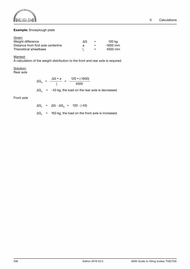
338 Edition 2018 V2.0 MAN Guide to fitting bodies TGS/TGX
V. Calculations
Example: Snowplough plate
Given:Weight difference ∆G = 120 kgDistance from first axle centerline a = -1600 mmTheoretical wheelbase lt = 4500 mm
Wanted:A calculation of the weight distribution to the front and rear axle is required.
Solution:Rear axle
∆G • a 120 • (-1600) ∆GH = = lt 4500
∆GH = -43 kg, the load on the rear axle is decreased.
Front axle
∆GV = ∆G - ∆GH = 120 - (-43)
∆GV = 163 kg, the load on the front axle is increased.
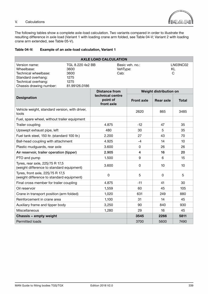
MAN Guide to fitting bodies TGS/TGX Edition 2018 V2.0 339
V. Calculations
The following tables show a complete axle-load calculation. Two variants compared in order to illustrate the resulting difference in axle load (Variant 1 with loading crane arm folded, see Table 04-V; Variant 2 with loading crane arm extended, see Table 05-V).
Table 04-V: Example of an axle-load calculation, Variant 1
AXLE LOAD CALCULATIONVersion name: TGL 8.220 4x2 BB Basic veh. no.: LN03NC02Wheelbase: 3600 VehType: KLTechnical wheelbase: 3600 Cab: CStandard overhang: 1275 Technical overhang: 1275 Chassis drawing number: 81.99126.0186
Designation
Distance from technical centre
point offront axle
Weight distribution on
Front axle Rear axle Total
Vehicle weight, standard version, with driver, tools 2620 865 3485
Fuel, spare wheel, without trailer equipment Trailer coupling 4.875 -12 47 35Upswept exhaust pipe, left 480 30 5 35Fuel tank steel, 150 ltr. (standard 100 ltr.) 2.200 27 43 70Ball-head coupling with attachment 4.925 -4 14 10Plastic mudguards, rear axle 3.600 0 26 26Air reservoir, trailer operation (tipper) 2.905 4 16 20PTO and pump 1.500 9 6 15Tyres, rear axle, 225/75 R 17,5(weight difference to standard equipment) 3.600 0 10 10
Tyres, front axle, 225/75 R 17,5(weight difference to standard equipment) 0 5 0 5
Final cross member for trailer coupling 4.875 -11 41 30Oil reservoir 1,559 60 45 105Crane in transport position (arm folded) 1,020 631 249 880Reinforcement in crane area 1,100 31 14 45Auxiliary frame and tipper body 3,250 90 840 930Miscellaneous 1,280 29 16 45Chassis – empty weight 3545 2266 5811Permitted loads 3700 5600 7490
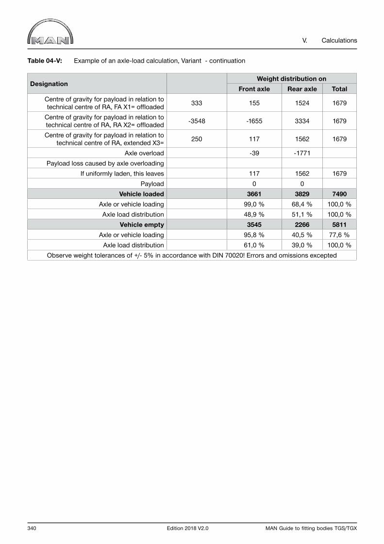
340 Edition 2018 V2.0 MAN Guide to fitting bodies TGS/TGX
V. Calculations
Table 04-V: Example of an axle-load calculation, Variant - continuation
DesignationWeight distribution on
Front axle Rear axle TotalCentre of gravity for payload in relation to technical centre of RA, FA X1= offloaded 333 155 1524 1679
Centre of gravity for payload in relation to technical centre of RA, RA X2= offloaded -3548 -1655 3334 1679
Centre of gravity for payload in relation to technical centre of RA, extended X3= 250 117 1562 1679
Axle overload -39 -1771Payload loss caused by axle overloading
If uniformly laden, this leaves 117 1562 1679Payload 0 0
Vehicle loaded 3661 3829 7490Axle or vehicle loading 99,0 % 68,4 % 100,0 %Axle load distribution 48,9 % 51,1 % 100,0 %
Vehicle empty 3545 2266 5811Axle or vehicle loading 95,8 % 40,5 % 77,6 %
Axle load distribution 61,0 % 39,0 % 100,0 %Observe weight tolerances of +/- 5% in accordance with DIN 70020! Errors and omissions excepted
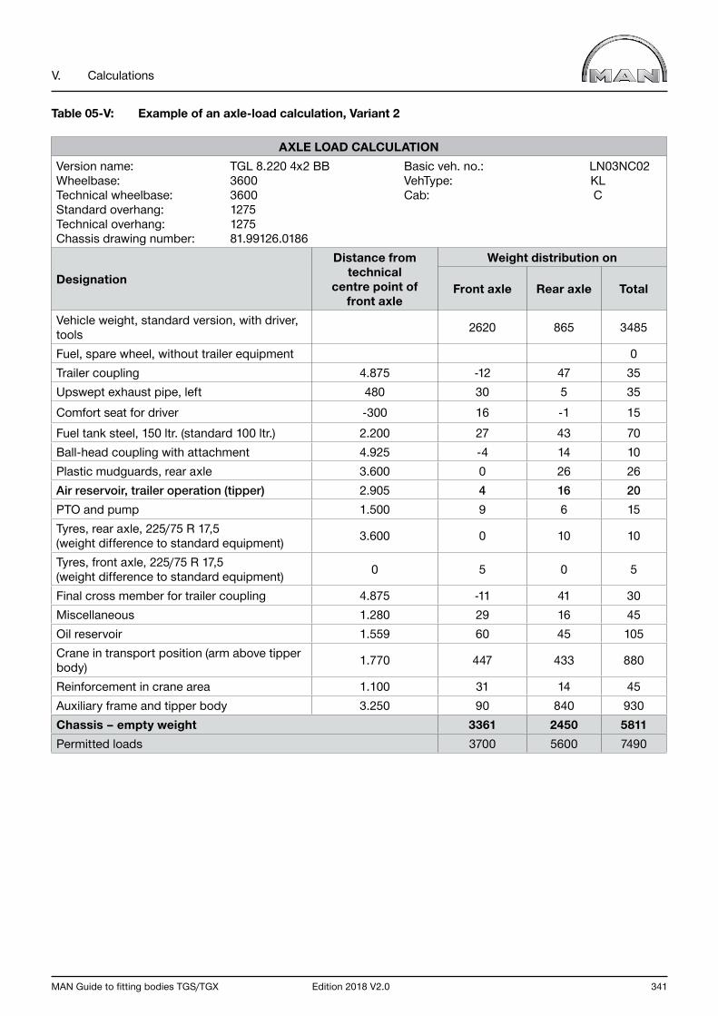
MAN Guide to fitting bodies TGS/TGX Edition 2018 V2.0 341
V. Calculations
Table 05-V: Example of an axle-load calculation, Variant 2
AXLE LOAD CALCULATIONVersion name: TGL 8.220 4x2 BB Basic veh. no.: LN03NC02Wheelbase: 3600 VehType: KLTechnical wheelbase: 3600 Cab: CStandard overhang: 1275 Technical overhang: 1275 Chassis drawing number: 81.99126.0186
Designation
Distance from technical
centre point offront axle
Weight distribution on
Front axle Rear axle Total
Vehicle weight, standard version, with driver, tools 2620 865 3485
Fuel, spare wheel, without trailer equipment 0Trailer coupling 4.875 -12 47 35Upswept exhaust pipe, left 480 30 5 35Comfort seat for driver -300 16 -1 15Fuel tank steel, 150 ltr. (standard 100 ltr.) 2.200 27 43 70Ball-head coupling with attachment 4.925 -4 14 10Plastic mudguards, rear axle 3.600 0 26 26Air reservoir, trailer operation (tipper) 2.905 4 16 20PTO and pump 1.500 9 6 15Tyres, rear axle, 225/75 R 17,5(weight difference to standard equipment) 3.600 0 10 10
Tyres, front axle, 225/75 R 17,5(weight difference to standard equipment) 0 5 0 5
Final cross member for trailer coupling 4.875 -11 41 30Miscellaneous 1.280 29 16 45Oil reservoir 1.559 60 45 105Crane in transport position (arm above tipper body) 1.770 447 433 880
Reinforcement in crane area 1.100 31 14 45Auxiliary frame and tipper body 3.250 90 840 930Chassis – empty weight 3361 2450 5811Permitted loads 3700 5600 7490
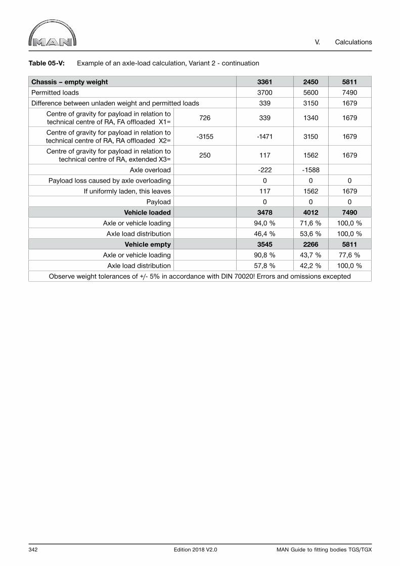
342 Edition 2018 V2.0 MAN Guide to fitting bodies TGS/TGX
V. Calculations
Table 05-V: Example of an axle-load calculation, Variant 2 - continuation
Chassis – empty weight 3361 2450 5811Permitted loads 3700 5600 7490Difference between unladen weight and permitted loads 339 3150 1679
Centre of gravity for payload in relation to technical centre of RA, FA offloaded X1= 726 339 1340 1679
Centre of gravity for payload in relation to technical centre of RA, RA offloaded X2= -3155 -1471 3150 1679
Centre of gravity for payload in relation to technical centre of RA, extended X3= 250 117 1562 1679
Axle overload -222 -1588Payload loss caused by axle overloading 0 0 0
If uniformly laden, this leaves 117 1562 1679Payload 0 0 0
Vehicle loaded 3478 4012 7490Axle or vehicle loading 94,0 % 71,6 % 100,0 %Axle load distribution 46,4 % 53,6 % 100,0 %
Vehicle empty 3545 2266 5811Axle or vehicle loading 90,8 % 43,7 % 77,6 %
Axle load distribution 57,8 % 42,2 % 100,0 %Observe weight tolerances of +/- 5% in accordance with DIN 70020! Errors and omissions excepted

MAN Guide to fitting bodies TGS/TGX Edition 2018 V2.0 343
V. Calculations
1.10.2 Calculation of weight with trailing axle lifted
The weights given for trailing-axle vehicles in the MANTED system www.manted.de) and other technical documents were calculated with the trailing axle lowered. Distribution of the axle loads to the front and drive axle after the trailing axle has been lifted can easily be determined with the following calculation.
Weight on the second axle (drive axle) when the third axle (trailing axle) is lifted:
Formula 26-V: Weight on the second axle when the third axle is lifted
G23 • lt G2an = l12
Weight on the front axle when the third axle (trailing axle) is lifted:
Formula 27-V: Weight on the first axle when the third axle is lifted
G1an = G - G2an
Where:
G Unladen weight of vehicle [kg] G1an Unladen weight on the first axle when the trailing axle is lifted [kg] G2an Unladen weight on the second axle when the third axle is lifted [kg] G23 Unladen weight on the second and third axle [kg] l12 Wheelbase from first to second axle [mm] lt Theoretical wheelbase [mm]
Example:
Given:Wheelbase 4800 + 1350Frame overhang 2600Cab XXL-cabs
Unladen weights with the trailing axle lowered:
Front axle G1ab = 5100 kgDrive axle with trailing axle G23ab = 3505 kgUnladen weight G = 8605 kg
Permissible axle loads:
G1 = 7500 kg G2 = 11500 kg G3 = 7500 kg
Wanted:The theoretical wheelbase and the unladen weights on the axles.
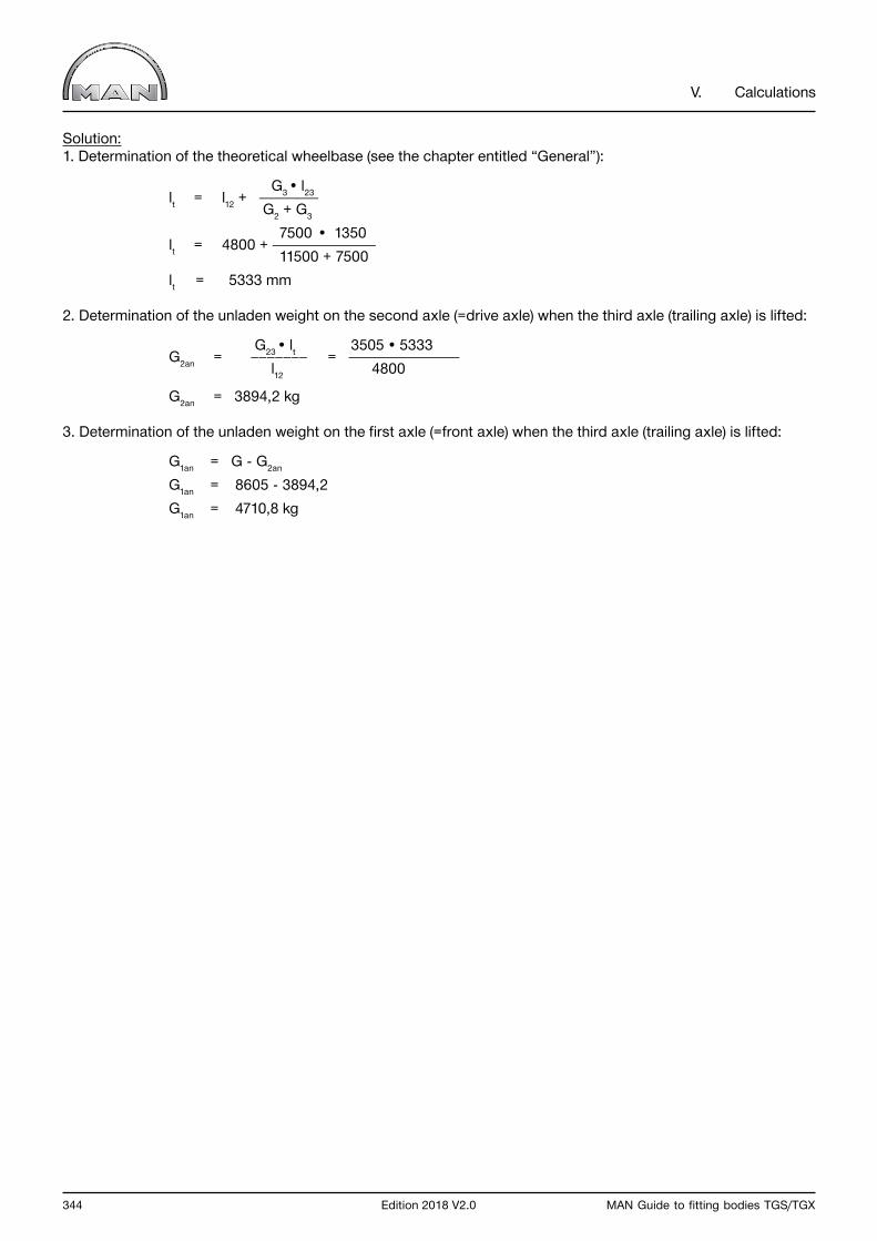
344 Edition 2018 V2.0 MAN Guide to fitting bodies TGS/TGX
V. Calculations
Solution:1. Determination of the theoretical wheelbase (see the chapter entitled “General”):
G3 • l23 lt = l12 + G2 + G3
7500 • 1350 lt = 4800 + 11500 + 7500 lt = 5333 mm
2. Determination of the unladen weight on the second axle (=drive axle) when the third axle (trailing axle) is lifted:
G23 • lt 3505 • 5333 G2an = = l12 4800
G2an = 3894,2 kg
3. Determination of the unladen weight on the first axle (=front axle) when the third axle (trailing axle) is lifted:
G1an = G - G2an
G1an = 8605 - 3894,2 G1an = 4710,8 kg
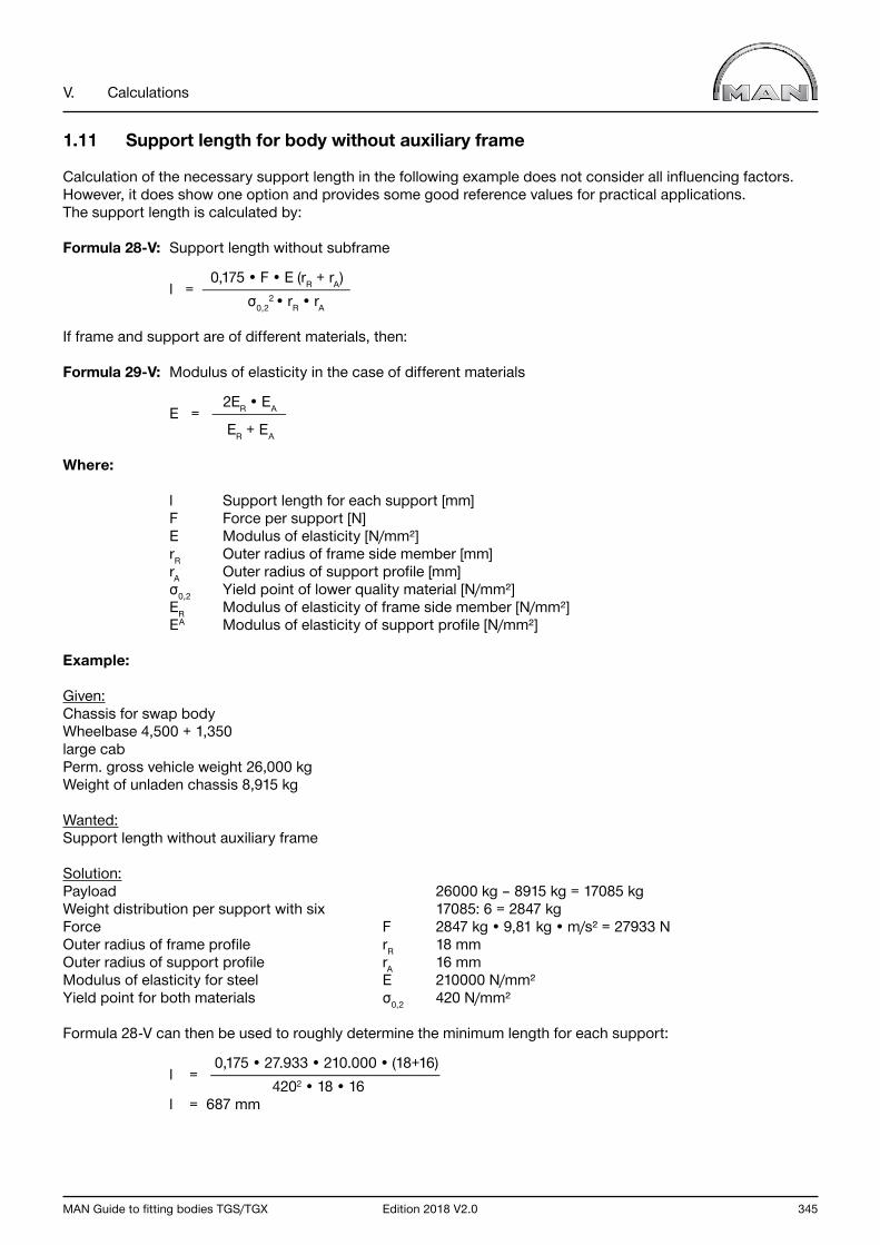
MAN Guide to fitting bodies TGS/TGX Edition 2018 V2.0 345
V. Calculations
1.11 Support length for body without auxiliary frame
Calculation of the necessary support length in the following example does not consider all influencing factors. However, it does show one option and provides some good reference values for practical applications. The support length is calculated by:
Formula 28-V: Support length without subframe
0,175 • F • E (rR + rA) l = σ0,2
2 • rR • rA
If frame and support are of different materials, then:
Formula 29-V: Modulus of elasticity in the case of different materials
2ER • EA E = ER + EA
Where:
l Support length for each support [mm] F Force per support [N] E Modulus of elasticity [N/mm²] rR Outer radius of frame side member [mm] rA Outer radius of support profile [mm] σ0,2 Yield point of lower quality material [N/mm²] ER Modulus of elasticity of frame side member [N/mm²] EA Modulus of elasticity of support profile [N/mm²]
Example:
Given:Chassis for swap bodyWheelbase 4,500 + 1,350large cabPerm. gross vehicle weight 26,000 kgWeight of unladen chassis 8,915 kg
Wanted:Support length without auxiliary frame
Solution:Payload 26000 kg – 8915 kg = 17085 kgWeight distribution per support with six 17085: 6 = 2847 kgForce F 2847 kg • 9,81 kg • m/s² = 27933 NOuter radius of frame profile rR 18 mmOuter radius of support profile rA 16 mmModulus of elasticity for steel E 210000 N/mm²Yield point for both materials σ0,2 420 N/mm²
Formula 28-V can then be used to roughly determine the minimum length for each support:
0,175 • 27.933 • 210.000 • (18+16) l = 4202 • 18 • 16 l = 687 mm
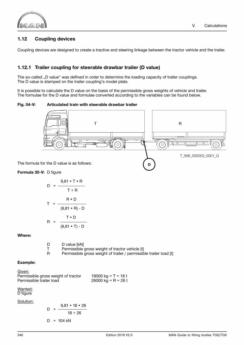
346 Edition 2018 V2.0 MAN Guide to fitting bodies TGS/TGX
V. Calculations
1.12 Coupling devices
Coupling devices are designed to create a tractive and steering linkage between the tractor vehicle and the trailer.
1.12.1 Trailer coupling for steerable drawbar trailer (D value)
The so-called „D value“ was defined in order to determine the loading capacity of trailer couplings. The D value is stamped on the trailer coupling‘s model plate.
It is possible to calculate the D value on the basis of the permissible gross weights of vehicle and trailer.The formulae for the D value and formulae converted according to the variables can be found below.
Fig. 04-V: Articulated train with steerable drawbar trailer
The formula for the D value is as follows:
Formula 30-V: D figure
9,81 • T • R D = T + R
R • D T = (9,81 • R) - D
T • D R = (9,81 • T) - D
Where:
D D value [kN] T Permissible gross weight of tractor vehicle [t] R Permissible gross weight of trailer / permissible trailer load [t]
Example:
Given:Permissible gross weight of tractor 18000 kg = T = 18 tPermissible trailer load 26000 kg = R = 26 t
Wanted:D figure
Solution: 9,81 • 18 • 26 D = 18 + 26
D = 104 kN
T_996_000003_0001_G
T R
D
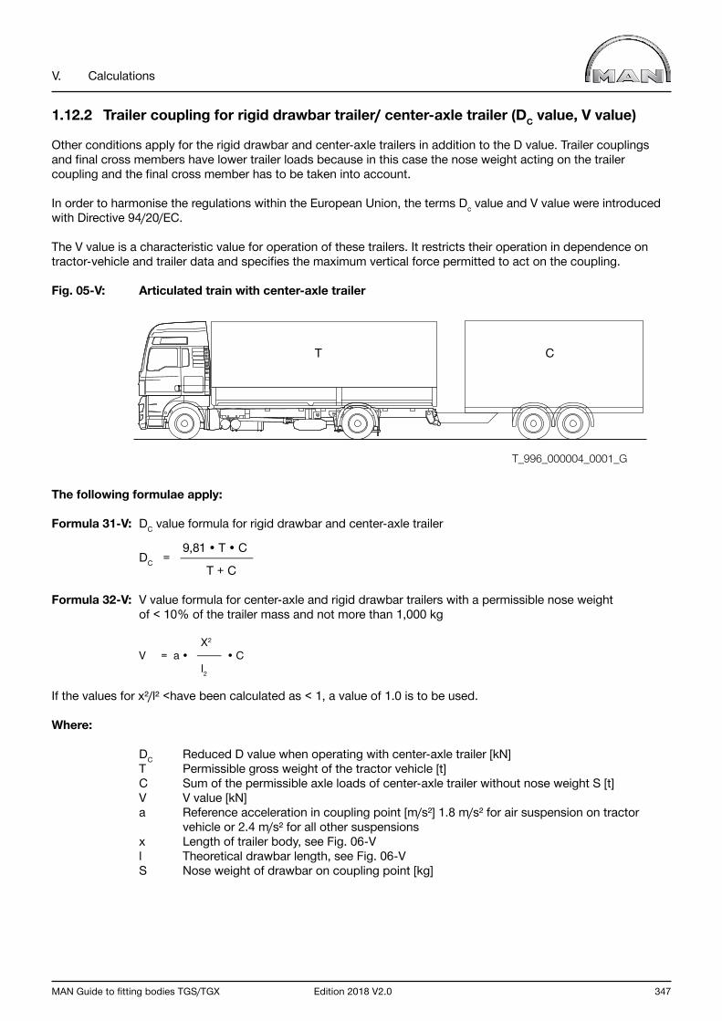
MAN Guide to fitting bodies TGS/TGX Edition 2018 V2.0 347
V. Calculations
1.12.2 Trailer coupling for rigid drawbar trailer/ center-axle trailer (DC value, V value)
Other conditions apply for the rigid drawbar and center-axle trailers in addition to the D value. Trailer couplings and final cross members have lower trailer loads because in this case the nose weight acting on the trailer coupling and the final cross member has to be taken into account.
In order to harmonise the regulations within the European Union, the terms Dc value and V value were introduced with Directive 94/20/EC.
The V value is a characteristic value for operation of these trailers. It restricts their operation in dependence on tractor-vehicle and trailer data and specifies the maximum vertical force permitted to act on the coupling.
Fig. 05-V: Articulated train with center-axle trailer
The following formulae apply:
Formula 31-V: DC value formula for rigid drawbar and center-axle trailer
9,81 • T • C DC = T + C
Formula 32-V: V value formula for center-axle and rigid drawbar trailers with a permissible nose weight of < 10% of the trailer mass and not more than 1,000 kg
X2
V = a • • C l2
If the values for x²/l² <have been calculated as < 1, a value of 1.0 is to be used.
Where:
DC Reduced D value when operating with center-axle trailer [kN] T Permissible gross weight of the tractor vehicle [t] C Sum of the permissible axle loads of center-axle trailer without nose weight S [t] V V value [kN] a Reference acceleration in coupling point [m/s²] 1.8 m/s² for air suspension on tractor vehicle or 2.4 m/s² for all other suspensions x Length of trailer body, see Fig. 06-V l Theoretical drawbar length, see Fig. 06-V S Nose weight of drawbar on coupling point [kg]
T_996_000004_0001_G
T C

348 Edition 2018 V2.0 MAN Guide to fitting bodies TGS/TGX
V. Calculations
Fig. 06-V: Length of trailer body and theoretical drawbar length
Example:
Given:Permissible gross weight of tractor vehicle T 7490 kg = 7,49 tSum of trailer axle loads C 11000 kg = 11 tNose weight S 700 kg = 0,7 tLength of body x 6,2 m Theoretical drawbar length l 5,2 m
Wanted:Can both vehicles be used in combination as a road train if the reinforced final cross member and the Ringfeder 864 trailer coupling are fitted to the truck?
Solution:DC value
9,81 • T • C 9,81 • 7,49 • 11 DC = = T + C 7,49 + 11
DC = 43,7 kN
DC value of final cross member: = 64 kN (see MAN guidelines to fitting bodies, supplementary booklet entitled „Coupling devices TG“).
x
v
x
v
l l
T_510_000003_0001_G

MAN Guide to fitting bodies TGS/TGX Edition 2018 V2.0 349
V. Calculations
V value
x2 6,22
= = 1,42 l2 5,22
x2
V = a • C = 1,8 • 1,42 • 11 l2
V = 28,12 kN (1.8 when the rear axle of the truck is equipped with air suspension)
V value of final cross member = 35 kN (see MAN guidelines to fitting bodies, supplementary booklet entitled “Coupling devices TG“)
Both vehicles can form a road train. However, the minimum front-axle load (including nose weight) as per the respectively applicable guidelines to fitting bodies must be adhered to. An unladen truck may only tow an unladen centre axle trailer.
1.12.3 Trailer coupling for semi-trailer (D value)
The so-called “D value” was defined in order to determine the loading capacity of trailer couplings. The D value is stamped on the trailer coupling’s model plate. The required fifth-wheel coupling size is determined by the D value.
Fig. 07-V: Semitrailer tractor
T_996_000005_0001_G
R
12 m
T U

350 Edition 2018 V2.0 MAN Guide to fitting bodies TGS/TGX
V. Calculations
The formula for the D value is as follows:
Formula 33-V: D figure for fifth-wheel coupling
0,6 • 9,81 • T • R D = T + R - U D • (T - U) R = (0,6 • 9.81 • T) - D D • (R - U) T = (0,6 • 9.81 • R) - D 0,6 • 9,81 • T • R U = T + R - D
Where:
D D value [kN] T Permissible gross weight of semitrailer tractor including fifth-wheel load [t] R Permissible gross weight of semitrailer including fifth-wheel load [t] U Fifth-wheel load [t]
Example: Semitrailer tractor
Given:Permissible gross weight of semitrailer tractor: 18000 kg = T = 18 tPermissible gross weight of semitrailer: 32000 kg = R = 32 tFifth-wheel load acc. to trailer type plate: 10750 kg = U = 10,75 t
Wanted:D value for the tractor and semitrailer combination described.
Solution: 0,6 • 9,81 • 18 • 32 D = 18 + 32 - 10,75 D = 86,38 kN
Note:The D value calculated must be lower than the D value stamped on the fifth-wheel coupling model plate (e.g. D value 152 kN).

MAN Guide to fitting bodies TGS/TGX Edition 2018 V2.0 351
V. Calculations
1.13 Theoretical wheelbase and permissible overhang length
This section contains formulae and examples of calculations concerning the theoretical wheelbase and permissible overhang length.
Formula 34-V: Theoretical wheelbase, two axles
lt = l12
Formula 35-V: Theoretical wheelbase, three axles with two rear axles and same rear axle loads
lt = l12 + 0,5 • l23
Formula 36-V: Theoretical wheelbase, three axles with two rear axles and different rear axle loads
Gzul3 • l23 lt = l12 + Gzul2 + Gzul3
Formula 37-V: Theoretical wheelbase, four axles with two front and two rear axles (random axle load distribution)
Gzul1 • l12 Gzul4 • l34 lt = l23 + + Gzul1 + Gzul2 Gzul3 + Gzul4
Formula 38-V: Permissible overhang length for a two-axle vehicle
Ut ≤ 0,65 • lt
Formula 39-V: Permissible overhang length for vehicles with three or more axles
Ut ≤ 0,70 • lt
Where:
lt Theoretical wheelbase [mm] l12 Wheelbase between first and second axle [mm] l23 Wheelbase between second and third axle [mm] l34 Wheelbase between third and fourth axle [mm] Gzul1 Permissible axle load, axle 1 [kg] Gzul2 Permissible axle load, axle 2 [kg] Gzul3 Permissible axle load, axle 3 [kg] Gzul4 Permissible axle load, axle 4 [kg] Ut Permissible overhang length [mm]
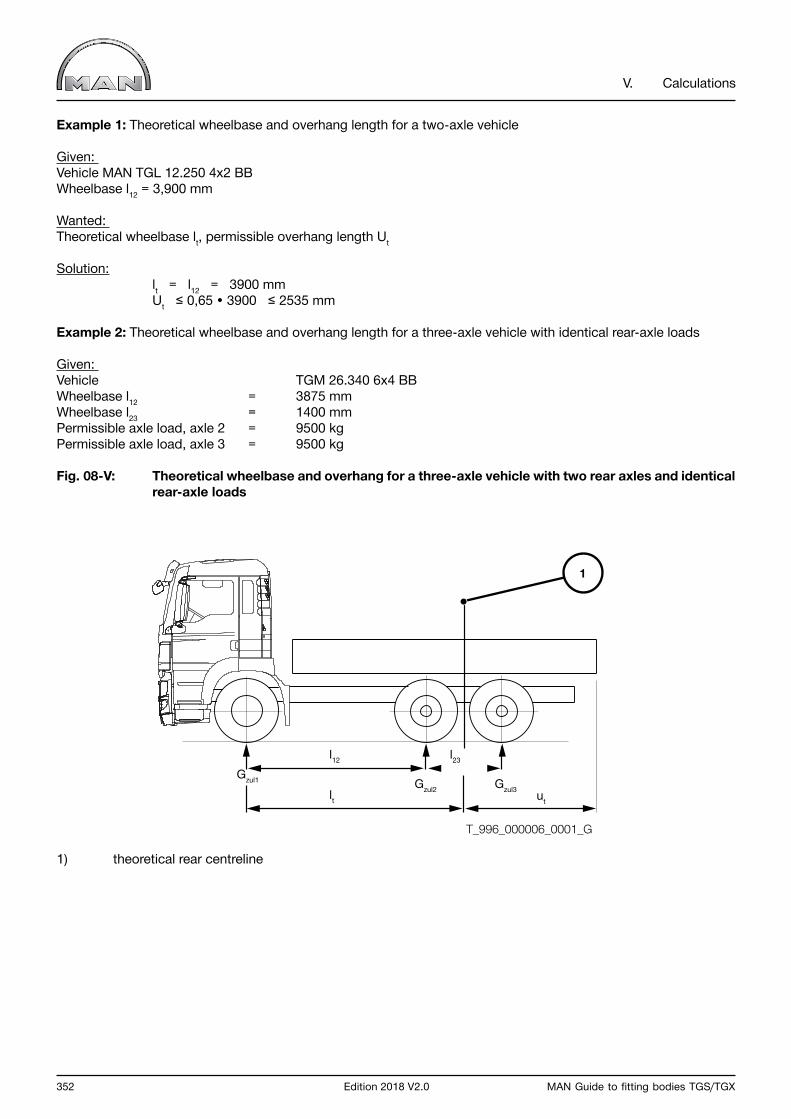
352 Edition 2018 V2.0 MAN Guide to fitting bodies TGS/TGX
V. Calculations
Example 1: Theoretical wheelbase and overhang length for a two-axle vehicle
Given: Vehicle MAN TGL 12.250 4x2 BBWheelbase l12 = 3,900 mm
Wanted: Theoretical wheelbase lt, permissible overhang length Ut
Solution: lt = l12 = 3900 mm Ut ≤ 0,65 • 3900 ≤ 2535 mm Example 2: Theoretical wheelbase and overhang length for a three-axle vehicle with identical rear-axle loads
Given: Vehicle TGM 26.340 6x4 BBWheelbase l12 = 3875 mmWheelbase l23 = 1400 mmPermissible axle load, axle 2 = 9500 kgPermissible axle load, axle 3 = 9500 kg
Fig. 08-V: Theoretical wheelbase and overhang for a three-axle vehicle with two rear axles and identical rear-axle loads
1) theoretical rear centreline
Gzul1
ut
Gzul2 Gzul3
l12
lt
l23
1
T_996_000006_0001_G
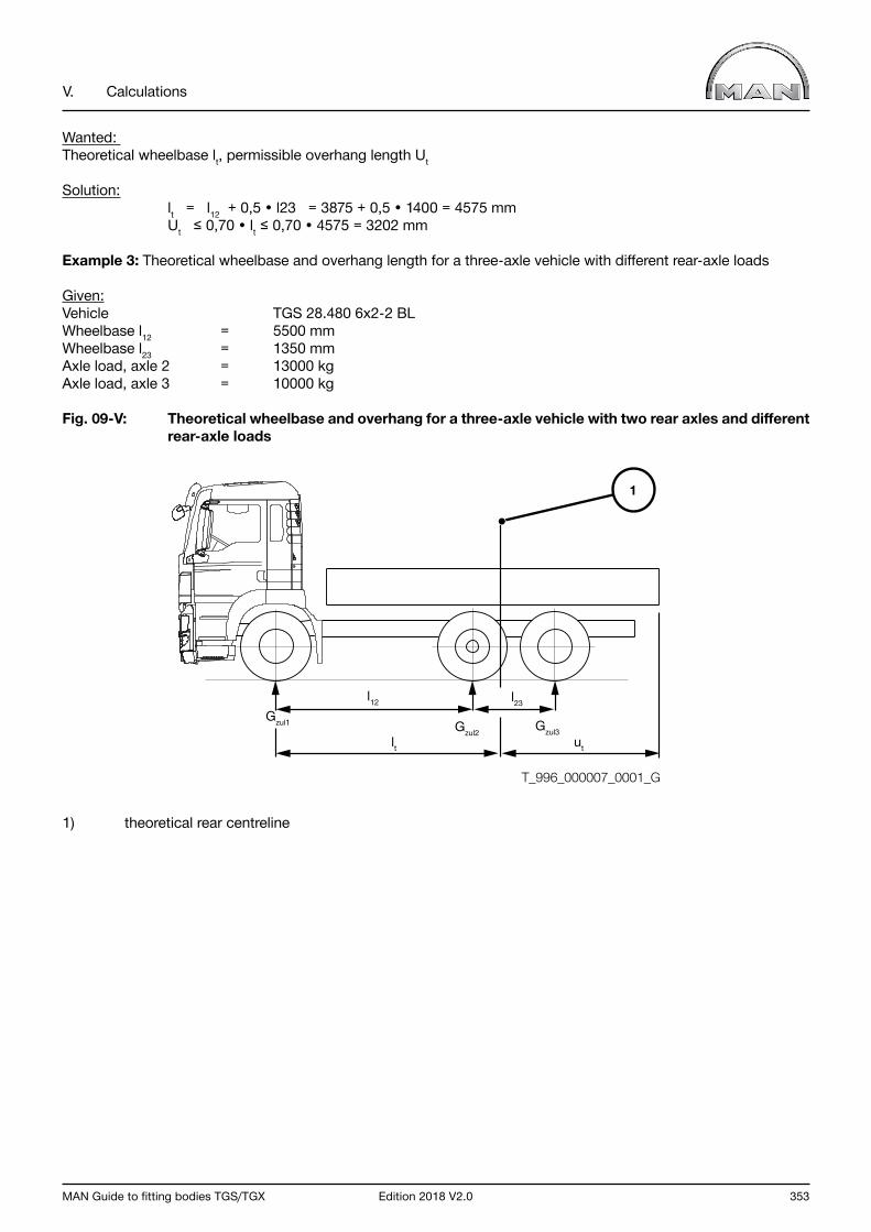
MAN Guide to fitting bodies TGS/TGX Edition 2018 V2.0 353
V. Calculations
Wanted: Theoretical wheelbase lt, permissible overhang length Ut
Solution: lt = l12 + 0,5 • l23 = 3875 + 0,5 • 1400 = 4575 mm Ut ≤ 0,70 • lt ≤ 0,70 • 4575 = 3202 mm
Example 3: Theoretical wheelbase and overhang length for a three-axle vehicle with different rear-axle loads
Given: Vehicle TGS 28.480 6x2-2 BLWheelbase l12 = 5500 mmWheelbase l23 = 1350 mmAxle load, axle 2 = 13000 kgAxle load, axle 3 = 10000 kg
Fig. 09-V: Theoretical wheelbase and overhang for a three-axle vehicle with two rear axles and different rear-axle loads
1) theoretical rear centreline
Gzul1
ut
Gzul2 Gzul3
l12
lt
l23
1
T_996_000007_0001_G

354 Edition 2018 V2.0 MAN Guide to fitting bodies TGS/TGX
V. Calculations
Wanted: Theoretical wheelbase lt, permissible overhang length Ut
Solution: Gzul3 • l23 lt = l12 + Gzul2 + Gzul3
10000 • 1350 lt = 5500 + 13000 + 10000
Example 4: Theoretical wheelbase and overhang length for a four-axle vehicle
Given:Vehicle TGS 32.480 8x4 BBWheelbase l12 = 1795 mmWheelbase l23 = 3205 mmWheelbase l34 = 1400 mmAxle load, axle 1 = 7100 kgAxle load, axle 2 = 7100 kgAxle load, axle 3 = 9500 kgAxle load, axle 4 = 9500 kg
Fig. 10-V: Theoretical wheelbase and overhang for a four-axle vehicle with two front and two rear axles (random axle-load distribution)
1) theoretical rear centreline2) theoretical front centreline
Wanted: Theoretical wheelbase lt, permissible overhang length Ut
Solution: Gzul1 • l12 Gzul4 • l34 lt = l23 + + Gzul1 + Gzul2 Gzul3 + Gzul4
7100 • 1795 9500 • 1400 lt = 3205 + + 7100 + 7100 9500 + 9500 lt = 4802 mm Ut ≤ 0,70 • lt ≤ 0,70 • 4802 = 3361 mm
Gzul1ut
Gzul2 Gzul3 Gzul4
l12
lt
l23 l24
1
2
T_996_000008_0001_G

MAN Guide to fitting bodies TGS/TGX Edition 2018 V2.0 355
V. Calculations
NOTICE

MAN Truck & Bus AGEngineering Vehicle TruckApplication EngineeringDachauer Straße 66780995 MunichE-Mail: [email protected] www.man.eu
MAN Truck & Bus – a member of the MAN Group
We reserve the right to make changes in the course of technical development.