
S3900 Series Switches Web Management User Manual | FS
314
S3900 Series Switches Web Management User Manual Models: S3900-48T4S/S3900-24F4S/S3900-24T4S
-
Upload
khangminh22 -
Category
Documents
-
view
3 -
download
0
Transcript of S3900 Series Switches Web Management User Manual | FS

S3900 Series SwitchesWebManagement User Manual
Models: S3900-48T4S/S3900-24F4S/S3900-24T4S

S3900 SERIES SWITCHES WEB MANAGEMENT USER MANUAL
Contents
System Information............................................................................................................................................................1System Info................................................................................................................................................................. 1System Description.....................................................................................................................................................1User Accounts.............................................................................................................................................................2
Switch Management.......................................................................................................................................................... 3Jumbo Frame.............................................................................................................................................................3Interface.....................................................................................................................................................................3
Port....................................................................................................................................................................3sFlow................................................................................................................................................................. 6Transceiver.........................................................................................................................................................8Cable Test........................................................................................................................................................ 10Green Ethernet................................................................................................................................................11Traffic Segment................................................................................................................................................12
Statistics.................................................................................................................................................................. 13Statistics Info...................................................................................................................................................13History Management...................................................................................................................................... 16Show History Statistics....................................................................................................................................17
Vlan.......................................................................................................................................................................... 18Static Vlan........................................................................................................................................................18GVRP................................................................................................................................................................20Protocol Vlan...................................................................................................................................................21IP Subnet Vlan.................................................................................................................................................23MAC-Based Vlan..............................................................................................................................................24Vlan Translation.............................................................................................................................................. 25VLAN Trunking................................................................................................................................................ 26QinQ................................................................................................................................................................ 27Voice Vlan........................................................................................................................................................32L2PT.................................................................................................................................................................34
MACAddress...........................................................................................................................................................36Dynamic MAC Learning.................................................................................................................................. 36Static Mac Setting........................................................................................................................................... 38
Port Mirror...............................................................................................................................................................40Local Port Mirror..............................................................................................................................................40RSPAN..............................................................................................................................................................41
Static Link Aggregation.........................................................................................................................................43Static Trunk..................................................................................................................................................... 43Static Trunk Member.......................................................................................................................................44Static Trunk Management.............................................................................................................................. 44Load Balance...................................................................................................................................................45
LACP.........................................................................................................................................................................46Configure Aggregator.....................................................................................................................................46Configure Aggregation Port........................................................................................................................... 47Show Aggregation Port Information..............................................................................................................49Dynamic Trunk................................................................................................................................................50Show Dynamic Trunk Member....................................................................................................................... 50
STP............................................................................................................................................................................51STP-RSTP..........................................................................................................................................................53MSTP................................................................................................................................................................61Loopback Detection........................................................................................................................................63
IGMP Snooping.......................................................................................................................................................64General............................................................................................................................................................65Current Multicast............................................................................................................................................ 68Static Multicast Router....................................................................................................................................69Static Member.................................................................................................................................................69VLAN Information........................................................................................................................................... 70

S3900 SERIES SWITCHES WEB MANAGEMENT USER MANUAL
Configure Interface......................................................................................................................................... 74Forwarding Entry............................................................................................................................................ 74Query Statistics............................................................................................................................................... 75VLAN Statistics................................................................................................................................................ 76Port Statistics...................................................................................................................................................77Trunk Stastics.................................................................................................................................................. 78
IGMP Filtering and Throttling...............................................................................................................................79Filter General...................................................................................................................................................79Filter Profile..................................................................................................................................................... 80Filter Range..................................................................................................................................................... 81Configure Filter Interface................................................................................................................................81
MLD Snooping........................................................................................................................................................ 82General............................................................................................................................................................83Immediate Leave Status..................................................................................................................................84Current Multicast Router.................................................................................................................................84Static Multicast Router....................................................................................................................................85Current Member..............................................................................................................................................86Static Member.................................................................................................................................................86Group Information..........................................................................................................................................87Statistics.......................................................................................................................................................... 88
MVR For IPv4...........................................................................................................................................................90Configure Global.............................................................................................................................................91Configure Domain...........................................................................................................................................92Show Configure Profile...................................................................................................................................93Add Configure Profile..................................................................................................................................... 94Show Associate Profile....................................................................................................................................95Add Associate Profile...................................................................................................................................... 96Configure Interface......................................................................................................................................... 96Show Static Group Member............................................................................................................................98Add Static Group Member..............................................................................................................................99Show Member.................................................................................................................................................99Show Query Statistics................................................................................................................................... 100Show VLAN Statistics.................................................................................................................................... 101Show Port Statistics.......................................................................................................................................102Show Trunk Statistics....................................................................................................................................103
MVR For IPv6.........................................................................................................................................................104Configure Global...........................................................................................................................................104Configure Domain.........................................................................................................................................106Show Configure Profile.................................................................................................................................107Add Configure Profile................................................................................................................................... 108Show Associate Profile..................................................................................................................................109Add Associate Profile.................................................................................................................................... 109Configure Interface....................................................................................................................................... 110Show Static Group Member..........................................................................................................................111Add Static Group Member............................................................................................................................112Show Member...............................................................................................................................................113Show Query Statistics................................................................................................................................... 113Show VLAN Statistics.................................................................................................................................... 115Show Port Statistics.......................................................................................................................................116Show Trunk Statistics....................................................................................................................................117
LLDP.......................................................................................................................................................................118Configure Global...........................................................................................................................................119Interface General...........................................................................................................................................120CA-Type.........................................................................................................................................................122Show Local Information................................................................................................................................123Show Remote Information............................................................................................................................125Show Statistics.............................................................................................................................................. 129
ERPS....................................................................................................................................................................... 130

S3900 SERIES SWITCHES WEB MANAGEMENT USER MANUAL
Configure Global...........................................................................................................................................131Domain..........................................................................................................................................................131Domain Details..............................................................................................................................................132Domain Operation........................................................................................................................................ 136Show Statistics.............................................................................................................................................. 136
Loopback Detection.............................................................................................................................................137Configure Global...........................................................................................................................................137Configure Interface.......................................................................................................................................138
UDLD......................................................................................................................................................................138Configure Global...........................................................................................................................................139Configure Interface....................................................................................................................................... 140Show Information......................................................................................................................................... 141
Congestion Control..............................................................................................................................................142Rate Limit...................................................................................................................................................... 142Storm Control................................................................................................................................................143Auto Traffic Control.......................................................................................................................................144
Stacking.................................................................................................................................................................148Configure Master Button.............................................................................................................................. 148Configure Stacking Button........................................................................................................................... 149Renumber......................................................................................................................................................149
PPPoE.....................................................................................................................................................................149Configure Global...........................................................................................................................................149Configure Interface....................................................................................................................................... 150Show Statistics.............................................................................................................................................. 151
RouteManagment......................................................................................................................................................... 152IPv4 Interface Configuration.............................................................................................................................. 152IPv6 Interface Configuration.............................................................................................................................. 153
Configure Global...........................................................................................................................................153Configure Interface....................................................................................................................................... 153IPv6 Address..................................................................................................................................................156Show IPv6 Neighbor Cache.......................................................................................................................... 158Show Statistics.............................................................................................................................................. 159Show MTU..................................................................................................................................................... 164
ARP.........................................................................................................................................................................164Configure General.........................................................................................................................................165Static Arp.......................................................................................................................................................167Show Information......................................................................................................................................... 167
Routing Table....................................................................................................................................................... 168ACL...................................................................................................................................................................................171
ACL Management......................................................................................................................................... 171ACL Rule Management................................................................................................................................. 172Configuring A Standard Ipv4 Acl..................................................................................................................172Configuring An Extended Ipv4 Acl............................................................................................................... 173Configuring A Standard Ipv6 Acl..................................................................................................................174Configuring An Extended Ipv6 Acl............................................................................................................... 175Configuring A Mac Acl.................................................................................................................................. 176Configuring An Arp Acl.................................................................................................................................177Show TCAM...................................................................................................................................................178Configure Interface....................................................................................................................................... 179Show Hardware Counter.............................................................................................................................. 179
CoS...................................................................................................................................................................................180Default Priority..............................................................................................................................................180Queue............................................................................................................................................................181Trust Mode.................................................................................................................................................... 182DSCP to DSCP................................................................................................................................................183CoS to DSCP.................................................................................................................................................. 185DSCP to CoS.................................................................................................................................................. 186IP Precedence to DSCP..................................................................................................................................188IP Port to DSCP..............................................................................................................................................189

S3900 SERIES SWITCHES WEB MANAGEMENT USER MANUAL
PHB to Queue................................................................................................................................................190QoS...................................................................................................................................................................................192
Class...............................................................................................................................................................192Class Rule.......................................................................................................................................................193Policy............................................................................................................................................................. 194Policy Rule.....................................................................................................................................................199Configure Interface....................................................................................................................................... 200
Security........................................................................................................................................................................... 200AAA........................................................................................................................................................................ 200
System Authentication................................................................................................................................. 201Configure AAA Server................................................................................................................................... 202AAA Group.................................................................................................................................................... 202Configure Accounting Periodic.................................................................................................................... 203Accounting Method......................................................................................................................................203Configure Accounting Service......................................................................................................................203Show Accounting Information..................................................................................................................... 204Authorization Method.................................................................................................................................. 204Configure Authorization service...................................................................................................................205Show Authorization Information..................................................................................................................205
Web Authentication.............................................................................................................................................205Configure Global...........................................................................................................................................206Configure Interface....................................................................................................................................... 206
802.1X....................................................................................................................................................................207Configure Global...........................................................................................................................................208Configure Interface....................................................................................................................................... 208Show Statistics.............................................................................................................................................. 208
Network Access.................................................................................................................................................... 209Configure Global...........................................................................................................................................209Configure Interface....................................................................................................................................... 210
HTTPS.....................................................................................................................................................................210Configure Global...........................................................................................................................................210Copy Certificate.............................................................................................................................................211
SSH.........................................................................................................................................................................212Configure Global...........................................................................................................................................212Show Host Key.............................................................................................................................................. 213Show User Key...............................................................................................................................................213
Port Security......................................................................................................................................................... 214DAI..........................................................................................................................................................................216
Configure General.........................................................................................................................................216Configure VLAN.............................................................................................................................................217Configure Interface....................................................................................................................................... 218Show Statistics.............................................................................................................................................. 219Show Log.......................................................................................................................................................220
IP Filter...................................................................................................................................................................220IP Filter Management....................................................................................................................................220
DoS Protection......................................................................................................................................................221IPv4 DHCP Snooping............................................................................................................................................223
Configure Global...........................................................................................................................................223Configure VLAN.............................................................................................................................................224Configure Interface....................................................................................................................................... 225Show Information......................................................................................................................................... 225
IPv6 DHCP Snooping............................................................................................................................................226Configure Global...........................................................................................................................................226VLAN Management.......................................................................................................................................228Configure Interface....................................................................................................................................... 228Show Information......................................................................................................................................... 229
IPv4 Source Guard................................................................................................................................................229General..........................................................................................................................................................230ACL Table...................................................................................................................................................... 231

S3900 SERIES SWITCHES WEB MANAGEMENT USER MANUAL
MAC Table..................................................................................................................................................... 231Dynamic Binding...........................................................................................................................................232
IPv6 Source Guard................................................................................................................................................233Port Configuration........................................................................................................................................ 233Static Binding................................................................................................................................................235Dynamic Binding...........................................................................................................................................236
Application Filter................................................................................................................................................. 236CPU Guard.............................................................................................................................................................237
Device Management......................................................................................................................................................238SNMP......................................................................................................................................................................238
Configure Global...........................................................................................................................................239Community................................................................................................................................................... 240Set Engine ID.................................................................................................................................................240Remote Engine..............................................................................................................................................241View...............................................................................................................................................................242View Subtree.................................................................................................................................................243Group............................................................................................................................................................ 243SNMPv3 Local User....................................................................................................................................... 244Change SNMPv3 Local User..........................................................................................................................245SNMPv3 Remote User................................................................................................................................... 245Trap............................................................................................................................................................... 246Show Statistics.............................................................................................................................................. 248
RMON.....................................................................................................................................................................250Global Management..................................................................................................................................... 250Interface Management................................................................................................................................. 252Show Interface Details.................................................................................................................................. 254
Cluster....................................................................................................................................................................254Configure Global...........................................................................................................................................254Cluster Member.............................................................................................................................................255Show Candidate............................................................................................................................................256
DNS........................................................................................................................................................................ 256Configure Global...........................................................................................................................................256Domain Names..............................................................................................................................................257Name Servers................................................................................................................................................ 257Static Host..................................................................................................................................................... 258Cache.............................................................................................................................................................259
DHCP......................................................................................................................................................................259Client............................................................................................................................................................. 259Relay..............................................................................................................................................................260Relay Option82..............................................................................................................................................261Dynamic Provision........................................................................................................................................ 263
OAM....................................................................................................................................................................... 264Interface........................................................................................................................................................ 264Counters........................................................................................................................................................266Event Log...................................................................................................................................................... 266Remote Interface...........................................................................................................................................267Show Loopback Result..................................................................................................................................268Loopback Test...............................................................................................................................................268
CFM........................................................................................................................................................................ 270Configure Global...........................................................................................................................................272Configure Interface....................................................................................................................................... 274MD Management..........................................................................................................................................275MDDetails.....................................................................................................................................................277MA Management.......................................................................................................................................... 278MA Details..................................................................................................................................................... 279MEPManagement.........................................................................................................................................280Remote MEP Management...........................................................................................................................281Transmit Link Trace.......................................................................................................................................282Transmit Loopback....................................................................................................................................... 283

S3900 SERIES SWITCHES WEB MANAGEMENT USER MANUAL
Transmit Delay Measure............................................................................................................................... 284Show Local MEP............................................................................................................................................285Show Local MEP Details................................................................................................................................286Show Local MIP............................................................................................................................................. 287Show Remote MEP........................................................................................................................................287Show Remote MEP Details............................................................................................................................288Show Link Trace Cache................................................................................................................................. 289Show Fault Notification Generator...............................................................................................................290Show Continuity Check Error........................................................................................................................290
Time Setting..........................................................................................................................................................291Configure time.............................................................................................................................................. 291SNTP Server...................................................................................................................................................292NTP Server.....................................................................................................................................................292NTP authentication Key................................................................................................................................ 293Configure Time Zone.................................................................................................................................... 294Configure Summer Time...............................................................................................................................294
Event Log...............................................................................................................................................................295Show System Logs........................................................................................................................................ 295Configure Global...........................................................................................................................................296Remote..........................................................................................................................................................297SMTP..............................................................................................................................................................298
File Management................................................................................................................................................. 298Copying Files Via Ftp/Tftp Or Http............................................................................................................... 299Saving The Running Configuration To A Local File......................................................................................300Setting The Startup File................................................................................................................................ 300
Auto Upgrade....................................................................................................................................................... 301Ping........................................................................................................................................................................303Trace Route........................................................................................................................................................... 304System Reboot......................................................................................................................................................305

S3900 SERIES SWITCHES WEB MANAGEMENT USER MANUAL
www.fs.com 1
System Information
System Info
Use the System Information> System Info page to identify the system by displayinginformation
Information:◆ SystemModel – The device type.◆ SystemUp Time – Length of time the device has beenup.◆ SystemName – Name assigned to the switch system.◆Serial Number – The serial number of the device.◆Hardware Version– The version of the device hardware.◆ Loader Version – The version of the boot loader.◆Firmware Version– The version of the firmware running in the device.
System Description
System Information > System Description display the information of the firmware and device.

S3900 SERIES SWITCHES WEB MANAGEMENT USER MANUAL
www.fs.com 2
User Accounts
System Information > User Accounts page to control management access to the switchbased on manually configured user names and passwords.COMMAND USAGE◆ The default guest name is “guest” with the password “guest.” The default administratorname is “admin” with the password “admin.”◆ The guest only has read access for most configuration parameters. However, theadministrator has write access for all parameters governing the onboard agent. You shouldtherefore assign a new administrator password as soon as possible, and store it in a safeplace.PARAMETERSThese parameters are displayed:◆ User Name – The name of the user. (Maximum length: 32 characters; maximum numberof users: 16)◆ Access Level – Specifies the user level. (Options: 0 - Normal, 15 - Privileged) Normalprivilege level provides access to a limited number of the commands which display thecurrent status of the switch, as well as several database clear and reset functions. Privilegedlevel provides full access to all commands.◆ Password Type – Specifies the following options:■ No Password – No password is required for this user to log in.■ Plain Password – Plain text unencrypted password.■ Encrypted Password – Encrypted password.The encrypted password is required for compatibility with legacy password settings (i.e.,plain text or encrypted) when reading the configuration file during system bootup or whendownloading theconfiguration file from a TFTP or FTP server. There is no need for you to manually configureencrypted passwords.◆ Password – Specifies the user password. (Range: 0-32 characters, casesensitive)◆ Confirm Password – Re-type the string entered in the previous field to ensure no errorswere made. The switch will not change the password if these two fields do notmatch.

S3900 SERIES SWITCHES WEB MANAGEMENT USER MANUAL
www.fs.com 3
Switch Management
Jumbo Frame
Use the Switch Management > Jumbo Frame page to configure support for layer 2 jumboframes. The switch provides more efficient throughput for large sequential data transfers bysupporting jumbo frames up to 10240 bytes for Gigabit Ethernet. Compared to standardEthernet frames that run only up to 1.5 KB, using jumbo frames significantly reduces theper-packet overhead required to process protocol encapsulation fields.
USAGE GUIDELINESTo use jumbo frames, both the source and destination end nodes (such as a computer orserver) must support this feature. Also, when the connection is operating at full duplex, allswitches in the network between the two end nodes must be able to accept the extendedframe size. And for half-duplexconnections, all devices in the collision domain would need to support jumbo frames.PARAMETERSThe following parameters are displayed:◆ Jumbo Frame – Configures support for jumbo frames.
(Default: Disabled)
Interface
Port
Port Information
Use the Switch Management > Interface > Port > Port Information page to display theinformation of ports.

S3900 SERIES SWITCHES WEB MANAGEMENT USER MANUAL
www.fs.com 4
Configuring by Port List
Use the Switch Management > Interface > Port > Configure by Port List page toenable/disable an interface, set auto-negotiation and the interface capabilities to advertise,or manually fix the speed, duplex mode, and flow control.COMMAND USAGE◆ Auto-negotiation must be disabled before you can configure or force a Gigabit RJ-45interface to use the Speed/Duplex mode or Flow Control options.◆When using auto-negotiation, the optimal settings will be negotiated between the linkpartners based on their advertised capabilities. To set the speed, duplex mode, or flowcontrol under auto-negotiation, the required operation modes must be specified in thecapabilities list for an interface.◆ The 1000BASE-T standard does not support forced mode. Autonegotiation should alwaysbe used to establish a connection over any 1000BASE-T port or trunk. If not used, thesuccess of the link process cannot be guaranteed when connecting to other types ofswitches.◆ The Speed/Duplex mode is fixed at 10Gfull on the 10GBASE SFP+ ports.Whenauto-negotiation is enabled, the only attributes which can be advertised include flow controland symmetric pause frames.PARAMETERSThese parameters are displayed:◆ Port – Port identifier. (Range: 1-28)◆ Type – Indicates the port type. (1000BASE-T, 10GBASE SFP+)◆ Name – Allows you to label an interface. (Range: 1-64characters)◆ Admin – Allows you to manually disable an interface. You can disable an interface due toabnormal behavior (e.g., excessive collisions), and then re-enable it after the problem hasbeen resolved. You may also disable an interface for security reasons.◆Media Type – Not applicable for this switch.◆ Autonegotiation (Port Capabilities) – Allows auto-negotiation to be enabled/disabled.When auto-negotiation is enabled, you need to specify the capabilities to be advertised.When auto-negotiation is disabled, you can force the settings for speed, mode, andflow

S3900 SERIES SWITCHES WEB MANAGEMENT USER MANUAL
www.fs.com 5
control.The following capabilities are supported.■ 10h - Supports 10 Mbps half-duplex operation■ 10f - Supports 10 Mbps full-duplex operation■ 100h - Supports 100 Mbps half-duplex operation■ 100f - Supports 100 Mbps full-duplex operation■ 1000f (Gigabit ports only) - Supports 1000 Mbps full-duplex Operation■ Sym (Gigabit only) - Check this item to transmit and receive pause frames.■ FC - Flow control can eliminate frame loss by “blocking” traffic from end stations orsegments connected directly to the switch when its buffers fill. When enabled, back pressureis used for half-duplex operation and IEEE 802.3-2005 (formally IEEE 802.3x) for fullduplexoperation. Default: Autonegotiation enabled on Gigabit and 10 Gigabit ports;Advertised capabilities for1000BASE-T – 10half, 10full, 100half, 100full, 1000full1000BASE-SX/LX/ZX (SFP+) – 1000full10GBASE-SR/LR/ER (SFP+) – 10Gfull◆ Speed/Duplex – Allows you to manually set the port speed and duplex mode. (i.e., withauto-negotiation disabled)◆ Flow Control – Allows automatic or manual selection of flowcontrol.
Configuring by Port Range
Use the Switch Management > Interface > Port > Configure by Port Range page toenable/disable an interface, set auto-negotiation and the interface capabilities to advertise,or manually fix the speed, duplex mode, and flow control. For more information oncommand usage and a description of the parameters.

S3900 SERIES SWITCHES WEB MANAGEMENT USER MANUAL
www.fs.com 6
sFlow
The flow sampling (sFlow) feature embedded on this switch, together with a remote sFlowCollector, can provide network administrators with an accurate, detailed and real-timeoverview of the types and levels of traffic present on their network. The sFlow Agentsamples 1 out of n packets from all data traversing the switch, re-encapsulates the samplesas sFlow datagrams and transmits them to the sFlow Collector. This sampling occurs at theinternal hardware level where all traffic is seen, whereas traditional probes will only have apartial view of traffic as it is sampled at the monitored interface. Moreover, the processorand memory load imposed by the sFlow agent is minimal since local analysis does not takeplace. The wire-speed transmission characteristic of the switch is thus preserved even at hightraffic levels.As the Collector receives streams from the various sFlow agents (other switches or routers)throughout the network, a timely, network-wide picture of utilization and traffic flows iscreated. Analysis of the sFlow stream(s) can reveal trends and information that can beleveraged in the following ways:◆ Detecting, diagnosing, and fixing network problems◆ Real-time congestion management◆ Understanding application mix (P2P,Web, DNS, etc.) and changes◆ Identification and tracing of unauthorized network activity◆ Usage accounting◆ Trending and capacity planningSwitch Management > Interface > sFlow page is used to create an sFlow receiver on theswitch.ParametersThese parameters are displayed:◆ Receiver Owner Name 2 – The name of the receiver. (Range: 1-256 characters; Default:None)◆ Receiver Timeout – The time that the sFlow process will continuously send samples to the

S3900 SERIES SWITCHES WEB MANAGEMENT USER MANUAL
www.fs.com 7
Collector before resetting all sFlow port parameters. (Range: 0-10000000 seconds, where 0indicates no time out)The sFlow parameters affected by this command include the sampling interval, the receiver’sname, address and UDP port, the time out, maximum header size, and maximum datagramsize.◆ Receiver Destination 2 – IP address of the sFlow Collector.■ ipv4-address - IPv4 address of the sFlow collector. Valid IPv4 addresses consist of fourdecimal numbers, 0 to 255, separated by periods.■ ipv6-address - IPv6 address of the sFlow collector. A full IPv6 address including thenetwork prefix and host address bits. An IPv6 address consists of 8 colon-separated 16-bithexadecimal values. One double colon may be used to indicate the appropriate number ofzeros required to fill the undefined fields.◆ Receiver Socket Port 2 – The UDP port on which the sFlow Collector is listening forsFlow streams. (Range: 1-65534)◆ Maximum Datagram Size – Maximum size of the sFlow datagram payload. (Range: 200-1500 bytes)◆ Datagram Version – Sends either v4 or v5 sFlow datagrams to the receiver.
Switch Management > Interface > sFlow Management page is used to enable an sFlowpolling data source that polls periodically based on a specified time interval, or an sFlow datasource instance that takes samples periodically based on the number of packets processed.

S3900 SERIES SWITCHES WEB MANAGEMENT USER MANUAL
www.fs.com 8
Press ‘new’ button to set the parameters:◆ Receiver Owner Name – The name of the receiver. (Range: 1-256 characters; Default:None)◆ Type – Specifies the polling type as an sFlow polling data source for a specified interfacethat polls periodically based on a specified time interval, or an sFlow data source instance fora specific interface that takes samples periodically based on the number of packets processed.◆ Data Source – The source from which the samples will be taken and sent to acollector.◆ Instance ID – An instance ID used to identify the sampling source. (Range:1)◆ Sampling Rate – The number of packets out of which one sample will be taken. (Range:256-16777215 packets; Default: Disabled)◆ Maximum Header Size – Maximum size of the sFlow datagram header. (Range: 64-256bytes)
Transceiver
Switch Management > Interface > Transceiver page is used to configure thresholds for alarm

S3900 SERIES SWITCHES WEB MANAGEMENT USER MANUAL
www.fs.com 9
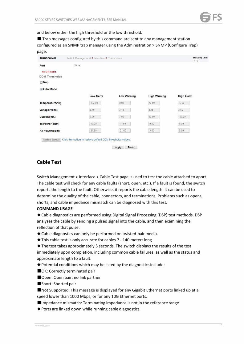
and warning messages for optical transceivers which support Digital Diagnostic Monitoring(DDM). This page also displays identifying information for supported transceiver types, andoperational parameters for transceivers which support DDM.ParametersThese parameters are displayed:◆ Port – Port number. (ECS4620-28F/28F-DC: 1-28, Other models: SFP/SFP+ ports 25-28 /49-52)◆ General – Information on connector type and vendor-relatedparameters.◆ DDM Information – Information on temperature, supply voltage, laser bias current,laser power, and received optical power. The switch can display diagnostic information forSFP modules which support the SFF-8472 Specification for Diagnostic Monitoring Interfacefor Optical Transceivers. This information allows administrators to remotely diagnoseproblems with optical devices. This feature, referred to as Digital Diagnostic Monitoring(DDM) provides information on transceiver parameters.◆ Trap – Sends a trap when any of the transceiver’s operation values falls outside ofspecified thresholds. (Default: Disabled)◆ Auto Mode – Uses default threshold settings obtained from the transceiver to determinewhen an alarm or trap message should be sent. (Default: Enabled)◆ DDM Thresholds – Information on alarm and warning thresholds. The switch can beconfigured to send a trap when the measured parameter falls outside of the specifiedthresholds.The following alarm and warning parameters are supported:■ High Alarm – Sends an alarm message when the high threshold is crossed.■ High Warning – Sends a warning message when the high threshold is crossed.■ LowWarning – Sends a warning message when the low threshold is crossed.■ Low Alarm – Sends an alarm message when the low threshold is crossed. Theconfigurable ranges are:■ Temperature: -128.00-128.00 °C■ Voltage: 0.00-6.55 Volts■ Current: 0.00-131.00 mA■ Power: -40.00-8.20 dBmThe threshold value for Rx and Tx power is calculated as the power ratio in decibels (dB) ofthe measured power referenced to one milliwatt (mW). Threshold values for alarm andwarning messages can be configured as described below.■ A high-threshold alarm or warning message is sent if the current value is greater than orequal to the threshold, and the last sample value was less than the threshold. After a risingevent has been generated, another such event will not be generated until the sampled valuehas fallen below the high threshold and reaches the lowthreshold.■ A low-threshold alarm or warning message is sent if the current value is less than or equalto the threshold, and the last sample value was greater than the threshold. After a fallingevent has been generated, another such event will not be generated until the sampled valuehas risen above the low threshold and reaches the high threshold.■ Threshold events are triggered as described above to avoid a hysteresis effect whichwould continuously trigger event messages if the power level were to fluctuate justabove
S3900 SERIES SWITCHES WEB MANAGEMENT USER MANUAL
www.fs.com 10
and below either the high threshold or the low threshold.■ Trap messages configured by this command are sent to any management stationconfigured as an SNMP trap manager using the Administration > SNMP (Configure Trap)page.
Cable Test
Switch Management > Interface > Cable Test page is used to test the cable attached to aport.The cable test will check for any cable faults (short, open, etc.). If a fault is found, the switchreports the length to the fault. Otherwise, it reports the cable length. It can be used todetermine the quality of the cable, connectors, and terminations. Problems such as opens,shorts, and cable impedance mismatch can be diagnosed with this test.COMMAND USAGE◆Cable diagnostics are performed using Digital Signal Processing (DSP) test methods. DSPanalyses the cable by sending a pulsed signal into the cable, and then examining thereflection of that pulse.◆Cable diagnostics can only be performed on twisted-pairmedia.◆This cable test is only accurate for cables 7 - 140 meters long.◆The test takes approximately 5 seconds. The switch displays the results of the testimmediately upon completion, including common cable failures, as well as the status andapproximate length to a fault.◆Potential conditions which may be listed by the diagnostics include:■OK: Correctly terminated pair■Open: Open pair, no link partner■Short: Shorted pair■Not Supported: This message is displayed for any Gigabit Ethernet ports linked up at aspeed lower than 1000 Mbps, or for any 10G Ethernet ports.■Impedance mismatch: Terminating impedance is not in the reference range.◆Ports are linked down while running cable diagnostics.

S3900 SERIES SWITCHES WEB MANAGEMENT USER MANUAL
www.fs.com 11
PARAMETERSThese parameters are displayed:◆Port – Switch port identifier.◆Type – Displays media type. (GE – Gigabit Ethernet, Other – SFP+)◆Link Status – Shows if the port link is up or down.◆Test Result – The results include common cable failures, as well as the status andapproximate distance to a fault, or the approximate cable length if no fault is found. Toensure more accurate measurement of the length to a fault, first disable power-saving modeon the link partner before running cable diagnostics. For link-down ports, the reporteddistance to a fault is accurate to within +/- 2 meters. For link-up ports, the accuracy is +/- 10meters.◆Last Updated – Shows the last time this port was tested.
Green Ethernet
Switch Management > Interface > Green Ethernet page is used to enable power savingsmode onthe selected port.COMMAND USAGE◆ IEEE 802.3 defines the Ethernet standard and subsequent power requirements based oncable connections operating at 100 meters. Enabling power saving mode can reduce powerused for cable lengths of 60 meters or less, with more significant reduction for cables of 20meters or less, and continue to ensure signal integrity.◆The power-saving methods provided by this switch include:■Power saving when there is no link partner:Under normal operation, the switch continuously auto-negotiates to find a link partner,keeping the MAC interface powered up even if no link connection exists. When usingpower-savings mode, the switch checks for energy on the circuit to determine if there is alink partner. If none is detected, the switch automatically turns off the transmitter, and mostof the receive circuitry (enters Sleep Mode). In this mode, the low-power energy-detectioncircuit continuously checks for energy on the cable. If none is detected, the MAC interface isalso powered down to save additional energy. If energy is detected, the switch immediatelyturns on both the transmitter and receiver functions, and powers up the MAC interface.■Power saving when there is a link partner:Traditional Ethernet connections typically operate with enough power to support at least100 meters of cable even though average network cable length is shorter. When cablelength is shorter, power consumption can be reduced since signal attenuation isproportional to cable length. When power-savings mode is enabled, the switch analyzes

S3900 SERIES SWITCHES WEB MANAGEMENT USER MANUAL
www.fs.com 12
cable length to determine whether or not it can reduce the signal amplitude used on aparticular link.PARAMETERSThese parameters are displayed:◆Port – Power saving mode only applies to the Gigabit Ethernet ports using coppermedia.◆Power Saving Status – Adjusts the power provided to ports based on the length of thecable used to connect to other devices. Only sufficient power is used to maintain connectionrequirements. (Default: Enabled on Gigabit Ethernet RJ-45 ports)
Traffic Segment
Switch Management > Interface > Traffic Segment page is used to enable trafficsegmentation.PARAMETERSThese parameters are displayed:◆Status – Enables port-based traffic segmentation. (Default: Disabled)◆Uplink-to-Uplink Mode – Specifies whether or not traffic can be forwarded betweenuplink ports assigned to different client sessions.■Blocking – Blocks traffic between uplink ports assigned to different sessions.■Forwarding – Forwards traffic between uplink ports assigned to different sessions.

S3900 SERIES SWITCHES WEB MANAGEMENT USER MANUAL
www.fs.com 13
Statistics
Statistics Info
Switch management > Statistics > Statistics Info page is used to display standard statistics onnetwork traffic from the Interfaces Group and Ethernet-like MIBs, as well as a detailedbreakdown of traffic based on the RMONMIB. Interfaces and Ethernet-like statistics displayerrors on the traffic passing through each port. This information can be used to identifypotential problems with the switch (such as a faulty port or unusually heavy traffic). RMONstatistics provide access to a broad range of statistics, including a total count of differentframe types and sizes passing through each port. All values displayed have beenaccumulated since the last system reboot, and are shown as counts per second. Statistics arerefreshed every 60 seconds by default.PARAMETERSThese parameters are displayed:
Parameter DescriptionInterface Statistics
Received OctetsThe total number of octets received on the interface, including framingcharacters.
Transmitted OctetsThe total number of octets transmitted out of the interface, includingframing characters.
Received ErrorsThe number of inbound packets that contained errors preventing themfrom being deliverable to a higher-layer protocol.
Transmitted ErrorsThe number of outbound packets that could not be transmittedbecause of errors.
Received UnicastPackets
The number of subnetwork-unicast packets delivered to a higher-layerprotocol.
Transmitted UnicastPackets
The total number of packets that higher-level protocols requested betransmitted to a subnetwork-unicast address, including those that werediscarded or not sent.
Received DiscardedPackets
The number of inbound packets which were chosen to be discardedeven though no errors had been detected to prevent their beingdeliverable to a higher-layer protocol. One possible reason fordiscarding such a packet could be to free up buffer space.
TransmittedDiscarded Packets
The number of outbound packets which were chosen to be discardedeven though no errors had been detected to prevent their beingtransmitted. One possible reason for discarding such a packet could beto free up buffer space.
Received MulticastPackets
The number of packets, delivered by this sub-layer to a higher(sub-)layer, which were addressed to a multicast address at thissub-layer.
Transmitted The total number of packets that higher-level protocols requested be

S3900 SERIES SWITCHES WEB MANAGEMENT USER MANUAL
www.fs.com 14
Multicast Packets transmitted, and which were addressed to a multicast address at thissub-layer, including those that were discarded or not sent.
Received BroadcastPackets
The number of packets, delivered by this sub-layer to a higher(sub-)layer, which were addressed to a broadcast address at thissub-layer.
TransmittedBroadcast Packets
The total number of packets that higher-level protocols requested betransmitted, and which were addressed to a broadcast address at thissub-layer, including those that were discarded or not sent.
Received UnknownPackets
The number of packets received via the interface which were discardedbecause of an unknown or unsupported protocol.
Etherlike StatisticsSingle CollisionFrames
The number of successfully transmitted frames for which transmissionis inhibited by exactly one collision.
Multiple CollisionFrames
A count of successfully transmitted frames for which transmission isinhibited by more than one collision.
Late CollisionsThe number of times that a collision is detected later than 512 bit-timesinto the transmission of a packet.
Excessive CollisionsA count of frames for which transmission on a particular interface failsdue to excessive collisions. This counter does not increment when theinterface is operating in full-duplex mode.
DeferredTransmissions
A count of frames for which the first transmission attempt on aparticular interface is delayed because the medium was busy.
Frames Too LongA count of frames received on a particular interface that exceed themaximum permitted frame size.
Alignment Errors The number of alignment errors (missynchronized data packets).
FCS Errors
A count of frames received on a particular interface that are an integralnumber of octets in length but do not pass the FCS check. This countdoes not include frames received with frame-too-long orframe-too-short error.
SQE Test ErrorsA count of times that the SQE TEST ERROR message is generated by thePLS sublayer for a particular interface.
Carrier Sense ErrorsThe number of times that the carrier sense condition was lost or neverasserted when attempting to transmit a frame.
Internal MACReceive Errors
A count of frames for which reception on a particular interface fails dueto an internal MAC sublayer receive error.
Internal MACTransmit Errors
A count of frames for which transmission on a particular interface failsdue to an internal MAC sublayer transmit error.
RMON Statistics
Drop EventsThe total number of events in which packets were dropped due to lackof resources.
JabbersThe total number of frames received that were longer than 1518 octets(excluding framing bits, but including FCS octets), and had either an FCSor alignment error.

S3900 SERIES SWITCHES WEB MANAGEMENT USER MANUAL
www.fs.com 15
Fragments The total number of frames received that were less than 64 octets inlength (excluding framing bits, but including FCS octets) and had eitheran FCS or alignment error.
Collisions The best estimate of the total number of collisions on this Ethernetsegment.
Received Octets Total number of octets of data received on the network. This statisticcan be used as a reasonable indication of Ethernet utilization.
Received Packets The total number of packets (bad, broadcast and multicast) received.Broadcast Packets The total number of good packets received that were directed to the
broadcast address. Note that this does not include multicast packets.Multicast Packets The total number of good packets received that were directed to this
multicast address.Undersize Packets The total number of packets received that were less than 64 octets long
(excluding framing bits, but including FCS octets) and were otherwisewell formed.
Oversize Packets The total number of packets received that were longer than 1518 octets(excluding framing bits, but including FCS octets) and wereotherwisewell formed.
64 Bytes Packets The total number of packets (including bad packets) received andtransmitted that were 64 octets in length (excluding framing bits butincluding FCS octets).
Input Octets in kbitsper second
Number of octets entering this interface in kbits/second.
Input Packets persecond
Number of packets entering this interface per second.
Input Utilization The input utilization rate for this interface.Output Octets inkbits per second
Number of octets leaving this interface in kbits/second.
Output Packets persecond
Number of packets leaving this interface per second.
Output Utilization The output utilization rate for this interface.

S3900 SERIES SWITCHES WEB MANAGEMENT USER MANUAL
www.fs.com 16
History Management
Switch Management > Statistics > History Management page is used to display statisticalhistory for the specified interfaces.Command Usage◆ For a description of the statistics displayed on these pages, see “Showing Port or TrunkStatistics”◆ To configure statistical history sampling, use the “Displaying Statistical History”ParametersThese parameters are displayed:Add◆ Port – Port number. (Range: 1-28/52)◆ History Name – Name of sample interval. (Range: 1-32 characters)◆ Interval - The interval for sampling statistics. (Range: 1-86400minutes)◆ Requested Buckets - The number of samples to take. (Range: 1-96)Show◆ Port – Port number. (Range: 1-26/28/52)◆ History Name – Name of sample interval. (Default settings: 15min, 1day)◆ Interval - The interval for sampling statistics.◆ Requested Buckets - The number of samples to take.Show Details◆Mode■ Status – Shows the sample parameters.■ Current Entry – Shows current statistics for the specified port and namedsample.■ Input Previous Entries – Shows statistical history for ingress traffic.■ Output Previous Entries – Shows statistical history for egress traffic.◆ Port – Port number. (Range: 1-26/28/52)◆ Name – Name of sample interval.

S3900 SERIES SWITCHES WEB MANAGEMENT USER MANUAL
www.fs.com 17
Show History Statistics

S3900 SERIES SWITCHES WEB MANAGEMENT USER MANUAL
www.fs.com 18
Vlan
Static Vlan
Switch Management > VLAN > Static Vlan > Vlan Management page is used to add ,modify ordelete static VLAN groups, set administrative status, or specify Remote VLAN type.

S3900 SERIES SWITCHES WEB MANAGEMENT USER MANUAL
www.fs.com 19
Topropagate information about VLAN groups used on this switch to external networkdevices, you must specify a VLAN ID for each of thesegroups.◆VLAN ID – ID of VLAN or range of VLANs (1-4093). Up to 4093 VLAN groups can be defined.VLAN 1 is the default untagged VLAN.◆VLAN Name – Name of the VLAN (1 to 32 characters).◆Status – Enables or disables the specified VLAN.◆Remote VLAN – Reserves this VLAN for RSPAN.◆L3 Interface – Sets the interface to support Layer 3 configuration, and reserves memoryspace required to maintain additional information about this interface type. This parametermust be enabled before you can assign an IP address to aVLAN
Switch Management > VLAN > Static Vlan > Edit member by vlan page is used to add/deletemultiple port members to/from a special vlan.
Switch Management > VLAN > Static Vlan > Edit member by interface page is used toadd/delete a interface member to/from multiple vlan
Switch Management > VLAN > Static Vlan > Edit member by interface range page is used to

S3900 SERIES SWITCHES WEB MANAGEMENT USER MANUAL
www.fs.com 20
add/delete multiple interface member to/from multiple vlan
GVRP
Switch Management > VLAN > GVRP page is used to enable GVRP globally on the switch, orto enable GVRP and adjust the protocol timers per interface.PARAMETERSThese parameters are displayed:Configure General◆ GVRP Status – GVRP defines a way for switches to exchange VLAN information in order toregister VLAN members on ports across the network. VLANs are dynamically configuredbased on join messages issued by host devices and propagated throughout the network.GVRP must be enabled to permit automatic VLAN registration, and to support VLANs whichextend beyond the local switch. (Default: Disabled)Configure Interface◆ Interface – Displays a list of ports or trunks.◆ Port – Port Identifier. (Range: 1-28)◆ Trunk – Trunk Identifier. (Range: 1-12)◆ GVRP Status – Enables/disables GVRP for the interface. GVRP must be globally enabledfor the switch before this setting can take effect (using the Configure General page). Whendisabled, any GVRP packets received on this port will be discarded and no GVRP registrationswill be propagated from other ports. (Default: Disabled) GVRP cannot be enabled for portsset to Access mode◆ GVRP Timers – Timer settings must follow this rule: 2 x (join timer) < leave timer <leaveAll timer■ Join – The interval between transmitting requests/queries toparticipate in a VLAN group. (Range: 20-1000 centiseconds; Default: 20)■ Leave – The interval a port waits before leaving a VLAN group. This time should be set tomore than twice the join time. This ensures that after a Leave or LeaveAll message has beenissued, the applicants can rejoin before the port actually leaves the group. (Range: 60-3000centiseconds; Default: 60)
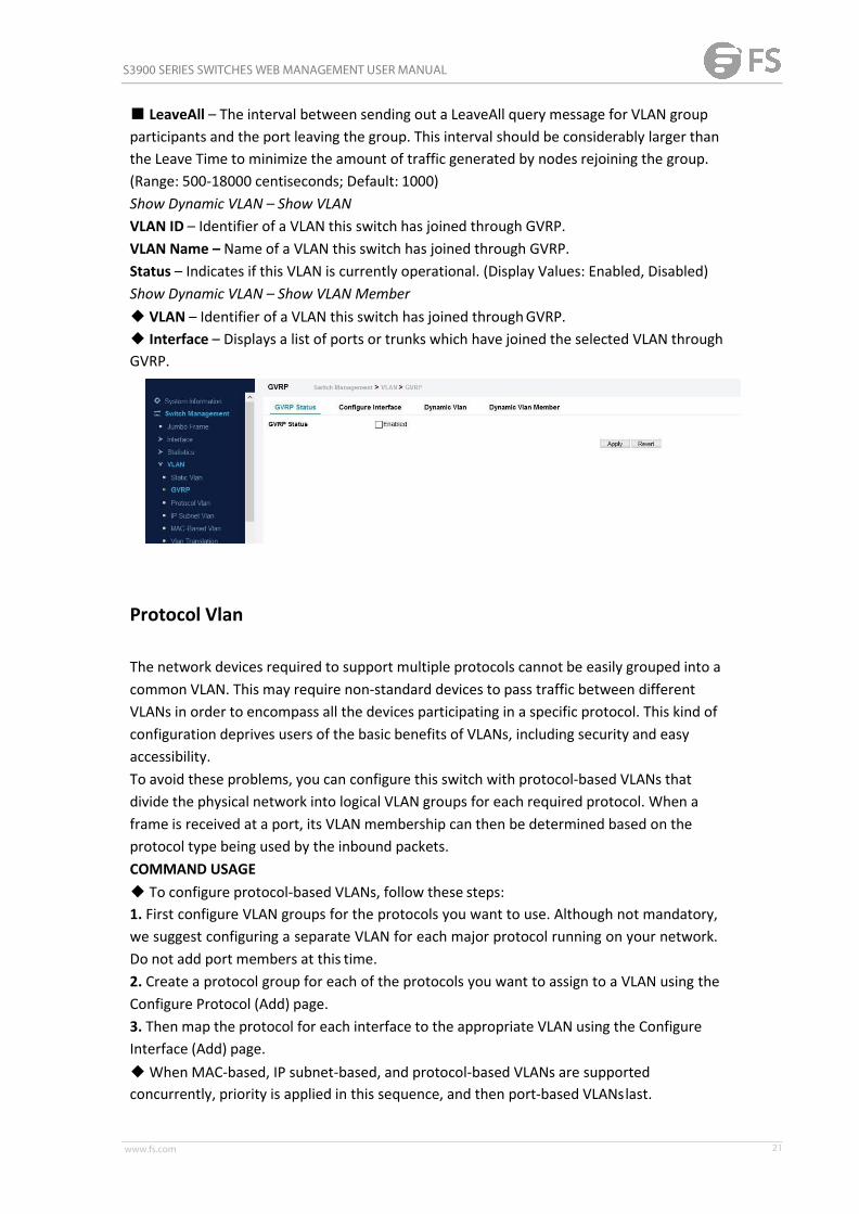
S3900 SERIES SWITCHES WEB MANAGEMENT USER MANUAL
www.fs.com 21
■ LeaveAll – The interval between sending out a LeaveAll query message for VLAN groupparticipants and the port leaving the group. This interval should be considerably larger thanthe Leave Time to minimize the amount of traffic generated by nodes rejoining the group.(Range: 500-18000 centiseconds; Default: 1000)Show Dynamic VLAN – Show VLANVLAN ID – Identifier of a VLAN this switch has joined through GVRP.VLAN Name – Name of a VLAN this switch has joined through GVRP.Status – Indicates if this VLAN is currently operational. (Display Values: Enabled, Disabled)Show Dynamic VLAN – Show VLAN Member◆ VLAN – Identifier of a VLAN this switch has joined throughGVRP.◆ Interface – Displays a list of ports or trunks which have joined the selected VLAN throughGVRP.
Protocol Vlan
The network devices required to support multiple protocols cannot be easily grouped into acommon VLAN. This may require non-standard devices to pass traffic between differentVLANs in order to encompass all the devices participating in a specific protocol. This kind ofconfiguration deprives users of the basic benefits of VLANs, including security and easyaccessibility.To avoid these problems, you can configure this switch with protocol-based VLANs thatdivide the physical network into logical VLAN groups for each required protocol. When aframe is received at a port, its VLAN membership can then be determined based on theprotocol type being used by the inbound packets.COMMAND USAGE◆ To configure protocol-based VLANs, follow these steps:1. First configure VLAN groups for the protocols you want to use. Although not mandatory,we suggest configuring a separate VLAN for each major protocol running on your network.Do not add port members at this time.2. Create a protocol group for each of the protocols you want to assign to a VLAN using theConfigure Protocol (Add) page.3. Then map the protocol for each interface to the appropriate VLAN using the ConfigureInterface (Add) page.◆When MAC-based, IP subnet-based, and protocol-based VLANs are supportedconcurrently, priority is applied in this sequence, and then port-based VLANslast.

S3900 SERIES SWITCHES WEB MANAGEMENT USER MANUAL
www.fs.com 22
Switch Management > VLAN > Protocol Vlan page is used to create and delete a protocolvlan entry.
Press New button to create a protocol vlan entry:
◆ Frame Type – Choose either Ethernet, RFC 1042, or LLC Other as the frame type used bythis protocol.◆ Protocol Type – Specifies the protocol type to match. The available options are IP, ARP,RARP and IPv6. If LLC Other is chosen for the Frame Type, the only available Protocol Type isIPX Raw.◆ Protocol Group ID – Protocol Group ID assigned to the Protocol VLAN Group. (Range:1-2147483647)
Switch Management > VLAN > Interface Mapping Table page is used to add/delete ainterface member to protocol vlan group.
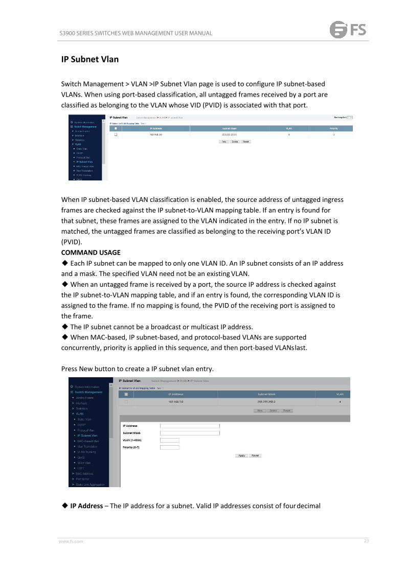
S3900 SERIES SWITCHES WEB MANAGEMENT USER MANUAL
www.fs.com 23
IP Subnet Vlan
Switch Management > VLAN >IP Subnet Vlan page is used to configure IP subnet-basedVLANs. When using port-based classification, all untagged frames received by a port areclassified as belonging to the VLAN whose VID (PVID) is associated with that port.
When IP subnet-based VLAN classification is enabled, the source address of untagged ingressframes are checked against the IP subnet-to-VLAN mapping table. If an entry is found forthat subnet, these frames are assigned to the VLAN indicated in the entry. If no IP subnet ismatched, the untagged frames are classified as belonging to the receiving port’s VLAN ID(PVID).COMMAND USAGE◆ Each IP subnet can be mapped to only one VLAN ID. An IP subnet consists of an IP addressand a mask. The specified VLAN need not be an existingVLAN.◆When an untagged frame is received by a port, the source IP address is checked againstthe IP subnet-to-VLAN mapping table, and if an entry is found, the corresponding VLAN ID isassigned to the frame. If no mapping is found, the PVID of the receiving port is assigned tothe frame.◆ The IP subnet cannot be a broadcast or multicast IP address.◆When MAC-based, IP subnet-based, and protocol-based VLANs are supportedconcurrently, priority is applied in this sequence, and then port-based VLANslast.
Press New button to create a IP subnet vlan entry.
◆ IP Address – The IP address for a subnet. Valid IP addresses consist of fourdecimal

S3900 SERIES SWITCHES WEB MANAGEMENT USER MANUAL
www.fs.com 24
numbers, 0 to 255, separated by periods.◆ Subnet Mask – This mask identifies the host address bits of the IP subnet.◆ VLAN – VLAN to which matching IP subnet traffic is forwarded. (Range:1-4093)◆ Priority – The priority assigned to untagged ingress traffic. (Range: 0-7, where 7 is thehighest priority; Default: 0)
To delete a IP subnet vlan entry, select the entry and press delete button.
MAC-Based Vlan
Switch Management > VLAN > Mac-Based Vlan page is used to configure VLAN based onMAC addresses.
The MAC-based VLAN feature assigns VLAN IDs to ingress untagged frames according tosource MAC addresses. When MAC-based VLAN classification is enabled, untagged framesreceived by a port are assigned to the VLAN which is mapped to the frame’s source MACaddress. When no MAC address is matched, untagged frames are assigned to the receivingport’s native VLAN ID (PVID).COMMAND USAGE◆ The MAC-to-VLAN mapping applies to all ports on the switch.◆ Source MAC addresses can be mapped to only one VLAN ID.◆ Configured MAC addresses cannot be broadcast or multicast addresses.◆When MAC-based, IP subnet-based, and protocol-based VLANs are supportedconcurrently, priority is applied in this sequence, and then port-based VLANslast.
To create a Mac based vlan, press New button:
◆MAC Address – A source MAC address which is to be mapped to a specific VLAN. TheMAC address must be specified in the format xx-xxxx-xx-xx-xx.◆ VLAN – VLAN to which ingress traffic matching the specified source MAC address is

S3900 SERIES SWITCHES WEB MANAGEMENT USER MANUAL
www.fs.com 25
forwarded. (Range: 1-4093)◆ Priority – The priority assigned to untagged ingress traffic. (Range: 0-7, where 7 is thehighest priority; Default: 0)
To delete a Mac based vlan entry, select the entry and press delete button.
Vlan Translation
Switch Management > VLAN > Vlan Translation page is used to to map VLAN IDs betweenthe customer and service provider for networks that do not support IEEE 802.1Q tunneling.
COMMAND USAGE◆ QinQ tunneling uses double tagging to preserve the customer’s VLAN tags on trafficcrossing the service provider’s network. However, if any switch in the path crossing theservice provider’s network does not support this feature, then the switches directlyconnected to that device can be configured to swap the customer’s VLAN ID with the serviceprovider’s VLAN ID for upstream traffic, or the service provider’s VLAN ID with thecustomer’s VLAN ID for downstream traffic. For example, assume that the upstream switchdoes not support QinQ tunneling. Select Port 1, and set the Old VLAN to 10 and the NewVLAN to 100 to map VLAN 10 to VLAN 100 for upstream traffic entering port 1, and VLAN100 to VLAN 10 for downstream traffic leaving port 1 as shownbelow.
◆ The maximum number of VLAN translation entries is 8 per port, and up to 96 for thesystem. However, note that configuring a large number of entries may degrade theperformance of other processes that also use the TCAM, such as IP Source Guard filter rules,Quality of Service (QoS) processes, QinQ, MAC-based VLANs, VLAN translation, ortraps.◆ If VLAN translation is set on an interface, and the same interface is also configured as aQinQ access port on the VLAN > Tunnel (Configure Interface) page, VLAN tag assignmentswill be determined by the QinQ process, not by VLAN translation.
Press New button to create a vlan translation.

S3900 SERIES SWITCHES WEB MANAGEMENT USER MANUAL
www.fs.com 26
These parameters are displayed:◆ Old VLAN – The original VLAN ID. (Range: 1-4093)◆ New VLAN – The new VLAN ID. (Range: 1-4093)
To delete a entry, select the entry and press delete button.
VLAN Trunking
Switch Management > VLAN > Vlan Trunking page is used to allow unknown VLAN groups topass through the specified interface.
Command Usage◆ Use this feature to configure a tunnel across one or more intermediate switches whichpass traffic for VLAN groups to which they do notbelong.The following figure shows VLANs 1 and 2 configured on switches A and B, with VLANtrunking being used to pass traffic for these VLAN groups across switches C, D and E.Figure 67: Configuring VLAN TrunkingWithout VLAN trunking, you would have to configure VLANs 1 and 2 on all intermediateswitches – C, D and E; otherwise these switches would drop any frames with unknown VLAN
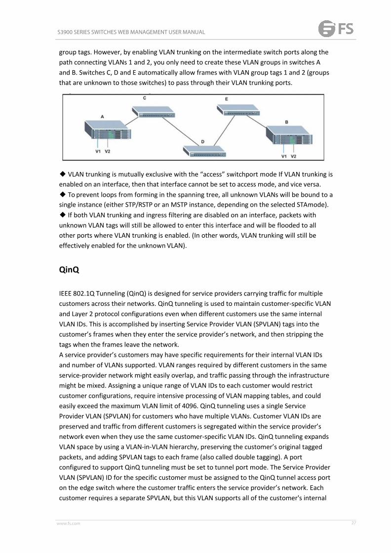
S3900 SERIES SWITCHES WEB MANAGEMENT USER MANUAL
www.fs.com 27
group tags. However, by enabling VLAN trunking on the intermediate switch ports along thepath connecting VLANs 1 and 2, you only need to create these VLAN groups in switches Aand B. Switches C, D and E automatically allow frames with VLAN group tags 1 and 2 (groupsthat are unknown to those switches) to pass through their VLAN trunking ports.
◆ VLAN trunking is mutually exclusive with the “access” switchport mode If VLAN trunking isenabled on an interface, then that interface cannot be set to access mode, and vice versa.◆ To prevent loops from forming in the spanning tree, all unknown VLANs will be bound to asingle instance (either STP/RSTP or an MSTP instance, depending on the selected STAmode).◆ If both VLAN trunking and ingress filtering are disabled on an interface, packets withunknown VLAN tags will still be allowed to enter this interface and will be flooded to allother ports where VLAN trunking is enabled. (In other words, VLAN trunking will still beeffectively enabled for the unknownVLAN).
QinQ
IEEE 802.1Q Tunneling (QinQ) is designed for service providers carrying traffic for multiplecustomers across their networks. QinQ tunneling is used to maintain customer-specific VLANand Layer 2 protocol configurations even when different customers use the same internalVLAN IDs. This is accomplished by inserting Service Provider VLAN (SPVLAN) tags into thecustomer’s frames when they enter the service provider’s network, and then stripping thetags when the frames leave the network.A service provider’s customers may have specific requirements for their internal VLAN IDsand number of VLANs supported. VLAN ranges required by different customers in the sameservice-provider network might easily overlap, and traffic passing through the infrastructuremight be mixed. Assigning a unique range of VLAN IDs to each customer would restrictcustomer configurations, require intensive processing of VLAN mapping tables, and couldeasily exceed the maximum VLAN limit of 4096. QinQ tunneling uses a single ServiceProvider VLAN (SPVLAN) for customers who have multiple VLANs. Customer VLAN IDs arepreserved and traffic from different customers is segregated within the service provider’snetwork even when they use the same customer-specific VLAN IDs. QinQ tunneling expandsVLAN space by using a VLAN-in-VLAN hierarchy, preserving the customer’s original taggedpackets, and adding SPVLAN tags to each frame (also called double tagging). A portconfigured to support QinQ tunneling must be set to tunnel port mode. The Service ProviderVLAN (SPVLAN) ID for the specific customer must be assigned to the QinQ tunnel access porton the edge switch where the customer traffic enters the service provider’s network. Eachcustomer requires a separate SPVLAN, but this VLAN supports all of the customer's internal

S3900 SERIES SWITCHES WEB MANAGEMENT USER MANUAL
www.fs.com 28
VLANs. The QinQ tunnel uplink port that passes traffic from the edge switch into the serviceprovider’s metro network must also be added to this SPVLAN. The uplink port can be addedto multiple SPVLANs to carry inbound traffic for different customers onto the serviceprovider’s network. When a double-tagged packet enters another trunk port in anintermediate or core switch in the service provider’s network, the outer tag is stripped forpacket processing. When the packet exits another trunk port on the same core switch, thesame SPVLAN tag is again added to the packet. When a packet enters the trunk port on theservice provider’s egress switch, the outer tag is again stripped for packet processing.However, the SPVLAN tag is not added when it is sent out the tunnel access port on the edgeswitch into the customer’s network. The packet is sent as a normal IEEE 802.1Q-taggedframe, preserving the original VLAN numbers used in the customer’s network.
Layer 2 Flow for Packets Coming into a Tunnel Access Port
A QinQ tunnel port may receive either tagged or untagged packets. No matter howmanytags the incoming packet has, it is treated as tagged packet. The ingress process does sourceand destination lookups. If both lookups are successful, the ingress process writes the packetto memory. Then the egress process transmits the packet. Packets entering a QinQ tunnelport are processed in the following manner:1. An SPVLAN tag is added to all outbound packets on the SPVLAN interface, no matter howmany tags they already have. The switch constructs and inserts the outer tag (SPVLAN) intothe packet based on the default VLAN ID and Tag Protocol Identifier (TPID, that is, theether-type of the tag). The priority of the inner tag is copied to the outer tag if it is a taggedor priority tagged packet.2. After successful source and destination lookup, the ingress process sends the packet tothe switching process with two tags. If the incoming packet is untagged, the outer tag is anSPVLAN tag, and the inner tag is a dummy tag (8100 0000). If the incoming packet is tagged,the outer tag is an SPVLAN tag, and the inner tag is a CVLANtag.3. After packet classification through the switching process, the packet is written to memorywith one tag (an outer tag) or with two tags (both an outer tag and inner tag).4. The switch sends the packet to the proper egress port.5. If the egress port is an untagged member of the SPVLAN, the outer tag will be stripped. Ifit is a tagged member, the outgoing packets will have twotags.Layer 2 Flow for Packets Coming into a Tunnel Uplink Port

S3900 SERIES SWITCHES WEB MANAGEMENT USER MANUAL
www.fs.com 29
An uplink port receives one of the following packets:◆ Untagged◆ One tag (CVLAN or SPVLAN)◆ Double tag (CVLAN + SPVLAN)The ingress process does source and destination lookups. If both lookups are successful, theingress process writes the packet to memory. Then the egress process transmits the packet.Packets entering a QinQ uplink port are processed in the followingmanner:1. If incoming packets are untagged, the PVID VLAN native tag isadded.2. If the ether-type of an incoming packet (single or double tagged) is not equal to the TPIDof the uplink port, the VLAN tag is determined to be a Customer VLAN (CVLAN) tag. Theuplink port’s PVID VLAN native tag is added to the packet. This outer tag is used for learningand switching packets within the service provider’s network. The TPID must be configuredon a per port basis, and the verification cannot bedisabled.3. If the ether-type of an incoming packet (single or double tagged) is equal to the TPID ofthe uplink port, no new VLAN tag is added. If the uplink port is not the member of the outerVLAN of the incoming packets, the packet will be dropped when ingress filtering is enabled.If ingress filtering is not enabled, the packet will still be forwarded. If the VLAN is not listed inthe VLAN table, the packet will be dropped.4. After successful source and destination lookups, the packet is double tagged. The switchuses the TPID of 0x8100 to indicate that an incoming packet is double-tagged. If the outertag of an incoming double-tagged packet is equal to the port TPID and the inner tag is0x8100, it is treated as a double-tagged packet. If a single-tagged packet has 0x8100 as itsTPID, and port TPID is not 0x8100, a new VLAN tag is added and it is also treatedasdouble-tagged packet.5. If the destination address lookup fails, the packet is sent to all member ports of the outertag's VLAN.6. After packet classification, the packet is written to memory for processing as asingle-tagged or double-tagged packet.7. The switch sends the packet to the proper egress port.8. If the egress port is an untagged member of the SPVLAN, the outer tag will be stripped. Ifit is a tagged member, the outgoing packet will have twotags.Configuration Limitations for QinQ◆ The native VLAN of uplink ports should not be used as the SPVLAN. If the SPVLAN is theuplink port's native VLAN, the uplink port must be an untagged member of the SPVLAN.Then the outer SPVLAN tag will be stripped when the packets are sent out. Another reason isthat it causes non-customer packets to be forwarded to the SPVLAN.◆ Static trunk port groups are compatible with QinQ tunnel ports as long as the QinQconfiguration is consistent within a trunk port group.◆ The native VLAN (VLAN 1) is not normally added to transmitted frames. Avoid using VLAN1 as an SPVLAN tag for customer traffic to reduce the risk of misconfiguration. Instead, useVLAN 1 as a management VLAN instead of a data VLAN in the service providernetwork.◆ There are some inherent incompatibilities between Layer 2 and Layer 3switching:■ Tunnel ports do not support IP Access Control Lists.■ Layer 3 Quality of Service (QoS) and other QoS features containing Layer 3 information

S3900 SERIES SWITCHES WEB MANAGEMENT USER MANUAL
www.fs.com 30
are not supported on tunnel ports.■ Spanning tree bridge protocol data unit (BPDU) filtering is automatically disabled on atunnel port.
Switch Management > VLAN > QinQ > Configure QinQ Status page is used to configure theswitch to operate in IEEE 802.1Q (QinQ) tunneling mode, which is used for passing Layer 2traffic across a service provider’s metropolitan area network. You can also globally set theTag Protocol Identifier (TPID) value of the tunnel port if the attached client is using anonstandard 2-byte ethertype to identify 802.1Q tagged frames.PARAMETERSThese parameters are displayed:◆ Tunnel Status – Sets the switch to QinQ mode. (Default: Disabled)◆ Ethernet Type – The Tag Protocol Identifier (TPID) specifies the ethertype of incomingpackets on a tunnel port. (Range: hexadecimal 0800-FFFF; Default: 8100)Use this field to set a custom 802.1Q ethertype value for the 802.1Q Tunnel TPID. Thisfeature allows the switch to interoperate with thirdparty switches that do not use thestandard 0x8100 ethertype to identify 802.1Q-tagged frames. For example, if 0x1234 is setas the custom 802.1Q ethertype on a trunk port, incoming frames containing that ethertypeare assigned to the VLAN contained in the tag following the ethertype field, as they would bewith a standard 802.1Q trunk. Frames arriving on the port containing any other ethertypeare looked upon as untagged frames, and assigned to the native VLAN of that port. Thespecified ethertype only applies to ports configured in Uplink mode. If the port is in normalmode, the TPID is always 8100. If the port is in Access mode, received packets are processesas untagged packets.
Switch Management > VLAN > QinQ > QinQ Service Management page is used to configurethe QinQ entry.

S3900 SERIES SWITCHES WEB MANAGEMENT USER MANUAL
www.fs.com 31
Press New button to create new QinQ entry.
To delete a entry, select the entry and press delete button.
Switch Management > VLAN > QinQ > QinQ interface Management page is used to set thetunnel mode for any participating interface.COMMAND USAGE◆ Use the Configure Global page to set the switch to QinQ mode before configuring atunnel access port or tunnel uplink port. Also set the Tag Protocol Identifier (TPID) value ofthe tunnel access port if the attached client is using a nonstandard 2-byte ethertype toidentify 802.1Q tagged frames.◆ Then use the Configure Interface page to set the access interface on the edge switch toAccess mode, and set the uplink interface on the switch attached to the service providernetwork to Uplink mode.PARAMETERSThese parameters are displayed:◆ Interface – Displays a list of ports or trunks.◆ Port – Port Identifier. (Range: 1-28)◆ Trunk – Trunk Identifier. (Range: 1-12)◆Mode – Sets the VLAN membership mode of the port.■ None – The port operates in its normal VLAN mode. (This is thedefault.)■ Access – Configures QinQ tunneling for a client access port to segregate and preservecustomer VLAN IDs for traffic crossing the service providernetwork.■ Uplink – Configures QinQ tunneling for an uplink port to another device within theservice provider network.

S3900 SERIES SWITCHES WEB MANAGEMENT USER MANUAL
www.fs.com 32
Voice Vlan
Switch Management > VLAN > Voice Vlan > Voice Vlan Status page is used to configure thevoice vlan.All ports are set to VLAN hybrid mode by default. Prior to enabling VoIP for a port first ensurethat VLAN membership is not set to access mode.
◆ Auto Detection Status – Enables the automatic detection of VoIP traffic on switch ports.(Default: Disabled)◆ Voice VLAN – Sets the Voice VLAN ID for the network. Only one Voice VLAN is supportedand it must already be created on the switch. (Range:1-4094)◆ Voice VLAN Aging Time – The time after which a port is removed from the Voice VLANwhen VoIP traffic is no longer received on the port. (Range: 5-43200 minutes; Default: 1440minutes)Note: The Voice VLAN ID cannot be modified when the global Auto Detection Status isenabled.
Switch Management > VLAN > Voice Vlan > OUI page is used to configure the OrganizationalUnique Identifier (OUI) in the source MAC address of received packets.

S3900 SERIES SWITCHES WEB MANAGEMENT USER MANUAL
www.fs.com 33
To create a OUI, press New button.
◆ Telephony OUI – Specifies a MAC address range to add to the list. Enter the MAC addressin format 01-23-45-67-89-AB.◆ Mask – Identifies a range of MAC addresses. Setting a mask of FF-FF-FF-00-00-00identifies all devices with the same OUI (the first three octets). Other masks restrict the MACaddress range. Setting a mask of FF-FF-FF-FF-FF-FF specifies a single MAC address. (Default:FF-FF-FF-00-00-00)◆ Description – User-defined text that identifies the VoIP devices
Todelete a OUI, select the OUI and press deletebutton.
Switch Management > VLAN > Voice Vlan > Voice Vlan Interface Management page is usedto configure ports for voice vlan, you need to set the mode (Auto or Manual), specify thediscovery method to use, and set the traffic priority. You can also enable security filtering toensure that only voice vlan traffic is forwarded on the Voice VLAN.
All ports are set to VLAN hybrid mode by default. Prior to enabling VoIP for a port (by setting

S3900 SERIES SWITCHES WEB MANAGEMENT USER MANUAL
www.fs.com 34
the VoIP mode to Auto or Manual as described below), first ensure that VLAN membership isnot set to access mode.◆Mode – Specifies if the port will be added to the Voice VLAN when VoIP traffic is detected.(Default: None)■ None – The Voice VLAN feature is disabled on the port. The port will not detect VoIPtraffic or be added to the VoiceVLAN.■ Auto – The port will be added as a tagged member to the Voice VLAN when VoIP traffic isdetected on the port. You must select a method for detecting VoIP traffic, either OUI or802.1AB (LLDP). When OUI is selected, be sure to configure the MAC address ranges in theTelephony OUI list.■ Manual – The Voice VLAN feature is enabled on the port, but the port must be manuallyadded to the Voice VLAN.◆ Security – Enables security filtering that discards any non-VoIP packets received on theport that are tagged with the voice VLAN ID. VoIP traffic is identified by source MACaddresses configured in the Telephony OUI list, or through LLDP that discovers VoIP devicesattached to the switch. Packets received from non-VoIP sources are dropped. (Default:Disabled)◆ Discovery Protocol – Selects a method to use for detecting VoIP traffic on the port.(Default: OUI)■ OUI – Traffic from VoIP devices is detected by the Organizationally Unique Identifier (OUI)of the source MAC address. OUI numbers are assigned to vendors and form the first threeoctets of a device MAC address. MAC address OUI numbers must be configured in theTelephony OUI list so that the switch recognizes the traffic as being from aVoIP device.■ LLDP – Uses LLDP (IEEE 802.1AB) to discover voice vlan devices attached to the port. LLDPchecks that the “telephone bit” in the system capability TLV is turned on.◆ Priority – Defines a CoS priority for port traffic on the Voice VLAN. The priority of anyreceived voice vlan packet is overwritten with the new priority when the Voice VLAN featureis active for the port. (Range: 0-6; Default: 6)◆ Remaining Age – Number of minutes before this entry is agedout.The Remaining Age starts to count down when the OUI’s MAC address expires from the MACaddress table. Therefore, the MAC address aging time should be added to the overall agingtime. For example, if you configure the MAC address table aging time to 30 seconds, and thevoice VLAN aging time to 5 minutes, then after 5.5 minutes, a port will be removed fromvoice VLAN when voice vlan traffic is no longer received on the port. Alternatively, if youclear the MAC address table manually, then the switch will also start counting down theRemaining Age.
L2PT
When L2PT is not used, protocol packets (such as STP) are flooded to 802.1Q access ports onthe same edge switch, but filtered from 802.1Q tunnel ports. This creates disconnectedprotocol domains in the customer’s network. L2PT can be used to pass various types ofprotocol packets belonging to the same customer transparently across a service provider’s

S3900 SERIES SWITCHES WEB MANAGEMENT USER MANUAL
www.fs.com 35
network. In this way, normally segregated network segments can be configured to functioninside a common protocol domain.L2PT encapsulates protocol packets entering ingress ports on the service provider’s edgeswitch, replacing the destination MAC address with a proprietary MAC address (for example,the spanning tree protocol uses 10-12-CF-00-00-02), a reserved address for other specifiedprotocol types (as defined in IEEE 802.1ad – Provider Bridges), or a user-defined address. Allintermediate switches carrying this traffic across the service provider’s network treat theseencapsulated packets in the same way as normal data, forwarding them across to thetunnel’s egress port. The egress port decapsulates these packets, restores the properprotocol and MAC address information, and then floods them onto the same VLANs at thecustomer’s remote site (via all of the appropriate tunnel ports and access ports25 connectedto the same metro VLAN). The way in which L2PT processes packets is based on the followingcriteria – (1) packet is received on a QinQ uplink port, (2) packet is received on a QinQ accessport, or (3) received packet is Cisco-compatible L2PT (i.e., as indicated by a proprietary MACaddress).Processing protocol packets defined in IEEE 802.1ad – Provider BridgesWhen an IEEE 802.1ad protocol packet is received on an uplink port (i.e., an 802.1Q tunnelingress port connecting the edge switch to the service provider network) with thedestination address 01-80-C2-00-00-00,0B~0F (C-VLAN tag), it is forwarded to all QinQ uplinkports and QinQ access ports in the same S-VLAN for which L2PT is enabled for that protocol.with the destination address 01-80-C2-00-00-01~0A (S-VLAN tag), it is filtered, decapsulated,and processed locally by the switch if the protocol is supported. When a protocol packet isreceived on an access port (i.e., an 802.1Q trunk port connecting the edge switch to the localcustomer network) with the destination address 01-80-C2-00-00-00,0B~0F (C-VLAN), andL2PT is enabled on the port, the frame is forwarded to all QinQ uplink ports and QinQ accessports on which L2PT is enabled for that protocol in the same S-VLAN. L2PT is disabled on theport, the frame is decapsulated and processed locally by the switch if the protocol issupported. with destination address 01-80-C2-00-00-01~0A (S-VLAN), the frame is filtered,decapsulated, and processed locally by the switch if the protocol is supported.Processing Cisco-compatible protocol packetsWhen a Cisco-compatible L2PT packet is received on an uplink port, and recognized as aCDP/VTP/STP/PVST+ protocol packet (where STP means STP/RSTP/MSTP), it is forwarded tothe following ports in the same S-VLAN: (a) all access ports for which L2PT has been disabled,and (b) all uplink ports. recognized as a Generic Bridge PDU Tunneling (GBPT) protocol packet(i.e., having the destination address 01-00-0C-CD-CD-D0), it is forwarded to the followingports in the same S-VLAN:other access ports for which L2PT is enabled after decapsulating the packet and restoring theproper protocol and MAC address information. all uplink ports. When a Cisco-compatibleL2PT packet is received on an access port, and recognized as a CDP/VTP/STP/PVST+protocol packet, and L2PT is enabled on this port, it is forwarded to the following ports in thesame S-VLAN: (a) other access ports for which L2PT is enabled, and (b) uplink ports afterrewriting the destination address to make it a GBPT protocol packet (i.e., setting thedestination address to 01-00-0C-CD-CD-D0). L2PT is disabled on this port, it is forwarded tothe following ports in the same S-VLAN: (a) other access ports for which L2PT is disabled, and

S3900 SERIES SWITCHES WEB MANAGEMENT USER MANUAL
www.fs.com 36
(b) all uplink ports. recognized as a GBPT protocol packet (i.e., having the destination address01-00-0C-CD-CD-D0), and L2PT is enabled on this port, it is forwarded to other access portsin the same S-VLAN for which L2PT is enabled L2PT is disabled on this port, it is forwarded tothe following ports in the same S-VLAN: (a) other access ports for which L2PT is disabled, and(b) all uplink ports.For L2PT to function properly.
Switch Management > VLAN > L2PT > Tunnel MAC page is used to configure the mac addressused in L2PT packet header.
Switch Management > VLAN > L2PT > L2PT interface page is used to configure the interfaceprocess L2PT and what l2 protocols will be processed.
MAC Address
Dynamic MAC Learning
Switch Management > MAC Address > Dynamic MAC Learning > Show Dynamic Mac page isused to display theMAC addresses learned by monitoring the source address for trafficentering the switch. When the destination address for inbound traffic is found in thedatabase, the packets intended for that address are forwarded directly to the associated

S3900 SERIES SWITCHES WEB MANAGEMENT USER MANUAL
www.fs.com 37
port. Otherwise, the traffic is flooded to all ports.PARAMETERS
These parameters are displayed:◆Sort Key - You can sort the information displayed based on MAC address, VLAN orinterface (port or trunk).◆MAC Address – Physical address associated with this interface.◆VLAN – ID of configured VLAN (1-4093).◆ Interface – Indicates a port or trunk.◆Type – Shows that the entries in this table are learned.◆Life Time – Shows the time to retain the specifiedaddress.
Switch Management > MAC Address > Dynamic MAC Learning > Clear Dynamic MAC page isused to remove any learned entries from the forwarding database.PARAMETERSThese parameters are displayed:◆Clear by – All entries can be cleared; or you can clear the entries for a specific MACaddress, all the entries in a VLAN, or all the entries associated with a port ortrunk.
Changing the Aging Time
Switch Management > MAC Address > Dynamic MAC Learning > Configure Aging page isused to set the aging time for entries in the dynamic address table. The aging time is used toage out dynamically learned forwarding information.PARAMETERS

S3900 SERIES SWITCHES WEB MANAGEMENT USER MANUAL
www.fs.com 38
These parameters are displayed:◆Aging Status – Enables/disables the function.◆Aging Time – The time after which a learned entry is discarded. (Range: 6-672 seconds;Default: 300 seconds)
Static Mac Setting
Switch Management > MAC Address > Static Mac Setting page is used to configure staticMAC addresses. A static address can be assigned to a specific interface on this switch. Staticaddresses are bound to the assigned interface and will not be moved. When a static addressis seen on another interface, the address will be ignored and will not be written to theaddress table.COMMAND USAGEThe static address for a host device can be assigned to a specific port within a specific VLAN.Use this command to add static addresses to the MAC Address Table. Static addresses havethe following characteristics:◆Static addresses are bound to the assigned interface and will not be moved. When a staticaddress is seen on another interface, the address will be ignored and will not be written tothe address table.◆Static addresses will not be removed from the address table when a given interface link isdown.◆A static address cannot be learned on another port until the address is removed from thetable.PARAMETERSThese parameters are displayed:◆VLAN – ID of configured VLAN. (Range: 1-4093)◆ Interface – Port or trunk associated with the device assigned a staticaddress.◆MAC Address – Physical address of a device mapped to this interface. Enter an address inthe form of xx-xx-xx-xx-xx-xx or xxxxxxxxxxxx.◆Static Status – Sets the time to retain the specified address.■Delete-on-reset - Assignment lasts until the switch is reset.■Permanent - Assignment is permanent. (This is the default.)WEB INTERFACETo configure a static MAC address:1. Click Switch Management, MAC Address, Static Mac Setting.2. Specify the VLAN, the port or trunk to which the address will be assigned, the MACaddress, and the time to retain this entry.3. Click Apply.

S3900 SERIES SWITCHES WEB MANAGEMENT USER MANUAL
www.fs.com 39
MAC NotificationSwitch Management > MAC Address > MAC Notification page is used to send SNMP traps(i.e., SNMP notifications) when a dynamic MAC address is added or removed.ParametersThese parameters are displayed:Configure Global◆MAC Notification Traps – Issues a trap when a dynamic MAC address is added or removed.(Default: Disabled)◆ MAC Notification Trap Interval – Specifies the interval between issuing two consecutivetraps. (Range: 1-3600 seconds; Default: 1 second)Configure Interface◆ Port – Port Identifier. (Range: 1-28/52)◆ MAC Notification Trap – Enables MAC authentication traps on the current interface.(Default: Disabled)MAC authentication traps must be enabled at the global level for this attribute to takeeffect.Web InterfaceTo enable MAC address traps at the global level:1. Click Switch Management, MAC Address, MACNotification.2. Select Global from the Step list.3. Configure MAC notification traps and the transmission interval.4. Click Apply.

S3900 SERIES SWITCHES WEB MANAGEMENT USER MANUAL
www.fs.com 40
Port Mirror
Local Port Mirror
Switch Management > Port Mirror > Local Port Mirror page is used to mirror traffic from anysource port to a target port for real-time analysis. You can then attach a logic analyzer orRMON probe to the target port and study the traffic crossing the source port in a completelyunobtrusive manner.COMMAND USAGE◆Traffic can be mirrored from one or more source ports to a destination port on the sameswitch (local port mirroring as described in this section), or from one or more source portson remote switches to a destination port on this switch.◆Monitor port speed should match or exceed source port speed, otherwise traffic may bedropped from the monitor port.◆When mirroring VLAN trafficor packets based on a source MAC address, the target portcannot be set to the same target ports as that used for port mirroring by thiscommand.

S3900 SERIES SWITCHES WEB MANAGEMENT USER MANUAL
www.fs.com 41
◆When traffic matches the rules for both port mirroring, and for mirroring of VLAN trafficor packets based on a MAC address, the matching packets will not be sent to target portspecified for port mirroring.◆Note that Spanning Tree BPDU packets are not mirrored to the targetport.PARAMETERSThese parameters are displayed:◆Source Port – The port whose traffic will bemonitored.◆Target Port – The port that will mirror the traffic on the sourceport.◆Type – Allows you to select which traffic to mirror to the target port, Rx (receive), Tx(transmit), or Both. (Default: Rx)
RSPAN
Switch Management > Port Mirror > RSPAN page is used to mirror traffic from remoteswitches for analysis at a destination port on the local switch. This feature, also calledRemote Switched Port Analyzer (RSPAN), carries traffic generated on the specified sourceports for each session over a user-specified VLAN dedicated to that RSPAN session in allparticipating switches. Monitored traffic from one or more sources is copied onto the RSPANVLAN through IEEE 802.1Q trunk or hybrid ports that carry it to any RSPAN destination portmonitoring the RSPAN VLAN as shown in the figure below.COMMAND USAGE◆Traffic can be mirrored from one or more source ports to a destination port on the sameswitch, or from one or more source ports on remote switches to a destination port on thisswitch (remote port mirroring as described in this section).◆Configuration GuidelinesTake the following step to configure an RSPAN session:1. Use the VLAN Static List to reserve a VLAN for use by RSPAN (marking the “Remote VLAN”field on this page. (Default VLAN 1 is prohibited.)2. Set up the source switch on the RSPAN configuration page by specifying the mirror session,the switch’s role (Source), the RSPAN VLAN, and the uplink port1. Then specify the sourceport(s), and the traffic type to monitor (Rx, Tx orBoth).3. Set up all intermediate switches on the RSPAN configuration page, entering the mirrorsession, the switch’s role (Intermediate), the RSPAN VLAN, and the uplinkport(s).4. Set up the destination switch on the RSPAN configuration page by specifying the mirrorsession, the switch’s role (Destination), the destination port, whether or not the trafficexiting this port will be tagged or untagged, and the RSPAN VLAN. Then specify each uplinkport where the mirrored traffic is being received.

S3900 SERIES SWITCHES WEB MANAGEMENT USER MANUAL
www.fs.com 42
◆RSPAN LimitationsThe following limitations apply to the use of RSPAN on this switch:■RSPAN Ports – Only ports can be configured as an RSPAN source, destination, or uplink;static and dynamic trunks are not allowed. A port can only be configured as one type ofRSPAN interface – source, destination, or uplink. Also, note that the source port anddestination port cannot be configured on the same switch.■Local/Remote Mirror – The destination of a local mirror session (created on the Interface >Port > Mirror page) cannot be used as the destination for RSPANtraffic.■Spanning Tree – If the spanning tree is disabled, BPDUs will not be flooded onto theRSPAN VLAN.■MAC address learning is not supported on RSPAN uplink ports when RSPAN is enabled onthe switch. Therefore, even if spanning tree is enabled after RSPAN has been configured,MAC address learning will still not be re-started on the RSPAN uplinkports.■IEEE 802.1X – RSPAN and 802.1X are mutually exclusivefunctions.When 802.1X is enabled globally, RSPAN uplink ports cannot be configured, even thoughRSPAN source and destination ports can still be configured. When RSPAN uplink ports areenabled on the switch, 802.1X cannot be enabled globally.■Port Security – If port security is enabled on any port, that port cannot be set as an RSPANuplink port, even though it can still be configured as an RSPAN source or destination port.Also, when a port is configured as an RSPAN uplink port, port security cannot be enabled onthat port.PARAMETERSThese parameters are displayed:◆Session – A number identifying this RSPAN session. (Range: 1)Only one mirror session is allowed, including both local and remote mirroring. If localmirroring is enabled , then no session can be configured for RSPAN.◆Operation Status – Indicates whether or not RSPAN is currently functioning.◆Switch Role – Specifies the role this switch performs in mirroring traffic.■None – This switch will not participate in RSPAN.■Source - Specifies this device as the source of remotely mirroredtraffic.■Intermediate - Specifies this device as an intermediate switch, transparently passingmirrored traffic from one or more sources to one or moredestinations.■Destination - Specifies this device as a switch configured with a destination port which isto receive mirrored traffic for this session.◆Remote VLAN – The VLAN to which traffic mirrored from the source port will be flooded.The VLAN specified in this field must first be reserved for the RSPAN application using theSwitch Management > VLAN > Static Vlan page.◆Uplink Port – A port on any switch participating in RSPAN through which mirrored trafficis passed on to or received from the RSPAN VLAN. Only one uplink port can be configured ona source switch, but there is no limitation on the number of uplink ports configured on anintermediate or destination switch. Only destination and uplink ports will be assigned by theswitch as members of the RSPAN VLAN. Ports cannot be manually assigned to an RSPANVLAN through the Switch Management > VLAN > Static Vlan page. Nor can GVRP dynamicallyadd port members to an RSPAN VLAN. Also, note that the Switch Management > VLAN>

S3900 SERIES SWITCHES WEB MANAGEMENT USER MANUAL
www.fs.com 43
Static Vlan page will not display any members for an RSPAN VLAN, but will only showconfigured RSPAN VLAN identifiers.◆Type – Specifies the traffic type to be mirrored remotely. (Options: Rx, Tx,Both)◆Destination Port – Specifies the destination port to monitor the traffic mirrored from thesource ports. Only one destination port can be configured on the same switch per session,but a destination port can be configured on more than one switch for the same session. Alsonote that a destination port can still send and receive switched traffic, and participate in anyLayer 2 protocols to which it has been assigned.◆Tag – Specifies whether or not the traffic exiting the destination port to the monitoringdevice carries the RSPAN VLAN tag.
Static Link Aggregation
Static Trunk
Switch Management >Static Link Aggregation > Static Trunk page is used to create and deletestatic trunk group.
To create a static trunk group, press New button. You can create a trunk group with the first

S3900 SERIES SWITCHES WEB MANAGEMENT USER MANUAL
www.fs.com 44
member.
◆ Trunk ID – Trunk identifier. (Range: 1-12)◆Member – The initial trunk member. Use the Add Member page toUnit – Unit identifier. (Range: 1)Port – Port identifier. (Range: 1-28)
Static Trunk Member
Switch Management >Static Link Aggregation > Static Trunk member page is used to add anddelete static trunk group member.
Static Trunk Management
Switch Management >Static Link Aggregation > Static Trunk Management page is used toconfigure the parameters of trunk group.

S3900 SERIES SWITCHES WEB MANAGEMENT USER MANUAL
www.fs.com 45
To configure the parameters, button configure button.
Load Balance
Switch Management >Static Link Aggregation > Load Balance page is used to configure theload balance mode of trunk group.
◆This page applies to all static and dynamic trunks on theswitch.◆ To ensure that the switch traffic load is distributed evenly across all links in a trunk, selectthe source and destination addresses used in the load-balance calculation to provide thebest result for trunk connections:■ Destination IP Address: All traffic with the same destination IP address is output on thesame link in a trunk. This mode works best for switch-torouter trunk links where trafficthrough the switch is destined for many different hosts. Do not use this mode for switch-to-server trunk links where the destination IP address is the same for all traffic.■ Destination MAC Address: All traffic with the same destination MAC address is output onthe same link in a trunk. This mode works best for switch-to-switch trunk links where trafficthrough the switch is destined for many different hosts. Do not use this mode for switch-to-router trunk links where the destination MAC address is the same for all traffic.■ Source and Destination IP Address: All traffic with the same source and destination IPaddress is output on the same link in a trunk. This mode works best for switch-to-router
S3900 SERIES SWITCHES WEB MANAGEMENT USER MANUAL
www.fs.com 46
trunk links where traffic through the switch is received from and destined for many differenthosts.■ Source and Destination MAC Address: All traffic with the same source and destinationMAC address is output on the same link in a trunk. This mode works best for switch-to-switch trunk links where traffic through the switch is received from and destined for manydifferent hosts.■ Source IP Address: All traffic with the same source IP address is output on the same linkin a trunk. This mode works best for switch-to-router or switch-to-server trunk links wheretraffic through the switch is received from many differenthosts.■ Source MAC Address: All traffic with the same source MAC address is output on the samelink in a trunk. This mode works best for switch-toswitch trunk links where traffic through theswitch is received frommany different hosts.
LACP
◆ To avoid creating a loop in the network, be sure you enable LACP before connecting theports, and also disconnect the ports before disabling LACP.◆ If the target switch has also enabled LACP on the connected ports, the trunk will beactivated automatically.◆ A trunk formed with another switch using LACP will automatically be assigned the nextavailable trunk ID.◆ If more than eight ports attached to the same target switch have LACP enabled, theadditional ports will be placed in standby mode, and will only be enabled if one of the activelinks fails.◆ All ports on both ends of an LACP trunk must be configured for full duplex, andauto-negotiation.◆ Ports are only allowed to join the same Link Aggregation Group (LAG) if (1) the LACP portsystem priority matches, (2) the LACP port admin key matches, and (3) the LAG admin keymatches (if configured). However, if the LAG admin key is set, then the port admin key mustbe set to thesame value for a port to be allowed to join that group.
Configure Aggregator
Switch Management >Static Link Aggregation > Load Balance page is used to configureparameters of aggregator.

S3900 SERIES SWITCHES WEB MANAGEMENT USER MANUAL
www.fs.com 47
◆ Admin Key – The LACP administration key must be set to the same value for ports thatbelong to the same LAG. (Range: 0-65535; Default – Actor: 1, Partner: 0) By default, theActor Admin Key is determined by port's link speed, and copied to Oper Key. The PartnerAdmin Key is assigned to zero, and the Oper Key is set based upon LACP PDUs received fromthe Partner.◆ Timeout Mode – The timeout to wait for the next LACP data unit (LACPDU):■ Long Timeout – Specifies a slow timeout of 90 seconds. (This is the default setting.)■ Short Timeout – Specifies a fast timeout of 3 seconds.The timeout is set in the LACP timeout bit of the Actor State field in transmitted LACPDUs.When the partner switch receives an LACPDU set with a short timeout from the actor switch,the partner adjusts the transmit LACPDU interval to 1 second. When it receives an LACPDUset with a long timeout from the actor, it adjusts the transmit LACPDU interval to 30 seconds.If the actor does not receive an LACPDU from its partner before the configured timeoutexpires, the partner port information will be deleted from the LACP group. When a dynamicport-channel member leaves a port-channel, the default timeout value will be restored onthat port. When a dynamic port-channel is torn down, the configured timeout value will beretained. When the dynamic port-channel is constructed again, that timeout value will beused.◆ System Priority – LACP system priority is used to determine link aggregation group (LAG)membership, and to identify this device to other switches during LAG negotiations. (Range:0-65535; Default: 32768) System priority is combined with the switch’s MAC address to formthe LAG identifier. This identifier is used to indicate a specific LAG during LACP negotiationswith other systems.
Configure Aggregation Port
Switch Management > LACP > Configure Aggregation Port page is used to enable LACP for aport, configure parameters of a local or remote port. Enable/disable port LACP

S3900 SERIES SWITCHES WEB MANAGEMENT USER MANUAL
www.fs.com 48
LCAP parameters of a local port.
LACP parameters of a remote partner port.
◆ Admin Key – The LACP administration key must be set to the same value for ports thatbelong to the same LAG. (Range: 0-65535; Default – Actor: 1, Partner: 0) By default, theActor Admin Key is determined by port's link speed, and copied to Oper Key. The PartnerAdmin Key is assigned to zero, and the Oper Key is set based upon LACP PDUs received fromthe Partner.◆ System Priority – LACP system priority is used to determine link aggregation group (LAG)membership, and to identify this device to other switches during LAG negotiations. (Range:0-65535; Default: 32768) System priority is combined with the switch’s MAC address to formthe LAG identifier. This identifier is used to indicate a specific LAG during LACP negotiationswith other systems.

S3900 SERIES SWITCHES WEB MANAGEMENT USER MANUAL
www.fs.com 49
◆ Port Priority – If a link goes down, LACP port priority is used to select a backup link.(Range: 0-65535; Default: 32768)■ Setting a lower value indicates a higher effective priority.■ If an active port link goes down, the backup port with the highest priority is selected toreplace the downed link. However, if two or more ports have the same LACP port priority,the port with the lowest physical port number will be selected as the backupport.■ If an LAG already exists with the maximum number of allowed port members, and LACP issubsequently enabled on another port using a higher priority than an existing member, thenewly configured port will replace an existing port member that has a lowerpriority.
Show Aggregation Port Information
Switch Management > LACP > Show Aggregation Port Information page is used to displaycounters, information of local and remote port in LCAP group. Counters:
Information of local port:
Information of remote port:
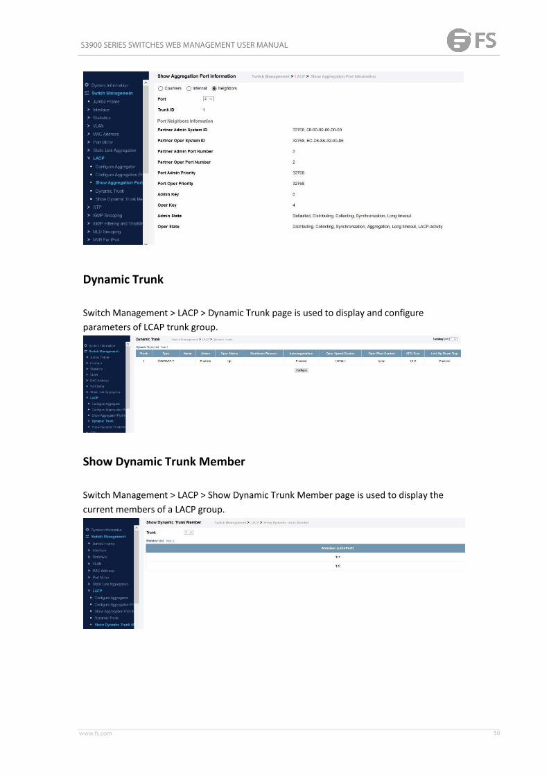
S3900 SERIES SWITCHES WEB MANAGEMENT USER MANUAL
www.fs.com 50
Dynamic Trunk
Switch Management > LACP > Dynamic Trunk page is used to display and configureparameters of LCAP trunk group.
Show Dynamic Trunk Member
Switch Management > LACP > Show Dynamic Trunk Member page is used to display thecurrent members of a LACP group.

S3900 SERIES SWITCHES WEB MANAGEMENT USER MANUAL
www.fs.com 51
STP
The Spanning Tree Algorithm (STA) can be used to detect and disable network loops, and toprovide backup links between switches, bridges or routers. This allows the switch to interactwith other bridging devices (that is, an STA-compliant switch, bridge or router) in yournetwork to ensure that only one route exists between any two stations on the network, andprovide backup links which automatically take over when a primary link goes down. Thespanning tree algorithms supported by this switch include these versions:◆STP – Spanning Tree Protocol (IEEE 802.1D)◆RSTP – Rapid Spanning Tree Protocol (IEEE 802.1w)◆MSTP – Multiple Spanning Tree Protocol (IEEE 802.1s)STP – STP uses a distributed algorithm to select a bridging device (STPcompliant switch,bridge or router) that serves as the root of the spanning tree network. It selects a root porton each bridging device (except for the root device) which incurs the lowest path cost whenforwarding a packet from that device to the root device. Then it selects a designatedbridging device from each LAN which incurs the lowest path cost when forwarding a packetfrom that LAN to the root device. All ports connected to designated bridging devices areassigned as designated ports. After determining the lowest cost spanning tree, it enables allroot ports and designated ports, and disables all other ports. Network packets are thereforeonly forwarded between root ports and designated ports, eliminating any possible networkloops.
Once a stable network topology has been established, all bridges listen for Hello BPDUs(Bridge Protocol Data Units) transmitted from the Root Bridge. If a bridge does not get aHello BPDU after a predefined interval (Maximum Age), the bridge assumes that the link tothe Root Bridge is down. This bridge will then initiate negotiations with other bridges toreconfigure the network to reestablish a valid network topology.RSTP – RSTP is designed as a general replacement for the slower, legacy STP. RSTP is alsoincorporated into MSTP. RSTP achieves much faster reconfiguration (i.e., around 1 to 3seconds, compared to 30 seconds or more for STP) by reducing the number of state changesbefore active ports start learning, predefining an alternate route that can be used when anode or port fails, and retaining the forwarding database for ports insensitive to changes inthe tree structure when reconfiguration occurs.MSTP – When using STP or RSTP, it may be difficult to maintain a stable path between allVLAN members. Frequent changes in the tree structure can easily isolate some of the groupmembers. MSTP (which is based on RSTP for fast convergence) is designed to supportindependent spanning trees based on VLAN groups. Using multiple spanning trees canprovide multiple forwarding paths and enable load balancing. One or more VLANs can be

S3900 SERIES SWITCHES WEB MANAGEMENT USER MANUAL
www.fs.com 52
grouped into a Multiple Spanning Tree Instance (MSTI). MSTP builds a separate MultipleSpanning Tree (MST) for each instance to maintain connectivity among each of the assignedVLAN groups. MSTP then builds a Internal Spanning Tree (IST) for the Region containing allcommonly configured MSTP bridges.
An MST Region consists of a group of interconnected bridges that have the same MSTConfiguration Identifiers (including the Region Name, Revision Level and ConfigurationDigest – see "Configuring Multiple Spanning Trees"). An MST Region may contain multipleMSTP Instances. An Internal Spanning Tree (IST) is used to connect all the MSTP switcheswithin an MST region. A Common Spanning Tree (CST) interconnects all adjacent MSTRegions, and acts as a virtual bridge node for communications with STP or RSTP nodes in theglobal network.
MSTP connects all bridges and LAN segments with a single Common and Internal SpanningTree (CIST). The CIST is formed as a result of the running spanning tree algorithm betweenswitches that support the STP, RSTP, MSTP protocols. Once you specify the VLANs to includein a Multiple Spanning Tree Instance (MSTI), the protocol will automatically build an MSTItree to maintain connectivity among each of the VLANs. MSTP maintains contact with theglobal network because each instance is treated as an RSTP node in the Common SpanningTree (CST).

S3900 SERIES SWITCHES WEB MANAGEMENT USER MANUAL
www.fs.com 53
STP-RSTP
Switch Management > STP > STP-RSTP > Global Management page is used to configureglobal settings for the spanning tree that apply to the entire switch.COMMAND USAGE◆Spanning Tree ProtocolThis option uses RSTP set to STP forced compatibility mode. It uses RSTP for the internalstate machine, but sends only 802.1D BPDUs. This creates one spanning tree instance for theentire network. If multiple VLANs are implemented on a network, the path between specificVLAN members may be inadvertently disabled to prevent network loops, thus isolatinggroup members. When operating multiple VLANs, we recommend selecting the MSTP option.◆Rapid Spanning Tree ProtocolRSTP supports connections to either STP or RSTP nodes by monitoring the incoming protocolmessages and dynamically adjusting the type of protocol messages the RSTP node transmits,as described below:■STP Mode – If the switch receives an 802.1D BPDU (i.e., STP BPDU) after a port’s migrationdelay timer expires, the switch assumes it is connected to an 802.1D bridge and starts usingonly 802.1D BPDUs.■RSTP Mode – If RSTP is using 802.1D BPDUs on a port and receives an RSTP BPDU after themigration delay expires, RSTP restarts the migration delay timer and begins using RSTPBPDUs on that port.◆Multiple Spanning Tree ProtocolMSTP generates a unique spanning tree for each instance. This provides multiple pathwaysacross the network, thereby balancing the traffic load, preventing wide-scale disruptionwhen a bridge node in a single instance fails, and allowing for faster convergence of a newtopology for the failed instance.■To allow multiple spanning trees to operate over the network, you must configure arelated set of bridges with the same MSTP configuration, allowing them to participate in aspecific set of spanning tree instances.■A spanning tree instance can exist only on bridges that have compatible VLAN instanceassignments.■Be careful when switching between spanning tree modes. Changing modes stops allspanning-tree instances for the previous mode and restarts the system in the new mode,temporarily disrupting user traffic.PARAMETERSThese parameters are displayed:Basic Configuration of Global Settings◆Spanning Tree Status – Enables/disables STA on this switch. (Default: Enabled)◆Spanning Tree Type – Specifies the type of spanning tree used on this switch:■STP: Spanning Tree Protocol (IEEE 802.1D); i.e., when this option is selected, the switchwill use RSTP set to STP forced compatibilitymode).■RSTP: Rapid Spanning Tree (IEEE 802.1w); RSTP is the default.

S3900 SERIES SWITCHES WEB MANAGEMENT USER MANUAL
www.fs.com 54
■MSTP: Multiple Spanning Tree (IEEE 802.1s)◆Priority – Bridge priority is used in selecting the root device, root port, and designatedport. The device with the highest priority becomes the STA root device. However, if alldevices have the same priority, the device with the lowest MAC address will then becomethe root device. (Note that lower numeric values indicate higherpriority.)■Default: 32768■Range: 0-61440, in steps of 4096■Options: 0, 4096, 8192, 12288, 16384, 20480, 24576, 28672, 32768, 36864, 40960,45056,49152, 53248, 57344, 61440◆BPDU Flooding – Configures the system to flood BPDUs to all other ports on the switch orjust to all other ports in the same VLAN when spanning tree is disabled globally on theswitch or disabled on a specific port.■To VLAN: Floods BPDUs to all other ports within the receiving port’s native VLAN (i.e., asdetermined by port’s PVID). This is the default.■To All: Floods BPDUs to all other ports on the switch. The setting has no effect if BPDUflooding is disabled on a port.Advanced Configuration SettingsThe following attributes are based on RSTP, but also apply to STP since the switch uses abackwards-compatible subset of RSTP to implement STP, and also apply to MSTP which isbased on RSTP according to the standard:◆Path Cost Method – The path cost is used to determine the best path between devices.The path cost method is used to determine the range of values that can be assigned to eachinterface.■Long: Specifies 32-bit based values that range from 1-200,000,000. (This is thedefault.)■Short: Specifies 16-bit based values that range from1-65535.◆Transmission Limit – The maximum transmission rate for BPDUs is specified by setting theminimum interval between the transmission of consecutive protocol messages. (Range: 1-10;Default: 3)When the Switch Becomes Root◆Hello Time – Interval (in seconds) at which the root device transmits a configurationmessage.■Default: 2■Minimum: 1■Maximum: The lower of 10 or [(Max. Message Age / 2) -1]◆Maximum Age – The maximum time (in seconds) a device can wait without receiving aconfiguration message before attempting to reconverge. All device ports (except fordesignated ports) should receive configuration messages at regular intervals. Any port thatages out STA information (provided in the last configuration message) becomes thedesignated port for the attached LAN. If it is a root port, a new root port is selected fromamong the device ports attached to the network. (References to “ports” in this section mean“interfaces,” which includes both ports and trunks.)■Default: 20■Minimum: The higher of 6 or [2 x (Hello Time + 1)]■Maximum: The lower of 40 or [2 x (Forward Delay -1)]

S3900 SERIES SWITCHES WEB MANAGEMENT USER MANUAL
www.fs.com 55
◆Forward Delay – The maximum time (in seconds) this device will wait before changingstates (i.e., discarding to learning to forwarding). This delay is required because every devicemust receive information about topology changes before it starts to forward frames. Inaddition, each port needs time to listen for conflicting information that would make it returnto a discarding state; otherwise, temporary data loops might result.■Default: 15■Minimum: The higher of 4 or [(Max. Message Age / 2) + 1]■Maximum: 30RSTP does not depend on the forward delay timer in most cases. It is able to confirm that aport can transition to the forwarding state without having to rely on any timer configuration.To achieve fast convergence, RSTP relies on the use of edge ports, and automatic detectionof point-to-point link types, both of which allow a port to directly transition to theforwarding state.Configuration Settings for MSTP◆Max Instance Numbers – The maximum number of MSTP instances to which this switchcan be assigned.◆Configuration Digest – An MD5 signature key that contains the VLAN ID to MST IDmapping table. In other words, this key is a mapping of all VLANs to theCIST.◆Region Revision4 – The revision for this MSTI. (Range: 0-65535; Default: 0)◆Region Name4 – The name for this MSTI. (Maximum length: 32 characters; switch’s MACaddress)◆Max Hop Count – The maximum number of hops allowed in the MST region before aBPDU is discarded. (Range: 1-40; Default: 20)

S3900 SERIES SWITCHES WEB MANAGEMENT USER MANUAL
www.fs.com 56
◆Bridge ID – A unique identifier for this bridge, consisting of the bridge priority, the MSTInstance ID 0 for the Common Spanning Tree when spanning tree type is set to MSTP, andMAC address (where the address is taken from the switch system).◆Designated Root – The priority and MAC address of the device in the Spanning Tree thatthis switch has accepted as the root device.◆Root Port – The number of the port on this switch that is closest to the root. This switchcommunicates with the root device through this port. If there is no root port, then thisswitch has been accepted as the root device of the Spanning Treenetwork.◆Root Path Cost – The path cost from the root port on this switch to the rootdevice.◆Configuration Changes – The number of times the Spanning Tree has beenreconfigured.◆Last Topology Change – Time since the Spanning Tree was last reconfigured.
Switch Management > STP > STP-RSTP > Configure Interface page is used to configure RSTPand MSTP attributes for specific interfaces, including port priority, path cost, link type, andedge port. You may use a different priority or path cost for ports of the same media type toindicate the preferred path, link type to indicate a point-to-point connection or sharedmediaconnection, and edge port to indicate if the attached device can support fast forwarding.(References to “ports” in this section means “interfaces,” which includes both ports andtrunks.)PARAMETERSThese parameters are displayed:◆ Interface – Displays a list of ports or trunks.◆Spanning Tree – Enables/disables STA on this interface. (Default: Enabled)◆BPDU Flooding - Enables/disables the flooding of BPDUs to other ports when globalspanning tree is disabled or when spanning tree is disabled on a specific port. When floodingis enabled, BPDUs are flooded to all other ports on the switch or to all other ports within thereceiving port’s native VLAN as specified by the Spanning Tree BPDU Flooding attribute .(Default: Enabled)◆Priority – Defines the priority used for this port in the Spanning Tree Protocol. If the pathcost for all ports on a switch are the same, the port with the highest priority (i.e., lowestvalue) will be configured as an active link in the Spanning Tree. This makes a port with higherpriority less likely to be blocked if the Spanning Tree Protocol is detecting network loops.Where more than one port is assigned the highest priority, the port with lowest numericidentifier will be enabled.■Default: 128■Range: 0-240, in steps of 16◆Admin Path Cost – This parameter is used by the STA to determine the best pathbetween

S3900 SERIES SWITCHES WEB MANAGEMENT USER MANUAL
www.fs.com 57
devices. Therefore, lower values should be assigned to ports attached to faster media, andhigher values assigned to ports with slower media. Note that path cost takesprecedenceover port priority. (Range: 0 for auto-configuration, 1-65535 for the short path cost method5,1-200,000,000 for the long path cost method) By default, the system automatically detectsthe speed and duplex mode used on each port, and configures the path cost accordingtothe values shown below. Path cost “0” is used to indicate auto-configuration mode. Whenthe short path cost method is selected and the default path cost recommended by the IEEE8021w standard exceeds 65,535, the default is set to 65,535.Table 12: Recommended STA Path Cost Range
Table 13: Default STA Path Costs
◆Admin Link Type – The link type attached to this interface.■Point-to-Point – A connection to exactly one other bridge.■Shared – A connection to two or more bridges.■Auto – The switch automatically determines if the interface is attached to a point-to-pointlink or to shared media. (This is the default setting.)◆Root Guard – STA allows a bridge with a lower bridge identifier (or same identifier andlower MAC address) to take over as the root bridge at any time. Root Guard can be used toensure that the root bridge is not formed at a suboptimal location. Root Guard should beenabled on any designated port connected to low-speed bridges which could potentiallyoverload a slower link by taking over as the root port and forming a new spanning treetopology. It could also be used to form a border around part of the network where the rootbridge is allowed. (Default: Disabled)◆Admin Edge Port – Since end nodes cannot cause forwarding loops, they can pass directlythrough to the spanning tree forwarding state. Specifying Edge Ports provides quickerconvergence for devices such as workstations or servers, retains the current forwardingdatabase to reduce the amount of frame flooding required to rebuild address tables duringreconfiguration events, does not cause the spanning tree to initiate reconfiguration whenthe interface changes state, and also overcomes other STA-related timeout problems.However, remember that Edge Port should only be enabled for ports connected to anendnode device. (Default: Auto)
S3900 SERIES SWITCHES WEB MANAGEMENT USER MANUAL
www.fs.com 58
■Enabled – Manually configures a port as an Edge Port.■Disabled – Disables the Edge Port setting.■Auto – The port will be automatically configured as an edge port if the edge delay timeexpires without receiving any RSTP or MSTP BPDUs. Note that edge delay time (802.1D-200417.20.4) equals the protocol migration time if a port's link type is point-to-point (which is 3seconds as defined in IEEE 802.3D-2004 17.20.4); otherwise it equals the spanning tree’smaximum age for configuration messages. An interface cannot function as an edge portunder the following conditions:■If spanning tree mode is set to STP , edge-port mode cannot automatically transition tooperational edge-port state using the automatic setting.■If loopback detection is enabled and a loopback BPDU is detected, the interface cannotfunction as an edge port until the loopback state is released.■If an interface is in forwarding state and its role changes, the interface cannot continue tofunction as an edge port even if the edge delay time hasexpired.■If the port does not receive any BPDUs after the edge delay timer expires, its role changesto designated port and it immediately enters forwarding state.◆BPDU Guard – This feature protects edge ports from receiving BPDUs. It prevents loops byshutting down an edge port when a BPDU is received instead of putting it into the spanningtree discarding state. In a valid configuration, configured edge ports should not receiveBPDUs. If an edge port receives a BPDU an invalid configuration exists, such as a connectionto an unauthorized device. The BPDU guard feature provides a secure response to invalidconfigurations because an administrator must manually enable the port. (Default:Disabled)◆BPDU Filter – BPDU filtering allows you to avoid transmitting BPDUs on configured edgeports that are connected to end nodes. By default, STA sends BPDUs to all ports regardlessof whether administrative edge is enabled on a port. BDPU filtering is configured onaper-port basis. (Default: Disabled)◆Migration – If at any time the switch detects STP BPDUs, including Configuration orTopology Change Notification BPDUs, it will automatically set the selected interface toforced STP-compatible mode. However, you can also use the Protocol Migration button tomanually re-check the appropriate BPDU format (RSTP or STPcompatible) to send on theselected interfaces. (Default: Disabled)

S3900 SERIES SWITCHES WEB MANAGEMENT USER MANUAL
www.fs.com 59
Switch Management > STP > STP-RSTP > Configure Interface page is used to display thecurrent status of ports or trunks in the Spanning Tree.PARAMETERSThese parameters are displayed:◆Spanning Tree – Shows if STA has been enabled on this interface.◆BPDU Flooding – Shows if BPDUs will be flooded to other ports when spanning tree isdisabled globally on the switch or disabled on a specific port.◆STA Status – Displays current state of this port within the Spanning Tree:■Discarding - Port receives STA configuration messages, but does not forwardpackets.■Learning - Port has transmitted configuration messages for an interval set by the ForwardDelay parameter without receiving contradictory information. Port address table is cleared,and the port begins learning addresses.■Forwarding - Port forwards packets, and continues learning addresses. The rules definingport status are:■A port on a network segment with no other STA compliant bridging device is alwaysforwarding.■If two ports of a switch are connected to the same segment and there is no other STAdevice attached to this segment, the port with the smaller ID forwards packets and the otheris discarding.■All ports are discarding when the switch is booted, then some of them change state tolearning, and then to forwarding.◆Forward Transitions – The number of times this port has transitioned from the Learningstate to the Forwarding state.◆Designated Cost – The cost for a packet to travel from this port to the root in the currentSpanning Tree configuration. The slower the media, the higher the cost.◆Designated Bridge – The bridge priority and MAC address of the device through which thisport must communicate to reach the root of the Spanning Tree.◆Designated Port – The port priority and number of the port on the designated bridgingdevice through which this switch must communicate with the root of the SpanningTree.

S3900 SERIES SWITCHES WEB MANAGEMENT USER MANUAL
www.fs.com 60
◆Oper Path Cost – The contribution of this port to the path cost of paths towards thespanning tree root which include this port.◆Oper Link Type – The operational point-to-point status of the LAN segment attached tothis interface. This parameter is determined by manual configuration or by auto-detection,as described for Admin Link Type in STA Port Configuration .◆Oper Edge Port – This parameter is initialized to the setting for Admin Edge Port in STAPort Configuration (i.e., true or false), but will be set to false if a BPDU is received, indicatingthat another bridge is attached to this port.◆Port Role – Roles are assigned according to whether the port is part of the active topology,that is the best port connecting a non-root bridge to the root bridge (i.e., root port),connecting a LAN through the bridge to the root bridge (i.e., designated port), is the MSTIregional root (i.e.,master port), or is an alternate or backup port that may provideconnectivity if other bridges, bridge ports, or LANs fail or are removed. The role is set todisabled (i.e., disabled port) if a port has no role within the spanning tree.

S3900 SERIES SWITCHES WEB MANAGEMENT USER MANUAL
www.fs.com 61
MSTP
Switch Management > STP > MSTP > MST List page is used to create an MSTP instance, or toadd VLAN groups to an MSTP instance.COMMAND USAGEMSTP generates a unique spanning tree for each instance. This provides multiple pathwaysacross the network, thereby balancing the traffic load, preventing wide-scale disruptionwhen a bridge node in a single instance fails, and allowing for faster convergence of a newtopology for the failed instance.By default all VLANs are assigned to the Internal Spanning Tree (MST Instance 0) thatconnects all bridges and LANs within the MST region. This switch supports up to 33 instances.You should try to group VLANs which cover the same general area of your network. However,remember that you must configure all bridges within the same MSTI Region with the sameset of instances, and the same instance (on each bridge) with the same set of VLANs. Also,note that RSTP treats each MSTI region as a single node, connecting all regions to theCommon Spanning Tree.To use multiple spanning trees:1. Set the spanning tree type to MSTP .2. Enter the spanning tree priority for the selected MST instance on the Spanning Tree >MSTP (Configure Global - Add) page.3. Add the VLANs that will share this MSTI on the Spanning Tree > MSTP (Configure Global -Add Member) page. To ensure that the MSTI maintains connectivity across the network, youmust configure a related set of bridges with the same MSTI settings.PARAMETERSThese parameters are displayed:◆MST ID – Instance identifier to configure. (Range: 0-4094)◆VLAN ID – VLAN to assign to this MST instance. (Range:1-4093)◆Priority – The priority of a spanning tree instance. (Range: 0-61440 in steps of 4096;Options: 0, 4096, 8192, 12288, 16384, 20480, 24576, 28672, 32768, 36864, 40960, 45056,49152, 53248, 57344, 61440; Default: 32768)

S3900 SERIES SWITCHES WEB MANAGEMENT USER MANUAL
www.fs.com 62
Switch Management > STP > MSTP > MST Interface page is used to configure the STAinterface settings for an MST instance.PARAMETERSThese parameters are displayed:◆MST ID – Instance identifier to configure. (Default: 0)◆ Interface – Displays a list of ports or trunks.◆STA Status – Displays the current state of this interface within the SpanningTree.■Discarding – Port receives STA configuration messages, but does not forwardpackets.■Learning – Port has transmitted configuration messages for an interval set by the ForwardDelay parameter without receiving contradictory information. Port address table is cleared,and the port begins learning addresses.■Forwarding – Port forwards packets, and continues learning addresses.◆Priority – Defines the priority used for this port in the Spanning Tree Protocol. If the pathcost for all ports on a switch are the same, the port with the highest priority (i.e., lowestvalue) will be configured as an active link in the Spanning Tree. This makes a port with higherpriority less likely to be blocked if the Spanning Tree Protocol is detecting network loops.Where more than one port is assigned the highest priority, the port with lowest numericidentifier will be enabled. (Default: 128; Range: 0-240, in steps of16)◆Admin MST Path Cost – This parameter is used by the MSTP to determine the best pathbetween devices. Therefore, lower values should be assigned to ports attached to fastermedia, and higher values assigned to ports with slower media. (Path cost takesprecedence

S3900 SERIES SWITCHES WEB MANAGEMENT USER MANUAL
www.fs.com 63
over port priority.) Note that when the Path Cost Method is set to short (page 3-63), themaximum path cost is 65,535.By default, the system automatically detects the speed and duplex mode used on each port,and configures the path cost according to the values shown below. Path cost “0” is used toindicate auto-configuration mode. When the short path cost method is selected and thedefault path cost recommended by the IEEE 8021w standard exceeds 65,535, the default isset to 65,535.The recommended range is listed in Table 12 .The default path costs are listed in Table 13 .
To display MSTP parameters for a port or trunk:
Loopback Detection
Switch Management > STP > Loopback Detection page is used to configure loopbackdetection on an interface. When loopback detection is enabled and a port or trunk receivesit’s own BPDU, the detection agent drops the loopback BPDU, sends an SNMP trap, andplaces the interface in discarding mode. This loopback state can be released manually orautomatically. If the interface is configured for automatic loopback release, then the portwill only be returned to the forwarding state if one of the following conditions is satisfied:

S3900 SERIES SWITCHES WEB MANAGEMENT USER MANUAL
www.fs.com 64
◆The interface receives any other BPDU except for it’s own, or;◆The interfaces’s link status changes to link down and then link up again, or;◆The interface ceases to receive it’s own BPDUs in a forward delay interval.PARAMETERSThese parameters are displayed:◆ Interface – Displays a list of ports or trunks.◆Status – Enables loopback detection on this interface. (Default: Enabled)◆Trap – Enables SNMP trap notification for loopback events on this interface. (Default:Disabled)◆Release Mode – Configures the interface for automatic or manual loopback release.(Default: Auto)◆Release – Allows an interface to be manually released from discard mode. This is onlyavailable if the interface is configured for manual releasemode.◆Action – Sets the response for loopback detection to block user traffic or shut down theinterface. (Default: Block)◆Shutdown Interval – The duration to shut down the interface. (Range: 60-86400 seconds;Default: 60 seconds) If an interface is shut down due to a detected loopback, and the releasemode is set to “Auto,” the selected interface will be automatically enabled when theshutdown interval has expired.If an interface is shut down due to a detected loopback, and the release mode is set to“Manual,” the interface can be re-enabled using the Release button.
IGMP Snooping
IGMP Snooping and Query – If multicast routing is not supported on other switches in yournetwork, you can use IGMP Snooping and IGMP Query to monitor IGMP service requestspassing between multicast clients and servers, and dynamically configure the switch portswhich need to forward multicast traffic. IGMP Snooping conserves bandwidth on networksegments where no node has expressed interest in receiving a specific multicast service. Forswitches that do not support multicast routing, or where multicast routing is alreadyenabled on other switches in the local network segment, IGMP Snooping is the only servicerequired to support multicast filtering. When using IGMPv3 snooping, service requests fromIGMP Version 1, 2 or 3 hosts are all forwarded to the upstream router as IGMPv3 reports.The primary enhancement provided by IGMPv3 snooping is in keeping track of informationabout the specific multicast sources which downstream IGMPv3 hosts have requested orrefused. The switch maintains information about both multicast groups and channels, wherea group indicates a multicast flow for which the hosts have not requested a specific source

S3900 SERIES SWITCHES WEB MANAGEMENT USER MANUAL
www.fs.com 65
(the only option for IGMPv1 and v2 hosts unless statically configured on the switch), and achannel indicates a flow for which the hosts have requested service from a specific source.For IGMPv1/v2 hosts, the source address of a channel is always null (indicating that anysource is acceptable), but for IGMPv3 hosts, it may include a specific address whenrequested. Only IGMPv3 hosts can request service from a specific multicast source.Whendownstream hosts request service from a specific source for a multicast service, thesesources are all placed in the Include list, and traffic is forwarded to the hosts from each ofthese sources. IGMPv3 hosts may also request that service be forwarded from any sourceexcept for those specified. In this case, traffic is filtered from sources in the Exclude list, andforwarded from all other available sources. Static IGMP Router Interface – If IGMP snoopingcannot locate the IGMP querier, you can manually designate a known IGMP querier (i.e., amulticast router/switch) connected over the network to an interface on your switch . Thisinterface will then join all the current multicast groups supported by the attachedrouter/switch to ensure that multicast traffic is passed to all appropriate interfaces withinthe switch. Static IGMP Host Interface – For multicast applications that you need to controlmore carefully, you can manually assign a multicast service to specific interfaces on theswitch . IGMP Snooping with Proxy Reporting – The switch supports last leave, and querysuppression (as defined in DSL Forum TR-101, April 2006):◆When proxy reporting is disabled, all IGMP reports received by the switch are forwardednatively to the upstreammulticast routers.◆Last Leave: Intercepts, absorbs and summarizes IGMP leaves coming from IGMP hosts.IGMP leaves are relayed upstream only when necessary, that is, when the last user leaves amulticast group.◆Query Suppression: Intercepts and processes IGMP queries in such a way that IGMPspecific queries are never sent to client ports. The only deviation from TR-101 is that themarking of IGMP traffic initiated by the switch with priority bits as defined in R-250 is notsupported.
General
Switch Management > IGMP Snooping> General page is used to configure the switch toforward multicast traffic intelligently. Based on the IGMP query and report messages, theswitch forwards multicast traffic only to the ports that request it. This prevents the switchfrom broadcasting the traffic to all ports and possibly disrupting network performance.COMMAND USAGE◆ IGMP Snooping – This switch can passively snoop on IGMP Query and Report packetstransferred between IP multicast routers/switches and IP multicast host groups to identifythe IP multicast group members. It simply monitors the IGMP packets passing through it,picks out the group registration information, and configures the multicast filters accordingly.◆ IGMP Querier – A router, or multicast-enabled switch, can periodically ask their hosts ifthey want to receive multicast traffic. If there is more than one router/switch on the LANperforming IP multicasting, one of these devices is elected “querier” and assumes the role ofquerying the LAN for group members. It then propagates the service requests on toany

S3900 SERIES SWITCHES WEB MANAGEMENT USER MANUAL
www.fs.com 66
upstreammulticast switch/router to ensure that it will continue to receive the multicastservice.PARAMETERSThese parameters are displayed:◆ IGMP Snooping Status – When enabled, the switch will monitor network traffic todetermine which hosts want to receive multicast traffic. This is referred to as IGMP Snooping.(Default: Disabled) When IGMP snooping is enabled globally, the per VLAN interface settingsfor IGMP snooping take precedence. When IGMP snooping is disabled globally, snooping canstill be configured per VLAN interface, but the interface settings will not take effect untilsnooping is re-enabled globally.◆Proxy Reporting Status – Enables IGMP Snooping with Proxy Reporting. (Default:Disabled)When proxy reporting is enabled with this command, the switch performs “IGMP Snoopingwith Proxy Reporting” (as defined in DSL Forum TR-101, April 2006), including last leave, andquery suppression. Last leave sends out a proxy query when the last member leaves amulticast group, and query suppression means that specific queries are not forwarded froman upstream multicast router to hosts downstream from this device. When proxy reportingis disabled, all IGMP reports received by the switch are forwarded natively to the upstreammulticast routers.◆TCN Flood – Enables flooding of multicast traffic if a spanning tree topology changenotification (TCN) occurs. (Default: Disabled) When a spanning tree topology change occurs,the multicast membership information learned by switch may be out of date. For example, ahost linked to one port before the topology change (TC) may be moved to another port afterthe change. To ensure that multicast data is delivered to all receivers, by default, a switch ina VLAN (with IGMP snooping enabled) that receives a Bridge Protocol Data Unit (BPDU) withTC bit set (by the root bridge) will enter into “multicast flooding mode” for a period of timeuntil the topology has stabilized and the new locations of all multicast receivers are learned.If a topology change notification (TCN) is received, and all the uplink ports are subsequentlydeleted, a time out mechanism is used to delete all of the currently learned multicastchannels. When a new uplink port starts up, the switch sends unsolicited reports for allcurrently learned channels out the new uplink port. By default, the switch immediatelyenters into “multicast flooding mode” when a spanning tree topology change occurs. In thismode, multicast traffic will be flooded to all VLAN ports. If many ports have subscribed todifferent multicast groups, flooding may cause excessive packet loss on the link between theswitch and the end host. Flooding may be disabled to avoid this, causing multicast traffic tobe delivered only to those ports on which multicast group members have been learned.Otherwise, the time spent in flooding mode can be manually configured to reduce excessiveloading. When the spanning tree topology changes, the root bridge sends a proxy query toquickly re-learn the host membership/port relations for multicast channels. The root bridgealso sends an unsolicited Multicast Router Discover (MRD) request to quickly locate themulticast routers in this VLAN. The proxy query and unsolicited MRD request are flooded toall VLAN ports except for the receiving port when the switch receives suchpackets.◆TCN Query Solicit – Sends out an IGMP general query solicitation when a spanning treetopology change notification (TCN) occurs. (Default: Disabled) When the root bridge ina

S3900 SERIES SWITCHES WEB MANAGEMENT USER MANUAL
www.fs.com 67
spanning tree receives a TCN for a VLAN where IGMP snooping is enabled, it issues a globalIGMP leave message (or query solicitation). When a switch receives this solicitation, it floodsit to all ports in the VLAN where the spanning tree change occurred. When an upstreammulticast router receives this solicitation, it immediately issues an IGMP general query. Aquery solicitation can be sent whenever the switch notices a topology change, even if it isnot the root bridge in spanning tree.◆Router Alert Option – Discards any IGMPv2/v3 packets that do not include the RouterAlert option. (Default: Disabled) As described in Section 9.1 of RFC 3376 for IGMP Version 3,the Router Alert Option can be used to protect against DOS attacks. One common method ofattack is launched by an intruder who takes over the role of querier, and starts overloadingmulticast hosts by sending a large number of group-and-source-specific queries, each with alarge source list and the Maximum Response Time set to a large value. To protect againstthis kind of attack, (1) routers should not forward queries. This is easier to accomplish if thequery carries the Router Alert option. (2) Also, when the switch is acting in the role of amulticast host (such as when using proxy routing), it should ignore version 2 or 3 queriesthat do not contain the Router Alert option.◆Unregistered Data Flooding – Floods unregistered multicast traffic into the attached VLAN.(Default: Disabled) Once the table used to store multicast entries for IGMP snooping andmulticast routing is filled, no new entries are learned. If no router port is configured in theattached VLAN, and unregistered-flooding is disabled, any subsequent multicast traffic notfound in the table is dropped, otherwise it is flooded throughout theVLAN.◆Forwarding Priority – Assigns a CoS priority to all multicast traffic. (Range: 0-6, where 6 isthe highest priority) This parameter can be used to set a high priority for low-latencymulticast traffic such as a video-conference, or to set a low priority for normal multicasttraffic not sensitive to latency.◆Version Exclusive – Discards any received IGMP messages which use a version different tothat currently configured by the IGMP Version attribute. (Default:Disabled)◆ IGMP Unsolicited Report Interval – Specifies how often the upstream interface shouldtransmit unsolicited IGMP reports when proxy reporting is enabled. (Range: 1-65535seconds, Default: 400 seconds) When a new upstream interface (that is, uplink port) startsup, the switch sends unsolicited reports for all currently learned multicast channels via thenew upstream interface. This command only applies when proxy reporting isenabled.◆Router Port Expire Time – The time the switch waits after the previous querier stopsbefore it considers it to have expired. (Range: 1-65535, Recommended Range: 300-500seconds, Default: 300)◆ IGMP Snooping Version – Sets the protocol version for compatibility with other deviceson the network. This is the IGMP Version the switch uses to send snooping reports. (Range:1-3; Default: 2) This attribute configures the IGMP report/query version used by IGMPsnooping. Versions 1 - 3 are all supported, and versions 2 and 3 are backward compatible, sothe switch can operate with other devices, regardless of the snooping versionemployed.◆Querier Status – When enabled, the switch can serve as the Querier, which is responsiblefor asking hosts if they want to receive multicast traffic. This feature is not supported forIGMPv3 snooping. (Default: Disabled)

S3900 SERIES SWITCHES WEB MANAGEMENT USER MANUAL
www.fs.com 68
Current Multicast
Switch Management > IGMP Snooping> Current Multicast Router page is used to staticallyshow an interface to a multicast router/switch.Depending on network connections, IGMP snooping may not always be able to locate theIGMP querier. Therefore, if the IGMP querier is a known multicast router/switch connectedover the network to an interface (port or trunk) on the switch, the interface (and a specifiedVLAN) can be manually configured to join all the current multicast groups supported by theattached router. This can ensure that multicast traffic is passed to all the appropriateinterfaces within the switch.COMMAND USAGEIGMP Snooping must be enabled globally on the switch before a multicast router port cantake effect.PARAMETERSThese parameters are displayed:◆VLAN – Selects the VLAN which is to propagate all multicast traffic coming from theattached multicast router. (Range: 1-4093)◆ Interface – Activates the Port or Trunk scroll down list.◆Port or Trunk – Specifies the interface attached to a multicast router.

S3900 SERIES SWITCHES WEB MANAGEMENT USER MANUAL
www.fs.com 69
Static Multicast Router
Switch Management > IGMP Snooping> Static Multicast Router page is used to staticallyattach an interface to a multicast router/switch. Depending on network connections, IGMPsnooping may not always be able to locate the IGMP querier. Therefore, if the IGMP querieris a known multicast router/switch connected over the network to an interface (port ortrunk) on the switch, the interface (and a specified VLAN) can be manually configured to joinall the current multicast groups supported by the attached router. This can ensure thatmulticast traffic is passed to all the appropriate interfaces within the switch.COMMAND USAGEIGMP Snooping must be enabled globally on the switch before a multicast router port cantake effect.PARAMETERSThese parameters are displayed:◆VLAN – Selects the VLAN which is to propagate all multicast traffic coming from theattached multicast router. (Range: 1-4093)◆ Interface – Activates the Port or Trunk scroll down list.◆Port or Trunk – Specifies the interface attached to a multicast router.
To show the static interfaces attached to a multicast router:
Static Member
Switch Management > IGMP Snooping > Static Member page is used to statically assign amulticast service to an interface. Multicast filtering can be dynamically configured usingIGMP Snooping and IGMP Query messages. However, for certain applications that requiretighter control, it may be necessary to statically configure a multicast service on the switch.First add all the ports attached to participating hosts to a common VLAN, and then assignthe multicast service to that VLAN group.COMMAND USAGE◆Static multicast addresses are never agedout.

S3900 SERIES SWITCHES WEB MANAGEMENT USER MANUAL
www.fs.com 70
◆When a multicast address is assigned to an interface in a specific VLAN, the correspondingtraffic can only be forwarded to ports within that VLAN.PARAMETERSThese parameters are displayed:◆VLAN – Specifies the VLAN which is to propagate the multicast service. (Range:1-4093)◆ Interface – Activates the Port or Trunk scroll down list.◆Port or Trunk – Specifies the interface assigned to a multicast group.◆Multicast IP – The IP address for a specific multicast service.
To show the static interfaces assigned to a multicast service:
VLAN Information
Switch Management > IGMP Snooping > VLAN Information page is used to configure IGMPsnooping attributes for a VLAN.COMMAND USAGEMulticast Router DiscoveryThere have been many mechanisms used in the past to identify multicast routers. This haslead to interoperability issues between multicast routers and snooping switches fromdifferent vendors. In response to this problem, the Multicast Router Discovery (MRD)protocol has been developed for use by IGMP snooping and multicast routing devices. MRDis used to discover which interfaces are attached to multicast routers, allowingIGMP-enabled devices to determine where to send multicast source and group membershipmessages. (MRD is specified in draft-ietf-magma-mrdisc-07.) Multicast source data andgroup membership reports must be received by all multicast routers on a segment. Usingthe group membership protocol query messages to discover multicast routers is insufficientdue to query suppression. MRD therefore provides a standardized way to identify multicastrouters without relying on any particular multicast routing protocol. Multicast RouterDiscovery uses the following three message types to discover multicast routers:◆Multicast Router Advertisement – Advertisements are sent by routers to advertise thatIP

S3900 SERIES SWITCHES WEB MANAGEMENT USER MANUAL
www.fs.com 71
multicast forwarding is enabled. These messages are sent unsolicited periodically on allrouter interfaces on which multicast forwarding is enabled. They are sent upon theoccurrence of these events:■Upon the expiration of a periodic (randomized) timer.■As a part of a router's start up procedure.■During the restart of a multicast forwarding interface.■On receipt of a Solicitationmessage.◆Multicast Router Solicitation – Devices send Solicitation messages in order to solicitAdvertisement messages from multicast routers. These messages are used to discovermulticast routers on a directly attached link. Solicitation messages are also sent whenever amulticast forwarding interface is initialized or re-initialized. Upon receiving a solicitation onan interface with IP multicast forwarding and MRD enabled, a router will respond with anAdvertisement.◆Multicast Router Termination – These messages are sent when a router stops IP multicastrouting functions on an interface. Termination messages are sent by multicast routerswhen:■Multicast forwarding is disabled on an interface.■An interface is administratively disabled.■The router is gracefully shut down.Advertisement and Termination messages are sent to the All-Snoopers multicast address.Solicitation messages are sent to the All-Routers multicast address.PARAMETERSThese parameters are displayed:◆VLAN – ID of configured VLANs. (Range: 1-4093)◆ IGMP Snooping Status – When enabled, the switch will monitor network traffic on theindicated VLAN interface to determine which hosts want to receive multicast traffic. This isreferred to as IGMP Snooping. (Default: Disabled) When IGMP snooping is enabled globally ,the per VLAN interface settings for IGMP snooping take precedence. When IGMP snooping isdisabled globally, snooping can still be configured per VLAN interface, but the interfacesettings will not take effect until snooping is re-enabledglobally.◆Version Exclusive – Discards any received IGMP messages (except for multicast protocolpackets) which use a version different to that currently configured by the IGMP Versionattribute. (Default: Disabled) If version exclusive is disabled on a VLAN, then this setting isbased on the global setting configured on the Multicast > IGMP Snooping > General page. Ifit is enabled on a VLAN, then this setting takes precedence over the globalsetting.◆ Immediate Leave Status – Immediately deletes a member port of a multicast service if aleave packet is received at that port and immediate leave is enabled for the parent VLAN.(Default: Disabled) If immediate leave is not used, a multicast router (or querier) will send agroup-specific query message when an IGMPv2 group leave message is received. Therouter/querier stops forwarding traffic for that group only if no host replies to the querywithin the specified time out period. Note that this time out is set to Last Member QueryInterval * Robustness Variable (fixed at 2) as defined in RFC 2236. If immediate leave isenabled, the switch assumes that only one host is connected to the interface. Therefore,immediate leave should only be enabled on an interface if it is connected to onlyoneIGMP-enabled device, either a service host or a neighbor running IGMP snooping. This

S3900 SERIES SWITCHES WEB MANAGEMENT USER MANUAL
www.fs.com 72
attribute is only effective if IGMP snooping is enabled, and IGMPv2 snooping is used.◆Multicast Router Discovery – MRD is used to discover which interfaces are attached tomulticast routers. (Default: Enabled)◆General Query Suppression – Suppresses general queries except for ports attached todownstreammulticast hosts. (Default: Disabled) By default, general query messages areflooded to all ports, except for the multicast router through which they are received. Ifgeneral query suppression is enabled, then these messages are forwarded only todownstream ports which have joined a multicast service.◆Proxy Reporting – Enables IGMP Snooping with Proxy Reporting. (Default: Based on globalsetting) When proxy reporting is enabled with this command, the switch performs “IGMPSnooping with Proxy Reporting” (as defined in DSL Forum TR-101, April 2006), including lastleave, and query suppression. Last leave sends out a proxy query when the last memberleaves a multicast group, and query suppression means that specific queries are notforwarded from an upstreammulticast router to hosts downstream from thisdevice.◆ Interface Version – Sets the protocol version for compatibility with other devices on thenetwork. This is the IGMP Version the switch uses to send snooping reports. (Range: 1-3;Default: 2) This attribute configures the IGMP report/query version used by IGMP snooping.Versions 1 - 3 are all supported, and versions 2 and 3 are backward compatible, so theswitch can operate with other devices, regardless of the snooping versionemployed.◆Query Interval – The interval between sending IGMP proxy general queries. (Range:2-31744 seconds; Default: 125 seconds) An IGMP general query message is sent by theswitch at the interval specified by this attribute. When this message is receivedbydownstream hosts, all receivers build an IGMP report for the multicast groups they havejoined. This command applies when the switch is serving as the querier, or as a proxy hostwhen IGMP snooping proxy reporting is enabled .◆Query Response Interval – The maximum time the system waits for a response to proxygeneral queries. (Range: 10-31744 tenths of a second; Default: 10 seconds) This commandapplies when the switch is serving as the querier, or as a proxy host when IGMP snoopingproxy reporting is enabled .◆Last Member Query Interval – The interval to wait for a response to a group-specific orgroup-and-source-specific query message. (Range: 1-31740 tenths of a second in multiplesof 10; Default: 1 second) When a multicast host leaves a group, it sends an IGMP leavemessage. When the leave message is received by the switch, it checks to see if this host isthe last to leave the group by sending out an IGMP groupspecificorgroup-and-source-specific query message, and starts a timer. If no reports are receivedbefore the timer expires, the group record is deleted, and a report is sent to the upstreammulticast router. A reduced value will result in reduced time to detect the loss of the lastmember of a group or source, but may generate more burst traffic. This attribute will takeeffect only if IGMP snooping proxy reporting is enabled or IGMP querier is enabled .◆Last Member Query Count – The number of IGMP proxy groupspecific orgroup-and-source-specific query messages that are sent out before the system assumesthere are no more local members. (Range: 1-255; Default: 2) This attribute will take effectonly if IGMP snooping proxy reporting or IGMP querier is enabled.◆Proxy Query Address – A static source address for locally generated query andreport

S3900 SERIES SWITCHES WEB MANAGEMENT USER MANUAL
www.fs.com 73
messages used by IGMP Proxy Reporting. (Range: Any valid IP unicast address; Default:0.0.0.0) IGMP Snooping uses a null IP address of 0.0.0.0 for the source of IGMP querymessages which are proxied to downstream hosts to indicate that it is not the electedquerier, but is only proxying these messages as defined in RFC 4541. The switch also uses anull address in IGMP reports sent to upstream ports. Many hosts do not implement RFC4541, and therefore do not understand query messages with the source address of 0.0.0.0.These hosts will therefore not reply to the queries, causing the multicast router to stopsending traffic to them.To resolve this problem, the source address in proxied IGMP query messages can bereplaced with any valid unicast address (other than the router’s own address).Rules Used for Proxy ReportingWhen IGMP Proxy Reporting is disabled, the switch will use a null IP address for the sourceof IGMP query and report messages unless a proxy query address has been set. When IGMPProxy Reporting is enabled, the source address is based on the following criteria:■If a proxy query address is configured, the switch will use that address as the source IPaddress in general and group-specific query messages sent to downstream hosts, and inreport and leave messages sent upstream from the multicast routerport.■If a proxy query address is not configured, the switch will use the VLAN’s IP address as theIP source address in general and groupspecific query messages sent downstream, and usethe source address of the last IGMP message received from a downstream host in report andleave messages sent upstream from the multicast router port.
To show the interface settings for IGMP snooping:

S3900 SERIES SWITCHES WEB MANAGEMENT USER MANUAL
www.fs.com 74
Configure Interface
Switch Management > IGMP Snooping > Configure Interface page is used to configure aninterface to drop IGMP query packets.PARAMETERSThese parameters are displayed:◆ IGMP Query Drop – Configures an interface to drop any IGMP query packets received onthe specified interface. If this switch is acting as a Querier, this prevents it from beingaffected by messages received from another Querier.
Forwarding Entry
Switch Management > IGMP Snooping > Forwarding Entry page is used to display theforwarding entries learned through IGMP Snooping.COMMAND USAGETo display information about multicast groups, IGMP Snooping must first be enabled on theswitch .PARAMETERSThese parameters are displayed:◆VLAN – An interface on the switch that is forwarding traffic to downstream ports for thespecified multicast group address.◆Group Address – IP multicast group address with subscribers directly attached ordownstream from the switch, or a static multicast group assigned to thisinterface.◆ Interface – A downstream port or trunk that is receiving traffic for the specified multicastgroup. This field may include both dynamically and statically configured multicast routerports.◆Up Time – Time that this multicast group has been known.◆Expire – Time until this entry expires.◆Count – The number of times this address has been learned by IGMPsnooping.

S3900 SERIES SWITCHES WEB MANAGEMENT USER MANUAL
www.fs.com 75
Query Statistics
Switch Management > IGMP Snooping > Query Statistics page is used to display IGMPsnooping protocol-related statistics for the specified interface.PARAMETERSThese parameters are displayed:◆VLAN – VLAN identifier. (Range: 1-4093)◆Port – Port identifier. (Range: 1-28)◆Trunk – Trunk identifier. (Range: 1-12)Query Statistics◆Querier IP Address – The IP address of the querier on this interface.◆Querier Expire Time – The time after which this querier is assumed to haveexpired.◆General Query Received – The number of general queries received on this interface.◆General Query Sent – The number of general queries sent from this interface.◆Specific Query Received – The number of specific queries received on this interface.◆Specific Query Sent – The number of specific queries sent from this interface.◆Number of Reports Sent – The number of reports sent from this interface.◆Number of Leaves Sent – The number of leaves sent from this interface.VLAN, Port, and Trunk StatisticsInput Statistics◆Report – The number of IGMP membership reports received on this interface.◆Leave – The number of leave messages received on this interface.◆G Query – The number of general query messages received on this interface.◆G(-S)-S Query – The number of group specific or group-and-source specific querymessages received on this interface.◆Drop – The number of times a report, leave or query was dropped.Packets may bedropped due to invalid format, rate limiting, packet content not allowed, or IGMP groupreport received.◆Join Success – The number of times a multicast group was successfully joined.◆Group – The number of IGMP groups active on this interface.Output Statistics◆Report – The number of IGMP membership reports sent from this interface.◆Leave – The number of leave messages sent from this interface.◆G Query – The number of general query messages sent from this interface.◆G(-S)-S Query – The number of group specific or group-and-source specific querymessages sent from this interface.
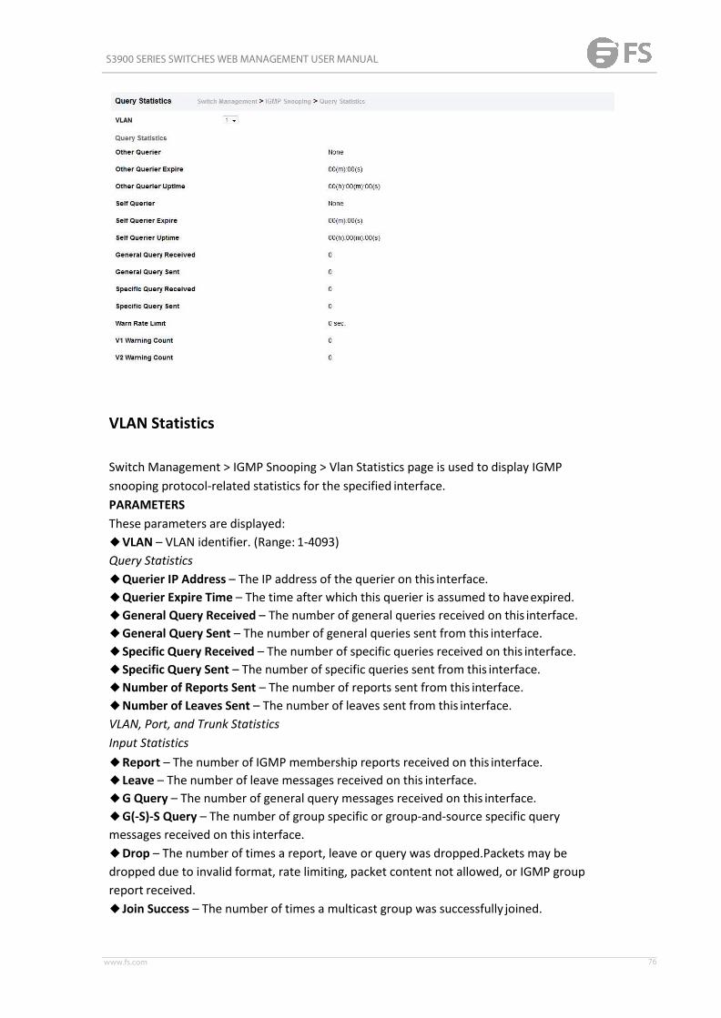
S3900 SERIES SWITCHES WEB MANAGEMENT USER MANUAL
www.fs.com 76
VLAN Statistics
Switch Management > IGMP Snooping > Vlan Statistics page is used to display IGMPsnooping protocol-related statistics for the specified interface.PARAMETERSThese parameters are displayed:◆VLAN – VLAN identifier. (Range: 1-4093)Query Statistics◆Querier IP Address – The IP address of the querier on this interface.◆Querier Expire Time – The time after which this querier is assumed to haveexpired.◆General Query Received – The number of general queries received on this interface.◆General Query Sent – The number of general queries sent from this interface.◆Specific Query Received – The number of specific queries received on this interface.◆Specific Query Sent – The number of specific queries sent from this interface.◆Number of Reports Sent – The number of reports sent from this interface.◆Number of Leaves Sent – The number of leaves sent from this interface.VLAN, Port, and Trunk StatisticsInput Statistics◆Report – The number of IGMP membership reports received on this interface.◆Leave – The number of leave messages received on this interface.◆G Query – The number of general query messages received on this interface.◆G(-S)-S Query – The number of group specific or group-and-source specific querymessages received on this interface.◆Drop – The number of times a report, leave or query was dropped.Packets may bedropped due to invalid format, rate limiting, packet content not allowed, or IGMP groupreport received.◆Join Success – The number of times a multicast group was successfully joined.
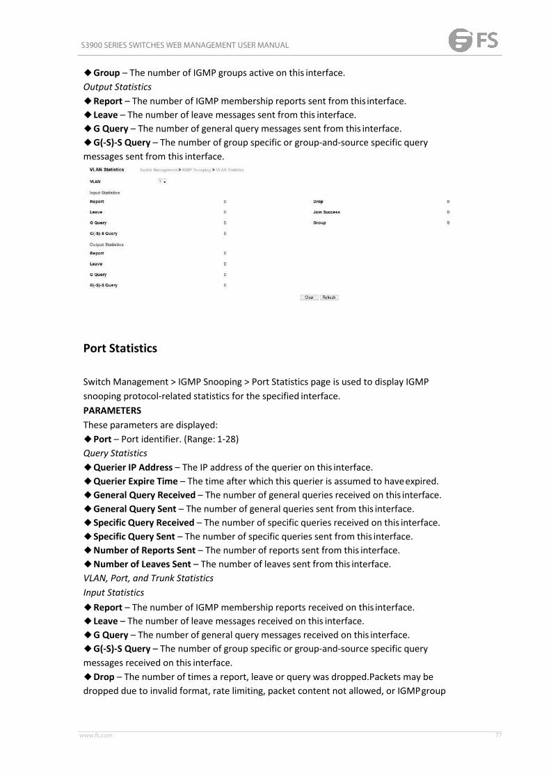
S3900 SERIES SWITCHES WEB MANAGEMENT USER MANUAL
www.fs.com 77
◆Group – The number of IGMP groups active on this interface.Output Statistics◆Report – The number of IGMP membership reports sent from this interface.◆Leave – The number of leave messages sent from this interface.◆G Query – The number of general query messages sent from this interface.◆G(-S)-S Query – The number of group specific or group-and-source specific querymessages sent from this interface.
Port Statistics
Switch Management > IGMP Snooping > Port Statistics page is used to display IGMPsnooping protocol-related statistics for the specified interface.PARAMETERSThese parameters are displayed:◆Port – Port identifier. (Range: 1-28)Query Statistics◆Querier IP Address – The IP address of the querier on this interface.◆Querier Expire Time – The time after which this querier is assumed to haveexpired.◆General Query Received – The number of general queries received on this interface.◆General Query Sent – The number of general queries sent from this interface.◆Specific Query Received – The number of specific queries received on this interface.◆Specific Query Sent – The number of specific queries sent from this interface.◆Number of Reports Sent – The number of reports sent from this interface.◆Number of Leaves Sent – The number of leaves sent from this interface.VLAN, Port, and Trunk StatisticsInput Statistics◆Report – The number of IGMP membership reports received on this interface.◆Leave – The number of leave messages received on this interface.◆G Query – The number of general query messages received on this interface.◆G(-S)-S Query – The number of group specific or group-and-source specific querymessages received on this interface.◆Drop – The number of times a report, leave or query was dropped.Packets may bedropped due to invalid format, rate limiting, packet content not allowed, or IGMPgroup

S3900 SERIES SWITCHES WEB MANAGEMENT USER MANUAL
www.fs.com 78
report received.◆Join Success – The number of times a multicast group was successfully joined.◆Group – The number of IGMP groups active on this interface.Output Statistics◆Report – The number of IGMP membership reports sent from this interface.◆Leave – The number of leave messages sent from this interface.◆G Query – The number of general query messages sent from this interface.◆G(-S)-S Query – The number of group specific or group-and-source specific querymessages sent from this interface.
Trunk Stastics
Switch Management > IGMP Snooping > Trunk Statistics page is used to display IGMPsnooping protocol-related statistics for the specified interface.PARAMETERSThese parameters are displayed:◆Trunk – Trunk identifier. (Range: 1-12)Query Statistics◆Querier IP Address – The IP address of the querier on this interface.◆Querier Expire Time – The time after which this querier is assumed to haveexpired.◆General Query Received – The number of general queries received on this interface.◆General Query Sent – The number of general queries sent from this interface.◆Specific Query Received – The number of specific queries received on this interface.◆Specific Query Sent – The number of specific queries sent from this interface.◆Number of Reports Sent – The number of reports sent from this interface.◆Number of Leaves Sent – The number of leaves sent from this interface.VLAN, Port, and Trunk StatisticsInput Statistics◆Report – The number of IGMP membership reports received on this interface.◆Leave – The number of leave messages received on this interface.◆G Query – The number of general query messages received on this interface.◆G(-S)-S Query – The number of group specific or group-and-source specific querymessages received on this interface.

S3900 SERIES SWITCHES WEB MANAGEMENT USER MANUAL
www.fs.com 79
◆Drop – The number of times a report, leave or query was dropped.Packets may bedropped due to invalid format, rate limiting, packet content not allowed, or IGMP groupreport received.◆Join Success – The number of times a multicast group was successfully joined.◆Group – The number of IGMP groups active on this interface.Output Statistics◆Report – The number of IGMP membership reports sent from this interface.◆Leave – The number of leave messages sent from this interface.◆G Query – The number of general query messages sent from this interface.◆G(-S)-S Query – The number of group specific or group-and-source specific querymessages sent from this interface.
IGMP Filtering and Throttling
In certain switch applications, the administrator may want to control the multicast servicesthat are available to end users. For example, an IP/TV service based on a specificsubscription plan. The IGMP filtering feature fulfills this requirement by restricting access tospecified multicast services on a switch port, and IGMP throttling limits the number ofsimultaneous multicast groups a port can join. IGMP filtering enables you to assign a profileto a switch port that specifies multicast groups that are permitted or denied on the port. AnIGMP filter profile can contain one or more addresses, or a range of multicast addresses; butonly one profile can be assigned to a port. When enabled, IGMP join reports received on theport are checked against the filter profile. If a requested multicast group is permitted, theIGMP join report is forwarded as normal. If a requested multicast group is denied, the IGMPjoin report is dropped. IGMP throttling sets a maximum number of multicast groups that aport can join at the same time. When the maximum number of groups is reached on a port,the switch can take one of two actions; either “deny” or “replace.” If the action is set todeny, any new IGMP join reports will be dropped. If the action is set to replace, the switchrandomly removes an existing group and replaces it with the new multicast group.
Filter General
Switch Management > IGMP Filtering and Throttling > Filter General page is used to enable

S3900 SERIES SWITCHES WEB MANAGEMENT USER MANUAL
www.fs.com 80
IGMP filtering and throttling globally on the switch.PARAMETERSThese parameters are displayed:◆ IGMP Filter Status – Enables IGMP filtering and throttling globally for the switch. (Default:Disabled)
Filter Profile
Switch Management > IGMP Filtering and Throttling > Filter Profile page is used to create anIGMP profile and set its access mode. Then use the (Add Multicast Group Range) page toconfigure the multicast groups to filter.COMMAND USAGESpecify a range of multicast groups by entering a start and end IP address; or specify a singlemulticast group by entering the same IP address for the start and end of the range.PARAMETERSThese parameters are displayed:Add◆Profile ID – Creates an IGMP profile. (Range: 1-4294967295)◆Access Mode – Sets the access mode of the profile; either permit or deny. (Default: Deny)When the access mode is set to permit, IGMP join reports are processed when a multicastgroup falls within the controlled range. When the access mode is set to deny, IGMP joinreports are only processed when the multicast group is not in the controlledrange.Add Multicast Group Range◆Profile ID – Selects an IGMP profile to configure.◆Start Multicast IP Address – Specifies the starting address of a range of multicastgroups.◆End Multicast IP Address – Specifies the ending address of a range of multicastgroups.
To show the IGMP filter profiles:1. Click Switch Management > IGMP Filtering and Throttling > Filter Profile.

S3900 SERIES SWITCHES WEB MANAGEMENT USER MANUAL
www.fs.com 81
Filter Range
Switch Management > IGMP Filtering and Throttling > Filter Range page is used to create anIGMP range and set its access mode. Then use the (new Multicast Group Range) page toconfigure the multicast groups to filter.COMMAND USAGESpecify a range of multicast groups by entering a start and end IP address; or specify a singlemulticast group by entering the same IP address for the start and end of the range.PARAMETERSThese parameters are displayed:new◆Start Multicast IP Address – Specifies the starting address of a range of multicastgroups.◆End Multicast IP Address – Specifies the ending address of a range of multicastgroups.
To show the multicast groups configured for an IGMP filter Range:
Configure Filter Interface
Switch Management > IGMP Filtering and Throttling > Configure Filter Interface page is usedto assign and IGMP filter profile to interfaces on the switch, or to throttle multicast traffic by

S3900 SERIES SWITCHES WEB MANAGEMENT USER MANUAL
www.fs.com 82
limiting the maximum number of multicast groups an interface can join at the same time.COMMAND USAGE◆ IGMP throttling sets a maximum number of multicast groups that a port can join at thesame time. When the maximum number of groups is reached on a port, the switch can takeone of two actions; either “deny” or “replace.” If the action is set to deny, any new IGMPjoin reports will be dropped. If the action is set to replace, the switch randomly removes anexisting group and replaces it with the new multicast group.PARAMETERSThese parameters are displayed:◆ Interface – Port or trunk identifier.An IGMP profile or throttling setting can be applied to a port or trunk. When ports areconfigured as trunk members, the trunk uses the settings applied to the first port member inthe trunk.◆Profile ID – Selects an existing profile to assign to an interface.◆Max Multicast Groups – Sets the maximum number of multicast groups an interface canjoin at the same time. (Range: 1-255; Default: 255)◆Current Multicast Groups – Displays the current multicast groups the interface has joined.◆Throttling Action Mode – Sets the action to take when the maximum number of multicastgroups for the interface has been exceeded. (Default: Deny)■Deny - The new multicast group join report is dropped.■Replace - The new multicast group replaces an existing group.◆Throttling Status – Indicates if the throttling action has been implemented on theinterface. (Options: True or False)
MLD Snooping
Multicast Listener Discovery (MLD) snooping operates on IPv6 traffic and performs a similarfunction to IGMP snooping for IPv4. That is, MLD snooping dynamically configures switchports to limit IPv6 multicast traffic so that it is forwarded only to ports with users that wantto receive it. This reduces the flooding of IPv6 multicast packets in the specified VLANs.There are two versions of the MLD protocol, version 1 and version 2. MLDv1 control packetsinclude Listener Query, Listener Report, and Listener Done messages (equivalent to IGMPv2query, report, and leave messages). MLDv2 control packets include MLDv2 query and report
S3900 SERIES SWITCHES WEB MANAGEMENT USER MANUAL
www.fs.com 83
messages, as well as MLDv1 report and done messages.Remember that IGMP Snooping andMLD Snooping are independent functions, and can therefore both function at the same time.
General
Switch Management > MLD Snooping > General page is used to configure the switch toforward multicast traffic intelligently. Based on the MLD query and report messages, theswitch forwards multicast traffic only to the ports that request it. This prevents the switchfrom broadcasting the traffic to all ports and possibly disrupting network performance.◆MLD Snooping Status – When enabled, the switch will monitor network traffic todetermine which hosts want to receive multicast traffic. (Default:Disabled)◆ Querier Status – When enabled, the switch can serve as the querier for MLDv2 snoopingif elected. The querier is responsible for asking hosts if they want to receive multicast traffic.(Default: Disabled) An IPv6 address must be configured on the VLAN interface from whichthe querier will act if elected. When serving as the querier, the switch uses this IPv6 addressas the query source address. The querier will not start or will disable itself after havingstarted if it detects an IPv6 multicast router on thenetwork.◆ Robustness – MLD Snooping robustness variable. A port will be removed from thereceiver list for a multicast service when no MLD reports are detected in response to anumber of MLD queries. The robustness variable sets the number of queries on ports forwhich there is no report. (Range: 2-10 Default: 2)◆ Query Interval – The interval between sending MLD general queries. (Range: 60-125seconds; Default: 125 seconds) This attribute applies when the switch is serving as thequerier. An MLD general query message is sent by the switch at the interval specified by thisattribute. When this message is received by downstream hosts, all receivers build an MLDreport for the multicast groups they have joined.◆ Query Max Response Time – The maximum response time advertised in MLD generalqueries. (Range: 5-25 seconds; Default: 10 seconds) This attribute controls how long the hosthas to respond to an MLD Query message before the switch deletes the group if it is the lastmember.◆ Router Port Expiry Time – The time the switch waits after the previous querier stopsbefore it considers the router port (i.e., the interface that had been receiving query packets)to have expired. (Range: 300-500 seconds; Default: 300 seconds)◆MLD Snooping Version – The protocol version used for compatibility with other deviceson the network. This is the MLD version the switch uses to send snooping reports. (Range:1-2; Default: 2)◆ UnknownMulticast Mode – The action for dealing with unknownmulticast packets.Options include:■ Flood – Floods any received IPv6 multicast packets that have not been requested by ahost to all ports in the VLAN.■ ToRouter Port – Forwards any received IPv6 multicast packets that have not beenrequested by a host to ports that are connected to a detected multicast router. (This is thedefault action.)

S3900 SERIES SWITCHES WEB MANAGEMENT USER MANUAL
www.fs.com 84
Immediate Leave Status
Switch Management> MLD Snooping > Immediate Leave Status page is used to configureImmediate Leave status for a VLAN.◆ VLAN – A VLAN identification number. (Range: 1-4094)◆ Immediate Leave Status – Immediately deletes a member port of an IPv6 multicastservice when a leave packet is received at that port and immediate leave is enabled for theparent VLAN. (Default: Disabled) If MLD immediate-leave is not used, a multicast router (orquerier) will send a group-specific query message when an MLD group leave message isreceived. The router/querier stops forwarding traffic for that group only if no host replies tothe query within the specified timeout period.If MLD immediate-leave is enabled, the switch assumes that only one host is connected tothe interface. Therefore, immediate leave should only be enabled on an interface if it isconnected to only one MLD-enabled device, either a service host or a neighbor running MLDsnooping.
Current Multicast Router
Switch Management > MLD Snooping > Current Multicast Router page is used to staticallyshow an interface to an IPv6 multicast router/switch.Depending on your network connections, MLD snooping may not always be able to locatethe MLD querier. Therefore, if the MLD querier is a known multicast router/ switchconnected over the network to an interface (port or trunk) on the switch, you can manuallyconfigure that interface to join all the current multicast groups.

S3900 SERIES SWITCHES WEB MANAGEMENT USER MANUAL
www.fs.com 85
Command UsageMLD Snooping must be enabled globally on the switch before a multicast router port cantake effect.◆ VLAN – Selects the VLAN which is to propagate all IPv6 multicast traffic coming from theattached multicast router. (Range: 1-4094)◆ Interface – Activates the Port or Trunk scroll down list.
Static Multicast Router
Switch Management> MLD Snooping> Static Multicast Router page is used to statically addan interface to an IPv6 multicast router/switch. Depending on your network connections,MLD snooping may not always be able to locate the MLD querier. Therefore, if the MLDquerier is a known multicast router/ switch connected over the network to an interface (portor trunk) on the switch, you can manually configure that interface to join all the currentmulticast groups.
MLD Snooping must be enabled globally on the switch before a multicast router port cantake effect.◆ VLAN – Selects the VLAN which is to propagate all IPv6 multicast traffic coming from theattached multicast router. (Range: 1-4094)◆ Interface – Activates the Port or Trunk scroll down list.

S3900 SERIES SWITCHES WEB MANAGEMENT USER MANUAL
www.fs.com 86
Current Member
Switch Management > MLD Snooping > Current Member page is used to statically show anIPv6 multicast service to an interface. Multicast filtering can be dynamically configured usingMLD snooping and query messages. However, for certain applications that require tightercontrol, it may be necessary to statically configure a multicast service on the switch. First addall the ports attached to participating hosts to a common VLAN, and then assign themulticast service to that VLAN group.Command Usage◆ Static multicast addresses are never aged out.◆When a multicast address is assigned to an interface in a specific VLAN, the correspondingtraffic can only be forwarded to ports within thatVLAN.◆ VLAN – Specifies the VLAN which is to propagate the multicast service. (Range:1-4094)◆Multicast IPv6 Address – The IP address for a specific multicastservice.◆ Interface – Activates the Port or Trunk scroll down list.◆ Port or Trunk – Specifies the interface assigned to a multicastgroup.◆ Type (Show CurrentMember) – Shows if this multicast streamwas statically configured bythe user, discovered by MLD Snooping, or is a data stream to which no other ports aresubscribing (i.e., the stream is flooded onto VLAN instead of being trapped to the CPU forprocessing, or is being processed byMVR6).
Static Member
Switch Management> MLD Snooping > Static Member page is used to statically add an IPv6multicast service to an interface. Multicast filtering can be dynamically configured using MLDsnooping and query messages However, for certain applications that require tighter control,it may be necessary to statically configure a multicast service on the switch. First add all theports attached to participating hosts to a common VLAN, and then assign the multicastservice to that VLAN group.Command Usage◆ Static multicast addresses are never aged out.◆When a multicast address is assigned to an interface in a specific VLAN, the correspondingtraffic can only be forwarded to ports within thatVLAN.ParametersThese parameters are displayed:◆ VLAN – Specifies the VLAN which is to propagate the multicast service. (Range:1-4094)◆Multicast IPv6 Address – The IP address for a specific multicastservice.

S3900 SERIES SWITCHES WEB MANAGEMENT USER MANUAL
www.fs.com 87
◆ Interface – Activates the Port or Trunk scroll down list.◆ Port or Trunk – Specifies the interface assigned to a multicastgroup.◆ Type (Show CurrentMember) – Shows if this multicast streamwas statically configured bythe user, discovered by MLD Snooping, or is a data stream to which no other ports aresubscribing (i.e., the stream is flooded onto VLAN instead of being trapped to the CPU forprocessing, or is being processed byMVR6).
Group Information
Switch Management > MLD Snooping > Group Information page is used to display and setknown multicast groups, member ports, the means by which each group was learned, andthe corresponding source list.ParametersThese parameters are displayed:◆ VLAN – VLAN identifier. (Range: 1-4094)◆ Interface – Port or trunk identifier.◆ Group Address – The IP address for a specific multicast service.◆ Type – The means by which each group was learned – MLD Snooping or MulticastData.◆ Filter Mode – The filter mode is used to summarize the total listening state of a multicastaddress to a minimum set such that all nodes' listening states are respected. In Include mode,the router only uses the request list, indicating that the reception of packets sent to thespecified multicast address is requested only from those IP source addresses listed in thehosts’ source-list. In Exclude mode, the router uses both the request list and exclude list,indicating that the reception of packets sent to the given multicast address is requested fromall IP source addresses, except for those listed in the exclude source-list and for any othersources where the source timer status has expired.◆ Filter Timer Elapse – The Filter timer is only used when a specific multicast address is inExclude mode. It represents the time for the multicast address filter mode to expire andchange to Include mode.◆ Request List – Sources included on the router’s request list.◆ Exclude List – Sources included on the router’s exclude list.

S3900 SERIES SWITCHES WEB MANAGEMENT USER MANUAL
www.fs.com 88
Statistics
Switch Management > MLD Snooping > Statistics pages is used to display MLD Snoopingprotocolrelated statistics for the specified interface.PARAMETERSThese parameters are displayed:◆Domain ID – An independent multicast domain. (Range: 1-5)◆VLAN – VLAN identifier. (Range: 1-4093)◆Port – Port identifier. (Range: 1-28)◆Trunk – Trunk identifier. (Range: 1-12)Query Statistics◆Querier IP Address – The IP address of the querier on this interface.◆Querier Expire Time – The time after which this querier is assumed to haveexpired.◆General Query Received – The number of general queries received on this interface.◆General Query Sent – The number of general queries sent from this interface.◆Specific Query Received – The number of specific queries received on this interface.◆Specific Query Sent – The number of specific queries sent from this interface.◆Number of Reports Sent – The number of reports sent from this interface.◆Number of Leaves Sent – The number of leaves sent from this interface.VLAN, Port, and Trunk StatisticsInput Statistics◆Report – The number of IGMP membership reports received on this interface.◆Leave – The number of leave messages received on this interface.◆G Query – The number of general query messages received on this interface.◆G(-S)-S Query – The number of group specific or group-and-source specific querymessages received on this interface.◆Drop – The number of times a report, leave or query was dropped. Packets may bedropped due to invalid format, rate limiting, packet content not allowed, or MVR groupreport received.◆Join Success – The number of times a multicast group was successfully joined.◆Group – The number of MVR groups active on this interface.Output Statistics◆Report – The number of IGMP membership reports received on this interface.◆Leave – The number of leave messages received on this interface.◆G Query – The number of general query messages received on this interface.

S3900 SERIES SWITCHES WEB MANAGEMENT USER MANUAL
www.fs.com 89
◆G(-S)-S Query – The number of group specific or group-and-source specific querymessages received on this interface.◆Drop – The number of times a report, leave or query was dropped. Packets may bedropped due to invalid format, rate limiting, packet content not allowed, or MVR groupreport received.◆Join Success – The number of times a multicast group was successfully joined.◆Group – The number of MVR groups active on this interface.
To display statistics for MLD Snooping input:
To display statistics for MLD Snooping output:
To display statistics for MLD Snooping Query:

S3900 SERIES SWITCHES WEB MANAGEMENT USER MANUAL
www.fs.com 90
To display statistics for MLD Snooping Summary:
To display statistics for MLD Snooping Summary:
MVR for IPv4
Multicast VLAN Registration (MVR) is a protocol that controls access to a singlenetwork-wide VLAN most commonly used for transmitting multicast traffic (such astelevision channels or video-on-demand) across a service provider’s network. Any multicasttraffic entering an MVR VLAN is sent to all attached subscribers. This protocol cansignificantly reduce to processing overhead required to dynamically monitor and establishthe distribution tree for a normal multicast VLAN. This makes it possible to support commonmulticast services over a wide part of the network without having to use any multicast

S3900 SERIES SWITCHES WEB MANAGEMENT USER MANUAL
www.fs.com 91
routing protocol. MVR maintains the user isolation and data security provided by VLANsegregation by passing only multicast traffic into other VLANs to which the subscribersbelong. Even though common multicast streams are passed onto different VLAN groupsfrom the MVR VLAN, users in different IEEE 802.1Q or private VLANs cannot exchange anyinformation (except through upper-level routing services).
Configure Global
Switch Management > MVR For IPv4 > Configure Global page is used to configure proxyswitching and the robustness variable.PARAMETERSThese parameters are displayed:◆Proxy Switching – Configures MVR proxy switching, where the source port acts as a host,and the receiver port acts as an MVR router with querier service enabled. (Default:Enabled)■When MVR proxy-switching is enabled, an MVR source port serves as the upstream orhost interface, and the MVR receiver port serves as the querier. The source port performsonly the host portion of MVR by sending summarized membership reports, andautomatically disables MVR router functions.■Receiver ports are known as downstream or router interfaces. These interfaces performthe standard MVR router functions by maintaining a database of all MVR subscriptions onthe downstream interface. Receiver ports must therefore be configured on all downstreaminterfaces which require MVR proxy service.■When the source port receives report and leave messages, it only forwards them to othersource ports.■When receiver ports receive any query messages, they are dropped.■When changes occurring in the downstreamMVR groups are learned by the receiver portsthrough report and leave messages, an MVR state change report is created and sent to theupstream source port, which in turn forwards this informationupstream.

S3900 SERIES SWITCHES WEB MANAGEMENT USER MANUAL
www.fs.com 92
■When MVR proxy switching is disabled:■Any membership reports received from receiver/source ports are forwarded to all sourceports.■When a source port receives a query message, it will be forwarded to all downstreamreceiver ports.■When a receiver port receives a query message, it will bedropped.◆Robustness Value – Configures the expected packet loss, and thereby the number oftimes to generate report and group-specific queries. (Range: 1-255; Default: 2)■This parameter is used to set the number of times report messages are sent upstreamwhen changes are learned about downstream groups, and the number of timesgroup-specific queries are sent to downstream receiver ports.■This parameter only takes effect when MVR proxy switching isenabled.◆Proxy Query Interval – Configures the interval at which the receiver port sends outgeneral queries. (Range: 2-31744 seconds; Default: 125 seconds)■This parameter sets the general query interval at which active receiver ports send outgeneral queries.■This interval is only effective when proxy switching is enabled.◆Source Port Mode – Configures the switch to forward any multicast streams within theparameters set by a profile, or to only forward multicast streams which the source port hasdynamically joined.■Always Forward – By default, the switch forwards any multicast streams within theaddress range set by a profile, and bound to a domain. The multicast streams are sent to allsource ports on the switch and to all receiver ports that have elected to receive data on thatmulticast address.■Dynamic – When dynamic mode is enabled, the switch only forwards multicast streamswhich the source port has dynamically joined. In other words, both the receiver port andsource port must subscribe to a multicast group before a multicast stream is forwarded toany attached client. Note that the requested streams are still restricted to the address rangewhich has been specified in a profile and bound to adomain.
Configure Domain
Switch Management > MVR For IPv4 > Configure Domain page is used to enable MVRglobally on the switch, and select the VLAN that will serve as the sole channel for commonmulticast streams supported by the service provider.PARAMETERS

S3900 SERIES SWITCHES WEB MANAGEMENT USER MANUAL
www.fs.com 93
These parameters are displayed:◆Domain ID – An independent multicast domain. (Range: 1-5)◆MVR Status – When MVR is enabled on the switch, any multicast data associated with anMVR group is sent from all designated source ports, to all receiver ports that have registeredto receive data from that multicast group. (Default: Disabled)◆MVR VLAN – Identifier of the VLAN that serves as the channel for streaming multicastservices using MVR. MVR source ports should be configured as members of the MVR VLAN(see "Adding Static Members to VLANs" ), but MVR receiver ports should not be manuallyconfigured as members of this VLAN. (Default: 1)◆MVR Running Status – Indicates whether or not all necessary conditions in the MVRenvironment are satisfied. Running status is Active as long as MVR is enabled, the specifiedMVR VLAN exists, and a source port with a valid link has been configured (see "ConfiguringMVR Interface Status" ).◆MVR Current Learned Groups – The number of MVR groups currently assigned to thisdomain.◆Forwarding Priority – The CoS priority assigned to all multicast traffic forwarded into thisdomain. (Range: 0-6, where 6 is the highest priority) This parameter can be used to set ahigh priority for low-latency multicast traffic such as a video-conference, or to set a lowpriority for normal multicast traffic not sensitive to latency.◆Upstream Source IP – The source IP address assigned to all MVR control packets sentupstream on the specified domain. By default, all MVR reports sent upstream use a nullsource IP address.
Show Configure Profile
Switch Management > MVR For IPv4 > Show Configure Profile pages is used to display themulticast group address for required services to one or more MVR domains.COMMAND USAGE◆Use the Show Configure Profile page to statically show all multicast group addresses thatwill join the MVR VLAN. Any multicast data associated with an MVR group is sent from allsource ports to all receiver ports that have registered to receive data from that multicastgroup.◆The IP address range from 224.0.0.0 to 239.255.255.255 is used for multicaststreams.

S3900 SERIES SWITCHES WEB MANAGEMENT USER MANUAL
www.fs.com 94
MVR group addresses cannot fall within the reserved IP multicast address range of 224.0.0.x.◆ IGMP snooping and MVR share a maximum number of 1024 groups. Any multicaststreams received in excess of this limitation will be flooded to all ports in the associateddomain.PARAMETERSThese parameters are displayed:Configure Profile◆Profile Name – The name of a profile containing one or more MVR group addresses.(Range: 1-21 characters)◆Start IP Address – Starting IP address for an MVR multicast group. (Range: 224.0.1.0239.255.255.255)◆End IP Address – Ending IP address for an MVR multicast group. (Range: 224.0.1.0 -239.255.255.255)Associate Profile
Add Configure Profile
Switch Management > MVR For IPv4 > Add Configure Profile page is used to assign themulticast group address for required services to one or more MVR domains.COMMAND USAGE◆Use the Add Configure Profile page to statically configure all multicast group addressesthat will join the MVR VLAN. Any multicast data associated with an MVR group is sent fromall source ports to all receiver ports that have registered to receive data from that multicastgroup.◆The IP address range from 224.0.0.0 to 239.255.255.255 is used for multicast streams.MVR group addresses cannot fall within the reserved IP multicast address range of224.0.0.x.◆ IGMP snooping and MVR share a maximum number of 1024 groups. Any multicaststreams received in excess of this limitation will be flooded to all ports in the associateddomain.PARAMETERSThese parameters are displayed:Configure Profile◆Profile Name – The name of a profile containing one or more MVR group addresses.(Range: 1-21 characters)◆Start IP Address – Starting IP address for an MVR multicast group. (Range: 224.0.1.0 -239.255.255.255)◆End IP Address – Ending IP address for an MVR multicast group. (Range: 224.0.1.0 -239.255.255.255)

S3900 SERIES SWITCHES WEB MANAGEMENT USER MANUAL
www.fs.com 95
Associate Profile(Range: 1-21 characters)
Show Associate Profile
Switch Management > MVR For IPv4 >Show Associate Profile pages is used to show themulticast group address for required services to one or more MVR domains.COMMAND USAGE◆Use the Show Associate Profile page to statically show all multicast group addresses thatwill join the MVR VLAN. Any multicast data associated with an MVR group is sent from allsource ports to all receiver ports that have registered to receive data from that multicastgroup.◆The IP address range from 224.0.0.0 to 239.255.255.255 is used for multicast streams.MVR group addresses cannot fall within the reserved IP multicast address range of224.0.0.x.◆ IGMP snooping and MVR share a maximum number of 1024 groups. Any multicaststreams received in excess of this limitation will be flooded to all ports in the associateddomain.PARAMETERSThese parameters are displayed:Configure Profile◆Profile Name – The name of a profile containing one or more MVR group addresses.(Range: 1-21 characters)◆Start IP Address – Starting IP address for an MVR multicast group. (Range: 224.0.1.0 -239.255.255.255)◆End IP Address – Ending IP address for an MVR multicast group. (Range: 224.0.1.0 -239.255.255.255)Associate Profile◆Domain ID – An independent multicast domain. (Range: 1-5)
To show the MVR group address profiles assigned to adomain:

S3900 SERIES SWITCHES WEB MANAGEMENT USER MANUAL
www.fs.com 96
Add Associate Profile
Switch Management > MVR For IPv4 > Add Associate Profile page is used to assign themulticast group address for required services to one or more MVR domains.COMMAND USAGE◆Use the Add Associate Profile page to statically configure all multicast group addressesthat will join the MVR VLAN. Any multicast data associated with an MVR group is sent fromall source ports to all receiver ports that have registered to receive data from that multicastgroup.◆The IP address range from 224.0.0.0 to 239.255.255.255 is used for multicast streams.MVR group addresses cannot fall within the reserved IP multicast address range of224.0.0.x.◆ IGMP snooping and MVR share a maximum number of 1024 groups. Any multicaststreams received in excess of this limitation will be flooded to all ports in the associateddomain.PARAMETERSThese parameters are displayed:Associate Profile◆Domain ID – An independent multicast domain. (Range: 1-5)◆Profile Name – The name of a profile to be assigned to this domain. (Range: 1-21characters)
Configure Interface
Switch Management > MVR For IPv4 > Configure Interface page is used to configure eachinterface that participates in the MVR protocol as a source port or receiver port. If you aresure that only one subscriber attached to an interface is receiving multicast services, you canenable the immediate leave function.COMMAND USAGE◆A port configured as an MVR receiver or source port can join or leave multicastgroups

S3900 SERIES SWITCHES WEB MANAGEMENT USER MANUAL
www.fs.com 97
configured under MVR. However, note that these ports can also use IGMP snooping to joinor leave any other multicast groups using the standard rules for multicast filtering.◆Receiver ports can belong to different VLANs, but should not be configured as a memberof the MVR VLAN. MVR allows a receiver port to dynamically join or leave multicast groupswithin an MVR VLAN. Multicast groups can also be statically assigned to a receiver port.Receiver ports should not be statically configured as a member of the MVR VLAN. If soconfigured, its MVR status will be inactive. Also, note that VLAN membership for MVRreceiver ports cannot be set to accessmode.◆One or more interfaces may be configured as MVR source ports. A source port is able toboth receive and send data for configured MVR groups or for groups which have beenstatically assigned. All source ports must belong to the MVR VLAN. Subscribers should not bedirectly connected to source ports.◆ Immediate leave applies only to receiver ports. When enabled, the receiver port isimmediately removed from the multicast group identified in the leave message. Whenimmediate leave is disabled, the switch follows the standard rules by sending a querymessage to the receiver port and waiting for a response to determine if there are anyremaining subscribers for that multicast group before removing the port from thegroup list.■Using immediate leave can speed up leave latency, but should only be enabled on a portattached to one multicast subscriber to avoid disrupting services to other group membersattached to the same interface.■Immediate leave does not apply to multicast groups which have been statically assignedto a port.PARAMETERSThese parameters are displayed:◆Domain ID – An independent multicast domain. (Range: 1-5)◆Port/Trunk – Interface identifier.◆Type – The following interface types are supported:■Source – An uplink port that can send and receive multicast data for the groups assignedto the MVR VLAN. Note that the source port must be manually configured as a member ofthe MVR VLAN.■Receiver – A subscriber port that can receive multicast data sent through the MVR VLAN.Any port configured as an receiver port will be dynamically added to the MVR VLAN when itforwards an IGMP report or join message from an attached host requesting any of thedesignated multicast services supported by the MVR VLAN. Just remember that only IGMPversion 2 or 3 hosts can issue multicast join or leave messages. If MVR must be configuredfor an IGMP version 1 host, the multicast groups must be statically assigned.■Non-MVR – An interface that does not participate in the MVR VLAN. (This is the defaulttype.)◆Forwarding Status – Shows if MVR traffic is being forwarded ordiscarded.◆MVR Status – Shows the MVR status. MVR status for source ports is “Active” if MVR isglobally enabled on the switch. MVR status for receiver ports is “Active” only if there aresubscribers receiving multicast traffic from one of the MVR groups, or a multicast group hasbeen statically assigned to an interface.◆ Immediate Leave – Configures the switch to immediately remove an interface froma

S3900 SERIES SWITCHES WEB MANAGEMENT USER MANUAL
www.fs.com 98
multicast stream as soon as it receives a leave message for that group. (This option onlyapplies to an interface configured as an MVR receiver.)
Show Static Group Member
Switch Management > MVR For IPv4 > Show Static Group Member page is used to staticallyshowmulticast groups for a port or trunk which will receive long-term multicast streamsassociated with a stable set of hosts.COMMAND USAGE◆Multicast groups can be statically assigned to a receiver port using this configurationpage.◆The IP address range from 224.0.0.0 to 239.255.255.255 is used for multicast streams.MVR group addresses cannot fall within the reserved IP multicast address range of224.0.0.x.◆Only IGMP version 2 or 3 hosts can issue multicast join or leave messages. If MVR must beconfigured for an IGMP version 1 host, the multicast groups must be staticallyassigned.◆The MVR VLAN cannot be specified as the receiver VLAN for staticbindings.PARAMETERSThese parameters are displayed:◆Domain ID – An independent multicast domain. (Range: 1-5)◆ Interface – Port or trunk identifier.◆VLAN – VLAN identifier. (Range: 1-4093)◆Group IP Address – Defines a multicast service sent to the selected port. Multicast groupsmust be assigned from the MVR group range configured on the Configure Generalpage.

S3900 SERIES SWITCHES WEB MANAGEMENT USER MANUAL
www.fs.com 99
Add Static Group Member
Switch Management > MVR For IPv4 > Add Static Group Member page is used to staticallybind multicast groups to a port which will receive long-term multicast streams associatedwith a stable set of hosts.COMMAND USAGE◆Multicast groups can be statically assigned to a receiver port using this configurationpage.◆The IP address range from 224.0.0.0 to 239.255.255.255 is used for multicast streams.MVR group addresses cannot fall within the reserved IP multicast address range of224.0.0.x.◆Only IGMP version 2 or 3 hosts can issue multicast join or leave messages. If MVR must beconfigured for an IGMP version 1 host, the multicast groups must be staticallyassigned.◆The MVR VLAN cannot be specified as the receiver VLAN for staticbindings.PARAMETERSThese parameters are displayed:◆Domain ID – An independent multicast domain. (Range: 1-5)◆ Interface – Port or trunk identifier.◆VLAN – VLAN identifier. (Range: 1-4093)◆Group IP Address – Defines a multicast service sent to the selected port. Multicast groupsmust be assigned from the MVR group range configured on the Configure Generalpage.
ShowMember
Switch Management > MVR For IPv4 >ShowMember page is used to show the multicastgroups either statically or dynamically assigned to the MVR receiver groups on eachinterface.PARAMETERSThese parameters are displayed:◆Domain ID – An independent multicast domain. (Range: 1-5)◆Group IP Address – Multicast groups assigned to the MVRVLAN.◆VLAN – The VLAN through which the service is received. Note that this may be differentfrom the MVR VLAN if the group address has been statically assigned.◆Port – Shows the interfaces with subscribers for multicast services provided through theMVR VLAN.◆Up Time – Time this service has been forwarded to attachedclients.◆Expire – Time before this entry expires if no membership report is received from currentlyactive or new clients.

S3900 SERIES SWITCHES WEB MANAGEMENT USER MANUAL
www.fs.com 100
◆Count – The number of multicast services currently being forwarded from the MVRVLAN.
Show Query Statistics
Switch Management > MVR For IPv4 > Show Query Statistics page is used to display MVRprotocolrelated statistics for the specified interface.PARAMETERSThese parameters are displayed:◆Domain ID – An independent multicast domain. (Range: 1-5)◆VLAN – VLAN identifier. (Range: 1-4093)◆Port – Port identifier. (Range: 1-28)◆Trunk – Trunk identifier. (Range: 1-12)Query Statistics◆Querier IP Address – The IP address of the querier on this interface.◆Querier Expire Time – The time after which this querier is assumed to haveexpired.◆General Query Received – The number of general queries received on this interface.◆General Query Sent – The number of general queries sent from this interface.◆Specific Query Received – The number of specific queries received on this interface.◆Specific Query Sent – The number of specific queries sent from this interface.◆Number of Reports Sent – The number of reports sent from this interface.◆Number of Leaves Sent – The number of leaves sent from this interface.VLAN, Port, and Trunk StatisticsInput Statistics◆Report – The number of IGMP membership reports received on this interface.◆Leave – The number of leave messages received on this interface.◆G Query – The number of general query messages received on this interface.◆G(-S)-S Query – The number of group specific or group-and-source specific querymessages received on this interface.◆Drop – The number of times a report, leave or query was dropped. Packets may bedropped due to invalid format, rate limiting, packet content not allowed, or MVR groupreport received.◆Join Success – The number of times a multicast group was successfully joined.◆Group – The number of MVR groups active on this interface.Output Statistics◆Report – The number of IGMP membership reports sent from this interface.◆Leave – The number of leave messages sent from this interface.◆G Query – The number of general query messages sent from this interface.

S3900 SERIES SWITCHES WEB MANAGEMENT USER MANUAL
www.fs.com 101
◆G(-S)-S Query – The number of group specific or group-and-source specific querymessages sent from this interface.
Show VLAN Statistics
Switch Management > MVR For IPv4 > Show VLAN Statistics page is used to display MVRprotocolrelated statistics for the specified interface.PARAMETERSThese parameters are displayed:◆Domain ID – An independent multicast domain. (Range: 1-5)◆VLAN – VLAN identifier. (Range: 1-4093)◆Port – Port identifier. (Range: 1-28)◆Trunk – Trunk identifier. (Range: 1-12)Query Statistics◆Querier IP Address – The IP address of the querier on this interface.◆Querier Expire Time – The time after which this querier is assumed to haveexpired.◆General Query Received – The number of general queries received on this interface.◆General Query Sent – The number of general queries sent from this interface.◆Specific Query Received – The number of specific queries received on this interface.◆Specific Query Sent – The number of specific queries sent from this interface.◆Number of Reports Sent – The number of reports sent from this interface.◆Number of Leaves Sent – The number of leaves sent from this interface.VLAN, Port, and Trunk StatisticsInput Statistics◆Report – The number of IGMP membership reports received on this interface.◆Leave – The number of leave messages received on this interface.◆G Query – The number of general query messages received on this interface.◆G(-S)-S Query – The number of group specific or group-and-source specific querymessages received on this interface.◆Drop – The number of times a report, leave or query was dropped. Packets may bedropped due to invalid format, rate limiting, packet content not allowed, or MVR groupreport received.◆Join Success – The number of times a multicast group was successfully joined.

S3900 SERIES SWITCHES WEB MANAGEMENT USER MANUAL
www.fs.com 102
◆Group – The number of MVR groups active on this interface.Output Statistics◆Report – The number of IGMP membership reports sent from this interface.◆Leave – The number of leave messages sent from this interface.◆G Query – The number of general query messages sent from this interface.◆G(-S)-S Query – The number of group specific or group-and-source specific querymessages sent from this interface.
Show Port Statistics
Switch Management > MVR For IPv4 > Show Port Statistics page is used to display MVRprotocolrelated statistics for the specified interface.PARAMETERSThese parameters are displayed:◆Domain ID – An independent multicast domain. (Range: 1-5)◆VLAN – VLAN identifier. (Range: 1-4093)◆Port – Port identifier. (Range: 1-28)◆Trunk – Trunk identifier. (Range: 1-12)Query Statistics◆Querier IP Address – The IP address of the querier on this interface.◆Querier Expire Time – The time after which this querier is assumed to haveexpired.◆General Query Received – The number of general queries received on this interface.◆General Query Sent – The number of general queries sent from this interface.◆Specific Query Received – The number of specific queries received on this interface.◆Specific Query Sent – The number of specific queries sent from this interface.◆Number of Reports Sent – The number of reports sent from this interface.◆Number of Leaves Sent – The number of leaves sent from this interface.VLAN, Port, and Trunk StatisticsInput Statistics◆Report – The number of IGMP membership reports received on this interface.

S3900 SERIES SWITCHES WEB MANAGEMENT USER MANUAL
www.fs.com 103
◆Leave – The number of leave messages received on this interface.◆G Query – The number of general query messages received on this interface.◆G(-S)-S Query – The number of group specific or group-and-source specific querymessages received on this interface.◆Drop – The number of times a report, leave or query was dropped. Packets may bedropped due to invalid format, rate limiting, packet content not allowed, or MVR groupreport received.◆Join Success – The number of times a multicast group was successfully joined.◆Group – The number of MVR groups active on this interface.Output Statistics◆Report – The number of IGMP membership reports sent from this interface.◆Leave – The number of leave messages sent from this interface.◆G Query – The number of general query messages sent from this interface.◆G(-S)-S Query – The number of group specific or group-and-source specific querymessages sent from this interface.
Show Trunk Statistics
Switch Management > MVR For IPv4 > Show Trunk Statistics page is used to display MVRprotocolrelated statistics for the specified interface.PARAMETERSThese parameters are displayed:◆Domain ID – An independent multicast domain. (Range: 1-5)◆VLAN – VLAN identifier. (Range: 1-4093)◆Port – Port identifier. (Range: 1-28)◆Trunk – Trunk identifier. (Range: 1-12)Query Statistics◆Querier IP Address – The IP address of the querier on this interface.◆Querier Expire Time – The time after which this querier is assumed to haveexpired.◆General Query Received – The number of general queries received on this interface.◆General Query Sent – The number of general queries sent from this interface.◆Specific Query Received – The number of specific queries received on this interface.◆Specific Query Sent – The number of specific queries sent from this interface.◆Number of Reports Sent – The number of reports sent from this interface.◆Number of Leaves Sent – The number of leaves sent from this interface.

S3900 SERIES SWITCHES WEB MANAGEMENT USER MANUAL
www.fs.com 104
VLAN, Port, and Trunk StatisticsInput Statistics◆Report – The number of IGMP membership reports received on this interface.◆Leave – The number of leave messages received on this interface.◆G Query – The number of general query messages received on this interface.◆G(-S)-S Query – The number of group specific or group-and-source specific querymessages received on this interface.◆Drop – The number of times a report, leave or query was dropped. Packets may bedropped due to invalid format, rate limiting, packet content not allowed, or MVR groupreport received.◆Join Success – The number of times a multicast group was successfully joined.◆Group – The number of MVR groups active on this interface.Output Statistics◆Report – The number of IGMP membership reports sent from this interface.◆Leave – The number of leave messages sent from this interface.◆G Query – The number of general query messages sent from this interface.◆G(-S)-S Query – The number of group specific or group-and-source specific querymessages sent from this interface.
MVR For IPv6
MVR6 functions in a manner similar to that described for MRV
Configure Global
Switch Management > MVR For IPv6 > Configure Global page is used to configure proxyswitching and the robustness variable.PARAMETERSThese parameters are displayed:◆Proxy Switching – Configures MVR proxy switching, where the source port acts as a host,and the receiver port acts as an MVR router with querier service enabled. (Default:Enabled)

S3900 SERIES SWITCHES WEB MANAGEMENT USER MANUAL
www.fs.com 105
■When MVR proxy-switching is enabled, an MVR source port serves as the upstream orhost interface, and the MVR receiver port serves as the querier. The source port performsonly the host portion of MVR by sending summarized membership reports, andautomatically disables MVR router functions.■Receiver ports are known as downstream or router interfaces. These interfaces performthe standard MVR router functions by maintaining a database of all MVR subscriptions onthe downstream interface. Receiver ports must therefore be configured on all downstreaminterfaces which require MVR proxy service.■When the source port receives report and leave messages, it only forwards them to othersource ports.■When receiver ports receive any query messages, they are dropped.■When changes occurring in the downstreamMVR groups are learned by the receiver portsthrough report and leave messages, an MVR state change report is created and sent to theupstream source port, which in turn forwards this informationupstream.■When MVR proxy switching is disabled:■Any membership reports received from receiver/source ports are forwarded to all sourceports.■When a source port receives a query message, it will be forwarded to all downstreamreceiver ports.■When a receiver port receives a query message, it will bedropped.◆Robustness Value – Configures the expected packet loss, and thereby the number oftimes to generate report and group-specific queries. (Range: 1-10; Default: 2)■This parameter is used to set the number of times report messages are sent upstreamwhen changes are learned about downstream groups, and the number of timesgroup-specific queries are sent to downstream receiver ports.■This parameter only takes effect when MVR6 proxy switching is enabled.◆Proxy Query Interval – Configures the interval at which the receiver port sends outgeneral queries. (Range: 2-31744 seconds; Default: 125 seconds)■This parameter sets the general query interval at which active receiver ports send outgeneral queries.■This interval is only effective when proxy switching is enabled.◆Source Port Mode – Configures the switch to forward any multicast streams within theparameters set by a profile, or to only forward multicast streams which the source port hasdynamically joined.■Always Forward – By default, the switch forwards any multicast streams within theaddress range set by a profile, and bound to a domain. The multicast streams are sent to allsource ports on the switch and to all receiver ports that have elected to receive data on thatmulticast address.■Dynamic – When dynamic mode is enabled, the switch only forwards multicast streamswhich the source port has dynamically joined. In other words, both the receiver port andsource port must subscribe to a multicast group before a multicast stream is forwarded toany attached client. Note that the requested streams are still restricted to the address rangewhich has been specified in a profile and bound to adomain.
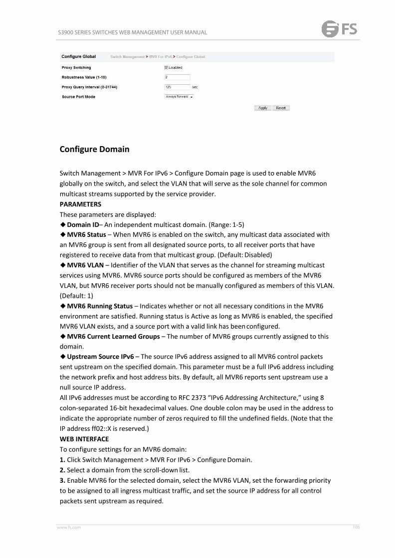
S3900 SERIES SWITCHES WEB MANAGEMENT USER MANUAL
www.fs.com 106
Configure Domain
Switch Management > MVR For IPv6 > Configure Domain page is used to enable MVR6globally on the switch, and select the VLAN that will serve as the sole channel for commonmulticast streams supported by the service provider.PARAMETERSThese parameters are displayed:◆Domain ID– An independent multicast domain. (Range: 1-5)◆MVR6 Status – When MVR6 is enabled on the switch, any multicast data associated withan MVR6 group is sent from all designated source ports, to all receiver ports that haveregistered to receive data from that multicast group. (Default:Disabled)◆MVR6 VLAN – Identifier of the VLAN that serves as the channel for streaming multicastservices using MVR6. MVR6 source ports should be configured as members of the MVR6VLAN, but MVR6 receiver ports should not be manually configured as members of this VLAN.(Default: 1)◆MVR6 Running Status – Indicates whether or not all necessary conditions in the MVR6environment are satisfied. Running status is Active as long as MVR6 is enabled, the specifiedMVR6 VLAN exists, and a source port with a valid link has beenconfigured.◆MVR6 Current Learned Groups – The number of MVR6 groups currently assigned to thisdomain.◆Upstream Source IPv6 – The source IPv6 address assigned to all MVR6 control packetssent upstream on the specified domain. This parameter must be a full IPv6 address includingthe network prefix and host address bits. By default, all MVR6 reports sent upstream use anull source IP address.All IPv6 addresses must be according to RFC 2373 “IPv6 Addressing Architecture,” using 8colon-separated 16-bit hexadecimal values. One double colon may be used in the address toindicate the appropriate number of zeros required to fill the undefined fields. (Note that theIP address ff02::X is reserved.)WEB INTERFACETo configure settings for an MVR6 domain:1. Click Switch Management > MVR For IPv6 > ConfigureDomain.2. Select a domain from the scroll-down list.3. Enable MVR6 for the selected domain, select the MVR6 VLAN, set the forwarding priorityto be assigned to all ingress multicast traffic, and set the source IP address for all controlpackets sent upstream as required.
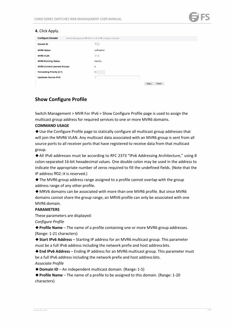
S3900 SERIES SWITCHES WEB MANAGEMENT USER MANUAL
www.fs.com 107
4. Click Apply.
Show Configure Profile
Switch Management > MVR For IPv6 > Show Configure Profile page is used to assign themulticast group address for required services to one or more MVR6 domains.COMMAND USAGE◆Use the Configure Profile page to statically configure all multicast group addresses thatwill join the MVR6 VLAN. Any multicast data associated with an MVR6 group is sent from allsource ports to all receiver ports that have registered to receive data from that multicastgroup.◆All IPv6 addresses must be according to RFC 2373 “IPv6 Addressing Architecture,” using 8colon-separated 16-bit hexadecimal values. One double colon may be used in the address toindicate the appropriate number of zeros required to fill the undefined fields. (Note that theIP address ff02::X is reserved.)◆The MVR6 group address range assigned to a profile cannot overlap with the groupaddress range of any other profile.◆MRV6 domains can be associated with more than one MVR6 profile. But since MVR6domains cannot share the group range, an MRV6 profile can only be associated with oneMVR6 domain.PARAMETERSThese parameters are displayed:Configure Profile◆Profile Name – The name of a profile containing one or more MVR6 group addresses.(Range: 1-21 characters)◆Start IPv6 Address – Starting IP address for an MVR6 multicast group. This parametermust be a full IPv6 address including the network prefix and host addressbits.◆End IPv6 Address – Ending IP address for an MVR6 multicast group. This parameter mustbe a full IPv6 address including the network prefix and host address bits.Associate Profile◆Domain ID – An independent multicast domain. (Range: 1-5)◆Profile Name – The name of a profile to be assigned to this domain. (Range: 1-20characters)

S3900 SERIES SWITCHES WEB MANAGEMENT USER MANUAL
www.fs.com 108
Add Configure Profile
Switch Management > MVR For IPv6 > Add Configure Profile page is used to assign themulticast group address for required services to one or more MVR6 domains.COMMAND USAGE◆Use the Configure Profile page to statically configure all multicast group addresses thatwill join the MVR6 VLAN. Any multicast data associated with an MVR6 group is sent from allsource ports to all receiver ports that have registered to receive data from that multicastgroup.◆All IPv6 addresses must be according to RFC 2373 “IPv6 Addressing Architecture,” using 8colon-separated 16-bit hexadecimal values. One double colon may be used in the address toindicate the appropriate number of zeros required to fill the undefined fields. (Note that theIP address ff02::X is reserved.)◆The MVR6 group address range assigned to a profile cannot overlap with the groupaddress range of any other profile.◆MRV6 domains can be associated with more than one MVR6 profile. But since MVR6domains cannot share the group range, an MRV6 profile can only be associated with oneMVR6 domain.PARAMETERSThese parameters are displayed:Configure Profile◆Profile Name – The name of a profile containing one or more MVR6group addresses. (Range: 1-21 characters)◆Start IPv6 Address – Starting IP address for an MVR6 multicast group. This parametermust be a full IPv6 address including the network prefix and host addressbits.◆End IPv6 Address – Ending IP address for an MVR6 multicast group. This parameter mustbe a full IPv6 address including the network prefix and host address bits.Associate Profile◆Domain ID – An independent multicast domain. (Range: 1-5)◆Profile Name – The name of a profile to be assigned to this domain. (Range: 1-20characters)
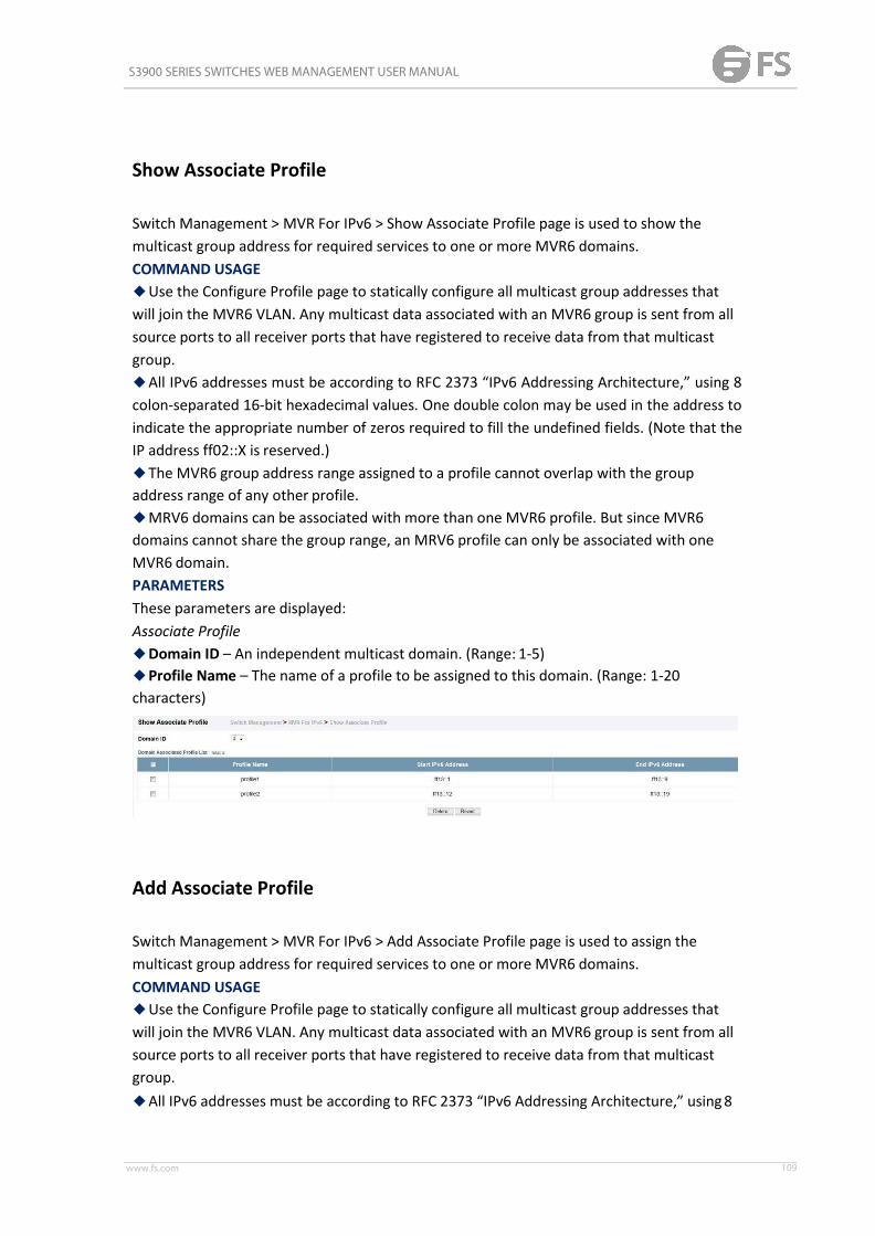
S3900 SERIES SWITCHES WEB MANAGEMENT USER MANUAL
www.fs.com 109
Show Associate Profile
Switch Management > MVR For IPv6 > Show Associate Profile page is used to show themulticast group address for required services to one or more MVR6 domains.COMMAND USAGE◆Use the Configure Profile page to statically configure all multicast group addresses thatwill join the MVR6 VLAN. Any multicast data associated with an MVR6 group is sent from allsource ports to all receiver ports that have registered to receive data from that multicastgroup.◆All IPv6 addresses must be according to RFC 2373 “IPv6 Addressing Architecture,” using 8colon-separated 16-bit hexadecimal values. One double colon may be used in the address toindicate the appropriate number of zeros required to fill the undefined fields. (Note that theIP address ff02::X is reserved.)◆The MVR6 group address range assigned to a profile cannot overlap with the groupaddress range of any other profile.◆MRV6 domains can be associated with more than one MVR6 profile. But since MVR6domains cannot share the group range, an MRV6 profile can only be associated with oneMVR6 domain.PARAMETERSThese parameters are displayed:Associate Profile◆Domain ID – An independent multicast domain. (Range: 1-5)◆Profile Name – The name of a profile to be assigned to this domain. (Range: 1-20characters)
Add Associate Profile
Switch Management > MVR For IPv6 > Add Associate Profile page is used to assign themulticast group address for required services to one or more MVR6 domains.COMMAND USAGE◆Use the Configure Profile page to statically configure all multicast group addresses thatwill join the MVR6 VLAN. Any multicast data associated with an MVR6 group is sent from allsource ports to all receiver ports that have registered to receive data from that multicastgroup.◆All IPv6 addresses must be according to RFC 2373 “IPv6 Addressing Architecture,” using8

S3900 SERIES SWITCHES WEB MANAGEMENT USER MANUAL
www.fs.com 110
colon-separated 16-bit hexadecimal values. One double colon may be used in the address toindicate the appropriate number of zeros required to fill the undefined fields. (Note that theIP address ff02::X is reserved.)◆The MVR6 group address range assigned to a profile cannot overlap with the groupaddress range of any other profile.◆MRV6 domains can be associated with more than one MVR6 profile. But since MVR6domains cannot share the group range, an MRV6 profile can only be associated with oneMVR6 domain.PARAMETERSThese parameters are displayed:Associate Profile◆Domain ID – An independent multicast domain. (Range: 1-5)◆Profile Name – The name of a profile to be assigned to this domain. (Range: 1-20characters)
Configure Interface
Switch Management > MVR For IPv6 > Configure Interface page is used to configure eachinterface that participates in the MVR6 protocol as a source port or receiver port. If you aresure that only one subscriber attached to an interface is receiving multicast services, you canenable the immediate leave function.COMMAND USAGE◆A port configured as an MVR6 receiver or source port can join or leave multicast groupsconfigured under MVR6.◆Receiver ports can belong to different VLANs, but should not be configured as a memberof the MVR6 VLAN. MVR6 allows a receiver port to dynamically join or leave multicastgroups within an MVR6 VLAN. Multicast groups can also be statically assigned to a receiverport. Receiver ports should not be statically configured as a member of the MVR6 VLAN. If soconfigured, its MVR6 status will be inactive. Also, note that VLAN membership for MVR6receiver ports cannot be set to accessmode.◆One or more interfaces may be configured as MVR6 source ports. A source port is able toboth receive and send data for configured MVR6 groups or for groups which have beenstatically assigned. All source ports must belong to the MVR6 VLAN. Subscribers should notbe directly connected to source ports.◆ Immediate leave applies only to receiver ports. When enabled, the receiver port isimmediately removed from the multicast group identified in the leave message. Whenimmediate leave is disabled, the switch follows the standard rules by sendingagroup-specific query to the receiver port and waiting for a response to determine if thereare any remaining subscribers for that multicast group before removing the port from the

S3900 SERIES SWITCHES WEB MANAGEMENT USER MANUAL
www.fs.com 111
group list.■Using immediate leave can speed up leave latency, but should only be enabled on a portattached to one multicast subscriber to avoid disrupting services to other group membersattached to the same interface.■Immediate leave does not apply to multicast groups which have been statically assignedto a port.PARAMETERSThese parameters are displayed:◆Domain ID – An independent multicast domain. (Range: 1-5)◆Port/Trunk – Interface identifier.◆Type – The following interface types are supported:■Non-MVR6 – An interface that does not participate in the MVR6 VLAN. (This is the defaulttype.)■Source – An uplink port that can send and receive multicast data for the groups assignedto the MVR6 VLAN. Note that the source port must be manually configured as a member ofthe MVR6 VLAN.■Receiver – A subscriber port that can receive multicast data sent through the MVR6 VLAN.Also, note that VLAN membership for MVR receiver ports cannot be set to accessmode.◆Forwarding Status – Shows if multicast traffic is being forwarded orblocked.◆MVR6 Status – Shows the MVR6 status. MVR6 status for source ports is “Active” if MVR6is globally enabled on the switch. MVR6 status for receiver ports is “Active” only if there aresubscribers receiving multicast traffic from one of the MVR6 groups, or a multicast group hasbeen statically assigned to an interface.◆ Immediate Leave – Configures the switch to immediately remove an interface from amulticast stream as soon as it receives a leave message for that group. (This option onlyapplies to an interface configured as an MVR6 receiver.)
Show Static Group Member
Switch Management > MVR For IPv6 > Show Static Group Member page is used to staticallybind multicast groups to a port which will receive long-term multicast streams associatedwith a stable set of hosts.

S3900 SERIES SWITCHES WEB MANAGEMENT USER MANUAL
www.fs.com 112
COMMAND USAGE◆Multicast groups can be statically assigned to a receiver port using this configurationpage.◆All IPv6 addresses must be according to RFC 2373 “IPv6 Addressing Architecture,” using 8colon-separated 16-bit hexadecimal values. One double colon may be used in the address toindicate the appropriate number of zeros required to fill the undefined fields. (Note that theIP address ff02::X is reserved.)◆The MVR6 VLAN cannot be specified as the receiver VLAN for staticbindings.PARAMETERSThese parameters are displayed:◆Domain ID – An independent multicast domain. (Range: 1-5)◆ Interface – Port or trunk identifier.◆VLAN – VLAN identifier. (Range: 1-4093)◆Group IPv6 Address – Defines a multicast service sent to the selected port. Multicastgroups must be assigned from the MVR6 group range configured on the Configure Generalpage.
Add Static Group Member
Switch Management > MVR For IPv6 > Add Static Group Member page is used to staticallybind multicast groups to a port which will receive long-term multicast streams associatedwith a stable set of hosts.COMMAND USAGE◆Multicast groups can be statically assigned to a receiver port using this configurationpage.◆All IPv6 addresses must be according to RFC 2373 “IPv6 Addressing Architecture,” using 8colon-separated 16-bit hexadecimal values. One double colon may be used in the address toindicate the appropriate number of zeros required to fill the undefined fields. (Note that theIP address ff02::X is reserved.)◆The MVR6 VLAN cannot be specified as the receiver VLAN for staticbindings.PARAMETERSThese parameters are displayed:◆Domain ID – An independent multicast domain. (Range: 1-5)◆ Interface – Port or trunk identifier.◆VLAN – VLAN identifier. (Range: 1-4093)◆Group IPv6 Address – Defines a multicast service sent to the selected port. Multicastgroups must be assigned from the MVR6 group range configured on the Configure Generalpage.

S3900 SERIES SWITCHES WEB MANAGEMENT USER MANUAL
www.fs.com 113
ShowMember
Switch Management > MVR For IPv6 > ShowMember page is used to show the multicastgroups either statically or dynamically assigned to the MVR6 receiver groups on eachinterface.PARAMETERSThese parameters are displayed:◆Domain ID – An independent multicast domain. (Range: 1-5)◆Group IPv6 Address – Multicast groups assigned to the MVR6VLAN.◆VLAN – The VLAN through which the service is received. Note that this may be differentfrom the MVR6 VLAN if the group address has been statically assigned.◆Port – Indicates the source address of the multicast service, or displays an asterisk if thegroup address has been statically assigned (these entries are marked as “Source”). Alsoshows the interfaces with subscribers for multicast services provided through the MVR6VLAN (these entries are marked as “Receiver”).◆Up Time – Time this service has been forwarded to attachedclients.◆Expire – Time before this entry expires if no membership report is received from currentlyactive or new clients.◆Count – The number of multicast services currently being forwarded from the MVR6VLAN.
Show Query Statistics
Switch Management > MVR For IPv6 > Show Query Statistics page is used to display MVR6protocol-related statistics for the specified interface.PARAMETERSThese parameters are displayed:◆Domain ID – An independent multicast domain. (Range: 1-5)◆VLAN – VLAN identifier. (Range: 1-4093)◆Port – Port identifier. (Range: 1-12)

S3900 SERIES SWITCHES WEB MANAGEMENT USER MANUAL
www.fs.com 114
◆Trunk – Trunk identifier. (Range: 1-12)Query Statistics◆Querier IPv6 Address – The IP address of the querier on this interface.◆Querier Expire Time – The time after which this querier is assumed to haveexpired.◆General Query Received – The number of general queries received on this interface.◆General Query Sent – The number of general queries sent from this interface.◆Specific Query Received – The number of specific queries received on this interface.◆Specific Query Sent – The number of specific queries sent from this interface.◆Number of Reports Sent – The number of reports sent from this interface.◆Number of Leaves Sent – The number of leaves sent from this interface.VLAN, Port, and Trunk StatisticsInput Statistics◆Report – The number of MLD membership reports received on this interface.◆Leave – The number of leave messages received on this interface.◆G Query – The number of general query messages received on this interface.◆G(-S)-S Query – The number of group specific or group-and-source specific querymessages received on this interface.◆Drop – The number of times a report, leave or query was dropped. Packets may bedropped due to invalid format, rate limiting, packet content not allowed, or MVR6 groupreport received.◆Join Success – The number of times a multicast group was successfully joined.◆Group – The number of MVR6 groups active on this interface.Output Statistics◆Report – The number of MLD membership reports sent from this interface.◆Leave – The number of leave messages sent from this interface.◆G Query – The number of general query messages sent from this interface.◆G(-S)-S Query – The number of group specific or group-and-source specific querymessages sent from this interface.

S3900 SERIES SWITCHES WEB MANAGEMENT USER MANUAL
www.fs.com 115
Show VLAN Statistics
Switch Management > MVR For IPv6 > Show VLAN Statistics page is used to display MVR6protocol-related statistics for the specified interface.PARAMETERSThese parameters are displayed:◆Domain ID – An independent multicast domain. (Range: 1-5)◆VLAN – VLAN identifier. (Range: 1-4093)◆Port – Port identifier. (Range: 1-12)◆Trunk – Trunk identifier. (Range: 1-12)Query Statistics◆Querier IPv6 Address – The IP address of the querier on this interface.◆Querier Expire Time – The time after which this querier is assumed to haveexpired.◆General Query Received – The number of general queries received on this interface.◆General Query Sent – The number of general queries sent from this interface.◆Specific Query Received – The number of specific queries received on this interface.◆Specific Query Sent – The number of specific queries sent from this interface.◆Number of Reports Sent – The number of reports sent from this interface.◆Number of Leaves Sent – The number of leaves sent from this interface.VLAN, Port, and Trunk StatisticsInput Statistics◆Report – The number of MLD membership reports received on this interface.◆Leave – The number of leave messages received on this interface.◆G Query – The number of general query messages received on this interface.◆G(-S)-S Query – The number of group specific or group-and-source specific querymessages received on this interface.◆Drop – The number of times a report, leave or query was dropped. Packets may bedropped due to invalid format, rate limiting, packet content not allowed, or MVR6 groupreport received.◆Join Success – The number of times a multicast group was successfully joined.◆Group – The number of MVR6 groups active on this interface.Output Statistics◆Report – The number of MLD membership reports sent from this interface.◆Leave – The number of leave messages sent from this interface.◆G Query – The number of general query messages sent from this interface.◆G(-S)-S Query – The number of group specific or group-and-source specific querymessages sent from this interface.

S3900 SERIES SWITCHES WEB MANAGEMENT USER MANUAL
www.fs.com 116
Show Port Statistics
Switch Management > MVR For IPv6 > Show Port Statistics page is used to display MVR6protocol-related statistics for the specified interface.PARAMETERSThese parameters are displayed:◆Domain ID – An independent multicast domain. (Range: 1-5)◆VLAN – VLAN identifier. (Range: 1-4093)◆Port – Port identifier. (Range: 1-12)◆Trunk – Trunk identifier. (Range: 1-12)Query Statistics◆Querier IPv6 Address – The IP address of the querier on this interface.◆Querier Expire Time – The time after which this querier is assumed to haveexpired.◆General Query Received – The number of general queries received on this interface.◆General Query Sent – The number of general queries sent from this interface.◆Specific Query Received – The number of specific queries received on this interface.◆Specific Query Sent – The number of specific queries sent from this interface.◆Number of Reports Sent – The number of reports sent from this interface.◆Number of Leaves Sent – The number of leaves sent from this interface.VLAN, Port, and Trunk StatisticsInput Statistics◆Report – The number of MLD membership reports received on this interface.◆Leave – The number of leave messages received on this interface.◆G Query – The number of general query messages received on this interface.◆G(-S)-S Query – The number of group specific or group-and-source specific querymessages received on this interface.◆Drop – The number of times a report, leave or query was dropped. Packets may bedropped due to invalid format, rate limiting, packet content not allowed, or MVR6 groupreport received.◆Join Success – The number of times a multicast group was successfully joined.

S3900 SERIES SWITCHES WEB MANAGEMENT USER MANUAL
www.fs.com 117
◆Group – The number of MVR6 groups active on this interface.Output Statistics◆Report – The number of MLD membership reports sent from this interface.◆Leave – The number of leave messages sent from this interface.◆G Query – The number of general query messages sent from this interface.◆G(-S)-S Query – The number of group specific or group-and-source specific querymessages sent from this interface.
Show Trunk Statistics
Switch Management > MVR For IPv6 > Show Trunk Statistics page is used to display MVR6protocol-related statistics for the specified interface.PARAMETERSThese parameters are displayed:◆Domain ID – An independent multicast domain. (Range: 1-5)◆VLAN – VLAN identifier. (Range: 1-4093)◆Port – Port identifier. (Range: 1-12)◆Trunk – Trunk identifier. (Range: 1-12)Query Statistics◆Querier IPv6 Address – The IP address of the querier on this interface.◆Querier Expire Time – The time after which this querier is assumed to haveexpired.◆General Query Received – The number of general queries received on this interface.◆General Query Sent – The number of general queries sent from this interface.◆Specific Query Received – The number of specific queries received on this interface.◆Specific Query Sent – The number of specific queries sent from this interface.◆Number of Reports Sent – The number of reports sent from this interface.◆Number of Leaves Sent – The number of leaves sent from this interface.VLAN, Port, and Trunk StatisticsInput Statistics◆Report – The number of MLD membership reports received on this interface.◆Leave – The number of leave messages received on this interface.

S3900 SERIES SWITCHES WEB MANAGEMENT USER MANUAL
www.fs.com 118
◆G Query – The number of general query messages received on this interface.◆G(-S)-S Query – The number of group specific or group-and-source specific querymessages received on this interface.◆Drop – The number of times a report, leave or query was dropped. Packets may bedropped due to invalid format, rate limiting, packet content not allowed, or MVR6 groupreport received.◆Join Success – The number of times a multicast group was successfully joined.◆Group – The number of MVR6 groups active on this interface.Output Statistics◆Report – The number of MLD membership reports sent from this interface.◆Leave – The number of leave messages sent from this interface.◆G Query – The number of general query messages sent from this interface.◆G(-S)-S Query – The number of group specific or group-and-source specific querymessages sent from this interface.
LLDP
Link Layer Discovery Protocol (LLDP) is used to discover basic information about neighboringdevices on the local broadcast domain. LLDP is a Layer 2 protocol that uses periodicbroadcasts to advertise information about the sending device. Advertised information isrepresented in Type Length Value (TLV) format according to the IEEE 802.1ab standard, andcan include details such as device identification, capabilities and configuration settings. LLDPalso defines how to store and maintain information gathered about the neighboring networknodes it discovers. Link Layer Discovery Protocol - Media Endpoint Discovery (LLDP-MED) isan extension of LLDP intended for managing endpoint devices such as Voice over IP phonesand network switches. The LLDP-MED TLVs advertise information such as network policy,power, inventory, and device location details. LLDP and LLDP-MED information can be usedby SNMP applications to simplify troubleshooting, enhance network management, andmaintain an accurate network topology.

S3900 SERIES SWITCHES WEB MANAGEMENT USER MANUAL
www.fs.com 119
Configure Global
Switch Management > LLDP > Configure Global page is used to set attributes for generalfunctions such as globally enabling LLDP on the switch, setting the message ageout time, andsetting the frequency for broadcasting general advertisements or reports about changes inthe LLDPMIB.PARAMETERSThese parameters are displayed:◆LLDP – Enables LLDP globally on the switch. (Default: Enabled)◆Transmission Interval – Configures the periodic transmit interval for LLDP advertisements.(Range: 5-32768 seconds; Default: 30 seconds)◆Hold Time Multiplier – Configures the time-to-live (TTL) value sent in LLDPadvertisements as shown in the formula below. (Range: 2-10; Default: 4) The time-to-livetells the receiving LLDP agent how long to retain all information pertaining to the sendingLLDP agent if it does not transmit updates in a timely manner. TTL in seconds is based on thefollowing rule: minimum value ((Transmission Interval * Holdtime Multiplier), or 65535)Therefore, the default TTL is 4*30 = 120 seconds.◆Delay Interval – Configures a delay between the successive transmission ofadvertisements initiated by a change in local LLDP MIB variables. (Range: 1-8192 seconds;Default: 2 seconds)The transmit delay is used to prevent a series of successive LLDP transmissions during ashort period of rapid changes in local LLDP MIB objects, and to increase the probability thatmultiple, rather than single changes, are reported in each transmission. This attribute mustcomply with the rule: (4 * Delay Interval) ≤ Transmission Interval◆Reinitialization Delay – Configures the delay before attempting to reinitialize after LLDPports are disabled or the link goes down. (Range: 1-10 seconds; Default: 2 seconds) WhenLLDP is re-initialized on a port, all information in the remote systems LLDP MIB associatedwith this port is deleted.◆Notification Interval – Configures the allowed interval for sending SNMP notificationsabout LLDP MIB changes. (Range: 5-3600 seconds; Default: 5 seconds) This parameter onlyapplies to SNMP applications which use data stored in the LLDP MIB for network monitoringor management. Information about changes in LLDP neighbors that occur between SNMPnotifications is not transmitted. Only state changes that exist at the time of a notification areincluded in the transmission. An SNMP agent should therefore periodically check the valueof lldpStatsRemTableLastChangeTime to detect any lldpRemTablesChangenotification-events missed due to throttling or transmission loss.◆MED Fast Start Count – Configures the amount of LLDP MED Fast Start LLDPDUs totransmit during the activation process of the LLDPMED Fast Start mechanism. (Range: 1-10packets; Default: 4 packets) The MED Fast Start Count parameter is part of the timer whichensures that the LLDP-MED Fast Start mechanism is active for the port. LLDPMED Fast Startis critical to the timely startup of LLDP, and therefore integral to the rapid availability ofEmergency Call Service.

S3900 SERIES SWITCHES WEB MANAGEMENT USER MANUAL
www.fs.com 120
Interface General
Switch Management > LLDP> Interface General page is used to specify the messageattributes for individual interfaces, including whether messages are transmitted, received, orboth transmitted and received, whether SNMP notifications are sent, and the type ofinformation advertised.PARAMETERSThese parameters are displayed:◆Admin Status – Enables LLDP message transmit and receive modes for LLDP Protocol DataUnits. (Options: Tx only, Rx only, TxRx, Disabled; Default: TxRx)◆SNMP Notification – Enables the transmission of SNMP trap notifications about LLDP andLLDP-MED changes. (Default: Disabled) This option sends out SNMP trap notifications todesignated target stations at the interval specified by the Notification Interval in thepreceding section. Trap notifications include information about state changes in the LLDPMIB (IEEE 802.1AB), the LLDP-MEDMIB (ANSI/ TIA-1057), or vendor-specific LLDP-EXT-DOT1and LLDP-EXT-DOT3 MIBs. For information on defining SNMP trapdestinations,Information about additional changes in LLDP neighbors that occur between SNMPnotifications is not transmitted. Only state changes that exist at the time of a trapnotification are included in the transmission. An SNMP agent should therefore periodicallycheck the value of lldpStatsRemTableLastChangeTime to detect any lldpRemTablesChangenotification-events missed due to throttling or transmission loss.◆MED Notification – Enables the transmission of SNMP trap notifications about LLDP-MEDchanges. (Default: Disabled)◆Basic Optional TLVs – Configures basic information included in theTLV field of advertisedmessages.■Management Address – The management address protocol packet includes the IPv4address of the switch. If no management address is available, the address should be theMAC address for the CPU or for the port sending this advertisement. The managementaddress TLV may also include information about the specific interface associated with thisaddress, and an object identifier indicating the type of hardware component or protocolentity associated with this address. The interface number and OID are included to assistSNMP applications in the performance of network discovery by indicating enterprisespecific
S3900 SERIES SWITCHES WEB MANAGEMENT USER MANUAL
www.fs.com 121
or other starting points for the search, such as the Interface or Entity MIB.Since there are typically a number of different addresses associated with a Layer 3 device, anindividual LLDP PDU may contain more than one management address TLV. Everymanagement address TLV that reports an address that is accessible on a port and protocolVLAN through the particular port should be accompanied by a port and protocol VLAN TLVthat indicates the VLAN identifier (VID) associated with the management address reportedby this TLV.■Port Description – The port description is taken from the ifDescr object in RFC 2863,which includes information about the manufacturer, the product name, and the version ofthe interface hardware/software.■System Capabilities – The system capabilities identifies the primary function(s) of thesystem and whether or not these primary functions are enabled. The information advertisedby this TLV is described in IEEE 802.1AB.■System Description – The system description is taken from the sysDescr object in RFC3418, which includes the full name and version identification of the system's hardware type,software operating system, and networking software.■System Name – The system name is taken from the sysName object in RFC 3418, whichcontains the system’s administratively assigned name. To configure the systemname.◆802.1 Organizationally Specific TLVs – Configures IEEE 802.1 information included in theTLV field of advertisedmessages.■Protocol Identity – The protocols that are accessible through this interface.■VLAN ID – The port’s default VLAN identifier (PVID) indicates the VLAN with whichuntagged or priority-tagged frames are associated.■VLAN Name – The name of all VLANs to which this interface has beenassigned.■Port and Protocol VLAN ID – The port-based protocol VLANs configured on this interface.◆802.3 Organizationally Specific TLVs – Configures IEEE 802.3 information included in theTLV field of advertisedmessages.■Link Aggregation – The link aggregation capabilities, aggregation status of the link, andthe IEEE 802.3 aggregated port identifier if this interface is currently a link aggregationmember.■Max Frame Size – The maximum frame size.■MAC/PHY Configuration/Status – The MAC/PHY configuration and status which includesinformation about auto-negotiation support/capabilities, and operational MultistationAccess Unit (MAU) type.◆MED TLVs – Configures general information included in the MED TLV field of advertisedmessages.■Capabilities – This option advertises LLDP-MED TLV capabilities, allowing Media Endpointand Connectivity Devices to efficiently discover which LLDP-MED related TLVs are supportedon the switch.■Inventory – This option advertises device details useful for inventory management, suchas manufacturer, model, software version and other pertinent information.■Location – This option advertises location identification details.■Network Policy – This option advertises network policy configuration information, aidingin the discovery and diagnosis of VLAN configuration mismatches on a port. Improper

S3900 SERIES SWITCHES WEB MANAGEMENT USER MANUAL
www.fs.com 122
network policy configurations frequently result in voice quality degradation or completeservice disruption.◆MED-Location Civic Address – Configures information for the location of the attacheddevice included in the MED TLV field of advertised messages, including the country and thedevice type.■Country – The two-letter ISO 3166 country code in capital ASCII letters. (Example: DK, DEor US)■Device entry refers to – The type of device to which the locationapplies:■Location of DHCP server.■Location of network element closest to client.■Location of client. (This is the default.)
CA-Type
Switch Management > LLDP > CA-Type page is used to specify the physical location of thedevice attached to an interface.COMMANDUSAGE◆Use the Civic Address type (CA-Type) to advertise the physical location of the deviceattached to an interface, including items such as the city, street number, building and roominformation. The address location is specified as a type and value pair, with the civic addresstype defined in RFC 4776. The following table describes some of the CA type numbers andprovides examples.
CA Type Description CA Value Example1 National subdivisions (state, canton, province) California2 County, parish Orange
3 City, township Irvine4 City division, borough, city district West Irvine
5 Neighborhood, block Riverside
6 Group of streets below the neighborhood levelExchange18 Street suffix or type Avenue

S3900 SERIES SWITCHES WEB MANAGEMENT USER MANUAL
www.fs.com 123
19 House number 32020 House number suffix A21 Landmark or vanity address Tech Center
26 Unit (apartment, suite) Apt 519
27 Floor 528 Room 509B
◆Any number of CA type and value pairs can be specified for the civic address location, aslong as the total does not exceed 250 characters.PARAMETERSThese parameters are displayed in the web interface:◆CA-Type – Descriptor of the data civic address value. (Range: 0-255)◆CA-Value – Description of a location. (Range: 1-32 characters)
Show Local Information
Switch Management > LLDP > Show Local Information page is used to display informationabout the switch, such as its MAC address, chassis ID, management IP address, and portinformation.PARAMETERSThese parameters are displayed:Global Settings◆Chassis Type – Identifies the chassis containing the IEEE 802 LAN entity associated withthe transmitting LLDP agent. There are several ways in which a chassis may be identified anda chassis ID subtype is used to indicate the type of component being referenced by thechassis ID field.
ID Basis Reference
Chassis componentEntPhysicalAlias when entPhysClass has a value of‘chassis(3)’ (IETF RFC 2737)
Interface alias IfAlias (IETF RFC 2863)
Port componentEntPhysicalAliaswhen entPhysicalClass has a value ‘port(10)’or ‘backplane(4)’ (IETF RFC 2737)
MAC address MAC address (IEEE Std 802-2001)
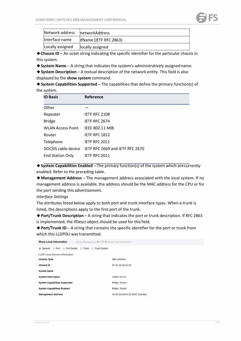
S3900 SERIES SWITCHES WEB MANAGEMENT USER MANUAL
www.fs.com 124
Network address networkAddressInterface name ifName (IETF RFC 2863)Locally assigned locally assigned
◆Chassis ID – An octet string indicating the specific identifier for the particular chassis inthis system.◆System Name – A string that indicates the system’s administratively assignedname.◆System Description – A textual description of the network entity. This field is alsodisplayed by the show system command.◆System Capabilities Supported – The capabilities that define the primary function(s) ofthe system.
ID Basis Reference
Other —Repeater IETF RFC 2108Bridge IETF RFC 2674WLAN Access Point IEEE 802.11 MIBRouter IETF RFC 1812Telephone IETF RFC 2011DOCSIS cable device IETF RFC 2669 and IETF RFC 2670End Station Only IETF RFC 2011
◆System Capabilities Enabled – The primary function(s) of the system which arecurrentlyenabled. Refer to the preceding table.◆Management Address – The management address associated with the local system. If nomanagement address is available, the address should be the MAC address for the CPU or forthe port sending this advertisement.Interface SettingsThe attributes listed below apply to both port and trunk interface types. When a trunk islisted, the descriptions apply to the first port of the trunk.◆Port/Trunk Description – A string that indicates the port or trunk description. If RFC 2863is implemented, the ifDescr object should be used for this field.◆Port/Trunk ID – A string that contains the specific identifier for the port or trunk fromwhich this LLDPDU was transmitted.

S3900 SERIES SWITCHES WEB MANAGEMENT USER MANUAL
www.fs.com 125
Show Remote Information
Switch Management > LLDP > Show Remote Information page is used to display informationabout devices connected directly to the switch’s ports which are advertising informationthrough LLDP, or to display detailed information about an LLDP-enabled device connected toa specific port on the local switch.PARAMETERSThese parameters are displayed:Port◆Local Port – The local port to which a remote LLDP-capable device isattached.◆Chassis ID – An octet string indicating the specific identifier for the particular chassis inthis system.◆Port ID – A string that contains the specific identifier for the port from which this LLDPDUwas transmitted.◆System Name – A string that indicates the system’s administratively assignedname.Port Details◆Port – Port identifier on local switch.◆Remote Index – Index of remote device attached to this port.◆Local Port – The local port to which a remote LLDP-capable device isattached.◆Chassis Type – Identifies the chassis containing the IEEE 802 LAN entity associated withthe transmitting LLDP agent. There are several ways in which a chassis may be identified anda chassis ID subtype is used to indicate the type of component being referenced by thechassis ID field.◆Chassis ID – An octet string indicating the specific identifier for the particular chassis inthis system.◆System Name – A string that indicates the system’s assignedname.◆System Description – A textual description of the networkentity.◆Port Type – Indicates the basis for the identifier that is listed in the Port IDfield.
ID Basis ReferenceInterface alias IfAlias (IETF RFC 2863)
Chassis componentEntPhysicalAlias when entPhysClass has a value of‘chassis(3)’ (IETF RFC 2737)
Port componentEntPhysicalAliaswhen entPhysicalClass has a value ‘port(10)’or‘backplane(4)’ (IETF RFC 2737)
MAC address MAC address (IEEE Std 802-2001)Network address networkAddressInterface name ifName (IETF RFC 2863)Agent circuit ID agent circuit ID (IETF RFC 3046)Locally assigned locally assigned
◆Port Description – A string that indicates the port’s description. If RFC 2863 isimplemented, the ifDescr object should be used for this field.◆Port ID – A string that contains the specific identifier for the port from which this LLDPDUwas transmitted.

S3900 SERIES SWITCHES WEB MANAGEMENT USER MANUAL
www.fs.com 126
Bit Capability
◆System Capabilities Supported – The capabilities that define the primary function(s) ofthe system.◆System Capabilities Enabled – The primary function(s) of the system which are currentlyenabled.◆Management Address List – The management addresses for this device. Since there aretypically a number of different addresses associated with a Layer 3 device, an individual LLDPPDU may contain more than one management address TLV. If no management address isavailable, the address should be the MAC address for the CPU or for the port sending thisadvertisement.Port Details – 802.1 Extension Information◆Remote Port VID – The port’s default VLAN identifier (PVID) indicates the VLAN withwhich untagged or priority-tagged frames are associated.◆Remote Port-Protocol VLAN List – The port-based protocol VLANs configured on thisinterface, whether the given port (associated with the remote system) supports port-basedprotocol VLANs, and whether the port-based protocol VLANs are enabled on the given portassociated with the remote system.◆Remote VLAN Name List – VLAN names associated with aport.◆Remote Protocol Identity List – Information about particular protocols that are accessiblethrough a port. This object represents an arbitrary local integer value used by this agent toidentify a particular protocol identity, and an octet string used to identify the protocolsassociated with a port of the remote system.Port Details – 802.3 Extension Port Information◆Remote Port Auto-Neg Supported – Shows whether the given port (associated withremote system) supports auto-negotiation.◆Remote Port Auto-Neg Adv-Capability – The value (bitmap) of theifMauAutoNegCapAdvertisedBits object (defined in IETF RFC 3636) which is associated with aport on the remote system.
0 other or unknown1 10BASE-T half duplex mode
2 10BASE-T full duplex mode3 100BASE-T44 100BASE-TX half duplex mode5 100BASE-TX full duplex mode6 100BASE-T2 half duplex mode7 100BASE-T2 full duplex mode8 PAUSE for full-duplex links9 Asymmetric PAUSE for full-duplex links10 Symmetric PAUSE for full-duplex links11 Asymmetric and Symmetric PAUSE for full-duplex links12 1000BASE-X, -LX, -SX, -CX half duplex mode
S3900 SERIES SWITCHES WEB MANAGEMENT USER MANUAL
www.fs.com 127
13 1000BASE-X, -LX, -SX, -CX full duplexmode14 1000BASE-T half duplex mode15 1000BASE-T full duplex mode
◆Remote Port Auto-Neg Status – Shows whether port autonegotiation is enabled on a portassociated with the remote system.◆Remote Port MAU Type – An integer value that indicates the operational MAU type of thesending device. This object contains the integer value derived from the list position of thecorresponding dot3MauType as listed in IETF RFC 3636 and is equal to the last number in therespective dot3MauType OID.Port Details – 802.3 Extension Power Information◆Remote Power Class – The port Class of the given port associated with the remote system(PSE – Power Sourcing Equipment or PD – PoweredDevice).◆Remote Power MDI Status – Shows whether MDI power is enabled on the given portassociated with the remote system.◆Remote Power Pairs – “Signal” means that the signal pairs only are in use, and “Spare”means that the spare pairs only are in use.◆Remote Power MDI Supported – Shows whether MDI power is supported on the givenport associated with the remote system.◆Remote Power Pair Controllable – Indicates whether the pair selection can be controlledfor sourcing power on the given port associated with the remotesystem.◆Remote Power Classification – This classification is used to tag different terminals on thePower over LAN network according to their power consumption. Devices such as IPtelephones, WLAN access points and others, will be classified according to their powerrequirements.Port Details – 802.3 Extension Trunk Information◆Remote Link Aggregation Capable – Shows if the remote port is not in link aggregationstate and/or it does not support link aggregation.◆Remote Link Aggregation Status – The current aggregation status of the link.◆Remote Link Port ID – This object contains the IEEE 802.3 aggregated port identifier,aAggPortID (IEEE 802.3-2002, 30.7.2.1.1), derived from the ifNumber of the ifIndex for theport component associated with the remote system. If the remote port is not in linkaggregation state and/or it does not support link aggregation, this value should be zero.Port Details – 802.3 Extension Frame Information◆Remote Max Frame Size – An integer value indicating the maximum supported frame sizein octets on the port component associated with the remote system.Port Details – LLDP-MED Capability 8◆Device Class – Any of the following categories of endpoint devices:■Class 1 – The most basic class of endpoint devices.■Class 2 – Endpoint devices that supports media streamcapabilities.■Class 3 – Endpoint devices that directly supports end users of the IP communicationsystems.■Network Connectivity Device – Devices that provide access to the IEEE 802 basedLAN

S3900 SERIES SWITCHES WEB MANAGEMENT USER MANUAL
www.fs.com 128
infrastructure for LLDP-MED endpoint devices. These may be any LAN access deviceincluding LAN switch/router, IEEE 802.1 bridge, IEEE 802.3 repeater, IEEE 802.11 wirelessaccess point, or any device that supports the IEEE 802.1AB and MED extensions defined bythis Standard and can relay IEEE 802 frames via any method.◆Supported Capabilities – The supported set of capabilities that define the primaryfunction(s) of the port:■LLDP-MED Capabilities■Network Policy■Location Identification■Extended Power via MDI – PSE■Extended Power via MDI – PD■Inventory◆Current Capabilities – The set of capabilities that define the primary function(s) of theport which are currently enabled.Port Details – Network Policy8◆Application Type – The primary application(s) defined for this networkpolicy:■Voice■Voice Signaling■Guest Signaling■Guest Voice Signaling■Softphone Voice■Video Conferencing■Streaming Video■Video Signaling◆Tagged Flag – Indicates whether the specified application type is using a tagged oruntagged VLAN.◆Layer 2 Priority – The Layer 2 priority to be used for the specified application type. Thisfield may specify one of eight priority levels (0-7), where a value of 0 represents use of thedefault priority.◆Unknown Policy Flag – Indicates that an endpoint device wants to explicitly advertise thatthis policy is required by the device, but is currently unknown.◆VLAN ID – The VLAN identifier (VID) for the port as defined in IEEE 802.1Q. A value of zeroindicates that the port is using priority tagged frames, meaning that only the IEEE 802.1Dpriority level is significant and the default PVID of the ingress port is usedinstead.◆DSCP Value – The DSCP value to be used to provide Diffserv node behavior for thespecified application type. This field may contain one of 64 code point values (0-63). A valueof 0 represents use of the default DSCP value as defined in RFC2475.Port Details – Location Identification8◆Location Data Format – Any of these location ID data formats:■Coordinate-based LCI9 – Defined in RFC 3825, includes latitude resolution, latitude,longitude resolution, longitude, altitude type, altitude resolution, altitude, anddatum.■Civic Address LCI9 – Includes What, Country code, CA type, CA length and CAvalue.■ECS ELIN – Emergency Call Service Emergency Location Identification Number supportstraditional PSAP-based Emergency Call Service in NorthAmerica.

S3900 SERIES SWITCHES WEB MANAGEMENT USER MANUAL
www.fs.com 129
◆Country Code – The two-letter ISO 3166 country code in capital ASCII letters. (Example:DK, DE or US)◆What – The type of device to which the location applies as described for the fieldentry.Port Details – Inventory8◆Hardware Revision – The hardware revision of the end-point device.◆Software Revision – The software revision of the end-point device.◆Manufacture Name – The manufacturer of the end-point device◆Asset ID – The asset identifier of the end-point device. End-point devices are typicallyassigned asset identifiers to facilitate inventory management and assetstracking.◆Firmware Revision – The firmware revision of the end-point device.◆Serial Number – The serial number of the end-point device.◆Model Name – The model name of the end-point device.◆Asset ID – The asset identifier of the end-pointdevice.
Show Statistics
Switch Management > LLDP > Show Statistics page is used to display statistics forLLDP-capable devices attached to the switch, and for LLDP protocol messages transmitted orreceived on all local interfaces.PARAMETERSThese parameters are displayed:General Statistics on Remote Devices◆Neighbor Entries List Last Updated – The time the LLDP neighbor entry list was lastupdated.◆New Neighbor Entries Count – The number of LLDP neighbors for which the remote TTLhas not yet expired.◆Neighbor Entries Deleted Count – The number of LLDP neighbors which have beenremoved from the LLDP remote systems MIB for any reason.◆Neighbor Entries Dropped Count – The number of times which the remote database onthis switch dropped an LLDPDU because of insufficient resources.◆Neighbor Entries Age-out Count – The number of times that a neighbor’s information hasbeen deleted from the LLDP remote systems MIB because the remote TTL timer has expired.Port/Trunk◆Frames Discarded – Number of frames discarded because they did not conform to thegeneral validation rules as well as any specific usage rules defined for the particularTLV.◆Frames Invalid – A count of all LLDPDUs received with one or more detectableerrors.◆Frames Received – Number of LLDP PDUs received.◆Frames Sent – Number of LLDP PDUs transmitted.◆TLVs Unrecognized – A count of all TLVs not recognized by the receiving LLDP localagent.

S3900 SERIES SWITCHES WEB MANAGEMENT USER MANUAL
www.fs.com 130
◆TLVs Discarded – A count of all LLDPDUs received and then discarded due to insufficientmemory space, missing or out-of-sequence attributes, or any other reason.◆Neighbor Ageouts – A count of the times that a neighbor’s information has been deletedfrom the LLDP remote systems MIB because the remote TTL timer hasexpired.
ERPS
The ITU G.8032 recommendation specifies a protection switching mechanism and protocolfor Ethernet layer network rings. Ethernet rings can provide wide-area multipointconnectivity more economically due to their reduced number of links. The mechanisms andprotocol defined in G.8032 achieve highly reliable and stable protection; and never formloops, which would fatally affect network operation and service availability. The G.8032recommendation, also referred to as Ethernet Ring Protection Switching (ERPS), can be usedto increase the availability and robustness of Ethernet rings. An Ethernet ring built usingERPS can provide resilience at a lower cost and than that provided by SONET or EAPS rings.ERPS is more economical than EAPS in that only one physical link is required between eachnode in the ring. However, since it can tolerate only one break in the ring, it is not as robustas EAPS. ERPS supports up to 255 nodes in the ring structure. ERPS requires a higherconvergence time when more that 16 nodes are used, but should always run under than 500ms.Operational ConceptLoop avoidance in the ring is achieved by guaranteeing that, at any time, traffic may flow onall but one of the ring links. This particular link is called the ring protection link (RPL), andunder normal conditions this link is blocked to traffic. One designated node, the RPL owner,is responsible for blocking traffic over the RPL. When a ring failure occurs, the RPL owner isresponsible for unblocking the RPL, allowing this link to be used for traffic. Ring nodes maybe in one of two states:Idle – normal operation, no link/node faults detected in ring Protection – Protectionswitching in effect after identifying a signal fault In Idle state, the physical topology has allnodes connected in a ring. The logical topology guarantees that all nodes are connectedwithout a loop by blocking the RPL. Each link is monitored by its two adjacent nodes usingConnectivity Fault Management (CFM) protocol messages. Protection switching (opening theRPL to traffic) occurs when a signal failure message generated by the Connectivity FaultManagement (CFM) protocol is declared on one of the ring links, and the detected failurehas a higher priority than any other request; or a Ring – Automatic ProtectionSwitching

S3900 SERIES SWITCHES WEB MANAGEMENT USER MANUAL
www.fs.com 131
protocol request (R-APS, as defined in Y.1731) is received which has a higher priority thanany other local request. A link/node failure is detected by the nodes adjacent to the failure.These nodes block the failed link and report the failure to the ring using R-APS (SF) messages.This message triggers the RPL owner to unblock the RPL, and all nodes to flush theirforwarding database. The ring is now in protection state, but it remains connected in alogical topology. When the failed link recovers, the traffic is kept blocked on the nodesadjacent to the recovered link. The nodes adjacent to the recovered link transmit R-APS (NR- no request) message indicating they have no local request. When the RPL owner receivesan R-APS (NR) message it starts the Wait-To-Recover (WTR) timer. Once WTR timer expires,the RPL owner blocks the RPL and transmits an R-APS (NR, RB - ring blocked) message.Nodes receiving this message flush the forwarding database and unblock their previouslyblocked ports. The ring is now returned to Idle state.
Configure Global
Switch Management > ERPS > Configure Global page is used to globally enable or disableERPS on the switch.PARAMETERSThese parameters are displayed:◆ERPS Status – Enables ERPS on the switch. (Default: Disabled) ERPS must be enabledglobally on the switch before it can enabled on an ERPS ring.
Domain
Switch Management > ERPS > Domain pages is used to add ERPS ring.

S3900 SERIES SWITCHES WEB MANAGEMENT USER MANUAL
www.fs.com 132
Domain Details
Switch Management > ERPS > Domain Details pages is used to configure details of ERPS ring.An ERPS ring containing one Control VLAN and one or more protected Data VLANs must beconfigured, and the global ERPS function enabled on the Switch before a ring canstart running. Once enabled, the RPL owner node and non-owner node state machines willstart, and the ring will enter the active state.LimitationsWhen configuring a ring port, note that these ports cannot be part of a spanning tree, norcan they be members of a static or dynamic trunk.Non-ERPS Device Protection◆The RPL owner node detects a failed link when it receives R-APS (SF - signal fault)messages from nodes adjacent to the failed link. The owner then enters protection state byunblocking the RPL. However, using this standard recovery procedure may cause a non-EPRSdevice to become isolated when the ERPS device adjacent to it detects a continuitycheckmessage (CCM) loss event and blocks the link between the non-ERPS device and ERPS device.CCMs are propagated by the Connectivity Fault Management (CFM) protocol. If the standardrecovery procedure were used as shown in the following figure, and node E detected CCMloss, it would send an RAPS (SF) message to the RPL owner and block the link to node D,isolating that non-ERPS device.
When non-ERPS device protection is enabled on the ring, the ring ports on the RPL ownernode and non-owner nodes will not be blocked when signal loss is detected by CCM lossevents.◆When non-ERPS device protection is enabled on an RPL owner node, it will send

S3900 SERIES SWITCHES WEB MANAGEMENT USER MANUAL
www.fs.com 133
non-standard health-check packets to poll the ring health when it enters the protection state.It does not use the normal procedure of waiting to receive an R-APS (NR - no request)message from nodes adjacent to the recovered link. Instead, it waits to see if thenon-standard health-check packets loop back. If they do, indicating that the fault has beenresolved, the RPL will be blocked. After blocking the RPL, the owner node will still transmitan R-APS (NR, RB - ring blocked) message. ERPS-compliant nodes receiving this messageflush their forwarding database and unblock previously blocked ports. The ring is nowreturned to Idle state.PARAMETERSThese parameters are displayed:Add◆Domain Name – Name of an ERPS ring. (Range: 1-12 characters)Show◆Domain Name – Name of a configured ERPS ring.◆Node State – Shows the following ERPS states:■Init – The ERPS ring has started but has not yet determined the status of thering.■Idle – If all nodes in a ring are in this state, it means that all the links in the ring are up.This state will switch to protection state if a link failureoccurs.■Protection – If a node in this state, it means that a link failure has occurred. This state willswitch to idle state if all the failed links recover.◆MEG Level – The maintenance entity group (MEG) level providing a communicationchannel for ring automatic protection switching (R-APS) information.◆Admin Status – Shows whether ERPS is enabled on the switch.◆West Port – Shows the west ring port for this node.◆East Port – Shows the east ring port for this node.◆RPL Owner – Shows if this node is the RPL owner.◆Control VLAN – Shows the Control VLAN ID.◆Non ERPS Device Protection – Shows if non-standard health-check packets are sent whenin protection state.Configure Details◆Domain Name – Name of a configured ERPS ring.◆Admin Status – Activates the current ERPS ring. Before enabling a ring, the global ERPSfunction should be enabled , the east and west ring ports configured on each node, the RPLowner specified, and the control VLAN configured. Once enabled, the RPL owner node andnon-owner node state machines will start, and the ring will enter idle state if no signalfailures are detected.◆MEG Level – The maintenance entity group (MEG) level which provides a communicationchannel for ring automatic protection switching (R-APS) information. (Range: 0-7) Thisparameter is used to ensure that received R-APS PDUs are directed for this ring. A uniquelevel should be configured for each local ring if there are many R-APS PDUs passing throughthis switch.◆Node ID – A MAC address unique to the ring node. The MAC address must be specified inthe format xx-xx-xx-xx-xx-xx or xxxxxxxxxxxx.◆Node State – Refer to the parameters for the Showpage.

S3900 SERIES SWITCHES WEB MANAGEMENT USER MANUAL
www.fs.com 134
◆West Port – Connects to next ring node to the west. Each node must be connected to twoneighbors on the ring. For convenience, the ports connected are referred to as east and westports. Alternatively, the closest neighbor to the east should be the next node in the ring in aclockwise direction, and the closest neighbor to the west should be the next node in the ringin a counter-clockwise direction. Note that a ring port cannot be configured as a member ofa spanning tree, a dynamic trunk, or a static trunk. Once configured, this field shows the ringport for this node, and the interface state:■Blocking – The transmission and reception of traffic is blocked and the forwarding ofR-APS messages is blocked, but the transmission of locally generated R-APS messages isallowed and the reception of all R-APS messages is allowed.■Forwarding – The transmission and reception of traffic is allowed; transmission, receptionand forwarding of R-APS messages is allowed.■Down – The interface is not linkedup.■Unknown – The interface is not in a known state.◆East Port – Connects to next ring node to theeast.◆RPL Port – If node is connected to the RPL, this shows by which interface.◆RPL Owner – Configures a ring node to be the Ring Protection Link (RPL)owner.◆Holdoff Timer – The hold-off timer is used to filter out intermittent link faults. Faults willonly be reported to the ring protection mechanism if this timer expires. (Range: 0-10000milliseconds, in steps of 100 milliseconds) In order to coordinate timing of protectionswitches at multiple layers, a hold-off timer may be required. Its purpose is to allow, forexample, a server layer protection switch to have a chance to fix the problem beforeswitching at a client layer. When a new defect or more severe defect occurs (new SignalFailure), this event will not be reported immediately to the protection switching mechanismif the provisioned hold-off timer value is non-zero. Instead, the hold-off timer will be started.When the timer expires, whether a defect still exists or not, the timer will be checked. If onedoes exist, that defect will be reported to the protection switching mechanism. The reporteddefect need not be the same one that started the timer.◆Guard Timer – The guard timer is used to prevent ring nodes from receiving outdatedR-APS messages. During the duration of the guard timer, all received R-APS messagesareignored by the ring protection control process, giving time for old messages still circulatingon the ring to expire. (Range: 10-2000 milliseconds, in steps of 10 milliseconds) The guardtimer duration should be greater than the maximum expected forwarding delay for an R-APSmessage to pass around the ring. A side-effect of the guard timer is that during its duration,a node will be unaware of new or existing ring requests transmitted from othernodes.◆WTR Timer – The wait-to-restore timer is used to verify that the ring has stabilized beforeblocking the RPL after recovery from a signal failure. (Range: 5-12 minutes) If the switch goesinto ring protection state due to a signal failure, after the failure condition is cleared, the RPLowner will start the wait-torestore timer and wait until it expires to verify that the ring hasstabilized before blocking the RPL and returning to the Idle (normal operating) state.◆Control VLAN – A dedicated VLAN used for sending and receiving E-APS protocolmessages. (Range: 1-4093) Configure one control VLAN for each ERPS ring. First create theVLAN to be used as the control VLAN, add the ring ports for the east and west interface astagged members to this VLAN, and then use this parameter to add it to the ring.The

S3900 SERIES SWITCHES WEB MANAGEMENT USER MANUAL
www.fs.com 135
following restrictions are recommended to avoid creating a loop in the network or otherproblems which may occur under some situations:■The Control VLAN must not be configured as a Layer 3 interface (with an IP address), adynamic VLAN (with GVRP enabled), nor as a private VLAN.■In addition, only ring ports may be added to the Control VLAN. No other ports can bemembers of this VLAN.■Also, the ring ports of the Control VLAN must be tagged. Once the ring has been activated,the configuration of the control VLAN cannot be modified. Use the Admin Status parameterto stop the ERPS ring before making any configuration changes to the controlVLAN.◆Propagate TC – Enables propagation of topology change messages from a secondary ringto the primary ring. (Default: Disabled) When a secondary ring detects a topology change, itcan pass a message about this event to the major ring. When the major ring receives thiskind of message from a secondary ring, it can clear the MAC addresses on its ring ports tohelp the second ay ring restore its connections more quickly through protection switching.When the MAC addresses are cleared, data traffic may flood onto the major ring. The datatraffic will become stable after the MAC addresses are learned again. The major ring will notbe broken, but the bandwidth of data traffic on the major ring may suffer for a short periodof time due to this flooding behavior.◆Sub Domain – A secondary ERPS ring which uses this primary ring for sending controlpackets.◆Major Domain – The ERPS ring used for sending control packets. This switch can supportup to two rings. However, ERPS control packets can only be sent on one ring. This parameteris used to indicate that the current ring is a secondary ring, and to specify the major ringwhich will be used to send ERPS control packets. The Ring Protection Link (RPL) is always thewest port. So the physical port on a secondary ring must be the west port. In other words, ifa domain has two physical ring ports, this ring can only be a major ring, not a secondary ring(or sub-domain) which can have only one physical ring port. The major domain thereforecannot be set if the east port is already configured.◆Non-ERPS Device Protection – Sends non-standard health-check packets when an ownernode enters protection state without any link down event having been detected throughSignal Fault messages. (Default: Disabled)

S3900 SERIES SWITCHES WEB MANAGEMENT USER MANUAL
www.fs.com 136
Domain Operation
Switch Management > ERPS > Domain Operation pages is used to configure force or manualmode on ring ports.
Show Statistics
Switch Management > ERPS > Show Statistics pages is used to display or clear statisticsinformation on ring ports.

S3900 SERIES SWITCHES WEB MANAGEMENT USER MANUAL
www.fs.com 137
Loopback Detection
Switch Management > Loopback Detection page is used to configure loopback detection onan interface. When loopback detection is enabled and a port or trunk receives it’s own BPDU,the detection agent drops the loopback BPDU, sends an SNMP trap, and places the interfacein discarding mode. This loopback state can be released manually or automatically. If theinterface is configured for automatic loopback release, then the port will only be returned tothe forwarding state if one of the following conditions is satisfied:◆The interface receives any other BPDU except for it’s own, or;◆The interfaces’s link status changes to link down and then link upagain,or;◆The interface ceases to receive it’s own BPDUs in a forward delayinterval.
Configure Global
PARAMETERSThese parameters are displayed:◆Status – Enables loopback detection on this interface. (Default: Enabled)◆Trap – Enables SNMP trap notification for loopback events on this interface. (Default:Disabled)◆Release Mode – Configures the interface for automatic or manual loopback release.(Default: Auto)◆Release – Allows an interface to be manually released from discard mode. This is onlyavailable if the interface is configured for manual releasemode.◆Action – Sets the response for loopback detection to block user traffic or shut down theinterface. (Default: Block)◆Transmit Interval – The duration to shut down the interface. (Range: 1-32767 seconds;Default: 60 seconds) If an interface is shut down due to a detected loopback, and the releasemode is set to “Auto,” the selected interface will be automatically enabled when theshutdown interval has expired.

S3900 SERIES SWITCHES WEB MANAGEMENT USER MANUAL
www.fs.com 138
If an interface is shut down due to a detected loopback, and the release mode is set to“Manual,” the interface can be re-enabled using the Release button.
Configure Interface
Enable/disable port loopback detection
UDLD
The switch can be configured to detect general loopback conditions caused by hardwareproblems or faulty protocol settings. When enabled, a control frame is transmitted on theparticipating ports, and the switch monitors inbound traffic to see if the frame is looped
S3900 SERIES SWITCHES WEB MANAGEMENT USER MANUAL
www.fs.com 139
back.Usage Guidelines◆ The default settings for the control frame transmit interval and recover time may beadjusted to improve performance for your specific environment. The shutdown mode mayalso need to be changed once you determine what kind of packets are being looped back.◆ General loopback detection provided by the commands described in this section andloopback detection provided by the spanning tree protocol cannot both be enabled at thesame time. If loopback detection is enabled for the spanning tree protocol, general loopbackdetection cannot be enabled on the same interface.◆ When a loopback event is detected on an interface or when a interface is released from ashutdown state caused by a loopback event, a trap message is sent and the event recordedin the system log.◆ Loopback detection must be enabled both globally and on an interface for loopbackdetection to take effect.
Configure Global
Switch Management > UDLD > Configure Global page is used to configure the UniDirectionalLink Detection message probe interval, detection interval, and recovery interval.ParametersThese parameters are displayed:◆ Message Interval – Configures the message interval between UDLD probe messages forports in the advertisement phase and determined to be bidirectional. (Range: 7-90 seconds;Default: 15 seconds) UDLD probe messages are sent after linkup or detection phases. Duringthe detection phase, messages are exchanged at the maximum rate of one per second. Afterthat, if the protocol reaches a stable state and determines that the link is bidirectional, themessage interval is increased to a configurable value based on a curve known as M1(t), atime-based function described in RFC 5171. If the link is deemed anything other thanbidirectional at the end of the detection phase, this curve becomes a flat line with a fixedvalue of Mfast (7 seconds). If the link is instead deemed bidirectional, the curve will useMfast for the first four subsequent message transmissions and then transition to an Mslowvalue for all other steady-state transmissions. Mslow is the value configured by thiscommand.◆ Detection Interval – Sets the amount of time the switch remains in detection state afterdiscovering a neighbor. (Range: 5-255 seconds; Default: 5 seconds) When a neighbor deviceis discovered by UDLD, the switch enters “detection state” and remains in this state forspecified detection-interval. After the detection-interval expires, the switch tries to decidewhether or the link is unidirectional based on the information collected during the“detection state.”◆ Recovery Status – Configures the switch to automatically recover from UDLD disabled portstate after a period specified by the Recovery Interval. (Default: Disabled) When automaticrecovery state is changed, any ports shut down by UDLD will be reset.◆ Recovery Interval – Specifies the period after which to automatically recover from UDLDdisabled port state. (Range: 30-86400 seconds; Default: 7 seconds) When the recovery

S3900 SERIES SWITCHES WEB MANAGEMENT USER MANUAL
www.fs.com 140
interval is changed, any ports shut down by UDLD will be reset.
Configure Interface
Switch Management > UDLD > Configure Interface page is used to enable UDLD andaggressive mode which reduces the shut-down delay after loss of bidirectional connectivityis detected.ParametersThese parameters are displayed:◆ Port – Port identifier. (Range: 1-28/52)◆ UDLD – Enables UDLD on a port. (Default: Disabled)■ UDLD requires that all the devices connected to the same LAN segment be running theprotocol in order for a potential mis-configuration to be detected and for promptcorrective action to be taken.■ Whenever a UDLD device learns about a new neighbor or receives a resynchronizationrequest from an out-of-synch neighbor, it (re)starts the detection process on its side of theconnection and sends N echo messages in reply. (This mechanism implicitly assumes that Npackets are sufficient to get through a link and reach the other end, even though some ofthem might get dropped during the transmission.) Since this behavior must be the same onall the neighbors, the sender of the echoes expects to receive an echo in reply. If thedetection process ends without the proper echo information being received, the link isconsidered to be unidirectional.◆ Aggressive Mode – Reduces the shut-down delay after loss of bidirectional connectivity isdetected. (Default: Disabled)UDLD can function in two modes: normal mode and aggressivemode.■ In normal mode, determination of link status at the end of the detection process is alwaysbased on information received in UDLD messages: whether that’s information about theexchange of proper neighbor identification or the absence of such. Hence, albeit bound by atimer, normal mode determinations are always based on gleaned information, and as suchare “event-based.” If no such information can be obtained (e.g., because of a bidirectionalloss of connectivity), UDLD follows a conservative approach to minimize false positivesduring the detection process and deems a port to be in “undetermined” state. In other words,normal mode will shut down a port only if it can explicitly determine that the associated linkis faulty for an extended period of time.

S3900 SERIES SWITCHES WEB MANAGEMENT USER MANUAL
www.fs.com 141
■ In aggressive mode, UDLD will also shut down a port if it loses bidirectional connectivitywith the neighbor for the same extended period of time (as that mentioned above fornormal mode) and subsequently fails repeated last-resort attempts to re-establishcommunication with the other end of the link. This mode of operation assumes that loss ofcommunication with the neighbor is a meaningful network event in itself, and a symptom ofa serious connectivity problem. Because this type of detection can be event-less, and lack ofinformation cannot always be associated to an actual malfunction of the link, this mode isrecommended only in certain scenarios (typically only on point-to-point links where nocommunication failure between two neighbors is admissible).◆ Operation State – Shows the UDLD operational state (Disabled, Link down, Link up,Advertisement, Detection, Disabled port, Advertisement - Single neighbor, Advertisement -Multiple neighbors)◆ Port State – Shows the UDLD port state (Unknown, Bidirectional, Unidirectional,Transmit-to-receive loop, Mismatch with neighbor state reported, Neighbor's echo is empty)The state is Unknown if the link is down or not connected to a UDLD-capable device. Thestate is Bidirectional if the link has a normal two-way connection to a UDLD-capable device.All other states indicate mis-wiring.◆ Message Interval – The interval between UDLD probe messages used for the indicatedoperational state.◆ Detection Interval – The period the switch remains in detection state after discovering aneighbor.
Show Information
Switch Management > UDLD >Show Information page is used to show UDLD neighborinformation, including neighbor state, expiration time, and protocol intervals.ParametersThese parameters are displayed:◆ Port – Port identifier. (Range: 1-28/52)

S3900 SERIES SWITCHES WEB MANAGEMENT USER MANUAL
www.fs.com 142
◆ Entry – Table entry number uniquely identifying the neighbor device discovered by UDLDon a port interface.◆ Device ID – Device identifier of neighbor sending the UDLDpacket.◆ Port ID – The physical port the UDLD packet is sent from.◆ Device Name – The device name of this neighbor.◆ Neighbor State – Link status of neighbor device (Values: unknown, neighborsEchoIsEmpty,bidirectional, mismatchWithneighborStateReported, unidirectional).◆ Expire – The amount of time remaining before this entry will expire.◆ Message Interval – The interval between UDLD probe messages for ports inadvertisement phase.◆ Detection Interval – The period the switch remains in detection state after discovering aneighbor.
Congestion Control
The switch can set the maximum upload or download data transfer rate for any port. It canalso control traffic storms by setting a maximum threshold for broadcast traffic or multicasttraffic. It can also set bounding thresholds for broadcast and multicast storms which can beused to automatically trigger rate limits or to shut down a port.
Rate Limit
Interface > Congestion Control > Rate Limit page is used to apply rate limiting to ingress oregress ports. This function allows the network manager to control the maximum rate fortraffic received or transmitted on an interface. Rate limiting is configured on interfaces atthe edge of a network to limit traffic into or out of the network. Packets that exceed theacceptable amount of traffic are dropped.Rate limiting can be applied to individual ports. When an interface is configured with thisfeature, the traffic rate will be monitored by the hardware to verify conformity.Non-conforming traffic is dropped, conforming traffic is forwarded without any changes.PARAMETERSThese parameters are displayed:◆ Interface – Displays the switch’s ports or trunks.◆Type – Indicates the port type. (1000BASE-T, 10GBASE SFP+)◆Status – Enables or disables the rate limit. (Default: Disabled)◆Rate – Sets the rate limit level.(Range: 64 - 1,000,000 kbits per second for Gigabit Ethernet ports; 64 - 10,000,000 kbits persecond for 10 Gigabit Ethernet ports)

S3900 SERIES SWITCHES WEB MANAGEMENT USER MANUAL
www.fs.com 143
Storm Control
Interface > Congestion Control > Storm Control page is used to configure broadcast,multicast, and unknown unicast storm control thresholds. Traffic storms may occur when adevice on your network is malfunctioning, or if application programs are not well designedor properly configured. If there is too much traffic on your network, performance can beseverely degraded or everything can come to complete halt. You can protect your networkfrom traffic storms by setting a threshold for broadcast, multicast or unknown unicast traffic.Any packets exceeding the specified threshold will then bedropped.COMMAND USAGE◆Broadcast Storm Control is enabled by default.◆When traffic exceeds the threshold specified for broadcast and multicast or unknownunicast traffic, packets exceeding the threshold are dropped until the rate falls back downbeneath the threshold.◆Traffic storms can be controlled at the hardware level using Storm Control or at thesoftware level using Automatic Traffic Control which triggers various control responses.However, only one of these control types can be applied to a port. Enabling hardware-levelstorm control on a port will disable automatic storm control on thatport.◆The rate limits set by this function are also used by automatic storm control when thecontrol response is set to rate control on the Auto Traffic Control (Configure Interface) page.◆Using both rate limiting and storm control on the same interface may lead to unexpectedresults. For example, suppose broadcast storm control is set to 5000 Kbps, and the rate limitis set to 100000 Kbps on a Gigabit Ethernet port. Since 200000 Kbps is 1/5 of line speed, thereceived rate will actually be 1000 Kbps, or 1/5 of the 5000 Kbps limit set by the stormcontrol command. It is therefore not advisable to use both of these commands on the sameinterface.PARAMETERS

S3900 SERIES SWITCHES WEB MANAGEMENT USER MANUAL
www.fs.com 144
These parameters are displayed:◆ Interface – Displays a list of ports or trunks.◆Type – Indicates interface type. (1000BASE-T or 10GBASE SFP)◆Unknown Unicast – Specifies storm control for unknown unicast traffic.◆Multicast – Specifies storm control for multicast traffic.◆Broadcast – Specifies storm control for broadcast traffic.◆Status – Enables or disables storm control. (Default: Enabled for broadcast storm control,disabled for multicast and unknown unicast storm control)◆Rate – Threshold level in Kilobits per second. (Range: 64-10,000,000 Kbps; Default: 64Kbps)
Auto Traffic Control
Interface > Congestion Control > Auto Traffic Control is used pages to configure boundingthresholds for broadcast and multicast storms which can automatically trigger rate limits orshut down a port.COMMAND USAGEATC includes storm control for broadcast or multicast traffic. The control response for eitherof these traffic types is the same, as shown in the following diagrams.

S3900 SERIES SWITCHES WEB MANAGEMENT USER MANUAL
www.fs.com 145
The key elements of this diagram are described below:◆Alarm Fire Threshold – The highest acceptable traffic rate. When ingress traffic exceedsthe threshold, ATC sends a Storm Alarm Fire Trap and logs it.◆When traffic exceeds the alarm fire threshold and the apply timer expires, a traffic controlresponse is applied, and a Traffic Control Apply Trap is sent and logged.◆Alarm Clear Threshold – The lower threshold beneath which a control response can beautomatically terminated after the release timer expires. When ingress traffic falls belowthis threshold, ATC sends a Storm Alarm Clear Trap and logs it.◆When traffic falls below the alarm clear threshold after the release timer expires, trafficcontrol (for rate limiting) will be stopped and a Traffic Control Release Trap sent and logged.Note that if the control action has shut down a port, it can only be manually re-enabledusing Manual Control Release .◆The traffic control response of rate limiting can be released automatically or manually.The control response of shutting down a port can only be releasedmanually.
The key elements of this diagram are the same as that described in the preceding diagram,except that automatic release of the control response is not provided. When traffic control isapplied, you must manually reenable the port.Functional LimitationsAutomatic storm control is a software level control function. Traffic storms can also be

S3900 SERIES SWITCHES WEB MANAGEMENT USER MANUAL
www.fs.com 146
controlled at the hardware level using Port Broadcast Control or Port Multicast Control (asdescribed ). However, only one of these control types can be applied to a port. Enablingautomatic storm control on a port will disable hardware-level storm control on that port.
Interface > Congestion Control > Auto Traffic Control (Global) page is used to set the time atwhich to apply the control response after ingress traffic has exceeded the upper threshold,and the time at which to release the control response after ingress traffic has fallen beneaththe lower threshold.COMMAND USAGE◆After the apply timer expires, the settings in the Interface > Congestion Control > AutoTraffic Control (Interface) page are used to determine if a control action will be triggered (asconfigured under the Action field) ora trap message sent (as configured under the TrapStorm Fire field).◆The release timer only applies to a Rate Control response set in the Action field of the ATC(Interface Configuration) page. When a port has been shut down by a control response, itmust be manually re-enabled using the Manual Control Release .PARAMETERSThese parameters are displayed in the web interface:◆Broadcast Apply Timer – The interval after the upper threshold has been exceeded atwhich to apply the control response to broadcast storms. (Range: 1-300 seconds; Default:300 seconds)◆Broadcast Release Timer – The time at which to release the control response after ingresstraffic has fallen beneath the lower threshold for broadcast storms. (Range: 1-900 seconds;Default: 900 seconds)◆Multicast Apply Timer – The interval after the upper threshold has been exceeded atwhich to apply the control response to multicast storms. (Range: 1-300 seconds; Default:300 seconds)◆Multicast Release Timer – The time at which to release the control response after ingresstraffic has fallen beneath the lower threshold for multicast storms. (Range: 1-900 seconds;Default: 900 seconds)
Interface > Congestion Control > Auto Traffic Control (Interface) page is used to set the

S3900 SERIES SWITCHES WEB MANAGEMENT USER MANUAL
www.fs.com 147
storm control mode (broadcast or multicast), the traffic thresholds, the control response, toautomatically release a response of rate limiting, or to send related SNMP trap messages.PARAMETERSThese parameters are displayed in the web interface:◆Storm Control – Specifies automatic storm control for broadcast traffic or multicasttraffic.◆Port – Port identifier.◆State – Enables automatic traffic control for broadcast or multicast storms. (Default:Disabled)Automatic storm control is a software level control function. Traffic storms can also becontrolled at the hardware level using the Storm Control menu. However, only one of thesecontrol types can be applied to a port. Enabling automatic storm control on a port willdisable hardware-level storm control on that port.◆Action – When the Alarm Fire Threshold (upper threshold) is exceeded and the applytimer expires, one of the following control responses will be triggered.■Rate Control – The rate of ingress traffic is limited to the level set by the Alarm ClearThreshold. Rate limiting is discontinued only after the traffic rate has fallen beneath theAlarm Clear Threshold (lower threshold), and the release timer has expired. (This is thedefault response.)■Shutdown – The port is administratively disabled. A port disabled by automatic trafficcontrol can only be manually re-enabled using the Manual Control Releaseattribute.◆Auto Release Control – Automatically stops a traffic control response of rate limitingwhen traffic falls below the alarm clear threshold and the release timer.When traffic control stops, the event is logged by the system and a Traffic Release Trap canbe sent. (Default: Disabled)If automatic control release is not enabled and a control response of rate limiting has beentriggered, you can manually stop the rate limiting response using the Manual ControlRelease attribute. If the control response has shut down a port, it can also be re-enabledusing Manual Control Release.◆Alarm Fire Threshold – The upper threshold for ingress traffic beyond which a stormcontrol response is triggered after the Apply Timer expires. (Range: 1-255 kilo-packets persecond; Default: 128 Kpps) Once the traffic rate exceeds the upper threshold and the ApplyTimer expires, a trap message will be sent if configured by the Trap Storm Fireattribute.◆Alarm Clear Threshold – The lower threshold for ingress traffic beneath which a controlresponse for rate limiting will be released after the Release Timer expires, if so configured bythe Auto Release Control attribute. (Range: 1-255 kilo-packets per second; Default: 128 Kpps)If rate limiting has been configured as a control response and Auto Control Release isenabled, rate limiting will be discontinued after the traffic rate has fallen beneath the lowerthreshold, and the Release Timer has expired. Note that if a port has been shut down by acontrol response, it will not be re-enabled by automatic traffic control. It can only bemanually re-enabled using Manual Control Release. Once the traffic rate falls beneath thelower threshold and the Release Timer expires, a trap message will be sent if configured bythe Trap Storm Clear attribute.

S3900 SERIES SWITCHES WEB MANAGEMENT USER MANUAL
www.fs.com 148
◆Trap Storm Fire – Sends a trap when traffic exceeds the upper threshold for automaticstorm control. (Default: Disabled)◆Trap Storm Clear – Sends a trap when traffic falls beneath the lower threshold after astorm control response has been triggered. (Default: Disabled)◆Trap Traffic Apply – Sends a trap when traffic exceeds the upper threshold for automaticstorm control and the apply timer expires. (Default: Disabled)◆Trap Traffic Release – Sends a trap when traffic falls beneath the lower threshold after astorm control response has been triggeredand the release timer expires. (Default: Disabled)◆Manual Control Release – Manually releases a control response of rate-limiting or portshutdown any time after the specified action has been triggered. If this function is enabledfor any port, clicking Apply with manually release the control response, and clear the checkbox.
Stacking
Switch stacking technology allows the network engineer to make that stack of physicalswitches act like one switch. This technology allows for enhancements in all areas ofnetwork design, including high availability, scalability, management, and maintenance.Master election strategy:Top priority - The switch gets ready to work firstly.Secondary priority - The switch setting master button.Lowest priority - The switch with the lowest mac adress.
Configure Master Button
Switch Management > Stacking > Configure Master Button page is used to set master button

S3900 SERIES SWITCHES WEB MANAGEMENT USER MANUAL
www.fs.com 149
on the switch.
Configure Stacking Button
Switch Management > Stacking > Configure Stacking Button page is used to convert switchmode between stacking and non-stacking.
Renumber
Switch Management > Stacking > Renumber page is used to reset unit numbers.
PPPoE
Configure Global
Switch Management > PPPoE > Configure Global page is used to configure the globalparameters.

S3900 SERIES SWITCHES WEB MANAGEMENT USER MANUAL
www.fs.com 150
◆ PPPoE IA Global Status – Enables the PPPoE Intermediate Agent globally on the switch.(Default: Disabled)Note that PPPoE IA must be enabled globally before it can be enabled on an interface.◆ Access Node Identifier – String identifying this switch as an PPPoE IA to the PPPoE server.(Range: 1-48 ASCII characters: Default: IP address of first IPv4 interface on the switch.) Theswitch uses the access-node-identifier to generate the circuit-id forPPPoEdiscovery stage packets sent to the BRAS, but does not modify the source or destinationMAC address of these PPPoE discovery packets. These messages are forwarded to all trustedports designated on the Configure Interface page.◆ Operational Access Node Identifier – The configured access node identifier.◆ Generic Error Message – An error message notifying the sender that the PPPoE Discoverypacket was too large. (Range: 0-127; Default: PPPoE Discover packet too large to process. Tryreducing the number of tags added.)◆ Operational Generic Error Message – The configured generic errormessage.
Configure Interface
Switch Management > PPPoE > Configure Global page is used to configure the parametersof PPPoE interface.
◆ PPPoE IA Status – Enables the PPPoE IA on an interface. (Default: Disabled) Note thatPPPoE IA must also be enabled globally on the switch for this command to take effect.◆ Trust Status – Sets an interface to trusted mode to indicate that it is connected to a PPPoEserver. (Default: Disabled)■ Set any interfaces connecting the switch to a PPPoE Server as trusted. Interfaces thatconnect the switch to users (PPPoE clients) should be set asuntrusted.

S3900 SERIES SWITCHES WEB MANAGEMENT USER MANUAL
www.fs.com 151
■ At least one trusted interface must be configured on the switch for the PPPoE IA tofunction.◆ Vendor Tag Strip – Enables the stripping of vendor tags from PPPoE Discovery packetssent from a PPPoE server. (Default: Disabled) This parameter only applies to trustedinterfaces. It is used to strip off vendorspecific tags (which carry subscriber and lineidentification information) in PPPoE Discovery packets received from an upstream PPPoEserver before forwarding them to a user.◆ Circuit ID – String identifying the circuit identifier (or interface) on this switch to whichthe user is connected. (Range: 1-10 ASCII characters; Default: Unit/ Port:VLAN-ID, or 0/Trunk-ID:VLAN-ID)■ The PPPoE server extracts the Line-ID tag from PPPoE discovery stage messages, and usesthe Circuit-ID field of that tag as a NAS-Port-ID attribute in AAA access and accountingrequests.■ The switch intercepts PPPoE discovery frames from the client and inserts a unique lineidentifier using the PPPoE Vendor-Specific tag (0x0105) to PPPoE Active Discovery Initiation(PADI) and Request (PADR) packets. The switch then forwards these packets to the PPPoEserver. The tag contains the Line-ID of the customer line over which the discovery packet wasreceived, entering the switch (or access node) where the intermediate agentresides.■ Outgoing PAD Offer (PADO) and Session-confirmation (PADS) packets sent from the PPPoEServer include the Circuit-ID tag inserted by the switch, and should be stripped out of PADOand PADS packets which are to be passed directly to end-nodeclients.◆ Operational Circuit ID – The configured circuit identifier.◆ Remote ID – String identifying the remote identifier (or interface) on this switch to whichthe user is connected. (Range: 1-63 ASCII characters; Default: Port MACaddress)◆ Operational Remote ID – The configured circuit identifier.
Show Statistics
Switch Management > PPPoE >Show Statistics page is used to display counters.

S3900 SERIES SWITCHES WEB MANAGEMENT USER MANUAL
www.fs.com 152
Route Managment
IPv4 Interface Configuration
This section describes how to configure an IPv4 interface for management access over thenetwork. Route Management > IPv4 Interface Configuration page is used to configure anIPv4 address for the switch. An IPv4 address is obtained via DHCP by default for VLAN 1. Toconfigure a static address, you need to change the switch’s default settings to values thatare compatible with your network. You may also need to a establish a default gatewaybetween the switch and management stations that exist on another network segment. Youcan direct the device to obtain an address from a BOOTP or DHCP server, or manuallyconfigure a static IP address. Valid IP addresses consist of four decimal numbers, 0 to 255,separated by periods. Anything other than this format will not be accepted.PARAMETERSThese parameters are displayed:◆VLAN – ID of the configured VLAN (1-4093). By default, all ports on the switch aremembers of VLAN 1. However, the management station can be attached to a port belongingto any VLAN, as long as that VLAN has been assigned an IP address.◆ IP Address Mode – Specifies whether IP functionality is enabled via manual configuration(User Specified), Dynamic Host Configuration Protocol (DHCP), or Boot Protocol (BOOTP). IfDHCP/BOOTP is enabled, IP will not function until a reply has been received from the server.Requests will be broadcast periodically by the switch for an IP address. DHCP/BOOTPresponses can include the IP address, subnet mask, and default gateway. (Default:DHCP)◆ IP Address Type – Specifies a primary or secondary IP address. An interface can have onlyone primary IP address, but can have many secondary IP addresses. In other words,secondary addresses need to be specified if more than one IP subnet can be accessedthrough this interface. For initial configuration, set this parameter to Primary. (Options:Primary, Secondary; Default: Primary) Note that a secondary address cannot be configuredprior to setting the primary IP address, and the primary address cannot be removed if asecondary address is still present. Also, if any router or switch in a network segment uses asecondary address, all other routers/switches in that segment must also use a secondaryaddress from the same network or subnet address space.◆ IP Address – Address of the VLAN to which the management station is attached. Valid IPaddresses consist of four numbers, 0 to 255, separated by periods. (Default:None)◆Subnet Mask – This mask identifies the host address bits used for routing to specificsubnets. (Default: None)◆Restart DHCP – Requests a new IP address from the DHCPserver.

S3900 SERIES SWITCHES WEB MANAGEMENT USER MANUAL
www.fs.com 153
IPv6 Interface Configuration
This section describes how to configure an IPv6 interface for management access over thenetwork.
Configure Global
Route Management > IPv6 Interface Configuration > Configure Global page is used toconfigure an IPv6 default gateway for the switch.PARAMETERSThese parameters are displayed:◆Default Gateway – Sets the IPv6 address of the default next hoprouter.■An IPv6 default gateway must be defined if the management station is located in adifferent IPv6 segment.■An IPv6 default gateway can only be successfully set when a network interface thatdirectly connects to the gateway has been configured on the switch.
Configure Interface
Route Management > IPv6 Interface Configuration > Configure Interface page is used toconfigure general IPv6 settings for the selected VLAN, including auto-configuration of aglobal unicast address, explicit configuration of a link local interface address, the MTU size,and neighbor discovery protocol settings for duplicate address detection and the neighborsolicitation interval.COMMANDUSAGE◆The switch must always be configured with a link-local address. The switch’s addressauto-configuration function will automatically create a link-local address, as well as an IPv6global address if router advertisements are detected on the local interface.

S3900 SERIES SWITCHES WEB MANAGEMENT USER MANUAL
www.fs.com 154
◆The option to explicitly enable IPv6 will also create a link-local address, but will notgenerate a global IPv6 address if auto-configuration is not enabled. In this case, you mustmanually configure an address.◆ IPv6 Neighbor Discovery Protocol supersedes IPv4 Address Resolution Protocol in IPv6networks. IPv6 nodes on the same network segment use Neighbor Discovery to discovereach other's presence, to determine each other's link-layer addresses, to find routers and tomaintain reachability information about the paths to active neighbors. The key parametersused to facilitate this process are the number of attempts made to verify whether or not aduplicate address exists on the same network segment, and the interval between neighborsolicitations used to verify reachability information.PARAMETERSThese parameters are displayed:VLANMode◆VLAN – ID of a configured VLAN which is to be used for management access. By default,all ports on the switch are members of VLAN 1. However, the management station can beattached to a port belonging to any VLAN, as long as that VLAN has been assigned an IPaddress. (Range: 1-4093)◆Address Autoconfig – Enables stateless autoconfiguration of IPv6 addresses on aninterface and enables IPv6 functionality on that interface. The network portion of theaddress is based on prefixes received in IPv6 router advertisement messages, and the hostportion is automatically generated using the modified EUI-64 form of the interface identifier(i.e., the switch’s MAC address).■If the router advertisements have the “other stateful configuration” flag set, the switchwill attempt to acquire other non-address configuration information (such as a defaultgateway).■If auto-configuration is not selected, then an address must be manually configured usingthe Add Interface page described below.◆Enable IPv6 Explicitly – Enables IPv6 on an interface. Note that when an explicit address isassigned to an interface, IPv6 is automatically enabled, and cannot be disabled until allassigned addresses have been removed. (Default: Disabled) Disabling this parameter doesnot disable IPv6 for an interface that has been explicitly configured with an IPv6address.◆MTU – Sets the size of the maximum transmission unit (MTU) for IPv6 packets sent on aninterface. (Range: 1280-65535 bytes; Default: 1500 bytes)■The maximum value set in this field cannot exceed the MTU of the physical interface,which is currently fixed at 1500 bytes.■IPv6 routers do not fragment IPv6 packets forwarded from other routers. However, trafficoriginating from an end-station connected to an IPv6 router may be fragmented.■All devices on the same physical medium must use the same MTU in order to operatecorrectly.■IPv6 must be enabled on an interface before the MTU can be set. If an IPv6 address hasnot been assigned to the switch, “N/A” is displayed in the MTUfield.◆ND DAD Attempts – The number of consecutive neighbor solicitation messages sent on aninterface during duplicate address detection. (Range: 0-600, Default: 3)■Configuring a value of 0 disables duplicate address detection.

S3900 SERIES SWITCHES WEB MANAGEMENT USER MANUAL
www.fs.com 155
■Duplicate address detection determines if a new unicast IPv6 address already exists on thenetwork before it is assigned to an interface.■Duplicate address detection is stopped on any interface that has beensuspended.While an interface is suspended, all unicast IPv6 addresses assigned to that interface areplaced in a “pending” state. Duplicate address detection is automatically restarted when theinterface is administratively re-activated.■An interface that is re-activated restarts duplicate address detection for all unicast IPv6addresses on the interface. While duplicate address detection is performed on theinterface’s link-local address, the other IPv6 addresses remain in a “tentative” state. If noduplicate link-local address is found, duplicate address detection is started for the remainingIPv6 addresses.■If a duplicate address is detected, it is set to “duplicate” state, and a warning message issent to the console. If a duplicate link-local address is detected, IPv6 processes are disabledon the interface. If a duplicate global unicast address is detected, it is not used. Allconfiguration commands associated with a duplicate address remain configured while theaddress is in “duplicate” state.■If the link-local address for an interface is changed, duplicate address detection isperformed on the new link-local address, but not for any of the IPv6 global unicast addressesalready associated with the interface.◆ND NS Interval – The interval between transmitting IPv6 neighbor solicitation messageson an interface. (Range: 1000-3600000 milliseconds; Default: 1000 milliseconds is used forneighbor discovery operations, 0 milliseconds is advertised in router advertisements. Thisattribute specifies the interval between transmitting neighbor solicitation messages whenresolving an address, or when probing the reachability of a neighbor. Therefore, avoid usingvery short intervals for normal IPv6 operations.◆ND Reachable-Time – The amount of time that a remote IPv6 node is consideredreachable after some reachability confirmation event has occurred. (Range: 0-3600000milliseconds; Default: 30000 milliseconds)◆ Interface – Shows port or trunk configuration page.◆RA Guard – Blocks incoming Router Advertisement and Router Redirect packets. (Default:Disabled)IPv6 Router Advertisements (RA) convey information that enables nodes to auto-configureon the network. This information may include the default router address taken from theobserved source address of the RA message, as well as on-link prefix information. However,note that unintended misconfigurations, or possibly malicious attacks on the network, maylead to bogus RAs being sent, which in turn can cause operational problems for hosts on thenetwork. RA Guard can be used to block RAs and Router Redirect (RR) messages on thespecified interface. Determine which interfaces are connected to known routers, and enableRA Guard on all other untrusted interfaces.

S3900 SERIES SWITCHES WEB MANAGEMENT USER MANUAL
www.fs.com 156
IPv6 Address
Route Management > IPv6 Interface Configuration > IPv6 Address page is used to configurean IPv6 interface for management access over the network.COMMAND USAGE◆All IPv6 addresses must be formatted according to RFC 2373 “IPv6 AddressingArchitecture,” using 8 colon-separated 16-bit hexadecimal values. One double colon may beused in the address to indicate the appropriate number of zeros required to fill theundefined fields.◆The switch must always be configured with a link-local address. Therefore anyconfiguration process that enables IPv6 functionality, or assigns a global unicast address tothe switch, including address autoconfiguration or explicitly enabling IPv6, will alsoautomatically generate a link-local unicast address. The prefix length for a link-local addressis fixed at 64 bits, and the host portion of the default address is based on themodifiedEUI-64 (Extended Universal Identifier) form of the interface identifier (i.e., the physical MACaddress). Alternatively, you can manually configure the link-local address by entering the fulladdress with the network prefix in the range of FE80~FEBF.◆To connect to a larger network with multiple subnets, you must configure a global unicastaddress. There are several alternatives to configuring this address type:■The global unicast address can be automatically configured by taking the network prefixfrom router advertisements observed on the local interface, and using the modified EUI-64form of the interface identifier to automatically create the host portion of theaddress.■It can be manually configured by specifying the entire network prefix and prefix length,and using the EUI-64 form of the interface identifier to automatically create the low-order64 bits in the host portion of the address.■You can also manually configure the global unicast address by entering the full addressand prefix length.◆You can configure multiple IPv6 global unicast addresses per interface, but only onelink-local address per interface.◆ If a duplicate link-local address is detected on the local segment, this interface is disabledand a warning message displayed on the console. If a duplicate global unicast address isdetected on the network, the address is disabled on this interface and a warningmessage

S3900 SERIES SWITCHES WEB MANAGEMENT USER MANUAL
www.fs.com 157
displayed on the console.◆When an explicit address is assigned to an interface, IPv6 is automatically enabled, andcannot be disabled until all assigned addresses have been removed.PARAMETERSThese parameters are displayed:◆VLAN – ID of a configured VLAN which is to be used for management access. By default,all ports on the switch are members of VLAN 1. However, the management station can beattached to a port belonging to any VLAN, as long as that VLAN has been assigned an IPaddress. (Range: 1-4093)◆Address Type – Defines the address type configured for this interface.■Global – Configures an IPv6 global unicast address with a full IPv6 address including thenetwork prefix and host address bits, followed by a forward slash, and a decimal valueindicating howmany contiguous bits (from the left) of the address comprise the prefix (i.e.,the network portion of the address).■EUI-64 (Extended Universal Identifier) – Configures an IPv6 address for an interface usingan EUI-64 interface ID in the low order 64bits.■When using EUI-64 format for the low-order 64 bits in the host portion of the address, thevalue entered in the IPv6 Address field includes the network portion of the address, and theprefix length indicates how many contiguous bits (starting at the left) of the addresscomprise the prefix (i.e., the network portion of the address). Note that the value specifiedin the IPv6 Address field may include some of the high-order host bits if the specified prefixlength is less than 64 bits. If the specified prefix length exceeds 64 bits, then the bits used inthe network portion of the address will take precedence over the interfaceidentifier.■IPv6 addresses are 16 bytes long, of which the bottom 8 bytes typically form a unique hostidentifier based on the device’s MAC address. The EUI-64 specification is designed fordevices that use an extended 8-byte MAC address. For devices that still use a 6-byte MACaddress (also known as EUI-48 format), it must be converted into EUI-64 format by invertingthe universal/local bit in the address and inserting the hexadecimal number FFFE betweenthe upper and lower three bytes of the MAC address. For example, if a device had an EUI-48address of 28-9F-18-1C- 82-35, the global/local bit must first be inverted to meet EUI-64requirements (i.e., 1 for globally defined addresses and 0 for locally defined addresses),changing 28 to 2A. Then the two bytes FFFE are inserted between the OUI (i.e.,organizationally unique identifier, or company identifier) and the rest of the address,resulting in a modified EUI-64 interface identifier of2A-9F-18-FF-FE-1C-82-35.■This host addressing method allows the same interface identifier to be used on multiple IPinterfaces of a single device, as long as those interfaces are attached to differentsubnets.■Link Local – Configures an IPv6 link-local address.■The address prefix must be in the range of FE80~FEBF.■You can configure only one link-local address per interface.■The specified address replaces a link-local address that was automatically generated forthe interface.◆ IPv6 Address – IPv6 address assigned to this interface.

S3900 SERIES SWITCHES WEB MANAGEMENT USER MANUAL
www.fs.com 158
Show IPv6 Neighbor Cache
Route Management > IPv6 Interface Configuration > Show IPv6 Neighbor Cache page is usedto display the IPv6 addresses detected for neighbor devices.PARAMETERSThese parameters are displayed:Field DescriptionIPv6 Address IPv6 address of neighbor
AgeThe time since the address was verified as reachable (in seconds). Astatic entry is indicated by the value “Permanent.”
Link-layerAddr
Physical layer MAC address.
State
The following states are used for dynamic entries:
◆
INCMP (Incomplete) - Address resolution is being carried out onthe entry. A neighbor solicitation message has been sent to themulticast address of the target, but it has not yet returned aneighbor advertisement message.
◆
REACH (Reachable) - Positive confirmation was received withinthe last ReachableTime interval that the forward path to theneighbor was functioning. While in REACH state, the device takesno special action when sending packets.
◆
STALE - More than the ReachableTime interval has elapsed sincethe last positive confirmation was received that the forward pathwas functioning. While in STALE state, the device takes no actionuntil a packet is sent.
◆DELAY - More than the ReachableTime interval has elapsed since

S3900 SERIES SWITCHES WEB MANAGEMENT USER MANUAL
www.fs.com 159
the last positive confirmation was received that the forward pathwas functioning. A packet was sent within the lastDELAY_FIRST_PROBE_TIME interval. If no reachabilityconfirmation is received within this interval after entering theDELAY state, the switch will send a neighbor solicitation messageand change the state to PROBE.
◆
PROBE - A reachability confirmation is actively sought byresending neighbor solicitation messages every RetransTimerinterval until confirmation of reachability is received.
The following states are used for static entries:◆ INCMP (Incomplete)-The interface for this entry is down.
◆
REACH (Reachable) - The interface for this entry is up.Reachability detection is not applied to static entries in the IPv6neighbor discovery cache.
VLAN VLAN interface from which the address was reached.
Show Statistics
Route Management > IPv6 Interface Configuration > Show Statistics page is used to displaystatistics about IPv6 traffic passing through this switch.COMMAND USAGEThis switch provides statistics for the following traffic types:◆ IPv6 – The Internet Protocol for Version 6 addresses provides a mechanism fortransmitting blocks of data (often called packets or frames) from a source to a destination,where these network devices (that is, hosts) are identified by fixed length addresses. TheInternet Protocol also provides for fragmentation and reassembly of long packets, ifnecessary, for transmission through “small packet” networks.◆ ICMPv6 – Internet Control Message Protocol for Version 6 addresses is a network layerprotocol that transmits message packets to report errors in processing IPv6 packets. ICMP istherefore an integral part of the Internet Protocol. ICMP messages may be used to reportvarious situations, such as when a datagram cannot reach its destination, when the gatewaydoes not have the buffering capacity to forward a datagram, and when the gateway candirect the host to send traffic on a shorter route. ICMP is also used by routers to feed backinformation about more suitable routes (that is, the next hop router) to use for aspecific

S3900 SERIES SWITCHES WEB MANAGEMENT USER MANUAL
www.fs.com 160
destination.◆UDP – User Datagram Protocol provides a datagram mode of packet switchedcommunications. It uses IP as the underlying transport mechanism, providing accesstoIP-like services. UDP packets are delivered just like IP packets – connection-less datagramsthat may be discarded before reaching their targets. UDP is useful when TCP would be toocomplex, too slow, or just unnecessary.PARAMETERSThese parameters are displayed:Field DescriptionIPv6 StatisticsIPv6 Received
TotalThe total number of input datagrams received by the interface,including those received in error.
Header ErrorsThe number of input datagrams discarded due to errors in theirIPv6 headers, including version number mismatch, other formaterrors, hop count exceeded, IPv6 options, etc.
Too Big ErrorsThe number of input datagrams that could not be forwardedbecause their size exceeded the link MTU of outgoing interface.
No RoutesThe number of input datagrams discarded because no routecould be found to transmit them to their destination.
Address Errors
The number of input datagrams discarded because the IPv6address in their IPv6 header's destination field was not a validaddress to be received at this entity. This count includes invalidaddresses (e.g., ::0) and unsupported addresses (e.g., addresseswith unallocated prefixes). For entities which are not IPv6 routersand therefore do not forward datagrams, this counter includesdatagrams discarded because the destination address was not alocal address.
Unknown Protocols
The number of locally-addressed datagrams received successfullybut discarded because of an unknown or unsupported protocol.This counter is incremented at the interface to which thesedatagrams were addressed which might not be necessarily theinput interface for some of the datagrams.
Truncated PacketsThe number of input datagrams discarded because datagramframe didn't carry enough data.
Discards
The number of input IPv6 datagrams for which no problemswereencountered to prevent their continued processing, but whichwere discarded (e.g., for lack of buffer space). Note that thiscounter does not include any datagrams discarded while awaitingre-assembly.
Delivers
The total number of datagrams successfully delivered to IPv6user-protocols (including ICMP). This counter is incremented atthe interface to which these datagrams were addressed whichmight not be necessarily the input interface for some of the

S3900 SERIES SWITCHES WEB MANAGEMENT USER MANUAL
www.fs.com 161
datagrams.
Reassembly RequestDatagrams
The number of IPv6 fragments received which needed to bereassembled at this interface. Note that this counter isincremented at the interface to which these fragments wereaddressed which might not be necessarily the input interface forsome of the fragments.
ReassemblySucceeded
The number of IPv6 datagrams successfully reassembled. Notethat this counter is incremented at the interface to which thesedatagrams were addressed which might not be necessarilytheinput interface for some of the fragments.
Reassembly Failed
The number of failures detected by the IPv6 re-assemblyalgorithm (for whatever reason: timed out, errors, etc.). Notethat this is not necessarily a count of discarded IPv6 fragmentssince some algorithms (notably the algorithm in RFC 815) canlose track of the number of fragments by combining them astheyare received. This counter is incremented at the interface towhich these fragments were addressed which might notbenecessarily the input interface for some of the fragments.
IPv6 Transmitted
Forwards Datagrams
The number of output datagrams which this entity received andforwarded to their final destinations. In entities which do not actas IPv6 routers, this counter will include only those packets whichwere Source-Routed via this entity, and the Source-Routeprocessing was successful. Note that for a successfully forwardeddatagram the counter of the outgoing interface is incremented.”
Requests
The total number of IPv6 datagrams which localIPv6user-protocols (including ICMP) supplied to IPv6 in requests fortransmission. Note that this counter does not include anydatagrams counted in ipv6IfStatsOutForwDatagrams.
Discards
The number of output IPv6 datagrams for which no problem wasencountered to prevent their transmission to their destination,but which were discarded (e.g., for lack of buffer space). Notethat this counter would include datagrams counted inipv6IfStatsOutForwDatagrams if any such packets met this(discretionary) discard criterion.
No RoutesThe number of input datagrams discarded because no routecould be found to transmit them to their destination.
GeneratedFragments
The number of output datagram fragments that have beengenerated as a result of fragmentation at this output interface.
Fragment SucceededThe number of IPv6 datagrams that have been successfullyfragmented at this output interface.
Fragment FailedThe number of IPv6 datagrams that have been discarded becausethey needed to be fragmented at this output interface but couldnot be.

S3900 SERIES SWITCHES WEB MANAGEMENT USER MANUAL
www.fs.com 162
ICMPv6 StatisticsICMPv6 received
Input
The total number of ICMP messages received by the interfacewhich includes all those counted by ipv6IfIcmpInErrors. Note thatthis interface is the interface to which the ICMP messages wereaddressed which may not be necessarily the input interface forthe messages.
ErrorsThe number of ICMP messages which the interface received butdetermined as having ICMP-specific errors (bad ICMP checksums, bad length, etc.).
DestinationUnreachableMessages
The number of ICMP Destination Unreachable messages receivedby the interface.
Packet Too BigMessages
The number of ICMP Packet Too Big messages received by theinterface.
Time ExceededMessages
The number of ICMP Time Exceeded messages received by theinterface.
Parameter ProblemMessages
The number of ICMP Parameter Problem messages received bythe interface.
Echo RequestMessages
The number of ICMP Echo (request) messages received by theinterface.
Echo Reply MessagesThe number of ICMP Echo Reply messages received by theinterface.
Router SolicitMessages
The number of ICMP Router Solicit messages received by theinterface.
RouterAdvertisementMessages
The number of ICMP Router Advertisement messages received bythe interface.
Neighbor SolicitMessages
The number of ICMP Neighbor Solicit messages received by theinterface.
NeighborAdvertisementMessages
The number of ICMP Neighbor Advertisement messages receivedby the interface.
Redirect Messages The number of Redirect messages received by the interface.Group MembershipQuery Messages
The number of ICMPv6 Group Membership Query messagesreceived by the interface.
GroupMembershipResponseMessages
The number of ICMPv6 Group Membership Response messagesreceived by the interface.
Group MembershipReduction Messages
The number of ICMPv6 Group Membership Reduction messagesreceived by the interface.
Multicast ListenerDiscovery Version 2Reports
The number of MLDv2 reports received by the interface.
ICMPv6 Transmitted

S3900 SERIES SWITCHES WEB MANAGEMENT USER MANUAL
www.fs.com 163
OutputThe total number of ICMP messages which this interfaceattempted to send. Note that this counter includes all thosecounted by icmpOutErrors.
DestinationUnreachableMessages
The number of ICMP Destination Unreachable messages sent bythe interface.
Packet Too BigMessages
The number of ICMP Packet Too Big messages sent by theinterface.
Time ExceededMessages
The number of ICMP Time Exceeded messages sent by theinterface.
Parameter ProblemMessage
The number of ICMP Parameter Problem messages sent by theinterface.
Echo RequestMessages
The number of ICMP Echo (request) messages sent by theinterface.
Echo Reply MessagesThe number of ICMP Echo Reply messages sent by the interface.Router SolicitMessages
The number of ICMP Router Solicitation messages sent by theinterface
RouterAdvertisementMessages
The number of ICMP Router Advertisement messages sent by theinterface.
Neighbor SolicitMessages
The number of ICMP Neighbor Solicit messages sent by theinterface.
NeighborAdvertisementMessages
The number of ICMP Router Advertisement messages sent by theinterface.
Redirect MessagesThe number of Redirect messagessent. For a host, this object willalways be zero, since hosts do not send redirects.
Group MembershipQuery Messages
The number of ICMPv6 Group Membership Query messages sentby the interface.
GroupMembershipResponseMessages
The number of ICMPv6 Group Membership Response messagessent.
Group MembershipReduction Messages
The number of ICMPv6 Group Membership Reduction messagessent.
Multicast ListenerDiscovery Version 2Reports
The number of MLDv2 reports sent by the interface.
Input The total number of UDP datagrams delivered to UDP users.
No Port ErrorsThe total number of received UDP datagrams for which there wasno application at the destination port.
Other ErrorsThe number of received UDP datagrams that could not bedelivered for reasons other than the lack of an application at thedestination port.
Output The total number of UDP datagrams sent from this entity.

S3900 SERIES SWITCHES WEB MANAGEMENT USER MANUAL
www.fs.com 164
ShowMTU
Route Management > IPv6 Interface Configuration > ShowMTU page is used to display themaximum transmission unit (MTU) cache for destinations that have returned an ICMPpacket-too-big message along with an acceptable MTU to this switch.PARAMETERSThese parameters are displayed:Field Description
MTUAdjusted MTU contained in the ICMP packet-too-big message returnedfromthis destination, and now used for all traffic sent along this path.
SinceTime since an ICMP packet-too-big message was received from thisdestination.
DestinationAddress
Address which sent an ICMP packet-too-big message.
ARP
If IP routing is enabled, the router uses its routing tables to make routing decisions, and usesAddress Resolution Protocol (ARP) to forward traffic from one hop to the next. ARP is usedto map an IP address to a physical layer (i.e., MAC) address. When an IP frame is received bythis router (or any standards-based router), it first looks up the MAC address correspondingto the destination IP address in the ARP cache. If the address is found, the router writes theMAC address into the appropriate field in the frame header, and forwards the frame on tothe next hop. IP traffic passes along the path to its final destination in this way, with eachrouting device mapping the destination IP address to the MAC address of the next hoptoward the recipient, until the packet is delivered to the final destination.If there is no entry for an IP address in the ARP cache, the router will broadcast an ARP

S3900 SERIES SWITCHES WEB MANAGEMENT USER MANUAL
www.fs.com 165
request packet to all devices on the network. The ARP request contains the following fieldssimilar to that shown in this example:
When devices receive this request, they discard it if their address does not match thedestination IP address in the message. However, if it does match, they write their ownhardware address into the destination MAC address field and send the message back to thesource hardware address. When the source device receives a reply, it writes the destinationIP address and corresponding MAC address into its cache, and forwards the IP traffic on tothe next hop. As long as this entry has not timed out, the router will be able forward trafficdirectly to the next hop for this destination without having to broadcast another ARPrequest. Also, if the switch receives a request for its own IP address, it will send back aresponse, and also cache the MAC of the source device's IP address.
Configure General
Route Management > ARP > Configure General page is used to specify the timeout for ARPcache entries, or to enable Proxy ARP for specific VLAN interfaces.COMMAND USAGEProxy ARPWhen a node in the attached sub-network does not have routing or a default gatewayconfigured, Proxy ARP can be used to forward ARP requests to a remote sub-network. Whenthe router receives an ARP request for a remote network and Proxy ARP is enabled, itdetermines if it has the best route to the remote network, and then answers the ARPrequest by sending its own MAC address to the requesting node. That node then sendstraffic to the router, which in turn uses its own routing table to forward the traffic to theremote destination.

S3900 SERIES SWITCHES WEB MANAGEMENT USER MANUAL
www.fs.com 166
PARAMETERSThese parameters are displayed:◆ Timeout – Sets the aging time for dynamic entries in the ARP cache. (Range: 300 - 86400seconds; Default: 1200 seconds or 20 minutes) The ARP aging timeout can be set for anyconfigured VLAN.The aging time determines how long dynamic entries remain in the cache. If the timeout istoo short, the router may tie up resources by repeating ARP requests for addresses recentlyflushed from the table. When a ARP entry expires, it is deleted from the cache and an ARPrequest packet is sent to re-establish the MAC address.◆ Proxy ARP – Enables or disables Proxy ARP for specified VLAN interfaces, allowinganon-routing device to determine the MAC address of a host on another subnet or network.(Default: Disabled)End stations that require Proxy ARP must view the entire network as a single network. Thesenodes must therefore use a smaller subnet mask than that used by the router or otherrelevant network devices. Extensive use of Proxy ARP can degrade router performancebecause it may lead to increased ARP traffic and increased search time for larger ARPaddress tables.WEB INTERFACETo configure the timeout for the ARP cache or to enable Proxy ARP for a VLAN (i.e., IPsubnetwork):1. Click Route Management > ARP > Configure General.2. Set the timeout to a suitable value for the ARP cache, or enable Proxy ARP forsubnetworks that do not have routing or a default gateway.3. Click Apply.

S3900 SERIES SWITCHES WEB MANAGEMENT USER MANUAL
www.fs.com 167
Static ARP
For devices that do not respond to ARP requests or do not respond in a timely manner,traffic will be dropped because the IP address cannot be mapped to a physical address. Ifthis occurs, use the Route Management > ARP > Static Arp page to manually map an IPaddress to the corresponding physical address in the ARP cache.COMMAND USAGE◆ The ARP cache is used to map 32-bit IP addresses into 48-bit hardware (that is, MediaAccess Control) addresses. This cache includes entries for hosts and other routers on localnetwork interfaces defined on this router.◆ You can define up to 128 static entries in the ARP cache.◆ A static entry may need to be used if there is no response to an ARP broadcast message.For example, some applications may not respond to ARP requests or the response arrivestoo late, causing network operations to timeout.◆ Static entries will not be aged out or deleted when power is reset. You can only remove astatic entry via the configuration interface.◆ Static entries are only displayed on the Show page for VLANs that are up. In other words,static entries are only displayed when configured for the IP subnet of an existing VLAN, andthat VLAN is linked up.ParametersThese parameters are displayed:◆ IP Address – IP address statically mapped to a physical MAC address. (Valid IP addressesconsist of four numbers, 0 to 255, separated by periods.)◆MAC Address – MAC address statically mapped to the corresponding IP address. (ValidMAC addresses are hexadecimal numbers in the format: xx-xxxx-xx-xx-xx)
Show Information
Route Management > ARP > Show Information page is used to display dynamic or localentries in the ARP cache and statistics for ARP messages crossing all interfaces on this router.The ARP cache contains static entries, and entries for local interfaces, including subnet, host,and broadcast addresses. However, most entries will be dynamically learned through repliesto broadcast messages.

S3900 SERIES SWITCHES WEB MANAGEMENT USER MANUAL
www.fs.com 168
Routing Table
Route Management > Routing Table page is used to display all routes that can be accessedvia local network interfaces, through static routes, or through a dynamically learned route. Ifroute information is available through more than one of these methods, the priority forroute selection is local, static, and then dynamic (except when the distance parameter of adynamic route is set to a value that makes its priority exceed that of a static route). Alsonote that the route for a local interface is not enabled (i.e., listed in the routing table) unlessthere is at least one active link connected to that interface.COMMAND USAGE◆ The Forwarding Information Base (FIB) contains information required to forward IP traffic.It contains the interface identifier and next hop information for each reachable destinationnetwork prefix based on the IP routing table. When routing or topology changes occur in thenetwork, the routing table is updated, and those changes are immediately reflected in the FIB.The FIB is distinct from the routing table (or, Routing Information Base – RIB),which holds allrouting information received from routing peers. The FIB contains unique paths only. It doesnot contain any secondary paths. A FIB entry consists of the minimum amount ofinformation necessary to make a forwarding decision on a particular packet. The typicalcomponents within a FIB entry are a network prefix, a router (i.e., VLAN) interface, and nexthop information.◆ The Routing Table (and the “show ip route” command described in the CLI ReferenceGuide) only displays routes which are currently accessible for forwarding. The router mustbe able to directly reach the next hop, so the VLAN interface associated with any dynamic orstatic route entry must be up. Note that routes currently not accessible for forwarding, maystill be displayed by using the “show ip route database” command.PARAMETERSThese parameters are displayed:◆ VLAN – VLAN identifier (i.e., configured as a valid IP subnet).◆ Destination IP Address – IP address of the destination network, subnetwork, or host.Note that the address 0.0.0.0 indicates the default gateway for this router.

S3900 SERIES SWITCHES WEB MANAGEMENT USER MANUAL
www.fs.com 169
◆ Net Mask / Prefix Length – Network mask for the associated IP subnet. This maskidentifies the host address bits used for routing to specific subnets.◆ Next Hop – The IP address of the next hop (or gateway) in this route.◆Metric – Cost for this interface.◆ Protocol – The protocol which generated this route information. (Options: Local, Static,RIP, OSPF, Others)
you can also manually enter static routes in the routing table. Static routes may be requiredto access network segments where dynamic routing is not supported, or can be set to forcethe use of a specific route to a subnet, rather than using dynamic routing. Static routes donot automatically change in response to changes in network topology, so you should onlyconfigure a small number of stable routes to ensure network accessibility.COMMAND USAGE◆ Up to 256 static routes can be configured.◆ Up to eight equal-cost multi-paths (ECMP) can be configured for static routing.◆ If an administrative distance is defined for a static route, and the same destination can bereached through a dynamic route at a lower administration distance, then the dynamicroute will be used.◆ If both static and dynamic paths have the same lowest cost, the first route stored in therouting table, either statically configured or dynamically learned via a routing protocol, willbe used.◆ Static routes are included in RIP and OSPF updates periodically sent by the router if thisfeature is enabled.PARAMETERSThese parameters are displayed:◆ Destination IP Address – IP address of the destination network, subnetwork, orhost.◆ Net Mask / Prefix Length – Network mask for the associated IP subnet. This maskidentifies the host address bits used for routing to specific subnets.◆ Next Hop – IP address of the next router hop used for this route.◆ Distance – An administrative distance indicating that this route can be overridden bydynamic routing information if the distance of the dynamic route is less than that configuredfor the static route. Note that the default administrative distances used by the dynamicunicast routing protocols is 110 for OSPF, 120 for RIP, 20 for eBGP, and 200 for iBGP. (Range:1-255, Default: 1)

S3900 SERIES SWITCHES WEB MANAGEMENT USER MANUAL
www.fs.com 170
The following feature is optional:Route Management > Routing Table (Configure ECMP Number) page is used to configure themaximum number of equal-cost paths that can transmit traffic to the same destination. TheEqual-cost Multipath routing algorithm is a technique that supports load sharing overmultiple equal-cost paths for data passing to the same destination. Whenever multiple pathswith equal path cost to the same destination are found in the routing table, the ECMPalgorithm first checks if the cost is lower than that of any other entries in the routing table. Ifthe cost is the lowest in the table, the switch will use up to eight of the paths with equallowest cost to balance the traffic forwarded to the destination. ECMP uses either equal-costmultipaths manually configured in the static routing table, or equal-cost multipathsdynamically generated by the Open Shortest Path Algorithm (OSPF). In other words, it useseither static or OSPF entries, not both. Normal unicast routing simply selects the path to thedestination that has the lowest cost. Multipath routing still selects the path with the lowestcost, but can forward traffic over multiple paths if they all have the same lowest cost. ECMPis enabled by default on the switch. If there is only one lowest cost path toward thedestination, this path will be used to forward all traffic. If there is more than one lowest-costpath configured in the static routing table, or dynamically generated by OSPFv2 , then up to8 paths with the same lowest cost can be used to forward traffic to thedestination.COMMAND USAGE◆ ECMP only selects paths of the same protocol type. It cannot be applied to both staticpaths and dynamic paths at the same time for the same destination. If both static anddynamic paths have the same lowest cost, the static paths have precedence over dynamicpaths.◆ Each path toward the same destination with equal-cost takes up one entry in the routingtable to record routing information. In other words, a route with 8 paths will take up 8entries.◆ The routing table can only have up to 8 equal-cost multipaths for static routing and 8 fordynamic routing for a common destination. However, the system supports up to 256 totalECMP entries in ASIC for fast switching, with any additional entries handled by softwarerouting.◆When there are multiple paths toward the same destination with equal-cost, the systemchooses one of these paths to forward each packet toward the destination by applyinga

S3900 SERIES SWITCHES WEB MANAGEMENT USER MANUAL
www.fs.com 171
load-splitting algorithm. A hash value is calculated based upon the source and destination IPfields of each packet as an indirect index to one of the multiple paths. Because the hashalgorithm is calculated based upon the packet header information which can identify specifictraffic flows, this technique minimizes the number of times a path is changed for individualflows. In general, path changes for individual flows will only occur when a path is added orremoved from the multipath group.PARAMETERSThese parameters are displayed:◆ ECMP Number – Sets the maximum number of equal-cost paths to the same destinationthat can be installed in the routing table. (Range: 1-8; Default: 8)
ACL
Access Control Lists (ACL) provide packet filtering for IPv4 frames (based on address,protocol, Layer 4 protocol port number or TCP control code), IPv6 frames (based on address,DSCP, or next header type), or any frames (based on MAC address or Ethernet type). To filterincoming packets, first create an access list, add the required rules, and then bind the list toa specific port.Configuring Access Control Lists –An ACL is a sequential list of permit or deny conditions that apply to IP addresses, MACaddresses, or other more specific criteria. This switch tests ingress or egress packets againstthe conditions in an ACL one by one. A packet will be accepted as soon as it matches apermit rule, or dropped as soon as it matches a deny rule. If no rules match, the packet isaccepted.
ACL Management
ACL page is used to create an ACL.PARAMETERSThese parameters are displayed:◆ACL Name – Name of the ACL. (Maximum length: 32characters)◆Type – The following filter modes are supported:■IP Standard: IPv4 ACL mode filters packets based on the source IPv4address.■IP Extended: IPv4 ACL mode filters packets based on the source or destination IPv4address, as well as the protocol type and protocol port number. If the “TCP” protocol isspecified, then you can also filter packets based on the TCP controlcode.■IPv6 Standard: IPv6 ACL mode filters packets based on the source IPv6address.■IPv6 Extended: IPv6 ACL mode filters packets based on the source or destination IPaddress, as well as DSCP, and the next header type.■MAC – MAC ACL mode filters packets based on the source or destination MACaddress

S3900 SERIES SWITCHES WEB MANAGEMENT USER MANUAL
www.fs.com 172
and the Ethernet frame type (RFC 1060).■ARP – ARP ACL specifies static IP-to-MAC address bindings used for ARP inspection (see"ARP Inspection").
To show a list of ACLs:1. Click ACL.
ACL Rule Management
Configuring a Standard Ipv4 ACL
ACL > ACL Rule Management > Ip Standard page is used to configure a Standard IPv4 ACL.PARAMETERSThese parameters are displayed:◆Type – Selects the type of ACLs to show in the Namelist.◆Name – Shows the names of ACLs matching the selected type.◆Action – An ACL can contain any combination of permit or deny rules.◆Address Type – Specifies the source IP address. Use “Any” to include all possibleaddresses, “Host” to specify a specific host address in the Address field, or“IP” to specify arange of addresses with the Address and Subnet Mask fields. (Options: Any, Host, IP; Default:Any)◆Source IP Address – Source IP address.◆Source Subnet Mask – A subnet mask containing four integers from 0 to 255, eachseparated by a period. The mask uses 1 bits to indicate “match” and 0 bits to indicate“ignore.” The mask is bitwise ANDed with the specified source IP address, and comparedwith the address for each IP packet entering the port(s) to which this ACL has beenassigned.◆Time Range – Name of a time range.

S3900 SERIES SWITCHES WEB MANAGEMENT USER MANUAL
www.fs.com 173
Configuring an Extended Ipv4 ACL
ACL > ACL Rule Management > Ip Extended page is used to configure an Extended IPv4 ACL.PARAMETERSThese parameters are displayed:◆Type – Selects the type of ACLs to show in the Namelist.◆Name – Shows the names of ACLs matching the selected type.◆Action – An ACL can contain any combination of permit or deny rules.◆Source/Destination Address Type – Specifies the source or destination IP address type.Use “Any” to include all possible addresses, “Host” to specify a specific host address in theAddress field, or “IP” to specify a range of addresses with the Address and Subnet Maskfields. (Options: Any, Host, IP; Default: Any)◆Source/Destination IP Address – Source or destination IP address.◆Source/Destination Subnet Mask – Subnet mask for source or destination address. (Seethe description for Subnet Mask .)◆Source/Destination Port – Source/destination port number for the specified protocol type.(Range: 0-65535)◆Source/Destination Port Bit Mask – Decimal number representing the port bits to match.(Range: 0-65535)◆Protocol – Specifies the protocol type to match as TCP, UDP or Others, where othersindicates a specific protocol number (0-255). (Options: TCP, UDP, Others; Default:Others)◆Service Type – Packet priority settings based on the following criteria:■Precedence – IP precedence level. (Range: 0-7)■DSCP – DSCP priority level. (Range: 0-63)◆Control Code – Decimal number (representing a bit string) that specifies flag bits in byte14 of the TCP header. (Range: 0-63)◆Control Code Bit Mask – Decimal number representing the code bits to match. (Range:0-63) The control bit mask is a decimal number (for an equivalent binary bit mask) that isapplied to the control code. Enter a decimal number, where the equivalent binary bit “1”means to match a bit and “0” means to ignore a bit. The following bits may bespecified:■1 (fin) – Finish■2 (syn) – Synchronize■4 (rst) – Reset

S3900 SERIES SWITCHES WEB MANAGEMENT USER MANUAL
www.fs.com 174
■8 (psh) – Push■16 (ack) – Acknowledgement■32 (urg) – Urgent pointerFor example, use the code value and mask below to catch packets with the following flagsset:■SYN flag valid, use control-code 2, control bit mask 2■Both SYN and ACK valid, use control-code 18, control bit mask18■SYN valid and ACK invalid, use control-code 2, control bit mask18◆Time Range – Name of a time range.
Configuring a Standard Ipv6 ACL
ACL > ACL Rule Management > IPv6 Standard page is used to configure a Standard IPv6 ACL.PARAMETERSThese parameters are displayed in the web interface:◆Type – Selects the type of ACLs to show in the Namelist.◆Name – Shows the names of ACLs matching the selected type.◆Action – An ACL can contain any combination of permit or deny rules.◆Source Address Type – Specifies the source IP address. Use “Any” to include all possibleaddresses, “Host” to specify a specific host address in the Address field, or “IPv6-Prefix” tospecify a range of addresses. (Options: Any, Host, IPv6-Prefix; Default: Any)◆Source IPv6 Address – An IPv6 source address or network class. The address must beformatted according to RFC 2373 “IPv6 Addressing Architecture,” using 8 colon-separated16-bit hexadecimal values. One double colon may be used in the address to indicate theappropriate number of zeros required to fill the undefined fields.◆Source Prefix-Length – A decimal value indicating howmany contiguous bits (from the left)of the address comprise the prefix (i.e., the network portion of the address). (Range: 0-128bits)◆Time Range – Name of a time range.

S3900 SERIES SWITCHES WEB MANAGEMENT USER MANUAL
www.fs.com 175
Configuring an Extended Ipv6 ACL
ACL > ACL Rule Management > IPv6 Extended page is used to configure an Extended IPv6ACL.PARAMETERSThese parameters are displayed in the web interface:◆Type – Selects the type of ACLs to show in the Namelist.◆Name – Shows the names of ACLs matching the selected type.◆Action – An ACL can contain any combination of permit or deny rules.◆Source/Destination Address Type – Specifies the source or destination IP address type.Use “Any” to include all possible addresses, or “IPv6-Prefix” to specify a range of addresses.(Options: Any, IPv6-Prefix; Default: Any)◆Source/Destination IPv6 Address – An IPv6 address or network class. The address mustbe formatted according to RFC 2373 “IPv6 Addressing Architecture,” using 8 colon-separated16-bit hexadecimal values. One double colon may be used in the address to indicate theappropriate number of zeros required to fill the undefined fields.◆Source/Destination Prefix-Length – A decimal value indicating how many contiguous bits(from the left) of the address comprise the prefix; i.e., the network portion of the address.(Range: 0-128 bits for the source address; 0-8 bits for the destinationaddress)◆DSCP – DSCP traffic class. (Range: 0-63)◆Next Header – Identifies the type of header immediately following the IPv6 header.(Range: 0-255)Optional internet-layer information is encoded in separate headers that may be placedbetween the IPv6 header and the upper-layer header in a packet. There are a small numberof such extension headers, each identified by a distinct Next Header value. IPv6 supports thevalues defined for the IPv4 Protocol field in RFC 1700, and includes these commonly usedheaders:0 : Hop-by-Hop Options (RFC 2460)6 : TCP Upper-layer Header (RFC 1700)17 : UDP Upper-layer Header (RFC 1700)43 : Routing (RFC 2460)44 : Fragment (RFC 2460)50 : Encapsulating Security Payload (RFC 2406)

S3900 SERIES SWITCHES WEB MANAGEMENT USER MANUAL
www.fs.com 176
51 : Authentication (RFC 2402)60 : Destination Options (RFC 2460)
Configuring a Mac ACL
ACL > ACL Rule Management > MAC page is used to configure a MAC ACL based on hardwareaddresses, packet format, and Ethernet type.PARAMETERSThese parameters are displayed:◆Type – Selects the type of ACLs to show in the Namelist.◆Name – Shows the names of ACLs matching the selected type.◆Action – An ACL can contain any combination of permit or deny rules.◆Source/Destination Address Type – Use “Any” to include all possible addresses, “Host” toindicate a specific MAC address, or “MAC” to specify an address range with the Address andBit Mask fields. (Options: Any, Host, MAC; Default: Any)◆Source/Destination MAC Address – Source or destination MACaddress.◆Source/Destination Bit Mask – Hexadecimal mask for source or destination MACaddress.◆Packet Format – This attribute includes the following packet types:■Any – Any Ethernet packet type.■Untagged-eth2 – Untagged Ethernet II packets.■Untagged-802.3 – Untagged Ethernet 802.3 packets.■Tagged-eth2 – Tagged Ethernet II packets.■Tagged-802.3 – Tagged Ethernet 802.3 packets.◆VID – VLAN ID. (Range: 1-4094)◆VID Bit Mask – VLAN bit mask. (Range: 0-4095)◆Ethernet Type – This option can only be used to filter Ethernet II formatted packets.(Range: 600-ffff hex.) A detailed listing of Ethernet protocol types can be found in RFC 1060.A few of the more common types include 0800 (IP), 0806 (ARP), 8137 (IPX).◆Ethernet Type Bit Mask – Protocol bit mask. (Range: 600-ffffhex)

S3900 SERIES SWITCHES WEB MANAGEMENT USER MANUAL
www.fs.com 177
◆Time Range – Name of a time range.
Configuring an ARP ACL
ACL > ACL Rule Management > ARP page is used to configure ACLs based on ARP messageaddresses. ARP Inspection can then use these ACLs to filter suspicious traffic.PARAMETERSThese parameters are displayed:◆Type – Selects the type of ACLs to show in the Namelist.◆Name – Shows the names of ACLs matching the selected type.◆Action – An ACL can contain any combination of permit or deny rules.◆Packet Type – Indicates an ARP request, ARP response, or either type.(Range: IP, Request, Response; Default: IP)◆Source/Destination IP Address Type – Specifies the source or destination IPv4 address.Use “Any” to include all possible addresses, “Host” to specify a specific host address in theAddress field, or “IP” to specify a range of addresses with the Address and Mask fields.(Options: Any, Host, IP; Default: Any)◆Source/Destination IP Address – Source or destination IPaddress.◆Source/Destination IP Subnet Mask – Subnet mask for source or destination address. (Seethe description for Subnet Mask .)◆Source/Destination MAC Address Type – Use “Any” to include all possible addresses,“Host” to indicate a specific MAC address, or “MAC” to specify an address range with theAddress and Mask fields. (Options: Any, Host, MAC; Default: Any)◆Source/Destination MAC Address – Source or destination MACaddress.◆Source/Destination MAC Bit Mask – Hexadecimal mask for source or destination MACaddress.◆Log – Logs a packet when it matches the access control entry.

S3900 SERIES SWITCHES WEB MANAGEMENT USER MANUAL
www.fs.com 178
Show TCAM
ACL > Show TCAM page is used to show utilization parameters for TCAM (Ternary ContentAddressable Memory), including the number policy control entries in use, the number offree entries, and the overall percentage of TCAM in use.COMMAND USAGEPolicy control entries (PCEs) are used by various system functions which rely on rule-basedsearches, including Access Control Lists (ACLs), IP Source Guard filter rules, Quality of Service(QoS) processes, QinQ, MAC-based VLANs, or traps. For example, when binding an ACL to aport, each rule in an ACL will use two PCEs; and when setting an IP Source Guard filter rulefor a port, the system will also use two PCEs.PARAMETERSThese parameters are displayed:◆Total Policy Control Entries – The number policy control entries inuse.◆Free Policy Control Entries – The number of policy control entries available foruse.◆Entries Used by System – The number of policy control entries used by the operatingsystem.◆Entries Used by User – The number of policy control entries used by configurationsettings, such as access control lists.◆TCAM Utilization – The overall percentage of TCAM in use.

S3900 SERIES SWITCHES WEB MANAGEMENT USER MANUAL
www.fs.com 179
Configure Interface
ACL > Configure Interface page is used to bind the ports that need to filter traffic to theappropriate ACLs. You can assign one IP access list and one MAC access list to any port.PARAMETERSThese parameters are displayed:◆Type – Selects the type of ACLs to bind to aport.◆Port – Port identifier.◆ACL – ACL used for ingress or egress packets.◆Time Range – Name of a time range.◆Counter – Enables counter for ACL statistics.
Show Hardware Counter
ACL > Show Hardware Counters page is used to show statistics for ACL hardware counters.PARAMETERSThese parameters are displayed:◆Port – Port identifier. (Range: 1-28)◆Type – Selects the type of ACL.

S3900 SERIES SWITCHES WEB MANAGEMENT USER MANUAL
www.fs.com 180
◆Direction – Displays statistics for ingress or egress traffic.◆ACL Name – The ACL bound this port.◆Action – Shows if action is to permit or deny specifiedpackets.◆Rules – Shows the rules for the ACL bound to this port.◆Hit – Shows the number of packets matching this ACL.7◆Clear Counter – Clears the hit counter for the specifiedACL.
CoS
Class of Service (CoS) allows you to specify which data packets have greater precedencewhen traffic is buffered in the switch due to congestion. his switch supports CoS with eightpriority queues for each port. Data packets in a port’s high-priority queue will be transmittedbefore th ose in the lower-priority queues. You can set the default priority for each interface,and configure the mapping of frame priority tags to the switch’s priority queues.
Default Priority
CoS > Default Priority page is used to specify the default port priority for each interface onthe switch. All untagged packets entering the switch are tagged with the specified defaultport priority, and then sorted into the appropriate priority queue at the output port.COMMAND USAGE◆This switch provides eight priority queues for each port. It uses Weighted Round Robin toprevent head-of-queue blockage, but can be configured to process each queue in strictorder, or use a combination of strict and weightedqueueing.◆The default priority applies for an untagged frame received on a port set to accept allframe types (i.e, receives both untagged and tagged frames). This priority does not apply toIEEE 802.1Q VLAN tagged frames. If the incoming frame is an IEEE 802.1Q VLAN taggedframe, the IEEE 802.1p User Priority bits will be used.◆ If the output port is an untagged member of the associated VLAN, these frames arestripped of all VLAN tags prior to transmission.PARAMETERSThese parameters are displayed:◆ Interface – Displays a list of ports or trunks.◆CoS – The priority that is assigned to untagged frames received on the specifiedinterface.

S3900 SERIES SWITCHES WEB MANAGEMENT USER MANUAL
www.fs.com 181
(Range: 0-7; Default: 0)
Queue
CoS > Queue page is used to set the queue mode for the egress queues on any interface. Theswitch can be set to service the queues based on a strict rule that requires all traffic in ahigher priority queue to be processed before the lower priority queues are serviced, orWeighted Round-Robin (WRR) queuing which specifies a scheduling weight for each queue.It can also be configured to use a combination of strict and weightedqueuing.COMMAND USAGE◆Strict priority requires all traffic in a higher priority queue to be processed before lowerpriority queues are serviced.◆WRR queuing specifies a relative weight for each queue. WRR uses a predefined relativeweight for each queue that determines the percentage of service time the switch serviceseach queue before moving on to the next queue. This prevents the head-of-line blockingthat can occur with strict priority queuing.◆ If Strict and WRR mode is selected, a combination of strict service is used for the highpriority queues and weighted service for the remaining queues. The queues assigned to usestrict priority should be specified using the Strict Mode fieldparameter.◆A weight can be assigned to each of the weighted queues (and thereby to thecorresponding traffic priorities). This weight sets the frequency at which each queue ispolled for service, and subsequently affects the response time for software applicationsassigned a specific priority value. Service time is shared at the egress ports by definingscheduling weights for WRR, or one of the queuing modes that use a combination of strictand weighted queuing.◆The specified queue mode applies to all interfaces.◆Protocols used to synchronize distributed switches use packets of 1588 bytes to controlthe synchronization process. This switch therefore assigns packets of this size to the highestpriority queue to ensure quick passage.PARAMETERSThese parameters are displayed:◆Queue Mode■Strict – Services the egress queues in sequential order, transmitting all traffic in thehigher

S3900 SERIES SWITCHES WEB MANAGEMENT USER MANUAL
www.fs.com 182
priority queues before servicing lower priority queues. This ensures that the highest prioritypackets are always serviced first, ahead of all other traffic.■WRR – Weighted Round-Robin shares bandwidth at the egress ports by using schedulingweights, and servicing each queue in a round-robin fashion. (This is the defaultsetting.)■Strict and WRR – Uses strict priority on the high-priority queues and WRR on theremaining queues.◆Queue ID – The ID of the priority queue. (Range: 0-7)◆Strict Mode – If “Strict and WRR” mode is selected, then a combination of strict service isused for the high priority queues and weighted service for the remaining queues. Use thisparameter to specify the queues assigned to use strict priority. (Default:Disabled)◆Weight – Sets a weight for each queue which is used by the WRR scheduler. (Range: 1-255;Default: Weights 1, 2, 4, 6, 8, 10, 12 and 14 are assigned to queues 0 - 7respectively)
Trust Mode
The switch allows a choice between using DSCP or CoS priority processing methods. CoS >Trust Mode page is used to select the required processing method.COMMAND USAGE◆ If the QoS mapping mode is set to DSCP, and the ingress packet type is IPv4, then priorityprocessing will be based on the DSCP value in the ingress packet.◆ If the QoS mapping mode is set to DSCP, and a non-IP packet is received, the packet’s CoSand CFI (Canonical Format Indicator) values are used for priority processing if the packet istagged. For an untagged packet, the default port priority is used for priority processing.◆ If the QoS mapping mode is set to CoS, and the ingress packet type is IPv4, then priorityprocessing will be based on the CoS and CFI values in the ingresspacket.For an untagged packet, the default port priority is used for priority processing.

S3900 SERIES SWITCHES WEB MANAGEMENT USER MANUAL
www.fs.com 183
PARAMETERSThese parameters are displayed:◆Port – Port identifier. (Range: 1-28)◆Trust Mode■CoS – Maps layer 3/4 priorities using Class of Service values. (This is the default setting.)■DSCP – Maps layer 3/4 priorities using Differentiated Services Code Pointvalues.
DSCP to DSCP
CoS > DSCP to DSCP page is used to map DSCP values in incoming packets to per-hopbehavior and drop precedence values for internal priority processing. The DSCP is six bitswide, allowing coding for up to 64 different forwarding behaviors. The DSCP replaces the ToSbits, but it retains backward compatibility with the three precedence bits so that non-DSCPcompliant, ToS-enabled devices, will not conflict with the DSCP mapping. Based on networkpolicies, different kinds of traffic can be marked for different kinds of forwarding.COMMAND USAGE◆Enter per-hop behavior and drop precedence for any of the DSCP values 0 -63.◆This map is only used when the priority mapping mode is set to DSCP, and the ingresspacket type is IPv4. Any attempt to configure the DSCP mutation map will not be acceptedby the switch, unless the trust mode has been set toDSCP.◆Two QoS domains can have different DSCP definitions, so the DSCP-to-PHB/DropPrecedence mutation map can be used to modify one set of DSCP values to match thedefinition of another domain. The mutation map should be applied at the receiving port(ingress mutation) at the boundary of a QoS administrativedomain.PARAMETERSThese parameters are displayed:◆Port – Specifies a port.◆DSCP – DSCP value in ingress packets. (Range: 0-63)

S3900 SERIES SWITCHES WEB MANAGEMENT USER MANUAL
www.fs.com 184
◆PHB – Per-hop behavior, or the priority used for this router hop. (Range:0-7)◆Drop Precedence – Drop precedence used for controlling traffic congestion. (Range: 0 -Green, 3 - Yellow, 1 - Red)
idscp1idscp100 0,0 0,1 0,0 0,3 0,0 0,1 0,0 0,31 1,0 1,3 1,0 1,1 1,0 1,3 2,0 2,12 2,0 2,1 2,0 2,3 3,0 3,1 3,0 3,33 3,0 3,3 4,0 4,1 4,0 4,3 4,0 4,14 5,0 5,1 5,0 5,3 5,0 5,1 6,0 5,35 6,0 6,3 6,0 6,1 6,0 6,3 7,0 7,16 7,0 7,1 7,0 7,3
To show the DSCP to internal PHB/drop precedence map:
ngress- 0 1 2 3 4 5 6 7 8 9
ngress-
1,0 1,12,0 2,33.0 3,1
4.0 4,36,0 6,17.0 7,3

S3900 SERIES SWITCHES WEB MANAGEMENT USER MANUAL
www.fs.com 185
CoS to DSCP
CoS > CoS to DSCP page is used to maps CoS/CFI values in incoming packets to per-hopbehavior and drop precedence values for priority processing.COMMAND USAGE◆The default mapping of CoS to PHB values is shown in followingtable.◆Enter up to eight CoS/CFI paired values, per-hop behavior and dropprecedence.◆ If a packet arrives with a 802.1Q header but it is not an IP packet, thentheCoS/CFI-to-PHB/Drop Precedence mapping table is used to generate priority and dropprecedence values for internal processing. Note that priority tags in the original packet arenot modified by this command.◆The internal DSCP consists of three bits for per-hop behavior (PHB) which determines thequeue to which a packet is sent; and two bits for drop precedence (namely color) which isused to control traffic congestion.◆The specified mapping applies to all interfaces.PARAMETERSThese parameters are displayed:◆Port – Specifies a port.◆CoS – CoS value in ingress packets. (Range: 0-7)◆CFI – Canonical Format Indicator. Set to this parameter to “0” to indicate that the MACaddress information carried in the frame is in canonical format. (Range: 0-1)◆PHB – Per-hop behavior, or the priority used for this router hop. (Range:0-7)◆Drop Precedence – Drop precedence used in controlling traffic congestion. (Range: 0 -Green, 3 - Yellow, 1 - Red)
CFICoS
0 1
0 (0,0) (0,0)1 (1,0) (1,0)2 (2,0) (2,0)3 (3,0) (3,0)4 (4,0) (4,0)5 (5,0) (5,0)6 (6,0) (6,0)7 (7,0) (7,0)
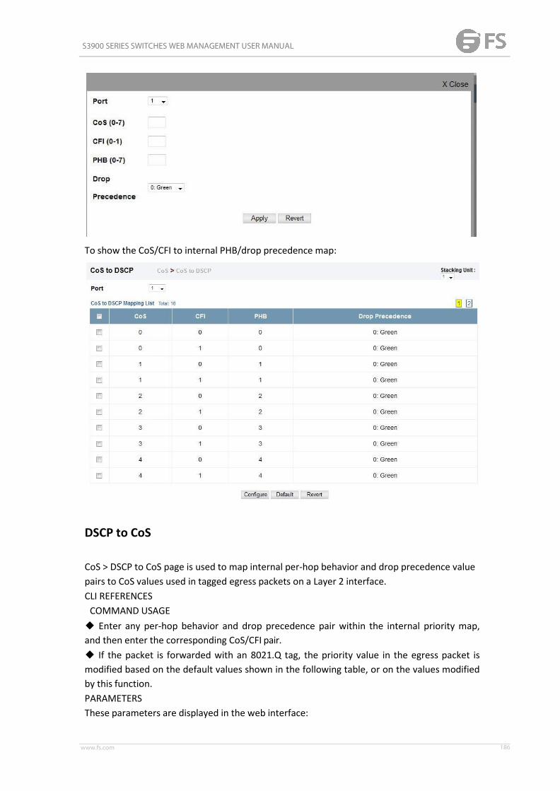
S3900 SERIES SWITCHES WEB MANAGEMENT USER MANUAL
www.fs.com 186
To show the CoS/CFI to internal PHB/drop precedence map:
DSCP to CoS
CoS > DSCP to CoS page is used to map internal per-hop behavior and drop precedence valuepairs to CoS values used in tagged egress packets on a Layer 2 interface.CLI REFERENCESCOMMAND USAGE◆ Enter any per-hop behavior and drop precedence pair within the internal priority map,and then enter the corresponding CoS/CFI pair.◆ If the packet is forwarded with an 8021.Q tag, the priority value in the egress packet ismodified based on the default values shown in the following table, or on the values modifiedby this function.PARAMETERSThese parameters are displayed in the web interface:

S3900 SERIES SWITCHES WEB MANAGEMENT USER MANUAL
www.fs.com 187
◆ Port – Specifies a port.◆ PHB – Per-hop behavior, or the priority used for this router hop. (Range:0-7)◆ Drop Precedence – Drop precedence used for controlling traffic congestion. (Range: 0 -Green, 3 - Yellow, 1 - Red)◆ CoS – Class-of-Service value. (Range: 0-7)◆ CFI – Canonical Format Indicator. Set to this parameter to “0” to indicate that the MACaddress information carried in the frame is in canonical format. (Range:0-1)

S3900 SERIES SWITCHES WEB MANAGEMENT USER MANUAL
www.fs.com 188
IP Precedence to DSCP
CoS > IP Precedence to DSCP page is used to map IP precedence values in incoming packetsto per-hop behavior and drop precedence values for priorityprocessing.The Type of Service (ToS) octet in the IPv4 header includes three precedence bits definingeight different priority levels ranging from highest priority for network control packets tolowest priority for routine traffic. The default IP Precedence values map one-to-one to theClass of Service values (that is, Precedence value 0 maps to PHB value 0, and so forth). Bits 6and 7 are used for network control, and the other bits for various application types.
◆ Enter per-hop behavior and drop precedence for any of the IP Precedence values 0 -7.◆ If the priority mapping mode is set the IP Precedence and the ingress packet type is IPv4,then the IP Precedence-to-PHB/Drop Precedence mapping table is used to generate priorityand drop precedence values for internal processing.PARAMETERS

S3900 SERIES SWITCHES WEB MANAGEMENT USER MANUAL
www.fs.com 189
These parameters are displayed in the web interface:◆ Port – Specifies a port.◆ IP Precedence – IP Precedence value in ingress packets. (Range: 0-7)◆ PHB – Per-hop behavior, or the priority used for this router hop. (Range:0-7)◆ Drop Precedence – Drop precedence used for controlling traffic congestion. (Range: 0 -Green, 3 - Yellow, 1 - Red)
IP Port to DSCP
CoS > IP Port to DSCP page is used to map network applications designated by a TCP/UDPdestination port number in the frame header to per-hop behavior and drop precedence

S3900 SERIES SWITCHES WEB MANAGEMENT USER MANUAL
www.fs.com 190
values for internal priority processing.COMMAND USAGE◆ This mapping table is only used if the protocol type of the arriving packet is TCP or UDP.Some of the more common TCP service ports include: HTTP: 80, FTP: 21, Telnet: 23 and POP3:110.◆ No default mapping is defined for ingress TCP/UDP port types.PARAMETERSThese parameters are displayed in the web interface:◆ Port – Specifies a port.◆ IP Protocol■ TCP – Transport Control Protocol■ UDP – User Datagram Protocol◆ Destination Port Number – 16-bit TCP/UDP destination port number. (Range: 0-65535)◆ PHB – Per-hop behavior, or the priority used for this router hop. (Range:0-7)◆ Drop Precedence – Drop precedence used for controlling traffic congestion. (Range: 0 -Green, 3 - Yellow, 1 - Red)
PHB to Queue
CoS > PHB to Queue page is used to specify the hardware output queues to use based on theinternal per-hop behavior value. (For more information on exact manner in which theingress priority tags are mapped to egress queues for internal processing, see "Mapping CoSPriorities to Internal DSCP Values" ).The switch processes Class of Service (CoS) priority tagged traffic by using eight priorityqueues for each port, with service schedules based on strict priority, Weighted Round-Robin

S3900 SERIES SWITCHES WEB MANAGEMENT USER MANUAL
www.fs.com 191
(WRR), or a combination of strict and weighted queuing. Up to eight separate trafficpriorities are defined in IEEE 802.1p. Default priority levels are assigned according torecommendations in the IEEE 802.1p standard as shown in following table. The followingtable indicates the default mapping of internal per-hop behavior to the hardware queues.The actual mapping may differ if the CoS priorities to internal DSCP values have beenmodified .
Priority 0 1 2 3 4 5 6 7Queue 2 0 1 3 4 5 6 7The priority levels recommended in the IEEE 802.1p standard for various networkapplications are shown in following table. However, priority levels can be mapped to theswitch’s output queues in any way that benefits application traffic for the network.Priority Level Traffic Type1 Background2 (Spare)0 (default) Best Effort3 Excellent Effort4 Controlled Load
Video, less than 100 millisecondslatency5 and jitter
Voice, less than 10 milliseconds latency6 and jitter7 Network Control
COMMAND USAGE◆Egress packets are placed into the hardware queues according to the mapping defined bythis command.◆The default internal PHB to output queue mapping is shownbelow.
Per-hop Behavior 0 1 2 3 4 5 6 7Hardware Queues 2 0 1 3 4 5 6 7
◆The specified mapping applies to all interfaces.PARAMETERSThese parameters are displayed:◆Port – Specifies a port.◆PHB – Per-hop behavior, or the priority used for this router hop. (Range: 0-7, where 7 isthe highest priority)◆Queue – Output queue buffer. (Range: 0-7, where 7 is the highest CoS priorityqueue)

S3900 SERIES SWITCHES WEB MANAGEMENT USER MANUAL
www.fs.com 192
QoS
The commands described in this section are used to configure Quality of Service (QoS)classification criteria and service policies. Differentiated Services (DiffServ) providespolicy-based management mechanisms used for prioritizing network resources to meet therequirements of specific traffic types on a per hop basis. Each packet is classified upon entryinto the network based on access lists, IP Precedence, DSCP values, or VLAN lists. Usingaccess lists allows you select traffic based on Layer 2, Layer 3, or Layer 4 informationcontained in each packet. Based on configured network policies, different kinds of traffic canbe marked for different kinds of forwarding.All switches or routers that access the Internet rely on class information to provide the sameforwarding treatment to packets in the same class. Class information can be assigned by endhosts, or switches or routers along the path. Priority can then be assigned based on ageneral policy, or a detailed examination of the packet. However, note that detailedexamination of packets should take place close to the network edge so that core switchesand routers are not overloaded.Switches and routers along the path can use class information to prioritize the resourcesallocated to different traffic classes. The manner in which an individual device handles trafficin the DiffServ architecture is called perhop behavior. All devices along a path should beconfigured in a consistent manner to construct a consistent end-to-end QoS solution.
Class
A class map is used for matching packets to a specified class. QoS > Class page is used to

S3900 SERIES SWITCHES WEB MANAGEMENT USER MANUAL
www.fs.com 193
configure a class map.COMMAND USAGE◆The class map is used with a policy map to create a service policy for a specific interfacethat defines packet classification, service tagging, and bandwidth policing. Note that one ormore class maps can be assigned to a policymap.◆Up to 32 class maps can be configured.PARAMETERSThese parameters are displayed:Add◆Class Name – Name of the class map. (Range: 1-32 characters)◆Type – The criteria specified by the match command.■Match All – Match all conditions within a classmap.■Match Any – Match any condition within a classmap.◆Description – A brief description of a class map. (Range: 1-64 characters) AddRule◆Class Name – Name of the classmap.◆Type – Only one match command is permitted per class map, so the match-any fieldrefers to the criteria specified by the lone match command.◆ACL – Name of an access control list. Any type of ACL can be specified, including standardor extended IP ACLs and MACACLs.◆ IP DSCP – A DSCP value. (Range: 0-63)◆ IP Precedence – An IP Precedence value. (Range: 0-7)◆ IPv6 DSCP – A DSCP value contained in an IPv6 packet. (Range: 0-63)◆VLAN ID – A VLAN. (Range:1-4093)◆CoS – A CoS value. (Range: 0-7)◆Source Port – A source port. (Range: 1-28)
Class Rule
To edit the rules for a class map:

S3900 SERIES SWITCHES WEB MANAGEMENT USER MANUAL
www.fs.com 194
Policy
QoS > Policy page is used to create a policy map that can be attached to multiple interfaces.A policy map is used to group one or more class map statements , modify service tagging,and enforce bandwidth policing. A policy map can then be bound by a service policy to oneor more interfaces .Configuring QoS policies requires several steps. A class map must first be configured whichindicates how to match the inbound packets according to an access list, a DSCP or IPPrecedence value, or a member of specific VLAN. A policy map is then configured whichindicates the boundary parameters used for monitoring inbound traffic, and the action totake for conforming and non-conforming traffic. A policy map may contain one or moreclasses based on previously defined class maps. The class of service or per-hop behavior (i.e.,the priority used for internal queue processing) can be assigned to matching packets. Inaddition, the flow rate of inbound traffic can be monitored and the response to conformingand non-conforming traffic based by one of three distinct policing methods as describedbelow.Police Flow Meter – Defines the committed information rate (maximum throughput),committed burst size (burst rate), and the action to take for conforming and non-conformingtraffic. Policing is based on a token bucket, where bucket depth (that is, the maximum burstbefore the bucket overflows) is specified by the “burst” field (BC), and the average ratetokens are removed from the bucket is specified by the “rate” option (CIR). Action may betaken for traffic conforming to the maximum throughput, or exceeding the maximumthroughput.srTCM Police Meter – Defines an enforcer for classified traffic based on a single rate threecolor meter scheme defined in RFC 2697. This metering policy monitors a traffic stream andprocesses its packets according to the committed information rate (CIR, or maximumthroughput), committed burst size (BC, or burst rate), and excess burst size (BE). Action maytaken for traffic conforming to the maximum throughput, exceeding the maximumthroughput, or exceeding the excess burst size.◆The PHB label is composed of five bits, three bits for per-hop behavior, and two bits forthe color scheme used to control queue congestion. In addition to the actions defined bythis command to transmit, remark the DSCP servicevalue, or drop a packet, the switch will

S3900 SERIES SWITCHES WEB MANAGEMENT USER MANUAL
www.fs.com 195
also mark the two color bits used to set the drop precedence of a packet. A packet is markedgreen if it doesn't exceed the committed information rate and committed burst size, yellowif it does exceed the committedinformation rate and committed burst size, but not the excess burst size, and red otherwise.◆The meter operates in one of two modes. In the color-blind mode, the meter assumesthat the packet stream is uncolored. In color-aware mode the meter assumes that somepreceding entity has pre-colored the incoming packet stream so that each packet is eithergreen, yellow, or red. The marker (re)colors an IP packet according to the results of themeter. The color is coded in the DS field [RFC 2474] of thepacket.◆The behavior of the meter is specified in terms of its mode and two token buckets, C and E,which both share the common rate CIR. The maximum size of the token bucket C is BC andthe maximum size of the token bucket E is BE. The token buckets C and E are initiallyfull,that is, the token count Tc(0) = BC and the token count Te(0) = BE. Thereafter, the tokencounts Tc and Te are updated CIR times per second as follows:■If Tc is less than BC, Tc is incremented by one, else■if Te is less then BE, Te is incremented by one, else■neither Tc nor Te is incremented.When a packet of size B bytes arrives at time t, the following happens if srTCM is configuredto operate in Color-Blind mode:■If Tc(t)-B ≥ 0, the packet is green and Tc is decremented by B down to the minimumvalue of 0, else■if Te(t)-B ≥ 0, the packets is yellow and Te is decremented by B down to the minimumvalue of 0,■else the packet is red and neither Tc nor Te is decremented. When a packet of size B bytesarrives at time t, the following happens if srTCM is configured to operate in Color-Awaremode:■If the packet has been precolored as green andTc(t)-B ≥ 0, the packet is green and Tc isdecremented by B down to the minimum value of 0, else■If the packet has been precolored as yellow or green and ifTe(t)-B ≥ 0, the packets isyellow and Te is decremented by B down to the minimum value of 0,else■the packet is red and neither Tc nor Te is decremented. The metering policy guarantees adeterministic behavior where the volume of green packets is never smaller than what hasbeen determined by the CIR and BC, that is, tokens of a given color are always spent onpackets of that color. Refer to RFC 2697 for more information on other aspects of srTCM.trTCM Police Meter – Defines an enforcer for classified traffic based on a two rate threecolor meter scheme defined in RFC 2698. This metering policy monitors a traffic stream andprocesses its packets according to the committed information rate (CIR, or maximumthroughput), peak information rate (PIR), and their associated burst sizes – committed burstsize (BC, or burst rate), and peak burst size (BP). Action may taken for traffic conforming tothe maximum throughput, exceeding the maximum throughput, or exceeding the peak burstsize.◆The PHB label is composed of five bits, three bits for per-hop behavior, and two bits forthe color scheme used to control queue congestion. In addition to the actions defined bythis command to transmit, remark the DSCP servicevalue, or drop a packet, the switch will

S3900 SERIES SWITCHES WEB MANAGEMENT USER MANUAL
www.fs.com 196
also mark the two color bits used to set the drop precedence of a packet. A packet is markedred if it exceeds the PIR. Otherwise it is marked either yellow or green depending onwhether it exceeds or doesn't exceed the CIR. The trTCM is useful for ingress policing of aservice, where a peak rate needs to be enforced separately from a committed rate.◆The meter operates in one of two modes. In the color-blind mode, the meter assumesthat the packet stream is uncolored. In color-aware mode the meter assumes that somepreceding entity has pre-colored the incoming packet stream so that each packet is eithergreen, yellow, or red. The marker (re)colors an IP packet according to the results of themeter. The color is coded in the DS field [RFC 2474] of thepacket.◆The behavior of the meter is specified in terms of its mode and two token buckets, P andC, which are based on the rates PIR and CIR, respectively. The maximum size of the tokenbucket P is BP and the maximum size of the token bucket C is BC. The token buckets P andCare initially (at time 0) full, that is, the token count Tp(0) = BP and the token count Tc(0) = BC.Thereafter, the token count Tp is incremented by one PIR times per second up to BP and thetoken count Tc is incremented by one CIR times per second up to BC. When a packet of sizeB bytes arrives at time t, the following happens if trTCM is configured to operate inColor-Blind mode:■If Tp(t)-B < 0, the packet is red, else■if Tc(t)-B < 0, the packet is yellow and Tp is decremented by B,else■the packet is green and both Tp and Tc are decremented by B. When a packet of size Bbytes arrives at time t, the following happens if trTCM is configured to operateinColor-Aware mode:■If the packet has been precolored as red or if Tp(t)-B < 0, the packet is red,else■if the packet has been precolored as yellow or if Tc(t)-B < 0, the packet is yellow and Tp isdecremented by B, else■the packet is green and both Tp and Tc are decremented byB.◆The trTCM can be used to mark a IP packet stream in a service, where different,decreasing levels of assurances (either absolute or relative) are given to packets which aregreen, yellow, or red. Refer to RFC 2698 for more information on other aspects of trTCM.COMMAND USAGE◆A policy map can contain 512 class statements that can be applied to the same interface .Up to 32 policy maps can be configured for ingressports.◆After using the policy map to define packet classification, service tagging, and bandwidthpolicing, it must be assigned to a specific interface by a service policy to take effect.PARAMETERSThese parameters are displayed:Add◆Policy Name – Name of policy map. (Range: 1-32 characters)◆Description – A brief description of a policy map. (Range: 1-256characters)Add Rule◆Policy Name – Name of policymap.◆Class Name – Name of a class map that defines a traffic classification upon which a policycan act.◆Action – This attribute is used to set an internal QoS value in hardware formatching

S3900 SERIES SWITCHES WEB MANAGEMENT USER MANUAL
www.fs.com 197
packets. The PHB label is composed of five bits, three bits for per-hop behavior, and two bitsfor the color scheme used to control queue congestion with the srTCM and trTCM meteringfunctions.■Set CoS – Configures the service provided to ingress traffic by setting an internal CoS valuefor a matching packet (as specified in rule settings for a class map). (Range:0-7).■Set PHB – Configures the service provided to ingress traffic bysetting the internal per-hop behavior for a matching packet (as specified in rule settings for aclass map). (Range: 0-7).◆Meter – Check this to define the maximum throughput, burst rate, and the action thatresults from a policy violation.◆Meter Mode – Selects one of the following policingmethods.■Flow (Police Flow) – Defines the committed information rate (CIR, or maximumthroughput), committed burst size (BC, or burst rate), and the action to take for conformingand non-conforming traffic. Policing is based on a token bucket, where bucket depth (that is,the maximum burst before the bucket overflows) is specified by the “burst” field, and theaverage rate tokens are removed from the bucket is by specified by the “rate”option.■Committed Information Rate (CIR) – Rate in kilobits per second. (Range: 0-10000000 kbpsat a granularity of 64 kbps or maximum port speed, whichever is lower) The rate cannotexceed the configured interface speed.■Committed Burst Size (BC) – Burst in bytes. (Range: 64-16000000 at a granularity of 4kbytes) The burst size cannot exceed 16Mbytes.■Conform – Specifies that traffic conforming to the maximum rate (CIR) will be transmittedwithout any change to the DSCP service level.■Transmit – Transmits in-conformance traffic without any change to the DSCP service level.■Violate – Specifies whether the traffic that exceeds the maximum rate (CIR) will bedropped or the DSCP service level will be reduced.■Set IP DSCP – Decreases DSCP priority for out of conformance traffic. (Range:0-63)■Drop – Drops out of conformance traffic.■srTCM (Police Meter) – Defines the committed information rate (CIR, or maximumthroughput), committed burst size (BC, or burst rate) and excess burst size (BE), and theaction to take for traffic conforming to the maximum throughput, exceeding the maximumthroughput but within the excess burst size, or exceeding the excess burst size. In addition tothe actions defined by this command to transmit, remark the DSCP service value, or drop apacket, the switch will also mark the two color bits used to set the drop precedence of apacket. The color modes include “Color-Blind” which assumes that the packet stream isuncolored, and “Color-Aware” which assumes that the incoming packets are pre-colored.The functional differences between these modes is described at the beginning of this sectionunder “srTCM PoliceMeter.”■Committed Information Rate (CIR) – Rate in kilobits per second. (Range: 0-10000000 kbpsat a granularity of 64 kbps or maximum port speed, whichever is lower) The rate cannotexceed the configured interface speed.■Committed Burst Size (BC) – Burst in bytes. (Range: 64-16000000 at a granularity of 4kbytes) The burst size cannot exceed 16Mbytes.■Excess Burst Size (BE) – Burst in excess of committed burst size. (Range: 0-16000000 ata

S3900 SERIES SWITCHES WEB MANAGEMENT USER MANUAL
www.fs.com 198
granularity of 4k bytes) The burst size cannot exceed 16 Mbytes.■Conform – Specifies that traffic conforming to the maximum rate (CIR) will be transmittedwithout any change to the DSCP service level.■Transmit – Transmits in-conformance traffic without any change to the DSCP service level.■Exceed – Specifies whether traffic that exceeds the maximum rate (CIR) but is within theexcess burst size (BE) will be dropped or the DSCP service level will be reduced.■Set IP DSCP – Decreases DSCP priority for out of conformance traffic. (Range:0-63)■Drop – Drops out of conformance traffic.■Violate – Specifies whether the traffic that exceeds the excess burst size (BE) will bedropped or the DSCP service level will be reduced.■Set IP DSCP – Decreases DSCP priority for out of conformance traffic. (Range:0-63)■Drop – Drops out of conformance traffic.■trTCM (Police Meter) – Defines the committed information rate (CIR, or maximumthroughput), peak information rate (PIR), and their associated burst sizes – committed burstsize (BC, or burst rate) and peak burst size (BP), and the action to take for traffic conformingto the maximum throughput, exceeding the maximum throughput but within the peakinformation rate, or exceeding the peak information rate. In addition to the actions definedby this command to transmit, remark the DSCP service value, or drop a packet, the switchwill also mark the two color bits used to set the drop precedence of a packet. The colormodes include “Color-Blind” which assumes that the packet stream is uncolored,and“Color-Aware” which assumes that the incoming packets are pre-colored. The functionaldifferences between these modes is described at the beginning of this section under “trTCMPolice Meter.”■Committed Information Rate (CIR) – Rate in kilobits per second. (Range: 0-10000000 kbpsat a granularity of 64 kbps or maximum port speed, whichever is lower) The rate cannotexceed the configured interface speed.■Committed Burst Size (BC) – Burst in bytes. (Range: 64-16000000 at a granularity of 4kbytes) The burst size cannot exceed 16Mbytes.■Peak Information Rate (PIR) – Rate in kilobits per second. (Range: 0-1000000 kbps at agranularity of 64 kbps or maximum port speed, whichever is lower) The rate cannot exceedthe configured interface speed.■Peak Burst Size (BP) – Burst size in bytes. (Range: 0-16000000 at a granularity of 4k bytes)The burst size cannot exceed 16Mbytes.■Conform – Specifies that traffic conforming to the maximum rate (CIR) will be transmittedwithout any change to the DSCP service level.■Transmit – Transmits in-conformance traffic without any change to the DSCP service level.■Exceed – Specifies whether traffic that exceeds the maximum rate (CIR) but is within thepeak information rate (PIR) will be dropped or the DSCP service level will bereduced.■Set IP DSCP – Decreases DSCP priority for out of conformance traffic. (Range:0-63).■Drop – Drops out of conformance traffic.■Violate – Specifies whether the traffic that exceeds the peak information rate (PIR) will bedropped or the DSCP service level will be reduced.■Set IP DSCP – Decreases DSCP priority for out of conformance traffic. (Range:0-63).■Drop – Drops out of conformance traffic.

S3900 SERIES SWITCHES WEB MANAGEMENT USER MANUAL
www.fs.com 199
Policy Rule
To edit the rules for a policy map:
To show the rules for a policy map:

S3900 SERIES SWITCHES WEB MANAGEMENT USER MANUAL
www.fs.com 200
Configure Interface
QoS > Configure Interface page is used to bind a policy map to a port.COMMAND USAGEFirst define a class map, define a policy map, and bind the service policy to the requiredinterface.PARAMETERSThese parameters are displayed:◆Port – Specifies a port.◆ Ingress – Applies the selected rule to ingress traffic.◆Egress – Applies the selected rule to egress traffic.
Security
AAA
The authentication, authorization, and accounting (AAA) feature provides the mainframework for configuring access control on the switch. The three security functions can besummarized as follows:◆ Authentication — Identifies users that request access to thenetwork.◆ Authorization — Determines if users can access specific services.◆ Accounting — Provides reports, auditing, and billing for services that users have accessedon the network. The AAA functions require the use of configured RADIUS or TACACS+servers in the network. The security servers can be defined as sequential groups that areapplied as a method for controlling user access to specified services. For example, when theswitch attempts to authenticate a user, a

S3900 SERIES SWITCHES WEB MANAGEMENT USER MANUAL
www.fs.com 201
request is sent to the first server in the defined group, if there is no response the secondserver will be tried, and so on. If at any point a pass or fail is returned, the process stops.The switch supports the following AAA features:◆ Accounting for IEEE 802.1X authenticated users that access the network through theswitch.◆ Accounting for users that access management interfaces on the switch through theconsole and Telnet.◆ Accounting for commands that users enter at specific CLI privilege levels.◆ Authorization of users that access management interfaces on the switch through theconsole and Telnet.
System Authentication
Security > AAA > System Authentication page to specify local or remote authentication. Localauthentication restricts management access based on user names and passwords manuallyconfigured on the switch. Remote authentication uses a remote access authentication serverbased on RADIUS or TACACS+ protocols to verify management access.Command Usage◆ By default, management access is always checked against the authentication databasestored on the local switch. If a remote authentication server is used, you must specify theauthentication sequence. Then specify the corresponding parameters for the remoteauthentication protocol using the Security > AAA > Server page. Local and remote logonauthentication control management access via the console port, web browser, orTelnet.◆ You can specify up to three authentication methods for any user to indicate theauthentication sequence. For example, if you select (1) RADIUS, (2) TACACS and (3) Local, theuser name and password on the RADIUS server is verified first. If the RADIUS server is notavailable, then authentication is attempted using the TACACS+ server, and finally the localuser name and password is checked.ParametersThese parameters are displayed:◆ Authentication Sequence – Select the authentication, or authentication sequencerequired:■ Local – User authentication is performed only locally by theswitch.■ RADIUS – User authentication is performed using a RADIUS server only.■ TACACS – User authentication is performed using a TACACS+ server only.■ [authentication sequence] – User authentication is performed by up to threeauthentication methods in the indicated sequence.

S3900 SERIES SWITCHES WEB MANAGEMENT USER MANUAL
www.fs.com 202
Configure AAA Server
To configure the parameters for RADIUS or TACACS+ authentication:
AAA Group
To configure the RADIUS or TACACS+ server groups to use for accounting and authorization:

S3900 SERIES SWITCHES WEB MANAGEMENT USER MANUAL
www.fs.com 203
Configure Accounting Periodic
To configure global settings for AAA accounting:
Accounting Method
To configure the accounting method applied to various service types and the assigned servergroup:
Configure Accounting Service
To configure the accounting method applied to specific interfaces, console commandsentered at specific privilege levels, and local console, Telnet, or SSH connections:

S3900 SERIES SWITCHES WEB MANAGEMENT USER MANUAL
www.fs.com 204
Show Accounting Information
To display a summary of the configured accounting methods and assigned server groups forspecified service types:
Authorization Method
To configure the authorization method applied to the Exec service type and the assignedserver group:

S3900 SERIES SWITCHES WEB MANAGEMENT USER MANUAL
www.fs.com 205
Configure Authorization service
To configure the authorization method applied to local console, Telnet, or SSH connections:
Show Authorization Information
To display a the configured authorization method and assigned server groups for The Execservice type:
Web Authentication
Web authentication allows stations to authenticate and access the network in situationswhere 802.1X or Network Access authentication are infeasible or impractical. The webauthentication feature allows unauthenticated hosts to request and receive a DHCP assignedIP address and perform DNS queries. All other traffic, except for HTTP protocol traffic, isblocked. The switch intercepts HTTP protocol traffic and redirects it to a switchgeneratedweb page that facilitates user name and password authentication via RADIUS. Onceauthentication is successful, the web browser is forwarded on to the originally requestedweb page. Successful authentication is valid for all hosts connected to the port.

S3900 SERIES SWITCHES WEB MANAGEMENT USER MANUAL
www.fs.com 206
Configure Global
Security > Web Authentication > Configure Global page is used to edit the global parametersfor web authentication.
◆Web Authentication Status – Enables web authentication for the switch. (Default:Disabled)Note that this feature must also be enabled for any port where required under the ConfigureInterface menu.◆ Session Timeout – Configures how long an authenticated session stays active before itmust re-authenticate itself. (Range: 300-3600 seconds; Default: 3600seconds)◆ Quiet Period – Configures how long a host must wait to attempt authentication againafter it has exceeded the maximum allowable failed login attempts. (Range: 1-180 seconds;Default: 60 seconds)◆ Login Attempts – Configures the amount of times a supplicant may attempt and failauthentication before it must wait the configured quiet period. (Range: 1-3 attempts;Default: 3 attempts)
Configure Interface
Security > Web Authentication > Configure Interface page is used to configure the interface.
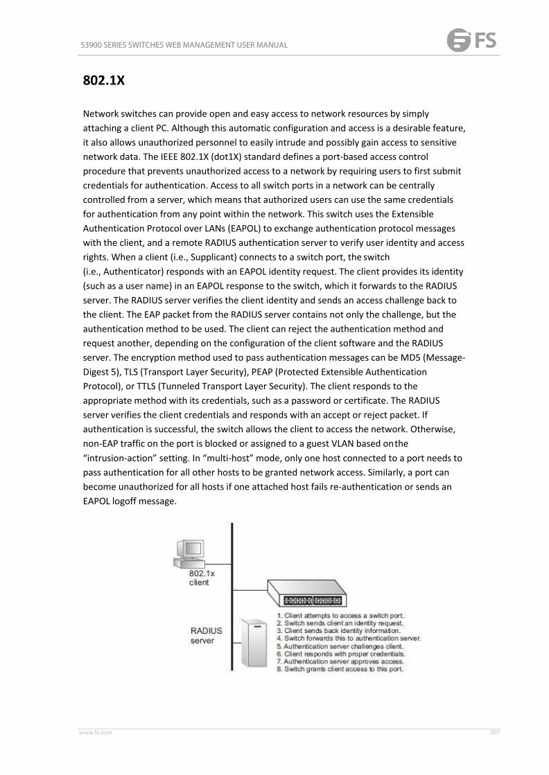
S3900 SERIES SWITCHES WEB MANAGEMENT USER MANUAL
www.fs.com 207
802.1X
Network switches can provide open and easy access to network resources by simplyattaching a client PC. Although this automatic configuration and access is a desirable feature,it also allows unauthorized personnel to easily intrude and possibly gain access to sensitivenetwork data. The IEEE 802.1X (dot1X) standard defines a port-based access controlprocedure that prevents unauthorized access to a network by requiring users to first submitcredentials for authentication. Access to all switch ports in a network can be centrallycontrolled from a server, which means that authorized users can use the same credentialsfor authentication from any point within the network. This switch uses the ExtensibleAuthentication Protocol over LANs (EAPOL) to exchange authentication protocol messageswith the client, and a remote RADIUS authentication server to verify user identity and accessrights. When a client (i.e., Supplicant) connects to a switch port, the switch(i.e., Authenticator) responds with an EAPOL identity request. The client provides its identity(such as a user name) in an EAPOL response to the switch, which it forwards to the RADIUSserver. The RADIUS server verifies the client identity and sends an access challenge back tothe client. The EAP packet from the RADIUS server contains not only the challenge, but theauthentication method to be used. The client can reject the authentication method andrequest another, depending on the configuration of the client software and the RADIUSserver. The encryption method used to pass authentication messages can be MD5 (Message-Digest 5), TLS (Transport Layer Security), PEAP (Protected Extensible AuthenticationProtocol), or TTLS (Tunneled Transport Layer Security). The client responds to theappropriate method with its credentials, such as a password or certificate. The RADIUSserver verifies the client credentials and responds with an accept or reject packet. Ifauthentication is successful, the switch allows the client to access the network. Otherwise,non-EAP traffic on the port is blocked or assigned to a guest VLAN based onthe“intrusion-action” setting. In “multi-host” mode, only one host connected to a port needs topass authentication for all other hosts to be granted network access. Similarly, a port canbecome unauthorized for all hosts if one attached host fails re-authentication or sends anEAPOL logoff message.

S3900 SERIES SWITCHES WEB MANAGEMENT USER MANUAL
www.fs.com 208
Configure Global
Security > 802.1x > Configure Global page is used to configure the global parameter of802.1x.
◆ System Authentication Control – Sets the global setting for 802.1X. (Default:Disabled)◆ EAPOL Pass Through – Passes EAPOL frames through to all ports in STP forwarding statewhen dot1x is globally disabled. (Default: Disabled)
Configure Interface
Security > 802.1x > Configure Interface page is used to configure the parameters of a port.
Show Statistics
Security > 802.1x > Show Statistics page is used to display the statistics of 802.1x.

S3900 SERIES SWITCHES WEB MANAGEMENT USER MANUAL
www.fs.com 209
Network Access
Some devices connected to switch ports may not be able to support 802.1X authenticationdue to hardware or software limitations. This is often true for devices such as networkprinters, IP phones, and some wireless access points. The switch enables network accessfrom these devices to be controlled by authenticating device MAC addresses with a centralRADIUS server.
Configure Global
Security > Web Authentication > Configure Global page is used to configure the globalparameters.
◆ Web Authentication Status – Enables web authentication for the switch. (Default:Disabled) Note that this feature must also be enabled for any port where required under theConfigure Interface menu.◆ Session Timeout – Configures how long an authenticated session stays active before itmust re-authenticate itself. (Range: 300-3600 seconds; Default: 3600seconds)◆ Quiet Period – Configures how long a host must wait to attempt authentication againafter it has exceeded the maximum allowable failed login attempts. (Range: 1-180 seconds;Default: 60 seconds)◆ Login Attempts – Configures the amount of times a supplicant may attempt and failauthentication before it must wait the configured quiet period. (Range: 1-3 attempts; Default:

S3900 SERIES SWITCHES WEB MANAGEMENT USER MANUAL
www.fs.com 210
3 attempts)
Configure Interface
Security > Web Authentication > Configure Interface page is used to configure theparameters of interface.
HTTPS
You can configure the switch to enable the Secure Hypertext Transfer Protocol (HTTPS) overthe Secure Socket Layer (SSL), providing secure access (i.e., an encrypted connection) to theswitch’s web interface.
Configure Global
The Security > HTTPS > Configure Global page is used to enable or disable HTTPS and specifythe UDP port used for this service.COMMAND USAGE◆Both the HTTP and HTTPS service can be enabled independently on the switch. However,you cannot configure both services to use the same UDPport.◆ If you enable HTTPS, you must indicate this in the URL that you specify in your browser:https://device[:port_number]◆When you start HTTPS, the connection is established in thisway:■The client authenticates the server using the server’s digital certificate.■The client and server negotiate a set of security protocols to use for theconnection.■The client and server generate session keys for encrypting and decryptingdata.◆The client and server establish a secure encrypted connection. A padlock icon shouldappear in the status bar for Internet Explorer 6.x or above, or Mozilla Firefox3.6.2/4/5.◆The following web browsers and operating systems currently supportHTTPS:
Web Browser Operating System
Internet Explorer 6.x orlater
Windows 98,Windows NT (with service pack 6a),Windows 2000, Windows XP,Windows Vista,Windows 7

S3900 SERIES SWITCHES WEB MANAGEMENT USER MANUAL
www.fs.com 211
Windows 2000, Windows XP, Linux
PARAMETERSThese parameters are displayed:◆HTTPS Status – Allows you to enable/disable the HTTPS server feature on the switch.(Default: Enabled)◆HTTPS Port – Specifies the UDP port number used for HTTPS connection to the switch’sweb interface. (Default: Port 443)
Copy Certificate
The Security > HTTPS > Copy Certificate page is used to replace the default secure-sitecertificate.When you log onto the web interface using HTTPS (for secure access), a Secure SocketsLayer (SSL) certificate appears for the switch. By default, the certificate that the webbrowser displays will be associated with a warning that the site is not recognized as a securesite. This is because the certificate has not been signed by an approved certificationauthority. If you want this warning to be replaced by a message confirming that theconnection to the switch is secure, you must obtain a unique certificate and a private keyand password from a recognized certification authority. When you have obtained these,place them on your TFTP server and transfer them to the switch to replace the default(unrecognized) certificate with an authorized one.PARAMETERSThese parameters are displayed:◆TFTP Server IP Address – IP address of TFTP server which contains the certificatefile.◆Certificate Source File Name – Name of certificate file stored on the TFTPserver.◆Private Key Source File Name – Name of private key file stored on the TFTPserver.◆Private Password – Password stored in the private key file. This password is used to verifyauthorization for certificate use, and is verified when downloading the certificate to theswitch.◆Confirm Password – Re-type the string entered in the previous field to ensure no errorswere made. The switch will not download the certificate if these two fields do notmatch.
Mozilla Firefox 3.6.2/4/5

S3900 SERIES SWITCHES WEB MANAGEMENT USER MANUAL
www.fs.com 212
SSH
The Berkeley-standard includes remote access tools originally designed for Unix systems.Some of these tools have also been implemented for Microsoft Windows and otherenvironments. These tools, including commands such as rlogin (remote login), rsh (remoteshell), and rcp (remote copy), are not secure from hostile attacks. Secure Shell (SSH) includesserver/client applications intended as a secure replacement for the older Berkeley remoteaccess tools. SSH can also provide remote management access to this switch as a securereplacement for Telnet. When the client contacts the switch via the SSH protocol, the switchgenerates a public-key that the client uses along with a local user name and password foraccess authentication. SSH also encrypts all data transfers passing between the switch andSSH-enabled management station clients, and ensures that data traveling over the networkarrives unaltered.
Configure Global
The Security > SSH > Configure Global page is used to enable the SSH server and configurebasic settings for authentication.PARAMETERSThese parameters are displayed:◆SSH Server Status – Allows you to enable/disable the SSH server on the switch. (Default:Disabled)◆Version – The Secure Shell version number. Version 2.0 is displayed, but the switchsupports management access via either SSH Version 1.5 or 2.0 clients.◆Authentication Timeout – Specifies the time interval in seconds that the SSH server waitsfor a response from a client during an authentication attempt. (Range: 1-120 seconds;Default: 120 seconds)◆Authentication Retries – Specifies the number of authentication attempts that a client isallowed before authentication fails and the client has to restart the authentication process.(Range: 1-5 times; Default: 3)◆Server-Key Size – Specifies the SSH server key size. (Range: 512-896 bits;Default:768)■The server key is a private key that is never shared outside theswitch.■The host key is shared with the SSH client, and is fixed at 1024bits.

S3900 SERIES SWITCHES WEB MANAGEMENT USER MANUAL
www.fs.com 213
Show Host Key
The Security > SSH > Show Host Key page is used to generate a host public/private key pairused to provide secure communications between an SSH client and the switch. Aftergenerating this key pair, you must provide the host public key to SSH clients and import theclient’s public key to the switch.PARAMETERSThese parameters are displayed:◆Host-Key Type – The key type used to generate the host key pair (i.e., public and privatekeys). (Range: RSA (Version 1), DSA (Version 2), Both; Default: Both) The SSH server uses RSAor DSA for key exchange when the client first establishes a connection with the switch, andthen negotiates with the client to select either DES (56-bit) or 3DES (168-bit) for dataencryption.◆Save Host-Key fromMemory to Flash – Saves the host key from RAM (i.e., volatilememory) to flash memory. Otherwise, the host key pair is stored to RAM by default. Notethat you must select this item prior to generating the host-key pair. (Default:Disabled)
Show User Key
The Security > SSH > Show User Key page is used to upload a user’s public key to the switch.This public key must be stored on the switch for the user to be able to log in using the publickey authentication mechanism. If the user’s public key does not exist on the switch, SSH willrevert to the interactive password authentication mechanism to complete authentication.PARAMETERSThese parameters are displayed:

S3900 SERIES SWITCHES WEB MANAGEMENT USER MANUAL
www.fs.com 214
◆User Name – This drop-down box selects the user who’s public key you wish to manage.Note that you must first create users on the User Accountspage.◆User Key Type – The type of public key toupload.■RSA: The switch accepts a RSA version 1 encrypted public key.■DSA: The switch accepts a DSA version 2 encrypted public key. The SSH server uses RSA orDSA for key exchange when the client first establishes a connection with the switch, andthen negotiates with the client to select either DES (56-bit) or 3DES (168-bit) for dataencryption. The switch uses only RSA Version 1 for SSHv1.5 clients and DSA Version 2 forSSHv2 clients.◆TFTP Server IP Address – The IP address of the TFTP server that contains the public keyfile you wish to import.◆Source File Name – The public key file toupload.
Port Security
The Security > Port Security page is used to configure the maximum number of device MACaddresses that can be learned by a switch port, stored in the address table, and authorizedto access the network. When port security is enabled on a port, the switch stops learningnew MAC addresses on the specified port when it has reached a configured maximumnumber. Only incoming traffic with source addresses already stored in the address table willbe authorized to access the network through that port. If a device with an unauthorizedMAC address attempts to use the switch port, the intrusion will be detected and the switchcan automatically take action by disabling the port and sending a trap message.COMMAND USAGE◆The default maximum number of MAC addresses allowed on a secure port is zero (that is,disabled). To use port security, you must configure the maximum number of addressesallowed on a port.◆To configure the maximum number of address entries which can be learned on aport,

S3900 SERIES SWITCHES WEB MANAGEMENT USER MANUAL
www.fs.com 215
specify the maximum number of dynamic addresses allowed. The switch will learn up to themaximum number of allowed address pairs <source MAC address, VLAN> for framesreceived on the port. When the port has reached the maximum number of MAC addresses,the port will stop learning new addresses. The MAC addresses already in the address tablewill be retained and will not be aged out. Note that you can manually add additional secureaddresses to a port using the Static Address Table .◆When the port security state is changed from enabled to disabled, all dynamically learnedentries are cleared from the address table.◆ If port security is enabled, and the maximum number of allowed addresses are set to anon-zero value, any device not in the address table that attempts to use the port will beprevented from accessing the switch.◆ If a port is disabled (shut down) due to a security violation, it must be manually re-enabledfrom the Interface > Port > General page.◆A secure port has the following restrictions:■It cannot be used as a member of a static or dynamic trunk.■It should not be connected to a network interconnectiondevice.PARAMETERSThese parameters are displayed:◆Port – Port number.◆Security Status – Enables or disables port security on an interface. (Default:Disabled)◆Port Status – The operational status:■Secure/Down – Port security is disabled.■Secure/Up – Port security is enabled.■Shutdown – Port is shut down due to a response to a port securityviolation.◆Action – Indicates the action to be taken when a port security violation isdetected:■None: No action should be taken. (This is the default.)■Trap: Send an SNMP trapmessage.■Shutdown: Disable the port.■Trap and Shutdown: Send an SNMP trap message and disable theport.◆Max MAC Count – The maximum number of MAC addresses that can be learned on a port.(Range: 0 - 1024, where 0 means disabled) The maximum address count is effective whenport security is enabled or disabled.◆Current MAC Count – The number of MAC addresses currently associated with thisinterface.◆MAC Filter – Shows if MAC address filtering has been set under Security > Network Access(Configure MAC Filter) as described.◆MAC Filter ID – The identifier for a MAC address filter.◆Last Intrusion MAC – The last unauthorized MAC address detected.◆Last Time Detected Intrusion MAC – The last time an unauthorized MAC address wasdetected.

S3900 SERIES SWITCHES WEB MANAGEMENT USER MANUAL
www.fs.com 216
DAI
DAI is a security feature that validates the MAC Address bindings for Address ResolutionProtocol packets. It provides protection against ARP traffic with invalid MAC-to-IP addressbindings, which forms the basis for certain “man-in-the-middle” attacks. This isaccomplished by intercepting all ARP requests and responses and verifying each of thesepackets before the local ARP cache is updated or the packet is forwarded to the appropriatedestination. Invalid ARP packets are dropped. ARP Inspection determines the validity of anARP packet based on valid IP-to-MAC address bindings stored in a trusted database – theDHCP snooping binding database. This database is built by DHCP snooping if it is enabled onglobally on the switch and on the required VLANs. ARP Inspection can also validate ARPpackets against user-configured ARP access control lists (ACLs) for hosts with staticallyconfigured addresses.
Configure General
The Security > DAI > Configure General page is used to enable ARP inspection globally for theswitch, to validate address information in each packet, and configure logging.COMMAND USAGEARP Inspection Validation◆By default, ARP Inspection Validation is disabled.◆Specifying at least one of the following validations enables ARP Inspection Validationglobally. Any combination of the following checks can be activeconcurrently.■Destination MAC – Checks the destination MAC address in the Ethernet header againstthe target MAC address in the ARP body. This check is performed for ARP responses. Whenenabled, packets with different MAC addresses are classified as invalid and aredropped.■IP – Checks the ARP body for invalid and unexpected IP addresses. These addressesinclude 0.0.0.0, 255.255.255.255, and all IP multicast addresses. Sender IP addresses arechecked in all ARP requests and responses, while target IP addresses are checked only in ARPresponses.■Source MAC – Checks the source MAC address in the Ethernet header against thesender

S3900 SERIES SWITCHES WEB MANAGEMENT USER MANUAL
www.fs.com 217
MAC address in the ARP body. This check is performed on both ARP requests and responses.When enabled, packets with different MAC addresses are classified as invalid and aredropped.ARP Inspection Logging◆By default, logging is active for ARP Inspection, and cannot bedisabled.◆The administrator can configure the log facility rate.◆When the switch drops a packet, it places an entry in the log buffer, then generates asystemmessage on a rate-controlled basis. After the system message is generated, the entryis cleared from the log buffer.◆Each log entry contains flow information, such as the receiving VLAN, the port number,the source and destination IP addresses, and the source and destination MACaddresses.◆ If multiple, identical invalid ARP packets are received consecutively on the same VLAN,then the logging facility will only generate one entry in the log buffer and one correspondingsystemmessage.◆ If the log buffer is full, the oldest entry will be replaced with the newestentry.PARAMETERSThese parameters are displayed:◆ARP Inspection Status – Enables ARP Inspection globally. (Default: Disabled)◆ARP Inspection Validation – Enables extended ARP Inspection Validation if any of thefollowing options are enabled. (Default: Disabled)■Dst-MAC – Validates the destination MAC address in the Ethernet header against thetarget MAC address in the body of ARP responses.■IP – Checks the ARP body for invalid and unexpected IP addresses. Sender IP addressesare checked in all ARP requests and responses, while target IP addresses are checked only inARP responses.■Src-MAC – Validates the source MAC address in the Ethernet header against the senderMAC address in the ARP body. This check is performed on both ARP requests andresponses.◆Log Message Number – The maximum number of entries saved in a log message. (Range:0-256; Default: 5)◆Log Interval – The interval at which log messages are sent. (Range: 0-86400 seconds;Default: 1 second)
Configure VLAN
The Security > DAI > Configure VLAN page is used to enable ARP inspection for any VLAN andto specify the ARP ACL to use.COMMAND USAGE

S3900 SERIES SWITCHES WEB MANAGEMENT USER MANUAL
www.fs.com 218
ARP Inspection VLAN Filters (ACLs)◆By default, no ARP Inspection ACLs are configured and the feature is disabled.◆ARP Inspection ACLs are configured within the ARP ACL configuration page .◆ARP Inspection ACLs can be applied to any configuredVLAN.◆ARP Inspection uses the DHCP snooping bindings database for the list of valid IP-to-MACaddress bindings. ARP ACLs take precedence over entries in the DHCP snooping bindingsdatabase. The switch first compares ARP packets to any specified ARPACLs.◆ If Static is specified, ARP packets are only validated against the selected ACL – packets arefiltered according to any matching rules, packets not matching any rules are dropped, andthe DHCP snooping bindings database check is bypassed.◆ If Static is not specified, ARP packets are first validated against the selected ACL; if no ACLrules match the packets, then the DHCP snooping bindings database determines theirvalidity.PARAMETERSThese parameters are displayed:◆ARP Inspection VLAN ID – Selects any configured VLAN. (Default: 1)◆ARP Inspection VLAN Status – Enables ARP Inspection for the selected VLAN. (Default:Disabled)◆ARP Inspection ACL Name■ARP ACL – Allows selection of any configured ARP ACLs. (Default: None)■Static – When an ARP ACL is selected, and static mode also selected, the switch onlyperforms ARP Inspection and bypasses validation against the DHCP Snooping Bindingsdatabase. When an ARP ACL is selected, but static mode is not selected, the switch firstperforms ARP Inspection and then validation against the DHCP Snooping Bindings database.(Default: Disabled)
Configure Interface
The Security > DAI > Configure Interface page is used to specify the ports that require ARPinspection, and to adjust the packet inspection rate.PARAMETERSThese parameters are displayed:◆ Interface – Port or trunk identifier.◆Trust Status – Configures the port as trusted or untrusted. (Default: Untrusted) Bydefault,

S3900 SERIES SWITCHES WEB MANAGEMENT USER MANUAL
www.fs.com 219
all untrusted ports are subject to ARP packet rate limiting, and all trusted ports are exemptfrom ARP packet rate limiting. Packets arriving on trusted interfaces bypass all ARPInspection and ARP Inspection Validation checks and will always be forwarded, while thosearriving on untrusted interfaces are subject to all configured ARP inspection tests.◆Packet Rate Limit – Sets the maximum number of ARP packets that can be processed byCPU per second on trusted or untrusted ports. (Range: 0-2048; Default: 15) Setting the ratelimit to “0” means that there is no restriction on the number of ARP packets that can beprocessed by the CPU. The switch will drop all ARP packets received on a port which exceedsthe configured ARP-packets-per-second rate limit.
Show Statistics
The Security > DAI > Show Statistics page is used to display statistics about the number ofARP packets processed, or dropped for various reasons.PARAMETERSThese parameters are displayed:Parameter DescriptionReceived ARP packets beforeARP inspection rate limit
Count of ARP packets received but not exceeding theARPInspection rate limit.
Dropped ARP packets in theprocess of ARP inspection ratelimit
Count of ARP packets exceeding (and dropped by) ARPrate limiting.
ARP packets droppedbyadditional validation (IP)
Count of ARP packets that failed the IP address test.
ARP packets dropped byadditional validation(Dst-MAC)
Count of packets that failed the destination MAC addresstest.
Total ARP packets processedby ARP inspection
Count of all ARP packets processed by the ARP Inspectionengine.
ARP packets dropped byadditional validation(Src-MAC)
Count of packets that failed the source MAC address test.
ARP packets dropped by ARP Count of ARP packets that failed validation against ARP

S3900 SERIES SWITCHES WEB MANAGEMENT USER MANUAL
www.fs.com 220
Parameter Description
ACLs ACL rules.ARP packets dropped by DHCPsnooping
Count of packets that failed validation against the DHCPSnooping Binding database.
Show Log
The Security > DAI > Show Log page is used to show information about entries stored in thelog, including the associated VLAN, port, and address components.PARAMETERSThese parameters are displayed:
VLAN ID The VLAN where this packet was seen.Port The port where this packet was seen.Src. IP Address The source IP address in the packet.Dst. IP Address The destination IP address in thepacket.Src. MAC Address The source MAC address in thepacket.Dst. MAC Address The destination MAC address in the packet.
IP Filter
IP Filter Management
The Security > IP Filter > IP Filter Management page is used to create a list of up to 15 IPaddresses or IP address groups that are allowed management access to the switch throughthe web interface, SNMP, or Telnet.COMMAND USAGE

S3900 SERIES SWITCHES WEB MANAGEMENT USER MANUAL
www.fs.com 221
◆The management interfaces are open to all IP addresses by default. Once you add anentry to a filter list, access to that interface is restricted to the specifiedaddresses.◆ If anyone tries to access a management interface on the switch from an invalid address,the switch will reject the connection, enter an event message in the system log, and send atrap message to the trapmanager.◆ IP address can be configured for SNMP, web and Telnet access respectively. Each of thesegroups can include up to five different sets of addresses, either individual addresses oraddress ranges.◆When entering addresses for the same group (i.e., SNMP, web or Telnet), the switch willnot accept overlapping address ranges. When entering addresses for different groups, theswitch will accept overlapping address ranges.◆You cannot delete an individual address from a specified range. You must delete theentire range, and reenter the addresses.◆You can delete an address range just by specifying the start address, or by specifying boththe start address and end address.PARAMETERSThese parameters are displayed:◆Mode■Web – Configures IP address(es) for the web group.■SNMP – Configures IP address(es) for the SNMPgroup.■Telnet – Configures IP address(es) for the Telnet group.◆Start IP Address – A single IP address, or the starting address of a range.◆End IP Address – The end address of a range.
DoS Protection
The Security > DoS Protection page is used to protect against denial-of-service (DoS) attacks.A DoS attack is an attempt to block the services provided by a computer or network resource.This kind of attack tries to prevent an Internet site or service from functioning efficiently orat all. In general, DoSattacks are implemented by either forcing the target to reset, to consume most of itsresources so that it can no longer provide its intended service, or to obstruct thecommunication media between the intended users and the target so that they can no longercommunicate adequately. This sectiondescribes how to protect against DoS attacks.PARAMETERSThese parameters are displayed:◆Echo/Chargen Attack – Attacks in which the echo service repeats anything sent to it, andthe chargen (character generator) service generates a continuous stream of data.When

S3900 SERIES SWITCHES WEB MANAGEMENT USER MANUAL
www.fs.com 222
used together, they create an infinite loop and result in a denial-of-service. (Default:Disabled)◆Echo/Chargen Attack Rate – Maximum allowed rate. (Range: 64-2000 kbits/second;Default: 1000 kbits/second)◆Smurf Attack – Attacks in which a perpetrator generates a large amount of spoofed ICMPEcho Request traffic to the broadcast destination IP address (255.255.255.255), all of whichuses a spoofed source address of the intended victim. The victim should crash due to themany interrupts required to send ICMP Echo response packets. (Default:Enabled)◆TCP Flooding Attack – Attacks in which a perpetrator sends a succession of TCP SYNrequests (with or without a spoofed-Source IP) to a target and never returns ACK packets.These half-open connections will bind resources on the target, and no new connections canbe made, resulting in a denial of service. (Default:Disabled)◆TCP Flooding Attack Rate – Maximum allowed rate. (Range: 64-2000 kbits/second;Default: 1000 kbits/second)◆TCP Null Scan – A TCP NULL scan message is used to identify listening TCP ports. The scanuses a series of strangely configured TCP packets which contain a sequence number of 0 andno flags. If the target's TCP port is closed, the target replies with a TCP RST (reset) packet. Ifthe target TCP port is open, it simply discards the TCP NULL scan. (Default:Enabled)◆TCP-SYN/FIN Scan – A TCP SYN/FIN scan message is used to identify listening TCP ports.The scan uses a series of strangely configured TCP packets which contain SYN (synchronize)and FIN (finish) flags. If the target's TCP port is closed, the target replies with a TCP RST(reset) packet. If the target TCP port is open, it simply discards the TCP SYN FIN scan.(Default: Enabled)◆TCP Xmas Scan – A so-called TCP XMAS scan message is used to identify listening TCPports. This scan uses a series of strangely configured TCP packets which contain a sequencenumber of 0 and the URG, PSH and FIN flags. If the target's TCP port is closed, the targetreplies with a TCP RST packet. If the target TCP port is open, it simply discards the TCP XMASscan. (Default: Enabled)◆UDP Flooding Attack – Attacks in which a perpetrator sends a large number of UDPpackets (with or without a spoofed-Source IP) to random ports on a remote host. The targetwill determine that application is listening at that port, and reply with an ICMP DestinationUnreachable packet. It will be forced to send many ICMP packets, eventually leading it to beunreachable by other clients. (Default: Disabled)◆UDP Flooding Attack Rate – Maximum allowed rate. (Range: 64-2000 kbits/second;Default: 1000 kbits/second)◆WinNuke Attack – Attacks in which affected the Microsoft Windows 3.1x/95/NT operatingsystems. In this type of attack, the perpetrator sends the string of OOB out-of-band (OOB)packets contained a TCP URG flag to the target computer on TCP port 139 (NetBIOS), casingit to lock up and display a “Blue Screen of Death.” This did not cause any damage to, orchange data on, the computer’s hard disk, but any unsaved data would be lost. Microsoftmade patches to prevent the WinNuke attack, but the OOB packets. (Default:Disabled)◆WinNuke Attack Rate – Maximum allowed rate. (Range: 64-2000 kbits/second; Default:1000 kbits/second)

S3900 SERIES SWITCHES WEB MANAGEMENT USER MANUAL
www.fs.com 223
IPv4 DHCP Snooping
The addresses assigned to DHCP clients on insecure ports can be carefully controlled usingthe dynamic bindings registered with DHCP Snooping (or using the static bindings configuredwith IP Source Guard). DHCP snooping allows a switch to protect a network from rogueDHCP servers or other devices which send port-related information to a DHCP server. Thisinformation can be useful in tracking an IP address back to a physical port.
Configure Global
Security > IPv4 DHCP Snooping > Configure Global page is used to enable DHCP Snoopingglobally on the switch, or to configure MAC Address Verification.PARAMETERSThese parameters are displayed:◆DHCP Snooping Status – Enables DHCP snooping globally. (Default:Disabled)◆DHCP Snooping MAC-Address Verification – Enables or disables MAC address verification.If the source MAC address in the Ethernet header of the packet is not same as the client'shardware address in the DHCP packet, the packet is dropped. (Default: Enabled)◆ DHCP Snooping Rate Limit – Sets the maximum number of DHCP packets that can betrapped by the switch for DHCP snooping. (Range: 1-2048 packets/ second)◆DHCP Snooping Information Option Status – Enables or disables DHCP Option 82information relay. (Default: Disabled)◆DHCP Snooping Information Option Sub-option Format – Enables or disables use ofsub-type and sub-length fields in circuit-ID (CID) and remote-ID (RID) in Option 82information.◆DHCP Snooping Information Option Remote ID – Specifies the MAC address, IP address,or arbitrary identifier of the requesting device (i.e., the switch in this context).■MAC Address – Inserts a MAC address in the remote ID sub-option for the DHCP snoopingagent (i.e., the MAC address of the switch’s CPU). This attribute can be encoded inHexadecimal or ASCII.■IP Address – Inserts an IP address in the remote ID sub-option for the DHCP snoopingagent (i.e., the IP address of the management interface). This attribute can be encoded inHexadecimal or ASCII.■string - An arbitrary string inserted into the remote identifier field. (Range:1-32

S3900 SERIES SWITCHES WEB MANAGEMENT USER MANUAL
www.fs.com 224
characters)◆ DHCP Snooping Information Option Remote ID TR101 VLAN Field – Adds “:VLAN” inTR101 field for untagged packets. The format for TR101 option 82 is: “<IP>eth<SID>/<PORT>[:<VLAN>]”. Note that the SID (Switch ID) is always 0. By default the PVID isadded to the end of the TR101 field for untagged packets. For tagged packets, the VLAN ID isalways added.◆DHCP Snooping Information Option Policy – Specifies how to handle DHCP client requestpackets which already contain Option 82 information.■Drop – Drops the client’s request packet instead of relaying it.■Keep – Retains the Option 82 information in the client request, and forwards the packetsto trusted ports.■Replace – Replaces the Option 82 information circuit-id and remote-id fields in the client’srequest with information about the relay agent itself, inserts the relay agent’s address (whenDHCP snooping is enabled), and forwards the packets to trusted ports. (This is the defaultpolicy.)
Configure VLAN
Security > IPv4 DHCP Snooping > Configure VLAN page is used to enable or disable DHCPsnooping on specific VLANs.COMMAND USAGE◆When DHCP snooping is enabled globally on the switch, and enabled on the specifiedVLAN, DHCP packet filtering will be performed on any untrusted ports within theVLAN.◆When the DHCP snooping is globally disabled, DHCP snooping can still be configured forspecific VLANs, but the changes will not take effect until DHCP snooping isgloballyre-enabled.◆When DHCP snooping is globally enabled, and DHCP snooping is then disabled on a VLAN,all dynamic bindings learned for this VLAN are removed from the binding table.PARAMETERSThese parameters are displayed:◆VLAN – ID of a configured VLAN. (Range: 1-4093)◆DHCP Snooping Status – Enables or disables DHCP snooping for the selected VLAN. WhenDHCP snooping is enabled globally on the switch, and enabled on the specified VLAN, DHCPpacket filtering will be performed on any untrusted ports within the VLAN.(Default:

S3900 SERIES SWITCHES WEB MANAGEMENT USER MANUAL
www.fs.com 225
Disabled)
Configure Interface
Security > IPv4 DHCP Snooping > Configure Interface page is used to configure switch portsas trusted or un-trusted.COMMAND USAGE◆A trusted interface is an interface that is configured to receive only messages from withinthe network. An un-trusted interface is an interface that is configured to receive messagesfrom outside the network or firewall.◆When DHCP snooping is enabled both globally and on a VLAN, DHCP filtering will beperformed on any un-trusted ports within theVLAN.◆When an un-trusted port is changed to a trusted port, all the dynamic DHCP snoopingbindings associated with this port are removed.◆Set all ports connected to DHCP servers within the local network or fire wall to trustedstate. Set all other ports outside the local network or fire wall to untrusted state.PARAMETERSThese parameters are displayed:◆Trust Status – Enables or disables a port as trusted. (Default:Disabled)◆Circuit ID – Specifies DHCP Option 82 circuit ID suboptioninformation.■Mode – Specifies the default string “VLAN-Unit-Port” or an arbitrary string. (Default:VLAN-Unit-Port)■Value – An arbitrary string inserted into the circuit identifier field. (Range: 1-32characters)
Show Information
Security > IPv4 DHCP Snooping > Show Information page is used to display entries in thebinding table.PARAMETERSThese parameters are displayed:◆MAC Address – Physical address associated with the entry.◆ IP Address – IP address corresponding to the client.◆Lease Time – The time for which this IP address is leased to theclient.◆Type – Entry types include:■DHCP-Snooping – Dynamically snooped.■Static-DHCPSNP – Statically configured.◆VLAN – VLAN to which this entry is bound.

S3900 SERIES SWITCHES WEB MANAGEMENT USER MANUAL
www.fs.com 226
◆ Interface – Port or trunk to which this entry is bound.◆Store – Writes all dynamically learned snooping entries to flash memory. This function canbe used to store the currently learned dynamic DHCP snooping entries to flash memory.These entries will be restored to the snooping table when the switch is reset. However, notethat the lease time shown for a dynamic entry that has been restored from flash memorywill no longer be valid.◆Clear – Removes all dynamically learned snooping entries from flashmemory.
IPv6 DHCP Snooping
The addresses assigned to DHCPv6 clients on insecure ports can be carefully controlled usingthe dynamic bindings registered with DHCPv6 Snooping (or using the static bindingsconfigured with IPv6 Source Guard). DHCPv6 snooping allows a switch to protect a networkfrom rogue DHCPv6 servers or other devices which send port-related information to aDHCPv6 server. This information can be useful in tracking an IP address back to a physicalport.COMMAND USAGEDHCP Snooping Process◆ Network traffic may be disrupted when malicious DHCPv6 messages are received from anoutside source. DHCPv6 snooping is used to filter DHCPv6 messages received on a unsecureinterface from outside the network or fire wall. When DHCPv6 snooping is enabled globallyand enabled on a VLAN interface, DHCPv6 messages received on an untrusted interface froma device not listed in the DHCPv6 snooping table will bedropped.◆When enabled, DHCPv6 messages entering an untrusted interface are filtered based upondynamic entries learned via DHCPv6 snooping.◆ Table entries are only learned for trusted interfaces. Each entry includes a MAC address,IPv6 address, lease time, binding type, VLAN identifier, and port identifier.◆When DHCPv6 snooping is enabled, the rate limit for the number of DHCPv6 messagesthat can be processed by the switch is 100 packets per second. Any DHCPv6 packets inexcess of this limit are dropped.
Configure Global
Security > IPv6 DHCP Snooping > Configure Global page is used to enable DHCPv6 Snoopingglobally on the switch, or to configure MAC Address Verification.PARAMETERSThese parameters are displayed:◆ DHCPv6 Snooping Status – Enables DHCPv6 snooping globally. (Default:Disabled)◆ DHCPv6 Snooping Option Remote ID – Enables the insertion of remote-id option 37information into DHCPv6 client messages. Remote-id option information such as theport

S3900 SERIES SWITCHES WEB MANAGEMENT USER MANUAL
www.fs.com 227
attached to the client, DUID, and VLAN ID is used by the DHCPv6 server to assignpre-assigned configuration data specific to the DHCPv6 client. (Default: Disabled)■ DHCPv6 provides a relay mechanism for sending information about the switch and itsDHCPv6 clients to the DHCPv6 server. Known as DHCPv6 Option 37, it allows compatibleDHCPv6 servers to use the information when assigning IP addresses, or to set other servicesor policies for clients.■When DHCPv6 Snooping Information Option 37 is enabled, the requesting client (or anintermediate relay agent that has used the information fields to describe itself ) can beidentified in the DHCPv6 request packets forwarded by the switch and in reply packets sentback from the DHCPv6 server.■When the DHCPv6 Snooping Option 37 is enabled, clients can be identified by the switchport to which they are connected rather than just their MAC address. DHCPv6 client-serverexchange messages are then forwarded directly between the server and client withouthaving to flood them to the entire VLAN.■ DHCPv6 snooping must be enabled for the DHCPv6 Option 37 information to be insertedinto packets. When enabled, the switch will either drop, keep or remove option 37information in incoming DHCPv6 packets. Packets are processed as follows:■ If an incoming packet is a DHCPv6 request packet with option 37 information, it willmodify the option 37 information according to the settings specified.■ If an incoming packet is a DHCPv6 request packet without option 37 information,enabling the DHCPv6 snooping information option will add option 37 information to thepacket.■ If an incoming packet is a DHCPv6 reply packet with option 37 information, enabling theDHCPv6 snooping information option will remove option 37 information from thepacket.■When this switch inserts Option 37 information in DHCPv6 client request packets, theswitch’s MAC address (hexadecimal) is used for the remote ID.◆ DHCPv6 Snooping Option Policy – Sets the remote-id option policy for DHCPv6 clientpackets that include Option 37 information. When the switch receives DHCPv6 packets fromclients that already include DHCP Option 37 information, the switch can be configured to setthe action policy for these packets. The switch can either drop the DHCPv6 packets, keep theexisting information, or replace it with the switch’s relay agent information.■ Drop – Drops the client’s request packet instead of relaying it (This is the defaultpolicy).■ Keep – Retains the Option 82 information in the client request, and forwards the packetsto trusted ports.■ Replace – Replaces the Option 37 remote-ID in the client’s request with the relay agent’sremote-ID (when DHCPv6 snooping is enabled), and forwards the packets to trustedports.

S3900 SERIES SWITCHES WEB MANAGEMENT USER MANUAL
www.fs.com 228
VLANManagement
Security > IPv6 DHCP Snooping > VLANManagement page is used to enable or disableDHCPv6 snooping on specific VLANs.COMMAND USAGE◆When DHCPv6 snooping enabled globally and enabled on a VLAN, DHCPv6 packet filteringwill be performed on any untrusted ports within theVLAN.◆When the DHCPv6 snooping is globally disabled, DHCPv6 snooping can still be configuredfor specific VLANs, but the changes will not take effect until DHCPv6 snooping isgloballyre-enabled.◆When DHCPv6 snooping is enabled globally, and then disabled on a VLAN, all dynamicbindings learned for this VLAN are removed from the binding table.PARAMETERSThese parameters are displayed:◆ VLAN – ID of a configured VLAN. (Range: 1-4094)
Configure Interface
Security > IPv6 DHCP Snooping > Configure Interface page is used to configure switchinterfaces as trusted or untrusted, and set the maximum number of entries which can bestored in the binding database for an interface.COMMAND USAGE◆ A trusted interface is an interface that is configured to receive only messages from withinthe network. An untrusted interface is an interface that is configured to receive messagesfrom outside the network or firewall.◆ Set all interfaces connected to DHCv6 servers within the local network or fire wall totrusted, and all other interfaces outside the local network or fire wall tountrusted.◆When DHCPv6 snooping is enabled globally and enabled on a VLAN, DHCPv6 packetfiltering will be performed on any untrusted ports within the VLAN according to the defaultstatus, or as specifically configured for an interface.◆When an untrusted port is changed to a trusted port, all the dynamic DHCPv6 snoopingbindings associated with this port are removed.◆ Additional considerations when the switch itself is a DHCPv6 client – The port(s) throughwhich it submits a client request to the DHCPv6 server must be configured astrusted.

S3900 SERIES SWITCHES WEB MANAGEMENT USER MANUAL
www.fs.com 229
PARAMETERSThese parameters are displayed:◆ Interface – Port or trunk identifier.◆ Trust Status – Enables or disables an interface as trusted. (Default:Disabled)◆Max Binding – Sets the maximum number of entries which can be stored in the bindingdatabase for an interface. (Range: 1-5; Default: 5)◆ Current Binding – Shows the maximum number of entries which can be stored in thebinding database for an interface.
Show Information
Security > IPv6 DHCP Snooping > Show Information page is used to display entries in thebinding table.PARAMETERSThese parameters are displayed:◆ Link-layer Address – IPv6 link-layer address associated with theentry.◆ IPv6 Address – IPv6 address corresponding to the client.◆ Lifetime – The time (number of seconds) for which this IPv6 address is leased to theclient.◆ VLAN – VLAN to which this entry is bound.◆ Interface – Port or trunk to which this entry is bound.◆ Type – Entry types include:■ NA – Non-temporary address.■ TA – Temporary address.◆ Clear – Removes all dynamically learned snooping entries fromRAM.
IPv4 Source Guard
IPv4 Source Guard is a security feature that filters IP traffic on network interfaces based onmanually configured entries in the IP Source Guard table, or dynamic entries in the DHCPSnooping table when enabled. IP source guard can be used to prevent traffic attacks causedwhen a host tries to use the IPv4 address of a neighbor to access the network. This sectiondescribes how to configure IPv4 Source Guard.

S3900 SERIES SWITCHES WEB MANAGEMENT USER MANUAL
www.fs.com 230
General
Security > IP Source Guard > Port Configuration page is used to set the filtering type basedon source IP address, or source IP address and MAC address pairs. IP Source Guard is used tofilter traffic on an insecure port which receives messages from outside the network or firewall, and therefore may be subject to traffic attacks caused by a host trying to use the IPaddress of a neighbor.COMMAND USAGE◆Setting source guard mode to SIP (Source IP) or SIP-MAC (Source IP and MAC) enables thisfunction on the selected port. Use the SIP option to check the VLAN ID, source IP address,and port number against all entries in the binding table. Use the SIP-MAC option to checkthese same parameters, plus the source MAC address. If no matching entry is found, thepacket is dropped.◆When enabled, traffic is filtered based upon dynamic entries learned via DHCP snooping,or static addresses configured in the source guard binding table.◆ If IP source guard is enabled, an inbound packet’s IP address (SIP option) or both its IPaddress and corresponding MAC address (SIP-MAC option) will be checked against thebinding table. If no matching entry is found, the packet will be dropped.◆Filtering rules are implemented as follows:■If DHCP snooping is disabled , IP source guard will check the VLAN ID, source IP address,port number, and source MAC address (for the SIP-MAC option). If a matching entry is foundin the binding table and the entry type is static IP source guard binding, the packet will beforwarded.■If DHCP snooping is enabled, IP source guard will check the VLAN ID, source IP address,port number, and source MAC address (for the SIP-MAC option). If a matching entry is foundin the binding table and the entry type is static IP source guard binding, or dynamic DHCPsnooping binding, the packet will be forwarded.■If IP source guard if enabled on an interface for which IP source bindings have not yetbeen configured (neither by static configuration in the IP source guard binding table nordynamically learned from DHCP snooping), the switch will drop all IP traffic on that port,except for DHCP packets.PARAMETERSThese parameters are displayed:◆Filter Type – Configures the switch to filter inbound traffic based source IP address, orsource IP address and corresponding MAC address. (Default: None)■None – Disables IP source guard filtering on theport.■SIP – Enables traffic filtering based on IP addresses stored in the binding table.■SIP-MAC – Enables traffic filtering based on IP addresses and corresponding MACaddresses stored in the binding table.◆Max Binding Entry – The maximum number of entries that can be bound to an interface.(Range: 1-5; Default: 5) This parameter sets the maximum number of address entries thatcan be mapped to an interface in the binding table, including both dynamic entriesdiscovered by DHCP snooping and static entries set by IP sourceguard.

S3900 SERIES SWITCHES WEB MANAGEMENT USER MANUAL
www.fs.com 231
ACL Table
Security > IPv4 Source Guard > ACL Table page is used to bind a valid static IP source guardentry to a port in ACL mode.COMMAND USAGE◆ Static bindings are processed as follows:■ A valid static IP source guard entry will be added to the binding table in ACL mode if oneof the following conditions is true:■ If there is no entry with the same VLAN ID and MAC address, a new entry is added to thebinding table using the type “static IP source guard binding.”■ If there is an entry with the same VLAN ID and MAC address, and the type of entry isstatic IP source guard binding, then the new entry will replace the oldone.■ If there is an entry with the same VLAN ID and MAC address, and the type of the entry isdynamic DHCP snooping binding, then the new entry will replace the old one and the entrytype will be changed to static IP source guard binding.PARAMETERSThese parameters are displayed:◆ Port – The port to which a static entry is bound.◆ VLAN – ID of a configured VLAN (Range: 1-4094)◆MAC Address – A valid unicast MACaddress.◆ IP Address – A valid unicast IP address, including classful types A, B orC.
MAC Table
Security > IPv4 Source Guard > MAC Table page is used to bind a valid static IP source guard

S3900 SERIES SWITCHES WEB MANAGEMENT USER MANUAL
www.fs.com 232
entry to a port in MAC mode.COMMAND USAGE◆ Static bindings are processed as follows:■ A valid static IP source guard entry will be added to the binding table in MAC mode if oneof the following conditions are true:■ If there is no binding entry with the same IP address and MAC address, a new entry willbe added to the binding table using the type of static IP source guard bindingentry.■ If there is a binding entry with same IP address and MAC address, then the new entryshall replace the old one.PARAMETERSThese parameters are displayed:◆MAC Address – A valid unicast MACaddress.◆ VLAN – ID of a configured VLAN or a range of VLANs. (Range: 1-4094)◆ IP Address – A valid unicast IP address, including classful types A, B orC.◆ Port – The port to which a static entry is bound. Specify a physical port number or list ofport numbers. Separate nonconsecutive port numbers with a comma and no spaces; or usea hyphen to designate a range of port numbers.(Range: 1-26/28/52)
Dynamic Binding
Security > IPv4 Source Guard > Dynamic Binding page is used to display the source-guardbinding table for a selected interface.PARAMETERSThese parameters are displayed:Query by◆Port – A port on this switch.◆VLAN – ID of a configured VLAN (Range: 1-4093)◆MAC Address – A valid unicast MACaddress.◆ IP Address – A valid unicast IP address, including classful types A, B orC.Dynamic Binding List◆VLAN – VLAN to which this entry is bound.◆MAC Address – Physical address associated with the entry.◆ Interface – Port to which this entry is bound.◆ IP Address – IP address corresponding to the client.◆Lease Time – The time for which this IP address is leased to theclient.

S3900 SERIES SWITCHES WEB MANAGEMENT USER MANUAL
www.fs.com 233
IPv6 Source Guard
IPv6 Source Guard is a security feature that filters IPv6 traffic on non-routed, Layer 2network interfaces based on manually configured entries in the IPv6 Source Guard table, ordynamic entries in the Neighbor Discovery Snooping table or DHCPv6 Snooping table wheneither snooping protocol is enabled (refer to the DHCPv6 Snooping commands in the CLIReference Guide). IPv6 source guard can be used to prevent traffic attacks caused when ahost tries to use the IPv6 address of a neighbor to access the network. This section describeshow to configure IPv6 Source Guard.
Port Configuration
Security > IPv6 Source Guard > Port Configuration page is used to filter inbound traffic basedon the source IPv6 address stored in the binding table. IPv6 Source Guard is used to filtertraffic on an insecure port which receives messages from outside the network or fire wall,and therefore may be subject to traffic attacks caused by a host trying to use the IPv6address of a neighbor.COMMAND USAGE◆ Setting source guard mode to SIP (Source IP) enables this function on the selected port.Use the SIP option to check the VLAN ID, IPv6 global unicast source IP address, and portnumber against all entries in the binding table.◆ After IPv6 source guard is enabled on an interface, the switch initially blocks all IPv6traffic received on that interface, except for ND packets allowed by ND snooping andDHCPv6 packets allowed by DHCPv6 snooping. A port access control list (ACL) is applied tothe interface. Traffic is then filtered based upon dynamic entries learned via ND snooping orDHCPv6 snooping, or static addresses configured in the source guard binding table. The portallows only IPv6 traffic with a matching entry in the binding table and denies all other IPv6traffic.◆ Table entries include a MAC address, IPv6 global unicast address, entry type(Static-IPv6-SG-Binding, Dynamic-ND-Binding, Dynamic-DHCPv6-Binding), VLAN identifier,and port identifier.◆ Static addresses entered in the source guard binding table (using the Static Binding page)are automatically configured with an infinite lease time. Dynamic entries learned via DHCPv6snooping are configured by the DHCPv6 server itself.◆ If IPv6 source guard is enabled, an inbound packet’s source IPv6 address will bechecked

S3900 SERIES SWITCHES WEB MANAGEMENT USER MANUAL
www.fs.com 234
against the binding table. If no matching entry is found, the packet will be dropped.◆ Filtering rules are implemented as follows:■ If ND snooping and DHCPv6 snooping are disabled, IPv6 source guard will check the VLANID, source IPv6 address, and port number. If a matching entry is found in the binding tableand the entry type is static IPv6 source guard binding, the packet will be forwarded.■ If ND snooping or DHCP snooping is enabled, IPv6 source guard will check the VLAN ID,source IP address, and port number. If a matching entry is found in the binding table and theentry type is static IPv6 source guard binding, dynamic ND snooping binding, or dynamicDHCPv6 snooping binding, the packet will be forwarded.■ If IPv6 source guard is enabled on an interface for which IPv6 source bindings(dynamically learned via ND snooping or DHCPv6 snooping, or manually configured) are notyet configured, the switch will drop all IPv6 traffic on that port, except for ND packets andDHCPv6 packets allowed by DHCPv6 snooping.■ Only IPv6 global unicast addresses are accepted for static bindings.PARAMETERS◆ Port – Port identifier.◆ Filter Type – Configures the switch to filter inbound traffic based on the following options.(Default: Disabled)■ Disabled – Disables IPv6 source guard filtering on theport.■ SIP – Enables traffic filtering based on IPv6 global unicast source IPv6 addresses stored inthe binding table.◆Max Binding Entry – The maximum number of entries that can be bound to an interface.(Range: 1-5; Default: 5)■ This parameter sets the maximum number of IPv6 global unicast source IPv6 addressentries that can be mapped to an interface in the binding table, including both dynamicentries discovered by ND snooping, DHCPv6 snooping .■ IPv6 source guard maximum bindings must be set to a value higher than DHCPv6snooping maximum bindings and ND snooping maximumbindings.■ If IPv6 source guard, ND snooping, and DHCPv6 snooping are enabled on a port, thedynamic bindings used by ND snooping, DHCPv6 snooping, and IPv6 source guard staticbindings cannot exceed the maximum allowed bindings set by this parameter. In otherwords, no new entries will be added to the IPv6 source guard binding table.■ If IPv6 source guard is enabled on a port, and the maximum number of allowed bindingsis changed to a lower value, precedence is given to deleting entries learned through DHCPv6snooping, ND snooping, and then manually configured IPv6 source guard static bindings,until the number of entries in the binding table reaches the newly configured maximumnumber of allowed bindings.

S3900 SERIES SWITCHES WEB MANAGEMENT USER MANUAL
www.fs.com 235
Static Binding
Use the Security > IPv6 Source Guard > Static Binding page to bind a static address to a port.Table entries include a MAC address, IPv6 global unicast address, entry type(Static-IPv6-SG-Binding, Dynamic-ND-Binding, Dynamic-DHCPv6-Binding), VLAN identifier,and port identifier.COMMAND USAGE◆ Traffic filtering is based only on the source IPv6 address, VLAN ID, and portnumber.◆ Static addresses entered in the source guard binding table are automatically configuredwith an infinite lease time.◆When source guard is enabled, traffic is filtered based upon dynamic entries learned viaND snooping, DHCPv6 snooping, or static addresses configured in the source guard bindingtable.◆ An entry with same MAC address and a diferent VLAN ID cannot be added to the bindingtable .◆ Static bindings are processed as follows:■ If there is no entry with same and MAC address and IPv6 address, a new entry is added tobinding table using static IPv6 source guard binding.■ If there is an entry with same MAC address and IPv6 address, and the type of entry isstatic IPv6 source guard binding, then the new entry will replace the oldone.■ If there is an entry with same MAC address and IPv6 address, and the type of the entry iseither a dynamic ND snooping binding or DHCPv6 snooping binding, then the new entry willreplace the old one and the entry type will be changed to static IPv6 source guardbinding.■ Only unicast addresses are accepted for static bindings.PARAMETERSThese parameters are displayed:◆ Port – The port to which a static entry is bound.◆ VLAN – ID of a configured VLAN (Range: 1-4094)◆MAC Address – A valid unicast MACaddress.◆ IPv6 Address – A valid global unicast IPv6 address. This address must be enteredaccording to RFC 2373 “IPv6 Addressing Architecture,” using 8 colon-separated16-bit

S3900 SERIES SWITCHES WEB MANAGEMENT USER MANUAL
www.fs.com 236
hexadecimal values. One double colon may be used in the address to indicate theappropriate number of zeros required to fill the undefined fields.
Dynamic Binding
Security > IPv6 Source Guard > Dynamic Binding page is used to display the source-guardbinding table for a selected interface.PARAMETERSThese parameters are displayed:Query by◆ Port – A port on this switch.◆ VLAN – ID of a configured VLAN (Range: 1-4094)◆MAC Address – A valid unicast MACaddress.◆ IPv6 Address – A valid global unicast IPv6 address.Dynamic Binding List◆ VLAN – VLAN to which this entry is bound.◆MAC Address – Physical address associated with the entry.◆ Interface – Port to which this entry is bound.◆ IPv6 Address – IPv6 address corresponding to the client.◆ Type – Shows the entry type:■ DHCP – Dynamic DHCPv6 binding, stateful address.■ ND – Dynamic Neighbor Discovery binding, stateless address.
Application Filter
Use the Security > Application Filter page to forward CDP or PVST packets.COMMAND USAGE

S3900 SERIES SWITCHES WEB MANAGEMENT USER MANUAL
www.fs.com 237
If this feature is not enabled, the switch will handle CDP or PVST packets as normal packets.In other words, they are forwarded to other ports in the same VLAN that are also configuredto forward the specified packet type.PARAMETERSThese parameters are displayed:◆ Port – Port identifier (Range: 1-26/28/52)◆ CDP – Cisco Discovery Protocol◆ PVST – Per-VLAN Spanning Tree
CPU Guard
Use the Security > CPU Guard page to set the CPU utilization high and low watermarks inpercentage of CPU time utilized and the CPU high and low thresholds in the number ofpackets being processed per second.PARAMETERSThe following parameters are displayed:◆ CPU Guard Status – Enables CPU Guard. (Default: Disabled)◆ High Watermark – If the percentage of CPU usage time is higher than the high-watermark,the switch stops packet flow to the CPU (allowing it to catch up with packets already in thebuffer) until usage time falls below the low watermark. (Range: 40-100 %; Default: 90%)◆ LowWatermark – If packet flow has been stopped after exceeding the high watermark,normal flow will be restored after Osage falls beneath the low watermark. (Range: 40-100 %;Default: 70 %)◆Maximum Threshold – If the number of packets being processed by the CPU is higherthan the maximum threshold, the switch stops packet flow to the CPU (allowing it to catchup with packets already in the buffer) until the number of packets being processed fallsbelow the minimum threshold. (Range: 50-500 pps; Default: 500 pps)◆Minimum Threshold – If packet flow has been stopped after exceeding the maximumthreshold, normal flow will be restored after usage falls beneath the minimum threshold.(Range: 50-500 pps; Default: 50 pps)◆ Trap Status – If enabled, an alarm message will be generated when utilization exceedsthe high watermark or exceeds the maximum threshold. (Default: Disabled)

S3900 SERIES SWITCHES WEB MANAGEMENT USER MANUAL
www.fs.com 238
Once the high watermark is exceeded, utilization must drop beneath the low watermarkbefore the alarm is terminated, and then exceed the high watermark again before anotheralarm is triggered.Once the maximum threshold is exceeded, utilization must drop beneath the minimumthreshold before the alarm is terminated, and then exceed the maximum threshold againbefore another alarm is triggered.◆ Current Threshold – Shows the configured threshold in packets per second.
Device Management
SNMP
Simple Network Management Protocol (SNMP) is a communication protocol designedspecifically for managing devices on a network. Equipment commonly managed with SNMPincludes switches, routers and host computers. SNMP is typically used to configure thesedevices for proper operation in a network environment, as well as to monitor them toevaluate performance or detect potential problems. Managed devices supporting SNMPcontain software, which runs locally on the device and is referred to as an agent. A definedset of variables, known as managed objects, is maintained by the SNMP agent and used tomanage the device. These objects are defined in a Management Information Base (MIB) thatprovides a standard presentation of the information controlled by the agent. SNMP definesboth the format of the MIB specifications and the protocol used to access this informationover the network. The switch includes an onboard agent that supports SNMP versions 1, 2c,and 3. This agent continuously monitors the status of the switch hardware, as well as thetraffic passing through its ports. A network management station can access this informationusing network management software. Access to the onboard agent from clients using SNMPv1 and v2c is controlled by community strings. To communicate with the switch, themanagement station must first submit a valid community string for authentication. Access tothe switch from clients using SNMPv3 provides additional security features that covermessage integrity, authentication, and encryption; as well as controlling user access tospecific areas of the MIB tree. The SNMPv3 security structure consists of security models,

S3900 SERIES SWITCHES WEB MANAGEMENT USER MANUAL
www.fs.com 239
with each model having it’s own security levels. There are three security models defined,SNMPv1, SNMPv2c, and SNMPv3. Users are assigned to “groups” that are defined by asecurity model and specified security levels. Each group also has a defined security access toset of MIB objects for reading and writing, which are known as “views.” The switch has adefault view (all MIB objects) and default groups defined for security models v1 and v2c. Thefollowing table shows the security models and levels available and the system defaultsettings.
Model Level Group Read View Write ViewNotifyView
Security
v1noAuthNoPriv
public (readonly)
defaultview none noneCommunity stringonly
v1noAuthNoPriv
private(read/write)
defaultview defaultview noneCommunity stringonly
v1noAuthNoPriv
user defined user defineduser defineduserdefined
Community stringonly
v2cnoAuthNoPriv
public (readonly)
defaultview none noneCommunity stringonly
v2cnoAuthNoPriv
private(read/write)
defaultview defaultview noneCommunity stringonly
v2cnoAuthNoPriv
user defined user defineduser defineduserdefined
Community stringonly
v3noAuthNoPriv
user defined user defineduser defineduserdefined
A user name matchonly
v3 AuthNoPriv user defined user defineduser defineduserdefined
Provides userauthentication viaMD5 or SHAalgorithms
v3 AuthPriv user defined user defineduser defineduserdefined
Provides userauthentication viaMD5 or SHAalgorithms and dataprivacy using DES56-bit encryption
Configure Global
Device Management > SNMP > Configure Global page is used to enable SNMPv3 service forall management clients (i.e., versions 1, 2c, 3), and to enable trap messages.PARAMETERSThese parameters are displayed:◆Agent Status – Enables SNMP on the switch. (Default: Enabled)◆Authentication Traps10 – Issues a notification message to specified IP trapmanagers

S3900 SERIES SWITCHES WEB MANAGEMENT USER MANUAL
www.fs.com 240
whenever an invalid community string is submitted during the SNMP access authenticationprocess. (Default: Enabled)◆Link-up and Link-down Traps – Issues a notification message whenever a port link isestablished or broken. (Default: Enabled)
Community
Device Management > SNMP > Community page is used to configure up to five communitystrings authorized for management access by clients using SNMP v1 and v2c. For securityreasons, you should consider removing the default strings.PARAMETERSThese parameters are displayed:◆Community String – A community string that acts like a password and permits access tothe SNMP protocol. Range: 1-32 characters, case sensitive Default strings:“public”(Read-Only), “private” (Read/Write)◆Access Mode – Specifies the access rights for the community string:■Read-Only – Authorized management stations are only able to retrieve MIBobjects.■Read/Write – Authorized management stations are able to both retrieve and modify MIBobjects.
Set Engine ID
Device Management > SNMP > Set Engine ID page is used to change the local engine ID. AnSNMPv3 engine is an independent SNMP agent that resides on the switch. This engineprotects against message replay, delay, and redirection. The engine ID is also used incombination with user passwords to generate the security keys for authenticating andencrypting SNMPv3 packets.CLI REFERENCES◆"snmp-server engine-id"COMMAND USAGE◆A local engine ID is automatically generated that is unique to the switch. This is referred toas the default engine ID. If the local engine ID is deleted or changed, all SNMP users willbe

S3900 SERIES SWITCHES WEB MANAGEMENT USER MANUAL
www.fs.com 241
cleared. You will need to reconfigure all existing users.PARAMETERSThese parameters are displayed:◆Engine ID – A new engine ID can be specified by entering 9 to 64 hexadecimal characters(5 to 32 octets in hexadecimal format). If an odd number of characters are specified,atrailing zero is added to the value to fill in the last octet. For example, the value “123456789”is equivalent to “1234567890”.◆Engine Boots – The number of times that the engine has (re-)initialized since the SNMPEngineID was last configured.
Remote Engine
Device Management > SNMP > Remote Engine page is used to configure a engine ID for aremote management station. To allow management access from an SNMPv3 user on aremote device, you must first specify the engine identifier for the SNMP agent on theremote device where the user resides. The remote engine ID is used to compute the securitydigest for authentication and encryption of packets passed between the switch and a useron the remote host.COMMAND USAGE◆SNMP passwords are localized using the engine ID of the authoritative agent. For informs,the authoritative SNMP agent is the remote agent. You therefore need to configure theremote agent’s SNMP engine ID before you can send proxy requests or informs to it.PARAMETERSThese parameters are displayed:◆Remote Engine ID – The engine ID can be specified by entering 9 to 64 hexadecimalcharacters (5 to 32 octets in hexadecimal format). If an odd number of characters arespecified, a trailing zero is added to the value to fill in the last octet. For example, the value“123456789” is equivalent to “1234567890”.◆Remote IP Host – The IP address of a remote management station which is using thespecified engine ID.

S3900 SERIES SWITCHES WEB MANAGEMENT USER MANUAL
www.fs.com 242
View
Device Management > SNMP > View page is used to configure SNMPv3 views which are usedto restrict user access to specified portions of the MIB tree. The predefined view“defaultview” includes access to the entire MIB tree.CLI REFERENCES◆"snmp-server view"PARAMETERSThese parameters are displayed:Add View◆View Name – The name of the SNMP view. (Range: 1-64characters)◆OID Subtree – Specifies the initial object identifier of a branch within the MIB tree. Wildcards can be used to mask a specific portion of the OID string. Use the Add OID Subtree pageto configure additional object identifiers.◆Type – Indicates if the object identifier of a branch within the MIB tree is included orexcluded from the SNMP view.Add OID Subtree◆View Name – Lists the SNMP views configured in the Add Viewpage.◆OID Subtree – Adds an additional object identifier of a branch within the MIB tree to theselected View. Wild cards can be used to mask a specific portion of the OIDstring.◆Type – Indicates if the object identifier of a branch within the MIB tree is included orexcluded from the SNMP view.

S3900 SERIES SWITCHES WEB MANAGEMENT USER MANUAL
www.fs.com 243
View Subtree
Device Management > SNMP > View Subtree page is used to add an object identifier to anexisting SNMP view of the switch’s MIB.
Group
Device Management > SNMP > Group page is used to add an SNMPv3 group which can beused to set the access policy for its assigned users, restricting them to specific read, write,and notify views. You can use the pre-defined default groups or create new groups to map aset of SNMP users to SNMP views.PARAMETERSThese parameters are displayed:◆Group Name – The name of the SNMP group to which the user is assigned. (Range: 1-32characters)◆Security Model – The user security model; SNMP v1, v2c or v3.◆Security Level – The following security levels are only used for the groups assigned to theSNMP security model:■noAuthNoPriv – There is no authentication or encryption used in SNMP communications.(This is the default security level.)■AuthNoPriv – SNMP communications use authentication, but the data is not encrypted.■AuthPriv – SNMP communications use both authentication andencryption.◆Read View – The configured view for read access. (Range: 1-32 characters)◆Write View – The configured view for write access. (Range: 1-32characters)◆Notify View – The configured view for notifications. (Range: 1-32 characters)

S3900 SERIES SWITCHES WEB MANAGEMENT USER MANUAL
www.fs.com 244
SNMPv3 Local User
Device Management > SNMP > SNMPv3 Local User page is used to authorize managementaccess for SNMPv3 clients, or to identify the source of SNMPv3 trap messages sent from thelocal switch. Each SNMPv3 user is defined by a unique name. Users must be configured witha specific security level and assigned to a group. The SNMPv3 group restricts users to aspecific read, write, and notify view.CLI REFERENCES◆"snmp-server user"PARAMETERSThese parameters are displayed:◆User Name – The name of user connecting to the SNMP agent. (Range: 1-32characters)◆Group Name – The name of the SNMP group to which the user is assigned. (Range: 1-32characters)◆Security Model – The user security model; SNMP v1, v2c or v3.◆Security Level – The following security levels are only used for the groups assigned to theSNMP security model:■noAuthNoPriv – There is no authentication or encryption used in SNMP communications.(This is the default security level.)■AuthNoPriv – SNMP communications use authentication, but the data is not encrypted.■AuthPriv – SNMP communications use both authentication andencryption.◆Authentication Protocol – The method used for user authentication. (Options: MD5, SHA;Default: MD5)◆Authentication Password – A minimum of eight plain text characters is required.◆Privacy Protocol – The encryption algorithm use for data privacy; only 56-bit DES iscurrently available.◆Privacy Password – A minimum of eight plain text characters is required.

S3900 SERIES SWITCHES WEB MANAGEMENT USER MANUAL
www.fs.com 245
Change SNMPv3 Local User
Device Management > SNMP > Change SNMPv3 Local User Group page is used to modifygroup of specify local user.
SNMPv3 Remote User
Device Management > SNMP > SNMPv3 Remote User page is used to identify the source ofSNMPv3 inform messages sent from the local switch. Each SNMPv3 user is defined by aunique name. Users must be configured with a specific security level and assigned to a group.The SNMPv3 group restricts users to a specific read, write, and notifyview.COMMAND USAGE◆To grant management access to an SNMPv3 user on a remote device, you must firstspecify the engine identifier for the SNMP agent on the remote device where the userresides. The remote engine ID is used to compute the security digest for authentication andencryption of packets passed between the switch and the remoteuser.PARAMETERSThese parameters are displayed:◆User Name – The name of user connecting to the SNMP agent. (Range: 1-32characters)◆Group Name – The name of the SNMP group to which the user is assigned. (Range: 1-32characters)◆Remote IP – The Internet address of the remote device where the userresides.◆Security Model – The user security model; SNMP v1, v2c or v3. (Default: v3)

S3900 SERIES SWITCHES WEB MANAGEMENT USER MANUAL
www.fs.com 246
◆Security Level – The following security levels are only used for the groups assigned to theSNMP security model:■noAuthNoPriv – There is no authentication or encryption used in SNMP communications.(This is the default security level.)■AuthNoPriv – SNMP communications use authentication, but the data is not encrypted.■AuthPriv – SNMP communications use both authentication andencryption.◆Authentication Protocol – The method used for user authentication. (Options: MD5, SHA;Default: MD5)◆Authentication Password – A minimum of eight plain text characters is required.◆Privacy Protocol – The encryption algorithm use for data privacy; only 56-bit DES iscurrently available.◆Privacy Password – A minimum of eight plain text characters is required.
Trap
Device Management > SNMP > Trap is used page to specify the host devices to be sent trapsand the types of traps to send. Traps indicating status changes are issued by the switch tothe specified trap managers. You must specify trap managers so that key events arereported by this switch to your management station (using network management software).You can specify up to five management stations that will receive authentication failuremessages and other trap messages from the switch.COMMAND USAGE◆Notifications are issued by the switch as trap messages by default. The recipient of a trapmessage does not send a response to the switch. Traps are therefore not as reliable asinform messages, which include a request for acknowledgement of receipt. Informs can beused to ensure that critical information is received by the host. However, note that informsconsume more system resources because they must be kept in memory until a response isreceived. Informs also add to network traffic. You should consider these effects whendeciding whether to issue notifications as traps or informs.To send an inform to a SNMPv2c host, complete these steps:1. Enable the SNMP agent .2. Create a view with the required notification messages .

S3900 SERIES SWITCHES WEB MANAGEMENT USER MANUAL
www.fs.com 247
3. Configure the group (matching the community string specified on the Configure Trap -Add page) to include the required notify view.4. Enable trap informs as described in the following pages.To send an inform to a SNMPv3 host, complete thesesteps:1. Enable the SNMP agent .2. Create a local SNMPv3 user to use in the message exchange process . If the user specifiedin the trap configuration page does not exist, an SNMPv3 group will be automatically createdusing the name of the specified local user, and default settings for the read, write, and notifyview.3. Create a view with the required notification messages .4. Create a group that includes the required notify view .5. Enable trap informs as described in the following pages.PARAMETERSThese parameters are displayed:SNMP Version 1◆ IP Address – IP address of a new management station to receive notification message (i.e.,the targeted recipient).◆Version – Specifies whether to send notifications as SNMP v1, v2c, or v3 traps. (Default:v1)◆Community String – Specifies a valid community string for the new trap manager entry.(Range: 1-32 characters, case sensitive) Although you can set this string in the ConfigureTrap – Add page, we recommend defining it in the Configure User – Add Communitypage.◆UDP Port – Specifies the UDP port number used by the trap manager. (Default:162)SNMP Version 2c◆ IP Address – IP address of a new management station to receive notification message (i.e.,the targeted recipient).◆Version – Specifies whether to send notifications as SNMP v1, v2c, or v3 traps.◆Notification Type■Traps – Notifications are sent as trapmessages.■Inform – Notifications are sent as inform messages. Note that this option is only availablefor version 2c and 3 hosts. (Default: traps are used)■Timeout – The number of seconds to wait for an acknowledgment before resending aninform message. (Range: 0-2147483647 centiseconds; Default: 1500centiseconds)■Retry times – The maximum number of times to resend an inform message if the recipientdoes not acknowledge receipt. (Range: 0-255; Default: 3)◆Community String – Specifies a valid community string for the new trap manager entry.(Range: 1-32 characters, case sensitive) Although you can set this string in the ConfigureTrap – Add page, we recommend defining it in the Configure User – Add Communitypage.◆UDP Port – Specifies the UDP port number used by the trap manager. (Default:162)SNMP Version 3◆ IP Address – IP address of a new management station to receive notification message (i.e.,the targeted recipient).◆Version – Specifies whether to send notifications as SNMP v1, v2c, or v3 traps.◆Notification Type

S3900 SERIES SWITCHES WEB MANAGEMENT USER MANUAL
www.fs.com 248
■Traps – Notifications are sent as trapmessages.■Inform – Notifications are sent as inform messages. Note that this option is only availablefor version 2c and 3 hosts. (Default: traps are used)■Timeout – The number of seconds to wait for an acknowledgment before resending aninform message. (Range: 0-2147483647 centiseconds; Default: 1500centiseconds)■Retry times – The maximum number of times to resend an inform message if the recipientdoes not acknowledge receipt. (Range: 0-255; Default: 3)◆Local User Name – The name of a local user which is used to identify the source ofSNMPv3 trap messages sent from the local switch. (Range: 1-32 characters) If an account forthe specified user has not been created , one will be automaticallygenerated.◆Remote User Name – The name of a remote user which is used to identify the source ofSNMPv3 inform messages sent from the local switch. (Range: 1-32 characters) If an accountfor the specified user has not been created , one will be automaticallygenerated.◆UDP Port – Specifies the UDP port number used by the trap manager. (Default:162)◆Security Level – When trap version 3 is selected, you must specify one of the followingsecurity levels. (Default: noAuthNoPriv)■noAuthNoPriv – There is no authentication or encryption used in SNMPcommunications.■AuthNoPriv – SNMP communications use authentication, but the data is not encrypted.■AuthPriv – SNMP communications use both authentication andencryption.
Show Statistics
Device Management > SNMP > Show Statistics page is used to show counters for SNMPinput and output protocol data units.PARAMETERSThe following counters are displayed:◆SNMP packets input – The total number of messages delivered to the SNMP entity fromthe transport service.◆Bad SNMP version errors – The total number of SNMP messages which were delivered tothe SNMP entity and were for an unsupported SNMPversion.◆Unknown community name – The total number of SNMP messages delivered to theSNMP entity which used a SNMP community name not known to saidentity.◆ Illegal operation for community name supplied – The total number of SNMP messagesdelivered to the SNMP entity which represented an SNMP operation which was not allowedby the SNMP community named in themessage.◆Encoding errors – The total number of ASN.1 or BER errors encountered by the SNMPentity when decoding received SNMPmessages.
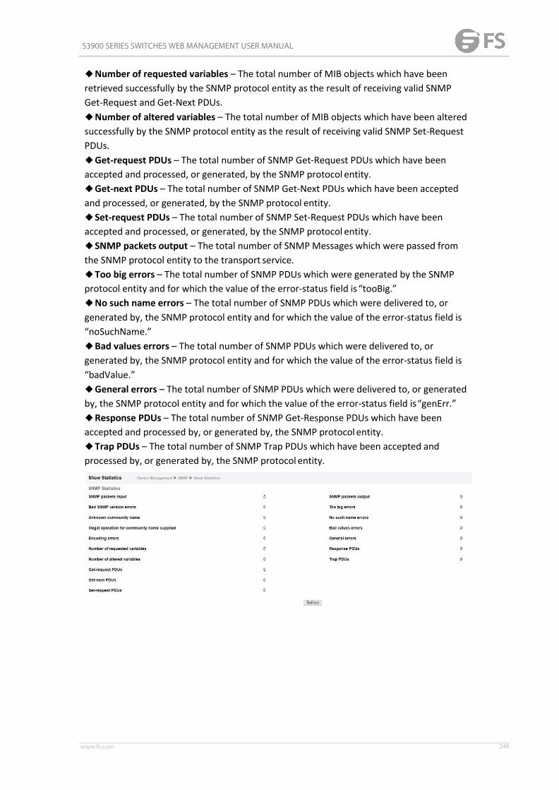
S3900 SERIES SWITCHES WEB MANAGEMENT USER MANUAL
www.fs.com 249
◆Number of requested variables – The total number of MIB objects which have beenretrieved successfully by the SNMP protocol entity as the result of receiving valid SNMPGet-Request and Get-Next PDUs.◆Number of altered variables – The total number of MIB objects which have been alteredsuccessfully by the SNMP protocol entity as the result of receiving valid SNMP Set-RequestPDUs.◆Get-request PDUs – The total number of SNMP Get-Request PDUs which have beenaccepted and processed, or generated, by the SNMP protocol entity.◆Get-next PDUs – The total number of SNMP Get-Next PDUs which have been acceptedand processed, or generated, by the SNMP protocol entity.◆Set-request PDUs – The total number of SNMP Set-Request PDUs which have beenaccepted and processed, or generated, by the SNMP protocol entity.◆SNMP packets output – The total number of SNMPMessages which were passed fromthe SNMP protocol entity to the transport service.◆Too big errors – The total number of SNMP PDUs which were generated by the SNMPprotocol entity and for which the value of the error-status field is “tooBig.”◆No such name errors – The total number of SNMP PDUs which were delivered to, orgenerated by, the SNMP protocol entity and for which the value of the error-status field is“noSuchName.”◆Bad values errors – The total number of SNMP PDUs which were delivered to, orgenerated by, the SNMP protocol entity and for which the value of the error-status field is“badValue.”◆General errors – The total number of SNMP PDUs which were delivered to, or generatedby, the SNMP protocol entity and for which the value of the error-status field is“genErr.”◆Response PDUs – The total number of SNMP Get-Response PDUs which have beenaccepted and processed by, or generated by, the SNMP protocol entity.◆Trap PDUs – The total number of SNMP Trap PDUs which have been accepted andprocessed by, or generated by, the SNMP protocol entity.

S3900 SERIES SWITCHES WEB MANAGEMENT USER MANUAL
www.fs.com 250
RMON
Global Management
Device Management > RMON > Global Management (Alarm) page is used to define specificcriteria that will generate response events. Alarms can be set to test data over any specifiedtime interval, and can monitor absolute or changing values (such as a statistical counterreaching a specific value, or a statistic changing by a certain amount over the set interval).Alarms can be set to respond to rising or falling thresholds. (However, note that after analarm is triggered it will not be triggered again until the statistical value crosses the oppositebounding threshold and then back across the trigger threshold.COMMAND USAGE◆ If an alarm is already defined for an index, the entry must be deleted before any changescan be made.PARAMETERSThese parameters are displayed:◆ Index – Index to this entry. (Range: 1-65535)◆Variable – The object identifier of the MIB variable to be sampled. Only variables of thetype etherStatsEntry.n.n may be sampled. Note that etherStatsEntry.n uniquely defines theMIB variable, and etherStatsEntry.n.n defines the MIB variable, plus the etherStatsIndex. Forexample, 1.3.6.1.2.1.16.1.1.1.6.1 denotes etherStatsBroadcastPkts, plus the etherStatsIndexof 1.◆ Interval – The polling interval. (Range: 1-31622400 seconds)◆Sample Type – Tests for absolute or relative changes in the specifiedvariable.■Absolute – The variable is compared directly to the thresholds at the end of the samplingperiod.■Delta – The last sample is subtracted from the current value and the difference is thencompared to the thresholds.◆Rising Threshold – If the current value is greater than or equal to the rising threshold, andthe last sample value was less than this threshold, then an alarm will be generated. After arising event has been generated, another such event will not be generated until the sampledvalue has fallen below the rising threshold, reaches the falling threshold, and again movesback up to the rising threshold. (Range: 0-2147483647)◆Rising Event Index – The index of the event to use if an alarm is triggered by monitoredvariables reaching or crossing above the rising threshold. If there is no corresponding entryin the event control table, then no event will be generated. (Range:0-65535)◆Falling Threshold – If the current value is less than or equal to the falling threshold, andthe last sample value was greater than this threshold, then an alarm will be generated. Aftera falling event has been generated, another such event will not be generated until thesampled value has risen above the falling threshold, reaches the rising threshold, and againmoves back down to the failing threshold. (Range: 0-2147483647)◆Falling Event Index – The index of the event to use if an alarm is triggered by monitoredvariables reaching or crossing below the falling threshold. If there is nocorresponding entry

S3900 SERIES SWITCHES WEB MANAGEMENT USER MANUAL
www.fs.com 251
in the event control table, then no event will be generated. (Range: 0-65535)◆Owner – Name of the person who created this entry. (Range: 1-127 characters)
Device Management > RMON > Global Management (Event) page is used to set the action totake when an alarm is triggered. The response can include logging the alarm or sending amessage to a trap manager. Alarms and corresponding events provide a way of immediatelyresponding to critical network problems.COMMAND USAGE◆ If an alarm is already defined for an index, the entry must be deleted before any changescan be made.◆One default event is configured as follows:event Index = 1Description: RMON_TRAP_LOGEvent type: log & trapEvent community name is publicOwner is RMON_SNMPPARAMETERSThese parameters are displayed:◆ Index – Index to this entry. (Range: 1-65535)◆Type – Specifies the type of event to initiate:■None – No event is generated.■Log – Generates an RMON log entry when the event is triggered. Log messages areprocessed based on the current configuration settings for event logging.■Trap – Sends a trap message to all configured trapmanagers.■Log and Trap – Logs the event and sends a trapmessage.

S3900 SERIES SWITCHES WEB MANAGEMENT USER MANUAL
www.fs.com 252
◆Community – A password-like community string sent with the trap operation to SNMP v1and v2c hosts. Although the community string can be set on this configuration page, it isrecommended that it be defined on the SNMP trap configuration page prior to configuring ithere. (Range: 1-127 characters)◆Description – A comment that describes this event. (Range: 1-127characters)◆Owner – Name of the person who created this entry. (Range: 1-127 characters)
Interface Management
Device Management > RMON > Interface Management (History) page is used to collectstatistics on a physical interface to monitor network utilization, packet types, and errors. Ahistorical record of activity can be used to track down intermittent problems. The record canbe used to establish normal baseline activity, which may reveal problems associated withhigh traffic levels, broadcast storms, or other unusual events. It can also be used to predictnetwork growth and plan for expansion before your network becomes too overloaded.COMMAND USAGE◆Each index number equates to a port on the switch.◆ If history collection is already enabled on an interface, the entry must be deleted beforeany changes can be made.◆The information collected for each sample includes: input octets, packets, broadcastpackets, multicast packets, undersize packets, oversize packets, fragments, jabbers, CRCalignment errors, collisions, drop events, and network utilization. For a description of thestatistics displayed on the Show Details page, refer to "Showing Portor Trunk Statistics" .◆The switch reserves two index entries for each port. If a default index entry is re-assignedto another port using the Add page, this index will not appear in the Show nor Show Detailspage for the port to which is normally assigned. For example, if control entry 15 is assignedto port 5, this index entry will be removed from the Show and Show Details page for port 8.PARAMETERSThese parameters are displayed:◆Port – The port number on the switch.◆ Index - Index to this entry. (Range: 1-65535)◆ Interval - The polling interval. (Range: 1-3600 seconds; Default: 1800 seconds)

S3900 SERIES SWITCHES WEB MANAGEMENT USER MANUAL
www.fs.com 253
◆Buckets - The number of buckets requested for this entry. (Range: 1-65536; Default: 50)The number of buckets granted are displayed on the Showpage.◆Owner - Name of the person who created this entry. (Range: 1-127characters)
Device Management > RMON > Interface Management (Statistics) page is used to collectstatistics on a port, which can subsequently be used to monitor the network for commonerrors and overall traffic rates.COMMAND USAGE◆ If statistics collection is already enabled on an interface, the entry must be deleted beforeany changes can be made.◆The information collected for each entry includes: input octets, packets, broadcastpackets, multicast packets, undersize packets, oversize packets, CRC alignment errors,jabbers, fragments, collisions, drop events, and frames of various sizes.PARAMETERSThese parameters are displayed:◆Port – The port number on the switch.◆ Index - Index to this entry. (Range: 1-65535)◆Owner - Name of the person who created this entry. (Range: 1-127characters)

S3900 SERIES SWITCHES WEB MANAGEMENT USER MANUAL
www.fs.com 254
Show Interface Details
Device Management > RMON > Show Interface Details page is used to display interfacedetails of RMON collects.
Cluster
Clustering is a method of grouping switches together to enable centralized managementthrough a single unit. Switches that support clustering can be grouped together regardless ofphysical location or switch type, as long as they are connected to the same local network.
Configure Global
The Device Management > Cluster > Configure Global page is used to create a switch cluster.COMMAND USAGEFirst be sure that clustering is enabled on the switch (the default is disabled), then set theswitch as a Cluster Commander. Set a Cluster IP Pool that does not conflict with the networkIP subnet. Cluster IP addresses are assigned to switches when they become Members andare used for communication between Member switches and the Commander.

S3900 SERIES SWITCHES WEB MANAGEMENT USER MANUAL
www.fs.com 255
PARAMETERSThese parameters are displayed:◆Cluster Status – Enables or disables clustering on the switch. (Default:Disabled)◆Commander Status – Enables or disables the switch as a cluster Commander. (Default:Disabled)◆ IP Pool – An “internal” IP address pool that is used to assign IP addresses to Memberswitches in the cluster. Internal cluster IP addresses are in the form 10.x.x.member-ID. Onlythe base IP address of the pool needs to be set since Member IDs can only be between 1and36. Note that you cannot change the cluster IP pool when the switch is currently inCommander mode. Commander mode must first be disabled. (Default: 10.254.254.1)◆Role – Indicates the current role of the switch in the cluster; either Commander, Member,or Candidate. (Default: Candidate)◆Number of Members – The current number of Member switches in the cluster.◆Number of Candidates – The current number of Candidate switches discovered in thenetwork that are available to becomeMembers.
Cluster Member
The Device Management > Cluster > Cluster Member page is used to addCandidate switches to the cluster as Members.PARAMETERSThese parameters are displayed:◆Member ID – Specify a Member ID number for the selected Candidate switch. (Range:1-36)◆MAC Address – Select a discovered switch MAC address from the Candidate Table, orenter a specific MAC address of a knownswitch.

S3900 SERIES SWITCHES WEB MANAGEMENT USER MANUAL
www.fs.com 256
Show Candidate
The Device Management > Cluster > Show Candidate page is used to show Candidate.
DNS
DNS service on this switch allows host names to be mapped to IP addresses using static tableentries or by redirection to other name servers on the network. When a client devicedesignates this switch as a DNS server, the client will attempt to resolve host names into IPaddresses by forwarding DNS queries to the switch, and waiting for a response. You canmanually configure entries in the DNS table used for mapping domain names to IP addresses,configure default domain names, or specify one or more name servers to use for domainname to address translation.
Configure Global
Device Management > DNS > Configure Global page is used to enable domain lookup and setthe default domain name.COMMAND USAGE◆To enable DNS service on this switch, enable domain lookup status, and configure one ormore name servers .PARAMETERSThese parameters are displayed:

S3900 SERIES SWITCHES WEB MANAGEMENT USER MANUAL
www.fs.com 257
◆Domain Lookup – Enables DNS host name-to-address translation. (Default:Disabled)◆Default Domain Name – Defines the default domain name appended to incomplete hostnames. Do not include the initial dot that separates the host name from the domain name.(Range: 1-127 alphanumeric characters)
Domain Names
Device Management > DNS > Domain Names page is used to configure a list of name serversto be tried in sequential order.COMMAND USAGE◆To enable DNS service on this switch, configure one or more name servers, and enabledomain lookup status.◆When more than one name server is specified, the servers are queried in the specifiedsequence until a response is received, or the end of the list is reached with noresponse.◆ If all name servers are deleted, DNS will automatically be disabled. This is done bydisabling the domain lookup status.PARAMETERSThese parameters are displayed:Name Server IP Address – Specifies the IPv4 or IPv6 address of a domain name server to usefor name-to-address resolution. Up to six IP addresses can be added to the name server list.
Name Servers
Device Management > DNS > Name Servers is used page to configure a list of name serversto be tried in sequential order.COMMAND USAGE◆To enable DNS service on this switch, configure one or more name servers, and enabledomain lookup status.◆When more than one name server is specified, the servers are queried in thespecified

S3900 SERIES SWITCHES WEB MANAGEMENT USER MANUAL
www.fs.com 258
sequence until a response is received, or the end of the list is reached with no response.◆ If all name servers are deleted, DNS will automatically be disabled. This is done bydisabling the domain lookup status.PARAMETERSThese parameters are displayed:Name Server IP Address – Specifies the IPv4 or IPv6 address of a domain name server to usefor name-to-address resolution. Up to six IP addresses can be added to the name server list.
Static Host
Device Management > DNS > Static Host page is used to manually configure static entries inthe DNS table that are used to map domain names to IP addresses.COMMAND USAGE◆Static entries may be used for local devices connected directly to the attached network, orfor commonly used resources located elsewhere on thenetwork.PARAMETERSThese parameters are displayed:◆Host Name – Name of a host device that is mapped to one or more IP addresses. (Range:1-127 characters)◆ IP Address – Internet address(es) associated with a hostname.

S3900 SERIES SWITCHES WEB MANAGEMENT USER MANUAL
www.fs.com 259
Cache
Device Management > DNS > Cache page is used to display entries in the DNS cache thathave been learned via the designated name servers.COMMAND USAGE◆Servers or other network devices may support one or more connections via multiple IPaddresses. If more than one IP address is associated with a host name via informationreturned from a name server, a DNS client can try each address in succession, until itestablishes a connection with the target device.PARAMETERSThese parameters are displayed:◆No. – The entry number for each resource record.◆Flag – The flag is always “4” indicating a cache entry and thereforeunreliable.◆Type – This field includes CNAME which specifies the host address for the owner, andALIAS which specifies an alias.◆ IP – The IP address associated with this record.◆TTL – The time to live reported by the nameserver.◆Host – The host name associated with this record.
DHCP
Dynamic Host Configuration Protocol (DHCP) can dynamically allocate an IP address andother configuration information to network clients when they boot up. If a subnet does notalready include a BOOTP or DHCP server, you can relay DHCP client requests to a DHCPserver on another subnet, or configure the DHCP server on this switch to support thatsubnet. When configuring the DHCP server on this switch, you can configure an address poolfor each unique IP interface, or manually assign a static IP address to clients based on theirhardware address or client identifier. The DHCP server can provide the host’s IP address,domain name, gateway router and DNS server, information about the host’s boot imageincluding the TFTP server to access for download and the name of the boot file, orboot information for NetBIOS Windows Internet Naming Service (WINS).
Client
Device Management > DHCP > Client page is used to specify the DHCP client identifier for aVLAN interface.COMMAND USAGE

S3900 SERIES SWITCHES WEB MANAGEMENT USER MANUAL
www.fs.com 260
◆The class identifier is used identify the vendor class and configuration of the switch to theDHCP server, which then uses this information to decide on how to service the client or thetype of information to return.◆The general framework for this DHCP option is set out in RFC 2132 (Option 60). Thisinformation is used to convey configuration settings or other identification informationabout a client, but the specific string to use should be supplied by your service provider ornetwork administrator.PARAMETERSThese parameters are displayed in the web interface:◆VLAN – ID of configured VLAN.◆Vendor Class ID – The following options are supported when the check box is marked toenable this feature:■Default – The default string is ECS4510-28T.■Text – A text string. (Range: 1-32 characters)■Hex – A hexadecimal value. (Range: 1-64 characters)
Relay
Device Management > DHCP > Relay page is used to configure DHCP relay service forattached host devices. If DHCP relay is enabled, and this switch sees a DHCP requestbroadcast, it inserts its own IP address into the request so that the DHCP server will knowthe subnet where the client is located. Then, the switch forwards the packet to the DHCPserver. When the server receives the DHCP request, it allocates a free IP address for theDHCP client from its defined scope for the DHCP client’s subnet, and sends a DHCP responseback to the DHCP relay agent (i.e., this switch). This switch then passes the DHCP responsereceived from the server to the client.
COMMAND USAGE

S3900 SERIES SWITCHES WEB MANAGEMENT USER MANUAL
www.fs.com 261
◆ You must specify the IP address for at least one active DHCP server. Otherwise, theswitch’s DHCP relay agent will not be able to forward client requests to a DHCP server. Up tofive DHCP servers can be specified in order of preference. If any of the specified DHCP serveraddresses are not located in the same network segment with this switch, specify the defaultrouter through which this switch can reach other IP subnetworks(see “Configuring StaticRoutes”).◆ DHCP relay configuration will be disabled if an active DHCP server is detected on thesame network segment.PARAMETERSThese parameters are displayed:◆ VLAN ID – ID of configured VLAN.◆ Server IP Address – Addresses of DHCP servers or relay servers to be used by the switch’sDHCP relay agent in order of preference.◆ Restart DHCP Relay – Use this button to re-initialize DHCP relay service.
Relay Option82
Device Management > DHCP > Relay Option82 page is used to configure DHCP relay servicefor attached host devices, including DHCP option 82 information. DHCP provides an optionfor sending information about its DHCP clients to the DHCP server(specifically, the interfaceon the relay server through which the DHCP client request was received). Also known asDHCP Relay Option 82, it allows compatible DHCP servers to use this information whenassigning IP addresses, or to set other services or policies for clients. Option 82 informationcontains information which can identify both the relay agent and the interface throughwhich the DHCP request was received:◆ The DHCP Relay Information Option Remote ID (RID) is the access node identifier – astring used to identify the switch to the DHCP server.◆ The DHCP Relay Information Option Fields are the Option 82 circuit identification fields(CID – including VLAN ID, stack unit, and port). These fields identify the requesting device byindicating the interface through which the relay agent received the request. If DHCP relay isenabled, and this switch sees a DHCP client request, it inserts its own IP address into therequest so that the DHCP server will know the subnet where the client is located. Dependingon the selected frame format set for the remote-id, this information may specify the MACaddress, IP address, or an arbitrary string for the requesting device (that is, the relay agent inthis context). By default, the relay agent also fills in the Option 82 circuit-id field withinformation indicating the local interface over which the switch received the DHCP clientrequest, including the VLAN ID, stack unit, and port. This allows DHCP client-server exchange

S3900 SERIES SWITCHES WEB MANAGEMENT USER MANUAL
www.fs.com 262
messages to be forwarded between the server and client without having to flood them ontothe entire VLAN. The switch then forwards the packet to the DHCP server. When the serverreceives the DHCP request, it allocates a free IP address for the DHCP client from its definedscope for the DHCP client’s subnet, and sends a DHCP response back to the DHCP relayagent (i.e., this switch). This switch then passes the DHCP response received from the serverto the client.COMMAND USAGE◆ You must specify the IP address for at least one active DHCP server. Otherwise, theswitch’s DHCP relay agent will not be able to forward client requests to a DHCP server. Up tofive DHCP servers can be specified in order of preference. If any of the specified DHCP serveraddresses are not located in the same network segment with this switch, specify the defaultrouter through which this switch can reach other IP subnetworks.◆ DHCP Snooping Information Option 82 and DHCP Relay Information Option 82 cannotboth be enabled at the same time.◆ DHCP request packets received by the switch are handled as follows:■ If a DHCP relay server has been set on the switch, when the switch receives a DHCPrequest packet without option 82 information from the management VLAN oranon-management VLAN, it will add option 82 relay information and the relay agent’s addressto the DHCP request packet, and then unicast it to the DHCP server.■ If a DHCP relay server has been set on the switch, when the switch receives a DHCPrequest packet with option 82 information from the management VLAN oranon-management VLAN, it will process it according to the configured relay informationoption policy:■ If the policy is “replace,” the DHCP request packet’s option 82 content (the RID and CIDsub-option) is replaced with information provided by the switch. The relay agent address isinserted into the DHCP request packet, and the switch then unicasts this packet to the DHCPserver.■ If the policy is “keep,” the DHCP request packet's option 82 content will be retained. Therelay agent address is inserted into the DHCP request packet, and the switch then unicaststhis packet to the DHCP server.■ If the policy is “drop,” the original DHCP request packet is flooded onto the VLAN whichreceived the packet but is not relayed.◆ DHCP reply packets received by the relay agent are handled as follows: When the relayagent receives a DHCP reply packet with Option 82 information over the management VLAN,it first ensures that the packet is destined for it.■ If the RID in the DHCP reply packet is not identical with that configured on the switch, theoption 82 information is retained, and the packet is flooded onto the VLAN through which itwas received.■ If the RID in the DHCP reply packet matches that configured on the switch, it thenremoves the Option 82 information from the packet, and sends it on asfollows:■ If the DHCP packet’s broadcast flag is on, the switch uses the circuit-id informationcontained in the option 82 information fields to identify the VLAN connected to therequesting client and then broadcasts the DHCP reply packet to thisVLAN.■ If the DHCP packet’s broadcast flag is off, the switch uses the circuit-id informationin

S3900 SERIES SWITCHES WEB MANAGEMENT USER MANUAL
www.fs.com 263
option 82 fields to identify the interface connected to the requesting client and unicasts thereply packet to the client.◆ DHCP packets are flooded onto the VLAN which received them if DHCP relay service isenabled on the switch and any of the following situations apply:■ There is no DHCP relay server set on the switch, when the switch receives a DHCPpacket.■ A DHCP relay server has been set on the switch, when the switch receives a DHCP requestpacket with a non-zero relay agent address field (that is not the address of thisswitch).■ A DHCP relay server has been set on the switch, when the switch receives DHCP replypacket without option 82 information from the managementVLAN.■ The reply packet contains a valid relay agent address field (that is not the address of thisswitch), or receives a reply packet with a zero relay agent address through the managementVLAN.■ A DHCP relay server has been set on the switch, and the switch receives a reply packet ona non-management VLAN.◆ DHCP relay configuration will not be active if an active DHCP server is detected on thesame network segment.PARAMETERSThese parameters are displayed:◆ Insertion of Relay Information – Enable DHCP Option 82 information relay. (Default:Disabled)◆ DHCP Option Policy – Specifies how to handle client requests which already containDHCP Option 82 information:■ Drop - Floods the original request packet onto the VLAN that received it instead ofrelaying it. (This is the default.)■ Keep - Retains the Option 82 information in the client request, inserts the relay agent’saddress, and unicasts the packet to the DHCPserver.■ Replace - Replaces the Option 82 information circuit-id and remote-id fields in the client’srequest with information provided by the relay agent itself, inserts the relay agent’s address,and unicasts the packet to the DHCP server.◆ DHCP Sub-option Format – Specifies whether or not to use the sub-type and sub-lengthfields in the circuit-ID (CID) and remote-ID (RID) in Option 82 information. (Default: Included)◆ Server IP Address – Addresses of DHCP servers or relay servers to be used by the switch’sDHCP relay agent in order of preference.
Dynamic Provision
Device Management > DHCP > Dynamic Provision is used to enable dynamic provisioning viaDHCP.

S3900 SERIES SWITCHES WEB MANAGEMENT USER MANUAL
www.fs.com 264
COMMAND USAGEDHCPD is the daemon used by Linux to dynamically configure TCP/IP information for clientsystems. To support DHCP option 66/67, you have to add corresponding statements to theconfiguration file of DHCPD. Some alternative commands which can be added to the DHCPDto complete the dynamic provisioning process are also described under the ip dhcp dynamicprovision command in the CLI Reference Guide. By default, the parameters for DHCP option66/67 are not carried by the reply sent from the DHCP server. To ask for a DHCP reply withoption 66/67, the client can inform the server that it is interested in option 66/67 by sendinga DHCP request that includes a 'parameter request list' option. Besides this, the client canalso send a DHCP request that includes a 'vendor class identifier' option to the server so thatthe DHCP server can identify the device, and determine what information should be given torequesting device.PARAMETERSThese parameters are displayed:◆ Dynamic Provision via DHCP Status – Enables dynamic provisioning via DHCP. (Default:Disabled)
OAM
The switch provides OAM (Operation, Administration, and Maintenance) remotemanagement tools required to monitor and maintain the links to subscriber CPEs (CustomerPremise Equipment). This section describes functions including enabling OAM for selectedports, loopback testing, and displaying remote device information.
Interface
The Device Management > OAM > Interface page is used to enable OAM functionality on theselected port. Not all CPEs support operation and maintenance functions, so OAM istherefore disabled by default. If a CPE supports OAM, this functionality must first be enabledon the connected port to gain access to the configuration functions provided under the OAMmenu.PARAMETERSThese parameters are displayed:◆Port – Port identifier. (Range: 1-28)◆Admin Status – Enables or disables OAM functions. (Default: Disabled)◆Operation State – Shows the operational state between the local and remote OAMdevices. This value is always “disabled” if OAM is disabled on the local interface.

S3900 SERIES SWITCHES WEB MANAGEMENT USER MANUAL
www.fs.com 265
OAMOperation StateState Description
DisabledOAM is disabled on this interface via the OAM AdminStatus.
Link FaultThe link has detected a fault or the interface is notoperational.
Passive WaitThis value is returned only by OAM entities in passivemode and indicates the OAM entity is waiting to see if thepeer device is OAM capable.
Active Send Local
This value is used by active mode devices and indicatesthe OAM entity is actively trying to discover whether thepeer has OAM capability but has not yet made thatdetermination.
Send Local AndRemote
The local OAM entity has discovered the peer but has notyet accepted or rejected the configuration of the peer.
Send Local AndRemote OK
OAM peering is allowed by the local device.
OAM Peering LocallyRejected
The local OAM entity rejects the peering.
OAM PeeringRemotely Rejected
The remote OAM entity rejects the peering.
OperationalWhen the local OAM entity learns that both it and theremote OAM entity have accepted the peering, the statemoves to this state.
Non Oper HalfDuplex
This state is returned whenever Ethernet OAM is enabledbut the interface is in half-duplex operation.
◆Mode – Sets the OAM operation mode. (Default: Active)■Active – All OAM functions are enabled.■Passive – All OAM functions are enabled, except for OAM discovery, sending variablerequest OAMPDUs, and sending loopback control OAMPDUs.◆Critical Link Event – Controls reporting of critical link events to its OAMpeer.■Dying Gasp – If an unrecoverable condition occurs, the local OAM entity (i.e., this switch)indicates this by immediately sending a trap message. (Default: Enabled) Dying gasp eventsare caused by an unrecoverable failure, such as a power failure or device reset.■Critical Event – If a critical event occurs, the local OAM entity indicates this to its peer bysetting the appropriate flag in the next OAMPDU to be sent and stores this information in itsOAM event log. (Default: Enabled) Critical events include various failures, such as abnormalvoltage fluctuations, out-of-range temperature detected, fan failure, CRC error in flashmemory, insufficient memory, or other hardware faults.◆Errored Frame – Controls reporting of errored frame link events. An errored frame is aframe in which one or more bits are errored. An errored frame link event occurs if thethreshold is reached or exceeded within the specified period. If reporting is enabled and anerrored frame link event occurs, the local OAM entity (this switch) sends an EventNotification OAMPDU to the remote OAM entity. The Errored Frame Event TLV includesthe

S3900 SERIES SWITCHES WEB MANAGEMENT USER MANUAL
www.fs.com 266
number of errored frames detected during the specified period.■Status – Enables reporting of errored frame link events. (Default: Enabled)■Window Size – The period of time in which to check the reporting threshold for erroredframe link events. (Range: 10-65535 in units of 10 milliseconds; Default: 10 units of 10milliseconds, or the equivalent of 1 second)■Threshold Count – The threshold for errored frame link events. (Range: 1-65535; Default:1)
Counters
The Device Management > OAM > Counters page is used to display statistics for the varioustypes of OAMmessages passed across each port.PARAMETERSThese parameters are displayed:◆Port – Port identifier. (Range: 1-28)◆Clear – Clears statistical counters for the selectedports.◆OAMPDU – Message types transmitted and received by the OAM protocol, includingInformation OAMPDUs, unique Event OAMPDUs, Loopback Control OAMPDUs, andOrganization Specific OAMPDUs.
Event Log
The Device Management > OAM > Event Log page is used to display link events for theselected port.COMMAND USAGE◆When a link event occurs, no matter whether the location is local or remote, thisinformation is entered in OAM event log.◆When the log system becomes full, older events are automatically deleted to make roomfor new entries.

S3900 SERIES SWITCHES WEB MANAGEMENT USER MANUAL
www.fs.com 267
◆The time of locally generated events can be accurately retrieved from the sysUpTimevariable. For remotely generated events, the time of an event is indicated by the receptionof an Event Notification OAMPDU from the peer.WEB INTERFACETo display link events for the selected port:1. Click Device Management, OAM, Event Log.2. Select a port from the drop-down list.
Remote Interface
The Device Management > OAM > Remote Interface page is used to display informationabout attached OAM-enabled devices.PARAMETERSThese parameters are displayed:◆Port – Port identifier. (Range: 1-28)◆MAC Address – MAC address of the OAMpeer.◆OUI – Organizational Unit Identifier of the OAMpeer.◆Remote Loopback – Shows if remote loopback is supported by the OAMpeer.◆Unidirectional Function – Shows if this function is supported by the OAMpeer.If supported, this indicates that the OAM entity supports the transmission of OAMPDUs onlinks that are operating in unidirectional mode (where traffic flows in one direction only).Some newer physical layer devices support the optional ability to encode and transmit datawhile one direction of the link is non-operational. This function allows OAM remote faultindication during fault conditions. This switch does not support the unidirectional function,but can parse error messages sent from a peer with unidirectional capability.◆Link Monitor – Shows if the OAM entity can send and receive Event NotificationOAMPDUs.◆MIB Variable Retrieval – Shows if the OAM entity can send and receive Variable Requestand Response OAMPDUs.

S3900 SERIES SWITCHES WEB MANAGEMENT USER MANUAL
www.fs.com 268
Show Loopback Result
Use the Device Management > OAM > Show Loopback Result page is used to display theresults of remote loop back testing for each port for which this information is available.PARAMETERSThese parameters are displayed:◆Port – Port identifier. (Range: 1-12/26)◆Packets Transmitted – The number of loop back frames transmitted during the last loopback test on this interface.◆Packets Received – The number of loop back frames received during the last loop backtest on this interface.◆Loss Rate – The percentage of packets transmitted for which there was noresponse.
Loopback Test
The Device Management > OAM > Loopback Test page is used to initiate a loop back test tothe peer device attached to the selected port.COMMAND USAGE• You can use this command to perform an OAM remote loop back test on the specified port.The port that you specify to run this test must be connected to a peer OAM device capableof entering into OAM remote loop back mode.◆During a remote loop back test, the remote OAM entity loops back every frame except forOAMPDUs and pause frames.◆OAM remote loopback can be used for fault localization and link performance testing.Statistics from both the local and remote DTE can be queried and compared at any timeduring loop back testing.◆To perform a loopback test, first enable Remote Loop Back Mode, click Test, and then clickEnd. The number of packets transmitted and received will be displayed.PARAMETERSThese parameters are displayed:Loopback Mode of Remote Device

S3900 SERIES SWITCHES WEB MANAGEMENT USER MANUAL
www.fs.com 269
◆Port – Port identifier. (Range: 1-28)◆Loopback Mode – Shows if loop back mode is enabled on the peer. This attribute must beenabled before starting the loopback test.◆Loopback Status – Shows if loopback testing is currently running.Loopback Test Parameters◆Packets Number – Number of packets to send. (Range: 1-99999999; Default: 10000)◆Packet Size – Size of packets to send. (Range: 64-1518 bytes; Default: 64bytes)◆Test – Starts the loop back test.◆End – Stops the loop back test.Loop Back Status of Remote Device◆Result – Shows the loop back status on the peer. The loop back states shown in this fieldare described below.OAMOperation State
State DescriptionNo Loopback Operating in normal mode with no loopback in progress.
Initiating Loopback
The local OAM entity is starting the loopback process withits peer. It has yet to receive any acknowledgement thatthe remoteOAMentity has received its loopback commandrequest.
Remote LoopbackThe local OAM client knows that the remote OAM entity isin loopback mode.
TerminatingLoopback
The local OAM client is in the process of terminating theremote loopback.
Local LoopbackThe remote OAM client has put the local OAM entity inloopback mode.
UnknownThis status may be returned if the OAM loopback is in atransition state but should not persist.
■Packets Transmitted – The number of loop back frames transmitted during the lastloopback test on this interface.■Packets Received – The number of loop back frames received during the last loopbacktest on this interface.■Loss Rate – The percentage of packets for which there was no response.

S3900 SERIES SWITCHES WEB MANAGEMENT USER MANUAL
www.fs.com 270
CFM
Connectivity Fault Management (CFM) is an OAM protocol that includes proactiveconnectivity monitoring using continuity check messages, fault verification through loopback messages, and fault isolation by examining end-to-end connections between provideredge devices or between customer edge devices. CFM is implemented as a service levelprotocol based on service instances which encompass only that portion of the metropolitanarea network supporting a specific customer. CFM can also provide controlled managementaccess to a hierarchy of maintenance domains (such as the customer, service provider, andequipment operator). This switch supports functions for defining the CFM structure,including domains, maintenance associations, and maintenance access points. It alsosupports fault detection through continuity check messages for all known maintenancepoints, and cross-check messages which are used to verify a static list of remotemaintenance points located on other devices (in the same maintenance association) againstthose found through continuity check messages. Fault verification is supported using loopback messages, and fault isolation with link trace messages. Fault notification is alsoprovided by SNMP alarms which are automatically generated by maintenance points whenconnectivity faults or configuration errors are detected in the local maintenance domain.Key Components of CFMCFM provides restricted management access to each Service Instance using a structuredconceptual network based on these components:◆A Maintenance Domain defines a part of the network controlled by a single operator, andsupports management access to the domain through Domain Service Access Points (DSAPs)configured on the domain boundary, as well as connectivity testing between theseDSAPs.◆A Maintenance Association (MA) contains the DSAPs for an individual Service Instance.DSAPs are the primary maintenance points used to monitor connectivity across amaintenance domain, and are the entry points to the paths which interconnect the accesspoints allocated to a service instance.◆A Maintenance Level allows maintenance domains to be nested in a hierarchical fashion,providing access to the specific network portions required by each operator. Domains atlower levels may be either hidden or exposed to operators managing domains at a higherlevel, allowing either course or fine fault resolution.◆Maintenance End Points (MEPs) which provide full CFM access to a Service Instance (i.e., aspecific MA), and Maintenance Intermediate Points (MIPs) which are passive entities thatmerely validate received CFM messages, or respond to link trace and loop back requests.MIPs are the interconnection points that make up all possible paths between the DSAPswithin an MA, and may also include interconnection points in lower-level domains if exposedby CFM settings. The following figure shows a single Maintenance Domain, with DSAPslocated on the domain boundary, and Internal Service Access Points (ISAPs) inside thedomain through which frames may pass between theDSAPs.

S3900 SERIES SWITCHES WEB MANAGEMENT USER MANUAL
www.fs.com 271
The figure below shows four maintenance associations contained within a hierarchicalstructure of maintenance domains. At the innermost level, there are two operator domainswhich include access points marked “O1” and “O2” respectively. The users of these domainscan see their respective MEPs as well as all the MIPs within their domains. There is a serviceprovider domain at the second level in the hierarchy. From the service provider’s view, theaccess points marked “P” are visible, and all access points within the operator domains havealso been made visible as MIPs according to common practice. And finally, there is acustomer domain at the top of the hierarchy. Users at this level can only see the accesspoints marked “C” on the outer domain boundary. Again, normal practice is to hide theinternal structure of the network from outsiders to reduce security risks.
Note that the Service Instances within each domain shown above are based on a uniquemaintenance association for the specific users, distinguished by the domain name,maintenance level, maintenance association’s name, and assignedVLAN.Basic CFM OperationsCFM uses standard Ethernet frames for sending protocol messages. Both the source anddestination address for these messages are based on unicast or multicast MAC addresses,and therefore confined to a single Layer 2 CFM service VLAN. For this reason, thetransmission, forwarding, and processing of CFM frames is performed by bridges, notrouters. Bridges that do not recognize CFM messages forward them as normal data. Thereare three basic types of CFM messages, including continuity check, link trace, and loop back.Continuity check messages (CCMs) are multicast within a single Service Instance (i.e., aspecific MA), allowing MEPs to discover other MEPs within the same MA, and MIPs to
S3900 SERIES SWITCHES WEB MANAGEMENT USER MANUAL
www.fs.com 272
discover MEPs. Connectivity faults are indicated when a known MEP stops sending CCMs, ora remote MEP configured in a static list does not come up. Configuration errors, such as across-connect between different MAs, are indicated when a CCM is received with anincorrect MA identifier or maintenance level. Loop back messages are used for faultverification. These messages can be sent using the MAC address of any destination MEPwithin the same MA. If the target MEP’s identifier has been discovered through CCMmessages, then a loop back message can also be sent using the MEPs identifier. A replyindicates that the destination is reachable. Link trace messages are used for fault verification.These messages are multicast frames sent out to track the hop-by-hop path to a target MEPwithin the same MA. Responses provide information on the ingress, egress, and relay actiontaken at each hop along the path, providing vital information about connectivity problems.Responses allow the sender to discover all of the maintenance points that would betraversed by a data frame sent to the target MAC address. SNMP traps can also beconfigured to provide an automated method of fault notification. If the fault notificationgenerator detects one or more defects within the configured time period, and fault alarmsare enabled, a corresponding trap will be sent. No further fault alarms are sent until the faultnotification generator has been reset by the passage of a configured time period withoutdetecting any further faults. Upon receiving a fault alarm, you should inspect the relatedSNMP objects for the reporting MEP, diagnose the fault, correct it, and re-examine theMEP’s SNMP objects to see whether the fault notification generator has beenreset.
Configure Global
Device Management > CFM > Configure Global page is used to configure global settings forCFM, such as enabling the CFM process on the switch, setting the start-up delay forcross-check operations, configuring parameters for the link trace cache, and enabling trapsfor events discovered by continuity check messages or cross-check messages.PARAMETERSThese parameters are displayed:Global Configuration◆CFM Status – Enables CFM processing globally on the switch.(Default: Enabled)To avoid generating an excessive number of traps, the complete CFM maintenance structureand process parameters should be configured prior to enabling CFM processing globally onthe switch. Specifically, the maintenance domains, maintenance associations, andmaintenance end-points (MEPs) should be configured on each participating bridge using theConfigure MD page, Configure MA page, and the Configure MEP page.When CFM is enabled, hardware resources are allocated for CFM processing.◆MEP Cross Check Start Delay – Sets the maximum delay that a device waits for remoteMEPs to come up before starting the crosscheck operation. (Range: 1-65535 seconds;Default: 10 seconds)This parameter sets the time to wait for a remote MEP to come up, and the switch startscross-checking the list of statically configured remote MEPs in the local maintenance domainagainst the MEPs learned through continuity check messages (CCMs). The cross-check start

S3900 SERIES SWITCHES WEB MANAGEMENT USER MANUAL
www.fs.com 273
delay should be configured to a value greater than or equal to the continuity check messageinterval to avoid generating unnecessary traps.LInk Trace Cache Settings◆Link Trace Cache – Enables caching of CFM data learned through link trace messages.(Default: Enabled) A linktrace message is a multicast CFM frame initiated by a MEP, andforwarded fromMIP to MIP, with each MIP generating a linktrace reply, up to the point atwhich the linktrace message reaches its destination or can no longer be forwarded. Use thiscommand attribute to enable the link trace cache to store the results of link trace operationsinitiated on this device. Use the CFM Transmit Link Trace page to transmit a linktracemessage. Linktrace responses are returned from each MIP along the path and from thetarget MEP. Information stored in the cache includes the maintenance domain name, MAname, MEPID, sequence number, and TTL value.◆Link Trace Cache Hold Time – The hold time for CFM link trace cache entries. (Range:1-65535 minutes; Default: 100 minutes) Before setting the aging time for cache entries, thecache must first be enabled in the Linktrace Cache attribute field.◆Link Trace Cache Size – The maximum size for the link trace cache. (Range: 1-4095 entries;Default: 100 entries) If the cache reaches the maximum number of specified entries, or thesize is set to a value less than the current number of stored entries, no new entries areadded. To add additional entries, the cache size must first be increased, or purged.Continuity Check Errors◆Connectivity Check Config – Sends a trap if this device receives a continuity checkmessage (CCM) with the same maintenance end point identifier (MPID) as its own but with adifferent source MAC address, indicating that a CFM configuration errorexists.◆Connectivity Check Loop – Sends a trap if this device receives a CCM with the samesource MAC address and MPID as its own, indicating that a forwarding loopexists.◆Connectivity Check MEP Down – Sends a trap if this device loses connectivity with aremote maintenance end point (MEP), or connectivity has been restored to a remote MEPwhich has recovered from an error condition.◆Connectivity Check MEP Up – Sends a trap if a remote MEP is discovered and added tothe local database, the port state of a previously discovered remote MEP changes, or a CCMis received from a remote MEP which as an expired entry in the archived database. MEP Uptraps are suppressed when cross-checking of MEPs is enabled11 because cross-check trapsinclude more detailed status information.Cross-check Errors◆Cross Check MA Up – Sends a trap when all remote MEPs in an MA comeup.An MA Up trap is sent if cross-checking is enabled, and a CCM is received from all remoteMEPs configured in the static list for this maintenance association◆Cross Check MEP Missing – Sends a trap if the cross-check timer expires and no CCMshave been received from a remote MEP configured in the static list. A MEP Missing trap issent if cross-checking is enabled11, and no CCM is received for a remote MEP configured inthe static list12.◆Cross Check MEP Unknown – Sends a trap if an unconfigured MEP comesup.A MEP Unknown trap is sent if cross-checking is enabled11, and a CCM is received from aremote MEP that is not configured in the static list12.
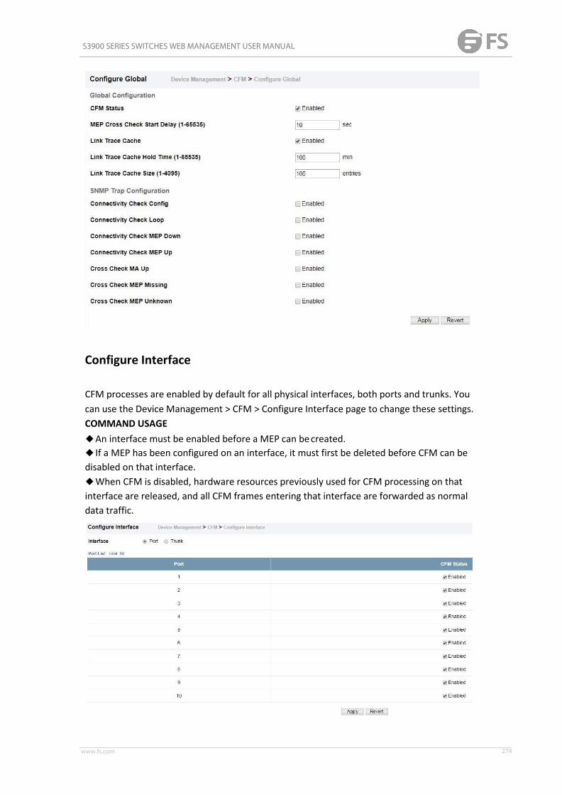
S3900 SERIES SWITCHES WEB MANAGEMENT USER MANUAL
www.fs.com 274
Configure Interface
CFM processes are enabled by default for all physical interfaces, both ports and trunks. Youcan use the Device Management > CFM > Configure Interface page to change these settings.COMMAND USAGE◆An interface must be enabled before a MEP can becreated.◆ If a MEP has been configured on an interface, it must first be deleted before CFM can bedisabled on that interface.◆When CFM is disabled, hardware resources previously used for CFM processing on thatinterface are released, and all CFM frames entering that interface are forwarded as normaldata traffic.

S3900 SERIES SWITCHES WEB MANAGEMENT USER MANUAL
www.fs.com 275
MDManagement
Device Management > CFM > MDManagement pages is used to create and configure aMaintenance Domain (MD) which defines a portion of the network for which connectivityfaults can be managed. Domain access points are set up on the boundary of a domain toprovide end-to-end connectivity fault detection, analysis, and recovery. Domains can beconfigured in a hierarchy to provide management access to the same basic networkresources for different user levels.COMMAND USAGEConfiguring General Settings◆Where domains are nested, an upper-level hierarchical domain must have a highermaintenance level than the ones it encompasses. The higher to lower level domain typescommonly include entities such as customer, service provider, andoperator.◆More than one domain can be configured at the same maintenance level, but a singledomain can only be configured with one maintenance level.◆ If MEPs or Mas are configured for a domain, they must firstbe removed before you canremove the domain. Maintenance domains are designed to provide a transparent method ofverifying and resolving connectivity problems for end-to-end connections. By default, theseconnections run between the domain service access points (DSAPs) within each MA definedfor a domain, and are manually configured. In contrast, MIPs are interconnection points thatmake up all possible paths between the DSAPs within an MA. MIPs are automaticallygenerated by the CFM protocol when the MIP Creation Type is set to “Default” or “Explicit,”and the MIP creation state machine is invoked (as defined in IEEE 802.1ag). The defaultoption allows MIPs to be created for all interconnection points within an MA, regardless ofthe domain’s level in the maintenance hierarchy (e.g., customer, provider, or operator).While the explicit option only generates MIPs within an MA if its associated domain is not atthe bottom of the maintenance hierarchy. This option is used to hide the structure ofnetwork at the lowest domain level.The diagnostic functions provided by CFM can be used to detect connectivity failuresbetween any pair of MEPs in an MA. Using MIPs allows these failures to be isolated tosmaller segments of the network. Allowing the CFM to generate MIPs exposes more of thenetwork structure to users at higher domain levels, but can speed up the process of faultdetection and recovery. This trade-off should be carefully considered when designing a CFMmaintenance structure. Also note that while MEPs are active agents which can initiateconsistency check messages (CCMs), transmit loop back or link trace messages, and maintainthe local CCM database, MIPs, on the other hand, are passive agents which can only validatereceived CFM messages, and respond to loop back and link trace messages. The MIPcreation method defined for an MA takes precedence over the method defined on the CFMDomain List.Configuring Fault Notification◆A fault alarm can generate an SNMP notification. It is issued when the MEP faultnotification generator state machine detects that the configured time period (MEP FaultNotify Alarm Time) has passed with one or more defects indicated, and fault alarmsare

S3900 SERIES SWITCHES WEB MANAGEMENT USER MANUAL
www.fs.com 276
enabled at or above the specified priority level (MEP Fault Notify Lowest Priority). The statemachine transmits no further fault alarms until it is reset by the passage of a configured timeperiod (MEP Fault Notify Reset Time) without a defect indication. The normal procedureupon receiving a fault alarm is to inspect the reporting MEP’s managed objects using anappropriate SNMP software tool, diagnose the fault, correct it, reexamine the MEP’smanaged objects to see whether the MEP fault notification generator state machine hasbeen reset, and repeat those steps until the fault is resolved.◆Only the highest priority defect currently detected is reported in the fault alarm.Priority levels include the following options:Remote MEP Priority LevelsPriority Level Level Name Description1 allDef All defects.
2 macRemErrXconDefMACstatus, DefRemoteCCM, DefErrorCCM, orDefXconCCM.
3 remErrXcon DefErrorCCM, DefXconCCM or DefRemoteCCM.
4 errXcon DefErrorCCM or DefXconCCM.5 xcon DefXconCCM
6 noXconNo defects DefXconCCM or lower are to bereported.
MEP Defect DescriptionsDefect Description
DefMACstatusEither some remote MEP is reporting its Interface Status TLV as notisUp, or all remoteMEPs are reporting a Port Status TLV that containssome value other than psUp.
DefRemoteCCM
The MEP is not receiving valid CCMs from at least one of the remoteMEPs.
DefErrorCCMThe MEP has received at least one invalid CCM whose CCM Intervalhas not yet timed out.
DefXconCCMTheMEP has received at least one CCM fromeither anotherMAID or alower MD Level whose CCM Interval has not yet timed out.
PARAMETERSThese parameters are displayed:Creating a Maintenance Domain◆MD Index – Domain index. (Range: 1-65535)◆MD Name – Maintenance domain name. (Range: 1-43 alphanumeric characters)◆MD Level – Authorized maintenance level for this domain. (Range: 0-7)◆MIP Creation Type – Specifies the CFM protocol’s creation method for maintenanceintermediate points (MIPs) in this domain:■Default – MIPs can be created for any maintenance association (MA) configured in thisdomain on any bridge port through which the MA’s VID canpass.■Explicit – MIPs can be created for any MA configured in this domain only on bridge portsthrough which the MA’s VID can pass, and only if a maintenance end point (MEP) is createdat some lower MA Level.■None – No MIP can be created for any MA configured in thisdomain.

S3900 SERIES SWITCHES WEB MANAGEMENT USER MANUAL
www.fs.com 277
MD Details
Device Management > CFM > MD Details page is used to configure details of specify MD.PARAMETERSConfiguring Detailed Settings for a Maintenance Domain◆MD Index – Domain index. (Range: 1-65535)◆MEP Archive Hold Time – The time that data from a missing MEP is retained in thecontinuity check message (CCM) database before being purged. (Range: 1-65535 minutes;Default: 100 minutes) A change to the hold time only applies to entries stored in thedatabase after this attribute is changed.◆MEP Fault Notify Lowest Priority – The lowest priority defect that is allowed to generatea fault alarm. (Range: 1-6, Default: 2)◆MEP Fault Notify Alarm Time – The time that one or more defects must be presentbefore a fault alarm is issued. (Range: 3-10 seconds; Default: 3 seconds)◆MEP Fault Notify Reset Time – The time after a fault alarm has been issued, and no defectexists, before another fault alarm can be issued. (Range: 3-10 seconds; Default: 10 seconds)Device Management > CFM > MAManagement pages is used to create and configure theMaintenance Associations (MA) which define a unique CFM service instance. Each MA canbe identified by its parent MD, the MD’s maintenance level, the VLAN assigned to the MA,and the set of maintenance end points (MEPs) assigned to it.COMMAND USAGE

S3900 SERIES SWITCHES WEB MANAGEMENT USER MANUAL
www.fs.com 278
MAManagement
Creating a Maintenance Association◆Use the Configure MA – Add screen to create an MA within the selected MD, map it to acustomer service instance (S-VLAN), and set the manner in which MIPs are created for thisservice instance. Then use the MEP List to assign domain service access points (DSAPs) tothis service instance.◆An MAmust be defined before any associated DSAPs or remote MEPs can beassigned.◆Multiple domains at the same maintenance level cannot have an MA on the sameVLAN.◆Before removing an MA, first remove the MEPs assigned to it.◆For a detailed description of the MIP types, refer to the Command Usagesection.Configuring Detailed Settings for a Maintenance Association◆CCMs are multicast periodically by a MEP in order to discover other MEPs in the same MA,and to assure connectivity to all other MEPs/MIPs in theMA.◆Each CCM received is checked to verify that the MEP identifier field sent in the messagedoes not match its own MEP ID, which would indicate a duplicate MEP or network loop. Ifthese error types are not found, the CCM is stored in the MEP’s local database until agedout.◆ If a maintenance point fails to receive three consecutive CCMs from any other MEP in thesame MA, a connectivity failure is registered.◆ If a maintenance point receives a CCM with an invalid MEPID or MA level or an MA levellower than its own, a failure is registered which indicates a configuration errororcross-connect error (i.e., overlapping MAs).◆The interval at which CCMs are issued should be configured to detect connectivityproblems in a timely manner, as dictated by the nature and size of theMA.◆The maintenance of a MIP CCM database by a MIP presents some difficulty for bridgescarrying a large number of Service Instances, and for whose MEPs are issuing CCMs at a highfrequency. For this reason, slower CCM transmission rates may have to be used.PARAMETERSThese parameters are displayed:Creating a Maintenance Association◆MD Index – Domain index. (Range: 1-65535)◆MA Index – MA identifier. (Range: 1-2147483647)◆MA Name – MA name. (Range: 1-43 alphanumeric characters) Each MA name must beunique within the CFM domain.◆Primary VLAN – Service VLAN ID. (Range: 1-4093) This is the VLAN through which all CFMfunctions are executed for thisMA.◆MIP Creation Type – Specifies the CFM protocol’s creation method for maintenanceintermediate points (MIPs) in thisMA:■Default – MIPs can be created for this MA on any bridge port through which the MA’s VIDcan pass.■Explicit – MIPs can be created for this MA only on bridge ports through which the MA’sVID can pass, and only if a maintenance end point (MEP) is created at some lower MALevel.

S3900 SERIES SWITCHES WEB MANAGEMENT USER MANUAL
www.fs.com 279
■None – No MIP can be created for thisMA.
MA Details
Device Management > CFM > MA Details page is used to configure details of specify MA.PARAMETERSConfiguring Detailed Settings for a Maintenance Association◆MD Index – Domain index. (Range: 1-65535)◆MA Index – MA identifier. (Range: 1-2147483647)◆MA Name Format – Specifies the name format for the maintenance association as IEEE802.1ag character based, or ITU-T SG13/SG15 Y.1731 defined ICC-basedformat.■Character String – IEEE 802.1ag defined character string format. This is an IETF RFC 2579DisplayString.■ICC Based – ITU-T SG13/SG15 Y.1731 defined ICC based format.◆ Interval Level – The delay between sending CCMs. The setting for this parameter isexpressed as levels 4 through 7, which in turn map to specific intervals of time. (Options: 4 -100 ms, 5 - 1 sec, 6 - 10 sec, 7 - 60sec)◆Connectivity Check – Enables transmission of CCMs. (Default: Disabled)◆Cross Check – Enables cross-checking between a static list of MEPs assigned to otherdevices within the same maintenance association and the MEPs learned through CCMs.Before starting the cross-check process, first configure the remote MEPs that exist on otherdevices inside the maintenance association using the Remote MEP List. These remote MEPsare used in the cross-check operation to verify that all endpoints in the specified MA areoperational. The cross-check start delay, which sets the maximum delay this device waits fora remote MEP to come up before starting the cross-check operation, is a domain-levelparameter. To set this parameter, use the CFMMD Configurationscreen.
◆AIS Status – Enables/disables suppression of the Alarm Indication Signal (AIS). (Default:Disabled)◆AIS Period – Configures the period at which AIS is sent in an MA. (Range: 1 or 60seconds;

S3900 SERIES SWITCHES WEB MANAGEMENT USER MANUAL
www.fs.com 280
Default: 1 second)◆AIS Transmit Level – Configure the AIS maintenance level in an MA. (Range: 0-7; Default is0)AIS Level must follow this rule: AIS Level >= Domain Level◆AIS Suppress Alarm – Enables/disables suppression of the AIS. (Default: Disabled)
MEPManagement
Device Management > CFM > MEP Management page is used to configure Maintenance EndPoints (MEPs). MEPs, also called Domain Service Access Points (DSAPs), must be configuredat the domain boundary to provide management access for each maintenance association.COMMAND USAGE◆CFM elements must be configured in the following order: (1) maintenance domain at thesame level as the MEP to be configured, (2) maintenance association within the domain,and(3) finally the MEPs using the MEP List.◆An interface may belong to more than one domain, or to different MAs in differentdomains.◆To change the MEP’s MA or the direction it faces, first delete the MEP, and then create anew one.PARAMETERSThese parameters are displayed:◆MD Index – Domain index. (Range: 1-65535)◆MA Index – MA identifier. (Range: 1-2147483647)◆MEP ID – Maintenance end point identifier. (Range: 1-8191)◆MEP Direction – Up indicates that the MEP faces inward toward the switch cross-connectmatrix, and transmits CFM messages towards, and receives them from, the direction of theinternal bridge relay mechanism. If the Up option is not selected, then the MEP is facingaway from the switch, and transmits CFM messages towards, and receives them from, thedirection of the physical medium.

S3900 SERIES SWITCHES WEB MANAGEMENT USER MANUAL
www.fs.com 281
◆ Interface – Indicates a port or trunk.
Remote MEP Management
Device Management > CFM > Remote MEP Management page is used to specify remotemaintenance end points (MEPs) set on other CFM-enabled devices within a common MA.Remote MEPs can be added to a static list in this manner to verify that each entry has beenproperly configured and is operational. When cross-checking is enabled, the list of staticallyconfigured remote MEPs is compared against the MEPs learned through continuity checkmessages (CCMs), and any discrepancies reported via SNMP traps.COMMAND USAGE◆All MEPs that exist on other devices inside a maintenance association should be staticallyconfigured to ensure full connectivity through the cross-checkprocess.◆Remote MEPs can only be configured if local domain service access points (DSAPs) havealready been created at the same maintenance level and in thesameMA. DSAPs are MEPsthat exist on the edge of the domain, and act as primary service access points for end-to-endcross-check, loopback, and link-trace functions.◆The MEP cross-check start delay which sets the maximum delay that a device waits forremote MEPs to come up before starting the crosscheck operation can be configured on theConfigure Global page.◆SNMP traps for continuity check events discovered by cross-check operations can also beconfigured on the Configure Global page.PARAMETERSThese parameters are displayed:◆MD Index – Domain index. (Range: 1-65535)◆MA Index – MA identifier. (Range: 1-2147483647)◆MEP ID – Identifier for a maintenance end point which exists on another CFM-enableddevice within the same MA. (Range: 1-8191)

S3900 SERIES SWITCHES WEB MANAGEMENT USER MANUAL
www.fs.com 282
Transmit Link Trace
Device Management > CFM > Transmit Link Trace page is used to transmit link tracemessages (LTMs). These messages can isolate connectivity faults by tracing the path througha network to the designated target node (i.e., a remote maintenance end point).COMMAND USAGE◆LTMs can be targeted to MEPs, not MIPs. Before sending a link trace message, be sure youhave configured the target MEP for the specifiedMA.◆ If MAC address of target MEP has not been learned by any local MEP, then the linktracemay fail. Use the Show Remote MEP pageto verify that a MAC address has been learned forthe target MEP.◆LTMs are sent as multicast CFM frames, and forwarded fromMIP to MIP, with each MIPgenerating a link trace reply, up to the point at which the LTM reaches its destination or canno longer be forwarded.◆LTMs are used to isolate faults. However, this task can be difficult in an Ethernetenvironment, since each node is connected through multipoint links. Fault isolation is evenmore challenging since the MAC address of the target node can age out in several minutes.This can cause the traced path to vary over time, or connectivity lost if faults cause thetarget MEP to be isolated from other MEPs in anMA.◆When using the command line or web interface, the source MEP used by to send a linktrace message is chosen by the CFM protocol. However, when using SNMP, the source MEPcan be specified by the user.◆Parameters controlling the link trace cache, including operational state, entry hold time,and maximum size can be configured on the Configure Global page.PARAMETERSThese parameters are displayed:◆MD Index – Domain index. (Range: 1-65535)◆MA Index – MA identifier. (Range: 1-2147483647)◆Source MEP ID – The identifier of a source MEP that will send the link trace message.(Range: 1-8191)

S3900 SERIES SWITCHES WEB MANAGEMENT USER MANUAL
www.fs.com 283
◆Target■MEP ID – The identifier of a remote MEP that is the target of a link trace message. (Range:1-8191)■MAC Address – MAC address of a remote MEP that is the target of a link trace message.This address can be entered in either of the following formats: xx-xx-xx-xx-xx-xx orxxxxxxxxxxxx◆TTL – The time to live of the link trace message. (Range: 0-255hops)
Transmit Loopback
Device Management > CFM > Transmit Loopback page is used to transmit LoopbackMessages (LBMs). These messages can be used to isolate or verify connectivity faults bysubmitting a request to a target node (i.e., a remote MEP or MIP) to echo the message backto the source.COMMAND USAGE◆Loopback messages can be used for fault verification and isolation after automaticdetection of a fault or receipt of some other error report. Loopback messages can also usedto confirm the successful restoration or initiation of connectivity. The receiving maintenancepoint should respond to the loop back message with a loopback reply.◆The point from which the loopback message is transmitted (i.e., a local DSAP) and thetarget maintenance point must be within the sameMA.◆ If the continuity check database does not have an entry for the specified maintenancepoint, an error message will be displayed.◆When using the command line or web interface, the source MEP used by to send aloopback message is chosen by the CFM protocol. However, when using SNMP, the sourceMEP can be specified by the user.PARAMETERSThese parameters are displayed:◆MD Index – Domain index. (Range: 1-65535)◆MA Index – MA identifier. (Range: 1-2147483647)◆Source MEP ID – The identifier of a source MEP that will send the loopback message.(Range: 1-8191)◆Target■MEP ID – The identifier of a remote MEP that is the target of a loopback message. (Range:1-8191)

S3900 SERIES SWITCHES WEB MANAGEMENT USER MANUAL
www.fs.com 284
■MAC Address – MAC address of a remote MEP that is the target of a loopback message.This address can be entered in either of the following formats: xx-xx-xx-xx-xx-xx orxxxxxxxxxxxx◆Count – The number of times the loopback message is sent. (Range: 1-1024)◆Packet Size – The size of the loopback message. (Range: 64-1518 bytes; Default: 64bytes)
Transmit Delay Measure
Device Management > CFM > Transmit Delay Measure page is used to send periodicdelay-measure requests to a specified MEP within a maintenance association.COMMAND USAGE◆Delay measurement can be used to measure frame delay and frame delay variationbetweenMEPs.◆A local MEP must be configured for the same MA before you can use thisfunction.◆ If a MEP is enabled to generate frames with delay measurement (DM) information, itperiodically sends DM frames to its peer MEP in the same MA., and expects to receive DMframes back from it.◆Frame delay measurement can be made only for two-way measurements, where the MEPtransmits a frame with DM request information with the TxTimeStampf (Timestamp at thetime of sending a frame with DM request information), and the receiving MEP responds witha frame with DM reply information with TxTimeStampf copied from the DM requestinformation, RxTimeStampf (Timestamp at the time of receiving a frame with DM requestinformation), and TxTimeStampb (Timestamp at the time of transmitting a frame with DMreply information): Frame Delay =(RxTimeStampb-TxTimeStampf)-(TxTimeStampb-RxTimeStampf)◆The MEP can also make two-way frame delay variation measurements based on its abilityto calculate the difference between two subsequent two-way frame delay measurements.PARAMETERSThese parameters are displayed:◆MD Index – Domain index. (Range: 1-65535)◆MA Index – MA identifier. (Range: 1-2147483647)

S3900 SERIES SWITCHES WEB MANAGEMENT USER MANUAL
www.fs.com 285
◆Source MEP ID – The identifier of a source MEP that will send the delay-measure message.(Range: 1-8191)◆Target■MEP ID – The identifier of a remote MEP that is the target of a delay-measure message.(Range: 1-8191)■MAC Address – MAC address of a remote MEP that is the target of a delay-measuremessage. This address can be entered in either of the following formats: xx-xx-xx-xx-xx-xx orxxxxxxxxxxxx◆Count – The number of times to retry sending the message if no response is receivedbefore the specified timeout. (Range: 1-5; Default: 5)◆Packet Size – The size of the delay-measure message. (Range: 64-1518 bytes; Default: 64bytes)◆ Interval – The transmission delay between delay-measure messages. (Range: 1-5 seconds;Default: 1 second)◆Timeout – The timeout to wait for a response. (Range: 1-5 seconds; Default: 5seconds)
Show Local MEP
Device Management > CFM > Show Local MEP page is used to show information for theMEPs configured on this device.PARAMETERSThese parameters are displayed:◆MEP ID – Maintenance end point identifier.◆MD Name – Maintenance domain name.◆Level – Authorized maintenance level for this domain.◆Direction – Direction in which the MEP communicates CFMmessages:■Down indicates that the MEP is facing away from the switch, and transmits CFMmessages

S3900 SERIES SWITCHES WEB MANAGEMENT USER MANUAL
www.fs.com 286
towards, and receives them from, the direction of the physical medium.■Up indicates that the MEP faces inward toward the switch crossconnect matrix, andtransmits CFM messages towards, and receives them from, the direction of the internalbridge relay mechanism.◆Primary VLAN – Service VLAN ID.◆ Interface – Physical interface of this entry (either a port or trunk).◆CC Status – Shows administrative status of CCMs.◆MAC Address – MAC address of this MEPentry.
Show Local MEP Details
Device Management > CFM > Show Local MEP Details page is used to show detailed CFMinformation about a local MEP in the continuity check database.PARAMETERSThese parameters are displayed:◆MD Index – Domain index. (Range: 1-65535)◆MA Index – MA identifier. (Range: 1-2147483647)◆MEP ID – Maintenance end point identifier. (Range: 1-8191)◆MD Name – The maintenance domain for this entry.◆MA Name – Maintenance association to which this remote MEPbelongs.◆MA Name Format – The format of the Maintenance Association name, including primaryVID, character string, unsigned Integer 16, or RFC 2865 VPN ID.◆Level – Maintenance level of the local maintenancepoint.◆Direction – The direction in which the MEP faces on the Bridge port (up ordown).◆ Interface – The port to which this MEP is attached.◆CC Status – Shows if the MEP will generate CCMmessages.◆MAC Address – MAC address of the local maintenance point. (If a CCM for the specifiedremote MEP has never been received or the local MEP record times out, the address will beset to the initial value of all Fs.)◆Defect Condition – Shows the defect detected on theMEP.◆Received RDI – Receive status of remote defect indication (RDI) messages on theMEP.◆AIS Status – Shows if MEPs within the specified MA are enabled to send frames with AISinformation following detection of defect conditions.◆AIS Period – The interval at which AIS information is sent.◆AIS Transmit Level – The maintenance level at which AIS information will be sent for thespecified MEP.◆Suppress Alarm – Shows if the specified MEP is configured to suppress sending framescontaining AIS information following the detection of defect conditions.◆Suppressing Alarms – Shows if the specified MEP is currently suppressing sending framescontaining AIS information following the detection of defect conditions.

S3900 SERIES SWITCHES WEB MANAGEMENT USER MANUAL
www.fs.com 287
Show Local MIP
Device Management > CFM > Show Local MIP page is used to show the MIPs on this devicediscovered by the CFM protocol.PARAMETERSThese parameters are displayed:◆MD Name – Maintenance domain name.◆Level – Authorized maintenance level for this domain.◆MA Name – Maintenance association name.◆Primary VLAN – Service VLAN ID.◆ Interface – Physical interface of this entry (either a port or trunk).
Show Remote MEP
Device Management > CFM > Show Remote MEP page is used to show MEPs located on

S3900 SERIES SWITCHES WEB MANAGEMENT USER MANUAL
www.fs.com 288
other devices which have been discovered through continuity check messages, or staticallyconfigured in the MEP database and verified through cross-check messages.PARAMETERSThese parameters are displayed:◆MEP ID – Maintenance end point identifier.◆MA Name – Maintenance association name.◆Level – Authorized maintenance level for this domain.◆Primary VLAN – Service VLAN ID.◆MEP Up – Indicates whether or not this MEP is functioning normally.◆Remote MAC Address – MAC address of the remote maintenance point. (If a CCM for thespecified remote MEP has never been received or the remote MEP record times out, theaddress will be set to the initial value of all Fs.)
Show Remote MEP Details
Device Management > CFM > Show Remote MEP Details is used page to show detailedinformation for MEPs located on other devices which have been discovered throughcontinuity check messages, or statically configured in the MEP database and verified throughcross-check messages.PARAMETERSThese parameters are displayed:◆MD Index – Domain index. (Range: 1-65535)◆MA Index – MA identifier. (Range: 1-2147483647)◆MEP ID – Maintenance end point identifier. (Range: 1-8191)◆MD Name – Maintenance domain name.◆MA Name – Maintenance association name.◆Level – Authorized maintenance level for this domain.◆MAC Address – MAC address of this MEPentry.◆Primary VLAN – Service VLAN ID.◆ Incoming Port – Port to which this remote MEP is attached.◆CC Lifetime – Length of time to hold messages about this MEP in the CCMdatabase.◆Age of Last CC Message – Length of time the last CCM message about this MEP has beenin the CCM database.◆Frame Loss – Percentage of transmitted frames lost.◆CC Packet Statistics – The number of CCM packets received successfully and those witherrors.◆Port State – Port states include:■Up – The port is functioning normally.■Blocked – The port has been blocked by the Spanning Tree Protocol.■No port state – Either no CCM has been received, or nor port status TLV was receivedin

S3900 SERIES SWITCHES WEB MANAGEMENT USER MANUAL
www.fs.com 289
the last CCM.◆ Interface State – Interface states include:■No Status – Either no CCM has been received, or no interface status TLV was received inthe last CCM.■Up – The interface is ready to pass packets.■Down – The interface cannot pass packets.■Testing – The interface is in some testmode.■Unknown – The interface status cannot be determined for somereason.■Dormant – The interface is not in a state to pass packets but is in a pending state, waitingfor some external event.■Not Present – Some component of the interface ismissing.■isLowerLayerDown – The interface is down due to state of the lower layer interfaces.◆Crosscheck Status – Shows if crosscheck function has beenenabled.
Show Link Trace Cache
Device Management > CFM > Show Link Trace Cache page is used to show information aboutlink trace operations launched from this device.PARAMETERSThese parameters are displayed:◆Hops – The number hops taken to reach the targetMEP.◆MA – Maintenance association name.◆ IP/Alias – IP address or DNS alias of the target device’s CPU.◆Forwarded – Shows whether or not this link trace message was forwarded. A message isnot forwarded if received by the targetMEP.◆ Ingress MAC Address – MAC address of the ingress port on the targetdevice.◆Egress MAC Address – MAC address of the egress port on the targetdevice.◆ Ingress Action – Action taken on the ingress port:■IngOk – The target data frame passed through to the MAC RelayEntity.■IngDown – The bridge port’s MAC_Operational parameter is false. This value could bereturned, for example, by an operationally Down MEP that has another DownMEP at ahigher MD level on the same bridge port that is causing the bridge port’s MAC_Operationalparameter to be false.■IngBlocked – The ingress port can be identified, but the target data frame was notforwarded when received on this port due to active topology management, i.e., the bridgeport is not in the forwarding state.■IngVid – The ingress port is not in the member set of the LTM’s VIDs, and ingress filteringis enabled, so the target data frame was filtered by ingress filtering.◆Egress Action – Action taken on the egressport:■EgrOk – The targeted data frame was forwarded.■EgrDown – The Egress Port can be identified, but that bridge port’s MAC_Operationalparameter is false.■EgrBlocked – The egress port can be identified, but the data frame was not passedthrough the egress port due to active topology management, i.e., the bridge port is notin

S3900 SERIES SWITCHES WEB MANAGEMENT USER MANUAL
www.fs.com 290
the forwarding state.■EgrVid – The Egress Port can be identified, but the bridge port is not in the LTM’s VIDmember set, and was therefore filtered by egress filtering.◆Reply – Reply action:■FDB – Target address found in forwarding database.■MPDB – Target address found in the maintenance point database.■HIT – Target located on this device.
Show Fault Notification Generator
Device Management > CFM > Show Fault Notification Generator page is used to displayconfiguration settings for the fault notification generator.PARAMETERSThese parameters are displayed:◆MEP ID – Maintenance end point identifier.◆MD Name – Maintenance domain name.◆MA Name – Maintenance association name.◆Highest Defect – The highest defect that will generate a fault alarm. (This is disabled bydefault.)◆Lowest Alarm – The lowest defect that will generate a fault alarm.◆Alarm Time – The time a defect must exist before a fault alarm is issued.◆Reset Time – The time after a fault alarm has been issued, and no defect exists, beforeanother fault alarm can be issued.
Show Continuity Check Error
Device Management > CFM > Show Continuity Check Error page is used to display the CFMcontinuity check errors logged on this device.PARAMETERSThese parameters are displayed:◆Level – Maintenance level associated with this entry.◆Primary VLAN – VLAN in which this error occurred.◆MEP ID – Identifier of remoteMEP.◆ Interface – Port at which the error was recorded.◆Remote MAC – MAC address of remoteMEP.◆Reason – Error types include:■LEAK – MA x is associated with a specific VID list14, one or more of the VIDs in this MAcan

S3900 SERIES SWITCHES WEB MANAGEMENT USER MANUAL
www.fs.com 291
pass through the bridge port, no MEP is configured facing outward (down) on any bridgeport for this MA, and some other MA y, at a higher maintenance level, and associated withat least one of the VID(s) also in MA x, does have a MEP configured on the bridge port.■VIDS – MA x is associated with a specific VID list14, an MEP is configured facing inward (up)on this MA on the bridge port, and some other MA y, associated with at least one of the VID(s)also in MA x, also has an Up MEP configured facing inward (up) on some bridgeport.■EXCESS_LEV – The number of different MD levels at which MIPs are to be created on thisport exceeds the bridge's capabilities.■OVERLAP_LEV – A MEP is created for one VID at one maintenance level, but a MEP isconfigured on another VID at an equivalent or higher level, exceeding the bridge'scapabilities.◆MA Name – The maintenance association for this entry.
Time Setting
Simple Network Time Protocol (SNTP) allows the switch to set its internal clock based onperiodic updates from a time server (SNTP or NTP). Maintaining an accurate time on theswitch enables the system log to record meaningful dates and times for event entries. Youcan also manually set the clock. If the clock is not set manually or via SNTP, the switch willonly record the time from the factory default set at the last bootup. When the SNTP client isenabled, the switch periodically sends a request for a time update to a configured timeserver. You can configure up to three time server IP addresses. The switch will attempt topoll each server in the configured sequence.
Configure time
The Device Management > Time Setting > Configure time page is used to set the system timeon the switch manually without using SNTP.PARAMETERSThe following parameters are displayed:◆Current Time – Shows the current time set on the switch.◆Hours – Sets the hour. (Range: 0-23)◆Minutes – Sets the minute value. (Range: 0-59)◆Seconds – Sets the second value. (Range: 0-59)◆Month – Sets the month. (Range: 1-12)◆Day – Sets the day of the month. (Range: 1-31)◆Year – Sets the year. (Range: 1970-2037)

S3900 SERIES SWITCHES WEB MANAGEMENT USER MANUAL
www.fs.com 292
SNTP Server
The Device Management > Time Setting > SNTP Server page is used to specify the IP addressfor up to three SNTP time servers.PARAMETERSThe following parameters are displayed:◆SNTP Server IP Address – Sets the IPv4 or IPv6 address for up to three time servers. Theswitch attempts to update the time from the first server, if this fails it attempts an updatefrom the next server in the sequence.
NTP Server
The Device Management > Time Setting > NTP Server page is used to add the IP address forup to 50 NTP time servers.PARAMETERSThe following parameters are displayed:◆NTP Server IP Address – Adds the IPv4 or IPv6 address for up to 50 time servers. Theswitch will poll the specified time servers for updates when the clock maintenance type isset to NTP on the System > Time (Configure General) page. It issues time synchronizationrequests at a fixed interval of 1024 seconds. The switch will poll all the time serversconfigured, the responses received are filtered and compared to determine the mostreliable and accurate time update for the switch.◆Version – Specifies the NTP version supported by the server. (Fixed: Version3)

S3900 SERIES SWITCHES WEB MANAGEMENT USER MANUAL
www.fs.com 293
◆Authentication Key – Specifies the number of the key in the NTP Authentication Key Listto use for authentication with the configured server. NTP authentication is optional. Ifenabled on the System > Time (Configure General) page, you must also configure at leastone key on the System > Time (Add NTP Authentication Key) page. (Range:1-65535)
NTP authentication Key
The Device Management > Time Setting > NTP Authentication Key page is used to add anentry to the authentication key list.PARAMETERSThe following parameters are displayed:◆Authentication Key – Specifies the number of the key in the NTP Authentication Key Listto use for authentication with a configured server. NTP authentication is optional. Whenenabled on the System > Time (Configure General) page, you must also configure at leastone key on this page. Up to 255 keys can be configured on the switch. (Range:1-65535)◆Key Context – An MD5 authentication key string. The key string can be up to32case-sensitive printable ASCII characters (no spaces). NTP authentication key numbers andvalues must match on both the server and client.

S3900 SERIES SWITCHES WEB MANAGEMENT USER MANUAL
www.fs.com 294
Configure Time Zone
The Device Management > Time Setting > Configure Time Zone page is used to set the timezone.SNTP uses Coordinated Universal Time (or UTC, formerly Greenwich Mean Time, or GMT)based on the time at the Earth’s prime meridian, zero degrees longitude, which passesthrough Greenwich, England. To display a time corresponding to your local time, you mustindicate the number of hours and minutes your time zone is east (before) or west (after) ofUTC. You can choose one of the 80 predefined time zone definitions, or your can manuallyconfigure the parameters for your local time zone.PARAMETERSThe following parameters are displayed:◆Direction: Configures the time zone to be before (east of) or after (west of)UTC.◆Name – Assigns a name to the time zone. (Range: 1-30 characters)◆Hours (0-13) – The number of hours before/after UTC. The maximum value before UTCis12. The maximum value after UTC is 13.◆Minutes (0-59) – The number of minutes before/afterUTC.
Configure Summer Time
The Device Management > Time Setting > Configure Summer Time page is used to set thesystem clock forward during the summer months (also known as daylight savings time). Insome countries or regions, clocks are adjusted through the summer months so thatafternoons have more daylight and mornings have less. This is known as Summer Time, orDaylight Savings Time (DST). Typically, clocks are adjusted forward one hour at the start ofspring and then adjusted backward in autumn.ParametersThe following parameters are displayed in the web interface:General Configuration◆ Summer Time in Effect – Shows if the system time has beenadjusted.◆ Status – Shows if summer time is set to take effect during the specifiedperiod.◆ Name – Name of the time zone while summer time is in effect, usually an acronym.(Range: 1-30 characters)◆Mode – Selects one of the following configuration modes. (The Mode option can only bemanaged when the Summer Time Status option has been set to enabled for the switch.)Predefined Mode – Configures the summer time status and settings for the switch usingpredefined configurations for several major regions of the world. To specify thetime

S3900 SERIES SWITCHES WEB MANAGEMENT USER MANUAL
www.fs.com 295
corresponding to your local time when summer time is in effect, select the predefinedsummer-time zone appropriate for your location.Date Mode – Sets the start, end, and offset times of summer time for the switch on aone-time basis. This mode sets the summer-time zone relative to the currently configuredtime zone. To specify a time corresponding to your local time when summer time is in effect,you must indicate the number of minutes your summertime zone deviates from your regulartime zone.◆ Offset – Summer-time offset from the regular time zone, in minutes. (Range: 1-120minutes)◆ From – Start time for summer-time offset.◆ To – End time for summer-time offset.Recurring Mode – Sets the start, end, and offset times of summer time for the switch on arecurring basis. This mode sets the summer-time zone relative to the currently configuredtime zone. To specify a time corresponding to your local time when summer time is in effect,you must indicate the number of minutes your summertime zone deviates from your regulartime zone.◆ Offset – Summer-time offset from the regular time zone, in minutes. (Range: 1-120minutes)◆ From – Start time for summer-time offset.◆ To – End time for summer-time offset.
Event Log
The switch allows you to control the logging of error messages, including the type of eventsthat are recorded in switch memory, logging to a remote System Log (syslog) server, anddisplays a list of recent event messages.
Show System Logs
The Device Management > Event Log > Show System Logs page is used to display SystemLogs This page allows you to scroll through the logged system and event messages. Theswitch can store up to 2048 log entries in temporary random access memory (RAM; i.e.,memory flushed on power reset)

S3900 SERIES SWITCHES WEB MANAGEMENT USER MANUAL
www.fs.com 296
and up to 4096 entries in permanent flash memory.
Configure Global
The Device Management > Event Log > Configure Global page is used to enable or disableevent logging, and specify which levels are logged to RAM or flash memory. Severe errormessages that are logged to flash memory are permanently stored in the switch to assist introubleshooting network problems. Up to 4096 log entries can be stored in the flashmemory, with the oldest entries being overwritten first when the available log memory (256kilobytes) has been exceeded.The System Logs page allows you to configure and limit system messages that are logged toflash or RAM memory. The default is for event levels 0 to 3 to be logged to flash and levels 0to 7 to be logged to RAM.PARAMETERSThese parameters are displayed:◆System Log Status – Enables/disables the logging of debug or error messages to thelogging process. (Default: Enabled)◆Flash Level – Limits log messages saved to the switch’s permanent flash memory for alllevels up to the specified level. For example, if level 3 is specified, all messages from level 0to level 3 will be logged to flash. (Range: 0-7, Default: 3)
Level Severity Name Description7 Debug Debugging messages6 Informational Informational messages only
5 NoticeNormal but significant condition, such as coldstart
4 WarningWarning conditions (e.g., return false,unexpected return)
3 ErrorError conditions (e.g., invalid input, defaultused)
2 CriticalCritical conditions (e.g., memory allocation, orfree memory error - resource exhausted)
1 Alert Immediate action needed
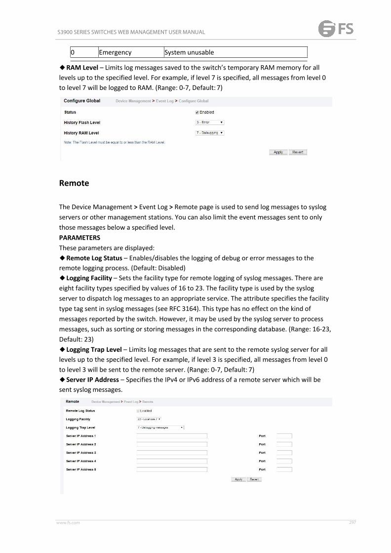
S3900 SERIES SWITCHES WEB MANAGEMENT USER MANUAL
www.fs.com 297
0 Emergency System unusable
◆RAM Level – Limits log messages saved to the switch’s temporary RAMmemory for alllevels up to the specified level. For example, if level 7 is specified, all messages from level 0to level 7 will be logged to RAM. (Range: 0-7, Default: 7)
Remote
The Device Management > Event Log > Remote page is used to send log messages to syslogservers or other management stations. You can also limit the event messages sent to onlythose messages below a specified level.PARAMETERSThese parameters are displayed:◆Remote Log Status – Enables/disables the logging of debug or error messages to theremote logging process. (Default: Disabled)◆Logging Facility – Sets the facility type for remote logging of syslog messages. There areeight facility types specified by values of 16 to 23. The facility type is used by the syslogserver to dispatch log messages to an appropriate service. The attribute specifies the facilitytype tag sent in syslog messages (see RFC 3164). This type has no effect on the kind ofmessages reported by the switch. However, it may be used by the syslog server to processmessages, such as sorting or storing messages in the corresponding database. (Range: 16-23,Default: 23)◆Logging Trap Level – Limits log messages that are sent to the remote syslog server for alllevels up to the specified level. For example, if level 3 is specified, all messages from level 0to level 3 will be sent to the remote server. (Range: 0-7, Default: 7)◆Server IP Address – Specifies the IPv4 or IPv6 address of a remote server which will besent syslog messages.

S3900 SERIES SWITCHES WEB MANAGEMENT USER MANUAL
www.fs.com 298
SMTP
The Device Management > Event Log > SMTP page is used to alert system administrators ofproblems by sending SMTP (Simple Mail Transfer Protocol) email messages when triggeredby logging events of a specified level. The messages are sent to specified SMTP servers onthe network and can be retrieved using POP or IMAP clients.ParametersThese parameters are displayed:◆ SMTP Status – Enables/disables the SMTP function. (Default: Enabled)◆ Severity – Sets the syslog severity threshold level used to trigger alert messages. Allevents at this level or higher will be sent to the configured email recipients. For example,using Level 7 will report all events from level 7 to level 0. (Default: Level7)◆ Email Source Address – Sets the email address used for the “From” field in alertmessages. You may use a symbolic email address that identifies the switch, or the address ofan administrator responsible for the switch. (Range: 1-41 characters)◆ Email Destination Address – Specifies the email recipients of alert messages. You canspecify up to five recipients.◆ Server IP Address – Specifies a list of up to three recipient SMTP servers. IPv4 or IPv6addresses may be specified. The switch attempts to connect to the listed servers insequential order if the first server fails to respond. For host name-to-IP address translationto function properly, host name lookup must be enabled, and one or more DNS serversspecified.
FileManagement
Device Management> File Management page is used to manage the file in device. User canupload configuration file to PC, download runtime file to device. Copy a configuration file toanother configuration file.

S3900 SERIES SWITCHES WEB MANAGEMENT USER MANUAL
www.fs.com 299
Copying Files via FTP/TFTP or HTTP
In the Device Management> File Management page, click copy button to download firmwareor configuration settings using FTP, TFTP or HTTP. You can also set the switch to use newfirmware or configuration settings without overwriting the current version. Just downloadthe file using a different name from the current version, and then set the new file as thestartup file.The following parameters are displayed:◆Copy Type – The firmware copy operation includes theseoptions:■FTP Upload – Copies a file from an FTP server to the switch.■HTTP Upload– Copies a file from a management station to theswitch.■TFTP Upload – Copies a file from a TFTP server to theswitch.◆FTP/TFTP Server IP Address – The IP address of an FTP/TFTPserver.◆User Name – The user name for FTP serveraccess.◆Password – The password for FTP server access.◆File Type – Specify Operation Code to copy firmware.◆File Name – The file name should not contain slashes (\ or /), and the maximum length forfile names is 32 characters for files on the switch or 128 characters for files on the server.(Valid characters: A-Z, a-z, 0-9, “.”, “-”, “_”)

S3900 SERIES SWITCHES WEB MANAGEMENT USER MANUAL
www.fs.com 300
Saving the Running Configuration to a Local File
In the Device Management> File Management page, click copy button to save the currentconfiguration settings to a local file on the switch. The configuration settings are notautomatically saved by the system for subsequent use when the switch is rebooted. Youmust save these settings to the current startup file, or to another file which can besubsequently set as the startup file.The following parameters are displayed:◆Copy Type – The copy operation includes this option:■Running-Config – Copies the current configuration settings to a local file on theswitch.◆Destination File Name – Copy to the currently designated startup file, or to a new file. Thefile name should not contain slashes (\ or /), the leading letter of the file name should not bea period (.), and the maximum length for file names is 31 characters for files on the switch.(Valid characters: A-Z, a-z, 0-9, “.”, “-”, “_”)NOTE: The maximum number of user-defined configuration files is limited only by availableflash memory space.
Setting the Startup File
In the Device Management> File Management page, click StartUp button to to specify thefirmware or configuration file to use for system initialization.

S3900 SERIES SWITCHES WEB MANAGEMENT USER MANUAL
www.fs.com 301
Auto Upgrade
Device Management > Auto Upgrade page is used to automatically download an operationcode file when a file newer than the currently installed one is discovered on the file server.After the file is transferred from the server and successfully written to the file system, it isautomatically set as the startup file, and the switch is rebooted.
USAGE GUIDELINES◆ If this feature is enabled, the switch searches the defined URL once during the bootupsequence.◆FTP (port 21) and TFTP (port 69) are both supported. Note that the TCP/UDP port bindingscannot be modified to support servers listening on non-standardports.◆The host portion of the upgrade file location URL must be a valid IPv4 IP address. DNS hostnames are not recognized. Valid IP addresses consist of four numbers, 0 to 255, separated byperiods.◆The path to the directory must also be defined. If the file is stored in the root directory forthe FTP/TFTP service, then use the “/” to indicate this (e.g., ftp://192.168.0.1/).◆The file name must not be included in the upgrade file location URL. The file name of thecode stored on the remote server must be ECS4510-Series.bix (using upper case and lowercase letters exactly as indicated here). Enter the file name for other switches described inthis manual exactly as shown on the web interface.◆The FTP connection is made with PASV mode enabled. PASV mode is needed to traversesome fire walls, even if FTP traffic is not blocked. PASV mode cannot bedisabled.◆The switch-based search function is case-insensitive in that it will accept a file name inupper or lower case (i.e., the switch will accept ECS4510-SERIES.BIX from the server eventhough ECS4510-SERIES.bix was requested). However, keep in mind that the file systems ofmany operating systems such as Unix and most Unixlike systems (FreeBSD, NetBSD,OpenBSD, and most Linux distributions, etc.) are case-sensitive, meaning that two files in thesame directory, ecs4510-series.bix and ECS4510-SERIES.bix are considered to be unique files.Thus, if the upgrade file is stored as ECS4510-SERIES.bix (or even EcS4510-SERIES.bix) on acase sensitive server, then the switch (requesting ecs4510-series.bix) will not beupgraded

S3900 SERIES SWITCHES WEB MANAGEMENT USER MANUAL
www.fs.com 302
because the server does not recognize the requested file name and the stored file name asbeing equal. A notable exception in the list of case-sensitive Unix-like operating systems isMac OS X, which by default is case-insensitive. Please check the documentation for yourserver’s operating system if you are unsure of its file system’s behavior.◆Note that the switch itself does not distinguish between upper and lower-case file names,and only checks to see if the file stored on the server is more recent than the currentruntime image.◆ If two operation code image files are already stored on the switch’s file system, then thenon-startup image is deleted before the upgrade image is transferred.◆The automatic upgrade process will take place in the background without impedingnormal operations (data switching, etc.) of the switch.◆During the automatic search and transfer process, the administrator cannot transfer orupdate another operation code image, configuration file, public key, or HTTPS certificate (i.e.,no other concurrent file management operations are possible).◆The upgrade operation code image is set as the startup image after it has beensuccessfully written to the file system.◆The switch will send an SNMP trap and make a log entry upon all upgrade successes andfailures.◆The switch will immediately restart after the upgrade file is successfully written to the filesystem and set as the startup image.PARAMETERSThe following parameters are displayed:◆Automatic Opcode Upgrade – Enables the switch to search for an upgraded operationcode file during the switch bootup process. (Default: Disabled)◆Automatic Upgrade Location URL – Defines where the switch should search for theoperation code upgrade file. The last character of this URL must be a forward slash (“/”). TheECS4510-Series.bix filename must not be included since it is automatically appended by theswitch. (Options: ftp, tftp)The following syntax must be observed:tftp://host[/filedir]/■tftp:// – Defines TFTP protocol for the server connection.■host – Defines the IP address of the TFTP server. Valid IP addresses consist of fournumbers, 0 to 255, separated by periods. DNS host names are notrecognized.■filedir – Defines the directory, relative to the TFTP server root, where the upgrade file canbe found. Nested directory structures are accepted. The directory name must be separatedfrom the host, and in nested directory structures, from the parent directory, with aprepended forward slash “/”.■/ – The forward slash must be the last character of theURL.ftp://[username[:password@]]host[/filedir]/■ftp:// – Defines FTP protocol for the server connection.■username – Defines the user name for the FTP connection. If the user name is omitted,then “anonymous” is the assumed user name for the connection.■password – Defines the password for the FTP connection. To differentiate the passwordfrom the user name and host portions of the URL, a colon (:) must precede thepassword,

S3900 SERIES SWITCHES WEB MANAGEMENT USER MANUAL
www.fs.com 303
and an “at” symbol (@), must follow the password. If the password is omitted, then “” (anempty string) is the assumed password for the connection.■host – Defines the IP address of the FTP server. Valid IP addresses consist of four numbers,0 to 255, separated by periods. DNS host names are not recognized.■filedir – Defines the directory, relative to the FTP server root, where the upgrade file canbe found. Nested directory structures are accepted. The directory name must be separatedfrom the host, and in nested directory structures, from the parent directory, with aprepended forward slash “/”.■/ – The forward slash must be the last character of theURL.ExamplesThe following examples demonstrate the URL syntax for a TFTP server at IP address192.168.0.1 with the operation code image stored in various locations:■tftp://192.168.0.1/The image file is in the TFTP root directory.■tftp://192.168.0.1/switch-opcode/The image file is in the “switch-opcode” directory, relative to the TFTP root.■tftp://192.168.0.1/switches/opcode/The image file is in the “opcode” directory, which is within the “switches” parent directory,relative to the TFTP root. The following examples demonstrate the URL syntax for an FTPserver at IP address 192.168.0.1 with various user name, password and file location optionspresented:■ftp://192.168.0.1/The user name and password are empty, so “anonymous” will be the user name and thepassword will be blank. The image file is in the FTP root directory.■ftp://switches:[email protected]/The user name is “switches” and the password is “upgrade”. The image file is in the FTP root.■ftp://switches:[email protected]/switches/opcode/The user name is “switches” and the password is “upgrade”. The image file is in the “opcode”directory, which is within the “switches” parent directory, relative to the FTP root.
Ping
The Device Management > Ping page is used to send ICMP echo request packets to anothernode on the network.PARAMETERSThese parameters are displayed:◆Host Name/IP Address – IP address or alias of thehost.

S3900 SERIES SWITCHES WEB MANAGEMENT USER MANUAL
www.fs.com 304
◆Probe Count – Number of packets to send. (Range: 1-16)◆Packet Size – Number of bytes in a packet. (Range: 32-512bytes)The actual packet size will be eight bytes larger than the size specified because the switchadds header information.COMMAND USAGE◆Use the ping command to see if another site on the network can bereached.◆The following are some results of the ping command:■Normal response - The normal response occurs in one to ten seconds, depending onnetwork traffic.■Destination does not respond - If the host does not respond, a “timeout” appears in tenseconds.■Destination unreachable - The gateway for this destination indicates that the destinationis unreachable.■Network or host unreachable - The gateway found no corresponding entry in the routetable.
Trace Route
The Device Management > Trace Route page is used to show the route packets take to thespecified destination.ParametersThese parameters are displayed:◆ Destination IP Address – Alias or IPv4/IPv6 address of the host.◆ IPv4 Max Failures – The maximum number of failures before which the trace route isterminated. (Fixed: 5)◆ IPv6 Max Failures – The maximum number of failures before which the trace route isterminated. (Range: 1-255; Default: 5)Command Usage◆ Use the trace route function to determine the path taken to reach a specifieddestination.◆ A trace terminates when the destination responds, when the maximum timeout (TTL) isexceeded, or the maximum number of hops is exceeded.◆ The trace route function first sends probe datagrams with the TTL value set at one. Thiscauses the first router to discard the datagram and return an error message. The tracefunction then sends several probe messages at each subsequent TTL level and displays theround-trip time for each message. Not all devices respond correctly to probes byreturning

S3900 SERIES SWITCHES WEB MANAGEMENT USER MANUAL
www.fs.com 305
an “ICMP port unreachable” message. If the timer goes off before a response is returned,the trace function prints a series of asterisks and the “Request Timed Out” message. A longsequence of these messages, terminating only when the maximum timeout has beenreached, may indicate this problem with the target device.◆ The same link-local address may be used by different interfaces/nodes in different zones(RFC 4007). Therefore, when specifying a link-local address, include zone-id informationindicating the VLAN identifier after the % delimiter. For example, FE80::7272%1 identifiesVLAN 1 as the interface from which the trace route is sent.
System Reboot
The Device Management > System Reboot page is used to restart the switch immediately, ata specified time,after a specified delay, or at a periodic interval.Command Usage◆ This command resets the entire system.◆When the system is restarted, it will always run the Power-On Self-Test. It will also retainall configuration information stored in non-volatilememory.ParametersThe following parameters are displayed:System Reload Information◆ Reload Settings – Displays information on the next scheduled reload and selected reloadmode as shown in the following example: “The switch will be rebooted at March 9 12:00:002012. Remaining Time: 0 days, 2 hours, 46 minutes, 5 seconds. Reloading switch regularlytime: 12:00 everyday.”◆ Refresh – Refreshes reload information. Changes made through the console or to systemtime may need to be refreshed to display the current settings.◆ Cancel – Cancels the current settings shown in this field.System Reload Configuration◆ Reset Mode – Restarts the switch immediately or at the specified time(s).■ Immediately – Restarts the system immediately.■ In – Specifies an interval after which to reload the switch. (The specified time must beequal to or less than 24 days.)■ hours – The number of hours, combined with the minutes, before the switch resets.(Range: 0-576)■minutes – The number of minutes, combined with the hours, before the switch resets.(Range: 0-59)■ At – Specifies a time at which to reload the switch.■ DD - The day of the month at which to reload. (Range: 01-31)
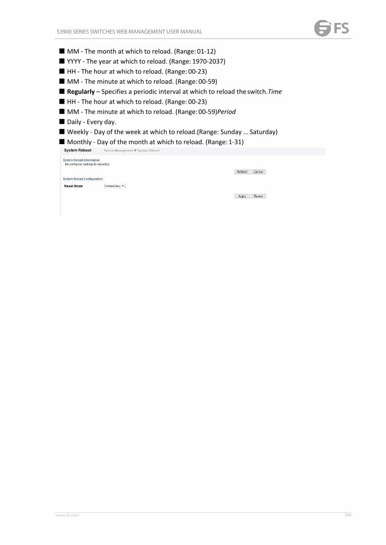
S3900 SERIES SWITCHES WEB MANAGEMENT USER MANUAL
www.fs.com 306
■MM - The month at which to reload. (Range: 01-12)■ YYYY - The year at which to reload. (Range: 1970-2037)■ HH - The hour at which to reload. (Range: 00-23)■MM - The minute at which to reload. (Range: 00-59)■ Regularly – Specifies a periodic interval at which to reload the switch.Time■ HH - The hour at which to reload. (Range: 00-23)■MM - The minute at which to reload. (Range: 00-59)Period■ Daily - Every day.■Weekly - Day of the week at which to reload.(Range: Sunday ... Saturday)■Monthly - Day of the month at which to reload. (Range: 1-31)