Procedural Detachment in International Commercial Arbitration
Upload
independentCategory
view
3download
0
Multiple detachment levels and their control on foldstyles in the compressional domain of the deepwaterwest Niger DeltaSepribo E. Briggs,n Richard J. Davies,w Joe A. Cartwrightn and Richard Morganzn3DLab, School of Earth, Ocean & Planetary Sciences, Cardiff University, Cardiff, UKwCeREES, Department of Earth Sciences, University of Durham, Science Labs, Durham, UKzVeritas DGCLimited, CromptonWay,West Sussex, UK
ABSTRACT
We interpret recently acquired two-dimensional (2D) and 3D seismic data from the contractionaldomain of theTertiary deepwater west Niger Delta, which is an area of current hydrocarbonexploration and development to show that during its gravitational collapse, multiple detachmentswere active. Detachments are locatedwithin (1) what we herein refer to as the ‘Dahomey unit’, (2) thetransition between theAgbada andAkata formations (TopAkata) and (3) theAkata formation. Seismicinterpretation and quantitative measurements of fault displacements show that the utilisation ofdi¡erent detachments results in contrasting styles of thrust propagation and fold growth.Twogeographical zones are de¢ned. In zone A (NW sector of the study area), the stratigraphicallyshallowestDahomeydetachment is dominant and is associatedwith thrust truncated folds. In zoneB (SEsector of the study area), a stratigraphically lower detachment approximately at the Agbada^Akataformation boundary is associatedwith thrust propagation folds. A third detachment, within the Akataformation, is locally developed and is also associatedwith thrust propagation folds.The di¡erentdeformational histories are probably related to the mechanical stratigraphy and the pore-pressurecharacteristics of the succession.
INTRODUCTION
Deformation caused by gravity tectonics is common tomany deepwater passive margins (Bruce, 1973; Dailly,1976; Evamy et al., 1978; Doust & Omatsola, 1990; Martonet al., 2000). As petroleum exploration becomes increas-ingly focused on these deepwater settings, insights intothe evolution of the contractional deformation structuresthat are located in the toe regions of the gravity tectonicsystem and their suitability as hydrocarbon traps have be-come important. The deepwater west Niger Delta region(Fig. 1a) is predominantly a compressional structural do-main that has recently become the focus of signi¢cant oiland gas exploration activity. However, there is currentlyno documentation of the variability of the fold styles acrossthe area and their structural evolution.This has been dueto the historical lack of extensive two-dimensional (2D)and 3D seismic re£ection data and well bore calibrationof the stratigraphy. Earlier studies were based largely on afew widely spaced reconnaissance seismic lines (Burke,1972; Delteil et al., 1974; Emery et al., 1975; Mascle, 1976;Lehner & De Ruiter, 1977; Damuth, 1994) and focused
upon the mapping of fracture zones and other basementstructures, whereas recent publications (Ajakaiye & Bally,2002a, b; Shaw et al., 2004; Bilotti & Shaw, 2005; Corredoret al., 2005a, b) have focused on studying the gravitationalstructures (Fig.1b). Speci¢cally, Corredor etal. (2005a) havecarried out structural reconstructions of the progressivedevelopment of the fold and thrust belts, describing thestyle of thrusting and associated folding.They drew linksbetween detachment level and structural style but did notfocus on the deepwater west Niger Delta.
Thrust-related folds can evolve in many ways (e.g.McClay, 2004).These can be distinguished based upon (a)the shape of the thrust that underlies the fold and the rela-tionship between folding and the kinematics of the thrusttip or (b) whether they have formed above a thrust with noramp; a lower £at and ramp; or a lower £at, ramp andupper£at.They can also be di¡erentiated kinematically depend-ing on whether they have formed from a ¢xed tip a propa-gating tip, or from a thrust that continues beyond the fold(Wallace &Homza, 2004).
The seismic data used in this study were acquired overwhat are herein termed the (a) inner (proximal) fold andthrust belt, (b) detachment (inter thrust) fold belt and(c) outer (distal) fold and thrust belt of the deepwater westNiger Delta (Fig. 1a). This work complements that ofCorredor et al. (2005a), who carried out structural recon-structions in 2D over selected cross sections across the
Correspondence: Sepribo E. Briggs, 3DLab, School ofEarth, Ocean & Planetary Sciences, Cardi¡ University, MainBuilding, Park Place, CF10 3YE, Cardi¡,UK. E-mail: briggss1@Cardi¡.ac.uk
BasinResearch (2006) 18, 435–450, doi: 10.1111/j.1365-2117.2006.00300.x
r 2006 The Authors. Journal compilation r 2006 Blackwell Publishing Ltd 435

delta.The aim of this paper is to document regional varia-tions in thrust and fold styles and relate these to the strati-graphic characteristics of di¡erent detachment levels.
PREVIOUS RESEARCH ONDETACHMENT ZONES
The structural styles of deepwater fold and thrust belts arein£uenced by a number of parameters including the origi-nal mechanical stratigraphy (Erickson, 1996) and the £uidpressure distribution (Ramsay & Huber, 1987). Thestrength and thickness of the competent layer being de-formed control the wavelength, amplitude and asymmetryof thrust-related fold structures (Erickson, 1996). As such,they control the location of a thrust or foldwithin a multi-layered stratigraphic package.
Pore £uid pressure plays a key role in the developmentof deepwater fold and thrust belts particularly where there
are no evaporitic sediments capable of localising a detach-ment surface. According to the Mohr^Coulomb failuretheory, an increase in pore pressure will reduce the e¡ec-tive normal stress, thereby lowering shear strength. Theoccurrence of excess £uid pressure helps to account forthe phenomenon of weak faults in general (Sibson, 1981;Byerlee, 1993) and this mechanical principle can also beapplied to the localisation of detachment surfaces inthrust domains (Hubbert & Rubey, 1959). Previous workon fold belts such as that of the Western Gulf of Mexico(Peel et al., 1995) and the Niger Delta (Doust & Omatsola,1990; Morley & Guerin, 1996; Wu & Bally, 2000) consid-ered detachment to occur on overpressured shales.Wheremultiple overpressured levels exist in passive margindeepwater settings, multiple detachment levels are notuncommon. Some compressional belts have developedabove multiple detachment levels composed of eithershale (Rowan et al., 2004), rock salt or other evaporites
Fig.1. (a)Map of theNigerDelta showing the di¡erent structural domains (modi¢ed afterDamuth,1994).Note IFTB,DFB andOFTBare equivalent to the inner fold and thrust belt, detachment fold belt and outer fold and thrust belt, respectively. (b) Regional dip lineextending across the onshore into the deepwater west Niger delta. Modi¢ed after Haack et al. (2000).Vertical exaggeration5 2.0.
r 2006 The Authors. Journal compilation r 2006 Blackwell Publishing Ltd,Basin Research, 18, 435^450436
S. E. Briggset al.

(Grelaud et al., 2003) or a combination of these (Peel et al.,1995). This has resulted in complex thrust-related foldgeometries (Davis & Engelder, 1985; Cobbold et al., 1995).
GEOLOGICAL SETTING
TheNiger Delta is one of the largest modern deltas in theworld (Doust & Omatsola, 1990; Hooper et al., 2002). It issituated at the southern end of NE^SW folded rift basin,the Benue trough which formed during the Cretaceousopening of the South Atlantic, when the equatorial partsof Africa and South America began to separate (Burke etal., 1971;Whiteman, 1982; Fairhead & Binks, 1991). Duringthe opening of the Equatorial Atlantic in the late EarlyCretaceous (Nˇrnberg & Mˇller, 1991; Maluski et al.,1995), the trough became ¢lled progressively with Albianandyounger post-rift deposits. By the Late Eocene, a deltahad begun to prograde over the continental margin fol-lowing the end of the Palaeocene marine transgressionwhen the Imo Shales were deposited (Damuth, 1994).Thedelta now consists of a sedimentary prism some 12 kmthickwith a subaerial extent of about 75 000 km2 (Fig.1a).
Stratigraphy
TheTertiary Niger Delta can be stratigraphically dividedinto three diachronous units of Eocene to Recent age thatform amajor regressive cycle that is broken up into a seriesof o¥ap cycles named the Akata, Agbada and Beninformations (Short & Stauble, 1967; Avbovbo, 1978; Evamyetal.,1978;Whiteman,1982;Knox&Omatsola,1989;Doust& Omatsola, 1990).The delta prograded over both oceanicand continental basement (Davies et al., 2005; Figs 2a, band 3a, b).This basement includes a syn-rift and post-rift
succession that ¢lls a northeast^southwest and WNW^ESE trending rift structure that formed during theCretaceous, probablyduringAptian rifting of theEquator-ial Atlantic (Gradstein et al., 1995; De Matos, 2000;Macgregor et al., 2003). An unconformity (mid-Aptianbreak-up unconformity) separates the syn-rift and post-rift sediment ¢ll. Above this lies a low-re£ectivity packagethought to be of Late Cretaceous to Palaeocene age.
In addition to the previously described subdivisions, weinformally de¢ned two major seismic^stratigraphicpackages (units 1 and 2) based upon contrasting seismicamplitude, seismic facies and deformational characteris-tics. Unit 2 is about 3^4 km thick and comprises a low-re-£ectivity package, which lacks internal re£ection exceptfor a single mid-level high-amplitude re£ection (Fig. 3b),which may be related to a detachment (Corredor et al.,2005a). This unit onlaps the older Late Cretaceous to Pa-laeocene succession, is of marine origin and at the base ofthe delta, corresponds to the Akata formation of Avbovbo(1978) andKnox &Omatsola (1989). It is mainly composedof marine shales believed to be the source rock for hydro-carbons and some locally developed sand and silt beds.This unit exhibits anomalously low P-wave seismic veloci-ties ( �2000m s�1) that may re£ect regional £uid over-pressures (Bilotti & Shaw, 2001). It provides a detachmenthorizon for large growth faults, located up dip of the studyarea (Knox &Omatsola, 1989).
Unit1 is further subdivided into units1a and1b (Figs 2band 3a). Unit 1a is a distinct package between 300 and600m thick, consisting of semi-continuous to continuouslow-amplitude re£ections that are deformed into a seriesof folds that are clearly evident in theNWof the deepwaterregion (Figs 2b and 3a). It thins southwards until it is belowseismic resolution ( �20m;Fig. 3b). It is herein termed the
Fig. 2. (a) Chronostratigraphic diagram showing the regional variability in stratigraphy along a NW^SE transect across the deepwaterwest Niger Delta. (b) Two-dimensional seismic line showing the abrupt change in stratigraphy between units 1a, 1b and 2. Note thatBSM, PASW, units 2, 1a and1b correspond to the basement (Ajakaiye & Bally, 2002a, b), pre-Akata sediment wedge (seeMorgan, 2003,2004),Akata formation (Avbovbo,1978;Knox&Omatsola,1989),Dahomeywedge (Morgan, 2003, 2004) andAgbadaFormation (Short&Stauble, 1967; Avbovbo, 1978), respectively.
r 2006 The Authors. Journal compilation r 2006 Blackwell Publishing Ltd,Basin Research, 18, 435^450 437
Fold styles in the compressional domain of the deepwater west Niger Delta
Dahomeywedge and is believed to have been sourced fromthe Dahomey trough of the onshore Guinea basin in thenorth of this study area (Morgan 2003, 2004). Unit 1b isabout 3 km thick below a water depth of over 4000m andcorresponds to the Agbada Formation that has been de-scribed by Short & Stauble (1967) from the Agbada-2 welland by Avbovbo (1978). It consists of alternating sand-stones and shales deposited by channelised turbidites,debrites and hemipelagites (e.g. Davies, 2003; Deptuck etal., 2003).The sands constitute the main reservoirs in thispart of the delta. Sand to shale ratio generally decreasesdownwards as the formation passes gradually into theAka-ta formation.The age of this formation is Eocene to Pleis-tocene (Short & Stauble, 1967; Doust & Omatsola, 1990).The Benin Formation, as described from the Elele-1 wellby Short & Stauble (1967), is not encountered in the deep-water region of the Niger Delta (Morgan, 2003).
Structure
TheNigerDelta tectonic province is a typical example of alinked regional gravity tectonic system where horizontal
translation of the post rift cover is driven by gravitationalfailure of the margin. This is accommodated by thin-skinned tectonics with extensional, intermediate transi-tional and downdip compressional domains (Fig.1b) aboveone or more detachment levels. Extension occurs on theshelf and is accommodated by growth faults (Weber &Daukoru, 1975; Evamy et al., 1978; Whiteman, 1982; Knox&Omatsola, 1989). A transitional domain is located basin-wards of this and is characterised by shale diapirs and theirassociated inter-diapir depocentres. The compressionaldomain is sited beneath the lower continental slope andrise, and is characterised by thrust faults and their asso-ciated folds.
Thin-skinned compressional deformation is manifestas regularly spaced thrust faults and associated withmainly asymmetric folds.The thrust faults have a regularspacing of between 2 and 5 km and occasionally up to10 km. These thrusts have developed in an overall sea-ward-propagating sequence with some out-of-sequencethrusting caused by the reactivation of older in-sequencethrust by the development of new thrust faults through adeformed thrust sheet (Morley, 1988).
Fig. 3. Interpreted seismic lines from (a) the two-dimensional (2D) dataset, (b) the 3D dataset, showing the major stratigraphicsubdivisions of the deepwater west Niger delta.The major re£ectors de¢ned in this section are the top of the basement, the pre-Akatasedimentwedge, unit 2 corresponding to theAkata formation, unit1a, which is theDahomeydetachment unit and unit1b,which de¢nesthe Agbada Formation. Note the sinusoidal geometry of the Dahomey unit that thins towards the SW direction here and in the SEdirection in Fig. 2 but becomes relatively thicker towards the NE.The compressional faults tip out from the thick units marked DW.Older inactive fold features are observed buriedwithout any sea£oor expression.The mid-Akata detachment level is clearly de¢ned onthe 3D dataset with thrusts propagating from it and showing situations of shale welding. Note the very strong and low-frequencyre£ector de¢ning the top of the crust and below which no coherent re£ections exist.
r 2006 The Authors. Journal compilation r 2006 Blackwell Publishing Ltd,Basin Research, 18, 435^450438
S. E. Briggset al.

The region has been subdivided into three structuraldomains (Connors et al., 1998; Corredor et al., 2005a)
(a) Inner fold and thrust belt (Fig.1a), characterised by a high-er structural dip with an average distance between im-bricated thrust sheets of between 1 and 2 km and withthe formation of occasional piggy-back basins (Corre-dor et al., 2005a).The dataset does not extend over thisdomain.
(b) Detachment fold belt (Fig.1a), characterised by large areasof minor deformation from thrust- or shale-inducedfolding (thrusting and folding due to shale swelling),with along-transport thrust sheet dimensions rangingfrom 2 to 5 km (Fig. 3a).
(c) Outer fold and thrust belt (Fig.1a), comprised of local de-pocentres and both basinward and hinterland vergingthrusts.This domain is situated further downdip, withchannelised turbidite sands trapped in broad-wave-length anticlines above incipient thrust propagationzones (Fig. 3b).
We divided the study area into two zones; A and B (Fig. 4),according to structural styles. ZoneA is in the detachmentfold belt located in the NW of the delta and is charac-terised by the presence of a group of open foldswith asym-metric to symmetric geometry, and with minor thrustfaults on the steeper limbs. Further to the SE, and alongstructural strike from zone A, we have de¢ned a secondset of thrust faults that are coupled with strongly asym-metric to symmetric, tighter folds, which we have beengrouped into zone B.We argue below that the distinctlydi¡erent structural styles within the compressional do-mains may be due to detachment zones that underlie thewedge-shaped fold and thrust systems.
DATA ANDMETHODOLOGY
Zone B is partially covered by1970 km2 of high-quality 3Dseismic data acquired in1999 over water depths of between1500 and 4000m and a1998 vintage of 2D seismic data thathas a combined length of 5230 km.ZoneA is, however, onlycovered by 2D seismic data. These data have a dip andstrike line spacing of 4 and 10 km, respectively, with a datarecord interval of 12 s and a 6 km cable length with an air-gun source.These data were processed using a Kirchho¡bent ray pre-stack time migration. The 3D dataset has a6 km o¡set length and a12-s record interval. Its processingsequence is similar to that of the 2D data.The datasets aredisplayedwith a reverse polarity (European convention) sothat an increase in acoustic impedance is represented by atrough and is black on the seismic data in all ¢gures pre-sented here. The data are displayed in seconds two-way-travel time (TWT). The vertical and lateral resolutionsare estimated to be between 10 and 20m at the top of unit1 and 100m at the base of unit 2. Stacking velocities ob-tained from Morgan (2003) were used to depth convertthe seismic data (see Yilmaz, 2001). The overall seismicdata quality is considered to be good within theTertiary
section; seismic noise is, however, noted in the dataset, oc-casionally due to poor migration of seismic energy in areaswhere there are abrupt lateral velocity changes i.e. in thefootwall regions beneath the major thrust planes.
Regional mapping was undertaken to subdivide theseismic-stratigraphy into units 1a, 1b and 2 (Figs 2b and3a, b).We then mapped high-amplitude continuous re£ec-tions to further subdivide the stratigraphy. These re£ec-tions have provided a basis for time stratigraphicinterpretation throughout the study area because of theease with which they can be correlated.This stratigraphicframework was then used as the basis for measuring faulto¡sets.The high continuity of the mapped re£ections wasinvaluable in aiding correlation across thrust faults withinthe 3D survey area in particular, because the lateral tips ofthe thrusts were found to tie beyond the limits of the sur-vey area. Further constraints on the correlation betweenfootwalls and hangingwalls were obtained by linking theregional 2D data to the 3D seismic data.
To analyse the faults,we adopted the ‘displacement^dis-tance’ method developed by Muraoka & Kamata (1983)and Williams & Chapman (1983). This graphical methodprovides a primary visual representation of the displace-ment distribution along the fault trace and provides im-
Fig.4. Location map of the study area showing the two-dimensional (2D) and 3D seismic database, the approximatedemarcation of zones A and B and the location of faults F1^F8described in this study. It also shows the approximate extent ofthe Dahomey wedge.
r 2006 The Authors. Journal compilation r 2006 Blackwell Publishing Ltd,Basin Research, 18, 435^450 439
Fold styles in the compressional domain of the deepwater west Niger Delta

portant constraints for the growth history of the thrust(Watterson, 1986; Ellis &Dunlap, 1988).
Depth-converted sections were constructed for eachfault analysed. For thrust faults in zone A, the faults weremapped using the widely spaced regional 2D seismic grid,and speci¢c pro¢les were selected for depth conversion onthe grounds that theywere most orthogonal to the strike ofthe thrust faults. Itwas assumed that because in the better-constrained distal parts of the region, fold axes weremapped parallel to the strike of the thrust faults, the likelymotion vector on the thrust faults was orthogonal to faultstrike. Hence, the seismic pro¢les selected are likely to bein or close to the transport direction.This interpretationaccords well withwhat is known of the regional kinematicsof the gravity tectonic system as a whole (e.g. Bilotti &Shaw, 2005). For thrust faults in zone B, we selected pro-¢les based on mapping of the thrusts and associated foldsusing the dense line spacing of the 3D seismic survey (Fig.5).The parallelism observed on structure maps of the 3Dsurvey area between fold axes and strike of thrust faultsagain strongly argues for a dominantly dip^slip regime,and hence we selected pro¢les that were considered paral-lel to the likely transport direction.
The displacement (D) valuesweremeasureddirectly fromthe depth^converted; true-scale sections using 2DMovestructural restoration software that allows for depth-converted seismic pro¢les to be displayed at any scale.
Displacement values were plotted graphically againstthe distance (X) measured along the thrust fault planefrom the upper fault tip to the midpoint position betweenfootwall and hangingwall cuto¡s for each speci¢c markerhorizon.Displacement valueswere only recorded for thosemarkers where there was a high con¢dence in the accuracyof the cross-fault correlation. This method ensured thatdistortions due to fault plane listricitywere not introducedinto the graphical display, thus preserving the value of the
displacement gradients that can be derived directly fromthe plots.This approach di¡ers from that used in displace-ment analysis of extensional faults, where it is more con-ventional to plot displacement or throw against a distanceordinate measured by projection onto a vertical plane(Walsh &Watterson, 1987).
OBSERVATIONS
In this section, we use representative 2D (Figs 6 and 7) and3D (Figs 8 and 9) seismic lines to illustrate the structuralinterpretation, pertinent features of the structural geologyof the deepwater region and to demonstrate the location ofthe detachment levels. The displacement distribution ofindividual thrusts is presented and discussed as a guide toreconstructing the structural evolution.
Fault interpretation and detachment level
The thrust faults in the study area are generally observed tobe oceanward verging and striking in a NW^SE direction,but some are landward-verging and out of sequence (Mor-ley, 1988). In general, the thrust planes are listric (concaveupwards), steepening upwards to a more planar geometryin the upper parts of the fault planes (Figs 6^9).The listricgeometry of these thrust faults and the generally asympto-tic relationship of the thrust planes with the regionalstratigraphy at their base are strongly indicative of the pre-sence of a detachment surface (McNeill et al., 1997). Theupper tips are well de¢ned by the shallowest resolvable o¡-set of seismic markers, although loss of signal coherence inshallow re£ections around the upper tips sometimesobscures its precise location (Figs 8 and 9). Individual faultplanes range in dip from sub-horizontal, close to theinferred detachment level to approximately 401 close tothe upper tip. The steepest, more planar sections of the
Fig. 5. Time structural map ofMiocene (10.3Ma) showing the parallelism between fold axes and the strike of the thrust faults.The¢gure is dominated by a dip^slip regime.The measurements of the fault displacements were made on pro¢les that are generally parallelto the likely transport direction.
r 2006 The Authors. Journal compilation r 2006 Blackwell Publishing Ltd,Basin Research, 18, 435^450440
S. E. Briggset al.

thrusts were observed to be generally steeper for faults inzone A in comparisonwith those in zone B.Depth conver-sion showed that the listric geometry is not simply due toan increase in seismic velocity with depth (Fig. 8e).
Fault planes were interpreted based on the followingcriteria: (a) abrupt o¡set of steeply dipping stratal re£ec-tions, (b) tracking of fault plane re£ections, (c) juxtaposi-tion across the fault plane re£ection of dissimilar unitsand (d) a deterioration in the data resolution beneath thefaults as a result of the juxtaposition of faster velocity rocksin the footwall juxtaposed laterally against slower velocityrocks in the hanging wall.
The majority of the thrust faults could be traced from adetachment level at depth upwards to close to the sea£oor
(e.g.Figs 6a, 7a,8a and9a).The detailedgeometry of seismicre£ections at the sole of the thrusts is critical for the deter-mination of the detachment levels in zones A and B.Thequality of the seismic data generally allows the detachmentlevel to be delineated within a vertical resolution limit ofless than 25m thickness (Figs 6^9), and hence contrastingdetachment levels observed from faults in zones A and Bcan be resolved with con¢dence. The detachment levelis de¢ned based on tracing the discordance between re£ec-tions in footwall and hangingwall to a positionwhere thereis no longer any visible discordance (see Fig. 6c). In thefollowing sections, we examine examples of faults inzones A and B in more detail to illustrate the interpreta-tional approach adopted to identify detachment levels.
Faults in zone A
We illustrate our general approach with reference to arepresentative example of a fault from zone A (Fig. 6). All
Fig. 6. Uninterpreted (a) and interpreted (b) representativeseismic section from zone A showing a typical fault (F1)detaching within theDahomey wedge and (c) an enlarged sectionof the sole segment where the fault plane re£ection terminateswithin a bedding parallel layer marked as BPR.
Fig.7. Uninterpreted (a) and interpreted (b) representativeseismic section from zone A showing a typical fault (F2)detaching in the Dahomey wedge.
r 2006 The Authors. Journal compilation r 2006 Blackwell Publishing Ltd,Basin Research, 18, 435^450 441
Fold styles in the compressional domain of the deepwater west Niger Delta
angular relationships were measured from true-scaledepth-converted pro¢les.We note that the fault plane ex-hibits an acute cuto¡ for re£ection B but not for re£ectionA. Re£ection B has a greater cut-o¡ angle with the fault(approximately 28^301 ^ labelled y1 in Fig. 6c), than re£ec-tion U (approximately 18^201 ^ labelled y2 in Fig. 6c) andre£ection W (approximately 12^151 ^ labelled y3 in Fig.6c). These values are based on depth-converted sections.Similar relationships are identi¢ed elsewhere (Fig. 7).The fault then shallows in dip asymptotically so that thediscordance between hangingwall and footwall stratal re-£ections diminishes to the point where the units are con-cordant, which, in this case, is coincidentwith re£ectionX(Fig. 6c). This is where we pinpoint the junction between
the thrust fault and the strata-parallel detachment, whichis labelled Z in Fig. 6c, and is the basis for our method ofidentifying the detachment level.We ¢nd that the detach-ment is often marked by a re£ection that has variable andoften high amplitude. Similar relationships are identi¢edfor most of the faults that we examined (e.g. Fig. 7).
Faults in zone B
In the fault displayed in Fig. 8, re£ections A and B both ex-hibit acute cuto¡s.We observed footwall cuto¡s at re£ec-tion W, but none for re£ections W and X (Fig. 8). Again,re£ection A has a greater cutt-o¡ angle (approximately20^251 ^ labelled y1 in Fig. 8d) and this reduces downwards
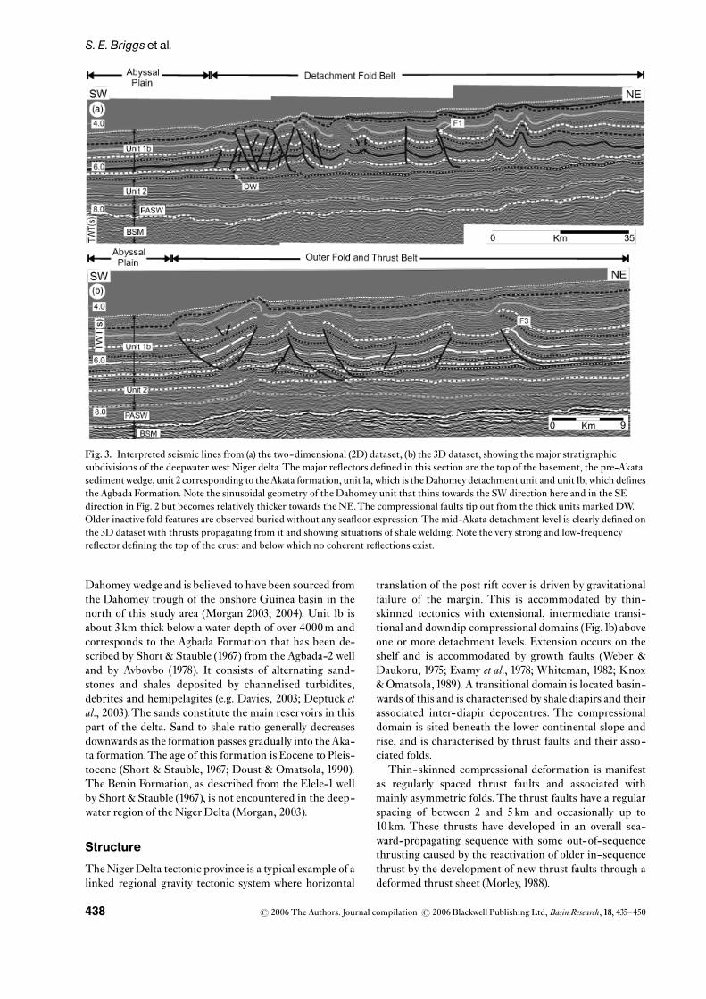
Fig. 8. Representative (a) uninterpreted and (b) interpreted seismic section from zone B showing fault F3. Note how the thrust rampsup, forming a thrust wedge. Also observed is the amount of displacement between the footwall and hanging walls.The upper tip isinvisible within a trishear zone. (c) A section of the sole segment de¢ning the exact position of the detachment layer. (d) Line drawing ofthe sole segment describing the relationship between the re£ections. (e)Adepth-converted seismic section showing faultF3 fromwhichactual displacement measurements were made.
r 2006 The Authors. Journal compilation r 2006 Blackwell Publishing Ltd,Basin Research, 18, 435^450442
S. E. Briggset al.

to approximately12^151 (marked labelled y2) inFig.8d. It isalso evident that the point where the thrust is interpretedto become layer parallel with stratal re£ections (i.e. thepoint at which it becomes a detachment) de¢nes the apexof a wedge-shaped element (Fig. 8d). Similar geometrieshave been described byCloos (1961) andMitra (2002b). Si-milar wedge elements are observed at the base of the foot-wall in Fig. 9. In marked contrast, there are no comparable‘wedges’of this type associatedwith faults in zone A. Also,it is observed that the upper tips of the faults in zone B arecharacterised by upward-widening triangular region ofmarkedly reduced amplitude (Figs 8 and 9). These low-amplitude regions bear a striking resemblance to a tip-re-lated shear zone called the trishear zone identi¢ed in manyoutcropping thrusts (Erslev, 1991).
Displacement^distance characteristics
Displacement measurements for eight faults (F1, F2, F3,F4, F5, F6, F7 andF8; located inFig. 4) were plotted against
their stratigraphic position. Faults F1 (Fig. 6), F2 (Fig. 7)and F7 are located in zone A, whereas faults F3 (Fig. 8),F4 (Fig. 9), F5, F6 and F8 are situated in zone B. Graphicalplots of displacement (D) versus distance (X) are presentedinFigs10 and11. Errors amounting to aprroximately10% inthese measurements include the sampling interval of 4ms,the errors in positioningdue to uncertainty in themigrationvelocities and interpretational errors.
Zone A
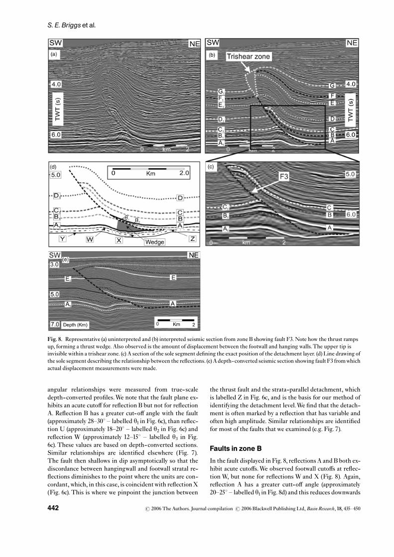
All the thrust faults in zone A characterised by displace-ment^distance plots that show an increase in displacementfrom the upper tip, to a position approximately midwaydown the main thrust ramp, where the displacement isa maximum, and from which point to the detachmentposition, show a clear decrease in displacement values.Three examples of this type of pattern are presented inFig. 10. In the case of fault F1, for example (Fig. 10a),the displacement maximum recorded at the mid-rampposition is 438m and decreases to 247m at the deepest hor-izon before the detachment. This reduction in displace-ment downwards is too large to be within the error range,and thus appears to be a genuine feature of this example.Similar patterns of asymmetrically peaked displacement^distance patterns can be seen for faults F2 and F3 (Fig.10b
Fig.9. Representative (a) non-interpreted and (b) interpretedseismic section from zone B showing fault F4. Note how thethrust ramps up, forming a thrust wedge on the top Akataformation de¢ned byA^A.The upper tip of the thrust is invisiblewithin the trishear zone.
400
200
0
400
600
200
200
100
0
0
0 500 1000 1500 2000 2500
0 500 1000 1500 2000
0 500 1000 1500 2000
2500
X
X
X
DD
D
(a)
(b)
(c)
Fig.10. Displacement^distance plots for thrusts F1, F2 and F7from zone A.
r 2006 The Authors. Journal compilation r 2006 Blackwell Publishing Ltd,Basin Research, 18, 435^450 443
Fold styles in the compressional domain of the deepwater west Niger Delta
and c), where there are even more pronounced downwarddecreases in displacement values from the maximumposition. These observations are highly signi¢cant inthe context of overall kinematic analysis (Williams &Chapman, 1983) in that the displacement clearly decreasesas the detachment is approached.
Zone B
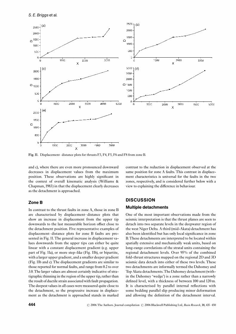
In contrast to the thrust faults in zone A, those in zone Bare characterised by displacement^distance plots thatshow an increase in displacement from the upper tipdownwards to the last measurable horizon o¡set close tothe detachment position. Five representative examples ofdisplacement^distance plots for zone B faults are pre-sented in Fig.11.The general increase in displacement va-lues downwards from the upper tips can either be quitelinear with a constant displacement gradient (e.g. upperpart of Fig. 11a), or more step-like (Fig. 11b), or bipartite,with a larger upper gradient, and a smaller deeper gradient(Fig. 11b and c).The displacement gradients are similar tothose reported for normal faults, and range from 0.2 to over3.0.The larger values are almost certainly indicative of stra-tigraphic thinning in the region of the upper tip, rather thanthe result of ductile strain associatedwith fault propagation.The deepest values in all cases were measured quite close tothe detachment, so the progressive increase in displace-ment as the detachment is approached stands in marked
contrast to the reduction in displacement observed at thesame position for zone A faults.This contrast in displace-ment characteristics is universal for the faults in the twozones, respectively, and is considered further below with aview to explaining the di¡erence in behaviour.
DISCUSSION
Multiple detachments
One of the most important observations made from theseismic interpretation is that the thrust planes are seen todetach into two separate levels in the deepwater region ofthe west Niger Delta. A third (mid-Akata) detachment hasalso been identi¢ed but has only local signi¢cance in zoneB.These detachments are interpreted to be locatedwithinspatially extensive and mechanically weak units, based onlong-range correlations of the stratal units containing theregional detachment levels. Over 95% of the combinedfold-thrust structures mapped on the regional 2D and 3Dseismic data detach into either of these two levels. Thesetwo detachments are informally termed the Dahomey andTopAkata detachments.TheDahomeydetachment (with-in the Dahomey ‘wedge’) is a zone rather than a narrowlyde¢ned level, with a thickness of between 100 and 120m.It is characterised by parallel internal re£ections withsome bedding parallel slip producing minor deformationand allowing the de¢nition of the detachment interval.
Fig.11. Displacement^distance plots for thrusts F3, F4, F5, F6 and F8 from zone B.
r 2006 The Authors. Journal compilation r 2006 Blackwell Publishing Ltd,Basin Research, 18, 435^450444
S. E. Briggset al.
This thick detachment ‘zone’ is conceivably due to thepresence of a speci¢cally weak lithology, such as acondensed interval with high organic content, or due tospeci¢c clay mineralogy (e.g. smectite rich). In contrastto the Dahomey detachment, the Top Akata detachmentshows no buckle-type minor deformation. It has a thick-ness of between 40 and 70m.
Displacement patterns
The displacement^distance pro¢le exhibited by faults inzone A (Fig. 10) have been shown to be characterised by adistinct peak in displacement value some distance abovethe detachment. It is not possible to constrain whetherthe displacement continues to diminish along the £atportion of the detachment, possibly even to a lower tipzone, as has been suggested for some thrust faults(P¢¡ner, 1985; Eisenstadt & De Paor, 1987).What is clear,however, is that the peak value occurs approximatelymidway up the post-detachment stratigraphy, relative tothe overburden present at the onset of thrusting. Thedisplacement^distance plots of these faults thus bearsome resemblance to the ‘C’-type plots described fromsmall normal faults by Muraoka & Kamata (1983) and forthrust faults byWilliams & Chapman (1983).
The ‘C’ type of displacement^distance plot impliesthat the thrust fault loses displacement both updip anddowndip from a point near the centre of the thrust, withconsiderable displacement gradients in both directions(and presumably, therefore, laterally too). Small variationsin the pro¢le are attributed to lithological e¡ects suchas bed-pervasive ductile thickening within weaker shalelayers. The relative smoothness of the pro¢le could beinterpreted to indicate an essentially uniform lithologythroughout the section consistent with the deepwaterdepositional setting. The recognition of displacementgradients implies that the wall rocks must be strained inorder to accommodate the displacement variation (Walsh& Watterson, 1987), which raises interesting questionsabout discrimination between thinning due to wallrockstrain versus thinning due to syn-kinematic changes inaccommodation space.
Previous studies have linked the recognition of a‘C’-type displacement pattern to a speci¢c propagationand growth model, in which the site of initiation of thefault coincides with the locus of maximum displacementon the fault (Walsh &Watterson, 1987). More recently, thisconcept has been challenged in cases where strong rheolo-gical contrasts in the faulted succession have been shownto skew the position of maximum displacement away fromthe initial locus of propagation (Wilkins&Gross, 2002). Insome previous models for thrust nucleation, analysis ofthis type of displacement pattern has been equated withinitial propagation in the ramp region of a ramp- £atthrust structure, with both updip and downdip propaga-tion as strain accumulates (P¢¡ner, 1985; Eisenstadt &De Paor, 1987), and we follow their interpretation insuggesting that the ‘C’-type patterns we observe are prob-
able indicators of a localised nucleation site above thedetachment, with later propagation of the thrust down-wards into the detachment.This propagation sequence isthought by some workers to be characteristic of faulteddetachment folds (Mitra, 2002b), alternatively referred toas thrust-truncated folds (Wallace & Homza, 2004). Thisinterpretation is similar to that proposed for a thrust andfold in the inter thrust sub-domain of the eastern part ofthe deepwater Niger delta, which was termed a ‘thrust-faulted detachment-fold anticline’ (Shirley, 2002).
In marked contrast, faults in zone B (Figs 8 and 9) showa steadily increasing pattern of displacementwith distancefrom the upper tip to the last measurable point close tothe detachment level (Fig. 11). As with faults in zone A,the distribution of displacement on the £at portion of thedetachment is unknown. Because the displacement valuesare unconstrained along the detachment, we cannot inferanything about nucleation and propagation other thanto link the distinctive displacement gradients across theentire post-detachment stratigraphic section to thrustpropagation in the transport direction. As noted earlier,the folds in zone B are seen to be more open than folds inzoneA,which could possibly be linked to the di¡erences indisplacement patterns on the thrust faults associatedwiththe folds in the two areas, and the relative partitioning ofcontractional strain between the thrusts and the folds.The parts of the displacement^distance plot with 0 slopemay be indicative of fault segments that have propagatedwith little associated wall strain (Muraoka & Kamata,1983; Suppe &Medwede¡,1984, 1990).
In summary, it can be concluded that there are substan-tial di¡erences between the thrusts in the two zones, bothin their displacement patterns and in their relationshipwith associated folds. Before addressing the key questionof why there are di¡erences between these two zones, we¢rst present a model for thrusting and folding in zones AandB based on our kinematic observations linked to thoseof previous workers.
Descriptivemodel for thrust propagation andfold-style development
Zone A
In this zone, the dominant structural fold type is thethrusted detachment fold, whichwe suggest resulted frombuckling of a strati¢ed succession, and that initially bentwithout rupture, leading to the formation of an openanticline and syncline pair. It is proposed that the fold thentightened and became more asymmetric as deformationprogressed.When the fold could no longer accommodatethe strain by folding, ruptures localised and linked onthe steeper limb, producing a thrust that broke throughthe forelimb of the fold and ¢nally connected to a mobiledetachment layer within the Dahomey unit. These typesof structure have been called break-thrust folds (Dixon &Liu, 1992; Fischer et al., 1992), thrusted detachmentfolds (Mitra, 2002b) or thrust-truncated folds (Wallace &Homza, 2004), and have been described mainly from
r 2006 The Authors. Journal compilation r 2006 Blackwell Publishing Ltd,Basin Research, 18, 435^450 445
Fold styles in the compressional domain of the deepwater west Niger Delta
kinematic models. The term fold-accommodation fault(Mitra, 2002a) would not be appropriate as these type offaults do not connect to a major detachment, which thesestructures do.This is critically supported by several exam-ples of thrust faults on the limbs of detachment folds thatare at an early stage in their development (Fig.12), inwhichthe thrust has not propagated downwards to connect withthe detachment. The presence of this buckled bed withlack of a thrust during shortening may be modi¢ed by latertruncations of a fault (Jamison, 1987; Mitra, 1990;McNaught &Mitra, 1993).The di¡erence is also shown bythe variation in nucleation pattern and the stratigraphicposition of the detachment.
Zone B
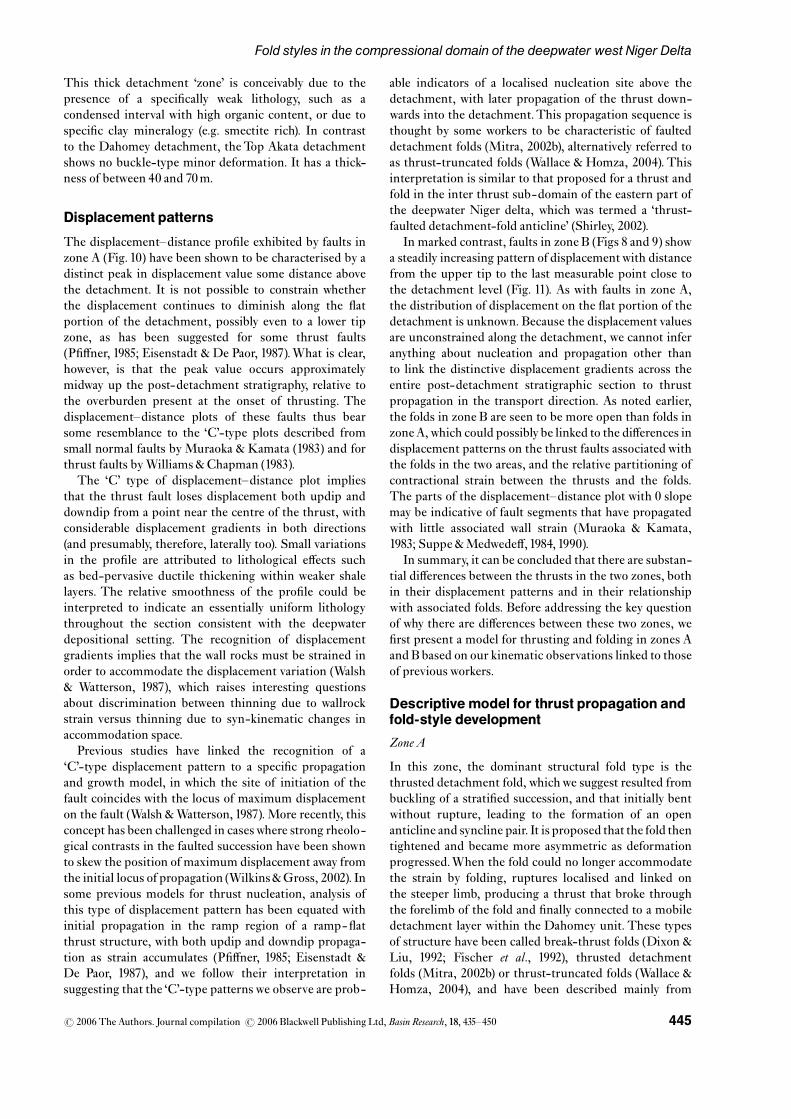
In zone B, we suggest that in contrast to zone A, the faultpropagation folds developed coevally with thrusting andconsumed slip at the tips of blind thrusts (Suppe &Medwede¡, 1984; Suppe, 1985; Marshak & Wilkerson,2004). As the thrust tip migrated, strata are folded in frontof it and are eventually breached by the thrust.The upwarddecrease in displacement observed on the displacement^distance plots is quite typical of a thrust-propagation foldbut is not really diagnostic of this class of structure (Mitra,2002b;Wallace &Homza, 2004). Here, the folds develop infront of the upper tip of the developing thrust as the ramppropagates up section (seeMitra, 1990, 2002b).
Controls on detachment level
The detachment layer in zoneA,which is the unit referredto as the Dahomey ‘wedge’, is over100m thick beneath theentire main structures in the area, and is clearly a me-chanically weak unit that relates in some way to its lithol-ogy. In contrast, in zone B, the detachment level is de¢nedacross a much thinner interval corresponding to theTopAkata.This detachment level may be due to the presenceof overpressure build-up as revealed from a velocity drop(Morgan, 2003) and shown by the high amplitude andreverse polarity re£ections (Figs 8 and 9).Wells drilled innearby areas have proved this to be the case (large pressureramp at the Top Akata). So overpressure is the likelymechanism for theTop Akata detachment level.
Stewart (1996) argued that detachment layer thicknessplayed a critical role in the style of shortening in contrac-tional settings. He showed that if a detachment occurredwithin a thick layer, signi¢cant fold ampli¢cation couldbe expected before thrusting. If the detachment layer isthin, shortening quickly leads to thrust nucleation andthrust propagation folds could be expected thereafter.
Combining the mapped distribution of detachmentfolds of zone A with the regional distribution of theDahomey wedge detachment ‘layer’ (Fig. 4), it can be seenthat the zone of detachment folds coincides exactly withthe mapped extent of the Dahomey wedge. Adopting theargument advanced by Stewart (1996) on the in£uenceof detachment layer thickness, we can therefore simply
propose that the main factor controlling the developmentof two distinct structural styles in the deepwater fold belt isthe presence or absence of a thick detachment layer.Wherepresent, detachment folds develop, with di¡ering degreesof associated thrusting out of the limbs. Where absent,instead, the shortening slope sediments detach at theTop Akata pressure ramp, which forms a discrete and thindetachment level, above which the nucleation of earlythrusts is encouraged, which evolve into the distinctivehigh strain, thrust propagation folds.
By analogy with the results of numerical and analoguemodelling of the factors a¡ecting fold style such as di¡er-ences in competency and stratigraphic thickness betweenthe upper Dahomey detachment and the underlying Akatadetachment units have probably a¡ected the style offolding we have observed. The Dahomey unit is relativelyincompetent, and thus is able to move into the cores of thedeveloping anticlines from the adjacent synclinal hinge.Wesuggest that this incompetent unit allowed the growth ofthe fold by £exural slip while maintaining parallel folding,
Fig.12. Non-interpreted (a) and interpreted (b) seismic sectionshowing early stage of development in a faulted detachment fold.Fault and deformation zones form on steeply dipping rotatedsegments on both limbs, resulting in pop-up-like structures.
r 2006 The Authors. Journal compilation r 2006 Blackwell Publishing Ltd,Basin Research, 18, 435^450446
S. E. Briggset al.

bed length and thickness. The deformation from the topAkata unit may primarily be due to internal ductile strainor £exural slip as indicated by thickness changes across foldlimbs andwidely spaced bed parallel slip surfaces.
IMPLICATIONS
Understanding the evolution of structures in the deep-water west Niger delta is necessary in order to avoid theimproper assessment of not only the trap geometry,location, shape, size, depth and vertical extent but alsothe reservoir, seal, source and migration.We ¢nd that faultpropagation folds generally form tighter anticlines thanthrusted detachment folds and as such would have di¡er-ent type and size of trap.This may be supported by the factthat most of the world class discoveries are located withinzone Awhere the thrusted detachment folds are the domi-nant structure with low relief and high area as comparedwith zone B, which is dominated by thrust propagationfolds that have higher relief but with smaller area.
The interpretation of these di¡erent structureswill havecontrasting implications for the presence and geometry of
the fault type whether they impede the migration of £uidor result in compartmentalisation of the reservoirs. Thestructures are likely to control hydrocarbon migration inthat in the zone A area, there may be no fault-linkingsource to trap and reservoir, whereas elsewhere (zone B)there generally would be a link. Therefore, we proposethat the risk of a trap not being on a migration pathway ishigher in zone A structures. This is particularly true forthe early developmental stages of thrusted detachmentfolds, where a through-going fault linking trap to sourcehas not fully developed.
CONCLUSIONS
Our study has shown that in the deepwater fold and thrustbelt of the Niger Delta, there is a strong dependence ofstructural style on the thickness and lithology of thedetachment unit. In zone A, folds formed in response toductile deformation of the inherently weak Dahomeywedge, which was susceptible to £ow due to the regionaloverpressure developed at or around the top of the Akataformation and shown from the greater amount of shorten-
Fig.13. Model showing thrust-related fold types and their associated displacement^distance pro¢les. (a) Thrust-related fold type withapparent nucleation point at the centre of the fault. (b) Idealised displacement^distance pattern from a ‘C-type’ fault (afterMuraoka &Kamata,1983). (c)Thrust-related fold type showing nucleation point at the base of the fault. (d) Idealised displacement^distance patternfrom a type II fault. Note here that the nucleation point corresponds to a detachment level. Displacement values are projected from aperpendicular down to a horizontal line from the midpoint between the hanging wall and footwall cut-o¡s.
r 2006 The Authors. Journal compilation r 2006 Blackwell Publishing Ltd,Basin Research, 18, 435^450 447
Fold styles in the compressional domain of the deepwater west Niger Delta

ing that could be due to lithologic changes. In zone B, thefolds are more clearly linked to thrust propagation.
This study has shown that two distinct structural pat-terns are possible within the deepwater west Niger Delta.They are the thrusted detachment folds in zone A and thethrust propagation folds in zoneB.The two structural stylescan be distinguished on the basis of markedly contrastingdisplacement^distance plots (Fig. 13). More symmetricaldisplacement patterns with a discrete maximum in themid-ramp position are found for all the thrusts in zone Aassociated with detachment folds, whereas the thrust pro-pagation folds are associated with a downward-increasingpattern of displacement towards the detachment.
ACKNOWLEDGEMENTS
Funding from Prime Energy Resources, Lagos NigeriaandChamberlainOyibo is gratefully acknowledged.VeritasDGC Ltd are thanked for the provision of seismic dataand permission to publish the results of this study.We aregrateful to SimonHiggins, Paivi Heinio and the 3DLab fordiscussion. We thank Schlumberger and Midland Valleyfor the use of seismic interpretation and depth conversionsoftware, respectively.We would like to thank Peter Cob-bold and an anonymous reviewer for their constructiveand helpful reviews.
REFERENCES
Ajakaiye, D.E. & Bally, A.W. (2002a) Course manual and atlasof structural styles of re£ection pro¢les from Niger Delta.AAPGContinuing Educ. Course Note Ser., 41, 1^107.
Ajakaiye,D.E. & Bally, A.W. (2002b) Some structural styles onre£ection pro¢les from o¡shore Niger Delta. Search Discov.,10031, 1^6.
Avbovbo, A.A. (1978) Tertiary lithostratigraphy of the NigerDelta.AAPGBull., 62(2), 295^306.
Bilotti,F.D.&Shaw, J.H. (2001)Modeling the compressive toeof the Niger Delta as a critical taper wedge (abs.).AAPGAnnu.Meeting Program, 10, A18^A19.
Bilotti, F.D. & Shaw, J.H. (2005) Deepwater Niger Delta foldand thrust belt modelled as a critical-taper wedge: the in£u-ence of elevated of elevated basal £uid pressure on structuralstyles.AAPGBull., 89, 1475^1491.
Bruce, C.H. (1973) Pressured shale and related sediment defor-mation: mechanism for development of regional contempora-neous faults.AAPGBull., 57, 878^886.
Burke,K.C.B. (1972) Longshore drift, submarine canyons, andsubmarine fans.AAPGBull., 56, 1975^1983.
Burke,K.,Dessauvagie,T.F.J.&Whiteman,A.J. (1971)Open-ing of the Gulf of Guinea and geological history of the Benuedepression andNiger Delta.Nat. Phys. Sci., 233, 51^55.
Byerlee, J. (1993) Model for episodic £ow of high-pressurewater in fault zone before earthquakes.Geology, 21, 303^306.
Cloos, E. (1961) Bedding slips, wedges and folding in layered se-quences.Socie¤ te¤ Ge¤ ologique de Finlande, Extrait des Comptes Rendus,33, 106^122.
Cobbold,P.R.,Szatmari,P.,Demercian,L.S.,Coelho,D.&Rossello, E.A. (1995) Seismic and experimental evidence forthin-skinned horizontal shortening by convergent radial
gliding on evaporites, deepwater Santos Basin, Brazil. In:Salt Tectonics: A Global Perspective (Ed. by M.P.A. Jackson,D.G. Robert & S. Snelson),AAPGMem., 65, 305^321.
Connors,C.D.,Denson,D.B.,Kristiansen,G.&Angstadt,D.M. (1998) Compressive anticlines of the mid-outer slope,central Niger Delta (abs.).AAPGBull., 82, 1903.
Corredor,F., Shaw, J.H.&Bilotti,F. (2005a) Structural stylesin the deep-water fold and thrust belts of the Niger Delta.AAPGBull., 89, 753^780.
Corredor, F., Shaw, J.H. & Suppe, J. (2005b) Shear fault-bendfold, deepwaterNigerDelta. In:Seismic Interpretation ofContrac-tional Fault-Related Folds (Ed. by J.H. Shaw, C. Connors &J. Suppe),AAPGStud. Geol., 53, 87^95.
Dailly, G.C. (1976) A possible mechanism relating prograda-tion, growth faulting, clay diapirism and overthrusting inthe regressive sequence of sediments. Bull. Canadian Petrol.Geol., 24, 92^116.
Damuth, J.E. (1994) Neogene gravity tectonics and depositionalprocesses on the deep Niger Delta continental margins.Mar.Petrol. Geol., 11, 321^346.
Davies, R.J. (2003) Kilometer-scale £uidization structuresformed during early burial of a deep-water slope channel onthe Niger Delta.Geology, 31(11), 949^952.
Davies, R.J., Macleod, C.J., Morgan, R. & Briggs, S.E.(2005) Termination of a fossil continent-ocean fracture zoneimaged with three-dimensional seismic data: the Chain Frac-ture Zone, eastern equatorial Atlantic.Geology, 33(8), 641^644.
Davis, D.M. & Engelder, T. (1985) The role of salt in fold-and-thrust belts.Tectonophysics, 119, 67^88.
DeMatos,D. (2000) Tectonic evolution of the Equatorial SouthAtlantic. In: Atlantic Rifts and Continental Margins. GeophysicalMonograph 115 (Ed. by W. Mohriak &M.Talwani), pp. 331^354.American Geophysical Union,Washington, DC.
Delteil, J.R., Valery, P., Montadert, L., Fondeur, C.,Patrait, P. & Mascle, J. (1974) Continental margins in thenorthern part of the Gulf of Guinea. In: The Geology ofContinental Margins (Ed. by C.A. Burk & C.L. Drake), pp.297^311. SpringerVerlag, NewYork.
Deptuck, M.E., Steffen, G.S., Barton, M. & Pirmez, C.(2003) Architecture and evolution of upper fan channel-beltson the Niger Delta slope and in the Arabian Sea. Mar. Petrol.Geol., 20(6^8), 649^676.
Dixon, J.M.&Liu,S. (1992) Centrifuge modelling of the propa-gation of thrust faults. In:ThrustTectonics (Ed. byK.R.McClay),pp. 53^69. Chapman &Hall, London.
Doust, H. & Omatsola, E. (1990) Niger Delta. In: Divergent/Passive Margins (Ed. by J.D. Edwards & P.A. Santogrossi),AAPGMem., 48, 201^238.
Eisenstadt, G. & De Paor, D.G. (1987) Alternative model ofthrust-fault propagation.Geology, 15, 630^633.
Ellis, M.A. & Dunlap, W.J. (1988) Displacement variationalong thrust faults: implications for the development of largefaults. J. Struct. Geol., 10, 183^192.
Emery,K.O.,Uchupi,E.,Phillips, J.,Brown,C.&Mascle, J.(1975) Continental margins o¡ western Africa: Angola toSierra Leone.AAPGBull., 59, 2209^2265.
Erickson, S.G. (1996) In£uence of mechanical stratigraphy onfolding vs. faulting. J. Struct. Geol., 18, 443^450.
Erslev, E.A. (1991) Trishear fault-propagation folding. Geology,19, 617^620.
Evamy, B.D., Haremboure, J., Kamerling, P., Knaap,W.A.,Malloy,F.A.&Rowlands,P.H. (1978)Hydrocarbon habitatof Tertiary Niger Delta.AAPGBull., 62, 1^39.
r 2006 The Authors. Journal compilation r 2006 Blackwell Publishing Ltd,Basin Research, 18, 435^450448
S. E. Briggset al.
Fairhead, J.D.& Binks,R.M. (1991) Di¡erential opening of theCentral andSouthAtlantic oceans and the opening of theWestAfrican rift system.Tectonophysics, 187, 191^203.
Fischer,M.P.,Woodward,N.B.&Mitchell,M.M. (1992)Thekinematics of break-thrust folds. J. Struct. Geol., 14, 451^460.
Gradstein,F.M.,Agterberg,F.P.,Ogg, J.G.,Hardenbol, J.,Van Veen, P.,Thierry, J. &Huang, Z. (1995) ATriassic, Jur-assic and Cretaceous time scale. In: Geochronology, Time Scaleand Global Stratigraphic Correlation (Ed. by W.A. Berggren, D.V.Kent, M.P. Aubrey & J. Hardenbol), Spec. Publ. Soc. Econ. Pa-laeontologists andMineralogists, 54, 95^126.
Grelaud,S.,Verges, J.,Nalpas,T.&Karpuz,R. (2003) Impactof multiple detachment levels on deformation of external fold-and-thrust belts.Geophys. Res. Abstr., 5, 11003.
Haack, R.C., Sundararaman, P., Diedjomahor, J.O., Xiao,H.,Gant,N.J.,May, E.D. &Kelsch,K. (2000) Niger Deltapetroleum systems, Nigeria. In: Petroleum Systems of SouthAtlantic Margins (Eds. by M.R. Mello & B.J. Katz), AAPGMem., 73, 213^231.
Hooper, R.J., Fitzsimmons, R.J., Grant, N. & Vendeville,B.C. (2002) The role of deformation in controlling deposi-tional patterns in the south-central Niger Delta,West Africa.J. Struct. Geol., 24, 847^859.
Hubbert, M.K. & Rubey,W.W. (1959) Role of £uid pressure inmechanics of over-thrust faulting, part I and II.Geol. Soc. Am.Bull., 70, 115^205.
Jamison,W.R. (1987) Geometric analysis of fold development inoverthrust terranes. J. Struct. Geol., 9, 207^219.
Knox,G.J.&Omatsola,E.M. (1989)Development of theCenozoicNiger Delta inTerms of the‘Escalator Regression’Model and Impact onHydrocarbon Distribution. Proceedings KNGMG Symposium‘Coastal Lowlands, Geology and Geotechnology’ (pp. 181^202).Kluwer Academic Publishers, Dordrecht.
Lehner, P.&De Ruiter, P.A.C. (1977) Structural history of theAtlantic margin of Africa.AAPGBull., 61, 961^981.
Macgregor, D.S., Robinson, J. & Spear, G. (2003) Play fair-ways of the Gulf of Guinea transform margin. In: PetroleumGeology of Africa: NewThemes and DevelopingTechnologies (Ed. byJ.J. Arthur, D.S. Macgregor & N.R. Cameron), Spec. Publ.Geol.Soc. Lond., 207, 131^150.
Maluski, H., Coulon, C., Popoff, M. & Baudin, P. (1995)40Ar/39Ar chronology, petrology and geodynamic setting ofMesozoic to early Cenozoic magmatism from the BenueTrough, Nigeria. J. Geol. Soc., 152, 311^326.
Marshak, S.&Wilkerson,M.S. (2004) Fold-thrust belts ^ anessay. In:EarthStructure, 2nd edn, Ed. byB.A.VanDer Pluijm&S.Marshak), pp. 444^474. Norton Publishers, NewYork.
Marton, L.G.,Tari,G.C. & Lehmann, C.T. (2000) Evolutionof the Angolan Passive margin, West Africa, with emphasison post-salt structural styles. In: Atlantic Rifts and ContinentalMargins. Geophysical Monograph 115 (Ed. by W. Mohriak &M. Talwani), pp. 129^149. American Geophysical Union,Washington, DC.
Mascle, J. (1976) Submarine Niger Delta structural framework.J. NigeriaMin. Geol.Metal. Soc., 13, 12^28.
Mcclay,K.R. (2004)Thrust tectonics and hydrocarbon systems:introduction. In:Thrust Tectonics and Hydrocarbon Systems (Ed.by K.R.McClay),AAPGMem., 82, ix^xx.
Mcnaught,M.A.&Mitra,G. (1993)A kinematicmodel for theorigin of footwall synclines. J. Struct. Geol., 15, 805^808.
Mcneill, L.C., Piper, K.A., Goldfinger, C., Kulm, L.D. &Yeats, R.S. (1997) Listric normal faulting on Cascadia conti-nental margin. J. Geophys. Res., 102(B6), 12123^12138.
Mitra, S. (1990) Fault-propagation folds: geometry, kinematicevolution, and hydrocarbon traps.AAPGBull., 74, 921^945.
Mitra, S. (2002a) Fold-accommodation faults. AAPG Bull., 86,671^693.
Mitra,S. (2002b)Structural models of faulted detachment folds.AAPGBull., 86, 1673^1694.
Morgan,R. (2003) Prospectivity in ultradeep water: the case forpetroleum generation and migration within the outer partsof the Niger Delta apron. In: Petroleum Geology of Africa:New Themes and Developing Technologies (Ed. by T.J. Arthur,D.S. MacGregor & N.R. Cameron), Spec. Publ. Geol. Soc.Lond., 207, 151^164.
Morgan, R. (2004) Structural controls on the positioning ofsubmarine channels on the lower slopes of the Niger Delta.In: 3D Seismic Technology: Application to the Exploration ofSedimentary Basins (Ed. by R.J. Davies, J. Cartwright, S.A.Stewart, J.R. Underhill & M. Lappin), Geol. Soc. London,Mem., 29, 45^51.
Morley, C.K. (1988) Out of sequence thrusts. Tectonics, 7,539^561.
Morley,C. &Guerin,G. (1996) Comparison of gravity-drivendeformation styles and behaviour associated with mobileshales and salt.Tectonics, 15, 1154^1170.
Muraoka, H. & Kamata, H. (1983) Displacement distributionalong minor fault traces. J. Struct. Geol., 5, 395^483.
Nˇrnberg,D.&Mˇller,R.D. (1991) The tectonic evolution ofthe South Atlantic from late Jurassic to present.Tectonophysics,187, 27^53.
Peel,F.J.,Travis,C.J.&Hossack, J.R. (1995)Genetic structuralprovinces and salt tectonics of the Cenozoic o¡shore US Gulfof Mexico: a preliminary analysis. In: Salt Tectonics: A GlobalPerspective (Ed. by M.P.A. Jackson, D.G. Robert & S. Snelson),AAPGMem., 65, 153^175.
Pfiffner,O.A. (1985) Displacements along thrust faults. EclogaeGeol. Helv., 79, 313^333.
Ramsay, J.G.&Huber,M.I. (1987)TheTechnique ofModern Struc-tural Geology,Vol. 2, Fold and Faults. Academy Press, London.
Rowan, M.G., Peel, F.J. & Vendeville, B.C. (2004) Gravity-driven fold belts on passive margins. In: Thrust Tectonics andHydrocarbon Systems (Ed. by K.R. McClay), AAPG Mem., 82,157^182.
Shaw, J.H.,Novoa,E.&Connors,C.D. (2004) Structural con-trols on growth stratigraphy in contraction fault-related folds.In: Thrust Tectonics and Hydrocarbon Systems (Ed. by K.R.McClay),AAPGMem., 82, 400^412.
Shirley, K. (2002) Agbami a 20-Mile long thrust-faulted anti-cline. Explorer, February 2002, p.11.
Short,K.C.&Stauble,A.J. (1967)Outline ofGeology ofNigerDelta.AAPGBull., 51, 761^779.
Sibson,R.H. (1981) Fluid £ow accompanying faulting: ¢eld evi-dence andmodels. In:Earthquake Prediction, an International Re-view (Ed. by D.W. Simpson & R.G. Richards), Am.Geophys.UnionMaurice Ewing Ser., 4, 593^603.
Stewart, S.A. (1996) In£uence of detachment layer thicknesson style of thin-skinned shortening. J. Struct. Geol., 18,1271^1274.
Suppe, J. (1985) Principles of Structural Geology. Prentice-Hall,Englewood Cli¡s, NJ.
Suppe, J. & Medwedeff, D.A. (1984) Fault-propagationfold: Geol. Soc. Am. 1984 Ann. Mtg. Program with Abs.,16, p. 670.
Suppe, J.&Medwedeff,D.A. (1990) Geometry and kinematicsof fault-propagation folding. Eclogae Geol. Helv, 83, 409^454.
r 2006 The Authors. Journal compilation r 2006 Blackwell Publishing Ltd,Basin Research, 18, 435^450 449
Fold styles in the compressional domain of the deepwater west Niger Delta
Wallace,W.K. &Homza,T.X. (2004) Detachment folds versusfault-propagation folds and their truncation by thrust faults.In: Thrust Tectonics and Hydrocarbon Systems (Ed. by K.R.McClay),AAPGMem., 82, 324^355.
Walsh, J.J. &Watterson, J. (1987) Distributions of cumulativedisplacement and seismic slip on a single normal fault surface.J. Struct. Geol., 9, 1039^1046.
Watterson, J. (1986) Fault dimensions, displacement, andgrowth. Pure Appl. Geophys., 124, 365^373.
Weber,K.J. &Daukoru, E.M. (1975) Petroleum geology of theNiger Delta.Proc.9th.World. Petrol. Cong.Tokyo, Jpn, 2, 209^221.
Whiteman,A.J. (1982)Nigeria: Its PetroleumGeology, Resources andPotential,Vol I. Graham&Trotman, London.
Wilkins, S.J. & Gross, M.R. (2002) Normal fault growth inlayered rocks at SplitMountain,Utah: in£uence of mechanical
stratigraphy on dip linkage, fault restriction and fault scaling.J. Struct. Geol., 24(9), 1413^1429.
Williams, G. & Chapman, T. (1983) Strains developedin the hanging walls of thrusts due to their slip/propagation rate: a dislocation model. J. Struct. Geol., 5(6),563^571.
Wu, S. & Bally, A.W. (2000) Slope Tectonics-comparisons andcontrasts of structural styles of salt and shale tectonics ofthe Northern Gulf of Mexico with shale tectonics of o¡shoreNigeria in Gulf of Guinea. In: Atlantic Rifts and ContinentalMargins (Ed. byW.Mohriak&M.Talwani),Geophys.Monogr., 115,151^172.
Yilmaz, O. (2001) Seismic Data Analysis: Processing, Inversion andAnalysis of Seismic Data (2Vol). Society of ExplorationGeophy-sicists,Tulsa.
r 2006 The Authors. Journal compilation r 2006 Blackwell Publishing Ltd,Basin Research, 18, 435^450450
S. E. Briggset al.
Copyright © 2022 FDOKUMEN