Multiplane transesophageal echocardiography to detect effectiveness of selective pulmonary...
10
J Clin Ultrasound 23:153- 162, March/April 1995 0 1995 by John Wiley & Sons, Inc. CCC 0091-2751/95/030153-10 Multiplane Transesophageal Echocardiographic Evaluation of Transvenous Defibrillation Leads Wolfgang Fehske, MD,* Werner Jung, MD,* Heyder Omran, MD,* Matthias Manz, MD,* Rainer Moosdorf, MD,f and Berndt Liideritz, MD* Abstract: Permanent transvenous cardioverter-defibrillator leads were investigated by multiplane transesophageal echocardiography (TEE) (1) to determine whether in- tracardiac lead segments can be visualized, (2) to verify the position of the coils, and (3) to detect possible thrombus formation. The diagnostic information obtained in 62 pa- tients by TEE was compared to that of transthoracic echocardiography (TTE). Abnor- mal findings were only visualized by multiplane TEE. However, further controlled studies are needed to determine the clinical relevance of displaced caval (one patient) and ventricular coils (15 patients), ventricular (1 patient) or atrial (6 patients) loops, and of clinically uneventful thrombi (13 patients). 0 1995 John Wiley & Sons, Inc. Indexing Words: Echocardiography . Thrombus formation . Coils . Heart morphology Transvenous lead systems have recently been introduced for implantable cardioverter-defib- rillator therapy, thereby obviating surgical tho- racotomy and its perioperative complications.' Furthermore, it has been shown in follow-up studies that endocardial leads have lower pacing thresholds than epicardial electrodes.2 Large me- tallic coils are needed for effective endocardial de- fibrillation, and the specific leads are therefore thicker and more rigid than conventional pacing leads. Little is known about the morphological alterations of the endocardium at the surface of defibrillator leads. In addition, routine investiga- tion gives no direct information on the exact localization of the electrodes with respect to in- tracardiac structures. Transesophageal echocar- diography (TEE) provides high-resolution images of right-sided cardiac structures3 and has been useful for the diagnosis and follow-up of patients with complications of conventional pacemaker electrode^.^,^ The latest development in TEE con- sists of a rotating transducer allowing patient in- vestigation with multiplane imaging,6facilitatat- From the Departments of *Cardiology and tCardiovascular Surgery, University of Bonn, Bonn, Germany. For reprints contact Wolfgang Fehske, MD, Department of Cardiology, University of Bonn, Sigmund-Freud-Strasse 25, D-53105 Bonn 1, Germany. ing 3-dimensional conceptualization of complex intracardiac structures. The goals of the present study were to assess the ability of multiplane TEE to (1) visualize the intracardiac segments of defibrillator leads, (2) recognize the position of the coils in relation to anatomical structures, and (3) detect possible thrombus formation. METHODS Patients The study group consisted of 62 patients (55 men, 7 women) aged 24 to 75 years (58 years f 11 years). The indications for implantation of the cardioverter-defibrillator devices were ventricu- lar fibrillation in 25 patients, sustained ventric- ular tachycardia in 15 patients, and both rhythm disturbances in 22 patients. The underlying or- ganic heart disease included coronary artery dis- ease in 48, cardiomyopathy in 10, and arrhyth- mogenic right ventricular dysplasia in one patient. In three patients no structural heart dis- ease was found and primary arrhythmogenic dis- ease was diagnosed. In 46 patients (74.2%) the defibrillator device had been discharged 1 to 15 times before the echocardiographic examination. VOL. 23, NO. 3, MARCHiAPRlL 1995 153
-
Upload
independent -
Category
Documents
-
view
3 -
download
0
Transcript of Multiplane transesophageal echocardiography to detect effectiveness of selective pulmonary...
J Clin Ultrasound 23:153- 162, March/April 1995 0 1995 by John Wiley & Sons, Inc. CCC 0091-2751/95/030153-10
Multiplane Transesophageal Echocardiographic Evaluation of Transvenous Defibrillation Leads
Wolfgang Fehske, MD,* Werner Jung, MD,* Heyder Omran, MD,* Matthias Manz, MD,* Rainer Moosdorf, MD,f and Berndt Liideritz, MD*
Abstract: Permanent transvenous cardioverter-defibrillator leads were investigated by multiplane transesophageal echocardiography (TEE) (1) to determine whether in- tracardiac lead segments can be visualized, (2) to verify the position of the coils, and (3) to detect possible thrombus formation. The diagnostic information obtained in 62 pa- tients by TEE was compared to that of transthoracic echocardiography (TTE). Abnor- mal findings were only visualized by multiplane TEE. However, further controlled studies are needed to determine the clinical relevance of displaced caval (one patient) and ventricular coils (15 patients), ventricular (1 patient) or atrial (6 patients) loops, and of clinically uneventful thrombi (13 patients). 0 1995 John Wiley & Sons, Inc. Indexing Words: Echocardiography . Thrombus formation . Coils . Heart morphology
Transvenous lead systems have recently been introduced for implantable cardioverter-defib- rillator therapy, thereby obviating surgical tho- racotomy and its perioperative complications.' Furthermore, it has been shown in follow-up studies that endocardial leads have lower pacing thresholds than epicardial electrodes.2 Large me- tallic coils are needed for effective endocardial de- fibrillation, and the specific leads are therefore thicker and more rigid than conventional pacing leads. Little is known about the morphological alterations of the endocardium at the surface of defibrillator leads. In addition, routine investiga- tion gives no direct information on the exact localization of the electrodes with respect to in- tracardiac structures. Transesophageal echocar- diography (TEE) provides high-resolution images of right-sided cardiac structures3 and has been useful for the diagnosis and follow-up of patients with complications of conventional pacemaker electrode^.^,^ The latest development in TEE con- sists of a rotating transducer allowing patient in- vestigation with multiplane imaging,6 facilitatat-
From the Departments of *Cardiology and tCardiovascular Surgery, University of Bonn, Bonn, Germany. For reprints contact Wolfgang Fehske, MD, Department of Cardiology, University of Bonn, Sigmund-Freud-Strasse 25, D-53105 Bonn 1, Germany.
ing 3-dimensional conceptualization of complex intracardiac structures.
The goals of the present study were to assess the ability of multiplane TEE to (1) visualize the intracardiac segments of defibrillator leads, (2) recognize the position of the coils in relation to anatomical structures, and (3) detect possible thrombus formation.
METHODS
Patients
The study group consisted of 62 patients (55 men, 7 women) aged 24 to 75 years (58 years f 11 years). The indications for implantation of the cardioverter-defibrillator devices were ventricu- lar fibrillation in 25 patients, sustained ventric- ular tachycardia in 15 patients, and both rhythm disturbances in 22 patients. The underlying or- ganic heart disease included coronary artery dis- ease in 48, cardiomyopathy in 10, and arrhyth- mogenic right ventricular dysplasia in one patient. In three patients no structural heart dis- ease was found and primary arrhythmogenic dis- ease was diagnosed. In 46 patients (74.2%) the defibrillator device had been discharged 1 to 15 times before the echocardiographic examination.
VOL. 23, NO. 3, MARCHiAPRlL 1995 153
FEHSKE ET AL.
After implantation all patients had been ran- domly assigned to an antithrombotic therapy ei- ther with phenprocoumon (Marcumar) or with acetylsalicylic acid (aspirin, 100 mg daily). Each group contained 31 individuals.
Endocardia1 Leads
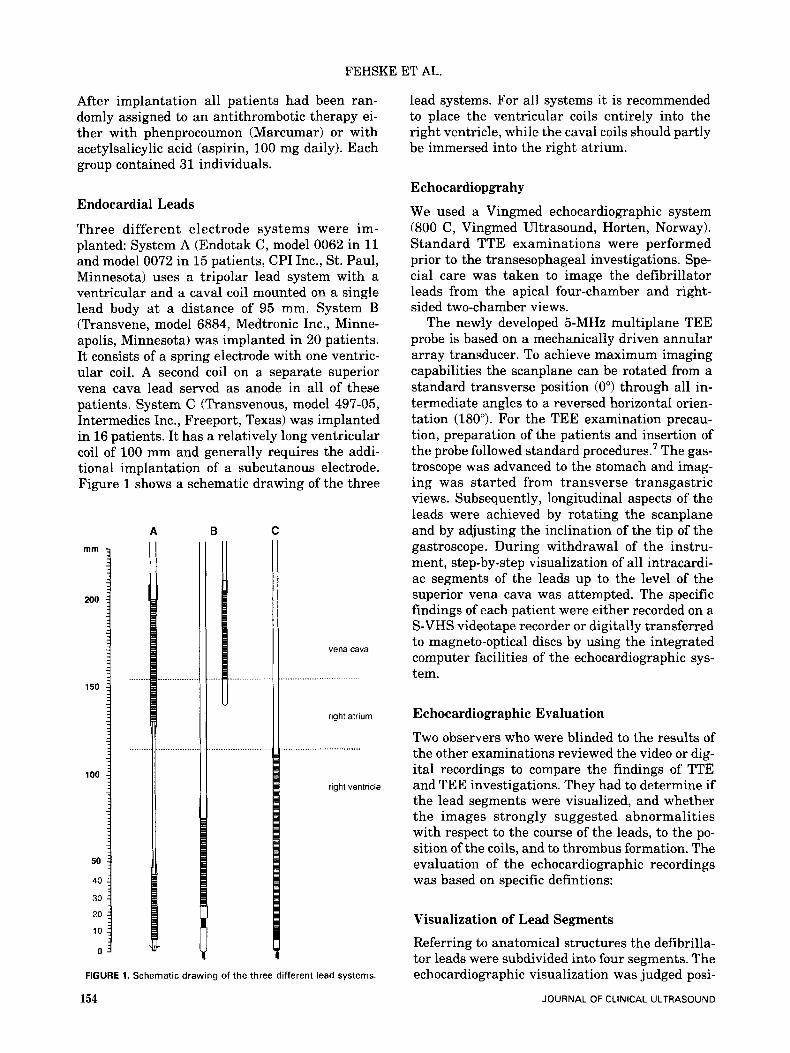
Three different electrode systems were im- planted: System A (Endotak C, model 0062 in 11 and model 0072 in 15 patients, CPI Inc., St. Paul, Minnesota) uses a tripolar lead system with a ventricular and a caval coil mounted on a single lead body at a distance of 95 mm. System B (Transvene, model 6884, Medtronic Inc., Minne- apolis, Minnesota) was implanted in 20 patients. It consists of a spring electrode with one ventric- ular coil. A second coil on a separate superior vena cava lead served as anode in all of these patients. System C (Transvenous, model 497-05, Intermedics Inc., Freeport, Texas) was implanted in 16 patients. It has a relatively long ventricular coil of 100 mm and generally requires the addi- tional implantation of a subcutanous electrode. Figure 1 shows a schematic drawing of the three
A B C mm
200
150
100
50
40
30
20
10
0
vena cava
right atrium
right ventricle
FIGURE 1. Schematic drawing of the three different lead systems.
154
lead systems. For all systems it is recommended to place the ventricular coils entirely into the right ventricle, while the caval coils should partly be immersed into the right atrium.
Echocardiopgrahy
We used a Vingmed echocardiographic system (800 C, Vingmed Ultrasound, Horten, Norway). Standard TTE examinations were performed prior to the transesophageal investigations. Spe- cial care was taken to image the defibrillator leads from the apical four-chamber and right- sided two-chamber views.
The newly developed 5-MHz multiplane TEE probe is based on a mechanically driven annular array transducer. To achieve maximum imaging capabilities the scanplane can be rotated from a standard transverse position (0") through all in- termediate angles to a reversed horizontal orien- tation (180"). For the TEE examination precau- tion, preparation of the patients and insertion of the probe followed standard procedures.' The gas- troscope was advanced to the stomach and imag- ing was started from transverse transgastric views. Subsequently, longitudinal aspects of the leads were achieved by rotating the scanplane and by adjusting the inclination of the tip of the gastroscope. During withdrawal of the instru- ment, step-by-step visualization of all intracardi- ac segments of the leads up to the level of the superior vena cava was attempted. The specific findings of each patient were either recorded on a S-VHS videotape recorder or digitally transferred to magneto-optical discs by using the integrated computer facilities of the echocardiographic sys- tem.
Echocardiographic Evaluation
Two observers who were blinded to the results of the other examinations reviewed the video or dig- ital recordings to compare the findings of TTE and TEE investigations. They had to determine if the lead segments were visualized, and whether the images strongly suggested abnormalities with respect to the course of the leads, to the po- sition of the coils, and to thrombus formation. The evaluation of the echocardiographic recordings was based on specific defintions:
Visualization of Lead Segments
Referring to anatomical structures the defibrilla- tor leads were subdivided into four segments. The echocardiographic visualization was judged posi-
JOURNAL OF CLINICAL ULTRASOUND
TRANSVENOUS DEFIBRILLATION LEADS
tive if the lead could be recorded over its full length within the right ventricle, at its passage through the tricuspid valve, within the right atrium, and at its entrance into the superior vena cava.
Abnormal Findings Orien-
tation was judged abnormal if the tip was not fixed to the distal part of the interventricular sep- tum. (2) Loops. If one segment of the lead demon-
strated a circular-shaped loop of more than 90" throughout the cardiac cycle, this was defined as an abnormal finding.
The position of a ventricular coil was noted as abnormal find- ing if it was found more than 10 mm proximal to the level of the systolic closing edge of the tricus- pid valve, while a vena cava coil was judged ab- normal if it was entirely visualized within the right atrium.
Prominent sessile or peduncu- lated masses attached to a defibrillation lead were considered to represent thrombi.
(1) Orientation of the Tip of the Lead.
(3) Abnormal Position of Coils.
(4) Thrombus.
Possible Risk Factors for Thrombus Formation The size of the right-sided cavities was estimated in each patient from the apical four-chamber view by measuring the end-diastolic minor axes of the right ventricle and the right atrium. The mea- sured diameters were corrected for body surface area and compared to published reference val- ues.8 Spontaneous echo contrast within the right atrium was also considered a possible risk factor for thrombosis.
Study Protocol TTE and TEE were performed within a minimum of 3 months after the implantation of leads (mean
6.1 months + 2.3 months). At the same time, a biplane chest X-ray and pulmonary scintigraphy were obtained and the function of the cardio- verter-defibrillator systems was evaluated. All patients were advised of the nature of the study, and written consent was obtained.
Statistical Analysis
The chi-square test was used to compare the di- agnostic value of TTE and multiplane TEE. For evaluating possible relationships between risk factors and the diagnosis of lead thrombi, the Fisher's exact test or Student's t-test for unpaired data were used, when appropriate. A p-value of <0.05 was considered statistically significant.
RESULTS
Visualization of the Cardioverter-Defibrillator Leads
The first part of Table 1 summarizes the results of segmental imaging of defibrillation leads by mul- tiplane TEE as compared to TTE investigations. In the majority of patients multiplane TEE al- lowed the imaging of all intracardiac segments of the leads. The tips and the intraventricular parts could be visualized in all but one patient. The possibility of rotating the imaging plane was es- pecially useful for the differentiation between the tips of the leads and intraventricular or intra- atrial bends. At the posterolateral side of the right atrium the caudal parts of the leads were occasionally missed. However, in 92% of all pa- tients the full length of the atrial segments could be recorded, and in 95% of the TEE investigations imaging of the passage through the tricuspid valve was successful. In all patients the inter- atrial parts of the leads and several centimeters
TABLE 1 Comparative Results of Transthoracic and Multiplane Transesophageal
Echocardiography in 62 Patients with Permanent Transvenous Cardioverter-Defibrillator Leads
TTE (%) Mukiplane TEE (YO) Significance
Identification of lead segments Right ventricle 48 (77.4) 61 (98.4) p < 0.01 Tricuspid valve 39 (62.9) 59 (95.2) p < 0.01 Right atrium 34 (54.8) 57 (91.9) p < 0.01 Superior vena cava 3 (4.8) 62 (100.0) p < 0.01
Orientation of the tip 3 (42.1) 7 Loops 2 (28.6) 7
Abnormal findings
Position of coils 1 (6.3) 16 Thrombi 1 (7.7) 13
TEE: transesophageal echocardiography; TE: transthoracic echocardiography.
VOL. 23, NO. 3, MARCHIAPRIL 1995 155
FEHSKE ET AL.
of their caval segments could be visualized by the transesophageal technique. Multiplane TEE was significantly superior to TTE imaging in all seg- ments of the leads. From the apical approach it was still possible to visualize the right ventricu- lar parts in 77% of the patients, but with increas- ing distances from the transducer, the image quality decreased, and lead segments could be im- aged at the passage through the valve, in the right atrium, and in the vena cava in only 63%, 55%, and 5% of patients, respectively.
Abnormal Findings
Abnormal findings are listed in the second part of Table 1. Successful imaging by TTE is given in percent values of all findings that were detected by multiplane TEE (100%). Transthoracic apical echo imaging revealed an abnormal orientation of the tips in 42% of the TEE studies, and loops were detected in 29%. TTE allowed the delineation of the coils and the recognition of clots (6% and 8%, respectively) only in exceptional cases.
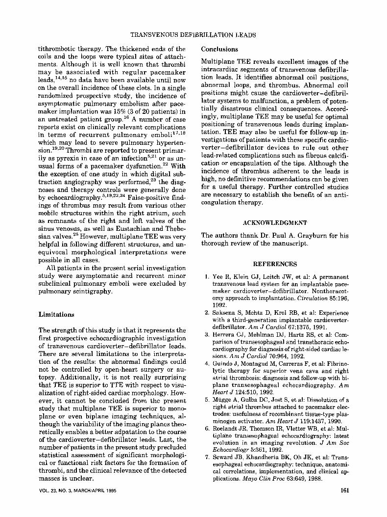
Orientation of the Tip of theLead. In 7 pa- tients (11.3%) an abnormal orientation of the tip was noted by multiplane TEE. In 3 of these cases a laterally directed tip was also suggested from the chest roentgenograms, while in the other pa- tients with either anterior (Figure 21, posterior, or proximal positions of the tips the X-ray photo- graphs were inconclusive. No functional abnor- mality of the cardioverter-defibrillator devices were related to the orientation of the tips. In one patient a small pericardial effusion was detected 15 weeks after implantation. It was located at the epicardial free wall which was opposed to the an- teriorly directed tip of the defibrillation lead. Re- gression of the effusion was documented by trans- thoracic follow-up examinations, and the patient had an uneventful clinical course.
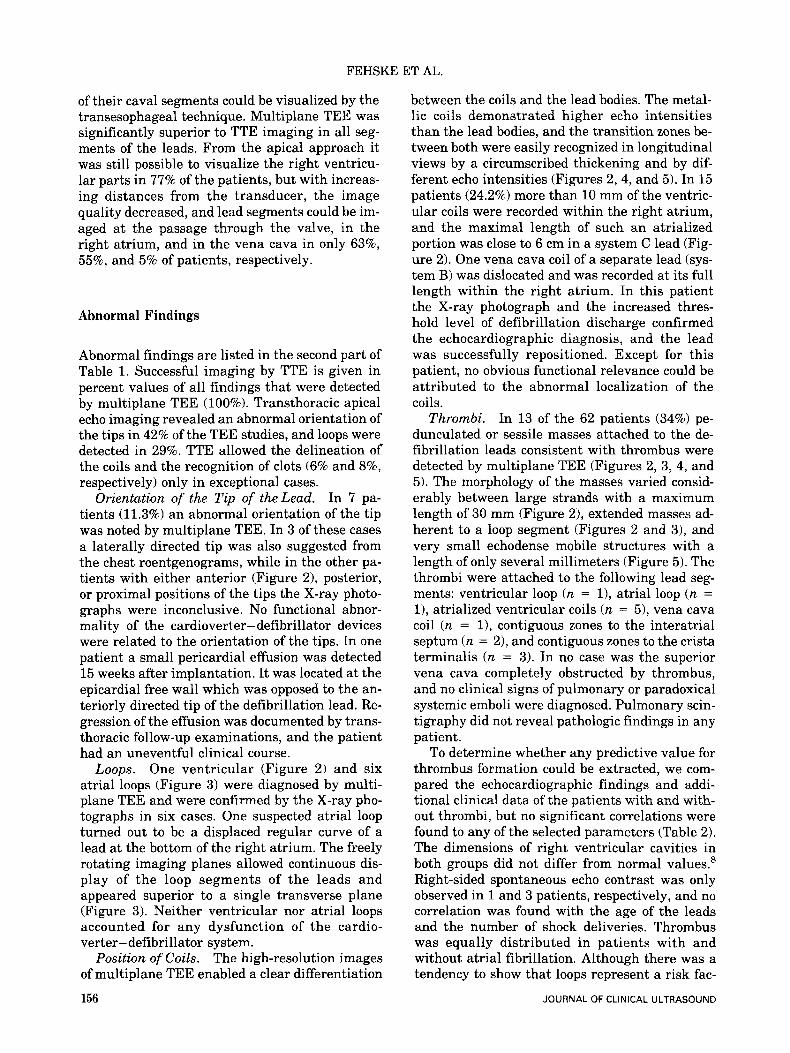
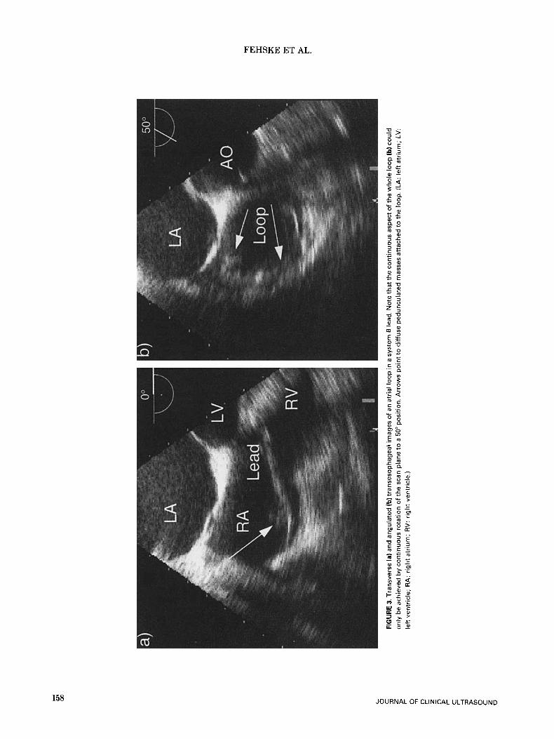
One ventricular (Figure 2) and six atrial loops (Figure 3) were diagnosed by multi- plane TEE and were confirmed by the X-ray pho- tographs in six cases. One suspected atrial loop turned out to be a displaced regular curve of a lead at the bottom of the right atrium. The freely rotating imaging planes allowed continuous dis- play of the loop segments of the leads and appeared superior to a single transverse plane (Figure 3). Neither ventricular nor atrial loops accounted for any dysfunction of the cardio- verter-defibrillator system.
The high-resolution images of multiplane TEE enabled a clear differentiation
156
Loops.
Position of Coils.
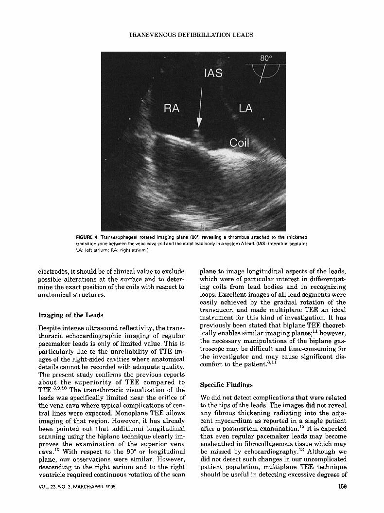
between the coils and the lead bodies. The metal- lic coils demonstrated higher echo intensities than the lead bodies, and the transition zones be- tween both were easily recognized in longitudinal views by a circumscribed thickening and by dif- ferent echo intensities (Figures 2 , 4 , and 5). In 15 patients (24.2%) more than 10 mm of the ventric- ular coils were recorded within the right atrium, and the maximal length of such an atrialized portion was close to 6 cm in a system C lead (Fig- ure 2). One vena cava coil of a separate lead (sys- tem B) was dislocated and was recorded at its full length within the right atrium. In this patient the X-ray photograph and the increased thres- hold level of defibrillation discharge confirmed the echocardiographic diagnosis, and the lead was successfully repositioned. Except for this patient, no obvious functional relevance could be attributed to the abnormal localization of the coils.
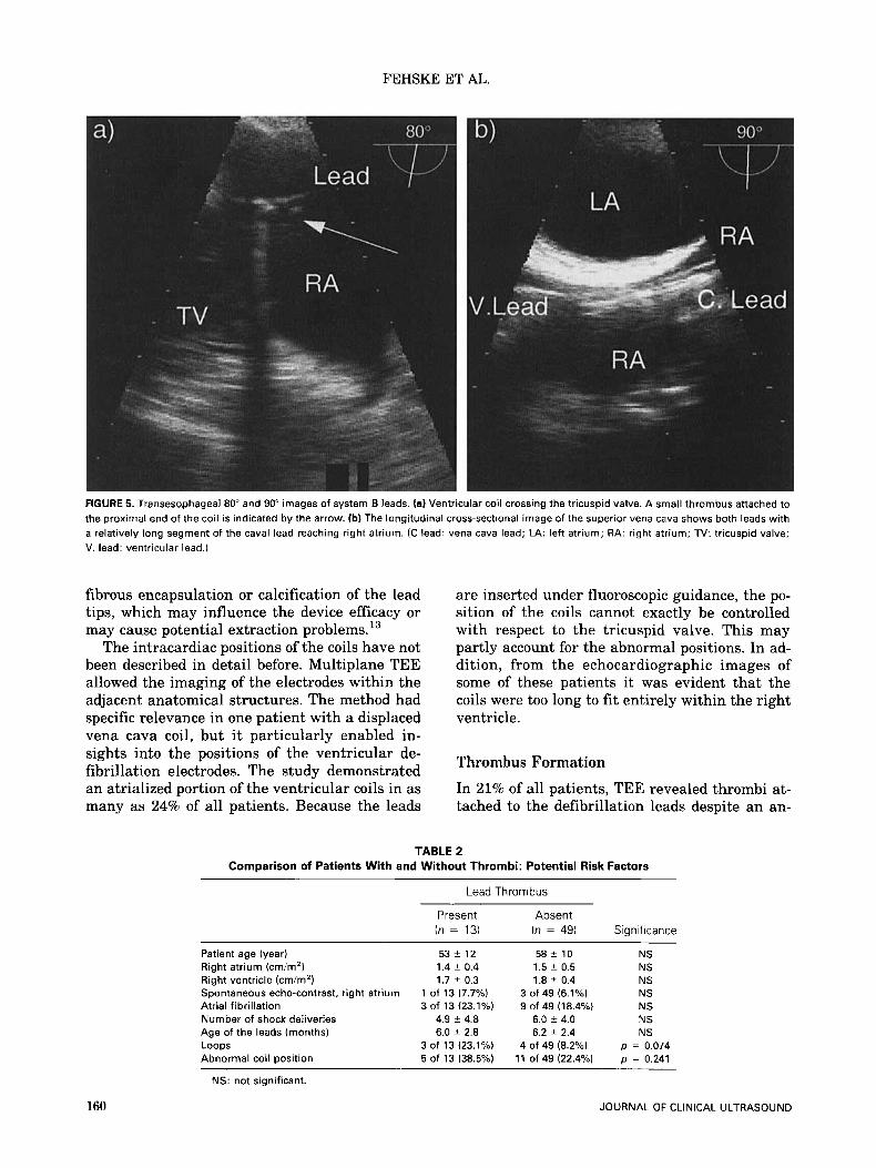
Thrombi. In 13 of the 62 patients (34%) pe- dunculated or sessile masses attached to the de- fibrillation leads consistent with thrombus were detected by multiplane TEE (Figures 2, 3, 4, and 5). The morphology of the masses varied consid- erably between large strands with a maximum length of 30 mm (Figure 21, extended masses ad- herent to a loop segment (Figures 2 and 31, and very small echodense mobile structures with a length of only several millimeters (Figure 5). The thrombi were attached to the following lead seg- ments: ventricular loop (n = l), atrial loop (n = l), atrialized ventricular coils (n = 5), vena cava coil (n = l), contiguous zones to the interatrial septum (n = 21, and contiguous zones to the crista terminalis (n = 3). In no case was the superior vena cava completely obstructed by thrombus, and no clinical signs of pulmonary or paradoxical systemic emboli were diagnosed. Pulmonary scin- tigraphy did not reveal pathologic findings in any patient.
To determine whether any predictive value for thrombus formation could be extracted, we com- pared the echocardiographic findings and addi- tional clinical data of the patients with and with- out thrombi, but no significant correlations were found to any of the selected parameters (Table 2). The dimensions of right ventricular cavities in both groups did not differ from normal values.8 Right-sided spontaneous echo contrast was only observed in 1 and 3 patients, respectively, and no correlation was found with the age of the leads and the number of shock deliveries. Thrombus was equally distributed in patients with and without atrial fibrillation. Although there was a tendency to show that loops represent a risk fac-
JOURNAL OF CLINICAL ULTRASOUND
TRANSVENOUS DEFIBRILLATION LEADS
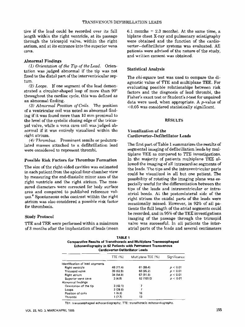
FIGURE 2. Multiplane transesophageal images of three patients with a system C lead. The rotational angles of the imaging planes are indicated in the right corners. ( 8 ) Transgastric view of an anteriorly directed tip. With an angulation of 75" the ventricular segment can be entirely visualized. (Note: The ventricular coil crosses the tricuspid valve.) (b) Vena cava segment in the same patient. Large floating strands (arrows) attached to the lead at the orifice of the vena cava. (c) Transgastric 25" view of a ventricular loop. Arrows mark clots. (d) Transesophageal 40" longitudinal aspect of a ventricular coil (arrow) reaching the superior limbus of the foramen ovale. (CT: crista terminalis; FO: foramen ovale; LA: left atrium; RA: right atrium; RV: right ventricle; TV: tricuspid valve.)
tor for thrombus formation (p = 0.074), we also recorded four loops without evidence of thrombus.
Because clots were detected in 4 of 31 patients on phenprocoumon and 9 of 31 patients on acetyl- salicylic acid, no statistically significant advan- tage of either antithrombotic therapy could be documented. Because of the small number of pa- tients, the incidence of thrombi showed no statisti- cally significant differences between the three lead systems with 3 of 26 (12%), 7 of 20 (35%), and 3 of 16 (19%) positive findings for systems A, B, and C.
VOL. 23, NO. 3, MARCH/APRIL 1995
DISCUSSION
This first prospective study of transesophageal echocardiographic investigations of transvenous cardioverter-defibrillator leads was motived by two major arguments: (1) The development of the multiplane transesophageal technique was ex- pected to allow better visualization of the intra- cardiac segments of the leads than previous meth- ods. (2) As the leads are thicker and have a particular shape compared to regular pacemaker
157
L 0
C n
2 D
FIG
UR
E 3.
Tra
nsve
rse
la) a
nd a
ngul
ated
(b) t
rans
esop
hage
al im
ages
of a
n at
rial
loop
in a
sys
tem
6 le
ad. N
ote
that
the
cont
inuo
us a
spec
t of t
he w
hole
loop
(b) c
ould
on
ly b
e ac
hiev
ed b
y co
ntin
uous
rot
atio
n of
the
scan
pla
ne to
a 5
0" p
ositi
on. A
rrow
s po
int t
o di
ffus
e pe
dunc
ulat
ed m
asse
s at
tach
ed to
the
loop
. (LA
: leR
atr
ium
; LV
: le
ft v
entr
icle
; R
A:
righ
t atr
ium
; R
V: r
ight
ven
tric
le.)
f E z r
TRANSVENOUS DEFIBRILLATION LEADS
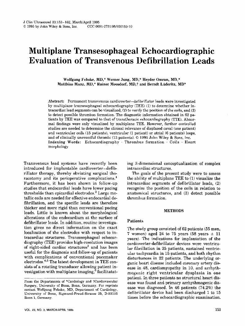
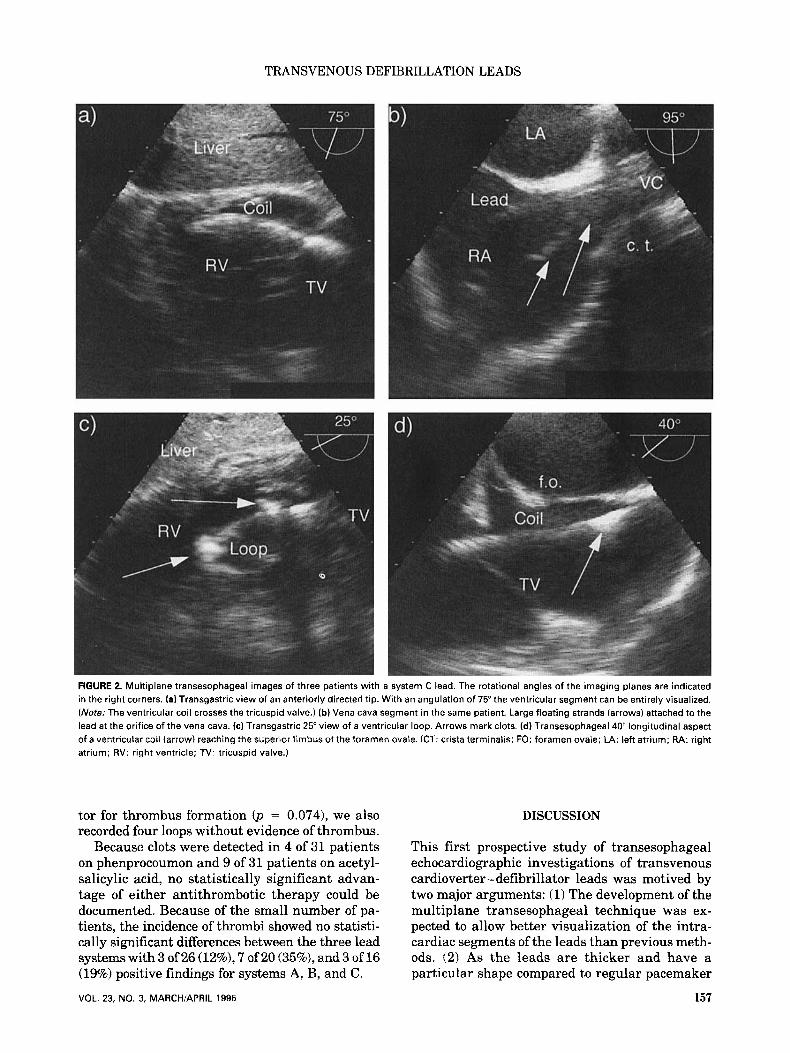
FIGURE 4. Transesophageal rotated imaging plane (80") revealing a thrombus attached to the thickened transition zone between the vena cava coil and the atrial lead body in a system A lead. (IAS: interatrial septum; LA: left atrium; RA: right atrium.)
electrodes, it should be of clinical value to exclude possible alterations at the surface and to deter- mine the exact position of the coils with respect to anatomical structures.
Imaging of the Leads
Despite intense ultrasound reflectivity, the trans- thoracic echocardiographic imaging of regular pacemaker leads is only of limited value. This is particularly due to the unreliability of TTE im- ages of the right-sided cavities where anatomical details cannot be recorded with adequate quality. The present study confirms the previous reports about the superiority of TEE compared to TTE .3,9,10 The transthoracic visualization of the leads was specifically limited near the orifice of the vena cava where typical complications of cen- tral lines were expected. Monoplane TEE allows imaging of that region. However, it has already been pointed out that additional longitudinal scanning using the biplane technique clearly im- proves the examination of the superior vena cava." With respect to the 90" or longitudinal plane, our observations were similar. However, descending to the right atrium and to the right ventricle required continuous rotation of the scan
VOL. 23, NO. 3, MARCH/APRIL 1995
plane to image longitudinal aspects of the leads, which were of particular interest in differentiat- ing coils from lead bodies and in recognizing loops. Excellent images of all lead segments were easily achieved by the gradual rotation of the transducer, and made multiplane TEE an ideal instrument for this kind of investigation. It has previously been stated that biplane TEE theoret- ically enables similar imaging planes;" however, the necessary manipulations of the biplane gas- troscope may be difficult and time-consuming for the investigator and may cause significant dis- comfort to the
Specific Findings
We did not detect complications that were related to the tips of the leads. The images did not reveal any fibrous thickening radiating into the adja- cent myocardium as reported in a single patient after a postmortem examination.12 It is expected that even regular pacemaker leads may become ensheathed in fibrocollagenous tissue which may be missed by ech~cardiography.~~ Although we did not detect such changes in our uncomplicated patient population, multiplane TEE technique should be useful in detecting excessive degrees of
159
FEHSKE ET AL.
FIGURE 5. Transesophageal 80" and 90" images of system B leads. fa) Ventricular coil crossing the tricuspid valve. A small thrombus attached to the proximal end of the coil is indicated by the arrow. (b) The longitudinal cross-sectional image of the superior vena cava shows both leads with a relatively long segment of the caval lead reaching right atrium. (C lead: vena cava lead; LA: left atrium; RA: right atrium; TV: tricuspid valve; V. lead: ventricular lead.)
fibrous encapsulation or calcification of the lead tips, which may influence the device efficacy or may cause potential extraction pr0b1ems.l~
The intracardiac positions of the coils have not been described in detail before. Multiplane TEE allowed the imaging of the electrodes within the adjacent anatomical structures. The method had specific relevance in one patient with a displaced vena cava coil, but it particularly enabled in- sights into the positions of the ventricular de- fibrillation electrodes. The study demonstrated an atrialized portion of the ventricular coils in as many as 24% of all patients. Because the leads
are inserted under fluoroscopic guidance, the po- sition of the coils cannot exactly be controlled with respect to the tricuspid valve. This may partly account for the abnormal positions. In ad- dition, from the echocardiographic images of some of these patients it was evident that the coils were too long to fit entirely within the right ventricle.
Thrombus Formation
In 21% of all patients, TEE revealed thrombi at- tached to the defibrillation leads despite an an-
TABLE 2 Comparison of Patients With and Without Thrombi: Potential Risk Factors
Lead Thrombus
Patient age (year) Right atrium (cmim') Right ventricle (cm/m2) Spontaneous echo-contrast, right atrium Atrial fibrillation Number of shock deliveries Age of the leads (months) Loops Abnormal coil position
Present (n = 13)
53 f 12 1.4 ? 0.4 1.7 ? 0.3
1 of 13 (7.7%) 3 of 13 (23.1%)
4.9 i 4.8 6.0 ? 2.8
5 of 13 (38.5%) 3 of 13 (23.1%)
Absent (n = 49)
58 ? 10 1.5 ? 0.5 1.8 ? 0.4
3 of 49 (6.1%)
6.0 i 4.0 6.2 ? 2.4
9 of 49 (18.4%)
4 of 49 (8.2%) 11 of 49 (22.4%)
Significance
NS NS NS NS NS NS NS
p = 0.074 p = 0.241
160
NS: not significant.
JOURNAL OF CLINICAL ULTRASOUND
TRANSVENOUS DEFIBRILLATION LEADS
tithrombotic therapy. The thickened ends of the coils and the loops were typical sites of attach- ments. Although it is well known that thrombi may be associated with regular pacemaker leads,14,15 no data have been available until now on the overall incidence of these clots. In a single randomized prospective study, the incidence of asymptomatic pulmonary embolism after pace- maker implantation was 15% (3 of 20 patients) in an untreated patient group." A number of case reports exist on clinically relevant complications in terms of recurrent pulmonary emboli17,1s which may lead to severe pulmonary hyperten- sion.19,20 Thrombi are reported to present primar- ily as pyrexia in case of an infection5v2' or as un- usual forms of a pacemaker dysfunction.22 With the exception of one study in which digital sub- traction angiography was performed,23 the diag- noses and therapy controls were generally done by echo~ardiography.~~'~~~~~~~ F alse-positive find- ings of thrombus may result from various other mobile structures within the right atrium, such as remnants of the right and left valves of the sinus venosus, as well as Eustachian and Thebe- sian valves.25 However, multiplane TEE was very helpful in following different structures, and un- equivocal morphological interpretations were possible in all cases.
All patients in the present serial investigation study were asymptomatic and recurrent minor subclinical pulmonary emboli were excluded by pulmonary scintigraphy.
Limitations
The strength of this study is that it represents the first prospective echocardiographic investigation of transvenous cardioverter-defibrillator leads. There are several limitations to the interpreta- tion of the results: the abnormal findings could not be controlled by open-heart surgery or au- topsy. Additionally, it is not really surprising that TEE is superior to TTE with respect to visu- alization of right-sided cardiac morphology. How- ever, i t cannot be concluded from the present study that multiplane TEE is superior to mono- plane or even biplane imaging techniques, al- though the variability of the imaging planes theo- retically enables a better adpatation to the course of the cardioverter-defibrillator leads. Last, the number of patients in the present study precluded statistical assessment of significant morphologi- cal or functional risk factors for the formation of thrombi, and the clinical relevance of the detected masses is unclear.
Conclusions
Multiplane TEE reveals excellent images of the intracardiac segments of transvenous defibrilla- tion leads. It identifies abnormal coil positions, abnormal loops, and thrombus. Abnormal coil positions might cause the cardioverter-defibril- lator systems to malfunction, a problem of poten- tially disastrous clinical consequences. Accord- ingly, multiplane TEE may be useful for optimal positioning of transvenous leads during implan- tation. TEE may also be useful for follow-up in- vestigations of patients with these specific cardio- verter-defibrillator devices to rule out other lead-related complications such as fibrous calcifi- cation or encapsulation of the tips. Although the incidence of thrombus adherent to the leads is high, no definitive recommendations can be given for a useful therapy. Further controlled studies are necessary to establish the benefit of an anti- coagulation therapy.
ACKNOWLEDGMENT
The authors thank Dr. Paul A. Grayburn for his thorough review of the manuscript.
REFERENCES
1.
2.
3.
4.
5.
6.
7.
Yee R, Klein GJ, Leitch JW, et al: A permanent transvenous lead system for an implantable pace- maker cardioverter-defibrillator. Nonthoracot- omy approach to implantation. Circulation 85:196, 1992. Saksena S, Mehta D, Krol RB, et al: Experience with a third-generation implantable cardioverter- defibrillator. A m J Cardiol67:1375, 1991. Herrera CJ, Mehlman DJ, Hartz RS, et al: Com- parison of transesophageal and transthoracic echo- cardiography for diagnosis of right-sided cardiac le- sions. Am J Cardiol 70:964, 1992. Guindo J , Montagud M, Carreras F, et al: Fibrino- lytic therapy for superior vena cava and right atrial thrombosis: diagnosis and follow-up with bi- plane transesophageal echocardiography. A m Heart J 124510, 1992. Mugge A, Gulba DC, Jost S, et al: Dissolution of a right atrial thrombus attached to pacemaker elec- trodes: usefulness of recombinant tissue-type plas- minogen activator. A m Heart J 119:1437, 1990. Roelandt JR, Thomson IR, Vletter WB, et al: Mul- tiplane transesophageal echocardiography: latest evolution in an imaging revolution. J A m SOC Echocardiogr 5:361, 1992. Seward JB, Khandheria BK, Oh JK, et al: Trans- esophageal echocardiography: technique, anatomi- cal correlations, implementation, and clinical ap- plications. Muyo Clin Proc 63:649, 1988.
161 VOL. 23, NO. 3, MARCH/APRIL 1995
FEHSKE ET AL.
8. Erbel R, Henkel B, Ostlander C, et al: Normal val- ues for two-dimensional echocardiography. Dtsch Med Wochenschr 110:123,1985.
9. Alam M, Sun I, Smith S: Transesophageal echocar- diographic evaluation of right atrial mass lesions. J A m SOC Echocardiogr 4:331, 1991.
10. Cohen GI, Klein AL, Chan KL, et al: Transesoph- ageal echocardiographic diagnosis of right-sided cardiac masses in patients with central lines. A m J Cardiol 70:925, 1992.
11. Khanderia BK, Oh J: Transesophageal echocardi- ography. A m J Cardiol 69:61, 1992.
12. Epstein AE, Anderson PG, Kay GN, et al: Gross and microscopic changes associated with a nontho- racotomy implantable cardioverter defibrillator. Pace 15:382, 1992.
13. Myers MR, Parsonnet V, Bernstein AD: Extraction of implanted transvenous pacing leads: a review of a persistent clinical problem. A m Heart J 121:881, 1991.
14. Phibbs B, Marriott HJ: Complications of perma- nent transvenous pacing. N Engl J Med 312:428, 1985.
15. Mitrovic V, Thormann J, Schlepper M, e t al: Thrombotic complications with pacemakers. Int J Cardiol 2:363, 1983.
16. Seeger W, Scherer K: Asymptomatic pulmonary embolism following pacemaker implantation. Pace 9:196, 1986.
17. Kinney EL, Allen RP, Weidner WA, et al: Recur- rent pulmonary emboli secondary to right atrial thrombus around a permanent pacing catheter: a case report and review of the literature. Pace 2196, 1979.
18. Porath A, Avnun L, Hirsch M, et al: Right atrial thrombus and recurrent pulmonary emboli second- ary to permanent cardiac pacing-a case report and short review of literature. Angiology 38:627, 1987.
19. De Vries H, Iversen S, Zimmermann W, et al: Chronic thromboembolic cor pulmonale in pace- maker-associated right atrial thrombi. Pulmonary thromboendarterectomy with removal of the elec- trodes as a life-saving measure. Dtsch Med Wochenschr 116:294, 1991.
20. Prozan GB, Shipley RE, Madding GF, et al: Pulmo- nary thromboembolism in the presence of an en- docardiac pacing catheter. JAMA 206:1564, 1968.
21. Grunewald RA, Smith PL, Nihoyannopoulos P, et al: Right ventricular pacing wire thrombus pre- senting as pyrexia of unknown origin. Clin Cardiol 12:106, 1989.
22. Perry RA, Clarke DB, Shiu MF: Entanglement of embolised thrombus with an endocardia1 lead caus- ing pacemaker malfunction and subsequent pulmo- nary embolism. Br Heart J 57:292, 1987.
23. Neuwirth J, Bohutova J, Kolar J, et al: DSA diag- nosis of pulmonary embolization from intracardial thrombus in a patient with permanent pacing cath- eter. Pace 13:7, 1990.
24. May KJ, Cardone JT, Stroebel PP, et al: Streptoki- nase dissolution of a right atrial thrombus associ- ated with a temporary pacemaker. Arch Intern Med 148:903, 1988.
25. Anderson RH, Becker AE: Cardiac Anatomy. Ed- inburgh, London, New York, Churchill Living- stone, 1980, p 22.
162 JOURNAL OF CLINICAL ULTRASOUND