
Multilevel Multiphase Feedforward Space-Vector Modulation Technique
10
Multilevel Multiphase Feed-forward Space Vector Modulation Technique J. I. Leon, Member, IEEE, O. Lopez, Member, L. G. Franquelo, Fellow Member, IEEE, J. Doval-Gandoy, Member, IEEE, S. Vazquez, Member, IEEE, J. Alvarez and F. D. Freijedo, Member, IEEE Abstract—Multiphase converters are being applied to an in- creasing number of industrial applications in recent years. On the other hand, multilevel converters have become a mature technology mainly in medium and high power applications. One of the problems of multilevel converters is the dc voltage unbalance of the dc bus. Depending on the loading conditions and the number of levels of the converter, oscillations appear in the dc voltages of the DC-Link. This paper presents a feed- forward modulation technique for multilevel multiphase convert- ers that reduces the distortion under balanced or unbalanced dc conditions. The proposed modulation method can be applied to any multilevel converter topology with any number of levels and phases. Experimental results are shown in order to validate the proposed feed-forward modulation technique. I. I NTRODUCTION M ULTIPHASE variable-speed drives field has experi- enced a substantial growth since the beginning of this century. There has been a rapid development in some specific application areas such as: electric ship propulsion, lo- comotive traction, industrial high-power applications, electric and hybrid-electric vehicles, electric aircrafts, etc... [1]–[5]. Recent developments in the field of multiphase variable speed drives have led to a corresponding development of pulsewidth modulation (PWM) schemes for multiphase inverters used in these drives. Most of the existing research related to PWM control of multiphase inverters applies to two-level inverters [6]–[9]. However, the use of multilevel inverters for multiphase variable speed drives has been established as a good solution in high power applications such as electric ship propulsion and locomotive traction [10]–[13]. Multilevel topologies consid- ered in the literature are typically either diode-clamped, flying capacitor or cascaded H-bridge converters [14]–[17]. Several space vector modulation techniques have been presented recently applied to multiphase converters of two- level voltage source type [18]–[20]. In [21], a general space vector modulation algorithm that can be applied to multilevel multiphase converters with any number of phases and levels was presented. This algorithm, called multilevel multiphase space vector modulation (MSVM) in this paper, is based on a Manuscript received June 17, 2009. Accepted for publication September 26, 2009. Copyright c 2009 IEEE. Personal use of this material is permitted. However, permission to use this material for any other purposes must be obtained from the IEEE by sending a request to [email protected]. J. I. Leon, L. G. Franquelo and S. Vazquez are with the Electronic Engineering Department, University of Seville (Spain), (e-mail: [email protected]). O. Lopez, J. Doval-Gandoy, J. Alvarez and F. D. Freijedo are with the Electronic Engineering Department, University of Vigo (Spain). reduction of the multilevel multiphase modulation problem to a two-level multiphase modulation problem using a two-level multiphase modulator. This two-level modulator is fed with the fractional part of the reference voltage vector to obtain a matrix, which includes a displaced switching vector sequence, and the switching times. The final switching sequence is calculated adding the integer part of the reference to the vectors of that sequence. This paper introduces a new feed-forward space vector modulation technique for multilevel multiphase power con- verters called multilevel multiphase feed-forward space vector modulation (MFFSVM). This modulation algorithm is a feed- forward version of the MSVM technique. In this way, the notation introduced in [21] has been used to explain the proposed MFFSVM strategy. This paper is organized as follows: In section II the aim of the MFFSVM technique is presented. The mathematical description of the MFFSVM strategy is introduced in section III. An example to show the good performance of the proposed idea is shown in section IV. Finally, experimental results and conclusions of the work are presented in section V and section VI respectively. II. AIM OF THE PROPOSED MODULATION STRATEGY In the most common multilevel converter topologies such as flying capacitor, diode-clamped, cascaded full-bridge or hybrid converters, the possible output voltages of each phase are equally distributed being an integer multiple of a fixed voltage step [14], [15]. However, in asymmetrical multilevel converters, this voltage condition is not true because unequal voltage steps are present in the power converter operation [22]–[24]. In both cases, symmetrical or asymmetrical mul- tilevel converters, the control of the dc voltage balance can not be accurately achieved in all loading conditions. Load imbalances and nonlinear or transient loads have a significant impact on the multilevel converter dc voltages ripple (oscilla- tions or actual values) [25]–[28]. As a consequence, transient imbalances and steady state oscillations can be present in the power converter operation. These phenomena lead to distorted output waveforms because the modulators usually do not take into account the actual dc voltage unbalance. Recently a work has been introduced in order to eliminate this distortion in three-level diode-clamped converters [29]. The previous MSVM technique can be applied to multilevel converters where the output voltage step between all the con- secutive voltage levels is constant. However, under unbalanced
-
Upload
independent -
Category
Documents
-
view
3 -
download
0
Transcript of Multilevel Multiphase Feedforward Space-Vector Modulation Technique
Multilevel Multiphase Feed-forward Space VectorModulation Technique
J. I. Leon, Member, IEEE, O. Lopez, Member, L. G. Franquelo, Fellow Member, IEEE, J. Doval-Gandoy,Member, IEEE, S. Vazquez, Member, IEEE, J. Alvarez and F. D. Freijedo, Member, IEEE
Abstract—Multiphase converters are being applied to an in-creasing number of industrial applications in recent years. Onthe other hand, multilevel converters have become a maturetechnology mainly in medium and high power applications.One of the problems of multilevel converters is the dc voltageunbalance of the dc bus. Depending on the loading conditionsand the number of levels of the converter, oscillations appearin the dc voltages of the DC-Link. This paper presents a feed-forward modulation technique for multilevel multiphase convert-ers that reduces the distortion under balanced or unbalanced dcconditions. The proposed modulation method can be applied toany multilevel converter topology with any number of levels andphases. Experimental results are shown in order to validate theproposed feed-forward modulation technique.
I. INTRODUCTION
MULTIPHASE variable-speed drives field has experi-enced a substantial growth since the beginning of
this century. There has been a rapid development in somespecific application areas such as: electric ship propulsion, lo-comotive traction, industrial high-power applications, electricand hybrid-electric vehicles, electric aircrafts, etc... [1]–[5].Recent developments in the field of multiphase variable speeddrives have led to a corresponding development of pulsewidthmodulation (PWM) schemes for multiphase inverters used inthese drives. Most of the existing research related to PWMcontrol of multiphase inverters applies to two-level inverters[6]–[9]. However, the use of multilevel inverters for multiphasevariable speed drives has been established as a good solution inhigh power applications such as electric ship propulsion andlocomotive traction [10]–[13]. Multilevel topologies consid-ered in the literature are typically either diode-clamped, flyingcapacitor or cascaded H-bridge converters [14]–[17].
Several space vector modulation techniques have beenpresented recently applied to multiphase converters of two-level voltage source type [18]–[20]. In [21], a general spacevector modulation algorithm that can be applied to multilevelmultiphase converters with any number of phases and levelswas presented. This algorithm, called multilevel multiphasespace vector modulation (MSVM) in this paper, is based on a
Manuscript received June 17, 2009. Accepted for publication September 26,2009. Copyright c© 2009 IEEE. Personal use of this material is permitted.However, permission to use this material for any other purposes must beobtained from the IEEE by sending a request to [email protected]. I. Leon, L. G. Franquelo and S. Vazquez are with the Electronic EngineeringDepartment, University of Seville (Spain), (e-mail: [email protected]). O.Lopez, J. Doval-Gandoy, J. Alvarez and F. D. Freijedo are with the ElectronicEngineering Department, University of Vigo (Spain).
reduction of the multilevel multiphase modulation problem toa two-level multiphase modulation problem using a two-levelmultiphase modulator. This two-level modulator is fed withthe fractional part of the reference voltage vector to obtain amatrix, which includes a displaced switching vector sequence,and the switching times. The final switching sequence iscalculated adding the integer part of the reference to thevectors of that sequence.
This paper introduces a new feed-forward space vectormodulation technique for multilevel multiphase power con-verters called multilevel multiphase feed-forward space vectormodulation (MFFSVM). This modulation algorithm is a feed-forward version of the MSVM technique. In this way, thenotation introduced in [21] has been used to explain theproposed MFFSVM strategy.
This paper is organized as follows: In section II the aimof the MFFSVM technique is presented. The mathematicaldescription of the MFFSVM strategy is introduced in sectionIII. An example to show the good performance of the proposedidea is shown in section IV. Finally, experimental results andconclusions of the work are presented in section V and sectionVI respectively.
II. AIM OF THE PROPOSED MODULATION STRATEGY
In the most common multilevel converter topologies suchas flying capacitor, diode-clamped, cascaded full-bridge orhybrid converters, the possible output voltages of each phaseare equally distributed being an integer multiple of a fixedvoltage step [14], [15]. However, in asymmetrical multilevelconverters, this voltage condition is not true because unequalvoltage steps are present in the power converter operation[22]–[24]. In both cases, symmetrical or asymmetrical mul-tilevel converters, the control of the dc voltage balance cannot be accurately achieved in all loading conditions. Loadimbalances and nonlinear or transient loads have a significantimpact on the multilevel converter dc voltages ripple (oscilla-tions or actual values) [25]–[28]. As a consequence, transientimbalances and steady state oscillations can be present in thepower converter operation. These phenomena lead to distortedoutput waveforms because the modulators usually do not takeinto account the actual dc voltage unbalance. Recently a workhas been introduced in order to eliminate this distortion inthree-level diode-clamped converters [29].
The previous MSVM technique can be applied to multilevelconverters where the output voltage step between all the con-secutive voltage levels is constant. However, under unbalanced

dc voltages this voltage step is not constant in general. In thiscase, the MSVM technique generates errors in the modulatedwaveforms leading to undesired distortion.
The modulation technique proposed in this work solves thisproblem using the feed-forward concept. Some modulationstrategies present in the literature use the feed-forward conceptin order to achieve modulated output waveforms with low dis-tortion for multilevel converters [30]–[33]. The feed-forwardbasic idea is to measure the actual dc voltages of the multilevelconverter and generate the switching of the power convertertaking them into account. In this way, the averaged value ofthe modulated output waveforms coincides with the desiredreference. The proposed feed-forward space vector modulationstrategy, called in this paper MFFSVM, is a simple method thatcan be applied to multilevel multiphase converters.
III. ENHANCED FEED-FORWARD MULTILEVELMULTIPHASE SVM TECHNIQUE (MFFSVM)
In a space-vector modulation (SVM) technique, the ref-erence vector Vr is generated by means of a sequence ofspace states or switching vectors {Vs1,Vs2,. . . ,Vs(P+1)}. Pis the number of phases of the multilevel multiphase converter.To achieve a proper synthesis of the reference vector overa switching period Tsw, each switching vector Vsk must beapplied during an interval Tk.
Vr =1
Tsw
P+1∑
k=1
VskTk
P+1∑
k=1
Tk = Tsw (1)
The reference vector Vr is composed of the voltage refer-ence for each phase of the system. Switching times vector Tis composed of the switching times of the switching sequence.
Vr = [V 1r , V
2r , · · · , V P
r ]T ∈ RP
Vsk = [V 1sk, V
2sk, · · · , V P
sk ]T ∈ RP
T = [T1, T2, · · · , TP+1] ∈ RP+1 (2)
Each phase j of the power converter can achieve in generalN different output voltage levels and each one of thesevoltages is described as V j
sk (possible output voltage numberk of phase j). Each possible output phase voltage V j
sk isachieved by a specific and known switching configuration ofthe phase j of the power converter denoted Sj
k. The possibleswitching configurations of the power converter Sj
k and thecorresponding phase voltages V j
sk are used to define matrices Sand Mv respectively. These matrices depend on the multilevelconverter topology. This is the only step of the MFFSVMtechnique that depends on the topology of the power converter.
S =
S11 S1
2 . . . S1N
S21 S2
2 . . . S2N
......
. . ....
SP1 SP
2 . . . SPN
(3)
Mv =
V 1s1 V 1
s2 . . . V 1sN
V 2s1 V 2
s2 . . . V 2sN
......
. . ....
V Ps1 V P
s2 . . . V PsN
(4)
The next step of the proposed MFFSVM technique is togenerate matrix Mo which contains the elements of matrixMv but ordered in increasing order. Matrix So (with elementscalled Sj
ok) is obtained from matrix S ordering their elementsin the order obtained in matrix Mo. In this way, each elementV jok is still related to switching configuration Sj
ok.
So =
S1o1 S1
o2 . . . S1oN
S2o1 S2
o2 . . . S2oN
......
. . ....
SPo1 SP
o2 . . . SPoN
Mo =
V 1o1 V 1
o2 . . . V 1oN
V 2o1 V 2
o2 . . . V 2oN
......
. . ....
V Po1 V P
o2 . . . V PoN
where V jok ≤ V j
ok+1 (5)
In order to consider any dc voltage in the multilevel powerconverter, voltage vectors Vr and Vsk and switching timesvector T are normalized determining respectively vectors vr
and vsk and t. It is important to remark that all vr and vsk andt belong to the multidimensional space of real numbers RP ≥0. The normalization of the voltage vectors is done using thelowest output voltage of each phase and the difference betweenthe highest and the lowest output voltages of each phase. Onthe other hand, the switching times vector is normalized usingthe switching period Tsw. These calculations force that thevalues of all the normalized voltage vector components are inthe range [0,1].
vr = [υ1r , υ
2r , . . . , υ
Pr ]
T
vsk = [υ1sk, υ
2sk, . . . , υ
Psj ]
T
t = [t1, t2, . . . , tP+1] (6)
υjr =
V jr − V j
o1
V joN − V j
o1
∈ R
υjsk =
Vsk − V jo1
V joN − V j
o1
∈ R
tk =Tk
Tsw(7)
Each element V jok of the output voltages matrix Mo is
also normalized obtaining the normalized positive matrix ofpossible output voltages of the power converter mo.
mo =
υ1o1 υ1
o2 . . . υ1oN
υ2o1 υ2
o2 . . . υ2oN
......
. . ....
υPo1 υP
o2 . . . υPoN
where υjok =
V jok − V j
o1
V joN − V j
o1
∈ R (8)
Each component of the normalized reference vector vr iscompared with the corresponding output voltages of its phaseobtaining matrix mc.
mc =
υ1c1 υ1
c2 . . . υ1ck
υ2c1 υ2
c2 . . . υ2ck
......
. . ....
υPc1 υP
c2 . . . υPck
where υjck =
{ −1 if υjok > υj
r
υjok otherwise
(9)
The normalized reference vector vr is decomposed into thesum of its nearest possible normalized positive voltage leveltowards to zero achieved by the power converter vn and therest vf .
vr = vn + vf
vn = [υ1n, υ
2n, · · · , υP
n ]T ∈ RP
vf = [υ1f , υ
2f , · · · , υP
f ]T ∈ RP (10)
Elements of vector vn can be easily determined. Compo-nents υj
n are real numbers and are equal to some element of therow j of matrix mo. Therefore, υj
n are normalized values ofone output voltage of phase j of the power converter presentin matrix Mo which can be directly achieved by a specificswitching state Sj
ok of phase j in matrix So. Therefore, vectorvn can be achieved using a switching vector of the powerconverter.
υjn = max[υj
c1, υjc2, · · · , υj
cN ] = υjcm (11)
The rest of the voltage vector vf is determined as thedifference between vr and vn as was introduced in sectionIII.
υjf = υj
r − υjn (12)
Vector vf also belongs to the space RP but it cannot bedirectly synthesized by means of a single switching vector.It has to be approximated with a sequence of two switchingvectors. The first switching vector is vn and the second switch-ing vector is defined as vector vn+1 that can be obtained from
matrix mc. This second switching vector vn+1 is achieved bythe switching state Sj
om+1 of phase j in matrix So.
υjn+1 = υj
cm+1 (13)
The final step of the proposed MFFSVM technique usesthe two-level multiphase SVM algorithm presented in [21].In order to use it, vector vf has to be normalized usingthe difference between the υj
n and υjn+1. In this way, the
normalized reminder of the voltage vector vf∆ is calculatedas
vf∆ = [υ1f∆, υ
2f∆, · · · , υP
f∆]T ∈ RP
υjf∆ =
υjf
υjn+1 − υj
n
(14)
Vector vf∆ can be used directly as the input of two-levelmultiphase SVM algorithm introduced in [21]. The result ofthis method are matrix D and vector vf∆ (which is vf∆ vectorsorted by descending values) and the switching times vectort of the switching sequence with elements tk equal to
tk =
1− υ1f∆, if k = 1
υk−1f∆ − υk
f∆, if 2 ≤ k ≤ P
υPf∆, if k = P + 1
(15)
Matrix D result of the two-level multiphase SVM algorithmshows the order of the switching between the different phasesof the converter. Ignoring first row and column of matrix D,reading the columns from left to right, only one element ofeach column changes from 0 to 1 compared with the previousone. The row’s element shows the phase that has to switchfrom its initial switching state to the final one in the single-phase switching sequence.
IV. EXAMPLE OF THE PROPOSED FEED-FORWARD SVMTECHNIQUE FOR MULTILEVEL MULTIPHASE CONVERTERS
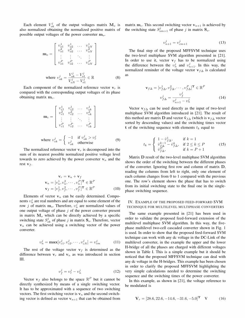
The same example presented in [21] has been used inorder to validate the proposed feed-forward extension of themultilevel multiphase SVM algorithm. In this way, the five-phase multilevel two-cell cascaded converter shown in Fig. 1is used. In order to show that the proposed feed-forward SVMtechnique can work with any dc voltage in the DC-Link of themultilevel converter, in the example the upper and the lowerH-bridge of all the phases are charged with different voltagesshown in Table I. This is a simple example but it should benoticed that the proposed MFFSVM technique can deal withany dc voltage in the H-bridges. This example has been chosenin order to clarify the proposed MFFSVM highlighting thevery simple calculations needed to determine the switchingsequence and the switching times of the power converter.
In this example, as shown in [21], the voltage reference tobe modulated is
Vr = [28.6, 22.6,−14.6,−31.6,−5.0]T V (16)

Vdckj
-
+
H-Bridge11
H-Bridge21
H-Bridge12
H-Bridge22 H-Bridge2
3
H-Bridge13
H-Bridge14
H-Bridge24 H-Bridge2
5
H-Bridge15
H-Bridgek
j
-
+
-
+
-
+
-
+
-
+
-
+
-
+
-
+
-
+
-
+
-
+Tk1j
Tk1j
Tk2j
Tk2j
Phase 1 Phase 2 Phase 3 Phase 4 Phase 5
Fig. 1. Multilevel multiphase cascaded H-bridge converter
The first step of the MFFSVM technique is to determinethe phase voltages of the power converter and the results leadto building of matrices S and Mv . In the case of the two-cellcascaded converter shown in Fig. 1, the possible switchingstates of the phase j can be denoted using factors Trjk todefine the trigger signals for the power semiconductors. Thesetrigger signals can be denoted using variables Hj
k for the H-bridge number k of phase j. Each factor Hj
k can take values0, 1 or 2 if the output H-bridgejk voltage is −V j
dck,0 or V jdck
respectively. The correspondence between these factors and thetrigger signals of the power semiconductors is summarized inTable II.
The switching factors Sjk are defined as a possible H-bridge
states configuration Hj1H
j2 . In the multilevel two-cell cascaded
converter case, nine different output phase voltages can beachieved in general. Therefore, nine factors Sj
k (k=1,2,· · · ,9)have to be defined. These factors are summarized in TableIII. Taking into account the dc voltage values of the convertersummarized in Table I, using Table II and Table III matricesS and Mo can be defined.
TABLE IDC VOLTAGES OF THE H-BRIDGES OF THE FIVE-PHASE TWO-CELL
MULTILEVEL CASCADED CONVERTER
Phase number V jdc1 (V) V j
dc2 (V)1 25 402 15 303 20 254 30 105 20 20
TABLE IIPOSSIBLE TRIGGER SIGNAL CONFIGURATIONS OF PHASE j OF THE
MULTILEVEL TWO-CELL CASCADED CONVERTER
Trigger signals H-bridge statesT j11T
j12T
j21T
j22 Hj
1Hj2
0000 11
0001 10
0010 12
0011 11
0100 01
0101 00
0110 02
0111 01
1000 21
1001 20
1010 22
1011 21
1100 11
1101 10
1110 12
1111 11
S =
00 01 02 10 11 12 20 21 2200 01 02 10 11 12 20 21 22...
......
......
......
......
00 01 02 10 11 12 20 21 22
(17)
Mv =
-65 -25 15 -40 0 40 -15 25 65-45 -15 15 -30 0 30 -15 15 45-45 -20 5 -25 0 25 -5 20 45-40 -30 -20 -10 0 10 20 30 40-40 -20 0 -20 0 20 0 20 40
(18)
The next step of the MFFSVM technique is to summarizethe output voltage levels of the power converter described in(18) using matrix Mo where the elements of each row areordered in increasing order. In addition, matrix So (with ele-ments called Sj
ok) is determined using matrix S and following
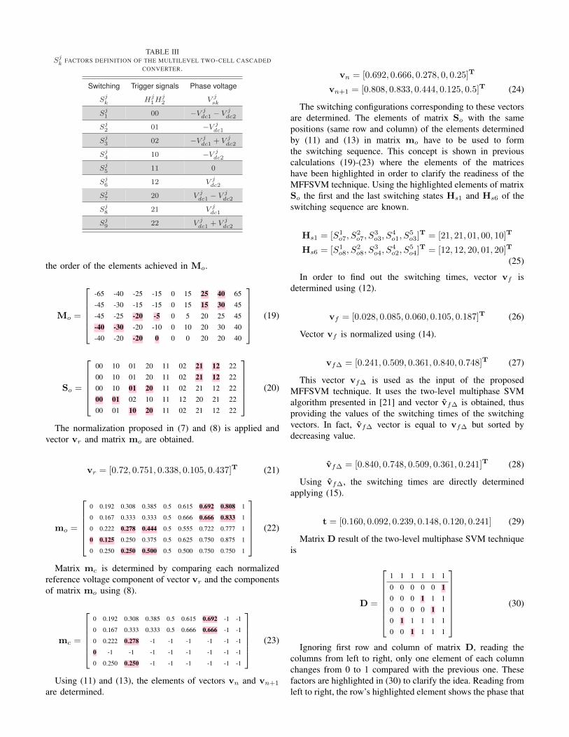
TABLE IIISjk FACTORS DEFINITION OF THE MULTILEVEL TWO-CELL CASCADED
CONVERTER.
Switching Trigger signals Phase voltage
Sjk Hj
1Hj2 V j
sk
Sj1 00 −V j
dc1 − V jdc2
Sj2 01 −V j
dc1
Sj3 02 −V j
dc1 + V jdc2
Sj4 10 −V j
dc2
Sj5 11 0
Sj6 12 V j
dc2
Sj7 20 V j
dc1 − V jdc2
Sj8 21 V j
dc1
Sj9 22 V j
dc1 + V jdc2
the order of the elements achieved in Mo.
Mo =
-65 -40 -25 -15 0 15 25 40 65-45 -30 -15 -15 0 15 15 30 45-45 -25 -20 -5 0 5 20 25 45-40 -30 -20 -10 0 10 20 30 40-40 -20 -20 0 0 0 20 20 40
(19)
So =
00 10 01 20 11 02 21 12 2200 10 01 20 11 02 21 12 2200 10 01 20 11 02 21 12 2200 01 02 10 11 12 20 21 2200 01 10 20 11 02 21 12 22
(20)
The normalization proposed in (7) and (8) is applied andvector vr and matrix mo are obtained.
vr = [0.72, 0.751, 0.338, 0.105, 0.437]T (21)
mo =
0 0.192 0.308 0.385 0.5 0.615 0.692 0.808 1
0 0.167 0.333 0.333 0.5 0.666 0.666 0.833 1
0 0.222 0.278 0.444 0.5 0.555 0.722 0.777 1
0 0.125 0.250 0.375 0.5 0.625 0.750 0.875 1
0 0.250 0.250 0.500 0.5 0.500 0.750 0.750 1
(22)
Matrix mc is determined by comparing each normalizedreference voltage component of vector vr and the componentsof matrix mo using (8).
mc =
0 0.192 0.308 0.385 0.5 0.615 0.692 -1 -1
0 0.167 0.333 0.333 0.5 0.666 0.666 -1 -1
0 0.222 0.278 -1 -1 -1 -1 -1 -1
0 -1 -1 -1 -1 -1 -1 -1 -1
0 0.250 0.250 -1 -1 -1 -1 -1 -1
(23)
Using (11) and (13), the elements of vectors vn and vn+1
are determined.
vn = [0.692, 0.666, 0.278, 0, 0.25]T
vn+1 = [0.808, 0.833, 0.444, 0.125, 0.5]T (24)
The switching configurations corresponding to these vectorsare determined. The elements of matrix So with the samepositions (same row and column) of the elements determinedby (11) and (13) in matrix mo have to be used to formthe switching sequence. This concept is shown in previouscalculations (19)-(23) where the elements of the matriceshave been highlighted in order to clarify the readiness of theMFFSVM technique. Using the highlighted elements of matrixSo the first and the last switching states Hs1 and Hs6 of theswitching sequence are known.
Hs1 = [S1o7, S
2o7, S
3o3, S
4o1, S
5o3]
T = [21, 21, 01, 00, 10]T
Hs6 = [S1o8, S
2o8, S
3o4, S
4o2, S
5o4]
T = [12, 12, 20, 01, 20]T
(25)
In order to find out the switching times, vector vf isdetermined using (12).
vf = [0.028, 0.085, 0.060, 0.105, 0.187]T (26)
Vector vf is normalized using (14).
vf∆ = [0.241, 0.509, 0.361, 0.840, 0.748]T (27)
This vector vf∆ is used as the input of the proposedMFFSVM technique. It uses the two-level multiphase SVMalgorithm presented in [21] and vector vf∆ is obtained, thusproviding the values of the switching times of the switchingvectors. In fact, vf∆ vector is equal to vf∆ but sorted bydecreasing value.
vf∆ = [0.840, 0.748, 0.509, 0.361, 0.241]T (28)
Using vf∆, the switching times are directly determinedapplying (15).
t = [0.160, 0.092, 0.239, 0.148, 0.120, 0.241] (29)
Matrix D result of the two-level multiphase SVM techniqueis
D =
1 1 1 1 1 1
0 0 0 0 0 10 0 0 1 1 10 0 0 0 1 10 1 1 1 1 10 0 1 1 1 1
(30)
Ignoring first row and column of matrix D, reading thecolumns from left to right, only one element of each columnchanges from 0 to 1 compared with the previous one. Thesefactors are highlighted in (30) to clarify the idea. Reading fromleft to right, the row’s highlighted element shows the phase that

TABLE IVEXPERIMENTAL DC VOLTAGES OF THE H-BRIDGES OF THE FIVE-PHASE
TWO-CELL MULTILEVEL CASCADED CONVERTER
Phase number V jdc1 V j
dc2
1 30.3 64.02 60.1 33.03 50.3 64.04 62.7 42.55 50.0 50.0
has to switch from its initial switching state to the final onein the single-phase switching sequence. Finally, the switchingsequence can be written using Hs1 and Hs6 determined in(25) and the switching times determined in (29).
Hs1 = [21, 21, 01, 00, 10]T, t1 = 0.160
Hs2 = [21, 21, 01, 01, 10]T, t2 = 0.092
Hs3 = [21, 21, 01, 01, 20]T, t3 = 0.239
Hs4 = [21, 12, 01, 01, 20]T, t4 = 0.148
Hs5 = [21, 12, 20, 01, 20]T, t5 = 0.120
Hs6 = [12, 12, 20, 01, 20]T, t6 = 0.241 (31)
V. RESULTS OF THE PROPOSED MODULATION TECHNIQUE
In order to test the proposed MFFSVM, experimental resultsare presented comparing the results with the previous MSVMpresented in [21]. A five-level five-phase cascaded full-bridgeinverter as shown in Fig. 1 has been used to obtain the results.The experimental setup includes a FPGA, a dSPACE platform,the inverter and the load. The dSPACE DS1103 PPC ControllerBoard provides the reference vectors to the FPGA whichgenerates the trigger signals of the power semiconductors. Theload is a five-phase distributed-concentrated winding inductionmotor with four poles. This motor was specifically built forthe tests by rewinding the stator phases on the 30 stator slotsof a 1.1-kW three-phase motor. In the experiments, a purelysinusoidal voltage is generated as the reference voltage of thepower converter. The amplitude of the reference sinusoidalwaveform is 80 V and the switching frequency is 5 kHz.
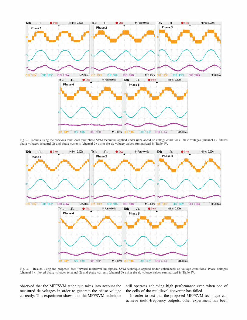
First of all, the MSVM technique is applied to the convertershown in Fig. 1 connected to a five-phase motor drive. Inthe experiment, the dc voltages summarized in Table IV areimposed for the dc sources of the converter. As the MSVMtechnique does not take into account the actual imbalancesin the dc voltages, the obtained phase voltages are highlydistorted as can be observed from Fig. 2 where the phasevoltages, their filtered versions and the phase currents arerepresented.
Secondly, the proposed MFFSVM technique is appliedconsidering again the dc voltages summarized in Table IV. Theobtained modulated phase voltages, their filtered versions andthe corresponding phase currents are shown in Fig. 3 showingthat the MFFSVM technique can work with any dc voltagegenerating phase voltages with low distortion. The proposedMFFSVM technique and the previous MSVM technique can
be directly compared observing Fig. 2 (MSVM results) andFig. 3 (FFMSVM results). Under the same unbalanced dcvoltage conditions, the proposed MFFSVM improves the be-havior of the power converter achieving a high quality of theoutput waveforms. A summary of the obtained results is shownin Table V where the harmonic spectrum data of the filteredphase voltages using both modulation techniques are written.It is clear that using the proposed MFFSVM technique, thelow harmonic distortion present with the MSVM method underunbalanced dc conditions is reduced. This means that the THDvalues obtained with the MFFSVM technique are improvedwhen compared to those achieved by the MSVM, as can beobserved in the last row of Table V.
It has to be noticed that, in the experimental results, non-zero values for either zero-sequence harmonics (5th, 15th, etc)or the even harmonics are present. The proposed algorithmapplied to an ideal converter obtains negligible low orderharmonics in the output waveform. The low order harmonicspresent in the measured output voltage waveform are due tononlinearities of the converter: dead times, turn on/off delays,voltage drop across power devices, etc [34], [35]. In addition,the harmonics amplitude are not the same for all phases, it isdue to the different number of steps in the output voltage ofevery leg.
In addition it has to be noticed that, in general, a phase withtwo H-bridges with different dc voltages achieves up to nineoutput voltage levels and the proposed MFFSVM uses all theselevels to generate the phase voltages. These phase voltageshave lower distortion because of the higher number of levelstaking advantage of the multilevel operation of the powerconverter. This phenomenon can be clearly seen comparing theresults of phase 4 and 5 from Fig. 3. The dc voltages of phase 4lead to achieve nine output voltages generating phase voltageswith low distortion (2.52%). On the other hand, the phase 5has balanced dc voltages achieving only five output voltagelevels achieving consequently a higher THD value (3.75%).
Finally, the proposed MFFSVM technique has been testedunder dynamic unbalanced dc conditions in order to showthe dynamic response of the modulator. In this experiment,in phase 1 the voltage of H-bridge2 is equal to 64 V whilethe voltage of H-bridge1 is variable. In this way, a 100 Hzsinusoidal oscillation is added to V 1
dc2 so that its mean valueis 50 V while it oscillates between 30 to 70 V. The obtainedresults are shown in Fig. 4 where the phase voltage, the phasevoltage filtered, the variable dc voltage of the cell and theharmonic spectrum of the phase voltage are represented. Itcan be seen that a high performance of the dynamic responseof the MFFSVM technique is achieved.
Other experiment has been done in order to test the gooddynamic performance of the proposed MFFSVM technique. Inthis case, the peak voltage of the reference voltage of phase1 is equal to 60 V. The dc voltage of H-bridge2 of phase 1 isconstant (V 1
dc2=64 V) whilst a drastic change in the voltage ofH-bridge1 of phase 1 (V 1
dc1) is applied. Its value is changedfrom its desired value (V 1
dc1=30.3 V) to zero and vice versa.The obtained results are shown in Fig. 5 where the phasevoltage, its low-pass filtered version and the voltage of bothH-bridges of phase 1 (V 1
dc1 and V 1dc2) are represented. It can be
Phase 1 Phase 2 Phase 3
Phase 4 Phase 5
Fig. 2. Results using the previous multilevel multiphase SVM technique applied under unbalanced dc voltage conditions. Phase voltages (channel 1), filteredphase voltages (channel 2) and phase currents (channel 3) using the dc voltage values summarized in Table IV.
Phase 1 Phase 2 Phase 3
Phase 4 Phase 5
Fig. 3. Results using the proposed feed-forward multilevel multiphase SVM technique applied under unbalanced dc voltage conditions. Phase voltages(channel 1), filtered phase voltages (channel 2) and phase currents (channel 3) using the dc voltage values summarized in Table IV.
observed that the MFFSVM technique takes into account themeasured dc voltages in order to generate the phase voltagecorrectly. This experiment shows that the MFFSVM technique
still operates achieving high performance even when one ofthe cells of the multilevel converter has failed.
In order to test that the proposed MFFSVM technique canachieve multi-frequency outputs, other experiment has been

Phase 1
V dc21
= 64V
V dc11
=’variable’
a)
b)
Fig. 4. Dynamic response results using the proposed feed-forward multilevelmultiphase SVM technique applied under dynamic unbalanced dc voltageconditions. a) Phase voltage, low-pass filtered phase voltage, phase current b)Harmonic spectrum of the phase voltage
carried out. In this case, the voltage reference is the same ofexperiment shown in Fig. 6 but it is added a third harmoniccontent with amplitude equal to 25 V. The results also showthe good performance of the MFFSVM method to achievemulti-frequency outputs.
a)
b)
Fig. 5. Dynamic response results using the proposed feed-forward multilevelmultiphase SVM technique applied under a drastic change of a dc voltage H-bridge of the multilevel cascaded converter. a) DC voltage changes from itsdesired value to zero b) DC voltage changes from zero to its desired value
VI. CONCLUSIONS
A feed-forward space vector modulation technique calledMFFSVM has been presented in this paper. This modulation
TABLE VEXPERIMENTAL RESULTS USING THE MSVM AND THE PROPOSED FFMSVM TECHNIQUES UNDER UNBALANCED DC VOLTAGES OF TABLE IV
Harmonic MSVM harmonic content results % FFMSVM harmonic content results %order (n) Phase 1 Phase 2 Phase 3 Phase 4 Phase 5 Phase 1 Phase 2 Phase 3 Phase 4 Phase 5
1 100 100 100 100 100 100 100 100 100 1002 0.17 0.52 0.12 0.17 0.31 0.01 0.15 0.07 0.25 0.063 8.86 7.05 4.43 1.57 1.26 1.59 1.33 1.73 1.36 1.434 0.30 0.20 0.32 0.14 0.29 0.07 0.14 0.25 0.13 0.215 0.68 0.58 0.77 0.47 0.84 0.64 0.63 0.81 0.74 0.586 0.19 0.37 0.10 0.31 0.07 0.21 0.16 0.45 0.26 0.077 1.30 0.65 0.85 0.91 0.84 0.36 0.18 0.51 0.26 0.288 0.84 0.60 0.82 0.67 0.71 0.07 0.04 0.49 0.29 0.879 0.32 0.51 0.24 0.35 0.22 0.29 0.08 0.27 0.11 0.17
10 0.69 0.69 0.71 0.81 0.68 0.30 0.35 0.07 0.12 0.6911 0.43 0.18 0.31 0.29 0.16 0.17 0.12 0.22 0.11 0.2012 0.17 0.13 0.17 0.09 0.14 0.25 0.07 0.06 0.04 0.1613 0.25 0.11 0.13 0.05 0.19 0.07 0.09 0.19 0.13 0.1214 0.07 0.15 0.05 0.05 0.13 0.63 0.61 0.22 0.08 0.0515 0.19 0.12 0.17 0.05 0.15 0.12 0.08 0.12 0.07 0.11
THD 9.52 8.14 5.58 4.22 3.89 2.99 2.76 2.83 2.52 3.75

−100 0 100
−100
−50
0
50
100
−100 0 100
−100
−50
0
50
100
Vd1 [V ] Vd2 [V ]
Vq1 [V ]
Vq2 [V ]
a)
b)
c)
Fig. 6. Response of the proposed MFFSVM technique when the referencevoltage includes a third harmonic content with amplitude equal to 25 V. a)Channel 1: Phase 1 voltage, channel 2: Filtered phase 1 voltage b) Harmonicspectrum of the phase voltage c) Trajectories of the output voltage (gray) andits filtered version (black) in stationary dq axis
technique has been designed for multilevel multiphase powerconverters. Measuring the actual dc voltages of the converterand thanks to the feed-forward control, the proposed techniquecan operate with any dc voltage value in the DC-link capac-itor voltages achieving good results without using any pre-stored off-line tables. Previous modulation techniques do notconsider the possible voltage imbalances and generate outputwaveforms with high distortion. Using the proposed MFFSVMtechnique, multilevel converters with different dc voltage val-ues, transient voltage imbalances or voltage oscillations do notaffect the quality of the generated output voltages and currents.The computational cost of the proposed MFFSVM technique iscomparable to previous techniques without loosing generalitybecause it can be applied to multilevel converters with anynumber of phases and levels. Experimental results are shownin order to validate the proposed modulation technique.
ACKNOWLEDGMENT
This work was supported by the Ministerio de Cienciae Innovacion under project number DPI2009-07004 and bythe Ministerio de Educacion y Ciencia under project numberTEC2007-61879.
REFERENCES
[1] E. Levi, “Multiphase Electric Machines for Variable-Speed Applica-tions,” IEEE Trans. Ind. Electron., vol. 55, no. 5, pp. 1893–1909, May2008.
[2] G. K. Singh, “Multi-phase induction machine drive research-A survey,”Electr. Power Syst. Res., vol. 61, no. 2, pp. 139–147, Mar. 2002.
[3] M. Jones and E. Levi, “A literature survey of state-of-the-art in multi-phase AC drives,” in Proc. UPEC, pp. 505–510, Stafford (UK), 2002.
[4] R. Bojoi, F. Farina, F. Profumo, and A. Tenconi, “Dual-three phaseinduction machine drives control-A survey,” IEEJ Trans. Ind. Applicat.,vol. 126, no. 4, pp. 420–429, 2006.
[5] E. Levi, R. Bojoi, F. Profumo, H. A. Toliyat, and S. Williamson,“Multiphase induction motor drives-A technology status review,” IETElectron. Power Applicat., vol. 1, no. 4, pp. 489–516, July 2007.
[6] O. Ojo, G. Dong, and Z. Wu, “Pulse-width modulation for five-phaseconverters based on device turn-on times,” IEEE IAS Annual Meeting(IAS’06), pp. 627–634, Tampa (USA), 2006.
[7] K. Marouani, L. Baghli, D. Hadiouche, A. Kheloui, and A. Rezzoug,“Discontinuous SVPWM techniques for double star induction motordrive control,” IEEE 32nd Annual Conference on Industrial Electronics(IECON’06), pp. 902–907, Paris (France), 2006.
[8] V. Oleschuk, R. Bojoi, F. Profumo, A. Tenconi, and A. M. Stankovic,“Multifunctional six-phase motor drives with algorithms of synchro-nized PWM,” IEEE 32nd Annual Conference on Industrial Electronics(IECON’06), pp. 1852–1859, Paris (France), 2006.
[9] S. Lu and K. Corzine, “Direct torque control of five-phase inductionmotor using space vector modulation with harmonics elimination andoptimal switching sequence,” IEEE Applied Power Electronics Confer-ence (APEC’06), pp. 195–201, Dallas (USA), 19-23 March 2006.
[10] D. Gritter, S. S. Kalsi, and N. Henderson, “Variable speed electric driveoptions for electric ships,” IEEE Electric Ship Technologies Symposium(ESTS’05), pp. 347–354, Philadelphia (USA), 25-27 July 2005.
[11] S. Lu and K. Corzine, “Multilevel multi-phase propulsion drives,”IEEE Electric Ship Technologies Symposium (ESTS’05), pp. 363–370,Philadelphia (USA), 25-27 July 2005.
[12] K. A. Corzine, S. D. Sudhoff, E. A. Lewis, D. H. Schmucker, R.A. Youngs and H. J. Hegner, “Use of multi-level converters in shippropulsion drives,” Proc. All Electr. Ship Conf., pp. 155–163, London(UK), 1998.
[13] M. Steiner, R. Deplazes, and H. Stemmler, “A new transformerlesstopology for AC-fed traction vehicles using multi-star induction motors,”EPE J., vol. 10, no. 3/4, pp. 45–53, 2000.
[14] J. Rodriguez, S. Bernet, B. Wu, J. O. Pontt and S. Kouro, “MultilevelVoltage-Source-Converter Topologies for Industrial Medium-VoltageDrives,” IEEE Trans. Ind. Electron., vol. 54, no. 6, pp. 2930–2945, Dec.2007.
[15] L. G. Franquelo, J. Rodriguez, J. I. Leon, S. Kouro, R. Portillo and M.M. Prats, “The age of multilevel converters arrives,” IEEE Ind. Electron.Magazine, vol. 2, no. 2, pp. 28–39, June 2008.
[16] D. Krug, S. Bernet, S. S. Fazel, K. Jalili and M. Malinowski, “Com-parison of 2.3-kV Medium-Voltage Multilevel Converters for IndustrialMedium-Voltage Drives,” IEEE Trans. Ind. Electron., vol. 54, no. 6, pp.2979–2992, Dec. 2007.
[17] E. P. Wiechmann, P. Aqueveque, R. Burgos and J. Rodriguez, “On theEfficiency of Voltage Source and Current Source Inverters for High-Power Drives,” IEEE Trans. Ind. Electron., vol. 55, no. 4, pp. 1771–1782, April 2008.
[18] D. Dujic, G. Grandi, M. Jones and E. Levi, “A Space Vector PWMScheme for Multifrequency Output Voltage Generation With MultiphaseVoltage-Source Inverters,” IEEE Trans. Ind. Electron., vol. 55, no. 5, pp.1943–1955, May 2008.
[19] J. M. Kelly, E. G. Strangas and J. M. Miller, “Multiphase space vectorpulse width modulation,” IEEE Trans. Energy Conversion, vol. 18, no. 2,pp. 259–264, June 2003.
[20] Hyung-Min Ryu, Jang-Hwan Kim and Seung-Ki Sul, “Analysis ofmultiphase space vector pulse-width modulation based on multiple d-q spaces concept,” IEEE Trans. Power Electron., vol. 20, no. 6, pp.1364–1371, Nov. 2005.
[21] O. Lopez, J. Alvarez, J. Doval-Gandoy and F. D. Freijedo, “MultilevelMultiphase Space Vector PWM Algorithm,” IEEE Trans. Ind. Electron.,vol. 55, no. 5, pp. 1933–1942, May 2008.
[22] S. Lu and K. A. Corzine, “Cascaded Multilevel Converters with Non-Integer or Dynamically Changing DC Voltage Ratios,” IEEE 5th Interna-tional Power Electronics and Motion Control Conference (IPEMC’06),vol. 1, pp. 1–5, Aug. 2006.

[23] M. Liserre, A. Pigazo, V. G. Monopoli, A. Dell’Aquila and V. M.Moreno, “A generalised hybrid multilevel modulation technique devel-oped in case of non-integer ratio among the dc-link voltages,” IEEEInternational Symposium on Industrial Electronics (ISIE’05), vol. 2, pp.513–518, Dubrovnik (Croatia), 20-23 June 2005.
[24] M. Liserre and V. G. Monopoli, “Multilevel Phase-Shifting Carrier PWMTechnique in case of Non-Equal dc-Link Voltages,” IEEE 32nd AnnualConference on Industrial Electronics (IECON’06), pp. 1639–1642, Paris(France), Nov. 2006.
[25] J. Pou, R. Pindado and D. Boroyevich, “Limits of the neutral-pointbalance in back-to-back-connected three-level converters,” IEEE Trans.Power Electron., vol. 19, no. 3, pp. 722–731, May 2004.
[26] J. Pou, D. Boroyevich and R. Pindado, “Effects of imbalances andnonlinear loads on the voltage balance of a neutral-point-clampedinverter,” IEEE Trans. Power Electron., vol. 20, no. 1, pp. 123–131,Jan. 2005.
[27] J. Pou, R. Pindado and D. Boroyevich, “Voltage-balance limits in four-level diode-clamped converters with passive front ends,” IEEE Trans.Ind. Electron., vol. 52, no. 1, pp. 190–196, Feb. 2005.
[28] J. Pou, R. Pindado and D. Boroyevich, “Evaluation of the low-frequencyneutral-point voltage oscillations in the three-level inverter,” IEEE Trans.Ind. Electron., vol. 52, no. 6, pp. 1582–1588, Dec. 2005.
[29] J. Pou, R. Pindado and D. Boroyevich, “Fast-Processing ModulationStrategy for the Neutral-Point-Clamped Converter With Total Elimina-tion of Low-Frequency Voltage Oscillations in the Neutral Point,” IEEETrans. Ind. Electron., vol. 54, no. 4, pp. 2288–2294, Aug. 2007.
[30] J. Pou, D. Boroyevich and R. Pindado, “New feedforward space-vectorPWM method to obtain balanced AC output voltages in a three-levelneutral-point-clamped converter,” IEEE Trans. Ind. Electron., vol. 49,no. 5, pp. 1026–1034, Oct. 2002.
[31] S. Kouro, P. Lezana, M. Angulo and J. Rodriguez, “Multicarrier PWMWith DC-Link Ripple Feedforward Compensation for Multilevel Invert-ers,” IEEE Trans. Power Electron., vol. 23, no. 1, pp. 52–59, Jan. 2008.
[32] J. I. Leon, S. Vazquez, A. J. Watson, L. G. Franquelo, P. W. Wheelerand J. M. Carrasco, “Feed-forward Space Vector Modulation for Single-Phase Multilevel Cascade Converters with any DC voltage ratio,” IEEETrans. Ind. Electron., vol. 56, no. 2, pp. 315–325, Feb. 2009.
[33] J. I. Leon, S. Vazquez, R. Portillo, L. G. Franquelo, J. M. Carrasco, P.W. Wheeler and A. J. Watson, “Three-Dimensional Feed-Forward SpaceVector Modulation Applied to Multilevel Diode-Clamped Converters,”IEEE Trans. Ind. Electron., vol. 56, no. 1, pp. 101–109, Jan. 2009.
[34] P. D. Evans and P. R. Close, “Harmonic distortion in PWM inverteroutput waveforms,” IEE Proceedings of Electric Power Applications,vol. 134, no. 4, pp. 224–232, July 1987.
[35] Hengbing Zhao, Q. M. J. Wu and A. Kawamura, “An accurate approachof nonlinearity compensation for VSI inverter output voltage,” IEEETrans. Power Electron., vol. 19, no. 4, pp. 1029–1035, July 2004.
Jose I. Leon (S’04, M’07) was born in Cadiz, Spain,in 1976. He received the B.S. and M.S. and PhDdegrees in telecommunications engineering from theUniversity of Seville (US), Spain, in 1999, 2001 and2006 respectively.
Currently, he is an Associate Professor with theDepartment of Electronic Engineering, US. His re-search interests include electronic power systems,modulation and control of power converters andindustrial drives.
Oscar Lopez (M’05) received the M.Sc. and thePh.D.degree from University of Vigo, Vigo, Spain,in 2001 and 2009, respectively.
Since 2004, he is an Assistant Professor withthe Department of Electronic Technology of theUniversity of Vigo. His research interests are in theareas of ac power switching converters technology.
Leopoldo G. Franquelo (M’84, SM’96, F’05) wasborn in Malaga, Spain. He received the M.Sc. andPh.D. degrees in electrical engineering from theUniversity de Seville (US), Seville, Spain in 1977and 1980 respectively.
He was the Vice-President of the Industrial Elec-tronics Society (IES) Spanish Chapter (2002 - 2003),member at Large of the IES AdCom (2002 - 2003).He was the Vice-President for Conferences of theIES (2004 - 2007), in which he has also been aDistinguished Lecturer since 2006. He has been
an Associated Editor for the IEEE Transactions on Industrial Electronicssince 2007. Since January 2008 he is President Elect of IEEE IndustrialElectronics Society. His current research interest lies on modulation techniquesfor multilevel inverters and its application to power electronic systems forrenewable energy systems.
Jesus Doval-Gandoy (M’99) received the M.Sc. de-gree from Polytechnic University of Madrid, Madrid,Spain, in 1991 and the Ph.D. degree from the Uni-versity of Vigo, Vigo, Spain in 1999.
From 1991 till 1994 he worked at industry. Heis currently an Associate Professor at the Universityof Vigo. His research interests are in the areas of acpower conversion.
Sergio Vazquez (S’04, M’08) was born in Seville,Spain, in 1974. He received the B.S. and M.S.degrees in industrial engineering from the Universityof Seville (US) in 2003 and 2006, respectively.
He is currently an Assistant Professor with theDepartment of Electronic Engineering in the US.His research interests include electronic power sys-tems, modeling, modulation and control of powerelectronic converters and power quality in renewablegeneration plants.
Jacobo Alvarez received the M.Sc. and thePh.D. degree from University of Vigo, Vigo, Spain,in 1991 and 1995, respectively.
He is a Full Professor with the Department ofElectronic Technology of the University of Vigosince 1997. His main topics of interest are pro-grammable logic devices and field-programmablegate arrays architectures and design methods appliedto industrial control problems.
Francisco D. Freijedo (M’07) received theM.Sc. degree in Physics from the University ofSantiago de Compostela, Santiago de Compostela,Spain, in 2002 and the Pd.D. degree from the Uni-versity of Vigo, Vigo, Spain, in 2009.
Since 2005, he is an Assistant Professor withthe Department of Electronic Technology of theUniversity of Vigo. Quality problems, grid con-nected switching converters, ac power conversionand flexible ac transmission systems are the areasof his research.