multi-sensors-for-robot-teaming-using-raspberry-pi-and-vex ...
16
Paper ID #21846 Multi-Sensors for Robot Teaming Using Raspberry Pi and VEX Robotics Construction Kit Dr. Shouling He, Vaughn College of Aeronautics & Technology Dr. Shouling He is an associate professor of Engineering and Technology at Vaughn College of Aero- nautics and Technology, where she is teaching the courses in Mechatronics Engineering and Electrical Engineering Technology. Her research interests include modeling and simulation, microprocessors and PLCs, control system designs and Robotics. She has published more than 45 journal and conference papers in these research areas. Dr. Sheng-Jen ”Tony” Hsieh, Texas A&M University Dr. Sheng-Jen (”Tony”) Hsieh is a Professor in the Dwight Look College of Engineering at Texas A&M University. He holds a joint appointment with the Department of Engineering Technology and the De- partment of Mechanical Engineering. His research interests include engineering education, cognitive task analysis, automation, robotics and control, intelligent manufacturing system design, and micro/nano manufacturing. He is also the Director of the Rockwell Automation laboratory at Texas A&M University, a state-of-the-art facility for education and research in the areas of automation, control, and automated system integration. c American Society for Engineering Education, 2018
-
Upload
khangminh22 -
Category
Documents
-
view
3 -
download
0
Transcript of multi-sensors-for-robot-teaming-using-raspberry-pi-and-vex ...

Paper ID #21846
Multi-Sensors for Robot Teaming Using Raspberry Pi and VEX RoboticsConstruction Kit
Dr. Shouling He, Vaughn College of Aeronautics & Technology
Dr. Shouling He is an associate professor of Engineering and Technology at Vaughn College of Aero-nautics and Technology, where she is teaching the courses in Mechatronics Engineering and ElectricalEngineering Technology. Her research interests include modeling and simulation, microprocessors andPLCs, control system designs and Robotics. She has published more than 45 journal and conferencepapers in these research areas.
Dr. Sheng-Jen ”Tony” Hsieh, Texas A&M University
Dr. Sheng-Jen (”Tony”) Hsieh is a Professor in the Dwight Look College of Engineering at Texas A&MUniversity. He holds a joint appointment with the Department of Engineering Technology and the De-partment of Mechanical Engineering. His research interests include engineering education, cognitivetask analysis, automation, robotics and control, intelligent manufacturing system design, and micro/nanomanufacturing. He is also the Director of the Rockwell Automation laboratory at Texas A&M University,a state-of-the-art facility for education and research in the areas of automation, control, and automatedsystem integration.
c©American Society for Engineering Education, 2018

Developing Teaming Robots for Engineering Design Education
Using Cross Platforms
Abstract
The paper presents an engineering design approach to develop an instructional module for
college students to learn Microprocessors and Robotics using multiple sensors, microprocessors
and software design tools. The module consists of research analysis, lesson content development
and laboratory practice selection, which satisfies the ABET (Accreditation Board for
Engineering & Technology) requirement for engineering education. The research analysis covers
the work reported by the scholars from MIT and other universities [1] [2], where the main
concern is how to enhance students’ capability in developing engineering products using new
technologies in the industry, such as multiple sensor fusion methodology as well as working
skills on cross-platform hardware (Intel, ARM, AMD and PIC, etc.) and software (Linux,
Windows and Androids, etc.). After the research paper analysis, a class activity has been
developed. The activity includes teaching students to build teaming robots by combining the
Cortex controllers with ROBOTC programming environment under Windows and the Raspberry
Pi (in ARM cores) using Python under Linux and guiding students to develop a cross-platform
software and hardware design using PIC Microcontrollers with embedded C under Windows and
the Raspberry Pi with Python under Linux.
The teaming robots under development contains a leading robot and a tracking robot. The
leading robot in the front can turn in any direction. When it “sees” an obstacle ahead using an
ultrasonic sensor, it will turn left or right to avoid the obstacle. The tracking robot has a Cortex
controller to drive the motors and an ultrasonic range finder to detect the distance between it and
the leading robot. At the same time, the tracking robot also holds a Raspberry Pi board with a Pi
Camera on it. The image signal obtained from the Pi Camera is processed by the Raspberry Pi
and sent to the Cortex controller. Based on the processed image signal, the second robot can
follow the first robot to turn accordingly, thus, they make a robot team. The exercise package
contains a PIC microcontroller with a speaker and the Raspberry Pi with Pi Camera. If the Pi
Camera finds some motion around, a signal will be sent to the PIC microcontroller and the siren
sound will be emitted. The activities largely aroused students’ curiosity and attention. The survey
result is very encouraging. After the class, students’ enthusiasm in learning Python, image
processing and engineering design using multiple boards and programming languages as well as
the applications has been noticeably enhanced.
Key words: Teaming Robots, Camera, Cross-platform Hardware and Software Design
1. Introduction
As it has been predicted, in the mid-21st century, Artificial Intelligence (AI) will become more
pervasive, potentially making every company and every employee smarter, faster, and more
productive. In addition, autonomous vehicles will replace most cars and other transportation
tools used today. Under the circumstance, as an educator, it is an urgent task for us to teach
students to effectively adopt new technologies in the automation industry, for example, being
quickly familiar with various types of cross-platform hardware and software design tools, as well

as being capable to design a robot that can make intelligent decision based on multiple sensor
inputs, particularly the inputs from computer vision devices.
However, to our observation, currently, in engineering education area, we still couldn’t find
economical and robust robot systems for us to efficiently teach students multiple sensor fusion
technology as well as control of a robot using a computer vision system. The report [3]
introduced their experience to build a robot controlled by a handy board with the inputs of a
camera and a sonar sensor. The Lego materials were used to build the robot body. Furthermore,
some research work has been done to develop ball tracking robots using a camera [4]. However,
due to the relatively complex image processing algorithm and camera requirements, most of the
robots were built in a small size and fragile with less power and, therefore, may be not proper in
robotics education. Considering that VEX robots have been popularly used in many universities
and colleges for robotics education. On the other hand, some affordable microcontroller boards,
such as Raspberry Pi and PIC Microcontrollers, are becoming more widespread in education, in
this paper, we demonstrate an approach to design autonomous teaming robots by combining the
Vex Cortex board and Raspberry Pi 3 board to teach cross-platform hardware and software
design, and then provide students an opportunity to practice cross-platform design using a PIC
Microcontroller board and a Raspberry Pi 3 board. For the teaming robots, the VEX Cortex
controllers will be mainly used to drive various motors and process the data sent from small and
less complicated sensors and the Raspberry Pi 3 board is primarily used to handle the image data
using computer vision algorithms. Since the VEX Robotics construction kit save educators’
efforts to find motor drivers and other mechanical parts, the design can focus on more
programming on the Cortex Controllers and Raspberry Pi using different programming
languages and operating systems.
Notice that the proposed courseware is designed for the students who have had some experience
in building VEX robots (with the completion of one credit course of Introduction to Robotics) as
well as high-level language programming, such as C/C++, and some course practices in
Microcontroller course using the PIC microcontroller board. Therefore, the paper will briefly
introduce the VEX robotic body design and discuss more in detail about the introduction to the
Raspberry Pi 3 processor, and the programming of Pi Camera in Python language, and finally
develop the cross platform using PIC Microcontrollers with Raspberry Pi 3 and Pi Camera.
The paper will discuss the development of cross-platform designs in the following steps. In
Section 2, the hardware and software used in the courseware are introduced. It includes a set of
VEX Robotics Construction kit with a Cortex controller and the programming environment
ROBOTC, a Raspberry Pi board, a Pi Camera and the programming environment, a PIC
Microcontroller and its programming environment MPLAB X IDE. Section 3 contributes to
teaching Python language and computer vision. The details of system implementation, i.e. color
filtering to detect the movement of the first robot by the second robot, the control algorithm for
the tracking robot and the flowchart of programs in ROBOTC and Python for the VEX Cortex
controller and Raspberry Pi are discussed in Section 4. Student learning results and comments as
well as some discussions are provided in Section 5. Conclusion is given in Section 6.
2. Hardware and Software Used
(1) VEX Robotics Construction Kit and Cortex Controller
Figure 1: Chassis of the VEX Robot
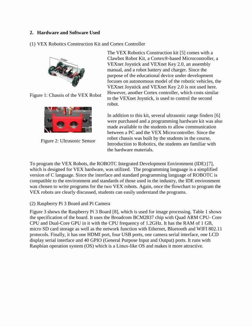
Figure 2: Ultrasonic Sensor
To program the VEX Robots, the ROBOTC Integrated Development Environment (IDE) [7],
which is designed for VEX hardware, was utilized. The programming language is a simplified
version of C language. Since the interface and standard programming language of ROBOTC is
compatible to the environment and standards of those used in the industry, the IDE environment
was chosen to write programs for the two VEX robots. Again, once the flowchart to program the
VEX robots are clearly discussed, students can easily understand the programs.
(2) Raspberry Pi 3 Board and Pi Camera
Figure 3 shows the Raspberry Pi 3 Board [8], which is used for image processing. Table 1 shows
the specification of the board. It uses the Broadcom BCM2837 chip with Quad ARM CPU- Core
CPU and Dual-Core GPU in it with the CPU frequency of 1.2GHz. It has the RAM of 1 GB,
micro SD card storage as well as the network function with Ethernet, Bluetooth and WIFI 802.11
protocols. Finally, it has one HDMI port, four USB ports, one camera serial interface, one LCD
display serial interface and 40 GPIO (General Purpose Input and Output) ports. It runs with
Raspbian operation system (OS) which is a Linux-like OS and makes it more attractive.
The VEX Robotics Construction kit [5] comes with a
Clawbot Robot Kit, a Cortex®-based Microcontroller, a
VEXnet Joystick and VEXnet Key 2.0, an assembly
manual, and a robot battery and charger. Since the
purpose of the educational device under development
focuses on autonomous model of the robotic vehicles, the
VEXnet Joystick and VEXnet Key 2.0 is not used here.
However, another Cortex controller, which costs similar
to the VEXnet Joystick, is used to control the second
robot.
In addition to this kit, several ultrasonic range finders [6]
were purchased and a programming hardware kit was also
made available to the students to allow communication
between a PC and the VEX Microcontroller. Since the
robot chassis was built by the students in the course,
Introduction to Robotics, the students are familiar with
the hardware materials.
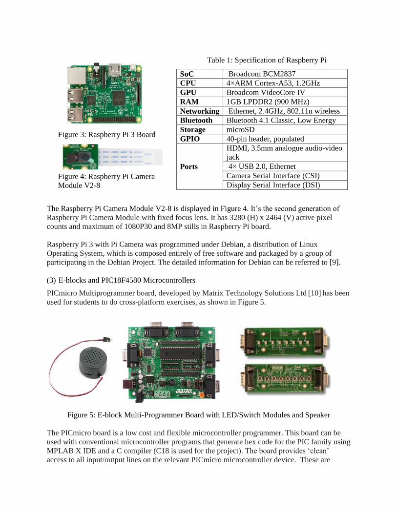
Table 1: Specification of Raspberry Pi
The Raspberry Pi Camera Module V2-8 is displayed in Figure 4. It’s the second generation of
Raspberry Pi Camera Module with fixed focus lens. It has 3280 (H) x 2464 (V) active pixel
counts and maximum of 1080P30 and 8MP stills in Raspberry Pi board.
Raspberry Pi 3 with Pi Camera was programmed under Debian, a distribution of Linux
Operating System, which is composed entirely of free software and packaged by a group of
participating in the Debian Project. The detailed information for Debian can be referred to [9].
(3) E-blocks and PIC18F4580 Microcontrollers
PICmicro Multiprogrammer board, developed by Matrix Technology Solutions Ltd [10] has been
used for students to do cross-platform exercises, as shown in Figure 5.
Figure 5: E-block Multi-Programmer Board with LED/Switch Modules and Speaker
The PICmicro board is a low cost and flexible microcontroller programmer. This board can be
used with conventional microcontroller programs that generate hex code for the PIC family using
MPLAB X IDE and a C compiler (C18 is used for the project). The board provides ‘clean’
access to all input/output lines on the relevant PICmicro microcontroller device. These are
SoC Broadcom BCM2837
CPU 4×ARM Cortex-A53, 1.2GHz
GPU Broadcom VideoCore IV
RAM 1GB LPDDR2 (900 MHz)
Networking Ethernet, 2.4GHz, 802.11n wireless
Bluetooth Bluetooth 4.1 Classic, Low Energy
Storage microSD
GPIO 40-pin header, populated
Ports
HDMI, 3.5mm analogue audio-video
jack
4× USB 2.0, Ethernet
Camera Serial Interface (CSI)
Display Serial Interface (DSI)
Figure 3: Raspberry Pi 3 Board
Figure 4: Raspberry Pi Camera
Module V2-8

presented on 9-pin D-type connectors: 8 bits and earth. A range of additional E-blocks boards
can be plugged into these D-type connectors to provide a rapid prototyping system for learning
and development.
The total cost for all hardware is around $758.39. The price distribution is listed in Table 2.
Table 2: Cost for All Hardware Used in Project
No. Name Price ($)
1 Clawbot Robot Dual Control Kit $439.99
2 Ultrasonic Range Finder x 2 $29.99
3 Raspberry Pi 3 Board $64.99
4 Raspberry Pi Camera Module V2-8 Megapixel, 1080p $29.49
5 Battery Pack for Raspberry Pi $24.94
6 E-block Multiprogrammer $115.00
7 LED Board in E-Block $22.00
8 Switch Board in E-Block $22.00
9 Speaker Module $9.99
Total $758.39
3. Python Programming Language and Computer Vision
In order to develop the program for image processing using the Raspberry Pi board, Python
language has been chosen. The reason for us to choose it is the language is easy to learn and
portable for different computers. Particularly, it’s suitable for processing a large amount of data,
such as image processing.
Since students who attended the class had learned C/C++ programming language as well as
programming a PIC Microcontroller using embedded C for 12 weeks (with the course
Microprocessors), the lecture focused on the comparison between the two languages, embedded
C and Python, in terms of (1) data types; (2) input/output statements; (3) control flow: if-
statements and while/for – loops; function calls and include/import library and modules and
classes.
After students were familiar with the syntax of Python program language, the fundamental
knowledge about computer vision and digital image processing were discussed. The introduction
started with the difficulty of digital image processing due to the transformation from 3D view
into 2D image. Furthermore, the quantization of analog signal introduces the concept of pixels.
For each pixel, the number of bright level can decide the clearness of an image as shown in
Figure 6 (See [12] for detailed information). In digital image processing, whether the number of
pixels and the level of brightness of each pixel change are important parameters for a processor
to decide if the motion happens after it compares a sequence of image frames.

Figure 6: Bright Level (a) 64; (b) 16; (c) 4; (d) 2
4. Design and implementation of teaming robots
Using the VEX robotics construction kit with two Cortex controllers, two Vex robots have been
built, as shown in Figure 7 and Figure 8, respectively. Raspberry Pi 3 and Pi Camera are
installed in the second robot as shown in Figure 8.
Figure 7: Leading Robot
After the completion of robot building, next step is to decide the algorithm so that the second
robot can follow the first robot autonomously. We completed the design in following steps:
(1) Determination of the color for the second robot to detect and color filtering
To identify the first robot’s position, a red color board is mounted to the back of the first robot,
as shown in Figure 9.
Figure 9: Red Symbol Board on the Back of the First Robot
After the color is decided, the program to select the threshold for the color parameters H (hue), S
(Saturation) and V (Value) is run. After the adjustment of HSV values, the upper boundary of
Figure 8: Tracking Robot

the red color is selected as [190, 255, 255] and the lower boundary of the red color is [160, 160,
10]. Using the two sides of threshold, the mask area of the red symbol board is identified as
shown in Figure 12 when the second robot is in the back of the first robot as seen in Figure 11.
Figure 10: HSV Definition for Image Processing
Figure 11: Positions of Two Robots
Figure 12: Image from Pi Camera and Mark Image
(2) Development of control algorithm
After the target symbol board is identified, the following step is to control the behavior of the
tracking robot according to the movement of the leading robot, which means if the white mask
shown in Figure 12 moves to one side (the leading robot turns to the side), the tracking robot
should turn to the side accordingly so that the mask is kept in the middle position of the image
frame.
In order to find parameters of the control algorithm, an experiment shown in Table 3 was
conducted. As Row# 2 and Row #3 show the first robot in the left side of the second robot with
the angle of 22˚ and the distance of 51 cm, the center x value is between 188.5 and 200.5. When
the first robot is in the right side with the angle of 22˚and the distance of 51cm, the center x
value is between -19.5 and -15.5. Row#1 shows that if the turning angle is zero, the center x is
between 90 and 95. Based on the measured result, we chose the control algorithm as follows: if
center x < 70, the robot turns right (turn=1); else if center x > 110, the robot turns left (turn=0);
else the robot goes straight (flag=0).

Table 3: Recorded center X and contour area with camera setting 320×160, 16 frame/sec
Physical →
Meaning Distance
between two
robots (cm)
Angle from the
camera to
the first robot (˚)
Center X recorded
from Python
program (pixels)
Contour Area
recorded from
Python program
(pixels) No.
Experiments
1 50 0˚ 90 ~ 95 1855 ~ 2280
2 51 (√(502+202)) -atan (2/5) = -22˚ (CCW from the
camera) 188.5 ~ 200.5 500 ~ 1780
3 51 (√(502+202)) atan (2/5) = 22˚ (CW from the camera)
-19.5 ~ -15.5 1750 ~ 2133
4 40 0˚ 83 ~ 86 1400 ~ 3700
5 60 0˚ 84 ~ 88 987 ~ 1323
(3) Flowchart of programs on both Cortex controller and Raspberry Pi 3 for the tracking robot
According to the flowchart shown in Figure 13 (Abbreviation words can be referred in the
bottom of the figure.), the Cortex controller is a master processor. It requires Raspberry Pi
continually provide 3-bit data, which are (1) Found (the target is found or not); (2) Flag (the
robot needs to turn or not); (3) Turn direction (if it’s turning right or left, turn=1 or 0). Based on
the three-bit information plus the ultrasonic sensor information, the tracking robot decides to go
forward, stop, turn left/right with radius or just turn right/left (without radius) to search the lost
target.
Figure 13: Program in ROBOTC (for Cortex) and Python (for Raspberry Pi), Respectively

(4) Wire two boards as well as motors and ultrasonic sensors
Figure 14 shows the circuit connection between two processor boards, motors and ultrasonic
sensors. Notice that the two boards must share the common ground. Otherwise, the measured
signals will be floated.
Figure 14: Hardware Wiring
After the hardware was connected, the system was run by firstly turning on the Raspberry Pi
program. When the Raspberry Pi board run well, two Cortex Controllers were turned on.
(5) Laboratory practice
Based on the lecture and building of teaming robots, students were guided to program the PIC
microcontroller 18F4580 on the E-block multi-programmer board [10]. The PIC microcontroller
board was connected to an LED board, a switch board and a speaker module. The RD0 pin of
PIC microcontroller was connected to the GPIO Pin 26 on the Raspberry Pi 3. When the Pi
Camera installed on Raspberry Pi 3 detects any change in the environment, such as a person
blinks his/her eyes or open his/her mouse, the Raspberry Pi 3 sends a signal to RD0 pin on the
PIC board. The PIC microcontroller then flashes LEDs on the LED board and emits a siren
sound to the speaker. Figure 15 shows the devices used in the lab. In terms of the programming
environment, the PIC microcontroller was programmed in embedded C using the MPLAB X IDE
under Windows and the Raspberry Pi 3 was programmed in Python under Debian Operation
System.
Figure 15: Laboratory Device for the Exercise
GPIO Pins for
Raspberry Pi
Digital Pins for
Cortex Controller
Motor pins
for Cortex
Controller

5. Student learning results, comments and discussions
The lecture was composed of a power point presentation and the demonstration of building
teaming-robots. Students were also briefly taught the fundamental architecture of Raspberry Pi 3
processor since the lecture was arranged by the 13th week in Microprocessors course where
students had learned PIC Microcontrollers and embedded C programming. After it, the essential
concept of image processing and basic Python program were discussed in comparison with the
PIC embedded C program. Before the class were taught, students were provided a 10-question
survey. The questions were multiple choices with emphasis on Python and image processing
(See the appendix for detail).
Ten students attended the class and 60% of them scored over 60 points. The distribution of the
grades is 80%, 80%, 70%, 70%, 60%, 60%, 40%, $40%, 30% and 30%. It can be seen that
although all of them hadn’t learned Python language, the knowledge that they learned from other
computer languages such as C++, embedded and Matlab helped them to find the correct
solutions. After the lecture, all students reached 100 points for the problems in question.
For the post-class comments, students wrote:
Very interesting, I wish we learn more in depth about computer vision and image processing.
Good better than the fundamental C++ class.
After the lecture, I would like to learn more about the different applications Python has. Also
that it is used for. Maybe have a course to learn Python.
More information about Python (more lectures) and get a chance to write more codes.
Good introduction of computer vision and basic Python.
I would like to see more applications.
I think it was very interesting. I wish it was more than just one lecture because it seems like
this is the direction the industry is going. More computer vision less sensors.
I think this class should be incorporated into the engineering program, Python.
I have never practiced Python before, the lecture was pretty informative but now I want to
know more, will definitely try what was given for practice with the program online.
Discussion: As college professors, we consider that our mission is to ignite the spark of passion,
creativity and energy inherent in our students so that they can believe in their gifts, gain
confidence and explore how they will contribute to the world. The idea of teaching engineering
design using cross-platform software and hardware is just an approach of inspiring students to
develop exciting projects in different levels of classes or areas, even in their club activities and
their summer jobs. Here are several examples:
Freshmen Level – Introduction to Robotics: Although students are not able to use two
different microcontrollers or various software design environments, they still can build two
robots so that the robots can talk via a bump sensor and an ultrasonic sensor. Thus, the robots
can co-work together to complete a duty. Figure 16 shows a course project where freshmen
students developed a clunker robot and a butler robot. Two of them talked to each other to
complete the duties such as garbage collection, garbage storage and garbage dumping, etc.

Junior Level – Microprocessors: A group of students was doing a course project: program a
Bluetooth board so that their smart phone can talk to a PIC18F4580 microcontroller.
However, they didn’t have any information to initialize the Bluetooth board. Fortunately, the
manufacturer provided the machine code running under a flowcode environment with a
midrange PIC microcontroller. Then, students ingeniously initialize the Bluetooth board
using a midrange PIC microcontroller and the flowcode environment. After the initialization,
they used the Bluetooth board for the advanced 8-bit microcontroller PIC18F4580 under
MPLAB X IDE programming environment for their course project. This is another example
for the application using cross-platforms for the development of computer hardware and
software.
Figure 16: Clunker and Butler Robots
(a) (b) (c)
Figure 16: Cross-Platform Applications for Bluetooth Initialization and Applications
(a) Flowcode with Bluetooth Board; (b) Students’ Project; (c) MPLAB X IDE Environment
Senior Level – Industrial Manufacturing and Automation: A course project is to interconnect
a particle photon microcontroller and a storage station controlled by Siemens S300 PLC. A
particle photon is a tiny Wi-Fi enabled microcontroller which can be remotely accessed and
programed. Through the project, students learned how to conduct the cross-platform design
among a Siemens PLC, an embedded controller and a web server. Figure 17 shows the
components of the project.

6. Conclusions
In this paper, we presented the motivation and courseware development related to multiple
sensors for teaming robots and motion detection using cross platform hardware and software to
enhance college students’ capability of adopting new technologies in the industry. We believe
it’s also an excellent approach for students to integrate their knowledge to solve the problems in
the real world.
Future improvements include (1) developing more opportunities for students to learn Python,
image processing as well as the fundamental knowledge of artificial intelligence so that they can
solve more practical engineering problems and (2) creating more exercises for students to do
exercises related to cross-platform hardware and software.
Figure 17: Cross-platform Design among a PLC, a Microcontroller and a Web Server
7. Acknowledgement
The work was supported by a grant from the National Science Foundation’s Research Experience
for Teachers (RET) Program (Award No. 1300779). Any opinions, findings, and conclusions or
recommendations expressed in this material are those of the authors and do not necessarily reflect
the views of the National Science Foundation.
8. References
[1] M. Agarwal and A. Sharma, “A survey on impact of embedded system on teaching,” MIT Int.
J. of Electronics and Communication Engineering, v.3, n.1, Jan. 2013, pp. 36-38.
[2] V. R. Kale & V. A. Kulkarni, “Object sorting system using robotic arm,” Int. J. of Advanced
Research in Electrical, Electronics and Instrumentation Engineering, v.2, issue 7, July 2012,
pp.3400-3407.

[3] T. Inanc and H. Dinh, “A low-cost autonomous mobile robotics experiment: control, vision,
sonar and handy board,” Computer Application Engineering Education, 20: pp. 203-213,
2012, wileyonlinelibrary.com/journal/cae.
[4] A. Joy, A.P. Somaraj, A. Joe, M. Shafi, and T. M. Nidheesh, “Ball tracking robot using
image processing and range detection,” Int. J. of Innovative Research in Computer and
Communication Engineering, v.2, Issue 3, March, 2014.
[5] Clawbot Robot Dual Control Kit, Available:
https://www.vexrobotics.com/vexedr/products/kits-and-bundles/starter-kits [Accessed July
2017].
[6] Ultrasonic Range Finder, Available: https://www.vexrobotics.com/276-2155.html,
[Accessed July 2017].
[7] ROBOTC Tutorial, Available: http://www.robotc.net/ [Accessed July 2017].
[8] Raspberry Pi 3 Specs, Available: https://www.raspberrypi.org/magpi/raspberry-pi-3-specs-
benchmarks/ [Accessed January 2018].
[9] Debian Operating System, Available: https://www.debian.org/ [Accessed February, 2018.]
[10] Matrix Technology Solutions Ltd, "E-block User Manual,” Available:
http://www.matrixtsl.com [Accessed January 2018].
[11] Python, Available: https://www.python.org/ [Accessed February, 2018].
[12] M. Sonta, V. Hlavac and R. Boyle, Image Processing, Analysis, and Machine Vision, 4th
edition, CENGAGE Learning, 2015.

Appendix - Pre/Post-Class Assessment
1. What are two of the most important benefits of the Python language?
A. Advanced mathematical equations and fast programs
B. Ease of use and fast programs
C. Ease of use and portability
D. Fast programs and smaller programs
2. What is the correct sequence of steps invoked by the Python Interpreter:
A. source code → virtual machine → byte code → compiler
B. source code → compiler → byte code → virtual machine
C. compiler → source code → virtual machine → byte code
D. byte code → virtual machine → source code → compiler
3. What is wrong with the following code snippet:
num1 = 10
num2 = 20
num3 = 30
total = Num1 + Num2 + Num3
A. Nothing, the variable total will be the sum of the three numbers
B. Python is case sensitive so Num1, Num2, and Num3 are undefined
C. total must be initialized to zero first
D. The numbers should be 10.0, 20.0 and 30.0
4. What is wrong with the following code snippet?
print("Hello")
print("World!")
A. The print function cannot be called twice
B. The print function is missing an argument
C. Nothing, the program prints Hello World on the same line
D. The second line should not be indented
5. What is the purpose of the following algorithm, written in pseudo-code?
num = 0
Repeat the following steps 15 times
Ask user for next number
If userNum > num
num = userNum
Print num
A. To print out the 15 numbers
B. To find the smallest among 15 numbers
C. To search for a particular number among 15 numbers
D. To find the highest among 15 numbers

6. Which of the following statements correctly defines a function?
A. def functionName(parameterName1, parameterName2) :
B. def functionName(parameterName1, parameterName2)
C. functionName(parameterName1, parameterName2) :
D. functionName(parameterName1, parameterName2)
7. What Python statement exits a function and gives the result to the caller?
A. def
B. return
C. send
D. result
8. A digital image is a collection of __________ arranged in a grid of rows and columns.
A. canvases
B. dots
C. elementary elements
D. pixels
9. In an RGB color model, what color is represented by 255, 255, 255?
A. black
B. green
C. white
D. yellow
10. The difference is intensity between the highest and lowest intensity levels in an image is
A. noise
B. saturation
C. contrast
D. brightness
Please provide comments for your overall learning experience through the lecture and
laboratory activities so that we can continually improve the course module and make it better.