User and Installation Manual output flter FN5420 and RWK5420
Upload
khangminh22Category
view
2download
0
MRX
Installation and User Manual
M
an
ual

Copyright © June 2018 INSYS MICROELECTRONICS GmbH
Any duplication of this manual is prohibited. All rights on this documentation and the devices are with INSYS MICROELECTRONICS GmbH Regensburg.
Trademarks
The use of a trademark not shown below is not an indication that it is freely availa-ble for use.
MNP is a registered trademark of Microcom Inc.
IBM PC, AT, XT are registered trademarks of International Business Machine Cor-poration.
INSYS®, VCom®, e-Mobility LSG® and e-Mobility PLC® are registered trademarks of
INSYS MICROELECTRONICS GmbH.
Windows™ is a registered trademark of Microsoft Corporation.
Linux is a registered trademark of Linus Torvalds.
Publisher:
INSYS MICROELECTRONICS GmbH
Hermann-Köhl-Str. 22
D-93049 Regensburg, Germany
Phone: +49 941 58692 0
Fax: +49 941 58692 45
E-mail: [email protected]
Internet: http://www.insys-icom.com
Date: Jun-18
Item: 10017625
Version: 1.5
Language: EN
Content
4
Jun-18
1 Preface ................................ ................................ ............... 7
1.1 Defects Liability Terms... . . . . . . . . . . . . . . . . . . . . . . . . . . . . . . . . . . . . . . . . . . . . . . . . . . . . . . . . . . . . . . . . . . . . 7
1.2 Feedback .. . . . . . . . . . . . . . . . . . . . . . . . . . . . . . . . . . . . . . . . . . . . . . . . . . . . . . . . . . . . . . . . . . . . . . . . . . . . . . . . . . . . . . 7
1.3 Marking of Warnings and Notes .. . . . . . . . . . . . . . . . . . . . . . . . . . . . . . . . . . . . . . . . . . . . . . . . . . . . . . . . . . 8
1.4 Symbols and the Formatting in this Manual . . . . . . . . . . . . . . . . . . . . . . . . . . . . . . . . . . . . . . . . . . . . . 9
2 Safety ................................ ................................ .............. 10
2.1 Intended Use .. . . . . . . . . . . . . . . . . . . . . . . . . . . . . . . . . . . . . . . . . . . . . . . . . . . . . . . . . . . . . . . . . . . . . . . . . . . . . . . 10
2.2 Permissible Technical Limits . . . . . . . . . . . . . . . . . . . . . . . . . . . . . . . . . . . . . . . . . . . . . . . . . . . . . . . . . . . . . . 11
2.3 Responsibilities of the Operator . . . . . . . . . . . . . . . . . . . . . . . . . . . . . . . . . . . . . . . . . . . . . . . . . . . . . . . . . . 11
2.4 Qualification of the Personnel . . . . . . . . . . . . . . . . . . . . . . . . . . . . . . . . . . . . . . . . . . . . . . . . . . . . . . . . . . . . 11
2.5 Instructions for Transport and Storage... . . . . . . . . . . . . . . . . . . . . . . . . . . . . . . . . . . . . . . . . . . . . . . . 11
2.6 Markings on the Product . . . . . . . . . . . . . . . . . . . . . . . . . . . . . . . . . . . . . . . . . . . . . . . . . . . . . . . . . . . . . . . . . . 12
2.7 Environmental Protection .. . . . . . . . . . . . . . . . . . . . . . . . . . . . . . . . . . . . . . . . . . . . . . . . . . . . . . . . . . . . . . . . 12
2.8 Safety Instructions for Electrical Installation .. . . . . . . . . . . . . . . . . . . . . . . . . . . . . . . . . . . . . . . . . . 13
2.9 General Safety Instructions .. . . . . . . . . . . . . . . . . . . . . . . . . . . . . . . . . . . . . . . . . . . . . . . . . . . . . . . . . . . . . . 14
3 Using Open Source Software ................................ .................. 16
3.1 General Information .. . . . . . . . . . . . . . . . . . . . . . . . . . . . . . . . . . . . . . . . . . . . . . . . . . . . . . . . . . . . . . . . . . . . . . . 16
3.2 Special Liability Regulations .. . . . . . . . . . . . . . . . . . . . . . . . . . . . . . . . . . . . . . . . . . . . . . . . . . . . . . . . . . . . . 17
3.3 Used Open-Source Software .. . . . . . . . . . . . . . . . . . . . . . . . . . . . . . . . . . . . . . . . . . . . . . . . . . . . . . . . . . . . 17
4 Version History ................................ ................................ ... 18
5 Device Variants ................................ ................................ ... 19
5.1 Housing Widths .. . . . . . . . . . . . . . . . . . . . . . . . . . . . . . . . . . . . . . . . . . . . . . . . . . . . . . . . . . . . . . . . . . . . . . . . . . . . 19
5.2 Basic Variants . . . . . . . . . . . . . . . . . . . . . . . . . . . . . . . . . . . . . . . . . . . . . . . . . . . . . . . . . . . . . . . . . . . . . . . . . . . . . . . 19
5.3 Plug-in Cards (MRcards) . . . . . . . . . . . . . . . . . . . . . . . . . . . . . . . . . . . . . . . . . . . . . . . . . . . . . . . . . . . . . . . . . . . 20
6 Scope of Delivery ................................ ................................ 21
Contents
Jun-18 5
7 Technical Information ................................ ........................... 22
7.1 Basic Variants . . . . . . . . . . . . . . . . . . . . . . . . . . . . . . . . . . . . . . . . . . . . . . . . . . . . . . . . . . . . . . . . . . . . . . . . . . . . . . . 22
7.1.1 Technical Data ..................................................................................... 22 7.1.2 Connections and display elements .......................................................24 7.1.3 Power consumption estimation ............................................................25 7.1.4 Redundant power supply .....................................................................25 7.1.5 Digital inputs........................................................................................25 7.1.6 Connecting the connectors ..................................................................26
7.2 MRcard PM ... . . . . . . . . . . . . . . . . . . . . . . . . . . . . . . . . . . . . . . . . . . . . . . . . . . . . . . . . . . . . . . . . . . . . . . . . . . . . . . . 27
7.2.1 Technical Data .....................................................................................27 7.2.2 Connections and display elements .......................................................27
7.3 MRcard PL .. . . . . . . . . . . . . . . . . . . . . . . . . . . . . . . . . . . . . . . . . . . . . . . . . . . . . . . . . . . . . . . . . . . . . . . . . . . . . . . . . . 29
7.3.1 Technical Data .....................................................................................29 7.3.2 Connections as well as display and control elements .......................... 31 7.3.3 Antennas for MIMO / Rx Diversity ....................................................... 33
7.4 MRcard PD... . . . . . . . . . . . . . . . . . . . . . . . . . . . . . . . . . . . . . . . . . . . . . . . . . . . . . . . . . . . . . . . . . . . . . . . . . . . . . . . . 34
7.4.1 Technical Data .................................................................................... 34 7.4.2 Connections as well as display and control elements .......................... 35
7.5 MRcard SI . . . . . . . . . . . . . . . . . . . . . . . . . . . . . . . . . . . . . . . . . . . . . . . . . . . . . . . . . . . . . . . . . . . . . . . . . . . . . . . . . . . . 37
7.5.1 Technical Data .................................................................................... 37 7.5.2 Connections and display elements ...................................................... 38
7.6 MRcard ES .. . . . . . . . . . . . . . . . . . . . . . . . . . . . . . . . . . . . . . . . . . . . . . . . . . . . . . . . . . . . . . . . . . . . . . . . . . . . . . . . . . 41
7.6.1 Technical Data .................................................................................... 41 7.6.2 Connections and display elements ...................................................... 41
8 MRcard Installation ................................ .............................. 43
8.1 Positions and Combinations of MRcards .. . . . . . . . . . . . . . . . . . . . . . . . . . . . . . . . . . . . . . . . . . . . . . 44
8.1.1 Slot for 4+1-port switch ...................................................................... 44 8.1.2 Slot for power supply .......................................................................... 45 8.1.3 Slots for extensions............................................................................. 46
8.2 Removal of an MRcard .. . . . . . . . . . . . . . . . . . . . . . . . . . . . . . . . . . . . . . . . . . . . . . . . . . . . . . . . . . . . . . . . . . . 47
8.3 Installation of an MRcard .. . . . . . . . . . . . . . . . . . . . . . . . . . . . . . . . . . . . . . . . . . . . . . . . . . . . . . . . . . . . . . . . . 48
8.4 Removal of a terminal cover . . . . . . . . . . . . . . . . . . . . . . . . . . . . . . . . . . . . . . . . . . . . . . . . . . . . . . . . . . . . . . 49
8.5 Installation of a terminal cover . . . . . . . . . . . . . . . . . . . . . . . . . . . . . . . . . . . . . . . . . . . . . . . . . . . . . . . . . . . 50
8.6 Device Label . . . . . . . . . . . . . . . . . . . . . . . . . . . . . . . . . . . . . . . . . . . . . . . . . . . . . . . . . . . . . . . . . . . . . . . . . . . . . . . . . 51
9 Assembly ................................ ................................ .......... 52
10 Commissioning ................................ ................................ ... 57
11 Operating Principle................................ ............................... 60
11.1 Operation via the web interface .. . . . . . . . . . . . . . . . . . . . . . . . . . . . . . . . . . . . . . . . . . . . . . . . . . . . . . . . . 60
11.2 Access via HTTPS Protocol . . . . . . . . . . . . . . . . . . . . . . . . . . . . . . . . . . . . . . . . . . . . . . . . . . . . . . . . . . . . . . . 62
11.2.1 Authentication via the device-individual certificate/key combination .....62 11.2.2 Authentication via an own certificate structure.................................... 63
11.3 Profiles and Profile Handling... . . . . . . . . . . . . . . . . . . . . . . . . . . . . . . . . . . . . . . . . . . . . . . . . . . . . . . . . . . . 64
11.3.1 Term definitions .................................................................................. 64 11.3.2 Working with one profile..................................................................... 64 11.3.3 Using several profiles .......................................................................... 65 11.3.4 ASCII Configuration............................................................................. 66
Content
6
Jun-18
12 Maintenance, Repair and Troubleshooting ................................ .. 67
12.1 Maintenance .. . . . . . . . . . . . . . . . . . . . . . . . . . . . . . . . . . . . . . . . . . . . . . . . . . . . . . . . . . . . . . . . . . . . . . . . . . . . . . . . 67
12.2 Troubleshooting... . . . . . . . . . . . . . . . . . . . . . . . . . . . . . . . . . . . . . . . . . . . . . . . . . . . . . . . . . . . . . . . . . . . . . . . . . . 67
12.3 Repair . . . . . . . . . . . . . . . . . . . . . . . . . . . . . . . . . . . . . . . . . . . . . . . . . . . . . . . . . . . . . . . . . . . . . . . . . . . . . . . . . . . . . . . . . 67
13 Waste Disposal ................................ ................................ ... 68
13.1 Repurchasing of Legacy Systems... . . . . . . . . . . . . . . . . . . . . . . . . . . . . . . . . . . . . . . . . . . . . . . . . . . . . . 68
14 Declaration of Conformity ................................ ...................... 69
14.1 Devices with Radio Technology .. . . . . . . . . . . . . . . . . . . . . . . . . . . . . . . . . . . . . . . . . . . . . . . . . . . . . . . . . 69
14.2 Devices without Radio Technology .. . . . . . . . . . . . . . . . . . . . . . . . . . . . . . . . . . . . . . . . . . . . . . . . . . . . . 69
15 FCC Statement................................ ................................ .... 70
16 Export Restriction ................................ ................................ 71
17 Glossary................................ ................................ ............ 72
18 Tables and Diagrams ................................ ............................ 76
18.1 List of Tables . . . . . . . . . . . . . . . . . . . . . . . . . . . . . . . . . . . . . . . . . . . . . . . . . . . . . . . . . . . . . . . . . . . . . . . . . . . . . . . . 76
18.2 List of Diagrams... . . . . . . . . . . . . . . . . . . . . . . . . . . . . . . . . . . . . . . . . . . . . . . . . . . . . . . . . . . . . . . . . . . . . . . . . . . 77
19 Index ................................ ................................ ............... 78
MRX Preface
7
1 Preface
This manual allows for the safe and efficient use of the product. The manual is part
of the product and must always be stored accessible for installation, commission-ing and operating personnel.
1.1 Defects Liability Terms
A usage not according to the intended purpose, an ignorance of this documenta-tion, the use of insufficiently qualified personnel as well as unauthorised modifica-tions exclude the liability of the manufacturer for damages resulting from this. The liability of the manufacturer ceases to exist.
The regulations of our Delivery and Purchasing Conditions are effective. These can
be found on our website (www.insys-icom.de/imprint/) under “General Terms and Conditions“.
1.2 Feedback
We are permanently improving our products and the associated technical docu-mentation. Your feedback is very helpful for this. Please tell us what you like in par-ticular on our products and publications and what can be improved from your point of view. We highly appreciate your suggestions and will include them in our work to support you and all our customers. We are looking forward to any of your feed-
back.
Please send an e-mail to [email protected].
We'd like to know your applications. Please send us a few headwords that we
know the applications you solve using products of INSYS icom.
Preface MRX
8
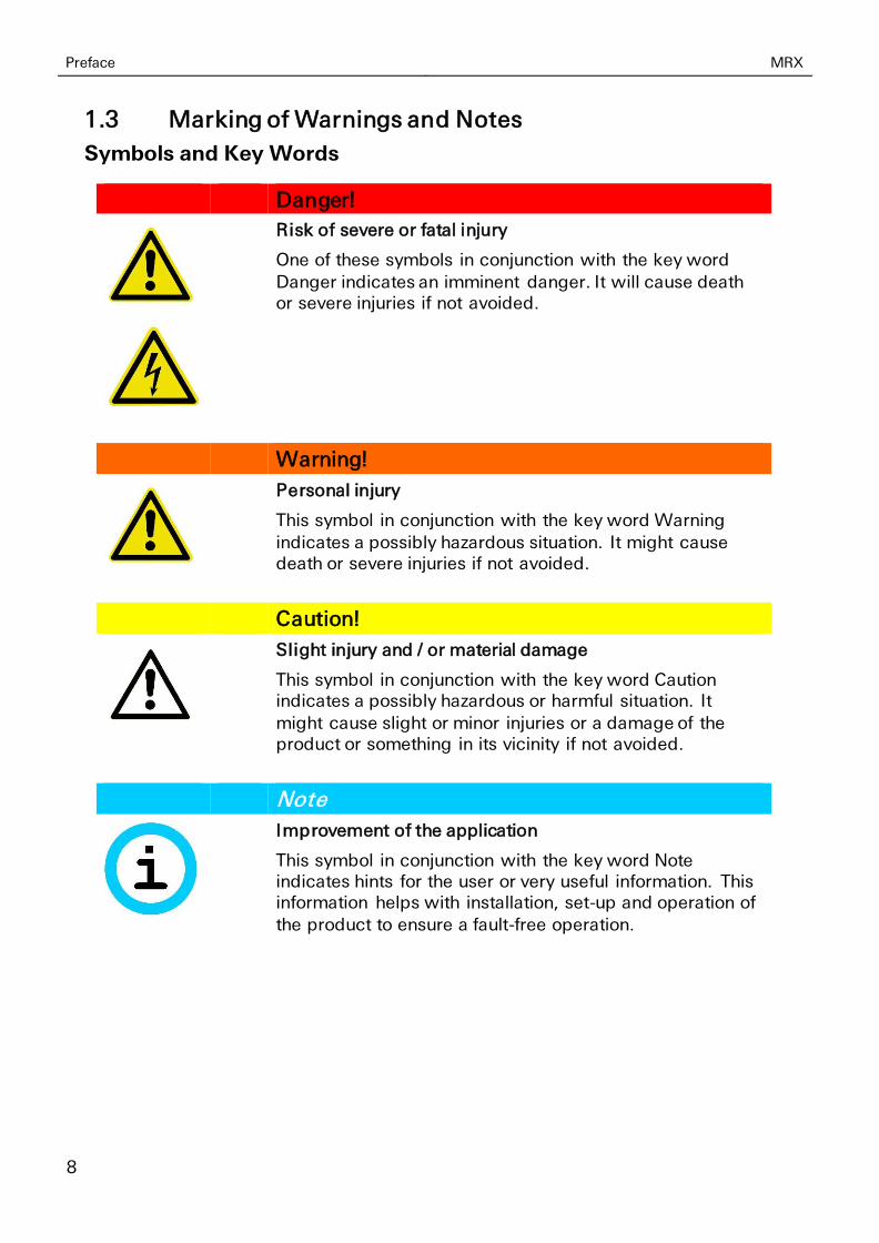
1.3 Marking of Warnings and Notes
Symbols and Key Words
Danger!
Risk of severe or fatal injury
One of these symbols in conjunction with the key word
Danger indicates an imminent danger. It will cause death or severe injuries if not avoided.
Warning!
Personal injury
This symbol in conjunction with the key word Warning indicates a possibly hazardous situation. It might cause death or severe injuries if not avoided.
Caution!
Slight injury and / or material damage
This symbol in conjunction with the key word Caution indicates a possibly hazardous or harmful situation. It
might cause slight or minor injuries or a damage of the product or something in its vicinity if not avoided.
Note
Improvement of the application
This symbol in conjunction with the key word Note indicates hints for the user or very useful information. This information helps with installation, set-up and operation of the product to ensure a fault-free operation.

MRX Preface
9
1.4 Symbols and the Formatting in this Manual
This section describes the definition, formatting and symbols used in this manual. The various symbols are meant to help you read and find the information relevant
to you. The following text is structured like a typical operating instruction of this manual.
Bold print: This will tell you what the following steps will result in
After that, there will be a detailed explanation why you could perform the following steps to be able to reach the objective indicated first. You can decide whether the section is relevant for you or not.
An arrow will indicate prerequisites which must be fulfilled to be able to process the subsequent steps in a meaningful way. You will also learn which software or which equipment you will need.
1. One individual action step: This tells you what you need to do at this point. The steps are numbered for better orientation.
A result which you will receive after performing a step will be marked with a check mark. At this point, you can check if the previous steps were successful.
Additional information which you should consider are marked with a circled "i". At this point, we will indicate possible error sources and tell you how to avoid them.
➢ Alternative results and steps are marked with an arrow. This will tell you how to reach the same results performing different steps, or what you could do if you didn't reach the expected results at this point.
Safety MRX
10
2 Safety
The Safety section provides an overview about the safety instructions, which must
be observed for the operation of the product.
The product is constructed according to the currently valid state-of-the-art technol-ogy and reliable in operation. It has been checked and left the factory in flawless condition concerning safety. In order to maintain this condition during the service life, the instructions of the valid publications and certificates must be observed and
followed.
It is necessary to adhere to the general safety instructions must when operating the product. The descriptions of processes and operation procedures are provided with precise safety instructions in the respective sections in addition to the general safety instructions.
Moreover, the local accident prevention regulations and general safety regulations for the operating conditions of the device are effective.
An optimum protection of the personnel and the environment from hazards as well as a safe and fault-free operation of the product is only possible if all safety instruc-tions are observed.
2.1 Intended Use
The product may be used for the following purposes:
• Usage and mounting in an industrial cabinet.
• Switching and data transmission functions in machines according to the machine directive 2006/42/EC.
• Usage as data transmission device for a PLC.
The product may not be used for the following purposes and used or operated un-der the following conditions:
• Controlling or switching of machines and systems, which do not
comply with the directive 2006/42/EC.
• Usage, controlling, switching and data transmission of machines and
systems, which are operated in explosive atmospheres.
• Controlling, switching and data transmission of machines, which may involve risks to life and limb due to their functions or when a breakdown occurs.
MRX Safety
11
2.2 Permissible Technical Limits
The product is only intended for the use within the permissible technical limits specified in the data sheets.
The following permissible limits must be observed:
• The ambient temperature limits must not be fallen below or exceeded.
• The supply voltage range must not be fallen below or exceeded.
• The maximum humidity must not be exceeded and condensate formation must be prevented.
• The maximum switching voltage and the maximum switching current load must not be exceeded.
• The maximum input voltage and the maximum input current must not
be exceeded.
2.3 Responsibilities of the Operator
As a matter of principle, the operator must observe the legal regulations, which are valid in his country, concerning operation, functional test, repair and maintenance of electrical devices.
2.4 Qualification of the Personnel
The installation, commissioning and maintenance of the product must only be per-formed by trained expert personnel, which has been authorised by the plant opera-tor. The expert personnel must have read and understood this documentation and observe the instructions.
Electrical connection and commissioning must only be performed by a person, who is able to work on electrical installations and identify and avoid possible hazards in-dependently, based on professional training, knowledge and experience as well as knowledge of the relevant standards and regulations.
2.5 Instructions for Transport and Storage
The following instructions must be observed:
• Do not expose the product to moisture and other potential hazardous environmental conditions (radiation, gases, etc.) during transport and storage. Pack product accordingly.
• Pack product sufficiently to protect it against shocks during transport and storage, e.g. using air-cushioned packing material.
Check product for possible damages, which might have been caused by improper transport, before installation. Transport damages must be noted down to the ship-ping documents. All claims or damages must be filed immediately and before in-stallation against the carrier or party responsible for the storage.

Safety MRX
12
2.6 Markings on the Product
The identification plate of the product is either a print or a label on a face of the product. Amongst other things, it can contain the following markings, which are
explained in detail here.
Observe manual
This symbol indicates that the manual of the product contains essential safety instructions that must be followed implicitly.
Dispose waste electronic equipment environmentally compatible
This symbol indicates that waste electronic equipment must be disposed separately from residual waste via appropriate collecting points. See also Section Disposal in this manual.
CE marking
By applying a CE marking, the manufacturer confirms that the product complies with the European directives that apply product-specific.
UL marking
By applying a UL marking, the manufacturer confirms that the product complies with the obligatory safety requirements.
Appliance Class II - double insulated
This symbol indicates that the product complies with Appliance Class II
Appliance Class III - protection by extra low voltage
This symbol indicates that the product complies with Appliance Class III
2.7 Environmental Protection
Dispose the product and the packaging according to the relevant environmental protection regulations. The Waste Disposal section in this manual contains notes about disposing the product. Separate the packaging components of cardboard and paper as well as plastic and deliver them to the respective collection systems for recycling.
MRX Safety
13
2.8 Safety Instructions for Electrical Installation
The electrical connection must only be made by authorised expert personnel ac-cording to the wiring diagrams.
The notes to the electrical connection in the manual must be observed. Otherwise, the protection category might be affected.
The safe disconnection of circuits, which are hazardous when touched, is only en-sured if the connected devices meet the requirements of VDE T.101 (Basic require-ments for safe disconnection).
The supply lines are to be routed apart from circuits, which are hazardous when touched, or isolated additionally for a safe disconnection.
An easily accessible isolation device that disconnects all lines must be installed prior to commissioning of the device to be able to isolate it completely from power supply.
Safety MRX
14
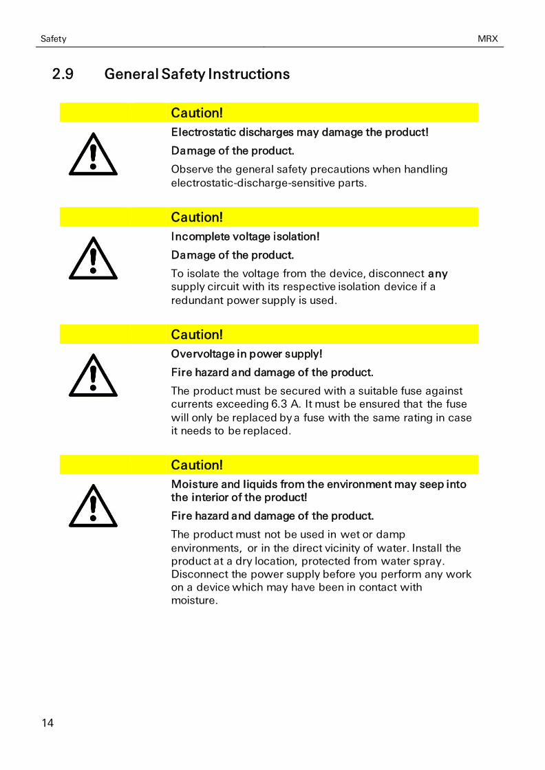
2.9 General Safety Instructions
Caution!
Electrostatic discharges may damage the product!
Damage of the product.
Observe the general safety precautions when handling electrostatic-discharge-sensitive parts.
Caution!
Incomplete voltage isolation!
Damage of the product.
To isolate the voltage from the device, disconnect any supply circuit with its respective isolation device if a
redundant power supply is used.
Caution!
Overvoltage in power supply!
Fire hazard and damage of the product.
The product must be secured with a suitable fuse against currents exceeding 6.3 A. It must be ensured that the fuse will only be replaced by a fuse with the same rating in case it needs to be replaced.
Caution!
Moisture and liquids from the environment may seep into the interior of the product!
Fire hazard and damage of the product.
The product must not be used in wet or damp
environments, or in the direct vicinity of water. Install the product at a dry location, protected from water spray. Disconnect the power supply before you perform any work on a device which may have been in contact with moisture.
MRX Safety
15
Caution!
Short circuits and damage due to improper repairs and modifications as well as opening of maintenance areas!
Fire hazard and damage of the product.
It is not permitted to open the product for repair or modification exceeding the removal or installation of the designated plug-in cards.
Caution!
Overvoltage and voltage peaks from the mains supply!
Fire hazard and damage of the product due to overvoltage.
Install suitable overvoltage protection.
Caution!
Damage due to chemicals!
Ketones and chlorinated hydrocarbons dissolve the plastic housing and damage the surface of the device.
Never let the device come into contact with ketones (e.g. acetone) or chlorinated hydrocarbons, such as dichloromethane.
Caution!
Distance from antennas to persons!
A too low distance from cellular antennas to persons can affect the health.
Please observe to keep a minimum distance of 20 cm between the cellular antenna and persons during operation.
Important note for installations in Sweden or Norway: Utrustning som är kopplad till skyddsjord via jordat vägguttag och/eller via annan utrustning och samtidigt är kopplad till kabel-TV nät kan I visa fall medföra risk fr brand. För att undvika detta skall vid anslutning av utrustningen till kabel-TV nät galvanisk isolator finnas mellan utrustningen och kabel-TV nätet.

Using Open Source Software MRX
16
3 Using Open Source Software
3.1 General Information
Our product MRX contains, amongst others, so-called open-source software that is provided by third parties and has been published for free public use. The open-source software is subject to special open-source software licenses and the copy-right of third parties. Basically, each customer can use the open-source software freely in compliance with the licensing terms of the respective producers. The rights of the customer to use the open-source software beyond the purpose of our product are regulated in detail by the respective concerned open-source software licenses. The customer use the open-source software freely, as provided in the re-
spective effective license, beyond the purpose that the open-source software gets in our product. In case there is a contradiction between the licensing terms for our product and the respective open-source software license, the respective relevant open-source software license takes priority over our licensing terms, as far as the respective open-source software is concerned by this.
The use of the used open-source software is possible free of charge. We do not de-mand usage fees or any comparable fees for the use of the open-source software contained in our product. The use of the open-source software in our product by the customer is not part of the earnings we achieve with the contractual compen-sation.
All open-source software programs contained in our product can be taken from the available list. The most important open-source software licenses are listed in the Li-censes section at the end of this publication.
As far as programs contained in our product are subject to the GNU General Public License (GPL), GNU Lesser General Public License (LGPL), Clarified Artistic License
or another open-source software license, which regulates that the source code must be made available, and if this software is not already delivered in source code on a data carrier with our product, we will send you this at any time upon request. If it is required to send this on a data carrier, the sending will be made against pay-ment of a cost compensation of € 10,00. Our offer to send the source code upon request ceases automatically 3 years after delivery of our product to the customer. Requests must be directed to the following address, if possible under specification of the serial number:
INSYS MICROELECTRONICS GmbH
Hermann-Köhl-Str. 22
93049 Regensburg, Germany
Phone +49 941 58692 0
Fax +49 941 58692 45
E-mail: [email protected]
MRX Using Open Source Software
17
3.2 Special Liability Regulations
We do not assume any warranty or liability, if the open-source software programs contained in our product are used by the customer in a manner that does not com-
ply any more with the purpose of the contract, which is the basis of the acquisition of our product. This concerns in particular any use of the open-source software programs outside of our product. The warranty and liability regulations that are pro-vided by the respective effective open-source software license for the respective open-source software as listed in the following are effective for the use of the open-source software beyond the purpose of the contract. In particular, we are not liable, if the open-source software in our product or the complete software configu-ration in our product is changed. The warranty granted with the contract, which is the basis of the acquisition of our product, is only effective for the unchanged open-source software and the unchanged software configuration in our product.
3.3 Used Open-Source Software
Please contact our support department ([email protected]) for a list of the open-source software used in this product. Alternatively, you’ll find a list of the open-source software in the web interface of the routers under Help -> Licences.
Version History MRX
18
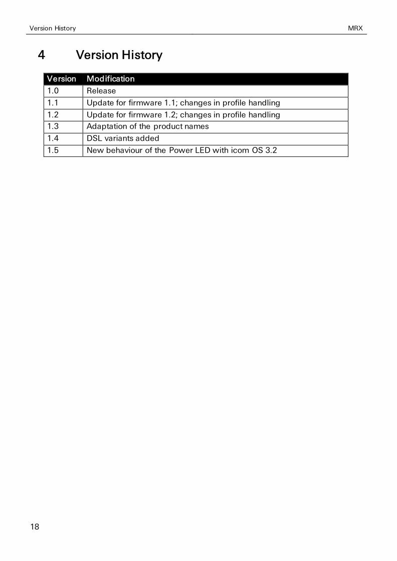
4 Version History
Version Modification
1.0 Release
1.1 Update for firmware 1.1; changes in profile handling
1.2 Update for firmware 1.2; changes in profile handling
1.3 Adaptation of the product names
1.4 DSL variants added
1.5 New behaviour of the Power LED with icom OS 3.2
MRX Device Variants
19
5 Device Variants
This manual describes different variants of the industrial router series MRX of IN-
SYS icom. The flexible industrial routers of the series MRX are available in two housing widths with three or five slots and three basic variants each. Various plug-in cards (MRcards) are also available to extend the functional scope of the router flexible. Only specific sections of this manual apply depending on housing width, basic variant and inserted plug-in cards.
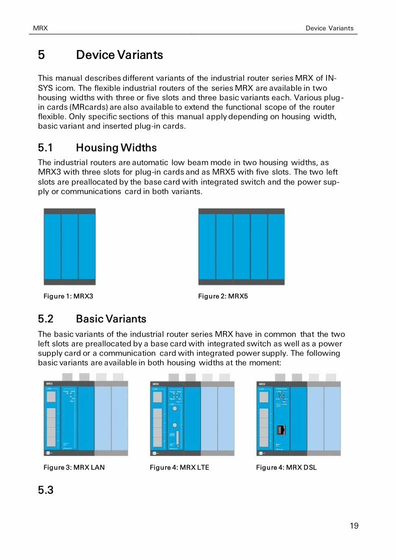
5.1 Housing Widths
The industrial routers are automatic low beam mode in two housing widths, as MRX3 with three slots for plug-in cards and as MRX5 with five slots. The two left
slots are preallocated by the base card with integrated switch and the power sup-ply or communications card in both variants.
Figure 1: MRX3
Figure 2: MRX5
5.2 Basic Variants
The basic variants of the industrial router series MRX have in common that the two left slots are preallocated by a base card with integrated switch as well as a power supply card or a communication card with integrated power supply. The following basic variants are available in both housing widths at the moment:
Figure 3: MRX LAN
Figure 4: MRX LTE
Figure 4: MRX DSL
5.3
Device Variants MRX
20
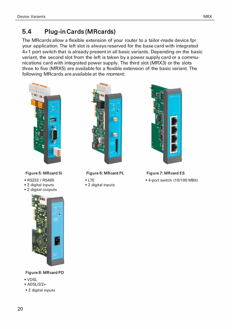
5.4 Plug-in Cards (MRcards)
The MRcards allow a flexible extension of your router to a tailor-made device fpr your application. The left slot is always reserved for the base card with integrated
4+1 port switch that is already present in all basic variants. Depending on the basic variant, the second slot from the left is taken by a power supply card or a commu-nications card with integrated power supply. The third slot (MRX3) or the slots three to five (MRX5) are available for a flexible extension of the basic variant. The following MRcards are available at the moment:
Figure 5: MRcard SI
▪ RS232 / RS485 ▪ 2 digital inputs ▪ 2 digital outputs
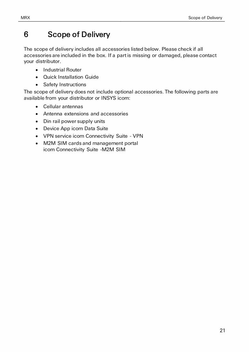
Figure 6: MRcard PL
▪ LTE ▪ 2 digital inputs
Figure 7: MRcard ES
▪ 4-port switch (10/100 MBit)
Figure 8: MRcard PD
▪ VDSL ▪ ADSL/2/2+
▪ 2 digital inputs
MRX Scope of Delivery
21
6 Scope of Delivery
The scope of delivery includes all accessories listed below. Please check if all
accessories are included in the box. If a part is missing or damaged, please contact your distributor.
• Industrial Router
• Quick Installation Guide
• Safety Instructions
The scope of delivery does not include optional accessories. The following parts are
available from your distributor or INSYS icom:
• Cellular antennas
• Antenna extensions and accessories
• Din rail power supply units
• Device App icom Data Suite
• VPN service icom Connectivity Suite - VPN
• M2M SIM cards and management portal
icom Connectivity Suite -M2M SIM
Technical Information MRX
22
7 Technical Information
7.1 Basic Variants
The following specifications apply to the basic variants MRX3/5 LAN, DSL and LTE. If these variants differ, the different values will be indicated separately. The specifi-cations of the MRcards can be found subsequently.
7.1.1 Technical Data
7.1.1.1 Physical Features
All specified data was measured with nominal input voltage, at full load, and an ambient temperature of 25 C. The limit value tolerances are subject to the usual
variations.
MRX Technical Information
23
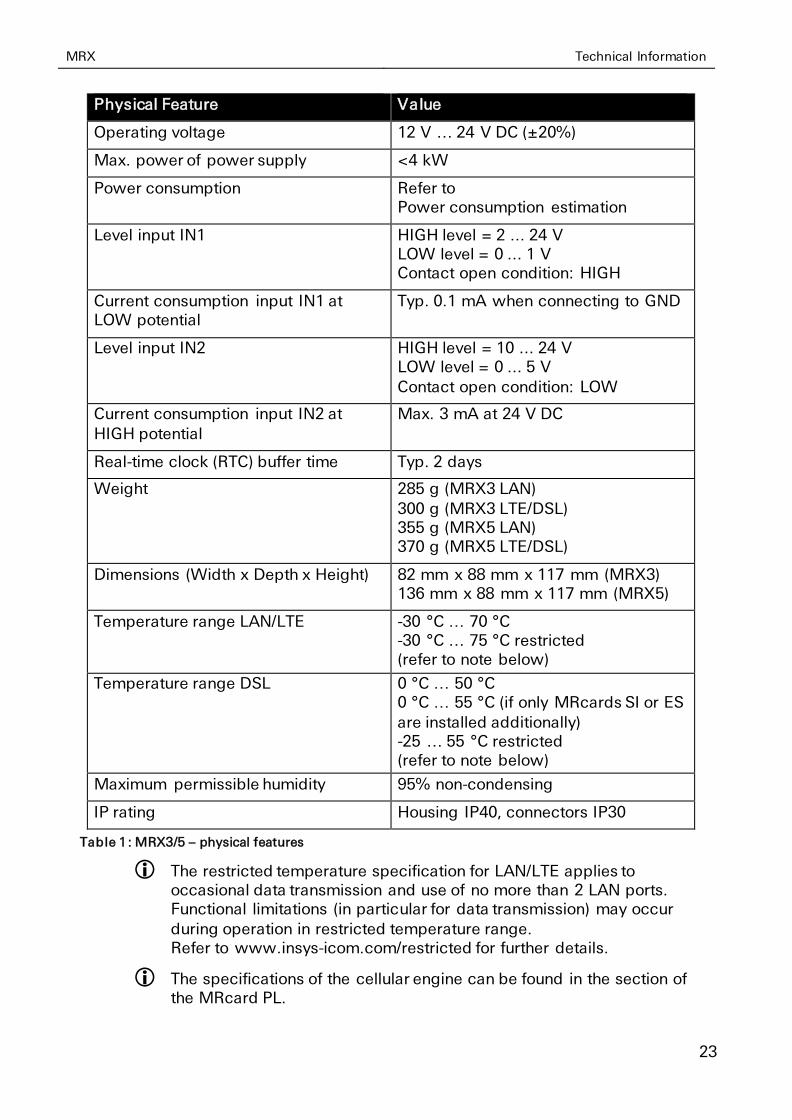
Physical Feature Value
Operating voltage 12 V … 24 V DC (±20%)
Max. power of power supply <4 kW
Power consumption Refer to Power consumption estimation
Level input IN1 HIGH level = 2 ... 24 V LOW level = 0 ... 1 V Contact open condition: HIGH
Current consumption input IN1 at LOW potential
Typ. 0.1 mA when connecting to GND
Level input IN2 HIGH level = 10 ... 24 V LOW level = 0 ... 5 V
Contact open condition: LOW
Current consumption input IN2 at
HIGH potential
Max. 3 mA at 24 V DC
Real-time clock (RTC) buffer time Typ. 2 days
Weight 285 g (MRX3 LAN)
300 g (MRX3 LTE/DSL) 355 g (MRX5 LAN) 370 g (MRX5 LTE/DSL)
Dimensions (Width x Depth x Height) 82 mm x 88 mm x 117 mm (MRX3) 136 mm x 88 mm x 117 mm (MRX5)
Temperature range LAN/LTE -30 °C … 70 °C -30 °C … 75 °C restricted (refer to note below)
Temperature range DSL 0 °C … 50 °C 0 °C … 55 °C (if only MRcards SI or ES
are installed additionally) -25 … 55 °C restricted (refer to note below)
Maximum permissible humidity 95% non-condensing
IP rating Housing IP40, connectors IP30
Table 1: MRX3/5 – physical features
The restricted temperature specification for LAN/LTE applies to occasional data transmission and use of no more than 2 LAN ports. Functional limitations (in particular for data transmission) may occur during operation in restricted temperature range. Refer to www.insys-icom.com/restricted for further details.
The specifications of the cellular engine can be found in the section of the MRcard PL.
Technical Information MRX
24
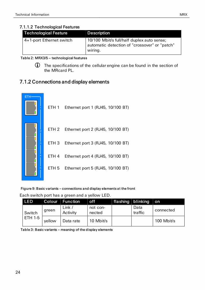
7.1.1.2 Technological Features
Technological Feature Description
4+1-port Ethernet switch 10/100 Mbit/s full/half duplex auto sense; automatic detection of "crossover" or "patch" wiring.
Table 2: MRX3/5 – technological features
The specifications of the cellular engine can be found in the section of the MRcard PL.
7.1.2 Connections and display elements
ETH 1 Ethernet port 1 (RJ45, 10/100 BT)
ETH 2 Ethernet port 2 (RJ45, 10/100 BT)
ETH 3 Ethernet port 3 (RJ45, 10/100 BT)
ETH 4 Ethernet port 4 (RJ45, 10/100 BT)
ETH 5 Ethernet port 5 (RJ45, 10/100 BT)
Figure 9: Basic variants – connections and display elements at the front
Each switch port has a green and a yellow LED.
LED Colour Function off flashing blinking on
Switch ETH 1-5
green Link / Activity
not con-nected
Data traffic
connected
yellow Data rate 10 Mbit/s 100 Mbit/s
Table 3 : Basic variants – meaning of the display elements
MRX Technical Information
25
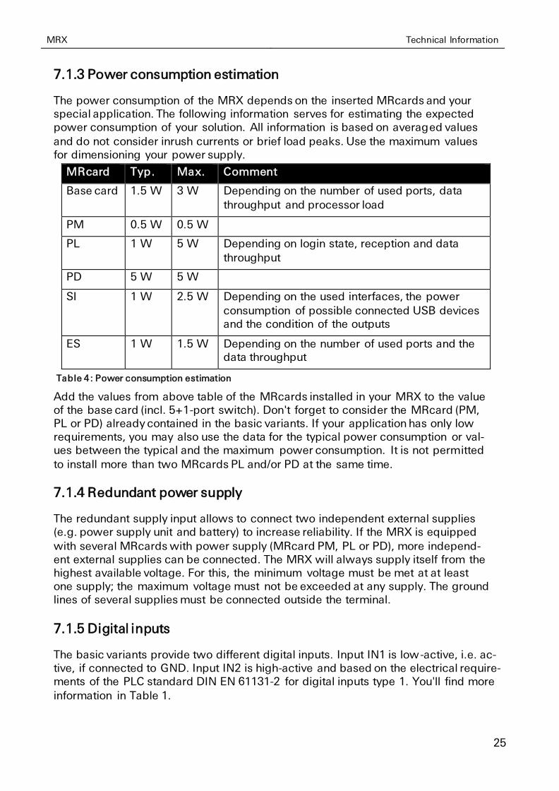
7.1.3 Power consumption estimation
The power consumption of the MRX depends on the inserted MRcards and your special application. The following information serves for estimating the expected power consumption of your solution. All information is based on averaged values
and do not consider inrush currents or brief load peaks. Use the maximum values for dimensioning your power supply.
MRcard Typ. Max. Comment
Base card 1.5 W 3 W Depending on the number of used ports, data
throughput and processor load
PM 0.5 W 0.5 W
PL 1 W 5 W Depending on login state, reception and data
throughput
PD 5 W 5 W
SI 1 W 2.5 W Depending on the used interfaces, the power
consumption of possible connected USB devices and the condition of the outputs
ES 1 W 1.5 W Depending on the number of used ports and the data throughput
Table 4: Power consumption estimation
Add the values from above table of the MRcards installed in your MRX to the value of the base card (incl. 5+1-port switch). Don't forget to consider the MRcard (PM, PL or PD) already contained in the basic variants. If your application has only low requirements, you may also use the data for the typical power consumption or val-ues between the typical and the maximum power consumption. It is not permitted
to install more than two MRcards PL and/or PD at the same time.
7.1.4 Redundant power supply
The redundant supply input allows to connect two independent external supplies (e.g. power supply unit and battery) to increase reliability. If the MRX is equipped
with several MRcards with power supply (MRcard PM, PL or PD), more independ-ent external supplies can be connected. The MRX will always supply itself from the highest available voltage. For this, the minimum voltage must be met at at least one supply; the maximum voltage must not be exceeded at any supply. The ground lines of several supplies must be connected outside the terminal.
7.1.5 Digital inputs
The basic variants provide two different digital inputs. Input IN1 is low-active, i.e. ac-tive, if connected to GND. Input IN2 is high-active and based on the electrical require-ments of the PLC standard DIN EN 61131-2 for digital inputs type 1. You'll find more
information in Table 1.

Technical Information MRX
26
7.1.6 Connecting the connectors
7.1.6.1 Connectors at the top
The connectors are delivered encoded and cannot be interchanged between differ-ent MRcards. The wires are contacted maintenance-free in the connector via a spring clip. Rigid wires (stripped) or stranded wires with end sleeves are only in-serted into the connectors to clamp them. Stranded wires (braids) without end sleeve are clamped by pushing in the orange opener (e.g. using a flt-blade screw-driver with max. 3.5 mm width). Unclamping a wires is also done by pushing in the opener.
The permissible wire cross-sections can be found in the following tables.
Wire Cross-section
Nominal cross-section 2.5 mm²
Rigid 0.2 – 2.5 mm²
Flexible 0.2 – 2.5 mm²
Flexible with end sleeve 0.25 – 2.5 mm²
Table 5: Permissible wire cross-sections for connectors at the top
7.1.6.2 Connectors at the front
The wires are contacted in the connector via a spring clip. Rigid wires (stripped) or stranded wires with end sleeves are only inserted into the connectors to clamp them. Stranded wires (braids) without end sleeve are clamped by pushing in the or-
ange opener (e.g. using a flt-blade screwdriver with max. 3.5 mm width). Unclamp-ing a wires is also done by pushing in the opener.
The permissible wire cross-sections can be found in the following tables.
Wire Cross-section
Nominal cross-section 1.5 mm²
Rigid 0.2 – 1.5 mm²
Flexible 0.2 – 1.5 mm²
Flexible with end sleeve 0.25 – 1.5 mm²
Table 6: Permissible wire cross-sections for connectors at the front
MRX Technical Information
27
7.2 MRcard PM
7.2.1 Technical Data
The MRcard PM is integral part of the MRX3/5 LAN and contains the power supply of the MRX.
Physical Feature Value
Weight 65 g
Table 7: MRcard PM – physical features
The specifications for the power supply and the inputs can be found in the basic variant section.
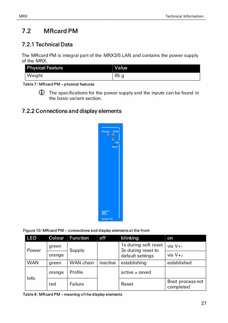
7.2.2 Connections and display elements
Figure 10: MRcard PM – connections and display elements at the front
LED Colour Function off blinking on
Power green
Supply 1x during soft reset 3x during reset to default settings
via V+1
orange via V+2
WAN green WAN chain inactive establishing established
Info
orange Profile
active ≠ saved
red Failure Reset Boot process not completed
Table 8: MRcard PM – meaning of the display elements
Technical Information MRX
28
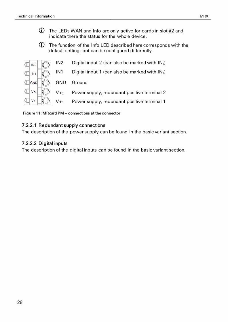
The LEDs WAN and Info are only active for cards in slot #2 and indicate there the status for the whole device.
The function of the Info LED described here corresponds with the default setting, but can be configured differently.
IN2 Digital input 2 (can also be marked with INb)
IN1 Digital input 1 (can also be marked with INa)
GND Ground
V+2 Power supply, redundant positive terminal 2
V+1 Power supply, redundant positive terminal 1
Figure 11: MRcard PM – connections at the connector
7.2.2.1 Redundant supply connections
The description of the power supply can be found in the basic variant section.
7.2.2.2 Digital inputs
The description of the digital inputs can be found in the basic variant section.
MRX Technical Information
29
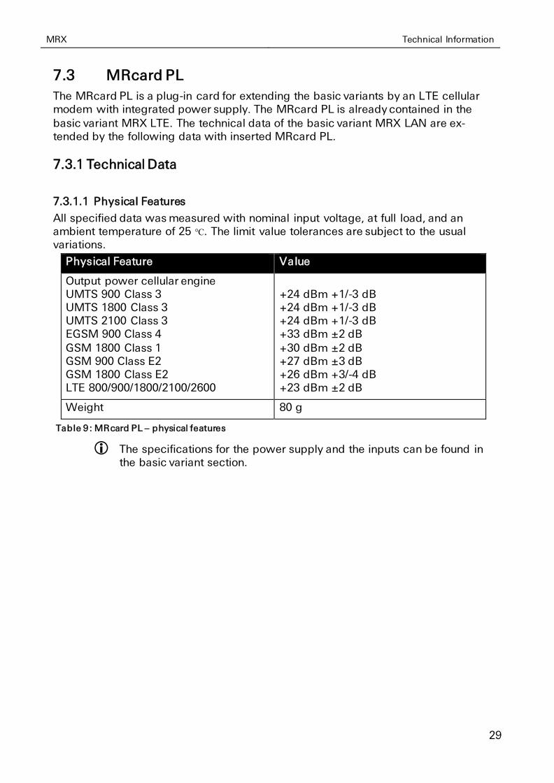
7.3 MRcard PL
The MRcard PL is a plug-in card for extending the basic variants by an LTE cellular modem with integrated power supply. The MRcard PL is already contained in the
basic variant MRX LTE. The technical data of the basic variant MRX LAN are ex-tended by the following data with inserted MRcard PL.
7.3.1 Technical Data
7.3.1.1 Physical Features
All specified data was measured with nominal input voltage, at full load, and an ambient temperature of 25 ℃. The limit value tolerances are subject to the usual variations.
Physical Feature Value
Output power cellular engine UMTS 900 Class 3 UMTS 1800 Class 3 UMTS 2100 Class 3 EGSM 900 Class 4
GSM 1800 Class 1 GSM 900 Class E2 GSM 1800 Class E2 LTE 800/900/1800/2100/2600
+24 dBm +1/-3 dB +24 dBm +1/-3 dB +24 dBm +1/-3 dB +33 dBm ±2 dB
+30 dBm ±2 dB +27 dBm ±3 dB +26 dBm +3/-4 dB +23 dBm ±2 dB
Weight 80 g
Table 9: MRcard PL – physical features
The specifications for the power supply and the inputs can be found in the basic variant section.

Technical Information MRX
30
7.3.1.2 Technological Features
Technological Feature Description
GSM/GPRS frequencies (2G) 900, 1800 MHz
UMTS/HSPA frequencies (3G) 900, 1800, 2100 MHz
LTE frequencies (4G) 800, 900, 1800, 2100, 2600 MHz
SIM card reader Support for 1.8 V and 3.0 V SIM cards Format: Mini-SIM (2FF), locked
SMS Dispatch / receipt
GPRS GPRS Multislot Class 12, Coding scheme 1 to 4, PBCCH, Mobile Station Class B
EDGE (EGPRS) EDGE Multislot Class 12, Modulation and Coding Scheme MCS 1-9
HSPA Uplink up to 5.76 MBit/s / downlink up to 42 MBit/s
UE CAT. 14, 24 supported Compressed mode (3GPP TS25.212) Rx Diversity
LTE Uplink up to 50 Mbit/s / downlink up to 100 Mbit/s UE CAT.3, MIMO in downlink direction
Table 10: MRcard PL – technological features
Please check the availability of the LTE frequencies in the planned operating area. Above specified frequencies are currently used in Europe, Middle East, Africa and, to some extent, in the Asia-Pacific region and South America.
The available data rates depend on reception conditions, use of MIMO/Rx Diversity (see page 33) and support of the respective provider (contract extent and network utilisation).
MRX Technical Information
31
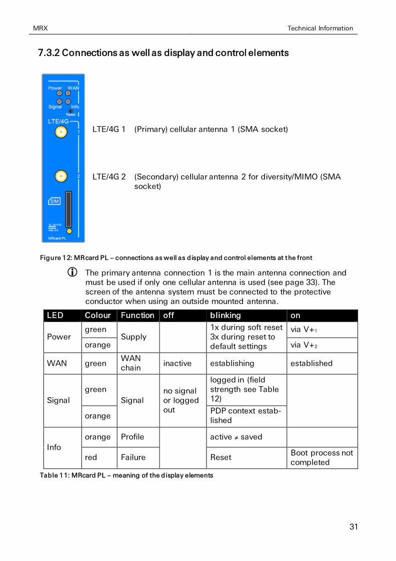
7.3.2 Connections as well as display and control elements
LTE/4G 1 (Primary) cellular antenna 1 (SMA socket)
LTE/4G 2 (Secondary) cellular antenna 2 for diversity/MIMO (SMA socket)
Figure 12: MRcard PL – connections as well as display and control elements at the front
The primary antenna connection 1 is the main antenna connection and must be used if only one cellular antenna is used (see page 33). The screen of the antenna system must be connected to the protective conductor when using an outside mounted antenna.
LED Colour Function off blinking on
Power green
Supply 1x during soft reset 3x during reset to default settings
via V+1
orange via V+2
WAN green WAN chain
inactive establishing established
Signal
green
Signal no signal or logged out
logged in (field strength see Table 12)
orange PDP context estab-lished
Info
orange Profile
active ≠ saved
red Failure Reset Boot process not completed
Table 11: MRcard PL – meaning of the display elements

Technical Information MRX
32
The LEDs WAN and Info are only active for cards in slot #2 and indicate there the status for the whole device.
The function of the Info LED described here corresponds with the default setting, but can be configured differently.
Blinking interval LED signal Signal quality
900 ms on, 100 ms off very good
200 ms on, 200 ms off good
100 ms on, 900 ms off poor
off no signal or logged out
Table 12: Blinking code of the signal LED
Designation Operation Meaning
Reset Press once for a short time.
Resets the software and restarts it.
(Soft reset)
Press at least 3 seconds. Resets the hardware and restarts it.
(Hard reset)
Press three times for a short time within 2 seconds.
Deletes all settings and resets the device to the factory defaults.
SIM Insert SIM card holder or press with a pointed object to eject
SIM card holder
Table 13: MRcard PL – description of the functions and meaning of the control elements
IN2 Digital input 2 (can also be marked with INb)
IN1 Digital input 1 (can also be marked with INa)
GND Ground
V+2 Power supply, redundant positive terminal 2
V+1 Power supply, redundant positive terminal 1
Figure 13: MRcard PL – connections at the connector
7.3.2.1 Redundant supply connections
The description of the power supply can be found in the basic variant section.
7.3.2.2 Digital inputs
The description of the digital inputs can be found in the basic variant section.
MRX Technical Information
33
7.3.3 Antennas for MIMO / Rx Diversity
In order to meet the respective cellular radio specification (and improve reception quality and data rate in downlink), it is necessary to use a second antenna for the operating modes Rx Diversity (UMTS) or MIMO (LTE) or a MIMO/diversity antenna
with two integrated antennas. The following must be observed when using two in-dividual antennas.
7.3.3.1 Main antenna
Since the main antenna is both, first reception antenna and only sending antenna, it should be set-up vertically polarised and omnidirectional to be perfectly aligned
with the base station (that is always vertically polarised). It should be possible to compensate the attenuation losses of the antenna lead with an appropriate gain of the antenna.
7.3.3.2 Auxiliary antenna
When using an auxiliary antenna, it is recommended to use the same type and the
same antenna lead as for the main antenna. It would be adverse if the difference in gain of the two antennas is too high. The auxiliary antenna is to be installed at an angle of 90° to receive the horizontally polarised portion of the radio waves that are least “detected” by the main antenna. This allows to compensate negative effects with adverse transmission. Moreover, the possible data rate increases, in particular
of the base station broadcasts using two antennas.
7.3.3.3 Antenna arrangement
The distance between the antennas should be as close as possible but not fall be-low ¼ of the maximum wave length (lowest frequency band). Approx. 9 cm would be ideal in case of 800 MHz (LTE, band 20) for example.
Tests have shown that the right arrangement of the antennas is very important. If both antennas are set-up vertically for example, the data rate can be worse than for only one antenna.
7.3.3.4 Outside mounted antenna
When using the outside mounted antennas offered by INSYS, the delivered mount-
ing bracket provides sufficient distance to the wall. If the main antenna is a ligned vertically and the auxiliary antenna is mounted at the same point perpendicular, the mounting brackets provide also a minimum distance of the antennas at the feeding point of 10 cm.
7.3.3.5 Magnetic base antenna
The magnetic base antennas offered by INSYS are especially intended for the use on metallic surfaces, e.g. outside a switch cabinet. The metallic, reflecting under-ground is mandatory for a good antenna effect. Both antennas are to be mounted at an upper corner of the switch cabinet such that the main antenna is on the top of the switch cabinet and the auxiliary antenna on its side wall. The minimum dis-
tance at the feeding point must also be observed here.
Technical Information MRX
34
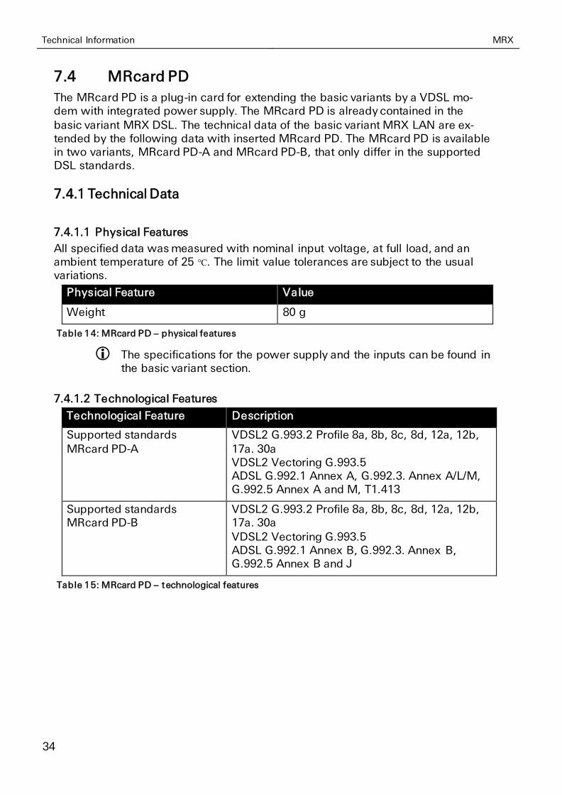
7.4 MRcard PD
The MRcard PD is a plug-in card for extending the basic variants by a VDSL mo-dem with integrated power supply. The MRcard PD is already contained in the
basic variant MRX DSL. The technical data of the basic variant MRX LAN are ex-tended by the following data with inserted MRcard PD. The MRcard PD is available in two variants, MRcard PD-A and MRcard PD-B, that only differ in the supported DSL standards.
7.4.1 Technical Data
7.4.1.1 Physical Features
All specified data was measured with nominal input voltage, at full load, and an ambient temperature of 25 ℃. The limit value tolerances are subject to the usual variations.
Physical Feature Value
Weight 80 g
Table 14: MRcard PD – physical features
The specifications for the power supply and the inputs can be found in the basic variant section.
7.4.1.2 Technological Features
Technological Feature Description
Supported standards MRcard PD-A
VDSL2 G.993.2 Profile 8a, 8b, 8c, 8d, 12a, 12b, 17a. 30a VDSL2 Vectoring G.993.5 ADSL G.992.1 Annex A, G.992.3. Annex A/L/M, G.992.5 Annex A and M, T1.413
Supported standards MRcard PD-B
VDSL2 G.993.2 Profile 8a, 8b, 8c, 8d, 12a, 12b, 17a. 30a VDSL2 Vectoring G.993.5 ADSL G.992.1 Annex B, G.992.3. Annex B, G.992.5 Annex B and J
Table 15: MRcard PD – technological features
MRX Technical Information
35
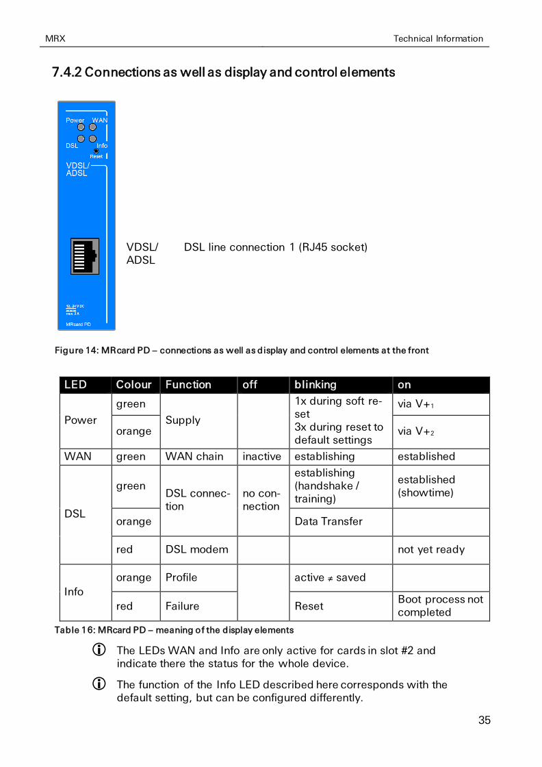
7.4.2 Connections as well as display and control elements
VDSL/ ADSL
DSL line connection 1 (RJ45 socket)
Figure 14: MRcard PD – connections as well as display and control elements at the front
LED Colour Function off blinking on
Power
green
Supply
1x during soft re-set 3x during reset to default settings
via V+1
orange via V+2
WAN green WAN chain inactive establishing established
DSL
green DSL connec-tion
no con-nection
establishing (handshake / training)
established (showtime)
orange Data Transfer
red DSL modem not yet ready
Info
orange Profile
active ≠ saved
red Failure Reset Boot process not completed
Table 16: MRcard PD – meaning of the display elements
The LEDs WAN and Info are only active for cards in slot #2 and indicate there the status for the whole device.
The function of the Info LED described here corresponds with the default setting, but can be configured differently.
Technical Information MRX
36
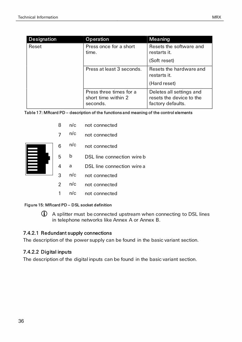
Designation Operation Meaning
Reset Press once for a short time.
Resets the software and restarts it.
(Soft reset)
Press at least 3 seconds. Resets the hardware and
restarts it.
(Hard reset)
Press three times for a short time within 2 seconds.
Deletes all settings and resets the device to the factory defaults.
Table 17: MRcard PD – description of the functions and meaning of the control elements
8 n/c not connected
7 n/c not connected
6 n/c not connected
5 b DSL line connection wire b
4 a DSL line connection wire a
3 n/c not connected
2 n/c not connected
1 n/c not connected
Figure 15: MRcard PD – DSL socket definition
A splitter must be connected upstream when connecting to DSL lines in telephone networks like Annex A or Annex B.
7.4.2.1 Redundant supply connections
The description of the power supply can be found in the basic variant section.
7.4.2.2 Digital inputs
The description of the digital inputs can be found in the basic variant section.
MRX Technical Information
37
7.5 MRcard SI
The MRcard SI is a plug-in card for extending the basic variants and contains two digital inputs, two digital outputs (changeover relays), a USB connection, a serial
RS232 interface as well as a serial RS485 interface. The technical data of the basic variants are extended by the following data with inserted MRcard SI.
7.5.1 Technical Data
7.5.1.1 Physical Features
All specified data was measured with nominal input voltage, at full load, and an ambient temperature of 25 ℃. The limit value tolerances are subject to the usual variations.
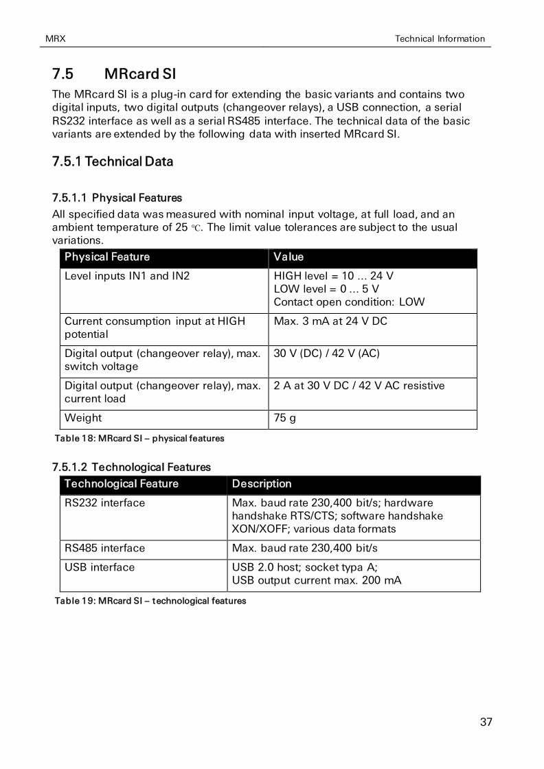
Physical Feature Value
Level inputs IN1 and IN2 HIGH level = 10 ... 24 V LOW level = 0 ... 5 V Contact open condition: LOW
Current consumption input at HIGH potential
Max. 3 mA at 24 V DC
Digital output (changeover relay), max. switch voltage
30 V (DC) / 42 V (AC)
Digital output (changeover relay), max. current load
2 A at 30 V DC / 42 V AC resistive
Weight 75 g
Table 18: MRcard SI – physical features
7.5.1.2 Technological Features
Technological Feature Description
RS232 interface Max. baud rate 230,400 bit/s; hardware handshake RTS/CTS; software handshake XON/XOFF; various data formats
RS485 interface Max. baud rate 230,400 bit/s
USB interface USB 2.0 host; socket typa A; USB output current max. 200 mA
Table 19: MRcard SI – technological features
Technical Information MRX
38
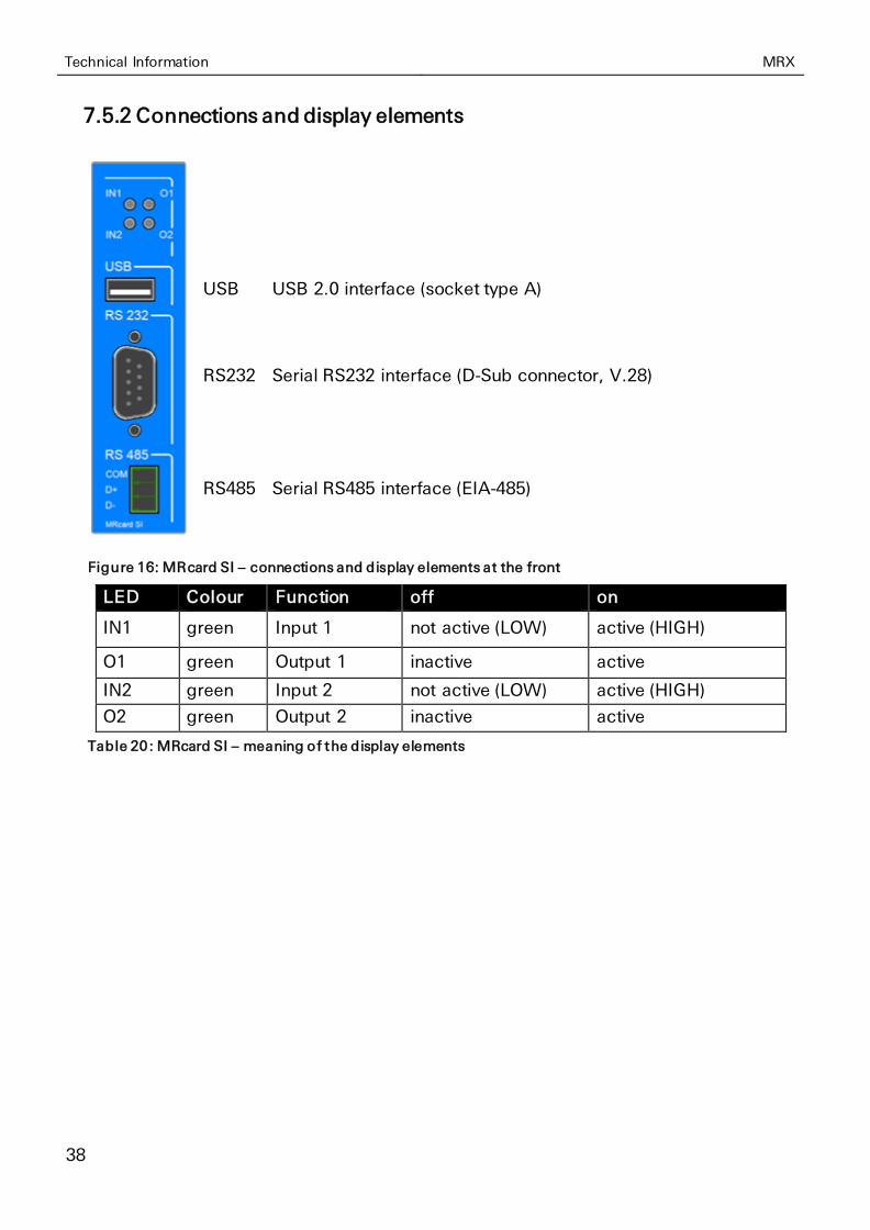
7.5.2 Connections and display elements
USB USB 2.0 interface (socket type A)
RS232 Serial RS232 interface (D-Sub connector, V.28)
RS485 Serial RS485 interface (EIA-485)
Figure 16: MRcard SI – connections and display elements at the front
LED Colour Function off on
IN1 green Input 1 not active (LOW) active (HIGH)
O1 green Output 1 inactive active
IN2 green Input 2 not active (LOW) active (HIGH)
O2 green Output 2 inactive active
Table 20: MRcard SI – meaning of the display elements
MRX Technical Information
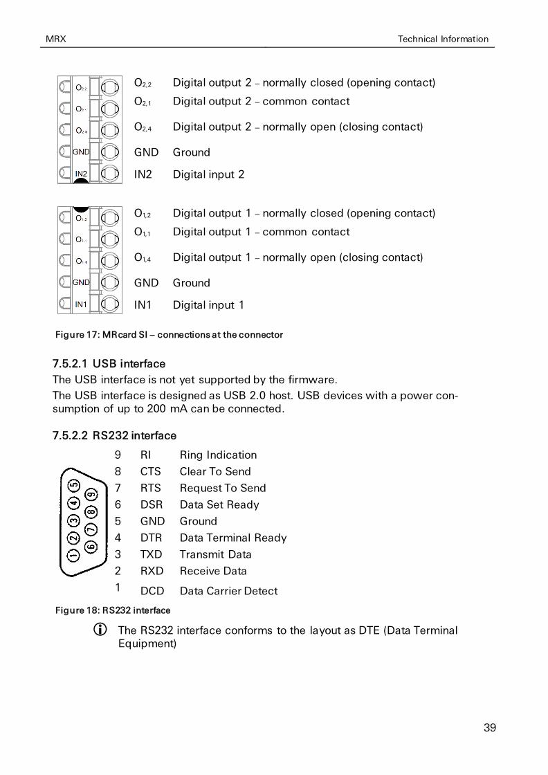
39
O2,2 Digital output 2 – normally closed (opening contact)
O2,1 Digital output 2 – common contact
O2,4 Digital output 2 – normally open (closing contact)
GND Ground
IN2 Digital input 2
O1,2 Digital output 1 – normally closed (opening contact)
O1,1 Digital output 1 – common contact
O1,4 Digital output 1 – normally open (closing contact)
GND Ground
IN1 Digital input 1
Figure 17: MRcard SI – connections at the connector
7.5.2.1 USB interface
The USB interface is not yet supported by the firmware.
The USB interface is designed as USB 2.0 host. USB devices with a power con-sumption of up to 200 mA can be connected.
7.5.2.2 RS232 interface
9 RI Ring Indication
8 CTS Clear To Send
7 RTS Request To Send
6 DSR Data Set Ready
5 GND Ground
4 DTR Data Terminal Ready
3 TXD Transmit Data
2 RXD Receive Data
1 DCD Data Carrier Detect
Figure 18: RS232 interface
The RS232 interface conforms to the layout as DTE (Data Terminal Equipment)
Technical Information MRX
40
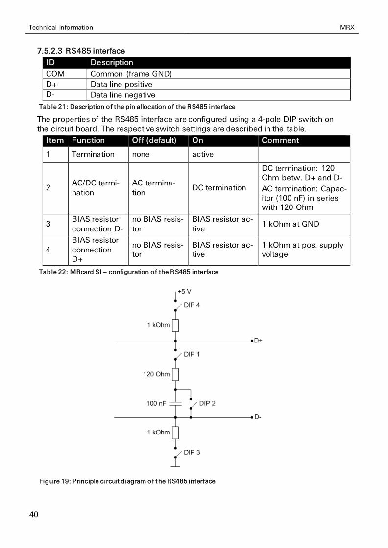
7.5.2.3 RS485 interface
ID Description
COM Common (frame GND)
D+ Data line positive
D- Data line negative
Table 21: Description of the pin allocation of the RS485 interface
The properties of the RS485 interface are configured using a 4-pole DIP switch on the circuit board. The respective switch settings are described in the table.
Item Function Off (default) On Comment
1 Termination none active
2 AC/DC termi-
nation
AC termina-
tion DC termination
DC termination: 120 Ohm betw. D+ and D-
AC termination: Capac-itor (100 nF) in series with 120 Ohm
3 BIAS resistor
connection D-
no BIAS resis-
tor
BIAS resistor ac-
tive 1 kOhm at GND
4
BIAS resistor
connection D+
no BIAS resis-tor
BIAS resistor ac-tive
1 kOhm at pos. supply voltage
Table 22: MRcard SI – configuration of the RS485 interface
Figure 19: Principle circuit diagram of the RS485 interface
MRX Technical Information
41
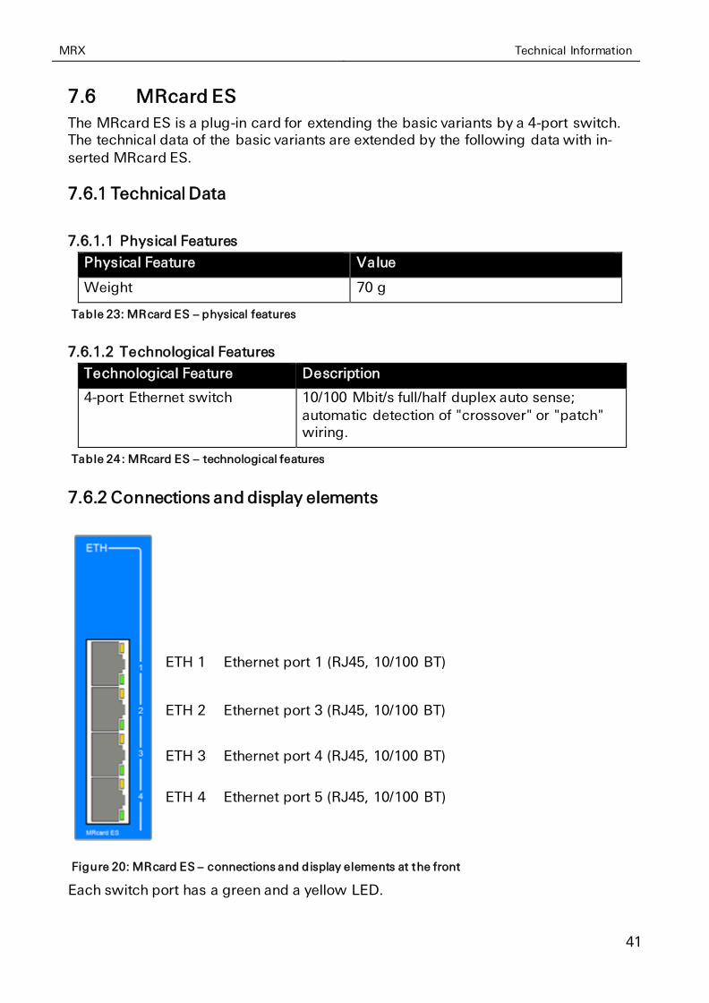
7.6 MRcard ES
The MRcard ES is a plug-in card for extending the basic variants by a 4-port switch. The technical data of the basic variants are extended by the following data with in-
serted MRcard ES.
7.6.1 Technical Data
7.6.1.1 Physical Features
Physical Feature Value
Weight 70 g
Table 23: MRcard ES – physical features
7.6.1.2 Technological Features
Technological Feature Description
4-port Ethernet switch 10/100 Mbit/s full/half duplex auto sense;
automatic detection of "crossover" or "patch" wiring.
Table 24: MRcard ES – technological features
7.6.2 Connections and display elements
ETH 1 Ethernet port 1 (RJ45, 10/100 BT)
ETH 2 Ethernet port 3 (RJ45, 10/100 BT)
ETH 3 Ethernet port 4 (RJ45, 10/100 BT)
ETH 4 Ethernet port 5 (RJ45, 10/100 BT)
Figure 20: MRcard ES – connections and display elements at the front
Each switch port has a green and a yellow LED.
Technical Information MRX
42
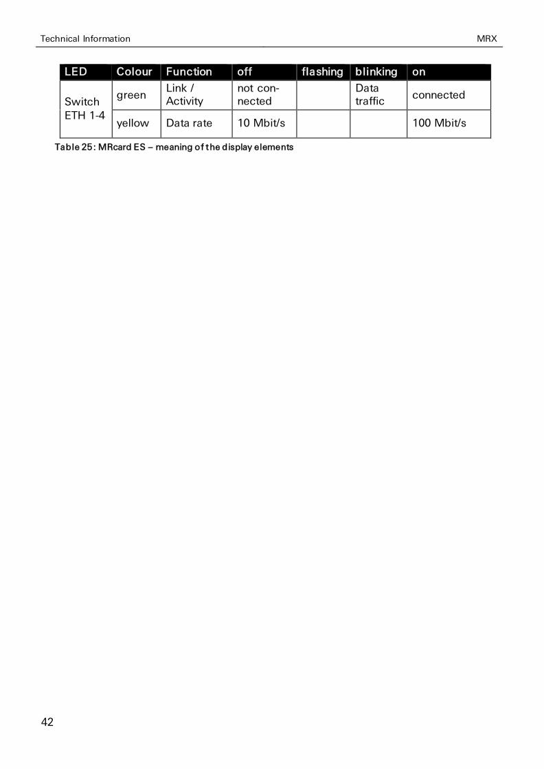
LED Colour Function off flashing blinking on
Switch
ETH 1-4
green Link / Activity
not con-nected
Data traffic
connected
yellow Data rate 10 Mbit/s 100 Mbit/s
Table 25: MRcard ES – meaning of the display elements
MRX MRcard Installation
43
8 MRcard Installation
The industrial router MRX is available in different basic variants and allows a flexi-
ble extension of these basic variants with the additionally available MRcards. Pro-ceed as follows to remove or install an MRcard.
Caution!
The MRX and the MRcards contain electrostatic-discharge-sensitive parts. Electrostatic discharges may damage these parts!
Damage of the parts.
Observe the general safety precautions when handling electrostatic-discharge-sensitive parts.
• Only install the cards with isolated power supply. Wait at least 30 seconds upon isolating the power supply.
• Only work on an ESD-compliant desktop that is connected to ground potential.
• Wear ESD-compliant shoes and clothing.
• Wear a ground strap at the wrist that is connected to ground potential.
• Take the MRcards directly out of the ESD protection packing and place removed MRcards directly back to the ESD protection packing.
Caution!
Objects penetrating the housing may damage the product!
Damage of the product.
When using tools like screwdrivers or ball-pens to remove the MRcards, pay attention not to penetrate the inside of the housing to avoid a damage of the product.
Cover the housing after removing an MRcard with a blind front cover and, if necessary, a terminal cover.
MRcard Installation MRX
44
8.1 Positions and Combinations of MRcards
The slots in the MRX are enumerated from the left with #1-#3 (MRX3) or . #1-#5 (MRX5). This enumeration is also visible at the base PCB if individual MRcards or
front covers are removed.
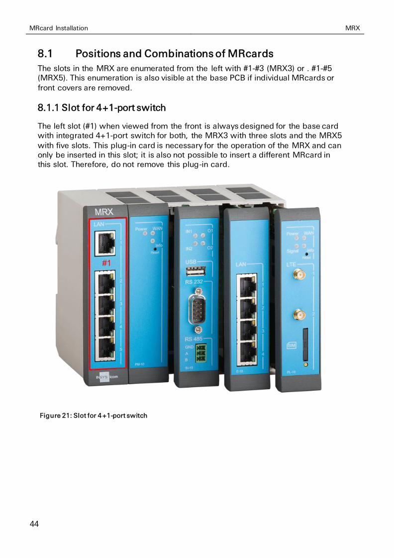
8.1.1 Slot for 4+1-port switch
The left slot (#1) when viewed from the front is always designed for the base card with integrated 4+1-port switch for both, the MRX3 with three slots and the MRX5
with five slots. This plug-in card is necessary for the operation of the MRX and can only be inserted in this slot; it is also not possible to insert a different MRcard in this slot. Therefore, do not remove this plug-in card.
Figure 21: Slot for 4+1-port switch
MRX MRcard Installation
45
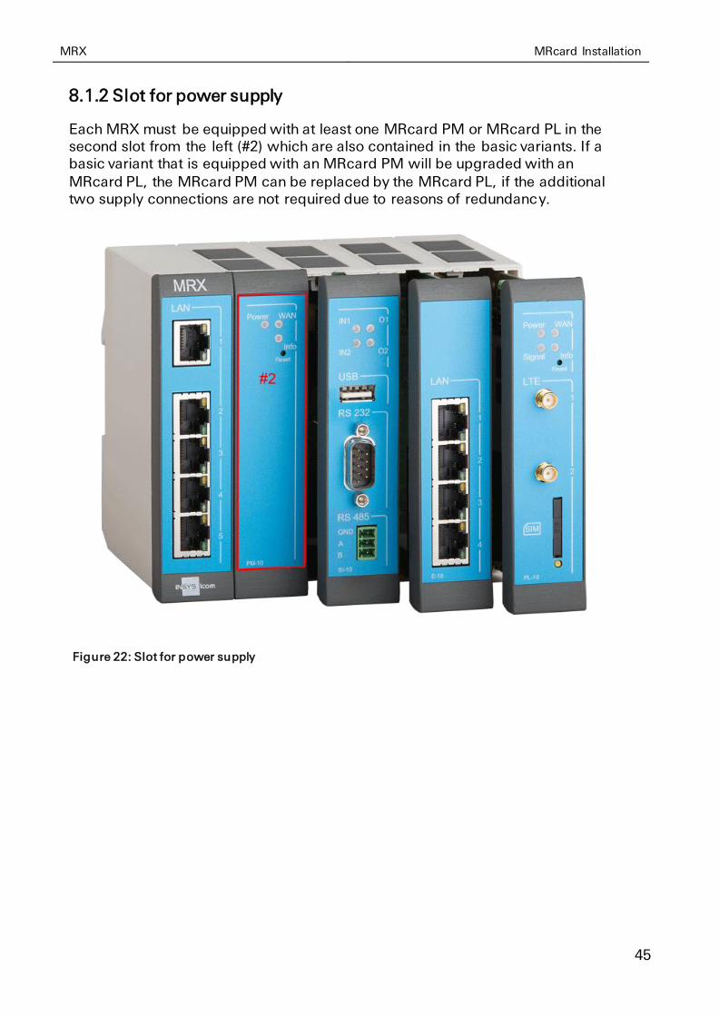
8.1.2 Slot for power supply
Each MRX must be equipped with at least one MRcard PM or MRcard PL in the second slot from the left (#2) which are also contained in the basic variants. If a basic variant that is equipped with an MRcard PM will be upgraded with an
MRcard PL, the MRcard PM can be replaced by the MRcard PL, if the additional two supply connections are not required due to reasons of redundancy.
Figure 22: Slot for power supply
MRcard Installation MRX
46
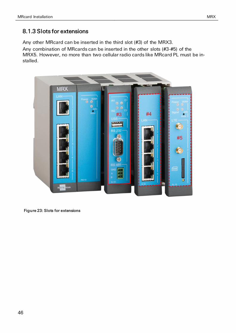
8.1.3 Slots for extensions
Any other MRcard can be inserted in the third slot (#3) of the MRX3.
Any combination of MRcards can be inserted in the other slots (#3-#5) of the MRX5. However, no more than two cellular radio cards like MRcard PL must be in-
stalled.
Figure 23: Slots for extensions
MRX MRcard Installation
47
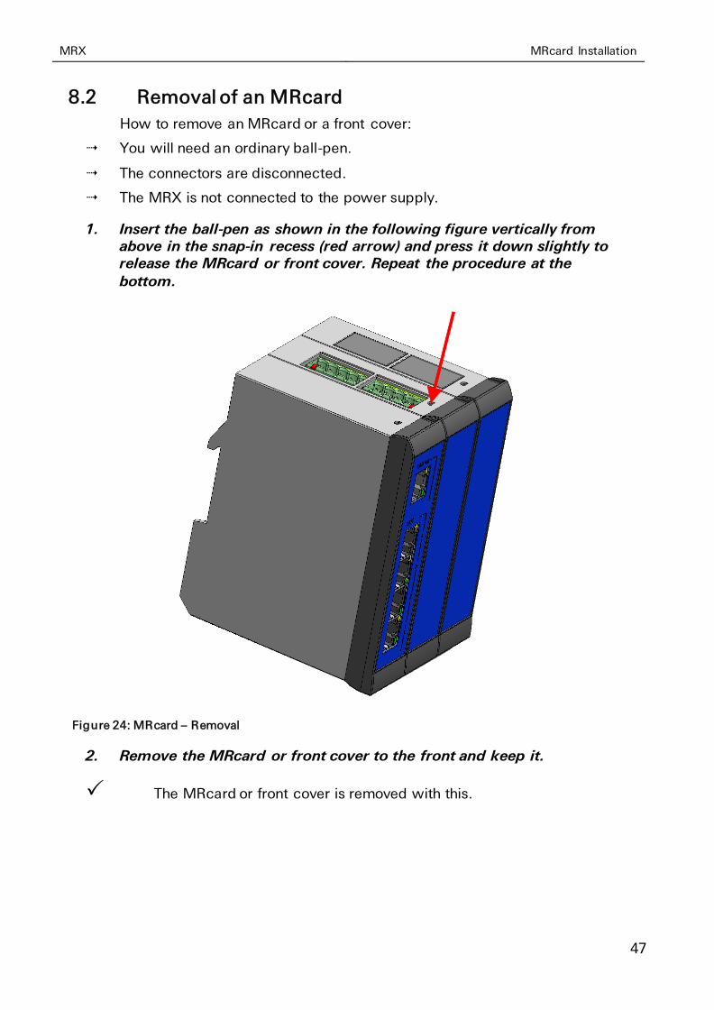
8.2 Removal of an MRcard
How to remove an MRcard or a front cover:
You will need an ordinary ball-pen.
The connectors are disconnected.
The MRX is not connected to the power supply.
1. Insert the ball-pen as shown in the following figure vertically from above in the snap-in recess (red arrow) and press it down slightly to release the MRcard or front cover. Repeat the procedure at the
bottom.
Figure 24: MRcard – Removal
2. Remove the MRcard or front cover to the front and keep it.
The MRcard or front cover is removed with this.
MRcard Installation MRX
48
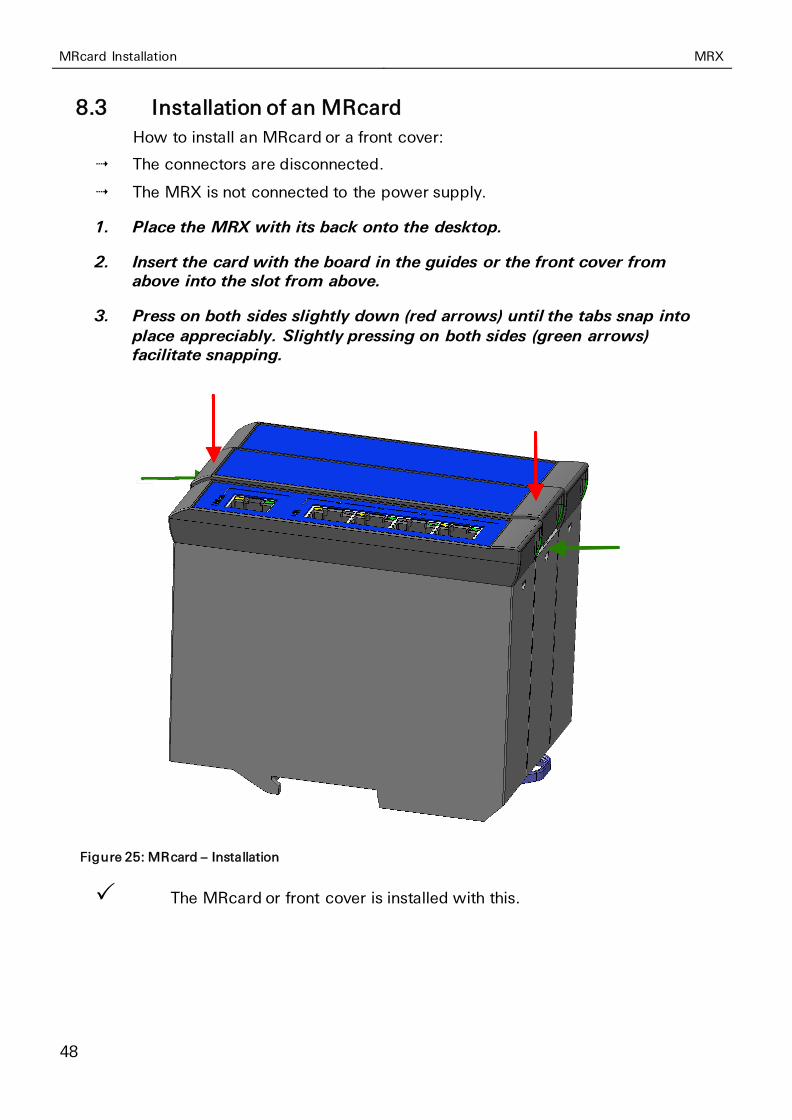
8.3 Installation of an MRcard
How to install an MRcard or a front cover:
The connectors are disconnected.
The MRX is not connected to the power supply.
1. Place the MRX with its back onto the desktop.
2. Insert the card with the board in the guides or the front cover from above into the slot from above.
3. Press on both sides slightly down (red arrows) until the tabs snap into place appreciably. Slightly pressing on both sides (green arrows) facilitate snapping.
Figure 25: MRcard – Installation
The MRcard or front cover is installed with this.
MRX MRcard Installation
49
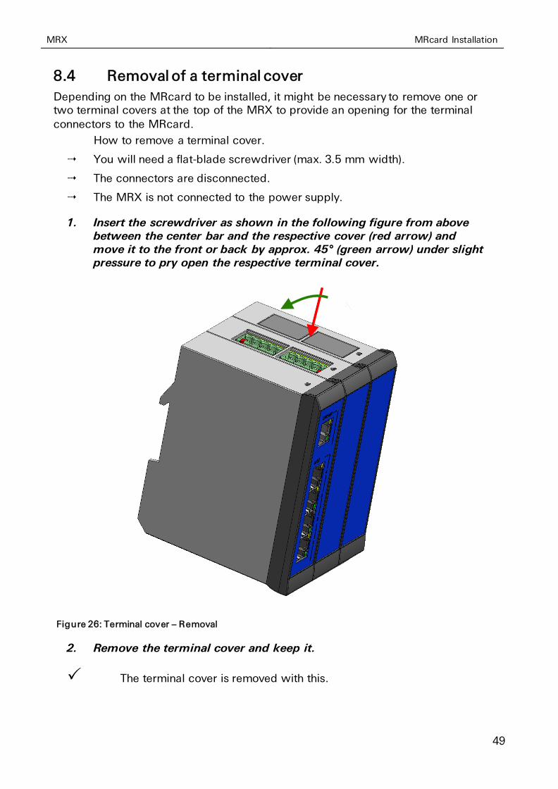
8.4 Removal of a terminal cover
Depending on the MRcard to be installed, it might be necessary to remove one or two terminal covers at the top of the MRX to provide an opening for the terminal
connectors to the MRcard.
How to remove a terminal cover.
You will need a flat-blade screwdriver (max. 3.5 mm width).
The connectors are disconnected.
The MRX is not connected to the power supply.
1. Insert the screwdriver as shown in the following figure from above between the center bar and the respective cover (red arrow) and move it to the front or back by approx. 45° (green arrow) under slight pressure to pry open the respective terminal cover.
Figure 26: Terminal cover – Removal
2. Remove the terminal cover and keep it.
The terminal cover is removed with this.

MRcard Installation MRX
50
8.5 Installation of a terminal cover
When you have removed an MRcard with terminal connector or replaced it by one without terminal connector, you need to insert the terminal cover(s) at the top of
the MRX again to re-establish the integrity of the housing.
How to install a terminal cover.
The connectors are disconnected.
The MRX is not connected to the power supply.
1. Place the terminal cover on the opening to be closed and press it slightly downwards (green arrow) until it snaps into place appreciably.
Different bars at the bottom avoid that a cover that is placed the wrong way round can snap into place.
Figure 27: Terminal cover – Installation
The terminal cover is installed with this.

MRX MRcard Installation
51
8.6 Device Label
The devices of the industrial router series MRX in their basic variants have a device label attached to one side face that contains various information, which specify the
device at hand exactly and also meet legal requirements. If a basic variant will be extended by one or more MRcards, this device label must also be modified accord-ingly. A field is provided for each free slot at the label for this, onto which the label delivered with the MRcard (see Figure 29) can be stuck.
Figure 28: Example for MRX device label
Moreover, it might be necessary after installing an MRcard to modify the fields for
CE marking and FCC approval. Just follow the instructions on the label supplement delivered with the MRcard.
Figure 29: Example for label supplement of an MRcard
Assembly MRX
52
9 Assembly
This section describes how to mount the MRX to a DIN rail, connect the
power supply and uninstall it again. Observe the instructions in the "Safety" section of this manual, in particular the "Safety Instructions for Electrical Installation" for that purpose unconditionally.
Caution!
Moisture and liquids from the environment may seep into the interior of the device!
Fire hazard and damage of the product.
The device must not be used in wet or damp
environments, or in the direct vicinity of water. Install the device at a dry location, protected from water spray. Disconnect the power supply before you perform any work on a device which may have been in contact with moisture.
Caution!
The device could be destroyed if the wrong power supply is used!
If the device is operated with a power supply that supplies a voltage exceeding the permissible operating voltage, it will be destroyed.
Make sure that you use the suitable power supply. Refer to the Technical Data section for the proper voltage range.
MRX Assembly
53
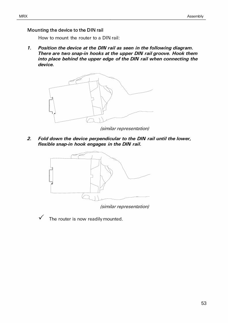
Mounting the device to the DIN rail
How to mount the router to a DIN rail:
1. Position the device at the DIN rail as seen in the following diagram. There are two snap-in hooks at the upper DIN rail groove. Hook them into place behind the upper edge of the DIN rail when connecting the device.
(similar representation)
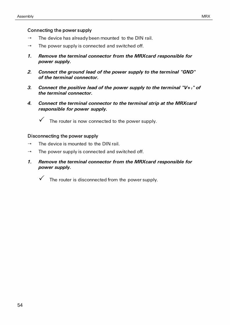
2. Fold down the device perpendicular to the DIN rail until the lower, flexible snap-in hook engages in the DIN rail.
(similar representation)
The router is now readily mounted.
Assembly MRX
54
Connecting the power supply
The device has already been mounted to the DIN rail.
The power supply is connected and switched off.
1. Remove the terminal connector from the MRXcard responsible for power supply.
2. Connect the ground lead of the power supply to the terminal "GND" of the terminal connector.
3. Connect the positive lead of the power supply to the terminal "V+1" of the terminal connector.
4. Connect the terminal connector to the terminal strip at the MRXcard responsible for power supply.
The router is now connected to the power supply.
Disconnecting the power supply
The device is mounted to the DIN rail.
The power supply is connected and switched off.
1. Remove the terminal connector from the MRXcard responsible for power supply.
The router is disconnected from the power supply.
MRX Assembly
55
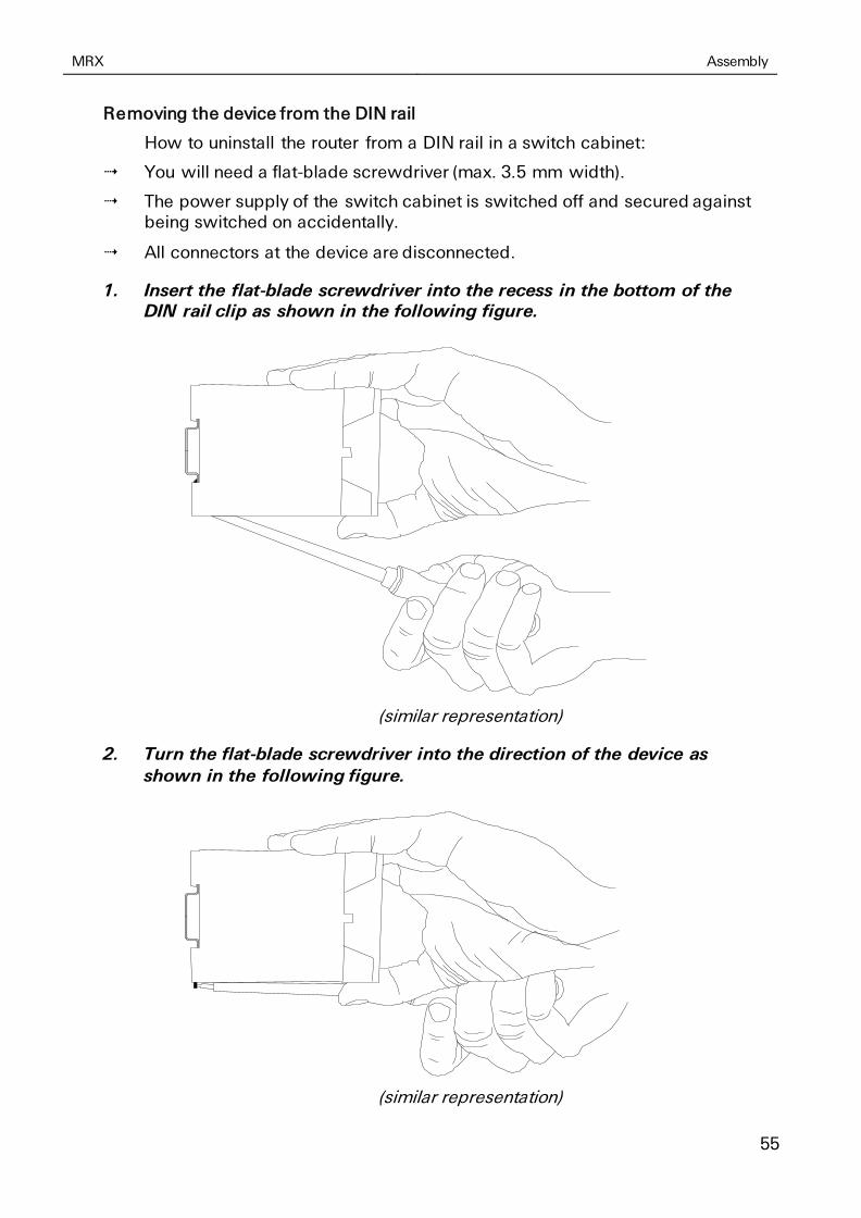
Removing the device from the DIN rail
How to uninstall the router from a DIN rail in a switch cabinet:
You will need a flat-blade screwdriver (max. 3.5 mm width).
The power supply of the switch cabinet is switched off and secured against being switched on accidentally.
All connectors at the device are disconnected.
1. Insert the flat-blade screwdriver into the recess in the bottom of the DIN rail clip as shown in the following figure.
(similar representation)
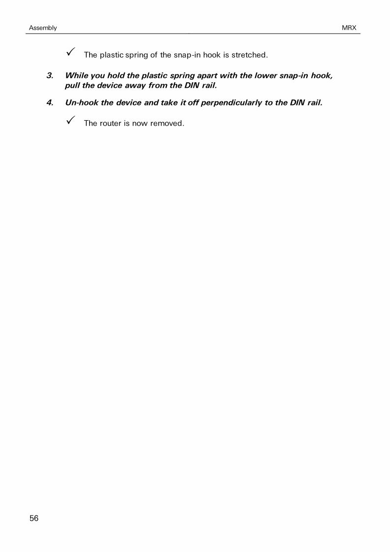
2. Turn the flat-blade screwdriver into the direction of the device as
shown in the following figure.
(similar representation)
Assembly MRX
56
The plastic spring of the snap-in hook is stretched.
3. While you hold the plastic spring apart with the lower snap-in hook,
pull the device away from the DIN rail.
4. Un-hook the device and take it off perpendicularly to the DIN rail.
The router is now removed.
MRX Commissioning
57
10 Commissioning
This chapter describes how to activate the MRX, i.e. how to connect it to a PC, and
how to prepare it for the configuration.
Inserting the SIM card (only MRX LTE or MRX LAN with MRcard PL).
How to insert the SIM card.
The power supply is disabled.
You will need a functionable Mini-SIM card of your mobile provider.
You will also need the associated PIN.
You will need a pointed object to operate the SIM card eject button, e.g. a screwdriver with a blade of max. 1.5 mm.
1. Press the SIM card eject button with the pointed object.
The SIM card holder will be ejected a little bit out of the housing.
2. Remove the SIM card holder.
3. Insert your SIM card into the card holder.
The SIM card will only fit into the SIM card holder in one position. Make sure that the SIM card does not extend over the card holder.
4. Insert the SIM card holder together with the SIM card again. The
contacts of the SIM card must face to the right.
5. Using a finger, carefully push the SIM card holder with the inserted SIM card into the housing, until the card holder snaps into place.
6. Enable the power supply again.
Connecting a cellular antenna (only MRX LTE or MRX LAN with MRcard PL).
How to connect the MRX to a cellular antenna.
The power supply is disabled.
You will need a suitable cellular antenna (available from INSYS icom).
When selecting and mounting the antenna, make sure to comply with CE conformity.
1. Connect the cellular antenna to antenna connector #1.
The cellular antenna is connected with this.

Commissioning MRX
58
Using a second antenna allows higher data rate if supported by the provider.
Connecting a PC
How to connect the MRX to a PC via a network cable.
The power supply is disabled.
You will need a Cat 5 network patch cable
You will need a network card in the PC.
1. Locate the RJ-45 socket of the network card at the PC.
2. Plug one end of the network cable into the RJ45 socket of the PC, and the other end into the ETH 1 socket in the left slot of the MRX.
The MRX is connected to the PC with this.
Configuring the MRX
The device is connected to the PC.
The power supply of the device is enabled and the device is ready for operation (Info LED doesn't light red any more).
You have the required access rights to change the IP address of the network card to which the MRX is connected.
1. Make sure that the DHCP client is enabled for the PC (Obtain an IP address automatically).
The integrated DHCP server of the MRX will then allocate an address from the according address range to your network card.
➢ Alternatively, you can change the IP address of the network card to which the device is connected to an address that starts with 192.168.1. Do not use the address 192.168.1.1 here. This is the factory default IP address of the device. For example, use 192.168.1.2 as IP address for the network card in your PC.
2. Open a web browser and enter the URL "http://192.168.1.1" into the address bar.
The browser loads the start page of the MRX.
➢ If you see the message in your browser window that the page with this address cannot be found, follow the following steps: Check, whether the device is supplied with power. If yes, most probably a wrong IP address is configured in the device. Press the reset key three times within two seconds and repeat this instruction from step 2.
MRX Commissioning
59
A dialogue will prompt you to enter a user name and password for authentication.
3. Enter the user name "insys" and the password "icom".
User name and password are set as factory defaults. If the registration at the web interface does not work with the data entered, just reset
the device to the factory defaults. Press the reset key three times within two seconds and repeat this instruction from step 2.
You should now see the start page of the web interface.
The MRX is installed successfully and ready for configuration.
Due to reasons of security, the session will be terminated after 15 minutes of inactivity (default setting) and you need to login again.

Operating Principle MRX
60
11 Operating Principle
This chapter describes how to operate and configure the router.
There are different options for configuration and operation:
• Via a web-based interface (web interface). The web interface itself is displayed and operated using a web browser. Operation via web interface and access via HTTPS protocol are described in the following.
• Via a command line interface (CLI) Configuration and operation via command line are described in detail in the online help of the router.
• Via a configuration file (binary or ASCII). Configuration and operation via a configuration file are described in detail in the online help of the router.
Profiles are used for all types of configuration. The basic handling of these profiles are described at the end of this section.
11.1 Operation via the web interface
The web interface allows easy configuration using a web browser. All functions can be configured via the web interface. The operation is mostly self-explanatory. The web interface also provides an inline help feature, which describes the meaning of possible settings The inline help is displayed by
selecting the button "Display help text" in the title bar besides the language selection. An online help is available for more detailed explanation. It can be opened using links in the inline help.
We urgently recommend to enable inline help for the first configurations to allow a quick and flawless configuration. If the inline help is enabled during configuration, all unsaved changes on this page will be lost.
MRX Operating Principle
61
Access to the Web Interface
How to access the web interface basically.
The device is ready for operation and you have access to it (refer to Commissioning section).
1. Start the web browser and enter the IP address into the address bar.
The factory default IP address is 192.168.1.1.
A login screen will prompt you to enter the user name and the password for authentication.
Due to reasons of security, the session will be terminated after 10 minutes of inactivity and you need to login again.
2. Enter the user name and the password and click OK.
The default settings of the web interface are as follows: the user name is "insys", the password is "icom".
The start page of the web interface is displayed.
3. Use the menu on the left side to select the menu item, in which you want to change settings.
4. Enter the required settings.
5. Click on the button OK on the according configuration page to save
the settings in the profile.
Consider the information in the profile section about the effectivity of configurations made.
Language selection in the web interface
How to change the language in the web interface.
The device is ready for operation and you have access to the web interface.
1. Select in the title bar the button for German or for English.
The web interface is displayed in the selected language then.

Operating Principle MRX
62
Logging out from the web interface
How to log off from the web interface. This prevents unauthorised access after completing the configuration.
The device is ready for operation and you have access to the web interface.
1. Select in the title bar the button (Logout).
You will be logged out from the web interface and returned to the login screen.
A session will also be terminated after 15 minutes of inactivity (default setting) due to security reasons.
11.2 Access via HTTPS Protocol
The web interface also allows a secure configuration using the HTTPS protocol. The HTTPS protocol allows an authentication of the server (i.e. the router) as well as an encryption of the data transmission.
11.2.1 Authentication via the device-individual certificate/key combination
The router will be authenticated via self-certified device-individual certificate/key combination by default. In case of a first access via the HTTPS protocol, the browser indicates that the router uses an invalid security certificate. The certificate is not trusted, because the CA (certification authority) certificate is unknown. You can ignore this warning and (depending
on browser and operating system) add an exception for this server or establish the secure connection to this server nevertheless.
We recommend to download the CA certificate CA_INSYS_Router.pem from the firmware page (http://www.insys-icom.com/firmware/) and import it into your browser, to approve INSYS MICROELECTRONICS as certification authority. Proceed for this as described in the documentation of your browser.
If INSYS MICROELECTRONICS is stored as certification authority in your browser and you access the device again via the HTTPS protocol, the browser indicates again that an invalid security certificate is used. The certificate is not trusted, because the Common Name of the certificate differs from your input in the address bar of the browser. The browser indicates that a different device answers under this URL. The Common Name of the certificate consists of the MAC address of the router, where the colons are replaced by underscores. You can ignore this warning and (depending on browser and operating system) add an exception for this server or establish the secure
connection to this server nevertheless.

MRX Operating Principle
63
In order to avoid this browser warning as well, you must enter the Common Name of the router to be accessed into the address bar of your browser. The Common Name must be connected with the IP address of the device that the URL leads to the correct device. You can find out the general name (Common Name) by downloading and viewing the certificate from the device. The
proceeding for this depends on your browser. The proceeding for setting up the link depends on your operating system.
• Editing of /etc/hosts (Linux/Unix)
• Editing of C:\WINDOWS\system32\drivers\etc\hosts (Windows XP/7/8/10)
• Configuring your own DNS server
For further information, refer to the documentation of your operating system.
11.2.2 Authentication via an own certificate structure
Alternatively, it is also possible to use an own certificate structure and upload a self-generated certificate/key combination to the router to use this for the access via an HTTPS connection.
You need to upload your self-generated certificate/key combination in the certificate manager of the router first (menu Administration -> Certificates).
Then, this certificate/key combination must be selected when configuring the web interface access via HTTPS (menu Administration -> Web interface).
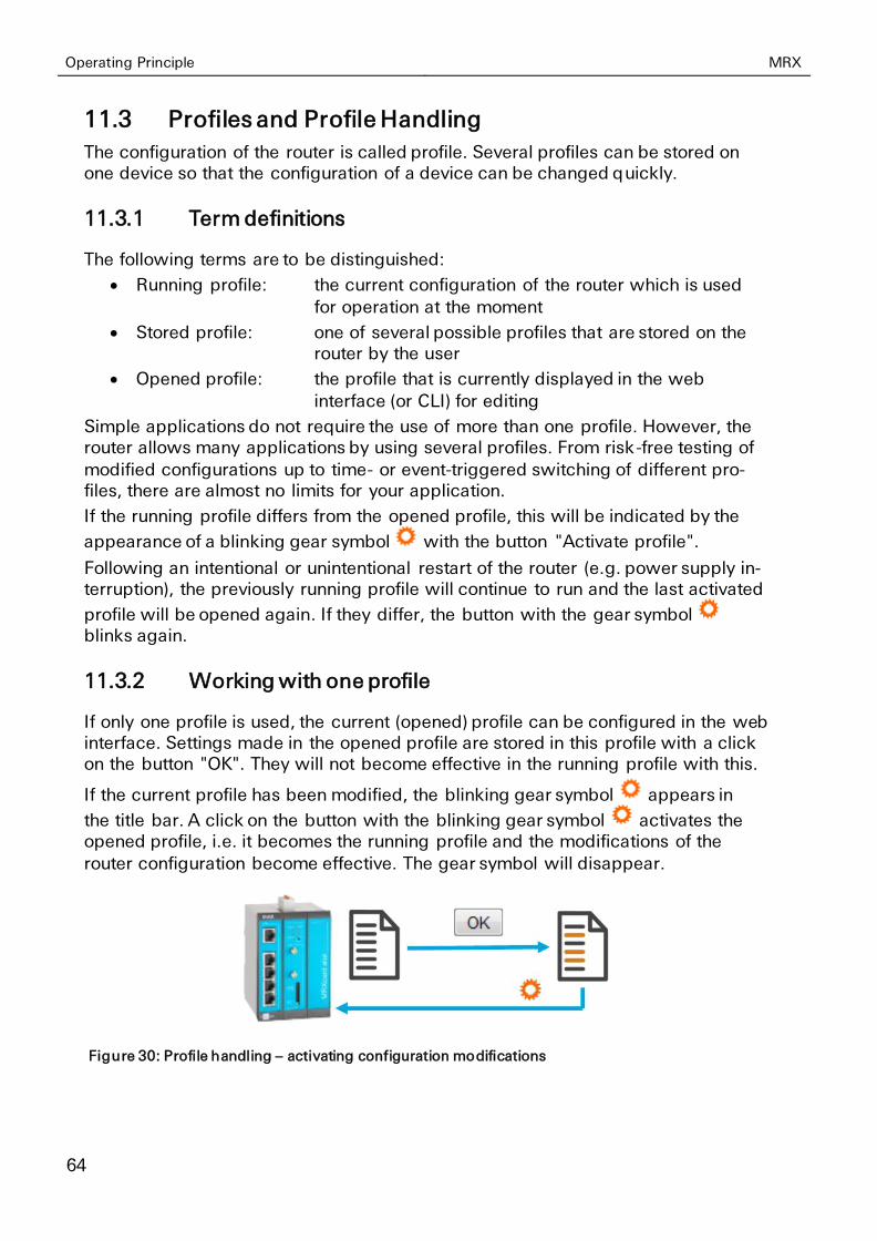
Operating Principle MRX
64
11.3 Profiles and Profile Handling
The configuration of the router is called profile. Several profiles can be stored on one device so that the configuration of a device can be changed quickly.
11.3.1 Term definitions
The following terms are to be distinguished:
• Running profile: the current configuration of the router which is used
for operation at the moment
• Stored profile: one of several possible profiles that are stored on the router by the user
• Opened profile: the profile that is currently displayed in the web
interface (or CLI) for editing
Simple applications do not require the use of more than one profile. However, the router allows many applications by using several profiles. From risk-free testing of
modified configurations up to time- or event-triggered switching of different pro-files, there are almost no limits for your application.
If the running profile differs from the opened profile, this will be indicated by the
appearance of a blinking gear symbol with the button "Activate profile".
Following an intentional or unintentional restart of the router (e.g. power supply in-terruption), the previously running profile will continue to run and the last activated
profile will be opened again. If they differ, the button with the gear symbol blinks again.
11.3.2 Working with one profile
If only one profile is used, the current (opened) profile can be configured in the web interface. Settings made in the opened profile are stored in this profile with a click on the button "OK". They will not become effective in the running profile with this.
If the current profile has been modified, the blinking gear symbol appears in
the title bar. A click on the button with the blinking gear symbol activates the opened profile, i.e. it becomes the running profile and the modifications of the
router configuration become effective. The gear symbol will disappear.
Figure 30: Profile handling – activating configuration modifications
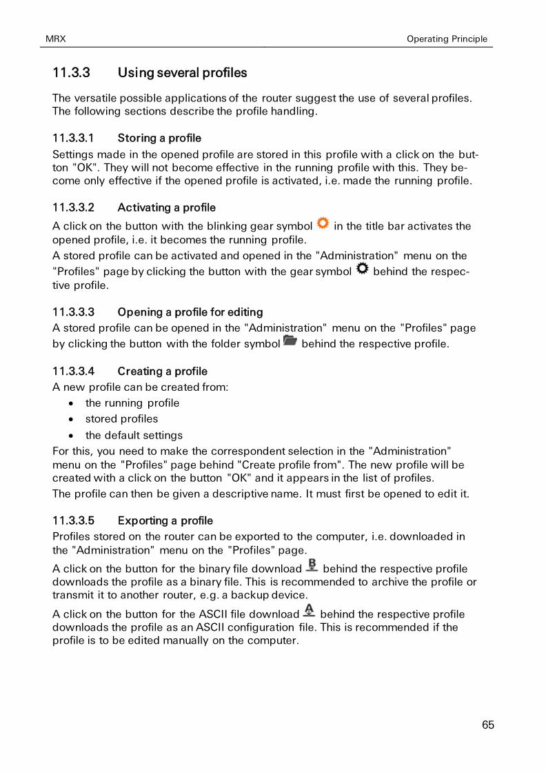
MRX Operating Principle
65
11.3.3 Using several profiles
The versatile possible applications of the router suggest the use of several profiles. The following sections describe the profile handling.
11.3.3.1 Storing a profile
Settings made in the opened profile are stored in this profile with a click on the but-ton "OK". They will not become effective in the running profile with this. They be-come only effective if the opened profile is activated, i.e. made the running profile.
11.3.3.2 Activating a profile
A click on the button with the blinking gear symbol in the title bar activates the opened profile, i.e. it becomes the running profile.
A stored profile can be activated and opened in the "Administration" menu on the
"Profiles" page by clicking the button with the gear symbol behind the respec-tive profile.
11.3.3.3 Opening a profile for editing
A stored profile can be opened in the "Administration" menu on the "Profiles" page
by clicking the button with the folder symbol behind the respective profile.
11.3.3.4 Creating a profile
A new profile can be created from:
• the running profile
• stored profiles
• the default settings
For this, you need to make the correspondent selection in the "Administration" menu on the "Profiles" page behind "Create profile from". The new profile will be created with a click on the button "OK" and it appears in the list of profiles.
The profile can then be given a descriptive name. It must first be opened to edit it.
11.3.3.5 Exporting a profile
Profiles stored on the router can be exported to the computer, i.e. downloaded in
the "Administration" menu on the "Profiles" page.
A click on the button for the binary file download behind the respective profile downloads the profile as a binary file. This is recommended to archive the profile or transmit it to another router, e.g. a backup device.
A click on the button for the ASCII file download behind the respective profile downloads the profile as an ASCII configuration file. This is recommended if the profile is to be edited manually on the computer.

Operating Principle MRX
66
11.3.3.6 Importing a profile
Profiles (in binary format) or ASCII configuration files can be uploaded to the router in the "Administration" menu on the “Profiles" page.
You need to locate the respective file on the computer under "Import profile or ASCII configuration file" for this. The profile will be uploaded with a click on the
button "OK" and it appears in the respective list.
11.3.3.7 Deleting a profile
A stored profile can be deleted in the "Administration" menu on the "Profiles" page
by clicking the button with the recycle bin symbol behind the respective profile.
11.3.3.8 Comparing two profiles
To show the differences between two profiles, it is possible to compare the default settings, the running profile and the stored profiles to each other.
For this, you need to select the two profiles to be compared in the "Administration" menu on the "Profiles" page under "Compare profiles". The different settings of
both profiles are displayed side by side when clicking the button "OK".
Figure 31: Profile handling – scheme
11.3.4 ASCII Configuration
ASCII configurations are a sequence of commands as they could also be entered in the CLI. Each line contains a command that modifies the opened profile.
Syntax and parameters can be taken from a downloaded profile in ASCII format for example. Refer to the CLI description for further information about the syntax.
Commands that affect plug-in cards that are not installed will be taken over to the profile, but will have no effect.
MRX Maintenance, Repair and Troubleshooting
67
12 Maintenance, Repair and Troubleshooting
12.1 Maintenance
The product is maintenance-free and does not require special regular maintenance.
12.2 Troubleshooting
If a failure occurs during the operation of the product, you will find troubleshooting tips in the "Knowledge Base" on our web site (http://www.insys-icom.de/knowledge/). If you need further support, please contact your reseller or INSYS icom. You can contact our support team via e-mail under support@insys-
tec.de.
12.3 Repair
Send defect devices with detailed failure description to the source of supply of your device. If you have purchased the device directly from INSYS icom, send the device to: INSYS MICROELECTRONICS GmbH, Hermann-Köhl-Str. 22, 93049 Regensburg.
Before dispatching the device:
• Remove any inserted SIM cards.
• Backup the configuration on the device and any other stored data if required.
• Backup any sandbox applications running on the device.
Caution!
Short circuits and damage due to improper repairs and modifications of products.
Fire hazard and damage of the product.
It is not permitted to open the product for repair or modification exceeding the exchange of plug-in cards.
Waste Disposal MRX
68
13 Waste Disposal
13.1 Repurchasing of Legacy Systems
According to the new WEEE guidelines, the repurchasing and recycling of legacy systems for our clients is regulated as follows:
Please send those legacy systems to the following address, carriage prepaid:
Frankenberg-Metalle Gaertnersleite 8 D-96450 Coburg
Germany
This regulation applies to all devices which were delivered after August 13, 2005.
Please consider possible stored passwords or security certificates before disposing the device. It is recommended to block possible existing access rights for the device (e.g. on your VPN server) and reset the device to default settings (if possible), before passing it on or disposing it.

MRX Declaration of Conformity
69
14 Declaration of Conformity
14.1 Devices with Radio Technology
Hereby, INSYS Microelectronics GmbH declares that the device type MRX is in compliance with Directives 2014/53/EU and 2011/65/EU. The full text of the EC Declaration of Conformity is available under the following Internet address: www.insys-icom.com/manual
For compliance with CE conformity, it is also necessary to comply with DIN EN62311. This controls the exposure of persons to electromagnetic fields.
Adherence to the following boundary condition is necessary for this:
• Persons do not come closer to the antenna than 20 cm for a prolonged time in normal use.
• Only use antennas that we have been approved for the use with this product
in our evaluation procedure.
14.2 Devices without Radio Technology
Hereby, INSYS Microelectronics GmbH declares that the device type MRX is in compliance with Directives 2014/30/EU and 2011/65/EU. The full text of the EC Declaration of Conformity is available under the following Internet address: www.insys-icom.com/manual
FCC Statement MRX
70
15 FCC Statement
Note: Certain variants of this device comply with part 15 of the FCC Rules (this is
indicated by the FCC symbol on the label). Operation is subject to the following two conditions: (1) This device may not cause harmful interference, and (2) this device must accept any interference received, including interference that may cause unde-sired operation.
Modifications not expressly approved by the manufacturer could void the user's au-thority to operate the equipment under FCC rules.

MRX Export Restriction
71
16 Export Restriction
The chip sets for analogue modems and cellular radio adapters used by INSYS Mi-
croelectronics GmbH are subject to export restrictions as per US ECCN classifica-tion (5A991).
Therefore, it is not allowed to export these communication devices into the follow-ing countries (at the time when this publication has been issued): Cuba, Iran, North
Korea, Sudan, Syria
The currently effective country list can be found in section „Country Group E“ in the document "Supplement No. 1 to Part 740" of the Export Administration Regula-tions (EAR) (http://www.bis.doc.gov). Please contact the US authorities directly for a special permit.
We want to make you aware that the US legislation may have an effect in Ger-many. Amongst others, it may happen that US companies may be precluded from supplying foreign violators of the EAR on the basis of US legislation.
Note
Export restriction!
Possible violation of export regulations.
This device uses encryption technology and is therefore
subject to export control as per German (AL classification 5A002) and European law (EG-DUAL-USE VO 428/2009). The export from Germany requires a permission of the Bundesamt für Wirtschaft und Ausfuhrkontrolle (Federal Office of Economics and Export Control).
This device may contain components with US origin. Possible export conditions as per US law (ECCN classification) will be mentioned explicitly on receipts, if possible, or can always be requested.
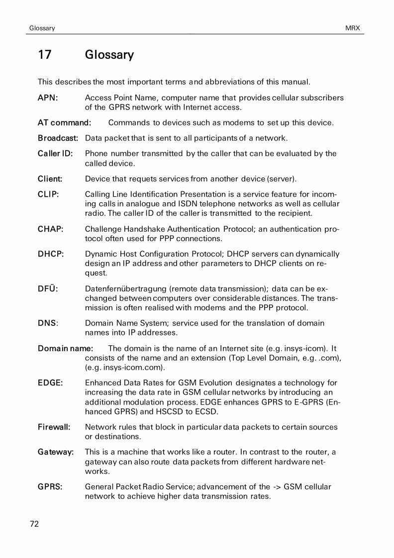
Glossary MRX
72
17 Glossary
This describes the most important terms and abbreviations of this manual.
APN: Access Point Name, computer name that provides cellular subscribers of the GPRS network with Internet access.
AT command: Commands to devices such as modems to set up this device.
Broadcast: Data packet that is sent to all participants of a network.
Caller ID: Phone number transmitted by the caller that can be evaluated by the
called device.
Client: Device that requets services from another device (server).
CLIP: Calling Line Identification Presentation is a service feature for incom-ing calls in analogue and ISDN telephone networks as well as cellular radio. The caller ID of the caller is transmitted to the recipient.
CHAP: Challenge Handshake Authentication Protocol; an authentication pro-tocol often used for PPP connections.
DHCP: Dynamic Host Configuration Protocol; DHCP servers can dynamically design an IP address and other parameters to DHCP clients on re-quest.
DFÜ: Datenfernübertragung (remote data transmission); data can be ex-changed between computers over considerable distances. The trans-mission is often realised with modems and the PPP protocol.
DNS: Domain Name System; service used for the translation of domain names into IP addresses.
Domain name: The domain is the name of an Internet site (e.g. insys-icom). It consists of the name and an extension (Top Level Domain, e.g. .com), (e.g. insys-icom.com).
EDGE: Enhanced Data Rates for GSM Evolution designates a technology for increasing the data rate in GSM cellular networks by introducing an
additional modulation process. EDGE enhances GPRS to E-GPRS (En-hanced GPRS) and HSCSD to ECSD.
Firewall: Network rules that block in particular data packets to certain sources or destinations.
Gateway: This is a machine that works like a router. In contrast to the router, a
gateway can also route data packets from different hardware net-works.
GPRS: General Packet Radio Service; advancement of the -> GSM cellular network to achieve higher data transmission rates.
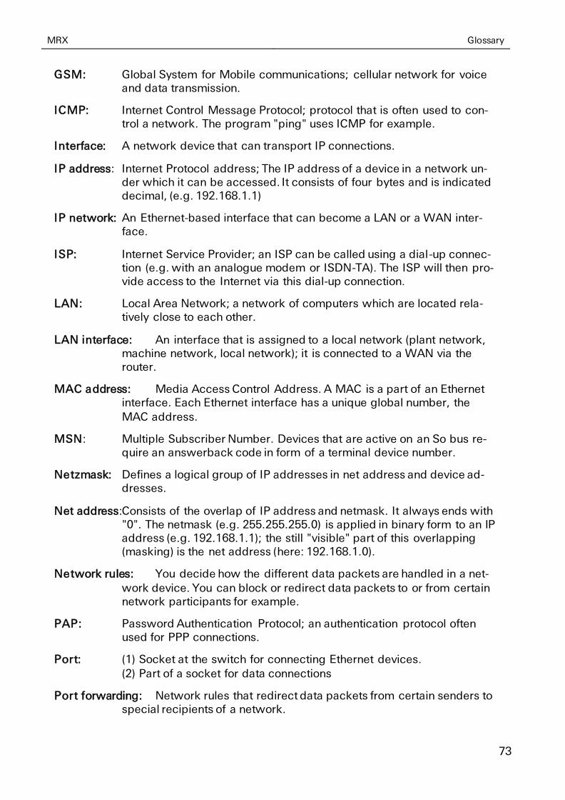
MRX Glossary
73
GSM: Global System for Mobile communications; cellular network for voice and data transmission.
ICMP: Internet Control Message Protocol; protocol that is often used to con-trol a network. The program "ping" uses ICMP for example.
Interface: A network device that can transport IP connections.
IP address: Internet Protocol address; The IP address of a device in a network un-der which it can be accessed. It consists of four bytes and is indicated decimal, (e.g. 192.168.1.1)
IP network: An Ethernet-based interface that can become a LAN or a WAN inter-face.
ISP: Internet Service Provider; an ISP can be called using a dial-up connec-tion (e.g. with an analogue modem or ISDN-TA). The ISP will then pro-vide access to the Internet via this dial-up connection.
LAN: Local Area Network; a network of computers which are located rela-tively close to each other.
LAN interface: An interface that is assigned to a local network (plant network, machine network, local network); it is connected to a WAN via the router.
MAC address: Media Access Control Address. A MAC is a part of an Ethernet interface. Each Ethernet interface has a unique global number, the
MAC address.
MSN: Multiple Subscriber Number. Devices that are active on an So bus re-quire an answerback code in form of a terminal device number.
Netzmask: Defines a logical group of IP addresses in net address and device ad-dresses.
Net address:Consists of the overlap of IP address and netmask. It always ends with "0". The netmask (e.g. 255.255.255.0) is applied in binary form to an IP address (e.g. 192.168.1.1); the still "visible" part of this overlapping (masking) is the net address (here: 192.168.1.0).
Network rules: You decide how the different data packets are handled in a net-work device. You can block or redirect data packets to or from certain network participants for example.
PAP: Password Authentication Protocol; an authentication protocol often used for PPP connections.
Port: (1) Socket at the switch for connecting Ethernet devices. (2) Part of a socket for data connections
Port forwarding: Network rules that redirect data packets from certain senders to special recipients of a network.
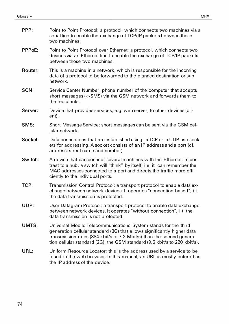
Glossary MRX
74
PPP: Point to Point Protocol; a protocol, which connects two machines via a serial line to enable the exchange of TCP/IP packets between those two machines.
PPPoE: Point to Point Protocol over Ethernet; a protocol, which connects two devices via an Ethernet line to enable the exchange of TCP/IP packets
between those two machines.
Router: This is a machine in a network, which is responsible for the incoming data of a protocol to be forwarded to the planned destination or sub network.
SCN: Service Center Number, phone number of the computer that accepts short messages (->SMS) via the GSM network and forwards them to the recipients.
Server: Device that provides services, e.g. web server, to other devices (cli-ent).
SMS: Short Message Service; short messages can be sent via the GSM cel-lular network.
Socket: Data connections that are established using ->TCP or ->UDP use sock-ets for addressing. A socket consists of an IP address and a port (cf. address: street name and number)
Switch: A device that can connect several machines with the Ethernet. In con-trast to a hub, a switch will "think” by itself, i.e. it can remember the MAC addresses connected to a port and directs the traffic more effi-ciently to the individual ports.
TCP: Transmission Control Protocol; a transport protocol to enable data ex-change between network devices. It operates "connection-based", i.t. the data transmission is protected.
UDP: User Datagram Protocol; a transport protocol to enable data exchange between network devices. It operates "without connection", i.t. the data transmission is not protected.
UMTS: Universal Mobile Telecommunications System stands for the third
generation cellular standard (3G) that allows significantly higher data transmission rates (384 kbit/s to 7,2 Mbit/s) than the second genera-tion cellular standard (2G), the GSM standard (9,6 kbit/s to 220 kbit/s).
URL: Uniform Resource Locator; this is the address used by a service to be found in the web browser. In this manual, an URL is mostly entered as the IP address of the device.
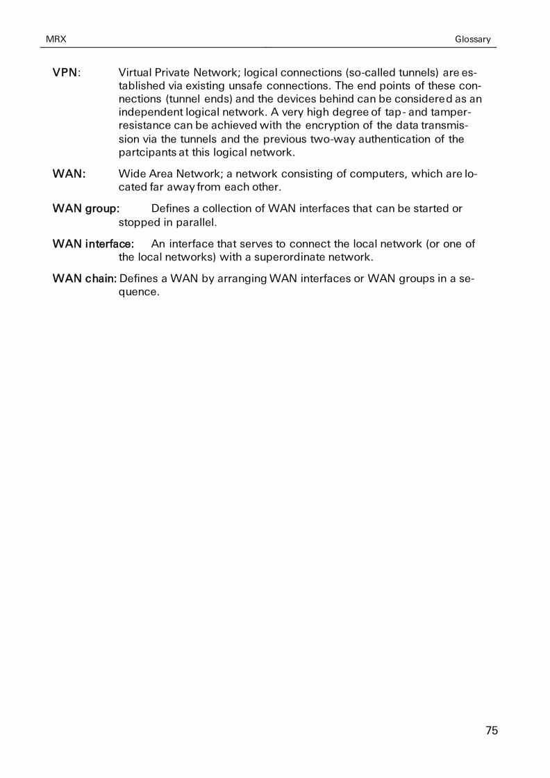
MRX Glossary
75
VPN: Virtual Private Network; logical connections (so-called tunnels) are es-tablished via existing unsafe connections. The end points of these con-nections (tunnel ends) and the devices behind can be considered as an independent logical network. A very high degree of tap- and tamper-resistance can be achieved with the encryption of the data transmis-
sion via the tunnels and the previous two-way authentication of the partcipants at this logical network.
WAN: Wide Area Network; a network consisting of computers, which are lo-cated far away from each other.
WAN group: Defines a collection of WAN interfaces that can be started or
stopped in parallel.
WAN interface: An interface that serves to connect the local network (or one of the local networks) with a superordinate network.
WAN chain: Defines a WAN by arranging WAN interfaces or WAN groups in a se-quence.
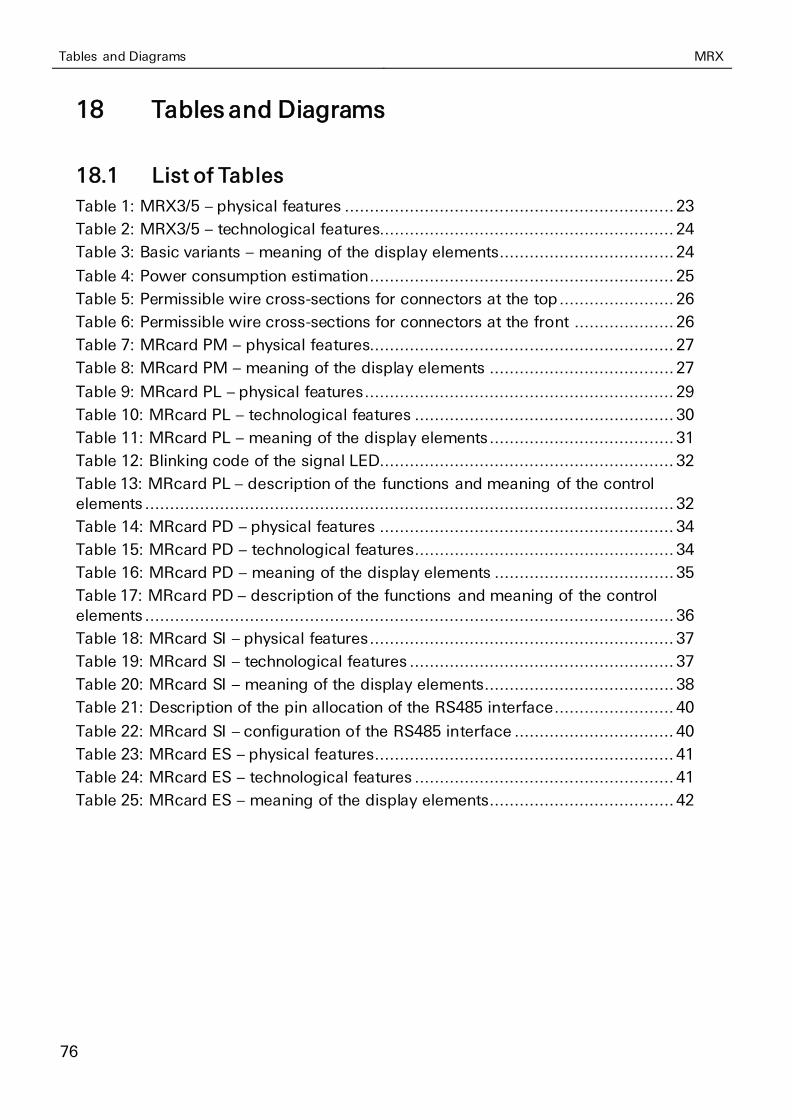
Tables and Diagrams MRX
76
18 Tables and Diagrams
18.1 List of Tables
Table 1: MRX3/5 – physical features .................................................................. 23
Table 2: MRX3/5 – technological features........................................................... 24
Table 3: Basic variants – meaning of the display elements................................... 24
Table 4: Power consumption estimation............................................................. 25
Table 5: Permissible wire cross-sections for connectors at the top ....................... 26
Table 6: Permissible wire cross-sections for connectors at the front .................... 26
Table 7: MRcard PM – physical features............................................................. 27
Table 8: MRcard PM – meaning of the display elements ..................................... 27
Table 9: MRcard PL – physical features .............................................................. 29
Table 10: MRcard PL – technological features .................................................... 30
Table 11: MRcard PL – meaning of the display elements ..................................... 31
Table 12: Blinking code of the signal LED........................................................... 32
Table 13: MRcard PL – description of the functions and meaning of the control
elements .......................................................................................................... 32
Table 14: MRcard PD – physical features ........................................................... 34
Table 15: MRcard PD – technological features .................................................... 34
Table 16: MRcard PD – meaning of the display elements .................................... 35
Table 17: MRcard PD – description of the functions and meaning of the control
elements .......................................................................................................... 36
Table 18: MRcard SI – physical features ............................................................. 37
Table 19: MRcard SI – technological features ..................................................... 37
Table 20: MRcard SI – meaning of the display elements...................................... 38
Table 21: Description of the pin allocation of the RS485 interface........................ 40
Table 22: MRcard SI – configuration of the RS485 interface ................................ 40
Table 23: MRcard ES – physical features ............................................................ 41
Table 24: MRcard ES – technological features .................................................... 41
Table 25: MRcard ES – meaning of the display elements..................................... 42
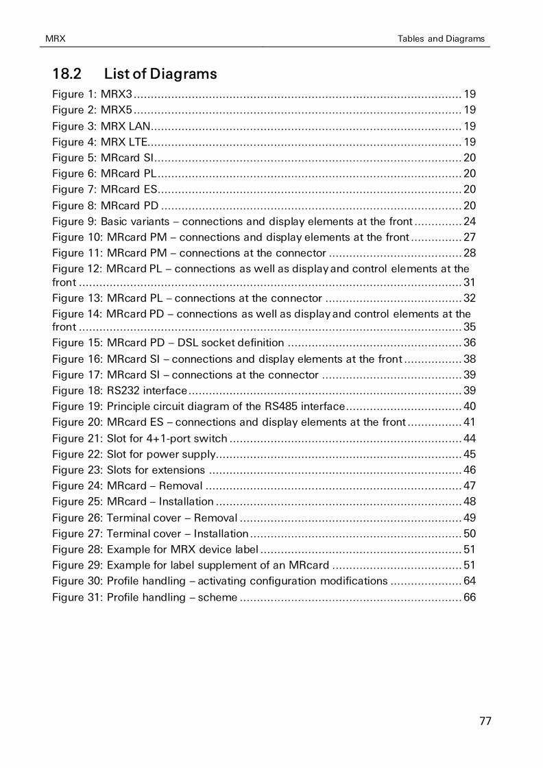
MRX Tables and Diagrams
77
18.2 List of Diagrams
Figure 1: MRX3 ................................................................................................ 19
Figure 2: MRX5 ................................................................................................ 19
Figure 3: MRX LAN........................................................................................... 19
Figure 4: MRX LTE............................................................................................ 19
Figure 5: MRcard SI .......................................................................................... 20
Figure 6: MRcard PL ......................................................................................... 20
Figure 7: MRcard ES ......................................................................................... 20
Figure 8: MRcard PD ........................................................................................ 20
Figure 9: Basic variants – connections and display elements at the front .............. 24
Figure 10: MRcard PM – connections and display elements at the front ............... 27
Figure 11: MRcard PM – connections at the connector ....................................... 28
Figure 12: MRcard PL – connections as well as display and control elements at the front ................................................................................................................ 31
Figure 13: MRcard PL – connections at the connector ........................................ 32
Figure 14: MRcard PD – connections as well as display and control elements at the front ................................................................................................................ 35
Figure 15: MRcard PD – DSL socket definition ................................................... 36
Figure 16: MRcard SI – connections and display elements at the front ................. 38
Figure 17: MRcard SI – connections at the connector ......................................... 39
Figure 18: RS232 interface ................................................................................ 39
Figure 19: Principle circuit diagram of the RS485 interface.................................. 40
Figure 20: MRcard ES – connections and display elements at the front ................ 41
Figure 21: Slot for 4+1-port switch .................................................................... 44
Figure 22: Slot for power supply ........................................................................ 45
Figure 23: Slots for extensions .......................................................................... 46
Figure 24: MRcard – Removal ........................................................................... 47
Figure 25: MRcard – Installation ........................................................................ 48
Figure 26: Terminal cover – Removal ................................................................. 49
Figure 27: Terminal cover – Installation .............................................................. 50
Figure 28: Example for MRX device label ........................................................... 51
Figure 29: Example for label supplement of an MRcard ...................................... 51
Figure 30: Profile handling – activating configuration modifications ..................... 64
Figure 31: Profile handling – scheme ................................................................. 66

Index MRX
78
19 Index
Access Point Name ....................... 72
Accessories................................... 21
Additional information ..................... 9
Alternative results............................ 9
APN.............................................. 72
Assembly ...................................... 52
AT command ................................ 72
Blinking interval LED signal ............ 32
Breakdown.................................... 10
Broadcast...................................... 72
Caller ID ........................................ 72
Cellular antenna .......................31, 57
CHAP............................................ 72
Checkmark...................................... 9
CLI ............................................... 60
Client ............................................ 72
CLIP.............................................. 72
Command line ............................... 60
Configuration ...........................59, 60
Connection ................................... 52
Current consumption ................23, 37
Defects liability terms ...................... 7
DFÜ .............................................. 72
DHCP ........................................... 72
Digital output ................................ 37
DIN rail ....................................53, 55
DNS.............................................. 72
Domain name................................ 72
DSL LED ....................................... 35
DSL line connection....................... 35
EDGE ............................................ 72
Electrical installation ...................... 13
Environment ............................14, 52
Environmental Protection ............... 12
Ethernet port ............................24, 41
Explosive atmosphere .................... 10
Firewall ......................................... 72
Formatting ...................................... 9
Gateway........................................ 72
General safety instructions ............. 14
GPRS ............................................ 72
Ground............................... 28, 32, 39
GSM ............................................. 73
Housing ........................................ 15
HTTPS........................................... 62
Humidity ....................................... 23
ICMP ............................................ 73
IN1 LED ........................................ 38
IN2 LED ........................................ 38
Info LED ............................. 27, 31, 35
Input .................................. 28, 32, 39
Intended Use ................................. 10
Interface.................................. 15, 73
IP address ............................... 58, 73
IP network..................................... 73
IP rating ........................................ 23
ISP................................................ 73
Key word ........................................ 8
LAN .............................................. 73
LAN interface ................................ 73
Liquids .................................... 14, 52
MAC address................................. 73
Marking .......................................... 8
Menu ............................................ 61
Modification ............................ 15, 67
Moisture ................................. 14, 52
MSN ............................................. 73
Net address ................................... 73
Netmask ....................................... 73
Network card ................................ 58
Network patch cable ...................... 58
Network rules ................................ 73
O1 LED ......................................... 38
O2 LED ......................................... 38
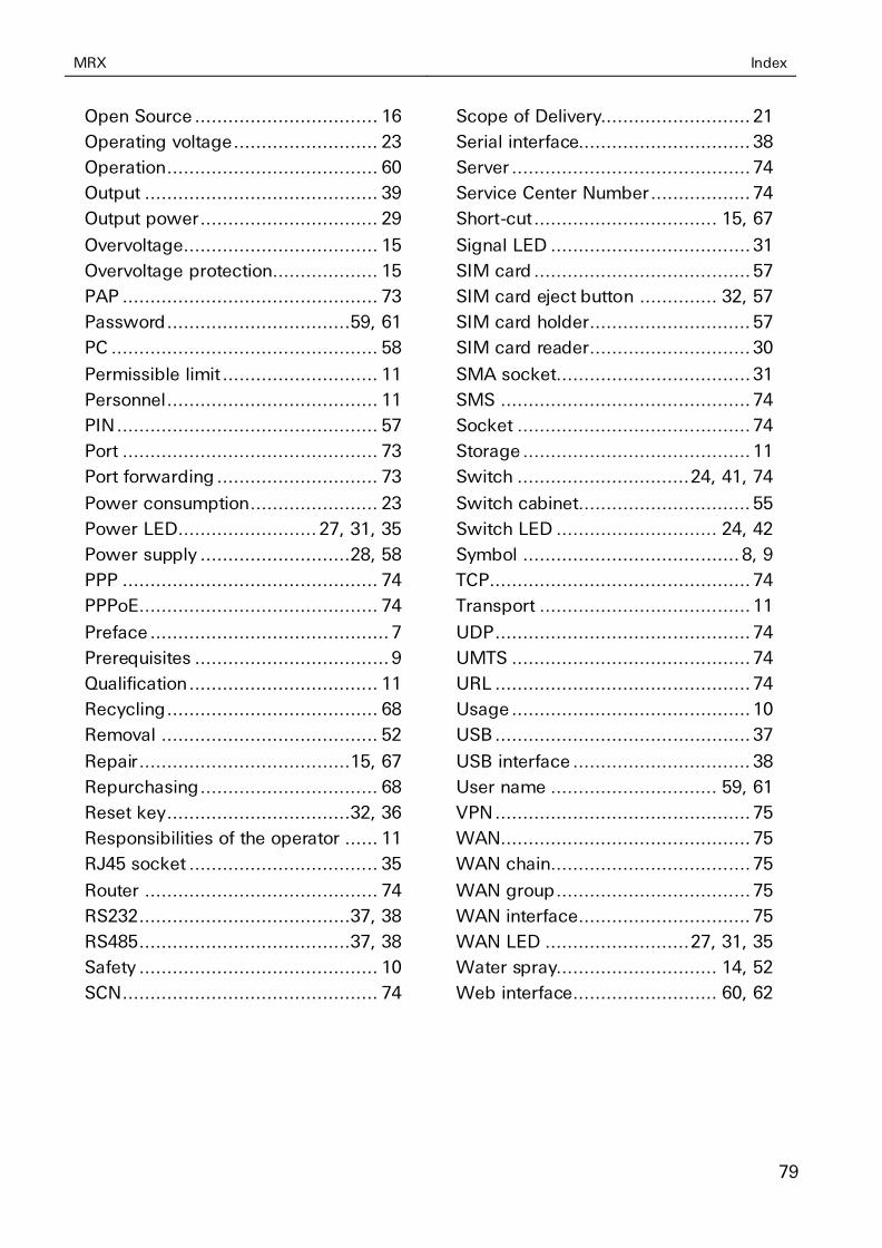
MRX Index
79
Open Source ................................. 16
Operating voltage .......................... 23
Operation ...................................... 60
Output .......................................... 39
Output power ................................ 29
Overvoltage................................... 15
Overvoltage protection................... 15
PAP .............................................. 73
Password .................................59, 61
PC ................................................ 58
Permissible limit ............................ 11
Personnel ...................................... 11
PIN ............................................... 57
Port .............................................. 73
Port forwarding ............................. 73
Power consumption....................... 23
Power LED ......................... 27, 31, 35
Power supply ...........................28, 58
PPP .............................................. 74
PPPoE........................................... 74
Preface ........................................... 7
Prerequisites ................................... 9
Qualification .................................. 11
Recycling ...................................... 68
Removal ....................................... 52
Repair ......................................15, 67
Repurchasing ................................ 68
Reset key .................................32, 36
Responsibilities of the operator ...... 11
RJ45 socket .................................. 35
Router .......................................... 74
RS232......................................37, 38
RS485......................................37, 38
Safety ........................................... 10
SCN .............................................. 74
Scope of Delivery........................... 21
Serial interface............................... 38
Server ........................................... 74
Service Center Number .................. 74
Short-cut ................................. 15, 67
Signal LED .................................... 31
SIM card ....................................... 57
SIM card eject button .............. 32, 57
SIM card holder ............................. 57
SIM card reader ............................. 30
SMA socket................................... 31
SMS ............................................. 74
Socket .......................................... 74
Storage ......................................... 11
Switch ............................... 24, 41, 74
Switch cabinet............................... 55
Switch LED ............................. 24, 42
Symbol ....................................... 8, 9
TCP............................................... 74
Transport ...................................... 11
UDP .............................................. 74
UMTS ........................................... 74
URL .............................................. 74
Usage ........................................... 10
USB .............................................. 37
USB interface ................................ 38
User name .............................. 59, 61
VPN .............................................. 75
WAN............................................. 75
WAN chain.................................... 75
WAN group ................................... 75
WAN interface............................... 75
WAN LED .......................... 27, 31, 35
Water spray............................. 14, 52
Web interface .......................... 60, 62

Copyright © 2022 FDOKUMEN