MR-J5D-G-N1 User's Manual (Introduction) - Mitsubishi Electric
124
MR-J5D-G-N1 User's Manual (Introduction) -MR-J5D_-_G_-_N1 Mitsubishi Electric AC Servo System
-
Upload
khangminh22 -
Category
Documents
-
view
0 -
download
0
Transcript of MR-J5D-G-N1 User's Manual (Introduction) - Mitsubishi Electric

MR-J5D-G-N1User's Manual(Introduction)
-MR-J5D_-_G_-_N1
Mitsubishi Electric AC Servo System


SAFETY INSTRUCTIONSPlease read the instructions carefully before using the equipment.To use the equipment correctly, do not attempt to install, operate, maintain, or inspect the equipment until you have read through this manual, installation guide, and appended documents carefully. Do not use the equipment until you have a full knowledge of the equipment, safety information and instructions.In this manual, the safety instruction levels are classified into "WARNING" and "CAUTION".
Note that the CAUTION level may lead to a serious consequence depending on conditions.Please follow the instructions of both levels because they are important to personnel safety.Forbidden actions and required actions are indicated by the following diagrammatic symbols.
In this manual, precautions for hazards that can lead to property damage, instructions for other functions, and other information are shown separately in the "POINT" area.After reading this manual, keep it accessible to the operator.
[Transportation]
[Installation/wiring]
[Setting/adjustment]
CAUTION● To prevent injury, transport the products correctly according to their mass.
WARNING● To prevent an electric shock, turn off the power and wait for 20 minutes or more before starting wiring
and/or inspection.● To prevent an electric shock, ground the converter unit/drive unit.● To prevent an electric shock, any person who is involved in wiring should be fully competent to do the
work.● To prevent an electric shock, mount the converter unit/drive unit before wiring.● To prevent an electric shock, connect the protective earth (PE) terminal of the converter unit/drive unit
to the protective earth (PE) of the cabinet, then connect the grounding lead wire to the ground.● To prevent an electric shock, do not touch the conductive parts.
WARNING● To prevent an electric shock, do not operate the switches with wet hands.
WARNING Indicates that incorrect handling may cause hazardous conditions, resulting in death or severe injury.
CAUTION Indicates that incorrect handling may cause hazardous conditions, resulting in medium or slight injury.
Indicates a forbidden action. For example, "No Fire" is indicated by .
Indicates a required action. For example, grounding is indicated by .
1

2
[Operation]
[Maintenance]
DISPOSAL OF WASTEPlease dispose of this product, battery (primary battery), and other options according to your local laws and regulations.
ABOUT THE MANUAL
e-Manuals are Mitsubishi Electric FA electronic book manuals that can be browsed with a dedicated tool.e-Manuals enable the following: • Searching for desired information in multiple manuals at the same time (manual cross searching) • Jumping from a link in a manual to another manual for reference • Browsing for hardware specifications by scrolling over the components shown in product illustrations • Bookmarking frequently referenced information • Copying sample programs to engineering tools
WARNING● To prevent an electric shock, do not operate the switches with wet hands.
WARNING● To prevent an electric shock, any person who is involved in inspection should be fully competent to do
the work.● To prevent an electric shock, do not operate the switches with wet hands.

If using the servo for the first time, prepare and use the following related manuals to ensure that the servo is used safely.
*1 For details of parameters, read chapter 7 and chapter 8 of this manual first.Page 67 SERVO PARAMETERSPage 106 NETWORK PARAMETERSPage 109 FUNCTIONAL SAFETY PARAMETERS
No. Manual name Manual No.(1) MR-J5D-G-N1 User's Manual (Introduction) IB(NA)-0300543ENG
(2) MR-J5D User's Manual (Hardware) IB(NA)-0300548ENG
(3) MR-CV Power Regeneration Converter Unit User's Manual IB(NA)-0300553ENG
(4) Rotary Servo Motor User's Manual (HK series) SH(NA)-030314ENG
(5) MR-J5 Partner's Encoder User's Manual SH(NA)-030320ENG
(6) MR-J5 User's Manual (Function) SH(NA)-030300ENG
(7) MR-J5-G-N1/MR-J5W-G-N1 User's Manual (Communication Function) SH(NA)-030371ENG
(8) MR-J5 User's Manual (Adjustment) SH(NA)-030306ENG
(9) MR-J5 User's Manual (Troubleshooting) SH(NA)-030312ENG
(10) MR-J5-G/MR-J5W-G User's Manual (Parameters) SH(NA)-030308ENG
(11) MR-J5-G-N1/MR-J5W-G-N1 User's Manual (Object Dictionary) SH(NA)-030376ENG
(4) Rotary Servo Motor
This manual is necessary primarily for installing, wiring, andusing options.
The manual is necessary for adjustment of operation status.
The manual is necessary for using communication functions.
The manual is necessary for specifying the causes of alarmsand warnings.
(5) Partner Encoder
(6) Function
(8) Adjustment
(11) Object Dictionary
(9) Troubleshooting
(1) Introduction
(2) Hardware
(7) Communication Function
(10) Parameters *1 It describes the parameters of the drive unit.
It describes the objects for the drive unit.
The manual is necessary for operation of drive units.For the usage of each function, refer to this manual.
(3) Converter unit
3

4
Interpreting servo parameter numbersFor a servo parameter which uses one particular digit to select a function, the position of its digit indicates the detail number of the servo parameter, and the value in hexadecimal which is set to the digit indicates the selected function.For example, the detail number of the servo parameter in the last digit is expressed as [Pr. PA01.0]. In addition, a servo parameter which uses a combination of several digits to select a function, is expressed using "-" as seen in [Pr. PA01.0-1].The following is an example of the servo parameter number PA01 with the setting values of "FEDCBA98" in hexadecimal. • When setting a servo parameter with one particular digit
• When setting a servo parameter using a combination of several digits
For example, if the servo parameter name is "Function selection A-1", the setting digit name is "Forced stop deceleration function selection", and the setting digit is the fourth last digit in PA04, the servo parameter is expressed as shown below.[Pr. PA04.3 Forced stop deceleration function selection]
U.S. CUSTOMARY UNITSU.S. customary units are not shown in this manual. Convert the values if necessary according to the following table.
Servo parameter
Symbol Name Summary
PA04.3 *AOP Forced stop deceleration function selection
Set "Forced stop deceleration function" to enabled/disabled.Initial value: 1h (enabled)
Quantity SI (metric) unit U.S. customary unitMass 1 [kg] 2.2046 [lb]
Length 1 [mm] 0.03937 [inch]
Torque 1 [N•m] 141.6 [oz•inch]
Moment of inertia 1 [(× 10-4 kg•m2)] 5.4675 [oz•inch2]
Load (thrust load/axial load) 1 [N] 0.2248 [lbf]
Temperature N [°C] × 9/5 + 32 N [°F]
[Pr. PA01] =
PA01.0 = "8"PA01.1 = "9"PA01.2 = "A"PA01.3 = "B"PA01.4 = "C"PA01.5 = "D"
CD BF AE 89
PA01.6 = "E"PA01.7 = "F"
Detail No.
[Pr. PA01] =
PA01.0-1 = "98"
PA01.2-4 = "CBA"
PA01.5 = "D"
CD BF AE 89
PA01.6 = "E"PA01.7 = "F"
Detail No.

CO
NTE
NTS
CONTENTSSAFETY INSTRUCTIONS. . . . . . . . . . . . . . . . . . . . . . . . . . . . . . . . . . . . . . . . . . . . . . . . . . . . . . . . . . . . . . . . . . . .1DISPOSAL OF WASTE. . . . . . . . . . . . . . . . . . . . . . . . . . . . . . . . . . . . . . . . . . . . . . . . . . . . . . . . . . . . . . . . . . . . . .2ABOUT THE MANUAL . . . . . . . . . . . . . . . . . . . . . . . . . . . . . . . . . . . . . . . . . . . . . . . . . . . . . . . . . . . . . . . . . . . . . .2U.S. CUSTOMARY UNITS . . . . . . . . . . . . . . . . . . . . . . . . . . . . . . . . . . . . . . . . . . . . . . . . . . . . . . . . . . . . . . . . . . .4
CHAPTER 1 SPECIFICATIONS 101.1 Outline . . . . . . . . . . . . . . . . . . . . . . . . . . . . . . . . . . . . . . . . . . . . . . . . . . . . . . . . . . . . . . . . . . . . . . . . . . . . . . . . 101.2 Model designation . . . . . . . . . . . . . . . . . . . . . . . . . . . . . . . . . . . . . . . . . . . . . . . . . . . . . . . . . . . . . . . . . . . . . . . 101.3 Drive unit/motor combinations . . . . . . . . . . . . . . . . . . . . . . . . . . . . . . . . . . . . . . . . . . . . . . . . . . . . . . . . . . . . 111.4 Drive unit standard specifications. . . . . . . . . . . . . . . . . . . . . . . . . . . . . . . . . . . . . . . . . . . . . . . . . . . . . . . . . . 12
MR-J5D1-_G_-N1 . . . . . . . . . . . . . . . . . . . . . . . . . . . . . . . . . . . . . . . . . . . . . . . . . . . . . . . . . . . . . . . . . . . . . . . . 12MR-J5D2-_G_-N1 . . . . . . . . . . . . . . . . . . . . . . . . . . . . . . . . . . . . . . . . . . . . . . . . . . . . . . . . . . . . . . . . . . . . . . . . 13MR-J5D3-_G_-N1 . . . . . . . . . . . . . . . . . . . . . . . . . . . . . . . . . . . . . . . . . . . . . . . . . . . . . . . . . . . . . . . . . . . . . . . . 14Positioning mode. . . . . . . . . . . . . . . . . . . . . . . . . . . . . . . . . . . . . . . . . . . . . . . . . . . . . . . . . . . . . . . . . . . . . . . . . 15Functional safety . . . . . . . . . . . . . . . . . . . . . . . . . . . . . . . . . . . . . . . . . . . . . . . . . . . . . . . . . . . . . . . . . . . . . . . . . 16Environment . . . . . . . . . . . . . . . . . . . . . . . . . . . . . . . . . . . . . . . . . . . . . . . . . . . . . . . . . . . . . . . . . . . . . . . . . . . . 17
1.5 Function block diagram . . . . . . . . . . . . . . . . . . . . . . . . . . . . . . . . . . . . . . . . . . . . . . . . . . . . . . . . . . . . . . . . . . 18MR-J5D1-_G_-N1 . . . . . . . . . . . . . . . . . . . . . . . . . . . . . . . . . . . . . . . . . . . . . . . . . . . . . . . . . . . . . . . . . . . . . . . . 18MR-J5D2-_G_-N1/MR-J5D3-_G_-N1 . . . . . . . . . . . . . . . . . . . . . . . . . . . . . . . . . . . . . . . . . . . . . . . . . . . . . . . . . 19
1.6 Configuration including peripheral equipment . . . . . . . . . . . . . . . . . . . . . . . . . . . . . . . . . . . . . . . . . . . . . . . 201.7 Special specifications . . . . . . . . . . . . . . . . . . . . . . . . . . . . . . . . . . . . . . . . . . . . . . . . . . . . . . . . . . . . . . . . . . . . 21
Drive units without the dynamic brake (-ED) . . . . . . . . . . . . . . . . . . . . . . . . . . . . . . . . . . . . . . . . . . . . . . . . . . . . 21
CHAPTER 2 FUNCTION 222.1 Restrictions on the MR-J5_-_G_ . . . . . . . . . . . . . . . . . . . . . . . . . . . . . . . . . . . . . . . . . . . . . . . . . . . . . . . . . . . 222.2 Function list . . . . . . . . . . . . . . . . . . . . . . . . . . . . . . . . . . . . . . . . . . . . . . . . . . . . . . . . . . . . . . . . . . . . . . . . . . . . 222.3 Security . . . . . . . . . . . . . . . . . . . . . . . . . . . . . . . . . . . . . . . . . . . . . . . . . . . . . . . . . . . . . . . . . . . . . . . . . . . . . . . 31
CHAPTER 3 STRUCTURE 323.1 Parts identification . . . . . . . . . . . . . . . . . . . . . . . . . . . . . . . . . . . . . . . . . . . . . . . . . . . . . . . . . . . . . . . . . . . . . . 323.2 Switch setting and display of the drive unit . . . . . . . . . . . . . . . . . . . . . . . . . . . . . . . . . . . . . . . . . . . . . . . . . . 35
Switches . . . . . . . . . . . . . . . . . . . . . . . . . . . . . . . . . . . . . . . . . . . . . . . . . . . . . . . . . . . . . . . . . . . . . . . . . . . . . . . 357-segment LED . . . . . . . . . . . . . . . . . . . . . . . . . . . . . . . . . . . . . . . . . . . . . . . . . . . . . . . . . . . . . . . . . . . . . . . . . . 36Status LEDs. . . . . . . . . . . . . . . . . . . . . . . . . . . . . . . . . . . . . . . . . . . . . . . . . . . . . . . . . . . . . . . . . . . . . . . . . . . . . 39LED display . . . . . . . . . . . . . . . . . . . . . . . . . . . . . . . . . . . . . . . . . . . . . . . . . . . . . . . . . . . . . . . . . . . . . . . . . . . . . 40
CHAPTER 4 STARTUP 414.1 Turning on drive unit for the first time . . . . . . . . . . . . . . . . . . . . . . . . . . . . . . . . . . . . . . . . . . . . . . . . . . . . . . 45
Test operation of the servo motor alone in test operation mode . . . . . . . . . . . . . . . . . . . . . . . . . . . . . . . . . . . . . 46Equipment configuration setting . . . . . . . . . . . . . . . . . . . . . . . . . . . . . . . . . . . . . . . . . . . . . . . . . . . . . . . . . . . . . 47Controller-related setting . . . . . . . . . . . . . . . . . . . . . . . . . . . . . . . . . . . . . . . . . . . . . . . . . . . . . . . . . . . . . . . . . . . 47Operation by controller command . . . . . . . . . . . . . . . . . . . . . . . . . . . . . . . . . . . . . . . . . . . . . . . . . . . . . . . . . . . . 48
4.2 Instructions on startup . . . . . . . . . . . . . . . . . . . . . . . . . . . . . . . . . . . . . . . . . . . . . . . . . . . . . . . . . . . . . . . . . . . 494.3 Troubleshooting at startup . . . . . . . . . . . . . . . . . . . . . . . . . . . . . . . . . . . . . . . . . . . . . . . . . . . . . . . . . . . . . . . . 494.4 Duplicate setting . . . . . . . . . . . . . . . . . . . . . . . . . . . . . . . . . . . . . . . . . . . . . . . . . . . . . . . . . . . . . . . . . . . . . . . . 50
Duplication using MR Configurator2 . . . . . . . . . . . . . . . . . . . . . . . . . . . . . . . . . . . . . . . . . . . . . . . . . . . . . . . . . . 504.5 Test operation . . . . . . . . . . . . . . . . . . . . . . . . . . . . . . . . . . . . . . . . . . . . . . . . . . . . . . . . . . . . . . . . . . . . . . . . . . 50
Execution method . . . . . . . . . . . . . . . . . . . . . . . . . . . . . . . . . . . . . . . . . . . . . . . . . . . . . . . . . . . . . . . . . . . . . . . . 50
5

6
Test operation mode . . . . . . . . . . . . . . . . . . . . . . . . . . . . . . . . . . . . . . . . . . . . . . . . . . . . . . . . . . . . . . . . . . . . . . 51Motor driving by test operation . . . . . . . . . . . . . . . . . . . . . . . . . . . . . . . . . . . . . . . . . . . . . . . . . . . . . . . . . . . . . . 52Motor-less operation . . . . . . . . . . . . . . . . . . . . . . . . . . . . . . . . . . . . . . . . . . . . . . . . . . . . . . . . . . . . . . . . . . . . . . 56Output signal (DO) forced output. . . . . . . . . . . . . . . . . . . . . . . . . . . . . . . . . . . . . . . . . . . . . . . . . . . . . . . . . . . . . 57
4.6 Drive unit setting initialization . . . . . . . . . . . . . . . . . . . . . . . . . . . . . . . . . . . . . . . . . . . . . . . . . . . . . . . . . . . . . 58Initialization procedure by MR Mode Change . . . . . . . . . . . . . . . . . . . . . . . . . . . . . . . . . . . . . . . . . . . . . . . . . . . 58
CHAPTER 5 MAINTENANCE, INSPECTION AND PARTS REPLACEMENT 595.1 Inspection items . . . . . . . . . . . . . . . . . . . . . . . . . . . . . . . . . . . . . . . . . . . . . . . . . . . . . . . . . . . . . . . . . . . . . . . . 59
Periodic inspection . . . . . . . . . . . . . . . . . . . . . . . . . . . . . . . . . . . . . . . . . . . . . . . . . . . . . . . . . . . . . . . . . . . . . . . 595.2 Parts with a service life. . . . . . . . . . . . . . . . . . . . . . . . . . . . . . . . . . . . . . . . . . . . . . . . . . . . . . . . . . . . . . . . . . . 595.3 Replacing fan unit . . . . . . . . . . . . . . . . . . . . . . . . . . . . . . . . . . . . . . . . . . . . . . . . . . . . . . . . . . . . . . . . . . . . . . . 60
CHAPTER 6 COMPLIANCE WITH GLOBAL STANDARDS 616.1 Compliance with global standards . . . . . . . . . . . . . . . . . . . . . . . . . . . . . . . . . . . . . . . . . . . . . . . . . . . . . . . . . 616.2 Handling of AC servo amplifier batteries for the United Nations Recommendations on the Transport of
Dangerous Goods . . . . . . . . . . . . . . . . . . . . . . . . . . . . . . . . . . . . . . . . . . . . . . . . . . . . . . . . . . . . . . . . . . . . . . . 616.3 Symbol for the new EU Battery Directive . . . . . . . . . . . . . . . . . . . . . . . . . . . . . . . . . . . . . . . . . . . . . . . . . . . . 636.4 Compliance with China Compulsory Certification (CCC) . . . . . . . . . . . . . . . . . . . . . . . . . . . . . . . . . . . . . . . 646.5 Compliance with the China RoHS directive . . . . . . . . . . . . . . . . . . . . . . . . . . . . . . . . . . . . . . . . . . . . . . . . . . 65
CHAPTER 7 SERVO PARAMETERS 677.1 Basic setting servo parameters group ([Pr. PA_ _ ]) . . . . . . . . . . . . . . . . . . . . . . . . . . . . . . . . . . . . . . . . . . . 67
[Pr. PA01_Operation mode (**STY)] . . . . . . . . . . . . . . . . . . . . . . . . . . . . . . . . . . . . . . . . . . . . . . . . . . . . . . . . . . 677.2 Gain/filter setting servo parameters group ([Pr. PB_ _ ]) . . . . . . . . . . . . . . . . . . . . . . . . . . . . . . . . . . . . . . . 68
[Pr. PB03_For manufacturer setting] . . . . . . . . . . . . . . . . . . . . . . . . . . . . . . . . . . . . . . . . . . . . . . . . . . . . . . . . . . 68[Pr. PB82_Position command smoothing filtering time constant (PFT)] . . . . . . . . . . . . . . . . . . . . . . . . . . . . . . . 68
7.3 Extension setting servo parameters group ([Pr. PC_ _ ]) . . . . . . . . . . . . . . . . . . . . . . . . . . . . . . . . . . . . . . . 69[Pr. PC42_Function selection C-10 (COP10)] . . . . . . . . . . . . . . . . . . . . . . . . . . . . . . . . . . . . . . . . . . . . . . . . . . . 69[Pr. PC43_Forward rotation torque limit 2 (TLP2)] . . . . . . . . . . . . . . . . . . . . . . . . . . . . . . . . . . . . . . . . . . . . . . . 69[Pr. PC44_Reverse rotation torque limit 2 (TLN2)] . . . . . . . . . . . . . . . . . . . . . . . . . . . . . . . . . . . . . . . . . . . . . . . 70[Pr. PC69_Following error output filtering time (FEWF)] . . . . . . . . . . . . . . . . . . . . . . . . . . . . . . . . . . . . . . . . . . . 70[Pr. PC71_In-position 2 - Output filtering time (INP2F)]. . . . . . . . . . . . . . . . . . . . . . . . . . . . . . . . . . . . . . . . . . . . 70[Pr. PC73_Speed reached 2 - Output filtering time (SA2F)] . . . . . . . . . . . . . . . . . . . . . . . . . . . . . . . . . . . . . . . . 71[Pr. PC78_Function selection C-F (*COPF)] . . . . . . . . . . . . . . . . . . . . . . . . . . . . . . . . . . . . . . . . . . . . . . . . . . . . 71[Pr. PC81_For manufacturer setting] . . . . . . . . . . . . . . . . . . . . . . . . . . . . . . . . . . . . . . . . . . . . . . . . . . . . . . . . . . 71
7.4 Extension setting 2 servo parameters group ([Pr. PE_ _ ]) . . . . . . . . . . . . . . . . . . . . . . . . . . . . . . . . . . . . . . 72[Pr. PE53_Maximum torque limit 1 (TLMX1)] . . . . . . . . . . . . . . . . . . . . . . . . . . . . . . . . . . . . . . . . . . . . . . . . . . . 72
7.5 Positioning control setting servo parameters group ([Pr. PT_ _ ]). . . . . . . . . . . . . . . . . . . . . . . . . . . . . . . . 73[Pr. PT01_Command mode selection (**CTY)] . . . . . . . . . . . . . . . . . . . . . . . . . . . . . . . . . . . . . . . . . . . . . . . . . . 73[Pr. PT53_Torque slope (TQS)] . . . . . . . . . . . . . . . . . . . . . . . . . . . . . . . . . . . . . . . . . . . . . . . . . . . . . . . . . . . . . . 74
7.6 Network setting servo parameters group ([Pr. PN_ _ ]) . . . . . . . . . . . . . . . . . . . . . . . . . . . . . . . . . . . . . . . . . 75[Pr. PN02_For manufacturer setting] . . . . . . . . . . . . . . . . . . . . . . . . . . . . . . . . . . . . . . . . . . . . . . . . . . . . . . . . . . 75[Pr. PN05_For manufacturer setting] . . . . . . . . . . . . . . . . . . . . . . . . . . . . . . . . . . . . . . . . . . . . . . . . . . . . . . . . . . 75[Pr. PN07_Communication cycle initial setting (**CCS)] . . . . . . . . . . . . . . . . . . . . . . . . . . . . . . . . . . . . . . . . . . . 75[Pr. PN13_For manufacturer setting] . . . . . . . . . . . . . . . . . . . . . . . . . . . . . . . . . . . . . . . . . . . . . . . . . . . . . . . . . . 75[Pr. PN18_Counter level for communication error detection (CERN)]. . . . . . . . . . . . . . . . . . . . . . . . . . . . . . . . . 76[Pr. PN20_For manufacturer setting] . . . . . . . . . . . . . . . . . . . . . . . . . . . . . . . . . . . . . . . . . . . . . . . . . . . . . . . . . . 76[Pr. PN22_For manufacturer setting] . . . . . . . . . . . . . . . . . . . . . . . . . . . . . . . . . . . . . . . . . . . . . . . . . . . . . . . . . . 76
7.7 Positioning extension setting servo parameters group ([Pr. PV_ _ ]) . . . . . . . . . . . . . . . . . . . . . . . . . . . . . 77

CO
NTE
NTS
[Pr. PV23_Speed unit conversion - Electronic gear - Numerator (*VCMX)] . . . . . . . . . . . . . . . . . . . . . . . . . . . . 77[Pr. PV24_Speed unit conversion - Electronic gear - Denominator (*VCDV)] . . . . . . . . . . . . . . . . . . . . . . . . . . . 77[Pr. PV25_Acceleration unit conversion - Electronic gear - Numerator (*ACMX)]. . . . . . . . . . . . . . . . . . . . . . . . 77[Pr. PV26_Acceleration unit conversion - Electronic gear - Denominator (*ACDV)] . . . . . . . . . . . . . . . . . . . . . . 77
7.8 Lists of supported control modes . . . . . . . . . . . . . . . . . . . . . . . . . . . . . . . . . . . . . . . . . . . . . . . . . . . . . . . . . . 78Basic setting servo parameters group ([Pr. PA_ _ ]) . . . . . . . . . . . . . . . . . . . . . . . . . . . . . . . . . . . . . . . . . . . . . . 79Gain/filter setting servo parameters group ([Pr. PB_ _ ]). . . . . . . . . . . . . . . . . . . . . . . . . . . . . . . . . . . . . . . . . . . 80Extension setting servo parameters group ([Pr. PC_ _ ]) . . . . . . . . . . . . . . . . . . . . . . . . . . . . . . . . . . . . . . . . . . 82I/O setting servo parameters group ([Pr. PD_ _ ]) . . . . . . . . . . . . . . . . . . . . . . . . . . . . . . . . . . . . . . . . . . . . . . . . 83Extension setting 2 servo parameters group ([Pr. PE_ _ ]) . . . . . . . . . . . . . . . . . . . . . . . . . . . . . . . . . . . . . . . . . 84Extension setting 3 servo parameters group ([Pr. PF_ _ ]) . . . . . . . . . . . . . . . . . . . . . . . . . . . . . . . . . . . . . . . . . 85Motor extension setting servo parameters group ([Pr. PL_ _ ]) . . . . . . . . . . . . . . . . . . . . . . . . . . . . . . . . . . . . . . 86Positioning control setting servo parameters group ([Pr. PT_ _ ]) . . . . . . . . . . . . . . . . . . . . . . . . . . . . . . . . . . . . 87Network setting servo parameters group ([Pr. PN_ _ ]). . . . . . . . . . . . . . . . . . . . . . . . . . . . . . . . . . . . . . . . . . . . 87Positioning extension setting servo parameters group ([Pr. PV_ _ ]) . . . . . . . . . . . . . . . . . . . . . . . . . . . . . . . . . 88
7.9 Lists of servo parameter initial values . . . . . . . . . . . . . . . . . . . . . . . . . . . . . . . . . . . . . . . . . . . . . . . . . . . . . . 89Basic setting servo parameters group ([Pr. PA_ _ ]) . . . . . . . . . . . . . . . . . . . . . . . . . . . . . . . . . . . . . . . . . . . . . . 89Gain/filter setting servo parameters group ([Pr. PB_ _ ]). . . . . . . . . . . . . . . . . . . . . . . . . . . . . . . . . . . . . . . . . . . 90Extension setting servo parameters group ([Pr. PC_ _ ]) . . . . . . . . . . . . . . . . . . . . . . . . . . . . . . . . . . . . . . . . . . 92I/O setting servo parameters group ([Pr. PD_ _ ]) . . . . . . . . . . . . . . . . . . . . . . . . . . . . . . . . . . . . . . . . . . . . . . . . 94Extension setting 2 servo parameters group ([Pr. PE_ _ ]) . . . . . . . . . . . . . . . . . . . . . . . . . . . . . . . . . . . . . . . . . 96Extension setting 3 servo parameters group ([Pr. PF_ _ ]) . . . . . . . . . . . . . . . . . . . . . . . . . . . . . . . . . . . . . . . . . 98Motor extension setting servo parameters group ([Pr. PL_ _ ]) . . . . . . . . . . . . . . . . . . . . . . . . . . . . . . . . . . . . . 100Positioning control setting servo parameters group ([Pr. PT_ _ ]) . . . . . . . . . . . . . . . . . . . . . . . . . . . . . . . . . . . 102Network setting servo parameters group ([Pr. PN_ _ ]). . . . . . . . . . . . . . . . . . . . . . . . . . . . . . . . . . . . . . . . . . . 104Positioning extension setting servo parameters group ([Pr. PV_ _ ]) . . . . . . . . . . . . . . . . . . . . . . . . . . . . . . . . 105
CHAPTER 8 NETWORK PARAMETERS 1068.1 Network basic parameters . . . . . . . . . . . . . . . . . . . . . . . . . . . . . . . . . . . . . . . . . . . . . . . . . . . . . . . . . . . . . . . 106
[Pr. NPA01_For manufacturer setting]. . . . . . . . . . . . . . . . . . . . . . . . . . . . . . . . . . . . . . . . . . . . . . . . . . . . . . . . 106[Pr. NPA02_For manufacturer setting]. . . . . . . . . . . . . . . . . . . . . . . . . . . . . . . . . . . . . . . . . . . . . . . . . . . . . . . . 106[Pr. NPA04_For manufacturer setting]. . . . . . . . . . . . . . . . . . . . . . . . . . . . . . . . . . . . . . . . . . . . . . . . . . . . . . . . 106[Pr. NPA08_For manufacturer setting]. . . . . . . . . . . . . . . . . . . . . . . . . . . . . . . . . . . . . . . . . . . . . . . . . . . . . . . . 106[Pr. NPA09_Node address setting] . . . . . . . . . . . . . . . . . . . . . . . . . . . . . . . . . . . . . . . . . . . . . . . . . . . . . . . . . . 106[Pr. NPA12_For manufacturer setting]. . . . . . . . . . . . . . . . . . . . . . . . . . . . . . . . . . . . . . . . . . . . . . . . . . . . . . . . 106
8.2 User authentication parameters. . . . . . . . . . . . . . . . . . . . . . . . . . . . . . . . . . . . . . . . . . . . . . . . . . . . . . . . . . . 107[Pr. NPB01_For manufacturer setting]. . . . . . . . . . . . . . . . . . . . . . . . . . . . . . . . . . . . . . . . . . . . . . . . . . . . . . . . 107[Pr. NPB04_For manufacturer setting]. . . . . . . . . . . . . . . . . . . . . . . . . . . . . . . . . . . . . . . . . . . . . . . . . . . . . . . . 107[Pr. NPB05_For manufacturer setting]. . . . . . . . . . . . . . . . . . . . . . . . . . . . . . . . . . . . . . . . . . . . . . . . . . . . . . . . 107[Pr. NPB06_For manufacturer setting]. . . . . . . . . . . . . . . . . . . . . . . . . . . . . . . . . . . . . . . . . . . . . . . . . . . . . . . . 107[Pr. NPB07_For manufacturer setting]. . . . . . . . . . . . . . . . . . . . . . . . . . . . . . . . . . . . . . . . . . . . . . . . . . . . . . . . 107[Pr. NPB08_For manufacturer setting]. . . . . . . . . . . . . . . . . . . . . . . . . . . . . . . . . . . . . . . . . . . . . . . . . . . . . . . . 107[Pr. NPB09_For manufacturer setting]. . . . . . . . . . . . . . . . . . . . . . . . . . . . . . . . . . . . . . . . . . . . . . . . . . . . . . . . 107[Pr. NPB10_For manufacturer setting]. . . . . . . . . . . . . . . . . . . . . . . . . . . . . . . . . . . . . . . . . . . . . . . . . . . . . . . . 107[Pr. NPB11_For manufacturer setting]. . . . . . . . . . . . . . . . . . . . . . . . . . . . . . . . . . . . . . . . . . . . . . . . . . . . . . . . 107[Pr. NPB12_For manufacturer setting]. . . . . . . . . . . . . . . . . . . . . . . . . . . . . . . . . . . . . . . . . . . . . . . . . . . . . . . . 107[Pr. NPB13_For manufacturer setting]. . . . . . . . . . . . . . . . . . . . . . . . . . . . . . . . . . . . . . . . . . . . . . . . . . . . . . . . 107[Pr. NPB14_For manufacturer setting]. . . . . . . . . . . . . . . . . . . . . . . . . . . . . . . . . . . . . . . . . . . . . . . . . . . . . . . . 107[Pr. NPB15_For manufacturer setting]. . . . . . . . . . . . . . . . . . . . . . . . . . . . . . . . . . . . . . . . . . . . . . . . . . . . . . . . 107[Pr. NPB16_For manufacturer setting]. . . . . . . . . . . . . . . . . . . . . . . . . . . . . . . . . . . . . . . . . . . . . . . . . . . . . . . . 107
7

8
[Pr. NPB17_For manufacturer setting]. . . . . . . . . . . . . . . . . . . . . . . . . . . . . . . . . . . . . . . . . . . . . . . . . . . . . . . . 108[Pr. NPB18_For manufacturer setting]. . . . . . . . . . . . . . . . . . . . . . . . . . . . . . . . . . . . . . . . . . . . . . . . . . . . . . . . 108[Pr. NPB19_For manufacturer setting]. . . . . . . . . . . . . . . . . . . . . . . . . . . . . . . . . . . . . . . . . . . . . . . . . . . . . . . . 108[Pr. NPB20_For manufacturer setting]. . . . . . . . . . . . . . . . . . . . . . . . . . . . . . . . . . . . . . . . . . . . . . . . . . . . . . . . 108[Pr. NPB21_For manufacturer setting]. . . . . . . . . . . . . . . . . . . . . . . . . . . . . . . . . . . . . . . . . . . . . . . . . . . . . . . . 108[Pr. NPB22_For manufacturer setting]. . . . . . . . . . . . . . . . . . . . . . . . . . . . . . . . . . . . . . . . . . . . . . . . . . . . . . . . 108[Pr. NPB23_For manufacturer setting]. . . . . . . . . . . . . . . . . . . . . . . . . . . . . . . . . . . . . . . . . . . . . . . . . . . . . . . . 108[Pr. NPB24_For manufacturer setting]. . . . . . . . . . . . . . . . . . . . . . . . . . . . . . . . . . . . . . . . . . . . . . . . . . . . . . . . 108[Pr. NPB25_For manufacturer setting]. . . . . . . . . . . . . . . . . . . . . . . . . . . . . . . . . . . . . . . . . . . . . . . . . . . . . . . . 108[Pr. NPB26_For manufacturer setting]. . . . . . . . . . . . . . . . . . . . . . . . . . . . . . . . . . . . . . . . . . . . . . . . . . . . . . . . 108[Pr. NPB27_For manufacturer setting]. . . . . . . . . . . . . . . . . . . . . . . . . . . . . . . . . . . . . . . . . . . . . . . . . . . . . . . . 108
CHAPTER 9 FUNCTIONAL SAFETY PARAMETERS 1099.1 Safety sub-function 1 parameters group ([Pr. PSA_ _ ]) . . . . . . . . . . . . . . . . . . . . . . . . . . . . . . . . . . . . . . . 109
[Pr. PSA01_Safety sub-function mode selection (**SOA)] . . . . . . . . . . . . . . . . . . . . . . . . . . . . . . . . . . . . . . . . 109[Pr. PSA05_For manufacturer setting]. . . . . . . . . . . . . . . . . . . . . . . . . . . . . . . . . . . . . . . . . . . . . . . . . . . . . . . . 109[Pr. PSA06_For manufacturer setting]. . . . . . . . . . . . . . . . . . . . . . . . . . . . . . . . . . . . . . . . . . . . . . . . . . . . . . . . 109[Pr. PSA07_For manufacturer setting]. . . . . . . . . . . . . . . . . . . . . . . . . . . . . . . . . . . . . . . . . . . . . . . . . . . . . . . . 109[Pr. PSA08_For manufacturer setting]. . . . . . . . . . . . . . . . . . . . . . . . . . . . . . . . . . . . . . . . . . . . . . . . . . . . . . . . 109[Pr. PSA09_For manufacturer setting]. . . . . . . . . . . . . . . . . . . . . . . . . . . . . . . . . . . . . . . . . . . . . . . . . . . . . . . . 109[Pr. PSA10_For manufacturer setting]. . . . . . . . . . . . . . . . . . . . . . . . . . . . . . . . . . . . . . . . . . . . . . . . . . . . . . . . 110[Pr. PSA11_For manufacturer setting] . . . . . . . . . . . . . . . . . . . . . . . . . . . . . . . . . . . . . . . . . . . . . . . . . . . . . . . . 110[Pr. PSA12_For manufacturer setting]. . . . . . . . . . . . . . . . . . . . . . . . . . . . . . . . . . . . . . . . . . . . . . . . . . . . . . . . 110[Pr. PSA13_For manufacturer setting]. . . . . . . . . . . . . . . . . . . . . . . . . . . . . . . . . . . . . . . . . . . . . . . . . . . . . . . . 110[Pr. PSA14_For manufacturer setting]. . . . . . . . . . . . . . . . . . . . . . . . . . . . . . . . . . . . . . . . . . . . . . . . . . . . . . . . 110[Pr. PSA17_For manufacturer setting]. . . . . . . . . . . . . . . . . . . . . . . . . . . . . . . . . . . . . . . . . . . . . . . . . . . . . . . . 110[Pr. PSA18_For manufacturer setting]. . . . . . . . . . . . . . . . . . . . . . . . . . . . . . . . . . . . . . . . . . . . . . . . . . . . . . . . 110[Pr. PSA19_For manufacturer setting]. . . . . . . . . . . . . . . . . . . . . . . . . . . . . . . . . . . . . . . . . . . . . . . . . . . . . . . . 110[Pr. PSA27_For manufacturer setting]. . . . . . . . . . . . . . . . . . . . . . . . . . . . . . . . . . . . . . . . . . . . . . . . . . . . . . . . 110[Pr. PSA28_For manufacturer setting]. . . . . . . . . . . . . . . . . . . . . . . . . . . . . . . . . . . . . . . . . . . . . . . . . . . . . . . . 110
9.2 Safety sub-function 2 parameters group ([Pr. PSB_ _ ]) . . . . . . . . . . . . . . . . . . . . . . . . . . . . . . . . . . . . . . . 111[Pr. PSB01_For manufacturer setting]. . . . . . . . . . . . . . . . . . . . . . . . . . . . . . . . . . . . . . . . . . . . . . . . . . . . . . . . 111[Pr. PSB02_For manufacturer setting]. . . . . . . . . . . . . . . . . . . . . . . . . . . . . . . . . . . . . . . . . . . . . . . . . . . . . . . . 111[Pr. PSB06_For manufacturer setting]. . . . . . . . . . . . . . . . . . . . . . . . . . . . . . . . . . . . . . . . . . . . . . . . . . . . . . . . 111[Pr. PSB10_For manufacturer setting]. . . . . . . . . . . . . . . . . . . . . . . . . . . . . . . . . . . . . . . . . . . . . . . . . . . . . . . . 111[Pr. PSB11_For manufacturer setting] . . . . . . . . . . . . . . . . . . . . . . . . . . . . . . . . . . . . . . . . . . . . . . . . . . . . . . . . 111[Pr. PSB12_For manufacturer setting]. . . . . . . . . . . . . . . . . . . . . . . . . . . . . . . . . . . . . . . . . . . . . . . . . . . . . . . . 111[Pr. PSB13_For manufacturer setting]. . . . . . . . . . . . . . . . . . . . . . . . . . . . . . . . . . . . . . . . . . . . . . . . . . . . . . . . 111[Pr. PSB14_For manufacturer setting]. . . . . . . . . . . . . . . . . . . . . . . . . . . . . . . . . . . . . . . . . . . . . . . . . . . . . . . . 111[Pr. PSB15_For manufacturer setting]. . . . . . . . . . . . . . . . . . . . . . . . . . . . . . . . . . . . . . . . . . . . . . . . . . . . . . . . 111[Pr. PSB16_For manufacturer setting]. . . . . . . . . . . . . . . . . . . . . . . . . . . . . . . . . . . . . . . . . . . . . . . . . . . . . . . . 111[Pr. PSB17_For manufacturer setting]. . . . . . . . . . . . . . . . . . . . . . . . . . . . . . . . . . . . . . . . . . . . . . . . . . . . . . . . 111[Pr. PSB18_For manufacturer setting]. . . . . . . . . . . . . . . . . . . . . . . . . . . . . . . . . . . . . . . . . . . . . . . . . . . . . . . . 111
9.3 Network parameters group ([Pr. PSC_ _ ]) . . . . . . . . . . . . . . . . . . . . . . . . . . . . . . . . . . . . . . . . . . . . . . . . . . 112[Pr. PSC01_For manufacturer setting]. . . . . . . . . . . . . . . . . . . . . . . . . . . . . . . . . . . . . . . . . . . . . . . . . . . . . . . . 112[Pr. PSC03_For manufacturer setting]. . . . . . . . . . . . . . . . . . . . . . . . . . . . . . . . . . . . . . . . . . . . . . . . . . . . . . . . 112[Pr. PSC06_For manufacturer setting]. . . . . . . . . . . . . . . . . . . . . . . . . . . . . . . . . . . . . . . . . . . . . . . . . . . . . . . . 112
9.4 Safety I/O device parameters group ([Pr. PSD_ _ ]) . . . . . . . . . . . . . . . . . . . . . . . . . . . . . . . . . . . . . . . . . . . 113[Pr. PSD01_For manufacturer setting]. . . . . . . . . . . . . . . . . . . . . . . . . . . . . . . . . . . . . . . . . . . . . . . . . . . . . . . . 113[Pr. PSD02_Input device selection DI1 (**SDI1)] . . . . . . . . . . . . . . . . . . . . . . . . . . . . . . . . . . . . . . . . . . . . . . . 113

CO
NTE
NTS
[Pr. PSD08_Output device selection DO1 (**SDO1)] . . . . . . . . . . . . . . . . . . . . . . . . . . . . . . . . . . . . . . . . . . . . 1159.5 Lists of functional safety parameter initial values . . . . . . . . . . . . . . . . . . . . . . . . . . . . . . . . . . . . . . . . . . . . 116REVISIONS. . . . . . . . . . . . . . . . . . . . . . . . . . . . . . . . . . . . . . . . . . . . . . . . . . . . . . . . . . . . . . . . . . . . . . . . . . . . . 118WARRANTY . . . . . . . . . . . . . . . . . . . . . . . . . . . . . . . . . . . . . . . . . . . . . . . . . . . . . . . . . . . . . . . . . . . . . . . . . . . . 119TRADEMARKS . . . . . . . . . . . . . . . . . . . . . . . . . . . . . . . . . . . . . . . . . . . . . . . . . . . . . . . . . . . . . . . . . . . . . . . . . .120
9

10
1 SPECIFICATIONS
1.1 OutlineMR-J5D_-_G_-N1 are EtherCAT drive units. EtherCAT is an abbreviation of Ethernet for Control Automation Technology. It is open network communication between a master station and slave stations via real-time Ethernet developed by Beckhoff Automation GmbH.MR-J5D2-_G_-N1 and MR-J5D3-_G_-N1 drive units can drive two or three servo motors with one drive unit. The footprint of MR-J5D2-_G_-N1 and MR-J5D3-_G_-N1 drive units is considerably smaller than that of two or three MR-J5D1-_G_-N1 drive units.
1.2 Model designation
Rating plateThe following shows an example of the rating plate for explanation of each item.
Serial number
ModelCapacityApplicable power supplyRated outputStandard, manual numberAmbient temperatureIP ratingKC certification number
The year and month of manufacture
Country of origin
1 SPECIFICATIONS1.1 Outline

1
ModelThe following describes what each block of a model name indicates. Not all combinations of the symbols are available.■MR-J5D_-_G_-_N1
*1 For the 2-axis drive unit and 3-axis drive unit.*2 For the 3-axis drive unit.
*1 : The corresponding item is included or supported.: The corresponding item is not included or not supported.
1.3 Drive unit/motor combinationsRefer to "Drive unit/motor combinations" in the following manual.MR-J5D User's Manual (Hardware)
Item Special specifications *1 Detailed explanation
Not attached (standard model) -ED
MR-J5D1
MR-J5D2
MR-J5D3
MR-J5D1
MR-J5D2
MR-J5D3
CN2AL connector Page 34 External encoder connectorFully closed loop system
Scale measurement functionTwo-wire type
Four-wire type
A/B/Z-phase differential input
Built-in dynamic brake Page 21 Special specifications
100 1200 2350 3.5500 5700 7
12
3.557
--21
-
M R - - -1 0 0 G E DJ 5 D 1 4
D2 2D1 1
D3 3
-ED
4
N 1
Series
Number of axesNumber of axes
Rated output
Symbol
Rated output [kW]Symbol
A-axis B-axis *1 C-axis *2
Special specificationSymbol Special specification
StandardNoneWithout the dynamic brake
SymbolPower supply
Power supply3-phase 380 V AC to 480 V AC
1 SPECIFICATIONS1.3 Drive unit/motor combinations 11

12
1.4 Drive unit standard specificationsMR-J5D1-_G_-N1
400 V class
*1 This value is applicable when all I/O signals are used. Reducing the number of I/O points decreases the current capacity.*2 IP20 requires a side protection cover (an option).
Model: MR-J5D1-_-N1 100G4 200G4 350G4 500G4 700G4Output Voltage 3-phase 0 V AC to 480 V AC
Rated current [A] 3.0 5.5 8.6 14.0 17.0
Main circuit power supply input The main circuit power of the drive unit is supplied by the converter unit.
Control circuit power supply input
Voltage/Frequency 1-phase 380 V AC to 480 V AC, 50 Hz/60 Hz
Rated current [A] 0.2
Permissible voltage fluctuation
1-phase 323 V AC to 528 V AC
Permissible frequency fluctuation
Within ±5 %
Power consumption [W]
40
Inrush current [A] Refer to "Inrush currents at power-on of control circuit" in the following manual.MR-J5D User's Manual (Hardware)
Interface power supply Voltage 24 V DC ±10 %
Current capacity [A] 0.3 (including CN8 connector signals) *1
Control method Sine-wave PWM control, current control method
Dynamic brake Built-in
EtherCAT Communication cycle
125 μs, 250 μs, 500 μs, 1 ms, 2 ms, 4 ms, 8 ms
Communication function
USB Connection to a personal computer or other devices (MR Configurator2-compatible)
Encoder output pulses Compatible (A/B/Z-phase pulse)
Analog monitor Two channels
Fully closed loop control Supported
Scale measurement function Supported
Load-side encoder interface Mitsubishi Electric high-speed serial communication/A/B/Z-phase differential input signal
Protective functions Overcurrent shut-off, overload shut-off (electronic thermal), servo motor overheat protection, encoder error protection, undervoltage protection, instantaneous power failure protection, overspeed protection, excessive error protection, magnetic pole detection protection, and linear servo control error protection
Satisfied standards CE marking LVD: EN 61800-5-1, EMC: EN 61800-3, MD: EN ISO 13849-1:2015, EN 61800-5-2, EN 62061
UKCA marking LVD: BS EN 61800-5-1, EMC: BS EN IEC 61800-3, MD: BS EN ISO 13849-1:2015, BS EN 61800-5-2, BS EN 62061
UL standard UL 61800-5-1
Structure (IP rating) Natural cooling, open (IP20) *2 Force cooling, open (IP20) *2
Mass [kg] 5.5 4.6
1 SPECIFICATIONS1.4 Drive unit standard specifications

1
MR-J5D2-_G_-N1400 V class
*1 This value is applicable when all I/O signals are used. Reducing the number of I/O points decreases the current capacity.*2 IP20 requires a side protection cover (an option).
Model: MR-J5D2-_-N1 100G4 200G4 350G4 500G4 700G4Output Voltage 3-phase 0 V AC to 480 V AC
Rated current (each axis) [A]
3.0 5.5 8.6 14.0 17.0
Main circuit power supply input The main circuit power of the drive unit is supplied by the converter unit.
Control circuit power supply input
Voltage/Frequency 1-phase 380 V AC to 480 V AC, 50 Hz/60 Hz
Rated current [A] 0.2
Permissible voltage fluctuation
1-phase 323 V AC to 528 V AC
Permissible frequency fluctuation
Within ±5 %
Power consumption [W]
40
Inrush current [A] Refer to "Inrush currents at power-on of control circuit" in the following manual.MR-J5D User's Manual (Hardware)
Interface power supply Voltage 24 V DC ±10 %
Current capacity [A] 0.35 (including CN8 connector signals) *1
Control method Sine-wave PWM control, current control method
Dynamic brake Built-in
EtherCAT Communication cycle
250 μs, 250 μs, 500 μs, 1 ms, 2 ms, 4 ms, 8 ms
Communication function
USB Connection to a personal computer or other devices (MR Configurator2-compatible)
Encoder output pulses Compatible (A/B-phase pulse)
Analog monitor Two channels
Fully closed loop control Supported
Scale measurement function Supported
Load-side encoder interface Mitsubishi Electric high-speed serial communication
Protective functions Overcurrent shut-off, overload shut-off (electronic thermal), servo motor overheat protection, encoder error protection, undervoltage protection, instantaneous power failure protection, overspeed protection, excessive error protection, magnetic pole detection protection, and linear servo control error protection
Satisfied standards CE marking LVD: EN 61800-5-1, EMC: EN 61800-3, MD: EN ISO 13849-1:2015, EN 61800-5-2, EN 62061
UKCA marking LVD: BS EN 61800-5-1, EMC: BS EN IEC 61800-3, MD: BS EN ISO 13849-1:2015, BS EN 61800-5-2, BS EN 62061
UL standard UL 61800-5-1
Structure (IP rating) Natural cooling, open (IP20) *2
Force cooling, open (IP20) *2
Mass [kg] 5.7 5.6 6.2
1 SPECIFICATIONS1.4 Drive unit standard specifications 13

14
MR-J5D3-_G_-N1
400 V class
*1 This value is applicable when all I/O signals are used. Reducing the number of I/O points decreases the current capacity.*2 IP20 requires a side protection cover (an option).
Model: MR-J5D3-_-N1 100G4 200G4Output Voltage 3-phase 0 V AC to 480 V AC
Rated current (each axis) [A]
3.0 5.5
Main circuit power supply input The main circuit power of the drive unit is supplied by the converter unit.
Control circuit power supply input
Voltage/Frequency 1-phase 380 V AC to 480 V AC, 50 Hz/60 Hz
Rated current [A] 0.2
Permissible voltage fluctuation
1-phase 323 V AC to 528 V AC
Permissible frequency fluctuation
Within ±5 %
Power consumption [W]
40
Inrush current [A] Refer to "Inrush currents at power-on of control circuit" in the following manual.IB0300548ENG
Interface power supply Voltage 24 V DC ±10 %
Current capacity [A] 0.45 (including CN8 connector signals) *1
Control method Sine-wave PWM control, current control method
Dynamic brake Built-in
EtherCAT Communication cycle
250 μs, 250 μs, 500 μs, 1 ms, 2 ms, 4 ms, 8 ms
Communication function
USB Connection to a personal computer or other devices (MR Configurator2-compatible)
Encoder output pulses Not supported
Analog monitor Two channels
Fully closed loop control Not supported
Scale measurement function Not supported
Protective functions Overcurrent shut-off, overload shut-off (electronic thermal), servo motor overheat protection, encoder error protection, undervoltage protection, instantaneous power failure protection, overspeed protection, excessive error protection, magnetic pole detection protection, and linear servo control error protection
Satisfied standards CE marking LVD: EN 61800-5-1, EMC: EN 61800-3, MD: EN ISO 13849-1:2015, EN 61800-5-2, EN 62061
UKCA marking LVD: BS EN 61800-5-1, EMC: BS EN IEC 61800-3, MD: BS EN ISO 13849-1:2015, BS EN 61800-5-2, BS EN 62061
UL standard UL 61800-5-1
Structure (IP rating) Natural cooling, open (IP20) *2 Force cooling, open (IP20) *2
Mass [kg] 5.9 5.8
1 SPECIFICATIONS1.4 Drive unit standard specifications
1
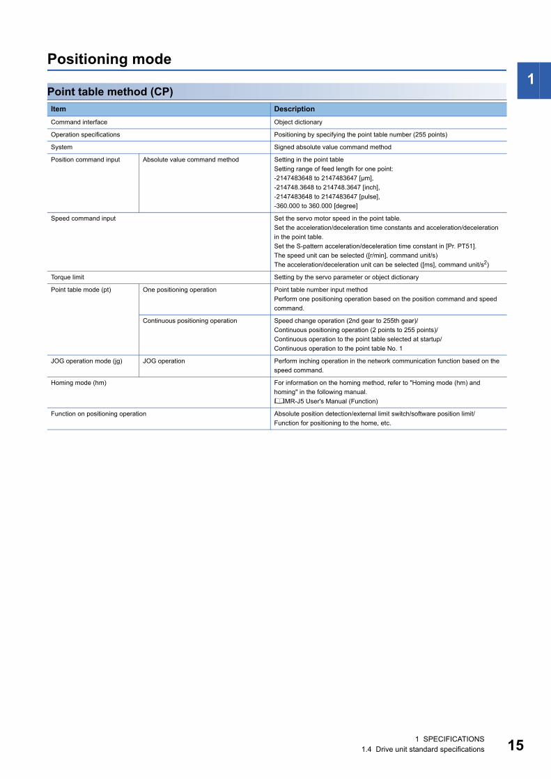
Positioning modePoint table method (CP)Item DescriptionCommand interface Object dictionary
Operation specifications Positioning by specifying the point table number (255 points)
System Signed absolute value command method
Position command input Absolute value command method Setting in the point tableSetting range of feed length for one point:-2147483648 to 2147483647 [μm],-214748.3648 to 214748.3647 [inch],-2147483648 to 2147483647 [pulse],-360.000 to 360.000 [degree]
Speed command input Set the servo motor speed in the point table.Set the acceleration/deceleration time constants and acceleration/deceleration in the point table.Set the S-pattern acceleration/deceleration time constant in [Pr. PT51].The speed unit can be selected ([r/min], command unit/s)The acceleration/deceleration unit can be selected ([ms], command unit/s2)
Torque limit Setting by the servo parameter or object dictionary
Point table mode (pt) One positioning operation Point table number input methodPerform one positioning operation based on the position command and speed command.
Continuous positioning operation Speed change operation (2nd gear to 255th gear)/Continuous positioning operation (2 points to 255 points)/Continuous operation to the point table selected at startup/Continuous operation to the point table No. 1
JOG operation mode (jg) JOG operation Perform inching operation in the network communication function based on the speed command.
Homing mode (hm) For information on the homing method, refer to "Homing mode (hm) and homing" in the following manual.MR-J5 User's Manual (Function)
Function on positioning operation Absolute position detection/external limit switch/software position limit/Function for positioning to the home, etc.
1 SPECIFICATIONS1.4 Drive unit standard specifications 15

16
Functional safety
Drive unit specifications
*1 When DI/O connection (CN8) is used, diagnosis by test pulses is required in order to satisfy Category 4 PL e, SIL 3.*2 Although the special proof tests within the mission time of the safety sub-function is not needed to be performed, the suggested
diagnostic test interval in IEC 61800-5-2: 2016 is at least one test per three months for Category 3 PL e, SIL 3.
Function specifications
*1 Available functions and safety levels differ depending on the combination of the drive units and the servo motors.Page 17 List of safety sub-function compatible units
*2 When DI/O connection (CN8) is used, diagnosis by test pulses is required in order to satisfy Category 4 PL e, SIL 3.*3 A test pulse is a signal which instantaneously turns off a signal to the drive unit at a constant period for external circuits to perform self-
diagnosis.
Item SpecificationsSafety performance
Satisfied standards *1 EN ISO 13849-1:2015 Category 4 PL e, IEC 61508 SIL 3, EN 62061 SIL CL 3, EN 61800-5-2
Mean time to dangerous failure (MTTFd)
MTTFd ≥ 100 [years] (750a)
Diagnostic coverage (DC) DC = Medium, 96.5 [%]
Probability of dangerous Failure per Hour (PFH)
PFH = 3 × 10⁻⁹ [1/h]
Mission time (TM) *2 TM = 20 [year]
Item SpecificationsSafety sub-function *1*2
STO Shut-off response time (STO input off → energy shut off)
8 ms or less (when an input device is used)
SS1 Deceleration delay time 0 ms to 60000 ms (set by functional safety parameters)
SBC Shut-off response time 8 ms or less (when an input device is used)
I/O function Input device Number of inputs 1 point × 2 systems
Permissible time for mismatched double inputs
0 ms to 60000 ms (set by functional safety parameters)
Noise elimination filter 1.000 ms to 32.000 ms (set by functional safety parameters)
Test pulse off time *3 1 Hz to 25 Hz
Output device Number of outputs 1 point × 2 systems
Test pulse off time *3 0.500 ms to 2.000 ms (set by functional safety parameters)
Test pulse interval *3 Within 1 s
1 SPECIFICATIONS1.4 Drive unit standard specifications
1
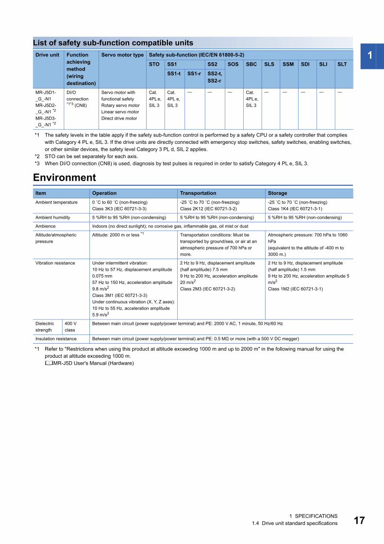
List of safety sub-function compatible units*1 The safety levels in the table apply if the safety sub-function control is performed by a safety CPU or a safety controller that complies with Category 4 PL e, SIL 3. If the drive units are directly connected with emergency stop switches, safety switches, enabling switches, or other similar devices, the safety level Category 3 PL d, SIL 2 applies.
*2 STO can be set separately for each axis.*3 When DI/O connection (CN8) is used, diagnosis by test pulses is required in order to satisfy Category 4 PL e, SIL 3.
Environment
*1 Refer to "Restrictions when using this product at altitude exceeding 1000 m and up to 2000 m" in the following manual for using the product at altitude exceeding 1000 m.MR-J5D User's Manual (Hardware)
Drive unit Function achieving method (wiring destination)
Servo motor type Safety sub-function (IEC/EN 61800-5-2)
STO SS1 SS2 SOS SBC SLS SSM SDI SLI SLT
SS1-t SS1-r SS2-t, SS2-r
MR-J5D1-_G_-N1MR-J5D2-_G_-N1 *2
MR-J5D3-_G_-N1 *2
DI/O connection *1*3 (CN8)
Servo motor with functional safetyRotary servo motorLinear servo motorDirect drive motor
Cat. 4PL e, SIL 3
Cat. 4PL e, SIL 3
Cat. 4PL e, SIL 3
Item Operation Transportation StorageAmbient temperature 0 ˚C to 60 ˚C (non-freezing)
Class 3K3 (IEC 60721-3-3)-25 ˚C to 70 ˚C (non-freezing)Class 2K12 (IEC 60721-3-2)
-25 ˚C to 70 ˚C (non-freezing)Class 1K4 (IEC 60721-3-1)
Ambient humidity 5 %RH to 95 %RH (non-condensing) 5 %RH to 95 %RH (non-condensing) 5 %RH to 95 %RH (non-condensing)
Ambience Indoors (no direct sunlight); no corrosive gas, inflammable gas, oil mist or dust
Altitude/atmospheric pressure
Altitude: 2000 m or less *1 Transportation conditions: Must be transported by ground/sea, or air at an atmospheric pressure of 700 hPa or more.
Atmospheric pressure: 700 hPa to 1060 hPa(equivalent to the altitude of -400 m to 3000 m.)
Vibration resistance Under intermittent vibration:10 Hz to 57 Hz, displacement amplitude 0.075 mm57 Hz to 150 Hz, acceleration amplitude 9.8 m/s2
Class 3M1 (IEC 60721-3-3)Under continuous vibration (X, Y, Z axes):10 Hz to 55 Hz, acceleration amplitude 5.9 m/s2
2 Hz to 9 Hz, displacement amplitude (half amplitude) 7.5 mm9 Hz to 200 Hz, acceleration amplitude 20 m/s2
Class 2M3 (IEC 60721-3-2)
2 Hz to 9 Hz, displacement amplitude (half amplitude) 1.5 mm9 Hz to 200 Hz, acceleration amplitude 5 m/s2
Class 1M2 (IEC 60721-3-1)
Dielectric strength
400 V class
Between main circuit (power supply/power terminal) and PE: 2000 V AC, 1 minute, 50 Hz/60 Hz
Insulation resistance Between main circuit (power supply/power terminal) and PE: 0.5 MΩ or more (with a 500 V DC megger)
1 SPECIFICATIONS1.4 Drive unit standard specifications 17

18
1.5 Function block diagramThe following shows the function block diagram of this drive unit.
MR-J5D1-_G_-N1
400 V class
*1 Drive units with the rated output symbol of 500 (MR-J5D1-500G4-N1) or greater have a cooling fan.
L11
L21
L+
MCCB
MCCB
U
V
W
E
+
CN
4
M
CN
2AC
NP3
A
CN
8C
N40
A
CN
2AL
CN5
USB
USB
CN1A CN1B
D/A
CN3
L-
CN
40B
Servo motor
Dynamic brake circuit
Current detector
Power supply
Cooling fan
Control circuit
power supply
STOControl circuitSTO
switchEncoder
Overcurrent protection
Base amplifier
Current detection
Step-down circuit
Control engine
I/F control
Personal computer
Digital I/O controlNetwork Network
Analog monitor (2 channels)
Drive unit
From L+ of converterunit
From L- of converterunit
To the maincircuit powersupply inputof theconverterunit
External encoder
From CN4 of converterunit or CN40B of driveunit
To CN40A of drive unit
1 SPECIFICATIONS1.5 Function block diagram

1
MR-J5D2-_G_-N1/MR-J5D3-_G_-N1400 V classThe following is an example using MR-J5D3-_G_-N1.
*1 Drive units other than the MR-J5D2-100G4-N1 and MR-J5D3-100G4-N1 have a cooling fan.
UVWE
UVWE
UVWE
M
E
M
E
M
E
TRM (A)L+
L-
MCCB
CN
P3A
CN
2AC
NP3
BC
N2B
CN
P3C
CN
2CC
N4
CN3 CN5
USB
L11
L21
CN
8C
N1A
CN
1B
+
*1
CN
40A
CN
40B
MCCB
A-axis servo motor
A-axis output
Current detector
Power supply
Dynamic brake circuit A
A-axis F/B
Cooling fanSTO circuit
Control circuit power supply
B-axis servo motorBase
amplifierCurrent
detection AOvervoltageOvercurrent
AB-axis output
Control engineSTO switchB-axis
F/B
Controlling B-axis
NetworkC-axis servo motorControlling C-axis
C-axis output
I/F control
Network
C-axis F/B
Step-down circuit
Digital I/O control
Analog output Personal
computer
From L+ of converter unit
From L- of converter unit
To the main circuit power supplyinput of the converter unit
From CN4 of converterunit or CN40B of driveunit
To CN40A of drive unit
Drive unit
1 SPECIFICATIONS1.5 Function block diagram 19

20
1.6 Configuration including peripheral equipment • To prevent a malfunction, do not connect these connectors to any network other than the specified network. • Equipment other than the converter unit, drive unit and servo motor is optional or a recommended product.The following is an example using MR-J5D1-100G4-N1 and MR-CV11K4.In the actual connection, the power regeneration converter unit is closely mounted to the drive unit.
*1 When using the same power supply for the main circuit and cooling fan for MR-CV_, do not supply power between the MR-CV_ and AC reactor or to the inductive load from the secondary side of the magnetic contactor. Connect them closer to the power supply side than the broken line area.
(FR-BLF)
*1
(MCCB)
(MCCB)
R S T
(MC)
(MR-AL-_K)
MR Configurator2
W
L1L2 L3
V U E
W V U E
L+
CN4
CN5
CN1A
CN40A
CN40A
CN2A
CN2A
CN1A
L-
L11L21 L+
L-
L11L21
L+
L-
L11L21
CN1B
CN40B
CN3
Molded-case circuit breaker
Molded-case circuit breaker
Line noise filter
Power supply
Personal computer
Magnetic contactor
Servo motor
Servo motor
Power regenerationconverter unit
Mounting attachment
Drive unit
Drive unit
Magneticcontactordrive output
AC reactor
ControllerProtectioncoordination cableI/O signal
Protection coordination cable
1 SPECIFICATIONS1.6 Configuration including peripheral equipment

1
1.7 Special specificationsDrive units without the dynamic brake (-ED)SummaryThis section describes the drive units without the dynamic brake. Items not described in this section are the same as the MR-J5D_-_G_-N1.
SpecificationsThe built-in dynamic brakes of the drive units are removed.Take safety measures such as providing an extra circuit in case of an emergency stop, alarm, and servo motor stop at power supply shut-off.When the following servo motors are being used, the electronic dynamic brake may be activated at an alarm occurrence.
Setting the following servo parameter disables the electronic dynamic brake.
When [Pr. PA04.3] is set to "2" (initial value), the forced stop deceleration function may be executed at an alarm occurrence. Setting [Pr. PA04.3] to "0" disables the forced stop deceleration function.
Series Servo motorHK-KT HK-KT053W/HK-KT13W/HK-KT1M3W
HK-ST HK-ST1024W
Drive unit Servo parameter Setting valueMR-J5D_-_G_-EDN1 [Pr. PF06.0] 2
1 SPECIFICATIONS1.7 Special specifications 21

22
2 FUNCTION
2.1 Restrictions on the MR-J5_-_G_
2.2 Function listThe function list of this drive unit is shown in the following table. For details of the functions, refer to each section indicated in the detailed explanation field.
Control mode
*1 "Ver." indicates the supported firmware version of the drive unit. The functions are available on drive units with the indicated firmware version or later.
*2 This control mode is not available for multi-axis drive units.
Category Detailed functions Network communication cycle restrictions (minimum)
MR-J5D1-_G_-N1 MR-J5D2-_G_-N1 MR-J5D3-_G_-N1Control mode Profile position mode (pp) 250 μs 500 μs 500 μs
Profile velocity mode (pv) 250 μs Not used Not used
Profile torque mode (tq) 250 μs Not used Not used
Point table method([Pr. PA01.0 Control mode selection] = "6")
250 μs 500 μs 500 μs
Command unit selection function(When [Pr. PT01.2 Unit for position data] is set to "2" (degree))
250 μs 500 μs 500 μs
Functions Detailed functions Description Ver. *1 Detailed explanationCiA 402 control mode
Cyclic synchronous position mode (csp)
This function operates the servo motor in the cyclic synchronous position mode.
C0 Refer to "CONTROL MODE" in the following manual.MR-J5 User's Manual (Function)Cyclic synchronous velocity
mode (csv)This function operates the servo motor in the cyclic synchronous velocity mode.
C0
Cyclic synchronous torque mode (cst)
This function operates the servo motor in the cyclic synchronous torque mode.
C0
Profile position mode (pp) This function operates the servo motor in the profile position mode.
C0
Profile velocity mode (pv) *2 This function operates the servo motor in the profile velocity mode.
C0
Profile torque mode (tq) *2 This function operates the servo motor in the profile torque mode.
C0
Homing mode (hm) This function either operates the servo motor in the homing mode or performs homing.
C0
Point table method Point table mode (pt) This function operates the servo motor according to the setting values by selecting the point table with preset 255 points.
C0
JOG operation mode (jg) This control mode enables desired positioning for machine adjustment and home positioning.
C0
Test operation Test operation mode This function requires MR Configurator2 for JOG operation, positioning operation, motor-less operation, DO forced output, and program operation.
C0 Page 50 Test operation
2 FUNCTION2.1 Restrictions on the MR-J5_-_G_

2
Drive motor
*1 "Ver." indicates the supported firmware version of the drive unit. The functions are available on drive units with the indicated firmware version or later.
Network
*1 "Ver." indicates the supported firmware version of the drive unit. The functions are available on drive units with the indicated firmware version or later.
Position detection
*1 "Ver." indicates the supported firmware version of the drive unit. The functions are available on drive units with the indicated firmware version or later.
Functions Detailed functions Description Ver. *1 Detailed explanationServo motor Linear servo motor Using the linear servo motor and linear encoder
enables the linear servo system to be configured.
C0
Direct drive motor Using this function enables the direct drive servo system to be configured to drive the direct drive motor.
C0
Encoder High-resolution encoder A 67108864 pulses/rev high-resolution encoder is used for the encoder of the rotary servo motor.
C0
Batteryless absolute position encoder
The rotation position of the servo motor can be backed up without the battery. Using the servo motor with this encoder enables an absolute value detection system to be configured without battery.
C0 Refer to "ABSOLUTE POSITION DETECTION SYSTEM" in the following manual.MR-J5D User's Manual (Hardware)
Functions Detailed functions Description Ver. *1 Detailed explanationOpen network EtherCAT communication This function connects the drive unit to
equipment such as a controller through EtherCAT communication.
C0 MR-J5-G-N1/MR-J5W-G-N1 User's Manual (Communication Function)
Functions Detailed functions Description Ver. *1 Detailed explanationControl method Semi closed loop system This function uses the servo motor encoder to
configure semi closed loop systems.C0
Fully closed loop system This function uses the load-side encoder to configure fully closed loop systems.
C0 Refer to "USING A FULLY CLOSED LOOP SYSTEM" in the following manual.MR-J5D User's Manual (Hardware)
Scale measurement function This function connects the scale measurement encoder in the state of the semi closed loop control to transmit the position information of the scale measurement encoder to the controller.
C0 Refer to "Scale measurement function" in the following manual.MR-J5 User's Manual (Function)
Absolute position Absolute position detection system
This function performs homing once, and thereafter does not require homing at every power-on.
C0 Refer to "ABSOLUTE POSITION DETECTION SYSTEM" in the following manual.MR-J5D User's Manual (Hardware)
2 FUNCTION2.2 Function list 23

24
Operation function
*1 "Ver." indicates the supported firmware version of the drive unit. The functions are available on drive units with the indicated firmware version or later.
Functions Detailed functions Description Ver. *1 Detailed explanationStop function Quick Stop This function stops the servo motor with a
specified method and switches to the servo-off status.
C0 Refer to "Quick stop" in the following manual.MR-J5 User's Manual (Function)
Halt This function stops the servo motor while the servo-on status is maintained.
C0 Refer to "Halt" in the following manual.MR-J5 User's Manual (Function)
Stroke limit function This function uses LSP (Forward rotation stroke end) and LSN (Reverse rotation stroke end) to limit the travel interval of the servo motor.
C0 Refer to "Stroke limit function" in the following manual.MR-J5 User's Manual (Function)
Software position limit This function uses servo parameters to limit the travel intervals by address. A function equivalent to the stroke limit function can be set with the servo parameter.
C0 Refer to "Software position limit" in the following manual.MR-J5 User's Manual (Function)
Command generation
Rotation/travel direction selection
This function sets the rotation direction of the servo motor without changing the command polarity.
C0 Refer to "Rotation/travel direction selection" in the following manual.MR-J5 User's Manual (Function)
Electronic gear This function performs positioning control with the value obtained by multiplying the position command from the upper controller by a set electronic gear ratio.
C0 Refer to "Electronic gear function" in the following manual.MR-J5 User's Manual (Function)
Acceleration/deceleration function
This function enables smooth acceleration/deceleration.
C0 Refer to "Acceleration/deceleration function" in the following manual.MR-J5 User's Manual (Function)
S-pattern acceleration/deceleration time constant
This function performs smooth acceleration and deceleration.
C0 Refer to "S-pattern acceleration/deceleration time constant" in the following manual.MR-J5 User's Manual (Function)
Torque limit This function limits the servo motor torque. C0 Refer to "Torque limit" in the following manual.MR-J5 User's Manual (Function)
Speed limit This function limits the servo motor speed in the torque control mode.
C0 Refer to "Speed limit" in the following manual.MR-J5 User's Manual (Function)
Command offset This function compensates the position/speed/torque commands by adding a desired amount of offset to the commands.
C0 Refer to "Command offset" in the following manual.MR-J5 User's Manual (Function)
2 FUNCTION2.2 Function list

2
Control function
*1 "Ver." indicates the supported firmware version of the drive unit. The functions are available on drive units with the indicated firmware version or later.
Functions Detailed functions Description Ver. *1 Detailed explanationVibration suppression
Advanced vibration suppression control II
This function suppresses vibration and residual vibration at an arm end.
C0 Refer to "Advanced vibration suppression control II" in the following manual.MR-J5 User's Manual (Adjustment)
Machine resonance suppression filter
This function decreases the gain of the specific frequency to suppress the resonance of the mechanical system.
C0 Refer to "Machine resonance suppression filter" in the following manual.MR-J5 User's Manual (Adjustment)
Shaft resonance suppression filter
When driving the servo motor with a load mounted to the servo motor shaft, resonance due to shaft torsion may generate high frequency mechanical vibration. The shaft resonance suppression filter suppresses this vibration.
C0 Refer to "Shaft resonance suppression filter" in the following manual.MR-J5 User's Manual (Adjustment)
Robust filter This function improves a disturbance response when a response performance cannot be increased because of a large load to motor inertia ratio, such as a roll feed axis.
C0 Refer to "Robust filter" in the following manual.MR-J5 User's Manual (Adjustment)
Slight vibration suppression control
This function suppresses vibration of ±1 pulse generated at each servo motor stop.
C0 Refer to "SLIGHT VIBRATION SUPPRESSION CONTROL" in the following manual.MR-J5 User's Manual (Adjustment)
Tracking control Lost motion compensation function
This function reduces the response delay generated when the machine moving direction is reversed.
C0 Refer to "Lost motion compensation function" in the following manual.MR-J5 User's Manual (Adjustment)
Super trace control This function reduces the droop pulses at the rated speed and at the uniform acceleration/deceleration to almost zero.
C0 Refer to "Super trace control" in the following manual.MR-J5 User's Manual (Adjustment)
Path tracking model adaptive control
This function reduces tracking errors in reciprocation.
C0 Refer to "Path tracking model adaptive control" in the following manual.MR-J5 User's Manual (Adjustment)
2 FUNCTION2.2 Function list 25

26
Adjustment function
*1 "Ver." indicates the supported firmware version of the drive unit. The functions are available on drive units with the indicated firmware version or later.
Functions Detailed functions Description Ver. *1 Detailed explanationAutomatic adjustment
Quick tuning This function automatically adjusts the gain at servo-on in a short time without acceleration/deceleration operation of the servo motor. Response without overshoot is possible, saving gain adjustment time.
C0 Refer to "Quick tuning" in the following manual.MR-J5 User's Manual (Adjustment)
Auto tuning This function automatically adjusts the gain to an optimum value even if the load applied to the servo motor shaft varies.
C0 Refer to "ADJUSTMENT FUNCTION TYPES" in the following manual.MR-J5 User's Manual (Adjustment)
One-touch tuning Gain adjustment is performed with this function just by pressing buttons on the drive unit or by clicking a button once on MR Configurator2. One-touch tuning can also be performed via a network.
C0 Refer to "One-touch tuning" in the following manual.MR-J5 User's Manual (Adjustment)
Custom adjustment Model adaptive control This function enables control according to the ideal model that is both stable and highly responsive. This is a two-degrees-of-freedom model and can adjust responses to the command and to the disturbance separately. This function can also be disabled.
C0 Refer to "MODEL ADAPTIVE CONTROL" in the following manual.MR-J5 User's Manual (Adjustment)
Gain switching function This function switches gains during rotation and during stop, and uses an input device to switch gains during operation.It supports the gain switching by rotation direction and the 3-step gain switching. Therefore, more detailed gain switching is available.
C0 Refer to "GAIN SWITCHING FUNCTION" in the following manual.MR-J5 User's Manual (Adjustment)
Adjustment support Machine analyzer This function analyzes the frequency characteristic of the mechanical system by simply connecting the drive unit with an MR Configurator2 installed personal computer.
C0 Refer to "Adjustment functions available in combination with MR Configurator2" in the following manual.MR-J5 User's Manual (Adjustment)
2 FUNCTION2.2 Function list

2
I/O, monitor
*1 "Ver." indicates the supported firmware version of the drive unit. The functions are available on drive units with the indicated firmware version or later.
Option
*1 "Ver." indicates the supported firmware version of the drive unit. The functions are available on drive units with the indicated firmware version or later.
Functions Detailed functions Description Ver. *1 Detailed explanationDI/DO Input signal selection (device
selection)This function assigns input devices such as LSP (Forward rotation stroke end) to certain pins of the connector.
C0 Refer to "Assigning I/O devices" in the following manual.MR-J5 User's Manual (Function)
Output signal selection (device setting)
This function assigns output devices such as MBR (Electromagnetic brake interlock) to certain pins of the connector.
C0
Output signal (DO) forced output
This function forcibly switches the output signals on and off regardless of the servo status. Use this function for purposes such as checking output signal wiring.
C0 Page 57 Output signal (DO) forced output
A/B/Z-phase output This function outputs the positions of the encoder and linear encoder in the A/B/Z-phase signal.
C0 Refer to "A/B/Z-phase pulse output function" in the following manual.MR-J5 User's Manual (Function)
LED Status display This function shows the servo status on the 7-segment LED display.
C0 Page 35 Switch setting and display of the drive unit
Analog input/output Analog monitor This function outputs the servo status in voltage in real time.
C0 Refer to "MONITORING" in the following manual.MR-J5 User's Manual (Function)Monitor Power monitoring function This function calculates the running power and
the regenerative power from the data in the drive unit such as speed and current. The power consumption and other values are displayed on MR Configurator2.
C0
Touch probe Current position latch function
This function latches the current position when TPR1 (Touch probe 1), TPR2 (Touch probe 2), or TPR3 (Touch probe 3) is turned on.
C0 Refer to "Touch probe" in the following manual.MR-J5 User's Manual (Function)
Functions Detailed functions Description Ver. *1 Detailed explanationRegenerative capacity enhancement
Simple converter This function enables servo amplifiers to be used in a common DC bus connection. Utilizing the regenerative power contributes to energy-conservation. In addition, it decreases the number of molded case circuit breakers and magnetic contactors.
For the MR-J5D_-_G_ drive unit, this function cannot be used.
Regenerative option Use this function if the built-in regenerative resistor of the servo amplifier does not have sufficient regenerative capacity for the generated regenerative power.
For the MR-J5D_-_G_ drive unit, this function cannot be used.
Multifunction regeneration converter
This function returns the regenerative energy generated at servo motor deceleration to the power supply. The bus voltage can be standardized among multiple servo amplifiers.
For the MR-J5D_-_G_ drive unit, this function cannot be used.
2 FUNCTION2.2 Function list 27

28
Engineering tool
*1 "Ver." indicates the supported firmware version of the drive unit. The functions are available on drive units with the indicated firmware version or later.
Protective functions
*1 "Ver." indicates the supported firmware version of the drive unit. The functions are available on drive units with the indicated firmware version or later.
Functions Detailed functions Description Ver. *1 Detailed explanationSetup software MR Configurator2 This function performs settings (such as servo
parameter settings), test operation, and monitoring with a personal computer.
C0 Page 41 STARTUP
Functions Detailed functions Description Ver. *1 Detailed explanationAlarm Alarm function This function displays an alarm or warning when
an error occurs during operation. When an alarm occurs, ALM (Malfunction) turns off and stops the servo motor. When a warning occurs, WNG (Warning) will turn on. The servo motor may stop or continue operation depending on the warning.
C0 Refer to "Alarm function" in the following manual.MR-J5 User's Manual (Function)
Alarm history clear This function clears alarm histories. C0 Refer to "Alarm history" in the following manual.MR-J5 User's Manual (Function)
Power error detection
Disconnection detection function
This function detects a disconnection in the main circuit power supply input and the servo motor power supply output.
C0 For the MR-J5D_-_G_ drive unit, the input open-phase detection function and servo motor incorrect wiring detection function cannot be used.Refer to "Disconnection/incorrect wiring detection function" in the following manual.MR-J5 User's Manual (Function)
Coasting distance reduction
Forced stop deceleration function
This function decelerates the servo motor to a stop at EM2 (Forced stop 2) off or when there is an alarm.
C0 Refer to "Forced stop deceleration function" in the following manual.MR-J5 User's Manual (Function)
Drop protection Electromagnetic brake interlock function
This function operates the electromagnetic brake at servo off and error occurrence, and prevents the vertical axis from dropping.
C0 Refer to "Electromagnetic brake interlock function" in the following manual.MR-J5 User's Manual (Function)
Vertical axis freefall prevention function
This function moves the axis up by the mechanical backlash amount of the electromagnetic brake to prevent damage to machines.
C0 Refer to "Vertical axis freefall prevention function" in the following manual.MR-J5 User's Manual (Function)
Braking protection Dynamic brake During the power shut-off and alarm occurrence, this function shorts between U, V, and W phases and operates the dynamic brake.
C0 Refer to "Dynamic brake characteristics" in the following manual.MR-J5D User's Manual (Hardware)
2 FUNCTION2.2 Function list

2
Functional safety
*1 "Ver." indicates the supported firmware version of the drive unit. The functions are available on drive units with the indicated firmware version or later.
Instantaneous power failure measures
*1 "Ver." indicates the supported firmware version of the drive unit. The functions are available on drive units with the indicated firmware version or later.
Functions Detailed functions Description Ver. *1 Detailed explanationSafety sub-function STO (Safe torque off)
(When functional safety parameters are not used)
This drive unit supports the STO function for functional safety as per IEC/EN 61800-5-2. This allows a safety system to be easily configured for the equipment.
C0 Refer to "USING STO FUNCTION" in the following manual.MR-J5D User's Manual (Hardware)
STO (Safe torque off)(When functional safety parameters are used)
This function electrically shuts off the servo motor driving energy with input signals from external devices (shut-off by the secondary-side output). This is equivalent to the stop category 0 of IEC/EN 60204-1.
C0 Refer to "FUNCTIONAL SAFETY" in the following manual.MR-J5 User's Manual (Function)
SS1 (Safe stop 1) This function starts deceleration with input signals from external devices. After the specified time to confirm the motor stop, the STO function is executed (SS1). This is equivalent to the stop category 1 of IEC/EN 60204-1.
C0
SBC (Safe brake control) This function outputs signals for controlling the external brake.
C0
Functions Detailed functions Description Ver. *1 Detailed explanationTough drive SEMI-F47 function This function uses the electrical energy charged
in the capacitor to avoid triggering [AL. 010 Undervoltage] in case that an instantaneous power failure occurs during operation. Use a 3-phase power supply for the input power supply of the servo amplifier. Using a 1-phase 200 V AC for the input power supply will not comply with SEMI-F47 standard.
For the MR-J5D_-_G_ drive unit, this function cannot be used.
Tough drive function This function makes the equipment continue operating even under conditions where an alarm would normally occur. There are two types of tough drive function: the vibration tough drive and the instantaneous power failure tough drive.
C0 For the MR-J5D_-_G_ drive unit, instantaneous power failure tough drive cannot be used.Refer to "Tough drive function" in the following manual.MR-J5 User's Manual (Function)
2 FUNCTION2.2 Function list 29

30
Diagnostics
*1 "Ver." indicates the supported firmware version of the drive unit. The functions are available on drive units with the indicated firmware version or later.
Functions Detailed functions Description Ver. *1 Detailed explanationDrive data diagnosis Drive recorder This function continuously monitors the servo
status and records the state transition before and after an alarm for a fixed period of time. The recorded data can be checked by the Waveform-Display button on the drive recorder window of MR Configurator2 being clicked.
C0 Refer to "Drive recorder" in the following manual.MR-J5 User's Manual (Function)
Graph function This function obtains the servo status in the graph.
C0 Refer to "Graph function" in the following manual.MR-J5 User's Manual (Function)
This function obtains a graph by using the trigger synchronized on multiple drive units via a network.
C0
Failure diagnosis Encoder communication diagnosis function
This function diagnoses with MR Configurator2 whether the encoder communication error is caused by the circuit malfunction of the drive unit or by the malfunction of the cables/encoder.
C0 Refer to "Encoder communication diagnosis function" in the following manual.MR-J5 User's Manual (Function)
Service life diagnosis
Servo amplifier life diagnosis function
This function enables checking of the cumulative energization time, the number of the inrush relay on/off times, and the number of dynamic brake usage times. It gives an indication of the replacement time for parts on the drive unit with a service life (such as the capacitor and the relay) before they malfunction. MR Configurator2 is required for this function.
C0 Refer to "Servo amplifier life diagnosis function" in the following manual.MR-J5 User's Manual (Function)
Motor life diagnosis function This function predicts failures of the equipment and the servo motor based on the machine total travel distance. It gives an indication of the replacement time for the servo motor.
C0
Machine diagnosis function This function uses the data in the drive unit to estimate the friction and vibrational component of the drive system in the equipment and to recognize an error in machine parts such as ball screws and bearings.
C0 Refer to "Machine diagnosis" in the following manual.MR-J5 User's Manual (Function)
This function automatically sets the threshold used for detecting the error of machine parts such as ball screws and bearings. It outputs the warning when the friction, vibrational component, and total revolution of the servo motor are out of the set threshold. The error in the machine parts such as ball screws and bearings can be detected automatically.
C0
This function estimates the friction of gears and loosening of belts (decrease in the belt tension), and detects errors in the gears and belts.
C0
System diagnosis System configuration information
This function uses MR Configurator2 to monitor the drive unit model, connected servo motor, encoder, and other information.
C0 Refer to "System configuration display" in the following manual.MR-J5 User's Manual (Function)
2 FUNCTION2.2 Function list

2
History
*1 "Ver." indicates the supported firmware version of the drive unit. The functions are available on drive units with the indicated firmware version or later.
2.3 SecurityTo completely prevent unauthorized access to the system from external devices, the user also must take safety measures. Mitsubishi Electric Corporation cannot be held responsible for any problems caused by unauthorized access.
Functions Detailed functions Description Ver. *1 Detailed explanation Alarm history This function saves information of the alarm that
occurred in the drive unit. The information is saved in chronological order and used for occasions such as analyzing the cause of the alarm.
C0 Refer to "Alarm history" in the following manual.MR-J5 User's Manual (Function)
2 FUNCTION2.3 Security 31
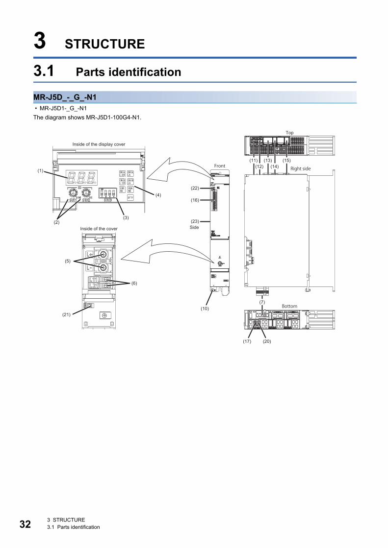
32
3 STRUCTURE
3.1 Parts identification
MR-J5D_-_G_-N1 • MR-J5D1-_G_-N1The diagram shows MR-J5D1-100G4-N1.
(1)
(2)
(5)
(6)
(21)
(4)
(3)
(11)
(22)
(16)
(23)
(15)(12)
(13)
(7)
(17)
(10)
(20)
(14)CN1AL-ER
CN1ALA
CN1BL-ER
CN1BLA
ERRNS
RUNMS
SFTY
Top
Inside of the display cover
SideInside of the cover
Right side
Bottom
Front
3 STRUCTURE3.1 Parts identification

3
• MR-J5D2-_G_-N1/MR-J5D3-_G_-N1The diagram shows MR-J5D3-100G4-N1.
No. Name Application Detailed explanation(1) Display section The 3-digit, 7-segment LED display shows the servo status and
alarm number.Page 35 Switch setting and display of the drive unit
(2) ID setting switches (SW1/SW2) Set the node address of the drive unit.
(3) DIP switch (SW3) Consists of the test operation switch and control axis deactivation switch.
(4) Network status LEDs Displays each network status.
(5) L+/L- terminal (TE2) Connect with the L+ and L- terminals of the converter unit or another drive unit by bus bars. (DC input)
Refer to "Explanation of power supply system" in the following manual.MR-J5D User's Manual (Hardware)
(6) Control circuit terminal (TE3) Connect the control circuit power supply.
(7) A-axis servo motor power connector (CNP3A)
Connect the A-axis servo motor.
(8) *1 B-axis servo motor power connector (CNP3B)
Connect the B-axis servo motor.
(9) *2 C-axis servo motor power connector (CNP3C)
Connect the C-axis servo motor.
(10) Protective earth (PE) terminal Connect this terminal to the protective earth (PE) of the cabinet.
(11) Ethernet cable connector (CN1A) (IN port) Connect the controller, drive unit, servo amplifier or each network connected device.
(12) Ethernet cable connector (CN1B) (OUT port)
Connect the drive unit, servo amplifier or each network connected device.
(13) Protection coordination connector (CN40A) Connect it with a nearby converter unit or drive unit. Refer to "Example power circuit connections" in the following manual.MR-J5D User's Manual (Hardware)
(14) Protection coordination connector (CN40B) Connect it with a nearby drive unit.
(1)
(2)
(5)
(6)
(21)
(4)
(3)
(11)
(22)
(16)
(23)
(15)(12)
(13)
(7) (8) (9)
(17) (18) (19)
(10)
(14)CN1AL-ER
CN1ALA
CN1BL-ER
CN1BLA
ERRNS
RUNMS
SFTY
Top
Inside of the display cover
SideInside of the cover
Right sideFront
Bottom
3 STRUCTURE3.1 Parts identification 33

34
*1 For the 2-axis drive unit and 3-axis drive unit.*2 For the 3-axis drive unit.*3 For the 1-axis drive unit.
■External encoder connectorThe following table shows the communication method of the external encoder compatible with the drive units.
*1 The MR-J4FCCBL03M branch cable is required.*2 If the external encoder communication method is the four-wire type, the MR-J5D2-_G_ cannot be used. Use MR-J5D1-_G_.
(15) Functional safety I/O signal connector (CN8)
Connect an external safety relay to use the STO function. When using other safety-sub functions, refer to "FUNCTIONAL SAFETY" in the following manual.MR-J5 User's Manual (Function)
Refer to "USING STO FUNCTION" and "USING FUNCTIONAL SAFETY" in the following manual.MR-J5D User's Manual (Hardware)
(16) I/O signal connector (CN3) Connect the digital I/O signals.The analog monitor is output from this connector.
Refer to "Connectors and pin assignments" in the following manual.MR-J5D User's Manual (Hardware)
(17) A-axis encoder connector (CN2A) Connect the A-axis servo motor encoder or external encoder. Page 34 External encoder connector(18) *1 B-axis encoder connector (CN2B) Connect the B-axis servo motor encoder or external encoder.
(19) *2 C-axis encoder connector (CN2C) Connect the C-axis servo motor encoder or external encoder.
(20) *3 External encoder connector (CN2AL) Connect the external encoder.
(21) Battery connector (CN4) This is a connector to connect the battery for absolute position data backup. When the servo motor with a batteryless absolute position encoder is being used, it does not need to be connected to the battery for absolute position data backup.
(22) USB communication connector (CN5) Connect with a personal computer.
(23) Rating plate Indicates model, capacity, and other information. Page 10 Rating plate
Operation mode External encoder communication method
Connector
MR-J5D1-_G_-N1 MR-J5D2-_G_-N1 MR-J5D3-_G_-N1Fully closed loop system Two-wire type CN2AL CN2A *1 *2
CN2B *1 *2
Four-wire type
A/B/Z-phase differential input
Scale measurement function Two-wire type CN2AL CN2A *1 *2
CN2B *1 *2
Four-wire type
A/B/Z-phase differential input
No. Name Application Detailed explanation
3 STRUCTURE3.1 Parts identification

3
3.2 Switch setting and display of the drive unitSwitching to the test operation mode and configuring network setting can be done with switches on the drive unit. The network communication status and alarm status can also be checked on the display (3-digit, 7-segment LED) of the drive unit.
SwitchesIf a metal screw driver contacts with the conductive areas, the switches may malfunction. Therefore, use an insulated screw driver instead of the metal screw driver to operate ID setting switches (SW1/SW2) and DIP switches (SW3).If all the DIP switches (SW3) are turned "ON (up)", the drive unit is switched to the operation mode for manufacturer setting and "off" will be displayed. The drive unit cannot be used in this mode. Thus, set the DIP switches (SW3) correctly according to this section.To apply the settings of all switches, cycle the control circuit power supply or reset the software.The following explains the ID setting switches (SW1/SW2) and DIP switches (SW3).
Switch identification■1-axis drive unit
■2-axis drive unit
■3-axis drive unit
1
ON
2 3 4
3-digit, 7-segment LED
DIP switch (SW3)
For manufacturer settingFor manufacturer setting
Test operation select switch (SW3-1)ID setting switch (upper) (SW1) ID setting switch (lower) (SW2)
Disabling control axis switch for A-axis (SW3-2)
1
ON
2 3 4
3-digit, 7-segment LED
DIP switch (SW3)
Disabling control axis switch for B-axis (SW3-3)For manufacturer setting
Test operation select switch (SW3-1)ID setting switch (upper) (SW1) ID setting switch (lower) (SW2)
Disabling control axis switch for A-axis (SW3-2)
1
ON
2 3 4
3-digit, 7-segment LED
DIP switch (SW3)
Disabling control axis switch for B-axis (SW3-3)Disabling control axis switch for C-axis (SW3-4)
Test operation select switch (SW3-1)ID setting switch (upper) (SW1) ID setting switch (lower) (SW2)
Disabling control axis switch for A-axis (SW3-2)
3 STRUCTURE3.2 Switch setting and display of the drive unit 35

36
Test operation select switch (SW3-1)Turning "ON (up)" the test operation select switch enables the test operation mode. In the test operation mode, functions such as JOG operation, positioning operation, and machine analyzer are available using MR Configurator2.Page 50 Test operation
Disabling control axis switches (SW3-2, SW3-3, and SW3-4)Turning "ON (up)" the disabling control axis switch disables the corresponding servo motor. The servo motor will become in the disabled-axis state and will not be recognized by the controller.
ID setting switches (SW1/SW2)The node address can be set with the ID setting switches (SW1/SW2) of the drive unit. SW1 indicates an upper digit and SW2 indicates a lower digit of a hexadecimal. The ID setting switches are set to 01h when shipped from the factory.For how to set node addresses, refer to "Node address setting" in the following manual.MR-J5-G-N1/MR-J5W-G-N1 User's Manual (Communication Function)
7-segment LEDThe network connection status, servo status, and alarm/warning occurrence statuses can be checked on the 7 segment LED display.
Display sequenceThe following shows the display sequence of the 7-segment LED display after power-on. Once a system check is complete and the drive unit is started, the network connection status will be displayed.
*1 The segment of the last 2 digits shows the node address.Page 37 When the network is connected
*1
Drive unit power on
Controller not connected
Controller power on (Network communication start)
Controller is connected
Controller power off
Cyclic communication in progress
3 STRUCTURE3.2 Switch setting and display of the drive unit

3
Alarm displayWhen an alarm/warning occurs, the alarm status is displayed after the network connection status. This is an example of the alarm display for when [AL. 032.2 Overcurrent] is occurring.
■1-axis drive unit
■For multi-axis drive units
When a 3-axis drive unit is used, the alarm occurrence status in the B-axis is indicated before the alarm occurrence in the C-axis.
When the network is connectedThe network connection status is displayed as follows. The servo status is expressed in decimal points.
The last 2 digits indicate a network address corresponding to each network.
1-axis drive unit 2-axis drive unit 3-axis drive unit
Network AddressEtherCAT A node address is displayed in hexadecimal.
Network status Blank Status display Alarm No. Alarm detail BlankAfter 1.6 s After 0.2 s After 0.8 s After 0.8 s After 0.8 s
Status display (1 digit)
Alarm detail (1 digit)
Alarm No. (3 digits)
After 0.2 s
: Indicates that an alarm is occurring.
Network status Blank Status display Alarm No. Alarm detail BlankAfter 1.6 s After 0.2 s After 0.8 s After 0.8 s After 0.8 s
A-axis status (1 digit)
Alarm No. (3 digits) Alarm detail (1 digit)
After 0.2 s
: Indicates that an alarm is occurring.
Status display Alarm No. Alarm detail BlankAfter 0.8 s After 0.8 s After 0.8 s
After 0.2 sB-axis status (1 digit)
Alarm No. (3 digits) Alarm detail (1 digit)
Servo statusOff: Indicates ready-off and servo-off status. Blinking: Indicates ready-on and servo-off status. On: Indicates ready-on and servo-on status.
B-axis servo statusA-axis servo statusOff: Indicates ready-off and servo-off status. Blinking: Indicates ready-on and servo-off status. On: Indicates ready-on and servo-on status.
C-axis servo statusB-axis servo status
A-axis servo statusOff: Indicates ready-off and servo-off status. Blinking: Indicates ready-on and servo-off status. On: Indicates ready-on and servo-on status.
3 STRUCTURE3.2 Switch setting and display of the drive unit 37

38
When the network is not connectedThe network connection status is displayed for each axis.
The 7-segment LED display during cyclic communication is as follows.
1-axis drive unit 2-axis drive unit 3-axis drive unit
Display DescriptionIndicates that the drive unit is not connected to the controller.
Indicates the Pre-Operational state shown in the state transition diagram of the ESM state machine.
Indicates the Safe-Operational state shown in the state transition diagram of the ESM state machine.
Indicates the BootStrap state shown in the state transition diagram of the ESM state machine.
Network statusB-axis network status
A-axis network status
C-axis network statusB-axis network status
A-axis network status
3 STRUCTURE3.2 Switch setting and display of the drive unit

3
Other status displays
Status LEDsThe LED states (RUN MS/ERR NS) indicate the network status of the drive unit.
Display Status DescriptionTest operation mode Indicates that the test operation mode is set.
CPU error Indicates that a CPU watchdog error has occurred.
This is for manufacturer setting.
Initialization in progress Indicates that initialization of settings such as parameters is in progress.
LED DescriptionCN1AL-ER/CN1BL-ER(red)
Name: Line error statusOn: Indicates that erroneous data is being received.
CN1ALA/CN1BLA(green)
Name: Link/ActivityPage 40 LED display
RUNMS(green)
Page 40 LED display
ERRNS(red)
SFTY(green)
Off: Indicates that the functional safety cannot be activated.On: Indicates that the functional safety can be activated.
3 STRUCTURE3.2 Switch setting and display of the drive unit 39

40
LED displayRUN MS (RUN LED), ERR NS (ERROR LED), and Link/Activity operate in compliance with the EtherCAT standard (ETG.1300 EtherCAT Indicator and Labeling Specification).
LED status definitionsThe following shows LED status definitions.
Explanations of LED statuses■RUN MS (RUN LED)The RUN LED indicates the EtherCAT communication status (ESM status).
■ERR NS (ERROR LED)The ERROR LED indicates an error occurrence in EtherCAT communication.
■Link/Activity LED (OUT port/IN port)The Link/Activity LEDs indicate the link status of each EtherCAT communication port.
LED status DefinitionOn The LED is lit steady.
Off The LED is unlit.
Flickering The LED turns on and off repeatedly in a 10 Hz cycle (every 50 ms).
Blinking The LED turns on and off repeatedly in a 2.5 Hz cycle (every 200 ms).
Single flash The LED turns on for 200 ms and off for 1000 ms repeatedly.
Double flash The LED repeats the cycle of turning on for 200 ms -> off for 200 ms -> on for 200 ms -> off for 1000 ms.
LED Description
Status ColorOff Indicates the power supply being shut off or the Init state.
Blinking Green Indicates the Pre-Operational state.
Single flash Indicates the Safe-Operational state.
On Indicates the Operational state.
LED Description
Status ColorOff No errors
Blinking Red Indicates that the EtherCAT state cannot be changed as instructed from the master station.
Single flash Indicates that the EtherCAT state has been changed autonomously because of an internal error.
Double flash Indicates a watchdog error in the Sync manager.
On Indicates critical errors such as a watchdog timeout.
LED Description
Status ColorOff Indicates that the power supply being shut off or the link-unestablished state.
On Green Indicates that the link is established but no traffic.
Flickering Indicates that the link is established with traffic.
3 STRUCTURE3.2 Switch setting and display of the drive unit

4
4 STARTUP
• MR-J5D_-_G_-N1 drive units can only be set with MR Configurator2 version 1.125F or later. • This chapter explains how to start up the drive unit by using MR Configurator2 with software version 1.100E. • Before starting operation, check each servo parameter. Depending on the machine, an unexpected
operation may occur.
When using a linear servo motor, the terms below have the following meanings. • Load to motor inertia ratio → Load to motor mass ratio • Torque → Thrust
Servo parameter setting method
• Servo parameters may be changed by the controller via a network. In this case, take measures such as not turning on the controller or not connecting the network cable to the controller, so that the servo parameter setting does not change.
MR Configurator2 is the software used for purposes such as servo parameter settings, graph measurement/display, and test operation. This chapter describes the startup procedure of the drive unit when the drive unit is connected to a personal computer which has MR Configurator2 installed. To learn more about using MR Configurator2, refer to Help in MR Configurator2.
1. Connect the drive unit and the personal computer with a USB cable. Turn on the drive unit control circuit power supply.
CN5
Personal computerUSB cable MR-J3USBCBL3M (option)
To USB connector
Drive unit
4 STARTUP 41

42
2. Start MR Configurator2 and create a new project. For the connection setting, select USB. Select the drive unit model.
3. Selecting "Parameter" from the project tree opens the "Parameter Setting" screen.
4 STARTUP

4
4. Select a group of servo parameters in the selection tree of the "Parameter Setting" window to display and configure the settings.
5. After changing the servo parameter, click "Selected Items Write" or "Axis Writing".
4 STARTUP 43

44
6. Abbreviated servo parameters prefixed with * and servo parameters marked with ** are enabled after the power is cycled or a software reset is performed. Click "Software Reset" in MR Configurator2 to perform the software reset.
4 STARTUP

4
4.1 Turning on drive unit for the first time
• For the controller settings, refer to the relevant controller manual. • For the gain adjustment, refer to the following manual.MR-J5 User's Manual (Adjustment)
When turning on the drive unit for the first time, follow the steps below.
Procedure Description Reference
1. Installation and wiring Install and wire the converter unit, drive unit and servo motor. MR-J5D User's Manual (Hardware)
2. Test operation of the servo motor alone in test operation mode
With the servo motor disconnected from the machine, operate the servo motor at the lowest speed possible, and check whether the servo motor operates correctly.
Page 46 Test operation of the servo motor alone in test operation mode
3. Equipment configuration setting
Set each servo parameter according to the equipment configuration. Page 47 Equipment configuration setting
4. Controller-related setting Perform necessary settings according to commands from the controller. Page 47 Controller-related setting
5. Operation by controller command
Operate the servo motor at the lowest speed possible by giving commands to the drive unit from the controller, and check whether the servo motor operates correctly.
Page 48 Operation by controller command
6. Actual operation
4 STARTUP4.1 Turning on drive unit for the first time 45

46
Test operation of the servo motor alone in test operation mode
• If the servo motor operates in an unintended manner, stop the servo motor with EM2 (Forced stop 2).
Check that the drive unit and servo motor operate normally. With the servo motor disconnected from the machine, use the test operation mode and check whether the servo motor operates correctly. This section describes how to check the servo motor operation in the JOG operation. The test operation also includes the positioning operation and program operation.Page 50 Test operationIn the linear servo motor control mode, the JOG operation cannot be performed. Check the linear servo motor operation status by using the positioning operation or by other means.Page 52 Motor driving by test operation
1. Turn off the power.
2. Turn "ON (up)" the test operation select switch (SW3-1). When performing test operation with multiple MR-J5D_-_G_ connected to one power regeneration converter unit, turn "ON (up)" the test operation select switch (SW3-1) of all the MR-J5D_-_G_ connected to the power regeneration converter unit.
3. Turn on the power supply of the converter unit and drive unit. Once initialization is complete, the display will change as follows.
The display of a 1-axis drive unit is shown as an example.
4. Open the "JOG Mode" screen of MR Configurator2.
1
ON
2 3 4
Set SW3-1 to "ON (up)".
Test operation status display
4 STARTUP4.1 Turning on drive unit for the first time

4
5. To operate the servo motor, input the motor speed and acceleration/deceleration time constants, then click "Forward CCW" or "Reverse CW". The servo motor operates only while the button is being clicked. Give a low speed command at first and check the operation status.
6. After the test operation is complete, turn off the power and "OFF (down)" the test operation select switch (SW3-1).
Equipment configuration settingSet the servo parameters for each function according to the equipment configuration. For details, refer to the following manual.MR-J5 User's Manual (Function)
Controller-related settingRefer to the applicable network instruction manual for the network connection setting.
Set the servo parameter using the controller according to the control mode to be used.
Item DescriptionRotation/travel direction selection To change the rotation/travel direction (POL), change the servo parameter.
Stroke limit function Limit switches can be used to limit travel intervals of the servo motor. Configure the settings according to the connection method of the limit switch.
In-position setting Positioning completion status can be checked with in-position. Set this as necessary.
Forced stop deceleration function Stops the servo motor at EM2 (Forced stop 2) off. Perform settings such as the deceleration time constant.
Vertical axis freefall prevention function For vertical axes, this function pulls up the shaft slightly. When using a servo motor with an electromagnetic brake for a vertical axis, perform settings as required.
Network Reference manualEtherCAT MR-J5-G-N1/MR-J5W-G-N1 User's Manual (Communication Function)
Item Description ReferenceNetwork standard mode Operates in the modes such as csp/csv/cst
specified in CiA 402.Refer to "CONTROL MODE" in the following manual.MR-J5 User's Manual (Function)
Positioning mode (point table method) This function operates the servo motor according to the setting values by selecting the point table with preset 255 points.
Refer to "POSITIONING MODE (POINT TABLE METHOD) (CP)" in the following manual.MR-J5 User's Manual (Function)
4 STARTUP4.1 Turning on drive unit for the first time 47
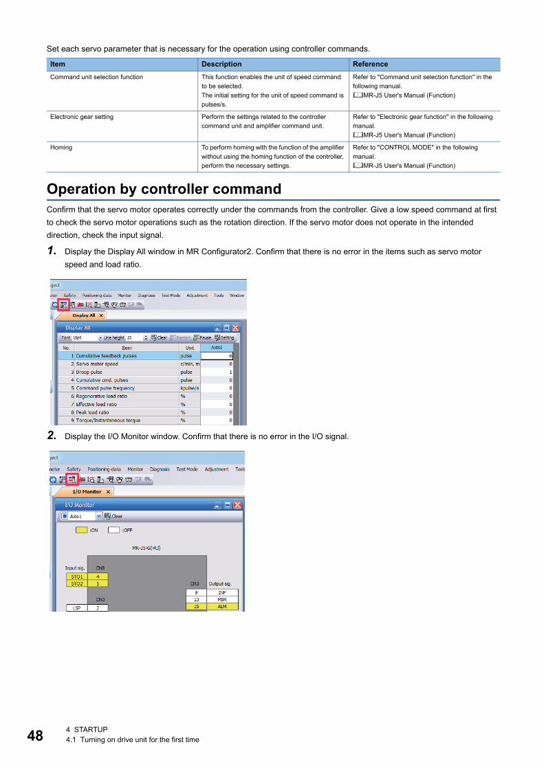
48
Set each servo parameter that is necessary for the operation using controller commands.
Operation by controller commandConfirm that the servo motor operates correctly under the commands from the controller. Give a low speed command at first to check the servo motor operations such as the rotation direction. If the servo motor does not operate in the intended direction, check the input signal.
1. Display the Display All window in MR Configurator2. Confirm that there is no error in the items such as servo motor speed and load ratio.
2. Display the I/O Monitor window. Confirm that there is no error in the I/O signal.
Item Description ReferenceCommand unit selection function This function enables the unit of speed command
to be selected.The initial setting for the unit of speed command is pulses/s.
Refer to "Command unit selection function" in the following manual.MR-J5 User's Manual (Function)
Electronic gear setting Perform the settings related to the controller command unit and amplifier command unit.
Refer to "Electronic gear function" in the following manual.MR-J5 User's Manual (Function)
Homing To perform homing with the function of the amplifier without using the homing function of the controller, perform the necessary settings.
Refer to "CONTROL MODE" in the following manual.MR-J5 User's Manual (Function)
4 STARTUP4.1 Turning on drive unit for the first time
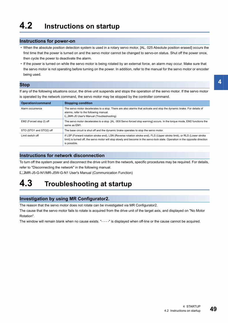
4
4.2 Instructions on startup
Instructions for power-on • When the absolute position detection system is used in a rotary servo motor, [AL. 025 Absolute position erased] occurs the
first time that the power is turned on and the servo motor cannot be changed to servo-on status. Shut off the power once, then cycle the power to deactivate the alarm.
• If the power is turned on while the servo motor is being rotated by an external force, an alarm may occur. Make sure that the servo motor is not operating before turning on the power. In addition, refer to the manual for the servo motor or encoder being used.
StopIf any of the following situations occur, the drive unit suspends and stops the operation of the servo motor. If the servo motor is operated by the network command, the servo motor may be stopped by the controller command.
Instructions for network disconnectionTo turn off the system power and disconnect the drive unit from the network, specific procedures may be required. For details, refer to "Disconnecting the network" in the following manual.MR-J5-G-N1/MR-J5W-G-N1 User's Manual (Communication Function)
4.3 Troubleshooting at startup
Investigation by using MR Configurator2.The reason that the servo motor does not rotate can be investigated via MR Configurator2.The cause that the servo motor fails to rotate is acquired from the drive unit of the target axis, and displayed on "No Motor Rotation".The window will remain blank when no cause exists. "- - - -" is displayed when off-line or the cause cannot be acquired.
Operation/command Stopping conditionAlarm occurrence The servo motor decelerates to a stop. There are also alarms that activate and stop the dynamic brake. For details of
alarms, refer to the following manual.MR-J5 User's Manual (Troubleshooting)
EM2 (Forced stop 2) off The servo motor decelerates to a stop. [AL. 0E6 Servo forced stop warning] occurs. In the torque mode, EM2 functions the same as EM1.
STO (STO1 and STO2) off The base circuit is shut off and the dynamic brake operates to stop the servo motor.
Limit switch off If LSP (Forward rotation stroke end), LSN (Reverse rotation stroke end), FLS (Upper stroke limit), or RLS (Lower stroke limit) is turned off, the servo motor will stop slowly and become in the servo-lock state. Operation in the opposite direction is possible.
4 STARTUP4.2 Instructions on startup 49

50
4.4 Duplicate settingDrive unit parameters for which setting has been completed can be copied to another drive unit. Use this function when replacing the drive unit of equipment with another drive unit during operation, and when starting up multiple devices with the same configuration.
Restrictions■The following data is not duplicated. Set them as required after the duplication.
■The following data is not duplicated. • Alarm history data • Drive recorder data
Duplication using MR Configurator21. The data set in MR Configurator2 can be saved as a project.
2. To copy the project to a different drive unit, open the project and then connect the drive unit and a personal computer via a USB cable. Turn on the drive unit control circuit power supply.
3. Write the required data in MR Configurator2. After the writing is completed, cycle the power or reset the software as necessary.
4.5 Test operationUsing the test operation function enables the machine operation to be checked before the actual operation. With a personal computer and MR Configurator2, operations such as the JOG operation, positioning operation, output signal forced output, and program operation can be performed.
Precautions • The test operation mode is designed for checking servo operation. This mode is not for checking machine operation. Do not
use this mode with the machine. Use this mode only with the servo motor.
Execution methodTest operation mode is enabled by MR Configurator2. To set to the normal operation mode again after executing the test operation mode, cycle the power or reset the software. • Perform the test operation after the forced stop has been released. For details of the forced stop, refer to "Forced stop
deceleration function" in the following manual.MR-J5 User's Manual (Function)
Item DescriptionHoming The information of the home position is not duplicated. Execute homing again.
Machine service life diagnosis Machine service life diagnosis information may not be duplicated. Refer to "Machine diagnosis" in the following manual, and perform required settings.MR-J5 User's Manual (Function)
4 STARTUP4.4 Duplicate setting

4
Test operation modeSetting the drive unit to the test operation mode enables the test operation while the personal computer and drive unit are connected via a USB cable.
1. Turn off the power.
2. Turn "ON (up)" the test operation select switch (SW3-1). When performing test operation with multiple MR-J5D_-_G_ connected to one power regeneration converter unit, turn "ON (up)" the test operation select switch (SW3-1) of all the MR-J5D_-_G_ connected to the power regeneration converter unit.
3. Turn on the power supply of the converter unit and drive unit. Once initialization is complete, the display will change as follows.
4. Use MR Configurator2 to perform the test operation.Page 52 Motor driving by test operation
5. After the test operation is complete, turn off the power and "OFF (down)" the test operation select switch (SW3-1).
1
ON
2 3 4
Set SW3-1 to "ON (up)".
Test operation status display
4 STARTUP4.5 Test operation 51

52
Motor driving by test operation
JOG operationThe JOG operation can be performed when there is no command from the controller. The motor can be operated at the specified speed. Operate the motor using the JOG Mode screen of MR Configurator2.
■Motor operation setting (1)Set the motor speed and acceleration/deceleration time constants for JOG operation. When changing the speed to the permissible speed, set the speed in [Pr. PA28.4 Speed range limit selection].
■Limit switch automatic ON (2)JOG operation can be performed when the limit switch is not connected. Be sure to avoid causing a collision while performing the operation.
■Operation (3)The servo motor can be started (CCW/CW), paused, stopped, or forcibly stopped. Clicking "Start" starts the operation.When "Rotation only while the CCW or CW button is being pushed" is selected, clicking "Forward CCW" or "Reverse CW" will perform operation until "Stop" or "Forced Stop" is clicked.
(1)
(2)
(3)
4 STARTUP4.5 Test operation

4
Positioning operationPositioning operation can be performed without the controller. Operate the motor using the Positioning Mode screen of MR Configurator2.
■Motor operation setting (1)Set the motor speed, acceleration/deceleration time constants, and travel distance in the positioning operation mode. When changing the speed to the permissible speed, set the speed in [Pr. PA28.4 Speed range limit selection].
■Limit switch (2)Select "Limit switch automatic ON" to perform the positioning operation when the limit switch is not connected. Be sure to avoid causing a collision while performing the operation.
■Move until Z-phase signal (3)When "Z-phase signal movement" is selected, the servo motor moves until the first Z-phase signal after positioning operation.
■Operation (4)The servo motor can be started (CCW/CW), paused, stopped, or forcibly stopped. Clicking "Operation Start" starts the operation in the specified operation condition.
■Repeat operation (5)Selecting "Make the repeated operation valid" enables the repeat operation. Selecting "Make the aging function valid" enables the continuous operation until clicking "Stop" or "Forced Stop". Set the repeat pattern, the dwell time, and the number of operations.
■Operation status (6)The operation status during the repeat operation and the number of operations are displayed.
(1)
(2)
(3)
(4)
(5)
(6)
4 STARTUP4.5 Test operation 53

54
Program operationPositioning operation using multiple operation patterns can be performed without a controller. Operate the motor using the Program Operation screen of MR Configurator2. For details, refer to Help of MR Configurator2.
1. Open the Program Operation screen of MR Configurator2.
2. Clicking "Program Edit" in the program operation screen opens the Program Edit screen.Input the program and click "OK". For program commands, refer to Help of MR Configurator2.
No. Item Screen operation(1) Program display Displays the program. To edit the display item, click "Program Edit".
(2) Operation The servo motor can be started (CCW/CW), paused, stopped, or forcibly stopped. Clicking "Operation Start" starts the operation.
(3) Repeat execution Displays the number of execution times. Selecting "Aging function" enables the repeated operation of the operation program.
(1)
(2)
(3)
4 STARTUP4.5 Test operation
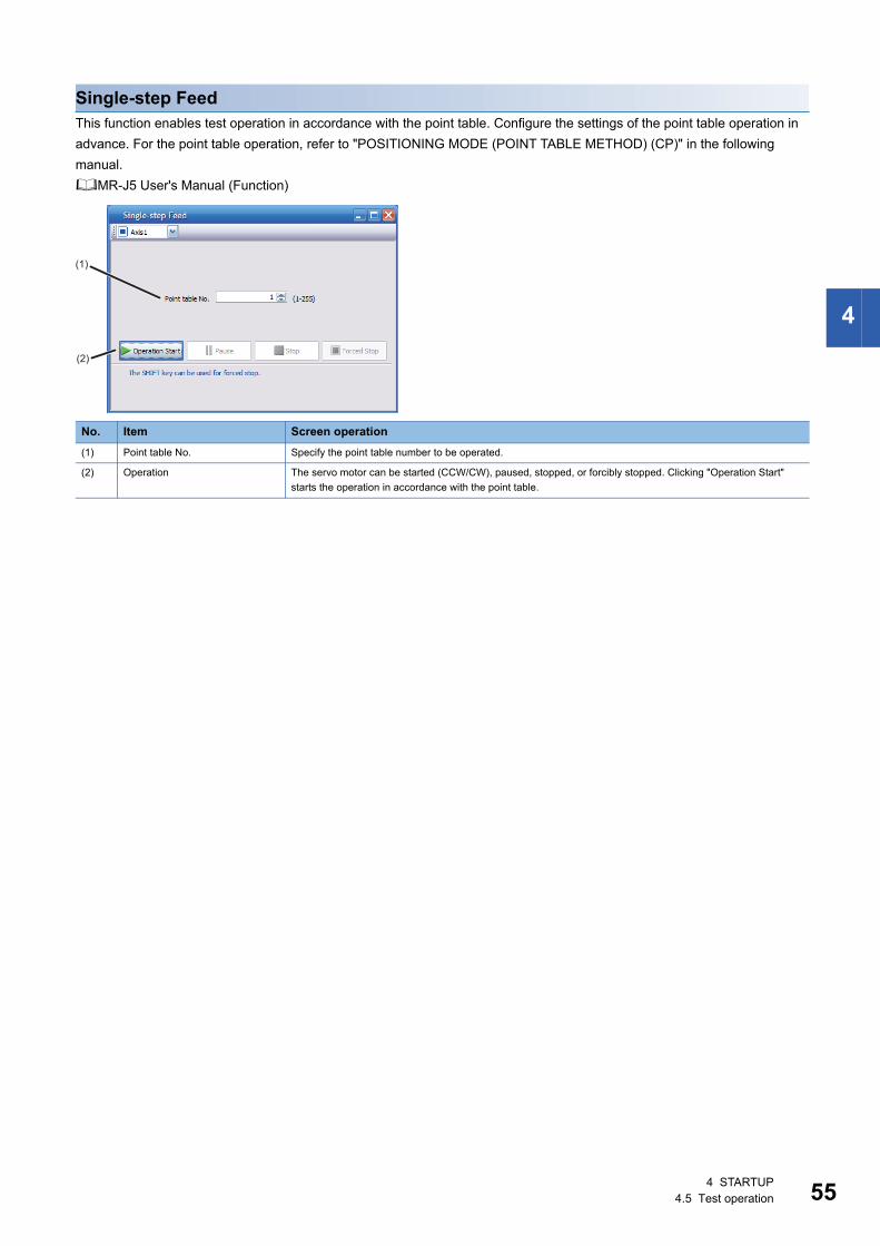
4
Single-step FeedThis function enables test operation in accordance with the point table. Configure the settings of the point table operation in advance. For the point table operation, refer to "POSITIONING MODE (POINT TABLE METHOD) (CP)" in the following manual.MR-J5 User's Manual (Function)
No. Item Screen operation(1) Point table No. Specify the point table number to be operated.
(2) Operation The servo motor can be started (CCW/CW), paused, stopped, or forcibly stopped. Clicking "Operation Start" starts the operation in accordance with the point table.
(1)
(2)
4 STARTUP4.5 Test operation 55

56
Motor-less operation
• The motor-less operation cannot be used in the linear servo motor control mode or direct drive motor control mode.
Without connecting a servo motor to the drive unit, output signals or status displays can be provided in response to the controller commands as if the servo motor is actually running. This operation can be used to check the sequence of a controller. Use this operation after the forced stop has been released. Use this operation with the drive unit connected to the controller.To perform the motor-less operation, set [Pr. PC05.0 Motor-less operation selection] to "1" (enabled). To terminate the motor-less operation, set [Pr. PC05.0] to "0" (disabled).
Load conditionsThe operation is performed in the following conditions. Note that the conditions may differ from those of actual machines.
AlarmIn the motor-less operation, some alarms and warnings are not generated. The following are examples of alarms which do not occur. • [AL. 016 Encoder initial communication error 1] • [AL. 01E Encoder initial communication error 2] • [AL. 01F Encoder initial communication error 3] • [AL. 020 Encoder normal communication error 1] • [AL. 021 Encoder normal communication error 2] • [AL. 025 Absolute position erased] • [AL. 092 Battery cable disconnection warning] • [AL. 09F Battery warning]
Load item ConditionLoad torque 0
Load to motor inertia ratio [Pr. PB06 Load to motor inertia ratio/load to motor mass ratio]
4 STARTUP4.5 Test operation

4
Output signal (DO) forced outputThis function forcibly switches the output signals on and off regardless of the servo status. Use this function for purposes such as checking output signal wiring. Operate this function on the DO Forced Output screen of MR Configurator2.
Each output signal can be turned on/off by clicking the ON/OFF button next to its name. After checking, click "Test Operation Mode Cancel" and terminate the output signal (DO) forced output.
4 STARTUP4.5 Test operation 57
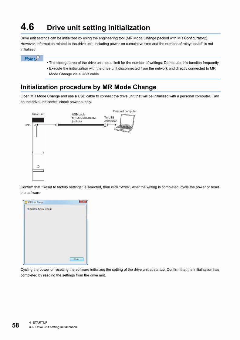
58
4.6 Drive unit setting initializationDrive unit settings can be initialized by using the engineering tool (MR Mode Change packed with MR Configurator2).However, information related to the drive unit, including power-on cumulative time and the number of relays on/off, is not initialized.
• The storage area of the drive unit has a limit for the number of writings. Do not use this function frequently. • Execute the initialization with the drive unit disconnected from the network and directly connected to MR
Mode Change via a USB cable.
Initialization procedure by MR Mode ChangeOpen MR Mode Change and use a USB cable to connect the drive unit that will be initialized with a personal computer. Turn on the drive unit control circuit power supply.
Confirm that "Reset to factory settings" is selected, then click "Write". After the writing is completed, cycle the power or reset the software.
Cycling the power or resetting the software initializes the setting of the drive unit at startup. Confirm that the initialization has completed by reading the settings from the drive unit.
CN5
Personal computerUSB cable MR-J3USBCBL3M (option)
To USB connector
Drive unit
4 STARTUP4.6 Drive unit setting initialization

5
5 MAINTENANCE, INSPECTION AND PARTS REPLACEMENT
5.1 Inspection itemsPrecautions
• Do not disassemble, repair, or modify the product. • For repair and parts replacement, contact your local sales office. • To prevent a malfunction, do not perform an insulation resistance test (megger test) on the drive unit.
Periodic inspectionPerform the following inspections. • Check for loose terminal block screws. Retighten any loose screws. • Check the cables and the like for scratches or cracks. Inspect them periodically according to operating conditions
especially when the servo motor is movable. • Check that the connector is securely connected to the drive unit. • Check that the wires are not coming out from the connector. • Check for dust accumulation on the drive unit. • Check for unusual noise generated from the drive unit. • Make sure that the emergency stop circuit operates properly such that an operation can be stopped immediately and a
power is shut off by the emergency stop switch.
5.2 Parts with a service lifeThe service life of the following parts is listed below. In addition, the service life varies depending on the operating methods and environment. If any fault is found in a part, it is necessary to replace it immediately regardless of its service life. For parts replacement, please contact your local sales office.
Relays A relay will reach the end of its service life if the following actions are performed a total of 100,000 times: powering on the drive unit, inputting the dynamic brake stop, and inputting the forced stop. In addition, the service life of a relay may vary depending on the power supply capacity.
Drive unit cooling fanThe cooling fan bearings will reach the end of their service life in 50,000 hours to 70,000 hours. Therefore, the cooling fan must be replaced after seven to eight years of continuous operation as a guideline. If unusual noise or vibration is found during inspection, the cooling fan must also be replaced. The service life has been calculated in an environment which contains no corrosive gas, flammable gas, oil mist, or dust. The average annual ambient temperature was 40 ˚C.
Part name Recommended service lifeRelay Total number of power-ons, stops by a dynamic brake, and forced stops:
100,000 times
Cooling fan 50,000 hours to 70,000 hours (7 to 8 years)
5 MAINTENANCE, INSPECTION AND PARTS REPLACEMENT5.1 Inspection items 59

60
5.3 Replacing fan unitThe internal circuits of the drive unit may be damaged by static electricity. Take the following precautions. • Ensure that the work bench and your body are grounded. • Do not directly touch conductive areas such as the connector pins and electrical parts.The fan unit is composed of a cooling fan and its cover.
List of applicable fan units
Replacement procedureFor the replacement procedure of fan units, refer to "Fan unit replacement procedure" in the following manual.MR-J5D User's Manual (Hardware)
Drive unit Fan unitsMR-J5D1-500G4-N1MR-J5D1-700G4-N1MR-J5D2-200G4-N1MR-J5D2-350G4-N1MR-J5D3-200G4-N1
MR-J5D-FAN1
MR-J5D2-500G4-N1MR-J5D2-700G4-N1
MR-J5D-FAN2
5 MAINTENANCE, INSPECTION AND PARTS REPLACEMENT5.3 Replacing fan unit

6
6 COMPLIANCE WITH GLOBAL STANDARDSConverter units and drive units refer to servo amplifiers in this chapter.
6.1 Compliance with global standardsRefer to the following manual for information about compliance with global standards.Safety Instructions and Precautions for MR-J5D AC Servos (IB(NA)-0300527)
6.2 Handling of AC servo amplifier batteries for the United Nations Recommendations on the Transport of Dangerous Goods
Rev. 15 (2007) of United Nations Recommendations on the Transport of Dangerous Goods (hereinafter Recommendations of the United Nations) was published. To reflect the Recommendations, transport regulations for lithium metal batteries are partially revised in the Technical Instruction (ICAO-TI) by the International Civil Aviation Organization (ICAO) and the International Maritime Dangerous Goods Code (IMDG Code) by the International Maritime Organization (IMO).To comply with the ICAO-TI and the IMDG Code, we have modified the indication on the package for AC servo batteries.The above change will not affect the function or performance of the product.
Target model■Battery (cell)
■Battery unit (assembled)
PurposeTo enable safer transportation of lithium metal batteries.
Change in regulationsThe following points have been changed for lithium metal batteries transportation by sea or air based on the IATA Dangerous Goods Regulations 54th edition effective January 1, 2013 in addition to the revision of the Recommendations of the United Nations Rev. 15 and the ICAO-TI 2009-2010 Edition. For lithium metal batteries, battery cells alone are classified as UN3090, and batteries assembled or packed with equipment are classified as UN3091.
Model Option model Type Lithium content Mass of battery RemarkER6 MR-J3BAT Cell 0.65 g 16 g Each battery (cell) contains more than 0.3 grams of
lithium content and must be handled as dangerous goods (Class 9) for certain packaging requirements.
ER17330 MR-BAT Cell 0.48 g 13 g
A6BAT Cell 0.48 g 13 g
Model Option model Type Lithium content Mass of battery RemarkER6 MR-J2M-BT Assembled
battery (Seven cells)
4.55 g 112 g The assembled battery contains more than two grams of lithium content and must be handled as dangerous goods (Class 9) regardless of packaging requirements.
CR17335A MR-BAT6V1 Assembled battery (Two cells)
1.20 g 34 g Each battery (cell) contains more than 0.3 grams of lithium content and must be handled as dangerous goods (Class 9) for certain packaging requirements.
MR-BAT6V1SET(-A) Assembled battery (Two cells)
1.20 g 34 g
MR-BAT6V1BJ Assembled battery (Two cells)
1.20 g 34 g
6 COMPLIANCE WITH GLOBAL STANDARDS6.1 Compliance with global standards 61

62
■Transportation of lithium metal batteries alone
■Transportation of lithium metal batteries packed with or contained in equipment • For batteries packed with equipment, follow the necessary requirements of UN3091 PI969. Batteries are classified into
either Section /Section depending on the lithium content/packaging requirements. • For batteries assembled in equipment, follow the necessary requirements of UN3091 PI970. Batteries are classified into
either Section /Section depending on the lithium content/packaging requirements. The special handling may be unnecessary depending on the number of batteries and gross mass per package.
Ex.
Mitsubishi Electric label with battery illustration
■Details of the package changeThe following caution has been added to the packages of the corresponding batteries."Containing lithium metal battery. Regulations apply for transportation."
■Transportation precaution for customersFor sea or air transportation, the handling label (above Fig.) must be attached to the package of a Mitsubishi Electric cell or battery. In addition, attaching the label to the outer package of an overpack containing several packages by Mitsubishi Electric is also required. When the content of a package must be handled as dangerous goods (Class 9), the Shipper's Declaration for Dangerous Goods is required, and the package must be compliant with Class 9 Packages. Documentation like the handling label in the specified design and the Shipper's Declaration for Dangerous Goods are required for transportation. Please attach the documentation to the packages and the outer package of the overpack.
The requirements of the IATA Dangerous Goods Regulations are subject to change according to the annual revision. When customers transport lithium batteries by themselves, the responsibility for the cargo lies with the customers. Thus, be sure to check the latest version of the IATA Dangerous Goods Regulations.
Packaging requirements Classification Main requirementsEight cells or fewer per package with one gram or less of lithium content per cell
UN3090 PI968 Section The package must pass a 1.2 m drop test, and a handling label with a battery illustration (size: 120 110 mm) must be attached to the package.Two or fewer assembled batteries per package with two grams or
less of lithium content per battery
More than eight cells per package with one gram or less of lithium content per cell
UN3090 PI968 Section IB The package must pass a 1.2 m drop test, and a handling label with a battery illustration (size: 120 110 mm) must be attached to the package.The batteries must be handled according to Class 9 Dangerous Goods Regulations -e.g., attaching the Class 9 hazard label.
More than two assembled batteries per package with two grams or less of lithium content per battery
Cells with more than one gram of lithium content per cell UN3090 PI968 Section IA The package must comply with Class 9 Packages and be handled according to Class 9 Dangerous Goods Regulations -e.g., attaching the Class 9 hazard label.
Assembled batteries with more than two grams of lithium content per battery
* UN number (s)** Telephone number for additional informationExample of Mitsubishi Electric label with battery illustration(Available from January 1, 2017)
6 COMPLIANCE WITH GLOBAL STANDARDS6.2 Handling of AC servo amplifier batteries for the United Nations Recommendations on the Transport of Dangerous Goods

6
6.3 Symbol for the new EU Battery DirectiveThe symbol for the new EU Battery Directive (2006/66/EC) that is plastered to the AC servo battery is explained here.
• This mark is valid only in EU.
This mark is in accordance with directive 2006/66/EC Article 20 "Information for end-users" and Annex .MITSUBISHI ELECTRIC products are designed and manufactured with high quality materials and components which can be recycled and/or reused.This symbol means that batteries and accumulators, at their end-of-life, should be disposed of separately from household waste.If a chemical symbol is shown beneath the above symbol, a heavy metal of the corresponding chemical symbol is contained in the battery or the accumulator with the following standard concentration or more.This will be indicated as follows.Hg: mercury (0.0005 %), Cd: cadmium (0.002 %), Pb: lead (0.004 %)In the European Union, there are separate collection systems for used batteries and accumulators. Batteries and accumulators must be disposed of properly.Help us to conserve the environment we live in.
6 COMPLIANCE WITH GLOBAL STANDARDS6.3 Symbol for the new EU Battery Directive 63

64
6.4 Compliance with China Compulsory Certification (CCC)
IntroductionSome products are required to comply with China Compulsory Certification (hereinafter referred to as CCC) if exported, distributed, or sold to China. An outline of CCC is explained in this section. Mitsubishi Electric servo products are not subject to CCC.
Outline of CCCCCC is a system for product certification that has been in effect in China since August 2003, the purpose of which is to protect consumers and ensure safety domestically in China. The certification system currently has five types of certification: safety, electromagnetic compatibility (EMC), safety + EMC, fire-fighting equipment, and wireless LAN. Products subject to the certification are allowed to be exported, distributed, or sold to China only if they are certified by this system.Products that have received certification proving compliance with the relevant technical standards (or products declared by the manufacturer as being compliant) must carry the specified mark (CCC mark). Many of the technical standards to be applied are GB standards (Chinese national standards), which comply with global standards such as those set forth by the IEC (International Electrotechnical Commission) and CISPR (International Special Committee on Radio Interference).
Judgment20 product groups divided into 158 categories are specified as the subject products (announcement No. 45, 2014). The following table shows whether the servo products are required to comply with CCC.
*1 Small capacity motors with a capacity of 750 W or lower are included in the catalog of products subject to CCC, but the requirements do not apply to our products for the following reasons:Explosion proof motors and controlled motors (servo motors, stepping motors, etc.) are excluded from the subject small capacity motors.
*2 Mitsubishi Electric option cables use the wires that is not classified into the cable category in the catalog.
Product JudgmentAC servo amplifier Not subject
AC servo motor *1 Not subject
Options *2 Not subject
CCC mark
6 COMPLIANCE WITH GLOBAL STANDARDS6.4 Compliance with China Compulsory Certification (CCC)

6
6.5 Compliance with the China RoHS directive
OutlineThe China RoHS directive: (Management Methods for Controlling Pollution by Electronic Information Products) came into effect on March 1, 2007. The China RoHS directive was replaced by the following China RoHS directive: (Management Methods for the Restriction of the Use of Hazardous Substances in Electrical and Electronic Products). The succeeding China RoHS directive has been in effect since July 1, 2016.The China RoHS directive restricts the following hazardous substances: six hazardous substances (lead, mercury, cadmium, hexavalent chromium, polybrominated biphenyls (PBB), and polybrominated diphenyl ethers (PBDE)) which are also restricted by EU RoHS 2 (directive 2011/65/EU), and other hazardous substances specified by the State (currently no applicable substances).
Status of our products for compliance with the China RoHS directiveThe following table shows the logo types for the environmental protection use period, and whether the six hazardous substances are contained in our products or not. This table was created based on the standard SJ/T11364.
*1 : Indicates that said hazardous substance contained in all of the homogeneous materials for this part is below the limit requirement of GB/T26572.: Indicates that said hazardous substance contained in at least one of the homogeneous materials for this part is above the limit requirement of GB/T26572.
*2 Indications based on "Marking for the restriction of the use of hazardous substances in electrical and electronic products" [SJ/T11364-2014]
Part name Hazardous substance (substance/threshold/standard) *1 Logo for environmental protection use period *2
Remark
Lead(Pb)
Mercury(Hg)
Cadmium(Cd)
Hexavalent chromium(Cr(VI))
PBB PBDE
Threshold: cadmium: 0.01 wt% (100 ppm), other than cadmium: 0.1 wt% (1000 ppm)
Servo amplifierServo system controllerConverter unitDrive unit
Mounting board
Heat sink
Resin cabinet
Plate and screw
Servo motor Bracket
Mounting board
Resin cabinet
Core and cable
Cable product Wire Including connector setConnector
Optional unit Mounting board
Resin cabinet
Plate and screw
Indicates that a certain hazardous substance is contained in the product manufactured or sold in China.Follow safety and usage precautions for the product, and use the product within a limited number of years from the production date. Doing so prevents any hazardous substances in the product from causing environmental pollution or seriously affecting human health or property.
Indicates that no certain hazardous substance is contained in the product.
电子信息产品污染控制管理办法
电器电子产品有害物质限制使用管理办法
6 COMPLIANCE WITH GLOBAL STANDARDS6.5 Compliance with the China RoHS directive 65
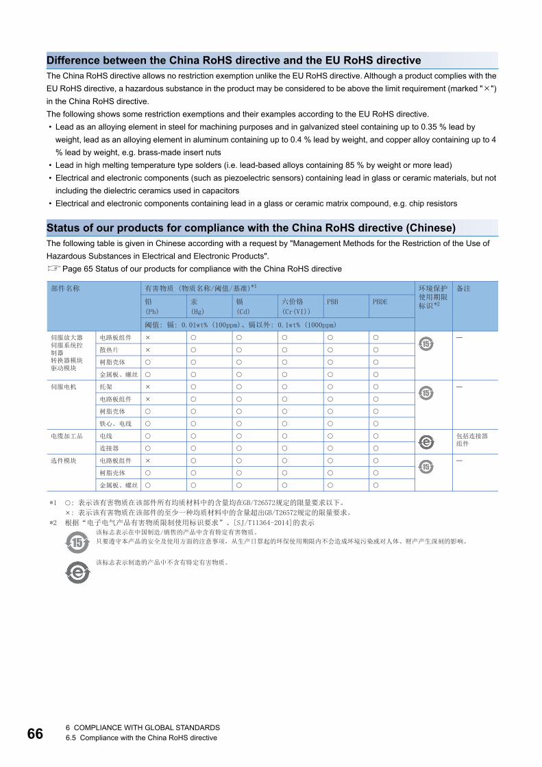
66
Difference between the China RoHS directive and the EU RoHS directiveThe China RoHS directive allows no restriction exemption unlike the EU RoHS directive. Although a product complies with the EU RoHS directive, a hazardous substance in the product may be considered to be above the limit requirement (marked "") in the China RoHS directive.The following shows some restriction exemptions and their examples according to the EU RoHS directive. • Lead as an alloying element in steel for machining purposes and in galvanized steel containing up to 0.35 % lead by
weight, lead as an alloying element in aluminum containing up to 0.4 % lead by weight, and copper alloy containing up to 4 % lead by weight, e.g. brass-made insert nuts
• Lead in high melting temperature type solders (i.e. lead-based alloys containing 85 % by weight or more lead) • Electrical and electronic components (such as piezoelectric sensors) containing lead in glass or ceramic materials, but not
including the dielectric ceramics used in capacitors • Electrical and electronic components containing lead in a glass or ceramic matrix compound, e.g. chip resistors
Status of our products for compliance with the China RoHS directive (Chinese)The following table is given in Chinese according with a request by "Management Methods for the Restriction of the Use of Hazardous Substances in Electrical and Electronic Products".Page 65 Status of our products for compliance with the China RoHS directive
部件名称 有害物质 (物质名称/阈值/基准)*1 环境保护使用期限标识*2
备注
铅
(Pb)
汞
(Hg)
镉
(Cd)
六价铬
(Cr(VI))
PBB PBDE
阈值: 镉: 0.01wt% (100ppm)、镉以外: 0.1wt% (1000ppm)
伺服放大器伺服系统控制器转换器模块驱动模块
电路板组件
散热片
树脂壳体
金属板、螺丝
托架伺服电机
电路板组件
树脂壳体
铁心、电线
电缆加工品 电线 包括连接器组件
连接器
选件模块 电路板组件
树脂壳体
金属板、螺丝
*1 : 表示该有害物质在该部件所有均质材料中的含量均在GB/T26572规定的限量要求以下。
: 表示该有害物质在该部件的至少一种均质材料中的含量超出GB/T26572规定的限量要求。
*2 根据“电子电气产品有害物质限制使用标识要求”、[SJ/T11364-2014]的表示
该标志表示在中国制造/销售的产品中含有特定有害物质。
只要遵守本产品的安全及使用方面的注意事项,从生产日算起的环保使用期限内不会造成环境污染或对人体、财产产生深刻的影响。
该标志表示制造的产品中不含有特定有害物质。
6 COMPLIANCE WITH GLOBAL STANDARDS6.5 Compliance with the China RoHS directive

7
7 SERVO PARAMETERS
Refer to the following manual for the parameters not described in this chapter.MR-J5-G/MR-J5W-G User's Manual (Parameters)
7.1 Basic setting servo parameters group ([Pr. PA_ _ ])[Pr. PA01_Operation mode (**STY)]
[Pr. PA01.0_Control mode selection]
Select a control mode.0: Network standard mode6: Positioning mode (point table method)
Setting a value other than "0" and "6" triggers [AL. 037 Parameter error].
[Pr. PA01.1_Operation mode selection]
0: Standard control mode4: Linear servo motor control mode6: Direct drive motor control mode
[Pr. PA01.4_Fully closed loop operation mode selection]
Select whether to enable or disable the fully closed loop control mode.The external encoder communication method of four-wire type cannot be used in the fully closed loop control mode on the MR-J5D2-_G_-N1. In that case, use the MR-J5D1-_G_-N1.When this servo parameter is set to "1" in the linear servo motor control mode, [AL. 037 Parameter error] occurs.Setting "1" on the MR-J5D3-_G_-N1 triggers [AL. 037].0: Disabled (semi closed loop control mode)1: Enabled (fully closed loop control mode)
[Pr. PA01.7_For manufacturer setting]This servo parameter is for manufacturer setting.
Initial value Setting range Setting method Ver.00003000h Refer to the relevant detail No. Each axis Refer to the relevant detail No.
Initial value Setting range Ver.0h Refer to the text B8
Supported control mode
[Pr. PA01.0] = "0" [Pr. PA01.0] = "6"csp/csv/cst/pp/pv/tq/hm pt/jg/hm
Initial value Setting range Ver.0h Refer to the text A0
Initial value Setting range Ver.0h Refer to the text A5
7 SERVO PARAMETERS7.1 Basic setting servo parameters group ([Pr. PA_ _ ]) 67

68
7.2 Gain/filter setting servo parameters group ([Pr. PB_ _ ])
[Pr. PB03_For manufacturer setting]This servo parameter is for manufacturer setting.
[Pr. PB82_Position command smoothing filtering time constant (PFT)]
Set the position command smoothing filtering time constant.This servo parameter can be used when [Pr. PB81.4 Position command smoothing filter] is set to "1" (enabled).
Initial value Setting range Setting method Ver.0.0 [ms] 0.0 to 100.0 Each axis A5
7 SERVO PARAMETERS7.2 Gain/filter setting servo parameters group ([Pr. PB_ _ ])

7
7.3 Extension setting servo parameters group ([Pr. PC_ _ ])
[Pr. PC42_Function selection C-10 (COP10)]
[Pr. PC42.0_Forward/Reverse rotation torque limit 2 selection]
Enable or disable the torque limit value switching which is performed by CPTL (bit 11 of [Controlword (Obj. 6040h)]) and by CNTL (bit 12 of [Controlword]).0: Disabled1: EnabledFor the combinations of servo parameters and objects that are switched by CPTL/CNTL, refer to the following table.
This servo parameter corresponds to [Positive/Negative torque limit 2 select (Obj. 2D6Dh: 01h)].
[Pr. PC43_Forward rotation torque limit 2 (TLP2)]
The torque or thrust generated by the servo motor can be limited.Set this servo parameter in relation to the rated torque or continuous thrust (= 100.0 %). Set the servo parameter when limiting the torque of the servo motor for CCW power running or CW regeneration, or when limiting the thrust of the linear servo motor for positive direction power running or negative direction regeneration. If this servo parameter is set to "0.0", the servo motor does not generate torque or thrust.The polarity of the torque limit can be changed with the setting values of [Pr. PA14 Travel direction selection] and [Pr. PC29.3 Torque POL reflection selection].This servo parameter corresponds to [Positive torque limit value 2 (Obj. 2D6Dh: 02h)].Depending on the settings in [Pr. PC29] and [Pr. PA14], the corresponding object changes to [Negative torque limit value 2 (Obj. 2D6Dh: 03h)].If a value larger than the maximum torque or maximum thrust of the servo motor is set, the value will be limited to the maximum torque or maximum thrust of the servo motor.
Initial value Setting range Setting method Ver.00000000h Refer to the relevant detail No. Each axis Refer to the relevant detail No.
Initial value Setting range Ver.0h Refer to the text A5
[Pr. PC42.0]/[Positive/Negative torque limit 2 select (Obj. 2D6Dh: 01h)]
Forward rotation torque limit value Reverse rotation torque limit value
CPTL: 0 CPTL: 1 CNTL: 0 CNTL: 1
0h/0000h
[Pr. PA11]/[Positive torque limit value (Obj. 60E0h)]
[Pr. PA11]/[Positive torque limit value (Obj. 60E0h)]
[Pr. PA12]/[Negative torque limit value (Obj. 60E1h)]
[Pr. PA12]/[Negative torque limit value (Obj. 60E1h)]
1h/0001h
[Pr. PA11]/[Positive torque limit value (Obj. 60E0h)]
[Pr. PC43]/[Positive torque limit value2 (Obj. 2D6Dh: 02h)]
[Pr. PA12]/[Negative torque limit value (Obj. 60E1h)]
[Pr. PC44]/[Negative torque limit value2 (Obj. 2D6Dh: 03h)]
Initial value Setting range Setting method Ver.1000.0 [%] 0.0 to 1000.0 Each axis A5
7 SERVO PARAMETERS7.3 Extension setting servo parameters group ([Pr. PC_ _ ]) 69
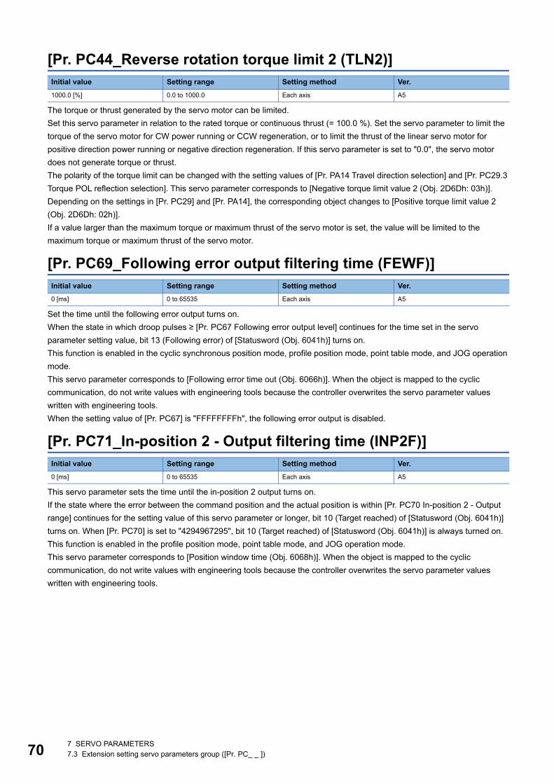
70
[Pr. PC44_Reverse rotation torque limit 2 (TLN2)]
The torque or thrust generated by the servo motor can be limited.Set this servo parameter in relation to the rated torque or continuous thrust (= 100.0 %). Set the servo parameter to limit the torque of the servo motor for CW power running or CCW regeneration, or to limit the thrust of the linear servo motor for positive direction power running or negative direction regeneration. If this servo parameter is set to "0.0", the servo motor does not generate torque or thrust.The polarity of the torque limit can be changed with the setting values of [Pr. PA14 Travel direction selection] and [Pr. PC29.3 Torque POL reflection selection]. This servo parameter corresponds to [Negative torque limit value 2 (Obj. 2D6Dh: 03h)].Depending on the settings in [Pr. PC29] and [Pr. PA14], the corresponding object changes to [Positive torque limit value 2 (Obj. 2D6Dh: 02h)].If a value larger than the maximum torque or maximum thrust of the servo motor is set, the value will be limited to the maximum torque or maximum thrust of the servo motor.
[Pr. PC69_Following error output filtering time (FEWF)]
Set the time until the following error output turns on.When the state in which droop pulses ≥ [Pr. PC67 Following error output level] continues for the time set in the servo parameter setting value, bit 13 (Following error) of [Statusword (Obj. 6041h)] turns on.This function is enabled in the cyclic synchronous position mode, profile position mode, point table mode, and JOG operation mode.This servo parameter corresponds to [Following error time out (Obj. 6066h)]. When the object is mapped to the cyclic communication, do not write values with engineering tools because the controller overwrites the servo parameter values written with engineering tools.When the setting value of [Pr. PC67] is "FFFFFFFFh", the following error output is disabled.
[Pr. PC71_In-position 2 - Output filtering time (INP2F)]
This servo parameter sets the time until the in-position 2 output turns on.If the state where the error between the command position and the actual position is within [Pr. PC70 In-position 2 - Output range] continues for the setting value of this servo parameter or longer, bit 10 (Target reached) of [Statusword (Obj. 6041h)] turns on. When [Pr. PC70] is set to "4294967295", bit 10 (Target reached) of [Statusword (Obj. 6041h)] is always turned on.This function is enabled in the profile position mode, point table mode, and JOG operation mode.This servo parameter corresponds to [Position window time (Obj. 6068h)]. When the object is mapped to the cyclic communication, do not write values with engineering tools because the controller overwrites the servo parameter values written with engineering tools.
Initial value Setting range Setting method Ver.1000.0 [%] 0.0 to 1000.0 Each axis A5
Initial value Setting range Setting method Ver.0 [ms] 0 to 65535 Each axis A5
Initial value Setting range Setting method Ver.0 [ms] 0 to 65535 Each axis A5
7 SERVO PARAMETERS7.3 Extension setting servo parameters group ([Pr. PC_ _ ])
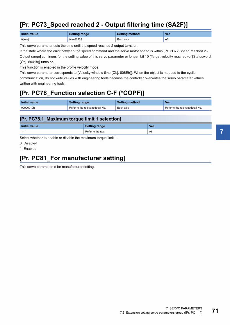
7
[Pr. PC73_Speed reached 2 - Output filtering time (SA2F)]
This servo parameter sets the time until the speed reached 2 output turns on.If the state where the error between the speed command and the servo motor speed is within [Pr. PC72 Speed reached 2 - Output range] continues for the setting value of this servo parameter or longer, bit 10 (Target velocity reached) of [Statusword (Obj. 6041h)] turns on.This function is enabled in the profile velocity mode.This servo parameter corresponds to [Velocity window time (Obj. 606Eh)]. When the object is mapped to the cyclic communication, do not write values with engineering tools because the controller overwrites the servo parameter values written with engineering tools.
[Pr. PC78_Function selection C-F (*COPF)]
[Pr. PC78.1_Maximum torque limit 1 selection]
Select whether to enable or disable the maximum torque limit 1.0: Disabled1: Enabled
[Pr. PC81_For manufacturer setting]This servo parameter is for manufacturer setting.
Initial value Setting range Setting method Ver.0 [ms] 0 to 65535 Each axis A5
Initial value Setting range Setting method Ver.00000010h Refer to the relevant detail No. Each axis Refer to the relevant detail No.
Initial value Setting range Ver.1h Refer to the text A5
7 SERVO PARAMETERS7.3 Extension setting servo parameters group ([Pr. PC_ _ ]) 71

72
7.4 Extension setting 2 servo parameters group ([Pr. PE_ _ ])
[Pr. PE53_Maximum torque limit 1 (TLMX1)]
The torque or thrust generated by the servo motor can be limited.When [Pr. PC78.1 Maximum torque limit 1 selection] is set to "0" (the maximum torque limit 1 is disabled)The torque limit function using this servo parameter or [Max torque (Obj. 6072h)] is disabled.The setting value of this servo parameter does not match the setting value of [Max torque (Obj. 6072h)].[Max torque (Obj. 6072h)] returns the maximum torque of the servo motor.When [Pr. PC78.1] is set to "1" (the maximum torque limit 1 is enabled)The torque limit function using this servo parameter or [Max torque (Obj. 6072h)] is enabled.Set this servo parameter in relation to the rated torque or continuous thrust (= 100.0 %).If this servo parameter is set to "0.0", the servo motor does not generate torque or thrust.This servo parameter corresponds to [Max torque (Obj. 6072h)].When the object is mapped to the cyclic communication, do not write values with engineering tools because the controller overwrites the servo parameter values written with engineering tools.
Initial value Setting range Setting method Ver.1000.0 [%] 0.0 to 1000.0 Each axis A5
7 SERVO PARAMETERS7.4 Extension setting 2 servo parameters group ([Pr. PE_ _ ])

7
7.5 Positioning control setting servo parameters group ([Pr. PT_ _ ])
[Pr. PT01_Command mode selection (**CTY)]
[Pr. PT01.1_Speed/acceleration/deceleration unit selection]
Select the unit of speed and the unit of acceleration/deceleration.This function is enabled in the cyclic synchronous mode, profile mode, and positioning mode (point table method).
*1 In the linear servo motor control mode, the unit is mm/s.*2 The command unit can be changed to 0.001 mm, 0.0001 inch, 0.001 degree, or pulses with [Pr. PT01.2 Unit for position data]. The
actual servo motor speed (encoder pulse unit) is calculated by multiplying the set speed data by the electronic gear ratio.The speed of point table and the unit of acceleration/deceleration are changed depending on the setting value of this servo parameter. When the unit is changed, review and reset the point table setting value.Servo parameters to be enabled by this servo parameter vary depending on whether the setting value of this servo parameter is "0" or "1". Refer to the following table.
Initial value Setting range Setting method Ver.00000300h Refer to the relevant detail No. Each axis Refer to the relevant detail No.
Initial value Setting range Ver.1h Refer to the text A5
Setting value Speed Acceleration/deceleration0 r/min, mm/s *1 ms
1 Command unit/s *2 Command unit/s2 *2
Setting value Object interlocked with servo parameter
0 1[Pr. PT65 Profile speed command] [Pr. PV01 Profile speed command extension
setting][Profile velocity (Obj. 6081h)]
[Pr. PT66 Maximum profile speed] [Pr. PV03 Maximum profile speed extension setting]
[Max profile velocity (Obj. 607Fh)]
[Pr. PT49 Speed acceleration time constant] [Pr. PV05 Profile acceleration] [Profile acceleration (Obj. 6083h)]
[Pr. PT50 Speed deceleration time constant] [Pr. PV07 Profile deceleration] [Profile deceleration (Obj. 6084h)]
[Pr. PC24 Deceleration time constant at forced stop]
[Pr. PV09 Deceleration at forced stop] [Quick stop deceleration (Obj. 6085h)]
[Pr. PT05 Homing speed] [Pr. PV11 Homing speed extension setting] [Speed during search for zero (Obj. 6099h: 2h)]
[Pr. PT06 Creep speed] [Pr. PV13 Creep speed extension setting] [Speed during search for switch (Obj. 6099h: 1h)]
[Pr. PT56 Homing acceleration time constant] [Pr. PV15 Homing acceleration] [Homing acceleration (Obj. 609Ah)]
[Pr. PT57 Homing deceleration time constant] [Pr. PV17 Homing deceleration]
[Pr. PC72 Speed reached 2 - Output range] [Pr. PV19 Speed reached 2 - Output range - Extension setting]
[Velocity window (Obj. 606Dh)]
[Pr. PC65 Zero speed 2 level] [Pr. PV20 Zero speed 2 level extension setting] [Velocity threshold (Obj. 606Fh)]
[Pr. PT67 Speed limit] [Pr. PV21 Speed limit extension setting] [Velocity limit value (Obj. 2D20h)]
7 SERVO PARAMETERS7.5 Positioning control setting servo parameters group ([Pr. PT_ _ ]) 73

74
[Pr. PT01.2_Unit for position data]
0: mm1: inch2: degree3: pulseIf this servo parameter is changed, perform homing.The compatible control modes and firmware versions are as follows.
*1 If [Pr. PA01.4 Fully closed loop operation mode selection] is set to "1" (enabled), use a rotary encoder as the load-side encoder. Connecting a linear encoder will trigger [AL. 037 Parameter error].
*2 If [Pr. PA01.1 Operation mode selection] is set to "4" (linear servo motor control mode), [AL. 037] will occur.*3 If this parameter is set to "2", the control mode cannot be switched to the cyclic synchronous mode.*4 Setting this value in a control mode other than the positioning mode (point table method) will cause [AL. 037].
[Pr. PT53_Torque slope (TQS)]
Set the rate of change in the torque command per second.When "0.0" is set, the torque slope is disabled.This function is enabled in the profile torque mode.This function corresponds to [Torque slope (Obj. 6087h)].When the object is mapped to the cyclic communication, do not write values with engineering tools because the controller overwrites the servo parameter values written with engineering tools.
Initial value Setting range Ver.3h Refer to the text B6
Control mode Setting value
0 (mm) *4 1 (inch) *4 2 (degree) *1*2 3 (pulse)Cyclic synchronous mode *3 A0
Profile mode B6 A5
Positioning mode (point table method) B8 B8 B8 B8
Initial value Setting range Setting method Ver.100.0 [%/s] 0.0 to 1000000.0 Each axis A5
7 SERVO PARAMETERS7.5 Positioning control setting servo parameters group ([Pr. PT_ _ ])

7
7.6 Network setting servo parameters group ([Pr. PN_ _ ])
[Pr. PN02_For manufacturer setting]This servo parameter is for manufacturer setting.
[Pr. PN05_For manufacturer setting]This servo parameter is for manufacturer setting.
[Pr. PN07_Communication cycle initial setting (**CCS)]
The initial value of the communication cycle in the PDO communication can be set.Use this servo parameter when [Cycle Time (Obj. 1C32h: 02h)] and [Cycle Time (Obj. 1C33h: 02h)] are not to be set with the master controller (asynchronous mode). This servo parameter setting is not required for master controllers that can change the communication cycle with the objects in the asynchronous mode.The setting value of this servo parameter will be set in [Cycle Time (Obj. 1C32h: 02h)] and [Cycle Time (Obj. 1C33h: 02h)] as the initial value. Once this servo parameter is set to "0", the objects will be set to "250000 ns (250 μs)". Setting an unsupported communication cycle triggers [AL. 037 Parameter error].
[Pr. PN13_For manufacturer setting]This servo parameter is for manufacturer setting.
Initial value Setting range Setting method Ver.00000000h Refer to the text Common B6
Setting value Communication cycle00 Automatic (250 μs)
04 125 μs
05 250 μs
06 500 μs
07 1 ms
08 2 ms
09 4 ms
0A 8 ms
7 SERVO PARAMETERS7.6 Network setting servo parameters group ([Pr. PN_ _ ]) 75

76
[Pr. PN18_Counter level for communication error detection (CERN)]
Set the threshold until [AL. 086.1 Network receive data error (Network communication error 1)] is detected.When "0" is set, this parameter is disabled.If the PDO data is not updated with Sync0, the internal error counter will be added by 3 at a time.When the PDO data is updated properly, the internal error counter is subtracted by 1.Refer to the following for the example of the counter.
This servo parameter corresponds to [Sync Error Counter Limit (Obj. 10F1h: 02h)].If detection of [AL. 086.1] is disabled, the servo motor cannot be stopped at occurrence of a communication error. In addition, if the setting value is increased, it takes longer for the servo motor to stop at occurrence of a communication error. Be careful when changing the set value as there is a danger of collision.
[Pr. PN20_For manufacturer setting]This servo parameter is for manufacturer setting.
[Pr. PN22_For manufacturer setting]This servo parameter is for manufacturer setting.
Initial value Setting range Setting method Ver.9 0 to 32767 Common A5
Receive (SM2) Event 1 0 1 0 1 0 1 0 1 0 1Internal Error Counter(Setting value = 9)
0 3 2 5 4 7 6 9(error)
9 9 9
7 SERVO PARAMETERS7.6 Network setting servo parameters group ([Pr. PN_ _ ])

7
7.7 Positioning extension setting servo parameters group ([Pr. PV_ _ ])
[Pr. PV23_Speed unit conversion - Electronic gear - Numerator (*VCMX)]
Set the electric gear numerator for converting the speed (command unit/s) into a value in speed units.This function is enabled when [Pr. PT01.1 Speed/acceleration/deceleration unit selection] is set to "1".
[Pr. PV24_Speed unit conversion - Electronic gear - Denominator (*VCDV)]
Set the electric gear denominator for converting the speed command (command unit/s) into a value in speed units.This function is enabled when [Pr. PT01.1 Speed/acceleration/deceleration unit selection] is set to "1".
[Pr. PV25_Acceleration unit conversion - Electronic gear - Numerator (*ACMX)]
Set the electric gear numerator for converting the acceleration (command unit/s2) into a value in acceleration/deceleration units.This function is enabled when [Pr. PT01.1 Speed/acceleration/deceleration unit selection] is set to "1".
[Pr. PV26_Acceleration unit conversion - Electronic gear - Denominator (*ACDV)]
Set the electric gear denominator for converting the acceleration (command unit/s2) into a value in acceleration/deceleration units.This function is enabled when [Pr. PT01.1 Speed/acceleration/deceleration unit selection] is set to "1".
Initial value Setting range Setting method Ver.1 1 to 1024 Each axis A5
Initial value Setting range Setting method Ver.1 1 to 256 Each axis A5
Initial value Setting range Setting method Ver.1 1 to 1024 Each axis A5
Initial value Setting range Setting method Ver.1 1 to 256 Each axis A5
7 SERVO PARAMETERS7.7 Positioning extension setting servo parameters group ([Pr. PV_ _ ]) 77

78
7.8 Lists of supported control modesThe following shows the meaning of each abbreviation used in the lists. "" indicates the modes that can be used, and "" indicates the modes that cannot be used or modes that are not used even if set.
Mode List abbreviation MeaningOperation mode Standard Standard control mode
Linear Linear servo motor control mode
DD Direct drive motor control mode
Semi closed Semi closed loop control mode
Fully closed Fully closed loop control mode
Control mode csp Cyclic synchronous position mode
csv Cyclic synchronous velocity mode
cst Cyclic synchronous torque mode
pp Profile position mode
pv Profile velocity mode
tq Profile torque mode
hm Homing mode
pt Point table mode
jg JOG operation mode
7 SERVO PARAMETERS7.8 Lists of supported control modes

7
Basic setting servo parameters group ([Pr. PA_ _ ])No. Detail No. Operation mode Control mode
Semi closed Fully closed
Standard Linear DD Standard DD csp csv cst pp pv tq hm pt jgPA01 PA01.0
PA01.1
PA01.4
PA03 PA03.0
PA03.1
PA03.2
PA04 PA04.2
PA04.3
PA06
PA07
PA08 PA08.0
PA08.4
PA08.5
PA08.6
PA09
PA10
PA11
PA12
PA14
PA15
PA16
PA17
PA18 PA18.0-3
PA19
PA20 PA20.1
PA21 PA21.0
PA22 PA22.1
PA22.3
PA23 PA23.0-1
PA23.2-4
PA24 PA24.0
PA25
PA26 PA26.0
PA28 PA28.4
PA34
7 SERVO PARAMETERS7.8 Lists of supported control modes 79

80
Gain/filter setting servo parameters group ([Pr. PB_ _ ])No. Detail No. Operation mode Control mode
Semi closed Fully closed
Standard Linear DD Standard DD csp csv cst pp pv tq hm pt jgPB01 PB01.0
PB01.3
PB02 PB02.0
PB02.1
PB04
PB06
PB07
PB08
PB09
PB10
PB11
PB12
PB13
PB14 PB14.1
PB14.2
PB15
PB16 PB16.0
PB16.1
PB16.2
PB17 PB17.0-1
PB17.2
PB18
PB19
PB20
PB21
PB22
PB23 PB23.0
PB23.1
PB23.3
PB24 PB24.0
PB24.1
PB25 PB25.0
PB26 PB26.0
PB26.1
PB26.2
PB26.4
PB26.5
PB27
PB28
PB29
PB30
PB31
PB32
PB33
PB34
PB35
PB36
7 SERVO PARAMETERS7.8 Lists of supported control modes

7
PB45 PB45.0-1
PB45.2
PB46
PB47 PB47.0
PB47.1
PB47.2
PB48
PB49 PB49.0
PB49.1
PB49.2
PB50
PB51 PB51.0
PB51.1
PB51.2
PB52
PB53
PB54
PB55
PB56
PB57
PB58
PB59
PB60
PB65
PB66
PB67
PB68
PB69
PB70
PB71
PB72
PB73
PB74
PB75
PB76
PB77
PB78
PB79
PB81 PB81.4
PB82
No. Detail No. Operation mode Control mode
Semi closed Fully closed
Standard Linear DD Standard DD csp csv cst pp pv tq hm pt jg
7 SERVO PARAMETERS7.8 Lists of supported control modes 81

82
Extension setting servo parameters group ([Pr. PC_ _ ])No. Detail No. Operation mode Control mode
Semi closed Fully closed
Standard Linear DD Standard DD csp csv cst pp pv tq hm pt jgPC01
PC02
PC03 PC03.0
PC03.1
PC03.2
PC04 PC04.3
PC05 PC05.0
PC05.4
PC06 PC06.0
PC06.3
PC07
PC08
PC09 PC09.0-1
PC09.3
PC10 PC10.0-1
PC10.3
PC11
PC12
PC16 PC16.5
PC17 PC17.1
PC19 PC19.0
PC19.4
PC19.6
PC20 PC20.2
PC21 PC21.0
PC24
PC26 PC26.3
PC27 PC27.0
PC27.2
PC27.5
PC29 PC29.0
PC29.3
PC29.5
PC31
PC38
PC41 PC41.0
PC41.3
PC42
PC43
PC44
PC46 PC46.1
PC46.2
PC46.3
PC65
PC66
PC67
PC69
PC70
7 SERVO PARAMETERS7.8 Lists of supported control modes
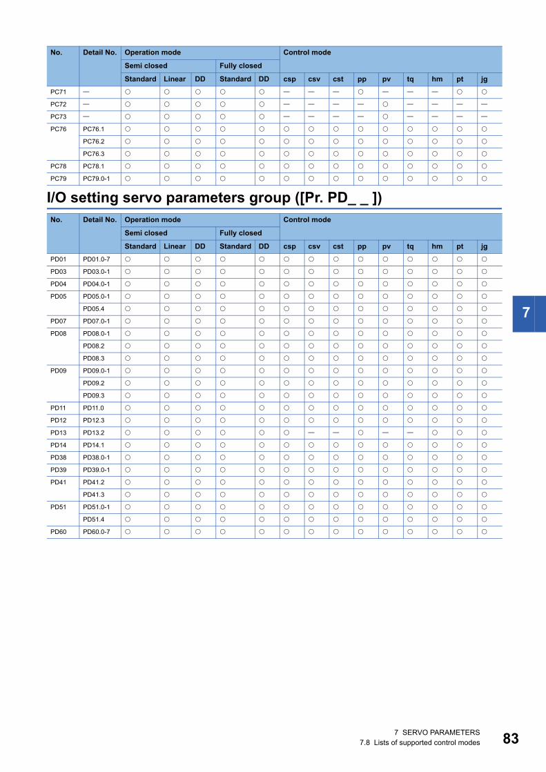
7
I/O setting servo parameters group ([Pr. PD_ _ ])
PC71
PC72
PC73
PC76 PC76.1
PC76.2
PC76.3
PC78 PC78.1
PC79 PC79.0-1
No. Detail No. Operation mode Control mode
Semi closed Fully closed
Standard Linear DD Standard DD csp csv cst pp pv tq hm pt jgPD01 PD01.0-7
PD03 PD03.0-1
PD04 PD04.0-1
PD05 PD05.0-1
PD05.4
PD07 PD07.0-1
PD08 PD08.0-1
PD08.2
PD08.3
PD09 PD09.0-1
PD09.2
PD09.3
PD11 PD11.0
PD12 PD12.3
PD13 PD13.2
PD14 PD14.1
PD38 PD38.0-1
PD39 PD39.0-1
PD41 PD41.2
PD41.3
PD51 PD51.0-1
PD51.4
PD60 PD60.0-7
No. Detail No. Operation mode Control mode
Semi closed Fully closed
Standard Linear DD Standard DD csp csv cst pp pv tq hm pt jg
7 SERVO PARAMETERS7.8 Lists of supported control modes 83

84
Extension setting 2 servo parameters group ([Pr. PE_ _ ])No. Detail No. Operation mode Control mode
Semi closed Fully closed
Standard Linear DD Standard DD csp csv cst pp pv tq hm pt jgPE01 PE01.0
PE03 PE03.0
PE03.1
PE03.3
PE04
PE05
PE06
PE07
PE08
PE10 PE10.1
PE41 PE41.0
PE41.6
PE44
PE45
PE46
PE47
PE48 PE48.0
PE48.1
PE49
PE50
PE51
PE53
7 SERVO PARAMETERS7.8 Lists of supported control modes

7
Extension setting 3 servo parameters group ([Pr. PF_ _ ])No. Detail No. Operation mode Control mode
Semi closed Fully closed
Standard Linear DD Standard DD csp csv cst pp pv tq hm pt jgPF02 PF02.0
PF02.4
PF02.5
PF06 PF06.0
PF06.1
PF12
PF18
PF19
PF20
PF21
PF23
PF24 PF24.0
PF25
PF29 PF29.1
PF31
PF32
PF34 PF34.0
PF34.1
PF34.2
PF34.5
PF34.6
PF40 PF40.0
PF40.1
PF40.2
PF40.4
PF40.5
PF41
PF42
PF43
PF45
PF46
PF47
PF66 PF66.0-3
PF66.4-7
PF67
PF68
PF69
PF70
PF71 PF71.0
PF71.1
PF72
PF73
PF74
PF75
PF76
PF80 PF80.0
PF80.2-3
PF81 PF81.0
7 SERVO PARAMETERS7.8 Lists of supported control modes 85

86
Motor extension setting servo parameters group ([Pr. PL_ _ ])
PF82 PF82.0
PF82.1
PF82.2
PF82.3
PF83 PF83.0
PF84 PF84.0-1
PF84.2-3
PF84.4-5
PF85
PF86
PF87 PF87.0-2
PF87.4-6
PF88 PF88.0-2
PF88.4-6
PF89 PF89.0-2
PF89.4-6
PF90 PF90.0-2
PF91 PF91.0-3
PF91.4-7
PF92 PF92.0-3
PF92.4-7
PF93 PF93.0-3
PF93.4-7
PF94 PF94.0-3
PF94.4-7
PF95 PF95.0
No. Detail No. Operation mode Control mode
Semi closed Fully closed
Standard Linear DD Standard DD csp csv cst pp pv tq hm pt jgPL01 PL01.0
PL01.2
PL02
PL03
PL04 PL04.0
PL04.3
PL05
PL06
PL07
PL08 PL08.0
PL08.2
PL09
PL17 PL17.0
PL17.1
PL18
No. Detail No. Operation mode Control mode
Semi closed Fully closed
Standard Linear DD Standard DD csp csv cst pp pv tq hm pt jg
7 SERVO PARAMETERS7.8 Lists of supported control modes

7
Positioning control setting servo parameters group ([Pr. PT_ _ ])
Network setting servo parameters group ([Pr. PN_ _ ])
No. Detail No. Operation mode Control mode
Semi closed Fully closed
Standard Linear DD Standard DD csp csv cst pp pv tq hm pt jgPT01 PT01.1
PT01.2
PT02 PT02.7
PT03 PT03.2
PT05
PT06
PT07
PT08
PT09
PT10
PT11
PT12
PT15
PT17
PT19
PT21
PT29 PT29.0
PT34 PT34.0
PT34.3
PT38 PT38.4
PT41 PT41.0
PT45
PT49
PT50
PT51
PT53
PT55 PT55.0
PT56
PT57
PT65
PT66
PT67
PT68 PT68.0
PT68.2
No. Detail No. Operation mode Control mode
Semi closed Fully closed
Standard Linear DD Standard DD csp csv cst pp pv tq hm pt jgPN07
PN18
7 SERVO PARAMETERS7.8 Lists of supported control modes 87
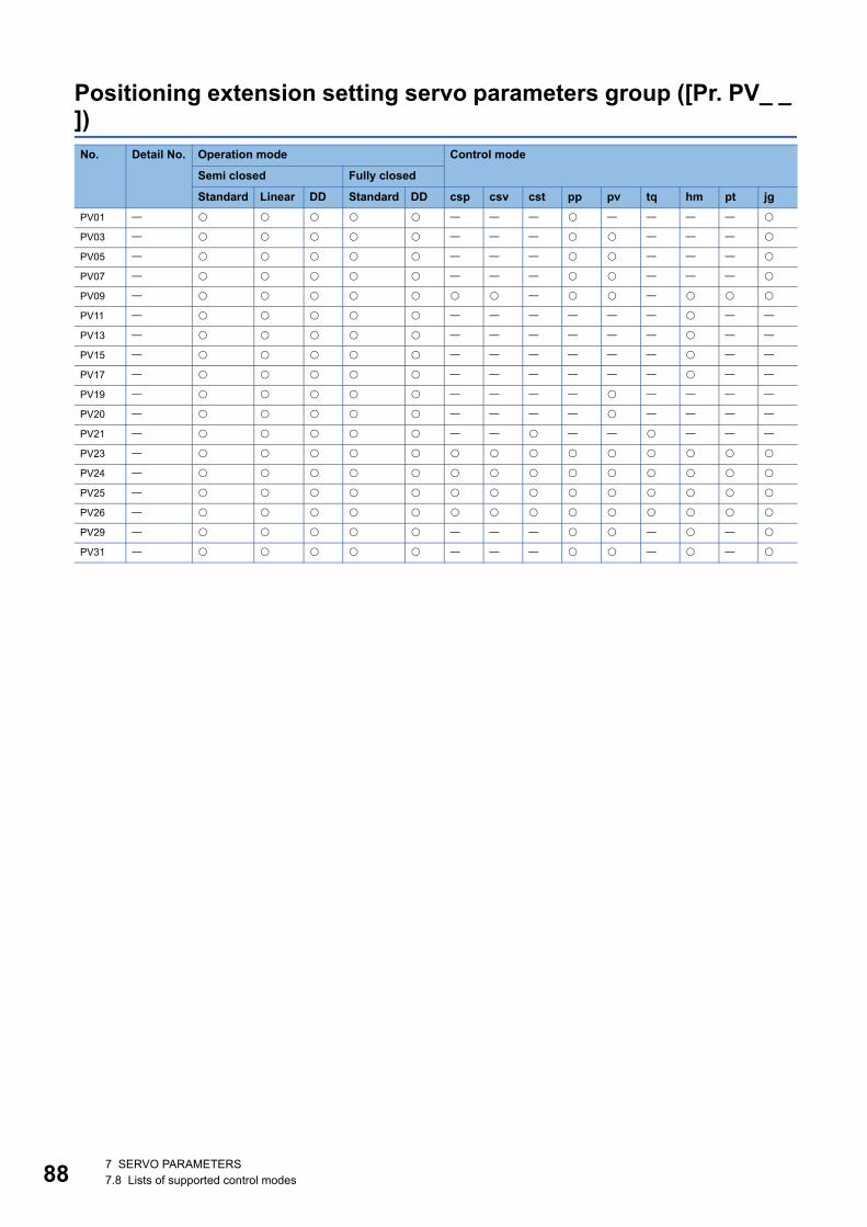
88
Positioning extension setting servo parameters group ([Pr. PV_ _ ])No. Detail No. Operation mode Control mode
Semi closed Fully closed
Standard Linear DD Standard DD csp csv cst pp pv tq hm pt jgPV01
PV03
PV05
PV07
PV09
PV11
PV13
PV15
PV17
PV19
PV20
PV21
PV23
PV24
PV25
PV26
PV29
PV31
7 SERVO PARAMETERS7.8 Lists of supported control modes

7
7.9 Lists of servo parameter initial valuesBasic setting servo parameters group ([Pr. PA_ _ ])No. Initial value RemarkPA01 00003000h
PA02 00000000h For manufacturer setting
PA03 00000000h
PA04 00002000h
PA05 10000 For manufacturer setting
PA06 1
PA07 1
PA08 00000001h
PA09 16
PA10 25600
PA11 1000.0
PA12 1000.0
PA13 00000000h For manufacturer setting
PA14 0
PA15 4000
PA16 1
PA17 00000000h
PA18 00000000h
PA19 000000ABh
PA20 00000000h
PA21 00000001h
PA22 00000000h
PA23 00000000h
PA24 00000000h
PA25 0
PA26 00000000h
PA27 00000000h For manufacturer setting
PA28 00000000h
PA29 0 For manufacturer setting
PA30 0 For manufacturer setting
PA31 0 For manufacturer setting
PA32 00000000h For manufacturer setting
PA33 0.0 For manufacturer setting
PA34 0
PA35 00000000h For manufacturer setting
PA36 00000000h For manufacturer setting
PA37 00000000h For manufacturer setting
PA38 00000000h For manufacturer setting
PA39 00000000h For manufacturer setting
PA40 00000000h For manufacturer setting
PA41 00000000h For manufacturer setting
PA42 00000000h For manufacturer setting
PA43 00000000h For manufacturer setting
PA44 00000000h For manufacturer setting
7 SERVO PARAMETERS7.9 Lists of servo parameter initial values 89

90
Gain/filter setting servo parameters group ([Pr. PB_ _ ])No. Initial value RemarkPB01 00000000h
PB02 00000000h
PB03 36000 For manufacturer setting
PB04 0
PB05 500 For manufacturer setting
PB06 7.00
PB07 15.0
PB08 37.0
PB09 823
PB10 33.7
PB11 980
PB12 0
PB13 4500
PB14 00000000h
PB15 4500
PB16 00000000h
PB17 00000000h
PB18 3141
PB19 100.0
PB20 100.0
PB21 0.00
PB22 0.00
PB23 00001000h
PB24 00000000h
PB25 00000000h
PB26 00000000h
PB27 10
PB28 1
PB29 7.00
PB30 0.0
PB31 0
PB32 0.0
PB33 0.0
PB34 0.0
PB35 0.00
PB36 0.00
PB37 1600 For manufacturer setting
PB38 0.000 For manufacturer setting
PB39 0.000 For manufacturer setting
PB40 0.000 For manufacturer setting
PB41 00000000h For manufacturer setting
PB42 00000000h For manufacturer setting
PB43 00000000h For manufacturer setting
PB44 0.00 For manufacturer setting
PB45 00000000h
PB46 4500
PB47 00000000h
PB48 4500
PB49 00000000h
PB50 4500
PB51 00000000h
7 SERVO PARAMETERS7.9 Lists of servo parameter initial values

7
PB52 100.0
PB53 100.0
PB54 0.00
PB55 0.00
PB56 0.0
PB57 0.0
PB58 0.00
PB59 0.00
PB60 0.0
PB61 0.0 For manufacturer setting
PB62 00000000h For manufacturer setting
PB63 00000000h For manufacturer setting
PB64 00000000h For manufacturer setting
PB65 10
PB66 1
PB67 7.00
PB68 0.0
PB69 0
PB70 0.0
PB71 0.0
PB72 0.0
PB73 0.00
PB74 0.00
PB75 0.0
PB76 0.0
PB77 0.00
PB78 0.00
PB79 0.0
PB80 177.0 For manufacturer setting
PB81 00000001h
PB82 0.0
PB83 00000000h For manufacturer setting
PB84 00000000h For manufacturer setting
PB85 00000000h For manufacturer setting
PB86 00000000h For manufacturer setting
PB87 00000000h For manufacturer setting
PB88 00000000h For manufacturer setting
PB89 00000000h For manufacturer setting
PB90 00000000h For manufacturer setting
PB91 00000000h For manufacturer setting
PB92 00000000h For manufacturer setting
No. Initial value Remark
7 SERVO PARAMETERS7.9 Lists of servo parameter initial values 91

92
Extension setting servo parameters group ([Pr. PC_ _ ])No. Initial value RemarkPC01 0
PC02 0
PC03 00000000h
PC04 00000000h
PC05 00000000h
PC06 00000000h
PC07 50
PC08 0
PC09 00000000h
PC10 00000001h
PC11 0
PC12 0
PC13 0 For manufacturer setting
PC14 0 For manufacturer setting
PC15 0 For manufacturer setting
PC16 00000000h
PC17 00000000h
PC18 00000000h For manufacturer setting
PC19 00000000h
PC20 00000000h
PC21 00000000h
PC22 0 For manufacturer setting
PC23 00000000h For manufacturer setting
PC24 100
PC25 0 For manufacturer setting
PC26 00000050h
PC27 00000000h
PC28 00000000h For manufacturer setting
PC29 00101000h
PC30 0 For manufacturer setting
PC31 0
PC32 0 For manufacturer setting
PC33 0 For manufacturer setting
PC34 100 For manufacturer setting
PC35 00000000h For manufacturer setting
PC36 00000000h For manufacturer setting
PC37 00000000h For manufacturer setting
PC38 0
PC39 0.0 For manufacturer setting
PC40 0.0 For manufacturer setting
PC41 00000000h
PC42 00000000h
PC43 1000.0
PC44 1000.0
PC45 00000000h For manufacturer setting
PC46 00000000h
PC47 00000000h For manufacturer setting
PC48 00000000h For manufacturer setting
PC49 00000000h For manufacturer setting
PC50 00000000h For manufacturer setting
PC51 00000000h For manufacturer setting
7 SERVO PARAMETERS7.9 Lists of servo parameter initial values
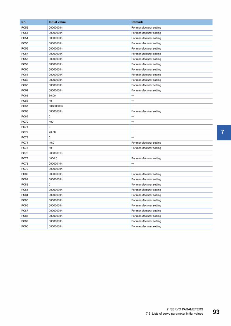
7
PC52 00000000h For manufacturer setting
PC53 00000000h For manufacturer setting
PC54 00000000h For manufacturer setting
PC55 00000000h For manufacturer setting
PC56 00000000h For manufacturer setting
PC57 00000000h For manufacturer setting
PC58 00000000h For manufacturer setting
PC59 00000000h For manufacturer setting
PC60 00000000h For manufacturer setting
PC61 00000000h For manufacturer setting
PC62 00000000h For manufacturer setting
PC63 00000000h For manufacturer setting
PC64 00000000h For manufacturer setting
PC65 50.00
PC66 10
PC67 00C00000h
PC68 00000000h For manufacturer setting
PC69 0
PC70 400
PC71 0
PC72 20.00
PC73 0
PC74 10.0 For manufacturer setting
PC75 10 For manufacturer setting
PC76 00000001h
PC77 1000.0 For manufacturer setting
PC78 00000010h
PC79 00000000h
PC80 00000000h For manufacturer setting
PC81 00000000h For manufacturer setting
PC82 0 For manufacturer setting
PC83 00000000h For manufacturer setting
PC84 00000000h For manufacturer setting
PC85 00000000h For manufacturer setting
PC86 00000000h For manufacturer setting
PC87 00000000h For manufacturer setting
PC88 00000000h For manufacturer setting
PC89 00000000h For manufacturer setting
PC90 00000000h For manufacturer setting
No. Initial value Remark
7 SERVO PARAMETERS7.9 Lists of servo parameter initial values 93

94
I/O setting servo parameters group ([Pr. PD_ _ ])No. Initial value RemarkPD01 00000000h
PD02 00000000h For manufacturer setting
PD03 0000000Ah
PD04 0000000Bh
PD05 00000022h
PD06 00000000h For manufacturer setting
PD07 00000005h
PD08 00000004h
PD09 00000003h
PD10 00000000h For manufacturer setting
PD11 00000007h
PD12 00000101h
PD13 00000000h
PD14 00000000h
PD15 00000000h For manufacturer setting
PD16 00000000h For manufacturer setting
PD17 00000000h For manufacturer setting
PD18 00000000h For manufacturer setting
PD19 00000000h For manufacturer setting
PD20 0 For manufacturer setting
PD21 0 For manufacturer setting
PD22 0 For manufacturer setting
PD23 0 For manufacturer setting
PD24 00000000h For manufacturer setting
PD25 00000000h For manufacturer setting
PD26 00000000h For manufacturer setting
PD27 00000000h For manufacturer setting
PD28 00000000h For manufacturer setting
PD29 00000000h For manufacturer setting
PD30 0 For manufacturer setting
PD31 0 For manufacturer setting
PD32 0 For manufacturer setting
PD33 00000000h For manufacturer setting
PD34 00000000h For manufacturer setting
PD35 00000000h For manufacturer setting
PD36 00000000h For manufacturer setting
PD37 00110001h For manufacturer setting
PD38 0000002Ch
PD39 0000002Dh
PD40 0 For manufacturer setting
PD41 00000000h
PD42 00000000h For manufacturer setting
PD43 00000000h For manufacturer setting
PD44 00000000h For manufacturer setting
PD45 00000000h For manufacturer setting
PD46 00000000h For manufacturer setting
PD47 00000000h For manufacturer setting
PD48 00000000h For manufacturer setting
PD49 0 For manufacturer setting
PD50 0 For manufacturer setting
PD51 00000062h
7 SERVO PARAMETERS7.9 Lists of servo parameter initial values

7
PD52 00000000h For manufacturer setting
PD53 00000000h For manufacturer setting
PD54 00000000h For manufacturer setting
PD55 00000000h For manufacturer setting
PD56 00000000h For manufacturer setting
PD57 00000000h For manufacturer setting
PD58 00000000h For manufacturer setting
PD59 00000000h For manufacturer setting
PD60 00000000h
PD61 00000000h For manufacturer setting
PD62 00000000h For manufacturer setting
PD63 00000000h For manufacturer setting
PD64 00000000h For manufacturer setting
PD65 00000000h For manufacturer setting
PD66 00000000h For manufacturer setting
PD67 00000000h For manufacturer setting
PD68 00000000h For manufacturer setting
PD69 00000000h For manufacturer setting
PD70 00000000h For manufacturer setting
PD71 00000000h For manufacturer setting
PD72 00000000h For manufacturer setting
No. Initial value Remark
7 SERVO PARAMETERS7.9 Lists of servo parameter initial values 95
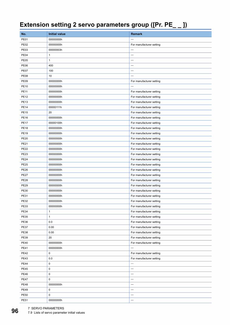
96
Extension setting 2 servo parameters group ([Pr. PE_ _ ])No. Initial value RemarkPE01 00000000h
PE02 00000000h For manufacturer setting
PE03 00000003h
PE04 1
PE05 1
PE06 400
PE07 100
PE08 10
PE09 00000000h For manufacturer setting
PE10 00000000h
PE11 00000000h For manufacturer setting
PE12 00000000h For manufacturer setting
PE13 00000000h For manufacturer setting
PE14 00000111h For manufacturer setting
PE15 20 For manufacturer setting
PE16 00000000h For manufacturer setting
PE17 00000100h For manufacturer setting
PE18 00000000h For manufacturer setting
PE19 00000000h For manufacturer setting
PE20 00000000h For manufacturer setting
PE21 00000000h For manufacturer setting
PE22 00000000h For manufacturer setting
PE23 00000000h For manufacturer setting
PE24 00000000h For manufacturer setting
PE25 00000000h For manufacturer setting
PE26 00000000h For manufacturer setting
PE27 00000000h For manufacturer setting
PE28 00000000h For manufacturer setting
PE29 00000000h For manufacturer setting
PE30 00000000h For manufacturer setting
PE31 00000000h For manufacturer setting
PE32 00000000h For manufacturer setting
PE33 00000000h For manufacturer setting
PE34 1 For manufacturer setting
PE35 1 For manufacturer setting
PE36 0.0 For manufacturer setting
PE37 0.00 For manufacturer setting
PE38 0.00 For manufacturer setting
PE39 20 For manufacturer setting
PE40 00000000h For manufacturer setting
PE41 00000000h
PE42 0 For manufacturer setting
PE43 0.0 For manufacturer setting
PE44 0
PE45 0
PE46 0
PE47 0
PE48 00000000h
PE49 0
PE50 0
PE51 00000000h
7 SERVO PARAMETERS7.9 Lists of servo parameter initial values

7
PE52 00000000h For manufacturer setting
PE53 1000.0
PE54 00000000h For manufacturer setting
PE55 00000000h For manufacturer setting
PE56 00000000h For manufacturer setting
PE57 00000000h For manufacturer setting
PE58 00000000h For manufacturer setting
PE59 00000000h For manufacturer setting
PE60 00000000h For manufacturer setting
PE61 0.000 For manufacturer setting
PE62 0.000 For manufacturer setting
PE63 0.000 For manufacturer setting
PE64 0.000 For manufacturer setting
PE65 0.0 For manufacturer setting
PE66 0.0 For manufacturer setting
PE67 0.0 For manufacturer setting
PE68 00000000h For manufacturer setting
PE69 00000000h For manufacturer setting
PE70 0.00 For manufacturer setting
PE71 0 For manufacturer setting
PE72 1.0000 For manufacturer setting
PE73 00000000h For manufacturer setting
PE74 00000000h For manufacturer setting
PE75 00000000h For manufacturer setting
PE76 00000000h For manufacturer setting
PE77 00000000h For manufacturer setting
PE78 0 For manufacturer setting
PE79 0 For manufacturer setting
PE80 00000000h For manufacturer setting
PE81 00000000h For manufacturer setting
PE82 00000000h For manufacturer setting
PE83 00000000h For manufacturer setting
PE84 00000000h For manufacturer setting
PE85 00000000h For manufacturer setting
PE86 00000000h For manufacturer setting
PE87 00000000h For manufacturer setting
PE88 00000000h For manufacturer setting
No. Initial value Remark
7 SERVO PARAMETERS7.9 Lists of servo parameter initial values 97

98
Extension setting 3 servo parameters group ([Pr. PF_ _ ])No. Initial value RemarkPF01 00000000h For manufacturer setting
PF02 00000000h
PF03 00000000h For manufacturer setting
PF04 0 For manufacturer setting
PF05 00000000h For manufacturer setting
PF06 00000013h
PF07 00000000h For manufacturer setting
PF08 00000000h For manufacturer setting
PF09 00000000h For manufacturer setting
PF10 00000000h For manufacturer setting
PF11 00000000h For manufacturer setting
PF12 2000
PF13 00000000h For manufacturer setting
PF14 10 For manufacturer setting
PF15 00000000h For manufacturer setting
PF16 00000000h For manufacturer setting
PF17 00000000h For manufacturer setting
PF18 10
PF19 0
PF20 0
PF21 0
PF22 200 For manufacturer setting
PF23 20
PF24 00000000h
PF25 200
PF26 0 For manufacturer setting
PF27 0 For manufacturer setting
PF28 0 For manufacturer setting
PF29 00000000h
PF30 0 For manufacturer setting
PF31 0
PF32 50
PF33 00000000h For manufacturer setting
PF34 00000000h
PF35 00000000h For manufacturer setting
PF36 00000000h For manufacturer setting
PF37 00000000h For manufacturer setting
PF38 00000000h For manufacturer setting
PF39 00000000h For manufacturer setting
PF40 00000000h
PF41 0
PF42 0
PF43 0
PF44 0 For manufacturer setting
PF45 0
PF46 0
PF47 0
PF48 00000000h For manufacturer setting
PF49 100 For manufacturer setting
PF50 100 For manufacturer setting
PF51 00000000h For manufacturer setting
7 SERVO PARAMETERS7.9 Lists of servo parameter initial values

7
PF52 00000000h For manufacturer setting
PF53 0 For manufacturer setting
PF54 0 For manufacturer setting
PF55 0 For manufacturer setting
PF56 0 For manufacturer setting
PF57 00000000h For manufacturer setting
PF58 00000000h For manufacturer setting
PF59 00000000h For manufacturer setting
PF60 00000000h For manufacturer setting
PF61 00000000h For manufacturer setting
PF62 00000000h For manufacturer setting
PF63 00000000h For manufacturer setting
PF64 00000000h For manufacturer setting
PF65 00000000h For manufacturer setting
PF66 00000000h
PF67 0
PF68 0
PF69 0
PF70 0
PF71 00000000h
PF72 0
PF73 0
PF74 0
PF75 0
PF76 0
PF77 00000000h For manufacturer setting
PF78 00000000h For manufacturer setting
PF79 00110010h For manufacturer setting
PF80 00000000h
PF81 00000000h
PF82 00000000h
PF83 00000000h
PF84 005A8101h
PF85 0
PF86 0
PF87 00020201h
PF88 02040003h
PF89 00090205h
PF90 0000000Ch
PF91 00120000h
PF92 80058010h
PF93 8000800Ah
PF94 801D8015h
PF95 00000000h
PF96 00000000h For manufacturer setting
PF97 00000000h For manufacturer setting
PF98 00000000h For manufacturer setting
PF99 00000000h For manufacturer setting
No. Initial value Remark
7 SERVO PARAMETERS7.9 Lists of servo parameter initial values 99

10
Motor extension setting servo parameters group ([Pr. PL_ _ ])No. Initial value RemarkPL01 00000301h
PL02 1000
PL03 1000
PL04 00000003h
PL05 0
PL06 0
PL07 100
PL08 00001010h
PL09 30
PL10 5 For manufacturer setting
PL11 100 For manufacturer setting
PL12 500 For manufacturer setting
PL13 00000000h For manufacturer setting
PL14 00000000h For manufacturer setting
PL15 20 For manufacturer setting
PL16 0 For manufacturer setting
PL17 00000000h
PL18 0
PL19 0 For manufacturer setting
PL20 0 For manufacturer setting
PL21 0 For manufacturer setting
PL22 0 For manufacturer setting
PL23 00000000h For manufacturer setting
PL24 0 For manufacturer setting
PL25 0 For manufacturer setting
PL26 00000000h For manufacturer setting
PL27 00000000h For manufacturer setting
PL28 00000000h For manufacturer setting
PL29 00000000h For manufacturer setting
PL30 00000000h For manufacturer setting
PL31 00000000h For manufacturer setting
PL32 00000000h For manufacturer setting
PL33 00000000h For manufacturer setting
PL34 00000000h For manufacturer setting
PL35 00000000h For manufacturer setting
PL36 00000000h For manufacturer setting
PL37 00000000h For manufacturer setting
PL38 00000000h For manufacturer setting
PL39 00000000h For manufacturer setting
PL40 00000000h For manufacturer setting
PL41 00000000h For manufacturer setting
PL42 00000000h For manufacturer setting
PL43 00000000h For manufacturer setting
PL44 00000000h For manufacturer setting
PL45 00000000h For manufacturer setting
PL46 00000000h For manufacturer setting
PL47 00000000h For manufacturer setting
PL48 00000000h For manufacturer setting
PL49 00000000h For manufacturer setting
PL50 0 For manufacturer setting
PL51 0 For manufacturer setting
0 7 SERVO PARAMETERS7.9 Lists of servo parameter initial values

7
PL52 12 For manufacturer setting
PL53 0 For manufacturer setting
PL54 00000000h For manufacturer setting
PL55 00000000h For manufacturer setting
PL56 00000000h For manufacturer setting
PL57 00000000h For manufacturer setting
PL58 00000000h For manufacturer setting
PL59 00000000h For manufacturer setting
PL60 00000000h For manufacturer setting
PL61 00000000h For manufacturer setting
PL62 00000000h For manufacturer setting
PL63 00000000h For manufacturer setting
PL64 00000000h For manufacturer setting
PL65 00000000h For manufacturer setting
PL66 00000000h For manufacturer setting
PL67 00000000h For manufacturer setting
PL68 00000000h For manufacturer setting
PL69 00000000h For manufacturer setting
PL70 00000000h For manufacturer setting
PL71 00000000h For manufacturer setting
PL72 00000000h For manufacturer setting
No. Initial value Remark
7 SERVO PARAMETERS7.9 Lists of servo parameter initial values 101

10
Positioning control setting servo parameters group ([Pr. PT_ _ ])No. Initial value RemarkPT01 00000310h
PT02 00000001h
PT03 00000000h
PT04 00000000h For manufacturer setting
PT05 100.00
PT06 10.00
PT07 0
PT08 0
PT09 1000
PT10 100
PT11 15.0
PT12 0
PT13 00000000h For manufacturer setting
PT14 0 For manufacturer setting
PT15 0
PT16 00000000h For manufacturer setting
PT17 0
PT18 00000000h For manufacturer setting
PT19 0
PT20 00000000h For manufacturer setting
PT21 0
PT22 00000000h For manufacturer setting
PT23 00000000h For manufacturer setting
PT24 00000000h For manufacturer setting
PT25 00000000h For manufacturer setting
PT26 00000000h For manufacturer setting
PT27 00000000h For manufacturer setting
PT28 8 For manufacturer setting
PT29 00000000h
PT30 00000000h For manufacturer setting
PT31 00000000h For manufacturer setting
PT32 00000100h For manufacturer setting
PT33 00000000h For manufacturer setting
PT34 00000000h
PT35 00000000h For manufacturer setting
PT36 00000000h For manufacturer setting
PT37 10 For manufacturer setting
PT38 00000000h
PT39 100 For manufacturer setting
PT40 0 For manufacturer setting
PT41 00000010h
PT42 00000000h For manufacturer setting
PT43 00000000h For manufacturer setting
PT44 00000000h For manufacturer setting
PT45 37
PT46 0 For manufacturer setting
PT47 00000000h For manufacturer setting
PT48 00000000h For manufacturer setting
PT49 0
PT50 0
PT51 0
2 7 SERVO PARAMETERS7.9 Lists of servo parameter initial values
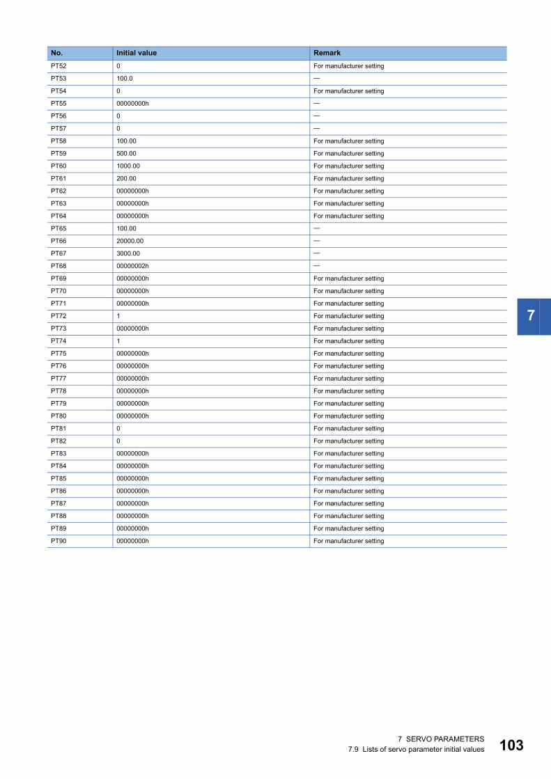
7
PT52 0 For manufacturer setting
PT53 100.0
PT54 0 For manufacturer setting
PT55 00000000h
PT56 0
PT57 0
PT58 100.00 For manufacturer setting
PT59 500.00 For manufacturer setting
PT60 1000.00 For manufacturer setting
PT61 200.00 For manufacturer setting
PT62 00000000h For manufacturer setting
PT63 00000000h For manufacturer setting
PT64 00000000h For manufacturer setting
PT65 100.00
PT66 20000.00
PT67 3000.00
PT68 00000002h
PT69 00000000h For manufacturer setting
PT70 00000000h For manufacturer setting
PT71 00000000h For manufacturer setting
PT72 1 For manufacturer setting
PT73 00000000h For manufacturer setting
PT74 1 For manufacturer setting
PT75 00000000h For manufacturer setting
PT76 00000000h For manufacturer setting
PT77 00000000h For manufacturer setting
PT78 00000000h For manufacturer setting
PT79 00000000h For manufacturer setting
PT80 00000000h For manufacturer setting
PT81 0 For manufacturer setting
PT82 0 For manufacturer setting
PT83 00000000h For manufacturer setting
PT84 00000000h For manufacturer setting
PT85 00000000h For manufacturer setting
PT86 00000000h For manufacturer setting
PT87 00000000h For manufacturer setting
PT88 00000000h For manufacturer setting
PT89 00000000h For manufacturer setting
PT90 00000000h For manufacturer setting
No. Initial value Remark
7 SERVO PARAMETERS7.9 Lists of servo parameter initial values 103

10
Network setting servo parameters group ([Pr. PN_ _ ])No. Initial value RemarkPN01 00000000h For manufacturer setting
PN02 0 For manufacturer setting
PN03 00000000h For manufacturer setting
PN04 0 For manufacturer setting
PN05 0 For manufacturer setting
PN06 00000000h For manufacturer setting
PN07 00000000h
PN08 00000000h For manufacturer setting
PN09 1 For manufacturer setting
PN10 0 For manufacturer setting
PN11 3600 For manufacturer setting
PN12 00000001h For manufacturer setting
PN13 00000100h For manufacturer setting
PN14 00000000h For manufacturer setting
PN15 00000000h For manufacturer setting
PN16 00000000h For manufacturer setting
PN17 00000000h For manufacturer setting
PN18 9
PN19 00000000h For manufacturer setting
PN20 0 For manufacturer setting
PN21 00000000h For manufacturer setting
PN22 00000000h For manufacturer setting
PN23 00000000h For manufacturer setting
PN24 00000000h For manufacturer setting
PN25 00000000h For manufacturer setting
PN26 00000000h For manufacturer setting
PN27 00000000h For manufacturer setting
PN28 00000000h For manufacturer setting
PN29 00000000h For manufacturer setting
PN30 00000000h For manufacturer setting
PN31 00000000h For manufacturer setting
PN32 00000000h For manufacturer setting
4 7 SERVO PARAMETERS7.9 Lists of servo parameter initial values
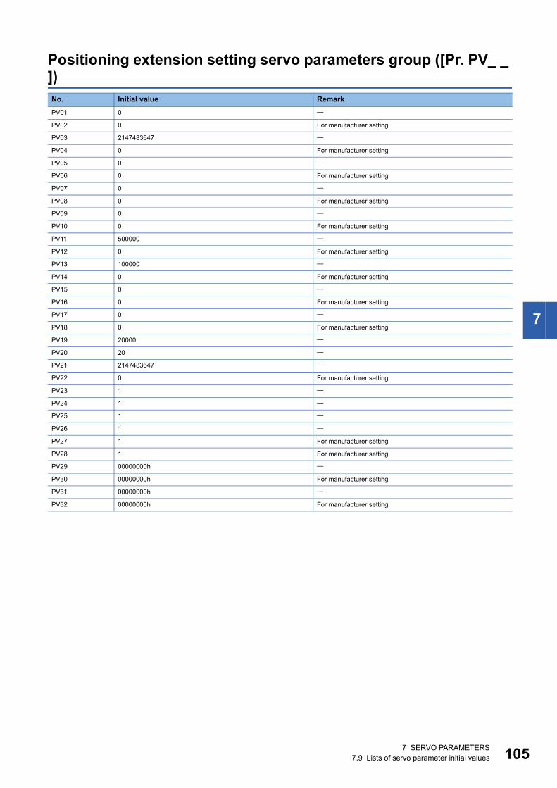
7
Positioning extension setting servo parameters group ([Pr. PV_ _ ])No. Initial value RemarkPV01 0
PV02 0 For manufacturer setting
PV03 2147483647
PV04 0 For manufacturer setting
PV05 0
PV06 0 For manufacturer setting
PV07 0
PV08 0 For manufacturer setting
PV09 0
PV10 0 For manufacturer setting
PV11 500000
PV12 0 For manufacturer setting
PV13 100000
PV14 0 For manufacturer setting
PV15 0
PV16 0 For manufacturer setting
PV17 0
PV18 0 For manufacturer setting
PV19 20000
PV20 20
PV21 2147483647
PV22 0 For manufacturer setting
PV23 1
PV24 1
PV25 1
PV26 1
PV27 1 For manufacturer setting
PV28 1 For manufacturer setting
PV29 00000000h
PV30 00000000h For manufacturer setting
PV31 00000000h
PV32 00000000h For manufacturer setting
7 SERVO PARAMETERS7.9 Lists of servo parameter initial values 105
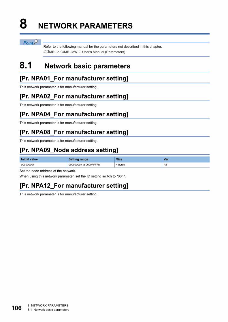
10
8 NETWORK PARAMETERS
Refer to the following manual for the parameters not described in this chapter.MR-J5-G/MR-J5W-G User's Manual (Parameters)
8.1 Network basic parameters[Pr. NPA01_For manufacturer setting]This network parameter is for manufacturer setting.
[Pr. NPA02_For manufacturer setting]This network parameter is for manufacturer setting.
[Pr. NPA04_For manufacturer setting]This network parameter is for manufacturer setting.
[Pr. NPA08_For manufacturer setting]This network parameter is for manufacturer setting.
[Pr. NPA09_Node address setting]
Set the node address of the network.When using this network parameter, set the ID setting switch to "00h".
[Pr. NPA12_For manufacturer setting]This network parameter is for manufacturer setting.
Initial value Setting range Size Ver.00000000h 00000000h to 0000FFFFh 4 bytes A5
6 8 NETWORK PARAMETERS8.1 Network basic parameters

8
8.2 User authentication parameters[Pr. NPB01_For manufacturer setting]This network parameter is for manufacturer setting.
[Pr. NPB04_For manufacturer setting]This network parameter is for manufacturer setting.
[Pr. NPB05_For manufacturer setting]This network parameter is for manufacturer setting.
[Pr. NPB06_For manufacturer setting]This network parameter is for manufacturer setting.
[Pr. NPB07_For manufacturer setting]This network parameter is for manufacturer setting.
[Pr. NPB08_For manufacturer setting]This network parameter is for manufacturer setting.
[Pr. NPB09_For manufacturer setting]This network parameter is for manufacturer setting.
[Pr. NPB10_For manufacturer setting]This network parameter is for manufacturer setting.
[Pr. NPB11_For manufacturer setting]This network parameter is for manufacturer setting.
[Pr. NPB12_For manufacturer setting]This network parameter is for manufacturer setting.
[Pr. NPB13_For manufacturer setting]This network parameter is for manufacturer setting.
[Pr. NPB14_For manufacturer setting]This network parameter is for manufacturer setting.
[Pr. NPB15_For manufacturer setting]This network parameter is for manufacturer setting.
[Pr. NPB16_For manufacturer setting]This network parameter is for manufacturer setting.
8 NETWORK PARAMETERS8.2 User authentication parameters 107

10
[Pr. NPB17_For manufacturer setting]This network parameter is for manufacturer setting.
[Pr. NPB18_For manufacturer setting]This network parameter is for manufacturer setting.
[Pr. NPB19_For manufacturer setting]This network parameter is for manufacturer setting.
[Pr. NPB20_For manufacturer setting]This network parameter is for manufacturer setting.
[Pr. NPB21_For manufacturer setting]This network parameter is for manufacturer setting.
[Pr. NPB22_For manufacturer setting]This network parameter is for manufacturer setting.
[Pr. NPB23_For manufacturer setting]This network parameter is for manufacturer setting.
[Pr. NPB24_For manufacturer setting]This network parameter is for manufacturer setting.
[Pr. NPB25_For manufacturer setting]This network parameter is for manufacturer setting.
[Pr. NPB26_For manufacturer setting]This network parameter is for manufacturer setting.
[Pr. NPB27_For manufacturer setting]This network parameter is for manufacturer setting.
8 8 NETWORK PARAMETERS8.2 User authentication parameters

9
9 FUNCTIONAL SAFETY PARAMETERSRefer to the following manual for the parameters not described in this chapter.MR-J5-G/MR-J5W-G User's Manual (Parameters)
9.1 Safety sub-function 1 parameters group ([Pr. PSA_ _ ])
[Pr. PSA01_Safety sub-function mode selection (**SOA)]
Set the safety sub-function.
[Pr. PSA01.0_Safety sub-function activation setting]
0: Disabled1: EnabledWhen setting this functional safety parameter to "1" (enabled), check the setting of each relevant parameter for problems. When setting this parameter to "0" (disabled), only the STO function with the CN8 connector can be used.
[Pr. PSA01.1_Input mode selection]
0: Safety sub-function control by input device2: Test operationWhen setting this functional safety parameter to "2" (test operation), the safety sub-function is not available.For information regarding test operation, refer to "Test operation" in the User's Manual (Introduction).If the functional safety parameter is set incorrectly, [AL. 537.2 Parameter combination error A (safety sub-function)] occurs.If the functional safety parameter is set to "1", [AL. 537.1 Parameter setting range error A (safety sub-function)] occurs.
[Pr. PSA05_For manufacturer setting]This functional safety parameter is for manufacturer setting.
[Pr. PSA06_For manufacturer setting]This functional safety parameter is for manufacturer setting.
[Pr. PSA07_For manufacturer setting]This functional safety parameter is for manufacturer setting.
[Pr. PSA08_For manufacturer setting]This functional safety parameter is for manufacturer setting.
[Pr. PSA09_For manufacturer setting]This functional safety parameter is for manufacturer setting.
Initial value Setting range Setting method Ver.00000000h Refer to the relevant detail No. Common Refer to the relevant detail No.
Initial value Setting range Ver.0h Refer to the text B2
Initial value Setting range Ver.0h Refer to the text B2
9 FUNCTIONAL SAFETY PARAMETERS9.1 Safety sub-function 1 parameters group ([Pr. PSA_ _ ]) 109

11
[Pr. PSA10_For manufacturer setting]This functional safety parameter is for manufacturer setting.
[Pr. PSA11_For manufacturer setting]This functional safety parameter is for manufacturer setting.
[Pr. PSA12_For manufacturer setting]This functional safety parameter is for manufacturer setting.
[Pr. PSA13_For manufacturer setting]This functional safety parameter is for manufacturer setting.
[Pr. PSA14_For manufacturer setting]This functional safety parameter is for manufacturer setting.
[Pr. PSA17_For manufacturer setting]This functional safety parameter is for manufacturer setting.
[Pr. PSA18_For manufacturer setting]This functional safety parameter is for manufacturer setting.
[Pr. PSA19_For manufacturer setting]This functional safety parameter is for manufacturer setting.
[Pr. PSA27_For manufacturer setting]This functional safety parameter is for manufacturer setting.
[Pr. PSA28_For manufacturer setting]This functional safety parameter is for manufacturer setting.
0 9 FUNCTIONAL SAFETY PARAMETERS9.1 Safety sub-function 1 parameters group ([Pr. PSA_ _ ])
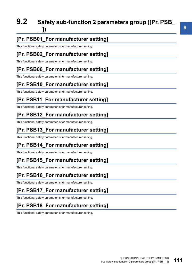
9
9.2 Safety sub-function 2 parameters group ([Pr. PSB__ ])[Pr. PSB01_For manufacturer setting]This functional safety parameter is for manufacturer setting.
[Pr. PSB02_For manufacturer setting]This functional safety parameter is for manufacturer setting.
[Pr. PSB06_For manufacturer setting]This functional safety parameter is for manufacturer setting.
[Pr. PSB10_For manufacturer setting]This functional safety parameter is for manufacturer setting.
[Pr. PSB11_For manufacturer setting]This functional safety parameter is for manufacturer setting.
[Pr. PSB12_For manufacturer setting]This functional safety parameter is for manufacturer setting.
[Pr. PSB13_For manufacturer setting]This functional safety parameter is for manufacturer setting.
[Pr. PSB14_For manufacturer setting]This functional safety parameter is for manufacturer setting.
[Pr. PSB15_For manufacturer setting]This functional safety parameter is for manufacturer setting.
[Pr. PSB16_For manufacturer setting]This functional safety parameter is for manufacturer setting.
[Pr. PSB17_For manufacturer setting]This functional safety parameter is for manufacturer setting.
[Pr. PSB18_For manufacturer setting]This functional safety parameter is for manufacturer setting.
9 FUNCTIONAL SAFETY PARAMETERS9.2 Safety sub-function 2 parameters group ([Pr. PSB_ _ ]) 111

11
9.3 Network parameters group ([Pr. PSC_ _ ])[Pr. PSC01_For manufacturer setting]This functional safety parameter is for manufacturer setting.
[Pr. PSC03_For manufacturer setting]This functional safety parameter is for manufacturer setting.
[Pr. PSC06_For manufacturer setting]This functional safety parameter is for manufacturer setting.
2 9 FUNCTIONAL SAFETY PARAMETERS9.3 Network parameters group ([Pr. PSC_ _ ])

9
9.4 Safety I/O device parameters group ([Pr. PSD_ _ ])[Pr. PSD01_For manufacturer setting]This functional safety parameter is for manufacturer setting.[Pr. PSD02_Input device selection DI1 (**SDI1)]
Select the device to be assigned to the input signal of the CN8-4/CN8-5 pin. Assign a device to [Pr. PSD02 Input device selection DI1] if "0" (safety sub-function control by input device) is selected in [Pr. PSA01.1 Input mode selection]. If no device is set to [Pr. PSD02], [AL. 537.2 Parameter combination error A (safety sub-function)] occurs.If this functional safety parameter is set incorrectly, [AL. 537.2] occurs.
[Pr. PSD02.0-1_Safety input device selection DI1]
Select the device to be assigned to the input signal of the CN8-4/CN8-5 pin.Refer to the following table for setting values.
If a value other than "00" (none), "01" (STOC), or "02" (SS1C) is selected, [AL. 537.1 Parameter setting range error A (safety sub-function)] occurs.
Initial value Setting range Setting method Ver.00000000h Refer to the relevant detail No. Each axis Refer to the relevant detail No.
Initial value Setting range Ver.00h Refer to the text B2
Setting value Input device00 None
01 STOC (STO command)
02 SS1C (SS1 command)
9 FUNCTIONAL SAFETY PARAMETERS9.4 Safety I/O device parameters group ([Pr. PSD_ _ ]) 113

11
[Pr. PSD02.3_Input axis selection DI1]
For a multi-axis drive unit, set which axis will use the input device that was assigned in [Pr. PSD02.0-1 Safety input device selection DI1].When this functional safety parameter is set to "0h", the input device is enabled for all axes using the automatic setting.
When A-axis selection is enabled, the device name is _ _ _-A. (example: "STOC-A")When B-axis selection is enabled, the device name is _ _ _-B. (example: "STOC-B")When C-axis selection is enabled, the device name is _ _ _-C. (example: "STOC-C")When multiple axes are enabled with this functional safety parameter, the input device signal is enabled for multiple axes simultaneously.For example, when [Pr. PSD02.3] = "5h" (A and C-axes enabled) and [Pr. PSD02.0] = "01h" (STOC) are set for the A-axis, STOC-A and STOC-C are enabled with the input signal of the DI1 pin.In the following cases, [AL. 537 Parameter setting range error (safety sub-function)] occurs. • When other than "0h" is set on the MR-J5D1-_G_-N1. • When C-axis selection is enabled on the MR-J5D2-_G_-N1.
Initial value Setting range Ver.0h Refer to the text B2
Servo parameter number Setting digit (BIN) Setting detailsPSD02.3 _ _ _ x A-axis selection
0: Disabled1: Enabled
_ _ x _ B-axis selection0: Disabled1: Enabled
_ x _ _ C-axis selection0: Disabled1: Enabled
x _ _ _ For manufacturer setting
4 9 FUNCTIONAL SAFETY PARAMETERS9.4 Safety I/O device parameters group ([Pr. PSD_ _ ])

9
[Pr. PSD08_Output device selection DO1 (**SDO1)]Select the device to be assigned to the output signal of the CN8-6/CN8-7 pin.If this functional safety parameter is set incorrectly, [AL. 537.2 Parameter combination error A (safety sub-function)] occurs.
[Pr. PSD08.0-1_Safety output device selection DO1]
Select the device to be assigned to the output signal of the CN8-6/CN8-7 pin.Refer to the following table for setting values.
If a value other than "00" (none), "01" (STOS), "02" (SS1S), or "0A" (SBCS) is selected, [AL. 537.1 Parameter setting range error A (safety sub-function)] occurs.
[Pr. PSD08.2_All-axis output condition selection DO1]
0: AND output1: OR outputFor AND output, the condition becomes significant (on or off) when the A, B, and C-axes all satisfy the condition.The device name at this time is C-_ _ _. (example: "C-STOS")For OR output, the condition becomes significant (on or off) when any of A, B, or C-axis satisfies the condition.The device name at this time is X-_ _ _. (example: "X-STOS")This functional safety parameter is enabled when [Pr. PSD08.3 Output axis selection] is set to "0" (all axes) while a multi-axis drive unit is used.
[Pr. PSD08.3_Output axis selection DO1]
0: All axes1: A-axis2: B-axis3: C-axisIf the setting value is 1, the device name is _ _ _-A. (example: "STOS-A")If the setting value is 2, the device name is _ _ _-B. (example: "STOS-B")If the setting value is 3, the device name is _ _ _-C. (example: "STOS-C")
Initial value Setting range Setting method Ver.00000000h Refer to the relevant detail No. Common Refer to the relevant detail No.
Initial value Setting range Ver.00h Refer to the text B2
Setting value Output device00 None
01 STOS (STO output)
02 SS1S (SS1 output)
0A SBCS (SBC output)
Initial value Setting range Ver.0h Refer to the text B2
Initial value Setting range Ver.0h Refer to the text B2
9 FUNCTIONAL SAFETY PARAMETERS9.4 Safety I/O device parameters group ([Pr. PSD_ _ ]) 115

11
9.5 Lists of functional safety parameter initial valuesRefer to "LISTS OF FUNCTIONAL SAFETY PARAMETER INITIAL VALUES" in the following manual.MR-J5-G/MR-J5W-G User's Manual (Parameters)
6 9 FUNCTIONAL SAFETY PARAMETERS9.5 Lists of functional safety parameter initial values

9
MEMO9 FUNCTIONAL SAFETY PARAMETERS9.5 Lists of functional safety parameter initial values 117

118
REVISIONS*The manual number is given on the bottom left of the back cover.
2021 MITSUBISHI ELECTRIC CORPORATION
Revision date *Manual number DescriptionJune 2021 IB(NA)-0300543ENG-A First edition
This manual confers no industrial property rights or any rights of any other kind, nor does it confer any patent licenses. Mitsubishi Electric Corporation cannot be held responsible for any problems involving industrial property rights which may occur as a result of using the contents noted in this manual.

119
WARRANTYWarranty1. Warranty period and coverage
We will repair any failure or defect hereinafter referred to as "failure" in our FA equipment hereinafter referred to as the "Product" arisen during warranty period at no charge due to causes for which we are responsible through the distributor from which you purchased the Product or our service provider. However, we will charge the actual cost of dispatching our engineer for an on-site repair work on request by customer in Japan or overseas countries. We are not responsible for any on-site readjustment and/or trial run that may be required after a defective unit are repaired or replaced.[Term]For terms of warranty, please contact your original place of purchase.[Limitations](1) You are requested to conduct an initial failure diagnosis by yourself, as a general rule.
It can also be carried out by us or our service company upon your request and the actual cost will be charged. However, it will not be charged if we are responsible for the cause of the failure.
(2) This limited warranty applies only when the condition, method, environment, etc. of use are in compliance with the terms and conditions and instructions that are set forth in the instruction manual and user manual for the Product and the caution label affixed to the Product.
(3) Even during the term of warranty, the repair cost will be charged on you in the following cases;1. a failure caused by your improper storing or handling, carelessness or negligence, etc., and a failure caused by your hardware
or software problem2. a failure caused by any alteration, etc. to the Product made on your side without our approval3. a failure which may be regarded as avoidable, if your equipment in which the Product is incorporated is equipped with a safety
device required by applicable laws and has any function or structure considered to be indispensable according to a common sense in the industry
4. a failure which may be regarded as avoidable if consumable parts designated in the instruction manual, etc. are duly maintained and replaced
5. any replacement of consumable parts (battery, fan, smoothing capacitor, etc.)6. a failure caused by external factors such as inevitable accidents, including without limitation fire and abnormal fluctuation of
voltage, and acts of God, including without limitation earthquake, lightning and natural disasters7. a failure generated by an unforeseeable cause with a scientific technology that was not available at the time of the shipment of
the Product from our company8. any other failures which we are not responsible for or which you acknowledge we are not responsible for
2. Term of warranty after the stop of production(1) We may accept the repair at charge for another seven (7) years after the production of the product is discontinued. The
announcement of the stop of production for each model can be seen in our Sales and Service, etc.(2) Please note that the Product (including its spare parts) cannot be ordered after its stop of production.
3. Service in overseas countriesOur regional FA Center in overseas countries will accept the repair work of the Product. However, the terms and conditions of the repair work may differ depending on each FA Center. Please ask your local FA center for details.
4. Exclusion of loss in opportunity and secondary loss from warranty liabilityRegardless of the gratis warranty term, Mitsubishi shall not be liable for compensation to:(1) Damages caused by any cause found not to be the responsibility of Mitsubishi.(2) Loss in opportunity, lost profits incurred to the user by Failures of Mitsubishi products.(3) Special damages and secondary damages whether foreseeable or not, compensation for accidents, and compensation for
damages to products other than Mitsubishi products.(4) Replacement by the user, maintenance of on-site equipment, start-up test run and other tasks.
5. Change of Product specificationsSpecifications listed in our catalogs, manuals or technical documents may be changed without notice.
6. Application and use of the Product(1) For the use of our AC Servo, its applications should be those that may not result in a serious damage even if any failure or
malfunction occurs in AC Servo, and a backup or fail-safe function should operate on an external system to AC Servo when any failure or malfunction occurs.
(2) Our AC Servo is designed and manufactured as a general purpose product for use at general industries.Therefore, applications substantially influential on the public interest for such as atomic power plants and other power plants of electric power companies, and also which require a special quality assurance system, including applications for railway companies and government or public offices are not recommended, and we assume no responsibility for any failure caused by these applications when used.In addition, applications which may be substantially influential to human lives or properties for such as airlines, medical treatments, railway service, incineration and fuel systems, man-operated material handling equipment, entertainment machines, safety machines, etc. are not recommended, and we assume no responsibility for any failure caused by these applications when used. We will review the acceptability of the abovementioned applications, if you agree not to require a specific quality for a specific application. Please contact us for consultation.

120
TRADEMARKSMELSERVO is a trademark or registered trademark of Mitsubishi Electric Corporation in Japan and/or other countries.EtherCAT is a registered trademark and patented technology licensed by Beckhoff Automation GmbH, Germany.All other product names and company names are trademarks or registered trademarks of their respective companies.
IB(NA)-0300543ENG-A


IB(NA)-0300543ENG-A(2106)MEEMODEL:MODEL CODE:
Specifications are subject to change without notice.
When exported from Japan, this manual does not require application to theMinistry of Economy, Trade and Industry for service transaction permission.
HEAD OFFICE : TOKYO BUILDING, 2-7-3 MARUNOUCHI, CHIYODA-KU, TOKYO 100-8310, JAPANNAGOYA WORKS : 1-14 , YADA-MINAMI 5-CHOME , HIGASHI-KU, NAGOYA , JAPAN