
morteza dianatfar safety analysis on human-robot ... - Trepo
87
MORTEZA DIANATFAR SAFETY ANALYSIS ON HUMAN-ROBOT COLLABORATION IN HEAVY ASSEMBLY TASKS Master of Science Thesis Examiner: Professor Minna Lanz, D.Sc. (Tech) Borja Ramis Ferrer Examiner and topic approved on 26 September 2018
-
Upload
khangminh22 -
Category
Documents
-
view
0 -
download
0
Transcript of morteza dianatfar safety analysis on human-robot ... - Trepo

MORTEZA DIANATFAR
SAFETY ANALYSIS ON HUMAN-ROBOT COLLABORATION IN
HEAVY ASSEMBLY TASKS
Master of Science Thesis
Examiner: Professor Minna Lanz, D.Sc. (Tech) Borja Ramis Ferrer Examiner and topic approved on 26 September 2018

i
ABSTRACT
Morteza Dianatfar: Safety analysis on human-robot collaboration in heavy as-sembly tasks Tampere University of Technology Master of Science Thesis, 79 pages Master’s Degree Programme in Automation Engineering Major: Factory Automation and Industrial Informatics Examiner: Professor Minna Lanz, Doctor of Science in Technology Borja Ramis Ferrer Keywords: Human-Robot Collaboration, Industrial Robot, Human-Robot Interac-tion Levels, Laser Scanner, ABB SafeMove Manufacturing assembly industry has traditionally utilized human labor to perform assembly tasks manually. With the introduction of industrial robots, fully auto-mated solutions have provided an opportunity to perform complex and repetitive tasks and assist in the assembly of heavy components. In recent years, improve-ment in robot technologies and changes in safety legislation have enabled new human-robot collaboration (HRC) concepts which have drawn attention of man-ufacturers. HRC uses characteristics of dexterity and flexibility of human and re-peatability and precision of robots to increase the flexibility of the system, de-crease the cost of labor in production and improve ergonomics in the design of shared workspace. The operator safety is one of the challenges inside the HRC environment. The safety concerns could be altered with different levels of physical interactions be-tween robot and human. This thesis aimed to develop solution for analyzing the safety functions on different human-robot interaction (HRI) levels. The approach was started with the classification of tasks between human and robot. In this the-sis, assembly sequences were designed to fulfill the requirements of each inter-action levels of HRI. These experiments were providing evaluation tables for an-alyzing the safety functions in HRI levels. The primary objective of this thesis is to design the HRC system with suitable safety functions. The safety of the workstation was developed using a combination of hardware and software. Laser scanners employed to detect the presence of a human in hazard areas and ABB SafeMove add-on were config-ured to exploit safety signals to the robot controller for adopting safety functions such as safety-rated monitored stop, and speed and separation monitoring. In this thesis, time work study analysis was demonstrated that the implementation of HRC decreases the fatigue and the injury risks of the operator and enhances the ergonomics for the operators. The study of safety functions through different HRI levels proved that with an increase of physical interactions it was necessary to employ multiple safety functions to prohibit collisions between robot and hu-man.

ii
PREFACE
The study presented in this thesis has been carried out at the Mechanical Engineering and
Industrial System (MEI) department of Tampere University of Technology (TUT).
Firstly, I would like to express my gratitude to Professor Minna Lanz for providing me
the opportunity to work in her team and her endless support for performing this experi-
ment. I am also thankful to my supervisor D.Sc. (Tech) Borja Ramis Ferrer for his sup-
ports throughout this thesis. Furthermore, I am grateful to my colleagues Jyrki Latokar-
tano, Alireza Changizi, Mehdi Mahmoodpour, Joe Samuel David for their assistance at
different stages of implementation of this thesis.
I owe my gratitude and special thanks to Saeid HeshmatiSafa for supporting and motivat-
ing me in all the stages of my thesis.
Finally, I appreciate my parents blessing and encouragement during my whole career.
Tampere, November 12, 2018
Morteza Dianatfar

iii
CONTENTS
1. INTRODUCTION .................................................................................................... 1
1.1 Research Gap.................................................................................................. 2
1.2 Research Objectives and Outline of the Thesis .............................................. 2
1.3 Research Questions and Limitations ............................................................. 3
1.4 Research Methodology ................................................................................... 3
2. LITERATURE REVIEW ......................................................................................... 5
2.1 Assembly systems in the manufacturing industry .......................................... 5
2.1.1 Flexible manual assembly ................................................................ 7
2.1.2 Flexible Automated Systems: ........................................................ 10
2.1.3 Hybrid Assembly Systems: ............................................................ 11
2.2 Industrial Robotics History .......................................................................... 12
2.3 Human-Robot Collaboration ........................................................................ 14
2.3.1 Industrial Robotics Markets ........................................................... 15
2.3.2 Industrial Robotics Applications .................................................... 17
2.4 Machine Directive and Safety Standards ..................................................... 20
2.4.1 Machine Directive .......................................................................... 20
2.4.2 EN ISO 12100 ................................................................................ 24
2.4.3 ISO 10218 ...................................................................................... 28
2.4.4 ISO-TS 15066 ................................................................................ 31
2.5 Review and Classification of Safety in HRC ............................................... 32
2.6 Literature Review Summary ........................................................................ 34
3. DEVELOPMENT / EXPERIMENT ....................................................................... 36
3.1 Experiment’s Equipment and design ........................................................... 36
3.2 Engine Components Analysis ...................................................................... 39
3.3 Task Allocation ............................................................................................ 40
3.4 Cell Design and Simulation.......................................................................... 44
3.5 Assembly Sequence based on Interaction Level .......................................... 46
3.5.1 First Interaction Level Scenario ..................................................... 47
3.5.2 Second Interaction Level Scenario ................................................ 50
3.5.3 Third Interaction Level Scenario ................................................... 54
3.6 Safety Implementation ................................................................................. 59
3.6.1 Laser Scanners ............................................................................... 59
3.6.2 ABB SafeMove .............................................................................. 62
4. RESULTS ............................................................................................................... 64
4.1.1 Time Work Study Analysis ............................................................ 64
4.1.2 Task Allocation Results ................................................................. 67
4.1.3 Safety Function Analysis ............................................................... 67
5. CONCLUSION ....................................................................................................... 71
REFERENCES ................................................................................................................ 73

iv
LIST OF FIGURES
Figure 1. Research Methodology Diagram ...................................................................... 4
Figure 2. Utilization area for manual, hybrid and automated assembly [16] .................. 6
Figure 3. Classification of assembly system based on output and complexity [16] ......... 7
Figure 4. Assembly station with set-wise sequencing for an electrical
componentry [16] ...................................................................................... 8
Figure 5. One-piece flow assembly station with different part supplies [16] ................... 9
Figure 6. Assembly layout for a various number of products [16] .................................. 9
Figure 7. Modular system for linear transfer assembly lines [16] ................................. 10
Figure 8. Extension stages of linear transfer assembly lines [16] ................................. 11
Figure 9. Yumi robot from ABB [34] .............................................................................. 13
Figure 10. Baxter from Rethink Robotics [36] ............................................................... 13
Figure 11. Estimated annual worldwide supply of Industrial robots 2008-2016
and 2017-2020 [42] ................................................................................. 16
Figure 12. Major industries usage [42] .......................................................................... 16
Figure 13. Global markets of the industrial robot by countries [42] ............................ 17
Figure 14. KR Quantec PA series from KUKA for palletizing [44] .............................. 18
Figure 15. KUKA Spot Welding [46] ............................................................................. 19
Figure 16. Assembly Application of Industrial Robot [49] ............................................ 19
Figure 17. Painting Application of Industrial Robots [29] ............................................ 20
Figure 18. Workplace accidents in Europe in 2012 [52] ............................................... 21
Figure 19. Machinery safety standards based on their categories [54] ........................ 24
Figure 20. Representation of the risk reduction process including iterative three-
step method [55] ...................................................................................... 26
Figure 21. The element of risk [55] ............................................................................... 27
Figure 22. Definition of shared workspace areas [57] ................................................. 30
Figure 23. Collaborative workspace Example [5] ......................................................... 31
Figure 24. Product: Diesel Engine ................................................................................ 36
Figure 25. ABB IRB 4600-60 [80] ................................................................................. 37
Figure 26. Motor Frame and Head Cover Jigs .............................................................. 37
Figure 27. From Top Left: First Design, Improved Design, Final Implementation ...... 38
Figure 28. Left: SCHUNK PGN-plus-P 100-1 [81], Right: SCHUNK PGN-plus-P
80-2 [82] .................................................................................................. 38
Figure 29. Left: Fingers Designed for the motor frame and headcover, Right:
Fingers Designed for pushrods and rockershaft ..................................... 39
Figure 30. Multi-gripper Final Design ........................................................................... 39
Figure 31. Assembly Stage Decomposition Model for Engine Components .................. 40
Figure 32. Cell Design in MEI Laboratory .................................................................... 44
Figure 33. Layout Simulation in Visual Components ..................................................... 45
Figure 34. Cell Workspaces ............................................................................................ 45
Figure 35. Timing Diagram for the First Interaction Level Sequence ........................... 50

v
Figure 36. Timing Diagram of Second Interaction Level Sequence ............................... 54
Figure 37. Timing Diagram for Third Interaction Level Sequence ................................ 58
Figure 38. SICK S3000 Laser Scanner .......................................................................... 59
Figure 39. Laser Scanners Set Up in Workstation .......................................................... 60
Figure 40. Protective and Warning Definition for Wall Mounted Scanner ................... 60
Figure 41. Protective and Warning Definition for Robot Mounted Scanner .................. 61
Figure 42. Safety Range Axis Properties from ABB SafeMove ..................................... 63
Figure 43. Safety Zone Definition in ABB RobotStudio .................................................. 63

vi
LIST OF TABLES
Table 1. Summary of reviewed methods .......................................................................... 33
Table 2. List of assembly components ............................................................................. 40
Table 3. Task Allocation analysis .................................................................................. 43
Table 4. Primary of Task Allocation ............................................................................... 46
Table 5. First Interaction level Assembly Sequence ....................................................... 47
Table 6. Second Interaction Level Assembly Sequence .................................................. 51
Table 7. Third Interaction Levels Assembly Sequence ................................................... 55
Table 8. Time Study of Manual Assembly Sequence ....................................................... 64
Table 9. Time Study of First Interaction Level of HRC Sequence ................................. 65
Table 10. Time Study of Second Interaction Level of HRC Sequence ............................ 65
Table 11. Time Study of Third Interaction Level of HRC Sequence ............................... 66
Table 12. Total Amount of Human Working Time in Different Assembly Sequence ...... 66
Table 13. Interaction Level Safety Function Analysis .................................................... 70

vii
LIST OF SYMBOLS AND ABBREVIATIONS
CAD Computer Aided Design
CE Conformité Européene
Cobots Collaborative Robots
DOF Degree of Freedom
EHSR Essential Health and Safety Requirements
GMAW Gas-shielded Metal Arc Welding
HRC Human-Robot Collaboration
HRI Human-Robot Interaction
ISO International Organization for Standardization
IFR International Federation of Robotics
MEI Mechanical Engineering and Industrial System
OSHA Occupational Safety & Health Department
PLC Programmable Logic Controller
SCARA Selective Compliance Articulated Robot Arm
TCP Tool Center Point
TUT Tampere University of Technology

1
1. INTRODUCTION
In the last decade, the human-robot interaction (HRI) and human-robot collaboration
(HRC) topics have gained the significant interests among researchers in manufacturing
assembly process. Traditionally, assembly process was performed by the operator in a
workstations that results in massive injuries and ergonomic issues leading to a social cost
of labor in the factory [1]. By introducing the industrial robots with repeatability,
precision, and high payload characteristics, new opportunities emerged to adopt robots in
assembly workstations. However, this trend brought some issues such as positioning
robots inside workstation with barriers such as fences and safeguarding walls. Robots
with low intelligence (manually programmed by the expert) cannot operate with the
complexity of products and sufficient flexibility during the assembly process.
Therefore, with adopting human cognitive capabilities such as dexterity and flexibility
and robot’s characteristics mentioned above, there is a possibility to create flexible
workstations, decrease the cost of manufacturing and provide a better ergonomic solution
for operators. The increased interaction between human and robot is expected to enhance
the assembly process in shared workspace. In this case operator may guide robot by hand
and robot bring power assistance to the operator [1]. With the help of semi-automated
assembly workstation industrial robots can cooperate with the operator as a team to take
advantge of their combination capabilities [2].
The HRC concepts have been implemented mainly in academia, but unfortunately, there
are only few implementations in industrial premises. The challenge is on ensuring human
safety inside shared workspace at all times. The most common existing solution is to
monitor the operator’s position in a shared workspace and continuous assessment of
movement speed. Recently, the International Organization for Standardization (ISO) has
published standards to provide safety requirements and guidance for industrial robots
inside HRC application. Standards such as ISO 10218-1/2 [3],[4] provide outline safety
requirements of industrial robot and robot system integration for the collaborative
workplace, and ISO/TS 15066 [5] grant additional guidelines for implementing safety in
HRI.
On this thesis, HRC application in industrial cases is examined where operator and
industrial robot together assemble the diesel engine’s components. Assembly tasks are
classified with proposed factors for each assembly task between human and robot.
Afterward, scenarios of assembly respected to the fourth interaction levels [6] are created
to analyze smoothness of workflow inside HRC based on different interaction levels.
Later on, the safety of the operator is concerned by using two SICK laser scanners [7] and

2
ABB Safemove feature [8]. The study is repeated for each interaction levels, the results
of the safety analysis for selecting suitable safety function, and time work study analysis
are presented in the resulting chapter.
1.1 Research Gap
Recently, research in the field of HRC in assembly has been focused on inherently safe
robots such as KUKA iiwa [9],[10], ABB Yumi [11],[12], and Baxter [13],[14] with small
payloads. The current applications for these type of collaborative robots (cobots) are
relating primarily for assisting the operator to hand-over the small tools or light-weight
components. However, the needs in the industry are also for handling mid and/ or heavy-
weight components. The industrial robots can have high payload capability and with good
reachability. Due to the safety reasons, industrial robots are seperated from human
operators by fences or barriers in the factory floor. The technological changes as well as
changes in standardization are expected to allow HRC implemented in mid and/ or heavy
assembly tasks. The indentified research gap relates to use of industrial robot experiments
in HRC tasks. There are less studies about how to employ industrial robots in HRC shared
workspace with heavier parts, due to the fact that implementation of safety for the bigger
robot is challenging and dangerous.
Other problem that is addressed here is that in the research field of HRC, there is quite a
few cases where researchers consider the interaction levels between the robot and human
inside HRC shared workspace. In this thesis, the interaction levels between industrial
robot and operator for the assembly process is studied, and their impacts on safety
implementation are analyzed.
1.2 Research Objectives and Outline of the Thesis
On this thesis, implementing a hybrid assembly workstation for assembly process of
product is investigated. Hence, the objectives of the thesis are following:
- Detection of the factors that are suitable for task allocation between robot and operator
- Selection and implementation of the safety devices which is suitable for each
interaction level safety based on standards guideline
- Determination of the scenarios that match with interaction levels and create smooth
workflow inside the shared workspace
The thesis includes following chapters and sections. In the chapter 2, an overview of
manufacturing assembly, HRC and industrial robot markets are discussed. Next, the
current studies in the field of robotics safety are reviewed. The details of the use case
development such as design of workstation, design of tools, task allocation and safety
implementation are provided in the chapter 3. Finally, the results related to the
implemented solution is explained in the chapter 4.

3
1.3 Research Questions and Limitations
The research questions of this thesis can be listed as follows:
RQ1: How to allocate task between the robots and human in HRI levels?
RQ2: What kind of safety functions should be implemented for workstation based on the
HRI levels?
RQ3: Is it possible with proper resource allocation to enhance productivity?
During the research of this thesis, the emerged limitations are as following:
- Due to the recent development of classification of HRI level, there has been a gap
between scholar researches and practical studies.
- There is a limitation to access all of the engine components due to the method of
manufacturing of the engine which made the disassembly of all the components chal-
lenging. Therefore, defining tasks related to interaction levels are limited to specific
components.
- Lack of access to a tool changing systems, only two grippers were selected for assem-
bly tasks which decreased the flexibility of choosing the components for robot’s task.
- The focus of thesis was not on the layout design, gripper or feeder strategies, thus the
existing available equipment was used.
1.4 Research Methodology
Based on the research questions mentioned in the previous subsection; different methods
have been tested to fulfill the research outcomes. The Figure 1 demonstrates the research
questions and utilized methods for each one and ultimately the results and outcomes are
presented.

4
Figure 1. Research Methodology Diagram
Two methods have been employed, “Assembly Stage Decomposition Model” and
“Classification of Task Allocation” in the chapters 3.2 and 3.3, for the first reseach
question to investigate the subject. With the help of the assembly stage decomposition
model [15], assembly sequences are identified and workstation tasks has been allotted by
classification of task allocation method. The outcome of these two methods provides tasks
allocation between robot and human based on four factors: task complexity, ergonomic,
payload, repeatability.
To explore the reseach question number two, the method of Evaluation Table on Safety
Functions for Interaction Levels (in the chapter 4.1.3) is used to identify the required
safety functions and Test Bench Implementation (in the chapter 3.5) is applied in the
experiment section to test the outcomes of the previous method. Ultimately, the outcomes
(4) of the mentioned methods resulted in satisfaction of safety requirement of three of
HRI levels.
The Time Work Study (in the chapter 4.1.1) and Test Bench Implementation (in the
chapter 3.5) methods are used to in parallel to scrutinize the productivity between manual
assembly and HRC system to observe the results.
Finally, the method is proposed for evaluating HRC safety in assembly systems with
considering different HRI levels.

5
2. LITERATURE REVIEW
In this chapter, the state of art of different type of assembly in the manufacturing industry
will be reviewed. Then, the introduction to the human-robot collaboration will be
discussed and also industrial robots history and applications will be explained.
Afterwards, the essence of machine directive and related standards for human-robot
collaboration will be explained and overview of standards related to the industrial robot
safety will be addressed.
2.1 Assembly systems in the manufacturing industry
The industrial assembly is affected by elements such as rapid product changes, growing
number of variants and short planning time of the client. In the particular the workload of
manual work in the factories can affect the cost pressure within low-wage countries. In
practice, the mentioned challenges can occur, through a rationalization approach to the
industrial assembly, flexible assembly technology and highly trained staff. There are dif-
ferent existing concepts that are suitable for competing productivity demand and flexibil-
ity; however, these concepts rely on the product complexity, variant diversity and output
rate which has to be considered [16].
Within sufficient technology in industrial assembly, the assembly of products take from
15 to 70 % of total manufacturing time [16],[17]. The varying volume of products and an
increasing number of variants can be hard to manage. Since products have a small period
of usage on the market due to the rapid technology change, the funding for the variant
dependant part and product of assembly system can decrease. There are numbers of ideas
to satisfy these requirements in the industry.
The classification of assembly systems in the manufacturing domain used in this thesis,
is provided by [16] and explained in this section. Figure 2 demonstrates the three most
vital assembly systems for utilization area in the industry, the following systems are man-
ual assembly, hybrid assembly and automated assembly [18].

6
Figure 2. Utilization area for manual, hybrid and automated assembly [16]
Figure 2 depicts the fact while the assembly design is changed from manual to automated
assembly system; the productivity of the system increases. With considering variant di-
versity and quantity factors such as sales duration, production rate per unit and the mar-
ket’s demand it is shown that hybrid assembly has higher flexibility compared to the au-
tomated assembly system. Manual flow assembly, manual single place assembly, one-
piece-flow assembly, hybrid assembly, automated single place assembly and automated
flow assembly are six basic types (depicted in Figure 3) which have been made to en-
counter the diversity of jobs during the development of industrial assembly systems [19].
Rigid and flexible assembly system are two classifications that are demonstrated in Figure
3. Afterwards, two categories are defined based on product output (pieces/hour) and their
complexity (expressed in number of assembled pieces). The essential contrast could be
observed between two groups where in the rigid automated system, the concentration is
on technical design and in the flexible manual system, the arrangement of workers is more
important [16].

7
Figure 3. Classification of assembly system based on output and complexity [16]
2.1.1 Flexible manual assembly
The core of this kind of assembly system is operator, where operator uses the intelligence
and speed skills of their hand beside aid such as tools, jigs, fixtures, gauges etc., to per-
form the assembly procedure. In this system, the output rate relies on the ergonomic de-
sign of the workplace, environments, light, and etc [19]. Workplace design that does not
follow ergonomic concepts such as bending and standing up repetitively should come up
with a better solution to prohibit fatigue and assembly errors. Moreover, these solutions
will improve the level of efficiency in workstation and create an environment suitable for
an elder worker or for the ones with reduced performance [16]. However, if a design is
created for a small work place with correct ergonomically solution then these solutions
are suitable for assemblies of small goods with less complexity [20]. Therefore, complex
goods can be assembled in a workstation that is divided to smaller sections. These work-
station can be linked together. It worth mentioning that there is another solution called
set-wise assembly flow which would be explained. Three forms of manual assembly in
manufacturing systems are as following [16]:
- Single Station Assembly with Set-Wise Assembly Flow
- Single Station Assembly According to the One-Piece-Flow Principle
- Multi-Station Assembly According to the One-Piece-Flow Principle

8
In Single Station Assembly with Set-Wise Assembly Flow, the product is assembled step
by step before the next product is started. In set-wise assembly flow, the first item will be
assembled for the whole production set, the second item for the entire product set and so
on [18]. For this purpose, there is an idea to use two turntables (such as Figure 4), one for
the products and one for items need to be assembled on the product in the set of ware
bins. Therefore, each item that need to be assembled will be rotated to the area that is
ergonomic and close to the worker [21],[16]. The forced repetitiveness of movements, a
short distance for grasping items can be an advantage of this arrangement. In addition,
each part is supplied equivalent to the pattern of assembly. Therefore the total assembly
time will be declined about 30-50%. However, there is a limitation for use of this method
based on a number of variants, and the size of tables [19].
Figure 4. Assembly station with set-wise sequencing for an electrical componentry [16]
Principle in assembly lines with a various number of components and product variants, it
requires to provide unique parts and tools accessible. One of the rational methods for this
purpose is a single workstation with one-piece flow concept (Figure 5). In this method,
the worker will walk along the line and use number of supply bins to assemble part piece
by piece and finalize it at the end of workstation [21],[16].
When the product variant is growing and product amount escalates to the 100000
pieces/year and the demands for the delivery lot are from 1 to 100 pieces, then the
previous solution cannot be used. The solution suggested here is to divide the supply of
variant dependent pieces from variant independent pieces [16].

9
Figure 5. One-piece flow assembly station with different part supplies [16]
This strategy Multi-Station Assembly According to the One-Piece-Flow can be used.
The suitable design for this solution would be dividing section into two sections:
commissioning area and assembly line itself (Figure 6). The variant dependent parts
are preserved in commissioning area such as supermarkets and variant independent
pieces are accessible along assembly line [21],[16].
Figure 6. Assembly layout for a various number of products [16]

10
2.1.2 Flexible Automated Systems:
The automatic assembly can be recalled in the application of indexing tables and feeder
in a fixed or hard automation. Briefly, soft automation utilizes programmable assembly
machines in parallel with robotic assembly cells such as single or a multi-station robotic
where all movement sequences of robot’s system are controlled by a programmable logic
controller (PLC) or computer system [22].
Recently, the main factors for applying automation are technological practicality and cost.
In addition, automation can accomplish a function more efficiently, reliably, or accurately
than the operator, or further exchange the operator at a lower cost [23]. Another study
from an industrial Delphi survey [24] demonstrates that the top three answers based on
the advantages of automation are cost savings, achieving higher efficiency and increasing
competitiveness.
Figure 3 depicts that in a system with output rate over 720 pieces per hour, there are
demands for an automated system. Linear transfer assembly lines are suitable for assem-
bly of product with 20 kg and surface area of 300x400 mm, which employs standardize
necessary modules. This will create a platform called process modules where you behave
operations such as screwing, welding or testing. If a linkage can be created between
process module and basic module, an automated station can be shaped. The process mod-
ule contains a variety of product from basic platform or customized product. Based on
the movability of process modules, changing the layout of the assembly process can finish
in less than an hour. In comparison, modifying a rigid system can occupy time more than
a couple of days. Other components such as manual modules can be combined within the
system [16].
Figure 7. Modular system for linear transfer assembly lines [16]
As Figure 7 demonstrates, a system comprise of different modules make the manual and
automated stations able to merge. Depending on relative high capital cost, customers can

11
state increase or decrease of the system with a change in demand along lifecycle. Hence,
the growing phase of new good can initiate with small system layouts such as one or two
manual modules and one automated workstation. If the production increases during the
next period, the assembly system could be integrated other extension modules to their
system as shown in Figure 8.
The capability of change based on production rate is assured by modifying manual sta-
tions to automatic and/or adding or removing the modules. There might be disadvantages
caused by the high price of process modules if they will not be needed later on. However,
if the span of products is shorter than a practical span of the modules using the modules
will be troublesome[16].
Figure 8. Extension stages of linear transfer assembly lines [16]
2.1.3 Hybrid Assembly Systems:
As mentioned before when the number of parts is growing, the manual workstations have
not enough capacities. Before encountering a fully automated system, another layout
needs to be discussed called a mixed manual assembly or hybrid systems. In this system,
the assembly units from automated workstations are mixed with manual workstation,
based on a number of items, variant diversity, productivity and flexibility they would be

12
placed between the two mentioned systems [25]. Building a hybrid system begins with
complete manual assembly and regarding the degree of automation of each assembly task,
the operation will be allocated to the manual or automated workstation. For instance, for
assembly operation which required high flexibility level, it will be wise to allocate it to
the manual workstation [18].
Another advantage of the hybrid system is that by utilizing the number of extension work-
stations, the degree of automation of system can modify within product rate in the period
of the total service life. The further extensions could be implemented on real sales number
while the total potential of one stage is worn out. It is vital to produce neutral products
for the hybrid systems, so rising the ratio of system modules that could be usable after the
end of product lifespan [16].
2.2 Industrial Robotics History
In 1954, George Devol invented the first industrial robots for part handling application.
This invention led to acquiring their robots in General Motors company in 1961 [26]. The
company ASEA (nowadays called ABB) built their own industrial robot named IRB6,
which consist of a microcomputer controller in 1973. This robot employed continuous
path motioning which provide applications in the automotive industry for welding and
material handling [27]. In 1978, Makino from Yamanashi University of Japan invented
the four-axis robot arm called Selective Compliance Articulated Robot Arm (SCARA)
which was suitable for fast assembly of small components that mostly used in electrical
manufacturing [28].
By optimization of robot dynamics and accuracy of SCARA robot, they were able to build
AdeptOne robot in 1984 [29]. During recent years, a hot topic emerged for researchers to
decrease the mass and inertia of serial robots. KUKA introduced their 7- Degree of Free-
dom (DOF) robot arm prototype in 2006 which included torque-control capabilities in its
joints to increase performance and safety in industrial robot application [30]. One of
significant differences between industrial robots and human was human’s dexterity. Ro-
bot manufacturers in years introduced robots to compensate human dexterity in their per-
formance. This aspect motivated manufacturers to develop two-arm robots where it could
increase productivity, capabilities and ergonomic quality to manual workstations
[31][32].
Dual arm robot such as Yumi from ABB was built for small parts assembly solution such
as electronic part assembly, toy industry and watch industry that could work side by side
with a human because of forcing sensor as an inherent safety feature (Figure 9). Each arm
of Yumi had a payload of 0.5 kg, and it had an integrated vision with the product itself
[33].

13
Figure 9. Yumi robot from ABB [34]
Another example was Baxter from Rethink Robotics, which was the world’s first two-
arm collaborative robot in 2012. It had a wide range of applications like line loading,
machine tending, packaging, and material handling. Against conventional industrial ro-
bots that was costly in safeguarding, programming and integrating to a single task, Baxter
could be trained by programming and installation was quickly and fast. Therefore, it was
suitable for lower volume and higher mix environment where determined the vast part of
the manufacturing task nowadays. This robot was fulfilled safety by inherent design with
power and force limited compliant arm (Figure 10) that contained elastic actuators and
embedded sensors [35].
Figure 10. Baxter from Rethink Robotics [36]

14
2.3 Human-Robot Collaboration
Regard to a significant number of customized products in the assembly lines, the need of
adjustment of assembly tasks based on maximizing flexibility and adaptability are in-
creasing. Ergo, human-robot collaboration has numerous advantages over full-automated
processes [37]. The complexity of processes decreases while worker guide the robot and
the robot bring power aid to the labor [1]. Hybrid assembly lines keep pace with industrial
demands for advanced production solutions, improvement of quality of the product, in-
crease the flexibility of production, reduce the costs and enhancement of ergonomics [38].
In general, labors and robot have their own advantages in assembly processes. The robot
can perform tasks without break, fatigue and operate simple task more productive. Alt-
hough the robot faces restrictions such as cumbersome programming, dealing with com-
plex shape components. However, a human can handle complex parts and quickly adapt
to the new task. But, a human has a lack of sufficient force and precision [1].
Nowadays, weight compensator or balancers are employed for the assembly of heavy
components. Due to lack of inertial force compensator in such systems, injuries can occur
by slight mistakes [39]. According to statistics published by the Occupational Safety &
Health Department (OSHA) of the US Department of labor [40], over 30 % of European
manufacturing labors face significant consequences such as social and economic cost
with lower back pain injuries.
Due to the significant investment in hybrid and automated assembly, the demands for
employing robotics in manufacturing processes is increasing. Industrial robots play a big
role in satisfying the mentioned demands. Robots are used in large volume in automotive,
electronics and electric product industries [29]. Generally, a robot workstation contains
one or more robots with their controllers and other relevant tools such as grippers, sensors,
safety devices and material handling components for transferring the parts inside work-
station between different stages of manufacturing.
During recent years, numerous scientists and researchers studied on implementation of
industrial applications focused on human and robots. They aimed to come up with a so-
lution upon a shared workspace where human and robots can work together in a safe
environment without barriers such as fences and cooperate to gain high product custom-
ization by implementing flexible and reconfigurable production system.
Several ISO standards have been published in recent years to accomplish the safe shared
workspace. ISO 10218-1/2 cover safety requirements of human-robot collaboration work-
spaces to help acquire further collaboration between industrial robots with humans. Tra-
ditionally the direct interaction between human and robots was prohibited. In 2016,
ISO/TS 15066 introduced additional guides and numerous safe methods as a supplement
to the previous standard [6].
The requirement to increase efficiency, flexibility, and productivity in the production line

15
along with the need to reduce the stress level of human and its workload, would make the
improvement of HRI obligatory [41]. HRI systems have been classified into “workspace
sharing,” and “time-sharing” by earlier studies depending on their functionality [6],[1].
In workspace sharing HRI system, robot and human both are working in the same work-
place and both responsible for handling and assembly task. The interaction between them
is restricted to the collision avoidance of the robot with a human where the robot will stop
moving if the distance between human and robot is lower than secure distance [5]. In a
time-sharing interaction system, the task is shared between human and robot to accom-
plish the shared task at the same time, the interaction of the robot with a human is more
important than just avoid collision between them [5]. Bdiwi [6], proposed a new
classification method for interaction levels between human and robot in industrial
application which divided into four sections:
a) Shared workspace without shared task: in this level of interaction, human and
robot do their own task separately, and there is no interference between each
other’s task by the opponent. Based on the physical limitation or process flow, the
environment uses the fenceless workstation. Workspace is defined in two zones,
one related to the human and one related to the robot. A human can freely move
in the human workspace, but if a human wants to enter the robot workspace, the
robot shall be stopped.
b) Shared workspace, shared task without physical interaction: in this level, a
task will be shared between human and robot, but there is no direct contact be-
tween them. Furthermore, another zone will be added to the workspace as a “co-
operate zone” where the robot could assist the human just by holding the part so
the human can operate on it; as an example the human do the assembly on the
part. If human works in the cooperate zone, the robot shall decrease its speed re-
gard to the distance between human and robot.
c) Shared workspace, shared task “handing-over”: in this level, the shared task
between robot and human includes the direct handing-over. For example, the ro-
bot will pick a component from the assembly line and hand it to human directly.
d) Shared workspace, shared the task with physical interaction: here a complete
physical interaction happens between robot and human. For instance, the robot
could pick up a heavy part from the line and bring it to the point near assembly
line and then a human can use hand-guiding devices to move the robot to the pre-
cise position for assembly and release the part [6].
2.3.1 Industrial Robotics Markets
International Federation of Robotics (IFR) publishes a report of robotics market annually.
A recent report on industrial robotics market in September of 2017 [42], announced that
robotics turnover during 2016 was about 40 billion dollars. They estimated that by 2020
there would be 1.7 million new industrial robots in the market. In 2016, 294 thousand
units acquired in the industry in global markets (Figure 11). The major industries that

16
employ the industrial robot were automotive industry and electrical/electronics. The au-
tomotive industry had 6 percent growth in 2016, and the electrical industry had 41 percent
growth within one year (Figure 12).
Figure 11. Estimated annual worldwide supply of Industrial robots 2008-2016 and
2017-2020 [42]
Figure 12. Major industries usage [42]
It is predicted that by 2020 there will be 3 million industrial robots in operation compared
to 2016 where 1.8 million industrial robots operated by industries. Total supply market
within the top 15 countries in 2016 is depicted in Figure 13; China exploited around 87
thousand units only by itself and took the first place among other countries. China, Re-
public of Korea, Japan, United States and Germany in overall include 74 percent of total
supply. The estimation for global supply concludes that China will have 40 percent of
global supply by 2020.

17
Figure 13. Global markets of the industrial robot by countries [42]
2.3.2 Industrial Robotics Applications
From industrial application perspective, there are many solutions to employ industrial
robotics in factories. The report from IFR [42] stated that most application of industrial
robots is in the automotive and electronic industries. The typical industrial robot
application are reviewed with their majority usage as following:
a) Handling: One of the enormous usages is in handling of the component in factory
layout. It includes vast processes such as grasping, transporting, packaging,
palletizing and picking. These processes have been used in most of the
workstations and specifically in logistics. The main challenge in this domain are
designing the gripper and related grasping strategies. However, it remarkably
depends on the geometry property of workpieces and their location in workstation
[29]. Currently, the most applicable potential for the industrial robot is palletizing
and lifting components to reduce ergonomic issues for operator and the existing
limitation due to payload by load handling regulations [43](Figure 14). For
designing gripper, additive manufacturing and 3D printing technology provide an
easy solution to implement a reliable solution for complicated grippers.

18
Figure 14. KR Quantec PA series from KUKA for palletizing [44]
b) Welding: welding process play an important role in car body assemblies where
two material can join by applying heat or pressure (Figure 15). Typically,
workpieces melt at contact locations with another filler material. Spot welding
and gas-shielded metal arc welding (GMAW) are common robot-based welding
use cases. Fumes, ergonomic working position issues, heat, and noise are common
hazardous risks in manual GMAW welding processes [29]. Based on industrial
robot advantages such as high repeatability and position accuracy, experts
exchange human operator with industrial robots even in smaller lot sizes to
prevent risks in workstation. Through modern robot calibration methods,
repeatability reaches ± 0.05mm, and position accuracy gained better values than
± 1.0mm [45].

19
Figure 15. KUKA Spot Welding [46]
c) Assembly: the assembly process is one of the most practical applications in fac-
tory floor that consists up to 80 % of product’s manufacturing cost [47]. The as-
sembly process is defined as a combination of subassembly component to other
components of the system through joining [48]. For instance, in the automotive
industry, there are many applications where industrial robots assemble compo-
nents or handle heavy components to a precise position for operator to finalize
assembly by joining processes such as screwing. Industrial robots specially em-
ploy in high-throughput manufacturing lines to provide flexible workstation and
versatile tools for the operators [29] (Figure 16). Traditionally, these robots oper-
ated with fences all around the workstation to equip safety environment for human
workers, but collaborative robots paved the path to be utilized in shared
workspace without fences to create human-robot collaboration workspace.
Figure 16. Assembly Application of Industrial Robot [49]

20
d) Painting: one of the other applications that implemented in the automotive indus-
try to reduce hazardous working conditions for the operator is painting. This pro-
cess initially developed by a Norwegian company called Trallfa in 1969. The ro-
bots spray paint for bumpers and other car body parts, nowadays it is employed
to paint the whole body of the car to substitute the traditional way of paint bath
[50] (Figure 17). Today’s industrial robot’s design provide electrical robots which
prevents the explosion in painting workstation, robots are designed with custom
gripper to open and close hoods and door while painting the body. The movement
of the robots is replicated from operators, and the robot programming of the
process is done by offline simulations to enhance paint deposition, thickness, and
coverage area [29].
‘
Figure 17. Painting Application of Industrial Robots [29]
2.4 Machine Directive and Safety Standards
2.4.1 Machine Directive
Today’s machinery sector plays a significant role in the engineering industry and consists
of various assembly processes in the factory layout; the power of these machineries come
from sources other than human or animal effort. Meanwhile, in decades engineering in-
dustry faced many accidents regarding operating machinery by a human. Some of these
accidents were so hazardous that in some cases led to the death of a person. There are a
couple of accidents that operator stuck between robot and the wall and crushed the person
and resulted to fatality. Another unfortunate example, is an industrial robot malfunctioned

21
and started to move outside of its safe area and loaded a massive car part onto the head
of the operator [51].
‘
Figure 18. Workplace accidents in Europe in 2012 [52]
Figure 18 Depicts a workplace accidents in Europe in 2012 [52]. In Finland, there were
32 fatal accidents; the report also showed that manufacturing sector had 17% of fatal
accidents and 22% of non-fatal injuries. These social costs of the numerous accident could
decrease by implementing the safe design of machinery and also by proper installation
and maintenance procedure. Therefore, the EUROPEAN PARLIAMENT and the
COUNCIL of the EUROPEAN UNION provided Machinery Directive 89/392/EEC in
1989 for the first time, the latest version of the directive was 2006/42/EC, which was
published on 9 June of 2006 and became applicable on 29 December of 2009 [53].
According to Machine Directive [53], this directive targets on the market of industrial
machinery to provide Essential Health and Safety Requirements (EHSR) of general ap-
plication of machinery. The goals of machinery directive are to ensure free movement of
machinery on the EU market, to assure the safety of operators against the risk of machin-
ery and to ensure safety by design consideration of system. The scope of this directive

22
applies to products such as “a) machinery, b) interchangeable equipment, c) safety com-
ponents, d) lifting accessories, e) chains, ropes, and webbing, f) removable mechanical
transmission devices and g) partly completed machinery for example industrial robots”
[53]. Some exceptions are mentioned in the directive, for instance, a) equipment that de-
signed to use in amusement parks, b) weapons, c) machinery that produced for military
or police purposes, d) machinery that designed for research goals, etc.
According to the directive, the manufacturer was defined as any natural or legal person
who was responsible for designing and/or producing machinery or partly completed
machinery. The manufacturer should provide the conformity of the machinery with this
directive wherever aimed to put the product on the market based on his/her name or trade-
mark. In the absence of a person any natural or legal person who wanted to employ ma-
chinery into the service should cover this directive for the machinery. For this purpose,
the manufacturer should provide Conformité Européene (CE) marking label on his/her
machinery as a guarantee of that machinery conforms to the requirements of machine
directive. Therefore, it was the requirement to obtain three steps consist of risk assess-
ment, risk reduction and proof before conformity assessment. Consequently, the manu-
facturer should define which essential health and safety requirements were suitable to
his/her machinery and depending on that, what kind of measure should be taken into the
account.
There were multiple annexes alongside this directive and most of the important ones re-
lated to industrial robots were:
- Annex I: Essential health and safety requirements relating to the design and construc-
tion of machinery
- Annex III: CE Marking
- Annex V: indicative list of the safety components
- Annex VI: assembly instructions for partly completed machinery
According to Annex I [53], the manufacturer or authorized representative was responsible
for ensuring to do the following steps:
- Distinguish the boundary of product whether it is intended for use or any other rea-
sonable foreseeable misuse of the machinery
- Recognize the hazardous risk that produced by the machinery and other dependent
hazardous situation
- Evaluate the severity of possible harm and the possibility of the occurrence caused by
risk
- Regarding the directive, measure the existing risk require the risk reduction process
- With the use of protective measures mention in the directive, remove the hazards and
lower the related risk

23
For ensuring the Essential Health and Safety Requirements regarding Annex I, There
were standards to help the manufacturer to fulfill these requirements, perform risk assess-
ment, and employ safety components in the machinery. These safety standards were cat-
egorized into three types:
- Type A standards: there are basic standards that determine the fundamental principle
to attain the safety of machinery
- Type B standards: there are universal standards that give guidelines about specific
safety aspects such as safety distances and separating distances, protective devices
like laser scanners or light curtains
- Type C standards: there are machine standards that clarify in-depth safety require-
ments for special machinery such as industrial robots.
Figure 19, It demonstrated the related standards to use alongside machine directive; it
depicted the essential standards for manufacturer to ensure essential health and safety
requirements.

24
Figure 19. Machinery safety standards based on their categories [54]
2.4.2 EN ISO 12100
One of the vital tasks of the manufacturer for conducting CE marking for machinery is
risk assessment and risk reduction. This procedure of these aspects is described in EN
ISO 12100 [55]. To do a risk assessment and risk reduction the manufacturer shall take

25
consider the following steps in order to understand how to implement safety for his ma-
chinery:
- Regarding intended use and any reasonable foreseeable misuse of his machinery, he
should define the limits of his machinery
- Recognize the hazardous and associated hazardous risk due to machine situations
- Calculate the risk level of each identified hazard risk
- Assess the identified risk and make decision based on the need of risk reduction
- Remove the hazard risk or decrease the associated risk with the help of protective
measures
Action A to D is related to risk assessment, and E is based on risk reduction. In general,
risk assessment consists of logical steps to analyze and evaluate the risks that exists with
the current state of machinery. If there is a need to reduce risk after a risk assessment, this
process can be iterated until the risk level is decreased to a practicable level in order it
can be implemented. In Figure 20, the process of risk assessment and risk reduction is
represented; it starts by determination of limits that exist in the machinery, continues to
the process of hazard risk identification and estimation of the level of risk. Afterwards,
with risk analysis, it concludes the risks that can be avoided by changing in design or
structure of machinery. Otherwise, it enters to the risk reduction phase to find suitable
protective measures for the machinery.
Determination of machinery limitation is divided to use limits, space limits, time limits
and other limits relevant to properties of the material that should be processed, such as
level of cleanliness and environmental conditions. Use limits consist of the intended use
and the reasonably foreseeable misuse of machinery by operators, maintenance personnel,
trainees and other attendees in the working area of machinery. Space limits take into ac-
count the range of movement, space required by the operator to interact with the machin-
ery during machine process and maintenance period, human interaction with the machine
and the power supply of the machinery. Time limits consider the lifetime of machinery
and its components as well as service intervals.
In order to identify hazards, the risk assessment is the essential step of machinery after
determining the limits. It is mandatory to identify all operations of machinery and all the
tasks that the operator should perform with the machine and consider the parts, mecha-
nism or all the functions of the machine that is interacting with an operator. The hazards
that manufacturer shall consider in the risk assessment process consist of a) operator in-
teraction in the whole life cycle of the machine b) possible state of the machine c)
reasonable foreseeable misuse of the machine.

26
Figure 20. Representation of the risk reduction process including iterative three-step
method [55]

27
Risk estimation shall be done after hazard identification for each hazard situation by de-
fining the elements of the risk. The risk of the hazard situation depends on: a) severity of
harm b) the probability of occurrence of that harm which is a function of the exposure of
a person to hazard, the possibility of occurrence of a hazardous situation and the possi-
bility of avoiding or limiting the harm by technical solution or human caution. The pro-
cedure of this evaluation is depicted in Figure 21.
Figure 21. The element of risk [55]
Ultimately, the risk reduction is an essential part of risk analysis. The objective of risk
reduction can accomplishe by removing the risks. There are three-step methods for im-
plementing protective measures for reducing risk.
- Step 1: Inherent safe design measures: this process, ensure the possibility to reduce
risk by implementing a suitable choice of design features of the machine itself.
- Step 2: Safeguarding and/or complementary protective measures: Considering
the intended use and the reasonably foreseeable misuse, safeguarding and protective
measures can reduce hazard when it is not practicable to remove hazard by the
previous step.
- Step 3: Information for use: even after implementing the first two steps, there are
still hazards that remain in the system. Thus, the solution for this is to provide infor-
mation about hazards and risks for the operators of the machine. This information can
include, information about operating procedure for the use of the machinery, recom-
mended safety practices and training to demonstrate how to use the machinery, warn-
ing sign and information for all phases of machinery life cycle and the instruction
about what kind of protective equipment that the operator should use in the machine
process.

28
2.4.3 ISO 10218
In this part, ISO 10218 [3], [4] will be explained which is related to the safety of industrial
robots. This standard is part of type C standards, describes the hazards that exist within
the use of industrial robots and industrial robot systems. There is a difference between
the provision of type C standard with type A or type B standards, therefore “the provisions
of the type C standard take precedence over the provisions of other standards for machines
that have been designed and built in accordance with the provisions of type C standard.”
[3].
Hazards that rely on the robots are well known in the industry, but the source of these
risks depends on the particular use case of the robot system. Based on the character of
automation process and difficulty of the robot’s installation, the number, and type of haz-
ard are dependent on these two factors. But the hazards that rely on these system changes
with the different types of robot are used in workstation.
ISO 10218 is divided into two parts; first, supply the guidance to ensure safety in the
design and production of robots. Second, provides the guidance about safeguarding for
personnel while working with robots inside shared workspace. ISO 10218-1 [3], provides
requirements and guidelines for inherent safe design, protective measures, and infor-
mation for the use of industrial robots. It demonstrates the primitive hazards while em-
ploying industrial robots and how to eliminate or decrease these hazards. One of the most
critical section of this standard is about requirements of collaborative operation.
Robots that work in collaborative operation shall provide a visual indication when a robot
operates in collaborative operation and shall fulfill one or more of below requirements:
a) Safety-rated monitored stop: This situation happens when human enters the col-
laborative workspace then robots shall stop its movement. For this purpose, the
robot would start to decrease its speed and lead to a category two, stop, by IEC
60204-1 [56]. Meanwhile, if human exits the collaborative workspace, the robot
may resume its automatic operation. It worth to mention that if there is fault hap-
pens in safety-rated monitored stop function, the robot shall stop in a category 0.
b) Hand-guiding: robots that provide the requirement of hand-guiding function for
their movement shall locate the hand-guiding equipment near to the end-effector
and shall be equipped with an emergency stop and an enabling device.
c) Speed and separation monitoring: in this set-up whenever human wants to get
near to the robot, robot shall maintain a determined speed and separation distance
from the human. In the case of failure robot shall result in a protective stop. The
robot itself inside shared workspace is just a component, and safety of robot only
cannot fulfill the safety of whole system where during collaborative operation
there are dynamic task happens inside the collaborative workspace. Therefore the
risk assessment shall be done during the design of the system. In addition, it is

29
vital to notify personnel by information for use about implementing speed values
and separation distances.
d) Power and force limiting by inherent design or control: During contacts be-
tween the robot and human, the robot can only impart limited static and dynamic
forces to avoid any harm to the human, if any of these parameters exceed their
limits, robots shall result in a protective stop.
As mentioned above, through the implementation of some of the collaborative workspace
there is a need to identify the hazard and perform a risk assessment. The risk assessment
shall provide particular consideration to the following objective:
- The intended use of the robot, including teaching, maintenance, setting and cleaning
- Unexpected starting of the robot
- Consider the possibility of personnel access from any direction
- Reasonably foreseeable misuse of the robot
- Take consideration of system failure during operation
- Hazards that associated based on specific robot application
These risk shall be removed or decreased by design or substitution in design, and
afterwards if it is needed safeguarding and other protective measures shall be used. Also,
another residual risk shall be reduced by information use such as warnings, signs or train-
ing. In Annex I of ISO 10218-1, there is a list of possible hazards with different categories
such as mechanical, electrical, thermal, noise, vibration, material substances, ergonomics
hazards or combination of them.
According to ISO 10218-2 [4], Safety requirements for industrial robots is about specify-
ing the safety requirements for the integration of industrial robots and industrial robot
system. This integration consist of the following sections:
- the design, manufacturing, installation, operation, maintenance and decommissioning
of the industrial robot system or cell;
- mandatory information needed for all processes above
- Component devices of the industrial robot system or cell.
ISO 10218 discuss the possible hazardous situation related to the industrial robot system
and provide requirement on how to reduce these hazards. It worth to mention, cause the
robot by itself produce noises in workstation. Therefore, a noise hazard is removed from
the risk assessment process.
The layout design of these system workstation is playing a significant role to reduce haz-
ard risk. For this purpose, it needs to consider the following factors while designing the
robot systems, a) set-up the physical limits of workstation, b) identify the workspaces,
access, and clearance, c) providing manual access control outside of safeguarding, d)
considering the ergonomics and human interface with equipment, e) considering

30
environmental conditions, f) the process of changing tools or workpieces, g) take into
account perimeter safeguarding, h) consider the requirement to install the emergency
stops in the location that needed, i) provide enabling device near to the robots, j) consider
the intended use of all equipment.
Based on the ISO 10218 standard, we can define spaces in shared workspace as follows:
- Maximum Space: it demonstrates the workspace that the robot can reach to the area.
- Operating Space: the workspace that the operation is done and the robot is not in its
safe limitation.
- Restricted Space: it demonstrates the safe workspace of the area where the robot uses
it as a mechanical limitation on its axis 1, 2 or 3. Also, it can be achieved by software
limitation, for example, the Safemove from ABB robots.
- Safeguarded Space: the area, which designed to have safety component such as safe-
guarding or light curtains.
All of these spaces are depicted in Figure 22.
Figure 22. Definition of shared workspace areas [57]
Safeguarding implements in the case that the hazard risk cannot be eliminated by design,
so safeguards such as guards, fences and protective devices shall protect the hazardous
area in station like the light curtains. The sensitive protective devices are usually utilized
when an operation requires frequent access to the operator, operator interacts with the
machinery or more importantly while it is not ergonomic to use fix guarding such as
fences.

31
2.4.4 ISO-TS 15066
Besides ISO 10218 part I and II, there is one technical specification that recently has been
published, ISO-TS 15066 [5]. This technical specification determines the safety require-
ments for the collaborative industrial robots and workspaces. It is a complement to the
guidelines of ISO 10218 about safety requirements and safety integration of industrial
robots and industrial robot systems. Some relevant terms and definition in HRC based on
this technical specification are:
- Collaborative operation: it is a condition where the industrial robot and human work
together inside the collaborative workspace.
- Collaborative workspace: a workspace near to the robot workspace where a human
can also perform the tasks at the same time the robot works.
- Quasi-static contact: it defines the contact that happens between the human and ro-
bot system and leads to human clamped between the robot and another fix or moving
part of shared workspace.
- Transient contact: it defines contact between operator and robot’s system where a
human can retract from moving components of the robot system.
Generally, the difference between collaborative operation and traditional robotcell is
where in collaborative operation human can perform the associated tasks in close distance
with robot system and also has direct contact with the robot while robot’s actuator is still
active (Figure 23).
Figure 23. Collaborative workspace Example [5]

32
To ensure safety for collaborative robot system, it is needed to utilize the system with
proper protective measure while the operator works inside collaborative workspace all
the time. Therefore, a risk assessment shall be done to recognize all possible hazards re-
lated to the collaborative operation and afterward the suitable risk reduction can be
picked.
The following factor shall be considered while designing the collaborative application
that can help for reducing the hazard inside shared workspace:
- set-up the physical limits of workstation
- identify the workspaces, access, and clearance
- considering the ergonomics and human interface with equipment
- declaring the use limits for the operator
- determine the transition or time limits of collaborative operation
The minimum factors that shall be considered during the hazard identification process are
robot related hazards, hazards depend on the robot systems and hazards that depend on
the application of operation by itself. The robot related hazards consist of robot charac-
teristics, quasi-static contact situation in the robot system and operator distance from ro-
bot workspace. As a process of identifying hazards depends on robot system, following
elements can be noticed such as hazards related to the end-effector and workpiece, oper-
ator movements regard to the location of components and orientation of structures, and
specifying the type of contact between human body and parts.
Finally, after all of the hazards are determined, the risks related to the collaborative robot
system shall be assessed before considering the risk reduction measures. These measures
are achieved from the ISO 10218 part II: firstly, remove hazards by applying the essential
safe design. Secondly, using protective measures to prohibit access of personnel to danger
zone or control the hazards before the operator enters the hazards environment. Thirdly,
providing complementary protective measures such as information for use, training or
personal protective devices, etc.
2.5 Review and Classification of Safety in HRC
In this subchapter, challenges in the research field of safety systems is mentioned and
current trend of the subject is reviewed for better understanding of existing methods and
safety measures applied in other studies. The Table 1 illustrates the trend of methods and
provide a comprehensive references for further investigation of outcomes and challenges
of the methods and sensor types in different fields.
One of the major issues in robot workstations is when presence of multiple persons or
large components lead to situation where human in shared workspace cannot be detected.
This can lead to critical problem about safety of operator with harmful injuries. Several

33
author on their researches have demonstrated that these risks of occlusion can be reduced
by employing several sensors. For instance, 2D vision cameras have studied and shown
that their capability for component detection and identification in shared workspace. But
some environmental conditions such as dust and light will cause disturbance in the detec-
tion of objects. Therefore, there were some authors studied the possibility of multiple
camera usage (e.g. Multiple Kinects).
Laser scanners or light curtains are monitored planes in the defined zones, the challenges
raised with these sensors are where operator or other worker obstruct the beams for car-
rying out their daily work. In another hand, 3D cameras, such as SafetyEYE are studied
to protect the access of operator or objects with 3D scanning of danger zones. The ad-
vantage can be mentioned as this three-dimensional sensor is capable of scanning differ-
ent zones simultaneously. In addition, there are limitation for use of this sensor, the zones
are defined for workstation is not dynamic and for reconfiguration of zone it is needed to
redo whole process from beginning. Other issue is about the location of sensor for setup
which with changes in the workstation it should be relocated again and calculate the zones
and also environmental elements such as light have effect on the precision of its camera.
Then, other investigation is projector and safety system where the zone of workspace is
projected on surface and with depth camera sensor the presence of human or object can
be detected. The challenge for this system is that in industrial application there can be
disturbances such as tables, fences, components, etc. for projection on the surface. Plus,
the resolution of depth camera is low for such large work area. The some of these studies
is summarized in Table 1.
In the majority of studies, the tool center point (TCP) collision with human body part or
object is investigated. For such system, vision cameras and force sensor for robot’s grip-
per are used. There is lack of research about collision of human or components with other
robot joints. In addition, there is demand to more detailed implementation of real-time
collision avoidance and motion planning. Heavy industrial robots cause latencies between
control system and delays in motion, also there is a gap of safety system implementation
for such robots.
Table 1. Summary of reviewed methods
Method Reference Sensor
type Safety- function
Safety EYE
Michalis et al 2015 [58],
Jalba et al 2017 [59],
Vivo et al 2017 [60],
3D cam-
era Safety-rated monitored stop
Safety EYE Thomas et al [61] 3D cam-
era
Safety-rated monitored stop,
Robot speed control ( dis-
tance between robot and hu-
man)

34
Projector and
safety system
Vogel et al. 2017, 2013,
2011 [62],[63],[64],
Leso et al 2015 [65],
Hietanen et al 2017 [66]
2D cam-
era Safety-rated monitored stop
Depth space
distance calcu-
lation
Flacco et al 2017,
2014,2012 [67],[68],[69]
Multiple
RGBD
Robot speed control ( dis-
tance between robot and hu-
man)
real-time hu-
man tracking Morato et al [70]
Multiple
Kinects
Safety-rated monitored stop,
Robot speed control ( dis-
tance between robot and hu-
man)
Collision
avoidance in
an augmented
environment
Mohammed et al. 2017
[71],
Schmidt et al. 2014
[72],[73],
Wang et al. 2013 [74]
RGBD
Safety rated monitored stop,
robot position control, robot
speed control (distance be-
tween robot and human)
Triple stereo-
vision system
and colour
markers
Tan and Arai [75]
Multiple
stereo
camera
Near field vision system :
Monitoring upper body
function, wrist function
Sensor for de-
tecting human
presence
Zaeh et al [76]
SICK
Laser
scanner
and pres-
sure mat
robot speed control (dis-
tance between robot and-
human)
Multi-Objec-
tive Convolu-
tional Neural
Networks
Miseikis et al [77] 2D cam-
era Robot position estimation
Level 3 of HRI Bdiwi et al [6]
RGBD
and ste-
reo cam
All (Robot position, Robot
speed, Near field vision sys-
tem, Detection of faulty
events)
Presence of
human in the
HRC area
Antonelli et al 2017 [78]
SICK
Laser
scanner
robot speed control (dis-
tance between robot and-
human)
Hand safety in
assembly
phase
Cherubini et al. 2016[79] 2D cam-
era
Near field vision system:
hand function
2.6 Literature Review Summary
In this chapter, the three types of assembly in the manufacturing industry, manual assem-
bly, fully automated assembly system, and hybrid assembly system are explained. In ad-
dition to this, the history of the development of industrial robots and their market share
until 2020 is reviewed. Then, most used applications of the industrial robot such as han-
dling, welding, assembly, and painting are discussed. In the next, the essence of machine

35
directive is addressed and afterwards the harmonized standards for industrial robots ISO
10218, ISO/TS 15066 are shortly specified. Finally, the challenges of employing different
safety system in current trend of researches are explained.

36
3. DEVELOPMENT / EXPERIMENT
In this thesis experiment, the goal is to create human-robot collaboration workstation for
assembly of heavy components. As mentioned earlier, in the current applications, collab-
orative robots used in HRC to assist the operator to handover the tools or small compo-
nents but there is a gap in the assembly of bigger components with employing large in-
dustrial robots in HRC. In this study, we decide to implement use-case for industrial ap-
plication of large robots in HRC.
3.1 Experiment’s Equipment and design
The selected case derives from the tractor industry and deals with the assembly of a diesel
engine (Figure 24). The diesel engine assembly station is one of the most challenging
stages of assembly process which is mostly done manually in the factory. The assembly
process performed by the operator with the help of portable tools and it is divided into
subtasks. The time estimate of the assembly of this product is 70 engines in two shifts.
Figure 24. Product: Diesel Engine
The robot used in this case was placed in Mechanical Engineering and Industrial System
(MEI) laboratories at Tampere University of Technology (TUT). The robot was ABB
IRB 4600 with a payload capability of 60 kg and reachability of 2.05 m. The robot was
equipped with the IRC5 controller and robot control software, RobotWare. RobotWare

37
supported every characteristic of the robot system, such as motion control, development,
and implementation of application programs, communication, etc.
Figure 25. ABB IRB 4600-60 [80]
The existing prototype jigs for components were used for robot tasks. These components
were a motor frame, head cover, pushrods, and rockershaft. It was assumed that the robot
would pick the components from a table in workstation, so the jigs were mounted on the
planar surface.
Figure 26. Motor Frame and Head Cover Jigs

38
For the pushrods and rockershaft, the design contained the combination of plywood holes
and 3D print part as a holder by MakerBot Replicator machine. The plywood holes con-
sidered as a holder for the cubic shape of rockershaft and for the pushrod the cylindrical
feeding system was used and afterwards, design of jigs improved by adopting grove shape
feeding system (Figure 27).
Figure 27. From Top Left: First Design, Improved Design, Final Implementation
The ABB IRB 4600 robot in laboratory had pneumatic air source for implementation of
grippers. The pneumatic grippers provided sufficient grasp force for the components in
the assembly process. That parameters for selecting the gripper for the aspect of this pro-
ject were the stroke of finger jaws and a total payload of the gripper.
Figure 28. Left: SCHUNK PGN-plus-P 100-1 [81], Right: SCHUNK PGN-plus-P 80-2
[82]
In the phase of selection of grippers, a multi-gripper with the capability of two grippers
for the purpose of picking multiple components was designed. The selected grippers were,
SCHUNK PGN-plus-P 100-1 and SCHUNK PGN-plus-P 80-2 (Figure 28). The PGN-

39
plus-P 100-1 had a stroke per jaw of 10mm and a maximum payload of 4.35 kg, and the
PGN-plus-P 80-2 had a stroke per jaw of 4mm and a maximum payload of 5.5 kg. The
used end-effector had two multi-functional fingers (Figure 29).
Figure 29. Left: Fingers Designed for the motor frame and headcover, Right: Fingers
Designed for pushrods and rockershaft
The rail material was selected due to sufficient strength of structure. Further, plates were
designed for grippers to enable movement of the grippers alongside structure. The whole
end-effector was mounted on the robot flange in 6th axis of the robot (Figure 30).
Figure 30. Multi-gripper Final Design
3.2 Engine Components Analysis
In the first step, the components of an engine should be analyzed to figure out which of
the components could be used in the assembly process. For this aspect, the disassembly
of components procedure took out. Some of the components could not be disassembled
because of the complexity of the assembly process, and it required special tools. In the
next step, the assembly stage decomposition model [15] was drawn. In this diagram, the
engine was divided into two section, the engine block (which the component could not

40
be disassembled) and engine head. Afterwards, the assembly process of the components
was analyzed and shown in the assembly stage decomposition model diagram (Figure
31).
Figure 31. Assembly Stage Decomposition Model for Engine Components
From the disassembly process and assembly stage decomposition analysis, the compo-
nents in Table 2 were considered for the assembly process of the experiment.
Table 2. List of assembly components
No Components Weight(g) Number
1 Exhaust cover of the engine 6170 1
2 Pushrods 100 8
3 Rocker arm 69 8
4 Electric kit and washer 158 1
5 Motor frame 1830 1
6 Screws 16-60 22
7 Nuts 60 3
8 Rocker shaft 4300 1
9 Headcover 1340 1
3.3 Task Allocation
Based on assembly stage decomposition model and list of components, the stages of as-
sembly was provided and assembly tasks were determined. In the next step, an analysis

41
method were provided to determine which tasks could be done by human and which tasks
could be done by a robot. A study had conducted in an article from Helander [83] about
multiple factors such as task complexity, equipment layout, specific type of robotics, load
capacity, reachability, repeatability memory ,ergonomics, job satisfaction and degrees of
freedom of motion considered in task allocation between the robot and the human. There-
fore, four factors had been chosen for evaluating the assembly tasks in this thesis.
These factors were task complexity, ergonomics, payload, and repeatability. Task com-
plexity evaluated based on the geometry of components, and how much it was complex
to grasp the component. Design of new gripper fingers was needed to be considered, be-
cause there was a limitation of using multiple tools in the system. The ergonomic of the
operator considered if it was violated by the assembly process, and if picking up the com-
ponent could be easily assigned to a robot. Payload factor related to the value of the
weight of components, for heavy components robot assigned to handle them and for
lighter components operator could handle the components. For the last factor, repeatabil-
ity, it was about the consideration of repeating the assembly task in the daily routine of
assembly (whole shift) and also took into account that how other factors affected when
there was a chance of high repeatability.
For each assembly task, each factor was considered and evaluated as a negative or posi-
tive effect on the system for both human and robot separately. For instance, considering
the assembly of exhaust cover, the component itself had a complex geometry which was
difficult to design gripper for picking the component, so it was a negative point for the
robot. Meanwhile, the geometry of exhaust cover was simple for human cause operator
could pick the component easily by using of two hands, so it was a positive point for a
human.
For ergonomics, the robot did not face ergonomic issues because it was a large machine
and could operate for a long period, while this component was heavy for human and in
the longer run, it would cause back injuries for the operator. For payload, the robot ca-
pacity for the payload was 60 kg therefore it did not face an issue while performs assem-
bly of this component. The weight of the component was around 6kg which considered
as a heavy part for the operator to carry it on during whole shift. By considering the re-
peatability, it was obvious that by a large robot for bigger components and simple geom-
etry, it would not face issue to redo the process at all. But for human, the effect of weight,
geometry, and number of operation would cause errors and fault during working time per
day. Also, it should be considered that high repetitive tasks for human could impact on
tiredness and fatigue of operator.
All factors for this analysis were shown in Table 3 . To sum up the result, the points gave
for each assembly task was collected. In the summary of negative points column, the
number of negative points for each robot and human was added together. Therefore, the
task allocation could be given to the resource which had less negative points. In a case

42
where the negative points were equal for both, it considered that the assembly task could
be given to the robot or the human. There was one special case for rocker shaft, the com-
ponent had a complexity of geometry and also the complexity of assembly process. There-
fore it might be the best choice if the assembly of this component could be assigned as a
combination of human and robot work.

43
Table 3. Task Allocation analysis
Task complexity Ergonomic Payload Repeatability
Summary
of negative
points
No Task Robot Human Robot Human Robot Human Robot Human RN HN Task allocation
1 Assembly of
exhaust cover - + + - + - + - 1 3 Robot
2 Assembly of
push rod + + + + + + + + 0 0 Robot or Human
3 Assembly of
rocker arm + + + + + + + + 0 0 Robot or Human
4 Assembly of
electric kit - + + + + + - + 2 0 Human
5 Assembly of
motor frame + + + - + - + + 0 2 Robot
6
Assembly of
screws and
nuts
- + + + + + - + 2 0 Human
7 Assembly of
rocker shaft - + + - + - - + 2 2 Robot & Human
8
Assembly of
engine head
cover
+ + + - + - + + 0 2 Robot

44
3.4 Cell Design and Simulation
For the purpose of cell design, the HRC workspaces were considered. Therefore, robot
workspace, human workspace, and cooperation workspace were three parts of this col-
laboration environment. In the beginning, the engine was transferred to the laboratory.
Then, two tables were placed in the shared workspace. One of them was providing the
components for the robot in robot workspace, and another one was providing the compo-
nents for human for assembly in the human workspace. With this arrangement, the engine
was placed in the middle of both tables to provide equal distances. The height of the
engine was adjusted to 90mm which was the average height of elbow based on anthropo-
metric data (Figure 32).
Figure 32. Cell Design in MEI Laboratory
For initial testing about robot movements inside workstation, it was decided to simulate
the environment in Visual Components software. Visual Components had capability to
simulate the workstation and programming robots. The software had virtual commission-
ing feature to upload program of the robot to the real robot controller. Therefore, the
whole workstation was simulated with basic movements in software, and tested on the
real robot at the laboratory (Figure 33).
After the performing virtual commissioning, some information were collected from im-
plementation. Firstly, the range of robot movements was observed, and it had shown that
the robot could cover the two table zones and the engine zone. Secondly, the initial infor-
mation for defining the workspaces for the workstation was collected. From Figure 34, it

45
Figure 33. Layout Simulation in Visual Components
was depicted the robot workspace in blue colors which shows the reachability of the robot.
For the human workspace, it was determined that human should start his assembly process
from behind the table for the safety purposes. For the assembly of components, two zones
were determined for human, the zone 1 which most of the components should be assem-
bled from this zone to prevent collision between robot and human. There was only one
exception for a sequence of assembly (exhaust cover) which should be assembled from
zone 2.
Figure 34. Cell Workspaces

46
3.5 Assembly Sequence based on Interaction Level
Based on task allocation which was discussed beforehand, assembly sequence related to
the human and robot needed to be determined. Due to the design and implementation of
the gripper for the components, there was a limitation to allocate every task to the robot.
Hence, some of the tasks were assigned to a human instead of robots.
For instance, the exhaust cover had a complex geometry for picking it up with grippers,
so it required a specific design for itself to the able robot for assembly. However, if robots
assigned to assemble exhaust cover, it was required to assemble the bolts at the same time
otherwise because of the position of assembly it could fall to the ground. So there were
two solutions for this challenge, the first solution could be that human assemble the com-
ponent bolts while robot holding the component which brings the danger for human. If
the robot malfunctions, human might collide with robot arm or clamp between robot and
table. The second solution could be to design more complex gripper which needed special
design of fingers for holding the component and also a nut-runner to assemble the bolts.
This solution might decrease the flexibility of designing other grippers while in the im-
plementation there was no access to the tool racks.
Based on the same explanation, the primitive idea of task allocation was shown in Table
4. The only exception over here would be for assembly of rockershaft which depended
on the interaction level of the system.
Table 4. Primary of Task Allocation
Assembly Process Task Allocation
Assembly of Exhaust Cover Human
Assembly of Rocker Arms Human
Assembly of Motor Frame Robot
Assembly of Electric Kit Human
Assembly of Pushrods Robot
Assembly of Rockershaft Robot + Human
Assembly of Head Cover Robot
Assembly of Bolts and Nuts Human
Due to the classification of interaction levels which was reviewed in section 2.3 on page
15, the scenarios were determined based on each interaction level characteristics and de-
fined the assembly sequence for each of the interaction levels. In the following, the sce-
nario for these interaction level was described.

47
3.5.1 First Interaction Level Scenario
Based on the first interaction level, robot or human could provide components in inter-
mediate storage for each other to continue the assembly. For the implementation of this
interaction, the motor frame was considered as a component for locating in intermediate
storage (table 2). Then, the human would continue the process of assembly by placing the
electric kit on the frame and at final step place the motor frame on the engine. The assem-
bly sequence followed by the Table 5.
Table 5. First Interaction level Assembly Sequence
Assem-
bly Se-
quence
Assem-
bly Task Instruction Image
1
Assem-
bly of
Exhaust
Cover
Human as-
semble ex-
haust cover
from behind
of engine
and tight
two of bolts
just to hold
the compo-
nent
2
Assem-
bly of
Bolts of
Exhaust
Cover
Human tight
the bolts to
finish the as-
sembly of
exhaust
cover

48
3
Assem-
bly of
Rocker
Arms
Human as-
semble the
rocker arms
from the
front of the
engine
4
Assem-
bly of
Motor
Frame
Robot pick
from table 1
and place it
on table 2
5
Assem-
bly of
Electric
Kit
Human as-
semble the
electric kit
on the table
and
afterward
place the
motor frame
on the en-
gine
6
Assem-
bly of
Motor
Frame
Screws
Human tight
screws of
motor frame
to the engine

49
7
Assem-
bly of
Pushrods
The robot
picks push-
rods from
the table and
places it in
the engine
8
Assem-
bly of
Rock-
ershaft
Human
picks up the
rockershaft
from table 2
and places it
on the en-
gine
9
Assem-
bly of
Nuts of
Rock-
ershaft
Human
tights the
nuts and bolt
of rock-
ershaft
10
Assem-
bly of
Head-
cover
The robot
picks the
head cover
from the
table and
places it on
the top of
the motor
frame

50
11
Assem-
bly of
Head-
cover
Bolts
Human
tights the
bolts of the
headcover
The timing diagram for this assembly sequence was depicted in Figure 35, it demonstrated
that the human-robot collaboration task was on a low level because the robot and the
human were not allowed to have any interaction with each other. In the first interaction,
the robot picked up the defined components and waited for the confirmation of the human.
The operator after completing the tasks, gave permission signals to the robot by the phys-
ical button to further continue the task. This process replicated for each robot’s task.
Figure 35. Timing Diagram for the First Interaction Level Sequence
3.5.2 Second Interaction Level Scenario
As discussed before, in the second interaction level, robot should provide a component
for a human to start assembly of another component on it. However, in this case, there
should not be any physical interaction between robot and human. For this purpose, the
robot picked up the motor frame, placed it on table 2 and waited for a human to finish the
electric kit assembly. At the same time, the physical button the light would be turned on.
This would indicate for an operator that it would wait for confirmation from operator to
continue the assembly process. Therefore, after finishing the assembly of electric kit, hu-
man would push the physical button and stand behind the table. The robot would continue
the assembly process by placing the motor frame on the engine. Table 6 demonstrated the
sequence of this interaction level.

51
Table 6. Second Interaction Level Assembly Sequence
Assem-
bly Se-
quence
Assem-
bly Task Instruction Image
1
Assem-
bly of
Exhaust
Cover
Human as-
semble ex-
haust cover
from be-
hind of en-
gine and
tight two of
bolts to
hold the
component
2
Assem-
bly of
Bolts of
Exhaust
Cover
Human
tight the
bolts to fin-
ish the as-
sembly of
the exhaust
cover
3
Assem-
bly of
Rocker
Arms
Human as-
semble the
rocker arms
from the
front of the
engine

52
4
Assem-
bly of
Motor
Frame
Robot picks
from table
1 and
places it on
table 2 and
waits for a
human to
assemble
electric kit
5
Assem-
bly of
Electric
Kit
Human as-
sembles the
electric kit
on the table
and
afterward
press the
physical
button to
trigger ro-
bot to
places the
motor
frame on
the engine
6
Assem-
bly of
Motor
Frame
Screws
Human
tights
screws of
motor
frame to the
engine

53
7
Assem-
bly of
Pushrods
The robot
picks push-
rods from
the table
and places
it in the en-
gine
8
Assem-
bly of
Rock-
ershaft
Human
picks up the
rockershaft
from table
2 and
places it on
the engine
9
Assem-
bly of
Nuts of
Rock-
ershaft
Human
tights the
nuts and
bolt of
rockershaft
10
Assem-
bly of
Head-
cover
The robot
picks the
head cover
from the
table and
places it on
the top of
the motor
frame

54
11
Assem-
bly of
Head-
cover
Bolts
Human
tights the
bolts of the
headcover
For this sequence, the timing diagram was shown in Figure 36. It could be seen that in
this level, a human had more engagement in the robot tasks and there was more depend-
ency between robot and human to perform their tasks. The robot picked up motor frame
in task four and brought it on human workspace. Then, operator assembled the electric
kit on the motor frame and with physical button sent confirmation signal for robot to
continue placing the motor frame on the engine. Also, the signal confirmation replicated
for assembly of pushrods and headcover.
Figure 36. Timing Diagram of Second Interaction Level Sequence
3.5.3 Third Interaction Level Scenario
Regarding the classification of interaction levels, in the third level robot would hand over
the components for a human. Hence, the robot and human had a physical interaction with
each other, but it might not engage the complete physical contacts. In this scenario, two
component were considered for hand over scenarios, the motor frame, and the rockershaft.
As stated before in Table 2, these components were assumed as heavy components in the
assembly process. In addition, carrying these components by a human during the whole
shift would increase the fatigue. Ergo, in this scenario by carrying the object with the
robot, the time of holding object inside workstation for human could be decreased. An-
other reason for picking rocker shaft for this scenario was that assembly of rockershaft
requires precise locating the component. The rockershaft needed to align with three bolts

55
on the engine which if it might be wanted to be fully automatic that would require image
processing tools and more complex gripper’s finger design.
The process of this scenario was as follows, in the sequence of assembly of the motor
frame, the robot picked up the motor frame from table 1 and brought it toward the collab-
oration zone. After robot reached to the collaboration zone, the physical button light
would be turned on. Human might enter to the collaboration workspace from zone 1 (Fig-
ure 34), press the physical button and after 5 seconds the robot release the component.
Then, human would continue the assembly process by placing the motor frame on the
engine. The same routine would occur for the rockershaft too.
Table 7. Third Interaction Levels Assembly Sequence
As-
sembly
Se-
quence
As-
sem-
bly
Task
Instruc-
tion Image
1
As-
sembly
of Ex-
haust
Cover
Human as-
sembles
exhaust
cover from
behind of
engine and
tights two
of bolts to
hold the
component
2
As-
sembly
of
Bolts
of Ex-
haust
Cover
Human
tights the
bolts to fin-
ish the as-
sembly of
the exhaust
cover

56
3
As-
sembly
of
Rocker
Arms
Human as-
sembles
the rocker
arms from
the front of
the engine
4
As-
sembly
of Mo-
tor
Frame
Robot picks
from table 1
and hands it
over to hu-
man and hu-
man pushes
physical but-
ton to release
the part and
places the
motor frame
on the engine
5
As-
sembly
of
Elec-
tric Kit
Human as-
sembles
the electric
kit on the
motor
frame of
the engine
6
As-
sembly
of Mo-
tor
Frame
Screws
Human
tights
screws of
motor
frame to
the engine

57
7
As-
sembly
of
Push-
rods
Robot
picks push-
rods from
the table
and place it
in the en-
gine
8
As-
sembly
of
Rock-
ershaft
Robot
picks rock-
ershaft
from table
1, hands it
over to hu-
man and
human
pushes
physical
button to
release the
part and
places the
rockershaft
on the
engine
9
As-
sembly
of
Nuts
of
Rock-
ershaft
Human
tights the
nuts and
bolt of
rockershaft

58
10
As-
sembly
of
Head-
cover
The robot
picks the
head cover
from the
table and
places it on
the top of
the motor
frame
11
As-
sembly
of
Head-
cover
Bolts
Human
tights the
bolts of the
headcover
The timing diagram of this level of interaction was depicted in Figure 37. In this level,
the engagement of robot in the assembly was more than the previous interaction levels.
One of the challenge here was that assembly of pushrod by robots brought delays between
task 6 and task 8. Therefore, the waiting time for the human would be increased. The
characteristic of this interaction level was to hand over components for operator. There-
fore, robot brought the motor frame and rockershaft near to the engine, the operator would
reach to the engine from the front. After sending permission signal, robot would release
the component after five seconds and operator would continue the assembly of compo-
nent.
Figure 37. Timing Diagram for Third Interaction Level Sequence

59
3.6 Safety Implementation
3.6.1 Laser Scanners
Laser scanners are the most frequently used safety sensors in the field of robotics. These
sensors are utilized in a shared workspace to detect an object (in our case the human) with
optical sensing. It can scan the environment in a 2D- horizontal field of view and send
infrared laser beams in the area. It uses the Time of Flight (TOF) principles where scan-
ners send out short pulses of light, and at the same time, a stopwatch is started. When
objects hit the beams of light, the light is reflected and pulses received by a laser scanner.
While intrusion occurs, from the time between sending and reception, scanners determine
the distance to the object and send stopping signal to its controller. Afterwards, the signal
will be transferred to the robot controller and send stop signal for robot movements. In
the laser scanner, a mirror is set up inside the device which by rotating at a constant speed
it will deflect the light pulses. By this method, scanners can cover more field of view and
detect an object in a desired field. The laser scanners can be chosen regarding the protec-
tive field range, scan angles, number of fields, etc.
The laser scanner S3000 from the SICK Company (Figure 38) was selected for this ex-
periment. It provided a protective field range of 4.70mm and 5.5 m, and a scanning angle
of 190 degrees. The response time of scanners were 120ms and number of field sets could
be defined up to 4 fields.
Figure 38. SICK S3000 Laser Scanner
The laser scanners beams had interference with the objects such as the engine and the
tables in workstation. Therefore, two laser scanners were set up in positions where facing
each other. So the beams could cover both areas of the front and behind the engine (Figure

60
39). The height of laser scanners adjusted to the 220mm, so it could detect operator’s leg
above the ankle and prohibit operator to crawl under the scanners. The resolution of pro-
tective field was set to 70mm for leg detection. Regarding the height of scanner set up,
the circumstances such as errors in detecting the ankle of leg while laser beam got wider
in the distance were avoided. The resulting range for the protective field was adjusted to
5.5m.
Figure 39. Laser Scanners Set Up in Workstation
There were two kinds of field sets in the laser scanner, protective field, and warning field.
The protective field protected the hazardous area on a machine (in our case robot). The
warning field could be defined in a state where the detection of the human might occur
before the human enter to the hazardous area. In this implementation, for each scanner
two fields were defined, the one field for protective field and another one for warning
field.
Figure 40. Protective and Warning Definition for Wall Mounted Scanner
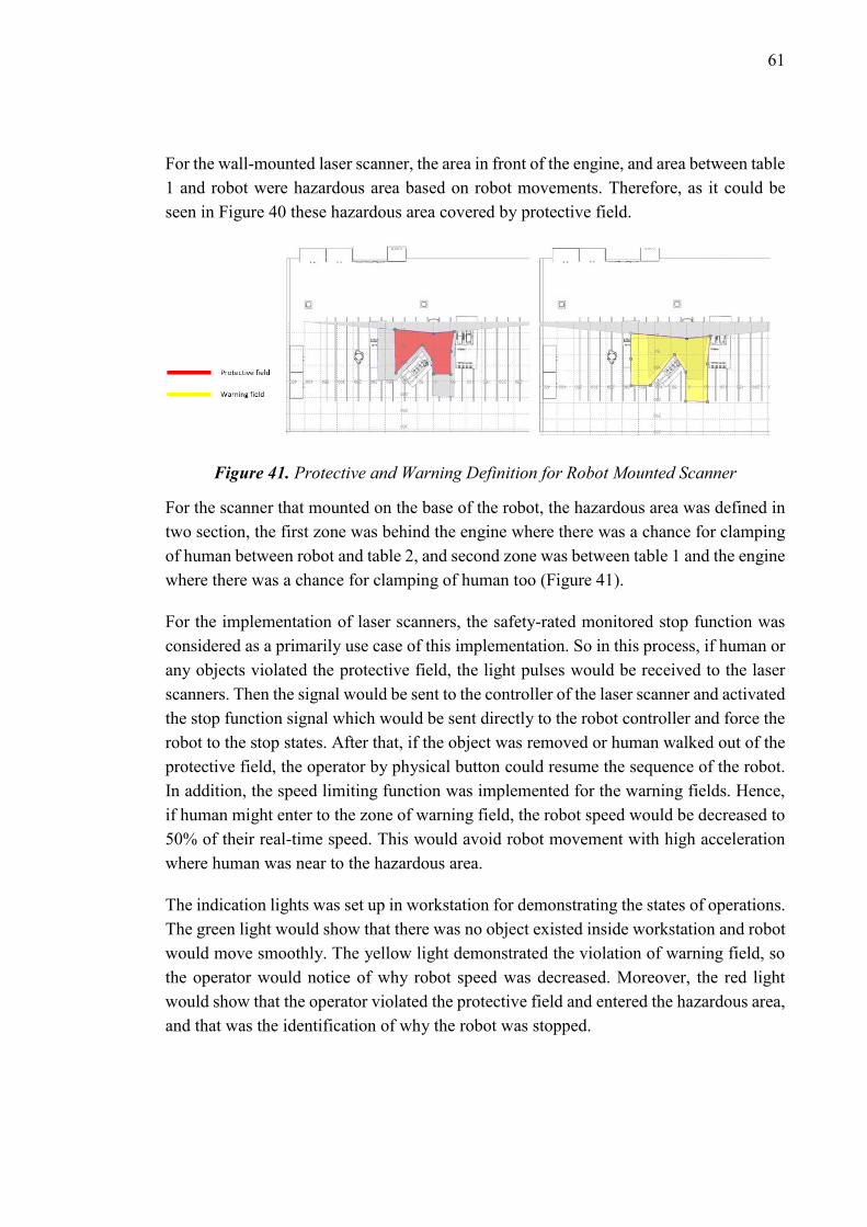
61
For the wall-mounted laser scanner, the area in front of the engine, and area between table
1 and robot were hazardous area based on robot movements. Therefore, as it could be
seen in Figure 40 these hazardous area covered by protective field.
Figure 41. Protective and Warning Definition for Robot Mounted Scanner
For the scanner that mounted on the base of the robot, the hazardous area was defined in
two section, the first zone was behind the engine where there was a chance for clamping
of human between robot and table 2, and second zone was between table 1 and the engine
where there was a chance for clamping of human too (Figure 41).
For the implementation of laser scanners, the safety-rated monitored stop function was
considered as a primarily use case of this implementation. So in this process, if human or
any objects violated the protective field, the light pulses would be received to the laser
scanners. Then the signal would be sent to the controller of the laser scanner and activated
the stop function signal which would be sent directly to the robot controller and force the
robot to the stop states. After that, if the object was removed or human walked out of the
protective field, the operator by physical button could resume the sequence of the robot.
In addition, the speed limiting function was implemented for the warning fields. Hence,
if human might enter to the zone of warning field, the robot speed would be decreased to
50% of their real-time speed. This would avoid robot movement with high acceleration
where human was near to the hazardous area.
The indication lights was set up in workstation for demonstrating the states of operations.
The green light would show that there was no object existed inside workstation and robot
would move smoothly. The yellow light demonstrated the violation of warning field, so
the operator would notice of why robot speed was decreased. Moreover, the red light
would show that the operator violated the protective field and entered the hazardous area,
and that was the identification of why the robot was stopped.

62
3.6.2 ABB SafeMove
One of the safety controllers exists in the robot system is provided from ABB called
SafeMove for some range of their industrial robots. The SafeMove is an add-on for ABB
RobotStudio software while it is connected to the IRC5 controller. The primary goal of
SafeMove is ensured high safety level in shared workspace with using supervision func-
tions. These functions are activated from a digital input of safety devices such as laser
scanners, light curtain, etc. However, these functions are capable of stopping robot move-
ments by setting digital output signals. With utilizing the robot system with safety PLC,
the input and output signals are transferred to the PLC and can control the characteristic
of robot movements. Some of the supervision functions are as follows:
- Safe Zones: This supervision provides optimization of cell size and process of in-
stallation of safeguarding will be simplified.
- Safe Axis Ranges: This supervision can be exchanged with electro-mechanical posi-
tion switches. This function can provide more flexibility and control on robot axis
movements.
- Safe Robot Speed: It supervises speed of tool center point and robot axis to protect
human who work close to the robot workspace
In this thesis, when human entered to the protective field or warning field, a laser scanner
sent digital signal outputs, this signal could be utilized to control robot program either to
stop the robot movements or to reduce the speed of robot system. For the first step, re-
garding the trajectory of the robot inside assembly tasks, the safety axis ranges was ad-
justed for the robot. The required values were demonstrated in Figure 42. Violating these
values would cause the category 1 stop for the robot. The category 1 stop was a controlled
stop state where the power was available for the actuators to achieve the stop. Power
would be removed from the actuators when the stop was completed. The axis 4, 5 and 6
were not limited because the design of the multi-gripper for enabling the reachability of
required angles and positions needed to be considered.

63
Figure 42. Safety Range Axis Properties from ABB SafeMove
In the next phase, the tool of the robot was simulated with boxes and capsules to utilize
the position of the tool when entered to the safety zones. Tool position function required
the definition of safety zones. Hence, five safety zones were determined in RobotStudio
environment, Table1, manual1, manual2, engine, and table 2 (Figure 43). If the robot
movements exceeded their path because of malfunctioning and violated the zones,
SafeMove would stop the robot in category 1. Meanwhile, the outputs from the laser
scanners field were collected in SafeMove function to monitor the violation of field which
led to robot stop function or reduced the speed of the robot path.
Figure 43. Safety Zone Definition in ABB RobotStudio
In the case of violations, the related indication light would be turned on as guidance for
the operator for understanding the states of safety in shared workspace. In the state of
stopping of the robot, after the object removed from safety zones with the help of a
physical button the robot program could be resumed.

64
4. RESULTS
4.1.1 Time Work Study Analysis
For studying the impact of human-robot collaboration on productivity of system, the time
work study was conducted. Therefore, the comparison of time study between manual as-
sembly process and HRI scenarios was required. The manual assembly process was im-
portant in this case because nowadays in the industry the most part of engine assembly
process was performed by an operator. For this study, an operator with some experience
with components was used. The assembly process repeated three times to have a reliable
experience with respect to the agility of the operator. The collected data was shown in
Table 8.
Table 8. Time Study of Manual Assembly Sequence
Assembly
Sequence Assembly Task First Try(s) Second Try(s) Third Try (s)
Average
Time (s)
1 Assembly of Exhaust
Cover 23.15 24.35 25.82 24.44
2 Assembly of Bolts of
Exhaust Cover 89.49 85.04 82.20 85.58
3 Assembly of Rocker
Arms 34.30 36.17 32.58 34.35
4 Assembly of Motor
Frame 15.78 15.76 18.36 16.63
5 Assembly of Motor
Frame Screws 47.40 47.45 49.79 48.21
6 Assembly of Electric
Kit 33.67 33.23 34.57 33.82
7 Assembly of Push-
rods 19.13 23.00 23.39 21.84
8 Assembly of Rock-
ershaft 29.05 30.45 30.13 29.88
9 Assembly of Nuts of
Rockershaft 48.87 43.99 44.93 45.93
10 Assembly of Head-
cover 16.33 16.83 16.19 16.45
11 Assembly of Head-
cover Bolts 61.77 57.53 63.30 60.87
Total time 418.00

65
In the next step, the time study was performed for each interaction levels. The robot speed
was set to the 200 mm/s. Also, the delay time of operator in reaction of performing robot
program was considered. The time study of three interaction levels were as following in
Table 9, Table 10, and Table 11.
Table 9. Time Study of First Interaction
Level of HRC Sequence
Assembly
Sequence Assembly Task
Average
Time (s)
1 Assembly of Ex-
haust Cover 24.44
2 Assembly of Bolts
of Exhaust Cover 85.58
3 Assembly of
Rocker Arms 34.35
4 Assembly of Motor
Frame(robot) 48.40
5 Assembly of Motor
Frame(human) 9.58
6 Assembly of Motor
Frame Screws 21.60
7 Assembly of Elec-
tric Kit 13.85
8 Assembly of Push-
rods 133.12
9 Assembly of Rock-
ershaft 20.18
10 Assembly of Nuts
of Rockershaft 32.01
11 Assembly of Head-
cover 36.21
12 Assembly of Head-
cover Bolts 45.29
Total
Time 504.61
Table 10. Time Study of Second Interac-
tion Level of HRC Sequence
Assembly
Sequence
Assembly Task Average
Time (s)
1 Assembly of Ex-
haust Cover 24.44
2 Assembly of Bolts
of Exhaust Cover 85.58
3 Assembly of
Rocker Arms 34.35
4 Assembly of Mo-
tor Frame (robot) 48.40
5 Assembly of Mo-
tor Frame (human) 9.58
6 Assembly of Mo-
tor Frame Screws 21.60
7 Assembly of Elec-
tric Kit 15.76
8 Assembly of Push-
rods 133.12
9 Assembly of
Rockershaft 20.18
10 Assembly of Nuts
of Rockershaft 32.01
11 Assembly of
Headcover 36.21
12 Assembly of
Headcover Bolts 45.29
Total
Time 506.52

66
Table 11. Time Study of Third Interaction Level of HRC Sequence
Assembly
Sequence Assembly Task
Average
Time (s)
1 Assembly of Exhaust
Cover 24.44
2 Assembly of Bolts of Ex-
haust Cover 85.58
3 Assembly of Rocker Arms 34.35
4 Assembly of Motor
Frame(robot) 37.60
5 Assembly of Motor
Frame(human) 6.15
6 Assembly of Motor Frame
Screws 21.60
7 Assembly of Electric Kit 13.85
8 Assembly of Pushrods 133.12
9 Assembly of Rock-
ershaft(robot) 33.76
10 Assembly of Rock-
ershaft(human) 11.92
11 Assembly of Nuts of
Rockershaft 32.01
12 Assembly of Headcover 36.21
13 Assembly of Headcover
Bolts 45.29
Total Time 515.88
It could be seen that total time of assembly process was increasing while the physical interaction
between robot and human rises too. The implementation of HRC in three different interaction
levels might not decrease the total time of assembly process in this case. However, by studying
working time of human inside workstation, the big differences could be observed between various
assembly sequences (Table 12). This result proved that with less time activity of human inside
workstation, the fatigue of worker could be decreased significantly. Also it could be mentioned
that with lower amount of workload, there would be less chance for injuries inside workstation. In
addition, by assigning high payload task to the robots, the ergonomic of operator was improved.
Table 12. Total Amount of Human Working Time in Different Assembly Sequence
Human Assem-
bly Process
Manual Assem-
bly
First Interaction
Level
Second Interac-
tion Level
Third Interaction
Level
Total Time (s) 418.00 286.88 288.79 275.19
67
As it was noticed in the time study, for robot assembly task, the assembly of pushrods took the
biggest time in the whole assembly. Reason for this, was that the grippers just only capable of
picking two pushrods at the same time. Also, the traveling time between pick and place point was
repeated four times which at final made the whole process four times longer. Therefore, if the
design of the gripper changed in a manner that the griper capable of pick all the eight pushrods at
the same time, then by calculations in simulation with Visual Components the time of assembly
could be reduced from 133 seconds to 38 seconds. This might be reduced the whole assembly
process by 95 seconds, as a result with just some modification in the design we might approach
nearly to the same time of manual assembly.
4.1.2 Task Allocation Results
Through the implementation of this project, the classification in section 3.3 was used for task
allocation between robot and human tasks. From time work study in previous section, some results
were noticed that it would be described as following. The first noticeable impact was from assem-
bly of pushrods. In the task allocation table, it had been analyzed that this task could be done either
by robot or by human. In this thesis, I decided to allocate this task to the robot, but the problem
was about time of the assembly which was related to the design of gripper. The pushrods did not
have complex geometry which was one of the factors in the task allocation, but complexity of the
design of gripper could effect on other the factors in task allocation. With the better design solu-
tion, more improvement might be achieved in timing of robot tasks.
Second result from robot task was related to the payload factor. With repeating the assembly se-
quences, an operator found out that he became less tired during HRC assembly sequences. Maybe
the time of assembly process between manual and HRC did not have so much difference but still
it improved the ergonomic of the operator. This could bring up the fact that ergonomic and payload
were two linked factors that impact on each other.
Regarding the design issues, it was better to test and analyze the task allocation before completing
the design of workstation. Simulation softwares such as Siemens Technomatix could be utilized
because it had capabilities to analyze human factors such as fatigue and ergonomics based on
possible risk of injuries.
4.1.3 Safety Function Analysis
In this section, there were multiple factors proposed that what kind of safety function required for
each interaction levels. Therefore, it worth to review the interaction levels again.
68
- Interaction level one: in this interaction level both robot and human operate in shared work-
space (without physical barriers), but human is not allowed to enter the robot workspace and
has not any physical interaction with robot.
- Interaction level two: in this interaction level both robot and human operate in shared work-
space, robot will provide component in intermediate storage for the assembly by human. Note-
worthy, human has not any physical interaction with robot and there is no need for human to
enter the robot workspace.
- Interaction level three: in this level, human is allowed to enter to the cooperative workspace
while robot provides components and hands it over to the human. In this interaction, partial
physical interaction exists between robot and human.
- Interaction level four: in this level, both robot and human operate in shared workspace. The
human uses hand guiding device to control the robot movements and assemble component in
precise position. Moreover, this interaction level is not included in this experiment.
In addition, the safety function could be mentioned as follows:
- Safety-rated monitored stop: in this method when human enters the collaborative workspace
the robot shall stop its motion.
- Speed and separation monitoring: in this method, if human enters the collaborative work-
space, the robot can continue its movement while the human does not violate the safety dis-
tance between robot and human. If human enters the warning field, the robot starts to decrease
the speed of movement. If human enters the protective field, the robot will stop completely.
- Hand guiding: in this method, the human use a hand guiding device to move robot system to
the required position. However, beforehand the human enters to the collaborative workspace
and using enabling device for controlling the robot movements, the robot shall achieve safety-
rated monitored stop.
- Power and force limiting: this safety function is considered when contacts between robot and
human are allowed. Based on quasi-static contact or transient contact, the amount of force on
human body parts can differ and it shall calculated in specific cases.
For implementation of this thesis, the hand guiding device was not implemented and for the first
three interaction levels, this safety function was not required as well. Also, the contact between
robot and human was not allowed because the large industrial robot was not equipped with sensors
such as capacitive skin sensors, and any contacts could cause injuries to the operator. Therefore,
the analysis of two safety functions was assessed in Table 13 by following factors:
- Mitigation of operator error: this criteria addresses the error value of the operator in the
assembly sequence, or violation of the process.
- Reachability of operator: it considers the ability level of the operator to grasp the compo-
nents. When the low reachability occurs, there will be a possibility for the operator to change
the working position.

69
- Distance between human and robot: this criteria defines the distance between human and
robot. According to the proper assembly sequence for each interaction level, it may require the
operator to enter the robot workspace.
- Complexity of assembly task: this factor considers the complexity of assembly process, the
complexity can mean the number of components, direction of assembly, and etc. For instance,
when the complexity is increasing, how much it can affect the safety of operator.
- Weight of components: based on existing components in the assembly of product, when the
components get heavier it may affect the operator’s ergonomic.
There were two levels for evaluation of the impact of each criteria on injuries severity [84]:
- Low impact: This level states the scale of injuries for the operator. On this master thesis, low
impact represents the minor or moderate injury severity scale.
- High impact: This level represents serious and severe injuries that may happen to the operator.
By considering these factors and evaluating the importance of safety functions, the results could
be concluded as follows:
- Interaction level one: for this level of interaction it had evaluated that implementation of
safety-rated monitored stop was necessary.
- Interaction level two: in this level, safety-rated monitored stop was necessary but if the
operator error could be increased it could affect on other factors which led to consideration
of speed and separation monitoring function as optional case.
- Interaction level three: while human entered to the collaboration workspace it could af-
fect on all of the factors. The operator could move between the robot workspace and human
workplaces, these movements would be harmful if the operator was near the robot. Colli-
sion of robot with human with high speed could cause serious damages. Therefore, imple-
mentation of speed and separation monitoring beside safety-rated monitored stop was nec-
essary.

70
Table 13. Interaction Level Safety Function Analysis
Interaction Level 1 Interaction Level 2 Interaction Level 3
Safety
Function
Safety-rated monitored
stop
Speed and distance
limiting
Safety-rated monitored
stop
Speed and distance
limiting
Safety-rated monitored
stop
Speed and distance
limiting
Evaluation
criterion
Impact
Low
Impact
High
Impact
Low
Impact
High
Impact
Low
Impact
High
Impact
Low
Impact
High
Impact
Low
Impact
High
Impact
Low
Impact
High
Impact
Mitigation op-
erator
Error
√ √ √ √ √
Reachability
of
operator
√ √ √ √ √ √
Distance be-
tween human
and robot
workspace
√ √ √ √ √ √
Complexity of
assembly task √ √ √ √ √ √
Weight of
component √ √ √ √ √ √
Result High Impact Low Impact High Impact Low Impact High Impact High Impact
√

71
5. CONCLUSION
For achieving the goals of this project, the interaction levels of HRC was studied. The
shared workspace for HRC environment was designed and proper tools such as multi-
function grippers were built for different assembly sequences. Each interaction levels de-
fined the different physical interactions between human and robot. This led to consider
different assembly sequences for each interaction level. Based on the task allocation be-
tween human and robot, assembly tasks were justified by factors such as complexity of
assembly tasks, ergonomics, repeatability and payload.
The assembly scenarios were investigated by simulations with Visual Components soft-
ware. Afterwards, for each HRI levels, the ABB IRB4600 was programmed to follow
main goals of each interaction level. The environment of shared workspace was deter-
mined by different zones and the possibility of hazard risks were assessed in different
zones. Therefore, with guidance of technical specification ISO/TS 15066, two safety
functions were determined for this project respect to HRI levels requirements. The two
safety functions were called “safety-rated monitored stop” and “speed and separation
monitoring”.
Firstly, the ABB SafeMove add-on in RobotStudio was utilized for definition of safety
zones. These safety zones provided primary tools as a safety stop function inside hazard-
ous area. Secondly, the SICK laser scanner was installed to scan the presence of human
or object inside protective and warning fields. The signals of detection transferred from
laser scanner to ABB IRC5 controller. In the case of violation of warning fields, the ro-
bot’s speed was decreased. Thus, if human or object violated the protective field, it led to
stop the robot movements.
Time work study was used to analyze assembly sequences in different interaction levels,
which shown that the cell design and gripper design could affect on the total time of
assembly and robot movements. In addition, task allocation had been shown that payload
and task complexity could be determined as important factors for allocating the tasks
between the human and the robot. With comparison of time work study and task alloca-
tion, it was considered that the complex geometry of components and design of grippers
had impacts on productivity of shared workspace.
In the scope of this project, the gripper fingers could be machined with rigid material to
provide more grasp force for the gripper. Therefore, multiple picking of components

72
could be achieved while operator performs the responsible tasks. This might reduce the
delay time for the robot to pick components and increase overlapping which finally im-
prove the productivity.
Implementation of Sim-4-Safety of laser scanner to define multiple fields could be an-
other solution that could affect the safety implementation. Up to four protective fields
could be defined to smooth the workflow of tasks between operator and robot and increase
the efficiency. Since the designed protective field in this experiment was one field and
shaped like polygon, when the operator entered the area which was not in the range of
robot movement, led the robot to stop. By defining multiple fields, the freedom of opera-
tor movements outside the hazardous area would increase and decrease the delay of the
robot’s working time. In addition, with better feeding strategy for the system, the delaying
time for feeding robot would be decreased. This could led to enhance robot tasks timing.
For further studies, there are solutions that can be considered. Firstly, the design of grip-
pers can be changed to provide faster movements inside workstation and reduce assembly
time. As time work study showed, the assembly of pushrods have massive time consump-
tion compared to manual assembly. As a solution, the gripper can be designed to pick
eight pushrods at same time and reduce the time of assembly.
Secondly, the 4th interaction level could be investigated. This interaction level requires
design of the hand guiding device for ABB IRB4600 and utilizing the robot grippers with
force sensors. Hence, the impact of more physical interaction between robot and human
can be studied and compared to the manual assembly. The hand guiding device can in-
crease the flexibility and precision of assembly sequence. As safety aspect, the power and
force limiting can be investigated in this specific case and results can be compared to the
less physical interaction.

73
REFERENCES
[1] J. Krüger, T. K. Lien, and A. Verl, “Cooperation of human and machines in
assembly lines,” CIRP Ann. - Manuf. Technol., vol. 58, no. 2, pp. 628–646, 2009.
[2] R. Ahmad and P. Plapper, “Human-Robot Collaboration: Twofold Strategy
Algorithm to Avoid Collisions Using ToF Sensor,” Int. J. Mater. Mech. Manuf.,
vol. 4, no. 2, pp. 144–147, 2015.
[3] S. Standardisoimisliitto, “Sfs-en iso 10218-1 3.,” no. Malminkatu 34, 2018.
[4] ISO 10218-2, “Robots and robotic devices -- Safety requirements for industrial
robots -- Part 2: Robot systems and integration,” Text, 2011.
[5] E. K. für Normung, “TECHNICAL SPECIFICATION ISO / TS Robots and
robotic devices —,” vol. 2016, 2016.
[6] M. Bdiwi, M. Pfeifer, and A. Sterzing, “A new strategy for ensuring human safety
during various levels of interaction with industrial robots,” CIRP Ann. - Manuf.
Technol., vol. 66, no. 1, pp. 453–456, 2017.
[7] “S3000 Standard SICK.” [Online]. Available: https://www.sick.com/ag/en/opto-
electronic-protective-devices/safety-laser-scanners/s3000-standard/c/g187231.
[Accessed: 05-Nov-2018].
[8] “SafeMove 2 - IRC5 Options (IRC5 Controller) | ABB.” [Online]. Available:
https://new.abb.com/products/robotics/controllers/irc5/irc5-options/safemove-2.
[Accessed: 05-Nov-2018].
[9] S. Stumm, J. Braumann, M. Von Hilchen, and S. Brell-Cokcan, “On-Site Robotic
Construction Assistance for Assembly Using A-Priori Knowledge and Human-
Robot Collaboration,” 2017.
[10] J. Sandoval, M. A. Laribi, S. Zeghloul, M. Arsicault, and G. Poisson, “Safety
Performance of a Variable Stiffness Actuator for Collaborative Robots,” in
Advances in Service and Industrial Robotics, 2019, pp. 35–43.
[11] S. Fang, X. Huang, H. Chen, and N. Xi, “Dual-arm robot assembly system for 3C
product based on vision guidance,” in 2016 IEEE International Conference on
Robotics and Biomimetics (ROBIO), 2016, pp. 807–812.
[12] N. Sanchez-Tamayo and J. P. Wachs, “Collaborative Robots in Surgical Research:
a Low-Cost Adaptation,” 2018.
[13] C. Yang, C. Zeng, P. Liang, Z. Li, R. Li, and C. Y. Su, “Interface Design of a
Physical Human-Robot Interaction System for Human Impedance Adaptive Skill

74
Transfer,” IEEE Trans. Autom. Sci. Eng., vol. 15, no. 1, pp. 329–340, 2018.
[14] K. N. Kaipa, C. W. Morato, J. Liu, and S. K. Gupta, “Human-robot Collaboration
for Bin-picking Tasks to Support Low-volume Assemblies.”
[15] M. Lanz, R. Velez Osuna, and R. Tuokko, “Feature-Based Modeling and Analysis
for Knowledge-Intensive Concurrent Engineering in Final Assembly,” Proceeding
CAID 2005, p. 6, 2005.
[16] H. a. ElMaraghy, Changeable and Reconfigurable Manufacturing Systems, vol. 4,
no. 9. 2008.
[17] D. Gyulai, Z. Vén, A. Pfeiffer, J. Váncza, and L. Monostori, “Matching Demand
and System Structure in Reconfigurable Assembly Systems,” Procedia CIRP, vol.
3, pp. 579–584, 2012.
[18] S. N. Samy and H. Elmaraghy, “A model for measuring complexity of automated
and hybrid assembly systems.”
[19] A. Al-Zuheri, “STRUCTURAL AND OPERATIONAL COMPLEXITY OF
MANUAL ASSEMBLY SYSTEMS,” J. Comput. Sci., vol. 9, no. 12, pp. 1822–
1829, 2013.
[20] J. Heilala and P. Voho, “Modular reconfigurable flexible final assembly systems,”
Assem. Autom., vol. 21, no. 1, pp. 266–272, 2001.
[21] N. Benkamoun, W. ElMaraghy, A.-L. Huyet, and K. Kouiss, “Architecture
Framework for Manufacturing System Design,” Procedia CIRP, vol. 17. pp. 88–
93, 2014.
[22] A. Mital, Product development, 2nd ed. Amsterdam: Elsevier Science, 2014.
[23] R. Parasuraman, T. B. Sheridan, and C. D. Wickens, “A model for types and levels
of human interaction with automation,” IEEE Trans. Syst. Man, Cybern. Part
ASystems Humans., vol. 30, no. 3, pp. 286–297, 2000.
[24] J. Frohm, Levels of Automation in Production Systems, no. October. 2008.
[25] H. P. Wiendahl et al., “Changeable Manufacturing - Classification, Design and
Operation,” CIRP Annals - Manufacturing Technology, vol. 56, no. 2. pp. 783–
809, 2007.
[26] L. Westerlund, The exteded arm of man : a history of the industrial robot.
Informationsforlaget, 2000.
[27] International Federation of Robotics (IFR), “History of Industrial Robots – From
the first installation until today,” Milestones Technol. Commer., pp. 1–12, 2012.
[28] H. Makino, “Development of the SCARA,” J. Robot. Mechatronics, vol. 26, no. 1,
pp. 5–8, 2014.

75
[29] K. S. Saidi et al., Springer Handbook of Robotics. 2008.
[30] S. Haddadin, S. Parusel, R. Belder, and A. Albu-Schäffer, “LNCS 8153 - It Is
(Almost) All about Human Safety: A Novel Paradigm for Robot Design, Control,
and Planning.”
[31] R. Bloss, “Innovations like two arms, cheaper prices, easier programming,
autonomous and collaborative operation are driving automation deployment in
manufacturing and elsewhere,” Assem. Autom., vol. 33, no. 4, pp. 312–316, Sep.
2013.
[32] S. Kock, T. Vittor, B. Matthias, H. J.-… (ISAM), 2011 IEEE, and undefined 2011,
“Robot concept for scalable, flexible assembly automation: A technology study on
a harmless dual-armed robot,” ieeexplore.ieee.org.
[33] P. Crowther and P. Management, “YuMi ® – IRB 14000 Overview,” no. April,
2015.
[34] “ABB Elektro-Praga, Czech Republic,” 2018. [Online]. Available:
https://new.abb.com/products/robotics/case-studies/abb-elektro-praga-czech-
republic. [Accessed: 03-Oct-2018].
[35] Rethink Robotics, “Baxter.” [Online]. Available:
https://www.rethinkrobotics.com/wp-
content/uploads/2015/11/Baxter_Datasheet_Oct2015.pdf. [Accessed: 03-Oct-
2018].
[36] E. Yudkowsky, “The Robots, AI, and Unemployment Anti-FAQ - LessWrong
2.0.” [Online]. Available:
https://www.lesswrong.com/posts/ZiRKzx3yv7NyA5rjF/the-robots-ai-and-
unemployment-anti-faq. [Accessed: 03-Oct-2018].
[37] H. Bley, G. Reinhart, G. Seliger, M. Bernardi, and T. Korne, “Appropriate human
involvement in assembly and disassembly,” CIRP Ann. - Manuf. Technol., vol. 53,
no. 2, pp. 487–509, 2004.
[38] P. Tsarouchi, A.-S. Matthaiakis, S. Makris, and G. Chryssolouris, “On a human-
robot collaboration in an assembly cell,” Int. J. Comput. Integr. Manuf., vol. 30,
no. 6, pp. 580–589, 2017.
[39] M. F. Zaeh and M. Prasch, “Systematic workplace and assembly redesign for aging
workforces,” Prod. Eng., vol. 1, no. 1, pp. 57–64, Aug. 2007.
[40] R. Op De Beek and V. Hermans, Research on work-related low back disorders.
2000.
[41] G. Michalos, S. Makris, P. Tsarouchi, T. Guasch, D. Kontovrakis, and G.
Chryssolouris, “Design considerations for safe human-robot collaborative
workplaces,” Procedia CIRP, vol. 37, pp. 248–253, 2015.

76
[42] International Federation of Robotics, “IFR World Robotics 2017,” IFR Forecast
1.7 million new Robot. to Transform world´s factories by 2020, no. September, p.
25, 2017.
[43] K. Rehkopf, “The Encyclopedia of Work‐related Illnesses, Injuries, and Health
Issues2004442Ada P. Kahn. The Encyclopedia of Work‐related Illnesses, Injuries,
and Health Issues . New York, NY: Facts on File 2004. xiv + 434 pp., ISBN: 0
8160 4844 4 £45.95/$65 Facts on File Library of Health and Living,” Ref. Rev.,
vol. 18, no. 8, pp. 37–37, Dec. 2004.
[44] K. Hodgens, “Discover Innovative Solutions for Packaging and Palletizing from
KUKA Robotics Corporation | Business Wire,” 2017. [Online]. Available:
https://www.businesswire.com/news/home/20170922005098/en/Discover-
Innovative-Solutions-Packaging-Palletizing-KUKA-Robotics. [Accessed: 03-Oct-
2018].
[45] Z. Pan, J. Polden, N. Larkin, S. Van Duin, and J. Norrish, “Recent progress on
programming methods for industrial robots,” 2012.
[46] KUKA Industries Automation, “Spot welding | KUKA AG.” [Online]. Available:
https://www.kuka.com/en-au/technologies/process-technologies/2016/07/spot-
welding. [Accessed: 03-Oct-2018].
[47] N. Lohse, H. Hirani, S. Ratchev, and M. Turitto, “An ontology for the definition
and validation of assembly processes for evolvable assembly systems,” Proc. IEEE
Int. Symp. Assem. Task Plan., vol. 2005, pp. 242–247, 2005.
[48] Deutsches Institut für Normung, DIN 8593-0: 2003-09 Manufacturing methods
Joining - Part 0: General; Classification, subdivision, concepts. .
[49] “KUKA Cobots | KUKA AG.” [Online]. Available: https://www.kuka.com/en-
de/technologies/industrie-4-0/industrie-4-0-cobots-in-industry. [Accessed: 03-
Oct-2018].
[50] N. Underhaug, “The world’s first paint robot,” 2000.
[51] V. Achieng, “15 Most Savage Deaths Caused By Robots | TheRichest,”
TheRichest, 2017. [Online]. Available:
https://www.therichest.com/technologies/15-shocking-deaths-caused-by-robots/.
[Accessed: 03-Oct-2018].
[52] O’Donoghue. Paul, “Ireland above EU average for fatal accidents at work -
Independent.ie,” independant.ie, 2015. [Online]. Available:
https://www.independent.ie/business/irish/ireland-above-eu-average-for-fatal-
accidents-at-work-31290967.html. [Accessed: 03-Oct-2018].
[53] THE EUROPEAN PARLIAMENT AND OF THE COUNCIL, “Directive
2006/42/Ec of the European Parliament and of the Council,” Off. J. Eur.
Communities, vol. L 269, no. September 2000, pp. 1–15, 2000.

77
[54] “Safety Requirements | Technical Guide | Australia | Omron IA,” Omron, 2008.
[Online]. Available:
http://www.omron.com.au/service_support/technical_guide/safety_component/sa
fety_requirements.asp. [Accessed: 03-Oct-2018].
[55] ISO, “ISO 12100 Safety of machinery — General principles for design — Risk
assessment and risk reduction,” no. January, 2011.
[56] S. Standardisoimisliitto, “Sfs-en 60204-1 3.,” no. Malminkatu 34, 2018.
[57] J. Safety, “Limiting devices for industrial robot cells,” 2018.
[58] G. Michalos, S. Makris, P. Tsarouchi, T. Guasch, D. Kontovrakis, and G.
Chryssolouris, “Design considerations for safe human-robot collaborative
workplaces,” Procedia CIRP, vol. 37. pp. 248–253, 2015.
[59] C. K. Jalba, P. Konold, I. Rapp, C. Mann, and A. Muminovic, “Cooperation
between humans and robots in fine assembly,” IOP Conf. Ser. Mater. Sci. Eng.,
vol. 163, no. 1, 2017.
[60] G. Vivo, A. Zanella, O. Tokcalar, and G. Michalos, “The ROBO-PARTNER EC
Project: CRF Activities and Automotive Scenarios,” Procedia Manuf., vol. 11, no.
June, pp. 364–371, 2017.
[61] C. Thomas, F. Busch, B. Kuhlenkoetter, and J. Deuse, “Process and human safety
in human-robot-interaction - A hybrid assistance system for welding applications,”
Lect. Notes Comput. Sci. (including Subser. Lect. Notes Artif. Intell. Lect. Notes
Bioinformatics), vol. 7101 LNAI, no. PART 1, pp. 112–121, 2011.
[62] C. Vogel, M. Poggendorf, C. Walter, and N. Elkmann, “Towards safe physical
human-robot collaboration: A projection-based safety system,” IEEE Int. Conf.
Intell. Robot. Syst., pp. 3355–3360, 2011.
[63] C. Vogel, C. Walter, and N. Elkmann, “A projection-based sensor system for safe
physical human-robot collaboration,” IEEE Int. Conf. Intell. Robot. Syst., pp.
5359–5364, 2013.
[64] C. Vogel, C. Walter, and N. Elkmann, “Safeguarding and Supporting Future
Human-robot Cooperative Manufacturing Processes by a Projection- and Camera-
based Technology,” Procedia Manuf., vol. 11, no. June 2017, pp. 39–46, 2017.
[65] M. Lešo, J. Žilková, and M. Vacek, “Robotic Manipulator with Optical Safety
System,” pp. 21–23, 2015.
[66] A. Hietanen, R. Halme, J. Latokartano, R. Pieters, and M. Lanz, “Depth-sensor –
projector safety model for human-robot collaboration,” no. 1, pp. 3–6.
[67] F. Flacco, T. Kröger, A. De Luca, and O. Khatib, “A depth space approach to
human-robot collision avoidance,” Proc. - IEEE Int. Conf. Robot. Autom., no. May

78
2012, pp. 338–345, 2012.
[68] F. Flacco, T. Kroeger, A. De Luca, and O. Khatib, “A Depth Space Approach for
Evaluating Distance to Objects: with Application to Human-Robot Collision
Avoidance,” J. Intell. Robot. Syst. Theory Appl., vol. 80, pp. 7–22, 2015.
[69] F. Fabrizio and A. De Luca, “Real-Time Computation of Distance to Dynamic
Obstacles With Multiple Depth Sensors,” IEEE Robot. Autom. Lett., vol. 2, no. 1,
pp. 56–63, 2017.
[70] C. Morato, K. N. Kaipa, B. Zhao, and S. K. Gupta, “Toward Safe Human Robot
Collaboration by Using Multiple Kinects Based Real-time Human Tracking,” J.
Comput. Inf. Sci. Eng., vol. 14, no. 1, p. 011006, 2014.
[71] A. Mohammed, B. Schmidt, and L. Wang, “Active collision avoidance for human–
robot collaboration driven by vision sensors,” Int. J. Comput. Integr. Manuf., vol.
30, no. 9, pp. 970–980, 2017.
[72] B. Schmidt and L. Wang, “Contact-less and programming-less human-robot
collaboration,” Procedia CIRP, vol. 7, pp. 545–550, 2013.
[73] B. Schmidt and L. Wang, “Depth camera based collision avoidance via active robot
control,” J. Manuf. Syst., vol. 33, no. 4, pp. 711–7118, 2014.
[74] L. Wang, B. Schmidt, and A. Y. C. Nee, “Vision-guided active collision avoidance
for human-robot collaborations,” Manuf. Lett., vol. 1, no. 1, pp. 5–8, 2013.
[75] J. T. C. Tan and T. Arai, “Triple stereo vision system for safety monitoring of
human-robot collaboration in cellular manufacturing,” Proc. - 2011 IEEE Int.
Symp. Assem. Manuf. ISAM 2011, pp. 1–6, 2011.
[76] M. Zaeh and W. Roesel, “Safety aspects in a human-robot interaction scenario: A
human worker is co-operating with an industrial robot BT - 12th FIRA RoboWorld
Congress on Progress in Robotics 2009, August 16, 2009 - August 20, 2009,” vol.
44 CCIS. pp. 53–62, 2009.
[77] J. Miseikis et al., “Robot Localisation and 3D Position Estimation Using a Free-
Moving Camera and Cascaded Convolutional Neural Networks,” no. April, 2018.
[78] D. Antonelli, G. Bruno, and D. Politecnico, “Human-Robot Collaboration Using
Industrial Robots,” vol. 86, no. Eame, pp. 99–102, 2017.
[79] A. Cherubini, R. Passama, A. Crosnier, A. Lasnier, and P. Fraisse, “Collaborative
manufacturing with physical human-robot interaction,” Robotics and Computer-
Integrated Manufacturing, vol. 40. pp. 1–13, 2016.
[80] “ABB IRB 4600-60.” [Online]. Available: https://www.robots.com/robots/abb-
irb-4600-60. [Accessed: 09-Nov-2018].

79
[81] “PGN-plus 100-1.” [Online]. Available: https://schunk.com/fi_en/gripping-
systems/product/547-0371102-pgn-plus-100-1/. [Accessed: 09-Nov-2018].
[82] “PGN-plus 80-2.” [Online]. Available: https://schunk.com/fi_en/gripping-
systems/product/928-0371151-pgn-plus-80-2/. [Accessed: 09-Nov-2018].
[83] B. K. Ghosh and M. G. Helander, “A systems approach to task allocation of
human-robot interaction in manufacturing,” J. Manuf. Syst., vol. 5, no. 1, pp. 41–
49, 1986.
[84] E. N. 954-1, “Safety of machinery. Safety-related parts of control systems. Part 1:
General principles for design,” p. 65, 1997.