DESIGN OF AUTONOMOUS CLEANING ROBOT - Trepo
67
1 Lakshmi Bangalore Gangadharaswamy DESIGN OF AUTONOMOUS CLEANING ROBOT Faculty of Engineering and Natural Science Master of Science Thesis December 2019
-
Upload
khangminh22 -
Category
Documents
-
view
0 -
download
0
Transcript of DESIGN OF AUTONOMOUS CLEANING ROBOT - Trepo
1
Lakshmi Bangalore Gangadharaswamy
DESIGN OF AUTONOMOUS CLEANING ROBOT
Faculty of Engineering and Natural Science
Master of Science Thesis
December 2019
ABSTRACT
Lakshmi Bangalore Gangadharaswamy: Design of Autonomous Cleaning Robot Master of Science Thesis Tampere University Automation Engineering December 2019
Today, the research is concentrated on designing and developing robots to address the challenges of human life in their everyday activities. The cleaning robots are the class of service robots whose demands are increasing exponentially. Nevertheless, the application of cleaning robots is confined to smaller areas such as homes. Not much autonomous cleaning products are commercialized for big areas such as schools, hospitals, malls, etc.
In this thesis, the proof of concept is designed for the autonomous floor-cleaning robot and autonomous board-cleaning robot for schools. A thorough background study is conducted on domestic service robots to understand the technologies involved in these robots. The components of the vacuum cleaner are assembled on a commercial robotic platform. The principles of vacuum cleaning technology and airflow equations are employed for the component selection of the vacuum cleaner. As the autonomous board-cleaning robot acts against gravity, a magnetic adhesion is used to adhere the robot to the classroom board. This system uses a belt drive mechanism to manoeurve. The use of belt drive increases the area of magnetic attraction while the robot is in motion. A semi-systematic approach using patterned path planning techniques for the complete coverage of the working environment is discussed in this thesis.
The outcome of this thesis depicts a new and conceptual mechanical design of an autonomous floor-cleaning robot and an autonomous board-cleaning robot. This evidence creates a preliminary design for proof-of-concept for these robots. This proof of concept design is developed from the basic equations of vacuum cleaning technology, airflow and magnetic adhesion. A general overview is discussed for collaborating the two robots. This research provides an extensive initial step to illustrate the development of an autonomous cleaning robot and further validates with quantitative data discussed in the thesis.
Keywords: robotic vacuum cleaner, autonomous cleaning, autonomous board cleaner, autonomous vacuuming, path planning techniques

2
PREFACE
This master thesis has been carried out in the Faculty of Engineering and Natural Sciences
at the Tampere University.
I would like to express my gratitude to Professor Kari T. Koskinen for vesting the oppor-
tunity of carrying out the thesis work at Mechatronics Research Group (MRG) and super-
vising my work. I would like to thank the project manager of the group Dr Jussi Aaltonen
for his guidance and supervision. MRG has provided me with a great working atmos-
phere.
I would like to extend my gratitude to Sankeerth Shivakumar, Joe David, Satish Kumar
and Arjun Aiengar for all the support and advice given during the completion of this
thesis.
Finally, a special thanks to my family and friends who have supported me in completion
of the Master of Science Degree.
Tampere, 17.12.2019
Lakshmi Bangalore Gangadharaswamy
3
CONTENTS
1. INTRODUCTION .............................................................................................. 10
1.1 Research methodology .............................................................................. 11
2. THEORETICAL BACKGROUND ..................................................................... 12
2.1 Principle of Vacuum Cleaning Technology ............................................... 12
2.2 Overview of Cleaning Robots ................................................................... 13
2.2.1 Floor cleaning robots .................................................................. 13
2.2.2 Window cleaning robots .............................................................. 19
2.2.3 Automated Board cleaning robot ................................................. 21
2.2.4 Climbing robots .......................................................................... 21
3. CONCEPTUAL DESIGN OF AN AUTONOMOUS FLOOR CLEANING ROBOT
............................................................................................................................ 23
3.1 Overview of the autonomous floor cleaning robot ..................................... 23
3.1.1 Robotic Platform ......................................................................... 23
3.2 Components selection for vacuum cleaning .............................................. 25
3.2.1 Motor and fan ............................................................................. 26
3.2.2 Hose and tubing .......................................................................... 30
3.2.3 Filter or dust bag ......................................................................... 31
3.2.4 Nozzle ........................................................................................ 31
3.2.5 Side brush ................................................................................... 36
3.2.6 Battery ........................................................................................ 38
3.3 Mechanical design of autonomous floor cleaning robot ............................. 39
3.3.1 Mechanical design of vacuum cleaner ......................................... 39
3.3.2 Mechanical assembly of vacuum cleaner and robotic platform .... 40
4. CONCEPTUAL DESIGN OF AN AUTONOMOUS BOARD CLEANING ROBOT
............................................................................................................................ 43
4.1 Overview of the autonomous board cleaning robot.................................... 43
4.1.1 Locomotion mechanism – synchronous belts ............................... 44
4.1.2 Adhesion through magnetic tapes ................................................ 44
4.1.3 Controller .................................................................................... 45
4.1.4 Sensory unit ................................................................................ 45
4.1.5 DC Motor for locomotion............................................................ 47
4.2 Mechanical design of autonomous board cleaning robot ........................... 48
4.2.1 Mechanical assembly of autonomous board cleaning robot ......... 51
5. PATH-PLANNING TECHNIQUES FOR AUTONOMOUS CLEANING ROBOT
............................................................................................................................ 53
5.1 Localization and mapping technique ......................................................... 53
5.2 Techniques involved in autonomous path planning ................................... 55
5.2.1 Spiral motion .............................................................................. 56
5.2.2 Zigzag algorithm ......................................................................... 57
5.2.3 Wall follow algorithm ................................................................. 57
4
5.3 Collaboration of autonomous robots ......................................................... 58
6. CONCLUSION ................................................................................................... 60
6.1 Future work .............................................................................................. 61
REFERENCES ........................................................................................................... 62
5
LIST OF FIGURES
Principal sketch of a canister vacuum cleaner (Leffler, Sörmark
2013).................................................................................................... 12
Different types of vacuum cleaners. Starting from left canister type,
stick type, cordless type and robotic type vacuum cleaner (Larsson,
Petersson 2009). .................................................................................. 12
Right - Cye personal robot vacuum cleaner (Robotnews 2007). Left
- Dyson's DC06, autonomous robotic vacuum cleaner, made up of
three CPU's, over 70 sensors and 54 batteries (Hanlon 2004). ............. 14
Koala cleaning robot built by Laboratory of Microcomputing,
Swiss Institute of technology to study the possible shapes of
vacuum cleaner and its sensor placement (Ulrich, Mondada et al.
1997). ................................................................................................... 14
Locomotion with suction cups (Yoshida, Shugen Ma Dec 2010). .......... 20
Cleaning pattern of Winbot 730 from top to bottom, back and forth
method (O’connell 2013). ..................................................................... 20
One of proposed board cleaning robot design (Zinsmeyer 2014). ......... 21
A – ALICIA3 climibing robot for wall inspection, negative pressure
adhesion (Longo, Muscato 2006).Fig. B - Climbing robots with
claws, CLIBO (Sintov, Avramovich et al. 2011). ................................... 22
Pulurobot M, robotic application platform. The right image shows
the full robot platform wherein the chassis supports the
application. The left image is the enlarged picture of the sensor
array on the front end of the robot. (Pulurobotics Oy Ltd ). .................. 24
Suction and airflow curves showing the effect of input power and
suction power (AEA Energy & Environment, Consumer Research
Associates 2009). ................................................................................. 26
Represents the characteristics of motor and fan of two vacuum
cleaners A and B. Even though A has higher suction power, B is
considered to have better cleaning performance as its load point is
over long range (AEA Energy & Environment, Consumer Research
Associates 2009). ................................................................................. 27
Principal sketch of an active and passive nozzle (Leffler, Sörmark
2013). ................................................................................................... 32
Parts in a nozzle (Leffler, Sörmark 2013). ............................................ 33
Plot of Conductance v/s flow, conductance v/s vacuum pressure for
different orifice loading. ....................................................................... 34
3D modelled vacuum cleaner. .............................................................. 39
Top view of the vacuum cleaner compartment to house motor, dust
bag and controller. ............................................................................... 40
6
Computer aided design (CAD) model of PULU-M robotic platform
(Pulurobotics Oy Ltd ). ......................................................................... 41
3D model of robotic vacuum cleaner. ................................................... 41
Starting from top left to right and bottom left to right, back view,
side view, top view, and isometric view of autonomous floor
cleaner. ................................................................................................ 42
Force direction representation in a magnetic tape (Supermagnete
a). ........................................................................................................ 44
Schematic illustration to represent position and orientation
measurement using IMU (Kok, Hol et al. 2017). ................................... 46
Pictorial representation of Raspberry pi and MPU 6050 with its
pins (RaspberryPiTutorials ). ............................................................... 46
Selected 200:1 Plastic Gearmotor, 900output (Pololu a)....................... 47
Force diagram for a wall-climbing robot on a vertical plane................ 48
3D model of autonomous board cleaning robot. ................................... 51
Starting from top left to right and bottom, side view, front view, top
view, and isometric view of autonomous board cleaner. ....................... 52
The autonomous robot with outer covering depicting a tanker. ............. 52
A – The 2D LIDAR cannot provide complete picture of the obstacle
as it cannot see the human foot in the way and the tabletop that is
above its sight, but it is useful for localization and mapping. B –
The 3D TOF sensors can see all the obstacles at once;hence, they
provide details for obstacle avoidance (Pulurobotics Oy Ltd ). ............. 55
Path generated by squared spiral motion algorithm. ............................ 56
Path generated by Zigzag motion algorithm. ........................................ 57
Path generated by wall follow motion algorithm. ................................. 57
Image to show the idea of collaboration of robotic vacuum cleaner
with robotic board cleaner. .................................................................. 59
7
LIST OF TABLES
Table 1. Specifications of Domestic cleaning robots (Siciliano, Khatib
2016), (Siciliano, Khatib 2008), (iRobot ), (Voltra ), (Mall.SK ). .......... 17
Table 2. Specifications of Domestic Cleaning Robots (Siciliano, Khatib
2016, Siciliano, Khatib 2008, Cooper 2012, RobotReviews 2012,
TestsAndReview 2016, Liszewski 2017). ............................................... 18
Table 3. Specification table for PULU-Robot M ................................................. 24
Table 4. Conductance values for different orifice loading of the selected
motor ................................................................................................... 29
Table 5. Table to represent the calculation of power consumption ..................... 38
Table 6. Specification of selected gear DC motor (Pololu a). ............................. 47
Table 7. List of components of autonomous board cleaning robot along with
the weight. ............................................................................................ 47
8
LIST OF SYMBOLS AND ABBREVIATIONS
BLDC Brushless Direct Current
CAD Computer aided design
DOF Degrees of freedom
Dpu Dust pick up
GPIO General Purpose input/output
IMU Inertial Measurement Unit
IR Infrared
LIDAR Light Detection and Ranging
Li-ion Lithium ion
MEMS Microelectromechanical systems
MCL Monte Carlo localization
RADAR Radio detection and ranging
ROS Robot operating system
RPS Room positing system
SLAM Simultaneous localization and mapping
SONAR Sound Navigation and Ranging
TOF Time of flight
A area of the orifice [m2]
a transmission probability of short structure
Anozzle cross-section area of the nozzle [m2]
B breath [m]
Chose conductance in hose for a viscous laminar flow [m3/s]
Corifice conductance of orifice in viscous laminar flow [m3/s]
Cdust_bag conductance in dust bag for a laminar flow [m3/s]
Cnozzle conductance in nozzle for a viscous laminar flow [m3/s]
C total conductance [m3/s]
d inside diameter of the tube [m]
F Force [N]
Fm Magnetic adhesive force [N]
Ff(i=1,2,3,4) frictional force components [N]
f0 Static friction co-efficient [N]
h height [m]
H distance between the board surface and center of mass [m]
I Inertia [kgm/ s2]
leff effective length of the line [m]
laxial axial length of the hose with bends [m]
l total length of the hose [m]
Kn Knudsen number
k2 safety factor
G force due to gravity [N]
L length between the center of the rollers [m]
m mass [kg]
M mass of the brush [kg]
MA moment about point A [Nm]
�̅� average pressure [Pa]
p1 exit pressure along the direction of flow [Pa]
p2 inlet pressure along the direction of flow [Pa]
9
P power [W]
Q airflow [m3/s]
R(i=1,2,3,4) reaction force [N]
R radius of the brush [m]
r radius of the wheel [m]
S pumping speed [m3/s]
Seff effective pumping speed [m3/s]
Ts starting torque [Nm]
To operational torque [Nm]
T Torque [Nm]
t time taken [s]
V volume [m3]
v speed of air [m/s]
α angular acceleration [rad/s2]
αt transmission ratio
𝜂 Efficiency
θ angle of the below/ bend [deg]
𝛿 critical pressure number
𝛥𝑝 Pressure difference [Pa]
𝜆 mean free path [m]
𝜌air density of airstream [kg/m3]
ω angular velocity [rad/s]
µ Frictional co-efficient value
10
1. INTRODUCTION
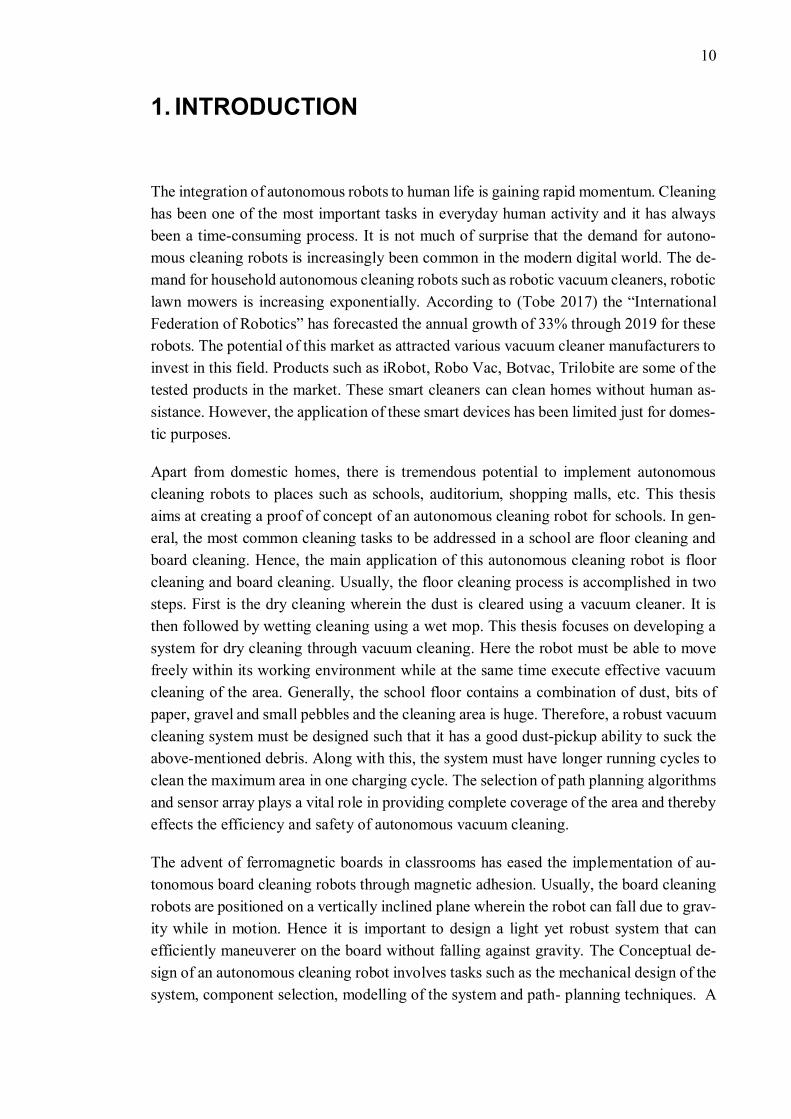
The integration of autonomous robots to human life is gaining rapid momentum. Cleaning
has been one of the most important tasks in everyday human activity and it has always
been a time-consuming process. It is not much of surprise that the demand for autono-
mous cleaning robots is increasingly been common in the modern digital world. The de-
mand for household autonomous cleaning robots such as robotic vacuum cleaners, robotic
lawn mowers is increasing exponentially. According to (Tobe 2017) the “International
Federation of Robotics” has forecasted the annual growth of 33% through 2019 for these
robots. The potential of this market as attracted various vacuum cleaner manufacturers to
invest in this field. Products such as iRobot, Robo Vac, Botvac, Trilobite are some of the
tested products in the market. These smart cleaners can clean homes without human as-
sistance. However, the application of these smart devices has been limited just for domes-
tic purposes.
Apart from domestic homes, there is tremendous potential to implement autonomous
cleaning robots to places such as schools, auditorium, shopping malls, etc. This thesis
aims at creating a proof of concept of an autonomous cleaning robot for schools. In gen-
eral, the most common cleaning tasks to be addressed in a school are floor cleaning and
board cleaning. Hence, the main application of this autonomous cleaning robot is floor
cleaning and board cleaning. Usually, the floor cleaning process is accomplished in two
steps. First is the dry cleaning wherein the dust is cleared using a vacuum cleaner. It is
then followed by wetting cleaning using a wet mop. This thesis focuses on developing a
system for dry cleaning through vacuum cleaning. Here the robot must be able to move
freely within its working environment while at the same time execute effective vacuum
cleaning of the area. Generally, the school floor contains a combination of dust, bits of
paper, gravel and small pebbles and the cleaning area is huge. Therefore, a robust vacuum
cleaning system must be designed such that it has a good dust-pickup ability to suck the
above-mentioned debris. Along with this, the system must have longer running cycles to
clean the maximum area in one charging cycle. The selection of path planning algorithms
and sensor array plays a vital role in providing complete coverage of the area and thereby
effects the efficiency and safety of autonomous vacuum cleaning.
The advent of ferromagnetic boards in classrooms has eased the implementation of au-
tonomous board cleaning robots through magnetic adhesion. Usually, the board cleaning
robots are positioned on a vertically inclined plane wherein the robot can fall due to grav-
ity while in motion. Hence it is important to design a light yet robust system that can
efficiently maneuverer on the board without falling against gravity. The Conceptual de-
sign of an autonomous cleaning robot involves tasks such as the mechanical design of the
system, component selection, modelling of the system and path- planning techniques. A
11
single system built to carry out the tasks of floor cleaning and board cleaning simultane-
ously is much more advantageous than two separate systems. Furthermore, the proof of
concept outlines the essential components and tasks involved in developing an autono-
mous cleaning vehicle.
1.1 Research methodology
This thesis focusses on designing a proof-of-concept for an autonomous cleaning robot.
The autonomous cleaning robot can come in various designs and types based on the ap-
plication area. The application area for this thesis work is school. Hence, the autonomous
cleaning robot comprises of an autonomous floor-cleaning robot and an autonomous
board-cleaning robot to cater to the needs of floor cleaning and board cleaning at school.
The methodologies followed in conducting this thesis are listed below
• Defining objective – The first step for the initiation of any project or research is
defining its objective. The topic “design of an autonomous cleaning robot” in-
volves a vast set of concepts, tools, theories, methods, and problems. It can be
narrowed down only based on the project requirements. The idea of a robotic vac-
uum cleaner is good, but it is already existing at private homes. This motivated to
design a proof of concept to a large area like schools. Nevertheless, the concept
of automated board cleaner is still in the research stage. Hence, the idea of collab-
orative implementation of automated vacuum cleaner robot along with board
cleaning robot was generated.
• Background study – The background study concentrated on reviewing and com-
paring the existing key technologies and recent developments related to the topic.
A lot of books, journal articles, conference proceedings, product reports, and con-
sumer reports were reviewed. The customer feedback on existing market products
was extensively studied to understand the drawbacks of the cleaning robots.
• Development of a proof of concept – basic calculation for the autonomous floor-
cleaning robot was done based on the equations of vacuum technology and air-
flow. The force diagrams and torque equations were used for the autonomous
board-cleaning robot. SOLIDWORKS was used to create the CAD model and
mechanical assembly.
• Navigation techniques – the techniques for mapping and path planning are dis-
cussed. Combination of planning algorithms were selected to achieve maximum
cleaning efficiency. In addition to this, the collaboration of two autonomous ro-
bots is briefly discussed.
12
2. THEORETICAL BACKGROUND
2.1 Principle of Vacuum Cleaning Technology
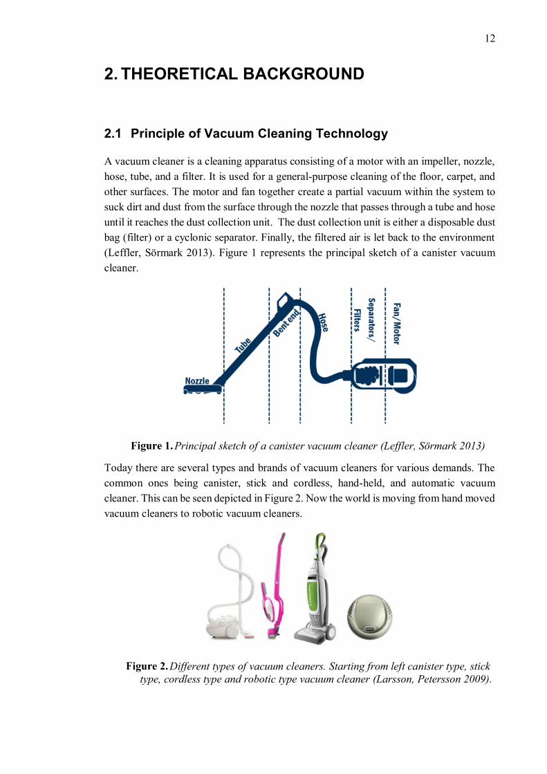
A vacuum cleaner is a cleaning apparatus consisting of a motor with an impeller, nozzle,
hose, tube, and a filter. It is used for a general-purpose cleaning of the floor, carpet, and
other surfaces. The motor and fan together create a partial vacuum within the system to
suck dirt and dust from the surface through the nozzle that passes through a tube and hose
until it reaches the dust collection unit. The dust collection unit is either a disposable dust
bag (filter) or a cyclonic separator. Finally, the filtered air is let back to the environment
(Leffler, Sörmark 2013). Figure 1 represents the principal sketch of a canister vacuum
cleaner.
Principal sketch of a canister vacuum cleaner (Leffler, Sörmark 2013)
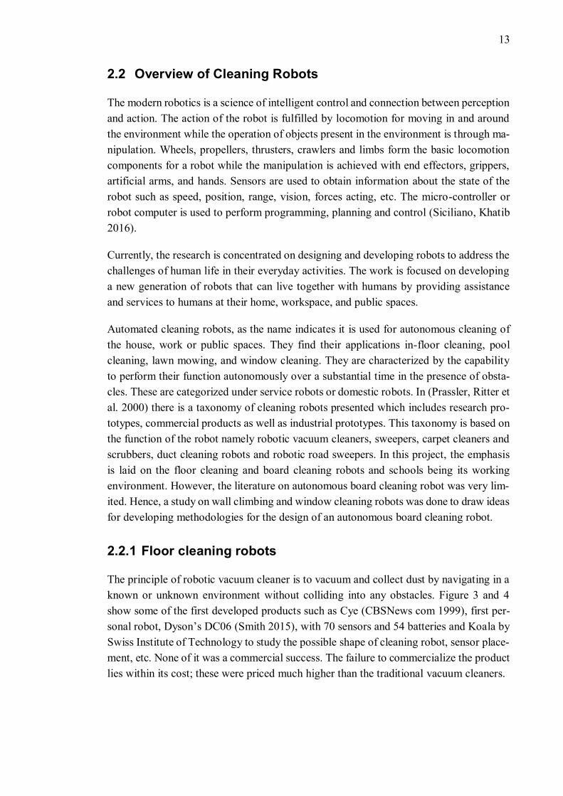
Today there are several types and brands of vacuum cleaners for various demands. The
common ones being canister, stick and cordless, hand-held, and automatic vacuum
cleaner. This can be seen depicted in Figure 2. Now the world is moving from hand moved
vacuum cleaners to robotic vacuum cleaners.
Different types of vacuum cleaners. Starting from left canister type, stick
type, cordless type and robotic type vacuum cleaner (Larsson, Petersson 2009).
13
2.2 Overview of Cleaning Robots
The modern robotics is a science of intelligent control and connection between perception
and action. The action of the robot is fulfilled by locomotion for moving in and around
the environment while the operation of objects present in the environment is through ma-
nipulation. Wheels, propellers, thrusters, crawlers and limbs form the basic locomotion
components for a robot while the manipulation is achieved with end effectors, grippers,
artificial arms, and hands. Sensors are used to obtain information about the state of the
robot such as speed, position, range, vision, forces acting, etc. The micro-controller or
robot computer is used to perform programming, planning and control (Siciliano, Khatib
2016).
Currently, the research is concentrated on designing and developing robots to address the
challenges of human life in their everyday activities. The work is focused on developing
a new generation of robots that can live together with humans by providing assistance
and services to humans at their home, workspace, and public spaces.
Automated cleaning robots, as the name indicates it is used for autonomous cleaning of
the house, work or public spaces. They find their applications in-floor cleaning, pool
cleaning, lawn mowing, and window cleaning. They are characterized by the capability
to perform their function autonomously over a substantial time in the presence of obsta-
cles. These are categorized under service robots or domestic robots. In (Prassler, Ritter et
al. 2000) there is a taxonomy of cleaning robots presented which includes research pro-
totypes, commercial products as well as industrial prototypes. This taxonomy is based on
the function of the robot namely robotic vacuum cleaners, sweepers, carpet cleaners and
scrubbers, duct cleaning robots and robotic road sweepers. In this project, the emphasis
is laid on the floor cleaning and board cleaning robots and schools being its working
environment. However, the literature on autonomous board cleaning robot was very lim-
ited. Hence, a study on wall climbing and window cleaning robots was done to draw ideas
for developing methodologies for the design of an autonomous board cleaning robot.
2.2.1 Floor cleaning robots
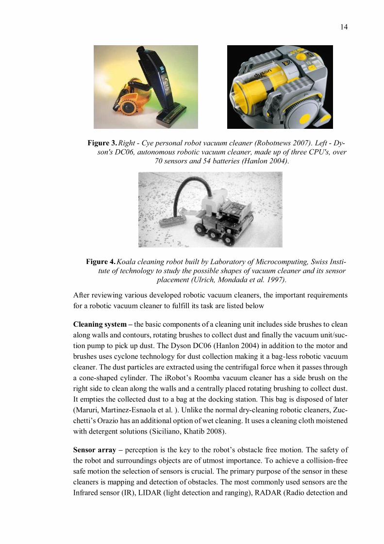
The principle of robotic vacuum cleaner is to vacuum and collect dust by navigating in a
known or unknown environment without colliding into any obstacles. Figure 3 and 4
show some of the first developed products such as Cye (CBSNews com 1999), first per-
sonal robot, Dyson’s DC06 (Smith 2015), with 70 sensors and 54 batteries and Koala by
Swiss Institute of Technology to study the possible shape of cleaning robot, sensor place-
ment, etc. None of it was a commercial success. The failure to commercialize the product
lies within its cost; these were priced much higher than the traditional vacuum cleaners.
14
Right - Cye personal robot vacuum cleaner (Robotnews 2007). Left - Dy-
son's DC06, autonomous robotic vacuum cleaner, made up of three CPU's, over
70 sensors and 54 batteries (Hanlon 2004).
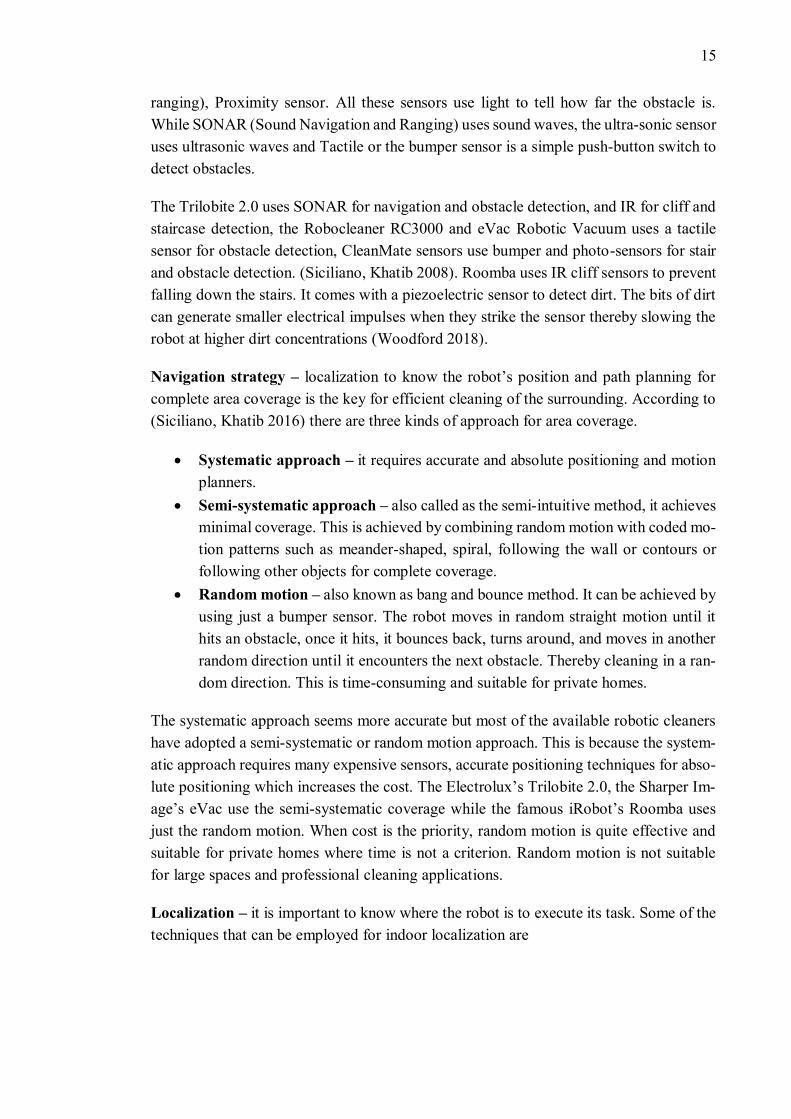
Koala cleaning robot built by Laboratory of Microcomputing, Swiss Insti-
tute of technology to study the possible shapes of vacuum cleaner and its sensor
placement (Ulrich, Mondada et al. 1997).
After reviewing various developed robotic vacuum cleaners, the important requirements
for a robotic vacuum cleaner to fulfill its task are listed below
Cleaning system – the basic components of a cleaning unit includes side brushes to clean
along walls and contours, rotating brushes to collect dust and finally the vacuum unit/suc-
tion pump to pick up dust. The Dyson DC06 (Hanlon 2004) in addition to the motor and
brushes uses cyclone technology for dust collection making it a bag-less robotic vacuum
cleaner. The dust particles are extracted using the centrifugal force when it passes through
a cone-shaped cylinder. The iRobot’s Roomba vacuum cleaner has a side brush on the
right side to clean along the walls and a centrally placed rotating brushing to collect dust.
It empties the collected dust to a bag at the docking station. This bag is disposed of later
(Maruri, Martinez-Esnaola et al. ). Unlike the normal dry-cleaning robotic cleaners, Zuc-
chetti’s Orazio has an additional option of wet cleaning. It uses a cleaning cloth moistened
with detergent solutions (Siciliano, Khatib 2008).
Sensor array – perception is the key to the robot’s obstacle free motion. The safety of
the robot and surroundings objects are of utmost importance. To achieve a collision-free
safe motion the selection of sensors is crucial. The primary purpose of the sensor in these
cleaners is mapping and detection of obstacles. The most commonly used sensors are the
Infrared sensor (IR), LIDAR (light detection and ranging), RADAR (Radio detection and
15
ranging), Proximity sensor. All these sensors use light to tell how far the obstacle is.
While SONAR (Sound Navigation and Ranging) uses sound waves, the ultra-sonic sensor
uses ultrasonic waves and Tactile or the bumper sensor is a simple push-button switch to
detect obstacles.
The Trilobite 2.0 uses SONAR for navigation and obstacle detection, and IR for cliff and
staircase detection, the Robocleaner RC3000 and eVac Robotic Vacuum uses a tactile
sensor for obstacle detection, CleanMate sensors use bumper and photo-sensors for stair
and obstacle detection. (Siciliano, Khatib 2008). Roomba uses IR cliff sensors to prevent
falling down the stairs. It comes with a piezoelectric sensor to detect dirt. The bits of dirt
can generate smaller electrical impulses when they strike the sensor thereby slowing the
robot at higher dirt concentrations (Woodford 2018).
Navigation strategy – localization to know the robot’s position and path planning for
complete area coverage is the key for efficient cleaning of the surrounding. According to
(Siciliano, Khatib 2016) there are three kinds of approach for area coverage.
• Systematic approach – it requires accurate and absolute positioning and motion
planners.
• Semi-systematic approach – also called as the semi-intuitive method, it achieves
minimal coverage. This is achieved by combining random motion with coded mo-
tion patterns such as meander-shaped, spiral, following the wall or contours or
following other objects for complete coverage.
• Random motion – also known as bang and bounce method. It can be achieved by
using just a bumper sensor. The robot moves in random straight motion until it
hits an obstacle, once it hits, it bounces back, turns around, and moves in another
random direction until it encounters the next obstacle. Thereby cleaning in a ran-
dom direction. This is time-consuming and suitable for private homes.
The systematic approach seems more accurate but most of the available robotic cleaners
have adopted a semi-systematic or random motion approach. This is because the system-
atic approach requires many expensive sensors, accurate positioning techniques for abso-
lute positioning which increases the cost. The Electrolux’s Trilobite 2.0, the Sharper Im-
age’s eVac use the semi-systematic coverage while the famous iRobot’s Roomba uses
just the random motion. When cost is the priority, random motion is quite effective and
suitable for private homes where time is not a criterion. Random motion is not suitable
for large spaces and professional cleaning applications.
Localization – it is important to know where the robot is to execute its task. Some of the
techniques that can be employed for indoor localization are
16
• Landmark-based position estimation – it uses artificial or natural landmarks
such as objects or contour to locate its position. A detailed approach to this tech-
nique can be found in (Willems 2017).
• Active beacons – position estimation using active beacon systems of SONAR, IR
or radio. These systems contain an RFID (radio frequency identification) receiver
that receives the signal from an ultra-sonic transmitter beacon that can be placed
on paths to track position (Kim, Lee et al. 2006).
• Dead reckoning localization – uses odometry to know the position for short dis-
tances. However, it is not accurate for long distances, must have an estimate of
the initial pose (books.org 2015).
• Probabilistic localization – it includes techniques such as Monte Carlo localiza-
tion and Markov localization. It employs sensory data and robots uncertainty be-
liefs in knowing where it is (Thrun, Burgard et al. 2008).
• Simultaneous localization and mapping (SLAM) – the robot creates the map of
the environment and locates its position simultaneously (Kudan 2016, Siciliano,
Khatib 2008)
User interface/ human-robot interaction – though the autonomous robot can execute
its task autonomously it still needs human assistance at some levels such as switching on
and off, emergency stop, recovery from error, etc. Another noticeable factor here is the
end-user. A non-technical person must also be able to operate the device. Hence, the user
interface panel must be designed taking into considerations the limits of the operator. It
should not force the user to acquire extra skills. The most simple user interface panel will
have an on/off switch, reset button, emergency stop button, in some dry and wet vacuum
cleaners there are buttons to select different cleaning mode (Siciliano, Khatib 2016,
TheVacuumDoctor 2018). Now the development for user interfaces as gone ahead in de-
veloping the interface panel through the phone. The Roomba robot can be controlled
through the phone using its app (McHugh 2015).
Safety – safety and precaution are important to keep the robot, humans and surrounding
objects safe. All the vacuum robots are programmed to prevent falling down the stairs or
cliff. Emergency stop button helps to retrieve the robot from a dangerous situation. The
Roomba motors shut off once lifted from the floor to prevent injuries (Siciliano, Khatib
2008).
Power supply – In the autonomous motion the distance covered is dependent on the
power supply, the robot must move in and around through different workspaces. Unlike
non-robotic vacuum cleaners, it cannot be operated using power cords. So, batteries are
used to power these autonomous robots. The constraint of weight and size limits the ca-
pacity of batteries. This is not an issue in domestic cleaning as their operation time frame
is 30-60 min. However, the robots in large workspaces must require a longer working
cycle. Some professional cleaning applications use 24V lead-acid batteries, but they are
heavy. Therefore, the choice is tricky and there is a compromise of weight or time. Some
17
of them now come with the feature of automatic charging; when the power hits low levels,
they automatically dock themselves to the charging stations (Siciliano, Khatib 2016, Si-
ciliano, Khatib 2008).
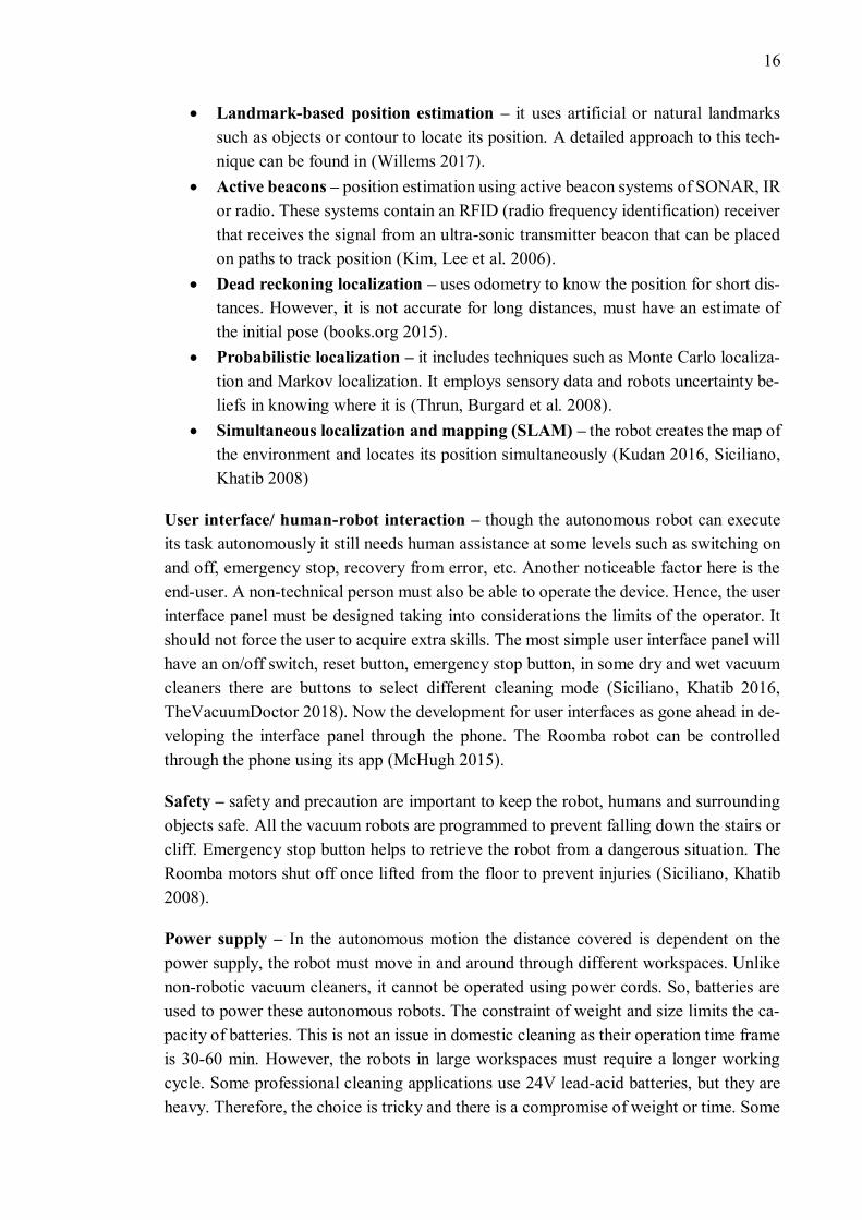
Table 1 and 2 lists the technical specifications such as sensors used, coverage methods
followed in some of the existing domestic cleaning robots.
Table 1. Specifications of Domestic cleaning robots (Siciliano, Khatib 2016), (Siciliano,
Khatib 2008), (iRobot ), (Voltra ), (Mall.SK ).
Manufacturer iRobot Kärcher Electrolux Friendly Robot-
ics
Model Roomba RC3000 Trilobite 2.0 Friendly Vac
Sensors IR range sensors,
IR cliff sensors (4)
IR cliff sensor (4),
contact sensor
(3600)
1800 ultrasound
sensors, IR cliff
sensor with a
Magnetic stripe
detector, contact
sensor in the
front side
Sonar sensor,
touch sensor,
cliff sensor
Coverage
Method
Bang and bounce
combined with a
random motion,
spiral motion and
also contour fol-
lowing
Bang and bounce
with random mo-
tion, see saw mo-
tion for spot
cleaning
Random motion
and wall-follow-
ing with obstacle
detection
Has contour fol-
low, motion pat-
terns (parallel
and spiral) and
bang and
bounce
Cleaning Tech-
nology
Counter rotating
side brush (2) with
suction pump
Rotating brush
with suction
pump
Rotating brush
with suction
pump
Rotating Brush
Automatic re-
charging
Yes Yes Yes No
Run time (min) 60 – 90 20 – 60 60 60
18
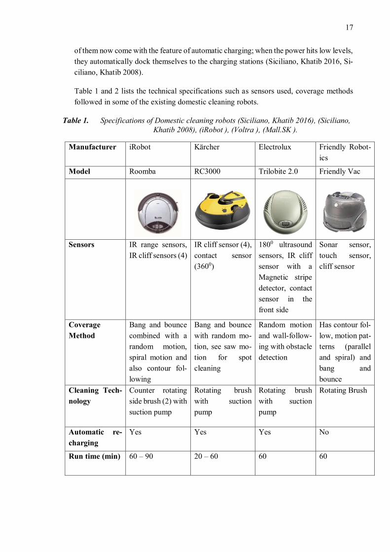
Table 2. Specifications of Domestic Cleaning Robots (Siciliano, Khatib 2016, Siciliano,
Khatib 2008, Cooper 2012, RobotReviews 2012, TestsAndReview 2016,
Liszewski 2017).
Manufac-
turer
Evolution Ro-
botics/ iRobot
LG Samsung Neato Robotics
Model Mint 4200 Hom-Bot 3.0 Navibot SR 8895 Si-
lencio
Neato XV-21
Sensors Cliff sensors,
bumper, gyro-
scope, Northstar
indoor GPS
Camera for ceiling
and floor, sonar
and IR for collision
avoidance, cliff
sensors, gyroscope
Range sensors cam-
era, collision sensor,
cliff sensors, gyro-
scope
1-D laser range
finder, cliff sensor,
gyroscope, accel-
erometer
Coverage
and Navi-
gation
Method
Systematic cov-
erage, SLAM
with north star,
map building
Systematic cover-
age, SLAM
Systematic cover-
age, SLAM based
with visionary map-
ping system (using
ceiling pictures)
Systematic cover-
age, SLAM based
with RPS (using
laser range finder)
Cleaning
Technol-
ogy
Dry or wet mi-
crofiber cloths
Two side brushes
with brush roller
Two side brushes
with brush roller
Bristled Brush
Automatic
recharging
No Yes Yes Yes
Run time
(min)
180 75 90 90
Comparing all the mentioned (from Table 1 and 2) cleaning robots, it is evident that they
all use similar technology with minor changes. The vacuuming unit majorly consists of
the brush (side or rotating depending on the robot) and fan along with the suction pump.
The important point in all these class of robots is the use of a few inexpensive sensors
such as tactile, dirt or cliff sensors to make the product more economical. Pre-pro-
grammed motion patterns such as bang and bounce, spiral, see-saw or parallel motion
together with random motion seem to be effective considering the limited number of sen-
sors. The success of any automated cleaning robot reflects the integration of state of art
automated services.
19
2.2.2 Window cleaning robots
According to (Siciliano, Khatib 2008) back in the 2000’s the concept of automated win-
dow cleaning robot was still a conception. However, today we were able to witness some
commercial products in the market such as Ecovas Winbot, Alfawise (Ezvid Wiki ) and
Hobot (TopTen Reviews ). The reason for it is the increase in window glasses outside the
buildings compared to private homes with fewer window glass panes. High-rise buildings
along with huge glass windows are now part of current modern architecture design. Man-
ual reaching onto the outer glass for cleaning is dangerous and of low output. The demand
for automated cleaning robots to be part of building maintenance is going to be a reality
soon (Akinfiev, Armada et al. 2009).
The development of automated window cleaning robot is much more complex and chal-
lenging than the automated floor-cleaning robot for several reasons, which will be dis-
cussed in this section. The main hurdle to the design is gravity. Designing cost-effective
locomotive mechanisms against gravity on vertical fragile glass planes are quite challeng-
ing. Crossing over windowpane outside the buildings can get tricky. Nevertheless, this
has not stopped the research and development of window cleaning robots (Siciliano,
Khatib 2008, Miyake, Ishihara 2003).
From (Miyake, Ishihara et al. 2006b), the main requirements for developing a window-
cleaning robot are it must be light, small and compact, easy portability, can run continu-
ous cleaning motions, execute automatic crossover between frames and most important
not to forget the corners.
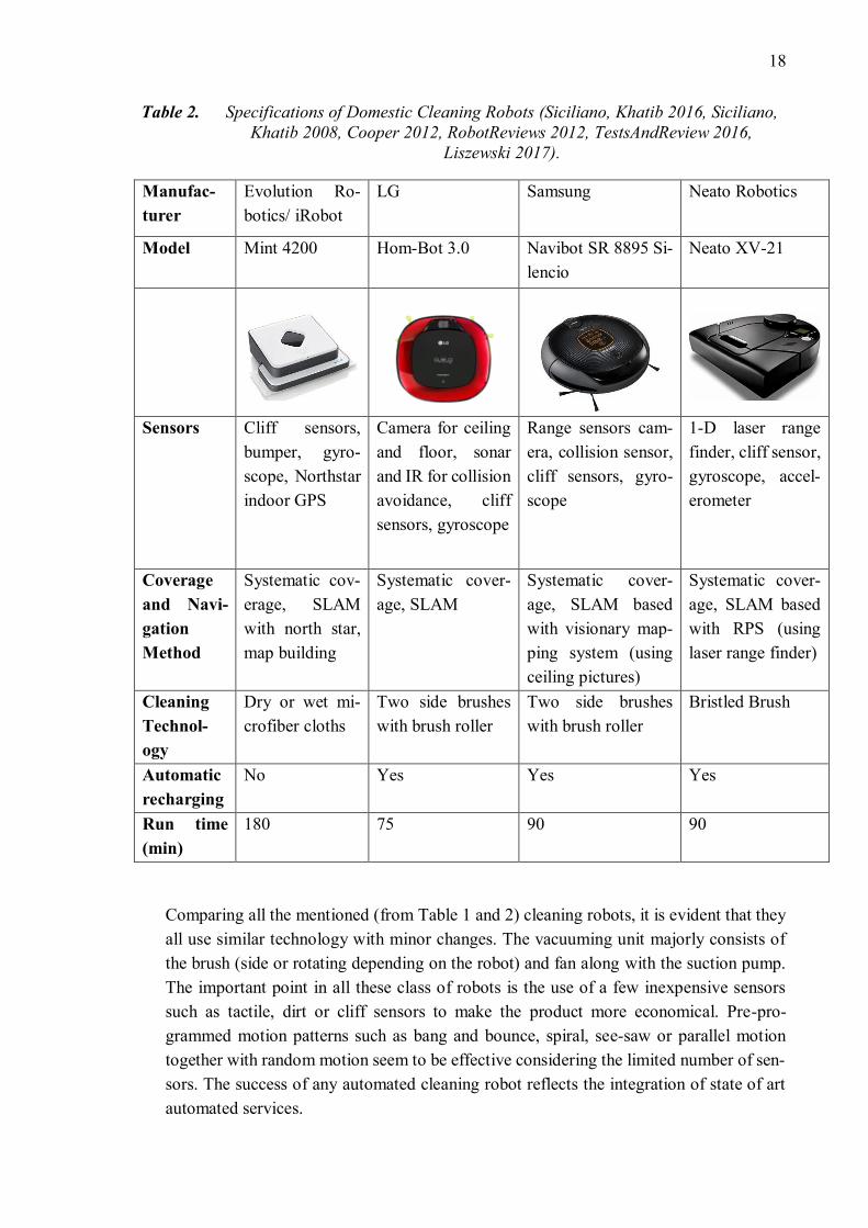
The three main units for designing a window-cleaning robot are adhesion unit, locomo-
tion unit, and the cleaning unit.
• Adhesion unit – there are different adhesion techniques for a robot to hold itself
against the glass surface such as magnetic attraction, vacuum system, counter-
weight to balance the robot and use of sticky material (Miyake, Ishihara et al.
2006a). The vacuum system seems to be a promising adhesion method for a glass
surface compared to the magnetic attraction, which requires the usage of ferro-
magnetic substances, counterweight that demands ropes and wires to balance or
the sticky material that gets the glass dirty. The vacuum method uses suction cups
and vacuum-motor, to make use of the negative pressure to seal the robot against
the glass surface (Muscato, Longo et al. 2003). All the existing commercial prod-
ucts currently use a safety tether to hold the robot against falling (when it loses
adhesion).
• Locomotion unit – for the free movement of the robot. It can be linear motion or
rotatory or a combination of both. The different mechanisms employed are crawl-
ers, drive wheels, caterpillar drives equipped with suction cups (Yoshida, Shugen
Ma Dec 2010), legs or limbs (Kawasaki, Kikuchi 2014) and parallel links. The
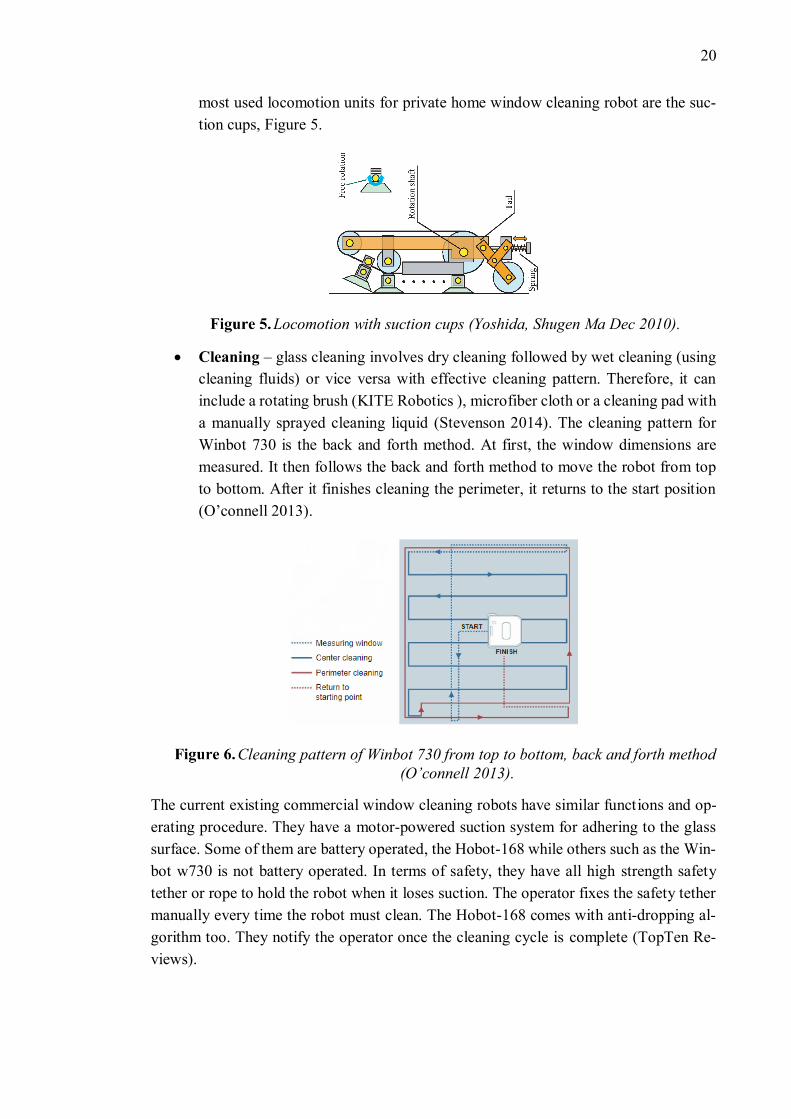
20
most used locomotion units for private home window cleaning robot are the suc-
tion cups, Figure 5.
Locomotion with suction cups (Yoshida, Shugen Ma Dec 2010).
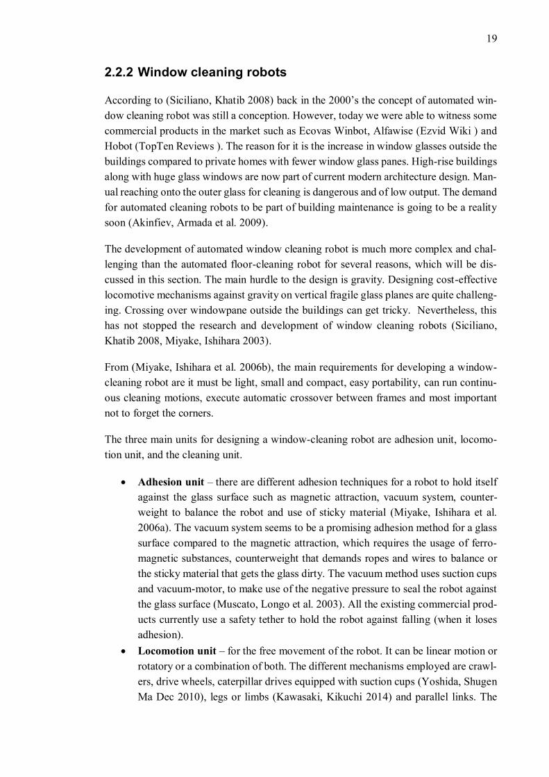
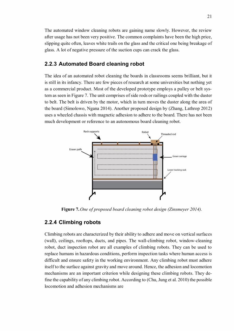
• Cleaning – glass cleaning involves dry cleaning followed by wet cleaning (using
cleaning fluids) or vice versa with effective cleaning pattern. Therefore, it can
include a rotating brush (KITE Robotics ), microfiber cloth or a cleaning pad with
a manually sprayed cleaning liquid (Stevenson 2014). The cleaning pattern for
Winbot 730 is the back and forth method. At first, the window dimensions are
measured. It then follows the back and forth method to move the robot from top
to bottom. After it finishes cleaning the perimeter, it returns to the start position
(O’connell 2013).
Cleaning pattern of Winbot 730 from top to bottom, back and forth method
(O’connell 2013).
The current existing commercial window cleaning robots have similar functions and op-
erating procedure. They have a motor-powered suction system for adhering to the glass
surface. Some of them are battery operated, the Hobot-168 while others such as the Win-
bot w730 is not battery operated. In terms of safety, they have all high strength safety
tether or rope to hold the robot when it loses suction. The operator fixes the safety tether
manually every time the robot must clean. The Hobot-168 comes with anti-dropping al-
gorithm too. They notify the operator once the cleaning cycle is complete (TopTen Re-
views).
21
The automated window cleaning robots are gaining name slowly. However, the review
after usage has not been very positive. The common complaints have been the high price,
slipping quite often, leaves white trails on the glass and the critical one being breakage of
glass. A lot of negative pressure of the suction cups can crack the glass.
2.2.3 Automated Board cleaning robot
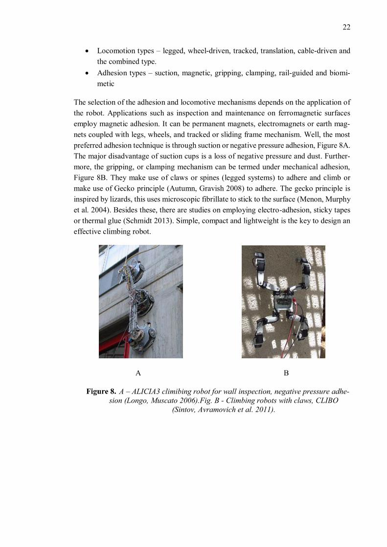
The idea of an automated robot cleaning the boards in classrooms seems brilliant, but it
is still in its infancy. There are few pieces of research at some universities but nothing yet
as a commercial product. Most of the developed prototype employs a pulley or belt sys-
tem as seen in Figure 7. The unit comprises of side rods or railings coupled with the duster
to belt. The belt is driven by the motor, which in turn moves the duster along the area of
the board (Simolowo, Ngana 2014). Another proposed design by (Zhang, Lathrop 2012)
uses a wheeled chassis with magnetic adhesion to adhere to the board. There has not been
much development or reference to an autonomous board cleaning robot.
One of proposed board cleaning robot design (Zinsmeyer 2014).
2.2.4 Climbing robots
Climbing robots are characterized by their ability to adhere and move on vertical surfaces
(wall), ceilings, rooftops, ducts, and pipes. The wall-climbing robot, window-cleaning
robot, duct inspection robot are all examples of climbing robots. They can be used to
replace humans in hazardous conditions, perform inspection tasks where human access is
difficult and ensure safety in the working environment. Any climbing robot must adhere
itself to the surface against gravity and move around. Hence, the adhesion and locomotion
mechanisms are an important criterion while designing these climbing robots. They de-
fine the capability of any climbing robot. According to (Chu, Jung et al. 2010) the possible
locomotion and adhesion mechanisms are
22
• Locomotion types – legged, wheel-driven, tracked, translation, cable-driven and
the combined type.
• Adhesion types – suction, magnetic, gripping, clamping, rail-guided and biomi-
metic
The selection of the adhesion and locomotive mechanisms depends on the application of
the robot. Applications such as inspection and maintenance on ferromagnetic surfaces
employ magnetic adhesion. It can be permanent magnets, electromagnets or earth mag-
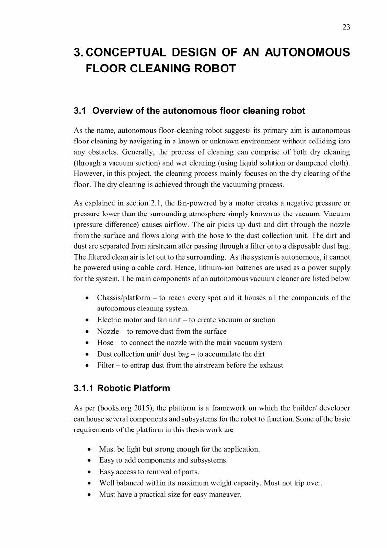
nets coupled with legs, wheels, and tracked or sliding frame mechanism. Well, the most
preferred adhesion technique is through suction or negative pressure adhesion, Figure 8A.
The major disadvantage of suction cups is a loss of negative pressure and dust. Further-
more, the gripping, or clamping mechanism can be termed under mechanical adhesion,
Figure 8B. They make use of claws or spines (legged systems) to adhere and climb or
make use of Gecko principle (Autumn, Gravish 2008) to adhere. The gecko principle is
inspired by lizards, this uses microscopic fibrillate to stick to the surface (Menon, Murphy
et al. 2004). Besides these, there are studies on employing electro-adhesion, sticky tapes
or thermal glue (Schmidt 2013). Simple, compact and lightweight is the key to design an
effective climbing robot.
A B
A – ALICIA3 climibing robot for wall inspection, negative pressure adhe-
sion (Longo, Muscato 2006).Fig. B - Climbing robots with claws, CLIBO
(Sintov, Avramovich et al. 2011).
23
3. CONCEPTUAL DESIGN OF AN AUTONOMOUS
FLOOR CLEANING ROBOT
3.1 Overview of the autonomous floor cleaning robot
As the name, autonomous floor-cleaning robot suggests its primary aim is autonomous
floor cleaning by navigating in a known or unknown environment without colliding into
any obstacles. Generally, the process of cleaning can comprise of both dry cleaning
(through a vacuum suction) and wet cleaning (using liquid solution or dampened cloth).
However, in this project, the cleaning process mainly focuses on the dry cleaning of the
floor. The dry cleaning is achieved through the vacuuming process.
As explained in section 2.1, the fan-powered by a motor creates a negative pressure or
pressure lower than the surrounding atmosphere simply known as the vacuum. Vacuum
(pressure difference) causes airflow. The air picks up dust and dirt through the nozzle
from the surface and flows along with the hose to the dust collection unit. The dirt and
dust are separated from airstream after passing through a filter or to a disposable dust bag.
The filtered clean air is let out to the surrounding. As the system is autonomous, it cannot
be powered using a cable cord. Hence, lithium-ion batteries are used as a power supply
for the system. The main components of an autonomous vacuum cleaner are listed below
• Chassis/platform – to reach every spot and it houses all the components of the
autonomous cleaning system.
• Electric motor and fan unit – to create vacuum or suction
• Nozzle – to remove dust from the surface
• Hose – to connect the nozzle with the main vacuum system
• Dust collection unit/ dust bag – to accumulate the dirt
• Filter – to entrap dust from the airstream before the exhaust
3.1.1 Robotic Platform
As per (books.org 2015), the platform is a framework on which the builder/ developer
can house several components and subsystems for the robot to function. Some of the basic
requirements of the platform in this thesis work are
• Must be light but strong enough for the application.
• Easy to add components and subsystems.
• Easy access to removal of parts.
• Well balanced within its maximum weight capacity. Must not trip over.
• Must have a practical size for easy maneuver.
24
• Efficient sensor array. Must detect and function in the presence and absence of
light, transparent obstacles and avoid cliffs.
• Reliable power supply for long working cycles of the robot.
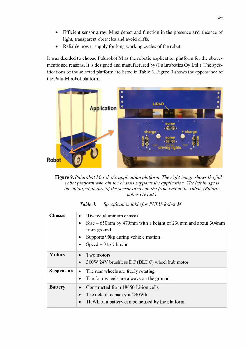
It was decided to choose Pulurobot M as the robotic application platform for the above-
mentioned reasons. It is designed and manufactured by (Pulurobotics Oy Ltd ). The spec-
ifications of the selected platform are listed in Table 3. Figure 9 shows the appearance of
the Pulu-M robot platform.
Pulurobot M, robotic application platform. The right image shows the full
robot platform wherein the chassis supports the application. The left image is
the enlarged picture of the sensor array on the front end of the robot. (Puluro-
botics Oy Ltd ).
Table 3. Specification table for PULU-Robot M
Chassis • Riveted aluminum chassis
• Size – 650mm by 470mm with a height of 230mm and about 304mm
from ground
• Supports 90kg during vehicle motion
• Speed – 0 to 7 km/hr
Motors • Two motors
• 300W 24V brushless DC (BLDC) wheel hub motor
Suspension • The rear wheels are freely rotating
• The four wheels are always on the ground
Battery • Constructed from 18650 Li-ion cells
• The default capacity is 240Wh
• 1KWh of a battery can be housed by the platform
25
Charger • The wall unit can connect to 110V/220V
• 100W built-in charger
• The robot can find and mount to its charger automatically
Sensor
Array
• LIDAR for long distance navigating and mapping
• Four 3D Time of Flight (TOF) cameras to see in direct sunlight or at
night and to sense obstacles lower or higher than the 2D LIDAR plane.
• SONAR for detecting transparent obstacles such as glass doors, etc.
Electronics • All electronics are in the same place on Robot Board for easy mainte-
nance
• It comes with two Raspberry Pi’s on the Robot Board and a possibility
to stack up to five of them
• Socket for Raspberry Pi 2/3
Controller
board
• STM32 microcontroller for sensor management & low-level naviga-
tion
• MEMS gyroscope, accelerometer, compass
• Powerful lithium ion charger (100W)
• Strong 5V power supply for computers, tablets, etc. (10A)
• 2 x BLDC motor controllers, 700W peak each
• On-board Raspberry Pi for running mapping (SLAM) & route-finding
algorithms
• Internet connection through WiFi and/or 3G/4G
3.2 Components selection for vacuum cleaning
Generally, the input power of different vacuum cleaners is compared to rate the perfor-
mance. However, the dust-pick-up (dpu) factor decides the percentage of dust a vacuum
cleaner can pick up from the different surfaces during cleaning. The parameters that in-
fluence the design and selection of the vacuum cleaner components are
• Dust pickup factor
• Dust storage capacity
• Cleaning surface
• Size
• Weight
• Storage
Initially, the designing of a vacuum cleaner system and its components selection was
based on assumptions. This was achieved through the practical understanding and as-
26
sumptions made by comparing the existing domestic vacuum cleaner products in the mar-
ket. Usually, the selected components are subjected to practical tests to rate their perfor-
mance. Later the system is refined based on the suction performance, dust removal per-
formance, weight and size by applying theories of vacuum technology.
3.2.1 Motor and fan
The present vacuum cleaner motors are characterized by their small size and high rota-
tional speeds. They can produce a relatively high vacuum along with quick discharge.
The motor inputs the electrical energy and converts it into mechanical energy in the form
of airflow and suction. The fan also known as impeller creates the suction by the effects
of the centrifugal force acting on it. The rotary motion of the fan rotates the air and moves
it outward from the hub to create a partial vacuum. The motor and fan are assembled into
a single unit. The selection of motor and fan unit is very important because they are the
biggest influencer on the size and performance of the vacuum cleaner (Facts about Vacs
b, Facts about Vacs a).
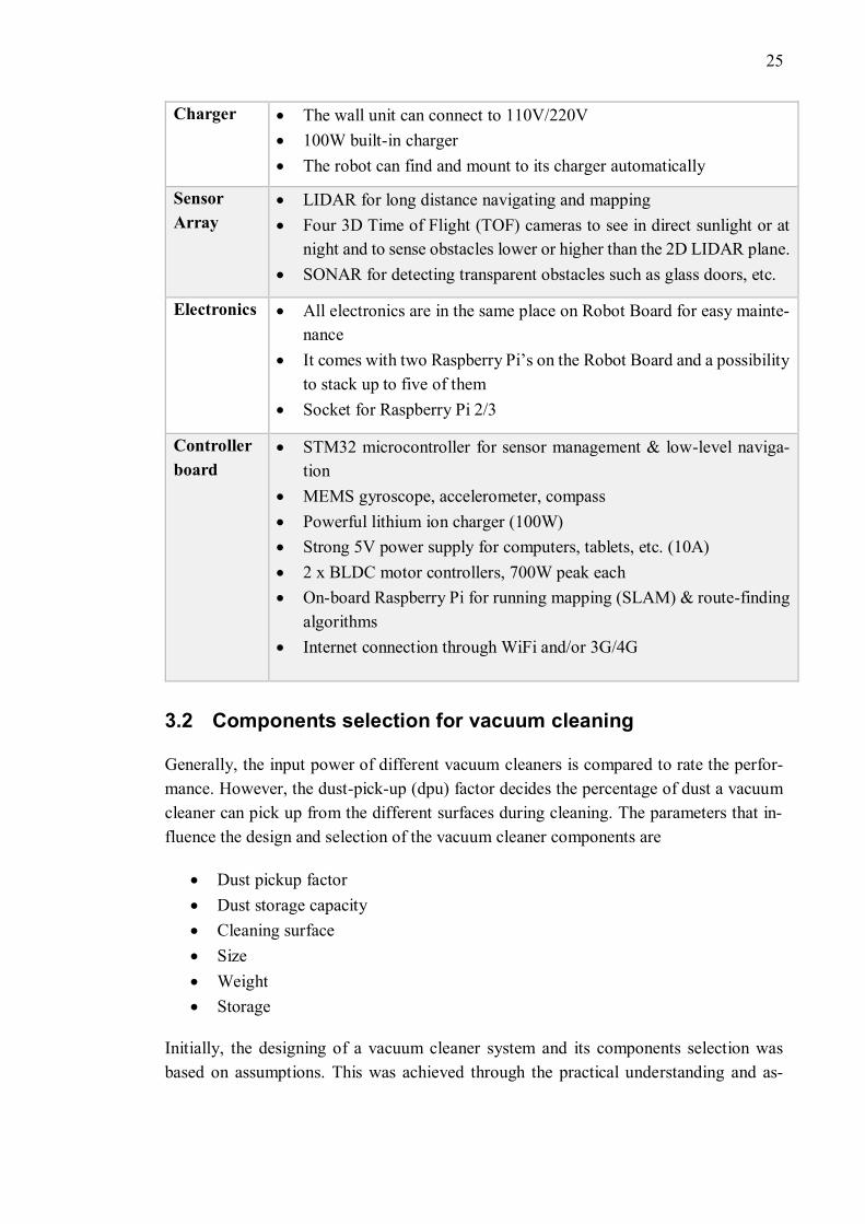
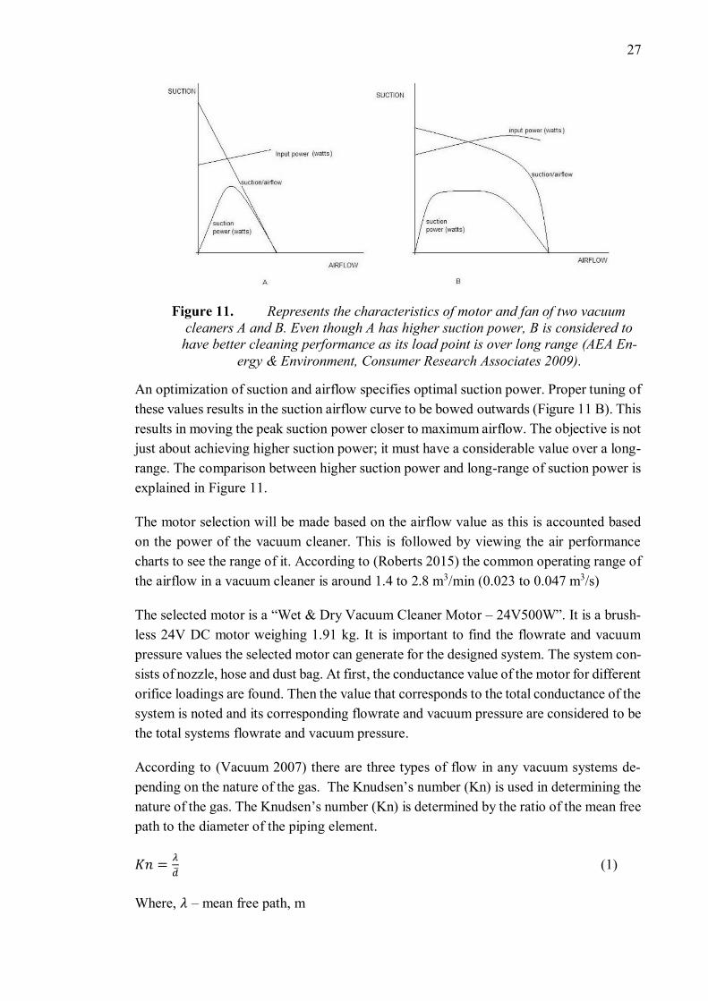
The combination of airflow and suction or vacuum measured in watts is known as suction
power. The suction and airflow curves or air performance graphs is an important tool for
motor selection. It shows the efficiency of the motor in converting the input power to
suction power. The quoted suction power and efficiency for any motor will be at its peak
suction power also known as load point. However, in reality, both suction power and
efficiency varies from zero to maximum. This can be seen in Figure 10. The load point
value is considered for the design calculations (AEA Energy & Environment, Consumer
Research Associates 2009).
Suction and airflow curves showing the effect of input power and
suction power (AEA Energy & Environment, Consumer Research Associates
2009).
27
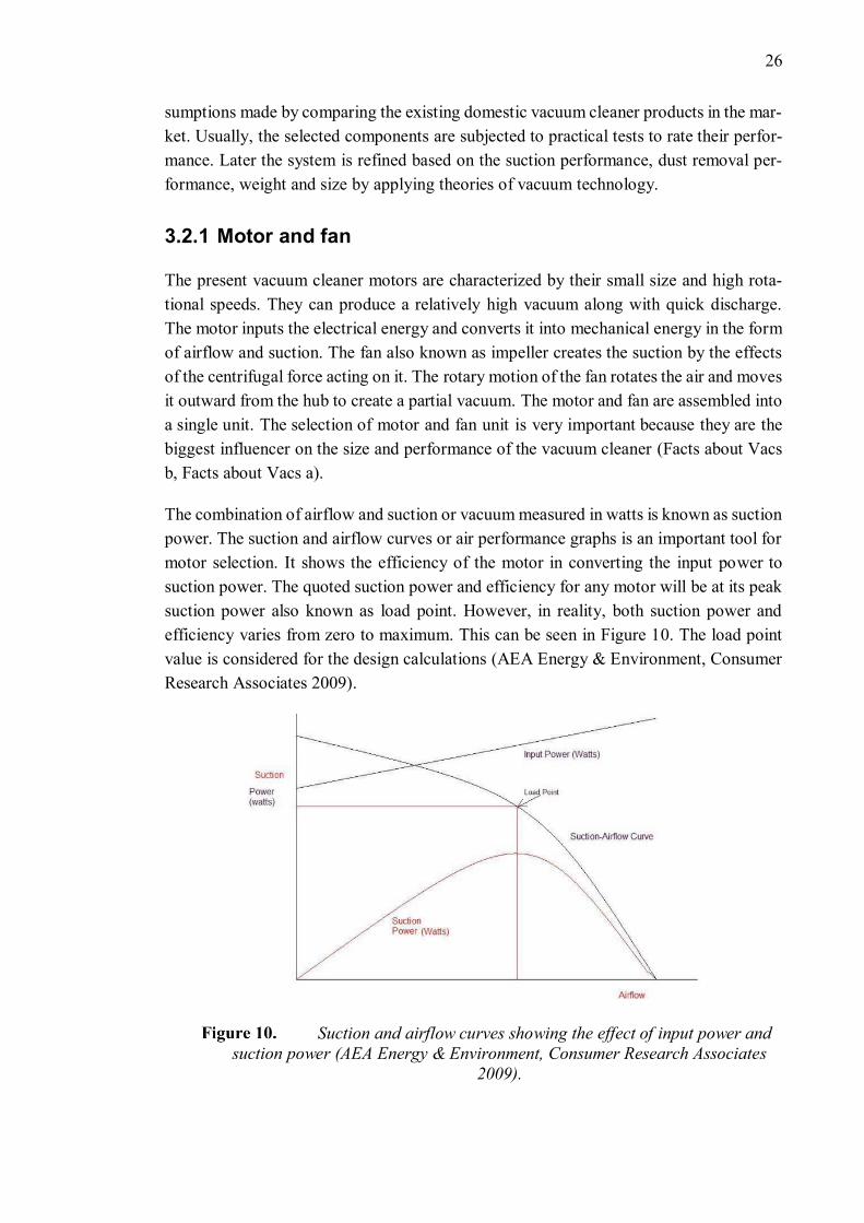
Represents the characteristics of motor and fan of two vacuum
cleaners A and B. Even though A has higher suction power, B is considered to
have better cleaning performance as its load point is over long range (AEA En-
ergy & Environment, Consumer Research Associates 2009).
An optimization of suction and airflow specifies optimal suction power. Proper tuning of
these values results in the suction airflow curve to be bowed outwards (Figure 11 B). This
results in moving the peak suction power closer to maximum airflow. The objective is not
just about achieving higher suction power; it must have a considerable value over a long-
range. The comparison between higher suction power and long-range of suction power is
explained in Figure 11.
The motor selection will be made based on the airflow value as this is accounted based
on the power of the vacuum cleaner. This is followed by viewing the air performance
charts to see the range of it. According to (Roberts 2015) the common operating range of
the airflow in a vacuum cleaner is around 1.4 to 2.8 m3/min (0.023 to 0.047 m3/s)
The selected motor is a “Wet & Dry Vacuum Cleaner Motor – 24V500W”. It is a brush-
less 24V DC motor weighing 1.91 kg. It is important to find the flowrate and vacuum
pressure values the selected motor can generate for the designed system. The system con-
sists of nozzle, hose and dust bag. At first, the conductance value of the motor for different
orifice loadings are found. Then the value that corresponds to the total conductance of the
system is noted and its corresponding flowrate and vacuum pressure are considered to be
the total systems flowrate and vacuum pressure.
According to (Vacuum 2007) there are three types of flow in any vacuum systems de-
pending on the nature of the gas. The Knudsen’s number (Kn) is used in determining the
nature of the gas. The Knudsen’s number (Kn) is determined by the ratio of the mean free
path to the diameter of the piping element.
𝐾𝑛 =𝜆
�̅� (1)
Where, 𝜆 – mean free path, m
28
d – diameter of the piping element, m
As per (O'Hanlon 2005), Mean free path (𝜆) is the possible straight-line distance that
different molecules can travel before a collision. For room temperature, it is given by the
following equation
𝜆 =6.7×10⁻⁴
�̅� (2)
Where, �̅� – average pressure, Pa. Given by
�̅� =𝑝1+𝑝2
2 (3)
Where, p1 – downstream pressure, Pa
p2 – upstream pressure, Pa
The three categories of flow are
• Continuous flow – this occurs in the viscous or rough vacuum region. Here the
flow can be termed as either laminar viscous flow or turbulent flow. Usually, the
continuous flow is considered to be laminar viscous unless a vortex motion ap-
pears in the system. In any vacuum system, the flow is considered to laminar vis-
cous when the Knudsen number is less than 0.01, i.e. Kn<0.01.
• Molecular flow – this occurs in ultrahigh vacuum ranges. In this region, the mean
free path is much higher when compared to the piping size. Hence, the molecules
can travel freely without mutual collision. In this flow, the Knudsen number is
greater than 1, i.e. Kn>1
• Knudsen flow – the region between continuous flow and molecular flow is known
as the Knudsen flow, medium vacuum range. The Knudsen number is less than 1
but greater than 0.01. i.e. 0.01<Kn>1.
The flow of gas in any piping element is dependent on the pressure drop across the pipe
and its geometry which is defined by conductance. There are different formulas for con-
ductance calculation depending on the type of flow and type of piping element (orifice,
round pipes, rectangular, slit, etc.).
At first, the ‘Kn’ for different orifice loadings in this case was calculated and it was found
to be less than 0.01. This says that the flow through the orifice is laminar viscous. The
conductance value of the motor for different orifice loadings are calculated and tabulated
in Table 4.
The equation for calculating conductance through an orifice (Vacuum 2007) depends on
the ratio of downstream pressure (P2) to upstream pressure (P1) i.e.
29
𝛿 =𝑃2
𝑃1 (4)
Where, p1 – downstream pressure, Pa
p2 – upstream pressure, Pa
When δ value is equal to 0.528 it is critical pressure situation if it is less than 0.5298 the
flow is choked. However, he obtained δ value for all the orifice loading was greater than
0.528 (Table 4).
The equation to calculate conductance through an orifice is given by
𝐶𝑜𝑟𝑖𝑓𝑖𝑐𝑒 = 766. 𝛿0.712√1 − 𝛿0.288 𝐴
1−𝛿 (5)
Where, Corifice – conductance through an orifice in laminar flow, m3/s
A – area of the orifice, m2
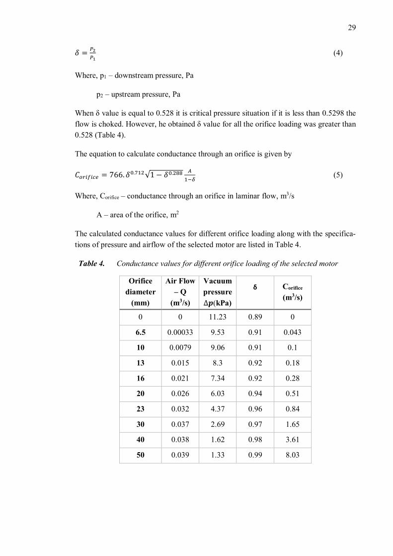
The calculated conductance values for different orifice loading along with the specifica-
tions of pressure and airflow of the selected motor are listed in Table 4.
Table 4. Conductance values for different orifice loading of the selected motor
Orifice
diameter
(mm)
Air Flow
– Q
(m3/s)
Vacuum
pressure
∆𝒑(kPa)
δ
Corifice
(m3/s)
0 0 11.23 0.89 0
6.5 0.00033 9.53 0.91 0.043
10 0.0079 9.06 0.91 0.1
13 0.015 8.3 0.92 0.18
16 0.021 7.34 0.92 0.28
20 0.026 6.03 0.94 0.51
23 0.032 4.37 0.96 0.84
30 0.037 2.69 0.97 1.65
40 0.038 1.62 0.98 3.61
50 0.039 1.33 0.99 8.03
30
3.2.2 Hose and tubing
This module consists of two types of a hollow tube. One is the rigid tube right after the
nozzle; it has no bends hence minimal pressure losses. 30 mm diameter hose was consid-
ered for the design as it is the most widely used dimension and other attachments can be
easily found. Before, finding the conductance value through the hose it is important to
find out if the flow is laminar or molecular. At first, the mean free path is found using
Equation 2 followed by the Knudsen number. For the purpose of calculations, the average
pressure in the hose is assumed to be similar to the average pressure generated by the
motor at an orifice loading of 30 mm (as the chosen hose diameter is 30 mm). The ob-
tained mean free path value is 6.72.10-8 m while the Knudsen number is 2.24.10-6 which
is less than 0.01. Hence the flow is laminar viscous flow.
The conductance value of the laminar viscous flow in the piping element is calculated as
per (Vacuum 2007). The conductance value depends on pressure and geometry of con-
ducting element in the laminar flow. Axial length of the element is considered for straight-
line elements while the effective length is considered for bends and elbows.
The designed hose has a straight-line length of 0.67018 m while the effective length for
the bends is found by Equation 6.
𝑙𝑒𝑓𝑓 = 𝑙𝑎𝑥𝑖𝑎𝑙 + 1.33𝜃
1800 𝑑 (6)
Where, leff – effective length of the line, m
laxial – axial length of the line, m
d – inside diameter of the line, m
θ – angle of the elbow/ bend, deg
The designed hose has three elbows each with an angle of 850, 560 and 900 respectively.
After finding the individual effective lengths, the obtained total length which is the addi-
tion of straight-line length and effective length is around 1.68 m.
The conductance for a hose in laminar flow is given by Equation 7.
𝐶ℎ𝑜𝑠𝑒 = 1350𝑑4
𝑙�̅� (7)
= 64.87 m3/s
Where, Chose – conductance in the hose for a laminar flow, m3/s
d – inside diameter of the line, m
31
l – length of the line, m
�̅� – average pressure in the system, Pa
3.2.3 Filter or dust bag
The function of the filter is to entrap all the dust and allergens from the airstream before
re-entering it to the surrounding. In this way, the surrounding and the motor unit gets
clean air. The filter can be disposable or reusable one. The disposable ones are the dust
bag wherein the bag material is a type of filter. The bag collects the dust while the clean
air passes through its material. The choice of filter bags is very important because any
dirt present in the air can erode motor parts, clog the system and reduce the suction and
airflow. The different types of filters are cloth filter, paper bags, treated paper bags, fleece,
etc. The use of HEPA filter in the vacuum cleaner assures a clean exhaust air (Dijk 2010).
The capacity of the bag depends on the quantity of dust that must be collected. The se-
lected disposable dust bag has a dimension of 318×330 mm wherein the expandable
height is up to 318mm. The diameter of the opening of the bag is 80mm. its average
capacity is 3.5L.
The conductance value through a dust bag is calculated as per (O'Hanlon 2005) consid-
ering it has a rectangular structure. At room temperature, the conductance value for a
rectangular, slit-like or short structures are given by
𝐶𝑑𝑢𝑠𝑡_𝑏𝑎𝑔 = 116(aA) (8)
= 8.43 m3/s
Where, Cdust_bag – conductance through a dust bag, m3/s
a – transmission probability for the structure
A – area of the structure, m2
The ratio of l/h for the dust bag was 1.03 and it’s corresponding ‘a’ value is 0.68438 and
area is the product of breath and height(O'Hanlon 2005). The obtained conductance value
through the dust bag was 8.43 m3/s.
3.2.4 Nozzle
Its function is to pick up several types of dust from the surface. Here the surface can be
anything such as the wooden floor, tiles, carpet or an uneven floor surface. There are
different nozzles for cleaning hard surface and carpets but generally, the combination
nozzle for all surfaces are used.
32
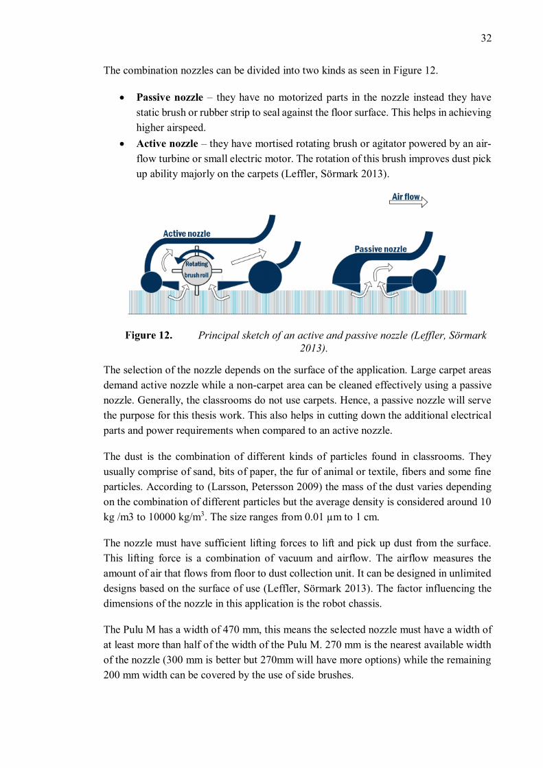
The combination nozzles can be divided into two kinds as seen in Figure 12.
• Passive nozzle – they have no motorized parts in the nozzle instead they have
static brush or rubber strip to seal against the floor surface. This helps in achieving
higher airspeed.
• Active nozzle – they have mortised rotating brush or agitator powered by an air-
flow turbine or small electric motor. The rotation of this brush improves dust pick
up ability majorly on the carpets (Leffler, Sörmark 2013).
Principal sketch of an active and passive nozzle (Leffler, Sörmark
2013).
The selection of the nozzle depends on the surface of the application. Large carpet areas
demand active nozzle while a non-carpet area can be cleaned effectively using a passive
nozzle. Generally, the classrooms do not use carpets. Hence, a passive nozzle will serve
the purpose for this thesis work. This also helps in cutting down the additional electrical
parts and power requirements when compared to an active nozzle.
The dust is the combination of different kinds of particles found in classrooms. They
usually comprise of sand, bits of paper, the fur of animal or textile, fibers and some fine
particles. According to (Larsson, Petersson 2009) the mass of the dust varies depending
on the combination of different particles but the average density is considered around 10
kg /m3 to 10000 kg/m3. The size ranges from 0.01 µm to 1 cm.
The nozzle must have sufficient lifting forces to lift and pick up dust from the surface.
This lifting force is a combination of vacuum and airflow. The airflow measures the
amount of air that flows from floor to dust collection unit. It can be designed in unlimited
designs based on the surface of use (Leffler, Sörmark 2013). The factor influencing the
dimensions of the nozzle in this application is the robot chassis.
The Pulu M has a width of 470 mm, this means the selected nozzle must have a width of
at least more than half of the width of the Pulu M. 270 mm is the nearest available width
of the nozzle (300 mm is better but 270mm will have more options) while the remaining
200 mm width can be covered by the use of side brushes.
33
Selecting a nozzle with a cleaning width of 270 mm provides a cleaning length of 25 mm.
Larger cleaning width nozzle (350 mm) has a narrow length of 14 mm which is not ac-
ceptable in this application. As the cleaning slit must be large enough to pick up large
objects such as organic waste, pebbles or bigger bits of paper that are commonly available
in classrooms. Choosing anything below 270mm will affect the efficiency of cleaning and
requires higher cleaning time duration due to the short width. Hence the only choice is
higher cleaning length nozzle.
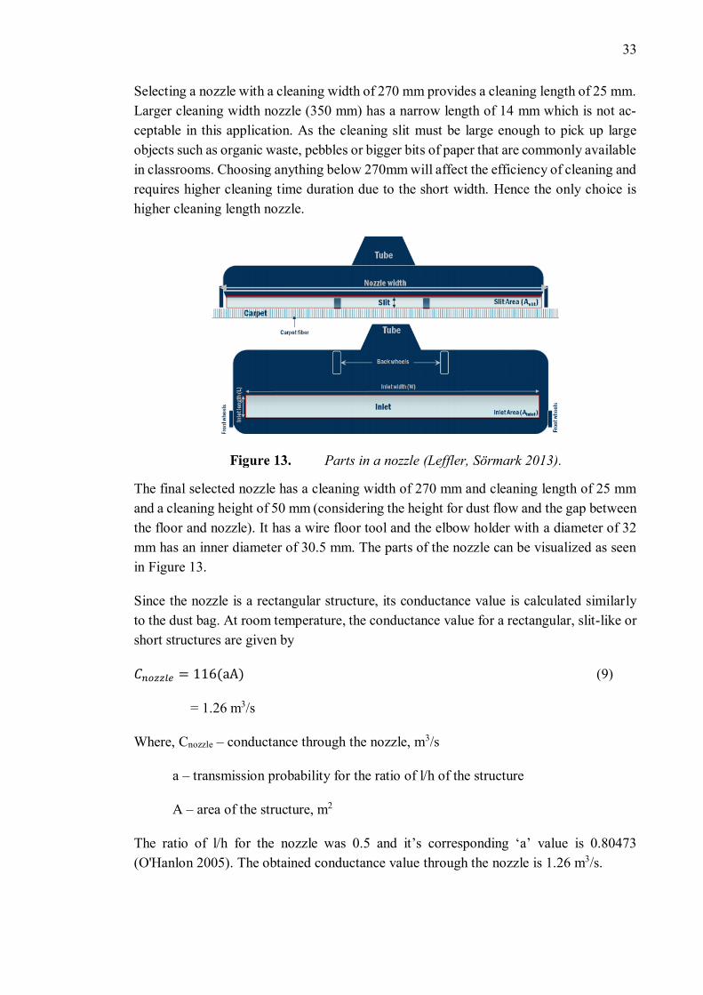
Parts in a nozzle (Leffler, Sörmark 2013).
The final selected nozzle has a cleaning width of 270 mm and cleaning length of 25 mm
and a cleaning height of 50 mm (considering the height for dust flow and the gap between
the floor and nozzle). It has a wire floor tool and the elbow holder with a diameter of 32
mm has an inner diameter of 30.5 mm. The parts of the nozzle can be visualized as seen
in Figure 13.
Since the nozzle is a rectangular structure, its conductance value is calculated similarly
to the dust bag. At room temperature, the conductance value for a rectangular, slit-like or
short structures are given by
𝐶𝑛𝑜𝑧𝑧𝑙𝑒 = 116(aA) (9)
= 1.26 m3/s
Where, Cnozzle – conductance through the nozzle, m3/s
a – transmission probability for the ratio of l/h of the structure
A – area of the structure, m2
The ratio of l/h for the nozzle was 0.5 and it’s corresponding ‘a’ value is 0.80473
(O'Hanlon 2005). The obtained conductance value through the nozzle is 1.26 m3/s.
34
Now the total conductance of the system considering the hose, dust bag and nozzle is
given by
1
𝐶=
1
𝐶ℎ𝑜𝑠𝑒+
1
𝐶𝑑𝑢𝑠𝑡_𝑏𝑎𝑔+
1
𝐶𝑛𝑜𝑧𝑧𝑙𝑒 (10)
Where, C – total conductance, m3/s
Chose – conductance through a hose, m3/s
Corifice – conductance through an orifice, m3/s
Cnozzle – conductance through a nozzle, m3/s
The total conductance value obtained is 1.077 m3/s.
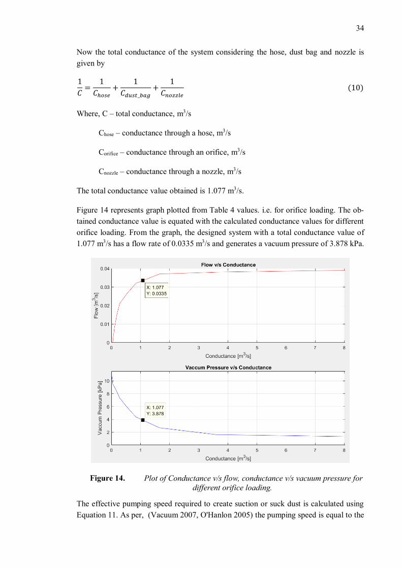
Figure 14 represents graph plotted from Table 4 values. i.e. for orifice loading. The ob-
tained conductance value is equated with the calculated conductance values for different
orifice loading. From the graph, the designed system with a total conductance value of
1.077 m3/s has a flow rate of 0.0335 m3/s and generates a vacuum pressure of 3.878 kPa.
Plot of Conductance v/s flow, conductance v/s vacuum pressure for
different orifice loading.
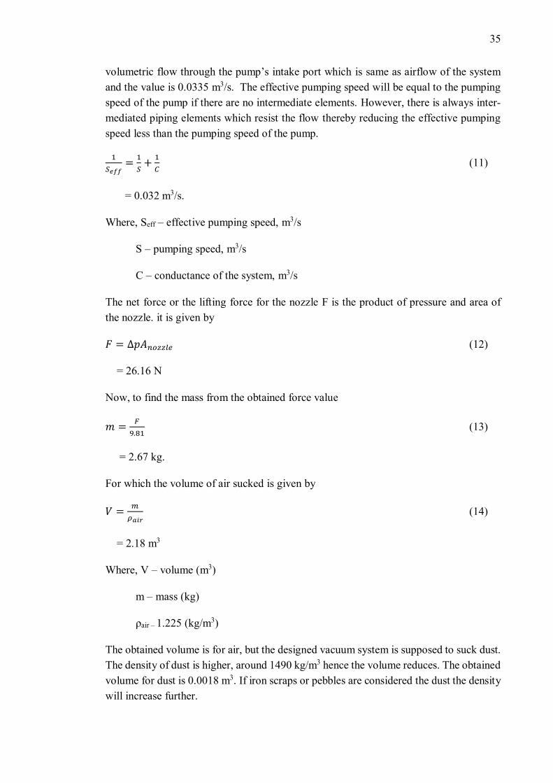
The effective pumping speed required to create suction or suck dust is calculated using
Equation 11. As per, (Vacuum 2007, O'Hanlon 2005) the pumping speed is equal to the
35
volumetric flow through the pump’s intake port which is same as airflow of the system
and the value is 0.0335 m3/s. The effective pumping speed will be equal to the pumping
speed of the pump if there are no intermediate elements. However, there is always inter-
mediated piping elements which resist the flow thereby reducing the effective pumping
speed less than the pumping speed of the pump.
1
𝑆𝑒𝑓𝑓=
1
𝑆+
1
𝐶 (11)
= 0.032 m3/s.
Where, Seff – effective pumping speed, m3/s
S – pumping speed, m3/s
C – conductance of the system, m3/s
The net force or the lifting force for the nozzle F is the product of pressure and area of
the nozzle. it is given by
𝐹 = ∆𝑝𝐴𝑛𝑜𝑧𝑧𝑙𝑒 (12)
= 26.16 N
Now, to find the mass from the obtained force value
𝑚 =𝐹
9.81 (13)
= 2.67 kg.
For which the volume of air sucked is given by
𝑉 =𝑚
𝜌𝑎𝑖𝑟 (14)
= 2.18 m3
Where, V – volume (m3)
m – mass (kg)
ρair – 1.225 (kg/m3)
The obtained volume is for air, but the designed vacuum system is supposed to suck dust.
The density of dust is higher, around 1490 kg/m3 hence the volume reduces. The obtained
volume for dust is 0.0018 m3. If iron scraps or pebbles are considered the dust the density
will increase further.
36
The velocity, v of inlet air can be found by the ratio of flowrate and area of the nozzle as
in Equation 15.
𝑣 =𝑄
𝐴𝑛𝑜𝑧𝑧𝑙𝑒 (15)
= 4.97 m/s
Nozzle placement
For a good cleaning process, the vacuum cleaner must be effective enough to suck the
dirt from the floor. This depends on the speed of airstream along the floor. Placing the
nozzle at the maximum speed location will improve the efficiency of cleaning. This point
on the floor must have the highest speed along the floor and at the same time have the
lowest pressure along with it. This point can be calculated using the velocity components
applied for laminar flow through the nozzle as per (Cengel A., Cimbala M. 2014). Based
on these velocity components, placing the nozzle right on the floor creates a stagnation
point as the flow becomes rotational at this point. So, placing the nozzle at a point above
the floor and not closest to the floor improves the performance of cleaning. This is de-
pendent on the dimensions of the nozzle and flowrate. Finding this point involves the
application of Bernoulli’s theorem, plotting and analyzing flow vectors, this is not in the
scope of this thesis. However, the point of maximum speed can be found manually by
experiment. Some amount of salt or sugar can be placed on the floor and the nozzle can
be tested for the height of best performance. Since in this project there is no manual back
and forth movement of the nozzle, it is important to have the right placement for efficient
cleaning.
3.2.5 Side brush
A pair of rotating side brushes are mounted on to the front end of the chassis supported
by a stationary frame. Motors power them. The use of side brushes aids in the effective
removal of dust from the sides. The dust swept by these brushes are sucked into the vac-
uum cleaner by a tangential force to the nozzle. Above all, these brushes can substitute
the gap left short due to the limited size of the nozzle. Of the 470mm of width at the front
end of PULU, the nozzle will cover 270 mm in the center. Therefore, a width of 100 mm
on each side must be compensated for cleaning by side brushes. The brush must be larger
than the 100mm gap to reach out to places outside the perimeter of the platform. So,
leaving an allowance of 50mm outside the Pulu and 50mm towards the nozzle (for the
tangential flow of dust), the brush diameter must be around 200mm. After reviewing the
existing side brushes available in the market. The torque required for the side brush must
be known to calculate the power required to run them.
Torque is given by the product of moment of inertia and angular acceleration
37
𝑇𝑠 = 𝐼𝛼 (16)
Where, Ts – torque, Nm
I – inertia, kgm2
α – angular acceleration, rad/s2
At first to find the inertia the circular brush is considered to be a solid disk or cylinder
about an axis through the middle, perpendicular to the plane of the disk. The radius and
the mass of the selected side brush are 100 mm and 25g respectively. The equation to
calculate inertia is given by.
𝐼 =1
2𝑀𝑅2 (17)
= 1.25𝑒−4kgm2
Where M – mass of the brush, kg
R – radius of the brush, m
The angular acceleration is calculated using Equation 18. It is considered that the device
reaches 40 rpm in 0.1 sec
𝛼 =𝜔
𝑡 (18)
= 41.89 rad/s2
Where, ω – angular velocity, rad/s
t – time taken, s
Using the obtained inertia and angular acceleration value in Equation 16, the calculated
torque value is 5.24.10-3 Nm. This is the starting torque value. Next, the torque required
to keep the brush in constant operation is calculated. The frictional coefficient between
the plastic bristle and concrete floor is taken as 0.6. For a brush of 25g and 100 mm radius,
the obtained operational torque value is
𝑇𝑜 = 𝜇𝐹𝑅 (19)
= 0.014715 Nm
Where, To – required operational torque, Nm
µ – frictional co-efficient value
38
F – force, N
R – radius of the brush, m
The total torque is the sum of starting and operational torque which is 0. 02𝑁𝑚.
Power P, is given by
𝑃 = 𝑇𝜔 (20)
= 0.084W
Where, T – torque (Nm)
ω – angular velocity (rad/s)
the obtained power value is 0.084𝑊 while the selected motor (Pololu b) can produce
1.2W which meets the requirement with room for further modifications.
3.2.6 Battery
One of the advantages of having PULU platform is its battery capabilities. The currently
developed platform can accommodate the smallest capacity being 420Wh and the biggest
being approximately 1.5kWh. The platform can also house 3kWh of a battery. There is
no limit in terms of the battery capacity that can be connected to the robot platform’s
internal power system. The model charges at 500W, using a fast 48V station, or at 200W,
using a slower 36V station.
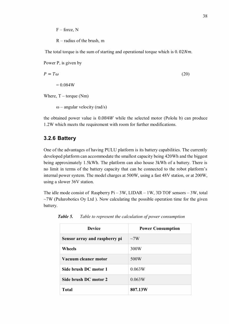
The idle mode consist of Raspberry Pi – 3W, LIDAR – 1W, 3D TOF sensors – 3W, total
~7W (Pulurobotics Oy Ltd ). Now calculating the possible operation time for the given
battery.
Table 5. Table to represent the calculation of power consumption
Device Power Consumption
Sensor array and raspberry pi ~7W
Wheels 300W
Vacuum cleaner motor 500W
Side brush DC motor 1 0.063W
Side brush DC motor 2 0.063W
Total 807.13W
39
The maximum operation time available before next recharge is calculated using Equation
21.
𝑇𝑖𝑚𝑒 =𝐵𝑎𝑡𝑡𝑒𝑟𝑦 𝑐𝑎𝑝𝑎𝑐𝑖𝑡𝑦
𝑇𝑜𝑡𝑎𝑙 𝑝𝑜𝑤𝑒𝑟 𝑐𝑜𝑛𝑠𝑢𝑚𝑝𝑡𝑖𝑜𝑛= 1.86 ℎ𝑜𝑢𝑟𝑠 (21)
So, the robot can work continuously for 1.86 hours with a battery of 1.5kWh and 3.7
hours for a battery of 3kWh for one complete recharge. This is a good operating time in
comparison to the existing products that last just for 40-60 min. They also have lower
suction power. Another added advantage with the Pulu platform is the self-charging abil-
ity when the battery depletes.
However, the vacuum cleaner motor operates at 24 V, but the side brush’s DC motor
operates at 3V. So, there is a requirement of voltage step down for the side brush (similar
to sensor array which operates at lower voltage).
3.3 Mechanical design of autonomous floor cleaning robot
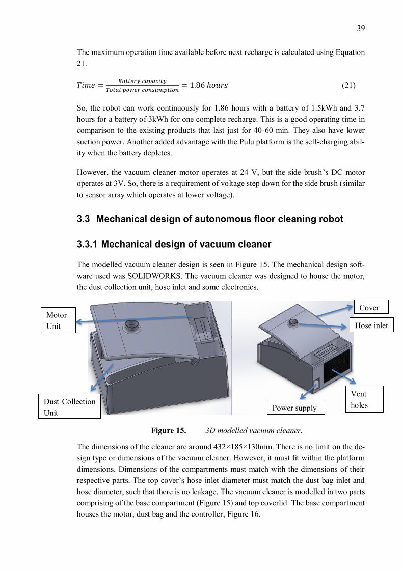
3.3.1 Mechanical design of vacuum cleaner
The modelled vacuum cleaner design is seen in Figure 15. The mechanical design soft-
ware used was SOLIDWORKS. The vacuum cleaner was designed to house the motor,
the dust collection unit, hose inlet and some electronics.
3D modelled vacuum cleaner.
The dimensions of the cleaner are around 432×185×130mm. There is no limit on the de-
sign type or dimensions of the vacuum cleaner. However, it must fit within the platform
dimensions. Dimensions of the compartments must match with the dimensions of their
respective parts. The top cover’s hose inlet diameter must match the dust bag inlet and
hose diameter, such that there is no leakage. The vacuum cleaner is modelled in two parts
comprising of the base compartment (Figure 15) and top coverlid. The base compartment
houses the motor, dust bag and the controller, Figure 16.
Power supply
Cover Motor
Unit Hose inlet
Dust Collection
Unit
Vent
holes
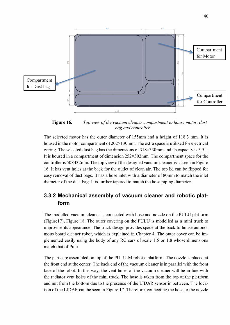
40
Top view of the vacuum cleaner compartment to house motor, dust
bag and controller.
The selected motor has the outer diameter of 155mm and a height of 118.3 mm. It is
housed in the motor compartment of 202×130mm. The extra space is utilized for electrical
wiring. The selected dust bag has the dimensions of 318×330mm and its capacity is 3.5L.
It is housed in a compartment of dimension 252×302mm. The compartment space for the
controller is 50×432mm. The top view of the designed vacuum cleaner is as seen in Figure
16. It has vent holes at the back for the outlet of clean air. The top lid can be flipped for
easy removal of dust bags. It has a hose inlet with a diameter of 80mm to match the inlet
diameter of the dust bag. It is further tapered to match the hose piping diameter.
3.3.2 Mechanical assembly of vacuum cleaner and robotic plat-
form
The modelled vacuum cleaner is connected with hose and nozzle on the PULU platform
(Figure17), Figure 18. The outer covering on the PULU is modelled as a mini truck to
improvise its appearance. The truck design provides space at the back to house autono-
mous board cleaner robot, which is explained in Chapter 4. The outer cover can be im-
plemented easily using the body of any RC cars of scale 1:5 or 1:8 whose dimensions
match that of Pulu.
The parts are assembled on top of the PULU-M robotic platform. The nozzle is placed at
the front end at the center. The back end of the vacuum cleaner is in parallel with the front
face of the robot. In this way, the vent holes of the vacuum cleaner will be in line with
the radiator vent holes of the mini truck. The hose is taken from the top of the platform
and not from the bottom due to the presence of the LIDAR sensor in between. The loca-
tion of the LIDAR can be seen in Figure 17. Therefore, connecting the hose to the nozzle
Compartment
for Controller
Compartment
for Motor
Compartment
for Dust bag
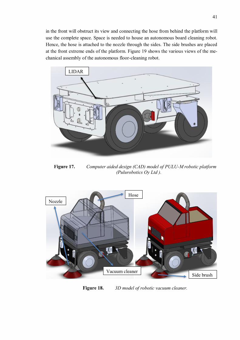
41
in the front will obstruct its view and connecting the hose from behind the platform will
use the complete space. Space is needed to house an autonomous board cleaning robot.
Hence, the hose is attached to the nozzle through the sides. The side brushes are placed
at the front extreme ends of the platform. Figure 19 shows the various views of the me-
chanical assembly of the autonomous floor-cleaning robot.
Computer aided design (CAD) model of PULU-M robotic platform
(Pulurobotics Oy Ltd ).
3D model of robotic vacuum cleaner.
LIDAR
Hose
Nozzle
Side brush Vacuum cleaner
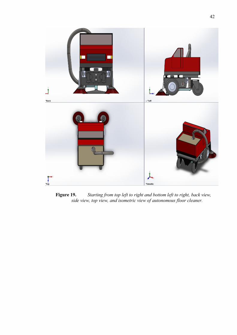
42
Starting from top left to right and bottom left to right, back view,
side view, top view, and isometric view of autonomous floor cleaner.
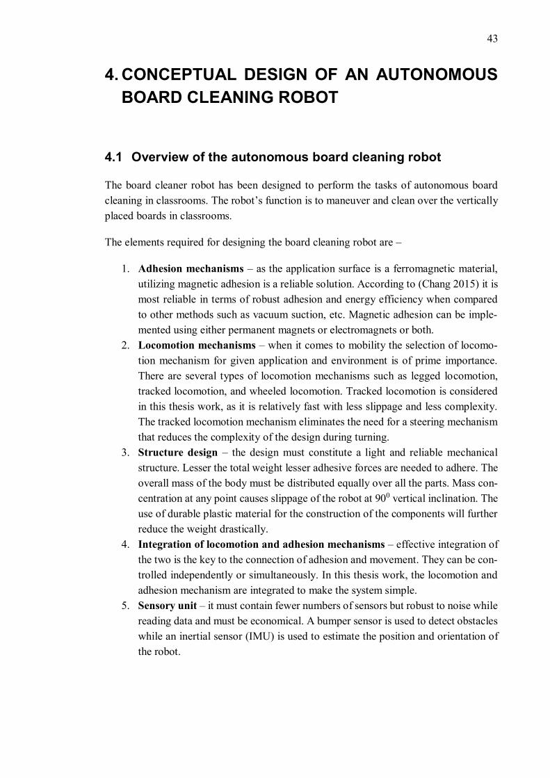
43
4. CONCEPTUAL DESIGN OF AN AUTONOMOUS
BOARD CLEANING ROBOT
4.1 Overview of the autonomous board cleaning robot
The board cleaner robot has been designed to perform the tasks of autonomous board
cleaning in classrooms. The robot’s function is to maneuver and clean over the vertically
placed boards in classrooms.
The elements required for designing the board cleaning robot are –
1. Adhesion mechanisms – as the application surface is a ferromagnetic material,
utilizing magnetic adhesion is a reliable solution. According to (Chang 2015) it is
most reliable in terms of robust adhesion and energy efficiency when compared
to other methods such as vacuum suction, etc. Magnetic adhesion can be imple-
mented using either permanent magnets or electromagnets or both.
2. Locomotion mechanisms – when it comes to mobility the selection of locomo-
tion mechanism for given application and environment is of prime importance.
There are several types of locomotion mechanisms such as legged locomotion,
tracked locomotion, and wheeled locomotion. Tracked locomotion is considered
in this thesis work, as it is relatively fast with less slippage and less complexity.
The tracked locomotion mechanism eliminates the need for a steering mechanism
that reduces the complexity of the design during turning.
3. Structure design – the design must constitute a light and reliable mechanical
structure. Lesser the total weight lesser adhesive forces are needed to adhere. The
overall mass of the body must be distributed equally over all the parts. Mass con-
centration at any point causes slippage of the robot at 900 vertical inclination. The
use of durable plastic material for the construction of the components will further
reduce the weight drastically.
4. Integration of locomotion and adhesion mechanisms – effective integration of
the two is the key to the connection of adhesion and movement. They can be con-
trolled independently or simultaneously. In this thesis work, the locomotion and
adhesion mechanism are integrated to make the system simple.
5. Sensory unit – it must contain fewer numbers of sensors but robust to noise while
reading data and must be economical. A bumper sensor is used to detect obstacles
while an inertial sensor (IMU) is used to estimate the position and orientation of
the robot.
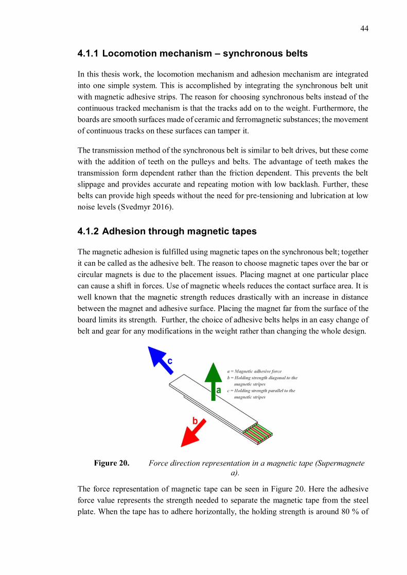
44
4.1.1 Locomotion mechanism – synchronous belts
In this thesis work, the locomotion mechanism and adhesion mechanism are integrated
into one simple system. This is accomplished by integrating the synchronous belt unit
with magnetic adhesive strips. The reason for choosing synchronous belts instead of the
continuous tracked mechanism is that the tracks add on to the weight. Furthermore, the
boards are smooth surfaces made of ceramic and ferromagnetic substances; the movement
of continuous tracks on these surfaces can tamper it.
The transmission method of the synchronous belt is similar to belt drives, but these come
with the addition of teeth on the pulleys and belts. The advantage of teeth makes the
transmission form dependent rather than the friction dependent. This prevents the belt
slippage and provides accurate and repeating motion with low backlash. Further, these
belts can provide high speeds without the need for pre-tensioning and lubrication at low
noise levels (Svedmyr 2016).
4.1.2 Adhesion through magnetic tapes
The magnetic adhesion is fulfilled using magnetic tapes on the synchronous belt; together
it can be called as the adhesive belt. The reason to choose magnetic tapes over the bar or
circular magnets is due to the placement issues. Placing magnet at one particular place
can cause a shift in forces. Use of magnetic wheels reduces the contact surface area. It is
well known that the magnetic strength reduces drastically with an increase in distance
between the magnet and adhesive surface. Placing the magnet far from the surface of the
board limits its strength. Further, the choice of adhesive belts helps in an easy change of
belt and gear for any modifications in the weight rather than changing the whole design.
Force direction representation in a magnetic tape (Supermagnete
a).
The force representation of magnetic tape can be seen in Figure 20. Here the adhesive
force value represents the strength needed to separate the magnetic tape from the steel
plate. When the tape has to adhere horizontally, the holding strength is around 80 % of
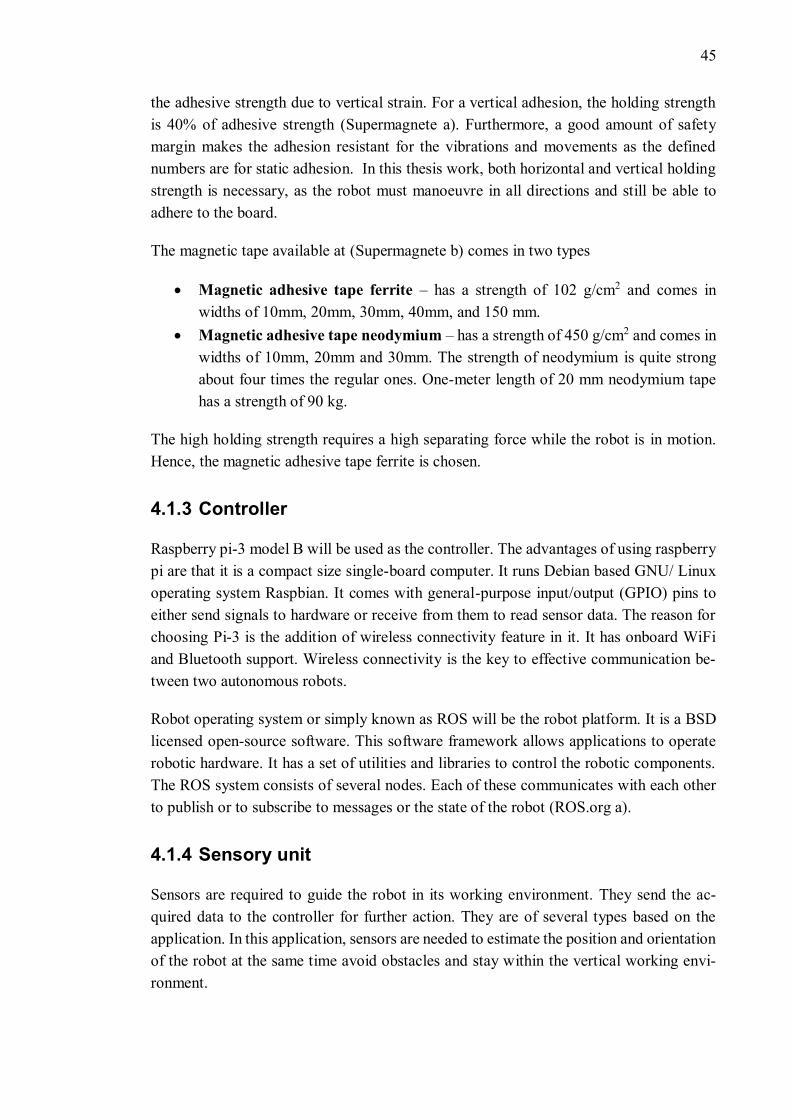
45
the adhesive strength due to vertical strain. For a vertical adhesion, the holding strength
is 40% of adhesive strength (Supermagnete a). Furthermore, a good amount of safety
margin makes the adhesion resistant for the vibrations and movements as the defined
numbers are for static adhesion. In this thesis work, both horizontal and vertical holding
strength is necessary, as the robot must manoeuvre in all directions and still be able to
adhere to the board.
The magnetic tape available at (Supermagnete b) comes in two types
• Magnetic adhesive tape ferrite – has a strength of 102 g/cm2 and comes in
widths of 10mm, 20mm, 30mm, 40mm, and 150 mm.
• Magnetic adhesive tape neodymium – has a strength of 450 g/cm2 and comes in
widths of 10mm, 20mm and 30mm. The strength of neodymium is quite strong
about four times the regular ones. One-meter length of 20 mm neodymium tape
has a strength of 90 kg.
The high holding strength requires a high separating force while the robot is in motion.
Hence, the magnetic adhesive tape ferrite is chosen.
4.1.3 Controller
Raspberry pi-3 model B will be used as the controller. The advantages of using raspberry
pi are that it is a compact size single-board computer. It runs Debian based GNU/ Linux
operating system Raspbian. It comes with general-purpose input/output (GPIO) pins to
either send signals to hardware or receive from them to read sensor data. The reason for
choosing Pi-3 is the addition of wireless connectivity feature in it. It has onboard WiFi
and Bluetooth support. Wireless connectivity is the key to effective communication be-
tween two autonomous robots.
Robot operating system or simply known as ROS will be the robot platform. It is a BSD
licensed open-source software. This software framework allows applications to operate
robotic hardware. It has a set of utilities and libraries to control the robotic components.
The ROS system consists of several nodes. Each of these communicates with each other
to publish or to subscribe to messages or the state of the robot (ROS.org a).
4.1.4 Sensory unit
Sensors are required to guide the robot in its working environment. They send the ac-
quired data to the controller for further action. They are of several types based on the
application. In this application, sensors are needed to estimate the position and orientation
of the robot at the same time avoid obstacles and stay within the vertical working envi-
ronment.
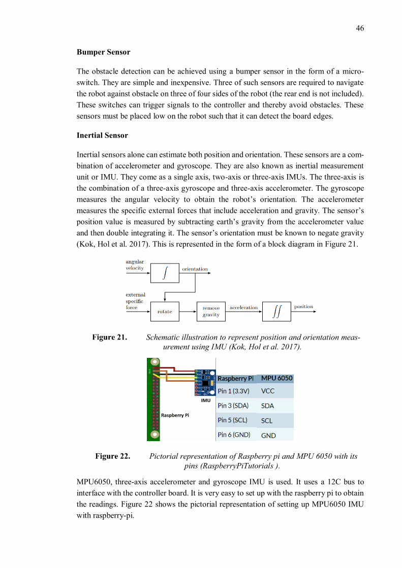
46
Bumper Sensor
The obstacle detection can be achieved using a bumper sensor in the form of a micro-
switch. They are simple and inexpensive. Three of such sensors are required to navigate
the robot against obstacle on three of four sides of the robot (the rear end is not included).
These switches can trigger signals to the controller and thereby avoid obstacles. These
sensors must be placed low on the robot such that it can detect the board edges.
Inertial Sensor
Inertial sensors alone can estimate both position and orientation. These sensors are a com-
bination of accelerometer and gyroscope. They are also known as inertial measurement
unit or IMU. They come as a single axis, two-axis or three-axis IMUs. The three-axis is
the combination of a three-axis gyroscope and three-axis accelerometer. The gyroscope
measures the angular velocity to obtain the robot’s orientation. The accelerometer
measures the specific external forces that include acceleration and gravity. The sensor’s
position value is measured by subtracting earth’s gravity from the accelerometer value
and then double integrating it. The sensor’s orientation must be known to negate gravity
(Kok, Hol et al. 2017). This is represented in the form of a block diagram in Figure 21.
Schematic illustration to represent position and orientation meas-
urement using IMU (Kok, Hol et al. 2017).
Pictorial representation of Raspberry pi and MPU 6050 with its
pins (RaspberryPiTutorials ).
MPU6050, three-axis accelerometer and gyroscope IMU is used. It uses a 12C bus to
interface with the controller board. It is very easy to set up with the raspberry pi to obtain
the readings. Figure 22 shows the pictorial representation of setting up MPU6050 IMU
with raspberry-pi.
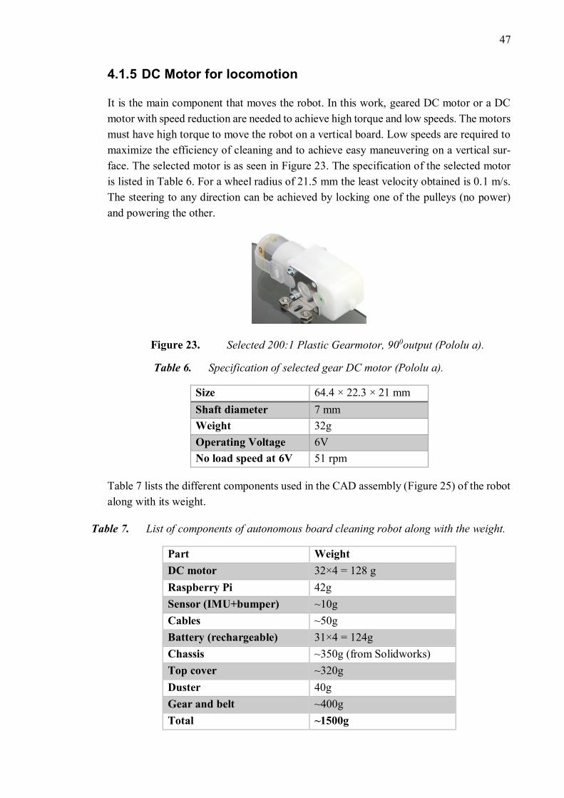
47
4.1.5 DC Motor for locomotion
It is the main component that moves the robot. In this work, geared DC motor or a DC
motor with speed reduction are needed to achieve high torque and low speeds. The motors
must have high torque to move the robot on a vertical board. Low speeds are required to
maximize the efficiency of cleaning and to achieve easy maneuvering on a vertical sur-
face. The selected motor is as seen in Figure 23. The specification of the selected motor
is listed in Table 6. For a wheel radius of 21.5 mm the least velocity obtained is 0.1 m/s.
The steering to any direction can be achieved by locking one of the pulleys (no power)
and powering the other.
Selected 200:1 Plastic Gearmotor, 900output (Pololu a).
Table 6. Specification of selected gear DC motor (Pololu a).
Size 64.4 × 22.3 × 21 mm
Shaft diameter 7 mm
Weight 32g
Operating Voltage 6V
No load speed at 6V 51 rpm
Table 7 lists the different components used in the CAD assembly (Figure 25) of the robot
along with its weight.
Table 7. List of components of autonomous board cleaning robot along with the weight.
Part Weight
DC motor 32×4 = 128 g
Raspberry Pi 42g
Sensor (IMU+bumper) ~10g
Cables ~50g
Battery (rechargeable) 31×4 = 124g
Chassis ~350g (from Solidworks)
Top cover ~320g
Duster 40g
Gear and belt ~400g
Total ~1500g
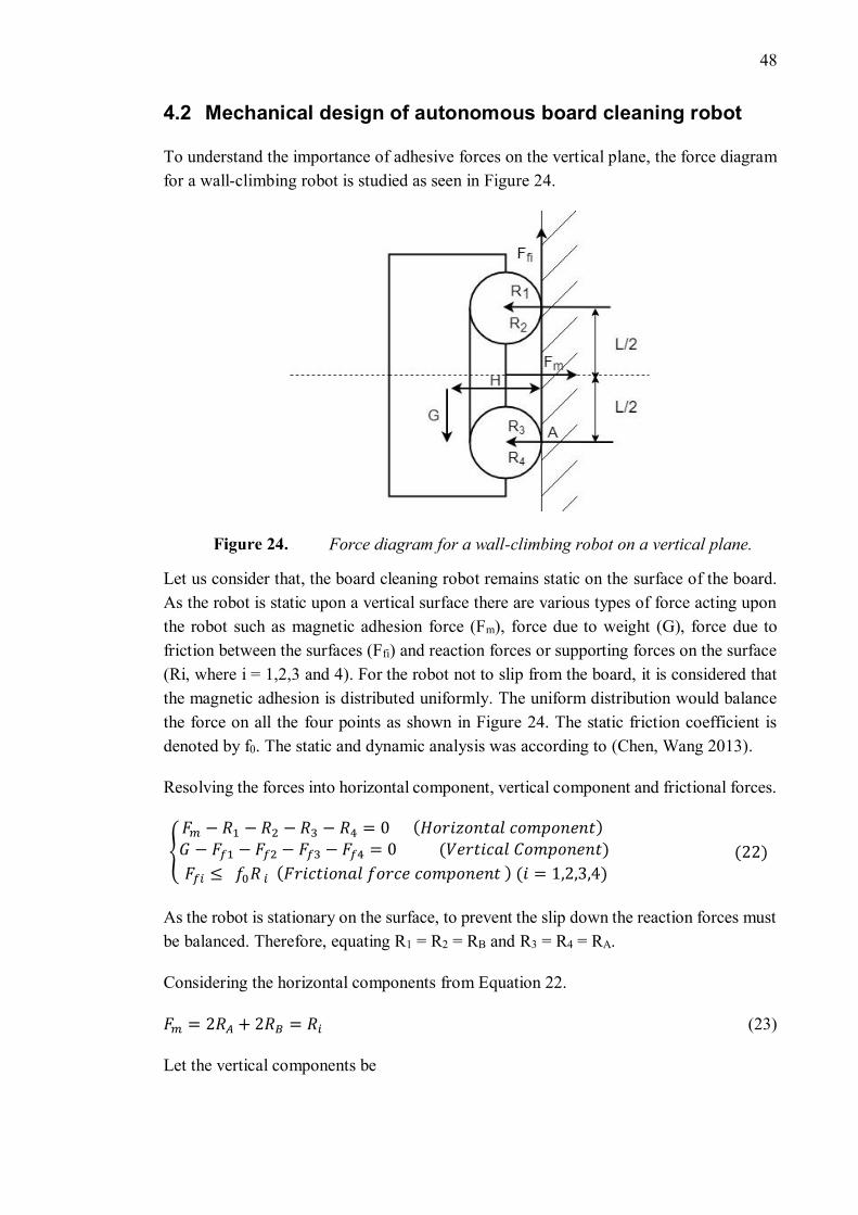
48
4.2 Mechanical design of autonomous board cleaning robot
To understand the importance of adhesive forces on the vertical plane, the force diagram
for a wall-climbing robot is studied as seen in Figure 24.
Force diagram for a wall-climbing robot on a vertical plane.
Let us consider that, the board cleaning robot remains static on the surface of the board.
As the robot is static upon a vertical surface there are various types of force acting upon
the robot such as magnetic adhesion force (Fm), force due to weight (G), force due to
friction between the surfaces (Ffi) and reaction forces or supporting forces on the surface
(Ri, where i = 1,2,3 and 4). For the robot not to slip from the board, it is considered that
the magnetic adhesion is distributed uniformly. The uniform distribution would balance
the force on all the four points as shown in Figure 24. The static friction coefficient is
denoted by f0. The static and dynamic analysis was according to (Chen, Wang 2013).
Resolving the forces into horizontal component, vertical component and frictional forces.
{
𝐹𝑚 − 𝑅1 − 𝑅2 − 𝑅3 − 𝑅4 = 0 (𝐻𝑜𝑟𝑖𝑧𝑜𝑛𝑡𝑎𝑙 𝑐𝑜𝑚𝑝𝑜𝑛𝑒𝑛𝑡) 𝐺 − 𝐹𝑓1 − 𝐹𝑓2 − 𝐹𝑓3 − 𝐹𝑓4 = 0 (𝑉𝑒𝑟𝑡𝑖𝑐𝑎𝑙 𝐶𝑜𝑚𝑝𝑜𝑛𝑒𝑛𝑡)
𝐹𝑓𝑖 ≤ 𝑓0𝑅 𝑖 (𝐹𝑟𝑖𝑐𝑡𝑖𝑜𝑛𝑎𝑙 𝑓𝑜𝑟𝑐𝑒 𝑐𝑜𝑚𝑝𝑜𝑛𝑒𝑛𝑡 ) (𝑖 = 1,2,3,4) (22)
As the robot is stationary on the surface, to prevent the slip down the reaction forces must
be balanced. Therefore, equating R1 = R2 = RB and R3 = R4 = RA.
Considering the horizontal components from Equation 22.
𝐹𝑚 = 2𝑅𝐴 + 2𝑅𝐵 = 𝑅𝑖 (23)
Let the vertical components be
49
𝐺 = 𝐹𝑓𝑖 (24)
After substituting equation 24 in equation 22, the frictional force component is given by
𝐺 ≤ 𝑓𝑜𝑅𝑖 (25)
Now, substituting equation 25 in equation 23.
𝑓𝑜(2𝑅𝐴 + 2𝑅𝐵) ≥ 𝐺 (26)
By using equation 22 and 23 in 26, the condition for the robot to adhere to the vertical
structure is
𝐹𝑚 ≥ 𝐺
𝑓𝑜 (27)
When the robot is in static position, the magnetic adhesion force must satisfy the condi-
tion in the equation 26 to stay upon the board.
Now, considering the rotation about point A. The distance between the center of the roll-
ers is L and the distance between the surface of the board and the center of mass of the
robot is H.
∑MA ≥ 0
−𝑅1𝐿
2− 𝑅2
𝐿
2+ 𝑅3
𝐿
2+ 𝑅4
𝐿
2− 𝐺𝐻 ≥ 0 (28)
Where, R1 = R2 = RB and R3 = R4 = RA.
−2𝑅𝐴 + 2𝑅𝐵 −2𝐺𝐻
𝐿 ≥ 0
2𝑅𝐴 − 2𝑅𝐵 +2𝐺𝐻
𝐿 ≥ 0
2𝑅𝐴 ≤ 2𝑅𝐵 −2𝐺𝐻
𝐿
From horizontal component of equation 22,
2𝑅𝐴 ≤ (𝐹𝑚 − 2𝑅𝐴) −2𝐺𝐻
𝐿
4𝑅𝐴 ≤ 𝐹𝑚 −2𝐺𝐻
𝐿
Dividing by 2
50
2𝑅𝐴 ≤𝐹𝑚
2−
𝐺𝐻
𝐿
For the robot to stick to the board it is known that the lower wheels should not rotate
around A. For that to happen the force on top wheels 2RA should be greater or equal to 0.
The minimum requirement is when 2RA is equal to 0. So, when 0 is substituted in above
equation the obtained condition is
𝐹𝑚 ≥ 2𝐺𝐻
𝐿 (29)
To estimate the magnetic adhesion force, the maximum of the equation 27 and 29 is con-
sidered.
𝐹𝑚 ≥ 𝑚𝑎𝑥 {𝐺
𝑓𝑜,2𝐺𝐻
𝐿} (30)
Considering the parameters from the CAD model, for 1.5 Kg payload of the robot, the
magnetic adhesion force must be greater than 49 N for the robot to remain static on the
board surface. The static coefficient of friction is taken as 0.3. The weight distribution
on the two sides of the bot would be 24.5N. The possible least magnetic adhesion through
the magnetic strips on one side of the bot considering 40% of total holding strength is
27.3N which is greater than 24.5N. Hence the robot can adhere to vertical magnetic plane.
Next the torque required for the robot movement is calculated. The torque of the motor
must satisfy:
𝑀𝑑 ≥ 𝑘2. F. 𝑓𝑜 . 𝑟
𝛼𝑡 . η (31)
𝑀𝑑 ≥ 9.629. 10−3 Nm
Where, k2 – is the safety factor, considering it to be 3
F – sum of reaction force and force due to weight, N
f0 – frictional coefficient
r – radius, m
αt – transmission ratio
η – efficiency
The obtained value is 0.01 Nm while motor can provide a torque of 0.7Nm which is higher
than the requirement to keep the robot moving on the vertical plane.
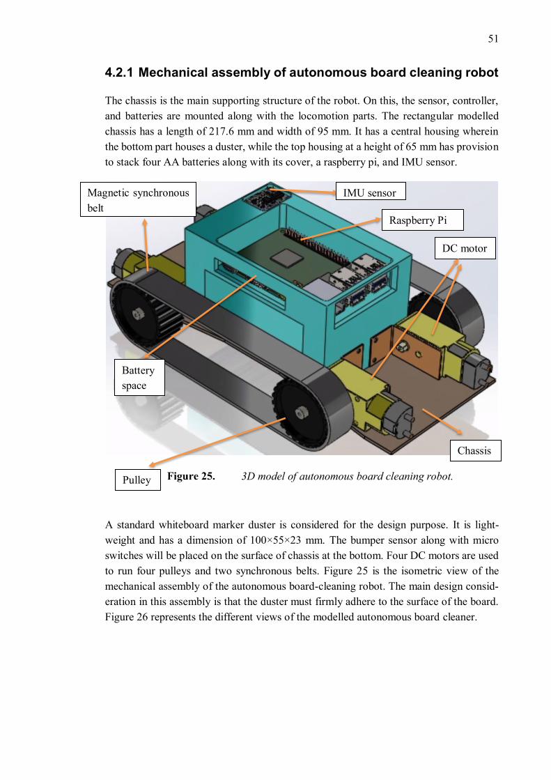
51
4.2.1 Mechanical assembly of autonomous board cleaning robot
The chassis is the main supporting structure of the robot. On this, the sensor, controller,
and batteries are mounted along with the locomotion parts. The rectangular modelled
chassis has a length of 217.6 mm and width of 95 mm. It has a central housing wherein
the bottom part houses a duster, while the top housing at a height of 65 mm has provision
to stack four AA batteries along with its cover, a raspberry pi, and IMU sensor.
3D model of autonomous board cleaning robot.
A standard whiteboard marker duster is considered for the design purpose. It is light-
weight and has a dimension of 100×55×23 mm. The bumper sensor along with micro
switches will be placed on the surface of chassis at the bottom. Four DC motors are used
to run four pulleys and two synchronous belts. Figure 25 is the isometric view of the
mechanical assembly of the autonomous board-cleaning robot. The main design consid-
eration in this assembly is that the duster must firmly adhere to the surface of the board.
Figure 26 represents the different views of the modelled autonomous board cleaner.
Battery
space
Pulley
DC motor
Raspberry Pi
Magnetic synchronous
belt
Chassis
IMU sensor
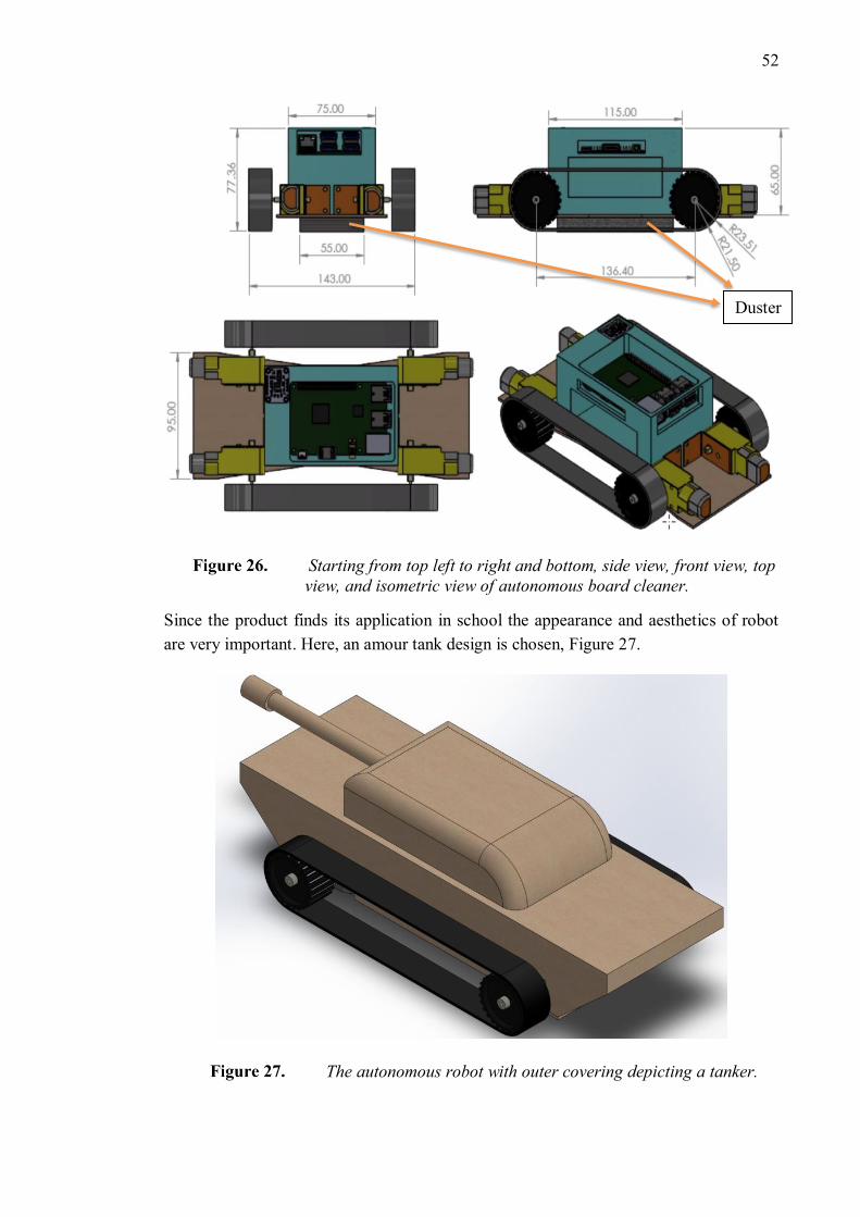
52
Starting from top left to right and bottom, side view, front view, top
view, and isometric view of autonomous board cleaner.
Since the product finds its application in school the appearance and aesthetics of robot
are very important. Here, an amour tank design is chosen, Figure 27.
The autonomous robot with outer covering depicting a tanker.
Duster
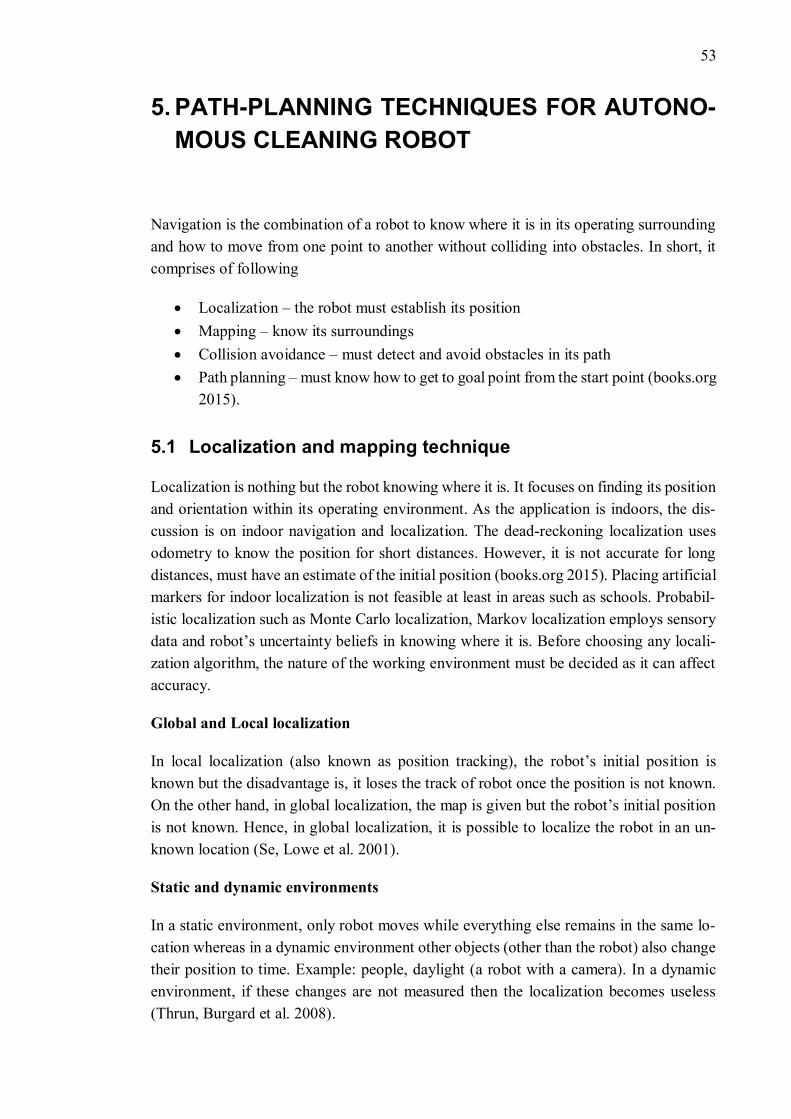
53
5. PATH-PLANNING TECHNIQUES FOR AUTONO-
MOUS CLEANING ROBOT
Navigation is the combination of a robot to know where it is in its operating surrounding
and how to move from one point to another without colliding into obstacles. In short, it
comprises of following
• Localization – the robot must establish its position
• Mapping – know its surroundings
• Collision avoidance – must detect and avoid obstacles in its path
• Path planning – must know how to get to goal point from the start point (books.org
2015).
5.1 Localization and mapping technique
Localization is nothing but the robot knowing where it is. It focuses on finding its position
and orientation within its operating environment. As the application is indoors, the dis-
cussion is on indoor navigation and localization. The dead-reckoning localization uses
odometry to know the position for short distances. However, it is not accurate for long
distances, must have an estimate of the initial position (books.org 2015). Placing artificial
markers for indoor localization is not feasible at least in areas such as schools. Probabil-
istic localization such as Monte Carlo localization, Markov localization employs sensory
data and robot’s uncertainty beliefs in knowing where it is. Before choosing any locali-
zation algorithm, the nature of the working environment must be decided as it can affect
accuracy.
Global and Local localization
In local localization (also known as position tracking), the robot’s initial position is
known but the disadvantage is, it loses the track of robot once the position is not known.
On the other hand, in global localization, the map is given but the robot’s initial position
is not known. Hence, in global localization, it is possible to localize the robot in an un-
known location (Se, Lowe et al. 2001).
Static and dynamic environments
In a static environment, only robot moves while everything else remains in the same lo-
cation whereas in a dynamic environment other objects (other than the robot) also change
their position to time. Example: people, daylight (a robot with a camera). In a dynamic
environment, if these changes are not measured then the localization becomes useless
(Thrun, Burgard et al. 2008).
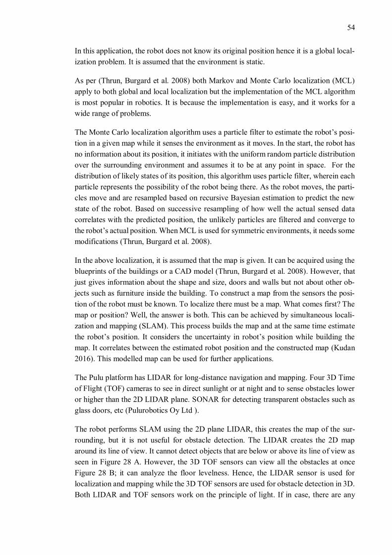
54
In this application, the robot does not know its original position hence it is a global local-
ization problem. It is assumed that the environment is static.
As per (Thrun, Burgard et al. 2008) both Markov and Monte Carlo localization (MCL)
apply to both global and local localization but the implementation of the MCL algorithm
is most popular in robotics. It is because the implementation is easy, and it works for a
wide range of problems.
The Monte Carlo localization algorithm uses a particle filter to estimate the robot’s posi-
tion in a given map while it senses the environment as it moves. In the start, the robot has
no information about its position, it initiates with the uniform random particle distribution
over the surrounding environment and assumes it to be at any point in space. For the
distribution of likely states of its position, this algorithm uses particle filter, wherein each
particle represents the possibility of the robot being there. As the robot moves, the parti-
cles move and are resampled based on recursive Bayesian estimation to predict the new
state of the robot. Based on successive resampling of how well the actual sensed data
correlates with the predicted position, the unlikely particles are filtered and converge to
the robot’s actual position. When MCL is used for symmetric environments, it needs some
modifications (Thrun, Burgard et al. 2008).
In the above localization, it is assumed that the map is given. It can be acquired using the
blueprints of the buildings or a CAD model (Thrun, Burgard et al. 2008). However, that
just gives information about the shape and size, doors and walls but not about other ob-
jects such as furniture inside the building. To construct a map from the sensors the posi-
tion of the robot must be known. To localize there must be a map. What comes first? The
map or position? Well, the answer is both. This can be achieved by simultaneous locali-
zation and mapping (SLAM). This process builds the map and at the same time estimate
the robot’s position. It considers the uncertainty in robot’s position while building the
map. It correlates between the estimated robot position and the constructed map (Kudan
2016). This modelled map can be used for further applications.
The Pulu platform has LIDAR for long-distance navigation and mapping. Four 3D Time
of Flight (TOF) cameras to see in direct sunlight or at night and to sense obstacles lower
or higher than the 2D LIDAR plane. SONAR for detecting transparent obstacles such as
glass doors, etc (Pulurobotics Oy Ltd ).
The robot performs SLAM using the 2D plane LIDAR, this creates the map of the sur-
rounding, but it is not useful for obstacle detection. The LIDAR creates the 2D map
around its line of view. It cannot detect objects that are below or above its line of view as
seen in Figure 28 A. However, the 3D TOF sensors can view all the obstacles at once
Figure 28 B; it can analyze the floor levelness. Hence, the LIDAR sensor is used for
localization and mapping while the 3D TOF sensors are used for obstacle detection in 3D.
Both LIDAR and TOF sensors work on the principle of light. If in case, there are any
55
transparent obstacles such as glass it will not be detected as the light passes through it.
To solve this problem, SONAR sensors are used. They detect transparent objects.
A B
A – The 2D LIDAR cannot provide complete picture of the obstacle
as it cannot see the human foot in the way and the tabletop that is above its
sight, but it is useful for localization and mapping. B – The 3D TOF sensors can
see all the obstacles at once; hence, they provide details for obstacle avoidance
(Pulurobotics Oy Ltd ).
5.2 Techniques involved in autonomous path planning
For an autonomous robot, path-planning aims at finding a collision-free path from the
start point to the goal point. When it comes to robotic vacuum cleaners the path-planning
gets complex, as it must aim at providing complete coverage of the surrounding for clean-
ing.
Various motion algorithms can be designed for path planning depending on the sophisti-
cation needed. Some are sophisticated demanding expensive sensory unit and heavy com-
putation while some simple algorithms can be implemented with just bumper and IR sen-
sor. The motion algorithms that are simple and yet provide complete coverage of the area
are
• Random coverage – in this the robot follows a random travel motion wherein it trav-
els straight until it hits an obstacle. Once it hits the obstacle, it changes its orientation
to any random direction and moves along until it encounters the next obstacle and
repeats. It is time-consuming, but it is possible to completely cover the surrounding.
Though it is simple, it requires more time for complete coverage. There is a possibility
for the robot to repeat the already traversed areas unless programmed no for it. This
is only suitable for domestic cleaning with small areas where time is not a priority.
• Systematic/ pattern coverage – this involves a predefined pattern path or combina-
tion of them to manoeuvre the robot. Since the paths are already predefined, it is sim-
ple and not computationally heavy. The systematic coverage will be used in this pro-
ject.
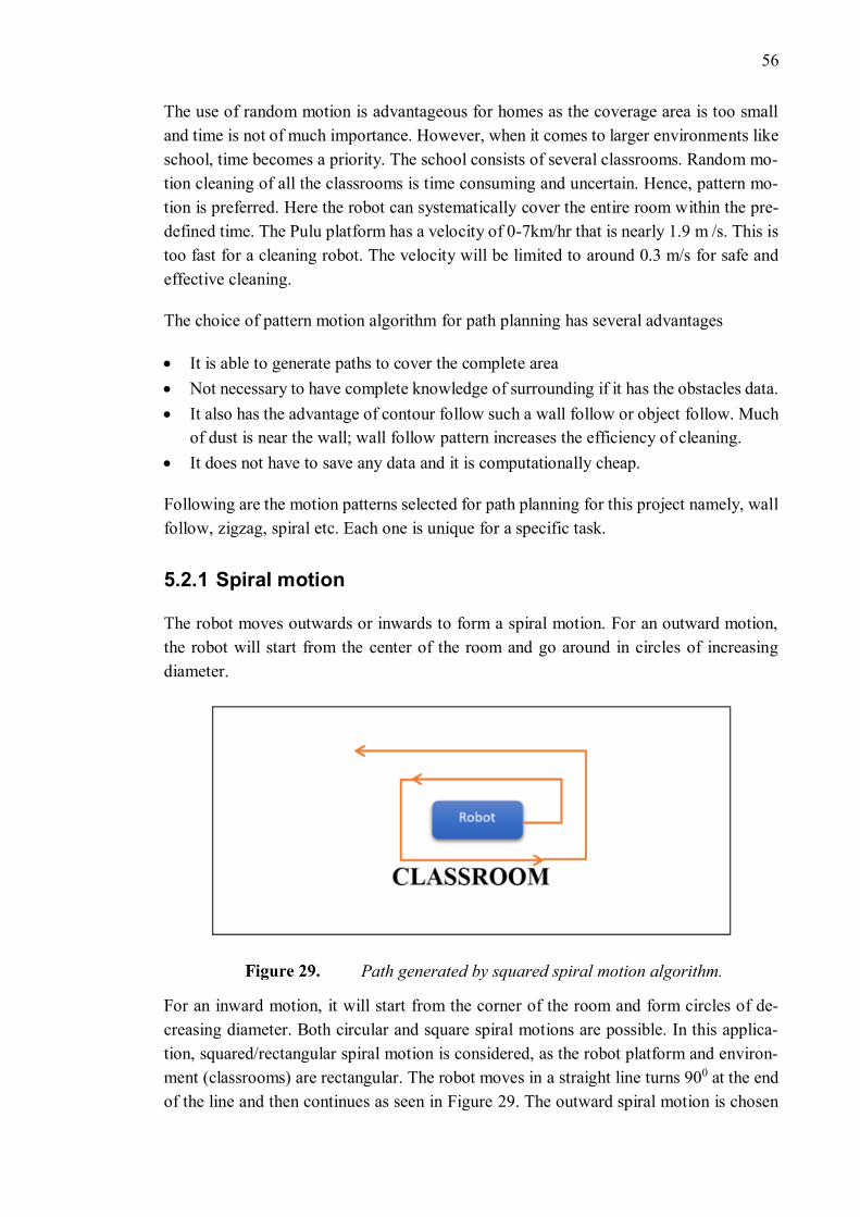
56
The use of random motion is advantageous for homes as the coverage area is too small
and time is not of much importance. However, when it comes to larger environments like
school, time becomes a priority. The school consists of several classrooms. Random mo-
tion cleaning of all the classrooms is time consuming and uncertain. Hence, pattern mo-
tion is preferred. Here the robot can systematically cover the entire room within the pre-
defined time. The Pulu platform has a velocity of 0-7km/hr that is nearly 1.9 m /s. This is
too fast for a cleaning robot. The velocity will be limited to around 0.3 m/s for safe and
effective cleaning.
The choice of pattern motion algorithm for path planning has several advantages
• It is able to generate paths to cover the complete area
• Not necessary to have complete knowledge of surrounding if it has the obstacles data.
• It also has the advantage of contour follow such a wall follow or object follow. Much
of dust is near the wall; wall follow pattern increases the efficiency of cleaning.
• It does not have to save any data and it is computationally cheap.
Following are the motion patterns selected for path planning for this project namely, wall
follow, zigzag, spiral etc. Each one is unique for a specific task.
5.2.1 Spiral motion
The robot moves outwards or inwards to form a spiral motion. For an outward motion,
the robot will start from the center of the room and go around in circles of increasing
diameter.
Path generated by squared spiral motion algorithm.
For an inward motion, it will start from the corner of the room and form circles of de-
creasing diameter. Both circular and square spiral motions are possible. In this applica-
tion, squared/rectangular spiral motion is considered, as the robot platform and environ-
ment (classrooms) are rectangular. The robot moves in a straight line turns 900 at the end
of the line and then continues as seen in Figure 29. The outward spiral motion is chosen
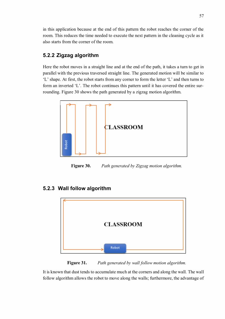
57
in this application because at the end of this pattern the robot reaches the corner of the
room. This reduces the time needed to execute the next pattern in the cleaning cycle as it
also starts from the corner of the room.
5.2.2 Zigzag algorithm
Here the robot moves in a straight line and at the end of the path, it takes a turn to get in
parallel with the previous traversed straight line. The generated motion will be similar to
‘L’ shape. At first, the robot starts from any corner to form the letter ‘L’ and then turns to
form an inverted ‘L’. The robot continues this pattern until it has covered the entire sur-
rounding. Figure 30 shows the path generated by a zigzag motion algorithm.
Path generated by Zigzag motion algorithm.
5.2.3 Wall follow algorithm
Path generated by wall follow motion algorithm.
It is known that dust tends to accumulate much at the corners and along the wall. The wall
follow algorithm allows the robot to move along the walls; furthermore, the advantage of
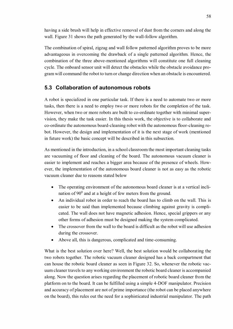
58
having a side brush will help in effective removal of dust from the corners and along the
wall. Figure 31 shows the path generated by the wall-follow algorithm.
The combination of spiral, zigzag and wall follow patterned algorithm proves to be more
advantageous in overcoming the drawback of a single patterned algorithm. Hence, the
combination of the three above-mentioned algorithms will constitute one full cleaning
cycle. The onboard sensor unit will detect the obstacles while the obstacle avoidance pro-
gram will command the robot to turn or change direction when an obstacle is encountered.
5.3 Collaboration of autonomous robots
A robot is specialized in one particular task. If there is a need to automate two or more
tasks, then there is a need to employ two or more robots for the completion of the task.
However, when two or more robots are built to co-ordinate together with minimal super-
vision, they make the task easier. In this thesis work, the objective is to collaborate and
co-ordinate the autonomous board-cleaning robot with the autonomous floor-cleaning ro-
bot. However, the design and implementation of it is the next stage of work (mentioned
in future work) the basic concept will be described in this subsection.
As mentioned in the introduction, in a school classroom the most important cleaning tasks
are vacuuming of floor and cleaning of the board. The autonomous vacuum cleaner is
easier to implement and reaches a bigger area because of the presence of wheels. How-
ever, the implementation of the autonomous board cleaner is not as easy as the robotic
vacuum cleaner due to reasons stated below
• The operating environment of the autonomous board cleaner is at a vertical incli-
nation of 900 and at a height of few meters from the ground.
• An individual robot in order to reach the board has to climb on the wall. This is
easier to be said than implemented because climbing against gravity is compli-
cated. The wall does not have magnetic adhesion. Hence, special grippers or any
other forms of adhesion must be designed making the system complicated.
• The crossover from the wall to the board is difficult as the robot will use adhesion
during the crossover.
• Above all, this is dangerous, complicated and time-consuming.
What is the best solution over here? Well, the best solution would be collaborating the
two robots together. The robotic vacuum cleaner designed has a back compartment that
can house the robotic board cleaner as seen in Figure 32. So, whenever the robotic vac-
uum cleaner travels to any working environment the robotic board cleaner is accompanied
along. Now the question arises regarding the placement of robotic board cleaner from the
platform on to the board. It can be fulfilled using a simple 4-DOF manipulator. Precision
and accuracy of placement are not of prime importance (the robot can be placed anywhere
on the board), this rules out the need for a sophisticated industrial manipulator. The path
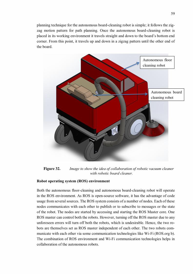
59
planning technique for the autonomous board-cleaning robot is simple; it follows the zig-
zag motion pattern for path planning. Once the autonomous board-cleaning robot is
placed in its working environment it travels straight and down to the board’s bottom end
corner. From this point, it travels up and down in a zigzag pattern until the other end of
the board.
Image to show the idea of collaboration of robotic vacuum cleaner
with robotic board cleaner.
Robot operating system (ROS) environment
Both the autonomous floor-cleaning and autonomous board-cleaning robot will operate
in the ROS environment. As ROS is open-source software, it has the advantage of code
usage from several sources. The ROS system consists of a number of nodes. Each of these
nodes communicates with each other to publish or to subscribe to messages or the state
of the robot. The nodes are started by accessing and starting the ROS Master core. One
ROS master can control both the robots. However, turning off the ROS master due to any
unforeseen errors will turn off both the robots, which is undesirable. Hence, the two ro-
bots are themselves set as ROS master independent of each other. The two robots com-
municate with each other via some communication technologies like Wi-Fi (ROS.org b).
The combination of ROS environment and Wi-Fi communication technologies helps in
collaboration of the autonomous robots.
Autonomous board
cleaning robot
Autonomous floor
cleaning robot
60
6. CONCLUSION
The main objective of this thesis work was to design a proof-of-concept for an autono-
mous floor-cleaning and an autonomous board-cleaning robot. An extensive literature
study was done to understand and compare the state of art technologies of these systems.
However, the studies concentrating on the methodology of these systems were quite lim-
ited. The preliminary design and component selection of the vacuum cleaner system was
based on the vacuum and airflow equations along with assumptions. The basis of these
assumptions were the analytical skills of understanding, reasoning and comparing the ex-
isting models of vacuum cleaners.
The choice of using the existing commercially available robot platform, PULU-M for the
robot chassis has eased the design process as it comes with the in-built sensory unit for
obstacle detection, locomotion unit and the in-built battery-package along with self-
charging capabilities. Furthermore, the in-built batteries of PULU provide about 3.7 hours
of working time, which is quite good for large working areas like school. This ability out
beats the domestic robotic vacuum cleaner, which has the cleaning cycle of around 30-60
min. By using PULU platform, more focus can be laid on developing an efficient cleaning
system. The platform has a maximum speed of 1.9m/s but it will be limited to around 0.3
m/s for the effective cleaning process. The main concerns of navigation in this project are
to provide a full area coverage. This is addressed by semi-systematic coverage approach
using the combination of patterned motion algorithms namely spiral, zigzag and wall fol-
low. By knowing the dimension of the environment, the time taken for a cleaning cycle
can be estimated. The choice of localization and mapping techniques are Monte-Carlo
localization and SLAM wherein the environment is assumed to be static with global lo-
calization.
Getting a robot function against gravity is quite complex. The choice of magnetic adhe-
sion for the autonomous board-cleaning robot harnessing the board’s ferromagnetic at-
traction makes the system simple, lightweight, and energy-efficient. Further, as the chas-
sis of the autonomous board-cleaning robot is small it can be 3D printed conveniently.
Belt drives with magnetic tapes are the preferred locomotion unit over the wheels to in-
crease the surface area of magnetic attraction. The robot weight estimation is important.
If weight force is greater than the adhesion force, the robot will fall. There is no safety
device designed if in case the robot loses adhesion. The equations show one hundred
percent adhesion, but this can be confirmed only with practical implementation. The use
of a simple sensory unit for obstacle detection and robot position estimation reduces the
complexity of data reading. Rechargeable batteries are preferred for power supply.
Further, the autonomous floor cleaner and board cleaner must be integrated into one sys-
tem for simultaneously floor cleaning and board cleaning. This can be done using a simple
61
4-DOF robotic manipulator wherein the manipulator picks and places the board cleaning
bot on the board and back on the platform after the completion of the task. Accuracy and
precision are not of much importance unlike the industrial manipulator, which also re-
duces the cost of manipulator implementation.
Robustness, safety, lightweight and cost-effectiveness are the keys for successful imple-
mentation of the robot system. Since the area of application of the project is school, ap-
pearance and aesthetics of the robot are of much importance. The work has shown that
there is a great potential to bring autonomous cleaning robot to schools. The implemen-
tation of autonomous service robots to school open new doors of the school to kids. Con-
stant interaction with autonomous robots can ignite innovative ideas among children.
6.1 Future work
Since this is a proof of concept, the road for practical implementation has many stops.
The safety concerns of the autonomous board-cleaning robot in terms of a safe and relia-
ble attachment must be worked upon. The motion control methods and graphical user
interface are key design requirements for practical implementation. The next stage of this
work must focus mainly on developing path planning algorithms. Programs must be de-
veloped to establish collaboration between autonomous robots. Use of cameras and ma-
chine vision techniques for path planning will improve the mapping techniques for au-
tonomous robots.
62
REFERENCES
AEA ENERGY & ENVIRONMENT and CONSUMER RESEARCH ASSOCIATES,
2009. Work on Preparatory Studies for Eco-Design Requirements of EuPs (II) Lot 17
Vacuum Cleaners.
AKINFIEV, T., ARMADA, M. and NABULSI, S., 2009. Climbing cleaning robot for
vertical surfaces. Industrial Robot: An International Journal, 36(4), pp. 352-357.
AUTUMN, K. and GRAVISH, N., 2008. Gecko adhesion: evolutionary nanotechnol-
ogy. Philosophical Transactions of the Royal Society of London A: Mathematical, Phys-
ical and Engineering Sciences, 366(1870), pp. 1575-1590.
BOOKS.ORG, 2015. Robotics. en.wikibooks.org.
CBSNEWS COM, S., "Aug 9, ", 1999-last update, Meet 'Cye,' A New Homebot. Avail-
able: https://www.cbsnews.com/news/meet-cye-a-new-homebot/ [Sep 27, 2018].
CENGEL A., Y. and CIMBALA M., J., 2014. Fluid Mechanics Fundamentals and Ap-
plications. 3 edn. United States of America: McGraw-Hill,.
CHANG, Y., 2015. Development of a wall climbing inspection robot with high mobility
on complex shaped walls.
CHEN, Y. and WANG, C.M., 2013The Design of Permanent Magnetic Adhesion Sys-
tem for Wall-Climbing Robot, Applied Mechanics and Materials 2013, Trans Tech
Publ, pp. 531-536.
CHU, B., JUNG, K., HAN, C. and HONG, D., 2010. A survey of climbing robots: Lo-
comotion and adhesion. International journal of precision engineering and manufactur-
ing, 11(4), pp. 633-647.
COOPER, D., "Sep 18, ", 2012-last update, iRobot buys rival Evolution Robotics for
$74 million to expand hard-floor cleaning tech. Available: https://www.en-
gadget.com/2012/09/18/irobot-buys-rival-evolution-robotics-for-74-million-to-expand-
h/ [Sep 27, 2018].
DIJK, L.M., 2010. Minimizing the overall size of a vacuum cleaner. Define the options
for minimizing (optimizing) the overall size of a vacuum cleaner, .
EZVID WIKI, , Top 7 Robotic Window Cleaners of 2018 | Video Review. Available:
https://wiki.ezvid.com/best-robotic-window-cleaners [Sep 28, 2018].
FACTS ABOUT VACS, a-last update, Fan or Impeller Types & Performance.
Available: https://www.ristenbatt.com/xcart/Fan-or-Impeller-Types-and-Perfor-
mance.html.
https://www.engadget.com/2012/09/18/irobot-buys-rival-evolution-robotics-for-74-million-to-expand-h/
https://www.engadget.com/2012/09/18/irobot-buys-rival-evolution-robotics-for-74-million-to-expand-h/
63
FACTS ABOUT VACS, b-last update, Power of the Vacuum Cleaner Suction Motor.
Available: https://www.ristenbatt.com/xcart/Power-of-the-Vacuum-Cleaner-Suction-
Motor.html.
HANLON, M., "Jun 03, ", 2004-last update, Dyson's Robot Vacuum Cleaner - the
DC06. Available: https://newatlas.com/go/1282/ [Sep 27, 2018].
HEATH, N., , What is the Raspberry Pi 3? Everything you need to know about the tiny,
low-cost computer. Available: https://www.zdnet.com/article/what-is-the-raspberry-pi-
3-everything-you-need-to-know-about-the-tiny-low-cost-computer/ [Nov 27, 2018].
IROBOT, , Accessories
for Roomba® Original Series. Available: http://store.irobot.com/default/parts-and-ac-
cessories/roomba-accessories/original-series/.
KAWASAKI, S. and KIKUCHI, K., 2014Development of a small legged wall climbing
robot with passive suction cups, Proceedings of the 3rd International Conference on
Design Engineering and Science—ICDES, Pilsen, Czech Republic 2014, pp. 112-116.
KIM, S., LEE, I.O., CHO, D.I. and LEE, J., 2006. Dynamic localization of a mobile ro-
bot with active beacon sensors. IFAC Proceedings Volumes, 39(16), pp. 921-925.
KITE ROBOTICS, KITE Robotics - How it works - Window cleaning robot technology.
KOK, M., HOL, J.D. and SCHÖN, T.B., 2017. Using inertial sensors for position and
orientation estimation. arXiv preprint arXiv:1704.06053, .
KUDAN, 2016. An Introduction to Simultaneous Localisation and Mapping.
LARSSON, A. and PETERSSON, J., 2009. Utveckling av ett dammsugarmunstycke för
energieffektiv dammupptagning.
LEFFLER, J. and SÖRMARK, C., 2013. Beating the carpet: Developing an active vac-
uum cleaner nozzlefor high carpet performance using less energy.
LISZEWSKI, A., "Aug 31, ", 2017-last update, Neato Robotics. Available: https://giz-
modo.com/?q=Neato%20Robotics&u=&zo=+03:00 [Sep 27, 2018].
LONGO, D. and MUSCATO, G., 2006. The Alicia/sup 3/climbing robot: a three-mod-
ule robot for automatic wall inspection. IEEE Robotics & Automation Magazine, 13(1),
pp. 42-50.
MALL.SK, , Electrolux Trilobite 2.0. Available: https://www.mall.sk/vysavace/electro-
lux-trilobite-2-0.
MARURI, L., MARTINEZ-ESNAOLA, A., LANDALUZE, J., CASAS, S. and FER-
NANDEZ, M., DESIGN OF A PROTOTYPE ROBOT VACUUM CLEANER.
MCHUGH, M., 2015. The New Roomba Can See Where It's Going, and Has an App.
Wired, .
64
MENON, C., MURPHY, M. and SITTI, M., 2004Gecko inspired surface climbing ro-
bots, Robotics and Biomimetics, 2004. ROBIO 2004. IEEE International Conference on
2004, IEEE, pp. 431-436.
MIYAKE, T. and ISHIHARA, H., 2003Mechanisms and basic properties of window
cleaning robot, Advanced Intelligent Mechatronics, 2003. AIM 2003. Proceedings. 2003
IEEE/ASME International Conference on 2003, IEEE, pp. 1372-1377.
MIYAKE, T., ISHIHARA, H., SHOJI, R. and YOSHIDA, S., 2006aDevelopment of
small-size window cleaning robot a traveling direction control on vertical surface using
accelerometer, Mechatronics and Automation, Proceedings of the 2006 IEEE Interna-
tional Conference on 2006a, IEEE, pp. 1302-1307.
MIYAKE, T., ISHIHARA, H., SHOJI, R. and YOSHIDA, S., 2006bDevelopment of
small-size window cleaning robot by wall climbing mechanism, Proceedings of the
23rd International Symposium on Automation and Robotics in Construction 2006b, pp.
215-220.
MUSCATO, G., LONGO, D. and MUSCATO, G., 2003. Climbing and Walking Robots
and the Supporting Technologies for Mobile Machines: CLAWAR 2003. Wiley.
O’CONNELL, F., 2013, "Nov 20, ". Inside the Winbot 730, a Robotic Window Cleaner.
The New York Times.
O'HANLON, J.F., 2005. A user's guide to vacuum technology. John Wiley & Sons.
POLOLU, R., a-last update, Pololu - 200:1 Plastic Gearmotor, 90° Output. Available:
https://www.pololu.com/product/1120/specs [Dec 24, 2018].
POLOLU, R., b-last update, Pololu - Solarbotics GM9 143:1 Gear Motor 90 deg. Out-
put. Available: https://www.pololu.com/product/188 [Dec 28, 2018].
PRASSLER, E., RITTER, A., SCHAEFFER, C. and FIORINI, P., 2000. A Short His-
tory of Cleaning Robots. Autonomous Robots, 9(3), pp. 211-226.
PULUROBOTICS OY LTD, , Pulurobot M. Available: https://pulurobot-
ics.fi/page/pulu-m2-1 [Oct 15, 2018].
RASPBERRYPITUTORIALS, Measuring Rotation and acceleration with the Rasp-
berry Pi.
ROBERTS, J., 2015. Best vacuum cleaners by suction - Is suction power that im-
portant? .
ROBOTNEWS, 2007. Home Navigation Robot – Cye.
ROBOTREVIEWS, 2012. LG Hom-Bot is available in the US! .
ROS.ORG, a-last update, ROS/Introduction. Available: http://wiki.ros.org/ROS/Intro-
duction.
65
ROS.ORG, b-last update, ROS/Technical Overview - ROS Wiki. Available:
http://wiki.ros.org/ROS/Technical%20Overview.
SCHMIDT, D., 2013. Safe navigation of a wall-climbing robot-risk assessment and
control methods. Dr. Hut.
SE, S., LOWE, D. and LITTLE, J., 2001Local and global localization for mobile robots
using visual landmarks, Intelligent Robots and Systems, 2001. Proceedings. 2001
IEEE/RSJ International Conference on 2001, IEEE, pp. 414-420.
SICILIANO, B. and KHATIB, O., 2016. Springer Handbook of Robotics. Springer In-
ternational Publishing.
SICILIANO, B. and KHATIB, O., 2008. Springer Handbook of Robotics.
SIMOLOWO, O.E. and NGANA, O.C., 2014. Preliminary Design of an Automated
White Board Cleaner. African Research Review, 8(2), pp. 68-82.
SINTOV, A., AVRAMOVICH, T. and SHAPIRO, A., 2011. Design and motion plan-
ning of an autonomous climbing robot with claws.
SMITH, M., "Oct 23, ", 2015-last update, Dyson's big, heavy, complicated robot vac-
uum that never was. Available: https://www.engadget.com/2015/10/23/dysons-big-
heavy-complicated-robot-vacuum-that-never-was/ [Sep 27, 2018].
STEVENSON, S., 2014. This Bot Does Windows. Slate, .
SUPERMAGNETE, a-last update, How strong is the adhesive force of a magnetic tape
and sheet?. Available: https://www.supermagnete.de/eng/faq/How-strong-is-the-adhe-
sive-force-of-a-magnetic-tape-and-sheet#a-numeric-example-with-maximum-adhesive-
force-case-a.
SUPERMAGNETE, b-last update, Magnetic adhesive tape for flexible attachments.
Available: https://www.supermagnete.de/eng/magnetictape.
SVEDMYR, C., 2016. Stabiliserad antennplattform för mobil satellitkommunikation.
TESTSANDREVIEW, S., "Oct 01, ", 2016-last update, Samsung NaviBot SR 8895 Si-
lencio – Comparison Test. Available: http://test-reviews.com/samsung-navibot-sr-8895-
silencio-comparison-test/.
THEVACUUMDOCTOR, "Feb 18, ", 2018-last update, The Nilfisk Horizon Program
For Autonomous Cleaning Equipment Or Nilfisk Robots Are Coming!!. Available:
https://vacuumdoctor.com.au/blogs/news/nilfisk-horizon-program-for-autonomous-
cleaning-equipment-or-nilfisk-robots-are-coming [Sep 27, 2018].
THRUN, S., BURGARD, W. and FOX, D., 2008. Probabilistic Robotics. United States
of America: MIT Press.
TOBE, F., 2017. Robotic cleaning market growing exponentially. The Robot Report, .
66
TOPTEN REVIEWS, , Why Buy a Robotic Window Cleaner?. Available:
https://www.toptenreviews.com/home/articles/why-buy-a-robotic-window-cleaner/ [Sep
28, 2018].
ULRICH, I., MONDADA, F. and NICOUD, J.-., 1997. Autonomous vacuum cleaner.
VACUUM, O.L., 2007. Fundamentals of Vacuum Technology, 00.200. 02, Kat. Nr,
199, pp. 90.
VOLTRA, , Karcher RC 3000 (1.269-101.0). Available: https://voltra.by/cata-
log/karcher-rc-3000-1-269-101-0/.
WILLEMS, O.T., 2017. Exploring a pure landmark-based
approach for indoor localisation , Delft University of Technology.
WOODFORD, C., "Jan 7, ", 2018-last update, How do Roomba robot vacuum cleaners
work?. Available: http://www.explainthatstuff.com/how-roomba-works.html [Nov 25,
2018].
YOSHIDA, Y. and SHUGEN MA, Dec 2010Design of a wall-climbing robot with pas-
sive suction cups, Dec 2010, IEEE, pp. 1513-1518.
ZHANG, L. and LATHROP, M., 2012. Autonomous Board Erasing Robot.
ZINSMEYER, J., 2014. White Board Cleaning Robot.