On the Development of Naphthalene-Based Sulfonated Polyimide Membranes for Fuel Cell Applications
Upload
independentCategory
view
0download
0
EUROPEAN
European Polymer Journal 42 (2006) 2486–2496
www.elsevier.com/locate/europolj
POLYMERJOURNAL
Morphological studies and ionic transport propertiesof partially sulfonated diblock copolymers
Daniel Gromadzki a, Peter Cernoch a, Miroslav Janata a, Vlastimil Kudela a,Frederic Nallet b, Olivier Diat c, Petr Stepanek a,*
a Institute of Macromolecular Chemistry, Academy of Sciences of the Czech Republic, Heyrovsky Sq. 2, 162 06 Prague, Czech Republicb Centre de Recherches Paul Pascal, CNRS, 33 600 Pessac, France
c Structures et Proprietes d’Architectures, Moleculaires, UMR 5819 (CEA, CNRS, UJF), DRFMC/SPrAM, CEA Grenoble,
38054 Grenoble Cedex 9, France
Received 17 March 2006; accepted 7 May 2006Available online 27 June 2006
Abstract
The morphological behavior of partially sulfonated polystyrene-block-poly(ethylene-alt-propylene) (PS-PEP) mem-branes cast from tetrahydrofuran (THF) solutions were investigated by small-angle X-ray scattering (SAXS) and atomicforce microscopy (AFM).
The uptakes of methanol and water increase as the sulfonation degree increases, the methanol uptake being overwhelm-ingly greater than the water uptake. The conductivity increases almost exponentially with increasing sulfonation degree ofpolystyrene units. Clusters of sulfonated units that are formed in the solution used for casting membranes persist in thesolid state after evaporation. In contact with water, swelling of the membranes proceeds predominantly in these clusters.The original lamellar morphology of the diblock copolymer is progressively deformed with increasing degree of sulfona-tion by the presence of the clusters containing ion-rich sequences of sulfonated polystyrene blocks.� 2006 Elsevier Ltd. All rights reserved.
Keywords: Sulfonated polystyrene-block-hydrogenated polyisoprene; Ionomer; Morphology; Conductivity
1. Introduction
It is now well established that block copolymersof AB or ABA type display phase-separated peri-odic morphologies on the nanometer scale (10–50 nm), which are generally spheres, cylinders orlamellae, depending on the composition of building
0014-3057/$ - see front matter � 2006 Elsevier Ltd. All rights reserved
doi:10.1016/j.eurpolymj.2006.05.012
* Corresponding author. Tel.: +420 296 809 211; fax: +420 296809 410.
E-mail address: [email protected] (P. Stepanek).
blocks [1]. Introduction of even small amounts ofionic groups into the polymer backbone causessignificant changes in physical properties, e.g.,increased hydrophilicity, strength, glass transitiontemperature and conductivity among others, whichare not observed with the non-ionic counterparts[2,3].
Polymer materials having approximately15 mol% of ionic groups attached to polymer back-bone are called ionomers and they can be of anionic,cationic or zwitterionic (both anionic and cationic)
.
D. Gromadzki et al. / European Polymer Journal 42 (2006) 2486–2496 2487
type according to the nature of incorporatedcharges [4–6]. It is well known that, due to incom-patibility of the polymers and electrostatic interac-tions, the polar groups are attracted to each otherresulting in ion-rich aggregates (clusters, multiplets)with the characteristic size of microphase-separateddomains 1–5 nm [7–10].
Studies of sulfonated block copolymers are espe-cially interesting, because of their promising appli-cations in various fields of technology, amongwhich proton exchange membrane fuel cells(PEMFC) and direct methanol fuel cells (DMFC)are extremely attractive as power sources for trans-portation, distributed power and portable electron-ics [10–13]. Sulfonation is the most common methodfor incorporation of sulfonic acid (SO3H) groupsinto aromatic polymer chains via electrophilic sub-stitution [14]. With increasing sulfonic acid contentin the ionomer, the isolated ion-rich domainsbecome interconnected throughout the ionomerreaching a threshold above which the proton trans-port and water swelling is highly facilitated.
A wide range of sulfonated polymers have beenprepared so far by sulfonation of existing polymerssuch as sulfonated poly(ether ether ketone) [15–18],sulfonated poly(phenylene oxide) [19,20], sulfonatedpoly(arylene ether)s [21], sulfonated polyphospha-zene [22], sulfonated polybenzimidazole [23],diblock [24–26] and triblock [27–32] styrene-basedcopolymers, random copolymers [33] and others[34]. A more recent strategy to control the localiza-tion of the acid functionalization consists in a directcopolymerization of sulfonated monomers yieldingrandom (statistical) or sequenced copolymers, e.g.,sulfonated poly(arylene ether sulfone) [35,36], sulfo-nated poly(arylene ether ketones) [37,38], sulfonatedpoly(ether-block-ester) [39], sulfonated polyimides[40,41], polybenzimidazole [42], and sulfonatedpolystyrene [43]. However, the latter route requiresinnovation in chemistry and even if the post-fun-tionalization of polymer membrane does not allowthe control of the ionic function distribution, itremains an easier method. Then, using the advan-tage of self-assembly properties of di- and triblockmolecules could be an interesting route for makingproton conductive membrane with good conductiv-ities as well as good mechanical behavior [24–26].Another advantage of starting block copolymerscomposed of styrene and aliphatic blocks is thattheir block length and the composition can be tai-lored thus producing materials exhibiting differentmorphologies [44]. Many studies have shown that
the solvent used for membrane casting has a signif-icant influence on morphology and transport prop-erties of the material [45,46].
The objective of this work is to assess informa-tion about microstructure changes and transportproperties of a polystyrene-block-(hydrogenatedpolyisoprene) (PS-HPI) copolymer sulfonated todifferent degrees. Small-angle X-ray scattering(SAXS) was used to perform the analysis of themembrane structure and atomic force microscopy(AFM) in order to visualize the surface morphol-ogy. The effect of incorporation of sulfonic acid intothe block copolymer on transport properties andwater/methanol swelling is discussed as well.
2. Experimental
2.1. Materials
The polymer used for sulfonation was Shellvis 50(Shell Co.) which is a diblock copolymer, polysty-rene-block-poly(ethylene-alt-propylene) (PS-PEP),with molecular weight Mn = 84000, polydispersityMw/Mn = 1.1 and composition 35 wt% styrene.The polystyrene block of the polymer was sulfo-nated with acetyl sulfate in various chlorinated sol-vents (CHCl3 or CH2Cl2 or 1,2-dichloroethane) toan extent of 5–15 mol% of its all monomeric units[47]. Acetyl sulfate, despite its toxicity, is preferredto other, mostly more efficient sulfonating agents(SO3, SO3 in H2SO4, chlorosulfuric acid) mainlybecause it practically does not cause degradationof the polymer chain and does not lead to the sul-fone formation, which leads to crosslinking. It wasprepared in situ by mixing sulfuric acid with aceticanhydride in the reaction mixture. The reactionwas conducted at 50 �C under argon in an oil bath.Details of the procedure are described elsewhere[47]. At the end of the reaction (3 h) the reactionmixture was cooled to room temperature, the reac-tion terminated with propan-2-ol and precipitatedwith distilled water. The solvent and other volatileswere evaporated from the mixture under vacuum.The resulting precipitate was filtered off and thor-oughly washed with distilled water. After short dry-ing (30 min) at room temperature the isolatedproduct was solubilized in tetrahydrofuran (THF).The resulting homogeneous solution (c � 2% w/v)was stored in tightly closed vials in the dark. Thesulfonated polymers have been characterized by ele-mental analysis, IR spectroscopy and NMR, asreported previously [47]. Six samples have been
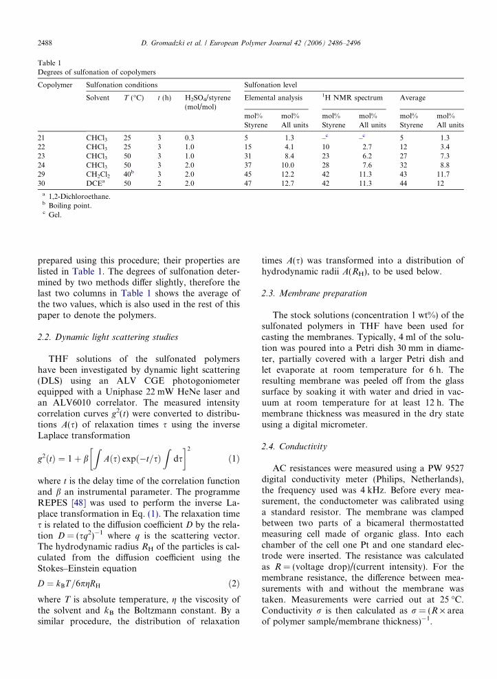
Table 1Degrees of sulfonation of copolymers
Copolymer Sulfonation conditions Sulfonation level
Solvent T (�C) t (h) H2SO4/styrene(mol/mol)
Elemental analysis 1H NMR spectrum Average
mol%Styrene
mol%All units
mol%Styrene
mol%All units
mol%Styrene
mol%All units
21 CHCl3 25 3 0.3 5 1.3 –c –c 5 1.322 CHCl3 25 3 1.0 15 4.1 10 2.7 12 3.423 CHCl3 50 3 1.0 31 8.4 23 6.2 27 7.324 CHCl3 50 3 2.0 37 10.0 28 7.6 32 8.829 CH2Cl2 40b 3 2.0 45 12.2 42 11.3 43 11.730 DCEa 50 2 2.0 47 12.7 42 11.3 44 12
a 1,2-Dichloroethane.b Boiling point.c Gel.
2488 D. Gromadzki et al. / European Polymer Journal 42 (2006) 2486–2496
prepared using this procedure; their properties arelisted in Table 1. The degrees of sulfonation deter-mined by two methods differ slightly, therefore thelast two columns in Table 1 shows the average ofthe two values, which is also used in the rest of thispaper to denote the polymers.
2.2. Dynamic light scattering studies
THF solutions of the sulfonated polymershave been investigated by dynamic light scattering(DLS) using an ALV CGE photogoniometerequipped with a Uniphase 22 mW HeNe laser andan ALV6010 correlator. The measured intensitycorrelation curves g2(t) were converted to distribu-tions A(s) of relaxation times s using the inverseLaplace transformation
g2ðtÞ ¼ 1þ bZ
AðsÞ expð�t=sÞZ
ds
� �2
ð1Þ
where t is the delay time of the correlation functionand b an instrumental parameter. The programmeREPES [48] was used to perform the inverse La-place transformation in Eq. (1). The relaxation times is related to the diffusion coefficient D by the rela-tion D = (sq2)�1 where q is the scattering vector.The hydrodynamic radius RH of the particles is cal-culated from the diffusion coefficient using theStokes–Einstein equation
D ¼ kBT =6pgRH ð2Þwhere T is absolute temperature, g the viscosity ofthe solvent and kB the Boltzmann constant. By asimilar procedure, the distribution of relaxation
times A(s) was transformed into a distribution ofhydrodynamic radii A(RH), to be used below.
2.3. Membrane preparation
The stock solutions (concentration 1 wt%) of thesulfonated polymers in THF have been used forcasting the membranes. Typically, 4 ml of the solu-tion was poured into a Petri dish 30 mm in diame-ter, partially covered with a larger Petri dish andlet evaporate at room temperature for 6 h. Theresulting membrane was peeled off from the glasssurface by soaking it with water and dried in vac-uum at room temperature for at least 12 h. Themembrane thickness was measured in the dry stateusing a digital micrometer.
2.4. Conductivity
AC resistances were measured using a PW 9527digital conductivity meter (Philips, Netherlands),the frequency used was 4 kHz. Before every mea-surement, the conductometer was calibrated usinga standard resistor. The membrane was clampedbetween two parts of a bicameral thermostattedmeasuring cell made of organic glass. Into eachchamber of the cell one Pt and one standard elec-trode were inserted. The resistance was calculatedas R = (voltage drop)/(current intensity). For themembrane resistance, the difference between mea-surements with and without the membrane wastaken. Measurements were carried out at 25 �C.Conductivity r is then calculated as r = (R · areaof polymer sample/membrane thickness)�1.
0.1 1 10 100 1000 10000
44 %
43 %
32 %
27 %
12 %
5 %
SV-50
Rh, nm
A(R
h)
Fig. 1. Distributions A(RH) of hydrodynamic radii of sulfonatedblock copolymers for various degrees of sulfonation. SV-50 is theoriginal unsulfonated block copolymer.
D. Gromadzki et al. / European Polymer Journal 42 (2006) 2486–2496 2489
2.5. Small-angle X-ray scattering (SAXS)
SAXS measurements have been performed ontwo different instruments to cover a wide range ofscattering vectors. For a part of the samples aNanostar-U instrument was used (Bruker AXS)with Goebel mirrors and a HiSTAR 2-D detectorpositioned 1070 mm from the sample. For othersamples a Nonius FR591RAG rotating anode wasused coupled with a home-made optical set-up witha long collimation and a 2-D gas-filled detectorlocated at 3600 mm from the sample to reach valuesof scattering vector q as small as q = 2 · 10�3 A�1
(q = (4p/k)sin(h/2) and h is the scattering angle).Both X-ray sources were a Cu-anode source yieldinga beam with wavelength k = 1.54 A. The resulting 2-D images were found in all cases to be isotropic, thedata were azimuthally averaged to yield intensity vs.q scattering curves. The scattering experiments wereperformed at room temperature. The polymer sam-ples were either sealed in 2-mm capillaries, whichwere placed in the evacuated chamber of the instru-ment or inserted in a cell (stack of two or threepieces of membranes) with thin Kapton windows.
Usual corrections for background subtractionand detector response were applied.
2.6. Atomic force microscopy (AFM)
AFM imaging has been performed with a multi-mode AFM Nanoscope IIIa (Digital Instruments)in the tapping mode. This method allows to obtainboth topography and phase scans of explored sur-faces; hence after measurement we have informationabout the surface topography profile (given byprofile image) and surface domains arrangement(visible in phase image). For scanning we use BS-Tap300-50 tips (Nanoscience Instruments) with res-onant frequency ca. 300 kHz and tip radius <10 nm. Experiments have been made with dry sam-ples and, for comparison, additional measurementsperformed were in water. The measured data wereprocessed with software WSxM� from NanotecElectronica [49].
3. Results and discussion
3.1. Solution characterization
Dynamic light scattering was performed in THFsolutions used casting various polymer membranes.The correlation functions were generally bimodal
leading to two size components observed in the dis-tributions of hydrodynamic radii obtained from theinverse Laplace transformations and shown inFig. 1. The particles with smaller hydrodynamicradius of ca. 10 nm correspond to molecularly dis-solved polymer. Indeed, the molecular weight – sizerelation given in Ref. [50] for solution of polystyrenein benzene gives a coil radius of 12 nm forMw = 85000, which is comparable with the sizesobtained here. The larger particles with hydrody-namic radius of ca. 100 nm (i.e., diameter 200 nm)are clusters of amphiphilic polymer chains withthe ionic groups preferentially located inside thecluster to avoid contacts with solvent.
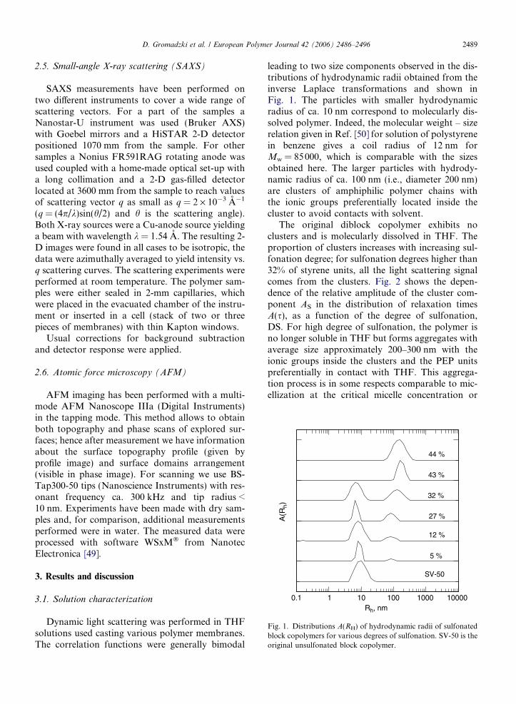
The original diblock copolymer exhibits noclusters and is molecularly dissolved in THF. Theproportion of clusters increases with increasing sul-fonation degree; for sulfonation degrees higher than32% of styrene units, all the light scattering signalcomes from the clusters. Fig. 2 shows the depen-dence of the relative amplitude of the cluster com-ponent AS in the distribution of relaxation timesA(s), as a function of the degree of sulfonation,DS. For high degree of sulfonation, the polymer isno longer soluble in THF but forms aggregates withaverage size approximately 200–300 nm with theionic groups inside the clusters and the PEP unitspreferentially in contact with THF. This aggrega-tion process is in some respects comparable to mic-ellization at the critical micelle concentration or
0
0.2
0.4
0.6
0.8
1.0
1.2
0 10 20 30 40 50
DS, mol%
As/
(Af+
As)
Fig. 2. Relative amplitude of the cluster component AS to thepolymer (Af) plus cluster component in the distribution ofrelaxation times A(s), as a function of the degree of sulfonation,DS.
0.1
1
10
100
1000
10000
0 10 20 30 40 50DS, %
Q, %
Fig. 3. Dependence of the water (d) and methanol (s) uptake Q
of the partially sulfonated membranes on the degree of sulfona-tion DS of polystyrene block.
2490 D. Gromadzki et al. / European Polymer Journal 42 (2006) 2486–2496
critical micelle temperature in diblock copolymers.In our case, however, the aggregation is not drivenby a change in concentration or temperature butby a change in composition of one of the copolymerblocks. One has to keep in mind, when examiningFig. 2, that the technique is more sensitive to largeaggregates than to small ones that still exist innon-negligible amounts. As in a thermodynamicalprocess, there is an equilibrium between solublepolymers and aggregates from which the scatteredsignal becomes dominant as the sulfonation rate isincreased.
3.2. Water and methanol uptake behavior
The incorporation of sulfonic acid groups intothe PS-PEP block copolymer makes the polymer
Table 2Solvent uptake and conductivity of sulfonated copolymers
Sample Sulfonation degreea Q, water u
DS – mol% of styrene units mol% of all units
21 5 1.3 1.322 12 3.4 7.323 27 7.3 2424 32 8.8 2929 43 11.7 6530 44 12 130
a Column ‘‘Average’’ from Table 1.b Below the detection limit.c Excessive swelling.
hydrophilic and induces water and methanolabsorption. The water and methanol uptake ofPS-PEP membranes was determined by measuringthe change in mass before and after swelling. Apiece of dry membrane was soaked in water ormethanol for 3 h at room temperature. The excesswater was wiped off with a tissue and the membranewas immediately weighed. The water-uptake is cal-culated using the equation
Q ¼ ½W g � W d�=W d � 100%
where Wg and Wd are the weights of swollen anddry membrane sample, respectively. The results areshown in Table 2 and Fig. 3 in terms of the percent-age of absorbed water or methanol per mol% of sul-fonic acid groups incorporated to PS-PEP ionomer.The uptakes of methanol and water increase as the
ptake, % Q, methanol uptake, % r, AC conductivity (S/cm)
8 –b
52 3.60 · 10�6
1693 1.82 · 10�3
c 1.59 · 10�3
c 5.15 · 10�2
c 1.84 · 10�2

10-6
10-4
10-2
100
102
104
0.01 0.1 1
75
4
2
q0
43 %
32 %
27 %
12 %
0 %
q, A-1
I, a.
u.
Fig. 5. X-ray scattering profiles I(q) for the Shellvis50 copolymerwith the indicated degrees of sulfonation of styrene units.
D. Gromadzki et al. / European Polymer Journal 42 (2006) 2486–2496 2491
sulfonation degree increases and the methanol up-take is substantially greater than the water uptake.The same observations have been already reportedfor sulfonated polystyrene-block-(ethene-co-bu-tene)-block-polystyrene copolymers [20] and forNafion [51]. While the water uptake remains rela-tively moderate for sulfonation degrees up to 30%,the methanol uptake is excessively large as soon asthe sulfonation degree exceeds 10%; for direct meth-anol fuel cell (DMFC) applications, however, a di-lute aqueous solution of methanol is used wherethe swelling can still be in a reasonable range.
3.3. Conductivity
The conductivity of the membranes has beenmeasured at 25 �C using the equipment describedabove. The results are displayed in Table 2. Thedependence of conductivity on the degree of sulfo-nation of the polymer is displayed in Fig. 4. Asexpected, the conductivity increases rather steeplywith increasing degree of sulfonation. Valuesexceeding 10�2 S/cm are commonly consideredacceptable [52] for electrochemical applications.
3.4. Morphology analysis by SAXS
Membranes of the sulfonated block copolymerswere investigated by X-ray scattering in the drystate and after swelling with water. Fig. 5 showsthe intensity profiles for various degrees of sulfona-
0.001
0.1
10
1000
0.01
1
100
0 10 20 30 40 50 60
DS, %
cond
uctiv
ity x
103 ,
S/c
m
Fig. 4. Conductivity of sulfonated PS-PEP membranes as afunction of sulfonation degree DS of polystyrene block. The lineis a guide to the eye.
tion, after initial evaporation of the solvent used forcasting the membranes. The membranes were thusnot thermoannealed. A clear first-order diffractionpeak is visible on the scattering curves the positionof which, q0, moves to larger values with increasingdegree of sulfonation. This corresponds to adecrease in the characteristic distance d of the struc-ture as displayed in Fig. 6. Higher-order peaks arepresent on the curve for the original unsulfonatedpolymer, clearly indicating a lamellar morphologyof the sample. Indeed, as expected for a lamellar
0
20
40
60
80
100
0 10 20 30 40 50
DS, %
d, n
m
Fig. 6. Characteristic distance d of the polymer structure as afunction of the degree of sulfonation, DS.
2492 D. Gromadzki et al. / European Polymer Journal 42 (2006) 2486–2496
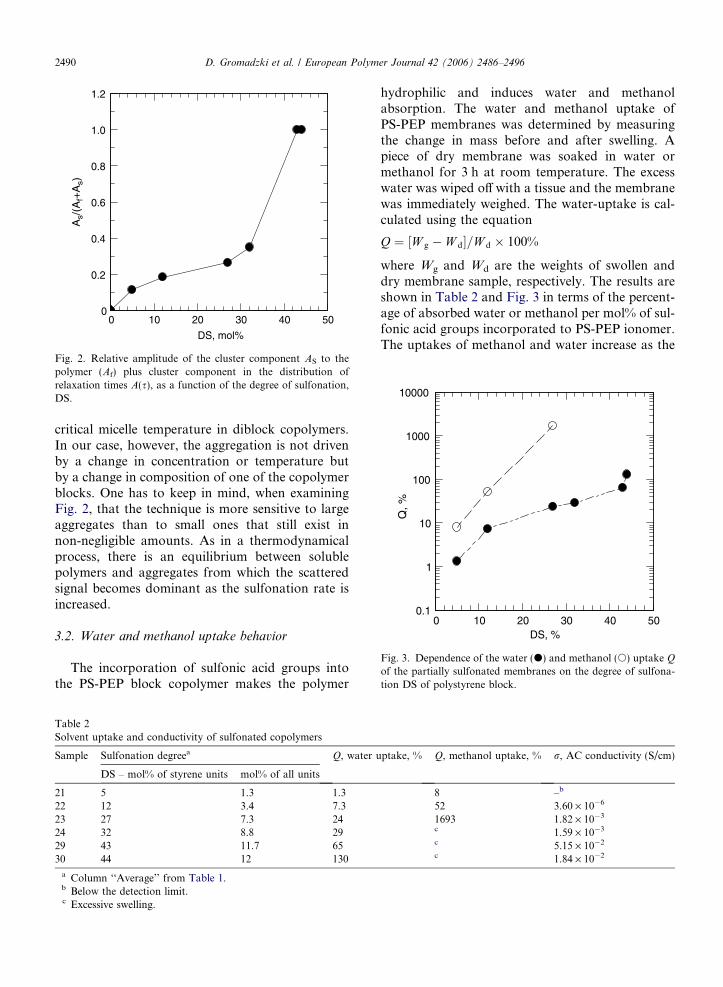
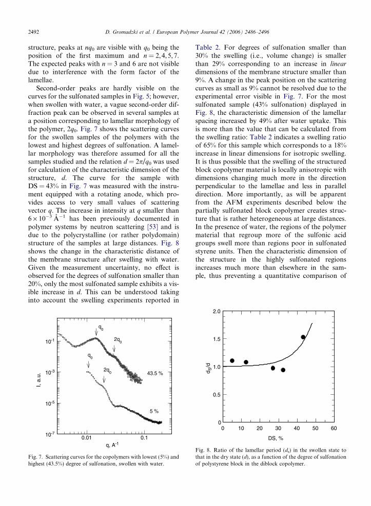
structure, peaks at nq0 are visible with q0 being theposition of the first maximum and n = 2,4,5,7.The expected peaks with n = 3 and 6 are not visibledue to interference with the form factor of thelamellae.
Second-order peaks are hardly visible on thecurves for the sulfonated samples in Fig. 5; however,when swollen with water, a vague second-order dif-fraction peak can be observed in several samples ata position corresponding to lamellar morphology ofthe polymer, 2q0. Fig. 7 shows the scattering curvesfor the swollen samples of the polymers with thelowest and highest degrees of sulfonation. A lamel-lar morphology was therefore assumed for all thesamples studied and the relation d = 2p/q0 was usedfor calculation of the characteristic dimension of thestructure, d. The curve for the sample withDS = 43% in Fig. 7 was measured with the instru-ment equipped with a rotating anode, which pro-vides access to very small values of scatteringvector q. The increase in intensity at q smaller than6 · 10�3 A�1 has been previously documented inpolymer systems by neutron scattering [53] and isdue to the polycrystalline (or rather polydomain)structure of the samples at large distances. Fig. 8shows the change in the characteristic distance ofthe membrane structure after swelling with water.Given the measurement uncertainty, no effect isobserved for the degrees of sulfonation smaller than20%, only the most sulfonated sample exhibits a vis-ible increase in d. This can be understood takinginto account the swelling experiments reported in
10-7
10-5
10-3
10-1
0.01 0.1
q0
2q0
2q0
q0
5 %
43.5 %
q, A-1
I, a
.u.
Fig. 7. Scattering curves for the copolymers with lowest (5%) andhighest (43.5%) degree of sulfonation, swollen with water.
Table 2. For degrees of sulfonation smaller than30% the swelling (i.e., volume change) is smallerthan 29% corresponding to an increase in linear
dimensions of the membrane structure smaller than9%. A change in the peak position on the scatteringcurves as small as 9% cannot be resolved due to theexperimental error visible in Fig. 7. For the mostsulfonated sample (43% sulfonation) displayed inFig. 8, the characteristic dimension of the lamellarspacing increased by 49% after water uptake. Thisis more than the value that can be calculated fromthe swelling ratio: Table 2 indicates a swelling ratioof 65% for this sample which corresponds to a 18%increase in linear dimensions for isotropic swelling.It is thus possible that the swelling of the structuredblock copolymer material is locally anisotropic withdimensions changing much more in the directionperpendicular to the lamellae and less in paralleldirection. More importantly, as will be apparentfrom the AFM experiments described below thepartially sulfonated block copolymer creates struc-ture that is rather heterogeneous at large distances.In the presence of water, the regions of the polymermaterial that regroup more of the sulfonic acidgroups swell more than regions poor in sulfonatedstyrene units. Then the characteristic dimension ofthe structure in the highly sulfonated regionsincreases much more than elsewhere in the sam-ple, thus preventing a quantitative comparison of
0
0.5
1.0
1.5
2.0
0 10 20 30 40 50 60
DS, %
d S/d
Fig. 8. Ratio of the lamellar period (ds) in the swollen state tothat in the dry state (d), as a function of the degree of sulfonationof polystyrene block in the diblock copolymer.
D. Gromadzki et al. / European Polymer Journal 42 (2006) 2486–2496 2493
a macroscopic property (swelling) with a micro-scopic property (structure period).
3.5. Atomic force microscopy
The samples for AFM have been prepared onsilica wafers by the spin-coating technique fromstock solutions of the sulfonated polymers in THF(1%). After preparation, all surfaces were more orless smooth in topography which is generally thecase in membrane investigations. In such cases thephase organization is more important since itdescribes the arrangement of the polymer indomains with different physical and chemical prop-erties. Therefore we shall primarily focus on phasescans of our topographically smooth layers.
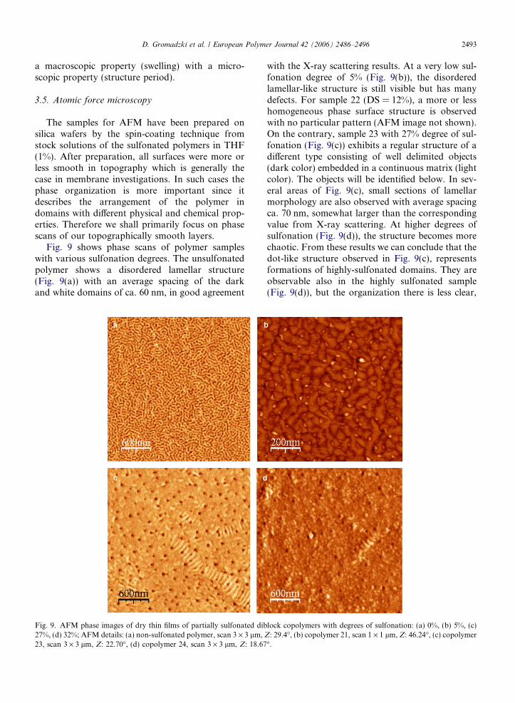
Fig. 9 shows phase scans of polymer sampleswith various sulfonation degrees. The unsulfonatedpolymer shows a disordered lamellar structure(Fig. 9(a)) with an average spacing of the darkand white domains of ca. 60 nm, in good agreement
Fig. 9. AFM phase images of dry thin films of partially sulfonated dib27%, (d) 32%; AFM details: (a) non-sulfonated polymer, scan 3 · 3 lm,23, scan 3 · 3 lm, Z: 22.70�, (d) copolymer 24, scan 3 · 3 lm, Z: 18.67
with the X-ray scattering results. At a very low sul-fonation degree of 5% (Fig. 9(b)), the disorderedlamellar-like structure is still visible but has manydefects. For sample 22 (DS = 12%), a more or lesshomogeneous phase surface structure is observedwith no particular pattern (AFM image not shown).On the contrary, sample 23 with 27% degree of sul-fonation (Fig. 9(c)) exhibits a regular structure of adifferent type consisting of well delimited objects(dark color) embedded in a continuous matrix (lightcolor). The objects will be identified below. In sev-eral areas of Fig. 9(c), small sections of lamellarmorphology are also observed with average spacingca. 70 nm, somewhat larger than the correspondingvalue from X-ray scattering. At higher degrees ofsulfonation (Fig. 9(d)), the structure becomes morechaotic. From these results we can conclude that thedot-like structure observed in Fig. 9(c), representsformations of highly-sulfonated domains. They areobservable also in the highly sulfonated sample(Fig. 9(d)), but the organization there is less clear,
lock copolymers with degrees of sulfonation: (a) 0%, (b) 5%, (c)Z: 29.4�, (b) copolymer 21, scan 1 · 1 lm, Z: 46.24�, (c) copolymer�.

2494 D. Gromadzki et al. / European Polymer Journal 42 (2006) 2486–2496
probably because of an excessive amount of SO3Hgroups, which cause unfolding of polar groupsover the layer at the surface. Also there may be anunfavorable competition between the kinetics ofmorphology formation and the rapid solvent evapo-ration during the spin-coating process, whichprevents formation of the disordered lamellar struc-ture at higher degrees of sulfonation, as wasobserved in the X-ray scattering results.
We also performed experiments to observe thebehavior of sulfonated polymers in water environ-ment. After the first measurement in the dry state,the polymer films on silica wafers were covered withdistilled water and AFM scans were performed inthe wet state. According to the previous results,we concentrated on the structured sample 23 with27% sulfonation. The results are presented inFig. 10 where both dry and wet samples are shownfor comparison.
It is clear that the dark regions in Fig. 9(c) arethose that are swollen when water is added to thesample. Sulfonation of a styrene chain is a random
Fig. 10. AFM image of the sample 23 (27% sulfonation): (a) topographyphase image in dry state (same as Fig. 9(c)), scan 3 · 3 lm, Z: 22.70�, (water, scan 3 · 3 lm, Z: 85.05 nm. The broken lines represent the profi
Fig. 11. Vertical profile of the surface of copolymer 23 (27% sulfonatioshown in Fig. 10(a) and (b) the wet surface shown in Fig. 10(c). The dasformations.
process; therefore, there are parts of the chain thatare more sulfonated and other parts that are lesssulfonated. The more sulfonated sequences of thechains form clusters as we have described above insolution behavior by light scattering. These clusterspersist after evaporation in the solid system (mem-brane or thin film) and can be visibly swollen whenwater is added.
Changes in the film swollen in water were studiedas topography scan because of different swellingratios in domains with various sulfonation levels.The results are clearly visible in Fig. 10, where theswollen surface (Fig. 10(c)) demonstrates signifi-cant changes compared with the unswollen one(Fig. 10(a)). From these scans we can see that, afterswelling, the dot-like formations are jutting fromthe surface, compared with the dry state. Thesechanges are even more evident from the profiles inFig. 11. Fig. 11(a) shows that the dot-like forma-tions in Fig. 10(a) have a depth of approximately3 nm below the surface; the profile in Fig. 11(b) ofthe surface after swelling with water (Fig. 10(c))
image in dry state, scan 3 · 3 lm Z: 17,22 nm (b) for comparisonc) topography image after swelling of layer of copolymer 23 withle paths shown below.
n) as measured along the indicated curve on: (a) the dry surfacehed line indicates the average surface height excluding the dot-like
D. Gromadzki et al. / European Polymer Journal 42 (2006) 2486–2496 2495
shows that the height of the dot-like formations haschanged to ca. 20 nm above the surface. Theseresults confirm that the dot-like formations aredomains regrouping highly sulfonated segmentsof polymer chains; these sections are organizedby unfavorable interactions between the sulfo-nated and non-sulfonated segments of the blockcopolymer.
Image analysis of these figures has been per-formed using the software [54] Image-J. In the drystate (Fig. 10(b)) the SO3H-rich domains have anaverage diameter of 32 nm and their average spac-ing is 130 nm. In the swollen state the average diam-eter is 48 nm and the average spacing is 147 nm. Thespacing of the SO3H-rich domains is almost thesame in both cases, although not identical, whichis due to the fact that a different part of the sampleis analyzed after wetting. The linear dimension ofthe SO3H domains in the plane of the surface thusincreases by about 50% on swelling. This is seen alsoon the profile curves in Fig. 11, where the ‘peaks’ inFig. 11(b) are somewhat larger at the base than the‘valleys’ in Fig. 11(a). However, this view is onlyqualitative since Fig. 11 shows just a few of thedot-like formations while the image analysis ofFig. 10 concerns several hundreds of them.
4. Conclusions
We have successfully modified a commercialdiblock copolymer of PS-PEP by sulfonation ofthe styrene block to different degrees. We haveshown that the original diblock copolymer has a dis-ordered lamellar morphology which is to a certainextent conserved after sulfonation. In THF solu-tions the coexistence of dissolved polymer and itsclusters was found. The clusters have a more or lessuniform diameter of 200–300 nm and their propor-tion increases with increasing degree of sulfonationuntil they become dominant the for sulfonationdegree of styrene units above 32%. Sulfonation ofpolystyrene blocks is a random process. The clusterscontain highly sulfonated sections of the polysty-rene blocks. When a membrane is cast from sucha solution, the clusters become trapped in the mem-brane and after evaporation of the solvent (THF)they collapse to a typical size of ca. 40 nm as shownby AFM analysis of thin films. In the presence ofwater these clusters then swell predominantly. Thesurrounding matrix consisting of less sulfonated sec-tions of the polystyrene blocks and the PEP blocksis disordered with random appearance of small
regions of short-range lamellar morphology. Thismorphology could be interesting for trapping ofanisotropic clay particles [55] in order to reducethe methanol crossover. The conductivity of thesepolymer membranes strongly increases with increas-ing degree of sulfonation. The swelling of the mem-branes is moderate for sulfonation degrees up to30% of styrene units. High swelling ratios observedat degrees of sulfonation above 30% make possibleapplications difficult.
Acknowledgements
The authors gratefully acknowledge support bythe Grant Agency of the Czech Republic (SON/03/E001) within the EUROCORES ProgrammeSONS of the European Science Foundation, whichis also supported by the European Commission,Sixth Framework Programme. D.G. would like toacknowledge the Marie Curie Fellowship at a MarieCurie Training Site at the Institute of Macromolec-ular Chemistry in Prague, under Contract No.HPMT-CT-2001-00396.
References
[1] Bates FS, Frederickson GH. Annu Rev Phys Chem1990;41:525.
[2] Jenkins DK, Druck EW. In: Holiday L, editor. Ionicpolymers. London/Toronto: Halsted Press; 1975 [Chapter3].
[3] Wilson D, Prosser HJ, Wilson AD, Prooser HJ, editors.Development in ionic polymers, 1. London and NewYork: Applied Science Publishers; 1983.
[4] Pineri M, Eisenberg A, Reidel D. Structure and properties ofionomers. Dordrecht: NATO ASI Series; 1987.
[5] Longworth R. In: Wilson AD, Prosser HJ, editors. Devel-opment in ionic polymers-1. London and New York: Ap-plied Science Publishers; 1983. p. 53.
[6] Tant MR, Mauritz KA, Wilkes GE. Ionomers: synthesis,structure, properties and applications. London: Blackie;1997.
[7] Dreyfus B. J Am Chem Soc 1985;18:284.[8] Eisenberg A. Macromolecules 1970;3:147–54.[9] Lu X, Steckle WP, Weiss RA. Macromolecules
1993;26:5876–84.[10] Hickner MA, Ghassemi H, Kim YS, Einsla BR, McGrath
JE. Chem Rev 2004;104:4587.[11] Rikukawa M, Sanui K. Prog Polym Sci 2000;25:1463.[12] Roziere J, Jones DJ. Ann Rev Mater Res 2003;33:503–55.[13] Varcoe JR, Slade RCT. Fuel cells 2005;5:188–200.[14] Noshay A, Robeson LM. J Appl Sci 1976;20:1885.[15] Lakshami VV, Choudhary V, Varma IK. Macromol Symp
2004;210:21–9.[16] Manea C, Mulder M. J Membr Sci 2002;206:443.[17] Alberti G, Casciola M, Massinelli L, Bauer B. J Membr Sci
2001;185:73.
2496 D. Gromadzki et al. / European Polymer Journal 42 (2006) 2486–2496
[18] Kaliaguine S, Mikhailenko SD, Wang KP, Xing P,Robertson G, Guiver M. Catal Today 2003;82:213–22.
[19] Kruczek B, Matsuura T. J Membr Sci 1998;146:263.[20] Schauer J, Albrecht W, Weigel T. J Appl Polym Sci
1999;73:161.[21] Shin CK, Maier G, Scherer GG. J Membr Sci 2004;245:
163–73.[22] Guo Q, Pintauro PN, Tang H, O’Connor S. J Membr Sci
1999;154:175–81.[23] Jones DJ, Roziere J. J Membr Sci 2001;185:41–58.[24] Weiss RA, Sen A, Willis CL, Pottick LA. Polymer
1991;32:1867.[25] Weiss RA, Sen A, Pottick LA, Willis CL. Polymer
1991;32:2785.[26] Kim J, Kim B, Jung B. J Membr Sci 2002;207:129.[27] Serpico JM, Ehrenberg SG, Fontanella JJ, Jiao X,
Perahia D, McGrady KA, et al. Macromolecules 2002;35:5916.
[28] Mani S, Weiss RA, Williams CE, Hahn SF. Macromolecules1999;32:3663–70.
[29] Mokrini A, Acosta JL. Polymer 2001;42:9–15.[30] Elabd YA, Napadensky E. Polymer 2004;45:3037–43.[31] Elabd YA, Napadensky E, Walker CHW, Winey KI.
Macromolecules 2006;39:399–407.[32] Wu C, Woo K, Jiang M. Macromolecules 1996;29(16):
5361–7.[33] Shim Sang-Yeon, Weiss RA. Polym Int 2005;54:1220–3.[34] Yang Y, Shi Z, Holdcroft S. Macromolecules 2004;37:
1678–81.[35] Allen RD, Huang TL, Mohanty DK, Huang SS, Qin HD,
McGrath JE. J Am Chem Soc, Div Polym Chem Polym Prep1983;24:41.
[36] Wang F, Hickner M, Kim YS, Zawodzinski TA, McGrathJE. J Membr Sci 2002;197:231.
[37] Xing P, Robertson G, Guiver M, Mikhailenko SD, Kalia-guine S. Macromolecules 2004;37:7960–7.
[38] Harrison W, Wang F, Mecham JB, Bhanu V, Hill M, KimYS, et al. J Polym Sci Part A: Polym Chem 2003;41:2264.
[39] Szymczyk A, Roslaniec Z. Polym Adv Technol 1999;10:579–87.
[40] Sauviat M, Salle R, Sillion B. French Patent no. 2 050 251;1969, p. 7214.
[41] Genies C, Mercier R, Sillion B, Cornet N, Gebel G, PineriM. Polymer 2001;42:359–73.
[42] Jouanneau J, Mercier R, Gonon L, Gebel G. Polym J,submitted for publication.
[43] Ding J, Chuy C, Holdcroft S. Macromolecules2002;35:1348–55.
[44] Rubatat L, Shi Z, Diat O, Holdcroft S, Frsiken B.Macromolecules 2006;39:720.
[45] Kim J, Kim B, Jung B. J Membr Sci 2005;250:175.[46] Kim J, Kim B, Jung B, Kang YS, Ha HY, Oh IH, et al. J
Macromol Rapid Commun 2002;23:753–6.[47] Janata M, Kudela V, Gromadzki D, Stepanek P, Nallet F,
Diat O, et al. React Funct Polym, submitted for publication.[48] Jakes J. Collect Czech Chem Commun 1995;60:1941.[49] http://www.nanotec.es.[50] Adam M, Delsanti M. Macromolecules 1977;10:1229.[51] Elliott JA, Hanna S, Elliott AMS, Cooley GE. Polymer
2001;42:2253–4.[52] Eikerling M, Kornyshev AA, Kuznetsov AM, Ulstru J,
Walbran S. J Phys Chem B 2001;105:3646.[53] Ryukhtin V, Stepanek P, Tuzar Z, Pranzas K, Bellmann D.
Physica B, in press.[54] National Institute of Health. Available from: <http://
rsb.info.nih.gov/ij/>.[55] Song MK, Park SB, Kim YT, Rhee HW, Kim J. Mol Cryst
Liq Cryst 2003;407:411–9.
Copyright © 2022 FDOKUMEN