On the Development of Naphthalene-Based Sulfonated Polyimide Membranes for Fuel Cell Applications
23
REVIEW ARTICLES On the Development of Naphthalene-Based Sulfonated Polyimide Membranes for Fuel Cell Applications Yan YIN, Otoo YAMADA, Kazuhiro TANAKA, and Ken-Ichi OKAMOTO y Department of Advanced Materials Science & Engineering, Faculty of Engineering, Yamaguchi University, Tokiwadai 2-16-1, Ube 755-8611, Japan (Received December 19, 2005; Accepted December 27, 2005; Published March 15, 2006) ABSTRACT: This article reviews the recent progress made over the past years based on naphthalene-based sulfo- nated polyimides (SPIs) in terms of proton conductivity, membrane swelling behavior, membrane stability toward water, and fuel cell performance in polymer electrolyte fuel cells (PEFCs) or direct methanol fuel cells (DMFCs). The structure-property relationship of SPI membranes is discussed in details with respect to the chemical structure of various sulfonated diamines and morphology of SPI membranes from the viewpoints of viscosity, mechanical strength and proton conductivity. Ion exchange capacity (IEC), basicity of sulfonated diamine, configuration (para-, meta-, or ortho-orientation) and chemical structure of polymer chain (linear or net-work) show great influence on the water stability and mechanical strength of SPI membrane. The SPIs with a branched/crosslinked structure and de- rived from highly basic sulfonated diamines display reasonably high water stability of more than 200–300 h in water at 130 C, suggesting high potential as PEMs operating at temperatures up to 100 C. The SPI membranes have fairly high proton conductivity at higher relative humidities and low methanol permeability. The water and methanol crossover through membrane under the fuel cell operation conditions is not controlled by electro-osmosis due to proton transport but by diffusion due to activity difference. This is quite different from the case of perfluorosulfonated membranes such as Nafion and results in the advantageous effects on fuel cell performance. SPI membranes displayed high PEFC per- formances comparable to those of Nafion 112. In addition, SPI membranes displayed higher performances in DMFC systems with higher methanol concentration (20–50 wt %), which is superior to Nafion and have high potential for DMFC applications at mediate temperatures (40–80 C). [DOI 10.1295/polymj.38.197] KEY WORDS Branching / Crosslinking / Fuel Cell Performance / Sulfonated Diamine / Sulfonated Polyimide / Polymer Electrolyte Membrane / Proton Conductivity / Water Stability / Hydrolysis Stability / In the past decades, great interest has been focused on the development of polymer electrolyte fuel cells (PEFCs) and direct methanol fuel cells (DMFCs) as a clean power source of energy for transportation, sta- tionary and portable power applications. 1,2 Fuel cells with high performance, high durability and potentially lower cost are greatly required. Polymer electrolyte membrane (PEM) is one of the key components in PEFC and DMFC systems. Perfluorosulfonic acid co- polymer membranes, such as DuPont’s Nafion mem- brane, are the state-of-the-art PEMs commercially available due to their high proton conductivity and excellent chemical stability. 3,4 However, because of their high cost, low operational temperature below 80 C and large methanol crossover, there has been much interest in alternative PEMs. Many efforts have been done in the development of PEMs based on sul- fonated aromatic hydrocarbon polymers. 5–9 The main problem existed in the hydrocarbon PEMs is the mem- brane stability under fuel cell conditions and low con- ducting performance at low moisture atmosphere. The balance between ion exchange capacity (IEC), proton conductivity and mechanical stability of a PEM plays an important role on its comprehensive performance in a fuel cell. It is well known that aromatic polyimides have found wide applications in many industrial fields due to their excellent thermal stability, high mechan- ical strength, good film forming ability, and superior chemical resistance. These merits are just what are required for the polyelectrolyte membrane materials employed in fuel cell systems. Sulfonated naphtha- lenic polyimides (SPIs) with six-membered imide rings have been developed as promising candidates for PEFCs. Mercier and his coworkers developed sul- fonated block copolyimides (co-SPIs) from 1,4,5,8- naphthalenetetracrboxylic dianhydride (NTDA), 2,2 0 - benzidinedisulfonic acid (BDSA, a commercially available sulfonated diamine) and common nonsulfo- nated diamines. 10–14 The sulfonated block copoly- y To whom correspondence should be addressed (Tel: +81-836-85-9660; Fax: +81-836-85-9601; E-mail: [email protected]). 197 Polymer Journal, Vol. 38, No. 3, pp. 197–219 (2006)
-
Upload
independent -
Category
Documents
-
view
0 -
download
0
Transcript of On the Development of Naphthalene-Based Sulfonated Polyimide Membranes for Fuel Cell Applications
REVIEW ARTICLES
On the Development of Naphthalene-Based SulfonatedPolyimide Membranes for Fuel Cell Applications
Yan YIN, Otoo YAMADA, Kazuhiro TANAKA, and Ken-Ichi OKAMOTOy
Department of Advanced Materials Science & Engineering, Faculty of Engineering,
Yamaguchi University, Tokiwadai 2-16-1, Ube 755-8611, Japan
(Received December 19, 2005; Accepted December 27, 2005; Published March 15, 2006)
ABSTRACT: This article reviews the recent progress made over the past years based on naphthalene-based sulfo-
nated polyimides (SPIs) in terms of proton conductivity, membrane swelling behavior, membrane stability toward
water, and fuel cell performance in polymer electrolyte fuel cells (PEFCs) or direct methanol fuel cells (DMFCs).
The structure-property relationship of SPI membranes is discussed in details with respect to the chemical structure
of various sulfonated diamines and morphology of SPI membranes from the viewpoints of viscosity, mechanical
strength and proton conductivity. Ion exchange capacity (IEC), basicity of sulfonated diamine, configuration (para-,
meta-, or ortho-orientation) and chemical structure of polymer chain (linear or net-work) show great influence on
the water stability and mechanical strength of SPI membrane. The SPIs with a branched/crosslinked structure and de-
rived from highly basic sulfonated diamines display reasonably high water stability of more than 200–300 h in water at
130 �C, suggesting high potential as PEMs operating at temperatures up to 100 �C. The SPI membranes have fairly high
proton conductivity at higher relative humidities and low methanol permeability. The water and methanol crossover
through membrane under the fuel cell operation conditions is not controlled by electro-osmosis due to proton transport
but by diffusion due to activity difference. This is quite different from the case of perfluorosulfonated membranes such
as Nafion and results in the advantageous effects on fuel cell performance. SPI membranes displayed high PEFC per-
formances comparable to those of Nafion 112. In addition, SPI membranes displayed higher performances in DMFC
systems with higher methanol concentration (20–50wt%), which is superior to Nafion and have high potential for
DMFC applications at mediate temperatures (40–80 �C). [DOI 10.1295/polymj.38.197]KEY WORDS Branching / Crosslinking / Fuel Cell Performance / Sulfonated Diamine /
Sulfonated Polyimide / Polymer Electrolyte Membrane / Proton Conductivity / Water Stability /Hydrolysis Stability /
In the past decades, great interest has been focusedon the development of polymer electrolyte fuel cells(PEFCs) and direct methanol fuel cells (DMFCs) asa clean power source of energy for transportation, sta-tionary and portable power applications.1,2 Fuel cellswith high performance, high durability and potentiallylower cost are greatly required. Polymer electrolytemembrane (PEM) is one of the key components inPEFC and DMFC systems. Perfluorosulfonic acid co-polymer membranes, such as DuPont’s Nafion mem-brane, are the state-of-the-art PEMs commerciallyavailable due to their high proton conductivity andexcellent chemical stability.3,4 However, because oftheir high cost, low operational temperature below80 �C and large methanol crossover, there has beenmuch interest in alternative PEMs. Many efforts havebeen done in the development of PEMs based on sul-fonated aromatic hydrocarbon polymers.5–9 The mainproblem existed in the hydrocarbon PEMs is the mem-brane stability under fuel cell conditions and low con-
ducting performance at low moisture atmosphere. Thebalance between ion exchange capacity (IEC), protonconductivity and mechanical stability of a PEM playsan important role on its comprehensive performancein a fuel cell.It is well known that aromatic polyimides have
found wide applications in many industrial fieldsdue to their excellent thermal stability, high mechan-ical strength, good film forming ability, and superiorchemical resistance. These merits are just what arerequired for the polyelectrolyte membrane materialsemployed in fuel cell systems. Sulfonated naphtha-lenic polyimides (SPIs) with six-membered imiderings have been developed as promising candidatesfor PEFCs. Mercier and his coworkers developed sul-fonated block copolyimides (co-SPIs) from 1,4,5,8-naphthalenetetracrboxylic dianhydride (NTDA), 2,20-benzidinedisulfonic acid (BDSA, a commerciallyavailable sulfonated diamine) and common nonsulfo-nated diamines.10–14 The sulfonated block copoly-
yTo whom correspondence should be addressed (Tel: +81-836-85-9660; Fax: +81-836-85-9601; E-mail: [email protected]).
197
Polymer Journal, Vol. 38, No. 3, pp. 197–219 (2006)

imide membranes have been reported to show reason-ably high performance in a H2/O2 fuel cell system at60 �C for more than 3000 h. However, the proton con-ductivities of these membranes were rather lower dueto their lower ion exchange capacity (IEC) values,which were essential for maintaining membrane dura-bility toward water. This seems to limit the furtherimprovement in PEFC performance.14
Other research groups have also reported the syn-thesis and proton conductivity of BDSA-based co-polyimides with different nonsulfonated diamine moi-eties. Miyatake et al. have reported on high protonconductivities more than 0.2 S/cm at 100% relativehumidity (RH) and high temperatures above 100 �Cfor their BDSA-based SPI membranes, whereas theydid not mention the water stability.15–18 Lee et al. havereported on the water stability up to 110 h at 80 �C fortheir BDSA-based SPI membranes.19,20 Recently, theresearch group of Mercier and Diat et al. has reportedon the aging of the BDSA-based block copolyimidemembranes in PEFCs and in hot water.21,22 The pre-dominant aging mechanism was imide group hydroly-sis, which was significantly accelerated above 80 �C.These results lead us to the view that a series of co-polyimide membranes derived from NTDA, BDSAand different nonsulfonated diamines generally have
poor water stability at temperatures above 80 �C.This review presents an overview of the synthesis,
membrane stability, chemical and electrochemicalproperties, and fuel cell applications of new proton-conducting polymer electrolyte membranes based onsulfonated polyimides that have been made duringthe past decade.
WATER STABILITY OF SPI MEMBRANESDEVELOPED SO FAR (I)
Proton conductivity and membrane stability are twoimportant factors that greatly affect the performanceof a fuel cell system. High proton conductivity of amembrane requires large sulfonation degree or IEC.However, higher IEC generally leads to larger swel-ling degree or even dissolution in water of the mem-branes. Improving membrane stability and enhancingproton conductivity seems to be contradictory to eachother. Therefore, IEC should be controlled at an ap-propriate level to balance the stability and conductiv-ity as well as possible. Besides IEC, the chemicalstructure of polymers is another key factor affectingmembrane stability and proton conductivity.We synthesized novel sulfonated (co)polyimides
from NTDA, novel different sulfonated diamines
NN
O
OO
O
NN
O
OO
O
R1 R2
O O
OO
HO3S
(p BAPBDS)
R1: Sulfonated diamines
O
O (3,3'-BSPB)(2,2'-BSPB)
SO3H
HO3S
O SO3H
OHO3S
R2: Nonsulfonated diamines
n mLinear Co-SPI:
(BAPB)
O O
(BAPPS)
SO
O
SO3H
CCF3
CF3
(BAHF)
OO
HO3S SO3H
O O
(p BAPPSDS)
SO
O
(m BAPBDS)
HO3S SO3H
Main-chain-type
Side-chain-type
(BDSA)
SO3H
HO3S
"Type 1"
(ODADS)
SO3H
HO3S
O
"Type 2" HO3S SO3H
(BAPFDS)O
O
HO3S
SO3H(o BAPBDS)
OO
(i BAPBDS)
SO3H
HO3S
O O
(BAPBz)
O
(ODA)
SO3-
C
C
C
C
O
O O
N NH
OH OH
SO3-
C
C
C
C
O
O
OH
O
N N
OH2
(Unstable)
More Positive
(Easy)
a)
C
C
C
C
O
O
OH
O
N N
OH2
C
C
C
C
O
O O
N NH
OH OH
(Difficult)
(Relatively Stable)
(Difficult)
b)
(Easy)
Less Positive
Figure 1. Chemical structure of NTDA-based SPIs.
Y. YIN et al.
198 Polym. J., Vol. 38, No. 3, 2006

(SDAs) and non sulfonated diamines, of which thechemical structures are shown in Figure 1, and inves-tigated the relationship between the chemical structureand water stability of the SPI membranes.23–28 Weclassified the sulfonated diamines into two groups.The sulfonated diamines such as BDSA, 4,40-di-amino-diphenyl-ether-2,20-disulfonic acid (ODADS)and 4,40-bis(4-amino-2-sulfophenoxy)biphenyl(iBAPBDS), where the electron-withdrawing sulfonicacid groups are bonded directly to the amino-phenylrings, are noted as ‘‘Type 1’’. On the other hand,‘‘Type 2’’ diamines developed, where the sulfonicacid groups are bonded to aromatic rings other thanthe amino-phenyl rings, are 4,40-bis(4-aminophen-oxy)biphenyl-3,30-disulfonic acid (pBAPBDS), 4,40-bis(3-aminophenoxy)biphenyl-3,30-disulfonic acid(mBAPBDS), 2,20-bis(4-aminophenoxy)-biphenyl-5,50-disulfonic acid (oBAPBDS), 9,9-bis(4-aminophenyl)-fluorene-2,7-disulfonic acid (BAPFDS), and bis[4-(4-aminophenoxy)-phenyl]sulfone-3,30-disulfonic acid(pBAPPSDS). Among these SDAs mentioned above,the p-, m-, o-, i-BAPBDS are isomers to each other.The water stability was evaluated by the elapsed timeuntil the membrane hydrated in water lost the mechan-ical property. The loss of mechanical property wasjudged when the membrane broke after being lightly
bent in the case of the soaking at 80 �C or when themembrane began to break into pieces under boilingin the case of soaking at 100 �C.26 The data are sum-marized in Table I.The water stability was a result of the total effect of
solubility stability, hydrolysis stability, and swelling-stress stability. The solubility stability was mainlydetermined by the IEC and the configuration of sulfo-nated diamine moiety. High IEC generally leads tolarge water uptake and thus high swelling degree oreven dissolution of membrane in water, indicatingpoor water stability. The BDSA-based co-SPIs shownin Table I with IECs of 1.98, 1.82 and 1.66meq g�1
displayed water stability of 5, 60 and 110 h, respec-tively, at 80 �C. Except for the effect of nonsulfonateddiamine, IEC may play a dominant role on their waterdurability. Beside IEC, the chemical structure alsohad large influence on water stability of the SPI mem-branes. As shown in Table I, for example, NTDA-ODADS/ODA (1/1) and NTDA-BDSA/ODA (1/1),had almost the same IEC but quite different water sta-bility. The former could maintain mechanical strengthafter being soaked in water at 80 �C for 25 h, whichwas much longer than that of the latter, and we haveascribed such a difference in water stability to theirdifferent chain flexibility.23 NTDA-ODADS/ODA
Table I. IEC, WU and water stability of NTDA-based SPIs
NTDA-based SPIsIECa WUb Water stability
Ref.(mequiv/g) (wt%) T (�C) Time (h)
BDSA/ODA (1/1) 1.98 79 80 5 24
BDSA/BAPBz (1/1) 1.82 77c 68d 80 60 41
BDSA/DDS (1/1) 1.66 21 80 110 19
ODADS/ODA (1/1) 1.95 87 80 25 23
ODADS/BAPB (1/1) 1.68 57 80 200 23
BAPFDS/ODA (2/1) 2.09 76 80 20 24
oBAPBDS/BAPB (2/1) 1.89 152 80 105 27
iBAPBDS/BAPB (2/1) 1.89 62e 100 200 29
mBAPBDS/BAPB (3/2) 1.73 47 100 500 29
pBAPBDS/BAPB (2/1) 1.89 63 100 >1000 26
pBAPBDS/BAPBz (2/1) 1.96 70c 58e 100 >500 41
pBAPPSDS/BAPPS (2/1) 1.73 98c 100 >200 28
mBAPPSDS/BAPPS (3/2) 1.59 53d 80 42 31
DAPPS 2.09 105d 80 200 32
2,20-BSPB 2.89 220d 100 2500 33
3,30-BSPB 2.89 250d 100 700 33
2,20-BSPB/BAPB (2/1) 2.02 61e 100 >3000 34
3,30-BSPB/BAPB (2/1) 2.02 64e 100 >3000 34
2,20-BSPOB/BAPB (2/1) 1.88 78e 100 >3000 37
3,30-BSPOB/BAPB (2/1) 1.88 55e 100 >3000 37
DASSPB/BAPBz (2/1)-s 1.64 47e 100 >300 38
BAPSBPS/BAPBz (2/1) 1.52 31e 100 >300 39
pBAPBDS/TAPB (6/1) 2.29 77e 100 >3000 40
3,30-BSPB/TAPB (6/1) 2.49 114e 130 >200 40
aCalculated value. bAt 80 �C. cAt 100 �C. dAt 50 �C. eAt 30 �C.
Sulfonated Polyimide Membranes for Fuel Cells
Polym. J., Vol. 38, No. 3, 2006 199

(1/1) has fairly flexible structure due to the flexiblelinkage of ether bond in ODADS moiety (and thusflexible main chain), whereas NTDA-BDSA/ODA(1/1) is rather rigid because the two phenyl rings ofBDSA cannot freely rotate along the axis due to thesteric effect of the two bulky sulfonic acid groups.Flexible chain can undergo easier relaxation of poly-mer chain against membrane swelling to reduce swel-ling stress than the rigid one, and this is likely themain reason for the better water stability of NTDA-ODADS/ODA (1/1). In addition, we have also postu-lated that the high basicity of SDAs is a favorable fac-tor for improving water stability of the resultingSPIs.24 It is well known that aromatic diamines withhigher basicity are generally more reactive with di-anhydrides than those with lower basicity. Since hy-drolysis is the reverse reaction of polymerization, SPIsderived from highly basic diamines should give muchbetter hydrolysis stability than those from weaklybasic ones. As shown in Table I, by only using theeffect of chain flexibility, it is difficult to explain therelatively good water stability of NTDA-BAPFDS/ODA (2/1) in comparison with that of NTDA-BDSA/ODA (1/1) because BAPFDS moiety is also highlyrigid and bulky and its IEC is even slightly larger.An obvious difference in structure between BAPFDSand BDSA is that the former belongs to ‘‘Type 2’’SDA and the latter belongs to ‘‘Type 1’’, as classifiedas mentioned above. Because of the strong electron-withdrawing effect resulting from the sulfonic acidgroups, the electron density of the phenyl rings wherethe amino groups are bonded should be higher forBAPFDS than for BDSA, that is, the ‘‘Type 2’’ SDAsare more basic than the ‘‘Type 1’’ ones. The schematicdiagram of hydrolysis for SPIs derived from ‘‘Type 1’’and ‘‘Type 2’’ diamines is also shown in Figure 1.For ‘‘Type 1’’ SDA-based polyimides, the protonatednitrogen is less stable because the positive chargein nitrogen cannot be well dispersed due to the lowelectron density of the phenyl ring to which theamino group and the sulfonic acid group are bonded(Figure 1a), and therefore the cleavage of the car-bon–nitrogen bond is fairly easy. On the contrary, for‘‘Type 2’’ SDA-based polyimides, the nitrogen is rel-atively stable because the positive charge in nitrogenis well dispersed due to the electron donor effect ofthe phenyl ring to which the amino group is bonded,and thus the cleavage of the carbon–nitrogen bond isrelatively difficult. As a result, ‘‘Type 2’’ SDA-basedpolyimides are difficult to hydrolyze in comparisonwith ‘‘Type 1’’ SDA-based ones (Figure 1b), whichis just consistent with the experimental results of wa-ter stability measurement. Correspondingly, it is nosurprise that NTDA-BAPFDS/ODA (2/1) displayedbetter water stability than NTDA-BDSA/ODA (1/1).
Besides IEC, flexibility and basicity of sulfonateddiamine, configuration of SPIs also had great influ-ence on the membrane stability toward water. As list-ed in Table I, the BAPBDS-based SPI membranesdisplayed significant difference in water stability.p-, m-, o- and iBAPBDS are isomeric sulfonateddiamines belong to ‘‘Type 2’’ except for iBAPBDSbelongs to ‘‘Type 1’’. It is reasonable to understandthe much better water stability of the p- andmBAPBDS-based co-SPIs than iBAPBDS-based one,due to the high basicity of the former SDAs. However,it was found that the oBAPBDS-based co-SPI showedpoorer water stability than the iBAPBDS-based one,although the former SDA was more basic. In fact,the difference in configuration for these isomeric di-amines led to quite different solubility behavior of theresulting SPIs in common organic solvents and in wa-ter.29 The para-oriented structure of the pBAPBDS-and iBAPBDS-based SPIs showed rather poor solu-bility in aprotic solvents such as DMSO and DMF.However, ortho-oriented (oBAPBDS) and the meta-oriented (mBAPBDS)-based SPIs displayed fairlygood solubility properties. The homo-SPI of NTDA-oBAPBDS and NTDA-mBAPBDS were even solublein water by heating. The introduction of hydrophobicnonsulfonated diamine led to decrease in solubilityand thus improvement in water stability. Consequent-ly, oBAPBDS-based co-SPI displayed the lowest wa-ter stability compared to other isomers-based ones,due to its better solubility property rather than hy-drolysis. In short, the para-, meta-, and ortho-orientedstructure had increased solubility behavior and thusdecreased water stability in that order. As a result,as shown in Table I, the pBAPBDS-based SPIs withpara-oriented configuration, moderate IEC, highly ba-sic diamine moiety, and more flexible structure dis-played much better water stability than the SPIs basedon other sulfonated diamines. The similar effect ofdifference in configuration on water stability was alsoobserved for BAPPSDS-based SPIs. For example,McGrath et al. have reported on novel co-SPIs basedon bis[4-(3-aminophenoxy)phenyl]sulfone-3,30-disul-fonic acid (mBAPPSDS).30,31 As listed in Table I,the mBAPPSDS-based co-SPIs displayed rather poorwater stability. NTDA-mBAPPSDS/BAPPS (3/2)membrane became brittle after soaking in water for42 h at 80 �C. While the pBAPPSDS-based co-SPIshowed much better water stability and could enduresoaking in water at 100 �C for more than 200 h.28
The above-mentioned SPIs are the main-chain-typeones, where the sulfonic acid groups are bonded direct-ly to aromatic rings composing polymer main chains.We also synthesized side-chain-type SPIs bearingpendant sulfoalkoxy groups, such as 2,20-bis(3-sulfo-propoxy)benzidine (2,20-BSPB) and 3,30-bis(3-sulfo-
Y. YIN et al.
200 Polym. J., Vol. 38, No. 3, 2006

propoxy)benzidine (3,30-BSPB), of which the chemi-cal structures are also shown in Figure 1, and investi-gated the water stability of their membranes.32–34 Thedata are also summarized in Table I. The side-chain-type SPIs based on 2,20-BSPB and 3,30-BSPB dis-played much better water stability than the main-chain-type SPIs. This may partly come from the high-er basicity of the diamine moieties due to the electron-donating effect of alkoxy groups. Furthermore, themicrophase-separated structure also plays an impor-tant role on their high water stability. Note that theflexible sulfopropoxy groups are favorable to aggre-gate into hydrophilic domains and the polyimidebackbones form hydrophobic domains. As a result, amicrophase separation structure composed of hydro-philic domains and hydrophobic moieties was wellformed.34 Because the hydrolysis of imide ring is anacid-catalytic reaction, if the protons are mostly re-stricted in the ion-rich domains isolated from thepolymer main chain, the hydrolysis of imide ring ofthe SPI will be depressed. This is likely another rea-son for the excellent water stability of NTDA-BSPB.Asano et al. also reported on the excellent hydrolyticstability of 3,30-BSPB-based co-SPIs.35
WATER STABILITY OF LINEARAND BRANCHED/CROSSLINKED
SPI MEMBRANES (II)
Based on the results developed so far, pBAPBDS-based SPIs and side-chain-type SPIs tend to havebetter water stability at high temperature and fullyhydrated state. Table II shows the physical propertiesof a series of SPIs from pBAPBDS and 2,20- or 3,30-BSPB. The SPIs with same chemical composition dis-played different viscosities and correspondingly dif-ferent properties in many fields, which will be dis-cussed in the next part. Novel side-chain-type SPIsbearing aromatic sulfonated side chains were synthe-sized from 3,30-bis(4-sulfophenoxy)benzidine (3,30-BSPOB),36,37 2,20-bis(4-sulfophenoxy)benzidine (2,20-BSPOB),37 3,5-diamino-30-sulfo-40-(4-sulfophenoxy)benzophenone (DASSPB)38 and 4,40-bis(4-aminophen-yl)-2,20-bis[4-(4-sulfophenyl)-2-sulfobenzoyl]-1,10-di-phenyl sulfone (BAPSBPS),39 of which the chemicalstructures are shown in Figure 2. To further improvethe mechanical stability of SPI membranes, branched/crosslinked SPIs (B/C-SPIs) derived from pBAPBDS,
Table II. Physical properties of NTDA-based SPI membranes
Code No. SPIsIECa [�]b WUc Size change Td1
(meq/g) (dL/g) (wt%) �tc �lc (�C)
M1 pBAPBDS 2.63 1.73 115d 0.32 0.087 —
M2-1 pBAPBDS/BAPB (2/1) 1.89 (1.86) 1.03 80 0.37 0.063 —
M2-2 pBAPBDS/BAPB (2/1) 1.89 (2.0) 2.7 51 0.20 0.044 —
M2-3 pBAPBDS/BAPB (2/1) 1.89 4.4 57 0.14 0.049 —
M3-1 pBAPBDS/BAPBz (2/1) 1.96 (4.9) 58 (70e) 0.10 0.070 309
M3-2 pBAPBDS/BAPBz (2/1) 1.96 (7.7) 53 0.14 0.065 —
M3-3 pBAPBDS/BAPBz (2/1) 1.96 (2.0) 55 0.14 0.070 —
M4 pBAPBDS/BAPPS (3/2)-s 1.66 1.83 48 0.15 0.047 309
M5 BDSA/BAPBz (1/1) 1.82 (3.3) 68 (77e) 0.20 0.03 —
M6-1 2,20-BSPB/BAPB (2/1) 2.02 — 76d 0.49 0.047 232
M6-2 2,20-BSPB/BAPB (2/1) 2.02 4.5 72 0.47 0.043 248
M7 2,20-BSPB/BAPB (2/1)-s 2.02 — 87 0.55 0.045 255
M8 2,20-BSPB/BAPPS (2/1) 1.95 — 39d 0.10 0.023 254
M9-1 3,30-BSPB/BAPB (2/1) 2.02 (1.72) — 62d 0.48 0.030 —
M9-2 3,30-BSPB/BAPB (2/1) 2.02 (1.73) 5.7 64 0.39 0.034 252
M10 2,20-BSPOB/BAPB (2/1) 1.88 3.9 78 0.39 0.026 300
M11 2,20-BSPOB/BAPBz (1/1)-s 1.56 2.9 57 0.24 0.024 —
M12 3,30-BSPOB/BAPB (2/1) 1.88 2.1 55 0.24 0.034 310
M13 DASSPB/BAPBz (2/1)-s 1.64 1.0 47 0.10 0.090 310
M14 DASSPB/BAHF (2/1)-s 1.99 — 60 0.13 0.12 —
M15 BAPSBPS/BAPBz (2/1) 1.52 0.8 31 0.23 0.040 350
M16 pBAPBDS/TAPB (6/1) 2.29 (2.32) — 77 0.23 0.077 —
M17pBAPBDS/TAPB (6/1)(chemical imidization)
2.29 — 62 0.27 0.032 —
M18 2,20-BSPB/TAPB (7.5/1) 2.57 — 104 0.59 0.012 256
M19 3,30-BSPB/TAPB (6/1) 2.49 — 114 0.68 0.020 —
aCalculated values, the data in parenthesis are measured values by titration. bIntrinsic viscosity at 35 �C, the data in
parenthesis are reduced viscosity measured at 0.5 g/dL in m-Cresol. cAt 30 �C. dAt 50 �C. eAt 100 �C.
Sulfonated Polyimide Membranes for Fuel Cells
Polym. J., Vol. 38, No. 3, 2006 201

2,20-BSPB and 3,30-BSPB were developed by using1,3,5-tris(4-aminophenoxy)benzene (TAPB), a tri-amine with flexible ether linkages, as a branching/crosslinking agent.40 The chemical structure of B/C-SPIs is presented in Figure 2. The B/C-SPI mem-branes had a net-work structure and were not solublein any solvents, and as a result displayed much betterwater stability than the corresponding linear SPImembranes, as listed in Table I. The physical proper-ties of these newly-developed SPIs are also listed inTable II. In this section, the membrane stability to-ward aging in water at 100 or 130 �C is investigatedin details with respect to changes in viscosity, me-chanical properties, weight loss, proton conductivityand spectral analysis.41
Intrinsic ViscosityFigure 3 shows variation in intrinsic viscosity [�]
with soaking time in water at 100 �C for pBAPBDS-based homo-SPI and co-SPI with relatively low vis-cosity. It should be noted that the SPI samples soaked
in water were all in proton form. Since the SPIsin proton form were not soluble in any solvents butthose in TEA salt form dissolved in m-cresol. So, inthe measurement of viscosity, the SPI samples inproton form were changed into their TEA salt formusing 0.1wt% TEA solution. However, with the ion-exchange procedure, the base-catalyzed hydrolysis ofpolymer chain took place to a certain extent, resultingin a decrease in [�]. For example, the reduction in [�]with the ion-exchanging procedure for pBAPBDS-based homo-SPI and co-SPI was 15 and 25% fromtheir original values of 1.73 and 1.03 dL/g down to1.47 and 0.77 dL/g, respectively. So, in evaluation ofthe data in Figure 3, we should take into account thatthe actual [�] values of the soaked membranes mightbe somewhat larger than the observed values. Asshown in Figure 3, for NTDA-pBAPBDS, the [�] de-creased down to a third of the original value after thesoaking at 100 �C for 24 h, but did not further decreaseafter 50 h. The initial decrease in [�] was smaller forNTDA-pBAPBDS/BAPB (2/1), although its initial[�] was as low as 0.8 dL/g, and it kept a high [�] valueof 0.5 dL/g even after 300 h. This indicates that thepolymer chain scission caused by the hydrolysis ofimide ring occurred in the initial period of the soakingbut very slowly in the further soaking and the molecu-lar weight might be kept at a reasonable level forfurther prolonged soaking at 100 �C. This may bethe reason that the pBAPBDS-based SPI membraneskept their sheet-shape in boiling water for more than1000 h as mentioned in Table I. These results suggestthe presence of some parts being less stable againstthe hydrolytic scission in polymer chains than otherparts. Hydrolytic polymer chain scission seems to takeplace fast there in the early stage and then slowly inother parts.According to the paper by McGrath et al., NTDA-
mBAPPSDS/BAPPS (3/2) membrane became brittle
NN
O
OO
O
NN
O
OO
O
R1 R2n m
O O
ONNO
OO
O
NNO
OO
O
R1n
Linear SPI:
TAPBTAPB
(TAPB)
O
O
SO3H
SO3H
OO
(BAPSBPS)
SO
O
O
O
SO3H
HO3S
(DASSPB)
O
O
(3,3'-BSPOB)
(2,2'-BSPOB)
OO
HO3SSO3 H
HO3S
SO3H
Novel Side-chain-type
Main-chain-type and Side-chain-type (Shown in Figure 1)R1:
TAPB-SO3H or-O(CH2)3SO3H
SPIOligomer
(Net-work structure of B/C-SPI)
Branched/crosslinked SPI:
Figure 2. Chemical structure of novel side-chain-type linear SPIs and schematic diagram of B/C-SPIs.
0
0.4
0.8
1.2
1.6
0 80 160 240 320Aging Time (h)
[] (
dL/g
)η
NTDA-BAPBDS (M1)
NTDA-BAPBDS/BAPB(2/1) (M2-1)
Figure 3. Variation in [�] of SPIs with aging in water at
100 �C.
Y. YIN et al.
202 Polym. J., Vol. 38, No. 3, 2006

after soaking in water for 42 h at 80 �C followed bythe significant decrease in intrinsic viscosity from anoriginal value of 2.51 dL/g down to 0.38 dL/g.31 Asa result, the pBAPBDS-based SPIs, the para-isomerin the present study, displayed much better water sta-bility and smaller reduction in [�]. It seems reasonableto consider that the para-isomers give better waterstability than the meta-isomers, as discussed in theformer part.
Mechanical PropertiesMechanical property stability of SPI membrane is
an important factor affecting membrane performancewith respect to lifetime. The mechanical propertieswere evaluated by means of tensile strength and mem-brane toughness. The membrane toughness level wasspecified as follows. In level I, the membrane is brittleand breaks into pieces by handling. In level II, themembrane sheet breaks when being bent by holdingboth ends between fingers. In level III, the membranesheet breaks along a fold when it is folded to zerodegree. In level IV, the membrane sheet breaks whenit is folded back. In level V, the membrane sheet doesnot break after it is folded back. The typical stress-strain curves of SPI membranes before and after agingin water at 100 �C are shown in Figure 4A. The un-aged sample displayed a large elongation after a yieldpoint till a break point, whereas the aged sample dis-played a much smaller elongation. As a result, theaged sample showed smaller maximum stress andmuch smaller elongation degree at break point com-pared to the un-aged one, although the Young’s mod-ulus was not so different between them. As can beseen from Table III, such a change in the tensilestrength property took place mainly in the initial peri-od (48–96 h) of the soaking and the further soaking till300 h slightly reduced the tensile strength property.
This behavior is similar to the viscosity change withthe soaking time mentioned above. So, after soakingfor 300 h, the pBAPBDS-, 2,20-BSPB- and 3,30-BSPB-based SPI membranes still kept reasonablyhigh Young’s modulus and maximum stress more than1GPa and 40MPa, respectively, and also fairly highmembrane toughness level of V or IV.As shown in Table IV, in the case of aging in water
at 130 �C, the similar change in the tensile strengthproperty took place within 24 h, and the further soak-ing very slightly reduced the tensile strength property.Comparison among the pBAPBDS-based co-SPIs(M2–M4) shows that the tensile strength propertywas similar before the aging but slightly different afterthe aging. This might be due to some effect of nonsul-fonated diamine structure and/or polymer segmentstructure as well as small difference in membranemorphology between different preparation batches.After soaking for 96 or 192 h, these pBAPBDS-basedSPI membranes still kept reasonably high Young’smodulus and maximum stress more than 0.6GPa and30MPa, respectively, and also high membrane tough-ness level of V. Furthermore, the 2,20- or 3,30-BSPOB-based side-chain-type co-SPI membranes (M10–M12)had high Young’s modula above 2.0GPa and maxi-mum stress values of 60–70MPa, after aging for192 or 300 h, which were larger than those of theBAPBDS-based ones. Especially, judging from theappearance of membrane just after the soaking andhigh mechanical strength shown in Figure 4B, M11is considered to have the water stability of 500 h ormore in water at 130 �C. On the other hand, theBDSA-based co-SPI membrane (M5) is noted to com-pletely loose its mechanical strength after soaking for24 h, indicating much poorer hydrolytic stability thanthe pBAPBDS- and 2,20- or 3,30-BSPOB-based SPIs.The change in the mechanical properties with the
0
20
40
60
80
100
120
0 20 40 60 80 100 120Strain (%)
Str
ess
(MP
a)
a
b
(A)
0
30
60
0 4 8Strain (%)
Str
ess
(MP
a)
0
20
40
60
80
100
0 10 20 30 40Strain (%)
Str
ess
(MP
a)
a
b
(B)
0
30
60
0 4 8 12Strain (%)
Str
ess
(MP
a)
Figure 4. Stress-strain curves of SPI membranes (a) before and (b) after aging in water. (A) M2-3, aged at 100 �C for 300 h, (B) M11,
aged at 130 �C for 300 h.
Sulfonated Polyimide Membranes for Fuel Cells
Polym. J., Vol. 38, No. 3, 2006 203

aging in 100% RH vapor at 130 �C was similar to thatwith the aging in water at the same temperature.The pBAPBDS- or BSPB-based B/C-SPI mem-
branes showed much better water stability from theviewpoint of mechanical property than the corre-sponding linear SPI membranes. After aging in waterat 130 �C for 192 h, NTDA-pBAPBDS/TAPB (6/1)(M16, M17) showed Young’s modulus, maximumstress and elongation degree at break point of 0.9GPa, 50MPa and 14%, respectively. The correspond-ing values for NTDA-3,30-BSPB/TAPB (6/1) (M19)were 2.0GPa, 90MPa and 12%. The network struc-ture was effective to keep the mechanical strength athigh level as possible as for long soaking time.As mentioned above, the commonly observed be-
havior with the aging in water at high temperatureswas a significant decrease in large elongation after ayield point till a break point and the correspondingreduction in maximum stress, which was due to thereduced effect of polymer chain entanglement as a re-sult of polymer chain scission. This took place mainlyin the early period of the aging and further reductionin the tensile strength properties with the prolonged
aging was rather small and most of the SPI mem-branes especially for the B/C-SPI ones kept theirmechanical properties at a reasonably high level.
Weight Loss and Spectroscopic AnalysisThe data of weight loss and sulfur loss against the
aging experiment are listed in Tables III and IV. Withsome exceptions, both weight loss and sulfur loss in-creased with an increase in aging time and also withan increase in aging temperature. In the case of somepBAPBDS-based SPI membranes (M2–M4, M16,M17), the weight loss and S loss with aging in waterat 100 �C for 300 h were as small as 2–5wt% and 2–3mol%, respectively, whereas they became as largeas 7–10wt% and 4–9mol%, respectively, at 130 �Cfor 96–192 h. The latter values were not so small.On the other hand, the BDSA-based co-SPI membranedisplayed extremely large weight loss and S loss of37wt% and 46mol%, respectively, at 130 �C for only24 h, and broke into pieces.In the case of 2,20-(or 3,30)-BSPB-based SPI mem-
branes (M6–M9, M18, M19), both weight loss and Sloss were larger compared with the pBAPBDS-based
Table III. Properties of NTDA-based SPI membranes before and after aging in water at 100 �C
Code Soaking Weight S loss � (50 �C, mS/cm) YM MS EBToughness
No. Time (h) loss (%) (mol%) In water 90% 70% 50% RH (GPa) (MPa) (%)
M2-1 0 140 89 28 2.5 1.6 85 80 V
96 0.5 1.7 — — — — 1.4 37 8 V
192 — 1.7 131 91 28 2.8 — — — V
300 2.0 2.9 — — — — 1.6 40 4 IV
M2-3 0 — — — — 1.8 120 120 V
300 2.8 1.7 — — — — 1.6 49 8 V
M3-2 0 — — — — 1.6 81 90 V
96 0.1 1.3 — — — — 1.4 45 6 V
300 5.2 3.2 — — — — 1.4 47 6 V
M6-1 0 138 99 9.1 1.0 — — — V
48 — 22 96 80 4.4 0.07 — — — V
300 — 21 113 93 1.4 0.05 — — — IV
M6-2 0 154a 95a 15.4a 2.8a 2.1 127 86 V
48 2.2 11 130a 75a 7.8a 1.2a 2.3 68 12 V
200 9.6 17 146a 80a 9.6a 1.5a 1.7 57 6 IV
M7 0 113 101 8.0 0.85 — — — V
48 — 3.0 98 90 16 1.6 — — — V
300 — 5.0 93 90 11 — — — — V
M8 0 47 18 3.9 0.04 — — — V
48 — 4.0 54 24 3.5 0.03 — — — V
300 — 6.0 46 29 2.6 0.05 — — — V
M9-1 0 121a 116a 23a 2.3a — — — V
48 — 13 104a 114a 19a 1.7a — — — V
300 — 11 118a 109a 9.1a 1.2a — — — IV
M9-2 0 135a 107a 16a 1.6a 1.9 172 84 V
48 4.1 22 99a 49a 6.9a 0.64a 1.9 113 41 V
300 6.1 22 99a 53a 7.0a 0.61a — — — IV
aMeasured at 60 �C.
Y. YIN et al.
204 Polym. J., Vol. 38, No. 3, 2006

SPIs. With the aging at 100 �C, the S loss significantlyvaried from membrane to membrane, that is, it wasmuch smaller for NTDA-2,20-BSPB/BAPB (2/1)-s(M7) and NTDA-2,20-BSPB/BAPPS (2/1) (M8) thanfor NTDA-2,20-BSPB/BAPB (2/1) (M6) and NTDA-3,30-BSPB/BAPB (2/1) (M9). Pairs of 2,20-(or 3,30)-BSPB-based co-SPI, of which the chemical structureis the same and only the preparation batch was differ-ent, displayed significantly different S loss values.The aging in 100% RH vapor at 130 �C gave much
smaller weight and S losses than the aging in water forthe pBAPBDS-based SPI membranes. For the BSPB-based SPI membranes, the similar behavior was alsoobserved.Figure 5 shows anion chromatograph spectra of
soaking water solutions after aging SPI membranes
in water at 130 �C for 48 h. The elution peaks around13min were attributed to SO4
2� ion produced byhydrolysis of sulfonic acid group. The hydrolysis de-composition degrees of sulfonic acid were 0.36 and0.49mol% at 130 �C for 24 and 96 h, respectively,for NTDA-pBAPBDS/BAPB (2/1), and 0.55 and0.65mol% at 130 �C for 48 and 196 h, respectively,for NTDA-3,30-BSPB/TAPB (6/1). The small decom-position degree and its small increase with an increasein soaking time indicate the reasonably high hydroly-sis stability of sulfonic acid for the pBAPBDS- andBSPB-based SPIs. In the case of the latter, a largepeak appeared at an elution time of 3min. The ion-chromatograph/MS analysis showed the m=z valueof this peak was 139, which was in agreement withthat of [HO(CH2)3SO3]
�. The cleavage of ether bond
Table IV. Properties of NTDA-based SPI membranes before and after aging in water at 130 �C
Code Soaking Weight S loss � (50 �C, mS/cm) YM MS EBToughness
No. Time (h) loss (%) (mol%) In water 90% 70% 50% RH (GPa) (MPa) (%)
M2-2 0 117 94 18 2.3 1.2 100 120 V
24 8.3 1.8 94 86 16 2.0 0.80 44 6 V
48 7.6 4.0 91 86 16 2.1 0.81 40 6 V
96 7.0 6.5 — — — — 0.61 34 6 V
M3-2 0 — — — — 1.3 64 95 V
24 3.6 7.5 — — — — 1.3 33 6 V
96 10 12 — — — — 1.1 30 6 V
M3-3 0 102a — 13a 2.3a 1.4 81 95 V
192 7.3 8.1 103a — 13a 2.9a 1.2 55 10 V
M4 0 91a 77a 19a 3.2a 1.2 78 94 V
48 0.3 1.0 91a 75a 20a 4.0a 1.2 67 11 V
48–96 7.0 2.6 87a 72a 16a 3.5a 1.1 62 12 V
M5 0 — — — — 2.6 85 50 V
24 37 46 Not measurable Not measurable I
M10 0 168a 128a 30a 7.0a 2.9 122 45 V
192 10 8.0 167a 128a 28a 5.9a 2.4 69 9 V
M11 0 118a — 14a 2.2a 2.3 94 37 V
300 8.6 13 120a — 10a 3.0a 2.2 64 11 V
M12 0 143a 104a 17a 2.0a 2.5 111 35 V
192 12 10 142a 92a 22a 2.6a 2.1 60 8 V
M16 0 148 84 16 2.7 1.2 98 110 V
48 6.6 5.7 142 98 17 2.4 0.90 55 10 V
96 8.3 7.9 136 94 22 3.2 0.88 54 13 V
M17 0 122 83 17 3.5 0.97 97 130 V
48 3.7 4.8 120 83 17 3.9 0.91 50 13 V
96 8.2 6.2 113 82 19 3.8 0.89 49 15 V
192 9.4 7.2 114 89 18 4.0 0.91 48 14 V
M18 0 150 95 12 1.7 — — — V
48 15 — — 90 4.4 0.14 2.4 120 9 V
96 13 — — 67 1.7 — 2.3 83 5 V
M19 0 147 128 11 1.1 2.3 120 18 V
48 11 22 100 125 6.1 0.44 2.0 120 16 V
96 10 22 91 109 6.1 0.34 1.93 110 17 V
196 18 30 118 — 3.6 0.10 2.0 90 12 V
aAt 60 �C.
Sulfonated Polyimide Membranes for Fuel Cells
Polym. J., Vol. 38, No. 3, 2006 205

of sulfopropoxy group took place fairly easily at130 �C for the BSPB-based SPIs.The FT-IR spectra and 1H NMR spectra were
measured for the residue on distillation of soakingwater solutions for pBAPBDS- and BDSA-based co-SPIs (M3-3 and M5) in Table IV. The FT-IR spectraare shown in Figure 6. They showed imide carbonyl(1712, 1668 cm�1), acid carbonyl (1784 cm�1), naph-thalenic C=C (1581 cm�1), imide C–N (1348 cm�1)and O=S=O of sulfonic acid (around 1020 cm�1).The 1H NMR spectra are shown in Figure 7. On thehydrolysis study of a naphthalenic imide model com-pound, Mercier et al. reported that the hydrolysisproduct of the imide–acid structure showed two dou-blets at 8.22 and 8.57 ppm.42 They also demonstratedthat the naphthalenic protons of copolyimide fromNTDA, BDSA and 1,4-bis(4-aminophenoxy)-2-tertio-butyl-benzene showed a doublet peak at 8.74–8.78ppm.13 The naphthalenic protons of NTDA-basedco-SPIs (in TEA salt form) dissolved in DMSO have
been reported to show a doublet-like peak at 8.7–8.8 ppm.13,30 Therefore, the singlet peak at 8.75 and8.80 ppm for NTDA-pBAPBDS/BAPBz (2/1) (M3-3) and NTDA-BDSA/BAPBz (1/1) (M5), respective-ly, in Figure 7 was attributed to equivalent naphtha-lenic protons of the imide–imide structure. The chem-ical shift was slightly larger for the latter SPI than forthe former, because of the electron-withdrawing effectof sulfonic acid group on the amino-phenylene unitin BDSA moiety. The peaks at 8.58–8.64, 8.22–8.28and 8.03 ppm in Figure 7 were attributed to naphta-lenic protons of imide–acid, imide–acid, and acid–acid structures, respectively. The naphthalenic com-ponent ratio was evaluated from the peak ratios. Thestructure ratio of imide–imide:imide–acid:acid–acidwas 1.00:0.32:0.04 for M3-3 and 1.00:0.67:0.30 forM5. It is noted that the content of the imide–imidestructure is larger than those of the other structures.The protons of 2-, 4- and 5-positions of the centralphenylene ring of BAPBz appear at 6.3–6.5 ppm.However, there was no peak in the range of 6.0 to6.9 ppm in Figure 7, indicating no presence of BAPBzcomponent in the residue of the soaking water. There-fore, the other peaks in the range of 7.0 to 8.2 ppm inFigure 7 were attributed to phenylene protons ofBAPBDS and BDSA components. The ratio of sulfo-nated diamine component per naphthalenic one dis-solved out into the soaking water was evaluated as0.86 and 1.05 for M3-3 and M5, respectively.The above-mentioned facts lead us to the following
conclusions about the hydrolysis. (1) With the agingin water at 130 �C, the polymer chain scission tookplace via the hydrolysis mainly on the imide (and/orisoimide and amide acid, if present) bonds neighbor-ing sulfonated diamine residues but hardly on thebonds neighboring nonsulfonated diamine residues.(2) The hydrolysis took place much more easily for
600100014001800Wavenumber (cm−1)
Tra
nsm
ittan
ce (
%)
a
b
Figure 6. FT-IR spectra of the residue on distillation of soak-
ing water solutions for (a) M3-3 and (b) M5 in KBr.
9.0 8.5 8.0 7.5 7.0 6.5 6.0
b
a
Figure 7. 1H NMR spectra of the residue on distillation of
soaking water solutions for (a) M3-3 and (b) M5 in DMSO-d6.
b
a4
4
0 2 4 6 8 10 12
Time (min)
SO4
SO3H
SO4
O CH2CH2CH2 SO3H
Figure 5. Anion chromatograph spectra of soaking water so-
lutions after aging (a) M2-2 and (b) M19 in water at 130 �C for
48 h.
Y. YIN et al.
206 Polym. J., Vol. 38, No. 3, 2006

the BDSA-based SPIs than for the pBAPBDS- andBSPB-based SPIs. (3) The component dissolved outin the soaking water was composed mainly of oligo-mers of NTDA and sulfonated diamine. Judging fromthe low ratios of imide–acid and acid–acid structure,the presence of insoluble part in the concentratedwater solution and appreciable viscosity of the con-centrated DMSO solution, the oligomers are consid-ered to have two or three repeat units of imide–imidestructure and one or two imide–acid structure at thechain end(s). The weight loss and S loss were ratherlarger for the BSPB-based SPIs than the pBAPBDS-based SPIs, because the sulfopropoxy groups, anotherhydrolysis product, easily dissolved out into water bythe soaking.
Proton Conductivity StabilityProton conductivity stability of SPI membrane is
also another important factor affecting membrane per-formance. In the case of pBAPBDS-based SPI mem-branes, no appreciable change in proton conductivitywith aging was observed in the whole range of RHeven after the aging in water at 100 �C for 300 hand in water or 100% RH vapor at 130 �C for 96–192 h, although the weight loss and sulfur loss upto 10wt% and 9mol%, respectively, took place (seeTables III and IV). This is probably because the sul-fonic acid content in membrane after the aging mightnot decrease so large as the sulfur loss. Thus, thepBAPBDS-based SPI membranes showed the highproton conductivity stability.On the other hand, in the case of 2,20-(or 3,30)-
BSPB-based SPI membranes, the proton conductivi-ties decreased with the aging at 100 or 130 �C. Thedecrease in � significantly depended on the RH. Asshown in Table III, The reduction in � was only 20%and rather small in water, but with decreasing RH thereduction in � increased significantly up to 85–90% at50% RH. As mentioned above, a large part of the sul-fur loss was due to the cleavage of sulfopropoxygroup rather than the hydrolysis of imide ring fol-lowed by dissolution of sulfonated diamine residue,resulting in an appreciable decrease in the sulfonicacid content in membrane. The actual decrease inIEC might be not so large and affect slightly the con-ductivity in water but more largely at lower RH. Withthe aging at 100 �C, as mentioned above, the S losssignificantly varied from membrane to membrane,and the proton conductivity change also varied simi-larly. For NTDA-2,20-BSPB/BAPB (2/1)-s (M7) andNTDA-2,20-BSPB/BAPPS (2/1) (M8), of which thesulfur losses were smaller, no appreciable change in� was observed in the whole range of RH even afterthe aging for 300 h. On the other hand, for NTDA-2,20(or 3,30)-BSPB/BAPB (2/1) (M6-1 and M9-1),
of which the sulfur losses were larger, the larger de-crease in � took place at the lower RHs, as in the caseof the aging at 130 �C. Thus, the BSPB-based SPImembranes displayed rather poor proton conductivitystability especially with the aging at 130 �C. With theaging at 100 �C, some membranes showed reasonablyhigh proton conductivity stability. The BSPB-basedSPI membranes have the microphase-separated struc-ture,34 and rather small difference in membrane mor-phology might play a large role on their proton con-ductivity stability.The 2,20-BSPOB- and 3,30-BSPOB-based SPIs also
displayed no reduction in � after aging in water at130 �C for 192 and 300 h, indicating the high protonconductivity stability as well as the stability of phen-oxy side groups.From the view points of mechanical stability, hy-
drolytic stability and proton conductivity stability,BAPBDS-based B/C-SPI and BSPOB-based SPImembranes displayed the water stability of 200 h forthe accelerated test at 130 �C, and were reasonablyconsidered to have the water stability as long as 300 hor more. BSPOB-based co-SPI membrane actuallydisplayed the high water stability of 300 h, and wasevaluated to have the water stability of 500 h or more.Assuming the activation energy of hydrolytic degra-dation of 100 kJ/mol, the water stability of 300 h at130 �C corresponds to 3300 and 20000 h at 100 and80 �C, respectively. Taking the operational humiditycondition of 60–80% RH in PEFC applications, theirwater stability would be improved more. Therefore,some SPI membranes have the reasonably high waterstability for PEFC application at 80 �C and also at90–100 �C with further improvement. The SPI mem-branes dealt here have no problem as for the waterstability for DMFC application below 80 �C.
PHYSICAL PROPERTIES OF SPI MEMBRANES
The physical properties of SPI membranes includethermal properties, water vapor sorption, water uptakeand dimensional change, as well as membrane mor-phology.
Thermal Properties of SPI MembranesThermal stability of SPIs was investigated by TG-
MS measurement. The weight loss starting from 250–350 �C is attributed to the decomposition of the sul-fonic acid groups judging from the evolution of sulfurmonoxide and sulfur dioxide.26,33 The BAPBDS-basedSPIs generally displayed decomposition temperatureof sulfonic acid groups around 300 �C. In the caseof 2,20- or 3,30-BSPB-based SPIs, the evolution ofpropane and propylene were also observed around250 �C, indicating the decomposition of sulfopropoxy
Sulfonated Polyimide Membranes for Fuel Cells
Polym. J., Vol. 38, No. 3, 2006 207

side groups. The decomposition temperatures ofBSPB-based SPIs were in the range of 232 to 256 �C,which was lower than those of the BAPBDS-basedSPIs, indicating lower thermal stability of the sulfopro-poxy groups. The side-chain-type SPIs bearing aro-matic sulfonated carbonyl side groups from BAPSBPS(M15) is noted to display high decomposition temper-ature of 350 �C, indicating higher thermal stability ofthe sulfonic acid groups bonding to a phenyl ring withlower electron density. DSC curves revealed that noclear glass transition temperature could be observedfor the sulfonated polyimides.
Membrane MorphologyThe microstructure of SPI membranes stained with
silver ion was investigated by transmission electronmicroscopy (TEM) analysis. The cross section micro-
graphs of NTDA-BAPBDS, NTDA-2,20-BSPB, andNTDA-2,20-BSPB/BAPB (2/1) membranes are shownin Figure 8. The darker regions represent localizedhydrophilic ionic domains and the lighter parts referto hydrophobic moieties. It was found that the side-chain-type of both (a) homo-SPI and (b) co-SPI mem-branes derived from 2,20-BSPB had clear microphase-separated structures. The ionic domains with an aver-age size of about 5 nm were observed for these SPImembranes. However, the connecting behavior ofhydrophilic domains was somewhat different. In thecase of homo-SPIs, the ionic domains seemed to beconnected to form ionic pathways or channels thatare favorable for water keeping and proton transport,whereas the formation of such kind of ionic channelswas relatively poor in co-SPI samples. This meansthat the homo-SPI with higher IEC is more favorableto form ionic conducting channels compared with thecorresponding co-SPI membrane. On the other hand,such kind of clear microphase-separated structurewas not observed for the main-chain-type SPI mem-branes, even for the homo-SPI membrane, as can beseen in Figure 8c.
Water Vapor Sorption IsothermThe water vapor sorption isotherms in a form of the
number of sorbed water molecules per sulfonic acidgroup, � , of typical SPIs and Nafion 117 are shownin Figure 9. With an increase in water vapor activity(aw), the water vapor sorption increased sigmoidally.It is interesting that the �–aw isotherm of the main-chain-type SPI such as M2 was similar or close to thatof Nafion 117 rather than those of the side-chain-typeSPIs. The SPIs with aromatic side chains (M10, M15)
c) NTDA-pBAPBDS
50nm
50nm
b) NTDA-2,2'-BSPB/BAPB (2/1)
50nm
a) NTDA-2,2'-BSPB
Figure 8. TEM images of SPI membranes in silver salt form
(cross-section).
0
2
4
6
8
10
12
0 0.2 0.4 0.6 0.8 1aw
(H2O
/SO
3H)
λ
M2
M9
M10
M15
Nafion112
Figure 9. Water vapor sorption isotherms of SPI membranes
and Nafion 112 at 60 �C.
Y. YIN et al.
208 Polym. J., Vol. 38, No. 3, 2006
displayed identical sorption behaviors in the whole awrange. They showed similar values to those of main-chain-type SPI of M2 and Nafion 112 at high watervapor activity level (aw > 0:7) but smaller ones atlower aw range. It is noted that the �–aw isothermof another co-SPI membrane with aliphatic sidegroups (M9) was quite different from those of the for-mer mentioned. That is, it displayed much lower �values in the whole aw range. This means apparentlymuch lower capacities of Langmuir sorption sitesbased on sulfonic acid groups for the aliphatic side-chain-type SPIs. However, its � values increased sig-nificantly with an increase in aw in the range ofaw > 0:9, probably due to larger molecular relaxationof polymer chains.
Water Uptake and Membrane SwellingWater uptake and dimensional change of NTDA-
based SPI membranes are summarized in Table II.M2–M4 and M6–M9 are linear co-SPIs frompBAPBDS and 2,20- or 3,30-BSPB, respectively.M10–M15 are linear SPIs from aromatic side groupsulfonated diamines. M5 is a linear co-SPI fromBDSA, which was used for comparison. M16–M17and M18–M19 are B/C-SPIs from pBAPBDS and2,20- or 3,30-BSPB, respectively.Generally, water uptake is mainly dependent on
IEC. Higher IEC usually leads to larger water uptakeas well as larger dimensional change of membrane,and vise versa. However, there are also some excep-tions resulting from the difference in polymer struc-ture, configuration or membrane morphology. Asshown in Table II, most of the SPIs displayed signifi-cantly anisotropic membrane swelling except for M13and M14, of which bearing long and bulky sidegroups. The dimensional change in thickness directionwas much larger than that in plane. The side-chain-type SPIs generally had much larger anisotropy inmembrane swelling than the main-chain-type ones.The strong anisotropic membrane swelling indicatesthe presence of anisotropic morphology with somedegree of in-plane orientation of polyimide polymerchains in these SPI membranes. It is noted that thereare some differences in viscosity, water uptake anddimensional change values between the SPI mem-branes with the same chemical composition but pre-pared in different batches under the similar conditions.For example, as shown in Table II, the membranes ofM2-1–M2-3 showed different water uptake and di-mensional change. Similar phenomenon was alsoobserved for M6. It seemed that some slight differ-ence in high-order structure and molecular weight ofSPI and membrane casting conditions resulted in aslight difference in membrane morphology or micro-structure, leading to large variations in water uptake
and membrane swelling. B/C-SPIs showed reducedwater uptake and decreased dimensional change com-pared with the uncrosslinkded ones with similar IECvalues.
PROTON CONDUCTIVITY
Proton conductivity is one of the most importantfactors that strongly affect fuel cell performance. Itis usually dependent on the IEC, water uptake, acidityof sulfonic acid group and membrane morphology ofthe polyelectrolytes. Larger IEC (corresponds to larg-er water uptake), higher acidity of sulfonic acid group(corresponds to easy dissociation of proton), and bet-ter microphase-separation in membrane morphologygenerally lead to high conducting performance.Water volume fraction, C, was calculated based on
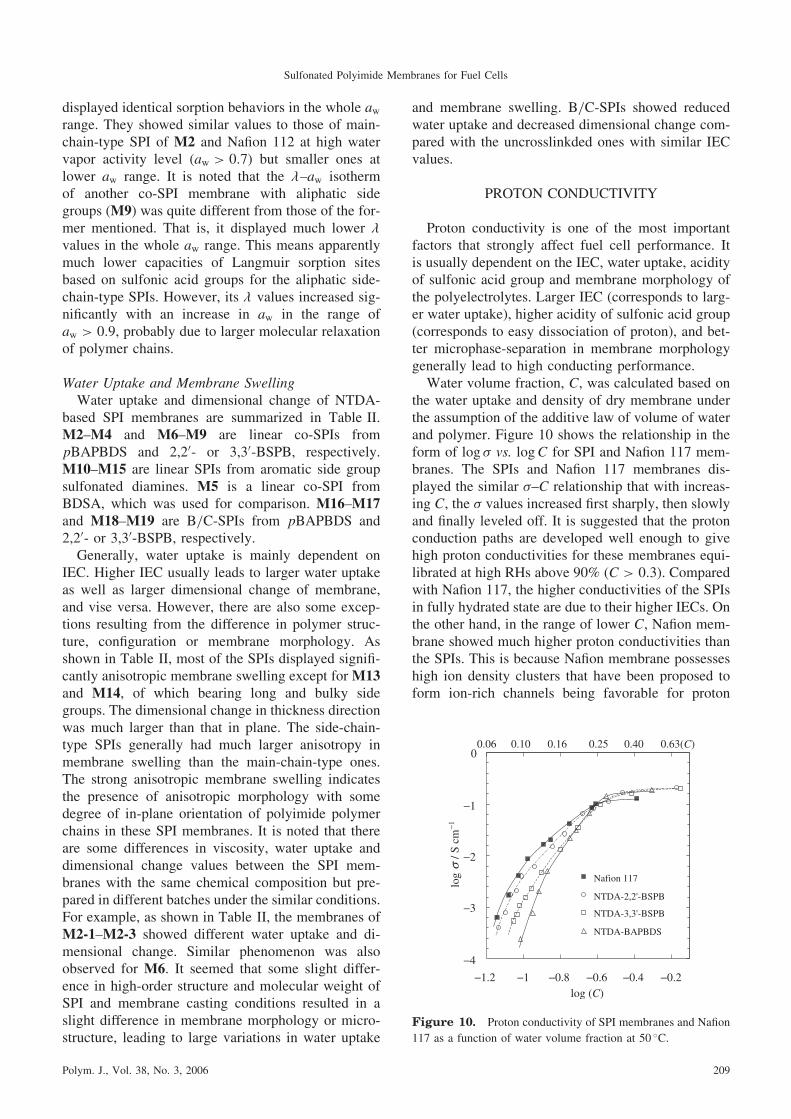
the water uptake and density of dry membrane underthe assumption of the additive law of volume of waterand polymer. Figure 10 shows the relationship in theform of log � vs. logC for SPI and Nafion 117 mem-branes. The SPIs and Nafion 117 membranes dis-played the similar �–C relationship that with increas-ing C, the � values increased first sharply, then slowlyand finally leveled off. It is suggested that the protonconduction paths are developed well enough to givehigh proton conductivities for these membranes equi-librated at high RHs above 90% (C > 0:3). Comparedwith Nafion 117, the higher conductivities of the SPIsin fully hydrated state are due to their higher IECs. Onthe other hand, in the range of lower C, Nafion mem-brane showed much higher proton conductivities thanthe SPIs. This is because Nafion membrane possesseshigh ion density clusters that have been proposed toform ion-rich channels being favorable for proton
−4
−3
−2
−1
0
−1.2 −1 −0.8 −0.6 −0.4 −0.2log (C)
log
−1
Nafion 117
NTDA-2,2'-BSPB
NTDA-3,3'-BSPB
NTDA-BAPBDS
0.06 0.10 0.16 0.25 0.63(C)0.40
σ/ S
cm
Figure 10. Proton conductivity of SPI membranes and Nafion
117 as a function of water volume fraction at 50 �C.
Sulfonated Polyimide Membranes for Fuel Cells
Polym. J., Vol. 38, No. 3, 2006 209

transport.43 The SPIs especially NTDA-BAPBDSneeded much larger C values to display the same pro-ton conductivity as that of Nafion. This suggests thepresence of a threshold water volume fraction C0,below which proton conduction is impossible, andthe different threshold values for these membranes.The proton conductivity in some proton-conducting
polymer membranes has been reported to obey the fol-lowing percolation theory as shown in eq 1.44–46
� ¼ �0ðC � C0Þn ð1Þ
where C0 is a threshold volume fraction required forprotons to transport, n is referred to as a critical expo-nent that controls the scaling behavior, and �0 is a pre-factor determined by carrier number and ion transportmobility.To test the percolation theory, C0 was initially
chosen as a minimum C value for each membrane inFigure 10 and the calculated line of log � vs. logðC �C0Þ was best fit to the experimental data except for thedatum measured in water. This procedure was repeat-ed for various values of C0 until a maximum fitting ofthe calculated and the experimental data was achiev-ed. The experimental data and best-fit line for SPImembranes and Nafion 117 are shown in Figure 11.The percolation thresholds, C0, of Nafion 117, NTDA-BSPB and NTDA-BAPBDS were 0.065, 0.075–0.090,and 0.105, respectively. Nafion 117 has a well-formedmicrophase-separated structure that is favorable forproton conduction, resulting in lower C0 value. Asmentioned above, the side-chain-type SPIs, NTDA-BSPB, also have microphase-separated structurewhere the ionic domains connected to each other toform proton-conducting pathways. This is likely thereason for the lower C0 for NTDA-BSPB comparedto NTDA-BAPBDS. As a result, the proton conductiv-
ity of SPI membranes could be explained by percola-tion theory in relation to the percolation thresholds.Figure 12 shows relative humidity dependence of
proton conductivity for typical co-SPI membranesand Nafion 112, at 60 �C. The SPIs cited in thisplot had reasonable IEC values of 1.5–2.0mequiv g�1
(see Table II). The proton conductivity for SPI mem-branes generally displayed larger RH dependence thanthat for Nafion 112. At lower RHs below 60%, the �values of SPI membranes were much lower than thoseof Nafion. However, the deviation in proton conduc-tivity became smaller with an increase in RH. At highRHs above 80%, the SPIs showed comparable � val-ues to Nafion 112. As mentioned above, Nafion is wellknown to be a super acid and has a good microphase-separation structure composed of hydrophilic ionicdomain (ionic cluster size �5 nm) and hydrophobicmoiety, which may be the reason of high proton con-ductivity even at lower RH. At higher RHs, IECseemed to play a more important role on proton con-ductivity. That is why the deviation in proton conduc-tivity between Nafion and SPIs became smaller withincreasing RH, since SPIs had larger IECs.As shown in Figure 12, SPIs of M10 and M2 with
larger IECs of 1.8–1.9mequiv g�1 displayed higherproton conductivities than other SPIs in the wholeRH range. It is surprise that the membrane of M9showed lower � values especially at lower RHs, al-though with a higher IEC of about 2.0mequiv g�1.This maybe explained by the much smaller wateruptake values in � of M9, as shown in Figure 9, com-pared with other SPIs. With lower IEC values, M13and M15 displayed identical conducting performance,which was comparable to that of M9.It should be mentioned that some of co-SPI mem-
branes with same chemical composition but in differ-
−3.0
−2.5
−1.5
−0.5
−2.2 −1.8 −1.4 −1 −0.6 −0.2
log (C−C0 )
log
−1
Nafion 117
NTDA-2,2'-BSPB
NTDA-3,3'-BSPB
NTDA-BAPBDS
σ/ S
cm
Figure 11. Data and best-fit lines for conductivity vs. water
volume fraction minus percolation threshold for SPI memberanes
and Nafion 117 at 50 �C.
0.0001
0.001
0.01
0.1
1
20 30 40 50 60 70 80 90Relative Humidity (%)
Con
duct
ivity
(S/
cm)
M10
M13M15
M9-2
M2-3Nafion 112
inwater
Figure 12. Proton conductivity at 60 �C for SPI membranes
and Nafion 112 as a function of relative humidity.
Y. YIN et al.
210 Polym. J., Vol. 38, No. 3, 2006
ent batches, such as M6 and M9, displayed differentconducting behaviors.34 The data can also be seen inTable II. Since the side-chain-type SPIs had micro-phase-separated structure, the slight difference inmembrane morphology of the same kind of SPI mem-branes may affect the conducting behavior more orless, especially at lower RH range.Figure 13 shows temperature dependence of proton
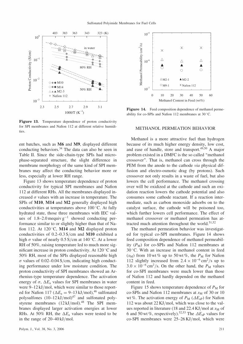
conductivity for typical SPI membranes and Nafion112 at different RHs. All the membranes displayed in-creased � values with an increase in temperature. TheSPIs of M10, M14 and M2 generally displayed highconductivities at temperatures above 100 �C. At fullyhydrated state, those three membranes with IEC val-ues of 1.8–2.0mequiv g�1 showed conducting per-formance similar to or slightly higher than that of Na-fion 112. At 120 �C, M14 and M2 displayed protonconductivities of 0.2–0.3 S/cm and M10 exhibited ahigh � value of nearly 0.5 S/cm at 140 �C. At a lowerRH of 50%, raising temperature led to much more sig-nificant increase in proton conductivity. At 120 �C and50% RH, most of the SPIs displayed reasonable high� values of 0.02–0.04 S/cm, indicating high conduct-ing performance under low moisture condition. Theproton conductivity of SPI membranes showed an Ar-rhenius-type temperature dependence. The activationenergy of �, �Ea values for SPI membranes in waterwere 9–12 kJ/mol, which were similar to those report-ed for Nafion 117 (�Ea ¼ 9{13 kJ/mol),46 sulfonatedpolysulfones (10–12 kJ/mol)47 and sulfonated poly-styrene membranes (12 kJ/mol).48 The SPI mem-branes displayed larger activation energies at lowerRHs. At 50% RH, the �Ea values were tested to bein the range of 20–40 kJ/mol.
METHANOL PERMEATION BEHAVIOR
Methanol is a more attractive fuel than hydrogenbecause of its much higher energy density, low cost,and ease of handle, store and transport.49,50 A majorproblem existed in a DMFC is the so called ‘‘methanolcrossover’’. That is, methanol can cross through thePEM from the anode to the cathode via physical dif-fusion and electro-osmotic drag (by protons). Suchcrossover not only results in a waste of fuel, but alsolowers the cell performance. The methanol crossingover will be oxidized at the cathode and such an oxi-dation reaction lowers the cathode potential and alsoconsumes some cathode reactant. If a reaction inter-mediate, such as carbon monoxide adsorbs on to thecatalyst surface, the cathode will be poisoned too,which further lowers cell performance. The effect ofmethanol crossover or methanol permeation has at-tracted much attention throughout the world.51,52
The methanol permeation behavior was investigat-ed for typical co-SPI membranes. Figure 14 showsfeed composition dependence of methanol permeabil-ity (PM) for co-SPIs and Nafion 112 membranes at30 �C. With an increase in methanol content in feed(xM) from 10wt% up to 50wt%, the PM for Nafion112 slightly increased from 2:4� 10�6 cm2/s up to3:0� 10�6 cm2/s. On the other hand, the PM valuesfor co-SPI membranes were much lower than thoseof Nafion 112 and hardly depended on the methanolcontent in feed.Figure 15 shows temperature dependence of PM for
co-SPIs and Nafion 112 membranes at xM of 30 or 10wt%. The activation energy of PM (�EaP) for Nafion112 was about 22KJ/mol, which was close to the val-ues reported in literature (18 and 22.4KJ/mol at xM of6 and 50wt%, respectively).52,53 The �EaP values forco-SPI membranes were 25–26KJ/mol, which were
2.3 2.5 2.7 2.9 3.1
Prot
on C
ondu
ctiv
ity (
S/cm
)
1000/T (K )−1
in water
80% RH
50% RH
323 (K)343363383403
10−3
10−2
10−1
100
M10M14M2-3
Nafion 112
Figure 13. Temperature dependence of proton conductivity
for SPI membranes and Nafion 112 at different relative humidi-
ties.
0 10 20 30 40 50 60
Methanol Content in Feed (wt%)
Met
hano
l Per
mea
bilit
y (c
m2/s
)
M2-1 M2-2
M9-1 Nafion 11210−7
10−6
10−5
Figure 14. Feed composition dependence of methanol perme-
ability for co-SPIs and Nafion 112 membranes at 30 �C.
Sulfonated Polyimide Membranes for Fuel Cells
Polym. J., Vol. 38, No. 3, 2006 211

comparable to those for Nafion membranes. A slightlysmaller �EaP value of 18 kJ/mol have been observedfor IonClad R-1010 and R-4010 membranes,52 where-as larger values of 41 and 37KJ/mol for C/S-PPP andS-SIBS membranes, respectively.53,54
The PM values are summarized in Table V. Nafion112 showed a high PM value of 2:4� 10�6 cm2/s atxM of 10wt% and 30 �C, which was in agreementwith the values reported in literature (2.3 and 2:6�10�6 cm2/s) at the same xM and room tempera-ture.55,56 The co-SPIs showed more than two timessmaller PM values than Nafion 112. The ratios of �to PM, � ¼ �=PM, are also listed in Table V. The ratio� is an effective parameter evaluating the membraneperformance in a DMFC system. With an increasein temperature, the � decreased as a result of the larg-er activation energy of methanol permeation than thatof proton conductivity. The � values of Nafion 112membrane were 3{4� 104 S cm�3 s at 30 and 50 �C.As shown in Table V, the co-SPI membranes dis-played 2–4 times larger � values than Nafion 112.
Nafion is known to have well-developed micro-phase-separation and proton conducting channels orconnected ionic domains, which give high proton con-ductivity and also high methanol permeability. Theco-SPI membranes have much lower methanol perme-ability and comparable proton conductivity in water,compared with Nafion. This is likely explained basedon both the difference in morphology between Nafionand co-SPI membranes and the difference in the trans-port mechanism between proton conduction and meth-anol permeation.Table VI shows comparison of the �, PM and � val-
ues among PEMs reported in literature and SPIs. Fluo-rinated ionomer membranes (IonClad R-1010 andR-4010) showed good performance of high � and �values.52 The C/S-PPP membrane with IEC of 1.07meq/g has been reported to have high � values of24 � and 8:4� 104 S cm�3 s at 25 and 80 �C, respec-tively.53 The SPI membrane derived from 3,30,4,40-bezophenonetetracarboxylic dianhydride (BTDA),BDSA and 4,40-oxydianiline (ODA) with IEC of 1.75mequiv g�1 has also been reported to have an extreme-ly high � value of 56� 104 S cm�3 s at room tempera-ture.57 In these two membranes, the high � values weredue to the much smaller PM values than for Nafionmembranes, whereas the � values were about twotimes smaller. Such high � values were not observedfor the present co-SPI membranes. However, it is not-ed that some co-SPI membranes showed high protonconductivities comparable to Nafion 112 and simulta-neously 3–4 times lower methanol permeabilities thanNafion and as a result, fairly high � values of 13–18and 10{13� 104 S cm�3 s at 30 and 50 �C, respective-ly.58 This indicates that the co-SPI membranes havehigh potential for DMFC application.
FUEL CELL PERFORMANCE
Polymer Electrolyte Fuel CellMembrane-electrode assemblies (MEAs) were pre-
pared by hot-pressing electrode/membrane/electrode
2.9 3 3.1 3.2 3.3 3.4 3.5
1000/T (K−1)
Met
hano
l Per
mea
bilit
y (c
m2
/s)
M2-1 (30wt%)
M2-2 (30wt%)
M9-1 (30wt%)
Nafion 112 (10wt%)10
−7
10−6
10−5
333 323 313 303 293 (K)
Figure 15. Temperature dependence of methanol permeabili-
ty for co-SPI and Nafion 112 membranes at xM of 10 or 30wt%.
Table V. Proton conductivity (�), methanol permeability (PM) and the ratios (�) of SPI membranes
SPIs
� (mS/cm)a PM (10�6 cm2/s)b � (104 S cm�3 s)b
30 �C 50 �C30 �C 50 �C 30 �C 50 �C
10% (30%) 10% (30%) 10% (30%) 10% (30%)
M2-1 91 124 1.15 (1.02) 1.66 (1.77) 7.9 (8.9) 7.5 (7.0)
M2-2 72 102 0.75 (0.73) (1.31) 9.6 (10) (7.8)
M6-0 52 63 0.34 (0.66) 0.51 15 (7.9) 12
M6-1 80 107 (1.00) — (8.0) —
M8 43 54 0.41 (0.32) 0.47 10 (13) 11
M9 82 118 0.62 (0.48) 1.04 (0.92) 13 (17) 11 (13)
Nafion 112 10 130 2.4 (3.0) 3.8 (4.0) 4.2 (3.3) 3.4 (3.3)
aMeasured in water. bxM ¼ 10 and 30wt%. The data in parenthesis refer to the values at xM of
30wt%.
Y. YIN et al.
212 Polym. J., Vol. 38, No. 3, 2006

sandwiches at 135 �C for 10min under 60 kg/cm2.The effective electrode area was 5 cm2. Figures 16aand 16b show the performances of PEFCs with Nafion112 and co-SPI membranes. The open circuit voltage(OCV) and cell voltage at current density of 1.0A cm�2 (V1) are summarized in Table VII, includingthe data for PEFCs with other SPI membranes. Thecomplex impedance spectra of cell were measured atdifferent dc voltages. Assuming a simple equivalentcircuit, membrane resistance (Rm) and reaction resist-ance at electrodes (Rel) were evaluated from the impe-dance spectra.59 The Rm and Rel values at 1.0V arelisted in Table VII. The lower Rel values indicatethe good contact of MEAs, which is essential for the
high performance of fuel cells. In the case of oxygensupply in the cathode, the SPI membranes displayedthe high PEFC performances comparable to those ofNafion 112. On the other hand, in the case of air sup-ply, the SPI membranes displayed slightly lowerPEFC performances because of slightly larger Rel val-ues. This implies the presence of a little larger resist-ance for gas diffusion in cathode catalyst layer, andthe MEA preparation process should be improved.The Rm was hardly dependent of dc voltage, and
was attributed mainly to conduction resistance ofmembrane except for too thin membranes. The protonconductivity in thickness direction of membrane (�?)was calculated from Rm and is listed in Table VII.
Table VI. Comparison of PM, � and � among PEMs
PEMsaThickness IEC WU Conditionsb PM �c �
Ref.(mm) (meq/g) (wt%) (�C) (wt%) (10�6 cm2/s) (10�2 S/cm) (104 S cm�3 s)
M2-1 32 1.89 45 30 30 0.73 7.2 10 58
63 30 1.81 12.1 6.7 58
M9-2 24 2.02 64 30 30 0.48 8.2 17 58
50 30 0.92 11.8 13 58
Nafion 112 55 0.91 30 30 10 2.4 10 4.2 58
R-1010 36 1.2 — 60 6 1.37 14.6 10.7 52
R-4010 63 1.5 — 60 6 0.94 13.2 14 52
C/S-PPP 183 1.07 38 25 10 0.145 4.5 24 53
80 10 1.54 13 8.4 53
BTDA-BDSA/ODA 85 1.75 16 25 15 0.073 4.1 56 57
Sulfonated polystyrene 338 1.41 44 22 6 0.52 5.0 9.6 48
60 6 1.19 11.9 7.2 48
S-SIBS 200–300 0.97 — 25 6 0.139 2.47 18 54
80 6 1.46 8.3 5.7 54
aR-1010 and R-4010: poly(styrenesulfonic acid) side chains grafted to a perflurorinated polymeric backbone; C/S-PPP: crosslinked
and sulfonated poly(phenoxy)phosphazene; S-SIBS: sulfonated poly(styrene-isobutylene-styrene). bTemperature and feed cocentration
of methanol for measurement of PM.cMeasured in water at the same temperature for PM.
0
0.2
0.4
0.6
0.8
1
0 0.5 1 1.5 2 2.5
Current Density (A/cm2)
Cel
l Vol
tage
(V
)
0
0.2
0.4
0.6
0.8
1
1.2
1.4
Pow
er O
utpu
t (W
/cm
2 )
(a)
0
0.2
0.4
0.6
0.8
1
0 0.5 1 1.5 2 2.5Current Density (A/cm2)
Cel
l Vol
tage
(V
)
0
0.2
0.4
0.6
0.8
1
1.2
1.4
Pow
er O
utpu
t (W
/cm
2 )
(b)
Figure 16. PEFC performances at 90 �C and 0.3MPa for (a) Nafion 112 (55 mm) and (b) co-SPI of NTDA-2,20-BSPB/BAPB (2/1)
(33 mm) supplied with O2 ( 100mL/min) and air ( 500mL/min) at cathode. (Pt (Pt/C: 30wt%): 0.5mg/cm2, Humidifier temper-
ature: 88 �C for H2, 85�C for O2 and air).
Sulfonated Polyimide Membranes for Fuel Cells
Polym. J., Vol. 38, No. 3, 2006 213

Judging from the operational conditions of PEFCs, thedata correspond to the �? values at 90 �C and 90%RH. For comparison, the conductivities in plane direc-tion of membranes (referred as ‘‘�==’’ here after) at thesame conditions were evaluated from the data at 50 �Cand 90% RH using the activation energy of 10 kJ/mol,60 as shown in Table VII. The �? values wereabout 30–50% as those of the �== ones. It is noted thatthe anisotropy of proton conductivity is slightly largerfor the BSPB-based SPIs of M6 and M19, with thelarger anisotropy of membrane swelling, than for theBAPBDS-based SPIs of M2 and M16.Figure 17 shows effect of humidifier temperature
on PEFC performance for NTDA-BAPBDS/BAPB(2/1) membrane.59 When the temperature of H2/O2
humidifiers decreased from 88/85 �C (correspondingto 93/84% RH) to 80/80 �C (70/70% RH), a slightdecrease in cell voltage, for example, by about 20mVat a current density of 1.0A/cm2 was observed. Judg-
ing from the large dependence of proton conductivityon RH, this rather small effect implies effective backdiffusion of water formed at the cathode into themembrane bulk. This is due to not only thinner mem-brane but also the water transport behavior character-istic to SPI membrane, that is, the water transportthrough SPI membrane is not controlled by electro-osmotic drag but by diffusion according to the activitydifference as mentioned below.A short-term stability test was carried out for a cell
with the SPI membrane under the same conditions asin Figure 16.61 The test cell kept a cell voltage of0.75V with a current density of 0.5A/cm2 for 300 h.The degradation rate was about 20 mV/h. Judgingfrom the water stability test mentioned above, theSPI membranes have high potential for PEFC applica-tions working at 80 �C.
Direct Methanol Fuel CellDMFCs are suited for portable devices or transpor-
tation applications owing to their high energy densityat low operating temperatures and the ease of handl-ing a liquid fuel.50 However, the methanol crossoveracross MEA impedes the improvement of DMFC per-formance, as has been reported for Nafion.51 Therehave been much attention for development of alterna-tive membranes that have lower methanol permeabil-ity with minimal loss of proton conductivity.62–64 TheSPI membranes dealt in this review have high toler-ance against methanol. They don’t swell in methanolrather than in water. This is quite different from othersulfonated aromatic polymers such as sulfonated poly-(arylene ethers). Although having reasonably highproton conductivities due to higher IECs, the SPImembranes have lower methanol permeabilities evenat high methanol concentrations. Thus, they have highpotential for DMFC applications.65
Table VII. Properties of PEFCs with SPI and Nafion 112 membranes operated at 90 �Ca
SPIsPt/C
loading(wt%)
Thickness(mm)
OCV(mV)
V1
(mV)Rm
(m�)Rel
(m�)�?
(mS/cm)�==
(mS/cm)
M2 (88/85) 20 23 948 685 14 16 (32) 130
(85/82) 20 23 955 696 14 16 (32) 130
(80/80) 20 23 951 672 15 17 (31) 130
M19 20 40 996 685 18 20 43 150
Nafion 112 20 55 982 658 15 15 74 140
M2 30 38 987 716 14 13 54 130
M6 O2 30 33 978 708 14 14 46 140
Air 30 26 963 616 14 41 (38) 140
M16 O2 30 35 981 706 12 13 59 140
Air 30 35 956 585 11 79 62 140
Nafion 112 O2 30 55 963 688 17 12 65 140
Air 30 55 916 643 17 35 66 140
aConditions are the same as mentioned in Figure 16 or Figure 17.
0.5
0.6
0.7
0.8
0.9
1
0 0.5 1 1.5 2 2.5
Current Load (A/cm2)
Cel
l Vol
tage
(V
)
0
0.2
0.4
0.6
0.8
1
1.2
1.4
Pow
er O
utpu
t (W
/cm
2)
88/85 °C
85/82 °C
80/80 °C
Figure 17. Effect of humidifier temperature on PEFC per-
formance for NTDA-BAPBDS/BAPB (2/1) 34 (23 mm). Cell:
90 �C, 0.3MPa, H2: 150mL/min, O2: 100mL/min.
Y. YIN et al.
214 Polym. J., Vol. 38, No. 3, 2006

Figures 18a and 18b show the performances forDMFCs with NTDA-BAPBDS/TAPB (6/1) (M16)and Nafion 112, respectively, supplied with methanolconcentration of 5–50wt%, at 60 �C. With 5wt%methanol, Nafion 112 displayed a high maximumpower output Wmax of about 140mWcm�2 at 500mA/cm�2, which was 20% higher than that for theSPI. With an increase in methanol concentration, thefuel cell performance decreased slightly for the SPIbut largely for Nafion 112. As a result, at 30wt%methanol, the SPI kept the high Wmax of 92mWcm�2,which was 3 times larger than that for Nafion 112. Ata methanol concentration of 50wt%, the DMFC withNafion 112 did not work stably, whereas the DMFCwith the SPI still kept reasonably high Wmax of69mWcm�2.Figure 19 shows effects of cathode gas and its flow
rate on DMFC performance for NTDA-BAPBDS/BAPB (2/1). When oxygen was supplied into cath-ode, the DMFC performance hardly depended on theflow rate above 30mL/min. On the other hand, in thecase of air supply, the DMFC performance was muchlower and significantly increased with increasing airflow rate. At 750mL/min, the Wmax was 68mWcm�2
at 30wt% methanol, which was 30% lower than thatfor oxygen supply. The reduction in DMFC perform-ance with air supply was larger for Nafion 112 thanfor SPI membranes especially at higher methanolconcentration. For Nafion 112, the Wmax was of 82mWcm�2 at 10wt% methanol, which was similarto that for the SPI membrane at 20wt% methanol.Figure 20 shows temperature dependence of DMFC
performance for NTDA-BAPBDS/TAPB (6/1) (M16).Even at 20wt% methanol, OCV and Wmax increasedsignificantly with increasing temperature up to 80 �C.
0.1
0.2
0.3
0.4
0.5
0.6
0.7
0 100 200 300 400 500Current Density (mA/cm2)
Cel
l Vol
tage
(V
)
0
20
40
60
80
100
120
Pow
er O
utpu
t (m
W/c
m2)
(a)
0
0.1
0.2
0.3
0.4
0.5
0.6
0 100 200 300 400 500Current Density (mA/cm2)
Cel
l Vol
tage
(V
)
0
20
40
60
80
100
120
140
Pow
er O
utpu
t (m
W/c
m2)
(b)
Figure 18. Effects of MeOH concentration on DMFC performance for (a) NTDA-BAPBDS/TAPB (6/1) (45 mm) and (b) Nafion 112.
(effective electrode area: 5 cm2; 2.2mg/cm2 Pt-Ru for anode and 1.8mg/cm2 Pt for cathode); ( : 5%, : 10%, : 20%, : 30%,
–: 50wt%) MeOH: 1mL/min, O2: 150mL/min; 60 �C; atmospheric pressure.
0
0.1
0.2
0.3
0.4
0.5
0.6
0 100 200 300 400 500
Current Density (mA/cm2)
Cel
l Vol
tage
(V
)
0
10
20
30
40
50
60
70
80
90
100
Pow
er O
utpu
t (m
W/c
m2 )
Figure 19. Effects of cathode gas and its flow rate on DMFC
performance for NTDA-BAPBDS/BAPB (2/1) (38 mm) at 60 �C.
(30wt% MeOH, : O2: 150mL/min, : air: 750mL/min,
: air: 450mL/min, : air: 150mL/min)
0
0.1
0.2
0.3
0.4
0.5
0.6
0.7
0 100 200 300 400 500Current Density (mA/cm2)
Cel
l Vol
tage
(V
)
0
20
40
60
80
100
120
140
160
Pow
er o
utpu
t (m
W/c
m2)
Figure 20. Temperature dependence of DMFC performance
for NTDA-BAPBDS/TAPB (6/1) (45 mm). 20wt% MeOH, O2:
150mL/min. ( : 40 �C, : 60 �C, : 80 �C)
Sulfonated Polyimide Membranes for Fuel Cells
Polym. J., Vol. 38, No. 3, 2006 215

This indicates that, in the case of DMFCs with SPIs,the advantageous effect of higher temperature on theelectrode reaction overcame its adverse effect onmethanol crossover, which was different from the caseof Nafion 112.Figures 21a and 21b show methanol and water
crossover through Nafion 115 and SPI membranesmeasured during DMFC operation. In Figure 21a, forNafion 115, the water flux qW increased significantlywith increasing load current density due to the in-creasing contribution of electro-osmotic drag of pro-ton migration. From the slope of the line in the currentrange above 200mAcm�2, the water electro-osmoticdrag coefficient for Nafion 115 was evaluated as 2.4H2O/H
þ, which was close to the literature values of2.5–3.3 H2O/H
þ at lower methanol concentrationsless than 3wt%.66,67 On the other hand, for SPI mem-brane, the qW slightly decreased with increasing cur-rent density, indicating that the water flux was con-trolled by the diffusion but not by the electro-osmosis under the present conditions. This is due tothe difference in membrane morphology. The SPImembranes have no clear hydrophilic ionic channelstructure as considered in Nafion membranes andhave less loosely bonded and/or free water thanNafion membranes. The similar water crossover be-havior has been reported for poly(arylene ethers).67
In Figure 21b at a constant current density of 200mAcm�2, for Nafion 115, the qW hardly changed, be-cause it was controlled by the electro-osmosis. On theother hand, for SPI membrane, the qW decreasedlargely with increasing methanol concentration (orwith decreasing water concentration) and became neg-ative at 50wt% methanol. This was due to the de-crease in driving force of water diffusion.In Figure 21a, for Nafion 115, the methanol flux qM
increased largely with increasing current density. This
indicates that an increase in the water flux due to theelectro-osmosis caused a fairly large increase in themethanol flux. On the other hand, for SPI membrane,the qM hardly changed with the current density. InFigure 21b, with increasing methanol concentrationat a constant current density, the qM increased slightlylinearly and sublinearly for Nafion and SPI mem-branes, respectively. This is due to the difference inmembrane swelling in higher methanol concentration.The methanol permeation coefficient PM values calcu-lated from the qM values which are listed in Table VIIIwere two or three times smaller than those measuredfrom the liquid–liquid permeation experiments men-tioned above. This is because of the lower membraneswelling for DMFC operations, where the membranesat the cathode were contact with gas instead of water.As mentioned above, the water and methanol cross-
over behavior is quite different between Nafion andSPI membranes. In the case of Nafion membranes,methanol crossover increases largely with increasingmethanol concentration and also with increasing loadcurrent density. Methanol crossover is followed bymethanol electro-oxidation on cathode, which com-petes with oxygen reduction on cathode, resulting ina mixed potential and a reduction of OCV50 as wellas a reduction of Faraday’s efficiency (percentage ofmethanol utilized for electricity per methanol con-sumed). Furthermore, under the conditions of a highermethanol concentration and a higher load current den-sity, the total amount of water in the cathode becamemuch larger for Nafion than for SPI membrane, as list-ed in Table VIII, because of larger water crossoverand larger water formation via oxidation of crossov-ered methanol. This interrupts diffusion of oxygenmolecules from gas diffusion layer to catalyst layerof cathode. As a result, oxygen supply into catalystlayer is apt to become a rate-determining step, espe-
0
2
4
6
8
10
0 0.1 0.2 0.3 0.4Current Density (A/cm2)
qW x
106
(mol
/cm
2 /s)
0
0.5
1
1.5
2
2.5
qM x
106
(mol
/cm
2/s
)
Nafion 115BAPBDS/BAPBz(2/1)
(a)
-1
1
3
5
7
9
0 10 20 30 40 50MeOH Concentration (wt%)
qW x
106
(mol
/cm
2/s
)
0
1
2
3
4
qM x
106
(mol
/cm
2 /s)
Nafion 115BAPBDS/BAPBz (2/1)
(b)
Figure 21. Water flux ( ) and methanol crossover ( ) for DMFCs with Nafion 115 and NTDA-BAPBDS/BAPBz (2/1) (50 mm)
membranes at 60 �C with O2 of 150mL/min humidified at 25 �C. (a) effect of current density at 20wt% MeOH. (b) effect of methanol
concentration at a current density of 200mA/cm2.
Y. YIN et al.
216 Polym. J., Vol. 38, No. 3, 2006
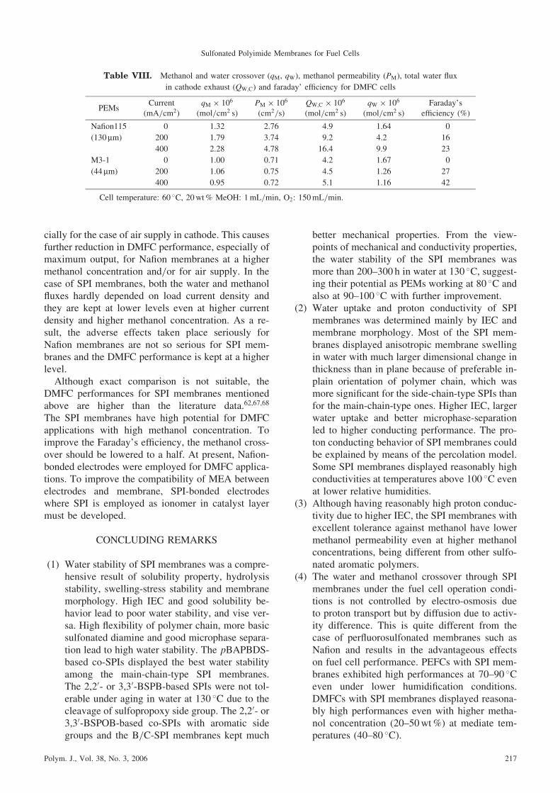
cially for the case of air supply in cathode. This causesfurther reduction in DMFC performance, especially ofmaximum output, for Nafion membranes at a highermethanol concentration and/or for air supply. In thecase of SPI membranes, both the water and methanolfluxes hardly depended on load current density andthey are kept at lower levels even at higher currentdensity and higher methanol concentration. As a re-sult, the adverse effects taken place seriously forNafion membranes are not so serious for SPI mem-branes and the DMFC performance is kept at a higherlevel.Although exact comparison is not suitable, the
DMFC performances for SPI membranes mentionedabove are higher than the literature data.62,67,68
The SPI membranes have high potential for DMFCapplications with high methanol concentration. Toimprove the Faraday’s efficiency, the methanol cross-over should be lowered to a half. At present, Nafion-bonded electrodes were employed for DMFC applica-tions. To improve the compatibility of MEA betweenelectrodes and membrane, SPI-bonded electrodeswhere SPI is employed as ionomer in catalyst layermust be developed.
CONCLUDING REMARKS
(1) Water stability of SPI membranes was a compre-hensive result of solubility property, hydrolysisstability, swelling-stress stability and membranemorphology. High IEC and good solubility be-havior lead to poor water stability, and vise ver-sa. High flexibility of polymer chain, more basicsulfonated diamine and good microphase separa-tion lead to high water stability. The pBAPBDS-based co-SPIs displayed the best water stabilityamong the main-chain-type SPI membranes.The 2,20- or 3,30-BSPB-based SPIs were not tol-erable under aging in water at 130 �C due to thecleavage of sulfopropoxy side group. The 2,20- or3,30-BSPOB-based co-SPIs with aromatic sidegroups and the B/C-SPI membranes kept much
better mechanical properties. From the view-points of mechanical and conductivity properties,the water stability of the SPI membranes wasmore than 200–300 h in water at 130 �C, suggest-ing their potential as PEMs working at 80 �C andalso at 90–100 �C with further improvement.
(2) Water uptake and proton conductivity of SPImembranes was determined mainly by IEC andmembrane morphology. Most of the SPI mem-branes displayed anisotropic membrane swellingin water with much larger dimensional change inthickness than in plane because of preferable in-plain orientation of polymer chain, which wasmore significant for the side-chain-type SPIs thanfor the main-chain-type ones. Higher IEC, largerwater uptake and better microphase-separationled to higher conducting performance. The pro-ton conducting behavior of SPI membranes couldbe explained by means of the percolation model.Some SPI membranes displayed reasonably highconductivities at temperatures above 100 �C evenat lower relative humidities.
(3) Although having reasonably high proton conduc-tivity due to higher IEC, the SPI membranes withexcellent tolerance against methanol have lowermethanol permeability even at higher methanolconcentrations, being different from other sulfo-nated aromatic polymers.
(4) The water and methanol crossover through SPImembranes under the fuel cell operation condi-tions is not controlled by electro-osmosis dueto proton transport but by diffusion due to activ-ity difference. This is quite different from thecase of perfluorosulfonated membranes such asNafion and results in the advantageous effectson fuel cell performance. PEFCs with SPI mem-branes exhibited high performances at 70–90 �Ceven under lower humidification conditions.DMFCs with SPI membranes displayed reasona-bly high performances even with higher metha-nol concentration (20–50wt%) at mediate tem-peratures (40–80 �C).
Table VIII. Methanol and water crossover (qM, qW), methanol permeability (PM), total water flux
in cathode exhaust (QW,C) and faraday’ efficiency for DMFC cells
PEMsCurrent
(mA/cm2)qM � 106
(mol/cm2 s)PM � 106
(cm2/s)QW,C � 106
(mol/cm2 s)qW � 106
(mol/cm2 s)Faraday’s
efficiency (%)
Nafion115 0 1.32 2.76 4.9 1.64 0
(130 mm) 200 1.79 3.74 9.2 4.2 16
400 2.28 4.78 16.4 9.9 23
M3-1 0 1.00 0.71 4.2 1.67 0
(44 mm) 200 1.06 0.75 4.5 1.26 27
400 0.95 0.72 5.1 1.16 42
Cell temperature: 60 �C, 20wt% MeOH: 1mL/min, O2: 150mL/min.
Sulfonated Polyimide Membranes for Fuel Cells
Polym. J., Vol. 38, No. 3, 2006 217

Acknowledgment. This work was financiallysupported by NEDO (New Energy and IndustrialTechnology Development): Fuel cell & hydrogentechnology development department, ‘‘Research anddevelopment of polymer electrolyte fuel cells’’, andby the Venture Business Laboratory of YamaguchiUniversity, Japan.
REFERENCES
1. a) P. Costamagna and S. Srinivasan, J. Power Sources, 102,
242 (2001).
b) P. Costamagna and S. Srinivasan, J. Power Sources, 102,
253 (2001).
2. V. Mehta and J. S. Cooper, J. Power Sources, 114, 32
(2003).
3. O. Savadogo, J. New Mater. Electrochem. Syst., 1, 47
(1998).
4. K. A. Mauritz and R. B. Moore, Chem. Rev., 104, 4535
(2004).
5. M. Rikukawa and K. Sanui, Prog. Polym. Sci., 25, 1463
(2000).
6. J. A. Kerres, J. Membr. Sci., 185, 3 (2001).
7. K. D. Kreuer, J. Membr. Sci., 185, 29 (2001).
8. Q. Li, R. He, J. O. Jensen, and N. Bjerrum, Chem. Mater.,
15, 4896 (2003).
9. M. A. Hickner, H. Ghassemi, Y. S. Kim, B. R. Einsla, and
J. E. Mc-Grath, Chem. Rev., 145, 4587 (2004).
10. S. Faure, N. Cornet, G. Gebel, R. Mercier, M. Pineri, and B.
Sillion, Proc. 2nd Int. Symp. New Materials for Fuel Cell
and Modern Battery Systems, Eds. O. Savadogo and P. R.
Roberge, Montreal, Canada, July 6–10, 1997.
11. E. Vallejo, G. Porucelly, C. Gavach, R. Mercier, and M.
Pineri, J. Membr. Sci., 160, 127 (1999).
12. N. Cornet, O. Diat, G. Gebel, F. Jousse, D. Marsacq, R.
Mercier, and M. Pineri, J. New Mater. Electrochem. Syst.,
3, 33 (2000).
13. C. Genies, R. Mercier, B. Sillion, N. Cornet, G. Gebel, and
M. Pineri, Polymer, 42, 359 (2001).
14. S. Besse, P. Capron, O. Diat, G. Gebel, F. Jousse, D.
Marsacq, M. Pineri, C. Marestin, and R. Mercier, J. New
Mater. Electrochem. Syst., 5, 109 (2002).
15. K. Miyatake, H. Zhou, H. Uchida, and M. Watanabe, Chem.
Commun., 368 (2003).
16. K. Miyakake, N. Asano, and M. Watanabe, J. Polym. Sci.,
Part A: Polym. Chem., 41, 3901 (2003).
17. K. Miyatake, H. Zhou, T. Matsuo, H. Uchida, and M.
Watanabe, Macromolecules, 37, 4961 (2004).
18. K. Miyatake, H. Zhou, and M. Watanabe, Macromolecules,
37, 4956 (2004).
19. C. Lee, S. Sundar, J. Kwon, and H. Han, J. Polym. Sci., Part
A: Polym. Chem., 42, 3612 (2004).
20. C. Lee, S. Sundar, J. Kwon, and H. Han, J. Polym. Sci., Part
A: Polym. Chem., 42, 3621 (2004).
21. G. Gebel, L. Gonon, G. Meyer, and C. Perrot, 15th Annual
Meeting of NAMS, Honolulu, Hawai, June 26–30, 2004.
22. G. Meyer, G. Gebel, L. Gonon, P. Capron, D. Marscaq, C.
Marestin, and R. Mercier, J. Power Sources, (2006) in press.
23. J. Fang, X. Guo, S. Harada, T. Watari, K. Tanaka, H. Kita,
and K. Okamoto, Macromolecules, 35, 9022 (2002).
24. X. Guo, J. Fang, T. Watari, K. Tanaka, H. Kita, and K.
Okamoto, Macromolecules, 35, 6707 (2002).
25. K. Okamoto, J. Photopolym. Sci. Technol., 16, 247 (2003).
26. T. Watari, J. Fang, K. Tanaka, H. Kita, and K. Okamoto,
J. Membr. Sci., 230, 111 (2004).
27. X. Guo, J. Fang, K. Tanaka, H. Kita, and K. Okamoto,
J. Polym. Sci., Part A: Polym. Chem., 42, 1432 (2004).
28. X. Guo, J. Fang, and K. Okamoto, Trans. Mater. Res. Soc.
Jpn., 29, 2579 (2004).
29. Y. Yin, S. Chen, X. Guo, J. Fang, K. Tanaka, H. Kita, and K.
Okamoto, High Perform. Polym., submitted.
30. B. R. Einsla, Y. S. Kim, M. A. Hickner, Y.-T. Hong, M. L.
Hill, B. S. Pivovar, and J. E. McGrath, J. Polym. Sci., Part
A: Polym. Chem., 42, 862 (2004).
31. B. R. Einsla, Y.-T. Hong, Y. S. Kim, F. Wang, N. Gunduz,
and J. E. McGrath, J. Membr. Sci., 255, 141 (2005).
32. Y. Yin, J. Fang, Y. Cui, K. Tanaka, H. Kita, and K.
Okamoto, Polymer, 44, 4509 (2003).
33. Y. Yin, J. Fang, T. Watari, K. Tanaka, H. Kita, and K.
Okamoto, J. Mater. Chem., 14, 1062 (2004).
34. Y. Yin, O. Yamada, Y. Suto, T. Mishima, K. Tanaka, H.
Kita, and K. Okamoto, J. Polym. Sci., Part A: Polym. Chem.,
43, 1545 (2005).
35. N. Asano, K. Miyatake, and M. Watanabe, Chem. Mater.,
16, 2841 (2004).
36. J. Fang, X. Guo, and M. Litt, Trans. Mater. Res. Soc. Jpn.,
29, 2541 (2004).
37. a) Y. Suto, Y. Yin, O. Yamada, K. Tanaka, H. Kita, and K.
Okamoto, Polym. Prepr., Jpn., 54, 4605 (2005).
b) Y. Suto, Y. Yin, O. Yamada, K. Tanaka, H. Kita, and K.
Okamoto, Macromolecules, submitted.
38. Z. Hu, Y. Yin, S. Chen, K. Tanaka, H. Kita, and K.
Okamoto, J. Polym. Sci., Part A: Polym. Chem., submitted.
39. S. Chen, K. Tanaka, H. Kita, and K. Okamoto, Polymer,
submitted.
40. Y. Yin, O. Yamada, H. Kita, and K. Okamoto, Macromol.
Rapid Commun., 26, 696 (2005).
41. Y. Yin, Y. Suto, T. Sakabe, S. Chen, S. Hayashi, T.
Mishima, O. Yamada, K. Tanaka, H. Kita, and K. Okamoto,
Macromolecules, in press.
42. C. Genies, R. Mercier, B. Sillion, R. Petiaud, N. Cornet, G.
Gebel, and M. Pineri, Polymer, 42, 5097 (2001).
43. T. D. Gier, G. E. Munn, and F. C. Wilson, J. Polym. Sci.,
Polym. Phys. Ed., 19, 1687 (1981).
44. C. A. Edmondson and J. J. Fontanella, Solid State Ionics,
152–153, 355 (2002).
45. W. Y. Hsu, J. R. Barkley, and P. Meakin, Macromolecules,
13, 198 (1980).
46. T. Xu, W. Yang, and B. He, Chem. Eng. Sci., 56, 5343
(2001).
47. F. Lufrano, I. Gatto, P. Staiti, V. Antonucci, and E.
Passalacqua, Solid State Ionics, 145, 47 (2001).
48. N. Carretta, V. Tricoli, and F. Picchioni, J. Membr. Sci.,
166, 189 (2000).
49. B. D. McNicol, D. A. J. Rand, and K. R. Williams, J. Power
Sources, 83, 15 (1999).
50. A. S. Arico, S. Srinivasan, and V. Antonucci, Fuel Cells, 1,
Y. YIN et al.
218 Polym. J., Vol. 38, No. 3, 2006

133 (2001).
51. Z. Qi and A. Kaufman, J. Power Sources, 110, 177 (2002).
52. V. Tricoli, N. Carretta, and M. Bartolozzi, J. Electrochem.
Soc., 147, 1286 (2000).
53. X. Zhou, J. Weston, E. Chalkova, M. A. Hofmann, C. M.
Ambler, H. R. Allcock, and S. N. Lvov, Electrochim. Acta,
48, 2173 (2003).
54. Y. A. Elabd, E. Napadensky, J. M. Sloan, D. M. Crawford,
and C. W. Walker, J. Membr. Sci., 217, 227 (2003).
55. J. Ding, C. Chuy, and S. Holdcroft, Macromolecules, 35,
1348 (2002).
56. J. M. Bae, I. Honma, M. Murata, T. Yamamoto, M.
Rikukawa, and N. Ogata, Solid State Ionics, 147, 189
(2002).
57. Y. Woo, S. Y. Oh, Y. S. Kang, and B. Jung, J. Membr. Sci.,
220, 31 (2003).
58. K. Okamoto, Y. Yin, O. Yamada, M. N. Islam, T. Honda, T.
Mishima, Y. Suto, K. Tanaka, and H. Kita, J. Membr. Sci.,
258, 115 (2005).
59. O. Yamada, Y. Yin, K. Tanaka, H. Kita, and K. Okamoto,
Electrochim. Acta, 50, 2655 (2005).
60. Y. Yin, O. Yamada, S. Hayashi, K. Tanaka, H. Kita, and K.
Okamoto, J. Polym. Sci., Part A: Polym. Chem., submitted.
61. a) O. Yamada, Y. Yin, T. Fukuda, K. Tanaka, H. Kita,
and K. Okamoto, The 45th Battery Symposium in Japan,
November 27–29, 2004.
b) O. Yamada, Y. Yin, T. Fukuda, K. Tanaka, H. Kita, and
K. Okamoto, J. Power Sources, submitted.
62. L. Jorissen, V. Gogel, J. Kerres, and J. Garche, J. Power
Sources, 105, 267 (2002).
63. T. Yamaguchi, F. Miyata, and S. Nakao, Adv. Mater., 15,
1198 (2003).
64. V. S. Silva, B. Ruffmann, H. Silva, Y. A. Gallego, A.
Mendes, L. M. Maderia, and S. P. Nunes, J. Power Sources,
140, 34 (2005).
65. O. Yamada, T. Ogo, Y. Yin, K. Tanaka, H. Kita, and K.
Okamoto, Polym. Prepr., Jpn., 54, 4535 (2005). To be sub-
mitted to J. Power Sources.
66. X. Ren and S. Gottesfeld, J. Electrochem. Soc., 148, A87
(2001).
67. Y. S. Kim, M. J. Summer, W. L. Harriso, J. S. Riffle, J. E.
McGrath, and B. S. Pivovar, J. Electrochem. Soc., 151,
A2150 (2004).
68. T. Yamaguchi, H. Kuroki, and F. Miyata, Electrochem.
Commun., 7, 730 (2005).
Yan Yin was born in Hebei province, China in 1974. She received her master degree from Tianjin Polytechnic Uni-
versity, China, in 1999 and her Ph.D. in 2003 from Yamaguchi University under the direction of Prof. Ken-ichi
Okamoto. Subsequently, she worked as a postdoctoral researcher in Prof. Okamoto’s lab focused on the struc-
ture-morphology-property relationships of fuel cell membranes. Yin’s current research interests include developing
new membranes for polymer electrolyte fuel cells and direct methanol fuel cells.
Otoo Yamada was born in Munich, Germany in 1971. He received Ph.D. from Yamaguchi University in 2000 for
studies on the positive electrode characteristics of lithiated metal oxides in organic electrolyte solutions. He joined
Yamaguchi University Collaborative Research Center as a Research Associate. From 2002, he worked at Prof.
Okamoto’s lab as a post doctor on polymer electrolyte fuel cell. His current research interests include application
of polymer electrolyte membranes for polymer electrolyte fuel cells and direct methanol fuel cells.
Kazuhiro Tanaka was born in Shiga, Japan in 1962. He received his B.S. and M.S. from Yamaguchi University and
his Ph.D. from Osaka University. He joined the faculty of Yamaguchi University in 1988 and was promoted to As-
sociate Professor in 1998. He worked as a visiting researcher at University of Colorado at Boulder in 1997–1998.
His research interests are membranes for fuel cell and gas separation applications.
Ken-ichi Okamoto was born in 1941 in Hiroshima Prefecture, Japan. He received his M.S. Engineering from Osaka
University in 1968. He joined Osaka University as a research associate. In 1971, he joined Yamaguchi University as
an assistant professor. He received his Dr. Eng. from Osaka University in 1974. He joined Temple University as a
visiting assistant professor for a year since August 1977. Since 1980, he has been in Yamaguchi University as a
professor. He received Technology Award (2002) of The Society of Chemical Engineers Japan for development
and industrial applications of zeolite membranes. His research focused on organic photoconductors, photocatalytic
and photosensitized reactions, membrane separation materials and processes, and polymer electrolyte membranes
and their fuel cell applications.
Sulfonated Polyimide Membranes for Fuel Cells
Polym. J., Vol. 38, No. 3, 2006 219